Application of Active Noise Control for Air-Conditioning System
8
Application of Active Noise Control for Air-Conditioning System a Lik Wei, Foong, b Ka Fei, Thang, c Wai Meng, Chin a, b School of Engineering, Asia Pacific University of Technology & Innovation Technology Park Malaysia, Bukit Jalil, 57000 Kuala Lumpur, Malaysia c R&D department, OYL Manufacturing Company Sdn, Bhd, Taman Perindustrian Bukit Rahman Putra, 47000, Sungai Buloh, Selangor, Malaysia a [email protected], b [email protected], c [email protected] ABSTRACT The focus of the paper is on evaluating active noise control (ANC) systems for effective noise reduction of the outdoor unit of air-conditioning system. The first problem intended to be solved is that the noise created by the outdoor unit will lead to noise- pollution to the environment. The second problem is that the noise emitting from the compressor of air- conditioning system varied with respect to time. The third problem is that the chosen ANC system must be able to cope with low and high frequency of the noise signal. The developed system to deal with aforementioned problems is the PC-based ANC system with normalised least-mean-square (NLMS) algorithm. Based on the testing result obtained, the average noise-reduction in actual outdoor unit is 0.9 dBA. The obtained result is encouraging and will form the foundation for future work on the same area. KEYWORDS Active Noise Control, Normalised Least-Mean- Square, Outdoor Unit, Air-Conditioning System, Noise Reduction. 1 INTRODUCTION Nowadays, air-conditioning system plays an important role in our daily life either at homes, offices, industries and so on. This is because the air-conditioning system can produce cooling air in order to lower ambient temperature as to provide more thermal comfort in the indoor environment. However, most of the conventional air- conditioning system will produce some unwanted noise to the surrounding where the most of the noise are caused by the operation of compressor of air-conditioning system whereby the noise level is around 60 to 70 Decibel (dB). Eventually, the noise created by the compressor will cause noise pollution to the environment since the compressor is running continuously while the air-conditioning system is switched on. As a result, the noise pollution will directly affect the human mental stress, health problem and even hearing problem due to high noise level. Therefore, the main purpose of the research is to reduce or control the noise level created by air- conditioning system such that the health and hearing of human can be preserved effectively. Basically, there are two main approaches to reduce or control the noise level which are passive noise control (PNC) and active noise control (ANC) [1]. Previously, the passive noise control is to use the passive sound silencer or the insulation in order to absorb noise energy so that the output of system will produce less noise. However, the passive noise control works best in high frequency only such as above 250 Hz [1]. This is because the dimension of sound silencer is dependent on the wavelength of the noise signal. If dealing with low frequency noise signal, then the wavelength of noise signal is longer. This will cause the dimension or size of the sound silencer become larger which leads to cost inefficiency and impracticality. Therefore, the best approach that deals with low frequency noise signal is to use ANC method whereby a power source such as speaker is used to generate the same amplitude but with anti- phase sound wave to the input noise signal in order to create a destructive interference condition so that both sound waves will be cancelling each other as to reduce the unwanted noise [2]. Proceedings of the International Conference on Electrical and Electronic Engineering Telecommunication Engineering, and Mechatronics, Kuala Lumpur, Malaysia, 2015 ISBN: 978-1-941968-18-5 ©2015 SDIWC 14
Transcript of Application of Active Noise Control for Air-Conditioning System

Application of Active Noise Control for Air-Conditioning System
a Lik Wei, Foong, b Ka Fei, Thang, c Wai Meng, Chin a, b School of Engineering, Asia Pacific University of Technology & Innovation
Technology Park Malaysia, Bukit Jalil, 57000 Kuala Lumpur, Malaysia c R&D department, OYL Manufacturing Company Sdn, Bhd, Taman Perindustrian Bukit Rahman
Putra, 47000, Sungai Buloh, Selangor, Malaysia a [email protected], b [email protected], c [email protected]
ABSTRACT
The focus of the paper is on evaluating active noise
control (ANC) systems for effective noise reduction
of the outdoor unit of air-conditioning system. The
first problem intended to be solved is that the noise
created by the outdoor unit will lead to noise-
pollution to the environment. The second problem is
that the noise emitting from the compressor of air-
conditioning system varied with respect to time. The
third problem is that the chosen ANC system must
be able to cope with low and high frequency of the
noise signal. The developed system to deal with
aforementioned problems is the PC-based ANC
system with normalised least-mean-square (NLMS)
algorithm. Based on the testing result obtained, the
average noise-reduction in actual outdoor unit is 0.9
dBA. The obtained result is encouraging and will
form the foundation for future work on the same area.
KEYWORDS
Active Noise Control, Normalised Least-Mean-
Square, Outdoor Unit, Air-Conditioning System,
Noise Reduction.
1 INTRODUCTION
Nowadays, air-conditioning system plays an
important role in our daily life either at homes,
offices, industries and so on. This is because the
air-conditioning system can produce cooling air
in order to lower ambient temperature as to
provide more thermal comfort in the indoor
environment.
However, most of the conventional air-
conditioning system will produce some
unwanted noise to the surrounding where the
most of the noise are caused by the operation of
compressor of air-conditioning system whereby
the noise level is around 60 to 70 Decibel (dB).
Eventually, the noise created by the compressor
will cause noise pollution to the environment
since the compressor is running continuously
while the air-conditioning system is switched on.
As a result, the noise pollution will directly
affect the human mental stress, health problem
and even hearing problem due to high noise
level.
Therefore, the main purpose of the research is to
reduce or control the noise level created by air-
conditioning system such that the health and
hearing of human can be preserved effectively.
Basically, there are two main approaches to
reduce or control the noise level which are
passive noise control (PNC) and active noise
control (ANC) [1].
Previously, the passive noise control is to use
the passive sound silencer or the insulation in
order to absorb noise energy so that the output
of system will produce less noise. However, the
passive noise control works best in high
frequency only such as above 250 Hz [1]. This
is because the dimension of sound silencer is
dependent on the wavelength of the noise signal.
If dealing with low frequency noise signal, then
the wavelength of noise signal is longer. This
will cause the dimension or size of the sound
silencer become larger which leads to cost
inefficiency and impracticality.
Therefore, the best approach that deals with low
frequency noise signal is to use ANC method
whereby a power source such as speaker is used
to generate the same amplitude but with anti-
phase sound wave to the input noise signal in
order to create a destructive interference
condition so that both sound waves will be
cancelling each other as to reduce the unwanted
noise [2].
Proceedings of the International Conference on Electrical and Electronic Engineering Telecommunication Engineering, and Mechatronics, Kuala Lumpur, Malaysia, 2015
ISBN: 978-1-941968-18-5 ©2015 SDIWC 14

Several ANC applications have been proposed
by researchers. ANC were used, specifically the
modified-filtered-u LMS algorithm (MFU-
LMS), to minimise the noise of short acoustic
duct application like pipe system of vehicle
engine with high convergence rate [3]. Besides,
the filter-x LMS (FxLMS) has been proposed in
order to minimise the acoustic noise in a yacht
cabin adaptively by using two sub-woofers and
four error microphones [2]. On the other hands,
a modified feedback ANC (MFANC) algorithm
has been proposed by using a low cost
microcontroller unit (MCU) known as PIC24H
to make a low price ANC headset with good
noise cancellation compared to conventional
headset that require high cost digital signal
processor (DSP) [4].
This paper presents an alternative ANC system
known as PC-based ANC system that can be
used to reduce the noise-level of outdoor unit for
air-conditioning application. Normalised LMS
(NLMS) algorithm is proposed for the system in
which its simulation results and the actual
testing at outdoor unit of air-conditioning
system will be discussed in the following
sections.
2 DESIGN AND METHODOLOGY
In this section, the concepts, processes and
algorithms of the proposed ANC system will be
discussed in the following sub-sections.
2.1 Proposed Methodology
PC-based ANC system is a type of ANC system
which applies NLMS algorithm to perform
noise reduction operation. The operation of the
proposed system is illustrated in Figure 1.
First of all, the input microphone is used to
collect the original noise signal from the
outdoor unit of air-conditioning system. Next,
the computer laptop will act as a controller
where it is used to analyse the behaviour and
characteristics of original noise signal obtained
from input microphone such as amplitude,
frequency and phase angle.
After the signal has been analysed, it will send
a corresponding signal to an output speaker in
order to generate an anti-phase signal with same
amplitude and frequency but 1800 degree out of
phase with respect to original noise signal as to
reduce the noise level. The error microphone is
used to collect the residual noise signal after
undergoes the ANC process so that it can
provides feedback to the controller in order to
generate an updated anti-phase signal to reduce
the outdoor unit noise adaptively.
Figure 1: Block diagram of the proposed ANC system
On the other hands, the computation of LMS
algorithm involves three main steps which are
filter output, estimation error and tap-weight
adaptation [5]:
FilterOutput:
� �� � � � ��� � � �����
��� 1�
Estimationerror:
# �� � � �� ��$ �� 2�Tapweightadaptation:
� � + 1� � � �� + ,- + ‖� ��‖/ # ��� �� 3�
Proceedings of the International Conference on Electrical and Electronic Engineering Telecommunication Engineering, and Mechatronics, Kuala Lumpur, Malaysia, 2015
ISBN: 978-1-941968-18-5 ©2015 SDIWC 15
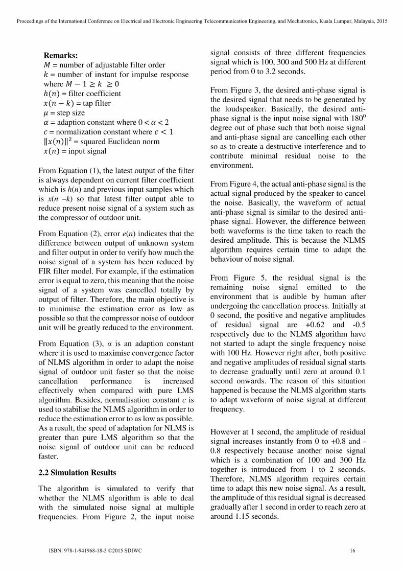
From Equation (1), the latest output of the filter
is always dependent on current filter coefficient
which is h(n) and previous input samples which
is x(n –k) so that latest filter output able to
reduce present noise signal of a system such as
the compressor of outdoor unit.
From Equation (2), error e(n) indicates that the
difference between output of unknown system
and filter output in order to verify how much the
noise signal of a system has been reduced by
FIR filter model. For example, if the estimation
error is equal to zero, this meaning that the noise
signal of a system was cancelled totally by
output of filter. Therefore, the main objective is
to minimise the estimation error as low as
possible so that the compressor noise of outdoor
unit will be greatly reduced to the environment.
From Equation (3), α is an adaption constant
where it is used to maximise convergence factor
of NLMS algorithm in order to adapt the noise
signal of outdoor unit faster so that the noise
cancellation performance is increased
effectively when compared with pure LMS
algorithm. Besides, normalisation constant c is
used to stabilise the NLMS algorithm in order to
reduce the estimation error to as low as possible.
As a result, the speed of adaptation for NLMS is
greater than pure LMS algorithm so that the
noise signal of outdoor unit can be reduced
faster.
2.2 Simulation Results
The algorithm is simulated to verify that
whether the NLMS algorithm is able to deal
with the simulated noise signal at multiple
frequencies. From Figure 2, the input noise
signal consists of three different frequencies
signal which is 100, 300 and 500 Hz at different
period from 0 to 3.2 seconds.
From Figure 3, the desired anti-phase signal is
the desired signal that needs to be generated by
the loudspeaker. Basically, the desired anti-
phase signal is the input noise signal with 1800
degree out of phase such that both noise signal
and anti-phase signal are cancelling each other
so as to create a destructive interference and to
contribute minimal residual noise to the
environment.
From Figure 4, the actual anti-phase signal is the
actual signal produced by the speaker to cancel
the noise. Basically, the waveform of actual
anti-phase signal is similar to the desired anti-
phase signal. However, the difference between
both waveforms is the time taken to reach the
desired amplitude. This is because the NLMS
algorithm requires certain time to adapt the
behaviour of noise signal.
From Figure 5, the residual signal is the
remaining noise signal emitted to the
environment that is audible by human after
undergoing the cancellation process. Initially at
0 second, the positive and negative amplitudes
of residual signal are +0.62 and -0.5
respectively due to the NLMS algorithm have
not started to adapt the single frequency noise
with 100 Hz. However right after, both positive
and negative amplitudes of residual signal starts
to decrease gradually until zero at around 0.1
second onwards. The reason of this situation
happened is because the NLMS algorithm starts
to adapt waveform of noise signal at different
frequency.
However at 1 second, the amplitude of residual
signal increases instantly from 0 to +0.8 and -
0.8 respectively because another noise signal
which is a combination of 100 and 300 Hz
together is introduced from 1 to 2 seconds.
Therefore, NLMS algorithm requires certain
time to adapt this new noise signal. As a result,
the amplitude of this residual signal is decreased
gradually after 1 second in order to reach zero at
around 1.15 seconds.
Remarks:
1 = number of adjustable filter order
� = number of instant for impulse response
where 1 � 1 ≥ � ≥ 0
� �� = filter coefficient
� � � �� = tap filter
4 = step size
,= adaption constant where 0 <, < 2
-= normalization constant where - < 1
‖� ��‖/= squared Euclidean norm
� �� = input signal
Proceedings of the International Conference on Electrical and Electronic Engineering Telecommunication Engineering, and Mechatronics, Kuala Lumpur, Malaysia, 2015
ISBN: 978-1-941968-18-5 ©2015 SDIWC 16

Similarly at 2 seconds, since another noise
signal combine with 100, 300 and 500 Hz are
introduced at 2 seconds, then NLMS algorithm
require certain time to adapt this new signal
again and then try to reduce it until reach zero at
around 2.25 seconds. Since only involve three
different frequencies noise signal, therefore the
residual noise signal will remain zero after 2.25
seconds onwards until another noise signal is
introduced again.
In summary, the proposed NLMS algorithm
able to reduce or cancel the noise signal with
multiple frequencies successfully. Therefore,
this means that the algorithm is capable of
reducing the noise of outdoor unit of air-
conditioning system since the noise consists of
multiple frequencies in real-world application.
Figure 2: Waveform of input noise signal for NLMS
algorithm
Figure 3: Waveform of desired anti-phase signal for
NLMS algorithm
Figure 4: Waveform of actual anti-phase signal for
NLMS algorithm
Figure 5: Waveform of residual signal for NLMS
algorithm
3 IMPLEMENTATION AND TESTING
In this section, the constructional details and
working principle of the system implementation
at the actual outdoor unit will be illustrated in
the following sub-sections.
3.1 System Implementation
The implementation of the proposed system is
illustrated in Figure 6. In this case, one audio
amplifier circuit has been deployed as an ANC
circuit to generate the anti-phase signal since the
noise source is coming from the actual outdoor
unit system not the simulated noise signal like
preliminary testing. Besides, a smart-phone was
used as a noise-level meter in order to measure
the original noise-level and residual noise-level
of the outdoor-unit system.
Proceedings of the International Conference on Electrical and Electronic Engineering Telecommunication Engineering, and Mechatronics, Kuala Lumpur, Malaysia, 2015
ISBN: 978-1-941968-18-5 ©2015 SDIWC 17
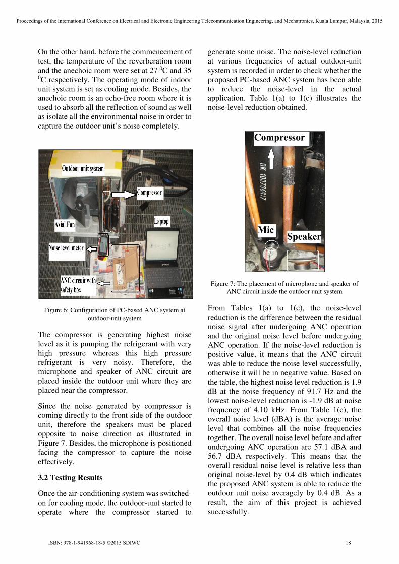
On the other hand, before the commencement of
test, the temperature of the reverberation room
and the anechoic room were set at 27 0C and 35 0C respectively. The operating mode of indoor
unit system is set as cooling mode. Besides, the
anechoic room is an echo-free room where it is
used to absorb all the reflection of sound as well
as isolate all the environmental noise in order to
capture the outdoor unit’s noise completely.
Figure 6: Configuration of PC-based ANC system at
outdoor-unit system
The compressor is generating highest noise
level as it is pumping the refrigerant with very
high pressure whereas this high pressure
refrigerant is very noisy. Therefore, the
microphone and speaker of ANC circuit are
placed inside the outdoor unit where they are
placed near the compressor.
Since the noise generated by compressor is
coming directly to the front side of the outdoor
unit, therefore the speakers must be placed
opposite to noise direction as illustrated in
Figure 7. Besides, the microphone is positioned
facing the compressor to capture the noise
effectively.
3.2 Testing Results
Once the air-conditioning system was switched-
on for cooling mode, the outdoor-unit started to
operate where the compressor started to
generate some noise. The noise-level reduction
at various frequencies of actual outdoor-unit
system is recorded in order to check whether the
proposed PC-based ANC system has been able
to reduce the noise-level in the actual
application. Table 1(a) to 1(c) illustrates the
noise-level reduction obtained.
Figure 7: The placement of microphone and speaker of
ANC circuit inside the outdoor unit system
From Tables 1(a) to 1(c), the noise-level
reduction is the difference between the residual
noise signal after undergoing ANC operation
and the original noise level before undergoing
ANC operation. If the noise-level reduction is
positive value, it means that the ANC circuit
was able to reduce the noise level successfully,
otherwise it will be in negative value. Based on
the table, the highest noise level reduction is 1.9
dB at the noise frequency of 91.7 Hz and the
lowest noise-level reduction is -1.9 dB at noise
frequency of 4.10 kHz. From Table 1(c), the
overall noise level (dBA) is the average noise
level that combines all the noise frequencies
together. The overall noise level before and after
undergoing ANC operation are 57.1 dBA and
56.7 dBA respectively. This means that the
overall residual noise level is relative less than
original noise-level by 0.4 dB which indicates
the proposed ANC system is able to reduce the
outdoor unit noise averagely by 0.4 dB. As a
result, the aim of this project is achieved
successfully.
Proceedings of the International Conference on Electrical and Electronic Engineering Telecommunication Engineering, and Mechatronics, Kuala Lumpur, Malaysia, 2015
ISBN: 978-1-941968-18-5 ©2015 SDIWC 18

Table 1(a): Noise level reduction at noise frequencies
from 46 Hz to 365 Hz in outdoor-unit application
Cooling Mode
Noise
Frequency
(Hz)
Noise level measured by 1 meter
front side of outdoor unit (dB)
Original
noise
level
Residual
noise level
Noise level
reduction
46.0 53.4 51.9 1.5
48.7 52.1 52.9 -0.9
51.7 43.7 43.5 0.2
54.6 44.0 44.4 -0.3
57.9 41.2 40.9 0.2
61.3 39.5 39.9 -0.4
64.9 37.6 38.3 -0.7
68.8 37.3 37.9 -0.6
72.9 38.4 38.4 0.0
77.2 41.0 40.8 0.2
81.8 45.0 45.1 -0.1
86.6 47.9 48.3 -0.4
91.7 49.9 48.0 1.9
97.2 46.0 45.7 0.2
103 43.5 42.4 1.1
109 39.0 38.5 0.5
115 39.5 39.4 0.0
122 40.6 40.8 -0.2
130 43.7 44.2 -0.5
137 45.1 44.7 0.4
145 48.5 47.7 0.8
154 42.0 41.7 0.3
163 40.9 40.9 0.0
173 41.9 41.8 0.1
183 42.2 41.8 0.4
194 44.6 43.6 1.0
205 39.8 39.8 0.0
218 39.7 39.9 -0.2
230 39.9 39.4 0.4
244 39.4 38.9 0.6
259 38.6 38.5 0.1
274 39.8 40.0 -0.2
290 48.8 48.8 0.0
307 41.8 41.4 0.3
325 38.4 38.4 0.0
345 39.0 38.9 0.1
365 38.3 38.3 0.0
Table 1(b): Noise level reduction at noise frequencies
from 387 Hz to 3.07 kHz in outdoor-unit application
Cooling Mode
Noise
Frequency
(Hz)
Noise level measured by 1 meter
front side of outdoor unit (dB)
Original
noise
level
Residual
noise level
Noise level
reduction
387 39.3 39.3 -0.1
410 37.5 37.7 -0.2
434 39.5 39.5 0.0
460 40.1 40.8 -0.7
487 45.5 45.1 0.4
516 37.7 38.0 -0.2
546 37.0 37.1 -0.1
579 37.0 37.1 -0.1
613 38.3 38.9 -0.6
649 36.1 36.3 -0.2
688 36.2 36.0 0.2
729 36.0 35.9 0.1
772 38.0 37.5 0.5
818 37.1 36.5 0.6
866 36.9 37.2 -0.3
917 37.2 37.0 0.2
972 38.2 38.1 0.0
1.03k 38.0 37.8 0.3
1.09k 37.6 37.2 0.3
1.15k 35.9 36.1 -0.1
1.22k 38.2 38.0 0.1
1.30k 37.7 38.0 -0.3
1.37k 37.0 37.2 -0.2
1.45k 35.6 36.2 -0.7
1.54k 36.7 36.7 0.0
1.63k 35.3 34.9 0.5
1.73k 37.4 36.9 0.4
1.83k 36.0 36.4 -0.4
1.94k 33.2 33.7 -0.5
2.05k 32.3 32.3 0.0
2.18k 32.6 32.7 0.0
2.30k 32.2 32.3 -0.1
2.44k 34.4 34.4 0.0
2.59k 33.6 34.4 -0.8
2.74k 46.0 45.4 0.6
2.90k 52.1 51.4 0.7
3.07k 34.6 34.1 0.5
Proceedings of the International Conference on Electrical and Electronic Engineering Telecommunication Engineering, and Mechatronics, Kuala Lumpur, Malaysia, 2015
ISBN: 978-1-941968-18-5 ©2015 SDIWC 19
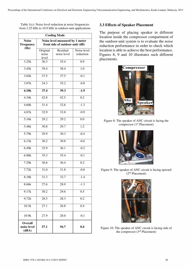
Table 1(c): Noise level reduction at noise frequencies
from 3.25 kHz to 10.9 kHz in outdoor-unit applications
Cooling Mode
Noise
Frequency
(Hz)
Noise level measured by 1 meter
front side of outdoor unit (dB)
Original
noise
level
Residual
noise level
Noise level
reduction
3.25k 36.3 35.4 0.9
3.45k 39.4 38.4 1.0
3.65k 37.5 37.5 -0.1
3.87k 34.3 35.2 -0.8
4.10k 37.4 39.3 -1.9
4.34k 42.8 42.5 0.2
4.60k 31.4 32.6 -1.3
4.87k 32.9 33.8 -0.9
5.16k 29.2 29.2 0.0
5.46k 30.8 29.7 1.2
5.79k 29.9 30.3 -0.4
6.13k 30.2 30.8 -0.6
6.49k 35.9 36.1 -0.2
6.88k 35.3 35.4 -0.1
7.29k 36.6 36.4 0.2
7.72k 31.0 31.8 -0.8
8.18k 31.3 32.7 -1.4
8.66k 27.6 28.9 -1.3
9.17k 30.2 29.6 0.5
9.72k 28.5 28.3 0.2
10.3k 27.1 26.8 0.4
10.9k 27.9 28.0 -0.1
Overall
noise level
(dBA)
57.1 56.7 0.4
3.3 Effects of Speaker Placement
The purpose of placing speaker in different
location inside the compressor compartment of
the outdoor-unit system is to evaluate the noise
reduction performance in order to check which
location is able to achieve the best performance.
Figures 8, 9 and 10 illustrates such different
placements.
Figure 8: The speaker of ANC circuit is facing the
compressor (1st Placement)
Figure 9: The speaker of ANC circuit is facing upward
(2nd Placement)
Figure 10: The speaker of ANC circuit is facing side of
the compressor (3rd Placement)
Proceedings of the International Conference on Electrical and Electronic Engineering Telecommunication Engineering, and Mechatronics, Kuala Lumpur, Malaysia, 2015
ISBN: 978-1-941968-18-5 ©2015 SDIWC 20

From the noise-level reduction obtained as
illustrated in Figure 11, the 3rd placement of
speaker has the best performance in terms of
overall noise reduction as it has highest overall
noise-level reduction which is 0.9 dBA if
compared with other two placements which are
0.4 dBA and 0.3 dBA respectively.
Based on this result, it can conclude that
different placements of speaker able to reduce
the noise-level at all noise frequencies.
However, the 3rd placement of speaker which is
the speaker that is facing to the side of
compressor is the most effective placement to
reduce the overall noise level of outdoor unit.
As a result, the 3rd placement of speaker is most
suitable placement used to reduce the outdoor
unit noise effectively.
Figure 11: Comparison of overall noise-level reduction
for different placement of speaker in actual outdoor-unit.
4 CONCLUSION
In actual outdoor unit application, the noise
reduction performance in terms of different
placements of speaker were evaluated. The 3rd
placement which is the speaker is facing to side
of compressor has highest performance where
its overall noise level reduction is 0.9 dBA from
the original noise level of 57.1 dBA. As the
proposed method sounds promising, future
investigation includes using a Raspberry Pi as a
real-time system where it can be installed inside
the outdoor unit system practically to perform
more effective noise level reduction.
REFERENCES
[1] Lawrence, J. G. (1997), Active Noise Control: A
Tutorial for HVAC Designers, American Society of
Heating, Refrigerating and Air-Conditioning
Engineers. p. 43-49.
[2] Peretti, P., Cecchi, S., Romoli, L., Piazza, F. (2014),
Adaptive Feedback Active Noise Control for Yacht
Environments, Control Systems Technology, IEEE
Transactions. 22(2). p. 737-744.
[3] Kim, H. W., Park, H.S., Lee, S.K., Shin, K. (2011),
Mechanical Systems and Signal Processing, 25(1). p.
475-484.
[4] Chang, C. Y., Li, S. T. (2011), Active Noise Control
in Headsets by Using a Low-Cost Microcontroller,
Industrial Electronics, IEEE Transactions. 58(5). p.
1936-1942.
[5] Proakis, J. G., Manolakis, D. G. (2007), Digital
signal processing: principles, algorithms, and
applications (4th edition), Upper Saddle River, N.J.:
Pearson Prentice Hall.
Proceedings of the International Conference on Electrical and Electronic Engineering Telecommunication Engineering, and Mechatronics, Kuala Lumpur, Malaysia, 2015
ISBN: 978-1-941968-18-5 ©2015 SDIWC 21