
~ , Air Conditioning System Manual - Amazon AWS
64
~, Air Conditioning System Manual
-
Upload
khangminh22 -
Category
Documents
-
view
1 -
download
0
Transcript of ~ , Air Conditioning System Manual - Amazon AWS

~, Air Conditioning System
Manual

AIR CONDITIONING (REFRIGERATION)
Printed in Great Britain by William Hodge & Chilver Limi1ed, London

PREFACE
The primary purpose of thi~ Manual is to provide the refrigeration engineer with information necessary to enable him to service and maintain the Rolls-Royce Refrigeration System. The Manual will also be of great assistance to the motor car engineer wishing to familiarise himself with the function and position of the various components.
Contained herein is a description of the system and comprehensive instructions for the maintenance, dismantling and assembly of each unit, together with the necessary service procedure. All special tools required to carry out service operations are listed and illustrated.
Although all information provided within the Manual was correct when going to print, additions or modifications may subsequently be necessary. These will be brought to the notice of the reader by means of Service Bulletins, and it is recommended that a note be made in the appropriate Section of the Manual, referring to the latest Bulletin.
Advice and assistance regarding maintenance and servicing problems will always be available on application to the Service Department at Pym's Lane, Crewe; all such enquiries should be accompanied by the chassis number of the car.

AIR CONDITIONING REFRIGERATION
UNDERWING UNIT

INTRODUCTION
The underwing air conditioning system fitted to Standard Steel Saloon Rolls-Royce Silver Cloud II and Bentley S.2 motor cars provides de-misting, de-frosting, car heating and ventilation. Alternatively, a comprehensive underwing refrigeration system, providing a wide range of heating and cooling conditions, can be installed at the customer's request.
Whilst servicing of the standard heating and de-misting system may be undertaken with confidence by the normal service engineer, it must be appreciated that correct maintenance of the refrigeration system will be better effected by a specialised refrigeration engineer.
Special equipment and precautions are necessary when un<lenaking scrvidng and overhaul operations and it should be always remembered that the refrigerant circulation system is sealed and pressurised. Thus join ls should not bl! disturbed unnecessarily as the system must be discharged prior to breaking any joint, unless this is protected by service valves.
The Refrigeration System, although an optional extra, is in fact not an isolated unit, but a large system carefully integrated into the design of the motor car. The electrical wiring, in most cases, is combined in th~ main wiring looms and the individual mechanical and electro•mechanical control units have been installed in positions promoting simplicity of operation and the facilitation of servicing.

A I/ enquiries should be addressed to:-
ROLLS-ROYCE LIMITED
Pym's Lane Crewe
Cheshire
Telephone: Crewe 55155
Telegrams: "ROYCRU, CREWE"
T.S.D. Publication 123
Printed in England

CONTENTS
DESCRIPTION SECTION C. l
OPERATING THE SYSTEM SECTION C.2
ELECTRICAL COMPONENTS . . SECTION C.3
COMPRESSOR, CONTROL VALVES AND ANCILLARY UNITS . . SECTION C.4
MAINTENANCE SECTION C.5
SERVICING . . SECTION C.6

INDEX
Description To remove and fit 16
Operating the system 5 Receiver .. 18
Maintenance Electrical components Schedules .. 21
Actuators .. 9 Every 2,500 miles 21 To adjust 10 Every 5,000 miles 21
Blower motors 13 Every 10,000 miles or annually 21 Evaporator change-over relay 12
Servicing Lower airstream switch .. 8
Charging the system 28 Magnetic clutch - compressor II
Checking for leaks 29 Rear window de-mister relay 12
Discharging the refrigerant 26 Resistances - blower motors 13
Evacuating the system 27 Solenoid valves II
Fault diagnosis 23 Thermostatic switches .. 9
Air delivery 24 Upper airstream switch .. 7
Fault location 24 The compreMor, control valves and ancillary unil.8 Pressure tests 26
Compressor IS Refrigerant circulation 24
Fault diagnosis 15 Superheat test .. 26 Lubricant 17 Importance of chemical stability 23
Oil level - lo check 17 Sealing of components 23 r--,
~ Shal\ seal - to replace 17 Precautions to be observed 23 - To purge the air 18 Exposure to refrigerant 23 al
' To remove and fit IS First-aid treatment 23 .... M r--,
Condenser 18 Right-hand front wing - to remove 29 0 v.i Drier 19 Special tools required 23 i,..;
Expansion valves 19 Sweeping the system 27 Flow control valve 20 Underwing unit - to remove 30 Magnetic clutch .. 15 To fit 30

FRESH WMM OR COOL AIR TO CAR INTERIOR
P.ECIRCULAT EO WARM OR COOL AIR TO REAR COMPARTMENT
RECIRCULATED WMM OR COOL AIR TO FRONT COMPARTMENT
RECIRCULATING AIR INTAKE
FILTER
BLOWER HOTOR
EXPANSION VALVE
SOLENOIDE VALVE
Fig, l ' The air condiliomn8 sy•ten:,
CONDENSEP.
FLOW CONTP.OL VALVE
I ' HEATER FLAP
FLAP ACTUAT ORS
/
EVAPORATOR MATRIX
EVAPORATOR MATRIX
FRESH AIR -RECIRCULATED AIR -

Rolls-Royce & Bentley-------Air Conditioning
Sy.stem Manual
SECTION C.l
DESCRIPTION
The function of the Rolls-Royce Air Conditioning Unit is to maintain the car interior temperature and humidity at a comfortable level in all climatic conditions.
The unit is divided into two parts - the fresh air system, and the recirculatory system; these
PHIAL
~ EVAPORATO R MATRIX
TEMPERATURE CONTROL PHIAL
-4===
/ EVAPORATOR MATRIX
L.P. VAPOUlll D H.P. VAPOUR •
H.P. LIQUID •
VALVE
~ SOLENOID VALVE
VALVE
/ SOLENOID VAL VE
may be operated independently or together in order to produce the desired condition. The fresh air system introduces heated, cooled or ambient temperature air into the car interior; the recirculatory system draws air from the car interior, conditions it, and re-introduces it.
CONDENSER
~
I COMPRESSOR
FLOW co~ VALVE
ORI~
es,
Ft1, 2 Dla«r•m of refrigerant circ11l•tion
Page 1

Air Conditioning
Sy.stem Manual ------- Rolls-Royce & Bentley ------------
The main advantage of this feature is that although recirculation enables the air conditioning system to operate more effectively, the simultaneous introduction of fresh air provides adequate ventilation, permitting the car to be driven with the windows closed.
In countries where humidity is high, the unit will extract a large proportion of moisture from the air; if necessary, the heater may be used in conjunction with the refrigeration system to provide warm, dry air when the atmosphere is cool and damp.
Fine gauze .filters incorporated in the recirculation and fresh air intakes (see Fig. 1), prevent the ingress of grit and other foreign particles.
The refrigeration system operates on a cyclic principle: after being compressed in the compressor, the refrigerant passes to a condenser and then in liquid form to a valve where it expands and then evaporates in a matrix before returning to the compressor.
During evaporation, the gas absorbs heat from the air passing over the matrix surface. The air thus enters the car at a reduced temperature, also at reduced humidity, since a proportion of the water vapour in the air will condense during the cooling process and drain away through drain holes provided.
The system is charged with Freon 12 refrigerant (Dichlorodifluoromethane) circulated by the compressor. The compressor is driven via a magnetic clutch by Vee belts from the coolant pump pulley.
The compressor delivers refrigerant to the condenser mounted in front of the engine radiator matrix, where the gas is condensed to liquid.
A series of pipes incorporating receiver, drier, solenoid valves and expansion valves connects the condenser to the evaporator units.
Page2
HIGH PRESSURE SER.VICE VAL VE
2 LOW PR ESSUR E SERVICE VALVE
COMPRESSOR OIL FlllER PLUG
IMPORTANT: Refer to compressor detailr
for instructions regarding the
removal of this plug.
Fig. 3 Compre&&or in po@ition
The refrigerant is atomised in the expansion valves before entering the evaporators, where the resultant pressure drop permits the liquid to vaporise ar;id so absorb heat from the air passing through the matrices.
Air is ducted to the evaporators by two systems:
From the air intake situated at the front of the right-hand wing, fresh air is ducted along inside
"' 0 .....

------------ Rolls-Royce & Bentley-------Air Conditioning
System Manual
the wing and boosted, by means of a blower motor, through the upper evaporator matrix and/or the top half of the heater matrix. The air is delivered into the saloon through the capping rail adjustable outlets and the windscreen de-misting slots.
The recirculating air is ducted from the air intake, situated behind the right-hand front seat, and b~osted, by means of a blower motor, through the lower evaporator matrix and the lower half of the heater matrix. It then enters the saloon via the cross duct under the facia, the adjustable duct under the front picnic tray, and the duct on the left-hand side of the scuttle.
To prevent the temperature of the air passing through the evaporator falling below freezing point and the system becoming blocked by the formation of ice, a thermostatic switch is fitted to each matrix: and is used in conjunction with the solenoid valves to control the flow of refrigerant. If both solenoid valves are closed, the refrigerant is by-passed from the condenser back to the compressor through the flow control valve. The control valve is adjusted to maintain a minimum pressure of 2 lb./sq. in. in the low pressure side of the system. The thermostatic switches control the minimum temperature of the evaporators and must not be ~et below 2"C., otherwise icing may occur.
Page3

LOWER AIRSTREAM SWITCH
FEED FR.OM COOLANT TEMP, INDICATOR
.....-11 ,I
l ~cl )
8
~5 7
UPPER lwr',: 1\ AIRSTREAM ----te - - :i;iel. 193 SWITCH ~ ,
' , i 8
FRESH AIR BLOWER MOTOR RESISTANCE -
DISTRIBUTION BOARD -
TO REAR WINDOW DE·MISTER
I;;. :: ~ ERMINAL STIii -
---...:•.;.• Io o o o ".I.
RECIRCULATING
All\6LOWE~ 7
~
<
rr===============(._J====:::!.111 I~
.... ..... ~
DE-tt1STl:R ... L CROSS DUCT ,,,~,o;w j ~ J~
I ~~· rll------------~ ,-.... SOLENO \::'-=aoiii,,,/..i,,_ ..... I ~ 'I, VAL.YES (,. ..... L.. ___ R_E_Ac:.R ____ ....;.LO_O.:..M ______ ..J (OWER- ' -
l
..
-Fig. " Wii·ing diagram - Air conditioning M:Y81nn
.,.,.-RECIRCULATING All\ RESISTANCE
I ~NGINE LOOM
COHPRESSOR CLUTCH -
HEATER - FLAP
ACTUATOR
FRESH · ~
FLAP ACTUATOR
TRANSFER DUCT THERMOSTAT
.... ~
• WATER TAP .--ACTUATOI< , .
·~ __!E~r.:i~~~-.1
.__" ----=.1.:i I ~:::r-"I. , '"'------
R.H. VALANCE LOOM ~ f===i'
) l
1
·-- FRESH AIR BLOWER MOTOR
Bl1B
L06lR/ £rL ·cnn.
(') ~ ""( -· .. .., ~
l'D n 3 0
:i
~ Q. ~
Q -. :i 0 C: :i -. Q :i - OQ

s 0\ -o:i
I
------------ Ro/ls-Royce & Bentley -------Air Conditioning
System Manual
SECTION C.2
OPERATING THE SYSTEM
The system is controlled by two switches mounted on the facia board and marked 'UPPER' and 'LOWER'.
The 'UPPER' switch controls the fresh air system and regulates the air entering the saloon from the adjustable vents on either side of the capping rail and from the windscreen de-misting slots. This switch has seven positions - four positions clockwise which control the heating system, and three positions anti-clockwise which control the refrigeration.
To obtain the desired condition when operating the refrigeration, the switch must be rotated anticlockwise.
In the first position the evaporator flap will be fully open and the heater flap fully closed; the water tap will be closed and the blower motor operating at medium speed. This results in normal ambient air enteri'ng the saloon.
In the second position both the evaporator flap and the heater flap will be fully open; the water tap will be closed, the compressor operating and the blower motor running at medium speed. The result is a mixture of ambient and refrigerated air passing from the top half of the heater matrix and the upper evaporator unit.
In the third position the evaporator flap will be fully open, the heater flap will be fully closed, the water tap will be closed, the compressor operating and the blower motor at medium speed. This results in cold air entering the saloon via the upper evaporator.
If the knob of the 'UPPER' switch is pulled out whilst turned to any of its positions, the blower motor operates at full speed.
The 'v;>WER' switch controls the recirculating system and has five positions. Three positions clockwise control the heating system and the two positions anti-clockwise control the refrigeration system.
In the first position anti-clockwise the water tap will be closed, the compressor operating and the blower motor at medium speed. This results in cold recirculated air entering the saloon via the lower evaporator.
In the second position anti-clockwise the water tap will be closed, the compressor operating and the blower motor at full speed. This results in recirculated air of minimum temperature entering the saloon.
Page 5

----------- - Rolls-Royce & Bentley--- - ---Air Conditioning
System Manual
SECTION C.3
ELECTRICAL COMPONENTS
UPPER AIRSTREAM SWITCH This switch controls the heater and evaporator flap actuators, the fresh air blower motor, the compressor clutch and the water tap actuator.
The switch utilises eight angular positions - the vertical or OFF position, four positions clockwise and three positions anti-clockwise.
In all seven operating positions, with the switch knob 'in', the fresh air blower motor operates at medium speed.
When the switch knob is pulled outwards, all seven conditions are duplicated but with the blower motor operating .at full speed. This is achieved by the provision of a contact sleeve at the end of the switch spindle. This sleeve connects two fixed contacts when the knob is pulled outwards, thereby completing a new circuit bypassing the resistance.
The main switch mechanism consists basically of five sets of moving contacts which rotate when the control knob is turned. Lobes on these contact plates 'make' and 'break' with eleven sets of fixed contacts spaced around the arc of travel of the contact Jobes.
A numbered disc is attached to the rear of the switch for terminal identification, the key to which is as follows:-
Terminal Number 1 Water Tap 'Leak'. 2 Evaporator Flap Closed. 3 Supply. 5 Heater Flap t Open. 6 Heater Flap Fully Open. 7 Water Tap Closed. 8 Heater Flap Closed. 9 Compressor Clutch 'In'.
10 Evaporator Flap Fully Open. 11 Blower Motor Medium Speed. 12 Blower Motor Full Speed. 13 Evaporator Flap t Open. 14 Evaporator Flap t Open.
Switch positions 1st clockwise
Evaporator Flap
Heater Flap
Water Tap Blower Motor
FULLY OPEN
CLOSED
LEAK POSITION
MEDIUM SPEED
Providing Normal ambient air flow at Medium Speed. (Heater Matrix warming in readiness for 2nd position.)
2nd clockwise Evaporator Flap
Heater Flap
Water Tap ..
Blower Motor
! OPEN
f OPEN
LEAK POSITION
MEDIUM SPEED
Providing Mixed flow of ambient and warm air.
3rd clockwise
Evaporator Flap
Heater Flap
Water Tap ..
Blower Motor
J OPEN
f OPEN
LEAK POSITION
MEDIUM SPEED
Providing As above, but air of increased temperature entering the car.
4th clockwise
Evaporator Flap
Heater Flap
Water Tap ..
Blower Motor
CLOSED
FULLY OPEN
LEAK POSITION
MEDIUM SPEED
Providing Maximum air temperature permitted by coolant leak.
N.B. Knob pulled fully out in any positionblower motor operates at FULL SPEED.
Page 7

Air Conditioning
System Manual -------Ro/1$-Royce & Bentley------------
1st anti-clockwise
Evaporator Flap
Heater Flap
Water Tap .. Blower Motor
FULLY OPEN
CLOSED
CLOSED
MEDIUM SPEED
Providing Air of ambient temperature entering the car.
2nd anti-clockwise
Evaporator Flap
Heater Flap Water Tap ..
Compressor Blower Motor
FULLY OPEN
FULLY OPEN
CLOSED
OPERATING
MEDIUM SPEED
Providing Ambient and cold air flow via the upper heater and upper evaporator matrices.
3rd anti-clockwise
Evaporator Flap
Heater Flap
Water Tap .. Compressor
Blower Motor
FULLY OPEN
CLOSED
CLOSED
OPERATING
MEDIUM SPEED
Providing Air of minimum temperature entering the car via the upper evaporator matrix.
N.B. If the switch knob is pulled out, the blower motor operates at FULL SPEED.
LOWER AIRSTREAM SWITCH This switch controls the recirculatory blower
motor, the water tap actuator and the compressor clutch.
Six positions are utilised - the vertical or OFF
position, three positions clockwise and two positions anti-clockwise.
The construction and operation of the mechanism is similar to that of the upper airstream switch except that no 'pull-out' mechanism
PageS
is provided for blower motor full speed - full speed is only obtained in position three clockwise and position two anti-clockwise.
Lobes on four sets of moving contacts complete circuits with combinations of the nine sets of fixed contacts.
A numbered disc is attached to the rear of the switch to assist terminal identification; the key to these numbers is as follows:-
Terminal Number l Recirculation Blower Motor Full Speed. 2 Recirculation Blower Motor Medium Speed. 3 Supply. 4 Water Tap 'Leak'. 5 Supply from Upper Airstream Switch No. I
Terminal. 7 Water Tap Closed. 8 Supply from Upper Airstream Switch No. 7
Terminal. 9 Compressor Clutch 'In'.
11 Water Tap Open.
Note: The system will not provide warm fresh air and cold recirculated air simultaneously.
If the lower airstream switch is in a 'cold' position (anti-clockwise) the water tap remains closed for all positions of the upper airstream switch, either clockwise or anti-clockwise.
If the Jower airstream switch is 'off' or in position I clockwise, the upper airstream switch selects water tap leak for all clockwise positions.
If the lower airstream switch is in positions 2 or 3 clockwise, the upper airstrearn switch selects water tap open for all clockwise positions.
Switch positio,u
1st clockwise
Water Tap ..
Blower Motor LEAK POSITION
MEDIUM SPEED
Providing Warm recirculated air.
2nd clock wise
Water Tap ..
Blower Motor
OPEN
MEDIUM SPEED

- - ---------- Rolfs-Royce & Bentley-------Air Conditioning
System Manual
Providing Recirculated air of increased temperature.
3rd' clockwise
Water Tap
Blower Motor
OPEN
FULL SPEED
Providing Recirculated air of maximum temperature.
1st anti-clockwise
Water Tap ..
Compressor Blower Motor
CLOSED
OPERATING
MEDIUM SPEED
Providing Cold recirculated air entering the car via the lower evaporator matrix.
2nd anti-clockwise
Water Tap ..
Compressor Blower Motor
CLOSED
OPERATING
FULL SPEED
Providing Recirculated air of minimum temperature entering the car via the lower evaporator matrix.
THERMOSTATIC SWITCHES The Cartridge Thermostat consists of two
silver contacts. attached to, but insulated from, two special nickel steel members of low expansion co~fficient, mounted under tension in a seamless drawn brass tubular shell.
Changes in temperature cause the shell to expand or contract, subjecting the steel contact supports to changes of tension, thereby causing the contacts to •make' or 'break'.
Two thermostats are incorporated in the system, each controlling one of the solenoid valves which regulate the supply of refrigerant to the evaporator matrices. When the temperature of the air leaving the matrices falls to a level a little above freezing point; the flow of refrigerant is cut off, in order to prevent the matrices becoming blocked by ice formation.
Adjustment of the cut-off point is effected by varying the tension in the nickel steel members by means of a vernier screw which is accessible when the thermostat rubber end cover is removed (see Fig. 5).
Setting the switch should be attempted only with the aid of a power source and indicator light. Random operation of the setting screw, without positive indication of the 'make' or 'break' of the contacts, may strain the internal assembly.
A locking clamp is provided to ensure that the setting remains undisturbed by vibrations, and should be adjusted so that the vernier screw may be turned without undue strain; this should be carried out before final adjustment of the switch, since tightening of the locking screw after adjustment may alter the setting.
Care should be exercised in handling the thermostat, since it is the outside shell which forms the operating element and distortion of this shell may affect the operation.
ACTUATORS
The heater flap, evaporator flap and heater water tap actuators are identical units, consisting of a small electric motor driving through a reduction gear train. The shaft carrying the final gear in the train also carries a contact disc which has a portion removed; this disc conveys current to the motor via any one of four fixed contacts, when the circuit is completed by the upper or lower airstream switch action.
Operation of the motor causes the disc to rotate until the gap in the disc reaches the contact, thus breaking the circuit.
Attached to the end of each actuator gear shaft is a crank lever. These crank levers are connected by links to sfmilar levers fixed to the water tap spindle and to extensions of the heater and evaporator flap spindles. The extension spindles protrude through the actuator mounting platform, and flexible couplings transmit the drive, through holes in the valance, to the flap spindles. Rubber sleeves are provided under the wing to protect the flap driving mechanism.
Page9

Air Conditioning
System Manual ------- Rolls-Royce & Bentley -------------
Fig. 5 Thermo81.ltic swilch
The water tap actuator is situated low down at the forward end of the right-hand valance (see Fig. 6). The heater and evaporator flap actuators are mounted together on a single platform midway along the valance, adjacent to the forward brake fluid reservoir (see Fig. 7) . ..
Actuators - to adjust
Whenever the underwing unit or the wing has been removed, it will be necessary to check and possibly adjust the actuator setting. This should be carried out after the wing has been refitted.
The procedure to be adopted is as follows, noting that instructions 2, 3 and 4 do not apply if the wing only has been removed: -
l. Slacken the four bolts which clamp the crank levers to the extension spindles and gear shafts, also slacken the two Allen grubscrews securing the collars to the extension spindles.
2. Remove the single nut and washer securing the forward end of the mounting platform to the valance and slacken the two rear securing nuts.
3. Move the forward end of the mounting platform away from the valance and insert the two coupling tubes through the valance
Page JO
holes, locating them on the driving dogs on the flap spindles.
4. Insert the extension spindle dogs into the slots in the coupling tubes and secure the mounting platform to the valance.
5. Push the extension spindles fully into the coupling tubes and tighten the two crank lever clamping bolts on to the extension spindles.
6. Slowly withdraw the extension spindles about n; in. and tighten the Allen grubscrews to lock the collars against the end faces of the bearing tubes.
7. Detach the two crank levers from the gear shafts and rotate the extension spindles by means of their crank arms. The spindles should be free to rotate through 90 °. Movement through a larger angle indicates that the coupling tubes are not engaged with the dogs on the spindles and this should be rectified.
8. Ensure that the upper and lower airstream switches are in the OFF position. Switch on the ignition for approximately 30 seconds to allow the actuator motors to
Fi8, 6 Water tap and actuator

------------ Rofls-Royce & Bentley-------Air Conditioning
System Manual
rotate to the fully closed position. It will then be necessary to adjust the two actuators separately as follows: -
Evaporator flap actuator
I. Rotate the extension spindle anti-clockwise (when viewed over the left-hand wing) until resistance is encountered.
2. Slightly slacken the crank lever clamping bolt and rotate the crank lever until it slopes forward and upward at 45 °.
3. Place the gear shaft crank lever loosely in position on the gear shaft.
4. Adjust the position of the extension crank so that when the gear shafi crank is rotated clockwise on the shaft, resistance is encountered for a few degrees to each side of the fully rearward position. (This indicates that the flap is being pressed tightly into its fully closed position). Tighten the clamping bolt to lock the extension spindle crank.
5. Rotate the gear shaft crank to the fully rearward end of its stroke (i.e. when the gear shaft crank and the connecting link are parallel) then tighten the clamping bolt.
Heater flap actuator I. Rotate the extension spindle clockwise
(when viewed over the left-hand wing) until resistance is encountered.
2. Slightly slacken the crank lever clamping bolt and rotate the crank lever until it slopes 60° forward of the vertical downward position.
3. Place the gear shaft crank lever loosely in position on the gear shaft.
4. Adjust the position of the extension spindle crank so that when the gear shaft crank is rotated clockwise on the shaft, resistance is encountered for a few degrees to each side of the fully rearward position.
1 HEATER FLAP ACTUATOR
2 EVAPORATOR FLAP ACTUATOR
Fig. 7 Flap aetuarors
Tighten the clamping bolt to lock the extension spindle crank.
5. Rotate the gear shaft crank to the fully rearward end of its stroke (i.e. when the gear shaft crank and the connecting link are parallel), then tighten the clamping bolt.
Operate the switches and visually check that the actuators are functioning correctly.
MAGNETIC CLUTCH - COMPRESSOR See Page 15 for description and procedure.
SOLENOID VALVES Model . . Danfoss EVJD-6 (Stamped 'F' on the
valve body).
The solenoid valves control the flow of refrigerant to the expansion valves which serve the two evaporator matrices.
The lower end of the movi,ng core has a rubber insert which seats against a nozzle protruding upwards from the body of the valve. When the circuit is open, the core seat is held against the nozzle by a spring-loaded plunger which is situated in the core so as to extend from the upper face and contact the blind end of the solenoid bore (see Fig. 8).
Page 11

Air Conditioning
System Manual ------- Rolls-Royce & Bentley-------------
·--~------
1 RETAINING SCREW
2 IDENTIFICATION PLATE
3 SOLENOID AND CASING
4 VALVE CHAMBER COVER
5 SECURING SCREWS
6 MOVING CORE
7 DIAPHRAGM AND NOZZLE
B SEALING RING
9 VALVE BODY
Fig. 8 So!P.nold valve - exploded view
When the coil is energised, the core is drawn upwards and the refrigerant flows through two small holes in the rubber diaphragm which mounts the nozzle, leaving via the nozzle orifice.
Since the total area of the two inlet holes in the diaphragm is less than the area of the nozzle
Page 12
orifice, the resultant pressure drop in the chamber causes the diaphragm to lift from its seating, allowing the refrigerant to flow from the annular inlet groove, under the diaphragm, to the outlet port, thus by-passing the two inlet holes and the nozzle orifice and permitting full flow.
A leak from the valve casing will probably be due to inefficient sealing; renew the rubber 'O' ring between the valve body and the valve chamber cover, refit the cover and tighten the six retaining screws.
A leaking valve may be caused either by a faulty diaphragm or a damaged core rubber insert.
Icing of the evaporator may be caused by a leaking valve or incorrect operation due to a faulty or wrongly set thermostat.
THE REAR WINDOW DE-MISTER RELAY In order to prevent heavy loading of the
battery, resulting from the refrigeration system and the rear window de-·mister unit working in opposition, a relay is incorporated in the system to break the circuit for the rear window de-mister whenever refrigerated air is being passed into the car, i.e. upper airstream switch - positions 2 and 3 anti-clockwise; lower airstrcam switch -positions 1 and 2 anti-clockwise.
The relay is mounted on the uppeI' right-hand side of the bulkhead.
THE EVAPORATOR CHANGE-OVER RELAY The leads from the number nine terminals of
the upper and lower airstream switches leave the left-hand valance loom and enter the WI and C3 terminals of the change-over relay mounted at the centre of the bulkhead. Fro m these terminals, leads pass through the right-hand valance loom to the cross duct and transfer duct thermostats which control the solenoid valves. From the C2 terminal a lead feeds the compressor clutch via the rear window de-mister relay.
The purpose of the change-over relay is to provide a feed to the. compressor clutch from
"' 0 ....

------------- Rolls-Royce & Bentley -------Air Conditioning
System Manual
••
Fig. 9 Blower motor - exploded vie>o"
either of the independently operated airstream switches.
The C3 and C2 contacts are normally closed, allowing a feed when the lower switch is turned to an anti-clockwise position. Operation of the upper switch to a 'cool' po~ition energises the winding and 'makes' the Cl and C_2 contacts.
THE BLOWER MOTORS
Model . . Smiths FHM 5342/ 01
Two identical motors are utilised in the system: the fresh air blower situated in the inlet ducting beneath the wing, and the recirculation blower mounted in the recirculation inlet duct beneath the front floor, to the rear of the lower evaporator.
Each motor and fan is mounted in a cast aluminium housing (see Fig. 9).
The motor shaft is carried in self-lubricating spherical bushes which are self-aligning to ensure smooth operation.
Two speeds - medium and high - are provided by the incorporation of a resistance in the circuit, which is by-passed when the upper airstream control knob is pulled outwards, or the lower airstream switch is turned to the third position clockwise or the second position anti-clockwise.
RESISTANCES - BLOWER MOTORS Two resistances - one for each blower motor -
are used to provide medium motor speed when placed in circuit.
Each resistance consists of a 66-inch length of oxidised wire forming a winding of 70 turns giving a resistance of 2.8 ohms. The resistance is held in a ~pool-type ceramic insulator bolted to a Bakelite mounting block which is attached to the bulkhead (see Fig. IO).
The resistance for the fresh air blower is mounted on the upper right-hand side of the bulkhead and the recirculation blower resistance on the upper left-hand side of the bulkhead.
Fig. 10 Reai•tance - blower motor
Poge 13

- - - --------- Rolfs-Royce & Bentley-------Air Conditioning
System Manual
SECTION C.4
THE COMPRESSOR, CONTROL VALVES
AND ANCILLARY UNITS
THE COMPRESSOR
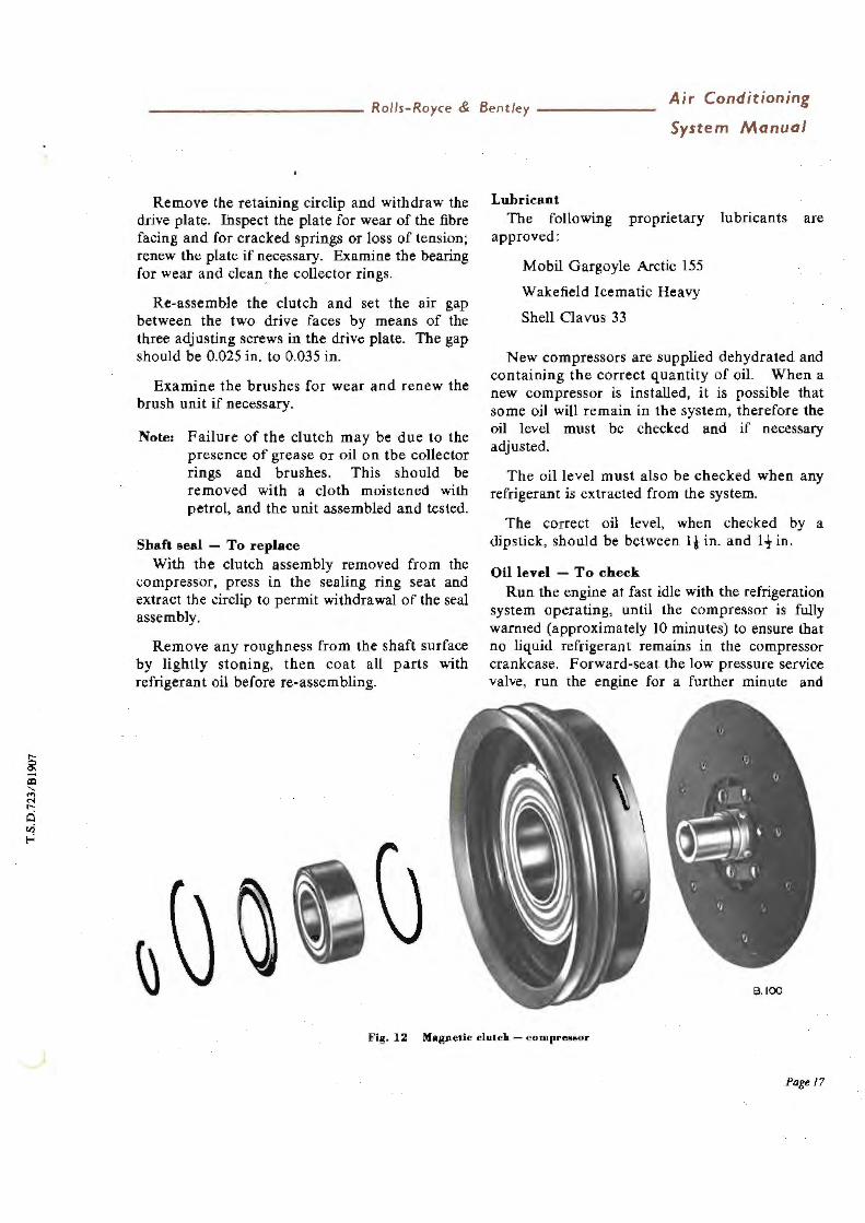
The compressor fitted to the Silver Cloud II and Bentley S.2 is the Tecumseh HH vertical twin cylinder unit, with an Eaton electromagnetic clutch ( see Fig. 12).
Replacement units are readily available and it is not recommended that any major overhaul work be attempted, except by the manufacturers. The valve plate, oil seal, clutch bearing, and the brush unit may be renewed as necessary.
Fault diagnosis When carrying out pressure tests, a low reading
on the high pressure side indicates an inoperative valve or defective gasket. To confirm the diagnosis, reduce the engine speed to 'slow idle' and turn the compressor low pressure service valve clockwise to the forward-seated position. The compound gauge should register 12 in. to 18 in. Hg almost immediately if the intake valve is satisfactory.
Switch off and observe the gauge readings. A leaking shaft seal will permit a rise to atmospheric pressure. A rise above atmospheric pressure indicates a defective gasket, or that the delivery valve is not seating correctly.
Before disturbing any compressor joint, close the service valves to seal off the system and release the pressure from the head as described for the oil level check.
When the cylinder head is removed, examine the valves and cylinder bores. A damaged valve will necessitate changing the valve plate assembly; where a cylinder bore is badly scored, a replacement compressor must be fitted.
When re-assembling, clean all joint faces carefully and immerse the new gaskets in clean refrigerant oil before fl tting.
The compressor - To remove and fit
Remove the magnetic clutch (see Page 16).
Forward-seat both compressor service valves and release the compressor pressure, as described for the oil level check. Release the Allen screws securing the service valves to the compressor. Remol/e the gauze filter from the compressor inlet port, together with the fibre washer.
Unscrew the four compressor securing setscrews situated beneath the compressor mounting bracket and remove the compressor unit, leaving the service valves connected to the pipes.
When fitting the compressor, secure all connections, then purge the air (see Page 18), and turn both service valves anti-clockwise until fully back-seated.
Test for leaks under operating conditions and static conditions. Install the gauge set, check the pressures, and ensure that the complete system is functioning correctly.
The magnetic clutch - compressor The clutch consists of an electromagnetic fly
wheel driven by twin 'Vee' belts from the engine, and a drive plate attached hy a flexible coupling plate to the forward end of the compressor crankshaft (see Fig. 3}.
Page 15

Air Conditioning
System Manual ------- Rolls-Royce & Bentley ------------
The flywheel is constantly driven by the engine and when the circuit is open, idles on a single bearing carried on the drive plate shaft. When the circuit is closed, current to energise the electromagnet is conveyed through two carbon brushes mounted on the compressor body and two copper collector rings attached to the inner face of the flywheel. The electromagnet attracts
the drive plate which is fitted with a fibre friction facing to take up the drive to the compressor. To remot•e an.d fit
Remove the single retaining bolt and withdraw the flywheel and drive · plate assembly from the crankshaft. Care should be exercised when removing the assembly to ensure that the brushes are not damaged.
110,, Fig. ll Compreuor - e"ploded view
Page 16
------------- Rolls-Royce & Bentley-------Air Conditioning
System Manual
Remove the retaining circlip and withdraw the drive plate. Inspect the plate for wear of the fibre facing and for cracked springs or loss of tension; renew the plate if necessary. Examine the bearing for wear and clean. the collector rings.
Re-assemble the clutch and set the air gap between the two drive faces by means of the three adjusting screws in the drive plate. The gap should be 0.025 in. to 0.035 in.
Examine the brushes for wear and renew the brush unit if necessary.
Note: Failure of the clutch may be due to the presence of grease or oil on tbe collector rings and brushes. This should be removed with a cloth moistened wilh petrol, and the unit assembled and tested.
Shaft seal - To replace With the clutch assembly removed from the
compressor, press in the sealing ring seat and extract the circlip to permit withdrawal of the seal assembly.
Remove any roughness from the shaft surface by lightly stoning, then coat all parts with refrigerant oil before re-assembling.
Lubricant The following proprietary lubricants are
approved:
Mobil Gargoyle Arctic 155
Wakefield Icematic Heavy
Shell Clavus 33
New compressors are supplied dehydrated and containing the correct quantity of oil. When a new compressor is installed, it is possible that some oil will remain in the system, therefore the oil level must be checked and if necessary adjusted.
The oil level must also be checked when any refrigerant is extracted from the system.
The correct oil level, when checked by a dipstick, should be between It in. and 1! in.
Oil level - To check Run the engine at fast idle with the refrigeration
system operating, until the compressor is fully warmed (approximately IO minutes) to ensure Lhat no liquid refrigerant remains in the compressor crankcase. Forward-seat the low pressure service valve, run the engine for a further minute and
8.100
Fig. 12 Magnetic clutch - c ompre&&or
Page 17

Air Conditioning
System Manual ------- Rolls-Royce & Bentley -------------
switch off. Forward-seat the high pressure service valve immediately. Do not operate the compressor with the high pressure valve closed.
Carefully slacken the gauge attachment capnut on each service valve to release the gas pressure from the head, then re-tighten. Thoroughly clean and dry the area around the oil filler plug and slowly remove the plug so as to gradually release the gas pressure from the crankcase.
When releasing gas pressures, protective goggles must be worn to pre.,,ent any possibility of refrigerant coming into contact with the eyes.
Measure the oil depth, using a dry, clean rod approximately tin. diameter. It may be found necessary to rotate the compressor slowly by hand to allow the 'dipstick' to pass the crank balance weights.
Adjust the oil level by means of a syringe, adding or drawing-off oil as necessary. Refit the filler plug loosely; do not tighten the plug as it is necessary to purge the air from the compressor.
Note: It is recommended that oil be used only from a sealed container.
To purge the air from the com·pressor Slacken the protective cap on the high pressure
service valve. Open the low pressure service valve very slightly and allow gas to pass through the compressor for about ten seconds. Whilst the gas is still passing, tighten the oil filler plug and then the valve capnut.
Back-seat both service valves and refit the protective caps.
THE CONDENSER The condenser matrix: is situated between the
radiator matrix and the intake grille (see Fig. 13). Its purpose is to cool refrigerant gas delivered by the compressor and condense it; the liquid refrigerant then passes into the receiver.
The matrix comprises two banks, each of sixteen horizontal tubes. A single inlet pipe conveys compressed refrigerant to a 'Tee' junction at the head of the matrix. This junction supplies the
Page 18
F'ig. 13 Condenser 01.a1rix
two banks independently. At the base of the matrix another junction connects them to the single outlet.
A by-pass pipe to the flow control valve permits high pressure vapour to flow back to the side of the compressor when the valve is open.
THE RECEIVER The receiver is a steel container of welded
construction, secured by three bolts to a bracket forward of the frame front cross-member (see Fig. 14).
The inlet pipe union is situated at the top of the container; the outlet union is positioned midway down the right-hand end-face. Inside the receiver, a pipe attached to the outlet union bends downward to the base of the unit in order to ensure that liquid refrigerant only will pass to the drier.
A fusible plug, inserted at the base of the unit (see Fig. 14), prevents explosion in the event of

------------- Rolls-Royce & Bentley -------Air Conditioning
System Manual
fire. Under no circumstances must this be replaced by a solid plug.
THE DRIER The drier unit is mounted below the right-hand
front apron and in the liquid line between the refrigerant receiver and the twin solenoid valves (see (Fig. 14).
The unit consists of a steel tubular shell fitted with flared connections at the inlet and outlet. Screwed into the inlet port is a metal gauze filter to prevent the ingress of coarse impurities and to protect the dehydration charge, which is granulated silica-gel. At the outlet end, a felt pad, retained by a perforated metal plate, prevents the ingress of fine impurities.
The drier unit and the dehydration charge should be renewed alternately at intervals of 10,000 miles, i.e. after 10,000 miles, renew the unit; after 20,000 miles, renew the charge only.
The charge must also be renewed if for any reason the system is opened to remove a faulty unit.
1 Dfll ER
To remove the unit, release the pipe union at each end of the shell.
To renew the charge, remove the union situated at the inlet end, clean the gauze filter and check to ensure that the felt filter is not obstructed. Extract the spent charge and replace by a fresh quantity of silica-gel.
THE EXPANSION VALVES Two expansion valves are used, each valve
controlling the atomisation of the refrigerant entering its respective evaporator matrix.
The valve body is a brass stamping and basically comprises an inlet passage, valve chamber and an outlet bore ; the inlet and outlet bores are fitted with flared connections. A renewable gauze filter is provided in the inlet bore to prevent the ingress of coarse impurities which could obstruct the valve orifice.
The valve is operated by the pressure difference in a hermetically sealed chamber containing a
·2 RECEIVER
3 FUS IBLE PLUG
Fig. 14 Drier aPd r eceiver
Pog~ /9

Air Conditioning
System Manual ------- Rolls-Royce & Bentley -------------
bellows system. The interior of the bellows is connected to the valve chamber by a single drilled hole.
The bellows exterior surface is subjected to pressure governed by the phial clipped to the return pipe from the evaporator and connected to the valve by a capillary tube (see Fig. 2). Expansion and contraction of the bellows operates the valve by moving three pins, which act on a spring-loaded piston attached to the valve seat. The spring tension is varied by means of an adjusting spindle, the squared end of which is protected by the capnut at the base of the valve. Adjustment of the spring tension 6ffectively adjusts the degree of superheat; this is set during initial testing at the factory and should require no re-adjustment.
In the event of adjustment being necessary, it will be noted that one complete turn clockwise of the spindle corresponds to approximately 3.6°F. (2°C.) decrease to the superheat. . The cap must always be tightened after each adjustment, otherwise refrigerant may escape or moisture may enter the system.
THE FLOW CONTROL VALVE The flow control valve is mounted midwa)
along the right-hand valance and is connected in the by-pass line between the compressor pipe and the condenser.
The purpose of this valve is to maintain a. minimum pressure of 2 lb./sq. in. on the low pressure side of the system. To maintain this pressure, high pressure vapour from the condenser is cooled by expanding it through the valve, before reintroducing it to the suction side of the compressor. This prevents too heavy a pressure drop in the compressor crankcase, which could ca use priming of the oil.
Page20
Fig. 15 Flow control valve
The outlet port ( compressor suction line) is directly connected with the valve chamber and the interior of a spring-loaded bellows system. The beffows exterior is subjected to pressure in a sealed chamber; thus the valve chamber pressure acts in opposition to the spring force and the pressure in the sealed chamber.
When the suction line pressure, and therefore the valve chamber pressure, falls to 2 lb./sq. in., the valve will be opened by the spring.
A combined friction and bellows damping device is incorporated to prevent too-frequent valve operation caused by rapidly fluctuating conditions.
An adjusting screw is fitted in the top of the valve to vary the spring force and thus the valve opening pressure. This is set during initial testing and should require no further adjustment. Should adjustment be necessary, the screwed cap must always be tightened afterwards.

------------ Rolls-Royce & Bentley -------Air Conditioning
System Manual
SECTION C.5
MAINTENANCE
No regular maintenance will be necessary other than that required at the specified intervals, but it should be noted that whenever the car enters a Service Department for periodic maintenance, the system should be checked for satisfactory operational effect.
The following schedules outline the necessary periodic maintenance operations.
SCHEDULES
Every 2,500 miles Check the tension of the compressor driving
belts. A 6 lb. load applied to each belt at the midpoint of the rurl between the compressor and generator pulleys should cause the belt to deflect i in.
Every 5,000 miles In addition to the foregoing, the following points
require attention.
Apply a few drops of engine oil to the flap actuator Linkages.
Examine the condenser matrix and remove all obstructions.
Inspect the filters in the fresh and recirculated air intakes for damage or blockage.
Note: These filters are self-cleaning and will generally require no attention.
Every 10,000 miles or annually, whichever is the shorter period
Discharge the system until the pressure falls to approximately 5 lb./sq. in.
Remove and clean the two filters situated in the expansion valve inlet bores, by releasing the flared connections.
Remove the gauze filter from the compressor inlet port, clean and refit (see Page 15).
Renew either the silica-gel charge or the complete drier unit (see Page 19).
Check and adjust the compressor oil level (see Page 17). Inspect the magnetic clutch collector rings for the presence of oil or grease, and check that the carbon brushes are not badly worn. Renew the brush unit if necessary (see Page 17).
Adjust the tension of the compressor driving belts (see 2,500 miles schedule).
Lubricate the flap actuator Linkages.
Examine the condenser matrix and the air intake filters and remove any obstructions.
Evacuate, sweep and charge the system (see Pages 27 to 29). Check all connections for leakage.
Operate the system throughout the full range of switch positions and ensure that all the components function correctly.
PageZI

9 J ~ g};
,...
MANIFOLD GAUGE SET
1 LEAK DETECiO~ LAMP
TUBE FLARING TOOL
4 T U BE CUTTING TOOL
5
6
l!!Q ,
3
~ 'i!=i
S SPANNER ,.ns '"· A/F ~ .e 7S '" A/F
b SPANNER 1 .oo ,n . A/ f , _r; o in. A/F
7 RATCHET WP.ENCH .2SO in, SQUl'.I\E
B THHMOMETH.
~ Sf"RING MLANCE
Fig. 16 Se,!'·l'ice tools
~ "<
~
"' ., ...
tt '"' 3 0 ::i
~ a. .... Q -. :J 0 i::: ~ -. Q ::i - ll'Q

------------ Rolls-Royce & Bentley-------Air Conditioning
System Manual
SECTION C.6
SERVICING
SPECIAL TOOLS REQUIRED
Part No. Description Number off
RH.527 'Blaydon' leak detector lamp, or similar model
RH.528 Tube flaring tool RH.529 Spring balance, 0-25 lb. RH.530 Thermometer RH.531 Spanner, ring, l.125 A/F
X 0.875 A/F RH.532 Spanner, ring, 0.75Q A/F
X LOO A/F I RH.533 Wrench, ratchet, 0.250 square 1 RH.534 Tube cutting tool I RH.538 Manifold gauge set assembly l
Also: A pair of goggles and a First-Aid kit containing medicated liquid paraffin, and saline wash.
PRECAUTIONS TO BE OBSERVED WHEN
HANDLING REFRIGERANT
Exposure to refrigerant Large quantities of refrigerant gas discharged
into a confined space will displace the oxygen in the air and could cause suffocation.
Liquid refrigerant which may accidentally escape is at least 20°F. below zero and if allowed to come into contact with the skin it can cause a burn by the rapid transference of heat from the skin to the liquid as it evaporates. Serious damage to the eyes will result from contact with liquid refrigerant. For this reason, goggles should always be worn when contact might be possible.
Should liquid refrigerant come into contact with the eye, immediate first-aid treatment is necessary and a doctor or eye specialist should be consulted as soon as is possible. Fir&t-Aid treatment
Medicated liquid paraffin from the first-aid kit should be applied to the eye from an eye dropper,
to wash away the Freon. The eye should not be rubbed, as this will increase the area of injury. If the eye remains painful after a few minutes, the wash should be repeated, using a sterile salt solution containing not more than 2% sodium chloride.
THE IMPORTANCE OF CHEMICAL STABILITY The efficient operation of the system is
dependent upon the pressure-saturation temperature relationship of pure Freon 12. So long as the system contains only pure Freon 12 (plus a certain amount of compressor lubricant which mixes with the Freon), it is considered to be chemically stable.
Wlten foreign materials such as dirt, air or moisture are allowed to enter the system, they will affect chemical stability, change the pressuresaturation temperature relationship of the Freon, and possibly cause freezing-up of the expansion valve. Thus, the system will no longer operate at the correct pressures and temperatures, with a consequent decrease in efficiency.
The sealing of components
Whenever it becomes necessary to break a refrigerant connection, the exposed ends should be immediately capped. Air entering the system will carry moisture, which collects quickly on any exposed surface, causing deterioration, owing to the acidic properties of an air-Freon compound.
FAULT DIAGNOSIS
In order to facilitate fault diagnosis, the unit may be considered as two separate systems, viz. the air delivery system and the refrigerant circulation system; these should be checked independently. The upper and lower airstream switches individually control air delivery through the fresh air and recirculated air ducting respectively.
Pagel)

Air Conditioning
System Manual ------- Rolls-Royce & Bentley------------
Air delivery Switch on the blower motors and check the air
delivery at the duct outlets. This should be carried out over the full range of switch positions.
Failure of one system in all switch positions indicates a blocked intake or filter, a defective blower motor or flap actuator, or faulty wiring.
Failure of the fresh air blower motor to operate when the knob of the upper airstream switch is in the pushed-in (medium speed) position only, indicates a defective resistance or switch or a wiring fault. Failure of the recirculation blower motor to operate in the medium speed positions (1st and 2nd clockwise and 1st anti-clockwise) of the lower airstream switch will probahly be due to a similar defect.
A failure in one switch position will probably be caused by defective switch contacts. Complete failure indicates a fuse, switch or wiring defect.
Refrigerant circulation
Initial procedure Site the car in a well ventilated and shady
position. Check the tension of the compressor driving belts and the external cleanliness of the condenser, as detailed in the Maintenance Schedule.
Start the engine and allow it to run at a fast idle, operating the refrigeration system with the blower motors at full speed. Visually check that the magnetic clutch is operating.
Fault location An obstructed condenser matrix cannot function
efficiently and will result in insufficient cooling and high compressor head pressures.
Blowers and compressor opera.ting - No cooling Possible causes are as follows:-
1. Low refrigerant charge. 2. An inoperative thermostat or solenoid valve. 3. A restriction in the refrigerant circuit. 4. Incorrect functioning of the compressor
valves.
Page 2.4
5. A faulty expansion valve.
6. Blower motor incorrectly installed.
The following action should be taken:-
1. Check the system for leaks and rectify, then re-charge.
2. Test the operation of the thermostat and solenoid valves and adjust or renew a faulty thermostat; service or renew a defective solenoid valve.
3. Inspect all hoses and pipes for kinks and check that the expansion valves are operating.
4. Test compressor head pressures and valves (see Page 15).
5. Test the expansion valves for correct operation; if faulty, remove and clean or if necessary renew the unit.
6. Check that the blower motor and impeller housing have not been installed facing in the reverse direction. This will cause a flow out of the intake. Reversing the motor leads will not effect a cure.
Blowers operating - Partial cooling Possible causes:
1. Low refrigerant charge.
2. A defective expansion valve.
3. The compressor operating above normal pressure.
4. Restricted condenser tubes or discharge line.
5. A faulty thermostat or solenoid valve.
6. The condenser matrix obstructed.
7. Incorrect refrigerant.
Action to be taken:
1. Check the system for leaks and re-charge.
2. Test the expansion valve, clean, adjust or ren:ew.
3. Test the compressor head pressures (see Page 15) and if necessary inspect the valves.

------------ Rolfs-Royce & Bentley-------Air Conditioning
System Manual
4. Discharge the refrigerant, remove the discharge line, and inspect it for signs of restriction. Inspect the condenser for kinked or obstructed tubes; apply dry compressed air or nitrogen to the tuhes to dislodge obstructions or, if necessary, renew the unit.
5. Test the thermostats and solenoid valves for correct operation, check the wiring connections.
6. Inspect the condenser matrix for obstructions and remove any foreign matter by cleaning the matrix with warm water and applying compressed air from the side adjacent to the radiator.
7. Test the pressure-saturation temperature relationship of the refrigerant (see Page 26).
Lo-w suction pressure and low head pressure
Possible causes:
l. Refrigerant charge low.
2. Filter-drier unit obstructed.
3. An obstruction in the liquid line.
4. An incorrect expansion valve superheat setting.
5. A damaged temperature control phial or a phial not correctly in contact with its adjacent pipe.
6. An expansion valve filter or port plugged with. moisture or grit.
7. Faulty compressor valves.
Action to be taken:
1. Check the system for leaks and re-charge.
2. Clean the filter and renew the dehydration charge or renew the· complete unit.
3. A partial blockage in the pipe will create a temperature fall at the point of restriction; this will be obvious to the touch. Remove the pipe from the unit and remove the obstruction, using dry compressed air or, if necessary, fit a new pipe.
4. Check the superheat reading (see Page 26), reset or, if necessary, renew the expansion valve.
5. Inspect the temperature control phials for maximum contact with their adjacent pipes, and examine the phials and c·apillary tubes for damage. Renew the complete valve unit if damage prevents correct operation.
6. Remove and clean the expansion valves and filters.
7. Carry out the pressure test (see Page 15), if this reveals a faulty valve, renew the valve plate assembly.
Low suction pressure and high head preuure
The probable cause is a blockage in the discharge pipe or condenser tubes. The obstruction should be removed or, if necessary, the component renewed.
High suction pressure and high head pressure Probable causes are:
1. The superheat setting of the expansion valve or valves is too low, causing the admission of liquid refrigerant to the compressor.
2. An obstructed condenser matrix.
3. The presence of air and/ or moisture in the system.
4. Too great a quantity of refrigerant.
Action to be taken:
I. Test the expansion valves and adjust or, if necessary, renew a faulty valve.
2. Wash the external surfaces of the condenser matrix with warm water and free the matrix of obstructions by applying compressed air to the face of the matrix adjacent to the radiator.
3. Discharge the system and re-charge it with the correct quantity of refrigerant.
4. Evacuate and re-charge the system.
Suction pressure correct but head pressure high Probable causes are:
1. The presence of air in the system.
2. Too great a charge of refrigerant.
Page25

Air Conditioning
System Manual - ------ Rolls-Royce & Bentley------------
Action to be taken:
1. Check the suction side of the system for leaks and rectify. Discharge the refrigerant, renew the dehydration charge in the drier, and evacuate. Re-charge with the correct quantity of new refrigerant.
2. Discharge the refrigerant and re-charge with the correct quantity.
Head pressure correct but suction preuure low Probable causes are:
I. Blower motor or motors not functioning.
2. Restricted filter-drier.
3. The Superheat setting of the expansion valve or valves too high.
Action to be taken:
I. Check the blower motor operation.
2. Test the filter-drier and renew it if the filters are choked.
3. Check the superheat settings.
Pressure tests
Switch off and install the manifold gauge set with both its valves firmly closed. Remove the protection caps from the compressor service valves and just crack open both valves by rotating one half-turn clockwise.
Warning: During these tests it is essential that the compressor service valves are not fully open, as this closes the system delivery and intake valves and could possibly cause an explosion.
Run the engine at fast idle wilh the refrigeration system operating and the blower motors at full speed.
Turn the compressor service valves anticlockwise to damp out any gauge fluctuation.
The compound gauge reading should be 20 to 35 lb.!sq.in. With the following ambient air
Page26
temperatures (temperature in the shade) the pressure gauge reading should be:-
60°F. (15.6°C.) I00-150 lb.I sq.in. so°F. (24.7°C.) 140-190 lb./sq.in.
100°F. (37.8°C.) 180-240 lb.I sq.in. l l0°F. (43.3°C.) 230-280 lb./sq.in.
Superheat test The system may be checked for correct
operation by testing the upper and lower evaporators individually as follows: -
Attach the thermometer RH.530 to the suction pipe from the evaporator. Cover the thermometer bulb and the pipe with a thick cloth to provide insulation from atmospheric temperature, leaving the scale visible. Allow the engine to run for a few minutes at 1,200-1,800 r.p.m. with the refrigeration system operating. Read the thermometer, and the compound gauge at the compressor. Add 3 lb./sq.in. to the gauge reading to compensate for pressure drop in the suction line.
Ref er to the following table to obtain the saturation temperature corresponding to this pressure and subtract this figure from the thermometer reading. The result should be between 8° and 15 ° F. which is termed the 'Superheat Reading'.
Having obtained the correct values, any inefficiency can only be attributed to poor air delivery. In such cases, check the blower motor operation and ensure that the inlet and outlet ducts are unobstructed.
TO DISCHARGE THE REFRIGERANT The refrigerant must be discharged from the
system prior to breaking any joint, except the compressor unit joints which are protected by the service valves.
Do not discharge in the presence of an open flame; the refrigerant does not burn, but decomposes to form a poisonous gas.
Remove the protective caps from the compressor service valves. Just 'crack' the high pressure valve in a clockwise direction, allowing

------------ Rolls-Royce & Bentley-------Air Conditioning
System Manuol
Pressure-Saturation Temperature Relationship1Table - Freon 12.
Pressure Temperature lb./eq.h>.. •F.
20 19.5 21 21 22 22 23 23.5 24 24.5 25 25.5 26 27 27 28.5 28 29.5 29 31 30 32.5 JI 33.5
32 34.5
33 36 34 37 35 38
the refrigerant in the system to be discharged to atmosphere. Care must be taken not to reiease the refrigerant too quickly as this will result in oil being drawn from the system. The operation should require at least fifteen minutes to ensure complete discharge.
Always use two spanners in opposition when releasing and securing flared connections, to prevent damaging the flares or tubes.
On completion of repair work it is necessary to evacuate and sweep the system to remove all moisture before re-charging. The compressor oil level should be checked, as described under 'Compressor'.
TO EVACUATE THE SYSTEM The use of a vacuum pump for evacuation is
advisable but if this is not available the compressor may be utilised as follows:-
Fit the manifold gauge set to the compressor as illustrated in Figure 17. Forward-seat the compressor high pressure service valve by turning it clockwise to the end of its travel. Open the pressure valve of the manifold gauge set by turning it fully anti-clockwise.
Press11re Temperature lb.leq.io. "F.
36 39 37 40 38 41 39 42 40 43.5 41 44.S 42 45.5 43 46.S 44 47.5
45 48.5 46 49.5
47 50.5 48 51.S 49 52.25 50 53
Close the vacuum valve of the manifold gauge set by turning it clockwise. Just 'crack' the low pressure service valve by rotating it one half tum clockwise.
Start the engine and switch on the blower motors to 'Fast' speed. Observe the vacuum gauge and when a vacuum of 28 inches Hg is reached, allow the compressor to continue drawing a vacuum for a further 10 minutes, then switch off the system and close the pressure valve on the manifold gauge set. These two operations must be carried out simultaneously, necessitating two operators.
Switch off the ignition and allow 20 minutes for conditions to settle before taking a reading of the vacuum gauge. This reading should be maintained for 5 hours. If a drop in vacuum is evident after this period, a leak in the system is indicated (see under leak detection).
TO SWEEP THE SYSTEM Back-seat the high pressure service valve by
turning it fully anti-clockwise. Forward-seat the low pressure service valve by turning it clockwise. Connect the centre union of the manifold gauge set to a Freon 12 container. Close both valves on the manifold gauge set by turning them clockwise.
Page ljl.

Air Conditioning
System Manual ------- Rolls-Royce & Bentley-------------
Fig. l 7 Manifold gauge set in poaition
Open the valve of the Freon 12 container, purge the air for a few seconds and then re-tighten. Attach a spring balance to the container and record the weight.
Open the vacuum valve of the manifold gauge set and allow I lb. of gas to pass into the system. In some cases, when the temperature (and therefore the pressure) is low, it may be necessary to start the engine and switch on the system in order to draw in the refrigerant. Owing to the variation in the time taken to charge, the weight of refrigerant remaining in the container must be checked frequently. Do not allow the pressure reading on the compound gauge to exceed 50 lb./sq.in. This can be controlled by regulating the manifold gauge set vacuum valve.
Switch off the compressor and the ignition. Close the manifold gauge set vacuum valve and back-seat the compressor low pressure service valve by turning it anti-clockwise. Close the valve of the refrigerant container and disconnect the centre hose. Start the engine and operate the
Page 28
system for approximately 10 minutes with the blower motors at full speed.
Switch off the system and switch off the ignition.
If the system fails to hold the vacuum when testing, it is necessary at this stage to locate ~he leak; this is possible because the system is under pressure and escape of refrigerant can be detected (see Section on Leak Detection). If the system maintains the vacuum it is ready for charging upon completion of the sweeping operation.
Ensure that the valves on the manifold gauge set are closed. Turn the high pressure service valve two complete turns clockwise.
Drain the system by slightly opening the pressure valve of the manifold gauge set.
TO CHARGE Before charging, it is necessary to draw out the
refrigerant remaining from the s\Veeping operation. Repeat the evacuation process (see Page 27).

Rolls-Royce & Bentley -------Air Conditioning
System Manual
Back-seat the high pressure service valve and forward-seat the low pressure service valve. Connect the centre union of the manifold gauge set to the refrigerant container and open the valve of the container. Break the joint of the manifold centre hose and purge the air for a few seconds, then re-tighten.
Attach a spring balance to the refrigerant container and record the weight. Open the vacuum of 'the manifold gauge set.
Start the engine and switch on both blower motors. If the refrigerant does not fl.ow into the system, even with the compressor in operation, place the container in a bucket of warm water not exceeding 113 ° F. Do not apply a flame, or localised heat. This could cause an explosion. Do not allow the reading on the compound gauge to exceed 50 lb./sq.in. This can be controlled by regulating the vacuum valve of the manifold gauge set.
When 7 lb. of refrigerant has been drawn into the system, switch off the ignition and close the vacuum valve of the manifold gauge set.
Close the valve of the Freon 12 container and disconnect the centre hose. Back-seat both service valves on the compressor. Disconnect and remove the manifold gauge set and refit the protective covers on the service valves. Check the system for leaks, adopting the following procedure.
TO CHECK FOR LEAKS Leak detection should be carried out at full
operating pressure and under static conditions, using the Detector Lamp RH.527 (see under pressure tests for appropriate figure s). In order to obtain the correct pressure, it may be necessary to re-charge the system.
·'a:.. Fig. 18 f..omprcssor service valve - backward-seated
Pass the end of the detector lamp flexible hose over all points where leaks are possible. The colour of the lamp flame wilJ change to green when the open end passes over a leak point.
Note:: It is important not to operate the lamp pressure pump when in the vicinity of possible leaks, as refrigerant will be drawn into the fuel container of the Lamp, causing the flame to remain green for some time. Futhermore, the car should be placed in an adequately ventilated position, otherwise refrigerant may persist in the vicinity of the car and give misleading results.
RIGHT-HAND FRONT WING - TO REMOVE Should it be necessary to remove the wing in
order to carry out leak detection tests or to remove the underwing unit, the following procedure should be adopted:-
The right-hand front door and the radiator shell fl1USt first be removed in order to gain access to the wing securing bolts : -
Open the right-hand front door and place a suitable support beneath the door to take its weight. Remove the split pin and clevis pin from the checkstrap.
If electrically operated windows are fitted, it will be necessarv to remove the three screws securing the cor{duit to the hinge post before unscrewing the six hinge bolts.
The door may then be removed unless this is prevented by the leads to the electrically operated window, in which case the door should be moved rearwards to ,the extent of the leads.
ua Fig, 19 Compree~or ~ervice Yah·e - forw1ud-seated
Page 'l9
Air Conditioning
System Manual ------- Rolls-Royce & Bentley------------
Unscrew the four bolts which secure the top of the radiator shell to the matrix and the bonnet centre stay, also the eight bolts securing the lower end of the shell to the under-tray and the front apron.
Remove the four bolts securing the front apron to the side fairings, also the four nuts, bolts and washers securing the right-hand side fairing to the wing.
Remove the side fairing, the front apron, and the radiator shell.
The wing panel can then be removed as follows:-
Remove the six bolts from the rear vertical edge of the wing, also two self-tapping screws and one bolt which secure the stainless steel strip to the lower edge.
Remove six bolts from the lower edge and front vertical edge of the wing.
Support the weight of the wing and remove the ten bolts securing the wing to the valance. Disconnect the headlamp and side lamp cables and remove the wing panel.
Should the cables for the electrically operated window have prevented removal of the door, it will be advisable to temporarily re-secure the hinges.
UNDERWING UNIT - TO REMOVE Should the detection of a leaking matrix or
similar fault necessitate the removal of the matrices and underwing ducting, proceed as follows.
Discharge the refrigerant from tlie system (see Page 26).
Remove the right-hand front wing (see Page 29).
Forward•seat the compressor low pressure service valve by rotating clockwise to the full extent of travel. Disconnect the evaporator return pipe union at the junction adjacent to the flap actuators.
Page 3.0
To prevent loss of engine coolant when disconnecting the pipes from the heater matrix, drain the radiator matrix, or alternatively, seal the heater pipes immediately they are disconnected, by inserting i in. bolts into their bores and clamping the hoses with worm drive clips.
Disconnect the two pipe unions at the forward ends of the solenoid valves.
Slacken the worm drive clip situated at the forward end of the recirculation ducting.
Disconnect the transfer duct thermostat at the rear snap connector leads.
Unscrew the seven nuts securing the underwing unit to the valance.
Disconnect the fresh air blower motor leads at the snap connectors, then slide the underwing unit off the motor housing, allowing the motor leads to pass through the hole in the ducting; remove the unit from the car.
Remove the two actuator coupling tubes, situated within the rubber seals protruding from the valance.
UNDERWING UNIT - TO FIT Pass the blower motor leads through the hole
in the front ducting and place the unit in position against the valance, so that the six mounting stqds protrude through the valance, the rear duct locates on the recirculation duct and the intake end fits over the housing of the fresh air blower motor. Secure the unit to the valance by fitting washers and nuts to the mounting studs and refitting the bolt, washer and nut at the top of the unit. Tighten the worm drive clip on the recirculation duct and seal with adhesive tape the joint between the ducting and blower housing.
Connect the coolant hoses to the heater matrix pipes; the hose from the water tap should be connected to the lower pipe from the matrix. Secure the hoses with worm drive clips.
Top-up or refill the radiator matrix with the correct anti-freeze mixture.

------------ Rolls-Royce & Bentley ------- Air Conditioning
System Manual
Attach the blower motor leads and the transfer duct thermostat leads to their respective connectors.
Connect the pipes between the expansion valves and the solenoid valves.
Secure the evaporator return pipe union at the valance Tee junction.
Evacuate and sweep the system, then check for leaks (refer to the appropriate Sections).
Charge the system with 7 lb. of refrigerant (see appropriate Section).
Fit the wing.
Check and, if necessary, reset the actuator adjustment.
Page 31

• I
AIR CONDITIONING REFRIGERATION
O.M.C. UNIT

CONTENTS
DESCRIPTION SECTION Cl
OPERA TING THE SYSTEM SECTION C2
ELECTRICAL COMPONENTS SECTION C3
COMPRESSOR, CONTROL VALVES AND ANCILLARY UNITS SECTION C4
MAINTENANCE SECTION CS
SER VICING . . SECTION C6

Published by The Technical Publications Department
Rolls-Royce Limited Pym's Lane,
Crewe
(T.S.D. Publication 744)
Printed in Great B~itain by William Hodge & Chilver Limited, London

------------ - Rolls-Royce & Bentley -------
Description ..
Operating the System Introduction To Operate (No. I Installation) To Operate (No. 2 Installation)
Electrical Components Blower Motors Blower Motor Resistances By-pass Solenoid Valve Rear Window De-mister Relay Thermostat Control Switch
INDEX
The Compressor, Control Valves and Ancillary Units Compressor •.
Fault Diaguosis To Remove and Fit
Condenser Drier Lubricants
Oil Level-To Check To Purge the Air
Magnetic Clutch Eaton Clutch Electro Lock Clutch
Shaft Seal-to Renew Tecumseh HH York A.209
Maintenance Safety Device Schedules Storage
Servicing Charging Chemical Stability-Importance of Diagnosis Discharging Refrigerant Evacuating .. Fault Location
Air Circulation Refrigerant Circulation
First Aid Treatment Leak Detectiou Precautions .. Pressure Tests Sealing of Components Superheat Test Sweeping Tools ..
Air Conditioning
System Manual
Page
Ct
cs cs C5
C7 C7 C9 C9 cs
Cll
Cl5 CIS CJ3
CJI
Cl2
Cl7 Cl7 Cl7
C24 C20 C2l C23 C23 C20
C20 C24 C20 C21 C20 C22 C23 Cl9

\ THE~MOSTAT CONTI\OL SWITCH
D a.aw PRESSURE VAPOUR
D HI~ .. PRESSURE VAPOUR
• HIGH PRESSURE LIQUID
LOW PRESSURE LIQUID
, CONDENSER
COMPRESSOR
'TEMPERATURE CONT~OL PHIAl
I EXPANSION VALVE
SIGHT GLASS
Fig. 1 Refrigerant Circlllation Diagram
V) :ti,. '< -. "' ~ ... n lb
3 0 :::,
~ 0.. --...
0 -· 0 :::, :::, C: ::, Q
(1q
11161

--------- ---- Rolls-Royce & Bentley-------
Cl
Air Conditioning
System Manual
Section Ct
DESCRIPTION
The vapour compression system used on RollsRoyce and Bentley cars is designed to reduce the temperature and humidity in the saloon when surrounding air temperature and humidity are high.
To achieve greater efficiency, Jablite roof insulation, 'Sundym' (tinted) glass and an exhaust heat shield are used to minimise heat penetration into the car interior.
Circulation of the refrigerant, Freon I 2 ( DICHLORODIFLUOROMETHA NE), is maintained by a compressor, driven through the medium of an electromagnetic clutch and Vee belts (see Fig. 2).
The purpose of the compressor is two-fold; to raise the pressure and temperature of the refrigerant vapour and also to pump the refrigerant through the system. The high pressure, high temperature vapour is delivered by the compressor to the condenser which is mounted in front of the radiator matrix. Ambient air passes across the condenser tubes by the forward motion of the car and engine fan action.
This air, which is of a lower temperature than the refrigerant vapour circulating through the condenser, creates a heat transfer between these two media. Condensation of the vapour occurs, creating a liquid refrigerant (see Fig. 3).
The high pressure and high temperature liquid now passes to the receiver, which is a storage tank located just below the condenser, through the filter drier and sight glass to the expansion valve located in the evaporator assembly in the boot (see Fig. 4).
This automatic thermal expansion valve is the dividing point, separating the high pressure and low pressure sides of the system. It automatically meters the high pressure, high temperature liquid refrigerant through a small orifice into the low pressure area of the evaporator coil. The low pressure is created by the pull of the low pressure (suction) side of the compressor.
At this point, as the liquid pressure is immediately decreased, the temperature will correspondingly decrease. Heat laden air from the car interior is passed over the evaporator coil fins and tu bes (through which the now cold refrigerant liquid is circulating), by twin blower motors, via the return air c1ucts.
HIGH PRESSURE SERVICE VALVE
1 LOW PRESSURE SERVICE VALVE
3 COMPRESSOR OIL FILLER PLUG
IMPORTANT, REFER TO COMPRESSOR
DETAILS FOR INSTRUCTIONS REGARD
ING THE REMOVAL OF THIS PLUG
Fig. 2 Tecumseh Compn~or in Position
Section Cl
C2
Air Conditioning
System Manua I - ----- Ro/ls-Royce & Bentley -------------
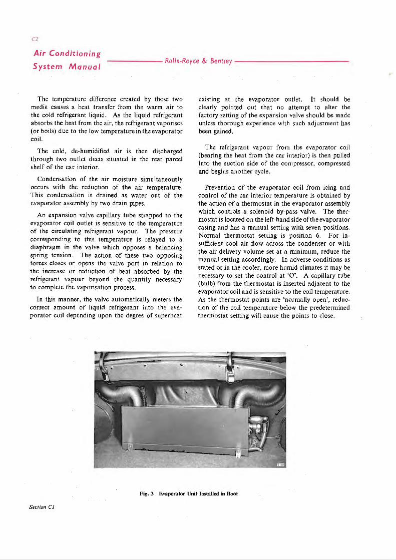
The temperature difference created by these two media causes a heat transfer from the warm air to the cold refrigerant liquid . As the liquid refrigerant absorbs the heat from the air, the refrigerant vaporises (or boils) due to the low temperature in the evaporator coil.
The cold, de-humidified air is then discharged through two outlet ducts situated m the rear parcel shelf of the car interior.
Condensation of the air moisture simultaneously occurs with the reduction of the air temperature. This condensation is drained as water out of the evaporator a,-sembly by two drain pipes.
An expansion valve capillary tube strapped to the evaporator coil outlet is sensit[ve to the temperature of the circulating refrigerant vapour. The pressure corresponding to this temperature is relayed to a diaphragm in the valve which opposes a balancing spring tension. The action of these two opposing forces closes or opens the valve port in relation to the increase or reduction of heat absorbed by the refrigerant vapour beyond the quantity necessary to complete the vaporisation process.
In this manner, the valve automatically meters the correct amount of liquid refrigerant into the evaporator coil depending upon the degree of superheat
exrstmg at the evaporator outlet. It should be clearly pointed out that no attempt to alter the factory setting of the expansion valve should be made unless thorough experience with such adjustment has been gained.
The refrigerant vapour from the evaporator coil (bearing the heat from the car interior) is then pulled into the suction side of the compressor, compressed and begins another cycle.
Prevention of the evaporator coil from icing and control of the car interior temperature is obtained by the action of a thermostat in the evaporator assembly which controls a solenoid by-pass valve. The thermostat is located on the left-hand side of the evaporator casing and has a manual setting with seven positions. Normal thermostat setting is position 6. For insufficient cool air flow across the condenser or with the air delivery volume set at a minimum, reduce the manual setting accordingly. In adverse conditions as stated or in the cooler, more humid climates it may be necessary to set the control at 'O'. A capillary tube (bulb) from the thermostat is inserted adjacent to the evaporator coil and is sensitive to the coil temperature. As the thermostat points are 'normally open', reduction of the coil temperature below the predetermined thermostat setting will cause the points to close.
Fig. 3 Evaporator Unit Installed in Boot
Section CJ

------------- Rolls-Royce & Bentley -------
CJ
Air Conditioning
System Manual
EVAPORATOR MATRIX
2 EXPANSION VALVE
l THERMOSTAT CONTROL SWITCH
~ BLOWER MOTOR
Fig. 4 Evnpore.tor Unit with Cover Removed
This creates an electrical circuit to a normally closed solenoid valve coil, causing the valve to open. The valve, located under the bonnet and adjacent to the right-hand valance, is connected to the condenser, and to a •r connection on the suction side of the compressor. As the valve opens, high pressure vapour from the condenser is mixed with the low pressure vapour from the evaporator. The resultant
pressure raises the evaporator pressure and corres
pondingly increases the evaporator temperature. The
thermostat is governed for an approximate 5°F.
variation at any setting. If the evaporator temperature
varies more than 5°F., the thermostat points will
open, simultaneously closing the solenoid by-pass
valve.
Sution Cl

cs
----------- -- Rolls-Royce & Bentley-------Air Conditioning
System Manual
Section C2
OPERATING THE SYSTEM
INTRODUCTION
Two slightly different control switches are fitted to operate the Rolls-Royce Silver Cloud 11 and Bentley S2 car Air Conditioning (Refrigeration) O.M.C. unit; these are described in detail below. The first description (No. l) of operation covers the push-button control switch panel located immediately to the left of the steering column (see Fig. 5) which is provided with a centre 'OFF-ON' cancelling button with three buttons on either side, marked LO, MED and HI. Those to the left of the 'OFF-ON' button control the left-hand blower speed and likewise those to the right control the right-hand blower speed.
The second installation (No. 2) is similar except that on the extreme right of the push-button control switch panel is an additional toggle type switch.
TO OPERATE (No. 1 INSTALLATION)
A. Turn the switch marked 'LOWER' (located on
the facia panel) to the FIRST position anti-clockwise. (The compressor is now operative and circulates the refrigerant through the system).
B. To Operate both Blower Motors
Select the required blower speed and push 'IN' the respective buttons on the push-button control panel.
C. To Operate One Blower Motor
Push 'IN' the centre 'OFF-ON' button (this cancels all buttons). Push 'IN' the button of the blower and speed desired.
TO OPERATE (No. 2 INSTALLATION)
A. Push 'UP' or 'DOWN' the toggle switch marked 'CLUTCH' (located on the extreme right of the push-button control panel).
B. Blower motor selection and speed desired see Band C of No . I INSTALLATION OPERATION.
Fig. 5 Blower Motor ( :ontrol Panel
Section C2

~ " i· Q
BLOWER MOTORS
RE
AUXILIARY FUSE
TO ~ EARWI Ol•HISTU.
"= REAP. WINDO.;,,~ DE-MISTER RELAY
LOOM
I LACk
8U l ~ /WHITE
Fig. 6 Wiring Diagralll
7- BUTTON SWITCH PANEL /
1--.:;SL.._~"'-"-K----+--OOff
'LOWER'-~/ AIR CONDITIONING SWITCH B 111
"" "< "' ... II)
3
~ Q :i C: Q
):a, 6< .... ., ('\ 0 :i ~ -· ... -· 0 :i -· ::i
OQ
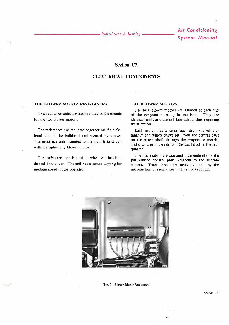
C7
------------- Ro//s-Royc.e & Bentley-------Air Conditioning
System Manual
Section C3
ELECTRICAL COMPONENTS
THE BLOWER MOTOR RESISTANCES
Two resistance units are incorporated in the circuits
for the two blower motors.
The resistances are mounted together on the right
hand side of the bulkhead and secured by screws.
The resistance unit mounted to the right is in circuit
with the right-hand blower motor.
The resistance consists of a wire coil inside a
domed fibre cover. The coil has a centre tapping for
medium speed motor operation.
THE BLOWER MOTORS
The twin blower motors are situated at each end of the evaporator casing in the boot. They are iden tic a I uni ts and are sel f-1 u br ica ting, th us req ui ring no attention.
Each motor has a centrifugal drum-shaped aluminium fan which draws air, from the central duct on the parcel shelf, through the evaporator matrix, and discharges through its individual duct in the rear quarter.
The two motors are operated independently by the push-button control panel adjacent to the steering column. Three speeds are made available by the introduction of resistances with centre tappings.
Fig. 7 Blower Motor Resistances
Section CJ

1· ...
Air Conditioning
System Manual ------- Ro/ls-Royce & Bentley--------------
Fig:. II Thermo~tat ( on trol Sn itl'h
THE Tl1ER:\-I0STAT CO:'IITROL SWITCH
A seven-positiot1 switch mounted 011 the left-hand side of the evapora tor casing controls the cut-111 tempc1-~lt ure of the solenoid by-pass val vc.
A capillary tuhe 1·rom the lo(, ot' the thermostat enters the evapornlor matrix, rnaki 11g the thermostat scn .,itive to the tcmpernlun: ul'thc euolcd <11r. Adjustment of the swi tch position vanes the poi11L al which the solenoid va Ive w i 11 open .rnd cyclc the co;11 pressor. This prevents too low a temperature i11 the evaporator matrix. w"hich could cause icing of the fi11s and rc:duced airnow.
I 2 3 4
A 11 in lernul adj u,;trncnt screv,,· is prnvided t·or i nitw 1
~etti ng o 1· the swi lch tem pern tu re range. This rn ust
be ,ct to the required range !givrn below) whc:n a
rep lacc:mcn l switch is filled; no Curt her adjustment
should be nccl:ssan-. \VARN I~(;. The s\vitch knob
should 11evcr be placed in the 'OFF" position \vhen
lhc ~y stern is operating as this could muse danrnge lo
!he solenoid valve and the compressor·.
The approximate minim um temperatures corres
ponding to the ,;even operating pos1 tions an: as
follows:-
s (, 7
42 -40 F I 40 -3~ F _,g -36 l· 36 -34 F 34 -32 F 32 -30 F JO -28 F
Seuit111 C3
)

C\I
- ------------ - Ro/is-Royce & Bentley-------Air Conditioning
System Manual
THE BY-PASS SOLENOID VALVE
Model-Danfoss EVJD-6 (Stamped FXM or FXMW on the valve body).
The solenoid valve is mounted midway along the right-hand valance and is connected in the by-pass line between the compressor intake pipe and the condcmer. Operation of the valve is governed by a thermostatic switch controlled by a phial in the evaporator matrix.
The purpose of this valve is to control the degree of cooling, preventing icing of the evaporator, and to maintain a minimum pressure of 2 lb/sq. in. on the low pressure side of the system. To maintain this pressure, high p ressure vapour from the condenser is passed through the valve and reintroduced to the suction side of the compressor. This also prevents too heavy a pressure drop in the compressor crankcase, which could cause priming of the oil.
The construction of the valve is shown in Figure 9.
The lower end of the moving core has a rubber insert which seats against a nozzle protruding upwards from the body of the va lve. When the circuit is open, the core seat is held against the nozzle by a spring-loaded plunger which is situated in the core so as to extend from the upper face and contact the blinc1 end of the solenoid bore (see Fig. 9).
When the coil is energised the core is drawn upwards and the refrigerant flows through two small holes in the rubhcr diaphragm which mounts the nozzle, leaving via the nozzle orifice.
Since the total area of the two inlet holes in the diaphragm is less than the area of the nozzle orifice, the resultant pressure drop in the cham bcr causes the diaphragm to lift from its seating, allowing the refrigerant to flow from the annular inlet groove, under the d iaphragm, to the outlet port, thus bypassing the two inlet holes and the nozzle orifice and permitting full flow.
A leak from the valve casing will probably be due to inefficient sealing; renew the rubber 'O' ring between the valve body and the valve chamber cover, refit the cover and tighten the six retaining screws.
A leaking valve may be caused either by a faulty diaphragm or a damaged core rubber insert.
) - ---
4 ·
6 --.
8
9
RETAINING SCREW
2 IDENTIFICATION PLATE
(FITTED TO EAisL Y TYPE ONLY)
3 SOLENOIO AND CASING
e 104
5 SECURING SCREWS
MOVING CORE
7 DIAPHRAGM AND NOZZLE
B SEALING isl NG
~ VALVE CHAMBER COVER 9 VALVE BODY
Fig. 9 By-p11ss Solenoid Valve
THE REAR WINDOW DE-MISTER RELAY
In order to prevent heavy loading of the battery, resulting from the refrigeration system and the rear window de-mister unit working in opposition, a relay is incorporated in the system to break the circuit for the rear window de-mister whenever refrigerated air is bci ng passed in to the car.
The relay is mounted on the uppcr right-hand side of the bulkhead.
Section CJ

C/0
Air Conditioning
System Manual
Section C4
------ - Rolls-Royce & Bentley---------- ---
B IOI
Fig. 10 Tecumseh Compressor-Exploded View

------------- Rolls-Royce & Bentley -------
Cl/
Air Conditioning
System Manual
Section C4
THE COMPRESSOR, CONTROL VALVES AND ANCILLARY UNITS
THE COMPRESSOR The compressor used in conjunction with the
O.M.C. unit is either the Tecumseh HH vertical twin cylinder unit, with an Eaton Electromagnetic clutch (see Fig. 2), or the York A.209 with an Electro Lock r nc. clutch.
Replacement units are readily available and it is not recommended that any major overhaul work be attempted, except by the manufacturers. The valve plate, oil seal and clutch bearing may be renewed as necessary.
FAULT DIAGNOSIS
When carrying out pressure tests, a low reading on the high pressure side indicates an inoperative valve or defective gasket. To confirm the diagnosis, reduce the engine speed to 'slow idle' and turn th~ compressor low pressure service valve clockwise to the forward-seated position. The compound gauge <;hould regbter 12 in. to 18 in. Hg. almost immediately if the intake valve is satisfactory.
Switch off and observe the gauge readings. A leaking shaft seal will permit a rise to atmospheric pressure. A rise above atmospheric pressure indicates a defective gasket, or that the delivery valve is not seating correctly.
Before disturbing any compressor joint, close the service valves to seal off the !>ystcm, and release the pressure from the head as described for the oil level check.
When the cylinder head is removed, txamim: lht: valves and cylinder bores. A damaged valve will necessitate changing the valve plate assembly; where a cylinder bore is badly scored, a replacement compressor must be fitted.
When re-assembling, clean all joint faces carefully and immerse the new gaskets in clean refrigerant oil before fitting.
COMPRESSOR UNIT-TO REMOVE AND FIT To Remove
Remove the magnetic clutch.
Forward-seat both compressor service valves and release the compressor pressure, as described for the
oil level check. Release the screws securing the service valves to the compressor. Remove the gauze filter from the compressor inlet port (also the :fibre washer on Tecumseh units).
Unscrew the four compressor securing setscrews situated beneath the compressor mounting bracket and remove the compressor unit, leaving the service valves connected to the pipes.
To Fit When fitting the compressor, secure all connections,
then purge the air and turn both service valves anticlockwise until fully back-seated.
Test for leaks under operating conditions and static conditions. Install the gauge set, check the pressures and ensure that the complete system is functioning correctly.
MAGNETIC CLUTCH-COMPRESSOR
The Eaton Clutch, as Fitted to the Tecumseh HH The clutch consists of an electromagnetic flywheel
driven by twin 'Vee' belts from the engine, and a drive plate attached by a flexible coupling plate to the forward end of the compressor crankshaft.
The flywheel is constantly driven by the engine and when the circuit is open, idles on a single bearing carried on the drive plate shaft. When the circuit is closed, current to energise the electromagnet is conveyed through two carbon brushes mounted on the compressor body and two copper collector rings att::iched to the inner face of the flywheel. The electromagnet attracts the drive plate which is fitted with a fibre friction facing to take up the drive to the compressor.
Eaton Clutch-To Remove Remove the single retaining bolt and withdraw the
flywheel and drive plate assembly from the crankshaft. Care should be exercised when removing the assembly to ensure that the brushes arc not damaged.
Remove the retaining circlip and withdraw the drive plate. Inspect the plate for wear of the fibre facing and for cracked springs or loss of tension; renew the plate if necessary. Examine the bearing for wear and clean the collector rings.
Section C4

Air Conditioning
System Manual ------- Rolls-Royce & Bentley --------------
B.100
l'ig. 11 Eaton Magnetic Clutch
Re-assemble the clutch and set the air gap between the two drive faces by means of the three adjusting screws in the drive plate. The gap should be 0·025 in. to 0·035 in.
Examine the brushes for wear and renew the brush unit if necessary. Failure of the clutch may be due to the presence of grease or oil on the collector rings and brushes. This should be removed with a cloth moistened with petrol and the unit assembled and tested.
The Electro Lock Magnetic Clutch as Fitted to the York A.209
This clutch differs from the Eaton clutch in that the solenoid does not rotate with the Aywheel but is secured to the compressor crankcase and thus remains stationary. The stationary solenoid design eliminates the necessity for feed brushes and collector rings and reduces servicing to the provision of lubrication for the bearings on which the clutch rotates.
Electro Lock Clutch-To Remove Remove the central retaining bolt and washer from
the compre5sor crankshaft; insert at in. UNC. bolt into the bore of the clutch. Screw in the bolt just far enough to free the clutch from the crankshaft, then withdraw the clutch and remove the bolt.
Extract the spring ring from the clutch shaft and withdraw the shaft and driving plate. Inspect the
Section C4
drive springs and nylon spigots, also the fibre facing in the annular groove in the driving plate.
Check that the bearings in the pulley are adcq uately lubricated and rotate freely without roughness or wear.
Shaft Seal-Tecumseh HH-To Renew With the clutch assembly removed from the com
pressor, press in the sealing ring seat and extract the circlip to permit withdrawal of the seal assembly.
Remove any roughness from the shaft surface by lightly stoning, then coat all parts with refrigerant oil before re-assembling.
Shaft Seal-York A.209-To Renew
REMOVAL
Remove the flywheel or clutch and the woodruff key from the compressor shaft.
Remove the seal plate capscrews and washers and gently pry the seal plate loose, taking care not to mar or scratch the flat sealing surfaces or the polished shaft surface. When removing the seal plate, the hand should be held under the seal housing to catch the carbon ring if it is free.
Do not pry or force the carbon ring with a hard sharp object in such a manner as to damage the

C/3
------------ - Rolls-Royce & Bentley-------Air Conditioning
System Manual
carbon ring. In some cases it may be bonded to the retainer.
Remove the seal assembly from the shaft by prying behind the drive ring which is that portion of the seal assembly farthest back on the shaft. When prying the seal assembly from the shaft, do not scratch the crankshaft or the sealing housing face on the crankcase.
All parts should be cleaned prior to re-assembly.
INSTALLATION
Check the front face of the crankshaft front bearing journal in the seal housing, to make certain that the two seal drive pins are in place. These two drive pins are located l B0° apart on the front bearing journal face.
Wash all portions of the seal assembly in clean refrigerant oil.
Push the seal assembly, less the carbon ring, if it is free, over the end of the shaft, with the carbon ring retainer facing out. Move the assembly along the shaft a few times to ensure a good seal between the neoprene ring and the shaft. Push the seal assembly all the way on the shaft making sure the slots in the seal drive ring engage the drive pins on the shaft bearing journal face.
If the carbon ring is separate, place it in the ring retainer so that the polished surface is facing out. The carbon ring must engage the driving lugs and be fully seated in the ring retainer.
Place a very light film of clean refrigerant oil on the matching metal foccs where the seal plate gasket is to be placed. Place the seal plate gasket, dry, in position on the seal housing face .
Fig. 12 York Compressor in Position
Place the seal face plate in position with the polished portion facing the carbon ring and insert the capscrews with the washers. Turn in the capscrews evenly while rotating the shaft, making sure there is even clearance between the shaft and shaft hole in the face plate. If clearance is not the same all around the shaft, gently tap the seal face plate into position until there is equal clearance. After equal cleo.ro.nce is obtained, tighten all the capscrews by tightening diagonally opposite capscrews evenly to the required 90 lb. in. torque.
LUBRICANTS
The following proprietary lubricants are approved for use in the Tecumseh HH and York A.209 compressors:-
MOBIL CASTROL SHELL
TECUMSEH HH GARGOYLE ARCTIC 155 ICEMATIC HEAVY CLAVUS 33
YORK A.209 REGENT TEXACO CAPELLA E
Section C4

Cl+
Air Conditioning
System Manual - ------ Rolls-Royce & Bentley --------------
Fig. 13 Filler Plug-York Compressor
New compres!'.ors are supplied dehydrated and containing the correct quantity of oil. When a new compressor is in!>taHed, it is possible that some oil will remain in the system, therefore the oil level must be checked and if necessary adjusted.
The oil level must also be checked when any refrigerant is extracted from the system.
The correct oil depth in the Tecumseh compressor, when checked by a dipstick, is between Ii in. and It in . The correct oil depth in the York A.209 is 1-± in.
Oil Level-to Check
Run the engine a t fast idle with the refrigeration system operating, until the compressor is fully warmed (approximately 10 minutes) to ensure that no liquid refrigerant remains in the compressor crankcase. Forward-seat the low pressure service valve, run the engine for a further minute and switch off. Forwardseat the high pressure service valve immediately.
Do not operate the compressor with the high pressure valve closed.
Carefully slacken the gauge attachment cap nut on each service valve to release the gas pressure from the head, then re-tighten. Thoroughly clean and dry the area around the oil filler plug and slowly remove the plug so as to gradually release the gas pressure from the crankcase.
When rdeasing gas pressures, protecrive goggles must be 11·orn to pre\'ent any possibility of refrigerant coming into contat:t 11·ith the eyes.
Section C4
Measure the oil depth usrng a dry, clean rod approximately i in. diameter. It may be found necessary to rotate the compressor slowly by hand to allow the 'dipstick' to pass the crank balance weights.
Adjust the oil level by means of a syringe, adding or drawing-off oil as necessary. Refit the filler plug loosely; do not tighten the plug as it is necessary to purge the air from the compressor.
NOTE: It is recommended that oil be used only from a sealed container.
To Purge the Air from the Compressor
Slacken the protective cap on the high pressure service valve. Open the low pressure service valve very slightly and allow gas to pass through the compressor for about ten seconds. Whilst the gas is still passing, tighten the oil filler plug and then the valve cap nut.
Back-seat both service valves and refit the protective caps.
Fig. 14 Condenser Matrix

C/5
------------- Rolls-Royce & Bentley ------ -Air Conditioning
System Manual
CONDENSER The condenser matrix is situated between the
radiator matrix and the intake grille (see Fig. 14). Its purpose is to cool refrigerant gas delivered by the compressor and condense it; the liquid refrigerant then passes into the receiver.
The matrix comprises two banks, each of sixteen horizontal tubes. A single inlet pipe conveys compressed refrigerant to a 'Tee' junction at the head of the matrix. This junction supplies the two banks independently. At the base of the matrix another junction connects them to the single outlet.
A by-pass pipe to the solenoid valve permits high pressure vapour to flow back to the suction side of the compressor when the valve is open.
THE RECEIVER The receiver is a steel container of welded con
struction, secured by three bolts to a bracket forward of the frame front cross-member (see Fig. 15).
The inlet pipe union is situated at the top of the container; the outlet union is positioned midway down the right-hand end-face. Inside the receiver, a pipe attached to the outlet union bends downward to the base of the unit in order to ensure that liquid refrigerant only wil l pass to the drier.
A fusible plug, inserted at the base of the unit, prevents explosion in the event of fire. Under no circumstances must thi.<; he replaced by a solid plug.
I SIGHT GLASS 2 RECEIVER 3 DRIER
Fig. 15 Drier, Receiver and Sight Glass
THE DRIER The drier unit is mounted below the right-hand front
apron (see Fig. 15), and has a sight glass attached to the elbow at the outlet end.
The drier unit consists of a steel tubular shell fitted with flared connections at the inlet and outlet.
8180
Fig. 16 Compressor and Refrigerant Lines
Screwed into the inlet port is a metal gauze filter to prevent the ingress of coarse impurities and to protect the dehydration charge, which is granulated Silica-gel. At the outlet end, a felt pad, retained by a perforated metal plate, prevents the ingress of fine impurities.
The drier unit and the dehydration charge should be renewed alternately at intervals of 10,000 miles, i.e., after 10,000 miles, renew the unit; after 20,000 miles, renew the charge only.
The charge must also be renewed if for any reason the system is opened to remove a faulty unit.
To remove the unit, release the pipe union at each end of the shell.
To renew the charge, remove the union situated at the inlet end, clean the gauze filter and check to ensure that the felt filter is not obstructed. Extract the spent charge and replace by a fresh quantity of Silica-gel.
Section C4

------------- Ro/ls-Royce & Bentley------
C/7
Air Conditioning
System Manual
Section C5
MAINTENANCE
The complete system should be checked every six months for correct operation and topped-up with refrigerant as necessary, particularly after periods of non-use of the Air Conditioning System during winter months.
EVERY 5,000 Mil.ES
l. Check the tension of the compressor driving belts. A 6 lb. load applied at the mid-point of the drive-side run of either belt should cause a deflection of i in.
2. Using compressed air, thoroughly clean the condenser matrix fins of all foreign matter.
STORAGE
The operation of the system should be checked before use after storage as loss of refrigerant can ensue due to leakage past seals.
SAFETY DEVICE
A fusible plug is inserted in the receiver to prevent explosion in the event of fire. Under no circumstances must this be replaced by a solid plug.
Section C5

C!Y
--- - --------- - Ro/ls-Royce & Bentley -------Air Conditioning
System Manual
Section C6
SERVICING
Thermometer
Spring Balance, 0-25 lbs.
The following special tools are available and can be ordered through Rolls-Royce and Bentley distributors, if required.
RH.530
RH.529
RH.527 'Blaydon' Leak Detector Lamp, or
Part No. Description Off. RH.531 Wrench, Ring. 1·125 m. A/F x
·B75 in. A/F
RH.532 Wrench, Ring, ·750 in. A/F x 1 ·000 in. A/F
RH.533 Wrench, Ratchet, ·250 in. square ..
RH.5J8 Manifold Gauge Set, Assembly ..
ri ~ 9
,I .~ 8 8 6 --
MANIFOLD GAUGE SET
2 LEAK DETECTOR LAMP
J TUBE FLARING TOOL
.f TUBE CUTTING TOOL
RH .528
RH.534
RH.669
~
Similar Model
Tube Flaring Tool ..
Tube Cutting Tool ..
Filter .. Goggles, Pair Kit. First Aid, containing medicated liquid paraffin and sa Ii ne wash.
4 ~
~ e
5 SPANNER I ·125 ,n. A/F x ·875 in. A/F
6 SPANNER I ·000 1n. A/F x ·750 in. A/F
7 RATCHET WRENCH ·250 in. SQUARE
B THERMOMETER
9 SPRING BALANCE
Fig. 17 Service Tools
Sec/ion C6

CJO
Air Conditioning
System Manual ------ Rolls-Royce & Bentley --- ----------
PRECAUTIONS TO BE OBSERVED WHEN HANDLING REFRIGERANT
Exposure to Refrigerant Large quantities of refrigerant gas discharged into
a confined space will displace the oxygen in the air and could cause suffocation.
Liquid refrigerant which may accidentally escape is at least 20"F. below zero and, if allowed to come into contact with the skin, it can cause a burn by the rapid transference of heat from the skin to the liquid as it evaporates. Serious damage to the eyes will result from contact with liquid refrigerant. For this reason, goggles should always be worn when contact might be possible.
Should liquid refrigerant come into contact with the eye, immediate Firs, A id is necessary and a doctor or eye specialist should be consulted as soon as possible.
:First Aid Treatment Medicated liquid paraffin from the First Aid Kit
should be applied to the eye from an eye dropper, to wash away the Freon. The eye should not be rubbed, as this will increase the area of injury. If the eye remains painful after a few minutes. the wash should be repeated. using a sterile salt solution containing not more than 2 % sodium chloride.
The Importance of Chemical Stability
The efficient operation of the system is dependent upon the Pressure-Saturation Temperature Relationship of pure Freon 12. So long as the system contains only pure Freon 12 (plus a certain amount of concpressor lubricant which mixes with the i:reon). it is considered to be chemically stable.
When foreign materials such as dirt. air or moisture are allowed to enter the system. they will affect chemical stability. change the Pressure-Saturation Temperature Relationship of the Freon. and possibly cause freezing up of the expansion valve. Thus. the system will no longer operate at the correct pressures and temperatures, with a consequent decrease in efficiency.
The Sealing of Components Whenever it becomes necessary to hreak a refri
gerant connection, the exposed ends should be immediately capped. Air entering the system will carry moisture, which collects quickly on any exposed
Secrio11 C6
surface, causing deterioration, owing to the acidic properties of an air-Freon compound.
FAULT LOCATION For the purpose of complaint diagnosis, the system
falls into two groups.
I . Air Circulation
2. Refrigerant Circulation
AIR CIRCULATION Switch on and check air delivery at the duct outlets.
Check over the full range of blower speeds.
A failure on one side only would be due to either a defective blower on that side or a defective connection between the push-button switch and the blower motor.
A failure in one switch position only would be due to a defective switch.
A complete failure indicates a fuse, switch or wiring defect.
REFRIGERANT CIRCULATION Initial Checks
Site rhe car in a well ventilated and shaded area. Check the belt tension and the external cleanliness of the condenser, as detailed under 'MAINTENANCE'.
Start the engine and warm-up at a fast idle. operating the Air Conditioning system with the blowers full on. Visually check that the magnetic clutch is operating.
Observe the sight glass located adjacent to the filter drier (this is either located adjacent to the receiver or in some instances adjacent to the evaporator assembly). If bubbles or foam appear in the sight glass, the refrigerant is low. Also, a distinct continuous or intermittent hiss from the expansion valve in the boot indicates that vapour is hcing passed through the valve and that the refrigerant charge is low. In either case check the system for leaks. (See Section on Leak Detection).
lee formation adjacent to the compressor intake is an indication of excessive delivery through the expansion valve. this can be caused by a faulty expansion valve.
A partial blockage will create a drop in temperature at the point of restriction in a hot vapour or liquid line, or across the receiver or filter-drier assembly, ~nd this will be obvious to the touch.

C2J
- ------------ Ro/ls-Royce & Bentley --- - - --Air Conditioning
System Manual
PRESSURE TESTS Before taking readings, the car should be sighted in
a well-ventilated position to ensure an adequate flow of air over the condenser. It is advisable to place a fan in front of the radiator for additional air flow over the condenser if the system is to be operated over a long period. Check the security of the radiator cap, after topping-up the coolant level as necessary. The 'blow-off' pressure is 7 lb/sq. in. and the pressure relief valve is located under the detachable plate on top of the radiator header tank, or is incorporated in the filler cap.
Switch OFF and insta!l the manifold gauge set on the compressor valve service ports with both its valves firmly closed. Remove the protection caps from the compressor service valves and just crack open both valves by rotating one half turn m a clockwise direction.
During these tests, it is essential that the compressor service valves are not fully opened, as this closes the system delivery and damage to the compressor and lines could occur.
Run the engine at a fast idle with the Air Conditioning system operating as previously mentioned.
Turn the compressor service valves ANTI-CLOCKWISE as necessary to damp out gauge fluctuation.
The compound gauge reading should be 15-30 lb/sq. in.
With the following ambient air temperatures (temperature recorded in the shade), the pressure gauge reading should be as follows:
60°F (15·6°C) 100---150 lb/sq. rn. 80°F (26·7°C) 140---190 lb/sq. m.
l00°F (37·8°C) 180---240 lb/sq. Ill,
110°F (43·3cq 2(5-270 lb/sq. in.
N.8.-The maximum reading for each of the above temperatures would only apply if very little air flow is allowed to pass over the condenser.
DIAGNOSIS
Set the compressor valves t a turn clockwise from the fully antt-clockwi.se position.
A low reading on the high pressure gauge coupled with a high reading on the compound gauge, indicates a defective compressor head gasket or valve plate gasket or :1 defective valve. (See Section-Valve Plate and Gaskets) .
Fig. 18 Manifold Gauge Set in position
Section C6

C22
Air Conditioning
System Manual ------- Ro/ls-Royce & Bentley --------------
Fig. 19 Serviee Valve-Back1~ard seated
An unusually low reading of the compound gauge indicates:
A low refrigerant charge.
A very light heat load condition.
A partial re-striction in the expansion valve.
A low expansion valve power element charge.
A defective expansion valve.
An evaporator coi l blocked hy ice.
A high reading of the compound gauge indicates:
An excessive refrigerant charge.
An unusually high heat load condition such as car windows lowered or heating system operative.
Poor contact of the expansion valve power element with the evaporator coil outlet.
A defective expansion valve.
An open solenoid by-pass valve.
An unusually low reading of the high pressure gauge indicates:
An open solenoid by-pass valve.
An unusually high reading of the high pressure gauge indicates:
An excessive refrigerant charge.
A restriction in the high pressure side.
An unusually high heat load condition.
Insufficient air passing over the condenser.
An unusually hot-running engine.
Air or non-condensable gases in the system.
An instantaneous high reading of the high pressure gauge and subsequent unusually low reading of this
Secrion C6
gauge, coupled with a low reading of the compound gauge indicates a restriction in the expansion valve port such as internal icing condition or a blocked expansion valve screen.
SUPERH[AT TEST
The system may be checked for correct operation as follows:
Attach a glass thermometer to the suction pipe from the evaporator so that it is near the expansion valve bulb. Cover the thermometer bulb and pipe with cloth to provide insulation from atmospheric temperature, leaving the scale visible. Operate the engine at a fast idle with the Air Conditioning system operating (full on) and leave running for a few minutes. Read the thermometer, and the compound gauge at the compressor. Add 3 lb/sq. in. to the gauge reading to compensate for pressure drop in the suction line.
Refer to the following table to obtain the saturation temperature corresponding to this pressure and subtract this figure from the thermometer reading. The result should lie between 8-15°F. This is termed the 'Superheat Reading'.
Pressure- Saturation Temperature relationship table-Freon 12
Pressure Temperature Pressure Temperature lb/sq. in. OF lb/sq. in. OF
20 19·5 35 38 21 21 36 39 22 22 37 40 73 21-''i 38 41 24 24·5 39 42 25 25·5 40 43·5 26 27 41 44·5 27 28·5 42 45·5 28 29·5 43 46·5 29 31 44 47·5 30 32·5 45 48·5 31 33·5 46 49·5 32 34·5 47 50·5 33 36 48 51 ·5 34 37 49 52·25
50 53
Where correct compound and high pressure gauge readings are obtained, any complaint of inefficiency

C23
----- --------- Rolls-Royce & Bentley -------Air Conditioning
System Manual
can only be attributed to Jack of air delivery. Check for operation and ensure that inlet and outlet ducts are unobstructed. A slightly low compound gauge reading would be observed if there were any obstructions causing a lack of air delivery.
DISCHARGING REFRIGERANT
When it is necessary to break any joint which is not protected by service valves, the refrigerant must first be discharged.
Do not discharge in an area where an open flame is exposed. The refrigerant does not burn, but decomposes and forms a poisonous gas.
Remove the protective caps from the compressor service valves. Just 'crack' the high pressure valve in a clockwise direction , allowing the refrigerant in the system to be discharged to atmosphere. Care must be taken not to release the refrigerant too quickly, as thi8 will result in oil being drawn out of the system. The operation should take at least fifteen minutes.
Always use two wrenches in oppos1t1on when disconnecting Aured connections, to prevent damage to flares or tubes. The tubes are easily twisted.
After the necessary repair has been made and before re-charging, it is necessary to evacuate and sweep the system, to remove all the moisture. The compressor oil level should be checked, as detailed under 'Compressor'.
EVACUATING
The use of a vacuum pump is recommended for evacuation but when not available the compressor may be utilised as follows:
Fit the manifold gauge unit to the compressor as illustrated . Forward-seat the high pressure service valve of the compressor hy rotating it in a clockwise direction to the end of its travel. Open the pressure valve of the manifold gauge set by rotating it in an anti-clockwise direction fully.
Close the vacuum valve of the manifold gauge set by rotating it in a clock wise direction. Just 'crack' the low pressure service valve by giving half a turn in a clockwise direction.
Start the engine and run on 'slow idle'. Switch on the blowers in the 'Hl' position. Observe the vacuum
B~5
Fig. 20 Service Valve-Forward seated
gauge and when a reading of 28 inches Hg. is reached, or when the maximum possible vacuum that can be obtained from the prevalent barometric conditions is reached; allow the compressor to continue drawing a vacuum for a further 15 minutes, then close the pressure valve on the manifold gauge set. Immediately switch off the ignition. The system must also be evacuated for a full 15 minutes when a vacuum pump is utilised.
Switch off the engine. If the system loses vacuum quickly, a leak is prevalent. Tf the system loses vacuum extremely slowly a leak is possible. In this condition, it is advisable to further evacuate for 45 minutes to eliminate the possibility of residual liquid Freon in the compressor oil vaporising and creating a pressure rise in the system. The final vacuum reading obtained should be held for 30 minutes to ascertain that no leaks are present. (To check the system for leaks, see under Leak Detection).
SWEEPING
It is n:l:ommi::11<l1c:<l lhal Lht: J"illt:r tlrit:r asst:mbly bt: renewed if the system has been open to atmosphere for any considerable length of time or if the diagnosis procedure outlined in this manual indicates the presence of moisture in the system.
Back-seat the high pressure service valve by turning anti-clockwise to the end of its travel. Forward-seat the low pressure service valve by turning in the clockwise direction. Connect the centre union of the manifold gauge set to a Freon 12 container. Close both valves on the manifold gauge set by turning in a clockwise direction.
Open the valve of the Freon 12 container. Break the manifold centre hose joint, purge the air for a
Section C6

04
Air Conditioning
System Manual ------ Rofls-Royce & Bentley ---------- ---
few seconds and then re-tighten. Hook a spring balance to the container and record the weight.
Open the vacuum valve of the manifold gauge set and allow approximately one pound of gas to pass into the evacuated system. In some cases one pound of gas will not flow into the system, so allow the amount to pass into the system which will balance the system pressure with the Freon 12 container pressure. Allow the dry Freon introduced into the system to remain for a period of IO minutes. Do not allow the pressure reading on the compound gauge to exceed 50 lb/sq. in. This can be controlled by regulating the manifold gauge set vacuum valve. Switch off the system and switch off the ignition.
Purge the Freon in the system by introducing an additional Freon charge as follows:
Remove the manifold gauge set from the compressor service valves, set the service valves to their midway position to allow the Freon remaining in the system to escape to atmosphere. Connect the hose of the high pressure gauge to the discharge service port of the compressor. With the manifold gauge set connected to the Freon container, the compound gauge valve closed and the high pressure gauge valve open, allow Freon from the container to pass into the discharge service port, through the service port, through the condenser, filter drier, evaporator and out through the service port of the suction (service) valve. Allow this operation to continue for approximately five seconds.
CHARGING
It is necessary to draw out the remainder of the refrigerant put in during the sweeping operation before charging fully. Repeat the evacuation process and switch off.
Back-seat the high pressure service valve and forward-seat the low pressure service valve. Reconnect the centre union of the manifold gauge set with the refrigerant container, and open the valve on the container. Break the manifold centre hose joint and purge the air for a few seconds, then re-tighten.
Hook a spring balance to the refrigerant container
Sec1inn C6
and record the weight. Open the vacuum valve of the manifold gauge set.
Start the engine and switch on the blowers. If the refrigerant will not flow into the system even with the compressor in operation stand the container in a bucket of warm water not exceeding 113°F. Do not apply a flame, or localised heat. This could cause an explosion. Do not allow the reading on the compound gauge to exceed 50 lb/sq. in. This can be controlled by regulating the manifold gauge set vacuum valve.
When 31-4 lbs. refrigerant has been drawn into the system, switch off and close the manifold gauge set vacuum valve.
Close the valve of the Freon 12 container and disconnect the centre hose. Back-seat both service valves on the compressor. Disconnect and remove the manifold gauge set and replace protective covers on service valves. Check the system for leaks, using a detector lamp.
LEAK DETECTION
Leak detection should be carried out at full operating pressure (see under pressure tests for appropriate figures) and under static conditions by means of the Detector Lamp. In order to obtain the correct pressure, it may be necessary to re-charge the system.
Light the detector lamp and move the open end of the flexible hose round all points where leaks are possible. The colour of the lamp flame will change to green when the open end passes over a leak point.
It is important not to operate the lamp pressure pump while in the vicinity of possible leaks because refrigerant will be drawn into the body of the lamp and the flame will thus remain green for some time, and be unusable as a leak detector.
Furthermore, the car should be placed in a position where there is adequate ventilation, otherwise refrigerant may persist in the vicinity of the car and give misleading results; however, draughts should not be prevalent or the seepage of gas in a particular area of a possible leak could dissipate without detection. (An alcohol leak detector may be used similarly as above).