Synthesis of metal-organic frameworks for energetic applications
232
HAL Id: tel-03604921 https://tel.archives-ouvertes.fr/tel-03604921 Submitted on 10 Mar 2022 HAL is a multi-disciplinary open access archive for the deposit and dissemination of sci- entific research documents, whether they are pub- lished or not. The documents may come from teaching and research institutions in France or abroad, or from public or private research centers. L’archive ouverte pluridisciplinaire HAL, est destinée au dépôt et à la diffusion de documents scientifiques de niveau recherche, publiés ou non, émanant des établissements d’enseignement et de recherche français ou étrangers, des laboratoires publics ou privés. Synthesis of metal-organic frameworks for energetic applications Boushra Mortada To cite this version: Boushra Mortada. Synthesis of metal-organic frameworks for energetic applications. Theoreti- cal and/or physical chemistry. Université de Haute Alsace - Mulhouse, 2019. English. NNT : 2019MULH2941. tel-03604921
-
Upload
khangminh22 -
Category
Documents
-
view
2 -
download
0
Transcript of Synthesis of metal-organic frameworks for energetic applications

HAL Id: tel-03604921https://tel.archives-ouvertes.fr/tel-03604921
Submitted on 10 Mar 2022
HAL is a multi-disciplinary open accessarchive for the deposit and dissemination of sci-entific research documents, whether they are pub-lished or not. The documents may come fromteaching and research institutions in France orabroad, or from public or private research centers.
L’archive ouverte pluridisciplinaire HAL, estdestinée au dépôt et à la diffusion de documentsscientifiques de niveau recherche, publiés ou non,émanant des établissements d’enseignement et derecherche français ou étrangers, des laboratoirespublics ou privés.
Synthesis of metal-organic frameworks for energeticapplicationsBoushra Mortada
To cite this version:Boushra Mortada. Synthesis of metal-organic frameworks for energetic applications. Theoreti-cal and/or physical chemistry. Université de Haute Alsace - Mulhouse, 2019. English. �NNT :2019MULH2941�. �tel-03604921�
Université de Haute-Alsace
Université de Strasbourg
Thèse
Présentée pour l’obtention du grade de
Docteur de l’Université de Haute-Alsace
Ecole Doctorale : Physique et Chimie Physique (ED 182)
Discipline : Chimie des Matériaux
Présentée et soutenue publiquement par
Boushra MORTADA
14 Novembre 2019
Synthesis of Metal-Organic Frameworks
for Energetic Applications
Synthèse de Matériaux de Type Metal-Organic
Frameworks pour l’Energétique
Directrice de thèse : Pr. Claire MARICHAL
Codirecteur de thèse : Dr. Gérald CHAPLAIS
Jury :
Pr. Nathalie AUDEBRAND , Université de Rennes 1 (Rapporteur)
Dr. Renaud DENOYEL, Aix-Marseille Université, CNRS (Rapporteur)
Dr. François-Xavier COUDERT, Chimie Paristech, PSL Université, CNRS (Examinateur)
Dr. Habiba NOUALI, Institut de Sciences des Matériaux de Mulhouse (Membre invitée)
Dr. Joël PATARIN, Directeur de recherche, CNRS (Membre invité)


Acknowledgements
This PhD work was realized at l’Institut de Sciences des Matériaux de Mulhouse (IS2M).
Therefore, I would like to thank the directors of the institute and my team “Matériaux à Porosité
Controlée (MPC)”, Vincent ROUCOULES and Benedict LEBEAU, respectively, for welcoming
me at the lab during the past three years.
To my supervisors, Professor Claire MARICHAL and Doctor Gérald CHAPLAIS. Thank you for
trusting me and giving me the chance to pursue this PhD. I cannot say that doing a PhD was easy,
but, indeed, I learned a lot thanks to your objective comments and suggestions. Thank you for all
the time that you have given me and for being highly dedicated to your job. I really appreciate it all.
I would also like to thank Pr. Nathalie AUDEBRAUND and Dr. Renaud DENOYEL for accepting
to be reviewers of this thesis manuscript. In addition, I thank Dr François-Xavier COUDERT for
accepting to be member of the jury. Special thanks to Dr. Joël PATARIN and Dr. Habiba NOUALI
for the great help and all the useful advice that they gave me during my PhD.
I also thank all the permanent members of the team MPC for their help in the laboratory work.
Especially Laure MICHELIN and Doctors Ludovic JOSIEN and Didier LE NOUEN for the training
and the great help they provided me while using the different techniques in the laboratory. I would
also like to thank Dr. Jean-Louis PALLIAUD for the Rietveld refinements and the very interesting
scientific discussions. Special thanks to Nathalie CASTELEIN for all the great help she provided
during the past three years.
PS: Nathalie and Laure, thank you for all the nice and fun conversations we had
To the nice people I met in Mulhouse, (in alphabetical order) Adrian, Ashling, Assi, Carole,
Charles, Dylan, Elyssa, Fatima, Flaurian, Gwandoline, Jocelin, Kassem, Kawthar, Lize, Luis-
Felipe, Lydie, Marie, Marion, Mathieu, Melania, Mirna, Natalia, Nghia, Nour, Oumina, Zainab and
Zakaria. Thank you for adding so much to the past three years.
PS: To those who were great listeners when I needed to speak, a very special thank you ;)
To my dad, the one and only man, and my angel in heaven… Thank you for all the love and trust
that you gave me. For all the days you worked so hard to provide us a happy life. You may not be
physically with us anymore, but I know that your pure and beautiful soul has never left us and is
always around. Thank you for being a great role model. Thank you for all the beautiful memories…
I love you

So much love and hugs and kisses from the other world Baba…
To my mother, the super mom, my super hero, my role model and the best gift from God … Who is
never tired of being strong and of facing all life’s difficulties to protect and support her family.
Words will never be enough to thank you for your unconditional love and support, they will never
be enough to express how much I love you mama! It would have never been the same without you
…May God bless you and keep you healthy and safe and sound.
So much love and hugs and kisses from the other side of the world Mama…
To my amazing sisters Sara and Lama, thank you for coming to this world and making me a big
sister. I can never imagine my life without my two babies. I am so proud of you and could not have
asked for a better gift from god.
Forever sisters and best friends, forever all the love in the world… (my baby Sarou and baby
Lamloumi )
To my brother in law, thank you for becoming part of our family. Your kind and, indeed, fun
personality brings us so much joy. We all love you so much
To my big family, my grandparents, aunts, uncles, and cousins (the youths and the babies), I love
you all so much. You truly make our life so much better. Thank you all for loving us, for being
supportive, and for sticking by our side during the happy days and, more importantly, during the
bad ones. We are so lucky to have you
Special thanks to my aunt Hanadi, who has always shown me extraordinary love and support, since
I was a little girl. Thank you for being an amazing second mother, whom I can trust and ask for
advice about anything, anytime. I love you to the moon and back khalto.
Also special thanks to my Aunt Inaya, the purest heart I have ever known, the cool and fun aunt!
Thank you for being not only an amazing aunt, but also a second mother. I love you to the moon
and back khalto.

Résumés du Manuscrit en Français
Comme ce manuscrit a été rédigé en anglais, un résumé en français de chaque chapitre a été ajouté.

Résumé du Chapitre 1
Dans le domaine de nouvelles applications énergétiques, Eroshenko a d'abord exploré et puis
développé des expériences d'intrusion‒extrusion de liquides non-mouillants dans des matériaux
poreux lyophobes destinées au stockage et à l'absorption de l’énergie mécanique. L’invention
d’Eroshenko repose sur l’existence d’un système hétérogène lyophobe (SHL), constitué d’un solide
poreux lyophobe entourée d’un liquide non-mouillant, qui est capable de restituer, d’accumuler ou
de dissiper de l’énergie. Selon Soulard et al., le phénomène d’intrusion‒extrusion peut s'expliquer
de la manière suivante : pour introduire un liquide non-mouillant dans un matériau poreux, il
convient d'appliquer une pression mécanique, appelée pression d'intrusion (Pint). Pendant la phase
d'intrusion, l'énergie mécanique est progressivement appliquée sur le SHL. À des pressions très
basses (0,003-1 MPa), les particules du solide sont comprimées et le liquide non-mouillant s'infiltre
dans la porosité interparticulaire. Sur les diagrammes pression-volume (P‒V), cette étape se traduit
par une variation de volume (augmentation du volume) du liquide non-mouillant. Lorsque la
pression appliquée atteint une valeur critique, correspondant à la pression d'intrusion (Pint), les
molécules du liquide non-mouillant peuvent pénétrer dans la porosité du matériau solide. Dans le
cas idéal, cette étape est caractérisée sur les diagrammes P‒V par une forte augmentation du volume
du liquide non-mouillant à une pression constante. Après le remplissage complet de la porosité,
théoriquement, aucune variation de volume supplémentaire ne devrait être observée lors de
l'application continue de la pression externe. Au niveau microscopique, au cours de l'étape
d'intrusion, le liquide massif est transformé en une multitude d'agrégats moléculaires, qui pénètrent
dans les pores et développent ainsi une grande interface solide-liquide (ΔΩ > 0). Par conséquent,
une partie de l'énergie mécanique, fournie par la pression externe, est convertie en énergie
interfaciale. Du point de vue thermodynamique, l’augmentation du contact à l’interface solide-
liquide est associée à une augmentation de l’énergie libre de Gibbs du système (ΔG > 0). Lors de la
deuxième étape, l’étape d’extrusion, la pression externe est progressivement relâchée. En fonction
de la nature du SHL, trois principaux comportements énergétiques peuvent être observés. Certains
systèmes peuvent réagir spontanément (ΔG < 0) et diminuer leur interface solide/liquide (ΔΩ < 0)
en expulsant complètement le liquide des nanopores à l'aide de l'énergie interfaciale stockée. Deux
phénomènes réversibles possibles sont courants. Dans le premier cas, l'expulsion du liquide a lieu à
une pression d'extrusion (Pext) qui est, idéalement, exactement égale à Pint. L’énergie stockée est
donc entièrement restaurée, avec un rendement énergétique (défini comme le rapport entre l’énergie
restaurée, Er, et l’énergie stockée, Es) de 100 %. Le système affiche alors un comportement de
parfait ressort (représenté sur les diagrammes P‒V par le chevauchement des courbes d’intrusion et

d’extrusion). Dans le second cas, l’énergie interfaciale est partiellement dissipée sous forme
d’énergie thermique (en raison du frottement de l’interface solide-liquide) pendant l’expulsion
complète du liquide hors des pores. Dans ce cas, le rendement énergétique est inférieur à 100 %.
Les diagrammes P‒V révèlent alors une hystérèse nette entre les courbes d’intrusion et d’extrusion
puisque Pext < Pint. Le système est défini comme un amortisseur. A travers ce manuscrit, la
distinction entre les comportements ressort et amortisseur est basée sur la valeur du rendement
énergétique. Pour des valeurs supérieures ou égales à 80%, il s’agit d’un ressort. Dans le cas
contraire, le système est défini comme amortisseur. Pour d’autres systèmes, le liquide est retenu
dans les nanopores. Dans ce cas, le phénomène d’intrusion‒extrusion est irréversible car l'énergie
mécanique fournie est complètement absorbée. Le rendement énergétique est donc nul et le système
se comporte comme un pare-choc. Sur les diagrammes P‒V, le comportement pare-choc est
singularisé par l'absence de variation de volume sur la courbe d'extrusion. A partir des diagrammes
P‒V, il est également possible d'estimer le travail ou l'énergie stockée/restituée/absorbée (Es/Er/Ea,
respectivement) par le système.
Dans cette étude bibliographique, les résultats des expériences passées d'intrusion‒extrusion menées
sur des SHLs, basés sur différents types de matériaux solides poreux et des liquides non-mouillants,
sont discutés. Les zéosils (zéolithes purement siliciques) ainsi que les Metal-Organic Frameworks
(MOFs) ou polymères de coordination sont parmi les matériaux les plus étudiés dans le domaine
énergétique, même si les performances énergétiques des matériaux à base de silice mésoporeuse ont
également été explorées. A ce titre, notre équipe a été la première à initier les expériences
d'intrusion‒extrusion sous haute pression en utilisant les zéosils en 2001 et, plus tard, les MOFs en
2013. Par la suite, d’autres équipes se sont intéressées à cette thématique prometteuse.
Concernant ce dernier type de matériaux poreux, les résultats publiés dans la littérature se sont plus
spécifiquement focalisés sur la sous-classe des Zeolitic Imidazolate Frameworks (appelés ZIFs).
Ces hybrides organiques-inorganiques sont caractérisés par une haute cristallinité, et surtout, par des
volumes microporeux plus élevés que ceux des zéosils. Les systèmes correspondants possèdent
ainsi comparativement des volumes intrusés plus élevés et, par conséquent, des énergies
stockées/absorbées supérieures même si les pressions d’intrusion sont souvent plus faibles. Ces
travaux soulignent également les influences de la composition chimique, de la topologie et de la
morphologie du MOF/ZIF sur le comportement énergétique du SHL. Alors que la nature du cation
de charpente n'a pas d'effet apparent, il a été montré que la présence de groupes fonctionnels
polaires ou de substituants volumineux sur le ligand imidazolate empêche l'intrusion d'eau. De plus,
la présence de défauts structuraux (associés à une taille de particule plus petite) induit une
diminution de la pression d'intrusion. Quelques résultats antérieurs tendent à montrer que la

pression d'intrusion est augmentée par l'utilisation des solutions aqueuses d’électrolytes en tant que
liquides non-mouillants et avec des concentrations croissantes. Cette tendance est plus marquée
pour des solutions aqueuses de LiCl par rapport à celles de NaCl et KCl. Il a également été prouvé
que les mélanges eau-alcool, à base d’alcools de grand diamètre moléculaire, amélioraient la
pression d’intrusion, mais dans une moindre mesure que les solutions aqueuses d’électrolytes.
Notons également que dans ce présent travail, de l’eau ainsi que des solutions aqueuses de KCl à 4
M et de LiCl à 20 M sont employées comme liquides non-mouillants. En effet, les concentrations
des deux solutions aqueuses d’électrolytes correspondent à leur solubilité maximale à température
ambiante. Cela implique la présence de moins de molécules d'eau pouvant interagir avec les défauts
des matériaux ZIF et pouvant, ainsi, favoriser un phénomène irréversible lors des expériences
d'intrusion‒extrusion. De telles solutions aqueuses d’électrolytes hautement concentrées sont
susceptibles d’être intrusées dans des matériaux hydrophiles, qui, a priori, ne présenteraient pas de
phénomène d'intrusion avec l'eau comme liquide non-mouillant. En outre, il a été démontré qu’en
augmentant la concentration de la solution aqueuse de LiCl, le comportement énergétique de
certains SHLs à base de zéosil peut être modifié avec l’évolution du système pare-choc à système
amortisseur.
Cette étude bibliographique met également en lumière que l'exploration des comportements
énergétiques de systèmes basés sur des matériaux de type ZIF avec des topologies qui n'ont pas
encore été étudiées, telles que LTA ou MER, pourrait conduire à des résultats prometteurs. Il serait
également intéressant d’aller plus loin dans la compréhension des effets d’autres paramètres sur les
comportements énergétiques des SHLs à base de ZIFs. Parmi ces paramètres, la fonctionnalisation
du ligand imidazolate ainsi que les ouvertures de pores (délimités avec des cycles à 10 et 12
chaînons) et ainsi la topologie peuvent être citées.

Résumé du Chapitre 2
Ce chapitre est dédié à la description des techniques expérimentales utilisées pour caractériser les
échantillons avant et après les expériences d’intrusion−extrusion.
Les techniques utilisées sont la diffraction de rayons X (DRX), la microscopie électronique à
balayage (MEB), l’analyse thermogravimétrique (ATG) et la manométrie d’adsorption-désorption
de diazote. Un porosimètre à mercure a été utilisé pour forcer l’eau et les solutions aqueuses
d’électrolytes dans les pores des matériaux de type MOF et pour étudier le comportement
énergétique des systèmes “MOF-liquide non mouillant”. Dans certains cas, la composition du
matériau a été déterminée en utilisant la résonance magnétique nucléaire en phase liquide (RMN
1H). De plus, pour vérifier la présence des cations de lithium dans la porosité du MOF après des
expériences d’intrusion−extrusion d’une solution aqueuse de LiCl 20 M, des analyses ICP
(inductively-coupled plasma) ont été réalisées. La porosimétrie au mercure a aussi été utilisée
ponctuellement dans le but de confirmer l'absence d'un effet de la pression seule sur la structure.
Toutes les techniques sont détaillées dans ce chapitre mais seule une brève explication de celles les
plus utilisées est mentionnée dans ce résumé.
La DRX est une technique puissante et non destructive utilisée pour déterminer la structure d’un
matériau cristallin. Elle permet l'identification des phases, ce qui est possible en se référant aux
bases de données disponibles. Dans ce travail, les diffractogrammes de RX des échantillons de
MOF avant et après intrusion ont été essentiellement enregistrés en mode transmission sur un
diffractomètre STOE STADI-P équipé d’un monochromateur courbé primaire en germanium (111)
et d’un détecteur linéaire sensible à la position (6 ° en 2θ) en utilisant le rayonnement CuKα1 (λ =
1,5406 Å). Dans le cas où seule une petite quantité de poudre était disponible pour l'analyse DRX,
l'échantillon a été étalé sur une plaque de verre et les diffractogrammes ont été enregistrés sur un
diffractomètre X'Pert Pro fonctionnant avec un rayonnement CuKα (λ = 1,5418 Å) équipé d'un
détecteur de bandes multiples en temps réel X'Celerator (longueur active = 2.122 ° 2θ).
La microscopie électronique à balayage est une technique permettant de déterminer la morphologie
(taille et forme) des particules d’un échantillon. La préparation des échantillons implique le
montage de l'échantillon sur un support recouvert d'un ruban de carbone puis les matériaux sont
recouverts d’une fine couche d’or (15 nm) afin de minimiser leur charge de surface. Dans ce travail,
le revêtement a été effectué en utilisant la méthode de pulvérisation cathodique par magnétron.

Enfin, un microscope Philips XL 30 FEG a été utilisé. Le faisceau d'électrons utilisé avait une
tension de 7 kV et les images ont été obtenues à un grossissement compris entre 20000-50000.
Lors de l’analyse thermogravimétrique (ATG), l’évolution de la masse de l’échantillon
(généralement affichée en pourcentage massique) est enregistrée en fonction du temps, ou plus
communément en fonction de la température. Dans ce travail, la stabilité thermique des matériaux
MOF étudiés a été déterminée en se référant à la température à laquelle commence la dégradation
de la charpente organique. En effet, l’ATG est efficace pour indiquer la présence/l’absence de
molécules de solvant (eau et solvants organiques), en plus de molécules n’ayant pas réagi qui
peuvent être piégées dans la porosité du matériau inactivé/partiellement activé suite à sa synthèse ou
dans le matériau MOF après intrusion. Par conséquent, la composition de la charpente peut être
déterminée/confirmée partiellement ou totalement en se référant à la courbe TG. Dans ce travail, les
analyses TG ont été réalisés sur un appareil TG Mettler Toledo STARe, sous un flux d’air
reconstitué, avec une vitesse de chauffage de 2 °C min-1
de 30 à 900 °C. Le logiciel STARe a été
utilisé pour effectuer les expériences et, plus tard, pour exploiter les données obtenues.
L'étude des propriétés texturales des matériaux poreux de type MOF, c'est-à-dire la surface
spécifique et le volume microporeux, a été réalisée à l'aide de mesures d'adsorption-désorption
d’azote. Les matériaux MOF après intrusion ont également été analysés et les résultats obtenus ont
été comparés à ceux des matériaux initiaux afin d'étudier la stabilité de la structure sous l'effet de la
haute pression et/ou du liquide non-mouillant lors des expériences d'intrusion−extrusion. Les
isothermes ont été réalisées à 77 K à l’aide d’un appareil Micromeritics ASAP 2420. Avant les
mesures d'adsorption, les échantillons ont été dégazés à des températures élevées sous vide
secondaire. Le volume microporeux a été déterminé selon la méthode du t-plot.
Dans ce travail, des expériences d'intrusion‒extrusion d'eau et de solutions aqueuses, de KCl à 4 M
et de LiCl à 20 M, ont été effectuées dans des échantillons de type MOF/ZIF, préalablement activés,
à l'aide d'un porosimètre à mercure Micromeritics (modèle Autopore IV) équipé du logiciel
Autopore IV 9500 VI.06. Ces expériences ont été réalisées à température ambiante, généralement
sur trois cycles d'intrusion−extrusion et jusqu'à une pression maximale de 350 MPa. Dans certains
cas, des études complémentaires ont été faites à plus basse pression ou avec un seul cycle
d'intrusion−extrusion. Le dispositif expérimental comprend un système « matériau poreux−liquide
non mouillant », appelé système hétérogène lyophobe (SHL), incorporé dans un cylindre en
polypropylène de 2 mL scellé avec un piston mobile, formant ainsi la cellule d’intrusion‒extrusion.
Cette cellule est à son tour introduite dans un pénétromètre en verre rempli de mercure.
L'augmentation de la pression appliquée pendant les expériences d'intrusion‒extrusion contraint le
mercure à diffuser hors du tube capillaire du pénétromètre, ce qui exerce une pression sur le piston

mobile de la cellule et, par conséquent, provoque l'intrusion forcée des molécules du liquide non-
mouillant dans les pores du matériau étudié. L’évolution de la quantité de mercure à l'intérieur du
capillaire en verre est suivie par les variations de la capacitance (électrique) du condenseur constitué
par le mercure et la couche métallique déposée sur la surface externe du capillaire. La capacitance
mesurée est proportionnelle à la variation de volume de mercure pouvant ainsi indiquer un
phénomène de compressibilité et/ou d’intrusion. À partir des diagrammes pression‒volume, les
performances énergétiques peuvent être évaluées, notamment les pressions et les volumes
d'intrusion et d'extrusion permettent de déduire l’énergie stockée/absorbée et le comportement
(ressort, amortisseur ou pare-chocs).

Résumé du Chapitre 3
Dans ce chapitre, les effets de la nature du liquide non-mouillant (eau ou solutions aqueuses
d’électrolytes) et du substituant porté par le ligand imidazolate sur le comportement énergétique des
systèmes constitués à partir de dérivés de ZIF-8 sont étudiés. Dans ce but, trois matériaux ont été
choisis : ZIF-8 (dénommé ZIF-8_CH3 dans ce chapitre et également commercialisé sous le nom de
Basolite® Z1200) et deux de ses dérivés halogénés récemment publiés dans la littérature, ZIF-8_Cl
et ZIF-8_Br. Ces matériaux sont construits à partir de cations Zn2+
pontés par des ligands
imidazolates qui sont substitués en position 2 par un groupe/atome méthyle (CH3), chlore (Cl) ou
brome (Br), respectivement pour ZIF-8_CH3, ZIF-8_Cl et ZIF-8_Br. De façon notable, ZIF-8_CH3
et ZIF-8_Cl se singularisent par la flexibilité de leur charpente, due au basculement des ligands
imidazolates sous différents stimuli. Ce phénomène peut être mis en évidence par le profil des
isothermes d’adsorption d’azote des deux matériaux de type ZIF, où une nette adsorption est
observée à une pression relative autour de 0,005. Le matériau ZIF-8_Br présente, quant à lui, une
isotherme d’adsorption d’azote de type Ia habituelle, sans aucune marque de flexibilité structurale.
L’encombrement stérique du substituant Br est probablement la cause de la rigidité de la structure
du solide ZIF-8_Br. De plus, les trois dérivés de ZIF-8 se caractérisent à la fois par un caractère
hydrophobe élevé (évalués par manométrie d'adsorption d’eau) et une porosité élevée comme le
soulignent les volumes microporeux de 0,66, 0,57 et 0,35 cm3 g
-1 pour respectivement ZIF-8_CH3,
ZIF-8_Cl et ZIF-8_Br. Ces caractéristiques font de ces matériaux de bons candidats pour les
expériences d’intrusion−extrusion.
L'Article 1, publié en 2018 dans le Journal of Physical Chemistry C et inséré dans ce chapitre, décrit
les expériences d'intrusion−extrusion effectuées sur ZIF-8_CH3, ZIF-8_Cl et ZIF-8_Br, en utilisant
de l'eau et des solutions aqueuses de KCl à 4 M et de LiCl à 20 M comme liquides non-mouillants.
Les expériences ont été réalisées jusqu'à une pression maximale de 80 ou 350 MPa et sur trois
cycles d'intrusion−extrusion. Sur la base des résultats expérimentaux, il est confirmé que la pression
d'intrusion augmente quand des espèces électrolytiques sont présentes dans le liquide non-
mouillant. Ces travaux mettent également en évidence que la nature du substituant présent sur le
ligand imidazolate peut influencer les performances énergétiques des systèmes correspondants par
l’établissement d’interactions hôte-invité spécifiques entre le ligand et la solution aqueuse
d’électrolyte. Le substituant peut également affecter la flexibilité/rigidité du matériau ZIF, ce qui
conduit par conséquent à des pressions d'intrusion plus élevées/plus basses, comme le démontrent
les systèmes basés sur les trois dérivés de ZIF-8 de topologie SOD. Enfin, cette étude montre que

plus le substituant est volumineux (c'est-à-dire plus le volume microporeux est petit), plus le
volume intrusé est petit. Il est également important de souligner les valeurs exceptionnelles des
énergies stockée (77 J g-1
) et absorbée (104 J g-1
) obtenues respectivement pour les systèmes « ZIF-
8_Cl− » de type ressort et « ZIF-8_CH3–solution aqueuse LiCl 20 M » de type pare-choc. Jusqu'à
présent, le système "ZIF-8_Cl−solution aqueuse LiCl 20 M" enregistre, en effet, la plus grande
valeur d'énergie stockée enregistrée pour un ressort moléculaire lors d'expériences
d’intrusion−extrusion.

Résumé du Chapitre 4
Ce chapitre est dédié à l’étude de l’influence du substituant présent sur le ligand imidazolate sur les
performances énergétiques de systèmes élaborés à partir de matériaux de type ZIF et de topologie
RHO. Quatre matériaux ont été sélectionnés : ZIF-71, MAF-6, ZIF-25 et ZIF-71_Br2. Après leurs
synthèses et caractérisations, ces matériaux ont été ensuite utilisés dans des expériences
d’intrusion−extrusion d’eau et d’une solution aqueuse de LiCl à 20 M afin de caractériser les
performances énergétiques de leurs systèmes respectifs. Ce chapitre est composé de deux parties.
La première partie se focalise sur les matériaux ZIF-71 et MAF-6. Grâce à son grand volume
microporeux et à son caractère hydrophobe, MAF-6, dont la synthèse a été publiée pour la première
fois en 2016, est un bon candidat pour les expériences d’intrusion−extrusion d’eau et de solutions
aqueuses. Concernant ZIF-71, ses performances énergétiques avaient été restreintes, par le passé, à
l’eau comme liquide non-mouillant. Dans cette étude, une solution aqueuse de LiCl à 20 M a
également été utilisée. Ces expériences d’intrusion−extrusion ont d'abord été réalisées jusqu'à une
pression maximale supérieure de l’ordre de 300 à 350 MPa. Toutefois, afin de mieux comprendre
l'effet de la pression appliquée sur la structure des matériaux étudiés, des expériences
complémentaires ont été effectuées à des pressions inférieures. Quel que soit le matériau, une seule
variation de volume, irréversible, est observée sur les diagrammes pression−volume (P−V) lors du
premier cycle. Dans tous les cas, les échantillons après intrusion ont été caractérisés principalement
par diffraction de rayons X et par manométrie d’adsorption d’azote. Les résultats montrent que les
matériaux ZIF-71 et MAF-6 subissent, sous pression, une transformation vers des phases non-
poreuses mais cristallines (respectivement, ZIF-72 de topologie lcs et une phase inconnue nommée
phase X). Il a été montré que cette transformation structurale, lors des expériences
d’intrusion−extrusion, se produit sous l’effet combiné de la pression et du liquide non-mouillant
(solution aqueuse de LiCl à 20 M pour ZIF-71, et eau ainsi qu’une solution aqueuse de LiCl à 20 M
pour MAF-6). La transformation de phase est associée à une intrusion partielle des molécules du
liquide non-mouillant dans la porosité, où elles semblent rester piégées même après le relâchement
de la pression mécanique appliquée. Les résultats indiquent que la phase X ne correspond à aucun
des polymorphes connus de MAF-6 mais suggèrent qu'il s'agit d'un pseudo-polymorphe de MAF-6
formé par un processus d'hydrolyse-condensation. Enfin, la pression d’intrusion augmente lorsque
le liquide non-mouillant incorpore un électrolyte.
La deuxième partie de ce chapitre concerne l’optimisation des paramètres de synthèses de ZIF-25 et
ZIF-71_Br2 en vue de tester leurs performances énergétiques par des expériences

d’intrusion−extrusion. Ce travail souligne la difficulté rencontrée dans la reproductibilité des
synthèses des matériaux de type MOF. Par exemple, le protocole de synthèse de ZIF-25 décrit par
Yaghi et ses collaborateurs n’a pas pu être reproduit. Plusieurs paramètres de composition et de
procédé ont dû être modifiés afin d’obtenir le matériau désiré. A l’issue de nombreux essais, un
échantillon pur de ZIF-25 a été synthétisé en quantité suffisante (107 mg) avec un rendement de 36
%, en utilisant de l’acide acétique comme modulateur. Il est bien cristallisé et possède des
propriétés texturales comparables à celles rapportées dans la littérature (volume microporeux et
surface spécifique BET de l’ordre de 0,55 cm3 g
-1 et 964 m
2 g
-1, respectivement). De façon notable,
la structure du matériau ZIF-25 a été résolue pour la première fois, avec un groupe d’espace en Pm-
3m, grâce à un affinement Rietveld à partir d’un diffractogramme de poudre. L’échantillon optimisé
de ZIF-25 a ensuite été utilisé dans des expériences d’intrusion−extrusion d’eau à haute pression.
La pression d’intrusion d’eau est plus faible dans le cas de ZIF-25 par rapport à ZIF-71 (58 MPa par
rapport à 71 MPa, respectivement). Cette différence ne peut pas être expliquée par une plus grande
flexibilité de ZIF-25 comme le montre une étude comparative basée sur la manométrie d’adsorption
d’azote. Les deux systèmes se comportent comme de parfaits amortisseurs.
Concernant le matériau ZIF-71_Br2, dont la synthèse n’a jamais été rapportée dans la littérature,
quels que soient les différents essais de synthèse effectués en modifiant plusieurs paramètres de
synthèse, un mélange de phases, contenant la phase attendue de topologie RHO et une autre phase
inconnue appelée phase Y, est toujours obtenu. De plus, même pour des conditions de synthèse
prometteuses, la synthèse n’est pas reproductible.
En conclusion, les systèmes « ZIF-25‒ » et « ZIF-71‒eau » de topologie RHO présentent des
comportements énergétiques similaires (amortisseur), avec des quantités d'énergie stockée
comprises entre 26 et 30 J g-1
. Ces résultats indiquent que la nature du substituant (atomes de Cl ou
groupes CH3) sur le ligand imidazolate ne semble pas avoir d’influence majeure sur le
comportement énergétique de ces systèmes lorsque l’eau est utilisée comme liquide non-mouillant.

Résumé du Chapitre 5
Le but des travaux exploratoires discutés dans ce chapitre vise à obtenir des valeurs d’énergie
stockée/absorbée plus élevées en utilisant des matériaux de type MOF à haute porosité et d’évaluer
les influences de la composition chimique et de la topologie de ces matériaux sur leurs
comportements et performances énergétiques lors des expériences d’intrusion−extrusion à haute
pression.
De par leur grande porosité et leur nouveauté relative, quatre autres ZIFs et deux MOFs à base de
ligands de type carboxylates, i. e. NOF-1 (SOD), ZIF-76 (LTA), AFI-Zn(im)2, CAN-Zn(im)2,
MOF-919(Sc/Cu) et MIL-101(Cr) étaient considérés comme des candidats prometteurs dans le
cadre de ces travaux. Ainsi, leurs synthèses et leurs caractérisations ont été entreprises afin
d’explorer leurs comportements énergétiques à travers des expériences d’intrusion−extrusion en
utilisant de l’eau et/ou une solution aqueuse de LiCl à 20 M comme liquides non mouillants.
Malheureusement, pour MOF-919(Sc/Cu), la synthèse s’est révélée non reproductible. En ce qui
concerne NOF-1, des problèmes ont été rencontrés lors de l’étape d'activation par immersion dans
du méthanol, à l’issue de laquelle la structure du matériau a perdu sa cristallinité. L'étape
d'activation s’est également avérée sensible dans le cas des matériaux de type ZIF de topologies
AFI et CAN. En effet, elle a généré une amorphisation partielle des structures avec des propriétés
texturales évaluées en deçà de celles attendues, comme indiquées par les analyses par diffraction de
rayons X et manométrie d’adsorption-désorption d’azote. De plus, les résultats expérimentaux,
montrent que les matériaux de type ZIF de topologies AFI et CAN sont instables dans l'eau, avec un
effet plus marqué pour ce dernier. Par conséquent, en raison des difficultés rencontrées dans la
reproductibilité des protocoles de synthèse des produits brut de synthèse ou bien lors de l'activation,
de la faible stabilité des matériaux dans l'eau, ainsi que du manque de temps nécessaire pour
optimiser les paramètres de synthèse et d'activation, les matériaux NOF-1, MOF-919(Sc/Cu) et les
ZIFs de topologies AFI et CAN n’ont pas pu être utilisés dans des expériences
d’intrusion−extrusion sous haute pression.
Toutefois, les solides ZIF-76 et MIL-101(Cr) ont été reproduits avec succès (synthétisés plusieurs
fois et complètement activés). Néanmoins, d’une part, en raison du caractère hydrophile de MIL-
101(Cr), et d’autre part à cause de la faible stabilité de ZIF-76 dans l'eau, les expériences
d'intrusion−extrusion d'eau n'ont pas été réalisées sur ces deux matériaux. En revanche, il est apparu
intéressant d'étudier leur comportement énergétique en utilisant une solution aqueuse de LiCl à 20
M. Les diagrammes pression-volume de MIL-101(Cr) ne montrent aucune étape d'intrusion, ce qui

peut être attribué à son caractère hydrophile et probablement expliqué par l'adsorption de molécules
d'eau à basse pression (réhydratation) au contact de la solution aqueuse de LiCl à 20 M, empêchant
ainsi l'intrusion du liquide non mouillant à des pressions élevées. Cependant, les résultats indiquent
que ce matériau est stable sous des pressions atteignant 350 MPa et au contact de la solution
aqueuse d’électrolyte. Ainsi, MIL-101(Cr) demeure un bon candidat pour un emploi dans une
stratégie de modification post-synthèse visant à atténuer son caractère hydrophile par le greffage
d’agents chimiques hydrophobes. Quant au ZIF-76, les diagrammes pression-volume du système
« ZIF-76‒solution aqueuse de LiCl à 20 M » présentent une variation de volume lors de l’intrusion
au cours du premier cycle. Des études complémentaires d'intrusion−extrusion, à de plus basses
pressions (par exemple, 80 MPa) que celles menées à 350 MPa initialement, sont nécessaires pour
mieux comprendre les performances énergétiques de ce système.
Enfin, comme pour le Chapitre 4, ce chapitre souligne aussi la difficulté liée à la synthèse des
matériaux de type MOF. En effet, les synthèses publiées ne sont pas toujours facilement
reproductibles. L'étape d'activation peut également être délicate. De plus, la stabilité des matériaux
MOF dans l'eau ou dans des milieux aqueux, ce qui est crucial pour les expériences
d’intrusion−extrusion, est difficile à prédire.

Table of Contents
Introduction ........................................................................................................................................ 1
Chapter 1: Bibliographic Studies ..................................................................................................... 7
I. Basic Principle of Energy Storage in Lyophobic Heterogeneous Systems .................................. 7
II. Zeosils for Energetic Applications ............................................................................................ 11
III. Metal-Organic Frameworks (MOFs) ....................................................................................... 16
A. Definition, Synthesis, and Properties .................................................................................... 16
B. Zeolitic Imidazolate Frameworks: a Sub-Class of MOFs ..................................................... 19
IV. Energetic Applications of Metal-Organic- and Zeolitic Imidazolate Frameworks ................. 22
A. “Breathing” Metal-Organic Frameworks for Energetic Applications .................................. 23
B. Water Intrusion−Extrusion in Metal-organic Frameworks ................................................... 24
V. Intrusion-Extrusion Experiments Using Aqueous Electrolyte Solutions .................................. 35
A. Zeosil-Based Systems ........................................................................................................... 35
B. ZIF-Based Systems................................................................................................................ 37
VI. Intrusion−Extrusion Experiments Using Other Non-Wetting Liquids .................................... 41
VII. Conclusions ............................................................................................................................ 43
References ...................................................................................................................................... 45
Chapter 2: Experimental Part ........................................................................................................ 57
I. Structural Analysis: X-Ray Diffraction (XRD) .......................................................................... 57
II. Determination of the Morphology: Scanning Electron Microscopy (SEM) ............................. 59
III. Chemical Composition ............................................................................................................. 60
A. Determination of Chemical Composition and Thermal Stability: Thermogravimetric
Analyses (TGA) ......................................................................................................................... 60
B. Proton Nuclear Magnetic Resonance (1H NMR) Spectroscopy ............................................ 61
C. Inductively Coupled Plasma Optical Emission Spectroscopy (ICP-OES) ............................ 62
IV. Textural Properties: N2 Adsorption-Desorption Measurements at 77 K ................................. 64
V. Stability under Pressure: Mercury Porosimetry ........................................................................ 67
VI. Intrusion‒Extrusion Experiments ............................................................................................ 68
References ...................................................................................................................................... 72
Chapter 3: Energetic Performances of ZIF-8 Derivatives: Impact of the Substitution (Me, Cl,
or Br) on the Imidazolate Linker.................................................................................................... 75

I. ZIF-8 and its Halogenated Derivatives ....................................................................................... 75
A. Structures............................................................................................................................... 75
B. Flexibility and Porosity ......................................................................................................... 77
C. Context of the Study on Energetic Performances of ZIF-8 Derivatives ............................... 78
II. Summary of the Article 1 .......................................................................................................... 78
III. Comments in the Light of Recently Published Results............................................................ 91
References ...................................................................................................................................... 92
Chapter 4: Synthesis and Study of the Energetic Performances of ZIFs of RHO Topology .... 95
I. Phase Transformations of Metal-Organic Frameworks MAF-6 and ZIF-71 during
Intrusion−Extrusion Experiments .................................................................................................. 95
A. Summary of Article 2 ............................................................................................................ 96
B. Identification of Phase X ..................................................................................................... 117
C. Composition of the Post-Intruded MAF-6 and ZIF-71 Samples: ICP and TG Analyses.... 121
D. Conclusions ......................................................................................................................... 123
II. Syntheses, Characterization and Energetic Performances of ZIF-25 and ZIF-71_Br2 ........... 124
A. ZIF-25 ................................................................................................................................. 124
B. ZIF-71_Br2 .......................................................................................................................... 142
C. Conclusions ......................................................................................................................... 157
III. Conclusions ............................................................................................................................ 159
References .................................................................................................................................... 161
Chapter 5: Highly Porous MOF Materials for Intrusion−Extrusion Experiments ................. 165
I. New ZIFs for Intrusion−Extrusion Experiments ...................................................................... 166
A. NOF-1 (SOD) ...................................................................................................................... 166
B. ZIF-76 (LTA) ...................................................................................................................... 169
C. AFI-[Zn(im)2] and CAN-[Zn(im)2] ..................................................................................... 177
II. Hydrophilic Mesoporous MOFs for Intrusion−Extrusion Experiments: Towards the Post-
Synthetic Modification Route ...................................................................................................... 188
A. MOF-919(Sc/Cu) ................................................................................................................ 188
B. MIL-101(Cr) ........................................................................................................................ 192
III. Conclusions ............................................................................................................................ 198
References .................................................................................................................................... 200
Conclusions and Perspectives ....................................................................................................... 205


Introduction
1
Introduction
With the accumulating negative environmental impacts associated with the use of fossil fuels
and concerns about petroleum supplies, has come the growing need for clean and renewable
energy resources. Biofuels (ethanol) and hydrogen gas are among the most remarkable
examples of alternative energy solutions that have been developed, while solar cells and
lithium batteries, in addition to being clean and renewable energy resources, provide the
possibility to store and restore the unused energy.1-4
Nowadays, energy storage, defined as the process of storing a certain type of energy that can
be recovered at a later time and usefully re-applied in a given operation, has become an urgent
demand for the world on its way to a sustainable future.5-6
Whereas electrical, thermal, and
chemical energy storage technologies are considered to be highly efficient and well
developed, available mechanical energy storage processes (pumped hydro, compressed air,
and flywheel) still present variable limitations in terms of the geographical location, high
price, low energy density, etc.5-6
Therefore, novel methods of mechanical energy storage, with
the ability to overcome the above limitations are highly desirable. Moreover, systems that are
capable of partially dissipating or absorbing mechanical energy in a clean and cheap way,
while providing higher efficiency compared to the conventional methods, are also desired.7
In the 1990’s, Eroshenko et al. suggested that the storage/dissipation of mechanical energy
can be achieved by coupling a porous solid with a non-wetting liquid, thereby forming a
lyophobic heterogeneous system (LHS). The feasibility of this concept was widely proven by
using zeosils (hydrophobic pure silica zeolites) as lyophobic porous matrices and water as the
non-wetting liquid.8 Under the effect of an applied mechanical energy, the non-wetting liquid
is transformed into numerous molecular clusters, which are intruded into the pores of the
solid, thus, developing a large solid-liquid interface. During this process, the mechanical
energy is converted into interfacial energy. When the pressure is released during the extrusion
step, three energetic behaviors can be observed: bumper (supplied mechanical energy is
absorbed), shock-absorber (partial dissipation of the supplied mechanical energy), and spring
(80-100 % of the supplied mechanical energy is restored). Applying the process suggested by
Eroshenko, several heterogeneous systems, based on zeosils as the lyophobic solid matrices,
have been investigated in high-pressure intrusion−extrusion experiments until now. The non-
wetting liquids used being, mainly, water or aqueous electrolyte solutions of different

Introduction
2
concentrations. Even though interesting results have been obtained, however, the reported
values of stored/absorbed energies still remain low for the employment of the zeosil-based
LHSs in industrial applications.
Increasing the porosity of the solid matrix and/or interfacial tension of the non-wetting liquid,
have been proven to increase the values of the intruded volume and/or intrusion pressure,
respectively. Consequently, the amount of stored/absorbed energy is also enhanced.
Among porous materials, MOFs (Metal-Organic Frameworks), also known as porous
coordination polymers, are hybrid materials with a mixed organic-inorganic matrix. MOFs
can be defined as porous crystalline solids in which the metal components are connected
through organic linkers to form bi- or three-dimensional and eventually porous structures. The
great diversity of linkers (carboxylic esters or acids, phosphonic acids, sulfonic acids, or
nitrogen-rich compounds) and metal cations makes it possible to obtain an immense variety of
hybrid materials. MOFs are, first and foremost, characterized by their outstanding textural
properties, with specific surfaces and pore volumes far superior to those of zeolites, thus,
making them interesting candidates for high pressure intrusion−extrusion experiments.
Moreover, MOFs also offer great modularity as the pore dimensionality, the pore and pore
aperture size, as well as the hydrophilic/hydrophobic character can be modulated by the
appropriate choice of the linker. Among the different classes of MOFs, that of ZIFs (Zeolitic
Imidazolate Frameworks) establishes the link, from a topological aspect, between hybrid
porous materials and zeolites. Indeed, ZIFs consist of assemblies of tetrahedral units, which,
in turn, are composed of a divalent cation (M2+
: Zn2+
, Co2+
… localized at the center of the
tetrahedron) that is linked to four nitrogen atoms from four (benz)imidazolates (L-, localized
at the vertices of the tetrahedron). The tetrahedra are, thus, connected to each other through
the (benz)imidazolate linkers. The M2+
L-4/2 units are similar to the SiO4/2 units found in
zeolites, with the M-L-M angle (in ZIFs) being close to the Si-O-Si angle (in zeolites). As a
result, ZIF structures of zeolitic topologies are often obtained. The figurative substitution of
transition metals and, more specifically, organic units for Si or Al atoms and oxygen atoms,
respectively, leads to expanded pore structures, which explains the higher pore size and pore
volume exhibited by some ZIFs compared to those of zeolites of an analogous topology. This
is mainly the reason why ZIFs were used for the first time in high-pressure
intrusion−extrusion experiments in 2013.9
In this work, we intend to find perfect heterogeneous systems formed of MOFs; as lyophobic
porous materials, and non-wetting liquids that are capable of storing/absorbing large amounts
of energy and can be used as springs, shock-absorbers, or bumpers for practical applications.

Introduction
3
However, in order to develop the perfect system for the target application, a better
understanding of the effect of various parameters (related to both porous material and the non-
wetting liquid) on the energetic behaviors of LHSs during intrusion−extrusion experiments, is
crucial. To this end, our work involves the synthesis and characterization of MOF/ZIF
materials (some of which are new) of high microporous volumes, followed by the study of
their energetic performances in high-pressure intrusion−extrusion experiments. Different
combinations of highly porous MOFs/ZIFs and non-wetting liquids are explored, where water
and the LiCl 20 M aqueous electrolyte solution are mainly used as non-wetting liquids.
Indeed, water is among the most extensively employed non-wetting liquids, due to its
molecular diameter that allows it to access even the very small micropores, in addition to its
availability, low price, and the fact that it is nontoxic. Furthermore, the use of aqueous
electrolyte solutions was proven to increase the intrusion pressure and, consequently, the
stored/absorbed energy. The post-intruded MOF/ZIF materials are also fully characterized in
order to investigate the influence of the high pressure and non-wetting liquid associated with
intrusion−extrusion experiments on their structure.
In this thesis manuscript, Chapter 1 involves a bibliographic study, wherein we shed light on
several characteristics of MOF/ZIF materials that are essential for applications in
intrusion−extrusion experiments. Among these characteristics are the high porous volume, in
addition to the hydrophobicity and water stability. The two latter parameters are essential in
the cases where water is used as the non-wetting liquid, nevertheless, are less important if a
highly concentrated aqueous electrolyte solution (for example, LiCl 20 M aqueous solution) is
employed instead.
In Chapter 2, all the techniques, that are required to characterize the parent and post-intruded
MOF materials, are developed, including, mainly: X-ray diffraction (XRD),
thermogravimetric analysis (TGA), N2 adsorption-desorption, scanning electron microscopy
(SEM), and proton nuclear magnetic resonance (1H NMR) spectroscopy.
Prior to this work, only two topologies have been successfully studied in high-pressure
intrusion−extrusion experiments; the SOD and RHO topologies, involving the ZIF-8 and ZIF-
71 materials, respectively, where both ZIFs are characterized by high porosity and a strong
hydrophobic character. In Chapter 3, based on new results, we complete the existing work on
intrusion−extrusion experiments performed on ZIF-8, by investigating the influence of the
substituent present on the imidazolate linker and the nature of the non-wetting liquid on the
energetic performances of different LHSs based on SOD-type ZIF materials.

Introduction
4
Chapter 4 is devoted to the synthesis and characterization, as well as the study of the energetic
performances of systems based on RHO-type ZIFs. The first part of this chapter develops the
results obtained from intrusion−extrusion experiments realized on ZIF-71 and the highly
porous MAF-6. In the second part, we aim at exploring the influence of the substitution on the
imidazolate linker (Cl for ZIF-71, Br for ZIF-71_Br2 and CH3 for ZIF-25) on the energetic
performances of the ZIF-based LHSs.
Chapter 5 is devoted to prospective studies of new MOFs/ZIFs that may be considered
promising for energetic applications. Among these materials are the cage-type ZIF-76 and
NOF-1 materials of LTA and SOD topologies, respectively. Furthermore, two new
hydrophobic, and highly porous MOF materials of a 1D channel pore system and large 12-
membered ring pore apertures have been recently reported in the literature, i. e. CAN- and
AFI-Zn(im)2, where im stands for imidazolate. As Cu2(tebpz) (with tebpz =
3,3′,5,5′‐tetraethyl‐4,4′‐bipyrazolate) is the only channel-type MOF that has been studied until
now in intrusion−extrusion experiments, investigating the energetic performances of the AFI-
and CAN-type ZIF materials would, indeed, provide new information on the effect of the pore
dimensionality on the energetic performances of MOF-based LHSs. Another target of this
work is to post-synthetically modify highly porous, however, hydrophilic MOF materials,
such as MIL-101(Cr) and MOF-919(Sc/Cu), so as to study their energetic performances in
water and aqueous electrolyte solutions intrusion−extrusion experiments.
Finally, a general conclusion summarizes the major results and advances of this PhD work
and sheds light on the perspectives in the areas of MOF synthesis and intrusion−extrusion
experiments.

Introduction
5
1. Mofijur, M.; Rasul, M. G.; Hyde, J.; Azad, A. K.; Mamat, R.; Bhuiya, M. M. K., Role of
Biofuel and their Binary (Diesel–Biodiesel) and Ternary (Ethanol–Biodiesel–Diesel) Blends
on Internal Combustion Engines Emission Reduction. Renewable and Sustainable Energy
Rev. 2016, 53, 265-278.
2. Dadashzadeh, M.; Ahmad, A.; Khan, F., Dispersion Modelling and Analysis of Hydrogen
Fuel Gas Released in an Enclosed Area: A CFD-Based Approach. Fuel 2016, 184, 192-201.
3. Tarascon, J. M.; Armand, M., Issues and Challenges Facing Rechargeable Lithium
Batteries. Nature 2001, 414, 359-367.
4. Lewis, N. S., Toward Cost-Effective Solar Energy Use. Science 2007, 315, 798-801.
5. Grosu, Y.; Li, M.; Peng, Y.-L.; Luo, D.; Li, D.; Faik, A.; Nedelec, J.-M.; Grolier, J.-P., A
Highly Stable Nonhysteretic {Cu2(tebpz) MOF+water} Molecular Spring. ChemPhysChem
2016, 17, 3359-3364.
6. Berrada, A.; Loudiyi, K., Operation, Sizing, and Economic Evaluation of Storage for Solar
and Wind Power Plants. Renewable and Sustainable Energy Rev. 2016, 59, 1117-1129.
7. Eroshenko, V., Interfacial Energy in the Lyophobic Systems and Thermomolecular
Energetics: Challange to All Physico-Chemists. 2014, 212-229.
8. Eroshenko, V.; Regis, R.-C.; Soulard, M.; Patarin, J., Energetics: A New Field of
Applications for Hydrophobic Zeolites. J. Am. Chem. Soc. 2001, 123, 8129-8130.
9. Ortiz, G.; Nouali, H.; Marichal, C.; Chaplais, G.; Patarin, J., Energetic Performances of the
Metal–Organic Framework ZIF-8 Obtained Using High Pressure Water Intrusion–Extrusion
Experiments. Phys. Chem. Chem. Phys. 2013, 15, 4888-4891.

Introduction
6

Chapter 1
7
Chapter 1: Bibliographic Studies
In this chapter, a review of intrusion−extrusion experiments in porous materials is presented. First,
the basic principle of these experiments is explained in details. Later, we discuss the different types
of lyophobic porous materials that have been employed in intrusion−extrusion experiments up to
our date. We mainly develop the results obtained for zeosils and, more recently, MOF materials.
Moreover, we shed light on how various parameters related to the topology, pore dimensionality
(1D or 3D), nature of the cation and the organic linker, and crystal shape and size can influence the
energetic behaviors of the lyophobic heterogeneous systems during intrusion−extrusion
experiments. The effect of the nature of the non-wetting liquid; aqueous electrolyte solutions and
other liquids (alcohol-water mixtures), on the energetic performances of the studied systems is also
investigated.
I. Basic Principle of Energy Storage in Lyophobic
Heterogeneous Systems
In the field of new energetic applications, intrusion−extrusion experiments of non-wetting liquids in
lyophobic porous materials for mechanical energy storage and absorption have been first explored
and widely developed by Eroshenko.1-2
Eroshenko’s invention is illustrated by a heterogeneous
structure that is capable of restoring, accumulating or dissipating energy that can be used in
thermodynamic systems or devices in a clean and renewable way. The device consists of a porous
capillary solid matrix, which is characterized by open capillary porosity and a liquid surrounding it,
therefore, forming what is known as a lyophobic heterogeneous system (LHS). The latter
component of the device exhibits high surface tension at its interface with the solid and is selected
to define a solid/liquid separation surface whose area varies isothermally and reversibly as a
function of an external pressure applied on the system. In other words, according to Soulard et al.,3
the phenomenon can be explained as follows: In order to spread a drop of a non-wetting liquid on
the surface of a solid, a certain pressure must be applied (Scheme 1a). Similarly, to introduce a non-
wetting liquid into a porous material, a hydraulic pressure, referred to as the intrusion pressure
(Pint), should be applied (Scheme 1b) that is determined by the Laplace-Washburn relation4
(Equation 1).
Pint = 2 L |cosθ| / r (Equation 1)

Chapter 1
8
With: Pint, the intrusion pressure (Pa)
L, the liquid-vapor surface tension (N m-1
)
r, the radius of the pores (m)
θ, the contact angle between the liquid and the solid (θ > 90° for a non-wetting liquid)
Scheme 1. Applying force to (a) spread a drop of a non-wetting liquid on the surface of a lyophobic
solid and (b) intrude a non-wetting liquid into the porosity of a lyophobic solid matrix.5
During the intrusion phase of an intrusion−extrusion experiment, mechanical energy is
progressively applied on the LHS. At very low pressures (0.003-1 MPa), the solid particles are
compressed and the non-wetting liquid is intruded (diffused) in the interparticular porosity. On the
pressure−volume (P−V) diagram (Figure 1), this step is reflected by a small volume variation (an
increase in the volume) of the non-wetting liquid (step A). The applied pressure continues to
increase until it reaches a critical value, corresponding to the intrusion pressure (Pint), at which the
non-wetting liquid molecules are forced into the porosity of the solid material. In the case of an
ideal P−V diagram, this step is characterized by a steep increase in the volume of the non-wetting
liquid at a constant pressure (step B). Nevertheless, on an experimentally obtained P−V diagram,
this increase rarely occurs at a constant pressure and the intrusion step exhibits a small slope. After
complete filling of the porosity, theoretically, no further volume variation should be observed on the
P−V diagram with the continuous application of external pressure (step C). However,
experimentally obtained P−V diagrams clearly reveal a slight increase in the volume of the non-
wetting liquid that is attributed to a further compression of the “porous material−non-wetting
liquid” system at elevated pressures (see experimentally obtained P−V diagrams in Chapters 3 and
4).
a) b)

Chapter 1
9
Figure 1. Schematic P−V diagrams demonstrating (a) bumper (b) spring and (c) shock absorber
behaviors of LHSs.
At the microscopic scale, during the intrusion step, the massive liquid is transformed into a
multitude of molecular clusters, which are intruded into the pores and, thus, develop a large solid-
liquid interface (ΔΩ > 0). Therefore, part of the mechanical energy spent by the pressure forces is
converted into interfacial energy. Indeed, the forced increase in the interfacial surface area requires
both mechanical work and heat and is, thus, accompanied with an endothermic effect. However, the
extensive solid-liquid interface friction that is created as the liquid is transported along the
nanopores, leads to the irreversible dissipation of the excessive part of the applied mechanical
energy in the form of thermal energy, which contributes to an exothermic effect.3-4, 6
Consequently,
the intrusion step can be viewed as both an endothermic and exothermic process. From a
thermodynamic point of view, the increased contact at the solid-liquid interface is associated with
an increase in the Gibb’s free energy of the system (ΔG > 0). The variation in Gibb’s free energy
can be expressed as mentioned in the literature and, thus, according to Equation 21:
ΔG = - L cosθ ΔΩ (Equation 2)
With: ΔG, the variation in Gibb’s free energy
L, the liquid-vapor interfacial tension
θ, the contact angle between the liquid and the solid (θ>90° for a non-wetting liquid)
ΔΩ, the solid-liquid interface
In the second step, the pressure is progressively decreased, and depending on the nature of the LHS
(including both the porous material and the non-wetting liquid), three main energetic behaviors can
be observed. For instance, some systems can spontaneously react (ΔG < 0) and decrease their
solid/liquid interface (ΔΩ < 0) by completely expelling the liquid out of the nanopores using the
stored interfacial energy. Two possible reversible phenomena are common here: In the first case,
expulsion of the liquid occurs at an extrusion pressure (Pext) that is, ideally, exactly equal to Pint
(Figure 1b). The stored energy is, thus, entirely restored, with an energy yield, defined as the ratio
a) b) c)

Chapter 1
10
of the restored to the stored energies, of 100% and the system displays perfect spring behavior that
is indicated from the overlap of the intrusion and extrusion curves on the P−V diagram (Figure 1b).
In the second phenomenon, the interfacial energy is partially dissipated as thermal energy (due to
the solid-liquid interface friction), as the liquid is completely extruded out of the pores, which
contributes to an exothermic effect similar to the one observed in the intrusion step. In this case, the
energy yield is less than 100% and the P−V diagram reveals that extrusion occurs at Pext < Pint,
which results in a clear hysteresis between the intrusion and extrusion curves (Figure 1c). The
system, therefore, is defined as a shock-absorber.3, 6
Nevertheless, in some heterogeneous systems,
the liquid is retained in the nanopores. In this case, the phenomenon is irreversible, as the system
only absorbs the supplied mechanical energy and is not capable of restoring it. Herein, the total
amount of energy absorbed is equal to the sum of the energy converted into interfacial energy and
the energy dissipated during the intrusion step.6 The energy yield is, thus, equal to zero and the
system is said to behave as a bumper. On the pressure−volume (P−V) diagram, bumper behavior is
indicated from the absence of a volume variation step on the extrusion curve (Figure 1a). From the
P−V diagrams, it is possible as well to estimate the work or the energy stored/restored/absorbed
(Es/Er/Ea, respectively) by the system (Equation 3).
0
. fV
V
E P dV (Equation 3)
With: E = Es and P = Pint (spring and shock-absorber behaviors)
Or E = Ea and P = Pint (bumper behavior)
Or E = Er and P = Pext (spring and shock-absorber behaviors)
V0: volume at the beginning of the volume variation step
Vf: volume at the end of the volume variation step
A simplified version of Equation 3 also exists and is often used to calculate the
stored/restored/absorbed energy of the LHS (Equation 4):
E = P*V (Equation 4)
With: E = Es, P = Pint and V = Vint (spring and shock-absorber behaviors)
Or E = Ea, P = Pint and V = Vint (bumper behavior)
Or E = Er, P = Pext and V = Vext (spring and shock-absorber behaviors)
Note that in Equations 3 and 4, the pressure (Pint/Pext) is expressed in MPa, the volume (Vint/Vext) in
mL g-1
, and the energy (Ea/ Es/Er) in J g-1
.
The energy yield is calculated according to Equation 5:
Energy yield = (Er / Es) *100 (Equation 5)

Chapter 1
11
Therefore, the energetic performances of a LHSs that will be discussed throughout this manuscript
include the systems’ behaviors (spring, bumper or shock-absorber) and the associated parameters
(Pint, Pext, Vint, Vext) leading to the absorption/storage/restoring of energy (Es, Er, Ea), in addition to
the corresponding energy yield when relevant. It is worthy to note that the description and
exploitation of the intrusion−extrusion experiments will be developed in the experimental part of
this manuscript (Chapter 2).
The following sections involve a review of the energetic performances of LHSs that have been
explored in intrusion−extrusion experiments up to our date, excluding the results that were obtained
during this PhD work. The results obtained for zeosils, mesoporous solids, and, more recently,
MOF materials are developed. Moreover, special attention is devoted to the influence of some
previously studied parameters (topology, pore volume and dimensionality, pore aperture) on the
energetic performances of the investigated LHSs.
II. Zeosils for Energetic Applications
Zeolites constitute a unique class of solid inorganic materials that are known for being highly
crystalline and porous, in which their porosity is a consequence of ordered micropores of molecular
dimensions in the range of 0.25-1 nm.7 These materials consist of hard, crystalline silica- (SiO2)
based frameworks. At some places in the framework, Al3+
ions may replace the Si4+
ions, resulting
in negatively-charged aluminosilicate frameworks. However, the presence of loosely-held cations
(Ca2+
, K+, Mg
2+, and H
+, etc), also commonly called non-framework or charge-compensating
cations, within the zeolitic cavities maintains the electroneutrality of the zeolite. Zeolites are also
highly stable materials that are capable of maintaining their structure and properties even under
harsh conditions of high acidity, temperature, and humidity. Characterized by these unique
properties, zeolites have been marked commercially successful and employed in different fields,
especially in adsorption-separation, ion exchange, and catalysis processes.8-11
In 2001, our group applied the process suggested by Eroshenko to strongly hydrophobic pure-silica
zeolites (so-called zeosils) for the first time, using water as the non-wetting liquid.12-13
It is
important to note that water is well suited as the mobile phase in such experiments for the following
reasons: it is liquid at room temperature, non-toxic, accessible, inexpensive, and has a high surface
tension (72.7 mN m-1
at room temperature) that is often desired in intrusion−extrusion experiments
(Equation 1). Moreover, water molecules possess a small diameter of around 2.7 Å that enables
them to access very small micropores.12
After the first investigation of zeosils in intrusion−extrusion experiments in 2001, the energetic
performances of numerous “zeosil‒non-wetting liquid” systems have been explored. The most
studied solid was the pure-silica Silicalite-1, of MFI topology and 3D channel system. The

Chapter 1
12
“Silicalite-1‒water” system displayed molecular spring behavior with an intrusion pressure around
96 MPa and a stored energy of 10 J g-1
.14
Water intrusion−extrusion experiments were also
performed on hydrophobic pure-silica chabazite zeolite (Si-CHA) of cage system. Results showed
that the “Si-CHA‒water” system displays spring behavior in the second and third cycles (compared
to bumper behavior in the first cycle).15-16
Spring behavior was also observed for the pure-silica AFI
(SSZ-24), MTW (ZSM-12), and TON-type (ZSM-22) zeolites, where the amount of stored energy
ranges between 6-14 J g-1
.17
In another study, the P−V diagrams of the “RUB-41‒water” system
(RUB-41 of RRO topology) revealed shock-absorber behavior at a very low intrusion pressure (Pint
= 1.5 MPa), which was indicated from the hysteresis (Pint > Pext) between the intrusion and
extrusion curves (Pext = 0.5 MPa). On the other hand, the pure-silica sodalite material, so-called S-
SOD, showed no water intrusion during three water intrusion−extrusion cycles, which is attributed
to the material’s high degree of hydrophobicity and small pore openings, or to the high value of
capillary pressure that probably exceeds the value tolerated by the instrument (i.e. 413 MPa).18
It appears that different parameters related to the nature of the solid matrix and non-wetting liquid
constituents of the heterogeneous system can have an effect on the latter’s energetic performance.
Table 1 represents the characteristics of the zeosils discussed in this section and the results obtained
from intrusion‒extrusion experiments performed on the corresponding “zeosil‒water” systems.
These zeosils were selected so as to illustrate the main parameters that affect the energetic
behaviors of the corresponding “zeosil‒water” systems during intrusion‒extrusion experiments.

Chapter 1
13
Table 1. Structural and energetic characteristics of some “zeosil‒water” systems.
Ref
eren
ce
14
14
19
14
18
14
18
14-1
6
19
14,
20
14,
20
14
21
En
erg
etic
beh
av
ior
new
def
init
ion
S
S
S
S
SA
S - Ba
Sb
B-S
Aa
Sb
S
S
S -
En
erg
etic
beh
av
ior
lite
ratu
re
S
S
S
S
SA
S - Ba
Sb
B-S
Aa
Sb
S
S
S -
En
erg
y
yie
ld
(%)
97
96
99
92
53
94
-
70
a
84
b
54
a
97
b
80
a
82
b
85
c
83
a
86
b
82
c
84
-
Ere
sto
red
(J g
-1)
5.6
0
14
.40
5.2
2
12
.70
0.1
8
10
.00
-
4.6
0
1.1
1
5.6
0a
4.7
0b
4.4
0c
5.8
0a
5.7
0b
5.0
0c
4.6
0
-
Est
ore
d
(J g
-1)
5.8
0
15
.00
5.2
8
14
.00
0.3
4
10
.60
-
6.6
0a
5.5
0b
2.0
4a
1.1
4b
7.0
0a
5.7
0b
5.2
0c
7.0
0a
6.6
0b
6.1
0c
5.5
0
3.4
0
Vin
t
(mL
g-1
)
0.1
02
0.1
14
0.0
3
0.0
75
0.1
5
0.1
10
-
0.1
57
a
0.1
48
b
0.0
4a
0.0
3b
0.1
35
a
0.1
14
b
0.1
00
c
0.1
37
a
0.1
18
b
0.1
11
c
0.1
48
0.1
7
Pex
t
(MP
a)
55
12
6
17
4
17
2
0.5
91
- 31
37
33
a
32
b
32
c
31
a
29
b
29
c
31
-
Pin
t
(MP
a)
58
13
2
17
6
18
6
1.3
96
-
42
a
37
b
51
a
38
b
40
a
36
b
36
c
34
a
31
b
30
c
37
20
Po
re o
pen
ing
(Å)
(nu
mb
er o
f
mem
ber
ed
-rin
g
O a
tom
s)
7.3
(1
2 M
R)
5.6
-6.0
(1
2 M
R)
4.5
-5.2
(1
0 M
R)
4.6
-5.7
(1
0 M
R)
2.7
-5.0
(8
MR
)
4.0
-6.5
(1
0 M
R)
5.1
-5.6
(1
0 M
R)
-
3.8
(8
MR
)
5.4
-5.7
(1
0 M
R)
2.4
-3.5
(7
MR
)
3.7
-5.3
(9
MR
)
2.4
-3.5
(7
MR
)
3.7
-5.3
(9
MR
)
3.8
(8
MR
)
4.1
(8
MR
)
Vm
icro
po
re
(cm
3 g
-1)
0.0
5
0.0
15
0.0
3
0.0
2
0.1
8
0.1
7
-
0.3
0
0.1
1
0.2
0
0.2
2
0.3
0
0.2
5
Po
re
stru
ctu
re
1D
chan
nel
s
1D
chan
nel
s
1D
chan
nel
s
1D
chan
nel
s
2D
chan
nel
s
3D
chan
nel
s
cag
es
cag
es
cag
es
cag
es
cag
es
cag
es
cag
es
Zeo
lite
top
olo
gy
AF
I
MT
W
MT
T
TO
N
RR
O
MF
I
SO
D
CH
A
ST
F
ST
T
ST
T
CH
A
LT
A
Zeo
sil
Sa
mp
le
(pu
re-s
ilic
a
zeo
lite
)
SS
Z-2
4
ZS
M-1
2
S-M
TT
ZS
M-2
2
RU
B-4
1
Sil
ica
lite
-1
S-S
OD
Si-
CH
A
S-S
TF
SS
Z-2
3(F
)
SS
Z-2
3(O
H)
Si-
CH
A
Pu
re-s
ilic
a
LT
A
Intrusion (Pint) and extrusion (Pext) pressures, intruded (Vint) and extruded (Vext) volumes, stored (Es) and restored
(Er) energies. a, b, and c refer to the first, second, and third intrusion-extrusion cycles, respectively.

Chapter 1
14
For example, in the case of channel-type zeosils, it has been shown that the intrusion pressure and
stored energy increase with the decrease in the pore diameter (the intrusion pressures for the 1D
channel AFI, MTW, and TON-type zeosils are around 60, 130, and 190 MPa for pore diameters of
7.3, 5.6 to 6.0, and 4.6 to 5.7 Å, respectively).14
In the case of cage-type zeosils, however, it is the
cage size (even though the cage size is not noted in Table 1) that influences the intrusion pressure
and no direct relationship was found between the intrusion pressure and the size of the window
opening.14
Nevertheless, the pore opening must be sufficiently large in order to enable the intrusion
of the non-wetting liquid molecules. For instance, the SOD-type zeosil, which displays no water
intrusion, and whose textural properties have not been reported (probably due to its inaccessible
porosity even through the largest 6-membered ring pore opening), tends to illustrate the importance
of this parameter. Moreover, the values obtained from water intrusion−extrusion experiments
performed on MTT, TON and STF-type zeosils, all three of 10-membered ring pore apertures and
similar pore diameters, prove that 1D channel-type zeosils (MTT and TON) exhibit higher intrusion
pressures of water than do cage-type (STF) zeosils.19
On another note, the presence of structure
defects has been proven to decrease the intrusion pressure in both channel and cage-type zeosils.
During the forced intrusion of water, the breaking of a siloxane bond (Si-O-Si) can occur, which
results in the formation of two neighboring silanols (Si-OH). A silanol can act as a defect by
trapping intruded water molecules through hydrogen bonding. Therefore, the reversibility of the
process is limited during extrusion, which also leads to lower intrusion pressures and intruded
volumes (Vint) in the next intrusion steps.14-15, 19
For instance, the energetic behaviors of two STT-
type zeosils, SSZ-23(F) and SSZ-23(OH), were shown to be influenced by the presence of defects.
Although the zeosil synthesized in the fluoride medium (SSZ-23(F)) presents less silanol defects,
the intrusion pressures and volumes are decreased after each water intrusion−extrusion cycle for
both samples due to the hydrogen bonding between water molecules and the silanol groups.20, 22
Other typical examples showing the influence of defects in high-pressure intrusion−extrusion
experiments are the “Si-CHA‒water” and “pure-silica-LTA‒water” systems.15, 21
In the former case,
in the first cycle, the extruded volume (Vext) is lower than Vint, which leads to a lower intruded
volume in the next cycle.15
As for the “pure-silica-LTA−water” system, decreasing the pressure
does not lead to the expulsion of water molecules, and the system, thus, behaves as a bumper.21
In
both cases, the irreversible phenomena are attributed to the defect sites that are created during the
first water intrusion step.
In conclusion, numerous “zeosil‒water” heterogeneous systems have been investigated in high-
pressure intrusion−extrusion experiments until now. The results obtained from the different studies
make it possible to understand some of the general parameters that can influence the intrusion
pressures and energetic behaviors of zeosil-based LHSs. The studied systems display variable

Chapter 1
15
energetic behaviors, ranging from bumpers to shock-absorbers and springs, which are dependent on
the nature of the zeosil. For instance, channel-type zeosils show higher intrusion pressures than
do cage-type zeosils, when both exhibit the same number of membered-ring pore apertures
and similar pore diameters. In the case of channel-type zeosils, the intrusion pressure
increases with the decrease in the pore diameter (i.e. the pore opening of the largest ring).
However, for cage-type zeosils, the intrusion pressure is no longer correlated to the size of the
window opening and increases with the decrease in the cage size. Finally, the presence of
structural defects such as silanol groups in the zeosil material affects the reversibility of the
intrusion−extrusion phenomenon. Another factor that can affect the energetic performances of
zeosil-based LHSs, that is the nature of the non-wetting liquid (aqueous electrolyte solutions and
alcohol-water mixtures), will be discussed in Sections V and VI.
Therefore, all the results published in the literature indicate that the energetic performances of the
“zeosil−water” systems rely on various structural parameters, whose roles are interdependent. The
highest stored energy value registered until now for a “zeosil−water” system is 14-15 J g-1
and is
obtained with the ZSM-12 and ZSM-22 materials of MTW and TON topologies, respectively, and
both of 1D-channel pore structures (Table 1). Even though these stored energy values are
considered relatively high compared to those attained by the various other studied “zeosil−water”
systems, however, they are still considered insufficient for real industrial applications (minimum
estimated value of stored energy required is approximately = 80 J g-1
). It is also important to note
that for both systems, the intrusion pressure is high (132-186 MPa), which can limit their practical
applications. For instance, the intrusion pressure value required for vehicle bumpers is in the 30-60
MPa range.23
Furthermore, the intruded volume is low (0.114 and 0.075 mL g-1
for the ZSM-12
and ZSM-22 materials, respectively) which, indeed, represents another limitation to the implication
of zeosils in LHSs, as it contributes to relatively low stored/absorbed energy values.
According to Equation 3 (and the related Equation 4), there are two ways by which the amount of
energy stored/absorbed by LHSs can be possibly increased. This is either by increasing the intruded
volume through increasingthe porous volume of host materials or by increasing the intrusion
pressure.
As mentioned above, even though promising results have been obtained with LHSs that are based
on zeosils and water, however, the relatively low microporous volume displayed by zeolites limits
the intruded volume and, consequently, the amount of energy that can be stored/absorbed by the
“zeolite‒water” system. Therefore, in a first approach towards increasing the amount of
stored/absorbed energy, materials that are characterized by a degree of porosity that exceeds that of
zeosils are desired (we note that the second approach towards increasing the stored/absorbed
energy, which is dependent of the nature on the non-wetting liquid, will be discussed in Sections V

Chapter 1
16
and VI). Some examples include grafted mesoporous materials. The “grafted mesoporous
silica‒water” systems generally exhibit shock-absorber behavior with a pronounced hysteresis,
which is beneficial for energy dissipation applications. However, a lower amount of stored energy
(in the order of 10 J g-1
) was registered for these systems compared to those based on zeosils and
water, which is attributed to the larger pore diameter of the grafted mesoporous silica materials,
leading to lower intrusion pressures (10-50 MPa).24-27
Spring or better shock-absorber behavior
associated with a very low intrusion pressure (< 5 MPa) was also observed for the periodic
mesoporous organosilica materials when studied in water intrusion−extrusion experiments.26
Furthermore, experiments were performed on zeosils to create additional micro-, meso-, and
macropores using porogen (carbon black) or templating agents (surfactants), respectively.28
Obtained results reveal that the formation of few additional micropores leads to only a slight
increase in the amount of stored energy, whereas, the presence of meso- and macropores does not
have any real contribution.
Furthermore, Metal-Organic Frameworks (MOFs) have emerged as an important class of crystalline
hybrid organic-inorganic solid materials. MOFs are characterized by their exceptional textural
properties such as specific surface area and microporous volume, where the latter may reach 1 to 2
cm3 g
-1, whereas in zeolites a microporous volume in the range of only 0.3 cm
3 g
-1 is considered
among the most extremely high values.29-30
In this regard, MOFs are considered highly promising
for energetic applications. Moreover, their pore size and hydrophilic/hydrophobic character can be
modulated by the appropriate choice of the organic precursor(s). The next section will be devoted to
the definition of MOF materials and their different synthetic routes. Light will be also shed on
several MOFs that are potentially interesting for energetic applications.
III. Metal-Organic Frameworks (MOFs)
A. Definition, Synthesis, and Properties
MOFs are made up of a metal component, which can be a single cation (0D), a 0D arrangement of
several bridged metal cations (usually defined as cluster), a metal chain (1D), a metal layer (2D) or
even a 3D metal architecture, coordinated to organic molecules (linkers). They are known for being
highly crystalline and porous materials forming one- or three-dimensional pore structures.31-33
The
wide variety of available metal and organic precursors leads to a large number of combinations,
which can be studied for potential applications in various fields, including gas storage, gas
separation, catalysis, sensing, drug delivery, and bactericidal applications.34-37
MOFs are formed by the self-assembly of metal cations with polytopic organic sources, in a two-
step process that involves a nucleation step followed by crystal growth. Their synthesis usually

Chapter 1
17
takes place in a solvent, either at room-temperature or using conventional heating syntheses
methods (up to a maximum temperature of approximately 250 °C). However, alternative synthesis
routes also exist, where the required energy input is introduced through microwave heating,
electrochemistry, or ultrasonic waves.38
In addition, solvent-free syntheses of MOFs have also been
established in the aim of reducing the use of harmful solvents, which, in turn, constitute an
important environmental challenge.39
These include mechanosynthesis, in addition to ambient- and
high-pressure synthesis.38-40
Controlling both, process parameters (pressure, temperature, heating source, and reaction duration)
and compositional parameters (nature of metal and organic precursors, their ratio, their
concentrations in the reaction mixture, the solvent(s), and pH), in addition to the use of structure-
directing agents (SDAs), additives (polymers, molecular-blocking agents, capping agents, and
modulators), reverse microemulsions, and temperature programming, can help control the nature
(composition and morphology) of the final MOF product. This is important because the
morphology (related to the size and shape of physical objects) of the obtained MOF material is
strongly related to its consequent application.38, 41-42
For example, in biosensing and drug delivery
applications, nanosized MOF crystals are highly desired, where the key for their synthesis is mainly
in the nucleation step. In this case, temperature programming allows increasing the temperature
rapidly in the beginning, so that nucleation occurs at a high rate, resulting in very small nuclei.
Later in the process, the temperature is decreased during crystal growth, which consequently leads
to the formation of nanocrystals.38
Moreover, MOFs can be prepared in the form of thin films or
membranes and as MOF composites. The thin films or membranes can be fabricated from nano-
sized MOF crystals and grow on the surface of a support (organic or inorganic). They can be
synthesized following the direct-growth, layer-by-layer, secondary/seeded-growth, or chemical
solution deposition methods, and are promising candidates for catalytic coatings and chemical
sensors.38, 43
MOF composites, on the other hand, which consist of a continuous phase
(organic/inorganic matrix) and a dispersed phase (MOF crystals) are of interest in catalysis, as the
catalytic activity of the dispersed phase combined with the superior stability of the continuous phase
allows for an easy recovery of the catalyst.38
Aside from the morphology, the chemical properties of a MOF material can also either limit or
enhance its performance in a specific application. For example, water-stability is highly desired in
MOFs applied to water treatment, antibacterial applications, and in some cases, to catalysis.44-46
Indeed, water-stability of the MOF materials employed in intrusion−extrusion experiments is also a
crucial parameter, especially when these experiments are performed using water or in a dilute
aqueous electrolyte solution as non-wetting liquids. This property of MOFs is usually characteristic
of the metal cluster. For instance, the strong chemical bonding and higher coordination number in

Chapter 1
18
the secondary building units (SBU) of the Zr(IV)-based UiO-66 and UiO-67 MOFs and of the
Cr(III)-based MIL-101(Cr), make these materials water-stable (water-stability: MIL-101(Cr) >
UiO-66(Zr) > UiO-67(Zr)).47-48
The hydrophilic/hydrophobic character of MOFs is also important
for their final applications.49-50
This property, however, depends on the nature of both the metal and
organic components of the material. Indeed, the presence of coordinating water molecules at the
metal site and/or free non-coordinating polar functional groups in polytopic linkers can lead to
further adsorption of water molecules through hydrogen bonding, which eventually contributes to
the formation of hydrophilic MOF pore and crystal surfaces. Structural defects can also contribute
to the hydrophilic character of MOFs. For example, the ideal UiO-66(Zr) unit cell shows a
particular hydrophobic behavior. In the defect unit cell, however, the coordination of additional
water molecules to the zirconium center at the sites where linker molecules are missing increases
the hydrophilic character of the MOF material.51-52
It is important to note that there is no generally
accepted definition for hydrophobicity in porous materials, but the pressure at which the pores fill
with water is a convenient metric.49, 52
In addition to the high crystallinity and porosity (microporous volume as high as 1-2 cm3 g
-1),
29 and
to the wide variety of combinations of metal and organic precursors, another advantage of MOFs is
the possibility to post-synthetically modify them at the metal center or linker positions, via
coordinative interactions or covalent bonds, respectively. Post-synthetic modification (PSM) of
MOFs can be defined as the chemical alteration of these materials after their synthesis, which
allows obtaining sophisticated materials for variable applications due to the economic and
convenient synthetic processes, in addition to the available variety of functionalized organic
groups.53
For instance, unsaturated metal centers can provide modification sites for the
functionalization of MOFs. An example is the MIL-101(Cr) material, where the open Cr(III) metal
sites could be successfully functionalized with a number of organic multifunctional amines such as
ethylene diamine (ED), diethylenetriamine (DETA), and 3-amino- propyltrialkoxysilane (APS). It
was proposed that only one amine group from each additive is involved in coordination to the metal
center, whereas, the other amine group(s) can serve as an immobilized base catalyst. The resulting
modified products, ED-MIL-101, DETA-MIL-101, and APS-MIL-101 were, therefore, evaluated
for their catalytic properties in the Knoevenagel condensation of benzaldehyde and ethyl
cyanoacetate.53
Furthermore, as previously mentioned, PSM also enables altering the organic
functionality of the MOF material that can, in certain cases, eventually modify the latter’s moisture-
stability and physical properties. For instance, the moisture-sensitive and hydrophilic IRMOF-3,
made up from ZnO4 units and 2-aminobenzene-1,4-dicarboxylate, can be modified into a highly
moisture-resistant and hydrophobic material by the post-synthetic transformation of the amino
group into an amide group.54
Moreover, the PSM approach offers potential advantages to

Chapter 1
19
functionalizing MOFs, which can be appreciated for the following reasons: (1) it is possible to
include a more diverse range of functional groups, in the absence of the restrictions imposed by
MOF synthetic conditions, (2) modified products are easily isolated and purified, as the chemical
derivatization is performed directly on the crystalline solids, (3) a given MOF structure can be
modified with different reagents, thus, generating a large number of isomorphic materials
(topologically identical, however, with different compositions).53
Thus, post-synthetic modification of MOF materials can be envisaged in order to obtain
hydrophobic MOFs from initially hydrophilic materials, which can be tested in intrusion−extrusion
experiments using water and/or low-concentration aqueous electrolyte solutions as non-wetting
liquids.
Among the different classes of MOFs, Zeolitic Imidazolate Frameworks (ZIFs) establish the link,
from a topological point of view, between zeolites and hybrid porous materials. The next section is
dedicated to the description of ZIF materials.
B. Zeolitic Imidazolate Frameworks: a Sub-Class of MOFs
Zeolitic imidazolate frameworks are made from divalent metal ions (e. g., Zn2+
, Co2+
, Cd2+
, Fe2+
,
Cu2+
) and bridging ditopic imidazolate anions or imidazolate derivatives.55-56
Each metal cation is
tetrahedrally linked, through nitrogen atoms, to four imidazolate derivatives, thus, forming extended
3D structures. The word “zeolitic” in ZIFs can be ascribed to the fact that the M-L-M angle (with M
= divalent metal cation and L = imidazolate anion or its derivatives) is similar to the Si-O-Si angle
(145°) in zeolites. Until now, a large number of crystalline ZIFs have been synthesized, where
many of these materials share common topologies with zeolites (RHO, SOD, MER, GIS, etc.).
Indeed, the introduction of transition metals (instead of Si or Al atoms) and more specifically
organic units (instead of oxygen atoms) into the backbones of these zeolites leads to expanded pore
structures, which explains the higher pore size and pore volume exhibited by some ZIFs as
compared to those of zeolites of same topology. Furthermore, similar to MOFs, ZIFs are highly
crystalline materials. However, compared to other MOF materials, ZIFs display higher chemical
and thermal stabilities.57
This can be attributed to the strong nature of the M-N bond. For instance,
both ZIF-8 and ZIF-11 maintain their full crystallinity when suspended in boiling organic solvents
(benzene and methanol) for 7 days.58
The ZIF-8 structure was also shown to remain intact after
suspending in boiling water for 7 days and in 0.1 and 8 M aqueous NaOH solution at 100°C for 24
h.58
All these properties of ZIFs, which combine the advantages of both MOFs and zeolites, have
made them attractive candidates for applications in the fields of catalysis, gas storage, gas
separation, drug delivery, and, recently, in the energy storage and dissipation fields.59-62
By
associating the superior chemical and thermal stabilities of ZIFs compared to other MOF materials

Chapter 1
20
and their higher microporous volumes compared to zeolites, promising results can be expected from
the implication of ZIFs in LHSs during intrusion−extrusion experiments, especially in terms of the
amount of stored/absorbed energy. Table 2 shows a list of the structural properties of ZIF materials
possessing zeolite topologies, in addition to a number of ZIFs possessing topologies that do not
exist in zeolites. In Table 2, we highlight the ZIF materials that were previously studied in
intrusion−extrusion experiments (in light green), the ones that have been further investigated in this
work (in green), those that have been newly studied (in cyan), and those that are considered
potential candidates for intrusion−extrusion experiments (in deep sky-blue, light grey, and grey).
MAF-32 and ZIF-14 are highlighted in yellow in order to emphasize on the fact that they are
polymorphs of MAF-6. Similarly, highlighted in yellow is ZIF-72, a polymorph of ZIF-71. It is
worthy to note that the da and dp values reported in Table 2 provide only a first estimation of the
size of the pore apertures and pore diameters of the ZIF materials, respectively. Indeed, it is
important to note that these values can vary in the case of the materials, defined as flexible ZIFs, for
which a swing of the linkers can intervene under the effect of an external stimuli.

Chapter 1
21
Table 2. Name, composition, CCDC code, topology, and the number of member-rings
corresponding to the largest pore aperture (da) and the pore diameter (dp)of porous ZIF materials.
Sample Composition CCDC
code
RCSR
topology
Zeolite
topology
Number of
imidazolate
anions
delimiting
the largest
window
da
(Å)
dp
(Å)
ZIF-857
Zn(mim)2 VELVOY sod SOD 6 3.4 - 6.7 11.6
ZIF-6757
Co(mim)2 GITTOT sod SOD 6 3.4 11.6
CdIF-163
Cd(mim)2 GUPBUP sod SOD 6 6.2 14.2
Zn(dcim)2-SALE64
Zn(dcim)2 -a sod SOD 6 -
a 3.2
ZIF-757
Zn(bim)2 VELVIS sod SOD 6 2.9 4.31
ZIF-9057
Zn(ica)2 WOJGEI sod SOD 6 3.5 11.2
ZIF-8_Cl65
Zn(cim-2)2 YITKIY sod SOD 6 -a -
a
ZIF-8_Br65
Zn(bim-2)2 YITKEU sod SOD 6 -a -
a
NOF-166
Zn(nim)2 CIMFUB sod SOD 6 -a 4.97
ZIF-6557
Co(nim)2 GITTIN sod SOD 6 3.4 10.4
ZIF-7157
Zn(dcim)2 GITVIP rho RHO 8 4.2-4.8 16.5-16.8
ZIF-7257
Zn(dcim)2 GIZJUV lcs -a 6 1.9 1.9
ZIF-2567
Zn(dmim)2 -a rho RHO 8 -
a -
a
ZIF-71_Br2 Zn(dbim)2 -a rho RHO 8 -
a -
a
ZIF-1157
Zn(bim)2 VEJZOA rho RHO 8 3 14.6
MAF-668
Zn(eim)2 MECWOH rho RHO 8 7.6 18.1
MAF-3268
Zn(eim)2 EHETER qtz -a 8 -
a -
a
ZIF-1457
Zn(eim)2 MECWIB ana ANA 8 2.2 2.2
ZIF-7669
Zn(im)(cbim) GITWEM lta LTA 8 5.4 12.2
ZIF-2257
Zn(abzd-5)2 MIHHIV lta LTA 8 2.9 14.8
ZIF-6057
Zn2(im)3(mim) GITSUY mer MER 8 7.2 9.4
ZIF-1057
Zn(im)2 VEJZIU mer MER 8 8.2 12.2
AFI-Zn(im)270
Zn(im)2 IMIDZB13 afi AFI 12 15.6 15.6
CAN-Zn(im)270
Zn(im)2 PAJRUQ can CAN 12 13.2 13.2
ZIF-7057
Zn(im)1.13(nim)0.87 GITVEL gme GME 12 13.1 15.9
ZIF-8057
Zn(dcim)(nim) YOZBUL gme GME 12 9.8 13.2
ZIF-8257
Zn(cnim)(nim) YOZCEW gme GME 12 8.1 12.3
ZIF-9557
Zn(cbim)2 NOFQAB poz -a 12 3.7 24
_a indicates that the zeolite topology are not applicable or that the CCDC code, pore aperture, and pore size are not
reported. da is the diameter of the largest sphere that will pass through the pore. dp is the diameter of the largest sphere
that will fit into the cages without contacting the framework atoms. Pore metrics measurements exclude guests when
present. The ZIF materials highlighted in light green are those studied in intrusion−extrusion experiments exclusively
prior to this work. ZIF materials highlighted in green and in cyan are those studied in intrusion−extrusion experiments
in this thesis work. The ZIF materials highlighted in deep sky-blue are considered potentially interesting candidates for
intrusion−extrusion experiments and will be discussed in Chapters 4 and 5. Presumed hydrophobic and hydrophilic
ZIFs that are also considered potentially interesting candidates for intrusion−extrusion experiments but are not

Chapter 1
22
discussed further in the next chapters of this manuscript are highlighted in light grey and grey, respectively. Some ZIFs
are highlighted in yellow in order to emphasize that they are polymorphs of other ZIFs mentioned in the table.
Due to its high hydrophobicity 65, 68
and water stability,58
in addition to its high porosity,71
ZIF-8 is
among the most intensively studied MOF materials in intrusion−extrusion experiments, using water
and other types of non-wetting liquids.60, 72-73
It is also worthy to note that some ZIFs mentioned in Table 2 exhibit a presumed hydrophobic
character (absence of polar hydrophilic functional groups on the imidazolate linker), in addition to
large pore diameters and, thus, can be interesting candidates for intrusion−extrusion experiments.
Examples include ZIF-10 and -60 of MER topology and ZIF-95 of poz topology. Indeed, to the best
of our knowledge, the energetic behaviors of these materials have not yet been explored in
intrusion−extrusion experiments, whereby they are expected to display relatively low intrusion
pressures and high intruded volumes (due to their relatively large pore apertures and pore diameters,
respectively), which is required for some practical applications. ZIF-22 of LTA topology can also
be interesting in terms of the large pore diameter. Nevertheless, high intrusion pressure values are
expected with this material during intrusion−extrusion experiments, as it displays relatively small
pore apertures. Finally, despite their relatively large pore diameters, ZIF-70, -80, and -82 of GME
topology, and NOF-1 as well as ZIF-65 of SOD topology are expected to be hydrophilic. This can
be attributed to the presence of the nitro group on the imidazolate linker. Indeed, this prevents their
application to water intrusion−extrusion experiments. However, their energetic performances can be
investigated using highly concentrated aqueous electrolyte solutions as non-wetting liquids (Section
V. A.). Nevertheless, before proceeding to intrusion−extrusion experiments, further studies must be
carried out on these materials in the aim of investigating, mainly, the reproducibility of their
syntheses, in addition to their stability in water and/or the aqueous electrolyte solution(s) to-be
employed in the intrusion−extrusion experiments.
The following section particularly sheds light on water intrusion−extrusion experiments that have
been reported in the literature using ZIFs and MOFs as the lyophobic porous component of the
studied LHSs. In Sections V and VI, the systems involving ZIF-type materials and non-wetting
liquids other than water will be commented.
IV. Energetic Applications of Metal-Organic- and Zeolitic
Imidazolate Frameworks
There are two ways by which MOFs can be used for energetic applications. For instance, flexible
carboxylate-based MOFs can be employed in the so-called compression−decompression
experiments, where a reversible structural transformation can lead to shock-absorber or spring
behaviors, whereas bumper behavior is accompanied with an irreversible structural transformation.

Chapter 1
23
On the other hand, the second way of exploring the energetic performances of MOFs is through the
intrusion−extrusion of non-wetting liquids into their porosity. Both compression−decompression
and water intrusion−extrusion phenomena will be further described in the two next sub-sections.
A. “Breathing” Metal-Organic Frameworks for Energetic
Applications
The study of phase transitions in flexible MOFs under high isostatic pressures for energetic
applications has been carried out using fluids that are unable to penetrate the pores due to either
wettability or size reasons. A typical example is the MIL-53(Cr) MOF material that is known for
undergoing a “breathing” phenomenon during room temperature CO2 adsorption.74
This
phenomenon consists of two successive crystal-to-crystal transformations from the initially large
pore (lp) state, obtained after evacuating the pores, to the narrow pore (np) state at low CO2
pressures, and then back to the lp state at higher CO2 pressures. Another well-known example is the
MIL-53(Al), which also undergoes similar lp-np and then np-lp breathing transitions during xenon
adsorption experiments carried out at 195, 220, 273, and 292 K.75
It seems that the internal
adsorption stress responsible for inducing structural transitions is equivalent to the external
hydrostatic pressure required to trigger the lp to np transition in the empty-pore material during
compression-decompression experiments.76
Such experiments were first conducted by Beurroies et
al. and demonstrated phase transitions in MIL-53(Cr) based on mercury porosimetry experiments.77
The “MIL-53(Cr)‒mercury” system displayed shock-absorber behavior during a reversible
structural transition, with an amount of stored energy of 12 J g-1
that is comparable to that obtained
for the best “zeosil‒water” systems, for example, the “MTW‒” and “ZSM-12‒water” systems
displaying an amount of stored energy of 15 J g-1
.14, 17, 77
This approach was then successfully
extended to other flexible carboxylate-based MOFs, where the “MIL-53(Al)‒mercury” system
showed bumper behavior during compression−decompression experiments accompanied with
irreversible phase transitions.78
On the other hand, the reversible phenomena observed for the
“MIL-47(VIV
)‒” and “MIL-53(Al)-FA‒mercury” systems (where MIL-53(Al)-FA is aluminum
fumarate, also known as Basolite® A520), and also for both “MIL-53(Al)-FA‒” and “MIL-53(Al)‒
silicon-oil” systems led to shock-absorber behavior.23, 79-80
Remarkably, the “MIL-53(Al)-
FA−mercury” system registers a very high value of stored energy ≈ 60 J g-1
that is, however,
obtained by virtue of the relatively high transition pressure value, which is in the order of 260
MPa.79
Table 3 represents the energetic performances of flexible MOF materials determined via
compression−decompression experiments carried out using mercury or silicon oil as non-wetting
liquids.

Chapter 1
24
Note that the term “intrusion−extrusion” is inappropriate in this case, as even though the
experiments are carried out under high pressures, the non-wetting liquid does not enter the pores of
the flexible solid porous material when undergoing phase transitions. Therefore, the term
“compression−decompression” is more relevant here.
Table 3. Phase transition pressure (Ptransition), volume variation corresponding to the lp-np transition
(Vlp-np), stored (Es) and absorbed (Ea) energies of flexible MOF materials studied in mercury (Hg)
and silicon oil compression−decompression experiments.
“MOF−non-wetting
liquid” system
Ptransition
(MPa)
Vlp-np
(mL g-1
)
Es or Ea
(J g-1
)
Energetic
behavior Reference
MIL-53(Cr)−Hg 55 0.25 12.0 SA 77
MIL-53(Al)−Hg 15 0.24 3.6* B 23
MIL-53(Al)−silicon oil 33 0.22
c
0.16d
7.8a
7.0b
Ba
SAb
23
MIL-47(V)−Hg 85 0.39 33.0 SA 80
MIL-53(Al)-FA−Hg 240 0.25 60.0 SA 79
MIL-53(Al)-FA−silicon oil 167
a
115b
0.25a
0.20b
41.7a
23.0*b
Ba
SAb
79
(*) Indicates that the stored and absorbed energy values are calculated from the product of the transition pressure and
the volume variation corresponding to the lp-np transition. a and b refer to the values obtained from the first and second
compression cycles, respectively. The energetic behaviors of the systems are based on those indicated in the
corresponding literature, where SA and B correspond to shock-absorber and bumper behaviors, respectively.
B. Water Intrusion−Extrusion in Metal-organic Frameworks
The energetic performances of ZIF materials based on water intrusion–extrusion experiments were
first investigated by our group in 2013.60
This work was part of the approach toward increasing the
amount of stored/absorbed energy in LHSs by increasing the volume of intruded water molecules,
which, as already mentioned in Section III, can be accomplished by using lyophobic solid materials
with a degree of porosity that exceeds that of zeosils. The first ZIF material studied in such
experiments was ZIF-8.
1. ZIF-8
ZIF-8 [Zn(mim)2, with mim = 2-methylimidazolate], which possesses a SOD framework topology
(cubic symmetry, space group I-43m with a ≈ 17.0 Å), displays sod cages of ≈ 12.0 Å in diameter
with 4- and 6- membered ring pore apertures. The 6-membered ring pore opening of the sod cage in

Chapter 1
25
ZIF-8 has an initial formal diameter of 3.4 Å. However, this value can be almost doubled to reach
approximately 6.4 Å during the diffusion of p-xylene molecules (of kinetic diameter ≈ 6.7 Å)
through its pore apertures.81
This phenomenon can be attributed to the swinging of the mim linkers
under pressure. Nevertheless, the swung conformation of ZIF-8 is energetically unfavorable and the
linkers, thus, relax back to their initial orientation after the p-xylene molecules have passed through
the pore opening. Other remarkable characteristics of ZIF-8 include its high microporous volume
(around 0.66 cm3 g
_1)71,82
and stability in aqueous media, even if framework degradation was
observed under extreme conditions.58, 83-87
For instance, hydrothermal stability tests were carried out
by Liu et al., by suspending ZIF-8 in water at 80°C for 24 h, using different ZIF mass
concentrations.85
The obtained results show that at a high mass concentration of around 6% (ZIF /
(ZIF + water) mass ratio = 0.06), the ZIF-8 structure remains intact. Nevertheless, with decreasing
concentration, a gradual decomposition of the ZIF-8 structure is clearly observed, which leads to a
complete transformation into ZnO at a ZIF mass concentration of 0.06%.85
Later in 2015, Zhang et
al. studied the water-stability of ZIF-8 crystals, by suspending the material in water at room
temperature and using a ZIF / water mass ratio of 0.006.87
The obtained results prove that ZIF-8
crystals undergo a degradation process upon contact with water, which is due to a hydrolysis
mechanism that results in the release of Zn2+
ions and protonated Hmim molecules.87
The presence
of Hmim molecules initially in the mother solution, however, protects the material from being
attacked by water molecules and, consequently, from being hydrolyzed.87
Sheng et al. investigated
the effect of the nature of the zinc source (zinc nitrate, acetate, chloride, or sulfate) on the
hydrothermal stability of ZIF-8 nanocrystals.83
The stability tests were carried out by suspending
ZIF-8 nanocrystals in water at 80°C, with a ZIF / (ZIF + water) mass percentage equal to 3%.83
Experimental results show that after being suspended in water for 7 days, the ZIF-8 nanocrystals
maintain their structure, regardless of the zinc source from which they were synthesized.
Nevertheless, by extending the stability test duration to 10 days, all the ZIF-8 samples, except for
that synthesized from zinc acetate, are degraded and become completely amorphous, whereas zinc-
acetate-based ZIF-8 retains 45% of its crystallinity. These results indicate that using zinc acetate as
a metal source leads to ZIF-8 materials of much higher hydrothermal stability compared to those
derived from zinc nitrate.83
Finally, in a very recent study, Zhang et al. highlighted the
transformation of ZIF-8 into a new phase, a nonporous pseudo-polymorph, via a hydrolysis-
condensation mechanism, when ZIF-8 is suspended in water under a low ZIF / (ZIF + water) mass
ratio for 24 h at room temperature.88
Nevertheless, according to Park et al., the crystalline structure
of ZIF-8 is stable after suspending in water for 7 days at room temperature or at 50°C, and even in
boiling water, thus, indicating the material’s high hydrothermal stability.58
Indeed, these results
indicate that ZIF-8 is stable in aqueous medium, however, to a certain limit, which is mainly

Chapter 1
26
dependent on the ZIF mass concentration. In other words, the lower the ZIF / (ZIF+ water) mass
ratio, the higher is the probability of the ZIF-8 structure undergoing degradation through hydrolysis.
It is also important to note that during the intrusion−extrusion experiments carried out in this work,
a ZIF / (ZIF + water) mass ratio of ≈ 0.09 (9%) is employed. This value, being much higher than the
ZIF mass concentration at which hydrolysis is observed in ZIF-8, neglects the possibility of
structure degradation during intrusion−extrusion experiments performed on this material. Moreover,
the contact time with water during intrusion−extrusion experiments does not exceed 24 h.
Furthermore, in an aqueous solution, a hypothesis suggests that dissolved anions can replace the
imidazolate (mim) linker by forming amorphous zinc complexes. In this context, Wang et al.
studied the effect of the presence of anions in the aqueous solution on the stability of ZIF-8.86
The
stability tests were performed by suspending the ZIF-8 crystals for 48 h and at room temperature in
a 50 mM aqueous solution containing a sodium salt, with a low ZIF / (ZIF + aqueous solution) mass
ratio of 0.006%.86
The effect of different sodium salts, and particularly that of counter-anion, was
studied (as the presence of sodium cations was shown to have no effect on the structure of ZIF-8).
The obtained results reveal that the ZIF-8 structure is maintained in the presence of Cl-, SO4
2-, NO
3-,
PO43-
, and CO42-
anions, whereas with HPO42-
and HCO4-, ZIF-8 transforms into a nonporous, yet
crystalline, material.86
Nonetheless, the ZIF-8 structure was shown to be maintained after
suspending in 0.1 and 8 M aqueous NaOH solution at 100°C for 24 h (ZIF / aqueous solution mass
ratio is unspecified for these tests).58
The use of saturated LiCl (20 M) and KCl (4 M) aqueous
solutions during intrusion−extrusion experiments in ZIF-8 will be discussed in Chapter 3 of this
thesis manuscript. However, it is important to note that framework degradation was not observed
for any of the “ZIF-8−aqueous electrolyte solution” systems, even at pressures as high as 350 MPa.
Furthermore, some vapor-phase water adsorption experiments realized by Küsgens et al. and
Cousin Saint Remi et al. have also evidenced the hydrophobic character of ZIF-8, which may be
likely due to the methyl group borne by the imidazolate linker.65, 68
All these characteristics, that is,
the high porous volume, relatively high water stability, and hydrophobic nature, which are highly
desired in the lyophobic solid matrix employed in high-pressure water intrusion−extrusion
experiments, have made ZIF-8 a very interesting MOF-type candidate for the investigation of its
energetic performances.60, 82
Another important feature of ZIF-8 is that its unit cell may expand or contract under hydrostatic
pressure depending on the solvent molecules used as the Pressure-Transmitting Medium (PTM). To
this end, several studies have been carried out using water, methanol, ethanol, and silicon oil as
PTM.89-90
Moggach et al. demonstrated the capability of ZIF-8 of undergoing a reversible structural
transition caused by the swinging effect of the imidazolate linkers when the pressure applied by
methanol as the hydrostatic medium reaches a certain value.90
A similar swing effect of the

Chapter 1
27
imidazolate linkers under pressure can be highly advantageous in intrusion−extrusion experiments,
as it is expected to allow the accommodation of a relatively larger amount of non-wetting liquid
molecules. Figure 2 demonstrates the P−V diagrams of the “ZIF-8‒water” system obtained from the
very first water intrusion−extrusion experiment carried out on ZIF-8.60
The first intrusion curve (in
black) of the P−V diagrams exhibits three parts corresponding to three distinct steps that take place
while mechanical energy is progressively applied on the LHS. A logarithmic scale is used for the
pressure axis in order to emphasize the phenomenon in the low-pressure range (Figure 2a). In the
first step, at pressures between 0.003 and 0.13 MPa, the small volume variation corresponds to the
compression of the non-intruded ZIF particles (Part 1, Figure 2a). In the second step, at pressures
between 0.13 and 1 MPa, the volume gain corresponds to the intrusion of water in the
interparticular porosity (Part 2, Figure 2a). The third step, which occurs at around 27 MPa (Pint), is
assigned to the intrusion of water molecules into the ZIF pores (Figure 2b). The slight volume gain
observed between 40 and 80 MPa, that is, after complete filling of the micropores, can be explained
by the weak compression of the “ZIF-8‒water” system. When the pressure is gradually released, the
extrusion of water molecules occurs at around 22 MPa (Pext). The intrusion−extrusion process is
completely reversible, with a small hysteresis between the intrusion and extrusion curves indicating,
thus, according to the literature, fairly good shock-absorber behavior of this system.60
Nevertheless,
by referring to our new definition of shock-absorber/spring behavior that is provided in Chapter 2
(experimental part), the “ZIF-8‒water” system is better described as a spring. Moreover, the
intrusion−extrusion phenomenon is reproducible over three cycles and the stability of the ZIF-8
structure is maintained as confirmed by XRD, SEM, TGA, and N2 sorption analyses. We note that
the amount of energy stored by the “ZIF-8‒water” system is equal to 13 J g-1
. Compared to the
“Chabazite‒”, “DD3R‒”, and “SSZ-23‒water” systems, where the corresponding zeosils, similar to
ZIF-8, exhibit a cage-pore system and pore apertures of diameter (2.4-4.4 Å) in the same range as
ZIF-8 (3.4 Å for nominal cage aperture size), the “ZIF-8‒water” system is capable of storing almost
twice the amount of energy (13 J g-1
for the “ZIF-8‒water” system, compared to 6 and 7 J g-1
for the
“Chabazite‒”, “DD3R‒”, and “SSZ-23‒water” systems, respectively).14, 16, 60
Thus, these results
illustrate that increasing the microporous volume may enhance the amount of stored/absorbed
energy in LHSs during intrusion−extrusion experiments.

Chapter 1
28
Figure 2. P-V diagrams obtained from water intrusion-extrusion in ZIF-8 with (a) a logarithmic
scale for the pressure values and (b) enlargement of the pressure area from 5 to 50 MPa.60
Later, in 2014, Coudert and coworkers investigated, using molecular simulations, the water
adsorption properties of ZIF-8 at 300 K.91
The obtained results highlighted again the hydrophobic
character of this material, as the water adsorption isotherm reveals no water adsorption in the gas
phase. Nevertheless, when the pressure exceeds the water saturation pressure (3.8 kPa at 300 K), the
isotherm reveals a steep step, indicating water adsorption in the liquid phase, with an adsorbed
water quantity of 29.1 mmol g-1
. Indeed, these results are in agreement with those experimentally
obtained from water intrusion−extrusion experiments, where 27.9 mmol g-1
of water are estimated
to be intruded into the porosity.60
ZIF-8 displays a type V water sorption isotherm, with a large
hysteresis loop, showing the desorption of water at 15 MPa, which is close to the experimentally
obtained value of extrusion pressure during water intrusion−extrusion experiments (around 20
MPa).60, 91
Therefore, the molecular simulation results are compatible with those revealed from
experimental water intrusion−extrusion experiments in ZIF-8.
In another experimental study realized in 2015 on ZIF-8, Grosu et al. investigated the energetic
characteristics of the “ZIF-8‒water” system in wide temperature and pressure ranges by means of
high-pressure calorimetry.92
It is important to note that, even though rarely studied, the thermal
effects on LHSs during compression−decompression or intrusion−extrusion experiments are
essential for practical applications and for the understanding of their working mechanisms. The high
pressure intrusion−extrusion experiments were performed in the 275-360 K temperature range.
Based on the obtained results, the “ZIF-8‒water” system is said to display stable spring behavior at
temperatures ranging between 275 and 350 K. Furthermore, in this temperature range, the intrusion
pressure is almost independent of the temperature and in the order of 25 MPa. Intrusion−extrusion
experiments performed at higher temperatures, however, reveal an irreversible decrease in the
intrusion and extrusion volumes of water. According to the authors, this is due to the simultaneous

Chapter 1
29
effect of temperature and pressure during intrusion−extrusion experiments, which leads to an
irreversible structural transition of ZIF-8 from the cubic to the orthorhombic symmetry.
Michelin-Jamois et al. also carried out water intrusion−extrusion experiments in ZIF-8 at
temperatures higher than room temperature.93
The obtained results reveal that at 343 K, the “ZIF-
8−water” system exhibits intrusion and extrusion pressures in the order of 25.2 and 20.9 MPa,
respectively, with the intruded volume ≈ 0.5 mL g-1
. The P−V diagram reveals a reversible
intrusion−extrusion phenomenon, with a small hysteresis between the intrusion and extrusion
curves. These results are close to the ones obtained from the experimental work published by Ortiz
et al. in terms of the values of the intrusion and extrusion pressures and are also in agreement with
the results obtained by Grosu et al., indicating the reversibility of the phenomenon at such a
temperature.60, 92
However, the intruded volume is higher in this case,93
which contradicts with the
data published by Grosu et al. concerning the negative dependence of the intruded/extruded volume
on the temperature.92
Furthermore, according to Sun et al., the water intrusion−extrusion
phenomenon in ZIF-8 is reproducible over 40 consecutive cycles, with the corresponding P−V
curves being almost overlapping.94
On another note, another study performed by our team in 2015 on the energetic performances of the
“ZIF-8‒water” system shed light on the influence of particle morphology (particles size and
shape).82
Previous investigation of the effect of the crystal size (nanometer/micrometer) on the
energetic behavior of zeosils during intrusion−extrusion experiments was first realized in 2014 on
the “pure-silica MFI‒water” system by Humplik et al.95
Nonetheless, the study indicates no real
influence of the studied parameter. However, the relative decrease in the energetic performances in
the case of the nanosized crystals is attributed to the presence of non-crystalline silica regions and,
thus, to a decreased porosity available for water intrusion. Besides, in order to evaluate the impact
of the morphological parameters on the energetic performance of the “ZIF-8‒water” system,
various ZIF-8 samples revealing variable crystal sizes and shapes were prepared according to
different protocols. The ZIF samples were synthesized as nanometer-sized spheres, nanometer-sized
rhombic dodecahedra, nanometer-sized cubes, micrometer-sized rhombic dodecahedra, and
micrometer-sized cubes with truncated edges. The water intrusion−extrusion experiments show that
higher intrusion pressures are encountered as the crystal size of ZIF-8 increases from nano- to
micrometers. This is explained by the presence of a larger number of defects in the nanosized ZIF-8
particles compared to the microsized analogues, even if the different samples exhibit similar
accessibility towards nitrogen (displaying similar microporous volumes of around 0.66 cm3 g
-1).
These framework defects tend to inhibit the extrusion of water molecules at low pressures, as
pointed out for MFI-type zeolites as well. Moreover, the crystal shape of the ZIF materials was also
demonstrated to affect the materials’ energetic performances. The experimentally obtained results

Chapter 1
30
reveal that in each group of size (nanometer and micrometer), the sample with the rhombic
dodecahedron shape exhibits lower starting and final intrusion pressures than those of cubic and
cubic with truncated-edges shaped ZIF-8 crystals. This is ascribed to the fact that rhombic-
dodecahedron-shaped crystals present only {110} facets, with the 4- and 6-membered rings
delimiting the cage aperture being exposed in a similar manner, whereas, crystals of cubic and cubic
with truncated edges shapes display only or mainly {100} facets, with only the 4-membered rings
of the cage aperture being directly exposed. By assuming that water intrusion occurs preferentially
through 6-membered rings and more difficultly, or most probably not at all, through 4-membered
rings, higher intrusion pressures are, thus, required so as to provoke the intrusion of water
molecules into the pores of the cubic and cubic with truncated edges. Regarding the intermediate
values obtained for the nanometer-sized spheres, they are explained by the random distribution of
the {110} and {100} facets on the surface of the crystallites. Therefore, for both nano- and micro-
sized crystals, the intrusion/extrusion pressures are higher for the cubic shaped crystals.
Nevertheless, the size and shape of the crystals do not seem to have an impact on the energetic
behavior, as all systems were classified as shock-absorbers. Here also, given our new definition of
shock-absorber/spring behavior that is provided in Chapter 2 (experimental part), all “ZIF-8‒water”
systems are better described as springs.
2. Other ZIFs
ZIF-8 is undoubtedly the most extensively studied material in water intrusion-extrusion
experiments. Nevertheless, different other ZIFs have also been investigated in water
intrusion−extrusion experiments and the effects of the physicochemical (related to the water
stability, hydrophilicity/hydrophobicity, natures of linkers and cations), structural (pore size and
geometry), topological (SOD and RHO), and morphological (crystal size and shape) parameters on
their energetic behavior have been explored.
Indeed, it has been shown that ZIFs that lack water-stability are unsuitable for water
intrusion−extrusion experiments. A typical example is the CdIF-1 material, the SOD-type Cd-based
analogue of ZIF-8.64
Moreover, ZIFs of hydrophilic character, usually related to the hydrophilic
nature of the organic linker, are ineffective in water intrusion−extrusion experiments.64
An example
is the case of ZIF-90 based on imidazole-2-carboxyaldehyde (Hica), in which no water intrusion is
observed after three intrusion−extrusion cycles. This phenomenon is ascribed to the presence of the
aldehyde group that interacts with water molecules at low pressures, while limiting their
accommodation at higher pressures in the process.64
The interaction between water molecules and
the aldehyde groups (polar functional groups) through hydrogen bonding can also inhibit water
from being expelled from the porosity during extrusion, which results in lower intrusion volumes in

Chapter 1
31
the following cycles and, hence, in a decreased reproducibility of the phenomenon. In addition to
the functionalization of the organic linker, the presence of bulky substituents can also influence the
intrusion step. Typical examples include both ZIF-7 (of SOD topology) and ZIF-11 (of RHO
topology), where regardless of the topology of the ZIF material, the 4,5-disubstitution with a benzyl
group on the imidazolate ring causes steric hindrance that prevents the intrusion of water
molecules.64
To continue to assess the effect of the topology of the ZIF material on the energetic performance of
the LHS during water intrusion−extrusion (in addition to the case of ZIF-7/ZIF-11 pair), the
energetic behaviors of two polymorphic ZIF materials (constructed from Zn2+
cations and 4,5-
dichloroimidazolate but having different topologies) were compared. These are Zn(dcim)2-SALE
and ZIF-71 of SOD and RHO topologies, respectively. Obtained results show that intrusion could
only occur in ZIF-71 (RHO). This is attributed to the fact that SOD-type Zn(dcim)2-SALE
displaying 4- and 6-membered facets and constituting of 4,5-disubstitued organic linkers are not
capable of allowing the diffusion of water molecules into their pores. However, in the case of ZIF-
71 (RHO) the 8-membered facets (in addition to the 4- and 6-membered facets) encountered in the
RHO topology are large enough to allow the intrusion of water molecules into the ZIF pores even if
constructed of 4,5-disubstituted linkers.64, 96
For the “ZIF-71−water” system, perfect shock-absorber
behavior was observed, with an energy yield of 42% and an amount of stored energy of 26 J g-1
,64
which is two times higher than the value registered for the “ZIF-8−water” system (13 J g-1
). Indeed,
this can be attributed to the intrusion pressure that is higher for ZIF-71 (71 MPa) than for ZIF-8 (27
MPa). A comparison between the “ZIF-8−” and “ZIF-71−water” systems is difficult, as both
materials are formed of different imidazolate derivatives and exhibit different topologies.
However, it seems that those ZIF materials do not follow the trends observed for
“zeosil−water” systems. Indeed, in the case of zeosils of cage structures, the intrusion pressure
is independent of the size of the pore aperture and increases with the decrease in the cage
size.14
Nevertheless, if the ZIF-8 flexibility is taken into account, its pore aperture becomes ≈
6.7 Å, which is greater than that of ZIF-71 (Table 2) and, thus, a cage aperture-size-dependent
phenomenon may be addressed.
The nature of the metal cation was proven to have a negligible effect on the performance of ZIF
materials during water intrusion−extrusion experiments.64
For instance, isomorphic ZIF-8 and ZIF-
67 (possessing both SOD topology and formed from the same organic linker (mim) but different
metal cations (Zn2+
for ZIF-8 and Co2+
for ZIF-67)) show similar shock-absorber behaviors with
stored energies in the order of magnitude of 11-13 J g-1
, and intrusion pressures of 27 and 25 MPa,
respectively.64
We note that according to our new definition of shock-absorber/spring behavior that

Chapter 1
32
is provided in Chapter 2 (experimental part), both the “ZIF-8‒” and “ZIF-67−water” systems are
better described as springs.
In another study, the MOF material Cu2(tebpz) was explored in high pressure water
intrusion−extrusion experiments.97
This MOF material, which is made up of Cu(I) cations and
bridging bipyrazolate linkers, possesses 1D channels lined with ethyl groups, which provide an
overall hydrophobic character. Cu2(tebpz) is also characterized by high thermal (stable up to 450
°C) and chemical stabilities that make it a good candidate for the investigation of its energetic
performances. The novelty of this work is related to the pore structure of the MOF material, as
MOFs with 1D channels had not been studied in intrusion−extrusion experiments before. The
“Cu2(tebpz)‒water” system displays spring behavior that is highly reversible and reproducible over
10 cycles. According to the authors, this was the first reported LHS based on MOFs presenting a
negligible hysteresis. Compared to other LHSs based on zeolites that exhibit a small hysteresis, the
“Cu2(tebpz)‒water” system displays a comparable but lower energy capacity of about 4.3 J g-1
,
which, however, is not attributed to the lower intrusion volume (0.12 cm3 g
-1) but rather to the lower
intrusion/extrusion pressure (35 MPa), which may be considered advantageous, as lower intrusion
pressures are more suitable for practical applications.97
Based on this work, it would have been interesting to study the effect of the pore structure (cage or
channel pore system) on the intrusion pressure and/or energetic behavior of the LHSs during water
intrusion−extrusion experiments, by comparing the energetic performance of the
“Cu2(tebpz)−water” system to that of another “ZIF−water” system of a cage pore structure.
Nevertheless, Cu2(tebpz) has three types of pore apertures, of 3- and 6-membered rings, with the
largest pore aperture having a diameter of 11.6 Å.98
Therefore, owing to the strong structural
differences between Cu2(tebpz) and the other ZIFs studied in water intrusion−extrusion experiments
(denoted in Table 4), a comparison of the energetic results does not seem to be relevant.
3. Summary
In conclusion, various MOF/ZIF materials have been explored in water intrusion−extrusion
experiments prior to this PhD work. Their textural and structural characteristics (0.207 cm3 g
-1 <
Vmicropore< 0.680 cm3 g
-1 and 2.9 Å < pore opening < 11.6 Å) and energetic performances (spring or
shock-absorber behavior and stored energy < 25.5 J g-1
) are reported in Table 4. The higher porosity
of MOFs/ZIFs compared to zeosils leads to enhanced amounts of stored/absorbed energies.
Experimental results reveal the influence of the MOF/ZIF’s chemical composition, topology, and
morphology on the energetic behavior of the LHS during intrusion−extrusion experiments. Whereas
the nature of the cation has no apparent effect, the presence of polar functional groups or bulky
substituents on the imidazolate linker is proven to prevent water intrusion. Moreover, the presence

Chapter 1
33
of structural defects (associated with smaller particle size) is also linked to lower intrusion pressures
and irreversible intrusion−extrusion phenomena.

Chapter 1
34
Table 4. Structural properties of MOFs and energetic characteristics of the corresponding
“MOF‒water” systems.
Ref
.
64
64
64
64
64
64
64
64
97
En
erg
etic
beh
av
ior
new
def
init
ion
S
S
Ph
ase
tran
sfo
rmat
ion
in c
on
tact
wit
h w
ater
No
ob
serv
ed i
ntr
usi
on
-ex
tru
sio
n p
hen
om
eno
n i
n t
he
ran
ge
0-3
50
MP
a
No
ob
serv
ed i
ntr
usi
on
-ex
tru
sio
n p
hen
om
eno
n i
n t
he
ran
ge
0-3
50
MP
a
No
ob
serv
ed i
ntr
usi
on
-ex
tru
sio
n p
hen
om
eno
n i
n t
he
0-3
00
MP
a p
ress
ure
ran
ge
SA
No
ob
serv
ed i
ntr
usi
on
-ex
tru
sio
n p
hen
om
eno
n i
n t
he
0-3
00
MP
a p
ress
ure
ran
ge
S
En
erg
etic
beh
av
ior
lite
ratu
re
SA
SA
SA
S
En
erg
y
yie
ld
(%)
91
81
42
99
Ere
sto
red
(J g
-1)
9.8
10
.3
10
.8
4.3
Est
ore
d
(J g
-1)
10
.8
12
.7
25
.5
4.3
Vin
t
(mL
g-1
)
0.4
0
0.5
3
0.3
6
0.1
2
Pex
t
(MP
a)
24
19
30
35
.4
Pin
t
(MP
a)
27
24
71
35
.7
Po
re
op
enin
g
(Å)
(nu
mb
er o
f
mem
ber
ed
- ri
ng
)
3.4
(6
MR
)
3.4
(6
MR
)
6.2
(6
MR
)
3.2
(6
MR
)
2.9
(6
MR
)
3.5
(6
MR
)
4.2
(8
MR
)
3.0
(8
MR
)
5.9
6.7
11
.6
Vm
icro
po
re
(cm
3 g
-1)
0.6
6
0.6
8
0.8
6
0.2
3
0.2
1
0.4
8
0.5
8
0.3
9
0.4
6
0.5
8
0.3
7
Po
re
stru
ctu
re
cag
es
cag
es
cag
es
cag
es
cag
es
cag
es
cag
es
cag
es
1D
chan
nel
s
Zeo
lite
top
olo
gy
SO
D
SO
D
SO
D
SO
D
SO
D
SO
D
RH
O
RH
O
Co
mp
osi
tio
n
Zn
(mim
) 2
Co
(mim
) 2
Cd
(mim
) 2
Zn
(dci
m) 2
Zn
(bim
) 2
Zn
(ica
) 2
Zn
(dci
m) 2
Zn
(bim
) 2
Cu
2(t
ebp
z)
MO
F
sam
ple
ZIF
-8
ZIF
-67
Cd
IF-1
Zn
(dci
m) 2
-
SA
LE
ZIF
-7
ZIF
-90
ZIF
-71
ZIF
-11
Cu
2(t
ebp
z)
For the Cu2(tebpz) material, the diameters of the pore openings are estimated from DFT pore size distribution
performed after exploitation of N2 sorption experiments. For the other ZIF materials, this value is estimated based on
structure analyses. Intrusion (Pint) and extrusion (Pext) pressures, intrusion volume (Vint), stored (Estored) and restored

Chapter 1
35
(Erestored) energies of MOF materials studied. S, SA, and B correspond to spring, shock-absorber, and bumper
behaviors, respectively.
Indeed, exploring the energetic behaviors of ZIF materials of topologies that have not been
previously investigated can be interesting (LTA, MER). It would be also interesting to go further
with studying the effects of other parameters on the energetic behaviors of the ZIF-based LHSs
during intrusion−extrusion experiments. Among these parameters can be the susbstitution on the
imidazolate linker in addition to extremely large pore apertures (10- and 12-membered ring pore
apertures).
V. Intrusion-Extrusion Experiments Using Aqueous
Electrolyte Solutions
The second approach toward enhancing the amount of stored/absorbed energy, as mentioned
previously, involves increasing the intrusion pressure. As experimentally proven, this could be
accomplished by replacing water with aqueous electrolyte solutions. Furthermore, experimental
work has also proven the enhancement of the intrusion pressure with the increased concentration of
the aqueous electrolyte solution.6, 73, 95, 99
In fact, different hypotheses have been suggested to
explain the increase in intrusion and extrusion pressures and, consequently, the stored/absorbed
energy associated with the use of aqueous electrolyte solutions as non-wetting liquids. In the next
sub-sections, we will discuss these hypotheses and support them with examples given in the
literature.
A. Zeosil-Based Systems
Indeed, by referring to the Laplace-Washburn relation (Equation 1), higher intrusion pressures are
expected with an increased value of the liquid-vapor interfacial tension. As aqueous electrolyte
solutions are characterized by higher liquid-vapor interfacial tensions compared to water, this
can be a first explanation of the increased intrusion pressure.73, 96
Another explanation is the
electrostatic repulsion, which contributes to a higher transport resistant force. These two
hypotheses were used to explain the increase in intrusion pressures accompanied with the use of
aqueous electrolyte solutions during intrusion-extrusion experiments performed on zeolite Y and
ZSM-5.6, 95
In another study, the influence of the addition of electrolytes on the intrusion pressure of the non-
wetting liquid in Silicalite-1 was studied and the results were compared to those obtained from
water intrusion−extrusion experiments.100
The selected media were LiCl3H2O, MgCl221H2O, and
NaCl11H2O. Regardless of its nature, the addition of salt into the system strongly enhances its
energetic performance, with the intrusion and extrusion pressures being strongly higher than those

Chapter 1
36
observed in the case of the “Silicalite-1‒water” system.14
All the systems behave as springs with a
small hysteresis, where the phenomenon is reversible and reproducible over several cycles.
However, the stored energy is the highest in the case of the “Silicalite-1‒LiCl3H2O” system.
According to the authors, this is due to the small radius of the lithium cation compared to
sodium and magnesium cations, and to the higher solubility of LiCl in water compared to
MgCl2 and NaCl.99-100
In a complementary study, the effect of the concentration of the LiCl
aqueous solution on the energetic performance of the “Silicalite-1‒LiCl aqueous solution” system
was investigated.101
Both intrusion and extrusion pressures and, consequently, the stored and
restored energies increase with increasing LiCl concentrations, with the highest values obtained
when using the LiCl 20 M aqueous solution (saturated solution at room temperature). Indeed, the
stored energy is tripled in the case of the “Silicalite-1‒LiCl 20 M” system (31 J g-1
) compared to the
“Silicalite-1‒water” system (11 J g-1
).14, 101
In addition to increasing the intrusion pressure, the addition of electrolytes to the non-wetting
liquid may also lead to a change in the energetic behavior of the LHS. Based on the work
carried out by Ryzhikov et al., the “*BEA zeosil‒LiCl aqueous solution” system shifts from
bumper to shock-absorber behavior upon increasing the concentration of the LiCl solution from 10
to 15 M.102
A similar phenomenon was also observed for the CHA-type zeosil, where the mixed
bumper/shock-absorber behavior observed with water is transformed into pure shock-absorber
behavior upon using LiCl as a non-wetting liquid.15, 103
The bumper behavior is attributed to the
formation of silanol defects, through hydration, in the presence of water. With aqueous electrolyte
solutions (especially those of high concentrations), however, the zeosil is protected from hydration,
due to the presence of less water molecules. In addition to this, it was shown that even in the case
of weakly hydrophilic zeolites, which exhibit no intrusion step with water, intrusion can occur
in the presence of aqueous electrolyte solutions.104
In spite of all the studies carried out on “porous materials‒aqueous electrolyte solution” systems,
the main debate remained over the nature of the intruded species. Is it only water, only salt ions, a
mixture of both water and salt ions? To answer to this question, Arletti et al. investigated the
energetic behavior of the pure-silica FER-type zeolite (Si-FER) based on intrusion-extrusion
experiments, using MgCl221H2O solution as the non-wetting liquid.105
For the first time, intrusion-
extrusion experiments were coupled to in situ synchrotron X-ray powder diffraction analysis, where
the data were collected over a wide pressure range (from ambient pressure to 1.47 GPa).105
Obtained results reveal that the intrusion occurs at a relatively high pressure of 195 MPa, with the
phenomenon being completely reversible and the “Si-FER‒MgCl2 aqueous solution” system
displaying spring behavior. Rietveld refinement of the data collected at 280 MPa, a pressure close
to the intrusion value, reveal that the composition of the intruded species is MgCl210H2O. This

Chapter 1
37
indicates that both water molecules and ions of the aqueous electrolyte solution are intruded in the
zeolite pores. However, the lower solvation degree of the intruded ions (MgCl210H2O) compared
to the initial solution (MgCl221H2O) indicates a partial desolvation of magnesium and chloride
ions.105
This can be explained by the fact that in aqueous electrolyte media, water molecules tend to
form solvation shells around the constituent salt ions, through ion-dipole interactions. These
interactions that depend on the size of the ion, in addition to its charge, polarizability, and
concentration in the medium, involve interaction energies of hundreds of kJ mol-1
. Therefore, in the
presence of electrolytes, another explanation for the increase in the applied pressure during
intrusion may be the additional force needed to break these solvation bonds.82, 99, 105
It is also important to note that the “Si-DDR‒LiCl 20 M” system studied by Ronchi et al. reveals
shock-absorber behavior with an intrusion pressure of 357 MPa, which in turn contributes to a very
high amount of stored mechanical energy (≈ 93 J g-1
).106
Interestingly, these values of intrusion
pressure and stored energy are the highest registered until now in the history of intrusion−extrusion
experiments. However, unfortunately, such elevated values of intrusion pressures are considered a
limitation for the employment of the corresponding LHSs in practical applications.107
B. ZIF-Based Systems
The effect of additive electrolytes in high-pressure intrusion−extrusion experiments was also
studied for ZIF materials.73, 93, 96, 108
Table 5 summarizes the energetic characteristics reported for
different studied “ZIF-8−” and “ZIF-71−aqueous solution” systems.

Chapter 1
38
Table 5. Energetic characteristics of some “MOF‒electrolyte aqueous solution” systems.
Ref
eren
ce
73
73
73
73
73
73
73
73
73
96
96
En
erg
etic
beh
av
ior
new
def
init
ion
S
S
S
S
Ba
Sb,
Ba
SA
b
S
S
Ba
Sb
Ba
SA
b,c
B
En
erg
etic
beh
av
ior
SA
SA
SA
SA
Ba
SA
b
Ba
SA
b
SA
SA
Ba
SA
b
Ba
SA
b,c
B
En
erg
y
yie
ld
(%)
84
88
89
85
68
a
81
b
45
a
75
b
90
87
76
a
85
b
29
a
41
b
51
c
5a
58
b
Es
or
Ea
(J g
-1)
13
.3
15
.5
19
.5
15
.0
20
a
16
.7b
26
a
15
.7b
15
.6
19
.11
26
a
23
.4b
26
.6a
15
.6b
12
.2c
34
.6a
3.1
b
Vin
t
(mL
g-1
)
0.5
0
0.5
0
0.5
0
0.5
0
0.5
0c
0.4
5d
0.5
0c
0.3
5d
0.5
0
0.4
9
0.5
0c
0.4
5d
0.3
6c
0.2
4d
0.2
0e
0.3
6c
0.0
5d
Pex
t
(MP
a)
22
.3
27
.5
34
.7
25
.6
30
.3
33
.7
28
.2
34
.7
44
32
36
Pin
t
(MP
a)
26
.6
31
39
30
40
a
37
.2b
52
.1a
44
.8b
31
.2
39
52
74
a
65
b
61
c
96
a
62
b
“Z
IF−
aq
ueo
us
elec
tro
lyte
so
luti
on
”
syst
em
ZIF
-8−
KC
l 1
M
ZIF
-8−
KC
l 2
.5 M
ZIF
-8−
KC
l 4
M
ZIF
-8−
LiC
l 1
M
ZIF
-8−
LiC
l 2
.5 M
ZIF
-8−
LiC
l 4
M
ZIF
-8−
NaC
l 1
M
ZIF
-8−
NaC
l 2
.5 M
ZIF
-8−
NaC
l 4
M
ZIF
-71
−K
Cl
1 M
ZIF
-71
−K
Cl
4 M
a, b, and c refer to the values obtained from the first, second and third intrusion/extrusion cycles, respectively. SA, S,
and B correspond to shock-absorber, spring, and bumper behaviors, respectively.
Similar to what was observed for zeosils, Ortiz et al.,73
and later Michelin-Jamois et al.,93
highlighted the increase in intrusion and extrusion pressures and stored energies with increasing ion
concentrations in LHSs using mainly ZIF-8 as the porous material. The former team studied the
influence of the cation size and salt concentration on the energetic performance of ZIF-8 using three
types of salts, namely LiCl, KCl, and NaCl of three different concentrations each (1, 2.5, and 4

Chapter 1
39
M).73
For all aqueous electrolyte solutions, the intrusion pressure and, thus, the stored energy
increase with the increase in the salt concentration. The “ZIF-8‒aqueous electrolyte solution”
systems show shock-absorber (spring behavior based on our new definition) behavior that is
reproducible over several cycles for intrusion−extrusion experiments carried out using both water
and low-concentration (1 and 2.5 M) aqueous electrolyte solutions. However, at high salt
concentrations (4 M), depending on their nature, the cations can interact differently with the
imidazolate linker, which eventually leads to variable energetic behaviors. Herein, considering the
highest salt concentration (4 M) and the first intrusion−extrusion cycle, the “ZIF-8‒KCl 4 M
aqueous solution” system shows shock-absorber (spring based on our new definition) behavior that
is maintained over several cycles, whereas, in the case of “ZIF-8‒LiCl 4 M aqueous solution” and
“ZIF-8‒NaCl 4 M aqueous solution” systems, the liquid is not completely expelled in the extrusion
step of the first cycle, which leads to lower intruded volumes in the second intrusion cycle. This is
explained by the interaction of sodium and, especially, lithium cations with the imidazolate
linker, which is stronger than the interaction encountered with potassium cations.
Furthermore, also for the highest salt concentration (4 M), it can also be noted that the intrusion
pressure decreases, even if slightly, with the increase in the ionic radius, ri, of the constituent cation
of the salt (Pint (LiCl) = 52.1 MPa, Pint (NaCl) = 52.0 MPa, Pint (KCl) = 47.2 MPa for ri(Li+) = 0.76
Å, ri(Na+) = 1.02 Å, ri(K
+) = 1.38 Å). In other words, higher intrusion pressures can be obtained
for the cations of smaller ionic radius and higher hydrodynamic diameter, as the two
parameters evolve in opposite sense.109-110
However, in a later study carried out on the effect of electrolytes, Michelin-Jamois et al. suggested
a fourth hypothesis that contributes the higher pressure values to the osmotic pressure, that is,
the additional pressure required to partially or totally filtrate the solution through the pores, such
that only water is intruded.93
They demonstrated that in the case of complete filtration, the osmotic
pressure can be written following the van ’t Hoff law:
∏ = icRT (Equation 4)
With: ∏, osmotic pressure (in Pa)
i, coefficient corresponding to the number of ions in a salt (for instance i = 2 for NaCl which
will dissociate into one Na+ and one Cl
−)
c, molarity
R, perfect gas constant
T, temperature (in K)
The authors studied the energetic behaviors of various “ZIF-8−aqueous solution” systems, in
addition to the “ZIF-8−water” system for comparison. The intrusion−extrusion experiments were
carried out at variable temperatures (303-343 K), using different concentrations of NaCl, NaI, and

Chapter 1
40
CaCl2, in addition to 1 M LiCl and NaBr aqueous solutions and LiI and CsCl aqueous solutions of
0.75 M and 0.86 M in concentration.93
The van ’t Hoff law, however, is only valid till a limit
concentration in the case of CaCl2, above which the intrusion and extrusion pressures seem to
increase more quickly with concentration than what is predicted by the law. However, based on this
study, only iodide ions are capable of entering the pores. According to the authors, this can be
explained by the very specific affinity of iodide ions to hydrophobic surfaces.93
Interestingly, the work published by Arletti et al., which was performed after the study of Michelin-
Jamois et al., disclaim the osmotic pressure hypothesis suggested by the latter team, as Arletti et al.
proved the presence of both water molecules and MgCl2 constituent ions in the intruded solution,
with the concentration of the confined liquid increasing compared to that of the bulk solution.105
Moreover, in a very recent study, Fraux et al. investigated, using molecular dynamic simulations,
the properties of the LiCl aqueous solution when confined in the ZIF-8 nanopores during
intrusion−extrusion experiments.111
Their results demonstrate that Li+, Cl
- and water molecules
enter the porosity but only Cl anions undergo a desolvation mechanism during intrusion into the
ZIF-8 pores. Furthermore, the ion solvation shells are restricted to specific preferential locations in
the porosity, which is due to interactions with the imidazolate linker.111
The authors also note that
the relatively small kinetic radius of lithium ions (2.1 Å) allows them to fit in smaller spaces.111
However, chloride ions and water molecules are more polarizable than lithium, and interact more
strongly with the aromatic linkers, which favors a highly organized arrangement.111
Ortiz et al. also studied the energetic behavior of ZIF-71 using KCl 1 and 4 M (saturated) aqueous
electrolyte solutions.96
At low KCl concentration (1 M), the LHS behaves as a shock-absorber,
which is similar to the energetic behavior encountered with the “ZIF-71−water” system.96
With the
saturated KCl aqueous solution, however, the LHS displays bumper behavior and the ZIF-71
framework collapses. We note that with ZIF-8, regardless of the concentration of the KCl solution,
the system behaves as a shock-absorber (spring according to our definition). This probably indicates
that KCl is more corrosive to the ZIF-71 framework than to ZIF-8 and highlights the influence of
the nature of the linker, which may be more important than that of the topology.
In conclusion, compared to the cases where water is used as a non-wetting liquid, an increase in the
intrusion pressure associated with the use of aqueous electrolyte solutions as non-wetting liquids in
intrusion−extrusion experiments has always been observed and highlighted in the case of both
MOF- and zeosil-based LHSs. Several explanations for this trend have been proposed. They mainly
include the higher liquid-vapor interfacial tensions of aqueous electrolyte solutions compared to
water and the electrostatic repulsion between ions, which contributes to a higher transport resistant
force. Furthermore, the increase in the applied pressure during intrusion may be the additional force
needed to break the solvation bonds that are initially formed around the ions of the non-wetting

Chapter 1
41
liquid in the bulk solution. Moreover, for all aqueous electrolyte solutions, the intrusion pressure
increases with the increase in the salt concentration. However, for different aqueous electrolyte
solutions of the same concentration, higher intrusion pressures can be obtained for the cations of
smaller ionic radius and higher hydrodynamic diameter. In addition, using aqueous electrolyte
solutions as non-wetting liquids may also lead to a change in the energetic behavior of the LHS.
Finally, even in the cases of weakly hydrophilic porous materials, which exhibit no intrusion step
with water, intrusion may occur in the presence of aqueous electrolyte solutions. It must also be
taken into account that a very high intrusion pressure value is undesired for practical applications of
the LHSs. For instance, the intrusion pressure value required for vehicle bumpers is in the 30-60
MPa range.23
In this regard, the choice of the combination of the non-wetting liquid and lyophobic
porous material should be finely established so that the value of intrusion pressure obtained remains
in the order of magnitude that is suitable for the corresponding application, while enabling the
storage/absorption of a large amount of energy.
VI. Intrusion−Extrusion Experiments Using Other Non-
Wetting Liquids
In addition to water and aqueous electrolyte solutions, other non-wetting liquids have also been
used during intrusion−extrusion experiments in ZIF-8. For instance, Sun et al. employed different
alcohol-water solution mixtures in order to follow up on the variations in the intrusion pressure and
the size of the pore apertures of ZIF-8 when subjected to moderate pressures (in the order of several
to tens of MPa) during intrusion−extrusion experiments carried out over 40 consecutive cycles.94
In
their work, the authors used mixtures of water and ethylene glycol (C2), glycerol (C3), erythritol
(C4), and xylitol (C5) (mainly at 10 wt% in alcohol) and compare the data obtained from the
corresponding alcohol-water intrusion−extrusion experiments to those obtained using only water as
a non-wetting liquid. Their results show that in the case of “pure” water, a slight decrease in the
intrusion pressure from 25 to 24 MPa is detected and can be linked to a slight loss of reproducibility
of the mechanism, due to the reversible swing of the imidazolate linkers and the consequent gate
opening mechanism in ZIF-8. However, in the case of the C3-C5 alcohol-water mixtures (involving
glycerol, erythritol, xylitol and water), in the first cycle, the intrusion pressure increases compared
to the case of water. This can be explained by the higher energy required so that the water
molecules can dissociate themselves from the alcohol-water clusters (by breaking down the
hydrogen bonds between them) and enter the ZIF-8 pores.94
Consequently, the C3-C5 alcohol
molecules serve as intrusion inhibitors in the first cycle (leading to an increase in the intrusion
pressure).

Chapter 1
42
Nevertheless, under the effect of consecutive multicycle loading, a decrease in intrusion pressure is
observed, however, only with the glycerol-water mixture. Similar to the case of “pure” water, this
phenomenon is ascribed to the presence of water molecules confined in the porosity, which leads to
the famous gate opening mechanism and expansion of the ZIF-8 pore apertures. Therefore, the
glycerol molecules act as intrusion promoters upon consecutive multicycle loading.94
As for the
case of the erythritol-, and xylitol-water mixtures, the large size of the alcohol molecules inhibits
their intrusion into the porosity even after gate opening and the intrusion pressure does not decrease
after several intrusion−extrusion cycles. Finally, due to its smaller molecular size, ethylene glycol
can be accommodated inside the ZIF-8 pores without deforming the pore apertures and, thus, only
acts as an intrusion promoter, facilitating the intrusion of water molecules into the ZIF-8 pores at
lower intrusion pressures.94
In the case of “pure” water and the glycerol-water solution mixture, the
post-intruded ZIF-8 samples were left to rest during 24 hours before carrying out a second set of 40
intrusion−extrusion cycles. The obtained results reveal that the gate opening mechanism in ZIF-8 is
reversible and the size of the pore aperture decreases (intrusion pressure increases) back in the first
cycle, whereas multicycle loading again leads to framework distortion (intrusion pressure
decreases). Finally, increasing the displacement rate from 5 to 50 mm min-1
(100 times increase),
leads to almost identical P−V curves for the “ZIF-8−10 wt% glycerol (C3)-water” system.
According to the authors, this can be explained by the fact that the gate opening mechanism in ZIF-
8 occurs gradually upon low-rate liquid intrusion (5 mm min-1
) and requires a continuous
application of pressure.94
It is important to note that, during intrusion−extrusion experiments in ZIF-8, even though compared
to the “pure” water case, the glycerol-, xylitol- and erythritol-water mixtures lead to higher intrusion
pressures in the first cycle and during multicycle loading,94
respectively, nonetheless, the attained
elevated intrusion pressure values are lower compared to those registered using KCl, LiCl, and
NaCl aqueous solutions of concentrations ranging between 1-4 M.73
Furthermore, the
intrusion−extrusion curves are superimposable even after 40 consecutive intrusion−extrusion cycles
using alcohol-water mixtures,94
whereas using LiCl and NaCl 4 M aqueous solutions, partial
bumper behavior is observed in the first cycle.73
This bumper behavior is linked to the presence of
non-wetting liquid molecules in the porosity at reduced pressure, which is due to their relatively
high binding energies to the imidazolate linker, or in other words, to the strong host-guest
interactions.73
Thus, alcohol-water mixtures can serve as alternatives to aqueous electrolyte
solutions, when the aim is to increase the intrusion pressure. Moreover, the host-guest interactions
can be diminished when using alcohols of molecular size that does not allow them to enter the
porosity.

Chapter 1
43
Therefore, similar to aqueous electrolyte solutions, alcohol-water mixtures can lead to increased
intrusion pressures during intrusion−extrusion experiments. The key, however, is to employ
alcohols of a molecular size that is much larger than that of the pore opening of the porous solid
material, in order to sustain the intrusion-inhibition effect. On the other hand, the pore aperture
should not expand upon multicycle loading (due to a gate opening phenomenon), so as not to induce
the decrease of the intrusion pressure. In other words, the porous solid component of the LHS must
display high rigidity. Finally, varying the nature of the non-wetting liquid allows tuning the
energetic behavior of the LHS.
VII. Conclusions
In this bibliographic study, we discussed intrusion−extrusion experiments that have been performed
on LHSs that are based on variable types of solid porous materials and non-wetting liquids. Zeosils
and MOFs are among the most extensively studied materials in the energetic field, even though the
energetic performances of mesoporous silica materials have also been investigated. The obtained
results reveal that MOFs, characterized by higher microporous volumes compared to zeosils
provide higher intruded volumes during intrusion−extrusion experiments. Moreover, in all cases,
the intrusion pressure is increased with the use of aqueous electrolyte solutions as non-wetting
liquids and with increasing concentrations of these solutions, where LiCl aqueous solution leads to
higher intrusion pressure values compared to NaCl and KCl. Alcohol-water mixtures, based on
alcohols of large molecular diameters, are also proven to enhance the intrusion pressure, however,
to a lower extent compared to aqueous electrolyte solutions. We note that in this work we use water,
KCl 4 M and LiCl 20 M aqueous solutions as non-wetting liquids. Indeed, the concentrations of
both aqueous electrolyte solutions correspond to their maximum solubility at room temperature.
This implies the presence of less water molecules that could interact with defects in the ZIF
materials, if any are present, and which can favor an irreversible phenomenon during
intrusion−extrusion experiments. Such highly concentrated aqueous solutions may also be intruded
even in hydrophilic materials, which, ideally, would not display an intrusion step when water is
used as the non-wetting liquid. Furthermore, it was shown that upon increasing the concentration of
the LiCl aqueous solution, the energetic behavior of some zeosil-based LHSs can be modified from
bumper to shock-absorber.102
This bibliographic study also shows that exploring the energetic behaviors of ZIF materials of
topologies that have not been previously investigated, such as LTA and MER, can lead to promising
results. It would be also interesting to go further with studying the effects of other parameters on the
energetic behaviors of the ZIF-based LHSs during intrusion−extrusion experiments. Among these

Chapter 1
44
parameters can be the susbstitution on the imidazolate linker, in addition to extremely large pore
apertures (10- and 12-membered ring pore apertures).

Chapter 1
45
References
1. Eroshenko, V. Heterogeneous Energy Accumulation or Dissipation Structure, Methods for Using
Such Structure and Associated Apparatus. June 13, 1996.
2. Eroshenko, V. A., Unusual Properties of One Complex Thermodynamic System. Dopov. Akad.
Nauk Ukr. RSR, Ser. A: Fiz.-Tekh. Mat. Nauki 1990, 10, 77-80.
3. Soulard, M.; Patarin, J.; Eroshenko, V.; Regis, R., Molecular Spring or Bumper: A New
Application for Hydrophobic Zeolitic Materials. Stud. Surf. Sci. Catal. 2004, 154B, 1830-1837.
4. Eroshenko, V. A.; Grosu, Y. G., Thermomechanical and thermophysical properties of repulsive
clathrates. J. Appl. Mech. Tech. Phys. 2013, 54, 798-808.
5. Soulard, M.; Patarin, J., Mechanics: Nanoporous Solids as Molecular Springs, Shock Absorbers
and Bumpers. In Nanomaterials and Nanochemistry, Part V: Applications of Naqnomaterials,
Lahami, M.; C.Bréchignac; Houdy, P., Eds. Springer, Berlin: 2007; pp 684-693.
6. Zhao, J.; Culligan, P. J.; Germaine, J. T.; Chen, X., Experimental Study on Energy Dissipation of
Electrolytes in Nanopores. Langmuir 2009, 25, 12687-12696.
7. Perez-Ramirez, J.; Christensen, C. H.; Egeblad, K.; Christensen, C. H.; Groen, J. C., Hierarchical
Zeolites: Enhanced Utilisation of Microporous Crystals in Catalysis by Advances in Materials
Design. Chem. Soc. Rev. 2008, 37, 2530-2542.
8. Mofarahi, M.; Gholipour, F., Gas Adsorption Separation of CO2/CH4 System Using Zeolite 5A.
Microporous Mesoporous Mater. 2014, 200, 1-10.
9. El Hanache, L.; Lebeau, B.; Nouali, H.; Toufaily, J.; Hamieh, T.; Daou, T. J., Performance of
Surfactant-Modified *BEA-Type Zeolite Nanosponges for the Removal of Nitrate in Contaminated
Water: Effect of the External Surface. J. Hazard. Mater. 2019, 364, 206-217.
10. Weckhuysen, B. M.; Yu, J., Recent Advances in Zeolite Chemistry and Catalysis. Chem. Soc.
Rev. 2015, 44, 7022-7024.
11. El Hanache, L.; Sundermann, L.; Lebeau, B.; Toufaily, J.; Hamieh, T.; Daou, T. J., Surfactant-
Modified MFI-Type Nanozeolites: Super-Adsorbents for Nitrate Removal from Contaminated
Water. Microporous and Mesoporous Mater. 2019, 283, 1-13.

Chapter 1
46
12. Eroshenko, V.; Regis, R.-C.; Soulard, M.; Patarin, J., Energetics: A New Field of Applications
for Hydrophobic Zeolites. J. Am. Chem. Soc. 2001, 123, 8129-8130.
13. Eroshenko, V.; Regis, R.-C.; Soulard, M.; Patarin, J., The Heterogeneous Systems "Water-
Hydrophobic Zeolites": New Molecular Springs. C. R. Phys. 2002, 3, 111-119.
14. Tzanis, L.; Trzpit, M.; Soulard, M.; Patarin, J., Energetic Performances of Channel and Cage-
Type Zeosils. J. Phys. Chem. C 2012, 116, 20389-20395.
15. Trzpit, M.; Rigolet, S.; Paillaud, J.-L.; Marichal, C.; Soulard, M.; Patarin, J., Pure Silica
Chabazite Molecular Spring: A Structural Study on Water Intrusion-Extrusion Processes. J. Phys.
Chem. B 2008, 112, 7257-7266.
16. Trzpit, M.; Soulard, M.; Patarin, J., The Pure Silica Chabazite: a High Volume Molecular
Spring at Low Pressure for Energy Storage. Chem. Lett. 2007, 36, 980-981.
17. Tzanis, L.; Trzpit, M.; Soulard, M.; Patarin, J., High Pressure Water Intrusion Investigation of
Pure Silica 1D Channel AFI, MTW and TON-Type Zeolites. Microporous Mesoporous Mater.
2011, 146, 119-126.
18. Saada, M. A.; Soulard, M.; Marler, B.; Gies, H.; Patarin, J., High-Pressure Water Intrusion
Investigation of Pure Silica RUB-41 and S-SOD Zeolite Materials. J. Phys. Chem. C 2011, 115,
425-430.
19. Ryzhikov, A.; Khay, I.; Nouali, H.; Daou, T. J.; Patarin, J., Energetic Performances of Pure
Silica STF and MTT-Type Zeolites Under High Pressure Water Intrusion. RSC Adv. 2014, 4,
37655-37661.
20. Tzanis, L.; Trzpit, M.; Soulard, M.; Patarin, J., Energetic Performances of STT-Type Zeosil:
Influence of the Nature of the Mineralizing Agent Used for the Synthesis. J. Phys. Chem. C 2012,
116, 4802-4808.
21. Ryzhikov, A.; Ronchi, L.; Nouali, H.; Daou, T. J.; Paillaud, J.-L.; Patarin, J., High-Pressure
Intrusion-Extrusion of Water and Electrolyte Solutions in Pure-Silica LTA Zeolite. J. Phys. Chem.
C 2015, 119, 28319-28325.
22. Ievtushenko, O. V.; Eroshenko, V. A.; Grosu, Y. G.; Nedelec, J.-M.; Grolier, J.-P. E., Evolution
of the Energetic Characteristics of {Silicalite-1 + Water} Repulsive Clathrates in a Wide
Temperature Range. Phys. Chem. Chem. Phys. 2013, 15, 4451-4457.

Chapter 1
47
23. Rodriguez, J.; Beurroies, I.; Loiseau, T.; Denoyel, R.; Llewellyn, P. L., The Direct Heat
Measurement of Mechanical Energy Storage Metal-Organic Frameworks. Angew. Chem., Int. Ed.
2015, 54, 4626-4630.
24. Gokulakrishnan, N.; Parmentier, J.; Trzpit, M.; Vonna, L.; Paillaud, J. L.; Soulard, M.,
Intrusion/Extrusion of Water into Organic Grafted SBA-15 Silica Materials for Energy Storage. J.
Nanosci. Nanotechnol. 2013, 13, 2847-2852.
25. Guillemot, L.; Galarneau, A.; Vigier, G.; Abensur, T.; Charlaix, E., New Device to Measure
Dynamic Intrusion/Extrusion Cycles of Lyophobic Heterogeneous Systems. Rev. Sci. Instrum.
2012, 83, 105105/1-105105/7.
26. Ryzhikov, A.; Daou, T. J.; Nouali, H.; Patarin, J.; Ouwehand, J.; Clerick, S.; De Canck, E.; Van
Der Voort, P.; Martens, J. A., Periodic Mesoporous Organosilicas as Porous Matrix for
Heterogeneous Lyophobic Systems. Microporous Mesoporous Mater. 2018, 260, 166-171.
27. Pillot, M.; Lebeau, B.; Nouali, H.; Daou, T. J.; Patarin, J.; Ryzhikov, A., High Pressure
Intrusion of Water and LiCl Aqueous Solutions in Hydrophobic KIT-6 Mesoporous Silica:
Influence of the Grafted Group Nature. Microporous Mesoporous Mater. 2019, 280, 248-255.
28. Trzpit, M.; Soulard, M.; Patarin, J., Water Intrusion in Mesoporous Silicalite-1: An Increase of
the Stored Energy. Microporous Mesoporous Mater. 2008, 117, 627-634.
29. Yaghi, O. M.; O'Keeffe, M.; Ockwig, N. W.; Chae, H. K.; Eddaoudi, M.; Kim, J., Reticular
Synthesis and the Design of New Materials. Nature 2003, 423, 705-714.
30. Awala, H.; Gilson, J.-P.; Retoux, R.; Boullay, P.; Goupil, J.-M.; Valtchev, V.; Mintova, S.,
Template-Free Nanosized Faujasite-Type Zeolites. Nat. Mater. 2015, 14, 447-451.
31. Furukawa, H.; Cordova, K. E.; O'Keeffe, M.; Yaghi, O. M., The Chemistry and Applications of
Metal-Organic Frameworks. Science 2013, 341, 974.
32. Kong, X.; Deng, H.; Yan, F.; Kim, J.; Swisher, J. A.; Smit, B.; Yaghi, O. M.; Reimer, J. A.,
Mapping of Functional Groups in Metal-Organic Frameworks. Science 2013, 341, 882-885.
33. Furukawa, H.; Ko, N.; Go, Y. B.; Aratani, N.; Choi, S. B.; Choi, E.; Yazaydin, A. O.; Snurr, R.
Q.; O'Keeffe, M.; Kim, J.; Yaghi, O. M., Ultrahigh Porosity in Metal-Organic Frameworks. Science
2010, 329, 424-428.

Chapter 1
48
34. Moussa, Z.; Hmadeh, M.; Abiad, M. G.; Dib, O. H.; Patra, D., Encapsulation of Curcumin in
Cyclodextrin-Metal Organic Frameworks: Dissociation of Loaded CD-MOFs Enhances Stability of
Curcumin. Food Chem. 2016, 212, 485-494.
35. Dhakshinamoorthy, A.; Opanasenko, M.; Cejka, J.; Garcia, H., Metal Organic Frameworks as
Heterogeneous Catalysts for the Production of Fine Chemicals. Catal. Sci. Technol. 2013, 3, 2509-
2540.
36. Cadiau, A.; Adil, K.; Bhatt, P. M.; Belmabkhout, Y.; Eddaoudi, M., A Metal-Organic
Framework-Based Splitter for Separating Propylene from Propane. Science 2016, 353, 137-140.
37. Mortada, B.; Matar, T. A.; Sakaya, A.; Atallah, H.; Kara Ali, Z.; Karam, P.; Hmadeh, M.,
Postmetalated Zirconium Metal Organic Frameworks as a Highly Potent Bactericide. Inorg. Chem.
2017, 56, 4740-4745.
38. Stock, N.; Biswas, S., Synthesis of Metal-Organic Frameworks (MOFs): Routes to Various
MOF Topologies, Morphologies, and Composites. Chem. Rev. 2012, 112, 933-969.
39. Paseta, L.; Potier, G.; Sorribas, S.; Coronas, J., Solventless Synthesis of MOFs at High Pressure.
ACS Sustainable Chem. Eng. 2016, 4, 3780-3785.
40. Leng, K.; Sun, Y.; Li, X.; Sun, S.; Xu, W., Rapid Synthesis of Metal-Organic Frameworks
MIL-101(Cr) Without the Addition of Solvent and Hydrofluoric Acid. Cryst. Growth Des. 2016,
16, 1168-1171.
41. Choi, E.-Y.; Park, K.; Yang, C.-M.; Kim, H.; Son, J.-H.; Lee, S. W.; Lee, Y. H.; Min, D.;
Kwon, Y.-U., Benzene-Templated Hydrothermal Synthesis of Metal-Organic Frameworks with
Selective Sorption Properties. Chem. - Eur. J. 2004, 10, 5535-5540.
42. Ferey, G., Hybrid Porous Solids: Past, Present, Future. Chem. Soc. Rev. 2008, 37, 191-214.
43. Shekhah, O.; Liu, J.; Fischer, R. A.; Woell, C., MOF Thin Films: Existing and Future
Applications. Chem. Soc. Rev. 2011, 40, 1081-1106.
44. Lan, X.; Zhang, H.; Bai, P.; Guo, X., Metal Organic Frameworks for Adsorptive Removal of
Hydrochloride from Dilute Aqueous Solution. Microporous Mesoporous Mater. 2016, 231, 40-46.
45. Rueff, J.-M.; Perez, O.; Caignaert, V.; Hix, G.; Berchel, M.; Quentel, F.; Jaffrès, P.-A., Silver-
Based Hybrid Materials from meta- or para-Phosphonobenzoic Acid: Influence of the Topology on
Silver Release in Water. Inorg. Chem. 2015, 54, 2152-2159.

Chapter 1
49
46. Fateeva, A.; Chater, P. A.; Ireland, C. P.; Tahir, A. A.; Khimyak, Y. Z.; Wiper, P. V.; Darwent,
J. R.; Rosseinsky, M. J., A Water-Stable Porphyrin-Based Metal-Organic Framework Active for
Visible-Light Photocatalysis. Angew. Chem., Int. Ed. 2012, 51, 7440-7444.
47. Jeazet, B. H.; Koschine, T.; Staudt, C.; Raetzke, K.; Janiak, C., Correlation of Gas Permeability
in a Metal-Organic Framework MIL-101(Cr)–Polysulfone Mixed-Matrix Membrane with Free
Volume Measurements by Positron Annihilation Lifetime Spectroscopy (PALS). Membranes 2013,
3.
48. Hafizovic Cavka, J.; Jakobsen, S.; Olsbye, U.; Guillou, N.; Lamberti, C.; Bordiga, S.; Lillerud,
K. P., A New Zirconium Inorganic Building Brick Forming Metal Organic Frameworks with
Exceptional Stability. J. Am. Chem. Soc. 2008, 130, 13850-13851.
49. Ghosh, P.; Kim, K. C.; Snurr, R. Q., Modeling Water and Ammonia Adsorption in Hydrophobic
Metal-Organic Frameworks: Single Components and Mixtures. J. Phys. Chem. C 2014, 118, 1102-
1110.
50. Wade, C. R.; Corrales-Sanchez, T.; Narayan, T. C.; Dinca, M., Postsynthetic Tuning of
Hydrophilicity in Pyrazolate MOFs to Modulate Water Adsorption Properties. Energy Environ. Sci.
2013, 6, 2172-2177.
51. Trickett, C. A.; Gagnon, K. J.; Lee, S.; Gandara, F.; Buergi, H.-B.; Yaghi, O. M., Definitive
Molecular Level Characterization of Defects in UiO-66 Crystals. Angew. Chem., Int. Ed. 2015, 54,
11162-11167.
52. Ghosh, P.; Colon, Y. J.; Snurr, R. Q., Water Adsorption in UiO-66: the Importance of Defects.
Chem. Commun. 2014, 50, 11329-11331.
53. Wang, Z.; Cohen, S. M., Postsynthetic Modification of Metal-Organic Frameworks. Chem. Soc.
Rev. 2009, 38, 1315-1329.
54. Nguyen, J. G.; Cohen, S. M., Moisture-Resistant and Superhydrophobic Metal-Organic
Frameworks Obtained via Postsynthetic Modification. J. Am. Chem. Soc. 2010, 132, 4560-4561.
55. Banerjee, R.; Furukawa, H.; Britt, D.; Knobler, C.; O'Keeffe, M.; Yaghi, O. M., Control of Pore
Size and Functionality in Isoreticular Zeolitic Imidazolate Frameworks and Their Carbon Dioxide
Selective Capture Properties. J. Am. Chem. Soc. 2009, 131, 3875-3877.

Chapter 1
50
56. Li, Y.; Zhou, K.; He, M.; Yao, J., Synthesis of ZIF-8 and ZIF-67 Using Mixed-Base and Their
Dye Adsorption. Microporous Mesoporous Mater. 2016, 234, 287-292.
57. Phan, A.; Doonan, C. J.; Uribe-Romo, F. J.; Knobler, C. B.; O'Keeffe, M.; Yaghi, O. M.,
Synthesis, Structure, and Carbon Dioxide Capture Properties of Zeolitic Imidazolate Frameworks.
Acc. Chem. Res. 2010, 43, 58-67.
58. Park, K. S.; Ni, Z.; Cote, A. P.; Choi, J. Y.; Huang, R.; Uribe-Romo, F. J.; Chae, H. K.;
O'Keeffe, M.; Yaghi, O. M., Exceptional Chemical and Thermal Stability of Zeolitic Imidazolate
Frameworks. Proc. Natl. Acad. Sci. U. S. A. 2006, 103, 10186-10191.
59. Murillo, B.; Zornoza, B.; de la Iglesia, O.; Tellez, C.; Coronas, J., Chemocatalysis of Sugars to
Produce Lactic Acid Derivatives on Zeolitic Imidazolate Frameworks. J. Catal. 2016, 334, 60-67.
60. Ortiz, G.; Nouali, H.; Marichal, C.; Chaplais, G.; Patarin, J., Energetic Performances of the
Metal–Organic Framework ZIF-8 Obtained Using High Pressure Water Intrusion–Extrusion
Experiments. Phys. Chem. Chem. Phys. 2013, 15, 4888-4891.
61. Liu, B.; Smit, B., Molecular Simulation Studies of Separation of CO2/N2, CO2/CH4, and
CH4/N2 by ZIFs. J. Phys. Chem. C 2010, 114, 8515-8522.
62. Timon, V.; Senent, M. L.; Hochlaf, M., Structural Single and Multiple Molecular Adsorption of
CO2 and H2O in Zeolitic Imidazolate Framework (ZIF) Crystals. Microporous Mesoporous Mater.
2015, 218, 33-41.
63. Tian, Y.-Q.; Yao, S.-Y.; Gu, D.; Cui, K.-H.; Guo, D.-W.; Zhang, G.; Chen, Z.-X.; Zhao, D.-Y.,
Cadmium Imidazolate Frameworks with Polymorphism, High Thermal Stability, and a Large
Surface Area. Chem. - Eur. J. 2010, 16, 1137-1141.
64. Khay, I.; Chaplais, G.; Nouali, H.; Ortiz, G.; Marichal, C.; Patarin, J., Assessment of the
Energetic Performances of Various ZIFs with SOD or RHO Topology using High Pressure Water
Intrusion-Extrusion Experiments. Dalton Trans. 2016, 45, 4392-4400.
65. Kuesgens, P.; Rose, M.; Senkovska, I.; Froede, H.; Henschel, A.; Siegle, S.; Kaskel, S.,
Characterization of Metal-Organic Frameworks by Water Adsorption. Microporous Mesoporous
Mater. 2009, 120, 325-330.

Chapter 1
51
66. Ban, Y.; Li, Y.; Peng, Y.; Jin, H.; Jiao, W.; Liu, X.; Yang, W., Metal-Substituted Zeolitic
Imidazolate Framework ZIF-108: Gas-Sorption and Membrane-Separation Properties. Chem. - Eur.
J. 2014, 20, 11402-11409.
67. Gao, M.; Wang, J.; Rong, Z.; Shi, Q.; Dong, J., A Combined Experimental-Computational
Investigation on Water Adsorption in Various ZIFs with the SOD and RHO Topologies. RSC Adv.
2018, 8, 39627-39634.
68. Cousin Saint Remi, J.; Remy, T.; Van Hunskerken, V.; van de Perre, S.; Duerinck, T.; Maes,
M.; De Vos, D.; Gobechiya, E.; Kirschhock, C. E. A.; Baron, G. V.; Denayer, J. F. M., Biobutanol
Separation with the Metal-Organic Framework ZIF-8. ChemSusChem 2011, 4, 1074-1077.
69. Banerjee, R.; Phan, A.; Wang, B.; Knobler, C.; Furukawa, H.; O'Keeffe, M.; Yaghi, O. M.,
High-Throughput Synthesis of Zeolitic Imidazolate Frameworks and Application to CO2 Capture.
Science 2008, 319, 939-943.
70. Shi, Q.; Xu, W.-J.; Huang, R.-K.; Zhang, W.-X.; Li, Y.; Wang, P.; Shi, F.-N.; Li, L.; Li, J.;
Dong, J., Zeolite CAN and AFI-Type Zeolitic Imidazolate Frameworks with Large 12-Membered
Ring Pore Openings Synthesized Using Bulky Amides as Structure-Directing Agents. J. Am. Chem.
Soc. 2016, 138, 16232-16235.
71. Perez-Pellitero, J.; Amrouche, H.; Siperstein, F. R.; Pirngruber, G.; Nieto-Draghi, C.; Chaplais,
G.; Simon-Masseron, A.; Bazer-Bachi, D.; Peralta, D.; Bats, N., Adsorption of CO2, CH4, and N2 on
Zeolitic Imidazolate Frameworks: Experiments and Simulations. Chem. - Eur. J. 2010, 16, 1560-
1571.
72. Fraux, G.; Boutin, A.; Fuchs, A. H.; Coudert, F.-X., Structure, Dynamics and Thermodynamics
of Intruded Electrolytes in ZIF-8. J. Phys. Chem. C 2019, Ahead of Print.
73. Ortiz, G.; Nouali, H.; Marichal, C.; Chaplais, G.; Patarin, J., Versatile Energetic Behavior of
ZIF-8 upon High Pressure Intrusion-Extrusion of Aqueous Electrolyte Solutions. J. Phys. Chem. C
2014, 118, 7321-7328.
74. Serre, C.; Bourrelly, S.; Vimont, A.; Ramsahye, N. A.; Maurin, G.; Llewellyn, P. L.; Daturi, M.;
Filinchuk, Y.; Leynaud, O.; Barnes, P.; Ferey, G., An Explanation for the Very Large Breathing
Effect of a Metal-Organic Framework during CO2 Adsorption. Adv. Mater. 2007, 19, 2246-2251.

Chapter 1
52
75. Boutin, A.; Springuel-Huet, M.-A.; Nossov, A.; Gedeon, A.; Loiseau, T.; Volkringer, C.; Ferey,
G.; Coudert, F.-X.; Fuchs, A. H., Breathing Transitions in MIL-53(Al) Metal-Organic Framework
Upon Xenon Adsorption. Angew. Chem., Int. Ed. 2009, 48, 8314-8317, S8314/1-S8314/8.
76. Neimark, A. V.; Coudert, F.-X.; Triguero, C.; Boutin, A.; Fuchs, A. H.; Beurroies, I.; Denoyel,
R., Structural Transitions in MIL-53 (Cr): View from Outside and Inside. Langmuir 2011, 27, 4734-
4741.
77. Beurroies, I.; Boulhout, M.; Llewellyn, P. L.; Kuchta, B.; Ferey, G.; Serre, C.; Denoyel, R.,
Using Pressure to Provoke the Structural Transition of Metal-Organic Frameworks. Angew. Chem.,
Int. Ed. 2010, 49, 7526-7529.
78. Yot, P. G.; Boudene, Z.; Macia, J.; Granier, D.; Vanduyfhuys, L.; Verstraelen, T.; Van
Speybroeck, V.; Devic, T.; Serre, C.; Ferey, G.; Stock, N.; Maurin, G., Metal-Organic Frameworks
as Potential Shock Absorbers: the Case of the Highly Flexible MIL-53(Al). Chem. Commun. 2014,
50, 9462-9464.
79. Yot, P. G.; Vanduyfhuys, L.; Alvarez, E.; Rodriguez, J.; Itie, J.-P.; Fabry, P.; Guillou, N.;
Devic, T.; Beurroies, I.; Llewellyn, P. L.; Van Speybroeck, V.; Serre, C.; Maurin, G., Mechanical
Energy Storage Performance of an Aluminum Fumarate Metal-Organic Framework. Chem. Sci.
2016, 7, 446-450.
80. Yot, P. G.; Ma, Q.; Haines, J.; Yang, Q.; Ghoufi, A.; Devic, T.; Serre, C.; Dmitriev, V.; Ferey,
G.; Zhong, C.; Maurin, G., Large Breathing of the MOF MIL-47(VIV) Under Mechanical Pressure:
a Joint Experimental-Modelling Exploration. Chem. Sci. 2012, 3, 1100-1104.
81. Peralta, D.; Chaplais, G.; Paillaud, J.-L.; Simon-Masseron, A.; Barthelet, K.; Pirngruber, G. D.,
The Separation of Xylene Isomers by ZIF-8: A Demonstration of the Extraordinary Flexibility of
the ZIF-8 Framework. Microporous Mesoporous Mater. 2013, 173, 1-5.
82. Khay, I.; Chaplais, G.; Nouali, H.; Marichal, C.; Patarin, J., Water Intrusion-Extrusion
Experiments in ZIF-8: Impacts of the Shape and Particle Size on the Energetic Performances. RSC
Adv. 2015, 5, 31514-31518.
83. Sheng, L.; Yang, F.; Wang, C.; Yu, J.; Zhang, L.; Pan, Y., Comparison of the Hydrothermal
Stability of ZIF-8 Nanocrystals and Polycrystalline Membranes Derived from Zinc Salt Variations.
Mater. Lett. 2017, 197, 184-187.

Chapter 1
53
84. Zhang, H.; Zhao, M.; Yang, Y.; Lin, Y. S., Hydrolysis and Condensation of ZIF-8 in Water.
Microporous Mesoporous Mater. 2019, 288, 109568.
85. Liu, X.; Li, Y.; Ban, Y.; Peng, Y.; Jin, H.; Bux, H.; Xu, L.; Caro, J.; Yang, W., Improvement of
Hydrothermal Stability of Zeolitic Imidazolate Frameworks. Chem. Commun. 2013, 49, 9140-9142.
86. Wang, H.; Jian, M.; Qi, Z.; Li, Y.; Liu, R.; Qu, J.; Zhang, X., Specific Anion Effects on the
Stability of Zeolitic Imidazolate Framework-8 in Aqueous Solution. Microporous Mesoporous
Mater. 2018, 259, 171-177.
87. Zhang, H.; Liu, D.; Yao, Y.; Zhang, B.; Lin, Y. S., Stability of ZIF-8 Membranes and
Crystalline Powders in Water at Room Temperature. J. Membr. Sci. 2015, 485, 103-111.
88. Zhang, H.; Zhao, M.; Yang, Y.; Lin, Y. S., Hydrolysis and Condensation of ZIF-8 in Water.
Microporous Mesoporous Mater. 2019.
89. Im, J.; Yim, N.; Kim, J.; Vogt, T.; Lee, Y., High-Pressure Chemistry of a Zeolitic Imidazolate
Framework Compound in the Presence of Different Fluids. J. Am. Chem. Soc. 2016, 138, 11477-
11480.
90. Moggach, S. A.; Bennett, T. D.; Cheetham, A. K., The Effect of Pressure on ZIF-8: Increasing
Pore Size with Pressure and the Formation of a High-Pressure Phase at 1.47 GPa. Angew. Chem.,
Int. Ed. 2009, 48, 7087-7089.
91. Ortiz, A. U.; Freitas, A. P.; Boutin, A.; Fuchs, A. H.; Coudert, F.-X., What Makes Zeolitic
Imidazolate Frameworks Hydrophobic or Hydrophilic? The Impact of Geometry and
Functionalization on Water Adsorption. Phys. Chem. Chem. Phys. 2014, 16, 9940-9949.
92. Grosu, Y.; Renaudin, G.; Eroshenko, V.; Nedelec, J. M.; Grolier, J. P. E., Synergetic Effect of
Temperature and Pressure on Energetic and Structural Characteristics of {ZIF-8 + Water}
Molecular Spring. Nanoscale 2015, 7, 8803-8810.
93. Michelin-Jamois, M.; Picard, C.; Vigier, G.; Charlaix, E., Giant Osmotic Pressure in the Forced
Wetting of Hydrophobic Nanopores. Phys. Rev. Lett. 2015, 115, 036101/1-036101/4.
94. Sun, Y.; Li, Y.; Tan, J.-C., Framework Flexibility of ZIF-8 Under Liquid Intrusion: Discovering
Time-Dependent Mechanical Response and Structural Relaxation. Phys. Chem. Chem. Phys. 2018,
20, 10108-10113.

Chapter 1
54
95. Humplik, T.; Raj, R.; Maroo, S. C.; Laoui, T.; Wang, E. N., Framework Water Capacity and
Infiltration Pressure of MFI Zeolites. Microporous Mesoporous Mater. 2014, 190, 84-91.
96. Ortiz, G.; Nouali, H.; Marichal, C.; Chaplais, G.; Patarin, J., Energetic Performances of "ZIF-
71-Aqueous Solution" Systems: A Perfect Shock-Absorber with Water. J. Phys. Chem. C 2014,
118, 21316-21322.
97. Grosu, Y.; Li, M.; Peng, Y.-L.; Luo, D.; Li, D.; Faik, A.; Nedelec, J.-M.; Grolier, J.-P., A
Highly Stable Nonhysteretic {Cu2(tebpz) MOF+water} Molecular Spring. ChemPhysChem 2016,
17, 3359-3364.
98. Wang, J.-H.; Li, M.; Li, D., An Exceptionally Stable and Water-Resistant Metal-Organic
Framework with Hydrophobic Nanospaces for Extracting Aromatic Pollutants from Water. Chem. -
Eur. J. 2014, 20, 12004-12008.
99. Soulard, M.; Patarin, J. Procédé pour le Stockage d’Energie Haute Pression par Solvatation.
WO2012164218A1, 2012.
100. Tzanis, L.; Nouali, H.; Daou, T. J.; Soulard, M.; Patarin, J., Influence of the Aqueous Medium
on the Energetic Performances of Silicalite-1. Mater. Lett. 2014, 115, 229-232.
101. Khay, I.; Daou, T. J.; Nouali, H.; Ryzhikov, A.; Rigolet, S.; Patarin, J., High Pressure
Intrusion-Extrusion of LiCl Aqueous Solutions in Silicalite-1 Zeolite: Influence on Energetic
Performances. J. Phys. Chem. C 2014, 118, 3935-3941.
102. Ryzhikov, A.; Khay, I.; Nouali, H.; Daou, T. J.; Patarin, J., Drastic Change of the Intrusion-
Extrusion Behavior of Electrolyte Solutions in Pure Silica *BEA-Type Zeolite. Phys. Chem. Chem.
Phys. 2014, 16, 17893-17899.
103. Ronchi, L.; Ryzhikov, A.; Nouali, H.; Daou, T. J.; Patarin, J., Influence of LiCl Aqueous
Solution Concentration on the Energetic Performances of Pure Silica Chabazite. New J. Chem.
2017, 41, 2586-2592.
104. Ryzhikov, A.; Khay, I.; Nouali, H.; Daou, T. J.; Patarin, J., High Pressure Intrusion-Extrusion
of Electrolyte Solutions in Aluminosilicate FAU and *BEA-Type Zeolites. Microporous
Mesoporous Mater. 2016, 221, 1-7.
105. Arletti, R.; Ronchi, L.; Quartieri, S.; Vezzalini, G.; Ryzhikov, A.; Nouali, H.; Daou, T. J.;
Patarin, J., Intrusion-Extrusion Experiments of MgCl2 Aqueous Solution in Pure Silica Ferrierite:

Chapter 1
55
Evidence of the Nature of Intruded Liquid by in Situ High Pressure Synchrotron X-ray Powder
Diffraction. Microporous Mesoporous Mater. 2016, 235, 253-260.
106. Ronchi, L.; Ryzhikov, A.; Nouali, H.; Daou, T. J.; Patarin, J., Energetic Performances of Pure-
Silica DDR Zeolite by High-Pressure Intrusion-Extrusion of Electrolyte Aqueous Solutions: A
Shock-Absorber with Huge Absorbed Energy. J. Phys. Chem. C 2018, 122, 2726-2733.
107. Eroshenko, V., Interfacial Energy in the Lyophobic Systems and Thermomolecular Energetics:
Challange to All Physico-Chemists. 2014, 212-229.
108. Michelin-Jamois, M.; Picard, C.; Charlaix, E.; Vigier, G., Osmotic Pressure Effects upon
Intrusion of Liquid Electrolytes Inside Hydrophobic MOFs. arXiv.org, e-Print Arch., Phys. 2014, 1-
4, arXiv:1404.5318v1 [physics.chem-ph].
109. Calleja, G.; Botas, J. A.; Martos, C.; Orcajo, G.; Villajos, J. A., Effect of Ion-Exchange
Modification on Hydrogen and Carbon Dioxide Adsorption Behaviour of RhoZMOF Material.
Adsorpt. Sci. Technol. 2012, 30, 793-806.
110. Liu, L.; Chen, X.; Lu, W.; Han, A.; Qiao, Y., Infiltration of Electrolytes in Molecular-Sized
Nanopores. Phys. Rev. Lett. 2009, 102, 184501-184504.
111. Fraux, G.; Boutin, A.; Fuchs, A. H.; Coudert, F.-X., Structure, Dynamics, and
Thermodynamics of Intruded Electrolytes in ZIF-8. J. Phys. Chem. C 2019, 123, 15589-15598.

Chapter 1
56

Chapter 2
57
Chapter 2: Experimental Part
In order to determine their structural, textural and physicochemical (morphology, chemical
composition, etc…) properties, the MOF materials were fully characterized following their
synthesis. Herein, we describe the basic principle and specific conditions of the main
characterization techniques employed in this work, i.e. X-ray diffraction (XRD), thermogravimetric
analyses (TGA), nitrogen adsorption-desorption measurements, and scanning electron microscopy
(SEM). Furthermore, the energetic behaviors of the MOF materials were studied using high
pressure intrusion‒extrusion experiments. In the aim of studying the influence of the high pressure
and/or the nature of non-wetting liquid associated with intrusion‒extrusion experiments on their
structure and physicochemical properties, similar to their corresponding parent materials, the post-
intruded MOF materials were also characterized using the same techniques mentioned above (XRD,
TGA, nitrogen adsorption-desorption measurements, and SEM). In some cases, liquid state proton
nuclear magnetic resonance (1H NMR) spectroscopy was used to determine the composition of the
MOF materials. Moreover, inductively coupled plasma optical emission spectroscopy (ICP-OES)
was employed in some of the cases where LiCl 20 M aqueous electrolyte solution was used as a
non-wetting liquid, in order to verify the presence of Li+
cations in the porosity after
intrusion‒extrusion experiments. Associated with TGA, ICP was also used to determine the
chemical composition of the post-intruded ZIF materials. Finally, mercury porosimetry experiments
were only employed when needed, in the aim of determining the separate effect of pressure on the
structure of the MOF material.
I. Structural Analysis: X-Ray Diffraction (XRD)
Crystals consist of orderly repeated structural motifs, which may consist of atoms, molecules or
ions. The crystal structure can be described by the unit cell, which is the smallest repeated
imaginary unit in the crystal from which the entire crystal structure can be constructed by using
only translations.1 Crystals can be also viewed as consisting of imaginary planes of atoms,
molecules or ions separated by a characteristic interplanar distance d. In 1912, Max von Laue and
coworkers discovered that crystalline substances can diffract X-rays of wavelengths similar to the
spacing between planes in a certain set of planes in a crystal lattice.2 Since then, the process of
diffraction of X-rays from planes in crystalline materials has been widely developed and nowadays,
X-ray diffraction is one of the most common characterization techniques applied, for example, to
the fields of material’s chemistry, pharmaceuticals, forensic science, and geological applications.2

Chapter 2
58
XRD is a powerful and nondestructive technique used to determine the structure of a crystalline
material i.e. the unit cell parameters, space group, number and positions of the atoms in the unit
cell.2-3
It also allows the identification of phases, which is enabled by referring to the available
databases. In addition to this, XRD provides information on parameters such as the average crystal
size and crystal defects.2 In XRD analysis, a monochromatic beam of X-rays interacts with a
crystalline sample to produce constructive interference when the conditions satisfy Bragg’s law
(Equation 1), i. e. when the path length difference (equal to 2 d sin θ) is in the same order of
magnitude as the wavelength (λ) of the incident beam of X-rays.2
2 d sin θ = n λ (Equation 1)
With: n, an integer
λ, wavelength of the beam of X-rays
d, interpalanar spacing for a particular set of planes
θ, diffraction angle.
XRD analysis of a powder crystalline compound yields a diffractogram (an XRD pattern) with
diffraction peaks, whose positions are characteristic of the set of planes diffracting the incident
radiation, whereas their intensities are related to the nature and distribution of the atoms within the
lattice.2
An X-ray diffractometer consists of three basic elements: an X-ray tube, a sample holder, and an
X-ray detector. X-rays are generated in a cathode ray tube by heating a filament, thus, producing
electrons that are accelerated toward a target material (Cu, Cr, Mo, Fe). If the energy of the
electrons hitting the target material is large enough, then they will cause the ejection of the
material’s inner shell electrons. Outer shell electrons then move to fill in for the ejected electrons,
with the excess of energy being emitted in the form of characteristic X-ray spectra.2 These spectra
consist of several components that depend on the type of electron transition that took place in the
target material, with the most common being the Kα and Kβ radiations.2 The produced spectra are
then filtered (using foils or crystal monochrometers) to produce monochromatic X-ray radiation
needed for diffraction. The resulting X-rays are directed toward the sample and when Bragg’s law is
satisfied, constructive interference occurs and a peak in intensity appears. Finally, the detector
records and processes the X-ray signal and converts it to a count rate.2
In this work, the powder XRD (PXRD) patterns of the parent and post-intruded MOF samples were
essentially recorded in the transmission mode on a STOE STADI-P diffractometer equipped with a
curved germanium (111) primary monochromator, and a linear position-sensitive detector (6° in 2θ)
using CuKα1 radiation (λ = 1.5406 Å). Measurements were usually achieved for 2θ angle values in
the 3-50° or in the 5-50° (in the case of SOD-type ZIF materials) ranges, with a step of 0.04° in 2θ.

Chapter 2
59
In the case where only a small amount of powder was available for XRD analysis, the sample was
spread on a glass or a zero-background silicon plate (to minimize the amorphous signals generated
by the glass sample holder) and the XRD patterns were recorded on a X’Pert Pro diffractometer
operating with CuKα1,2 radiation (λ = 1.5418 Å) equipped with an X’Celerator real-time multiple
strip detector (active length = 2.122° 2θ). In this case also, measurements were generally achieved
for 2θ angle values in the 3-50° or in the 5-50° (for SOD-type ZIF materials) ranges, with a step of
0.0167° in 2θ.
In order to verify that the targeted structure is obtained after synthesis and to determine the phase
purity of both the parent and post-intruded samples, when the MOF material is of known structure,
the powdered MOF sample was analyzed with XRD and the obtained pattern was compared to that
simulated from the corresponding single crystal structure. The unit cell parameters were then
directly refined using the DICVOL04 algorithm of the WinXPOW software (STOE Powder
Diffraction Software Package WinXPOW, version 2.20; STOE & Cie GmbH: Darmstadt, 2006) and
were later compared to the unit cell parameters obtained for the corresponding single crystal
structure.4 On the other hand, in the case of a MOF material of an unknown structure, the XRD
pattern obtained for the corresponding powdered sample was first indexed and then refined (using
the same approach previously described), in order to determine the unit cell parameters whenever
possible.4 In parallel, investigations were conducted using the ICDD (International Center for
Diffraction Data) database as well as a laboratory-specific database, including the crystallographic
data of potential candidates collected from the COD (Crystallography Open Database), CCDC
(Cambridge Crystallographic Data Centre) databases or directly from the published data.
II. Determination of the Morphology: Scanning Electron
Microscopy (SEM)
Scanning Electron Microscopy is a technique that allows determining the morphology (size and
shape) of the particles of a sample.5 During this process, the electrons from an incident beam lose
some of their energy while repeatedly colliding with the electrons of the constituent atoms of the
target specimen (inelastic scattering).5 As a result of these collisions, outer-shell electrons of the
specimen constituent atoms are ejected and emitted from the specimen’s surface. These are called
secondary electrons, which are later accelerated and converted by the detector into an electric signal
that is amplified. Consequently, an image of the specimen is obtained by displaying the intensity of
the detected secondary electrons on a computer screen as a series of bright spots synchronized with
the scan of the electron probe.
Sample preparation involves mounting the sample on a holder covered with a carbon tape i.e. a
double-sided conductive adhesive that allows mounting the sample without the use of a liquid or a

Chapter 2
60
colloidal adhesive. Since MOFs are non-conductive specimens, they do not allow the dissipation of
beam electrons, which results in charging. Therefore, in the second step of the sample preparation
process, the ZIF-type materials are coated with a thin layer of gold (15 nm) in order to minimize
their surface charge. Coating also reduces the heating effects and, most importantly, enhances the
electron emissions provided by the electrically conductive layer at the sample surface. In this work,
coating was done using the magnetron sputtering method. Finally, a Philips XL 30 FEG microscope
was used to scan the samples and produce the images. The beam of electrons used was of a voltage
of 7 kV and the images were obtained at a magnification in the order of 20000-50000.
III. Chemical Composition
A. Determination of Chemical Composition and Thermal
Stability: Thermogravimetric Analyses (TGA)
This technique allows measuring the changes in the mass of a sample that can occur while the latter
is subjected to controlled increasing temperature.6 TGA is carried out in a controlled gaseous
atmosphere that can be either static (gas at reduced pressure) or dynamic (inert or reactive gas). The
mass of the sample employed is usually in the 1-100 mg range and the sensitivity of the technique is
limited by that of the balance, which may be as high as 0.1 µg. During TGA, the studied sample
undergoes changes that are mainly accompanied with one or several mass losses. Examples of mass
loss processes include: degradation and/or decomposition, vaporization (of bulk liquids or liquids
adsorbed by the solid surface or in the porosity), sublimation, desorption of gases, etc. The result of
a TG measurement is a TG curve that represents the evolution of the mass of the sample (usually
displayed in mass percentage) as a function of time, or more commonly, as a function of
temperature.
In this work, the thermal stability of the studied MOF materials was determined by referring to the
temperature at which the degradation of the organic network begins. Indeed, TGA is efficient in
indicating the presence/absence of solvent molecules (water and organic solvents), in addition to
unreacted linker molecules that can be entrapped in the porosity of an inactivated/partially activated
material following its synthesis, or in the post-intruded MOF material. Usually, below 200 °C, any
observed mass loss is mainly attributed to the loss of physisorbed water and/or occluded molecules,
whereas the degradation of the framework linkers occurs at temperatures higher than 200 °C.
Consequently, the framework composition can be partially or fully determined/confirmed by
referring to the TG curve, through the estimation of the amount of organic matter (that is part of the
framework and that entrapped in the porosity) and, in some cases, water present in the studied
material and by comparing the obtained values to the calculated/expected ones. Furthermore,

Chapter 2
61
complementary analysis such as 1H NMR spectroscopy can be also coupled to TGA, in the aim of
determining/confirming the framework composition. The experimental mass loss corresponding to
the degradation of the organic framework, P3, is expressed in percentage and is calculated according
to Equation 2.
P3 = (P2-P1) / (100+P1) * 100 (Equation 2)
With: P1, mass loss (in %) calculated between room temperature and usually 200 °C and
corresponding to the release of physisorbed or accommodated species
P2, mass loss (in %) calculated between room temperature and usually 800 °C and
corresponding to the release of physisorbed or accommodated species in addition to the framework
degradation
P3, mass loss (in %) usually calculated between 200 and 800 °C and allowing the
determination of the framework composition.
Pi, mass loss (in %) defined by Pi = (m0-mi)/m0 *100 where m0 and mi stand for the sample
mass (in mg) at room temperature and at the end of a supposed phenomenon (e. g. release of solvent
molecules, organic framework decomposition…), respectively
Generally, there is a fine correlation between the mass loss attributed to the degradation of the
organic network and the composition of the MOF material. It should be noted, however, that
exceptions have been encountered during this thesis work, as in the case of ZIF-8_Br, ZIF-8_Cl,
ZIF-71, and ZIF-71_Br2, where the assumed formation of gaseous ZnBr2 and ZnCl2 leads to
experimental mass losses that are higher than those expected.7-8
Consequently, the reliability of the
technique is affected. Finally, the nature of the residues obtained during TGA can also reveal some
information concerning the composition of the framework.
In this work, TGA were carried out on a TG Mettler Toledo STARe apparatus, under reconstituted
air flow (20.5% O2, 0.5 ppm of H2O, and N2), with a heating rate of 2 °C min−1
from 30 to 900 °C.
8-20 mg of the sample were employed in the analysis, which were placed in alumina crucibles. The
STARe software was used to perform the experiments and, later, to exploit the data obtained.
B. Proton Nuclear Magnetic Resonance (1H NMR) Spectroscopy
NMR spectroscopy involves the resonant absorption of radiofrequency radiation by a set of nuclei
with a spin I (I ≠ 0) exposed to an external magnetic field. The result is an NMR spectrum revealing
a resonance signal for every nucleus characteristic of a surrounding electronic environment in the
studied set of nuclei. Therefore, the positions of the resonance signals give information on the local
environment of the corresponding nuclei in the sample,9 whereas their intensities allow quantifying
the species.

Chapter 2
62
Herein, the identification and quantification (proportion) of occluded organic species and linker
molecules is achieved for some MOF materials (e. g. ZIF-25, ZIF-71_Br2, and ZIF-76) using liquid-
state 1H (I = 1/2) NMR spectroscopy. This technique is commonly applied for composition
determination as the 1H isotope is highly abundant and present in commonly used solvents and
linkers. Moreover, the liquid-state analysis is fast and the sample preparation is easy, with only a
small amount of sample required (less than 5 mg). Indeed, deuterated solvents are used in NMR
spectroscopy analysis so as to prevent interference from the protons of the solvents.
In this work, the samples were prepared as follows. In a glass bottle, around 3 mg of the MOF
material were digested (solubilized) in 1 mL of DCl (35 wt. % in D2O) by sonication. The solution
was then diluted by adding 1 mL of D2O and sonicated again. 1 mL of the solution was transferred
into the NMR tube for analysis. 1H NMR spectra were recorded on a Bruker Avance II 400 MHz
spectrometer.
C. Inductively Coupled Plasma Optical Emission Spectroscopy
(ICP-OES)
This technique is used to detect certain elements that are suspected to be present in a sample, often
as traces. It involves the presence of inductively coupled plasma, i.e. an ionization source that is
capable of fully decomposing the sample into its constituent elements and transforming them into
ions.10
The inductively coupled plasma (ICP) is typically composed of argon gas and an induction
coil that provides the energy needed to form the plasma.
In the case of ICP-OES, the plasma excites the atoms and ions that travel through it. When an atom
or ion is excited, the electrons jump to higher energy levels. Upon relaxation, the electrons return
back to their initial energy level (ground state), while emitting the excess of energy in the form of
photons. The emitted photons possess wavelengths that are characteristic of the corresponding
element. Some elements can have multiple electron excitations and relaxations and, thus, possess
more than one characteristic wavelength.10
In this work, ICP-OES analysis was carried out in the aim of detecting the presence of Li+ ions in
the porosity of certain ZIF materials (ZIF-8, ZIF-71, and MAF-6) after intrusion‒extrusion
experiments with a LiCl 20 M aqueous solution. The analysis was carried out at the Centre
Commun de Mesures-Université du Littoral Côte d’Opale, using a Thermo Model 6300DUO
spectrometer. Sample preparation involved digesting around 50 mg of the post-intruded ZIF powder
in a few milliliters (2-5 mL) of a strong acid (hydrofluoric or nitric acids). The obtained solution
was diluted 10 times with ultrapure water and then filtered. The wavelength of the corresponding
spectrometric lines that were used for the Li analysis was 670.784 nm.

Chapter 2
63
In order to determine the chemical composition of the material obtained after LiCl 20 M aqueous
solution intrusion‒extrusion experiments, ICP analysis results are combined with those obtained
from TGA. Indeed, ICP gives information on the amount of Li+ ions present in the porosity (if any),
whereas TGA indicates the mass of the entrapped water molecules. The chemical composition of a
post-intruded ZIF-type material, expressed as Zn(linker)2 xLiClyH2O, is calculated by referring to
Equations 3 and 4.
PATG = ((mLi + mCl + mZIF) / (mLi + mCl + mZIF + mH2O)) * 100 (Equation 3)
PICP = mLi / (mLi + mCl + mZIF + mH2O) * 100 (Equation 4)
With: PATG, mass percentage of the post-intruded sample remaining after the loss of water
molecules entrapped in the porosity and obtained from TGA
PICP, the mass percentage of Li+ ions detected in the porosity of the post-intruded ZIF
material and obtained from ICP analysis
mLi, mCl, mH2O, and mZIF the masses of Li+ ions, Cl
- ions, water, and the ZIF material,
respectively.
By referring to Equations 3 and 4 and by dividing PATG by PICP:
PATG / PICP = (mLi + mCl + mZIF) / mLi (Equation 5)
By developing and factorizing by mLi, Equation 5 gives:
(PATG - PICP) * mLi = PICP * mCl + PICP * mZIF (Equation 6)
nLi, nCl, nH2O and nZIF correspond to the molar quantities of Li+ ions, Cl
- ions, water, and the ZIF
material, respectively, and the corresponding molar masses are MLi (6.941 g mol-1
) MCl (35.453 g
mol-1
), MH2O (18.015 g mol-1
) and MZIF.
Since nCl = nLi then: mCl = mLi * (MCl / M Li).
By substituting mCl into Equation 6 and by expressing mLi as a function of mZIF:
mLi / mZIF = PICP / (PATG - PICP* (1 + MCl / MLi)) (Equation 7)
Given that mLi / mZIF equal also to (nLi * MLi) / (nZIF * MZIF) then from Equation 7:
X = nLi / nZIF = PICP / (PATG - PICP* (1 + MCl / MLi)) * (MZIF / MLi) (Equation 8)
For determining y, which is equal to nH2O / nZIF, from for example Equation 4, it can be
demonstrated after conversion of the different masses into products of molar quantities by molar
masses that:
y = ((x * (100 * MLi - PICP * (MLi + MCl))) - PICP * MZIF) / (PICP * MH2O) (Equation 9)

Chapter 2
64
IV. Textural Properties: N2 Adsorption-Desorption
Measurements at 77 K
The study of the textural properties of the porous MOF materials, that is, the specific surface area
and microporous volume was carried out using N2 adsorption-desorption measurements. Briefly, in
N2 sorption measurements, molecular nitrogen (the adsorbate) is brought in contact with the solid
material (the adsorbent), which results in a physisorption phenomenon (weak adsorbent-adsorbate
interactions).11
At an adsorption temperature below the critical temperature of the adsorbate, the
sorption isotherm represents the variation of the gas uptake (volume of gas adsorbed per 1 gram of
the adsorbent, expressed in cm3 g
-1 under Standard Temperature and Pressure (STP) conditions) as a
function of the relative pressure of this gas (p/p0), where p is the equilibrium pressure of the gas and
p0 is the saturation pressure at the adsorption temperature.
Figure 1. Classification of physisorption isotherms.11
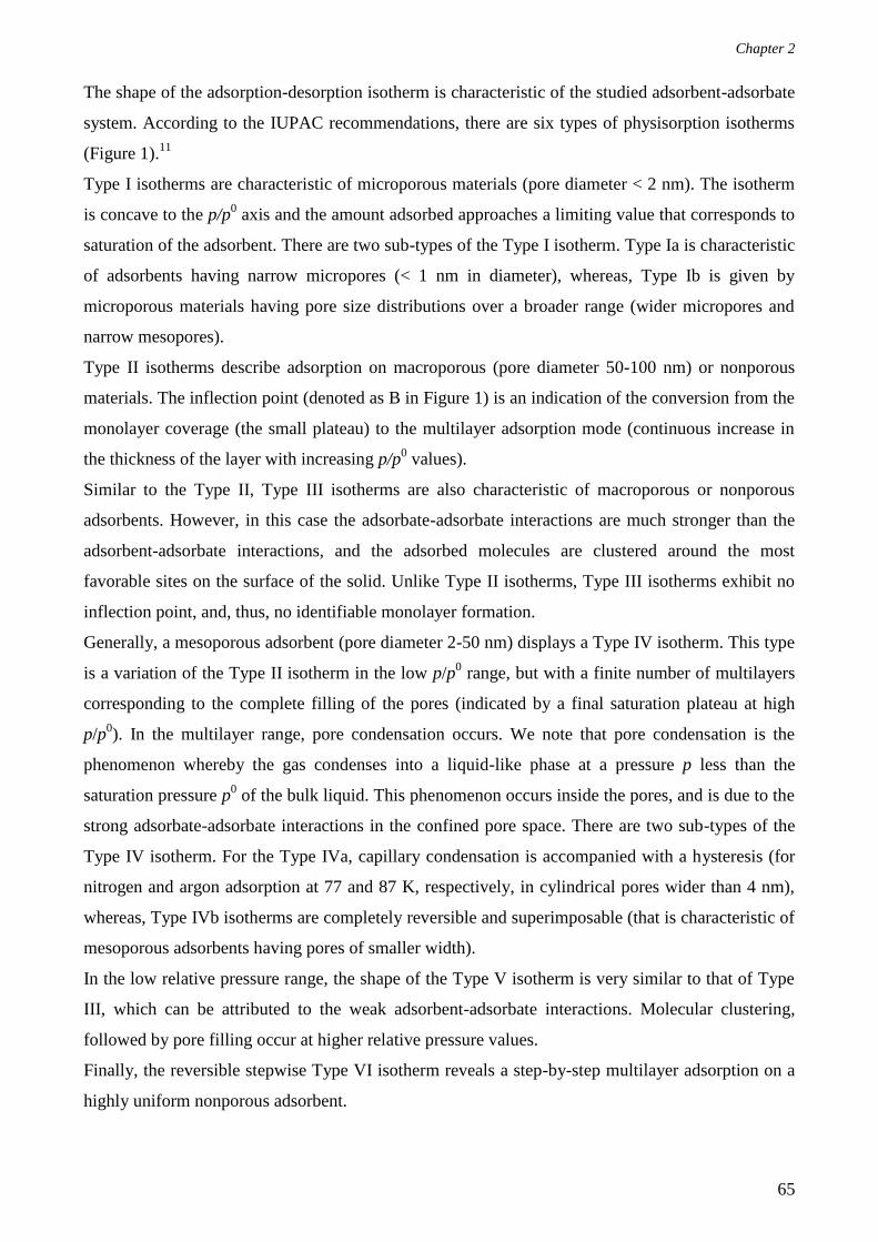
Chapter 2
65
The shape of the adsorption-desorption isotherm is characteristic of the studied adsorbent-adsorbate
system. According to the IUPAC recommendations, there are six types of physisorption isotherms
(Figure 1).11
Type I isotherms are characteristic of microporous materials (pore diameter < 2 nm). The isotherm
is concave to the p/p0 axis and the amount adsorbed approaches a limiting value that corresponds to
saturation of the adsorbent. There are two sub-types of the Type I isotherm. Type Ia is characteristic
of adsorbents having narrow micropores (< 1 nm in diameter), whereas, Type Ib is given by
microporous materials having pore size distributions over a broader range (wider micropores and
narrow mesopores).
Type II isotherms describe adsorption on macroporous (pore diameter 50-100 nm) or nonporous
materials. The inflection point (denoted as B in Figure 1) is an indication of the conversion from the
monolayer coverage (the small plateau) to the multilayer adsorption mode (continuous increase in
the thickness of the layer with increasing p/p0 values).
Similar to the Type II, Type III isotherms are also characteristic of macroporous or nonporous
adsorbents. However, in this case the adsorbate-adsorbate interactions are much stronger than the
adsorbent-adsorbate interactions, and the adsorbed molecules are clustered around the most
favorable sites on the surface of the solid. Unlike Type II isotherms, Type III isotherms exhibit no
inflection point, and, thus, no identifiable monolayer formation.
Generally, a mesoporous adsorbent (pore diameter 2-50 nm) displays a Type IV isotherm. This type
is a variation of the Type II isotherm in the low p/p0 range, but with a finite number of multilayers
corresponding to the complete filling of the pores (indicated by a final saturation plateau at high
p/p0). In the multilayer range, pore condensation occurs. We note that pore condensation is the
phenomenon whereby the gas condenses into a liquid-like phase at a pressure p less than the
saturation pressure p0 of the bulk liquid. This phenomenon occurs inside the pores, and is due to the
strong adsorbate-adsorbate interactions in the confined pore space. There are two sub-types of the
Type IV isotherm. For the Type IVa, capillary condensation is accompanied with a hysteresis (for
nitrogen and argon adsorption at 77 and 87 K, respectively, in cylindrical pores wider than 4 nm),
whereas, Type IVb isotherms are completely reversible and superimposable (that is characteristic of
mesoporous adsorbents having pores of smaller width).
In the low relative pressure range, the shape of the Type V isotherm is very similar to that of Type
III, which can be attributed to the weak adsorbent-adsorbate interactions. Molecular clustering,
followed by pore filling occur at higher relative pressure values.
Finally, the reversible stepwise Type VI isotherm reveals a step-by-step multilayer adsorption on a
highly uniform nonporous adsorbent.

Chapter 2
66
In this work, the textural properties (BET surface area and microporous volume) of the parent (non-
intruded) MOF materials were determined from N2 adsorption-desorption measurements. Later, the
post-intruded MOF materials were also analyzed and the obtained results were compared to those of
the corresponding parent material in order to investigate the framework stability under the effect of
high pressure and/or the non-wetting liquid during intrusion‒extrusion experiments. In most of the
cases, type I isotherms were obtained.
Herein, all the nitrogen adsorption-desorption isotherms were performed at 77 K using a
Micromeritics ASAP 2420 apparatus. Prior to the adsorption measurements, the samples were
degassed at elevated temperatures under secondary vacuum. We note that in this work, the
temperatures used to degas the MOF materials range between 125 and 250 °C and are dependent of
the MOF type and more especially of their thermal stability and the nature of guest molecules to-be
desorbed. Table 1 shows a list of the different MOF materials analyzed with N2 sorption
measurements in this work, in addition to the corresponding topology and degassing temperature
used. We also note that in all cases, the degassing duration is 12 hours.
Table 1. Degassing conditions prior to nitrogen sorption measurements at 77 K for MOF samples
before and after intrusion-extrusion experiments.
MOF
sample
Zeolite
Topology
Degassing
temperature
(°C)
Degassing
time
(h)
ZIF-8 SOD 200 12
ZIF-8_Cl SOD 200 12
ZIF-8_Br SOD 200 12
MAF-6 RHO 150 12
ZIF-71 RHO 150 12
ZIF-25 RHO 150 12
ZIF-71_Br2 RHO 150 12
ZIF-76 LTA 250 12
AFI-Zn(im)2 AFI 125 12
CAN-Zn(im)2 CAN 125 12
MIL-101(Cr) MTN 200 12
The degassing step is necessary to activate the pores by desorbing gases and evaporating volatile
molecules that may be entrapped, thus, making the pores accessible for the adsorption of N2
molecules. The software MicroActive was used to perform the N2 sorption measurements and to
treat the obtained adsorption-desorption isotherms. The specific surface area (SBET) was calculated
according to the criteria given in the literature, which are described below, and by using the
Brunauer-Emmett-Teller (BET) method (Equation 10).12-13
The first step in determining the BET
surface area is transforming the adsorption isotherm into a linear BET plot by drawing 1/V [(p
0/p) -

Chapter 2
67
1] versus p/p0. The constant C is first calculated from the slope of the obtained straight line,
whereas, the specific monolayer capacity Vm is calculated from the y-intercept.
In the case of nonporous, mesoporous, and macroporous adsorbents (displaying perfect Type II or
Type IVa isotherms), the range of linearity in the BET plot is usually within the 0.05-0.35 p/p0
range. This partial pressure range is chosen assuming that monolayer formation occurs within it,
and works well for materials that do not contain micropores.11,12
For the majority of MOF materials
(exhibiting only micropores), however, the smaller micropores are completely filled with N2 at
pressures below the standard BET range. In addition, several partial pressure ranges on the BET
plot may yield a linear region, which can be confusing and may also lead to subjective values of the
monolayer capacity and, consequently, of the BET surface area.12
In order to avoid this uncertainty,
three major criteria should be respected: (1) according to Rouquerol et al.,14
V(p0-p) should be
traced versus p/p0, and the relative pressure range selected should correspond to a continuous
increase of V(p0-p), (2) the value of the C parameter must be positive (a negative intercept on the y-
axis of the BET plot indicates that one is outside the appropriate p/p0 range), (3) the BET plot in the
selected p/p0 range should exhibit a high correlation coefficient (> 0.9999).
The microporous volume (Vμ) was determined according to the t-plot method.14
This method allows
drawing a t-plot relating the adsorbed quantity of the adsorbate (cm3 g
-1) to the thickness of the
adsorbate layer (Å) at different p/p0 values. The point of intersection of the t-plot with the y-axis (y-
intercept) permits the determination of the uptake corresponding to the formation of a monolayer
and, thus, Vμ. The thickness of the layer is obtained from the continuous adsorption of N2 on a
reference nonporous solid of same chemical nature as the studied porous adsorbent at different p/p0
values. However, since in many cases it is difficult to find a reference, the Harkins-Jura equation
can be applied to the determination of the thickness values t (Equation 11).15
t = [13.99 / (0.034 - log(p/p0))]
1/2 (Equation 11)
V. Stability under Pressure: Mercury Porosimetry
Mercury is a non-wetting liquid that cannot spontaneously penetrate pores by capillary action and,
thus, must be forced into the pores by the application of an external pressure.16
Mercury
porosimetry analysis corresponds to the progressive intrusion of mercury into a porous structure
under controlled pressure. The obtained volume versus pressure data allows the determination of the
1
V (p0/p-1)
= 1
VmC
+ C-1
VmC
(p/p0) (Equation 10)

Chapter 2
68
cumulative pore volume and the pore size distributions by referring to the Laplace-Washburn
equation (Equation 12).17
Pc = 2 |cosθ |/ r (Equation 12)
With: Pc, capillary pressure
, liquid-vapor surface tension (485 mN/m for mercury)
r, radius of the pores
θ, contact angle between the liquid and the solid (θ =130° for mercury)
However, only macroporous materials or those of high mesoporous volumes can be investigated
using mercury porosimetry, as mercury cannot penetrate inside micropores or small mesopores.16
Nevertheless, mercury porosimetry experiments have been applied to the study of the energetic
performance of flexible MIL-53-type microporous materials by provoking structural transitions in
them via, what we use to call, compression-decompression phenomena (Chapter 1, sub-section IV.
A.).18
It is important to note that in this work, we only carried out once a mercury porosimetry experiment
on the ZIF-71 material. This experiment was performed in the aim of proving the absence of a
separate effect of pressure on the phase transformation phenomenon evidenced for ZIF-71 during
the LiCl 20 M intrusion‒extrusion experiments.
The mercury porosimetry experiment was carried out using a Micromeritics mercury porosimeter
(Model Autopore IV, in the 0.2 to 400 MPa pressure range).
VI. Intrusion‒Extrusion Experiments
In the field of energetic applications, the intrusion‒extrusion of non-wetting liquids (such as water
or aqueous electrolyte solutions) into lyophobic porous materials has been widely investigated by
our team.19,20
In this work, we carried out the intrusion‒extrusion of water, KCl 4 M, and LiCl 20 M
aqueous solutions in activated MOF/ZIF samples using a Micromeritics mercury porosimeter
(Model Autopore IV). The intrusion‒extrusion experiments were run using the Autopore IV 9500
VI.06 software. The intrusion‒extrusion experiments were realized at room temperature, usually
over three intrusion‒extrusion cycles and up to a pressure of 350 MPa. In some cases (i.e. for the
“MAF-6−water”, “MAF-6−” and “ZIF-71−LiCl 20 M aqueous solution” systems), complementary
experiments were performed, which involved only one intrusion‒extrusion cycle up to maximum
pressures of 25, 47, 70, 90, 185, and 215 MPa. The experimental setup involves a “porous material–
non-wetting liquid” system, referred to as a Lyophobic Heterogeneous System (LHS), incorporated
within a 2 mL polypropylene cylinder that is sealed with a mobile piston, therefore, forming the
intrusion‒extrusion cell. This cell, in turn, is introduced into a glass penetrometer, which is filled

Chapter 2
69
with mercury. The increasing applied pressure during intrusion‒extrusion experiments forces
mercury out of the capillary tube of the penetrometer, which, in turn pushes the mobile piston of the
cell and, consequently, provokes the forced intrusion of the non-wetting liquid molecules into the
pores of the studied material. As the amount of mercury decreases inside the capillary, so does the
capacitance. The decrease in capacitance is, thus, proportional to the volume of mercury leaving the
capillary at each pressure value.
As previously developed in Chapter 1 section I, during intrusion‒extrusion experiments, three
different energetic behaviors may be observed: bumper, spring, or shock-absorber (Figure 2). The
energetic behavior of the LHS depends on the nature of both of its components: the porous solid
material and non-wetting liquid.
Figure 2. Schematic P‒V diagrams demonstrating (a) bumper, (b) spring and (c) shock-absorber
behaviors of LHSs.
From the P‒V diagrams shown in Figure 2, several experimental parameters can be extracted such
as the pressure at which the liquid enters the pores, namely the intrusion pressure (Pint), the pressure
at which the liquid is expelled from the pores, namely the extrusion pressure (Pext), the
corresponding intruded volume (Vint) and the extruded volume (Vext). For a better accuracy, we
define Vint = Vinte - Vintb and Vext = Vextb - Vexte, where Vintb and Vinte refer to the volume values at
the beginning and end of the intrusion step, respectively. Similarly, Vextb and Vexte correspond to the
volume values at the beginning and end of the extrusion step, respectively. The values Pint and Pext
correspond to the pressure at half total volume variation. The pressure is expressed in MPa, and the
volume variation in milliliter per gram (mL g-1
) of the activated MOF/ZIF material. From those
experimental parameters it is possible to calculate the energy E that can be, depending on the
behavior, the stored, restored, or absorbed energy (Es, Er, or Ea, respectively), expressed in J g-1
,
according to Equation 13.
0
. fV
V
E P dV (Equation 13)
a) b) c)

Chapter 2
70
With: E = Es and P = Pint (spring and shock-absorber behaviors)
Or E = Ea and P = Pint (bumper behavior)
Or E = Er and P = Pext (spring and shock-absorber behaviors)
V0, volume at the beginning of the volume variation step
Vf, volume at the end of the volume variation step
A simplified method that we have been using allows calculating the energy value from the product
of pressure and volume (Equation 14).
E = P*V (Equation 14)
With: E = Es, P = Pint and V = Vint
Or E = Ea, P = Pint and V = Vint
Or E = Er, P = Pext and V = Vext
Finally, the energetic yield (in %) is calculated from the ratio of Es to Er multiplied by 100
(Equation 15).
Energetic yield = Er/Es*100 (Equation 15)
Considering the experimental P‒V diagrams reported in this work, it is worth noting that the 0-5
MPa pressure range is not shown on the pressure-axis, since the corresponding volume variation is
only due to the compression of the “ZIF–non-wetting liquid” system and to the filling of the
interparticular porosity.20
As previously mentioned, it is the nature of both components of the LHS and how strongly/weakly
they interact with each other that determines the resulting energetic behavior of the system. For
instance, if the intruded liquid is retained in the pores at reduced pressures, the phenomenon is
defined as irreversible, as the system only absorbs the supplied mechanical energy (E = Ea,
expressed according to Equations 13 and/or 14) and is not capable of restoring it. On the pressure-
volume (P‒V) diagrams, bumper behavior is indicated by the absence of volume variation on the
extrusion curve (Figure 2a).
We note that in some cases, the solid porous material may undergo an irreversible phase transition
phenomenon during the intrusion step (accompanied with a partial or no intrusion of the non-
wetting liquid into the porosity), which is usually attributed to the combined effect of the high
pressure and non-wetting liquid. In such cases, the LHS is also defined as a bumper, as most of/all
the applied mechanical energy is absorbed by the system during the irreversible phase
transformation.
On the other hand, some systems can spontaneously react (ΔG < 0) and decrease their solid/liquid
interface (ΔΩ < 0) by completely expelling the liquid out of the pores. In this case, two possible
phenomena are common. In the first phenomenon, extrusion of the non-wetting liquid occurs at an

Chapter 2
71
extrusion pressure (Pext) exactly equal to or close to the intrusion pressure (Pint). The stored energy
is, thus, entirely, or almost entirely, restored, with an energy yield of 100 %, or slightly lower, and
the system displays spring behavior that is indicated on the P‒V diagrams from the overlap of the
intrusion and extrusion curves or the formation of a small hysteresis (Figure 2b). In the second
phenomenon, however, the mechanical energy stored in the form of interfacial energy is partially
dissipated during the extrusion of the non-wetting liquid from the pores and, thus, the energy yield
is significantly lower than 100 %. In this case, the P‒V diagrams reveal that extrusion occurs at Pext
significantly lower than Pint, which results in the formation of a large hysteresis between the
intrusion and extrusion curves (Figure 2c). The system, therefore, is defined as a shock-absorber.
Finally, we note that in the presence of a small hysteresis on the P‒V diagrams, to avoid
confusion, herein, the energetic behavior of the studied LHS is classified as shock-absorber or
spring based on a complete extrusion of the non-wetting liquid from the porosity with an
energy yield lower or equal to/higher than 80%, respectively.

Chapter 2
72
References
1. Atkins, P. W., Physical Chemistry. Sixth edition ed.; Oxford University Press: Oxford, 2001.
2. Bunaciu, A. A.; Udristioiu, E. G.; Aboul-Enein, H. Y., X-Ray Diffraction: Instrumentation and
Applications. Crit. Rev. Anal. Chem. 2015, 45, 289-299.
3. Cullity, B. D., Elements of X-Ray Diffraction. Addison-Wesley Pub. Co.: United States of
America, 1956.
4. Boultif, A.; Louer, D., Powder Pattern Indexing with the Dichotomy Method. J. Appl.
Crystallogr. 2004, 37, 724-731.
5. UI-Hamid, A., A Beginners' Guide to Scanning Electron Microscopy First edition ed.; Springer
International Publishing: Switzerland, 2018.
6. Vyazovkin, S. Thermogravimetric Analysis 2012.
7. Mortada, B.; Chaplais, G.; Veremeienko, V.; Nouali, H.; Marichal, C.; Patarin, J., Energetic
Performances of ZIF-8 Derivatives: Impact of the Substitution (Me, Cl, or Br) on Imidazolate
Linker. J. Phys. Chem. C 2018, 122, 3846-3855.
8. Schweinefuss, M. E.; Springer, S.; Baburin, I. A.; Hikov, T.; Huber, K.; Leoni, S.; Wiebcke, M.,
Zeolitic Imidazolate Framework-71 Nanocrystals and a Novel SOD-Type Polymorph: Solution
Mediated Phase Transformations, Phase Selection Via Coordination Modulation and a Density
Functional Theory Derived Energy Landscape. Dalton Trans. 2014, 43, 3528-3536.
9. Lambert, J. B.; Mazzola, E. P.; Ridge, C., Nuclear Magnetic Resonance Spectroscopy an
Introduction to Principles, Applications, and Experimental Methods. Second edition ed.; Wiley-
Blackwell: United States of America, 2019.
10. Boss, C. B.; Fredeen, K. J., Concepts, Instrumentation and Techniques in Inductively Coupled
Plasma Optical Emission Spectrometry. Second edition ed.; Perkin Elmer: United States of
America, 1999.
11. Matthias, T.; Kaneko, A.; Neimark, A. V.; Olivier, J. P.; Rodriguez-Reinoso, F.; Rouquerol, J.;
S.W. Sing, K., Physisorption of Gases, with Special Reference to the Evaluation of Surface area and
Pore Size Distribution (IUPAC Technical Report). Pure. Appl. Chem. 2015, 87, 1051-1069.

Chapter 2
73
12. Walton, K. S.; Snurr, R. Q., Applicability of the BET Method for Determining Surface Areas of
Microporous Metal−Organic Frameworks. J. Am. Chem. Soc. 2007, 129, 8552-8556.
13. Rouquerol, J.; Llewellyn, P.; Rouquerol, F., Is the BET Equation Applicable to Microporous
Adsorbents? Stud. Surf. Sci. Catal. 2007, 160, 49-56.
14. Rouquerol, J.; Rouquerol, F.; Llewellyn, P.; Maurin, G.; Sing, K. S. W., Adsorption by Powders
and Porous Solids: Principles, Methodology and Applications. Second edition ed.; Elsevier
Science: 2013.
15. Aligizaki, K., Pore Structure of Cement-Based Materials: Testing Interpretation and
Requirements. First edition ed.; Spon: 2003.
16. Giesche, H., Mercury Porosimetry: A General (Practical) Overview. Part. Part. Syst. Charact.
2006, 23, 9-19.
17. Eroshenko, V. A.; Grosu, Y. G., Thermomechanical and thermophysical properties of repulsive
clathrates. J. Appl. Mech. Tech. Phys. 2013, 54, 798-808.
18. Beurroies, I.; Boulhout, M.; Llewellyn, P. L.; Kuchta, B.; Ferey, G.; Serre, C.; Denoyel, R.,
Using Pressure to Provoke the Structural Transition of Metal-Organic Frameworks. Angew. Chem.,
Int. Ed. 2010, 49, 7526-7529.
19. Eroshenko, V.; Regis, R.-C.; Soulard, M.; Patarin, J., Energetics: A New Field of Applications
for Hydrophobic Zeolites. J. Am. Chem. Soc. 2001, 123, 8129-8130.
20. Ortiz, G.; Nouali, H.; Marichal, C.; Chaplais, G.; Patarin, J., Energetic Performances of the
Metal–Organic Framework ZIF-8 Obtained Using High Pressure Water Intrusion–Extrusion
Experiments. Phys. Chem. Chem. Phys. 2013, 15, 4888-4891.

Chapter 2
74

Chapter 3
75
Chapter 3: Energetic Performances of ZIF-8
Derivatives: Impact of the Substitution (Me, Cl, or Br)
on the Imidazolate Linker
In this chapter we aim at investigating the effect of both, the nature of the non-wetting liquid (water
or aqueous electrolyte solutions) and the substituent borne by the imidazolate linker on the energetic
behaviors of ZIF-8 derivatives during high-pressure intrusion−extrusion experiments. The first
section is devoted to the description of the structure of ZIF-8 and two halogenated derivatives, i. e.
ZIF-8_Cl and ZIF-8_Br. The second section is a summary of our first article (referred to as article
1), which deals with the materials’ energetic performances (where ZIF-8 is named as ZIF-8_CH3).1
A copy of this article is provided afterwards. Finally, in Section III, additional comments are given
in the light of recently published computational results concerning the intrusion of LiCl aqueous
solution in ZIF-8.
I. ZIF-8 and its Halogenated Derivatives
A. Structures
Prior to this PhD work, two SOD-type materials, ZIF-8_Cl and ZIF-8_Br, were synthesized in the
aim of studying the impact of the substitution on the imidazolate linker on the ZIFs’ structural and
adsorptive properties by comparing them to those of the well-known ZIF-8, also commercially
labeled as Basolite® Z1200. These materials are constructed from Zn2+
cations bridged by
imidazolate linkers that are substituted at the position 2 by a methyl (CH3), chlorine (Cl), or
bromine (Br) group/atom for ZIF-8, ZIF-8_Cl, and ZIF-8_Br, respectively. It is worthy to note that
ZIF-8_Cl, and ZIF-8_Br are quite new variants of ZIF-8 as they were experimentally reported only
once, where only the capacity of ZIF-8_Cl in the kinetic separation of propane and propene was
evaluated.2 Their structures were later elucidated, showing that the three ZIF materials are
isoreticular, possessing a zeolitic SOD framework topology, with 4- and 6-membered ring pore
apertures (Scheme 1).3

Chapter 3
76
Scheme 1. Representation of the SOD topology of the ZIF-8 derivatives. In red, zinc cations. In
yellow and green, the 4- and 6-membered ring pore apertures, respectively.
ZIF-8 and its derivatives crystallize in the cubic symmetry (space group I-43m), with the lattice
constant a ≈ 17.01,4 17.04,
3 and 17.08
3 Å for ZIF-8, ZIF-8_Cl, and ZIF-8_Br, respectively. The
slight increase in the value of the lattice constant is related to the steric hindrance provided by the
substituent on the imidazolate linker and which is more important for Br than for Cl and then CH3.
Another notable structural feature is the fact that the 2-chloroimidazolate (cim-2) and 2-
bromoimidazolate (bim-2) linkers incorporated in the ZIF-8_Cl and ZIF-8_Br frameworks,
respectively, are disordered. These linkers are indeed tilted around a fixed axis defined by the two
nitrogen atoms. This results in two sets of atoms, with a site occupation factor of around 50 % for
each set. Figures 1a and 1b represent the ZIF-8_Cl and ZIF-8_Br asymmetric units, whereas Figures
1c and 1d demonstrate the angles between the disordered (tilted) linkers in the two materials.

Chapter 3
77
Figure 1. Asymmetric units of (a) ZIF-8_Cl and (b) ZIF-8_Br (50% of probability ellipsoid).
Dihedral angles between the disordered imidazolate linkers of (c) ZIF-8_Cl and (d) ZIF-8_Br.3
B. Flexibility and Porosity
Remarkably, ZIF-8_Cl and more especially ZIF-8 are characterized by a framework flexibility,
which is due to the swing of the imidazolate linkers under various stimuli. This phenomenon can be
indicated from the profile of the N2 sorption isotherms of both ZIF materials, where a step uptake is
observed at a relative pressure around 0.005 (Figure 2b in attached article 1).1 Previous and
different studies have already highlighted this structural characteristic of ZIF-8. For example,
Fairen-Jimenez et al. evidenced this peculiar phenomenon through a combined experimental-
simulation study based on nitrogen sorption measurements combined with crystallographic data.5
They assigned a step observed for relative pressure between 0.002 and 0.02 in the isotherm to the
structural transition. Ania et al. used experimental and simulation studies in order to demonstrate
that this swing effect is governed by the characteristics (polarizability, molecular size and shape) of
the used gases (N2, Ar, O2, CO) and that the stepped adsorption behavior is defined by the guest
packing inside the host.6 Moggach et al. demonstrated the capability of ZIF-8 of undergoing a
reversible structural transition when a pressure of 1.47 GPa is applied in the presence of methanol
as the hydrostatic medium.7 Such a structural transition of the imidazolate linkers under pressure
can be highly advantageous in intrusion−extrusion experiments, as it is expected to allow the
accommodation of a relatively larger amount of non-wetting liquid molecules. As for ZIF-8_Br, it
displays a usual type Ia nitrogen sorption isotherm, with no sign of the flexibility of this material
(characterized by stepped uptake at low relative pressure). The steric hindrance of Br substituent

Chapter 3
78
may be the reason for the rigidity of the material’s framework. Moreover, based on molecular
dynamic simulation studies, it appears that the structural transition is triggered by a repacking of the
nitrogen molecules, thereby inducing the swinging effect.3 In this regard, the origin of the different
sorption features observed for the three ZIF-8 derivatives can be assigned to the difference in pore
size and shape, the pores in ZIF-8_Br being too small to enable a reordering of accommodated
nitrogen molecules to occur.
Furthermore, the three ZIF-8 derivatives are characterized by a high degree of hydrophobicity and
by high porosity (average microporous volume of 0.66, 0.57, and 0.35 cm3 g
-1 for ZIF-8, ZIF-8_Cl,
and ZIF-8_Br, respectively) as revealed from water and N2 adsorption-desorption measurements,
respectively.1 Therefore, these materials have been considered as good candidates for
intrusion−extrusion experiments.
C. Context of the Study on Energetic Performances of ZIF-8
Derivatives
In previous work published by our team in 20138 and, later, in 2014
9, the energetic performances of
ZIF-8 were explored using water, in addition to NaCl, KCl and LiCl aqueous solutions of
concentrations ranging between 1- 4 M. Therefore, in the current study, we intend to complete this
previous work performed on ZIF-8 by investigating the energetic behaviors of its derivatives using
water, KCl 4 M aqueous solution, and LiCl 20 M aqueous solution. The aim is to analyze the
influence of the substitution on the imidazolate linker on the energetic performances of the ZIF
materials. As previously mentioned in Chapter 1, water is a nontoxic non-wetting liquid that has
been extensively employed in intrusion−extrusion experiments. Moreover, the concentrations of
both aqueous electrolyte solutions employed in this work (KCl 4 M and LiCl 20 M aqueous
solutions) correspond to their maximum solubility at room temperature. This indicates the presence
of less water molecules surrounding the alkaline cations (in the outer solvation shell and as free
water molecules) and, thereby, a lower number of water molecules that could interact with/or create
defects in the ZIF materials and, consequently, provoke an irreversible phenomenon during
intrusion−extrusion experiments. Furthermore, it was shown that upon increasing the concentration
of the LiCl aqueous solution, the energetic behavior of some zeosil-based LHSs can be modified
from bumper to shock-absorber.10
II. Summary of the Article 1
Article 1 reports the intrusion−extrusion experiments performed on ZIF-8 (ZIF-8_CH3 in the
article), ZIF-8_Cl, and ZIF-8_Br using water, KCl 4 M, and LiCl 20M aqueous solutions as non-
wetting liquids, whereby the experiments were realized up to a maximum pressure of 80 or 350

Chapter 3
79
MPa and over three intrusion−extrusion cycles. The obtained results reveal that the intrusion
pressure is enhanced with the addition of electrolytes to the non-wetting liquid, which is in
agreement with the literature. Notably, for the three ZIF-8 derivatives, higher intrusion pressures are
obtained with LiCl 20 M compared to the KCl 4 M aqueous solution. This confirms the results
published by our team in 2014, where it was shown that for the same salt concentration of 4 M,
higher intrusion pressures are attained with the LiCl (and NaCl) compared to the KCl aqueous
solution during intrusion−extrusion experiments in ZIF-8.9 This can be attributed to the larger
hydrodynamic diameter of lithium compared to that of potassium11
(or to the smaller size of the
lithium cation compared to that of potassium12
). Another explanation is the additional force needed
to break down the solvation bonds, which are stronger in the case of lithium chloride than the case
of potassium chloride salts.13
Our experimental results also prove that the intrusion pressure is always higher for the ZIF-8- and
ZIF-8_Cl-based systems compared to the ZIF-8_Br-based systems, regardless of the nature of the
non-wetting liquid. This can be explained by the additional pressure required to induce the swing of
the imidazolate linkers and gate opening phenomenon in ZIF-8 and ZIF-8_Cl during the intrusion of
the non-wetting liquid molecules, whereas, as previously mentioned in Section I, ZIF-8_Br is rigid.
Moreover, the obtained results show that the presence of an electron donating group on the
imidazolate linker, such as the CH3 group, can increase the interactions with the cations of the salt
present in the non-wetting liquid (due to the increased electron density on the imidazolate linker),
hence, preventing the complete extrusion of the non-wetting liquid molecules from the porosity at
reduced pressures. This is particularly the case when a LiCl 20 M aqueous solution is used. In this
respect, the “ZIF-8–LiCl 20 M aqueous solution” system displays bumper behavior with a
remarkable value of absorbed energy of 104 J g-1
. These results are in agreement with the ones
obtained very recently through molecular dynamic simulations14
(which will be commented in
Section III) and confirm that when confined in the porosity, the electrolyte from the non-wetting
liquid may interact with the imidazolate linker.
Conversely, in the presence of an electron withdrawing group on the imidazolate linker, such as Cl
or Br atoms, the interactions with the imidazolate linker are weakened (electron density on the
imidazolate linker is decreased), which makes possible a complete extrusion of the non-wetting
liquid molecules when the pressure is released and, thus, spring behavior is favored, as shown for
the “ZIF-8_Cl–LiCl 20 M aqueous solution” and “ZIF-8_Br–LiCl 20 M aqueous solution” systems.
Concerning the former system, it is important to highlight the outstanding value of the stored
energy: 77 J g-1
. Indeed, until now, this is the highest value of stored energy registered for a spring
system during intrusion−extrusion experiments.

Chapter 3
80
We note that the high values of absorbed and stored energies obtained for the “ZIF-8−” and “ZIF-
8_Cl−LiCl 20 M aqueous solution” systems, respectively, are ascribed to both the high intruded
volumes (0.56 and 0.38 mL g-1
for the “ZIF-8−” and “ZIF-8_Cl−LiCl 20 M aqueous solution”
systems, respectively) and intrusion pressures (186 and 201 MPa for the “ZIF-8−” and “ZIF-
8_Cl−LiCl 20 M aqueous solution” systems, respectively).
When KCl 4 M aqueous solution is employed, the behaviors of all related systems are basically
comparable to those of corresponding “ZIFs−water” systems. This could indicate weaker
interactions of these electrolyte species with porous materials than those disclosed in “ZIFs−LiCl 20
M aqueous solution” systems.
Based on these results, it can be concluded that for a LHS consisting of a ZIF material and an
aqueous electrolyte solution, the nature of the substituent present on the imidazolate linker can
influence the energetic behavior of the system during intrusion−extrusion experiments, through
host−guest (linker−aqueous electrolyte solution) interactions. The substituent can also affect the
flexibility/rigidity of the ZIF material,1 which consequently leads to higher/lower intrusion
pressures, as demonstrated for the LHSs based on the three ZIF-8 derivatives of SOD topology.
Finally, this study shows that the bulkier the substituent (i.e. the smaller the microporous volume),
the smaller is the intruded volume.
The full text of article 1 entitled “Energetic Performances of ZIF-8 Derivatives: Impact of the
Substitution (Me, Cl or Br) on Imidazolate Linker” and published in the Journal of Physical
Chemistry C in 2018 is presented within next ten pages.

Chapter 3
81

Chapter 3
82

Chapter 3
83

Chapter 3
84

Chapter 3
85

Chapter 3
86

Chapter 3
87

Chapter 3
88

Chapter 3
89

Chapter 3
90

Chapter 3
91
III. Comments in the Light of Recently Published Results
Fraux et al. studied, using molecular dynamic simulations, the properties of the LiCl aqueous
solution when confined in the ZIF-8 nanopores.14
The results obtained based on this study confirms
that in the nanopores, the solvation degree of the ions is diminished (desolvation) and the formation
of Li-Cl ion pairs is favored. Moreover, instead of being widely distributed in the porosity, the
solvated ions are restricted to specific preferential locations, due to interactions with the imidazolate
linker. This effect of preferential distribution is stronger for the Cl/water pairs than for the
water/water (in the case of “pure” water intrusion−extrusion experiments) or Li/water pairs. The
authors also note that the relatively small kinetic radius of lithium ions (2.1 Å) allows them to fit in
smaller spaces, which results in even distribution of the cations in the nanopores and a consequent
increase in the total entropy of the system. However, chlorine ions and water molecules are more
polarizable than lithium, and interact more strongly with the aromatic linkers, which favors a highly
organized arrangement. Finally, from a thermodynamic point of view, there is no free energy barrier
for the intrusion of water molecules into the ZIF-8 pores. As for chlorine anions, the free energy
profile reveals two barriers. These barriers can be correlated to the fact that there is not enough
space inside the window to accommodate a Cl anion with 7 water molecules in the solvation shell,
and the anion has to partially desolvate to pass through the 6-membered ring pore aperture of ZIF-8.
Thus, it can be considered that the Cl anions have a kinetic barrier to entry in ZIF-8. Nevertheless,
for Li cations, the results are different. Indeed, the solvation of Li cations by water is much
stronger, and its solvation sphere is smaller in size compared to that of Cl anions. Therefore, lithium
does not partially desolvate or rearrange to pass through the pores and the whole solvation sphere
needs to go through a relatively small window, thus, making the barrier higher. In conclusion,
molecular dynamic simulations give some very interesting insights into the intrusion of electrolytes,
in particular LiCl, in ZIF-8 and confirm some of our assumptions of desolvation and the interaction
of the electrolytes from the non-wetting liquid with the imidazolate linker.

Chapter 3
92
References
1. Mortada, B.; Chaplais, G.; Veremeienko, V.; Nouali, H.; Marichal, C.; Patarin, J., Energetic
Performances of ZIF-8 Derivatives: Impact of the Substitution (Me, Cl, or Br) on Imidazolate
Linker. J. Phys. Chem. C 2018, 122, 3846-3855.
2. Li, K.; Olson, D. H.; Seidel, J.; Emge, T. J.; Gong, H.; Zeng, H.; Li, J., Zeolitic Imidazolate
Frameworks for Kinetic Separation of Propane and Propene. J. Am. Chem. Soc. 2009, 131, 10368-
10369.
3. Chaplais, G.; Fraux, G.; Paillaud, J.-L.; Marichal, C.; Nouali, H.; Fuchs, A. H.; Coudert, F.-X.;
Patarin, J., Impacts of the Imidazolate Linker Substitution (CH3, Cl, or Br) on the Structural and
Adsorptive Properties of ZIF-8. J. Phys. Chem. C 2018, 122, 26945-26955.
4. Morris, W.; Stevens, C. J.; Taylor, R. E.; Dybowski, C.; Yaghi, O. M.; Garcia-Garibay, M. A.,
NMR and X-ray Study Revealing the Rigidity of Zeolitic Imidazolate Frameworks. J. Phys. Chem.
C 2012, 116, 13307-13312.
5. Fairen-Jimenez, D.; Moggach, S. A.; Wharmby, M. T.; Wright, P. A.; Parsons, S.; Duren, T.,
Opening the Gate: Framework Flexibility in ZIF-8 Explored by Experiments and Simulations. J.
Am. Chem. Soc. 2011, 133, 8900-8902.
6. Ania, C. O.; Garcia-Perez, E.; Haro, M.; Gutierrez-Sevillano, J. J.; Valdes-Solis, T.; Parra, J. B.;
Calero, S., Understanding Gas-Induced Structural Deformation of ZIF-8. J. Phys. Chem. Lett. 2012,
3, 1159-1164.
7. Moggach, S. A.; Bennett, T. D.; Cheetham, A. K., The Effect of Pressure on ZIF-8: Increasing
Pore Size with Pressure and the Formation of a High-Pressure Phase at 1.47 GPa. Angew. Chem.,
Int. Ed. 2009, 48, 7087-7089.
8. Ortiz, G.; Nouali, H.; Marichal, C.; Chaplais, G.; Patarin, J., Energetic Performances of the
Metal–Organic Framework ZIF-8 Obtained Using High Pressure Water Intrusion–Extrusion
Experiments. Phys. Chem. Chem. Phys. 2013, 15, 4888-4891.
9. Ortiz, G.; Nouali, H.; Marichal, C.; Chaplais, G.; Patarin, J., Versatile Energetic Behavior of ZIF-
8 upon High Pressure Intrusion-Extrusion of Aqueous Electrolyte Solutions. J. Phys. Chem. C
2014, 118, 7321-7328.

Chapter 3
93
10. Ryzhikov, A.; Khay, I.; Nouali, H.; Daou, T. J.; Patarin, J., Drastic Change of the Intrusion-
Extrusion Behavior of Electrolyte Solutions in Pure Silica *BEA-Type Zeolite. Phys. Chem. Chem.
Phys. 2014, 16, 17893-17899.
11. Calleja, G.; Botas, J. A.; Martos, C.; Orcajo, G.; Villajos, J. A., Effect of Ion-Exchange
Modification on Hydrogen and Carbon Dioxide Adsorption Behaviour of RhoZMOF Material.
Adsorpt. Sci. Technol. 2012, 30, 793-806.
12. Liu, L.; Chen, X.; Lu, W.; Han, A.; Qiao, Y., Infiltration of Electrolytes in Molecular-Sized
Nanopores. Phys. Rev. Lett. 2009, 102, 184501/1-184501/4.
13. Bostroem, M.; Ninham, B. W., Contributions from Dispersion and Born Self-Free Energies to
the Solvation Energies of Salt Solutions. J. Phys. Chem. B 2004, 108, 12593-12595.
14. Fraux, G.; Boutin, A.; Fuchs, A. H.; Coudert, F.-X., Structure, Dynamics, and Thermodynamics
of Intruded Electrolytes in ZIF-8. J. Phys. Chem. C 2019, 123, 15589-15598.

Chapter 3
94

Chapter 4
95
Chapter 4: Synthesis and Study of the Energetic
Performances of ZIFs of RHO Topology
The literature review of this thesis manuscript (Chapter 1) demonstrates the significant impact of
the topology on the energetic performances of both zeolites and MOFs. The SOD topology has been
widely studied in intrusion−extrusion experiments (Chapters 1 and 3), whereas the RHO topology
was only studied for ZIF-71, where the “ZIF-71−water” system displays perfect shock-absorber
behavior, with a stored energy value of 26 J g-1
, i.e. twice the value registered for the “ZIF-8–water”
system.1-2
Furthermore, the results obtained from the intrusion−extrusion experiments carried out on
ZIF-8 derivatives of SOD framework-type topology (Chapter 3), reveal the effect of the substituent
present on the imidazolate linker on the energetic performances of the corresponding lyophobic
heterogeneous system (LHS).3
Thus, a part of this thesis work was devoted to the further investigation of RHO-type ZIF materials
in intrusion−extrusion experiments, and the study of the influence of the substitution on the
imidazolate linker on the energetic performances of the related systems. In this regard, two newly
reported ZIFs, i.e. ZIF-25 and MAF-6,4-6
were selected for this study. Our research also included
ZIF-71, which was integrated into new LHSs that were not investigated in intrusion−extrusion
experiments prior to this work, in addition to a new isoreticular analog of ZIF-71, MAF-6, and ZIF-
25, named ZIF-71_Br2, which was attempted to be prepared purely.
This chapter is divided into two parts. The first part is devoted to the study of the energetic
performances of ZIF-71 and MAF-6 in water and LiCl 20 M aqueous solution intrusion−extrusion
experiments, which evidences phase transformation phenomena that were not reported in the
literature prior to our work. Consequently, owing to the novelty of the obtained results, they were
published this year (Article 2).7 On the other hand, Part II of this chapter is dedicated to the
optimization of the syntheses of the porous ZIF-25 and ZIF-71_Br2 materials, in the aim of
exploring them in high-pressure intrusion−extrusion experiments of water and LiCl 20 M aqueous
solution.
I. Phase Transformations of Metal-Organic Frameworks
MAF-6 and ZIF-71 during Intrusion−Extrusion
Experiments
Herein, we report the water and LiCl 20 M aqueous solution intrusion−extrusion experiments
realized on MAF-6 and ZIF-71. Indeed, MAF-6, a recently reported (2016) ZIF material,6 was

Chapter 4
96
selected owing to its structural characteristics (large pore volume, pore size, and pore aperture) that
were expected to lead to a large amount of stored/absorbed energy, together with a relatively low
intrusion pressure (more suitable for practical applications). Furthermore, according to the
literature, MAF-6 exhibits a strong hydrophobic character that is highly desired in water and
aqueous solution intrusion−extrusion experiments.6 In the aim of comparison, the energetic
performance of the “ZIF-71−water” system is recalled, whereas that of the “ZIF-71−LiCl 20 M
aqueous solution” system is investigated for the first time.
A. Summary of Article 2
This publication reports the synthesis and characterization of two hydrophobic zeolitic-imidazolate
framework (ZIF) materials, MAF-6 and ZIF-71, which are prepared in the aim of studying their
energetic behaviors in high pressure intrusion−extrusion experiments using water and LiCl 20 M
aqueous solution as non-wetting liquids. The materials are made up of zinc cations bridged by 2-
ethylimidazolate (eim) and 4,5-dichloroimidazolate (dcim) linkers for MAF-6 and ZIF-71,
respectively. Both ZIF materials display a RHO framework topology with large cages (16.5-16.8
and 18.1 Å in diameter for ZIF-71 and MAF-6, respectively) delimited by 4-, 6-, and 8-membered
ring pore apertures (4.2-4.8 and 7.6 Å in diameter for ZIF-71 and MAF-6, respectively) (Scheme 1).
Scheme 1. Representation of the RHO framework topology. In red, zinc cations. In yellow, green,
and blue; the 4-, 6-, and 8-membered ring pore apertures, respectively.
For both the MAF-6 and ZIF-71 materials, the intrusion−extrusion experiments were first realized
up to a maximum pressure of 350 or 300 MPa, respectively. Nevertheless, in order to understand
the effect of the applied pressure on the structure of the studied materials, complementary

Chapter 4
97
experiments were conducted under lower pressures. In all cases, the post-intruded samples were
characterized mainly using X-ray diffraction (XRD) and N2 sorption analyses.
The “ZIF-71‒water” system was already reported to display perfect shock-absorber behavior.1
However, our study showed that with LiCl 20 M aqueous solution, ZIF-71 is transformed into the
dense ZIF-72 phase; a ZIF-71 polymorph of lcs topology. This structural transformation was proven
to occur under the combined effect of high pressure and the non-wetting liquid during
intrusion−extrusion experiments. The phase transformation phenomenon was associated with a
partial intrusion of the non-wetting liquid molecules into the porosity, where they seem to remain
entrapped even after the release of the applied mechanical pressure, as revealed by
thermogravimetric (TG) and inductively-coupled plasma (ICP) analyses (Section I. C.). On the
pressure−volume (P−V) diagrams, only one volume variation step is observed on the intrusion
curve of the first intrusion−extrusion cycle, which indicates the irreversibility of the phase
transformation and intrusion phenomena.
As for the “MAF-6‒water” and “MAF-6‒LiCl 20 M aqueous solution” systems, the P−V diagrams
also reveal only one volume variation step (observed on the intrusion curve of the first
intrusion−extrusion cycle), which based on TG and ICP analyses corresponds, in part, to the
intrusion of the non-wetting liquid molecules into the porosity. Besides, similar to the case of the
“ZIF-71−LiCl 20 M aqueous solution” system, for both the “MAF-6‒water” and “MAF-6‒LiCl 20
M aqueous solution” systems, the intrusion is associated with a phase transformation and, more
precisely, with a partial collapse of the structure, resulting in the formation of a highly crystalline,
but, nonporous phase that is called phase X. It is worthy to note that the phase X does not
correspond to any of the MAF-6 polymorphs (MAF-32 or ZIF-14 (also called MAF-5) of quartz
and ANA topologies, respectively) nor to the organic precursor molecules (Heim). The probable
identity of the newly formed phase X and its formation mechanism will be further discussed in
Section I. B.
Finally, it is important to highlight that this work confirms that the addition of electrolytes to the
non-wetting liquid increases the intrusion pressure (higher intrusion pressure with LiCl 20 M
aqueous solution compared to water). Moreover, for the first time, irreversible crystal phase
transformation phenomenona are observed during intrusion−extrusion experiments, leading to a
mixture of shock-absorber and bumper behaviors for the “MAF-6−water” system and bumper
behavior for both the “MAF-6−” and “ZIF-71−LiCl 20 M aqueous solution” systems. The
originality of this work is illustrated in proving that the detected volume variation on the P‒V
diagram, usually related to the intrusion of the non-wetting liquid into the porosity of the material,
can also be attributed, in some particular cases, to a complete or partial phase transformation,
potentially associated to an intrusion phenomenon.

Chapter 4
98
The full text and supporting information of Article 2 entitled “Phase Transformations of Metal-
Organic Frameworks MAF-6 and ZIF-71 during Intrusion-Extrusion Experiments” that was
published in the Journal of Physical Chemistry C in 2019 are presented within the next eighteen
pages.

Chapter 4
99

Chapter 4
100

Chapter 4
101

Chapter 4
102
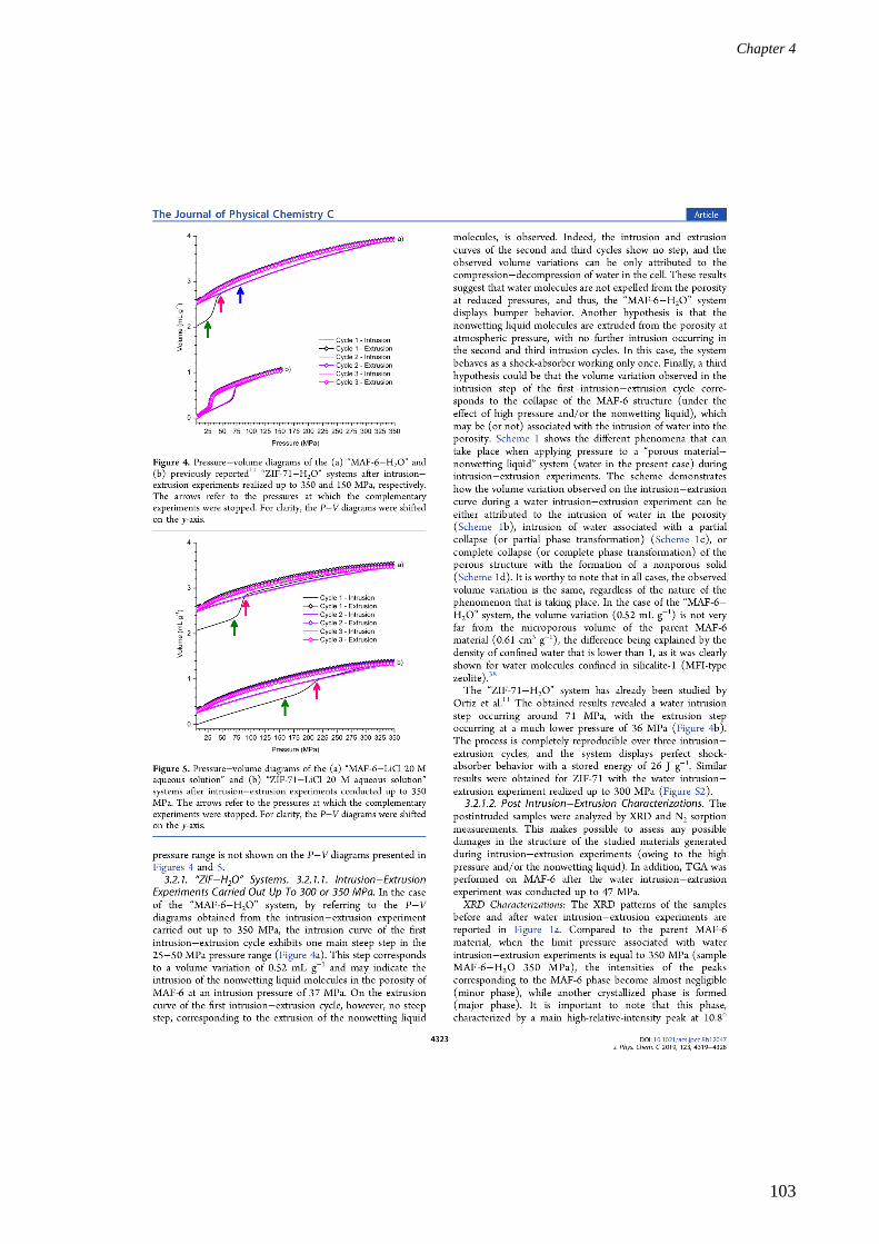
Chapter 4
103

Chapter 4
104

Chapter 4
105

Chapter 4
106

Chapter 4
107
Chapter 4
108

Chapter 4
109

Chapter 4
110

Chapter 4
111

Chapter 4
112

Chapter 4
113

Chapter 4
114

Chapter 4
115
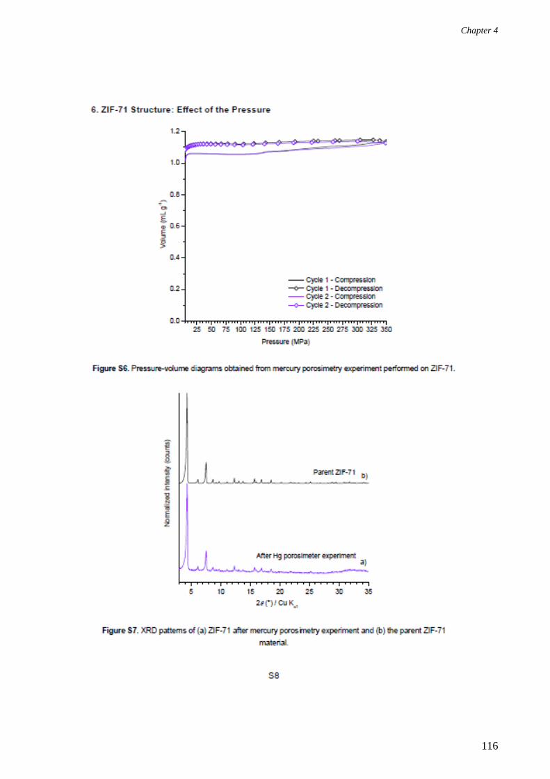
Chapter 4
116

Chapter 4
117
B. Identification of Phase X
When Article 2 was accepted for publication, the identification of phase X was still in progress.
Phase X still remains unidentified, but does not correspond to any of the MAF-6 polymorphs
(MAF-32 or ZIF-14/MAF-5), or the organic precursor (Heim), or the plausible zinc-based
hydroxide/oxide species; Zn(OH)2 or ZnO, respectively. As previously mentioned, phase X is
obtained from MAF-6 via a phase transformation process during intrusion−extrusion experiments of
water and LiCl 20 M aqueous solution. This phase transformation is clearly more prominent in the
case of water. Moreover, phase X is nonporous, as revealed with N2 sorption analyses, while,
according to TG analysis, it is a hybrid organic-inorganic material. Besides, as shown in Figure 1,
Scanning Electron Microcopy (SEM) analyses reveal a different morphology for the post-intruded
samples (spherical shaped crystals shown in Figures 1b and 1c) compared to the parent MAF-6
material (dodecahedral crystals shown in Figure 1a).
Figure 1. SEM images of (a) parent MAF-6 sample, and (b) samples recovered after three cycles of
water and (c) LiCl 20 M aqueous solution intrusion−extrusion experiments realized up to 350 MPa.
a) b)
c)

Chapter 4
118
Based on these results, one hypothesis would be that MAF-6 is capable of undergoing a partial
hydrolysis-condensation phenomenon in the presence of water molecules, which results in the
formation of phase X. Even though stability tests performed at room pressure and temperature, by
suspending MAF-6 samples in water and LiCl 20 M aqueous solution (with a MAF-6 / water and
MAF-6 / LiCl 20 M aqueous solution mass ratios of 10 and 4.8 %, respectively), reveal that the ZIF
structure is maintained (Figure 2 and Figure S3 of the supporting information of Article 2),
however, it seems that hydrolysis can take place under the combined effect of high pressure and the
non-wetting liquid.
Figure 2. XRD patterns of MAF-6 after suspending in water for (a) 1 d and (b) 4 d and (c) after
suspending in LiCl 20 M aqueous solution for 1 d. For comparison, the XRD pattern of parent
MAF-6 is also included. ° and * refer to the peaks corresponding to MAF-32 and phase X,
respectively.7
Indeed, by referring to the XRD and N2 sorption analyses (Figures 1 and 2 of the Article 2)
performed on the ZIF materials after the complementary intrusion−extrusion experiments, at the
pressure corresponding to the beginning of the intrusion step, hydrolysis probably only occurs at the
surface, as the non-wetting liquid molecules have not yet entered the porosity. Consequently, a
slight decrease in the textural properties of MAF-6 is observed at 25 and 70 MPa with water and
LiCl 20 M aqueous solution, respectively. This could be assigned to a rising pore blocking caused
by the superficial hydrolysis, while the MAF-6 structure is preserved at long range order. When the

Chapter 4
119
pressure reaches Pint, water/electrolyte aqueous solution is intruded into the ZIF pores and the effect
of hydrolysis starts increasing. This results in further degradation of the framework and, hence, in a
lower microporous volume at the end of the intrusion step. Finally, when the applied pressure
continues to increase during water intrusion for example, the aqueous medium becomes more
“harsh”, leading to some further hydrolysis, as indicated from the XRD patterns and N2 sorption
isotherms of the “MAF-6−water” system obtained at 80 and 350 MPa. It is important to note that
with both water and the LiCl 20 M aqueous solution, hydrolysis appears mainly when the non-
wetting liquid molecules are present inside the porosity, which explains the significant decrease in
the textural properties of MAF-6 between the beginning and end pressures of the intrusion step. As
the pressure continues to increase, a small decrease in the textural properties of MAF-6 is observed
in the case of water, whereas no further decrease is noted with the LiCl 20 M aqueous solution. The
fact that the phase transformation of MAF-6 into phase X is more prominent (91% transformation
based on nitrogen sorption experiments) during water intrusion−extrusion experiments than in the
case of the LiCl 20 M aqueous solution (84% transformation based on nitrogen sorption
experiments), can be attributed to the smaller amount of water molecules available for hydrolysis in
the case of the highly concentrated aqueous electrolyte solution. Indeed, in the case of the “MAF-
6−water” system, part of the water molecules that were intruded into the MAF-6 pores was
probably used to hydrolyze the ZIF material. However, the hydrolysis (and the formation of phase
X) remains partial (40% of water-intruded MAF-6 remains at the end of the intrusion step, as
revealed by the N2 sorption isotherms obtained after water intrusion−extrusion experiments realized
up to 47 MPa) and the water molecules entrapped in the pores of the remaining MAF-6 material
seem to be mainly extruded at atmospheric pressure, as indicated from TG analysis. Thus, the
“MAF-6−water” system is said to display a mixture of shock-absorber and bumper behaviors.
Notably, a hydrolysis-condensation mechanism that is similar to the one proposed to explain the
formation of phase X was reported in the case of ZIF-8 in a very recent study published in 2019.8
Indeed, Zhang et al. shed light on the transformation of the ZIF-8 structure into another crystalline
phase through a partial hydrolysis-condensation mechanism. When ZIF-8 is suspended in a dilute
aqueous medium (ZIF-8 / water mass ratio of ≈ 0.02%) for 24 h at room temperature, with
continuous stirring, the authors demonstrated that ZIF-8 is partially hydrolyzed. During the
hydrolysis step, a Zn-N coordination bond is cleaved. Consequently, a hydroxyl group from a water
molecule substitutes a 2-methylimidazolate linker molecule, whereas the remaining hydrogen atom
bonds to the nitrogen of the initially coordinating 2-methylimidazolate. In order to recover the
product of hydrolysis, water is evaporated by heating the suspension at 40°C in a convection oven.
This step is referred to as the condensation step, during which the clusters and ions reunite and then
stack, through hydrogen bonding, to form the new phase. The phase transformation of ZIF-8 is

Chapter 4
120
confirmed through XRD, N2 sorption, SEM, energy-dispersive X-ray spectroscopy (EDS), and TG
analyses. Furthermore, the hydrolysis-tested phase is a hybrid organic-inorganic material with the
same C: N: Zn ratio as ZIF-8, however, with an increased oxygen content that is ascribed to the
coordinating hydroxyl groups. Therefore, all these characterizations allow concluding that the phase
obtained through hydrolysis is a new pseudo-polymorph of ZIF-8, which is dense, nonporous, and
has a different morphology (leaf-like) compared to the parent ZIF-8 material (octahedral crystals).
Notably, the results obtained from the characterizations performed on the post-intruded MAF-6
samples are closely related with those obtained by Zhang et al for the pseudo-polymorph of ZIF-8.8
For instance, an analogy can be made up between the mechanisms leading to the formation of the
pseudo-polymorph of ZIF-8 and phase X, as both ZIF-8 and MAF-6 are Zn-based materials that are
made up of linkers substituted at the position 2 (2-methylimidazolate and 2-ethylimidazolate,
respectively). Moreover, similar to the hydrolysis-tested ZIF-8 material, phase X is also nonporous
and dense, with the main high relative-intensity peak centered at 10.8° (2θ). It also seems to be a
hybrid organic-inorganic material. Besides, a different morphology is revealed for the post-intruded
samples (spherical shaped crystals) compared to the parent MAF-6 material (dodecahedral crystals).
Therefore, it can be assumed that, as in the case of ZIF-8, in the presence of water molecules,
MAF-6 is capable of undergoing hydrolysis, which is followed by the connection of the ions
and clusters and stacking of the framework through hydrogen bonding, finally resulting in
the formation of a probably new pseudo-polymorph of MAF-6; denoted as phase X. It is
important to note that Fourier-transform infrared spectroscopy (FTIR) analyses could be used in a
comparative study between the parent and post-intruded MAF-6 samples in order to confirm the
presence of newly formed hydroxyl groups, in addition to the presence of intermolecular hydrogen
bonds between these groups and protons in phase X (which lead to stacking of the framework).
Moreover, the oxygen content of phase X could be determined by elementary analyses.
Finally, in order to be able to determine the structure of phase X, a pure phase X sample should be
obtained, i. e. no peaks corresponding to traces of the MAF-6 phase should be visible on the XRD
pattern of the hydrolyzed sample. In this respect, a complementary water intrusion−extrusion
experiment was realized up to 350 MPa and by increasing the number of intrusion−extrusion cycles
from 3 to 10. It was expected that continuous loading would eventually lead to the formation of
pure phase X. Nevertheless, Figure 3 clearly demonstrates the similarity between the XRD patterns
of the post-intruded samples obtained after 3 and 10 consecutive water-intrusion−extrusion cycles.
Indeed, this indicates the persistence of a mixture of MAF-6 and phase X and sheds light on the
high stability of the latter phase, which was not destroyed over continuous loading.

Chapter 4
121
Figure 3. XRD patterns of the “MAF-6−water” system after (a) 3 and (b) 10 intrusion−extrusion
cycles realized up to 350 MPa. For comparison, (c) the XRD pattern of the parent MAF-6 material
is also represented.
C. Composition of the Post-Intruded MAF-6 and ZIF-71
Samples: ICP and TG Analyses
In the aim of confirming the presence/absence of entrapped LiCl salt ions and/or water molecules in
the post-intruded samples after LiCl 20 M aqueous solution intrusion−extrusion experiments
realized up to 350 MPa, ICP and TG analyses were carried out and their results were combined so
as to determine the composition of the post-intruded samples.
In the case of the ZIF-71 and MAF-6 samples recovered after the LiCl 20 M aqueous solution
intrusion−extrusion experiments, ICP analyses indicate a mass percentage of 0.7 and 0.2%,
respectively, corresponding to Li cations present in the post-intruded samples’ pores. Furthermore,
TG analyses reveal a mass loss of 14.6 and 7% for the post-intruded ZIF-71 and MAF-6 samples,
respectively, between room temperature and 200°C. Assuming that the salt ions detected with ICP
analyses are surrounded by water solvation shells and/or free water inside the ZIF pores, the mass
losses observed in this low temperature range can be entirely assigned to the desorption of
entrapped water molecules. Indeed, the results obtained based on ICP and TG analyses do

Chapter 4
122
confirm the intrusion of both water and electrolytes into the ZIF pores. Moreover, it seems that
the non-wetting liquid molecules remain in the porosity even when the pressure is released, which
indicates bumper behavior of both the “ZIF-71−” and “MAF-6−LiCl 20 M aqueous solution”
systems.
Finally, by following the calculation method mentioned in Section III. C. of Chapter 2, the
composition of the post-intruded ZIF-71 sample (i.e. ZIF-72) is determined to be:
Zn(dcim)20.42LiCl3.37H2O. It is important to note that the calculations were done based on the
fact that ZIF-71 and ZIF-72 (the ZIF-71 polymorph) have the same molar mass.
As for the post-intruded MAF-6 sample, its composition cannot be definitely determined, as
supplementary analyses are required, mainly in order to determine the oxygen content resulting
from the coordinating hydroxyl groups in the hydrolyzed sample. In this respect, EDS analyses may
be carried out (however, after having degassed the post-intruded sample, so as to desorb the
entrapped water molecules from intrusion and avoid confusion between the different oxygen
sources). Nevertheless, by analogy with what was suggested by Zhang et al.,8 the formula of the
post-intruded MAF-6 sample (pure MAF-6 and phase X) can be denoted as follows: Zn((n + m) /
2)(Heim)n(eim)m(OH)n. Furthermore, ICP analysis revealed the presence of 0.00207 g of Li per 1 g
of the post-intruded sample.

Chapter 4
123
D. Conclusions
In this section, the energetic performances of two ZIF materials; MAF-6 and ZIF-71, were
investigated in water and LiCl 20 M aqueous solution intrusion−extrusion experiments. This is the
first time that an irreversible phase transformation is observed during intrusion−extrusion
experiments, which is attributed to the combined effect of high pressure and the non-wetting liquid.
This was highlighted for the “ZIF-71−LiCl 20 M aqueous solution” system, where ZIF-71
undergoes a complete and irreversible crystal phase transformation into the dense and nonporous
ZIF-72 phase; a ZIF-71 polymorph of lcs topology, leading, thus, to bumper behavior. Therefore,
for the latter system, the volume variation step observed on the P−V diagrams corresponds, in part
to the intrusion of the non-wetting liquid molecules into the porosity, associated with the phase
transformation into ZIF-72. In contrast, the “ZIF-71−water” system behaves as a perfect shock-
absorber. As for MAF-6, the intrusion of water or LiCl 20 M aqueous solution leads to the
formation of a new pseudo-polymorph. This new phase, referred to herein as phase X, is probably
the result of a partial hydrolysis-condensation mechanism that occurs during both water and LiCl 20
M aqueous solution intrusion−extrusion experiments, however, to a higher extent with water. Even
if its chemical composition and structure still need to be resolved, nevertheless, it was evidenced
that this new phase is nonporous. In addition, the “MAF-6−water” system displays a mixture of
shock-absorber and bumper behaviors, as even though the phase transformation into phase X is
irreversible (bumper behavior), however, most of the intruded water molecules are extruded from
the porosity at reduced pressure (according to TG analysis). As for the “MAF-6−LiCl 20 M
aqueous solution” system, in addition to the fact that the applied mechanical energy is mainly used
to induce the irreversible phase transformation, both ICP and TG analyses reveal the persistence of
the non-wetting liquid molecules in the porosity of the post-intruded material after the pressure has
been reduced. Therefore, the latter system behaves as a bumper.

Chapter 4
124
II. Syntheses, Characterization and Energetic Performances
of ZIF-25 and ZIF-71_Br2
In the aim of studying the influence of the substituent present on the imidazolate linker on the
energetic performances of RHO-type ZIF materials during intrusion−extrusion experiments, two
ZIF materials of RHO topology; ZIF-25 and ZIF-71_Br2 (with two CH3 and Br atoms in positions 4
and 5, respectively) were chosen to be compared with ZIF-71 (two Cl atoms in position 4 and 5).
To this end, herein, the syntheses of ZIF-25 and ZIF-71_Br2 are optimized prior to studying their
energetic performances in high-pressure intrusion−extrusion experiments of water and LiCl 20 M
aqueous solution. The syntheses conditions of both materials are developed by varying several
compositional (reaction mixture composition and solvent) and process (synthesis duration and
temperature) parameters. We note that the synthesis of ZIF-25 has already been reported in the
literature,4-5
whereas, to the best of our knowledge, that of ZIF-71_Br2 has never been published. In
Section II. A., the optimization procedure for the synthesis of ZIF-25 is detailed together with its
structure and properties. This section also includes the results obtained from water
intrusion−extrusion experiments performed on ZIF-25. Section II. B. is devoted to the optimization
of the ZIF-71_Br2 synthesis.
A. ZIF-25
ZIF-25 is made up of zinc cations that are tetrahedrally coordinated by 4,5-dimethylimodazolate
(dmim) linkers. Similar to the MAF-6 and ZIF-71 materials, ZIF-25 possesses a RHO framework
topology, with 4-, 6-, and 8-membered ring pore apertures (Section I. A.). The synthesis of ZIF-25
was first reported in the literature by Yaghi and coworkers.4 The corresponding synthesis conditions
involve dissolving anhydrous zinc acetate and 4,5-dimethylimidazole (Hdmim) in N,N-
dimethylformamide (DMF), resulting in the formation of two separate solutions of the metal and
organic precursors. The two solutions are then mixed together and the molar composition of the
starting reaction mixture is, therefore, 1 Zn: 3 Hdmim: 260 DMF. The reaction mixture is then
heated at 125°C for 12 h, finally yielding ZIF-25 powder (Table 1). Even though, according to the
literature, the synthesis protocol followed by Yaghi and coworkers successfully yields ZIF-25
crystals of RHO topology, however, by repeating the synthesis under the exact same conditions,
only a gel-like material was obtained (Sample 1 in Table 1). In this regard, the optimization of the
synthesis of ZIF-25 was necessary. The corresponding synthesis conditions of significant attempts
are represented in Table 1, whereas Section II. A. 1. details the process of optimization of the ZIF-
25 synthesis.

Chapter 4
125
Table 1. Synthesis conditions of the ZIF-25 samples synthesized with and without modulators.
Ex
per
imen
tal
yie
ld
(%)
76
- - 24
62
11
6
39
- 12
36
7
4
3
Ex
per
imen
tal
ma
ss
(mg
)
27
- - 52
24
0
45
6
12
3
- 35
10
7
14
4
10
Asp
ect
Po
wd
er
Yel
low
gel
lish
mat
eria
l
Yel
low
gel
lish
mat
eria
l
Wh
ite
po
wd
er
Pal
e y
ello
w
po
wd
er
Dar
k b
row
n
susp
ensi
on
Yel
low
susp
ensi
on
No
pre
cip
itat
ion
Yel
low
pre
cip
itat
e
Yel
low
pre
cip
itat
e
Po
wd
er
Bro
wn
po
wd
er
Bro
wn
po
wd
er
Bro
wn
po
wd
er
Co
nta
iner
Sci
nti
llat
ion
via
l (2
0 m
L)
Gla
ss b
ott
le
Gla
ss b
ott
le
T-2
0 a
uto
clav
e
T-5
0 a
uto
clav
e
T-5
0 a
uto
clav
e
T-5
0 a
uto
clav
e
T-5
0 a
uto
clav
e
T-5
0 a
uto
clav
e
T-5
0 a
uto
clav
e
T-3
0 a
uto
clav
e
T-5
0 a
uto
clav
e
T-5
0 a
uto
clav
e
T-5
0 a
uto
clav
e
Du
rati
on
(h)
12
12
48
19
48
48
48
48
48
72
24
24
48
41
Tem
per
atu
re
(°C
)
12
5
12
5
12
5
12
5
14
0
14
0
14
0
14
0
14
0
14
0
12
0
12
0
10
0
11
0
Zn
: H
dm
im:
solv
ent:
aci
d
mo
lar
rati
o
1:
3:
260
: 0
1:
3:
260
: 0
1:
3:
260
: 0
1:
3:
260
: 0
1:
3:
260
: 0
1:
3:
260
: 0
1:
3:
260
: 3
1:
3:
260
: 1
2
1:
3:
260
: 7
.5
1:
3:
260
: 7
.5
*1
: 3
: 37
0:3
1:
3:
370
: 3
1:
3:
370
: 3
1:
3:
370
: 3
Aci
d
- - - - - -
AA
AA
AA
AA
FA
FA
FA
FA
So
lven
t
DM
F
DM
F
DM
F
DM
F
DM
F
DM
F
DM
F
DM
F
DM
F
DM
F
MeO
H
EtO
H
EtO
H
EtO
H
Sa
mp
le
acco
rdin
g
to R
ef.
4
1
2
3
4
5
6
7
8
9
acco
rdin
g
to R
ef.
5
10
11
12
In all cases, the metal source used is anhydrous zinc acetate (except in the case of reference 5). * indicates that zinc
acetate dihydrate is used as the metal source. AA and FA refer to acetic acid and formic acid, respectively.

Chapter 4
126
1. Optimization of the Synthesis Protocol
In the first approach towards optimizing the synthesis conditions of ZIF-25, while keeping the same
compositional and process parameters as those employed in the protocol followed by Yaghi and
coworkers,4 only the synthesis duration was extended to 48 h, as we assumed that 12 h (as denoted
in the literature) are probably not enough to crystallize the material. Nonetheless, this resulted again
in the formation of a gel-like material (Sample 2). To this end, in the next synthesis, both the
synthesis duration and nature of the container were varied . The reaction mixture was heated in a
PTFE-lined stainless-steel autoclave (instead of a glass bottle) for 19 h (an intermediate duration
between 12 and 48 h). By referring to Figure 1, the powder X-ray diffraction (PXRD) pattern of
Sample 3 could be indexed in the RHO topology, which indicates the successful formation of ZIF-
25 crystals. However, the experimental yield was low (≈ 24%) and the obtained mass (≈ 52 mg)
was also insufficient for an intrusion−extrusion experiment where around 100 mg of the ZIF
material are required. Therefore, further optimization of the synthesis of ZIF-25 was needed. In
order to increase the yield of the reaction, two process parameters were varied compared to the
previous synthesis. In this regard, the synthesis temperature and duration were increased from 125
to 140°C and from 19 to 48 h, respectively (Table 1). In addition, we attempted to scale up (by a
factor of 2) the synthesis by increasing the masses of the metal and organic precursors and the
solvent, while maintaining the same molar composition of the reaction mixture as the one used in
the previous syntheses. Following this protocol, around 240 mg of ZIF-25 were successfully
obtained with a yield of 62% (Sample 4). It is important to note that Sample 4 was used to fully
determine the structure of ZIF-25, from which the ZIF’s theoretical XRD pattern was, consequently,
generated (Section II. A. 2.). Nevertheless, this recipe for the synthesis of ZIF-25 was not
reproducible, as it later led to the formation of aggregations of nanocrystals of indefinite shape, as
revealed by the scanning electron microscopy (SEM) analysis performed on Sample 5 (Figure 2).
The formation of nanocrystals could also be indicated from the broad shape of the corresponding
PXRD peaks compared to the theoretical pattern (Figure 1). The very high synthesis yield obtained
for Sample 5 (116%) may be probably attributed to the presence of solvent molecules entrapped in
the interparticular porosity of the formed aggregations. It is also important to note that nanosized
ZIF materials were shown to display a larger number of defects compared to microcrystals, which
was associated with lower intrusion pressures and irreversible phenomena during water
intrusion−extrusion experiments.9 Indeed, this makes microcrystals more desired for energetic
applications.

Chapter 4
127
Figure 1. (a) Theoretical XRD pattern of ZIF-25 and the experimentally obtained PXRD patterns
corresponding to Samples (b) 3, (c) 4, and (d) 5.
Figure 2. SEM image of Sample 5.
Given these results, it was important to enhance the crystal growth so as to obtain ZIF-25 on the
micrometer scale. One way for increasing the crystal size of MOFs, is through employing
modulators, such as organic acids.
In Section II. A. 1. a., the role of the modulator in MOF synthesis is defined and the two different
modulator-assisted synthesis routes, that were followed in the aim of optimizing the synthesis of
ZIF-25, are discussed.

Chapter 4
128
a. Optimization of the ZIF-25 synthesis Protocol by Using Modulators
In fact, a modulator can be viewed as both, a crystal growth inhibitor or promoter.10
In the former
case, the modulator acts as a capping agent as it terminates the crystal by coordinating to the metal
center at the site where a polydentate framework linker should exist.10
The capping agent is
monodentate and lacks further binding sites. Thus, no further assembly of the network can take
place and MOFs of smaller particle size are expected to be formed.10
Nonetheless, when competing
with the ligand on coordination to the metal cation, a monodentate modulator decreases the
nucleation rate and, consequently, increases the MOF particle size.10
Moreover, the lower the pKa of
the modulator, the more deprotonated i.e. more acidic it is, which implies stronger competition with
the ligands on coordinating to the metal center. For instance, using 30 equivalents of benzoic acid,
as a modulator, in the synthesis of UiO-68-NH2, yielded microcrystals of 100 µm in size.11
In this work, two organic acids; acetic and formic acids, were employed as modulators in two
separate synthesis protocols towards the optimization of the ZIF-25 synthesis by increasing the
particle size. Acetic acid was used as it is the conjugate acid of acetate in zinc acetate; the metal
precursor, whereas formic acid was employed in order to mimic the synthesis protocol reported by
Gao et al.5
i. The Acetic Acid Synthesis Route
A first modulator-assisted ZIF-25 synthesis trial was carried out using acetic acid (CH3COOH) of
pKa value ≈ 4.8. Assuming that each mole of acetic acid will compete with one mole of the organic
precursor, 3 molar equivalents of CH3COOH were employed in the first synthesis trial. Indeed, the
compositional and process parameters were maintained similar to the previous synthesis (Samples 4
and 5), with the only difference being the addition of the modulator to the reaction mixture
(Sample 6) (Table 1). A fine yellow powder was obtained, which, based on XRD analyses,
corresponded to ZIF-25 of RHO topology (Figure 3). Moreover, compared to Sample 5, the XRD
peak widths were remarkably diminished after the addition of acetic acid (Figure 3). Nonetheless,
employing 12 molar equivalents of acetic acid did not lead to the precipitation of the product,
probably due to the highly acidic pH of the reaction medium (Sample 7). However, with an
optimized molar composition, using 7.5 molar equivalents of the modulator, narrower peaks were
revealed from the corresponding XRD pattern (Sample 8) (Figure 3). Furthermore, dodecahedral-
shaped microcrystals of 2-6 µm in size were obtained, i.e. similar to was obtained by Gao et al.,5
albeit a slightly smaller particle size and presenting a wider size distribution (Figure 4a). These
results are in agreement with the hypothesis on the role of the modulator in decreasing the
nucleation rate, while enhancing crystal growth. The acetic acid synthesis route was also further
optimized by increasing the synthesis duration to 72 h, so as to enhance the synthesis yield (Sample

Chapter 4
129
9) (Table 1). The optimized protocol yielded 104 mg of pure ZIF-25 material of RHO framework
topology, as indicated in Figure 3, with the synthesis yield increasing from 12 to 36% for Samples
8 and 9, respectively. Furthermore, SEM analysis shows that increasing the synthesis duration does
not affect the morphology of the ZIF-25 crystals, as, similar to Sample 8, crystals of Sample 9 also
show a dodecahedral shape, with the particle size ranging between 2-6 µm (Figure 4b) and again
revealing a wide distribution in crystals size.
Figure 3. (a) Theoretical XRD pattern of ZIF-25 and the experimentally obtained XRD patterns
corresponding to Samples (b) 5 (c) 6, (d) 8, (e) 9, and (f) 10. AA and FA are the abbreviations for
acetic and formic acids, respectively. The number noted next to the acid name’s abbreviation
indicates the corresponding number of molar equivalents of the acid (ex: AA 3 corresponds to three
molar equivalents of acetic acid).

Chapter 4
130
Figure 4. SEM image of Samples (a) 8 and (b) 9.
The optimized synthesis protocol of ZIF-25 (Sample 9) is the following:
In a PTFE-lined stainless steel autoclave (T-50 mL), anhydrous zinc acetate (Zn(C2H3O)2, 0.2093 g,
1.1412 mmol) was dissolved in DMF (21.70 g, 296.85 mmol). 4,5-dimethylimidazole (Hdmim,
0.3278, 3.4100 mmol) was added and the reaction mixture was stirred for 10 minutes (a white
solution was obtained). Then, acetic acid (C2H4O2, 0.514 mg, 8.56 mmol) was added to the reaction
mixture, which was stirred for 3 minutes, resulting in the formation of a clear solution. The molar
composition of the starting reaction mixture was, therefore, 1 Zn: 3 Hdmim: 260 DMF: 7.5 C2H4O2.
The autoclave was sealed and heated in an oven at 140°C for 72 h.
Crude ZIF-25 was recovered by Büchner filtration on a grade 5 Whatman filter paper. The retained
powder was washed with MeOH (≈ 40 mL) and then dried in air.
ii. The Formic Acid Synthesis Route
In 2018, Gao et al. reported a new synthesis protocol for ZIF-25,5 which is based on the same Zn
precursor: organic precursor molar ratio used in the work of Yaghi and coworkers (i.e., 3),4
however, while employing 4,5-dimethylimidazole formate as the organic precursor (instead of 4,5-
dimethylimidazole) and methanol as a solvent (instead of DMF). We note that the pKa value of
formic acid is ≈ 3.75, which is lower than that of acetic acid (≈ 4.8). This indicates a higher acidity
of formic acid, which can probably lead to an enhanced growth-promoting effect.10
The synthesis
protocol also requires heating the reaction mixture at 120°C for 24 h.
In the aim of obtaining the best-quality ZIF-25 sample, we intended to mimic Gao et al.’s synthesis
protocol and compare its results to those obtained from the optimized protocol (following the acetic
acid route). To this end, a 1: 1 molar ratio of Hdmim and formic acid were used (giving a zinc
precursor: formic acid molar ratio of 1: 3). In addition, methanol was substituted by ethanol for
safety reasons (Sample 10). A well crystallized sample of ZIF-25 was successfully obtained, as
indicated with XRD analysis (Figure 3), nevertheless, in a very low yield (7 %), with only 14 mg
a) b)

Chapter 4
131
that are, indeed, insufficient for going further with the characterization of the material and for
performing intrusion−extrusion experiments. It is also important to note that modifying the process
parameters, such as the duration and temperature did not improve the synthesis yield (Samples 11
and 12) (Table 1).
Therefore, these results indicate that, compared to acetic acid, the formic acid route is less efficient
in the synthesis of ZIF-25, as it is associated with much lower synthesis yields.
In conclusion, after varying several process and compositional parameters, the synthesis of
ZIF-25 of RHO-type framework topology was optimized. The best conditions (Sample 9) were
obtained by using acetic acid as a modulator.
The next sections involve a description of the structure of the ZIF-25 material and its main
properties. Note that the work concerning the structure was performed by Dr. Jean-Louis Paillaud
(IS2M, MPC).
2. Structural Analysis Based on Rietveld Refinement
ZIF-25 and ZIF-71 are two isoreticular materials, where the crystal structure of the latter ZIF
material is already known. Therefore, the XRD pattern of ZIF-25 can be simulated from the single
crystal structure of ZIF-71, by substituting the two chlorine atoms in the latter material by two
methyl groups. By comparing the simulated (calculated) XRD pattern to that obtained from PXRD
analysis, a Rietveld refinement can be performed, which allows refining the structure.12
As previously mentioned, the synthesis of ZIF-25 was first reported by Yaghi and coworkers in
2010.4 Based on experimental data and simulation analysis, the latter team indexed the PXRD
pattern of ZIF-25 in the F-centered cubic lattice (a ≈ 28.76 Å, Fd-3m space group).4 However,
surprisingly, the authors did not report any Rietveld refinement data. Later in 2018, based only on
simulation analysis, Gao et al. reinvestigated the structure of ZIF-25.5 Nevertheless, unlike the
results reported by Yaghi and coworkers,4 ZIF-25 crystallizes in the primitive cubic lattice (a ≈
28.55 Å, Pm-3m space group,) according to Gao et al.5 Surprisingly, the authors did not publish the
simulated atomic coordinates.
To this end, using Rietveld refinement, we intended to resolve the crystal structure of ZIF-25 from
the powdered sample. Thus, the PXRD pattern of ZIF-25 (Sample 4) was compared to that
calculated based on the single crystal structure of ZIF-71.13
The starting model, including hydrogen
atoms, was constructed from ZIF-71 in the space group Pm-3m and the structure was minimized
with the Universal force field available in the Cerius2 package. Then, during Rietveld refinement,
all the atoms were refined isotropically and soft restraints (bonds, angles, planars) were added to the
ZnN4 tetrahedra and 4,5-dimethylimidazolate linkers in order to maintain their suitable geometries.
Consequently, the final Rietveld refinement gave acceptable reliability factors. Figure 5 represents

Chapter 4
132
the final Rietveld plot, whereas the crystal and Rietveld refinement parameters and the atomic
parameters are listed in Tables 2 and 3, respectively.
Figure 5. Rietveld plot of ZIF-25. The high-angles range (30-63 in 2θ (°)) is magnified by a factor
of 35. Δ/σ is the weighted difference between the experimental and calculated diffraction patterns;
the square of this weighted difference is what is actually minimized.

Chapter 4
133
Table 2. Crystal and Rietveld refinement data of ZIF-25.
Chemical formula C20H28N8Zn2
Space group Pm-3m (# 221)
λ (Å), CuKα1 1.5406
Data collection temperature (°C) 20
a (Å) 28.5639(3)
V (Å3) 23305.2(8)
Z 24
Computing Rietveld software GSAS-II14
Number of data points, 2θ range (°) (step (° (2θ)) 6051, 2.5-63.0, 0.01
Number of contributing reflections 829
Number of structural variables 20
Number of profile parameters 5
Total number of restraints (bonds, angles, planars) 78 (32, 42, 4)
Total number of constraints 4
Rp 0.0253
wRp 0.0378
wRexp 0.0262
RF 0.0499
RF2 0.0441
RB 0.0260
wRB 0.0357
Goodness of fit 1.468
Largest differences peak and hole (ē/Å3) 0.386, -0.244

Chapter 4
134
Table 3. Atomic parameters of ZIF-25.
Atom Wyckoff
positions x y z U (Å
2)
a
Zn1 48n 0.39477(16) 0.10328(17) 0.25195(20) 0.1137(15)
C1A 24k 0.3921(7) 0 0.2575(8) 0.120(7)
H1A 24k 0.4210(26) 0 0.276(4) 0.1200
N1A 48n 0.3708(5) 0.03923(30) 0.2423(7) 0.1200
C2A 48n 0.3327(6) 0.02367(15) 0.2184(7) 0.1200
C3A 48n 0.2986(4) 0.0557(4) 0.1948(5) 0.1200
H2A 48n 0.301(4) 0.0883(16) 0.208(4) 0.1200
H3A 48n 0.2654(9) 0.043(3) 0.200(5) 0.1200
H4A 48n 0.306(4) 0.057(5) 0.1599(12) 0.1200
C1B 24l 1/2 0.1090(13) 0.2506(7) 0.089(7)
H1B 24l 1/2 0.1198(15) 0.2177(10) 0.0890
N1B 48n 0.46047(29) 0.0995(7) 0.2752(5) 0.0890
C2B 48n 0.47629(15) 0.0859(7) 0.3186(5) 0.0890
C3B 48n 0.4458(4) 0.0714(6) 0.3587(5) 0.0890
H2B 48n 0.4127(13) 0.083(4) 0.3534(22) 0.0890
H3B 48n 0.4583(26) 0.085(3) 0.3883(11) 0.0890
H4B 48n 0.446(4) 0.0356(10) 0.3616(27) 0.0890
C1C 24m 0.3180(6) 0.1120(7) 0.31800 0.138(7)
H1C 24m 0.3057(11) 0.0819(12) 0.30570 0.1380
N1C 48n 0.3544(5) 0.1357(5) 0.2986(5) 0.1380
C2C 48n 0.3596(5) 0.1743(6) 0.3257(5) 0.1380
C3C 48n 0.3973(5) 0.2082(4) 0.3142(5) 0.1380
H2C 48n 0.3830(11) 0.2390(18) 0.305(5) 0.1380
H3C 48n 0.416(3) 0.1958(25) 0.288(4) 0.1380
H4C 48n 0.4180(31) 0.213(4) 0.3419(18) 0.1380
C1D 24m 0.3899(9) 0.1794(5) 0.17940 0.120(7)
H1D 24m 0.3753(22) 0.2022(10) 0.20220 0.1200
N1D 48n 0.3962(7) 0.1332(4) 0.1885(5) 0.1200
C2D 48n 0.4174(6) 0.11609(32) 0.1493(3) 0.1200
C3D 48n 0.4307(5) 0.0667(4) 0.1423(6) 0.1200
H2D 48n 0.4051(26) 0.0500(16) 0.125(5) 0.1200
H3D 48n 0.435(5) 0.0516(16) 0.173(1) 0.1200
H4D 48n 0.4607(31) 0.0651(9) 0.124(5) 0.1200
a The atomic displacement parameters (ADPs) of same values were constrained to be equal.

Chapter 4
135
Figure 6 represents the asymmetric unit of ZIF-25, where there is one crystallographically distinct
Zn atom and four distinct linkers’ moieties.
Figure 6. Asymmetric unit of ZIF-25.
3. Textural Properties and Thermal Stability
In addition to the high crystallinity and phase purity of the obtained ZIF-25 material, N2 adsorption-
desorption measurements revealed that the optimized ZIF-25 sample (Sample 9) exhibits a type I
sorption isotherm (Figure 7) and that its textural properties are comparable to those reported in the
literature,4-5
with the experimentally determined microporous volume and BET surface area
(determined in the 0.00263- 0.00616 p/p0 range) in the order of 0.55 cm
3 g
-1 and 964 m
2 g
-1,
respectively.
H2C
H1D
C2C
C3C
C1C
H2A H3A
H1C
H4C N1C
C1D
H3C C3A
H4A N1D
Zn1
C2A
C2D
N1A
H2B
H2D C3D
N1B
C3B
H3B
C1A
H3D H1B
C2B
H4D
C1B
H4B
H1A
a b
c

Chapter 4
136
Figure 7. N2 adsorption-desorption isotherm of Sample 9. Filled and empty symbols correspond to
the adsorption and desorption branches, respectively.
Moreover, TGA performed on the optimized ZIF-25 sample (Sample 9) after activation, reveals
that the ZIF material is thermally stable up to around 300°C (Figure 8), proving again the relatively
high thermal stability of ZIF materials. Only one main decomposition step is observed on the TG
curve between 300-650°C, corresponding to a mass loss of 69 %, and indicating the degradation of
the organic framework. Indeed, this value is in agreement with the calculated mass loss (68 %)
assigned to the transformation of ZIF-25 into ZnO (i.e. the degradation of the organic network). The
absence of a mass loss between room temperature and 300°C reveals that the ZIF pores are
liberated and that ZIF-25 is hydrophobic (absence of organic solvent in the porosity and/or water
molecules in the porosity and on the crystal surface). The hydrophobic character of ZIF-25 had also
been confirmed through water vapor adsorption-desorption measurements carried out by Gao et al.5
Indeed, the corresponding simulated and experimentally obtained water vapor sorption isotherms (at
298 K) indicate that the water uptake remains almost negligible with the increase in water’s relative
pressure.

Chapter 4
137
Figure 8. TG curve of Sample 9.
Therefore, the optimized ZIF-25 sample (Sample 9), obtained via the acetic acid route, shows high
crystallinity and phase purity as indicated by the corresponding XRD pattern. The textural
characteristics deduced from N2 sorption measurements are similar to the ones reported in the
literature. TG and water sorption analyses also reveal the relatively high thermal stability and
hydrophobicity of ZIF-25. Furthermore, SEM images show the formation of microcrystals, which
are, indeed, desired in intrusion−extrusion experiments. Thus, all these characteristics of ZIF-25
make it an interesting candidate for the investigation of its energetic performances in high-pressure
water and LiCl 20 M aqueous solution intrusion‒extrusion experiments.
In Section II. A. 4., the results obtained from the water intrusion−extrusion experiment performed
on ZIF-25 are described. The intrusion−extrusion experiments carried out using LiCl 20 M aqueous
solution are still in progress.
4. Water Intrusion−Extrusion Experiments
a. Pressure−Volume Diagrams
A water intrusion−extrusion experiment was carried out on ZIF-25 up to 350 MPa and over three
consecutive cycles. The corresponding pressure−volume (P−V) diagrams are represented in Figure

Chapter 4
138
9. On the diagrams, the 0-5 MPa pressure range, which is related to the compression of the ZIF
particles and intrusion of water in the interparticular porosity, is not shown.
Figure 9. P−V diagrams of the “ZIF-25−water” system.
The intrusion curve of the first intrusion−extrusion cycle exhibits one main steep step that
corresponds to the intrusion of water molecules into the ZIF-25 pores, with an intrusion pressure in
the order of 58 MPa that is lower than the Pint value registered for the “ZIF-71−water” system (Pint =
71 MPa).
The intruded water volume is 0.53 mL g-1
, which is higher than that in the case of ZIF-71 (0.36 mL
g-1
). Such a difference in the intruded volumes between both materials is in agreement with their
microporous volumes (Vmicroporous = 0.55 and 0.37 cm3 g
-1 for ZIF-25 and ZIF-71, respectively). The
calculated water density values (or occupation factor of water in the space accessible by nitrogen)
are 0.96 and 0.97 for ZIF-25 and ZIF-71, respectively. This is in contrast with what is observed for
ZIF-8 and ZIF-8_Cl, with the corresponding water density values being lower and in the order of
0.76 and 0.84, respectively. The P−V diagrams of the “ZIF-25−water” system reveal that the
phenomenon is completely reversible, as the extrusion curve also exhibits a steep volume variation
step, corresponding to 0.53 mL g-1
(Vext) and, thus, implying the complete extrusion of the non-
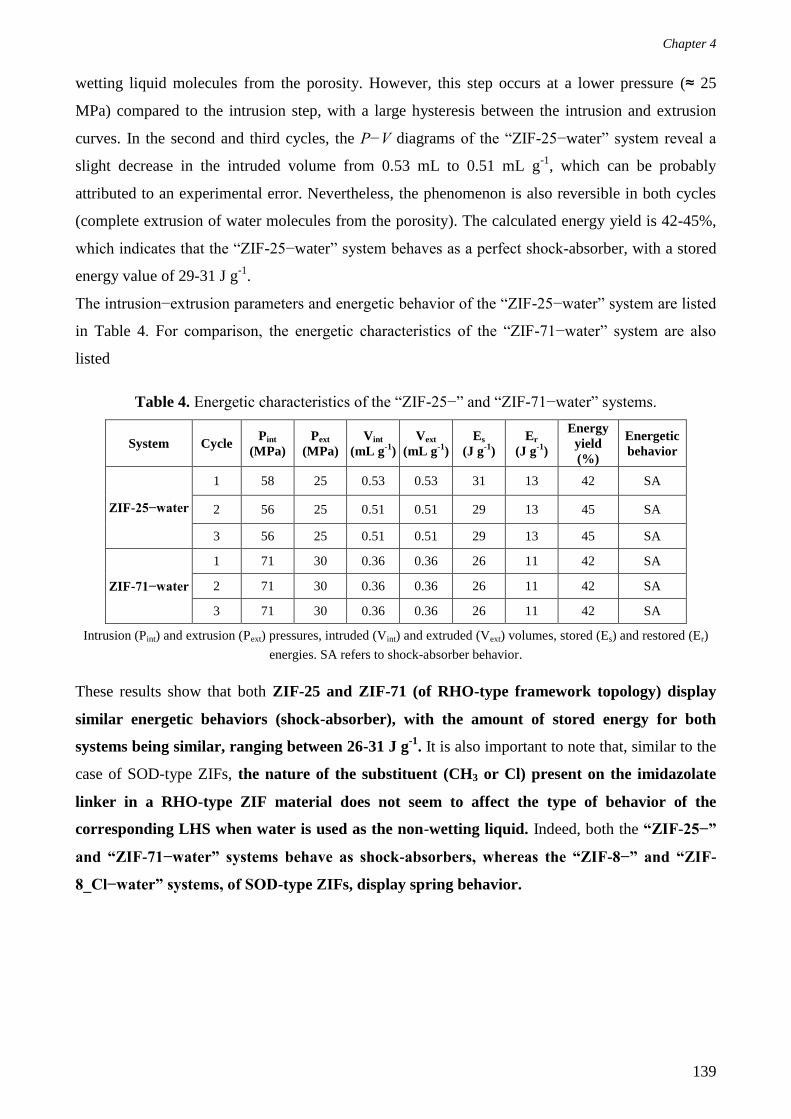
Chapter 4
139
wetting liquid molecules from the porosity. However, this step occurs at a lower pressure (≈ 25
MPa) compared to the intrusion step, with a large hysteresis between the intrusion and extrusion
curves. In the second and third cycles, the P−V diagrams of the “ZIF-25−water” system reveal a
slight decrease in the intruded volume from 0.53 mL to 0.51 mL g-1
, which can be probably
attributed to an experimental error. Nevertheless, the phenomenon is also reversible in both cycles
(complete extrusion of water molecules from the porosity). The calculated energy yield is 42-45%,
which indicates that the “ZIF-25−water” system behaves as a perfect shock-absorber, with a stored
energy value of 29-31 J g-1
.
The intrusion−extrusion parameters and energetic behavior of the “ZIF-25−water” system are listed
in Table 4. For comparison, the energetic characteristics of the “ZIF-71−water” system are also
listed
Table 4. Energetic characteristics of the “ZIF-25−” and “ZIF-71−water” systems.
System Cycle Pint
(MPa)
Pext
(MPa)
Vint
(mL g-1
)
Vext
(mL g-1
)
Es
(J g-1
)
Er
(J g-1
)
Energy
yield
(%)
Energetic
behavior
ZIF-25−water
1 58 25 0.53 0.53 31 13 42 SA
2 56 25 0.51 0.51 29 13 45 SA
3 56 25 0.51 0.51 29 13 45 SA
ZIF-71−water
1 71 30 0.36 0.36 26 11 42 SA
2 71 30 0.36 0.36 26 11 42 SA
3 71 30 0.36 0.36 26 11 42 SA
Intrusion (Pint) and extrusion (Pext) pressures, intruded (Vint) and extruded (Vext) volumes, stored (Es) and restored (Er)
energies. SA refers to shock-absorber behavior.
These results show that both ZIF-25 and ZIF-71 (of RHO-type framework topology) display
similar energetic behaviors (shock-absorber), with the amount of stored energy for both
systems being similar, ranging between 26-31 J g-1
. It is also important to note that, similar to the
case of SOD-type ZIFs, the nature of the substituent (CH3 or Cl) present on the imidazolate
linker in a RHO-type ZIF material does not seem to affect the type of behavior of the
corresponding LHS when water is used as the non-wetting liquid. Indeed, both the “ZIF-25−”
and “ZIF-71−water” systems behave as shock-absorbers, whereas the “ZIF-8−” and “ZIF-
8_Cl−water” systems, of SOD-type ZIFs, display spring behavior.

Chapter 4
140
b. Post-Intrusion Characterizations
The recovered post-intruded ZIF-25 sample was analyzed with XRD and N2 sorption analyses.
Figure 10 reveals that the ZIF-25 structure is retained after the water intrusion−extrusion
experiment, as the XRD patterns of the parent (Sample 9) and post-intruded ZIF-25 samples are
similar.
Figure 10. XRD patterns of the (a) parent (Sample 9) and (b) post-intruded ZIF-25 materials.
However, N2 adsorption-desorption measurements show a small decrease in the textural properties
of ZIF-25 after water intrusion compared to the parent material (Figure 11). The BET surface area
(determined in the 0.00206 - 0.00689 p/p0 range) and microporous volume decrease from 949 to
846 m2 g
-1 and from 0.55 to 0.48 cm
3 g
-1 (13% decrease), respectively, which can be probably
attributed to a partial degradation of the framework under the combined effect of high pressure and
the non-wetting liquid during intrusion−extrusion experiments. The effect of pressure on the partial
degradation of the ZIF-25 framework is planned to be verified by carrying out a supplementary
intrusion−extrusion experiment, up to a lower pressure, i.e. 100 MPa.

Chapter 4
141
Figure 11. N2 adsorption-desorption isotherms of the parent (Sample 9) and the post-intruded ZIF-
25 materials. Filled and empty symbols correspond to the adsorption and desorption branches,
respectively.
5. Conclusions
After following different synthesis routes and varying several process and compositional
parameters, the synthesis of ZIF-25 was successfully optimized by employing acetic acid as a
modulator. The acetic acid synthesis route leads to the formation of highly crystalline ZIF-25
material in a yield of 36% and with a mass that is sufficient for intrusion−extrusion experiments.
The obtained product also exhibits relatively high porosity (0.55 cm3 g
-1), thermal stability (up to
300°C), and hydrophobicity. Furthermore, microcrystalline ZIF-25 particles are obtained, which
should theoretically exhibit less defects compared to nanocrystals and are, thus, more desired in
intrusion−extrusion experiments. It is also important to note that herein, the structure of ZIF-25 is
refined through Rietveld refinement and fully reported for the first time in Pm-3m space group. The
novelty of this work is also attributed to the study of ZIF-25 in water intrusion−extrusion
experiments for the first time, whereby the “ZIF-25−water” system, similar to the “ZIF-71−water”
system, displays perfect shock-absorber behavior, with a stored energy value close to 30 J g-1
.
Nevertheless, the intrusion pressure is lower in the case of ZIF-25 compared to the ZIF-71−water”
system, which could not be attributed to the flexibility of the former material.

Chapter 4
142
It also appears that, similar to the case of SOD-type ZIFs, the nature of the substituent present on
the imidazolate linker (considering CH3 and Cl) in a RHO-type ZIF material does not influence the
energetic behavior of the corresponding LHS when water is used as the non-wetting liquid. In
contrast, the energetic behavior seems to be affected by the topology as shock-absorber behavior is
observed for both the “ZIF-25−” and “ZIF-71−water” systems, based on RHO-type ZIFs, whereas
both the “ZIF-8−” and “ZIF-8_Cl−water” systems, based on SOD-type ZIF materials, display
spring behavior. Moreover, post-intrusion characterizations reveal only a partial degradation of the
framework (based on N2 sorption measurements) during intrusion−extrusion experiments, which is
probably due to the combined effect of water and high pressure. We note that as a future
perspective, a supplementary water intrusion−extrusion experiment up to a maximum pressure of
100 MPa has to be undertaken, so as to verify the effect of pressure on the partial degradation of the
ZIF-25 framework. Finally, the energetic performance of ZIF-25 using LiCl 20 M aqueous solution
is to-be investigated, so as to compare the ZIF-25-based system’s behavior to that of the “ZIF-
71−LiCl 20 M aqueous solution” system.
B. ZIF-71_Br2
In this work, we also intended to synthesize a new bromated and isoreticular analogue of ZIF-71
material of formula Zn(dcim)2,13
exceptionally denoted in the following sections as ZIF-71_Cl2 (in
order to avoid any confusion), so as to investigate its energetic performances in water and LiCl 20
M aqueous solution intrusion−extrusion experiments. This targeted ZIF material is expected to be
constituted of Zn cations bridged through 4,5-dibromoimidazolate (dbim) ions and is referred to
herein as ZIF-71_Br2. Indeed, being isoreticular to ZIF-71 (ZIF-71_Cl2) and ZIF-25, ZIF-71_Br2
should also exhibit an RHO framework-type topology. In the following sections, we present the
different synthesis protocols and the associated process and compositional parameters that were
varied in the aim of obtaining a pure phase ZIF-71_Br2 material. Nevertheless, XRD analyses
revealed that the product of the syntheses was always a mixture of the targeted RHO phase and
another unknown phase, which will be referred to in the following sections as phase Y, where the
latter’s abundance varies with the syntheses conditions.
1. Synthesis of ZIF-71_Br2
a. Effect of the Synthesis Duration
In the first approach towards obtaining ZIF-71_Br2, Samples 13 and 14 were synthesized by
mimicking the synthesis conditions of ZIF-71_Cl2 15
i.e. the metal and organic precursors; zinc
acetate and Hdbim, respectively, were dissolved in MeOH, unlike the ZIF-71_Cl2 protocol, which
involves preparing two separate solutions; a metal and an organic precursor solution, after which

Chapter 4
143
the former solution is added to the latter. Similar to the case of ZIF-71_Cl2, the final molar
composition of the reaction mixture was: 1 Zn: 4 organic precursor: 1854 MeOH. The reaction
mixture was then left to stand at room temperature until the formation of a precipitate. The
corresponding synthesis conditions are further detailed in Table 5. Based on our frequent
observation of the reaction medium, precipitation first occurred after 9 d (Sample 13), that is, after
a significant longer duration compared to ZIF-71_Cl2. Nevertheless, we extended the synthesis
duration for the second sample (Sample 14) to 11 d. Both samples were recovered by Büchner
filtration over a Whatman 5 filter paper, washed with a few milliliters of fresh MeOH, and then left
to dry in air. The obtained white powders were analyzed with XRD and the experimental patterns
were compared to the theoretical XRD pattern of ZIF-71_Br2 (Figure 12). The latter was simulated
from the crystal structure of ZIF-71_Cl2, by substituting the chlorine atoms with bromine. For both
Samples 13 and 14, XRD analysis reveals the formation of ZIF-71_Br2 of RHO topology.
However, the presence of an extra peak at 5.5° in 2 (Figure 12) that cannot be indexed in the RHO
phase indicates the formation of another unknown phase, denoted herein as phase Y. Table 6
displays the lattice parameters of Samples 13 and 14 obtained from the refinement of the
corresponding PXRD patterns using the Pm-3m space group. In order to estimate the evolution of
phase Y with the synthesis duration, for each sample, the areas A1 and A2 under the peaks centered
around 4.3 and 5.5° in 2, corresponding to the RHO and Y phases, respectively, were determined
(by using the integrate function of Origin software in the 3.28 - 4.76° and 4.96 - 5.84° in 2θ ranges
of the corresponding XRD patterns, respectively). Preferential orientation can be excluded owing to
the Debye-Scherrer mode used for the registering of XRD patterns as well as the supposed cubic
system of ZIF-71_Br2 and phase Y structures. The ratios of A2 / A1 were then calculated and the
corresponding values are represented in Figure 15 and Table 5. The obtained results reveal a
decrease in the A2 / A1 ratio with the decrease in the synthesis duration. Indeed, the lower the A2 /
A1 ratio, the less prominent is phase Y with respect to the ZIF-71_Br2 phase.

Chapter 4
144
Table 5. Synthesis conditions of the ZIF-71_Br2 samples.
A2 /
A1
rati
o
-
0.1
11
0.2
47
-
0.0
79
0.0
20
0.0
02
0.2
88
0.0
55
0.0
06
1.0
05
1.7
60
0.0
98
Ex
per
imen
tal
pse
ud
o
yie
ld (
%)
94
58
73
63
77
59
56
48
59
81
17
40
45
Ex
per
imen
tal
ma
ss
(mg
)
10
22
12
1
15
1
58
70
53
50
44
54
75
16
37
41
Asp
ect
Pal
e p
ink
po
wd
er
Wh
ite
po
wd
er
Wh
ite
po
wd
er
Wh
ite
po
wd
er
Wh
ite
po
wd
er
Wh
ite
po
wd
er
Wh
ite
po
wd
er
Wh
ite
po
wd
er
Wh
ite
po
wd
er
Wh
ite
po
wd
er
Wh
ite
po
wd
er
Wh
ite
po
wd
er
Wh
ite
po
wd
er
Du
rati
on
(d)
1
9
11
1
4.7
4.7
4.7
3.8
3.8
2.7
4.7
4.7
4.7
Zn
: li
nk
er:
MeO
H:
HC
OO
Na
mo
lar
rati
o
1:4
: 1
85
2:
0
1:4
: 1
85
2:
0
1:4
: 1
85
2:
0
1:4
: 3
00
: 0
1:4
: 3
00
: 0
1:4
: 3
00
: 4
1:4
: 3
00
:8
1:4
: 3
00
: 4
1:4
: 3
00
:8
1:4
: 3
00
:8
1:4
: 3
00
: 4
1:4
: 3
00
: 4
1:4
: 3
00
: 4
Sa
mp
le
ZIF
-71
_C
l 2
acco
rdin
g t
o
ref
15
13
14
15
16
17
18
19
20
21
22
23
24
For comparison, the synthesis conditions of ZIF-71_Cl2 are also recalled in the first line. A1 and A2 values were
determined by using the integrate function of Origin software in the 3.28 - 4.76° and 4.96 - 5.84° ranges of the
corresponding XRD patterns, respectively. Note that the term “pseudo yield” is used in the table, as the obtained
products in all cases are not pure (ex: ZIF-71_Br2 + phase Y).

Chapter 4
145
Figure 12. (a) Theoretical XRD pattern of ZIF-71_Br2 and XRD patterns of Samples (b) 13 and (c)
14. * denotes the extra peak corresponding to phase Y.
Table 6. Lattice parameters of Samples 13 and 14 obtained from the refinement of the
corresponding PXRD patterns.
Sample Crystal system a (Å) V (Å3) Space group
Figures of merit
F(30)
13 cubic 28.55(4) 23280.4(542) Pm-3m 11.5
14 cubic 28.50(4) 23139.1(621) Pm-3m 11.1
The extra peak at 5.5° is not taken into account when indexing.
Interestingly also, SEM images of both samples clearly show a mixture of two types of particles;
dodecahedral microcrystals of 5-8 µm in size, which constitute the majority of the particles and
probably correspond to ZIF-71_Br2, in addition to larger crystals of a very-well defined shape and a
particle size reaching up to 50 µm, which may be associated to the phase Y (Figure 13).

Chapter 4
146
Figure 13. SEM images of Samples (a) 13 and (b) 14.
Based on these results, the optimization of the synthesis of ZIF-71_Br2 was necessary in order to
obtain a pure RHO-phase material, however, in a shortened duration. Therefore, in the second
approach, we study the effect of increasing the concentrations of the metal and organic precursors
on the rate of precipitation and purity of the targeted product.
b. Effect of the Concentration of the Precursors
The concentrations of the metal and organic precursors in the reaction mediums of Samples 15 and
16 were increased by around 6 times with respect to those of Samples 13 and 14, while maintaining
the Hdbim / anhydrous zinc acetate molar ratio in all cases (Table 5). Based on frequent
observations of the reaction medium, the formation of a precipitate was first indicated after 1.1 d for
Sample 15. However, according to the XRD analysis, the obtained product is mostly amorphous
(Figure 14). Thus, we increased the synthesis duration for Sample 16 to 4.7 d, which, based on
XRD analysis is enough to obtain a highly crystalline material (Figure 14). Nonetheless, similar to
Samples 13 and 14, the PXRD pattern of Sample 16 also reveals an extra peak at 5.5° in 2,
thereby, indicating the formation of phase Y during the synthesis. Interestingly, however, Figure 15
and Table 5 show that the A2 / A1 ratio decreases with respect to Sample 14 (from 0.247 to 0.079
for Samples 14 and 16, respectively). Therefore, by increasing the concentration of the reaction
medium, it was possible to decrease the synthesis duration, while enhancing the selectivity towards
the targeted product with respect to the previously synthesized samples (Samples 13 and 14).
a) b)

Chapter 4
147
Figure 14. (a) Theoretical XRD pattern of ZIF-71_Br2, XRD patterns of Samples (b) 15 and (c) 16.
* denotes the extra peak corresponding to phase Y.

Chapter 4
148
Figure 15. Variation of the A2 / A1 ratio as a function of the synthesis duration. The samples’
numbers are indicated next to the symbols.
By referring to the results obtained for Samples 13-16, it may be concluded that: i) the shorter the
synthesis duration, the less prominent is phase Y, as long as the duration is sufficient for the
crystallization of the product, ii) the high concentrations of the metal and organic precursors
seem to enhance the selectivity towards ZIF-71_Br2.
In the quest of obtaining pure material, we attempted, in another approach, to increase the rate of
formation of the product by employing an additive in the synthesis of ZIF-71_Br2.
c. Effect of an Additive
In the syntheses of MOFs, employing a base allows/facilitates the deprotonation of the linker
(especially in room-temperature syntheses, where amide-based solvents such as DMF and DEF
cannot be thermally decomposed to yield amines as weak bases to deprotonate the linker).16
Consequently, the kinetics of the reaction is enhanced by promoting nucleation and, thus,
accelerating the crystal formation. The use of additives leads to higher yields. However, smaller
crystals (nanocrystals) may be expected following this strategy, as the base favors nucleation over
crystal growth.17-18

Chapter 4
149
Herein, and as mentioned in Section II. B. 1. b., the aim is to increase the rate of formation of the
product, as this parameter seems to be related to the final product’s purity (i.e. the formation of pure
RHO phase). In other words, the target is to enhance the kinetics of the reaction, as ZIF-71_Br2
may be considered as the kinetic product, whereas phase Y may be the thermodynamic
product that becomes more prominent with the increase in the synthesis duration. Therefore,
an additive-assisted protocol for the synthesis of ZIF-71_Br2 was followed, by employing sodium
formate (HCOONa). Various syntheses were carried out, using 4 and 8 molar equivalents of
HCOONa, while keeping the same concentrations of organic and metal precursors. The synthesis
duration was fixed at 4.7 d (Samples 17 and 18), similar to the case of Sample 16. The XRD
analysis reveals the formation of ZIF-71_Br2 (Figure 16A), along with a decrease in the A2 / A1
ratio with the addition of HCOONa to the reaction medium (Samples 17 and 18). This ratio
decreases to almost zero with 8 molar equivalents of the additive, as shown for Sample 18 (Figure
21 and Table 5). However, an additional peak of low relative intensity appears on the XRD pattern
at 44° in 2, which is not assignable to HCOONa (Figure 16B). Our assumption of the absence of
HCOONa in Sample 18 is attributed to the fact that the high-relative-intensity peaks corresponding
to the base do not exist in the sample’s experimentally obtained XRD pattern (Figure 16B).
A)

Chapter 4
150
Figure 16. (A) (a) Theoretical XRD pattern of ZIF-71_Br2, XRD patterns of Samples (b) 17 and (c)
18, (d) experimentally XRD pattern of sodium formate. For comparison, (e) XRD pattern of Sample
16 is recalled. * denotes the extra peak corresponding to phase Y. (B) A closer view of the XRD
patterns of Sample (c) 18 and (d) sodium formate in the 40-50° in 2θ range. Indicates the
additional and unidentified peak. The number noted next to HCOONa indicates the corresponding
number of molar equivalents of the additive (ex: HCOONa 4 corresponds to four molar equivalents
of HCOONa).
SEM analyses were carried out on Samples 17 and 18. For both samples, the pictures depicted in
Figure 17 show the presence of dodecahedral crystals of an average size of 2 µm, in addition to the
larger crystals that were previously observed for Samples 13 and 14 and assigned to phase Y.
However, in the case of Samples 17 and 18, the number of these crystals seems to be less
prominent than in the previous cases.
B)

Chapter 4
151
Figure 17. SEM images of Samples (a) 17 and (b) 18.
Samples 17 and 18 were also analyzed with N2 adsorption-desorption measurements. The obtained
N2 sorption isotherms display a type I profile that is characteristic of microporous materials (Figure
18). Based on the experimental isotherms, the BET surface areas were determined to be 602 and
558 m2 g
-1 (in the 0.00122 - 0.00620 p/p
0 range), whereas the microporous volumes ranged between
0.26 and 0.24 cm3 g
-1 for Samples 17 and 18, respectively.
Figure 18. N2 adsorption-desorption isotherm of Samples 17 and 18. Filled and empty symbols
refer to the adsorption and desorption branches, respectively. The number noted next HCOONa
indicates the corresponding number of molar equivalents of the additive (ex: HCOONa 4
corresponds to four molar equivalents of HCOONa).
a) b)

Chapter 4
152
The experimentally obtained value of the microporous volume is in agreement with the theoretical
value (0.26 cm3 g
-1). The latter was calculated by referring to the microporous volumes of both ZIF-
71_Cl2 and ZIF-25 as follows: by multiplying the microporous volume of ZIF-71_Cl2 or ZIF-25
(0.41 and 0.54 cm3 g
-1, respectively) by the corresponding molar mass (337.302 and 255.630 g mol
-
1, respectively), the quantity of adsorbed molecular nitrogen can be determined in cm
3 mol
-1. Then,
the obtained value is divided by the molar mass of ZIF-71_Br2 (515.103 g mol-1
), which finally
leads to the theoretical microporous volume of ZIF-71_Br2 (around 0.26 cm3 g
-1 or 165 cm
3 g
-1
STP).
Therefore, for Samples 17 and 18, N2 sorption analyses, in addition to the XRD analyses, confirm
the formation of ZIF-71_Br2 and the porosity of the material, in spite of the presence of, probably,
traces of phase Y, as could be indicated from XRD and SEM analyses. The slightly lower textural
properties of Sample 18 (558 m2 g
-1 and 0.24 cm
3 g
-1 for the BET surface area and microporous
volume, respectively) compared to Sample 17 (602 m2 g
-1 and 0.26 cm
3 g
-1 for the BET surface
area and microporous volume, respectively) may be attributed to the third phase detected from XRD
analysis by the peak at 44° in 2θ.
TGA performed on Sample 17, after N2 adsorption-desorption measurements, revealed that the ZIF
material is thermally stable up to 300°C (Figure 19), thus, indicating the absence of solvent and
organic precursor molecules in the porosity On the TG curve, a main decomposition step is
observed between 300-540°C, with a global mass loss of 89 %, indicating the degradation of the
organic framework. This value is higher than the calculated mass loss contributing to the
degradation of the organic network (84 %). This trend appears to be common in the case of
halogenated ZIFs, i.e. where the organic linker possesses one or more halogens as substituents.19
Typical examples of ZIFs displaying a similar phenomenon include ZIF-71_Cl2,1 ZIF-8_Cl, and
ZIF-8_Br.3 It is also worthy to note that the absence of a mass loss between room temperature and
200°C reveals that the ZIF pores are liberated. Nevertheless, in order to confirm the hydrophobic
character of ZIF-71_Br2, water adsorption-desorption measurements are required.

Chapter 4
153
Figure 19. TG curve of Sample 17.
In another approach towards further optimizing the synthesis of ZIF-71_Br2, we aimed at
decreasing the synthesis duration. Among all the prepared samples, Samples 17 and 18 (obtained
using HCOONa as an additive) have shown the lowest A2 / A1 ratios (Table 5). Therefore, the new
synthesis protocols were inspired by those of the two latter samples, however, by only decreasing
the synthesis duration. Table 5 presents the synthesis conditions for Sample 19, synthesized using 4
molar equivalents of HCOONa (inspired by Sample 17), with the synthesis duration decreased to
3.8 d. As for Samples 20 and 21 (inspired by Sample 18), obtained by employing 8 molar
equivalents of the additive, the synthesis duration was decreased to 3.8 and 2.7 d, respectively.
Figure 20 demonstrates the XRD patterns of Samples 19, 20, and 21.

Chapter 4
154
Figure 20. (a) Theoretical XRD pattern of ZIF-71_Br2, XRD patterns of Samples (b) 19, (c) 20, and
(d) 21. * denotes the extra peak corresponding to phase Y. The number noted next to HCOONa
indicates the corresponding number of molar equivalents of the additive (ex: HCOONa 4
corresponds to four molar equivalents of HCOONa).
Surprisingly, PXRD analyses reveal unexpected results. It seems that regardless of the number of
molar equivalents of the additive used, decreasing the synthesis duration increases back the A2 / A1
ratio for a given number of HCOONa molar equivalents, as shown in Table 5 and Figure 21.

Chapter 4
155
Figure 21. Variation of the A2 / A1 ratio as a function of the synthesis duration. The samples’
numbers are indicated next to the symbols.
These results disagree with our hypothesis on the probability of ZIF-71_Br2 and phase Y
being the kinetic and thermodynamic products, respectively. As if it were the case, then the A2 /
A1 ratio should decrease with the decrease in the synthesis duration.
Based on these results, it was decided to go no further with the optimization of the ZIF-71_Br2
synthesis and to follow, instead, the protocol used to synthesize Sample 17. Even though Sample
17 (synthesized by employing only 4 molar equivalents of HCOONa) exhibits an A2 / A1 ratio that
is higher than that exhibited by Sample 18 (synthesized by employing 8 molar equivalents of
HCOONa), nevertheless, the latter seems to include more impurities compared to Sample 17 that
are indicated by the presence of the extra peak at 44° in 2θ and a lower microporous volume.
Therefore, it was first necessary to check the reproducibility of this synthesis protocol. In this
respect, three separate syntheses were carried out, yielding Samples 22, 23, and 24 (Table 5). The
corresponding XRD patterns are displayed in Figure 22, whereas Table 5 and Figure 21 represent
the A2 / A1 ratios. Surprisingly also, the values obtained from peak integration reveal the
irreproducibility of the synthesis, with the A2 / A1 ratios being different and all higher than the value
obtained for Sample 17 (Figure 21).

Chapter 4
156
Figure 22. (a) Theoretical XRD pattern of ZIF-71_Br2, XRD patterns of Samples (b) 22, (c) 23, (d)
24. For comparison, the XRD pattern of (e) Sample 17 is recalled. * denotes the extra peak
corresponding to phase Y. The number noted next to HCOONa indicates the corresponding number
of molar equivalents of the additive (ex: HCOONa 4 corresponds to four molar equivalents of
HCOONa).
Therefore, to this moment, the preparation of pure ZIF-71_Br2 has not yet been achieved. Another
strategy that may be followed to synthesize ZIF-71_Br2 of RHO topology, can be through the
solvent-assisted ligand exchange process (SALE)19
that has been previously employed in the
synthesis of Zn(dcim)2 of SOD topology (a polymorph of ZIF-71_Cl2).19-20
In this case, RHO-type
ZIF-71_Cl2 crystals can be used as the templates and suspended in a solution with 4,5-
dibromoimidazole. The SALE route may be considered as one of our future perspectives in the aim
of obtaining pure phase ZIF-71_Br2 material.
2. Conclusions
The synthesis of ZIF-71_Br2 of RHO framework-type topology has never been reported in the
literature prior to this work. Herein, we intended to synthesize this latter material and to investigate
its energetic performances in high-pressure intrusion−extrusion experiments using water and LiCl
20 M aqueous solution as non-wetting liquids. In this aim, several synthesis parameters were varied

Chapter 4
157
(concentration of the reactants, synthesis duration, and use of additives). Even though, based on
XRD and N2 sorption analyses, ZIF-71_Br2 was obtained, however, the product was not pure and a
mixture of the ZIF material and another unknown phase, referred to as phase Y, was obtained in all
cases. Furthermore, according to XRD analyses, the ratio of the latter phase to ZIF-71_Br2 (A2 / A1)
does not follow a linear trend and is difficult to control. In addition, the synthesis yielding one of
the lowest A2 / A1 ratios (0.020) is not reproducible, which represents another limitation to the
synthesis of the target ZIF material. Finally, one possible route for the synthesis of a pure phase
RHO-type ZIF-71_Br2 material may be the SALE process, which can be considered as one of our
team’s perspectives. In addition, another perspective is the identification of the phase Y. As for
water and LiCl 20 M aqueous solution intrusion−extrusion experiments, they are intended to be
carried out on the optimized ZIF-71_Br2 sample, once obtained.
C. Conclusions
In Section II of this chapter, the syntheses of two RHO-type ZIF materials; ZIF-25 and ZIF-71_Br2,
were intended to be optimized for energetic applications. After numerous trials, whereby several
synthesis parameters were varied, ZIF-25 was successfully obtained using acetic acid as a
modulator. The optimized protocol leads to the formation of a pure-phase microcrystalline ZIF-25
material, which exhibits high porosity and hydrophobicity. Furthermore, the structure of ZIF-25
was resolved through Rietveld refinement and fully reported for the first time in the Pm-3m space
group. The optimized ZIF-25 sample was also studied in high-pressure water intrusion‒extrusion
experiments, whereby the corresponding LHS shows perfect shock-absorber behavior. It is
important to note that both the “ZIF-25‒” and “ZIF-71‒water” systems display similar energetic
behaviors (perfect shock-absorber), with the amount of stored energy ranging between 26-30 J g-1
.
This indicates the absence of the effect of the substitution on the imidazolate linker (in the case of
Cl atoms or CH3 groups) on the energetic behavior of RHO-type-ZIF-based LHSs during water
intrusion‒extrusion experiments, which is also the case for the SOD-type ZIFs (as both the “ZIF-
8‒” and “ZIF-8_Cl‒water” systems display spring behavior). However, this effect has to be studied
during LiCl 20 M aqueous solution intrusion‒extrusion experiments in ZIF-25, so as to compare the
obtained results to those corresponding to the “ZIF-71‒LiCl 20 M aqueous solution” system. On
another note, the water intrusion pressure is lower in the case of ZIF-25 compared to ZIF-71 (58
compared to 71 MPa, for the ZIF-25- and -71-based LHSs, respectively), which could not be
attributed to an enhanced flexibility of the former material. As for the ZIF-71_Br2 material,
regardless of the various synthesis trials that have been carried out, while modifying several process
and compositional parameters, the obtained product is still impure not completely pure and consists
of a mixture of the RHO phase and another unknown phase Y. Moreover, even for one of the most

Chapter 4
158
promising samples (with a low phase Y/ZIF-71_Br2 ratio, i. e. 0.02), the synthesis is irreproducible.
Therefore, further optimization of the synthesis conditions is required in the aim of obtaining a
pure-RHO phase material. To this end, one possibility may be the SALE route. Indeed, similar to
ZIF-25, the optimized ZIF-71_Br2 material is intended to be employed in high-pressure
intrusion‒extrusion experiments of water and LiCl 20 M aqueous solution.

Chapter 4
159
III. Conclusions
In this chapter, the energetic performances of four RHO-type ZIF materials; MAF-6, ZIF-71, ZIF-
25, and ZIF-71_Br2, were intended to be investigated in high-pressure intrusion‒extrusion
experiments of water and LiCl 20 M aqueous solution. The work aimed at exploring the effect of
both the topology of the ZIF material and the substitution on the imidazolate linker (Cl or Br atoms,
as well as methyl or ethyl groups) on the energetic behaviors of LHSs. The first part of this study
involved MAF-6 and ZIF-71, which both display mainly bumper behaviors due to the intrusion
phenomena that are associated with irreversible crystal phase transformations during LiCl 20 M
aqueous solution intrusion‒extrusion experiments. For instance, ZIF-71 (RHO) is transformed into
ZIF-72; one of the former’s dense polymorphs of lcs topology, while MAF-6 undergoes a partial
hydrolysis-condensation process, which results in the formation of a new pseudo-polymorph,
referred to as phase X. A similar partial phase transformation into phase X, but to a higher extent
compared to the case of the LiCl 20 M aqueous solution, is also highlighted for the “MAF-6−water”
system. This system displays a mixture of shock-absorber and bumper behaviors. In all cases, the
phase transformation is assigned to the combined effect of the high pressure and non-wetting liquid.
It is also important to note that the structure of phase X has not yet been determined, due to the
difficulty of obtaining it in a pure phase, nevertheless, it is proven to be a crystalline and nonporous
phase, with a spherical-like morphology. As for ZIF-71, it displays perfect shock absorber behavior
with water. On another note, after numerous trials, the synthesis of ZIF-25 was successfully
optimized using acetic acid as a modulator. The optimized sample exhibits high phase purity,
crystallinity, and porosity, in addition to a hydrophobic character. Furthermore, similar to ZIF-71,
ZIF-25 also displays shock-absorber behavior during water intrusion‒extrusion experiments, with
an amount of stored energy ranging between 26-30 J g-1
. Nevertheless, the “ZIF-25‒water” system
exhibits a lower intrusion pressure compared to the “ZIF-71‒water” system, which does not appear
to be due to a more pronounced flexibility of ZIF-25. Therefore, it seems that the topology of the
ZIF material possesses a more prominent effect compared to the functionalization (when Cl
and CH3 substituents are considered) on the energetic behavior of the LHS system during
water intrusion‒extrusion experiments, which may explain the spring behavior displayed in the
case of the SOD-type ZIFs, compared to a shock-absorber behavior for the RHO-type materials.
Nevertheless, the effects of the ZIF topology and the substitution on the imidazolate linker still need
to be investigated using LiCl 20 M aqueous solution. Finally, despite numerous synthesis trials that
involved varying several process and compositional parameters, the synthesis of ZIF-71_Br2 still
needs to be optimized so as to obtain a pure RHO-phase material for applications in water and
aqueous solution intrusion−extrusion experiments. The main obstacles facing the synthesis of ZIF-

Chapter 4
160
71_Br2 are the impurity of the final product, due to the presence of another unknown phase that is
referred to as phase Y, and the irreproducibility of the syntheses. In this respect, the SALE process
may be an alternative route for the synthesis of a pure phase RHO-type ZIF-71_Br2 material. In
addition, other perspectives concern the identification of phases X and Y.
In order to complete these intermediate results evidencing a more pronounced impact of the
topology compared to the functionalization of the linker on the energetic behaviors of LHSs,
Chapter 5 includes different prospective studies aiming to enlarge the fields of investigation based
on these two parameters. For example, the synthesis and characterization of ZIFs with new
topologies such as LTA, displaying the same types of membered-ring pore apertures (4-, 6- and 8-
membered rings) as the RHO type, as well as AFI and CAN, with larger cage apertures
(including12-membered rings) will be addressed. The attempts to elaborate a ZIF from a NO2-
funtionnalized linker will be also described.

Chapter 4
161
References
1. Ortiz, G.; Nouali, H.; Marichal, C.; Chaplais, G.; Patarin, J., Energetic Performances of "ZIF-71-
Aqueous Solution" Systems: A Perfect Shock-Absorber with Water. J. Phys. Chem. C 2014, 118,
21316-21322.
2. Ortiz, G.; Nouali, H.; Marichal, C.; Chaplais, G.; Patarin, J., Energetic Performances of the
Metal–Organic Framework ZIF-8 Obtained Using High Pressure Water Intrusion–Extrusion
Experiments. Phys. Chem. Chem. Phys. 2013, 15, 4888-4891.
3. Mortada, B.; Chaplais, G.; Veremeienko, V.; Nouali, H.; Marichal, C.; Patarin, J., Energetic
Performances of ZIF-8 Derivatives: Impact of the Substitution (Me, Cl, or Br) on Imidazolate
Linker. J. Phys. Chem. C 2018, 122, 3846-3855.
4. Morris, W.; Leung, B.; Furukawa, H.; Yaghi, O. K.; He, N.; Hayashi, H.; Houndonougbo, Y.;
Asta, M.; Laird, B. B.; Yaghi, O. M., A Combined Experimental-Computational Investigation of
Carbon Dioxide Capture in a Series of Isoreticular Zeolitic Imidazolate Frameworks. J. Am. Chem.
Soc. 2010, 132, 11006-11008.
5. Gao, M.; Wang, J.; Rong, Z.; Shi, Q.; Dong, J., A Combined Experimental-Computational
Investigation on Water Adsorption in Various ZIFs with the SOD and RHO Topologies. RSC Adv.
2018, 8, 39627-39634.
6. He, C.-T.; Jiang, L.; Ye, Z.-M.; Krishna, R.; Zhong, Z.-S.; Liao, P.-Q.; Xu, J.; Ouyang, G.;
Zhang, J.-P.; Chen, X.-M., Exceptional Hydrophobicity of a Large-Pore Metal-Organic Zeolite. J.
Am. Chem. Soc. 2015, 137, 7217-7223.
7. Mortada, B.; Chaplais, G.; Nouali, H.; Marichal, C.; Patarin, J., Phase Transformations of Metal-
Organic Frameworks MAF-6 and ZIF-71 during Intrusion-Extrusion Experiments. J. Phys. Chem. C
2019, 123, 4319-4328.
8. Zhang, H.; Zhao, M.; Yang, Y.; Lin, Y. S., Hydrolysis and Condensation of ZIF-8 in Water.
Microporous Mesoporous Mater. 2019, 288, 109568.
9. Khay, I.; Chaplais, G.; Nouali, H.; Marichal, C.; Patarin, J., Water Intrusion-Extrusion
Experiments in ZIF-8: Impacts of the Shape and Particle Size on the Energetic Performances. RSC
Adv. 2015, 5, 31514-31518.

Chapter 4
162
10. McGuire, C. V.; Forgan, R. S., The Surface Chemistry of Metal-Organic Frameworks. Chem.
Commun. 2015, 51, 5199-5217.
11. Schaate, A.; Roy, P.; Godt, A.; Lippke, J.; Waltz, F.; Wiebcke, M.; Behrens, P., Modulated
Synthesis of Zr-Based Metal-Organic Frameworks: From Nano to Single Crystals. Chem. - Eur. J.
2011, 17, 6643-6651.
12. Rietveld, H. M., Profile Refinement Method for Nuclear and Magnetic Structures. J. Appl.
Crystallogr. 1969, 2, 65-71.
13. Banerjee, R.; Phan, A.; Wang, B.; Knobler, C.; Furukawa, H.; O'Keeffe, M.; Yaghi, O. M.,
High-Throughput Synthesis of Zeolitic Imidazolate Frameworks and Application to CO2 Capture.
Science 2008, 319, 939-943.
14. Toby, B. H.; Von Dreele, R. B., GSAS-II: the Genesis of a Modern Open-Source all Purpose
Crystallography Software Package. J. Appl. Crystallogr. 2013, 46, 544-549.
15. Lively, R. P.; Dose, M. E.; Thompson, J. A.; McCool, B. A.; Chance, R. R.; Koros, W. J.,
Ethanol and Water Adsorption in Methanol-Derived ZIF-71. Chem. Commun. 2011, 47, 8667-
8669.
16. Tian, Y.-Q.; Zhao, Y.-M.; Chen, Z.-X.; Zhang, G.-N.; Weng, L.-H.; Zhao, D.-Y., Design and
Generation of Extended Zeolitic Metal-Organic Frameworks (ZMOFs): Synthesis and Crystal
Structure of zinc(II) Imidazolate Polymers with Zeolitic Frameworks. Chem. - Eur. J. 2007, 13,
4146-4154.
17. Peralta, D.; Chaplais, G.; Simon-Masseron, A.; Barthelet, K.; Pirngruber, G. D., Synthesis and
Adsorption Properties of ZIF-76 Isomorphs. Microporous Mesoporous Mater. 2012, 153, 1-7.
18. Huang, L.; Wang, H.; Chen, J.; Wang, Z.; Sun, J.; Zhao, D.; Yan, Y., Synthesis, Morphology
Control, and Properties of Porous Metal-Organic Coordination Polymers. Microporous Mesoporous
Mater. 2003, 58, 105-114.
19. Schweinefuss, M. E.; Springer, S.; Baburin, I. A.; Hikov, T.; Huber, K.; Leoni, S.; Wiebcke, M.,
Zeolitic Imidazolate Framework-71 Nanocrystals and a Novel SOD-Type Polymorph: Solution
Mediated Phase Transformations, Phase Selection Via Coordination Modulation and a Density
Functional Theory Derived Energy Landscape. Dalton Trans. 2014, 43, 3528-3536.

Chapter 4
163
20. Khay, I.; Chaplais, G.; Nouali, H.; Ortiz, G.; Marichal, C.; Patarin, J., Assessment of the
Energetic Performances of Various ZIFs with SOD or RHO Topology using High Pressure Water
Intrusion-Extrusion Experiments. Dalton Trans. 2016, 45, 4392-4400.

Chapter 4
164

Chapter 5
165
Chapter 5: Highly Porous MOF Materials for
Intrusion−Extrusion Experiments
In our quest for higher stored energy values and, thus, for more accessible porous volumes, two new
highly porous MOFs, namely AFI- and CAN-type ZIFs,1 appear as interesting candidates for high-
pressure intrusion−extrusion experiments. Moreover, it was proven in Chapters 3 and 4, where the
SOD2 and RHO
3 topologies were widely investigated, that the topology of the MOF material
(among other parameters) has a significant impact on the energetic behavior of the LHS in which
the MOF is incorporated. In this respect, herein, new ZIF topologies, such as CAN, AFI, and LTA,
are intended to be investigated in intrusion−extrusion experiments. Notably, the CAN- and AFI-
Zn(im)2 and ZIF-76 materials, displaying CAN, AFI, and LTA topologies, respectively, are
assumed to exhibit a hydrophobic character. Furthermore, we were also interested in investigating
the energetic performances of three highly porous, however, hydrophilic MOFs; NOF-14 (SOD) and
the two mesoporous materials; MIL-101(Cr)5 and the more-recently reported MOF-919(Sc/Cu).
6
Indeed, their hydrophilic character prevents the application of these materials in water or diluted
aqueous electrolyte solutions intrusion−extrusion experiments. Nonetheless, it may be possible to
investigate the energetic behaviors of hydrophilic MOFs using a highly concentrated aqueous
electrolyte solution, such as LiCl 20 M. However, this remains a hypothesis that needs to be
verified through experiments. Another possibility that allows taking advantage of the high porosity
of the mesoporous MIL-101(Cr) and MOF-919(Sc/Cu) materials in intrusion−extrusion
experiments may be through post-synthetic modification (PSM), i.e. by removing the metal-
coordinated water molecules and substituting them for hydrophobic capping agents, as suggested by
Hong et al.7 This route is expected to consequently enable employing the post-synthetically
modified hydrophobic materials to water and aqueous electrolyte solutions intrusion−extrusion
experiments. However, with such mesoporous materials exhibiting also relatively large pore
apertures, it can be wondered whether there is an upper limit for the pore aperture, above which the
intrusion pressure is too low to be observed on P−V diagrams, or the non-wetting liquid
spontaneously enters the pores. Therefore, the aim of this chapter is to perform a preliminary study
in order to broaden the scope of work in the field of energetic applications and open up the door for
future research on various parameters that can control the energetic behaviors and performances of
ZIF-based LHSs. In this regard, all of the above mentioned MOF/ZIF materials were synthesized
and fully characterized, in order to explore their energetic behaviors in intrusion−extrusion
experiments of water and/or LiCl 20 M aqueous solution. It is also important to highlight the

Chapter 5
166
novelty of this work, as the MOFs/ZIFs discussed herein were never explored in
intrusion−extrusion experiments prior to our work.
I. New ZIFs for Intrusion−Extrusion Experiments
A. NOF-1 (SOD)
1. Description
NOF-1 (also known as ZIF-1088) is a ZIF material made up from zinc cations tetrahedrally
coordinated to 2-nitroimidazolate (nim) linkers leading to a 3D porous framework. Similar to ZIF-8
and its derivatives (ZIF-8_Cl and ZIF-8_Br), which we have previously discussed in Chapter 3 of
this manuscript, NOF-1 possesses a SOD framework topology, with sod cages of 5.0 Å in diameter
(determined by N2 sorption analysis using the Horvath-Kawazoe method) delimited by 4- and 6-
membered ring cage apertures as displayed on Scheme 1.
Scheme 1. Representation of the SOD topology of NOF-1. In red, zinc cations. In yellow and green,
the 4- and 6-membered ring pore apertures, respectively.
The presence of nitro groups on the imidazolate linker is expected to render the ZIF material
hydrophilic, which can, indeed, limit its application to water intrusion−extrusion experiments.
However, in such cases, a highly concentrated aqueous electrolyte solution, for example LiCl 20 M,
can be a promising alternative to water. Therefore, herein, we aimed at synthesizing, activating, and
fully characterizing NOF-1 so as to study its energetic behavior using LiCl 20 M aqueous solution
as a non-wetting liquid. Moreover, as NOF-1 displays a SOD topology, the presence of the nitro
group on the imidazolate linker offers the opportunity to complete our study on the effect of the

Chapter 5
167
nature of the substituent present on the imidazolate linker of the ZIF material on the energetic
performance of the related LHS, by comparing the energetic behavior of NOF-1 to those of ZIF-8
and its halogenated derivatives.
2. Synthesis and Activation
NOF-1 was prepared according to the synthesis protocol reported by Diring et al.4 2-nitroimidazole
(Hnim, 113 mg, 1.0 mmol) and sodium formate (HOOCNa, 136 mg, 2.0 mmol) were dissolved in a
DMF/H2O (v/v, 10/1) mixture (5 mL) and a solution (S1) is obtained. Sodium formate is used to
facilitate the deprotonation of the organic source, thus, increasing the nucleation rate.9 A solution
(S2) of Zn(NO3)26H2O (149 mg, 0.5 mmol) in H2O (5 mL) was also prepared and added to S1. The
reaction mixture was then stirred vigorously at room temperature. The reaction mixture became
cloudy within a few minutes after the addition of S1. The starting molar composition was 1.00
Zn(NO3)2: 2.00 Hnim: 4.00 HOOCNa: 612.00 H2O: 117.00 DMF. After 18 h of stirring, the
precipitate was centrifuged and washed with water (2*15 mL) and DMF (3*15 mL) and then dried
in air for 48 h, to yield 70.8 mg of a pale yellow powder that corresponds to the crude material.
According to Diring et al., the activation of NOF-1 involves a solvent-exchange step, whereby the
powder is soaked in fresh MeOH (5*15 mL over 48 h), so as to remove the entrapped water and
DMF molecules, followed by heating at 80 °C under reduced pressure (10 mbar) for 18 h. In our
case, the product was activated by solvent (MeOH) exchange, but we did not go further to heating it
under vacuum.
3. Characterizations
The XRD pattern of the crude material is presented in Figure 1, together with the theoretical pattern
obtained based on the published NOF-1 structural parameters.4 Despite the differences in relative
intensities, presumably due to the presence of guest molecules, the peak positions indicate that the
synthesized material corresponds to NOF-1. Refinement of the experimental XRD data confirms
that the material crystallizes in the cubic symmetry, with a lattice constant a ≈ 17.3 Å and belongs
to the space group I-43m, which is in agreement with the literature.4

Chapter 5
168
Figure 1. (a) Theoretical XRD pattern of NOF-1 and XRD patterns of the (b) as-synthesized and (c)
methanol-activated NOF-1 samples.
The experimentally obtained XRD pattern of the powder recovered after the activation by soaking
in MeOH is also represented in Figure 1. Surprisingly, the presence of additional peaks with respect
to the crude material clearly indicates that NOF-1 is unstable in MeOH and partially loses
crystallinity during the soaking process. The new peaks correspond neither to the organic precursor
molecules nor to NOF-3, where the latter is a 2D nonporous polymorph formed of nim linkers and
Zn2+
ions4. Furthermore, an attempt to heat the activated sample at 70 °C during 2 h (results not
shown) did not allow recovering the NOF-1 structure indicating a presumably irreversible phase
transformation.
Therefore, according to these results, and due to the lack of time required to optimize the activation
step of NOF-1, we decided, at least for the meantime, to stop the work on this material.
Nevertheless, NOF-1 remains an interesting candidate for LiCl 20 M aqueous solution
intrusion−extrusion experiments and in this regard, optimizing the activation process can be
considered as one of our team’s future perspectives.

Chapter 5
169
B. ZIF-76 (LTA)
1. Description
The zinc-based ZIF-76 material of formula; Zn(im)x(cbim)y (where im and cbim stand for
imidazolate and 5-chlorobenzimidazolate, respectively) is one of the few existing ZIF materials that
combine both relatively large pore apertures and pore volumes.10
ZIF-76 has an LTA framework
topology that consists of lta cages, with 4-, 6-, and 8-membered ring pore apertures as well as sod
cages of 4- and 6-membered ring pore windows that are linked together through d4r (double 4-
membered rings) (Scheme 2). According to the literature, the average estimated values of the largest
pore aperture and pore diameter in ZIF-76 are 5.4 and 12.2 Å, respectively.11
Scheme 2. Representation of the LTA topology of ZIF-76. In red, zinc cations. The 8-, 6- and 4-
membered ring facets are represented in blue, green and yellow, respectively.
Moreover, ZIF-76 displays high thermal stability (up to 350 °C in air) and can be stored under
ambient atmosphere without being degraded. All these characteristics of ZIF-76 have made it an
attractive candidate for applications in the fields of separation and adsorption.10, 12
Indeed, the
advantage of high porosity associated with large pore apertures is also of huge interest in the field
of energetic applications, as this combination allows for higher intruded volumes (due to high
porosity), while maintaining a relatively low intrusion pressure (large pore apertures), which is
required for some practical applications.13
Thus, in the aim of studying its energetic behavior in
intrusion−extrusion experiments, ZIF-76 was synthesized.

Chapter 5
170
2. Synthesis and Activation
Five samples of ZIF-76 were prepared following the optimized synthesis protocol published by
Peralta et al., that is inspired by the protocol suggested by Yaghi et al.,10-11
however, using NaOH
as a base. In general, a base is employed in order to deprotonate the organic source,9 especially in
room temperature syntheses (where amide-based solvents such as DMF and DEF cannot be
thermally decomposed to yield amines as weak bases to deprotonate the organic precursor). This
speeds up the kinetics of the reaction by promoting nucleation, thus, accelerating the crystal
formation and leading to higher yields.10, 14
However, smaller crystals (nanocrystals) are expected
following this strategy, as the base favors nucleation over crystal growth.10, 14
The typical synthesis protocol of ZIF-76 is the following: in a 23 mL polypropylene bottle, the
organic precursors imidazole (Him, 0.1258 g, 1.8478 mmol) and 5-chlorobenzimidazole (Hcbim,
0.1379 g, 0.9038 mmol) were dissolved in a DMF/DEF mixture (DMF, 5.83 g, 79.8000 mmol and
DEF, 5.46 g, 53.9792 mmol). A yellow solution was obtained. Later, the metal precursor
Zn(NO3)26H2O (0.2728 g, 0.9170 mmol) was added and the reaction mixture was stirred for 10
minutes. NaOH (0.55 mL, 1.3750 mmol) was finally added to the reaction mixture, which was
stirred for 5 minutes resulting in the formation of a yellow suspension. The initial molar
composition was 1.0 Zn(NO3)2: 1.0 Hcbim : 2.0 Him : 58 DEF : 86.0 DMF : 1.4 NaOH : 6.0 H2O.
The reaction mixture was then heated in an oven at 90 °C for 5 d. After cooling the bottle to room
temperature, the product (yellow powder) was recovered by filtration, washed with a few milliliters
of EtOH, and left to dry in air. In order to remove any entrapped solvent molecules and liberate the
porosity, the as-synthesized ZIF-76 material was activated by degassing at 250 °C for 12 h under
vacuum.
3. Characterizations
In order to verify that the desired structure is obtained and to determine the material’s phase purity,
the as-synthesized samples were analyzed with XRD and the obtained patterns were compared to
the pattern simulated from the corresponding single crystal structure.11
Figure 2 reveals that the
typical experimental (corresponding to the as-synthesized material) and theoretical XRD patterns
are similar, indicating the formation of a highly crystalline material of an LTA structure.
Furthermore, based on the results obtained from our data refinement, ZIF-76 crystallizes in the
cubic symmetry, with the refined unit cell parameters a = b = c = 22.693(3) Å and belongs to the P-
43m space group. Indeed, these results are in agreement with the data obtained for the
corresponding single crystal structure (crystallographic published data: a = b = c = 22.6702(2) Å).11
The XRD pattern of the activated ZIF-76 samples (Figure 2) is similar to the as-synthesized ones,
thus, indicating that the framework is maintained after activation. It is also important to note that

Chapter 5
171
around 5 batches of ZIF-76 were synthesized and activated and that the results obtained from XRD
analyses revealed a high reproducibility of both the synthesis and activation process.
Figure 2. (a) Theoretical XRD pattern of ZIF-76 and XRD patterns of the (b) as-synthesized, (c)
activated ZIF-76 samples. The XRD patterns of the ZIF-76 samples obtained after (d) the LiCl 20
M aqueous solution and (e) water and stability tests are also presented. (f) XRD pattern of the LiCl
20 M-intruded ZIF-76 sample.
In order to determine the chemical composition of the activated ZIF-76 sample, and more precisely
the ratio between the two constituting linkers (i.e. im and cbim), 1H NMR spectroscopy analysis
was carried out. The corresponding 1H NMR spectrum is displayed in Figure 3. The resonances
detected at 9.15 (H2) and 7.93 (H4) ppm are assigned to Him, whereas those at 9.63 (H2), 8.37
(H4), 8.27 (H7), 8.25 (H7), 8.07 (H6), and 8.05 (H6) ppm correspond to Hcbim. From the relative
intensities of the resonance peaks it is possible to deduced a chemical composition of
Zn(im)1.17(cbim)0.83 for the ZIF-76 sample, which is close to the composition reported in the
literature; Zn(im)1.25(cbim)0.75.10
The 1H NMR spectrum also shows the absence of resonance
corresponding to DMF and/or DEF solvent molecules, expected around 7.90 and 8 ppm,
respectively, which is in agreement with the results obtained from TG analysis displayed hereafter.

Chapter 5
172
Figure 3. 1H NMR spectrum of the activated ZIF-76 sample. The number denoted above each
resonance (in red for imidazole and in blue for 5-chlorobenzimidazole) corresponds to the position
of the hydrogen atom in the organic precursor.
Moreover, the activated material was analyzed with TGA, and according to Figure 4, no mass loss
is observed between room temperature and 200 °C, which proves that the activation step is
sufficient to remove the solvent molecules from the pores. The TG curve of the activated ZIF-76
sample also displays a main decomposition step between 400 and 660 °C, which is attributed to the
degradation of the organic network. The mass loss between 200 and 800 °C is 75.8 % and is higher
than the expected mass loss, which is 69.8 %. Similar to the cases of ZIF-8_Cl and ZIF-71,2-3
prepared with chlorine-substituted organic precursors, this small difference between the
experimental and theoretical mass losses for ZIF-76 can be explained by the presence of the
chlorine substituent on the cbim linker, which could lead to the formation of a gaseous ZnCl2
residue at high temperatures.

Chapter 5
173
Figure 4. TG curves of the (a) activated and (b) post-intruded ZIF-76 samples.
The textural properties of ZIF-76 were determined via N2 adsorption-desorption measurements.
Figure 5 shows the N2 adsorption-desorption isotherms of ZIF-76. The material displays a Type I
sorption isotherm, with an average BET surface area of 1398 m2 g
-1 (determined in the 0.00384-
0.00970 pressure range) and a microporous volume of 0.56 cm3 g
-1. These values are comparable to
the ones reported in the literature.10

Chapter 5
174
Figure 5. N2 adsorption-desorption isotherms of the (purple) activated and (red) post-intruded ZIF-
76 samples. Filled and empty symbols refer to the adsorption and desorption branches, respectively.
Furthermore, SEM images of the activated ZIF-76 sample indicate that the ZIF-76 crystals do not
possess a definite shape and that the crystal size distribution is broad, ranging between 500 nm and
2 µm (Figure 6), which is also in agreement with the literature.10
Figure 6. SEM images of the activated ZIF-76 sample.
In conclusion, ZIF-76 could be successfully synthesized and activated, as indicated by XRD, TGA,
N2 sorption, and SEM analyses, which reveal structural and textural properties of the synthesized
and activated samples that are comparable to the literature.

Chapter 5
175
4. Intrusion‒Extrusion Experiments
Before proceeding to intrusion−extrusion experiments, the stability of the ZIF-76 framework in
water and LiCl 20 M aqueous solution (the non-wetting liquids to-be employed in intrusion-
extrusion experiments) was studied. Stability tests involved suspending crude ZIF-76 material in
water and in LiCl 20 M aqueous solution for 24 h at room temperature. A ZIF/non-wetting liquid
mass ratio similar to the one usually involved in intrusion−extrusion experiments was used. The
XRD patterns of both materials are reported in Figure 2. After contact with water, a loss of
crystallinity of the ZIF structure is indicated by a broad component centered around 18° in 2θ.
Nevertheless, Figure 2 reveals that the LTA topology of ZIF-76 is conserved after suspending the
powder in the LiCl 20 M aqueous solution, with the XRD patterns of the parent ZIF-76 and the
sample recovered after the LiCl 20 M aqueous solution stability test being superimposable. Based
on these results, the ZIF-76 framework was proven to be unstable in water, nonetheless, stable in a
LiCl 20 M aqueous solution. Consequently, an intrusion−extrusion experiment was performed up to
350 MPa and over three intrusion−extrusion cycles, using LiCl 20 M aqueous solution as a non-
wetting liquid. Such a high pressure was chosen in a first approach in order to screen the whole
pressure range, even if a low intrusion pressure is expected according to the large pore aperture.
The P−V diagrams of the “ZIF-76‒LiCl 20 M aqueous solution” system is presented in Figure 7. It
reveals the presence of a volume variation step on the intrusion curve of the first intrusion-extrusion
cycle, whereas no volume variation is observed during the first extrusion cycle or the second and
third intrusion−extrusion cycles. This suggests bumper behavior of the system, with Pint = 50 MPa
and Vint = 0.42 mL g-1
and, therefore, an absorbed energy of 22 J g-1
. Nevertheless, complementary
experiments such as those performed in the cases of MAF-6- and ZIF-71-based LHSs must be
realized in order to discriminate between intrusion or partial/total framework collapse. Indeed, the
volume variations observed during the second and third cycles correspond to the compression-
decompression of the liquid as already proven in previous work (Chapter 3).2 It is worthy to note
that the intrusion pressure in this case is lower than the intrusion pressures obtained with the
SOD topology (for the “ZIF-8_X‒LiCl 20 M aqueous solution” systems, with intrusion pressures in
the 166-200 MPa range). These results could be in agreement with the hypothesis suggesting
the decrease in intrusion pressure with the increase in the size of the window opening (4-, 6-
and 8 membered rings for the LTA topology, compared to 4- and 6 membered rings for the SOD
topology), even if the linker functionalization is different in each case. At last, the volume variation
is significantly lower than the microporous volume (0.57 mL g-1
), as encountered in the “ZIF-
8_X‒LiCl 20 M aqueous solution” systems (Chapter 3).

Chapter 5
176
Figure 7. Pressure−volume diagrams of the “ZIF-76−LiCl 20 M aqueous solution” system.
As previously discussed in Chapter 3, bumper behavior of a system can have several explanations3
and in order to understand the nature of the phenomenon taking place during intrusion−extrusion
experiments, post-intrusion−extrusion characterizations are required. According to XRD analyses
(Figure 2), the post-intruded-extruded sample is essentially amorphous. Moreover, the N2
adsorption-desorption isotherms of the post-intruded ZIF-76 material, shown in Figure 5, indicates
that it is non-porous. In addition, the TG curve of the corresponding sample (Figure 3) reveals a
small mass loss (of 4 %) between room temperature and 250 °C that may be attributed to the
evaporation of water molecules intruded in the porosity of the ZIF sample. Moreover, similar to the
profile of the TG curve obtained for the parent (non-intruded) ZIF-76 material, the TG curve of the
post-intruded sample reveals a mass loss of 78 % (compared to around 76 % for the parent material)
in the 250-800 °C temperature range, corresponding to the degradation of the organic framework.
This indicates that the post-intruded sample is a hybrid organic-inorganic material of similar
chemical composition as the parent material. Therefore, the volume variation step observed on the
intrusion curve of the first intrusion−extrusion cycle presumably results from the intrusion of the
non-wetting liquid molecules into the ZIF-76 pores, associated with the amorphization of the ZIF
framework. In other words, the framework seems to collapse as the non-wetting liquid molecules
are being intruded, which prevents further intrusion and explains the very small mass loss of only 4

Chapter 5
177
% observed on the TG curve and corresponding to the loss of water molecules. However, the
current data are not enough to claim at which stage the amorphization occurs (i.e. before, during, or
after the intrusion of the non-wetting liquid molecules) and the nature of the non-wetting liquid
molecules intruded into the porosity (water or water and LiCl). Consequently, complementary
intrusion−extrusion experiments must be realized up to various pressures, followed by
characterizing the post-intruded samples (with XRD, N2 sorption, TG and ICP analyses).
In conclusion, this preliminary study demonstrates for the first time the potential feasibility of
intrusion−extrusion experiments in the case of LTA-type ZIF materials. Indeed, the collapse of the
ZIF-76 framework may be avoided by lowering the pressure applied during the experiments. Thus,
complementary experiments (realized under lower pressures, i.e 80 MPa), in addition to post-
intrusion−extrusion characterizations are required in order to gain better insight into the
energetic performances of the “ZIF-76−LiCl 20 M aqueous solution” system.
C. AFI-[Zn(im)2] and CAN-[Zn(im)2]
1. Description
Large-pore crystalline materials have always been interesting in both the academic and industrial
fields for their potential ability to accommodate bulky molecules.16
Most of the ZIF structures
reported to date possess topologies, with cage windows consisting of 8-membered rings (including
also, most of the time, 4- and 6-membered ring facets). Examples include the zeolitic topologies:
ACO,17
AFX,18
ANA,19-20
CHA,18, 21
BCT,22
LTA,23
MER,19
and RHO, 19, 24-25
in addition to non-
zeolitic topologies, such as frl,11
qtz,20
and yqt.19, 26
To the best of our knowledge, only a few ZIF
topologies (including zeolitic and non-zeolitic topologies) have large, i.e. > 8-membered ring, pore
windows. Among these topologies are the zec topology,9 with 10-membered ring pore windows,
and the AFI,1 CAN,
1 GME,
18 moz,
18 poz,
27 ucb,
18 and zea topologies,
28 with 12-membered ring pore
apertures. Furthermore, topologies with 14, 18, and even 24-membered ring pore windows also
exist and include the ykh,18
gcc,18
and bam topologies,18
respectively. It is important to note that
more than 70 zeolite topologies display large/extra large pore apertures (≥ 12-membered ring pore
apertures),1 which are typically obtained using bulky organic molecules as structure-directing
agents (SDA). As for the few existing ZIFs of topologies displaying 12-membered ring pore
apertures, they have been synthesized following the ligand-directed strategy, i.e. using large-size
substituted imidazolate linkers.18, 29
Nevertheless, unfortunately, the presence of bulky substituents
can have the disadvantage of blocking the ZIF apertures. In 2016, Shi et al. demonstrated an
alternative way for obtaining ZIF materials with both large and accessible pore openings, which is
through using large solvent molecules as SDAs and imidazolate groups as linkers.1 They

Chapter 5
178
synthesized, for the first time, two Zn(im)2 ZIF materials of 12-membered ring channel apertures,
with AFI- and CAN-type zeolite topologies, using the bulky amides N,N-dipropylformamide (DPF)
and N,N-dibutylformamide (DBF) as SDAs (and solvents), respectively.
In the aim of investigating the influence of the pore aperture size and the pore dimensionality (cage-
versus channel systems) on the energetic performances of ZIF-based LHSs, we chose to prepare the
AFI- and CAN-Zn(im)2 materials and study them in high-pressure intrusion−extrusion experiments.
For instance, both ZIFs possess topologies that were not explored in intrusion−extrusion
experiments prior to this work. Furthermore, they display a channel-pore system. Knowing that ZIF
materials displaying 1D channels are not very common, the synthesis of CAN-[Zn(im)2] and AFI-
[Zn(im)2] materials of channel systems represents a breakthrough in the world of ZIFs. In addition,
these materials can be interesting candidates for intrusion−extrusion experiments as part of the
study of the effect of the pore dimensionality on the intrusion pressure, by comparing them to ZIFs
of cage systems having comparable pore volumes. Moreover, in their paper published in 2016, Shi
et al.,1 claimed that the CAN and AFI-type ZIFs exhibited the largest pore apertures reported to that
date for ZIF materials. Indeed, both materials display larger pore apertures compared to SOD- (ZIF-
8_X), -RHO (ZIF-71, MAF-6, ZIF-25), and LTA-type (ZIF-76) ZIFs. In addition, regardless of the
absence of water sorption analyses results, the CAN- and AFI-Zn(im)2 materials are expected to
exhibit a hydrophobic character (in the absence of polar hydrophilic substituents on the imidazolate
linker). Therefore, all these properties of AFI-[Zn(im)2] and CAN-[Zn(im)2] have made them
interesting candidates for the investigation of their energetic behaviors in intrusion−extrusion
experiments, using water and aqueous electrolyte solutions.
On another note, the GME-type materials could have also been implicated in the prospective work
dealing with the influence of the pore aperture (and topology) on the energetic performances of
ZIF-based LHSs. Nevertheless, they are mainly/partially constructed from linkers such as nim (2-
nitroimidazolate) and ica (imidazolate-2-carboxaldehyde), which possess substituents that render
the ZIF materials hydrophilic and, thereby, less promising for water and aqueous solutions
intrusion−extrusion experiments. We also recall that the influence of the presence of a nitro group
on the imidazolate linker on the energetic performances of the related systems was considered with
the preparation of NOF-1. However, having failed in the activation of this ZIF (Section I. A.), the
study could not be completed.
The structure of the CAN-[Zn(im)2] material of CAN topology is made up of can cages of 4- and 6-
membered ring pore openings.1 The connection of these cages around a 3-fold axis leads to the
formation of 1D channels (formed by ato cages) of 12-membered ring pore apertures with a
diameter of 13.2 Å (Scheme 3a). CAN-[Zn(im)2] has an orthorhombic symmetry and belongs to the
space group Pnma with the lattice parameters a = 9.6256(8) Å, b = 23.436(2) Å, and c = 41.593(3)

Chapter 5
179
Å.1 As for the AFI-[Zn(im)2] structure, the 4- and 6-membered rings are related to three types of
tiles/cages: the kah, lov and afi. 1D large 12-membered ring channels (materialized by apf tiles) of
15.6 Å in diameter are obtained when the former cages are connected by shared 6-membered rings
(Scheme 3b).1 The AFI-type ZIF material crystallizes in the hexagonal symmetry and belongs to the
space group P6/mcc, with the cell parameters a = b = 26.437 Å and c = 16.632 Å. The reported N2
adsorption-desorption analyses reveal microporous volumes of 0.64 and 0.54 cm3 g
-1 for the AFI-
[Zn(im)2] and CAN-[Zn(im)2] materials, respectively, which, indeed, make these two ZIFs
attractive candidates for intrusion−extrusion experiments.
Scheme 3. Representation of the (a) CAN-[Zn(im)]2 framework, with 4- and 6-membered rings (in
yellow and green, respectively) of the can tiles and 12-membered rings of 13.2 Ǻ in diameter (in
pink) of the ato tiles and (b) AFI-[Zn(im)]2 framework, with 4- and 6-membered rings (in yellow
and green, respectively) of the kah, lov, and afi tiles, respectively and 12-membered rings of 15.6 Ǻ
in diameter (in pink) of the apf tiles.
2. Synthesis and Activation
The CAN- and AFI-[Zn(im)2] materials were prepared following the synthesis protocols reported by
Shi et al.1 However, for the latter material the synthesis conditions were optimized by increasing the
synthesis duration from 3 (reported in the literature) to 4 d, as the first attempt (3 d) led to a
partially amorphous material. As for CAN-[Zn(im)2], the synthesis was successfully scaled up 4
times. Nevertheless, in the aim of enhancing the material’s crystallinity, compared to the literature,1
the nature of the container was varied, by using a polypropylene bottle instead of an autoclave, and
the synthesis duration was increased from 3 to 4 d. The optimized synthesis conditions of both ZIF
materials are shown in Table 1.
a) b)

Chapter 5
180
Table 1. Synthesis conditions of the CAN-[(im)2] and AFI-[(im)2] ZIF materials.
ZIF
Zn(ac)2
2H2O
(g)
Him
(g)
Solvent/SDA
(g)
H2O
(g)
Molar
composition
(in order)
Container T
(°C)
Duration
(days)
Mass
(mg)
Yield
(%)
CAN-
[Zn(im)2] 0.367 0.573
(DBF)
29 - 1: 5: 110: 2 PP 125 mL 40 4 345 96*
AFI-
[Zn(im)2] 0.234 0.286
(DPF)
14.13 - 1: 4: 103: 2 T-20 60 4 182 85
PP: polypropylene bottle. T-20: 20 mL Teflon-lined autoclave. The noted masses of the samples correspond to those
obtained for the as-synthesized product (before soaking in dry acetone and degassing). The symbol (*) indicates that the
yield is calculated according to TGA, by taking into consideration the amount of solvent/SDA entrapped in the porosity.
CAN-[Zn(Im)2] was prepared by dissolving zinc acetate dihydrate, Zn(ac)22H2O, (the metal
precursor) in DBF, which was followed by the addition of Him (the organic precursor). The
reaction mixture was stirred for 10 minutes at room temperature and then heated in an oven at 40 °C
for 4 d.
As for the synthesis of AFI-[Zn(im)2], a solution (S1) was prepared by dissolving Him (the organic
precursor) in 2/3 of the total quantity of DPF. Another solution (S2) was prepared by dissolving
Zn(ac)22H2O (the metal precursor) in the remaining quantity of DPF (1/3 of the total quantity of
the solvent). S2 was added to S1 and the reaction mixture was stirred at room temperature for 5
minutes, which was followed by heating at 60 °C for 4 d. The as-synthesized products were then
collected by filtration over Whatman grade 5 filter papers, washed with a few milliliters of acetone,
and dried at room temperature.
In order to liberate the pores and remove the entrapped solvent/SDA molecules, the as-synthesized
CAN and AFI-Zn(im)2 samples were soaked in dry acetone (4*10 mL) over 48 h.
3. Characterizations
Figures 8 and 9A show the XRD patterns of the as-synthesized and acetone-activated CAN-
[Zn(im)2] and AFI-[Zn(im)2] materials, respectively, in addition to the corresponding simulated
patterns. Indeed, for both ZIFs, the as-synthesized materials display the targeted topologies and the
XRD patterns of the powdered samples are comparable to the corresponding simulated patterns
(Figures 8 and 9A). Refinements of the experimental patterns reveal that CAN-[Zn(im)2]
crystallizes in the orthorhombic symmetry, with the lattice parameters a = 9.61(5) Å, b = 23.27(9)
Å, and c = 41.49(6) Å and the space group Pnma. As for the AFI-[Zn(im)2] material, it crystallizes
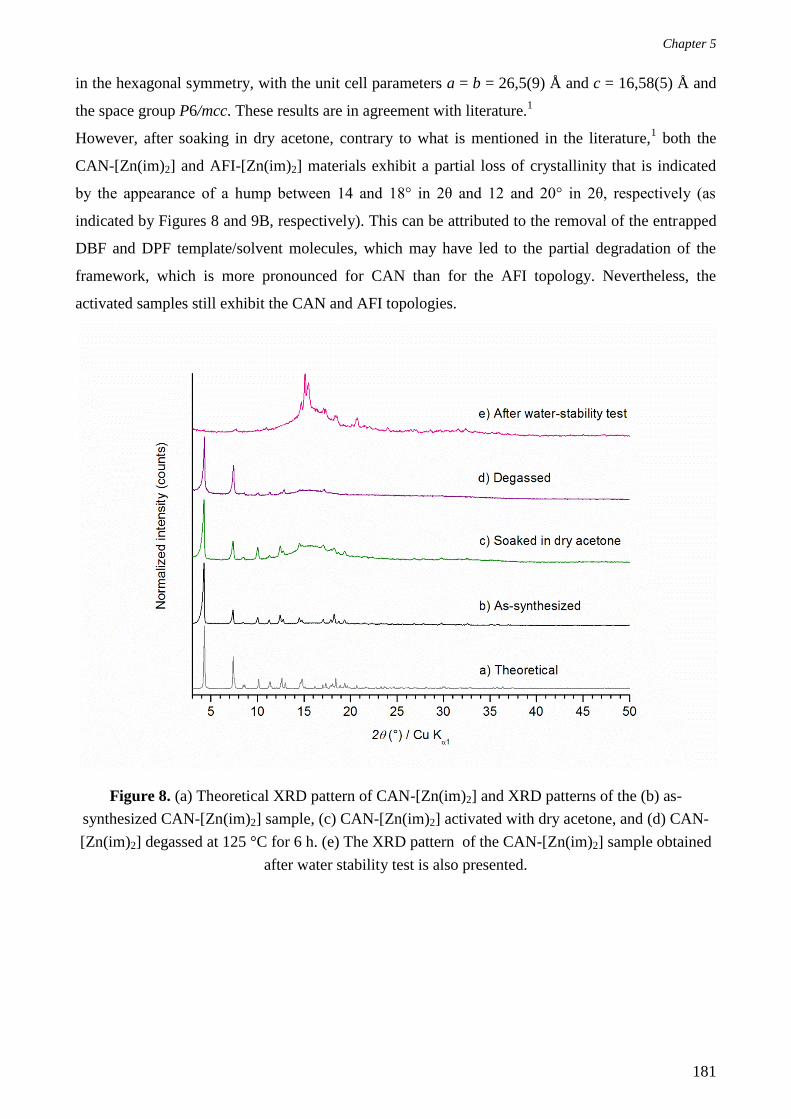
Chapter 5
181
in the hexagonal symmetry, with the unit cell parameters a = b = 26,5(9) Å and c = 16,58(5) Å and
the space group P6/mcc. These results are in agreement with literature.1
However, after soaking in dry acetone, contrary to what is mentioned in the literature,1 both the
CAN-[Zn(im)2] and AFI-[Zn(im)2] materials exhibit a partial loss of crystallinity that is indicated
by the appearance of a hump between 14 and 18° in 2θ and 12 and 20° in 2θ, respectively (as
indicated by Figures 8 and 9B, respectively). This can be attributed to the removal of the entrapped
DBF and DPF template/solvent molecules, which may have led to the partial degradation of the
framework, which is more pronounced for CAN than for the AFI topology. Nevertheless, the
activated samples still exhibit the CAN and AFI topologies.
Figure 8. (a) Theoretical XRD pattern of CAN-[Zn(im)2] and XRD patterns of the (b) as-
synthesized CAN-[Zn(im)2] sample, (c) CAN-[Zn(im)2] activated with dry acetone, and (d) CAN-
[Zn(im)2] degassed at 125 °C for 6 h. (e) The XRD pattern of the CAN-[Zn(im)2] sample obtained
after water stability test is also presented.

Chapter 5
182
Figure 9. (A) XRD pattern of AFI-[Zn(im)2] (a) Theoretical (b) as-synthesized sample, (c) sample
activated with dry acetone (d) sample degassed at 125 °C for 6 h (e) sample recovered after water
stability test (B) A closer view (in the 10-25 ° in 2θ range) of the XRD pattern of AFI-[Zn(im)2] (a)
theoretical (b) as-synthesized sample, (c) sample activated with dry acetone (d) sample degassed at
125 °C for 6 h (e) sample recovered after water-stability test.
A)
B)

Chapter 5
183
Figures 10A and 10B represent the TG curves of the as-synthesized, acetone-activated, and
degassed CAN-[Zn(im)2] and AFI-[Zn(im)2] samples. For both ZIFs, the TG curves of the as-
synthesized samples reveal a mass loss between room temperature and 200 °C of 17 and 4 % for
CAN-[Zn(im)2] and AFI-[Zn(im)2], respectively, which is assigned to the release of solvent
molecules entrapped in the porosity. As for the corresponding samples that were activated with dry
acetone, a small mass loss still exists in the low-temperature range, corresponding to 4 % for both
CAN-[Zn(im)2] and AFI-[Zn(im)2], indicating the persistence of some solvent molecules in the ZIF
pores and, thus, an incomplete activation process. These results prove that soaking in acetone is not
sufficient for the complete removal of the template (DPF and DBF) molecules from the porosity of
the AFI- and CAN-type ZIFs. Nonetheless, the latter activation process seems to be more efficient
in the case of AFI-[Zn(im)2] compared to CAN-[Zn(im)2]. However, the TG curves of the CAN-
and AFI-type ZIF materials that were degassed following their activation in acetone show that both
materials are thermally stable up to 260 °C (a thermal plateau associated with a negligible mass loss
between room temperature and 260 °C). This is followed by a main decomposition step between
260-800 °C, consisting of multiple sub-steps that can be all attributed to the decomposition of the
organic network and correspond to a mass loss of 60 % in the case of both the CAN- and AFI-type
ZIF materials. These results are similar to the ones reported in the literature,1 which reveal a thermal
stability up to 300 °C, after which the decomposition of the organic network occurs, resulting in a
mass loss of ≈ 59 % for both CAN-[Zn(im)2] and AFI-[Zn(im)2].

Chapter 5
184
Figure 10. (A) TG curves of (a) the as-synthesized CAN-[Zn(im)2], and the CAN-[Zn(im)2]
samples (b) activated with dry acetone and (c) degassed at 125 °C for 6 h. (B) TG curves of (a) as-
synthesized AFI-[Zn(im)2] and the AFI-[Zn(im)2] samples (b) activated with dry acetone and (c)
degassed at 125 °C for 6 h.
A)
B)

Chapter 5
185
Due to the failure of the acetone-activation step in fully liberating the ZIF pores and the consequent
persistence of entrapped DPF and DBF molecules in the porosity, prior to N2 adsorption-desorption
analyses, the ZIF samples were further activated by degassing at 125 °C for 6 h under vacuum. It is
worthy to note that these degassing conditions are different from the ones reported in the literature,
where a degassing temperature of 50 °C (under vacuum) is employed.1 This choice of the degassing
temperature has been done as the reported temperature value appeared to be abnormally low
compared to conventional degassing temperatures.
Figures 11a and 11b show the N2 adsorption-desorption isotherms of the CAN-[Zn(im)2] and AFI-
[Zn(im)2] materials after activation by soaking in dry acetone and degassing. Both ZIFs display
Type I isotherms characteristic of microporous materials, with the presence of a hysteresis, which is
more pronounced in the case of AFI-[Zn(im)2], probably indicating an interparticular mesoporosity.
However, the obtained BET surface areas (270 and 249 m2 g
-1 for the CAN-[Zn(im)2] and AFI-
[Zn(im)2] materials, respectively) and microporous volumes (0.10 cm3 g
-1 for both materials) are
much lower compared to the values reported in the literature (BET surface areas of 1178 and 1386
m2 g
-1 and microporous volumes of 0.54 and 0.64 cm
3 g
-1 for CAN-[Zn(im)2] and AFI-[Zn(im)2],
respectively).1 In order to interpret these surprising results, the recovered materials were analyzed
after N2 sorption measurements with XRD. For both ZIF materials, the obtained XRD patterns
reveal a further decrease in the crystallinity that could be clearly indicated by the growth of the
humps between 14 and 18° 2θ and 12 and 20° 2θ for CAN-[Zn(im)2] and AFI-[Zn(im)2],
respectively (Figures 8 and 9A). This is probably attributed to the distortion of the framework
during degassing, while the DPF and DBF molecules are being removed from the ZIF pores and/or
the harsh degassing conditions (heating at 125 °C for 6 h under vacuum) employed.

Chapter 5
186
Figure 11. N2 adsorption-desorption isotherms of the (a) CAN-[Zn(im)2] and (b) AFI-[Zn(im)2]
materials. The filled and empty symbols refer to the adsorption and desorption branches,
respectively.
a)
b)

Chapter 5
187
Therefore, the activation process for both the CAN-[Zn(im)2] and AFI-[Zn(im)2] materials must be
optimized so as to liberate the pores without compromising on the stability of the ZIFs’
frameworks. However, before proceeding to optimize the activation step, we studied the stability of
the CAN-[Zn(im)2] and AFI-[Zn(im)2] frameworks in water, which is an essential parameter for
water intrusion−extrusion experiments. In this respect, the crude AFI-[Zn(im)2] and dry acetone
activated CAN-[Zn(im)2] materials were suspended in water, for 48 h at room temperature, with a
ZIF / H2O mass ratio similar to the one employed during intrusion‒extrusion experiments. The
powder was then recovered by filtration and dried in air. Unfortunately, the results obtained from
XRD analyses performed on both ZIFs after water stability tests reveal a large loss of crystallinity,
accompanied with a phase transformation for CAN-[Zn(im)2] and a change in the relative peak
intensities in the case of AFI-[Zn(im)2] (Figures 8 and 9A). These results could be assigned to a
lower water stability of the CAN framework compared to AFI. Nonetheless, this attribution must be
qualified as the natures (crude or activated) of the starting materials were not identical. Indeed, the
CAN-[Zn(im)2] framework had already lost some crystallinity during soaking in dry acetone and
was further distorted during the water stability test, whereas an initially crystalline AFI-[Zn(im)2]
sample (crude sample) was used for the water stability test. Thus, the lack of water stability
prevents the application of both materials to water intrusion‒extrusion experiments. However, their
energetic behavior can still be investigated using highly concentrated aqueous electrolyte solutions
(such as LiCl 20 M aqueous solution). Nevertheless, the framework stability in the aqueous
electrolyte medium should be first tested at ambient pressure.
In conclusion, XRD analyses reveal a partial amorphization of the CAN-[Zn(im)2] and AFI-
[Zn(im)2] frameworks associated with the removal of the guest molecules (DPF and DBF) during
the activation step using dry acetone. This amorphization seems to become more prominent during
degassing at 125 °C, which is clearly shown by XRD and N2 sorption analyses, even if TGA
demonstrate a thermal stability of both ZIF materials up to 300 °C. Furthermore, based on XRD
analyses, the ZIF frameworks are not stable in water. Indeed, this makes CAN-[Zn(im)2] and AFI-
[Zn(im)2] unsuitable for water intrusion‒extrusion experiments. However, their energetic
performances may be investigated using a LiCl 20 M aqueous solution. To this end, future
perspectives include the optimization of the activation processes for both ZIF materials so as to be
studied in high-pressure intrusion‒extrusion experiments of a LiCl 20 M aqueous solution.

Chapter 5
188
II. Hydrophilic Mesoporous MOFs for Intrusion−Extrusion
Experiments: Towards the Post-Synthetic Modification
Route
As mentioned in the introduction of this chapter, the presence of water molecules coordinated to the
metal center in some Secondary Building Units (SBU), renders, presumably, the material
hydrophilic (as more water molecules may be added through hydrogen bonding), thus, limiting its
application to water and, maybe, aqueous electrolyte solutions intrusion−extrusion experiments.
Therefore, in order to make the materials hydrophobic, we aimed at post-synthetically modifying
them at the metal sites, via the coordinate covalent route. The process involves dehydrating the
MOF material i.e. removing the metal-coordinated water molecules, and substituting them by
hydrophobic agents such as primary amines with perfluoroalkane. When coordinated to the metal
center, these capping agents are also supposed to prevent or limit the rehydration of the modified
MOF. This strategy is similar to the concept of post-synthetic modification (PSM) widely applied to
the well-known MIL-101(Cr) and HKUST-1(Cu) MOF materials.30
The latter is a highly porous
MOF that consists of dimeric Cu(II) paddle-wheel SBUs linked through benzene-1,3,5-
tricarboxylate (BTC) linkers, whereby labile aqua ligands on the Cu(II) paddle-wheel SBU can be
removed by dehydration and then replaced by other molecules (pyridine for example).30
Owing to
structural analogies with HKUST-1(Cu), i. e. the presence of coordinated water molecules on
copper atoms, MOF-919(Sc/Cu) was also selected, in addition to MIL-101(Cr), for studying the
feasibility of their PSM in the aim of employing the post-synthetically modified hydrophobic MOF
materials in water and aqueous electrolyte solutions intrusion−extrusion experiments. The next two
sections present a description of the MIL-101(Cr) and MOF-919 materials, in addition to the work
that has been performed on them.
A. MOF-919(Sc/Cu)
In the aim of increasing the amount of stored/absorbed energy by LHSs, mesoporous MOF-
919(Sc/Cu) was considered as a good candidate for intrusion−extrusion experiments, mainly due to
its high porous volume, estimated at 1,70 cm3 g
-1, and chemical stability.
6 Indeed, according to Liu
et al.,6 the activated MOF-919(Sc/Cu) material is thermally stable up to 280 °C and exhibits
excellent chemical stability in air and humidity that was indicated by the unaltered XRD patterns,
compared to the simulated pattern, after exposure to air for one week. In addition, the high water
and chemical stabilities of MOF-919(Sc/Cu) were evidenced after suspending the powder in water
and strong acidic and basic aqueous media (HCl and NaOH solutions, respectively) for 2 h. Indeed,

Chapter 5
189
these characteristics of MOF-919(Sc/Cu) i.e. the high thermal, chemical, and water stabilities are
highly desired for PSM and, later, for intrusion−extrusion experiments.
1. Description
MOF-919(Sc/Cu) is made up by the assembly of scandium and copper metal cations and 1-H-
pyrazole-4-carboxylic acid (H2Pyc). The structure (Scheme 4) consists of Sc- and Cu-SBUs. The
former type of SBUs is formed by the coordination of trimeric scandium (III) units (Sc3O) with the
carboxylate groups from the pyrazolate (Pyc) linkers, where these linkers also form with copper
cations a triangular SBU.
MOF-919(Sc/Cu) exhibits a moo topology, also displayed by MIL-100(Cr), which involves two
types of mesoporous cages of permanent porosity; the yys and liu cages of 49 and 60 Å in diameter,
respectively. The yys cage has twelve 10-membered ring pore apertures of 20 Å in diameter,
whereas the liu cage, i. e the larger cage, in addition to twelve 10-membered ring pore apertures
(similar to the ones exhibited by the yys cage) also has four 12-membered ring pore apertures of 25
Å in diameter (Scheme 4).6

Chapter 5
190
Scheme 4. Representations of the (a) yys and (b) liu cages in MOF-919(Sc/Cu). The trimeric ScO3
units and Cu atoms are represented in brown and green, respectively.6
The formula of the guest-free (solvent-free) MOF-919(Sc/Cu) material suggested by Liu et al. is
[Sc3(μ3-O)(OH)3][Cu3(μ3-O)(μ-PyC)3(H2O)6]2.6 It was determined by taking into consideration the
charge balance, XRD analysis results, and previous reports.6, 31-33
2. Synthesis
MOF-919(Sc/Cu) was prepared following the synthesis protocol published by Liu et al.6
ScCl36H2O (76.2 mg, 0.2937 mmol) and Cu(NO3)23H2O (135.6 mg, 0.5613 mmol) were
dissolved in DMF by sonication in a 80 mL glass bottle. The organic precursor H2Pyc (34.8 mg,
a)
b)

Chapter 5
191
0.3105 mmol) was then added to the metal solution and the reaction mixture was sonicated. The
reaction mixture, of molar composition; 1 Sc(NO3)3: 2 Cu(NO3)3: 1 H2Pyc: 440 DMF: 12 H2O, was
heated in an oven at 100 °C for 15 h to yield green crystals after cooling down to room temperature.
The crystals were recovered by filtration, washed with a few milliliters of DMF and left to dry in air
during 48 h.
3. Characterizations
The obtained product was analyzed with XRD. Figure 12 shows the XRD pattern corresponding to
the as-synthesized material compared to simulated pattern.
Figure 12. (a) Theoretical XRD pattern of MOF-919(Sc/Cu) and (b) XRD pattern of the as-
synthesized MOF-919(Sc/Cu) sample.
Clearly, the product does not correspond to MOF-919(Sc/Cu) and is mostly amorphous, with five
small peaks that do not belong to traces of the desired material. In this case, we decided not to go
further with the optimization of the synthesis protocol of MOF-919(Sc/Cu), even though it remains
an interesting candidate for the development of the PSM route and intrusion−extrusion experiments.

Chapter 5
192
B. MIL-101(Cr)
1. Description
MIL-101(Cr) is one of the most representative mesoporous MOFs. Its structure is based on trimeric
Cr(III) units, where three hexacoordinated chromium (III) atoms are sharing one oxygen atom
(Scheme 5a).34-35
These units are interconnected by benzene-1,4-dicarboxylate (BDC) linkers, thus,
giving rise to a 3D structure, with a chemical formula of Cr3(O)F(H2O)2(BDC)3nH2O (with n ≈
25). For two of the three chromium atoms of the trimeric unit, the coordination sphere is completed
by four oxygen atoms from four BDC linkers and one oxygen atom from one water molecule. It
should be noted that these chemisorbed water molecules are labile and that their de-coordination
allows the formation of coordinatively unsaturated metal sites (CUS), also called open-metal sites.
A post-activation grafting of nucleophilic agents on these sites is then possible, as it has been
demonstrated by Férey and coworkers.36
As for the third chromium atom, its environment is similar
to that of the other two chromium atoms constituting the trimeric unit, except that the oxygen atom
from water molecule is substituted by one hydroxo group or one fluorine atom, depending on the
synthetic route.
The MIL-101(Cr) structure can be also depicted as the assembly of a super tetrahedron (Scheme 5b)
and two types of mesoporous cages (Schemes 5c and 5d). Moreover, MIL-101(Cr) possesses a
framework of MTN zeolite-type architecture (analogous to the framework of MTN-type zeolites,
however, by increasing the size of the SiO4 tetrahedron to a super tetrahedron). Concerning the
mesoporous and quasi-spherical cages, the ratio is 2:1 (in favor to the smaller ones). The latter, of
27-29 Å in size, displays 3- and 5-membered ring pore windows (with the chromium trimeric units
forming the vertexes), whereas the larger mesoporous cages, of 34 Å in size, are delimited by 3-, 5-
and 6-membered ring pore windows. The dimensions of the pentagonal and hexagonal pore
apertures, are evaluated around 12 and 14.5 Å x 16 Å, respectively.5, 7, 34
Moreover, MIL-101(Cr)
was reported to be stable under moisture and, more remarkably, after suspending in boiling water at
100 °C for a week.7 Hence, these exceptionally large dimensions (resulting from the presence of
mesoporous cages), in addition to a microporous volume surpassing 1 cm3 g
-1 and the remarkable
chemical stability make MIL-101(Cr) an interesting candidate for intrusion−extrusion experiments.

Chapter 5
193
Scheme 5. Representations of the (a) trimeric Cr(III) unit, (b) super tetrahedron, (c) small cage,
with 3- and 5-membered ring pore apertures and (d) large cage, with 3-, 5- and 6-membered ring
pore apertures.
2. Synthesis and Activation
MIL-101(Cr) microcrystals were prepared following the synthesis protocol reported by Hong et al.7
by dissolving the metal and organic precursors in a mixture of water and hydrofluoric acid (HF) and
then heating the reaction mixture at 220 °C for 8 h. Thus, 5.02 g (12.5 mmol) of chromium nitrate
nonahydrate (Cr(NO3)39H2O), were dissolved in 62.92 g (3492.6 mmol) of deionized water (by
stirring over 10 min), then 0.63 g (12.5 mmol) of a 40 wt% aqueous solution of HF was added.
a)
c)
b)
d)

Chapter 5
194
After mixing, 2.08 g (12.5 mmol) of terephthalic acid (H2BDC) were added. The solution obtained
with the following molar composition, 1.0 Cr(NO3)3 :1.0 H2BDC: 1.0 HF: 289.0 H2O, was mixed
during 1 min, under magnetic stirring, before being transferred into a 120 mL Teflon®-lined
stainless steel autoclave. The reaction mixture was then heated at 220 °C for 8 h in a pre-heated
oven. After cooling down to room temperature, a first filtration (using a grade 2 borosilicate filter)
was performed in order to remove the unreacted and crystallized terephtalic acid present in the
medium. Large amounts of deionized water were used to transfer the green MIL-101(Cr)
microcrystals (containing terephtalic acid entrapped in the porosity) through the filter. The resulting
green suspension was then filtered on a microfiltration setup (using a PTFE membrane, 1 µm) and
the MOF microcrystals were recovered. In order to remove the residual terephthalic acid entrapped
in the pores of the as-synthesized MOF sample (activation stage), three successive
soaking/(micro)filtration steps were carried out, as suggested by Hong et al.7: The first step
involved soaking the sample in deionized water at 70 °C under weak stirring (150-200 rpm) during
5 h. This was followed (after recovering the powder from water by filtration) by soaking in absolute
ethanol at 60 °C also under weak stirring over 5 h. Finally, in the last activation step, the MOF
microcrystals were suspended in an aqueous NH4F solution (3.10-2
M) at 60 °C during 15 h, in
order to transform the remaining entrapped H2BDC molecules into an ammonium salt, which is
more soluble in water.
3. Characterizations
The theoretical XRD pattern of the activated MIL-101(Cr) was generated based on the published
structure, which reveals a cubic symmetry (space group Fd-3m).35
According to Figure 13, the XRD
pattern of the activated MIL-101(Cr) material and the theoretical MIL-101(Cr) pattern are similar in
terms of the peak positions, which indicates the high crystallinity and phase purity of the sample.
Nonetheless, compared to the theoretical XRD pattern, the XRD pattern of the activated MIL-
101(Cr) material reveals a difference in the relative peak intensities.

Chapter 5
195
Figure 13. (a) Theoretical XRD pattern of MIL-101(Cr) and XRD patterns of the (b) activated and
(c) post-intruded MIL-101(Cr) samples.
The activated sample was also investigated with N2 sorption measurements (Figure 14). Even if in
our case the low pressure domain was not explored (so as to save time), the N2 sorption isotherm
displays the general profile already reported.7, 34, 37
Before achieving the complete filling of the
porosity, slightly below a relative pressure of 0.30, two nitrogen uptake steps are observable at
relative pressure values of 0.15 and 0.25 and are correlated with the filling of the two types of
cages. The values for the porous volume and BET surface area are determined as 1.10 cm3 g
-1 and
2103 m2 g
-1, respectively. Even though these values (especially in terms of the porous volume) are
slightly lower compared to the literature, however, they still demonstrate the high porosity of MIL-
101(Cr).38-39

Chapter 5
196
Figure 14. N2 adsorption-desorption isotherms of the activated MIL-101(Cr) sample. The filled and
empty symbols refer to the adsorption and desorption branches, respectively.
4. Intrusion−Extrusion Experiments
By virtue of its high porosity, and knowing that this material has never been explored in
intrusion−extrusion experiments before, a first attempt to determine its energetic behavior using a
LiCl 20 M aqueous solution as a non-wetting liquid was undertaken on the degassed sample. The
obtained intrusion−extrusion curve (Figure 15) reveals no volume variation step characteristic of
the intrusion of the non-wetting liquid molecules into the MIL-101(Cr) pores. The volume
variations observed during the three cycles are only attributed to the compression-decompression of
the non-wetting liquid molecules in the intrusion−extrusion cell.

Chapter 5
197
Figure 15. Pressure-volume diagrams of the “MIL-101(Cr)−LiCl 20 M aqueous solution” system.
Figure 13 shows the XRD pattern of the post-intruded MIL-101(Cr) sample. Clearly, the MOF
structure is retained after three intrusion−extrusion cycles realized up to 350 MPa, which indicates
the high stability of the MIL-101(Cr) framework under the combined effect of both the high
pressure and the aqueous medium. Moreover, the absence of an intrusion step may be attributed to
the hydrophilic character of MIL-101(Cr), which might have led to the adsorption of some water
molecules at low pressures, thereby preventing the further intrusion of any non-wetting liquid
molecules at elevated pressures. Nevertheless, post-intrusion N2 sorption analysis is also necessary
in order to confirm the stability of the MOF framework.

Chapter 5
198
III. Conclusions
By virtue of their high porosity and novelty, several reported MOFs/ZIFs i. e. NOF-1, ZIF-76, AFI-
Zn(im)2, CAN-Zn(im)2, MOF-919(Sc/Cu), and MIL-101(Cr), were considered promising
candidates for intrusion−extrusion experiments. Thus, we intended to synthesize these materials,
fully characterize them, and explore their energetic behaviors in intrusion−extrusion experiments
using water and/or LiCl 20 M aqueous solution as non-wetting liquids. Unfortunately, for MOF-
919(Sc/Cu), the synthesis was not reproducible. As for NOF-1, problems were encountered during
activation by soaking in MeOH, where the ZIF structure loses crystallinity. The activation step was
also complicated in the case of the AFI- and CAN-type ZIF materials, as it was associated with a
partial amorphization of the structure and did not lead to fully activated pores, which were indicated
from XRD and N2 adsorption-desorption measurements, respectively. Moreover, based on our
experimental results, the AFI- and CAN-type ZIF materials are unstable in water (with the AFI-type
material being slightly more stable in water compared to CAN). Consequently, due to the lack of
reproducibility, problems encountered during activation, and the low water stability, in addition to
the lack of the time required to further optimize the synthesis and activation processes, NOF-1,
MOF-919(Sc/Cu), and the AFI- and CAN-type ZIF materials were not investigated in water or
aqueous electrolyte solutions intrusion−extrusion experiments.
In contrast, ZIF-76 and MIL-101(Cr) were successfully reproduced (synthesized several times and
fully activated). Nonetheless, due to the hydrophilic character of MIL-101(Cr), in addition to the
low water stability of ZIF-76, water intrusion−extrusion experiments were not realized on these two
materials. But, it was worth studying their energetic behavior using a LiCl 20 M aqueous solution.
Based on the experimentally obtained results, the P−V diagrams of MIL-101(Cr) shows no
intrusion step, which can be attributed to its hydrophylic character and probably explained by the
adsorption of some water molecules at low pressure values, thus, preventing the intrusion of the
non-wetting liquid at elevated pressures. However, our results indicate that this material is stable
under pressures as high as 350 MPa and in contact with a LiCl 20 M aqueous solution. Thus, it
remains a good candidate for the strategy involving PSM followed by intrusion−extrusion
experiments. As for ZIF-76, the “ZIF-76‒LiCl 20 M aqueous solution” system exhibits a volume
variation step upon intrusion. Further investigation, in particular, complementary
intrusion−extrusion experiments (realized under lower pressures, i.e 80 MPa) in addition to post-
intrusion−extrusion characterizations, are required in order to gain better insight into the energetic
performances of this system.
Finally, this chapter highlights the difficulty of MOF synthesis. Indeed, published syntheses are not
always easily reproducible. The activation step can also be delicate. In addition, the stability of

Chapter 5
199
MOF materials in water or in aqueous media, which is crucial for intrusion−extrusion experiments,
is difficult to predict.

Chapter 5
200
References
1. Shi, Q.; Xu, W.-J.; Huang, R.-K.; Zhang, W.-X.; Li, Y.; Wang, P.; Shi, F.-N.; Li, L.; Li, J.; Dong,
J., Zeolite CAN and AFI-Type Zeolitic Imidazolate Frameworks with Large 12-Membered Ring
Pore Openings Synthesized Using Bulky Amides as Structure-Directing Agents. J. Am. Chem. Soc.
2016, 138, 16232-16235.
2. Mortada, B.; Chaplais, G.; Veremeienko, V.; Nouali, H.; Marichal, C.; Patarin, J., Energetic
Performances of ZIF-8 Derivatives: Impact of the Substitution (Me, Cl, or Br) on Imidazolate
Linker. J. Phys. Chem. C 2018, 122, 3846-3855.
3. Mortada, B.; Chaplais, G.; Nouali, H.; Marichal, C.; Patarin, J., Phase Transformations of Metal-
Organic Frameworks MAF-6 and ZIF-71 during Intrusion-Extrusion Experiments. J. Phys. Chem. C
2019, 123, 4319-4328.
4. Diring, S.; Wang, D. O.; Kim, C.; Kondo, M.; Chen, Y.; Kitagawa, S.; Kamei, K.-i.; Furukawa,
S., Localized Cell Stimulation by Nitric Oxide using a Photoactive Porous Coordination Polymer
Platform. Nat Commun. 2013, 4, 2684-2692.
5. Bullot, L.; Vieira-Sellai, L.; Chaplais, G.; Simon-Masseron, A.; Daou, T. J.; Patarin, J.; Fiani, E.,
Adsorption of 1,2-Dichlorobenzene and 1,2,4-Trichlorobenzene in Nano- and Microsized Crystals
of MIL-101(Cr): Static and Dynamic Gravimetric Studies. Environ. Sci. Pollut. Res. 2017, 24,
26562-26573.
6. Liu, Q.; Song, Y.; Ma, Y.; Zhou, Y.; Cong, H.; Wang, C.; Wu, J.; Hu, G.; O'Keeffe, M.; Deng,
H., Mesoporous Cages in Chemically Robust MOFs Created by a Large Number of Vertices with
Reduced Connectivity. J. Am. Chem. Soc. 2019, 141, 488-496.
7. Hong, D.-Y.; Hwang, Y. K.; Serre, C.; Ferey, G.; Chang, J.-S., Porous Chromium Terephthalate
MIL-101 with Coordinatively Unsaturated Sites: Surface Functionalization, Encapsulation,
Sorption and Catalysis. Adv. Funct. Mater. 2009, 19, 1537-1552.
8. Ban, Y.; Li, Y.; Peng, Y.; Jin, H.; Jiao, W.; Liu, X.; Yang, W., Metal-Substituted Zeolitic
Imidazolate Framework ZIF-108: Gas-Sorption and Membrane-Separation Properties. Chem. - Eur.
J. 2014, 20, 11402-11409.
9. Tian, Y.-Q.; Zhao, Y.-M.; Chen, Z.-X.; Zhang, G.-N.; Weng, L.-H.; Zhao, D.-Y., Design and
Generation of Extended Zeolitic Metal-Organic Frameworks (ZMOFs): Synthesis and Crystal

Chapter 5
201
Structure of zinc(II) Imidazolate Polymers with Zeolitic Frameworks. Chem. - Eur. J. 2007, 13,
4146-4154.
10. Peralta, D.; Chaplais, G.; Simon-Masseron, A.; Barthelet, K.; Pirngruber, G. D., Synthesis and
adsorption properties of ZIF-76 isomorphs. Microporous Mesoporous Mater. 2012, 153, 1-7.
11. Banerjee, R.; Phan, A.; Wang, B.; Knobler, C.; Furukawa, H.; O'Keeffe, M.; Yaghi, O. M.,
High-Throughput Synthesis of Zeolitic Imidazolate Frameworks and Application to CO2 Capture.
Science (Washington, DC, U. S.) 2008, 319, 939-943.
12. Pham, T.; Forrest, K. A.; Furukawa, H.; Eckert, J.; Space, B., Hydrogen Adsorption in a Zeolitic
Imidazolate Framework with lta Topology. J. Phys. Chem. C 2018, 122, 15435-15445.
13. Grosu, Y.; Li, M.; Peng, Y.-L.; Luo, D.; Li, D.; Faik, A.; Nedelec, J.-M.; Grolier, J.-P., A
Highly Stable Nonhysteretic {Cu2(tebpz) MOF+water} Molecular Spring. ChemPhysChem 2016,
17, 3359-3364.
14. Huang, L.; Wang, H.; Chen, J.; Wang, Z.; Sun, J.; Zhao, D.; Yan, Y., Synthesis, Morphology
Control, and Properties of Porous Metal-Organic Coordination Polymers. Microporous Mesoporous
Mater. 2003, 58, 105-114.
15. Ortiz, G.; Nouali, H.; Marichal, C.; Chaplais, G.; Patarin, J., Energetic Performances of the
Metal–Organic Framework ZIF-8 Obtained Using High Pressure Water Intrusion–Extrusion
Experiments. Phys. Chem. Chem. Phys. 2013, 15, 4888-4891.
16. Ferey, G.; Mellot-Draznieks, C.; Serre, C.; Millange, F., Crystallized Frameworks with Giant
Pores: Are There Limits to the Possible? Acc. Chem. Res. 2005, 38, 217-225.
17. Wu, T.; Bu, X.; Zhang, J.; Feng, P., New Zeolitic Imidazolate Frameworks: From
Unprecedented Assembly of Cubic Clusters to Ordered Cooperative Organization of
Complementary Ligands. Chem. Mater. 2008, 20, 7377-7382.
18. Yang, J.; Zhang, Y.-B.; Liu, Q.; Trickett, C. A.; Gutierrez-Puebla, E.; Monge, M. A.; Cong, H.;
Aldossary, A.; Deng, H.; Yaghi, O. M., Principles of Designing Extra-Large Pore Openings and
Cages in Zeolitic Imidazolate Frameworks. J. Am. Chem. Soc. 2017, 139, 6448-6455.
19. Tian, Y.-Q.; Yao, S.-Y.; Gu, D.; Cui, K.-H.; Guo, D.-W.; Zhang, G.; Chen, Z.-X.; Zhao, D.-Y.,
Cadmium Imidazolate Frameworks with Polymorphism, High Thermal Stability, and a Large
Surface Area. Chem. - Eur. J. 2010, 16, 1137-1141.
Chapter 5
202
20. Zhu, A.-X.; Lin, R.-B.; Qi, X.-L.; Liu, Y.; Lin, Y.-Y.; Zhang, J.-P.; Chen, X.-M., Zeolitic Metal
Azolate Frameworks (MAFs) from ZnO/Zn(OH)2 and Monoalkyl-Substituted Imidazoles and
1,2,4-Triazoles: Efficient Syntheses and Properties. Microporous Mesoporous Mater. 2012, 157,
42-49.
21. Nguyen, N. T. T.; Furukawa, H.; Gandara, F.; Nguyen, H. T.; Cordova, K. E.; Yaghi, O. M.,
Selective Capture of Carbon Dioxide under Humid Conditions by Hydrophobic Chabazite-Type
Zeolitic Imidazolate Frameworks. Angew. Chem., Int. Ed. 2014, 53, 10645-10648.
22. Park, K. S.; Ni, Z.; Cote, A. P.; Choi, J. Y.; Huang, R.; Uribe-Romo, F. J.; Chae, H. K.;
O'Keeffe, M.; Yaghi, O. M., Exceptional Chemical and Thermal Stability of Zeolitic Imidazolate
Frameworks. Proc. Natl. Acad. Sci. U. S. A. 2006, 103, 10186-10191.
23. Hayashi, H.; Cote, A. P.; Furukawa, H.; O'Keeffe, M.; Yaghi, O. M., Zeolite A Imidazolate
Frameworks. Nat. Mater. 2007, 6, 501-506.
24. Karagiaridi, O.; Bury, W.; Sarjeant, A. A.; Stern, C. L.; Farha, O. K.; Hupp, J. T., Synthesis and
Characterization of Isostructural Cadmium Zeolitic Imidazolate Frameworks via Solvent-Assisted
Linker Exchange. Chem. Sci. 2012, 3, 3256-3260.
25. Biswal, B. P.; Panda, T.; Banerjee, R., Solution Mediated Phase Transformation (RHO to SOD)
in Porous Co-Imidazolate Based Zeolitic Frameworks with High Water Stability. Chem. Commun.
(Cambridge, U. K.) 2012, 48, 11868-11870.
26. Yao, S.-Y.; Tian, Y.-Q., An Exceptional Self-Penetrating 4-Connected Network Derived from a
(3,4)-Connected Net of tfa-c Topology. CrystEngComm 2010, 12, 697-699.
27. Wang, B.; Cote, A. P.; Furukawa, H.; O'Keeffe, M.; Yaghi, O. M., Colossal Cages in Zeolitic
Imidazolate Frameworks as Selective Carbon Dioxide Reservoirs. Nature (London, U. K.) 2008,
453, 207-211.
28. Wu, T.; Bu, X.; Liu, R.; Lin, Z.; Zhang, J.; Feng, P., A New Zeolitic Topology with Sixteen-
Membered Ring and Multidimensional Large Pore Channels. Chem. - Eur. J. 2008, 14, 7771-7773.
29. Banerjee, R.; Furukawa, H.; Britt, D.; Knobler, C.; O'Keeffe, M.; Yaghi, O. M., Control of Pore
Size and Functionality in Isoreticular Zeolitic Imidazolate Frameworks and their Carbon Dioxide
Selective Capture Properties. J. Am. Chem. Soc. 2009, 131, 3875-3877.

Chapter 5
203
30. Wang, Z.; Cohen, S. M., Postsynthetic Modification of Metal-Organic Frameworks. Chem. Soc.
Rev. 2009, 38, 1315-1329.
31. Feng, D.; Wang, K.; Su, J.; Liu, T.-F.; Park, J.; Wei, Z.; Bosch, M.; Yakovenko, A.; Zou, X.;
Zhou, H.-C., A Highly Stable Zeotype Mesoporous Zirconium Metal-Organic Framework with
Ultralarge Pores. Angew. Chem., Int. Ed. 2015, 54, 149-154.
32. Ferey, G.; Serre, C.; Mellot-Draznieks, C.; Millange, F.; Surble, S.; Dutour, J.; Margiolaki, I., A
Hybrid Solid with Giant Pores Prepared by a Combination of Targeted Chemistry, Simulation, and
Powder Diffraction. Angew Chem Int Ed Engl 2004, 43, 6296-301.
33. Furukawa, H.; Gandara, F.; Zhang, Y.-B.; Jiang, J.; Queen, W. L.; Hudson, M. R.; Yaghi, O.
M., Water Adsorption in Porous Metal-Organic Frameworks and Related Materials. J. Am. Chem.
Soc. 2014, 136, 4369-4381.
34. Anon, A Chromium Terephthalate-Based Solid With Unusually Large Pore Volumes and
Surface Area. Science 2005, 310, 1119.
35. Lebedev, O. I.; Millange, F.; Serre, C.; Van Tendeloo, G.; Ferey, G., First Direct Imaging of
Giant Pores of the Metal-Organic Framework MIL-101. Chem. Mater. 2005, 17, 6525-6527.
36. Hwang, Y. K.; Hong, D.-Y.; Chang, J.-S.; Jhung, S. H.; Seo, Y.-K.; Kim, J.; Vimont, A.; Daturi,
M.; Serre, C.; Ferey, G., Amine Grafting on Coordinatively Unsaturated Metal Centers of MOFs:
Consequences for Catalysis and Metal Encapsulation. Angew. Chem., Int. Ed. 2008, 47, 4144-4148.
37. Jiang, D.; Burrows, A. D.; Edler, K. J., Size-Controlled synthesis of MIL-101(Cr) nanoparticles
with Enhanced selectivity for CO2 over N2. CrystEngComm 2011, 13, 6916-6919.
38. Sun, J.; Yu, G.; Huo, Q.; Kan, Q.; Guan, J., Epoxidation of Styrene over Fe(Cr)-MIL-101
Metal-Organic Frameworks. RSC Adv. 2014, 4, 38048-38054.
39. Chowdhury, P.; Bikkina, C.; Gumma, S., Gas Adsorption Properties of the Chromium-Based
Metal Organic Framework MIL-101. J. Phys. Chem. C 2009, 113, 6616-6621.

Chapter 5
204

Conclusions and Perspectives
205
Conclusions and Perspectives
Heterogeneous systems formed of solid porous matrices such as ZIF materials and non-wetting
liquids, also known as lyophobic heterogeneous systems (LHS), which can be used for mechanical
energy storage and dissipation, have been explored in high-pressure intrusion−extrusion
experiments. Tables 1 and 2 summarize the results obtained from all the intrusion−extrusion
experiments conducted during this PhD work and from a few experiments previously reported in the
literature. The tables tackle cage-type MOFs and the energetic characteristics of their related
systems when water (Table 1) and aqueous electrolyte solutions (Table 2), restricted to KCl 4 M
and LiCl 20 M, are used as non-wetting liquids.
Different parameters have been proven to influence the energetic behaviors and/or performances of
ZIF-based LHSs during intrusion‒extrusion experiments. The impacts of these parameters, that are
the topology of the ZIF-type material, the functionalization of the linker, and the nature of the non-
wetting liquid, are discussed in the next paragraphs.
The topology of ZIF-type materials appears to be probably one of the most impacting parameters
on both energetic behaviors and performances of ZIF-based LHSs. As examples, the water-based
systems involving, on one hand, ZIF-8 and ZIF-8_Cl of SOD topology and, on the other hand, ZIF-
25 and ZIF-71 of RHO topology, can be cited. It is recalled that these materials are functionalized
either by methyl groups (ZIF-8 and ZIF-25) or chlorine atoms (ZIF-8_Cl and ZIF-71). Whereas the
LHSs based on SOD-type ZIFs display spring behavior with stored energies of around 11 J g-1
and
intrusion pressures of 22-27 MPa, those elaborated from RHO-type ZIFs give rise to perfect shock-
absorber behavior with stored energies of around 26-30 J g-1
and intrusion pressures of 57-71 MPa.
These results are somewhat surprising as highest stored energies and, more especially, intrusion
pressures were expected for LHSs involving SOD-type ZIFs, according to a model governed by the
dimensions of cage apertures. Even though the structural flexibility of ZIF-8 and ZIF-8_Cl
materials has been demonstrated, thereby implying an increase in the size of cage windows, this
trend based on the ZIFs topology remains to be deepened.
The effect of the linker’s functionalization can be, indeed, demonstrated through differences
encountered in the physicochemical properties of ZIF material (such as their chemical stability), in
addition to the energetic performances and behaviors of the ZIF-based LHSs. First, in order to illus-

Conclusions and Perspectives
206
Table 1. Composition, structural and textural properties of MOFs and the energetic characteristics
of the corresponding “MOF‒water” systems.
En
erg
etic
beh
av
ior
new
def
init
ion
S
S - S
Ph
ase
tran
sfo
rmat
ion
in
to C
dIF
-3 i
n c
on
tact
wit
h w
ater
No
ob
serv
ed i
ntr
usi
on
-ex
tru
sio
n p
hen
om
eno
n i
n t
he
ran
ge
0-3
50
MP
a
No
ob
serv
ed i
ntr
usi
on
-ex
tru
sio
n p
hen
om
eno
n i
n t
he
ran
ge
0-3
50
MP
a SA
Ph
ase
tran
sfo
rmat
ion
in
to p
has
e X
SA
No
ob
serv
ed i
ntr
usi
on
-ex
tru
sio
n p
hen
om
eno
n i
n t
he
0-3
00
MP
a p
ress
ure
ran
ge
En
erg
y
yie
ld
(%)
91
91
- 81
42
42
Er
(J g
-1)
9.8
10
-
10
.3
10
.8
13
Es
(J g
-1)
10
.8
11
-
12
.7
25
.5
30
Vin
t
(mL
g-1
)
0.4
0
0.4
8
a
0.5
3
0.3
6
0.5
2
Pex
t
(MP
a)
24
20
a
19
30
25
Pin
t
(MP
a)
27
22
a
24
71
57
Vm
icro
po
re
(cm
3 g
-1)
0.6
6
0.5
7
0.3
5
0.6
8
0.8
6
0.2
3
0.2
1
0.3
9
0.6
1
0.5
5
0.4
6
0.5
8
La
rges
t
cag
e
ap
ertu
re
6 M
R
8 M
R
To
po
log
y
SO
D
RH
O
Co
mp
osi
tio
n
Zn
(mim
) 2
Zn
(cim
) 2
Zn
(bim
) 2
Co
(mim
) 2
Cd
(mim
) 2
Zn
(dci
m) 2
Zn
(bim
) 2
Zn
(dci
m) 2
Zn
(eim
) 2
Zn
(dm
im) 2
Zn
(bim
) 2
MO
F
sam
ple
ZIF
-8
ZIF
-8_
Cl
ZIF
-8_
Br
ZIF
-67
Cd
IF-1
Zn
(dci
m) 2
-
SA
LE
ZIF
-7
ZIF
-71
MA
F-6
ZIF
-25
ZIF
-11
The diameters of the pore openings are estimated based on structure analyses. Intrusion (Pint) and extrusion (Pext)
pressures, intrusion volume (Vint), stored (Es) and restored (Er) energies of MOF materials studied. S, SA, and B
correspond to spring, shock-absorber, and bumper behaviors, respectively. Cells corresponding to results from previous
works are grayed out. a indicates that the value could not be determined from the intrusion−extrusion curves.

Conclusions and Perspectives
207
trate the impact of functionalization on the chemical stability of porous materials, the “ZIF-25–”
and “MAF-6–water” systems can be considered (Table 1). Those two materials possess the RHO
topology and alkyl groups as substituents (with two methyl groups placed in positions 4 and 5 for
ZIF-25 and one ethyl group borne in position 2 for MAF-6). Whereas “ZIF-25–water” system
adopts, as mentioned above, perfect shock-absorber behavior, MAF-6 undergoes a phase
transformation under the combine effect of the pressure and water, thus, leading to the formation of
a new pseudo-polymorph named phase X. The series of LHSs, based on water and SOD-type ZIFs
such as ZIF-8, ZIF-8_Cl, ZIF-8_Br, Zn(dcim)2-SALE, and ZIF-7 (Table 1), provide another
example of the impact of the functionalization on the energetic performances and behaviors of
LHSs. The systems incorporating ZIF-8 and ZIF-8_Cl, as described previously, behave as a spring.
In contrast, no volume variation on the pressure–volume diagrams is evidenced for the LHSs
incorporating ZIF-8_Br, Zn(dcim)2-SALE, and ZIF-7. This difference highlights the importance of
the imidazolate’s functionalization and, interestingly also, that of the steric hindrance related to the
nature of the substituents. Indeed, the bromine atom in position 2 (ZIF-8_Br), the two chlorine
atoms in positions 4 and 5 (Zn(dcim)2-SALE), and the benzyl group adjoining the imidazolate
moiety at positions 4 and 5 (ZIF-7) are believed to block the diffusion of water molecules through
the materials’ porosity. Another consequence induced by the functionalization is the remarkable
flexibility/stiffness of the linker in ZIFs. The influence of this structural parameter, which can be
also correlated to steric hindrance, is particularly emphasized by the series of the LHSs based on
ZIF-8 and its halogenated derivatives, with water as the non-wetting liquid (Table 1). Based on
experimental and simulated nitrogen sorption measurements, ZIF-8 and ZIF-8_Cl are flexible,
whereas ZIF-8_Br is stiff, which affects distinctly the energetic behaviors of the related systems
during intrusion−extrusion experiments. Therefore, the functionalization can regulate the
dimensions of cage apertures directly via the steric hindrance, or indirectly through the linker’s
flexibility, thereby, impacting the energetic performances of LHSs.
The nature of the non-wetting liquid constitutes also a significant component directing the
energetic performances and behaviors of LHSs. Indeed, depending on the used non-wetting liquid,
the chemical stability of the porous material, the intrusion pressure, and the behavior may be
affected significantly. The “ZIF-71–water” and “ZIF-71–LiCl 20 M aqueous solution” systems
provide examples illustrating the effect of the nature of the non-wetting liquid on the chemical
stability of ZIFs (Tables 1 and 2). In fact, upon pressure and in the presence of LiCl 20 M aqueous
solution, ZIF-71 is transformed into one of its known polymorphs; ZIF-72 of lcs topology. Even if
ZIF-71 and ZIF-72 display the same chemical composition, the transformation from ZIF-71 to ZIF-
72 implies an alteration of chemical stability. In contrast, with water, ZIF-71 leads to a system
displaying perfect shock-absorber behavior.

Conclusions and Perspectives
208
Table 2. Composition, structural and textural properties of MOFs and the energetic characteristics
of the corresponding “MOF−non-wetting liquid” systems.
En
erg
etic
beh
av
ior
new
def
init
ion
S
B
SA
S
B
S
B
Ph
ase
tran
sfo
rmat
ion
in
to Z
IF-7
2
Ph
ase
tran
sfo
rmat
ion
in
to p
has
e X
B
No
ob
serv
ed i
ntr
usi
on
-ex
tru
sio
n p
hen
om
eno
n i
n t
he
0-3
50
MP
a
pre
ssu
re r
ang
e
En
erg
y
yie
ld
(%)
89
0
78
88
0
90
5a
58
b
0
Er
(J g
-1)
17
.4
- 14
68
- 38
1.7
3a
1.8
b
-
Es/
Ea
(J g
-1)
19
.5
10
4
18
77
2
42
34
.6a
3.1
b
22
Vin
t
(mL
g-1
)
0.5
0
0.5
6
0.4
0
0.3
8
0.1
6
0.2
5
0.3
6a
0.0
5b
0.4
2
Pex
t
(MP
a)
34
.7
- 34
18
0
-
15
0
36
-
Pin
t
(MP
a)
39
18
6
44
20
2
11
16
7
96
a
62
b
50
No
n-
wet
tin
g
liq
uid
KC
l 4
M
LiC
l 2
0 M
KC
l 4
M
LiC
l 2
0 M
KC
l 4
M
LiC
l 2
0 M
KC
l 4
M
LiC
l 2
0 M
LiC
l 2
0 M
LiC
l 2
0 M
LiC
l 2
0 M
Vm
icro
po
re
(cm
3 g
-1)
0.6
6
0.5
7
0.3
5
0.3
9
0.6
1
0.5
6
1.0
0
La
rges
t
cag
e
ap
ertu
re
6 M
R
8 M
R
6 M
R
14
.5 Å
x 1
6 Å
To
po
log
y
SO
D
RH
O
LT
A
MT
N
Co
mp
osi
tio
n
Zn
(mim
) 2
Zn
(cim
) 2
Zn
(bim
) 2
Zn
(dci
m) 2
Zn
(eim
) 2
Zn
(im
) 1.1
7(c
bim
) 0.8
3
Cr 3
(O)F
(BD
C) 3
MO
F
sam
ple
ZIF
-8
ZIF
-8_
Cl
ZIF
-8_
Br
ZIF
-71
MA
F-6
ZIF
-76
MIL
-
10
1(C
r)
Intrusion (Pint) and extrusion (Pext) pressures, intrusion volume (Vint), stored (Es), absorbed (Ea) and restored (Er)
energies of MOF materials studied. S, SA, and B correspond to spring, shock-absorber, and bumper behaviors,
respectively. The components, behaviors and absorbed/stored energies of the most relevant systems are written in bold
and colored in blue. Cells corresponding to results from previous works are grayed out. a and
b refer to the values
obtained from the first and second intrusion/extrusion cycles, respectively.

Conclusions and Perspectives
209
Moreover, the ZIF-8-based systems, involving water as well as the KCl 4 M and LiCl 20 M
aqueous solutions, reveal a strong variation of the intrusion pressure value as function of the
nature of the non-wetting liquid (Tables 1 and 2). Taking into account the extreme cases, the
intrusion pressure increases considerably from 27 MPa with water to 186 MPa with the LiCl 20 M
aqueous solution. A similar trend is observed for the LHSs incorporating the halogenated
derivatives of ZIF-8. Such results reflect the impact of the nature of the electrolyte and the
concentration of the corresponding aqueous electrolyte solution on the strength of the inter-
molecular water-water and water-electrolyte interactions. Keeping the same LHSs in mind, it can be
noted that the non-wetting liquid may modify also the energetic behavior. Indeed, the “ZIF-
8‒water” system behaves as a spring, whereas the “ZIF-8‒LiCl 20 M aqueous solution” system
displays bumper behavior with a notable value of absorbed energy of 104 J g-1
. Moreover, for ZIF-
8_Br, whereas no volume variation is observed for the LHS in the case where water is employed as
the non-wetting liquid, with a LiCl 20 M aqueous solution, the LHS displays perfect spring
behavior. As for the ZIF-8_Cl-based systems, the spring behavior is conserved whatever the nature
of non-wetting liquid (water or the LiCl 20 M aqueous solution), with a remarkable stored energy
value of 77 J g-1
. These variable energetic transformations not only emphasize the importance of the
nature of the non-wetting liquid, but also suggest that the chemical composition of ZIFs and,
therefore, the linker’s functionalization play a non-negligible role. This states that the host-guest
interactions between the building components of ZIFs, i.e. the linkers, and the constituent molecules
from the non-wetting liquid, such as water and electrolytic species, influence the type of energetic
behavior of the LHS. Thus, for the cases developed above, with the LiCl 20 M aqueous solution, it
is argued that the presence of an electron-donating group, such as a methyl group, on the
imidazolate linker increases its electron density and favors the interactions with the salt cations. In
contrary, the presence of substituent with an electron withdrawing effect, such as a chlorine atom,
decreases the electron density on the imidazolate linker and, hence, the electrostatic interaction with
the salt cations. However, in the light of molecular dynamic simulation studies reported recently in
the literature, the repulsive interactions of the hydrated chlorine anions with the imidazolate linker
have to be also considered.
In addition to advances in understanding the key parameters governing the energetic performances
and behaviors of MOF-based LHSs, this work also sheds light on the difficulty of MOF synthesis.
Indeed, published syntheses are not always easily reproducible, which is clearly demonstrated in the
case of ZIF-25 and MOF-919(Sc/Cu). The activation step can also be delicate. For instance, NOF-1,
in addition to the AFI- and CAN-type ZIF materials reveal a loss of crystallinity during soaking in
methanol and dry acetone, respectively. Furthermore, the stability of MOF materials in water or in
aqueous media is difficult to predict, nonetheless, is an essential characteristic of MOFs applied to

Conclusions and Perspectives
210
intrusion−extrusion experiments. However, despite all the difficulties and after varying several
compositional and process parameters, we achieved in optimizing the synthesis of ZIF-25 of RHO
topology using acetic acid as a modulator. Based on X-ray diffraction and nitrogen sorption
analyses, a pure RHO-phase material of high crystallinity and textural properties similar to those
reported in the literature was obtained, with a yield of 36 %. Moreover, the ZIF-25 structure was
successfully and fully refined in the Pm-3m space group, for the first time, through Rietveld
refinement from a powder X-ray diffraction pattern.
In the aim of completing the study on the energetic performances of LHSs based on RHO-type ZIF
materials, the “ZIF-25‒LiCl 20 M aqueous solution” system is also intended to be investigated in
intrusion‒extrusion experiments. On the other hand, the activation processes for CAN-Zn(im)2 and
AFI-Zn(im)2 should be enhanced, so as to completely liberate the pores, while maintaining a high
crystallinity of both materials. Knowing that the CAN-Zn(im)2 and AFI-Zn(im)2 materials display
both 1D channels accessed through large 12-memebered ring pore apertures (of 13.2 and 15.6 Ǻ for
the CAN- and AFI-type material, respectively), indeed, they are considered as attractive candidates
for the investigation of the effects of the topology and, more importantly, the pore dimensionality
and large pore aperture size on the energetic behaviors and performances of LHSs applied to high-
pressure intrusion−extrusion experiments.
Other zeolitic topologies explored in this work are the LTA and MTN of ZIF-76 and MIL-101(Cr)
materials, respectively. The “ZIF-76−LiCl 20 M aqueous solution” system reveals bumper behavior
during intrusion‒extrusion experiments realized up to 350 MPa (with an absorbed energy of 22 J g-
1), which, based on post-intrusion characterizations, leads to the amorphization of the ZIF-76
framework. However, it is important to note that the volume variation occurs in the 50-60 MPa
pressure range for this system (with ZIF-76 displaying 4-, 6-, and 8-membered ring pore apertures),
which is lower than the intrusion pressures obtained with the SOD topology (where the structure
consists of 4- and 6-membered ring pore apertures only). Although the “ZIF-76−LiCl 20 M aqueous
solution” system is still under investigation, these results seem to be in agreement with the
hypothesis suggesting the decrease in intrusion pressure with the increase in the size of the window
opening, even if the linker functionalization is different in each case. Complementary
intrusion‒extrusion experiments on ZIF-76 (LTA), under lower pressures (i. e. 80 MPa), in addition
to post-intrusion−extrusion characterizations, are needed in order to gain better insight into the
effect of the topology on the energetic behavior and performances of the “ZIF-76−LiCl 20 M
aqueous solution” system. Concerning the “MIL-101(Cr)−LiCl 20 M aqueous solution” system, the
intrusion−extrusion curves reveal no volume variation step characteristic of the intrusion of the non-
wetting liquid molecules into the MIL-101(Cr) pores, which may be attributed to the hydrophilic

Conclusions and Perspectives
211
character of MIL-101(Cr) that might have led to the adsorption of some water molecules at low
pressure (rehydration of the activated sample), thereby preventing the further intrusion of any non-
wetting liquid molecules at elevated pressures. Therefore the post-synthetic modification route
seems to be the only perspective for employing hydrophilic materials of such a high pore volume in
intrusion−extrusion experiments. Mainly, the mesoporous MIL-101(Cr) and MOF-919(Sc/Cu)
materials are among the considered candidates for this strategy, which can be achieved through the
grafting of a fluorinated primary amine, for example, on the metal center. This is intended to be
followed by water- and aqueous electrolyte solution-intrusion‒extrusion experiments, in the aim of
obtaining high amounts of stored/absorbed energies, indeed, by virtue of the high porosity of these
materials. Nevertheless, the synthesis of MOF-919(Sc/Cu) needs to be optimized first.
Finally, it is also important to note that even though the basic hypothesis suggests that increasing
the porosity leads to higher stored/absorbed energy values, however, the experimentally obtained
results clearly demonstrate that this is not the only parameter that controls the LHS’s energetic
performances during intrusion−extrusion experiments. For instance, for certain systems, a relatively
high stored/absorbed energy value is the result of both a relatively high intruded volume and
intrusion pressure, which is, indeed, the case for the “ZIF-8_Cl−LiCl 20 M aqueous solution”
system that, as previously mentioned, registers until now the largest amount of stored energy (77 J
g-1
) for a spring behavior obtained during intrusion−extrusion experiments.