Synthesis and Characterization of Aluminum Matrix Nanocomposites
46
Project Report Synthesis and Characterization of Aluminum Matrix Nanocomposites Submitted by: MUHAMMAD ABDULLAH ADIL Reg. number: 1426-111001 Objectives : Following are the Objectives of this experiment: To Synthesize Aluminum based Nanocomposites, e.g. Al/Al 2 O 3 and Al/(WC/TiC). Characterization of these Nanocomposites X-Ray Diffraction Micro hardness Testing To learn about different apparatus and equipments: High energy Planetary Ball Mill Laser Particle Size Analyzer Optical microscope
-
Upload
pinsat-idrc -
Category
Documents
-
view
0 -
download
0
Transcript of Synthesis and Characterization of Aluminum Matrix Nanocomposites

Project ReportSynthesis and Characterization ofAluminum Matrix Nanocomposites
Submitted by:MUHAMMAD ABDULLAH ADILReg. number: 1426-111001
Objectives :
Following are the Objectives of this experiment:
To Synthesize Aluminum based Nanocomposites, e.g.Al/Al2O3 and Al/(WC/TiC).
Characterization of these Nanocomposites
X-Ray Diffraction Micro hardness Testing
To learn about different apparatus and equipments:
High energy Planetary Ball Mill Laser Particle Size Analyzer Optical microscope

Metallographic Polishing Machine withfrequency Converter
Pycnometer X-ray Diffractometer (XRD) BET (Accelerated Surface Area and
Porosimetry System) Furnaces
Theory:
Attrition:Attrition methods include methods by which macro ormicro scale particles are ground in a ball mill, aplanetary ball mill, or other size reducing mechanism.The resulting particles are air classified to recovernanoparticles.
1. Involves mechanical thermal cycles.
2. Yields:
Broad size distribution (10-1000 nm) Varied particle shape or geometry Impurities
3. Application
Nanocomposites Nano-grained bulk materials
Ball milling:
Ball milling is a method of production of nanomaterials. This process is used in producing metallic
and ceramic nano materials. Ball milling can be used tomake carbon nanotubes and boron nitride nanotubes.These mills are equipped with grinding media composedof wolfram carbide or steel. Ball mills rotate around ahorizontal axis, partially filled with the material tobe ground plus the grinding medium. The balls rotatewith high energy inside a drum and then fall on thesolid with gravity force and crush the solid into nanocrystallites. The significant advantage of this methodis that it can be readily implemented commercially. Itis a preferred method for preparing metal oxide nanocrystals like cerium (CeO2) and zinc oxide (ZnO).
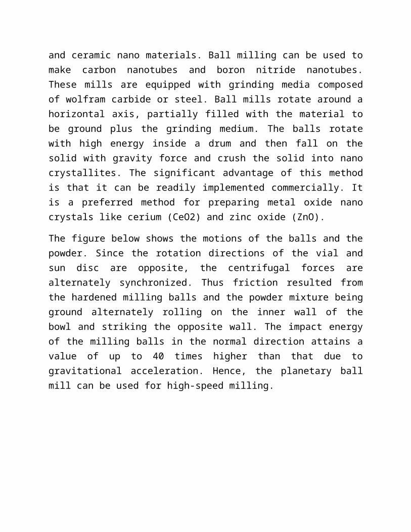
The figure below shows the motions of the balls and thepowder. Since the rotation directions of the vial andsun disc are opposite, the centrifugal forces arealternately synchronized. Thus friction resulted fromthe hardened milling balls and the powder mixture beingground alternately rolling on the inner wall of thebowl and striking the opposite wall. The impact energyof the milling balls in the normal direction attains avalue of up to 40 times higher than that due togravitational acceleration. Hence, the planetary ballmill can be used for high-speed milling.

Schematic view of motion of the ball and powder mixture.
During the high-energy ball milling process, the powderparticles are subjected to high energetic impact. Micro– structurally, the mechanical alloying process can bedivided into four stages:
a)Initial stage,b)Intermediate stage, c)Final stage, andd)Completion stage.
a)At the initial stage of ball milling, the powderparticles are flattened by the compressive forces dueto the collision of the balls. Micro-forging leads tochanges in the shapes of individual particles, or

cluster of particles being impacted repeatedly by themilling balls with high kinetic energy. However, suchdeformation of the powders shows no net change in mass.
b) At the intermediate stage of the mechanical alloyingprocess, significant changes occur in comparison withthose in the initial stage. The intimate mixture ofthe powder constituents decreases the diffusiondistance to the micrometer range. Fracturing and coldwelding are the dominant milling processes at thisstage. Although some dissolution may take place, thechemical composition of the alloyed powder is still nothomogeneous.
c) At the final stage of the mechanical alloyingprocess, considerable refinement and reduction inparticle size is evident. The microstructure of theparticle also appears to be more homogenous inmicroscopic scale than those at the initial andintermediate stages. True alloys may have already beenformed.
d) At the completion stage of the mechanical alloyingprocess, the powder particles possess an extremelydeformed metastable structure. At this stage, thelamellae are no longer resolvable by opticalmicroscopy. Further mechanical alloying beyond thisstage cannot physically improve the dispersoiddistribution. Real alloy with composition similar tothe starting constituents is thus formed.
Types of forces on powder particles:
a.Impact: instantaneous striking of particles byballs

b.Attrition: wearc.Shear: cuttingd.Compression: crushing
Steps in ball milling method:
1. As the name suggests, the ball milling methodconsists of balls and a mill chamber. Thereforeover all a ball mill contains a stainless steelcontainer and many small iron, hardened steel,silicon carbide, or tungsten carbide balls are madeto rotate inside a mill (drum).
2. The powder of a material is taken inside the steelcontainer. This powder will be made into nanosizeusing the ball milling technique.
3. The ball to material mass ratio is normallymaintained at 2 ratio1.
4. These silicon carbide balls provide very largeamount of energy to the material powder and thepowder then get crushed. This process of ballmilling is done approximately in 40 hrs to getuniform fine powder.
5. Ball milling is a mechanical process and thus allthe structural and chemical changes are produced bymechanical energy.
Milling media:
1. Powder to ball weight ratio is very important:wb/wp=10.

2. PCA: Process Control Agent that avoid gathering ofpowder at walls and with the walls. Usuallysolvents like toluene and hexane are used. Theseprevent oxidation and also act as a surfactant.
3. Rpm (revolution per minute) of sundisk and rpm ofvials have the ratio of -1.5. The rpm of vials is250.
The movement of the vials is clockwise and sundisk isanticlockwise.
Advantages of ball milling process:
1. Nanopowders of 2 to 20 nm in size can be produced.The size of nanopowder also depends upon the speedof the rotation of the balls.
2. It is an inexpensive and easy process.
Disadvantages:
1. As the process is not so sophisticated, thereforethe shape of the nanomaterial is irregular.
2. There may be contaminants inserted from ball andmilling additives.
3. This method produces crystal defects.
2. Determination of Particle size:
Pyconometer:

It Measures density similarly like using Archimedesprinciple. Powder sample is use which is filled to 1/3of the cup(sample chamber). Gas pycnometers are used tomeasure the density of a material. They determine thisby comparing the change in pressure caused by a changein closed reference volume, to that of a sample underthe same conditions. The pressure differential can berelated back to the volume of the sample, which allowsthe density to be calculated. Volume vs densityWhile pycnometers (of any type) are recognizedas density measuring devices they are in fact devicesfor measuring volume only. Density is merely calculatedas the ratio of mass to volume; mass being invariablymeasured on a discrete device, usually by weighing. Thevolume measured in a gas pycnometer is that amount ofthree-dimensional space which is inaccessible to thegas used, i.e. That volume within the sample chamberfrom which the gas is excluded. Therefore the volumemeasured considering the finest scale of surfaceroughness will depend on the atomic or molecular sizeof the gas. Helium therefore is most often prescribedas the measurement gas, not only is it of small size,it is also inert and the most ideal gas.Closed pores, i.e. Those that do not communicate withthe surface of the solid, are included in the measuredvolume. Helium may however demonstrate somemeasurable permeability through low density solid(polymers and cellulosic materials predominantly) thusinterfering with the measurement of solid volume. In

such cases larger molecule gases suchas nitrogen or sulfur hexafluorideare beneficial.Adsorption of the measuring gas should be avoided, asshould excessive vapor pressure from moisture or otherliquids present in the otherwise solid sample.
Laser particle size analyzer:Powder is made into suspension where particles shouldbe well dispersed. We use laser light and determine theangle of 1st minima and intensity of 0 maximum.Particles greater than the wavelength of laser, can beeasily detected while those with sizes less thanwavelength of the laser, light is either reflected ordeflected. Refractive index is used for calculations.
Principle
Laser particle size analyzer measures the particle sizedistribution on basis of the scattering phenomenaproduced by particles. When the light beam is blockedby particles, part of them will diffract and scatteringphenomenon occurs. An angle θ will be formed betweendiffracted light and the main beam. Both scatteringtheory and results from experiments show that angle θis related to particle size, the larger the particleis, the smaller the angle θ is; the smaller theparticle is, the larger the angle θ is. Furtherresearch shows that intensity of scattering lightrepresents the particles numbers, thus particle sizedistribution of sample is obtained through measuringintensity of the scattered light from different angle.

Asap 2020 accelerated surface area and porosimetrysystem accurate and precise surface area andPorosimetry measurements are essential to thedetermination of the effectiveness and Quality of awide variety of materials. The Micromeritics asap 2020accelerated Surface area and porosimetry systemIntegrates multiple as sorption techniques into asingle, convenient tabletop instrument.
Optical microscopy
A microscope is in principle nothing else than a simplelens system for magnifying small objects. The firstlens, called the objective, has a short focal length (afew mm), and creates an image of the object in theintermediate image plane. This image in turn can belooked at with another lens, the eye-piece, which canprovide further magnification.
Principle of optical microscope (compound microscope)
An optical microscope creates a magnified image of anobject specimen with an objective lens and magnifies

the image further more with an eyepiece to allow theuser to observe it by the naked eye. Assuming aspecimen as ab in the following figure, primary image(magnified image) a'b' of inverted real image iscreated with an objective lens. (ob).
Next, arrange the eyepiece (oc) so that primary imagea'b' is located closer to the eyepiece than theanterior focal point, then more enlarged erect virtualimage a"b" is created. Put your naked eye in the eye(pupil) position on the eyepiece barrel to observe theenlarged image. In short, the last image to be observedis an inverted virtual image. As described above, thistype of microscope which creates a magnified image bycombining an objective lens making an inverted realimage and an eyepiece making an erect virtual image iscalled a compound microscope. The observation opticalsystem in an optical microscope is commonlystandardized on this compound microscope. Meanwhile,such type of microscope that directly observes aninverted real image magnified with an objective lens iscalled a single microscope. A microscopic observationon a tv monitor, recently popularized increasingly,uses the way of directly capturing this inverted realimage with a ccd camera, thereby being comprised of asimple microscope optical system.
The Transmission Electron Microscope
The transmission electron microscope (tem) operates onthe same basic principles as the light microscope butuses electrons instead of light. What you can see witha light microscope is limited by the wavelength oflight. TEM’s use electrons as "light source" and their

much lower wavelength make it possible to get aresolution a thousand times better than with a lightmicroscope.
You can see objects to the order of a few angstroms (10-
10 m). For example, you can study small details in thecell or different materials down to near atomic levels.The possibility for high magnifications has made thetem a valuable tool in both medical, biological andmaterials research.
Magnetic lenses guide the electrons a "light source" atthe top of the microscope emits the electrons thattravel through vacuum in the column of the microscope.Instead of glass lenses focusing the light in the lightmicroscope, the tem uses electromagnetic lenses tofocus the electrons into a very thin beam. The electronbeam then travels through the specimen you want tostudy. Depending on the density of the materialpresent, some of the electrons are scattered anddisappear from the beam. At the bottom of themicroscope the unscattered electrons hit a fluorescentscreen, which gives rise to a "shadow image" of thespecimen with its different parts displayed in varieddarkness according to their density. The image can bestudied directly by the operator or photographed with acamera.

X-Ray Diffraction (xrd)
The atomic planes of a crystal cause an incident beamof x-rays to interfere with one another as they leave

the crystal. The phenomenon is Called x-raydiffraction. X-ray crystallography is a method used fordetermining the atomic and molecular structure ofa crystal, in which the crystalline atoms cause a beamof x-rays to diffract into many specific directions. Bymeasuring the angles and intensities of thesediffracted beams, a crystallographer can produce athree-dimensional picture of the densityof electrons within the crystal. From this electrondensity, the mean positions of the atoms in the crystalcan be determined, as well as their chemical bonds,their disorder and various other information.
Bragg's Law:
When x-rays are scattered from a crystal lattice, peaksof scattered intensity are observed which correspond tothe following conditions:
The angle of incidence = angle of scattering.

The path length difference is equal to an integernumber of wavelengths.The condition for maximumintensity contained in Bragg's law above allow us tocalculate details about the crystal structure, or ifthe crystal structure is known, to determine thewavelength of the x-rays incident upon the crystal.
3. Compaction:
Compaction of ceramic powders is a specific formingtechnique for ceramics. It is a process in whichceramic granular materials are made cohesive throughmechanical densification, involving (hot pressing) ornot (cold forming) temperature exposition. The processpermits an efficient production of parts ranging widelyin size and shape to close tolerances with low dryingshrinkage. Traditional (for instance: ceramic tiles,porcelain products) and structural (for instance: chipcarriers, spark plugs, cutting tools) ceramics areproduced. Cold compaction of ceramic powders ends upwith the realization of the so-called green piece,which is later subject to sintering.
Compaction by pressing:
The function principles of the mechanic press machinesdiffer in how to ensure the upper punch main movementby cams, spindles and friction drives, eccentric,

knuckle-joints or by the round table principle,independent if the die or lower punch movement isrealized by cams or eccentric systems or othermechanically or hydraulically combined systems. Theexecutions of auxiliary movements are also not decisivefor a term-classification. These auxiliary movementscan also base on pneumatic and hydraulic principles. Incomparison to hydraulic press machines the maximumcompaction forces of mechanical powder presses arelimited and are placed in the range </= 5000 kn
For this experiment we took a dye and inserted powderin it and applied varied load to form pallets.
Compaction: Powder is kept under pressure. Density ismeasured at different pressures. When it is maximum itis green compact.
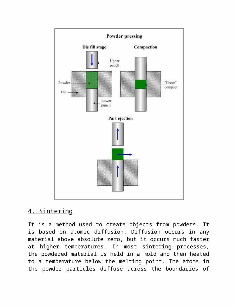
4. Sintering
It is a method used to create objects from powders. Itis based on atomic diffusion. Diffusion occurs in anymaterial above absolute zero, but it occurs much fasterat higher temperatures. In most sintering processes,the powdered material is held in a mold and then heatedto a temperature below the melting point. The atoms inthe powder particles diffuse across the boundaries of

the particles, fusing the particles together andcreating one solid piece. Because the sinteringtemperature does not have to reach the melting point ofthe material, sintering is often chosen as the shapingprocess for materials with extremely high meltingpoints such as tungsten and molybdenum.
Sintering is traditionally used for manufacturingceramic objects but finds applications in almost allfields of industry. The study of sintering and ofpowder-related processes is known as powder metallurgy.A simple, intuitive example of sintering can beobserved when ice cubes in a glass of water adhere toeach other.
Green compact is heat-treated at different temperaturesfor various time intervals till maximum density. Withsintering grain boundary diffusion and bulk diffusioncontribute to densification. Surface diffusion andevaporation cause grain growth and no densification.
Usually the sintering temperature is 0.5 to 0.9 of themelting temperature of the matrix.
Electric induction furnace
The electric induction furnace is a type of meltingfurnace that uses electric currents to melt Metal.Induction furnaces are ideal for melting and alloying awide variety of metals with Minimum melt losses,however, little refining of the metal is possible.
Principle of induction furnace

The principle of induction furnace is the inductionheating
Induction heating:
Induction heating is a form of non-contact heating forconductive materials.
The principle of induction heating is mainly based ontwo well-known physical phenomena:
1. Electromagnetic induction
2. The joule effect
1) Electromagnetic induction
The energy transfer to the object to be heated occursby means of electromagnetic induction. Any electricallyconductive material placed in a variable magnetic fieldis the site of induced Electric currents, called eddycurrents, which will eventually lead to joule heating.
2) Joule heating
Joule heating, also known as ohmic heating andresistive heating, is the process by which
The passage of an electric current through a conductorreleases heat.

The heat produced is proportional to the square of thecurrent multiplied by the electrical resistance of thewire.
Features of induction furnace
1. An electric induction furnace requires an electriccoil to produce the charge. This Heating coil iseventually replaced.
2. The crucible in which the metal is placed is madeof stronger materials that can resist the requiredheat, and the electric coil itself cooled by awater system so that it does not overheat or melt.
3. The induction furnace can range in size, from asmall furnace used for very precise alloys onlyabout a kilogram in weight to a much largerfurnaces made to mass Produce clean metal for manydifferent applications.
4. The advantage of the induction furnace is a clean,energy-efficient and well controllable meltingprocess compared to most other means of metalmelting.
5. Foundries use this type of furnace and now alsomore iron foundries are replacing cupolas withinduction furnaces to melt cast iron, as the formeremit lots of dust and other pollutants.
6. Induction furnace capacities range from less thanone kilogram to one hundred tonnes capacity, and

are used to melt iron and steel, copper, aluminium,and precious metals.
7. The one major drawback to induction furnace usagein a foundry is the lack of refining capacity;charge materials must be clean of oxidationproducts and of a known Composition, and somealloying elements may be lost due to oxidation (andmust be Re-added to the melt).
Fast sintering vacuum hot-pressing furnace1. Maximum temperature: 2200℃
2. The inner chamber heat insulation panel takeshigh quality graphite hard compound felt, which ismade by particular mold; at the outside, adopts theceramic fiber material of vacuum informed technology,with the features of small thermal capacity and hightemperature adiabatic performance; special insulationdesign, to sure rising quickly.
3. Heating element: high-strength graphite
4. Principle of heating: induction heating.
5. Heating-up rate: 150-250℃/min
6. Maximum size of samples: ¢15, ¢20, ¢30mm
7. Pressure range: 5t,10t, 20t
8. Diameter of pressure head: ¢60mm
9. Pressure head trip: 100mm
10. Vacuum degree: 6.67×10⁻²pa

11. Pressuring method: one-way pressure
12. Mold material: high-strength graphite
High-vacuum sintering furnace
-1/+0.1 bar, temperature 2400°c, with gas flarefacility
Heat treatment under vacuum and in protectiveatmosphere (n2, n2/h2 mixture, h2)
Full-metal heater insert with 180kw thermal output Gas flare facility (tüv-tested) for post-combustion of
the hazardous gas Temperature up to 2400°c - short process times High-vacuum operation up to 1*10e-6 mbars
The main principle of the vacuum sintering furnace Vacuum sintering furnace items to be heated in a vacuumenvironment protection sintering furnace, heating methods, such as resistance heating, induction

heating, microwave heating. Vacuum induction furnace isthe use of induction heating protection sintering furnace is heated items can be divided into the frequency, medium frequency, high frequency type, belong to a subclass of vacuum sintering furnace. Vacuum induction sinteringfurnace, vacuum induction sintering furnace in vacuum or protective atmosphere conditions, the use of medium frequency induction heating principle of the carbide tips and a variety of metal powder to suppress the body to achieve sintering equipment, for the carbide,dysprosium industrial production of ceramic materials are designed. Vswf vacuum induction tungsten sinteringhydrogen furnace, the main principle and purpose vacuum induction tungsten sintering furnace in the vacuum charge and hydrogen protect the state and the use of medium frequency induction heating of the principle, to produce high temperature in in a coil of tungsten crucible, through thermal radiation conduction to work for scientific research, military units forming sintered powder of refractory alloy of gold, such as tungsten, molybdenum and its alloys. Second, the main structure and composition in the form of vertical, under a material way. Its main components as follows: the body electric furnace, vacuum system, cooling system, pneumatic system, hydraulic system, access to material bodies, base table, the induction heating device (tungsten heating element and advanced insulation materials), into the electrical device, the frequency power supply and

electrical control systems. The three main functions of the vacuum filled with hydrogen shielding gas to control the furnace pressure and atmosphere of the sintering state. Available fiber-optic infrared radiation thermometers and sheathed thermocouple continuous temperature measurement (0 to 2500 ℃), and intelligent temperaturecontrol device set-up process compared back to the intermediate frequency power supply, the level of automatic control of temperature and insulation program.
Grinding and polishing:
The grinding and polishing steps in a metallographicpreparation method can be accomplished in many ways andcombinations. Most steps are performed on a table-topunit that can be used for both grinding and polishing.
Metallographic polishing machine with frequencyconverter Grinding is done using continuous rotation of thepaper, and the pallet is placed over it in order tosmoothen the surface. Continuous supply of water isrequired to avoid heat contact with the skin. Propermetallographic specimen preparation is the key toobtaining accurate micro structural analysis. This isaccomplished by minimizing damage initially by properlysectioning the specimen with a metallographic abrasivesaw for most metals and larger samples, or with the useof a metallographic precision wafering saw for smalleror more delicate specimens. In polishing alumina slurryor diamond paste is added when velvet like piece of

paper is continuously rotated with fixed rpm. Polishingenables shine of the surface.4. Mechanical testing:
Structures and machines, or their components, failbecause of fracture or excessive deformation. Inattempting to prevent such failure, the designerestimates how much stress (load per unit area) can beanticipated, and specifies materials that can withstandexpected stresses.
Vickers test:
The vickers (hv) test was developed in england is 1925and was formally known as the diamond pyramid hardness(dph) test. The vickers test has two distinct forceranges, micro (10g to 1000g) and macro (1kg to 100kg),to cover all testing requirements. The indenter is thesame for both ranges therefore vickers hardness valuesare continuous over the total range of hardness formetals (typically hv100 to hv1000). With the exceptionof test forces below 200g, vickers values are generallyconsidered test force independent. In other words, ifthe material tested is uniform, the vickers values willbe the same if tested using a 500g force or a 50kgforce. Below 200g, caution must be used when trying tocompare results.
Vickers test method : All vickers ranges use a 136°pyramidal diamond indenter that forms a square indent.

The indenter is pressed into the sample by anaccurately controlled test force.
The force is maintained for a specific dwelltime, normally 10 – 15 seconds.
After the dwell time is complete, the indenter isremoved leaving an indent in the sample thatappears square shaped on the surface.
The size of the indent is determined optically bymeasuring the two diagonals of the square indent.
The vickers hardness number is a function of thetest force divided by the surface area of theindent. The average of the two diagonals is usedin the following formula to calculate the vickershardness.
Hv = constant x test force / indent diagonal squared
The constant is a function of the indenter geometry andthe units of force and diagonal. The vickers number,which normally ranges from hv 100 to hv1000 for metals,will increase as the sample gets harder. Tables areavailable to make the calculation simple, while alldigital test instruments do it automatically. A typicalvickers hardness is specified as follows:

356hv0.5
The hv number is then determined by theratio f/a where f is the force applied to the diamondin kilograms-force and A is the surface area of theresulting indentation in square millimeters. A can bedetermined by the formula
This can be approximated by evaluating the sine term to
give
Where d is the average length of the diagonal left by
the indenter in millimeters. Hence,
Where f is in kg and d is in millimeters.

Applications
Because of the wide test force range, the vickers testcan be used on almost any metallic material. The partsize is only limited by the testing instrument'scapacity.
Strengths
1.One scale covers the entire hardness range.2.A wide range of test forces to suit every
application.3.Nondestructive, sample can normally be used.
Weaknesses
1.The main drawback of the vickers test is the needto optically measure the indent size. This requiresthat the test point be highly finished to be able

to see the indent well enough to make an accuratemeasurement.
2.Slow. Testing can take 30 seconds not counting thesample preparation time.
Materials:Aluminum powder, Alumina (Al2O3), Tungsten Carbide (WC)and Titanium Carbide Mixture (TiC) (70/30 ratio),Hexane (Process Control Agent - PCA), Alcohol (forwashing)
Procedure We took a vial and added 30 g of Aluminum Powder
(Matrix) in it along with 3g of Al2O3 (Reinforcement).This indicates that we are making a Nanocomposite witha 10% Reinforcement.
In another vial we again added 30g of Al along with 3gof WC/TiC Mixture. Here Al again serves as the matrixand the WC/TiC will serve as the reinforcement. Againthis will constitute a Nanocomposite with 10%reinforcement.
After adding the constituents of both theNanocomposites in their respective vials, we added 330gof WC (ball – milling) balls of 5mm diameter in bothof the vials, according to the Milling Media rule; Theratio of balls to powder added in the vials should beequal to 10.

Then we added Hexane as PCA till all the constituentsin the vials got submerged.
After adding all of the constituents in the vials, wecovered them with lids and placed them in theirrespective chambers.
Then we set the RPM of the vials to 250, whichindicates the RPM of the Sun-disc to be 375.
After this we turned ON the High Energy Planetary BallMill and allowed it to mix the constituents for thetotal of 26 hours and 20 minutes. Of this time, theactual mixing took place for 13 hours and 10 minutesand for the rest of the time, the machine was allowedto ‘rest’.
After the mixing is completed, we removed the vialsform their respective chambers and then with the helpof a spatula, removed the WC balls from the vials.
After that, we poured the remaining constituents insidethe vials in a beaker. Then we again placed the WCballs in their respective vials and with the help of analcohol washed them to remove any of the compositeconstituents from the balls’ surfaces.
Again we removed the WC balls from the vials afterwashing them, and added the alcohol containingcomposite constituents in the beaker that alreadycontained the constituents of the composite removedearlier.

Then we placed the two beakers; one containing alcohol+ hexane + Al/Al2O3 and the other containing alcohol +hexane + Al/(WC/TiC), in a (low) vacuum oven and driedthe mixtures at 80°C for 2 hours.
After the drying is completed, we weigh out 1 g of eachof the Nanocomposite powders with the help of abalance, and added this powder in a (alcohol washed)10mm dye.
After adding the powders in the dye, we placed it in ahydraulic press and applied loads of 2 ton (249.7MPa), 3 ton (374.5 MPa) and 4 ton (499.4 MPa) to twosamples each, of both Al/Al2O3 and Al/(WC/TiC), making atotal of 12 samples (6 of Al/Al2O3 and 6 ofAl/(WC/TiC))
As a result of applying various loads, our powder hasnow been converted into small round pallets of 10 mmdiameter. We have formed a Green (Ceramic)Nanocomposite.
We then took the X Ray Diffraction Pattern of thesepallets. We placed the samples in the X rayDiffractometer and observed various peaks at differentangles.

For Densification, we placed these pallets in aSintering furnace, and sintered them for 1 hour. Halfof the samples were sintered at 500°C and the remainingat 600°C. Since the load of 2 ton was applied on twosamples of Al/Al2O3 (and on two samples of Al/(WC/TiC)),we sintered one sample at 500°C and the other one at600°C.
After sintering, we had 6 samples that were sintered at500°C (three of Al/Al2O3 and three of Al/(WC/TiC) andagain 6 samples that were sintered at 600°C.
These samples were then taken for grinding. We used two grades of fine SiC sand papers for
grinding; 1000 no. and #1500 no. All of the 12 sample were grinded on 1000 no. sand
paper first and then on 1500 no. sand paper, at a RPMof 635.
After the process of grinding, we polished thesesamples by using Alumina Slurry and a velvet-like sandpaper.
After polishing, we conducted Micro hardness testsusing Vickers Indentation (Vicker hardness test).
For this purpose, we placed our sample in the viewingrange of a microscope, examined a suitable surface toindent upon, and then by using different loadsconducted the hardness test using Pyramid shapedVicker’s indenter.

Then by examining the indent by the microscope,adjusting the scales and then finally calculating thelength of the indent, we calculated the hardness of thesample by the following formula:
Hardness = 1.854PL2 Where
P = Load in kg L = Length of Indent in mm.
Precautions : o While dealing with powders of Al for example, always
wear gloves and protective eye gear.o Take care not to take out the composite constituents
while removing the balls from the vialso Don’t mix the WC balls used in Al/Al2O3 vial with the
balls used in Al/(WC/TiC) vial.o The time taken for mixing by the ball mill should be
carefully monitored.o While grinding the samples, take care not to damage
your hands or the sampleo While making pallets from the powders, care should be
taken not to exceed beyond the required load to beapplied.

o While sintering the samples, they should be placed atsome distances with each other to avoid their mixingwith each other
o When conducting the micro hardness test, don’t applythe load for more than 30 seconds.
Results & Discussion: X- RayDiffraction Analysis
System: Al/Al2O3
Graph obtained for Al/ Al2O3 system by XRD.
Reference Graph for Al

Reference Graph for Al 2O3
Discussion:

From the experimental graph obtained from XRD, we can seethat the first intensity peak has the 2θ at approximately39°. By comparing this with the reference graph for Al, wecan conclude that this is the intensity peak of Aluminum.Similarly by comparing the remaining intensity peaks withthe reference graph, we can easily conclude that all ofthe sharp and intense peaks observed are of Al Matrix.
But when we compare our experimental graph with thereference graph for Al2O3, just like in the referencegraph, two small peaks of very low intensity can be seenin our experimental graph having the 2θ at 36° and 44°(approximately) respectively.
Hence from both of the reference graphs we can concludethat we have successfully synthesized a Nanocomposite inwhich Al is used as matrix and Al2O3 is used as theReinforcement.
From the Graph, we can find out the Lattice Constant aswell as the grain size of both, the matrix and thereinforcement.
Analysis
Lattice constants Å Grain size (nm)Matrix(Al)
Filler(Al2O3) Matrix
(Al)Filler(Al2O3)a a c
1 4.045 4.759
12.94 30.9 25.4
2 4.046 4.752
13.00 70.1 30.1
3 - - - -

Structure Formed: Rhombohedral
Analysis 1 represents the readings that were taken fromthe X Ray Diffractometer without applying the correctionfactor
Analysis 2 represents the readings taken from the X RayDiffractometer after applying the correction factor of theincluded matrix/media.
Analysis 3 represents the readings taken from the X RayDiffractometer after applying the correction factor ofStrain in the system.
System: Al/(WC/TiC)
Graph obtained for Al/ Al2O3 system by XRD.

Reference Graph for TiC
Discussion: Now if we compare our experimental graph obtained from theXRD with the reference graph for Al, we will find that inthe reference graph the first intensity peak for Al hasthe 2θ at 39° approximately. Same is in our graph. Thereis a high intensity peak that has 2θ at 39° approximately.Similarly by comparing the remaining intensity peaks withthe reference graph, we can easily conclude that all ofthe sharp and intense peaks observed are of Al Matrix.
But when we compare our experimental graph with thereference graph for TiC, just like in the reference graph,a no. of relatively smaller peaks of relatively lowintensity can be seen in our experimental graph, havingthe 2θ at 36°, 42° and at 60° (approximately)

respectively, indicating that TiC is present in thestructure.
While making the Nanocomposite, we used a mixture of WC(70%) and TiC (30%) as reinforcement. But there is no signof the WC in the XRD graph. The reason is that when thefiller material is added in less than 2 vol % in acomposite system, on analyzing it with XRD, no intensitypeaks of such filler material are observed.
In this Particular system, we used 96.66 vol % of Almatrix and 3.05 vol% of the (WC/TiC) filler. This showsthat the total amount of 3.05 vol% is being shared by WCand TiC. As a result the vol% of WC gets below the 2 Vol %condition and its intensity peaks would not be observed inthe graphs by XRD.
From the Graph, we can find out the Lattice Constant aswell as the grain size of both, the matrix and thereinforcement (TiC).
Analysis
Lattice constants Å Grain size (nm)Matrix(Al)
Filler(TiC) Matrix
(Al)Filler(TiC)a a
1 4.046 4.316 36 362 4.048 4.316 47.3 43.63 4.084 4.316 60 67.8
Structure Formed: Cubic F (FCC)
Calculations: Micro Hardness Testing

Load Applied by Indenter – ‘P’ = 2kg.
System: “Al/Al2O3 - Sintered at 500°C on which a load of 2 ton wasapplied by the Hydraulic Press”
Load Applied by Indenter – ‘P’ = 2kg.Vickers Indentation – ‘L’ = 625µm or 625 x 10-3 mm
Diamond Pyramid Hardness – DPH = 1.854 P/L2 (where‘P’ is in kg and ‘L’ is in mm)
Putting the values – DPH = 1.854 x 2/(625 x10-3)2
DPH = 9.49 kg/mm2
Similarly, Diamond Pyramid Hardness value (DPH) orVickers Hardness value (Hv) was determined in thismanner for all of the remaining samples.
System
LoadApplied byHydraulicPress(PalletFormation)(ton)
Vickers Indentation – L(mm)
Diamond Pyramid HardnessDPH=(1.854 P)/L2
(kg/mm2)SampleSintered at500°C
SampleSintered at600°C
SampleSintered at500°C
SampleSintered at600°C
Al/Al2O3
2 625 x 10-3 563 x 10-3 9.49 11.693 462 x 10-3 315 x 10-3 17.37 37.374 342 x 10-3 370 x 10-3 31.70 27.08
Al/(WC/TiC)
2 272 x 10-3 NoImpression 50.12 -
3 226 x 10-3 217 x 10-3 72.60 78.74*4 170 x 10-3 157 x 10-3 128.0 225.6
*For System Al/(WC/TiC) 4 ton, sintered at600°C, load ‘P’ applied is 3kg

Results & Discussions:Since these tests are being conducted to determine thehardness of our prepared samples, the greater the DPHvalue of the sample the greater will be its hardness.Furthermore, just by looking at the degree of indentation/penetration by the indenter on the sample, we can suggestwhich material is the harder. The less the distancecovered by the indenter while penetrating the sample, themore hard will be the material.
Comparison on the basis of Sintering Temperature.
Just to see the effect of Temperature on the hardness ofthe samples, we sintered them at two differenttemperatures i.e. 500°C and 600°C. By observing the DPHvalues obtained, we can see that except for one Al/Al2O3
sample, on which a load of 4 ton was applied by hydraulicpress (for making pallet) and was sintered at 600°C, allof the samples got harder at the higher of the twotemperatures.
The reason for this hardness is that at highertemperatures, the atoms/molecules gain higher energies andhence diffuse together more strongly as compared to lowtemperatures. As a result of this the material gets denserand more compact. Now higher compaction of the materialmeans that its atoms/molecules are now more stronglybonded with each other, and since Hardness is theresistance shown by the material to deformation, strongerbonding means more resistance. That is why at high

temperatures, the materials get more compact and henceharder. We can see from the Table that when two of the Al/Al2O3
samples were taken, on which a load of 2 ton was appliedby the Hydraulic Press, the sample sintered at 600°C gavethe DPH value of 11.69 (kg/mm2), where as the samplesintered at 500°C gave the DPH value of 9.49 (kg/mm2). Thisclearly shows that the sample sintered at 600°C was harderof the two.
Similarly when again two of Al/Al2O3 samples were taken,but on which a load of 3 ton was applied by the HydraulicPress, the sample sintered at 600°C gave the DPH value of37.37 (kg/mm2), where as the sample sintered at 500°C gavethe DPH value of 17.37 (kg/mm2). This again shows that thesample sintered at 600°C was harder of the two.
But when the last two samples of Al/Al2O3 were taken, andupon whom a load of 4 ton was applied by the HydraulicPress, the sample sintered at 600°C gave the DPH value of27.08 (kg/mm2), where as the sample sintered at 500°C gavethe DPH value of 31.70 (kg/mm2). Here we can see that byincreasing the sintering temperature, our sample gotsofter, which is not what we have observed in the previouscases, as there, increase in sintering temperatureresulted in a harder material.
One reason for this unusual behavior could be that whileloading the composite powder in the dye, we were unable topour in the required amount of 1g and might have added alittle less. The lesser amounts will obviously result inless compaction and less densification of the materialwhich will ultimately result in a softer product.

Another reason can be that the sintering at the higher ofthe two temperatures, i.e. 600°C, resulted in softening ofthe material (Al/Al2O3) rather than hardening. Hencesoftening as a result of high temperature sintering mighthave taken place.
In case of Al/(WC/TiC) system, just like in the case ofAl/Al2O3 system, we can see from the table given above thatwhen two of the Al/(WC/TiC) samples were taken, on which aload of 2 ton was applied by the Hydraulic Press, thesample sintered at 500°C gave the DPH value of 50.12(kg/mm2), where as the sample sintered at 600°C was unableto give a DPH value as the surface of this sample was notgrinded and then polished properly. Hence the two samplescan’t be compared.
Similarly when two of Al/(WC/TiC) samples were takenagain, but on which a load of 3 ton was applied by theHydraulic Press, the sample sintered at 600°C gave the DPHvalue of 78.74 (kg/mm2), where as the sample sintered at500°C gave the DPH value of 72.60 (kg/mm2). This showedthat the sample sintered at 600°C was harder of the twosamples.
Finally when the last two samples of Al/(WC/TiC) weretaken, and upon which a load of 4 ton was applied by theHydraulic Press, the sample sintered at 600°C gave the DPHvalue of 225.6 (kg/mm2), where as the sample sintered at500°C gave the DPH value of 128.0 (kg/mm2). This againshowed that the sample sintered at higher temperature wasthe harder one of the two.

Hence we can say that by increasing the sinteringtemperature, we can manufacture harder NanocompositeSystems with the exception of 4 ton Al/Al2O3 systemsintered at 600°C
Comparison on the basis of Load Applied by the Hydraulic Press (Pallet Formation)
As mentioned before, we have manufactured a total of 6samples of Al/(WC/TiC) system and again 6 samples ofAl/Al2O3 systems. On two samples out of each system, a loadof 2ton was applied by the hydraulic press to form thepallet, 3 ton on the next two samples and finally 4 ton onthe remaining two samples. Hence we prepared 4 samples on which 2 ton load wasapplied, 4 samples on which 3 ton load was applied andagain 4 samples on which 4 ton load was applied by thehydraulic press to form pallets of the composite powder.
Now in the case of Al/Al2O3, we can clearly see that themore the load is applied by the hydraulic press, theharder is the material. This is because when the loadapplied for making pallets is large, strong mechanicalbonding will be the result. Or in other words more loadapplied on the system will result in better (mechanical)bonding. Better bonding leads to better compaction anddensification of the system. And when the system is denseand highly compact, consequently the material formed isvery hard.
This is why, from the Table we can clearly see that thepallets formed by applying a load of 4 ton are much harder(31.70 and 27.08 (kg/mm2)) than the pallets formed by

applying a load of 2 ton (9.49 and 11.69 (kg/mm2)),regardless of the temperature they are sintered at (500°Cand 600°C respectively).
Similarly for the case of Al/(WC/TiC) system and againfrom the table, we can clearly see that the pallets formedby applying a load of 4 ton by the hydraulic press aremuch harder (128.0 and 225.6 (kg/mm2)) than the palletsformed by applying a load of 2 ton (50.12 and (nill)(kg/mm2)). This too is again regardless of the temperaturethey are sintered at (500°C and 600°C respectively).
Comparison between Al/Al 2O3 and Al/(WC/TiC)Systems.
Now if we compare the two systems we prepared, from theTable it is quite clear that that the samples ofAl/(WC/TiC) are harder than the samples of Al/Al2O3.
If we take the samples of Al/Al2O3 and compare them with thesamples of Al/(WC/TiC) on which a load of 3 ton wasapplied by the hydraulic press, the Al/(WC/TiC) comes outto be the harder of the two, as DPH value for Al/Al2O3
samples sintered at 500°C and 600°C are 17.37 and 37.37(kg/mm2 ) respectively, whereas the DPH value forAl/(WC/TiC) samples sintered at 500°C and 600°C are 72.6and 78.74 (kg/mm2) respectively . Similarly if the samples of both the systems are comparedon which a load of 3 ton was applied by the hydraulicpress, again the Al/(WC/TiC) comes out to be the harder ofthe two, as DPH value for Al/Al2O3 samples sintered at500°C and 600°C are 31.70 and 27.08 (kg/mm2 )

respectively, whereas the DPH value for Al/(WC/TiC)samples sintered at 500°C and 600°C are 128.0 and 225.6(kg/mm2) respectively.
Hence from here we can conclude that the Al/(WC/TiC)Nanocomposite is the harder of the two systems. This ismainly because of the chemical composition of the twosystems that Al/(WC/TiC) comes out to be the harder one.