Synthesis and catalytic applications of metal nanoparticles
183
Synthesis and catalytic applications of metal nanoparticles CUMULATIVE DISSERTATION submitted to the faculty of Heinrich-Heine-Universität Düsseldorf Institut für Anorganische Chemie I: Bioanorganische Chemie und Katalyse in partial fulfillment of the requirements for the degree of Dr. rer. nat. submitted by Christian Peter Vollmer Düsseldorf, May 2012
-
Upload
khangminh22 -
Category
Documents
-
view
3 -
download
0
Transcript of Synthesis and catalytic applications of metal nanoparticles
Synthesis and catalytic applications of
metal nanoparticles
CUMULATIVE DISSERTATION
submitted to the faculty of
Heinrich-Heine-Universität Düsseldorf
Institut für Anorganische Chemie I: Bioanorganische Chemie und Katalyse
in partial fulfillment of the requirements for the degree of
Dr. rer. nat.
submitted by
Christian Peter Vollmer
Düsseldorf, May 2012
Printed with permission of the
Mathematisch-Naturwissenschaftliche Fakultät
Heinrich-Heine-Universität Düsseldorf
Graduate referee: Prof. Dr. Christoph Janiak
Co-referee: Prof. Dr. Christian Ganter
Date of graduate thesis defense: 15.05.2012


Herewith, I affirm that this dissertation was written by myself without using any
unauthorized materials regarding “Grundsätze zur Sicherung guter
wissenschaftlicher Praxis an der Heinrich-Heine-Universität Düsseldorf”.
Neither this dissertation nor any similar documents have been submitted to any
other faculty. No unsuccessful dissertation attempts have been undertaken.

ACKNOWLEDGMENT
First and foremost I would like to thank Prof. Dr. Christoph Janiak for giving me the
opportunity to work in his group and for the guidance to my doctoral research. I really
appreciate all his contributions of time, ideas and helpful and valuable advice. For the prolific
discussions I would like to express my sincere gratitude. He gave me freedom in my field of
research and realized the cooperation with the group of Prof. Dr. Chris Hardacre at Queen’s
University in Belfast, Northern Ireland.
I would like to give my thanks to my co-referee Prof. Dr. Christian Ganter.
I would like to express my sincere thanks to Dr. Ralf Thomann und Dr. Yi Thomann for their
countless TEM und SEM measurements and analysis, Angela Thiemann and Anette Ricken
for the AAS analysis and Dietmar Frunzke for the IR spectroscopy.
I would like to say thank you to PD Dr. Peter Kunz for having a sympathetic ear for my
chemical and physical challenges.
Many thanks go to all my colleagues in the institutes in Düsseldorf and Freiburg. In this
regard I would particularly like to thank Francisca Alberti, Dagmar Biercher, Frederik Blank,
Ishtvan Boldog, Victoria Gräfner, Björn Hildebrand, Daniel Himmel, Hajo Meyer, Beate Rau,
Mareike Richter, Claudia Schäfer, Kai Schütte, Abdelaziz Makhloufi, Axel Mundt and
Corinna Wetzel for their advice and their helping hands.
I would also like to thank Prof. Dr. Chris Hardacre und Dr. Haresh Manyar at Queen’s
University in Belfast for the collaboration and the fruitful stays at the Centre for the Theory
and Application of Catalysis. I also would like to say thanks to my colleagues Richard
Morgan, Eoghain O‘Hara and Thomas Sheppard.
I owe many thanks to my family and to all of my friends for giving me their encouragement
and for their belief in me. They have always supported me in all my pursuits.

to my parents

This cumulative dissertation is based on the following published, accepted or submitted publications (in the reverse chronological order):
4. “Organic carbonates as stabilizing solvents for transition metal nanoparticles” Christian Vollmer, Ralf Thomann, Christoph Janiak, manuscript submitted to Dalton Transactions 3. “Turning Teflon-coated magnetic stirring bars to catalyst systems with metal nanoparticle trace deposits - A caveat and a chance” Christian Vollmer, Marcel Schröder, Yi Thomann, Ralf Thomann, Christoph Janiak, Appl. Cat. A: Gen. 425-426 (2012) 178-183.� 2. “Naked metal nanoparticles from metal carbonyls in ionic liquids: Easy synthesis and stabilization” Christian Vollmer, Christoph Janiak, Coord. Chem. Rev. 255 (2011) 2039-2057. 1. “The use of microwave irradiation for the easy synthesis of graphene-supported transition metal nanoparticles in ionic liquids” Dorothea Marquardt, Christian Vollmer, Ralf Thomann, Peter Steurer, Rolf Mülhaupt, Engelbert Redel, Christoph Janiak, Carbon 49 (2011) 1326-1332.
Additionally, the following publications, which are not part of this thesis, appeared while the
thesis was in progress:
1a. “’Ligand-free’ Cluster Quantized Charging in an Ionic Liquid“ Stijn F. L. Mertens, Christian Vollmer, Alexander Held, Myriam H. Aguirre, Michael Walter, Christoph Janiak, Thomas Wandlowski, Angew. Chem. Int. Ed. 50 (2011) 9735-9738. 1b. „Quantisierte Aufladung von „ligandenfreien“ Clustern in einer ionischen Flüssigkeit“ Stijn F. L. Mertens, Christian Vollmer, Alexander Held, Myriam H. Aguirre, Michael Walter, Christoph Janiak, Thomas Wandlowski Angew. Chem. 123 (2011) 9909-9912.
Additionally, parts of this thesis have been presented in form of poster contributions:
1.�“Naked, ligand-free metal nanoparticles from synthesis to application” Dorothea Marquardt, Francisca Alberti, Hajo Meyer, Christian Vollmer, Christina Rutz, Myriam Türkmen, Christoph Janiak, 8. Koordinationschemie-Treffen, TU Dortmund, 26.2.- 28.2.2012. Dortmund, Germany.
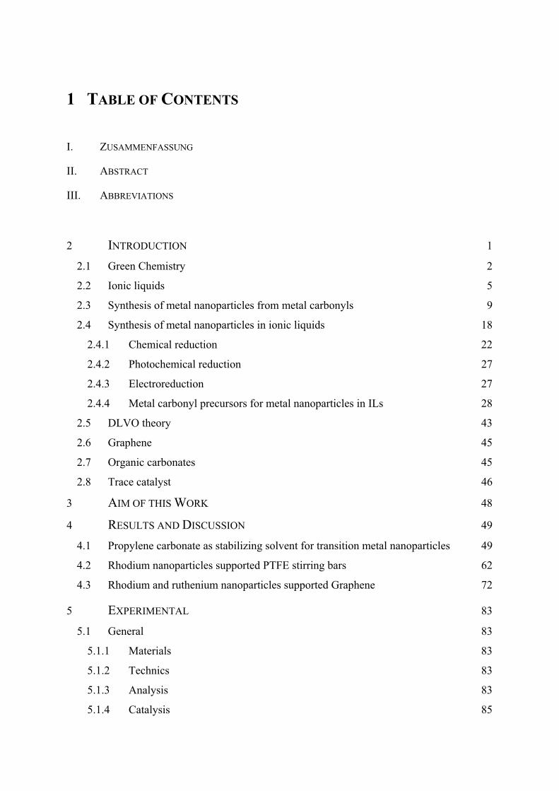
1 TABLE OF CONTENTS
I. ZUSAMMENFASSUNG
II. ABSTRACT
III. ABBREVIATIONS
2� INTRODUCTION 1�
2.1� Green Chemistry 2�
2.2� Ionic liquids 5�
2.3� Synthesis of metal nanoparticles from metal carbonyls 9�
2.4� Synthesis of metal nanoparticles in ionic liquids 18�
2.4.1� Chemical reduction 22�
2.4.2� Photochemical reduction 27�
2.4.3� Electroreduction 27�
2.4.4� Metal carbonyl precursors for metal nanoparticles in ILs 28�
2.5� DLVO theory 43�
2.6� Graphene 45�
2.7� Organic carbonates 45�
2.8� Trace catalyst 46�
3� AIM OF THIS WORK 48�
4� RESULTS AND DISCUSSION 49�
4.1� Propylene carbonate as stabilizing solvent for transition metal nanoparticles 49�
4.2� Rhodium nanoparticles supported PTFE stirring bars 62�
4.3� Rhodium and ruthenium nanoparticles supported Graphene 72�
5� EXPERIMENTAL 83�
5.1� General 83�
5.1.1� Materials 83�
5.1.2� Technics 83�
5.1.3� Analysis 83�
5.1.4� Catalysis 85�

5.2� Propylene carbonate as stabilizing solvent for transition metal nanoparticles 86�
5.2.1� General 86�
5.2.2� Metal nanoparticle (M-NP) synthesis 89�
5.2.3� Catalysis 90�
5.2.4� Preparation of ligand-capped M-NP in PC 90�
5.3� Rhodium nanoparticles supported PTFE stirring bars 91�
5.3.1� General 91�
5.3.2� Preparation of Rh-NP/IL dispersion 91�
5.3.3� Preparation of Rh-NP@stirring bar 92�
5.3.4� Catalysis 92�
5.4� Graphene-supported transition metal nanopaticles 94�
5.4.1� General 94�
5.4.2� Synthesis of chemically derived graphene ("graphene")-supported transition metal nanoparticles (M-NP/CDG) 95�
5.4.3� Catalysis 96�
5.5� Synthesis of nickel nanoparticles in BMImBF4 98�
5.6� Synthesis of palladium nanoparticles in BMImBF4 105�
6� PUBLICATIONS 108�
6.1� Organic carbonates as stabilizing solvents for transition metal nanoparticles 108�
6.2� Turning Teflon-coated magnetic stirring bars to catalyst systems with metal nanoparticle trace deposits - A caveat and a chance 109�
6.3� Naked metal nanoparticles from metal carbonyls in ionic liquids: Easy synthesis and stabilization 110�
6.4� The use of microwave irradiation for the easy synthesis of graphene-supported transition metal nanoparticle in ionic liquids 111�
7� SUMMARY AND OUTLOOK 112�
8� REFERENCES 114�
9 ATTACHMENT 128

I. ZUSAMMENFASSUNG
Metall Nanopartikel sind auf Grund ihrer großen Anwendungsbreite unter anderem in
Bereichen der Katalyse, Medizin und Materialwissenschaften von großem wissenschaftlichem
Interesse. Synthese und Stabilisierung kleinster Partikel stellen immer noch eine große
Herausforderung dar.
Das Ziel dieser Dissertation war es, kleine Metall Nanopartikel mit Partikel-
durchmessern kleiner 5 nm ausgehend von ihren binären Carbonylen reproduzierbar
herzustellen und ohne Stabilisator-Liganden alleine mit Hilfe eines schwach koordinierenden
Lösungsmittels oder durch Immobilisierung auf einer Oberfläche zu stabilisieren.
Ausgewählte Metall Nanopartikel sollten auf ihre katalytischen Hydrieraktivitäten untersucht
werden. Im Kontext der Grünen Chemie sollte die Nanopartikel-Präparation und die
anschließende Katalyse unter möglichst milden, energiesparenden Bedingungen durchgeführt
werden.
Im Rahmen der vorliegenden Arbeit wurden folgende Ziele erreicht:
1. Sphärische Nanopartikel der Übergangsmetalle Molybdän, Wolfram, Rhenium, Eisen,
Ruthenium, Osmium, Cobalt, Rhodium und Iridium konnten ausgehend von ihren
Metallcarbonylen in racemischem Propylencarbonat mit Hilfe von kurzzeitiger und
geringer Mikrowellenstrahlung (5 min, 50 W) erzeugt werden. Die Hydrierung von
Cyclohexen und 1-Hexin mit elementarem Wasserstoff und Rhodium Nanopartikeln in
Propylencarbonat gelang mit Aktivitäten von bis zu 1875 mol Produkt × (mol Rh) -1 ×
h-1. Rhodium und Ruthenium Nanopartikeln konnten mit Hilfe von 3-
Mercaptopropionsäure oder Trioctylphosphinoxid (TOPO) aus der Propylen-
carbonatphase extrahiert und für 3 Wochen stabilisiert werden ohne Änderung der
Partikeldurchmesser.
2. Rhodium Nanopartikel konnten ausgehend von Rh6(CO)16 in der ionischen Flüssigkeit
n-1-Butyl-3-methyl-imidazolium tetrafluoroborat (BMImBF4) mit kurzzeitiger und
geringer Mikrowellenstrahlung (6 min, 10 W) erzeugt werden. Nach der Trägerung
der Partikel auf einem PTFE ummantelten, handelsüblichen Rührfisch wurde mit dem
diesem „Katalysatorsytem“ in mehreren Durchläufen Cyclohexen und Benzol mit
elementarem Wasserstoff hydriert. Die Aktivitäten der Hydrierung von Cyclohexen zu
Cyclohexan verringerten sich über zehn Durchläufe von 14.9 × 10³ auf 6.6 × 10³ mol
Produkt × (mol Rh)-1 × h-1. Die Aktivitäten der Hydrierung von Benzen zu
Cyclohexan verringerten sich über drei Durchläufe von 750 auf 460 mol Produkt ×
(mol Rh)-1 × h-1.
3. Rhodium und Ruthenium Nanopartikel wurden ausgehend von ihren Carbonylen in
der ionischen Flüssigkeit BMImBF4 auf chemisch erhaltenem Graphen (CDG)
geträgert und die M-NP/CDG-Systeme in mehreren Durchläufen für die Hydrierung
von Cyclohexen und Benzol mit elementarem Wasserstoff verwendet. Die Aktivitäten
blieben über zehn Durchgänge für die Hydrierung von Cyclohexen zu Cyclohexan von
1570 mol Produkt × (mol Ru)-1 × h-1 mit Ru-NP/CDG und von 360 mol Produkt ×
(mol Rh)-1 × h-1 mit Rh-NP/CDG konstant. Die Aktivitäten von Rh-NP/CDG wurden
bei der Hydrierung von Benzen zu Cyclohexan bei verschiedenen
Reaktionstemperaturen (25, 50, 75°C) untersucht. Die höchste Aktivität von 310 mol
Produkt × (mol Rh)-1 × h-1 wurde bei 50°C ermittelt.
II. ABSTRACT
Metal nanoparticles are of high scientific interest because of their broad range of
applications in the fields of catalysis, medicine and material science. Synthesis and
stabilization of small particles still pose a big challenge.
The aim of this thesis was to obtain reproducible particles with the size smaller than 5
nm originated from their binary carbonyls and to stabilize the particles only with the help of a
weak coordinating solvent or by deposition on a surface. Selected metal nanoparticles should
be screened for their catalytic activities in hydrogenation reactions. In the context of green
chemistry the synthesis of the nanoparticles and the following catalysis should be carried out
in mild, energy-saving conditions.
In the context of this thesis following aims were accomplished:
1. Spherical nanoparticles of the transition metals molybdenum, tungsten, rhenium, iron,
ruthenium, cobalt, rhodium and iridium from their carbonyl precursors in racemic
propylene carbonate could be obtained via low and rapid microwave irradiation (5
min, 50 W). The hydrogenation of cyclohexene and 1-hexyne was successful with
elemental hydrogen and rhodium nanoparticle in propylene carbonate with activities
up to 1875 mol product × (mol Rh)-1 × h-1. Rhodium and Ruthenium nanoparticles
could be extracted with 3-mercaptopropionic acid or trioctylphosphine oxide (TOPO)
from the propylene carbonate phase and were stabilized without a big change in the
particle diameter for 3 weeks.
2. Rhodium nanoparticles could be obtained from Rh6(CO)16 in the ionic liquid n-1-
butyl-3-methyl-imidazolium tetrafluoroborate (BMImBF4) via low and rapid
microwave irradiation (6 min, 10 W). After the deposition of the particles on a PTFE
coated, commercially available stirring bar, this “catalytic system” was used for
catalytic hydrogenation runs from cyclohexene or benzene to cyclohexane. The
activities of the hydrogenation cyclohexene to cyclohexane decreased in ten runs from
14.9 × 10³ to 6.6 × 10³ mol product × (mol Rh)-1 × h-1. The activities of the
hydrogenation from benzene to cylohexane slowly decreased in three runs from von
750 auf 460 mol product × (mol Rh)-1 × h-1.
3. Chemical derived graphene was synthesized from natural graphite over graphite oxide
(Hummers and Offeman) and a following thermal reduction process. Rhodium and
Ruthenium nanoparticles were obtained from their carbonyl precursors in the ionic
liquid BMImBF4 and deposited onto chemical derived graphene (CDG) and the M-

NP/CDG-system was used for hydrogenation runs from cyclohexene or benzene to
cyclohexane with elemental hydrogen. The activities remained constant in ten runs
from cyclohexene to cyclohexane of 1570 mol product × (mol Rh)-1 × h-1. The
activities of Rh-NP/CDG were examined during the hydrogenation of benzene to
cylcohexane at different temperatures (25, 50, 75 °C). The highest activity of 310 mol
product × (mol Rh)-1 × h-1 was measured at 50 °C.
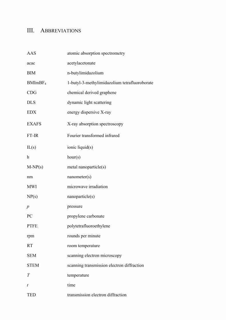
III. ABBREVIATIONS
AAS atomic absorption spectrometry
acac acetylacetonate BIM n-butylimidazolium
BMImBF4 1-butyl-3-methylimidazolium tetrafluoroborate
CDG chemical derived graphene
DLS dynamic light scattering
EDX energy dispersive X-ray
EXAFS X-ray absorption spectroscopy
FT-IR Fourier transformed infrared
IL(s) ionic liquid(s)
h hour(s)
M-NP(s) metal nanoparticle(s)
nm nanometer(s)
MWI microwave irradiation
NP(s) nanoparticle(s)
p pressure
PC propylene carbonate
PTFE polytetrafluoroethylene
rpm rounds per minute
RT room temperature
SEM scanning electron microscopy
STEM scanning transmission electron diffraction
T temperature
t time
TED transmission electron diffraction

TEM transmission electron microscopy
THF tetrahydrofuran
TOF turnover frequency
TOPO trioctylphosphine oxide
wt.% weight-%
XMCD x-ray magnetic circular dichroism
°C degree

1
2 INTRODUCTION
Metal nanoparticles (M-NPs) are of significant interest for technological applications
in several areas of science and industry, especially in catalysis due to their high activity. The
controlled and reproducible synthesis of defined and stable M-NPs with a small size
distribution is very important for a range of applications.[1-6] Note that through the years metal
nanoparticles were also referred to as nanophase metal clusters, metal nanocrystals and metal
colloids. In the following the term (metal) nanoparticles for simplicity is primarily used. M-
NPs are only kinetically stable and will combine to thermodynamically favored larger metal
particles via agglomeration. This M-NP tendency for aggregation is due to the high surface
energy and the large surface area. To avoid this agglomeration, M-NPs need to be stabilized
with strongly coordinating protective ligand layers which provide electrostatic and/ or steric
protection like polymers and surfactants.[7-9] The immobilization of M-NP onto a surface is a
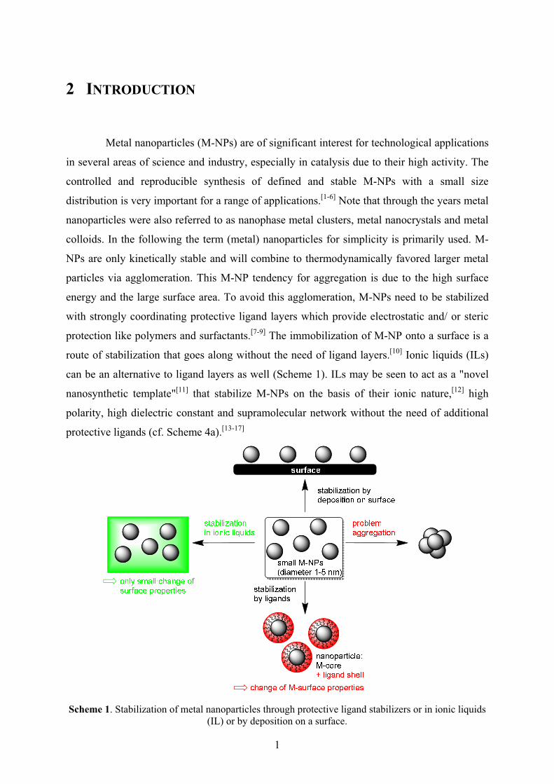
route of stabilization that goes along without the need of ligand layers.[10] Ionic liquids (ILs)
can be an alternative to ligand layers as well (Scheme 1). ILs may be seen to act as a "novel
nanosynthetic template"[11] that stabilize M-NPs on the basis of their ionic nature,[12] high
polarity, high dielectric constant and supramolecular network without the need of additional
protective ligands (cf. Scheme 4a).[13-17]
Scheme 1. Stabilization of metal nanoparticles through protective ligand stabilizers or in ionic liquids (IL) or by deposition on a surface.
2
In the absence of strongly coordinating protective ligand layers, M-NPs in ILs should
be effective catalysts. The IL network contains only weakly coordinating cations and anions
(Scheme 4) that bind less strongly to the metal surface and, hence, are less deactivating, than
the commonly employed capping or protective ligands. The combination of M-NPs and ILs
can be considered a green catalytic system because it can avoid the use of organic solvents.
ILs are interesting in the context of green catalysis[18] which requires that catalysts be
designed for easy product separation from the reaction products and multi-time efficient
reuse/recycling.[19-21] Firstly, the very low vapor pressure of the IL and designable low
miscibility of ILs with organic substrates allows for a facile separation of volatile products by
distillation or removal in vacuum. Secondly, the IL is able to retain the M-NPs for catalyst
reuse and recycling. For example, Dupont and coworkers have shown that a M-NP/ IL system
can be recycled quite easily and can be reused several times without any significant changes
in catalytic activity.[13] In recent reports of Rh-NP/IL in hydrogenation reactions, the catalytic
activity did not decrease upon repeated reuse.[22,23] A sizable number of catalytic reactions
have successfully been carried out in ILs.[24] Generally, the catalytic properties (activity and
selectivity) of dispersed M-NPs indicate that they possess pronounced surface-like (multi-site)
rather than single-site-like character.[25]
2.1 Green Chemistry
Before the Bhophal desaster in 1984[26] the chemical industry neglected ecological
aspects. High yields and the interrelated profits were prioritized over security and ecological
effects. In the 1990s scientific, ecological and sustainable chemistry, also known as green
chemistry, gained in importance. Rethinking took place both in industry and in scientific
research. In 1991 Trost was the first to bring in the concept of atom economy.[27,28] Around
that time Sheldon established the term E(nvironmental) Factor.[18] Green chemistry became
more prominent through the publications of Anastas,[29] Warner[29] and Clarke.[30,31] It can
easily be defined as:[32] Green chemistry efficiently utilises (preferably renewable) raw
materials, eliminates waste and avoids the use of toxic and/or hazardous reagents and
solvents in the manufacture and application of chemical products. In the context of green
chemistry among others catalysis itself, catalysis in non-conventional media, e.g. ionic
liquids, and alternative energy input, e.g. microwave, are at the forefront.[18,33] This trend is

3
being increasingly supported by politicians. Since 1995 the U.S. agency “Environmental
Protection Agency” (EPA) has rewarded this ecological tendency with the “Presidential Green
Chemistry Challenge Award”.
The following twelve principles in Table 1 were established by Anastas and Warner
and should be understood as general criteria in chemistry, like yields and selectivity.[29]
Anastas consequently expanded this issue into the field of engineering by defining the twelve
principles of green engineering.[34]
Table 1. The 12 principles of green chemistry.
1 It is better to prevent waste than to treat or clean up waste after it has been created.
2 Synthetic methods should be designed to maximize the incorporation of all materials used in the
process to create the final product.
3 Wherever practicable, synthetic methods should be designed to use and generate
substances that possess little or no toxicity to people or the environment.
4 Chemical products should be designed to effect their desired function while minimizing their
toxicity.
5 The use of auxiliary substances (e.g., solvents or separation agents) should be made unnecessary
whenever possible and innocuous when used.
6 Energy requirements of chemical processes should be recognized for their environmental and
economic impacts and should be minimized. If possible, synthetic methods should be conducted
at ambient temperature and pressure.
7 A raw material or feedstock should be renewable rather than depleting whenever technically and
economically practicable.
8 Unnecessary derivatization (use of blocking groups, protection/de-protection, and temporary
modification of physical/chemical processes) should be minimized or avoided if possible,
because such steps require additional reagents and can generate waste.
9 Catalytic reagents (as selective as possible) are superior to stoichiometric reagents.
10 Chemical products should be designed so that at the end of their function they break down into
innocuous degradation products and do not persist in the environment.
11 Analytical methodologies need to be further developed to allow for real-time, in-process
monitoring and control prior to the formation of hazardous substances.
12 Substances and the form of a substance used in a chemical process should be chosen to minimize
the potential for chemical accidents, including releases, explosions, and fires.
4
These twelve principles have recently been summarized by Poliakoff to a catchy
phrase: PRODUCTIVELY:[35]
P Prevent wastes R Renewable materials O Omit derivatisation steps D Degradable chemical products U Use of safe synthetic methods C Catalytic reagents T Temperature, pressure ambient I In-Process monitoring V Very few auxiliary subtrates E E Factor, maximize feed in products L Low toxicity of chemical products Y Yes, it is safe
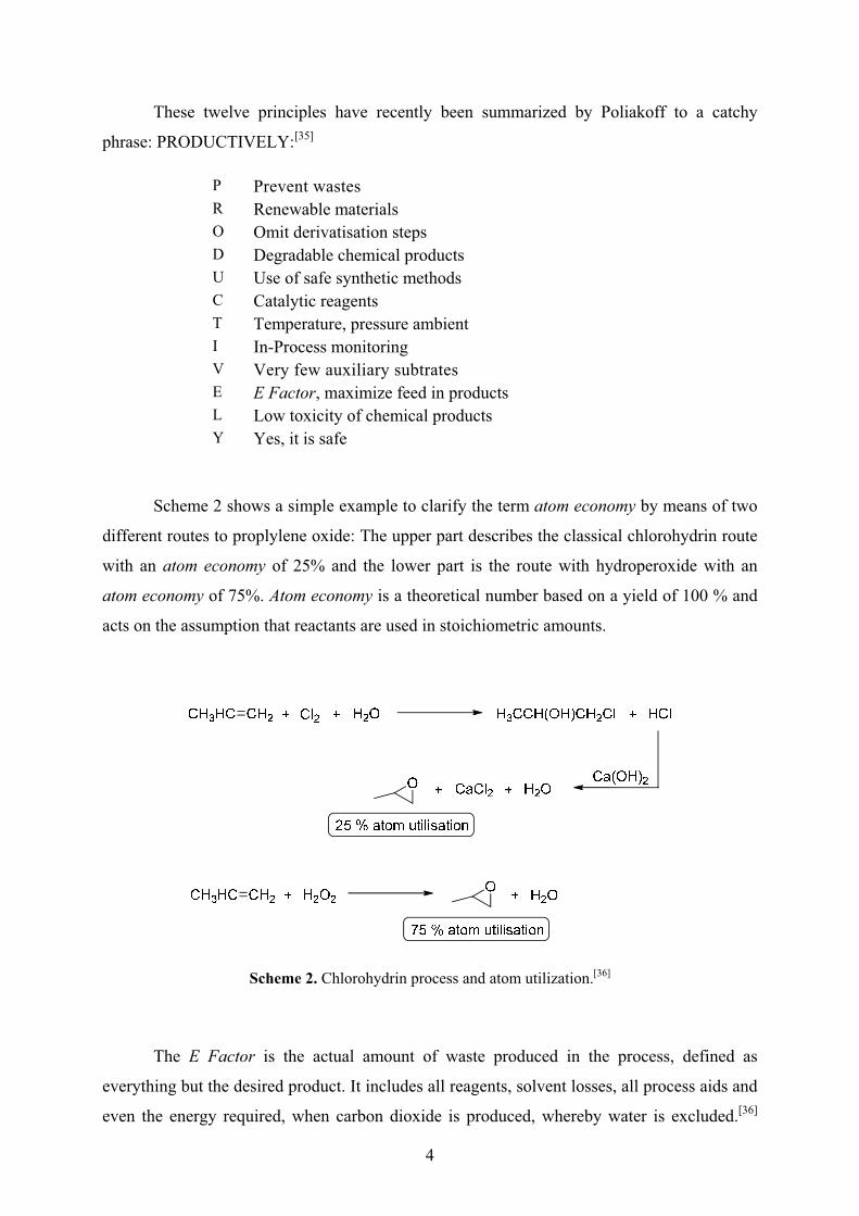
Scheme 2 shows a simple example to clarify the term atom economy by means of two
different routes to proplylene oxide: The upper part describes the classical chlorohydrin route
with an atom economy of 25% and the lower part is the route with hydroperoxide with an
atom economy of 75%. Atom economy is a theoretical number based on a yield of 100 % and
acts on the assumption that reactants are used in stoichiometric amounts.
Scheme 2. Chlorohydrin process and atom utilization.[36]
The E Factor is the actual amount of waste produced in the process, defined as
everything but the desired product. It includes all reagents, solvent losses, all process aids and
even the energy required, when carbon dioxide is produced, whereby water is excluded.[36]
5
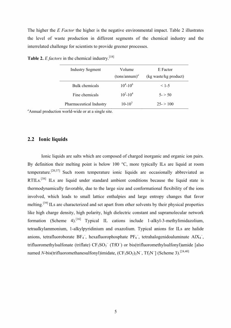
The higher the E Factor the higher is the negative environmental impact. Table 2 illustrates
the level of waste production in different segments of the chemical industry and the
interrelated challenge for scientists to provide greener processes.
Table 2. E factors in the chemical industry.[18]
Industry Segment Volume (tons/annum)a
E Factor (kg waste/kg product)
Bulk chemicals 104-106 < 1-5
Fine chemicals 102-104 5- > 50
Pharmaceutical Industry 10-103 25- > 100 aAnnual production world-wide or at a single site.
2.2 Ionic liquids
Ionic liquids are salts which are composed of charged inorganic and organic ion pairs.
By definition their melting point is below 100 °C, more typically ILs are liquid at room
temperature.[20,37] Such room temperature ionic liquids are occasionally abbreviated as
RTILs.[38] ILs are liquid under standard ambient conditions because the liquid state is
thermodynamically favorable, due to the large size and conformational flexibility of the ions
involved, which leads to small lattice enthalpies and large entropy changes that favor
melting.[39] ILs are characterized and set apart from other solvents by their physical properties
like high charge density, high polarity, high dielectric constant and supramolecular network
formation (Scheme 4).[16] Typical IL cations include 1-alkyl-3-methylimidazolium,
tetraalkylammonium, 1-alkylpyridinium and oxazolium. Typical anions for ILs are halide
anions, tetrafluoroborate BF4–, hexafluorophosphate PF6
–, tetrahalogenidoaluminate AlX4–,
trifluoromethylsulfonate (triflate) CF3SO3– (TfO–) or bis(trifluoromethylsulfonyl)amide [also
named N-bis(trifluoromethanesulfonyl)imidate, (CF3SO2)2N–, Tf2N–] (Scheme 3).[24,40]

6
Scheme 3. Typical cations and anions of most common commercially available ILs. BMIm+ is also
abbreviated as BMI in the literature.
�
The desired properties of the IL can be designed through judicious combination of
anions and cations which presents an advantage over other solvent systems for the various
envisioned IL applications. For instance: ILs containing Tf2N– offer low viscosity and high
electrochemical and thermal stability.[41] If bis(trifluoromethylsulfonyl)amide Tf2N– is
replaced by bis(methylsulfonyl)amide, viscosity increases and stability decreases.[42] This
variety leads to a high interest towards ILs as new green reusable reaction media, especially
in the field of catalysis.[25]
Scattering experiments on ILs provided important information on the structure of ionic
liquids which, thus, are not liquids in the conventional sense, but may rather be considered as
mesophases. ILs have an intrinsic "nanostructure" which is caused by electrostatic, hydrogen
bonding and van der Waals interactions.[37,43] The mesoscopic structure of imidazolium ionic
liquids in particular can be described in part as a supramolecular three-dimensional hydrogen-
bonded network (Scheme 3a).[44] Pure 1,3-dialkylimidazolium ILs can be described as a
hydrogen-bonded[44] polymeric supramolecular network of the type {[(RR'Im)x(A)x–n)]n+
[(RR'Im)x–n(A)x)]n–}n where RR'Im is the 1,3-dialkylimidazolium cation and A the anion. This
structural pattern is not only seen in the solid phase but is also maintained to a great extent in
the liquid phase. The introduction of other molecules and macromolecules proceeds with a
disruption of the hydrogen bonding network and in some cases can generate nano-structures
with polar and non-polar regions where inclusion-type compounds can be formed.[13,14] When
mixed with other molecules or M-NPs, ILs become nanostructured materials with polar and
nonpolar regions.[45-47]
Ionic liquids are nanostructural liquid media.[48] Nanometer-scale structuring in
room-temperature ILs was observed by molecular simulation for ionic liquids belonging to
the 1-alkyl-3-methylimidazolium family with hexafluorophosphate or with bis(trifluoro-

7
methylsulfonyl)amide as the anions. For ionic liquids with alkyl side chains longer than or
equal to C4, aggregation of the alkyl chains in nonpolar domains was observed. These
domains permeate a tridimensional network of charged or polar ionic channels formed by
anions and by the imidazolium rings of the cations (cf. Scheme 4a). As the length of the alkyl
chain increases, the nonpolar domains become larger and more connected and cause swelling
of the ionic network, in a manner analogous to systems exhibiting microphase separation.[48]
In other words, ILs are nanostructurally organized with nonpolar regions arising from
clustering of the alkyl chains and ionic networks arising from charge ordering of the anions
and imidazolium rings of the cations.[38] The combination of undirected Coulomb forces and
directed hydrogen bonds leads to a high attraction of the IL building units. This is the basis
for their (high) viscosity, negligible vapor pressure and three-dimensional constitution. The IL
network properties should be well suited for the synthesis of defined nano-scaled metal
colloid structures (Scheme 4).[13-15]

8
+ –
+
+–
–+
+–
–+
+–
–+
+–
–+
+–
–
+
+–
–+
+–
–+
+–
–+
+–
–
+–
+–
+–
+–
+–
+–
+–
+–
–
–
–+
+
+
+
+–
–+
+–
–+
+–
–+
+–
–
+–
–
+–
–
–
+
+–
–+
–
+–
+–
+–
+–
+–
+–
+–
+–
–
–
–+
+
metalnanoparticle
= anion
= stabilizing anion layer aroundthe metal nanoparticle
= imidazolium cation
Electrostatic and H-bonded network in imidazolium salts
with metal nanoparticles included
anion(cation)C–Hhydrogen bond
(a)
(b)
BF4–, PF6
–
TfO– = CF3SO2–
Tf2N– = (CF3SO2)2N–N N
Scheme 4. (a) Schematic network structure in 1,3-dialkylimidazolium-based ionic liquids. (b) The inclusion of metal nanoparticles (M-NPs) in the supramolecular IL network with electrostatic and
steric (= electrosteric) stabilization is indicated through the formation of the suggested primary anion layer forming around the M-NPs.
9
2.3 Synthesis of metal nanoparticles from metal carbonyls
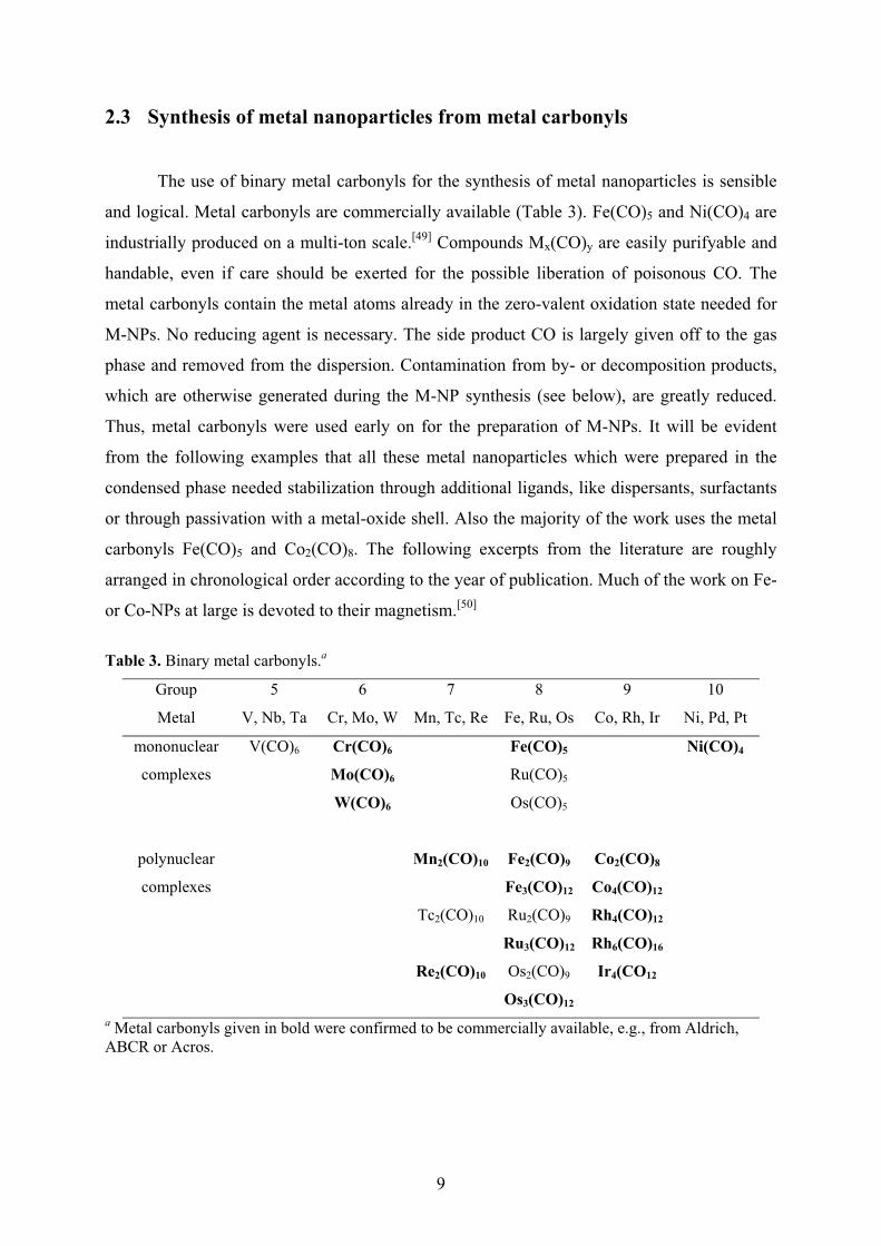
The use of binary metal carbonyls for the synthesis of metal nanoparticles is sensible
and logical. Metal carbonyls are commercially available (Table 3). Fe(CO)5 and Ni(CO)4 are
industrially produced on a multi-ton scale.[49] Compounds Mx(CO)y are easily purifyable and
handable, even if care should be exerted for the possible liberation of poisonous CO. The
metal carbonyls contain the metal atoms already in the zero-valent oxidation state needed for
M-NPs. No reducing agent is necessary. The side product CO is largely given off to the gas
phase and removed from the dispersion. Contamination from by- or decomposition products,
which are otherwise generated during the M-NP synthesis (see below), are greatly reduced.
Thus, metal carbonyls were used early on for the preparation of M-NPs. It will be evident
from the following examples that all these metal nanoparticles which were prepared in the
condensed phase needed stabilization through additional ligands, like dispersants, surfactants
or through passivation with a metal-oxide shell. Also the majority of the work uses the metal
carbonyls Fe(CO)5 and Co2(CO)8. The following excerpts from the literature are roughly
arranged in chronological order according to the year of publication. Much of the work on Fe-
or Co-NPs at large is devoted to their magnetism.[50]
Table 3. Binary metal carbonyls.a
Group
Metal
5
V, Nb, Ta
6
Cr, Mo, W
7
Mn, Tc, Re
8
Fe, Ru, Os
9
Co, Rh, Ir
10
Ni, Pd, Pt
mononuclear
complexes
V(CO)6 Cr(CO)6 Fe(CO)5 Ni(CO)4
Mo(CO)6 Ru(CO)5
W(CO)6 Os(CO)5
polynuclear
complexes
Mn2(CO)10 Fe2(CO)9
Fe3(CO)12
Co2(CO)8
Co4(CO)12
Tc2(CO)10 Ru2(CO)9
Ru3(CO)12
Rh4(CO)12
Rh6(CO)16
Re2(CO)10 Os2(CO)9
Os3(CO)12
Ir4(CO12
a Metal carbonyls given in bold were confirmed to be commercially available, e.g., from Aldrich, ABCR or Acros.

10
In early reports Hess and Parker (1966)[51] and Thomas (1966)[52] described processes
for preparing metallic cobalt particles of uniform size in the 10-1000 Å range (0.1-100 nm).
Dicobalt octacarbonyl Co2(CO)8 was thermally decomposed in typcially toluene solutions of
dispersant polymers, such as methyl methacrylate-ethyl acrylate-vinylpyrrolidone
terpolymers, high-purity polystyrene, styrene-acrylonitrile polymers, polyacrylonitril,
chloropolyethylene sulfonamide, polyester and polyether urethanes to form stable colloids of
discrete particles which are separated by polymer coatings. Variation of polymer composition,
molecular weight and solvent used results in a variation of particle size and colloid stability.
Preparation of single-domain ferromagnetic cobalt particles with good magnetic properties
was possible through a balance between dispersant polymer, solvent, and the growing metal
particle.[51]
Papirer et al. (1983) prepared a stable suspension of metallic cobalt particles in an
organic solvent (ferrofluid) by decomposition of Co2(CO)8.[53,54] The cobalt particles originate
from the thermolysis of the dicobalt octacarbonyl solution in the presence of a chosen surface
active agent. The reaction temperature, the nature of the solvent and of the surfactant, the
weight ratio of carbonyl and surfactant, and the initial concentration of the cobalt carbonyl
solution were varied. Spherical particles, of a narrow size distribution, are obtained when the
decomposition of Co2(CO)8 is carried out in an aromatic solvent above 110 °C and in the
presence of a surfactant possessing a long hydrocarbon chain and a strong ionic group
(sulfonate). The decomposition in toluene, in which ethyl (2-hexyl) sodium sulfo-succinate is
dissolved, leads to particles of about 70 Å in diameter. When a ferrofluid is being formed, an
initial and rapid evolution of CO corresponding to the formation of Co4(CO)12 is recorded.
Part of this compound is insoluble in the reaction medium and appears to be a regulating
intermediate. After this short initial stage the rate of decomposition of Co4(CO)12 slows down
and becomes practically constant. Later the CO formation is accelerated again and finally it
decreases as the reaction goes to completion. This S-shaped curve which describes the
decomposition of Co2(CO)8 is always observed when a ferrofluid is in progress of
formation.[53] The diameters of the particles, and the number of growing particles have been
measured using also small-angle X-ray scattering and magnetic methods. The presence of
microreactors in the reaction medium and a diffusion controlled growth mechanism are seen
as the responsible two factors for the formation of particles of very narrow size
distribution.[54]
Suslick et al. (1996) reported the synthesis of "monosized" iron nanoparticles from 3
to 8 nm (amorphous according to electron microdiffraction) through the sonochemical
11
decomposition of iron pentacarbonyl, Fe(CO)5 in octanol or hexadecane in the presence of
polyvinylpyrrolidone (PVP) or oleic acid, respectively, as a stabilizer.[55]
Platonova et al. (1996) obtained Co nanoparticles in polystyrene(PS)-poly-4-vinyl-
pyridine (PVP) micelles by thermal decomposition of Co2(CO)8 in micellar solutions of such
block copolymers. Co particles are effectively stabilized by the block copolymer matrix and
do not aggregate. Thermal treatment of such dried polymers at 200 °C for 2 h leads to
spherical particles of 3-5 nm in size. The polymeric hybrid materials displayed remarkably
high values of magnetization at rather low Co contents in the polymer.[56]
Lee et al. (1998) produced nanoparticles of iron, chromium, molybdenum and tungsten
by laser decomposition of the corresponding metal carbonyls with a 10.6 μm CO2 laser in the
presence of Ar and SF6.[57] Argon helped to increase the purity of the metal clusters by
suppressing the formation of (M)x(CO)y for M = Cr, Mo, W). SF6 acted as an infrared
photosensitizer, which initially absorbed the 10.6 μm IR photons from the CO2 laser and
transferred its energy to a metal carbonyl via collisions. The M-NP size distributions were
narrow and the average diameter was 6, 3.5, 2 and ~1 nm for Fe, Cr, Mo and W clusters,
respectively, as determined by TEM. The structure was found to be bcc for both Fe and Cr
clusters, fcc for Mo clusters, and amorphous for W clusters as determined from the X-ray
diffraction patterns (note that all the bulk metals have bcc structure). The cluster size (n) in
one cluster of average diameter was estimated by assuming a spherical shape such that n =
(cluster volume/atomic volume) × packing fraction = (r/r0)3f, with r the cluster radius, r0 the
atomic radius and f the packing fraction (0.68 for bcc and 0.74 for fcc). Considering the
cluster sizes (n = 9630, 1870, 230 and ~30 for Fe-, Cr-, Mo- and W-NPs, respectively)
estimated from their average diameters, it was found likely that there exists a structural
transition from fcc to bulk bcc with increasing cluster size in these metal clusters.[57]
Dinega and Bawendi (1999) used the kinetic control of crystal growth in the presence
of a coordinating ligand for the formation of a new structure of elemental cobalt (�-cobalt),
which was discovered upon analyzing the metallic powder produced by the thermal
decomposition of Co2(CO)8 in solution in the presence of trioctylphosphane oxide.[58]
Giersig and Hilgendorff (1999) prepared cobalt nanoparticles by thermolysis of
Co2(CO)8 in Ar-saturated toluene as an organic carrier at 110 °C in the presence of two
different surfactants. The surfactants used were sodium bis 2-(ethyl-hexyl)sulfosuccinate and
oleoylsarcosine. The magnetic nanoparticles were then ordered into a two-dimensional array
using a magnetophoretic technique. The quality of the ordering was observed by electron
microscopy and the lattice constants determined by electron diffraction. It could be shown
12
that the cobalt particles condense into a hexagonal close packed array.[59] These arrays of
monodisperse colloidal 11.4-nm Co nanoparticles were investigated by multifrequency
ferromagnetic resonance and x-ray magnetic circular dichroism (XMCD) to determine the
ratio of orbital-to-spin magnetic moment as μL/μSeff=0.24±0.06 by XMCD.[60]
Van Wonterghem, Mørup et al. (1985, 1988),[61,62] Pathmamanoharan et al. (2000),[63]
Gossens et al. (2002)[64] and Butter, Philipse et al. (2003)[65] formed iron nanoparticles by
thermolysis of Fe(CO)5 in decalin with modified polyisobutene and oleic acid as stabilizers.
The magnetic Fe-NPs are fairly monodisperse even for particle radii below 10 nm. The
particle size can be increased by seeded growth, and the particle shape can be changed by
using a mercaptan stabilizer, which leads to rod-like iron colloids. The thermal decomposition
of iron pentacarbonyl in a mixture of decalin and sarkosyl-O (n-oleyoyl sarcosine) has been
studied by Moessbauer spectroscopy. Together the X-ray diffraction it was shown that the
sample contained small particles of a metallic glass (amorphous material). Annealing of the
particles at 523 K resulted in crystallization of the particles into a mixture of �-Fe and
Fe5C2.[61] Fe2+ was found in all samples. After some time of reaction, a new iron carbonyl
complex appeared. During the final stages of the reaction, this intermediate carbonyl complex
decomposed, and ultrafine particles of an amorphous Fe100�xCx alloy were formed.[62]
Moessbauer spectroscopy also showed that the Fe-NPs with r = 5.3, 6.9 and 8.2 nm are
dominated by the broadened sextuplet with Heff =262 kOe similar to that found in the sarcosyl
and oleic acid stabilized colloids. This hyperfine field characterizes Fe1�xCx species with x �
0.25 by comparison with sputtered amorphous Fe1�xCx films.[66] In addition, a small
contribution of a sextuplet with Heff = 496 kOe characterising an Fe(III) oxidic contribution is
visible in the spectra of the Fe-NPs with r = 5.3 and 6.9 nm. This Fe(III) oxidic contribution is
absent for the largest NP with r = 8.2 nm, while the spectrum of the NPs with the smallest
radius (r = 2.1 nm) turned out to be completely oxidic.[64]
Huh et al. combined a thermal decomposition of metal carbonyls with a collision
induced clustering. Metal carbonyls Fe(CO)5 and Mo(CO)6 were thermally decomposed with
a hot filament and resultant bare metal atoms underwent collisions to produce high purity Fe,
Mo, and alloy Fe/Mo nanometer size metal particles.[67]
Park, Hyeon et al. (2000) prepared monodisperse 2 nm spherical iron nanoparticles by
the thermal decomposition of Fe(CO)5 in the presence of the stabilizing surfactant
trioctylphosphine oxide (TOPO). Subsequently, nearly uniform rodshaped iron nanoparticles
were then obtained from the controlled growth of these monodisperse spherical
nanoparticles.[68]
13
By thermal decomposition of Fe(CO)5 with simultaneous reduction of platinum
acetylacetonate Pt(acac)2 in the presence of oleic acid and oleyl amine Sun, Murray et al.
(2000) synthesized monodisperse iron–platinum nanoparticles.[69] Chen and Nikles (2002)
used this procedure for the preparation of FePd and FeCoPt alloy nanoparticles with very
narrow size distribution, using Fe(CO)5, Pd(acac)2 or Pt(acac)2 and Co(acac)2.[70,71]
From Co2(CO)8 and Pt(hfac)2 in hot toluene and oleic acid very small and
monodisperse CoPt3 alloy nanoparticles with 1.8(1) nm were obtained by Park and Cheon
(2001).[72]
Puntes, Krishnan and Alivisatos (2001) reported the synthesis of monodisperse �-Co
nanoparticles with spherical shapes and sizes ranging from 3 to 17 nm by the rapid pyrolysis
of a dicobalt octacarbonyl solution in dichlorobenzene in the presence of a surfactant mixture
composed of oleic acid, lauric acid and trioctylphosphine. The size distribution and the shape
of the nanocrystals were controlled by varying the surfactant (oleic acid, phosphonic oxides
and acids, etc.) its concentration, and the reaction temperature.[73]
Hyeon et al. (2001) utilized a high-temperature (300 °C) aging of an iron-oleic acid
metal complex, which was in turn prepared by the thermal decomposition of iron
pentacarbonyl in the presence of oleic acid at 100 °C to generate monodisperse iron
nanoparticles. The Fe-NP particle size ranged from 4 to 20 nm. The resulting iron
nanoparticles were then transformed to monodisperse �-Fe2O3 nanocrystallites by controlled
oxidation using trimethylamine oxide as a mild oxidant.[74] With a similar procedure Kim,
Hyeon et al. (2001) prepared cobalt nanoparticles from Co2(CO)8, oleic acid,
trioctylphosphine and dioctyl ether under reflux. The Co-NPs were applied as recyclable
catalysts for Pauson–Khand reactions, which involve the cycloaddition of alkynes, alkenes
and carbon monoxide to cyclopentenones.[75]
Burke, Stöver et al. (2002) prepared polymer-coated iron nanoparticles by the thermal
decomposition of Fe(CO)5 in the presence of ammonia and polymeric dispersants.[76] The
dispersants consist of polyisobutylene (PIB), polyethylene, or polystyrene chains
functionalized with tetraethylenepentamine, a short polyethyleneimine chain. Inorganic-
organic core-shell nanoparticles were formed with all three types of dispersants. With the PIB
dispersants, the particle size is determined, in part, by the iron pentacarbonyl loading,
increasing from 8 ± 1 nm for a 1:1 Fe(CO)5/dispersant ratio to 20 ± 4 nm for a 5.5:1 ratio.[76]
Butter et al. (2002) studied the preparation and properties of metallic iron particles,
synthesized by thermal decomposition of Fe(CO)5 in the presence of the stabilizer modified
polyisobutylene. By varying the iron carbonyl/polymer ratio, the particle size could be varied
14
from 2 to 10 nm. Particles were characterized by magnetization measurements, transmission
electron microscopy (TEM), small angle X-ray scattering and cryo-TEM. Cryo-TEM pictures
show linear structures of the larger particles as a consequence of magnetic interaction. From
susceptibility measurements, it is seen that particles oxidize fast on exposure to air.[77]
Rutnakornpituk, Riffle et al. (2002) use copolymers as micelles in toluene to serve as
nanoreactors for the thermal decomposition of Co2(CO)8 to superparamagnetic Co-NP
dispersions. The steric stabilizers are poly[dimethylsiloxane-b-(3-cyanopropyl)methyl-
siloxane-b-dimethylsiloxane] (PDMS-PCPMS-PDMS) triblock copolymers in poly-
(dimethylsiloxane) carrier fluids. The nitrile groups on the PCPMS central blocks are thought
to adsorb onto the particle surface. The Co-NP size could be controlled by adjusting the Co-
to-copolymer ratio. TEM showed non-aggregated Co-NPs with narrow size distributions and
evenly surrounded by the copolymer sheaths.[78]
Diana et al. (2003) synthesized cobalt nanoparticles within inverse micelles of
polystyrene-block-poly(2-vinylpyridine) copolymer in toluene by the pyrolysis of Co2(CO)8 at
115 °C.[79] The nanoparticle structure at different reaction times was investigated using
transmission electron microscopy and Fourier transform infrared spectroscopy (FT-IR). At
early reaction stages, the nanoparticles were found to be noncrystalline from TEM, and FT-IR
showed that the precursor was only partially decomposed. After 15 min of reaction, the
nanoparticles became crystalline, forming chains due to magnetic interactions. The
noncrystalline nanoparticles could be crystallized upon heating to 420 °C on grids in the
transmission electron microscope. This produced nearly monodisperse single nanocrystals
inside each micelle, with limited aggregation, but such annealing led to the degradation of the
polymer.[79]
Bönnemann, Behrens et al. (2003-2007) obtained monodisperse Co, Fe, and FeCo
nanoparticles through thermal decomposition of the metal carbonyls Co2(CO)8, Fe(CO)5 or
Fe(CO)5/Co2(CO)8 in the presence of aluminium alkyls (AlR3), as air-stable magnetic metal
nanoparticles after surface passivation.[80-83] After decomposition the metal particles were
treated with synthetic air through a thin capillary (smooth oxidation) (Scheme 5) to yield
particles stable in air under ambient conditions for over one year, as confirmed by magnetic
measurements.

15
Scheme 5. Thermolysis of Co2(CO)8 in the presence of aluminium alkyls to Co-NPs and smooth air oxidation for surface passivation.
The aluminium alkyl acts as a catalyst, activating the thermal decomposition of the
metal carbonyl as well as the surface passivation during the smooth oxidation. The resulting
particles strongly depend on the alkyl chain length R of the aluminium alkyl and the Co2(CO)8
to AlR3 ratio. Monodisperse Co nanoparticles, 3–4.5 nm, 6.5–8.5 nm to 8.5–10.5 nm in
diameter, were obtained for Al(CH3)3, Al(C2H5)3, and Al(C8H17)3, respectively.[81] The
particles were characterized by electron microscopy (SEM, TEM, ESI), electron spectroscopy
(MIES, UPS, and XPS) and X-ray absorption spectroscopy (EXAFS). EXAFS measurements
showed that this preparation pathway provides long term stable zerovalent magnetic cobalt
particles. The chemical nature of the surfactant used exerts a significant influence on the
stability and the local electronic and geometric structure of the analyzed nanoparticles.[80]
With the help of surfactants, for instance oleic acid or cashew nut shell liquid, the metal
particles can be peptized in organic solvents like toluene or kerosene, resulting in magnetic
fluids. The saturation of magnetization, Ms, of the fluids was determined by specific
magnetization. The sizes and structure of the particles were investigated by transmission
electron microscopy, and Moessbauer analysis showed that the core of the particles was
metallic or alloyed, respectively. The particle surface termination was studied by X-ray
photoelectron and Auger electron spectroscopy.[81] The particles were also peptized by
surfactants to form stable magnetic fluids in various organic media and water, exhibiting a
high volume concentration and a high saturation magnetization. In view of potential
biomedical applications of the particles, several procedures for surface modification are
possible, including peptization by functional organic molecules, silanization, and in situ
polymerization.[81] Other procedures for surface modification of these pre-stabilized, metallic
Co-NPs include direct anchoring of surface-active functional groups and biocompatible
dextran layers as well as silica and polymer coatings. As a result, individually coated
nanoparticles as well as microspheres can be obtained.[83]

16
Yin, Alivisatos et al. (2004) formed a Pt@CoO yolk-shell nanostructure in which a
platinum nanocrystal of a few nanometers was encapsulated in a CoO shell.[84] This was
achieved by first reducing platinum acetylacetonate with a longchain polyol to form uniform
platinum nanoparticles in the presence of surfactants such as oleic acid, oleylamine, and
trioctylphosphine. The size of the platinum particles was tuned from 1 to 10 nm, depending on
the concentration of surfactants. Co2(CO)8 was then injected into the hot solution and
decomposed to form a conformal coating on the platinum nanocrystals. Oxidation of the
Pt@Co nanocrystals was performed a few minutes after introduction of the cobalt carbonyl by
blowing a stream of O2/Ar mixture into the colloidal solution at 455 K.[84]
Zubris, King, Tannenbaum et al. (2005) describe the synthesis of iron and cobalt alloy
nanoparticles by the co-decomposition of iron and cobalt carbonyl precursors in the presence
of polystyrene as a surface stabilizing agent.[85] The decomposition kinetics of the Fe(CO)5
and Co2(CO)8 were established and controlled. The results suggest that Fe(CO)5
decomposition is a higher-order process (not first-order as previously assumed), with a
complicated intermediate mechanism. Equal initial concentrations of both precursors
generated nanoalloys with a crystalline core–shell dense morphology, while precursor
concentrations corresponding to initial equal rates of decomposition generated polycrystalline
nanoalloys with a diffuse morphology.[85]
Hütten et al. (2005) prepared ferromagnetic FeCo-alloyed nanoparticles from the two
precursors Co2(CO)8 and Fe(CO)5 aiming for a Fe to Co ratio of 50:50.[86] Characterization of
the alloyed nanoparticles utilized high-resolution transmission electron microscopy and
dispersive X-ray analyses.[87]
Korth, Pyun et al. (2006) synthesized polystyrene (PS)-coated cobalt nanoparticles by
the thermolysis of Co2(CO)8 in the presence of end-functional polymeric surfactants in
refluxing 1,2-dichlorobenzene.[88] A mixture of amine and phosphine oxide PS surfactants
(4:1 wt ratio) was used in the thermolysis of Co2(CO)8 to prepare polymer-coated cobalt
nanoparticles, where the ligating end group passivated the colloidal surface. The combination
of both amine and phosphine oxide ligands on the PS chain was found necessary to yield
uniform ferromagnetic nanoparticles. These polymer-coated cobalt nanoparticles (PS-Co)
were then characterized using TEM, atomic force microscopy (AFM), and magnetic force
microscopy (MFM) to determine particle size and morphology of magnetic colloids and
nanoparticle chains.[88]
It is obvious that the use of metal carbonyls for M-NP preparation will also be noted in
the patent literature. An example is given by Mercuri (2007), describing "a process for

17
producing nano-scale metal particles which includes feeding at least one metal carbonyl into a
reactor vessel; exposing the metal carbonyl to a source of energy sufficient to decompose the
metal carbonyl to produce nano-scale metal particles; and depositing or collecting the metal
nanoparticles. Oxygen is fed into the reactor vessel to partially oxidize the nanoscale metal
particles produced by decomposition of the decomposable moiety. The nanoscale metal
particles are then brought onto an end-use substrate which are intended to be employed, such
as the aluminum oxide or other components of an automotive catalytic converter, or the
electrode or membrane of a fuel cell or electrolysis cell".[89,90]
Gergely et al. describe "a process for preparing superparamagnetic transition metal
nanoparticles by introducing into a gas stream a hydrocarbon and a transition metal carboxyl
wherein the transition metal carbonyl is introduced downstream from the hydrocarbon;
wherein at the point of introduction of the hydrocarbon the gas stream is as a plasma, and
wherein at the point of introduction of the transition metal carbonyl the gas stream is at a
temperature of at least 1000 °C, followed by quenching to form C-coated transition metal
nanoparticles; and wherein the gas stream consists essentially of at least one inert gas and
H".[91]
Gürler, Schmidt et al. (2008) showed that hydroxyfunctional cobalt nanoparticles can
be obtained in a single step by thermal decomposition of Co2(CO)8 in the presence of ricinolic
acid as a functional surfactant. The chemisorbed ricinolic acid through the carboxylic acid
group served to introduce hydroxyl groups that serve as an initiator for the ring-opening
polymerization of 3-caprolactone to give the desired hybrid cobalt/polycaprolactone brush
particles.[92]
Doan, Johans et al. (2010) investigated the oxidation of Co nanoparticles stabilized
with various ligands in an autoclave.[93] Tridodecylamine stabilized Co nanoparticles with
different sizes (8 nm, 22 nm and 36 nm) were prepared by thermal decomposition of
Co2(CO)8 in dodecane. The oxidation of the particles was studied by introducing oxygen into
the autoclave and following the oxygen consumption with a pressure meter. Tridodecylamine
capped particles were initially oxidized at a high rate, however, the oxidation layer quickly
inhibited further oxidation. The thickness of the oxide layer estimated from the oxygen
consumption was 0.8 nm for all three particle sizes showing that the oxidation is size
independent in the studied particle size range. The tridodecylamine ligand was exchanged for
various long chain carboxylic acids followed by subsequent oxidation. With the carboxylic
acids the formed oxide layer does not inhibit further oxidation as effectively as in the case of
tridodecylamine. TEM studies show that tridodecylamine capping leads to particles with a

18
metal core surrounded by an oxide layer, while particles capped with long chain carboxylic
acids form hollow cobalt oxide shells.[93]
The aforementioned examples together with reviews on the chemical synthesis of
metal nanoparticles[50] illustrate the wide applicability of Fe(CO)5 and Co2(CO)8 for the
preparation of iron- and cobalt-containing nanoparticles. Yet, it is also evident that the
utilization of metal carbonyls in nanoparticle synthesis is largely limited to these two carbonyl
compounds. This may in part be due to the strong interest in magnetic M-NPs. It also
becomes clear that the prepared M-NPs need a protecting layer to prevent aggregation to
larger particles or oxidation.
2.4 Synthesis of metal nanoparticles in ionic liquids
Metal nanoparticles can be synthesized in ILs[94] through chemical reduction[23,95-99] or
decomposition,[100,134,143,147] by means of photochemical reduction[101,102] or electro-
reduction[103-105] of metal salts where the metal atom is in a formally positive oxidation state
and by decomposition of metal carbonyls with zero-valent metal atoms[11,22,23,106] without the
need of extra stabilizing molecules or organic solvents.[7,13,15,107,108]
A myriad of M-NPs have been prepared in ILs from compounds with the metal in a
formally positive oxidation state Mn+. Such M-NPs then include, for example, the main-group
metals and metalloids Al,[109] Te,[110] and the transition metals Ru,[111] Rh,[98] Ir,[112] Pt,[113]
Ag,[95,114] Au,[115] (cf. Table 4).
The inclusion of metal nanoparticles in the supramolecular ionic liquid network brings
with it the needed electrostatic and steric (= electrosteric) stabilization through the formation
of an ion layer forming around the M-NPs. The type of this ion layer, hence, the mode of
stabilization of metal nanoparticles in ILs is still a matter of some discussion.[15,135] Aside
from the special case of thiol-, ether-, carboxylic acid-, amino-, hydroxyl- and other
functionalized ILs (see below) one could decide between IL-cation or –anion coordination to
the NP surface. Schrekker and co-workers proposed electrostatic stabilization of a negatively
charged surface of Au-NPs by parallel coordination mode of the imidazolium cation on the
basis of surface-enhanced Raman spectroscopy (SERS) studies.[116] This proposal was
supported by Alvarez-Puebla and co-workers who found a negative zeta potential of M-NPs
19
prepared by chemical reduction processes which indicated a negative charge of such NPs in
aqueous solutions.[117]
According to DLVO (Derjaugin-Landau-Verwey-Overbeek) theory (see chapter 1.5),[118]
ILs provide an electrostatic protection in the form of a "protective shell" for M-NPs.[107,119-123]
DLVO theory predicts that and the first inner shell must be anionic and the anion charges
should be the primary source of stabilization for the electrophilic metal nanocluster.[118]
DLVO theory treats anions as ideal point charges. Real-life anions with a molecular volume
would be better classified as "electrosteric stabilizers" meaning to combine both the
electrostatic and the steric stabilization. However, the term "electrosteric" is contentious and
ill-defined.[124] The stabilization of metal nanoclusters in ILs could, thus, be attributed to
"extra-DLVO" forces[124] which includes effects from the network properties of ILs such as
hydrogen bonding, the hydrophobicity and steric interactions.[2,125]
Density functional theory (DFT) calculations in a gas phase model favor interactions
between IL anions, such as BF4–, instead of imidazolium cations and Aun clusters (n = 1, 2, 3,
6, 19, 20). This suggests a Au···F interaction and anionic Aun stabilization in fluorous ILs. A
small and Au-concentration dependent 19F-NMR chemical shift difference (not seen in 11B -or 1H-NMR) for Au-NP/BMIm+BF4
– supports the notion of a BF4–-fluorine···Au-NP contact seen
as crucial for the NP stabilization in dynamic ILs.[126] The DFT study used the binding energy
(BE) of different IL-ions, free bases and the Cl– anion to gold clusters of various sizes as a
relative measure for the interaction strength The BE is defined as the difference of the relaxed
energies of the gas phase anions and the Aun clusters to the energy of their adduct (Eqn.
1).[126,137]
���������������� ��������������������� ��� (1)
Fig. 1 shows the Aun–IL anion binding configurations and the variation of the BE with
cluster size n. Fig. 2 illustrates Aun–substrate binding configurations and the variation of the
BE with cluster size n for BF4– in comparison with other common substrate ligands. The BE
of BMIm+ is found to be very weak and not shown.[126,137] BE comparison with chloride,
citrate, PH3 and H2O illustrates the critical influence of the ionic charge and electron
delocalization from the ligand to Aun (Fig. 4). The softer the anion or ligand, that is, the more
charge transfer or electron delocalization (according to Pearsons hard-soft concept and the
nephelauxetic series)[127] to Aun is possible, the better the stabilizing effect. H2O as a hard and
neutral ligand offers the least stabilization, hence, reduction of gold salts by SnCl2 in water
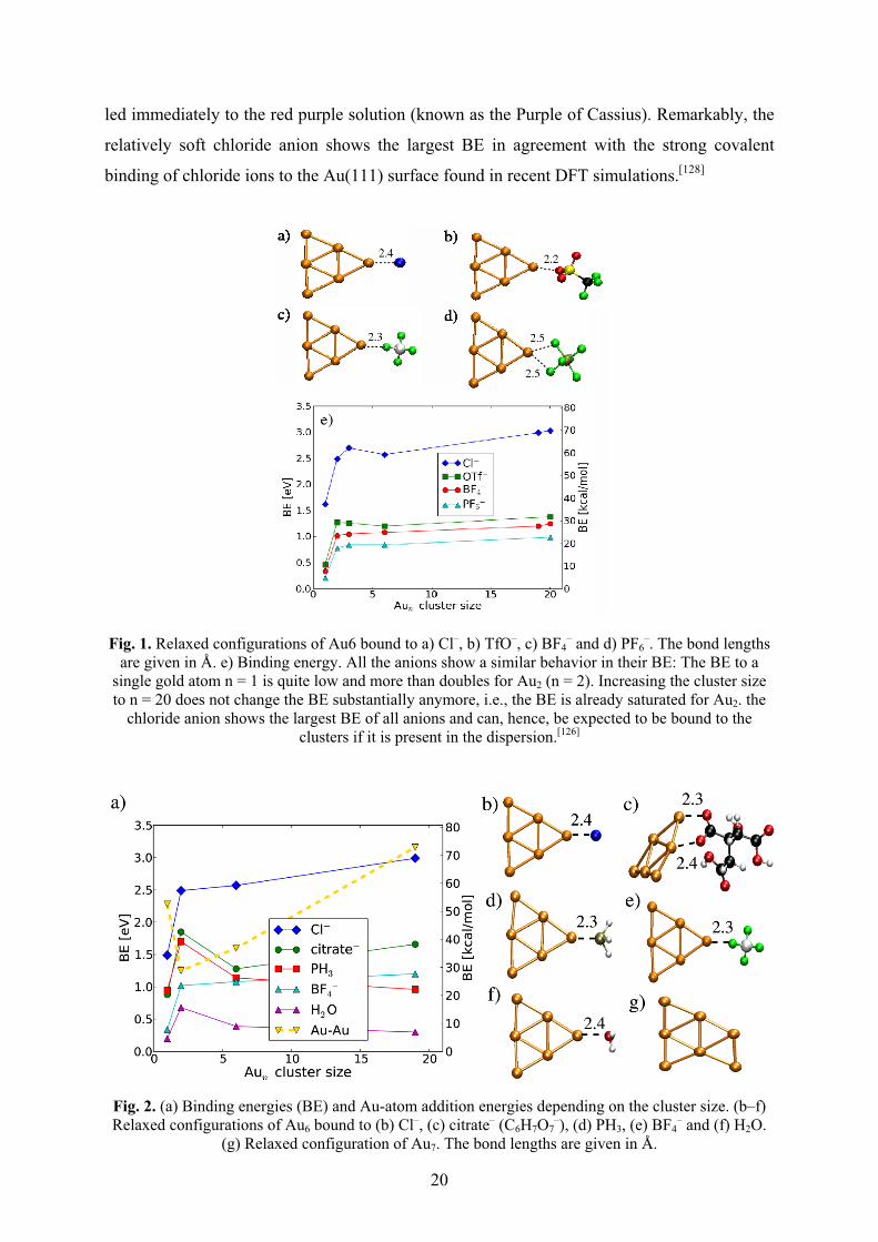
20
led immediately to the red purple solution (known as the Purple of Cassius). Remarkably, the
relatively soft chloride anion shows the largest BE in agreement with the strong covalent
binding of chloride ions to the Au(111) surface found in recent DFT simulations.[128]
Fig. 1. Relaxed configurations of Au6 bound to a) Cl–, b) TfO–, c) BF4– and d) PF6
–. The bond lengths are given in Å. e) Binding energy. All the anions show a similar behavior in their BE: The BE to a
single gold atom n = 1 is quite low and more than doubles for Au2 (n = 2). Increasing the cluster size to n = 20 does not change the BE substantially anymore, i.e., the BE is already saturated for Au2. the
chloride anion shows the largest BE of all anions and can, hence, be expected to be bound to the clusters if it is present in the dispersion.[126]
Fig. 2. (a) Binding energies (BE) and Au-atom addition energies depending on the cluster size. (b–f) Relaxed configurations of Au6 bound to (b) Cl–, (c) citrate– (C6H7O7
–), (d) PH3, (e) BF4– and (f) H2O.
(g) Relaxed configuration of Au7. The bond lengths are given in Å.

21
The DFT calculations also indicate a weak covalent part in this Au···F interaction. Free
imidazole bases (e.g. 1-methylimidazole) show similar binding energies. The Cl– anions are
found to have the highest binding energy and can therefore be expected to bind to the NP if
present in the solution. At the same time no significant binding of the BMIm+ or MIm+
imidazolium cations is found. These findings support the model of preferred interaction
between anions and Au-NPs, but also confirm the importance to consider a possible presence
of Cl– anions in the ionic liquid solution.[126,137]
Compared with the unfunctionalized imidazolium-ILs (cf. Scheme 3), functionalized
imidazolium-ILs stabilize aqueous dispersed metal NPs much more efficiently because of the
special functional group. Thiol-,[115,129,130] ether-,[116] carboxylic acid-,[135] amino-,[131,135] and
hydroxyl-functionalized[129] imidazolium-ILs (Scheme 6) have been used to synthesize
aqueous dispersed noble, primarily gold metal NPs.

22
Scheme 6. Examples of functionalized imidazolium-ILs.[115,116,129-131,135]
2.4.1 Chemical reduction
The reduction of metal salts is the most utilized method to generate NPs in solution
and also in ILs in general. Many different types of reducing agents are used, like gases (H2),
organic (citrate, ascorbic acid, imidazolium cation of IL) and inorganic (NaBH4, SnCl2)
agents.
23
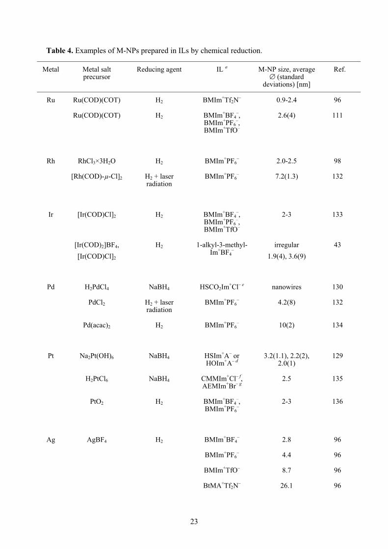
Table 4. Examples of M-NPs prepared in ILs by chemical reduction.
Metal Metal salt precursor
Reducing agent IL a M-NP size, average � (standard
deviations) [nm]
Ref.
Ru Ru(COD)(COT) H2 BMIm+Tf2N– 0.9-2.4 96
Ru(COD)(COT) H2 BMIm+BF4–,
BMIm+PF6–,
BMIm+TfO–
2.6(4) 111
Rh RhCl3×3H2O H2 BMIm+PF6– 2.0-2.5 98
[Rh(COD)-μ-Cl]2 H2 + laser radiation
BMIm+PF6– 7.2(1.3) 132
Ir [Ir(COD)Cl]2 H2 BMIm+BF4–,
BMIm+PF6–,
BMIm+TfO–
2-3 133
[Ir(COD)2]BF4, [Ir(COD)Cl]2
H2 1-alkyl-3-methyl-Im+BF4
– irregular
1.9(4), 3.6(9) 43
Pd H2PdCl4 NaBH4 HSCO2Im+Cl– e nanowires 130
PdCl2 H2 + laser radiation
BMIm+PF6– 4.2(8) 132
Pd(acac)2 H2 BMIm+PF6– 10(2) 134
Pt Na2Pt(OH)6 NaBH4 HSIm+A– or HOIm+A– d
3.2(1.1), 2.2(2), 2.0(1)
129
H2PtCl6 NaBH4 CMMIm+Cl– f, AEMIm+Br– g
2.5 135
PtO2 H2 BMIm+BF4–,
BMIm+PF6–
2-3 136
Ag AgBF4 H2 BMIm+BF4– 2.8 96
BMIm+PF6– 4.4 96
BMIm+TfO– 8.7 96
BtMA+Tf2N– 26.1 96
24
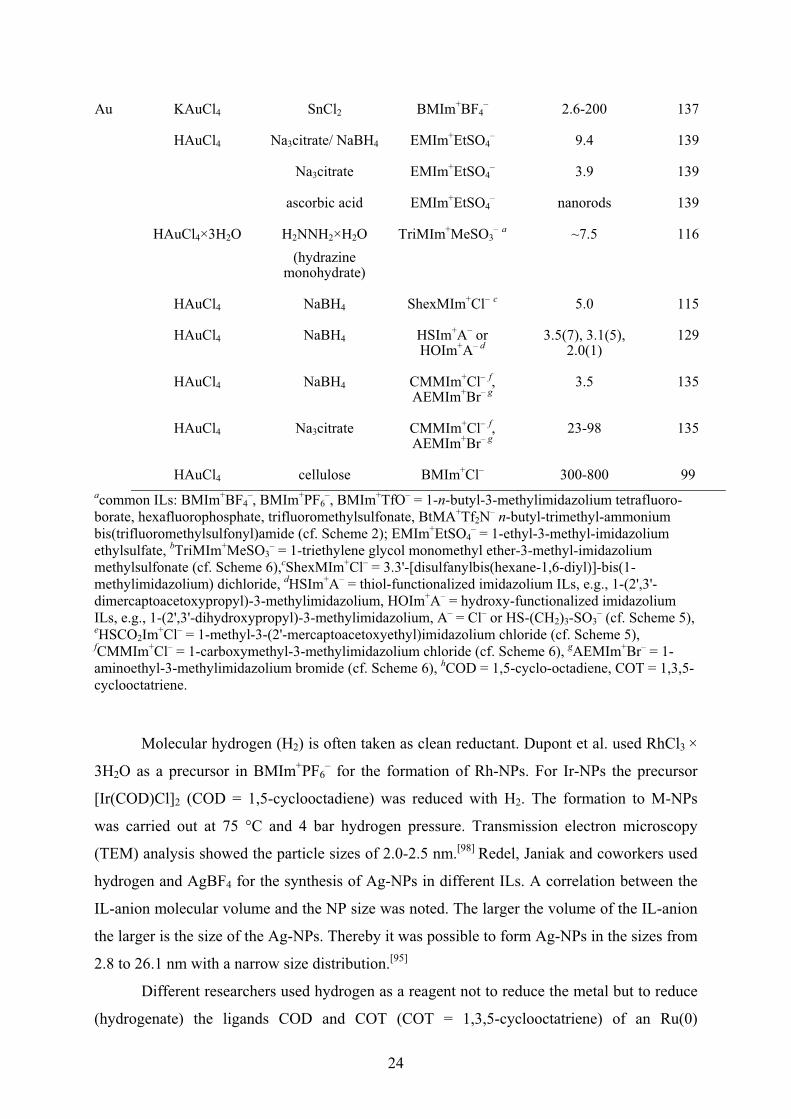
Au KAuCl4 SnCl2 BMIm+BF4– 2.6-200 137
HAuCl4 Na3citrate/ NaBH4 EMIm+EtSO4– 9.4 139
Na3citrate EMIm+EtSO4– 3.9 139
ascorbic acid EMIm+EtSO4– nanorods 139
HAuCl4×3H2O H2NNH2×H2O (hydrazine
monohydrate)
TriMIm+MeSO3– a ~7.5 116
HAuCl4 NaBH4 ShexMIm+Cl– c 5.0 115
HAuCl4 NaBH4 HSIm+A– or HOIm+A– d
3.5(7), 3.1(5), 2.0(1)
129
HAuCl4 NaBH4 CMMIm+Cl– f, AEMIm+Br– g
3.5 135
HAuCl4 Na3citrate CMMIm+Cl– f, AEMIm+Br– g
23-98 135
HAuCl4 cellulose BMIm+Cl– 300-800 99 acommon ILs: BMIm+BF4
–, BMIm+PF6–, BMIm+TfO– = 1-n-butyl-3-methylimidazolium tetrafluoro-
borate, hexafluorophosphate, trifluoromethylsulfonate, BtMA+Tf2N– n-butyl-trimethyl-ammonium bis(trifluoromethylsulfonyl)amide (cf. Scheme 2); EMIm+EtSO4
– = 1-ethyl-3-methyl-imidazolium ethylsulfate, bTriMIm+MeSO3
– = 1-triethylene glycol monomethyl ether-3-methyl-imidazolium methylsulfonate (cf. Scheme 6),cShexMIm+Cl– = 3.3'-[disulfanylbis(hexane-1,6-diyl)]-bis(1-methylimidazolium) dichloride, dHSIm+A– = thiol-functionalized imidazolium ILs, e.g., 1-(2',3'-dimercaptoacetoxypropyl)-3-methylimidazolium, HOIm+A– = hydroxy-functionalized imidazolium ILs, e.g., 1-(2',3'-dihydroxypropyl)-3-methylimidazolium, A– = Cl– or HS-(CH2)3-SO3
– (cf. Scheme 5), eHSCO2Im+Cl– = 1-methyl-3-(2'-mercaptoacetoxyethyl)imidazolium chloride (cf. Scheme 5), fCMMIm+Cl– = 1-carboxymethyl-3-methylimidazolium chloride (cf. Scheme 6), gAEMIm+Br– = 1-aminoethyl-3-methylimidazolium bromide (cf. Scheme 6), hCOD = 1,5-cyclo-octadiene, COT = 1,3,5-cyclooctatriene.
Molecular hydrogen (H2) is often taken as clean reductant. Dupont et al. used RhCl3 ×
3H2O as a precursor in BMIm+PF6– for the formation of Rh-NPs. For Ir-NPs the precursor
[Ir(COD)Cl]2 (COD = 1,5-cyclooctadiene) was reduced with H2. The formation to M-NPs
was carried out at 75 °C and 4 bar hydrogen pressure. Transmission electron microscopy
(TEM) analysis showed the particle sizes of 2.0-2.5 nm.[98] Redel, Janiak and coworkers used
hydrogen and AgBF4 for the synthesis of Ag-NPs in different ILs. A correlation between the
IL-anion molecular volume and the NP size was noted. The larger the volume of the IL-anion
the larger is the size of the Ag-NPs. Thereby it was possible to form Ag-NPs in the sizes from
2.8 to 26.1 nm with a narrow size distribution.[95]
Different researchers used hydrogen as a reagent not to reduce the metal but to reduce
(hydrogenate) the ligands COD and COT (COT = 1,3,5-cyclooctatriene) of an Ru(0)
25
organometallic precursor.[96,111] They dissolved Ru(COD)(COT) in imidazolium based ILs and
heated the mixture under 4 bar of hydrogen under different conditions. Both organic ligands
were reduced to cyclooctane and thereby dissociate from the already zero-valent metal atom.
Cyclooctane can then be removed under reduced pressure.
It is also possible to use less-noble metals for the reduction of noble metals. The
reduction of KAuCl4 by SnCl2 leads to the formation of Au-NPs.[137] By variation of the molar
AuIII : SnII ratio it was possible to synthesize Au-NPs in different sizes in a stop-and-go,
stepwise and "ligand-free" nucleation, nanocrystal growth process which can be stopped and
resumed at different color steps and Au-NP sizes from 2.6 to 200 nm. This stepwise Au-NP
formation was possible because the IL apparently acted as a kinetically stabilizing, dynamic
molecular network in which the reduced Au0 atoms and clusters can move by diffusion and
cluster together, as verified by TEM analysis.[137]
A well-known method to generate Au-NPs was already established by Turkevich et al.
in 1951.[138] The reducing agent was citrate. Bockstaller and coworkers used this method and
carried out the reduction in the imidazolim-based IL 1-ethyl-3-methylimidazolium ethyl-
sulfate (EMIm+EtSO4–). Afterwards it was possible to give these particles different shapes by
adding AgI.[139]
Taubert et al. reacted HAuCl4 with cellulose.[99] Thereby cellulose has two roles: First,
cellulose is the reducing agent for Au(III). Second, cellulose acts as a morphology- and size-
directing agent, which drives the crystallization towards polyhedral particles or thick plates.
The gold particle morphologies and sizes mainly depend on the reaction temperature. With
this route it was possible to synthesize plates with a thickness from 300 nm at 110 °C to 800
nm at 200 °C.
Gold nanoparticles of 1-4 nm size could be prepared by sputter deposition of the metal
onto the surface of the ionic liquid BMIm+BF4– to generate nanoparticles in the liquid with no
additional stabilizing agents.[140] Likewise, Au-NPs were prepared by sputter deposition of Au
metal in BMIm+PF6–. The size of Au nanoparticles was increased from 2.6 to 4.8 nm by heat
treatment at 373 K.[141] Sputter deposition of indium in the ionic liquids BMIm+BF4–,
EMIm+BF4–, (1-allyl)MIm+BF4
– and (1-allyl)(3-ethyl)Im+BF4– could produce stable In metal
nanoparticles whose surface was covered by an amorphous In2O3 layer to form In/In2O3
core/shell particles. The size of the In core was tunable from ca. 8 to 20 nm by selecting the
IL.[142]
In the presence of imidazolium-based ILs Pd-NPs from palladium(II) salts could
synthesized without the need for an additional reducing agent. It is suggested that formation
26
of N-heterocyclic Pd-carbene complexes takes place as an intermediate preceding the
formation of Pd-NPs (Scheme 7) which can then catalyze Suzuki C-C coupling
reactions.[143,144] Pd-carbene complexes are able to catalyze the Heck reaction.[145,146]
Deshmukh et al. used Pd(OAc)2 or PdCl2 in the imidazolium-based ILs BBImBr or
BBImBF4 to irradiate the mixtures with ultrasound for 1 h. The Pd-NPs were nearly spherical
and a size of 20 nm was observed.[143]
Anderson, Marr et al. formed Pd-NPs with a diameter of ~1 nm from Pd(OAc)2 in
BMIm+Tf2N– simply by heating to 80 °C in the presence of PPh3.[147]
Ruta, Kiwi-Minsker et al. synthesized monodispersed Pd nanoparticles of 5 and 10 nm
through reduction of Pd(acac)2 dissolved in the hydroxyl-functionalized butyl-3-
methylimidazolium bis(trifluoromethylsulfonyl)amide IL HOBMIm+Tf2N– by simple heating
in the absence of an additional reducing agent.[134]
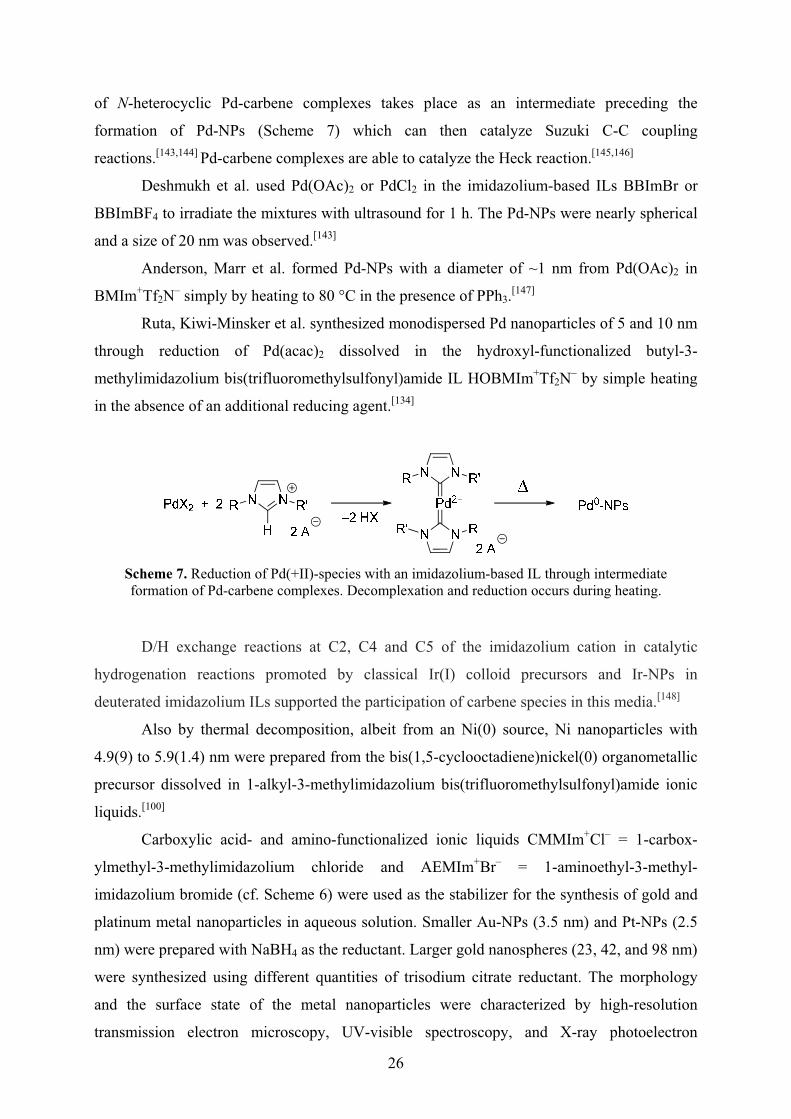
Scheme 7. Reduction of Pd(+II)-species with an imidazolium-based IL through intermediate formation of Pd-carbene complexes. Decomplexation and reduction occurs during heating.
D/H exchange reactions at C2, C4 and C5 of the imidazolium cation in catalytic
hydrogenation reactions promoted by classical Ir(I) colloid precursors and Ir-NPs in
deuterated imidazolium ILs supported the participation of carbene species in this media.[148]
Also by thermal decomposition, albeit from an Ni(0) source, Ni nanoparticles with
4.9(9) to 5.9(1.4) nm were prepared from the bis(1,5-cyclooctadiene)nickel(0) organometallic
precursor dissolved in 1-alkyl-3-methylimidazolium bis(trifluoromethylsulfonyl)amide ionic
liquids.[100]
Carboxylic acid- and amino-functionalized ionic liquids CMMIm+Cl– = 1-carbox-
ylmethyl-3-methylimidazolium chloride and AEMIm+Br– = 1-aminoethyl-3-methyl-
imidazolium bromide (cf. Scheme 6) were used as the stabilizer for the synthesis of gold and
platinum metal nanoparticles in aqueous solution. Smaller Au-NPs (3.5 nm) and Pt-NPs (2.5
nm) were prepared with NaBH4 as the reductant. Larger gold nanospheres (23, 42, and 98 nm)
were synthesized using different quantities of trisodium citrate reductant. The morphology
and the surface state of the metal nanoparticles were characterized by high-resolution
transmission electron microscopy, UV-visible spectroscopy, and X-ray photoelectron
27
spectroscopy. X-ray photoelectron spectroscopy spectra indicated that binding energies of C
1s and N 1s from ionic liquids on the surface of metal nanoparticles shifted negatively
compared with that from pure ionic liquids. The mechanism of stabilization is proposed to be
due to the interactions between imidazolium ions/functional groups in ionic liquids and metal
atoms. The imidazolium ring moiety of ionic liquids might interact with the �-electronic
nanotube surface by virtue of cation-� and/or �-� interactions, and the functionalized group
moiety of ionic liquids might interact with the metal NPs surface.[135]
2.4.2 Photochemical reduction
Photochemical methods for the synthesis of M-NPs present a rather clean procedure
because contaminations by reducing agents are excluded. Zhu, Zhang et al used HAuCl4×4
H2O in a mixed solution of BMIm+BF4– and acetone (ratio 10:1) and irradiated the salt for 8 h
with a UV light at a wave length of 254 nm. The UV light turns the acetone into a free radical,
which then reduces the cationic AuIII to Au-NPs. The obtained Au nanosheets were about 4
μm long and 60 nm thick.[101] Firestone, Zaluzec and coworkers used this route to form Au-
NPs from HAuCl4 in the IL 1-decyl-3-methyl-imidazolium chloride in water. The irradiation
was carried out with 254 nm UV-light for 30 to 70 min. The obtained Au-NPs were analyzed
by scanning electron microscopy (SEM). The nanorods had different shapes and
morphologies. The sizes varied between 100 and 1000 nm.[102] Harada, Isoda et al. used a
high-pressure mercury lamp to irradiate AgClO4 in a mixture of an IL, water and Tween 20
(polyoxyethylene sorbitan monolaurate). Benzoin was used as photoactivator. The average
diameters of Ag-NPs prepared in water/BMIm+BF4– and water/OMIm+BF4
– (1-octyl-3-
methylimidazolium) microemulsions were 8.9 and 4.9 nm, respectively.[149]
2.4.3 Electroreduction
Another clean route to prepare nanoparticles is electroreduction as only electrons are
used as the reducing agent. It should be noted, however, that the size of the metal
nanoparticles from electroreduction is often above the 100 nm definition limit for
nanoparticles.
Imanishi, Kuwabata et al. used a low-energy electron beam irradiation to synthesize
Au-NPs from a NaAuCl4 × 2H2O precursor in the IL BMIm+Tf2N–. The obtained particles had
a large size of 122 nm.[150] It is also possible to deposite particles on supporting material. Roy,
28
Schmucki et al. prepared Ag-NPs from AgBF4 in BMIm+BF4– on TiO2. The electroreduction
was performed in the high vacuum chamber of a SEM. The resulting Ag-NPs arranged
themselves in a dendritic network structure.[151] Fu, Zhou and coworkers reduced graphene
oxide (GO) and HAuCl4 simultaneously in BMIm+PF4– at a potential of –2.0 V. The obtained
Au-NPs on the electrochemical reduced graphene had a size of 10 nm.[152] El Abedin and
Endres used Ag(TfO) as a source of silver. The precursor was electrochemically reduced in 1-
ethyl-3-methylimidazolium trifluoromethylsulfonate, EMIm+TfO–. The prepared Ag
nanowires were 3 μm long and 200 nm wide.[153] CuCl as precursor was used by Lu, Chen
and coworkers and reduced in a cavity microelectrode in BMIm+PF6–. The electrode potential
was varied. The smallest particles had a size of 10 nm and were obtained at an electrode
potential of –1.8 nm.[154]
2.4.4 Metal carbonyl precursors for metal nanoparticles in ILs
As pointed out in section 2.4.3 metal carbonyls contain the metal atoms already in the
zero-valent oxidation state needed for the metal nanoparticles. No reducing agent is
necessary. The side product CO is largely given off to the gas phase and removed from the M-
NP/IL dispersion. The M-NP synthesis in IL from Mx(CO)y is generally carried out without
any additional stabilizers, surfactants or capping molecules which is different from the use of
metal carbonyls for the M-NP syntheses described in section 2.4.3.
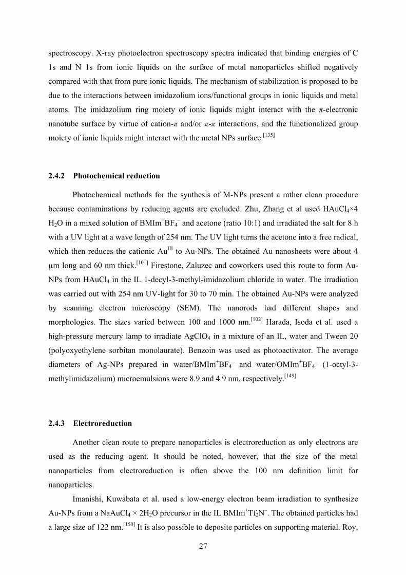
Metal carbonyls can be decomposed to metal nanoparticles in ILs by microwave
irradiation (MWI), UV-photolysis or conventional thermal heating (Fig. 3).
Fig. 3. M-NPs synthesis from Mx(CO)y by microwave irradiation, photolysis or conventional heating.
ILs are an especially attractive media for microwave reactions and have significant
absorption efficiency for microwave energy because of their high ionic charge, high polarity
and high dielectric constant.[20] Microwave heating is extremely rapid. Microwaves are a low-

29
frequency energy source that is remarkably adaptable to many types of chemical reactions.[155]
Microwave radiation can interact directly with the reactions components, the reactant mixture
absorbs the microwave energy and localized superheating occurs resulting in a fast and
efficient heating time.[156,157] Using microwaves is a fast way to heat reactants compared with
conventional thermal heating. Any presumptions about abnormal "microwave effects" [158-160]
have been proven wrong in the meantime.[161,162] Moreover, microwave reactions are also an
"instant on/instant off" energy source, significantly reducing the risk of overheating
reactions.[155,156]
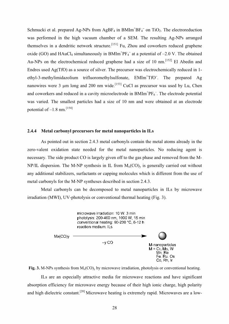
Metal nanoparticles were reproducibly obtained by easy, rapid (3 min) and energy-
saving 10 Watt microwave irradiation (MWI) under an argon atmosphere from their metal
carbonyl precursors Mx(CO)y in ILs. This MWI synthesis was compared to UV-photolytic
(1000 W, 15 min) or conventional thermal decomposition (180-250 °C, 6-12 h) of Mx(CO)y in
ILs. The MWI-obtained nanoparticles have a very small (< 5 nm) and uniform size and are
prepared without any additional stabilizers or capping molecules as long-term stable M-NP/IL
dispersions [characterization by transmission electron microscopy (TEM), transmission
electron diffraction (TED) and dynamic light scattering (DLS)]
Stable chromium, molybdenum and tungsten nanoparticles could be obtained
reproducibly by thermal or photolytic decomposition under argon from their mononuclear
metal carbonyl precursors M(CO)6 (M = Cr, Mo, W) suspended in the ionic liquids
BMIm+BF4–, BMIm+TfO– and BtMA+Tf2N– (Scheme 8).[106] Later it was also shown that an
even more rapid and energy-saving decomposition could be achieved with a 10 W microwave
irradiation for 3 min of 0.4 ml (0.48 g) of a BMIm+BF4– sample with a 0.5 wt.% M/IL-
dispersion.[23] The resulting Cr-, Mo- and W-NPs were of very small and uniform size of 1 to
1.5 nm in BMIm+BF4– (Table 5) which increases with the molecular volume of the ionic
liquid anion to 100 nm in BtMA+Tf2N– (Fig. 4). Characterization was done by TEM,
dynamic light scattering (DLS) and transmission electron diffraction (TED) analysis.[106]
microwave irradiation: 10 W, 3 minphotolysis: 200-400 nm, 1000 W, 15 minconventional heating: 90-230 °C, 6-12 h
reaction medium: ILsCr(CO)6orMo(CO)6orW(CO)6 M-nanoparticles
M = Cr, Mo, W–6 CO
Scheme 8. Formation of Cr, Mo and W nanoparticles by microwave, photolytic or thermal, decomposition of metal carbonyls M(CO)6 under argon in ionic liquids.[23,106]
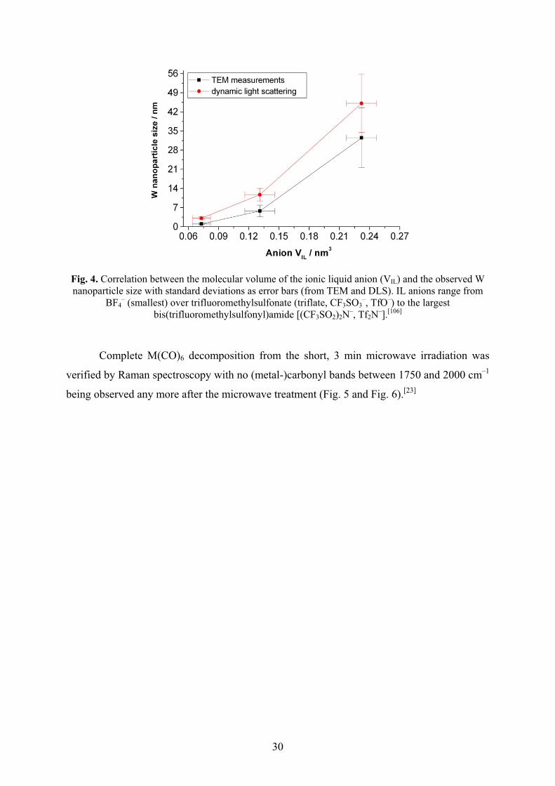
30
Fig. 4. Correlation between the molecular volume of the ionic liquid anion (VIL) and the observed W nanoparticle size with standard deviations as error bars (from TEM and DLS). IL anions range from
BF4– (smallest) over trifluoromethylsulfonate (triflate, CF3SO3
–, TfO–) to the largest bis(trifluoromethylsulfonyl)amide [(CF3SO2)2N–, Tf2N–].[106]
Complete M(CO)6 decomposition from the short, 3 min microwave irradiation was
verified by Raman spectroscopy with no (metal-)carbonyl bands between 1750 and 2000 cm–1
being observed any more after the microwave treatment (Fig. 5 and Fig. 6).[23]
31
Fig. 5. Raman-FT spectra of pure Cr(CO)6 and dissolved in BMIm+BF4– before (upper part) and after 3
min 10 W microwave irradiation (MWI) dissolved in BMIm+BF4– (lower part). Red boxes highlight
the indicative chromium carbonyl bands.[23]
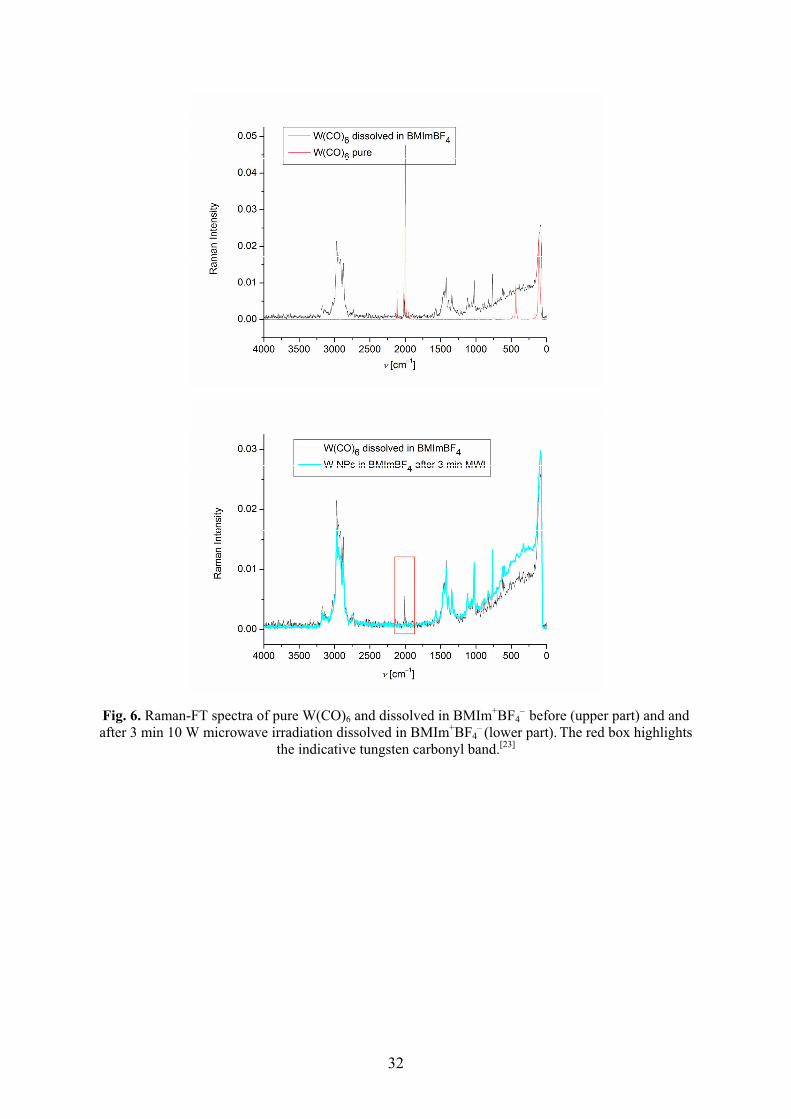
32
Fig. 6. Raman-FT spectra of pure W(CO)6 and dissolved in BMIm+BF4– before (upper part) and and
after 3 min 10 W microwave irradiation dissolved in BMIm+BF4– (lower part). The red box highlights
the indicative tungsten carbonyl band.[23]

33
Table 5. M-NP (M = Cr, Mo, W, Re, Mn, Fe, Ru, Os, Co, Rh and Ir) size and size distributiona in BMIm+BF4
– [23]
Metal carbonyl
Microwave decomposition b Photolytic decomposition c Conventional thermal decompositiond
Entry TEM NP diameter/ nm,
(standard deviation �)
Dynamic light scattering NP
median diameter e/
nm, (standard deviation �)
TEM NP diameter/ nm,
(standard deviation �)
Dynamic light scattering NP
median diameter e/
nm, (standard deviation �)
TEM NP diameter/ nm,
(standard deviation �)
Dynamic light scattering NP
median diametere/
nm, (standard deviation �)
1 Cr(CO)6 � 1.5 (± 0.3) f 3.8 (± 0.8) 4.4 (± 1.0) 7.1 (± 0.3) � 1.5 (± 0.3)g 3.0 (± 0.6)g
2 Mo(CO)6 ~1 – 2 4.5 (± 0.8) ~1 – 2 g 3.8 (± 1.1) g � 1.5 (± 0.3)g 2.5 (± 0.6)g
3 W(CO)6 3.1 (± 0.8) 5.2 (± 1.2) < 1 10.8 (± 0.5) � 1.5 (± 0.3)g 3.1 (± 0.5)g
4 Mn2(CO)10 12.4 (± 3)h 29 (± 5.0) h < 1 2.5 (± 0.8) -- --
5 Re2(CO)10 2.4 (± 0.9) 5.7 (± 1.4) < 1 7.2 (± 2.2) -- --
6 Fe2(CO)9 8.6 (± 3.2)i 12.8 (± 0.6) i 7.0 (± 3.1) i 12.5 (± 0.5) i 5.2 (± 1.6)g 10.1 (± 2.1)g
7 Ru3(CO)12 a) 1.6 (± 0.3) a) 3.2 (± 0.8) 2.0 (± 0.5) g 3.9 (± 1.0) g 1.6 (± 0.4)g 2.9 (± 0.5)g
b) 1.6 (± 0.3) j b) 3.2 (± 0.8) j
8 Os3(CO)12 0.7 (± 0.2) 2.8 (± 0.7) 2.0 (± 1.0) 2.1 (± 0.4) 2.5 (± 0.4)g,k 5.6 (± 1.5)l
9 Co2(CO)8 5.1 (± 0.9) 20 (± 3) 8.1 (± 2.5) 12.6 (± 0.4) 14 (± 8) g --
10 Rh6(CO)16 a) 1.7 (± 0.3) 3.7 (± 0.6) 1.9 (± 0.3) 5.5 (± 0.4) 3.5 (± 0.8) g 7.0 (± 1.2) g
b) 1.7 (± 0.3) j 3.4 (± 0.5) j
11 Ir6(CO)16 0.8 (± 0.2) 3.3 (± 0.9) 1.4 (± 0.3) 4.1 (± 1.2) a) 1.1 (± 0.2)g 4.1 (± 0.7) g
b) 1.3 (±0.2)g,m 3.4 (± 1.0) g,m
a Median diameters and standard deviations are for a single TEM or DLS experiment. Reproducibility of the particle size and distribution was insured by selected repeated TEM experiments and especially by DLS which was carried out for almost all repeated decomposition reactions, bMicrowave irradiation of metal carbonyls with 10 W for 3 min unless mentioned otherwise, cPhotolytic de-composition of metal carbonyls with a 1000 W Hg lamp (200-450 nm wavelength) for 15 min. dThermal decomposition of metal carbonyls from 6-12 h with 180-230 °C depending on the metal carbonyl. eHydrodynamic radius, median diameter from the first 3 measurements at 633 nm. The hydrodynamic radius is roughly 2-3 times the size of the pure kernel cluster. For very small M-NPs (~1 nm) the size of the hydrodynamic radius can even increase to more than 3 times the M-NP radius. The resolution of the DLS instrument is 0.6 nm. Solubility of metal carbonyl precursors in BMIm+BF4
– is limited to a maximum value of about 1 wt.% M. Statistical evaluation of the total sample pictures. f TEM pictures with particles of median diameter of less than 1.5 nm show electron dense cloudy structures due to scattering by the surrounding IL so that resolution of the TEM is limited and particles below 1.5 nm are hardly resolved. gData from ref. [11,22,106], h Mn2(CO)10 was of larger grain size than all the other metal carbonyls which came as fine powders. Also upon grinding in a mortar, Mn2(CO)10 could not be as finely powdered as the other metal carbonyls. iTEM/TED analyses of the nanoparticles from the microwave and photolytic decomposition of Fe2(CO)9 show the presence of iron oxide, Fe2O3. Because of the experimental setup rigorous air exclusion is more difficult during the microwave irradiation and photolysis and workup. jMicrowave decomposition of metal carbonyls with 10 W for 10 min. k0.2 wt.% Os3(CO)12 in BMIm+BF4
–. l1 wt.% Os3(CO)12 in BMIm+BF4–. m18 h
decomposition time of 0.5 wt.% Ir4(CO)12 in BMIm+BF4–.

34
Stable manganese and rhenium metal nanoparticles were reproducibly obtained by
microwave irradiation or UV photolysis from their metal carbonyl precursors M2(CO)10 in the
ionic liquid BMIm+BF4– (Scheme 9, Fig. 7, Table 5).[23]
Scheme 9. Formation of Mn and Re nanoparticles by microwave, photolytic or thermal, decomposition of the metal carbonyls M2(CO)10 under argon in the ionic liquid BMIm+BF4
–.[23]
Fig. 7. TEM photograph of Re-NPs from Re2(CO)10 by MWI (� 2.4 (± 0.9) nm, entry 5 in Table 5).[23]
Complete M2(CO)10 decomposition from the short, 3 min microwave irradiation was
verified by Raman spectroscopy with no (metal-)carbonyl bands between 1750 and 2000 cm–1
being observed any more after the microwave treatment (Fig. 8).[23]
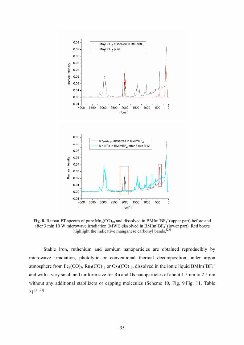
35
Fig. 8. Raman-FT spectra of pure Mn2(CO)10 and dissolved in BMIm+BF4– (upper part) before and
after 3 min 10 W microwave irradiation (MWI) dissolved in BMIm+BF4– (lower part). Red boxes
highlight the indicative manganese carbonyl bands.[23]
Stable iron, ruthenium and osmium nanoparticles are obtained reproducibly by
microwave irradiation, photolytic or conventional thermal decomposition under argon
atmosphere from Fe2(CO)9, Ru3(CO)12 or Os3(CO)12, dissolved in the ionic liquid BMIm+BF4–
and with a very small and uniform size for Ru and Os nanoparticles of about 1.5 nm to 2.5 nm
without any additional stabilizers or capping molecules (Scheme 10, Fig. 9-Fig. 11, Table
5).[11,23]
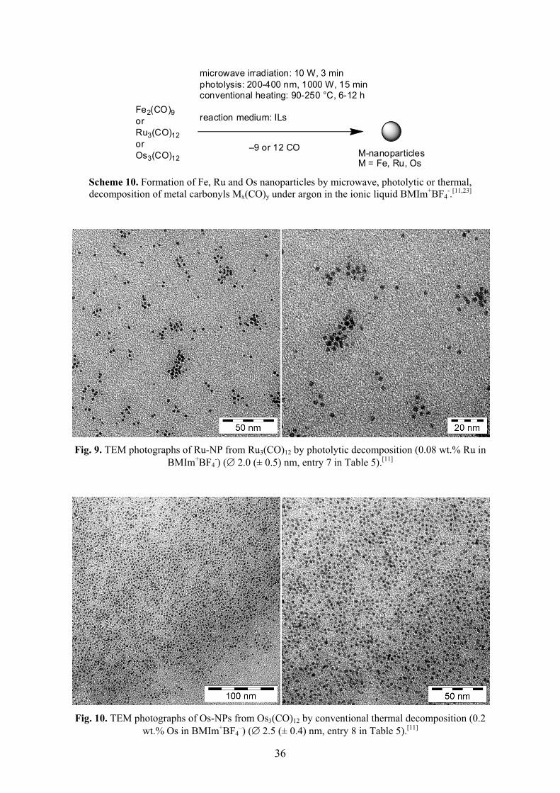
36
microwave irradiation: 10 W, 3 minphotolysis: 200-400 nm, 1000 W, 15 minconventional heating: 90-250 °C, 6-12 h
reaction medium: ILsFe2(CO)9orRu3(CO)12orOs3(CO)12 M-nanoparticles
M = Fe, Ru, Os
–9 or 12 CO
Scheme 10. Formation of Fe, Ru and Os nanoparticles by microwave, photolytic or thermal, decomposition of metal carbonyls Mx(CO)y under argon in the ionic liquid BMIm+BF4
-.[11,23]
Fig. 9. TEM photographs of Ru-NP from Ru3(CO)12 by photolytic decomposition (0.08 wt.% Ru in
BMIm+BF4-) (� 2.0 (± 0.5) nm, entry 7 in Table 5).[11]
Fig. 10. TEM photographs of Os-NPs from Os3(CO)12 by conventional thermal decomposition (0.2
wt.% Os in BMIm+BF4–) (� 2.5 (± 0.4) nm, entry 8 in Table 5).[11]
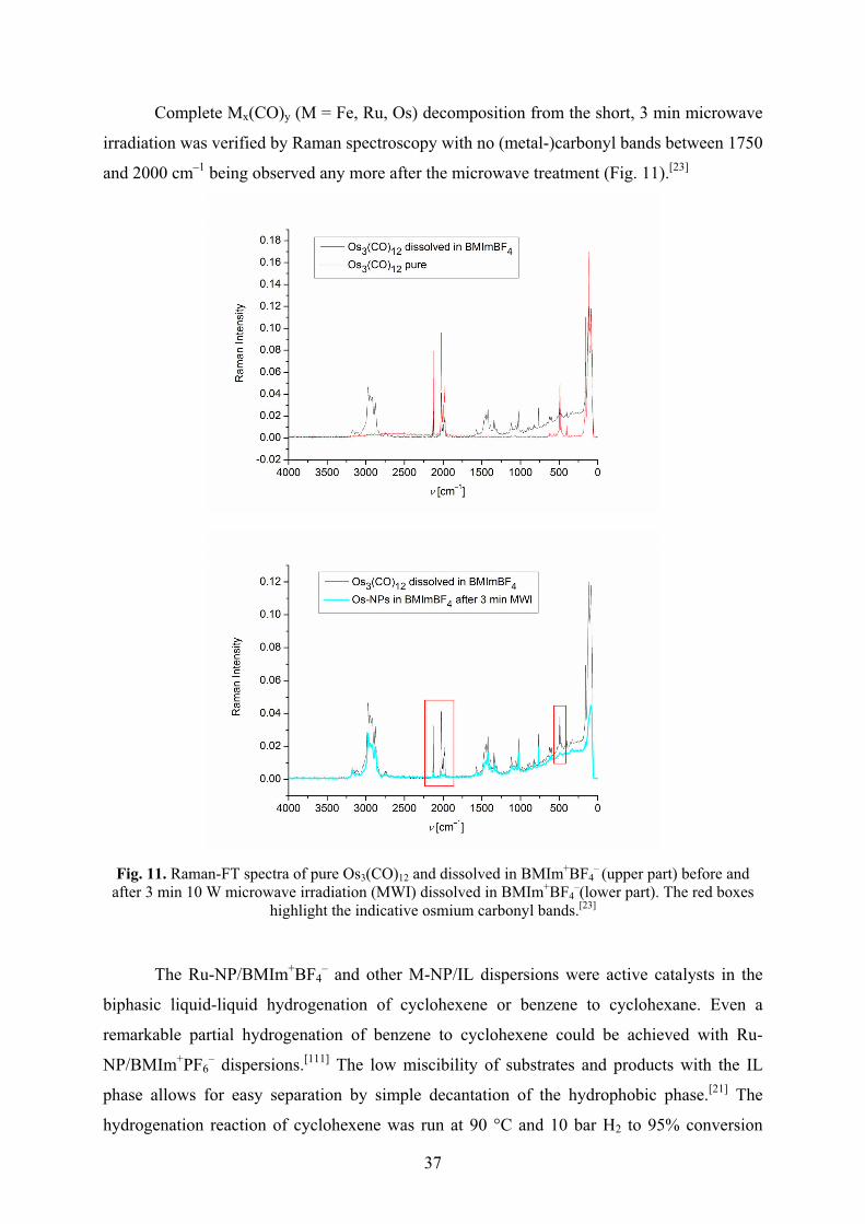
37
Complete Mx(CO)y (M = Fe, Ru, Os) decomposition from the short, 3 min microwave
irradiation was verified by Raman spectroscopy with no (metal-)carbonyl bands between 1750
and 2000 cm–1 being observed any more after the microwave treatment (Fig. 11).[23]
Fig. 11. Raman-FT spectra of pure Os3(CO)12 and dissolved in BMIm+BF4– (upper part) before and
after 3 min 10 W microwave irradiation (MWI) dissolved in BMIm+BF4–(lower part). The red boxes
highlight the indicative osmium carbonyl bands.[23]
The Ru-NP/BMIm+BF4– and other M-NP/IL dispersions were active catalysts in the
biphasic liquid-liquid hydrogenation of cyclohexene or benzene to cyclohexane. Even a
remarkable partial hydrogenation of benzene to cyclohexene could be achieved with Ru-
NP/BMIm+PF6– dispersions.[111] The low miscibility of substrates and products with the IL
phase allows for easy separation by simple decantation of the hydrophobic phase.[21] The
hydrogenation reaction of cyclohexene was run at 90 °C and 10 bar H2 to 95% conversion
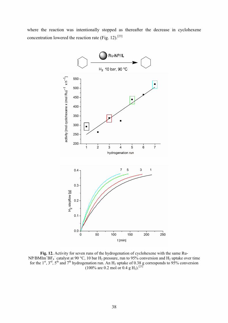
38
where the reaction was intentionally stopped as thereafter the decrease in cyclohexene
concentration lowered the reaction rate (Fig. 12).[23]
Fig. 12. Activity for seven runs of the hydrogenation of cyclohexene with the same Ru-NP/BMIm+BF4
– catalyst at 90 °C, 10 bar H2 pressure, run to 95% conversion and H2 uptake over time for the 1st, 3rd, 5th and 7th hydrogenation run. An H2 uptake of 0.38 g corresponds to 95% conversion
(100% are 0.2 mol or 0.4 g H2).[23]
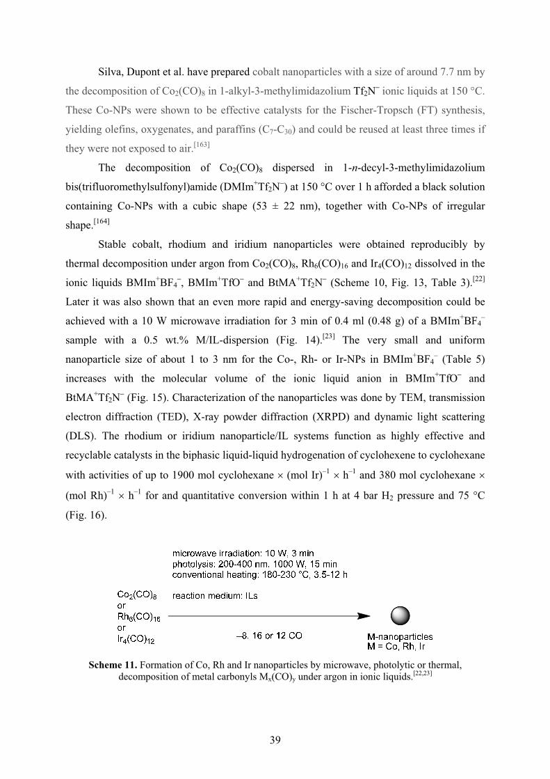
39
Silva, Dupont et al. have prepared cobalt nanoparticles with a size of around 7.7 nm by
the decomposition of Co2(CO)8 in 1-alkyl-3-methylimidazolium Tf2N– ionic liquids at 150 °C.
These Co-NPs were shown to be effective catalysts for the Fischer-Tropsch (FT) synthesis,
yielding olefins, oxygenates, and paraffins (C7-C30) and could be reused at least three times if
they were not exposed to air.[163]
The decomposition of Co2(CO)8 dispersed in 1-n-decyl-3-methylimidazolium
bis(trifluoromethylsulfonyl)amide (DMIm+Tf2N–) at 150 °C over 1 h afforded a black solution
containing Co-NPs with a cubic shape (53 ± 22 nm), together with Co-NPs of irregular
shape.[164]
Stable cobalt, rhodium and iridium nanoparticles were obtained reproducibly by
thermal decomposition under argon from Co2(CO)8, Rh6(CO)16 and Ir4(CO)12 dissolved in the
ionic liquids BMIm+BF4–, BMIm+TfO– and BtMA+Tf2N– (Scheme 10, Fig. 13, Table 3).[22]
Later it was also shown that an even more rapid and energy-saving decomposition could be
achieved with a 10 W microwave irradiation for 3 min of 0.4 ml (0.48 g) of a BMIm+BF4–
sample with a 0.5 wt.% M/IL-dispersion (Fig. 14).[23] The very small and uniform
nanoparticle size of about 1 to 3 nm for the Co-, Rh- or Ir-NPs in BMIm+BF4– (Table 5)
increases with the molecular volume of the ionic liquid anion in BMIm+TfO– and
BtMA+Tf2N– (Fig. 15). Characterization of the nanoparticles was done by TEM, transmission
electron diffraction (TED), X-ray powder diffraction (XRPD) and dynamic light scattering
(DLS). The rhodium or iridium nanoparticle/IL systems function as highly effective and
recyclable catalysts in the biphasic liquid-liquid hydrogenation of cyclohexene to cyclohexane
with activities of up to 1900 mol cyclohexane � (mol Ir)–1 � h–1 and 380 mol cyclohexane �
(mol Rh)–1 � h–1 for and quantitative conversion within 1 h at 4 bar H2 pressure and 75 °C
(Fig. 16).
Scheme 11. Formation of Co, Rh and Ir nanoparticles by microwave, photolytic or thermal,
decomposition of metal carbonyls Mx(CO)y under argon in ionic liquids.[22,23]
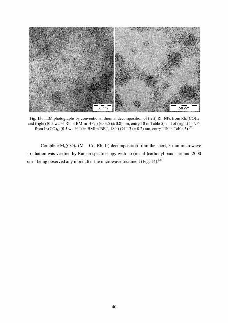
40
Fig. 13. TEM photographs by conventional thermal decomposition of (left) Rh-NPs from Rh6(CO)16 and (right) (0.5 wt. % Rh in BMIm+BF4
–) (� 3.5 (± 0.8) nm, entry 10 in Table 5) and of (right) Ir-NPs from Ir4(CO)12 (0.5 wt. % Ir in BMIm+BF4
–, 18 h) (� 1.3 (± 0.2) nm, entry 11b in Table 5).[22]
Complete Mx(CO)y (M = Co, Rh, Ir) decomposition from the short, 3 min microwave
irradiation was verified by Raman spectroscopy with no (metal-)carbonyl bands around 2000
cm–1 being observed any more after the microwave treatment (Fig. 14).[23]

41
Fig. 14. Raman-FT spectra of pure Ir4(CO)12 and dissolved in BMIm+BF4– (upper part) before and
after 3 min 10 W microwave irradiation (MWI) dissolved in BMIm+BF4– (lower part). The red box
highlights the indicative iridium carbonyl bands.[23]
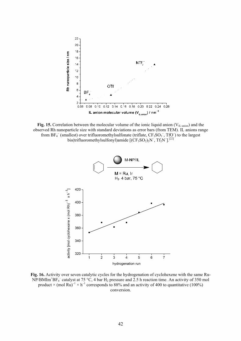
42
Fig. 15. Correlation between the molecular volume of the ionic liquid anion (VIL-anion) and the observed Rh nanoparticle size with standard deviations as error bars (from TEM). IL anions range
from BF4– (smallest) over trifluoromethylsulfonate (triflate, CF3SO3
–, TfO–) to the largest bis(trifluoromethylsulfonyl)amide [(CF3SO2)2N–, Tf2N–].[22]
Fig. 16. Activity over seven catalytic cycles for the hydrogenation of cyclohexene with the same Ru-NP/BMIm+BF4
– catalyst at 75 °C, 4 bar H2 pressure and 2.5 h reaction time. An activity of 350 mol product × (mol Ru)–1 × h–1 corresponds to 88% and an activity of 400 to quantitative (100%)
conversion.

43
2.5 DLVO theory
The classic theory for interaction of two particles in a dispersion is the DLVO
(Derjaugin-Landau-Verwey-Overbeek) theory, developed by the research groups of Derjaguin
and Landau in the USSR and the group of Vervey and Overbeek in the Netherlands nearly
simultaneously in the 1940s. This basic and most commonly theory is considered as a
combination of the repulsive Coulomb and the attraction van der Waals forces. Hence DLVO
potential is the sum of an effective electrostatic term and a direct van der Waals term.
Some simplifications and thesis are involved in this theory: The surfaces of the
particles are flat. The charge density is homogeneous and remains homogenous, even when
particles approach each other. Also there is no change of the concentration of the counter ions
which cause the electric potential. The solvent itself has only an influence through its
dielectric constant.[165]
It is quite clear that the surface of a particle is not flat and the charge density changes
when two particles approach each other. It is evident that the theory can only approximate the
real-life interactions of two particles. DLVO theory works very well and is the best predictor
of the stability of lyophobic colloids. This theory is fundamental for chemists working on and
with colloids.[166-168]
It should be pointed that there are two main types of stabilizers for NPs: Electrostatic
or "DLVO-type" stabilizers which are considered as point charge stabilizers and "classical"
steric stabilizers. Small anions like halides seem to be the closest real-life electrostatic
stabilizers.
Concerning nanoparticles and their interactions, the anion is the main focus because
anions will bind to the unsaturated surface of the electrophilic NP.[169] Thus, the NPs with
their anion layer assume a negative charge and turn into a large multi-negative anion. The
repulsion between two such negatively charged NPs is the Coulomb part of the DLVO theory.
The stability of colloids is a balance between Coulomb forces and van der Waals
attraction. A measure of the stability of a colloid is the thickness of the Debye layer, which is
the sum of the layers of counterions surrounding the particle. The thicker the Debye layer the
more stable is the particle because the distance to the next particle is greater and the van der
Waals attraction is reduced. Finke et al studied the stability of colloids in different solvents
and found that the higher the dielectric constant of the medium the better is the stabilization of
the colloid.[97]
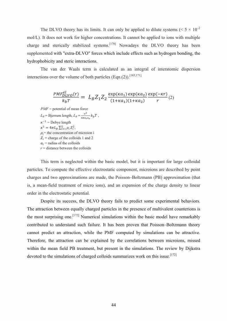
44
The DLVO theory has its limits. It can only be applied to dilute systems (< 5 × 10⁻²
mol/L). It does not work for higher concentrations. It cannot be applied to ions with multiple
charge and sterically stabilized systems.[170] Nowadays the DLVO theory has been
supplemented with "extra-DLVO" forces which include effects such as hydrogen bonding, the
hydrophobicity and steric interactions.
The van der Waals term is calculated as an integral of interatomic dispersion
interactions over the volume of both particles (Eqn.(2)).[165,171]
��������� ���
���� � !"#"$
%&'�()*� %&'�()+�
�#,()*��#,()+�
%&'�-(��
� (2)
PMF = potential of mean force
LB = Bjerrum length, LB = .+
/01213456 ,
7-# = Debye length 7$ � 89 ! : ;<
$<=# "<
$, ;<= the concentration of microion i "< = charge of the colloids 1 and 2 >< = radius of the colloids
r = distance between the colloids
This term is neglected within the basic model, but it is important for large colloidal
particles. To compute the effective electrostatic component, microions are described by point
charges and two approximations are made, the Poisson–Boltzmann (PB) approximation (that
is, a mean-field treatment of micro ions), and an expansion of the charge density to linear
order in the electrostatic potential.
Despite its success, the DLVO theory fails to predict some experimental behaviors.
The attraction between equally charged particles in the presence of multivalent counterions is
the most surprising one.[172] Numerical simulations within the basic model have remarkably
contributed to understand such failure. It has been proven that Poisson–Boltzmann theory
cannot predict an attraction, while the PMF computed by simulations can be attractive.
Therefore, the attraction can be explained by the correlations between microions, missed
within the mean field PB treatment, but present in the simulations. The review by Dijkstra
devoted to the simulations of charged colloids summarizes work on this issue.[172]
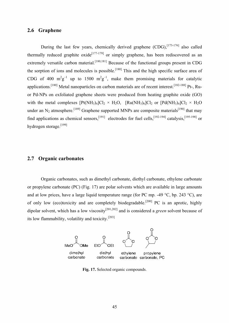
45
2.6 Graphene
During the last few years, chemically derived graphene (CDG),[173-176] also called
thermally reduced graphite oxide[177-179] or simply graphene, has been rediscovered as an
extremely versatile carbon material.[180,181] Because of the functional groups present in CDG
the sorption of ions and molecules is possible.[180] This and the high specific surface area of
CDG of 400 m2g–1 up to 1500 m2g–1, make them promising materials for catalytic
applications.[180] Metal nanoparticles on carbon materials are of recent interest.[182-188] Pt-, Ru-
or Pd-NPs on exfoliated graphene sheets were produced from heating graphite oxide (GO)
with the metal complexes [Pt(NH3)4]Cl2 × H2O, [Ru(NH3)6]Cl2 or [Pd(NH3)4]Cl2 × H2O
under an N2 atmosphere.[189] Graphene supported MNPs are composite materials[190] that may
find applications as chemical sensors,[191] electrodes for fuel cells,[192-194] catalysis,[195-198] or
hydrogen storage.[199]
2.7 Organic carbonates
Organic carbonates, such as dimethyl carbonate, diethyl carbonate, ethylene carbonate
or propylene carbonate (PC) (Fig. 17) are polar solvents which are available in large amounts
and at low prices, have a large liquid temperature range (for PC mp. -49 °C, bp. 243 °C), are
of only low (eco)toxicity and are completely biodegradable.[200] PC is an aprotic, highly
dipolar solvent, which has a low viscosity[201,202] and is considered a green solvent because of
its low flammability, volatility and toxicity.[203]
Fig. 17. Selected organic compounds.
46
Organic carbonates are recognized as solvents in industrial applications such as
cleaning, degreasing, paint stripping, gas treating, and textile dyeing.[204] Yet, so far organic
carbonates are used primarily for extractive applications and as solvents in
electrochemistry.[200] PC is used as a solubilizer and co-solvent in cosmetics,[205] in the
FLUOR process for the removal of carbon dioxide from natural gas streams in the oil
industry,[206] in lacquer[207] and BASF is using PC for waste removal in the copper wire-
coating process.[208] PC is also investigated for Li-ion battery research.[209,210] Reports on
metal nanoparticles in organic carbonates are rare and appear to be of accidental coincidence
for Pd-NPs.[211-214]
2.8 Trace catalyst
It has recently become more evident that not every component which was originally
claimed as catalyst turned out to be the actual active ingredient. In some prominent case trace
metal impurities were eventually proven as the actual catalytic species.[215,216] In an early
example, traces of nickel compounds which formed unintentional during the cleaning of a
V2A steal autoclave and remained in there changed the Ziegler-Aufbau reaction (reaction of
AlEt3 with ethylene at 100 °C under pressure to long-chain Al-alkyls) to a clean ethylene
dimerization to yield butene. The cause of this unexpected dimerisation was at first unknown
and later termed the "nickel effect" after its origin had become clear. In addition, the nickel
compounds had required traces of acetylene which were present in technical ethylene for
stabilization of the nickel catalyst.[217,218] More recently, a Suzuki cross-coupling which was
thought to have occured metal-free was indeed promoted by ppb Pd traces in the Na2CO3 or
K2CO3 bases used for the reaction.[219] Suggested iron-catalyzed cross-coupling reactions with
different FeCl3 sources were eventually corrected to ppm-scale copper impurities doing the
catalysis.[220] Even with Pd in the ppb range it is possible to carry out a Sonogashira coupling
with quantitative conversion.[221] On the other hand, metal traces or dopants are intentionally
added to enhance or promote catalytic performance[222,223] or to assist catalyst
regeneration.[224]
Researchers in catalysis are aware that impurities left over from previous experiments
in their (cleaned) vessels can give activating of desactivating "memory effects" which change

47
the outcome of a catalytic reaction. Thus, catalytic reactions should be carried out more than
once to ensure reproducibility. Surprisingly, a Scifinder search[225] combining the terms
"memory effect", "contamination" or "impurity" and "catalysis" did not give any relevant
references.
This introduction is part of this cumulative dissertation (publication 6.3).
48
3 AIM OF THIS WORK
The aim of this thesis was to synthesize small and ligand-free “naked” transition metal
nanoparticles from their binary carbonyls. The metal nanoparticles should be reproducibly
obtainable by an easy and quick synthetic route under as mild conditions as possible. The
metal nanoparticles should be kinetically stabilized by a weakly coordinating medium or on a
surface without the use of strongly coordinating capping ligands. The use of propylene
carbonate (PC) as a liquid medium and polytetrafluoroethylene (PTFE, Teflon) as a surface
should be investigated. Both propylene carbonate and Teflon are viewed as environmentally
benign, non hazardous, relatively inexpensive and safe-to-handle reagents. Further the
catalytic behavior and recyclability of the obtained metal nanoparticles in hydrogenation
reactions should be investigated. In the context of green chemistry the catalyst systems should
be reusable, the conditions for the preparation/synthesis of the catalyst and the conditions of
the catalytic reactions should be mild and energy-saving.

49
4 RESULTS AND DISCUSSION
4.1 Propylene carbonate as stabilizing solvent for transition metal
nanoparticles
The metal carbonyl Mo(CO)6, W(CO)6, Re2(CO)10, Fe2(CO)9, Ru3(CO)12, Os3(CO)12,
Co2(CO)8, Rh6(CO)16 or Ir6(CO)16 was dissolved/suspended under an argon atmosphere in
dried and deoxygenated propylene carbonate (PC). Complete decomposition by microwave
irradiation of the metal carbonyl in PC was achieved after only 3 minutes using a low power
of 50 W under argon (Fig. 18).
Fig. 18. Microwave decomposition of metal carbonyls to M-NPs in PC.
The resulting orange-red Os-, yellow W-, and dark-brown to black Mo-, Re-, Fe-, Ru-,
Co-, Rh- and Ir-NP dispersions were reproducibly obtained through the microwave
decomposition route. Complete Mx(CO)y decomposition from short, 5 min microwave
irradiation was verified by Raman spectroscopy with no (metal–)carbonyl bands between
1800 and 2000 cm–1 being observed any more after the microwave treatment (Fig. 19).
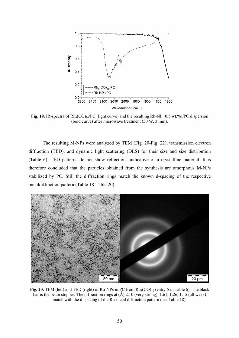
50
Fig. 19. IR-spectra of Rh6(CO)16/PC (light curve) and the resulting Rh-NP (0.5 wt.%)/PC dispersion
(bold curve) after microwave treatment (50 W, 3 min).
The resulting M-NPs were analyzed by TEM (Fig. 20-Fig. 22), transmission electron
diffraction (TED), and dynamic light scattering (DLS) for their size and size distribution
(Table 6). TED patterns do not show reflections indicative of a crystalline material. It is
therefore concluded that the particles obtained from the synthesis are amorphous M-NPs
stabilized by PC. Still the diffraction rings match the known d-spacing of the respective
metaldiffraction pattern (Table 18-Table 20).
Fig. 20. TEM (left) and TED (right) of Ru-NPs in PC from Ru3(CO)12 (entry 5 in Table 6). The black bar is the beam stopper. The diffraction rings at (�) 2.10 (very strong), 1.61, 1.26, 1.15 (all weak)
match with the d-spacing of the Ru-metal diffraction pattern (see Table 18).
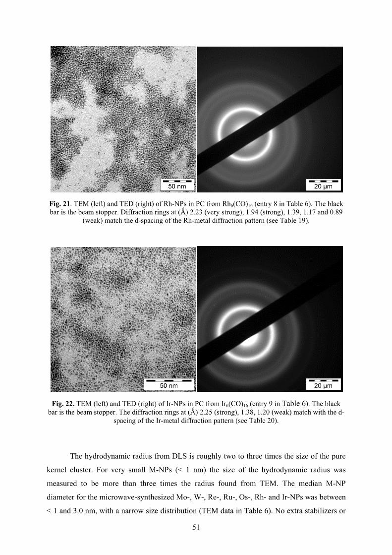
51
Fig. 21. TEM (left) and TED (right) of Rh-NPs in PC from Rh6(CO)16 (entry 8 in Table 6). The black bar is the beam stopper. Diffraction rings at (�) 2.23 (very strong), 1.94 (strong), 1.39, 1.17 and 0.89
(weak) match the d-spacing of the Rh-metal diffraction pattern (see Table 19).
Fig. 22. TEM (left) and TED (right) of Ir-NPs in PC from Ir6(CO)16 (entry 9 in Table 6). The black bar is the beam stopper. The diffraction rings at (�) 2.25 (strong), 1.38, 1.20 (weak) match with the d-
spacing of the Ir-metal diffraction pattern (see Table 20).
The hydrodynamic radius from DLS is roughly two to three times the size of the pure
kernel cluster. For very small M-NPs (< 1 nm) the size of the hydrodynamic radius was
measured to be more than three times the radius found from TEM. The median M-NP
diameter for the microwave-synthesized Mo-, W-, Re-, Ru-, Os-, Rh- and Ir-NPs was between
< 1 and 3.0 nm, with a narrow size distribution (TEM data in Table 6). No extra stabilizers or
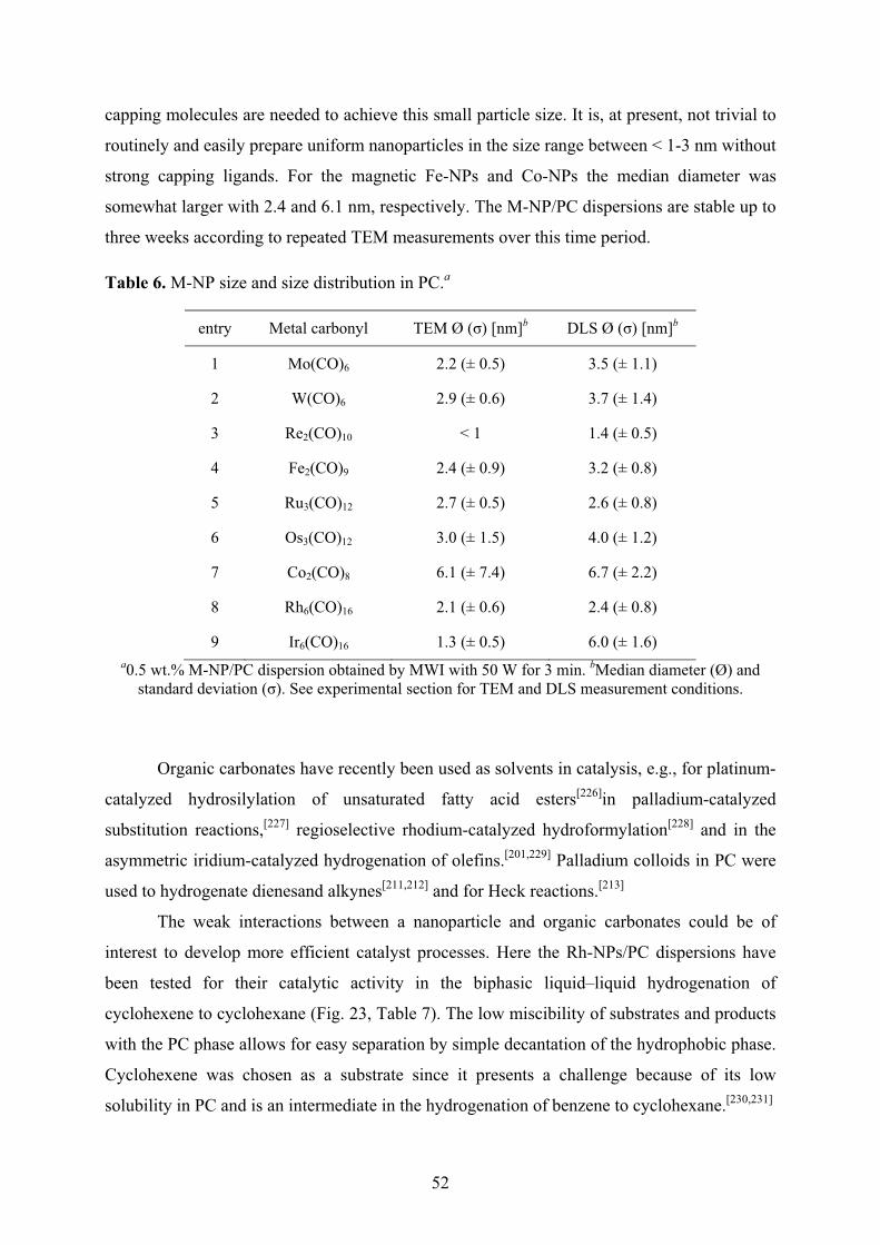
52
capping molecules are needed to achieve this small particle size. It is, at present, not trivial to
routinely and easily prepare uniform nanoparticles in the size range between < 1-3 nm without
strong capping ligands. For the magnetic Fe-NPs and Co-NPs the median diameter was
somewhat larger with 2.4 and 6.1 nm, respectively. The M-NP/PC dispersions are stable up to
three weeks according to repeated TEM measurements over this time period.
Table 6. M-NP size and size distribution in PC.a
entry Metal carbonyl TEM Ø (�) [nm]b DLS Ø (�) [nm]b
1 Mo(CO)6 2.2 (± 0.5) 3.5 (± 1.1)
2 W(CO)6 2.9 (± 0.6) 3.7 (± 1.4)
3 Re2(CO)10 < 1 1.4 (± 0.5)
4 Fe2(CO)9 2.4 (± 0.9) 3.2 (± 0.8)
5 Ru3(CO)12 2.7 (± 0.5) 2.6 (± 0.8)
6 Os3(CO)12 3.0 (± 1.5) 4.0 (± 1.2)
7 Co2(CO)8 6.1 (± 7.4) 6.7 (± 2.2)
8 Rh6(CO)16 2.1 (± 0.6) 2.4 (± 0.8)
9 Ir6(CO)16 1.3 (± 0.5) 6.0 (± 1.6) a0.5 wt.% M-NP/PC dispersion obtained by MWI with 50 W for 3 min. bMedian diameter (Ø) and
standard deviation (�). See experimental section for TEM and DLS measurement conditions.
Organic carbonates have recently been used as solvents in catalysis, e.g., for platinum-
catalyzed hydrosilylation of unsaturated fatty acid esters[226]in palladium-catalyzed
substitution reactions,[227] regioselective rhodium-catalyzed hydroformylation[228] and in the
asymmetric iridium-catalyzed hydrogenation of olefins.[201,229] Palladium colloids in PC were
used to hydrogenate dienesand alkynes[211,212] and for Heck reactions.[213]
The weak interactions between a nanoparticle and organic carbonates could be of
interest to develop more efficient catalyst processes. Here the Rh-NPs/PC dispersions have
been tested for their catalytic activity in the biphasic liquid–liquid hydrogenation of
cyclohexene to cyclohexane (Fig. 23, Table 7). The low miscibility of substrates and products
with the PC phase allows for easy separation by simple decantation of the hydrophobic phase.
Cyclohexene was chosen as a substrate since it presents a challenge because of its low
solubility in PC and is an intermediate in the hydrogenation of benzene to cyclohexane.[230,231]
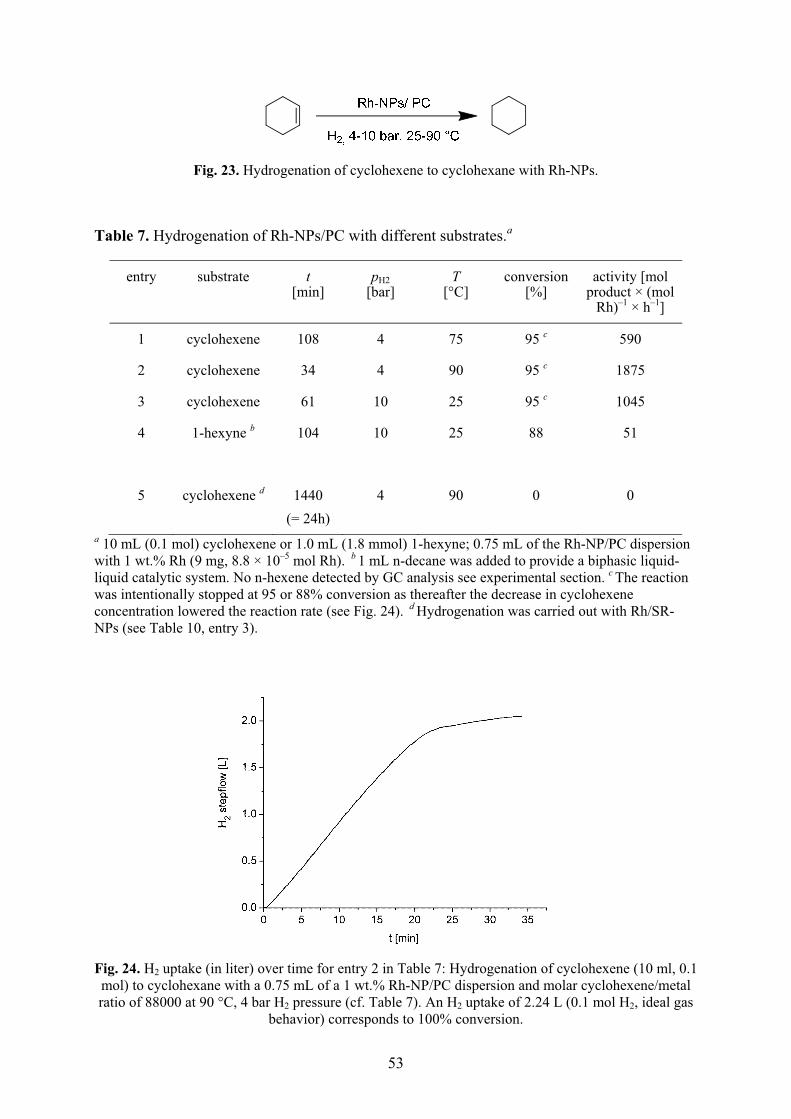
53
Fig. 23. Hydrogenation of cyclohexene to cyclohexane with Rh-NPs.
Table 7. Hydrogenation of Rh-NPs/PC with different substrates.a
entry substrate t [min]
pH2 [bar]
T [°C]
conversion [%]
activity [mol product × (mol
Rh)–1 × h–1]
1 cyclohexene 108 4 75 95 c 590
2 cyclohexene 34 4 90 95 c 1875
3 cyclohexene 61 10 25 95 c 1045
4 1-hexyne b 104 10 25 88 51
5 cyclohexene d 1440 (= 24h)
4 90 0 0
a 10 mL (0.1 mol) cyclohexene or 1.0 mL (1.8 mmol) 1-hexyne; 0.75 mL of the Rh-NP/PC dispersion with 1 wt.% Rh (9 mg, 8.8 × 10⁻⁵ mol Rh). b 1 mL n-decane was added to provide a biphasic liquid-liquid catalytic system. No n-hexene detected by GC analysis see experimental section. c The reaction was intentionally stopped at 95 or 88% conversion as thereafter the decrease in cyclohexene concentration lowered the reaction rate (see Fig. 24). d Hydrogenation was carried out with Rh/SR-NPs (see Table 10, entry 3).
Fig. 24. H2 uptake (in liter) over time for entry 2 in Table 7: Hydrogenation of cyclohexene (10 ml, 0.1 mol) to cyclohexane with a 0.75 mL of a 1 wt.% Rh-NP/PC dispersion and molar cyclohexene/metal ratio of 88000 at 90 °C, 4 bar H2 pressure (cf. Table 7). An H2 uptake of 2.24 L (0.1 mol H2, ideal gas
behavior) corresponds to 100% conversion.

54
For activity comparison Table 8 and Table 9 summarize related hydrogenation
activities for cyclohexene and 1-hexyne with M-NPs in ILs and on supports from the
literature. Activities for cyclohexene hydrogenations with Rh-NPs/PC were twice as good
than for Ru- or Rh-NP catalysts in ILs[23,111,235] but not as good as for Rh-NPs on
supports[232,237,238,284] The lower hydrogenation activities of Ru- and Rh-NPs in ILs are traced
to the IL diffusion barrier for H2 and the substrate, whereas ligand-free NPs on supports have
a lower diffusion barrier.
Table 8. Catalyst activities of M-NPs in the 1-hexyne to hexane hydrogenation.
Metal-NP system pH2 conversion [%] activity [mol product × (mol Rh)–1 × h–1]
(= TOF [h–1])
Ref.
Rh/PC 4 bar 88 51 this work
Pt2(P2O5H2)44– 20.7 atm not given not given 233
1 % Pd/Al2O3 1 atm 50 22680, TOF = 6.3 s–1 234
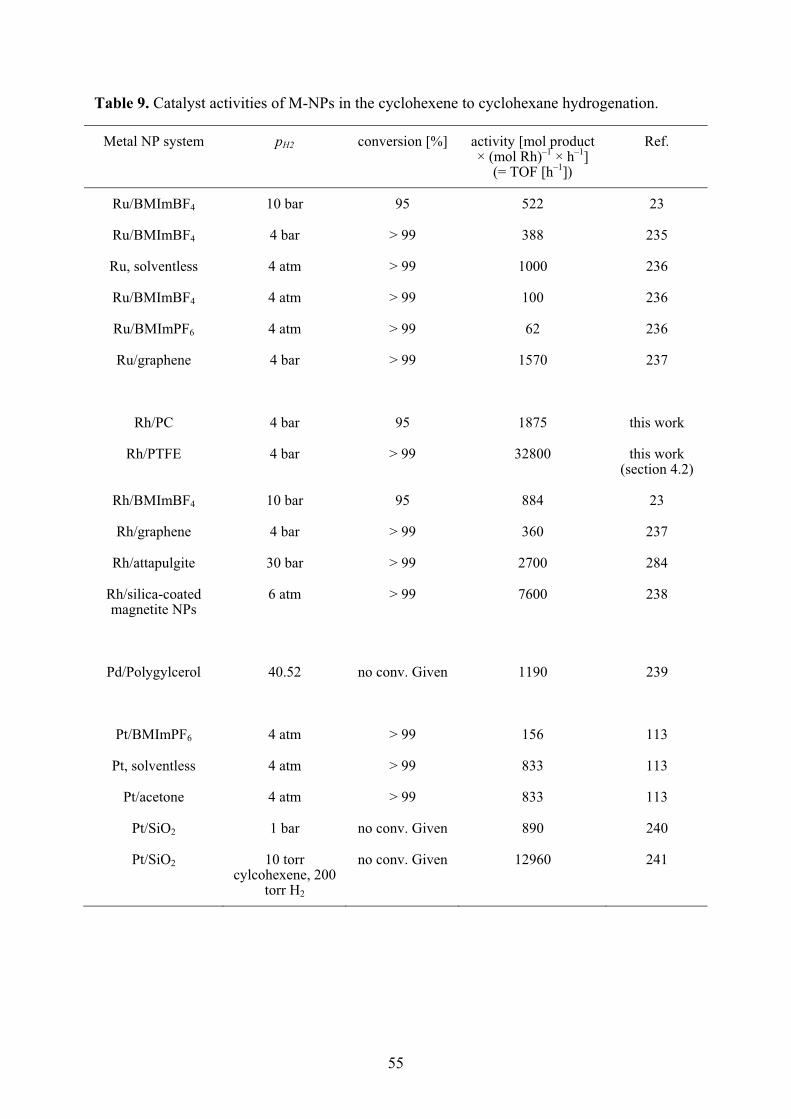
55
Table 9. Catalyst activities of M-NPs in the cyclohexene to cyclohexane hydrogenation.
Metal NP system pH2 conversion [%] activity [mol product × (mol Rh)–1 × h–1]
(= TOF [h–1])
Ref.
Ru/BMImBF4 10 bar 95 522 23
Ru/BMImBF4 4 bar > 99 388 235
Ru, solventless 4 atm > 99 1000 236
Ru/BMImBF4 4 atm > 99 100 236
Ru/BMImPF6 4 atm > 99 62 236
Ru/graphene 4 bar > 99 1570 237
Rh/PC 4 bar 95 1875 this work
Rh/PTFE 4 bar > 99 32800 this work (section 4.2)
Rh/BMImBF4 10 bar 95 884 23
Rh/graphene 4 bar > 99 360 237
Rh/attapulgite 30 bar > 99 2700 284
Rh/silica-coated magnetite NPs
6 atm > 99 7600 238
Pd/Polygylcerol 40.52 no conv. Given 1190 239
Pt/BMImPF6 4 atm > 99 156 113
Pt, solventless 4 atm > 99 833 113
Pt/acetone 4 atm > 99 833 113
Pt/SiO2 1 bar no conv. Given 890 240
Pt/SiO2 10 torr cylcohexene, 200
torr H2
no conv. Given 12960 241

56
The addition of an organic ligand to the bare M-NP surface is generally described as a
surface functionalization. However derivatization, coating, or capping are better terms.[126]
The post synthetic introduction of an organic capping ligand on the dispersed M-NPs in PC is
possible. Surface capping of Rh- or Ru-nanoparticles dispersed in the propylene carbonate
was carried out here with 3-mercaptopropionic acid, HS-(CH2)2-COOH or trioctylphosphine
oxide (TOPO). Both 3-mercaptopropionic acid[126] and TOPO[242,243] are well-known
stabilizing reagents and both are soluble in propylene carbonate. The transformation of M-
NP/PC to M-NP/HS-(CH2)2-COOH or M-NP/TOPO was done by treating the M-NP/PC
dispersion with an excess of HS-(CH2)2-COOH or TOPO at room temperature over night. The
strong affinity between the thiol (-SH) or phospine oxide (-P=O) group and the rhodium or
ruthenium nanoparticles replaces the PC protective layer. The ligand-capped nanoparticles are
significantly larger (Table 10, Fig. 25-Fig. 28). The use of a protic organic thiol ligand and the
unpolar TOPO ligand more than doubles the size of the resulting capped metal nanoparticles
(Table 10). The aggregation is a result of the introduction of the capping ligands into the polar
PC network. Subsequently the stabilizing property of propylene carbonate towards the M-NPs
is weakened and results in further M-NP agglomeration which is driven by the surface-surface
interactions.
Table 10. Ligand capped M-NP and size distribution.
M-NP/ligand in PC
entry metal ligand M-NP/PC original size
from TEM [nm]
TEM Ø (�) [nm]a
DLS Ø (�) [nm]a,b
1 Rh HS-(CH2)2-COOH 2.1 (± 0.6) 9 (±5) 24 (± 17)c
2 Rh TOPO 10 (±5) 30 (± 14)d
3 Ru HS-(CH2)2-COOH 2.7 (± 0.5) 13 (±4) 6.0 (± 1.5)c
4 Ru TOPO 13 (± 5) 37 (± 12)d a Median diameter (Ø) and standard deviation (�). See experimental section for TEM and DLS measurement conditions. bHydrodynamic radius, median diameter from the measurements at 633 nm. The resolution of the DLS instrument is 0.6 nm. cmeasurement performed in ethanol. dmeasurement performed in chloroform.
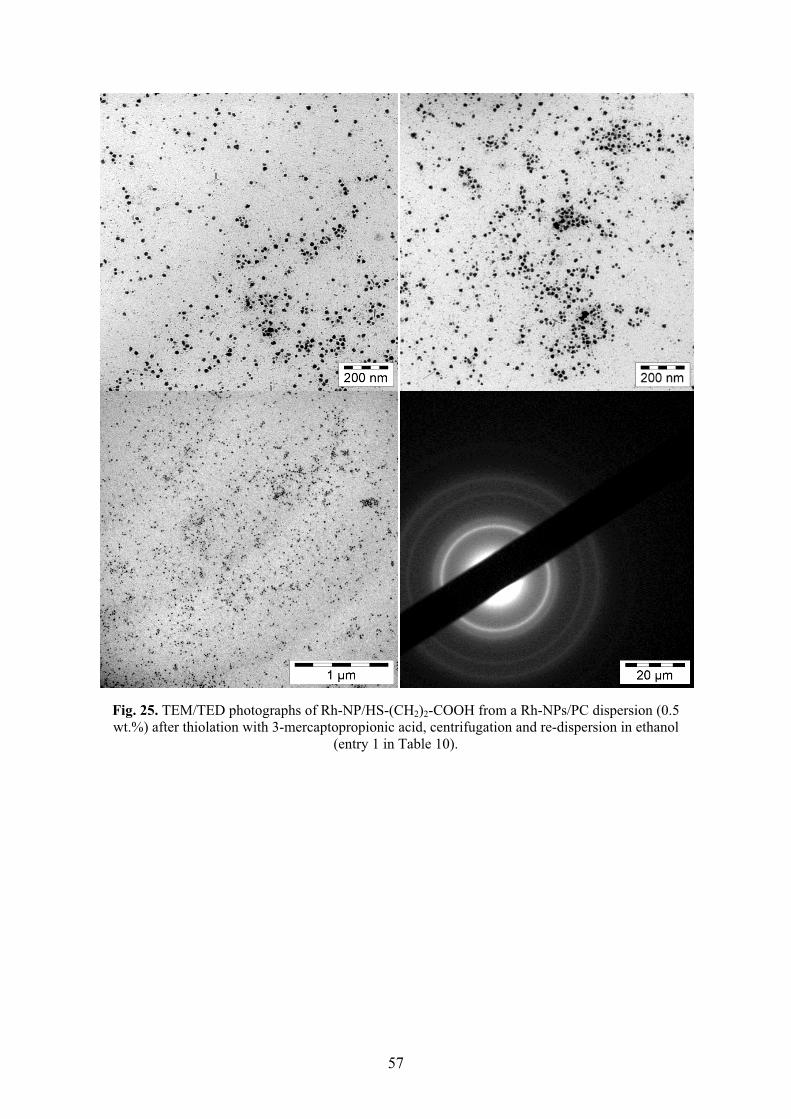
57
Fig. 25. TEM/TED photographs of Rh-NP/HS-(CH2)2-COOH from a Rh-NPs/PC dispersion (0.5 wt.%) after thiolation with 3-mercaptopropionic acid, centrifugation and re-dispersion in ethanol
(entry 1 in Table 10).

58
Fig. 26. TEM/TED photographs of Rh-NP/TOPO from a Rh-NPs/PC (0.5 wt.%) after stabilization with TOPO, centrifugation and re-dispersion in chloroform (entry 2 in Table 10).

59
Fig. 27. TEM/TED photographs of Ru-NP/HS-(CH2)2-COOH from a Ru-NP/PC dispersion (0.5 wt.%) after thiolation with 3-mercaptopropionic acid, centrifugation and re-dispersion in ethanol (entry 3 in
Table 10).

60
Fig. 28. TEM/TED photographs of Ru-NP/TOPO from a Ru-NP/PC dispersion (0.5 wt.%) stabilized by TOPO, centrifugation and re-dispersion in chloroform (entry 4 in Table 10).
Here a simple, reproducible, and broadly applicable microwave-induced metal
carbonyl decomposition for the synthesis of common transition metal nanoparticles in
propylene carbonate is shown. The M-NP sizes of about 1 to 3 nm for most of these transition
metal nanoparticles are very small and uniform with no extra stabilizers or capping molecules
needed to achieve this small particle size in a stable M-NP/PC dispersion. Polar organic
carbonates are susceptible for microwave irradiation which, thus, provides a very simple and
reproducible way for the rapid (3 min) and energy-saving (50 W power) synthesis of defined
and very small M-NPs from their binary metal–carbonyl complexes in PC. The obtained Rh-
NP/PC dispersions can be used - without further treatment - as highly active hydrogenation
catalysts. In comparison to ionic liquids, PC and other organic carbonates are established
61
industrial and low-priced solvents.[203] PC appears as an attractive alternative for weakly
coordinated, albeit sufficiently stabilized metal nanoparticles
These results are part of this cumulative dissertation (publication 6.1).
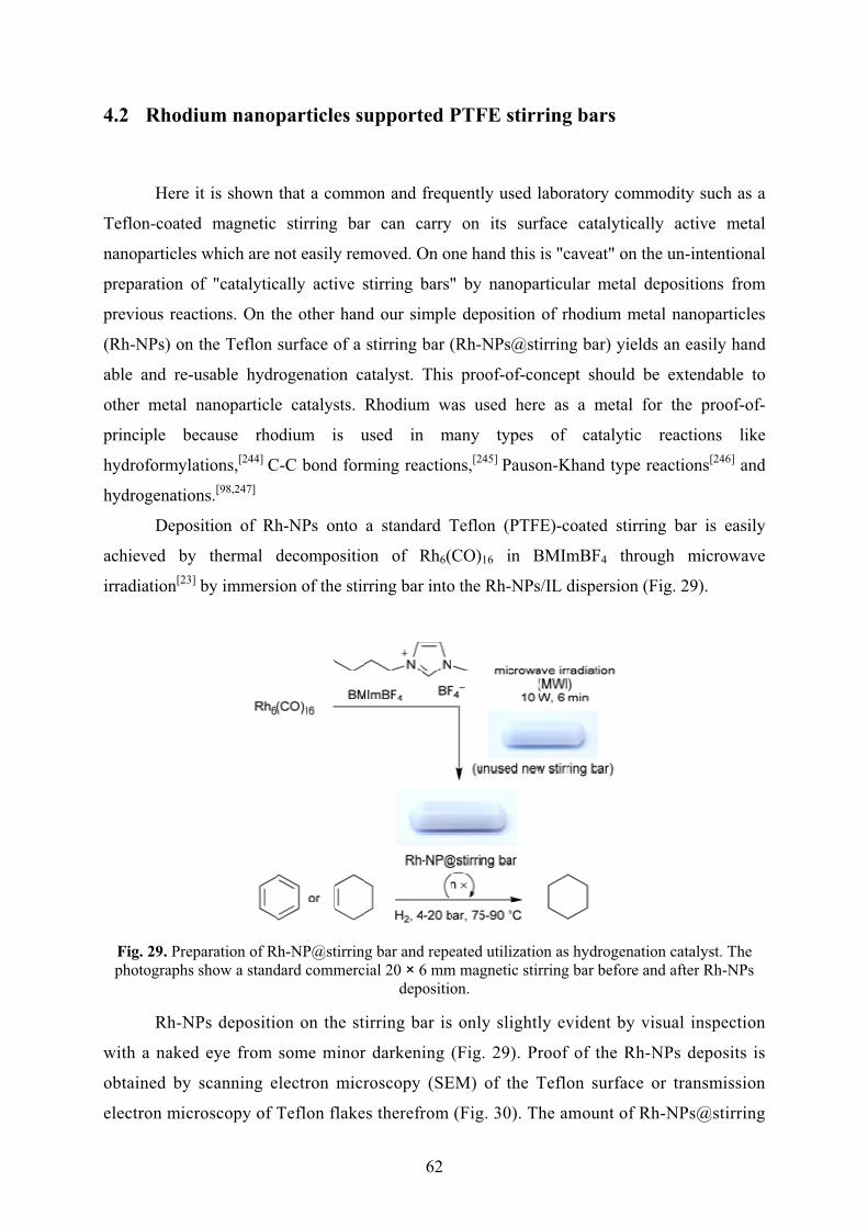
62
4.2 Rhodium nanoparticles supported PTFE stirring bars
Here it is shown that a common and frequently used laboratory commodity such as a
Teflon-coated magnetic stirring bar can carry on its surface catalytically active metal
nanoparticles which are not easily removed. On one hand this is "caveat" on the un-intentional
preparation of "catalytically active stirring bars" by nanoparticular metal depositions from
previous reactions. On the other hand our simple deposition of rhodium metal nanoparticles
(Rh-NPs) on the Teflon surface of a stirring bar (Rh-NPs@stirring bar) yields an easily hand
able and re-usable hydrogenation catalyst. This proof-of-concept should be extendable to
other metal nanoparticle catalysts. Rhodium was used here as a metal for the proof-of-
principle because rhodium is used in many types of catalytic reactions like
hydroformylations,[244] C-C bond forming reactions,[245] Pauson-Khand type reactions[246] and
hydrogenations.[98,247]
Deposition of Rh-NPs onto a standard Teflon (PTFE)-coated stirring bar is easily
achieved by thermal decomposition of Rh6(CO)16 in BMImBF4 through microwave
irradiation[23] by immersion of the stirring bar into the Rh-NPs/IL dispersion (Fig. 29).
Fig. 29. Preparation of Rh-NP@stirring bar and repeated utilization as hydrogenation catalyst. The photographs show a standard commercial 20 × 6 mm magnetic stirring bar before and after Rh-NPs
deposition.
Rh-NPs deposition on the stirring bar is only slightly evident by visual inspection
with a naked eye from some minor darkening (Fig. 29). Proof of the Rh-NPs deposits is
obtained by scanning electron microscopy (SEM) of the Teflon surface or transmission
electron microscopy of Teflon flakes therefrom (Fig. 30). The amount of Rh-NPs@stirring
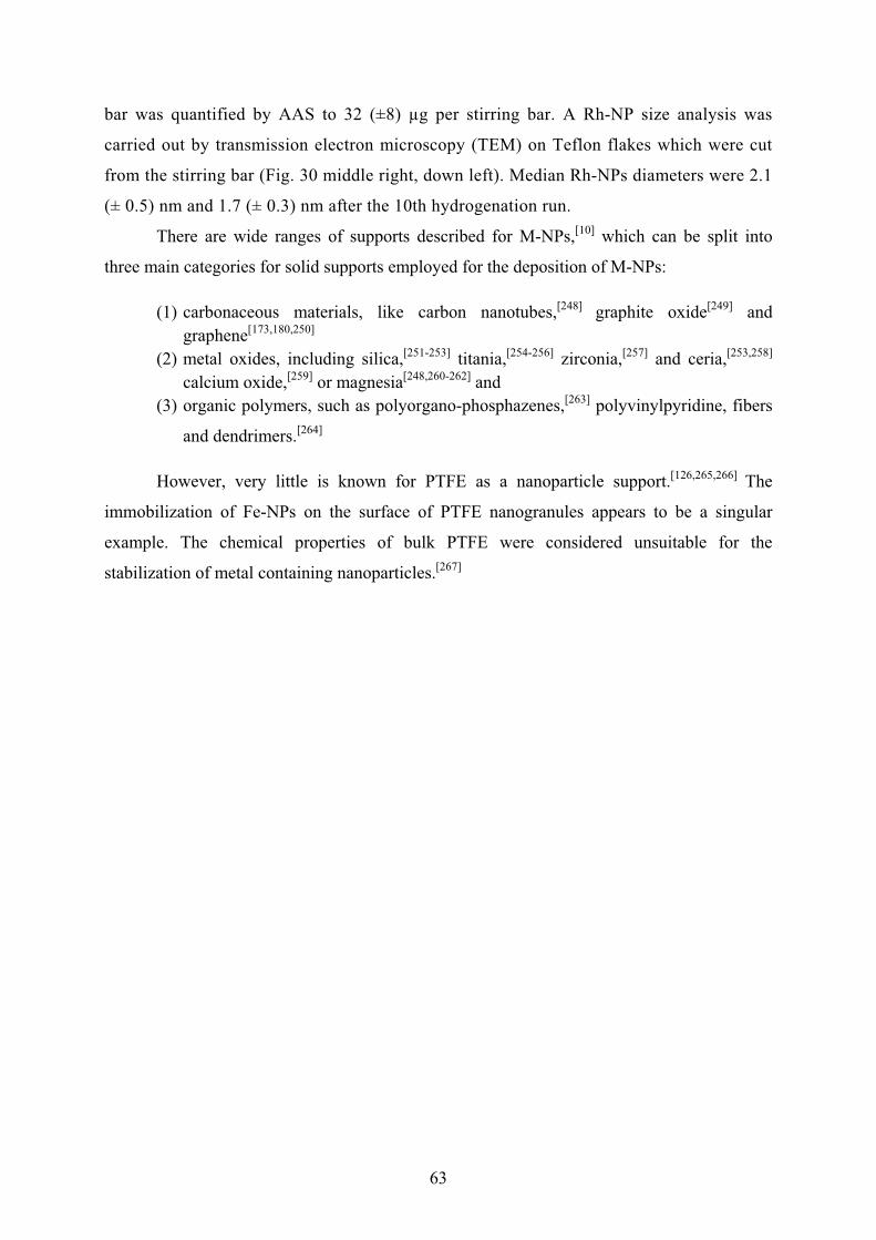
63
bar was quantified by AAS to 32 (±8) μg per stirring bar. A Rh-NP size analysis was
carried out by transmission electron microscopy (TEM) on Teflon flakes which were cut
from the stirring bar (Fig. 30 middle right, down left). Median Rh-NPs diameters were 2.1
(± 0.5) nm and 1.7 (± 0.3) nm after the 10th hydrogenation run.
There are wide ranges of supports described for M-NPs,[10] which can be split into
three main categories for solid supports employed for the deposition of M-NPs:
(1) carbonaceous materials, like carbon nanotubes,[248] graphite oxide[249] and graphene[173,180,250]
(2) metal oxides, including silica,[251-253] titania,[254-256] zirconia,[257] and ceria,[253,258] calcium oxide,[259] or magnesia[248,260-262] and
(3) organic polymers, such as polyorgano-phosphazenes,[263] polyvinylpyridine, fibers
and dendrimers.[264]
However, very little is known for PTFE as a nanoparticle support.[126,265,266] The
immobilization of Fe-NPs on the surface of PTFE nanogranules appears to be a singular
example. The chemical properties of bulk PTFE were considered unsuitable for the
stabilization of metal containing nanoparticles.[267]
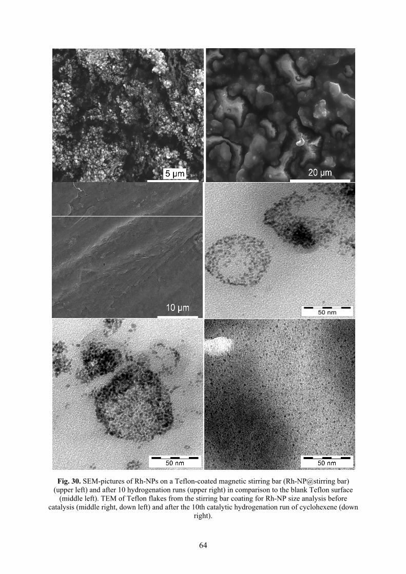
64
Fig. 30. SEM-pictures of Rh-NPs on a Teflon-coated magnetic stirring bar (Rh-NP@stirring bar) (upper left) and after 10 hydrogenation runs (upper right) in comparison to the blank Teflon surface
(middle left). TEM of Teflon flakes from the stirring bar coating for Rh-NP size analysis before catalysis (middle right, down left) and after the 10th catalytic hydrogenation run of cyclohexene (down
right).

65
The caveat: It is evident that PTFE, albeit generally considered a chemically inert
material with a non-sticking surface, can support nanoparticular metal deposits. Such
nanoparticular deposits can originate from various uses of stirring bars in a laboratory. These
M-NP deposits are also not easily removed by washing with organic solvents. If then such a
stirring bar with a "colorful past" is used in catalysis experiments the metal nanoparticle
deposits can exert an activity while the intended catalysis system is less active or even
inactive (akin to the metal impurites in "intended" catalysts noted in the introduction). This
possibility is especially problematic because such metal nanoparticle deposits cannot be
visually detected.
The chance: The ease of support of metal nanoparticles on a readily available and
thermally stable PTFE surface can open new vistas for metal nanoparticle and catalysis
research, especially in view of the easy separation of a catalytically acitve magnetic stirring
bar akin to the recovery of magnetic nanoparticle catalysts.[268-270]
As a proof-of-concept the Rh-NPs@stirring bar supported magnetic stirring bars were
tested for their re-usable catalytic activity in the known hydrogenation of cyclohexene or
benzene to cyclohexane under organic-solvent-free conditions where comparative literature
data is available (Fig. 7, Fig. 29, Table 12). The hydrogenation reactions were carried out in a
stainless steel autoclave equipped with a glass inlay. The autoclave was heated to 75 °C or 90
°C and pressurized with the hydrogen consumption monitored by a Büchi pressflow gas
contoller (H2 uptake over time, Fig. 33, Fig. 34). Near quantitative conversion the reactor was
depressurized and the volatile organic components were condensed under vacuum into a clean
cold trap. To test for recycling the Rh-NPs@stirring bar was left behind in the autoclave and
was re-used by adding fresh substrate. Catalyst recycling was carried out ten times for
cyclohexene and three times for benzene. There is an initial increase in activity with recycling
from entry 1-3 in Table 11 which was also seen in other hydrogenations with Rh-NPs/IL
systems.[22,23] This is probably due to a slow surface restructuring and not due to the rapid
formation of Rh–hydride or Rh–heterocyclic carbene (NHC)[271] surface species.[272]
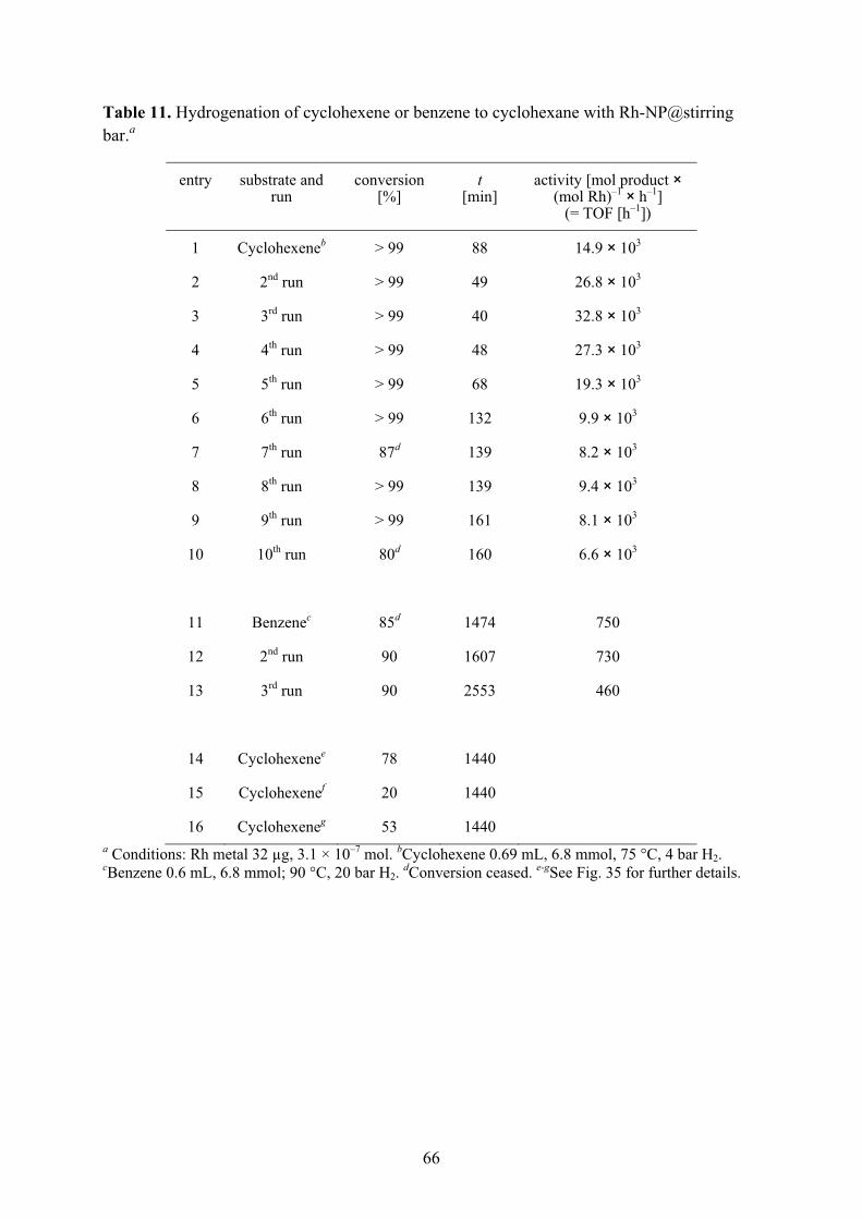
66
Table 11. Hydrogenation of cyclohexene or benzene to cyclohexane with Rh-NP@stirring bar.a
entry substrate and run
conversion [%]
t [min]
activity [mol product × (mol Rh)–1 × h–1]
(= TOF [h–1])
1 Cyclohexeneb > 99 88 14.9 × 10³
2 2nd run > 99 49 26.8 × 10³
3 3rd run > 99 40 32.8 × 10³
4 4th run > 99 48 27.3 × 10³
5 5th run > 99 68 19.3 × 10³
6 6th run > 99 132 9.9 × 10³
7 7th run 87d 139 8.2 × 10³
8 8th run > 99 139 9.4 × 10³
9 9th run > 99 161 8.1 × 10³
10 10th run 80d 160 6.6 × 10³
11 Benzenec 85d 1474 750
12 2nd run 90 1607 730
13 3rd run 90 2553 460
14 Cyclohexenee 78 1440
15 Cyclohexenef 20 1440
16 Cyclohexeneg 53 1440 a Conditions: Rh metal 32 μg, 3.1 × 10⁻⁷ mol. bCyclohexene 0.69 mL, 6.8 mmol, 75 °C, 4 bar H2. cBenzene 0.6 mL, 6.8 mmol; 90 °C, 20 bar H2. dConversion ceased. e-gSee Fig. 35 for further details.
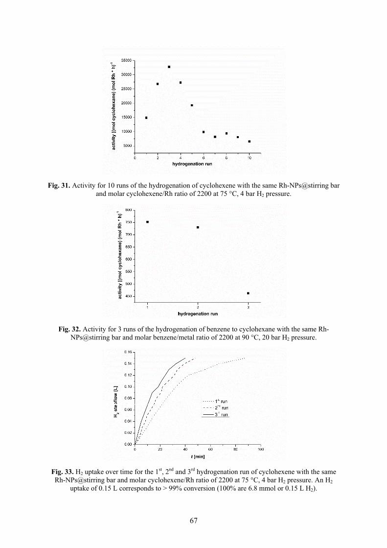
67
Fig. 31. Activity for 10 runs of the hydrogenation of cyclohexene with the same Rh-NPs@stirring bar and molar cyclohexene/Rh ratio of 2200 at 75 °C, 4 bar H2 pressure.
Fig. 32. Activity for 3 runs of the hydrogenation of benzene to cyclohexane with the same Rh-NPs@stirring bar and molar benzene/metal ratio of 2200 at 90 °C, 20 bar H2 pressure.
Fig. 33. H2 uptake over time for the 1st, 2nd and 3rd hydrogenation run of cyclohexene with the same Rh-NPs@stirring bar and molar cyclohexene/Rh ratio of 2200 at 75 °C, 4 bar H2 pressure. An H2
uptake of 0.15 L corresponds to > 99% conversion (100% are 6.8 mmol or 0.15 L H2).
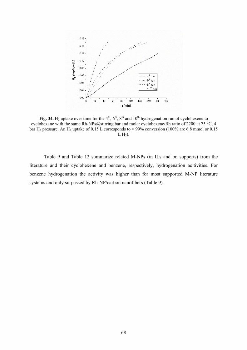
68
Fig. 34. H2 uptake over time for the 4th, 6th, 8th and 10th hydrogenation run of cyclohexene to cyclohexane with the same Rh-NPs@stirring bar and molar cyclohexene/Rh ratio of 2200 at 75 °C, 4
bar H2 pressure. An H2 uptake of 0.15 L corresponds to > 99% conversion (100% are 6.8 mmol or 0.15 L H2).
Table 9 and Table 12 summarize related M-NPs (in ILs and on supports) from the
literature and their cyclohexene and benzene, respectively, hydrogenation acitivities. For
benzene hydrogenation the activity was higher than for most supported M-NP literature
systems and only surpassed by Rh-NP/carbon nanofibers (Table 9).
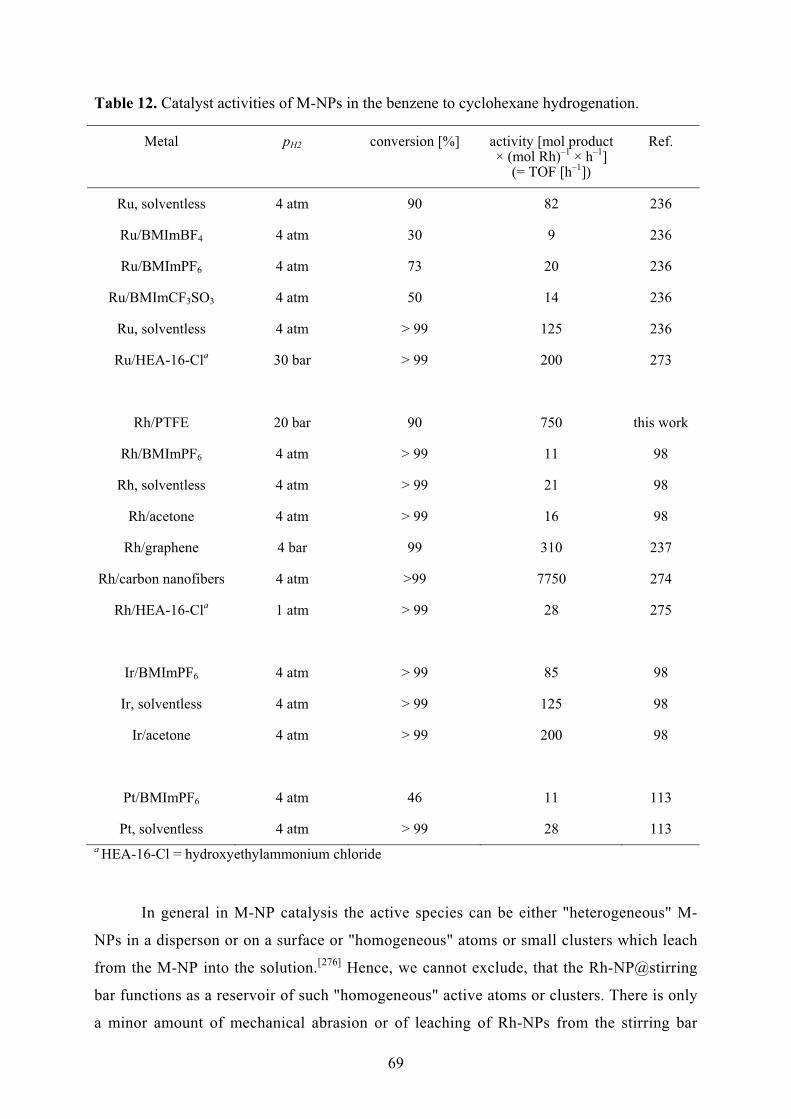
69
Table 12. Catalyst activities of M-NPs in the benzene to cyclohexane hydrogenation.
Metal pH2 conversion [%] activity [mol product × (mol Rh)–1 × h–1]
(= TOF [h–1])
Ref.
Ru, solventless 4 atm 90 82 236
Ru/BMImBF4 4 atm 30 9 236
Ru/BMImPF6 4 atm 73 20 236
Ru/BMImCF3SO3 4 atm 50 14 236
Ru, solventless 4 atm > 99 125 236
Ru/HEA-16-Cla 30 bar > 99 200 273
Rh/PTFE 20 bar 90 750 this work
Rh/BMImPF6 4 atm > 99 11 98
Rh, solventless 4 atm > 99 21 98
Rh/acetone 4 atm > 99 16 98
Rh/graphene 4 bar 99 310 237
Rh/carbon nanofibers 4 atm >99 7750 274
Rh/HEA-16-Cla 1 atm > 99 28 275
Ir/BMImPF6 4 atm > 99 85 98
Ir, solventless 4 atm > 99 125 98
Ir/acetone 4 atm > 99 200 98
Pt/BMImPF6 4 atm 46 11 113
Pt, solventless 4 atm > 99 28 113 a HEA-16-Cl = hydroxyethylammonium chloride
In general in M-NP catalysis the active species can be either "heterogeneous" M-
NPs in a disperson or on a surface or "homogeneous" atoms or small clusters which leach
from the M-NP into the solution.[276] Hence, we cannot exclude, that the Rh-NP@stirring
bar functions as a reservoir of such "homogeneous" active atoms or clusters. There is only
a minor amount of mechanical abrasion or of leaching of Rh-NPs from the stirring bar

70
during each catalytic run as was attested by three reproducible experiments outlined in
Fig. 35. Abrasion onto the glass surface appears to be more prominent than simple
leaching when comparing the resulting activities from stirred (Fig. 35a, Table 11, entry
14) versus non-stirred preparations (Fig. 35b, Table 11, entry 15) before applying the
hydrogen pressure. Sizeable conversion can be attested from the abrasion, albeit at
prolonged reaction times (24 h, entry 14) when compared to the conversion versus time of
Rh-NPs@stirring bar under otherwise identical conditions (entry 1-10).
H24 bar75 °C75 °C
12 h
cyclohexene(new)
to 25 %conversion new
vial (new)
cyclohexenecyclohexene / cyclohexanemixture after 24 h
Rh-NP@stirring barnew (unused) bar
+con-version78%24 h
(a)
(b)
75 °C12 h
(new)
X
H24 bar75 °C con-
version20%24 h
(c)
75 °C12 h
H24 bar75 °C
H24 bar75 °C
24 h
filter
conversion53%
Fig. 35. Experiments to attest the abrasion or leaching from Rh-NPs@stirring bar (carried out twice to ensure reproducibility within experimental error). (a) (Table 11, Entry 14) Stirring of Rh-
NPs@stirring bar in the empty glass inlay at 75 °C for 12 h under N2, followed by removal of the stirring bar, addition of a new (unused) stirring bar, cyclohexene and H2. A conversion of 78% is
reached after 24 h (cf. > 99% with Rh-NPs@stirring 1-2 h, entry 1-5) and indicates some, but little mechanical abrasion of the Rh-NPs from the PTFE surface. (b) (Table 11, Entry 15,) Allowing Rh-NPs@stirring bar to stand in cyclohexene at 75 °C for 12 h under N2, followed by removal of the
stirring bar, addition of a new stirring bar and H2. A conversion of only 20% after 24 h indicates little leaching from the stirring bar into the cyclohexene substrate. (c) (Table 11, Entry 16) Cyclohexene
hydrogenation was run to 25% conversion (within 12 min, monitored by gas uptake). Then, Rh-NPs@stirring bar was removed, the cyclohexene/cyclohexane mixture filtered under argon into a new glass inlay, equipped with a new stirring bar and re-pressurized. Conversion proceeded very slowly to
53% in 24 h, attesting little leaching even under the reaction conditions.

71
Metal nanoparticle traces can easily be deposited – intentional or unintentional –
on the PTFE surface of magnetic stirring bars. Memory effects can derive from un-
intentional deposits when such stirring bars are employed in catalytic reactions. At the
same time it is shown that a lab commodity such as a Teflon-coated magnetic stirring bar
can be easily turned into a re-usable, smoothly handable and magnetically removable
catalyst system. "Traces" of 32 μg or less of Rh-nanoparticles on the stirring bar surface
exert very high hydrogenation activities for cyclohexene or benzene under mild
conditions.
These results are part of this cumulative dissertation (publication 6.2).

72
4.3 Rhodium and ruthenium nanoparticles supported Graphene
The fluffy CDG powder (Fig. 36 synthesis according to Fig. 37) can be suspended in
the IL 1-butyl-3-methylimidazolium tetrafluoroborate (BMImBF4). The subsequent TEM
pictures with M-NPs show single graphene sheets (cf. Fig. 38 and Fig. 39) which suggest that
the CDG is dispersed into individual flakes in the IL.
Fig. 36. Scanning electron microscope (SEM) images of CDG from thermally reduced GO, showing the exfoliated sheets at the larger magnification at the right.
The solid metal carbonyl powders Mx(CO)y (M = Ru, Rh) were added to the CDG
slurry in BMImBF4 and suspended under argon atmosphere. The mixture was subjected to
microwave 10 irradiation (6 min, 20 W) under argon atmosphere. The M-NP/CDG materials
(M = Ru, Rh) can be separated from the IL and unsupported M-NP/IL by centrifugation of the
slurry, washing with water and drying in air. Black-grayish flake-like solids of M-NP/CDG
were obtained in good yield (Table 13). Defined and small Ru- and Rh-NPs with narrow size
distributions (2.2 ± 0.4 nm for Ru, 2.8 ± 0.5 nm for Rh) can be seen on the almost transparent
CDG surfaces in the TEM image of the Ru- and Rh-NP/CDG hybrid structures (Fig. 38 and
Fig. 39).
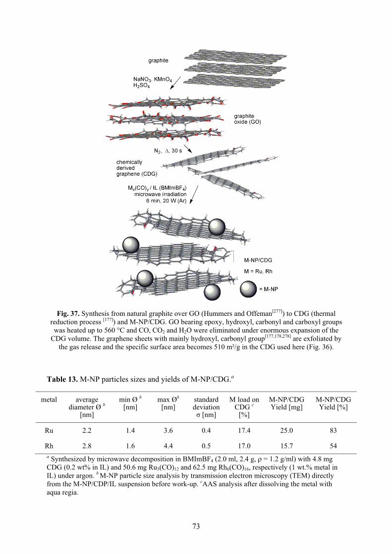
73
Fig. 37. Synthesis from natural graphite over GO (Hummers and Offeman[277]) to CDG (thermal reduction process [177]) and M-NP/CDG. GO bearing epoxy, hydroxyl, carbonyl and carboxyl groups was heated up to 560 °C and CO, CO2 and H2O were eliminated under enormous expansion of the
CDG volume. The graphene sheets with mainly hydroxyl, carbonyl group[177,178,278] are exfoliated by the gas release and the specific surface area becomes 510 m²/g in the CDG used here (Fig. 36).
Table 13. M-NP particles sizes and yields of M-NP/CDG.a
metal average diameter Ø b
[nm]
min Ø b
[nm] max Øb
[nm] standard deviation � [nm]
M load on CDG c
[%]
M-NP/CDG Yield [mg]
M-NP/CDG Yield [%]
Ru 2.2 1.4 3.6 0.4 17.4 25.0 83
Rh 2.8 1.6 4.4 0.5 17.0 15.7 54 a Synthesized by microwave decomposition in BMImBF4 (2.0 ml, 2.4 g, ��= 1.2 g/ml) with 4.8 mg CDG (0.2 wt% in IL) and 50.6 mg Ru3(CO)12 and 62.5 mg Rh6(CO)16, respectively (1 wt.% metal in IL) under argon. b M-NP particle size analysis by transmission electron microscopy (TEM) directly from the M-NP/CDP/IL suspension before work-up. cAAS analysis after dissolving the metal with aqua regia.
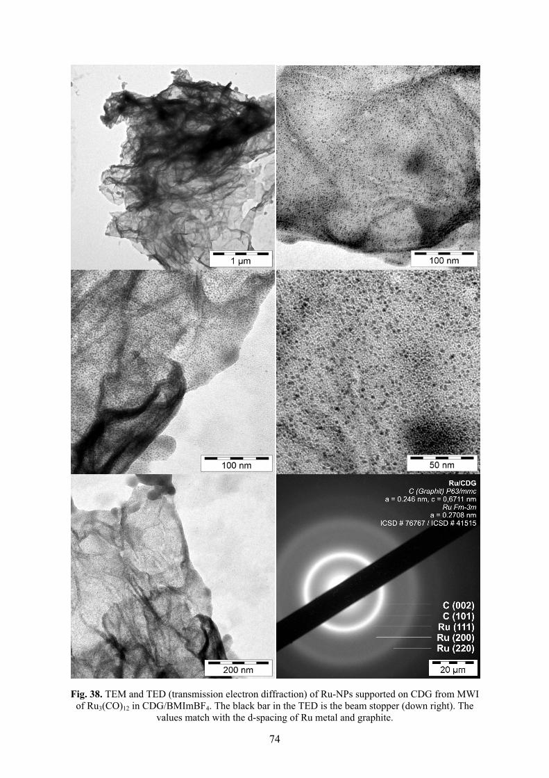
74
Fig. 38. TEM and TED (transmission electron diffraction) of Ru-NPs supported on CDG from MWI of Ru3(CO)12 in CDG/BMImBF4. The black bar in the TED is the beam stopper (down right). The
values match with the d-spacing of Ru metal and graphite.
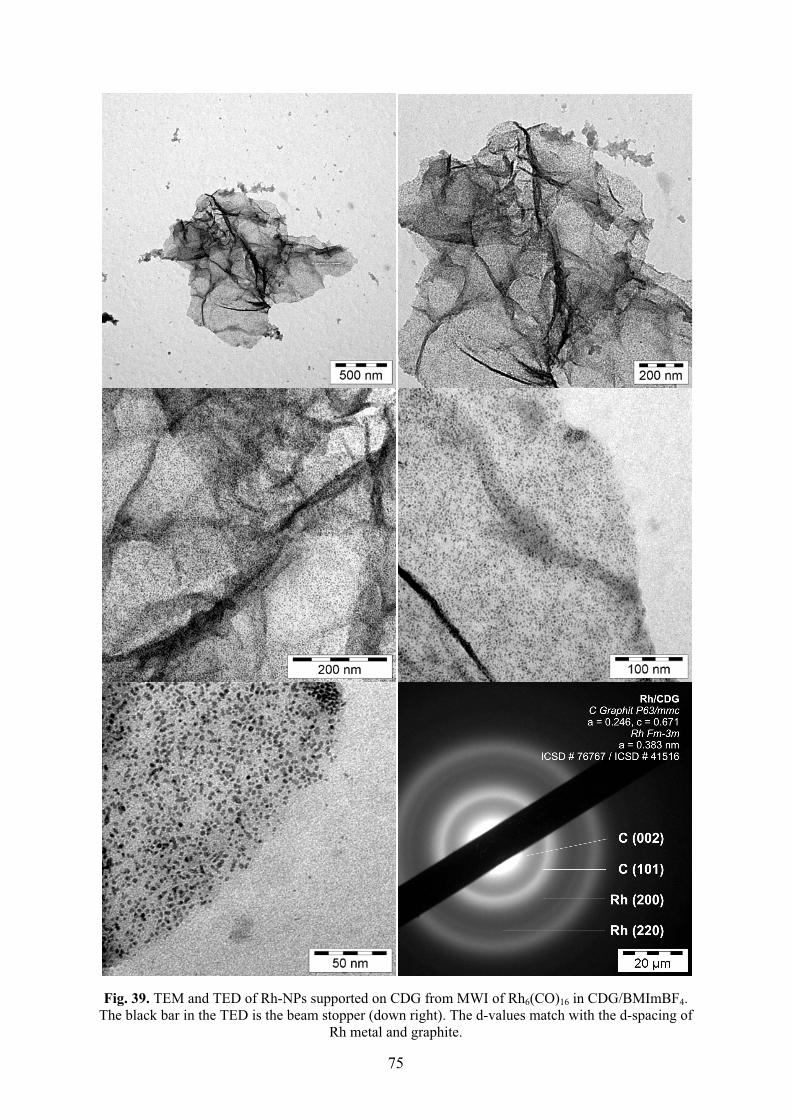
75
Fig. 39. TEM and TED of Rh-NPs supported on CDG from MWI of Rh6(CO)16 in CDG/BMImBF4. The black bar in the TED is the beam stopper (down right). The d-values match with the d-spacing of
Rh metal and graphite.
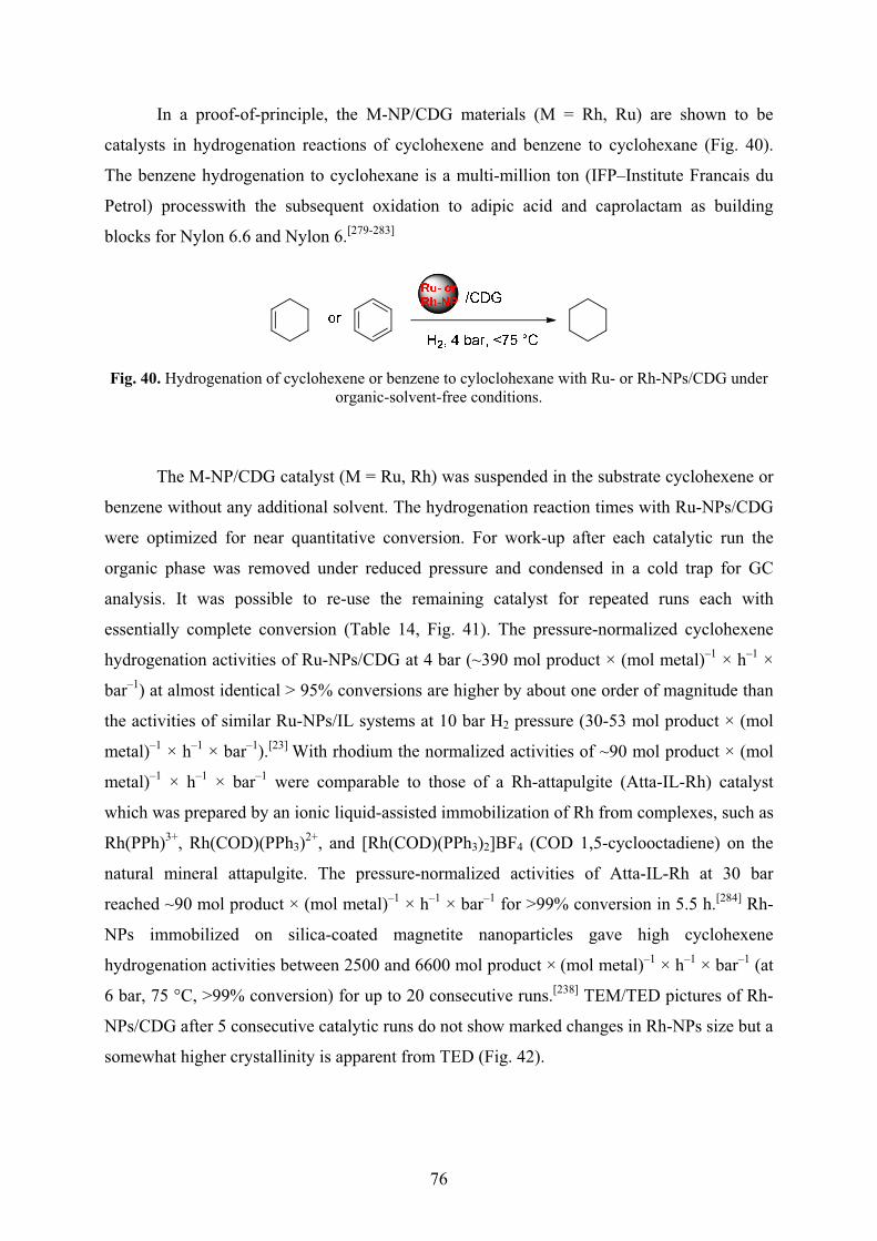
76
In a proof-of-principle, the M-NP/CDG materials (M = Rh, Ru) are shown to be
catalysts in hydrogenation reactions of cyclohexene and benzene to cyclohexane (Fig. 40).
The benzene hydrogenation to cyclohexane is a multi-million ton (IFP–Institute Francais du
Petrol) processwith the subsequent oxidation to adipic acid and caprolactam as building
blocks for Nylon 6.6 and Nylon 6.[279-283]
Fig. 40. Hydrogenation of cyclohexene or benzene to cyloclohexane with Ru- or Rh-NPs/CDG under organic-solvent-free conditions.
The M-NP/CDG catalyst (M = Ru, Rh) was suspended in the substrate cyclohexene or
benzene without any additional solvent. The hydrogenation reaction times with Ru-NPs/CDG
were optimized for near quantitative conversion. For work-up after each catalytic run the
organic phase was removed under reduced pressure and condensed in a cold trap for GC
analysis. It was possible to re-use the remaining catalyst for repeated runs each with
essentially complete conversion (Table 14, Fig. 41). The pressure-normalized cyclohexene
hydrogenation activities of Ru-NPs/CDG at 4 bar (~390 mol product × (mol metal)–1 × h–1 ×
bar–1) at almost identical > 95% conversions are higher by about one order of magnitude than
the activities of similar Ru-NPs/IL systems at 10 bar H2 pressure (30-53 mol product × (mol
metal)–1 × h–1 × bar–1).[23] With rhodium the normalized activities of ~90 mol product × (mol
metal)–1 × h–1 × bar–1 were comparable to those of a Rh-attapulgite (Atta-IL-Rh) catalyst
which was prepared by an ionic liquid-assisted immobilization of Rh from complexes, such as
Rh(PPh)3+, Rh(COD)(PPh3)2+, and [Rh(COD)(PPh3)2]BF4 (COD 1,5-cyclooctadiene) on the
natural mineral attapulgite. The pressure-normalized activities of Atta-IL-Rh at 30 bar
reached ~90 mol product × (mol metal)–1 × h–1 × bar–1 for >99% conversion in 5.5 h.[284] Rh-
NPs immobilized on silica-coated magnetite nanoparticles gave high cyclohexene
hydrogenation activities between 2500 and 6600 mol product × (mol metal)–1 × h–1 × bar–1 (at
6 bar, 75 °C, >99% conversion) for up to 20 consecutive runs.[238] TEM/TED pictures of Rh-
NPs/CDG after 5 consecutive catalytic runs do not show marked changes in Rh-NPs size but a
somewhat higher crystallinity is apparent from TED (Fig. 42).
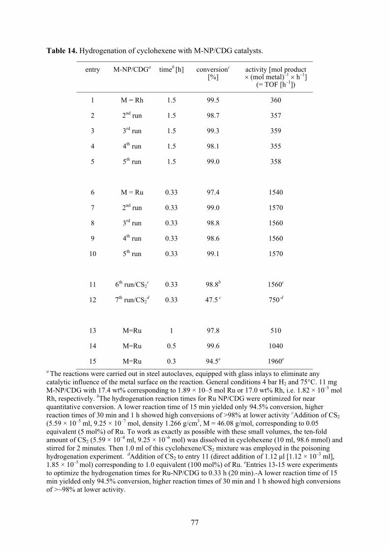
77
Table 14. Hydrogenation of cyclohexene with M-NP/CDG catalysts.
entry M-NP/CDGa timeb [h] conversionc [%]
activity [mol product ��(mol metal)–1 ��h–1]
(= TOF [h–1])
1 M = Rh 1.5 99.5 360
2 2nd run 1.5 98.7 357
3 3rd run 1.5 99.3 359
4 4th run 1.5 98.1 355
5 5th run 1.5 99.0 358
6 M = Ru 0.33 97.4 1540
7 2nd run 0.33 99.0 1570
8 3rd run 0.33 98.8 1560
9 4th run 0.33 98.6 1560
10 5th run 0.33 99.1 1570
11 6th run/CS2c 0.33 98.8b 1560c
12 7th run/CS2d 0.33 47.5 c 750 d
13 M=Ru 1 97.8 510
14 M=Ru 0.5 99.6 1040
15 M=Ru 0.3 94.5e 1960e
a The reactions were carried out in steel autoclaves, equipped with glass inlays to eliminate any catalytic influence of the metal surface on the reaction. General conditions 4 bar H2 and 75°C. 11 mg M-NP/CDG with 17.4 wt% corresponding to 1.89 × 10⁻⁵ mol Ru or 17.0 wt% Rh, i.e. 1.82 × 10⁻⁵ mol Rh, respectively. bThe hydrogenation reaction times for Ru NP/CDG were optimized for near quantitative conversion. A lower reaction time of 15 min yielded only 94.5% conversion, higher reaction times of 30 min and 1 h showed high conversions of >98% at lower activity cAddition of CS2 (5.59 × 10⁻⁵ ml, 9.25 × 10⁻⁷ mol, density 1.266 g/cm3, M = 46.08 g/mol, corresponding to 0.05 equivalent (5 mol%) of Ru. To work as exactly as possible with these small volumes, the ten-fold amount of CS2 (5.59 × 10⁻⁴ ml, 9.25 × 10⁻⁶ mol) was dissolved in cyclohexene (10 ml, 98.6 mmol) and stirred for 2 minutes. Then 1.0 ml of this cyclohexene/CS2 mixture was employed in the poisoning hydrogenation experiment. dAddition of CS2 to entry 11 (direct addition of 1.12 �l [1.12 × 10⁻³ ml], 1.85 × 10⁻⁵ mol) corresponding to 1.0 equivalent (100 mol%) of Ru. eEntries 13-15 were experiments to optimize the hydrogenation times for Ru-NP/CDG to 0.33 h (20 min).-A lower reaction time of 15 min yielded only 94.5% conversion, higher reaction times of 30 min and 1 h showed high conversions of >~98% at lower activity.

78
Fig. 41. Activities for the hydrogenation of cyclohexene with the same M-NP/CDG catalyst, entry 1-5 for Rh and entry 6-10 for Ru in Table 14. An even lower reaction time of 15 min for M = Ru gave
only 94.5% conversion.
Following the work by Finke et al.[285,286] CS2 binds strongly to active metal sites and
blocks access of the substrates. If it is possible to poison a catalyst completely with << 1
equivalent (<< 100 mol%) of the added ligand per Ru atom, this is strong evidence that it is a
heterogeneous catalyst. The reasoning is that in a heterogeneous (colloidal) metal-particle
catalyst only a fraction of the metal atoms are on the surface, hence much less than a one
molar equivalent of ligand per metal atom will be sufficient to deactivate the catalyst.[286,287] A
molecular, homogeneous catalyst needs � 1.0 equivalent of the ligand (per metal atom) for the
poisoning. To differentiate between possible homogeneous Ru atom and heterogeneous Ru-
NP catalysts we have added CS2 as a known ruthenium catalyst poison following the work by
Finke et al. (see above for explanation).[286,287] For a consecutive catalytic 6th run in the
presence of CS2 (Table 14, entry 11, 0.05 eq., 5 mol% of Ru) we found that CS2 has only a
marginal poisoning effect on the Ru-NPs/CDG catalyst. Even at 1.0 equivalent of CS2 (100
mol%) to Ru (Table 14, entry 12) still about half of the previous conversion and activity is
retained. Failure of Ru-NP/CDG poisoning can be explained with formation of xanthates from
alcohols, here the hydroxy-functionalities of CDG and CS2 (Scheme 12).
Scheme 12. Xanthate formation. CS2 capture by the CDG hampers the conclusive evidence from the poisoning experiments.
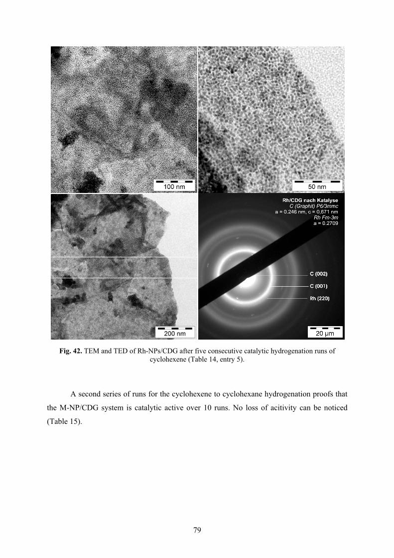
79
Fig. 42. TEM and TED of Rh-NPs/CDG after five consecutive catalytic hydrogenation runs of cyclohexene (Table 14, entry 5).
A second series of runs for the cyclohexene to cyclohexane hydrogenation proofs that
the M-NP/CDG system is catalytic active over 10 runs. No loss of acitivity can be noticed
(Table 15).
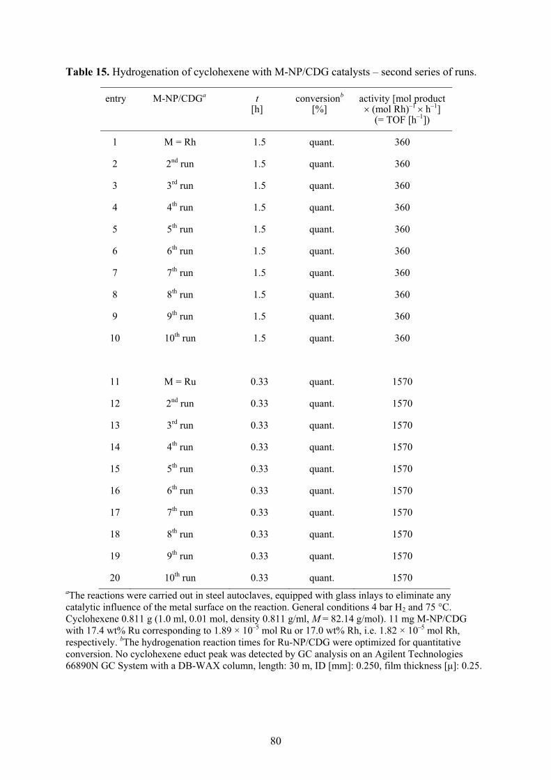
80
Table 15. Hydrogenation of cyclohexene with M-NP/CDG catalysts – second series of runs.
entry M-NP/CDGa t [h]
conversionb [%]
activity [mol product � (mol Rh)–1 ��h–1]
(= TOF [h–1])
1 M = Rh 1.5 quant. 360
2 2nd run 1.5 quant. 360
3 3rd run 1.5 quant. 360
4 4th run 1.5 quant. 360
5 5th run 1.5 quant. 360
6 6th run 1.5 quant. 360
7 7th run 1.5 quant. 360
8 8th run 1.5 quant. 360
9 9th run 1.5 quant. 360
10 10th run 1.5 quant. 360
11 M = Ru 0.33 quant. 1570
12 2nd run 0.33 quant. 1570
13 3rd run 0.33 quant. 1570
14 4th run 0.33 quant. 1570
15 5th run 0.33 quant. 1570
16 6th run 0.33 quant. 1570
17 7th run 0.33 quant. 1570
18 8th run 0.33 quant. 1570
19 9th run 0.33 quant. 1570
20 10th run 0.33 quant. 1570 aThe reactions were carried out in steel autoclaves, equipped with glass inlays to eliminate any catalytic influence of the metal surface on the reaction. General conditions 4 bar H2 and 75 °C. Cyclohexene 0.811 g (1.0 ml, 0.01 mol, density 0.811 g/ml, M = 82.14 g/mol). 11 mg M-NP/CDG with 17.4 wt% Ru corresponding to 1.89 × 10⁻⁵ mol Ru or 17.0 wt% Rh, i.e. 1.82 × 10⁻⁵ mol Rh, respectively. bThe hydrogenation reaction times for Ru-NP/CDG were optimized for quantitative conversion. No cyclohexene educt peak was detected by GC analysis on an Agilent Technologies 66890N GC System with a DB-WAX column, length: 30 m, ID [mm]: 0.250, film thickness [�]: 0.25.
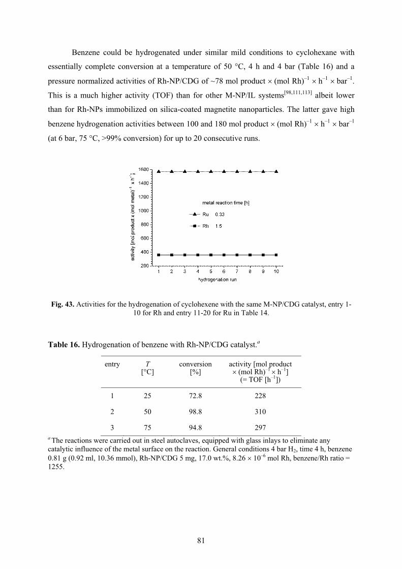
81
Benzene could be hydrogenated under similar mild conditions to cyclohexane with
essentially complete conversion at a temperature of 50 °C, 4 h and 4 bar (Table 16) and a
pressure normalized activities of Rh-NP/CDG of ~78 mol product ��(mol Rh)–1 ��h–1 ��bar–1.
This is a much higher activity (TOF) than for other M-NP/IL systems[98,111,113] albeit lower
than for Rh-NPs immobilized on silica-coated magnetite nanoparticles. The latter gave high
benzene hydrogenation activities between 100 and 180 mol product ��(mol Rh)–1 ��h–1 ��bar–1
(at 6 bar, 75 °C, >99% conversion) for up to 20 consecutive runs.
Fig. 43. Activities for the hydrogenation of cyclohexene with the same M-NP/CDG catalyst, entry 1-10 for Rh and entry 11-20 for Ru in Table 14.
Table 16. Hydrogenation of benzene with Rh-NP/CDG catalyst.a
entry T [°C]
conversion [%]
activity [mol product ��(mol Rh)–1 ��h–1]
(= TOF [h–1])
1 25 72.8 228
2 50 98.8 310
3 75 94.8 297 a The reactions were carried out in steel autoclaves, equipped with glass inlays to eliminate any catalytic influence of the metal surface on the reaction. General conditions 4 bar H2, time 4 h, benzene 0.81 g (0.92 ml, 10.36 mmol), Rh-NP/CDG 5 mg, 17.0 wt.%, 8.26 ��10–6 mol Rh, benzene/Rh ratio = 1255.
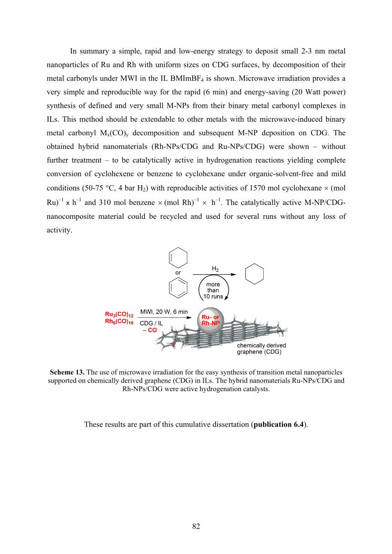
82
In summary a simple, rapid and low-energy strategy to deposit small 2-3 nm metal
nanoparticles of Ru and Rh with uniform sizes on CDG surfaces, by decomposition of their
metal carbonyls under MWI in the IL BMImBF4 is shown. Microwave irradiation provides a
very simple and reproducible way for the rapid (6 min) and energy-saving (20 Watt power)
synthesis of defined and very small M-NPs from their binary metal carbonyl complexes in
ILs. This method should be extendable to other metals with the microwave-induced binary
metal carbonyl Mx(CO)y decomposition and subsequent M-NP deposition on CDG. The
obtained hybrid nanomaterials (Rh-NPs/CDG and Ru-NPs/CDG) were shown – without
further treatment – to be catalytically active in hydrogenation reactions yielding complete
conversion of cyclohexene or benzene to cyclohexane under organic-solvent-free and mild
conditions (50-75 °C, 4 bar H2) with reproducible activities of 1570 mol cyclohexane � (mol
Ru)–1 x h–1 and 310 mol benzene ��(mol Rh)–1 � �h–1. The catalytically active M-NP/CDG-
nanocomposite material could be recycled and used for several runs without any loss of
activity.
Scheme 13. The use of microwave irradiation for the easy synthesis of transition metal nanoparticles supported on chemically derived graphene (CDG) in ILs. The hybrid nanomaterials Ru-NPs/CDG and
Rh-NPs/CDG were active hydrogenation catalysts.
These results are part of this cumulative dissertation (publication 6.4).
83
5 EXPERIMENTAL
5.1 General 5.1.1 Materials
Mo(CO)6, W(CO)6, Re2(CO)10, Fe2(CO)9, Ru3(CO)12, Os3(CO)12, Co2(CO)8, Rh6(CO)16 and
Ir6(CO)16 were obtained from STREM and Aldrich, Propylene carbonate (PC) (99.7 %, H2O
free), 3-mercaptopropionic acid (> 99 %), TOPO (99 %), 1-hexyne (> 97%), cylcohexene (>
97%), acetone (99% p.a.; particle free) and benzene (> 99 %) from Sigma-Aldrich, BMImBF4
from IoLiTec (H2O content << 100 ppm; Cl– content<< 50 ppm).
Literature reported decomposition temperatures are 180 °C for Mo(CO)6 and W(CO)6, 177 °C
for Re2(CO)10, above 100 °C for Fe2(CO)9, 155 °C for Ru3(CO)12 and 224 °C for Os3(CO)12,
above 100 °C for Co2(CO)8, 220 °C for Rh6(CO)16 and 210 °C for Ir6(CO)16.[293]
Stirring bars were obtained by VWR International GmbH, Hilpertstraße 20a, 64295
Darmstadt.
5.1.2 Technics
All manipulations were done using Schlenk techniques under nitrogen since the metal
carbonyls salts are hygroscopic and air sensitive. The ILs and PC were dried at high vacuum
(10–3 mbar) for several days.
Microwave irradiation
For the synthesis of the dispersions a CEM microwave type Discover was used.
5.1.3 Analysis
AAS
Atomic absorption spectrometry (AAS) was performed with Perkin-Elmer AAnalyst 100
(flame AAS), using the software AA WinLab.
DLS
A Malvern Zetasizer Nano-ZS was used for the dynamic light scattering (DLS) measurements
working at 633 nm wavelength. Care was taken for choosing the right parameters, such as the
index of refraction of the transition metals at their wavelength (Table 17).
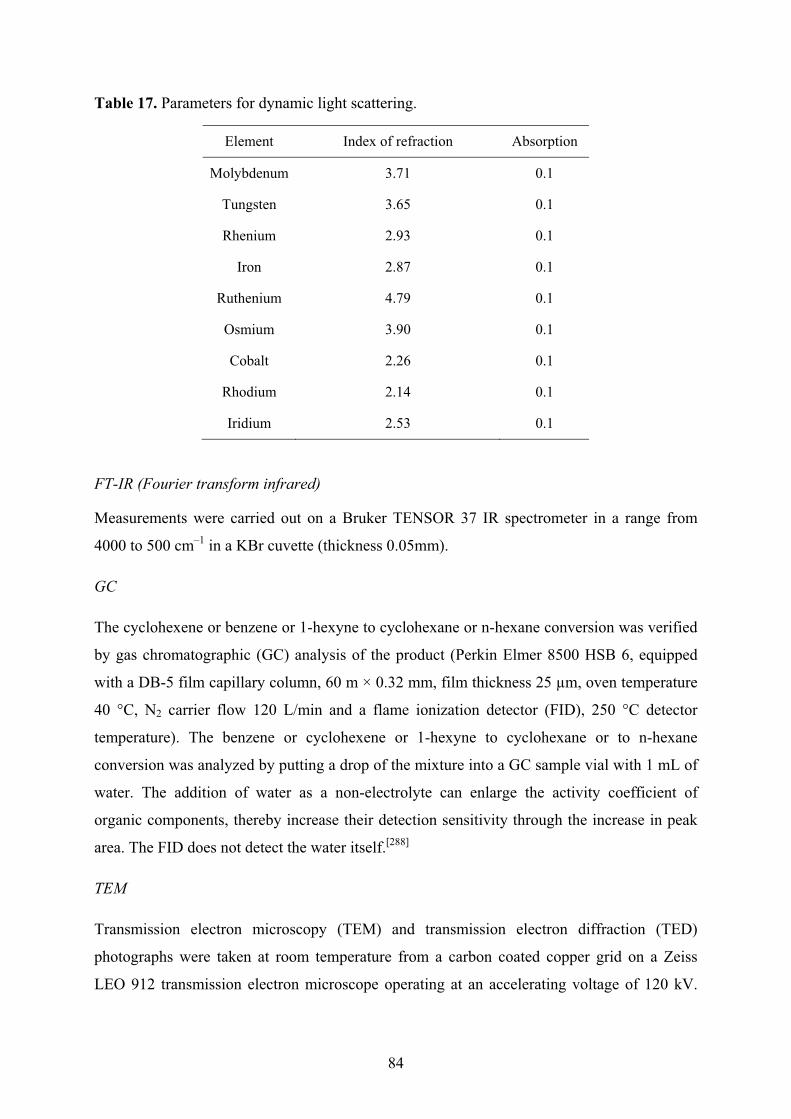
84
Table 17. Parameters for dynamic light scattering.
Element Index of refraction Absorption
Molybdenum 3.71 0.1
Tungsten 3.65 0.1
Rhenium 2.93 0.1
Iron 2.87 0.1
Ruthenium 4.79 0.1
Osmium 3.90 0.1
Cobalt 2.26 0.1
Rhodium 2.14 0.1
Iridium 2.53 0.1
FT-IR (Fourier transform infrared)
Measurements were carried out on a Bruker TENSOR 37 IR spectrometer in a range from
4000 to 500 cm–1 in a KBr cuvette (thickness 0.05mm).
GC
The cyclohexene or benzene or 1-hexyne to cyclohexane or n-hexane conversion was verified
by gas chromatographic (GC) analysis of the product (Perkin Elmer 8500 HSB 6, equipped
with a DB-5 film capillary column, 60 m × 0.32 mm, film thickness 25 μm, oven temperature
40 °C, N2 carrier flow 120 L/min and a flame ionization detector (FID), 250 °C detector
temperature). The benzene or cyclohexene or 1-hexyne to cyclohexane or to n-hexane
conversion was analyzed by putting a drop of the mixture into a GC sample vial with 1 mL of
water. The addition of water as a non-electrolyte can enlarge the activity coefficient of
organic components, thereby increase their detection sensitivity through the increase in peak
area. The FID does not detect the water itself.[288]
TEM
Transmission electron microscopy (TEM) and transmission electron diffraction (TED)
photographs were taken at room temperature from a carbon coated copper grid on a Zeiss
LEO 912 transmission electron microscope operating at an accelerating voltage of 120 kV.
85
Samples were loaded on holey, carbon coated copper grids. The solvents were removed by
floating the grids on water for several minutes.
Particles diameters were measured manually using iTEM software tools for manual
measurements. Completely automatic measurements, which can be easily performed for well
separated particles, fail in the case of heavily clustered particles. For a better comparison of
the samples also particles which would have allowed automatic detection were measured
manually.
5.1.4 Catalysis
An autoclave with a glass inlay was used. The hydrogenation reactions were carried out in the
glass inlay.
The autoclave was conditioned by evacuation and re-filling with nitrogen. All autoclave
loading was carried out under nitrogen. Stirring rate was 850 rpm. The autoclave was heated
to the desired temperature and set to the desired pressure of H2 which was kept constant over
the reaction time. The H2 uptake over time was monitored with a Büchi pressflow gas
controller. After quantitative or near quantitative conversion was reached (adjudged by the H2
consumption) the reactor was depressurized, the volatile organic components were condensed
under vacuum into a clean cold trap. The catalytic system is left behind in the glass inlay of
the autoclave and was re-used by adding fresh substrate.

86
5.2 Propylene carbonate as stabilizing solvent for transition metal
nanoparticles 5.2.1 General
TED
Transmission electron diffraction (TED): d-Spacing, intensity and hkl from STOE WinXPow
version 1.10, data base, STOE & Cie GmbH, Darmstadt, Germany, 2002.
Table 18. Diffraction rings of Ru-particles compared with IPDS database, Ru [6-663]
d-Spacing from diffraction rings
[Å]
d-spacing [Å] Intensity hkl
from database
2.10 2.0560 100 101
1.61 1.5808 25 102
not seen 1.3530 25 110
1.26 1.2189 25 103
1.15 1.1299 20 201
Table 19. Diffraction rings of Rh-particles compared with IPDS database, Rh [5-685]
d-Spacing from diffraction rings
[Å]
d-spacing [Å] Intensity hkl
from database
2.23 2.1960 100 111
1.94 1.9020 50 200
1.39 1.3450 26 220
1.17 1.1468 33 311
not seen 1.0979 11 222
not seen 0.9508 7 400
0.89 0.8724 20 331
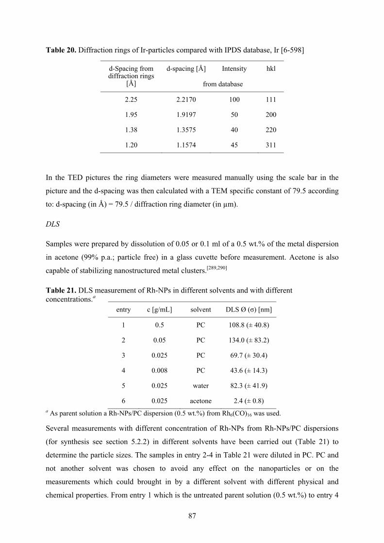
87
Table 20. Diffraction rings of Ir-particles compared with IPDS database, Ir [6-598]
d-Spacing from diffraction rings
[Å]
d-spacing [Å] Intensity hkl
from database
2.25 2.2170 100 111
1.95 1.9197 50 200
1.38 1.3575 40 220
1.20 1.1574 45 311
In the TED pictures the ring diameters were measured manually using the scale bar in the
picture and the d-spacing was then calculated with a TEM specific constant of 79.5 according
to: d-spacing (in Å) = 79.5 / diffraction ring diameter (in μm).
DLS
Samples were prepared by dissolution of 0.05 or 0.1 ml of a 0.5 wt.% of the metal dispersion
in acetone (99% p.a.; particle free) in a glass cuvette before measurement. Acetone is also
capable of stabilizing nanostructured metal clusters.[289,290]
Table 21. DLS measurement of Rh-NPs in different solvents and with different concentrations.a
a As parent solution a Rh-NPs/PC dispersion (0.5 wt.%) from Rh6(CO)16 was used.
Several measurements with different concentration of Rh-NPs from Rh-NPs/PC dispersions
(for synthesis see section 5.2.2) in different solvents have been carried out (Table 21) to
determine the particle sizes. The samples in entry 2-4 in Table 21 were diluted in PC. PC and
not another solvent was chosen to avoid any effect on the nanoparticles or on the
measurements which could brought in by a different solvent with different physical and
chemical properties. From entry 1 which is the untreated parent solution (0.5 wt.%) to entry 4
entry c [g/mL] solvent DLS Ø (�) [nm]
1 0.5 PC 108.8 (± 40.8)
2 0.05 PC 134.0 (± 83.2)
3 0.025 PC 69.7 (± 30.4)
4 0.008 PC 43.6 (± 14.3)
5 0.025 water 82.3 (± 41.9)
6 0.025 acetone 2.4 (± 0.8)

88
with is a diluted sample the particle sizes decreases, but the results did not match with the
result (2.1 (± 0.6) nm) obtained by TEM (see Table 6). Water was used as a dilution solvent in
entry 5 and was considered to be unfeasible, because after a few minutes a precipitate
appeared on the bottom of the glass cuvette before the measurement was started. Water seems
to weaken the protective, stabilizing PC-Layers around the nanoparticles which, thus, are
agglomerating to bulk material. Acetone was used as solvent and the results obtained by DLS
with acetone used as solvent best fit the results obtained by TEM (see Table 6).
DLS is commonly used for analyses of polymers with particle size larger than nanoparticles.
The sizes of nanoparticles (1-5 nm) may not be analyzed precisely because the resolution
limit of the DLS is 1 nm. The DLS measurement does not measure the “actual” particle size,
but it measures the hydrodynamic diameter d(H) as is described by the Stokes-Einstein (Eqn.
3):
?��@� � ���
A0BC (3)
d (H) = hydrodynamic diameter [nm] D = translational diffusion coefficient k = Boltzmann’s constant, k = 1.38 × 10²³ J/K T = absolute temperature [k] � = viscosity of the solvent [kg/(ms)]
The diameter measured in DLS is a value that refers to how a particle diffuses within a fluid
so it is referred to as a hydrodynamic diameter. Actually it is not the diameter of a particle,
which is measured, but the diameter of a sphere that has the same translational diffusion
coefficient (D) as the particle. This coefficient D depends on the particle size, surface
structure, concentration and type of ions in the medium and is calculated via a correlation
function during the measurement.[291,292] With these variables a precise investigation of the
particle sizes is not possible.
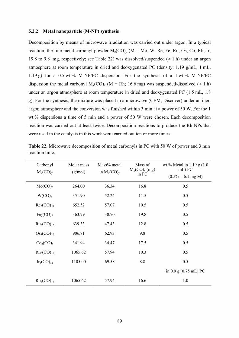
89
5.2.2 Metal nanoparticle (M-NP) synthesis
Decomposition by means of microwave irradiation was carried out under argon. In a typical
reaction, the fine metal carbonyl powder Mx(CO)y (M = Mo, W, Re, Fe, Ru, Os, Co, Rh, Ir;
19.8 to 9.8 mg, respectively; see Table 22) was dissolved/suspended (� 1 h) under an argon
atmosphere at room temperature in dried and deoxygenated PC (density: 1.19 g/mL, 1 mL,
1.19 g) for a 0.5 wt.% M-NP/PC dispersion. For the synthesis of a 1 wt.% M-NP/PC
dispersion the metal carbonyl Mx(CO)y (M = Rh; 16.6 mg) was suspended/dissolved (� 1 h)
under an argon atmosphere at room temperature in dried and deoxygenated PC (1.5 mL, 1.8
g). For the synthesis, the mixture was placed in a microwave (CEM, Discover) under an inert
argon atmosphere and the conversion was finished within 3 min at a power of 50 W. For the 1
wt.% dispersions a time of 5 min and a power of 50 W were chosen. Each decomposition
reaction was carried out at least twice. Decomposition reactions to produce the Rh-NPs that
were used in the catalysis in this work were carried out ten or more times.
Table 22. Microwave decomposition of metal carbonyls in PC with 50 W of power and 3 min reaction time.
Carbonyl Mx(CO)y
Molar mass (g/mol)
Mass% metal in Mx(CO)y
Mass of Mx(CO)y (mg)
in PC
wt.% Metal in 1.19 g (1.0 mL) PC
(0.5% = 6.1 mg M)
Mo(CO)6 264.00 36.34 16.8 0.5
W(CO)6 351.90 52.24 11.5 0.5
Re2(CO)10 652.52 57.07 10.5 0.5
Fe2(CO)9 363.79 30.70 19.8 0.5
Ru3(CO)12 639.33 47.43 12.8 0.5
Os3(CO)12 906.81 62.93 9.8 0.5
Co2(CO)8 341.94 34.47 17.5 0.5
Rh6(CO)16 1065.62 57.94 10.3 0.5
Ir4(CO)12 1105.00 69.58 8.8 0.5
in 0.9 g (0.75 mL) PC
Rh6(CO)16 1065.62 57.94 16.6 1.0
90
5.2.3 Catalysis
The hydrogenation reactions with Rh-NPs/PC were carried out in stainless steel autoclaves
connected with an online hydrogenation-consumption monitoring system (Büchi pressflow
gas controller, bpc). The autoclave was conditioned by evacuation and re-filling with
nitrogen. All autoclave loading was carried out under nitrogen. Each autoclave was equipped
with a glass inlay, to eliminate any catalytic influence of the stainless steel surface on the
reaction process. A typical experiment used 0.75 mL of the Rh-NPs/PC dispersion with 1
wt.% Rh (9 mg, 8.8 × 10⁻⁵ mol Rh) and 10 mL of cyclohexene (0.1 mol, density 0.811 g/ml,
M = 82.14 g/mol,) or 1.0 mL of 1-hexyne (1.8 mmol, density 0.72 g/ml, M = 82.14 g/mol).
The autoclave was heated to the desired temperature and set to the desired pressure of H2
which was kept constant over the reaction time. After this time the reactor was depressurized,
and the volatile organic components condensed under vacuum (15 min) into a clean cold trap
(liquid nitrogen cooled). The Rh-NPs/PC dispersion was left behind.
5.2.3.1 Conditions for cyclohexene hydrogenation
Cyclohexene 10 mL, 0.89 mol (density 0.811 g/ml, M = 82.14 g/mol); Rh metal (9 mg, 8.8 ×
10–5 mol); 25-95 °C, 4-10 bar H2.
5.2.3.2 Conditions for 1-hexyne hydrogenation
1-hexyne (1.0 mL, 1.8 mmol (density 0.72 g/ml, M = 82.11 g/mol); Rh metal (9 mg, 8.8 × 10⁻⁵
mol); 25 °C, 10 bar H2.
5.2.4 Preparation of ligand-capped M-NP in PC
The obtained Rh- and Ru-NPs/PC (0.4 ml, 0.5 wt.%) were stirred with 3-mercaptopropionic
acid (2 mL, 3.5 × 10⁻⁵ mol) or TOPO (14 mg, 3.5 × 10⁻⁵ mol) over night. The ligand-capped
M-NPs were collected by centrifugation (2000 rpm, 15 min) and decantation of the clear
propylene carbonate phase. The capped M-NPs were dried for several days under high
vacuum to remove the PC solvent.

91
5.3 Rhodium nanoparticles supported PTFE stirring bars 5.3.1 General
Stirring bars (20 × 6 mm) were obtained by VWR International GmbH, Hilpertstraße 20a,
64295 Darmstadt.
Analysis
SEM
Scanning electron microscope (SEM) samples were coated with a thin Au layer (~ 8 nm) and
analyzed with a Quanta 250 FEG instrument. The measurements were performed at 3.20–4 Pa
and at 10 kV voltage using an ETD detector.
AAS
AAS (atomic absorption spectrometry) was performed with Perkin-Elmer AAnalyst 100
(flame AAS), using the software AA WinLab. The rhodium loading on the stirring bar and the
rhodium leaching in the catalytic runs was analyzed by AAS. To dissolve the Rh-NPs from
the Teflon-coating of the stirring bar it was placed into a conc. HCl/HNO3 mixture (aqua
regia, 50 ml) over night. The resulting solution was directly used for the AAS analysis.
Analysis of the Rh-NP content on a stirring bar from the above preparations reproducibly
gave 32 (± 8) μg of rhodium (± 8 is the standard deviation from multiple Rh-content
determinations of different stirring bars). After the treatment with aqua regia the magnetic
stirring bars lost their catalytic properties regarding the hydrogenation of cyclohexene or
benzene.
5.3.2 Preparation of Rh-NP/IL dispersion
Rh6(CO)16 (41.42 mg, 3.89 � 10–5 mol) was dissolved/suspended (~1 h) under a nitrogen
atmosphere at room temperature in dried and deoxygenated BMImBF4 (2.0 mL, 2.4 g) to give
a 1.0 wt.% dispersion. For the synthesis the mixture was placed in a CEM microwave type
Discover under inert nitrogen atmosphere and the conversion was finished within 6 minutes at
a power of 10 W. Rh6(CO)16 decomposes at 220 °C, so it can easily be handled at room
temperature under inert atmosphere.[293]
92
5.3.3 Preparation of Rh-NP@stirring bar
A brand-new (unused) magnetic stir bar was washed with dried acetone (10 mL) and dried
under high vacuum prior to the Rh-NP deposition. Rhodium nanoparticle deposition on PTFE
was obtained by stirring the magnetic stirring bar in the Rh-NPs/BMImBF4 dispersion at
room temperature under nitrogen for different defined number of 2-8 days. The nanoparticle-
loaded stirring bar was removed from the Rh-NPs/BMImBF4 dispersion and stirred in a
washing solvent (20 mL) for 15 s to remove the IL, removed with a pincer and dried under
vacuum for 30 min. The solvents acetone, water, methanol, iso-propanol, tetrahydrofuran and
methylene chloride were tested for the washing and removal of the ionic liquid film which
adhered to Rh-NP@stirring bar. For each different washing solvent, a cyclohexene
hydrogenation run (see section 5.3.4) was carried out to test for the resulting activity.
Activities for acetone (p.a), THF or methylene chloride were similar and higher than for
acetone (technical), methanol, iso-propanol or water. Eventually, THF (p.a) was used as a
standard washing solvent for the catalytic recycling experiments.
5.3.4 Catalysis
5.3.4.1 General
Rh-NPs@stirring bars were conditioned after their preparation by using the above-mentioned
washing procedure with dried THF (20 mL) for 15 s before the first run to remove the ionic
liquid.
An autoclave with a glass inlay was used. The hydrogenation reactions were carried out in the
glass inlay. The autoclave was conditioned by evacuation and re-filling with nitrogen. All
autoclave loading was carried out under nitrogen. Stirring rate was 850 rpm. The H2 uptake
over time was monitored with a Büchi pressflow gas controller (Büchi pbc). After quantitative
or near quantitative conversion was reached (adjudged by the H2 consumption) the reactor
was depressurized, the volatile organic components were condensed under vacuum into a
clean cold trap. The Rh-NPs@stirring bar is left behind in the glass inlay of the autoclave and
was re-used by adding fresh substrate. Catalyst recycling was carried out ten times for
cyclohexene and three times for benzene.
5.3.4.2 Conditions for cyclohexene hydrogenation
Cyclohexene 0.69 mL, 6.8 mmol (density 0.811 g/mL, M = 82.14 g/mol); Rh metal (0.032
mg, 3.1 ��10–7 mol); 75 °C, 4 bar H2.
93
5.3.4.3 Conditions for benzene hydrogenation
Benzene 0.60 mL, 6.8 mmol (density 0.88 g/mL, M = 78.11 g/mol); Rh metal (0.032 mg, 3.1
��10–7 mol); 90 °C, 20 bar H2. For the slower benzene hydrogenation the reaction was
intentionally stopped at 90% conversion (adjudged by the H2 consumption) as thereafter the
decrease in benzene concentration lowered the reaction rate. Thus, the reactor was
depressurized after 90 % conversion and the liquid product removed under vacuum and fresh
benzene (0.60 mL) was added.
5.3.4.4 Special Experiments
To investigate the possibility of mechanical abrasion or of leaching of Rh-NPs from the
stirring bar the following special experiments were performed:
Entry 14 in Table 11– test for mechanical abrasion: Rh-NPs@stirring bar was stirred for 12 h
at 75 °C in an empty glass inlay at 850 rpm under N2. Afterwards this Rh-NPs@stirring bar
was replaced by brand-new (untreated) stirring bar. Cyclohexene (0.69 mL) was added and
the autoclave was pressurized. Hydrogenation took place at 75 °C and 4 bar H2. After 24 h the
hydrogenation was stopped and the conversion verified by GC.
Entry 15 in Table 11– test for leaching into cyclohexene: Rh-NPs@stirring bar was placed in
and allowed to stand for 12 h at 75 °C in cyclohexene (0.69 mL) without stirring under N2.
Afterwards Rh-NPs@stirring bar was replaced by a brand-new (untreated) stirring bar and the
autoclave was pressurized. Hydrogenation was carried out at 75 °C and 4 bar H2. After 24 h
the hydrogenation was stopped and the conversion verified by GC.
Entry 16 in Table 11– test for leaching into cyclohexene under hydrogenation conditions:
Using the general hydrogenation conditions, the hydrogenation of cyclohexene (0.69 mL) was
started at 75 °C and 4 bar H2 and run until 25 % conversion (which reached after 12 min). The
cyclohexane/ cyclohexene mixture was filtered hot at 60 °C under N2 atmosphere into a new
glass inlay equipped with brand-new (untreated) stirring bar. The glass inlay was placed into
the autoclave and hydrogenation was resumed at 75 °C by pressurizing to 4 bar H2. After 24 h
the hydrogenation was stopped and the conversion verified by GC.
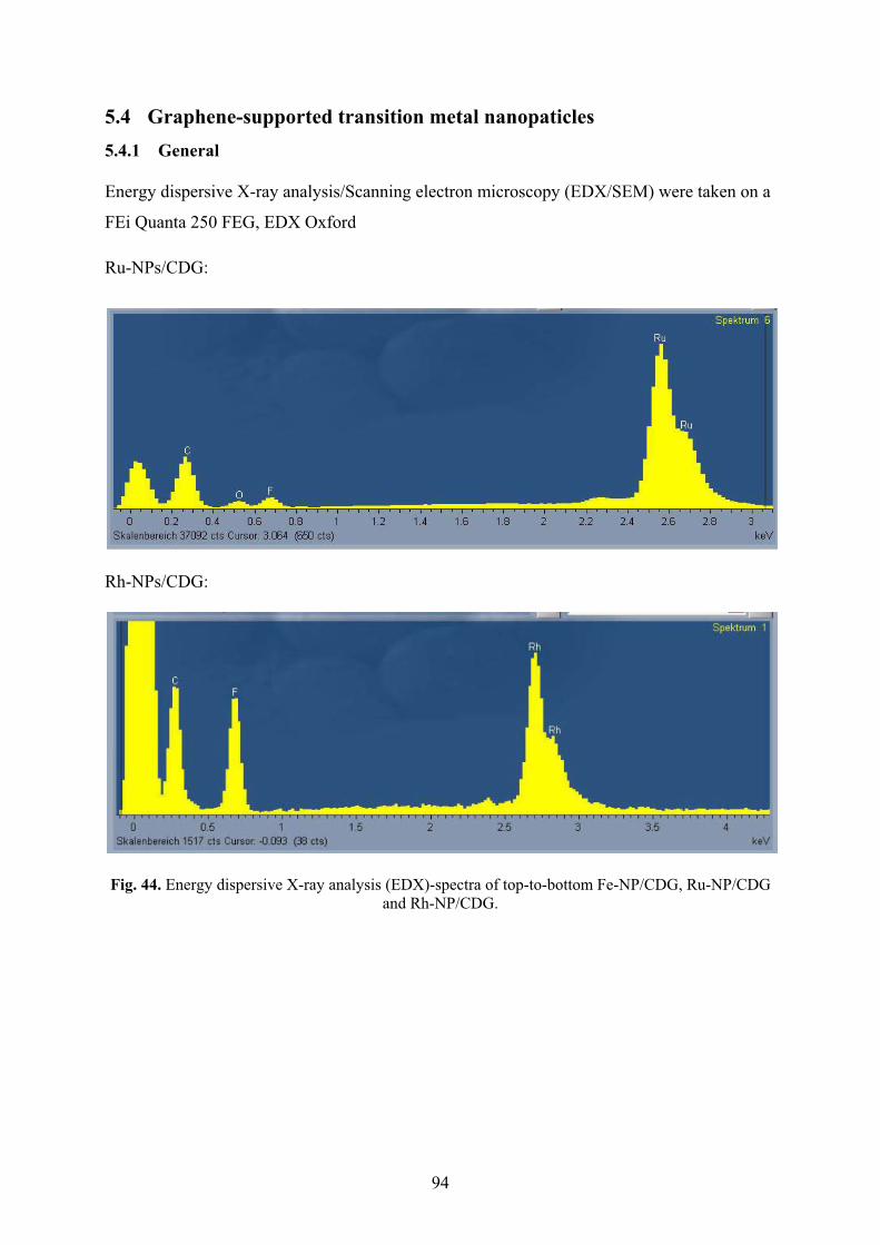
94
5.4 Graphene-supported transition metal nanopaticles 5.4.1 General
Energy dispersive X-ray analysis/Scanning electron microscopy (EDX/SEM) were taken on a
FEi Quanta 250 FEG, EDX Oxford
Ru-NPs/CDG:
�
Rh-NPs/CDG:
�
Fig. 44. Energy dispersive X-ray analysis (EDX)-spectra of top-to-bottom Fe-NP/CDG, Ru-NP/CDG and Rh-NP/CDG.
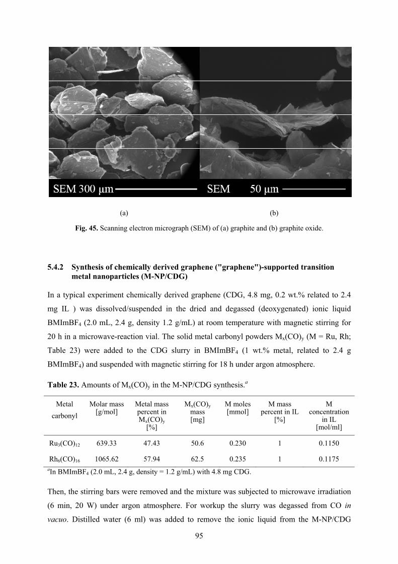
95
(a) (b)
Fig. 45. Scanning electron micrograph (SEM) of (a) graphite and (b) graphite oxide.
5.4.2 Synthesis of chemically derived graphene ("graphene")-supported transition metal nanoparticles (M-NP/CDG)
In a typical experiment chemically derived graphene (CDG, 4.8 mg, 0.2 wt.% related to 2.4
mg IL ) was dissolved/suspended in the dried and degassed (deoxygenated) ionic liquid
BMImBF4 (2.0 mL, 2.4 g, density 1.2 g/mL) at room temperature with magnetic stirring for
20 h in a microwave-reaction vial. The solid metal carbonyl powders Mx(CO)y (M = Ru, Rh;
Table 23) were added to the CDG slurry in BMImBF4 (1 wt.% metal, related to 2.4 g
BMImBF4) and suspended with magnetic stirring for 18 h under argon atmosphere.
Table 23. Amounts of Mx(CO)y in the M-NP/CDG synthesis.a
Metal carbonyl
Molar mass [g/mol]
Metal mass percent in Mx(CO)y
[%]
Mx(CO)y mass [mg]
M moles [mmol]
M mass percent in IL
[%]
M concentration
in IL [mol/ml]
Ru3(CO)12 639.33 47.43 50.6 0.230 1 0.1150
Rh6(CO)16 1065.62 57.94 62.5 0.235 1 0.1175 aIn BMImBF4 (2.0 mL, 2.4 g, density = 1.2 g/mL) with 4.8 mg CDG.
Then, the stirring bars were removed and the mixture was subjected to microwave irradiation
(6 min, 20 W) under argon atmosphere. For workup the slurry was degassed from CO in
vacuo. Distilled water (6 ml) was added to remove the ionic liquid from the M-NP/CDG
96
system. The black slurry was centrifuged (2 × 15 min, 2000 rpm, Hettich Rotina 46) and the
supernatant liquid H2O/IL phase decanted and discarded. The addition of H2O, centrifugation
and decantation was repeated three times. At last, the residue was again dispersed in water,
filtered and dried under vacuum. The dry black-greyish residue formed flakes which could
easily be removed from the filter. The primary characterization of the M-NP/CDG composite
was carried out by transmission electron microscopy (TEM). The Ru or Rh metal content of
the M-NP/CDG samples was determined with AAS by digestion of the sample (15 mg) in hot
aqua regia [30 mL, HCl (37 %)/HNO3 (65 %) 3:1]. After the aqua regia was boiled down, the
residue was re-dissolved in HCl (30 ml, 37 %) and boiled down again. The residue was
resolved in conc. HCl (37 %) and the solution was filtered to remove particles. Aqua regia
was added to a total volume of 25 ml followed by AAS analysis.
5.4.3 Catalysis
5.4.3.1 Hydrogenation of cyclohexene
The hydrogenation reactions of cyclohexene with graphene-supported Ru- and Rh-
nanoparticles were carried out in stainless steel autoclaves. The autoclave was conditioned by
evacuation and re-filling with argon. All autoclave loading was carried out under argon. Each
autoclave was equipped with a glass inlay, to eliminate any catalytic influence of the stainless
steel surface on the reaction process, into which the catalyst (Ru-NPs/CDG 11 mg containing
17.4 wt.% Ru or 1.89 × 10⁻⁵ mol Ru; Rh-NPs/CDG, 11 mg, containing 17.0 wt.% Rh or 1.82
× 10–5 mol Rh) and the cyclohexene substrate (1.0 ml, density 0.811 g/ml, M = 82.14 g/mol,
0.01 mol) were loaded. The autoclave was heated to 75 °C and pressurized to 4 bar of H2
which was kept constant over the reaction time. The reaction mixture was stirred for an
optimized set time of 1.5 h or 20 min. After this time the reactor was depressurized, and the
volatile organic components condensed under vacuum (15 min) into a clean cold trap (liquid
nitrogen cooled). Decanting of the organic layer from solid M-NP/CDG was not feasible
because the later formed a fine dispersion which did not settle even after a prolonged time.
The M-NP/CDG catalyst is left behind in the autoclave and was reused by adding fresh
cyclohexene. Organic substrate workup and catalyst recycling was done four times for Ru or
Rh. The cyclohexene to cyclohexane conversions were investigated by GC [Perkin Elmer, DB
5 column (60 m × 0.32 mm)].

97
5.4.3.2 Hydrogenation of benzene
The hydrogenation reactions of benzene with graphene-supported Ru- and Rh-nanoparticles
were carried out in stainless steel autoclaves. The autoclave was conditioned by
evacuationand re-filling with argon. All autoclave loading was carried out under argon. Each
autoclave was equipped with a glass inlay, to eliminate any catalytic influence of the stainless
steel surface on the reaction process, into which the catalyst (Rh-NPs/CDG, 5 mg, containing
17.0 wt.% Rh or 8.26 × 10⁻⁶ mol Rh) and the benzene substrate (0.92 ml, 0.81 g, 10.36 mmol)
were loaded. The autoclave was heated to the desired temperature (25, 50 or 75 °C) and
pressurized to 4 bar of H2 which was kept constant over the reaction time. The reaction
mixture was stirred for a set time of 4 h. After this time the reactor was depressurized, and the
volatile organic components condensed under vacuum (15 min) into a clean cold trap (liquid
nitrogen cooled). Decanting of the organic layer from solid M-NP/CDG was not feasible
because the later formed a fine dispersion which did not settle even after a prolonged time.
The MNP/CDG catalyst is left behind in the autoclave and was reused by adding fresh
benzene. The benzene to cyclohexane conversions were investigated by GC [Perkin Elmer,
PEG column (25 m × 0.32 mm)].
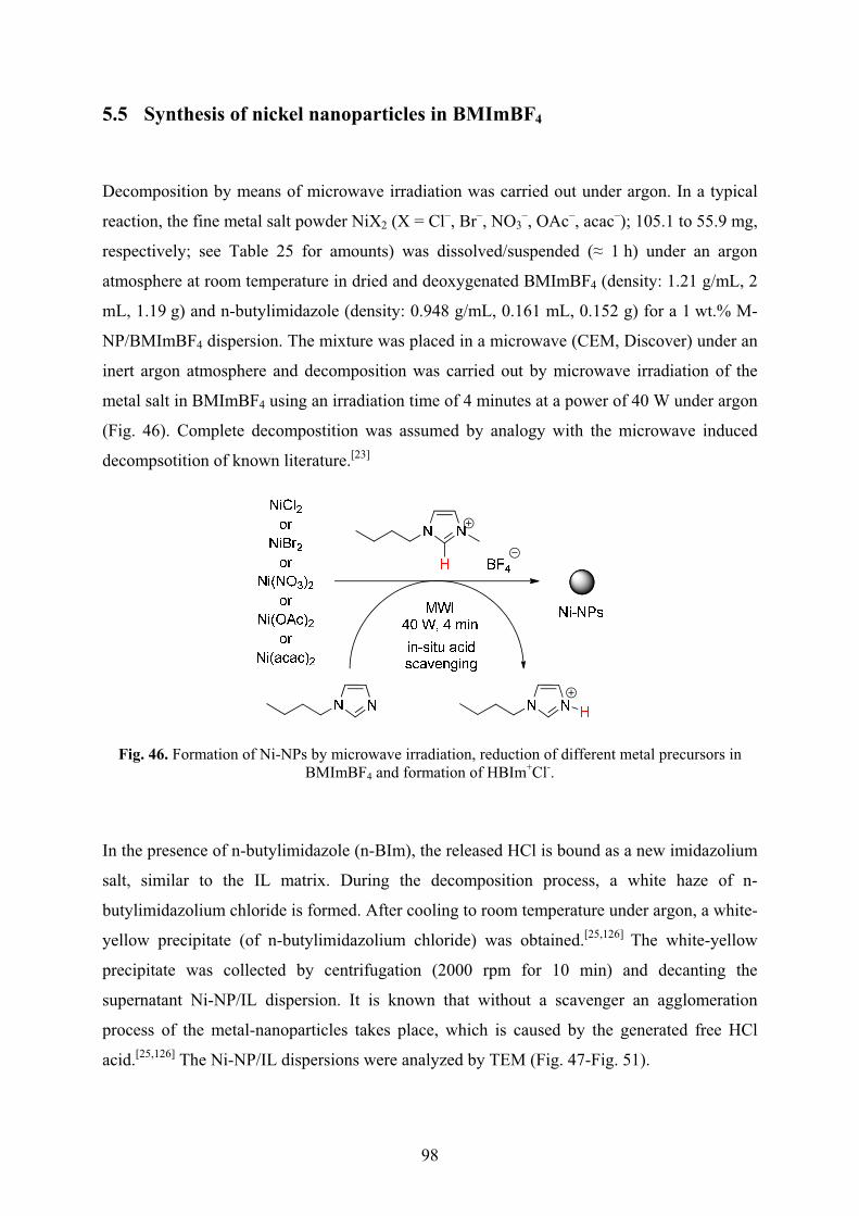
98
5.5 Synthesis of nickel nanoparticles in BMImBF4
Decomposition by means of microwave irradiation was carried out under argon. In a typical
reaction, the fine metal salt powder NiX2 (X = Cl–, Br–, NO3–, OAc–, acac–); 105.1 to 55.9 mg,
respectively; see Table 25 for amounts) was dissolved/suspended (� 1 h) under an argon
atmosphere at room temperature in dried and deoxygenated BMImBF4 (density: 1.21 g/mL, 2
mL, 1.19 g) and n-butylimidazole (density: 0.948 g/mL, 0.161 mL, 0.152 g) for a 1 wt.% M-
NP/BMImBF4 dispersion. The mixture was placed in a microwave (CEM, Discover) under an
inert argon atmosphere and decomposition was carried out by microwave irradiation of the
metal salt in BMImBF4 using an irradiation time of 4 minutes at a power of 40 W under argon
(Fig. 46). Complete decompostition was assumed by analogy with the microwave induced
decompsotition of known literature.[23]
Fig. 46. Formation of Ni-NPs by microwave irradiation, reduction of different metal precursors in BMImBF4 and formation of HBIm+Cl-.
In the presence of n-butylimidazole (n-BIm), the released HCl is bound as a new imidazolium
salt, similar to the IL matrix. During the decomposition process, a white haze of n-
butylimidazolium chloride is formed. After cooling to room temperature under argon, a white-
yellow precipitate (of n-butylimidazolium chloride) was obtained.[25,126] The white-yellow
precipitate was collected by centrifugation (2000 rpm for 10 min) and decanting the
supernatant Ni-NP/IL dispersion. It is known that without a scavenger an agglomeration
process of the metal-nanoparticles takes place, which is caused by the generated free HCl
acid.[25,126] The Ni-NP/IL dispersions were analyzed by TEM (Fig. 47-Fig. 51).
99
Table 24. Ni-NPs size and size distribution in BMImBF4.a
entry Metal salts TEM Ø (�) [nm]b
1 NiCl2 80.0 (± 22.9)
2 NiBr2 82.8 (± 17.1)
3 Ni(NO3)2 78.6 (± 17.1)
4 Ni(OAc)2 79.3 (± 31.6)
5 Ni(acac)2 2.7 (± 1.1) a1wt.% Ni-NP/BMImBF4 dispersion obtained by MWI with 40 W for 4 min. bMedian diameter (Ø) and standard deviation (�). See experimental section for TEM and DLS measurement conditions.
Table 25. Microwave decomposition of nickel salts to Ni-NPs in BMImBF4 with 40 W of power and 4 min reaction time.
Metal salt Molar mass (g/mol)
Mass of NiX2 (mg) in
BMImBF4
wt.% metal in 2.42 g (2.0 mL) BMImBF4
NiCl2 129.60 55.9 1
NiBr2 218.50 89.4 1
Ni(NO3)2 182.70 74.7 1
Ni(OAc)2 × 4 H2O 248.86 101.8 1
Ni(acac)2 256.93 105.1 1
Unless noted otherwise the TEM analyses were carried out on a on a Zeiss LEO 912
transmission electron microscope operating at an accelerating voltage of 120 kV by Dr. Ralf
Thomann at the Materials Research Center (FMF), University of Freiburg.
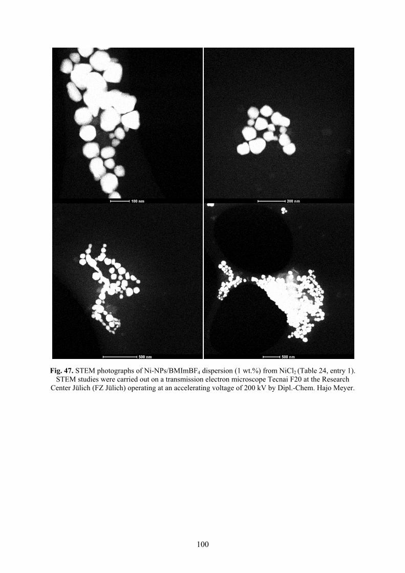
100
Fig. 47. STEM photographs of Ni-NPs/BMImBF4 dispersion (1 wt.%) from NiCl2 (Table 24, entry 1). STEM studies were carried out on a transmission electron microscope Tecnai F20 at the Research
Center Jülich (FZ Jülich) operating at an accelerating voltage of 200 kV by Dipl.-Chem. Hajo Meyer.
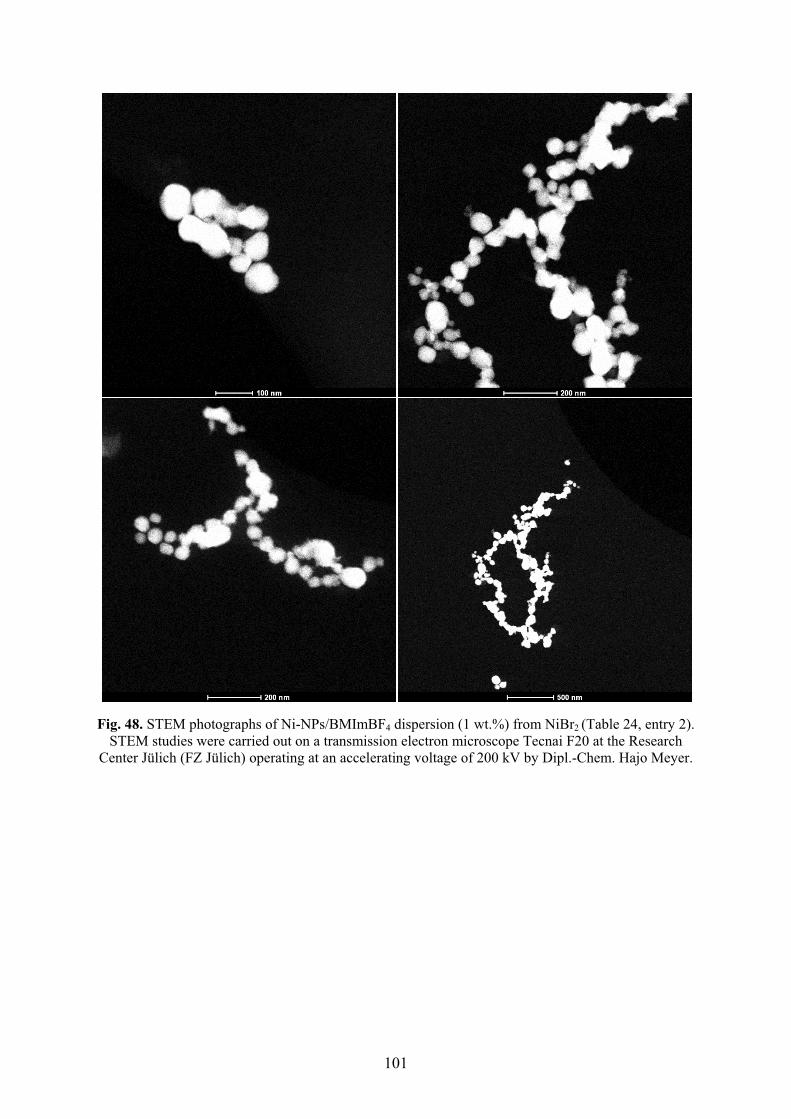
101
Fig. 48. STEM photographs of Ni-NPs/BMImBF4 dispersion (1 wt.%) from NiBr2 (Table 24, entry 2). STEM studies were carried out on a transmission electron microscope Tecnai F20 at the Research
Center Jülich (FZ Jülich) operating at an accelerating voltage of 200 kV by Dipl.-Chem. Hajo Meyer.
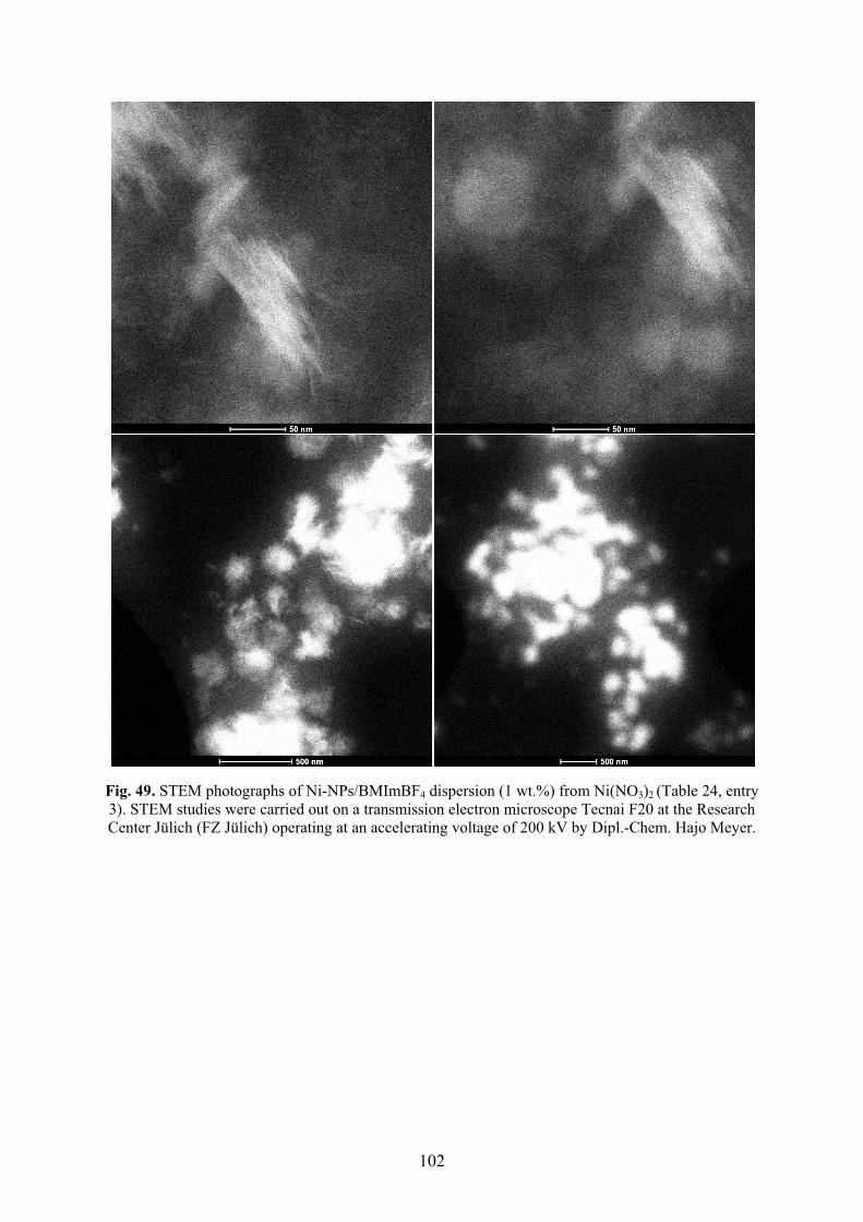
102
Fig. 49. STEM photographs of Ni-NPs/BMImBF4 dispersion (1 wt.%) from Ni(NO3)2 (Table 24, entry 3). STEM studies were carried out on a transmission electron microscope Tecnai F20 at the Research Center Jülich (FZ Jülich) operating at an accelerating voltage of 200 kV by Dipl.-Chem. Hajo Meyer.
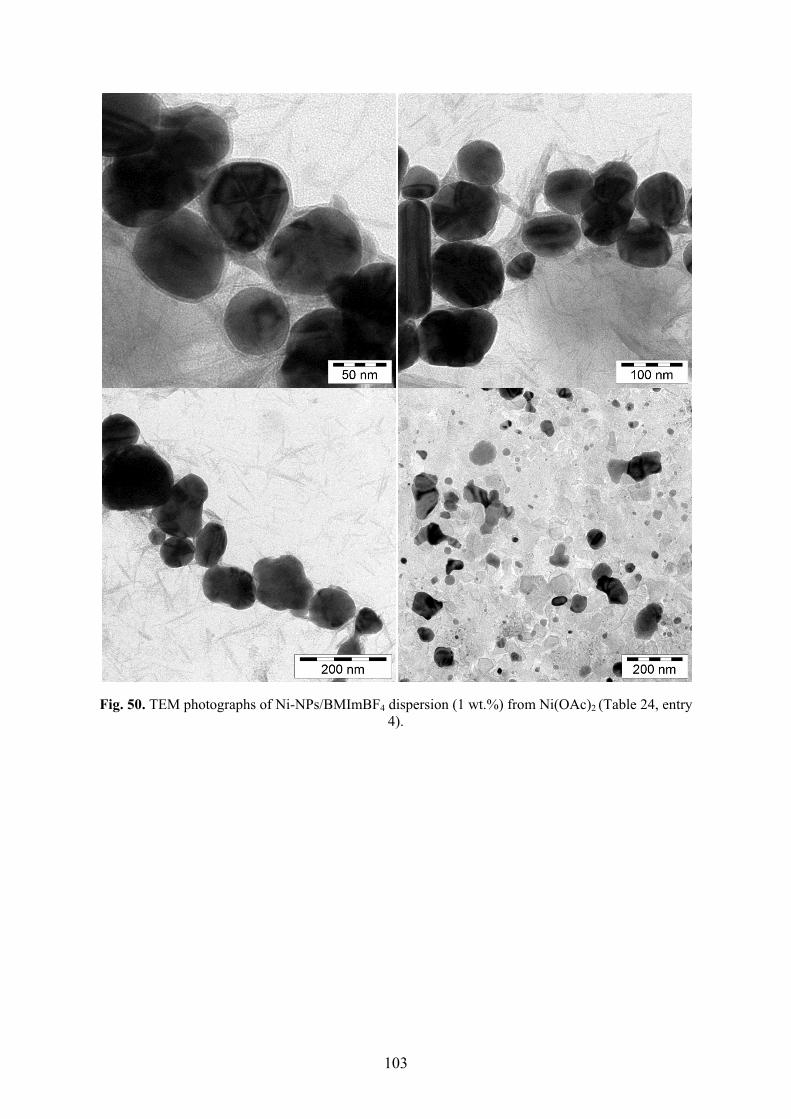
103
Fig. 50. TEM photographs of Ni-NPs/BMImBF4 dispersion (1 wt.%) from Ni(OAc)2 (Table 24, entry 4).
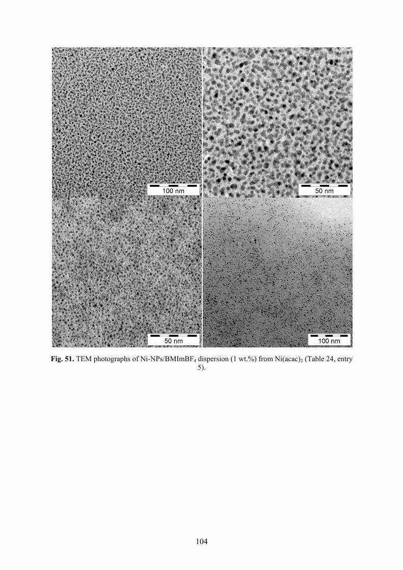
104
Fig. 51. TEM photographs of Ni-NPs/BMImBF4 dispersion (1 wt.%) from Ni(acac)2 (Table 24, entry 5).
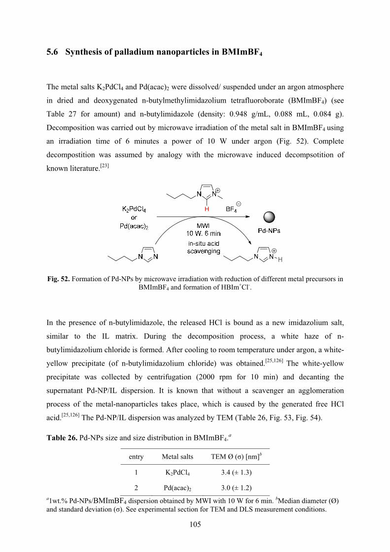
105
5.6 Synthesis of palladium nanoparticles in BMImBF4
The metal salts K2PdCl4 and Pd(acac)2 were dissolved/ suspended under an argon atmosphere
in dried and deoxygenated n-butylmethylimidazolium tetrafluoroborate (BMImBF4) (see
Table 27 for amount) and n-butylimidazole (density: 0.948 g/mL, 0.088 mL, 0.084 g).
Decomposition was carried out by microwave irradiation of the metal salt in BMImBF4 using
an irradiation time of 6 minutes a power of 10 W under argon (Fig. 52). Complete
decompostition was assumed by analogy with the microwave induced decompsotition of
known literature.[23]
Fig. 52. Formation of Pd-NPs by microwave irradiation with reduction of different metal precursors in BMImBF4 and formation of HBIm+Cl-.
In the presence of n-butylimidazole, the released HCl is bound as a new imidazolium salt,
similar to the IL matrix. During the decomposition process, a white haze of n-
butylimidazolium chloride is formed. After cooling to room temperature under argon, a white-
yellow precipitate (of n-butylimidazolium chloride) was obtained.[25,126] The white-yellow
precipitate was collected by centrifugation (2000 rpm for 10 min) and decanting the
supernatant Pd-NP/IL dispersion. It is known that without a scavenger an agglomeration
process of the metal-nanoparticles takes place, which is caused by the generated free HCl
acid.[25,126] The Pd-NP/IL dispersion was analyzed by TEM (Table 26, Fig. 53, Fig. 54).
Table 26. Pd-NPs size and size distribution in BMImBF4.a
entry Metal salts TEM Ø (�) [nm]b
1 K2PdCl4 3.4 (± 1.3)
2 Pd(acac)2 3.0 (± 1.2) a1wt.% Pd-NPs/BMImBF4 dispersion obtained by MWI with 10 W for 6 min. bMedian diameter (Ø) and standard deviation (�). See experimental section for TEM and DLS measurement conditions.
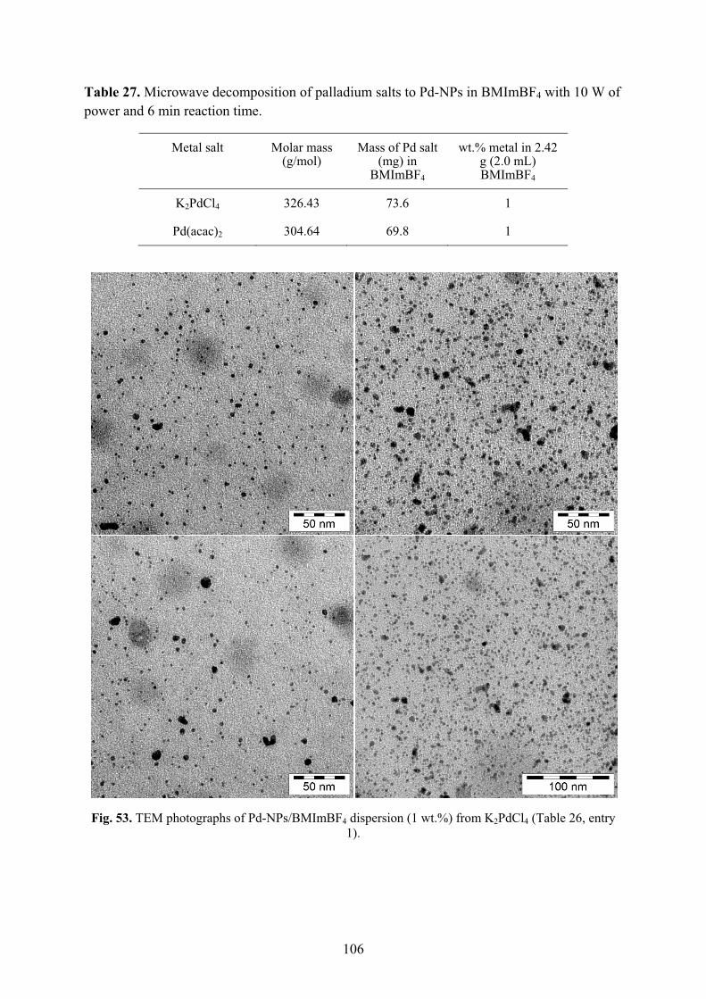
106
Table 27. Microwave decomposition of palladium salts to Pd-NPs in BMImBF4 with 10 W of power and 6 min reaction time.
Metal salt Molar mass (g/mol)
Mass of Pd salt (mg) in
BMImBF4
wt.% metal in 2.42 g (2.0 mL) BMImBF4
K2PdCl4 326.43 73.6 1
Pd(acac)2 304.64 69.8 1
Fig. 53. TEM photographs of Pd-NPs/BMImBF4 dispersion (1 wt.%) from K2PdCl4 (Table 26, entry 1).
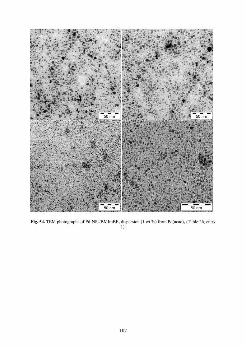
107
Fig. 54. TEM photographs of Pd-NPs/BMImBF4 dispersion (1 wt.%) from Pd(acac)2 (Table 26, entry 1).
108
6 PUBLICATIONS
Publications relevant for this cumulative dissertation are enrolled and the estimated
contributions are discussed.
6.1 Organic carbonates as stabilizing solvents for transition metal
nanoparticles
Christian Vollmer, Ralf Thomann, Christoph Janiak, manuscript submitted to Dalton Transactions
Impact factor: 3.647 (2010)
Contribution:
In the framework of this thesis, I planned and performed the experimental work including the
optimization. I wrote the first draft of the manuscript, compiled the supporting information,
and was involved in the discussions. GC and DLS analysis were carried out solely by me. The
TEM analysis was performed by Dr. Ralf Thomann.
My contribution as a co-author of this paper is approximately 65 %.
109
6.2 Turning Teflon-coated magnetic stirring bars to catalyst systems with
metal nanoparticle trace deposits - A caveat and a chance
Christian Vollmer, Marcel Schröder, Yi Thomann, Ralf Thomann, Christoph Janiak,
Appl. Catal. A: Gen. 425-426 (2012) 178-183.
Impact factor: 3.383 (2010)
Contribution:
In the framework of this thesis, I developed the idea to establish this method, planned the
experiments, and performed all of the experimental work including the optimization. B. Sc.
Marcel Schröder carried out the hydrogenation of benzene under my guidiance during his
bachelor thesis. I wrote the first draft of the manuscript, compiled the supporting information,
and was involved in the discussions. The TEM and SEM analysis were performed by the co-
authors Dr. Yi Thomann and Dr. Ralf Thomann.
My contribution as a co-author of this paper is approximately 55 %.

110
6.3 Naked metal nanoparticles from metal carbonyls in ionic liquids: Easy
synthesis and stabilization
Christian Vollmer, Christoph Janiak, Coord. Chem. Rev. 255 (2011) 2039.
Impact factor: 10.018 (2010)
Contribution:
All the literature research was performed by me. I wrote approximately 60 % of this Review.
My contribution as a co-author of this paper is approximately 60%.
111
6.4 The use of microwave irradiation for the easy synthesis of graphene-
supported transition metal nanoparticle in ionic liquids
Dorothea Marquardt, Christian Vollmer, Ralf Thomann, Peter Steurer, Rolf Mülhaupt,
Engelbert Redel, Christoph Janiak, Carbon 49 (2011) 1326.
Impact factor: 4.893 (2010)
Contribution:
In the framework of this thesis, I developed the idea to investigate the catalytic behavior of
M-NPs/CDG towards hydrogenation reactions. I planned and put out all of the hydrogenation
experiments including the optimization. The GC analysis was done by me. I wrote
approximately 50 % of the manuscript and the supporting information. I was involved in all
discussions. The immobilization of the M-NPs on CDG was done by Dipl.-Chem. Engelbert
Redel and Dipl.-Chem. Dorothea Marquardt, whereby Dipl.-Chem. Dorothea Marquardt was
under my guidiance during her diploma thesis at this time. The TEM analysis was performed
by Dr. Ralf Thomann.
My contribution as a co-author of this paper is 50 %.
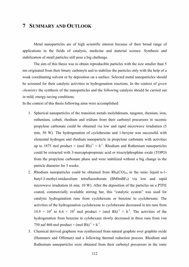
112
7 SUMMARY AND OUTLOOK
Metal nanoparticles are of high scientific interest because of their broad range of
applications in the fields of catalysis, medicine and material science. Synthesis and
stabilization of small particles still pose a big challenge.
The aim of this thesis was to obtain reproducible particles with the size smaller than 5
nm originated from their binary carbonyls and to stabilize the particles only with the help of a
weak coordinating solvent or by deposition on a surface. Selected metal nanoparticles should
be screened for their catalytic activities in hydrogenation reactions. In the context of green
chemistry the synthesis of the nanoparticles and the following catalysis should be carried out
in mild, energy-saving conditions.
In the context of this thesis following aims were accomplished:
1. Spherical nanoparticles of the transition metals molybdenum, tungsten, rhenium, iron,
ruthenium, cobalt, rhodium and iridium from their carbonyl precursors in racemic
propylene carbonate could be obtained via low and rapid microwave irradiation (5
min, 50 W). The hydrogenation of cyclohexene and 1-hexyne was successful with
elemental hydrogen and rhodium nanoparticle in propylene carbonate with activities
up to 1875 mol product × (mol Rh)-1 × h-1. Rhodium and Ruthenium nanoparticles
could be extracted with 3-mercaptopropionic acid or trioctylphosphine oxide (TOPO)
from the propylene carbonate phase and were stabilized without a big change in the
particle diameter for 3 weeks.
2. Rhodium nanoparticles could be obtained from Rh6(CO)16 in the ionic liquid n-1-
butyl-3-methyl-imidazolium tetrafluoroborate (BMImBF4) via low and rapid
microwave irradiation (6 min, 10 W). After the deposition of the particles on a PTFE
coated, commercially available stirring bar, this “catalytic system” was used for
catalytic hydrogenation runs from cyclohexene or benzene to cyclohexane. The
activities of the hydrogenation cyclohexene to cyclohexane decreased in ten runs from
14.9 × 10³ to 6.6 × 10³ mol product × (mol Rh)-1 × h-1. The activities of the
hydrogenation from benzene to cylohexane slowly decreased in three runs from von
750 auf 460 mol product × (mol Rh)-1 × h-1.
3. Chemical derived graphene was synthesized from natural graphite over graphite oxide
(Hummers and Offeman) and a following thermal reduction process. Rhodium and
Ruthenium nanoparticles were obtained from their carbonyl precursors in the ionic

113
liquid BMImBF4 and deposited onto chemical derived graphene (CDG) and the M-
NP/CDG-system was used for hydrogenation runs from cyclohexene or benzene to
cyclohexane with elemental hydrogen. The activities remained constant in ten runs
from cyclohexene to cyclohexane of 1570 mol product × (mol Rh)-1 × h-1. The
activities of Rh-NPs/CDG were examined during the hydrogenation of benzene to
cylcohexane at different temperatures (25, 50, 75 °C). The highest activity of 310 mol
product × (mol Rh)-1 × h-1 was measured at 50 °C.
Prospective investigations could be focused on other transition metals, especially metals,
which are also commonly used as hydrogenation catalyst, like palladium, platinum and nickel,
from other organic and inorganic precursors. With these “catalytic systems” a broad range of
subtrates could be hydrogenated, for instance aromatic compounds, alkenes, alkynes, ,-
unsaturated ketones/aldehyds and carbonyl-compounds in general.
With the above described methods it should be possible to synthesize bimetallic
nanoparticles.
Beside catalytic hydrogenations, the “catalytic systems” should be investigated on other
catalytic reactions, for instance: Palladium is also known as a catalyst for a broad range of C-
C coupling reactions, platinum is known as a good catalyst for hydrosilylation reactions and
cobalt is an established catalyst for Fischer-Tropsch reactions.
In the case of racemic propylene carbonate, other organic carbonates, cyclic, non-
cyclic and enantiopure, for instance dimethyl carbonate or ethylene carbonate or S-propylene
carbonate, should be investigated as media to synthesize metal nanoparticles. The dispersions
should be also tested in different catalytic reactions.
114
8 REFERENCES [1] A.H. Lu, E.L. Salabas, F. Schüth, Angew. Chem. Int. Ed. 46 (2007) 1222.
[2] A. Gedanken, Ultrasonics Sonochemistry 11 (2004) 47.
[3] C.N.R. Rao, S R.C. Vivekchand, K. Biwas, A. Govindaraj, Dalton Trans. (2007) 3728.
[4] Y. Mastai, A. Gedanken in: C.N.R. Rao, A. Müller, A.K. Cheetham (editors), Chemistry of
Nanomaterials, Wiley-VCH, Weinheim, vol. 1, 2004, 113.
[5] D. Mahajan, E.T. Papish, K. Pandya, Ultrasonics Sonochemistry 11 (2004) 385.
[6] J. Park, J. Joo, S.G. Kwon, Y. Jang, T. Hyeon, Angew. Chem. Int. Ed. 46 (2007) 4630.
[7] D. Astruc, F. Lu, J.R. Aranzaes, Angew. Chem. Int. Ed. 44 (2005) 7852.
[8] C. Pan, K. Pelzer, K. Philippot, B. Chaudret, F. Dassenoy, P. Lecante, M.-J Casanove, J. Am.
Chem. Soc. 123 (2001) 7584.
[9] J.D. Aiken III, R.G. Finke, J. Am. Chem. Soc. 121 (1999) 8803.
[10] R.J. White, R. Luque, V.L. Budarin, J.H. Clark, D.J. Macquarrie, Chem. Soc. Rev. 38 (2009) 481.
[11] J. Krämer, E. Redel, R. Thomann, C. Janiak, Organometallics 27 (2008) 1976.
[12] K. Ueno, H. Tokuda, M. Watanabe, Phys. Chem. Chem. Phys. 12 (2010) 1649.
[13] J. Dupont, J.D. Scholten, Chem. Soc. Rev. 39 (2010) 1780.
[14] J. Dupont, J. Brazil Chem. Soc. 15 (2004) 341.
[15] M.-A. Neouze, J. Mater. Chem. 20 (2010) 9593.
[16] C.S. Consorti, P.A.Z. Suarez, R.F. de Souza, R.A. Burrow, D.H. Farrar, A.J. Lough, W. Loh,
L.H.M. da Silva, J. Dupont, J. Phys. Chem. B 109 (2005) 4341.
[17] J. Dupont, P.A.Z. Suarez, R.F. de Souza, R.A. Burrow, J.-P. Kintzinger, Chem. Eur. J. 6 (2000)
2377.
[18] R.A. Sheldon, Chem. Commun. (2008) 3352.
[19] P. Wasserscheid, T.Welton, Ionic Liquid in Synthesis, Wiley-VCH, Weinheim, vol. 1, 2007, 93.
[20] P. Wasserscheid, W. Keim, Angew. Chem. Int. Ed. 39 (2000) 3773.
[21] C. van Doorslaer, Y. Schellekens, P. Mertens, K. Binnemanns, D. De Vos, Phys. Chem. Chem.
Phys. 12 (2010) 1741.
[22] E. Redel, J. Krämer, R. Thomann, C. Janiak, J. Organomet. Chem. 694 (2009) 1069.

115
[23] C. Vollmer, E. Redel, K. Abu-Shandi, R. Thomann, H. Manyar, C. Hardacre, C. Janiak, Chem.
Eur. J. 16 (2010) 3849.
[24] V. Parvulescu, C. Hardacre, Chem Rev. 107 (2007) 2615.
[25] D. Astruc, Nanoparticles and Catalysis, Wiley-VCH, Weinheim, 2008, 211.
[26] K.P.C. Vollhardt, N.E. Schore, Organische Chemie, Wiley-VCH, Weinheim, vol. 3, 2000, 981.
[27] B.M. Trost, Science 254 (1991) 1471.
[28] B.M. Trost, Angew. Chem. Int. Ed. 34 (1995) 259.
[29] P.T. Anastas, J.C. Warner, Green Chemistry: Theory and Practice, Oxford University Press, New
York, 1998.
[30] J.H. Clarke, Green Chem. 1 (1999) 1.
[31] P.J. Dunn, Chem. Soc. Rev. 41 (2012) 1452.
[32] R.A. Sheldon, I. Arend, U. Hanefeld, Green Chemistry and Catalysis, Wiley-VCH, Weinheim,
2007, 1.
[33] R.B.N. Baig, R.S. Varma, Chem. Soc. Rev. 41 (2012) 1559.
[34] P.T. Anastas, J. B. Zimmerman, Sustainability Science and Engineering Defining Principles,
Elsevier, Amsterdam, vol. 1, 2006, 11.
[35] S.L.Y. Tang, R.L. Smith, M. Poliakoff, Green Chem. 7 (2005) 761.
[36] R.A. Sheldon, Chem. Soc. Rev. 41 (2012) 1437.
[37] H. Weingärtner, Angew. Chem. Int. Ed. 47 (2008) 654.
[38] D. Xiao, J.R. Rajian, A. Cady, S. Li, R.A. Bartsch, E.L. Quitevis, J. Phys. Chem. B 111 (2007)
4669.
[39] I. Krossing, J.M. Slattery, C. Daguenet, P.J. Dyson, A. Oleinikova, H. Weingärtner, J. Am. Chem.
Soc. 128 (2006) 13427.
[40] K.R. Seddon, Chem. Soc. Rev. 37 (2008) 123.
[41] P. Bonhôte, A.-P. Dias, N. Papageorgiou, K.K. Kalyanasundaram, M. Grätzel, Inorg. Chem. 35
(1996) 1168.
[42] J.M. Pringle, J. Golding, K. Baranyai, C.M. Forsyth, B.B. Deacon, J.L. Scott, D.R. Mc Farelane,
New J. Chem. 27 (2003) 1504.
[43] P. Migowski, D. Zanchet, G. Machado, M.A. Gelesky, S.R. Teixeira, J. Dupont, Phys. Chem.
Chem. Phys. 12 (2010) 6826.
116
[44] J.J. Jodry, K. Mikami, Tetrahedron Lett. 45 (2004) 4429.
[45] T.J. Gannon, G. Law, R.P. Watson, A.J. Carmichael, K.R. Seddon, Langmuir 15 (1999) 8429.
[46] J.N.A Canongia Lopes, M.F.C. Gomes, A.A.H. Padua, J. Phys. Chem. B 110 (2006) 16816.
[47] G. Law, R. P. Watson, A. J. Carmichael, K. R. Seddon, Phys. Chem. Chem. Phys. 3 (2001) 2879.
[48] J.N.A. Canongia Lopes, A.A.H. Pádua, J. Phys. Chem. B 110 (2006) 3330.
[49] D.G.E. Kerfoot, X. Nickel, E. Wildermuth, H. Stark, G. Friedrich, F.L. Ebenhöch, B. Kühborth, J.
Silver, R. Rituper, Iron Compounds, in Ullmann’s Encyclopaedia of Industrial Chemistry, Wiley,
5th edn (online), 2008.
[50] T. Hyeon, Chem. Commun. (2003) 927.
[51] P.H. Hess, P.H. Parker, Jr., J. Appl. Polym. Sci. 10 (1966) 1915.
[52] J.R. Thomas, J. Appl. Phys. 37 (1966) 2914.
[53] E. Papirer, P. Horny, H. Balard, R. Anthore, C. Petipas, A. Martinet, J. Colloid Interface Sci. 94
(1983) 207.
[54] E. Papirer, P. Horny, H. Balard, R. Anthore, C. Petipas, A. Martinet, J. Colloid Interface Sci. 94
(1983) 220.
[55] K. S. Suslick, M. Fang, T. Hyeon, J. Am. Chem. Soc. 118 (1996) 11960.
[56] O.A. Platonova, L.M. Bronstein, S.P. Solodovnikov, I.M. Yanovskaya, E.S. Obolonkova, P.M.
Valetsky, E. Wenz, M. Antonietti, Colloid Polym. Sci. 275 (1997) 426.
[57] G.H. Lee, S.H. Huh, H.I. Jung, J. Mol. Struct. 400 (1998) 141.
[58] D.P. Dinega, M.G. Bawendi, Angew. Chem. Int. Ed. 38 (1999) 1788.
[59] M. Giersig, M. Hilgendorff, J. Phys. D: Appl. Phys. 32 (1999) L111.
[60] U. Wiedwald, M. Spasova, E.L. Salabas, M. Ulmeanu, M. Farle, Z. Frait, A. Fraile Rodriguez, D.
Arvanitis, N.S. Sobal, M. Hilgendorff, M. Giersig, Phys. Rev. B 68 (2003) 064424.
[61] J. van Wonterghem, S. Mørup, S.W. Charles, S. Wells, J. Villadsen, Phys. Rev. Lett. 55 (1985)
410.
[62] J. van Wonterghem, S. Mørup, S.W. Charles, S. Wells, J. Colloid Interface Sci. 121 (1988) 558.
[63] C. Pathmamanoharan, N.L. Zuiverloon, A.P. Philipse, Progr. Colloid Polym. Sci. 115 (2000) 141.
[64] A. Goossens, L.J. de Jongh, K. Butter, A.P. Philipse, M.W.J. Crajé, A.M. van der Kraan,
Hyperfine Interact. 141/142 (2002) 381.
[65] K. Butter, P.H.H. Bomans, P.M. Frederik, G.J. Vroege, A.P. Philipse, Nat. Mater. 2 (2003) 88.

117
[66] E. Bauer-Grosse, G. Le Caër, Phil. Mag. B 56 (1987) 485.
[67] S.H. Huh, S.J. Oh, Y.N. Kim, G.H. Lee, Rev. Sci. Instrum. 70 (1999) 4366.
[68] S.-J. Park, S. Kim, S. Lee, Z.G. Khim, K. Char, T. Hyeon, J. Am. Chem. Soc. 122 (2000) 8581.
[69] S. Sun, C.B. Murray, D. Weller, L. Folks, A. Moser, Science 287 (2000) 1989.
[70] M. Chen, D.E. Nikles, J. Appl. Phys. 91 (2002) 8477.
[71] M. Chen, D.E. Nikles, Nano Lett. 2 (2002) 211.
[72] J.-I. Park, J. Cheon, J. Am. Chem. Soc. 123 (2001) 5743.
[73] V.F. Puntes, K.M. Krishnan, P. Alivisatos, Appl. Phys. Lett. 78 (2001) 2187.
[74] T. Hyeon, S.S. Lee, J. Park, Y. Chung, H.B. Na, J. Am. Chem. Soc. 123 (2001) 12798.
[75] S.-W. Kim, S.U. Son, S.S. Lee, T. Hyeon, Y.K. Chung, Chem. Commun. (2001) 2212.
[76] N.A.D. Burke, H.D.H. Stöver, F.P. Dawson, Chem. Mater. 14 (2002) 4752.
[77] K. Butter, A.P. Philipse, G.J. Vroege, J. Magn. Magn. Mater. 252 (2002) 1.
[78] M. Rutnakornpituk, M.S. Thompson, L.A. Harris, K.E. Farmer, A.R. Esker, J.S. Riffle, J.
Connolly, T.G. St. Pierre, Polymer 43 (2002) 2337.
[79] F.S. Diana, S.-H. Lee, P.M. Petroff, E.J. Kramer, Nano Lett. 3 (2003) 891.
[80] H. Bönnemann, W. Brijoux, R. Brinkmann, N. Matoussevitch, H. Waldöfner, N. Palina, H.
Modrow, Inorg. Chim. Acta 350 (2003) 617.
[81] H. Bönnemann, R.A. Brand, W. Brijoux, H.-W. Hofstadt, M. Frerichs, V. Kempter, W. Maus-
Friedrichs, N. Matoussevitch, K.S. Nagabhushana, F. Voigts, V. Caps, Appl. Organometal.
Chem. 19 (2005) 790.
[82] S. Behrens, H. Bönnemann, N. Matoussevitch, A. Gorschinski, E. Dinjus, W. Habicht, J. Bolle, S.
Zinoveva, N. Palina, J. Hormes, H. Modrow, S. Bahr V. Kempter, J. Phys.: Condens. Matter 18
(2006) S2543.
[83] N. Matoussevitch, A. Gorschinski, W. Habicht, J. Bolle, E. Dinjus, H. Bönnemann, S. Behrens, J.
Magn. Magn. Mater. 311 (2007) 92.
[84] Y. Yin, R.M. Rioux, C.K. Erdonmez, S. Hughes, G.A. Somorjai, A.P. Alivisatos, Science 304
(2004) 711.
[85] M. Zubris, R.B. King, H. Garmestani, R. Tannenbaum, J. Mater. Chem. 15 (2005) 1277.
[86] A. Hütten, D. Sudfeld, I. Ennen, G. Reiss, K. Wojczykowski, P. Jutzi, J. Magn. Magn. Mater. 293
(2005) 93.
118
[87] D. Sudfeld, I. Ennen, A. Hütten, U. Golla-Schindler, H. Jaksch, G. Reiss, D. Meißner, K.
Wojczykowski, P. Jutzi, W. Saikaly, G. Thomas, J. Magn. Magn. Mater. 293 (2005) 151.
[88] B.D. Korth, P. Keng, I. Shim, S.E. Bowles, C. Tang, T. Kowalewski, K.W. Nebesny, J. Pyun, J.
Am. Chem. Soc. 128 (2006) 6562.
[89] R.A. Mercuri, Chem. Abstr. 148 (2007) 37461.
[90] R.A. Mercuri, Chem. Abstr. 146 (2007) 233646.
[91] J.S. Gergely, E.S. Marston, S. Subramoney, L. Zhang, Chem. Abstr. 146 (2007) 433242.
[92] C. Gürler, M. Feyen, S. Behrens, N. Matoussevitch, A.M. Schmidt, Polymer 49 (2008) 2211.
[93] N. Doan, K. Kontturi, C. Johans, J. Colloid Interface Sci. 350 (2010) 126.
[94] A. Taubert, Z. Li, Dalton Trans. (2007) 723.
[95] E. Redel, R. Thomann, C. Janiak, Inorg. Chem. 47 (2008) 14.
[96] T. Gutel, J. Garcia-Anton, K. Pelzer, K. Philippot, C.C. Santini, Y. Chauvin, B. Chaudret, J.-M.
Basset, J. Mater. Chem. 17 (2007) 3290.
[97] L.S. Ott, R.G. Finke, Inorg. Chem. 45 (2006) 8382.
[98] G.S. Fonseca, A.P. Umpierre, P.F.P. Fichtner, S.R. Teixeira, J. Dupont, Chem. Eur. J. 9 (2003)
3263.
[99] Z. Li, A. Friedrich, A. Taubert, J. Mater. Chem. 18 (2008) 1008.
[100] P. Migowski, G. Machado, S.R.Teixeira, M.C.M. Alves, J. Morais, A. Traverse, J. Dupont,
Phys. Chem. Chem. Phys. 9 (2007) 4814.
[101] J.M. Zhu, Y.H. Shen, A.J. Xie, L.G. Qiu, Q. Zhang, X.Y. Zhang, J. Phys. Chem. C 111 (2007)
7629.
[102] M.A. Firestone, M.L. Dietz, S. Seifert, S. Trasobares, D.J. Miller, N.J. Zaluzec, Small 1 (2005)
754.
[103] K. Peppler, M. Polleth, S. Meiss, M. Rohnke, J.Z. Janek, Phys. Chem. 220 (2006) 1507.
[104] A. Safavi, N. Maleki, F. Tajabadi, E. Farjami, Electrochem. Commun. 9 (2007) 1963.
[105] K. Kim, C. Lang, P.A. Kohl, J. Electrochem. Soc. 152 (2005) E9.
[106] E. Redel, R. Thomann, C. Janiak, Chem. Commun. 15 (2008) 1789.
[107] G. Schmid, Nanoparticles, Wiley-VCH, Weinheim, vol. 2, 2010, 215.
[108] M. Antonietti, D. Kuang, B. Smarly, Y. Zhou, Angew. Chem. Int. Ed. 43 (2004) 4988.
119
[109] F. Endres, M. Bukowski, R. Hempelmann, H. Natter, H. Angew. Chem., Int. Ed. 42 (2003)
3428.
[110] Y.J. Zhu, W.W. Wang, R.J. Qi, X.L. Hu, Angew. Chem., Int. Ed. 43 (2004) 1410.
[111] E.T. Silveira, A.P. Umpierre, L.M. Rossi, G. Machado, J. Morais, G.V. Soares, I.J.R. Baumvol,
S.R. Teixeira, R.F.P. Fichtner, J. Dupont, Chem. Eur. J. 10 (2004) 3734.
[112] J. Dupont, G.S. Fonseca, A.P. Umpierre, P.F.P. Fichtner, S.R. Teixeira, J. Am. Chem. Soc. 124
(2002) 4228.
[113] C.W. Scheeren, G. Machado, J. Dupont, P.F.P. Fichtner, S.R. Texeira, Inorg. Chem. 42 (2003)
4738.
[114] A.I. Bhatt, A. Mechler, L.L. Martin, A.M. Bond, J. Mater. Chem. 17 (2007) 2241.
[115] H. Itoh, K. Naka, Y. Chujo, J. Am. Chem. Soc. 126 (2004) 3026.
[116] H.S. Schrekker, M.A. Gelesky, M.P. Stracke, C.M.L. Schrekker, G. Machado, S.R. Teixeira,
J.C. Rubim, J. Dupont, J. Colloid Interface Sci. 316 (2007) 189.
[117] R.A. Alvarez-Puebla, E. Arceo, P.J.G. Goulet, J.J. Garrido, R.F. Aroca, J. Phys. Chem. B 109
(2005) 3787.
[118] E.J.W. Verwey, J.T.G. Overbeek , Theory of the Stability of Lyophobic Colloids, Dover
Publications Mineola, New York, 1999, 106.
[119] E. Redel, J. Krämer, R. Thomann, C. Janiak, GIT Labor-Fachzeitschrift, April 2008, 400.
[120] A.N. Shipway, E. Katz, I. Willner, ChemPhysChem 1 (2000) 18.
[121] T. Cassagneau, J. H. Fendler, J. Phys. Chem. B 103 (1999) 1789.
[122] C.D. Keating, K.K. Kovaleski, M.J. Natan, J. Phys. Chem. B. 102 (1998) 9404.
[123] M.N. Kobrak, H. Li, Phys. Chem. Chem. Phys. 12 (2010) 1922.
[124] L.S. Ott, R.G. Finke, Coord. Chem. Rev. 251 (2007) 1075.
[125] B.L. Bhargava, S. Balasubramanian, M.L. Klein, Chem. Commun. (2008) 3339.
[126] E. Redel, M. Walter, R. Thomann, C. Vollmer, L. Hussein, H. Scherer, M. Krüger, C. Janiak,
Chem. Eur. J. 15 (2009) 10047.
[127] R.G. Pearson, Chemical Hardness: Application from Molecules to Solids, Wiley-VCH,
Weinheim, 1997, 1.
[128] T.A. Baker, C.M. Friend, E. Kaxiras, J. Am. Chem. Soc. 130 (2008) 3720-3721.
[129] K.-S. Kim, D. Demberelnyamba, H. Lee, Langmuir 20 (2004) 556-560.
120
[130] S. Gao, H. Zhang, X. Wang, W. Mai, C. Peng, L. Ge, Nanotechnology 16 (2005) 1234.
[131] R. Marcilla, D. Mecerreyes, I. Odriozola, J.A. Pomposo, J. Rodriguez, I. Zalakain, I.
Mondragon, Nano 2 (2007) 169.
[132] M.A. Gelesky, A.P. Umpierre, G. Machado, R.R.B. Correia, W.C. Magno, J. Morais, G.
Ebeling, J. Dupont, J. Am. Chem. Soc. 127 (2007) 4588.
[133] G.S. Fonseca, G. Machado, S.R. Teixeira, G.H. Fecher, J. Morais, M.C.M. Alves, J. Dupont, J.
Colloid Interface Sci. 301 (2006) 193.
[134] M. Ruta, G. Laurenczy, P.J. Dyson, L. Kiwi-Minsker, J. Phys. Chem. C 112 (2008) 17814.
[135] H. Zhang, H. Cui, Langmuir 25 (2009) 2604.
[136] C.W. Scheeren, J.B. Domingos, G. Machado, J. Dupont, J. Phys. Chem. C 112 (2008) 16463.
[137] E. Redel, M. Walter, R. Thomann, L. Hussein, M. Krüger, C. Janiak, Chem. Commun. 46
(2010) 1159.
[138] J. Turkevich, P.C. Stevenson, J. Hillier, Discuss. Faraday Soc. 11 (1951) 55.
[139] H.R. Ryu, L. Sanchez, H.A. Keul, A. Raj, M.R. Bockstaller, Angew. Chem. Int. Ed. 47 (2008)
7639.
[140] Y. Hatakeyama, S. Takahashi, K. Nishikawa, J. Phys. Chem. C. 114 (2010) 11098.
[141] T. Kameyama, Y. Ohno, T. Kurimoto, K.-I. Okazaki, T. Uematsu, S. Kuwabata, T. Torimoto,
Phys. Chem. Chem. Phys. 12 (2010) 1804.
[142] T. Suzuki, K.-I. Okazaki, S. Suzuki, T. Shibayama, S. Kuwabata, T. Torimoto, Chem. Mater. 22
(2010) 5209.
[143] R.R. Deshmukh, R. Rajagopal, K.V. Srinivasan, Chem. Commun. (2001) 1544.
[144] M.H.G. Prechtl, J.D. Scholten, J. Dupont, Molecules 15 (2010) 3441.
[145] V. Calo, A. Nacci, A. Monopoli, S. Laera, N. Coffi, J. Org. Chem. 68 (2003) 2929.
[146] L. Xu, W. Chen, J. Xiao, Organometallics 19 (2000) 1123.
[147] K. Anderson, S.C. Fernández, C. Hardacre, P.C. Marr, Inorg. Chem. Commun. 7 (2004) 73.
[148] J.D. Scholten, G. Ebeling, J. Dupont, Dalton Trans. (2007) 5554.
[149] M. Harada, Y. Kimura, K. Saijo, T. Ogawa, S. Isoda, J. Colloid Interface Sci. 339 (2009) 373.
[150] A. Imanishi, M. Tamura, S. Kuwabata, Chem. Commun. (2009) 1775.
[151] P. Roy, R. Lynch, P. Schmuki, Electrochem. Commun. 11 (2009) 1567.
121
[152] C. Fu, Y. Kuang, Z. Huang, X. Wang, N. Du, J. Chen, H. Zhou, Chem. Phys. Lett. 499 (2010)
250.
[153] S.Z. El Abedin, F. Endres, Electrochim. Acta 54 (2009) 5673.
[154] L. Yu, H. Sun, J. He, D. Wang, X. Jin, X. Hu, G.Z. Chen, Electrochem. Commun. 9 (2007)
1374.
[155] D. Bogdal, Microwave-Assisted Organic Synthesis, Oxford, Elsevier, 2005, 47.
[156] A.L. Buchachenko, E.L. Frankevich, Chemical Generation and Reception of Radio- and
Microwaves, Wiley-VCH, Weinheim, 1993, 11.
[157] V.K. Ahluwulia, Alternative Energy Processes in Chemical Synthesis, Alpha Science
International LTD, Oxford, 2008, 1.
[158 J. Berlan, P. Giboreau, S. Lefeuvre, C. Marchand, Tedrahedron Lett. 32 (1991) 2363.
[159 F. Langa, P. de la Cruz, A. de la Hoz, A. Diez-Barra, Contemp. Org. Synth. 4 (1997) 373.
[160] L. Perreux, A. Loupy, Tetrahedron 57 (2001) 9199.
[161] A. Stadler, C.O. Kappe, J. Chem. Soc. Perkin Trans. 2 (2000) 1363.
[162] A. Stadler, C.O. Kappe, Eur. J. Org. Chem. (2001) 919.
[163] D.O. Silva, J.D. Scholten, M.A. Gelesky, S.R. Teixeira, A.C.B. Dos Santos, E.F. Souza-Aguiar,
J. Dupont, ChemSusChem 1 (2008) 291.
[164] M. Scariot, D.O. Silva, J.D. Scholten, G. Machado, S.R. Teixeira, M.A. Novak, G. Ebeling, J.
Dupont, Angew. Chem. Int. Ed. 47 (2008) 9075.
[165] V. Dahirel, M. Jardat, Curr. Opin. Colloid Interafce Sci. 15 (2010) 2.
[166] B.W. Ninham, Adv. Colloid Interface Sci. 83 (1999) 1.
[167] J.-P. Hansen, H. Löwen, Annu. Reb. Phys. Chem. 51 (2000) 209.
[168] T. Liu, Langmuir 26 (2010) 9202.
[169] R.G. Finke in: D.L. Feldheim, C.A. Foss Jr. (editors), Metal Nanoparticle: Synthesis,
Characterization and Applications, Marcel Dekker, Inc., New York, 2002, 17.
[170] M. Boström, D.R.W. Williams, B.W. Ninham, Phys. Rev. Lett. 87 (2001) 168103.
[171] J. Lyklema, Fundamentals of Interface and Colloid Science, Elsevier, London, 2005.
[172] M. Dijkstra, Curr. Opin. Colloid Interface Sci. 6 (2001) 372.
[173] G.M. Scheuermann , L. Rumi, P. Steurer, W. Bannwarth, R. Mülhaupt, J. Am. Chem. Soc. 131
(2009) 8262.

122
[174] S. Stankovich, D.A. Dikin, G.H.B. Dommett, K.M. Kohlhaas, E.J. Zimney, E.A. Stach, R.D.
Piner, S.T. Nguyen, R.S. Ruoff, Nature 442 (2006) 282.
[175] A.K. Geim, K.S. Novoselov, Nature Mater. 6 (2007) 183.
[176] D. Li, R.B. Kaner, Science 320 (2008) 1170.
[177] P. Steurer, R. Wissert, R. Thomann, R. Mülhaupt, Macromol. Rapid Commun. 30 (2009) 316.
[178] M.J. McAllister, J.-L. Li, D.H. Adamson, H.C. Schniepp, A.A. Abdala, J. Liu, M. Herrera-
Alonso, D.L. Milius, R. Car, R.K. Prud'homme, I.A. Aksay Chem. Mater. 19 (2007) 4396.
[179] H.C. Schniepp, J.L. Li, M.J. McAllister, H. Sai, M. Herrera-Alonso, D.H. Adamson, R.K.
Prud'homme, R. Car, D.A. Saville, I.A. Aksa J. Phys.Chem. B 110 (2006) 8535.
[180] G. Goncalves, P.A.A.P. Marques, C.M. Granadeiro, H.I.S. Nogueira, M.K. Singh, J. Grácio,
Chem. Mater. 21 (2009) 4796.
[181] H.P. Boehm, E. Stumpp, Carbon 45 (2007) 1381.
[182] H.B. Li, W.J. Kang, B.J. Xi, Y. Yan, H.Y. Bi, Y.C. Zuhu, Y. Qian, Carbon 48 (2010) 464.
[183] H. Park, J.S. Kim, B.G. Choi, S.M. Jo, D.Y. Kim, W.H. Hong, S.-Y. Jang, Carbon 48 (2010)
1325.
[184] D.N. Ventura, R.A. Stone, K.S. Chen, H.H. Hariri, K.A. Riddle, T.J. Fellers, C.S. Yun, G.F.
Strouse, H.W. Kroto, S.F.A. Acquah, Carbon 48 (2010) 987.
[185] S. Kudo, T. Maki, K. Miura, K. Mae, Carbon 48 (2010) 1186.
[186] K. Scholz, J. Scholz, A.J. McQuilla, G. Wagner, O. Klepel, Carbon 48 (2010) 1788.
[187] Y.H. Kim, Y.T. Kim, H. Kim, D. Lee, Carbon 48 (2010) 2072.
[188] V. Tzitzios, V. Georgakilas, E. Oikonomou, M. Karakassides, D. Petridis, Carbon 44 (2006)
848.
[189] K. Gotoh, K. Kawabata, E. Fujii, K. Morishige, T. Kinumoto, Y. Miyazaki, H. Ishida, Carbon 47
(2009) 2120.
[190] J. Li, C.Y. Liu, Eur. J. Inorg. Chem. (2010) 1244.
[191] M.P.N. Bui, S. Lee, K.N. Han, X.H. Pham, C.A. Li, J. Choo, G.H. Seong, Chem. Commun.
(2009) 5549.
[192] W.Z. Li, M. Waje, Z.W. Chen, P. Larsen, Y.S. Yan, Carbon 48 (2010) 995.
[193] G. Lee, J.H. Shim, H. Kang, K.M. Nam, H. Song, J.T. Park, Chem. Commun. (2009) 5036.
[194] B. Seger, P.V. Kamat, J. Phys. Chem. 113 (2009) 7990.
123
[195] L. Dong, R.R.S. Gari, Z. Li, M.M. Craig, S. Hou, Carbon 48 (2010) 781.
[196] B. Karimi, F. Kabiri Esfahani, Chem. Commun. (2009) 5555.
[197] M. Sun, J. Zhang, Q. Zhang, Y. Wang, H. Wan, Chem. Commun. (2009) 5174.
[198] L. Armelao, D.B.D. Amico, R. Braglia, F. Calderazzo, F. Garbassi, G. Marra, A. Merigo,
DaltonTrans. (2009) 5559.
[199] I.V. Lightcap, T.H. Kosel, P.V. Kamat, Nano Lett. 10 (2010) 577.
[200] B. Schäffner, F. Schäffner, S.P. Verevkin, A. Börner, Chem. Rev. 110 (2010) 4554.
[201] J. Bayardon, J. Holz, B. Schäffner, V. Andrushko, S. Verevkin, A. Preetz , A. Börner, Angew.
Chem. Int. Ed. 46 (2007) 5971.
[202] S.P. Verevkin, V.N. Emel’yanenko, A.V. Toktonov, Y. Chernyak, B. Schäffner, A. Börner, J.
Chem. Thermodynamics 40 (2008) 1428.
[203] B. Schäffner, S.P. Verevkin, A. Börner, Chem. Unserer Zeit 43 (2009) 12.
[204] J. H. Clements, J. Ind. Eng. Chem. Res. 42 (2003) 663.
[205] A. Ansmann, B. Boutty, M. Dierker, Chem. Abstr. 149 (2008) 17219.
[206] A.L. Kohl, P.A. Buckingham, Oil Gas J. 58 (1960) 146.
[207] J. Xia, M.E. Ragsdale, E.B. Stephens, Chem. Abstr. 136 (2001) 38897.
[208] S. Schmidt, Chem. Abstr. 142 (2004) 375279.
[209] R. Jasinski, J. Electroanal. Chem. 15 (1967) 89.
[210] K.K.D. Ehinon, S. Naille, R. Dedryvère, P.-E. Lippens, J.-C. Jumas, D. Gonbeau, Chem. Mater.
20 (2008) 5388.
[211] A. Behr, H. Schmidke, Chem.-Ing.-Tech. 65 (1993) 568.
[212] A. Behr, N. Döring, S. Durowicz-Heil, B. Ellenberg, C. Kozik, C. Lohr, H. Schmidke, Fat Sci.
Technol. 95 (1993) 2.
[213] M. Reetz, G. Lohmer, Chem. Commun. (1996) 1921.
[214] J. Demel, J. �ejka, S. Bakardjieva, P. Št�pni ka, J. Mol. Catal. A: Chem. 263 (2007) 259.
[215] I. Thomé, A. Nijs, C. Bolm, Chem. Soc. Rev. 41 (2012) 979.
[216] J.M. Crow, Chemistry World, 46 May 2011.
[217] G. Wilke, Angew. Chem. Int. Ed. 42 (2003) 5000.
[218] K. Fischer, K. Jonas, P. Misbach, R. Stabba, G. Wilke, Angew. Chem. Int. Ed. 12 (1973) 943.

124
[219] R.K. Arvela, N.E. Leadbeater, M.S. Sangi, V.A. Williams, P. Granados, R.D. Singer, J. Org.
Chem. 70 (2005) 161.
[220] S.L. Buchwald, C. Bolm, Angew. Chem. Int. Ed. 48 (2009) 5586.
[221] Z. Gonda, G.L. Tolnai, Z. Novák, Chem. Eur. J. 16 (2010) 11822.
[222] K. Yoshida, N. Begum, S.-I. Ito, K. Tomishige, Appl. Catal. A 358 (2009) 186.
[223] K. Nishida, I. Atake, D. Li, T. Shishido, Y. Oumi, T. Sano, K. Takehira, Appl. Catal. A 337
(2008) 48.
[224] D. Li, I. Atake, T. Shishido, Y. Oumi, T. Sano, K. Takehira, Appl. Catal. A 332 (2007) 98.
[225] Scifinder search performed November 2011.
[226] A. Behr, F. Naendrup, D. Obst, Adv. Synth. Catal. 344 (2002) 1142.
[227] B. Schäffner, J. Holz, S.P. Verevkin, A. Börner, ChemSusChem, 1 (2008) 249.
[228] A. Behr, D. Obst, B. Turkowski, J. Mol. Catal. A: Chem. 226 (2005) 215.
[229] B. Schäffner, V. Andrushko, J. Bayardon, J. Holz, A. Börner, Chirality, 21 (2009) 857.
[230] H.-E. Elias, Makromoleküle, Wiley-VCH, Weinheim, 2001, Vol. 3, 368.
[231] B.K. Hodnett, Heterogeneous Catalytic Oxidations, Wiley-VCH, Weinheim. 2000, 240; P.T.
Anastas, J.C. Warner, Green Chemistry: Theory and Practice, Oxford University Press, New
York, 1998.
[232] C. Vollmer, M. Schröder, Y. Thomann, R. Thomann, C. Janiak, Appl. Catal. A (2012) in press.
http://dx.doi.org/10.1016/j.apcata.2012.03.017
[233] J. Lin, C.U. Pittman, J. Orgmet. Chem. 512 (1996) 69.
[234] J.A. Anderson, J. Mellor, R.P.K. Wells, J. Catal. 261 (2009) 208.
[235] L. M. Rossi, G. Machado, P. F. P. Fichtner, S.R. Teixeira, J. Dupont, Catal. Lett. 92 (2004) 149.
[236] E.T. Silveira, A.P. Umpierre, L.M. Rossi, G. Machado, J. Morais, I.L.R. Baumvol, S.R.
Teixeira, P.F.P. Fichtner, J. Dupont, Chem. Eur. J. 10 (2004) 3734.
[237] D. Marquardt, C. Vollmer, R. Thomann, P. Steurer, R. Mülhaupt, E. Redel, C. Janiak, Carbon 49
(2011) 1326.
[238] M.J. Jacinto, P.K. Kiyohara, S.H. Masunaga, R.F. Jardim, L.M. Rossi, Applied Catalysis A:
Gen. 338 (2008) 52.
[239] R. Sablong, U. Schlotterbeck, D. Vogt, S. Mecking, Adv. Synth. Catal. 345 (2003) 333.

125
[240] L. Armelao, D.B.D. Amico, R. Braglia, F. Calderazzo, F. Garbassi, G. Marra, A. Merigo, Dalton
Trans. (2009) 5559.
[241] R.M. Rioux, B.B. Hsu, M.E. Grass, H. Song, G.A. Somorjai, Catal Lett. 126 (2008) 10.
[242] C. Pan, K. Pelzer, K. Philippot, B. Chaudret, F. Dassenoy, P. Lecante, M.-J. Casanove, J. Am
Chem. Soc. 124 (2001) 7584.
[243] T. Cassagneau, T. E. Mallouk, J.H. Fendler, J. Am. Chem. Soc. 120 (1998) 7848.
[244] M.-N. Birkholz, Z. Freixa, P.W.N.M. van Leeuwen, Chem. Soc. Rev. 38 (2009) 1099.
[245] K. Fagnou, M. Lautens, Chem. Rev. 103 (2003) 169.
[246] N. Jeong, B.K. Sung, J.S. Kim, S.B. Park, S.D. Seo, J.Y. Shin, K.Y. In, Y.K. Choi, Pure Appl.
Chem. 74 (2002) 85.
[247] X. Cui, K. Burgess, Chem. Rev. 105 (2005) 3272.
[248] G.G. Wildgoose, C.E. Banks, R. G. Compton, Small 2 (2006) 182.
[249] P.M. Ajayan, B.I. Yakobson, Nature 441 (2006) 818.
[250] C.N.R.Rao, K. Biswas, K.S. Subrahmanyam, A. Govindaraj, J. Mater. Chem. 19 (2009) 2457.
[251] A.R. McDonald, C. Müller, D. Vogt, G.P M. van Klink, G. van Koten, Green Chem. 10 (2008)
424.
[252] R.A. May, B.L. Iversen, B.D. Chandler, J. Am. Chem. Soc. 125 (2003) 14832.
[253] G. Glaspell, H.M.A. Hassan, A. Elzatahry, V. Abdalsayed, M.S. El-Shall, Top. Catal. 47 (2008)
22.
[254] N. Perkas, Z. Zhong, J. Grinblat, A. Gedanken, Catal. Lett. 120 (2008) 19.
[255] M. Haruta, Chem. Record. 3 (2003) 75.
[256] L. Guczi, A. Beck, A. Horvath, Z. Koppany, G. Stefler, K. Frey, I. Sajo, O. Geszti, D. Bazin, J.
Lynch, J. Mol. Catal. A: Chem. 204 (2004) 545.
[257] S. Pröckl, W. Kleist, M.A. Gruber, K. Köhler, Angew. Chem. Int. Ed. 43 (2004) 1881.
[258] S. Senkan, M. Kahn, S. Duan, A. Ly, C. Ledholm, Catal. Today 117 (2006) 291.
[259] K. Mori, T. Hara, T. Mizugaki, K. Ebitani, K. Kaneda, J. Am. Chem. Soc. 126 (2004) 10657.
[260] X. Yang, X. Zhang, Y. Ma, Y. Huang, Y. Wang, Y. Chen, J. Chem. Mater. 19 (2009) 2710.
[261] Y. Si, E.T. Samulski, Chem. Mater. 20 (2008) 6792.
[262] P. Pfeifer, K. Schubert, M.A. Liauw, G. Emig, Appl. Catal. A 270 (2004) 165.

126
[263] N. Panziera, P. Pertici, L. Barazzone, A.M. Caporusso, G. Vitulli, P. Salvadori, S. Borsacchi,
M. Geppi, C.A. Veracini, G. Martra, L. Bertinetti, J. Catal. 246 (2007) 351.
[264] D. Astruc, F. Lu, J.R. Aranzaes, Angew. Chem. Int. Ed. 44 (2005) 7852.
[265] K. Grytsenko, Y. Kolomzarov, O. Lytvyn, V. Strelchuk, V. Ksianzou, S. Schrader, H. Beyer, B.
Servet, S. Enouz-Vedrenne, G. Garry, R.D. Schulze, J. Friedrich, Adv. Sci. Lett. 3 (2010) 308.
[266] Z. Jia, Y. Yang, B. Fan, Appl. Mechanics Mater. 29-32 (2010) 395.
[267] M.S. Korobov, G.Yu. Yurkov, A.V. Kozinkin, Yu.A. Koksharov, I.V. Pirog, S.V. Zubkov, V.V.
Kitaev, D.A. Sarychev, V.M. Buznik, A.K. Tsvetnikov, S.P. Gubin, Inorg. Mater. 40 (2004) 31.
[268] T. Zeng, W.-W. Chen, C.M. Cirtiu, A. Moores, G. Song, C.-J. Li, Green Chem. 12 (2010) 570.
[269] M. Rossier, F.M. Koehler, E.K. Athanassiou, R.N. Grass, B. Aeschlimann, D. Güntherm, W.J.
Stark, J. Mater. Chem. 19 (2009) 8239.
[270] D. Guin, B. Baruwati, S.V. Manorama, Org. Lett. 9 (2007) 1419.
[271] J.M. Praetorius, C.M. Crudden, Dalton Trans. (2008) 4079.
[272] G. Ertl, H. Knözinger, J. Weitkamp in: Handbook of Heterogenous Catalysis, Wiley-VCH,
Weinheim, Vol. 9, 2008.
[273] A. Nowicki, V. Le Boulaire, A. Roucoux, Adv. Synth. Catal. 349 (2007) 2326.
[274] Y. Motoyama, M. Takasaki, S.-H. Yoon, I. Mochida, H. Nagashami, Org. Lett. 11 (2009) 5042.
[275] F. Lu, J. Liu, J. Xu, J. Mol. Catal. A: Chem. 271 (2007) 6.
[276] L. Durán Pachón, G. Rothenberg, Appl. Organometal. Chem. 22 (2008) 288.
[277] W.S. Hummers, R.E. Offeman, J. Am. Chem. Soc. 80 (1958) 1339.
[278] Z. Li, W. Zhang, Y. Luo, J. Yang , J.G. Hou, J. Am. Chem. Soc. 131 (2009) 6320.
[279] H. Brunner in: B. Cornils, W.A. Herrmann (editors), Applied Homogeneous catalysis with
organometallic compounds, Wiley-VCH, Weinheim, vol. 1, 2000, 209.
[280] G.W. Parshall, S.D. Ittel, Homogeneous catalysis, Wiley-VCH, New York, 1992.
[281] M.G. Clerici, M. Ricci, G. Strukul in: G.P. Chiusoli, P.M. Maitlis (editors), Metal-catalysis in
industrial organic processes, RSC Publishing, Cambridge, 2006, 28.
[282] H.-G. Elias, Makromoleküle, Wiley-VCH, Weinheim, 2000, vol. 3, 155.
[283] A. Behr, Angewandte homogene Katalyse, Wiley-VCH, Weinheim, 2008, 408.
[284] S. Miao, Z. Liu, Z. Zhang, B. Han, Z. Miao, K. Ding, G. An, Phys. Chem. C 111 (2007) 2185.
[285] Y. Lin, R.G. Finke Inorg. Chem. 33 (1994) 4891.
127
[286] B.J. Hornstein, J.D. Aikon III, R.G. Finke, Inorg. Chem. 41 (2002) 1625.
[287] J.A. Widegren, M.A. Bennett, R.G. Finke, J. Am. Chem. Soc. 125 (2002) 10301.
[288] H. Hachenberg, K. Beringer, Die Headspace-Gaschromatographie als Analysen- und
Meßmethode, Vieweg, Braunschweig/Wiesbaden, Germany, 1996, 32.
[289] K.J. Klabunde, G. Cárdenas-Trivino in: A. Fürstner, Active Metals: Preparation,
Characterization, Applications, VCH-Wiley, Weinheim, 1996, 247, 263, 264.
[290] G. Cárdenas, S. Salinas, R. Oliva, Colloid Polym Sci. 282 (2003) 41; G. Cárdenas, R. Segura, J.
Morales, H. Soto, C.A. Lima, Mater. Res. Bull. (35) 2000 1251; K. Cheng, Q. Chen, Z. Wu, M.
Wang, H. Wang, CrystEngComm 13 (2011) 5394.
[291] B.N. Khlebtsov, N.G.Khlebtsov, Colloid J. 73 (2011)118.
[292] R. Pecora, Dynamic Light Scattering. Applications of Photon Correlation Spectroscopy, Plenum,
New York-London, 1985.
[293] A.F. Hollemann, N. Wiberg, Lehrbuch der anorganischen Chemie, 33 ed, de Gruyter, Berlin,
1985, 1159.

128
9 ATTACHEMENT
This cumulative dissertation is based on the following published, accepted or submitted publications (in the reverse chronological order) which are attached:
4. “Organic carbonates as stabilizing solvents for transition metal nanoparticles” Christian Vollmer, Ralf Thomann, Christoph Janiak, manuscript submitted to Dalton Transactions 3. “Turning Teflon-coated magnetic stirring bars to catalyst systems with metal nanoparticle trace deposits - A caveat and a chance” Christian Vollmer, Marcel Schröder, Yi Thomann, Ralf Thomann, Christoph Janiak, Appl. Cat. A: Gen. 425-426 (2012) 178-183.� 2. “Naked metal nanoparticles from metal carbonyls in ionic liquids: Easy synthesis and stabilization” Christian Vollmer, Christoph Janiak, Coord. Chem. Rev. 255 (2011) 2039-2057. 1. “The use of microwave irradiation for the easy synthesis of graphene-supported transition metal nanoparticles in ionic liquids” Dorothea Marquardt, Christian Vollmer, Ralf Thomann, Peter Steurer, Rolf Mülhaupt, Engelbert Redel, Christoph Janiak, Carbon 49 (2011) 1326-1332.
Journal Name
Cite this: DOI: 10.1039/c0xx00000x
www.rsc.org/xxxxxx
Dynamic Article Links �
ARTICLE TYPE�
This journal is © The Royal Society of Chemistry [year] [journal], [year], [vol], 00–00 | 1
Organic carbonates as stabilizing solvents for transition-metal nanoparticles† Christian Vollmer,a Ralf Thomannb and Christoph Janiak*a
Received (in XXX, XXX) Xth XXXXXXXXX 20XX, Accepted Xth XXXXXXXXX 20XX 5
DOI: 10.1039/b000000x
Biodegradable, non-toxic, "green" and inexpensive propylene carbonate (PC) solvent is shown to function as a stabilizing medium for the synthesis of weakly-coordinated transition-metal nanoparticles. Kinetically stable nanoparticles (M-NPs) with a small and uniform particle size (typically < 5±1 nm) have been reproducibly obtained by easy, rapid (3 min) and energy-saving 50 W microwave irradiation under 10
an argon atmosphere from their metal–carbonyl precursors in PC. The M-NP/PC dispersions are stable for up to three weeks according to repeated TEM studies over this time period. The rhodium nanoparticle/PC dispersion is a highly active and easily recyclable catalyst for the biphasic liquid–liquid hydrogenation of cyclohexene to cyclohexane with activities of up to and 1875 (mol product)�(mol Rh)�1�h�1 and near quantitative conversion at 4 to 10 bar H2 and 90�°C. From the PC dispersion the M-NPs can be coated 15
with organic capping ligands such as 3-mercaptopropionic acid or trioctylphosphine oxide for further stabilization.
Introduction Organic carbonates, such as dimethyl carbonate, diethyl carbonate, ethylene carbonate or propylene carbonate (PC) (Fig. 20
1) are polar solvents which are available in large amounts and at low prices, have a large liquid temperature range (for PC mp. -49 °C, bp. 243 °C), are of only low (eco)toxicity and are completely biodegradable.1 Propylene carbonate (PC) is an aprotic, highly dipolar solvent, which has a low viscosity2,3 and is considered a 25
green solvent because of its low flammability, volatility and toxicity.4
MeO OMe
O
dimethylcarbonate
EtO OEt
O
diethylcarbonate
ethylenecarbonate
OO
O
propylenecarbonate, PC
OO
O
Fig. 1 Selected organic carbonates
Organic carbonates are recognized as solvents in industrial 30
applications such as cleaning, degreasing, paint stripping, gas treating, and textile dyeing.5 Yet, so far organic carbonates are used primarily for extractive applications and as solvents in electrochemistry.1 PC is used as a solubilizer and co-solvent in cosmetics,6 in the FLUOR process for the removal of carbon 35
dioxide from natural gas streams in the oil industry,7 in lacquer8 and BASF is using PC for waste removal in the copper wire-coating process.9 PC is also investigated for Li-ion battery research.10,11
Here we show that PC can function as a solvent for metal 40
nanoparticle synthesis and stabilization without the need for additional capping ligands. Metal nanoparticles (M-NPs) are of significant interest for technological applications in several areas of science and industry, especially in catalysis due to their high activity.12,13,14,15 The controlled and reproducible synthesis of 45
defined and stable M-NPs with a small size distribution is important.16,17,18,19,20 Very small M-NPs tend to aggregate because of their high surface energy and large surface area. To avoid this agglomeration, M-NPs need to be stabilized either by organic donor ligands,21,22,23,24 ionic liquids15,25,26,27, or by 50
deposition on solid supports.28,29,30 Reports on metal nanoparticles in organic carbonates are rare and appear to be of accidental coincidence for Pd-NPs.31,32,33,34 Here we demonstrate that PC can generally stabilize small M-NPs (<5 nm). 55
Results and discussion M-NP synthesis and characterization
The metal carbonyl Mo(CO)6, W(CO)6, Re2(CO)10, Fe2(CO)9, Ru3(CO)12, Os3(CO)12, Co2(CO)8, Rh6(CO)16 or Ir6(CO)16 was dissolved/ suspended under an argon atmosphere in dried and 60
deoxygenated propylene carbonate (PC). Complete decomposition by microwave irradiation of the metal carbonyl in PC was achieved after only 3 minutes using a low power of 50 W under argon (Fig. 2).
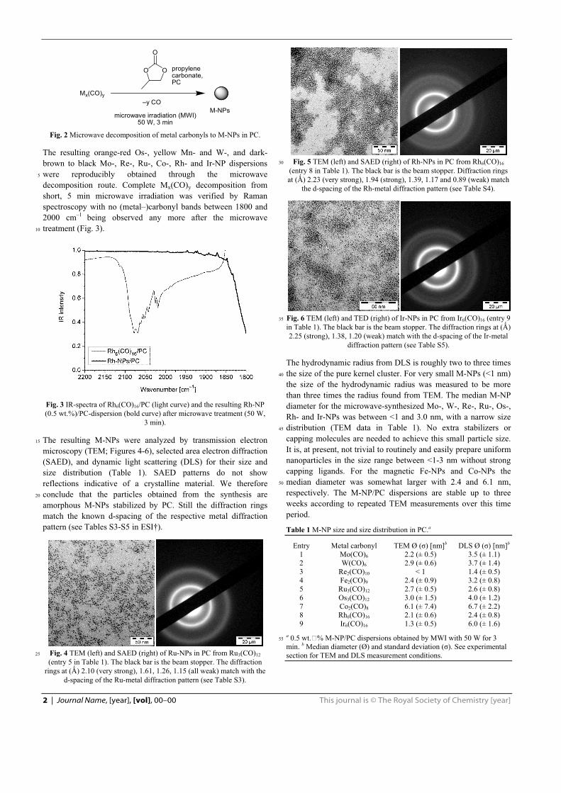
2 | Journal Name, [year], [vol], 00–00 This journal is © The Royal Society of Chemistry [year]
Mx(CO)y
OO
O
–y CO
microwave irradiation (MWI)50 W, 3 min
M-NPs
propylenecarbonate,PC
Fig. 2 Microwave decomposition of metal carbonyls to M-NPs in PC.
The resulting orange-red Os-, yellow Mn- and W-, and dark-brown to black Mo-, Re-, Ru-, Co-, Rh- and Ir-NP dispersions were reproducibly obtained through the microwave 5
decomposition route. Complete Mx(CO)y decomposition from short, 5 min microwave irradiation was verified by Raman spectroscopy with no (metal–)carbonyl bands between 1800 and 2000 cm–1 being observed any more after the microwave treatment (Fig. 3). 10
Fig. 3 IR-spectra of Rh6(CO)16/PC (light curve) and the resulting Rh-NP (0.5 wt.%)/PC-dispersion (bold curve) after microwave treatment (50 W,
3 min).
The resulting M-NPs were analyzed by transmission electron 15
microscopy (TEM; Figures 4-6), selected area electron diffraction (SAED), and dynamic light scattering (DLS) for their size and size distribution (Table 1). SAED patterns do not show reflections indicative of a crystalline material. We therefore conclude that the particles obtained from the synthesis are 20
amorphous M-NPs stabilized by PC. Still the diffraction rings match the known d-spacing of the respective metal diffraction pattern (see Tables S3-S5 in ESI†).
Fig. 4 TEM (left) and SAED (right) of Ru-NPs in PC from Ru3(CO)12 25
(entry 5 in Table 1). The black bar is the beam stopper. The diffraction rings at (�) 2.10 (very strong), 1.61, 1.26, 1.15 (all weak) match with the
d-spacing of the Ru-metal diffraction pattern (see Table S3).
Fig. 5 TEM (left) and SAED (right) of Rh-NPs in PC from Rh6(CO)16 30
(entry 8 in Table 1). The black bar is the beam stopper. Diffraction rings at (�) 2.23 (very strong), 1.94 (strong), 1.39, 1.17 and 0.89 (weak) match
the d-spacing of the Rh-metal diffraction pattern (see Table S4).
Fig. 6 TEM (left) and TED (right) of Ir-NPs in PC from Ir6(CO)16 (entry 9 35
in Table 1). The black bar is the beam stopper. The diffraction rings at (�) 2.25 (strong), 1.38, 1.20 (weak) match with the d-spacing of the Ir-metal
diffraction pattern (see Table S5).
The hydrodynamic radius from DLS is roughly two to three times the size of the pure kernel cluster. For very small M-NPs (<1 nm) 40
the size of the hydrodynamic radius was measured to be more than three times the radius found from TEM. The median M-NP diameter for the microwave-synthesized Mo-, W-, Re-, Ru-, Os-, Rh- and Ir-NPs was between <1 and 3.0 nm, with a narrow size distribution (TEM data in Table 1). No extra stabilizers or 45
capping molecules are needed to achieve this small particle size. It is, at present, not trivial to routinely and easily prepare uniform nanoparticles in the size range between <1-3 nm without strong capping ligands. For the magnetic Fe-NPs and Co-NPs the median diameter was somewhat larger with 2.4 and 6.1 nm, 50
respectively. The M-NP/PC dispersions are stable up to three weeks according to repeated TEM measurements over this time period.
Table 1 M-NP size and size distribution in PC.a
Entry Metal carbonyl TEM Ø (�) [nm]b DLS Ø (�) [nm]b
1 Mo(CO)6 2.2 (± 0.5) 3.5 (± 1.1) 2 W(CO)6 2.9 (± 0.6) 3.7 (± 1.4) 3 Re2(CO)10 < 1 1.4 (± 0.5) 4 Fe2(CO)9 2.4 (± 0.9) 3.2 (± 0.8) 5 Ru3(CO)12 2.7 (± 0.5) 2.6 (± 0.8) 6 Os3(CO)12 3.0 (± 1.5) 4.0 (± 1.2) 7 Co2(CO)8 6.1 (± 7.4) 6.7 (± 2.2) 8 Rh6(CO)16 2.1 (± 0.6) 2.4 (± 0.8) 9 Ir6(CO)16 1.3 (± 0.5) 6.0 (± 1.6)
a 0.5 wt.�% M-NP/PC dispersions obtained by MWI with 50 W for 3 55
min. b Median diameter (Ø) and standard deviation (�). See experimental section for TEM and DLS measurement conditions.
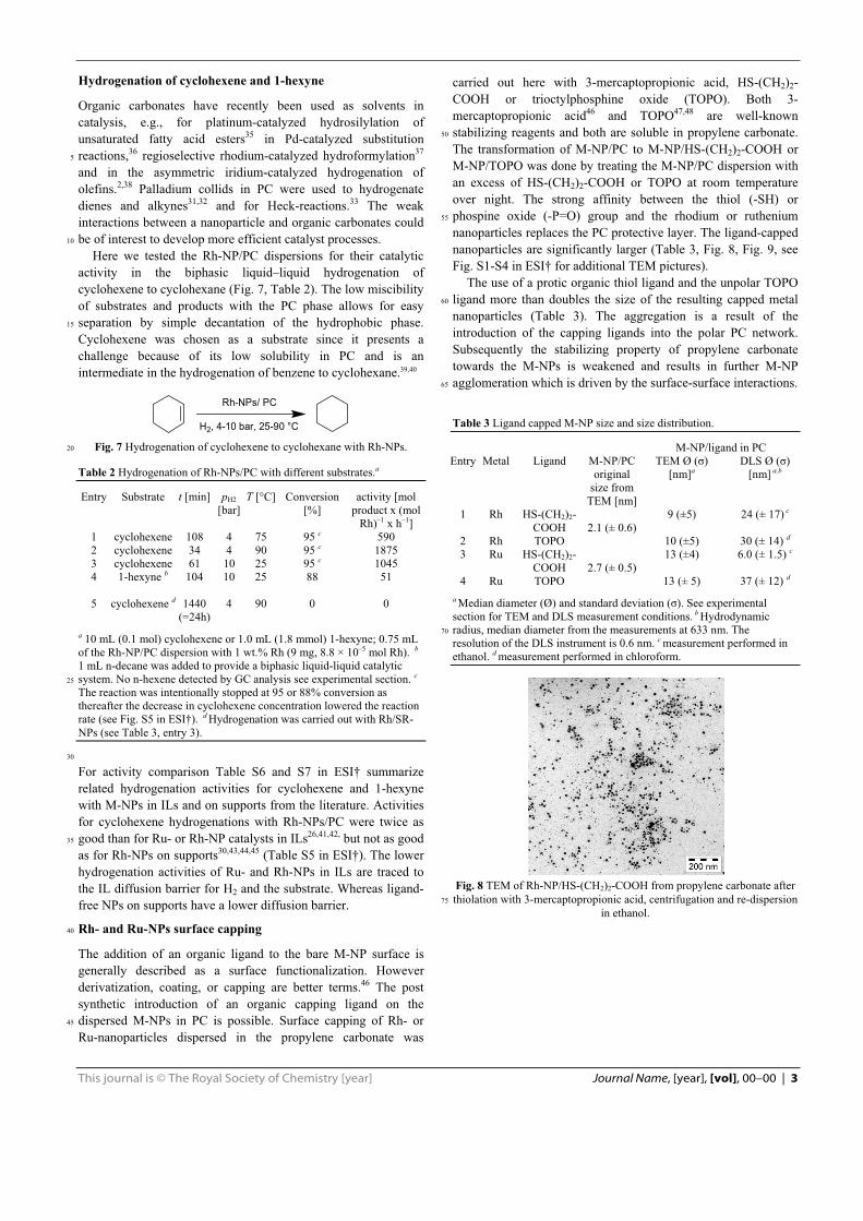
This journal is © The Royal Society of Chemistry [year] Journal Name, [year], [vol], 00–00 | 3
Hydrogenation of cyclohexene and 1-hexyne
Organic carbonates have recently been used as solvents in catalysis, e.g., for platinum-catalyzed hydrosilylation of unsaturated fatty acid esters35 in Pd-catalyzed substitution reactions,36 regioselective rhodium-catalyzed hydroformylation37 5
and in the asymmetric iridium-catalyzed hydrogenation of olefins.2,38 Palladium collids in PC were used to hydrogenate dienes and alkynes31,32 and for Heck-reactions.33 The weak interactions between a nanoparticle and organic carbonates could be of interest to develop more efficient catalyst processes. 10
Here we tested the Rh-NP/PC dispersions for their catalytic activity in the biphasic liquid–liquid hydrogenation of cyclohexene to cyclohexane (Fig. 7, Table 2). The low miscibility of substrates and products with the PC phase allows for easy separation by simple decantation of the hydrophobic phase. 15
Cyclohexene was chosen as a substrate since it presents a challenge because of its low solubility in PC and is an intermediate in the hydrogenation of benzene to cyclohexane.39,40
Rh-NPs/ PC
H2, 4-10 bar, 25-90 °C Fig. 7 Hydrogenation of cyclohexene to cyclohexane with Rh-NPs. 20
Table 2 Hydrogenation of Rh-NPs/PC with different substrates.a
Entry Substrate t [min] pH2 [bar]
T [°C] Conversion [%]
activity [mol product x (mol
Rh)–1 x h–1] 1 cyclohexene 108 4 75 95 c 590 2 cyclohexene 34 4 90 95 c 1875 3 cyclohexene 61 10 25 95 c 1045 4 1-hexyne b 104 10 25 88 51 5 cyclohexene d 1440
(=24h) 4 90 0 0
a 10 mL (0.1 mol) cyclohexene or 1.0 mL (1.8 mmol) 1-hexyne; 0.75 mL of the Rh-NP/PC dispersion with 1 wt.% Rh (9 mg, 8.8 × 10⁻⁵ mol Rh). b
1 mL n-decane was added to provide a biphasic liquid-liquid catalytic system. No n-hexene detected by GC analysis see experimental section. c
25
The reaction was intentionally stopped at 95 or 88% conversion as thereafter the decrease in cyclohexene concentration lowered the reaction rate (see Fig. S5 in ESI†). d Hydrogenation was carried out with Rh/SR-NPs (see Table 3, entry 3).
30
For activity comparison Table S6 and S7 in ESI† summarize related hydrogenation activities for cyclohexene and 1-hexyne with M-NPs in ILs and on supports from the literature. Activities for cyclohexene hydrogenations with Rh-NPs/PC were twice as good than for Ru- or Rh-NP catalysts in ILs26,41,42, but not as good 35
as for Rh-NPs on supports30,43,44,45 (Table S5 in ESI†). The lower hydrogenation activities of Ru- and Rh-NPs in ILs are traced to the IL diffusion barrier for H2 and the substrate. Whereas ligand-free NPs on supports have a lower diffusion barrier.
Rh- and Ru-NPs surface capping 40
The addition of an organic ligand to the bare M-NP surface is generally described as a surface functionalization. However derivatization, coating, or capping are better terms.46 The post synthetic introduction of an organic capping ligand on the dispersed M-NPs in PC is possible. Surface capping of Rh- or 45
Ru-nanoparticles dispersed in the propylene carbonate was
carried out here with 3-mercaptopropionic acid, HS-(CH2)2-COOH or trioctylphosphine oxide (TOPO). Both 3-mercaptopropionic acid46 and TOPO47,48 are well-known stabilizing reagents and both are soluble in propylene carbonate. 50
The transformation of M-NP/PC to M-NP/HS-(CH2)2-COOH or M-NP/TOPO was done by treating the M-NP/PC dispersion with an excess of HS-(CH2)2-COOH or TOPO at room temperature over night. The strong affinity between the thiol (-SH) or phospine oxide (-P=O) group and the rhodium or ruthenium 55
nanoparticles replaces the PC protective layer. The ligand-capped nanoparticles are significantly larger (Table 3, Fig. 8, Fig. 9, see Fig. S1-S4 in ESI† for additional TEM pictures). The use of a protic organic thiol ligand and the unpolar TOPO ligand more than doubles the size of the resulting capped metal 60
nanoparticles (Table 3). The aggregation is a result of the introduction of the capping ligands into the polar PC network. Subsequently the stabilizing property of propylene carbonate towards the M-NPs is weakened and results in further M-NP agglomeration which is driven by the surface-surface interactions. 65
Table 3 Ligand capped M-NP size and size distribution.
M-NP/ligand in PC Entry Metal Ligand M-NP/PC
original size from
TEM [nm]
TEM Ø (�) [nm]a
DLS Ø (�) [nm] a,b
1 Rh HS-(CH2)2-COOH 2.1 (± 0.6)
9 (±5) 24 (± 17) c
2 Rh TOPO 10 (±5) 30 (± 14) d3 Ru HS-(CH2)2-
COOH 2.7 (± 0.5) 13 (±4) 6.0 (± 1.5) c
4 Ru TOPO 13 (± 5) 37 (± 12) d a Median diameter (Ø) and standard deviation (�). See experimental section for TEM and DLS measurement conditions. b Hydrodynamic radius, median diameter from the measurements at 633 nm. The 70
resolution of the DLS instrument is 0.6 nm. c measurement performed in ethanol. d measurement performed in chloroform.
Fig. 8 TEM of Rh-NP/HS-(CH2)2-COOH from propylene carbonate after thiolation with 3-mercaptopropionic acid, centrifugation and re-dispersion 75
in ethanol.
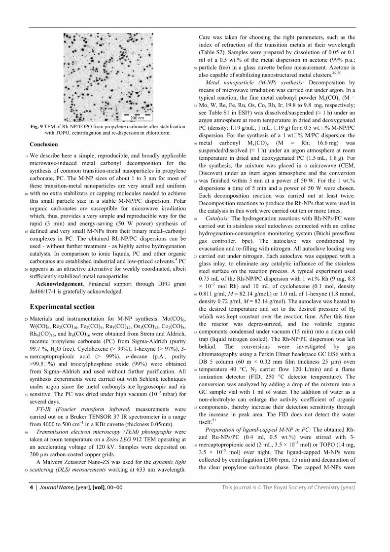
4 | Journal Name, [year], [vol], 00–00 This journal is © The Royal Society of Chemistry [year]
Fig. 9 TEM of Rh-NP/TOPO from propylene carbonate after stabilization
with TOPO, centrifugation and re-dispersion in chloroform.
Conclusion
We describe here a simple, reproducible, and broadly applicable 5
microwave-induced metal carbonyl decomposition for the synthesis of common transition-metal nanoparticles in propylene carbonate, PC. The M-NP sizes of about 1 to 3 nm for most of these transition-metal nanoparticles are very small and uniform with no extra stabilizers or capping molecules needed to achieve 10
this small particle size in a stable M-NP/PC dispersion. Polar organic carbonates are susceptible for microwave irradiation which, thus, provides a very simple and reproducible way for the rapid (3 min) and energy-saving (50 W power) synthesis of defined and very small M-NPs from their binary metal–carbonyl 15
complexes in PC. The obtained Rh-NP/PC dispersions can be used - without further treatment - as highly active hydrogenation catalysts. In comparison to ionic liquids, PC and other organic carbonates are established industrial and low-priced solvents.4 PC appears as an attractive alternative for weakly coordinated, albeit 20
sufficiently stabilized metal nanoparticles.
Acknowledgement. Financial support through DFG grant Ja466/17-1 is gratefully acknowledged.
Experimental section Materials and instrumentation for M-NP synthesis: Mo(CO)6, 25
W(CO)6, Re2(CO)10, Fe2(CO)9, Ru3(CO)12, Os3(CO)12, Co2(CO)8, Rh6(CO)16, and Ir6(CO)16 were obtained from Strem and Aldrich, racemic propylene carbonate (PC) from Sigma-Aldrich (purity 99.7 %, H2O free). Cyclohexene (> 99%), 1-hexyne (> 97%), 3-mercaptopropionic acid (> 99%), n-decane (p.A., purity 30
>99.5�%) and trioctylphosphine oxide (99%) were obtained from Sigma–Aldrich and used without further purification. All synthesis experiments were carried out with Schlenk techniques under argon since the metal carbonyls are hygroscopic and air sensitive. The PC was dried under high vacuum (10�3 mbar) for 35
several days. FT-IR (Fourier transform infrared) measurements were carried out on a Bruker TENSOR 37 IR spectrometer in a range from 4000 to 500 cm–1 in a KBr cuvette (thickness 0.05mm). Transmission electron microscopy (TEM) photographs were 40
taken at room temperature on a Zeiss LEO 912 TEM operating at an accelerating voltage of 120 kV. Samples were deposited on 200 μm carbon-coated copper grids. A Malvern Zetasizer Nano-ZS was used for the dynamic light scattering (DLS) measurements working at 633 nm wavelength. 45
Care was taken for choosing the right parameters, such as the index of refraction of the transition metals at their wavelength (Table S2). Samples were prepared by dissolution of 0.05 or 0.1 ml of a 0.5 wt.% of the metal dispersion in acetone (99% p.a.; particle free) in a glass cuvette before measurement. Acetone is 50
also capable of stabilizing nanostructured metal clusters.49,50 Metal nanoparticle (M-NP) synthesis: Decomposition by means of microwave irradiation was carried out under argon. In a typical reaction, the fine metal carbonyl powder Mx(CO)y (M = Mo, W, Re, Fe, Ru, Os, Co, Rh, Ir; 19.8 to 9.8 mg, respectively; 55
see Table S1 in ESI†) was dissolved/suspended (� 1 h) under an argon atmosphere at room temperature in dried and deoxygenated PC (density: 1.19 g/mL, 1 mL, 1.19 g) for a 0.5 wt.�% M-NP/PC dispersion. For the synthesis of a 1 wt�% M/PC dispersion the metal carbonyl Mx(CO)y (M = Rh; 16.6 mg) was 60
suspended/dissolved (� 1 h) under an argon atmosphere at room temperature in dried and deoxygenated PC (1.5 mL, 1.8 g). For the synthesis, the mixture was placed in a microwave (CEM, Discover) under an inert argon atmosphere and the conversion was finished within 3 min at a power of 50 W. For the 1 wt.% 65
dispersions a time of 5 min and a power of 50 W were chosen. Each decomposition reaction was carried out at least twice. Decomposition reactions to produce the Rh-NPs that were used in the catalysis in this work were carried out ten or more times. Catalysis: The hydrogenation reactions with Rh-NPs/PC were 70
carried out in stainless steel autoclaves connected with an online hydrogenation-consumption monitoring system (Büchi pressflow gas controller, bpc). The autoclave was conditioned by evacuation and re-filling with nitrogen. All autoclave loading was carried out under nitrogen. Each autoclave was equipped with a 75
glass inlay, to eliminate any catalytic influence of the stainless steel surface on the reaction process. A typical experiment used 0.75 mL of the Rh-NP/PC dispersion with 1 wt.% Rh (9 mg, 8.8 × 10⁻⁵ mol Rh) and 10 mL of cyclohexene (0.1 mol, density 0.811 g/ml, M = 82.14 g/mol,) or 1.0 mL of 1-hexyne (1.8 mmol, 80
density 0.72 g/ml, M = 82.14 g/mol). The autoclave was heated to the desired temperature and set to the desired pressure of H2 which was kept constant over the reaction time. After this time the reactor was depressurized, and the volatile organic components condensed under vacuum (15 min) into a clean cold 85
trap (liquid nitrogen cooled). The Rh-NP/PC dispersion was left behind. The conversions were investigated by gas chromatography using a Perkin Elmer headspace GC HS6 with a DB 5 column (60 m × 0.32 mm film thickness 25 μm) oven temperature 40 °C, N2 carrier flow 120 L/min) and a flame 90
ionization detector (FID, 250 °C detector temperature). The conversion was analyzed by adding a drop of the mixture into a GC sample vial with 1 ml of water. The addition of water as a non-electrolyte can enlarge the activity coefficient of organic components, thereby increase their detection sensitivity through 95
the increase in peak area. The FID does not detect the water itself.51 Preparation of ligand-capped M-NP in PC: The obtained Rh- and Ru-NPs/PC (0.4 ml, 0.5 wt.%) were stirred with 3-mercaptopropionic acid (2 mL, 3.5 × 10⁻⁵ mol) or TOPO (14 mg, 100
3.5 × 10⁻⁵ mol) over night. The ligand-capped M-NPs were collected by centrifugation (2000 rpm, 15 min) and decantation of the clear propylene carbonate phase. The capped M-NPs were

This journal is © The Royal Society of Chemistry [year] Journal Name, [year], [vol], 00–00 | 5
dried for several days under high vacuum to remove the PC solvent.
Notes and references a Institut für Anorganische Chemie und Strukturchemie, Heinrich-Heine-Universität Düsseldorf 1, D-40204 Düsseldorf, Germany. Fax: +49 211 5
81 12287; Tel: + 49 211 81 12286; E-mail: [email protected] b Freiburger Material Forschungszentrum (FMF) and Institut für Makromolekulare Chemie, Universität Freiburg, Stefan-Meier-Str. 21-31, 79104 Germany. Tel: +49 761 2035379; E-mail: [email protected] 10
† Electronic Supplementary Information (ESI) available: additional TEMs, DLS and SAED parameters, catalytic activity with comparative activity data from literature. See DOI: 10.1039/b000000x/ �
�
1 B. Schäffner, F. Schäffner, S. P. Verevkin and A. Börner, Chem. Rev., 2010, 110, 4554-4581.
2 J. Bayardon, J. Holz, B. Schäffner, V. Andrushko, S. Verevkin, A. Preetz and A. Börner, Angew. Chem. Int. Ed. 2007, 46, 5971-5974.
3 S. P. Verevkin, V. N. Emel’yanenko, A. V. Toktonov, Y. Chernyak, B. Schäffner and A. Börner, J. Chem. Thermodynamics 2008, 40, 1428-1432.
4 B. Schäffner, S. P. Verevkin and A. Börner, Chem. Unserer Zeit, 2009, 43, 12-21.
5 J. H. Clements, J. Ind. Eng. Chem. Res., 2003, 42, 663-674. 6 A. Ansmann, B. Boutty and M. Dierker, Chem. Abstr. 2008, 149,
17219. 7 A. L. Kohl and P. A. Buckingham, Oil Gas J., 1960, 58, 146. 8 J. Xia, M. E. Ragsdale and E. B. Stephens, Chem. Abstr., 2001, 136,
38897. 9 S. Schmidt, Chem. Abstr., 2004, 142, 375279. 10 R. Jasinski, J. Electroanal. Chem., 1967, 15, 89-91. 11 K. K. D. Ehinon, S. Naille, R. Dedryvère, P.-E. Lippens, J.-C. Jumas
and D. Gonbeau, Chem. Mater., 2008, 20, 5388-5398. 12 V. I. Pârvulescu and C. Hardacre, Chem. Rev., 2007, 107, 2615-2665. 13 A. Seyed-Razavi, I. K. Snook and A. S. Barnard, J. Mater. Chem.,
2010, 20, 416-421; 14 Y. Teow, P. V. Asharani, M. P. Hande and S. Valiyaveettil, Chem.
Comm., 2011, 47, 7025-7038. 15 J. Dupont and J. D. Scholten, Chem. Soc. Rev., 2010, 39, 1780-1804. 16 A.-H. Lu, E. L. Salabas and F. Schüth, Angew. Chem. Int. Ed., 2007,
46, 1222-1244. 17 A. Gedanken, Ultrasonics Sonochem., 2004, 11, 47-55. 18 C. N. R. Rao, S.R.C. Vivekchand, K. Biswas and A. Govindaraj,
Dalton Trans., 2007, 3728-3749. 19 Y. Mastai, A. Gedanken, in: C. N. R. Rao, A. Müller, A. K.
Cheetham (Eds.), Chemistry of Nanomaterials, vol. 1, Wiley-VCH, Weinheim, 2004, p. 113.
20 J. Park, J. Joo, S. G. Kwon, Y. Jang and T. Hyeon, Angew. Chem. Int. Ed., 2007, 46, 4630-4660.
21 L. D. Pachón and G. Rothenberg, Appl. Organometal. Chem. 2008, 22, 288-299.
22 P. Graf, A. Mantion, A. Foelske, A. Shkilnyy, A. M�si�, A. F. Thünemann and A. Taubert, Chem. Eur. J., 2009, 15, 5831-5844.
23 G. Salas, C. C. Santini, K. Philippot, V. Collière, B. Chaudret, B. Fenet and P. F. Fazzini, Dalton Trans., 2011, 40, 4660-4668.
24 C. Pan, K. Pelzer, K. Philippot, B. Chaudret, F. Dassenoy, P. Lecante and M.-J. Casanove, J. Am. Chem. Soc., 2011, 123, 7584-7593.
25 A. Taubert and Z. Li, Dalton Trans., 2007, 723-727; E. Redel, R. Thomann and C. Janiak, Inorg. Chem., 2008, 47, 14-16; E. Redel, R. Thomann and C. Janiak, Chem. Commun., 2008 1789-1791; E. Redel, J. Krämer, R. Thomann and C. Janiak, J. Organomet. Chem.,
�
�
�
�
2009, 694, 1069-1075; E. Redel, M. Walter, R. Thomann, L. Hussein, M. Krüger and C. Janiak, Chem. Commun., 2010, 46, 1159-1161.
26 C. Vollmer, E. Redel, K. Abu-Shandi, R. Thomann, H. Manyar, C. Hardacre and C. Janiak, Chem. Eur. J., 2010, 16, 3849-3858.
27 C. Vollmer and C. Janiak, Coord. Chem. Rev., 2011, 255, 2039-2057. 28 R. J. White, R. Luque, V. L. Budarin, J. H. Clark and D. J.
Macquarrie, Chem. Soc. Rev., 2009, 38, 481-494. 29 B. Inceesungvorn, J. López-Castro, J. J. Calvino, S. Bernal, F. C.
Meunier, C. Hardacre, K. Griffin and J. J. Delgado, Appl. Catal. A, 2011, 391, 187-193.
30 D. Marquardt, C. Vollmer, R. Thomann, P. Steurer, R. Mülhaupt, E. Redel and C. Janiak, Carbon, 2011, 49, 1326-1332.
31 A. Behr and H. Schmidke, Chem.-Ing.-Tech., 1993, 65, 568-569. 32 A. Behr, N. Döring, Susanne Durowicz-Heil, B. Ellenberg, C. Kozik,
C. Lohr and H. Schmidke, Fat Sci. Technol., 1993, 95, 2-12. 33 M. Reetz and G. Lohmer, Chem. Commun., 1996, 1921-1922. 34 J. Demel, J. �ejka, S. Bakardjieva and P. Št�pni ka, J. Mol. Catal. A:
Chem., 2007, 263, 259-265. 35 A. Behr, F. Naendrup and D. Obst, Adv. Synth. Catal., 2002, 344,
1142-1145. 36 B. Schäffner, J. Holz, S. P. Verevkin and A. Börner, ChemSusChem,
2008, 1, 249-253. 37 A. Behr, D. Obst and B. Turkowski, J. Mol. Catal. A: Chem., 2005,
226, 215-219. 38 B. Schäffner, V. Andrushko, J. Bayardon, J. Holz and A. Börner,
Chirality, 2009, 21, 857-861. 39 H.-E. Elias in Makromoleküle, Vol. 3, Wiley-VCH, Weinheim, 2001,
pp. 368-454. 40 B. K. Hodnett in Heterogeneous Catalytic Oxidations, Wiley-VCH,
Weinheim. 2000, pp. 240-263. 41 E. T. Silveira, A. P. Umpierre, L. M. Rossi, G. Machado, J. Morais, I.
L. R. Baumvol, S. R. Teixeira, P. F. P. Fichtner and J. Dupont, Chem. Eur. J., 2004, 10, 3734-3740.
42 L. M. Rossi, G. Machado, P. F. P. Fichtner and S. R. Teixeira, J. Dupont, Catal. Lett., 2004, 92, 149-155.
43 S. Miao, Z. Liu, Z. Zhang, B. Han, Z. Miao, K. Ding, G. An, J. Phys. Chem. C, 2007, 111, 2185-2190.
44 M. J. Jacinto, P. K. Kiyohara, S. H. Masunaga, R. F. Jardim and L. M. Rossi, Appl. Catal. A, 2008, 338, 52-57.
45 C. Vollmer, M. Schröder, Y. Thomann, R. Thomann, C. Janiak, Appl. Catal. A, 2012, in press. http://dx.doi.org/10.1016/j.apcata.2012.03.017
46 E. Redel, M. Walter, T. Thomann, C. Vollmer, L. Hussein, H. Scherer, M. Krüger, C. Janiak, Chem. Eur. J. 2009, 15, 10047-10059.
47 C. Pan, K. Pelzer, K. Philippot, B. Chaudret, F. Dassenoy, P. Lecante and M.-J. Casanove, J. Am Chem. Soc., 2001, 124, 7584-7593.
48 T. Cassagneau, T. E. Mallouk and J. H. Fendler, J. Am. Chem. Soc., 1998, 120, 7848-7859.
49 K. J. Klabunde and G. Cárdenas-Trivino, in Active Metals: Preparation, Characterization, Applications, ed. A. Fürstner, VCH, Weinheim, 1996, pp. 247, 263, 264.
50 G. Cárdenas, S. Salinas and R. Oliva, Colloid Polym Sci., 2003, 282, 41-47; G. Cárdenas, R. Segura, J. Morales, H. Soto and C. A. Lima, Mater. Res. Bull., 2000, 35, 1251–1259; K. Cheng, Q. Chen, Z. Wu, M. Wang and H. Wang, CrystEngComm, 2011, 13, 5394–5400
51 H. Hachenberg and K. Beringer, Die Headspace-Gaschromatographie als Analysen- und Meßmethode, Vieweg, Braunschweig/ Wiesbaden, Germany, 1996, pp. 32–35.

Applied Catalysis A: General 425– 426 (2012) 178– 183
Contents lists available at SciVerse ScienceDirect
Applied Catalysis A: General
jo u r n al hom epage: www.elsev ier .com/ locate /apcata
Turning Teflon-coated magnetic stirring bars to catalyst systems with metal
nanoparticle trace deposits – A caveat and a chance
Christian Vollmera, Marcel Schrödera, Yi Thomannb, Ralf Thomannb, Christoph Janiaka,∗
a Institut für Anorganische Chemie und Strukturchemie, Universität Düsseldorf, Universitätsstr. 1, D-40225 Düsseldorf, Germanyb Freiburger Material Forschungszentrum (FMF) and Institut für Makromolekulare Chemie, Universität Freiburg, Stefan-Meier-Str. 21-31, 79104 Freiburg, Germany
a r t i c l e i n f o
Article history:
Received 13 February 2012
Received in revised form 8 March 2012
Accepted 10 March 2012
Available online 19 March 2012
Keywords:
Metal nanoparticles
Rhodium
Teflon surface
Trace metal
Hydrogenation
Stirring bar
a b s t r a c t
It could be an unintentional effect to deposit metal nanoparticles on a simple Teflon-coated magnetic
stirring bar. Rhodium nanoparticles, as an example, were reproducibly deposited onto a standard, com-
mercial Teflon-coated magnetic stirring bar by easy and rapid microwave-assisted decomposition of
the metal carbonyl precursor Rh6(CO)16 in the ionic liquid 1-n-butyl-3-methyl-imidazolium tetrafluo-
roborate. Such metal nanoparticle deposits are not easy to remove from the Teflon surface by simple
washing procedures and present active catalysts which one is not necessarily aware of. Barely visible
metal-nanoparticle deposits on a stirring bar can act as trace metal impurities in catalytic reactions. As
a proof-of-principle the rhodium-nanoparticle deposits of 32 �g or less Rh metal on a 20 mm × 6 mm
magnetic stirring bar were shown to catalyze the hydrogenation reaction of neat cyclohexene or ben-
zene to cyclohexane with quantitative conversion. Rhodium-nanoparticle-coated stirring bars were easily
handable, separable and re-usable catalyst system for the heterogeneous hydrogenation with quantita-
tive conversion and very high turnover frequencies of up to 32,800 mol cyclohexene × (mol Rh)−1 × h−1
under organic-solvent-free conditions.
© 2012 Elsevier B.V. All rights reserved.
1. Introduction
It has recently become more evident that not every component
which was originally claimed as catalyst turned out to be the actual
active ingredient. In some prominent cases trace metal impurities
were eventually proven as the actual catalytic species [1,2]. In an
early example, traces of nickel compounds which formed uninten-
tional during the cleaning of a V2A steal autoclave and remained
in there changed the Ziegler–Aufbau reaction (reaction of AlEt3
with ethylene at 100 ◦C under pressure to long-chain Al-alkyls) to
a clean ethylene dimerization to yield butene. The cause of this
unexpected dimerization was at first unknown and later termed
the “nickel effect” after its origin had become clear. In addition,
the nickel compounds had required traces of acetylene which were
present in technical ethylene for stabilization of the nickel catalyst
[3,4].
More recently, a Suzuki cross-coupling which was thought to
have occurred metal-free was indeed promoted by ppb Pd traces
in the Na2CO3 or K2CO3 bases used for the reaction [5]. Sug-
gested iron-catalyzed cross-coupling reactions with different FeCl3sources were eventually corrected to ppm-scale copper impurities
∗ Corresponding author. Tel.: +49 211 81 12286; fax: +49 211 81 12287.
E-mail address: [email protected] (C. Janiak).
doing the catalysis [6]. Even with Pd in the ppb range it is possible
to carry out a Sonogashira coupling with quantitative conversion
[7].
On the other hand, metal traces or dopants are intentionally
added to enhance or promote catalytic performance [8,9] or to
assist catalyst regeneration [10].
Researchers in catalysis are aware that impurities left over from
previous experiments in their (cleaned) vessels can give activating
of desactivating effects which change the outcome of a catalytic
reaction. Thus, catalytic reactions should be carried out more than
once to ensure reproducibility. Surprisingly, a Scifinder search [11]
combining the terms “memory effect”, “contamination” or “impu-
rity” and “catalysis” did not give any relevant references.
Here we show that a common and frequently used labora-
tory commodity such as a Teflon-coated magnetic stirring bar can
carry on its surface catalytically active metal nanoparticles which
are not easily removed. On one hand this is “caveat” on the un-
intentional preparation of “catalytically active stirring bars” by
nanoparticular metal depositions from previous reactions. On the
other hand our simple deposition of rhodium metal nanoparticles
(Rh-NPs) on the Teflon surface of a stirring bar (Rh-NPs@stirring
bar) yields an easily handable and re-usable hydrogenation cat-
alyst. This proof-of-concept should be extendable to other metal
nanoparticle catalysts. Rhodium was used here as a metal for
the proof-of-principle because rhodium is used in many types of
0926-860X/$ – see front matter © 2012 Elsevier B.V. All rights reserved.doi:10.1016/j.apcata.2012.03.017
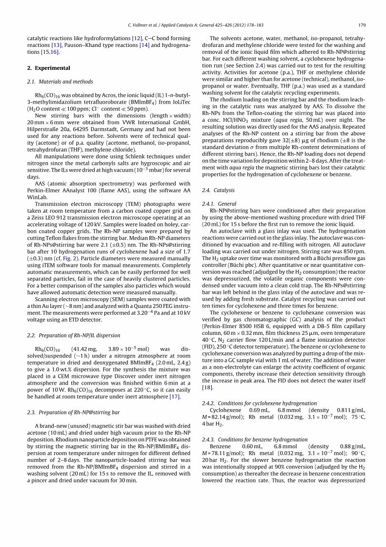
C. Vollmer et al. / Applied Catalysis A: General 425– 426 (2012) 178– 183 179
catalytic reactions like hydroformylations [12], C C bond forming
reactions [13], Pauson–Khand type reactions [14] and hydrogena-
tions [15,16].
2. Experimental
2.1. Materials and methods
Rh6(CO)16 was obtained by Acros, the ionic liquid (IL) 1-n-butyl-
3-methylimidazolium tetrafluoroborate (BMImBF4) from IoLiTec
(H2O content � 100 ppm; Cl− content � 50 ppm).
New stirring bars with the dimensions (length × width)
20 mm × 6 mm were obtained from VWR International GmbH,
Hilperstraße 20a, 64295 Darmstadt, Germany and had not been
used for any reactions before. Solvents were of technical qual-
ity (acetone) or of p.a. quality (acetone, methanol, iso-propanol,
tetrahydrofuran (THF), methylene chloride).
All manipulations were done using Schlenk techniques under
nitrogen since the metal carbonyls salts are hygroscopic and air
sensitive. The ILs were dried at high vacuum (10−3 mbar) for several
days.
AAS (atomic absorption spectrometry) was performed with
Perkin-Elmer AAnalyst 100 (flame AAS), using the software AA
WinLab.
Transmission electron microscopy (TEM) photographs were
taken at room temperature from a carbon coated copper grid on
a Zeiss LEO 912 transmission electron microscope operating at an
accelerating voltage of 120 kV. Samples were loaded on holey, car-
bon coated copper grids. The Rh-NP samples were prepared by
cutting Teflon flakes from the stirring bar. Median Rh-NP diameters
of Rh-NPs@stirring bar were 2.1 (±0.5) nm. The Rh-NPs@stirring
bar after 10 hydrogenation runs of cyclohexene had a size of 1.7
(±0.3) nm (cf. Fig. 2). Particle diameters were measured manually
using iTEM software tools for manual measurements. Completely
automatic measurements, which can be easily performed for well
separated particles, fail in the case of heavily clustered particles.
For a better comparison of the samples also particles which would
have allowed automatic detection were measured manually.
Scanning electron microscopy (SEM) samples were coated with
a thin Au layer (∼8 nm) and analyzed with a Quanta 250 FEG instru-
ment. The measurements were performed at 3.20−4 Pa and at 10 kV
voltage using an ETD detector.
2.2. Preparation of Rh-NP/IL dispersion
Rh6(CO)16 (41.42 mg, 3.89 × 10⁻⁵ mol) was dis-
solved/suspended (∼1 h) under a nitrogen atmosphere at room
temperature in dried and deoxygenated BMImBF4 (2.0 mL, 2.4 g)
to give a 1.0 wt.% dispersion. For the synthesis the mixture was
placed in a CEM microwave type Discover under inert nitrogen
atmosphere and the conversion was finished within 6 min at a
power of 10 W. Rh6(CO)16 decomposes at 220 ◦C, so it can easily
be handled at room temperature under inert atmosphere [17].
2.3. Preparation of Rh-NP@stirring bar
A brand-new (unused) magnetic stir bar was washed with dried
acetone (10 mL) and dried under high vacuum prior to the Rh-NP
deposition. Rhodium nanoparticle deposition on PTFE was obtained
by stirring the magnetic stirring bar in the Rh-NP/BMImBF4 dis-
persion at room temperature under nitrogen for different defined
number of 2–8 days. The nanoparticle-loaded stirring bar was
removed from the Rh-NP/BMImBF4 dispersion and stirred in a
washing solvent (20 mL) for 15 s to remove the IL, removed with
a pincer and dried under vacuum for 30 min.
The solvents acetone, water, methanol, iso-propanol, tetrahy-
drofuran and methylene chloride were tested for the washing and
removal of the ionic liquid film which adhered to Rh-NP@stirring
bar. For each different washing solvent, a cyclohexene hydrogena-
tion run (see Section 2.4) was carried out to test for the resulting
activity. Activities for acetone (p.a.), THF or methylene chloride
were similar and higher than for acetone (technical), methanol, iso-
propanol or water. Eventually, THF (p.a.) was used as a standard
washing solvent for the catalytic recycling experiments.
The rhodium loading on the stirring bar and the rhodium leach-
ing in the catalytic runs was analyzed by AAS. To dissolve the
Rh-NPs from the Teflon-coating the stirring bar was placed into
a conc. HCl/HNO3 mixture (aqua regia, 50 mL) over night. The
resulting solution was directly used for the AAS analysis. Repeated
analyses of the Rh-NP content on a stirring bar from the above
preparations reproducibly gave 32(±8) �g of rhodium (±8 is the
standard deviation � from multiple Rh-content determinations of
different stirring bars). Hence, the Rh-NP loading does not depend
on the time variation for deposition within 2–8 days. After the treat-
ment with aqua regia the magnetic stirring bars lost their catalytic
properties for the hydrogenation of cyclohexene or benzene.
2.4. Catalysis
2.4.1. General
Rh-NP@stirring bars were conditioned after their preparation
by using the above-mentioned washing procedure with dried THF
(20 mL) for 15 s before the first run to remove the ionic liquid.
An autoclave with a glass inlay was used. The hydrogenation
reactions were carried out in the glass inlay. The autoclave was con-
ditioned by evacuation and re-filling with nitrogen. All autoclave
loading was carried out under nitrogen. Stirring rate was 850 rpm.
The H2 uptake over time was monitored with a Büchi pressflow gas
controller (Büchi pbc). After quantitative or near quantitative con-
version was reached (adjudged by the H2 consumption) the reactor
was depressurized, the volatile organic components were con-
densed under vacuum into a clean cold trap. The Rh-NPs@stirring
bar was left behind in the glass inlay of the autoclave and was re-
used by adding fresh substrate. Catalyst recycling was carried out
ten times for cyclohexene and three times for benzene.
The cyclohexene or benzene to cyclohexane conversion was
verified by gas chromatographic (GC) analysis of the product
(Perkin-Elmer 8500 HSB 6, equipped with a DB-5 film capillary
column, 60 m × 0.32 mm, film thickness 25 �m, oven temperature
40 ◦C, N2 carrier flow 120 L/min and a flame ionization detector
(FID), 250 ◦C detector temperature). The benzene or cyclohexene to
cyclohexane conversion was analyzed by putting a drop of the mix-
ture into a GC sample vial with 1 mL of water. The addition of water
as a non-electrolyte can enlarge the activity coefficient of organic
components, thereby increase their detection sensitivity through
the increase in peak area. The FID does not detect the water itself
[18].
2.4.2. Conditions for cyclohexene hydrogenation
Cyclohexene 0.69 mL, 6.8 mmol (density 0.811 g/mL,
M = 82.14 g/mol); Rh metal (0.032 mg, 3.1 × 10⁻⁷ mol); 75 ◦C,
4 bar H2.
2.4.3. Conditions for benzene hydrogenation
Benzene 0.60 mL, 6.8 mmol (density 0.88 g/mL,
M = 78.11 g/mol); Rh metal (0.032 mg, 3.1 × 10⁻⁷ mol); 90 ◦C,
20 bar H2. For the slower benzene hydrogenation the reaction
was intentionally stopped at 90% conversion (adjudged by the H2
consumption) as thereafter the decrease in benzene concentration
lowered the reaction rate. Thus, the reactor was depressurized
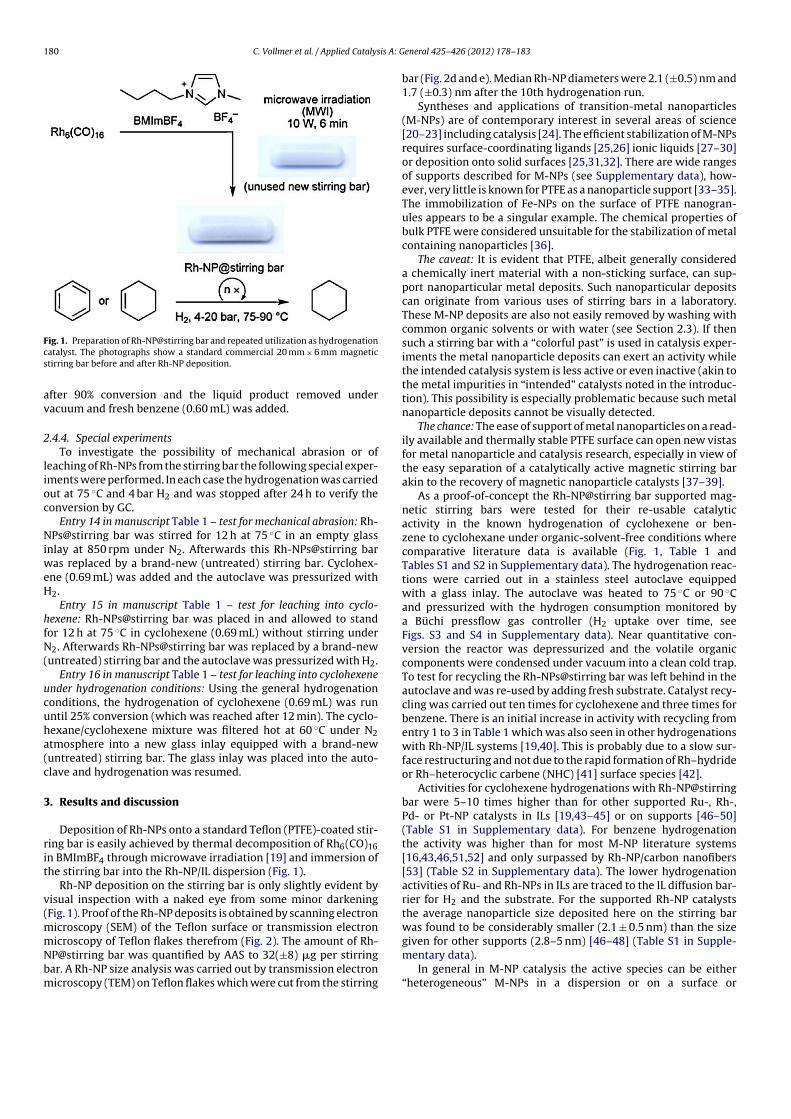
180 C. Vollmer et al. / Applied Catalysis A: General 425– 426 (2012) 178– 183
Fig. 1. Preparation of Rh-NP@stirring bar and repeated utilization as hydrogenation
catalyst. The photographs show a standard commercial 20 mm × 6 mm magnetic
stirring bar before and after Rh-NP deposition.
after 90% conversion and the liquid product removed under
vacuum and fresh benzene (0.60 mL) was added.
2.4.4. Special experiments
To investigate the possibility of mechanical abrasion or of
leaching of Rh-NPs from the stirring bar the following special exper-
iments were performed. In each case the hydrogenation was carried
out at 75 ◦C and 4 bar H2 and was stopped after 24 h to verify the
conversion by GC.
Entry 14 in manuscript Table 1 – test for mechanical abrasion: Rh-
NPs@stirring bar was stirred for 12 h at 75 ◦C in an empty glass
inlay at 850 rpm under N2. Afterwards this Rh-NPs@stirring bar
was replaced by a brand-new (untreated) stirring bar. Cyclohex-
ene (0.69 mL) was added and the autoclave was pressurized with
H2.
Entry 15 in manuscript Table 1 – test for leaching into cyclo-
hexene: Rh-NPs@stirring bar was placed in and allowed to stand
for 12 h at 75 ◦C in cyclohexene (0.69 mL) without stirring under
N2. Afterwards Rh-NPs@stirring bar was replaced by a brand-new
(untreated) stirring bar and the autoclave was pressurized with H2.
Entry 16 in manuscript Table 1 – test for leaching into cyclohexene
under hydrogenation conditions: Using the general hydrogenation
conditions, the hydrogenation of cyclohexene (0.69 mL) was run
until 25% conversion (which was reached after 12 min). The cyclo-
hexane/cyclohexene mixture was filtered hot at 60 ◦C under N2
atmosphere into a new glass inlay equipped with a brand-new
(untreated) stirring bar. The glass inlay was placed into the auto-
clave and hydrogenation was resumed.
3. Results and discussion
Deposition of Rh-NPs onto a standard Teflon (PTFE)-coated stir-
ring bar is easily achieved by thermal decomposition of Rh6(CO)16
in BMImBF4 through microwave irradiation [19] and immersion of
the stirring bar into the Rh-NP/IL dispersion (Fig. 1).
Rh-NP deposition on the stirring bar is only slightly evident by
visual inspection with a naked eye from some minor darkening
(Fig. 1). Proof of the Rh-NP deposits is obtained by scanning electron
microscopy (SEM) of the Teflon surface or transmission electron
microscopy of Teflon flakes therefrom (Fig. 2). The amount of Rh-
NP@stirring bar was quantified by AAS to 32(±8) �g per stirring
bar. A Rh-NP size analysis was carried out by transmission electron
microscopy (TEM) on Teflon flakes which were cut from the stirring
bar (Fig. 2d and e). Median Rh-NP diameters were 2.1 (±0.5) nm and
1.7 (±0.3) nm after the 10th hydrogenation run.
Syntheses and applications of transition-metal nanoparticles
(M-NPs) are of contemporary interest in several areas of science
[20–23] including catalysis [24]. The efficient stabilization of M-NPs
requires surface-coordinating ligands [25,26] ionic liquids [27–30]
or deposition onto solid surfaces [25,31,32]. There are wide ranges
of supports described for M-NPs (see Supplementary data), how-
ever, very little is known for PTFE as a nanoparticle support [33–35].
The immobilization of Fe-NPs on the surface of PTFE nanogran-
ules appears to be a singular example. The chemical properties of
bulk PTFE were considered unsuitable for the stabilization of metal
containing nanoparticles [36].
The caveat: It is evident that PTFE, albeit generally considered
a chemically inert material with a non-sticking surface, can sup-
port nanoparticular metal deposits. Such nanoparticular deposits
can originate from various uses of stirring bars in a laboratory.
These M-NP deposits are also not easily removed by washing with
common organic solvents or with water (see Section 2.3). If then
such a stirring bar with a “colorful past” is used in catalysis exper-
iments the metal nanoparticle deposits can exert an activity while
the intended catalysis system is less active or even inactive (akin to
the metal impurities in “intended” catalysts noted in the introduc-
tion). This possibility is especially problematic because such metal
nanoparticle deposits cannot be visually detected.
The chance: The ease of support of metal nanoparticles on a read-
ily available and thermally stable PTFE surface can open new vistas
for metal nanoparticle and catalysis research, especially in view of
the easy separation of a catalytically active magnetic stirring bar
akin to the recovery of magnetic nanoparticle catalysts [37–39].
As a proof-of-concept the Rh-NP@stirring bar supported mag-
netic stirring bars were tested for their re-usable catalytic
activity in the known hydrogenation of cyclohexene or ben-
zene to cyclohexane under organic-solvent-free conditions where
comparative literature data is available (Fig. 1, Table 1 and
Tables S1 and S2 in Supplementary data). The hydrogenation reac-
tions were carried out in a stainless steel autoclave equipped
with a glass inlay. The autoclave was heated to 75 ◦C or 90 ◦C
and pressurized with the hydrogen consumption monitored by
a Büchi pressflow gas controller (H2 uptake over time, see
Figs. S3 and S4 in Supplementary data). Near quantitative con-
version the reactor was depressurized and the volatile organic
components were condensed under vacuum into a clean cold trap.
To test for recycling the Rh-NPs@stirring bar was left behind in the
autoclave and was re-used by adding fresh substrate. Catalyst recy-
cling was carried out ten times for cyclohexene and three times for
benzene. There is an initial increase in activity with recycling from
entry 1 to 3 in Table 1 which was also seen in other hydrogenations
with Rh-NP/IL systems [19,40]. This is probably due to a slow sur-
face restructuring and not due to the rapid formation of Rh–hydride
or Rh–heterocyclic carbene (NHC) [41] surface species [42].
Activities for cyclohexene hydrogenations with Rh-NP@stirring
bar were 5–10 times higher than for other supported Ru-, Rh-,
Pd- or Pt-NP catalysts in ILs [19,43–45] or on supports [46–50]
(Table S1 in Supplementary data). For benzene hydrogenation
the activity was higher than for most M-NP literature systems
[16,43,46,51,52] and only surpassed by Rh-NP/carbon nanofibers
[53] (Table S2 in Supplementary data). The lower hydrogenation
activities of Ru- and Rh-NPs in ILs are traced to the IL diffusion bar-
rier for H2 and the substrate. For the supported Rh-NP catalysts
the average nanoparticle size deposited here on the stirring bar
was found to be considerably smaller (2.1 ± 0.5 nm) than the size
given for other supports (2.8–5 nm) [46–48] (Table S1 in Supple-
mentary data).
In general in M-NP catalysis the active species can be either
“heterogeneous” M-NPs in a dispersion or on a surface or
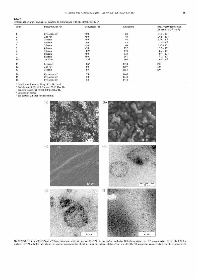
C. Vollmer et al. / Applied Catalysis A: General 425– 426 (2012) 178– 183 181
Table 1Hydrogenation of cyclohexene or benzene to cyclohexane with Rh-NP@stirring bar.a
Entry Substrate and run Conversion [%] Time [min] Activity (TOF) [mol prod-
uct × (mol Rh)−1 × h−1]
1 Cyclohexeneb >99 88 14.9 × 10³
2 2nd run >99 49 26.8 × 10³
3 3rd run >99 40 32.8 × 10³
4 4th run >99 48 27.3 × 10³
5 5th run >99 68 19.3 × 10³
6 6th run >99 132 9.9 × 10³
7 7th run 87d 139 8.2 × 10³
8 8th run >99 139 9.4 × 10³
9 9th run >99 161 8.1 × 10³
10 10th run 80d 160 6.6 × 10³
11 Benzenec 85d 1474 750
12 2nd run 90 1607 730
13 3rd run 90 2553 460
14 Cyclohexenee 78 1440
15 Cyclohexenee 20 1440
16 Cyclohexenee 53 1440
a Conditions: Rh metal 32 �g, 3.1 × 10⁻⁷ mol.b Cyclohexene 0.69 mL, 6.8 mmol, 75 ◦C, 4 bar H2.c benzene 0.6 mL, 6.8 mmol; 90 ◦C, 20 bar H2.d Conversion ceased.e See Section 2.4.4 for further details.
Fig. 2. SEM-pictures of Rh-NPs on a Teflon-coated magnetic stirring bar (Rh-NP@stirring bar) (a) and after 10 hydrogenation runs (b) in comparison to the blank Teflon
surface (c). TEM of Teflon flakes from the stirring bar coating for Rh-NP size analysis before catalysis (d, e) and after the 10th catalytic hydrogenation run of cyclohexene (f).
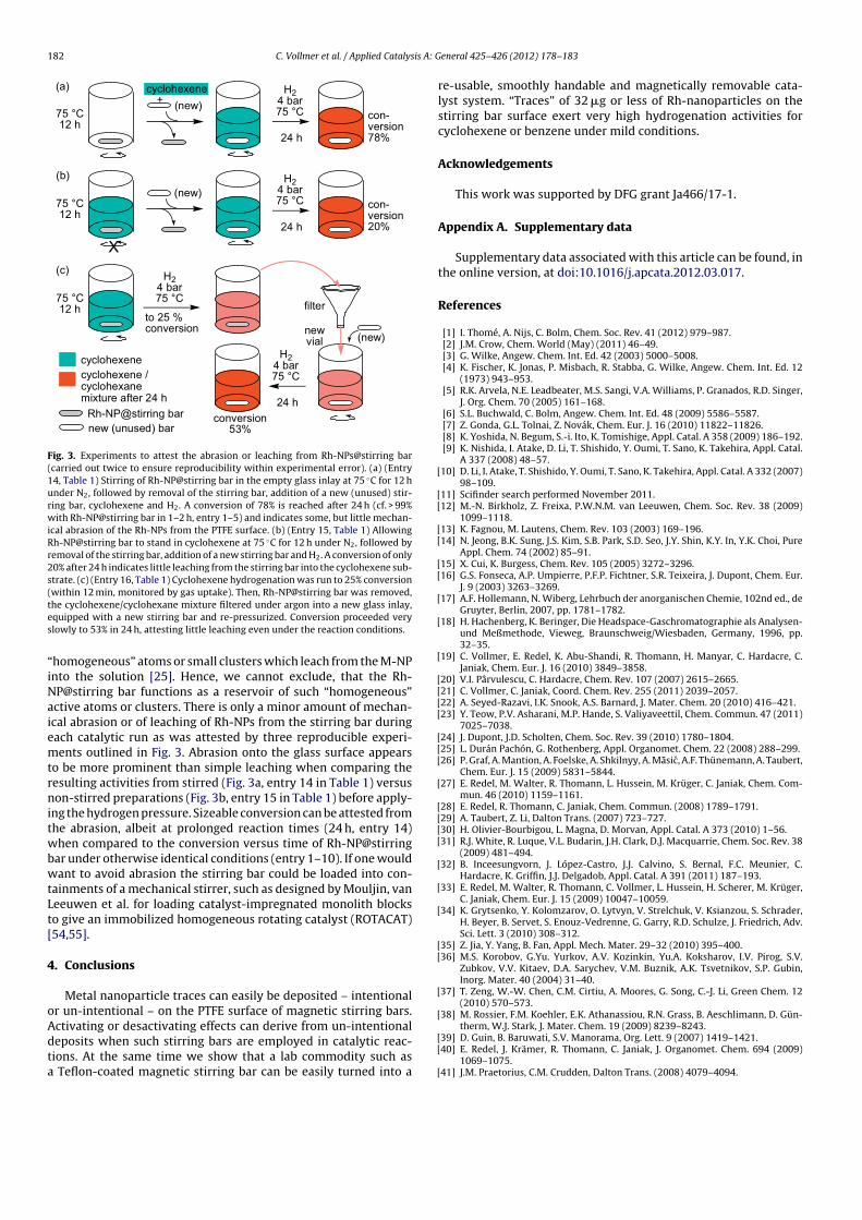
182 C. Vollmer et al. / Applied Catalysis A: General 425– 426 (2012) 178– 183
H24 bar75 °C75 °C
12 h
cyclohexene(new)
to 25 %conversion new
vial (new)
cyclohexenecyclohexene / cyclohexanemixture after 24 h
Rh-NP@stirring barnew (unused) bar
+con-version78%24 h
(a)
(b)
75 °C12 h
(new)
X
H24 bar75 °C con-
version20%24 h
(c)
75 °C12 h
H24 bar75 °C
H24 bar75 °C
24 h
filter
conversion53%
Fig. 3. Experiments to attest the abrasion or leaching from Rh-NPs@stirring bar
(carried out twice to ensure reproducibility within experimental error). (a) (Entry
14, Table 1) Stirring of Rh-NP@stirring bar in the empty glass inlay at 75 ◦C for 12 h
under N2, followed by removal of the stirring bar, addition of a new (unused) stir-
ring bar, cyclohexene and H2. A conversion of 78% is reached after 24 h (cf. > 99%
with Rh-NP@stirring bar in 1–2 h, entry 1–5) and indicates some, but little mechan-
ical abrasion of the Rh-NPs from the PTFE surface. (b) (Entry 15, Table 1) Allowing
Rh-NP@stirring bar to stand in cyclohexene at 75 ◦C for 12 h under N2, followed by
removal of the stirring bar, addition of a new stirring bar and H2. A conversion of only
20% after 24 h indicates little leaching from the stirring bar into the cyclohexene sub-
strate. (c) (Entry 16, Table 1) Cyclohexene hydrogenation was run to 25% conversion
(within 12 min, monitored by gas uptake). Then, Rh-NP@stirring bar was removed,
the cyclohexene/cyclohexane mixture filtered under argon into a new glass inlay,
equipped with a new stirring bar and re-pressurized. Conversion proceeded very
slowly to 53% in 24 h, attesting little leaching even under the reaction conditions.
“homogeneous” atoms or small clusters which leach from the M-NP
into the solution [25]. Hence, we cannot exclude, that the Rh-
NP@stirring bar functions as a reservoir of such “homogeneous”
active atoms or clusters. There is only a minor amount of mechan-
ical abrasion or of leaching of Rh-NPs from the stirring bar during
each catalytic run as was attested by three reproducible experi-
ments outlined in Fig. 3. Abrasion onto the glass surface appears
to be more prominent than simple leaching when comparing the
resulting activities from stirred (Fig. 3a, entry 14 in Table 1) versus
non-stirred preparations (Fig. 3b, entry 15 in Table 1) before apply-
ing the hydrogen pressure. Sizeable conversion can be attested from
the abrasion, albeit at prolonged reaction times (24 h, entry 14)
when compared to the conversion versus time of Rh-NP@stirring
bar under otherwise identical conditions (entry 1–10). If one would
want to avoid abrasion the stirring bar could be loaded into con-
tainments of a mechanical stirrer, such as designed by Mouljin, van
Leeuwen et al. for loading catalyst-impregnated monolith blocks
to give an immobilized homogeneous rotating catalyst (ROTACAT)
[54,55].
4. Conclusions
Metal nanoparticle traces can easily be deposited – intentional
or un-intentional – on the PTFE surface of magnetic stirring bars.
Activating or desactivating effects can derive from un-intentional
deposits when such stirring bars are employed in catalytic reac-
tions. At the same time we show that a lab commodity such as
a Teflon-coated magnetic stirring bar can be easily turned into a
re-usable, smoothly handable and magnetically removable cata-
lyst system. “Traces” of 32 �g or less of Rh-nanoparticles on the
stirring bar surface exert very high hydrogenation activities for
cyclohexene or benzene under mild conditions.
Acknowledgements
This work was supported by DFG grant Ja466/17-1.
Appendix A. Supplementary data
Supplementary data associated with this article can be found, in
the online version, at doi:10.1016/j.apcata.2012.03.017.
References
[1] I. Thomé, A. Nijs, C. Bolm, Chem. Soc. Rev. 41 (2012) 979–987.[2] J.M. Crow, Chem. World (May) (2011) 46–49.[3] G. Wilke, Angew. Chem. Int. Ed. 42 (2003) 5000–5008.[4] K. Fischer, K. Jonas, P. Misbach, R. Stabba, G. Wilke, Angew. Chem. Int. Ed. 12
(1973) 943–953.[5] R.K. Arvela, N.E. Leadbeater, M.S. Sangi, V.A. Williams, P. Granados, R.D. Singer,
J. Org. Chem. 70 (2005) 161–168.[6] S.L. Buchwald, C. Bolm, Angew. Chem. Int. Ed. 48 (2009) 5586–5587.[7] Z. Gonda, G.L. Tolnai, Z. Novák, Chem. Eur. J. 16 (2010) 11822–11826.[8] K. Yoshida, N. Begum, S.-i. Ito, K. Tomishige, Appl. Catal. A 358 (2009) 186–192.[9] K. Nishida, I. Atake, D. Li, T. Shishido, Y. Oumi, T. Sano, K. Takehira, Appl. Catal.
A 337 (2008) 48–57.[10] D. Li, I. Atake, T. Shishido, Y. Oumi, T. Sano, K. Takehira, Appl. Catal. A 332 (2007)
98–109.[11] Scifinder search performed November 2011.[12] M.-N. Birkholz, Z. Freixa, P.W.N.M. van Leeuwen, Chem. Soc. Rev. 38 (2009)
1099–1118.[13] K. Fagnou, M. Lautens, Chem. Rev. 103 (2003) 169–196.[14] N. Jeong, B.K. Sung, J.S. Kim, S.B. Park, S.D. Seo, J.Y. Shin, K.Y. In, Y.K. Choi, Pure
Appl. Chem. 74 (2002) 85–91.[15] X. Cui, K. Burgess, Chem. Rev. 105 (2005) 3272–3296.[16] G.S. Fonseca, A.P. Umpierre, P.F.P. Fichtner, S.R. Teixeira, J. Dupont, Chem. Eur.
J. 9 (2003) 3263–3269.[17] A.F. Hollemann, N. Wiberg, Lehrbuch der anorganischen Chemie, 102nd ed., de
Gruyter, Berlin, 2007, pp. 1781–1782.[18] H. Hachenberg, K. Beringer, Die Headspace-Gaschromatographie als Analysen-
und Meßmethode, Vieweg, Braunschweig/Wiesbaden, Germany, 1996, pp.32–35.
[19] C. Vollmer, E. Redel, K. Abu-Shandi, R. Thomann, H. Manyar, C. Hardacre, C.Janiak, Chem. Eur. J. 16 (2010) 3849–3858.
[20] V.I. Pârvulescu, C. Hardacre, Chem. Rev. 107 (2007) 2615–2665.[21] C. Vollmer, C. Janiak, Coord. Chem. Rev. 255 (2011) 2039–2057.[22] A. Seyed-Razavi, I.K. Snook, A.S. Barnard, J. Mater. Chem. 20 (2010) 416–421.[23] Y. Teow, P.V. Asharani, M.P. Hande, S. Valiyaveettil, Chem. Commun. 47 (2011)
7025–7038.[24] J. Dupont, J.D. Scholten, Chem. Soc. Rev. 39 (2010) 1780–1804.[25] L. Durán Pachón, G. Rothenberg, Appl. Organomet. Chem. 22 (2008) 288–299.[26] P. Graf, A. Mantion, A. Foelske, A. Shkilnyy, A. Masic, A.F. Thünemann, A. Taubert,
Chem. Eur. J. 15 (2009) 5831–5844.[27] E. Redel, M. Walter, R. Thomann, L. Hussein, M. Krüger, C. Janiak, Chem. Com-
mun. 46 (2010) 1159–1161.[28] E. Redel, R. Thomann, C. Janiak, Chem. Commun. (2008) 1789–1791.[29] A. Taubert, Z. Li, Dalton Trans. (2007) 723–727.[30] H. Olivier-Bourbigou, L. Magna, D. Morvan, Appl. Catal. A 373 (2010) 1–56.[31] R.J. White, R. Luque, V.L. Budarin, J.H. Clark, D.J. Macquarrie, Chem. Soc. Rev. 38
(2009) 481–494.[32] B. Inceesungvorn, J. López-Castro, J.J. Calvino, S. Bernal, F.C. Meunier, C.
Hardacre, K. Griffin, J.J. Delgadob, Appl. Catal. A 391 (2011) 187–193.[33] E. Redel, M. Walter, R. Thomann, C. Vollmer, L. Hussein, H. Scherer, M. Krüger,
C. Janiak, Chem. Eur. J. 15 (2009) 10047–10059.[34] K. Grytsenko, Y. Kolomzarov, O. Lytvyn, V. Strelchuk, V. Ksianzou, S. Schrader,
H. Beyer, B. Servet, S. Enouz-Vedrenne, G. Garry, R.D. Schulze, J. Friedrich, Adv.Sci. Lett. 3 (2010) 308–312.
[35] Z. Jia, Y. Yang, B. Fan, Appl. Mech. Mater. 29–32 (2010) 395–400.[36] M.S. Korobov, G.Yu. Yurkov, A.V. Kozinkin, Yu.A. Koksharov, I.V. Pirog, S.V.
Zubkov, V.V. Kitaev, D.A. Sarychev, V.M. Buznik, A.K. Tsvetnikov, S.P. Gubin,Inorg. Mater. 40 (2004) 31–40.
[37] T. Zeng, W.-W. Chen, C.M. Cirtiu, A. Moores, G. Song, C.-J. Li, Green Chem. 12(2010) 570–573.
[38] M. Rossier, F.M. Koehler, E.K. Athanassiou, R.N. Grass, B. Aeschlimann, D. Gün-therm, W.J. Stark, J. Mater. Chem. 19 (2009) 8239–8243.
[39] D. Guin, B. Baruwati, S.V. Manorama, Org. Lett. 9 (2007) 1419–1421.[40] E. Redel, J. Krämer, R. Thomann, C. Janiak, J. Organomet. Chem. 694 (2009)
1069–1075.[41] J.M. Praetorius, C.M. Crudden, Dalton Trans. (2008) 4079–4094.

C. Vollmer et al. / Applied Catalysis A: General 425– 426 (2012) 178– 183 183
[42] G. Ertl, H. Knözinger, J. Weitkamp, Handbook of Heterogeneous Catalysis, vol.9, Wiley-VCH, Weinheim, 2008.
[43] E.T. Silveira, A.P. Umpierre, L.M. Rossi, G. Machado, J. Morais, I.L.R. Baumvol,S.R. Teixeira, P.F.P. Fichtner, J. Dupont, Chem. Eur. J. 10 (2004) 3734–3740.
[44] L.M. Rossi, G. Machado, P.F.P. Fichtner, S.R. Teixeira, J. Dupont, Catal. Lett. 92(2004) 149–155.
[45] C.W. Scheeren, G. Machado, J. Dupont, P.F.P. Fichtner, S.G. Texeira, Inorg. Chem.42 (2003) 4738–4742.
[46] D. Marquardt, C. Vollmer, R. Thomann, P. Steurer, R. Mülhaupt, E. Redel, C.Janiak, Carbon 49 (2011) 1326–1332, Ru-NPs and Rh-NPs on graphene.
[47] S. Miao, Z. Liu, Z. Zhang, B. Han, Z. Miao, K. Ding, G. An, J. Phys. Chem. C 111(2007) 2185–2190, Rh-NPs on attapulgite support.
[48] M.J. Jacinto, P.K. Kiyohara, S.H. Masunaga, R.F. Jardim, L.M. Rossi, Appl. Catal. A338 (2008) 52–57, Rh-NPs on silica-coated magnetite NPs.
[49] L. Armelao, D.B.D. Amico, R. Braglia, F. Calderazzo, F. Garbassi, G. Marra, A.Merigo, Dalton Trans. (2009) 5559–5566, Pt-NPs on SiO2.
[50] R.M. Rioux, B.B. Hsu, M.E. Grass, H. Song, G.A. Somorjai, Catal. Lett. 126 (2008)10–19, Pt-NPs on SiO2.
[51] F. Lu, J. Liu, J. Xu, J. Mol. Catal. A: Chem. 271 (2007) 6–13.[52] A. Nowicki, V. Le Boulaire, A. Roucoux, Adv. Synth. Catal. 349 (2007)
2326–2330.[53] Y. Motoyama, M. Takasaki, S.-H. Yoon, I. Mochida, H. Nagashami, Org. Lett. 11
(2009) 5042–5045.[54] R.K. Edvinsson, M.J.J. Houterman, T. Vergunst, E. Grolman, J.A. Moulijn, AIChE J.
44 (1998) 2459–2464.[55] A.J. Sandee, R.S. Ubale, M. Makkee, J.N.H. Reek, P.C.J. Kamer, J.A. Moulijn,
P.W.N.M. van Leeuwen, Adv. Synth. Catal. 343 (2001) 201–206.
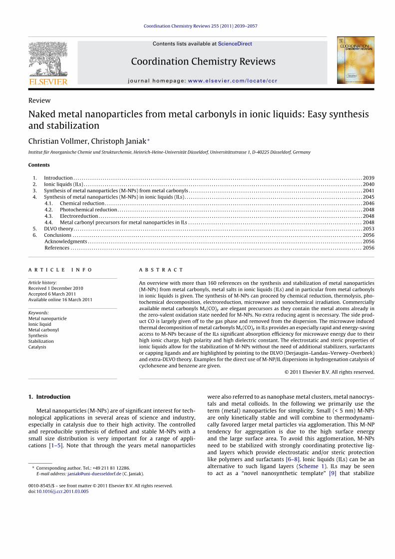
Coordination Chemistry Reviews 255 (2011) 2039– 2057
Contents lists available at ScienceDirect
Coordination Chemistry Reviews
jo ur n al homepage: www.elsev ier .com/ locate /ccr
Review
Naked metal nanoparticles from metal carbonyls in ionic liquids: Easy synthesis
and stabilization
Christian Vollmer, Christoph Janiak ∗
Institut für Anorganische Chemie und Strukturchemie, Heinrich-Heine-Universität Düsseldorf, Universitätsstrasse 1, D-40225 Düsseldorf, Germany
Contents
1. Introduction . . . . . . . . . . . . . . . . . . . . . . . . . . . . . . . . . . . . . . . . . . . . . . . . . . . . . . . . . . . . . . . . . . . . . . . . . . . . . . . . . . . . . . . . . . . . . . . . . . . . . . . . . . . . . . . . . . . . . . . . . . . . . . . . . . . . . . . . . . 20392. Ionic liquids (ILs) . . . . . . . . . . . . . . . . . . . . . . . . . . . . . . . . . . . . . . . . . . . . . . . . . . . . . . . . . . . . . . . . . . . . . . . . . . . . . . . . . . . . . . . . . . . . . . . . . . . . . . . . . . . . . . . . . . . . . . . . . . . . . . . . . . . . . 20403. Synthesis of metal nanoparticles (M-NPs) from metal carbonyls . . . . . . . . . . . . . . . . . . . . . . . . . . . . . . . . . . . . . . . . . . . . . . . . . . . . . . . . . . . . . . . . . . . . . . . . . . . . . . . . . . . 20414. Synthesis of metal nanoparticles (M-NPs) in ionic liquids (ILs) . . . . . . . . . . . . . . . . . . . . . . . . . . . . . . . . . . . . . . . . . . . . . . . . . . . . . . . . . . . . . . . . . . . . . . . . . . . . . . . . . . . . . 2045
4.1. Chemical reduction . . . . . . . . . . . . . . . . . . . . . . . . . . . . . . . . . . . . . . . . . . . . . . . . . . . . . . . . . . . . . . . . . . . . . . . . . . . . . . . . . . . . . . . . . . . . . . . . . . . . . . . . . . . . . . . . . . . . . . . . . . . 20464.2. Photochemical reduction . . . . . . . . . . . . . . . . . . . . . . . . . . . . . . . . . . . . . . . . . . . . . . . . . . . . . . . . . . . . . . . . . . . . . . . . . . . . . . . . . . . . . . . . . . . . . . . . . . . . . . . . . . . . . . . . . . . . . 20484.3. Electroreduction . . . . . . . . . . . . . . . . . . . . . . . . . . . . . . . . . . . . . . . . . . . . . . . . . . . . . . . . . . . . . . . . . . . . . . . . . . . . . . . . . . . . . . . . . . . . . . . . . . . . . . . . . . . . . . . . . . . . . . . . . . . . . . 20484.4. Metal carbonyl precursors for metal nanoparticles in ILs . . . . . . . . . . . . . . . . . . . . . . . . . . . . . . . . . . . . . . . . . . . . . . . . . . . . . . . . . . . . . . . . . . . . . . . . . . . . . . . . . . . 2048
5. DLVO theory . . . . . . . . . . . . . . . . . . . . . . . . . . . . . . . . . . . . . . . . . . . . . . . . . . . . . . . . . . . . . . . . . . . . . . . . . . . . . . . . . . . . . . . . . . . . . . . . . . . . . . . . . . . . . . . . . . . . . . . . . . . . . . . . . . . . . . . . . . 20536. Conclusions . . . . . . . . . . . . . . . . . . . . . . . . . . . . . . . . . . . . . . . . . . . . . . . . . . . . . . . . . . . . . . . . . . . . . . . . . . . . . . . . . . . . . . . . . . . . . . . . . . . . . . . . . . . . . . . . . . . . . . . . . . . . . . . . . . . . . . . . . . 2056
Acknowledgments . . . . . . . . . . . . . . . . . . . . . . . . . . . . . . . . . . . . . . . . . . . . . . . . . . . . . . . . . . . . . . . . . . . . . . . . . . . . . . . . . . . . . . . . . . . . . . . . . . . . . . . . . . . . . . . . . . . . . . . . . . . . . . . . . . . 2056References . . . . . . . . . . . . . . . . . . . . . . . . . . . . . . . . . . . . . . . . . . . . . . . . . . . . . . . . . . . . . . . . . . . . . . . . . . . . . . . . . . . . . . . . . . . . . . . . . . . . . . . . . . . . . . . . . . . . . . . . . . . . . . . . . . . . . . . . . . . 2056
a r t i c l e i n f o
Article history:
Received 1 December 2010
Accepted 6 March 2011
Available online 16 March 2011
Keywords:
Metal nanoparticle
Ionic liquid
Metal carbonyl
Synthesis
Stabilization
Catalysis
a b s t r a c t
An overview with more than 160 references on the synthesis and stabilization of metal nanoparticles
(M-NPs) from metal carbonyls, metal salts in ionic liquids (ILs) and in particular from metal carbonyls
in ionic liquids is given. The synthesis of M-NPs can proceed by chemical reduction, thermolysis, pho-
tochemical decomposition, electroreduction, microwave and sonochemical irradiation. Commercially
available metal carbonyls Mx(CO)y are elegant precursors as they contain the metal atoms already in
the zero-valent oxidation state needed for M-NPs. No extra reducing agent is necessary. The side prod-
uct CO is largely given off to the gas phase and removed from the dispersion. The microwave induced
thermal decomposition of metal carbonyls Mx(CO)y in ILs provides an especially rapid and energy-saving
access to M-NPs because of the ILs significant absorption efficiency for microwave energy due to their
high ionic charge, high polarity and high dielectric constant. The electrostatic and steric properties of
ionic liquids allow for the stabilization of M-NPs without the need of additional stabilizers, surfactants
or capping ligands and are highlighted by pointing to the DLVO (Derjaugin–Landau–Verwey–Overbeek)
and extra-DLVO theory. Examples for the direct use of M-NP/IL dispersions in hydrogenation catalysis of
cyclohexene and benzene are given.
© 2011 Elsevier B.V. All rights reserved.
1. Introduction
Metal nanoparticles (M-NPs) are of significant interest for tech-
nological applications in several areas of science and industry,
especially in catalysis due to their high activity. The controlled
and reproducible synthesis of defined and stable M-NPs with a
small size distribution is very important for a range of appli-
cations [1–5]. Note that through the years metal nanoparticles
∗ Corresponding author. Tel.: +49 211 81 12286.
E-mail address: [email protected] (C. Janiak).
were also referred to as nanophase metal clusters, metal nanocrys-
tals and metal colloids. In the following we primarily use the
term (metal) nanoparticles for simplicity. Small (< 5 nm) M-NPs
are only kinetically stable and will combine to thermodynami-
cally favored larger metal particles via agglomeration. This M-NP
tendency for aggregation is due to the high surface energy
and the large surface area. To avoid this agglomeration, M-NPs
need to be stabilized with strongly coordinating protective lig-
and layers which provide electrostatic and/or steric protection
like polymers and surfactants [6–8]. Ionic liquids (ILs) can be an
alternative to such ligand layers (Scheme 1). ILs may be seen
to act as a “novel nanosynthetic template” [9] that stabilize
0010-8545/$ – see front matter © 2011 Elsevier B.V. All rights reserved.doi:10.1016/j.ccr.2011.03.005
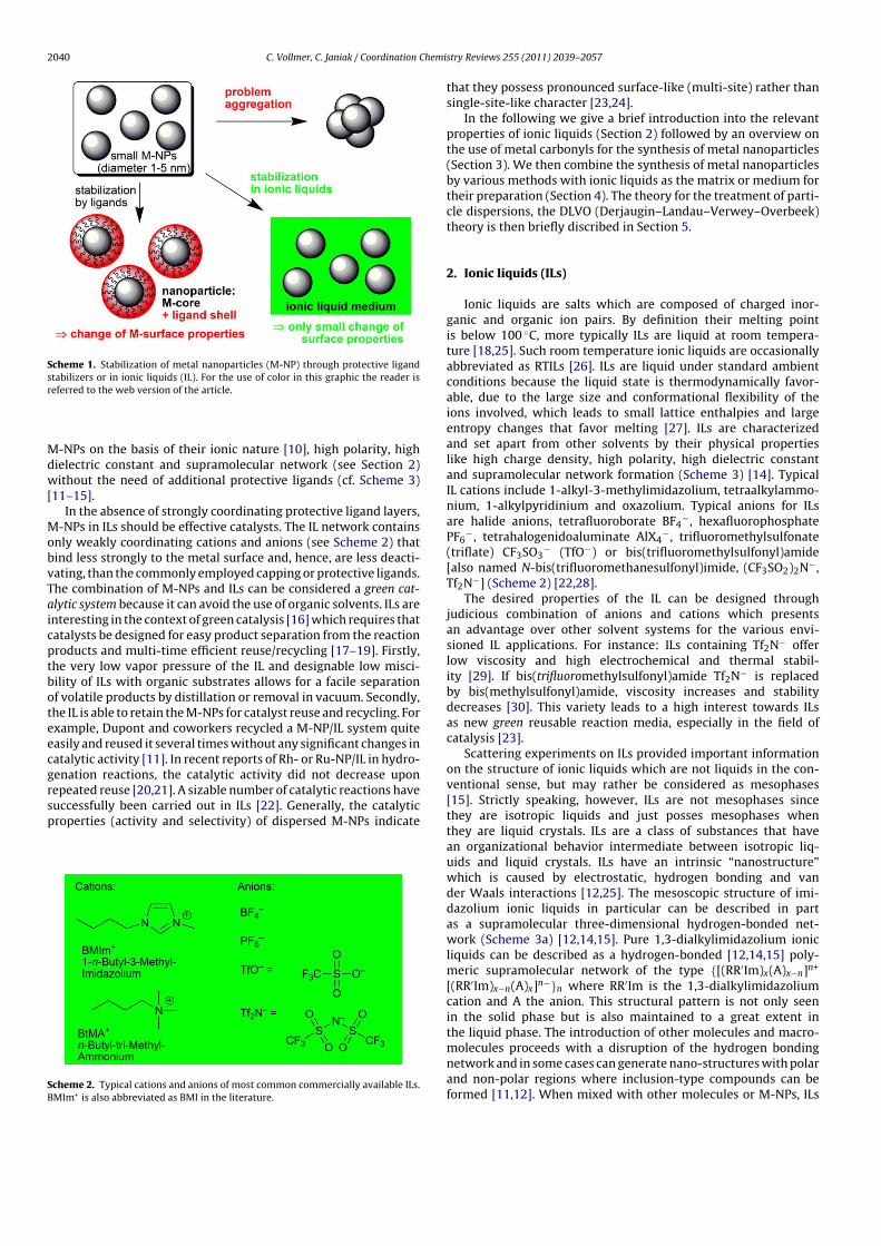
2040 C. Vollmer, C. Janiak / Coordination Chemistry Reviews 255 (2011) 2039– 2057
Scheme 1. Stabilization of metal nanoparticles (M-NP) through protective ligand
stabilizers or in ionic liquids (IL). For the use of color in this graphic the reader is
referred to the web version of the article.
M-NPs on the basis of their ionic nature [10], high polarity, high
dielectric constant and supramolecular network (see Section 2)
without the need of additional protective ligands (cf. Scheme 3)
[11–15].
In the absence of strongly coordinating protective ligand layers,
M-NPs in ILs should be effective catalysts. The IL network contains
only weakly coordinating cations and anions (see Scheme 2) that
bind less strongly to the metal surface and, hence, are less deacti-
vating, than the commonly employed capping or protective ligands.
The combination of M-NPs and ILs can be considered a green cat-
alytic system because it can avoid the use of organic solvents. ILs are
interesting in the context of green catalysis [16] which requires that
catalysts be designed for easy product separation from the reaction
products and multi-time efficient reuse/recycling [17–19]. Firstly,
the very low vapor pressure of the IL and designable low misci-
bility of ILs with organic substrates allows for a facile separation
of volatile products by distillation or removal in vacuum. Secondly,
the IL is able to retain the M-NPs for catalyst reuse and recycling. For
example, Dupont and coworkers recycled a M-NP/IL system quite
easily and reused it several times without any significant changes in
catalytic activity [11]. In recent reports of Rh- or Ru-NP/IL in hydro-
genation reactions, the catalytic activity did not decrease upon
repeated reuse [20,21]. A sizable number of catalytic reactions have
successfully been carried out in ILs [22]. Generally, the catalytic
properties (activity and selectivity) of dispersed M-NPs indicate
Scheme 2. Typical cations and anions of most common commercially available ILs.
BMIm+ is also abbreviated as BMI in the literature.
that they possess pronounced surface-like (multi-site) rather than
single-site-like character [23,24].
In the following we give a brief introduction into the relevant
properties of ionic liquids (Section 2) followed by an overview on
the use of metal carbonyls for the synthesis of metal nanoparticles
(Section 3). We then combine the synthesis of metal nanoparticles
by various methods with ionic liquids as the matrix or medium for
their preparation (Section 4). The theory for the treatment of parti-
cle dispersions, the DLVO (Derjaugin–Landau–Verwey–Overbeek)
theory is then briefly discribed in Section 5.
2. Ionic liquids (ILs)
Ionic liquids are salts which are composed of charged inor-
ganic and organic ion pairs. By definition their melting point
is below 100 ◦C, more typically ILs are liquid at room tempera-
ture [18,25]. Such room temperature ionic liquids are occasionally
abbreviated as RTILs [26]. ILs are liquid under standard ambient
conditions because the liquid state is thermodynamically favor-
able, due to the large size and conformational flexibility of the
ions involved, which leads to small lattice enthalpies and large
entropy changes that favor melting [27]. ILs are characterized
and set apart from other solvents by their physical properties
like high charge density, high polarity, high dielectric constant
and supramolecular network formation (Scheme 3) [14]. Typical
IL cations include 1-alkyl-3-methylimidazolium, tetraalkylammo-
nium, 1-alkylpyridinium and oxazolium. Typical anions for ILs
are halide anions, tetrafluoroborate BF4−, hexafluorophosphate
PF6−, tetrahalogenidoaluminate AlX4
−, trifluoromethylsulfonate
(triflate) CF3SO3− (TfO−) or bis(trifluoromethylsulfonyl)amide
[also named N-bis(trifluoromethanesulfonyl)imide, (CF3SO2)2N−,
Tf2N−] (Scheme 2) [22,28].
The desired properties of the IL can be designed through
judicious combination of anions and cations which presents
an advantage over other solvent systems for the various envi-
sioned IL applications. For instance: ILs containing Tf2N− offer
low viscosity and high electrochemical and thermal stabil-
ity [29]. If bis(trifluoromethylsulfonyl)amide Tf2N− is replaced
by bis(methylsulfonyl)amide, viscosity increases and stability
decreases [30]. This variety leads to a high interest towards ILs
as new green reusable reaction media, especially in the field of
catalysis [23].
Scattering experiments on ILs provided important information
on the structure of ionic liquids which are not liquids in the con-
ventional sense, but may rather be considered as mesophases
[15]. Strictly speaking, however, ILs are not mesophases since
they are isotropic liquids and just posses mesophases when
they are liquid crystals. ILs are a class of substances that have
an organizational behavior intermediate between isotropic liq-
uids and liquid crystals. ILs have an intrinsic “nanostructure”
which is caused by electrostatic, hydrogen bonding and van
der Waals interactions [12,25]. The mesoscopic structure of imi-
dazolium ionic liquids in particular can be described in part
as a supramolecular three-dimensional hydrogen-bonded net-
work (Scheme 3a) [12,14,15]. Pure 1,3-dialkylimidazolium ionic
liquids can be described as a hydrogen-bonded [12,14,15] poly-
meric supramolecular network of the type {[(RR′Im)x(A)x−n]n+
[(RR′Im)x−n(A)x]n−}n where RR′Im is the 1,3-dialkylimidazolium
cation and A the anion. This structural pattern is not only seen
in the solid phase but is also maintained to a great extent in
the liquid phase. The introduction of other molecules and macro-
molecules proceeds with a disruption of the hydrogen bonding
network and in some cases can generate nano-structures with polar
and non-polar regions where inclusion-type compounds can be
formed [11,12]. When mixed with other molecules or M-NPs, ILs
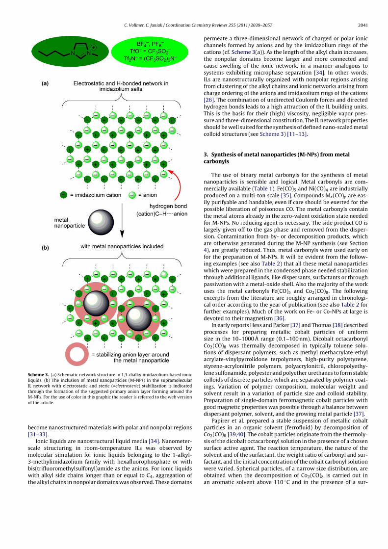
C. Vollmer, C. Janiak / Coordination Chemistry Reviews 255 (2011) 2039– 2057 2041
Scheme 3. (a) Schematic network structure in 1,3-dialkylimidazolium-based ionic
liquids. (b) The inclusion of metal nanoparticles (M-NPs) in the supramolecular
IL network with electrostatic and steric (=electrosteric) stabilization is indicated
through the formation of the suggested primary anion layer forming around the
M-NPs. For the use of color in this graphic the reader is referred to the web version
of the article.
become nanostructured materials with polar and nonpolar regions
[31–33].
Ionic liquids are nanostructural liquid media [34]. Nanometer-
scale structuring in room-temperature ILs was observed by
molecular simulation for ionic liquids belonging to the 1-alkyl-
3-methylimidazolium family with hexafluorophosphate or with
bis(trifluoromethylsulfonyl)amide as the anions. For ionic liquids
with alkyl side chains longer than or equal to C4, aggregation of
the alkyl chains in nonpolar domains was observed. These domains
permeate a three-dimensional network of charged or polar ionic
channels formed by anions and by the imidazolium rings of the
cations (cf. Scheme 3(a)). As the length of the alkyl chain increases,
the nonpolar domains become larger and more connected and
cause swelling of the ionic network, in a manner analogous to
systems exhibiting microphase separation [34]. In other words,
ILs are nanostructurally organized with nonpolar regions arising
from clustering of the alkyl chains and ionic networks arising from
charge ordering of the anions and imidazolium rings of the cations
[26]. The combination of undirected Coulomb forces and directed
hydrogen bonds leads to a high attraction of the IL building units.
This is the basis for their (high) viscosity, negligible vapor pres-
sure and three-dimensional constitution. The IL network properties
should be well suited for the synthesis of defined nano-scaled metal
colloid structures (see Scheme 3) [11–13].
3. Synthesis of metal nanoparticles (M-NPs) from metalcarbonyls
The use of binary metal carbonyls for the synthesis of metal
nanoparticles is sensible and logical. Metal carbonyls are com-
mercially available (Table 1). Fe(CO)5 and Ni(CO)4 are industrially
produced on a multi-ton scale [35]. Compounds Mx(CO)y are eas-
ily purifyable and handable, even if care should be exerted for the
possible liberation of poisonous CO. The metal carbonyls contain
the metal atoms already in the zero-valent oxidation state needed
for M-NPs. No reducing agent is necessary. The side product CO is
largely given off to the gas phase and removed from the disper-
sion. Contamination from by- or decomposition products, which
are otherwise generated during the M-NP synthesis (see Section
4), are greatly reduced. Thus, metal carbonyls were used early on
for the preparation of M-NPs. It will be evident from the follow-
ing examples (see also Table 2) that all these metal nanoparticles
which were prepared in the condensed phase needed stabilization
through additional ligands, like dispersants, surfactants or through
passivation with a metal-oxide shell. Also the majority of the work
uses the metal carbonyls Fe(CO)5 and Co2(CO)8. The following
excerpts from the literature are roughly arranged in chronologi-
cal order according to the year of publication (see also Table 2 for
further examples). Much of the work on Fe- or Co-NPs at large is
devoted to their magnetism [36].
In early reports Hess and Parker [37] and Thomas [38] described
processes for preparing metallic cobalt particles of uniform
size in the 10–1000 A range (0.1–100 nm). Dicobalt octacarbonyl
Co2(CO)8 was thermally decomposed in typically toluene solu-
tions of dispersant polymers, such as methyl methacrylate-ethyl
acrylate-vinylpyrrolidone terpolymers, high-purity polystyrene,
styrene-acrylonitrile polymers, polyacrylonitril, chloropolyethy-
lene sulfonamide, polyester and polyether urethanes to form stable
colloids of discrete particles which are separated by polymer coat-
ings. Variation of polymer composition, molecular weight and
solvent result in a variation of particle size and colloid stability.
Preparation of single-domain ferromagnetic cobalt particles with
good magnetic properties was possible through a balance between
dispersant polymer, solvent, and the growing metal particle [37].
Papirer et al. prepared a stable suspension of metallic cobalt
particles in an organic solvent (ferrofluid) by decomposition of
Co2(CO)8 [39,40]. The cobalt particles originate from the thermoly-
sis of the dicobalt octacarbonyl solution in the presence of a chosen
surface active agent. The reaction temperature, the nature of the
solvent and of the surfactant, the weight ratio of carbonyl and sur-
factant, and the initial concentration of the cobalt carbonyl solution
were varied. Spherical particles, of a narrow size distribution, are
obtained when the decomposition of Co2(CO)8 is carried out in
an aromatic solvent above 110 ◦C and in the presence of a sur-
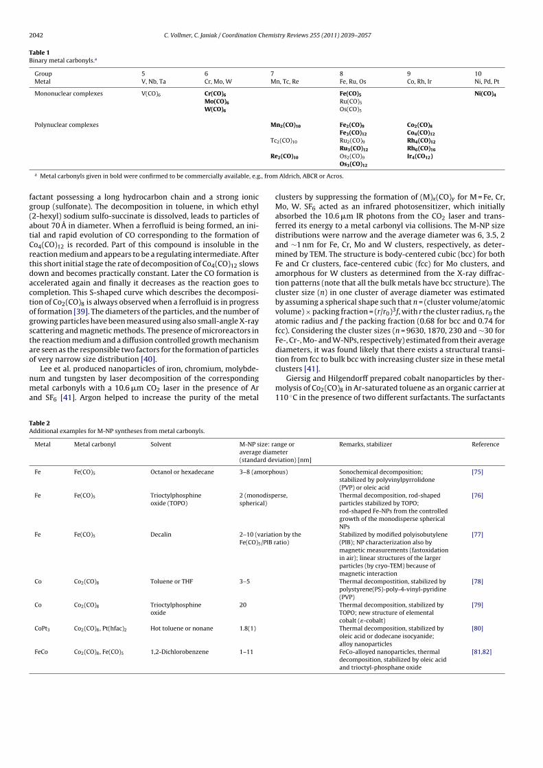
2042 C. Vollmer, C. Janiak / Coordination Chemistry Reviews 255 (2011) 2039– 2057
Table 1Binary metal carbonyls.a
Group 5 6 7 8 9 10
Metal V, Nb, Ta Cr, Mo, W Mn, Tc, Re Fe, Ru, Os Co, Rh, Ir Ni, Pd, Pt
Mononuclear complexes V(CO)6 Cr(CO)6 Fe(CO)5 Ni(CO)4
Mo(CO)6 Ru(CO)5
W(CO)6 Os(CO)5
Polynuclear complexes Mn2(CO)10 Fe2(CO)9 Co2(CO)8
Fe3(CO)12 Co4(CO)12
Tc2(CO)10 Ru2(CO)9 Rh4(CO)12
Ru3(CO)12 Rh6(CO)16
Re2(CO)10 Os2(CO)9 Ir4(CO12)Os3(CO)12
a Metal carbonyls given in bold were confirmed to be commercially available, e.g., from Aldrich, ABCR or Acros.
factant possessing a long hydrocarbon chain and a strong ionic
group (sulfonate). The decomposition in toluene, in which ethyl
(2-hexyl) sodium sulfo-succinate is dissolved, leads to particles of
about 70 A in diameter. When a ferrofluid is being formed, an ini-
tial and rapid evolution of CO corresponding to the formation of
Co4(CO)12 is recorded. Part of this compound is insoluble in the
reaction medium and appears to be a regulating intermediate. After
this short initial stage the rate of decomposition of Co4(CO)12 slows
down and becomes practically constant. Later the CO formation is
accelerated again and finally it decreases as the reaction goes to
completion. This S-shaped curve which describes the decomposi-
tion of Co2(CO)8 is always observed when a ferrofluid is in progress
of formation [39]. The diameters of the particles, and the number of
growing particles have been measured using also small-angle X-ray
scattering and magnetic methods. The presence of microreactors in
the reaction medium and a diffusion controlled growth mechanism
are seen as the responsible two factors for the formation of particles
of very narrow size distribution [40].
Lee et al. produced nanoparticles of iron, chromium, molybde-
num and tungsten by laser decomposition of the corresponding
metal carbonyls with a 10.6 �m CO2 laser in the presence of Ar
and SF6 [41]. Argon helped to increase the purity of the metal
clusters by suppressing the formation of (M)x(CO)y for M = Fe, Cr,
Mo, W. SF6 acted as an infrared photosensitizer, which initially
absorbed the 10.6 �m IR photons from the CO2 laser and trans-
ferred its energy to a metal carbonyl via collisions. The M-NP size
distributions were narrow and the average diameter was 6, 3.5, 2
and ∼1 nm for Fe, Cr, Mo and W clusters, respectively, as deter-
mined by TEM. The structure is body-centered cubic (bcc) for both
Fe and Cr clusters, face-centered cubic (fcc) for Mo clusters, and
amorphous for W clusters as determined from the X-ray diffrac-
tion patterns (note that all the bulk metals have bcc structure). The
cluster size (n) in one cluster of average diameter was estimated
by assuming a spherical shape such that n = (cluster volume/atomic
volume) × packing fraction = (r/r0)3f, with r the cluster radius, r0 the
atomic radius and f the packing fraction (0.68 for bcc and 0.74 for
fcc). Considering the cluster sizes (n = 9630, 1870, 230 and ∼30 for
Fe-, Cr-, Mo- and W-NPs, respectively) estimated from their average
diameters, it was found likely that there exists a structural transi-
tion from fcc to bulk bcc with increasing cluster size in these metal
clusters [41].
Giersig and Hilgendorff prepared cobalt nanoparticles by ther-
molysis of Co2(CO)8 in Ar-saturated toluene as an organic carrier at
110 ◦C in the presence of two different surfactants. The surfactants
Table 2Additional examples for M-NP syntheses from metal carbonyls.
Metal Metal carbonyl Solvent M-NP size: range or
average diameter
(standard deviation) [nm]
Remarks, stabilizer Reference
Fe Fe(CO)5 Octanol or hexadecane 3–8 (amorphous) Sonochemical decomposition;
stabilized by polyvinylpyrrolidone
(PVP) or oleic acid
[75]
Fe Fe(CO)5 Trioctylphosphine
oxide (TOPO)
2 (monodisperse,
spherical)
Thermal decomposition, rod-shaped
particles stabilized by TOPO;
rod-shaped Fe-NPs from the controlled
growth of the monodisperse spherical
NPs
[76]
Fe Fe(CO)5 Decalin 2–10 (variation by the
Fe(CO)5/PIB ratio)
Stabilized by modified polyisobutylene
(PIB); NP characterization also by
magnetic measurements (fastoxidation
in air); linear structures of the larger
particles (by cryo-TEM) because of
magnetic interaction
[77]
Co Co2(CO)8 Toluene or THF 3–5 Thermal decompostition, stabilized by
polystyrene(PS)-poly-4-vinyl-pyridine
(PVP)
[78]
Co Co2(CO)8 Trioctylphosphine
oxide
20 Thermal decomposition, stabilized by
TOPO; new structure of elemental
cobalt (�-cobalt)
[79]
CoPt3 Co2(CO)8, Pt(hfac)2 Hot toluene or nonane 1.8(1) Thermal decomposition, stabilized by
oleic acid or dodecane isocyanide;
alloy nanoparticles
[80]
FeCo Co2(CO)8, Fe(CO)5 1,2-Dichlorobenzene 1–11 FeCo-alloyed nanoparticles, thermal
decomposition, stabilized by oleic acid
and trioctyl-phosphane oxide
[81,82]
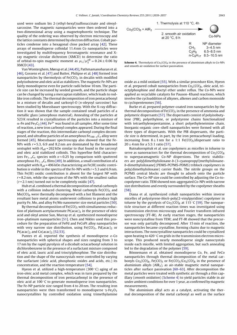
C. Vollmer, C. Janiak / Coordination Chemistry Reviews 255 (2011) 2039– 2057 2043
used were sodium bis 2-(ethyl-hexyl)sulfosuccinate and oleoyl-
sarcosine. The magnetic nanoparticles were then ordered into a
two-dimensional array using a magnetophoretic technique. The
quality of the ordering was observed by electron microscopy and
the lattice constants determined by electron diffraction. Cobalt par-
ticles condense into a hexagonal close packed array [42]. These
arrays of monodisperse colloidal 11.4 nm Co nanoparticles were
investigated by multifrequency ferromagnetic resonance and X-
ray magnetic circular dichroism (XMCD) to determine the ratio
of orbital-to-spin magnetic moment as �L/�effS
= 0.24 ± 0.06 by
XMCD [43].
Van Wonterghem, Mørup et al. [44,45], Pathmamanoharan et al.
[46], Gossens et al. [47] and Butter, Philipse et al. [48] formed iron
nanoparticles by thermolysis of Fe(CO)5 in decalin with modified
polyisobutene and oleic acid as stabilizers. The magnetic Fe-NPs are
fairly monodisperse even for particle radii below 10 nm. The parti-
cle size can be increased by seeded growth, and the particle shape
can be changed by using a mercaptan stabilizer, which leads to rod-
like iron colloids. The thermal decomposition of iron pentacarbonyl
in a mixture of decalin and sarkosyl-O (n-oleyoyl sarcosine) has
been studied by Moessbauer spectroscopy. With the X-ray diffrac-
tion it was shown that the sample contained small particles of a
metallic glass (amorphous material). Annealing of the particles at
523 K resulted in crystallization of the particles into a mixture of
�-Fe and Fe5C2 [44]. Fe2+ was found in all samples. After some time
of reaction, a new iron carbonyl complex appeared. During the final
stages of the reaction, this intermediate carbonyl complex decom-
posed, and ultrafine particles of an amorphous Fe100−xCx alloy were
formed [45]. Moessbauer spectroscopy also showed that the Fe-
NPs with r = 5.3, 6.9 and 8.2 nm are dominated by the broadened
sextuplet with Heff = 262 kOe similar to that found in the sarcosyl
and oleic acid stabilized colloids. This hyperfine field character-
izes Fe1−xCx species with x ≈ 0.25 by comparison with sputtered
amorphous Fe1−xCx films [49]. In addition, a small contribution of a
sextuplet with Heff = 496 kOe characterizing an Fe(III) oxidic contri-
bution is visible in the spectra of the Fe-NPs with r = 5.3 and 6.9 nm.
This Fe(III) oxidic contribution is absent for the largest NP with
r = 8.2 nm, while the spectrum of the NPs with the smallest radius
(r = 2.1 nm) turned out to be completely oxidic [47].
Huh et al. combined a thermal decomposition of metal carbonyls
with a collision induced clustering. Metal carbonyls Fe(CO)5 and
Mo(CO)6 were thermally decomposed with a hot filament and the
resultant bare metal atoms underwent collisions to produce high
purity Fe, Mo, and alloy Fe/Mo nanometer size metal particles [50].
By thermal decomposition of Fe(CO)5 with simultaneous reduc-
tion of platinum acetylacetonate Pt(acac)2 in the presence of oleic
acid and oleyl amine Sun, Murray et al. synthesized monodisperse
iron–platinum nanoparticles [51]. Chen and Nikles used this pro-
cedure for the preparation of FePd and FeCoPt alloy nanoparticles
with very narrow size distribution, using Fe(CO)5, Pd(acac)2 or
Pt(acac)2 and Co(acac)2 [52,53].
Puntes et al. reported the synthesis of monodisperse �-Co
nanoparticles with spherical shapes and sizes ranging from 3 to
17 nm by the rapid pyrolysis of a dicobalt octacarbonyl solution in
dichlorobenzene in the presence of a surfactant mixture composed
of oleic acid, lauric acid and trioctylphosphine. The size distribu-
tion and the shape of the nanocrystals were controlled by varying
the surfactant (oleic acid, phosphonic oxides and acids, etc.) its
concentration, and the reaction temperature [54].
Hyeon et al. utilized a high-temperature (300 ◦C) aging of an
iron-oleic acid metal complex, which was in turn prepared by the
thermal decomposition of iron pentacarbonyl in the presence of
oleic acid at 100 ◦C to generate monodisperse iron nanoparticles.
The Fe-NP particle size ranged from 4 to 20 nm. The resulting iron
nanoparticles were then transformed to monodisperse �-Fe2O3
nanocrystallites by controlled oxidation using trimethylamine
Scheme 4. Thermolysis of Co2(CO)8 in the presence of aluminium alkyls to Co-NPs
and smooth air oxidation for surface passivation.
oxide as a mild oxidant [55]. With a similar procedure Kim, Hyeon
et al. prepared cobalt nanoparticles from Co2(CO)8, oleic acid, tri-
octylphosphine and dioctyl ether under reflux. The Co-NPs were
applied as recyclable catalysts for Pauson–Khand reactions, which
involve the cycloaddition of alkynes, alkenes and carbon monoxide
to cyclopentenones [56].
Burke et al. prepared polymer-coated iron nanoparticles by the
thermal decomposition of Fe(CO)5 in the presence of ammonia and
polymeric dispersants [57]. The dispersants consist of polyisobuty-
lene (PIB), polyethylene, or polystyrene chains functionalized
with tetraethylenepentamine, a short polyethyleneimine chain.
Inorganic-organic core–shell nanoparticles were formed with all
three types of dispersants. With the PIB dispersants, the parti-
cle size is determined, in part, by the iron pentacarbonyl loading,
increasing from 8 ± 1 nm for a 1:1 Fe(CO)5/dispersant ratio to
20 ± 4 nm for a 5.5:1 ratio [57].
Rutnakornpituk et al. use copolymers as micelles in toluene to
serve as nanoreactors for the thermal decomposition of Co2(CO)8
to superparamagnetic Co-NP dispersions. The steric stabiliz-
ers are poly[dimethylsiloxane-b-(3-cyanopropyl)methylsiloxane-
b-dimethylsiloxane] (PDMS-PCPMS-PDMS) triblock copolymers in
poly(dimethylsiloxane) carrier fluids. The nitrile groups on the
PCPMS central blocks are thought to adsorb onto the particle
surface. The Co-NP size could be controlled by adjusting the Co-to-
copolymer ratio. TEM showed non-aggregated Co-NPs with narrow
size distributions and evenly surrounded by the copolymer sheaths
[58].
Diana et al. synthesized cobalt nanoparticles within inverse
micelles of polystyrene-block-poly(2-vinylpyridine) copolymer in
toluene by the pyrolysis of Co2(CO)8 at 115 ◦C [59]. The nanopar-
ticle structure at different reaction times was investigated using
transmission electron microscopy and Fourier transform infrared
spectroscopy (FT-IR). At early reaction stages, the nanoparticles
were noncrystalline from TEM; and FT-IR showed that the precur-
sor was only partially decomposed. After 15 min of reaction, the
nanoparticles became crystalline, forming chains due to magnetic
interactions. The noncrystalline nanoparticles could be crystallized
upon heating to 420 ◦C on grids in the transmission electron micro-
scope. This produced nearly monodisperse single nanocrystals
inside each micelle, with limited aggregation, but such annealing
led to the degradation of the polymer [59].
Bönnemann et al. obtained monodisperse Co, Fe, and FeCo
nanoparticles through thermal decomposition of the metal car-
bonyls Co2(CO)8, Fe(CO)5 or Fe(CO)5/Co2(CO)8 in the presence of
aluminium alkyls (AlR3), as air-stable magnetic metal nanopar-
ticles after surface passivation [60–63]. After decomposition the
metal particles were treated with synthetic air through a thin cap-
illary (smooth oxidation) (Scheme 4) to yield particles stable in air
under ambient conditions for over 1 year, as confirmed by magnetic
measurements.
The aluminium alkyl acts as a catalyst, activating the ther-
mal decomposition of the metal carbonyl as well as the surface
2044 C. Vollmer, C. Janiak / Coordination Chemistry Reviews 255 (2011) 2039– 2057
passivation during the smooth oxidation. The resulting particles
strongly depend on the alkyl chain length R of the aluminium
alkyl and the Co2(CO)8 to AlR3 ratio. Monodisperse Co nanopar-
ticles, 3–4.5, 6.5–8.5 and 8.5–10.5 nm in diameter, were obtained
for Al(CH3)3, Al(C2H5)3 and Al(C8H17)3, respectively. The par-
ticles were characterized by electron microscopy (SEM, TEM),
electron spectroscopy (MIES, UPS, and XPS) and X-ray absorp-
tion spectroscopy (EXAFS). EXAFS measurements showed that this
preparation pathway provides long-term stable zerovalent mag-
netic cobalt particles [62]. The chemical nature of the surfactant
used exerts a significant influence on the stability and the local
electronic and geometric structure of the analyzed nanoparticles
[61]. With the help of surfactants, for instance oleic acid or cashew
nut shell liquid, the metal particles can be peptized in organic sol-
vents like toluene or kerosene, resulting in magnetic fluids. The
saturation of magnetization, Ms, of the fluids was determined by
specific magnetization. The sizes and structure of the particles were
investigated by transmission electron microscopy, and Moessbauer
analysis showed that the core of the particles was metallic or
alloyed, respectively. The particle surface termination was stud-
ied by X-ray photoelectron and Auger electron spectroscopy [61].
The particles were also peptized by surfactants to form stable
magnetic fluids in various organic media and water, exhibiting
a high volume concentration and a high saturation magnetiza-
tion. In view of potential biomedical applications of the particles,
several procedures for surface modification are possible, includ-
ing peptization by functional organic molecules, silanization, and
in situ polymerization [62]. Other procedures for surface mod-
ification of these pre-stabilized, metallic Co-NPs include direct
anchoring of surface-active functional groups and biocompatible
dextran layers as well as silica and polymer coatings. As a result,
individually coated nanoparticles as well as microspheres can be
obtained [63].
Yin et al. (2004) formed a Pt@CoO yolk–shell nanostructure in
which a platinum nanocrystal of a few nanometers was encap-
sulated in a CoO shell [64]. This was achieved by first reducing
platinum acetylacetonate with a longchain polyol to form uniform
platinum nanoparticles in the presence of surfactants such as oleic
acid, oleylamine, and trioctylphosphine. The size of the platinum
particles was tuned from 1 to 10 nm, depending on the concentra-
tion of surfactants. Co2(CO)8 was then injected into the hot solution
and decomposed to form a conformal coating on the platinum
nanocrystals. Oxidation of the Pt@Co nanocrystals was performed
a few minutes after introduction of the cobalt carbonyl by blowing
a stream of O2/Ar mixture into the colloidal solution at 455 K [64].
Zubris et al. describe the synthesis of iron and cobalt alloy
nanoparticles by the co-decomposition of iron and cobalt car-
bonyl precursors in the presence of polystyrene as a surface
stabilizing agent [65]. The decomposition kinetics of Fe(CO)5 and
Co2(CO)8 were established and controlled. The results suggest that
Fe(CO)5 decomposition is a higher-order process (not first-order
as previously assumed), with a complicated intermediate mech-
anism. Equal initial concentrations of both precursors generated
nanoalloys with a crystalline core–shell dense morphology, while
precursor concentrations corresponding to initial equal rates of
decomposition generated polycrystalline nanoalloys with a diffuse
morphology [65].
Korth et al. synthesized polystyrene (PS)-coated cobalt nanopar-
ticles by the thermolysis of Co2(CO)8 in the presence of end-
functional polymeric surfactants in refluxing 1,2-dichlorobenzene
[66]. A mixture of amine and phosphine oxide PS surfactants
(4:1 wt ratio) was used in the thermolysis of Co2(CO)8 to prepare
polymer-coated cobalt nanoparticles, where the ligating end group
passivated the colloidal surface. The combination of both amine
and phosphine oxide ligands on the PS chain was necessary to yield
uniform ferromagnetic nanoparticles. These polymer-coated cobalt
nanoparticles (PS-Co) were then characterized using TEM, atomic
force microscopy (AFM), and magnetic force microscopy (MFM) to
determine particle size and morphology of magnetic colloids and
nanoparticle chains [66].
It is obvious that the use of metal carbonyls for M-NP prepa-
ration will also be noted in the patent literature. An example is
given by Mercuri, describing “a process for producing nano-scale
metal particles which includes feeding at least one metal carbonyl
into a reactor vessel; exposing the metal carbonyl to a source
of energy sufficient to decompose the metal carbonyl to produce
nano-scale metal particles; and depositing or collecting the metal
nanoparticles. Oxygen is fed into the reactor vessel to partially
oxidize the nanoscale metal particles produced by decomposition
of the decomposable moiety. The nanoscale metal particles are
then brought onto an end-use substrate which are intended to be
employed, such as the aluminium oxide or other components of an
automotive catalytic converter, or the electrode or membrane of a
fuel cell or electrolysis cell” [67,68].
Gergely et al. describe “a process for preparing superparam-
agnetic transition metal nanoparticles by introducing into a gas
stream a hydrocarbon and a transition metal carboxyl wherein
the transition metal carbonyl is introduced downstream from the
hydrocarbon; wherein at the point of introduction of the hydro-
carbon the gas stream is as a plasma, and wherein at the point of
introduction of the transition metal carbonyl the gas stream is at a
temperature of at least 1000 ◦C, followed by quenching to form C-
coated transition metal nanoparticles; and wherein the gas stream
consists essentially of at least one inert gas and H” [69].
Gürler et al. showed that hydroxyfunctional cobalt nanoparti-
cles can be obtained in a single step by thermal decomposition of
Co2(CO)8 in the presence of ricinolic acid as a functional surfactant.
The chemisorbed ricinolic acid through the carboxylic acid group
served to introduce hydroxyl groups that serve as an initiator for the
ring-opening polymerization of 3-caprolactone to give the desired
hybrid cobalt/polycaprolactone brush particles [70].
Doan et al. investigated the oxidation of Co nanoparticles sta-
bilized with various ligands in an autoclave [71]. Tridodecylamine
stabilized Co nanoparticles with different sizes (8, 22 and 36 nm)
were prepared by thermal decomposition of Co2(CO)8 in dodecane.
The oxidation of the particles was studied by introducing oxygen
into the autoclave and following the oxygen consumption with a
pressure meter. Tridodecylamine capped particles were initially
oxidized at a high rate, however, the oxidation layer quickly inhib-
ited further oxidation. The thickness of the oxide layer estimated
from the oxygen consumption was 0.8 nm for all three particle
sizes showing that the oxidation is size independent in the stud-
ied particle size range. The tridodecylamine ligand was exchanged
for various long chain carboxylic acids followed by subsequent oxi-
dation. With the carboxylic acids the formed oxide layer does not
inhibit further oxidation as effectively as in the case of tridode-
cylamine. TEM studies show that tridodecylamine capping leads to
particles with a metal core surrounded by an oxide layer, while par-
ticles capped with long chain carboxylic acids form hollow cobalt
oxide shells [71].
Howard and coworkers used a carbonyl metallate Na2Fe(CO)4
(Collman’s reagent) and Pt(acac)2 to synthesize bimetallic fcc and
face-centered tetragonal (fct) FePt nanoparticles in hydrocarbon
solvents with the size of 3 nm stabilized by oleic acid [72].
Another way to generate bimetallic FePt nanoparticles is the
decomposition of the bimetallic cluster Pt3Fe3(CO)15 by sonication
in toluene, oleic acid and oleylamine. The resulting nanoparticles
had a size of 2 nm [73].
Robinson et al. used the bimetallic carbonyl metallate clus-
ter anions [FeCo3(CO)12]−, [Fe3Pt3(CO)15]2−, [FeNi5(CO)13]2− and
[Fe4Pt(CO)16]2− as precursors and obtained the bimetallic FeCo3,
FePt, FeNi5 and Fe4Pt, respectively, particles by thermal decompo-

C. Vollmer, C. Janiak / Coordination Chemistry Reviews 255 (2011) 2039– 2057 2045
sition in 1,2-dichlorobenzene with the average diameters of 7.0,
4.4, 2.6 and 3.2 nm, respectively. The size variation is due to the use
of different stabilizers like oleic acid, myristic acid or hexadecyl
amine [74].
The aforementioned examples together with reviews on the
chemical synthesis of metal nanoparticles [36] illustrate the wide
applicability of commercial Fe(CO)5 and Co2(CO)8 for the prepa-
ration of iron- and cobalt-containing nanoparticles (additional
examples are given in Table 2). Yet, it is also evident that the utiliza-
tion of metal carbonyls in nanoparticle synthesis is largely limited
to these two carbonyl compounds. This may in part be due to the
strong interest in magnetic M-NPs. It also becomes clear that the
prepared M-NPs need a protecting layer to prevent aggregation to
larger particles or oxidation.
4. Synthesis of metal nanoparticles (M-NPs) in ionic liquids(ILs)
Metal nanoparticles can be synthesized in ionic liquids [83]
through chemical reduction [21,84–89] or decomposition [90–93],
by means of photochemical reduction [94,95] or electro-reduction
[96–98] of metal salts where the metal atom is in a formally posi-
tive oxidation state and by decomposition of metal carbonyls with
zero-valent metal atoms [9,20,21,99] without the need of extra
stabilizing molecules or organic solvents [6,11,13,100,101].
A myriad of M-NPs have been prepared in ILs from compounds
with the metal in a formally positive oxidation state Mn+. Such
M-NPs then include, for example, the main-group metals and met-
alloids Al [102], Te [103], and the transition metals Ru [104], Rh
[87], Ir [105], Pt [106], Ag [84,107], Au [108] (cf. Table 3).
The inclusion of metal nanoparticles in the supramolecular ionic
liquid network brings with it the needed electrostatic and steric
(=electrosteric) stabilization through the formation of an ion layer
forming around the M-NPs. The type of this ion layer, hence, the
mode of stabilization of metal nanoparticles in ILs is still a mat-
ter of some discussion [13,109]. Aside from the special case of
thiol-, ether-, carboxylic acid-, amino-, hydroxyl- and other func-
tionalized ILs (see Scheme 5 and accompanying text) one could
decide between IL-cation or -anion coordination to the NP surface.
Schrekker and co-workers proposed electrostatic stabilization of
a negatively charged surface of Au-NPs by parallel coordination
mode of the imidazolium cation on the basis of surface-enhanced
Raman spectroscopy (SERS) studies [110]. This proposal was sup-
ported by Alvarez-Puebla and co-workers who found a negative
zeta potential of M-NPs prepared by chemical reduction processes
which indicated a negative charge of such NPs in aqueous solutions
[111].
According to DLVO (Derjaugin–Landau–Verwey–Overbeek)
theory (see Section 5) [112], ILs provide an electrostatic protection
in the form of a “protective shell” for M-NPs [100,113–117]. DLVO
theory predicts that the first inner shell must be anionic and the
anion charges should be the primary source of stabilization for the
electrophilic metal nanocluster [112]. DLVO theory treats anions as
ideal point charges. Real-life anions with a molecular volume would
be better classified as “electrosteric stabilizers” meaning to com-
bine both the electrostatic and the steric stabilization. However, the
term “electrosteric” is contentious and ill-defined [118]. The sta-
bilization of metal nanoclusters in ILs could, thus, be attributed to
“extra-DLVO” forces [118] which include effects from the network
properties of ILs such as hydrogen bonding, the hydrophobicity and
steric interactions [2,119].
Density functional theory (DFT) calculations in a gas phase
model favor interactions between IL anions, such as BF4−, instead of
imidazolium cations and Aun clusters (n = 1, 2, 3, 6, 19, 20). This sug-
gests a Au· · ·F interaction and anionic Aun stabilization in fluorous
Scheme 5. Examples of functionalized imidazolium-ILs [108–110,124–126].
ILs. A small and Au-concentration dependent 19F NMR chemical
shift difference (not seen in 11B- or 1H NMR) for Au-NP/BMIm+BF4−
supports the notion of a BF4−-fluorine· · ·Au-NP contact seen as cru-
cial for the NP stabilization in dynamic ILs [120]. The DFT study used
the binding energy (BE) of different IL-ions, free bases and the Cl−
anion to gold clusters of various sizes as a relative measure for the
interaction strength.
The BE is defined as the difference of the relaxed energies of the
gas phase anions and the Aun clusters to the energy of their adduct
(Eq. (1)) [120,121].
BE = E(anion) + E(Aun) − E(anion adduct to Aun) (1)
Fig. 1 shows the Aun–IL anion binding configurations and
the variation of the BE with cluster size n. Fig. 2 illustrates
Aun–substrate binding configurations and the variation of the BE
with cluster size n for BF4− in comparison with other common sub-
strate ligands. The BE of BMIm+ is very weak and not shown here
(see in Refs. [120,121]). BE comparison with chloride, citrate, PH3
and H2O illustrates the critical influence of the ionic charge and
electron delocalization from the ligand to Aun (Fig. 2). The softer
the anion or ligand, that is, the more charge transfer or electron
delocalization (according to Pearsons hard-soft concept and the

2046 C. Vollmer, C. Janiak / Coordination Chemistry Reviews 255 (2011) 2039– 2057
Table 3Examples of M-NPs prepared in ILs by chemical reduction.
Metal Metal salt precursor Reducing agent ILa M-NP size, average
diameter (standard
deviation) [nm]
Reference
Ru Ru(COD)(COT)b H2 BMIm+Tf2N−− 0.9–2.4 [85]
Ru(COD)(COT)b H2 BMIm+BF4− , BMIm+PF6
− , BMIm+TfO− 2.6(4) [104]
Rh RhCl3·3H2O H2 BMIm+PF6− 2.0–2.5 [87]
[Rh(COD)-�-Cl]2b H2 + laser radiation BMIm+PF6
− 7.2(1.3) [127]
Ir [Ir(COD)Cl]2b H2 BMIm+BF4
− , BMIm+PF6− , BMIm+TfO− 2–3 [128]
[Ir(COD)2]BF4, [Ir(COD)Cl]2b H2 1-alkyl-3-methyl-Im+BF4
− Irregular 1.9(4), 3.6(9) [89]
Pd H2PdCl4 NaBH4 HSCO2Im+Cl−c Nanowires [125]
PdCl2 H2 + laser radiation BMIm+PF6− 4.2(8) [127]
Pd(acac)2 H2 BMIm+PF6− 10(2) [91]
Pt Na2Pt(OH)6 NaBH4 HSIm+A− or HOIm+A−d 3.2(1.1), 2.2(2), 2.0(1) [124]
H2PtCl6 NaBH4 CMMIm+Cl−e, AEMIm+Br− f 2.5 [109]
PtO2 H2 BMIm+BF4− , BMIm+PF6
− 2–3 [129]
Ag AgBF4 H2 BMIm+BF4− 2.8 [85]
BMIm+PF6− 4.4 [85]
BMIm+TfO− 8.7 [85]
BtMA+Tf2N− 26.1 [85]
Au KAuCl4 SnCl2 BMIm+BF4− 2.6–200 [121]
HAuCl4 Na3citrate/NaBH4 EMIm+EtSO4− 9.4 [131]
Na3citrate EMIm+EtSO4− 3.9 [131]
Ascorbic acid EMIm+EtSO4− Nanorods [131]
HAuCl4·3H2O H2NNH2·H2O (hydrazine monohydrate) TriMIm+MeSO3−g ∼7.5 [110]
HAuCl4 NaBH4 ShexMIm+Cl−h 5.0 [108]
HAuCl4 NaBH4 HSIm+A− or HOIm+A−d 3.5(7), 3.1(5), 2.0(1) [124]
HAuCl4 NaBH4 CMMIm+Cl−e, AEMIm+Br− f 3.5 [109]
HAuCl4 Na3citrate CMMIm+Cl−e, AEMIm+Br− f 23–98 [109]
HAuCl4 Cellulose BMIm+Cl− 300–800 [88]
a Common ILs: BMIm+BF4− , BMIm+PF6
− , BMIm+TfO− = 1-n-butyl-3-methylimidazolium tetrafluoroborate, hexafluorophosphate, trifluoromethylsulfonate, BtMA+Tf2N−
n-butyl-trimethylammonium bis(trifluoromethylsulfonyl)amide (cf. Scheme 2); EMIm+EtSO4− = 1-ethyl-3-methylimidazolium ethylsulfate.
b COD = 1,5-cyclooctadiene, COT = 1,3,5-cyclooctatriene.c HSCO2Im+Cl− = 1-methyl-3-(2′-mercaptoacetoxyethyl)imidazolium chloride (cf. Scheme 5).d HSIm+A− = thiol-functionalized imidazolium ILs, e.g., 1-(2′ ,3′-dimercaptoacetoxypropyl)-3-methylimidazolium, HOIm+A− = hydroxy-functionalized imidazolium ILs, e.g.,
1-(2′ ,3′-dihydroxypropyl)-3-methylimidazolium, A− = Cl− or HS-(CH2)3-SO3− (cf. Scheme 5).
e CMMIm+Cl− = 1-carboxymethyl-3-methylimidazolium chloride (cf. Scheme 5).f AEMIm+Br− = 1-aminoethyl-3-methylimidazolium bromide (cf. Scheme 5).g TriMIm+MeSO3
− = 1-triethylene glycol monomethyl ether-3-methylimidazolium methylsulfonate (cf. Scheme 5).h ShexMIm+Cl− = 3.3′-[disulfanylbis(hexane-1,6-diyl)]-bis(1-methylimidazolium) dichloride.
nephelauxetic series) [122] to Aun is possible, the better the sta-
bilizing effect. H2O as a hard and neutral ligand offers the least
stabilization, hence, reduction of gold salts by SnCl2 in water led
immediately to the red purple solution (known as the Purple of
Cassius). Remarkably, the relatively soft chloride anion shows the
largest BE in agreement with the strong covalent binding of chloride
ions to the Au(1 1 1) surface found in recent DFT simulations [123].
The DFT calculations also indicate a weak covalent part in this
Au· · ·F interaction. Free imidazole bases (e.g., 1-methylimidazole)
show similar binding energies. The Cl− anions have the highest
binding energy and can therefore be expected to bind to the NP
if present in the solution. At the same time no significant binding
of the BMIm+ or MIm+ imidazolium cations is found. These find-
ings support the model of preferred interaction between anions
and Au-NPs, but also confirm the importance to consider a possible
presence of Cl− anions in the ionic liquid solution [120,121].
Compared with the non-functionalized imidazolium-ILs (cf.
Scheme 2), functionalized imidazolium-ILs stabilize aqueous
dispersed metal NPs much more efficiently because of the
special functional group. Thiol-functionalized [108,124,125],
ether-functionalized [110], carboxylic acid-functionalized [109],
amino-functionalized [109,126], and hydroxyl-functionalized
[124] imidazolium-ILs (Scheme 5) have been used to synthesize
aqueous dispersed noble, primarily gold metal NPs.
4.1. Chemical reduction
The reduction of metal salts is the most utilized method to gen-
erate NPs in solution and also in ILs in general. Many different types
of reducing agents are used, like gases (H2), organic (citrate, ascor-
bic acid, imidazolium cation of IL) and inorganic (NaBH4, SnCl2)
agents (Table 3).
Molecular hydrogen (H2) is often taken as clean reductant.
Dupont et al. used RhCl3·3H2O as a precursor in BMIm+PF6− for
the formation of Rh-NPs. For Ir-NPs the precursor [Ir(COD)Cl]2
(COD = 1,5-cyclooctadiene) was reduced with H2. The formation
to M-NPs was carried out at 75 ◦C and 4 bar hydrogen pres-
sure. Transmission electron microscopy (TEM) analysis showed
the particle sizes of 2.0–2.5 nm [87]. Redel et al. used hydro-
gen and AgBF4 for the synthesis of Ag-NPs in different ILs. A
correlation between the IL-anion molecular volume and the NP
size was noted. The larger the volume of the IL-anion the larger
is the size of the Ag-NPs. Thereby it was possible to form Ag-
NPs in sizes from 2.8 to 26.1 nm with a narrow size distribution
[84].
Different researchers used hydrogen as a reagent not to reduce
the metal but to reduce (hydrogenate) the ligands COD and
COT (COT = 1,3,5-cyclooctatriene) of an Ru(0) organometallic pre-
cursor [85,104]. They dissolved Ru(COD)(COT) in imidazolium
based ILs and heated the mixture under 4 bar of hydrogen
under different conditions. Both organic ligands were reduced to
cyclooctane and thereby dissociate from the already zero-valent
metal atom. Cyclooctane can then be removed under reduced
pressure.
It is also possible to use less-noble metals for the reduction of
noble metals. The reduction of KAuCl4 by SnCl2 leads to the forma-
tion of Au-NPs [121]. By variation of the molar Au(III):Sn(II) ratio
it was possible to synthesize Au-NPs in different sizes in a stop-
and-go, stepwise and “ligand-free” nucleation, nanocrystal growth
process which can be stopped and resumed at different color steps

C. Vollmer, C. Janiak / Coordination Chemistry Reviews 255 (2011) 2039– 2057 2047
Fig. 1. Relaxed configurations of Au6 bound to (a) Cl− , (b) TfO− , (c) BF4− and (d)
PF6− . The bond lengths are given in Å. (e) Binding energy. All the anions show a
similar behavior in their BE: the BE to a single gold atom n = 1 is quite low and more
than doubles for Au2 (n = 2). Increasing the cluster size to n = 20 does not change the
BE substantially anymore, i.e., the BE is already saturated for Au2. The chloride anion
shows the largest BE of all anions and can, hence, be expected to be bound to the
clusters if it is present in the dispersion [120].
and Au-NP sizes from 2.6 to 200 nm. This stepwise Au-NP forma-
tion was possible because the IL apparently acted as a kinetically
stabilizing, dynamic molecular network in which the reduced Au0
atoms and clusters can move by diffusion and cluster together, as
verified by TEM analysis [121].
A well-known method to generate Au-NPs was already estab-
lished by Turkevich et al. in 1951 [130]. The reducing agent
was citrate. Bockstaller and coworkers used this method and
carried out the reduction in the imidazolium-based IL 1-ethyl-
3-methylimidazolium ethyl-sulfate (EMIm+EtSO4−). Afterwards it
was possible to give these particles different shapes by adding Ag(I)
[131].
Taubert et al. reacted HAuCl4 with cellulose [88]. Thereby cel-
lulose has two roles: first, cellulose is the reducing agent for
Au(III). Second, cellulose acts as a morphology- and size-directing
agent, which drives the crystallization towards polyhedral particles
or thick plates. The gold particle morphologies and sizes mainly
depend on the reaction temperature. With this route it was possi-
ble to synthesize plates with a thickness from 300 nm at 110 ◦C to
800 nm at 200 ◦C.
Gold nanoparticles of 1–4 nm size could be prepared by sput-
ter deposition of the metal onto the surface of the ionic liquid
BMIm+BF4− to generate nanoparticles in the liquid with no addi-
tional stabilizing agents [132]. Likewise, Au-NPs were prepared
by sputter deposition of Au metal in BMIm+PF6−. The size of
Au nanoparticles was increased from 2.6 to 4.8 nm by heat
treatment at 373 K [133]. Sputter deposition of indium in the
ionic liquids BMIm+BF4−, EMIm+BF4
−, (1-allyl)MIm+BF4− and (1-
allyl)(3-ethyl)Im+BF4− could produce stable In metal nanoparticles
whose surface was covered by an amorphous In2O3 layer to form
In/In2O3 core/shell particles. The size of the In core was tunable
from ca. 8 to 20 nm by selecting the IL [134].
Mudring and coworkers evaporated elemental Cu powder under
high vacuum (10−6 torr) into the IL 1-butyl-3-methylimidazolium
hexafluorophosphate and generated Cu nanoparticles with the
size of 3 nm. Au nanoparticles were prepared with the same
evaporation method. Depending on the different ILs which
were used, nanoparticles from 4 to 50 nm were generated. This
method made it also possible to produce Cu/ZnO nanocomposites
[135].
Dupont et al. prepared Au-NPs with the size of 3–5 nm from gold
foil by sputtering deposition onto several imidazolium-based ILs.
[136].
In the presence of imidazolium-based ILs Pd-NPs from pal-
ladium(II) salts could be synthesized without the need for an
additional reducing agent. It is suggested that formation of N-
heterocyclic Pd-carbene complexes takes place as an intermediate
preceding the formation of Pd-NPs (Scheme 6) which can then
catalyze Suzuki C–C coupling reactions [92,137]. Pd-carbene com-
plexes are able to catalyze the Heck reaction [138,139].
Deshmukh et al. used Pd(OAc)2 or PdCl2 in the imidazolium-
based ILs BBImBr or BBImBF4 to irradiate the mixtures with
Fig. 2. (a) Binding energies (BE) and Au-atom addition energies depending on the cluster size. (b–f) Relaxed configurations of Au6 bound to (b) Cl− , (c) citrate− (C6H7O7−),
(d) PH3, (e) BF4− and (f) H2O. (g) Relaxed configuration of Au7. The bond lengths are given in Å [121].
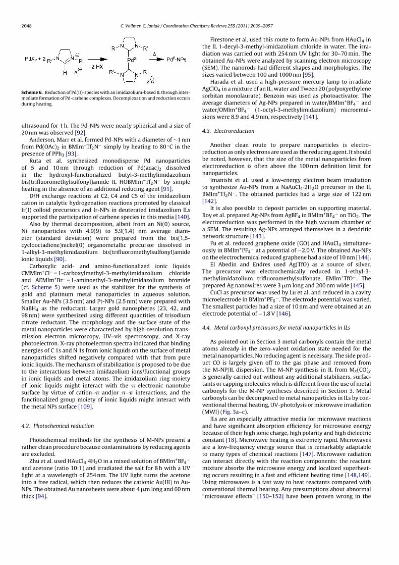
2048 C. Vollmer, C. Janiak / Coordination Chemistry Reviews 255 (2011) 2039– 2057
Scheme 6. Reduction of Pd(II)-species with an imidazolium-based IL through inter-
mediate formation of Pd-carbene complexes. Decomplexation and reduction occurs
during heating.
ultrasound for 1 h. The Pd-NPs were nearly spherical and a size of
20 nm was observed [92].
Anderson, Marr et al. formed Pd-NPs with a diameter of ∼1 nm
from Pd(OAc)2 in BMIm+Tf2N− simply by heating to 80 ◦C in the
presence of PPh3 [93].
Ruta et al. synthesized monodisperse Pd nanoparticles
of 5 and 10 nm through reduction of Pd(acac)2 dissolved
in the hydroxyl-functionalized butyl-3-methylimidazolium
bis(trifluoromethylsulfonyl)amide IL HOBMIm+Tf2N− by simple
heating in the absence of an additional reducing agent [91].
D/H exchange reactions at C2, C4 and C5 of the imidazolium
cation in catalytic hydrogenation reactions promoted by classical
Ir(I) colloid precursors and Ir-NPs in deuterated imidazolium ILs
supported the participation of carbene species in this media [140].
Also by thermal decomposition, albeit from an Ni(0) source,
Ni nanoparticles with 4.9(9) to 5.9(1.4) nm average diam-
eter (standard deviation) were prepared from the bis(1,5-
cyclooctadiene)nickel(0) organometallic precursor dissolved in
1-alkyl-3-methylimidazolium bis(trifluoromethylsulfonyl)amide
ionic liquids [90].
Carboxylic acid- and amino-functionalized ionic liquids
CMMIm+Cl− = 1-carboxylmethyl-3-methylimidazolium chloride
and AEMIm+Br− = 1-aminoethyl-3-methylimidazolium bromide
(cf. Scheme 5) were used as the stabilizer for the synthesis of
gold and platinum metal nanoparticles in aqueous solution.
Smaller Au-NPs (3.5 nm) and Pt-NPs (2.5 nm) were prepared with
NaBH4 as the reductant. Larger gold nanospheres (23, 42, and
98 nm) were synthesized using different quantities of trisodium
citrate reductant. The morphology and the surface state of the
metal nanoparticles were characterized by high-resolution trans-
mission electron microscopy, UV–vis spectroscopy, and X-ray
photoelectron. X-ray photoelectron spectra indicated that binding
energies of C 1s and N 1s from ionic liquids on the surface of metal
nanoparticles shifted negatively compared with that from pure
ionic liquids. The mechanism of stabilization is proposed to be due
to the interactions between imidazolium ions/functional groups
in ionic liquids and metal atoms. The imidazolium ring moiety
of ionic liquids might interact with the �-electronic nanotube
surface by virtue of cation–� and/or �–� interactions, and the
functionalized group moiety of ionic liquids might interact with
the metal NPs surface [109].
4.2. Photochemical reduction
Photochemical methods for the synthesis of M-NPs present a
rather clean procedure because contaminations by reducing agents
are excluded.
Zhu et al. used HAuCl4·4H2O in a mixed solution of BMIm+BF4−
and acetone (ratio 10:1) and irradiated the salt for 8 h with a UV
light at a wavelength of 254 nm. The UV light turns the acetone
into a free radical, which then reduces the cationic Au(III) to Au-
NPs. The obtained Au nanosheets were about 4 �m long and 60 nm
thick [94].
Firestone et al. used this route to form Au-NPs from HAuCl4 in
the IL 1-decyl-3-methyl-imidazolium chloride in water. The irra-
diation was carried out with 254 nm UV light for 30–70 min. The
obtained Au-NPs were analyzed by scanning electron microscopy
(SEM). The nanorods had different shapes and morphologies. The
sizes varied between 100 and 1000 nm [95].
Harada et al. used a high-pressure mercury lamp to irradiate
AgClO4 in a mixture of an IL, water and Tween 20 (polyoxyethylene
sorbitan monolaurate). Benzoin was used as photoactivator. The
average diameters of Ag-NPs prepared in water/BMIm+BF4− and
water/OMIm+BF4− (1-octyl-3-methylimidazolium) microemul-
sions were 8.9 and 4.9 nm, respectively [141].
4.3. Electroreduction
Another clean route to prepare nanoparticles is electro-
reduction as only electrons are used as the reducing agent. It should
be noted, however, that the size of the metal nanoparticles from
electroreduction is often above the 100 nm definition limit for
nanoparticles.
Imanishi et al. used a low-energy electron beam irradiation
to synthesize Au-NPs from a NaAuCl4·2H2O precursor in the IL
BMIm+Tf2N−. The obtained particles had a large size of 122 nm
[142].
It is also possible to deposit particles on supporting material.
Roy et al. prepared Ag-NPs from AgBF4 in BMIm+BF4− on TiO2. The
electroreduction was performed in the high vacuum chamber of
a SEM. The resulting Ag-NPs arranged themselves in a dendritic
network structure [143].
Fu et al. reduced graphene oxide (GO) and HAuCl4 simultane-
ously in BMIm+PF4− at a potential of −2.0 V. The obtained Au-NPs
on the electrochemical reduced graphene had a size of 10 nm [144].
El Abedin and Endres used Ag(TfO) as a source of silver.
The precursor was electrochemically reduced in 1-ethyl-3-
methylimidazolium trifluoromethylsulfonate, EMIm+TfO−. The
prepared Ag nanowires were 3 �m long and 200 nm wide [145].
CuCl as precursor was used by Lu et al. and reduced in a cavity
microelectrode in BMIm+PF6−. The electrode potential was varied.
The smallest particles had a size of 10 nm and were obtained at an
electrode potential of −1.8 V [146].
4.4. Metal carbonyl precursors for metal nanoparticles in ILs
As pointed out in Section 3 metal carbonyls contain the metal
atoms already in the zero-valent oxidation state needed for the
metal nanoparticles. No reducing agent is necessary. The side prod-
uct CO is largely given off to the gas phase and removed from
the M-NP/IL dispersion. The M-NP synthesis in IL from Mx(CO)y
is generally carried out without any additional stabilizers, surfac-
tants or capping molecules which is different from the use of metal
carbonyls for the M-NP syntheses described in Section 3. Metal
carbonyls can be decomposed to metal nanoparticles in ILs by con-
ventional thermal heating, UV-photolysis or microwave irradiation
(MWI) (Fig. 3a–c).
ILs are an especially attractive media for microwave reactions
and have significant absorption efficiency for microwave energy
because of their high ionic charge, high polarity and high dielectric
constant [18]. Microwave heating is extremely rapid. Microwaves
are a low-frequency energy source that is remarkably adaptable
to many types of chemical reactions [147]. Microwave radiation
can interact directly with the reaction components: the reactant
mixture absorbs the microwave energy and localized superheat-
ing occurs resulting in a fast and efficient heating time [148,149].
Using microwaves is a fast way to heat reactants compared with
conventional thermal heating. Any presumptions about abnormal
“microwave effects” [150–152] have been proven wrong in the
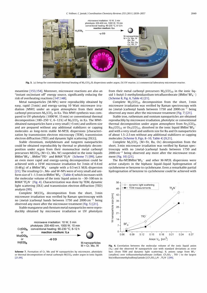
C. Vollmer, C. Janiak / Coordination Chemistry Reviews 255 (2011) 2039– 2057 2049
Fig. 3. (a) Setup for conventional thermal heating of Mx(CO)y/IL dispersions under argon, (b) UV reactor, (c) commercial laboratory microwave reactor.
meantime [153,154]. Moreover, microwave reactions are also an
“instant on/instant off” energy source, significantly reducing the
risk of overheating reactions [147,148].
Metal nanoparticles (M-NPs) were reproducibly obtained by
easy, rapid (3 min) and energy-saving 10 Watt microwave irra-
diation (MWI) under an argon atmosphere from their metal
carbonyl precursors Mx(CO)y in ILs. This MWI synthesis was com-
pared to UV-photolytic (1000 W, 15 min) or conventional thermal
decomposition (180–250 ◦C, 6–12 h) of Mx(CO)y in ILs. The MWI-
obtained nanoparticles have a very small (<5 nm) and uniform size
and are prepared without any additional stabilizers or capping
molecules as long-term stable M-NP/IL dispersions [characteri-
zation by transmission electron microscopy (TEM), transmission
electron diffraction (TED) and dynamic light scattering (DLS)].
Stable chromium, molybdenum and tungsten nanoparticles
could be obtained reproducibly by thermal or photolytic decom-
position under argon from their mononuclear metal carbonyl
precursors M(CO)6 (M = Cr, Mo, W) suspended in the ionic liquids
BMIm+BF4−, BMIm+TfO− and BtMA+Tf2N− (Scheme 7) [99]. Later
an even more rapid and energy-saving decomposition could be
achieved with a 10 W microwave irradiation for 3 min of 0.4 ml
(0.48 g) of a BMIm+BF4− sample with a 0.5 wt.% M/IL-dispersion
[21]. The resulting Cr-, Mo- and W-NPs were of very small and uni-
form size of 1–1.5 nm in BMIm+BF4− (Table 4) which increases with
the molecular volume of the ionic liquid anion to ∼30–100 nm in
BtMA+Tf2N− (Fig. 4). Characterization was done by TEM, dynamic
light scattering (DLS) and transmission electron diffraction (TED)
analysis [99].
Complete M(CO)6 decomposition from the short, 3 min
microwave irradiation was verified by Raman spectroscopy with
no (metal-)carbonyl bands between 1750 and 2000 cm−1 being
observed any more after the microwave treatment (Fig. 5) [21].
Stable manganese and rhenium metal nanoparticles were repro-
ducibly obtained by microwave irradiation or UV photolysis
Scheme 7. Formation of Cr, Mo and W nanoparticles by microwave, photolytic
or thermal decomposition of metal carbonyls M(CO)6 under argon in ionic liquids
[21,99].
from their metal carbonyl precursors M2(CO)10 in the ionic liq-
uid 1-butyl-3-methylimidazolium tetrafluoroborate (BMIm+BF4−)
(Scheme 8, Fig. 6, Table 4) [21].
Complete M2(CO)10 decomposition from the short, 3 min
microwave irradiation was verified by Raman spectroscopy with
no (metal-)carbonyl bands between 1750 and 2000 cm−1 being
observed any more after the microwave treatment (Fig. 7) [21].
Stable iron, ruthenium and osmium nanoparticles are obtained
reproducibly by microwave irradiation, photolytic or conventional
thermal decomposition under argon atmosphere from Fe2(CO)9,
Ru3(CO)12 or Os3(CO)12, dissolved in the ionic liquid BMIm+BF4−
and with a very small and uniform size for Ru and Os nanoparticles
of about 1.5–2.5 nm without any additional stabilizers or capping
molecules (Scheme 9, Figs. 8–10, Table 4) [9,21].
Complete Mx(CO)y (M = Fe, Ru, Os) decomposition from the
short, 3 min microwave irradiation was verified by Raman spec-
troscopy with no (metal-)carbonyl bands between 1750 and
2000 cm−1 being observed any more after the microwave treat-
ment (Fig. 10) [21].
The Ru-NP/BMIm+BF4− and other M-NP/IL dispersions were
active catalysts in the biphasic liquid–liquid hydrogenation of
cyclohexene or benzene to cyclohexane. Even a remarkable partial
hydrogenation of benzene to cyclohexene could be achieved with
Fig. 4. Correlation between the molecular volume of the ionic liquid anion
(VIL) and the observed W nanoparticle size with standard deviations as error
bars (from TEM and dynamic light scattering). IL anions range from BF4−
(smallest) over trifluoromethylsulfonate (triflate, CF3SO3− , TfO−) to the largest
bis(trifluoromethylsulfonyl)amide [(CF3SO2)2N− , Tf2N−] [99].
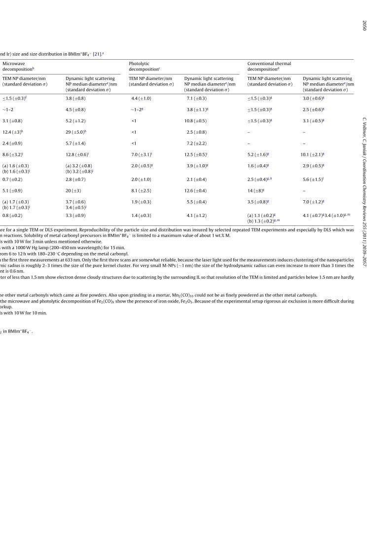
2050C
.
Vollm
er,
C.
Jan
iak
/
Coord
inatio
n
Ch
emistry
Rev
iews
255 (2011) 2039– 2057
and Ir) size and size distribution in BMIm+BF4− [21].a
Microwave
decompositionb
Photolytic
decompositionc
Conventional thermal
decompositiond
TEM NP diameter/nm
(standard deviation �)
Dynamic light scattering
NP median diametere/nm
(standard deviation �)
TEM NP diameter/nm
(standard deviation �)
Dynamic light scattering
NP median diametere/nm
(standard deviation �)
TEM NP diameter/nm
(standard deviation �)
Dynamic light scattering
NP median diametere/nm
(standard deviation �)
≤1.5 (±0.3)f 3.8 (±0.8) 4.4 (±1.0) 7.1 (±0.3) ≤1.5 (±0.3)g 3.0 (±0.6)g
∼1–2 4.5 (±0.8) ∼1–2g 3.8 (±1.1)g ≤1.5 (±0.3)g 2.5 (±0.6)g
3.1 (±0.8) 5.2 (±1.2) <1 10.8 (±0.5) ≤1.5 (±0.3)g 3.1 (±0.5)g
12.4 (±3)h 29 (±5.0)h <1 2.5 (±0.8) – –
2.4 (±0.9) 5.7 (±1.4) <1 7.2 (±2.2) – –
8.6 (±3.2)i 12.8 (±0.6)i 7.0 (±3.1)i 12.5 (±0.5)i 5.2 (±1.6)g 10.1 (±2.1)g
(a) 1.6 (±0.3)
(b) 1.6 (±0.3)j
(a) 3.2 (±0.8)
(b) 3.2 (±0.8)j
2.0 (±0.5)g 3.9 (±1.0)g 1.6 (±0.4)g 2.9 (±0.5)g
0.7 (±0.2) 2.8 (±0.7) 2.0 (±1.0) 2.1 (±0.4) 2.5 (±0.4)g,k 5.6 (±1.5)l
5.1 (±0.9) 20 (±3) 8.1 (±2.5) 12.6 (±0.4) 14 (±8)g –
(a) 1.7 (±0.3)
(b) 1.7 (±0.3)j
3.7 (±0.6)
3.4 (±0.5)j
1.9 (±0.3) 5.5 (±0.4) 3.5 (±0.8)g 7.0 (±1.2)g
0.8 (±0.2) 3.3 (±0.9) 1.4 (±0.3) 4.1 (±1.2) (a) 1.1 (±0.2)g
(b) 1.3 (±0.2)g,m
4.1 (±0.7)g3.4 (±1.0)g,m
are for a single TEM or DLS experiment. Reproducibility of the particle size and distribution was insured by selected repeated TEM experiments and especially by DLS which was
n reactions. Solubility of metal carbonyl precursors in BMIm+BF4− is limited to a maximum value of about 1 wt.% M.
ls with 10 W for 3 min unless mentioned otherwise.
s with a 1000 W Hg lamp (200–450 nm wavelength) for 15 min.
rom 6 to 12 h with 180–230 ◦C depending on the metal carbonyl.
m the first three measurements at 633 nm. Only the first three scans are somewhat reliable, because the laser light used for the measurements induces clustering of the nanoparticles
mic radius is roughly 2–3 times the size of the pure kernel cluster. For very small M-NPs (∼1 nm) the size of the hydrodynamic radius can even increase to more than 3 times the
nt is 0.6 nm.
eter of less than 1.5 nm show electron dense cloudy structures due to scattering by the surrounding IL so that resolution of the TEM is limited and particles below 1.5 nm are hardly
he other metal carbonyls which came as fine powders. Also upon grinding in a mortar, Mn2(CO)10 could not be as finely powdered as the other metal carbonyls.
the microwave and photolytic decomposition of Fe2(CO)9 show the presence of iron oxide, Fe2O3. Because of the experimental setup rigorous air exclusion is more difficult during
orkup.
ls with 10 W for 10 min.
2 in BMIm+BF4− .
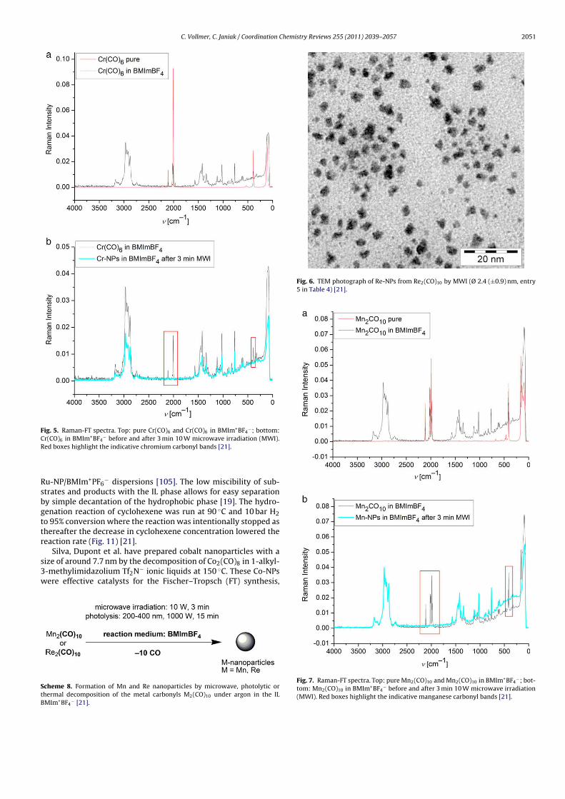
C. Vollmer, C. Janiak / Coordination Chemistry Reviews 255 (2011) 2039– 2057 2051
Fig. 5. Raman-FT spectra. Top: pure Cr(CO)6 and Cr(CO)6 in BMIm+BF4−; bottom:
Cr(CO)6 in BMIm+BF4− before and after 3 min 10 W microwave irradiation (MWI).
Red boxes highlight the indicative chromium carbonyl bands [21].
Ru-NP/BMIm+PF6− dispersions [105]. The low miscibility of sub-
strates and products with the IL phase allows for easy separation
by simple decantation of the hydrophobic phase [19]. The hydro-
genation reaction of cyclohexene was run at 90 ◦C and 10 bar H2
to 95% conversion where the reaction was intentionally stopped as
thereafter the decrease in cyclohexene concentration lowered the
reaction rate (Fig. 11) [21].
Silva, Dupont et al. have prepared cobalt nanoparticles with a
size of around 7.7 nm by the decomposition of Co2(CO)8 in 1-alkyl-
3-methylimidazolium Tf2N− ionic liquids at 150 ◦C. These Co-NPs
were effective catalysts for the Fischer–Tropsch (FT) synthesis,
Scheme 8. Formation of Mn and Re nanoparticles by microwave, photolytic or
thermal decomposition of the metal carbonyls M2(CO)10 under argon in the IL
BMIm+BF4− [21].
Fig. 6. TEM photograph of Re-NPs from Re2(CO)10 by MWI (Ø 2.4 (±0.9) nm, entry
5 in Table 4) [21].
Fig. 7. Raman-FT spectra. Top: pure Mn2(CO)10 and Mn2(CO)10 in BMIm+BF4−; bot-
tom: Mn2(CO)10 in BMIm+BF4− before and after 3 min 10 W microwave irradiation
(MWI). Red boxes highlight the indicative manganese carbonyl bands [21].
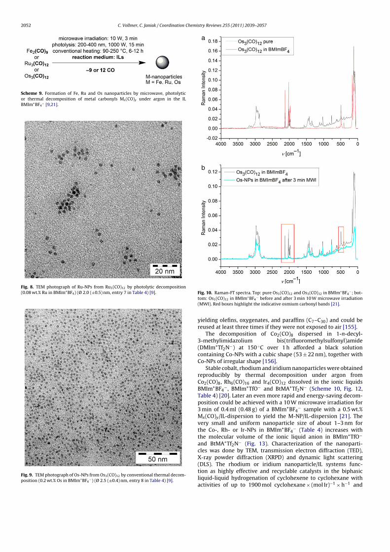
2052 C. Vollmer, C. Janiak / Coordination Chemistry Reviews 255 (2011) 2039– 2057
Scheme 9. Formation of Fe, Ru and Os nanoparticles by microwave, photolytic
or thermal decomposition of metal carbonyls Mx(CO)y under argon in the IL
BMIm+BF4− [9,21].
Fig. 8. TEM photograph of Ru-NPs from Ru3(CO)12 by photolytic decomposition
(0.08 wt.% Ru in BMIm+BF4) (Ø 2.0 (±0.5) nm, entry 7 in Table 4) [9].
Fig. 9. TEM photograph of Os-NPs from Os3(CO)12 by conventional thermal decom-
position (0.2 wt.% Os in BMIm+BF4−) (Ø 2.5 (±0.4) nm, entry 8 in Table 4) [9].
Fig. 10. Raman-FT spectra. Top: pure Os3(CO)12 and Os3(CO)12 in BMIm+BF4−; bot-
tom: Os3(CO)12 in BMIm+BF4− before and after 3 min 10 W microwave irradiation
(MWI). Red boxes highlight the indicative osmium carbonyl bands [21].
yielding olefins, oxygenates, and paraffins (C7–C30) and could be
reused at least three times if they were not exposed to air [155].
The decomposition of Co2(CO)8 dispersed in 1-n-decyl-
3-methylimidazolium bis(trifluoromethylsulfonyl)amide
(DMIm+Tf2N−) at 150 ◦C over 1 h afforded a black solution
containing Co-NPs with a cubic shape (53 ± 22 nm), together with
Co-NPs of irregular shape [156].
Stable cobalt, rhodium and iridium nanoparticles were obtained
reproducibly by thermal decomposition under argon from
Co2(CO)8, Rh6(CO)16 and Ir4(CO)12 dissolved in the ionic liquids
BMIm+BF4−, BMIm+TfO− and BtMA+Tf2N− (Scheme 10, Fig. 12,
Table 4) [20]. Later an even more rapid and energy-saving decom-
position could be achieved with a 10 W microwave irradiation for
3 min of 0.4 ml (0.48 g) of a BMIm+BF4− sample with a 0.5 wt.%
Mx(CO)y/IL-dispersion to yield the M-NP/IL-dispersion [21]. The
very small and uniform nanoparticle size of about 1–3 nm for
the Co-, Rh- or Ir-NPs in BMIm+BF4− (Table 4) increases with
the molecular volume of the ionic liquid anion in BMIm+TfO−
and BtMA+Tf2N− (Fig. 13). Characterization of the nanoparti-
cles was done by TEM, transmission electron diffraction (TED),
X-ray powder diffraction (XRPD) and dynamic light scattering
(DLS). The rhodium or iridium nanoparticle/IL systems func-
tion as highly effective and recyclable catalysts in the biphasic
liquid-liquid hydrogenation of cyclohexene to cyclohexane with
activities of up to 1900 mol cyclohexane × (mol Ir)−1 × h−1 and

C. Vollmer, C. Janiak / Coordination Chemistry Reviews 255 (2011) 2039– 2057 2053
Fig. 11. Activity for seven runs of the hydrogenation of cyclohexene with the same
Ru-NP/BMIm+BF4− catalyst at 90 ◦C, 10 bar H2 pressure, run to 95% conversion and
H2 uptake over time for the 1st, 3rd, 5th and 7th hydrogenation run. An H2 uptake
of 0.38 g corresponds to 95% conversion (100% are 0.2 mol or 0.4 g H2) [21].
Scheme 10. Formation of Co, Rh and Ir nanoparticles by microwave, photolytic or
thermal decomposition of metal carbonyls Mx(CO)y under argon in ionic liquids
[20,21].
380 mol cyclohexane × (mol Rh)−1 × h−1 for quantitative conver-
sion at 4 bar H2 pressure and 75 ◦C (Fig. 14).
Stable ruthenium or rhodium metal nanoparticles could be sup-
ported on chemically derived graphene (CDG) surfaces with small
and uniform particle sizes (Ru 2.2 ± 0.4 nm and Rh 2.8 ± 0.5 nm)
by decomposition of their metal carbonyl precursors Ru3(CO)12
and Rh6(CO)16, respectively, by rapid microwave irradiation in
a suspension of CDG in BMIm+BF4− (Scheme 11, Fig. 15). The
obtained hybrid nanomaterials Rh-NP/CDG and Ru-NP/CDG were
– without further treatment – catalytically active in hydrogena-
tion reactions yielding complete conversion of cyclohexene or
benzene to cyclohexane under organic-solvent-free and mild
conditions (50–75 ◦C, 4 bar H2) with reproducible turnover fre-
quencies of 1570 mol cyclohexane × (mol Ru)−1 × h−1 and 310 mol
benzene × (mol Rh)−1 × h−1. The catalytically active M-NP/CDG-
nanocomposite material could be recycled and used for several runs
without any loss of activity. (Scheme 11, Fig. 16) [157].
5. DLVO theory
This section gives a brief overview on the theory for the treat-
ment of particle dispersions.
The classic theory for interaction of two particles in a dispersion
is the DLVO (Derjaugin–Landau–Verwey–Overbeek) theory, devel-
oped by the research groups of Derjaugin and Landau in the USSR
and the group of Vervey and Overbeek in the Netherlands nearly
simultaneously in the 1940s. This basic and most commonly theory
is considered as a combination of the repulsive Coulomb and the
attraction van der Waals forces. Hence DLVO potential is the sum
of an effective electrostatic term and a direct van der Waals term.
Some simplifications and assumptions are involved in this the-
ory: the surfaces of the particles are flat. The charge density
is homogeneous and remains homogenous, even when particles
approach each other. Also there is no change of the concentration
of the counter ions which cause the electric potential. The solvent
itself has only an influence through its dielectric constant.
It is quite clear that the surface of a particle is not flat and the
charge density changes when two particles approach each other. It
is evident that the theory can only approximate the real-life inter-
actions of two particles. DLVO theory works very well and is the
best predictor of the stability of lyophobic colloids. This theory is
fundamental for chemists working on and with colloids [158].
It should be pointed out that there are two main types of stabi-
lizers for NPs: Electrostatic or “DLVO-type” stabilizers which are
considered as point charge stabilizers and “classical” steric sta-
bilizers. Small anions like halides seem to be the closest real-life
electrostatic stabilizers.
Concerning nanoparticles and their interactions, the anion is
the main focus because anions will bind to the unsaturated sur-
face of the electrophilic NP [159]. Thus, the NPs with their anion
layer assume a negative charge and turn into a large multi-negative
anion. The repulsion between two such negatively charged NPs is
the Coulomb part of the DLVO theory.
Scheme 11. The use of microwave irradiation for the easy synthesis of transition
metal nanoparticles supported on chemically derived graphene (CDG) in ILs. The
hybrid nanomaterials Ru-NP/CDG and Rh-NP/CDG were active hydrogenation cata-
lysts [157].
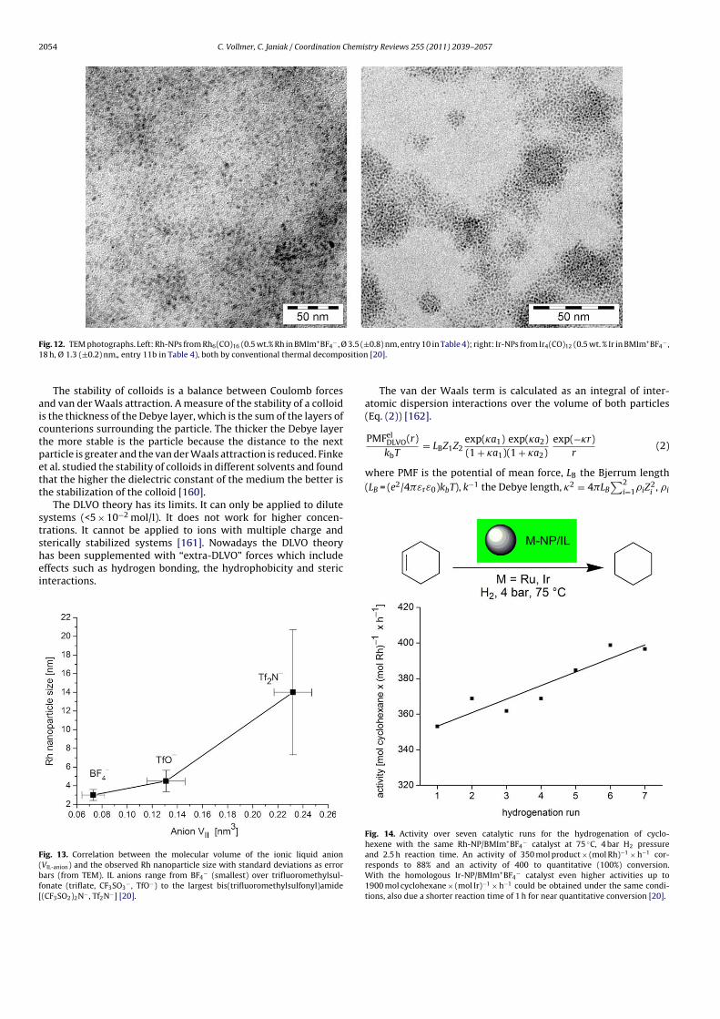
2054 C. Vollmer, C. Janiak / Coordination Chemistry Reviews 255 (2011) 2039– 2057
Fig. 12. TEM photographs. Left: Rh-NPs from Rh6(CO)16 (0.5 wt.% Rh in BMIm+BF4− , Ø 3.5 (±0.8) nm, entry 10 in Table 4); right: Ir-NPs from Ir4(CO)12 (0.5 wt. % Ir in BMIm+BF4
− ,
18 h, Ø 1.3 (±0.2) nm„ entry 11b in Table 4), both by conventional thermal decomposition [20].
The stability of colloids is a balance between Coulomb forces
and van der Waals attraction. A measure of the stability of a colloid
is the thickness of the Debye layer, which is the sum of the layers of
counterions surrounding the particle. The thicker the Debye layer
the more stable is the particle because the distance to the next
particle is greater and the van der Waals attraction is reduced. Finke
et al. studied the stability of colloids in different solvents and found
that the higher the dielectric constant of the medium the better is
the stabilization of the colloid [160].
The DLVO theory has its limits. It can only be applied to dilute
systems (<5 × 10⁻² mol/l). It does not work for higher concen-
trations. It cannot be applied to ions with multiple charge and
sterically stabilized systems [161]. Nowadays the DLVO theory
has been supplemented with “extra-DLVO” forces which include
effects such as hydrogen bonding, the hydrophobicity and steric
interactions.
Fig. 13. Correlation between the molecular volume of the ionic liquid anion
(VIL-anion) and the observed Rh nanoparticle size with standard deviations as error
bars (from TEM). IL anions range from BF4− (smallest) over trifluoromethylsul-
fonate (triflate, CF3SO3− , TfO−) to the largest bis(trifluoromethylsulfonyl)amide
[(CF3SO2)2N− , Tf2N−] [20].
The van der Waals term is calculated as an integral of inter-
atomic dispersion interactions over the volume of both particles
(Eq. (2)) [162].
PMFelDLVO(r)
kbT= LBZ1Z2
exp(�a1) exp(�a2)
(1 + �a1)(1 + �a2)
exp(−�r)
r(2)
where PMF is the potential of mean force, LB the Bjerrum length
(LB = (e2/4�εrε0)kbT), k−1 the Debye length, �2 = 4�LB
∑2
i=1�iZ
2i
, �i
Fig. 14. Activity over seven catalytic runs for the hydrogenation of cyclo-
hexene with the same Rh-NP/BMIm+BF4− catalyst at 75 ◦C, 4 bar H2 pressure
and 2.5 h reaction time. An activity of 350 mol product × (mol Rh)−1 × h−1 cor-
responds to 88% and an activity of 400 to quantitative (100%) conversion.
With the homologous Ir-NP/BMIm+BF4− catalyst even higher activities up to
1900 mol cyclohexane × (mol Ir)−1 × h−1 could be obtained under the same condi-
tions, also due a shorter reaction time of 1 h for near quantitative conversion [20].

C. Vollmer, C. Janiak / Coordination Chemistry Reviews 255 (2011) 2039– 2057 2055
Fig. 15. TEM and TED pictures. Top row: Ru-NP supported on chemically derived graphene (CDG), bottom row: Rh-NP on CDG, from microwave irradiation of Ru3(CO)12 and
Rh6(CO)16, respectively, in CDG/BMIm+BF4− [158].
Fig. 16. Activities for the hydrogenation of cyclohexene to cyclohexane with the
same M-NP/CDG catalyst in 10 consecutive runs [157].
the concentration of microion i, Zi the charge of the colloids 1 and
2, ai the radius of the colloids, and r is the distance between the
colloids.
This term is neglected within the basic model, but it is important
for large colloidal particles. To compute the effective electrostatic
component, microions are described by point charges and two
approximations are made, the Poisson–Boltzmann (PB) approx-
imation (that is, a mean-field treatment of micro ions), and an
expansion of the charge density to linear order in the electrostatic
potential.
Despite its success, the DLVO theory fails to predict some experi-
mental behaviors. The attraction between equally charged particles
in the presence of multivalent counterions is the most surpris-
ing one [163]. Numerical simulations within the basic model have
remarkably contributed to understand such failure. It has been
proven that Poisson–Boltzmann theory cannot predict an attrac-
tion, while the PMF computed by simulations can be attractive.
Therefore, the attraction can be explained by the correlations
between microions, missed within the mean field PB treatment,
but present in the simulations. The review by Dijkstra devoted to
the simulations of charged colloids summarizes work on this issue
[163].

2056 C. Vollmer, C. Janiak / Coordination Chemistry Reviews 255 (2011) 2039– 2057
6. Conclusions
In this review is shown that ionic liquids (ILs) are remark-
able and excellent media for the synthesis and stabilization of
metal nanoparticles (M-NPs) without the need of additional sta-
bilizers, surfactants or capping ligands. ILs can be regarded as
a supramolecular three-dimensional electrostatic and hydrogen-
bonded network. The stabilization of metal nanoparticles in ILs can,
thus, be attributed to “extra-DLVO” forces which include effects
from the network properties of ILs such as hydrogen bonding, the
hydrophobicity and steric interactions to prevent M-NPs agglomer-
ation. Various chemical synthesis methods of metal nanoparticles
in ILs allow for the design of a variety of M-NP shapes and
sizes. The synthesis of M-NPs can proceed by chemical reduc-
tion, thermolysis, photochemical decomposition, electroreduction,
microwave and sonochemical irradiation. A microwave induced
thermal decomposition of metal carbonyls Mx(CO)y in ILs provides
an especially rapid and energy-saving access to M-NPs because of
the ILs significant absorption efficiency for microwave energy due
to their high ionic charge, high polarity and high dielectric con-
stant. Metal carbonyls Mx(CO)y present attractive synthons as they
are readily commercially available and contain the metal atoms
already in the zero-valent oxidation state needed for M-NPs. No
extra reducing agent is necessary and the only side product CO is
given off to the gas phase and removed from the dispersion, thereby
largely avoiding contaminations of the M-NP/IL dispersion.
Acknowledgments
Our work is supported by the Deutsche Forschungsgemein-
schaft through grant Ja466/17-1. We thank the company IoLiTec
(Germany, www.iolitec.de) for donations of ionic liquids.
References
[1] A.H. Lu, E.L. Salabas, F. Schüth, Angew. Chem. Int. Ed. 46 (2007) 1222;A.H. Lu, E.L. Salabas, F. Schüth, Angew. Chem. 118 (2007) 1242.
[2] A. Gedanken, Ultrasonics Sonochem. 11 (2004) 47.[3] C.N.R. Rao, S.R.C. Vivekchand, K. Biswas, A. Govindaraj, Dalton Trans. (2007)
3728.[4] Y. Mastai, A. Gedanken, in: C.N.R. Rao, A. Müller, A.K. Cheetham (Eds.), Chem-
istry of Nanomaterials, vol. 1, Wiley-VCH, Weinheim, 2004, p. 113.[5] J. Park, J. Joo, S.G. Kwon, Y. Jang, T. Hyeon, Angew. Chem. Int. Ed. 46 (2007)
4630;J. Park, J. Joo, S.G. Kwon, Y. Jang, T. Hyeon, Angew. Chem. 119 (2007) 4714.
[6] D. Astruc, F. Lu, J.R. Aranzaes, Angew. Chem. Int. Ed. 44 (2005) 7852;D. Astruc, F. Lu, J.R. Aranzaes, Angew. Chem. 117 (2005) 8062.
[7] C. Pan, K. Pelzer, K. Philippot, B. Chaudret, F. Dassenoy, P. Lecante, M.-J.Casanove, J. Am. Chem. Soc. 123 (2001) 7584.
[8] J.D. Aiken III, R.G. Finke, J. Am. Chem. Soc. 121 (1999) 8803.[9] J. Krämer, E. Redel, R. Thomann, C. Janiak, Organometallics 27 (2008) 1976.
[10] K. Ueno, H. Tokuda, M. Watanabe, Phys. Chem. Chem. Phys. 12 (2010) 1649.[11] J. Dupont, J.D. Scholten, Chem. Soc. Rev. 39 (2010) 1780.[12] J. Dupont, J. Brazil. Chem. Soc. 15 (2004) 341.[13] M.-A. Neouze, J. Mater. Chem. 20 (2010) 9593.[14] C.S. Consorti, P.A.Z. Suarez, R.F. de Souza, R.A. Burrow, D.H. Farrar, A.J. Lough,
W. Loh, L.H.M. da Silva, J. Dupont, J. Phys. Chem. B 109 (2005) 4341.[15] J. Dupont, P.A.Z. Suarez, R.F. de Souza, R.A. Burrow, J.-P. Kintzinger, Chem. Eur.
J. 6 (2000) 2377.[16] R.A. Sheldon, Chem. Commun. (2008) 3352.[17] P. Wasserscheid, T. Welton, Ionic Liquid in Synthesis, vol. 1, Wiley-VCH, Wein-
heim, 2007, pp. 325.[18] P. Wasserscheid, W. Keim, Angew. Chem. Int. Ed. 39 (112) (2000) 3773;
P. Wasserscheid, W. Keim, Angew. Chem. 112 (2000) 3926.[19] C. van Doorslaer, Y. Schellekens, P. Mertens, K. Binnemanns, D. De Vos, Phys.
Chem. Chem. Phys. 12 (2010) 1741.[20] E. Redel, J. Krämer, R. Thomann, C. Janiak, J. Organomet. Chem. 694 (2009)
1069.[21] C. Vollmer, E. Redel, K. Abu-Shandi, R. Thomann, H. Manyar, C. Hardacre, C.
Janiak, Chem. Eur. J. 16 (2010) 3849.[22] V. Parvulescu, C. Hardacre, Chem. Rev. 107 (2007) 2615.[23] D. Astruc, Nanoparticles and Catalysis, Wiley-VCH, New York, 2007.[24] J. Dupont, R.F. de Souza, P.A.Z. Suarez, Chem. Rev. 102 (2002) 3667.[25] H. Weingärtner, Angew. Chem. Int. Ed. 47 (2008) 654;
H. Weingärtner, Angew. Chem. 120 (2008) 664.
[26] D. Xiao, J.R. Rajian, A. Cady, S. Li, R.A. Bartsch, E.L. Quitevis, J. Phys. Chem. B111 (2007) 4669.
[27] I. Krossing, J.M. Slattery, C. Daguenet, P.J. Dyson, A. Oleinikova, H. Weingärtner,J. Am. Chem. Soc. 128 (2006) 13427.
[28] K.R. Seddon, Chem. Soc. Rev. 37 (2008) 123.[29] P. Bonhôte, A.-P. Dias, N. Papageorgiou, K.K. Kalyanasundaram, M. Grätzel,
Inorg. Chem. 35 (1996) 1168.[30] J.M. Pringle, J. Golding, K. Baranyai, C.M. Forsyth, B.B. Deacon, J.L. Scott, D.R.
Mc Farelane, New J. Chem. 27 (2003) 1504.[31] T.J. Gannon, G. Law, R.P. Watson, A.J. Carmichael, K.R. Seddon, Langmuir 15
(1999) 8429.[32] J.N.A. Canongia Lopes, M.F.C. Gomes, A.A.H. Pádua, J. Phys. Chem. B 110 (2006)
16816.[33] G. Law, R.P. Watson, A.J. Carmichael, K.R. Seddon, Phys. Chem. Chem. Phys. 3
(2001) 2879.[34] J.N.A. Canongia Lopes, A.A.H. Pádua, J. Phys. Chem. B 110 (2006) 3330.[35] D.G.E. Kerfoot, X. Nickel, E. Wildermuth, H. Stark, G. Friedrich, F.L. Ebenhöch,
B. Kühborth, J. Silver, R. Rituper, in: Ullmann’s Encyclopaedia of IndustrialChemistry, 5th ed., Wiley (online), 2008.
[36] T. Hyeon, Chem. Commun. (2003) 927.[37] P.H. Hess, P.H. Parker Jr., J. Appl. Polym. Sci. 10 (1966) 1915.[38] J.R. Thomas, J. Appl. Phys. 37 (1966) 2914.[39] E. Papirer, P. Horny, H. Balard, R. Anthore, C. Petipas, A. Martinet, J. Colloid
Interface Sci. 94 (1983) 207.[40] E. Papirer, P. Horny, H. Balard, R. Anthore, C. Petipas, A. Martinet, J. Colloid
Interface Sci. 94 (1983) 220.[41] G.H. Lee, S.H. Huh, H.I. Jung, J. Mol. Struct. 400 (1998) 141.[42] M. Giersig, M. Hilgendorff, J. Phys. D: Appl. Phys. 32 (1999) L111–L113.[43] U. Wiedwald, M. Spasova, E.L. Salabas, M. Ulmeanu, M. Farle, Z. Frait, A. Fraile
Rodriguez, D. Arvanitis, N.S. Sobal, M. Hilgendorff, M. Giersig, Phys. Rev. B 68(2003) 064424.
[44] J. van Wonterghem, S. Mørup, S.W. Charles, S. Wells, J. Villadsen, Phys. Rev.Lett. 55 (1985) 410.
[45] J. van Wonterghem, S. Mørup, S.W. Charles, S. Wells, J. Colloid Interface Sci.121 (1988) 558.
[46] C. Pathmamanoharan, N.L. Zuiverloon, A.P. Philipse, Progr. Colloid Polym. Sci.115 (2000) 141.
[47] A. Goossens, L.J. de Jongh, K. Butter, A.P. Philipse, M.W.J. Crajé, A.M. van derKraan, Hyperfine Interact. 141–142 (2002) 381.
[48] K. Butter, P.H.H. Bomans, P.M. Frederik, G.J. Vroege, A.P. Philipse, Nat. Mater.2 (2003) 88.
[49] E. Bauer-Grosse, G. Le Caër, Phil. Mag. B 56 (1987) 485.[50] S.H. Huh, S.J. Oh, Y.N. Kim, G.H. Lee, Rev. Sci. Instrum. 70 (1999) 4366.[51] S. Sun, C.B. Murray, D. Weller, L. Folks, A. Moser, Science 287 (2000) 1989.[52] M. Chen, D.E. Nikles, J. Appl. Phys. 91 (2002) 8477.[53] M. Chen, D.E. Nikles, Nano Lett. 2 (2002) 211.[54] V.F. Puntes, K.M. Krishnan, P. Alivisatos, Appl. Phys. Lett. 78 (2001) 2187.[55] T. Hyeon, S.S. Lee, J. Park, Y. Chung, H.B. Na, J. Am. Chem. Soc. 123 (2001)
12798.[56] S.-W. Kim, S.U. Son, S.S. Lee, T. Hyeon, Y.K. Chung, Chem. Commun. (2001)
2212.[57] N.A.D. Burke, H.D.H. Stöver, F.P. Dawson, Chem. Mater. 14 (2002) 4752.[58] M. Rutnakornpituk, M.S. Thompson, L.A. Harris, K.E. Farmer, A.R. Esker, J.S.
Riffle, J. Connolly, T.G. St. Pierre, Polymer 43 (2002) 2337.[59] F.S. Diana, S.-H. Lee, P.M. Petroff, E.J. Krämer, Nano Lett. 3 (2003) 891.[60] H. Bönnemann, W. Brijoux, R. Brinkmann, N. Matoussevitch, H. Waldöfner, N.
Palina, H. Modrow, Inorg. Chim. Acta 350 (2003) 617.[61] H. Bönnemann, R.A. Brand, W. Brijoux, H.-W. Hofstadt, M. Frerichs, V.
Kempter, W. Maus-Friedrichs, N. Matoussevitch, K.S. Nagabhushana, F. Voigts,V. Caps, Appl. Organomet. Chem. 19 (2005) 790.
[62] S. Behrens, H. Bönnemann, N. Matoussevitch, A. Gorschinski, E. Dinjus, W.Habicht, J. Bolle, S. Zinoveva, N. Palina, J. Hormes, H. Modrow, S. Bahr, V.Kempter, J. Phys.: Condens. Matter 18 (2006) S2543–S2561.
[63] N. Matoussevitch, A. Gorschinski, W. Habicht, J. Bolle, E. Dinjus, H. Bönne-mann, S. Behrens, J. Magn. Magn. Mater. 311 (2007) 92.
[64] Y. Yin, R.M. Rioux, C.K. Erdonmez, S. Hughes, G.A. Somorjai, A.P. Alivisatos,Science 304 (2004) 711.
[65] M. Zubris, R.B. King, H. Garmestani, R. Tannenbaum, J. Mater. Chem. 15 (2005)1277.
[66] B.D. Korth, P. Keng, I. Shim, S.E. Bowles, C. Tang, T. Kowalewski, K.W. Nebesny,J. Pyun, J. Am. Chem. Soc. 128 (2006) 6562.
[67] R.A. Mercuri, PCT Int. Appl. (2007), WO 2007136389, Chem. Abstr. 148 (2007)37461.
[68] R.A. Mercuri, U.S. Pat. Appl. Publ. (2007), US 2007034050, Chem. Abstr. 146(2007) 233646.
[69] J.S. Gergely, E.S. Marston, S. Subramoney, L. Zhang, U.S. Pat. Appl. Publ. (2007),US 2007085053, Chem. Abstr. 146 (2007) 433242.
[70] C. Gürler, M. Feyen, S. Behrens, N. Matoussevitch, A.M. Schmidt, Polymer 49(2008) 2211.
[71] N. Doan, K. Kontturi, C. Johans, J. Colloid Interface Sci. 350 (2010) 126.[72] L.E.M. Howard, H.L. Nguyen, S.R. Giblin, B.K. Tanner, I. Terry, A.K. Hughes, J.S.O.
Evans, J. Am. Chem. Soc. 127 (2005) 10140.[73] R.D. Rutledge, W.H. Morris III, M.S. Wellons, Z. Gai, J. Shen, J. Bentley, J.E.
Wittig, C.M. Lukehart, J. Am. Chem. Soc. 128 (2006) 14210.[74] I. Robinson, S. Zacchini, L.D. Tung, S. Maenosono, N.T.K. Thanh, Chem. Mater.
21 (2009) 3021.

C. Vollmer, C. Janiak / Coordination Chemistry Reviews 255 (2011) 2039– 2057 2057
[75] K.S. Suslick, M. Fang, T. Hyeon, J. Am. Chem. Soc. 118 (1996) 11960.[76] S.-J. Park, S. Kim, S. Lee, Z.G. Khim, K. Char, T. Hyeon, J. Am. Chem. Soc. 122
(2000) 8581.[77] K. Butter, A.P. Philipse, G.J. Vroege, J. Magn. Magn. Mater. 252 (2002) 1.[78] O.A. Platonova, L.M. Bronstein, S.P. Solodovnikov, I.M. Yanovskaya, E.S.
Obolonkova, P.M. Valetsky, E. Wenz, M. Antonietti, Colloid Polym. Sci. 275(1997) 426.
[79] D.P. Dinega, M.G. Bawendi, Angew. Chem. Int. Ed. 38 (1999) 1788;D.P. Dinega, M.G. Bawendi, Angew. Chem. 111 (1999) 1906.
[80] J.-I. Park, J. Cheon, J. Am. Chem. Soc. 123 (2001) 5743.[81] A. Hütten, D. Sudfeld, I. Ennen, G. Reiss, K. Wojczykowski, P. Jutzi, J. Magn.
Magn. Mater. 293 (2005) 93.[82] D. Sudfeld, I. Ennen, A. Hütten, U. Golla-Schindler, H. Jaksch, G. Reiss, D.
Meißner, K. Wojczykowski, P. Jutzi, W. Saikaly, G. Thomas, J. Magn. Magn.Mater. 293 (2005) 151.
[83] A. Taubert, Z. Li, Dalton Trans. (2007) 723.[84] E. Redel, R. Thomann, C. Janiak, Inorg. Chem. 47 (2008) 14.[85] T. Gutel, J. Garcia-Anton, K. Pelzer, K. Philippot, C.C. Santini, Y. Chauvin, B.
Chaudret, J.-M. Basset, J. Mater. Chem. 17 (2007) 3290.[86] L.S. Ott, R.G. Finke, Inorg. Chem. 45 (2006) 8382.[87] G.S. Fonseca, A.P. Umpierre, P.F.P. Fichtner, S.R. Teixeira, J. Dupont, Chem. Eur.
J. 9 (2003) 3263.[88] Z. Li, A. Friedrich, A. Taubert, J. Mater. Chem. 18 (2008) 1008.[89] P. Migowski, D. Zanchet, G. Machado, M.A. Gelesky, S.R. Teixeira, J. Dupont,
Phys. Chem. Chem. Phys. 12 (2010) 6826.[90] P. Migowski, G. Machado, S.R. Teixeira, M.C.M. Alves, J. Morais, A. Traverse, J.
Dupont, Phys. Chem. Chem. Phys. 9 (2007) 4814.[91] M. Ruta, G. Laurenczy, P.J. Dyson, L. Kiwi-Minsker, J. Phys. Chem. C 112 (2008)
17814.[92] R.R. Deshmukh, R. Rajagopal, K.V. Srinivasan, Chem. Commun. (2001) 1544.[93] K. Anderson, S.C. Fernández, C. Hardacre, P.C. Marr, Inorg. Chem. Commun. 7
(2004) 73.[94] J.M. Zhu, Y.H. Shen, A.J. Xie, L.G. Qiu, Q. Zhang, X.Y. Zhang, J. Phys. Chem. C 111
(2007) 7629.[95] M.A. Firestone, M.L. Dietz, S. Seifert, S. Trasobares, D.J. Miller, N.J. Zaluzec,
Small 1 (2005) 754.[96] K. Peppler, M. Polleth, S. Meiss, M. Rohnke, J.Z. Janek, Phys. Chem. 220 (2006)
1507.[97] A. Safavi, N. Maleki, F. Tajabadi, E. Farjami, Electrochem. Commun. 9 (2007)
1963.[98] K. Kim, C. Lang, P.A. Kohl, J. Electrochem. Soc. 152 (2005) E9.[99] E. Redel, R. Thomann, C. Janiak, Chem. Commun. 15 (2008) 1789.
[100] G. Schmid, Nanoparticles, 2nd ed., Wiley-VCH, Weinheim, 2010, pp. 214.[101] M. Antonietti, D. Kuang, B. Smarly, Y. Zhou, Angew. Chem. Int. Ed. 43 (2004),
pp. 4988;M. Antonietti, D. Kuang, B. Smarly, Y. Zhou, Angew. Chem. 116 (2004) 5096.
[102] F. Endres, M. Bukowski, R. Hempelmann, H. Natter, H. Angew, Chem. Int. Ed.42 (2003) 3428;F. Endres, M. Bukowski, R. Hempelmann, H. Natter, H. Angew, Angew. Chem.115 (2003) 3550.
[103] Y.J. Zhu, W.W. Wang, R.J. Qi, X.L. Hu, Angew. Chem. Int. Ed. 43 (2004) 1410;Y.J. Zhu, W.W. Wang, R.J. Qi, X.L. Hu, Angew. Chem. 116 (2004) 1434.
[104] E.T. Silveira, A.P. Umpierre, L.M. Rossi, G. Machado, J. Morais, G.V. Soares, I.J.R.Baumvol, S.R. Teixeira, R.F.P. Fichtner, J. Dupont, Chem. Eur. J. 10 (2004) 3734.
[105] J. Dupont, G.S. Fonseca, A.P. Umpierre, P.F.P. Fichtner, S.R. Teixeira, J. Am.Chem. Soc. 124 (2002) 4228.
[106] C.W. Scheeren, G. Machado, J. Dupont, P.F.P. Fichtner, S.R. Texeira, Inorg.Chem. 42 (2003) 4738.
[107] A.I. Bhatt, A. Mechler, L.L. Martin, A.M. Bond, J. Mater. Chem. 17 (2007) 2241.[108] H. Itoh, K. Naka, Y. Chujo, J. Am. Chem. Soc. 126 (2004) 3026.[109] H. Zhang, H. Cui, Langmuir 25 (2009) 2604.[110] H.S. Schrekker, M.A. Gelesky, M.P. Stracke, C.M.L. Schrekker, G. Machado, S.R.
Teixeira, J.C. Rubim, J. Dupont, J. Colloid Interface Sci. 316 (2007) 189.[111] R.A. Alvarez-Puebla, E. Arceo, P.J.G. Goulet, J.J. Garrido, R.F. Aroca, J. Phys.
Chem. B 109 (2005) 3787.[112] E.J.W.J.T.G Verwey, Overbeek in Theory of the Stability of Lyophobic Colloids,
Dover Publications Mineola, New York, 1999, pp. 1.[113] E. Redel, J. Krämer, R. Thomann, C. Janiak, GIT Labor-Fachzeitschrift 2008,
April, 400.[114] A.N. Shipway, E. Katz, I. Willner, ChemPhysChem 1 (2000) 18.[115] T. Cassagneau, J.H. Fendler, J. Phys. Chem. B 103 (1999) 1789.[116] C.D. Keating, K.K. Kovaleski, M.J. Natan, J. Phys. Chem. B 102 (1998) 9404.[117] M.N. Kobrak, H. Li, Phys. Chem. Chem. Phys. 12 (2010) 1922.[118] L.S. Ott, R.G. Finke, Coord. Chem. Rev. 251 (2007) 1075.[119] B.L. Bhargava, S. Balasubramanian, M.L. Klein, Chem. Commun. (2008)
3339.
[120] E. Redel, M. Walter, R. Thomann, C. Vollmer, L. Hussein, H. Scherer, M. Krüger,C. Janiak, Chem. Eur. J. 15 (2009) 10047.
[121] E. Redel, M. Walter, R. Thomann, L. Hussein, M. Krüger, C. Janiak, Chem. Com-mun. 46 (2010) 1159.
[122] R.G. Pearson, Chemical Hardness. Application from Molecules to Solids,Wiley-VCH, 1997, pp. 1.
[123] T.A. Baker, C.M. Friend, E. Kaxiras, J. Am. Chem. Soc. 130 (2008) 3720.[124] K.-S. Kim, D. Demberelnyamba, H. Lee, Langmuir 20 (2004) 556.[125] S. Gao, H. Zhang, X. Wang, W. Mai, C. Peng, L. Ge, Nanotechnology 16 (2005)
1234.[126] R. Marcilla, D. Mecerreyes, I. Odriozola, J.A. Pomposo, J. Rodriguez, I. Zalakain,
I. Mondragon, Nano 2 (2007) 169.[127] M.A. Gelesky, A.P. Umpierre, G. Machado, R.R.B. Correia, W.C. Magno, J. Morais,
G. Ebeling, J. Dupont, J. Am. Chem. Soc. 127 (2007) 4588.[128] G.S. Fonseca, G. Machado, S.R. Teixeira, G.H. Fecher, J. Morais, M.C.M. Alves, J.
Dupont, J. Colloid Interface Sci. 301 (2006) 193.[129] C.W. Scheeren, J.B. Domingos, G. Machado, J. Dupont, J. Phys. Chem. C 112
(2008) 16463.[130] J. Turkevich, P.C. Stevenson, J. Hillier, Discuss. Faraday Soc. 11 (1951) 55.[131] H.R. Ryu, L. Sanchez, H.A. Keul, A. Raj, M.R. Bockstaller, Angew. Chem. Int. Ed.
47 (2008) 7639;H.R. Ryu, L. Sanchez, H.A. Keul, A. Raj, M.R. Bockstaller, Angew. Chem. 120(2008) 7751.
[132] Y. Hatakeyama, S. Takahashi, K. Nishikawa, J. Phys. Chem. C 114 (2010) 11098.[133] T. Kameyama, Y. Ohno, T. Kurimoto, K.-I. Okazaki, T. Uematsu, S. Kuwabata,
T. Torimoto, Phys. Chem. Chem. Phys. 12 (2010) 1804.[134] T. Suzuki, K.-I. Okazaki, S. Suzuki, T. Shibayama, S. Kuwabata, T. Torimoto,
Chem. Mater. 22 (2010) 5209.[135] K. Richter, A. Birkner, A.-V. Mudring, Angew. Chem. Int. Ed. 49 (2010) 2431;
K. Richter, A. Birkner, A.-V. Mudring, Angew. Chem. 122 (2010) 2481.[136] H. Wender, L.F. de Oliveira, P. Migowski, A.F. Feil, E. Lissner, M.H.G. Prechtl,
S.R. Teixeira, J. Dupont, J. Phys. Chem. C 114 (2010) 11764.[137] M.H.G. Prechtl, J.D. Scholten, J. Dupont, Molecules 15 (2010) 3441.[138] V. Calo, A. Nacci, A. Monopoli, S. Laera, N. Coffi, J. Org. Chem. 68 (2003) 2929.[139] L. Xu, W. Chen, J. Xiao, Organometallics 19 (2000) 1123.[140] J.D. Scholten, G. Ebeling, J. Dupont, Dalton Trans. (2007) 5554.[141] M. Harada, Y. Kimura, K. Saijo, T. Ogawa, S. Isoda, J. Colloid Interface Sci. 339
(2009) 373.[142] A. Imanishi, M. Tamura, S. Kuwabata, Chem. Commun. (2009) 1775.[143] P. Roy, R. Lynch, P. Schmuki, Electrochem. Commun. 11 (2009) 1567.[144] C. Fu, Y. Kuang, Z. Huang, X. Wang, N. Du, J. Chen, H. Zhou, Chem. Phys. Lett.
499 (2010) 250.[145] S.Z. El Abedin, F. Endres, Electrochim. Acta 54 (2009) 5673.[146] L. Yu, H. Sun, J. He, D. Wang, X. Jin, X. Hu, G.Z. Chen, Electrochem. Commun. 9
(2007) 1374.[147] D. Bogdal, Microwave-Assisted Organic Synthesis, Elsevier, New York, USA,
2006, pp. 47.[148] A.L. Buchachenko, E.L. Frankevich, Chemical Generation and Reception of
Radio- and Microwaves, Wiley-VCH, Weinheim, Germany, 1993, pp. 41.[149] V.K. Ahluwulia, Alternative Energy Processes in Chemical Synthesis, Alpha
Science International Ltd., Oxford, United Kingdom, 2008.[150] J. Berlan, P. Giboreau, S. Lefeuvre, C. Marchand, Tedrahedron Lett. 32 (1991)
2363.[151] F. Langa, P. de la Cruz, A. de la Hoz, A. Diaz-Ortiz, E. Diez-Barra, Contemp. Org.
Synth. 4 (1997) 373.[152] L. Perreux, A. Loupy, Tetrahedron 57 (2001) 9199.[153] A. Stadler, C.O. Kappe, J. Chem. Soc. Perkin Trans. 2 (2000) 1363.[154] A. Stadler, C.O. Kappe, Eur. J. Org. Chem. (2001) 919.[155] D.O. Silva, J.D. Scholten, M.A. Gelesky, S.R. Teixeira, A.C.B. Dos Santos, E.F.
Souza-Aguiar, J. Dupont, ChemSusChem 1 (2008) 291.[156] M. Scariot, D.O. Silva, J.D. Scholten, G. Machado, S.R. Teixeira, M.A. Novak, G.
Ebeling, J. Dupont, Angew. Chem. Int. Ed. 47 (2008) 9075;M. Scariot, D.O. Silva, J.D. Scholten, G. Machado, S.R. Teixeira, M.A. Novak, G.Ebeling, J. Dupont, Angew. Chem. 120 (2008) 9215.
[157] D. Marquardt, C. Vollmer, R. Thomann, P. Steurer, R. Mülhaupt, E. Redel, C.Janiak, Carbon 49 (2011) 1326.
[158] B.W. Ninham, Adv. Colloid Interface Sci. 83 (1999) 1.[159] R.G. Finke, in: D.L. Feldheim, C.A. Foss Jr. (Eds.), Metal Nanoparticle: Synthesis,
Characterization and Applications, Marcel Dekker, New York, 2002 (Chapter2).
[160] L.S. Ott, R.G. Finke, Inorg. Chem. 45 (2006) 8283.[161] M. Boström, D.R.W. Williams, B.W. Ninham, Phys. Rev. Lett. 87 (2001)
168103.[162] J. Lyklema, Fundamentals of Interface and Colloid Science, Elsevier, Amster-
dam, 2005.[163] M. Dijkstra, Curr. Opin. Colloid Interface Sci. 6 (2001) 372.
The use of microwave irradiation for the easy synthesisof graphene-supported transition metal nanoparticlesin ionic liquids
Dorothea Marquardt a, Christian Vollmer a, Ralf Thomann b, Peter Steurer b,Rolf Mulhaupt b,c, Engelbert Redel a, Christoph Janiak a,*
a Institut fur Anorganische und Analytische Chemie, Universitat Freiburg, Albertstr. 21, D-79104 Freiburg, Germanyb Freiburger Material Forschungszentrum (FMF) and Institut fur Makromolekulare Chemie, Universitat Freiburg,
Stefan-Meier-Str. 21-31, 79104 Freiburg, Germanyc FRIAS, Freiburg Institute for Advanced Studies, Albertstr. 19, 79104 Freiburg, Germany
A R T I C L E I N F O
Article history:
Received 16 July 2010
Accepted 29 September 2010
Available online 4 December 2010
A B S T R A C T
Stable ruthenium or rhodium metal nanoparticles were supported on chemically derived
graphene (CDG) surfaces with small and uniform particle sizes (Ru 2.2 ± 0.4 nm and Rh
2.8 ± 0.5 nm) by decomposition of their metal carbonyl precursors by rapid microwave irra-
diation in a suspension of CDG in the ionic liquid 1-butyl-3-methylimidazolium tetrafluo-
roborate. The graphene-supported hybrid nanoparticles were shown to be active and could
be re-used at least 10 times as catalysts for the hydrogenation of cyclohexene and benzene
under organic-solvent-free conditions with constant activities up to 1570 mol cyclohex-
ane · (mol metal)�1 · h�1 at 4 bar and 75 �C.� 2010 Elsevier Ltd. All rights reserved.
1. Introduction
Metal nanoparticles (M-NPs) are of high interest in catalysis
[1]. M-NPs can be synthesized in ionic liquids (ILs) [2] by ther-
mal decomposition of their metal carbonyls [3–5] in a rapid
(min) and low-energy (10–20W) procedure using microwave
irradiation (MWI) [1,6]. ILs are an ideal media for microwave
reactions with a significant absorption efficiency for micro-
wave energy and also for the stabilization of M-NPs, both be-
cause of their high ionic charge, high polarity and high
dielectric constant [1,7–9]. An efficient M-NP stabilization is
also possible on solid surfaces [10,11] including graphenes
[12–17].
During the last few years, chemically derived graphene
(CDG) [16–20], also called thermally reduced graphite oxide
[21–23] or simply graphene, has been rediscovered as an ex-
tremely versatile carbon material [14,17,24]. Because of the
functional groups present in CDG (Fig. S1b in Supporting
information), the sorption of ions and molecules is possible
[14]. This and the high specific surface area of CDG of
400 m2 g�1 up to 1500 m2 g�1, make them promising materials
for catalytic applications [14]. Metal-nanoparticles on carbon
materials are of recent interest [25–31]. Pt-, Ru- or Pd-NPs on
exfoliated graphene sheets were produced from heating
graphite oxide (GO) with the metal complexes [Pt(NH3)4]Cl2Æ-
H2O, [Ru(NH3)6]Cl2 or [Pd(NH3)4]Cl2ÆH2O under an N2 atmo-
sphere [32]. Graphene supported M-NPs are composite
materials [33] that may find applications as chemical sensors
[34], electrodes for fuel cells [35–37], catalysis [38–41] or hydro-
gen storage [42].
Here we show that Ru- and Rh-NPs can easily be deposited
on CDG-surfaces by decomposition of their metal carbonyls
Ru3(CO)12 and Rh6(CO)16, respectively, through low-energy
and rapid microwave irradiation (20 W, 6 min) in suspensions
0008-6223/$ - see front matter � 2010 Elsevier Ltd. All rights reserved.doi:10.1016/j.carbon.2010.09.066
* Corresponding author:E-mail address: [email protected] (C. Janiak).
C A R B O N 4 9 ( 2 0 1 1 ) 1 3 2 6 –1 3 3 2
avai lab le at www.sc iencedi rec t .com
journal homepage: www.elsev ier .com/ locate /carbon
of CDG in BMImBF4. The resulting M-NP/CDG composites are
active hydrogenation catalysts.
2. Experimental
2.1. Materials and instrumentation
Ru3(CO)12 and Rh6(CO)16 were obtained from ABCR, benzene
(p.A.) from Merck, cyclohexene (p.A., purity >99.5%) from Ac-
ros Organics and Sigma–Aldrich and used without further puri-
fication. CDG was prepared in a two step oxidation/thermal
reduction process using natural graphite (type KFL 99.5 from
Kropfmuhl AG, Passau, Germany) as raw material. The graph-
ite oxidation process of Hummers and Offeman [43] was em-
ployed (see Supporting information). The ionic liquid (IL) 1-
butyl-3-methylimidazolium tetrafluoroborate, BMImBF4 was
received from IoLiTec (Denzlingen, Germany, www.iolitec.de)
(H2O content «100 ppm; Cl� content «50 ppm). The IL was
dried under high vacuum (10�3 mbar) for several days.
All synthesis experiments were done using Schlenk tech-
niques or a glove box under argon since the metal carbonyls
are hygroscopic and air sensitive. The microwave reactions
were carried out in the laboratory microwave system Discover
by CEM.
Transmission electron microscopy (TEM) photographs
were taken at room temperature from a 200 lm carbon-
coated copper grid on a Zeiss LEO 912 transmission electron
microscope operating at an accelerating voltage of 120 kV.
The particle size was determined by measuring manually at
least 100 particles from different images using iTEM software
tools for manual measurements by OlympusSIS. Completely
automatic measurements, which can be easily performed
for well separated particles, fail in the case of heavily clus-
tered particles. For a better comparison of the samples also
particles which would have allowed automatic detection were
measured manually.
Metal analyses were performed by flame atomic absorp-
tion spectroscopy (AAS) on a Vario 6 from Analytik Jena.
Gas chromatographic analyses were done on a Perkin–El-
mer 8500 with an HS-6B inlet (HS headspace), equipped with
a DB 5 column (60 m · 0.32 mm, film thickness 25 lm, oven
temperature 60 �C) for cyclohexene or a PEG column
(25 m · 0.32 mm, film thickness 1.0 lm, oven temperature
40 �C) for benzene (both at an N2 carrier flow of 120 L/min)
and flame ionization detector (FID, 250 �C detector tempera-
ture). Probe injection occurred through the headspace sam-
pler thermostated for 20 min to 50 �C. The benzene or
cyclohexene to cyclohexane conversion was analyzed by
putting a drop of the mixture into a GC sample vial with
1 ml of distilled water. The addition of water as a non-electro-
lyte can enlarge the activity coefficient of organic compo-
nents, thereby increase their detection sensitivity through
the increase in peak area. The FID does not detect the water
[44] itself. The vial was closed with aluminum crimp caps
(with butyl rubber septum), placed into the headspace sam-
pler of the GC-headspace. After the thermostatization time
a sample was automatically drawn from the gas phase in
the vial. The product was analyzed by the GC retention time
versus authentic samples of benzene or cyclohexene and
cyclohexane. Hydrogenation conversion (%) was calculated
from the obtained cyclohexane-to-benzene or -cyclohexene
peak area, respectively, and compared to a calibration curve
from different ratios of given benzene or cyclohexene/cyclo-
hexane mixtures which had been measured under identical
headspace conditions.
2.2. Synthesis of chemically derived graphene(‘‘graphene’’)-supported transition metal-nanoparticles (M-NP/CDG)
In a typical experiment chemically derived graphene (CDG,
4.8 mg, 0.2 wt.% related to 2.4 mg IL) was dissolved/sus-
pended in the dried and degassed (desoxygenated) ionic li-
quid BMImBF4 (2.0 ml, 2.4 g, q = 1.2 g/mL) at room
temperature with magnetic stirring for 20 h in a microwave-
reaction vial. The solid metal carbonyl powders Mx(CO)y[50.6 mg Ru3(CO)12, 0.230 mmol Ru or 62.5 mg Rh6(CO)16,
0.235 mmol Rh, see Table S1a, Supporting information] were
added to the CDG slurry in BMImBF4 (1 wt.% metal, related
to 2.4 g BMImBF4) and suspended with magnetic stirring for
18 h under argon atmosphere. Then, the stirring bars were re-
moved and the mixture was subjected to microwave irradia-
tion (6 min, 20 W) under argon atmosphere.
For workup the slurry was degassed from CO in vacuo. Dis-
tilled water (6 ml) was added to remove the ionic liquid from
the M-NP/CDG system. The black slurry was centrifuged
(2 · 15 min, 2000 rpm, Hettich Rotina 46) and the supernatant
liquid H2O/IL phase decanted and discarded. The addition of
H2O, centrifugation and decantation was repeated three
times. At last, the residue was again dispersed in water, fil-
tered and dried under vacuum. The dry black-greyish residue
formed flakeswhich could easily be removed from the filter to
yield 25.0 mg (83%) Ru-NP/CDG and 15.7 mg (54%) Rh-NP/CDG.
The primary characterization of the M-NP/CDG composite
was carried out by transmission electron microscopy (TEM).
The Ru or Rh metal content of the M-NP/CDG samples was
determined with AAS by digestion of the sample (15 mg) in
hot aqua regia [30 ml, HCl (37%)/HNO3 (65%) 3:1]. After the
aqua regia was boiled down, the residue was re-dissolved in
HCl (30 ml, 37%) and boiled down again. The residue was re-
solved in conc. HCl (37%) and the solution was filtered to re-
move particles. Aqua regia was added to a total volume of
25 ml followed by AAS analysis. Ru and Rh contents of the
M-NP/CDG samples were 17.4 and 17.0 wt.%, respectively.
2.3. Hydrogenation of cyclohexene
The hydrogenation reactions of cyclohexene with graphene-
supported Ru and Rh-nanoparticles were carried out in stain-
less steel autoclaves. The autoclave was conditioned by evac-
uation and re-filling with argon. All autoclave loading was
carried out under argon. Each autoclave was equipped with
a glass inlay, to eliminate any catalytic influence of the stain-
less steel surface on the reaction process, into which the cat-
alyst (Ru-NP/CDG 11 mg containing 17.4 wt.% Ru or
1.89 · 10�5 mol Ru; Rh-NP/CDG, 11 mg, containing 17.0 wt.%
Rh or 1.82 · 10�5 mol Rh) and the cyclohexene substrate
(1.0 ml, density 0.811 g/ml, M = 82.14 g/mol, 0.01 mol) were
loaded. The autoclave was heated to 75 �C and pressurized
to 4 bar of H2 which was kept constant over the reaction time.
C A R B O N 4 9 ( 2 0 1 1 ) 1 3 2 6 –1 3 3 2 1327

The reaction mixture was stirred for an optimized set time of
1.5 h or 20 min. After this time the reactor was depressurized,
and the volatile organic components condensed under vac-
uum (15 min) into a clean cold trap (liquid nitrogen cooled).
Decanting of the organic layer from solid M-NP/CDG was
not feasible because the later formed a fine dispersion which
did not settle even after a prolonged time. The M-NP/CDG cat-
alyst is left behind in the autoclave andwas re-used by adding
fresh cyclohexene. Organic substrate workup and catalyst
recycling was done 10 times for Ru or Rh. The cyclohexene
to cyclohexane conversions were investigated by GC [Per-
kin–Elmer, DB 5 column (60 m · 0.32 mm)].
2.4. Hydrogenation of benzene
The hydrogenation reactions of benzene with graphene-sup-
ported Ru and Rh-nanoparticles were carried out in stainless
steel autoclaves. The autoclave was conditioned by evacua-
tion and re-filling with argon. All autoclave loading was car-
ried out under argon. Each autoclave was equipped with a
glass inlay, to eliminate any catalytic influence of the stain-
less steel surface on the reaction process, into which the cat-
alyst (Rh-NP/CDG, 5 mg, containing 17.0 wt.% Rh or
8.26 · 10�6 mol Rh) and the benzene substrate (0.92 ml,
0.81 g, 10.36 mmol) were loaded. The autoclave was heated
to the desired temperature (25, 50 or 75 �C) and pressurized
to 4 bar of H2 which was kept constant over the reaction time.
The reaction mixture was stirred for a set time of 4 h. After
this time the reactor was depressurized, and the volatile or-
ganic components condensed under vacuum (15 min) into a
clean cold trap (liquid nitrogen cooled). Decanting of the or-
ganic layer from solid M-NP/CDG was not feasible because
the later formed a fine dispersion which did not settle even
after a prolonged time. The M-NP/CDG catalyst is left behind
in the autoclave and was re-used by adding fresh benzene.
The benzene to cyclohexane conversions were investigated
by GC [Perkin–Elmer, PEG column (25 m · 0.32 mm)].
3. Results and discussion
The fluffy CDG powder (Fig. 1, synthesis according to Fig. 2)
can be suspended in the IL 1-butyl-3-methylimidazolium tet-
rafluoroborate (BMImBF4) to form a stable dispersion of single
graphene sheets. Stable dispersions of graphene sheets were
shown to be obtainable in ILs without the need of additional
surfactants/stabilizers [45,46]. The subsequent TEM pictures
with M-NPs show single graphene sheets (cf. Fig. 3) which
Fig. 1 – Scanning electron microscope (SEM) images of CDG from thermally reduced GO, showing the exfoliated sheets at the
larger magnification at the right.
Fig. 2 – Synthesis from natural graphite over GO (Hummers
and Offeman [42]) to CDG (thermal reduction process [22])
and M-NP/CDG. GO bearing epoxy, hydroxyl, carbonyl and
carboxyl groups was heated up to 560 �C and CO, CO2 and
H2O were eliminated under enormous expansion of the CDG
volume. The graphene sheets with mainly hydroxyl,
carbonyl groups [21,22,47] are exfoliated by the gas release
and the specific surface area becomes 510m2/g in the CDG
used here (Fig. 1); for further details see Supporting
information.
1328 C A R B O N 4 9 ( 2 0 1 1 ) 1 3 2 6 –1 3 3 2

suggest that the CDG is dispersed into individual flakes in
the IL.
The solidmetal carbonyl powdersMx(CO)y (M = Ru,Rh)were
added to the CDG slurry in BMImBF4 and suspended under ar-
gon atmosphere. The mixture was subjected to microwave
irradiation (6 min, 20 W) under argon atmosphere. The M-NP/
CDG materials (M = Ru, Rh) can be separated from the IL and
unsupported M-NP/IL by centrifugation of the slurry, washing
with water and drying in air. Black-grayish flake-like solids of
M-NP/CDG were obtained in good yield. Defined and small
Ru- and Rh-NPs with narrow size distributions (2.2 ± 0.4 nm
[standard deviation r] for Ru, 2.8 ± 0.5 nm for Rh, see also
Table S1b in Supporting information) canbe seenon thealmost
transparent CDG surfaces in the TEM image of the Ru- and
Rh-NP/CDG hybrid structures (Fig. 3).
In a proof-of-principle, the M-NP/CDG materials (M = Rh,
Ru) are shown to be catalysts in hydrogenation reactions of
cyclohexene and benzene to cyclohexane (Fig. 4). The ben-
zene hydrogenation to cyclohexane is a multi-million ton
(IFP – Institute Francais du Petrol) process with the subse-
quent oxidation to adipic acid and caprolactam as building
blocks for Nylon 6.6 and Nylon 6 [48–53].
The M-NP/CDG catalyst (M = Ru, Rh) was suspended in the
substrate cyclohexene or benzene without any additional sol-
vent. The hydrogenation reaction times with Ru- and Rh-NP/
CDG were optimized for near quantitative conversion. For
work-up after each catalytic run the organic phase was re-
moved under reduced pressure and condensed in a cold trap
forGCanalysis. Itwas possible to re-use the remaining catalyst
for 10 repeated runs each with quantitative conversion and a
constant activity of 1570 mol product · (mol metal)�1 · h�1
for Ru-NP/CDG and 360 mol product · (mol metal)�1 · h�1 for
Rh-NP/CDG (Fig. 5, Table S2b in Supporting information). The
pressure-normalized cyclohexene hydrogenation activities of
Ru-NP/CDG at 4 bar (390 mol product · (mol metal)�1 · h�1 ·bar�1) at quantitative conversions are higher by about one
order of magnitude than the activities of similar Ru-NP/IL
systems at 10 bar H2 pressure (30–53 mol product · (mol
metal)�1 · h�1 · bar�1) [6].With rhodium the normalized activ-
ities of 90 mol product · (molmetal)�1 · h�1 · bar�1 were com-
parable to those of a Rh-attapulgite (Atta-IL-Rh) catalyst which
Fig. 3 – TEM and TED of Ru- (top row) and Rh-NP (bottom row) supported on CDG fromMWI of Ru3(CO)12 and Rh6(CO)16 in CDG/
BMImBF4. The black bar in the TED is the beam stopper. The d-values match with the d-spacing of Rh metal and graphite.
Additional TEM pictures of Ru-NP/CDG and Rh-NP/CDG in Figs. S2 and S3, Supporting information.
Fig. 4 – Hydrogenation of cyclohexene or benzene to
cyloclohexane with Ru- or Rh-NP/CDG under organic-
solvent-free conditions.
C A R B O N 4 9 ( 2 0 1 1 ) 1 3 2 6 –1 3 3 2 1329
was prepared by an ionic liquid-assisted immobilization of Rh
from complexes, such as Rh(PPh)3+, Rh(COD)(PPh3)2+, and
[Rh(COD)(PPh3)2]BF4 (COD 1,5-cyclooctadiene) on the natural
mineral attapulgite. The pressure-normalized activities of
Atta-IL-Rh at 30 bar reached �90 mol product · (mol
metal)�1 · h�1 · bar�1 for >99% conversion in 5.5 h [54]. Rh-
NPs immobilized on silica-coated magnetite nanoparticles
gave high cyclohexene hydrogenation activities between
2500 and 6600 mol product · (mol metal)�1 · h�1 · bar�1 (at
6 bar, 75 �C, >99% conversion) for up to 20 consecutive runs
[55]. TEM/TED pictures of Rh-NP/CDG after five or ten consec-
utive catalytic runs do not showmarked changes in Rh-NP size
but somewhat higher crystallinity is apparent from TED (Fig. 6
and S7). The metal-NP size distributions of 2.4 ± 0.4 and
3.0 ± 1.0 nm after five runs for Ru and Rh, respectively and of
2.7 ± 0.7 and 2.8 ± 0.8 nm after 10 runs for Ru and Rh, respec-
tively, (referring to Table S2b in Supporting information) were
very similar to those of the starting samples (2.2 ± 0.4 nm
for Ru, 2.8 ± 0.5 nm for Rh). While there seems to be a slight
increase in the Ru-NP size with prolonged catalytic use, the
average size of the Rh-NPs stays invariantwithin experimental
error.
Benzene could be hydrogenated under similar mild condi-
tions to cyclohexane with essentially complete conversion at
a temperature of 50 �C, 4 h and 4 bar (Table 1) and a pressure-
normalized activities of Rh-NP/CDG of �78 mol prod-
uct · (mol Rh)�1 · h�1 · bar�1. This is a much higher activity
(TOF) than for other M-NP/IL systems [56–58] albeit lower than
for Rh-NPs immobilized on silica-coated magnetite nanopar-
ticles. The latter gave high benzene hydrogenation activities
between 100 and 180 mol product · (mol Rh)�1 · h�1 · bar�1
(at 6 bar, 75 �C, >99% conversion) for up to 20 consecutive
runs.
4. Conclusions
We describe here a simple, rapid and low-energy strategy to
deposit small 2–3 nm metal nanoparticles of Ru and Rh with
uniform sizes on CDG surfaces, by decomposition of their me-
tal carbonyls under MWI in the IL BMImBF4. Microwave irradi-
ation provides a very simple and reproducible way for the
rapid (6 min) and energy-saving (20 W power) synthesis of de-
fined and very small M-NPs from their binary metal carbonyl
complexes in ILs. This method should be extendable to other
metals with the microwave-induced binary metal carbonyl
Fig. 5 – Activities for the hydrogenation of cyclohexene with
the same M-NP/CDG catalyst in 10 consecutive runs (entry
1–10 for Rh and entry 11–20 for Ru in Table S2b, Supporting
information). A lower reaction time of 15 min for M = Ru
gave only 94.5% conversion (Table S2a).
Fig. 6 – TEM and TED of Rh-NP/CDG after 10 consecutive catalytic hydrogenation runs of cyclohexene (after entry 10 of
Table S2b, Supporting information).
Table 1 – Hydrogenation of benzene with Rh-NP/CDGcatalyst.a
Entry Temp.(�C)
Conversion(%)
Activity(mol product ·
(mol Rh)�1 · h�1)
1 25 72.8 2282 50 98.8 3103 75 94.8 297a The reactions were carried out in steel autoclaves, equipped with
glass inlays to eliminate any catalytic influence of the metal surface
on the reaction. General conditions 4 bar H2, time 4 h, benzene 0.81 g
(0.92 ml, 10.36 mmol), Rh-NP/CDG 5 mg, 17.0 wt.%, 8.26 · 10�6 mol
Rh, benzene/Rh ratio = 1255.
1330 C A R B O N 4 9 ( 2 0 1 1 ) 1 3 2 6 –1 3 3 2

Mx(CO)y decomposition and subsequent M-NP deposition on
CDG. The obtained hybrid nanomaterials (Rh-NP/CDG and
Ru-NP/CDG) were shown – without further treatment – to be
catalytically active in hydrogenation reactions yielding com-
plete conversion of cyclohexene or benzene to cyclohexane
under organic-solvent-free and mild conditions (50–75 �C,4 bar H2) with reproducible activities of 1570 mol cyclohex-
ane · (mol Ru)�1 · h�1 and 310 mol benzene · (mol Rh)�1 ·h�1. The catalytically active M-NP/CDG-nanocomposite mate-
rial could be recycled and used for several runs without any
loss of activity.
Acknowledgments
We thank the DFG for Grant Ja466/17-1 and IoLiTec (Denzlin-
gen, Germany, www.iolitec.de) for a gift of BMImBF4.
Appendix A. Supplementary data
Supplementary data associated with this article can be found,
in the online version, at doi:10.1016/j.carbon.2010.09.066.
R E F E R E N C E S
[1] Dupont J, Scholten JD. On the structural and surfaceproperties of transition metal nanoparticles in ionic liquids.Chem Soc Rev 2010;39:1780–804.
[2] Taubert A, Li Z. Inorganic materials from ionic liquids. DaltonTrans 2007:723–7.
[3] Kramer J, Redel E, Thomann R, Janiak C. Use of ionic liquidsfor the synthesis of iron, ruthenium and osmiumnanoparticles from their metal carbonyl precursors.Organometallics 2008;27:1976–8.
[4] Redel E, Thomann R, Janiak C. Use of ionic liquids (ILs) for theIL-anion size-dependent formation of Cr, Mo and Wnanoparticles from metal carbonyl M(CO)6 precursors. ChemCommun 2008:1789–91.
[5] Redel E, Kramer J, Thomann R, Janiak C. Synthesis of Co, Rhand Ir nanoparticles from metal carbonyls in ionic liquidsand their use as biphasic liquid–liquid hydrogenationnanocatalysts for cyclohexene. J Organomet Chem2009;694:1069–75.
[6] Vollmer C, Redel E, Abu-Shandi K, Thomann R, Manyar H,Hardacre H, et al. Microwave irradiation for the facilesynthesis of transition-metal nanoparticles (NPs) in ionicliquids (ILs) frommetal carbonyl precursors and Ru-, Rh-, andIr-NP/IL dispersions as biphasic liquid liquid hydrogenationnanocatalysts for cyclohexene. Chem Eur J 2010;16:3849–58.
[7] Dupont J. On the solid, liquid and solution structuralorganization of imidazolium ionic liquids. J Braz Chem Soc2004;15:341–50.
[8] Consorti CS, Suarez PAZ, de Souza RF, Burrow RA, Farrar DH,Lough AJ, et al. Identification of 1,3-dialkylimidazolium saltsupramolecular aggregates in solution. J Phys Chem B2005;109:4341–9.
[9] Wasserscheid P, Keim W. Ionic liquids – new ‘‘solutions’’ fortransition metal catalysis. Angew Chem Int Ed2000;39:3772–89.
[10] Duran Pachon L, Rothenberg G. Transition-metalnanoparticles: synthesis, stability and the leaching issue.Appl Organomet Chem 2008;22:288–99.
[11] White RJ, Luque R, Budarin VL, Clark JH, Macquarrie DJ.Tuneable porous carbonaceous materials from renewableresources. Chem Soc Rev 2009;38:3401–18.
[12] Kong BS, Geng JX, Jung HT. Layer-by-layer assembly ofgraphene and gold nanoparticles by vacuum filtration andspontaneous reduction of gold ions. Chem Commun2009;16:2174–6.
[13] Yang X, Zhang X, Ma Y, Huang Y, Wang Y, Chen Y.Superparamagnetic graphene oxide–Fe3O4 nanoparticleshybrid for controlled targeted drug carriers. J Mater Chem2009;19:2710–4.
[14] Goncalves G, Marques PAAP, Granadeiro CM, Nogueira HIS,Singh MK, Gracio J. Surface modification of graphenenanosheets with gold nanoparticles: the role of oxygenmoieties at graphene surface on gold nucleation and growth.Chem Mater 2009;21:4796–802.
[15] Rao CNR, Biswas K, Subrahmanyam KS, Govindaraj A.Graphene, the new nanocarbon. J Mater Chem2009;19:2457–69.
[16] Scheuermann GM, Rumi L, Steurer P, Bannwarth W,Mulhaupt R. Palladium nanoparticles on graphite oxide andits functionalized graphene derivatives as highly activecatalysts for the Suzuki-Miyaura coupling reaction. J AmChem Soc 2009;131:8262–70.
[17] Rao CNR, Sood AK, Voggu R, Subrahmanyam KS. Some novelattributes of graphene. J Phys Chem Lett 2010;1:572–80.
[18] Stankovich S, Dikin DA, Dommett GHB, Kohlhaas KM,Zimney EJ, Stach EA, et al. Graphene-based compositematerials. Nature 2006;442:282–6.
[19] Geim AK, Novoselov KS. The rise of graphene. Nat Mater2007;6:183–91.
[20] Li D, Kaner RB. Materials science – graphene-based materials.Science 2008;320:1170–1.
[21] Steurer P, Wissert R, Thomann R, Mulhaupt R. Functionalizedgraphenes and thermoplastic nanocomposites based uponexpanded graphite oxide. Macromol Rapid Commun2009;30:316–27.
[22] McAllister MJ, Li JL, Adamson DH, Schniepp HC, Abdala AA,Liu J, et al. Single sheet functionalized graphene by oxidationand thermal expansion of graphite. Chem Mater2007;19:4396–404.
[23] Schniepp HC, Li JL, McAllister MJ, Sai H, Herrera-Alonso M,Adamson DH. Functionalized single graphene sheets derivedfrom splitting graphite oxide. J Phys Chem B 2006;110:8535–9.
[24] Boehm HP, Stumpp E. Citation errors concerning the firstreport on exfoliated graphite. Carbon 2007;45:1381–3.
[25] Li HB, Kang WJ, Xi BJ, Yan Y, Bi HY, Zuhu YC, et al. Thermalsynthesis of Cu@carbon spherical core–shell structures fromcarbonaceous matrices containing embedded copperparticles. Carbon 2010;48:464–9.
[26] Park H, Kim JS, Choi BG, Jo SM, Kim DY, Hong WH, et al.Sonochemical hybridization of carbon nanotubes with goldnanoparticles for the production of flexible transparentconducing films. Carbon 2010;48:1325–30.
[27] Ventura DN, Stone RA, Chen KS, Hariri HH, Riddle KA, FellersTJ, et al. Assembly of cross-linked multi-walled carbonnanotube mats. Carbon 2010;48:987–94.
[28] Kudo S, Maki T, Miura K, Mae K. High porous carbon with Cu/ZnO nanoparticles made by the pyrolysis of carbon materialas a catalyst for steam reforming of methanol and dimethylether. Carbon 2010;48:1186–95.
[29] Scholz K, Scholz J, McQuilla AJ, Wagner G, Klepel O. Partiallyembedded highly dispersed Pt nanoparticles in mesoporouscarbon with enhanced leaching stability. Carbon2010;48:1788–98.
[30] Kim YH, Kim YT, Kim H, Lee D. Catalytic oxidation kinetics ofiron-containing carbon particles generated by spraying
C A R B O N 4 9 ( 2 0 1 1 ) 1 3 2 6 –1 3 3 2 1331
ferrocene-mixed with diesel fuel into a hydrogen–airdiffusion flame. Carbon 2010;48:2072–84.
[31] Tzitzios V, Georgakilas V, Oikonomou E, Karakassides M,Petridis D. Synthesis and characterization of carbonnanotube/metal nanoparticle composites well dispersed inorganic media. Carbon 2006;44:848–53.
[32] Gotoh K, Kawabata K, Fujii E, Morishige K, Kinumoto T,Miyazaki Y, et al. The use of graphite oxide to producemesoporous carbon supporting Pt, Ru or Pd nanoparticles.Carbon 2009;47:2120–4.
[33] Li J, Liu CY. Ag/graphene heterostructures: synthesis,characterization and optical properties. Eur J Inorg Chem2010:1244–8.
[34] Bui MPN, Lee S, Han KN, Pham XH, Li CA, Choo J, et al.Electrochemical patterning of gold nanoparticles ontransparent single-walled carbon nanotube films. ChemCommun 2009:5549–51.
[35] Li WZ, Waje M, Chen ZW, Larsen P, Yan YS. Platinumnanoparticles supported on stacked-cup carbon nanofibersas electrocatalysts for proton exchange membrane fuel cell.Carbon 2010;48:995–1003.
[36] Lee G, Shim JH, Kang H, Nam KM, Song H, Park JT.Monodisperse Pt and PtRu/C-60 hybrid nanoparticles for fuelcell anode catalysts. Chem Commun 2009:5036–8.
[37] Seger B, Kamat PV. Electrocatalytically active graphene–platinum nanocomposites. Role of 2-D carbon support in PEMfuel cells. J Phys Chem 2009;113:7990–5.
[38] Dong L, Gari RRS, Li Z, Craig MM, Hou S. Graphene-supportedplatinum and platinum–ruthenium nanoparticles with highelectrocatalytic activity for methanol and ethanol oxidation.Carbon 2010;48:781–7.
[39] Karimi B, Kabiri Esfahani F. Gold nanoparticles supported onCs2CO3 as recyclable catalyst system for selective aerobicoxidation of alcohols at room temperature. Chem Commun2009:5555–7.
[40] Sun M, Zhang J, Zhang Q, Wang Y, Wan H. Polyoxometalate-supported Pd nanoparticles as efficient catalysts for thedirect synthesis of hydrogen peroxide in the absence of acidor halide promoters. Chem Commun 2009:5174–6.
[41] Armelao L, Dell’Amico DB, Braglia R, Calderazzo F, Garbassi F,Marra G, et al. Loading silica with metals (palladium orplatinum) under mild conditions by using well-definedmolecular precursors. Dalton Trans 2009:5559–66.
[42] Lightcap IV, Kosel TH, Kamat PV. Anchoring semiconductorand metal nanoparticles on a two-dimensional catalyst mat.Storing and shuttling electrons with reduced graphene oxide.Nano Lett 2010;10:577–83.
[43] Hummers WS, Offeman RE. Preparation of graphitic oxide. JAm Chem Soc 1958;80:1339.
[44] Hachenberg H, Beringer K. Die headspace-gaschromatographie als analysen- undmeßmethode. Braunschweig/Wiesbaden, Germany: Vieweg;1996. p. 32–5.
[45] Zhang B, Ning W, Zhang J, Qiao X, Zhang J, He J, et al. Stabledispersions of reduced graphene oxide in ionic liquids. JMater Chem 2010;20:5401–3.
[46] Zhou X, Wu T, Ding K, Hu B, Hou M, Han B. Dispersion ofgraphene sheets in ionic liquid [bmim][PF6] stabilized by anionic liquid polymer. Chem Commun 2010;46:386–8.
[47] Li Z, Zhang W, Luo Y, Yang J, Hou JG. How graphene is cutupon oxidation? J Am Chem Soc 2009;131:6320–1.
[48] Brunner H. Hydrogenation. In: Cornils B, Herrmann WA,editors. Applied homogeneous catalysis with organometalliccompounds. Weinheim: Wiley-VCH; 2000. p. 216–7.
[49] Parshall GW, Ittel SD. Homogeneous catalysis. 2nd ed. NewYork: Wiley; 1992. p. 180–1.
[50] Clerici MG, Ricci M, Strukul G. Formation of C–O bonds byoxidation. In: Chiusoli GP, Maitlis PM, editors. Metal-catalysisin industrial organic processes. Cambridge: RSC Publishing;2008. p. 28–9.
[51] Elias HG. Makromolekule, vol. 3. Weinheim: Wiley-VCH; 2001.p. 368–454.
[52] Hodnett BK. Heterogeneous catalyticoxidations. Weinheim: Wiley-VCH; 2000. p. 240–63.
[53] Behr A. Angewandte homogene katalyse, vol. 516. Weinheim:Wiley-VCH; 2008. p. 524–5.
[54] Miao S, Liu Z, Zhang Z, Han B, Miao Z, Ding K, et al. Ionicliquid-assisted immobilization of Rh on attapulgite and itsapplication in cyclohexene hydrogenation. J Phys Chem C2007;111:2185–90.
[55] Jacinto MJ, Kiyohara PK, Masunaga SH, Jardim RF, Rossi LM.Recoverable rhodium nanoparticles: synthesis,characterization and catalytic performance in hydrogenationreactions. Appl Catal A: Gen 2008;338:52–7.
[56] Silveira ET, Umpierre AP, Rossi LM, Machado G, Morais J,Soares GV, et al. The partial hydrogenation of benzene tocyclohexene by nanoscale ruthenium catalysts inimidazolium ionic liquids. Chem Eur J 2004;10:3734–40.
[57] Fonseca GS, Umpierre AP, Fichtner PFP, Teixeira SR, Dupont J.The use of imidazolium ionic liquids for the formationand stabilization of Ir0 and Rh0 nanoparticles: efficientcatalysts for the hydrogenation of arenes. Chem Eur J2003;9:3263–9.
[58] Scheeren CW, Machado G, Dupont J, Fichtner PFP, Texeira SR.Nanoscale Pt(0) particles prepared in imidazolium roomtemperature ionic liquids: synthesis from an organometallicprecursor, characterization, and catalytic properties inhydrogenation reactions. Inorg Chem 2003;42:4738–42.
1332 C A R B O N 4 9 ( 2 0 1 1 ) 1 3 2 6 –1 3 3 2