SYNAPSIS System Manual Version: E02.00 or higher
186
Raytheon Anschuetz GmbH Postfach 11 66 D-24100 Kiel Germany Tel +49-4 31-30 19-0 Fax +49-4 31-30 19 464 Email [email protected] www.raytheon-anschuetz.com Edition: Apr 2017 4346.DOC000002 SYNAPSIS System Manual Version: E02.00 or higher System Manual Radar, ECDIS, Nautoconning, HD Conning and Multifunction Console (MFC) and for Integrated Navigation System (INS)
-
Upload
khangminh22 -
Category
Documents
-
view
0 -
download
0
Transcript of SYNAPSIS System Manual Version: E02.00 or higher

Raytheon Anschuetz GmbH
Postfach 11 66
D-24100 Kiel
Germany
Tel +49-4 31-30 19-0
Fax +49-4 31-30 19 464
Email [email protected]
www.raytheon-anschuetz.com
Edition: Apr 2017
4346.DOC000002
SYNAPSIS System Manual Version: E02.00 or higher
System Manual Radar, ECDIS, Nautoconning, HD Conning and Multifunction Console (MFC) and for Integrated
Navigation System (INS)
Dieses Dokument sowie dessen Inhalt sind
urheberrechtlich geschützt. Die Weitergabe,
Vervielfältigung und Speicherung sowie die
Übersetzung wie auch Verwendung dieses
Dokuments oder dessen Inhalts, als Ganzes
oder in Teilen und egal in welcher Form, ist
ohne vorherige ausdrückliche schriftliche
Genehmigung nicht gestattet.
Zuwiderhandlungen verpflichten zu
Schadenersatz.
Änderungen dieses Dokuments und dessen
Inhalt bleiben vorbehalten.
This document and its content are copyright
protected. Distribution, reproduction and
storage as well as translation and exploitation
of this document and its content, in whole or
in parts and regardless of what form, are
prohibited without prior express written
permission. Offenders will be hold liable for
the payment of damages.
Changes and modification to this document
and its content reserved.
SYNAPSIS System Manual Version: E02.00 or higher
System Manual
Edition: Apr 2017 I 4346.DOC000002
CHANGE HISTORY
Date Change
February 2016 New edition
April 2017 New CCRS alert added
SYNAPSIS System Manual Version: E02.00 or higher System Manual
4346.DOC000002 II Edition: Apr 2017
Intentionally left blank
SYNAPSIS System Manual Version: E02.00 or higher
System Manual
Edition: Apr 2017 III 4346.DOC000002
TABLE OF CONTENTS
0 General ..........................................................................................................................IX
0.1 Safety Regulations ...................................................................................................X
0.2 Product and Performance Standards ......................................................................XI
0.3 Further Documents .................................................................................................XI
0.4 List of Abbreviation ................................................................................................ XII
1 System Description ...................................................................................................... 1-1
1.1 General Infomation ............................................................................................... 1-1
1.2 SYNAPSIS System Architecture ........................................................................... 1-4
1.2.1 SYNAPSIS System Architecture under BoxPC conditions ............................. 1-4
1.2.2 SYNAPSIS System Architecture under Small Marine Computer conditions ... 1-5
1.3 SYNAPSIS INS System Structure ......................................................................... 1-7
1.3.1 Sensor & Interface Management with BoxPc (serial) ..................................... 1-7
1.3.2 Sensor & Interface Management with Small Marine Computer (LAN) ............ 1-7
1.3.3 Central Configuration ..................................................................................... 1-7
1.3.4 Integrated Target Management (ITM) ............................................................ 1-7
1.3.5 Consistent Common Reference System (CCRS) ........................................... 1-8
1.3.6 System Monitor .............................................................................................. 1-8
1.3.7 Dimming ........................................................................................................ 1-9
1.4 Bridge Alert Management (BAM) ........................................................................ 1-10
1.4.1 Alert Categories and Priorities ..................................................................... 1-13
1.4.2 MUTE Function (INS and Nautoconning specific) ........................................ 1-16
1.4.3 ALERT ESCALATION.................................................................................. 1-16
1.4.4 Central Alert Acknowledgement and Silencing ............................................. 1-18
1.4.5 Alert Aggregation ......................................................................................... 1-18
1.4.6 Alert Grouping and Filtering ......................................................................... 1-19
1.4.7 Responsibility Transfer of Alerts .................................................................. 1-19
2 Operation ..................................................................................................................... 2-1
2.1 General Information on Operation (INS specific) ................................................... 2-1
2.2 CENTRAL ALERT MANAGEMENT (CAM HMI) .................................................... 2-1
2.2.1 CENTRAL ALERT MANAGEMENT (HMI) Display (INS specific) ................... 2-3
2.3 ALERT HISTORY (INS specific) ........................................................................... 2-5
2.3.1 ALERT HISTORY Information Page .............................................................. 2-5
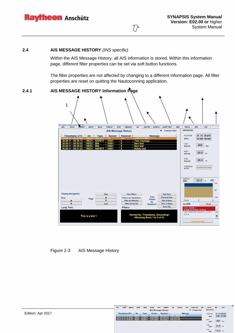
2.4 AIS MESSAGE HISTORY (INS specific) ............................................................... 2-7
2.4.1 AIS MESSAGE HISTORY Information Page .................................................. 2-7
2.5 NAVTEX MESSAGE HISTORY (INS specific) ...................................................... 2-9
2.5.1 NAVTEX MESSAGE HISTORY Information Page ......................................... 2-9
SYNAPSIS System Manual Version: E02.00 or higher System Manual
4346.DOC000002 IV Edition: Apr 2017
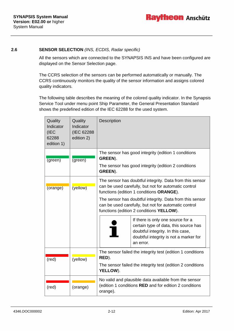
2.6 SENSOR SELECTION (INS, ECDIS, Radar specific) ......................................... 2-12
2.6.1 SENSOR SELECTION ................................................................................ 2-14
2.7 SYSTEM STATUS (INS specific) ........................................................................ 2-24
2.7.1 SYSTEM STATUS Information Page ........................................................... 2-24
3 CCRS Data Processing ................................................................................................ 3-1
3.1 CCRS Principle ..................................................................................................... 3-1
3.2 Valid Input Data .................................................................................................... 3-3
3.3 Criteria Plausibility Checks .................................................................................... 3-6
3.4 Sensor Timeouts ................................................................................................... 3-7
3.5 CCRP Correction .................................................................................................. 3-7
3.6 Methods of Integrity Verification ............................................................................ 3-8
3.6.1 Consistency Check ........................................................................................ 3-9
3.7 Sensor Monitoring and Rating (IEC 62288 edition 1 and 2) ................................. 3-12
3.8 Automatic and Manual Sensor Selection ............................................................. 3-13
3.9 Data Calculation ................................................................................................. 3-13
3.10 Time Synchronization ......................................................................................... 3-13
4 Integrated Target Management .................................................................................... 4-1
4.1 Target Association ................................................................................................ 4-1
4.2 Target Labels ........................................................................................................ 4-2
4.3 AIS capacity and Limitations for Target Processing and Display ........................... 4-2
5 User Settings and Default Displays .............................................................................. 5-3
6 Interfaces and Data Distribution ................................................................................... 6-1
6.1 Interface to Standard 22 GYRO Compass System................................................ 6-2
6.2 NMEA Interfaces ................................................................................................... 6-2
6.3 Interfaces to External Equipment .......................................................................... 6-3
6.4 Output Interface to VDR ........................................................................................ 6-3
6.5 Interfaces to BNWAS ............................................................................................ 6-3
6.6 Alert Related Communication and System Monitoring .......................................... 6-4
6.7 Required Redundancies ....................................................................................... 6-4
6.8 Recommendations for System Design .................................................................. 6-4
6.8.1 Redundant AP/GYRO Supply via NautoPlex8plus8 ....................................... 6-4
6.8.2 Redundant AIS Supply ................................................................................... 6-5
7 CCRS and System Monitoring Alert List ....................................................................... 7-1
7.1 Overview ............................................................................................................... 7-1
7.2 Detailed Description .............................................................................................. 7-5
7.2.1 POSITION: NOT AVAILABLE ........................................................................ 7-5
7.2.2 GPS TIME AND SYSTEM TIME DO NOT MATCH ........................................ 7-7
7.2.3 SWITCHING TO DEAD RECKONING ........................................................... 7-8

SYNAPSIS System Manual Version: E02.00 or higher
System Manual
Edition: Apr 2017 V 4346.DOC000002
7.2.4 >>SENSOR<<: MODE INDICATIOR INCONSISTENT .................................. 7-8
7.2.5 COG/SOG: NOT AVAILABLE ........................................................................ 7-9
7.2.6 WATER SPEED: NOT AVAILABLE ............................................................. 7-10
7.2.7 SET AND DRIFT: NOT AVAILBLE............................................................... 7-11
7.2.8 HEADING: NOT AVAILABLE ....................................................................... 7-12
7.2.9 POSITION AND SPEED ARE NOT REFERENCED TO CCRP ................... 7-13
7.2.10 ROT: NOT AVAILABLE ............................................................................... 7-14
7.2.11 WATER DEPTH: NOT AVAILABLE ............................................................. 7-15
7.2.12 UTC TIME DEVIATION MORE THAN >>DIIFERENCE<< ........................... 7-16
7.2.13 WIND: NOT AVAILABLE ............................................................................. 7-17
7.2.14 ROLL/PITCH: NOT AVAILABLE .................................................................. 7-18
7.2.15 AIR PRESSURE: NOT AVAILABLE ............................................................. 7-19
7.2.16 HUMIDITY: NOT AVAILABLE ...................................................................... 7-20
7.2.17 AIR TEMP: NOT AVAILABLE ...................................................................... 7-21
7.2.18 WATER TEMP: NOT AVAILABLE ............................................................... 7-22
7.2.19 >>DATA<<: NOT AVAILABLE FROM SENSOR >>SENSOR<< (IN USE) ... 7-23
7.2.20 >>DATA<<: POOR INTEGRITY .................................................................. 7-25
7.2.21 >>DATA<<: BETTER SENSOR AVAILABLE ............................................... 7-26
7.2.22 CCRS BACKUP LOST ................................................................................. 7-26
7.2.23 AIS CCRP DIFFERS FROM INS CCRP ...................................................... 7-27
7.2.24 >>SENSOR<< IS HEATING/SETTLING –HEADING IS NOT USED ........... 7-27
7.2.25 HEADING FROM >>SENSOR<< IS UNCORRECTED ................................ 7-28
7.2.26 WMM COEFFICIENT FILE HAS EXPIRED ................................................. 7-29
7.2.27 WMM COEFFICIENT FILE .......................................................................... 7-30
7.2.28 WMM COEFFICIENT FILE IS INVALID OR MISSING ................................. 7-31
7.2.29 MAGNETIC DEVIATION TABLE IS NOT INITIALIZED ................................ 7-32
7.2.30 COMPASS SYSTEM: TO SELECT SENSOR AT CCRS ............................. 7-32
7.2.31 CCRS: UNABLE TO SELECT SENSOR AT COMPASS SYSTEM .............. 7-33
7.2.32 HEAVE: NOT AVAILABLE ........................................................................... 7-34
7.2.33 POSITION OFFSET APPLIED ..................................................................... 7-35
8 System Monitoring Alerts ............................................................................................. 8-1
8.1 Overview ............................................................................................................... 8-1
8.2 Detailed Description .............................................................................................. 8-3
8.2.1 >>DEVICE<<: LOSS OF SYSTEM COMMUNICATION ................................. 8-3
8.2.2 >>MFC<<: HOST LOST ................................................................................ 8-4
8.2.3 >>DEVICE<<: FUNCTION LOST .................................................................. 8-4
8.2.4 NEW >>TYPE<< MESSAGE RECEIVED ...................................................... 8-5
8.2.5 TEST ALERT ONLY ...................................................................................... 8-5
8.2.6 >>SWITCH<< BANDWIDTH LIMIT REACHED.............................................. 8-6
8.2.7 >>SWITCH<< LINK FAILURE ....................................................................... 8-6
8.2.8 DEPTH TOO SHALLOW, LESS THAN >>LIMIT<< ........................................ 8-7
9 Target Related Alerts ................................................................................................... 9-1

SYNAPSIS System Manual Version: E02.00 or higher System Manual
4346.DOC000002 VI Edition: Apr 2017
9.1 Overview ............................................................................................................... 9-1
9.2 Detailed Description .............................................................................................. 9-2
9.2.1 CPA TCPA BY >>COUNT<< TARGET(S) ..................................................... 9-2
9.2.2 LOST >>COUNT<< TARGET(S) ................................................................... 9-2
9.2.3 >>COUNT<< NEW TARGET(S) FROM >>SOURCE<< ................................. 9-3
9.2.4 >>COUNT<< NEW TARGET(S) .................................................................... 9-3
9.2.5 GUARD ZONE INTRUSION BY >>COUNT<< TARGET(S) ........................... 9-4
9.2.6 LOST REFERENCE TARGET ....................................................................... 9-4
9.2.7 MAX >>COUNT<< TARGET(S) ..................................................................... 9-5
10 Power Supply Requirements INS ............................................................................... 10-6
10.1 Power Supply Requirements INS supplied with separate Power Net .................. 10-6
10.1.1 Switching Board ........................................................................................... 10-8
10.1.2 UPS Requirements ...................................................................................... 10-9
10.1.3 Participants ................................................................................................ 10-10
10.1.3.1 Console / MFC ....................................................................................... 10-10
10.1.3.2 Switch 10-10
10.1.3.3 Serial / Ethernet (NautoPlex 8plus8)....................................................... 10-10
11 Fulfilled Carriage Requirements of INS ...................................................................... 11-1
12 Power Supply Failure ................................................................................................. 12-1
13 System Recovery Timer ............................................................................................. 13-1
14 Reference to IEC 61924 INS Performance Standard (INS specific) ........................... 14-1
14.1 Latency (IEC section 5.3.3.2) .............................................................................. 14-1
14.1.1 Radar Tracks ............................................................................................... 14-1
14.1.2 Track Control ............................................................................................... 14-1
14.1.3 Correlation of Radar Echos .......................................................................... 14-1
14.1.4 High Speed Craft ......................................................................................... 14-1
14.2 Required Number of Consoles (IEC section 6.3.1) .............................................. 14-2
14.3 Reduction of Single Point of Failure (IEC section 6.5.2.2) ................................... 14-3
14.4 Style Book (IEC section 6.5.1.2) ......................................................................... 14-4
14.4.1 General Screen Layout ................................................................................ 14-4
14.4.2 Color Palettes .............................................................................................. 14-7
14.4.3 Alarm Window .............................................................................................. 14-7
14.4.4 Sensor Selection Page ................................................................................ 14-8
14.4.5 Analog Instruments .................................................................................... 14-10
14.4.6 Navigation Page with Ship Symbole .......................................................... 14-10
14.4.7 Other Display features for Conning Display ............................................... 14-11
14.4.8 Tool Bar for ECDIS .................................................................................... 14-12
14.4.9 Pull Down Menu ......................................................................................... 14-12
14.4.10 Alert Management HMI .............................................................................. 14-13
SYNAPSIS System Manual Version: E02.00 or higher
System Manual
Edition: Apr 2017 VII 4346.DOC000002
14.4.11 Alert and Acknowledge Button ................................................................... 14-14
14.4.12 System Status Page .................................................................................. 14-14
14.4.13 AIS and Navtex Messages ......................................................................... 14-15
14.4.14 Monitor Settings ......................................................................................... 14-17
14.4.15 MCF Task Switch ....................................................................................... 14-18
14.5 License Convention .......................................................................................... 14-20
TABLE OF FIGURES
Figure 1-1 SYNAPSIS Block Diagram ........................................................................... 1-3
Figure 1-2 SYNAPSIS System architecture under BoxPc conditions ............................. 1-4
Figure 1-3 SYNAPSIS System architecture under Small Marine Computer conditions .. 1-5
Figure 1-4 Sensor & Interface Management Small Marine Computer (LAN) .................. 1-6
Figure 1-5 CAM Architecture ....................................................................................... 1-11
Figure 2-1 Central Alert Management ........................................................................... 2-3
Figure 2-2 Alert History Information ............................................................................... 2-5
Figure 2-3 AIS Message History .................................................................................... 2-7
Figure 2-4 NAVTEX Message History ........................................................................... 2-9
Figure 2-5 INS Sensor Selection Page ........................................................................ 2-14
Figure 2-6 ECDIS Nav Device Selection ..................................................................... 2-15
Figure 2-7 Radar Device Selection .............................................................................. 2-20
Figure 2-8 SYSTEM STATUS Information Page ......................................................... 2-24
Figure 3-1 CCRS Data Flow .......................................................................................... 3-2
Figure 6-1 Logic Interface of SYNAPSIS INS ................................................................ 6-1
Figure 10-1 General Network Setup .............................................................................. 10-7
Figure 10-2 Switching Board ......................................................................................... 10-8
Figure 14-1 Screen Layout Conning .............................................................................. 14-4
Figure 14-2 Screen Layout Conning Selection Page ..................................................... 14-5
Figure 14-3 Screen Layout Radar ................................................................................. 14-5
Figure 14-4 Screen Layout ECDIS ................................................................................ 14-6
Figure 14-5 Alarm Window ............................................................................................ 14-7
Figure 14-6 Sensor Selection Page Conning ................................................................. 14-8
Figure 14-7 Sensor Selection Page ECDIS ................................................................... 14-9
Figure 14-8 Sensor Information Radar .......................................................................... 14-9
Figure 14-9 Motion data around silhouette of vessel ................................................... 14-10
Figure 14-10 Pointer Instruments Graphs...................................................................... 14-11
Figure 14-11 Toolbar ..................................................................................................... 14-12
Figure 14-12 Pull Down Menu Nautoconning and ECDIS .............................................. 14-12
Figure 14-13 Alert Management HMI ............................................................................ 14-13
Figure 14-14 Alert Button and Acknowledge Button ...................................................... 14-14
Figure 14-15 System Status Page ................................................................................. 14-14
Figure 14-16 AIS Messages Page ................................................................................. 14-15
SYNAPSIS System Manual Version: E02.00 or higher System Manual
4346.DOC000002 VIII Edition: Apr 2017
Figure 14-17 NAVTEX Page ......................................................................................... 14-16
Figure 14-18 Monitor Settings ....................................................................................... 14-17
Figure 14-19 MFC Task Switch ..................................................................................... 14-19
TABLE OF TABLES
Table 1-1 Removed Alerts for switched off Functions / Components .......................... 1-12
Table 1-2 Emergency Alert Symbol ............................................................................ 1-15
Table 1-3 Alarm Symbols ........................................................................................... 1-15
Table 1-4 Warning Symbols ....................................................................................... 1-15
Table 1-5 Caution Symbol .......................................................................................... 1-15
Table 1-6 Acknowledge Not Allowed Symbols ........................................................... 1-16
Table 1-7 Alert Signaling ............................................................................................ 1-16
Table 1-8 Warnings repeated as warning ................................................................... 1-17
Table 3-1 Sentence Specific Criteria for Valid Data ...................................................... 3-3
Table 3-2 Criteria for Plausibility Checks ...................................................................... 3-6
Table 3-3 Methods of Integrity Monitoring .................................................................... 3-8
Table 3-4 Deviance Threshold ................................................................................... 3-10
Table 3-5 Sensor Monitoring and Rating .................................................................... 3-12
Table 5-1 Settings for Route Monitoring and Route Planning Display (ECDIS) ............ 5-3
Table 5-2 Settings for Collision Avoidance (Radar) ...................................................... 5-4
Table 6-1 NMEA Interfaces .......................................................................................... 6-2
Table 7-1 Monitoring Alert List ...................................................................................... 7-1
Table 8-1 Re-evaluate Function Lost Alert Priority ....................................................... 8-1
Table 8-2 System Monitoring Alerts.............................................................................. 8-1
Table 9-1 Target Related Alerts ................................................................................... 9-1
Table 10-1 UPS specification ....................................................................................... 10-9

SYNAPSIS System Manual Version: E02.00 or higher
System Manual
Edition: Apr 2017 IX 4346.DOC000002
0 General
The present manual has been drawn up as a description and reference book.
It will help answer questions and will solve problems in the quickest possible manner.
Before operating the equipment read and follow the instructions and hints in this manual.
For this purpose refer to the table of contents and read the corresponding chapters
thoroughly.
If you have any further questions, please contact us on the following address:
RAYTHEON ANSCHÜTZ GMBH
Zeyestr. 16 - 24
D-24106 Kiel
Germany Tel. +49 431 / 3019 - 0
Fax +49 31 / 3019 - 291
All rights reserved. No part of this manual may be copied, neither mechanically,
electronically, magnetically, manually nor otherwise, or distributed, forwarded or stored in
a data bank without written permission of RAYTHEON ANSCHÜTZ GMBH.
Copyright:
RAYTHEON ANSCHÜTZ GMBH
Zeyestr. 16 - 24
D-24106 Kiel
Germany
Since errors can hardly be avoided in the documentation in spite of all efforts, we should
appreciate any remark and suggestion.
Subject to alterations.
SYNAPSIS System Manual Version: E02.00 or higher System Manual
4346.DOC000002 X Edition: Apr 2017
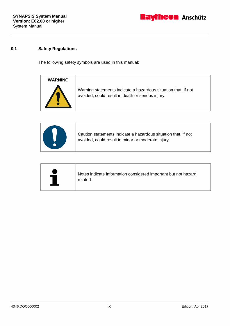
0.1 Safety Regulations
The following safety symbols are used in this manual:
WARNING
Warning statements indicate a hazardous situation that, if not
avoided, could result in death or serious injury.
Caution statements indicate a hazardous situation that, if not
avoided, could result in minor or moderate injury.
Notes indicate information considered important but not hazard
related.
SYNAPSIS System Manual Version: E02.00 or higher
System Manual
Edition: Apr 2017 XI 4346.DOC000002
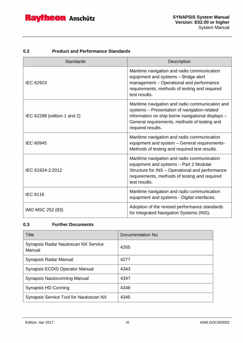
0.2 Product and Performance Standards
Standards Description
IEC 62923
Maritime navigation and radio communication
equipment and systems – Bridge alert
management – Operational and performance
requirements, methods of testing and required
test results.
IEC 62288 (edition 1 and 2)
Maritime navigation and radio communication and
systems – Presentation of navigation-related
information on ship borne navigational displays –
General requirements, methods of testing and
required results.
IEC 60945
Maritime navigation and radio communication
equipment and system – General requirements-
Methods of testing and required test results.
IEC 61924-2:2012
Maritime navigation and radio communication
equipment and systems – Part 2 Modular
Structure for INS – Operational and performance
requirements, methods of testing and required
test results.
IEC 6116 Maritime navigation and radio communication
equipment and systems - Digital interfaces.
IMO MSC 252 (83) Adoption of the revised performance standards
for Integrated Navigation Systems (INS).
0.3 Further Documents
Title Documentation No.
Synapsis Radar Nautoscan NX Service
Manual 4265
Synapsis Radar Manual 4277
Synapsis ECDIS Operator Manual 4343
Synapsis Nautoconning Manual 4347
Synapsis HD Conning 4348
Synapsis Service Tool for Nautoscan NX 4345
SYNAPSIS System Manual Version: E02.00 or higher System Manual
4346.DOC000002 XII Edition: Apr 2017
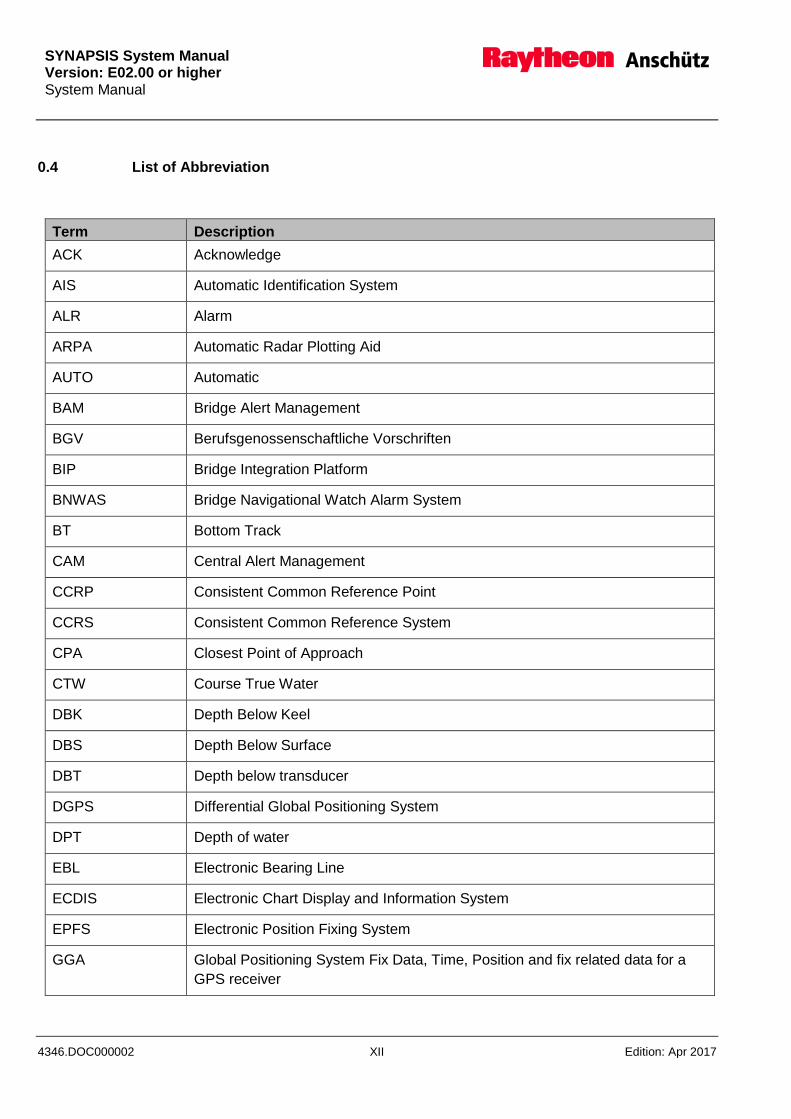
0.4 List of Abbreviation
Term Description
ACK Acknowledge
AIS Automatic Identification System
ALR Alarm
ARPA Automatic Radar Plotting Aid
AUTO Automatic
BAM Bridge Alert Management
BGV Berufsgenossenschaftliche Vorschriften
BIP Bridge Integration Platform
BNWAS Bridge Navigational Watch Alarm System
BT Bottom Track
CAM Central Alert Management
CCRP Consistent Common Reference Point
CCRS Consistent Common Reference System
CPA Closest Point of Approach
CTW Course True Water
DBK Depth Below Keel
DBS Depth Below Surface
DBT Depth below transducer
DGPS Differential Global Positioning System
DPT Depth of water
EBL Electronic Bearing Line
ECDIS Electronic Chart Display and Information System
EPFS Electronic Position Fixing System
GGA Global Positioning System Fix Data, Time, Position and fix related data for a
GPS receiver

SYNAPSIS System Manual Version: E02.00 or higher
System Manual
Edition: Apr 2017 XIII 4346.DOC000002
Term Description
GLL Geographic Position - Latitude/Longitude
GNS Fix Data
GPS Global Positioning System
HDG Heading - Deviation & Variation
HDT Heading - True
HMI Human Machine Interface
IEC International Electro technical Commission
IMO International Maritime Organization
INS Integrated Navigation System
ITM Integrated Target Management
LAN Local Area Network
MAN Manual
MFC Multifunction Console
MFD Multifunction Display
MHU Humidity
MKD Minimum Keyboard and Display
MMSI Maritime Mobile Service Identify
MSC Marine Safety Committee
MTW Water Temperature
MWD Wind Direction and Speed
MWV Wind Speed and Angle
NMEA National Marine Electronics Association
NMEA0183 Standard protocol for data transfer
NRX NavTex
NSR National Standard Report
PCP Potential Collision Point
RAN Raytheon Anschütz
SYNAPSIS System Manual Version: E02.00 or higher System Manual
4346.DOC000002 XIV Edition: Apr 2017
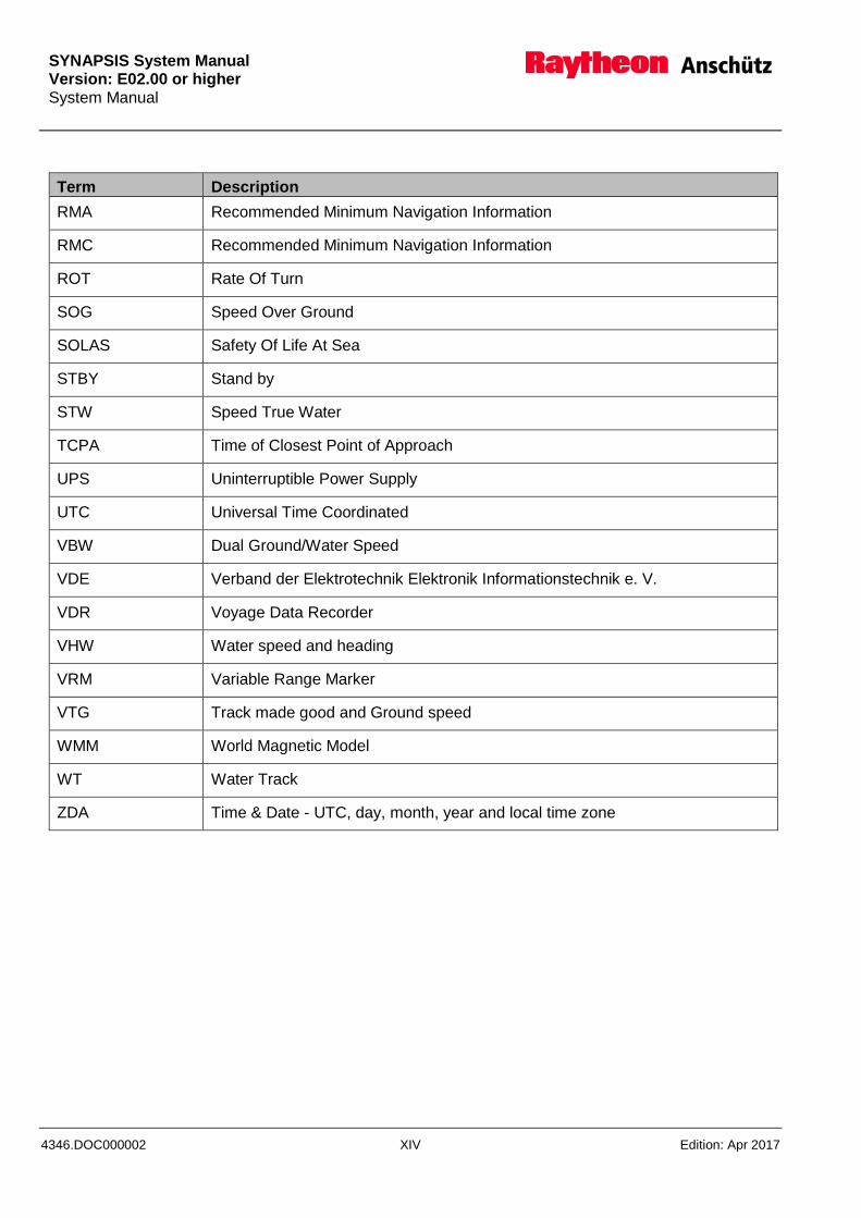
Term Description
RMA Recommended Minimum Navigation Information
RMC Recommended Minimum Navigation Information
ROT Rate Of Turn
SOG Speed Over Ground
SOLAS Safety Of Life At Sea
STBY Stand by
STW Speed True Water
TCPA Time of Closest Point of Approach
UPS Uninterruptible Power Supply
UTC Universal Time Coordinated
VBW Dual Ground/Water Speed
VDE Verband der Elektrotechnik Elektronik Informationstechnik e. V.
VDR Voyage Data Recorder
VHW Water speed and heading
VRM Variable Range Marker
VTG Track made good and Ground speed
WMM World Magnetic Model
WT Water Track
ZDA Time & Date - UTC, day, month, year and local time zone
SYNAPSIS System Manual
Version: E02.00 or higher System Manual
Edition: Apr 2017 1-1 4346.DOC000002
1 System Description
1.1 General Infomation
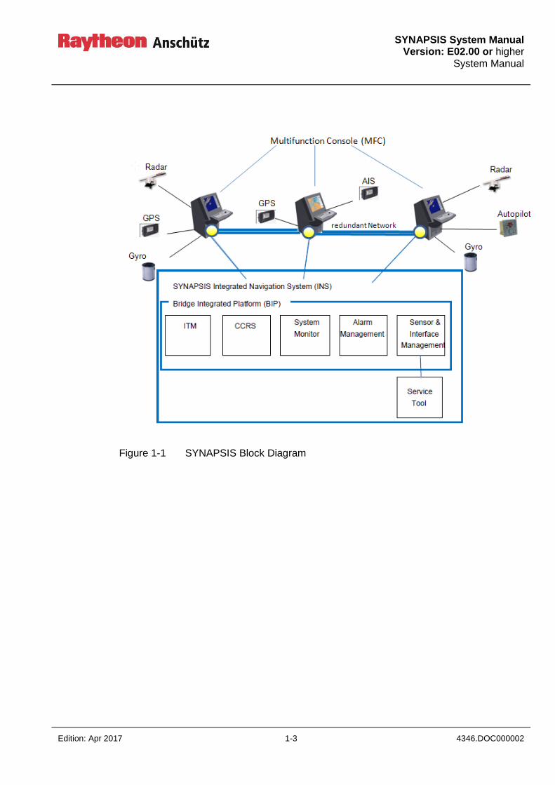
The SYNAPSIS Bridge Integrated Platform (BIP) provides data management and data
distribution functionality for the SYNAPSIS INS as well as the SYNAPSIS stand-alone
systems Radar, ECDIS, ECDIS 24 and Nautoconning. The overall functionality of the BIP
is depicted in Figure 1-1.
The SYNAPSIS INS thus handles the nautical functions Route Planning, Route
Monitoring, Collision Avoidance, Navigation Control Data, Status and Data Display,
Central Alert Management and Track Control in accordance with the INS performance
standard.
A multifunction console (MFC) on which an ECDIS is installed can be used as a task
station for Route Planning and Route Monitoring.
If the radar application is installed, the MFC can be used as a task station for Collision
Avoidance.
An installed Nautoconning system provides the tasks Navigation Control Data, Status
and Data Display and Central Alert Management.
An ECDIS and an Autopilot are required for execution of Track Control.
An INS bridge system essentially comprises the multifunction consoles (MFC) and the
Autopilot. The computers of the multifunction consoles are generally equipped and
supplied with the software for the applications for Radar, ECDIS and Nautoconning and
the SYNAPSIS Bridge Integration Platform. Multifunction consoles are connected to a
system wide redundant network (LAN).
In addition to interfacing of the sensors (Gyro, GPS, AIS, etc.), the INS bridge system also
provides an interface to the Bridge Navigational Watch Alarm System BNWAS (ALERT
ESCALATION).
The configuration of the SYNAPSIS INS can be performed or modified from any
multifunction console within the bridge system. After confirmation, changes are
transmitted to all the MFCs via the network (LAN) and are after a restart of the system
effective.
The SYNAPSIS INS includes a Consistent Common Reference System (CCRS). This
system evaluates the sensor data applying qualifying criteria and provides analysed data
to all components. On request, the CCRS automatically selects the best sensors (see
section 0).

SYNAPSIS System Manual Version: E02.00 or higher System Manual
4346.DOC000002 1-2 Edition: Apr 2017
The SYNAPSIS INS includes an Integrated Target Management (ITM). This management
evaluates the tracked targets and AIS acquired from the Radar equipment in the system.
In this case a central target association, calculation, evaluation and alerting take place.
The user benefit is a redundantly target apparition on an avoidance display and a
redundantly alarm handling.
The SYNAPSIS INS fulfilled the Bridge Alert Management (BAM) concept corresponding
to the IMO Performance standard.
The overarching Alert System displays in a unified and harmonized way, navigational and
system alarms and messages simultaneously on all MFCs.
The system monitor of the SYNAPSIS INS monitors the components of the System and
the interfaced sensors.
INS specific
SYNAPSIS INS information pages (SENSOR SELECTION, AIS HISTORY, CENTRAL
ALERT MANAGEMENT, ALERT HISTORY, NAVTEX HISTORY, SYSTEM STATUS) are
provided within the Nautoconning application.
Within the ECDIS application, the SENSOR SELECTION information page is provided for
the sensor selection.
A system wide dimming and color scheme changeover is possible at any time at any
MFC.
A service tool integrated into the SYNAPSIS INS allows centralized input of ship-specific
parameters, the adaption of all interfaced sensors and the read-out of log and system
error messages. Access to the service tool is protected by a password and should only be
allowed to trained personnel.
SYNAPSIS System Manual
Version: E02.00 or higher System Manual
Edition: Apr 2017 1-3 4346.DOC000002
Figure 1-1 SYNAPSIS Block Diagram
SYNAPSIS System Manual Version: E02.00 or higher System Manual
4346.DOC000002 1-4 Edition: Apr 2017
1.2 SYNAPSIS System Architecture
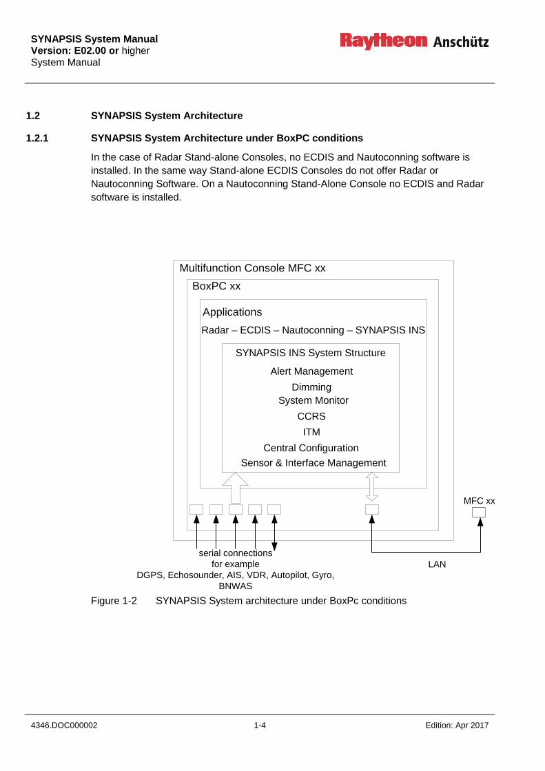
1.2.1 SYNAPSIS System Architecture under BoxPC conditions
In the case of Radar Stand-alone Consoles, no ECDIS and Nautoconning software is
installed. In the same way Stand-alone ECDIS Consoles do not offer Radar or
Nautoconning Software. On a Nautoconning Stand-Alone Console no ECDIS and Radar
software is installed.
Figure 1-2 SYNAPSIS System architecture under BoxPc conditions
Multifunction Console MFC xx
BoxPC xx
Applications
SYNAPSIS INS System Structure
Radar – ECDIS – Nautoconning – SYNAPSIS INS
Alert Management
Dimming
System Monitor
ITM
Central Configuration
Sensor & Interface Management
LAN
MFC xx
serial connections
for example
DGPS, Echosounder, AIS, VDR, Autopilot, Gyro,
BNWAS
CCRS

SYNAPSIS System Manual
Version: E02.00 or higher System Manual
Edition: Apr 2017 1-5 4346.DOC000002
1.2.2 SYNAPSIS System Architecture under Small Marine Computer conditions
In the case of Radar Stand-alone Consoles, no ECDIS and Nautoconning software is
installed. In the same way Stand-alone ECDIS Consoles do not offer Radar or
Nautoconning Software. On a Nautoconning Stand-Alone Console no ECDIS and Radar
software is installed.
Figure 1-3 SYNAPSIS System architecture under Small Marine Computer conditions
Seriell / Ethernet Unit
Multifunction Console MFC xx
Small Marine Computer
Applications
SYNAPSIS INS System Structure
Radar – ECDIS – Nautoconning – SYNAPSIS INS
Alert Management
Dimming
System Monitor
ITM
Central Configuration
Sensor & Interface Management
LA
N MFC xx
serial connections
for example
DGPS, Echosounder, AIS, VDR, Autopilot, Gyro,
BNWAS
CCRS
Seriell / Ethernet Unit
LA
N

SYNAPSIS System Manual Version: E02.00 or higher System Manual
4346.DOC000002 1-6 Edition: Apr 2017
Switch
PC
PC
SwitchSwitch 1
MFC2
AIS GPS2LOG GPS1 Echosounder VDR
Pedestal
1
Pedestal
2
Wind
Gateway
Gyro /
Autopilot
BNWAS NAVTEX
MFC1
Switch 2
Serial / Ethernet 1 Serial / Ethernet 2
MFC2CAM-HMI
(optional)
Figure 1-4 Sensor & Interface Management Small Marine Computer (LAN)
SYNAPSIS System Manual
Version: E02.00 or higher System Manual
Edition: Apr 2017 1-7 4346.DOC000002
1.3 SYNAPSIS INS System Structure
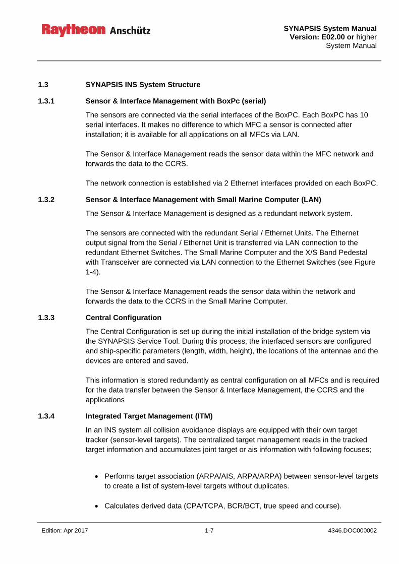
1.3.1 Sensor & Interface Management with BoxPc (serial)
The sensors are connected via the serial interfaces of the BoxPC. Each BoxPC has 10
serial interfaces. It makes no difference to which MFC a sensor is connected after
installation; it is available for all applications on all MFCs via LAN.
The Sensor & Interface Management reads the sensor data within the MFC network and
forwards the data to the CCRS.
The network connection is established via 2 Ethernet interfaces provided on each BoxPC.
1.3.2 Sensor & Interface Management with Small Marine Computer (LAN)
The Sensor & Interface Management is designed as a redundant network system.
The sensors are connected with the redundant Serial / Ethernet Units. The Ethernet
output signal from the Serial / Ethernet Unit is transferred via LAN connection to the
redundant Ethernet Switches. The Small Marine Computer and the X/S Band Pedestal
with Transceiver are connected via LAN connection to the Ethernet Switches (see Figure
1-4).
The Sensor & Interface Management reads the sensor data within the network and
forwards the data to the CCRS in the Small Marine Computer.
1.3.3 Central Configuration
The Central Configuration is set up during the initial installation of the bridge system via
the SYNAPSIS Service Tool. During this process, the interfaced sensors are configured
and ship-specific parameters (length, width, height), the locations of the antennae and the
devices are entered and saved.
This information is stored redundantly as central configuration on all MFCs and is required
for the data transfer between the Sensor & Interface Management, the CCRS and the
applications
1.3.4 Integrated Target Management (ITM)
In an INS system all collision avoidance displays are equipped with their own target
tracker (sensor-level targets). The centralized target management reads in the tracked
target information and accumulates joint target or ais information with following focuses;
Performs target association (ARPA/AIS, ARPA/ARPA) between sensor-level targets
to create a list of system-level targets without duplicates.
Calculates derived data (CPA/TCPA, BCR/BCT, true speed and course).

SYNAPSIS System Manual Version: E02.00 or higher System Manual
4346.DOC000002 1-8 Edition: Apr 2017
Evaluates target data against thresholds (CPA/TCPA limit, guard zone).
Generates targets-related alerts (new target, lost target, CPA/TCPA violation, guard
zone) based on system-level targets.
Sends system-level targets to Collision Avoidance and Route Monitoring display
together with all target-related data for immediate situation assessment.
Target-related alerts (cat. A) are acknowledgeable at every Collision Avoidance
(Radar) and Route Monitoring (ECDIS) display
Collision Avoidance and Route Monitoring displays provide means to set target
management parameters (e.g. threshold, labels, association priorities, zones, …).
If provided, information from tender tracking system is incorporated into the integrated
target management.
1.3.5 Consistent Common Reference System (CCRS)
The Consistent Common Reference System performs a qualitative evaluation of all sensor
data. The sensor data is displayed on the SENSOR SELECTION page (in the
Nautoconning application, if available). A color scaling scheme rates the quality of the
sensor data.
If a sensor failure is registered within the INS, the CCRS immediately initiates an
automatic changeover to a backup sensor and generates an associated alert
1.3.6 System Monitor
The system monitor monitors all applications of the MFCs, the hardware (BoxPC) and the
external devices interfaced to the INS.
The status of all interfaced devices is continuously monitored (ON or OFF). Devices
providing an NMEA alert interface (ALR or ALC/ALF telegram format) generate additional
error or fault messages. This information is read in via the alert system and displayed at
the CENTRAL ALERT management HMI.
The system monitor provides simple monitoring of the network. It checks continuously
whether an MFC can be reached via the network. Error and status messages of the
network switches are not evaluated

SYNAPSIS System Manual
Version: E02.00 or higher System Manual
Edition: Apr 2017 1-9 4346.DOC000002
1.3.7 Dimming
All MFCs of a bridge system support a synchronized system wide changeover of the color
schemes in addition to the common brightness dimming.
For dimming and change of color scheme, the MFCs are split into groups using the
service tool during the initial installation. The changeover of the color scheme at an MFC
or the setting of the global dimming value always applies to all the MFCs belonging to the
same group.
Furthermore, each MFC can be adjusted individually according to the light conditions
without influencing other MFCs.
The change of color schemes is provided when using Radar, ECDIS or Nautoconning

SYNAPSIS System Manual Version: E02.00 or higher System Manual
4346.DOC000002 1-10 Edition: Apr 2017
1.4 Bridge Alert Management (BAM)
Bridge alert management (BAM) is an overall concept to enhance the handling,
distribution and presentation of alerts on the bridge in a consistent manner.
This concept is described in the IMO performance standard “MSC.302(87) Performance
standard for Bridge Alert Management”. Equipment related details are defined in other
equipment related performance and test standards.
The objective of BAM is to harmonize the priority, classification, handling, distribution and
presentation of alerts, to enable the bridge team to devote full attention to the safe
operation of the ship and to immediately identify any alert situation requiring attention
and/or action to maintain the safe operation of the ship.
Unnecessary distraction of the bridge team by redundant and superfluous audible and
visual alert announcements should be avoided. It reduces the cognitive workload of the
operator by minimizing the information presented which is necessary to draw attention to
and to assess the situation.
On the bridge alerts are presented on the individual equipment and/or on a central alert
management human machine interface (CAM-HMI).
The central alert management (CAM) is an integral part of the SYNAPSIS INS. Figure 1-5
shows an overview of the CAM architecture within the INS. The CAM-HMI can be
presented on multiple MFCs of the system or on separate panel PCs. The CAM-HMI shall
at least be installed at the navigation and manoeuvring workstation. Providing CAM-HMIs
on all MFCs of the system ensures additional backups for central alert management.
The SYNAPSIS CAM is preconfigured to meet the IMO requirements for alert handling.
The CAM-HMI displays all alerts from the SYNAPSIS INS as well as all alerts which are
sent by connected systems. Bridge alert management requires that all systems on the
bridge which are able to generate alerts shall be connected to the CAM.
If an INS is installed, MSC.302(87) requires the CAM-HMI to be integrated into the INS. It
is not allowed to operate an INS and a separate, non-integrated CAM-HMI in parallel.
The system supports alert communication based on
ALC, ALF, ACN, and ARC sentences as defined in IEC 61924-2
ALR, ACK sentences as defined in IEC 61162-1
relay contacts with definable alert texts and priorities
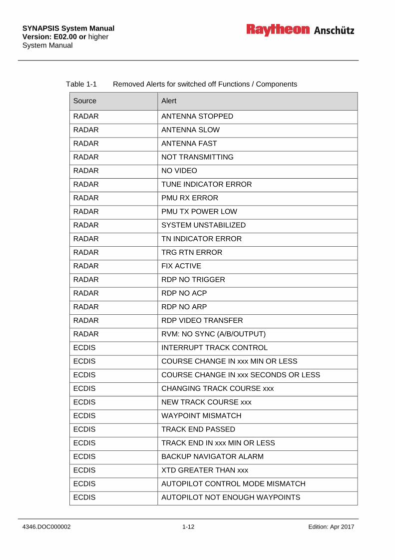
If a function / component is switched off deliberately, alerts from this function / component
will be removed, see Table 1-1.

SYNAPSIS System Manual
Version: E02.00 or higher System Manual
Edition: Apr 2017 1-11 4346.DOC000002
Figure 1-5 CAM Architecture
SYNAPSIS System Manual Version: E02.00 or higher System Manual
4346.DOC000002 1-12 Edition: Apr 2017
Table 1-1 Removed Alerts for switched off Functions / Components
Source Alert
RADAR ANTENNA STOPPED
RADAR ANTENNA SLOW
RADAR ANTENNA FAST
RADAR NOT TRANSMITTING
RADAR NO VIDEO
RADAR TUNE INDICATOR ERROR
RADAR PMU RX ERROR
RADAR PMU TX POWER LOW
RADAR SYSTEM UNSTABILIZED
RADAR TN INDICATOR ERROR
RADAR TRG RTN ERROR
RADAR FIX ACTIVE
RADAR RDP NO TRIGGER
RADAR RDP NO ACP
RADAR RDP NO ARP
RADAR RDP VIDEO TRANSFER
RADAR RVM: NO SYNC (A/B/OUTPUT)
ECDIS INTERRUPT TRACK CONTROL
ECDIS COURSE CHANGE IN xxx MIN OR LESS
ECDIS COURSE CHANGE IN xxx SECONDS OR LESS
ECDIS CHANGING TRACK COURSE xxx
ECDIS NEW TRACK COURSE xxx
ECDIS WAYPOINT MISMATCH
ECDIS TRACK END PASSED
ECDIS TRACK END IN xxx MIN OR LESS
ECDIS BACKUP NAVIGATOR ALARM
ECDIS XTD GREATER THAN xxx
ECDIS AUTOPILOT CONTROL MODE MISMATCH
ECDIS AUTOPILOT NOT ENOUGH WAYPOINTS

SYNAPSIS System Manual
Version: E02.00 or higher System Manual
Edition: Apr 2017 1-13 4346.DOC000002
1.4.1 Alert Categories and Priorities
Alerts are divided in different categories:
Category A
Alerts for which graphical information at the task station (such as Radar or ECDIS)
directly assigned to the function generating the alert is necessary, as decision
support for the evaluation of the alert-related condition. These alerts can only be
acknowledged at the task station.
Category B
Alerts where no additional information for decision support is necessary besides the
information which can be presented at the CAM-HMI. These alerts can be
acknowledged at the task station or at the CAM-HMI.
Category C
Alerts that cannot be acknowledged on the bridge but for which information is
required about the status and treatment of the alerts (e.g. certain alerts from the
engine). The SYNAPSIS INS does not generate own category C alerts, but
processes and displays category C alerts from connected systems.
Alerts are divided in different priorities:
Emergency alarm
Highest priority of an alert. Alarms which indicate immediate danger to human life or
to the ship and its machinery exists and that immediate action must be taken. The
Synapsis INS does not generate own emergency alarms, but processes and
displays emergency alarms from connected systems.
Alarm
Alarms need immediate attention of the operator. The most recent alarm is always
displayed in the top line of the list.
- The alarm text is displayed in RED.
- Unacknowledged alarms are flashing.
- An acoustic signal is released with the alarm.
An Alarm must be acknowledged according to their category, A or B as assigned to
it. Category C alerts cannot be acknowledged on the bridge.
Warning
Warnings are not immediately dangerous, but may become so.
As long as there is no active or unacknowledged alarm, a current warning is
displayed in the top line of the list in yellowisch ORANGE.
- The warning text is displayed in ORANGE.
SYNAPSIS System Manual Version: E02.00 or higher System Manual
4346.DOC000002 1-14 Edition: Apr 2017
- Unacknowledged warnings are flashing.
- An acoustic signal is released with the warning.
A Warning must be acknowledged according to category A or B.
Category C alerts cannot be acknowledged on the bridge.Caution
CAUTION
An active caution message is always placed after the alarm and/or warning entries
in the displayed list. Caution messages are displayed in GRAY with a yellow symbol.
An active current caution message is also displayed as GRAY text on the alarm
displays of the applications Radar and ECDIS.

SYNAPSIS System Manual
Version: E02.00 or higher System Manual
Edition: Apr 2017 1-15 4346.DOC000002
Table 1-2 Emergency Alert Symbol
Icon/Symbol Description
Active
Table 1-3 Alarm Symbols
Icon/Symbol Description
Active – unacknowledged alarm (flashing)
Active – silenced alarm (flashing)
Active – acknowledged alarm
Rectified – unacknowledged alarm (flashing)
Active – responsibility transferred alarm
Table 1-4 Warning Symbols
Icon/Symbol Description
Active – unacknowledged warning (flashing)
Active – silenced warning (flashing)
Active – acknowledged warning
Rectified – unacknowledged warning (flashing)
Active – responsibility transferred warning
Table 1-5 Caution Symbol
Icon/Symbol Description
Caution
SYNAPSIS System Manual Version: E02.00 or higher System Manual
4346.DOC000002 1-16 Edition: Apr 2017
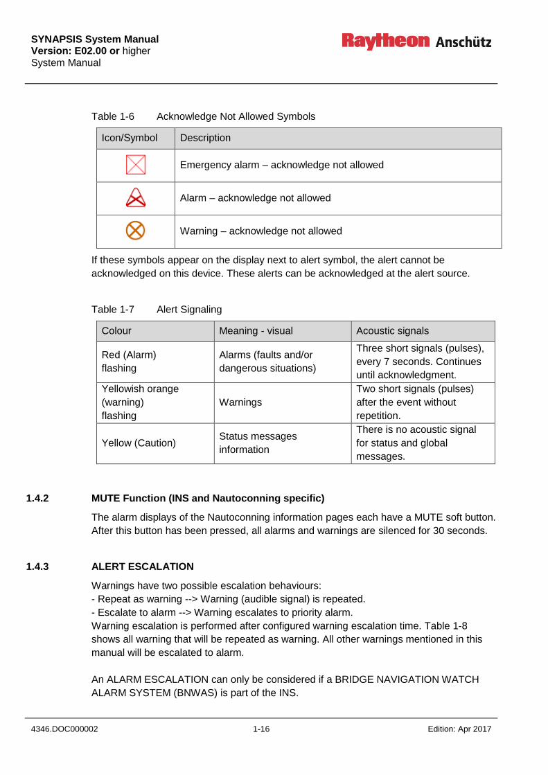
Table 1-6 Acknowledge Not Allowed Symbols
Icon/Symbol Description
Emergency alarm – acknowledge not allowed
Alarm – acknowledge not allowed
Warning – acknowledge not allowed
If these symbols appear on the display next to alert symbol, the alert cannot be
acknowledged on this device. These alerts can be acknowledged at the alert source.
Table 1-7 Alert Signaling
Colour Meaning - visual Acoustic signals
Red (Alarm)
flashing
Alarms (faults and/or
dangerous situations)
Three short signals (pulses),
every 7 seconds. Continues
until acknowledgment.
Yellowish orange
(warning)
flashing
Warnings
Two short signals (pulses)
after the event without
repetition.
Yellow (Caution) Status messages
information
There is no acoustic signal
for status and global
messages.
1.4.2 MUTE Function (INS and Nautoconning specific)
The alarm displays of the Nautoconning information pages each have a MUTE soft button.
After this button has been pressed, all alarms and warnings are silenced for 30 seconds.
1.4.3 ALERT ESCALATION
Warnings have two possible escalation behaviours:
- Repeat as warning --> Warning (audible signal) is repeated.
- Escalate to alarm --> Warning escalates to priority alarm.
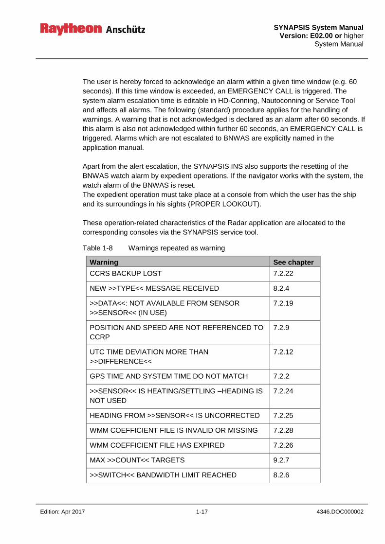
Warning escalation is performed after configured warning escalation time. Table 1-8
shows all warning that will be repeated as warning. All other warnings mentioned in this
manual will be escalated to alarm.
An ALARM ESCALATION can only be considered if a BRIDGE NAVIGATION WATCH
ALARM SYSTEM (BNWAS) is part of the INS.
SYNAPSIS System Manual
Version: E02.00 or higher System Manual
Edition: Apr 2017 1-17 4346.DOC000002
The user is hereby forced to acknowledge an alarm within a given time window (e.g. 60
seconds). If this time window is exceeded, an EMERGENCY CALL is triggered. The
system alarm escalation time is editable in HD-Conning, Nautoconning or Service Tool
and affects all alarms. The following (standard) procedure applies for the handling of
warnings. A warning that is not acknowledged is declared as an alarm after 60 seconds. If
this alarm is also not acknowledged within further 60 seconds, an EMERGENCY CALL is
triggered. Alarms which are not escalated to BNWAS are explicitly named in the
application manual.
Apart from the alert escalation, the SYNAPSIS INS also supports the resetting of the
BNWAS watch alarm by expedient operations. If the navigator works with the system, the
watch alarm of the BNWAS is reset.
The expedient operation must take place at a console from which the user has the ship
and its surroundings in his sights (PROPER LOOKOUT).
These operation-related characteristics of the Radar application are allocated to the
corresponding consoles via the SYNAPSIS service tool.
Table 1-8 Warnings repeated as warning
Warning See chapter
CCRS BACKUP LOST 7.2.22
NEW >>TYPE<< MESSAGE RECEIVED 8.2.4
>>DATA<<: NOT AVAILABLE FROM SENSOR
>>SENSOR<< (IN USE)
7.2.19
POSITION AND SPEED ARE NOT REFERENCED TO
CCRP
7.2.9
UTC TIME DEVIATION MORE THAN
>>DIFFERENCE<<
7.2.12
GPS TIME AND SYSTEM TIME DO NOT MATCH 7.2.2
>>SENSOR<< IS HEATING/SETTLING –HEADING IS
NOT USED
7.2.24
HEADING FROM >>SENSOR<< IS UNCORRECTED 7.2.25
WMM COEFFICIENT FILE IS INVALID OR MISSING 7.2.28
WMM COEFFICIENT FILE HAS EXPIRED 7.2.26
MAX >>COUNT<< TARGETS 9.2.7
>>SWITCH<< BANDWIDTH LIMIT REACHED 8.2.6

SYNAPSIS System Manual Version: E02.00 or higher System Manual
4346.DOC000002 1-18 Edition: Apr 2017
Warning See chapter
POSITION OFFSET APPLIED 7.2.33
>>SWITCH<< LINK FAILURE 8.2.7
1.4.4 Central Alert Acknowledgement and Silencing
The Central Alert Management HMI enables the operator to acknowledge category B
alerts from all connected sources. When an alert from a connected system is
acknowledged, the CAM-HMI sends an acknowledge command to the alert source. It
depends on the alert source if the acknowledgement is accepted. The CAM-HMI displays
the alert status as it is reported by the alert source.
When the operator temporarily silences all alerts on the CAM-HMI, silence commands are
sent to the alert sources.
Silencing alerts on the CAM-HMI affects
all SYNAPSIS internal alerts,
all alerts from connected systems using the sentences ALC,ALF,ACN, and ARC for
alert communication,
all alerts generated by SYNAPSIS from relay contacts.
Alerts reported by ALR/ACK are only silenced if the SYNAPSIS INS is configured to take
over the responsibility of these alerts.
1.4.5 Alert Aggregation
The Central Alert Management HMIs of the SYNAPSIS INS provide the possibility to
aggregate alerts for a condensed view on the alerts in the system.
When aggregation is enabled on a CAM-HMI, all alerts with a similar cause (sharing the
same alert code) and the same priority are grouped under a common headline. The group
can be expanded to see and handle the individual alerts, e.g. for acknowledgement.
The headline of a group shows a preconfigured descriptive text. If no preconfigured text is
available for a group, the text of the individual alert with the highest priority in the group is
used. The alert symbol of the headline represents the state of the most important alert in
the group.
It is not possible to acknowledge an aggregated group of alerts. Alerts must be
acknowledged individually.
SYNAPSIS System Manual
Version: E02.00 or higher System Manual
Edition: Apr 2017 1-19 4346.DOC000002
1.4.6 Alert Grouping and Filtering
Alert grouping is a function similar to alert aggregation, but is only performed temporarily
on user request.
Alerts can be group by source, type, and function. When grouping alerts by source, alerts
from the same source are presented together. When grouping alerts by type, alerts
sharing the same alert code are presented in a group, even if priorities of the alerts differ.
When grouping alerts by function, the CAM-HMI presents alerts from the same type of
equipment in one group, e.g. all position sensor-related alerts.
The CAM-HMI offers the possibility to filter cautions.
If the user does not operate the CAM-HMI for 5 minutes, alert grouping and filtering is
removed and the normal CAM-HMI presentation is restored. Additionally, the grouping
and filtering can be removed with a single operation action.
1.4.7 Responsibility Transfer of Alerts
Synapsis supports the “responsibility take over” functionality as defined in IEC 61924-2. If
multiple alerts (e.g., from different sources) refer to the same failure condition, the most
descriptive one of these alerts takes over the responsibility for a failure condition. The
other alerts are automatically set to the state “responsibility transferred”.
The CAM-HMI delays the presentation of alerts in status “active-unacknowledged” by 3 to
5 seconds to allow responsibility take over before activating the buzzer.
The following types of alerts cause a transfer of responsibility:
a “>>SENSOR<<: FUNCTION LOST” alert of a certain sensor takes over responsibility
for the “>>DATA<<: NOT AVAILABLE FROM >>SENSOR<< (NOT) IN USE”
The “HEADING: NOT AVAILABLE” alert takes over responsibility of the “SYSTEM
UNSTABILIZED” alerts of all Radar displays as well as the “POSITION AND SPEED
ARE NOT REFERENCED TO CCRP” alert.
“MFCx: HOST LOST” takes over responsibility of the “FUNCTION LOST” alerts of all
applications running on that MFC and all sensors connected to that MFC.
New target alerts are set to state “responsibility transferred” if the integrated target
management detects the target as not being “new” because it is associated with an
already known target. New target alerts are rectified when they are acknowledged or
responsibility is transferred.
The SYNAPSIS INS accepts responsibility transfer from external systems using the alert
communication as defined in IEC 61924-2 for category B alerts. The responsibility of
category A alerts cannot be transferred to externals systems.

SYNAPSIS System Manual Version: E02.00 or higher System Manual
4346.DOC000002 1-20 Edition: Apr 2017
Intentionally left blank
SYNAPSIS System Manual
Version: E02.00 or higher System Manual
Edition: Apr 2017 2-1 4346.DOC000002
2 Operation
2.1 General Information on Operation (INS specific)
There is no direct operation for the SYNAPSIS INS. All system-relevant information is
displayed on the information pages of the NAUTOCONNING application. These
SYNAPSIS INS-specific information pages are described in the following sections; for
further information, see NAUTOCONNING and SYNAPSIS INS Service Tool Manual for
Nautoscan NX.
2.2 CENTRAL ALERT MANAGEMENT (CAM HMI)
The Central Alert Management reads in all navigational and system alarms, warnings and
messages and displays them.
At least 20 alerts can be displayed at once. Additional alerts can be displayed by scrolling-
down the list.
Displayed information includes the status and alarm category, the cause, an information
text and the date and time of recording.
Alarms and warnings are classified and tagged in three categories.
Category A
Alarms and warnings of this category must be acknowledged at the MFC application
referred to in the table of the CAM HMI.
Category B
Alarms and warnings of this category can be acknowledged at any application and at the
CAM HMI.
Active or unacknowledged alarms are always handled with the highest priority and
displayed in order of their priority.
Category C
Alarms and warnings of this category cannot be acknowledged on the bridge, e.g., certain
alerts from the engine. The audible annunciation of these alerts is duplicated at the CAM-
HMI.
SYNAPSIS System Manual Version: E02.00 or higher System Manual
4346.DOC000002 2-2 Edition: Apr 2017
ALARM
Alarms need immediate attention of the operator.
The most recent alarm is always displayed in the top line of the list.
The alarm text is displayed in RED.
Unacknowledged alarms are flashing.
An acoustic signal is released with the alarm.
An Alarm must be acknowledged according to category A or B as assigned to it.
Category C alerts cannot be acknowledged on the bridge.
WARNING
Warnings are not immediately dangerous, but may become so.
As long as there is no active or unacknowledged alarm, a current warning is displayed in
the top line of the list in ORANGE.
The warning text is displayed in ORANGE.
Unacknowledged warnings are flashing.
An acoustic signal is released with the warning.
A Warning must be acknowledged according to category A or B.
Category C alerts cannot be acknowledged on the bridge.
CAUTION
A caution message is always placed after the alarm or warning entries in the displayed
list. Caution messages are displayed in GRAY.
Caution messages are also displayed as GRAY text on the alarm displays of the
applications Radar and ECDIS.

SYNAPSIS System Manual
Version: E02.00 or higher System Manual
Edition: Apr 2017 2-3 4346.DOC000002
2.2.1 CENTRAL ALERT MANAGEMENT (HMI) Display (INS specific)
Figure 2-1 Central Alert Management
Pos. Information
1 Status display CAM; alarm, warning or caution still active.
Status display CAM; alarm, warning or caution message already
acknowledged (GRAY).
2 Source (Radar, ECDIS, CCRS).
3 Text message.
4 UTC Time with date and time.
5 Display for alarms, warnings and caution messages.
6 Soft button MUTE: When the button is pressed, all alarms and warnings are
muted for 30 seconds.
8
6
7
5

SYNAPSIS System Manual Version: E02.00 or higher System Manual
4346.DOC000002 2-4 Edition: Apr 2017
Pos. Information
7 Soft button (up/down): Selection of an item from the display.
8 Soft button: Acknowledge.
For explanation of alert categories, alert priorities and alert symbols, see chapter 1.4.1.
SYNAPSIS System Manual
Version: E02.00 or higher System Manual
Edition: Apr 2017 2-5 4346.DOC000002
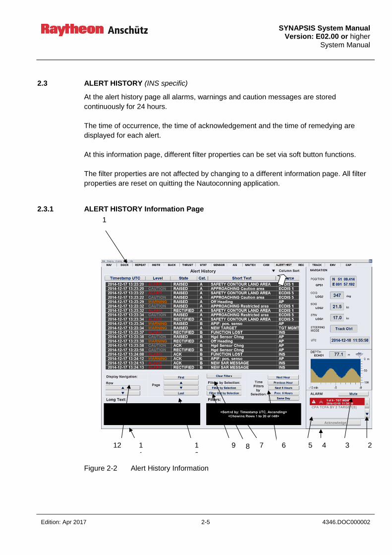
2.3 ALERT HISTORY (INS specific)
At the alert history page all alarms, warnings and caution messages are stored
continuously for 24 hours.
The time of occurrence, the time of acknowledgement and the time of remedying are
displayed for each alert.
At this information page, different filter properties can be set via soft button functions.
The filter properties are not affected by changing to a different information page. All filter
properties are reset on quitting the Nautoconning application.
2.3.1 ALERT HISTORY Information Page
Figure 2-2 Alert History Information
8 1
0
7 5 2 1
1
6 12 9 4 3
1
SYNAPSIS System Manual Version: E02.00 or higher System Manual
4346.DOC000002 2-6 Edition: Apr 2017
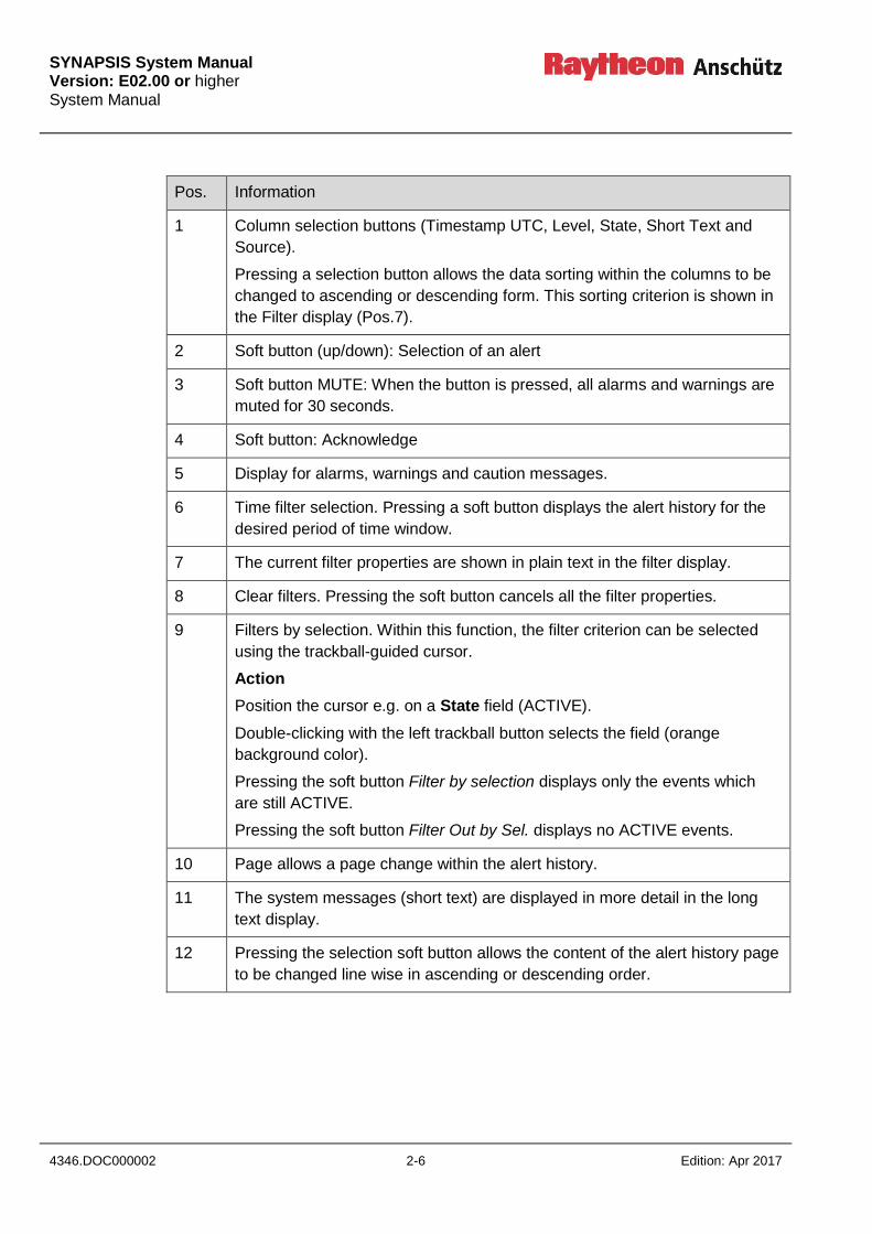
Pos. Information
1 Column selection buttons (Timestamp UTC, Level, State, Short Text and
Source).
Pressing a selection button allows the data sorting within the columns to be
changed to ascending or descending form. This sorting criterion is shown in
the Filter display (Pos.7).
2 Soft button (up/down): Selection of an alert
3 Soft button MUTE: When the button is pressed, all alarms and warnings are
muted for 30 seconds.
4 Soft button: Acknowledge
5 Display for alarms, warnings and caution messages.
6 Time filter selection. Pressing a soft button displays the alert history for the
desired period of time window.
7 The current filter properties are shown in plain text in the filter display.
8 Clear filters. Pressing the soft button cancels all the filter properties.
9 Filters by selection. Within this function, the filter criterion can be selected
using the trackball-guided cursor.
Action
Position the cursor e.g. on a State field (ACTIVE).
Double-clicking with the left trackball button selects the field (orange
background color).
Pressing the soft button Filter by selection displays only the events which
are still ACTIVE.
Pressing the soft button Filter Out by Sel. displays no ACTIVE events.
10 Page allows a page change within the alert history.
11 The system messages (short text) are displayed in more detail in the long
text display.
12 Pressing the selection soft button allows the content of the alert history page
to be changed line wise in ascending or descending order.
SYNAPSIS System Manual
Version: E02.00 or higher System Manual
Edition: Apr 2017 2-7 4346.DOC000002
2.4 AIS MESSAGE HISTORY (INS specific)
Within the AIS Message History, all AIS information is stored. Within this information
page, different filter properties can be set via soft button functions.
The filter properties are not affected by changing to a different information page. All filter
properties are reset on quitting the Nautoconning application.
2.4.1 AIS MESSAGE HISTORY Information Page
Figure 2-3 AIS Message History
7 6 4 2 1
1
8 12 1
0
3 9 5
1
SYNAPSIS System Manual Version: E02.00 or higher System Manual
4346.DOC000002 2-8 Edition: Apr 2017
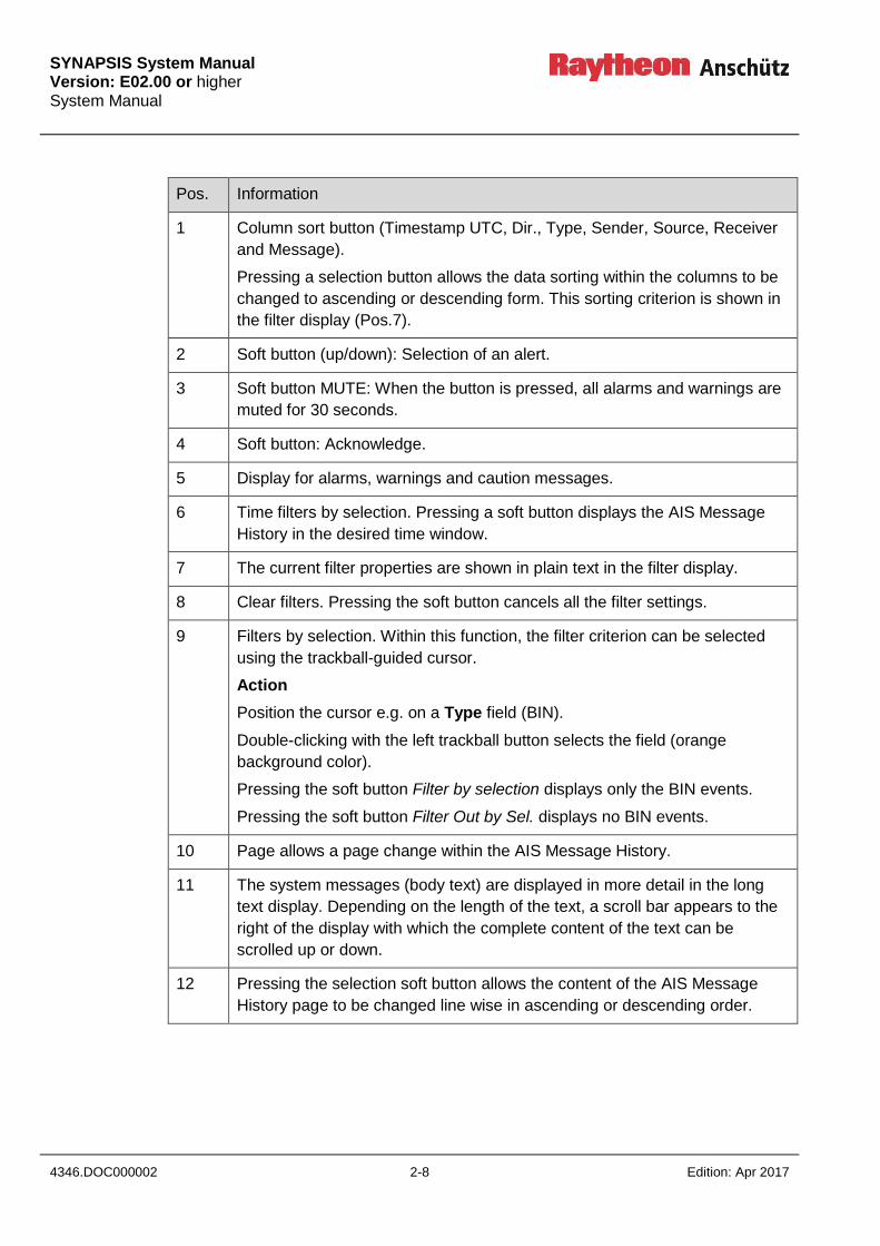
Pos. Information
1 Column sort button (Timestamp UTC, Dir., Type, Sender, Source, Receiver
and Message).
Pressing a selection button allows the data sorting within the columns to be
changed to ascending or descending form. This sorting criterion is shown in
the filter display (Pos.7).
2 Soft button (up/down): Selection of an alert.
3 Soft button MUTE: When the button is pressed, all alarms and warnings are
muted for 30 seconds.
4 Soft button: Acknowledge.
5 Display for alarms, warnings and caution messages.
6 Time filters by selection. Pressing a soft button displays the AIS Message
History in the desired time window.
7 The current filter properties are shown in plain text in the filter display.
8 Clear filters. Pressing the soft button cancels all the filter settings.
9 Filters by selection. Within this function, the filter criterion can be selected
using the trackball-guided cursor.
Action
Position the cursor e.g. on a Type field (BIN).
Double-clicking with the left trackball button selects the field (orange
background color).
Pressing the soft button Filter by selection displays only the BIN events.
Pressing the soft button Filter Out by Sel. displays no BIN events.
10 Page allows a page change within the AIS Message History.
11 The system messages (body text) are displayed in more detail in the long
text display. Depending on the length of the text, a scroll bar appears to the
right of the display with which the complete content of the text can be
scrolled up or down.
12 Pressing the selection soft button allows the content of the AIS Message
History page to be changed line wise in ascending or descending order.

SYNAPSIS System Manual
Version: E02.00 or higher System Manual
Edition: Apr 2017 2-9 4346.DOC000002
2.5 NAVTEX MESSAGE HISTORY (INS specific)
Within the NAVTEX Message History, all NAVTEXT information is stored. Within this
information page, different filter properties can be set via soft button functions.
The filter properties are not affected by changing to a different information page. All filter
properties are reset on quitting the Nautoconning application.
2.5.1 NAVTEX MESSAGE HISTORY Information Page
Figure 2-4 NAVTEX Message History
5 4 3 2 11
1
12
10 9 6 7 8

SYNAPSIS System Manual Version: E02.00 or higher System Manual
4346.DOC000002 2-10 Edition: Apr 2017
Pos. Information
1 Column sort button (Timestamp UTC, Freq., Message Type, ID and Message
Text).
Pressing a selection button allows the data sorting within the columns to be
changed to ascending or descending form. This sorting criterion is shown in
the filter display (Pos. 8).
2 Soft button (up/down): Selection of an alert.
3 Soft button MUTE: When the button is pressed, all alarms and warnings are
muted for 30 seconds.
4 Soft button: Acknowledge
5 Display for alarms, warnings and caution messages.
6 Clear filters. Pressing the soft button cancels all the filter settings.
7 Pressing a soft button displays the NAVTEX Message History in the desired
time window.
8 The current filter properties are shown in plain text in the filter display.
9 Filters by selection. Within this function, the filter criterion can be selected
using the trackball-guided cursor.
Action
Position the cursor e.g. on a Message Type field (met warning).
Double-clicking with the left trackball button selects the field (orange
background color).
Pressing the soft button Filter by selection displays only the BIN events.
Pressing the soft button Filter Out by Sel. displays no BIN events.
10 Page allows a page change within the NAVTEX Message History.
11 The system messages (body text) are displayed in more detail in the long text
display. Depending on the length of the text, a scroll bar appears to the right of
the display with which the complete content of the text can be scrolled up or
down.
Error Rate:
Error rate displays the error rate of the NAVTEX message. Within the
NAVTEX transmission, special characters, parts of sentence of complete lines
can be lost due to transmission errors. These missing parts of the sentence
are replaced with substitute characters (e.g. **).
SYNAPSIS System Manual
Version: E02.00 or higher System Manual
Edition: Apr 2017 2-11 4346.DOC000002
Pos. Information
12 Pressing the selection soft button allows the content of the NAVTEX Message
History page to be changed line wise in ascending or descending order.
SYNAPSIS System Manual Version: E02.00 or higher System Manual
4346.DOC000002 2-12 Edition: Apr 2017
2.6 SENSOR SELECTION (INS, ECDIS, Radar specific)
All the sensors which are connected to the SYNAPSIS INS and have been configured are
displayed on the Sensor Selection page.
The CCRS selection of the sensors can be performed automatically or manually. The
CCRS continuously monitors the quality of the sensor information and assigns colored
quality indicators.
The following table describes the meaning of the colored quality indicator. In the Synapsis
Service Tool under menu point Ship Parameter, the General Presentation Standard
shows the predefined edition of the IEC 62288 for the used system.
Quality
Indicator
(IEC
62288
edition 1)
Quality
Indicator
(IEC 62288
edition 2)
Description
(green)
(green)
The sensor has good integrity (edition 1 conditions
GREEN).
The sensor has good integrity (edition 2 conditions
GREEN).
(orange)
(yellow)
The sensor has doubtful integrity. Data from this sensor
can be used carefully, but not for automatic control
functions (edition 1 conditions ORANGE).
The sensor has doubtful integrity. Data from this sensor
can be used carefully, but not for automatic control
functions (edition 2 conditions YELLOW).
If there is only one source for a
certain type of data, this source has
doubtful integrity. In this case,
doubtful integrity is not a marker for
an error.
(red)
(yellow)
The sensor failed the integrity test (edition 1 conditions
RED).
The sensor failed the integrity test (edition 2 conditions
YELLOW).
(red)
(orange)
No valid and plausible data available from the sensor
(edition 1 conditions RED and for edition 2 conditions
orange).
SYNAPSIS System Manual
Version: E02.00 or higher System Manual
Edition: Apr 2017 2-13 4346.DOC000002
In automatic sensor selection (AUTO) the CCRS uses the sensor with the best result of
the integrity check as a source for the system level data. If there are multiple “best”
sensors the sensor with the higher priority (according to the configured degradation path)
is used.
The user can exclude sensors from automatic sensor selection. If a sensor is excluded,
the sensor is not selected even if this sensor has the best quality rating.
In manual sensor selection mode (MAN), the user selects the source sensor for the
system level data. As long as the sensor delivers data, this data is used. If the sensor
does not deliver data, the CCRS switches to the next sensor in the configured degradation
path. If the best sensor recovers, the CCRS switches back to the selected sensor. If the
user did not choose the best sensor according to the sensor rating of the CCRS, a
“BETTER SENSOR AVAILABLE” caution is generated.
SYNAPSIS System Manual Version: E02.00 or higher System Manual
4346.DOC000002 2-14 Edition: Apr 2017
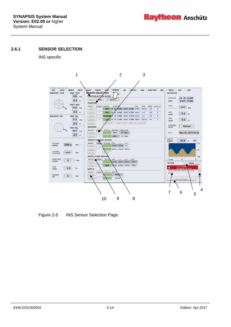
2.6.1 SENSOR SELECTION
INS specific
Figure 2-5 INS Sensor Selection Page
1 2 3
7
6 5 4
8 9 10

SYNAPSIS System Manual
Version: E02.00 or higher System Manual
Edition: Apr 2017 2-15 4346.DOC000002
ECDIS specific
Figure 2-6 ECDIS Nav Device Selection
8 10
9
1 2 3
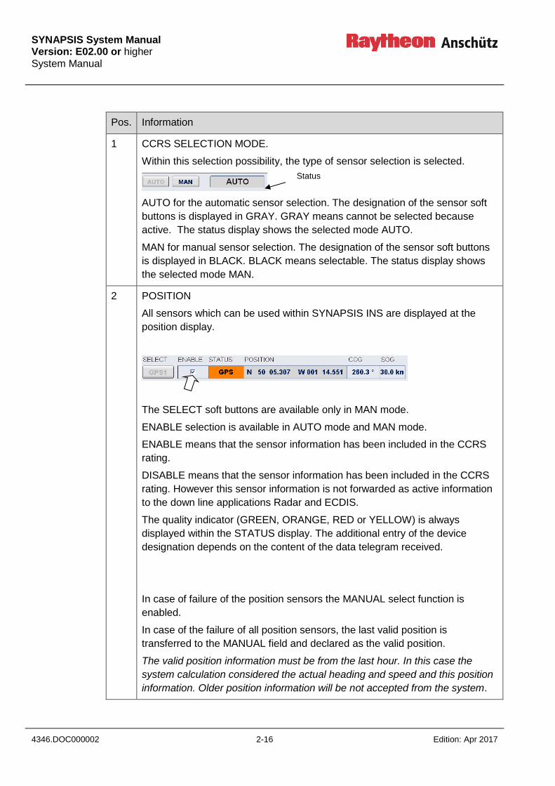
SYNAPSIS System Manual Version: E02.00 or higher System Manual
4346.DOC000002 2-16 Edition: Apr 2017
Pos. Information
1 CCRS SELECTION MODE.
Within this selection possibility, the type of sensor selection is selected.
AUTO for the automatic sensor selection. The designation of the sensor soft
buttons is displayed in GRAY. GRAY means cannot be selected because
active. The status display shows the selected mode AUTO.
MAN for manual sensor selection. The designation of the sensor soft buttons
is displayed in BLACK. BLACK means selectable. The status display shows
the selected mode MAN.
2 POSITION
All sensors which can be used within SYNAPSIS INS are displayed at the
position display.
The SELECT soft buttons are available only in MAN mode.
ENABLE selection is available in AUTO mode and MAN mode.
ENABLE means that the sensor information has been included in the CCRS
rating.
DISABLE means that the sensor information has been included in the CCRS
rating. However this sensor information is not forwarded as active information
to the down line applications Radar and ECDIS.
The quality indicator (GREEN, ORANGE, RED or YELLOW) is always
displayed within the STATUS display. The additional entry of the device
designation depends on the content of the data telegram received.
In case of failure of the position sensors the MANUAL select function is
enabled.
In case of the failure of all position sensors, the last valid position is
transferred to the MANUAL field and declared as the valid position.
The valid position information must be from the last hour. In this case the
system calculation considered the actual heading and speed and this position
information. Older position information will be not accepted from the system.
Status

SYNAPSIS System Manual
Version: E02.00 or higher System Manual
Edition: Apr 2017 2-17 4346.DOC000002
Pos. Information
Within this field, position corrections can be made via an on-screen keyboard.
The entered position serves as the anchor position for the dead reckoning.
Action
Position the trackball-guided cursor on e.g. 1st field and press the left trackball
button. The online keyboard appears the system is operated via the trackball-
guided cursor. The input must be terminated with the ENTER key. The online
keyboard disappears.
3 HEADING
All sensors which can be used within SYNAPSIS INS are displayed at the
heading display.
The SELECT soft buttons are available only in MAN mode.
ENABLE selection is available in AUTO mode and MAN mode.
ENABLE means that the sensor information has been included in the CCRS
rating.
DISABLE means that the sensor information has been included in the CCRS
rating. However this sensor information is not forwarded as active information
to the down line applications Radar and ECDIS.
The quality indicator (GREEN, ORANGE, RED or YELLOW) is always
displayed within the STATUS display. The additional entry of the device
designation depends on the content of the data telegram received.
4 Soft button (up/down): Selection of an item from the display.
5 Soft button MUTE: When the button is pressed, all alarms and warnings are
muted for 30 seconds.
6 Soft button: Acknowledge.

SYNAPSIS System Manual Version: E02.00 or higher System Manual
4346.DOC000002 2-18 Edition: Apr 2017
Pos. Information
7 Display for alarms, warnings and caution messages.
8 SPEED THROUGH WATER
All sensors which can be used within SYNAPSIS INS are displayed within the
SPEED THROUGH WATER display.
The SELECT soft buttons are available only in MAN mode.
ENABLE selection is available in AUTO mode and MAN mode.
ENABLE means that the sensor information has been included in the CCRS
rating.
DISABLE means that the sensor information has been included in the CCRS
rating. However this sensor information is not forwarded as active information
to the down line applications Radar and ECDIS.
The quality indicator (GREEN, ORANGE, RED or YELLOW) is always
displayed within the STATUS display. The additional entry of the device
designation depends on the content of the data telegram received.
Failure of the speed sensors.
In case of the MANUAL select function is enabled.
After the failure of all speed sensors, the last valid speed through water (STW)
information is transferred to the MANUAL field and declared as the valid STW.
Within this field, speed corrections can be made via an on-screen keyboard.
Action
Position the trackball-guided cursor in the field and press the left trackball
button. The online keyboard appears, the system is operated via the trackball-
guided cursor. The input must be terminated with the ENTER key. The online
keyboard then disappears.
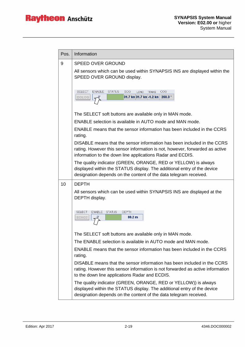
SYNAPSIS System Manual
Version: E02.00 or higher System Manual
Edition: Apr 2017 2-19 4346.DOC000002
Pos. Information
9 SPEED OVER GROUND
All sensors which can be used within SYNAPSIS INS are displayed within the
SPEED OVER GROUND display.
The SELECT soft buttons are available only in MAN mode.
ENABLE selection is available in AUTO mode and MAN mode.
ENABLE means that the sensor information has been included in the CCRS
rating.
DISABLE means that the sensor information has been included in the CCRS
rating. However this sensor information is not, however, forwarded as active
information to the down line applications Radar and ECDIS.
The quality indicator (GREEN, ORANGE, RED or YELLOW) is always
displayed within the STATUS display. The additional entry of the device
designation depends on the content of the data telegram received.
10 DEPTH
All sensors which can be used within SYNAPSIS INS are displayed at the
DEPTH display.
The SELECT soft buttons are available only in MAN mode.
The ENABLE selection is available in AUTO mode and MAN mode.
ENABLE means that the sensor information has been included in the CCRS
rating.
DISABLE means that the sensor information has been included in the CCRS
rating. However this sensor information is not forwarded as active information
to the down line applications Radar and ECDIS.
The quality indicator (GREEN, ORANGE, RED or YELLOW)) is always
displayed within the STATUS display. The additional entry of the device
designation depends on the content of the data telegram received.

SYNAPSIS System Manual Version: E02.00 or higher System Manual
4346.DOC000002 2-20 Edition: Apr 2017
Radar specific
Figure 2-7 Radar Device Selection
Pos. Information
1 Within this selection possibility, the type of sensor selection is selected.
AUTO MODE
In AUTO MODE the OWN ship’s data will be monitored by the Consistent
Common Reference System (CCRS). The CCRS is a software established
for SYNAPSIS INS. The CCRS determines sensor quality and accuracy.
The soft key color (GYRO, GPS, LOG and CCRS) is a measure for sensor
performance.
MANUAL MODE
In the MANUAL MODE the OWN ship’s data will be selected by the user.
1
3
4
5
6
2
function display
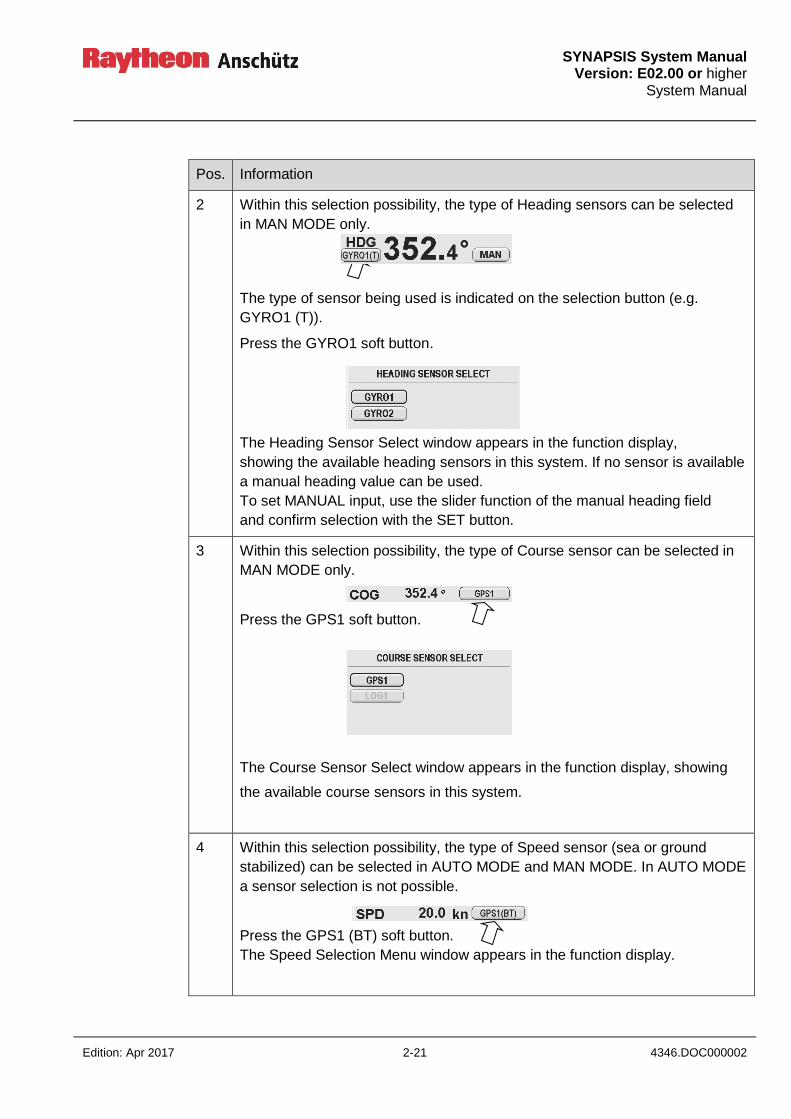
SYNAPSIS System Manual
Version: E02.00 or higher System Manual
Edition: Apr 2017 2-21 4346.DOC000002
Pos. Information
2 Within this selection possibility, the type of Heading sensors can be selected
in MAN MODE only.
The type of sensor being used is indicated on the selection button (e.g.
GYRO1 (T)).
Press the GYRO1 soft button.
The Heading Sensor Select window appears in the function display,
showing the available heading sensors in this system. If no sensor is available
a manual heading value can be used.
To set MANUAL input, use the slider function of the manual heading field
and confirm selection with the SET button.
3 Within this selection possibility, the type of Course sensor can be selected in
MAN MODE only.
Press the GPS1 soft button.
The Course Sensor Select window appears in the function display, showing
the available course sensors in this system.
4 Within this selection possibility, the type of Speed sensor (sea or ground
stabilized) can be selected in AUTO MODE and MAN MODE. In AUTO MODE
a sensor selection is not possible.
Press the GPS1 (BT) soft button.
The Speed Selection Menu window appears in the function display.
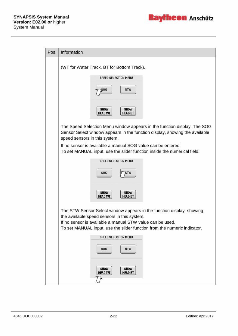
SYNAPSIS System Manual Version: E02.00 or higher System Manual
4346.DOC000002 2-22 Edition: Apr 2017
Pos. Information
(WT for Water Track, BT for Bottom Track).
The Speed Selection Menu window appears in the function display. The SOG
Sensor Select window appears in the function display, showing the available
speed sensors in this system.
If no sensor is available a manual SOG value can be entered.
To set MANUAL input, use the slider function inside the numerical field.
The STW Sensor Select window appears in the function display, showing
the available speed sensors in this system.
If no sensor is available a manual STW value can be used.
To set MANUAL input, use the slider function from the numeric indicator.
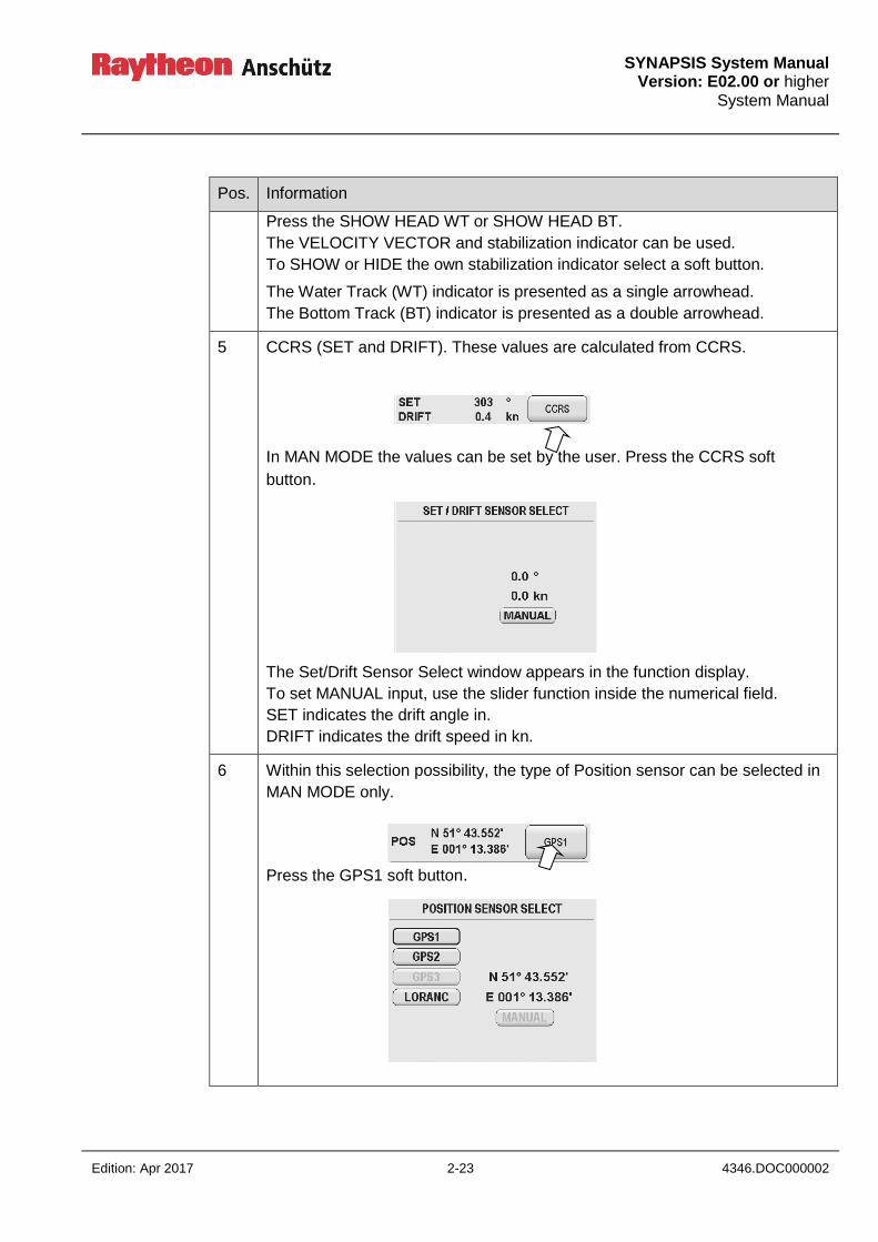
SYNAPSIS System Manual
Version: E02.00 or higher System Manual
Edition: Apr 2017 2-23 4346.DOC000002
Pos. Information
Press the SHOW HEAD WT or SHOW HEAD BT.
The VELOCITY VECTOR and stabilization indicator can be used.
To SHOW or HIDE the own stabilization indicator select a soft button.
The Water Track (WT) indicator is presented as a single arrowhead.
The Bottom Track (BT) indicator is presented as a double arrowhead.
5 CCRS (SET and DRIFT). These values are calculated from CCRS.
In MAN MODE the values can be set by the user. Press the CCRS soft
button.
The Set/Drift Sensor Select window appears in the function display.
To set MANUAL input, use the slider function inside the numerical field.
SET indicates the drift angle in.
DRIFT indicates the drift speed in kn.
6 Within this selection possibility, the type of Position sensor can be selected in
MAN MODE only.
Press the GPS1 soft button.

SYNAPSIS System Manual Version: E02.00 or higher System Manual
4346.DOC000002 2-24 Edition: Apr 2017
Pos. Information
The Position Sensor Select window appears in the function display, showing
the available position sensors in this system. If no sensor is available a
manual position value can be entered.
To set MANUAL input, use the slider function inside the field for numerical
values and confirm with the SET button.
2.7 SYSTEM STATUS (INS specific)
Within the System Status page, the SYNAPSIS INS out hand is displayed in the form of a
system block circuit diagram. Within this block circuit diagram, the current status of all
applications, devices and interfaces are displayed in color and by means of line patterns.
2.7.1 SYSTEM STATUS Information Page
Figure 2-8 SYSTEM STATUS Information Page
3
2 1 port status
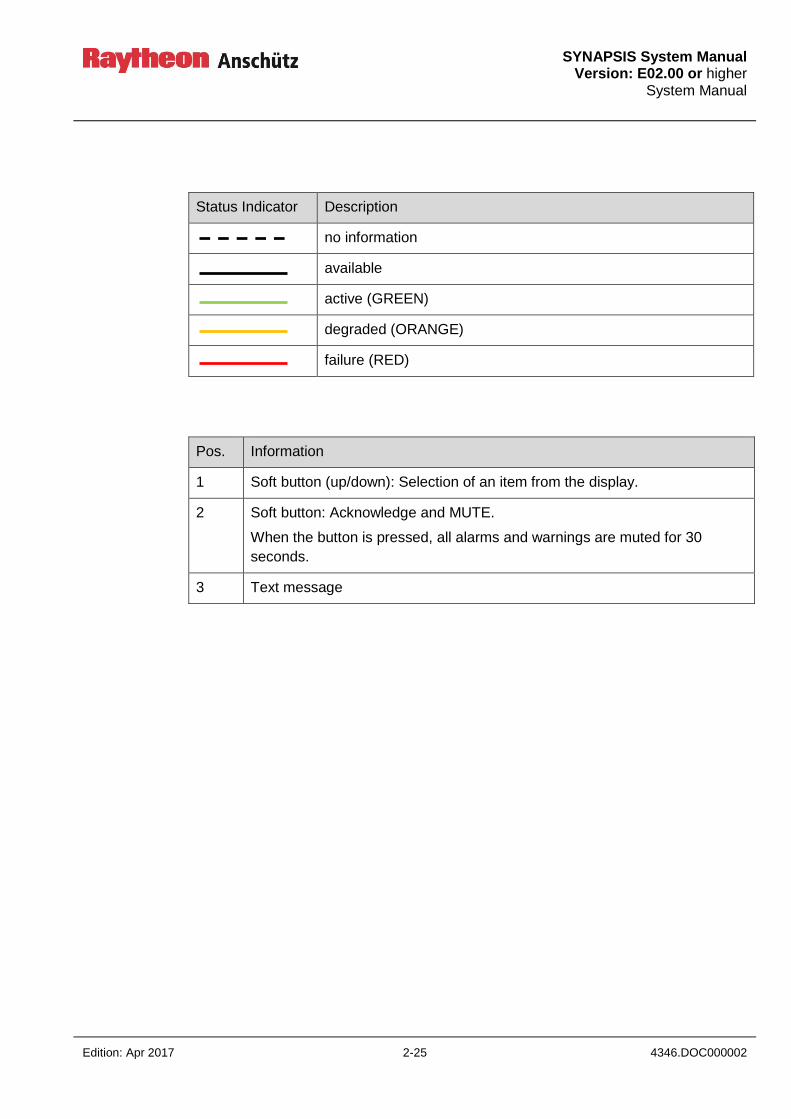
SYNAPSIS System Manual
Version: E02.00 or higher System Manual
Edition: Apr 2017 2-25 4346.DOC000002
Status Indicator Description
no information
available
active (GREEN)
degraded (ORANGE)
failure (RED)
Pos. Information
1 Soft button (up/down): Selection of an item from the display.
2 Soft button: Acknowledge and MUTE.
When the button is pressed, all alarms and warnings are muted for 30
seconds.
3 Text message

SYNAPSIS System Manual Version: E02.00 or higher System Manual
4346.DOC000002 2-26 Edition: Apr 2017
Intentionally left blank
SYNAPSIS System Manual
Version: E02.00 or higher System Manual
Edition: Apr 2017 3-1 4346.DOC000002
3 CCRS Data Processing
3.1 CCRS Principle
The SYNAPSIS INS contains a Consistent Common Reference System (CCRS) which
ensures that all parts of the system work with the same navigational data.
The CCRS
collects all available sensor data,
checks sensor data for validity, plausibility, and integrity,
corrects sensor data according to the CCRP of the vessel,
publishes a consistent set of navigational data to the rest of the system,
monitors and rates quality of sensor data,
selects the most suitable sensors in automatic sensor selection mode,
calculates derived related, connected data,
synchronizes the time within the system
Figure 3-1 depicts the flow of sensor data through the CCRS. The following sections
describe the steps of data processing in detail.
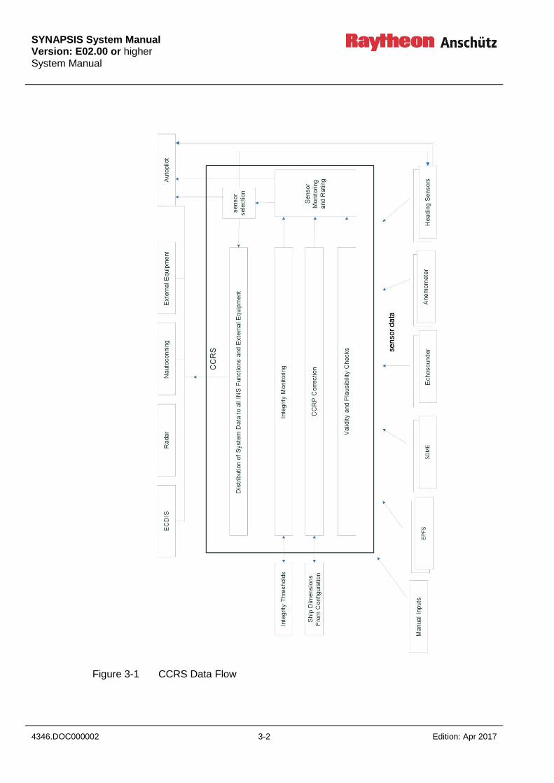
SYNAPSIS System Manual Version: E02.00 or higher System Manual
4346.DOC000002 3-2 Edition: Apr 2017
Figure 3-1 CCRS Data Flow
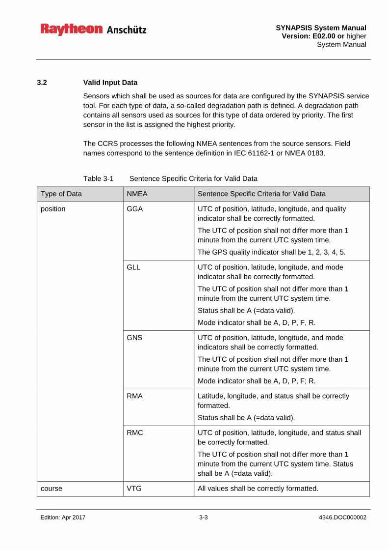
SYNAPSIS System Manual
Version: E02.00 or higher System Manual
Edition: Apr 2017 3-3 4346.DOC000002
3.2 Valid Input Data
Sensors which shall be used as sources for data are configured by the SYNAPSIS service
tool. For each type of data, a so-called degradation path is defined. A degradation path
contains all sensors used as sources for this type of data ordered by priority. The first
sensor in the list is assigned the highest priority.
The CCRS processes the following NMEA sentences from the source sensors. Field
names correspond to the sentence definition in IEC 61162-1 or NMEA 0183.
Table 3-1 Sentence Specific Criteria for Valid Data
Type of Data NMEA Sentence Specific Criteria for Valid Data
position GGA UTC of position, latitude, longitude, and quality
indicator shall be correctly formatted.
The UTC of position shall not differ more than 1
minute from the current UTC system time.
The GPS quality indicator shall be 1, 2, 3, 4, 5.
GLL UTC of position, latitude, longitude, and mode
indicator shall be correctly formatted.
The UTC of position shall not differ more than 1
minute from the current UTC system time.
Status shall be A (=data valid).
Mode indicator shall be A, D, P, F, R.
GNS UTC of position, latitude, longitude, and mode
indicators shall be correctly formatted.
The UTC of position shall not differ more than 1
minute from the current UTC system time.
Mode indicator shall be A, D, P, F; R.
RMA Latitude, longitude, and status shall be correctly
formatted.
Status shall be A (=data valid).
RMC UTC of position, latitude, longitude, and status shall
be correctly formatted.
The UTC of position shall not differ more than 1
minute from the current UTC system time. Status
shall be A (=data valid).
course VTG All values shall be correctly formatted.
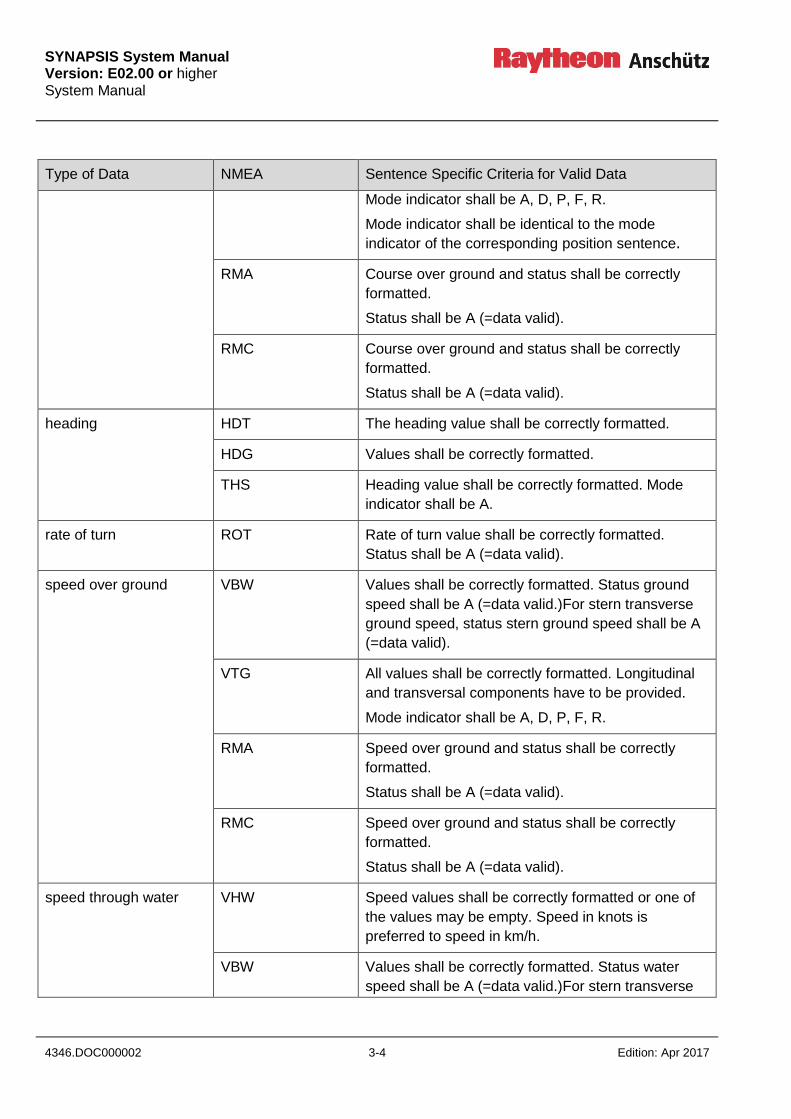
SYNAPSIS System Manual Version: E02.00 or higher System Manual
4346.DOC000002 3-4 Edition: Apr 2017
Type of Data NMEA Sentence Specific Criteria for Valid Data
Mode indicator shall be A, D, P, F, R.
Mode indicator shall be identical to the mode
indicator of the corresponding position sentence.
RMA Course over ground and status shall be correctly
formatted.
Status shall be A (=data valid).
RMC Course over ground and status shall be correctly
formatted.
Status shall be A (=data valid).
heading HDT The heading value shall be correctly formatted.
HDG Values shall be correctly formatted.
THS Heading value shall be correctly formatted. Mode
indicator shall be A.
rate of turn ROT Rate of turn value shall be correctly formatted.
Status shall be A (=data valid).
speed over ground VBW Values shall be correctly formatted. Status ground
speed shall be A (=data valid.)For stern transverse
ground speed, status stern ground speed shall be A
(=data valid).
VTG All values shall be correctly formatted. Longitudinal
and transversal components have to be provided.
Mode indicator shall be A, D, P, F, R.
RMA Speed over ground and status shall be correctly
formatted.
Status shall be A (=data valid).
RMC Speed over ground and status shall be correctly
formatted.
Status shall be A (=data valid).
speed through water VHW Speed values shall be correctly formatted or one of
the values may be empty. Speed in knots is
preferred to speed in km/h.
VBW Values shall be correctly formatted. Status water
speed shall be A (=data valid.)For stern transverse

SYNAPSIS System Manual
Version: E02.00 or higher System Manual
Edition: Apr 2017 3-5 4346.DOC000002
Type of Data NMEA Sentence Specific Criteria for Valid Data
water speed, status stern water speed shall be A
(=data valid).
roll / pitch PANZHRP Values shall be correctly formatted. . Longitudinal
and transversal components have to be provided.
Status shall be A (=data valid).
depth DBK Depth values shall be correctly formatted. At least
one value shall be not empty. Priority of values:
depth in meters, depth in feet, depth in fathoms. DBS
DBT
DPT Water depth and offset shall be correctly formatted.
set and drift VDR Values shall be correctly formatted.
wind MWD Values shall be correctly formatted; one field for
direction and speed may be empty.
Wind direction true is preferred to wind direction
magnetic. Wind speed in knots is preferred to wind
speed in m/s.
MWV Values shall be correctly formatted. Status shall be A
(=data valid).
humidity MHU Values shall be correctly formatted.
air pressure MMB Values shall be correctly formatted. Pressure in bar
is preferred to pressure in inches of mercury.
air temperature MTA The value shall be correctly formatted.
water temperature MTW The value shall be correctly formatted.
time ZDA The values shall be correctly formatted.
All sentences are checked for a valid checksum.
It is possible to suppress checksum validation for NMEA sentences from dedicated
sensors. Suppression of checksum validation is not recommended and only used at own
risk.
Sensor data is only used if it passes the validity criteria.
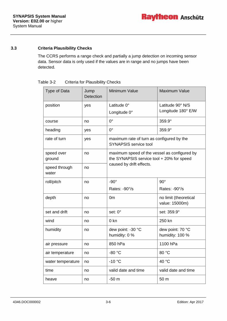
SYNAPSIS System Manual Version: E02.00 or higher System Manual
4346.DOC000002 3-6 Edition: Apr 2017
3.3 Criteria Plausibility Checks
The CCRS performs a range check and partially a jump detection on incoming sensor
data. Sensor data is only used if the values are in range and no jumps have been
detected.
Table 3-2 Criteria for Plausibility Checks
Type of Data Jump
Detection
Minimum Value Maximum Value
position yes Latitude 0°
Longitude 0°
Latitude 90° N/S
Longitude 180° E/W
course no 0° 359.9°
heading yes 0° 359.9°
rate of turn yes maximum rate of turn as configured by the
SYNAPSIS service tool
speed over
ground
no maximum speed of the vessel as configured by
the SYNAPSIS service tool + 20% for speed
caused by drift effects. speed through
water
no
roll/pitch no -90°
Rates: -90°/s
90°
Rates: -90°/s
depth no 0m no limit (theoretical
value: 15000m)
set and drift no set: 0° set: 359.9°
wind no 0 kn 250 kn
humidity no dew point: -30 °C
humidity: 0 %
dew point: 70 °C
humidity: 100 %
air pressure no 850 hPa 1100 hPa
air temperature no -80 °C 80 °C
water temperature no -10 °C 40 °C
time no valid date and time valid date and time
heave no -50 m 50 m
SYNAPSIS System Manual
Version: E02.00 or higher System Manual
Edition: Apr 2017 3-7 4346.DOC000002
Position and SOG/COG from one sensor must share a common mode indicator. It is not
allowed to use a position derived in autonomous mode while SOG/COG was calculated in
differential mode.
3.4 Sensor Timeouts
The CCRS monitors the sensors for u and plausible data. If the Sensor does not deliver
valid and plausible data for the specified timeout period, an alert is generated.
Timeouts can be configured by the SYNAPSIS Service Tool. By default, a timeout of 5s is
used.
3.5 CCRP Correction
The CCRS performs a CCRP correction on position, course, speed, and depth values.
The mounting points of the sensors have to be configured in the SYNAPSIS service tool.
The Consistent Common Reference Point (CCRP) has to be configured in the SYNAPSIS
service tool, as well. It is recommended to set the CCRP to the conning position of the
vessel.
For CCRP correction, the sensor position, course, and speed are transformed to reflect
the position, course, and speed as if the sensor had been mounted at the CCRP. The
depth value is transformed to reflect the depth below keel instead the depth below the
transducer.
The heading of the vessel is needed to transform sensor data. If no
heading is available, CCRP correction fails. This will influence the
integrity monitoring process, the sensor quality rating, the automatic
sensor selection, and the distributed system-level data.
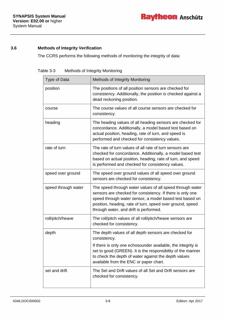
SYNAPSIS System Manual Version: E02.00 or higher System Manual
4346.DOC000002 3-8 Edition: Apr 2017
3.6 Methods of Integrity Verification
The CCRS performs the following methods of monitoring the integrity of data:
Table 3-3 Methods of Integrity Monitoring
Type of Data Methods of Integrity Monitoring
position The positions of all position sensors are checked for
consistency. Additionally, the position is checked against a
dead reckoning position.
course The course values of all course sensors are checked for
consistency.
heading The heading values of all heading sensors are checked for
concordance. Additionally, a model based test based on
actual position, heading, rate of turn, and speed is
performed and checked for consistency values.
rate of turn The rate of turn values of all rate of turn sensors are
checked for concordance. Additionally, a model based test
based on actual position, heading, rate of turn, and speed
is performed and checked for consistency values.
speed over ground The speed over ground values of all speed over ground
sensors are checked for consistency.
speed through water The speed through water values of all speed through water
sensors are checked for consistency. If there is only one
speed through water sensor, a model based test based on
position, heading, rate of turn, speed over ground, speed
through water, and drift is performed.
roll/pitch/heave The roll/pitch values of all roll/pitch/heave sensors are
checked for consistency.
depth The depth values of all depth sensors are checked for
consistency.
If there is only one echosounder available, the integrity is
set to good (GREEN). It is the responsibility of the mariner
to check the depth of water against the depth values
available from the ENC or paper chart.
set and drift The Set and Drift values of all Set and Drift sensors are
checked for consistency.
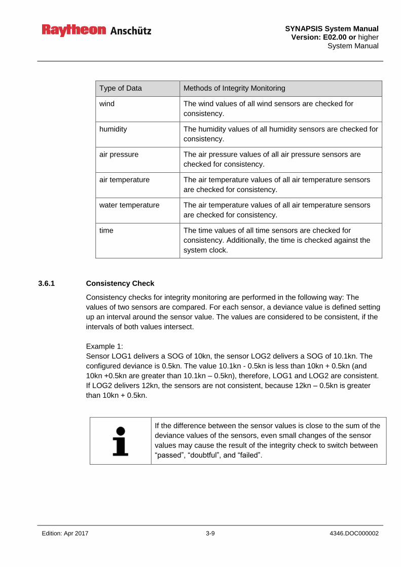
SYNAPSIS System Manual
Version: E02.00 or higher System Manual
Edition: Apr 2017 3-9 4346.DOC000002
Type of Data Methods of Integrity Monitoring
wind The wind values of all wind sensors are checked for
consistency.
humidity The humidity values of all humidity sensors are checked for
consistency.
air pressure The air pressure values of all air pressure sensors are
checked for consistency.
air temperature The air temperature values of all air temperature sensors
are checked for consistency.
water temperature The air temperature values of all air temperature sensors
are checked for consistency.
time The time values of all time sensors are checked for
consistency. Additionally, the time is checked against the
system clock.
3.6.1 Consistency Check
Consistency checks for integrity monitoring are performed in the following way: The
values of two sensors are compared. For each sensor, a deviance value is defined setting
up an interval around the sensor value. The values are considered to be consistent, if the
intervals of both values intersect.
Example 1:
Sensor LOG1 delivers a SOG of 10kn, the sensor LOG2 delivers a SOG of 10.1kn. The
configured deviance is 0.5kn. The value 10.1kn - 0.5kn is less than 10kn + 0.5kn (and
10kn +0.5kn are greater than 10.1kn – 0.5kn), therefore, LOG1 and LOG2 are consistent.
If LOG2 delivers 12kn, the sensors are not consistent, because 12kn – 0.5kn is greater
than 10kn + 0.5kn.
If the difference between the sensor values is close to the sum of the
deviance values of the sensors, even small changes of the sensor
values may cause the result of the integrity check to switch between
“passed”, “doubtful”, and “failed”.
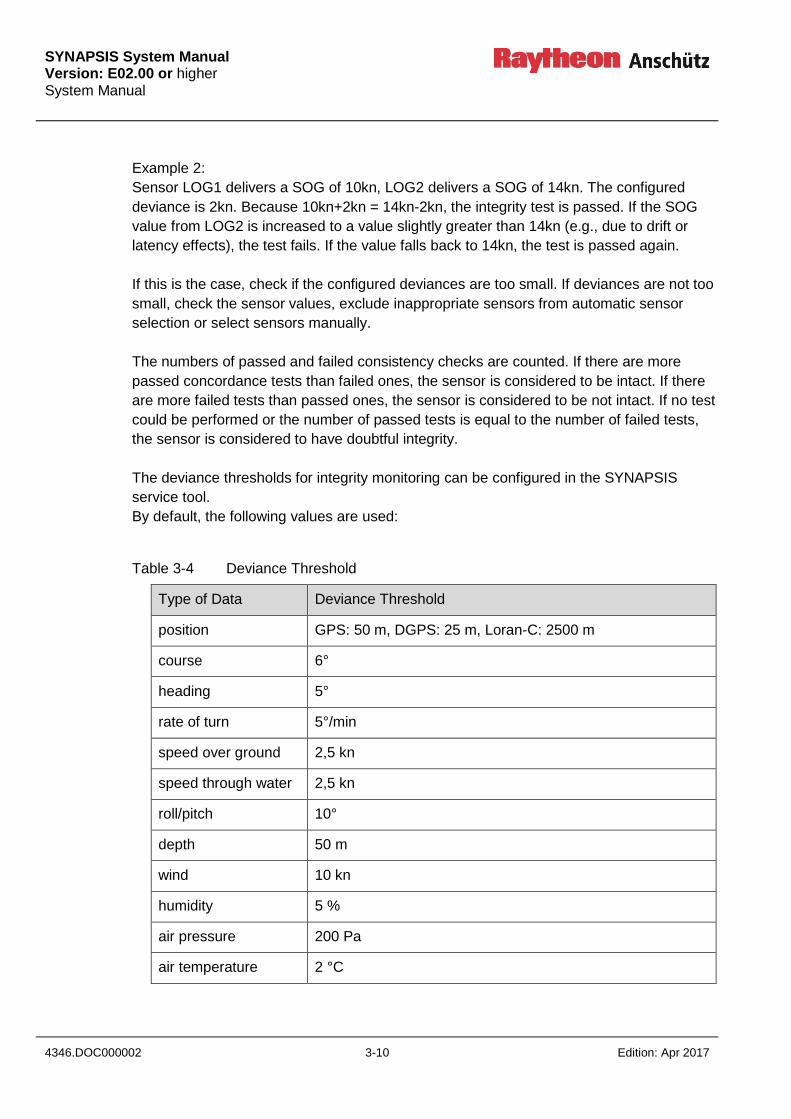
SYNAPSIS System Manual Version: E02.00 or higher System Manual
4346.DOC000002 3-10 Edition: Apr 2017
Example 2:
Sensor LOG1 delivers a SOG of 10kn, LOG2 delivers a SOG of 14kn. The configured
deviance is 2kn. Because 10kn+2kn = 14kn-2kn, the integrity test is passed. If the SOG
value from LOG2 is increased to a value slightly greater than 14kn (e.g., due to drift or
latency effects), the test fails. If the value falls back to 14kn, the test is passed again.
If this is the case, check if the configured deviances are too small. If deviances are not too
small, check the sensor values, exclude inappropriate sensors from automatic sensor
selection or select sensors manually.
The numbers of passed and failed consistency checks are counted. If there are more
passed concordance tests than failed ones, the sensor is considered to be intact. If there
are more failed tests than passed ones, the sensor is considered to be not intact. If no test
could be performed or the number of passed tests is equal to the number of failed tests,
the sensor is considered to have doubtful integrity.
The deviance thresholds for integrity monitoring can be configured in the SYNAPSIS
service tool.
By default, the following values are used:
Table 3-4 Deviance Threshold
Type of Data Deviance Threshold
position GPS: 50 m, DGPS: 25 m, Loran-C: 2500 m
course 6°
heading 5°
rate of turn 5°/min
speed over ground 2,5 kn
speed through water 2,5 kn
roll/pitch 10°
depth 50 m
wind 10 kn
humidity 5 %
air pressure 200 Pa
air temperature 2 °C
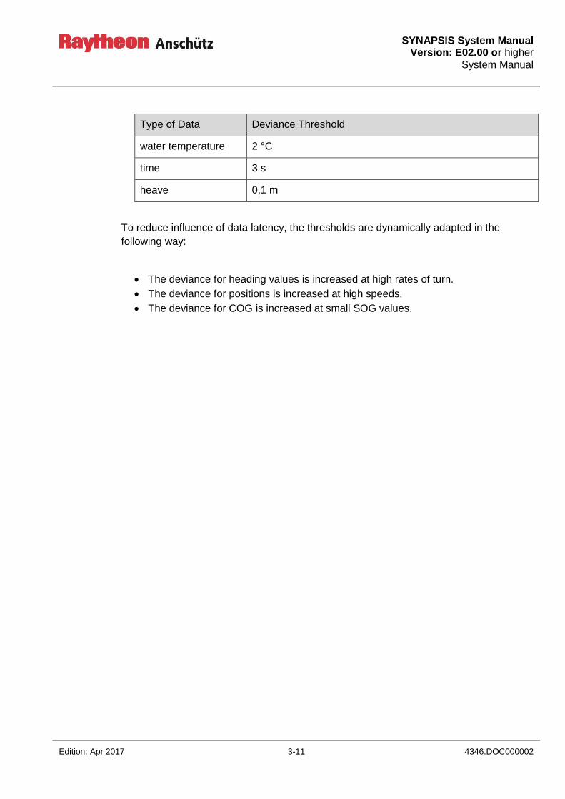
SYNAPSIS System Manual
Version: E02.00 or higher System Manual
Edition: Apr 2017 3-11 4346.DOC000002
Type of Data Deviance Threshold
water temperature 2 °C
time 3 s
heave 0,1 m
To reduce influence of data latency, the thresholds are dynamically adapted in the
following way:
The deviance for heading values is increased at high rates of turn.
The deviance for positions is increased at high speeds.
The deviance for COG is increased at small SOG values.
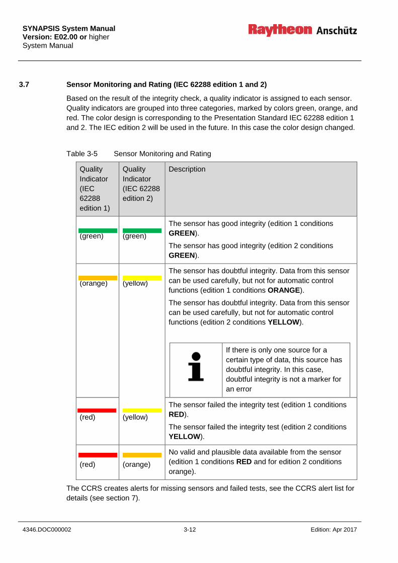
SYNAPSIS System Manual Version: E02.00 or higher System Manual
4346.DOC000002 3-12 Edition: Apr 2017
3.7 Sensor Monitoring and Rating (IEC 62288 edition 1 and 2)
Based on the result of the integrity check, a quality indicator is assigned to each sensor.
Quality indicators are grouped into three categories, marked by colors green, orange, and
red. The color design is corresponding to the Presentation Standard IEC 62288 edition 1
and 2. The IEC edition 2 will be used in the future. In this case the color design changed.
Table 3-5 Sensor Monitoring and Rating
Quality
Indicator
(IEC
62288
edition 1)
Quality
Indicator
(IEC 62288
edition 2)
Description
(green)
(green)
The sensor has good integrity (edition 1 conditions
GREEN).
The sensor has good integrity (edition 2 conditions
GREEN).
(orange)
(yellow)
The sensor has doubtful integrity. Data from this sensor
can be used carefully, but not for automatic control
functions (edition 1 conditions ORANGE).
The sensor has doubtful integrity. Data from this sensor
can be used carefully, but not for automatic control
functions (edition 2 conditions YELLOW).
If there is only one source for a
certain type of data, this source has
doubtful integrity. In this case,
doubtful integrity is not a marker for
an error
(red)
(yellow)
The sensor failed the integrity test (edition 1 conditions
RED).
The sensor failed the integrity test (edition 2 conditions
YELLOW).
(red)
(orange)
No valid and plausible data available from the sensor
(edition 1 conditions RED and for edition 2 conditions
orange).
The CCRS creates alerts for missing sensors and failed tests, see the CCRS alert list for
details (see section 7).

SYNAPSIS System Manual
Version: E02.00 or higher System Manual
Edition: Apr 2017 3-13 4346.DOC000002
3.8 Automatic and Manual Sensor Selection
The CCRS supports two modes of sensor selection: automatic sensor selection and
manual sensor selection. In automatic sensor selection the CCRS uses the sensor with
the best result of the integrity check as a source for the system level data. If there are
multiple “best” sensors the sensor with the higher priority (according to the configured
degradation path) is used.
The user can exclude sensors from automatic sensor selection with the ENABLE check
box. If a sensor is excluded, the sensor cannot be selected even if this sensor has the
best quality rating.
In manual sensor selection mode, the user selects the source sensor for the system level
data. As long as the sensor delivers data, this data is used. If the sensor does not deliver
data, the CCRS switches to the next sensor in the configured degradation path. If the best
sensor recovers, the CCRS switches back to the selected sensor. If the user did not
choose the best sensor according to the sensor rating of the CCRS, a “BETTER SENSOR
AVAILABLE” caution is generated.
3.9 Data Calculation
The CCRS calculates related (connected) data if no direct sensor data is available:
true wind from relative wind and vice versa
relative set and drift
speed at bow and stern
dead reckoning position
3.10 Time Synchronization
The CCRS synchronizes the time of all MFCs in the system.
If a time sensor (e.g., an EPFS or a radio clock) is available, the CCRS synchronizes the
system clock to the time reported by the sensor. Otherwise, a manual time adjustment has
to be applied.

SYNAPSIS System Manual Version: E02.00 or higher System Manual
4346.DOC000002 3-14 Edition: Apr 2017
Intentionally left blank

SYNAPSIS System Manual
Version: E02.00 or higher System Manual
Edition: Apr 2017 4-1 4346.DOC000002
4 Integrated Target Management
4.1 Target Association
The integrated target management performs a target association by comparing the
position, the speed, and the course of the targets.
Positions given in range/bearing or latitude/longitude coordinates are automatically
converted if the own ship position and heading are available.
SOG/COG and STW/CTW are automatically converted if drift is known. As a
simplification, it is assumed that the same drift applies to the own ship as well as the
target. In the case of relevant drift differences, target association between ARPA and AIS
targets may be degraded if the ARPA tracker is operated in water stabilized mode. The
course of the target is ignored at low target speeds.
Association and de-association are subject to a hysteresis: position, speed, and course of
the targets have to be close enough for a period of time before the target is associated.
The association is canceled if position, speed, or course diverges for a period of time.
The system provides a set of predefined, user-selectable association profiles to adapt the
sensitivity of the association process:
default – The default profile offers a trade-off between elimination of duplicate targets
and unwanted association between targets which are close together.
open sea – The open sea profile favors association by an increased threshold for
position differences, a reduced association time and an increased de-
association time
coastal waters – The coastal waters profile favors association by a reduced
association time and an increased de-association time.
pilotage – The pilotage profile restricts association by smaller allowed differences in
position, speed, and course for use in areas with high traffic.
habour berthing – The habour berthing profile favors de-association by smaller allowed
differences in position, speed, and course, a high association time
and a reduced de-association time for use in areas with high traffic.
anchorage – the anchorage profile may be used in areas with many slow moving targets,
because small allowed differences in position, speed, and course, a high
association time and a reduced de-association time are used.
SYNAPSIS System Manual Version: E02.00 or higher System Manual
4346.DOC000002 4-2 Edition: Apr 2017
The association profile is user-selectable on Collision Avoidance (Radar) and Route
Monitoring (ECDIS) displays and affects the whole system. For each profile, the user can
adapt the priority of the target sources (e.g., AIS, X-band Radar, S-Band Radar.)
Target association can be disabled.
4.2 Target Labels
The integrated target management assigns a unique target id to each target. Additionally,
a label can be assigned to each target. The label can be manually entered or derived from
AIS static data (MMSI, ship name, call sign), if available. Targets may be displayed on
Collision Avoidance (Radar) or Route Monitoring (ECDIS) displays either with the unique
target id, the target label, or no label.
4.3 AIS capacity and Limitations for Target Processing and Display
The target management is able to process up to 7000 targets. Processing includes the
calculation of collision-relevant data such as CPA/TCPA. If the limit of 7000 targets is
reached, a “MAX 7000 TARGETS” warning is raised and additional targets are dropped
without processing (corresponding to category of ship/craft 1 from SOLAS V “All
ships/craft > 10 000 gross tonnages”).
If the number of processed targets is greater than 1000 targets, a “MAX 1000
DISPLAYED TARGETS” warning is raised. Target management starts to filter out
processed targets to avoid to obscure Radar and ECDIS display. Filtering is applied in the
following order:
1. sleeping non-dangerous AIS targets
2. active non-dangerous AIS targets with speed < 3kn
3. active non-dangerous AIS targets with speed > 3kn
4. non-dangerous ARPA targets

SYNAPSIS System Manual
Version: E02.00 or higher System Manual
Edition: Apr 2017 5-3 4346.DOC000002
5 User Settings and Default Displays
The system provides pre-defined default display settings and operational modes for
navigation in open sea, coastal waters, pilotage, harbor berthing, and anchorage. Display
settings apply to Radar, ECDIS, and Conning displays, each application has specific
settings. Only settings of the local display can be applied.
Pre-defined display settings are read-only, but user-defined display settings can be saved
based on pre-defined settings or the current settings of an application. User-defined
settings can be re-loaded on any MFC of the system. Additionally, the user can transfer
the settings from a selected MFC and apply these settings to the local MFC.
When a pre-defined operational mode for Route Monitoring and Route Planning Displays
(ECDIS) is selected, the following settings are applied:
Table 5-1 Settings for Route Monitoring and Route Planning Display (ECDIS)
parameter defaults
route
monitoring
defaults
route
planning
open sea coastal
waters
pilotage harbor
berthing
anchorage
display
category
standard
display
as is standard
display
standard
display
standard
display
standard
display
standard
display
selected
area
own ship as is own ship own ship own ship own ship own ship
range 3 NM 6 NM 12 NM 6 NM 3 NM 1.5 NM 1.5 NM
past track on off off off off off off
look-ahead
time
6 min 6 min 6 min 6 min 6 min 6 min 6 min
info panel Track /
Navigation
off Navigation Navigation Navigation Docking Docking
target
overlay
on off on on on on on
search light on off on on on on on
heading
line /
course
vector
on off on on on on on
Display settings do not affect the primary or secondary route.

SYNAPSIS System Manual Version: E02.00 or higher System Manual
4346.DOC000002 5-4 Edition: Apr 2017
When a pre-defined operational mode for Collision Avoidance (Radar) is selected, the
following settings are applied:
Table 5-2 Settings for Collision Avoidance (Radar)
parameter defaults
collision
avoidance
open sea coastal
waters
pilotage harbor
berthing
anchorage
gain as is as is as is as is as is as is
tuning as is as is as is as is as is as is
range 6 NM 12 NM 6 NM 3 NM 1.5 NM 1.5 NM
range rings off off off off off off
VRM one VRM on,
0.25NM
off off off off off
EBL One EBL on off off off off off
parallel
index lines
as is as is as is as is as is as is
display
mode
true motion,
north-up
true
motion,
north-up
true
motion,
north-up
true
motion,
north-up
true
motion,
north-up
true motion,
north-up
off-
centering
on on on on on off
stabilization ground stab ground
stab
ground
stab
ground
stab
ground
stab
ground stab
trails on (6min) on (6min) on (6min) on (6min) on (6min) on (6min)
past
positions
off off off off off off
vectors relative
(6min)
relative
(6min)
relative
(6min)
relative
(6min)
relative
(6min)
relative
(6min)
AIS display on on on on on on
AIS
new/lost
target alerts
off off off off off off
AIS
activation
on
CPA/TCPA
on on on on on off
chart off off off off off off
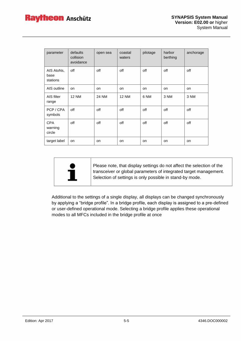
SYNAPSIS System Manual
Version: E02.00 or higher System Manual
Edition: Apr 2017 5-5 4346.DOC000002
parameter defaults
collision
avoidance
open sea coastal
waters
pilotage harbor
berthing
anchorage
AIS AtoNs,
base
stations
off off off off off off
AIS outline on on on on on on
AIS filter
range
12 NM 24 NM 12 NM 6 NM 3 NM 3 NM
PCP / CPA
symbols
off off off off off off
CPA
warning
circle
off off off off off off
target label on on on on on on
Please note, that display settings do not affect the selection of the
transceiver or global parameters of integrated target management.
Selection of settings is only possible in stand-by mode.
Additional to the settings of a single display, all displays can be changed synchronously
by applying a “bridge profile”. In a bridge profile, each display is assigned to a pre-defined
or user-defined operational mode. Selecting a bridge profile applies these operational
modes to all MFCs included in the bridge profile at once
SYNAPSIS System Manual Version: E02.00 or higher System Manual
4346.DOC000002 5-6 Edition: Apr 2017
Intentionally left blank
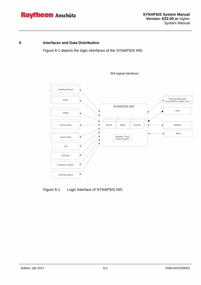
SYNAPSIS System Manual
Version: E02.00 or higher System Manual
Edition: Apr 2017 6-1 4346.DOC000002
6 Interfaces and Data Distribution
Figure 6-1 depicts the logic interfaces of the SYNAPSIS INS.
SYNAPSIS INS
Heading Sensors
EPFS
SDME
AIS
NAVTEX
Echosounder
Anemometer
Propulsion System
Steering System
External Equipment
(e.g. GMDSS, Engine, etc.)
VDR
BNWAS
Heading / Track
Control System
ECDIS Radar Conning
INS logical interfaces
BAM
Figure 6-1 Logic Interface of SYNAPSIS INS
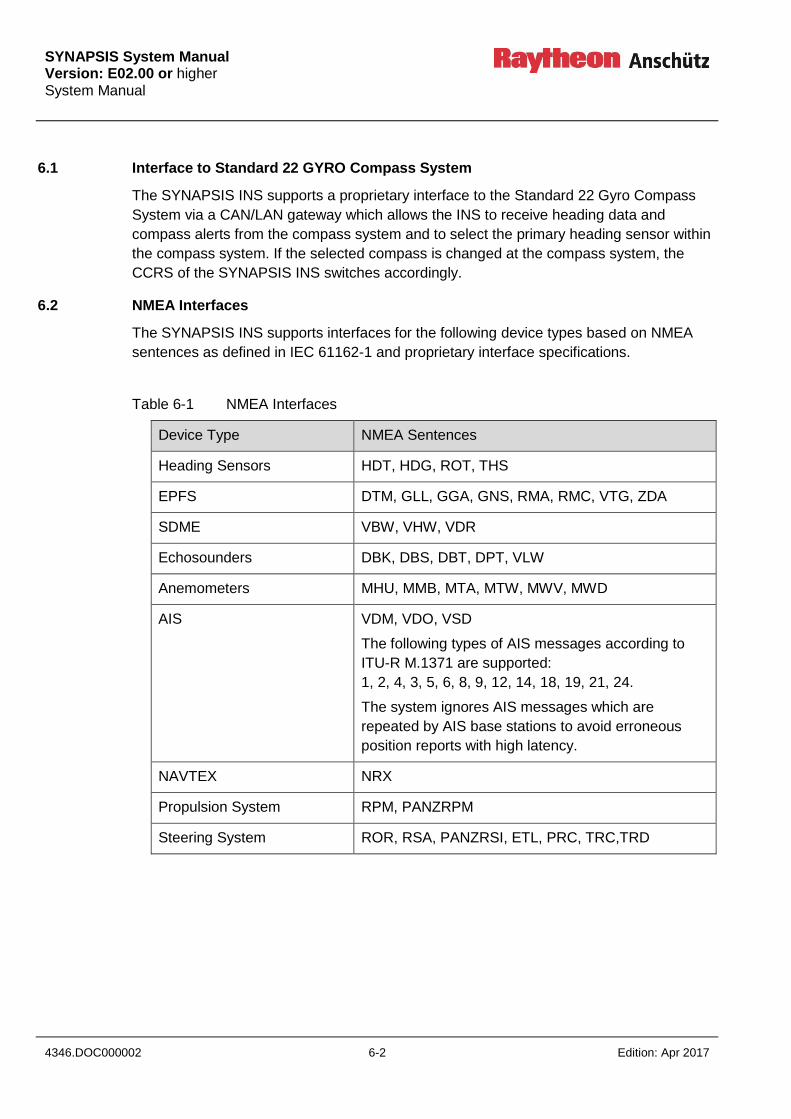
SYNAPSIS System Manual Version: E02.00 or higher System Manual
4346.DOC000002 6-2 Edition: Apr 2017
6.1 Interface to Standard 22 GYRO Compass System
The SYNAPSIS INS supports a proprietary interface to the Standard 22 Gyro Compass
System via a CAN/LAN gateway which allows the INS to receive heading data and
compass alerts from the compass system and to select the primary heading sensor within
the compass system. If the selected compass is changed at the compass system, the
CCRS of the SYNAPSIS INS switches accordingly.
6.2 NMEA Interfaces
The SYNAPSIS INS supports interfaces for the following device types based on NMEA
sentences as defined in IEC 61162-1 and proprietary interface specifications.
Table 6-1 NMEA Interfaces
Device Type NMEA Sentences
Heading Sensors HDT, HDG, ROT, THS
EPFS DTM, GLL, GGA, GNS, RMA, RMC, VTG, ZDA
SDME VBW, VHW, VDR
Echosounders DBK, DBS, DBT, DPT, VLW
Anemometers MHU, MMB, MTA, MTW, MWV, MWD
AIS VDM, VDO, VSD
The following types of AIS messages according to
ITU-R M.1371 are supported:
1, 2, 4, 3, 5, 6, 8, 9, 12, 14, 18, 19, 21, 24.
The system ignores AIS messages which are
repeated by AIS base stations to avoid erroneous
position reports with high latency.
NAVTEX NRX
Propulsion System RPM, PANZRPM
Steering System ROR, RSA, PANZRSI, ETL, PRC, TRC,TRD

SYNAPSIS System Manual
Version: E02.00 or higher System Manual
Edition: Apr 2017 6-3 4346.DOC000002
6.3 Interfaces to External Equipment
Additionally to the NMEA sentences listed in section 6.2, the SYNAPSIS INS supports the
following NMEA sentences from external equipment:
RTE, WPL, TLB, TTD, TTM, TLL, XTE, ZTG, TRO
PANZCOL, PANZHRP
STRD, STRP
The SYNAPSIS INS is able to deliver the following NMEA sentences as defined in IEC
61162-1 to external equipment:
APB, BWC, BWR, DBK, DBS, DBT, DPT, DTM, GGA, GLL, GNS, HBT, HDG, HDT, HSC,
MHU, MMB, MTA, MTW, MWD, MWV, NSR, OSD, POS, RMB, RMC, ROT, RSD, THS,
TTD, TLB, TLL, TTM, VBW, VHW, VDR, VTG, XTE, ZDA, ZTG
PANZCOL, PANZETA, PRAYCUR, PRAYMKR
6.4 Output Interface to VDR
The SYNAPSIS INS provides the following NMEA sentences to the voyage data recorder:
ALR, DBK, GGA, HDT, MWV, ROT, RSA, TTM, VBW, VTG, ZDA
6.5 Interfaces to BNWAS
The SYNAPSIS INS provides the following ALR NMEA sentence in case of an emergency
call:
$INALR,,260,A,V,Emergency Call*1C<0D><0A>
The sentence is repeated at an interval of 60 seconds as long as there is an escalated
alarm. The SYNAPSIS INS accepts an ACK sentence from the BNWAS to acknowledge
the emergency call:
$BNACK,260*5D<0D><0A>
After acknowledgement, the SYNAPSIS INS sends the emergency call with the
acknowledge flag set to ‘A’:
$INALR,,260,A,A,Emergency Call*0B<0D><0A>
If there is no escalated alarm, the SYNAPSIS INS sends the empty alert list to the
BNWAS at an interval of 60 seconds:
$INALR,,,V,V,*74<0D><0A>
SYNAPSIS System Manual Version: E02.00 or higher System Manual
4346.DOC000002 6-4 Edition: Apr 2017
Working with the Radar application at a task station which has a proper look out causes
the SYNAPSIS INS to send an EVE NMEA sentence to reset the watch alarm:
$--EVE,113011.69,BNWAS,Operator Activity*hh<0D><0A>
The SNAPSIS INS reads the BNWAS status message as defined in IEC 62616-2 for
system monitoring purposes (contained status data is an example):
$BNALR,,000,A,V,C1=AUT;C2=03;C3=1*hh<CR><LF>
6.6 Alert Related Communication and System Monitoring
The SYNAPSIS INS supports alert communication with sensors and other external
equipment by using ALR and ACK sentences as defined in IEC 61162-1. The SYNAPSIS
INS reads ALR sentences and processes these sentences according to IEC 61924-2,
Annex L. Alerts are acknowledged by using ACK sentences.
According to IEC 61924-2, all alerts delivered by ALR sentences are mapped to warnings
of category B.
The SYNAPSIS INS provides an ALR and ACK based alert interface to the Nautosteer
Advanced Steering Control System.
For system monitoring purposes, the SYNAPSIS INS supports HBT and PANZSYS NMEA
sentences from external devices. The SYNAPSIS INS is able to deliver the NSR sentence
to external equipment e.g. VDR.
The system supports the advanced INS alert communication according to IEC61924-2,
based on ALC, ALF, ACN, ARC sentences.
6.7 Required Redundancies
The SYNAPSIS INS shall be connected to backup sensors for
electronic position fixing
heading measurement
speed measurement
6.8 Recommendations for System Design
6.8.1 Redundant AP/GYRO Supply via NautoPlex8plus8
AP and Gyro system receive navigational data (position, time, speed) from the Synapsis
system on a serial line. This serial line is connected to the NautoPlex8plus8 interface
connection box. The data that shall be sent to AP/GYRO is supplied to the
NautoPlex8plus8 by the BIP of the MFCs via the navigational network.
SYNAPSIS System Manual
Version: E02.00 or higher System Manual
Edition: Apr 2017 6-5 4346.DOC000002
To avoid loss of data in case of failure or shutdown of one MFC (single point of failure) it is
recommended to integrate the serial port redundantly on two MFCs. Redundant
integration of serial ports is configured via Synapsis Service Tool (see section
“Configuration Integrated Devices”).
6.8.2 Redundant AIS Supply
It is recommended to connect AIS on a second workstation or NautoPlex interface at least
for Rx (target information from AIS to INS).

SYNAPSIS System Manual Version: E02.00 or higher System Manual
4346.DOC000002 6-6 Edition: Apr 2017
Intentionally left blank
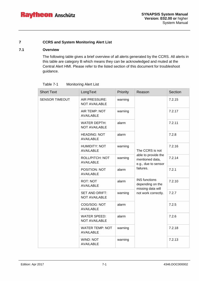
SYNAPSIS System Manual
Version: E02.00 or higher System Manual
Edition: Apr 2017 7-1 4346.DOC000002
7 CCRS and System Monitoring Alert List
7.1 Overview
The following table gives a brief overview of all alerts generated by the CCRS. All alerts in
this table are category B which means they can be acknowledged and muted at the
Central Alert HMI. Please refer to the listed section of this document for troubleshoot
guidance.
Table 7-1 Monitoring Alert List
Short Text LongText Priority Reason Section
SENSOR TIMEOUT AIR PRESSURE:
NOT AVAILABLE
warning
The CCRS is not
able to provide the
mentioned data,
e.g., due to sensor
failures.
INS functions
depending on the
missing data will
not work correctly.
7.2.15
AIR TEMP: NOT
AVAILABLE
warning 7.2.17
WATER DEPTH:
NOT AVAILABLE
alarm 7.2.11
HEADING: NOT
AVAILABLE
alarm 7.2.8
HUMIDITY: NOT
AVAILABLE
warning 7.2.16
ROLL/PITCH: NOT
AVAILABLE
warning 7.2.14
POSITION: NOT
AVAILABLE
alarm 7.2.1
ROT: NOT
AVAILABLE
alarm 7.2.10
SET AND DRIFT:
NOT AVAILABLE
warning 7.2.7
COG/SOG: NOT
AVAILABLE
alarm 7.2.5
WATER SPEED:
NOT AVAILABLE
alarm 7.2.6
WATER TEMP: NOT
AVAILABLE
warning 7.2.18
WIND: NOT
AVAILABLE
warning 7.2.13
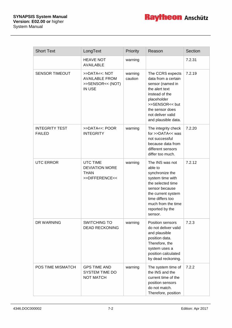
SYNAPSIS System Manual Version: E02.00 or higher System Manual
4346.DOC000002 7-2 Edition: Apr 2017
Short Text LongText Priority Reason Section
HEAVE NOT
AVAILABLE
warning 7.2.31
SENSOR TIMEOUT >>DATA<<: NOT
AVAILABLE FROM
>>SENSOR<< (NOT)
IN USE
warning
caution
The CCRS expects
data from a certain
sensor (named in
the alert text
instead of the
placeholder
>>SENSOR<< but
the sensor does
not deliver valid
and plausible data.
7.2.19
INTEGRITY TEST
FAILED
>>DATA<<: POOR
INTEGRITY
warning The integrity check
for >>DATA<< was
not successful
because data from
different sensors
differ too much.
7.2.20
UTC ERROR UTC TIME
DEVIATION MORE
THAN
>>DIFFERENCE<<
warning The INS was not
able to
synchronize the
system time with
the selected time
sensor because
the current system
time differs too
much from the time
reported by the
sensor.
7.2.12
DR WARNING SWITCHING TO
DEAD RECKONING
warning Position sensors
do not deliver valid
and plausible
position data.
Therefore, the
system uses a
position calculated
by dead reckoning.
7.2.3
POS TIME MISMATCH GPS TIME AND
SYSTEM TIME DO
NOT MATCH
warning The system time of
the INS and the
current time of the
position sensors
do not match.
Therefore, position
7.2.2
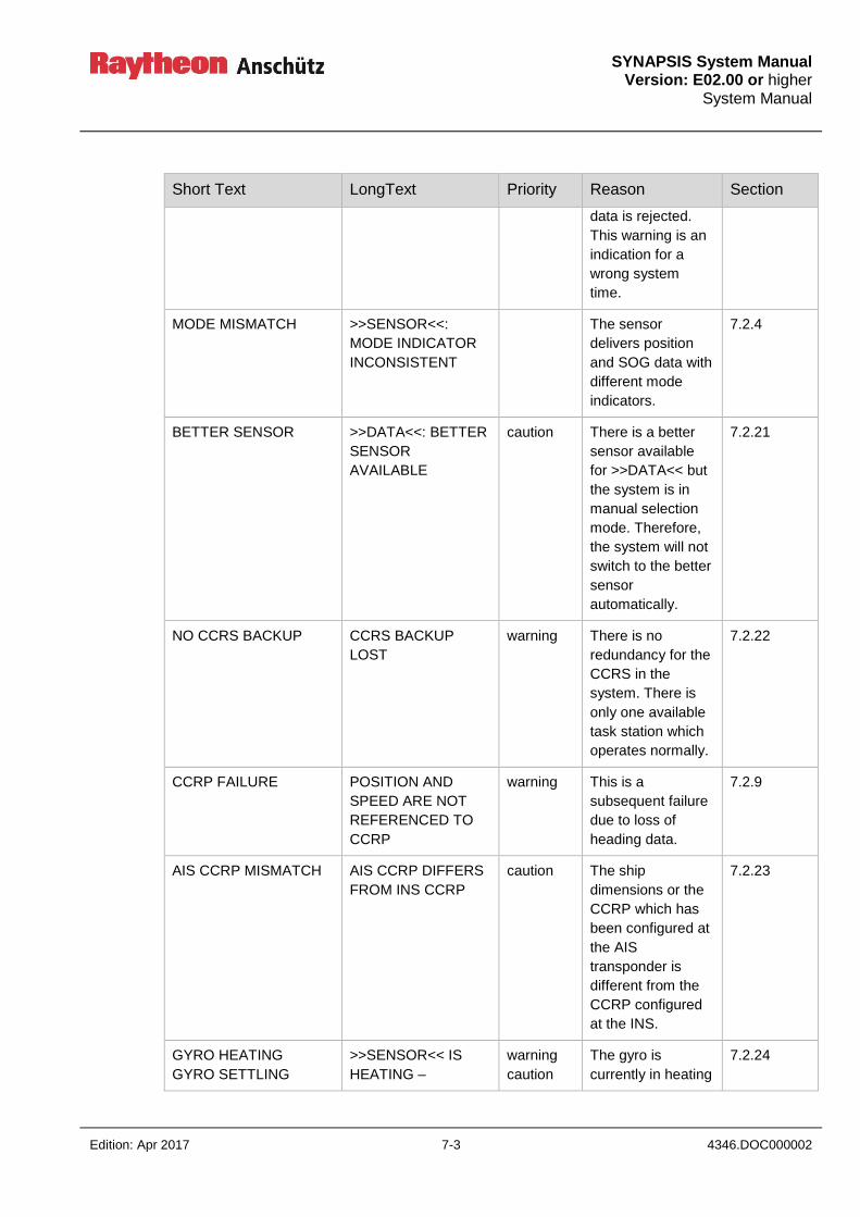
SYNAPSIS System Manual
Version: E02.00 or higher System Manual
Edition: Apr 2017 7-3 4346.DOC000002
Short Text LongText Priority Reason Section
data is rejected.
This warning is an
indication for a
wrong system
time.
MODE MISMATCH >>SENSOR<<:
MODE INDICATOR
INCONSISTENT
The sensor
delivers position
and SOG data with
different mode
indicators.
7.2.4
BETTER SENSOR >>DATA<<: BETTER
SENSOR
AVAILABLE
caution There is a better
sensor available
for >>DATA<< but
the system is in
manual selection
mode. Therefore,
the system will not
switch to the better
sensor
automatically.
7.2.21
NO CCRS BACKUP CCRS BACKUP
LOST
warning There is no
redundancy for the
CCRS in the
system. There is
only one available
task station which
operates normally.
7.2.22
CCRP FAILURE POSITION AND
SPEED ARE NOT
REFERENCED TO
CCRP
warning This is a
subsequent failure
due to loss of
heading data.
7.2.9
AIS CCRP MISMATCH AIS CCRP DIFFERS
FROM INS CCRP
caution The ship
dimensions or the
CCRP which has
been configured at
the AIS
transponder is
different from the
CCRP configured
at the INS.
7.2.23
GYRO HEATING
GYRO SETTLING
>>SENSOR<< IS
HEATING –
warning
caution
The gyro is
currently in heating
7.2.24

SYNAPSIS System Manual Version: E02.00 or higher System Manual
4346.DOC000002 7-4 Edition: Apr 2017
Short Text LongText Priority Reason Section
HEADING IS NOT
USED
>>SENSOR<< IS
SETTLING –
HEADING IS NOT
USED
or settling mode.
That’s why, the
heading and rate
of turn from this
gyro is not used
within the INS.
UNCORRECTED HDG HEADING FROM
>>SENSOR<< IS
UNCORRECTED
warning
caution
The heading from
the given sensor is
not corrected due
to missing speed
or position.
7.2.25
WMM EXPIRED WMM COEFFICIENT
FILE HAS EXPIRED
warning The world
magnetic model
used to correct
magnetic headings
has expired.
7.2.26
WMM WILL EXPIRE WMM COEFFICIENT
FILE WILL EXPIRE
WITHIN 30 DAYS
caution The world
magnetic model
used to correct
magnetic headings
will expire within
30 days.
7.2.27
WMM MISSING WMM COEFFICIENT
FILE IS INVALID OR
MISSING
warning The coefficient file
for the world
magnetic model is
missing or corrupt.
7.2.28
DEV TBL MISSING MAGNETIC
DEVIATION TABLE
IS NOT INITIALIZED
caution The magnetic
deviation table has
not been initialized.
7.2.29
SEL TIMEOUT COMPASS SYSTEM:
UNABLE TO
SELECT SENSOR
AT CCRS
alarm sensor selection
between INS and
compass system
could not be
synchronized
7.2.30
SEL FAILED CCRS: UNABLE TO
SELECT SENSOR
AT COMPASS
SYSTEM
alarm sensor selection
between INS and
compass system
could not be
synchronized
7.2.31

SYNAPSIS System Manual
Version: E02.00 or higher System Manual
Edition: Apr 2017 7-5 4346.DOC000002
Short Text LongText Priority Reason Section
POS OFFSET POSITION OFFSET
APPLIED
warning The operator
entered a manual
position offset in
the ECDIS. Sensor
positions are
corrected by this
manual offset.
7.2.33
7.2 Detailed Description
7.2.1 POSITION: NOT AVAILABLE
Priority: alarm
Category: B
Short Text: SENSOR TIMEOUT
Long Text: POSITION: NOT AVAILABLE
Reason: The CCRS is not able to provide position data to the tasks of the INS
because
there is no sensor available which delivers position
no data is received from the connected position sensors
position data received from the position sensors is not valid or
not plausible
Impact: Subsequent INS functions depending on position data will not work
correctly.
Troubleshooting: 1. Identify the position sensors which are expected by the
CCRS. The expected position sensors can be seen at the
Conning sensor selection display or the CCRS configuration
page in the service tool. All your position sensors shall be
listed here. Add the position sensors by using the service
tool.
2. Look for warnings and cautions for sensor timeout for these
sensors, e.g.
POSITION: NOT AVAILABLE FROM SENSOR GPS1 IN USE
Continue troubleshooting by resolving these warnings and
cautions see section 7.2.19.

SYNAPSIS System Manual Version: E02.00 or higher System Manual
4346.DOC000002 7-6 Edition: Apr 2017
SYNAPSIS System Manual
Version: E02.00 or higher System Manual
Edition: Apr 2017 7-7 4346.DOC000002
7.2.2 GPS TIME AND SYSTEM TIME DO NOT MATCH
Priority: warning
Category: B
Short Text: POS TIME MISMATCH
Long Text: GPS TIME AND SYSTEM TIME DO NOT MATCH
Reason: The system time and the time of the position data reported by the
position sensors do not match. This may be caused by
unsynchronized system clocks of the INS task stations.
Impact: Position data cannot be used.
Troubleshooting: 1. Check the system time of the INS. The time shall match the
current UTC time. If not, synchronize the system time to the
current UTC time.
2. Look for alerts caused by broken time sensors (see section
7.2.12 and 7.2.19). If there is such an alert, continue
troubleshooting by resolving these alerts.
3. Use the interface viewer of the service tool to monitor ZDA
sentences from the sensors. Reported UTC times shall match
current UTC time. If not, the sensors deliver wrong time data.
4. If the system time matches UTC time, use the interface view
of the service tool to monitor the NMEA data received from
the position sensors. The timestamps in the GGA, GLL, GNS,
and RMC sentences (if present) shall match the current UTC
time, too. If there is a significant time difference between the
time of the position sensor and the current UTC time, the
position sensor is broken or receives an invalid or spoofed
signal.
SYNAPSIS System Manual Version: E02.00 or higher System Manual
4346.DOC000002 7-8 Edition: Apr 2017
7.2.3 SWITCHING TO DEAD RECKONING
Priority: warning
Category: B
Short Text: DR POSITION
Long Text: SWITCHING TO DEAD RECKONING
Reason: No position data is available from the position sensors. The system
uses dead reckoning to estimate the current position of the vessel.
Impact: The position estimated by dead reckoning is of poor quality and
degrades over time.
Troubleshooting: 1. Look for warnings and cautions for sensor timeouts for
position sensors, e.g.,
POSITION: NOT AVAILABLE SENSOR GPS1 IN USE.
Continue troubleshooting by resolving these warnings and
cautions see section 7.2.19.
7.2.4 >>SENSOR<<: MODE INDICATIOR INCONSISTENT
Priority: caution
Category: B
Short Text: MODE MISMATCH
Long Text: >>SENSOR<<: MODE INDICATOR INCONSISTENT
Reason: The sensor delivers position and SOG data with different mode
indicators, e.g., position from differential mode and SOG from
autonomous mode. This is forbidden for INS systems.
Impact: Because SOG is derived from position data, this behavior indicates a
sensor error and sensor data is not plausible.
Troubleshooting: Start troubleshooting the sensor. The sensor has to report the same
mode indicators in position data sentences (e.g., GGA, GLL, GNS,
RMC) and SOG sentences (VTG).
If the system is not an INS, deactivate the check in the SYNAPSIS
service tool.
SYNAPSIS System Manual
Version: E02.00 or higher System Manual
Edition: Apr 2017 7-9 4346.DOC000002
7.2.5 COG/SOG: NOT AVAILABLE
Priority: alarm
Category: B
Short Text: SENSOR TIMEOUT
Long Text: COG/SOG: NOT AVAILABLE
Reason: The CCRS is not able to provide speed over ground or course over
ground data to the tasks of the INS because
there is no sensor available which delivers speed over ground and
course over ground
no data is received from the connected sensors
speed over ground or course over ground data received from the
sensors is not valid or not plausible
Impact: Subsequent INS functions depending on speed over ground or course
over ground data will not work correctly.
Troubleshooting: 1. Identify the sensors which are expected by the CCRS to deliver
speed over ground and course over ground. The expected
sensors can be seen at the Conning sensor selection display or
the CCRS configuration page in the service tool. All your
position sensors and all your logs delivering speed over ground
shall be listed here. If not, add these sensors by using the
service tool.
2. Look for warnings and cautions for sensor timeout for these
sensors, e.g.
COG/SOG: NOT AVAILABLE FROM SENSOR GPS1 IN USE
Continue troubleshooting by resolving these warnings and
cautions see section 7.2.19.
SYNAPSIS System Manual Version: E02.00 or higher System Manual
4346.DOC000002 7-10 Edition: Apr 2017
7.2.6 WATER SPEED: NOT AVAILABLE
Priority: alarm
Category: B
Short Text: SENSOR TIMEOUT
Long Text: WATER SPEED: NOT AVAILABLE
Reason: The CCRS is not able to provide speed through water data to the tasks
of the INS because
there is no sensor available which delivers speed through water
no data is received from the connected sensors
speed through water data received from the sensors is not valid or
not plausible
Impact: Subsequent INS functions depending on speed through water data will
not work correctly.
Troubleshooting: 1. Identify the sensors which are expected by the CCRS to deliver
speed through water. The expected sensors can be seen at the
Conning sensor selection display or the CCRS configuration
page in the service tool. All your logs shall be listed here. If not,
add these sensors by using the service tool.
2. Look for warnings and cautions for sensor timeout for these
sensors, e.g.
WATER SPEED: NOT AVAILABLE FROM SENSOR DOLOG IN
USE
Continue troubleshooting by resolving these warnings and
cautions see section 7.2.19.
SYNAPSIS System Manual
Version: E02.00 or higher System Manual
Edition: Apr 2017 7-11 4346.DOC000002
7.2.7 SET AND DRIFT: NOT AVAILBLE
Priority: warning
Category: B
Short Text: SENSOR TIMEOUT
Long Text: SET AND DRIFT: NOT AVAILABLE
Reason: The CCRS is not able to provide set and drift data to the tasks of the
INS because
there is no sensor available which delivers set and drift and
the CCRS is not able to calculate set and drift because some of the
following data is missing:
speed over ground
course over ground
speed through water
heading
no data is received from the connected sensors
set and drift data received from the sensors or calculated by the
INS is not valid or not plausible
Impact: Subsequent INS functions depending on set and drift data will not work
correctly.
Troubleshooting: 1. Identify the sensors which are expected by the CCRS to deliver
set and drift. The expected sensors can be seen at the CCRS
configuration page in the service tool. If there are any sensors
which deliver set and drift, add them by using the service tool.
2. Ensure that the following alarms are not present:
HEADING: NOT AVAILABLE
WATER SPEED: NOT AVAILABLE
COG/SOG: NOT AVAILABLE
3. If any of the listed alarms is present, continue troubleshooting by
resolving these alarms see sections 7.2.5, 7.2.9, 7.2.8 and
7.2.6.
4. Look for warnings and cautions for sensor timeout for these
sensors, e.g.
SET/DRIFT: NOT AVAILABLE FROM SENSOR DOLOG IN
USE Continue troubleshooting by resolving these warnings and
cautions see section 7.2.19.

SYNAPSIS System Manual Version: E02.00 or higher System Manual
4346.DOC000002 7-12 Edition: Apr 2017
7.2.8 HEADING: NOT AVAILABLE
Priority: alarm
Category: B
Short Text: SENSOR TIMEOUT
Long Text: HEADING: NOT AVAILABLE
Reason: The CCRS is not able to provide heading data to the tasks of the INS
because
there is no gyro or magnetic compass available
no data is received from the connected sensors
heading data received from the sensors is not valid or not plausible
Impact: Subsequent INS functions depending on heading data will not work
correctly.
Troubleshooting: 1. Identify the sensors which are expected by the CCRS to deliver
heading. The expected sensors can be seen at the Conning
sensor selection display or the CCRS configuration page in the
service tool. All your gyros shall be listed here. If not, add these
sensors by using the service tool.
2. Look for warnings and cautions for sensor timeout for these
sensors, e.g.
HEADING: NOT AVAILABLE FROM SENSOR GYRO1 IN USE
Continue troubleshooting by resolving these warnings and
cautions see section 7.2.19.
SYNAPSIS System Manual
Version: E02.00 or higher System Manual
Edition: Apr 2017 7-13 4346.DOC000002
7.2.9 POSITION AND SPEED ARE NOT REFERENCED TO CCRP
Priority: warning
Category: B
Short Text: CCRP FAILURE
Long Text: POSITION AND SPEED ARE NOT REFERENCED TO CCRP
Reason: The CCRS needs the current heading of the vessel to calculate the
position of the CCRP as well as the speed of the vessel at the CCRP
from the sensor data. If no heading is available, the CCRP correction is
not correct.
Impact: The position displayed by the INS is not the position of the CCRP.
There may be an error of at most 2 times the distance between the
CCRP and the mounting point of the selected position sensor.
Correction of speed values is also wrong.
Because the error depends on the mounting point of each sensor, the
integrity check for position and speed may fail.
Troubleshooting: 1. Look for warnings and cautions for sensor timeout for these
sensors, e.g.
HEADING: NOT AVAILABLE FROM SENSOR GYRO1 IN USE
Continue troubleshooting by resolving these warnings and
cautions see section 7.2.19.
SYNAPSIS System Manual Version: E02.00 or higher System Manual
4346.DOC000002 7-14 Edition: Apr 2017
7.2.10 ROT: NOT AVAILABLE
Priority: alarm
Category: B
Short Text: SENSOR TIMEOUT
Long Text: ROT: NOT AVAILABLE
Reason: The CCRS is not able to provide rate of turn data to the tasks of the INS
because
there is no sensor for rate of turn available
no data is received from the connected sensors
rate of turn data received from the sensors is not valid or not
plausible
Impact: Subsequent INS functions depending on rate of turn data will not work
correctly.
Troubleshooting: 1. Identify the sensors which are expected by the CCRS to deliver
rate of turn. The expected sensors can be seen at the Conning
sensor selection display or the CCRS configuration page in the
service tool. All your sensors that deliver rate of turn shall be
listed here. If not, add these sensors by using the service tool.
2. Look for warnings and cautions for sensor timeout for these
sensors, e.g.
ROT: NOT AVAILABLE FROM SENSOR GYRO1 IN USE
Continue troubleshooting by resolving these warnings and
cautions see section 7.2.19.
SYNAPSIS System Manual
Version: E02.00 or higher System Manual
Edition: Apr 2017 7-15 4346.DOC000002
7.2.11 WATER DEPTH: NOT AVAILABLE
Priority: alarm
Category: B
Short Text: SENSOR TIMEOUT
Long Text: WATER DEPTH: NOT AVAILABLE
Reason: The CCRS is not able to provide depth below keel and depth of water
data to the tasks of the INS because
there is no sensor for water depth
no data is received from the connected sensors
water depth data received from the sensors is not valid or not
plausible
Impact: Subsequent INS functions depending on water depth data will not work
correctly.
Troubleshooting: 1. Identify the sensors which are expected by the CCRS to deliver
water depth. The expected sensors can be seen at the Conning
sensor selection display or the CCRS configuration page in the
service tool. All your echo sounders shall be listed here. If not,
add these sensors by using the service tool.
2. Look for warnings and cautions for sensor timeout for these
sensors, e.g.
WATER DEPTH: NOT AVAILABLE FROM SENSOR SND1 IN
USE Continue troubleshooting by resolving these warnings and
cautions see section 7.2.19.

SYNAPSIS System Manual Version: E02.00 or higher System Manual
4346.DOC000002 7-16 Edition: Apr 2017
7.2.12 UTC TIME DEVIATION MORE THAN >>DIIFERENCE<<
Priority: warning
Category: B
Short Text: UTC ERROR
Long Text: UTC TIME DEVIATION MORE THAN >>DIFFERENCE<<
Reason: The CCRS will only synchronize the system time with an external clock
if the difference between the current system time and the time reported
by the external clock is less than preconfigured difference (e.g., 4 days.)
Impact: System time is not synchronized with the external clock. This will
generate subsequent alerts such as 7.2.2 and effects all time based
monitoring functions of the INS.
Troubleshooting: Use the SYNAPSIS service tool to set the system time of all task
stations to the current UTC time. If the warning does not disappear, use
the interface view of the service tool to monitor the NMEA sentences
(ZDA) from the external clock. The UTC time reported by the external
clock shall match the current UTC time. If there is a significant
deviation, the external clock is broken or receives an invalid or spoofed
time signal.
SYNAPSIS System Manual
Version: E02.00 or higher System Manual
Edition: Apr 2017 7-17 4346.DOC000002
7.2.13 WIND: NOT AVAILABLE
Priority: warning
Category: B
Short Text: SENSOR TIMEOUT
Long Text: WIND: NOT AVAILABLE
Reason: The CCRS is not able to provide wind data to the tasks of the INS
because
there is no wind sensor available
no data is received from the connected sensors
wind data received from the sensors is not valid or not plausible
Impact: Subsequent INS functions depending on wind data will not work
correctly.
Troubleshooting: 1. Identify the sensors which are expected by the CCRS to deliver
wind data. The expected sensors can be seen at the CCRS
configuration page in the service tool. All your anemometers
shall be listed here. If not, add these sensors by using the
service tool.
2. Look for warnings and cautions for sensor timeout for these
sensors, e.g.
WIND: NOT AVAILABLE FROM SENSOR WX1 IN USE
Continue troubleshooting by resolving these warnings and
cautions see section 7.2.19.
SYNAPSIS System Manual Version: E02.00 or higher System Manual
4346.DOC000002 7-18 Edition: Apr 2017
7.2.14 ROLL/PITCH: NOT AVAILABLE
Priority: warning
Category: B
Short Text: SENSOR TIMEOUT
Long Text: ROLL/PITCH: NOT AVAILABLE
Reason: The CCRS is not able to provide roll or pitch data to the tasks of the INS
because
there is no MINS available, but the CCRS shall process roll and
pitch
no data is received from the connected MINS or roll/pitch sensors
roll and pitch data received from the MINS or roll/pitch is not valid or
not plausible
Impact: Subsequent INS functions depending on roll and pitch data will not work
correctly.
Troubleshooting: 1. Identify the sensors which are expected by the CCRS to deliver
roll and pitch data. The expected sensors can be seen at the
CCRS configuration page in the service tool. All your roll/pitch
sensors shall be listed here. If not, add these sensors by using
the service tool.
2. Look for warnings and cautions for sensor timeout for these
sensors, e.g.
ROLL/PITCH: NOT AVAILABLE FROM SENSOR MINS1 IN
USE
Continue troubleshooting by resolving these warnings and
cautions see section 7.2.19.

SYNAPSIS System Manual
Version: E02.00 or higher System Manual
Edition: Apr 2017 7-19 4346.DOC000002
7.2.15 AIR PRESSURE: NOT AVAILABLE
Priority: warning
Category: B
Short Text: SENSOR TIMEOUT
Long Text: AIR PRESSURE: NOT AVAILABLE
Reason: The CCRS is not able to provide air pressure data to the tasks of the
INS because
there is no sensor available, but the CCRS shall process air
pressure
no data is received from the connected sensors
air pressure data received from the sensors is not valid or not
plausible
Impact: Subsequent INS functions depending on air pressure data will not work
correctly.
Troubleshooting: 1. Identify the sensors which are expected by the CCRS to deliver
air pressure data. The expected sensors can be seen at the
CCRS configuration page in the service tool. All your sensors
delivering air pressure data shall be listed here. If not, add these
sensors by using the service tool.
2. Look for warnings and cautions for sensor timeout for these
sensors, e.g.
AIR PRESSURE: NOT AVAILABLE FROM SENSOR WX1 IN
USE Continue troubleshooting by resolving these warnings and
cautions see section 7.2.19.

SYNAPSIS System Manual Version: E02.00 or higher System Manual
4346.DOC000002 7-20 Edition: Apr 2017
7.2.16 HUMIDITY: NOT AVAILABLE
Priority: warning
Category: B
Short Text: SENSOR TIMEOUT
Long Text: HUMIDITY: NOT AVAILABLE
Reason: The CCRS is not able to provide humidity data to the tasks of the INS
because
there is no sensor available, but the CCRS shall process humidity
no data is received from the connected sensors
humidity data received from the sensors is not valid or not plausible
Impact: Subsequent INS functions depending on humidity data will not work
correctly.
Troubleshooting: 1. Identify the sensors which are expected by the CCRS to deliver
humidity data. The expected sensors can be seen at the CCRS
configuration page in the service tool. All your sensors delivering
humidity data shall be listed here. If not, add these sensors by
using the service tool.
2. Look for warnings and cautions for sensor timeout for these
sensors, e.g.
HUMIDITY: NOT AVAILABLE FROM SENSOR WX1 IN USE
Continue troubleshooting by resolving these warnings and
cautions see section 7.2.19.
SYNAPSIS System Manual
Version: E02.00 or higher System Manual
Edition: Apr 2017 7-21 4346.DOC000002
7.2.17 AIR TEMP: NOT AVAILABLE
Priority: warning
Category: B
Short Text: SENSOR TIMEOUT
Long Text: AIR TEMP: NOT AVAILABLE
Reason: The CCRS is not able to provide air temperature data to the tasks of the
INS because
there is no sensor available, but the CCRS shall process air
temperature
no data is received from the connected sensors
humidity data received from the sensors is not valid or not plausible
Impact: Subsequent INS functions depending on air temperature data will not
work correctly.
Troubleshooting: 1. Identify the sensors which are expected by the CCRS to deliver
air temperature data. The expected sensors can be seen at the
CCRS configuration page in the service tool. All your sensors
delivering air temperature data shall be listed here. If not, add
these sensors by using the service tool.
2. Look for warnings and cautions for sensor timeout for these
sensors, e.g.
AIR TEMP: NOT AVAILABLE FROM SENSOR WX1 IN USE
Continue troubleshooting by resolving these warnings and
cautions see section 7.2.19.
SYNAPSIS System Manual Version: E02.00 or higher System Manual
4346.DOC000002 7-22 Edition: Apr 2017
7.2.18 WATER TEMP: NOT AVAILABLE
Priority: warning
Category: B
Short Text: SENSOR TIMEOUT
Long Text: WATER TEMP: NOT AVAILABLE
Reason: The CCRS is not able to provide water temperature data to the tasks of
the INS because
there is no sensor available, but the CCRS shall process water
temperature
no data is received from the connected sensors
water temperature data received from the sensors is not valid or not
plausible
Impact: Subsequent INS functions depending on water temperature data will not
work correctly.
Troubleshooting: 1. Identify the sensors which are expected by the CCRS to deliver
water temperature data. The expected sensors can be seen at
the CCRS configuration page in the service tool. All your
sensors delivering water temperature data shall be listed here. If
not, add these sensors by using the service tool.
2. Look for warnings and cautions for sensor timeout for these
sensors, e.g.
WATER TEMP: NOT AVAILABLE FROM SENSOR WX1 IN
USE Continue troubleshooting by resolving these warnings and
cautions see section 7.2.19.
SYNAPSIS System Manual
Version: E02.00 or higher System Manual
Edition: Apr 2017 7-23 4346.DOC000002
7.2.19 >>DATA<<: NOT AVAILABLE FROM SENSOR >>SENSOR<< (IN USE)
Priority: warning (data is not available from the sensor currently in use)
caution (data is not available from a sensor currently not in use)
Category: B
Short Text: SENSOR TIMEOUT
Long Text: >>DATA<<: NOT AVAILABLE FROM SENSOR >>SENSOR<< IN USE
>>DATA<<: NOT AVAILABLE FROM SENSOR >>SENSOR<<
Reason: The CCRS expects data from a sensor but the sensor does not deliver
valid and plausible data.
Impact: The quality indicator of the sensor is lowered and degradation to a
redundant sensor takes place. If there is no redundant sensor available,
a “not data” alarm is generated (see sections 7.2.1, 7.2.4, 7.2.7, 7.2.8,
7.2.10, 7.2.13, 7.2.14, 7.2.15, 7.2.16, 7.2.17, 7.2.18).
Troubleshooting: 1. Open the interface viewer of the service tool. Select the
interface(s) where the sensor is connected to. Check the data
which is received from the sensor:
Receives the system any sentences?
Look for the following NMEA sentences:
position: GGA, GLL, GNS, RMC
heading: HDT, HDG, THS
course: VTG
time: ZDA
speed over ground: VTG, VBW
speed through water: VBW, VHW
set and drift: VDR
water depth: DBT, DBK, DBS, DPT
wind: MWV, MWD
roll/pitch: PANZHRP, TRO
air pressure: MMB
air temperature: MTA
water temperature: MTW
humidity: MHU
2. If NMEA data is available, look at the checksum: Is the
checksum of the sentences correct?
3. Check validity flags of the NMEA sentences. The CCRS only
processes valid data.
4. Check plausibility of data. The CCRS only processes data with
plausible magnitudes of values.

SYNAPSIS System Manual Version: E02.00 or higher System Manual
4346.DOC000002 7-24 Edition: Apr 2017
5. If data received from the sensor is marked as invalid or not
plausible, continue troubleshooting at the sensor which sends
invalid data.
6. Otherwise: check data for jumps or high rates of change. CCRS
performs a jump detection on position, heading, and rate of turn.
Check the maximum speed and maximum rate of turn
parameters configured for the vessel for values whether they are
too low.
7. If the interface viewer does not show any NMEA sentences from
the sensor or the received data is no valid NMEA, check the
interface configuration of the sensor (wiring, baud rate of
interface, configuration of sensor).
8. Check that redundant interfaces share a common role arbitration
concern.
9. If interface configuration is correct and no data is displayed in
the interface viewer, check that the sensor is correctly plugged
in and the cable is not damaged.
SYNAPSIS System Manual
Version: E02.00 or higher System Manual
Edition: Apr 2017 7-25 4346.DOC000002
7.2.20 >>DATA<<: POOR INTEGRITY
Priority: warning
Category: B
Short Text: POOR INTEGRITY
Long Text: >>DATA<<: POOR INTEGRITY
Reason: The CCRS compares data from redundant sensors. If the deviance
between data from two sensors exceeds the configured threshold, the
integrity test fails. Otherwise, the integrity test is passed. The warning is
generated when the values of the selected sensor differ from the values
of redundant sensors (there are more failed integrity tests for the
selected sensor than passed integrity tests or the integrity tests do not
have a clear result).
Please note: If there is only one sensor available for a certain data item,
the warning is not generated.
Impact: Data which did not pass the integrity check cannot be used for
automatic control functions.
Troubleshooting: Poor integrity may be the result of a noisy sensor signal. Open the
Conning sensor selection page and compare the values. If the
difference is acceptable, the deviance thresholds may be configured to
a value which is too low. Open the service tool and increase the
“absolute deviance” configuration parameters of the sensors.
Check that the mounting positions of the sensors are correct. The
CCRS performs a CCRP correction on position, speed, course, and
depth. Wrong mounting positions cause a wrong CCRP correction
which results in a deviance between the values.
Check that the heading value used by the system is correct. Heading is
an important factor in CCRP correction.
SYNAPSIS System Manual Version: E02.00 or higher System Manual
4346.DOC000002 7-26 Edition: Apr 2017
7.2.21 >>DATA<<: BETTER SENSOR AVAILABLE
Priority: caution
Category: B
Short Text: BETTER SENSOR AVAILABLE
Long Text: >>DATA<<: BETTER SENSOR AVAILABLE
Reason: The CCRS works in manual selection mode, a sensor has been
manually selected, but there is another sensor which has a better
quality.
Impact: This is information for the mariner.
Troubleshooting: The mariner should confirm that the manually selected sensor is the
best choice.
7.2.22 CCRS BACKUP LOST
Priority: warning
Category: B
Short Text: NO CCRS BACKUP
Long Text: CCRS BACKUP LOST
Reason: The CCRS runs redundantly on every task station of the INS. This
warning occurs when only one CCRS is available in the system.
Impact: This is information for the mariner. If the last CCRS instance fails, the
whole INS will miss any sensor data.
Troubleshooting: The warning occurs when either only one task station of the INS works
under normal conditions or there is a network error such that
communication between the task stations is disturbed. In the first case,
restart the other task stations of the INS. In the second case, start
troubleshooting of the network components.
SYNAPSIS System Manual
Version: E02.00 or higher System Manual
Edition: Apr 2017 7-27 4346.DOC000002
7.2.23 AIS CCRP DIFFERS FROM INS CCRP
Priority: caution
Category: B
Short Text: AIS CCRP MISMATCH
Long Text: AIS CCRP DIFFERS FROM INS CCRP
Reason: Ship dimensions and CCRP are configured for the INS and the AIS
transponder individually. There is a mismatch between both
configurations.
Impact: If the INS configuration of the CCRP or ship dimensions is wrong, the
CCRP correction of sensor data will not work correctly. If the AIS
configuration is wrong, the AIS target data reported to other vessels is
wrong.
Troubleshooting: Configure the correct ship dimensions and CCRP location (typically the
Conning position) both at the INS (by using the service tool) and the
AIS transponder.
7.2.24 >>SENSOR<< IS HEATING/SETTLING –HEADING IS NOT USED
Priority: warning (>>SENSOR<< is the selected heading sensor)
caution (>>SENSOR<< is not selected)
Category: B
Short Text: GYRO HEATING / GYRO SETTLING
Long Text: >>SENSOR<< IS HEATING – HEADING IS NOT USED
>>SENSOR<< IS SETTLING – HEADING IS NOT USED
Reason: The given gyro is currently in heating or settling mode. The heading and
rate of turn from this gyro are too imprecise to be used within the INS.
Impact: Heading and rate of turn from a gyro in heating or settling mode cannot
be used in the INS. If the user selects a gyro in settling mode manually,
no heading and rate of turn information will be available in the INS.
Troubleshooting: Wait until the gyro finished the heating and settling phase. If the
selected heading sensor is currently heating or settling, try to select
another gyro which is in normal operation mode.
SYNAPSIS System Manual Version: E02.00 or higher System Manual
4346.DOC000002 7-28 Edition: Apr 2017
7.2.25 HEADING FROM >>SENSOR<< IS UNCORRECTED
Priority: warning (>>SENSOR<< is the selected heading sensor)
caution (>>SENSOR<< is not selected)
Category: B
Short Text: UNCORRECTED HDG
Long Text: HEADING FROM >>SENSOR<< IS UNCORRECTED
Reason: Due to missing speed or position data, the heading from the given gyro
is not corrected and does not reference to true north.
Impact: The heading reported by the given gyro might be imprecise and may
deviate from the real heading of the vessel. Display may show a wrong
heading. CPA/TCPA values of ARPA and AIS targets may be wrong.
Collision warnings may be wrong or missing. Heading control and
navigational calculations may not work correctly. Sensor data may not
be CCRP corrected.
Troubleshooting: Check that speed and position data is available (look for missing data
and alarms.) If data is missing (e.g., at the Conning display), continue
troubleshooting by resolving the alarms.
If speed and position data is available, use the interface viewer of the
SYNAPSIS service tool to check the interface between the INS and the
compass system if speed and position is reported by the INS correctly
and the connection works properly.
If possible, try to enter manual speed and position at the compass
system.
SYNAPSIS System Manual
Version: E02.00 or higher System Manual
Edition: Apr 2017 7-29 4346.DOC000002
7.2.26 WMM COEFFICIENT FILE HAS EXPIRED
Priority: warning
Category: B
Short Text: WMM EXPIRED
Long Text: WMM COEFFICIENT FILE HAS EXPIRED
Reason: The coefficient file of the World Magnetic Model (WMM) is too old.
Impact: Heading values from the magnetic compass cannot be correctly
referenced to true north because the current magnetic variation of the
earth magnetic field is not known.
This alert is only applicable to systems where the INS is responsible to
correct magnetic headings.
Troubleshooting: Download the latest version of the World Magnetic Model coefficient file
from the National Oceanic and Atmospheric Administration (NOAA) and
install the file according to the system installation manual.
URL (May 2014):
http://www.ngdc.noaa.gov/geomag/WMM/DoDWMM.shtml
SYNAPSIS System Manual Version: E02.00 or higher System Manual
4346.DOC000002 7-30 Edition: Apr 2017
7.2.27 WMM COEFFICIENT FILE
Priority: caution
Category: B
Short Text: WMM WILL EXPIRE
Long Text: WMM COEFFICIENT FILE WILL EXPIRE WITHIN 30 DAYS
Reason: The coefficient file of the World Magnetic Model (WMM) will expire
within the next 30 days.
Impact: This is a pre-caution. After the coefficient file has expired, heading
values from the magnetic compass cannot be correctly referenced to
true north because the current magnetic variation of the earth magnetic
field is not known.
This alert is only applicable to systems where the INS is responsible to
correct magnetic headings.
Troubleshooting: Download the latest version of the World Magnetic Model coefficient file
from the National Oceanic and Atmospheric Administration (NOAA) and
install the file according to the system installation manual.
URL (May 2014):
http://www.ngdc.noaa.gov/geomag/WMM/DoDWMM.shtml

SYNAPSIS System Manual
Version: E02.00 or higher System Manual
Edition: Apr 2017 7-31 4346.DOC000002
7.2.28 WMM COEFFICIENT FILE IS INVALID OR MISSING
Priority: warning
Category: B
Short Text: WMM MISSING
Long Text: WMM COEFFICIENT FILE IS INVALID OR MISSING
Reason: The coefficient file of the World Magnetic Model (WMM) was not
correctly installed.
Impact: Without the coefficient file of the World Magnetic Model, heading values
from the magnetic compass cannot be correctly referenced to true north
because the current magnetic variation of the earth magnetic field is not
known.
This alert is only applicable to systems where the INS is responsible to
correct magnetic headings.
Troubleshooting: Download the latest version of the World Magnetic Model coefficient file
from the National Oceanic and Atmospheric Administration (NOAA) and
install the file according to the system installation manual.
URL (May 2014):
http://www.ngdc.noaa.gov/geomag/WMM/DoDWMM.shtml
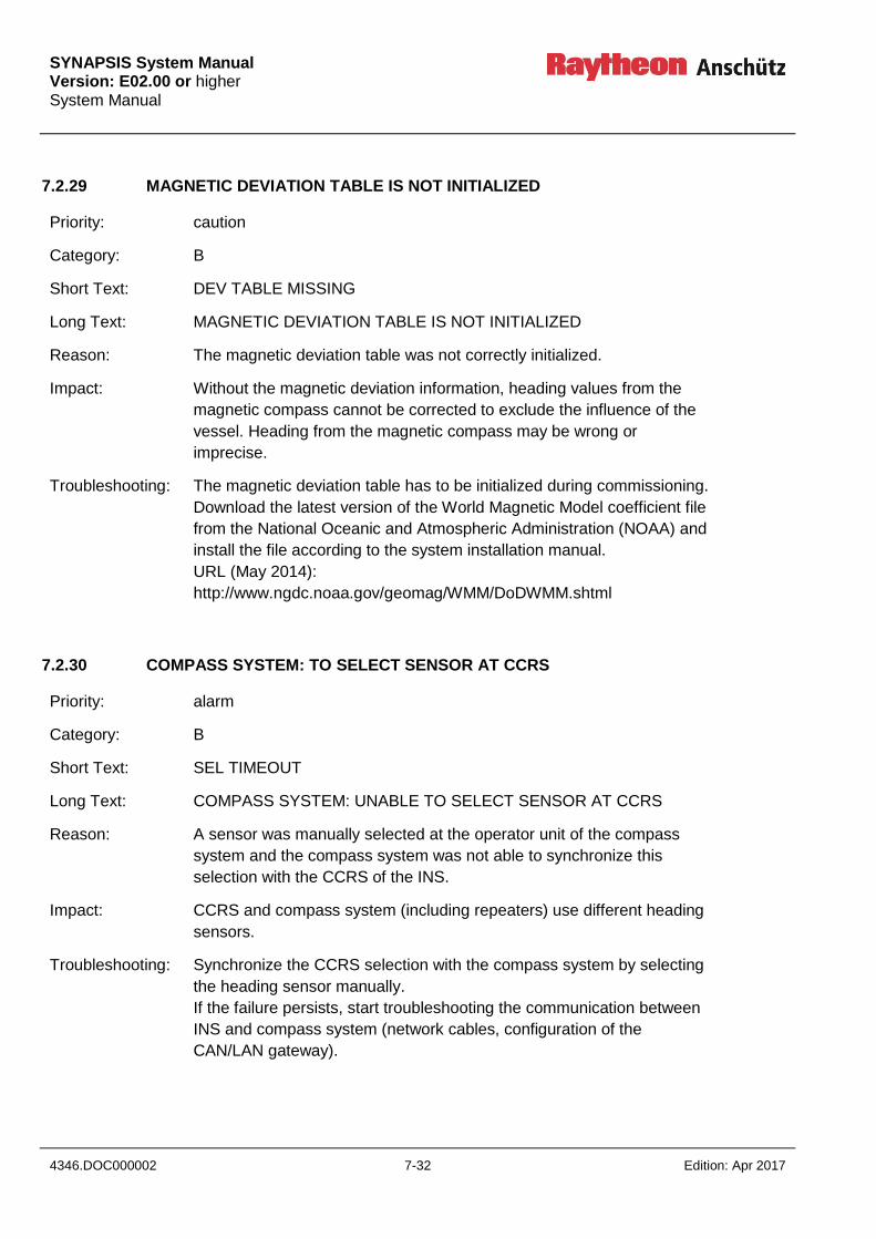
SYNAPSIS System Manual Version: E02.00 or higher System Manual
4346.DOC000002 7-32 Edition: Apr 2017
7.2.29 MAGNETIC DEVIATION TABLE IS NOT INITIALIZED
Priority: caution
Category: B
Short Text: DEV TABLE MISSING
Long Text: MAGNETIC DEVIATION TABLE IS NOT INITIALIZED
Reason: The magnetic deviation table was not correctly initialized.
Impact: Without the magnetic deviation information, heading values from the
magnetic compass cannot be corrected to exclude the influence of the
vessel. Heading from the magnetic compass may be wrong or
imprecise.
Troubleshooting: The magnetic deviation table has to be initialized during commissioning.
Download the latest version of the World Magnetic Model coefficient file
from the National Oceanic and Atmospheric Administration (NOAA) and
install the file according to the system installation manual.
URL (May 2014):
http://www.ngdc.noaa.gov/geomag/WMM/DoDWMM.shtml
7.2.30 COMPASS SYSTEM: TO SELECT SENSOR AT CCRS
Priority: alarm
Category: B
Short Text: SEL TIMEOUT
Long Text: COMPASS SYSTEM: UNABLE TO SELECT SENSOR AT CCRS
Reason: A sensor was manually selected at the operator unit of the compass
system and the compass system was not able to synchronize this
selection with the CCRS of the INS.
Impact: CCRS and compass system (including repeaters) use different heading
sensors.
Troubleshooting: Synchronize the CCRS selection with the compass system by selecting
the heading sensor manually.
If the failure persists, start troubleshooting the communication between
INS and compass system (network cables, configuration of the
CAN/LAN gateway).

SYNAPSIS System Manual
Version: E02.00 or higher System Manual
Edition: Apr 2017 7-33 4346.DOC000002
7.2.31 CCRS: UNABLE TO SELECT SENSOR AT COMPASS SYSTEM
Priority: alarm
Category: B
Short Text: SEL FAILED
Long Text: CCRS: UNABLE TO SELECT SENSOR AT COMPASS SYSTEM
Reason: A sensor was selected in CCRS (either manually or automatically.) The
CCRS was not able to synchronize this selection with the compass
system.
Impact: CCRS and compass system (including repeaters) use different heading
sensors.
Troubleshooting: Synchronize the sensor selection at the compass system with the
CCRS selection.
If the failure persists, start troubleshooting the communication between
INS and compass system (network cables, configuration of the
CAN/LAN gateway).

SYNAPSIS System Manual Version: E02.00 or higher System Manual
4346.DOC000002 7-34 Edition: Apr 2017
7.2.32 HEAVE: NOT AVAILABLE
Priority: warning
Category: B
Short Text: SENSOR TIMEOUT
Long Text: HEAVE: NOT AVAILABLE
Reason: The CCRS is not able to provide heave data to the tasks of the INS
because
there is no heave sensor available, but the CCRS shall process
heave
no data is received from the connected heave sensor
received heave is not valid or not plausible
Impact: Subsequent INS functions depending on heave data will not work
correctly.
Troubleshooting: 1. Identify the sensors that are expected by the CCRS to deliver
heave data. The expected sensors can be seen at the CCRS
configuration page in the service tool. All heave sensors shall be
listed here. If not, add these sensors by using the service tool.
2. Look for warnings and cautions for sensor timeout for these
sensors, e.g.
HEAVE: NOT AVAILABLE FROM SENSOR >>SENSOR<< IN
USE"
Continue troubleshooting by resolving these warnings and
cautions see section 7.2.19.

SYNAPSIS System Manual
Version: E02.00 or higher System Manual
Edition: Apr 2017 7-35 4346.DOC000002
7.2.33 POSITION OFFSET APPLIED
Priority: warning
Category: B
Short Text: POS OFFSET
Long Text: POSITION OFFSET APPLIED
Reason: The operator entered a manual position offset in the ECDIS. Sensor
positions are corrected by this manual offset
Impact: All position indications in the system on all workstations indicate the
corrected position. The operator has to constantly monitor and revise
the position offset.
Troubleshooting: The alert is raised because of a potentially dangerous operation by the
operator. The operator has the duty to check the correctness of the
entered manual offset, update the value if necessary or remove the
offset if it is no longer valid. The alert will be rectified when the position
offset is removed.

SYNAPSIS System Manual Version: E02.00 or higher System Manual
4346.DOC000002 7-36 Edition: Apr 2017
Intentionally left blank
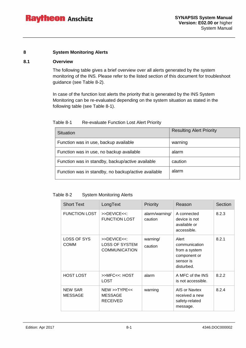
SYNAPSIS System Manual
Version: E02.00 or higher System Manual
Edition: Apr 2017 8-1 4346.DOC000002
8 System Monitoring Alerts
8.1 Overview
The following table gives a brief overview over all alerts generated by the system
monitoring of the INS. Please refer to the listed section of this document for troubleshoot
guidance (see Table 8-2).
In case of the function lost alerts the priority that is generated by the INS System
Monitoring can be re-evaluated depending on the system situation as stated in the
following table (see Table 8-1).
Table 8-1 Re-evaluate Function Lost Alert Priority
Situation Resulting Alert Priority
Function was in use, backup available warning
Function was in use, no backup available alarm
Function was in standby, backup/active available caution
Function was in standby, no backup/active available alarm
Table 8-2 System Monitoring Alerts
Short Text LongText Priority Reason Section
FUNCTION LOST >>DEVICE<<:
FUNCTION LOST
alarm/warning/
caution
A connected
device is not
available or
accessible.
8.2.3
LOSS OF SYS
COMM
>>DEVICE<<:
LOSS OF SYSTEM
COMMUNICATION
warning/
caution
Alert
communication
from a system
component or
sensor is
disturbed.
8.2.1
HOST LOST >>MFC<<: HOST
LOST
alarm A MFC of the INS
is not accessible.
8.2.2
NEW SAR
MESSAGE
NEW >>TYPE<<
MESSAGE
RECEIVED
warning AIS or Navtex
received a new
safety-related
message.
8.2.4
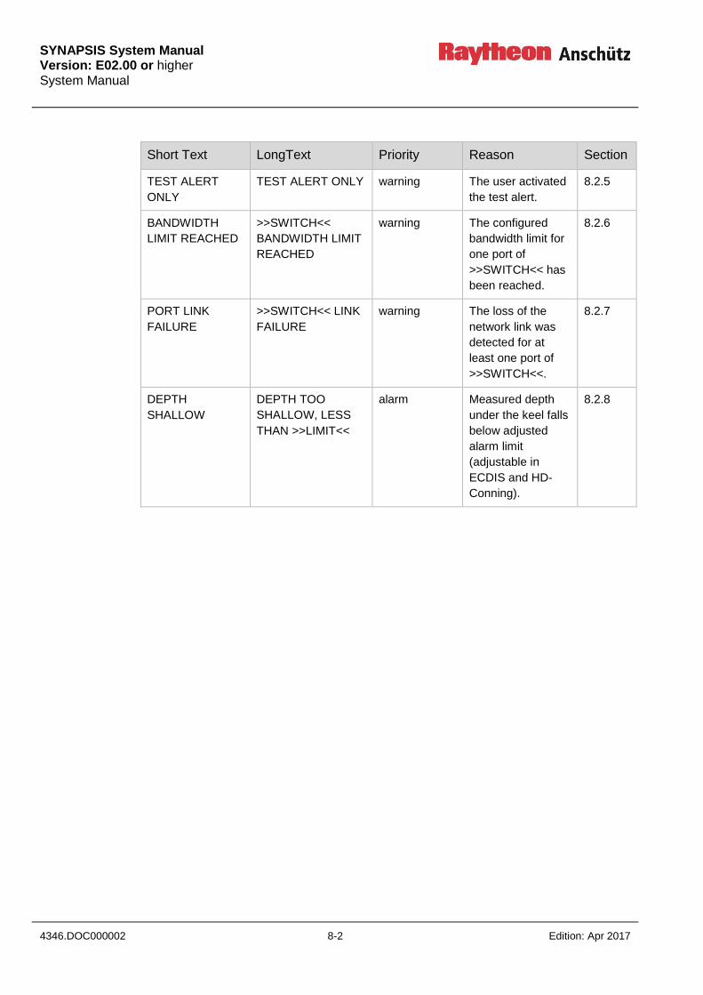
SYNAPSIS System Manual Version: E02.00 or higher System Manual
4346.DOC000002 8-2 Edition: Apr 2017
Short Text LongText Priority Reason Section
TEST ALERT
ONLY
TEST ALERT ONLY warning The user activated
the test alert.
8.2.5
BANDWIDTH
LIMIT REACHED
>>SWITCH<<
BANDWIDTH LIMIT
REACHED
warning The configured
bandwidth limit for
one port of
>>SWITCH<< has
been reached.
8.2.6
PORT LINK
FAILURE
>>SWITCH<< LINK
FAILURE
warning The loss of the
network link was
detected for at
least one port of
>>SWITCH<<.
8.2.7
DEPTH
SHALLOW
DEPTH TOO
SHALLOW, LESS
THAN >>LIMIT<<
alarm Measured depth
under the keel falls
below adjusted
alarm limit
(adjustable in
ECDIS and HD-
Conning).
8.2.8

SYNAPSIS System Manual
Version: E02.00 or higher System Manual
Edition: Apr 2017 8-3 4346.DOC000002
8.2 Detailed Description
8.2.1 >>DEVICE<<: LOSS OF SYSTEM COMMUNICATION
Priority: warning or caution
Category: B
Short Text: LOSS OF SYS COMM
Long Text: >>DEVICE<<: LOSS OF SYSTEM COMMUNICATION
Reason: Some connected device or INS function is not able to send alerts to the
INS. If ALC sentences are not repeated within a considerable time,
priority will be caution. If ALC and HBT sentences are not repeated
within a considerable time, priority will be warning.
Impact: No alerts from this device or function are displayed on the Conning alert
page.
Troubleshooting: Confirm that the device is properly running and connected to the INS.
Try to restart the device. If an INS function fails to send alerts, try to
restart the MFC where the function runs. If an external device fails to
send alerts, check data from the device if any successful connection is
established. Monitor the interface data to find ALR or ALC sentences
sent from the device with an interval not longer than 60 seconds.
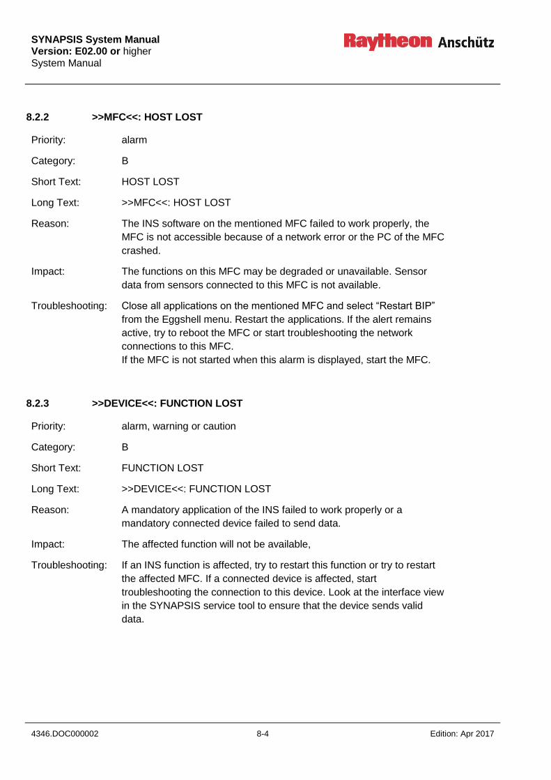
SYNAPSIS System Manual Version: E02.00 or higher System Manual
4346.DOC000002 8-4 Edition: Apr 2017
8.2.2 >>MFC<<: HOST LOST
Priority: alarm
Category: B
Short Text: HOST LOST
Long Text: >>MFC<<: HOST LOST
Reason: The INS software on the mentioned MFC failed to work properly, the
MFC is not accessible because of a network error or the PC of the MFC
crashed.
Impact: The functions on this MFC may be degraded or unavailable. Sensor
data from sensors connected to this MFC is not available.
Troubleshooting: Close all applications on the mentioned MFC and select “Restart BIP”
from the Eggshell menu. Restart the applications. If the alert remains
active, try to reboot the MFC or start troubleshooting the network
connections to this MFC.
If the MFC is not started when this alarm is displayed, start the MFC.
8.2.3 >>DEVICE<<: FUNCTION LOST
Priority: alarm, warning or caution
Category: B
Short Text: FUNCTION LOST
Long Text: >>DEVICE<<: FUNCTION LOST
Reason: A mandatory application of the INS failed to work properly or a
mandatory connected device failed to send data.
Impact: The affected function will not be available,
Troubleshooting: If an INS function is affected, try to restart this function or try to restart
the affected MFC. If a connected device is affected, start
troubleshooting the connection to this device. Look at the interface view
in the SYNAPSIS service tool to ensure that the device sends valid
data.

SYNAPSIS System Manual
Version: E02.00 or higher System Manual
Edition: Apr 2017 8-5 4346.DOC000002
8.2.4 NEW >>TYPE<< MESSAGE RECEIVED
Priority: warning
Category: B
Short Text: NEW SAR MESSAGE
Long Text: NEW NAVTEX MESSAGE RECEIVED
NEW AIS MESSAGE RECEIVED
Reason: A new safety-related message has been received via Navtex or AIS.
Impact:
Troubleshooting: Read the message in ECDIS or Conning and acknowledge the warning.
8.2.5 TEST ALERT ONLY
Priority: warning
Category: B
Short Text: TEST ALERT ONLY
Long Text: TEST ALERT ONLY
Reason: The user activated the test alert in an application
Impact: The test alert can be used to test alert communication in the system
and with external systems. The alert will be rectified after 60 seconds.
Troubleshooting: Acknowledge the alert and wait until the alert is rectified after 60
seconds.
SYNAPSIS System Manual Version: E02.00 or higher System Manual
4346.DOC000002 8-6 Edition: Apr 2017
8.2.6 >>SWITCH<< BANDWIDTH LIMIT REACHED
Priority: warning
Category: B
Short Text: BANDWIDTH LIMIT REACHED
Long Text: >>SWITCH<< BANDWIDTH LIMIT REACHED
Reason: The configuration bandwidth limit for one port of >>SWITCH<< has
been reached.
Impact: Reaching the bandwidth limit may result in loss of data messages
between consoles and /or connected devices.
Troubleshooting: Check the INS status page on the Conning (System Status Display) to
see which ports bandwidth limit has been reached. Use the system
connection diagram to identify the connected console/device. Try to
restart the connected console/device. Use the SYNAPSIS Service Tool
(Doc. No. 4280) to check the configured bandwidth limit for the affected
port.
8.2.7 >>SWITCH<< LINK FAILURE
Priority: warning
Category: B
Short Text: PORT LINK FAILURE
Long Text: >>SWITCH<< LINK FAILURE
Reason: The loss of network link was detected for at least one port of
>>SWITCH<<.
Impact: No communication with the console/device connected to this port.
Troubleshooting: Check the INS status on the Conning (System Status Display) to see for
which ports the loss of network link has been detected. Use the system
connection diagram to identify the connected console/device. Try to
restart the connected console/device. Check the corresponding network
cable (wire break).
SYNAPSIS System Manual
Version: E02.00 or higher System Manual
Edition: Apr 2017 8-7 4346.DOC000002
8.2.8 DEPTH TOO SHALLOW, LESS THAN >>LIMIT<<
Priority: alarm
Category: A
Short Text: DEPTH SHALLOW
Long Text: DEPTH TOO SHALLOW, LESS THAN >>LIMIT<<
Reason: Measured depth under the keel falls below adjusted alarm limit
(adjustable in ECDIS and HD-Conning).
Impact: Ship could run aground.
Troubleshooting: Check depth display at ECDIS and HD-Conning. Acknowledge alarm at
ECDIS. Check depth information of ECDIS chart. If water depth within
current motion range is too low, change ship course.

SYNAPSIS System Manual Version: E02.00 or higher System Manual
4346.DOC000002 8-8 Edition: Apr 2017
Intentionally left blank
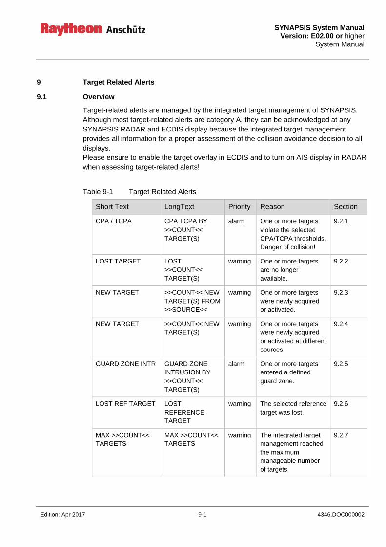
SYNAPSIS System Manual
Version: E02.00 or higher System Manual
Edition: Apr 2017 9-1 4346.DOC000002
9 Target Related Alerts
9.1 Overview
Target-related alerts are managed by the integrated target management of SYNAPSIS.
Although most target-related alerts are category A, they can be acknowledged at any
SYNAPSIS RADAR and ECDIS display because the integrated target management
provides all information for a proper assessment of the collision avoidance decision to all
displays.
Please ensure to enable the target overlay in ECDIS and to turn on AIS display in RADAR
when assessing target-related alerts!
Table 9-1 Target Related Alerts
Short Text LongText Priority Reason Section
CPA / TCPA CPA TCPA BY
>>COUNT<<
TARGET(S)
alarm One or more targets
violate the selected
CPA/TCPA thresholds.
Danger of collision!
9.2.1
LOST TARGET LOST
>>COUNT<<
TARGET(S)
warning One or more targets
are no longer
available.
9.2.2
NEW TARGET >>COUNT<< NEW
TARGET(S) FROM
>>SOURCE<<
warning One or more targets
were newly acquired
or activated.
9.2.3
NEW TARGET >>COUNT<< NEW
TARGET(S)
warning One or more targets
were newly acquired
or activated at different
sources.
9.2.4
GUARD ZONE INTR GUARD ZONE
INTRUSION BY
>>COUNT<<
TARGET(S)
alarm One or more targets
entered a defined
guard zone.
9.2.5
LOST REF TARGET LOST
REFERENCE
TARGET
warning The selected reference
target was lost.
9.2.6
MAX >>COUNT<<
TARGETS
MAX >>COUNT<<
TARGETS
warning The integrated target
management reached
the maximum
manageable number
of targets.
9.2.7
SYNAPSIS System Manual Version: E02.00 or higher System Manual
4346.DOC000002 9-2 Edition: Apr 2017
9.2 Detailed Description
9.2.1 CPA TCPA BY >>COUNT<< TARGET(S)
Priority: alarm
Category: A
Short Text: CPA TCPA
Long Text: CPA TCPA BY >>COUNT<< TARGET(S)
Reason: Some targets violate the current CPA/TCPA thresholds.
Impact: Danger of collision!
Troubleshooting: The dangerous targets are marked as dangerous targets on all RADAR
PPIs and ECDIS displays. When assessing the situation at ECDIS,
ensure that the target overlay is displayed. Check all dangerous targets
for potential collisions and perform all necessary actions according to
the rules to avoid these collisions.
9.2.2 LOST >>COUNT<< TARGET(S)
Priority: warning
Category: A
Short Text: LOST TARGET
Long Text: LOST >>COUNT<< TARGET(S)
Reason: Collision avoidance data for some targets is no longer available.
Impact: Collision alerts for these targets are no longer available.
Troubleshooting: Check all lost targets for the reason of losing the target. Target loss is
normal when the target leaves the tracking range of the ARPA tracker
(24 NM) or the reporting range of AIS. In other cases, check the lost
targets for potential danger of collision.

SYNAPSIS System Manual
Version: E02.00 or higher System Manual
Edition: Apr 2017 9-3 4346.DOC000002
9.2.3 >>COUNT<< NEW TARGET(S) FROM >>SOURCE<<
Priority: warning
Category: A
Short Text: NEW TARGET
Long Text: >>COUNT<< NEW TARGET(S) FROM >>SOURCE<<
Reason: A new target was automatically acquired by the specified ARPA tracker
or automatically activated by AIS processing.
Impact: The target will be monitored for a potential danger of collision.
Troubleshooting: This is a notification of the user. Acknowledge the alert. The alert is
automatically replaced by the >>COUNT<< NEW TARGET(S) alerts
when multiple sources acquired or activated new targets.
9.2.4 >>COUNT<< NEW TARGET(S)
Priority: warning
Category: A
Short Text: NEW TARGET
Long Text: >>COUNT<< NEW TARGET(S)
Reason: A new target was automatically acquired by an ARPA tracker or
automatically activated by AIS processing. This alert is an aggregated
alert if the target management detects multiple new targets from
different sources.
Impact: The target will be monitored for a potential danger of collision.
Troubleshooting: This is a notification of the user. Acknowledge the alert.

SYNAPSIS System Manual Version: E02.00 or higher System Manual
4346.DOC000002 9-4 Edition: Apr 2017
9.2.5 GUARD ZONE INTRUSION BY >>COUNT<< TARGET(S)
Priority: alarm
Category: A
Short Text: GUARD ZONE INTR
Long Text: GUARD ZONE INTRUSION BY >>COUNT<< TARGET(S)
Reason: Some targets entered a defined guard zone.
Impact: Danger of collision!
Troubleshooting: When assessing the situation at ECDIS, ensure that the target overlay
is displayed. Check all dangerous targets for potential collisions and
perform all necessary actions according to the rules to avoid these
collisions.
9.2.6 LOST REFERENCE TARGET
Priority: warning
Category: B
Short Text: LOST REF TARGET
Long Text: LOST REFERENCE TARGET
Reason: The target selected to be the reference target for SOG/COG calculation
was lost.
Impact: SOG/COG cannot be calculated from the reference target any longer. If
no other SOG/COG input is available, tracking performance will
decrease.
Troubleshooting: Select another reference target. If no other reference target and no
sensor input for SOG/COG is available, switch to water stabilization or
enter the values manually.
SYNAPSIS System Manual
Version: E02.00 or higher System Manual
Edition: Apr 2017 9-5 4346.DOC000002
9.2.7 MAX >>COUNT<< TARGET(S)
Priority: warning
Category: B
Short Text: MAX >>COUNT<< TARGETS
Long Text: MAX >>COUNT<< TARGETS
Reason: The processing capacity of the integrated target management is
exceeded.
Impact: New targets (ARPA, AIS) cannot be processed. Collision avoidance
functionality is degraded.
Troubleshooting: Adjust the automatic acquisition zones and AIS the AIS transponder
such that less targets have to be processed. Delete targets which are
no longer needed.

SYNAPSIS System Manual Version: E02.00 or higher System Manual
4346.DOC000002 10-6 Edition: Apr 2017
10 Power Supply Requirements INS
The Integrated Navigation System (INS) has to be connected to the Main Ships Power
Supply and to the Ships Emergency Power Supply. This applies to all INS Components
(depending on the applying carriage requirements (number of consoles for RADAR and
ECDIS) inclusive 1 Antenna, 1 Transceiver as well as for the Autopilot if part of the INS.
Furthermore 1 Gyro, 1 Speed Sensor and 1 Depth Sensor must be connected to an
Uninterruptible Power Supply (UPS).
The performance data of the relevant equipment must be considered.
Original IMO requirement:
(MSC 252(83)/13.4.1) Power supply requirements applying to parts of the INS as a result
of other IMO requirements shall remain applicable.
(MSC 252(83)/13.4.2) The INS including the sensors for position, speed, heading and
depth shall be supplied:
1. from both the main and the emergency source of electrical power with
automated changeover through a local distribution board with provision to
preclude inadvertent shutdown; and
2. from a transitional source of electrical power for a duration of not less than 45 s.
The INS and the sensors can be connected to an UPS that can be also provided by the
shipyard. The power supply concept must ensure that any single point of failure condition
(e.g. failure of main power supply or failure of transitional power source) may not cause
any system failure or shutdown. This may be achieved by the use of several UPS, each
individually fused against short circuit, or other means.
Additional class notations of classification society’s rules may require extended power
supply concepts. This has to be clarified with the relevant classification society.
10.1 Power Supply Requirements INS supplied with separate Power Net
The INS power supply is divided into two separate power nets. In case of a failure of one
power net the INS will still be operational (see Figure 10-1).
The reliability of the power nets might be increased by using uninterruptable power
supplies (UPS). This is only necessary if the existing power sources (generators) are not
reliable enough.
The supply of the sensors is also divided by the two power nets.
Sensors that exist twice for redundancy purpose shall be connected to both power nets
(e.g. GPS).
The power distribution should be realized via a Switching Board see section 10.1.1.
The UPS can be realized from the shipyard or from RAn (optional contract).
For UPS requirements see section 10.1.2.
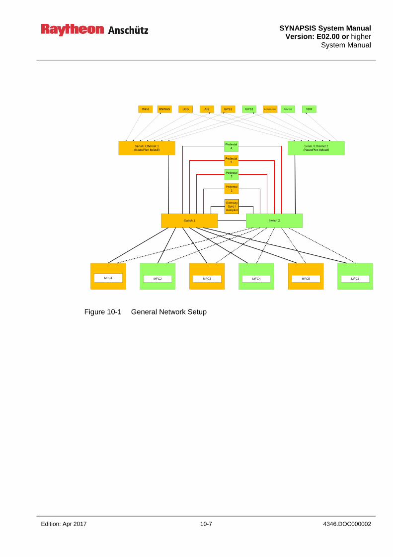
SYNAPSIS System Manual
Version: E02.00 or higher System Manual
Edition: Apr 2017 10-7 4346.DOC000002
Figure 10-1 General Network Setup
PCPCPCPC
Switch
PC
PC
Switch
MFC6MFC5MFC4MFC3
Switch 1
MFC2
AIS GPS2LOG GPS1 Echosounder VDR
Pedestal
1
Pedestal
2
Wind
Gateway
Gyro /
Autopilot
BNWAS NAVTEX
MFC1
Switch 2
Serial / Ethernet 1
(NautoPlex 8plus8)
Serial / Ethernet 2
(NautoPlex 8plus8)
Pedestal
3
Pedestal
4
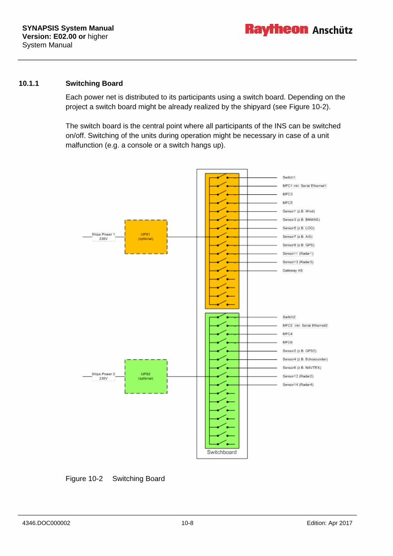
SYNAPSIS System Manual Version: E02.00 or higher System Manual
4346.DOC000002 10-8 Edition: Apr 2017
10.1.1 Switching Board
Each power net is distributed to its participants using a switch board. Depending on the
project a switch board might be already realized by the shipyard (see Figure 10-2).
The switch board is the central point where all participants of the INS can be switched
on/off. Switching of the units during operation might be necessary in case of a unit
malfunction (e.g. a console or a switch hangs up).
Figure 10-2 Switching Board
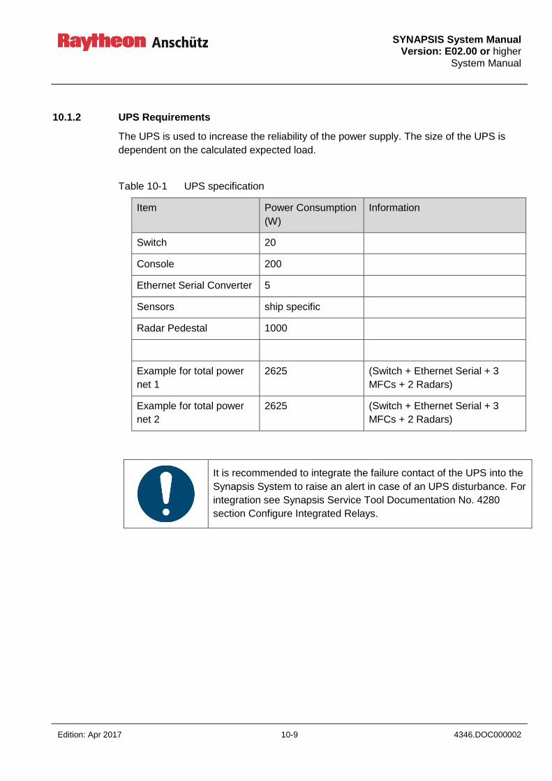
SYNAPSIS System Manual
Version: E02.00 or higher System Manual
Edition: Apr 2017 10-9 4346.DOC000002
10.1.2 UPS Requirements
The UPS is used to increase the reliability of the power supply. The size of the UPS is
dependent on the calculated expected load.
Table 10-1 UPS specification
Item Power Consumption
(W)
Information
Switch 20
Console 200
Ethernet Serial Converter 5
Sensors ship specific
Radar Pedestal 1000
Example for total power
net 1
2625 (Switch + Ethernet Serial + 3
MFCs + 2 Radars)
Example for total power
net 2
2625 (Switch + Ethernet Serial + 3
MFCs + 2 Radars)
It is recommended to integrate the failure contact of the UPS into the
Synapsis System to raise an alert in case of an UPS disturbance. For
integration see Synapsis Service Tool Documentation No. 4280
section Configure Integrated Relays.
SYNAPSIS System Manual Version: E02.00 or higher System Manual
4346.DOC000002 10-10 Edition: Apr 2017
10.1.3 Participants
10.1.3.1 Console / MFC
Each console is supplied witch 230VAC. Additional Voltages within the console (24VDC
for Small Marine Computer and optional Ethernet Serial Converter) are generated within
the console.
10.1.3.2 Switch
The Switch is supplied with 230VAC.
10.1.3.3 Serial / Ethernet (NautoPlex 8plus8)
The Serial Ethernet Converters shall be situated within Console 1 and 2. They are
supplied in parallel to the Small Marine Computer sharing the 24VDC inside the Console.
SYNAPSIS System Manual
Version: E02.00 or higher System Manual
Edition: Apr 2017 10-11 4346.DOC000002
Intentionally left blank

SYNAPSIS System Manual
Version: E02.00 or higher System Manual
Edition: Apr 2017 11-1 4346.DOC000002
11 Fulfilled Carriage Requirements of INS
The INS fulfils the following carriage requirements:
Radar / collision avoidance (Res. MSC 192(79))
ECDIS / route monitoring (Res. MSC.232(82))
Track Control, if installed (Res. MSC.74(69) Annex 2)
The installation of INS should be in accordance with
IMO SOLAS regulation V/15: Principles relating to bridge design, design and
arrangement of navigational systems and equipment and bridge procedures
MSC/Circ.982: Guidelines on ergonomic criteria for bridge equipment and layout
Sn.1/Circ.265: Guidelines on the application of SOLAS regulation V/15 to INS, IBS and
Bridge design
SN.1/Circ.288: Guidelines for bridge equipment and systems, their arrangement and
integration (BES).

SYNAPSIS System Manual Version: E02.00 or higher System Manual
4346.DOC000002 11-2 Edition: Apr 2017
Intentionally left blank
SYNAPSIS System Manual
Version: E02.00 or higher System Manual
Edition: Apr 2017 12-1 4346.DOC000002
12 Power Supply Failure
If the board power supply is disturbed, the UPS (see chapter 10) will be activated
automatically.
INS bridges without UPS protection shut down (see chapter 13).
The current alarm and warning monitoring situation is lost.
After a system recovery time (4 minutes) the alarm history is present again.
The CCRS data processing fulfils a system check, active alarms and warnings are
restored and will be displayed via the alarm window and central alert management
display.
The alarm history data updates automatically.

SYNAPSIS System Manual Version: E02.00 or higher System Manual
4346.DOC000002 12-2 Edition: Apr 2017
Intentionally left blank

SYNAPSIS System Manual
Version: E02.00 or higher System Manual
Edition: Apr 2017 13-1 4346.DOC000002
13 System Recovery Timer
The Radar, ECDIS, Conning applications on a MFC are available 3 minutes after a reboot,
Radar transmit mode is ready after 4 minutes.
CCRS data evaluation is available 1 minute after the BIP process has been started.
By default, system monitoring and INS status information is available 3 minutes after the
BIP process has been (re-) started.

SYNAPSIS System Manual Version: E02.00 or higher System Manual
4346.DOC000002 13-2 Edition: Apr 2017
Intentionally left blank

SYNAPSIS System Manual
Version: E02.00 or higher System Manual
Edition: Apr 2017 14-1 4346.DOC000002
14 Reference to IEC 61924 INS Performance Standard (INS specific)
14.1 Latency (IEC section 5.3.3.2)
Latency of sensor data has to be avoided as far as possible; examples of latency and their
influence on navigation are given below:
14.1.1 Radar Tracks
The update rate for heading data has significant impact on the tracking process. A
heading update frequency of at least 10 Hz is required to guarantee precise determination
of radar target track motion.
14.1.2 Track Control
Accuracy of the track keeping process depends on the availability of position, heading and
speed data. To calculate accurate rudder responses an update rate of at least 1 Hz is
needed, otherwise precise track keeping will not be possible.
14.1.3 Correlation of Radar Echos
For reduction of clutter and noise correlation methods are applied which are sensitive to
heading and speed information provided. Speed update rates of at least 1 Hz are needed
in addition to adequate heading information to avoid extinction of existing targets.
14.1.4 High Speed Craft
For high speed crafts even higher demands on the data update rate are to be applied. For
Radar the antenna rotation rate has to be increased by a factor of 2 because otherwise
the tracking process will not be reliable enough for HSC.

SYNAPSIS System Manual Version: E02.00 or higher System Manual
4346.DOC000002 14-2 Edition: Apr 2017
14.2 Required Number of Consoles (IEC section 6.3.1)
The number of consoles needed for safe navigation is determined by several factors:
Carriage requirements, i.e. size of ship
Requirements of Classification societies.
Availability of Multifunction Consoles (MFC)
Availability of Track Control
If multifunction consoles are part of the bridge system it must be possible to select from
the tasks available by means of a simple operator action (which is two steps). Only if all
six INS tasks are available on all MFCs a reduction of the number of consoles can be
considered (i.e. less than six).
According to the IEC standard for INS 4 tasks must be available simultaneously in the fore
ground, Collision Avoidance, Route Monitoring, Nav Data Control, plus one for
redundancy).
Route Planning, Status and Data Display, and Alert Management HMI can be kept in the
background.
This leads to a number of 4 consoles needed.
Classification society DnV uses a different terminology for INS tasks and requires 5
consoles, ARPA, ECDIS, Conning, Alarm Management, plus one for redundancy
purposes.
Further, it has to be decided if one of the consoles will be dedicated to the track control
function.
As a summary it can be said that, 4 consoles should be sufficient to cover INS
requirements; however, requirements of classification societies will override this
statement.
SYNAPSIS System Manual
Version: E02.00 or higher System Manual
Edition: Apr 2017 14-3 4346.DOC000002
14.3 Reduction of Single Point of Failure (IEC section 6.5.2.2)
The following list gives an overview of the implemented measures and methods to avoid
single point of failure and human error:
1. All six tasks are available at all times (Route Planning, Route Monitoring, Collision
Avoidance, Nav Control Data, Status and Data Display, Alert Management).
2. Sufficient number of consoles (minimum 4).
3. Fall back arrangement for automatic control function, i.e. track control;
Track control → heading control → manual steering.
4. Back up for following information: position, heading, speed, Radar, Chart Data
Base.
5. Smoothing of jumps in case of failure: integrity checks, multiple sources,
Consistent Common Reference System (CCRS), Dead Reckoning.
6. Clear indication of faulty and not available data.
7. Provision of alternative sensors and indication of their availability.
8. System overview (on at least one console) for consoles, tasks, interfaces
(including Alert Management), sensors (see also 6).
9. Avoidance of Power Interruptions by means of UPS.
10. Provision of Radar tracking and AIS targets.
11. Clear indication of manual settings, manual control, manual measuring (of e.g.
position).
12. Undo button and queries “Do you really want to …”

SYNAPSIS System Manual Version: E02.00 or higher System Manual
4346.DOC000002 14-4 Edition: Apr 2017
14.4 Style Book (IEC section 6.5.1.2)
The Style Book will define which design elements are used to implement the layout of
user interfaces for all INS applications. These elements are proprietary of Raytheon
Anschütz but with regard to size and shape certain requirements from international
standards have to be considered (IEC60945, IEC62288).
In addition, terms and abbreviations as specified in standard IEC62288 have to be used.
14.4.1 General Screen Layout
An identical basic screen layout is used for all applications, Route Monitoring, Collision
Avoidance, Nav Data Control, and Alert HMI. The display area is subdivided into three
parts, a main center area and two areas adjacent to the left and right edge of it.
Depending on the application the center area is used for display of the most essential
data, while the two other areas are used for additional data and user interfaces, see
Figure 14-1, Figure 14-2, Figure 14-3, Figure 14-4.
Figure 14-1 Screen Layout Conning

SYNAPSIS System Manual
Version: E02.00 or higher System Manual
Edition: Apr 2017 14-5 4346.DOC000002
Figure 14-2 Screen Layout Conning Selection Page
Figure 14-3 Screen Layout Radar
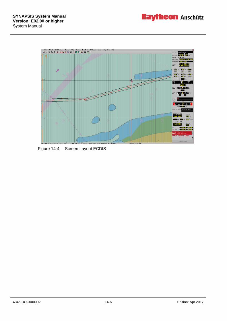
SYNAPSIS System Manual Version: E02.00 or higher System Manual
4346.DOC000002 14-6 Edition: Apr 2017
Figure 14-4 Screen Layout ECDIS
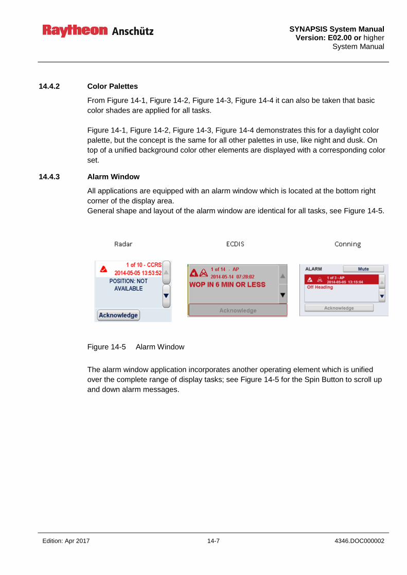
SYNAPSIS System Manual
Version: E02.00 or higher System Manual
Edition: Apr 2017 14-7 4346.DOC000002
14.4.2 Color Palettes
From Figure 14-1, Figure 14-2, Figure 14-3, Figure 14-4 it can also be taken that basic
color shades are applied for all tasks.
Figure 14-1, Figure 14-2, Figure 14-3, Figure 14-4 demonstrates this for a daylight color
palette, but the concept is the same for all other palettes in use, like night and dusk. On
top of a unified background color other elements are displayed with a corresponding color
set.
14.4.3 Alarm Window
All applications are equipped with an alarm window which is located at the bottom right
corner of the display area.
General shape and layout of the alarm window are identical for all tasks, see Figure 14-5.
Figure 14-5 Alarm Window
The alarm window application incorporates another operating element which is unified
over the complete range of display tasks; see Figure 14-5 for the Spin Button to scroll up
and down alarm messages.
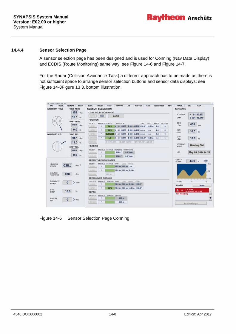
SYNAPSIS System Manual Version: E02.00 or higher System Manual
4346.DOC000002 14-8 Edition: Apr 2017
14.4.4 Sensor Selection Page
A sensor selection page has been designed and is used for Conning (Nav Data Display)
and ECDIS (Route Monitoring) same way, see Figure 14-6 and Figure 14-7.
For the Radar (Collision Avoidance Task) a different approach has to be made as there is
not sufficient space to arrange sensor selection buttons and sensor data displays; see
Figure 14-8Figure 13 3, bottom illustration.
Figure 14-6 Sensor Selection Page Conning

SYNAPSIS System Manual
Version: E02.00 or higher System Manual
Edition: Apr 2017 14-9 4346.DOC000002
Figure 14-7 Sensor Selection Page ECDIS
Figure 14-8 Sensor Information Radar

SYNAPSIS System Manual Version: E02.00 or higher System Manual
4346.DOC000002 14-10 Edition: Apr 2017
14.4.5 Analog Instruments
Nav Data Control display and ECDIS info panel (if displaying the docking version) use the
same elements to display data in an analog presentation.
Examples for analog instruments are e.g. rubber bands to show heading, RoT, and rudder
settings, or weather vanes to display wind and, by a similar graph, drift information, see
Figure 14-2.
14.4.6 Navigation Page with Ship Symbole
As illustrated in Figure 14-9 the vessel’s motion data are grouped around the silhouette of
a ship. The same graphics is used for the conning display center main page and for the
ECDIS info panel.
This graphics is also shown in Figure 13 4.
Figure 14-9 Motion data around silhouette of vessel
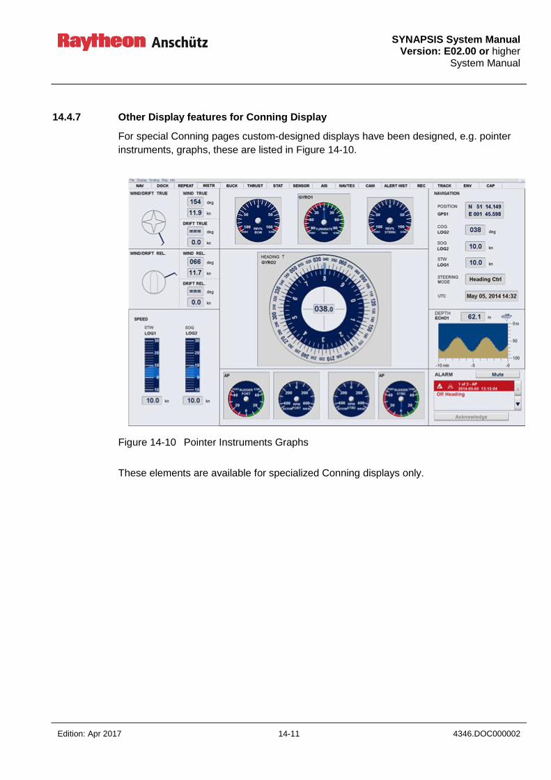
SYNAPSIS System Manual
Version: E02.00 or higher System Manual
Edition: Apr 2017 14-11 4346.DOC000002
14.4.7 Other Display features for Conning Display
For special Conning pages custom-designed displays have been designed, e.g. pointer
instruments, graphs, these are listed in Figure 14-10.
Figure 14-10 Pointer Instruments Graphs
These elements are available for specialized Conning displays only.

SYNAPSIS System Manual Version: E02.00 or higher System Manual
4346.DOC000002 14-12 Edition: Apr 2017
14.4.8 Tool Bar for ECDIS
Another operator element is uniquely used for the ECDIS (Route Monitoring, Route
Planning), the so called Toolbar; see Figure 14-11.
Figure 14-11 Toolbar
Buttons are used as short cuts to frequently used functions.
14.4.9 Pull Down Menu
Windows like pull down menus are implemented into the ECDIS and Nautoconning
applications, see Figure 14-12. For Radar this element is not suitable as essential
information could be covered and this is not in accordance with the Radar Performance
Standards.
Figure 14-12 Pull Down Menu Nautoconning and ECDIS
Nautoconning ECDIS

SYNAPSIS System Manual
Version: E02.00 or higher System Manual
Edition: Apr 2017 14-13 4346.DOC000002
14.4.10 Alert Management HMI
For INS a central alert management is required and with it a dedicated HMI to display and
handle upcoming alarms. The Alert Management HMI is a unique feature and therefore
has its own design which is not shared by any other task or application of the INS, see
Figure 14-13.
Figure 14-13 Alert Management HMI

SYNAPSIS System Manual Version: E02.00 or higher System Manual
4346.DOC000002 14-14 Edition: Apr 2017
14.4.11 Alert and Acknowledge Button
Five special design elements come with the Alert Management HMI, the alert and the
acknowledge button, see Figure 14-14.
I A K L j
Figure 14-14 Alert Button and Acknowledge Button
14.4.12 System Status Page
The System Status Page is a unique feature and therefore has its own design which is not
shared by any other task or application of the INS, see Figure 14-15.
Figure 14-15 System Status Page
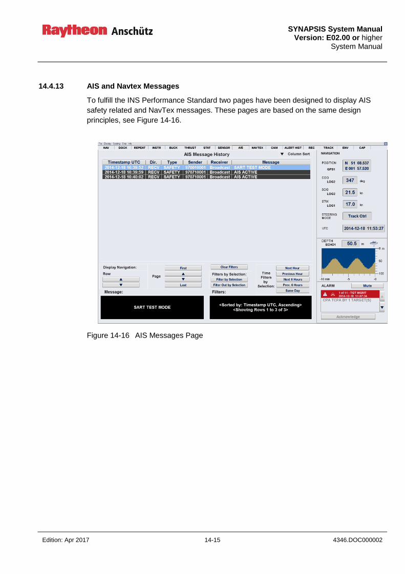
SYNAPSIS System Manual
Version: E02.00 or higher System Manual
Edition: Apr 2017 14-15 4346.DOC000002
14.4.13 AIS and Navtex Messages
To fulfill the INS Performance Standard two pages have been designed to display AIS
safety related and NavTex messages. These pages are based on the same design
principles, see Figure 14-16.
Figure 14-16 AIS Messages Page

SYNAPSIS System Manual Version: E02.00 or higher System Manual
4346.DOC000002 14-16 Edition: Apr 2017
Figure 14-17 NAVTEX Page
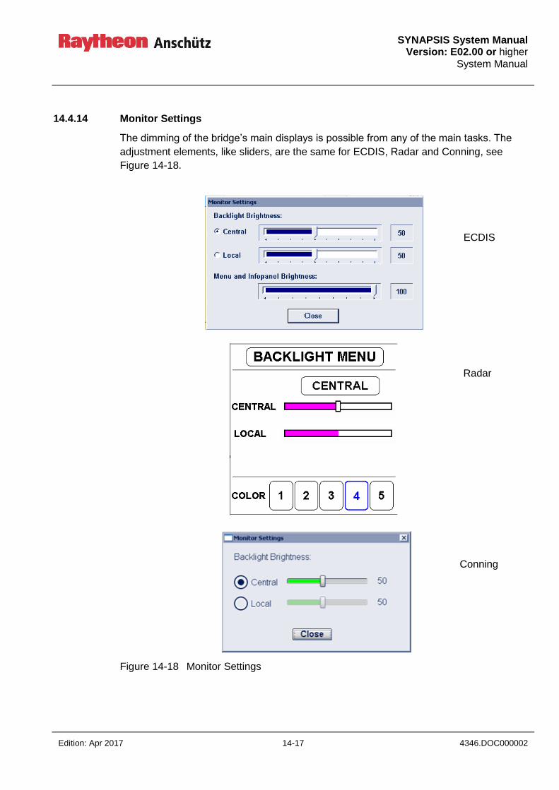
SYNAPSIS System Manual
Version: E02.00 or higher System Manual
Edition: Apr 2017 14-17 4346.DOC000002
14.4.14 Monitor Settings
The dimming of the bridge’s main displays is possible from any of the main tasks. The
adjustment elements, like sliders, are the same for ECDIS, Radar and Conning, see
Figure 14-18.
Figure 14-18 Monitor Settings
ECDIS
Radar
Conning
SYNAPSIS System Manual Version: E02.00 or higher System Manual
4346.DOC000002 14-18 Edition: Apr 2017
14.4.15 MCF Task Switch
The MFC Task Switch is placed on the top right corner of the display.
If not used the MFC Switcher shrinks to a little icon. If selected, the Switcher expands to a
pull down menu providing a set of application buttons. The application buttons are
equipped with Task identifiers; these Task buttons allow direct access to special ECDIS
and Radar functions and Conning pages.
Status indication:
Status color Information
Green The application is working correctly
White The application does not work
Yellow The application is in the startup process
red The application is disturbed
The context menu is used to control the applications for Radar, ECDIS and Nautoconning
and the MFC processor.
Control Information
Conning Calling up the Feature
Radar Calling up the Feature
ECDIS Calling up the Feature
Feature Information
Restart The application will be closed and restarted again
Start Start the application
Shutdown Shutdown the application
Kill The application will be terminated directly
Service Calling up the Synapsis Service Tool
Close All All applications will be closed. The EggShell Utility Selection
window appears after some seconds

SYNAPSIS System Manual
Version: E02.00 or higher System Manual
Edition: Apr 2017 14-19 4346.DOC000002
The MFC Task Switcher is another unique and central operating element which is
available for all tasks, see Figure 14-19.
ECDIS application
ECDIS task Route Planning
ECDIS task Route Monitoring
NAUTOCONNING
CONNING page Nav
CONNING page STAT
CONNING page CAM
RADAR application
RADAR task Collision Avoid.
Figure 14-19 MFC Task Switch
context
menu right trackball key
status indication

SYNAPSIS System Manual Version: E02.00 or higher System Manual
4346.DOC000002 14-20 Edition: Apr 2017
14.5 License Convention
Boost Software License - Version 1.0 - August 17th, 2003
Permission is hereby granted, free of charge, to any person or organization obtaining a
copy of the software and accompanying documentation covered by this license (the
"Software") to use, reproduce, display, distribute, execute, and transmit the Software,
and to prepare derivative works of the Software, and to permit third-parties to whom the
Software is furnished to do so, all subject to the following:
The copyright notices in the Software and this entire statement, including the above
license grant, this restriction and the following disclaimer, must be included in all copies
of the Software, in whole or in part, and all derivative works of the Software, unless
such copies or derivative works are solely in the form of machine-executable object
code generated by a source language processor.
THE SOFTWARE IS PROVIDED "AS IS", WITHOUT WARRANTY OF ANY KIND,
EXPRESS OR IMPLIED, INCLUDING BUT NOT LIMITED TO THE WARRANTIES OF
MERCHANTABILITY, FITNESS FOR A PARTICULAR PURPOSE, TITLE AND NON-
INFRINGEMENT. IN NO EVENT SHALL THE COPYRIGHT HOLDERS OR ANYONE
DISTRIBUTING THE SOFTWARE BE LIABLE FOR ANY DAMAGES OR OTHER
LIABILITY, WHETHER IN CONTRACT, TORT OR OTHERWISE, ARISING FROM,
OUT OF OR IN CONNECTION WITH THE SOFTWARE OR THE USE OR OTHER
DEALINGS IN THE SOFTWARE.
Poco
Boost Software License - Version 1.0 - August 17th, 2003
Permission is hereby granted, free of charge, to any person or organization obtaining a
copy of the software and accompanying documentation covered by this license (the
"Software") to use, reproduce, display, distribute, execute, and transmit the Software,
and to prepare derivative works of the Software, and to permit third-parties to whom the
Software is furnished to do so, all subject to the following:
The copyright notices in the Software and this entire statement, including the above
license grant, this restriction and the following disclaimer, must be included in all copies
of the Software, in whole or in part, and all derivative works of the Software, unless
such copies or derivative works are solely in the form of machine-executable object
code generated by a source language processor.
THE SOFTWARE IS PROVIDED "AS IS", WITHOUT WARRANTY OF ANY KIND,
EXPRESS OR IMPLIED, INCLUDING BUT NOT LIMITED TO THE WARRANTIES OF
MERCHANTABILITY, FITNESS FOR A PARTICULAR PURPOSE, TITLE AND NON-
SYNAPSIS System Manual
Version: E02.00 or higher System Manual
Edition: Apr 2017 14-21 4346.DOC000002
INFRINGEMENT. IN NO EVENT SHALL THE COPYRIGHT HOLDERS OR ANYONE
DISTRIBUTING THE SOFTWARE BE LIABLE FOR ANY DAMAGES OR OTHER
LIABILITY, WHETHER IN CONTRACT, TORT OR OTHERWISE, ARISING FROM,
OUT OF OR IN CONNECTION WITH THE SOFTWARE OR THE USE OR OTHER
DEALINGS IN THE SOFTWARE.
ACE
Copyright and Licensing Information for ACE(TM), TAO(TM), CIAO(TM), and
CoSMIC(TM)
[1]ACE(TM), [2]TAO(TM), [3]CIAO(TM), and [4]CoSMIC(TM) (henceforth referred to as
"DOC software") are copyrighted by [5]Douglas C. Schmidt and his [6]research group at
[7]Washington University, [8]University of California, Irvine, and [9]Vanderbilt University,
Copyright (c) 1993-2010, all rights reserved. Since DOC software is open-source, freely
available software, you are free to use, modify, copy, and distribute--perpetually and
irrevocably--the DOC software source code and object code produced from the source,
as well as copy and distribute modified versions of this software. You must, however,
include this copyright statement along with any code built using DOC software that you
release. No copyright statement needs to be provided if you just ship binary executables
of your software products.
You can use DOC software in commercial and/or binary software releases and are under
no obligation to redistribute any of your source code that is built using DOC software.
Note, however, that you may not do anything to the DOC software code, such as
copyrighting it yourself or claiming authorship of the DOC software code, that will prevent
DOC software from being distributed freely using an open-source development model.
You needn't inform anyone that you're using DOC software in your software, though we
encourage you to let [10]us know so we can promote your project in the [11]DOC
software success stories.
The [12]ACE, [13]TAO, [14]CIAO, and [15]CoSMIC web sites are maintained by the
[16]DOC Group at the [17]Institute for Software Integrated Systems (ISIS) and the
[18]Center for Distributed Object Computing of Washington University, St. Louis for the
development of open-source software as part of the open-source software community.
Submissions are provided by the submitter ``as is'' with no warranties whatsoever,
including any warranty of merchantability, noninfringement of third party intellectual
property, or fitness for any particular purpose. In no event shall the submitter be liable for
any direct, indirect, special, exemplary, punitive, or consequential damages, including
without limitation, lost profits, even if advised of the possibility of such damages.
Likewise, DOC software is provided as is with no warranties of any kind, including the
warranties of design, merchantability, and fitness for a particular purpose,
noninfringement, or arising from a course of dealing, usage or trade practice. Washington

SYNAPSIS System Manual Version: E02.00 or higher System Manual
4346.DOC000002 14-22 Edition: Apr 2017
University, UC Irvine, Vanderbilt University, their employees, and students shall have no
liability with respect to the infringement of copyrights, trade secrets or any patents by
DOC software or any part thereof. Moreover, in no event will Washington University, UC
Irvine, or Vanderbilt University, their employees, or students be liable for any lost revenue
or profits or other special, indirect and consequential damages.
DOC software is provided with no support and without any obligation on the part of
Washington University, UC Irvine, Vanderbilt University, their employees, or students to
assist in its use, correction, modification, or enhancement. A [19]number of companies
around the world provide commercial support for DOC software, however.
DOC software is Y2K-compliant, as long as the underlying OS platform is Y2K-compliant.
Likewise, DOC software is compliant with the new US daylight savings rule passed by
Congress as "The Energy Policy Act of 2005," which established new daylight savings
times (DST) rules for the United States that expand DST as of March 2007. Since DOC
software obtains time/date and calendaring information from operating systems users will
not be affected by the new DST rules as long as they upgrade their operating systems
accordingly.
The names ACE(TM), TAO(TM), CIAO(TM), CoSMIC(TM), Washington University, UC
Irvine, and Vanderbilt University, may not be used to endorse or promote products or
services derived from this source without express written permission from Washington
University, UC Irvine, or Vanderbilt University. This license grants no permission to call
products or services derived from this source ACE(TM), TAO(TM), CIAO(TM), or
CoSMIC(TM), nor does it grant permission for the name Washington University, UC
Irvine, or Vanderbilt University to appear in their names.
If you have any suggestions, additions, comments, or questions, please let [20]me know.
[21]Douglas C. Schmidt
_________________________________________________________________
Back to the [22]ACE home page.
References
1. http://www.cs.wustl.edu/~schmidt/ACE.html
2. http://www.cs.wustl.edu/~schmidt/TAO.html
3. http://www.dre.vanderbilt.edu/CIAO/
4. http://www.dre.vanderbilt.edu/cosmic/
5. http://www.dre.vanderbilt.edu/~schmidt/
6. http://www.cs.wustl.edu/~schmidt/ACE-members.html
7. http://www.wustl.edu/
SYNAPSIS System Manual
Version: E02.00 or higher System Manual
Edition: Apr 2017 14-23 4346.DOC000002
8. http://www.uci.edu/
9. http://www.vanderbilt.edu/
10. mailto:[email protected]
11. http://www.cs.wustl.edu/~schmidt/ACE-users.html
12. http://www.cs.wustl.edu/~schmidt/ACE.html
13. http://www.cs.wustl.edu/~schmidt/TAO.html
14. http://www.dre.vanderbilt.edu/CIAO/
15. http://www.dre.vanderbilt.edu/cosmic/
16. http://www.dre.vanderbilt.edu/
17. http://www.isis.vanderbilt.edu/
18. http://www.cs.wustl.edu/~schmidt/doc-center.html
19. http://www.cs.wustl.edu/~schmidt/commercial-support.html
20. mailto:[email protected]
21. http://www.dre.vanderbilt.edu/~schmidt/
22. http://www.cs.wustl.edu/ACE.html
QT Framework
GNU LESSER GENERAL PUBLIC LICENSE Version 2.1, February 1999
Copyright (C) 1991, 1999 Free Software Foundation, Inc. 51 Franklin Street, Fifth Floor,
Boston, MA 02110-1301 USA Everyone is permitted to copy and distribute verbatim
copies of this license document, but changing it is not allowed.
[This is the first released version of the Lesser GPL. It also counts as the successor of
the GNU Library Public License, version 2, hence the version number 2.1.]
Preamble
The licenses for most software are designed to take away your freedom to share and
change it. By contrast, the GNU General Public Licenses are intended to guarantee
your freedom to share and change free software--to make sure the software is free for
all its users.
This license, the Lesser General Public License, applies to some specially designated
software packages--typically libraries--of the Free Software Foundation and other
authors who decide to use it. You can use it too, but we suggest you first think carefully
about whether this license or the ordinary General Public License is the better strategy
to use in any particular case, based on the explanations below.
When we speak of free software, we are referring to freedom of use, not price. Our
General Public Licenses are designed to make sure that you have the freedom to
distribute copies of free software (and charge for this service if you wish); that you
receive source code or can get it if you want it; that you can change the software and
use pieces of it in new free programs; and that you are informed that you can do these

SYNAPSIS System Manual Version: E02.00 or higher System Manual
4346.DOC000002 14-24 Edition: Apr 2017
things.
To protect your rights, we need to make restrictions that forbid distributors to deny you
these rights or to ask you to surrender these rights. These restrictions translate to
certain responsibilities for you if you distribute copies of the library or if you modify it.
For example, if you distribute copies of the library, whether gratis or for a fee, you must
give the recipients all the rights that we gave you. You must make sure that they, too,
receive or can get the source code. If you link other code with the library, you must
provide complete object files to the recipients, so that they can relink them with the
library after making changes to the library and recompiling it. And you must show them
these terms so they know their rights.
We protect your rights with a two-step method: (1) we copyright the library, and (2) we
offer you this license, which gives you legal permission to copy, distribute and/or modify
the library.
To protect each distributor, we want to make it very clear that there is no warranty for
the free library. Also, if the library is modified by someone else and passed on, the
recipients should know that what they have is not the original version, so that the
original author's reputation will not be affected by problems that might be introduced by
others.
Finally, software patents pose a constant threat to the existence of any free program.
We wish to make sure that a company cannot effectively restrict the users of a free
program by obtaining a restrictive license from a patent holder. Therefore, we insist that
any patent license obtained for a version of the library must be consistent with the full
freedom of use specified in this license.
Most GNU software, including some libraries, is covered by the ordinary GNU General
Public License. This license, the GNU Lesser General Public License, applies to certain
designated libraries, and is quite different from the ordinary General Public License. We
use this license for certain libraries in order to permit linking those libraries into non-free
programs.
When a program is linked with a library, whether statically or using a shared library, the
combination of the two is legally speaking a combined work, a derivative of the original
library. The ordinary General Public License therefore permits such linking only if the
entire combination fits its criteria of freedom. The Lesser General Public License
permits more lax criteria for linking other code with the library.
We call this license the "Lesser" General Public License because it does Less to protect
the user's freedom than the ordinary General Public License. It also provides other free
software developers Less of an advantage over competing non-free programs. These

SYNAPSIS System Manual
Version: E02.00 or higher System Manual
Edition: Apr 2017 14-25 4346.DOC000002
disadvantages are the reason we use the ordinary General Public License for many
libraries. However, the Lesser license provides advantages in certain special
circumstances.
For example, on rare occasions, there may be a special need to encourage the widest
possible use of a certain library, so that it becomes a de-facto standard. To achieve this,
non-free programs must be allowed to use the library. A more frequent case is that a
free library does the same job as widely used non-free libraries. In this case, there is
little to gain by limiting the free library to free software only, so we use the Lesser
General Public License.
In other cases, permission to use a particular library in non-free programs enables a
greater number of people to use a large body of free software. For example, permission
to use the GNU C Library in non-free programs enables many more people to use the
whole GNU operating system, as well as its variant, the GNU/Linux operating system.
Although the Lesser General Public License is Less protective of the users' freedom, it
does ensure that the user of a program that is linked with the Library has the freedom
and the wherewithal to run that program using a modified version of the Library.
The precise terms and conditions for copying, distribution and modification follow. Pay
close attention to the difference between a "work based on the library" and a "work that
uses the library". The former contains code derived from the library, whereas the latter
must be combined with the library in order to run.
GNU LESSER GENERAL PUBLIC LICENSE
TERMS AND CONDITIONS FOR COPYING, DISTRIBUTION AND MODIFICATION
0. This License Agreement applies to any software library or other program which
contains a notice placed by the copyright holder or other authorized party saying it may
be distributed under the terms of this Lesser General Public License (also called "this
License"). Each licensee is addressed as "you".
A "library" means a collection of software functions and/or data prepared so as to be
conveniently linked with application programs (which use some of those functions and
data) to form executables.
The "Library", below, refers to any such software library or work which has been
distributed under these terms. A "work based on the Library" means either the Library or
any derivative work under copyright law: that is to say, a work containing the Library or
a portion of it, either verbatim or with modifications and/or translated straightforwardly
into another language. (Hereinafter, translation is included without limitation in the term
"modification".)
"Source code" for a work means the preferred form of the work for making modifications

SYNAPSIS System Manual Version: E02.00 or higher System Manual
4346.DOC000002 14-26 Edition: Apr 2017
to it. For a library, complete source code means all the source code for all modules it
contains, plus any associated interface definition files, plus the scripts used to control
compilation and installation of the library.
Activities other than copying, distribution and modification are not covered by this
License; they are outside its scope. The act of running a program using the Library is
not restricted, and output from such a program is covered only if its contents constitute
a work based on the Library (independent of the use of the Library in a tool for writing
it). Whether that is true depends on what the Library does and what the program that
uses the Library does.
1. You may copy and distribute verbatim copies of the Library's complete source code
as you receive it, in any medium, provided that you conspicuously and appropriately
publish on each copy an appropriate copyright notice and disclaimer of warranty; keep
intact all the notices that refer to this License and to the absence of any warranty; and
distribute a copy of this License along with the Library.
You may charge a fee for the physical act of transferring a copy, and you may at your
option offer warranty protection in exchange for a fee.
2. You may modify your copy or copies of the Library or any portion of it, thus forming a
work based on the Library, and copy and distribute such modifications or work under
the terms of Section 1 above, provided that you also meet all of these conditions:
a) The modified work must itself be a software library.
b) You must cause the files modified to carry prominent notices stating that you
changed the files and the date of any change.
c) You must cause the whole of the work to be licensed at no charge to all third parties
under the terms of this License.
d) If a facility in the modified Library refers to a function or a table of data to be supplied
by an application program that uses the facility, other than as an argument passed
when the facility is invoked, then you must make a good faith effort to ensure that, in the
event an application does not supply such function or table, the facility still operates,
and performs whatever part of its purpose remains meaningful.
(For example, a function in a library to compute square roots has a purpose that is
entirely well-defined independent of the application. Therefore, Subsection 2d requires
that any application-supplied function or table used by this function must be optional: if
the application does not supply it, the square root function must still compute square
roots.)

SYNAPSIS System Manual
Version: E02.00 or higher System Manual
Edition: Apr 2017 14-27 4346.DOC000002
These requirements apply to the modified work as a whole. If identifiable sections of
that work are not derived from the Library, and can be reasonably considered
independent and separate works in themselves, then this License, and its terms, do not
apply to those sections when you distribute them as separate works. But when you
distribute the same sections as part of a whole which is a work based on the Library,
the distribution of the whole must be on the terms of this License, whose permissions
for other licensees extend to the entire whole, and thus to each and every part
regardless of who wrote it.
Thus, it is not the intent of this section to claim rights or contest your rights to work
written entirely by you; rather, the intent is to exercise the right to control the distribution
of derivative or collective works based on the Library.
In addition, mere aggregation of another work not based on the Library with the Library
(or with a work based on the Library) on a volume of a storage or distribution medium
does not bring the other work under the scope of this License.
3. You may opt to apply the terms of the ordinary GNU General Public License instead
of this License to a given copy of the Library. To do this, you must alter all the notices
that refer to this License, so that they refer to the ordinary GNU General Public License,
version 2, instead of to this License. (If a newer version than version 2 of the ordinary
GNU General Public License has appeared, then you can specify that version instead if
you wish.) Do not make any other change in these notices.
Once this change is made in a given copy, it is irreversible for that copy, so the ordinary
GNU General Public License applies to all subsequent copies and derivative works
made from that copy.
This option is useful when you wish to copy part of the code of the Library into a
program that is not a library.
4. You may copy and distribute the Library (or a portion or derivative of it, under Section
2) in object code or executable form under the terms of Sections 1 and 2 above
provided that you accompany it with the complete corresponding machine-readable
source code, which must be distributed under the terms of Sections 1 and 2 above on a
medium customarily used for software interchange.
If distribution of object code is made by offering access to copy from a designated
place, then offering equivalent access to copy the source code from the same place
satisfies the requirement to distribute the source code, even though third parties are not
compelled to copy the source along with the object code.
5. A program that contains no derivative of any portion of the Library, but is designed to
work with the Library by being compiled or linked with it, is called a "work that uses the
SYNAPSIS System Manual Version: E02.00 or higher System Manual
4346.DOC000002 14-28 Edition: Apr 2017
Library". Such a work, in isolation, is not a derivative work of the Library, and therefore
falls outside the scope of this License.
However, linking a "work that uses the Library" with the Library creates an executable
that is a derivative of the Library (because it contains portions of the Library), rather
than a "work that uses the library". The executable is therefore covered by this License.
Section 6 states terms for distribution of such executables.
When a "work that uses the Library" uses material from a header file that is part of the
Library, the object code for the work may be a derivative work of the Library even
though the source code is not. Whether this is true is especially significant if the work
can be linked without the Library, or if the work is itself a library. The threshold for this to
be true is not precisely defined by law.
If such an object file uses only numerical parameters, data structure layouts and
accessors, and small macros and small inline functions (ten lines or less in length), then
the use of the object file is unrestricted, regardless of whether it is legally a derivative
work. (Executables containing this object code plus portions of the Library will still fall
under Section 6.)
Otherwise, if the work is a derivative of the Library, you may distribute the object code
for the work under the terms of Section 6. Any executables containing that work also fall
under Section 6, whether or not they are linked directly with the Library itself.
6. As an exception to the Sections above, you may also combine or link a "work that
uses the Library" with the Library to produce a work containing portions of the Library,
and distribute that work under terms of your choice, provided that the terms permit
modification of the work for the customer's own use and reverse engineering for
debugging such modifications.
You must give prominent notice with each copy of the work that the Library is used in it
and that the Library and its use are covered by this License. You must supply a copy of
this License. If the work during execution displays copyright notices, you must include
the copyright notice for the Library among them, as well as a reference directing the
user to the copy of this License. Also, you must do one of these things:
a) Accompany the work with the complete corresponding machine-readable source
code for the Library including whatever changes were used in the work (which must be
distributed under Sections 1 and 2 above); and, if the work is an executable linked with
the Library, with the complete machine-readable "work that uses the Library", as object
code and/or source code, so that the user can modify the Library and then relink to
produce a modified executable containing the modified Library. (It is understood that the
user who changes the contents of definitions files in the Library will not necessarily be
able to recompile the application to use the modified definitions.)
b) Use a suitable shared library mechanism for linking with the Library. A suitable
SYNAPSIS System Manual
Version: E02.00 or higher System Manual
Edition: Apr 2017 14-29 4346.DOC000002
mechanism is one that (1) uses at run time a copy of the library already present on the
user's computer system, rather than copying library functions into the executable, and
(2) will operate properly with a modified version of the library, if the user installs one, as
long as the modified version is interface-compatible with the version that the work was
made with.
c) Accompany the work with a written offer, valid for at least three years, to give the
same user the materials specified in Subsection 6a, above, for a charge no more than
the cost of performing this distribution.
d) If distribution of the work is made by offering access to copy from a designated place,
offer equivalent access to copy the above specified materials from the same place.
e) Verify that the user has already received a copy of these materials or that you have
already sent this user a copy.
For an executable, the required form of the "work that uses the Library" must include
any data and utility programs needed for reproducing the executable from it. However,
as a special exception, the materials to be distributed need not include anything that is
normally distributed (in either source or binary form) with the major components
(compiler, kernel, and so on) of the operating system on which the executable runs,
unless that component itself accompanies the executable.
It may happen that this requirement contradicts the license restrictions of other
proprietary libraries that do not normally accompany the operating system. Such a
contradiction means you cannot use both them and the Library together in an
executable that you distribute.
7. You may place library facilities that are a work based on the Library side-by-side in a
single library together with other library facilities not covered by this License, and
distribute such a combined library, provided that the separate distribution of the work
based on the Library and of the other library facilities is otherwise permitted, and
provided that you do these two things:
a) Accompany the combined library with a copy of the same work based on the Library,
uncombined with any other library facilities. This must be distributed under the terms of
the Sections above.
b) Give prominent notice with the combined library of the fact that part of it is a work
based on the Library, and explaining where to find the accompanying uncombined form
of the same work.
8. You may not copy, modify, sublicense, link with, or distribute the Library except as
expressly provided under this License. Any attempt otherwise to copy, modify,

SYNAPSIS System Manual Version: E02.00 or higher System Manual
4346.DOC000002 14-30 Edition: Apr 2017
sublicense, link with, or distribute the Library is void, and will automatically terminate
your rights under this License. However, parties who have received copies, or rights,
from you under this License will not have their licenses terminated so long as such
parties remain in full compliance.
9. You are not required to accept this License, since you have not signed it. However,
nothing else grants you permission to modify or distribute the Library or its derivative
works. These actions are prohibited by law if you do not accept this License. Therefore,
by modifying or distributing the Library (or any work based on the Library), you indicate
your acceptance of this License to do so, and all its terms and conditions for copying,
distributing or modifying the Library or works based on it.
10. Each time you redistribute the Library (or any work based on the Library), the
recipient automatically receives a license from the original licensor to copy, distribute,
link with or modify the Library subject to these terms and conditions. You may not
impose any further restrictions on the recipients' exercise of the rights granted herein.
You are not responsible for enforcing compliance by third parties with this License.
11. If, as a consequence of a court judgment or allegation of patent infringement or for
any other reason (not limited to patent issues), conditions are imposed on you (whether
by court order, agreement or otherwise) that contradict the conditions of this License,
they do not excuse you from the conditions of this License. If you cannot distribute so
as to satisfy simultaneously your obligations under this License and any other pertinent
obligations, then as a consequence you may not distribute the Library at all. For
example, if a patent license would not permit royalty-free redistribution of the Library by
all those who receive copies directly or indirectly through you, then the only way you
could satisfy both it and this License would be to refrain entirely from distribution of the
Library.
If any portion of this section is held invalid or unenforceable under any particular
circumstance, the balance of the section is intended to apply, and the section as a
whole is intended to apply in other circumstances.
It is not the purpose of this section to induce you to infringe any patents or other
property right claims or to contest validity of any such claims; this section has the sole
purpose of protecting the integrity of the free software distribution system which is
implemented by public license practices. Many people have made generous
contributions to the wide range of software distributed through that system in reliance
on consistent application of that system; it is up to the author/donor to decide if he or
she is willing to distribute software through any other system and a licensee cannot
impose that choice.
This section is intended to make thoroughly clear what is believed to be a consequence
of the rest of this License.
SYNAPSIS System Manual
Version: E02.00 or higher System Manual
Edition: Apr 2017 14-31 4346.DOC000002
12. If the distribution and/or use of the Library is restricted in certain countries either by
patents or by copyrighted interfaces, the original copyright holder who places the
Library under this License may add an explicit geographical distribution limitation
excluding those countries, so that distribution is permitted only in or among countries
not thus excluded. In such case, this License incorporates the limitation as if written in
the body of this License.
13. The Free Software Foundation may publish revised and/or new versions of the
Lesser General Public License from time to time. Such new versions will be similar in
spirit to the present version, but may differ in detail to address new problems or
concerns.
Each version is given a distinguishing version number. If the Library specifies a version
number of this License which applies to it and "any later version", you have the option of
following the terms and conditions either of that version or of any later version published
by the Free Software Foundation. If the Library does not specify a license version
number, you may choose any version ever published by the Free Software Foundation.
14. If you wish to incorporate parts of the Library into other free programs whose
distribution conditions are incompatible with these, write to the author to ask for
permission. For software which is copyrighted by the Free Software Foundation, write to
the Free Software Foundation; we sometimes make exceptions for this. Our decision
will be guided by the two goals of preserving the free status of all derivatives of our free
software and of promoting the sharing and reuse of software generally.
NO WARRANTY
15. BECAUSE THE LIBRARY IS LICENSED FREE OF CHARGE, THERE IS NO
WARRANTY FOR THE LIBRARY, TO THE EXTENT PERMITTED BY APPLICABLE
LAW. EXCEPT WHEN OTHERWISE STATED IN WRITING THE COPYRIGHT
HOLDERS AND/OR OTHER PARTIES PROVIDE THE LIBRARY "AS IS" WITHOUT
WARRANTY OF ANY KIND, EITHER EXPRESSED OR IMPLIED, INCLUDING, BUT
NOT LIMITED TO, THE IMPLIED WARRANTIES OF MERCHANTABILITY AND
FITNESS FOR A PARTICULAR PURPOSE. THE ENTIRE RISK AS TO THE QUALITY
AND PERFORMANCE OF THE LIBRARY IS WITH YOU. SHOULD THE LIBRARY
PROVE DEFECTIVE, YOU ASSUME THE COST OF ALL NECESSARY SERVICING,
REPAIR OR CORRECTION.
16. IN NO EVENT UNLESS REQUIRED BY APPLICABLE LAW OR AGREED TO IN
WRITING WILL ANY COPYRIGHT HOLDER, OR ANY OTHER PARTY WHO MAY
MODIFY AND/OR REDISTRIBUTE THE LIBRARY AS PERMITTED ABOVE, BE
LIABLE TO YOU FOR DAMAGES, INCLUDING ANY GENERAL, SPECIAL,
INCIDENTAL OR CONSEQUENTIAL DAMAGES ARISING OUT OF THE USE OR
INABILITY TO USE THE LIBRARY (INCLUDING BUT NOT LIMITED TO LOSS OF
SYNAPSIS System Manual Version: E02.00 or higher System Manual
4346.DOC000002 14-32 Edition: Apr 2017
DATA OR DATA BEING RENDERED INACCURATE OR LOSSES SUSTAINED BY
YOU OR THIRD PARTIES OR A FAILURE OF THE LIBRARY TO OPERATE WITH
ANY OTHER SOFTWARE), EVEN IF SUCH HOLDER OR OTHER PARTY HAS BEEN
ADVISED OF THE POSSIBILITY OF SUCH DAMAGES.
END OF TERMS AND CONDITIONS
Nokia Qt LGPL Exception version 1.1
As an additional permission to the GNU Lesser General Public License version 2.1, the
object code form of a "work that uses the Library" may incorporate material from a
header file that is part of the Library. You may distribute such object code under terms
of your choice, provided that: (i) the header files of the Library have not been modified;
and (ii) the incorporated material is limited to numerical parameters, data structure
layouts, accessors, macros, inline functions and templates; and (iii) you comply with the
terms of Section 6 of the GNU Lesser General Public License version 2.1.
Moreover, you may apply this exception to a modified version of the Library, provided
that such modification does not involve copying material from the Library into the
modified Library's header files unless such material is limited to (i) numerical
parameters; (ii) data structure layouts; (iii) accessors; and (iv) small macros, templates
and inline functions of five lines or less in length.
Furthermore, you are not required to apply this additional permission to a modified
version of the Library.
SNMP++
Copyright (c) 2001-2010 Jochen Katz, Frank Fock
This software is based on SNMP++2.6 from Hewlett Packard:
Copyright (c) 1996
Hewlett-Packard Company
ATTENTION: USE OF THIS SOFTWARE IS SUBJECT TO THE FOLLOWING TERMS.
Permission to use, copy, modify, distribute and/or sell this software and/or its
documentation is hereby granted without fee. User agrees to display the above
copyright notice and this license notice in all copies of the software and any
documentation of the software. User agrees to assume all liability for the use of the
software; Hewlett-Packard and Jochen Katz make no representations about the
suitability of this software for any purpose. It is provided "AS-IS" without warranty of any
SYNAPSIS System Manual
Version: E02.00 or higher System Manual
Edition: Apr 2017 14-33 4346.DOC000002
kind, either express or implied. User hereby grants a royalty-free license to any and all
derivatives based upon this software code base.
Stuttgart, Germany, Thu Sep 2 00:07:47 CEST 2010
libpng
COPYRIGHT NOTICE, DISCLAIMER, and LICENSE:
If you modify libpng you may insert additional notices immediately following this
sentence.
This code is released under the libpng license.
libpng versions 1.2.6, August 15, 2004, through 1.6.10, March 6, 2014, are Copyright
(c) 2004, 2006-2014 Glenn Randers-Pehrson, and are distributed according to the
same disclaimer and license as libpng-1.2.5 with the following individual added to the
list of Contributing Authors
Cosmin Truta
libpng versions 1.0.7, July 1, 2000, through 1.2.5 - October 3, 2002, are Copyright (c)
2000-2002 Glenn Randers-Pehrson, and are distributed according to the same
disclaimer and license as libpng-1.0.6 with the following individuals added to the list of
Contributing Authors
Simon-Pierre Cadieux
Eric S. Raymond
Gilles Vollant
and with the following additions to the disclaimer:
There is no warranty against interference with your enjoyment of the library or against
infringement. There is no warranty that our efforts or the library will fulfill any of your
particular purposes or needs. This library is provided with all faults, and the entire risk of
satisfactory quality, performance, accuracy, and effort is with the user.
libpng versions 0.97, January 1998, through 1.0.6, March 20, 2000, are Copyright (c)
1998, 1999 Glenn Randers-Pehrson, and are distributed according to the same
disclaimer and license as libpng-0.96, with the following individuals added to the list of
Contributing Authors:
SYNAPSIS System Manual Version: E02.00 or higher System Manual
4346.DOC000002 14-34 Edition: Apr 2017
Tom Lane
Glenn Randers-Pehrson
Willem van Schaik
libpng versions 0.89, June 1996, through 0.96, May 1997, are Copyright (c) 1996, 1997
Andreas Dilger Distributed according to the same disclaimer and license as libpng-0.88,
with the following individuals added to the list of Contributing Authors:
John Bowler
Kevin Bracey
Sam Bushell
Magnus Holmgren
Greg Roelofs
Tom Tanner
libpng versions 0.5, May 1995, through 0.88, January 1996, are Copyright (c) 1995,
1996 Guy Eric Schalnat, Group 42, Inc.
For the purposes of this copyright and license, "Contributing Authors" is defined as the
following set of individuals:
Andreas Dilger
Dave Martindale
Guy Eric Schalnat
Paul Schmidt
Tim Wegner
The PNG Reference Library is supplied "AS IS". The Contributing Authors and Group
42, Inc. disclaim all warranties, expressed or implied, including, without limitation, the
warranties of merchantability and of fitness for any purpose. The Contributing Authors
and Group 42, Inc. assume no liability for direct, indirect, incidental, special, exemplary,
or consequential damages, which may result from the use of the PNG Reference
Library, even if advised of the possibility of such damage.
Permission is hereby granted to use, copy, modify, and distribute this source code, or
portions hereof, for any purpose, without fee, subject to the following restrictions:
1. The origin of this source code must not be misrepresented.
2. Altered versions must be plainly marked as such and must not be misrepresented as
being the original source.
3. This Copyright notice may not be removed or altered from any source or altered

SYNAPSIS System Manual
Version: E02.00 or higher System Manual
Edition: Apr 2017 14-35 4346.DOC000002
source distribution.
The Contributing Authors and Group 42, Inc. specifically permit, without fee, and
encourage the use of this source code as a component to supporting the PNG file
format in commercial products. If you use this source code in a product,
acknowledgment is not required but would be appreciated.
A "png_get_copyright" function is available, for convenient use in "about" boxes and the
like:
printf("%s",png_get_copyright(NULL));
Also, the PNG logo (in PNG format, of course) is supplied in the files "pngbar.png" and
"pngbar.jpg" (88x31) and "pngnow.png" (98x31).
Libpng is OSI Certified Open Source Software. OSI Certified Open Source is a
certification mark of the Open Source Initiative.
Glenn Randers-Pehrson
glennrp at users.sourceforge.net
March 6, 2014
libjpeg
The authors make NO WARRANTY or representation, either express or implied, with
respect to this software, its quality, accuracy, merchantability, or fitness for a particular
purpose. This software is provided "AS IS", and you, its user, assume the entire risk as
to its quality and accuracy.
This software is copyright (C) 1991-2012, Thomas G. Lane, Guido Vollbeding. All Rights
Reserved except as specified below.
Permission is hereby granted to use, copy, modify, and distribute this software (or
portions thereof) for any purpose, without fee, subject to these conditions:
(1) If any part of the source code for this software is distributed, then this README file
must be included, with this copyright and no-warranty notice unaltered; and any
additions, deletions, or changes to the original files must be clearly indicated in
accompanying documentation.
(2) If only executable code is distributed, then the accompanying documentation must
state that "this software is based in part on the work of the Independent JPEG Group".
(3) Permission for use of this software is granted only if the user accepts full
responsibility for any undesirable consequences; the authors accept NO LIABILITY for
damages of any kind.

SYNAPSIS System Manual Version: E02.00 or higher System Manual
4346.DOC000002 14-36 Edition: Apr 2017
These conditions apply to any software derived from or based on the IJG code, not just
to the unmodified library. If you use our work, you ought to acknowledge us.
Permission is NOT granted for the use of any IJG author's name or company name in
advertising or publicity relating to this software or products derived from it. This software
may be referred to only as "the Independent JPEG Group's software".
We specifically permit and encourage the use of this software as the basis of
commercial products, provided that all warranty or liability claims are assumed by the
product vendor.
libjpeg-turbo
Most of libjpeg-turbo inherits the non-restrictive, BSD-style license used by libjpeg (see
README.) The TurboJPEG wrapper (both C and Java versions) and associated test
programs bear a similar license, which is reproduced below:
Redistribution and use in source and binary forms, with or without modification, are
permitted provided that the following conditions are met:
- Redistributions of source code must retain the above copyright notice, this list of
conditions and the following disclaimer.
- Redistributions in binary form must reproduce the above copyright notice, this list of
conditions and the following disclaimer in the documentation and/or other materials
provided with the distribution.
- Neither the name of the libjpeg-turbo Project nor the names of its contributors may be
used to endorse or promote products derived from this software without specific prior
written permission.
THIS SOFTWARE IS PROVIDED BY THE COPYRIGHT HOLDERS AND
CONTRIBUTORS "AS IS", AND ANY EXPRESS OR IMPLIED WARRANTIES,
INCLUDING, BUT NOT LIMITED TO, THE IMPLIED WARRANTIES OF
MERCHANTABILITY AND FITNESS FOR A PARTICULAR PURPOSE ARE
DISCLAIMED. IN NO EVENT SHALL THE COPYRIGHT HOLDERS OR
CONTRIBUTORS BE LIABLE FOR ANY DIRECT, INDIRECT, INCIDENTAL, SPECIAL,
EXEMPLARY, OR CONSEQUENTIAL DAMAGES (INCLUDING, BUT NOT LIMITED
TO, PROCUREMENT OF SUBSTITUTE GOODS OR SERVICES; LOSS OF USE,
DATA, OR PROFITS; OR BUSINESS INTERRUPTION) HOWEVER CAUSED AND ON
ANY THEORY OF LIABILITY, WHETHER IN CONTRACT, STRICT LIABILITY, OR
TORT (INCLUDING NEGLIGENCE OR OTHERWISE) ARISING IN ANY WAY OUT OF
THE USE OF THIS SOFTWARE, EVEN IF ADVISED OF THE POSSIBILITY OF SUCH
DAMAGE.