Symbolic Analysis and Atomistic Model as a Basis for a ...
328
-
Upload
khangminh22 -
Category
Documents
-
view
1 -
download
0
Transcript of Symbolic Analysis and Atomistic Model as a Basis for a ...

��� � � � � � � � � � � � � � � � � � � � � �
������������ �� ��
������������������ �!����!���� "����#����$�%��%�&%�����'%"("�����
�"!(� ���&�
����������
JYVÄSKYLÄ STUDIES IN COMPUTING 90
Erkki Laitila
UNIVERSITY OF
JYVÄSKYLÄ 2008
Esitetään Jyväskylän yliopiston informaatioteknologian tiedekunnan suostumuksellajulkisesti tarkastettavaksi yliopiston Agora-rakennuksessa (Ag Aud. 3)
huhtikuun 26. päivänä 2008 kello 12.
Academic dissertation to be publicly discussed, by permission ofthe Faculty of Information Technology of the University of Jyväskylä,
in the Building Agora (Ag Aud. 3), on April 26, 2008 at 12 o'clock noon.
JYVÄSKYLÄ
Atomistic Model as a Basis for a ProgramComprehension Methodology
Symbolic Analysis and
Symbolic Analysis andAtomistic Model as a Basis for a Program
Comprehension Methodology

JYVÄSKYLÄ STUDIES IN COMPUTING 90
JYVÄSKYLÄ 2008
Symbolic Analysis and
UNIVERSITY OF JYVÄSKYLÄ
Erkki Laitila
Atomistic Model as a Basis for a ProgramComprehension Methodology
Copyright © , by University of Jyväskylä
URN:ISBN:978-951-39-3252-7ISBN 978-951-39-3252-7 (PDF)
ISBN 978-951-39-2908-4 (nid.)ISSN 1456-5390
2008
Jyväskylä University Printing House, Jyväskylä 2008
Cover picture by Erkki Laitila
EditorsTommi KärkkäinenDepartment of Mathematical Information Technology, University of JyväskyläIrene Ylönen, Marja-Leena TynkkynenPublishing Unit, University Library of Jyväskylä

3
ABSTRACT
Laitila, Erkki Symbolic Analysis and Atomistic Model as a Basis for a Program Comprehension Methodology Jyväskylä: University of Jyväskylä, 2008, 326 p.(Jyväskylä Studies in Computing, ISSN 1456-5390; 90) ISBN 978-951-39-3252-7 (PDF), 978-951-39-2908-4 (nid.)Finnish summary Diss. Research on program comprehension (PC) is very important, because the amount of source code in mission-critical applications is increasing world-wide. Software maintenance takes more than one half of all software development time and the effort to understand code about a half of this. Although of great importance, research on program comprehension is not yet very advanced.
Notwithstanding with its many excellent qualities, modern object-oriented code is harder to understand and more difficult to analyze than former procedural languages due to encapsulation and object bindings. As a solution for this problem we propose an information flow structure with four stages to help us in systematically obtaining new knowledge from the code. The first stage consists of loading the program through GrammarWare into a symbolic form to function as a construction for the model, as the second stage, which we call here ModelWare. In our research we wanted to find the smallest possible structure that could be used for modeling. This gave us the idea of an "atom" in the source code. The idea was then implemented as a so-called hybrid object, combining, in an ideal manner, object based abstraction and expressiveness of a logic language. As a consequence, semantics and associations could be presented in a symbolic form.
The third stage, code simulation based on SimulationWare enables symbolic analysis, which brings to light a program simulation functionality that is comparable with dynamic analysis. The last stage in our methodology, KnowledgeWare, is aimed for collecting knowledge: the user constructs, stage by stage, the most suitable representations for the current tasks, which include code inspection, error detection and verification of current operations.
The methodology is programmed with Visual Prolog and implemented in our JavaMaster tool, which enables the handling of Java code in accordance with the main stages. The formalism of the resulting implementation architecture combines the main functions in program development: reverse engineering for maintenance, and forward engineering for design of new code. Keywords: software maintenance, program comprehension, reverse engineering, grammars and automata, model theory, knowledge capture.

4
Author’s address Laitila, Erkki
Department of Mathematical Information Technology University of Jyväskylä, Finland P.O. Box 35 (Agora), 40014 University of Jyväskylä [email protected]
Supervisors Neittaanmäki, Pekka
Department of Mathematical Information Technology University of Jyväskylä, Finland
Kärkkäinen, Tommi Department of Mathematical Information Technology University of Jyväskylä, Finland
Koskinen, Jussi Department of Computer Science and Information Systems University of Jyväskylä, Finland
Reviewers Lahdelma, Risto
Department of Information Technology University of Turku, Finland Leiss, Ernst L. University of Houston, USA
Opponents Sajaniemi, Jorma University of Joensuu, Finland
Seppänen, Veikko University of Oulu, Finland
ACKNOWLEDGEMENTS
The primary motivation for this work has its origins in the practical problems that I had come across in programming. For the past two decades I have been able to dedicate my company working hours both for implementing industrial Prolog applications and for studying interesting phenomena in artificial intelligence. I thank my wife, Maritta, for allowing me this rather flexible life-style, which finally led to this contribution.
My aspiration towards program comprehension is due to my background both as a practitioner and an entrepreneur. My participation (2001-2002) in an educational program sponsored by Tekes aimed for Finnish software entrepreneurs in the USA allowed me to define, for this research, the most promising pragmatic stance in software reverse engineering, where static analysis and dynamic analysis are the current paradigms.
During the re-orientation, Visual Prolog has been my secret weapon, the means to practice computer-aided invention and to implement prototypes and applications. My thanks for this excellent product with which one can create formalisms, such as hybrid-object models, go to Leo Jensen and his colleques in PDC. Of the topic related conversations that I had, the most pragmatic were those with Tuomo Tuomikoski and Prof. Veikko Seppänen from Elektrobit Ltd.
My heartfelt thanks to my principal supervisor, Prof. Pekka Neittaanmäki for organizing the research work since 2004 when I began to update my initial knowledge as a computer engineer in order to obtain a PhD degree. I would like to express my gratitude to the supervisors for reviewing the most critical chapters. It surely has been a challenging task to assimilate all my proposals - I extended the scope no less than three times.
Being a proposal for a new paradigm, symbolic code analysis also met criticism. Doubts were cast on the workings of software atom and on whether the Turing machine model would be relevant in this work. It was encouraging when Emeritus Prof. Aarni Perko voluntarily evaluated the thesis and wrote the first positive report about it. Further positive arguments came from Prof. Ernst Leiss, who saw, in my inclination towards reaching a comprehensive understanding instead of further specialization, a virtue, not a burden. To him, I therefore wish to express my sincere gratitude. I would like to thank Prof. Risto Lahdelma, a specialist in Prolog and software, for several suggestions during the long examination process, which improved the readability.
I would like to thank COMAS (Jyväskylä Graduate School in Computing and Mathematical Sciences) for providing the financial means for my investigation. I would also like to thank the Ellen and Artturi Nyyssönen Foundation for their contribution.
During the research Steve Legrand has helped me in completing the text. I would like to thank Steve for many interesting conversations leading to a conference trip as far as Mexico, and for nine checked articles. The quality must

6
have been good, because all of my latest six articles have been accepted for international conferences.
Finally, I want to salute my children, who patiently supported my efforts during lonely times when the whole software formalism loomed over my work like a huge Gordian knot. My special thanks to Ville, who has kept me informed about the best practices in Java programming.
In Jyväskylä, Nenäinniemi 7.4.2008 Erkki Laitila
7
FIGURES
0HFIGURE 1 Program comprehension data flow...................................................... 368H22 1HFIGURE 2 Reverse engineering, a horse shoe diagram (Tichelaar, 2001)......... 369H30 2HFIGURE 3 Main levels of the methodology. .......................................................... 370H55 3HFIGURE 4 The main approaches for the program comprehension tool. ........... 371H58 4HFIGURE 5 Program comprehension as automata and transformations. ........... 372H63 5HFIGURE 6 Definition of a computable function by a register machine. ............ 373H67 6HFIGURE 7 The research as a three machine model. .............................................. 374H72 7HFIGURE 8 The research approach and the corresponding theories. .................. 375H85 8HFIGURE 9 Defining the Symbolic language........................................................... 376H89 9HFIGURE 10 Direct, semantic translation................................................................. 377H105 10HFIGURE 11 Summary of GrammarWare............................................................... 378H115 11HFIGURE 12 Atomistic hybrid object, AHO, the architecture............................... 379H120 12HFIGURE 13 Class hierarchy of the symbolic atom. ............................................... 380H120 13HFIGURE 14 Atomistic metaphor for the Java main method. ............................... 381H122 14HFIGURE 15 The semantics of the symbolic atom. ................................................. 382H129 15HFIGURE 16 Presenting structural dependencies of an atom as links. ................ 383H133 16HFIGURE 17 The role of the abstract machine and SimulationWare. .................. 384H144 17HFIGURE 18 The functional principle of the symbolic abstract machine............ 385H147 18HFIGURE 19 Challenges for analyzing OO programs............................................ 386H151 19HFIGURE 20 Executing a statement block and simulating it by Prolog. ............. 387H163 20HFIGURE 21 Turing model for an atomistic element. ............................................ 388H171 21HFIGURE 22 Implementation layers for the symbolic abstract machine............. 389H175 22HFIGURE 23 Information levels, produced by the symbolic model..................... 390H176 23HFIGURE 24 Sample code for illustrating its data and Turing model. ................ 391H181 24HFIGURE 25 Bridging from grammar to model, and knowledge unit. ............... 392H183 25HFIGURE 26 A graphic explanation is a set of causal relations. .......................... 393H184 26HFIGURE 27 Skill-level presentation (variable X). .................................................. 394H189 27HFIGURE 28 A causal chain of a sequence with its pre- and postconditions. .... 395H190 28HFIGURE 29 A model for evaluating a sequence as a Hoare triple...................... 396H192 29HFIGURE 30 An automated explanation based on a flow as natural semantics. 397H195 30HFIGURE 31 Action levels based on adaptation, preference, and fallback. ........ 398H198 31HFIGURE 32 Hypothesis resolution approach......................................................... 399H200 32HFIGURE 33 Different functions for an operand to be used in tapes................... 400H202 33HFIGURE 34 Specifying constraints in a tape. ......................................................... 401H202 34HFIGURE 35 Sample theorems, forward and backward chaining........................ 402H204 35HFIGURE 36 Resulting model for KnowledgeWare. .............................................. 403H212 36HFIGURE 37 Architecture levels of the JavaMaster tool. ....................................... 404H218 37HFIGURE 38 Data flow of the tool. ............................................................................ 405H220 38HFIGURE 39 Symbolic icons, illustrating a symbolic Turing machine. ............... 406H222 39HFIGURE 40 Displaying an atom in the atom toolbar. ........................................... 407H222 40HFIGURE 41 Entering the test code for the abstract machine. .............................. 408H223 41HFIGURE 42 Input tape of the atomistic model derived from EXAMPLE 1....... 409H224
8
42HFIGURE 43 Output tape derived from the abstract machine for EXAMPLE 1. 410H224 43HFIGURE 44 A theorem is a selected sequence of atoms, consisting of rules. .... 411H225 44HFIGURE 45 Simulator option dialog. ...................................................................... 412H227 45HFIGURE 46 Configuring a hypothesis for a loop. ................................................. 413H228 46HFIGURE 47 Interactive theorem prover for Java programs................................. 414H229 47HFIGURE 48 Simulation results in the theorem prover dialog. ............................ 415H233 48HFIGURE 49 Problem formulation dialog. ............................................................... 416H234 49HFIGURE 50 Selecting the understanding strategy................................................. 417H235 50HFIGURE 51 Display for validating functionality. All functions are shown. ..... 418H236 51HFIGURE 52 Display for validating a control flow (side effects not shown). ..... 419H237 52HFIGURE 53 Display for validating a data flow...................................................... 420H237 53HFIGURE 54 A hypothesis for tracing objects, here DataInputStream. ............... 421H238 54HFIGURE 55 Display for validating object flows, constructors............................. 422H239 55HFIGURE 56 Display for validating state-oriented functionality. ........................ 423H239 56HFIGURE 57 A draft considering a snapshot of a dependency model. ............... 424H241 57HFIGURE 58 Layout of the tool. ................................................................................. 425H243 58HFIGURE 59 Data flow in the methodology. ........................................................... 426H247 59HFIGURE 60 Making a formal model for program comprehension..................... 427H255 60HFIGURE 61 System understanding controls the software life cycle. .................. 428H264 61HFIGURE 62 Connections to computer science. ...................................................... 429H279 62HFIGURE 63 Server – example as a sequence diagram. ......................................... 430H305 63HFIGURE 64 Prolog’s computation model. .............................................................. 431H310 64HFIGURE 65 Each goal (call) tries to get solutions exhaustively. ......................... 432H311
9
TABLES
65HTABLE 1 Contents of the research......................................................................... 433H24 66HTABLE 2 Tool approaches for software development archetypes. .................. 434H74 67HTABLE 3 Statistics from the file Java.grm for Java the 3rd edition. ................. 435H90 68HTABLE 4 Conversion table between Java and Symbolic.................................... 436H96 69HTABLE 5 The logic behind the symbolic model weaver. ................................. 437H117 70HTABLE 6 Categories of atomic links.................................................................... 438H131 71HTABLE 7 The run method as a state transition table. ....................................... 439H142 72HTABLE 8 While command as a state table. ........................................................ 440H166 73HTABLE 9 Atomistic semantics for Symbolic with Java compatibility. ........... 441H174 74HTABLE 10 Simulating Java in Symbolic................................................................ 442H175 75HTABLE 11 Server-example (see Appendix 1) as a Turing-tape......................... 443H182 76HTABLE 12 The information ladder based on the atomistic model. .................. 444H188 77HTABLE 13 Making conclusions based on proof results...................................... 445H205 78HTABLE 14 The size of JavaMaster source code: classes and source lines. ....... 446H219 79HTABLE 15 Grammar-oriented symbols of the model. ........................................ 447H249 80HTABLE 16 The main symbols of the atomistic model. ....................................... 448H250 81HTABLE 17 The simulator model. ........................................................................... 449H251 82HTABLE 18 Maintenance approach......................................................................... 450H252 83HTABLE 19 Foundation for KnowledgeWare........................................................ 451H253 84HTABLE 20 Results from the KnowledgeWare knowledge presentation.......... 452H254 85HTABLE 21 Proposed type system to cover reverse engineered elements........ 453H256 86HTABLE 22 Accuracy of transformations in the proposed PC environment. ... 454H273 87HTABLE 23 Reference index to the JavaMaster structures of Chapters 4 to 7. . 455H313 88HTABLE 24 Examples from Visual Prolog types. .................................................. 456H314 89HTABLE 25 A Visual Prolog example interface..................................................... 457H315 90HTABLE 26 A Visual Prolog example class............................................................ 458H316 91HTABLE 27 A Visual Prolog code file. .................................................................... 459H317 92HTABLE 28 Layout for presenting simulation results. ......................................... 460H319 93HTABLE 29 The input tape from simulation.......................................................... 461H320 94HTABLE 30 The output tape from simulation. ...................................................... 462H321
10
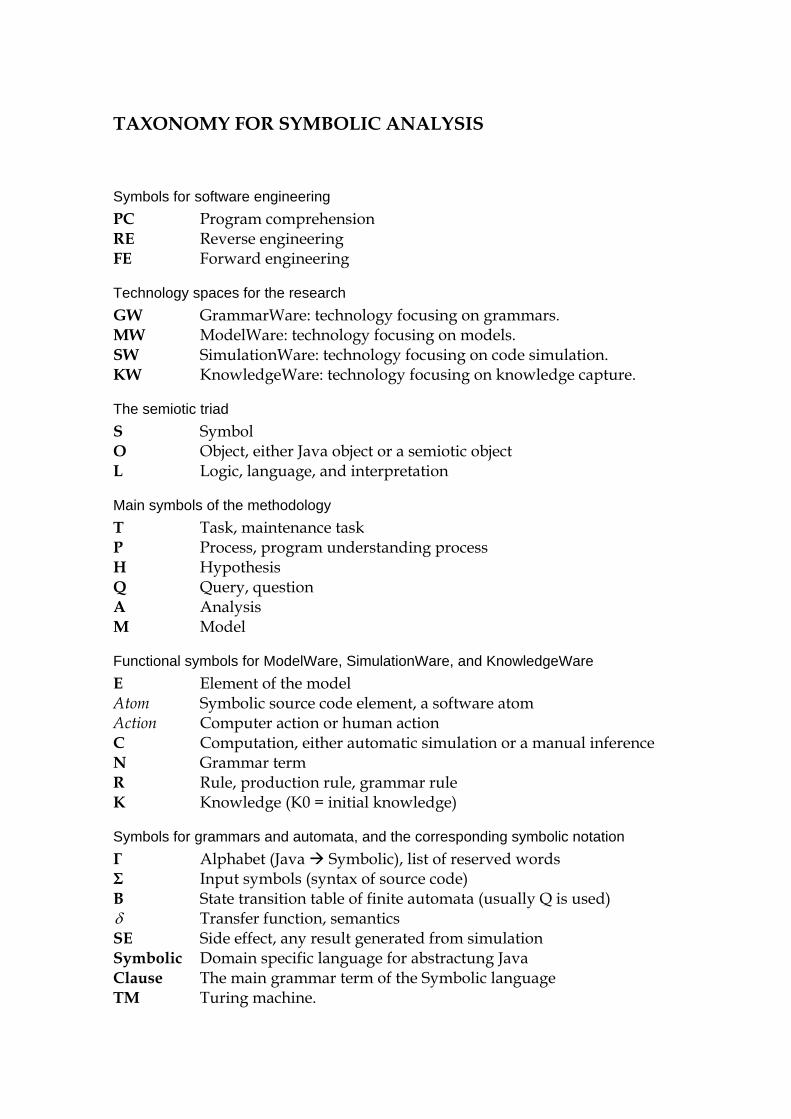
TAXONOMY FOR SYMBOLIC ANALYSIS
Symbols for software engineering PC Program comprehension RE Reverse engineering FE Forward engineering
Technology spaces for the research GW GrammarWare: technology focusing on grammars. MW ModelWare: technology focusing on models. SW SimulationWare: technology focusing on code simulation. KW KnowledgeWare: technology focusing on knowledge capture.
The semiotic triad S Symbol O Object, either Java object or a semiotic object L Logic, language, and interpretation
Main symbols of the methodology T Task, maintenance task P Process, program understanding process H Hypothesis Q Query, question A Analysis M Model
Functional symbols for ModelWare, SimulationWare, and KnowledgeWare E Element of the model Atom Symbolic source code element, a software atom Action Computer action or human action C Computation, either automatic simulation or a manual inference N Grammar term R Rule, production rule, grammar rule K Knowledge (K0 = initial knowledge)
Symbols for grammars and automata, and the corresponding symbolic notation Γ Alphabet (Java Symbolic), list of reserved words Σ Input symbols (syntax of source code) B State transition table of finite automata (usually Q is used) δ Transfer function, semantics SE Side effect, any result generated from simulation Symbolic Domain specific language for abstractung Java Clause The main grammar term of the Symbolic language TM Turing machine.
11
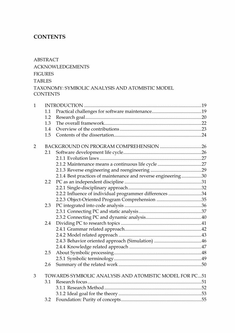
CONTENTS
ABSTRACT ACKNOWLEDGEMENTS FIGURES TABLES TAXONOMY: SYMBOLIC ANALYSIS AND ATOMISTIC MODEL CONTENTS
95H1 INTRODUCTION ................................................................................................... 463H19 96H1.1 Practical challenges for software maintenance.......................................... 464H19 97H1.2 Research goal.................................................................................................. 465H20 98H1.3 The overall framework.................................................................................. 466H22 99H1.4 Overview of the contributions ..................................................................... 467H23 100H1.5 Contents of the dissertation.......................................................................... 468H24
101H2 BACKGROUND ON PROGRAM COMPREHENSION ................................... 469H26 102H2.1 Software development life cycle.................................................................. 470H26
103H2.1.1 Evolution laws ...................................................................................... 471H27 104H2.1.2 Maintenance means a continuous life cycle ..................................... 472H27 105H2.1.3 Reverse engineering and reengineering ........................................... 473H29 106H2.1.4 Best practices of maintenance and reverse engineering ................. 474H30
107H2.2 PC as an independent discipline ................................................................. 475H31 108H2.2.1 Single-disciplinary approach.............................................................. 476H32 109H2.2.2 Influence of individual programmer differences ............................ 477H34 110H2.2.3 Object-Oriented Program Comprehension ...................................... 478H35
111H2.3 PC integrated into code analysis ................................................................. 479H36 112H2.3.1 Connecting PC and static analysis..................................................... 480H37 113H2.3.2 Connecting PC and dynamic analysis............................................... 481H40
114H2.4 Dividing PC to research topics .................................................................... 482H41 115H2.4.1 Grammar related approach................................................................. 483H42 116H2.4.2 Model related approach ...................................................................... 484H43 117H2.4.3 Behavior oriented approach (Simulation) ........................................ 485H46 118H2.4.4 Knowledge related approach ............................................................. 486H47
119H2.5 About Symbolic processing.......................................................................... 487H48 120H2.5.1 Symbolic terminology.......................................................................... 488H49
121H2.6 Summary of the related work ...................................................................... 489H50
122H3 TOWARDS SYMBOLIC ANALYSIS AND ATOMISTIC MODEL FOR PC... 490H51 123H3.1 Research focus ................................................................................................ 491H51
124H3.1.1 Research Method.................................................................................. 492H52 125H3.1.2 Ideal goal for the theory ...................................................................... 493H53
126H3.2 Foundation: Purity of concepts.................................................................... 494H55
12
127H3.2.1 Main concepts defining the symbolic layer...................................... 495H55 128H3.2.2 The user’s side of the methodology................................................... 496H57
129H3.3 Simplicity of theories: Technology spaces ................................................. 497H58 130H3.3.1 Commitments to GrammarWare ....................................................... 498H59 131H3.3.2 Commitments to ModelWare ............................................................. 499H59 132H3.3.3 Commitments to SimulationWare ..................................................... 500H60 133H3.3.4 Commitments to KnowledgeWare .................................................... 501H61
134H3.4 Accuracy of PC transformations.................................................................. 502H62 135H3.4.1 Universal transformation formalism................................................. 503H63 136H3.4.2 Type theories......................................................................................... 504H64 137H3.4.3 Knowledge transformation set ........................................................... 505H64 138H3.4.4 Graph approach (model theory) ........................................................ 506H65
139H3.5 SimulationWare: Completeness of logic ................................................... 507H66 140H3.5.1 Connection between logic and automaton theory .......................... 508H66 141H3.5.2 Definition for the smallest computation ........................................... 509H66 142H3.5.3 Towards an ideal analysis................................................................... 510H67 143H3.5.4 Turing machine metaphor - the base of computer simulation ...... 511H69 144H3.5.5 Simulating parallel features, the starting logic of threads ............. 512H69 145H3.5.6 User as the Decider .............................................................................. 513H70 146H3.5.7 Automated reasoning .......................................................................... 514H70 147H3.5.8 The final approach for logic, theorem proving................................ 515H70
148H3.6 Relevance of questions: referring to use scenarios ................................... 516H72 149H3.6.1 Mental simulation ................................................................................ 517H72 150H3.6.2 Organizational approaches................................................................. 518H73 151H3.6.3 Familiarization scenario ...................................................................... 519H74 152H3.6.4 Testing scenario .................................................................................... 520H75 153H3.6.5 Troubleshooting scenario.................................................................... 521H75 154H3.6.6 Definition for the focused approach towards source code ............ 522H76
155H3.7 Certainty of the results of analyses (answers) ........................................... 523H77 156H3.7.1 Does the method give correct answers?............................................ 524H78 157H3.7.2 Test evaluation possibilities for the results ...................................... 525H78
158H3.8 Correctness of programs and the tool......................................................... 526H79 159H3.8.1 The functional approach for the tool, Facade................................... 527H79 160H3.8.2 Programming approach for tools....................................................... 528H79 161H3.8.3 Hybrid programming, combining logic and OOP .......................... 529H80 162H3.8.4 Knowledge analysis of tasks............................................................... 530H82 163H3.8.5 About the formalization and development tool Visual Prolog ..... 531H83
164H3.9 Summary of the approach ............................................................................ 532H83
165H4 GRAMMARWARE ................................................................................................. 533H86 166H4.1 Foundation for GrammarWare.................................................................... 534H87
167H4.1.1 Automaton A1 including the grammar tool .................................... 535H87 168H4.1.2 Automaton A2, parsing and the Symbolic language ...................... 536H92 169H4.1.3 Automaton A3, abstraction by symbolic transformation............... 537H95 170H4.1.4 Conclusions about GrammarWare (the automata A1..A3) ............ 538H97
171H4.2 Comparing the foundation with related work .......................................... 539H97
13
172H4.2.1 Symbolic Grammar Term.................................................................... 540H98 173H4.2.2 Expressing language semantics in typed Prolog ............................. 541H98 174H4.2.3 Symbolic Grammar Rule ..................................................................... 542H99 175H4.2.4 Implementing the grammar tool........................................................ 543H99
176H4.3 Developing the output of parsing ............................................................... 544H100 177H4.3.1 Predicate-augmented AST .................................................................. 545H102
178H4.4 Raising the abstraction level ........................................................................ 546H103 179H4.4.1 Symbolic Code Description Language.............................................. 547H103
180H4.5 Direct translation ........................................................................................... 548H104 181H4.5.1 The principles and the main goals of translating source code ...... 549H104 182H4.5.2 Definitions for a direct translation..................................................... 550H105
183H4.6 Symbolic, the symbolic language ................................................................ 551H106 184H4.6.1 The Symbolic language ....................................................................... 552H107 185H4.6.2 Categories of the Symbolic clause...................................................... 553H109 186H4.6.3 Data model of the Symbolic language .............................................. 554H113 187H4.6.4 Operational model of Symbolic language ........................................ 555H113
188H4.7 Summary of GrammarWare, a bridge to ModelWare............................ 556H114
189H5 MODELWARE, THE ATOMISTIC SYMBOLIC MODEL ................................. 557H116 190H5.1 Foundation for ModelWare.......................................................................... 558H116
191H5.1.1 Automaton A4, Symbolic-to-model transformation ....................... 559H117 192H5.1.2 Atomistic architecture ......................................................................... 560H119 193H5.1.3 Conclusions about ModelWare (Automaton A4)............................ 561H121
194H5.2 Symbolic model, its definition and features .............................................. 562H121 195H5.2.1 Atomistic model and its features ....................................................... 563H121 196H5.2.2 Symbolic atomistic model ................................................................... 564H123 197H5.2.3 Creating the model and other model functions............................... 565H123 198HOutputs from the symbolic atomistic model ............................................. 566H126
199H5.3 Symbolic atom................................................................................................ 567H127 200H5.3.1 Special characteristics of symbolic atom........................................... 568H128 201H5.3.2 Semantic definition for the symbolic atom....................................... 569H129 202H5.3.3 Expressing links between atoms ........................................................ 570H131 203H5.3.4 Arguments of the atom command..................................................... 571H132 204H5.3.5 Atomistic operations: scanning and searching ................................ 572H132 205H5.3.6 Atom reachability, analyzing sequences and control flows .......... 573H133 206H5.3.7 Atomistic result processing................................................................. 574H134
207H5.4 Architecture of the atomistic model............................................................ 575H136 208H5.4.1 Programming model for the symbolic model .................................. 576H136 209H5.4.2 Atomistic hybrid object ....................................................................... 577H136
210H5.5 Summary of ModelWare .............................................................................. 578H137
211H6 SIMULATIONWARE, AN ABSTRACT MACHINE FOR SYMBOLIC........... 579H138 212H6.1 Foundation for SimulationWare.................................................................. 580H139
213H6.1.1 Automaton A5, defining a simulation process ................................ 581H139 214H6.1.2 Automaton A6, the simulation process............................................. 582H140 215H6.1.3 Conclusions about SimulationWare for automata A5 and A6 ...... 583H143
14
216H6.2 Background for the abstract machine ......................................................... 584H143 217H6.2.1 Chomsky hierarchy and the corresponding automata ................... 585H144 218H6.2.2 Principles for computations in the atomistic model ....................... 586H145 219H6.2.3 Turing machine model ........................................................................ 587H146 220H6.2.4 Symbolic abstract machine (SAM)..................................................... 588H146
221H6.3 Technical preconditions for Java simulation ............................................. 589H148 222H6.3.1 Java execution model........................................................................... 590H148 223H6.3.2 Sequential computation model .......................................................... 591H149 224H6.3.3 Reachability analysis............................................................................ 592H149 225H6.3.4 Problems and limitations of symbolic execution............................. 593H149 226H6.3.5 Relations of the abstract machine to hardware and performance 594H150 227H6.3.6 Influence of the object-oriented paradigm to simulation............... 595H150
228H6.4 The Turing machine as a reference for simulation ................................... 596H153 229H6.5 Foundation for source code simulation...................................................... 597H154
230H6.5.1 Simulation in computer science ......................................................... 598H154 231H6.5.2 Source code simulation........................................................................ 599H155 232H6.5.3 Complete simulation of the whole application................................ 600H155 233H6.5.4 Partial simulation ................................................................................. 601H155 234H6.5.5 Run method, the nucleus of the simulation ..................................... 602H159 235H6.5.6 Limitations of the simulation solutions in this research................. 603H160
236H6.6 Simulating static procedural commands.................................................... 604H160 237H6.6.1 Extending the symbolic model into a behavioral model................ 605H162 238H6.6.2 Simulating a statement block.............................................................. 606H163 239H6.6.3 Constants and their semantics (valClause)....................................... 607H164 240H6.6.4 Simulating operations (opClause) ..................................................... 608H164 241H6.6.5 Simulating variable references (refClause)....................................... 609H164 242H6.6.6 Simulating assignments (setClause).................................................. 610H165 243H6.6.7 Simulating conditional clauses (pathClause) ................................... 611H165 244H6.6.8 Simulating loops (loopClause) ........................................................... 612H166 245H6.6.9 Simulating method calls (getClause)................................................. 613H167
246H6.7 Simulating dynamic object-oriented commands ...................................... 614H168 247H6.7.1 Limitations of the partial simulation of object-oriented code........ 615H168 248H6.7.2 A protocol to handle unknown types and object handles.............. 616H168 249H6.7.3 Simulating create commands (creatorClause) ................................. 617H169 250H6.7.4 A protocol to simulate polymorphism.............................................. 618H170
251H6.8 Atomistic and distributed semantics .......................................................... 619H170 252H6.8.1 Turing model for the atomistic element............................................ 620H170 253H6.8.2 Atomistic semantics for defining Java as a high abstraction ......... 621H172
254H6.9 Summary: describing semantics by an abstract machine ........................ 622H173 255H6.9.1 Simulating Java in Symbolic ............................................................... 623H175 256H6.9.2 Results from the symbolic model....................................................... 624H176 257H6.9.3 Unified data model for the simulation results ................................. 625H177
258H7 KNOWLEDGEWARE............................................................................................. 626H178 259H7.1 Preliminaries for KnowledgeWare.............................................................. 627H178
260H7.1.1 Information ladder for knowledge capture...................................... 628H179

15
261H7.1.2 Hierarchical action model for capturing knowledge ...................... 629H180 262H7.1.3 An example code and its simulation model ..................................... 630H180
263H7.2 Foundation for KnowledgeWare................................................................. 631H182 264H7.2.1 Domain-independent definitions for knowledge............................ 632H182 265H7.2.2 Problem centric knowledge definitions ............................................ 633H185 266H7.2.3 Summary illustrating knowledge-related information .................. 634H187
267H7.3 Illustrating information model for source code ........................................ 635H188 268H7.3.1 Information model for an atom.......................................................... 636H188 269H7.3.2 Information model for a flow ............................................................. 637H189 270H7.3.3 Information model for ProgramContext........................................... 638H191
271H7.4 Interaction model using action levels ......................................................... 639H193 272H7.4.1 SkillAction ............................................................................................. 640H193 273H7.4.2 Rule Action............................................................................................ 641H194 274H7.4.3 Knowledge Action................................................................................ 642H196 275H7.4.4 MetaAction............................................................................................ 643H197 276H7.4.5 Combined Action – model .................................................................. 644H197
277H7.5 Method: Configuring hypotheses for familiarization and proofing ...... 645H199 278H7.5.1 Hypotheses are bridges from goals to actions ................................. 646H199 279H7.5.2 Model checking approach for a tape based on resolution trees .... 647H199 280H7.5.3 Building a resolution tree: theorems, operands and constraints... 648H201 281H7.5.4 Learning method based on gradual proving ................................... 649H205
282H7.6 Extending the method to the maintenance process.................................. 650H206 283H7.6.1 Top-down approach considering the change request .................... 651H206 284H7.6.2 Problem recognition............................................................................. 652H207 285H7.6.3 Problem formulation............................................................................ 653H207 286H7.6.4 Problem analysis................................................................................... 654H208 287H7.6.5 A use case: Using symbolic analysis for capturing knowledge.... 655H210
288H7.7 Summary of KnowledgeWare ..................................................................... 656H212
289H8 TOOL FOR SYMBOLIC ANALYSIS AND ATOMISTIC MODEL................... 657H214 290H8.1 Requirements for the tool ............................................................................. 658H214
291H8.1.1 Selected features for the tool............................................................... 659H215 292H8.2 Selected architecture...................................................................................... 660H216
293H8.2.1 PCMEF - architecture........................................................................... 661H217 294H8.2.2 Summary of the selected architecture ............................................... 662H218 295H8.2.3 Some measures of the tool implementation ..................................... 663H219 296H8.2.4 Data flow through the tool.................................................................. 664H219
297H8.3 Low level approach, the technology behind the tool ............................... 665H221 298H8.3.1 Demonstrating the architecture by a small code example ............. 666H221 299H8.3.2 Graphic symbols for the symbolic Turing machine ........................ 667H221 300H8.3.3 Prototyping small code examples...................................................... 668H223 301H8.3.4 Capturing knowledge: KnowledgeWare.......................................... 669H225
302H8.4 Symbolic Turing machine for symbolic analysis ...................................... 670H226 303H8.4.1 Principles of symbolic analysis .......................................................... 671H226 304H8.4.2 Starting simulation............................................................................... 672H226 305H8.4.3 The method to use hypotheses for program comprehension........ 673H228
16
306H8.4.4 User interface for proving simulation results .................................. 674H229 307H8.4.5 Code understanding process .............................................................. 675H230
308H8.5 Practical use case............................................................................................ 676H231 309H8.5.1 Practical example, a Server ................................................................. 677H231 310H8.5.2 Problem Recognition............................................................................ 678H233 311H8.5.3 Problem formulating............................................................................ 679H234 312H8.5.4 Simulating critical paths...................................................................... 680H235 313H8.5.5 General rules for detecting problems in the output tape ............... 681H235
314H8.6 The concluding remarks related to the PC process .................................. 682H240 315H8.6.1 Problems in visualization.................................................................... 683H240 316H8.6.2 Some observations relating to the atomistic model ........................ 684H241
317H8.7 Summary of the tool implementation......................................................... 685H242
318H9 RESULTS: A UNIFIED THEORY FOR PROGRAM COMPREHENSION ..... 686H245 319H9.1 Short history of the work.............................................................................. 687H245
320H9.1.1 The first research approach................................................................. 688H245 321H9.1.2 Toward a unified theory...................................................................... 689H246
322H9.2 Concepts for PC ............................................................................................. 690H247 323H9.2.1 Splitting the scope of the research to technology spaces................ 691H247
324H9.3 Technology spaces ......................................................................................... 692H249 325H9.3.1 GrammarWare ...................................................................................... 693H249 326H9.3.2 ModelWare............................................................................................ 694H250 327H9.3.3 SimulationWare.................................................................................... 695H251 328H9.3.4 KnowledgeWare................................................................................... 696H252 329H9.3.5 Program type theory............................................................................ 697H255 330H9.3.6 Mental or automated simulation ....................................................... 698H257
331H9.4 Summary about research goals.................................................................... 699H257 332H9.4.1 Explaining the main theories by the concepts of systems science 700H263
333H9.5 Summary of results........................................................................................ 701H263
334H10 DISCUSSION AND CONCLUSIONS.................................................................. 702H264 335H10.1 Unified computation model for maintenance ........................................... 703H265
336H10.1.1 Summarizing the maintenance computation model ............. 704H269 337H10.2 Scientific ideals............................................................................................... 705H270
338H10.2.1 Purity of the created concepts................................................... 706H270 339H10.2.2 Simplicity of the created theories ............................................. 707H271 340H10.2.3 Accuracy of transformations from code to knowledge......... 708H272 341H10.2.4 Completeness of the logic of the PC formalism ..................... 709H273 342H10.2.5 Correctness of programs of the created PC formalism ......... 710H274 343H10.2.6 Certainty of answers given by the PC formalism .................. 711H274 344H10.2.7 Relevancy of questions considering the PC formalism......... 712H275
345H10.3 Connections to Computer Science............................................................... 713H275 346H10.3.1 Experiments in building PC formalism................................... 714H275 347H10.3.2 Created theories for the technology spaces............................. 715H276 348H10.3.3 Created knowledge to be used in future research ................. 716H276 349H10.3.4 New discoveries to summarize the research .......................... 717H277
17
350H10.3.5 Interdisciplinarity and multidisciplinarity ............................. 718H277
351HREFERENCES.................................................................................................................... 719H280
352HSUMMARY........................................................................................................................ 720H298
353HYHTEENVETO (FINNISH SUMMARY)....................................................................... 721H301
354HAPPENDIX 1 : SERVER - EXAMPLE ............................................................................ 722H304
355HAPPENDIX 2: TUTORIAL FOR VISUAL PROLOG................................................... 723H310
356HAPPENDIX 3 : SIMULATION RESULTS OF THE EXAMPLE.................................. 724H319

19
1 INTRODUCTION
Software maintenance is becoming more and more important, because development times and product lifecycles are shortening and the life around us is becoming more complex demanding even more complicated features from new information systems.
In this research the focus is on source code comprehension, which should help the user in planning new implementations based on the current programming platform. The goal of the research is to create a framework, a formalism to connect the code, its behavior model, and the corresponding knowledge in order to aid the user in the problem recognition and problem analysis phases that are typical at that stage of maintenance where programming is transformed to code. This idea is very practical, because it allows a profitable use of the old code as far as possible without any need to reinvent the wheel. Furthermore, this kind of approach is needed, because developing software versions step by step involves significant risks in all situations where current behavior is not well understood. Such incomplete understanding can lead to erroneous products and weakening architectures, and to other maintenance problems (Lehman and Belady, 1985).
1.1 Practical challenges for software maintenance
Although the methods of software development have improved much since the time of procedural programming, there are still problems that decrease productivity and cause risks and serious quality problems for software deliveries (Boehm, 1991). This can result in benefits of object-oriented programming being lost, because programs are nowadays bigger and much more complex than during the procedural programming era in the '70s and '80s (Sneed, 2004a).
It is especially laborious to analyze large object-oriented programs, which contain, e.g., dynamic bindings and layer structures, due to problems in tools

20
and methodologies that are not as comprehensive as the ones in the procedural era, when the programs were simpler (Arevalo, 2006). For example, the run-time functionality of modern programs can only be investigated by using dynamic analysis that requires complex arrangements like code instrumenting and running of a complete implementation. The problem is that in a large output typical of dynamic analysis the most interesting thing, possibly a small feature of the large behavior model, can be lost behind irrelevant data. A modular and flexible approach is needed to allow selective investigation of code from the user’s point of view.
Because dynamic analysis has proved to be impractical for testing, there have been many attempts to decrease the number of the known problems related to it (Sneed, 2004b). As a solution special testbeds have been programmed, new software code has been instrumented to enable test extensions, and even new test modules have been coded for the original application software modules. Unfortunately the extensions can cause new problems, because they change the behavior of the original software. They can slow the program down, resulting in unproductive use of work time to maintain the special test code. Furthermore, planning test cases is a very expensive, laborious phase, because the tests should cover the new code and old versions and their interconnections in minor details. A completely perfect test environment cannot be created, because there is a vast number of different approaches and use cases to be covered in detailed tests.
In research, the dependencies of source code, i.e., the most essential code information, have been studied with a technology known as slicing for twenty years. Nevertheless, it is not a complete method (Gallagher and Lyle, 1991), and covers only a special point-of-view at a time. So although providing a large number of code statements, traditionally a laborious problem for the user to master, slicing is still too narrow a method, having relevance mainly for static analysis.
In object-oriented development UML diagrams are widely used to specify the structure, logic and behavior of the new application, but they are not specific enough to cover the programming approach (Rumbaugh, et al., 1999). Thus much work must be done to make the final program complete and that is why the code and the previous UML plans are not usually compatible after the programming phase. There are no good technologies to synchronize code and UML diagrams because UML reverse engineering tools, including ADM (architecture driven modernization), are not accurate enough to cover the details of the programming languages (Ulrich, 2005). For this reason they cannot help in program comprehension efforts.
1.2 Research goal
Taking into account the formal characteristics of the code and the quite different informal characteristics of the knowledge of maintenance persons as users, it is
21
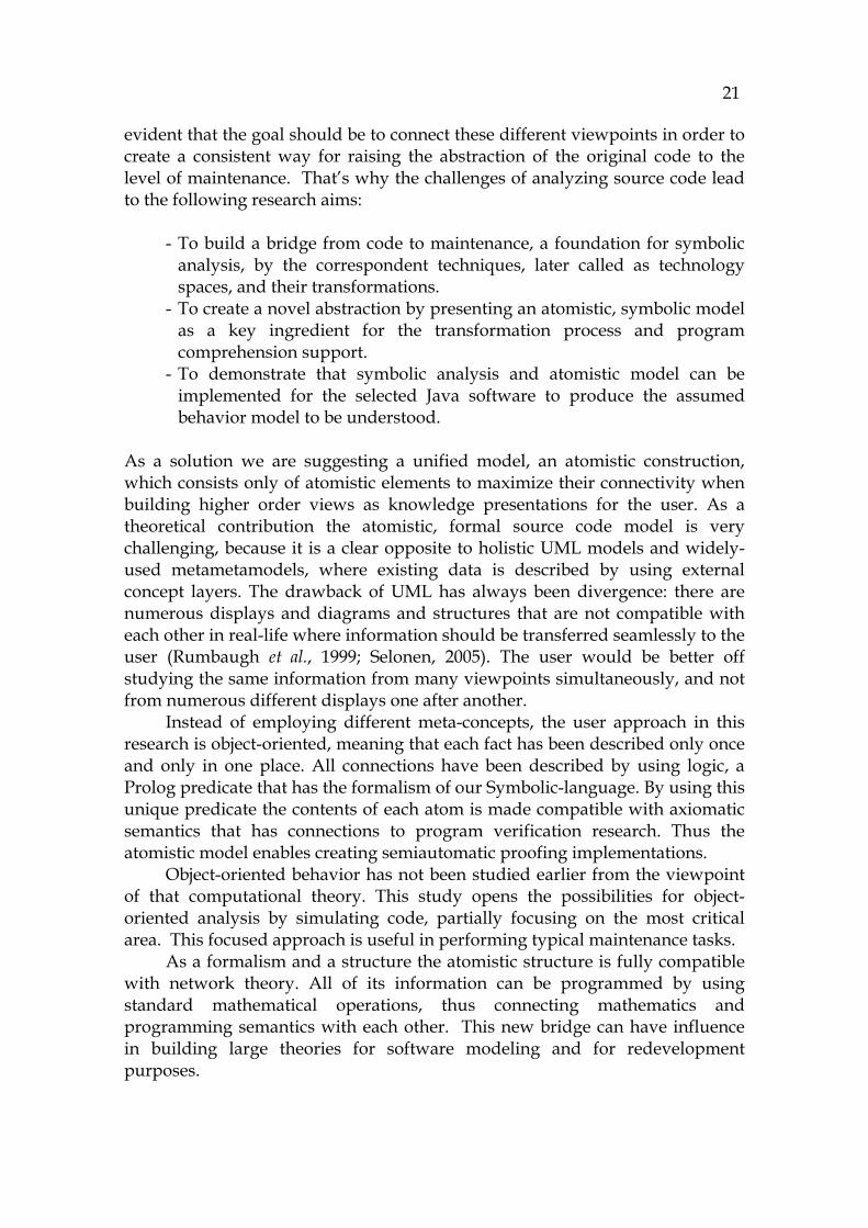
evident that the goal should be to connect these different viewpoints in order to create a consistent way for raising the abstraction of the original code to the level of maintenance. That’s why the challenges of analyzing source code lead to the following research aims:
- To build a bridge from code to maintenance, a foundation for symbolic analysis, by the correspondent techniques, later called as technology spaces, and their transformations.
- To create a novel abstraction by presenting an atomistic, symbolic model as a key ingredient for the transformation process and program comprehension support.
- To demonstrate that symbolic analysis and atomistic model can be implemented for the selected Java software to produce the assumed behavior model to be understood.
As a solution we are suggesting a unified model, an atomistic construction, which consists only of atomistic elements to maximize their connectivity when building higher order views as knowledge presentations for the user. As a theoretical contribution the atomistic, formal source code model is very challenging, because it is a clear opposite to holistic UML models and widely-used metametamodels, where existing data is described by using external concept layers. The drawback of UML has always been divergence: there are numerous displays and diagrams and structures that are not compatible with each other in real-life where information should be transferred seamlessly to the user (Rumbaugh et al., 1999; Selonen, 2005). The user would be better off studying the same information from many viewpoints simultaneously, and not from numerous different displays one after another.
Instead of employing different meta-concepts, the user approach in this research is object-oriented, meaning that each fact has been described only once and only in one place. All connections have been described by using logic, a Prolog predicate that has the formalism of our Symbolic-language. By using this unique predicate the contents of each atom is made compatible with axiomatic semantics that has connections to program verification research. Thus the atomistic model enables creating semiautomatic proofing implementations.
Object-oriented behavior has not been studied earlier from the viewpoint of that computational theory. This study opens the possibilities for object-oriented analysis by simulating code, partially focusing on the most critical area. This focused approach is useful in performing typical maintenance tasks.
As a formalism and a structure the atomistic structure is fully compatible with network theory. All of its information can be programmed by using standard mathematical operations, thus connecting mathematics and programming semantics with each other. This new bridge can have influence in building large theories for software modeling and for redevelopment purposes.

22
1.3 The overall framework
In this research a complete framework have been developed to build a formalism and a comprehensive data flow from software, extending from the source code into the knowledge capturing phase, in order to utilize the program comprehension information ( 725HFIGURE 1).
The flow starts from the grammar management (GrammarWare), which makes it possible to define the semantics of the code when parsing Java code for all later phases. For handling source code behaviour in high abstraction models, a new symbolic language, Symbolic, was developed. It enables effective processing while still having a declarative internal notation for programming.
FIGURE 1 Program comprehension data flow.
The most important discovery of the study is the atomistic source code model, presented as ModelWare in 726HFIGURE 1. Because of its simplicity (it only contains simple elements), it is an ideal construction for modeling purposes. Further, its architecture is novel as it connects two different paradigms in the tool - the abstraction features of object-oriented programming and association capabilities of logic-programming - in order to create a minimal structure as a unifying element of the model. We call this new structure an atom, because it is the smallest structure captured from the code that cannot be divided into smaller parts without it losing its internal semantics. Furthermore, each atom is backwards compatible to a grammar term.
The atomistic model creates a formal and efficient structure for later analyses and enables Hoare’s axiomatic semantics to be used in modeling the behavior of the atoms. However, in analyzing a possible code behavior, the most essential specification is operational semantics, because it describes the functionality of the language. For implementing an operational semantics as a framework, SimulationWare defining an abstract machine is needed: it shows how an axiomatic structure is changed into a functional behaviour. The research introduces the theory of abstract machines and automata (Chomsky,
GrammarWare ModelWare Knowledge-Ware
Maintainer
Know-how for creating a new installation
SimulationWare:Abstract Machine
Software Hardware
GrammarWare ModelWare Knowledge-Ware
Maintainer
Know-how for creating a new installation
SimulationWare:Abstract Machine
Software Hardware
23
1956; Chomsky and Schützenberger, 1963; Hopcroft and Ullman, 1979) in order to show that the formalism of the Turing machine (TM) metaphor is a fruitful concept for program comprehension purposes with its background of computation theory including simulation. Simulated computations, evaluating the code, save time. This allows the user more time for making higher level computations like testing and proving the program or for considering changes. The symbolic Turing machine, introduced here as a symbolic abstract machine (SAM), allows simulating source code as a reductionist atomistic source code model. We show that, by function, any atomistic element has a behavior resembling its typical automaton level in the Chomsky hierarchy. All elements have an equal outer formalism and an internal state-table, compatible with their origin in the programming language grammar (here Java).
However, the abstract machine with its tapes is not enough for the user to improve the development process. The developer also needs to obtain new up-to-date, practical information for solving any specific problem. We have developed a new framework, KnowledgeWare (727HFIGURE 1), to describe the transformation from the output of the abstract machine into user knowledge that can be used in planning maintenance tasks. This theory has three levels according to the concept of Rasmussen: knowledge level, rule level, and skill level (Rasmussen, 1983). Our theory for KnowledgeWare describes action stereotypes for each level as an information ladder (Longworth, 1996) in the following way. The original code is data, and the results captured from that data produce low-level information. Furthermore, the specific analyses produce argumentative proofs for the user collecting accumulated program knowledge. This, in turn, improves the current know-how of the user, and the skills of how to make safe modifications for the current program.
It is essential to observe how the computer can help the user at each level. The main concept in the automated program comprehension, computation, illustrates the behavior of the atom and refers strongly to the computational theory. In the atomistic model all the computations take place modularly at the element level, a low level, which has the formalism of a simple state-machine. As this simple state-machine extends itself via its links to all the referring sub-state machines, it is possible to combine the program knowledge, the source code model, the theories of state automata, and the computation theory into a unified formalism to cover the whole scope of program comprehension.
1.4 Overview of the contributions
From the user’s point-of-view the current reverse engineering software tools almost without an exception transform all their input data into display information to be studied further (Walenstein, 2002). Thus the human-computer interaction does not allow interactive, problem-oriented analysis of the problem. Instead, the focused approach defined in this research allows the user to modularly define the level of the information to be shown, the most

24
important data flow type and the most difficult area of his/her work to be validated and brought to the focus. From that focused point of view the user can navigate interactively in each level at different abstraction levels. This allows problem recognition, modular simulation of the selected code model and collection of simulation results in order to build a mental image of the current problem. The model works like a server, where the query formalism has its background in the integrated mental model of program comprehension.
From the cognitive viewpoint the research introduces some new perspectives, because it connects together the Turing machine metaphor (Turing, 1936), artificial intelligence, source code analysis (Binkley, 2007), and cognitive models (Rasmussen, 1983 ; Anderson and Lebiere, 1998).
1.5 Contents of the dissertation
The contents of the dissertation are shown in 728HTABLE 1. One can get a quick idea of the contribution by reading the abstract, introduction and summary. A more profound understanding can be obtained by reading Chapters 1, 2, and 3 and Appendix 2 that describes the formalism used, and, as a conclusion, Chapters 9 and 10.
TABLE 1 Contents of the research.
Chapter Topic Contents 1 Introduction Introduction, this chapter 2 Background Related work describing background on the research area and
the known approaches. 3 Approach Research approach including an abstract and more concrete
goals for the dissertation. The concrete goals are evaluated in Chapter 9, and the abstract goals are summarized in Chapter 10.
4 GrammarWare Grammar-related methodology. It describes a symbolic notation for grammars based on predicate logic. A novel symbolic language, named Symbolic, is presented there.
5 ModelWare Model-based methodology. It describes the motivation for an atomistic model, and building the model and corresponding characteristics including the architecture.
6 SimulationWare Simulating methodology. A symbolic abstract machine is illustrated. Simulating the atomistic model as a Turing machine metaphor is introduced. Semantics for the corresponding model is presented as an atomistic semantics. Corresponding formalisms are introduced.
7 KnowledgeWare Knowledge-related methodology. This chapter is a synthesis, which combines maintenance, the corresponding tool and the atomistic model to a cognitive architecture.
8 JavaMaster tool A demonstration to model a symbolic Turing machine including its architecture and user interface as well as an approach for proving programs.
continues…

25
729HTABLE 1 continued. 9 Results A summary of the methodology described in Chapters 4 – 7.
Concrete goals from Chapter 2 are evaluated . 10 Conclusions Conclusions including a summary of abstract goals from
Chapter 2. Summary The summary both in English and Finnish.
App 1 Server example A short Java example of a typical object-oriented program, which uses threads in communication.
App 2 Prolog tutorial A short Visual Prolog tutorial. App 3 Simulation data Simulation data for the example (Appendix 1).
26
2 BACKGROUND ON PROGRAM COMPREHENSION
This chapter describes program comprehension (PC) research starting from software development process, which is the large context. Maintenance is the area where the problems of code understanding (a synonym for PC) are principally found. Creating a theory for solving program comprehension problems is important, because it could produce clear positive feedback to the whole development process.
The aim of this research is to create a unified comprehension methodology for object-oriented programming (OOP). This focus has been selected, because OOP doesn’t have a well-established theory for analyzing dynamic behavior. Thus, it is lacking a theory that could provide most valuable information for solving maintenance tasks and object-oriented programs in general, which are often identified with serious problems (Sakkinen, 1992; Arevalo, 2006; Zaidman, 2006; Tichelaar 2001) .
2.1 Software development life cycle
Software development is a relatively new discipline, and doesn’t yet have a strong theoretical foundation. Therefore its methods are practical rather than formal, even though the goal to increase formalism in development is apparent also in organization-centric proposals such as SPICE and CMMI (Raak et al., 2004; Garcia & Turner, 2006).
Although a number of new technologies have been created since the 1970’s one after another, programming is still laborious work, and object-oriented programming has its own typical comprehension problems (Bezevin, 2003). One reason for this is that while large software vendors exert a very strong influence on the strategy of software development organizations, they are not interested in developing totally new paradigms or new programming or
27
program comprehension theories. That’s why commercial tools, research communities, and practitioners do not come together in the daily work.
2.1.1 Evolution laws
In the long run, software related work rather than being seen as a temporary activity, should be seen as a continuous process that obeys certain evolution laws (Lehman and Belady, 1985):
- Continuous change: Software that is used in industrial and practical applications must evolve and be updated, lest it cease to fulfill its mission and meet its operational objectives.
- Increasing complexity: When a system evolves, its structure becomes more complex and brittle unless software engineers take specific actions to remediate the phenomenon.
- Numerous layers of feedback in the systems: The development processes are multi-loop, multi-agent feedback systems that are difficult to master.
Lehman’s laws suggest that there are maintenance problems in future, too, due to continuous change and increasing complexity. By careful maintenance planning it is still possible to improve the quality of software, but in many cases it can be laborious and expensive. Therefore, developers need new methodologies in order to justify future investments in the existing software.
2.1.2 Maintenance means a continuous life cycle
Maintenance is the last part of the whole software production cycle, which aims at increasing the quality and value of the software implementation (Sneed, 2004a). Much research has been done on making maintenance systematic, but the theoretical background for the results is rather thin. Generally one recognizes four types of maintenance activities: corrective, adaptive, perfective, and preventive (Chapin et al., 2001).
The focus of this study is task based maintenance, which is organized bottom-up and case-by-case. The larger scale approach, system wide maintenance, which is organized top-down and involves very abstract planning for enterprise architectures and organizational goals (Zachman, 1987), is left out of the scope in this work. Task based maintenance starts from a typical change request, usually leading to PC needs in the functions of problem recognition, problem formulation, and deeper analysis.
Corrective maintenance
The most critical type of maintenance is correcting code errors. This has been studied extensively, but most often the proposed methods can only be used for procedural languages. (See Tonella et. al, 2007) The most detailed method for a
28
corrective maintenance process was created by Jambor-Sadeghi et al. (1994). It is described next.
In the “Jambor-Sadeghi process” the application software is described to a bug management system by using a functionality hierarchy and collected information about individual bugs. In every new situation where a bug is identified, that bug is matched with the up-to-date information in order to find possible problem candidates, which normally are specific execution paths in the program. The execution paths and structural components selected by the user from the bug information are mapped together to a test case database to cover all known malfunctions. Information about each new bug solved is saved, and the functionality and path information is specified.
The process works well in principle, but there are some problems in practice, because the software should be rather stable and homogenous to allow this kind of functionality mapping. In general, it cannot be used in OOP, where the class hierarchies can be deep and complex. One essential limitation for this method is that critical execution paths should be executed individually. The problem is that the analysis method that is currently used, dynamic analysis, doesn’t allow this. That’s why the “Jambor-Sadeghi process” and other similar ones are best in static investigation of source code that is characterized by execution paths and static structures, functionalities and sub-functionalities. With object-oriented code this is not so simple, because most paths are activated dynamically in run-time and in layered architectures, and it is not possible to know all use cases and possible uses such as class contracts. The most serious drawback of dynamic analysis is that it cannot be used selectively piece by piece to test the most interesting execution paths or sub-functionalities.
Thus neither static analysis nor dynamic analysis is perfect in implementing a complete corrective maintenance tool by itself. The same conclusion has been made in many articles considering OOP (Sneed, 2004b). Although there are numerous methods for fixing and correcting specific problems in procedural and object-oriented code, a more general methodology is needed for a unified approach in corrective maintenance.
Adaptive, perfective and enhancive maintenance
The role of object-oriented programming is important in the pragmatics of creating new software in all maintenance types other than corrective maintenance. In each maintenance case, when fixing a bug or making a modification, the purpose should be to raise the quality of the software in order to avoid problems of degradation (Lehman et al., 1985). The means usually employed for raising the quality are design patterns (Gamma et al., 1995) best practice integrating rules, and architecture recommendations, which are specific for each organization (Brown et al., 1998; Demeyer, Ducasse, and Nierstratz, 2003; Shawn and Garlan, 1993; Kazman et al., 1994).
Raising quality is not easy, on the contrary it is often very laborious, because the changes in the code can propagate into numerous other places causing turbulence. This is a gray area, where there are no good general
29
answers. Refactoring and reorganization (Fowler el al., 1999) are some ways to make progress (Demeyer et al., 2003), but there are no ready answers for all the questions. The most problematic topic in maintenance is then the code-related approach, where the information is the most complex and also the most critical.
2.1.3 Reverse engineering and reengineering
Reverse engineering is a research discipline relating to maintenance and through it to the whole software development process. By definition, reverse engineering is the process of analyzing a subject system to create presentations of the system at a higher level of abstraction (Chikofsky et al., 1992). Reverse engineering in and of itself does not involve changing the subject system. It is a process of examination, not a change or replication.
There is a great deal of motivation for reverse engineering in industry, because there are hundreds of billions of lines of code in mission critical systems worldwide. Furthermore, technology is changing rapidly, which exerts continuous modernization pressure. It is problematic that all systems degrade in quality due to continuous change. So there is a point in time for every mission critical system at which it either has to be reengineered (that means developing the system into the next step), rewritten or replaced (Morris, O’Brian, Smith, and Wrage, 2005).
Software reengineering is a larger concept than reverse engineering, because its purpose is to modernize the current system (Chikofsky et al., 1992). It refers to techniques and methodologies that aim to facilitate:
1. Understanding a software system and its components. 2. Increasing functional and non-functional characteristics and properties
of the software system. 3. Collecting, modeling, categorizing and storing information related to
the software system. Thus reengineering can be regarded as a process to read current source code, to understand it, to plan the necessary changes, bigger or smaller, in order to create a new software system implemented at the source code level. It can be done manually without tools or semi-automatically by using source code analysis methods.
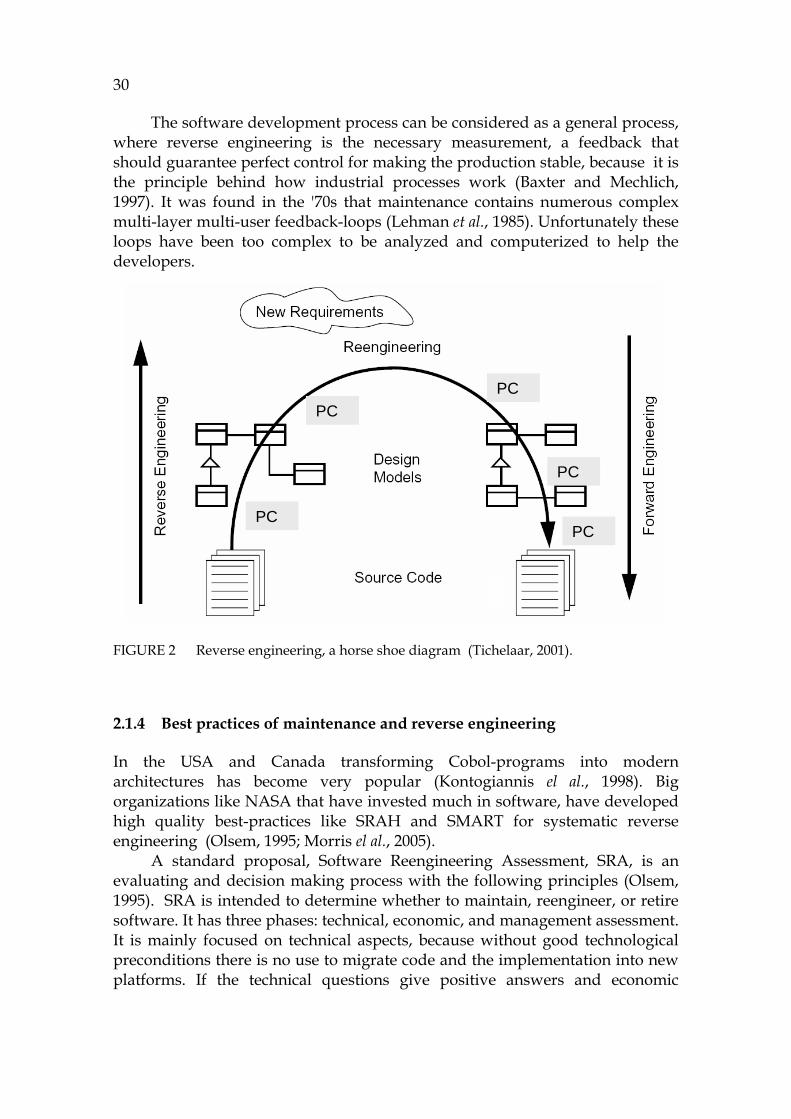
A horse shoe diagram (730HFIGURE 2) is a widely used metaphor to describe how the current source code (the left bottom corner in the figure) will be transformed into a high abstraction model for problem analysis (Kazman et al., 1998). In this loop PC is the process to raise the abstraction level. It is needed also when planning modifications in forward engineering. After understanding the situation, the modifications can safely be made and programmed into the code (right lower corner of the figure).
30
The software development process can be considered as a general process, where reverse engineering is the necessary measurement, a feedback that should guarantee perfect control for making the production stable, because it is the principle behind how industrial processes work (Baxter and Mechlich, 1997). It was found in the '70s that maintenance contains numerous complex multi-layer multi-user feedback-loops (Lehman et al., 1985). Unfortunately these loops have been too complex to be analyzed and computerized to help the developers.
FIGURE 2 Reverse engineering, a horse shoe diagram (Tichelaar, 2001).
2.1.4 Best practices of maintenance and reverse engineering
In the USA and Canada transforming Cobol-programs into modern architectures has become very popular (Kontogiannis el al., 1998). Big organizations like NASA that have invested much in software, have developed high quality best-practices like SRAH and SMART for systematic reverse engineering (Olsem, 1995; Morris el al., 2005).
A standard proposal, Software Reengineering Assessment, SRA, is an evaluating and decision making process with the following principles (Olsem, 1995). SRA is intended to determine whether to maintain, reengineer, or retire software. It has three phases: technical, economic, and management assessment. It is mainly focused on technical aspects, because without good technological preconditions there is no use to migrate code and the implementation into new platforms. If the technical questions give positive answers and economic
PC
PCPC
PC
PC
PC
PCPC
PC
PC
31
conditions are advantageous, it is very easy for the project persons to present, to the management, the argument that migrating is profitable in a long-run.
SMART (Service-Oriented Migration and Reuse Technique) is a modernization technology developed for the US Air force and has the following goals (Morris el al., 2005):
- Establish stakeholder context. - Describe existing capabilities. - Describe the future service-based state. - Analyze the gap between the service-based state and existing
capabilities. - Develop strategy to service migration.
There are no actual measures for maintenance evaluation. The best of them are COCOMO-metrics (Boehm, 1981), but they normally provide information that is too specific and too narrow. The quality of forward engineering processes can be evaluated by using SPICE and CMMI models (Raak et al., 2004; Garcia et al., 2006), but these ignore the omni-present role of reverse engineering in the whole development cycle.
2.2 PC as an independent discipline
Program comprehension is a domain of computing science dealing with the processes used by software engineers to understand programs during their evaluation, before their modification (Brooks, 1983). PC is also known as a synonym for program understanding. In this chapter PC is discussed both as an independent discipline (this section), and as integrated into a larger context (next section).
There is a conference series ICPC 0F
1 on program comprehension (started in 1992), which has focused mostly on the approach of the independent PC discipline. However, because of its rather narrow scope this forum does not provide complete answers for industrial software development. A latter approach, multi disciplinary focus in integrating PC to other technologies, has attracted very little interest, although it can have more practical value than the single-disciplinary approach. There are conferences like WCRE (Working Conference on Reverse Engineering) 1F
2 and SCAM (Source Code Analysis and Manipulation) 2F
3 , where questions typical for PC are discussed. The topics they deal with are often rather technical, solving some special problems or covering a large area of the development process.
1 ICPC, The 15th IEEE International Conference on Program Comprehension,
www.cs.ualberta.ca/icpc2007/index.html. 2 WCRE2007, www.rcost.unisannio.it/wcre2007/program/main_conference_program.htm
(1.11.2007) 3 SCAM2007, www.ieee-scam.org (1.11.2007)
32
2.2.1 Single-disciplinary approach
Storey's survey has illustrated the past, present, and future of program comprehension (Storey, 2006). In the following we present some observations about the survey.
About models and theories
The lack of theories of program comprehension was recognized as being problematic (Détienne, 2001) already before the '90s, but as the field of program comprehension matured, research methods and theories were borrowed from other areas of research, such as text comprehension, problem solving, and education. The theories for program mental models were created in the '80s and in the '90s (Brooks, 1983; Pennington, 1987; von Mayrhauser and Vans, 1997).
Mental and cognitive models. A mental model describes a mental representation of the program as understood by the developer, whereas a cognitive model describes the cognitive processes and temporary information structures in the programmer’s head that are used to form the mental model. Cognitive support refers to support provided for cognitive tasks such as thinking or reasoning (Walenstein, 2003).
Programming plans. In the '90s, program comprehension became an
important topic as a possible solution for the productivity problem. The best known model from that area results from Pennington’s research about bottom-up understanding (Pennington, 1987), where she showed in which order the students and programming novices learn code features. Its main construct is the so-called five-tuple: function, control flow, data flow, state, and operation. This information set is useful to describe the information and even knowledge that can be captured from a procedural source code.
Top-down comprehension model. In the '80s Brooks developed (Brooks,
1983) a theory for the developer about matching source code with similar collections of high-level mental concepts. It is useful to note that without matching of that kind, or without making any assumptions, it is hard to learn code features.
Integrated metamodel. An important theoretical framework for program
comprehension is the integrated metamodel of von Mayrhauser (von Mayrhauser et al., 1997), because it connects the theories of other researchers into a whole. It includes the three main models: the bottom-up model, the top-down model, and the situation model. According to von Mayrhauser the relation between maintenance and program comprehension is the following (von Mayrhauser et al., 1997):

33
“Program comprehension is said to be a first task before maintenance. The biggest problem in maintenance is the difficulty to understand the current implementation, all its dependencies and its business relations so that the program can safely be modified without any risk to cause new problems in the earlier functionality.”
The top-down model concentrates on high-level plans and what the specified code element should do. The bottom-up model is suitable for detecting, from the code, different kinds of flows (control flow, data flow, and program flow), state dependencies or function of each code element. The situation model is an accumulated set of information collected in the program investigation phase. Situation model is needed for understanding relations between domain-specific dependencies and program structures and flows (von Mayrhauser et al., 1997).
Storey (2006) summarizes the integrated mental model as follows: - The top-down (domain) model is usually invoked and developed using
an as-needed strategy, when the programming language or code is familiar. It incorporates domain knowledge as a starting point for formulating hypotheses.
- The program model may be invoked when the code and application is completely unfamiliar. The program model is a control-flow abstraction.
- The situation model describes data-flow and functional abstractions in the program. It may be developed after a partial program model is formed using systematic or opportunistic strategies.
- The knowledge base consists of information needed to build these three cognitive models. It represents the programmer’s current knowledge and is used to store new and inferred knowledge.
- Understanding is formed at several levels of abstraction simultaneously by switching between the three comprehension processes.
Role of hypotheses in program understanding
Hypotheses have long been recognized as major drivers of program comprehension (von Mayrhauser et al., 1997). They help to direct further investigation. Brooks (1983) theorizes that hypotheses are the only drivers of cognition, because understanding is complete when the mental model consists entirely of a complete hierarchy of hypotheses in which the lowest level hypotheses are either verified against the actual code or documentation, or fail.
If we have, for example, a client-server application, which doesn’t respond to queries, we can make the following assumptions. Either the server has not been started, the machine is down, or the answering process is blocked. Each of them is a typical troubleshooting hypothesis. In most cases it is possible for the user to coarsely localize the hypotheses to the code. Proving which one of them is erroneous is often difficult because of dynamic behavior of the application.
34
Using questions in exploring programs
Goals or questions embody the cognitive processes by which maintenance engineers understand code. So goals of program comprehension have a logical connection to maintenance tasks. Solving a goal consists of lower level comprehension actions, which the user should perform in order to get a picture about the current goal. Von Mayrhauser describes the sequence of a goal (von Mayrhauser et al., 1997) containing the following lower levels: hypothesis, sub-goal, sub-hypothesis, and an action. The role of this action level is typically to search or to prove something in the code. She has also described tool requirements for supporting program comprehension, where selective navigation has an essential role to play.
Problems in reading object-oriented code
Because of encapsulation, the most difficult thing in understanding object-oriented source code can be attributed to crosscutting and dynamic bindings. Those bindings that are dynamic cannot be understood from the caller’s code without understanding all possible called elements. This is necessary in order to get real understanding about the real-time behavior (Walkinshaw, Roper, and Wood, 2005).
Due to encapsulation, the contents of each class are difficult to be read. The invocations of each class and each method, in particular, cannot be found without reading the code. This is what is known as a crosscut problem. So analyzing the behavior automatically in order to automatically find all call candidates should be the most advantageous feature for the reader.
Static analysis can solve neither the behavior nor invocation paths which form the real logic and control flow of an object-oriented system. This invocation logic is called the behavior of the system. In UML it is typically presented as a sequence diagram (or as a scenario).
Programming paradigms will also impact comprehension strategies. Object-oriented (OO) programs are often seen as a more natural fit to problems in the real world, because of ‘is-a’ and ‘is-part-of’ relationships in their class hierarchy and structure, but others argue that objects do not always map easily to real world problems (Détienne, 2001) .
2.2.2 Influence of individual programmer differences
There are many individual characteristics that will impact on how a programmer tackles a comprehension task. These differences also affect the requirements for a supporting tool. There exist clear differences in programmers' ability and creativity that cannot be measured simply by their experience (Curtis, 1981).
Vessey (1985) has noted that experts use breadth-first approaches and at the same time are able to adopt a system view of the problem area, whereas novices use breadth-first and depth-first approaches but are unable to think in
35
system terms. Moreover, experts tend to reason about programs according to both functional and object-oriented relationships and consider the algorithm, whereas novices tend to focus on objects. Burkhardt et al. (2002) performed experiments to study how object-oriented programs are comprehended. They observed that novices are less likely than experts to use inheritance and compositional relationships to guide their comprehension. Furthermore, Davies (1993) noted that experts tend to externalize low level details, but novices externalize higher levels of representation related to the problem.
2.2.3 Object-Oriented Program Comprehension
Only a few theories have been developed for understanding object-oriented programs. The proposal of Burkhardt et al. is one of the most promising, because it defines the program comprehension approach taking care of the specialties of OO-programs (Burkhardt et al., 2002):
- Main goals. The main goals of the problem correspond to functions accomplished by the program viewed at a high level of granularity. They do not correspond to single program units. Rather, the complex plan which realizes a single goal is usually a delocalized plan, a set of distributed activities, in an OO program.
- Problem object(s) (PO). These objects directly model objects of the problem domain.
- Relationships between problem objects. These consist of the inheritance and composition relationships between PO’s.
- Computing or reified objects. An example of a computing, or reified, object is a string class, which is not a problem domain object per se. Reified objects are represented at the situation model level inasmuch as they are necessary to complete the representation of the relationships between problem objects, i.e., they bundle together program level elements needed by the domain objects.
- Client–server relationships. Communication between objects corresponds to client–server relationships in which one object processes and supplies data needed by another object. These connections between objects are the links connecting units of complex delocalized plans. In an OO system, the actions in a complex plan which performs a main goal are encapsulated in a set of routines, and the routines are divided among a set of classes and connected by the control flow. Client–server relationships represent those delocalized connections.
- Data flow relationships. Communication between variables corresponds to data flow relationships connecting units of local plans within a routine.
The list above has only some connections to the procedural Pennington model (Pennington, 1987), because that list has been created supposing that object-oriented programs and classes do have many use cases, that code elements have

36
numerous activation models, and, what is important, that a huge number of details are hidden behind the signatures of the classes. Therefore, in normal situations the role of the user is initially to investigate the most probable goals and problem objects in order to find and to understand the most essential connections, data paths and flows, and objects.
It is essential to observe that the procedural comprehension model (Pennington, 1987) and its object-oriented equivalent (Burkhardt et al., 2002) can be connected with each other by creating some generic concepts, i.e., specialized program flows, that are common for both of them. However, currently there are no good tools for OOP understanding that would directly support these comprehension models.
2.3 PC integrated into code analysis
In most surveys of the field it can be seen that PC is considered to be an independent discipline, which has no connections to other parts of software development (Storey, 2006) relating to source code analysis in general (Binkley, 2007), which is a wider approach. Rather than being a vivid activity, PC should be seen as a comprehensive link combining cognitive models and theories and the practical life of the programmer. There are two main reasons why PC should also be seen from a multidisciplinary approach:
- von Mayrhauser et al. (1997) have proposed that PC is a mandatory phase before each maintenance task. That is why it should be integrated into other technologies and source code analysis tools. Furthermore, multidisciplinary research should be conducted in order to connect critical development phases like programming, design, maintenance, and restructuring together.
- The best-known and most widely used source code analysis methods are program comprehension methods, because their purpose is to help the user to understand better the source code. Furthermore, it is not possible to change the code without understanding how the current functional and qualitative behavior will change in the modification process.
Creating a comprehensive view to software maintenance
Test cases, analysis methods, and the corresponding tools have been connected into a comprehensive set of methodology by Sneed (2004b). In his test system environment, built for a large commercial information system, the roles between different technologies are the following. Static analysis is used as much as possible, because the results from a source code can be captured without any cost (automatically). Dynamic analysis is so expensive that it is used only in critical phases. So in practical maintenance cases it is useful to find compromises between different technologies. Integrating various tools with
37
each other in order to make a flexible environment for ensuring software production quality is very important.
Programming can be seen as the most complex part of maintenance, which fact, therefore, emphasizes the role of PC. In most cases it is the most expensive phase, too, and has an important economical value. Thus all means to utilize the results of programming as perfectly as possible are valuable. The following use cases serve for extending the scope of PC to a larger software development context:
- Finding problems in source code. - Proving programs. - Improving co-operation and delegation of work by means of better PC
knowledge. - Avoiding reinventing the wheel by using current code as efficiently as
possible. - Avoiding degrading the quality of software by systematic familiarization
of code. - Scheduling the testing and verification phases as early as possible to
minimize error costs. - Providing feedback to other organizations and teams and stakeholders
by better metrics and more complete models. Source code can be analyzed either manually or automatically. Manual work is very expensive whenever we deal with huge amounts of code, often running to possibly millions of lines. Simply put, programmers have never enough time to get a very detailed mental image about large applications. Furthermore, it is hard for the developer to remember dependency information of code elements that are not in the active focus of the user. So the users must rely on their memory and use different hypotheses to check individual things case-by-case. Furthermore, often when the focus is changing then several places in the code that have already been visited must be re-navigated because of their different roles in the new task.
2.3.1 Connecting PC and static analysis
Static code analysis produces rather good results for procedural languages, although pointers cause often serious problems for C developers. Thus pointer-analysis is a widely investigated area, studied by big organizations like NASA, Airbus and Boeing.
There are numerous methods and principles for static analysis (Caprile et al., 2003; Binkley, 2007). The area contains a few basic methodologies and various ways to analyze, but the role of program comprehension there cannot easily be seen, because most of the analysis principles are technologically oriented having no cognitive background.
- The basic methodologies specify algorithms for static analysis and how to handle internal source code structures. They are based on variations of abstract-syntax-tree (AST), parse-tree (PT) and feature vector (FV).
38
- Several presentations for semantics have been proposed (Heering and Clint, 2007) . The best known of them are dependency graph (DG) providing outputs as flow analysis, abstract syntax graph (ASG) (Dean, 2004), type inference analysis, slicing and clustering tools, transformers, and different kinds of call graphs. Definitions for them can be found in the survey by Binkley (2007).
It is problematic that these analysis functions are separate and cannot be used from one tool to cover all output information. This fragmentation prevents the industry from using static analysis widely in software development, because there are no good tools to satisfy all the developers' needs. There are several specific analysis techniques for meeting the analyzing challenges described by Binkley (2007). However, most of them are useful for programmers in the context of program comprehension:
- Program slicing: Useful for detecting dependencies and correcting errors (Weiser, 1984; Binkley, 1996). Slicing (Weiser, 1984) is a method to locate statements in the code that can influence the target statement, pointed at by the user (Lucia, 2001). Because the method returns statements from the source without abstracting them, it is a low level method. There are numerous implementations of slicing, including forwards and backwards slicing and dynamic slicing. The best-known tool implementation is CodeSurfer (Anderson et al., 2001). The problem is that often the output of slicing is too large for the user to be used efficiently in the user’s detailed questions about code behavior.
- Flow analysis: Useful in understanding program flows and influences (Reps, 1998). Dataflow analysis studies the behavior of data. A well-known method there, gen-kill, analyses the def, set and use references of variables in linear time (Dwyer el al., 1996).
- Call graph extraction: This is an essential tool in behavior analysis (Caprile et al., 2003) (Reps et al., 1995). It relates to the area of control flow analysis.
- Automatic transformations: These provide utilities for larger tasks (Cordy et al., 2006; Baxter et al., 2004).
- Clustering: Clustering divides software artifacts to possible subsystems (Beyer and Noack, 2005 ).
- Architecture recovery: This gives high-level understanding support (Sartipi, 2003).
- Class diagram recovery: This helps in synchronizing design and code (Selonen, 2005).
- Impact analysis: This is essential in troubleshooting and preliminary tasks for maintenance (Ren el al. 2004).
- Abstract interpretation: This is mostly a theoretical approach without PC context (Cousot and Cousot, 1977).
39
- Model checking: This approach doesn’t have a direct PC connection (Rajamani, 2005; Visser et al., 2003), because it studies understanding model behaviour, which seldom has connections to reverse engineering.
- Different demand algorithms have been developed for query purposes for source code. The queries are complex because source code information is strongly hierarchical and has tight connections between elements. Many of the query implementations use a Prolog-engine and a database or relational model SCA (Paul and Prakash, 1994) or EDATS (Wilde, Dietrich, and Calliss, 1995). Some query systems have been developed for querying the features of object-oriented systems (Richner and Ducasse, 2002).
- Analyzing hierarchical structures is one area where lambda calculus has been implemented. It can be used for recovering information from parse trees or hierarchical expressions.
- Constraint-based implementations have become popular in analyzing models, especially for model checking purposes. The constraints can be real-time connections between threads or processes and state machine conditions for mastering state machine code.
- Studying reachability of elements is important because the dependencies are the most important things of PC, and they have strong influence in refactoring, too. The dependencies are hard to describe and model due to many simultaneous challenges that need to be overcome. These include implicit connections, nondeterministic features, conditional branches, dynamic bindings, as well as the semantics of source code languages. The problem arising from different access possibilities to variable access can be dealt with the alias analysis.
- Studying logic paths is one part of the area of reachability. Symbolic execution and path profiling techniques are mostly used for logic path analysis (Ball, 1999).
Because the research of static analysis is fragmented, the tools are also differentiated. The most popular slicing tool is CodeSurfer (Anderson and Teitelbaum, 2001). There are several tools (Bellay and Gall, 1998; Koskinen et al., 2004), which produce static call graphs (Eclipse, 2007). Other tools produce automatic documentation for Java and C++, such as UnderstandC 3F
4 . The problem from the viewpoint of the user is that it is not possible to integrate tools, because they have different data models and different kinds of interfaces (Dean, 2004). A unified formalism could, to a great extent, eliminate this tool interoperability problem.
4UnderstandC++(2007). Scientific Toolworks, Inc.,. url=www.scitools.com/products/understand
(10.1.2008).

40
Source code interpretation
Abstract interpretation is a theory for static analysis of software systems to formalize the notation approximation and abstraction in a mathematical setting, which is independent of any particular language (Cousot and Cousot, 1977). Because abstract interpretation conceptualizes only some parts of the software, it is not a usable method for PC, which should have a generic approach to the whole code. It has been observed that currently the main assumption for abstract interpretation, language-independency, has not become true in current research (Logozzo and Cortesi, 2005). Therefore, abstract interpretation relating to PC is out of the scope of this research.
2.3.2 Connecting PC and dynamic analysis
Dynamic analysis is mainly based on debugging source code (Ball, 1999). Its best feature is that it can follow, in a very detailed manner, the final behavior of the program including dynamic bindings. Its drawbacks include:
- Mandatory preliminary tasks, code instrumentation, before analysis, - Narrow scope for each debugging session, and - No standards for the results of dynamic analysis (Denker, Greevy, and
Lanza, 2006). It is also problematic that the information of dynamic analysis cannot be easily filtered to cover only the most interesting details. Furthermore, in most cases, e.g., in telecommunication software development environments, it is not possible to use dynamic analysis because of its security and installation problems.
Zaidman has described different principles for dynamic analysis (Zaidman, 2006). There are two main approaches for it: a profiler or debugger based tracing. A profiler is typically used to investigate the performance or memory requirements of a software system. A debugger, on the other hand, is frequently used to step through a software system at a very fine-grained level in order to uncover the reasons for unanticipated behavior. An overview of the strengths and weaknesses of using dynamic analysis for PC purposes is useful here. The strengths are its support for polymorphism and goal-oriented behavior analysis, which produce consistent information about program flows. The weaknesses are the overhead of the results and the observer's personal efforts needed for interpreting the results. These drawbacks can make analysis very laborious if the program logic is complex.
Combining static and dynamic analysis
Because both static analysis and dynamic analysis have their own benefits, it is natural to connect them to support each other. Connecting them has been studied in many works (Systä et al., 2001), (Richner and Ducasse, 1999), and there has been some success, especially in the testing area (Sneed, 2004b). The approach of Richner and Ducasse is based on storing both statically and
41
dynamically obtained information from a software system in a logic database. First, static and dynamic facts of an object-oriented application are modelled in terms of logic facts, after which queries can be formulated to obtain information about the system (Richner et al., 1999). Another research path that Systä follows is the combination of static and dynamic information (Systä et al., 2001). One of the observations made is that when combining static and dynamic information, one has to choose very early on which of these two sources of information will be the base layer and which approach will be used to augment this base layer. A drawback when using this kind of a hybrid analysis approach is that it often leads to separate subtasks where narrow displays will be generated so that it can be difficult to build a larger understanding about the application.
Combining a forward model and a reverse model
Combining the captured reverse engineering model and the corresponding forward engineering model is an interesting idea, because synchronizing them can automate the feedback from the current installation to the next installation, which could produce an excellent learning curve for the organization. This could be helpful for agile development in increasing the abstraction level of basic refactoring (Fowler et al., 1999). It has been studied in Nokia, where the reverse engineered model is called the R-model and the forward engineering model, correspondingly, the F-model (Selonen, 2005). In that Nokia project the biggest problem was found in adjusting the abstraction levels: forward models have a general nature whereas reverse models are mostly very detailed. The data model for the software in that project was FAMIX (Demeyer, Tichelaar, and Steyaert, 1999), which is not a complete source code model.
2.4 Dividing PC to research topics
Comprehension is a rough synonym for understanding, which is said to be the limit of conceptualization. In PC, concepts are made from a formal programming language. That is why the approach of semiotics is relevant. Positioned between philosophy and language research, semiotics studies characters, data transfer, and interpretations (Boman, 1997).
We propose that the three dimensions of semiotics describing the role of syntax, semantics and semiotics are useful in PC research, because all of them can be recognized in reverse engineering of formal programming languages. The third dimension, semiotics, could be considered as an interpretation, as knowledge captured from the model. In other words, semantics is an interpretation of syntax and knowledge is an interpretation of semantics and the results. There is, however, a gap between axiomatic semantics describing the static code and captured knowledge, because the dynamic behavior should be modeled for dedicated PC purposes. A definition for an abstract machine is needed to enable simulating the code in order to eliminate that gap.

42
In this section (as well as in this research) the scope of PC has been divided into four (4) sectors by using the concept of a technology space to define each sector. A technology space (Kurtev, Bezivin, and Aksit, 2002) is said to be a concept that employs the following individual features: it has a working context of its own, a set of concepts, a common representation system, a shared knowledge and know-how, and finally, a set of tools working on the common representation system.
The four sectors, the candidates for technology spaces of PC research are: 1. Grammar-based technologies, summarized as GrammarWare (Klint,
Lämmel, and Verhoef, 2003), starting from the code and leading to syntax.
2. Models are necessary in evaluating complex structures leading to semantics, referred to later as ModelWare.
3. EkaSimulation is a concept to execute a source code model. It leads to a behavior model of the code by analyzing static and dynamic program flows. In this research all activities relating to simulation are referred to as SimulationWare.
4. The cognitive approach for PC leads to semiotics and to the questions of what is information and what is knowledge. These questions that form the base of PC research are referred to as KnowledgeWare.
These technology spaces provide the explicit steps to climb up the semiotic path.
2.4.1 Grammar related approach
There are many proved techniques for grammars and transformations including Abstract Syntax Tree, AST (Jones, 2003), ASF+SDF (van den Brand et al., 2001), Stratego (Visser, 2001), TXL (Dean et al., 2002) and DMS (Baxter et al., 2004) as well as Antlr (Parr, 2007). All of them support the formalism of context free grammars, so they are useful in building parsers and language implementations. Their main focus is how to define syntax patterns in order to identify and validate any expression of the current language. The biggest problems related to these are (Klint et al., 2003):
- Implementations are often too language dependent and too narrow to enable the user to build a comprehensive view for understanding a program.
- Current practice of grammar implementations is not state-of-the-art, rather it could be described as hacking. The implementations often are semi-automatic, which prevents from automating the tools entirely. This is apparent for example in the free source code of the Koala-project to implement an interpreter for Java, called DynamicJava (DynamicJava, 2007). Tangled grammars that are hard-coded into the source code of software are almost impossible to update if the grammar changes.
- The most used grammar notation, EBNF (EBNF, 1996), is not ideal for describing semantics, because EBNF connects only syntax terms with
43
each other. There have been some attempts, though, to convert EBNF to models (Wimmer and Kramler, 2005).
If a piece of code was to be translated into any executable model then semantics should be included. Attribute grammars have been trialed to add evaluation features to AST, and a principle named ASD+SDF is one way to write evaluation logic for grammar based models (van den Brand et al., 2001). The DMS tool has a strong formalism for transformations and for evaluating source code structures (Baxter et al., 2004), where the transformations are mainly intended for developing maintenance activities.
Many modern tools have an AST interface as an extension for programmers to study their own installations (Eclipse, 2007). However, AST information is very low level data and not practical per se in source code understanding, because it is too complex for navigating. Thus, the main use of AST is for compiler construction.
The output of parsers, AST (abstract syntax tree), is a model, too, but such model is not complete for analysis, because its data structures are tree based and do not contain the execution semantics. A tree cannot provide an open access to various levels of code elements. Although AST is very close to the original syntax, it still doesn’t contain the semantics of the language, among them access rules, for example, which is an essential part for analysis purposes. So the value of AST for program comprehension is in its support for browsing code elements, not in supporting understanding of program behavior.
2.4.2 Model related approach
Modelling is a common nominator for all modern computer systems, because all information systems contain only artificial elements, concepts that are models about wanted phenomena in the physical world (Falkenberg et al., 1998). The main alternatives for modelling technologies are UML modeling, including MDA, XML, ontologies and technologies that use grammars as the foundation (Bézivin, 2005). UML is not a theoretical platform or an innovation but a widely used industrial standard (Koskimies et al., 2007) in industry for creating source code design models. It is managed by Object Management Group (OMG) (MDA, 2007).
Recently, UML-technology has become popular in maintenance based on round-trip-engineering (Henriksson and Larsson, 2003), which is a technology capable in connecting class models, current code structures and an interactive user interface. It helps in learning changes of class structures, but does not help in recognizing individual control flow structures, because UML cannot express source code statements in the lowest level of information, i.e., the variable level and variable semantics.
UML provides several approaches to the model, but most of them are not relevant to the PC approach. Thus component/package diagrams, use case diagrams and many constructs are not essential PC topics. The most relevant view is a sequence diagram, because it lists the actions in the execution order, which is the goal of the behavior model for PC also.
44
MDA (Model Driven Architectures) is the modeling platform of OMG for software development (MDA, 2007). Its base, the Meta Object Facility MOF (MOF, 2004), which has been published in the XMI standard proposal (XMI, 1998) has four levels: M0, M1, M2, and M3. From the PC viewpoint dealing with multiple layers is annoying, because the user is forced to work with several mental models one after each other. That may be useful from the stepwise forward development point of view, but it is likely that all these and any discontinuities prevent the user from integrating a unified picture about the current program. Unfortunately the data model of MOF, with M3 as its best candidate for PC, is too complex for tools in the programming use, because the information it contains is too detailed (associations).
We argue that the information model of a source code from the PC perspective should be as flat as possible. When evaluating and capturing a dependency between the focused elements in relation to all other possible elements, the approach should be independent of grammatical types. Any layers in the models make understanding unified dependencies more complex.
There has been some discussion about executable UML models (Mellor and Balcer, 2002). However, it is widely known that UML models are not executable, because they do not have a model containing the source code level inside, or any variable environment or dynamic semantics. Therefore, the UML models are only models with their constraint described in the OCL language, which is not compatible with any known programming language (Akehurst and Patrascoiu, 2004).
Architecture Driven Modernization, ADM
OMG has presented an idea to revitalize the source code of current applications by Architecture Driven Modernization, ADM (ADM, 2007). Unfortunately ADM has not had much progress, perhaps due to its complex seven-layer structure that starts from the AST level. The AST implementation has been extended by a meta structure, a meta AST layer, ASTM. The next level above it is Action semantics, the next is the analyzing level, then the metrics, refactoring, and the last level is about knowledge capturing. This principle sounds interesting and very informative, but it is still hard to understand how these highly interconnecting things can be divided into different layers. How can it help PC if the model is very complex with a lot of ADM discontinuities? ADM tries to define knowledge capturing in one of its layers. However, what is that knowledge if in the model there are numerous layers hiding all their specific data and information. What is the role of the user in ADM in interpreting lower level information?
The main purpose of ADM, revitalizing source code, is clearly relevant for the topic of this research. However, in this work our purpose is to open up all source code element information, not to separate it into different layers. There are numerous open questions relating to ADM. Solving the semantics of the underlying model is one of the most difficult ones. It is described next.
45
The influence of language semantics
Although the problem of semantic definition has been the object of theoretical study for as long as the problem of syntactic definition, a satisfactory solution has been more difficult to find (Pratt and Zelkowitz, 2000).
Semantics is said to be the “agreement” about the interpretation of syntax. Semantics is then a data transfer from syntax to a set of interpretations Syntax Set (Interpretation), which is also called a meaning function.
Unfortunately the agreement is not so simple, and there are numerous interpretations (Baxter, 2004):
- Informal Semantics: This information can have any notation, even natural language. It has been created in order that everybody could be pretty sure to understand it.
- Operational Semantics: This information describes the model that can be executed by a well-defined interpreter, which is usually called an abstract machine.
- Transformational Semantics: This information is a map to a notation with known semantics.
- Denotational Semantics: This information is a map to lambda calculus. - Models and Algebraic Semantics: This information models reasoning of
the program by evaluating the correspondent rules such as its algebraic laws.
It is surprising that there should be so many different semantic notations without concrete transformations connecting them. In some notations there are some ambiguities. A valid question considering PC is therefore: Could there be only one accurate foundation for all the semantics in the PC approach? This is a novel question without a concrete answer yet.
Java semantics
In general Java is an excellent language for analyzing purposes, because it is logically isolated from its run time environment (Java Virtual Machine, JVM) (Qian, 1999). Run-time features and exception handling are the most difficult things to analyze because of their strong connection to JVM.
Java semantics is, however, much more complex than that of procedural languages, because it includes inheritance, polymorphism, abstract classes, and virtual functions that define invocation possibilities. Because of polymorphism the behavior of the program cannot be evaluated without knowing the types of the arguments of invocations.
There is a lot of research considering Java semantics, but mostly its purpose is to demonstrate the connections of the language either in a specification or in describing the behavior of statements (Attali, Caromel, and Russo, 1998). For example, action semantics is a framework to combine operational, denotational, and algebraic semantics in order to avoid their worst features (Mosses, 2004). Although a good idea, action semantics has not

46
matured yet, because there are no perfect software implementations for complete languages.
As a demonstration Watt and Brown (2000) have reviewed three notations to describe dynamic semantics of Java containing control flow, method invocations, and exceptions. The presentation, covering action semantics too, considers only a subset of Java, specifying the formal notations only. Therefore it cannot be used as a simulation specification for PC purposes.
Model checking
Model checking may be understood as the knowledge capturing tool of PC. There is a separate community that studies model checking as a separate discipline (Rajamani, 2005). The topics in this field have almost without an exception a mathematical foundation, often based on mu-calculus, Kripke graphs or temporal logic, which doesn’t often have any influence on programming language semantics or on program comprehension. There are some examples about this kind of academic research (see Visser et al., 2003; Rajamani, 2005).
Because of the automated error detection, model checking has been studied in Microsoft for decades. Microsoft has both a static model checking tool named SLAM (Rajamani, 2005) and a dynamic tool for checking concurrent software named ZING (Andrews et al., 2004). SLAM is focused on driver verification, whereas ZING functions as a scalable, systematic state-space exploration infrastructure.
2.4.3 Behavior oriented approach (Simulation)
Why is understanding of the behavior so important in program comprehension? The answer is that it describes accurately what the program does when it works perfectly and what it does when an error occurs. Therefore, where practical use of static code for troubleshooting is very limited, the behavior model is the best input for OOP code. Another use for behavior models is the possibility to analyze the complexity and functionality of algorithms (Leiss, 2006) like quicksort based on the sequence of computations in the result of simulation started in the beginning of an algorithm.
Simulation and automata theories
A lot of research considers state machines and the analysis of concurrent and event-based systems that are typical for object-oriented systems. Almost without exception the input for the research has been derived from UML models, from bytecode, from other results of dynamic analysis or from specifications. Hardly ever has this been captured from the source code. One reason why original source code has not been used for model evaluation or simulation purposes is that there are no standards for captured code information (Denker et al., 2006).
47
In the following list there are some observations about research relating to simulation and automata theory:
- Automata and automation theory has often been used for academic writing and for evaluating mathematical formulation (Dams and Namjoshi, 2005), but this approach does not cover PC purposes.
- The Chomsky hierarchy and Turing machines (TM) are widely used in education and for modeling simple automaton (Herken, 1995), but they have not been used for PC applications.
- Side effect analysis is one area which has some relations to PC. It is a research topic, but a unified definition for side effect is missing. Instead, it studies, for example, which method is a pure method and what kind of impurities there are (Salcianu and Rinard, 2005). For PC purposes, the goal should be to better compute all side effects from the code and to show the relations between the code and the side effects in order to help modification and refactoring.
2.4.4 Knowledge related approach
It is essential to consider the area of program comprehension from the point-of-view of human cognition. The corresponding theories are attempts to explain the model of learning and human thinking and how the developers (maintainers) conduct themselves in their day-to-day work. Hardly ever have such theories been used for PC, although they could provide essential value for it. The most relevant theories for PC are ACT-R (Anderson and Lebiere, 1998), Soar (Newell, 1994) and Step-ladder (Rasmussen, 1983).
In maintenance and PC the input for a maintenance task may be seen as a domain dependent high-level specification. However, a maintenance task cannot be solved without understanding the logical relations behind the task (Suitiala, 1993). Therefore, in the best of the cases the user can transform the task into a compact logical formulation. If the problem, just formulated, is computable, then the solution will be generated as automatically as possible. The complex tasks and actions, which require a lot of preliminary work like search, should be done by using a computer as a tool to preprocess information.
Walenstein (2002) has argued: “Current tools have seriously failed in finding a balance between the user and the computer”, which should be the main goal of all human – computer interfaces. He says that an optimal tool display screen should show the user only the intersection of the most important and most difficult elements of the current model.
Rasmussen has developed a substitution hierarchy (Step-ladder), also called a SRK-model, which contains Skill-level (S) for immediate skilled actions that are based on a low-level processor of a human’s hardware model. Rule-level (R) is then the layer for rule-based recognition, which has a rapid response. Knowledge-level (K) is for deliberate reasoning to be used for solving problems that are not trivial (Rasmussen, 1983).
Walenstein has extended the SRK-model by the symbol M, for meta, to describe all implicit information that cannot be solved by using knowledge
48
actions or lower level actions (Walenstein, 2002). We propose that this meta-feature can have logical connections to those metamodels that are typical for UML. This would allow the most abstract features of PC and UML models be connected with each other.
Knowledge capturing methods
The common practice in PC research and in source code analysis in general is to produce graphs or views, which are meant to be viewed as outputs, for the user. However, most often the user's capacities are not up to the task (Walenstein, 2002). Therefore a more focused approach is needed. Some observations about knowledge related research are:
- There have been some trials to define a cognitive navigation environment to cover both low-level and high-level navigation as well as horizontal navigation (Storey, Fracchia, and Mueller, 1999).
- The tool SHriMP introduces a method to support integrated mental models, but there is no practical experience about how it should work in a larger context. Its status is not fixed either (Storey, 2003).
- In the reverse engineering roadmap Mueller et al. (2000) propose that reverse engineering should be done separately for code and data. This idea sounds a little clumsy, because the purpose of PC is to remove discontinuities of code and models, not to create new ones.
2.5 About Symbolic processing
It is essential to study symbolic processing in the PC context for two reasons. Newell has described how a human connects symbols in different cognition bands (Newell, 1994). Thus, expressing information connected by symbols via predicates is more effective for PC purposes than showing mere alpha-numeric information, e.g., constants. The "origins" of the computer are to be found in the Turing machine, which was designed using the symbolism of a person writing to a square paper by a pen (Copeland, 2004). This symbolic feature has been lost in modern computers, because they are alpha-numeric as a default. However, that feature can be retrieved for computers as symbolic processing (King, 1976).
In computer science there are numerous concepts, which have the prefix symbolic. Most of them have their origin in symbolic computation. These concepts include symbolic execution, symbolic analysis (Cheatham et al., 1979), symbolic evaluation, and symbolic manipulation. Cheatham et al. describe low level principles in detail: simulating variable references, evaluating conditional statements, limitations of loop analysis, and a symbolic evaluator, which uses an expression simplifier. In this section the concept symbolic processing is used to connect all of these together to emphasize that symbolic processing (evaluation) is an extension to numerical processing, because its allows using symbols and symbolic expressions both as inputs and outputs for calculations
49
and logical expressions (Havlak, 1994; King, 1976; Boyer et al., 1975). Traditional software is not capable of calculating any expressions that have unknown variables or variables without values. A missing value in a non-symbolic program can crash the program or even a computer.
The motivation for using symbolic processing for source code analysis arises from the fact that not all information of all the elements of the source code is known in each processing phase. Therefore, in symbolic processing it is natural to substitute the missing variable values by the variable references (their names or their handles). If there is no value for a variable x in formula y = sin(x) then the output is sin(x). From a programmer’s point-of-view symbolic processing is a higher abstraction information level than traditional numeric processing. Hence, the best way to connect the symbolic needs of the user and the symbolic abilities of the computer in a tool and in a methodology is to use symbolic processing in the computer.
2.5.1 Symbolic terminology
In a nutshell, the most used symbolic terminology for source code analysis consists of the following:
- Symbolic execution analyzes if and when errors occur in the code. It can be used to predict what code statements do to specified inputs and outputs. It is also important for path traversal. It has difficulties in dealing with statements which are not purely mathematical (King, 1976; Rajamani, 2005). However, the scope of symbolic execution does not extend to complete software installations. Symbolic execution has found wider use in investigating different problems of source code analysis.
- Symbolic analysis doesn’t have any good definition, because it has two meanings. The meaning in the domain of mathematical calculation tools is used more often than the meaning connected to source code analysis. Symbolic analysis has been used in research of procedural languages and in compiler construction (Cheatham et al., 1979; Blieberger et al., 2000; Havlak, 1994; Blieberger et al., 1999; Xie et al., 2003). Cheatham et al. (1979) have studied symbolic analysis for procedural code in order to find out about the problems of automatic analysis.
- Symbolic model checking is a research area for verifying software models (Clarke et al., 1996; Henzinger et al., 1994; Rajamani, 2005). It is an academic field which has not much influence on PC, because the formalisms of it are using, as their input, symbolisms that are more abstract but less formal than source code (Java, C++).
Symbolic execution has been used in numerous research projects for analyzing some parts of code, most often capturing method invocations (Roover et al., 2006), control flow information (Xie et al., 2003), or database functions (Ngo et al., 2006).
Symbolic analysis has been used for optimizing compilers by Havlak (1994), who introduced the principles of typical flow graphs of the code and the
50
corresponding formula. Because Havlak’s work is focused on creating new code, its purpose is very far from that of PC.
2.6 Summary of the related work
Program comprehension research has created exceptionally specific theories and empiric results for specific areas covering different programming languages, analysis approaches, and program features. The integrated mental model is one of the more generic approaches, but it doesn’t have a strong formal base or tools that would enable a wide body of empiric research. It seems to be too challenging to instantiate such a model in tools, at least we have not found any such discussions in the most recent conferences ICPC (ICPC, 2007) or SCAM (SCAM, 2006).
The role of tools has been understood to cover only some limited areas like documentation, browsing, and navigation support, searching and querying, providing multiple views for the same thing, creating context-driven views, and giving individual cognitive support (Storey, 2006). The focus, as far as the tools are concerned, has thus been to aid one separate program comprehension task at a time, as opposed to the user’s need of being holistic.
One may conclude that the area of PC is fragmented and specialized, which prevents the researchers and programmers from creating a general idea about the program itself from all of its possible perspectives. Therefore, in order to avoid specialization and to enable generalization, contrary to the current PC approach, a general formalism should be created connecting the code to the corresponding models including their semantics and the results from the analyses. There are clear gaps between grammar-based and model-based technologies and between model-based and analysis-oriented technologies, as well as between the information in models and the knowledge that is needed for executing maintenance tasks. As a solution for the gaps different technology spaces should be identified and integrated to make a unified platform for PC.
51
3 TOWARDS SYMBOLIC ANALYSIS AND ATOMISTIC MODEL FOR PC
This chapter describes the research approach and the most important selections in order to define the goals and commitments for the methodology, which is presented in the following four chapters in more detail.
3.1 Research focus
Several trials have been done to catch the overall formalism of source code and the design models in order to synchronize forward engineering and reverse engineering, which could provide stable development information for the software production. If this kind of synchronization could be reached, PC could work as a glue between the reverse and forward directions ( Demeyer, Ducasse, and Nierstratz, 2003; Selonen, 2005).
Some reasons for failures in creating a coherent model to contain all necessary PC information may be due to many ambiguous definitions and inaccurate semantics of the code, which have made the elements incompatible with each other. Furthermore, the UML notation is not compatible with its own object constraint language, OCL, and none of them are compatible with semantics of Java or other languages. The analyzing algorithms, methods and structures are incompatible with other notations (Heering and Clint, 2007).
In this research we bravely assume that the best possible way to solve the problem of several incompatible ambiguous languages behind the different notations, is to minimize the model as far as possible. This reductionist approach leads to a need to use the Occam’s razor in order to minimize the number and complexity of the elements and concepts by ignoring all irrelevant information and data.
For efficiently mixing languages and notations, a powerfully expressive language should be selected as a doctor in order to understand the patients, the notations to be connected and studied. The widely used proposition for that

52
kind of problem is XML with its schemas and tools. However, it has not succeeded in solving the interconnection problems of executable models and languages, because XML doesn't have a real computation model to generate new information. Futhermore, most software models like FAMIX are only static (Demeyer et al., 1999). Instead, a real dynamic computation model is required.
We argue that for investigating the formalism of source code and corresponding models, a novel approach would be to use predicate logic and object-oriented modeling tightly together in order to describe all the syntactical structures and semantics notations as compactly and completely as possible. For evaluating the captured heterogeneous information, we have chosen to create a symbolic construction, which would produce as accurate information as possible about the run-time behavior of object-oriented software by using only a minimal number of concepts. The pragmatic goal is to accelerate the maintenance process and to help in building new software installations.
Unlike some traditional approaches this research covers both theory building and tool construction in order to demonstrate a focused approach, in which the amount of information to be presented on the display is minimized for the user. The necessary program comprehension tool, JavaMaster, is implemented using Visual Prolog 4F
5 , because that tool is object-oriented providing a hybrid platform for programming declarative, computable models. As a strongly typed language it is rather fast providing a performance comparable with that of traditional languages.
3.1.1 Research Method
As suggested before, the research is done in a bottom-up fashion by defining first the low level structures and concepts in Prolog. These are modeled in order to build larger and larger theories until the level of the aimed technology space (see Chapter 2 and (Kurtev, Bezivin, and Aksit, 2002)) is reached. The approach is reductionist in order to minimize complexity and the number of structures and to maximize expressiveness.
Many researchers have found that current tools are somewhat too bounded allowing only a limited approach to the source code model (Zaidman, 2006). To avoid the bottleneck of tool information, our purpose is to allow partial evaluation and flexible simulation of source code by high-level structures, even though user interactions would be needed in order to select the actual program flow.
The basic qualitative attributes the research addresses are: - Coverage and consistency of the structures in each technology space.
These are to be maximized. - Simplicity. It is obtained by using a minimal number of terms in each
formulation.
5 Visual Prolog by Prolog Development Center A/S, Denmark: www.visual-prolog.org
(referred 10.08.2007).
53
Because coverage and simplicity are the main features of the implementation, it is natural to expect that a solution for the formalism is found as a kernel object of the model to keep it simple, but still expressive. This reasoning leads to the first goal of the work.
Goal 1. To find an atomistic representation of source code as a basis for a higher-order model, simulation, and user interaction.
There are some topics that are not studied in this research in order to emphasize the role of the formalism. These are discussed next.
Performance is ignored, because source code is interpreted here symbolically step-by-step, causing its overload, in order to maximize information access to the user, who has a limited capacity to adapt new information. Therefore, the minimum requirement relating to performance is that the tool should be faster than the user in the selected activities.
No compromises for mixing small atomistic structures with more complex models are allowed, because this research champions an approach to the code that is novel but extreme in order to minimize the complexity of the smallest element of the goal 1. This is important, because mixing more complex models would break the architecture, even though they could be more practical to use.
No metamodels are used. A serious drawback for metamodels is that they lead to procedural thinking, where the model is seen as an external box, separated from the tool programmer’s approach. That’s why there should be an external parser, an external code generator or visitor to read metamodels. An object-oriented model should open a view into the internal perspective of each object.
Although visualization is an important feature of PC, it is not studied in this research, because the first challenge should be to tame the complexity of source code structures and models. After the formalisms have been created, they can be used as bases for building new visualization views of the source code.
The newest features of Java 5, including generics and annotations, are not studied, because generic definitions are only syntactic sugar that can be treated by using a simple pre-processor. The annotations of Java are a way to customize the software. It is a syntactical feature, too, giving no essential information for program comprehension research, which is based on creating formalisms.
Capturing architecture models or design patterns are not studied, because they can be equated to mental models of the user, built gradually from the lower level models.
3.1.2 Ideal goal for the theory
When planning a new research framework it is essential to discover the ideal features for the research plan in order to create a model about an optimal solution. The following definition for the ideal of science is from Hoare from the
54
presentation The ideal of program correctness5F
6. It is modified for this research as follows:
- purity of materials, which is defined here as a purity of concepts - simplicity of reverse engineering theories to be created - accuracy of transformations of the process to be created - completeness of logic of models and conversions - certainty of answers to relevant basic reverse engineering questions - correctness of programs of the tool to be created.
Even though the purpose of Hoare is different from the focus of this work, which is more specific, we are using the list as a planning methodology to make our goals clearer but with the following modifications:
- For building new theories it is better to speak about purity of concepts instead of purity of materials. Clear concepts are the building foundation for this work.
- Simplicity of theory is essential. Thus we have selected a reductionist approach for all concepts and theories in order to get the maximum expressing power by minimizing complexity, perhaps sacrifying performance at the same time. Each set of combined theories that use the same foundation, is called a technology space (see 731HFIGURE 3).
- Accuracy of measurement in this research aims formalizing the main structures and processes, which has a logical connection to granularity of transformations. There is a comparable reference model for a transformation framework in the DMS toolbox (Baxter et al., 2004).
- Completeness of logic emphasizes the role of logic in the science in general. In this research it is used as a method to show the rules between technology spaces and within each of them, as the approach here is that of logic formulation.
- Certainty of answers is relevant to program comprehension because of the cognitive nature of understanding software. There are two kinds of answers: for research problems and for end user enquiries in real-time.
- Relevancy of questions here has to do with the cognitive approach of the research, because user questions are not all simple queries, rather, these are complex assumptions about something, on many abstraction levels.
- Correctness of programs means in this research two things: How to show the correctness of the user program and how to justify the tool, JavaMaster, and simultaneously prove the technology developed.
These seven topics form the body of this chapter.
6 http://www.fst.umac.mo/seminar/2006/sem20060526.html. The ideal of verified
software: http://www.easychair.org/FLoC-06/CAV-day229.html, referred 20.07.07 (Computer Aided Verification, CAV2006).
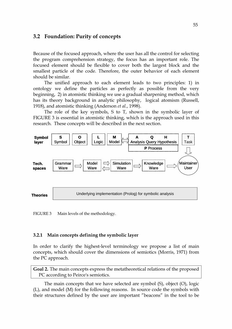
55
3.2 Foundation: Purity of concepts
Because of the focused approach, where the user has all the control for selecting the program comprehension strategy, the focus has an important role. The focused element should be flexible to cover both the largest block and the smallest particle of the code. Therefore, the outer behavior of each element should be similar.
The unified approach to each element leads to two principles: 1) in ontology we define the particles as perfectly as possible from the very beginning, 2) in atomistic thinking we use a gradual sharpening method, which has its theory background in analytic philosophy, logical atomism (Russell, 1918), and atomistic thinking (Anderson et al., 1998).
The role of the key symbols, S to T, shown in the symbolic layer of 732HFIGURE 3 is essential in atomistic thinking, which is the approach used in this research. These concepts will be described in the next section.
FIGURE 3 Main levels of the methodology.
3.2.1 Main concepts defining the symbolic layer
In order to clarify the highest-level terminology we propose a list of main concepts, which should cover the dimensions of semiotics (Morris, 1971) from the PC approach.
Goal 2. The main concepts express the metatheoretical relations of the proposed PC according to Peirce's semiotics.
The main concepts that we have selected are symbol (S), object (O), logic (L), and model (M) for the following reasons. In source code the symbols with their structures defined by the user are important ”beacons” in the tool to be
SimulationWare
GrammarWare
SSymbol
OObject
LLogic
MModel
A Q H Analysis Query Hypothesis
P Process
TTask
MaintainerUser
Underlying implementation (Prolog) for symbolic analysis
Tech.spaces
Symbollayer
Theories
ModelWare
KnowledgeWare
SimulationWare
GrammarWare
SSymbol
OObject
LLogic
MModel
A Q H Analysis Query Hypothesis
P Process
TTask
MaintainerUser
Underlying implementation (Prolog) for symbolic analysis
Tech.spaces
Symbollayer
Theories
ModelWare
KnowledgeWare
56
used in modeling the corresponding behavior (Pennington, 1987; von Mayrhauser et al., 1997). For this reason the symbol (S) is an important interface (see 733HFIGURE 3). The internal structure relating to each symbol (Peirce, 1958) is an object (O). For making interpretations, logic (L) is needed for describing meanings between symbols and objects (Tarski, 1941). By combining them a metaconcept SOL can be created to mean a symbolic approach with its interpretation. Furthermore, for combining the elements to be studied, a set is needed being a model (M) of the user’s focus.
This metaconcept SOL should cover the semantics and formalism of each source code element starting from the parser and ending to the most advanced representation to be shown on the display. The symbolism is compatible with Peirce’s semiotic triad (Peirce, 1958), because symbol (S) means a sign and object (O) and logic (L) refers to an interpretant.
Importance of a language is great in semiotics, too (Tarski, 1983). Therefore, a symbolic notation is needed as a foundation for all data transfer in the tool. For that reason we have created a novel symbolic language, later called the Symbolic language. Definitions for the language are defined in the next goal.
Goal 3. To emphasize the meaning of the symbolic language: both in translating source code into an internal language and further into a metalanguage for user interpretations.
By using the internal language the original source language is transformed into an internal intermediate notation (symbolic language), which is used as an object language and further as a foundation for interpretations in a metalanguage (Tarski, 1941) to describe all the entities and the possible relations between them.
The role of Symbol (S)
The role of symbols in Java software is to name structures like class, method, attribute (field), and variables. These user symbols give an initial mapping from the tool to source code and back, but the granularity of user symbols is not sufficient for representing e.g. loops or assignments. Therefore, every grammar term should have a symbolic name of its own, including all the necessary statements and expressions. 6F
7 In summary, in full symbolic analysis there are the following categories for
symbols: - User symbol that is read from the source code. - An automated numbered symbol describing software low-level
structures.
7 This kind of strict model may be called an atomistic implementation if the symbols have a
minimum internal semantics created by splitting the contents of the objects into object references.
57
- Dynamic symbols referring to the behavior model of the system including all intermediate and result values and assignments. These are called side effects later in the dissertation.
As a conclusion, to enable identification for each element, a unified naming principle should be created leading to the next goal.
Goal 4. To establish a convention to define an element for symbolic presentation
The roles of Object (O)
In interpretations of symbolic analysis there are three kinds of objects: - An object of the original Java code has the format of a Java class
definition. - An object that corresponds to the information in the Java object is a
simulated artifact. - An interpretation produces a semiotic object, which has a run-time
history (side effect). In interpretation it is possible to accumulate all the events that refer to the run-time objects.
There are some problems in using a monolithic object model in expressing complex connections with hierarchical crosscutting features, because the links should be saved into separate objects, which would require complex iteration logic to be programmed. This problem can be avoided by resorting to the next key factor, i.e., logic.
The roles of Logic (L)
Logic implements the following things. It connects the symbols and formalisms in a theoretical level. It implements the symbolic language, the foundation of the research by predicate logic, here Visual Prolog. It is the base for the tool (JavaMaster) containing all the structures, code statements, and transformations (parser, model weaver etc).
In Prolog there is an internal semantics to associatively connect the referred elements with each other through variables and by unification (Clocksin and Mellish, 1981). This important feature combined with the type system of Visual Prolog enables proving the critical low-level structures of the tool and allows projecting evidence into the higher logic layer in the context of the corresponding technology space and main concepts.
3.2.2 The user’s side of the methodology
The symbols for the maintenance task (T), process (P), analysis (A), hypothesis (H), and query (Q) will be described later in Sections 3.6 and 3.7.
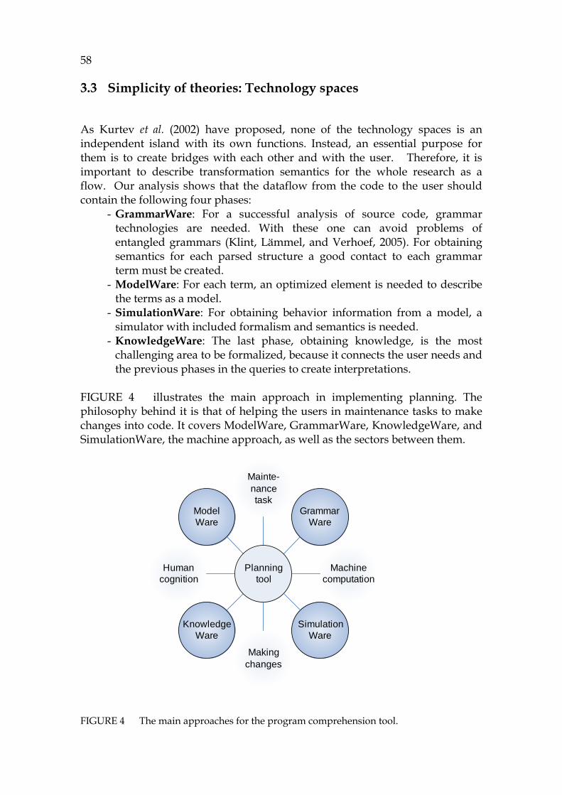
58
3.3 Simplicity of theories: Technology spaces
As Kurtev et al. (2002) have proposed, none of the technology spaces is an independent island with its own functions. Instead, an essential purpose for them is to create bridges with each other and with the user. Therefore, it is important to describe transformation semantics for the whole research as a flow. Our analysis shows that the dataflow from the code to the user should contain the following four phases:
- GrammarWare: For a successful analysis of source code, grammar technologies are needed. With these one can avoid problems of entangled grammars (Klint, Lämmel, and Verhoef, 2005). For obtaining semantics for each parsed structure a good contact to each grammar term must be created.
- ModelWare: For each term, an optimized element is needed to describe the terms as a model.
- SimulationWare: For obtaining behavior information from a model, a simulator with included formalism and semantics is needed.
- KnowledgeWare: The last phase, obtaining knowledge, is the most challenging area to be formalized, because it connects the user needs and the previous phases in the queries to create interpretations.
734HFIGURE 4 illustrates the main approach in implementing planning. The philosophy behind it is that of helping the users in maintenance tasks to make changes into code. It covers ModelWare, GrammarWare, KnowledgeWare, and SimulationWare, the machine approach, as well as the sectors between them.
FIGURE 4 The main approaches for the program comprehension tool.
ModelWare
Human cognition
KnowledgeWare
Makingchanges
SimulationWare
Machine computation
GrammarWare
Mainte-nancetask
Planningtool
59
3.3.1 Commitments to GrammarWare
Starting from the program and parsing the code makes it natural to select grammar technology (GrammarWare) as the first focus area for the methodology. The responsibility for the GrammarWare implementation is to convert Java-files into a notation of a higher abstraction level that can be used for later modeling purposes.
Some assumptions for GrammarWare are: - The parse trees should contain grammar terms with semantics. - Unlike in AST, the terms should be in a formalized notation. - The purpose is to get as compact structures as possible to create a
foundation for the whole information flow related to this technology. As a formalism GrammarWare should be seen as an acceptor to enable the next phase leading to the next goal.
Goal 5. To implement GrammarWare using a symbolic formalism.
3.3.2 Commitments to ModelWare
Several principles have been used for creating complex models and especially for creating source code models and design models (Bezevin, 2003) leading to ambiguous or too complex implementations (XMI, 1998).
In order to avoid complexity of models, a better suited technology space named ModelWare, is developed for this research to meet the next conditions:
- To avoid multi-layer structures and to prefer short homogenous representation.
- To implement a unified element architecture with a homogenous interface each.
- To optimize the number of types. In Java1.5 there are 130 term types (Java, 2003).
- To minimize the number of methods in simulation. - To maximize extendibility of the model to allow new public functions. - To make integrating the model to commercial and public models
possible. The definitions above can be presented with the corresponding measures: L (the number of layers), B (the number of different base classes), T (the number of types), S (the number of obligatory simulation methods), F (the number of public functions), and E ( extendibility). Summarizing, a common model architecture can be defined by the following tuple: model(L, B, T, S, F, E) For the symbolic model we select the following values:

60
- L is 1, because the purpose is to make a 1 layer model to maximize the simplicity.
- B is 1, assuming that all the elements (objects) can inherit from the same base class, providing the symbolic language.
- T should be only a fraction of Java types. In Chapter 4 it is told that the value will be 12 to cover all code element types and two types for simulation (14).
- S (number of public simulation methods needed for an element) is assumed to be as small as possible. Later it is shown that S can be as low as 1.
- Number of features, F, should be unlimited. We assume that it is possible to program numerous handlers and callbacks for manipulating model information.
- By appropriate efforts E and F can be large, because the model is executable including a variable model or a dynamic extension to contain all the results from the simulation.
By summarizing the values of the list above the following model estimate for the symbolic model is obtained: model(1,1,14,1,infinite,infinite). The values of the list above are very different compared to MDA-models (MOF-levels M0...M4) or FAMIX (Demeyer, Tichelaar, and Steyaert, 1999; MDA, 2007), which have deep inheritance hierarchies and hundreds of types in the schema. As a conclusion, a definition for ModelWare is listed in the next goal.
Goal 6. To create a model weaver for ModelWare in order to build a reductionist model for embedding Java semantics to it for simulation purposes.
3.3.3 Commitments to SimulationWare
Analyzing behavior yields the most essential program comprehension information about object-oriented code because of the yoyo-phenomenon and late bindings (Wilde and Huitt, 1992). For simulating OOP, a technology space named SimulationWare is presented.
As a reference for simulating Java, the best candidate is the Java virtual machine 7F
8. As the formalism for Java virtual machine is not presented on a statement level, Java’s behavior model should be deduced from the Java specification (Java, 2005). The semantic representation of Java is divided into levels using formalisms of the Chomsky hierarchy (Chomsky, 1956). The semantic representation of Java (Gosling et al., 2005) in this research is divided into four technology spaces with different natures:
- GrammarWare creates symbol tables and static semantics for the code. - ModelWare creates the reachability rules including the OOP behavior.
8 In the automata theory the concept abstract machine is used instead of virtual machine,
because the latter is more language-specific.
61
- SimulationWare handles ambiguous references and dynamic bindings. - KnowledgeWare is needed for making selections between ambiguous
references. The purpose of simulation is to get an output, a sequence that is comparable with a UML sequence diagram as an output. This compatibility should allow a functional verification of the tool with dynamic analysis and debuggers. The requirements for simulation are listed in the next goal which has two different purposes.
Goal 7. To describe formalism for source code simulation according to the automata theory as well as to create a platform for partial simulation.
3.3.4 Commitments to KnowledgeWare
A technology space, KnowledgeWare, is needed for capturing knowledge, i.e., program comprehension information, from the code. The responsibility of KnowledgeWare is to create a formal definition for maintenance actions and for the information of the model concerned according to the known principles of program comprehension, in order to help the user in attempting to understand and solve actual hypotheses.
Getting knowledge from data, the output from the PC process, is the final result to the user (Ackoff, 1989). It is a set of interpretations based on knowledge representations. Converting data into knowledge requires established definitions about what is data and what is its practical use in most typical situations. Mapping these things with each other creates knowledge in a tool which makes the necessary transformations. We emphasize familiarization, testing, and troubleshooting to describe the user interaction side. Further, an information ladder for creating knowledge is used (Ackoff, 1989).
There are several theories relating to KnowledgeWare like the one of Nonaka and Takeuchi (1995), as well as the conceptual graphs of Sowa (1976; 2000) and semiotics of Peirce (1958). The whole semiotic taxonomy of Peirce, including his concepts of rhematic, dicent, and argumentative, is relevant in this respect.
As a more abstract aim, KnowledgeWare should be able to help the user in creating more hierarchical mental models by expressing granular worlds (Bargiela and Pedrycz, 2002). The theory of so-called mini-minds (Wells, 2006) provides a good starting point to analyze a sequence that is atomistic. There is another theory, logic atomism, which studies language understanding and concepts as atomistic things (Russell, 1918). An abstract definition for KnowledgeWare is listed in the next goal.
Goal 8. To create a bridge between the code model and the user language supporting the maintenance approach based on KnowledgeWare.

62
3.4 Accuracy of PC transformations
PC is shown as a set of automata and transformations in 735HFIGURE 5. Parsing can be considered as a special kind of measurement process of the source code. Parsing is complete if the grammar of the proposed language has been implemented correctly. Starting from parsing the code, the whole process of program comprehension can be regarded as a set of transformations, as suggested, regarding maintenance, by Baxter, Pidgeon, and Mehlich (2004).
The main transformations are shown in 736HFIGURE 5, where the given automata realize parsing, transforming to the higher symbolic language, weaving the model, simulating, and obtaining knowledge.
The key topics in evaluating the whole process are the coherency, consistency, and granularity of the automata, and completeness of the corresponding transformations, which have the following notation: Data I+1 = Ai:transform(DataI).
The automata and corresponding data in 737HFIGURE 5 are: - D0: Grammar definition for Java as a file. - A1: Grammar tool including a parser generator D1: Parse tree for Java. - A2: Parser (here for Java), D2: Parse tree. - A3: Translator to convert parse trees to symbolic notation, D3: Symbolic
parse tree. - A4: Model weaver to create a model, D4: Model formalism (includes
elements). - A5: Selector for the user to select and control simulation, D5: List of
selected elements to build a simulation queue (input tape). - A6: Simulator for the input tape, D6: Output-tape with dynamic
(operational) information. - A7: User interface to allow knowledge mining from the output tape, D7:
An information ladder (Longworth, 1996) connecting data, simulated sequences, and all specific relations with all actual information.
- The last phase is planning of changes by using D7. We assume that the transformation realized by automata A1 to A3 is complete and consistent with the features of Java (except the newest features of Java 1.5) in a higher notation. The information in A3 is defined by using an intermediate language, which has equivalent axiomatic semantics with Java. However, a more challenging automaton is needed in SimulationWare, dealing with operational semantics. In this research the challenge is to show how completely the individual elements of the model can be simulated and connected with each other while mirroring their corresponding behavior in JVM. For that, a semantic notation is needed (it is called atomistic semantics in Chapter 6). The main function of the last automaton is to implement the computer-side actions consisting of successive computations for maintenance queries.

63
FIGURE 5 Program comprehension as automata and transformations.
3.4.1 Universal transformation formalism
According to the transformation model of DMS (Baxter and Mehlich, 2002), each transformation should be defined and should include its domain (here Java in Automaton A1) and schema (AST is widely used, but here the different technology spaces have their own, yet still compatible definitions: grammar term, model element, simulated sequence, and knowledge unit).
It is essential to define also the specified semantics. Some other things that are specified in the DMS framework are binding, locator, properties, metaprogram, and transform process (Baxter et al., 2004). For each translation it is necessary to specify the input and output languages, a foundation for the transformation, and a location for transformations. It is also necessary to specify a tool, optional databases, and use cases for the process. A summary goal for each automaton is listed next.
Goal 9. To describe transformations between the technology spaces as automata.
Initialknowledge
Grammartool
Parse-tree
Symbolicparse tree
Symbolicmodel
Input forsimulation
Output-sequence
Informationladder
Possiblechanges
Practicaluse
D0
A3
A5 A6SimulationWareTuring machine
D2
D3 D4
D5 D6
A1
A4
A2
D1
A7
D7
D8
Initialknowledge
Grammartool
Parse-tree
Symbolicparse tree
Symbolicmodel
Input forsimulation
Output-sequence
Informationladder
Possiblechanges
Practicaluse
D0
A3
A5 A6SimulationWareTuring machine
D2
D3 D4
D5 D6
A1
A4
A2
D1
A7
D7
D8

64
3.4.2 Type theories
As said earlier, successive translations are relations between the previous layer term relations when they are expressed and formalized by predicate logic. Prolog enables associative and recursive structures mix individual data structures with each other.
The general logics between the automata are assumed to be the following: - Static code: 1st order logic. - Dynamic references: relations about static code, where constructors
produce objects as 2nd order relations. - Side effects (influences), caused by the code: next level relations from the
creator. - Sequences, simulated separately: next level relations for the simulation
query. - Actions to test and validate sequences: next level relations for the test
sequences. Separating successive orders leads to type theory and set theory, where any new set is a combination (set) of the previous sets. Most of them can be expressed by using Prolog’s type system and data structures. The topic is then how to master the overlapping relations as summarized in the next goal.
Goal 10. To express the main relations of the captured knowledge as nested types.
3.4.3 Knowledge transformation set
The knowledge layers of semiotics are defined in the Peircean taxonomy by Gudwin (2006) in his theory about computational semiotics. In it rhematic means a verbal or symbolic structure (here source code), dicent means a proposition or a captured structure from the model, and argumentative means a proved explanation, either deductive, inductive, or abductive. These definitions can be modelled as transducer functions in the Visual Prolog notation calling these automata as follows:
- Rhematic: StaticKnowledge = access(Model, Parameters) - Dicent: Dynamic knowledge = query(Model, Sequence) - Argumentative: Argument = proof(Model, Sequence, Hypothesis).
We will interpret the knowledge interface for each layer in the following way. For rhematic, getting static knowledge, only a simple relation model is needed to enable accessing the selected elements that are relevant to the invocation parameters. For getting dicent information, a simulated sequence is needed. This is later called an output tape, having its origin in the Turing machine (Wells, 2006). The dicent query is then an explanation interpreted from a sequence, giving either the whole sequence or a specified subset of it, and illustrating a specified flow such as a dataflow. For getting argument
65
information, a proof is done in order to match the assumed hypothesis and the corresponding sequence of the model. As a summary, knowledge access is specified in the next goal.
Goal 11. To realize a knowledge access interface containing the three semiotic layers.
3.4.4 Graph approach (model theory)
The parse tree is, as its name says, a tree structure. The biggest problem in using trees in manipulating code structures is that the tree doesn’t have a semantics compatible with programming languages that would allow pointing correctly to individual leafs of the tree. Therefore, we argue that a tree should be ignored in our case and that a more flexible model is needed. This conclusion leads to the definition of ModelWare. Results from ModelWare are mainly sequences, but the main aim of the user is to understand complex dependencies caused by crosscuttings, hidden object references of methods. Normally they are expressed as graphs or networks, which often are very large.
In this research we are reaching for a dependency model, which is rich in the number of elements but has only a limited set of types and associations (link types). It is clear that for a computer program (here JavaMaster) it is easier to connect existing, semantically correct small elements in order to create a dependency graph than to use complex manipulations for splitting larger structures into smaller ones in consideration of their semantics.
From the small elements (these are called atoms later) the tool can transitively collect higher level hierarchies such as a graph for a method, for a class, and for a package. When these graphs are interconnected, useful program comprehension information becomes available.
This approach leads into the graph theory with its well-established practices and methods. In the research we need to use a principle which determines that bi-directional links (graph edges) are embedded inside elements (graph nodes) and do not need their own elements as would normally be required, for example, by Atlas (2005) and XMI (1998). This principle makes the graphs atomistic when the elements contain a compact semantics, expressed by a single predicate. Thus, evaluating symbolic output graphs connected by simple predicates is easy and effective, and no public iterators are needed. All elements will then be independent, and the only data structure in the model will be the element. This leads to an atomistic approach for graphs and models. Each model will be simply a set of elements as a result.
66
3.5 SimulationWare: Completeness of logic
In this section the role of logic is discussed against the computation model of the source code, where the computing subject, the computant (Wells, 2006), can be any of the following possibilities. In the programmer’s Java environment the computant is the Java virtual machine, but in the hardware level it is the concrete machine, which has its higher level equivalence to an abstract machine as the Turing machine metaphor. An idealized analysis performed by the corresponding tool works, in symbiosis with the user, as the third possible computant, a Decider making any necessary decisions during the analysis. In order to minimize the load of the user, the tool should flexibly enable selective simulations and computations for interactive and automated proving of the source code. From this point-of-view the whole research can be seen as a functional model, whose logic should be as complete as possible.
Why logic is so essential in computation
In addition to the fact that logic is the language of science for all of its interpretations, it is useful in evaluating complex data structures, code parsing, and transforming data into a new notation. If the input of an automaton has an exact axiomatic semantics, then an output of the simulation can be evaluated to be a set of overlapping relations. Therefore, this is an excellent platform for implementing a query system and simulator to derive information for the model in order to create maintenance knowledge. Among some attempts to build query systems for source code are EDATS (Wilde et al., 1995), SCA (Paul and Prakash, 1994), and Tamar Richner (Richner and Ducasse, 2002), but these do not have any simulation framework or any specific interface for maintenance processes.
3.5.1 Connection between logic and automaton theory
The role of automata A1…A7 was described in Section 3.4 to illustrate the transformation model in order to formalize the whole program comprehension framework. In this section the computation and simulation approach is discussed.
3.5.2 Definition for the smallest computation
In computability theory several formalisms have been developed for abstract machines (Hopcroft and Ullman, 1979) and for computation (Papadimitriou, 1994). The formalism of a register machine regarding a single source code element, which is the foundation for the ModelWare approach, is especially interesting ( 738HFIGURE 6). If the logic of each element can be defined by a single structure, in the figure f, which has a number of arguments m1 to mk, then it is
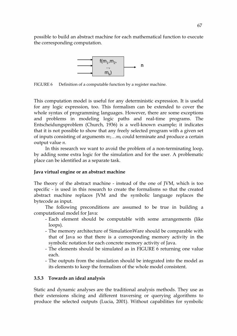
67
possible to build an abstract machine for each mathematical function to execute the corresponding computation.
FIGURE 6 Definition of a computable function by a register machine.
This computation model is useful for any deterministic expression. It is useful for any logic expression, too. This formalism can be extended to cover the whole syntax of programming languages. However, there are some exceptions and problems in modeling logic paths and real-time programs. The Entscheidungsproblem (Church, 1936) is a well-known example; it indicates that it is not possible to show that any freely selected program with a given set of inputs consisting of arguments m1…mk could terminate and produce a certain output value n.
In this research we want to avoid the problem of a non-terminating loop, by adding some extra logic for the simulation and for the user. A problematic place can be identified as a separate task.
Java virtual engine or an abstract machine
The theory of the abstract machine - instead of the one of JVM, which is too specific - is used in this research to create the formalisms so that the created abstract machine replaces JVM and the symbolic language replaces the bytecode as input.
The following preconditions are assumed to be true in building a computational model for Java:
- Each element should be computable with some arrangements (like loops).
- The memory architecture of SimulationWare should be comparable with that of Java so that there is a corresponding memory activity in the symbolic notation for each concrete memory activity of Java.
- The elements should be simulated as in 739HFIGURE 6 returning one value each.
- The outputs from the simulation should be integrated into the model as its elements to keep the formalism of the whole model consistent.
3.5.3 Towards an ideal analysis
Static and dynamic analyses are the traditional analysis methods. They use as their extensions slicing and different traversing or querying algorithms to produce the selected outputs (Lucia, 2001). Without capabilities for symbolic
f(m1,m2,..,
mk)n
f(m1,m2,..,
mk)n
68
processing they cannot express values, i.e., the most detailed information of simulation, which has special importance in evaluating complex communication software as distributed packages or database transactions.
It is widely known that static analysis is not sufficient for Java to describe its behavior or dynamic semantics. Static analysis is capable of producing dependency diagrams, class diagrams, and static call trees. Sequence diagrams can, too, be generated directly from the code in order to check the main details of program flows (the implementations are tool dependent).
Dynamic analysis is, on the other hand, very complex for real-life applications and projects. In most cases a debugger is employed to run the current implementation and on tracing the functions by using selected breakpoints and traces. While it is possible for the testers to get a trace, the output can contain too much information, possibly obsolete, making interpretation thus difficult. Sometimes 98% of the activities in the trace can involve useless invocations made within a method (Koskinen, 2006).
Hence, the requirements for an ideal analysis are: - It should be possible to activate a new analysis whenever deemed
necessary and from any place of the source code consisting of any class, any method, any block of statements, or any collection of packages.
- The analysis should capture all program comprehension information such as the flows defined by Pennington (1987) and those by Burkhardt and Wiedenbeck (2002).
- The analysis process should be iterative and recursive and enable capturing knowledge cumulatively to form a situation model relating to the user’s active problem.
- The output of the analysis should enable using semantic links and dependencies between elements for efficient navigation.
- The analysis should be controllable by the user for stopping, skipping, reactivating, and changing the defaults made by the simulator.
Some of the requirements above form the hard theory to connect formal elements, whilst the others form the soft theory to support the user’s information needs.
A complete coverage of the granularity of the ideal analysis is better known as complete analyzability. It refers to a sequence of computations where every step between the elements involved can be recorded into a trace. Typically the traces of a dynamic analysis can record a lot of information, tracing every statement in the code at a Java bytecode level or assembly level, and a single statement can make numerous computations between registers. Later in this dissertation the atomistic semantics is introduced in order to satisfy the requirements of complete analyzability. We will illustrate the unique approach of the ideal analysis in the next goal allowing a comparison with static and dynamic analysis.

69
3.5.4 Turing machine metaphor - the base of computer simulation
Each programmed action in a computer occurs in the CPU as a computation. Thus the concept of computation is the base of computer acitivities. That's why we argue that it is necessary to take the Turing machine metaphor (Turing, 1950) as a foundation of the formalism of SimulationWare. It defines the laws for computations. All computer programs, excluding their parallel features, obey the principles of the von Neumann architecture (von Neumann, 1951) with its input-process-output nature and sequential functionality, where the computation model of a register machine of 740HFIGURE 6 is included. This gives us the following ways to extend the usability of this study to a more generic concept like natural laws:
- By using the Turing machine formalism as a foundation it is possible to simulate any computer program (there are some restrictions such as parallel features).
- By using a universal Turing machine it is possible to simulate any computer.
- By using our Visual Prolog programs it is possible to approximate the state tables of the Turing machine very far. This is the main functionality of SimulationWare.
Therefore the purpose of SimulationWare is to mimic the Universal Turing Machine. There are several implementations of it (Hodges, 1988), but most of them are for simple numeric data and none of them has a distributed logic. The purpose of SimulationWare is to implement an interactive abstract machine, which has a distributed logic. The main reason for this decision is the following: If the architecture of the model (ModelWare) is distributed, then for getting a high-quality architecture for the tool, the logic should be distributed, too. As a summary, the main idea for the formalism and simulation of SimulationWare is described in the next goal.
Goal 12. To create a sequential computation model for SimulationWare.
3.5.5 Simulating parallel features, the starting logic of threads
In cases where parallel features are used in Java, those features can be thought to create separate Turing tapes. Each of these parallel features should reserve a tape of its own. For parallel features the communication and synchronization between different tapes should be arranged by using the formalism of the nondetermistic Turing machine (Hopcroft et al., 1979).
Although simulating threads and other parallel features is not automated, it is useful to employ the thinking model of a Turing tape to describe the semantics of each parallel feature. For simulating threads, a manual user interface can easily be generated so that the user can synchronize the threads interactively. The problem when using several simultaneous tapes is how to
70
master the side effects between them. If this is solved, then it should be possible for an application to simulate resource allocation situations like a producer-consumer function. This topic forms one of the main interests of Microsoft in source code analysis (Andrews et al, 2004).
The next goal is a summary for parallel simulation in this research.
Goal 13. To investigate how to implement parallel activities, e.g., threads in order to capture program flows.
3.5.6 User as the Decider
As said earlier, the user (human) has a role to control the simulation process in cases of loops, ambiguous references, in simulating parallel features and in selecting alternatives due to unknown information, which is typical for partial simulation.
In this role the user completes the simulation process deterministic to the level of the decider, which is a concept of the Chomsky hierarchy (Hopcroft et al., 1979). The synonym for it is a total Turing machine, which is equipped with a feature to terminate in all conditions to return one value. The role of the user in deciding about each ambiguous reference in a partial simulation is not too laborious, because in static analysis the user should in every case solve all the ambiguities when following the code manually. This process is manually laborious due to the yoyo-phenomena (Wilde and Huitt, 1992). The computer, especially SimulationWare, should help the user in finding all the possible alternatives for each case automatically.
3.5.7 Automated reasoning
Automated reasoning is a process to simulate sequences in order to produce outputs as a symbolic tape. It consists of successive computations, which all have the formalism of a register machine. For each computation an input-output model can be built. Further, for each computation a Hoare’s triple can be defined to describe the assumed preconditions and postconditions.8F
9
3.5.8 The final approach for logic, theorem proving
Source code is mostly made up of a vast collection of information with a huge amount of dependencies. All attempts to visualize it as a whole are deemed to fail. The opposite for such a holistic approach is a focused approach to produce only pragmatic information.
For troubleshooting cases the pragmatic information can be found at the locations where the errors (faults) may originate from. Also useful but not as demanding is to find change candidates in order to list the elements that 9 This atomistic thinking is suggestive of the cognitive theory of Wells' mini-minds (Wells,
2006).
71
possibly cause problems. Each flow that is directly related to a problematic case is a possible definition for a list of change candidates. There are some definitions for the important flows that can be used as program comprehension information (Pennington, 1987; Burkhardt et al., 2002).
The programs form cycling graphs in all situations, where the exceptions can only be:
- Recursive invocations, where the end conditions may be too complex to be simulated by symbolic execution, because sometimes the end conditions refer to unknown methods or variables or to unknown values.
- Loops with their terminating conditions with the same restriction as recursion.
- Exceptions that create direct branches. In all other situations all the critical flows can be simulated assuming that the necessary information can be evaluated. In those cases where the information cannot be converted into a numeric form due to missing data (unknown subterms) the symbolic expressions calculated by SimulationWare can still be used.
This typical troubleshooting case can lead to a situation, where the user, very eagerly, tries to prove some element flows either correct or incorrect. This contrafactual thinking is essential for the user to build a situation model, where a synthesis about the most probable place for the bug can be done.
Sometimes the user may not have the necessary initial knowledge. This can then be regarded as the opportunity to create that knowledge by simulating the most critical code and by navigating the results and values. In conformance with the approach of this research the user will then have “three machines”, collected from the four technology spaces, drawn as symbols for automata, see 741HFIGURE 7.
The first machine, MGw+MW, which includes both GrammarWare and ModelWare, creates an acceptor that can accept or reject input code. The second machine, MSW, is SimulationWare, which produces tapes, T, for the last machine, MKW, or KnowledgeWare.
There are some theories to cover a situation, where an executed trace will be validated, including manual program verification (Gries, 1981) and automatic theorem proving (Duffy, 1991). Deductive testing has been used according to a created test case model in industry and model checking is used in general (Visser et al., 2003). The biggest difference between the earlier solutions and this novel approach is that in our approach there is a traceable predicate describing each grammar term captured from the source code (MGw+MW) to the theorem proving interface ready to be used in writing proving specifications.
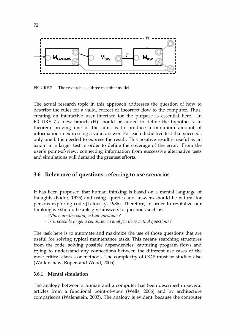
72
FIGURE 7 The research as a three machine model.
The actual research topic in this approach addresses the question of how to describe the rules for a valid, correct or incorrect flow to the computer. Thus, creating an interactive user interface for the purpose is essential here. In 742HFIGURE 7 a new branch (H) should be added to define the hypothesis. In theorem proving one of the aims is to produce a minimum amount of information in expressing a valid answer. For each deductive test that succeeds only one bit is needed to express the result. This positive result is useful as an axiom in a larger test in order to define the coverage of the error. From the user’s point-of-view, connecting information from successive alternative tests and simulations will demand the greatest efforts.
3.6 Relevance of questions: referring to use scenarios
It has been proposed that human thinking is based on a mental language of thoughts (Fodor, 1975) and using queries and answers should be natural for persons exploring code (Letovsky, 1986). Therefore, in order to revitalize our thinking we should be able give answers to questions such as:
- Which are the valid, actual questions? - Is it possible to get a computer to analyze these actual questions?
The task here is to automate and maximize the use of those questions that are useful for solving typical maintenance tasks. This means searching structures from the code, solving possible dependencies, capturing program flows and trying to understand any connections between the different use cases of the most critical classes or methods. The complexity of OOP must be studied also (Walkinshaw, Roper, and Wood, 2005).
3.6.1 Mental simulation
The analogy between a human and a computer has been described in several articles from a functional point-of-view (Wells, 2006) and by architecture comparisons (Walenstein, 2003). The analogy is evident, because the computer
MGW+MW MKWMSWT
H
MGW+MW MKWMSWTMGW+MW MKWMSWMGW+MW MKWMKWMSWT
H

73
design follows the principles of a person who uses a pencil and paper in matching serial information (Hodges, 1988). Furthermore, after its invention the computer has often been used as a model when trying to understand the main principles that a person might use in memory, processor, input, and output processes (Walenstein, 2002).
For program comprehension purposes the common feature combining the process of a person and a computer is simulation. Computer simulation is described and formalized by the Turing machine, though each programming language has its semantics. It corresponds, in personal thinking, to mental program simulation (Nakamura et al., 2003).
There are theories based on using agents in solving complex problems. These include the use of an agenda, a to-do-list (Walenstein, 2002), and a process to divide a larger task into smaller ones until the end is reached (von Mayrhauser et al., 1997). Rasmussen (1983) has shown that human cognition uses three essential layers: skill level, rule level, and knowledge level.
The concept of action is useful in modeling both what a person does and what a computer does. Action is a term used in task action grammars as well as in UML (Rumbaugh, Jacobsen, and Booch, 1999). The lowest action level in the computer is computation which computes only one thing at a time. As a conclusion, the message of this section is condensed in the next goal.
Goal 14. To plan a hierarchical action model to support solving maintenance tasks in the known cognition layers.
3.6.2 Organizational approaches
Because source code is based on a language, and understanding a language requires universal human thinking, the problems of program comprehension are universal problems that can be encountered in any size organization. For example, there are different situations depending on the size and packaging of the software giving rise to these sort of problems. If it is a part of a larger delivery, a single package or component can cause some typical problems due to incomplete information about the other parts of the software (Sawyer, 2004).
When simulating total software with the whole code loaded, all information can be found both at source code level and at object code level. The situation is quite different in an open-source community, where the developers face strong challenges trying to discover the behavior of many external components in the assumed situations and deciding on how to simulate them with or without code. For this kinds of situations the function of partial simulation is very important.
There are three types of development archetypes with either a sequence, a group, or a network as a foundation (Sawyer, 2004). Communication forms the base for the network-based development in the open source community (like Linux-projects), where possibly hundreds of people have an access to the details of source code and the achievements of others. Because of continuous
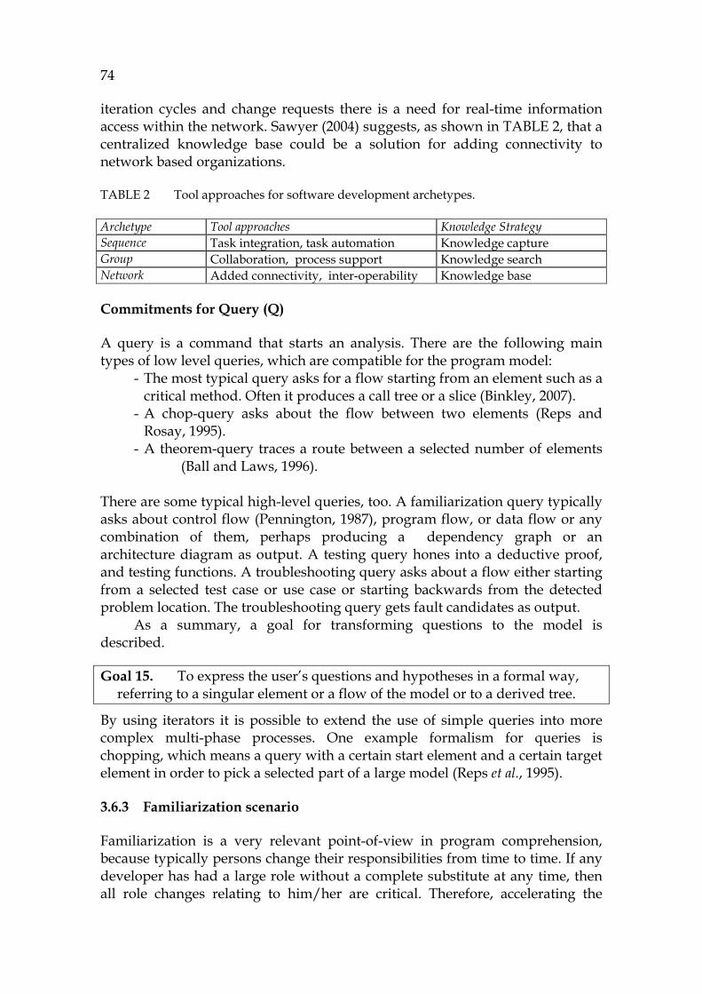
74
iteration cycles and change requests there is a need for real-time information access within the network. Sawyer (2004) suggests, as shown in 743HTABLE 2, that a centralized knowledge base could be a solution for adding connectivity to network based organizations.
TABLE 2 Tool approaches for software development archetypes.
Archetype Tool approaches Knowledge Strategy Sequence Task integration, task automation Knowledge capture Group Collaboration, process support Knowledge search Network Added connectivity, inter-operability Knowledge base
Commitments for Query (Q)
A query is a command that starts an analysis. There are the following main types of low level queries, which are compatible for the program model:
- The most typical query asks for a flow starting from an element such as a critical method. Often it produces a call tree or a slice (Binkley, 2007).
- A chop-query asks about the flow between two elements (Reps and Rosay, 1995).
- A theorem-query traces a route between a selected number of elements (Ball and Laws, 1996).
There are some typical high-level queries, too. A familiarization query typically asks about control flow (Pennington, 1987), program flow, or data flow or any combination of them, perhaps producing a dependency graph or an architecture diagram as output. A testing query hones into a deductive proof, and testing functions. A troubleshooting query asks about a flow either starting from a selected test case or use case or starting backwards from the detected problem location. The troubleshooting query gets fault candidates as output.
As a summary, a goal for transforming questions to the model is described.
Goal 15. To express the user’s questions and hypotheses in a formal way, referring to a singular element or a flow of the model or to a derived tree.
By using iterators it is possible to extend the use of simple queries into more complex multi-phase processes. One example formalism for queries is chopping, which means a query with a certain start element and a certain target element in order to pick a selected part of a large model (Reps et al., 1995).
3.6.3 Familiarization scenario
Familiarization is a very relevant point-of-view in program comprehension, because typically persons change their responsibilities from time to time. If any developer has had a large role without a complete substitute at any time, then all role changes relating to him/her are critical. Therefore, accelerating the
75
familiarization process by means of program comprehension technology is essential. The familiarization process can take several months of a newcomer's time. This clearly shows its important economic dimension.
Familiarization is the process to increase the initial knowledge (K0) of a user. In program comprehension the user is assumed to have either the basic skills about the current programming language or expertise of the actual business domain, but very often a profound knowledge of both of them is lacking.
The theory of information ladder (Longworth and Davies, 1996) introduces how to increase knowledge accumulation from data. In this model, data is said to contain relations that the user should be able to learn from information. The step to the next level is to understand patterns of information in order to build new knowledge.
For object-oriented reverse engineering some practical methods have been introduced for climbing up the information ladder, including Read the Code in One Hour, Refactor to Understand, and Step through the Execution (Demeyer et al., 2003). They are useful in real life, although they have no scientific base.
3.6.4 Testing scenario
Nowadays testing has been outsourced and delegated in practical software production into many external distributed teams and organizations. However, testing doesn’t improve the quality; it can only prevent the possible bugs from moving to the final product. Currently a rather big test package must be built to enable tests for dynamic analysis, although it is well-known that the sooner a bug is removed the cheaper it is to fix. One reason for this yet unproductive practice in source code projects is in the current analysis methodologies, which do not allow testing modularly and partially the modules and classes and functions, in the order they have been written. This problem makes testing a very expensive and complex process.
Testing is a process where the user has both initial knowledge (K0) and default knowledge (K1). The purpose of testing is to find out whether the default knowledge is true or not. This process has the clear characteristics of a deductive argumentation. When a test succeeds, no new information appears, except that the test was done. If the test fails, then there is a contradiction (K2). That is very important information and starts the troubleshooting process.
3.6.5 Troubleshooting scenario
Troubleshooting is the most expensive and challenging part of software development if planning of changes is assumed to be included in it. 9F
10 In a 10 In the biggest organizations there are specific persons and teams for troubleshooting, but
most often the developers and the maintainers are responsible for finding bugs from their own code. In this section the persons active in troubleshooting are called developers.
76
typical troubleshooting case there are numerous teams involved in building either an application platform, a subsystem like a new protocol, or a multi-function component. Changing application software is the easiest case, whereas updating a heavily used multi-function component is the most difficult one.
Typically in the application there can be numerous interfaces and layers starting from the hardware level and ending up in a sophisticated user interface for actual users. The developers can know only some parts of large software in detail. The problem is that usually the teams are from separate, individual organizations, and there is no common test practice and no common language between them.
Sawyer (2004) has suggested that the biggest challenge for the project and its success is the interconnection of troubleshooting skills of individual persons. If the only way for the developers to trace possible errors is to read the source code of other developers or to opportunistically read class contracts of other interfaces, then troubleshooting can be very risky, sometimes almost impossible. To alleviate this, a modular, focused approach to possible product problems should be created.
Troubleshooting is a process where reasons for a contradiction are looked for. There is the initial knowledge (K0), default knowledge (K1), and the result of a testing process (K2). The aim is to find either one or more locations or one or more change candidates that can be considered guilty, so to speak.
3.6.6 Definition for the focused approach towards source code
The most typical models such as UML models (Rumbaugh et al., 1999) and layered models such as reflection models (Pacione, Roper, and Wood, 2003) have a holistic purpose to produce a maximum amount of information for a user query at each time. This functionality is very natural, because providing information is the main purpose of information systems. However, due to the nature of source code and its corresponding models these are huge in size and almost impossible to visualize in computer screens as screenshots. The opposite for the holistic approach is the focused approach where the amount of information for the user is the smallest possible, while keeping the selected context of the user. Therefore, a focused approach is needed for solving individual maintenance tasks.
It has been proposed that the logic of a maintenance task contains different phases, including productive tasks and unproductive delays (Gilb, 2005). Once the unproductive parts have been removed, then the productive side of a maintenance task can be defined to contain:
- Problem recognition - Problem formulation - Focused subtasks (1 to N items).
The goal is to create an opportunistic method, where program can be understood by means of information about executed actions relating to maintenance tasks and subtasks derived from them. The methodology has as its
77
main goal to improve program understanding by providing actual focused information in order to decrease the user’s work load (Storey, Fracchia and Mueller, 1999).
The motivation for supporting distributed cognition as an independent topic is that were a data model (later atomistic model) well-established and practical by its nature, it should support communication over tools and processes. In this way it should (in the optimum situation) support people talking and learning in groups, rather than individuals using the tool alone. Group-based learning should enable network-based use scenarios (see 744HTABLE 2).
Commitments for Hypothesis (H)
Each action in program comprehension culminates in building a hypothesis (Brooks, 1983; von Mayrhauser et al., 1997). A person uses questions and answers in trying to solve a problem in general, as when finding solutions for his maintenance task. In creating questions the user is able to create hypotheses. von Mayrhauser et al. (1997) have studied the hypotheses of programmers, and Letovsky (1986) has proposed that the most typical question words are what, why and how. We connect them to PC as follows:
- Question “What does an element X do?” can be mapped into functionality, which can be estimated by recognizing the JDK library invocations caused by X.
- Questions “When and why has element X been activated?” gather information for a larger question “What is the purpose of it?”. The former question can be mapped into a cause-effect analysis by evaluating the external influences (and the internal side effects of them).
- Question “How does element X work?” can be mapped into the program flow.
If there is a data model with a versatile formalism in the tool, which has access to the elements and their inter-relations in a unified way, then it is possible to connect the questions to the possible queries of the model. The queries should then provide a result set as a way of an answer. To show how hypotheses should be realized in the tool is described as the next goal.
Goal 16. To build a demonstration for simulating an example and a theoretical approach as regards the captured PC flow using hypotheses.
3.7 Certainty of the results of analyses (answers)
It is essential that every computer system should return correct answers. This is usually confirmed by using a set of test levels including functional tests, module and detail tests.
78
3.7.1 Does the method give correct answers?
As proposed earlier, the answers are sequences that have been selected in accordance with the approach in the current maintenance task. It is the user's responsibility to connect the results into a mental model, i.e., a situation model.
Because each query has a unified functionality and the model is modular containing only elements that are not aware of their neighbour elements, it is very easy to test the semantics as a detail test session and as a module test, too. Extending this model into the functional testing level leads into the outer Turing model, where the outputs are Turing output tapes. Because the whole process follows a pipes and filters architecture (Bass et al., 2003), GrammarWare, ModelWare, SimulationWare, and KnowledgeWare as the user interfaces, it is easy to create these functional tests. In cases where some of the computations cannot produce alphanumeric information, the simulation expression can be used as an evaluation criterion.
3.7.2 Test evaluation possibilities for the results
For verifying the certainty of the results of analyses it is sufficient to verify the main functionality of each technology space bottom-up as detail tests using the follow pragmatics:
- GrammarWare can be checked by a local loop connecting the parser and the pretty printer together, because they are reverse functions of each other.
- Symbol table can be checked by comparing its printouts to manually read information.
- Symbolic model (ModelWare) can be checked by comparing the element displays with manually estimated information.
- SimulationWare can be checked by comparing the output tapes with manually estimated information.
- KnowledgeWare can be checked by using the tool and relevant hypotheses to filter the symbolic flow information.
A validating plan for the results is important. It can be created in a modular manner for the selected functions. A goal to show the whole data flow correct is stated next.
Goal 17. To validate the process - including all technology spaces - by a small sample program by comparing its output tape with a manually estimated program flow.
79
3.8 Correctness of programs and the tool
If one can rely on the answers of the tool, then for proving the correctness of the whole tool, only the highest abstraction layer of the tool and the connections from the user interface to the technology spaces need to be proved.
The connections between the UI and the symbolic layer are described next. In a PC tool (here JavaMaster) the symbol (S) is a reference to the corresponding object (O) (see 745HFIGURE 3). There are two kinds of references: one for the user and one for the computer. The computer uses an object handle as a reference, but the user may use either the name or the symbol as a string or a symbolic name including the type of the symbol, like class X. Thus, through the symbol (double-clicking) it is possible for the user to get access to all of its features. The computer retrieves the corresponding information using the corresponding object handle (4 bytes). A symbol is a means to enable presenting, communication, and to control the user interface.
3.8.1 The functional approach for the tool, Facade
The tool can be considered to be a black box, the highest abstraction layer, which contains only a parser, a model weaver, a simulation mechanism as well as a theorem prover to match the initial knowledge of the user with the existing model and sequence information.
The external interface for it can shortly be expressed by the following predicate calls:
- Parsing: ParseTree = GrammarWare:parse(Str) - Weaving: Model = ModelWare:weave(ParseTree) - Simulating: Sequence = Model:run() - Proving: Argument = Sequence:proof(Hypothesis)
These four invocations are necessary to demonstrate the main functionality of each technology space. All other technology spaces have a code of their own, but simulation will be embedded into the run-method of the element (related to ModelWare).
3.8.2 Programming approach for tools
In this section programming paradigms are shortly discussed from the tool-implementation point-of-view.
OO-programming as a tool implementation methodology
Although encapsulation is a very useful feature for making abstractions, it has its drawbacks (as earlier discussed), because one of its feature, information hiding, causes a serious problem for an analysis tool: all the dependency information of the application, like object and method references (e.g.,
80
croscuttings), must be hidden in methods of classes and objects (DynamicJava, 2007).
Expressing dependencies is a problem for all object-oriented languages, because if a dependency is programmed to be an object, its information should be saved in meta-structures describing both sides of the connection. This principle is widely used in model weavers of MDA (Bézivin, Jouault, and Valduriez, 2004). Another principle should be to keep dependencies within the connected elements in order to build composite elements, but the data model of Java is not capable of combining complex dependency information as itself, because its type system is very modest. The notations like Atlas (2005) and XMI (XMI, 1998) use several types of links and associations that make mastering the software very challenging.
So it is possible to argue that Java might require many metaelements to describe dependency information (due to the nature of its type system). Programming this kind of dependency system can be rather laborious, because the programmer must write several overlapping sets of iterators in order to connect all the possible elements with each other. The conclusion is that it is not practical, perhaps even not possible to write a formal modeling system for any language by using Java as the language.
Logic programming as a paradigm
The logic programming paradigm contrasts strongly with OOP, because it has been created for connecting different abstractions and terms, including language elements or model structures. Logic is open by its nature to enable modelling simultaneous parallel artifacts.
In logic there are operators (connectives) and operands that form formal relations. As an implementation for relations Prolog programming language contains a relational model of its own, resembling that of a traditional relational database system, but it is much richer for programming purposes, because its inference engine and the declarative language have a lot of expression power for implementing queries for the application model. The query model of Prolog is symbolic by nature, thus allowing easy building of analysis tools.
For building large systems with large resources, traditional Prolog (Clocksin, and Mellish, 1981) proves to be unwieldy. It is too open and centralized, suffering from some features of procedural programming where all information is kept in a large repository. Furthermore, ISO Prolog (ISOProlog, 2007) with its interpreting feature can be too slow for practical commercial implementations. Making modern multi-layer implementations with up-to-date visual user interfaces could hence turn out to be impossible by a traditional Prolog.
3.8.3 Hybrid programming, combining logic and OOP
As a methodology, the features of the object system of Visual Prolog that support making abstractions are useful for source code analysis as follows:
81
- By abstraction it is possible to connect lower-level features like Java structures into higher-level concepts in order to create a sophisticated class hierarchy. AST is a good example of that. In AST systems an AST node is the base class which defines the basic functionality for all kinds of nodes. In source code analysis we define the object name SymbolicElement to correspond to the AST base class.
- By specialization it is possible to create the necessary behavior models for each element types including loops, assignments, and method calls.
- One can define the internal information, an internal language between elements, by using a common base class. We define a class, Symbolic, to make all the connections between the objects formal. This base class creates a common language that can be used for formalization and model checking purposes.
As pointed out earlier, the logic programming paradigm should provide an open and associative data model, and an OO-paradigm should provide an excellent abstraction system for the complex information. Combining these paradigms was studied, e.g., by Spinellis (Spinellis, 1994) as a goal of multi-paradigm programming or certain kinds of hybrid programming. This was done in order to understand the paradigm differences and to create some typical implementations (like those for geographical information systems). Nevertheless, the earlier research has not connected these two as completely as is the case here for PC purposes.
From the code modeling point-of-view, the semantics of the tool language is not as important as the unified formal structure of the application model, which enables unified access to all information as generally as possible. For query purposes it is important to enable a simple programming logic for queries and for programming intermediate results. The main requirements for the programming are:
- A mechanism to enable creating model verification systems, including nondeterministic features.
- Direct access to model elements without any need to use metastructures between the elements in describing dependencies.
- Support for simple but effective traversing algorithms for scanning and querying dependencies without overhead and memory problems due to iteration.
- A compact notation for expressing dependencies, because dependencies are, generally, the most important information for program comprehension.
This dissertation intends to meet the previous requirements, i.e., to show how to implement a formal data processing system for source code analysis to enable program comprehension queries for maintenance process purposes. This architectural goal is listed next.
82
Goal 18. To create a hybrid construction, combining the benefits of OOP and logic programming.
3.8.4 Knowledge analysis of tasks
In the theory of knowledge analysis of tasks (KAT) there are the following levels (Payne and Green, 1989). Goal substructure explains how a person conceptualizes the goal structure of a task. Task plan defines the ordering in which subtasks are carried out. Task strategy describes a set of procedures along with the circumstances under which these procedures form the strategy to be employed. Procedures are a set of actions and objects that form such a procedure. Objects and actions are the lowest level, the basic taxonomic structure.
Commitments for the maintenance Task (T)
In most cases the input that activates a maintenance task is a Change Request (CR) (Gilb, 1988). It can refer to an improvement or it can be an impulse for adaptive or corrective work. In most cases it requires some familiarization for the developer before implementation.
The task is split into minor activities, into operations that form a plan or a process. In the research the flow starting from a task is described by the symbols TPHQ meaning Task-Process-Hypothesis-Query. This concept should be organized into a comprehensive chain to solve typical maintenance problems in corresponding tasks. It belongs to the area of KnowledgeWare in the methodology. A task is split into operations in order to build a plan for it.
Commitments for the task solving process (P)
A group of activities to execute a task plan is denoted with a symbol process (P). There are the following kinds of processes that relate to the selected use
scenarios. - Familiarization process collects information for the user. That
information is very useful and can be used for some information requests to the model.
- Testing process is a set of activities to verify some test cases. - Troubleshooting process is a set of operations to find the fault
candidates.
A precondition for a process is the definition of an active code (compared with a dead code). If all active code and its elements with their dependencies can be found in the symbolic model, then it is a clearcut process for the user to scan through all the critical elements. Thus all different kinds of processes are reliable and fast and really can remove the discontinuities of different kinds of information to form an integrated model.

83
If the requirement for an integrated model succeeds, then each process category (above) can be created systematically from any selected point-of-view. Demonstrating how the PC approach relates to the lower level work is described in the next goal.
Goal 19. To show how a PC process works leading to low-level actions.
3.8.5 About the formalization and development tool Visual Prolog
Like operators in mathematics, logical connectives define operations between symbols and other operations. If all grammar terms have been translated into predicates in a tool based on a predicate logic (like Visual Prolog) then it is possible to connect all the language elements with each other to form axiomatic semantics for each structure (Hoare, 1969).
The interference engine of Prolog is useful for programming traversing algorithms, because it validates all allowed paths automatically and backtracks the possible paths without any need for the programmer to implement intermediate structures for the query.
It is very important for the implementation to Java that its invocation model is simple, returning only one value from any method. This simple call/return-principle makes developing an execution model rather straightforward. Therefore, we only need one method with an optional return expression in order to simulate calling of elements in the simulation phase. For that purpose we have selected in our architecture a method named run to start and execute each element in turn.
The implementation approach of the research is the last goal of this section.
Goal 20. To formalize the main features of the research in Visual Prolog and to program the corresponding tool, JavaMaster.
3.9 Summary of the approach
In this chapter the selected approach for the research was introduced. The approach is characterized by the specified goals that illustrate the pragmatic purpose of the corresponding title in the text. The logic behind this chapter and its contents comes from the article of Hoare describing the ideals of science adapted for this research, including pure concepts, theories about technology spaces, transformation formalisms illustrating coherence, completeness of logic illustrating consistency, relevancy of questions illustrating the selected cognitive architecture, certainty of answers illustrating verification of results, and correctness of programs to validate the whole theory set in a tool.
84
The theories are discussed as technology spaces, here GrammarWare (GW), ModelWare (MW), SimulationWare (SW), and KnowledgeWare (KW). They each have a “pure” main concept as a foundation. Granularity (accuracy) of transformations is discussed as formalisms. Completeness of logic is an essential topic, which evaluates the coherency of the research. Maximum coherency can be reached when a maximum number of concepts can explicitly be formulated in the development tool, here Visual Prolog. Relevancy of questions has strong connections with cognitive architectures, here relating to the thinking model and use scenarios of the maintainer. Certainty of answers is discussed as evaluating the symbolic analysis, which is a new approach to investigate source code. Correctness of programs refers to evaluating a correspondent practical tool and its implementation. As the programming approach a hybrid approach combining logic programming and object-oriented programming is introduced as a new architecture platform for the tool.
In 746HFIGURE 8 the research approach is depicted with the specified technology spaces in respect to the current comprehension of what is meant by computer science (CS) and its sub-fields.
It is useful to note that the theory about models, the model theory, (relating to ModelWare) is not very accurate, because generally speaking everything can be said to be a model. On the other hand, the theory about object-oriented programming and their models relates to UML and its specific practical issues in a large research area and has clear connections to ModelWare.
The theory about knowledge is large and somewhat ambiguous, because there are many different theories about data, information and knowledge. In the approach presented in this section we view the theory of cognitive architectures as modeling the user and the tool as a connection to KnowledgeWare. Furthermore, we use the Peircean taxonomy, Rasmussen specialization model and Nonaka knowledge layers to explain the different abstractions of KnowledgeWare that the user needs in the practical work.
The theory about grammars is extensive. The compilation theory is its most advanced area, because there are long traditions for writing compilers. Another area relating to GrammarWare is the type theory with its connections to ontologies. The third link to grammars is its compatibility with the Chomsky hierarchy. Hence, the main information about parsers can be used in implementing reverse engineering applications.
Even though computer simulation has a long history starting from the Turing machine model since the '30s, the simulation theory is not used in current reverse engineering tools as a foundation. However, in this research we try to build a theory via SimulationWare to connect the highest abstraction model of the user and the lowest abstraction computation model of the computer in order to establish a novel approach for program comprehension via the traditional automata theory. Atomistic model is the key element in this approach and symbolic analysis is a new idealized way to analyze the weaved model in order to support human thinking in evaluating code structures and their behavior.

85
FIGURE 8 The research approach and the corresponding theories.
86
4 GRAMMARWARE
In this chapter the necessary knowledge for applying grammar-based techniques and the corresponding methods is described for the purposes of symbolic analysis. GrammarWare is a concept combining the methods that have a grammar as their foundation (Klint, Lämmel, and Verhoef, 2005). The name comes from the fact that a grammar is an essential information source for all these related activities. This description includes the phases of how source code information is transferred from terms specified in a grammar into parse trees and into a high level notation for later use for a symbolic model. In this research GrammarWare is a technology space covering all grammar-related functions of the methodology. The bridge from GrammarWare into the modeling space, ModelWare, is described in the next chapter.
The GrammarWare methodology is introduced by using a grammar tool SwToolFactory (Laitila, 2006), which was developed in order to generate all the necessary grammar based software functions like parsers, pretty printers, and code generators 10F
11 . The language implemented in this research is Java1.5, whereas the language for modeling, Symbolic, is a new language optimized for symbolic analysis of Java programs. It is a domain specific language (Deursen et al., 2000), created to increase the abstraction level of the source code and to allow program simulation as an augmentation to static and dynamic analyses.
JavaMaster (see Chapter 8) is a tool that uses the illustrated GrammarWare technology in the end-user environment. All formulation of this research and the tool itself were done by using the syntax of Visual Prolog 11F
12.
11 The language-independent grammar tool, SwToolFactory, has been used for making
grammars for some typical programming languages like C++, Pascal, and Cobol. 12 Visual Prolog: www.visual-prolog.org (referred 20.12.2007).
87
4.1 Foundation for GrammarWare
In this section a grammar methodology is defined to enable the symbolic paradigm in the tool. It defines the automaton A1..A3, the verbal definition of which is:
Proposition 1. A formal grammar can be defined by a semantic structure in such a way that its output, the parser, is able to handle symbolic information. This makes it possible to use direct translation in translating lower level programming language semantics into a higher abstraction symbolic language, such as the Symbolic language, without missing the essential original semantics.
4.1.1 Automaton A1 including the grammar tool
Definition 1. Grammar Let L be a formal language. A grammar for L is a set of production rules describing both syntax and axiomatic semantics of L. Each rule is attached into a production name.
In Java there are about 130 different production names (Gosling et al., 2005). The most important of these are class definition, statement, expression, identifier, and literal.
Definition 2. Grammar production rule Let N be a non-terminal production name in grammar G. A grammar production rule is a grouped list of specification terms ordered by their priority to specify both the syntax and the corresponding semantics.
A production rule is a list of rule definition lists. The lower list describes the rule definitions of a similar parsing priority and the upper list describes the priority groups (such as calculating orders of expressions). PRODUCTION RULE = RULE_DEFINITION** RULE_DEFINITION = rule(GramTok*, SemanticName); prod(GramTok*, term(Name, SubTermNames)) Because the production names are independent of other contents, it is possible to illustrate a grammar modularly by focusing on one production name at a time. For example, an internal rule definition for an if-statement is: X = rule([”if”, ----], ”iff”).
Changing an external rule R to an internal production P (to be used in a grammar tool) is a process of collecting subterm names from the rule into a list in order to build a term data structure. 12F
13 13 From the rule-definition it is possible to automatically build perfect terms that are used in
each rule for generating parsers.

88
The definition for a grammar term metastructure for a production name PN, referred to from outside by termname (PN), is in Visual Prolog as follows: term = 1 name(string); 2 term(string SemanticId,prodnames); 3 dom(prodname); 4 list(prodname). The internal grammar term, above, has the following alternatives. Line 1 defines a name, which is an explicit variable reference (class name, attribute name, variable name). Line 2 is a reference to lower production names connected by 747HDefinition 3. Line 3 specifies a domain reference (a language domain such as an integer, a float or a string). Line 4 specifies a list (e.g., a statement list is a list of statements).
Definition 3. Semantic id of a grammar term Let PN be a production name including grammar term definitions and M be a functor (predicate) describing the use of each grammar term one after another. Hence, M is the meaning of the term expressed in a predicate notation. We then call M a semantic id for the term.
For example, the production name Statement has several possible alternatives in Java. The meaning for an if-statement can be stated as functor (predicate) iff. Statement = “if” ParExpression Statement Opt_ElseStatement -> iff In the predicate notation it contains the arguments, too, giving the notation: iff(ParExpression , Statement, Opt_ElseStatement). A GrammarToken, gramtok, is any token in the grammar meaning either a production name, a reserved word or a basic domain to illustrate the type of the described language.
Examples: - A production name in Java (according to the Java specification). - A reserved word is written with quotes.
In Visual Prolog: gramtok= termname(prodname) % a reference to a term reservedWord(string) % reserved word Examples: In the following, a production name AddExpression is defined (line 1). It can have either an add-term with two arguments (2) or a sub-expression (3). 1 AddExpression = 2 AddExpression ”+” AddExpression -> add, 3 AddExpression ”-” AddExpression -> sub.
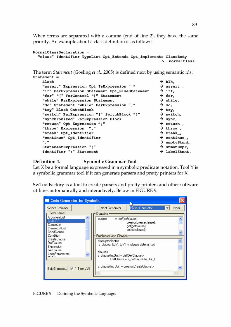
89
When terms are separated with a comma (end of line 2), they have the same priority. An example about a class definition is as follows: NormalClassDeclaration = “class” Identifier TypeList Opt_Extends Opt_implements ClassBody -> normalClass. The term Statement (Gosling et al., 2005) is defined next by using semantic ids: Statement = Block blk, “assert” Expression Opt_IsExpression ”;” assert_, “if” ParExpression Statement Opt_ElseStatement iff, “for” “(“ ForControl “)” Statement for, “while” ParExpression Statement while, “do” Statement “while” ParExpression ”;” do, “try” Block CatchBlock try, “switch” ParExpression ”{” SwitchBlock ”}” switch, “synchronized” ParExpression Block sync, “return” Opt_Expression ”;” return_, “throw” Expression ”;” throw_, “break” Opt_Identifier break_, “continue” Opt_Identifier continue_, “;” emptyStmnt, StatementExpression “;” stmntExpr, Identifier “:” Statement labelStmnt.
Definition 4. Symbolic Grammar Tool Let X be a formal language expressed in a symbolic predicate notation. Tool Y is a symbolic grammar tool if it can generate parsers and pretty printers for X. SwToolFactory is a tool to create parsers and pretty printers and other software utilities automatically and interactively. Below in 748HFIGURE 9.
FIGURE 9 Defining the Symbolic language.
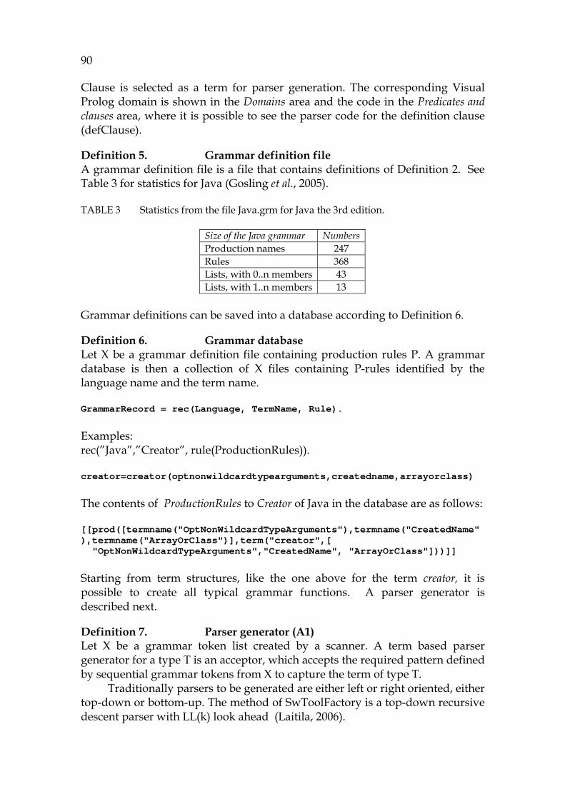
90
Clause is selected as a term for parser generation. The corresponding Visual Prolog domain is shown in the Domains area and the code in the Predicates and clauses area, where it is possible to see the parser code for the definition clause (defClause).
Definition 5. Grammar definition file A grammar definition file is a file that contains definitions of 749HDefinition 2. See Table 3 for statistics for Java (Gosling et al., 2005).
TABLE 3 Statistics from the file Java.grm for Java the 3rd edition.
Size of the Java grammar Numbers Production names 247 Rules 368 Lists, with 0..n members 43 Lists, with 1..n members 13
Grammar definitions can be saved into a database according to 750HDefinition 6.
Definition 6. Grammar database Let X be a grammar definition file containing production rules P. A grammar database is then a collection of X files containing P-rules identified by the language name and the term name. GrammarRecord = rec(Language, TermName, Rule). Examples: rec(”Java”,”Creator”, rule(ProductionRules)). creator=creator(optnonwildcardtypearguments,createdname,arrayorclass) The contents of ProductionRules to Creator of Java in the database are as follows: [[prod([termname("OptNonWildcardTypeArguments"),termname("CreatedName"),termname("ArrayOrClass")],term("creator",[ "OptNonWildcardTypeArguments","CreatedName", "ArrayOrClass"]))]] Starting from term structures, like the one above for the term creator, it is possible to create all typical grammar functions. A parser generator is described next.
Definition 7. Parser generator (A1) Let X be a grammar token list created by a scanner. A term based parser generator for a type T is an acceptor, which accepts the required pattern defined by sequential grammar tokens from X to capture the term of type T.
Traditionally parsers to be generated are either left or right oriented, either top-down or bottom-up. The method of SwToolFactory is a top-down recursive descent parser with LL(k) look ahead (Laitila, 2006).
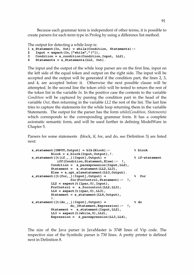
91
Because each grammar term is independent of other terms, it is possible to create parsers for each term type in Prolog by using a difference list method.
The output for detecting a while loop is: 1 s_Statement(In, Out) = while(Condition, Statements):- 2 Input = expect(In,[”while”,”(”]), 3 Condition = s_condition(Condition,Input, LL2), 4 Statements = s_Statements(LL2, Out). The input and the output of the while loop parser are on the first line, input on the left side of the equal token and output on the right side. The input will be accepted and the output will be generated if the condition part, the lines 2, 3, and 4, are accepted before it. Otherwise the next possible clause will be attempted. In the second line the token while will be tested to return the rest of the token list in the variable In. In the positive case the contents to the variable Condition will be captured by parsing the condition part in the head of the variable Out, then returning in the variable LL2 the rest of the list. The last line tries to capture the statements for the while loop returning them in the variable Statements. The output for the parser has the form while(Condition, Statements) which corresponds to the corresponding grammar form. It has a complete axiomatic semantic form, and will be used further in defining ModelWare in Chapter 5.
Parsers for some statements (block, if, for, and do, see 751HDefinition 3) are listed next: s_statement(INPUT,Output) = blk(Block):- % block Block = s_block(Input,Output),!. s_statement([t(if_,_)|Input],Output) = % if-statement iff(Condition,Statement,Else):- !,
Condition = s_parexpression(Input,LL2), Statement = s_statement(LL2,LL3), Else = s_opt_elsestatement(LL3,Output). s_statement([t(for,_)|Input],Output) = % for for(ForControl,Statement):- !,
LL2 = expect(t(lpar,0),Input), ForControl = s_forcontrol(LL2,LL3), LL4 = expect(t(rpar,0),LL3), Statement = s_statement(LL4,Output), !. s_statement([t(do_,_)|Input],Output) = % do do_(Statement,Expression):- !,
Statement = s_statement(Input,LL2), LL3 = expect(t(while,0),LL2), Expression = s_parexpression(LL3,LL4), The size of the Java parser in JavaMaster is 3748 lines of Vip code. The respective size of the Symbolic parser is 730 lines. A pretty printer is defined next in 752HDefinition 8.
92
Definition 8. Pretty printer – generator (A1) Let X be a symbolic parse tree. A pretty printer for a specific type T is a transducer to translate the corresponding grammar tokens into a string list to be modified for the display. An example for a while loop: 1 p_while(Condition, Statements) = concatList([”while” 2 ”(”, p_Condition ( Condition), ”) ”, 3 p_statements ( Statements),”};”]. There is only one clause in this rule returning, by a Visual Prolog predicate concatList, successively the keyword while and both the parentheses and semicolon and, by using recursive predicates, the contents of the condition part and statements part - all in a correct order.
4.1.2 Automaton A2, parsing and the Symbolic language
A parser is a tool to create parse trees. Its principle is discussed later in this chapter. A Visual Prolog based parse tree is a hierarchical data structure, the levels of which are grammar structures each. An example about an interface and one of its methods: public interface AnswerListener extends java.util.EventListener { public void yes(AnswerEvent e); .. } The corresponding parse tree is the following: classorif(interfdecl([public_()],normalif(ninterfdecl(id(jvar("AnswerListener")),notany(),extends(ext(typelist(reftype(id(jvar("java.util. EventListener")),notany(),[],[]),[]))), intfbody([interf([public_()],intmethodorfield(imfd(basictype(void_), id(jvar("yes")),intfmethodrest(intfmethoddeclrest(formalparams( params(paramdecl(notfinal(),notany(),reftype(id(jvar("AnswerEvent")) notany(),[],[]),[],vardecl(vardeclid(id(jvar("e")),[]),notany())))) ,[],notany())))))
It is possible to see that AnswerListener is a public normal interface with its parent. Its body (intfbody) contains a structure, where the symbol jvar(“AnswerEvent”) can be found with the argument e. Abstracting formal languages as a specific symbolic notation is described next in 753HDefinition 9 and 754HDefinition 10.
Definition 9. A2 Symbolic code description language (SCDL)
93
Let L1 be a formal language with grammar G1. Symbolic code description language L2 is a substitution for L1 where new abstracted types are created for each subtype for G1 and the hierarchy contains a minimal amount of levels.
Definition 10. Definition for the Symbolic language Symbolic is a symbolic code description language for abstracting Java and other programming languages. The definition for Symbolic is a tuple (Clause, Name, Type). interface symbolic domains 1 Clause definition: clause = … .. % 755HDefinition 11 2 Symbolic name: symbolicName = .. % 756HDefinition 12 3 Symbolic type: symbolicType = .. % 757HDefinition 13 end interface symbolic The whole semantics of Symbolic structures is described by using the term clause according to 758HDefinition 11.
Definition 11. Symbolic clause The only base term of Symbolic is clause. Hence, all references of the language can be identified as clauses. Clause is the foundation of symbolic processing, because all tokens can be parsed and written as clauses.
In the following list the subtypes of clause and their meanings are listed:
clause = 1 Definitions: def(defClause); 2 Creating commands: creator(createClause); 3 References: ref(refClause); 4 Method calls: get(getClause); 5 Change clauses: set(setClause); 6 Conditional clauses: path(pathClause); 7 Loops: loop(loopClause); 8 Operations: op(opClause); 9 Constants: val(valClause); 10 Other clauses: other(otherClause); 11 Internal links: at(SymbolicElement, clause*); 12 Side effects: seffect(sideEffectClause); 13 Meta information: meta(metaClause); 14 Comments: info(string) The definition above is intended for expressing the static structure and dynamic behavior of Java and that of other languages. The clause structures of lines 1 to 9 are directly compatible with Java. Those commands that cannot be simulated are grouped according to the structure of line 10. Dynamic results are saved according to line 12. The groups of lines 1-14 are described in more detail later in this section.

94
Symbolic name is a way to express the clauses to the user as follows:
Definition 12. Symbolic name Let X be a symbolic clause. Symbolic name is then a notation, which enables to point to X by referencing to its type.
The names below have been captured from the Java grammar: symbolicName = 1 Package: package_name(string) 2 Class: class_name(string) 3 Object: class_handle(string ClassName, string VarName) 4 Expression: expression_name(string) 5 .. packageOrTypeName(string) 6 Method: method_name(string) 7 Attribute: attr_name(string) 8 Variable: var_name(string) 9 Reference: javaRef(string) There is a specific name type for each element as a string. In the list (lines 1 and 2 and 6 to 9) the names obtained directly from Java are shown. Line 4 is an example of an internal name for an expression. The types of Symbolic structures are categorized according to the original Java input as follows:
Definition 13. Symbolic type Let X be a variable in a Java program. A symbolic type for X is basic_type(String) if the X’s type in Java is a basic type of the language. Otherwise the symbolic type is cls(String). 13F
14 symbolicType = Basic type: basic_type(string); Other type, class: cls(string) The values for symbols with the symbolic type basic_type are processed like constants. For keeping the grammar structures consistent, symbol tables and the corresponding generator are needed.
Definition 14. Symbol table generator A symbol table generator is a tool to detect class names, method names, class parenthood and other else identifiers in order to create a valid symbol table for the whole architecture.
14 In Java there are boxing types that are conversion-comparable with basic types. They are
converted as cls-types in the symbolic model, described in this methodology.
95
The principle of detecting symbol tables from the code resembles round-trip engineering. The output of a symbol table generator is capable of building class diagrams with associations between classes.
The symbol table is capable of identifying each symbol (each member) of its scope, to retrieve code for each method and to retrieve parent classes of each class.
4.1.3 Automaton A3, abstraction by symbolic transformation
For translating programming languages into Symbolic a translator is needed. Definition 15 describes a high-level translation process and Definition 16 its specific version for Java.
Definition 15. Direct translation (A3) Let XT be a semantic grammar term in an input language X with arguments X1.. XN and YT the corresponding production name in an isomorphic language Y. Hence, a direct translation from XT to YT is a substitution YT = yterm(Y1..YM) where the arguments X1.. Xn are recursively translated to Y1..YM by direct translation.
Definition 16. Java to Symbolic – translator. Let X be a parse tree expressed in Java in a symbolic format. Let Y be the corresponding Symbolic parse tree. Hence, the tool to translate X to Y is a Java-to-Symbolic translator. It should be able to make symbol tables for classes in the symbolic model. The Visual Prolog formalism for calling the Java-to-Symbolic translator is as follows: translate_X_to_y(x(Terms)) = y(translate_Xterms_to_2y(Terms)). It is a parse tree conversion: SymbolicParseTree = java2Symbolic::xlate(ParseTree) The emphasis in the conversions from Java to Symbolic is in declarativeness and backwards compatibility with Java (759HTABLE 4). Thus, there are definitions for classes, methods, objects, variables etc. in the Symbolic language. Let’s, for example, translate the statement Sum = A+B+C to Java and further to Symbolic. The Java Parse tree for it is 14F
15: ce(cor(coe(cae(ior(eoe(ae(ee(inst(re(se(ae(me(ue(primary( id(name("Sum"),[],notany()),[],notany())), []),[]),[]),[]),notany()), []),[]),[]),[]),[]),[]),notany()),lhs(eq(), ce(cor(coe(cae(ior(eoe(ae(ee(inst(re(se(ae(me(ue(primary(id(name("A"),
15 The semantic ids nested from ce to primary here describe the semantic levels of the Java
expression. It has 15 nesting levels, which are needed for parsing expressions correctly.
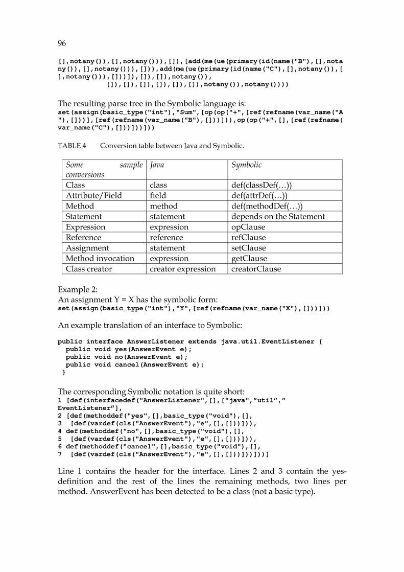
96
[],notany()),[],notany())),[]),[add(me(ue(primary(id(name("B"),[],notany()),[],notany())),[])),add(me(ue(primary(id(name("C"),[],notany()),[],notany())),[]))]),[]),[]),notany()), []),[]),[]),[]),[]),[]),notany()),notany()))) The resulting parse tree in the Symbolic language is: set(assign(basic_type("int"),"Sum",[op(op("+",[ref(refname(var_name("A"),[]))],[ref(refname(var_name("B"),[]))])),op(op("+",[],[ref(refname(var_name("C"),[]))]))]))
TABLE 4 Conversion table between Java and Symbolic.
Some sample conversions
Java Symbolic
Class class def(classDef(…)) Attribute/Field field def(attrDef(…)) Method method def(methodDef(…)) Statement statement depends on the Statement Expression expression opClause Reference reference refClause Assignment statement setClause Method invocation expression getClause Class creator creator expression creatorClause
Example 2: An assignment Y = X has the symbolic form: set(assign(basic_type("int"),"Y",[ref(refname(var_name("X"),[]))])) An example translation of an interface to Symbolic: public interface AnswerListener extends java.util.EventListener { public void yes(AnswerEvent e); public void no(AnswerEvent e); public void cancel(AnswerEvent e); } The corresponding Symbolic notation is quite short: 1 [def(interfacedef("AnswerListener",[],["java",”util”,” EventListener”], 2 [def(methoddef("yes",[],basic_type("void"),[], 3 [def(vardef(cls("AnswerEvent"),"e",[],[]))])), 4 def(methoddef("no",[],basic_type("void"),[], 5 [def(vardef(cls("AnswerEvent"),"e",[],[]))])), 6 def(methoddef("cancel",[],basic_type("void"),[], 7 [def(vardef(cls("AnswerEvent"),"e",[],[]))]))]))] Line 1 contains the header for the interface. Lines 2 and 3 contain the yes-definition and the rest of the lines the remaining methods, two lines per method. AnswerEvent has been detected to be a class (not a basic type).

97
4.1.4 Conclusions about GrammarWare (the automata A1..A3)
Automaton A1 defines the grammar tool, A2 defines the parsing automaton and A3 defines the Symbolic language for abstraction. Referring to Proposition 1 we have implemented the data flow from the input of A1 to the output of A3 by programming the corresponding Prolog rules and tested that it produces expected elements to the model. Hence, there is a practical proof for 760HProposition 1. Automaton A1 requires ca. 2000 lines of code for parser generation. Automaton A2 for Java (parser) requires 3.700 lines and Automaton A3, Java-to-Symbolic translation 3.000 lines. 15F
16.
4.2 Comparing the foundation with related work
A formal language is a notation whose structure has been defined by exact rules and terms of its grammar (Chomsky, 1956). In addition to the formal language, there are specifications for the type system of the language and the agreements about its data scope and statement semantics. If the language is object-oriented like Java, then the specifications for object features are needed, too. These include inheritance, encapsulation rules, and all the reference semantics.
Each traditional programming language has as its foundation a formal context-free grammar, which means that each structure of the source code can be parsed completely 16F
17, although the languages can have some minor context-sensitive features (Sakkinen, 1988; Willink, 2001).
The overall definition for a formal grammar has the following form (Chomsky, 1956; Grune and Jacobs, 1991):
G = <N, ∑, R, S0>
N refers to a divisible term, non-terminal, which contains at least a two-level hierarchical structure. ∑ is a list (dictionary) of all reserved words including limiters and lowest level symbols, terminals. R refers to a group of production rules that list all the valid structures for each N. Each rule R can have multiple different terms as its alternatives. For example, the divisible term statement, can be either a for loop, while loop, an assignment or some other statement. In Java there are about 15 different statement structures. S0 is the start symbol, the starting term for parsing. In Java the start symbol, named compilation_unit, refers to the definition of a Java file.
From a grammar definition it is possible to create a corresponding parser obeying either left or right oriented algorithm (Grune et al., 1991). There are several notations to describe grammars, such as EBNF (EBNF, 2001) and Antlr
16 Being Prolog, the code for A1, A2, and A3, can be proofed step-by-step if necessary. 17The languages that have dynamic typing, like Ruby and Smalltalk, are not completely
context-free.

98
(Parr, 2007). A clear difference between these traditional tools (Lahdelma, 1988a, 1988b, 1988c, 1989) and the ones that are able to handle symbolic information (see 761HDefinition 4) is the fact that in the output of a symbolic grammar tool each term should contain both syntax and the correspondent semantics packed into the same structure in the way of 762HDefinition 3.
4.2.1 Symbolic Grammar Term
In this research the traditional approach for defining formal languages based on their syntax is used. In our approach it is essential that we maintain the semantics in parsing and in later processing phases by using a semantic grammar term based on 763HDefinition 3 and the Symbolic language based on 764HDefinition 10.
Attribute grammars (Paakki, 1991) have some similar features. Attribute grammars are an extension into grammar notations that have a syntactical addition-like definition for each calculation term, but they cannot be extended to cover all the language terms like, for example, when describing the behavior of an object-oriented reference. Instead, a way to add a semantic identification into a grammar has been proposed by Jensen et al. (1998). We have extended Jensen’s approach to cover the whole program comprehension methodology.
4.2.2 Expressing language semantics in typed Prolog
Typed Prolog is useful for expressing grammar terms, because its type system can match directly all the details of each term. It can even show possible errors, because in Prolog the meaning of a semantic identification, which is actually a predicate, is indirect and implicit. The predicate is a symbol, not an actual term. It makes it possible to create exact abstractions for current grammar terms.
Next a typed development tool, Visual Prolog (VisualProlog, 2007), is described to shed light on implementing grammar development tools, such as SwToolFactory (Laitila, 2006). When using typed Prolog according to 765HDefinition 4, all the grammar rules of the implemented analysis language like Java (and later Symbolic) have a proper control, because the type system of the development language knows all the features of the analyzed language.
As an example, let's consider an if statement. The term statement has a term if with the semantic id iff including the condition, the true-block and else-block. In typed Prolog it is not possible to refer to an iff term by using illegal grammar structures. It is possible, however, to refer to any if statement of the current language by this iff id. So there is a contrafactual two-way correspondence between the analyzed language and its formulated notation in the tool. This feature is valuable in developing source code analysis, because the structures of source code are often very complex. A programming error can cause serious troubles in the applications if the development tool doesn’t provide accurate type system, which could prevent from using any erroneous types in programming the tool.
99
The traditional principle in programming compiled structures uses the AST method (Mak, 1996; Gough, 2001). However, AST is very demanding for developers, because it doesn’t support model validation. Thus AST implementations are error-prone. Another serious problem when using AST is that AST information contains a set of individual cells and cell members that do not have a combined semantics corresponding to predicate semantics. So it is the developers' responsibility to maintain all the semantics features in all the analysis phases. In fact when programming AST structures the grammar is in the head of the programmer, not in the development tool. This is in opposition to the main idea of GrammarWare.
4.2.3 Symbolic Grammar Rule
Ordering the rules is necessary to express evaluation (calculation) rules. Further, some rules are on the same precedence levels. These include addition and subtraction. For Prolog, advanced precedence groups and parsing principles like xy and operator priorities (Clocksin, and Mellish, 1981) have been developed. For practical development purposes these are far too detailed.
4.2.4 Implementing the grammar tool
With SwToolFactory (see 766HDefinition 4) it is possible to enter grammars and to produce grammar-based functionalities (Laitila, 2006). SwToolFactory differs from traditional grammar tools in that it is object-oriented, visual and fully automated. It contains a scanner, a pretty printer, and, among other functionalities, parser and code generator development support. The object-oriented nature of the tool means that each language is treated as a composite object where each rule is a separate language object and each term is an independent language object. This reductionist principle makes developing tool functions productive, because each grammar-wide task can be converted into small subtasks by just relating one term at a time. Collecting them to cover the whole grammar is easy.
In DCG, which is a non-typed Prolog notation (Clocksin et al., 1981), the grammar is too flexible and thus allows erroneous features. This kind of flexible definition is hard to remember and validate. When using DCG, the type checking code should be written in any case. Another way to write parsers is to program parsing into the source code of the tool, but that is too laborious when a large scale analysis is needed.
For implementing a novel, object-oriented grammar tool the following definitions introduce the concepts of metaterm and metarule:
Definition 17. Metaterm Let X be a symbolic grammar term. Metaterm is then an object in a grammar tool to define the corresponding grammatical functionality, instantiated for X.

100
Definition 18. Metarule Let X be a symbolic grammar rule. Metarule is then an object to define the corresponding grammatical functionality, instantiated for any X.
Combined, the objects metarule and metaterm contain all the features of a formal language, and grammar mappings are converted into object-oriented mappings of the grammar tool. Statement and expression are examples of metaterms. Here a while loop is a metarule object referring to a statement object. In the similar way, an if statement, for loop, assignment and other statement commands can each reserve a metarule instance which can be referred to from a statement object.
In the following, a top-down parser that uses the recursive descendant principle is presented (Willink, 2001). It has earlier been introduced by PDC 17F
18 (Jensen et al., 1988). This parser uses a difference list principle employing two lists, where the first (In) contains current source code information as a token list and the second (Out) contains the returning information to the successive phases for other rules.
The rules for parsing have been named so that there is a prefix s_ before the name of the corresponding term name. The acceptor procedure has the predicate expect to read reserved words and to return the remaining part of the token list to parse. For each rule, one independent starting clause is generated. If there are multiple alternatives in the rule, then the separation is done by using several clauses. For each priority group, a group of clauses are generated and, for each rule instance, a clause is needed. They are numbered in an ascending order.
4.3 Developing the output of parsing
There have been parsing tools since the '70s. Compared with other software technologies, Yacc and Lex tools for Unix were rather early products (Pratt and Zelkowitz, 2000). However, there were no well-established ways to handle the output of these tools, and that is one reason why the status of source code analysis has not been as advanced as parsing in general (Parr and Quong, 1994).
The most important step for improving parser technology since the time of Yacc has been the abstract syntax tree (AST) (Jones, 2003). With AST it is possible to construct new models for the output of parsers. AST is an object-oriented model derived from a parse tree, where the hierarchy of the code has been implemented as bindings of AST nodes. Usually the object hierarchy for the tool is programmed and customized for the language to be analyzed. The most typical super classes are Command, Expression, Term, and Value, for
18 PDC, Prolog Development Center, A/S, www.pdc.dk (referred 10.08.2007).

101
which AST should be the base class. A typical AST implementation can be found in the Eclipse integrated development environment. 18F
19 In spite of their straightforward structure AST implementations are hard
to program, because the nodes often contain language specific variables and because AST has a rather complex class hierarchy with its strict integrity rules. So the tools are often highly language-dependent. AST node and its code
In an AST implementation, AST node is an object. The links of the original grammar structure are members (handles) of the substructures of the corresponding AST node. When combined, the members/handles of each AST form, as a composite object, the contents of the corresponding source code term. For example, an assignment LetCommand of Basic contains two or three separate AST members: a possible assignment operator, a reference to the left side, and a reference to the right side (Watt, 1990). LetCommand = D + C (D = Declaration, C = Expression) If the parts declaration, command and left side are separate, it is difficult, in the tool, to maintain the semantics of each structure, because there are in practice numerous variations in many AST nodes. Although AST implementations have most often been written in Java or C++, Visual Prolog is used here. This is because that language will also be used later in the research. 1 interface ast 2 % abstract super class for AST 3 end interface ast 4 interface astLetCommand supports ast 5 6 end interface asmLetCommand There is an interface corresponding to AST base class on lines 1-3. The class definition LetCommand (lines 4-6) is straightforward. Below an internal definition for the AST node of the Let-command is presented: 1 implement astLetCommand inherits ast 2 facts 3 declaration : declaration. 4 command : expression. end implement astLetCommand Because the structure's declaration and command are separated (let on line 1, declaration on line 3, and command on line 4), this AST construction model cannot be formalized. This drawback decreases the quality of AST
19 http://www.eclipse.org (10.08.2007).
102
implementations. Thus the model doesn’t cover all the lowest features of the grammarware.
The following construction, 767H4.3.1, is implemented by using Prolog.
4.3.1 Predicate-augmented AST
Predicate-augmented AST is an extended AST where the semantics of each grammar rule are embedded into the AST node by using a command predicate. The difference between AST and the augmented AST is the new predicate, command, that contains the whole semantics of the original grammar term as a single structure pointing to its leaves via its arguments. So there is no need to have separate AST variables as members. The new construction is much simpler than the original one. 1 implement astLetCommand inherits ast 2 facts 3 contents: let(declaration, expression). end implement astLetCommand The only necessary structure is the predicate contents, which connects the terms declaration and command and the let semantics. This small modification enables axiomatizing the output model, because the output structure is a compact element that can be traced back into the original code, here Java. Thus, a software tool can be used here to capture the semantics of any node simply by making it read the contents of the corresponding element. With a typical AST this is not possible. Later the contents field label will be replaced with the label command field, because that label describes better its functionality. Prolog-based parse tree (PPT)
Prolog-based parse tree (see 768HDefinition 7) is a hierarchical notation that uses Prolog data structures in saving grammar terms. In it each grammar rule level occupies one hierarchical level. Like AST, a Prolog-based parse tree doesn’t contain any discontinuities, because all the information lies hierarchically in the same physical structure. This enables moving a parse tree to another location by a single assignment. Parse trees are organized in Prolog according to first-order predicate semantics.
In Java, typically, one file at a time is compiled, so there is a parse tree for each file. In source code analysis more modular parsing may be needed. The parse trees for these can easily be defined by adding new alternative start symbols for the grammar.

103
4.4 Raising the abstraction level
For abstracting programs a principle called abstract interpretation has been developed ( Cousot and Cousot, 1977). This principle is, due to its history, limited and is based on a mathematical analysis of some features of the code. Abstract interpretation is not capable of covering program flow analysis and analyzing object-oriented features of modern languages (Logozzo and Cortesi, 2005).
In this research a new proposal for abstracting, by using a high-level symbolic notation, is presented in 769HDefinition 10. Basically, an increase in abstraction level is advocated by the MDA and DSM (Mernik, Heering, and Sloane, 2006) movements, but there the abstraction has been raised in a formal and rigorous way similar to refining specifications to working code using refinement calculus.
4.4.1 Symbolic Code Description Language
Symbolic Code Description Language (SCDL, see 770HDefinition 9) is a formal notation to describe the original programming language and its semantics as a high level abstraction language. The greatest benefit of a symbolic notation is that the corresponding tool can utilize the intermediate notations of the structures in addition to their contents.
For example, the semantic identification while can be used in identifying which statement will be executed next when the contents of the loop are to be identified recursively. There is a strong need to simplify the original source code structures in programming tools, because, being directly parsed from a context-free language, they are highly hierarchical. For example, a Java expression, the condition part of a loop, contains about 20 hierarchical levels according to the Java grammar (Java, 2003). These levels are needed for expressing all the possible calculation rules and their inter-connections. After parsing, however, there is no need to keep these levels, because in the Prolog based tool the structures are tightly packed as predicates. By simplifying the expressions for abstracting purposes the hierarchy can be minimized to the depth of three. 19F
20 For example, a condition can be a relative operation including a logical pairwise comparison having only three levels. Another benefit in using a symbolic code description language is the possibility to categorize the structures in an optimal way for analysis purposes.
In the AST technology a symbolic language cannot be used, because all the members of AST nodes are separated and there are no internal semantics between them. If there is no internal language in the analysis, then all semantics and analysis results must be done by programming individual
20 We have improved the capacity and performance of the tool to about 80% calculated
from typical expressions, measured by the SwToolFactory tool.

104
features, one after the other. Klint et al. (2003) use the term retangled grammars for this drawback.
In contrast to AST, SCDL provides a foundation for all source code analysis functionalities, including automatic explanation for the connections and for the behavior of the most interesting source code elements.
4.5 Direct translation
This section handles the principles of source code translation from the viewpoint of symbolic analysis, and does not cover the whole area of transformation technologies. Because specific transformation packages have a large and complex rule-based theory, including an own transformation language as the background, their focus is far from our PC needs.
4.5.1 The principles and the main goals of translating source code
Let us consider some implementing issues of translators relating to source code analysis:
- The most logical way to connect things with each other is to use direct transformation rules on a semantic level. Translating from syntax into syntax is more difficult, because of the burden of reserved words and separators (comma, semicolon, parenthesis etc). It is typical for other technologies like Stratego, DMS, TXL and ASF+SDF to have an indirect transformation language (syntax-to-syntax), which engenders complexity in building formalisms. In this work we create a symbolic model on top of the programming language syntax, which allows a direct translation.
- The most abstract way to carry out a translation is to save grammar terms into the corresponding objects in the tool and to translate the input objects to output objects. This principle is typical of XML-technologies (Fung, 2000).
- The best way to connect things with each other is to use associative definitions (like in a relational database) by using a symbolic notation. Symbolic notation fixes both the presentation and the contents, and there is no need then to program low level features one after the other for each individual case.
- The most formal way to interconnect concepts is to use formal languages and to switch input and output terms using Prolog predicates, which should provide an axiomatized output in all the fundamental situations of the transformation.
When the output language can be tailored and optimized for the current situation, then it is possible to plan the transformation so that there is no loss of information in any structure.

105
4.5.2 Definitions for a direct translation
Next, translation between two formal languages is described according to 771HDefinition 15. Translation is a process to transform one formal input language into an output language. Translation engine is a tool or software component to implement the translation. One of the best known translation engines is TXL (Dean, 2002), which is based on rule based translation. It needs three different kinds of information:
- The type system of the input language (XIn) - The type system of the output language (Xout) - The transformation rule base (Xin2Xout)
The drawback of the rule based translation is that it contains three different grammars that should be mastered, because the rule base contains a language of its own. In practice making translations is demanding by using TXL for each input-output language pair. A principle different to that of rule based translation is direct translation, which is presented in 772HDefinition 15. In this principle the symbolic programming language of the tool, here Visual Prolog, is used as third language. The principle is illustrated in 773HFIGURE 10.
FIGURE 10 Direct, semantic translation.
Using the symbolic language of the tool on a semantic level by utilizing its whole symbolic expression power according to 774HDefinition 16 is straightforward, because a header and a default body for each translation predicate can be automatically generated. Semantic translation is executed recursively from each input term into the corresponding output term. All subterm translations are called by a recursive assignment that is similar to the call of the main level assignment. Because of this recursive assignment, there is no need to use separate transformation rules or any independent transformation engine. The default code for the translation is captured from the grammar tool,
InN
in(A1,..Ak)
OutM
out(B1, Bk)
Out1InN+11
OutkInN+1 k
A1 B1
BkAk
InN
in(A1,..Ak)
OutM
out(B1, Bk)
Out1InN+11
OutkInN+1 k
A1 B1
BkAk

106
SwToolFactory (Laitila, 2001). The only manual operation required is to pick the output terms for each input term.
Semantic translation (in most typical situations) between the terms of input and output languages takes place as follows (see 775HFIGURE 10). Let In be a symbol describing an input term as a hierarchy level N with the semantic id in, which has the parameters A1..Ak. Let the corresponding term in the output language be out, with its parameters B1..Bk. The output term is now the predicate out(B1.. Bk), where each transformation is executed recursively into the lower level N+1, N+2 etc., to the level where there are only indivisible terms (terminals).
Translation between languages has been researched widely (Klint et al., 2005), but typically the focus has been on demonstrating the problems and differences between languages, such as different indexing of the languages Pascal and C (Harsu, 1997).20F
21 Direct translation, based on recursive assignment, forms an essential
phase for source code analysis purposes. It can guarantee a proven result in all compatible situations, which is the prerequisite for the Symbolic language presented next. 21F
22 Although the principle of semantic translation may sound trivial, it is suitable for all abstraction purposes for this research. The greatest benefit of it is to have the translated code as first order predicate logic. Small incompatibilities can be programmed away by adding some wrappers into the most difficult places. For example the type system of Java is different of that of the symbolic tool, because the latter is based on the type system of the development language. Each conversion between types can be programmed aside to be used in type reference clauses. The only extension to the principle of semantic translation, considering further requirements in Chapter 5, is programming symbol table functions (Sethi, 1996) to capture the class contracts and variable and method definitions for centralized use in the model weaver.
4.6 Symbolic, the symbolic language
The Symbolic language is a symbolic code description language for program comprehension oriented symbolic analysis as defined in 776HDefinition 9.
There are many languages such as OCL (Akehurst, and Patrascoiu, 2004) describing source code constraints and model features, and there are many UML presentations (MDA, 2007), some of which focus on Action semantics
21 There are some incompatibilities between widely used programming languages, and the
gap between procedural languages like Cobol and object-oriented languages is almost impossible to bridge by automatic transformation without manual interaction (Kontogiannis et al., 1998).
22 The purpose is not to implement transformations between paradigms.

107
(Mosses, 2004) and other semantics. UML is suitable for expressing class and meta functions, but its granularity is not sufficient for programming language features. OCL is neither Java nor C++ compatible, which is a serious drawback. It can be argued that there are no compatible integral languages to describe both programming language semantics and object-level features to form a complete foundation for program comprehension. There is thus a strong need to have a fundamentally new language satisfying the requirements indicated, because, as it is currently, it is a great burden for a programmer to skip from an UML model into code-based data descriptions in the editor and backwards numerous times in a typical maintenance session. In every model transfer a lot of information will be lost.
Symbolic has been planned to keep the uniform model of all source code elements as well as the high level structures. In it the relation between simplicity and declarativeness of the language has been optimized.
Some earlier alternatives for mastering complex data structures include lambda calculus (Church, 1936), XML and domain specific languages (Mernik et al., 2006). Lambda calculus is very flexible, but it is clumsy, because interpreting a lambda notation creates a heavy load for the tool. Typical domain specific languages, being not universal, are limited for the selected approach. However, they can still require an unreasonable number of commands and details to be programmed in order to implement a successful analysis. With Prolog all these approaches are possible if a suitable optimized language can be written.
Minimizing language structures of Symbolic
In the next description we have used the principle that all the structures can be expressed by two, or in the most challenging cases by three hierarchical levels. Furthermore, only a list notation (*) and a list of lists (**) are allowed in the notation to connect terms with each other. They are necessary, because our development tool, Visual Prolog, supports them explicitly and they can express ordered sequences, bags and nested collections. Adding implicit conversions could produce complex data structures, which could damage the architecture of the symbolic construction with its atomistic model.
4.6.1 The Symbolic language
Symbolic is a formal abstracting language for source code analysis to express syntactical structure, semantics, and behavior model of object-oriented languages (see 777HDefinition 10). The Symbolic language contains, in accordance with the goals of this research, the semantics of Java in order to meet its simulation requirements (Laitila, 2006). More precisely, it contains the following type categories:
- Def: Definition clauses for all Java terms - Creator: Creating clauses (for objects and tables) - Ref: References to all possible Java elements - Get: Method calls

108
- Set: The clauses capable of performing memory changes - Path: Conditional clauses and branching clauses (paths) - Loop: Program loops - Op: Mathematical-logical operations and transformations - Val: Constants - Other: The clauses that are not simulated - At: Linking elements with each other (a new clause) - SideEffect: Results from simulation actions (a new clause) - MetaClause: Connective structures for argumenting (a new clause) - Info: Comment and verbal explanation (a new clause)
The collection of all the clause types (see 778HDefinition 11) can be described as a notation <T>, where <T> = Def, Set, Get, Call, Loop, Path, Creator, Op, Val, At, Other, SideEffect, MetaClause, and Info.
From the list above it can be seen that many Java statements and structures have been combined into type categories. For example the group Loop contains all the possible loop types, while, do-while, and for.
Type categories of Symbolic
The Symbolic language has been divided into groups to optimize the declarativeness of the language in relation to the specialization needs of the language. When Prolog is used in the tool, the type system selection's range extends from a monolithic version where all the elements are kept in a parse tree to a deeply specialized model where each clause should reserve a class of its own like AST systems do.
The planning rules for the research have been selected in the following way:
- The grammar and type model of Symbolic forms the base class of the language.
- Each type category has been implemented in a class of the tool, making specialization possible. For example, all the program code for all loops share the same class.
In this chapter the type category is referred to by a notation <T> or <Ti>. The former refers to any Symbolic type and the latter refers to an indexed type i, in succession.
Formal definition for Symbolic
The Symbolic language has a compact definition that defines all the structures and data. The language has a type system of its own (symbolicType, see 779HDefinition 13) a naming system for all symbols (symbolicName, see 780HDefinition 12), and its own instruction set (clause, see 781HDefinition 11).
109
4.6.2 Categories of the Symbolic clause
The foundation for the Symbolic language is the definition of a clause (see 782HDefinition 11). It builds the instruction set of the whole language. Clause is the only start symbol for Symbolic. This simplification makes all data transfer and the whole architecture straightforward to program and understand.
The hierarchy of the Symbolic clause has only two levels, because Clause contains the type categories as the first level. It is divided into individual clauses in the second level. Thus DefClause contains all definitions, SetClause all data changes etc.22F
23 clause = 1 Definitions: def(defClause); 2 Creating commands: creator(createClause); 3 References: ref(refClause); 4 Method calls: get(getClause); 5 Change clauses: set(setClause); 6 Conditional clauses: path(pathClause); 7 Loops: loop(loopClause); 8 Operations: op(opClause); 9 Constants: val(valClause); 10 Other clauses: other(otherClause); 11 Internal links: at(SymbolicElement, clause*); 12 Side effects: seffect(sideEffectClause); 13 Meta information: meta(metaClause); 14 Comments: info(string) The logic behind the Symbolic clause is the following:
- There are two kinds of definitions: static definitions and dynamic creating clauses.
- There are two kinds of references, for variables and for methods. - There is only one change category. It contains an assignment and
autoincrementing and autodecrementing features. - The statement blocks are conditional blocks and loops. - There is only one type category for calculating and evaluating: opClause. - The constants are stored into valClause. - The definition of otherClause contains the statements that are not
simulated. - The internal links between symbols are stored as atClause. - The results from simulations are side effects. They have been saved as
sideEffect clauses. They can be either intermediate values or final results. - When the structures have been combined into a larger clause like a
metalanguage for argumentation purposes, then metaClause is used. <T1> Symbolic definition clauses
23 In Java, e.g., there are 20 nesting levels in the structure relating to the opClause.
110
Symbolic definitions have been translated from Java. They are backwards compatible with Java including the definitions for a class, attribute, method, variable, and an exception in the following format: defClause = 1 Class: classDef(string, Modifiers, superClass*, clause*) 2 Interface: InterfaceDef(string,symbolicType*,Parents,clause*) 3 Method: methodDef(string,Modifiers,symbolicType, clause*,clause*)
4 Constructor: constructorDef(string, clause*, clause*) 5 Enumerating: enumDef (string, clause*, clause*) 6 Constant: constDef (string, symbolicType, clause*) 7 Variable: varDef(symbolicType, string, clause*, clause*) The definition clause* refers to a list of clauses, a clauselist. Because the clause is the foundation of the language, this definition can be found in any argument. The exceptions are modifiers to describe original Java modifiers of the definitions and string that is intended for names and the definition superclass for superclasses to mean inheritance definitions. <T2> Symbolic creator
The create operations for a class and for a table are defined as follows: createClause = Creating a class: newClass(symbolicType*, clause*, clause*) Creating a table: createArray(symbolicType, string, clause*) Both the class creator and the table creator have the identifying part, information about what to create, and the punctuation or optional arguments. <T3> Symbolic reference statement
The reference statement is based on Java: refClause = Variable reference: refName(symbolicName*, Suffix) this: this(clause*) super: super(clause*) The clauses this and super have the same semantics as their corresponding entities in Java. <T4> Symbolic method call
The method call contains the arguments and the method identification, which is referred to as a getObject: getClause = Method call: call(getObject, ArgList)
111
There are two formats for the called object (getObject): one for static identification before making the model and one to be used in the model. Polymorphism and virtual functions create some complexity for defining these structures. That is why the contents of the getObject should consist of lists having the following definition: getObject = sGet(symbolicName*); dGet(symbolicDefElement*) The definition sGet refers to static code elements (parts of the parse tree) and dGet to dynamic model structures. SymbolicDefElement is here a reference to the method element (Symbolic Def Element) described in the next section. <T5> Symbolic change clause
All the instructions that are capable of making changes into data have been concentrated into the same clause group, which is called a setClause. It contains the following alternatives: setClause = Assignment: assign_(setObject, AssignOp, clause*) Incrementing: incr(clause*) Decrementing: decr(clause*) The assignment clause has the same feature as the getClause. There are two formats: one before model weaving and one for the model containing dynamic references. The format of the setObject causing this feature is the following: setObject = sSet(symbolicType, string Var) ; dSet(symbolicDefElement). In the static definition there are the variable name and its type, but in the dynamic definition only a reference to the model element is needed. <T6> Symbolic path clause
The conditional statements derived for Java are (sometimes the condition is missing): pathClause = If clause: iff_(clause*, clause*, clause*) Switch clause: switch_(string, clause*, clause*) Other branch clauses: control(controlCommand, clause*) The purpose of the path clause is to control the program flow by its conditions and direct branching statements. The branching commands can be:
- Method call: return - Breaking a statement block: break - Skipping a clause block: continue

112
<T7> Symbolic loop clause
The loop derived for Java can be: loopClause = While: while (clause*, clause*) Do: doWhile(clause*, clause*) For: for(clause*, clause*, clause*, clause*) The three types of loops in Java have their correspondences in Symbolic. The while loop has a precondition as the first parameter and an execution part as the second parameter. The do loop resembles it, but the first parameter contains an execution and the second is a postcondition. The for loop contains one parameter for initialization, condition, execution and iteration in the same order as they are in the Java grammar. <T8> Symbolic evaluator, an op clause
There are multiple operations for calculating, for describing logical relations, and for describing type transformations: opClause = op(string, clause*, clause*); typeCast (symbolicType, clause*); exprCast (Expression, clause*); preOp(string, clause*); postOp(clause*, clause*, clause*); instance_Of(clause*, symbolicType); math(MathOp, clause*); rel(RelativeOp, clause*); unary(OperatorName, clause*). Operators can be expressed in many ways in Symbolic. There are operators with one and two arguments, cast operations, pre and post processing clauses. There is a high backwards compatibility to Java from the Symbolic opClause. <T9> Symbolic constant, a val clause
Fixed values have single value, empty, a list, or a tree as the alternatives: valClause = empty ; sv(symbolicValue); list(valClause, Arg*). The type sv means single value. The other alternatives are empty cell or a list. A list is capable of expressing Java vectors and matrixes. <T10> Symbolic otherclause
The Java clauses that do not have exact operational semantics in Symbolic have been collected into otherclause. However, the following notation maintains their axiomatic semantic notation as Horn clauses:
113
otherClause = 1 Assert: assert(clause*, clause*); 2 Try-catch: try(clause*, clause*); 3 Try .. catch: catch(clause*, clause*); 4 Synchronized: syncr(clause*, clause*) There are only four clauses in this group, but these functions can, too, be analyzed partially and all the commands inside these blocks can be analyzed as they are. The principles of source code simulation are described in Chapter 6.
4.6.3 Data model of the Symbolic language
In symbolic analysis the Symbolic language has two roles: - To enable abstracting Java via a translation bridge, which can be
extended for other programming languages, because all axiomatic new features can be programmed as extensions of a symbolic name, symbolic type, and any other clause.
- To keep original code information in a model, maintaining original semantics. In this role the connections between Symbolic elements are dynamic.
Symbolic’s data model
The data model has been defined by clause. It is needed for automatic analysis. The main clause types can be divided into data, code, and object. The contents of a clause is the only input for symbolic analysis. The data model is thus very straightforward. It will be described more precisely in Chapters 6 and 7.
4.6.4 Operational model of Symbolic language
The two ways to analyze object-oriented code are static and dynamic analyses. The latter is more challenging requiring an ability to simulate code from the tools. That’s why the operational model of Symbolic describes all the functions that a clause can produce in simulating the original code. When simulating, it is necessary to define an abstract machine to describe the simulation process and how to execute clauses in the analysis. The abstract machine is described in Chapter 8.
Although Java is expressed in a very highly abstracted form in the Symbolic language, there is a logical backwards compatibility from Symbolic to Java. It is possible to trace every Symbolic command into Java code. Thus every simulation function can be validated against the original Java semantics.
114
4.7 Summary of GrammarWare, a bridge to ModelWare
The grammar described consists of rules which are used to create a parser for a specific language. The parser produces parse trees as outputs, cf. 783HFIGURE 11. The definitions for the concepts Prolog-augmented AST, symbolic grammar, and symbolic code description language were presented in this chapter, and are shown in 784HFIGURE 11.
A semantic grammar notation was introduced to connect syntax and semantics tightly with each other (see 785HDefinition 2). By using this semantic link it is possible to raise the abstraction level higher than by using syntax alone. The abstraction in newer symbolic analysis languages that are able to maintain the original semantics can thus be utilized.
Semantic addition described in this chapter can be done with predicate logic by employing a single predicate for each grammar rule (786HDefinition 3). Predicate notation makes a compact structure that maintains the original semantics of each structure of any grammar term. This kind of consistency cannot be maintained in implementations where the semantics is split into separate individual memory locations, which is typical for AST implementations. To enable a formal transfer from the grammar to a model, a grammar tool is needed. For this tool, a metadescription of the grammar model is needed as well as a database to store grammar definitions for Java, for C++, and for other languages. For the grammar tool, an object based architecture was presented to reduce the complexity of a formal language into a rule level which is easy to master and update.
In modeling, the most efficient way to describe the original structures is describing them on a level higher than that of the original code. For abstraction purposes a new analysis language, Symbolic, was presented ( 787HDefinition 10). By using this language instead of Java, about 80 % of the hierarchy can be removed without missing code information. For example, a condition expression of Java changes to a Symbolic structure, which contains only three levels. In Symbolic all its clauses and all the references have been categorized to build an ontology of its own to meet both the static and dynamic modeling and analyzing requirements.
For programming languages other than Java the GrammarWare methodology is identical provided that the type system of the corresponding language is not dynamic. Thus C++ and C# can be modeled in the same way as Java.
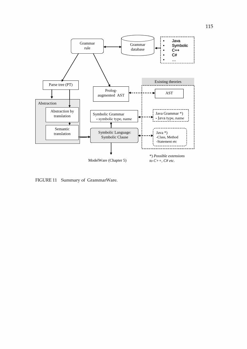
115
Abstraction
ModelWare (Chapter 5)
Existing theories
Grammarrule
ASTProlog-augmented AST
Parse tree (PT)
Symbolic Language:Symbolic Clause
Symbolic Grammar- symbolic type, name
Grammardatabase
Abstraction bytranslation
Semantictranslation
*) Possible extensions to C++, C# etc.
Java *)-Class, Method-Statement etc
Java Grammar *)- Java type, name
• Java• Symbolic• C++• C# • …
FIGURE 11 Summary of GrammarWare.
116
5 MODELWARE, THE ATOMISTIC SYMBOLIC MODEL
The main features of any modeling technique are expression power, performance, and richness of semantics. OMG distinguishes modularity, transformability, traceability, specialization capabilities, and executability as the main feature requirements for models. In this section an atomistic, symbolic source code model is described, the purpose of which is to meet these requirements (Bézivin, 2005).23F
24
5.1 Foundation for ModelWare
Specification for ModelWare is described in the following proposition:
Proposition 2. The contents of the Symbolic language can be transformed into an atomistic model, which contains only atomistic elements, whose links are embedded into the atoms bi-directionally. The operational semantics of the original code can be implemented in the run method of each element type making simulation possible.
In this section a symbolic atomistic model is defined. Its base, the atom, is defined next.
Definition 19. Atom (source code atom). Let T be a grammar term in a parse tree. A source code atom is a reductionist construction containing the semantics of T in a single predicate form. We call this predicate a command of the atom.
24 Aspect definition is one of key features, appreciated by OMG, too, but it has no special
interest in this research from the modeling point of view. Instead, recovering selected aspects from the code can be an essential part of source code simulation and is described in Chapter 6.
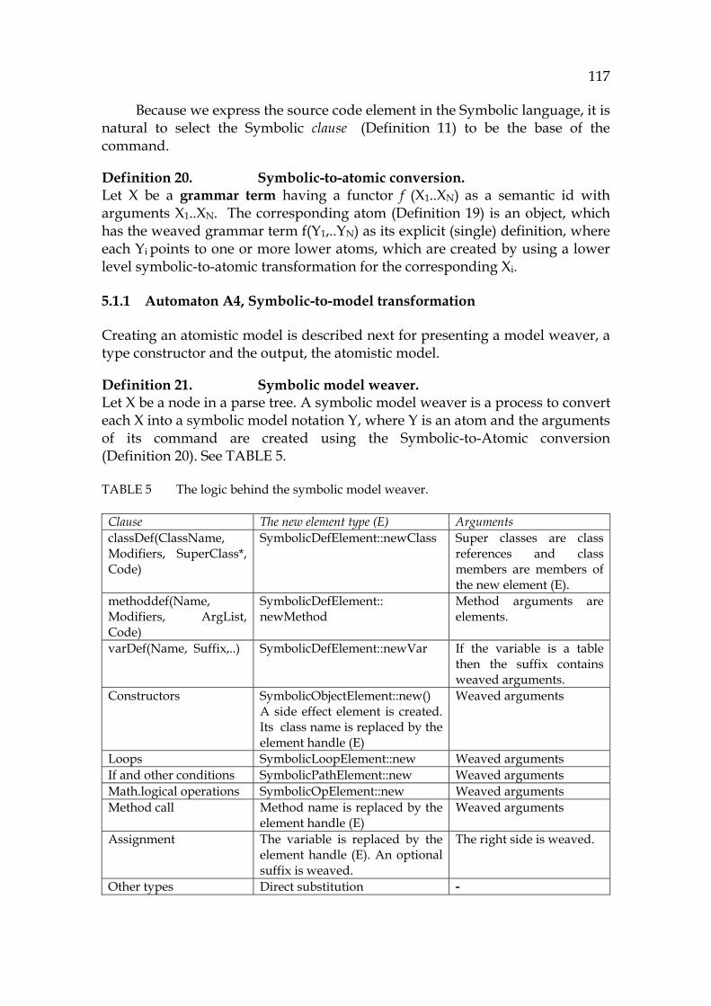
117
Because we express the source code element in the Symbolic language, it is natural to select the Symbolic clause (788HDefinition 11) to be the base of the command.
Definition 20. Symbolic-to-atomic conversion. Let X be a grammar term having a functor f (X1..XN) as a semantic id with arguments X1..XN. The corresponding atom (789HDefinition 19) is an object, which has the weaved grammar term f(Y1,..YN) as its explicit (single) definition, where each Yi points to one or more lower atoms, which are created by using a lower level symbolic-to-atomic transformation for the corresponding Xi.
5.1.1 Automaton A4, Symbolic-to-model transformation
Creating an atomistic model is described next for presenting a model weaver, a type constructor and the output, the atomistic model.
Definition 21. Symbolic model weaver. Let X be a node in a parse tree. A symbolic model weaver is a process to convert each X into a symbolic model notation Y, where Y is an atom and the arguments of its command are created using the Symbolic-to-Atomic conversion ( 790HDefinition 20). See 791HTABLE 5.
TABLE 5 The logic behind the symbolic model weaver.
Clause The new element type (E) Arguments classDef(ClassName, Modifiers, SuperClass*, Code)
SymbolicDefElement::newClass Super classes are class references and class members are members of the new element (E).
methoddef(Name, Modifiers, ArgList, Code)
SymbolicDefElement:: newMethod
Method arguments are elements.
varDef(Name, Suffix,..) SymbolicDefElement::newVar If the variable is a table then the suffix contains weaved arguments.
Constructors SymbolicObjectElement::new() A side effect element is created. Its class name is replaced by the element handle (E)
Weaved arguments
Loops SymbolicLoopElement::new Weaved arguments If and other conditions SymbolicPathElement::new Weaved arguments Math.logical operations SymbolicOpElement::new Weaved arguments Method call Method name is replaced by the
element handle (E) Weaved arguments
Assignment The variable is replaced by the element handle (E). An optional suffix is weaved.
The right side is weaved.
Other types Direct substitution -
118
A type constructor for creating model elements is defined next.
Definition 22. Type constructor (of the model weaver). Let C be a clause to be weaved and <T> its type. Type constructor TC is a constructor to create an object Symbolic<T>Element to return its handle to the calling element. A short if-example expressed in Java: if (OldFriend) print(Hello). The corresponding model is: If 1 01480000:path(iff_([at(014965C0,[])],[at(04FAFCC0,[])],[])) OldFriend 014965C0:def(vardef(basic_type("int"),"OldFriend",[],[])) print 04FAFCC0:get(call(sget([method_name("print")]), [at(01496450,[])])) Hello 01496450:def(vardef(basic_type("int"),"Hello",[],[]) Definition for the atomistic model is simple, because it only consists of atoms.
Definition 23. Atomistic model. An atomistic model is a set of source code atoms. A short main method (which has something in common with the Server program): void main() { int port = 1; new Server(port); } The corresponding atom for the main contains the following command: def(methoddef("main",[],basic_type("void"),[],[at(04FD3450,[]), at(04FB2990,[at(04FD3450,[])])])) It is easy to deduce that 04FD3450 refers to the assignment referring to the variable port and the link 04FB2990 refers to the constructor creating a Server object. In the atom there are only two essential data structures: the command and the links. The command is described next.
Definition 24. Atomistic descriptor: atom command. The atom command is the description for each atom in order to define their operational behavior. The connections between atoms are essential. They are described next.
119
Definition 25. Link of an atom. Let X be an atom. The external links of X are internal facts within X pointing to other atoms.
In the atomistic model the links are embedded into the atoms. Bi-directional links have their opposite side edges as complementary links. Static links are atom invocations in the corresponding command as well as structural links implemented by has-a and is-a relationships. Dynamic links are side effects, which are new atoms from simulation attached to the host atom by has-a and is-a links.
Below, there is an example in Java: listen_socket = new ServerSocket(port);
The corresponding list of links for the variable listen_socket is the following in XML: 1 <element name='listen_socket' handle = ’01496450’ type='var'> 2 def(vardef(cls("ServerSocket"),"listen_socket",[],[])) 3 <parent>014965C0:Server</parent> 4 <child>04FB2000:SEff 3</child> 5 <fromRef>014965C0:Server, 04FB2BB0:Set 1</fromRef> 6 </element> The lines between 1 and 6 define the element and its links. The atom has the type var and its internal handle is shown on line 1. The command is shown on line 2. The parent link tells that the parent is Server. On line 4 a side effect element (Seff 3) is shown. It is an object saved from a simulation where the ServerSocket object was created. On line 5 the possible cross-cuttings are shown. The variable is only assigned in one place, which is the element named Set 1.
By using the XML – notation it is possible to integrate software development tools for analyzing further the symbolic model and its simulation results.
5.1.2 Atomistic architecture
The atoms are implemented as hybrid objects. This concept is described next.
Definition 26. Atomistic hybrid object, AHO. The atomistic hybrid object, AHO, is an object to implement the atomistic architecture, which consists of an object-oriented interface and contents implemented by a predicate combining the logic programming paradigm with the object paradigm.
Atomistic architecture is a reductionist model having the base class (SymbolicElement) and specializations Symbolic<T>Element for each type <T>. The semantics for an atom is packed on the command field. Simulating the model is done by invoking the run method, which gives the result to the caller as Symbolic clauses. See 792HFIGURE 12.
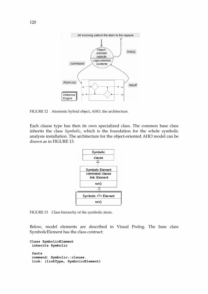
120
FIGURE 12 Atomistic hybrid object, AHO, the architecture.
Each clause type has then its own specialized class. The common base class inherits the class Symbolic, which is the foundation for the whole symbolic analysis installation. The architecture for the object-oriented AHO model can be drawn as in 793HFIGURE 13.
FIGURE 13 Class hierarchy of the symbolic atom.
Below, model elements are described in Visual Prolog. The base class SymbolicElement has the class contract: Class SymbolicElement inherits Symbolic facts command: Symbolic::clause. link: (linkType, SymbolicElement)
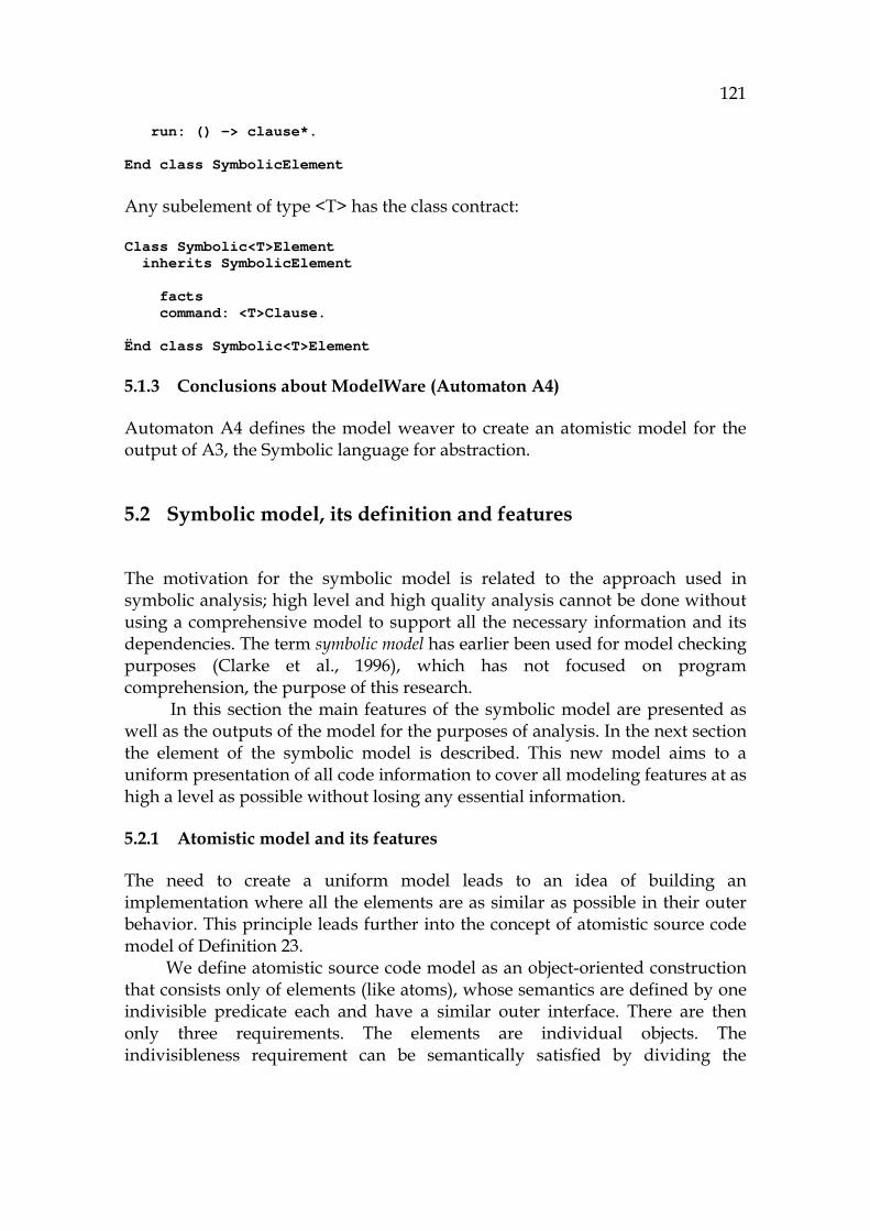
121
run: () -> clause*. End class SymbolicElement Any subelement of type <T> has the class contract: Class Symbolic<T>Element inherits SymbolicElement facts command: <T>Clause. Ënd class Symbolic<T>Element
5.1.3 Conclusions about ModelWare (Automaton A4)
Automaton A4 defines the model weaver to create an atomistic model for the output of A3, the Symbolic language for abstraction.
5.2 Symbolic model, its definition and features
The motivation for the symbolic model is related to the approach used in symbolic analysis; high level and high quality analysis cannot be done without using a comprehensive model to support all the necessary information and its dependencies. The term symbolic model has earlier been used for model checking purposes (Clarke et al., 1996), which has not focused on program comprehension, the purpose of this research.
In this section the main features of the symbolic model are presented as well as the outputs of the model for the purposes of analysis. In the next section the element of the symbolic model is described. This new model aims to a uniform presentation of all code information to cover all modeling features at as high a level as possible without losing any essential information.
5.2.1 Atomistic model and its features
The need to create a uniform model leads to an idea of building an implementation where all the elements are as similar as possible in their outer behavior. This principle leads further into the concept of atomistic source code model of 794HDefinition 23.
We define atomistic source code model as an object-oriented construction that consists only of elements (like atoms), whose semantics are defined by one indivisible predicate each and have a similar outer interface. There are then only three requirements. The elements are individual objects. The indivisibleness requirement can be semantically satisfied by dividing the
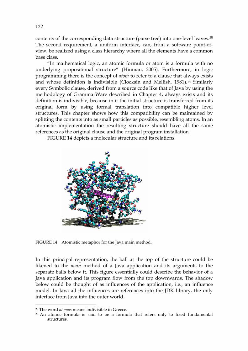
122
contents of the corresponding data structure (parse tree) into one-level leaves.24F
25 The second requirement, a uniform interface, can, from a software point-of-view, be realized using a class hierarchy where all the elements have a common base class.
“In mathematical logic, an atomic formula or atom is a formula with no underlying propositional structure” (Hinman, 2005). Furthermore, in logic programming there is the concept of atom to refer to a clause that always exists and whose definition is indivisible (Clocksin and Mellish, 1981). 25F
26 Similarly every Symbolic clause, derived from a source code like that of Java by using the methodology of GrammarWare described in Chapter 4, always exists and its definition is indivisible, because in it the initial structure is transferred from its original form by using formal translation into compatible higher level structures. This chapter shows how this compatibility can be maintained by splitting the contents into as small particles as possible, resembling atoms. In an atomistic implementation the resulting structure should have all the same references as the original clause and the original program installation.
795HFIGURE 14 depicts a molecular structure and its relations.
FIGURE 14 Atomistic metaphor for the Java main method.
In this principal representation, the ball at the top of the structure could be likened to the main method of a Java application and its arguments to the separate balls below it. This figure essentially could describe the behavior of a Java application and its program flow from the top downwards. The shadow below could be thought of as influences of the application, i.e., an influence model. In Java all the influences are references into the JDK library, the only interface from Java into the outer world. 25 The word atomos means indivisible in Greece. 26 An atomic formula is said to be a formula that refers only to fixed fundamental
structures.

123
This research treats the concept of formal model as a continuum from formal language into formal model leading to definition 796H5.2.2 of an atomistic model
5.2.2 Symbolic atomistic model
We define symbolic atomistic model as a collection of atomistic elements that forms a complete model about the corresponding system (see 797HDefinition 23). The necessary semantics is described by a symbolic notation. The symbolic notation for the Symbolic language was presented in Chapter 4. The concept of atom is abstracted by its reference and its contents (see 798HDefinition 19). Information from the atom can be read for example by a call: Atom:getContents().
There are many theories and practices related to model checking (Visser et al., 2003). Of these the most interesting principles for program comprehension purposes are the axiomatized model, program correctness, and definition for an executable model, because all of them emphasize the role of logic of the model, which is one of the strongest features of the selected approach (see Chapter 3). 26F
27 An axiomatic model is a model to apply axiomatic semantics. Axiomatic
semantics is commonly associated with proving a program to be correct using a purely static analysis of the text of the program in the form of the Hoare triple: {PRE} C { POST }. The concept of axiomatic model leads to the concept of correctness (Hoare, 1969), which is an application area of the symbolic model, because its information allows proving programs.
Features of an executable model
A model is executable if it is able to simulate the code elements of the model according to the selected formalism, thus having the desired behavior model. When the purpose is to simulate Java, then the behavior of an executable model should be comparable with that of the Java virtual machine (Qian, 1999), and the model should contain an instruction set corresponding to the Java instruction set. There is a clear difference between a model and a system (Falkenberg at al., 1998). JVM is a system to be modeled by using the technology developed in this research.
There is some discussion about whether UML models are executable or not. If the UML models don’t contain the necessary data structures and simulation features to respond to the Java environment JVM, then UML models cannot be said to be executable (Mellor and Balcer, 2002).
5.2.3 Creating the model and other model functions
For creating a model, a model weaver is needed. A model weaver is a technique to create a new unique model from the original source by transforming the 27 It is practical to prioritize the logic approach, because in most cases the current model
checking systems do not have a direct import from the source code. Configuring them involves laborious work.
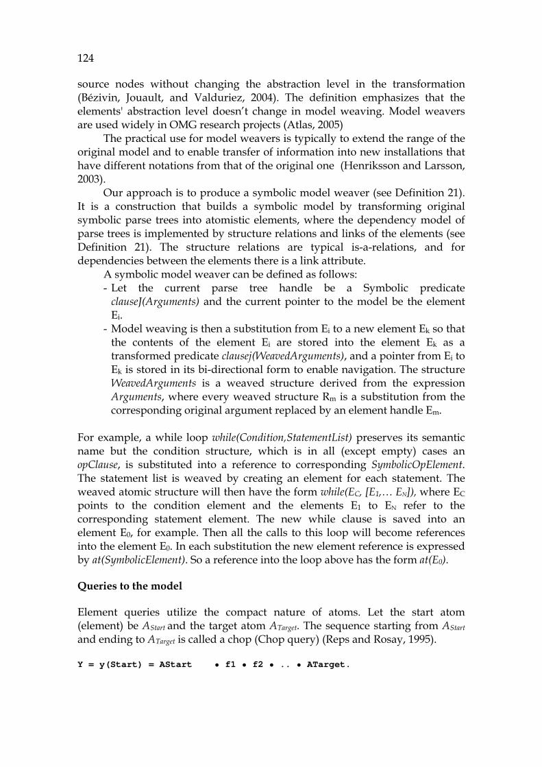
124
source nodes without changing the abstraction level in the transformation (Bézivin, Jouault, and Valduriez, 2004). The definition emphasizes that the elements' abstraction level doesn’t change in model weaving. Model weavers are used widely in OMG research projects (Atlas, 2005)
The practical use for model weavers is typically to extend the range of the original model and to enable transfer of information into new installations that have different notations from that of the original one (Henriksson and Larsson, 2003).
Our approach is to produce a symbolic model weaver (see 799HDefinition 21). It is a construction that builds a symbolic model by transforming original symbolic parse trees into atomistic elements, where the dependency model of parse trees is implemented by structure relations and links of the elements (see 800HDefinition 21). The structure relations are typical is-a-relations, and for dependencies between the elements there is a link attribute.
A symbolic model weaver can be defined as follows: - Let the current parse tree handle be a Symbolic predicate
clauseJ(Arguments) and the current pointer to the model be the element Ei.
- Model weaving is then a substitution from Ei to a new element Ek so that the contents of the element Ei are stored into the element Ek as a transformed predicate clausej(WeavedArguments), and a pointer from Ei to Ek is stored in its bi-directional form to enable navigation. The structure WeavedArguments is a weaved structure derived from the expression Arguments, where every weaved structure Rm is a substitution from the corresponding original argument replaced by an element handle Em.
For example, a while loop while(Condition,StatementList) preserves its semantic name but the condition structure, which is in all (except empty) cases an opClause, is substituted into a reference to corresponding SymbolicOpElement. The statement list is weaved by creating an element for each statement. The weaved atomic structure will then have the form while(EC, [E1,… EN]), where EC points to the condition element and the elements E1 to EN refer to the corresponding statement element. The new while clause is saved into an element E0, for example. Then all the calls to this loop will become references into the element E0. In each substitution the new element reference is expressed by at(SymbolicElement). So a reference into the loop above has the form at(E0).
Queries to the model
Element queries utilize the compact nature of atoms. Let the start atom (element) be AStart and the target atom ATarget. The sequence starting from AStart and ending to ATarget is called a chop (Chop query) (Reps and Rosay, 1995). Y = y(Start) = AStart • f1 • f2 • .. • ATarget.

125
Prolog used in this research works by default using the depth-first mode. When traversing structures as an element query, Prolog can return the selected elements at the selected granularity level. For example, the Prolog code to traverse the model and to return the output for an element query can be of the form: 1 chopping(Target) = [f(This)|Sequence]:- 2 f(NextId, Arguments), 3 Sequence = NextId:chopping(Target).
Above, the variable This on the first line will be saved into the returned sequence. It is assumed that each element has references into other elements (handle f). The clause above can be activated by a call: Sequence = StartElement:chopping(TargetElement). The output of this query resembles the input tape of the Turing machine (Copeland, 2004). The output is described with more details in Chapter 6.
Traversing the model
Due to the simple data model, a traverser can only use the atomistic contents of each element and the links embedded into the elements. The output of the traverser is an answer for a specified analysis. It is a logical structure to describe the dependencies of the elements meeting the queried conditions. An atomistic traverser may be regarded as an ideal analysis approach, because the model works like a database engine without serious side effects or preliminary preparations before the query.
A universal traverser can be demonstrated by the following logic: 1 traverser(Query, CallArguments) = [at(This,Arguments)| ResultSet]:- 2 getLogicalLink(Query, LinkedElement, LinkArguments), 3 Arguments = evaluate(CallArguments, LinkArguments), 4 ResultSet = LinkedElement:traverser(Query, Arguments). On line 1 there is a query with specified arguments on the left side and the possible output on the right side. The query can be a control flow, data flow, program flow, object flow, or any other combination between clause elements. Arguments are used to filter information off or on by using callbacks and constraints. The query will be successful for each combination when the call getLogicalLink succeeds for the current element, and the evaluating function succeeds, too. The parameters for the output will be calculated by the clause evaluate. The command traverser is capable of returning a result set that contains, for each logical link, an element handle and the evaluated arguments. This principle is useful for creating displays, for scanning information for program sequences, for analyzing object-oriented features of the OOP code, and even for

126
theorem proving. Because it is a unified principle and completely independent of the element type, it supports efficiently focused program comprehension and reaches the performance of typical graph traversing algorithms.
Outputs from the symbolic atomistic model
The data model of the symbolic atomistic model is described next. The three possible output formats from the model are as follows: - The output may consist of model elements that form a sequential chain
like that in an element query. The output can be ordered or not. It has the form SymbolicElement*.
- The output may consist of hierarchical structures as trees in the form of clause = xClause(.., clause*).
- The output may consist of parallel, alternative structures, where the parallel structure can be found like in a network. In the following expression the symbol || means a parallel definition separating all alternative branches by using a nondeterministic predicate call subClause: [ Parameter || subClause( Parameter) ] .
Unique for symbolic processing is evaluating, which is a principle to generate new values, instances, and branches by using model elements and their symbolic clause notation. A motivation for symbolic evaluation can be either an analysis that is demanding like a consumer-producer analysis, or a theorem proving process, or a simulation of source code model with all its side effects and influences. Next, some output possibilities are described.
Results from the symbolic model
We define the output of the symbolic model to enable further symbolic processing. Symbolic output model is a result set, i.e., a collection, derived from the original source and presented by using symbolic notation to enable symbolic further processing. By using a symbolic notation it is possible to express the output of
- the structures as they are, as command fields (801HDefinition 24). - the chains between structures as links (802HDefinition 25). - an analysis for queries by using the three principles above, including
simulation values and metastructures (see Section 803H5.3.5). Because the clause notation combines the elements formally as the output, the output can be used as an input for the subsequent analysis. From an output model it is then possible to create a new model, which makes it possible to create a versatile analyzing process to trace and search for all the problematic features relating to the current problem solving task, which might be an adaptive or a corrective maintenance task. These features are described in more detail in Chapters 7 and 8.
127
Features of symbolic graphs
The symbolic graph is a network based presentation, which contains the output of any analysis from the symbolic model in symbolic notation to enable re-evaluation and query justification. In general, a graph means a collection of nodes and links in a syntactic notation without semantic extensions. There are some graph languages, including Rigi (Wong, 1998) and Graphviz (Gansner et al., 2006), and tools like CodeCrawler (Lanza, 2003) that have their focus in producing graphs as outputs. Their approach is, however, limited, because in PC the graph generation should be integrated tightly into navigation in order to keep the links between the elements and the graphs in the memory of the computer, and not in the memory of the user. The latter requires a lot of manpower and a lot of extra work from the user, whereas the former can be accomplished by symbolic graphs.
The symbolic approach for graph generation is more user-friendly, because the user can change the focus and the approach flexibly according to the current results. The user can re-evaluate the information and to use the best possible hypothesis in order to tackle the most critical point in the software. Because of the symbolic notation all the transfer between alternative visualization modes and user interface components can be done by a direct translation technology described in Chapter 4.
5.3 Symbolic atom
The motivation for creating a novel construction, a symbolic atom for source code analysis, comes from an observation that there must be something in common in all the different source code elements, which is related to their external behavior and their analysis requirements. Hence, some informal research questions in implementing the symbolic model include:
- What is the largest common denominator describing the common features of source code elements?
- Should this common denominator describe the essential nature of the computer architecture?
- What is the relation between these common features and the role of computer CPU?
- Can computer software be distributed among independent elements if the software code was written for a stand-alone application without parallel features?
It is easy to see that the larger the common denominator is the easier it is to create analyzing applications, because all the common features can be standardized in an object-oriented software analysis tool by its abstracting features.

128
In order to address these questions in this study the principle of symbolic atom was created. Symbolic atom is really the common denominator (see 804HDefinition 19). Next it is compared with the specialized structure of a typical source code element.
5.3.1 Special characteristics of symbolic atom
The symbolic atom is a software element that has been semantically defined by an atomistic (indivisible) formulation. Symbolic atoms are created from source code, step by step, by splitting larger structures into atomic clauses.
The contents of the symbolic atom has been defined to be as minimal (short) as possible. An atom consists only of its symbolic name, its semantic definition and the necessary links describing static dependencies. A symbolic atom can be compared with a traditional AST node (Jones, 2003; Neamtiu, Foster, and Hicks, 2005). The project named DynamicJava is a good example about how an AST software has been programmed for interpreting Java (DynamicJava, 2007). This project shows that in programming AST nodes many compromises must be done, which can lead to the problem of entangled grammars (Klint, Lämmel, and Verhoef, 2005). The weakest part of the AST technology is, as said in Chapter 4, that the contents of an AST node are separated into many variables, and due to this separation the semantics there cannot be proved. This is the reason why an AST node is not atomistic. In fact, the concept of AST is extremely complex with its functional class hierarchies and sub-hierarchies and selected programming practices, which is evident in the DynamicJava project. In AST implementations typically the links have been implemented by using independent objects, which is very far from the atomistic idea.
In the case of the symbolic atom the links are embedded into the atoms so that for a link only the receiver and a link type must be defined. This principle saves much space compared with MDA (MDA, 2007) or XMI models (XMI, 2007), where associations are divided into numerous external elements.
The features of the symbolic atom
As said earlier, the symbolic atom can be seen as the least common denominator between all source code elements. One can consider it as an atomistic component, the theory of which has been studied widely by Anderson and Lebiere (1998) from the cognitive viewpoint. Thus there is a theoretical background for the symbolic atom, which is useful in program comprehension.
Next its semantics is described. Semantics is said to be the “agreement” about the interpretation of syntax (Baxter et al., 2004). Semantics describes the meaning of words and clauses by their references. Although much is known about programming language syntax, we have less knowledge of how correctly define the semantics of a language (Pratt and Zelkowitz, 2000). The problem of semantic definition has been the object of theoretical study as long as the problem of syntactic definition, but a satisfactory solution for the former has
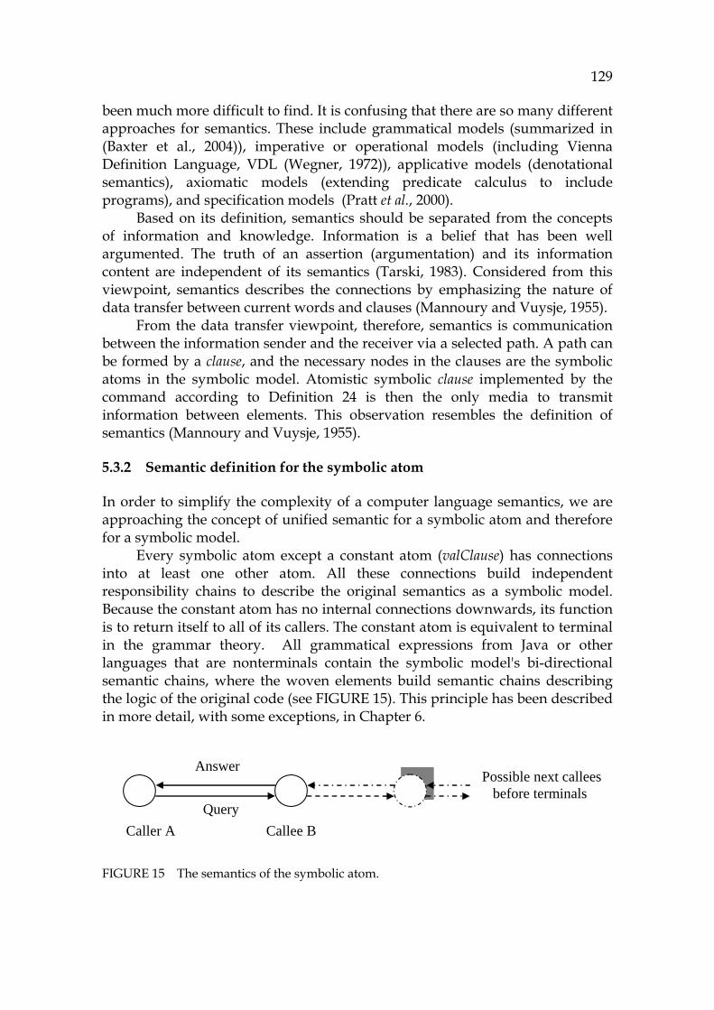
129
been much more difficult to find. It is confusing that there are so many different approaches for semantics. These include grammatical models (summarized in (Baxter et al., 2004)), imperative or operational models (including Vienna Definition Language, VDL (Wegner, 1972)), applicative models (denotational semantics), axiomatic models (extending predicate calculus to include programs), and specification models (Pratt et al., 2000).
Based on its definition, semantics should be separated from the concepts of information and knowledge. Information is a belief that has been well argumented. The truth of an assertion (argumentation) and its information content are independent of its semantics (Tarski, 1983). Considered from this viewpoint, semantics describes the connections by emphasizing the nature of data transfer between current words and clauses (Mannoury and Vuysje, 1955).
From the data transfer viewpoint, therefore, semantics is communication between the information sender and the receiver via a selected path. A path can be formed by a clause, and the necessary nodes in the clauses are the symbolic atoms in the symbolic model. Atomistic symbolic clause implemented by the command according to 805HDefinition 24 is then the only media to transmit information between elements. This observation resembles the definition of semantics (Mannoury and Vuysje, 1955).
5.3.2 Semantic definition for the symbolic atom
In order to simplify the complexity of a computer language semantics, we are approaching the concept of unified semantic for a symbolic atom and therefore for a symbolic model.
Every symbolic atom except a constant atom (valClause) has connections into at least one other atom. All these connections build independent responsibility chains to describe the original semantics as a symbolic model. Because the constant atom has no internal connections downwards, its function is to return itself to all of its callers. The constant atom is equivalent to terminal in the grammar theory. All grammatical expressions from Java or other languages that are nonterminals contain the symbolic model's bi-directional semantic chains, where the woven elements build semantic chains describing the logic of the original code (see 806HFIGURE 15). This principle has been described in more detail, with some exceptions, in Chapter 6.
FIGURE 15 The semantics of the symbolic atom.
Answer
Query Caller A Callee B
Possible next callees before terminals
130
In 807HFIGURE 15 atom A needs atom B for a calculation or for a method call or for satisfying any dependency. For computers, bi-directionality of links (see 808HDefinition 25) is natural, and is known as the call/return-phenomenon. 27F
28 This bi-directional feature of any element makes a foundation for the atomistic semantic of 809HFIGURE 15. Atom B responds to the caller (A) either by returning its contents (if B is a constant) or by continuing the call chain into the next element to satisfy all the dependencies. The chain can stop because of missing information, which is typical for symbolic processing, but it does not weaken the model use, because the returned element can be the answer itself building a formula like f(A,B,…). This output is useful, because it still allows the code reader to skip to interpret the captured mathematical notation, even if exact alpha-numeric information cannot be obtained.
This atomistic duality is very useful for PC purposes, because all the code elements of a very complex expression can be split into atomistic particles that can be handled in a standardized way, and this is typical for an equivalent Java term also. If some expression cannot be analyzed, then the lowest element can return its handle as a variable for user investigation.
The axiomatic semantics of each atom can be seen and visualized by using its contents, the command ( 810HDefinition 24). In the symbolic model the command is expressed by a structure named clause and the corresponding element type is defined by using the definition <T>. The operational semantic of each atom is in the output of each atom combined with the other atoms connected into the same semantic chain. Their common behavior creates side effects and influences other atoms. This simulation functionality will be described in Chapter 6.
The command of the atom is the description for each atom in order to define its operational behavior as an atomistic (indivisible) formulation. Predicate logic is an excellent way to implement the atom command, because each command can be implemented by a single fact (a predicate without a body). According to its definition, in a symbolic atomistic model the atom command is the same as the equivalent grammar term. This explicit compatibility makes the model elements traceable to the code and enables verifying all model information.
The term command originates from the Hoare triple, where the goal is to study program correctness. For example, each while loop has the following axiomatic descriptor: while(Condition, StatementBlock)
There are no preconditions for the while statement to be seen, but when we consider the program flow from the approach of StatementBlock, there is a precondition for it named Condition. StatementBlock can be interpreted as a
28 Goto commands are the biggest exception for this feature, but they are rarely used in
modern programming languages (Dijkstra, 1968).

131
command. After executing the expression, Condition is evaluated. It is then a postcondition, which can enable an exit from the loop.
In the atom command there cannot be open, non-ground variables, because all the links are connected into existing elements. Due to this, the entire symbolic model is in the notation of propositional calculus.
The atom command can be represented in Prolog as follows: facts command : clause The definition for clause was described in Chapter 4.
5.3.3 Expressing links between atoms
A link of a symbolic atom is a reference into another atom containing the link type and the atom referred (see 811HDefinition 25). Atomistic links are needed for analysis and navigation purposes. For example, a class hierarchy is described by using atomistic links as well as structure dependencies of the model.
All links for each atom can be queried by using the command getLinkList. There is also the function getLink to return links in succession. This function is specified to query and return links as follows:
- E:getLink() each element that has a connection into element E. - E:getLink(hasA) all structural sub-components for element E. - E:getLink(isA) the structural master components for the element. - E:getLink(sCall) static calls. - E:getLink(sRef) static references (backwards). - E:getLink(super) superclasses. - E:getLink(sub) subclasses. - E:userLinkTo links made by the user. - E:userLinkFrom user links (backwards).
In Chapter 6 dynamic dependencies and value bindings are explained. By connecting them and all the functionality of the link it is possible to build a complete dependency model describing Java semantics and enabling its simulation.
Alternative links are described in 812HTABLE 6. Because dynamic analysis has been implemented by using flat tapes (Chapter 6) in the model, there are only three types of links: hierarchical structures, static calls connecting elements, and mappings made by the user in order to connect the user domain to the model.
TABLE 6 Categories of atomic links.
Link level Link type The purpose of the link 0. Structure hasA, isA Structural form of the application 1. Static call sCall, sRef Static dependency logic 2. User links userLinkFrom and
userLinkTo Mapping the model into user problems
132
5.3.4 Arguments of the atom command
The argument of an atom command is a reference captured from the source code and translated by the model weaver to point to the equivalent atom. The atomistic argument is then always an element reference. For example, each assignment in Java has the form assign(LeftSideExpression, AssignmentOperator, RightSideExpression). The symbolic model weaver replaces the left side and the right side by elements that can be called by using the variables LeftSide and RightSide. Then the contents of the atom command becomes assign(LeftSide, AssignmentOperator, RightSide) with three arguments as in the original expression.
Every atomistic command should have at least one argument. This is because the command is based on the Symbolic language, which is compatible with the Java grammar. The type of the argument can be:
- Input, to be calculated and evaluated. - Executable, to be simulated as an independent clause. - Output, to be returned to the caller. - Reference, to continue the semantic chain into the next element. - Definition, memory space allocation, either dynamic or static.
For example, a while command imposes a condition as an input argument, and the statement block as an executable argument. From the category above it is possible to define a behavior model for each argument. For each element it is possible to create a complete black box model. This can then be transitively transferred into the next higher level as far as needed in order to create a complete behavior model for a class, a packet or a component or, for the whole application, to specify its execution model or a test environment for it.
Functionality of the symbolic atom
The axiomatic functionality of each atom is the same as its command (descriptor). Further, there is a need to analyze the dependencies and the execution and the results relating to the operational semantics of the atom.
5.3.5 Atomistic operations: scanning and searching
Atomistic operation is a public method of the atom to satisfy either simulating or traversing needs for the model. The functional model of an atom is very straightforward. It either simulates itself according to its command or provides a method for traversing purposes with other linked atoms. One motivation for traversing is transforming model information to XMI notation for other models such as UML and for tools using these.
Because there are neither containers nor main elements to contain the list of sub-elements, all the structural hierarchy should be captured by traversing the element hierarchy. In 813HFIGURE 16 the top element could be a class, number 2
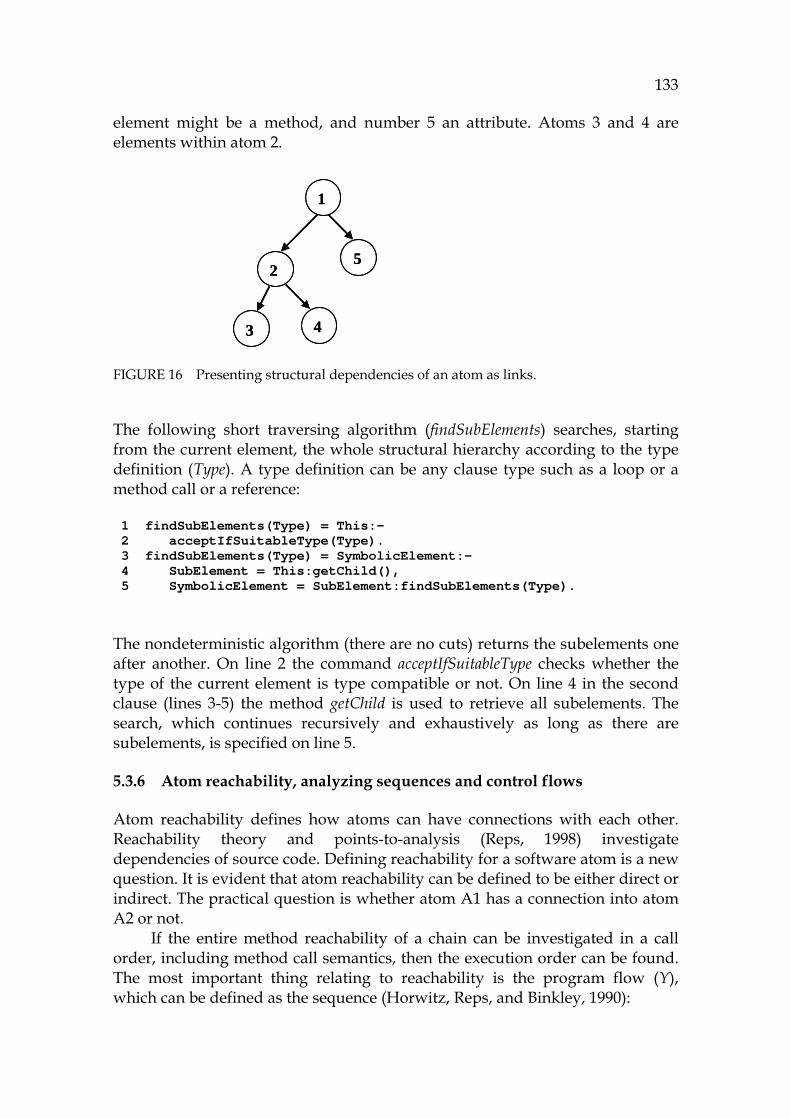
133
element might be a method, and number 5 an attribute. Atoms 3 and 4 are elements within atom 2.
FIGURE 16 Presenting structural dependencies of an atom as links.
The following short traversing algorithm (findSubElements) searches, starting from the current element, the whole structural hierarchy according to the type definition (Type). A type definition can be any clause type such as a loop or a method call or a reference: 1 findSubElements(Type) = This:- 2 acceptIfSuitableType(Type). 3 findSubElements(Type) = SymbolicElement:- 4 SubElement = This:getChild(), 5 SymbolicElement = SubElement:findSubElements(Type). The nondeterministic algorithm (there are no cuts) returns the subelements one after another. On line 2 the command acceptIfSuitableType checks whether the type of the current element is type compatible or not. On line 4 in the second clause (lines 3-5) the method getChild is used to retrieve all subelements. The search, which continues recursively and exhaustively as long as there are subelements, is specified on line 5.
5.3.6 Atom reachability, analyzing sequences and control flows
Atom reachability defines how atoms can have connections with each other. Reachability theory and points-to-analysis (Reps, 1998) investigate dependencies of source code. Defining reachability for a software atom is a new question. It is evident that atom reachability can be defined to be either direct or indirect. The practical question is whether atom A1 has a connection into atom A2 or not.
If the entire method reachability of a chain can be investigated in a call order, including method call semantics, then the execution order can be found. The most important thing relating to reachability is the program flow (Y), which can be defined as the sequence (Horwitz, Reps, and Binkley, 1990):
1
2
43
5
1
2
43
5

134
Y = sequence = A1 • Ak • A2 There are some measures describing the reachability chain:
- Atomistic distance is the number of the elements separating the atoms from each other.
- The length of the chain is the number of the elements from the start atom to the last atom.
As an example about reachability and program flows, a control flow (cfg) can be specified as a subset of the model to contain the logic and while structures, including their branching conditions.
In the next code example the method cfgSubterms is a default handler that returns the information from “non-control-flow” clauses that are processed by the method cfgList: 1 cfg(while(Condition,Stmnts)) = while(cfg(Condition),cfg(Stmnts)):-!. 2 cfg(iff(Condition, Stmnts)) = iff(cfg(Condition), cfg(Stmnts)) :-!. 3 cfg(Other) = cfgList(cfgSubTerms(Other)). On lines 1 and 2, while and if statements, returning their commands filtered by the method cfg, are detected. There is a default handler on line 3 to seek information from other clauses.
In Java there are three kinds of loops, for, while, and doWhile, which have the semantics while(Condition, Block), doWhile(Block, Condition), and for(Init, Condition, Block, RepeatBlock) (cf. definition <T5> in Chapter 4). Because of the simple loop construction all conditional elements can be captured by the following code: 1 getLoopConditions(while(Condition, _)) = Condition. 2 getLoopConditions(doWhile(_,Condition)) = Condition. 3 getLoopConditions(for(_,Condition, _)) = Condition. 4 getLoopConditions(Clause)=getLoopConditions(getLinkedTerms(Clause)). As in the control flow example, there are actual clauses that still can have sub-structures containing actual clauses. Line 4 is for retrieving these sub-structures.
5.3.7 Atomistic result processing
Atomistic result processing is a feature to keep the intermediate results and the output of the atomistic model in an atomistic form. It is not clear whether all the functions of an atomistic model should keep the model atomistic forever, after the multi-phased analysis. The model could be corrupted; the access to the atomistic elements can become more difficult if all the necessary conditions have not been met when planning the model whilst avoiding any harmful side effects (cf. software degeneracy (Lehman, 1985)).
This is why one of the core technical requirements for an atomistic model should be that the model doesn’t produce any harmful side effects, and that all the information that it produces should obey the rules of existing model

135
elements. This is a challenging requirement, because it necessitates elimination of all the intermediate results, or changing them into atomistic elements. In practice, these intermediate results should be programmed without separate memory or data structures, which are typically vectors or arrays or a container in Java. In programming them, separate nested iterators should be used. However, it is impossible to use stacked hardcoded iterators in complex queries where the nesting order is dynamic, not static. For the atomistic model, implementing a flexible, dynamic query system is not a problem.
With a traditional programming language, it may be argued, it is almost impossible to program atomistic result processing, because these languages are so tightly coupled with the computer memory model. Visual Prolog can, however, provide a higher abstraction because of its inference engine. As shown by the Prolog code examples of control flow analysis, loop analysis and chopping above, it is possible to program model traversing without using any intermediate results. Sequences can be modeled in Visual Prolog as lists by appending new members after the current list. Parallel structures can be captured by using breadth-first search and by using findall to capture all the alternatives at a time (VisualProlog, 2007).
As an example about automatic intermediate processing, one could consider searching loop variables from loop conditions (the predicate getLoopConditions above). It is possible to combine successive searches by using the Prolog’s relation model. If the purpose were to investigate all the variables that are critical and possibly erroneous and that can cause a fatal error in the program, stopping or breaking it down, then all the loop conditions in the critical control flow would form the input for a more exact analysis. This could happen for example if there were a problem in loop parameters or in method calls in the condition part of the loop. In the following code example the findVariableRefs method demonstrates how these critical variables can be found from the output of the previous search (in clause notation): 1 findVariableRefs(at(SymbolicElement,_)) = SymbolicElement:- 2 SymbolicElement:getCommand() = varDef(_, VarName,_,_). 3 findVariableRefs(Clause) = findVariableRefs(getLinkedTerms(Clause)). Again there is the resulting clause returning the accepted result on line 1 in the SymbolicElement variable. The condition to be satisfied is that the element that is referred to must have a varDef (variable definition) as its command, described on line 2. The third line is a recursive call to continue search from all linked elements.
Atomistic searches can be cascaded to build chains of hundreds or thousands of successive phases if the search has been done depth-first. Because of the principle to avoid side effects in the atomistic model, its programming model is rather straightforward. It is described in the next section.
136
5.4 Architecture of the atomistic model
The atomistic model is to be programmed using a hybrid paradigm which combines the benefits of object-oriented approach and logic programming: the advantegeous features of each can be used in order to minimize the weaknesses of the other. Logic programming suits best for combining different structures due to its relation model and wide support for language processing. The object-oriented paradigm is the best in abstracting and encapsulating objects. These two different principles can seamlessly be connected into a hybrid object.
5.4.1 Programming model for the symbolic model
A model is in general a software construction to enable integration into other technology spaces and tools (Kurtev, Bezivin, and Aksit, 2002). The symbolic model is based on elements implementing a true object architecture. In simulation it can be used in modularly building the principle of the call/return architecture, which is described in Chapter 6. The model could be decorated with an external facade, if needed, to build an external interface. A container and a facade would enable data transfer into commercial tools like MS Studio (Studio, 2007), Eclipse (Eclipse, 2007) and other tools supporting UML, allowing all the information from the model be published in the intranet. Because semantics is essential in the symbolic model, its basic behavior model is a data flow architecture emphasizing the input and output from each element.
5.4.2 Atomistic hybrid object
A hybrid object is defined to be an object that has been programmed by using two or more programming paradigms. Spinellis (1994) and others have studied multi-paradigm programming, but almost without an exception the focus has been to evaluate separate features of the paradigms for programming purposes, combining the different features on a functional level. The focus has not been on how to merge the paradigms as completely as possible, which is the focus of this research. This tight coupling is implemented by AHO-objects according to 814HDefinition 26.
The foundation of AHO is a clause expressed in the logic-based Symbolic language. AHOs internal functionality is defined by one of the Symbolic's commands. In AHO the object-oriented "capsule" acts as the handle of the object and all the object-based features (see 815HFIGURE 12 and 816HFIGURE 13). The other part of the circle contains the logic and an inference engine (IE). IE is embedded into the code of each logic programming rule, including in interpreting the command. In the figure the run method is shown. It is essential in the AHO implementation that the whole simulation process can be programmed by using the run method only. It can be called successively to make a semantic chain in order to emulate the behavior of the original code written in Java, C++, or other language.

137
The key idea behind the abstraction features of the AHO object is its class hierarchy (see 817HFIGURE 13). Each clause type has its own specialized class. All these classes inherit the common base class Symbolic Elements that inherits the class Symbolic, which is the foundation for the whole symbolic analysis installation.
5.5 Summary of ModelWare
This chapter presents a novel idea about an atomistic source code model as well as a description about the communication between source code elements that are implemented as indivisible structures, atoms. There is no evaluation in this chapter, excepting some samples, but correspondency between the original code and models can be seen in Annex 3. The semantics of an atomistic model is said to be the same as the communication model between the elements, which have been weaved from the GrammarWare technology described in Chapter 4. This can be checked in 818HTABLE 30.
An architecture for the symbolic atom is presented. It consists of the concept of AHO, an atomistic hybrid object, which is a combination of an object-oriented reference model and a reductionist predicate-based logic programming structure. Each structure is defined by using just a single Prolog fact, making the model formal and executable.
It has been shown that the atomistic model and each of its elements can be traced backwards to the source code via the Symbolic language. Here Java is presented as the reverse engineered language, though the methodology is language independent.
Because the elements are so modular that they don’t know the semantics of any other elements, it is possible to use the created model for several applications like testing, verifying code, and model checking. It is clear that refactoring and reorgnization are interesting application areas, which can accelerate creating new installations, too. The principle of links that connect the elements with each other is bi-directional, providing a foundation for high-quality navigation applications and for building visual user interfaces.
In this chapter it is proposed that the atomistic model should be able to keep its atomistic formalism in simulation. That feature is essential in building functions for partial simulation, in itself a sophisticated high-level analysis, symbolic analysis, which is capable of building a focused approach for program comprehension purposes - the main idea of this research. Unlike dynamic analysis, partial simulation described in more details in SimulationWare (see Chapter 6) is a rather flexible end-user function that allows the user to selectively make dedicated queries to the model for checking the relevancy and correctness of the referred source code model by simulating the correspondent sequences.
138
6 SIMULATIONWARE, AN ABSTRACT MACHINE FOR SYMBOLIC
In traditional computer systems code and data are complementary parts. Data is of no use there without code and vice versa. However, in modeling technologies it is a common practice to introduce data models without describing an engine that could make the selected model active. Especially, when XML models and ontologies or UML models are presented, the main focus is on the contents of the model and its internal semantics, instead of an engine and use scenarios.
The purpose of this chapter is to introduce a novel source code simulation technology, SimulationWare, which employs an abstract machine as its main construction. This engine is powered by the atomistic model, which enables simulation of the original source code at a high abstraction level using the Symbolic language and the AHO architecture, as presented in Chapters 4 and 5.
The purpose of simulation is to mimic execution of the original system, here JVM, by using the symbolic model. We speak about an abstract machine instead of a virtual machine, because the selected topic is closer to the automata theory than the execution model of a virtual machine. The methodology of SimulationWare is then language independent. In simulating a functionality, this chapter resembles the one on dynamic analysis. The purpose of this chapter, in fact, is to introduce the features of partial simulation that make symbolic analysis more flexible by producing more information than dynamic analysis. The formalism of the Turing machine is used as far as possible. Here it is based on atoms on the input and output tape in order to describe the behavioral model of a computer and hence to describe any program from the program comprehension viewpoint.

139
6.1 Foundation for SimulationWare
The specification for SimulationWare is shortly as follows:
Proposition 3. The atomistic model is simulated as an automaton so that the input atoms activating the simulation are packed in an ”input tape”, whereas the elements that have been executed with their simulation results are stored into the ”output tape”.
In this section an abstract symbolic machine is defined based on automata A5 and A6.
6.1.1 Automaton A5, defining a simulation process
We describe Automaton A5, the input process to activate simulation, by defining an abstract machine model ( 819HDefinition 27), the wanted output as a symbolic output tape ( 820HDefinition 28), and a test generator as a sequence builder ( 821HDefinition 29) as follows.
Definition 27. Atomistic machine model (automata) Let M be an atomistic model (822HDefinition 23). An abstract machine model for simulating M is a construction, where there is an input tape for starting a simulating queue and an output tape to get the results.
The input tape and the output tape are vectors or specific objects (classes) in the tool. For defining the simulation process the way a test case is defined, one only needs to append the corresponding atoms one after another to the tape.
Definition 28. Symbolic output tape A symbolic output tape is a result from simulation made by the atomistic machine ( 823HDefinition 27) in the execution order.
Because of the execution order the symbolic output tape contains information similar to that of the UML sequence diagram. However, the notation of the tape is more accurate and symbolic, making further processing flexible for re-evaluating purposes.
Definition 29. Sequence builder Let X be an input tape for a simulation. A sequence builder is a tool to pack the necessary atoms to X in the assumed execution order for the atomistic machine in order to activate a wanted test case (sequence).
When simulating a method, only its atom needs to be added to the input tape. However, if its arguments contain other than basic types, it is necessary for the user and the sequence builder to create an initialization logic for these types to precede the atom in the input tape.
For example, the Connection method in Appendix 1 has the following header:

140
public Connection(Socket client, int priority, Vulture vulture)
For simulating the method, it is necessary to initialize the variables client and vulture by calling the object constructors before the method.
6.1.2 Automaton A6, the simulation process
We define tools and functions for simulating object-oriented code to include a simulator ( 824HDefinition 30), side effect as a simulation result ( 825HDefinition 31), partial and interactive simulation (826HDefinition 32 and 827HDefinition 33), selector functionality ( 828HDefinition 34), simulation method ( 829HDefinition 35), simulating logic ( 830HDefinition 36), atomistic semantics (831HDefinition 37), and formalism for state transition tables (832HDefinition 38).
Definition 30. Simulator Let T be an input tape for simulation. A simulator reads an input tape in order to simulate the atoms of it by implementing the corresponding semantics. The simulator updates the contents of the tape in order to save the execution history with the results of it according to 833HDefinition 28.
Definition 31. Side effect Let A be an atom in an atomistic model. A side effect is an output element from simulating A containing the influences that A creates in its environment, i.e., in other atoms.
Side effects form a special group in the Symbolic clause (834HDefinition 11). This feature makes it possible to connect other clauses and side effects together in order to create dynamic dependency models.
Typical examples of this are calling a method, assigning a value, branching, and creating an object, which can be formalized as:
- Creating an object: obj(Class, Arg*) - Creating an array: arr(Array, Suffix*) - Repetition in a loop: redo(Code) - Assignment: bind(SymbolicElement,AssignOp,Expression) - Calculated value: midValue(Def, Input, Output) - Branch: branch(FromElement, ToElement) - Method call: call(CalledElement, Arg*) - JDK reference: jdkRef(Result, Class, Method, Arg*)
Only through symbolic exececution and dynamic analysis can one generate such information about every invocation, every variable reference and every action caused by commands at the programming language level. Two modes for simulation are described next: partial and interactive simulation.
141
Definition 32. Partial simulation Let M be an atomistic model. A partial simulation is an interactive process to simulate a subset of M using a focused approach.
The opposite of partial simulation is the traditional approach, i.e., total simulation, which tries to simulate the main goal of the model (in Java, the main method). Each partial simulation is a sequence producing one output tape as a result.
Definition 33. Interactive simulation Let M be an atomistic model. An interactive simulation is a process, where the user selects the program flow in M to be simulated in ambiguous situations of M.
Interactive simulation corresponds to the sequence builder in 835HDefinition 29. While the sequence builder is capable of creating batch processes, interactive simulation is a navigation method to traverse the selected contexts. A selector functionality is required by the user to control the simulation process.
Definition 34. Selector Let X be an ambiguous branch (atom) in an interactive partial simulation session. A selector is a dialog for the user to ask which alternative should be selected in that simulation.
Some typical selections are selecting a type for a variable or an argument or a branch for a condition.
Atomistic simulation
Atomistic simulation can be defined by the corresponding method, the logic inside it, the semantics between atoms, and the state transition table formalism as follows:
Definition 35. Simulating method (run) Let A be an atom in an atomistic model M having command C. The run simulating method is a method, which uses the semantics of C in order to implement the assumed behavior for A so that the situation of M with side effects will be updated in order to allow a recursive simulation of the called atoms with their invocations.
We state that the necessary atom activation for each element type has the form: Result = Atom:run(). It is necessary to initialize only some atom types before their use. These types are methods, some variable types, and dynamic references if no corresponding constructors have been run in the sequence before a reference.
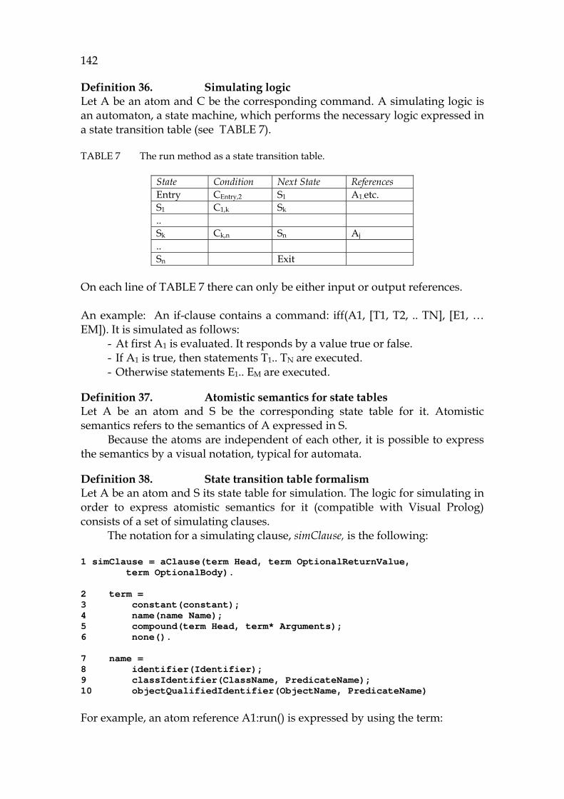
142
Definition 36. Simulating logic Let A be an atom and C be the corresponding command. A simulating logic is an automaton, a state machine, which performs the necessary logic expressed in a state transition table (see 836HTABLE 7).
TABLE 7 The run method as a state transition table.
State Condition Next State References Entry CEntry,2 S1 A1.etc. S1 C1,k Sk .. Sk Ck,n Sn Aj .. Sn Exit
On each line of 837HTABLE 7 there can only be either input or output references. An example: An if-clause contains a command: iff(A1, [T1, T2, .. TN], [E1, … EM]). It is simulated as follows:
- At first A1 is evaluated. It responds by a value true or false. - If A1 is true, then statements T1.. TN are executed. - Otherwise statements E1.. EM are executed.
Definition 37. Atomistic semantics for state tables Let A be an atom and S be the corresponding state table for it. Atomistic semantics refers to the semantics of A expressed in S.
Because the atoms are independent of each other, it is possible to express the semantics by a visual notation, typical for automata.
Definition 38. State transition table formalism Let A be an atom and S its state table for simulation. The logic for simulating in order to express atomistic semantics for it (compatible with Visual Prolog) consists of a set of simulating clauses.
The notation for a simulating clause, simClause, is the following: 1 simClause = aClause(term Head, term OptionalReturnValue, term OptionalBody). 2 term = 3 constant(constant); 4 name(name Name); 5 compound(term Head, term* Arguments); 6 none(). 7 name = 8 identifier(Identifier); 9 classIdentifier(ClassName, PredicateName); 10 objectQualifiedIdentifier(ObjectName, PredicateName) For example, an atom reference A1:run() is expressed by using the term:

143
compound(“:”, name(“A1”), [name(“run”)])). These clauses can be translated and moved to Visual Prolog and interpreted in it providing that there is necessary logic for compound terms in the interpreter.
6.1.3 Conclusions about SimulationWare for automata A5 and A6
Automaton A5 defines a testcase generator, a sequence builder to collect atoms to the input for a coming simulation. Automaton A6 defines the Turing machine model for Java code in the notation of the symbolic, atomistic model.
6.2 Background for the abstract machine
In model research, when describing the definition and formulation, the main interest is perhaps the semantics of the model (Slonneger and Kurtz, 1995). Despite this, no satisfactory solution has been found for it (Pratt and Zelkowitz, 2000). Different kind of semantics are ordered by their specialization degree: informal, operational, transformal, and denotational semantics as well as models and algebraic semantics (Baxter and Gray, 2005).
All these types of semantics emphasize the task of presenting the interconnections between the modeled elements. From this point-of-view the transfer between all language elements is important, although the purpose of semantics is not to investigate the contents of the data transfer. This thought, in turn, leads to the idea of symbolic evaluation.
The atomistic model is a construction without any hierarchy. That is why the only way to investigate its contents and practical features involves an extensive use of semantics. In an atomistic model all the semantics can be formally defined by the semantics between its linked elements. An atomistic model of this kind is thus a distributed communication system, where the logic has been distributed into command fields of each element. A pure and simple construction sounds a good principle, but its drawbacks include the lack of centralized logic to control the whole system. It is necessary to study whether something essential may be missed when dealing with complex object-oriented source code models, where there typically are many kinds of dynamic functionalities between classes and objects. How far can this symbolic model support PC if the model contains multiform object-oriented features? Can this model work at all if the whole source code has not been captured into the model to cover all the dependencies?
When extending the focus into the dynamic behavior profile, operational semantics must be defined, and there will be a need to define an idealized abstract machine behind the model to execute the model. Due to its atomistic structure (see 838HFIGURE 12), the execution of the model can be realized using command fields of the basic elements. Each element can be thought to form one part of a Hoare triple, defining its preconditions and postconditions. It is thus

144
possible to achieve a well-established semantic behavior model for Java starting from the element level and extending it over the entire Java level, covering in practice all Java applications and all practical situations that may be produced using Java as the programming platform. 839HFIGURE 17 illustrates the role of the abstract machine, i.e., conversion of axiomatic semantics into operational semantics. This conversion formalism enables making tools that can produce important feedback for programmers to allow them understand better all the relations in the source code model.
FIGURE 17 The role of the abstract machine and SimulationWare.
The purpose of this chapter is to show how object-oriented source code can partially be analyzed. Differently from existing partial evaluation (Schultz 2001), which aims at specializating programs, our purpose is to increase the user’s knowledge of the source code behavior using a selective, focused approach. We use the concept symbolic analysis to mean partial simulation ( 840HDefinition 32), which is intended for analyzing selective parts of the source code by using a selector functionality ( 841HDefinition 34). While Chapter 5 defines axiomatic semantics for the symbolic model, this chapter will transform it into operational semantics (842HDefinition 37) by describing the simulation process ( 843HDefinition 30) for the model.
6.2.1 Chomsky hierarchy and the corresponding automata
The different levels describing languages and automata are presented in the Chomsky hierarchy in order to emphasize their typical features and, which is important, to declare what are the relations and requirements between each language type and the corresponding automata (Chomsky and Schützenberger, 1963).
Operationalsemantics
GrammarWare
ModelWare
SimulationWare
Behavior modelfor the language
Axiomaticsemantics
Abstract Machine
Languageto be described
Model
Executable ModelOperationalsemantics
GrammarWare
ModelWare
SimulationWare
Behavior modelfor the language
Axiomaticsemantics
Abstract Machine
Languageto be described
Model
Executable Model

145
The Turing machine is generally presented as using a tape with bits as its input and output. This simplification has made it possible to create many formalisms for various purposes such as the theory of computation (Hopcroft and Ullman, 1979). The most interesting feature of the Turing machine is that it makes it possible to observe the sequential nature of program models. Each operation in a computer system can be thought of as a modular part of the larger program having its own input-output model typical for the von Neumann computer architecture (von Neumann, 1951). 28F
29 This call/return-phenomenon allows the code to be analyzed if a similar tape that is typical for the Turing machine model can be produced. The Turing model has many connections with program verification (Hopcroft and Ullman, 1979) shedding light on program correctness. This, in turn, strongly contributes towards program comprehension, troubleshooting being an essential part of it. In the next section Turing machine equivalence and Chomsky hierarchy are considered from the viewpoint of the atomistic model.
6.2.2 Principles for computations in the atomistic model
As a separate construction, each symbolic element, i.e., an atom (844HDefinition 19), is a state machine at level 3, because the functionality of each element have been defined by a formalized clause of the Symbolic language, and the clause is independent of the elements connected to it. It should be noted that the hierarchy level of each command is one.
As described earlier, the semantics of a program is a summary of the semantic data transfers between elements (845HDefinition 37). This feature leads to the principle of level 2, a pushdown automaton. The simplest case is when the elements that are coupled into the focused element are deterministic containing no branches, calls, decisions, or loops. In that case the current element works like a state machine at level 3 having the property to terminate always by returning only one value. But when the coupled elements are complex, such as loops, then the semantics of the focused element exhibits, as seen from outside, the same behavior as the corresponding part of the software.
Each computation uses stack (push) when it calls each of its substructures such as a constant or a subformula. When the substructures have been evaluated, then the stack will be emptied one term at a time (pop or pull). After each calculation, the stack should have the same state as before it. When this evaluation process is programmed recursively (normal compilers do that by default in method calls), simulating the evaluation process is not a problem, because the formalism of method calls in a typical programming language, used in the tool, has the push down semantics equivalent to that of Java.29F
30
29 A drawback for this architecture is that it causes performance problems for conventional
processors. The processor must wait for the previous command to be executed. 30 One additional feature that makes developing Java simulators easy is that a method can
not return values in its arguments, the only output is the return value.
146
Some model elements contain sequential features. For example, while and if elements contain a statement block transformed into a list of elements. In the Prolog tool used in this dissertation the development language has the semantics to simulate sequences as lists (Warren, 1983; Sterling and Shapiro, 1994).
6.2.3 Turing machine model
The Turing machine is a simplification for picking up symbols from the tape (input) one after the other and to make correct decisions based on its current state according to its state model, where the newest symbol is the key to the state table to select corresponding activities. After each evaluation the machine saves the possible intermediate results to the tape (output, see 846HDefinition 28). Some authors divide the tape into separate input and output tapes.
The atomistic model of 847HDefinition 27 is similar to the principle of the original Turing machine when the atoms are seen as symbols of the Turing tape. The greatest improvement to the latter is that the logic can be distributed into the symbols due to the atomistic semantics of 848HDefinition 37; there is no need for a centralized logic typical for Turing machine constructions. Another significant feature is that the symbol is an atomistic element and the tape is either a reverse engineered program or a selected part of it. The keys to the state transition table are fetched from the command of the current element, and the state transition table resides in the memory of the current element (see 849HDefinition 26). In order to emphasize the compact nature of the logic (850HDefinition 36) this local state transition table (851HDefinition 38) has been implemented into the selected method (run) of each element type ( 852HDefinition 35).
An actual research topic for this chapter concerns whether this kind of distributed intelligence can produce the same functionality as its equivalent Chomsky level. In this chapter each element type will be evaluated, and the possible problems in simulating each element type will be described.
6.2.4 Symbolic abstract machine (SAM)
The motivation for a symbolic abstract machine, later called SAM, comes from the Turing machine and its theory. Another source of motivation is the theory of operational semantics that is intended here for simulation purposes.
We define the symbolic abstract machine, SAM, to be an automaton to execute symbolic code in order to generate a specified behavior model while assuming the necessary input and output responsibilities. In 853HFIGURE 18 the logic and the principle of this chapter are presented in a notation of a technology space (see (Bézivin, 2005)) in order to emphasize the different roles of the three main components: 1) Java execution model, 2) the new high level simulation environment, the symbolic abstract machine (see 854HDefinition 27) based on an atomistic model and the output model for the simulated information, 3) the Turing machine with its tape metaphors. The user has its role as a Decider (Hopcroft et al., 1979) in controlling such selections (855HDefinition
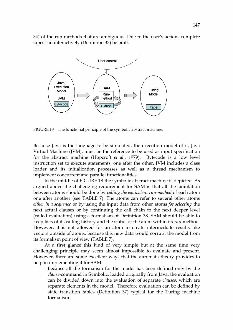
147
34) of the run methods that are ambiguous. Due to the user’s actions complete tapes can interactively ( 856HDefinition 33) be built.
FIGURE 18 The functional principle of the symbolic abstract machine.
Because Java is the language to be simulated, the execution model of it, Java Virtual Machine (JVM), must be the reference to be used as input specification for the abstract machine (Hopcroft et al., 1979). Bytecode is a low level instruction set to execute statements, one after the other. JVM includes a class loader and its initialization processes as well as a thread mechanism to implement concurrent and parallel functionalities.
In the middle of 857HFIGURE 18 the symbolic abstract machine is depicted. As argued above the challenging requirement for SAM is that all the simulation between atoms should be done by calling the equivalent run-method of each atom one after another (see 858HTABLE 7). The atoms can refer to several other atoms either in a sequence or by using the input data from other atoms for selecting the next actual clauses or by continuing the call chain to the next deeper level (called evaluation) using a formalism of 859HDefinition 38. SAM should be able to keep lists of its calling history and the status of the atom within its run method. However, it is not allowed for an atom to create intermediate results like vectors outside of atoms, because this new data would corrupt the model from its formalism point of view (860HTABLE 7).
At a first glance this kind of very simple but at the same time very challenging principle may seem almost impossible to evaluate and present. However, there are some excellent ways that the automata theory provides to help in implementing it for SAM:
- Because all the formalism for the model has been defined only by the clause-command in Symbolic, loaded originally from Java, the evaluation can be divided down into the evaluation of separate clauses, which are separate elements in the model. Therefore evaluation can be defined by state transition tables (861HDefinition 37) typical for the Turing machine formalism.
Java Execution
Model
JVM
Bytecode
SAM
Clause
Run-method
TuringModel
Tape
User control
Java Execution
Model
JVM
Bytecode
Java Execution
Model
JVM
Bytecode
SAM
Clause
SAM
Clause
Run-method
TuringModel
Tape
TuringModel
Tape
User control

148
- The requirement for partial simulation ( 862HDefinition 32) is challenging, because all the dynamic features have their own, possibly unknown history, when simulation starts ”in the middle of the code”. To adjust and fix the behavior model for this partial simulation model, we simply propose a user interface that would allow the user to control the control flow according to 863HDefinition 34 in order to trace the program for familiarization, verification and test coverage purposes.
In order to prove the completeness of the formalism for each clause, the operational semantics of the static and dynamic symbolic clauses is presented in this chapter with the results. With the help of these results, it is then possible to evaluate each clause and its compatibility compared with the execution of the corresponding bytecode (Qian, 1999).
6.3 Technical preconditions for Java simulation
Next the preconditions for Java simulation in general are described including the nature of a context-free language, known problems of symbolic execution (see Section 864H2.5), and the challenges of partial simulation of object-oriented code.
6.3.1 Java execution model
The execution model for Java has been defined by Sun for each of its versions (Gosling et al., 2005). Most features of its behavior model have been specified in the semantics of the language itself. The functionality of JVM is not essential from the viewpoint of program comprehension, but for debugging purposes it is necessary to note the loading protocol for classes and interfaces that are not in the memory when the simulation starts. Loading non-existing classes and starting their constructions have influence on the control flow of a sequence. Understanding the process of memory allocation is not very important from the PC point of view, because there is an automatic garbage collector in Java. It is important to describe thread simulation, and the command synchronized belongs to the same topic. Together these cover the real time behavior of the program. Simulating exceptions is a special case that is not described in this dissertation because of its narrow scope.
The JDK library is a versatile package containing all the functional interfaces to the outer world from a Java application. JDK calls are widely used in all typical classes in Java applications. Because of its large size it is not possible to emulate the whole JDK in this research. Instead, the connections between Java code and the JDK library are emphasized. By interpreting these connections it is possible to create a functionality model for each Java class, method and package.
149
6.3.2 Sequential computation model
Like computer architectures in general, Java computation model is sequential due to the influence of the Turing model on the background. One command is executed after another without any parallel functionality, threads being a special exception. Generally, all the commands return the control to the location where they were invoked. This makes it easy for the analyzing tool to follow the control flow. The exceptions for that call/return principle are return, continue, break, and exit commands. All of them are described in pathClause of Symbolic, in the sub-command controlCommand.
6.3.3 Reachability analysis
Reachability, also known as a points-to analysis, is a functionality to solve how program elements refer to each other and what kinds of rules there are for referencing. Identifying the methods and variables of Java and connecting the references with actual definitions is not a problem in an atomistic model, because the model weaver inserts a pointer to the host element for each element in order to enable a complete hierarchical identification process (known as lookup, in semantics (Sethi, 1996)). By using the host element it is possible for the tool to find the definition in all cases, including inheritance. By using the pointer to the host element it is possible to identify unnamed classes, inner classes, and all special naming features of Java. Virtual functions are a special case for references that point outside the current class. These references may be cascaded, giving rise to the challenge of identifying the right object to be called. All the variable and object references in the symbolic model are found in the refClause command, and method references are found in the getClause command.
6.3.4 Problems and limitations of symbolic execution
Entscheidungsproblem (terminating problem) has been a much discussed problem in program verification (Turing, 1936). Some modifications are needed in the simulation tool to avoid the problem. Problems can arise when loop variables are not known or the methods behind them cannot be simulated (Cheatham et al., 1979; Havlak, 1997). Recursive functions that have an inductive logic also cause problems if the induction cannot be simulated completely, giving rise to a non-terminating and infinite control flow for the simulator.
For these special cases some additional constraints must be built for the simulator. The easiest way is to create a maximum counter for limiting loops. An alternative is a user interface for controlling loops manually, which is useful in controlling threads in the forever loops of their run methods.
Because the behavior and loops must be limited in simulation, it weakens the completeness of the output. From a program comprehension viewpoint this is not a serious drawback, because all the functionality from each loop can be
150
captured after the simulation in the Symbolic language. Once a loop has been simulated three times, the information necessary for the user to evaluate whether the loop exit logic is valid or not can often be found. If that does not become clear from these three runs, the loops can be simulated under the user's specific control focusing on the terminating behavior.
6.3.5 Relations of the abstract machine to hardware and performance
This chapter shows how atoms can be used so that there is no need for an external memory. The instruction fetching process is equivalent for the run method of each element, calling other elements according to the semantics of each element. Loops, conditional statements, method calls and other commands can be employed in this.
In this research, the performance of the model has not been used as a factor in any evaluation criteria. So there is no discussion about whether using an external memory or other CPU blocks would be essential to speed up the simulation. Instead, the atomistic model has been made to create a clear formalism to enable practical tools, too, as applications. In this research we extend the concept of register machine, which normally has been directed for mathematical and logical operations in Java. Earlier the semantics of the register machine has been proposed to cover the semantics of Pascal using lambda calculus (Backus, 1978). One essential precondition for abstracting Java as a register machine is that there is a user control ( 865HDefinition 34) for focusing the simulation process. The challenges of the object-oriented behavior from the program comprehension viewpoint are discussed next.
6.3.6 Influence of the object-oriented paradigm to simulation
Much research has been done about the problems of object-oriented programs and their dynamic behavior (Wilde and Huitt, 1992). Walkinshaw, Roper and Wood (2005) have described these problematic topics (866HFIGURE 19). The numbering is added.
The cases in the figure from 1 to 12 are numbered from the easiest to the most difficult. The cases are ordered by their nature (either static or dynamic) and by the complexity or ambiguity of the references they can create from the viewpoint of source code analysis:
R1. JDK references are stored to the model. R2. Static method calls have their calling semantics with returned values. R3. A factory design pattern is used for objects containing states. R4. References to a super class, including attributes and methods. R5. Methods are inherited from super classes. R6. Conditions for overwritten methods must be detected. R7. Polymorphic calls must be identified according to actual arguments. R8. Different class instances must be identified. R9. Threads and other delocalized operations give rise to distributed phenomena.

151
R10. Object instances and their memory requirements must be identified. R11. Shared object references should be mastered by a read/write logic. R12. Selecting a type for an object depends on commands like instanceOf.
FIGURE 19 Challenges for analyzing OO programs.
In the following the challenges of the requirements from R1 to R12 that must be observed in investigating OOP code will be discussed.
R1. JDK references. The JDK library should be loaded into SAM to support analyzing JDK symbols. Two examples of these references are direct and indirect (dynamic) invocations: a. Instantiation of a new object, e.g., new ServerSocket (see Appendix
1) is a direct invocation that reveals the structure to be called exactly.
b. System.out.println(“Hello”) contains an indirect branching according to the value of the attribute out in the class System. It typically points to the PrintStream class that contains the println method.
R2. Static method calls. The requirements for static calls include the description of static simulation, described later in this chapter. The process of argument binding and returning the value from a method to the caller is also described. Most of the Symbolic clauses are static.
R3. State model. A state is defined to be an individual set of variable values in an object. This is a fairly exact definition, covering also the combinations. It is very challenging for the user to understand all the
3
4
11
7
8
10
9
1
2
6
5
12
3
4
11
7
8
10
9
1
2
6
5
12
152
possible states, and all the value combinations. Each variable is a possible source for numerous new state candidates. The logic defines more complex states and the transitions between them. Analyzing the state behavior of methods and objects is an interesting topic to evaluate by partial simulation. How can states be identified? Can a state machine be evaluated by an abstract machine?
R4. References to a super class, including attributes and methods. Calls to the super class can be detected to the underlying code. To provide a capability to simulate inheritance requires that the information about super classes is stored into each class element.
R5. Inherited methods in a super class. Inheriting a method is a process to direct the method call into the super class in all cases of a closed virtual function, where a method corresponding to the argument combination cannot be found in the object referred to. Inheritance is a lookup searching the method or attribute in the next super class, then in the next higher super class, and finally traversing the whole hierarchy if needed.
R6. Overwritten methods in a base class. When a method has been invoked by a closed virtual function, then the most detailed implementation is selected.
R7. Polymorphic calls according to current types. When there are many methods of the same name with alternative argument and type definitions, then the type combination that has exactly the type compatible method argument and return type combination is selected. In many cases the types are known, and the simulator works deterministically and automatically like JVM. However, in partial simulation this is a problem if all arguments are not bound. The type of the returned value is the most complex thing to be analyzed because it cannot be evaluated until the method has been executed. For resolving this problem an interface dialog for the user is needed to present the possible polymorphic method candidates. The user is then the Decider to control the program flow.
R8. Identifying different class instances. The object handles must be stored into the model during simulation. When an object is created, a link to the handle value (pointer) from the corresponding method and the corresponding type should be saved. For example, a call Connection c = new Connection(…) causes an object Connection to be created. The creator clause saves the handle into a link to the variable c, but not to the memory of c, because using an atom as a memory doesn’t belong to the principles of an atomistic model.
R9. Threads and other delocalized operations. Communication from a thread to the elements that are not loaded into the model is analyzed from the code. Threads must be simulated individually, user-assisted, because thread processing could require multi-output-tape realization as in JVM.

153
R10. Managing object instance and their memory. When object instances are created, they have their creators stored as links. So it is possible for them to signal to their creators whether they are still alive or not.
R11. Shared object references. The most complex situation in analyzing object-oriented code is the shared pools between objects storing object references. The pools can be vectors, matrices, or objects that use references as attributes. If the pool is a vector, then vector semantics should be added to the model. However, currently there is no vector semantics in SAM. It is the responsibility of the user to trace the pool references in order to decide about the reference in each case. So object pools must be identified as a separate behavior model for program comprehension purposes, to enable verification of large software.
R12. Selecting a type in program logic. It is possible to reverse engineer type casts and the command instanceOf according to the control flow. This simulation resembles the behavior of JVM.
An additional feature to the topics above is the analysis of design patterns (Gamma et al., 1995) due to references, but it is not in the scope of this research.
6.4 The Turing machine as a reference for simulation
The Turing machine is an abstraction of a computer to illustrate the overall behavior of programs. It has not been intended that concrete installations use Turing machine as their architecture (Herken, 1995). However, it is essential that every computer program works like the Turing machine. Another very important point is that every program can be simulated by an idealized Universal Turing Machine (UTM) (Rogozhin, 1998), which can simulate any computer. In this research Java has been selected as the programming language, and an atomistic model compatible with the main principle of the UTM is proposed.
In this chapter the most important commands of the Symbolic language are discussed using the Turing model as a reference. That is why it is essential to define how this new construct should use the tapes:
- An input tape is a collection of atoms that specify the elements to be simulated (such as a method, or a sequence containing several elements) according to 867HDefinition 29.
- An output tape is a sequence (868HDefinition 28) containing the commands that have been executed as well as the results from them.
Because of the challenges of OOP, it is not assumed that this simulation can be executed automatically without manual interaction. That is why a necessary user support should be added to the abstract machine to extend it to contain an interactive extension for simulation.
154
The symbolic abstract machine (SAM) is a modification from the one-tape Turing machine (Hopcroft et al., 1979) (see 869HTABLE 7) with its set of states, its finite set of tape symbols, input symbols, the transition function, and final (accepted) states.
The finite state machine is represented by a state transition table ( 870HDefinition 38) together with its state register. The "external storage medium" is the tape. The input to the state machine is the scanned symbol on the tape, the command of the atom (871HDefinition 24). In the original Turing machine the output of the state machine is a symbol to print or the erase command and tape motion-command left or right (Rogozhin, 1998).
However, as stated earlier, the atomistic model, due to its distributed nature, is a clear opposite of the centralized transition function. This doesn’t prevent us from analyzing similar features. The elements of SAM are symbols of the Turing machine, because they can store input and output information by using their links.
- When simulation is started first time, the possible set of input states is an empty set. But, because each dynamic reference requires preliminary actions to initialize the object referred, these actions are the necessary input states.
- If simulation is started from the beginning of any method, then the arguments of it must be initialized. There should be a user interface in the tool to allow this to be done.
- The simulation of the whole program or an applet starts from the main method, which is a special case.
- To extend the symbolic model to cover all the behavior of source code, an extension for a side effect (SideEffectElement) must be defined to implement the simulation result, the side effect defined by 872HDefinition 31. This ensures that the whole atomistic model will indeed be atomistic and coherent after each simulation.
6.5 Foundation for source code simulation
Simulating means mimicking the reality, which is the world around us. The purpose is to build a logical model about the world, or an Umwelt. This model is typically transformed into a program to be processed by a computer.
6.5.1 Simulation in computer science
Computer simulation has its traditions beginning from the start of the computer theory (Minsky, 1967; Hein, 1996). Turing has used the term "simulation" to refer to what happens when a computer runs a state transition table by describing the state transitions, inputs and outputs of a subject discrete-state machine when running a program. The computer thus simulates the subject
155
machine. Hence, simulation has strong connections to state machines and transition systems.
However, it is not clear how to simulate standard programming languages without using external hardware and software library packages. Static analysis can be used, but it cannot produce program comprehension information the way behavioral models can (Richner and Ducasse, 1999).
6.5.2 Source code simulation
We define source code simulation ( 873HDefinition 30) as a functionality that simulates the operational semantics of software according to the semantics of the programming language in order to provide an execution trace and, by means of it, the behavior model for the simulated code.
There are two special cases in source code simulation: with the use of a virtual machine (VM) or without it. There may be an application server to control active programs and their status by maintaining the transactional status of the whole system. However, it is clear what source code simulation situation should do, because this has been specified by the programming language. The program is, in fact, a clear specification of how the computer system should work (Reeves, 2005).
When using Prolog as a simulator’s language, the problems of simulation consist of the problems of interpreting the formalism of the state transition table logic defined in 874HDefinition 37 and 875HDefinition 38. Furthermore, simulation of loops, arrays, complex references, and unknown types are special requirements.
6.5.3 Complete simulation of the whole application
Complete simulation is a process that covers all the selected features of an application from the user’s point of view.
In Java typically the main method is the place to start a complete simulation. To enable it, the whole application should be loaded into the symbolic model. For analyzing JDK references we only load the class contracts of JDK into the model, without loading the code of the libraries, because JDK, due to its large size, could overload the analyzing tool.
Complete simulation has a lot in common with dynamic analysis. Complete simulation is, however, much more flexible with its options, output possibilities, and tracing. 30F
31
6.5.4 Partial simulation
Many times a complete simulation of the whole program is too large and complex because of the large amount of information in the model. This is why more flexible and granular approaches are needed. Partial simulation
31 The performance aspect of the simulation does not, however, play a key part in symbolic
abstraction (SAM implementation)
156
( 876HDefinition 32) is intended for a fundamental evaluation of selected critical features of the application. This is discussed next.
We define partial simulation as a functionality that makes it possible for the user to create a focused view to the source code by means of simulating only selected parts of the code. Partial simulation of source code (PSSC) has not been proposed earlier, because traditionally it has been assumed that a simulation should always be complete, returning all the relevant values from each object. However, it is seldom practical and possible due to the large amount of code information. This mismatch is one reason why Walenstein (2002) has argued that current reverse engineering tools have failed. They don’t focus on the user’s problem in trying to capture all possible information, whether it is relevant or not. 31F
32 In order to make PSSC possible, some arrangements that are not necessary
with a complete evaluation of the software must be made: - The parsing process (see Section 877H4.1.2) of the analyzing tool, here SAM,
must be modified to accept parts of software that are smaller than a traditional file to be compiled. A good solution for this is to make parsing and simulation more flexible it to modify the start symbol of the grammar (see 878HDefinition 1) to contain smaller elements, including separated methods and statements and groups of methods and statements. In this new abstraction the compiled information should be moved into default structures, such as a default class and a default model, to contain the created elements.
- Some semantic principles for references should be made more allowable in the Symbolic language (see 879HDefinition 11) than in the original language, because not all invocations can be completely recognized in simulation. These changes don’t cause interpretation problems if the source has been captured from a compiled Java program, because Java software has been checked by its integrity rules. Partial simulation doesn’t change that. A well-defined user interface to support handling all ambiguous or incompletely defined variables and object types must be created to fill the gap between the loaded parts and parts that are not loaded. This interface to implement interactive mode is later referred to as selector (880HDefinition 33).
The criteria for partial simulation deals with the following questions:
- Granularity: What is the smallest part of source code that can be simulated as a separate session?
- Correspondence: To what extent can PSSC correspond to the behavior of the original program? This can be evaluated by using dynamic analysis as a reference. It is possible to trace the commands that have been executed by using both dynamic analysis and PSSC.
32 Instead, partial evaluation is seen as a technique for program optimization by
specialization.

157
- Coverage: To what extent can the user influence, in advance, the control paths that the simulation process should use? This question is important, because through an appropriate user's influence PSSC can provide a completely new testing paradigm.
The most important technical prerequisite for partial simulation is the ability to use symbolic processing. In cases where a definition of an element cannot be found or a value cannot be known (because it is outside of the model), the only means for a typical non-symbolic tool to deal with this would be to give an error message from an unknown reference. In our approach the Symbolic clause enables symbolic references.
The main task of a tool using PSSC is to deal with the precondition problem of the Hoare triple. If all the conditions of the precondition {P} can be satisfied considering declared and bound variables and types referred from the simulated code, then partial simulation can produce reliable information.
The levels of PSSC granularity include the following: - Statement level: Individual statements are simulated in order to check
computation and calculation rules and critical parts of algorithms. Loop analysis is an essential part of it.
- Method level: Simulating one method at a time makes it possible to test, in detail, each difficult method in order to check its black box behavior as well as the grey box. It is possible to find out how the arguments are used in order to return the selected value.
- Class level: This level describes how a class and its object behavior can be evaluated. The good news for the class level simulation is that there is no need for any preliminary testing arrangements, except starting the constructor to create the dynamic model. If the class includes a state machine, then by partial simulation it is possible to evaluate each individual state combination by activating its methods from the selected starting locations. Usually the states are encoded by a switch command, an if command, a listener, or by other arrangements. All events and their behavior can be simulated partially, but in complex models creating simulation sequences should be automated. This approach has some correspondences with the principles of model checking (Visser et al., 2003) and theorem proving (Duffy, 1991).
- Component level: Component level is important, because often the components are coupled tightly with each other, making testing laborious. By using PSSC it is possible to simulate each public method of the component as well as the selected sequences in any order to validate the functionality of the component.
- Layer level: It is possible to load all the components, related to a specified architecture layer, to the model. From a layer structure it is possible to get data flow information selectively by reflection models (Pacione, Roper, and Wood, 2003).
158
The practical use for PSSC is to enable a focused approach to source code simulations by using the selected granularity level. The atomistic model is ideal for such construction because of its extreme modularity. However, a symbolic notation is the only way to abstract unknown or vaguely known fuzzy information, which is typical for any partially loaded application.
Problems of partial simulation
The notions or problems related to partial simulation include:
- Reference to an abstract class: If the variable, having an abstract class type as its definition, does not have a known value, then the set for all possible references includes the subclasses of the abstract class.
- Reference to a concrete class: If a variable, referencing a concrete class, does not have a value, it is possible for the simulator to use the most abstract type for simulation.
- If there is a reference in the code to a more specialized operation than could be enabled by the current object handle (whose type is currently more abstract), then the user could change the type of the object instantiation to more specified to enable simulation of the more specialized function.
A general rule in referencing unknown object variables should be that the tool should ask the user whether the corresponding objects are to be initialized by their constructors. This is one part of the role of interactive simulation, described next.
Interactive simulation
As stated earlier, partial simulation cannot be used without the support of the user in deciding which control paths should be executed in each case. The main task for interactive simulation (compared with automatic simulation) is to ensure coverage for PSSC to enable the user to complete the analysis of each particle of the source code. We define interactive source code simulation (ISCS, see 881HDefinition 33) as a functionality to help the user in partial simulation to trace all possible control paths (program flow) in order to verify all the parts of the source code successively. The targets for interactive simulation are as follows:
- Variables: to evaluate further expressions (variables with free (non-fixed, non-ground) values, especially object variables).
- Conditions: to create branches needed for verifying critical paths. - Types: to verify the wanted class/type in the active class hierarchy. - Loops: to verify all loop conditions. - Objects: to verify and activate constructors.

159
Interactive simulation gives the user the possibility to be a Decider (Hopcroft et al., 1979), which is the level 0 in the Chomsky hierarchy. By using this principle it is possible for the virtual architecture of SAM and the Decider, together, to form a minimum architecture to enable verification of the most critical places of the studied software.
There are some prerequisites for ISCS. The information for ISCS should be in a symbolic notation. If that is not the case, it is impossible to maintain the status of variables and their invocations including control paths and the states of conditional expressions. In that case there should be a default model for unknown variables, classes, and types. For example, unknown classes should be modeled as stub classes without contents if none of its members are known.
By using the symbolic clause notation, each intermediate value and expression can be printed to the user either exactly in the format that the tool uses or translated into a verbal form or a picture. The symbolic presentation techniques are described in Chapter 8.
In order to control the logic a simulation selector is needed. We define simulation selector to be a control switch for the user to select the control path for simulation. The subfunctions for the simulation selector, which support interactive simulation, are the following:
- Condition selector: The user can select the logic paths to be simulated. - Type selector: The user can select the types and objects to simulate. - Object selector: The user can select the class instances to be simulated. - Value selector: The user can select the values a variable can have. - Expression selector: The user can skip the logic of an expression
(operation) if there are some unsolved parameters in it. Each of these consists of a set of questions, to be implemented by a simple query dialog.
Simulating state machines
Because the user interface of the simulator (SAM) works in a command level, it is accurate enough to enable simulating all the features of state machines and even for verifying the logic of user interface applications, even though the logic of them has been embedded inside methods. To satisfy these requirements Selector has the switches to control the selected program flow. For example, to decide which event to select, an expression selector is used. For selecting an individual path, a condition selector dialog is used.
6.5.5 Run method, the nucleus of the simulation
The run method ( 882HDefinition 35) makes simulation possible by being the glue which connects the current atom to other actual atoms around it in order to make a correct sequence, i.e., a tape with its side effects according to the state formalism of 883HDefinition 37.
A general call for a run method of an element E is the following: Output = E:run()
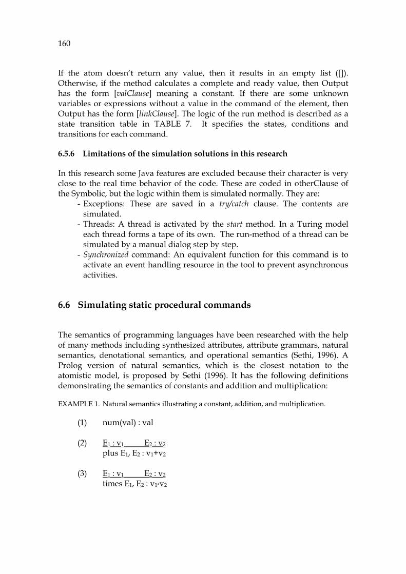
160
If the atom doesn’t return any value, then it results in an empty list ([]). Otherwise, if the method calculates a complete and ready value, then Output has the form [valClause] meaning a constant. If there are some unknown variables or expressions without a value in the command of the element, then Output has the form [linkClause]. The logic of the run method is described as a state transition table in 884HTABLE 7. It specifies the states, conditions and transitions for each command.
6.5.6 Limitations of the simulation solutions in this research
In this research some Java features are excluded because their character is very close to the real time behavior of the code. These are coded in otherClause of the Symbolic, but the logic within them is simulated normally. They are:
- Exceptions: These are saved in a try/catch clause. The contents are simulated.
- Threads: A thread is activated by the start method. In a Turing model each thread forms a tape of its own. The run-method of a thread can be simulated by a manual dialog step by step.
- Synchronized command: An equivalent function for this command is to activate an event handling resource in the tool to prevent asynchronous activities.
6.6 Simulating static procedural commands
The semantics of programming languages have been researched with the help of many methods including synthesized attributes, attribute grammars, natural semantics, denotational semantics, and operational semantics (Sethi, 1996). A Prolog version of natural semantics, which is the closest notation to the atomistic model, is proposed by Sethi (1996). It has the following definitions demonstrating the semantics of constants and addition and multiplication:
EXAMPLE 1. Natural semantics illustrating a constant, addition, and multiplication.
(1) num(val) : val (2) E1 : v1 E2 : v2
plus E1, E2 : v1+v2
(3) E1 : v1 E2 : v2
times E1, E2 : v1*v2
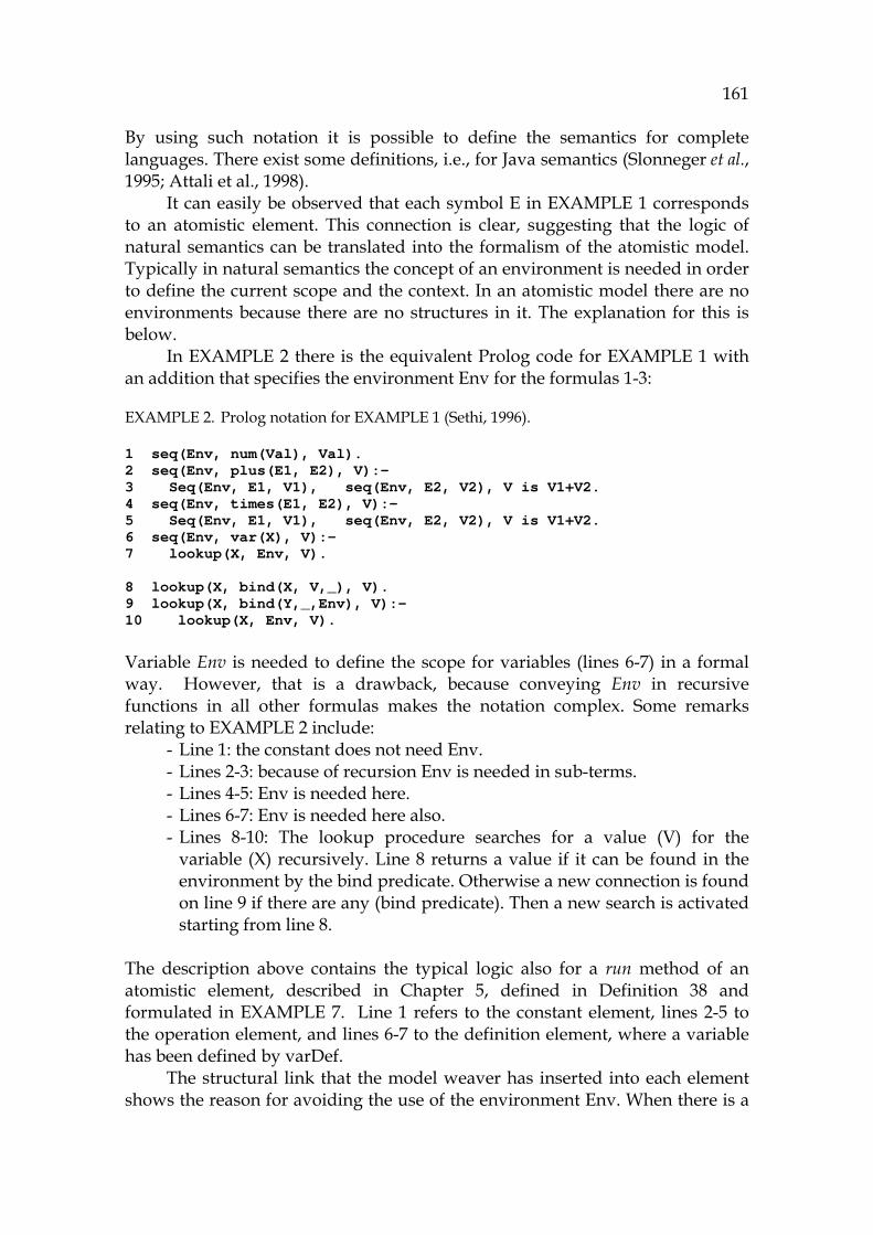
161
By using such notation it is possible to define the semantics for complete languages. There exist some definitions, i.e., for Java semantics (Slonneger et al., 1995; Attali et al., 1998).
It can easily be observed that each symbol E in 885HEXAMPLE 1 corresponds to an atomistic element. This connection is clear, suggesting that the logic of natural semantics can be translated into the formalism of the atomistic model. Typically in natural semantics the concept of an environment is needed in order to define the current scope and the context. In an atomistic model there are no environments because there are no structures in it. The explanation for this is below.
In 886HEXAMPLE 2 there is the equivalent Prolog code for 887HEXAMPLE 1 with an addition that specifies the environment Env for the formulas 1-3:
EXAMPLE 2. Prolog notation for 888HEXAMPLE 1 (Sethi, 1996).
1 seq(Env, num(Val), Val). 2 seq(Env, plus(E1, E2), V):- 3 Seq(Env, E1, V1), seq(Env, E2, V2), V is V1+V2. 4 seq(Env, times(E1, E2), V):- 5 Seq(Env, E1, V1), seq(Env, E2, V2), V is V1+V2. 6 seq(Env, var(X), V):- 7 lookup(X, Env, V). 8 lookup(X, bind(X, V,_), V). 9 lookup(X, bind(Y,_,Env), V):- 10 lookup(X, Env, V). Variable Env is needed to define the scope for variables (lines 6-7) in a formal way. However, that is a drawback, because conveying Env in recursive functions in all other formulas makes the notation complex. Some remarks relating to 889HEXAMPLE 2 include:
- Line 1: the constant does not need Env. - Lines 2-3: because of recursion Env is needed in sub-terms. - Lines 4-5: Env is needed here. - Lines 6-7: Env is needed here also. - Lines 8-10: The lookup procedure searches for a value (V) for the
variable (X) recursively. Line 8 returns a value if it can be found in the environment by the bind predicate. Otherwise a new connection is found on line 9 if there are any (bind predicate). Then a new search is activated starting from line 8.
The description above contains the typical logic also for a run method of an atomistic element, described in Chapter 5, defined in 890HDefinition 38 and formulated in 891HEXAMPLE 7. Line 1 refers to the constant element, lines 2-5 to the operation element, and lines 6-7 to the definition element, where a variable has been defined by varDef.
The structural link that the model weaver has inserted into each element shows the reason for avoiding the use of the environment Env. When there is a
162
reference into a variable “X” in the original Java code and a model derived from it has been created, then the link field is_A of the calling elements has the environment information functioning similarly to the lookup method. That is why in the simulation there is no need for a lookup-method, making its semantics very straightforward. There are only atom references in the atomistic model.
6.6.1 Extending the symbolic model into a behavioral model
In an atomistic model the elements are the only places to keep information. The original construction, described in Chapter 4, doesn’t contain other elements apart from the ones from Java code. In a behavioral model intermediate results and outputs for evaluation are needed, too. For this purpose the symbolic model is extended by a new dynamic type, which is called a SideEffect (see 892HDefinition 31) and which illustrates the nature of the new information.32F
33 To implement it in the model, the following definition is needed.
We define side effect element (see 893HDefinition 31) as an extension to the symbolic model for capturing the dynamic activations from the source code. The behavior profile for each simulation is a collection containing all the side effect elements from the run. From the tool approach it inherits the base class SymbolicElement and with it all the features of the original model element such as traversing, printing, navigating and even executing. The purpose of the side effect element is to describe, in detail, the progress of the program. The calculated values, branches and evaluated conditions can be used for tracing a problem, for code familiarization, and for automatic theorem proving in order to verify the logic.
A lot of effort has been put into researching how to extract information in dynamic analysis. There is a strong need to collect very detailed information of this type from dynamic analysis, but there is no accepted information model for the results (Denker et al., 2006). Therefore, it has been proposed that a special virtual machine is needed, because dynamic analysis is not an ideal analysis to collect information, and because it produces its results as side effects from executing the code. Thus it is very difficult to control the process of dynamic analysis for verifying purposes.
Connecting elements by an evaluating chain
The elements must work with each other seamlessly without extra variables or flags. That seamless activity is enabled by the call/return architecture, which is referred to here as an evaluating chain. Its main purpose is to guarantee repeatability for simulation. Its logical equivalence in the Chomsky hierarchy is
33 Partial simulation often refers to elements that are not loaded into the model. Because the
referred element can be of any type (method, variable, object), all outer references are systematically called side effects in the symbolic model. Final outputs are called side effects, too.
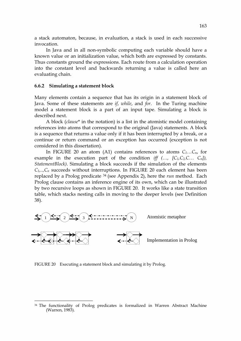
163
a stack automaton, because, in evaluation, a stack is used in each successive invocation.
In Java and in all non-symbolic computing each variable should have a known value or an initialization value, which both are expressed by constants. Thus constants ground the expressions. Each route from a calculation operation into the constant level and backwards returning a value is called here an evaluating chain.
6.6.2 Simulating a statement block
Many elements contain a sequence that has its origin in a statement block of Java. Some of these statements are if, while, and for. In the Turing machine model a statement block is a part of an input tape. Simulating a block is described next.
A block (clause* in the notation) is a list in the atomistic model containing references into atoms that correspond to the original (Java) statements. A block is a sequence that returns a value only if it has been interrupted by a break, or a continue or return command or an exception has occurred (exception is not considered in this dissertation).
In 894HFIGURE 20 an atom (A1) contains references to atoms C1…Cn, for example in the execution part of the condition iff (…, [C1,C2,C… Cn]), StatementBlock). Simulating a block succeeds if the simulation of the elements C1,..,Cn succeeds without interruptions. In 895HFIGURE 20 each element has been replaced by a Prolog predicate 33F
34 (see Appendix 2), here the run method. Each Prolog clause contains an inference engine of its own, which can be illustrated by two recursive loops as shown in 896HFIGURE 20. It works like a state transition table, which stacks nesting calls in moving to the deeper levels (see 897HDefinition 38).
FIGURE 20 Executing a statement block and simulating it by Prolog.
34 The functionality of Prolog predicates is formalized in Warren Abstract Machine
(Warren, 1983).
1 2 3 N Atomistic metaphor
Implementation in Prolog
1 2 3 N Atomistic metaphor
Implementation in Prolog

164
6.6.3 Constants and their semantics (valClause)
Constants are, as stated earlier, the lowest level in the ecology of software. Simulating a constant as a separate element simplifies the semantics of other code elements. With the help of constant elements the behavior of other elements can be made equivalent in all situations, and this provides us with a unified behavior model for all elements. That is why constants can be found in the semantics of all traditional notations including natural semantics (Slonneger et al., 1995).
As a result from simulation a constant returns its value to the caller. Thus, for a constant, a state table consisting only of the entry and exit states is feasible. The constant elements provide practical means for PC as follows:
- By using their bi-directional links it is possible to navigate around locations where they are used, in order to obtain an image of the software ecology. This image can be very useful in data analysis and in troubleshooting.
- Constant elements are excellent for tracing the model and for defining critical points in theorem proving.
6.6.4 Simulating operations (opClause)
There are many types of operations in Java: - Logical, inclusive, exclusive, and bitwise operations for and and or - Testing equality and other relative comparisons - Transfer operations - Mathematical calculations - Not, tilde (~), and cast operations - Instanceof operation - Conditional operator ? - This and Super.
Logical operations, comparisons, and calculations are simulated in SAM by a simple interpreter as they were in Java-operations, in most cases without any difference in the functionality. Casts are simulated by attaching the type of the expression into the element. This and super are simulated by referring to the corresponding element in the model.
From the viewpoint of an evaluating chain the operation clauses are intermediate phases, or filters, to be more exact. They can hold one or two parameters in a parsed form, although in the code the number of parameters can be very large. Any parameter can have multiple nesting levels.
6.6.5 Simulating variable references (refClause)
Variable references can point either to a single variable or to an array (table), which has a suffix described here, by using a clause list for each index. There are two possible cases in the simulation approach: the variable can have a value

165
or it can be missing. In the former case the value will be returned to the caller. In the latter case there are some alternatives due to symbolic notation and the characteristics of partial simulation. If the user wants, he/she can enter any value to be assigned to the variable. Otherwise a default value or initialization value (as in Java) is used. Array references are calculated by evaluating the indexes before pointing to the element. Arrays are simulated by using a sparse matrix technique (Tewarson, 1973).
6.6.6 Simulating assignments (setClause)
An assignment causes a change to the data. The left side can be either a single variable or an array reference, and the right side can be any expression. In the symbolic model the right side is simply an atom reference, because it can refer either to a variable (or array variable) or to an operation element. The assignment operator needs simulation, because there are many alternatives in Java including pre- and post–incrementing and decrementing.
As an output the assignment causes a side effect, which changes the status of the program. If the variable is dynamic, it must be reset in exiting the dynamic method.34F
35 Saving the side effects of assignments to SAM happens as follows:
- If the right side is a constant, then a link from the variable is made to the constant.
- If the value has been calculated from an expression creating a new constant, then the connection from the left side element is created to the new constant element.
- If the right side cannot be evaluated, then the assignment information will be saved by the setClause itself (because it is very short).
- If the user entered a value, then this new value is saved. Auto-incrementing and auto-decrementing are combined assignments; variable references have the behavior of both of them, including the corresponding value change.
6.6.7 Simulating conditional clauses (pathClause)
The conditional clauses are if and switch-case. In the Symbolic language in the same group (pathClause) there are the control commands return, break and continue (as well as userBreak and toolBreak), because they all can change the execution order. Simulating conditional clauses is made by evaluating the
35 From the viewpoint of PC a static assignment is more complex than a dynamic one,
because a permanent change causes problems in repeating the code in test cases. In a large application, public attributes, if changed widely in the code, are the most difficult part to be mastered. In the symbolic model their influences can be traced.

166
corresponding operations (opClause) of the condition and by selecting the corresponding branch based on the result.
Simulation of an if statement resembles the behavior of the original Java statement. A switch-case structure can be expressed in the symbolic model either by a large command or by unpacking it to separate if commands. The latter alternative is more complex to program because of the successive case branches and the logic of break and default commands.
6.6.8 Simulating loops (loopClause)
Loops are the only commands that can cause repetition and recursion. Loop commands consist of while, for, and do-while. Simulating them causes problems, if a large number of iterations is required. The forever loops are a special case, and widely used in threads. Because of huge number of iterations the output tape can grow exponentially. To prevent overloading, simulating loops must be controlled by logic.
In 898HTABLE 8 a state transition table ( 899HTABLE 7) for the while-loop is presented as an example of the compatibility between the Turing model and Prolog as a tool development language.
TABLE 8 While command as a state table.
Current State Condition Next State IO Entry Condition Decision Decision True True: Decision False Exit True: BlockControl S1 S1 BlockControl S(i) last S(i) BlockControl Condition
Exit LastStatus
The state table shown in 900HTABLE 8 has been programmed with Visual Prolog in 901HEXAMPLE 3. The left column of the example, after the line number, contains the labels of the left column of 902HTABLE 8. On the second line the atomistic command, a loopClause, is split into condition and execution (LoopStatements) parts. Otherwise the conversion is very straightforward, except that there is a sub-command runBlock to implement block simulation returning the status of the block.
EXAMPLE 3. The state table of while command in Prolog.
1 Entry run(CurrentStatus) = LastStatus:- 2 getParameters() = [PreCondition, LoopStatements], 3 Condition ConditionResult = run(This, PreCondition), 4 Decision if checkIfTrue(This, ConditionResult) = true 5 then 6 True: LoopStatus = runBlock(This, LoopStatements),
167
7 Last S(i) LastStatus = run(LoopStatus) 8 else 9 Exit LastStatus = [] 10 end if Analyzing loops relates to the terminating problem (Entscheidungsproblem). In loop simulation it is necessary to constrain the number of iterations, making the simulator a Decider. Wrong interpretations caused by limiting iterations can be avoided by informing the user about a break generated by the tool with an internal signal toolBreak.
6.6.9 Simulating method calls (getClause)
Because of the challenges of simulating late binding, described in Section 903H6.3.6, it is useful to simplify the notation of a method call to allow multiple invocations in the call structure for the run-time decision made by the simulator. Then, instead of an atom reference, there is a list of atom references in the definition getObject of the getClause. If in the list there is only one candidate, then it is selected for simulation if the argument types match with the parameters. The selector method is a feature of the tool to allow the user to select manually which method to activate.
In the symbolic model a method call activates the selected element by assigning values to the parameters before entering its code. A method can use the return command to cause an exit from the method anywhere. The returned value can be void or any expression in the range that is compatible with the type of the method. Because the parameters are implemented as independent elements, the activation model is simple, making simulation straightforward. Each parameter value assignment corresponds to a typical assignment clause, and the inner part of the method behaves atomistically without knowing its activation history. The data that activates a method invocation is called an activation frame. One should save it into the tool, because the information about method invocations is the best information for tracing a program. This is true, because method calls form a very clear interprocedural concept for PC purposes (Horwitz, Reps, and Binkley, 1990b).
In traditional program analysis interprocedural and intraprocedural slicing and dependency analysis are kept apart, giving rise to two different research areas (Binkley and Gallagher, 1996). In the atomistic model there are no other constructs apart from atoms, making the model uniform. The gap between interprocedural and intraprocedural analysis in the symbolic model has vanished because of its simple invocation model (904HDefinition 37). Another challenge for object-oriented program comprehension is virtual functions, described later.
168
6.7 Simulating dynamic object-oriented commands
Static commands are easy to simulate, because from the atomistic point of view they can be thought to be public code where the code of methods have been taken into a large code pool, providing that the necessary parameter assignments are made correctly. Dynamic commands have their own challenges, described in this section.
6.7.1 Limitations of the partial simulation of object-oriented code
Being able to interpret object-oriented (OO) code is important from the program comprehension viewpoint, the written program and its behavior model greatly differing from each other. Its challenges are shown in 905HFIGURE 19.
In complete simulation that has been started from the main method, the tool is able to find the correct type for each variable, because it is possible to identify each constructor call. However, in partial simulation it is not sure how an object or an object handle have been initialized, because the initialization code is outside of the actual control flow.
One needs to know whether it is possible, in a partial simulation in the atomistic model, to interpret and initialize the referred objects so that by means of interactive control, the selector ( 906HDefinition 34), it is then possible for the user to analyze any part of the OO-code, covering all possible logic paths.
It is clear that the user should have a consistent comprehension about the principal use of the objects containing at least one typical use for each of them when starting the simulation. This information forms part of necessary initialization knowledge. In this respect the ecology of objects can be captured by manually searching the constructors.
6.7.2 A protocol to handle unknown types and object handles
Handling unknown information is a real challenge in any technology. Some theories about how to solve the problem come from the expert systems sector and other sectors of AI (Copeland, 2004). In source code simulation the user can work in many "eagerness" levels, which is described by either systematic or opportunistic approach (von Mayrhauser et al., 1997). The different interaction levels are useful in their typical situations relating to familiarization and troubleshooting. Sometimes the user wants to get an exact numeric answer for some expression, but a symbolic expression consisting of the axiomatic notation of the sub-structures may result in an expression resembling a mathematical formula such as y = f(X) + C.
Symbolic evaluation makes it possible to create and to obtain source code information according to the user’s eagerness level. The lowest level is the static code itself, which, as its output, creates an output tape containing clauses of the Symbolic language. The highest eagerness level is a complete execution sequence consisting only of alpha-numeric values resulting from calculations.
169
This level is called Decider in the Chomsky hierarchy. The possible levels between these two extreme granularities are not specified, as they are more relevant to the area of AI.
In order to cover all possible situations where an object variable (X) can occur in the code in the current control flow (CF), the following list, known as the object relevance list (ORL), has been created:
- A constructor is in CF before there are any references to it. This situation is deterministic and complete if the arguments for X can be initialized. To solve the object relevance list for the arguments if that is needed is a recursive process .
- In method calls a non-initialized object type X is used as a parameter. If the parameter refers to an interface, then there are many possible types of which to select depending on the hierarchical level of the interface and its subtypes.
- An object reference to X is found in CF before an assignment to it. There are two possibilities. The variable can refer either into an abstract type (open virtual function) or to a non-abstract type (closed virtual function).
It is the responsibility of the interactive simulator to consult with the user in situations where an object variable is not initialized before being referenced. Here the following questions are relevant:
- What is the type of the object variable (type means here a Java class)? - Do you want to initialize it? If so, what constructor (of a list) do you
want to use?
Because of this interactive logic all references can be mastered, but sometimes it can be too laborious to select all the types systematically. In those cases the user can skip the questions and use symbolic notations that are close to the static notation.
6.7.3 Simulating create commands (creatorClause)
In Java there are two kinds of creator clauses: createClass for objects and createArray for arrays. Simulating object creation in the atomistic model is done as follows:
- A new object is created and its handle is saved into the class element which will contain all member references to the referred class.
- The constructor is simulated. Perhaps user interaction is needed for selecting the constructor method (in cases where the invocation is ambiguous).
- The handle from the object is returned to the caller. Possibly it is saved into an object handle corresponding to the Java assignment.
170
6.7.4 A protocol to simulate polymorphism
In creating the symbolic model all types cannot be known because of late bindings. It makes program comprehension and tool building complex. Here we propose a construction, which contains a model that is as simple as possible but has the necessary flexibility that is characteristic for object-oriented software. In the atomistic model all the methods of the class that have the same name are call candidates, atomic references in the call. In simulation, when a method is called, the call candidates are checked one after another if their parameters match with the caller. How to select a method for execution depends on the situation:
- If the invocation is clear and explicitly points to a suitable method, with only one possibility, then there is no need for user interaction.
- If there is no prototype for the current invocation in the referred class or in its class hierarchy, the tool traverses the class hierarchy and shows a list of methods to the user. The user selects the method to be activated or skips it if it is not an important function for analysis.
6.8 Atomistic and distributed semantics
As a conclusion we propose that the symbolic model can be formalized as a tuple resembling the formalization of the original Turing machine (Hopcroft et al., 1979) as an abstract machine (907HDefinition 27). It can be implemented with or without using a blank symbol.
Hence, SAM = <Q, Γ, Σ, δ , q0, F>, where the notation is interpreted as: δ Transition function to refer to the run method of each element. F Final state to refer to the exit state of the simulation of the element. Q State transition table: the set of states. q0 Init state: the entry state for simulation, covering necessary
initializing actions. Γ Finite set of tape alphabet symbols. Σ Subset of Γ, the set of input symbols.
The formalism remains valid in all granularity levels. A difference to TM is that the symbols (Σ) are predicates having multiple atoms as parameters, which require more complex interpretations than the original TM. We have programmed that logic into the state transition table Q (see 908HDefinition 37) by mimicking the original metaphor as far as possible.
6.8.1 Turing model for the atomistic element
A motivation for creating a Turing model for an individual element comes from the fact that the element is the only computational (”thinking”) part of model.
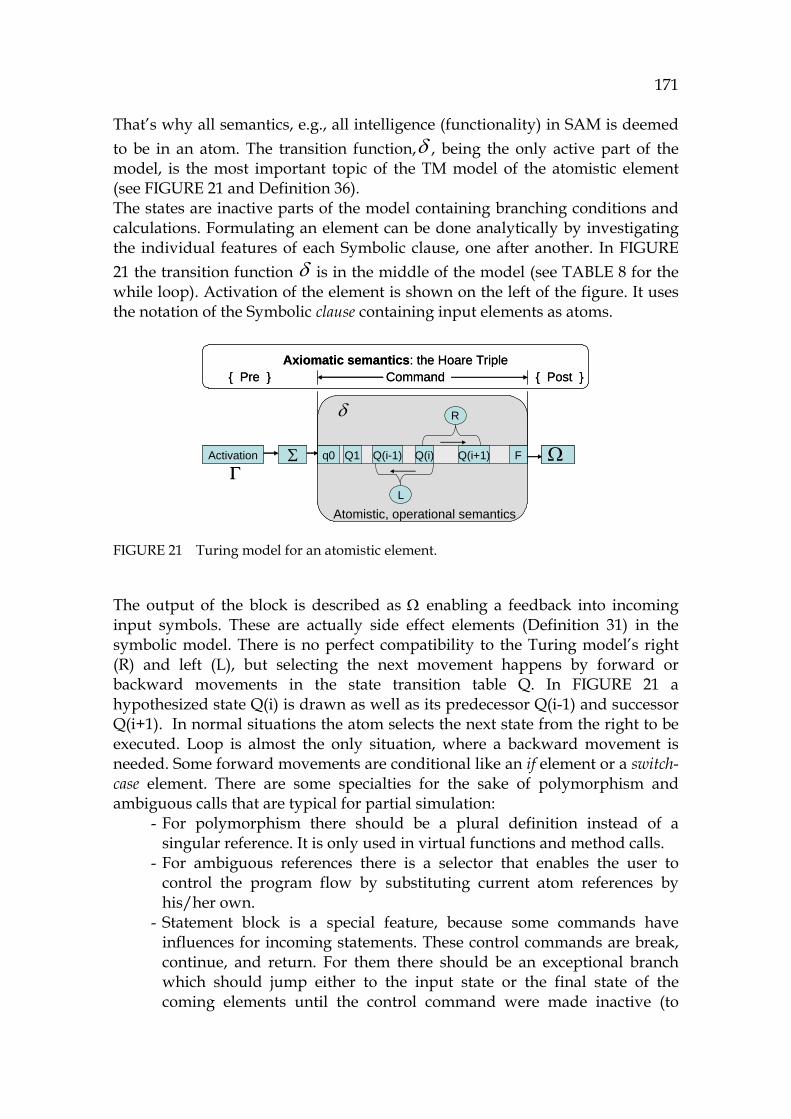
171
That’s why all semantics, e.g., all intelligence (functionality) in SAM is deemed to be in an atom. The transition function,δ , being the only active part of the model, is the most important topic of the TM model of the atomistic element (see 909HFIGURE 21 and 910HDefinition 36). The states are inactive parts of the model containing branching conditions and calculations. Formulating an element can be done analytically by investigating the individual features of each Symbolic clause, one after another. In 911HFIGURE 21 the transition function δ is in the middle of the model (see 912HTABLE 8 for the while loop). Activation of the element is shown on the left of the figure. It uses the notation of the Symbolic clause containing input elements as atoms.
FIGURE 21 Turing model for an atomistic element.
The output of the block is described as Ω enabling a feedback into incoming input symbols. These are actually side effect elements ( 913HDefinition 31) in the symbolic model. There is no perfect compatibility to the Turing model’s right (R) and left (L), but selecting the next movement happens by forward or backward movements in the state transition table Q. In 914HFIGURE 21 a hypothesized state Q(i) is drawn as well as its predecessor Q(i-1) and successor Q(i+1). In normal situations the atom selects the next state from the right to be executed. Loop is almost the only situation, where a backward movement is needed. Some forward movements are conditional like an if element or a switch-case element. There are some specialties for the sake of polymorphism and ambiguous calls that are typical for partial simulation:
- For polymorphism there should be a plural definition instead of a singular reference. It is only used in virtual functions and method calls.
- For ambiguous references there is a selector that enables the user to control the program flow by substituting current atom references by his/her own.
- Statement block is a special feature, because some commands have influences for incoming statements. These control commands are break, continue, and return. For them there should be an exceptional branch which should jump either to the input state or the final state of the coming elements until the control command were made inactive (to
Activation
{ Pre } { Post }Command
δ
ΓFq0 Q1 Q(i) Q(i+1)Q(i-1)
L
R
Axiomatic semantics: the Hoare Triple
Atomistic, operational semantics
Σ ΩActivation
{ Pre } { Post }Command
δ
ΓFq0 Q1 Q(i) Q(i+1)Q(i-1)
L
R
Axiomatic semantics: the Hoare Triple
Atomistic, operational semantics
Σ Ω
172
return after exiting the method and to break and continue when exiting the blocks).
6.8.2 Atomistic semantics for defining Java as a high abstraction
915HTABLE 9 presents a summary of the atomistic model for Java illustrating the logic of 916HFIGURE 21 for the most important clauses of Symbolic. The table ( 917HDefinition 36) has the following columns:
- Column 1, which contains the Symbolic type (918HDefinition 13) and the clause (919HDefinition 11)
- Column 2, which describes preconditions for the element in Column 1 - Column 3, which shows either the input state or the first state depending
on the clause - Column 4, which describes a hypothetic i’th state Q(i) to illustrate a
possible iteration - Column 5, which describes a hypothetic sub-state Q(i+1) illustrating the
last state - Column 6, which describes the transition function for the clause
( 920HDefinition 38) - Column 7, which shows the outputs (Ω) - both the functionality (F) and
side effects (S), if any. They are listed as references in 921HTABLE 7.
Each clause has its own logic (922HDefinition 38), but the overall logic behind each element contains an initial state (fixed initial state q0 or a dynamic input state Q1), a final state (Q(i+1)), and a logic of how the control makes progress between them. The only backward movements can be found in the loops on lines 7 and 8 and in the assignment (the line 6). Other movements are forward transitions making the logic clear. Pathclauses have conditional logic (lines 9 and 10) of how to skip right. The call command, on line 3, is the most complex of all, because the type and argument polymorphism and other features of virtual functions need the user's help if the invocation of a move is ambiguous ( 923HDefinition 34). A recursive call can logically be seen as a special case of a move, where the logic goes backwards to the invocation that already has been activated.
924HTABLE 9 is a summary connecting Java, the Symbolic clause with its axiomatic semantics, and the operational model for the clauses shown by seeking equivalence to TM. Because there is no centralized logic illustrating a traditional CPU, this novel model is atomistic. All the necessary logic for each atom can be seen on the corresponding line of the table. This distributed behavior model is the foundation for the atomistic semantics (925HDefinition 37).
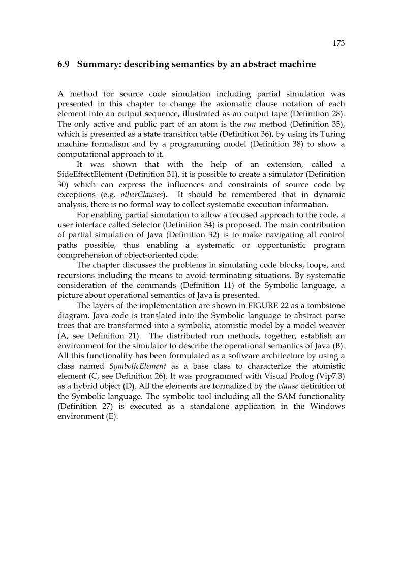
173
6.9 Summary: describing semantics by an abstract machine
A method for source code simulation including partial simulation was presented in this chapter to change the axiomatic clause notation of each element into an output sequence, illustrated as an output tape ( 926HDefinition 28). The only active and public part of an atom is the run method (927HDefinition 35), which is presented as a state transition table ( 928HDefinition 36), by using its Turing machine formalism and by a programming model ( 929HDefinition 38) to show a computational approach to it.
It was shown that with the help of an extension, called a SideEffectElement ( 930HDefinition 31), it is possible to create a simulator ( 931HDefinition 30) which can express the influences and constraints of source code by exceptions (e.g. otherClauses). It should be remembered that in dynamic analysis, there is no formal way to collect systematic execution information.
For enabling partial simulation to allow a focused approach to the code, a user interface called Selector ( 932HDefinition 34) is proposed. The main contribution of partial simulation of Java (933HDefinition 32) is to make navigating all control paths possible, thus enabling a systematic or opportunistic program comprehension of object-oriented code.
The chapter discusses the problems in simulating code blocks, loops, and recursions including the means to avoid terminating situations. By systematic consideration of the commands (934HDefinition 11) of the Symbolic language, a picture about operational semantics of Java is presented.
The layers of the implementation are shown in 935HFIGURE 22 as a tombstone diagram. Java code is translated into the Symbolic language to abstract parse trees that are transformed into a symbolic, atomistic model by a model weaver (A, see 936HDefinition 21). The distributed run methods, together, establish an environment for the simulator to describe the operational semantics of Java (B). All this functionality has been formulated as a software architecture by using a class named SymbolicElement as a base class to characterize the atomistic element (C, see 937HDefinition 26). It was programmed with Visual Prolog (Vip7.3) as a hybrid object (D). All the elements are formalized by the clause definition of the Symbolic language. The symbolic tool including all the SAM functionality ( 938HDefinition 27) is executed as a standalone application in the Windows environment (E).
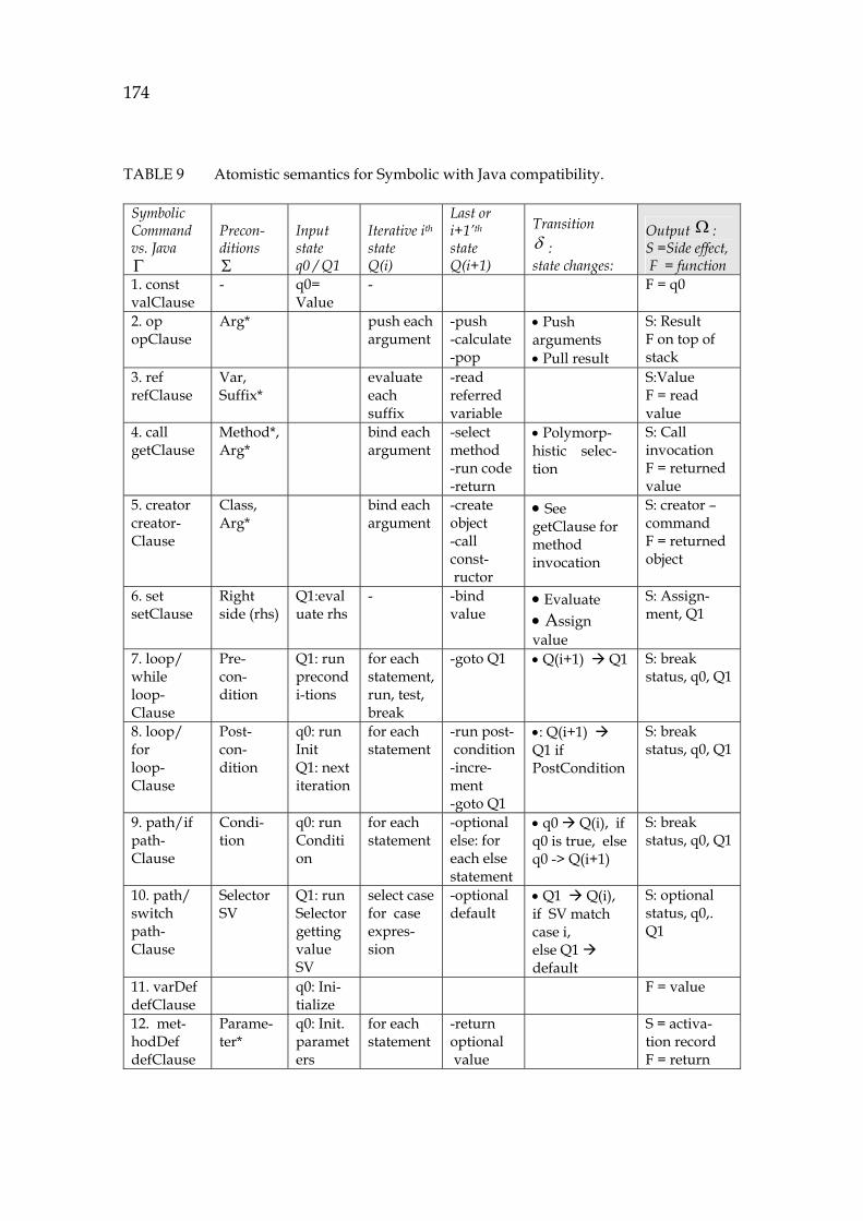
174
TABLE 9 Atomistic semantics for Symbolic with Java compatibility.
Symbolic Command vs. Java Γ
Precon-ditions Σ
Input state q0 / Q1
Iterative ith
state Q(i)
Last or i+1’th state Q(i+1)
Transition δ : state changes:
Output Ω : S =Side effect, F = function
1. const valClause
- q0= Value
- F = q0
2. op opClause
Arg* push each argument
-push -calculate-pop
• Push arguments • Pull result
S: Result F on top of stack
3. ref refClause
Var, Suffix*
evaluate each suffix
-read referred variable
S:Value F = read value
4. call getClause
Method*, Arg*
bind each argument
-select method -run code -return
• Polymorp-histic selec-tion
S: Call invocation F = returned value
5. creator creator- Clause
Class, Arg*
bind each argument
-create object -call const- ructor
• See getClause for method invocation
S: creator – command F = returned object
6. set setClause
Right side (rhs)
Q1:evaluate rhs
- -bind value
• Evaluate • Assign value
S: Assign-ment, Q1
7. loop/ while loop-Clause
Pre- con-dition
Q1: run precondi-tions
for each statement, run, test, break
-goto Q1 • Q(i+1) Q1 S: break status, q0, Q1
8. loop/ for loop-Clause
Post- con-dition
q0: run Init Q1: next iteration
for each statement
-run post- condition -incre-ment -goto Q1
•: Q(i+1) Q1 if PostCondition
S: break status, q0, Q1
9. path/if path-Clause
Condi-tion
q0: run Condition
for each statement
-optional else: for each else statement
• q0 Q(i), if q0 is true, else q0 -> Q(i+1)
S: break status, q0, Q1
10. path/ switch path-Clause
Selector SV
Q1: run Selector getting value SV
select case for case expres-sion
-optional default
• Q1 Q(i), if SV match case i, else Q1 default
S: optional status, q0,. Q1
11. varDef defClause
q0: Ini-tialize
F = value
12. met-hodDef defClause
Parame-ter*
q0: Init. parameters
for each statement
-return optional value
S = activa-tion record F = return
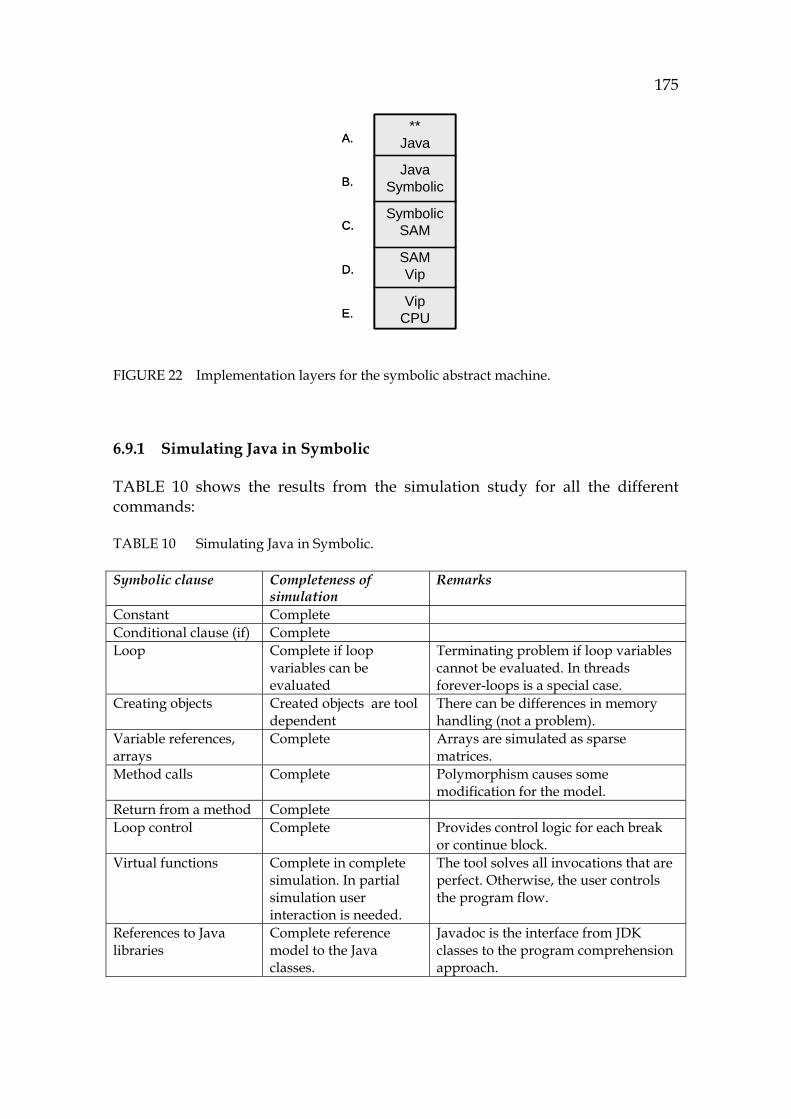
175
FIGURE 22 Implementation layers for the symbolic abstract machine.
6.9.1 Simulating Java in Symbolic
939HTABLE 10 shows the results from the simulation study for all the different commands:
TABLE 10 Simulating Java in Symbolic.
Symbolic clause Completeness of simulation
Remarks
Constant Complete Conditional clause (if) Complete Loop Complete if loop
variables can be evaluated
Terminating problem if loop variables cannot be evaluated. In threads forever-loops is a special case.
Creating objects Created objects are tool dependent
There can be differences in memory handling (not a problem).
Variable references, arrays
Complete Arrays are simulated as sparse matrices.
Method calls Complete Polymorphism causes some modification for the model.
Return from a method Complete Loop control Complete Provides control logic for each break
or continue block. Virtual functions Complete in complete
simulation. In partial simulation user interaction is needed.
The tool solves all invocations that are perfect. Otherwise, the user controls the program flow.
References to Java libraries
Complete reference model to the Java classes.
Javadoc is the interface from JDK classes to the program comprehension approach.
**Java
JavaSymbolic
SymbolicSAM
SAMVip
VipCPU
A.
B.
C.
D.
E.
**Java
JavaSymbolic
SymbolicSAM
SAMVip
VipCPU
**Java
JavaSymbolic
SymbolicSAM
SAMVip
VipCPU
A.
B.
C.
D.
E.
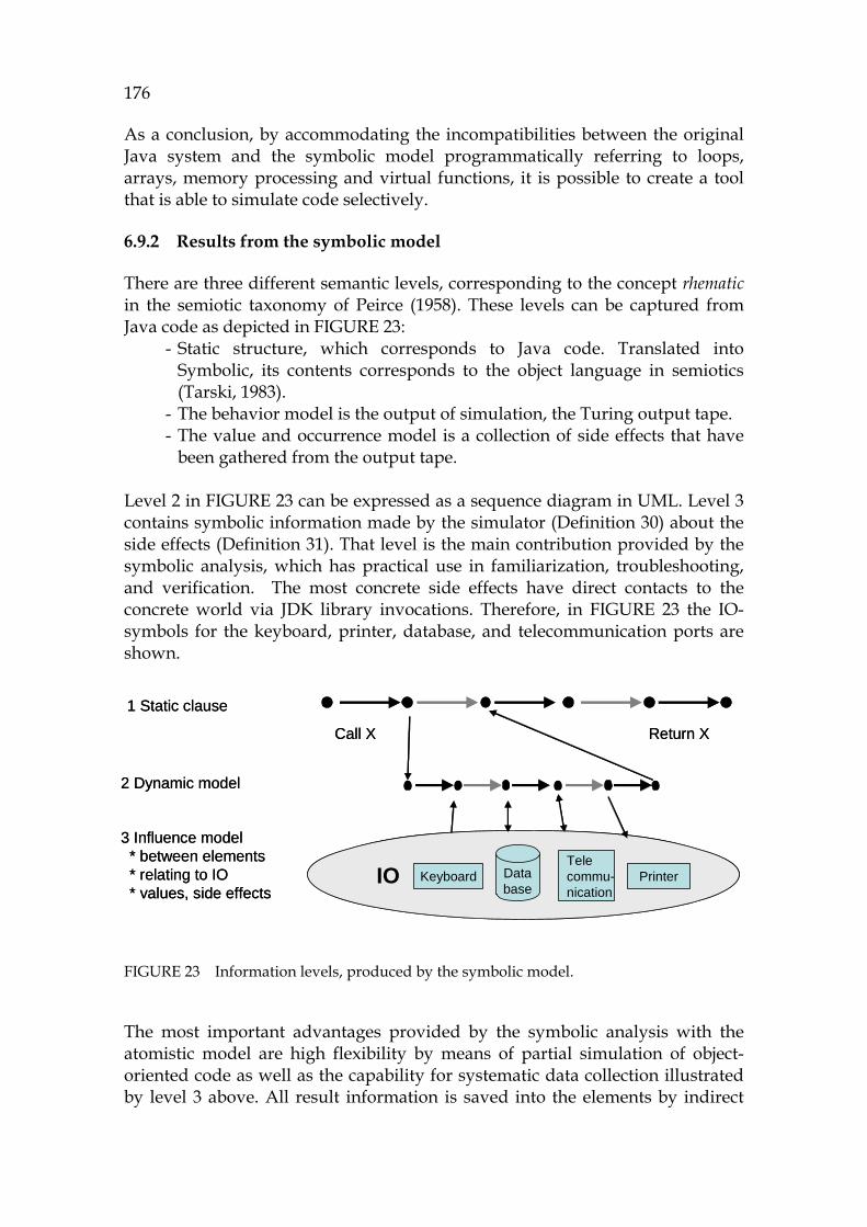
176
As a conclusion, by accommodating the incompatibilities between the original Java system and the symbolic model programmatically referring to loops, arrays, memory processing and virtual functions, it is possible to create a tool that is able to simulate code selectively.
6.9.2 Results from the symbolic model
There are three different semantic levels, corresponding to the concept rhematic in the semiotic taxonomy of Peirce (1958). These levels can be captured from Java code as depicted in 940HFIGURE 23:
- Static structure, which corresponds to Java code. Translated into Symbolic, its contents corresponds to the object language in semiotics (Tarski, 1983).
- The behavior model is the output of simulation, the Turing output tape. - The value and occurrence model is a collection of side effects that have
been gathered from the output tape. Level 2 in 941HFIGURE 23 can be expressed as a sequence diagram in UML. Level 3 contains symbolic information made by the simulator ( 942HDefinition 30) about the side effects ( 943HDefinition 31). That level is the main contribution provided by the symbolic analysis, which has practical use in familiarization, troubleshooting, and verification. The most concrete side effects have direct contacts to the concrete world via JDK library invocations. Therefore, in 944HFIGURE 23 the IO-symbols for the keyboard, printer, database, and telecommunication ports are shown.
FIGURE 23 Information levels, produced by the symbolic model.
The most important advantages provided by the symbolic analysis with the atomistic model are high flexibility by means of partial simulation of object-oriented code as well as the capability for systematic data collection illustrated by level 3 above. All result information is saved into the elements by indirect
1 Static clause
2 Dynamic model
3 Influence model* between elements* relating to IO* values, side effects
IO
Call X Return X
Database
Keyboard PrinterTelecommu-nication
1 Static clause
2 Dynamic model
3 Influence model* between elements* relating to IO* values, side effects
IO
Call X Return X
Database
Keyboard PrinterTelecommu-nication
177
links ( 945HDefinition 25). This linking method makes it possible for the user to study all the elements focusing to the most critical part (see 946H5.3.5). This is in contrast to the approach in UML, which tries to explain everything as standard diagrams to give a total picture. UML doesn’t succeed in creating a total picture for the user, because the amount of information is too large for the user to understand. The focused approach, on the other hand, can collect, for example, a telecommunication behavior of a large system starting from the low level code functions in order to reveal a specific aspect in the code. This feature is very useful in typical troubleshooting cases. The next chapter shows how this code information can be used, in practice, for maintenance.
6.9.3 Unified data model for the simulation results
Because the tape, the formalism of which has been transformed from GrammarWare, can present all the information on the basis of the source code behavior, it is useful to create a new concept or an axiom to describe it. The contents of all outputs of symbolic simulation are shown, in a symbolic notation, as a flow of the elements in the tape ( 947HDefinition 28) in the execution order. It is thus natural to call it a symbolic flow.
Symbolic flow
We define symbolic flow as a logical chain combining the program flow, data flow, object flow, and the side effect information in the program execution order. It can be used later for symbolic analysis in its symbolic notation format.
Information of a static program flow is called a program dependency graph (Horwitz, Reps, and Binkley, 1990a). In the symbolic model the symbolic flow is more complete than static flow, because of the richness of information in the symbolic model. Nevertheless, there is only one uniformed model to combine all elements. The flow can contain either symbolic clauses (commands) or symbolic elements as follows: Symbolic Flow = Clause* or SymbolicElement*
The symbolic flow corresponds to the output tape of TM.
178
7 KNOWLEDGEWARE
This chapter describes knowledge capture from the atomistic model. In Section 7.1 the concept of the information ladder (Longworth and Davies, 1996) is introduced to characterize learning as well as the Rasmussen’s category for task specialization (Rasmussen, 1983). In Section 7.2 for the foundation for KnowledgeWare, its main definitions are proposed. Section 7.3 describes an information model for each category of the output of the symbolic model. In Section 7.4 the corresponding actions for that information are introduced for applying the Rasmussen specialization levels. In Section 7.5 a method for checking and proving simulation results is introduced. It uses argumentation and hypotheses in order to verify the assumptions, which are rather typical in the program comprehension activities. The hypotheses are formalized by using theorems for a logical formulation, which can be matched with the output tapes. Section 7.6 describes an interactive process, which uses the described method of Section 7.5 in solving a maintenance task. It has two main purposes: familiarization and troubleshooting. In the end of this chapter there is a small use case related to Appendix 1 in order to demonstrate how the principles of problem recognition, formulation and analysis can be used in searching critical places of the program flow.
7.1 Preliminaries for KnowledgeWare
Knowledge mining is a popular research area, and therefore several formalisms have been proposed (Zeleny, 2006; Aamodt et al., 1995; Longworth et al., 1996), some of them for automatic knowledge capture (Halpern and Fagin, 1985). The problem of incomplete and non-general definitions for information or knowledge remains (Aamodt et al., 1995). An article of Ackoff (1989) has inspired many researchers to study how data can be transferred into knowledge and vice versa, and an information ladder was proposed as a metaphor for the
179
purpose by one of them. The same idea was presented as a knowledge pyramid, which has the levels from data to wisdom (Longworth et al., 1996).
Because the atomistic model is flat and non-hierarchical, it doesn’t provide the user with the means to understand its structural and hierarchical relations. KnowledgeWare, a method for the user to configure hierarchical and network-based information, addresses this problem.
7.1.1 Information ladder for knowledge capture
According to Ackoff (1989) the steps in the information ladder consist of: 1) data, 2) information, 3) knowledge, 4) insight, and 5) wisdom, the highest level. In this framework the user gets information from data by understanding its relations. From this information the user can obtain knowledge by understanding the essential patterns of the information. Finally, the user can reach the next levels, insight and wisdom, by understanding the principles of that knowledge.
Cleveland describes understanding as a continuum using the ladder (1982). In our approach, temporary data does not have necessary information for formulating wisdom. Instead, we speak about insight and know-how to describe cumulative high level decisions and conclusions captured from knowledge, in order to illustrate the understanding process that aims at future activities, e.g., in order to implement new software versions.
In this chapter the motivation is to help the software maintainer to change tangible data and information of the source code model into intangible knowledge (Nonaka et al., 1995) into skills that enable more productive development and safer new installations in the future. It is assumed that the maintainer or any other person in the organization has the necessary explicit knowledge. As a contribution of the proposed KnowledgeWare the user should be able to use explicit knowledge more efficiently in order to create new tacit knowledge.
Applying the information ladder (Longworth et al., 1996)) to the atomistic source code model (Chapter 5 and Chapter 6) is described next. The four selected categories, in the the context of the human mind (Ackoff, 1989), are the following:
- Data: Related to model elements as symbols. - Information: Related to program flow. Each element has the command
and its links illustrating formal answers to informal questions made by the user. Some typical questions are:
− Which element is the one called here? − What are the elements referring to this place? − From where (to where) do the selected references come (go)? − When is the element activated (what are the preconditions for it)?
- Knowledge: Related to "how" each element is called, i.e., what is the triple of the focused element like and “what should happen if the element were to be changed”.
180
- Know-how: Related to "why" questions. What is the purpose of the current method, why has it been written? Can I change, correct, or replace it without causing new problems? What is our insight about the quality and usability of this element or component based on its behavior models?
7.1.2 Hierarchical action model for capturing knowledge
The area of KnowledgeWare combines the cognitive approach to the maintenance and the computational technology in order to accelerate building new systems. Anderson proposes two different approaches to knowledge referring to memories (ACT-R, 2007). Declarative memory describes adapted tangible knowledge, whereas procedural knowledge is needed in the process of capturing the necessary information. Rasmussen (1983) has proposed that the user works in three different cognitive levels: skill, rule, and knowledge.
In this research the Rasmussen categories are used with the following modifications:
- Skill level activities are based on local perceptions related to the symbolic model.
- The rule level means the activities used for evaluating sequential information such as successive statements or a tape.
- In the knowledge level the user collects information from different rule level activities and makes decisions as a conclusion.
Walenstein (2002) has extended the Rasmussen specialization model to cover metalevel as the most abstract level in external information search and in connecting existing information informally to each other.
The layers for specializing knowledge information and activities are skill, rule, knowledge, and meta. The skill layer is based on fast observations, and the rule layer for deducing information for one case at a time. The knowledge layer is based on deliberate reasoning and considers multiple alternatives and methods at a time. The meta layer is dedicated for connecting information from different sources in order to catch information to the other layers.
7.1.3 An example code and its simulation model
948HFIGURE 24 shows a short example, a subset of Appendix I, which contains a typical JDK reference; in this particular case an Internet socket for a communication process is activated. This example illustrates a model captured from the code and the corresponding output tape. The code in the example can be proved and provides information with which this sequence from the Start (the first method is main) to the target can be evaluated by the user and by the tool.
The focus in this example is not in visualizing, but in showing the formalism and internal symbolic notation of the symbolic model. From 9 lines
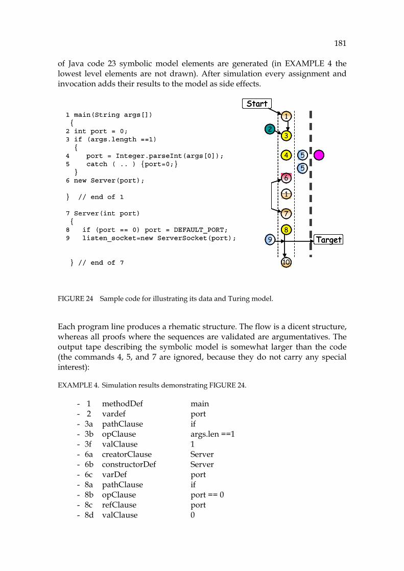
181
of Java code 23 symbolic model elements are generated (in 949HEXAMPLE 4X the lowest level elements are not drawn). After simulation every assignment and invocation adds their results to the model as side effects.
FIGURE 24 Sample code for illustrating its data and Turing model.
Each program line produces a rhematic structure. The flow is a dicent structure, whereas all proofs where the sequences are validated are argumentatives. The output tape describing the symbolic model is somewhat larger than the code (the commands 4, 5, and 7 are ignored, because they do not carry any special interest):
EXAMPLE 4. Simulation results demonstrating 950HFIGURE 24.
- 1 methodDef main - 2 vardef port - 3a pathClause if - 3b opClause args.len ==1 - 3f valClause 1 - 6a creatorClause Server - 6b constructorDef Server - 6c varDef port - 8a pathClause if - 8b opClause port == 0 - 8c refClause port - 8d valClause 0
1 main(String args[]){
2 int port = 0;3 if (args.length ==1)
{4 port = Integer.parseInt(args[0]);5 catch ( .. ) {port=0;}
}6 new Server(port);
} // end of 1
7 Server(int port){
8 if (port == 0) port = DEFAULT_PORT;9 listen_socket=new ServerSocket(port);
} // end of 7
1
32
4
6
7
8
10
9
5
1
Target
Start
5
1
32
4
6
7
8
10
9
5
1
Target
Start
5
182
- 8e setClause port = - 8f refClause port - 8g valClause DEFAULT_PORT - 9a setClause listen_socket… - 9b refClause listen_socket - 9c creator new ServerSocket - 9d refClause port
The tape can be drawn as a vector as shown in 951HTABLE 11. The elements in the output tape have symbolic codes according to the Symbolic language. They are in the tape in the execution order. A detailed description about the representations of the symbolic Turing model will be given in Chapter 8. The presentation shows the successive symbolic elements with a prefix of each clause and an increasing number.
TABLE 11 Server-example (see Appendix 1) as a Turing-tape.
M1 V1 P1 O1 R1 G1 V1 S1 C1 M2 V3 P1 O2 R2 .. There were three different presentations about the same code above. A principal sequential diagram is in the right side of 952HFIGURE 24. The vector showing the corresponding symbolic model is shown in 953HTABLE 11 illustrating the symbolic Turing tape.
7.2 Foundation for KnowledgeWare
In this section a formalism for capturing knowledge from the symbolic atomistic model and its simulation results is defined. The information flow for it is described as follows:
Proposition 4. Information from the atomistic model and its simulation results can be comprehended in a layerwise form. By using the specified actions the user is able to create high level concepts when locating the program flows of interest.
7.2.1 Domain-independent definitions for knowledge
According to the Peircean taxonomy, the following definitions form semiotic layers. These can be applied for the symbolic atomistic model.
Definition 39. KnowledgeUnit Let M be a symbolic model and S a subset of atoms in M. A KnowledgeUnit is a subset of S , which can be used for building a mental model of the program behavior for the user.

183
For example, we may have an output tape which contains an if-command with a condition, true-clauses and else-clauses. The KnowledgeUnit is then a proposition built from the if-command for understanding the functionality of the corresponding command in the Symbolic language. It is characterized in every case by the corresponding condition, but the user can consider this KnowledgeUnit in multiple ways:
- In a situation dependent case the user tries to get a value true or false for it.
- In higher-order logic the user tries to prove the command correct or incorrect.
- In evaluating usability of the command the user tries to evaluate whether the command is good enough to be used in upcoming software versions.
Each clause of the simulation output can be considered both as a proposition whether it will become executed or not, or as a proof to verify whether its output is correct or not.
In building knowledge-based systems it is essential to assume that knowledge is something that can be identified, modeled, and explicitly represented (Aamodt et al., 1995). In computational semiotics Gudwin (2006) defines KnowledgeUnit to contain selectively collected data and information. In our research the grammar including its semantic is the starting point. It is then changed into a model element. Knowledge units are, as shown in 954HFIGURE 25, collections of model elements with relations between them.
FIGURE 25 Bridging from grammar to model, and knowledge unit.
Knowledge type is a class describing a knowledge unit according to the classification. It can be either fundamental, propositional, or argumentative knowledge (Gudwin, 2006). Examples related to Appendix 1:
- Class Server is a KnowledgeUnit, into which user knowledge is accumulated in reading code.
- The relevant methods are KnowledgeUnits.
Definition 40. Dependency graph Let A be a KnowledgeUnit considering the model M. A dependency graph is a network and the created visualization focused on A so that incoming references
KnowledgeUnit
GrammarTerm
SymbolicModel Element
1..
1..
KnowledgeUnit
GrammarTerm
SymbolicModel Element
1..
1..

184
are drawn in one direction (top to bottom or left to right) and outgoing references in the opposite direction.
A dependency graph is a skill level presentation, making it possible for the user to search, match and make decisions on the information in the display.
Definition 41. Explanation Let C be an input sequence (input tape) giving an output tape O ( 955HDefinition 28) as a simulation result (see Section 956H6.9.3). An explanation is then a filtered flow to transform O into a logical graph containing both the program flow and the side effects (see 957HFIGURE 26).
FIGURE 26 A graphic explanation is a set of causal relations.
A specialized explanation is a flow-dependent set of Symbolic clauses connected with each other. The types of explanations are:
- Data flow - Program flow

185
- Call tree - Object flow - Control flow - Operation flow
List of states and side effects (see 958HDefinition 31). It is possible to mix these flows and to filter the information flexibly by using regular expressions, selecting side effects etc. The output tape is like a hierarchical database, where the invocations form the structural hierarchy for the explanation, too. It is useful to express explanations as text by using natural semantics or graphically by visualization: in 959HFIGURE 26 the top element is the model, which activates an if atom, which activates a condition atom which, if true, gives the statement atoms.
Definition 42. Argument Let E be an explanation considering a symbolic flow (see Section 960H6.9.3). An argument is a reasoning result on deciding whether the explanation is correct, includes to correct or incorrect cases or gives new information for deciding changes for the flow. Example about Appendix 1:
- A deductive reasoning chain: The TCP/IP-connection is opened because the object ServerSocket is created. The latter was enabled by the constructor of Server, which was activated by the main method.
7.2.2 Problem centric knowledge definitions
A maintenance task can be seen as a specification either to correct an existing error, to find the trouble, to verify the current code, or to plan changes for the current version (corrective, adaptive, perfective, and preventive tasks as well as re-organization requests). An input for a task is a change request (CR), which is either a specific and formal or vague and informal task description.
A task solving process (P) is a set of activities to complete the task. The process contains a problem formulation phase (recognition), a problem analysis, and verification phases in order to check the low level features (Gilb, 1988).
Definition 43. ProgramConcept A ProgramConcept is an association made by the user in order to understand the underlying atomistic model. It is a specialization of an abstract concept to be used for mapping task actions to code in formulating information retrieval from the model.
As examples from the Server program (Appendix 1) consider the following:
- Each class is a ProgramConcept of its own. The ones for classes are Server, Connection, and Vulture. Some of them are relevant in a single
186
troubleshooting case and some others are relevant in planning intended changes.
- For tracing an object (a class) there are some essential class responsibilities (class contracts) to be handled as individual ProgramConcepts, too.
- The most interesting ProgramConcepts for the methods for Server are the main, constructor (in Server), and the run method. The run method is interesting, because it opens a connection which responds to the client.
- More specific ProgramConcepts are the constructor for Connection and its run method.
Because ProgramConcept has a pragmatic feature, building ProgramConcepts depends on the situation and the user. Once a ProgramConcept has been created, it is persistent unless removed (forgotten), illustrating its static behavior.
Definition 44. Object-of-interest (OOI) Let M be an atomistic model (containing classes and methods and variables) and C be a ProgramConcept selected for investigation. An Object-of-interest is a target in the model, which has a special purpose for understanding data flows and program flows.
In the Server program (Appendix 1) the main functional concepts are starting the server and responding to the client. A task of the process of problem recognition is to localize these concepts in the code as atom references. In starting the TCP/IP-connection the constructor to activate the ServerrSocket is OOI.
Definition 45. ProgramContext Let M be an atomistic model and OOI an Object-of-interrest to be inspected. Let X be a sequence leading from the selected starting element to OOI in M. The group of side effects before OOI in X is called a ProgramContext for OOI defining the coming sequence.
The essential use for a ProgramContext is to understand cross-cuttings activated by the ProgramConcept. Because the ProgramContext defines the preconditions for the OOI and the simulation process is capable of creating the assumed side effects for the code, the definition of ProgramContext leads to a construction similar to the Hoare triple, where input side effects work as preconditions for the triple and conditional output side effects are postconditions for it.
Unlike ProgramConcept, a ProgramContext provides a dynamic, bottom-up approach for the model M. Together the ProgramConcept and the ProgramContext form a couple for describing both high level and low level functionalities. It is the process of verification which can prove whether the assumed high level approach will be implemented by the low level presentations made by the model M.
Examples from the Server program (Appendix 1):

187
- The run method of Server. How many invocations for it are there in the code?
- The constructor for Connection. Are all Connection objects created in the same way?
- The run method of Connection. Is the sequence correct, or are there several different use cases for the method?
Understanding cross-cuttings and side effects is the most laborious phase in understanding object-oriented software. ProgramContexts can be used as an approach for understanding cross-cuttings. In this, collecting bottom-up information into higher level concepts is useful.
Definition 46. Hypothesis Let M be a symbolic model and P be a maintenance task solving process. A hypothesis H is an assumption related to M, which formalizes the subtarget (or target) of P.
Often auxiliary information must be used for localizing the requirements represented in H. For any simulated output a hypothesis H can be expressed as a set of lower level theorems, which describe the assumed behavior of the program flow with its alternative logic and dependency information.
In the example 961HFIGURE 24 the most evident hypothesis is named starting a server. It can be formalized to contain any sequence between main and the corresponding OOI.
Definition 47. Theorem Let H be a hypothesis. Theorem T is a resolution tree, which defines the logic for H based on operands and constraints and connectives for relations between program elements. The purpose of T can be either validate or refutate. A theorem can be nested containing subtheorems.
Because of the formulation of the resolution tree, logic programming and constraint solving are recommandable implementations for solving theorems.
Otherwise in the example 962HFIGURE 24 in a practical case there can be several ProgramContexts that lead to the current hypothesis. Therefore theorems are often complex, but they can be made easier by splitting the sequences shorter.
7.2.3 Summary illustrating knowledge-related information
When the informative model of the atomistic model and the proposed classification of this section and the Rasmussen category and the Peircean taxonomy are combined, the correspondence table (see 963HTABLE 12) is obtained. 964HTABLE 12 builds a procedural familiarization model for the atomistic model. It clarifies the kinds of actions (Column 3, see later Section 965H7.4) the user should employ in order to understand the type of information on the left column (see Section 966H7.3).

188
TABLE 12 The information ladder based on the atomistic model.
Atomistic model, behavior model and conclusions
Information level
Action level
Equivalence in Peirce’s taxonomy
1. Symbolic model itself Data Skill Rhematic • Symbolic name Data Skill • Symbolic • Object handle Data Skill • Indexical • An element in the tape Data Skill • Iconic • A structure in code, a Symbolic clause
Data Skill • Sensorial
• An object (corresponds to Java object)
Data Skill • Object (entity)
• A side effect Data Skill • Occurrence (value) 2. Tape (sequence) Information Rule Dicent • Symbolic Element* Information Rule • Iconic dicent • Metaclause connecting elements: clause
Information Rule • Symbolic dicent
3. Proof or conclusion Knowledge Knowledge Argumentative • Symbolic output tape Knowledge Knowledge • Deductive reasoning • Collection of output tapes Knowledge Knowledge • Inductive • Conclusions about inductive reasoning
Knowledge Knowledge • Abductive
Each term in the symbolic model (Column 1) maps directly to the rhematic concept of Peirce (Column 4). If the element can be expressed by words, it is a symbolic reference. Otherwise, it can be either relative being indexical or absolute being iconic. The iconic references can point to either an entity being object which has its own life cycle, or to an observation being a sensorial view or to an occurrence being a temporary value.
Furthermore, the Turing tape has a clear correspondence to the dicent concept. A tape itself is an iconic dicent, an explanation ( 967HDefinition 41), whereas a tape, where the symbolic conditions are expressed is a symbolic dicent. The third main concept of the Peircean taxonomy, argumentative ( 968HDefinition 42), is similar to a proof where symbolic tapes are tested as ProgramContexts ( 969HDefinition 45) against user assumptions (hypotheses based on definition 970HDefinition 46) of their behavior considering the most critical objects (971HDefinition 44).
7.3 Illustrating information model for source code
In this section descriptions for the information layers are presented.
7.3.1 Information model for an atom
Each symbolic element of 972HFIGURE 24 can be considered to be a center which contains the definition and the links. An atomistic mental image about a
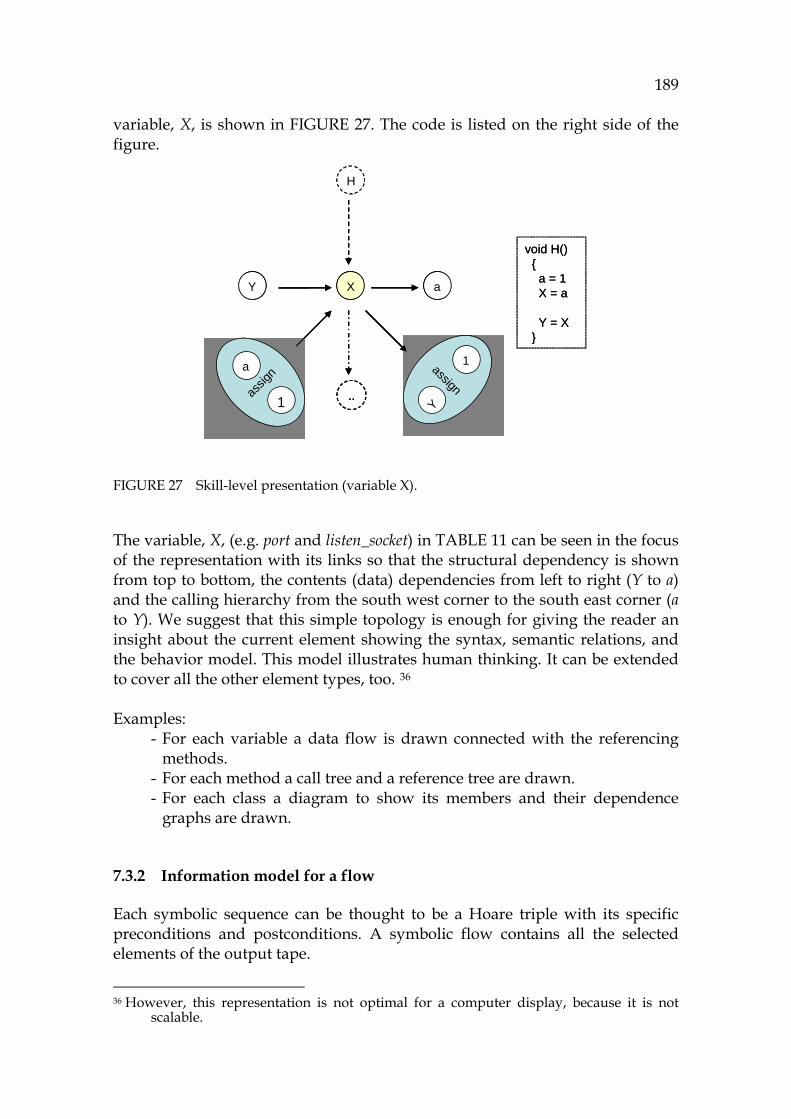
189
variable, X, is shown in 973HFIGURE 27. The code is listed on the right side of the figure.
FIGURE 27 Skill-level presentation (variable X).
The variable, X, (e.g. port and listen_socket) in 974HTABLE 11 can be seen in the focus of the representation with its links so that the structural dependency is shown from top to bottom, the contents (data) dependencies from left to right (Y to a) and the calling hierarchy from the south west corner to the south east corner (a to Y). We suggest that this simple topology is enough for giving the reader an insight about the current element showing the syntax, semantic relations, and the behavior model. This model illustrates human thinking. It can be extended to cover all the other element types, too. 35F
36 Examples:
- For each variable a data flow is drawn connected with the referencing methods.
- For each method a call tree and a reference tree are drawn. - For each class a diagram to show its members and their dependence
graphs are drawn.
7.3.2 Information model for a flow
Each symbolic sequence can be thought to be a Hoare triple with its specific preconditions and postconditions. A symbolic flow contains all the selected elements of the output tape.
36 However, this representation is not optimal for a computer display, because it is not
scalable.
void H() {
a = 1 X = a
Y = X}
assig
nas
sign
H
XY a
..
a
1
assign
assignY
1
void H() {
a = 1 X = a
Y = X}
assig
nas
sign
H
XY a
..
a
1
assign
assignY
1
assig
nas
sign
H
XY a
..
a
1
assign
assignY
1
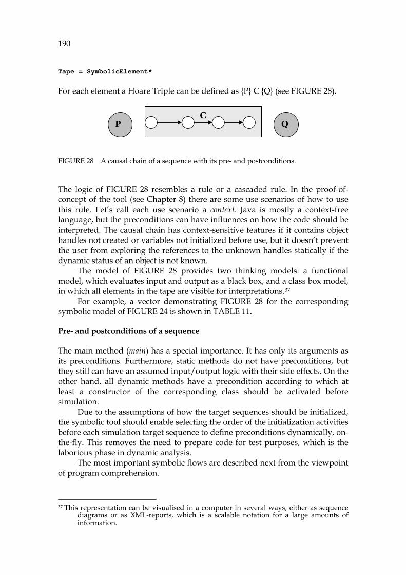
190
Tape = SymbolicElement* For each element a Hoare Triple can be defined as {P} C {Q} (see 975HFIGURE 28).
FIGURE 28 A causal chain of a sequence with its pre- and postconditions.
The logic of 976HFIGURE 28 resembles a rule or a cascaded rule. In the proof-of-concept of the tool (see Chapter 8) there are some use scenarios of how to use this rule. Let’s call each use scenario a context. Java is mostly a context-free language, but the preconditions can have influences on how the code should be interpreted. The causal chain has context-sensitive features if it contains object handles not created or variables not initialized before use, but it doesn’t prevent the user from exploring the references to the unknown handles statically if the dynamic status of an object is not known.
The model of 977HFIGURE 28 provides two thinking models: a functional model, which evaluates input and output as a black box, and a class box model, in which all elements in the tape are visible for interpretations.36F
37 For example, a vector demonstrating 978HFIGURE 28 for the corresponding
symbolic model of 979HFIGURE 24 is shown in 980HTABLE 11.
Pre- and postconditions of a sequence
The main method (main) has a special importance. It has only its arguments as its preconditions. Furthermore, static methods do not have preconditions, but they still can have an assumed input/output logic with their side effects. On the other hand, all dynamic methods have a precondition according to which at least a constructor of the corresponding class should be activated before simulation.
Due to the assumptions of how the target sequences should be initialized, the symbolic tool should enable selecting the order of the initialization activities before each simulation target sequence to define preconditions dynamically, on-the-fly. This removes the need to prepare code for test purposes, which is the laborious phase in dynamic analysis.
The most important symbolic flows are described next from the viewpoint of program comprehension.
37 This representation can be visualised in a computer in several ways, either as sequence
diagrams or as XML-reports, which is a scalable notation for a large amounts of information.
C P Q

191
Using specialized flows for analyzing sequences
The result of an analysis is a tape. It consists of an ordered set of elements, which contains unordered rhematic information, data. Rhematic refers to all elements obtained from a simulation covering the Turing model itself. It is useful to note that a practical meaning for a subset of rhematic information for PC purposes is an object life cycle, which is a collection of elements containing information about selected object references starting from the constructor.
Dicent refers to an intermediate information form describing the conditions and logical connections between the selected code elements. The information needs of PC research (Pennington, 1987), (Burkhardt, Detienne, and Wiedenbeck, 2002) are useful in evaluating the dicent information as follows:
- MainFlow, MF (Burkhardt et al., 2002) (main goal) - Control Flow, CF (Pennington, 1987) - Program Flow, PF (Pennington, 1987) - Data Flow, DF (Pennington, 1987; Dwyer, 1996) - Object Flow (Burkhardt et al., 2002; Pontelli et al., 1996)
- State Flow (Pennington, 1987)
It is possible to mix these flows, for example, by adding a control flow, an object flow, and a data flow to a control object flow. This new flow creates a useful approach for evaluating conditional object flows with their context sensitive features. This principle leads to automatic cause-reason analysis, which has connections to impact analysis and then to troubleshooting (Ren et al., 2004). Examples:
- All the conditional statements and invocations of 981HFIGURE 24 form the program flow.
- All the data references form the data flow. - All the side effects (see Appendix 3) form the state flow. - All the object references starting from the constructor form an object
flow.
7.3.3 Information model for ProgramContext
The main purpose of the atomistic model is to remove the gap between the interprocedural and the intraprocedural interpretation of the execution, making the whole behavior model and the whole interpretation linear. In source code analysis this has been studied in a context of path-profiling (Ball and Laws, 1996), model checking (Visser et al., 2003), and partial evaluation (Schultz, 2000).
Our approach provides a semiotic perspective, where each output is an argumentative (Peirce, 1958), which has a logical nature describing whether the selected sequence or element is acceptable or not ( 982HDefinition 42). In a deductive proof the sequence will be validated. In inductive argumentation the results of arguments are collected for the user to evaluate the common features that might
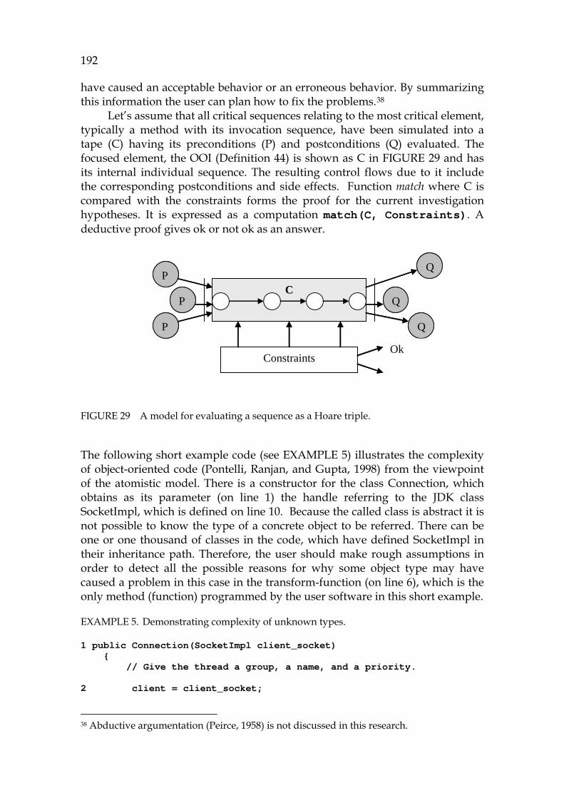
192
have caused an acceptable behavior or an erroneous behavior. By summarizing this information the user can plan how to fix the problems.37F
38 Let’s assume that all critical sequences relating to the most critical element,
typically a method with its invocation sequence, have been simulated into a tape (C) having its preconditions (P) and postconditions (Q) evaluated. The focused element, the OOI ( 983HDefinition 44) is shown as C in 984HFIGURE 29 and has its internal individual sequence. The resulting control flows due to it include the corresponding postconditions and side effects. Function match where C is compared with the constraints forms the proof for the current investigation hypotheses. It is expressed as a computation match(C, Constraints). A deductive proof gives ok or not ok as an answer.
FIGURE 29 A model for evaluating a sequence as a Hoare triple.
The following short example code (see 985HEXAMPLE 5) illustrates the complexity of object-oriented code (Pontelli, Ranjan, and Gupta, 1998) from the viewpoint of the atomistic model. There is a constructor for the class Connection, which obtains as its parameter (on line 1) the handle referring to the JDK class SocketImpl, which is defined on line 10. Because the called class is abstract it is not possible to know the type of a concrete object to be referred. There can be one or one thousand of classes in the code, which have defined SocketImpl in their inheritance path. Therefore, the user should make rough assumptions in order to detect all the possible reasons for why some object type may have caused a problem in this case in the transform-function (on line 6), which is the only method (function) programmed by the user software in this short example.
EXAMPLE 5. Demonstrating complexity of unknown types.
1 public Connection(SocketImpl client_socket) { // Give the thread a group, a name, and a priority. 2 client = client_socket;
38 Abductive argumentation (Peirce, 1958) is not discussed in this research.
CP Q
P
P Q
Q
ConstraintsOk
CP Q
P
P Q
Q
ConstraintsOk
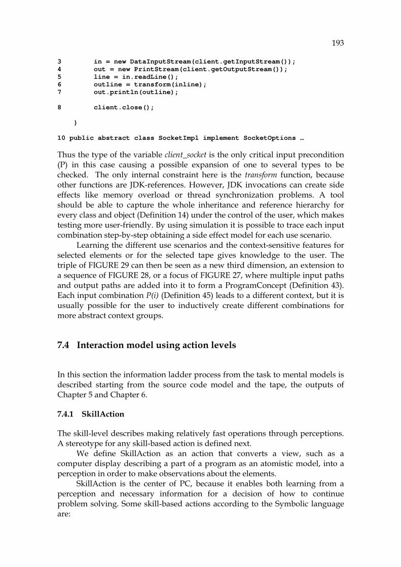
193
3 in = new DataInputStream(client.getInputStream()); 4 out = new PrintStream(client.getOutputStream()); 5 line = in.readLine(); 6 outline = transform(inline); 7 out.println(outline); 8 client.close(); } 10 public abstract class SocketImpl implement SocketOptions … Thus the type of the variable client_socket is the only critical input precondition (P) in this case causing a possible expansion of one to several types to be checked. The only internal constraint here is the transform function, because other functions are JDK-references. However, JDK invocations can create side effects like memory overload or thread synchronization problems. A tool should be able to capture the whole inheritance and reference hierarchy for every class and object ( 986HDefinition 14) under the control of the user, which makes testing more user-friendly. By using simulation it is possible to trace each input combination step-by-step obtaining a side effect model for each use scenario.
Learning the different use scenarios and the context-sensitive features for selected elements or for the selected tape gives knowledge to the user. The triple of 987HFIGURE 29 can then be seen as a new third dimension, an extension to a sequence of 988HFIGURE 28, or a focus of 989HFIGURE 27, where multiple input paths and output paths are added into it to form a ProgramConcept ( 990HDefinition 43). Each input combination P(i) (991HDefinition 45) leads to a different context, but it is usually possible for the user to inductively create different combinations for more abstract context groups.
7.4 Interaction model using action levels
In this section the information ladder process from the task to mental models is described starting from the source code model and the tape, the outputs of Chapter 5 and Chapter 6.
7.4.1 SkillAction
The skill-level describes making relatively fast operations through perceptions. A stereotype for any skill-based action is defined next.
We define SkillAction as an action that converts a view, such as a computer display describing a part of a program as an atomistic model, into a perception in order to make observations about the elements.
SkillAction is the center of PC, because it enables both learning from a perception and necessary information for a decision of how to continue problem solving. Some skill-based actions according to the Symbolic language are:
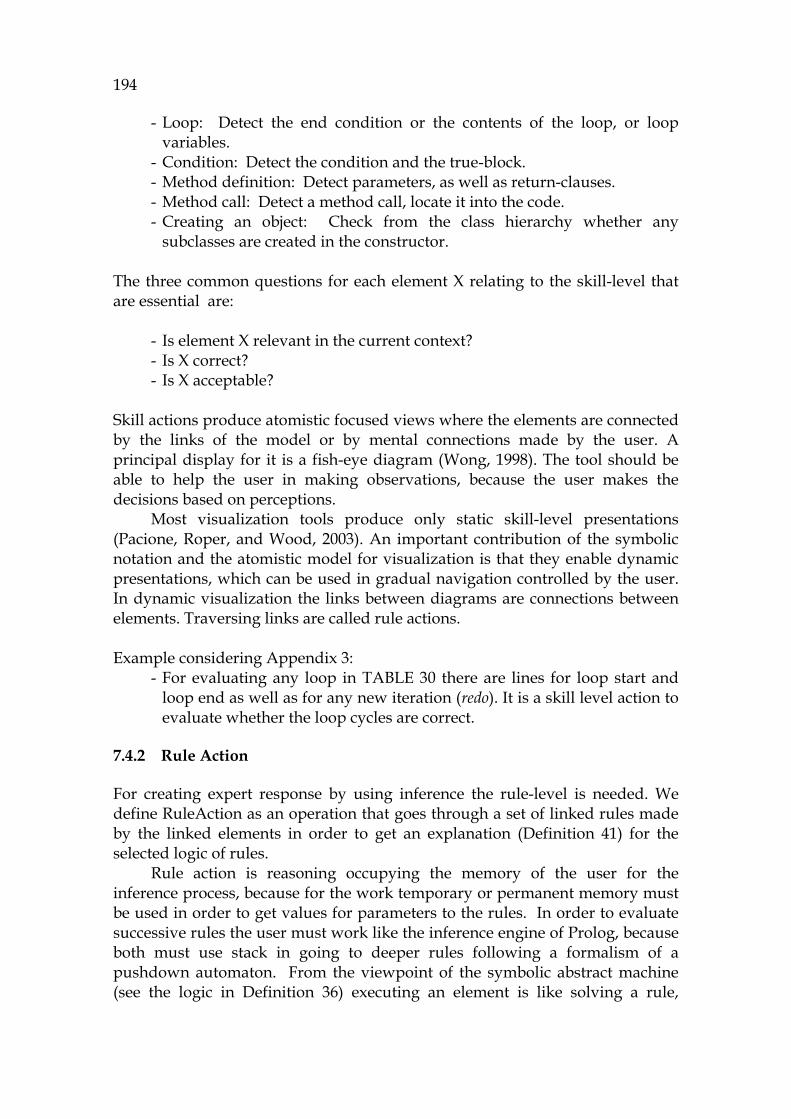
194
- Loop: Detect the end condition or the contents of the loop, or loop variables.
- Condition: Detect the condition and the true-block. - Method definition: Detect parameters, as well as return-clauses. - Method call: Detect a method call, locate it into the code. - Creating an object: Check from the class hierarchy whether any
subclasses are created in the constructor. The three common questions for each element X relating to the skill-level that are essential are:
- Is element X relevant in the current context? - Is X correct? - Is X acceptable?
Skill actions produce atomistic focused views where the elements are connected by the links of the model or by mental connections made by the user. A principal display for it is a fish-eye diagram (Wong, 1998). The tool should be able to help the user in making observations, because the user makes the decisions based on perceptions.
Most visualization tools produce only static skill-level presentations (Pacione, Roper, and Wood, 2003). An important contribution of the symbolic notation and the atomistic model for visualization is that they enable dynamic presentations, which can be used in gradual navigation controlled by the user. In dynamic visualization the links between diagrams are connections between elements. Traversing links are called rule actions.
Example considering Appendix 3:
- For evaluating any loop in 992HTABLE 30 there are lines for loop start and loop end as well as for any new iteration (redo). It is a skill level action to evaluate whether the loop cycles are correct.
7.4.2 Rule Action
For creating expert response by using inference the rule-level is needed. We define RuleAction as an operation that goes through a set of linked rules made by the linked elements in order to get an explanation ( 993HDefinition 41) for the selected logic of rules.
Rule action is reasoning occupying the memory of the user for the inference process, because for the work temporary or permanent memory must be used in order to get values for parameters to the rules. In order to evaluate successive rules the user must work like the inference engine of Prolog, because both must use stack in going to deeper rules following a formalism of a pushdown automaton. From the viewpoint of the symbolic abstract machine (see the logic in 994HDefinition 36) executing an element is like solving a rule,
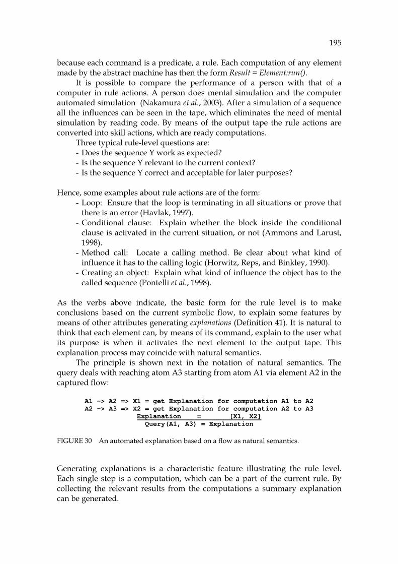
195
because each command is a predicate, a rule. Each computation of any element made by the abstract machine has then the form Result = Element:run().
It is possible to compare the performance of a person with that of a computer in rule actions. A person does mental simulation and the computer automated simulation (Nakamura et al., 2003). After a simulation of a sequence all the influences can be seen in the tape, which eliminates the need of mental simulation by reading code. By means of the output tape the rule actions are converted into skill actions, which are ready computations.
Three typical rule-level questions are: - Does the sequence Y work as expected? - Is the sequence Y relevant to the current context? - Is the sequence Y correct and acceptable for later purposes?
Hence, some examples about rule actions are of the form: - Loop: Ensure that the loop is terminating in all situations or prove that
there is an error (Havlak, 1997). - Conditional clause: Explain whether the block inside the conditional
clause is activated in the current situation, or not (Ammons and Larust, 1998).
- Method call: Locate a calling method. Be clear about what kind of influence it has to the calling logic (Horwitz, Reps, and Binkley, 1990).
- Creating an object: Explain what kind of influence the object has to the called sequence (Pontelli et al., 1998).
As the verbs above indicate, the basic form for the rule level is to make conclusions based on the current symbolic flow, to explain some features by means of other attributes generating explanations (995HDefinition 41). It is natural to think that each element can, by means of its command, explain to the user what its purpose is when it activates the next element to the output tape. This explanation process may coincide with natural semantics.
The principle is shown next in the notation of natural semantics. The query deals with reaching atom A3 starting from atom A1 via element A2 in the captured flow:
A1 -> A2 => X1 = get Explanation for computation A1 to A2 A2 -> A3 => X2 = get Explanation for computation A2 to A3
Explanation = [X1, X2] Query(A1, A3) = Explanation
FIGURE 30 An automated explanation based on a flow as natural semantics.
Generating explanations is a characteristic feature illustrating the rule level. Each single step is a computation, which can be a part of the current rule. By collecting the relevant results from the computations a summary explanation can be generated.
196
7.4.3 Knowledge Action
At the knowledge level the user solves difficult tasks by using deliberate reasoning in order to understand relations between ProgramConcepts ( 996HDefinition 43) and ProgramContexts (997HDefinition 45) focused on OOIs ( 998HDefinition 44). In the atomistic model the main concept of the knowledge action for PC purposes is the Hoare triple with alternative preconditions and postconditions. Because there are several alternative program flows to reach the focus area in the application software, it would be a burden for the user to try to understand all these contexts ( 999HDefinition 45). Therefore, he/she must use serial reasoning case by case. This should be done serially, even though knowledge is highly parallel and strongly connected information.
We define KnowledgeAction as an operation for verifying a piece of software in order to understand its relevance and usability and correctness according to the corresponding behavior model. Because of the selected focused approach to the source code, the knowledge level is in this research the highest abstraction of program comprehension. The purpose of it is to ensure that the selected element, an OOI (1000HDefinition 44), its definitions, references, and assignments are valid in the selected context (1001HDefinition 45). It is the responsibility of the user to ensure that this functionality is valid for each element to form a proper ProgramConcept ( 1002HDefinition 43). 38F
39 The purpose of the knowledge level is to enable deductive verification of
the model selectively, sequence by sequence, in order to enable inductive learning from the system. The output is the better the smaller it is (Kolodner, 1987). For example, if there is only one explanation for the failure, it can be corrected by changing just one element.
Three typical questions considering the knowledge action Z are: - Is the object Z relevant in the current context? - Is the current sequence through the object Z valid? - What is the responsibility of Z? - What kind of contracts can Z provide?
All intermediate values from knowledge actions can be collected into specific objects of the symbolic model, which is called a KnowledgeElement. In the integrated mental model the output from all traversing of the program is referred to as a situation model, and contains both sequences and domain-specific information.
Some examples about knowledge based activities are: - Method: Find the collaborations called by the method.
39 It might be asked whether the user's responsibility, or burden, is too heavy here.
Wouldn't the computer be more useful in drawing bigger views for the user? The main purpose of the atomistic model is to concentrate on atomistic operations. Perhaps there can be an optimum (a compromise) between large, complex displays and the focus of the atomistic model, but finding it is not in the scope of this dissertation.
197
- Method call: Analyze the calls to the method. Are they different from the current context?
- Creating an object: Is the object created in different situations? A typical output from a knowledge action is a tree containing the calls and the references of the OOI. The control flow and the values can be seen to be leafs of the tree.
For our example ( 1003HFIGURE 24) a knowledge action considering its validity is to check that all conditions and invocations in the flow between lines 1 to 9 are correct (as well as that the exeptions have been programmed in the assumed way).
7.4.4 MetaAction
Capturing metalevel information can partially be automated by round-trip-engineering (Henriksson and Larsson, 2003). There are several ways to evaluate a program manually as metamodels and as architectural solutions.
A general picture about the metalevel can be drawn by thinking that atomistic elements form a dependency model (1004HDefinition 40) with each other to contain, in addition to the static and dynamic links, also logical connections, associations between classes, and typical meta and meta meta definitions classifying the elements for specific groups. That’s why it is necessary to define a unified meta-action to describe all the activities in the meta level. MetaAction should be an operation to make the dependency model of the problem area comprehensible in order to understand its architecture and design. Unlike other levels, the metalevel starts from the top (Brooks, 1983) in order to create a non-atomistic picture. Thus it complements bottom-up understanding, which is supported by the skill, rule and knowledge levels.
The metalevel has goals that are similar to those of UML diagrams. Three questions about the metalevel regarding the component C are:
- Does the component C contain the specified feature relating to the current context?
- Are there suspicious elements in C? - Is the component C acceptable for reengineering? If it is, what is the best
strategy: to wrap it, to refactor it, or to rewrite it? For our example MetaActions are actions that need to search information that is not visible, typically class contracts and interface definitions.
7.4.5 Combined Action – model
The maintenance process can be understood as an iteration that uses skill, rule, knowledge and metaactions of the user one after another in order to get inductive information about what kind of changes to the source code should be done, e.g., in order to avoid the problem of corrupted architecture (Lehman and Belady, 1985).
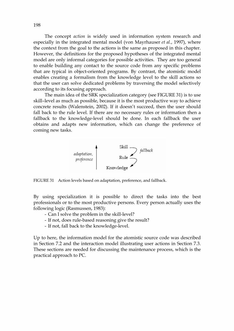
198
The concept action is widely used in information system research and especially in the integrated mental model (von Mayrhauser et al., 1997), where the context from the goal to the actions is the same as proposed in this chapter. However, the definitions for the proposed hypotheses of the integrated mental model are only informal categories for possible activities. They are too general to enable building any contact to the source code from any specific problems that are typical in object-oriented programs. By contrast, the atomistic model enables creating a formalism from the knowledge level to the skill actions so that the user can solve dedicated problems by traversing the model selectively according to its focusing approach.
The main idea of the SRK specialization category (see 1005HFIGURE 31) is to use skill–level as much as possible, because it is the most productive way to achieve concrete results (Walenstein, 2002). If it doesn’t succeed, then the user should fall back to the rule level. If there are no necessary rules or information then a fallback to the knowledge-level should be done. In each fallback the user obtains and adapts new information, which can change the preference of coming new tasks.
FIGURE 31 Action levels based on adaptation, preference, and fallback.
By using specialization it is possible to direct the tasks into the best professionals or to the most productive persons. Every person actually uses the following logic (Rasmussen, 1983):
- Can I solve the problem in the skill-level? - If not, does rule-based reasoning give the result? - If not, fall back to the knowledge-level.
Up to here, the information model for the atomistic source code was described in Section 7.2 and the interaction model illustrating user actions in Section 7.3. These sections are needed for discussing the maintenance process, which is the practical approach to PC.
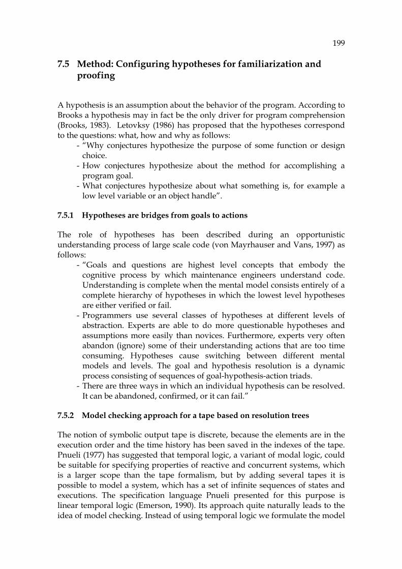
199
7.5 Method: Configuring hypotheses for familiarization and proofing
A hypothesis is an assumption about the behavior of the program. According to Brooks a hypothesis may in fact be the only driver for program comprehension (Brooks, 1983). Letovksy (1986) has proposed that the hypotheses correspond to the questions: what, how and why as follows:
- “Why conjectures hypothesize the purpose of some function or design choice.
- How conjectures hypothesize about the method for accomplishing a program goal.
- What conjectures hypothesize about what something is, for example a low level variable or an object handle”.
7.5.1 Hypotheses are bridges from goals to actions
The role of hypotheses has been described during an opportunistic understanding process of large scale code (von Mayrhauser and Vans, 1997) as follows:
- “Goals and questions are highest level concepts that embody the cognitive process by which maintenance engineers understand code. Understanding is complete when the mental model consists entirely of a complete hierarchy of hypotheses in which the lowest level hypotheses are either verified or fail.
- Programmers use several classes of hypotheses at different levels of abstraction. Experts are able to do more questionable hypotheses and assumptions more easily than novices. Furthermore, experts very often abandon (ignore) some of their understanding actions that are too time consuming. Hypotheses cause switching between different mental models and levels. The goal and hypothesis resolution is a dynamic process consisting of sequences of goal-hypothesis-action triads.
- There are three ways in which an individual hypothesis can be resolved. It can be abandoned, confirmed, or it can fail.”
7.5.2 Model checking approach for a tape based on resolution trees
The notion of symbolic output tape is discrete, because the elements are in the execution order and the time history has been saved in the indexes of the tape. Pnueli (1977) has suggested that temporal logic, a variant of modal logic, could be suitable for specifying properties of reactive and concurrent systems, which is a larger scope than the tape formalism, but by adding several tapes it is possible to model a system, which has a set of infinite sequences of states and executions. The specification language Pnueli presented for this purpose is linear temporal logic (Emerson, 1990). Its approach quite naturally leads to the idea of model checking. Instead of using temporal logic we formulate the model

200
checking approach by using resolution trees, typical for Prolog in order to specify functionality for symbolic Turing tapes. Its operations are compatible with that of temporal logic.
In 1006HFIGURE 32 a typical hypothesis resolution situation is described. The user has a goal to be performed, which at first will be recognized as a problem instance. It will be encoded (formulated) as a conjunctive normal form consisting of individual logical connections. In order to make a proof, a solver is needed. Later it is called a theorem prover, which returns to the user either satisfied (confirmed) or unsatisfied (fail). The third possibility is that the input is not relevant, which leads to ignoring the hypothesis with the current input (abandon). The function of the hypothesis can be either to refute or to validate. Experts are very flexible in selecting a function that is best in each case (Vessey, 1985).
FIGURE 32 Hypothesis resolution approach.39F
40
Each tape is rather simple to be modelled, because it only contains precedence constraints. Furhermore, by combining individual tapes it is possible to describe more complex situations, different ProgramContexts like state machines, and connected behavior models. The problem in connecting the tapes is how to evaluate and transmit side effects from a tape into another. But even if there are problems in automatic synchronization of side effects between separate tapes, there is still a possibility that the output of one simulation can help the user in understanding the side effects of the others by its symbolic notation. Thus connections between side effects referring to different states and model events and actions can be investigated manually by the help of SAM.
For example, in Appendix 1 there are three threads. They can be connected into the program flow by adding the output of each run-method after the invocation of the corresponding start-invocation. Without doing it, it is possible for the user to simulate each run-method individually in order to understand their logic with their side effects.
40 The approach of FIGURE 32 can also be considered related to constraint logic
programming (CLP), e.g., constraint solvers. These express individual elements of the model as node-consistency definitions in arc-consistency rules (van Hentenryck, 2002).
RuleEncoder Solver
H satisfied
unsatisfied
ignore
Probleminstance
Constraints
RuleEncoder Solver
H satisfied
unsatisfied
ignore
Probleminstance
Constraints

201
Typical formalism for the hypothesis
The problem instance in 1007HFIGURE 32 is a Turing tape or a number of them. Input H is a Boolean hypothesis in CNF combining the sub-rules by connectives as a resolution tree, typical for any Prolog program. An example, a hypothesis is formally a combination of its lower hypotheses: H = (H1 OR ¬H2) AND (H5 OR ¬H7 OR H4) AND etc., where at the lowest levels the sub-hypotheses point to the tape elements. They can be expressed by Horn clauses (Clocksin and Mellish, 1994). Sub-hypotheses are called theorems.
In our example ( 1008HFIGURE 24) selecting a value for the parameter port contains several clauses. We can define a resolution tree for proving that the value for the port is not DEFAULT_PORT on line 9 when creating the socket by creating a logical function that connects the lines 1, 2, 3, 4, 5, 6, 7, 8 and 9. Only lines 1, 4, and 6 can change the value.
7.5.3 Building a resolution tree: theorems, operands and constraints
The following framework to define PC hypotheses for learning code and validating programs is downwards compatible with temporal logic having similar functionalities. Typical hypotheses are either assumptions or specifications describing the relevant program flow with its side effects. These contain, in the time order, critical elements like the main method in the beginning and some problematic element as targets of the program flow.
The main elements of the framework are: - An operand, which means an explicit pointer to the ouput tape possibly
including several tape references. - A constraint, the purpose of which is to signal about logical conflicts. - A theorem, which is a small logical task for the tool to be proved
according to the contents of the tape. For a proof, constraints are needed for validating the operand references. However, even a single operand can be a theorem, because a tape is valid only if the specified operand can be found in the tape, which rule implements an existence theorem.
Defining operands
Operand is a subset of the tape, where elements are connected with optional operations and list specifiers (See 1009HFIGURE 33). An operand can point either to a specific atom in the tape, or to a list, or to any logical operation. Furthermore, an operand can be justified with its constrained specification. An operand can also be any of the alternatives or an internal variable, or a list of constants, or ranges. In special cases an operand can point to all elements (like in saving information).
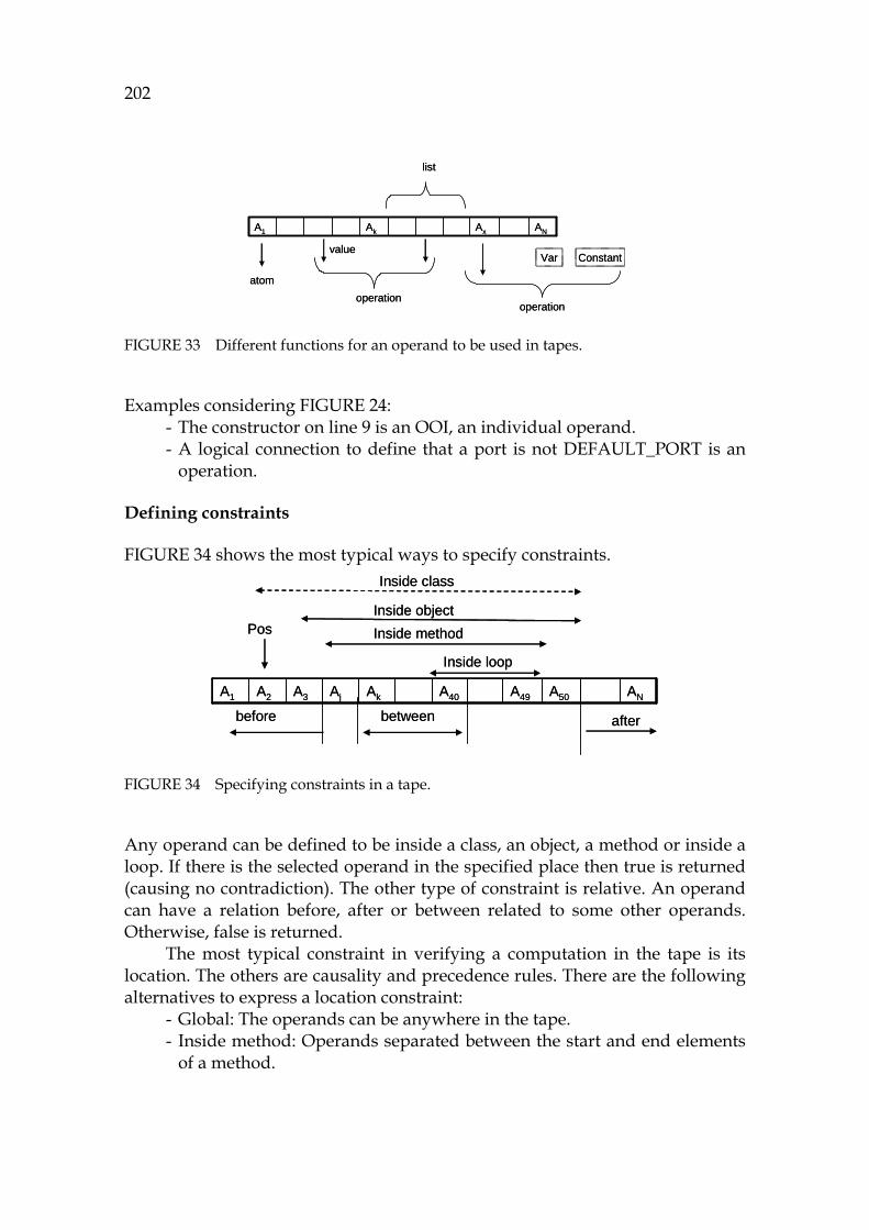
202
FIGURE 33 Different functions for an operand to be used in tapes.
Examples considering 1010HFIGURE 24: - The constructor on line 9 is an OOI, an individual operand. - A logical connection to define that a port is not DEFAULT_PORT is an
operation.
Defining constraints
1011HFIGURE 34 shows the most typical ways to specify constraints.
FIGURE 34 Specifying constraints in a tape.
Any operand can be defined to be inside a class, an object, a method or inside a loop. If there is the selected operand in the specified place then true is returned (causing no contradiction). The other type of constraint is relative. An operand can have a relation before, after or between related to some other operands. Otherwise, false is returned.
The most typical constraint in verifying a computation in the tape is its location. The others are causality and precedence rules. There are the following alternatives to express a location constraint:
- Global: The operands can be anywhere in the tape. - Inside method: Operands separated between the start and end elements
of a method.
Ax ANAkA1
operation
list
atom
valueVar Constant
operation
Ax ANAkA1
operation
list
atom
valueVar Constant
operation
A50A49 ANA40AkAjA3A2A1
Pos
before afterbetween
Inside class
Inside objectInside method
Inside loop
A50A49 ANA40AkAjA3A2A1
Pos
before afterbetween
Inside class
Inside objectInside method
Inside loop
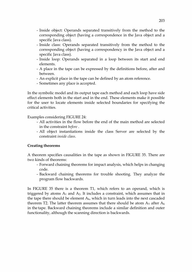
203
- Inside object: Operands separated transitively from the method to the corresponding object (having a correspondence in the Java object and a specific Java class).
- Inside class: Operands separated transitively from the method to the corresponding object (having a correspondency in the Java object and a specific Java class).
- Inside loop: Operands separated in a loop between its start and end elements.
- A place in the tape can be expressed by the definitions before, after and between.
- An explicit place in the tape can be defined by an atom reference. - Sometimes any place is accepted.
In the symbolic model and its output tape each method and each loop have side effect elements both in the start and in the end. These elements make it possible for the user to locate elements inside selected boundaries for specifying the critical activities. Examples considering 1012HFIGURE 24:
- All activities in the flow before the end of the main method are selected in the constraint before .
- All object instantiations inside the class Server are selected by the constraint inside class.
Creating theorems
A theorem specifies causalities in the tape as shown in 1013HFIGURE 35. There are two kinds of theorems:
- Forward chaining theorems for impact analysis, which helps in changing code.
- Backward chaining theorems for trouble shooting. They analyze the program flow backwards.
In 1014HFIGURE 35 there is a theorem T1, which refers to an operand, which is triggered by atoms A1 and A2. It includes a constraint, which assumes that in the tape there should be element Ak, which in turn leads into the next cascaded theorem T2. The latter theorem assumes that there should be atom AY after Ak in the tape. Backward chaining theorems include a similar definition and outer functionality, although the scanning direction is backwards.
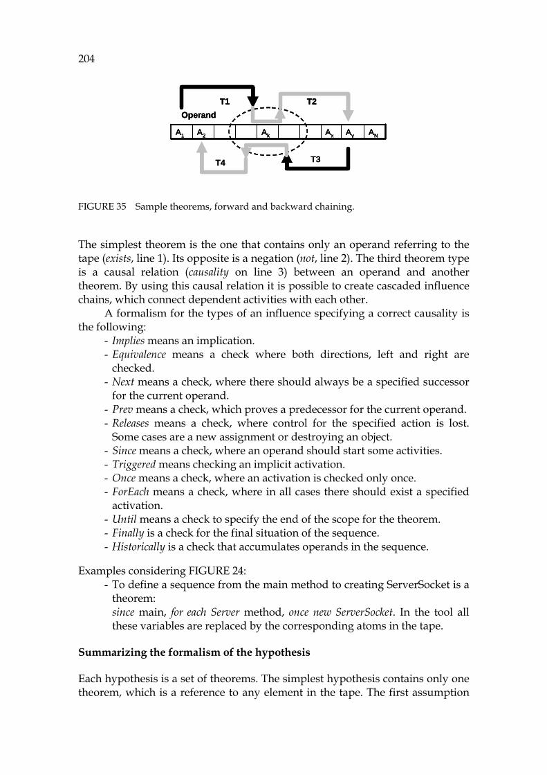
204
FIGURE 35 Sample theorems, forward and backward chaining.
The simplest theorem is the one that contains only an operand referring to the tape (exists, line 1). Its opposite is a negation (not, line 2). The third theorem type is a causal relation (causality on line 3) between an operand and another theorem. By using this causal relation it is possible to create cascaded influence chains, which connect dependent activities with each other.
A formalism for the types of an influence specifying a correct causality is the following:
- Implies means an implication. - Equivalence means a check where both directions, left and right are
checked. - Next means a check, where there should always be a specified successor
for the current operand. - Prev means a check, which proves a predecessor for the current operand. - Releases means a check, where control for the specified action is lost.
Some cases are a new assignment or destroying an object. - Since means a check, where an operand should start some activities. - Triggered means checking an implicit activation. - Once means a check, where an activation is checked only once. - ForEach means a check, where in all cases there should exist a specified
activation. - Until means a check to specify the end of the scope for the theorem. - Finally is a check for the final situation of the sequence. - Historically is a check that accumulates operands in the sequence.
Examples considering 1015HFIGURE 24:
- To define a sequence from the main method to creating ServerSocket is a theorem: since main, for each Server method, once new ServerSocket. In the tool all these variables are replaced by the corresponding atoms in the tape.
Summarizing the formalism of the hypothesis
Each hypothesis is a set of theorems. The simplest hypothesis contains only one theorem, which is a reference to any element in the tape. The first assumption
ANAyAxAkA2A1
OperandT1 T2
T3T4
ANAyAxAkA2A1
OperandT1 T2
ANAyAxAkA2A1
OperandT1 T2
T3T4

205
for triggering an analysis in a typical Java application is the main method. Chopping can be defined by a theorem which has a since definition and a triggered definition. The operand can contain separate elements or any logical combinations connecting elements with each other.
Backward slicing can be defined as a causality theorem, which has a until definition. In contrast to traditional slicing, the formalism above makes it possible to re-evaluate the captured flows and make complex multi-phase queries by using operands in order to validate or refute complex parts of the software.
7.5.4 Learning method based on gradual proving
The results from a proving process vary depending on the problem type and the eagerness. In familiarization, in the read-to-recall process (Burkhardt et al., 2002) the user gets a number of chunks including information about program relations (see 1016HTABLE 13). If the task was a troubleshooting problem, then the user loads the personal memory as economically as possible without learning unnecessary features. Then the output from the proving process is a number of matches, where contradictions have an important role. Each contradiction that cannot be explained by other matches or other contradictions are possible errors.
When planning changes, each possible place to be modified can be considered as a contradiction against the current program model, because there is a mismatch between all impacts of the planned modification against the current behavior. As found in 1017HTABLE 13 a proving method can be seen as a state transition table, whose state variables are initial/current knowledge, proof result and the type of the PC effort. These lead step-by-step to conclusions, to next steps either for familiarization or troubleshooting.
TABLE 13 Making conclusions based on proof results.
Type of current PC phase
Initial knowledge
Proof result Conclusions and remarks and possible decisions
Familiarization Low Finding relevant plans
Chunking relevant places
Familiarization Perfect No contradictions As above, no conclusions Familiarization Perfect Contradiction A conflict. Either an error or an
exception. It starts a troubleshooting phase
Troubleshooting Low No contradictions Find relevant places. Use a familiarization phase to increase eagerness
Troubleshooting Moderate Contradiction Find more information by using familiarization if needed
Troubleshooting Moderate No contradictions Continue, skip to next subtask Troubleshooting High No contradictions Continue proofing Troubleshooting High A contradiction Conclusion: Isolate the problem,
fix the bug
206
7.6 Extending the method to the maintenance process
This section describes a computer-aided process, where the maintenance task is performed iteratively, in a systematic way, based on user actions and computations of the computer. It has the following features:
- An iterative, gradually deepening process (Deming, 2000) from concepts via ProgramConcepts to ProgramContexts.
- The user has total control for the simulation in order to select all the relevant program flows, e.g., ProgramContexts to be analyzed.
- Each relevant ProgramContext is simulated to produce an output tape. Next a task flow is described as a sequence via problem recognition, problem formulation, and the necessary analysis and through making conclusions.
7.6.1 Top-down approach considering the change request
In this section a rational method for executing a maintenance task is described.
From task to problem
A typical maintenance task is a change request, cf. (Gallagher, and Lyle, 1991). The first phase in solving the task is to reduce it as much as possible (Walenstein, 2002). The best way for minimizing a software task is to find the smallest problem area that it covers, a problem space. A problem is then formulated as a set of desired end results (goal), including necessary operations and constraints. This approach leads to a definition for the problem (Walenstein, 2002):
Problem = {Goals40F
41, Operations, Constraints}. Relating to the symbolic model, the operations are either the user’s abstract decisions or more concrete user actions (which are defined later in this chapter). Abstract operations are actions relating to relevant components or packages of software to load and to evaluate critical classes. After the relevant code has been selected the next operations for the analysis relate to how to set constraints that limit the scope. These include finding the start and target elements and for selecting the approach in accordance with the symptom or the nature of task definition. This deliberation should lead to selections that control navigation. The goal is to create a mental image about an entity that caused the problem or that is a candidate to be changed.
For example a starting problem considering 1018HFIGURE 24: - Goal 1: To locate where the server is starting - Goal 2: To locate how far the initialization works
41 Walenstein uses here the concept End instead of the concept Goal.
207
7.6.2 Problem recognition
Problem recognition is the first concrete phase in the corrective and adaptive maintenance process (Gilb, 1988). The selected approach for problem recognition deals with how to map the problem, i.e., a failure, to any actual part of the software. In Java applications mapping is easy, because almost without an exception a problem that can be seen outside can be mapped into a JDK class or a method. This includes wrong data or wrong behavior that can be mapped into the functionality. The granularity in problem recognition has the following levels X:
- Application (the lowest granularity) - Model (package or class) - Execution path - Local function.
The fault types can be data, state, or logic related, or functional, including anomalies. If an electronic trace is obtained, for example a log or a trace indicating the problem, then most often it can be mapped into the code very accurately.
Problem recognition is said to be completed when the problem is mapped into a part of source code (a file or a small area in a file) and the type of the problem is known so accurately that the next phase, problem formulating, can be started.
7.6.3 Problem formulation
Problem formulation is a logical phase to make assumptions about the cause, about the sequence that caused the problem. In source code all causes are causal chains, results from a program flow. It makes the formulating straightforward. When the problem, discovered in the recognition phase, is in the focused element, a sequence or a use scenario that goes through this element and causes the wrong behavior should be selected.
Problem formulation is thus a knowledge action giving one or more contexts for the problematic function. In most cases it gives multiple sequences as results. Some of them are relevant to the problem, some may be erroneous, and some of them should be working correctly. Problem formulation can be skipped in the cases where the overall architecture is not known, and wherever a clear observation can be made by using a JDK function (like an internet function). In these cases the class where the invocation emanates from, can be used as an indicator, a beacon, for a later analysis.
The task of the user is to detect (prove) the cases which need attention, updates or even corrections. This is called problem analysis.
208
7.6.4 Problem analysis
Problem analysis is an iterative process to identify a cause for the problem from several sequences. There are multiple alternatives according to the granularity of problem recognition:
- If the recognition process remains at the application level, the most probable sequence, the main process, is selected. Thereafter a flow is selected by using an assumption of the fault type as a selector (data, state, object, or control).
- The selected sequences are verified and the most critical elements are found.
- The most critical elements are set as focus elements. Necessary knowledge actions are created for them.
- The sequences for focused elements are evaluated according to the selected hypothesis (see Section 7.5). The results from the proofs (Section 7.5.3) are used in controlling the selection of the next steps of the problem analysis.
- Decisions about the correctness are made, matching the ProgramContext, the element, and the initial knowledge about the behavior of the ProgramContext.
Problem analysis is a deductive process to prove the selected sequences. Proving each sequence is rule level work, which gives explanations as its output. The explanations are captured relations from the sequences (like subsets of a data flow or a program flow).
Formulating the problem by using questions
Programs can be learnt in several eagerness levels. Burkhardt et al. propose two levels: ready-to-recall and ready-to-use. Some other eagerness levels relate to the type of the task. In familiarization the eagerness is lower than in critical troubleshooting, where the fault should be isolated as accurately as possible, which can minimize the risks in modifications. The following answering logic obeys the principles of the Letovsky questions (Letovsky, 1986):
- Question 1: Do we have enough initialization knowledge? The user has some initialization knowledge, K0, about the program. If there is no sufficient knowledge, thus leaving the user unsure, then a familiarization process should be started.
- Question 2: What should the program do? The user answers either by collecting the information from his/her memory or by using symbolic analysis to collect the functionality of the program automatically. If the answer is empty then the user gathers more initialization knowledge or exits the process.
- Question 3: What is the most relevant feature to be investigated? The user locates the feature in the code.
209
- Question 4: Does this feature work as assumed? The user simulates the code getting a function flow. It is compared with the assumption. If the behavior was correct, question 4 is removed and a skip is made to question 2. If the behaviour was not as expected then the next question is made.
- Question 5: Specify, how does the function flow work? The answer can be any mix of symbolic flows: control flow, data, state, object or operation flow. The user checks this flow (skill-level action) in order to see problematic places.
- Question 6: For each target find the position in the flow of which the user asks: Why was this target activated and when (under what conditions)? If the user finds a problematic place (an illogical answer to a why-question) then the flow before the target is investigated until the problem is fixed. If there were no answers in the current flow, then the next question is needed.
- Question 7: Select a new start-target-flow combination which produces a subset of the flow of question 5. Was the current target activated correctly? Use branching and splitting principles in order to decrease the size of the current flow.
The PC process ends when the input (a tape or several tapes) has been processed in familiarization or, when a contradiction, a conflict has been localized in troubleshooting.
Transforming the problem to questions
The problem considering the current task is divided into questions and subtasks. Structural elements can be divided into subelements and use scenarios, and sequences can be divided into smaller groups to be studied. Questions may be employed (Letovsky, 1986) to create a base of a communication language for the team collaboration. Some examples about the questions relating to a problematic element E are of the form:
- Skill level: Is E relevant? What does it do? Is it correct and acceptable? - Rule level: What is the function of element E in the current flow? What is
the relation between E and the object (O) in this particular sequence? What side effects can E and the sequence E to O cause? Is the sequence E to O valid?
- Knowledge level: How does E work in different cases? What is the purpose of the element E? What are the parameters of E in different cases? How do the collaborations between E and O work?
- Metalevel: Which external elements have any explicit influence to module M? Which internal elements have some implicit influence to module M?
Distributing processing here means that the operations and actions are
divided into tasks for multiple maintainers. If the persons have a common tool,

210
the language and its notation can enable productive cooperation. Here the data model and simulation capability of SAM can be helpful in this respect.
In the list above the questions considering skill, rule and knowledge correspond to the definitions of rhematic, dicent and argumentative in the knowledge unit.X These questions are transformed to model queries next.
Transforming questions to queries and further on to hypotheses
Transforming informal questions to queries is not obvious. The possible constraints and parameters for the queries include, among others, the query type (fault type), and the elements to be focused. Usually many queries are needed, both for getting positive deductive information about successful samples and cases and negative information about erroneous situations, in order to create an inductive decision.
7.6.5 A use case: Using symbolic analysis for capturing knowledge
Let’s describe a situation where a TCP/IP-server, acting as a class Server (see Appendix 1), does not start. All the necessary initial knowledge pertaining to the TCP/IP server consists of that the communication is done with the object ServerSocket. The user can employ the initial knowledge about the implemented modifications, the history of the software and earlier errors in many different ways, in order to locate the problem as efficiently as possibly.
A general rule for isolating the problem using symbolic analysis is as follows:
- In the knowledge level the user creates a hypothesis about a relation between the symptom and its possible cause. If the function doesn’t start at all the user may assume that the problem is either a state problem or a control flow problem between the main and the focus.
- The user confirms the hypothesis that the problem can only occur when the program is started from the main method (skill action).
- In the rule level, the user validates the paths and, in the skill level, the invocations.
- In the skill level the user validates all the conditions and their relevancy. The user inspects the control paths that are close to the target and in the end of the output tape, because it may be assumed that the problem is one of the last conditions of the simulation (unless a totally erroneous logic path has been selected).
In this particular case the process can be divided into iterative phases as follows:
1. Problem Recognition: - The failure is located into an application, which is responsible for
TCP/IP communication. The process and code for creating a ServerSocket object should be found there.

211
2. Problem Formulation: - It is found that there is only a main method in the application. Thus, it is
selected as the start element. The formulation is then to investigate the flow between it (main) and the target element, the ServerSocket instantiation.
- Locating the ServerSocket is a search activity that requires skill knowledge to identify the possible invocations (skill action).
- The object ServerSocket is the selected target (problem object), the focused element. All possible input paths leading to it are found (KnowledgeAction).
3. Problem Analysis: - When the start and the target are fixed, a complete query can be made
from the main to creating the object ServerSocket. This is simulated and the output tape is created.
- If an object is not created, then the problem should be in the selected sequence.
- The assignments are checked (variable port etc). - The user finds that the only things that can have influence in the variable
port are the command line and the variable DEFAULT_PORT. - The value for DEFAULT_PORT is checked. - In this particular case, a problem is found in the side effect element,
considering the value of the variable DEFAULT_PORT.
4. Change Specification: - The modification should be done to the area of the variable port. It can
be written in several ways. Evaluating the best way can be done by means of impact analysis, by using forward chaining theorems for the current model in order to minimize the number of impacts.
Unit Testing:
- After the modification, the same code area with the new code is inspected again. The correction can be read from the simulation output tape without going through problem formulation or preliminary analysis.
- In these cases where the elements that have been modified to form complex logic between their environments a theorem prover can be used for showing that the newer version uses valid control paths. Inspecting side effects is not necessary if there are no changes in the references. Instead, in regression testing all test cases are exhaustively checked.
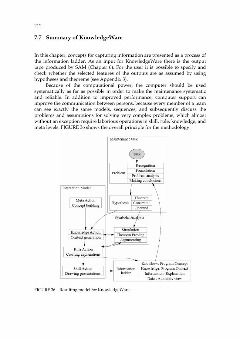
212
7.7 Summary of KnowledgeWare
XIn this chapter, concepts for capturing information are presented as a process of the information ladder. As an input for KnowledgeWare there is the output tape produced by SAM (Chapter 6). For the user it is possible to specify and check whether the selected features of the outputs are as assumed by using hypotheses and theorems (see Appendix 3).
Because of the computational power, the computer should be used systematically as far as possible in order to make the maintenance systematic and reliable. In addition to improved performance, computer support can improve the communication between persons, because every member of a team can see exactly the same models, sequences, and subsequently discuss the problems and assumptions for solving very complex problems, which almost without an exception require laborious operations in skill, rule, knowledge, and meta levels. 1019HFIGURE 36 shows the overall principle for the methodology.
FIGURE 36 Resulting model for KnowledgeWare.
213
The task is transformed into problem recognition, which gives the focused elements in the model, and into problem formulation that gives a logical notation, which describes the sequences and triples that are critical and need to be checked. Checking is done by using the atomistic model as queries that activate simulating runs. For these runs, the user does model checking either manually or by using the theorem prover that gives a proof. The actions concerning the model are directed at levels specified by Rasmussen (1983), and the information is classified according to the principles of the information ladder.
With the help of the actions at the different levels the user can create presentations to the computer display and to the personal memory by chunking.
214
8 TOOL FOR SYMBOLIC ANALYSIS AND ATOMISTIC MODEL
This chapter describes a tool implementation based on symbolic analysis and an atomistic model. Requirements for the implementation, architecture selections, a data model for the tool, the user interface, and the analyzing process are introduced.
The tool described has been named JavaMaster. Its main task is to demonstrate the Turing model and its different connections to the human interaction model and to maintenance. Therefore, it has not been optimized as far as its usefulness and efficiency for pragmatic purposes is concerned. The main goal is to show that a symbolic atomistic model can be realized and that it is useful for increasing the user’s knowhow.
8.1 Requirements for the tool
Maintenance tools have been described from the program comprehension point-of-view in many publications (Tools, 2007; Storey, 2006; Jackson and Rinard, 2000; Müller et al., 2000), but only a few articles have been written from the cognitive viewpoint (Walenstein, 2002), where the focus should be to balance the load between the user and the tool.
In the atomistic methodology, understanding one element at a time is a skill level action (see Chapter 7). If the user is not able to make a skill level decision, then a larger display or a set of automatic information is needed for the user to progress to the rule action level. If the rule action information, which typically is a chain of successive elements, is not enough, then a wider graph should be used to enable making hypotheses about the current situation.
215
8.1.1 Selected features for the tool
The tool implements all technology spaces: GrammarWare, ModelWare, SimulationWare (Symbolic Abstract Machine), and KnowledgeWare. It has the special ingredients of the atomistic model that has no hierarchy. This unified model for all elements enables the user to change abstraction in his/her mind depending on the elements in the display. Unlike in UML, there is no need to change the diagram to study elements of different levels.
In order to satisfy the requirements R6 and R7, the JDK library is loaded into the model as class definitions (not their code). A maximum capacity for the loaded software is evaluated to be 1-10 million source code lines, which corresponds to 5-20 million atoms, because it is the same size as a typical large stand-alone application. The number of AST nodes is about the same as the number of symbolic atoms, derived from the same source, because both have been created by grammar structures.41F
42 However, in practice the size of practical models may be closer to the range of 1000 to 100.000 atoms, because the focused approach allows ignoring irrelevant parts of the code.
Abstracting the Turing machine
The purpose of the tool is to implement a construction of an idealized symbolic Turing machine with its tapes. Here the essential improvement for the original TM, which only uses bits as input, is to enable the use of symbolic elements expressed by the Symbolic language as inputs and outputs. In some research articles TM is considered to have two tapes, one for input and one for output, but sometimes only one tape is drawn, which means reading and writing of the same tape. In the JavaMaster tool we have selected a two tape system, which contains a sequence builder for creating an input sequence corresponding to an input tape. All output is directed into an output tape, which is a history about all executed elements. All elements in these tapes are atoms.
Dividing the functions according to knowledge levels
The intentional goal for the tool is to use the categories of Rasmussen (1983) to group the actions for the user in the following way:
- Skill level: An individual element is focused. Its presentation is a centered dependency view.
- Rule level: A flow between two or more elements is focused. Its input is a query (also chop in this meaning). The output is an output tape, which in fact is an explanation, which can be visualized in several ways.
- Knowledge level: A collected focused graph between elements containing alternative paths for studying cross-cuttings. Its function is to
42 Word97 (Microsoft ™) has 6 million AST nodes and about 18 million links between these
nodes (Rajamani, 2005a).

216
show the alternative incoming and outgoing flows from the focused element.
Furthermore, the meta level introduced by Walenstein (2002) is important in program comprehension, because it helps in building up a complete information set to cover both the top-level design presentations and low-level code models. The meta level can be characterized by diagrams containing dependency information about class structures. This level is highly correspondent with UML presentations.
Special focus in partial evaluation
The purpose of the tool described is, in contrast to traditional reverse engineering tools, to present as small amount of information as possible. This focused approach should give the user a better chance to find the most important information without a burden to explore unnecessary data or large displays. The user should form an active part of the cognitive architecture with its different agent roles.
Symbolic execution provides two principal benefits for supporting corrective maintenance:
- Tracing information between components is possible symbolically by
evaluating the scripts of the data flows. This feature includes the analysis of JDBC, RMI, Corba and communication.
- Tracing program flows inside components is possible both for small and large software by using partial simulation (PSSC), including desktop applications and application-server installations.
The purpose of the tool is to enable tracing both internal component problems and the semantics of external components on the same platform.
8.2 Selected architecture
For selecting an architecture for the tool several principles were studied. These include MVC (Model View Control) and data centered architectures with databases or repositories as the main principle.
At the first glance the generic MVC architecture, which emphasizes the concept of the model seemed promising. However, using a centered model as a base proved to be a wrong decision, because the MVC model is a centralized artefact, thus very far from the atomistic model where the elements should remain as independent as possible. From the atomistic perspective an object-oriented architecture would seem a better prospect than a centralized one. Preferably, each element should be an independent model, with a controller feature and the views typical for that element.

217
8.2.1 PCMEF - architecture
An appropriate selection for the architecture proved to be PCMEF, which holds the layers for Presentation, Controller, Mediator, Entity, and Foundation. (Maciaszek and B.Liong, 2005).42F
43 Because it doesn’t define a model layer at all, it is possible to embed the model into the architecture. Next it is described from the atomistic approach.
Foundation: The most important layer for the atomistic model is the lowest level, the foundation, because the data model is based on the concept of atom, which doesn’t have a structure. In JavaMaster tool the lowest layer, Foundation, was dedicated to the Symbolic clause, because it is a semantic communication type agreement, “a software bus”, connecting all the atoms of the model by using a single command field, which has clause as its definition.
Entity: The only entity in the tool is the symbolic element (atom) of the model. It contains all of its information, the links being located in the elements. Because the element is strong and expressive by itself, it is not necessary to create a model layer or to use any database. The entity layer thus corresponds to the data access layer of a typical architecture.
Mediator: However, a centre for logic functions of the tool is needed for organizing data flows from the user to the tool and to model elements and from the results of the activities to the display. This layer is called Mediator. The role of Mediator is to create connections between the main function as modules of the tool: GrammarWare and ModelWare. They together with KnowledgeWare form the tool model, AppModel, to describe the main information flow. This is three-dimensional according to the Peircean taxonomy with GrammarWare describing syntax, ModelWare semantics, and KnowledgeWare implementing pragmatics from the Controller-level.
Transformations are important invisible functions in the Mediator layer. Because the whole architecture is based on the Symbolic language, there is no need to write numerous transformations between all possible data notations. It is necessary to write a transformation from any input notation into Symbolic and from Symbolic to any output notation. All these transformations can be written by using direct translation, enabling reliable data transfer and proved transformations. Typical transformations are conversions from clauses to trees, graphs, table displays and xml documents.
Controller: One layer is needed for enabling changes in the system. This layer is called Controller. In the tool the main responsibility for high level changes in the status of the application is given to the ApplicationController class, and the responsibility to execute the application model (AppModel) is given to the user via KnowledgeWare and to the computer using a façade named Turing
43 The Presentation layer shows the displays. The Controller layer is both for the user to
select the functions and for the internal software to select a new internal status for the software. The Mediator layer contains the business logic and is the centre of activities. The Entity layer contains the data model, and the Foundation layer contains typically a database interface, the base for the system data.

218
Machine, which delegates the commands to the symbolic abstract machine (SAM), which can explicitly run the model elements.
Presentation: For generating displays and showing them, a Presentation layer is needed. In the tool display, components build up a framework called UiFrameWork. All UI controls are inherited from the general class AbstractController enabling unified programming regardless of the control type. In the sheets of UiFrameWork it is possible to present trees, tables, source code as editors, xml information, graphs, text comparisons etc. For each control a popup-menu is defined to enable context sensitive navigation.
8.2.2 Summary of the selected architecture
1020HFIGURE 37 shows the selected architecture with its layers.
FIGURE 37 Architecture levels of the JavaMaster tool.
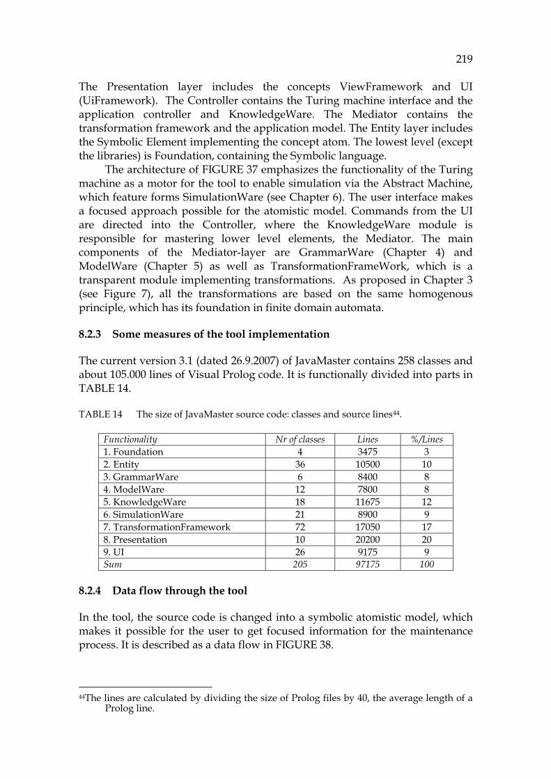
219
The Presentation layer includes the concepts ViewFramework and UI (UiFramework). The Controller contains the Turing machine interface and the application controller and KnowledgeWare. The Mediator contains the transformation framework and the application model. The Entity layer includes the Symbolic Element implementing the concept atom. The lowest level (except the libraries) is Foundation, containing the Symbolic language.
The architecture of 1021HFIGURE 37 emphasizes the functionality of the Turing machine as a motor for the tool to enable simulation via the Abstract Machine, which feature forms SimulationWare (see Chapter 6). The user interface makes a focused approach possible for the atomistic model. Commands from the UI are directed into the Controller, where the KnowledgeWare module is responsible for mastering lower level elements, the Mediator. The main components of the Mediator-layer are GrammarWare (Chapter 4) and ModelWare (Chapter 5) as well as TransformationFrameWork, which is a transparent module implementing transformations. As proposed in Chapter 3 (see Figure 7), all the transformations are based on the same homogenous principle, which has its foundation in finite domain automata.
8.2.3 Some measures of the tool implementation
The current version 3.1 (dated 26.9.2007) of JavaMaster contains 258 classes and about 105.000 lines of Visual Prolog code. It is functionally divided into parts in 1022HTABLE 14.
TABLE 14 The size of JavaMaster source code: classes and source lines43F
44.
Functionality Nr of classes Lines %/Lines 1. Foundation 4 3475 3 2. Entity 36 10500 10 3. GrammarWare 6 8400 8 4. ModelWare 12 7800 8 5. KnowledgeWare 18 11675 12 6. SimulationWare 21 8900 9 7. TransformationFramework 72 17050 17 8. Presentation 10 20200 20 9. UI 26 9175 9 Sum 205 97175 100
8.2.4 Data flow through the tool
In the tool, the source code is changed into a symbolic atomistic model, which makes it possible for the user to get focused information for the maintenance process. It is described as a data flow in 1023HFIGURE 38. 44The lines are calculated by dividing the size of Prolog files by 40, the average length of a
Prolog line.

220
FIGURE 38 Data flow of the tool.
The first phase (1) is loading source code to the tool. It is made by selecting a base directory or Java files one after another. The GrammarWare module of the tool converts the code into a Java parse tree and further into a Symbolic parse tree. This data is an input to the ModelWeaver, which is an essential part of ModelWare. By using the model it is possible to formulate the problem by seeking critical elements and links (3a). This information is shown in the tool, from which the user can select the sequences that are most problematic or least known (3b). Abstract machine is then the tool that changes the input tapes (input sequence definitions) to output tapes (4). This output is the base for all later program comprehension activities. There is a proof engine, a theorem prover, which validates or invalidates the hypotheses of the selected sequences according to the on-the-fly rules defined by the user (5a). The results from the proof process show the change candidates that contain the potential locations to be modified (6). After modifications the same software including the modifications will be checked again as in regression testing (7). The steps 3 and 4 (Act), 5 (Plan), 6 (Do), and 7 (Check) form a Deming cycle (Deming, 2000), explained further in Chapter 7. Some of its main principles are divide et conquer, focusing and systematic approach for unsystematic tasks. All these principles are relevant in symbolic analysis and in JavaMaster, where the purpose is to keep the focus of the user on the same start to target area until it will be validated. However, the user can change the focus at any time in order to find a more relevant focus area, because one of the main characteristics of an experienced programmer compared with novices is the ability to change frequently the understanding strategy (Vessey, 1985).
1 Source code is parsed2 Atomistic model is weaved3a Maintenance task is formulated3b Critical sequences are selected4 Sequences are simulated5 Results are proofed6 Modifications are planned7 Modifications are checked
ModelWare
User
KnowledgeWare
Practicalcontribution
Simulation Ware
MachineCompu-
tation
GrammarWare
Change request
MaintenanceTool
3a
4
2
1
3b5a
5b
7
6
ModelWare
User
KnowledgeWare
Practicalcontribution
Simulation Ware
MachineCompu-
tation
GrammarWare
Change request
MaintenanceTool
3a
4
2
1
3b5a
5b
7
6
3a
4
2
1
3b5a
5b
7
6

221
8.3 Low level approach, the technology behind the tool
This section introduces some detailed features of the data flow of 1024HFIGURE 38.
8.3.1 Demonstrating the architecture by a small code example
In this section a small demonstration about a Java code is shown to illustrate how a simple loop goes through the tool. It shows the internal structures of the tool in detail. A while loop of Java is selected as an example:
EXAMPLE 1. An example loop to be simulated.
1 while (i<10) 2 { 3 print(i); 4 i++; 5 } Partial simulation makes it possible for the tool to create a model for this small code particle even though it doesn’t have any class definition or any method definition or any definition for the variable i. The code is assumed to print its output via the method print, which is not defined either.
The symbolic notation
The following is an intermediate Symbolic correspondence for the Java loop (lines 1-5): 30 [loop(while([op(rel("<",[ref(refname(amb_name("i"),[]))], 31 [val(sv(integer(10)))]))], 32 [get(call(sget([method_name("print")]), 33 [ref(refname(amb_name("i"),[]))])), 34 op(math("++",[ref(refname(amb_name("i"),[]))]))]))] This notation seems complex, but it is very natural for Prolog to handle complex data structures. Lines 30 and 31 keep the conversion result from line 1, lines 32 and 33 the result of line 3 (print) and lines 33 and 34 the result from line 4. Because of abstraction the size of the parse tree here is only about 10 % of the size of the correspondent Java parse tree. There were no definition for the variable i, thus it is referred to by amb_name(”i”). If there is a definition then the reference should have a typed name.
8.3.2 Graphic symbols for the symbolic Turing machine
In this section using the TM model and its general functionality are discussed.
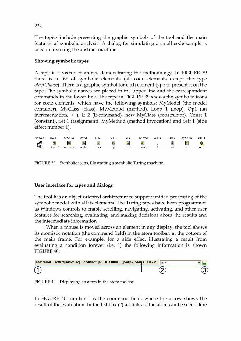
222
The topics include presenting the graphic symbols of the tool and the main features of symbolic analysis. A dialog for simulating a small code sample is used in invoking the abstract machine.
Showing symbolic tapes
A tape is a vector of atoms, demonstrating the methodology. In 1025HFIGURE 39 there is a list of symbolic elements (all code elements except the type otherClause). There is a graphic symbol for each element type to present it on the tape. The symbolic names are placed in the upper line and the correspondent commands in the lower line. The tape in 1026HFIGURE 39 shows the symbolic icons for code elements, which have the following symbols: MyModel (the model container), MyClass (class), MyMethod (method), Loop 1 (loop), Op1 (an incrementation, ++), If 2 (if-command), new MyClass (constructor), Const 1 (constant), Set 1 (assignment), MyMethod (method invocation) and Seff 1 (side effect number 1).
FIGURE 39 Symbolic icons, illustrating a symbolic Turing machine.
User interface for tapes and dialogs
The tool has an object-oriented architecture to support unified processing of the symbolic model with all its elements. The Turing tapes have been programmed as Windows controls to enable scrolling, navigating, activating, and other user features for searching, evaluating, and making decisions about the results and the intermediate information.
When a mouse is moved across an element in any display, the tool shows its atomistic notation (the command field) in the atom toolbar, at the bottom of the main frame. For example, for a side effect illustrating a result from evaluating a condition forever (i.e. 1) the following information is shown 1027HFIGURE 40:
FIGURE 40 Displaying an atom in the atom toolbar.
In 1028HFIGURE 40 number 1 is the command field, where the arrow shows the result of the evaluation. In the list box (2) all links to the atom can be seen. Here
1 2 31 2 3
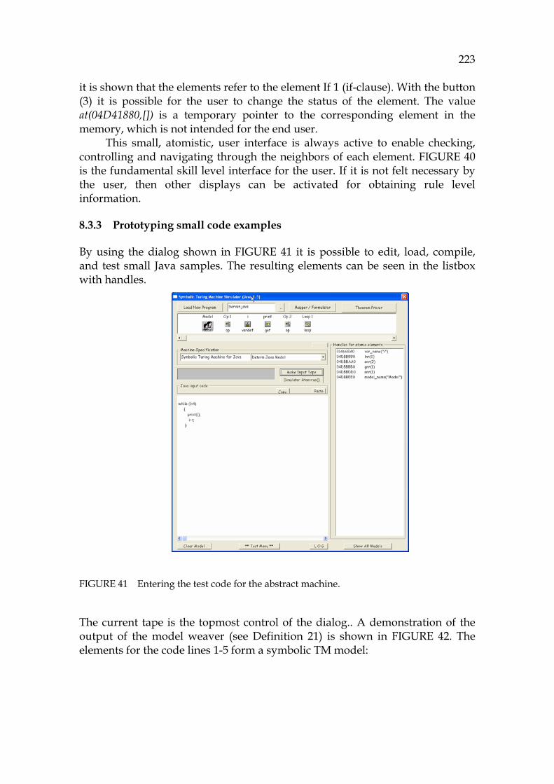
223
it is shown that the elements refer to the element If 1 (if-clause). With the button (3) it is possible for the user to change the status of the element. The value at(04D41880,[]) is a temporary pointer to the corresponding element in the memory, which is not intended for the end user.
This small, atomistic, user interface is always active to enable checking, controlling and navigating through the neighbors of each element. 1029HFIGURE 40 is the fundamental skill level interface for the user. If it is not felt necessary by the user, then other displays can be activated for obtaining rule level information.
8.3.3 Prototyping small code examples
By using the dialog shown in 1030HFIGURE 41 it is possible to edit, load, compile, and test small Java samples. The resulting elements can be seen in the listbox with handles.
FIGURE 41 Entering the test code for the abstract machine.
The current tape is the topmost control of the dialog.. A demonstration of the output of the model weaver (see 1031HDefinition 21) is shown in 1032HFIGURE 42. The elements for the code lines 1-5 form a symbolic TM model:
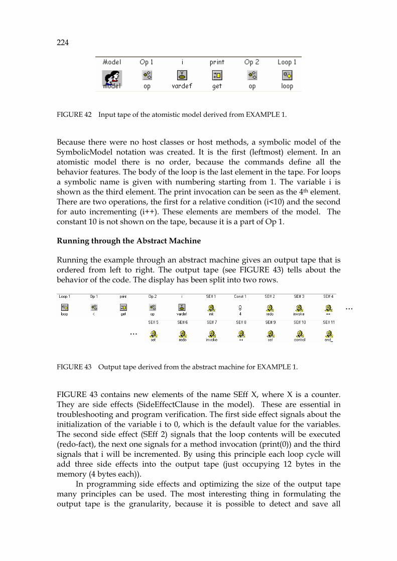
224
FIGURE 42 Input tape of the atomistic model derived from 1033HEXAMPLE 1.
Because there were no host classes or host methods, a symbolic model of the SymbolicModel notation was created. It is the first (leftmost) element. In an atomistic model there is no order, because the commands define all the behavior features. The body of the loop is the last element in the tape. For loops a symbolic name is given with numbering starting from 1. The variable i is shown as the third element. The print invocation can be seen as the 4th element. There are two operations, the first for a relative condition (i<10) and the second for auto incrementing (i++). These elements are members of the model. The constant 10 is not shown on the tape, because it is a part of Op 1.
Running through the Abstract Machine
Running the example through an abstract machine gives an output tape that is ordered from left to right. The output tape (see 1034HFIGURE 43) tells about the behavior of the code. The display has been split into two rows.
FIGURE 43 Output tape derived from the abstract machine for 1035HEXAMPLE 1.
1036HFIGURE 43 contains new elements of the name SEff X, where X is a counter. They are side effects (SideEffectClause in the model). These are essential in troubleshooting and program verification. The first side effect signals about the initialization of the variable i to 0, which is the default value for the variables. The second side effect (SEff 2) signals that the loop contents will be executed (redo-fact), the next one signals for a method invocation (print(0)) and the third signals that i will be incremented. By using this principle each loop cycle will add three side effects into the output tape (just occupying 12 bytes in the memory (4 bytes each)).
In programming side effects and optimizing the size of the output tape many principles can be used. The most interesting thing in formulating the output tape is the granularity, because it is possible to detect and save all
…
…
…
…
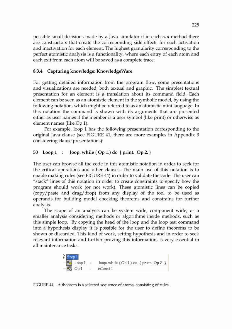
225
possible small decisions made by a Java simulator if in each run-method there are constructors that create the corresponding side effects for each activation and inactivation for each element. The highest granularity corresponding to the perfect atomistic analysis is a functionality, where each entry of each atom and each exit from each atom will be saved as a complete trace.
8.3.4 Capturing knowledge: KnowledgeWare
For getting detailed information from the program flow, some presentations and visualizations are needed, both textual and graphic. The simplest textual presentation for an element is a translation about its command field. Each element can be seen as an atomistic element in the symbolic model, by using the following notation, which might be referred to as an atomistic mini language. In this notation the command is shown with its arguments that are presented either as user names if the member is a user symbol (like print) or otherwise as element names (like Op 1).
For example, loop 1 has the following presentation corresponding to the original Java clause (see 1037HFIGURE 41, there are more examples in Appendix 3 considering clause presentations):
50 Loop 1 : loop: while ( Op 1.) do { print. Op 2. } The user can browse all the code in this atomistic notation in order to seek for the critical operations and other clauses. The main use of this notation is to enable making rules (see 1038HFIGURE 44) in order to validate the code. The user can ”stack” lines of this notation in order to create constraints to specify how the program should work (or not work). These atomistic lines can be copied (copy/paste and drag/drop) from any display of the tool to be used as operands for building model checking theorems and constrains for further analysis.
The scope of an analysis can be system wide, component wide, or a smaller analysis considering methods or algorithms inside methods, such as this simple loop. By copying the head of the loop and the loop test command into a hypothesis display it is possible for the user to define theorems to be shown or discarded. This kind of work, setting hypothesis and in order to seek relevant information and further proving this information, is very essential in all maintenance tasks.
FIGURE 44 A theorem is a selected sequence of atoms, consisting of rules.
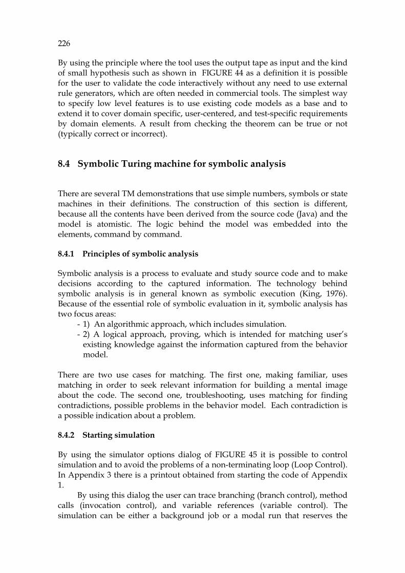
226
By using the principle where the tool uses the output tape as input and the kind of small hypothesis such as shown in 1039HFIGURE 44 as a definition it is possible for the user to validate the code interactively without any need to use external rule generators, which are often needed in commercial tools. The simplest way to specify low level features is to use existing code models as a base and to extend it to cover domain specific, user-centered, and test-specific requirements by domain elements. A result from checking the theorem can be true or not (typically correct or incorrect).
8.4 Symbolic Turing machine for symbolic analysis
There are several TM demonstrations that use simple numbers, symbols or state machines in their definitions. The construction of this section is different, because all the contents have been derived from the source code (Java) and the model is atomistic. The logic behind the model was embedded into the elements, command by command.
8.4.1 Principles of symbolic analysis
Symbolic analysis is a process to evaluate and study source code and to make decisions according to the captured information. The technology behind symbolic analysis is in general known as symbolic execution (King, 1976). Because of the essential role of symbolic evaluation in it, symbolic analysis has two focus areas:
- 1) An algorithmic approach, which includes simulation. - 2) A logical approach, proving, which is intended for matching user’s
existing knowledge against the information captured from the behavior model.
There are two use cases for matching. The first one, making familiar, uses matching in order to seek relevant information for building a mental image about the code. The second one, troubleshooting, uses matching for finding contradictions, possible problems in the behavior model. Each contradiction is a possible indication about a problem.
8.4.2 Starting simulation
By using the simulator options dialog of 1040HFIGURE 45 it is possible to control simulation and to avoid the problems of a non-terminating loop (Loop Control). In Appendix 3 there is a printout obtained from starting the code of Appendix 1.
By using this dialog the user can trace branching (branch control), method calls (invocation control), and variable references (variable control). The simulation can be either a background job or a modal run that reserves the
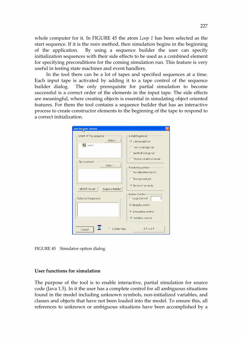
227
whole computer for it. In 1041HFIGURE 45 the atom Loop 1 has been selected as the start sequence. If it is the main method, then simulation begins in the beginning of the application. By using a sequence builder the user can specify initialization sequences with their side effects to be used as a combined element for specifying preconditions for the coming simulation run. This feature is very useful in testing state machines and event handlers.
In the tool there can be a lot of tapes and specified sequences at a time. Each input tape is activated by adding it to a tape control of the sequence builder dialog. The only prerequisite for partial simulation to become successful is a correct order of the elements in the input tape. The side effects are meaningful, where creating objects is essential in simulating object oriented features. For them the tool contains a sequence builder that has an interactive process to create constructor elements to the beginning of the tape to respond to a correct initialization.
FIGURE 45 Simulator option dialog.
User functions for simulation
The purpose of the tool is to enable interactive, partial simulation for source code (Java 1.5). In it the user has a complete control for all ambiguous situations found in the model including unknown symbols, non-initialized variables, and classes and objects that have not been loaded into the model. To ensure this, all references to unknown or ambiguous situations have been accomplished by a
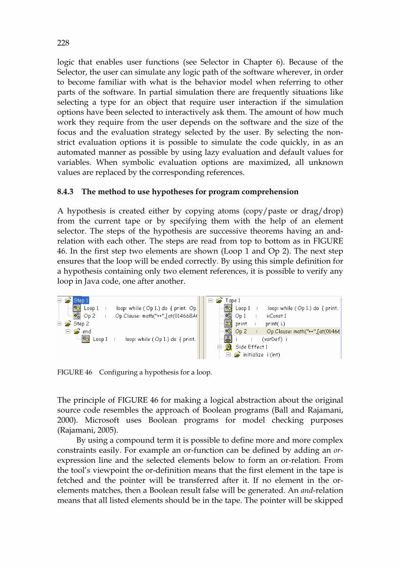
228
logic that enables user functions (see Selector in Chapter 6). Because of the Selector, the user can simulate any logic path of the software wherever, in order to become familiar with what is the behavior model when referring to other parts of the software. In partial simulation there are frequently situations like selecting a type for an object that require user interaction if the simulation options have been selected to interactively ask them. The amount of how much work they require from the user depends on the software and the size of the focus and the evaluation strategy selected by the user. By selecting the non-strict evaluation options it is possible to simulate the code quickly, in as an automated manner as possible by using lazy evaluation and default values for variables. When symbolic evaluation options are maximized, all unknown values are replaced by the corresponding references.
8.4.3 The method to use hypotheses for program comprehension
A hypothesis is created either by copying atoms (copy/paste or drag/drop) from the current tape or by specifying them with the help of an element selector. The steps of the hypothesis are successive theorems having an and-relation with each other. The steps are read from top to bottom as in 1042HFIGURE 46. In the first step two elements are shown (Loop 1 and Op 2). The next step ensures that the loop will be ended correctly. By using this simple definition for a hypothesis containing only two element references, it is possible to verify any loop in Java code, one after another.
FIGURE 46 Configuring a hypothesis for a loop.
The principle of 1043HFIGURE 46 for making a logical abstraction about the original source code resembles the approach of Boolean programs (Ball and Rajamani, 2000). Microsoft uses Boolean programs for model checking purposes (Rajamani, 2005).
By using a compound term it is possible to define more and more complex constraints easily. For example an or-function can be defined by adding an or-expression line and the selected elements below to form an or-relation. From the tool’s viewpoint the or-definition means that the first element in the tape is fetched and the pointer will be transferred after it. If no element in the or-elements matches, then a Boolean result false will be generated. An and-relation means that all listed elements should be in the tape. The pointer will be skipped
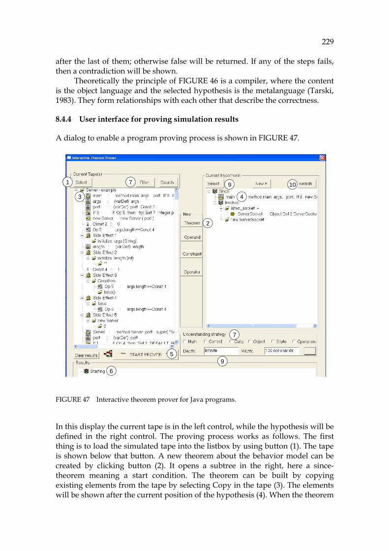
229
after the last of them; otherwise false will be returned. If any of the steps fails, then a contradiction will be shown.
Theoretically the principle of 1044HFIGURE 46 is a compiler, where the content is the object language and the selected hypothesis is the metalanguage (Tarski, 1983). They form relationships with each other that describe the correctness.
8.4.4 User interface for proving simulation results
A dialog to enable a program proving process is shown in 1045HFIGURE 47.
FIGURE 47 Interactive theorem prover for Java programs.
In this display the current tape is in the left control, while the hypothesis will be defined in the right control. The proving process works as follows. The first thing is to load the simulated tape into the listbox by using button (1). The tape is shown below that button. A new theorem about the behavior model can be created by clicking button (2). It opens a subtree in the right, here a since-theorem meaning a start condition. The theorem can be built by copying existing elements from the tape by selecting Copy in the tape (3). The elements will be shown after the current position of the hypothesis (4). When the theorem
1
3
2
4
5
6
7
7
9
9 101
3
2
4
5
6
7
7
9
9 10

230
is ready, it can be checked by button “Start prover” (5). The result is shown in (6). This was a short description of the automatic proving process. An interactive proving process contains successive human actions combined with computations of the tool.
Often there is too much information in the tape, but it can be filtered in multiple ways. Subsets from the tape can be selected by omitting irrelevant flows (7). This is done by defining an understanding strategy, which activates a functional filter that specifies the types of elements that the user wants to follow and validate. Furthermore, the depth of element invocations to be shown in the display can be limited, and the number of successive elements in the tape (9) can be reduced.
The process based on 1046HFIGURE 47 can better show how the program might work incorrectly. Proving program correctness automatically is not possible, but it is possible for the user to check the critical sequences by using hypotheses as described in the next section.
Deductive and inductive proving by using hypotheses
The hypotheses are connected to the symbolic model and via it to the real life by using model elements. Domain elements are special case elements that can be mapped, in the tool, to any original element. Domain elements are either test cases, pointers to use cases or any specific domains or terms relating to the maintenance task. Especially important items to be mapped to the model are JDK invocations, because they build all external influences from any Java application (in addition to internal interfaces).
Deductive proving is a process to show whether a selected tape corresponds to the user's initial knowledge or not. The principle of the tool relating to that is highly compatible with the definition of Peirce’s deductive argumentation (Peirce, 1958). A deductive proof doesn’t create new information. It replies either true or false. Although it is a very simple method, it can be used exhaustively to test and verify to ensure, opportunistically, a large application.
However, in planning changes and fixing bugs, using deductive proving is not enough. Inductive and abductive reasoning are also needed. By using the command feature of the formalism it is possible for the tool to collect information to the user for inductive proofs, also. For example, some method arguments are important to signal about an erroneous or a valid function. It is natural that these arguments are collected systematically to the memory of the tool. The user then has an excellent possibility to infer what are the differences between the valid and invalid groups.
8.4.5 Code understanding process
Code understanding is a process for understanding ProgramConcepts via ProgramContexts that are simulated. It is an essential phase of executing each maintenance task before making changes. Usually it is an iterative recursive

231
loop that goes through each step one after another. If the information of a step can be found in the relevant tape (a sequence) then the pointer in the tape will be transferred and the commands in the next step of the current hypotheses are used.
Hypothesis proving then resembles an acceptor formalism, which converts a result from the current tape validated according to a specification to a Boolean result true or false. If all the steps can be satisfied to be true then there are no contradictions and the process gives the expected answer (no contradiction). Otherwise the step that didn’t succeed will be shown to the user as a possible problem location.
8.5 Practical use case
A typical case for searching an error from an object-oriented program is the following:
- The analysis is started from the main method of the critical components. These sequences are run to get their program flows.
- The most probable sequence is simulated. - Erroneous situations are defined by using constraints and functions of
temporal logic (see Chapter 7 for the formalism). - The status of each object is inspected to ensure that its start is valid. - In simulation the tool informs about illegal values causing a
contradiction. - If no contradictions are found then more and more sequences are
checked in order to find a side effect that can have an influence to this illegal status.
The search stops either to a situation, where change candidates are found, or to a situation, where a cause cannot be found, because the problem is outside of the model.
8.5.1 Practical example, a Server
A demonstration program illustrating the functionality of a TCP/IP-server is presented in Appendix 1 to demonstrate theorem proving and the information captured from the code (Flanagan, 2000).
Let’s assume that there is a problem in the control flow starting from the main (line 48) and ending to the constructor Server of line 54 above, which prevents executing this flow (a few lines). From the approach of TM it is a one-dimensional task of investigation, where a possible error can be localized into a certain flow based on the program model (Pennington, 1987). Because of this simple approach the error can mathematically be defined by listing the
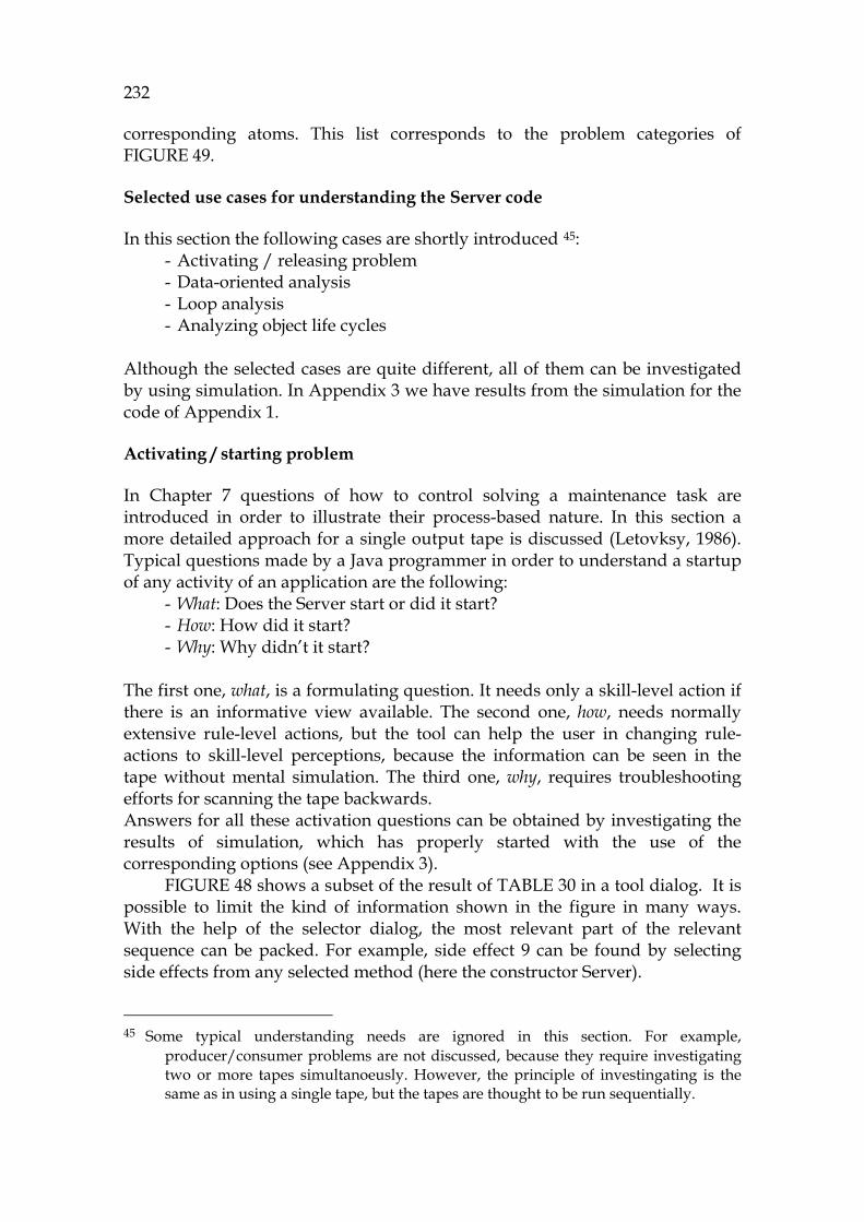
232
corresponding atoms. This list corresponds to the problem categories of 1047HFIGURE 49.
Selected use cases for understanding the Server code
In this section the following cases are shortly introduced 44F
45: - Activating / releasing problem - Data-oriented analysis - Loop analysis - Analyzing object life cycles
Although the selected cases are quite different, all of them can be investigated by using simulation. In Appendix 3 we have results from the simulation for the code of Appendix 1.
Activating / starting problem
In Chapter 7 questions of how to control solving a maintenance task are introduced in order to illustrate their process-based nature. In this section a more detailed approach for a single output tape is discussed (Letovksy, 1986). Typical questions made by a Java programmer in order to understand a startup of any activity of an application are the following:
- What: Does the Server start or did it start? - How: How did it start? - Why: Why didn’t it start?
The first one, what, is a formulating question. It needs only a skill-level action if there is an informative view available. The second one, how, needs normally extensive rule-level actions, but the tool can help the user in changing rule-actions to skill-level perceptions, because the information can be seen in the tape without mental simulation. The third one, why, requires troubleshooting efforts for scanning the tape backwards. Answers for all these activation questions can be obtained by investigating the results of simulation, which has properly started with the use of the corresponding options (see Appendix 3).
1048HFIGURE 48 shows a subset of the result of 1049HTABLE 30 in a tool dialog. It is possible to limit the kind of information shown in the figure in many ways. With the help of the selector dialog, the most relevant part of the relevant sequence can be packed. For example, side effect 9 can be found by selecting side effects from any selected method (here the constructor Server).
45 Some typical understanding needs are ignored in this section. For example,
producer/consumer problems are not discussed, because they require investigating two or more tapes simultanoeusly. However, the principle of investingating is the same as in using a single tape, but the tapes are thought to be run sequentially.

233
FIGURE 48 Simulation results in the theorem prover dialog.
Rather than creating concrete PC tools, the purpose of this research is to create a formalism for PC. 1050HFIGURE 48 demonstrates a symbolic flow and its information, where every line contains an output obtained from a simple pretty printer for the Symbolic language. The same results are shown in Appendix 3 in 1051HTABLE 30. By tuning the output, it is possible to tailor the layout to be used as an end-user display, because more sophisticated displays can easily be created by transforming this information into a more graphic notation and to XML.
Each line in the display starting from the left holds information from a command. The side effects are shown as subtrees, including several lines showing corresponding parameters such as invocation arguments, values to be assigned and calculated values. Next their use in problem analysis is discussed.
Each starting sequence can be validated and inspected perfectly due to the information of the tape. It is recommendable to explore at first the object flow if the activating occurs in an object. The next principle to explore is control flow. The third one is data flow. If it can be found that there are problems in any of these flows then the most critical operations of the elements must be evaluated.
8.5.2 Problem Recognition
The problem is mapped to the tool either as a use case, as a test case or as a JDK-method call describing a function. When this simple phase has been done,
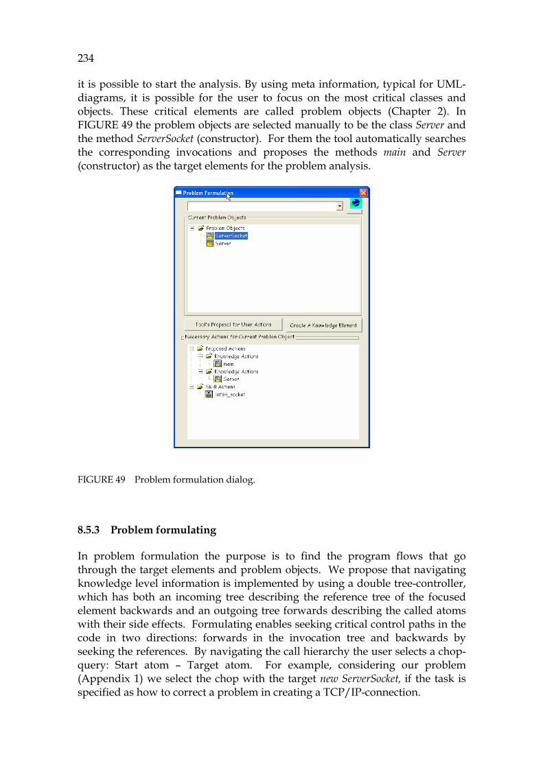
234
it is possible to start the analysis. By using meta information, typical for UML-diagrams, it is possible for the user to focus on the most critical classes and objects. These critical elements are called problem objects (Chapter 2). In 1052HFIGURE 49 the problem objects are selected manually to be the class Server and the method ServerSocket (constructor). For them the tool automatically searches the corresponding invocations and proposes the methods main and Server (constructor) as the target elements for the problem analysis.
FIGURE 49 Problem formulation dialog.
8.5.3 Problem formulating
In problem formulation the purpose is to find the program flows that go through the target elements and problem objects. We propose that navigating knowledge level information is implemented by using a double tree-controller, which has both an incoming tree describing the reference tree of the focused element backwards and an outgoing tree forwards describing the called atoms with their side effects. Formulating enables seeking critical control paths in the code in two directions: forwards in the invocation tree and backwards by seeking the references. By navigating the call hierarchy the user selects a chop-query: Start atom – Target atom. For example, considering our problem (Appendix 1) we select the chop with the target new ServerSocket, if the task is specified as how to correct a problem in creating a TCP/IP-connection.

235
8.5.4 Simulating critical paths
Once a critical sequence has been identified, it is then simulated. The simulation can be done either for an application, a package, a class or for a method, or even for only some statements. Because of the encapsulation feature of OO-programs all classes form a unique structure whose behavior can be analyzed apart of other classes (except inheritance). By simulation a side effect model can be found for each method and each sequence.
The code to be simulated is selected with the help of the sequence builder. Because of the Turing-model and its call/return-architecture each method can individually be simulated by starting it in the beginning of the method (when the parameters are initialized). For dynamic methods, a constructor invocation to the input tape should be defined in the sequence builder for enabling correct dynamic bindings.
8.5.5 General rules for detecting problems in the output tape
Searching and making observations are skill-level actions based on the tapes. However, the biggest problem in analyzing a large program flow is its huge size. In order to avoid laborious scanning and reading, the tool provides automated functions. A total of six different types of tool support are described in this section.
Selecting an understanding strategy for analyzing tape information
Once the tape and the target elements have been detected, the tape at hand can be deductively evaluated completely. This is called flow analysis. According to the principles of bottom-up PC and object-oriented PC the critical things in the code are function (responding to the main goal), control flow (code), data flow, state dependencies and operations. These can be selected by clicking the corresponding button in 1053HFIGURE 50.
FIGURE 50 Selecting the understanding strategy.
It is natural to assume that if the PC needs are organized according to the categories of 1054HFIGURE 50 then the fault types are classified in the same way. The most challenging topic related to object-oriented software is the object life cycle, being also the hardest to tackle. These flows are discussed next.
236
Tool support for understanding functionality
1055HFIGURE 51 shows a snapshot about analyzing frame activities of the code. The object referred to is Frame, whose class contract is detected by JavaMaster from the source of JDK (the code is on lines 24-28 in Appendix I).
The display is used as follows. If there are some problems considering UI in the application, then all relevant Frame-invocations can be triggered into the atomistic double tree. By using problem formulation it is possible to select problem objects as candidates which refer to the problem. Thereafter, by simulation, it is possible to obtain parameters and sequences for Frame-activations. If the problem formulation has been made correctly, then the sequence should contain the necessary data for solving the problem, which is a skill-level action done by the user.
FIGURE 51 Display for validating functionality. All functions are shown.
From 1056HFIGURE 51 it is possible to see that for the method add and for the method resize two arguments are fed each. For the addition these are the constant 8 that contains a string ”Center” and a variable connection list and for the resizing of these are the constants 9 and 10 (not shown in the figure). If there are problems in these invocations, a process to create values for the methods where either control flow, data flow or object flow contains the necessary information is needed. These flows are described next.
Tool support for understanding control flows
1057HFIGURE 52 displays the loops and conditions for the selected code. If the problem is a stopping problem, then the reason for it can be found in one of these elements. There are as many "guilty" candidates as there are elements in the list. The same rule can be used in detecting incorrect logic paths. If there are only a few elements in the list then the problem is rather easy to fix. The main power of the symbolic analysis is in how it can connect different views into a unified focused approach. Loop 2 below synchronizes TCP/IP-connections (on the line referring to it). In case of problems the assignments for the variables client_socket and connections are very critical if the network communication is not valid. They can be traced by analysing the data of 1058HFIGURE 53.
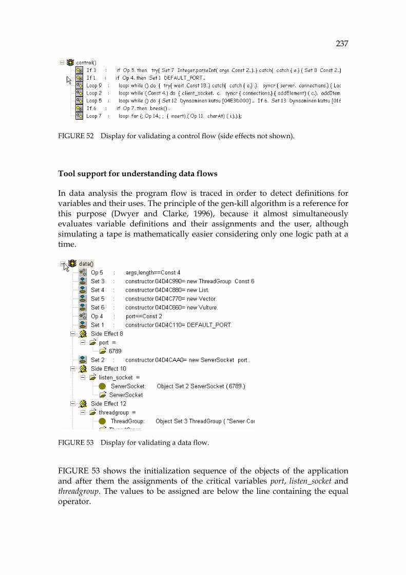
237
FIGURE 52 Display for validating a control flow (side effects not shown).
Tool support for understanding data flows
In data analysis the program flow is traced in order to detect definitions for variables and their uses. The principle of the gen-kill algorithm is a reference for this purpose (Dwyer and Clarke, 1996), because it almost simultaneously evaluates variable definitions and their assignments and the user, although simulating a tape is mathematically easier considering only one logic path at a time.
FIGURE 53 Display for validating a data flow.
1059HFIGURE 53 shows the initialization sequence of the objects of the application and after them the assignments of the critical variables port, listen_socket and threadgroup. The values to be assigned are below the line containing the equal operator.

238
Tool support for understanding object flows
Research considering object flows is important, because in tools objects are invisible and temporary. Therefore it is not possible in typical cases to investigate their history or attributes when they are still alive. In 1060HFIGURE 54 a hypothesis has been defined for tracing DataInputStream (see Appendix 1).
FIGURE 54 A hypothesis for tracing objects, here DataInputStream.
In order to create a valid object flow or any subset that should define a valid sequence for it, a theorem can be built be dragging the necessary elements from the tape and dropping them to the hypothesis-display. In this way it is possible to detect three kinds of problems:
- Problems in the creating and destroying logic of objects. - Problems in invocation parameters of any reference. - Problems in precedence of elements.
If the number of possible combinations is too complex to be defined by logic it is still possible to gather all the object invocations in a summary, where they can manually be investigated. Therefore, the next section discusses the manual work, skill-based activities based on the information of the tapes. 1061HFIGURE 55 displays an object flow, which contains the constructor command with its parameters. This display is useful as the first step in cases where there are problems in creating objects. After the constructors have been localized (in their order), this information can be used for formulating failures like memory allocation or consumer/producer problems.
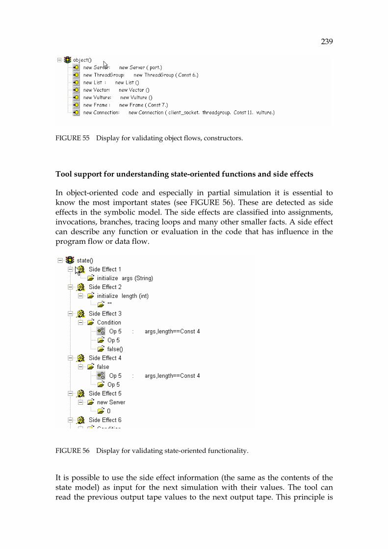
239
FIGURE 55 Display for validating object flows, constructors.
Tool support for understanding state-oriented functions and side effects
In object-oriented code and especially in partial simulation it is essential to know the most important states (see 1062HFIGURE 56). These are detected as side effects in the symbolic model. The side effects are classified into assignments, invocations, branches, tracing loops and many other smaller facts. A side effect can describe any function or evaluation in the code that has influence in the program flow or data flow.
FIGURE 56 Display for validating state-oriented functionality.
It is possible to use the side effect information (the same as the contents of the state model) as input for the next simulation with their values. The tool can read the previous output tape values to the next output tape. This principle is
240
analogous to the theory of the concept environment in computer semantics. An output tape is an environment to the next simulation.
Challenges in understanding individual operations (computations)
By following the side effects of the tape it is possible to simulate each computation both mentally and by machine (see 1063HFIGURE 56). If a list for valid values is known for each side effect then it is a very straightforward process to find possible problems in the most relevant flow considering these side effects.
Challenges in evaluating sequences with missing elements
In cases where the program flow doesn’t contain wanted elements (such as an element that creates a Server object) the user can follow the program flow from the hypothesized starting point by simulation. A procedure to solve what is the best guess (candidate) to be studied next in order to find where the program takes a wrong branch is a deterministic process where two main approaches are useful:
- By using heuristics it is possible to follow the different categories: a functionality, control flow, data flow, object flow, or state flow.
- By splitting the current sequence into smaller and smaller subsequences to investigate (for example investigating one half, then splitting it to two parts etc) the problematic place can be found.
Based on these preliminary selections the earlier elements in the tape can be investigated in order to find the unwanted phenomenon. The tool support for it is illustrated in 1064HFIGURE 48, 1065HFIGURE 54, 1066HFIGURE 51, 1067HFIGURE 52, 1068HFIGURE 53, 1069HFIGURE 55, and 1070HFIGURE 56.
8.6 The concluding remarks related to the PC process
8.6.1 Problems in visualization
1071HFIGURE 57 shows a small snapshot of a relatively large dependency model captured from the Server application.
It can be concluded that displaying dependencies requires, from an average work station, a lot of time for drawing and a lot of space for showing the result on the screen. Typically the graphs are generated at night in order to avoid computer load during working hours. A large graph can contain thousands of nodes. Therefore, it would be useful for the user to use a focused approach in tracing critical sequences, which is rather fast in all normal

241
situations. There will be no irrelevant information once the displays have been filtered by the fault category.
The quickest way to get dedicated information from a big mass is to request it from the tool, not to navigate large displays like that of 1072HFIGURE 57, where a lot of time can be lost in seeking information. Instead, when making a first contact to software, more general displays to describe metaknowledge are useful.
FIGURE 57 A draft considering a snapshot of a dependency model.
8.6.2 Some observations relating to the atomistic model
Next some observations about the tool and its use for the atomistic model are discussed:
- Implementing a user interface for an atomistic model is not problematic, even though there is no standard for them. The atomistic notation, shown earlier in the tiny controls, is an ideal way for the user to investigate and navigate the code model, because as the most simple notation it enables focusing. Furthermore, because all its elements are

242
similar and small and formal, it is possible for the user to trace all atomic links between atoms in the traditional way of navigators.
- UML-displays and typical specialized displays for source code are more complex, because most of them do not contain a unified model to connect all the elements with each other.
- Visualizing results is a problem for a focused graph, because studying large displays entails much scrolling work for the user and the connections (edges) in a graph can easily disappear behind the corners of the current display, resulting in scanning problems.
- The argumentation process is a promising area, because it leads to automatic explanation generation from formal, coherent input information. The tool based on Prolog is ideal for deductive argumentation. By using the method of theorem proving it is possible for the user to collect systematic information for inductive reasoning, too. The same information is useful for abductive reasoning as well. But in the cases of inductive and abductive reasoning the user is mostly the one to make the decisions.
- The theorem proving process described has a formalism of a higher order logic, which has a strong theory background. The JavaMaster tool allows programming typical model checking and theorem proving algorithms, because it is compatible with temporal logic (see 1073HDefinition 46).
- The biggest problem for symbolic execution is how JDK references can be captured. In the proving process every JDK invocation is a black box that should be used as an axiom, not as a function call returning actual information from the JDK library. This discontinuity caused by missing JDK simulation can be alleviated by using Javadoc information as auxiliary information for matching arguments of JDK references. There is a possibility to load critical JDK classes to the model, too.
8.7 Summary of the tool implementation
The tool demonstrates the methodology of the symbolic atomistic model including the realization of GrammarWare, ModelWare, Abstract Machine, and KnowledgeWare. In the user interface there are functions for loading code (GrammarWare), weaving the model (ModelWare), running simulation (Abstract Machine), and capturing information from the simulation results (KnowledgeWare). See 1074HFIGURE 58 for these.
The tool connects source code analysis and model checking and verification with the range of test applications on behalf of its interactive theorem prover. This unified principle provides several practical use cases both in programming and in maintenance, because software development is typically iterative work where inspections and modifications are done frequently. The drawback of dynamic analysis when used for each
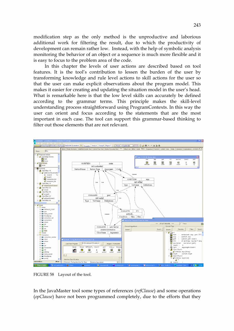
243
modification step as the only method is the unproductive and laborious additional work for filtering the result, due to which the productivity of development can remain rather low. Instead, with the help of symbolic analysis monitoring the behavior of an object or a sequence is much more flexible and it is easy to focus to the problem area of the code.
In this chapter the levels of user actions are described based on tool features. It is the tool’s contribution to lessen the burden of the user by transforming knowledge and rule level actions to skill actions for the user so that the user can make explicit observations about the program model. This makes it easier for creating and updating the situation model in the user’s head. What is remarkable here is that the low level skills can accurately be defined according to the grammar terms. This principle makes the skill-level understanding process straightforward using ProgramContexts. In this way the user can orient and focus according to the statements that are the most important in each case. The tool can support this grammar-based thinking to filter out those elements that are not relevant.
FIGURE 58 Layout of the tool.
In the JavaMaster tool some types of references (refClause) and some operations (opClause) have not been programmed completely, due to the efforts that they
244
would require in programming and testing. Our purpose in this chapter was to demonstrate that the created model structures work in the user interface and in simulation as assumed. The status of the tool can be improved in future projects.
The results obtained from simulation are more accurate than the results obtained from the usual dynamic analysis or static analysis. The main reason for the accuracy of the tool is due to symbolic evaluation, the Symbolic language, the atomistic model with the atomistic semantics, and the simulation process, which has a full access to all small phases of the atoms' run methods. Another advantage of the symbolic analysis is better information access, because it allows many specific formal analyses to be run based on the information of a simulation output. Some examples about more specific analyses include analyzing deadlocks, memory consumption, object life cycles or producer/consumer-problems.
As a conclusion, the tool, described in this chapter, demonstrates a systematic method to investigate and navigate the source code for comprehension purposes. It supports multiple knowledge layers and a focused approach for capturing most relevant information. The only level that the computer can do is the rule action, which takes from a computer only some billionths of a second. Because the performance of the user in rule-level computations is only a fraction of the one of the computer, all possible rule-level actions should be directed to the computer, whose output should help the user for building abstract mental models.
Because of its symbolic information and the focused approach, the process and the tool described in this chapter suit best to corrective and adaptive maintenance, where the challenges to follow and trace program behavior are strong. For that, dynamic analysis can be inflexible with its preliminary arrangements and laborious analysis operations. Symbolic analysis is, on the other hand, a thorough analysis method that allows partial simulation and evaluation of any sequence of the code in any situation in order to increase the user’s knowledge for building the next successive program versions.

245
9 RESULTS: A UNIFIED THEORY FOR PROGRAM COMPREHENSION
This chapter summarizes the methodologies and observations related to the research. It includes a short history, a summary about the main concepts and the technology spaces, as well as a unified transformation model to connect all the main theories together. The last section describes shortly the goals that were listed in Chapter 3.
9.1 Short history of the work
In this section a brief history about the work is presented for the purposes of possible future work.
9.1.1 The first research approach
This research started in 2004. The initial main focus was to create a Prolog notation that could form a base for Java simulation. Early in the beginning it became clear that it is possible, by using Prolog structures, to express all formal structures of typical programming languages as axiomatic semantics. Simulation was then a problem because of inheritance and some other object-oriented features of Java. As the dissertation was to deal with program comprehension, there was a rigorous need to handle all the elements of the code in the tool at the same level, and not hierarchically, because the programmer had to be able to connect the elements with each other in his/her mind, without being dependent on hierarchies. Strong and spontaneous connectivity, which is often needed for code investigation processes, demands a very compact and small entity as a foundation for the code structures. This seemed a very promising idea in the early 2006.
246
9.1.2 Toward a unified theory
Attempts to maximize the independency of elements lead in summer 2006 to the first trials of a reductionist model, where elements were to be indivisible atoms. The connecting feature between these elements was found to be a Prolog predicate. Thus the construction of an atomistic hybrid object was invented.
Building a hybrid object became a fruitful, though a difficult, challenge. How was one to make a tool to automatically produce very small hybrid objects without loosing the semantics between the elements? The model weavers of UML in Atlas and other tools seemed simpler, because their structures are more natural and the rules between their elements are easier to understand. It was thought, in 2006, that the most difficult things in programming are building a model weaver and simulating the model.
For simulation some help was found in AST implementations (Jones, 2003) and in attribute grammars (AttributeGrammars, 1998; Sierra and Fern´andez-Valmayor, 2006), as these sources introduce evaluation features. Nevertheless, object-oriented features remained challenges that had not been described in code simulation covering the whole language from low level structures to the semantics of class hierarchies. An essential problem area in analyzing simulation possibilities for Java was how to define and model dynamic features, inheritance and the yoyo-phenomenon.
After a thorough assessment, a clear decision was made to avoid dynamic analysis in all functional features. Dynamic analysis demands preliminary work before a program is run and often filtering and sorting information after the run, too. A clear goal for the new symbolic analysis, therefore, was to provide, as far as possible, a query based user interface which would enable that analysis to be done whenever required and without any preliminary arrangements for any part of the code. The user should have the responsibility and all the power to select the analysis freely.
Programming the simulation process for the atomistic model seemed a very difficult challenge. Some help for solving this problem was found from the theory of the abstract machine, automaton, and the Turing machine (Hopcroft and Ullman, 1979). When studying the formalism of automaton and atomistic elements, it was found that, seen from outside, the elements work in a similar way. It was then natural to maximize this similarity in the architecture of the model, and a unified operation for the simulation was selected to be the run method. Considering the architecture, it became evident that the symbolic language should form the base class for the whole model in order to make it formal. The element groups could be its subclasses contributing thus to the conceptual hierarchy for the model.
In the first experiments, early in 2007, the run methods of the elements were considered to be typical tailored code, where different elements do not have any common features. However, in studying the formalism of Turing machines it became evident that in fact there is a common formalism also between all the run methods. Each run method is like a small Turing machine,
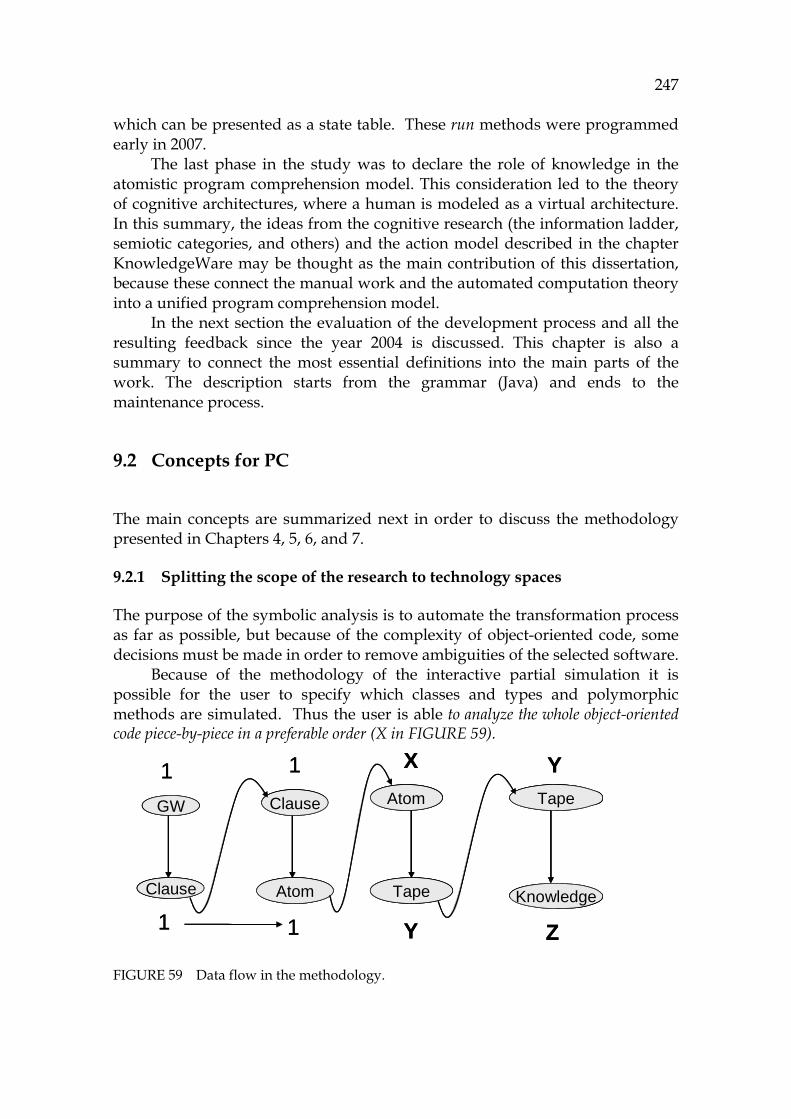
247
which can be presented as a state table. These run methods were programmed early in 2007.
The last phase in the study was to declare the role of knowledge in the atomistic program comprehension model. This consideration led to the theory of cognitive architectures, where a human is modeled as a virtual architecture. In this summary, the ideas from the cognitive research (the information ladder, semiotic categories, and others) and the action model described in the chapter KnowledgeWare may be thought as the main contribution of this dissertation, because these connect the manual work and the automated computation theory into a unified program comprehension model.
In the next section the evaluation of the development process and all the resulting feedback since the year 2004 is discussed. This chapter is also a summary to connect the most essential definitions into the main parts of the work. The description starts from the grammar (Java) and ends to the maintenance process.
9.2 Concepts for PC
The main concepts are summarized next in order to discuss the methodology presented in Chapters 4, 5, 6, and 7.
9.2.1 Splitting the scope of the research to technology spaces
The purpose of the symbolic analysis is to automate the transformation process as far as possible, but because of the complexity of object-oriented code, some decisions must be made in order to remove ambiguities of the selected software.
Because of the methodology of the interactive partial simulation it is possible for the user to specify which classes and types and polymorphic methods are simulated. Thus the user is able to analyze the whole object-oriented code piece-by-piece in a preferable order (X in 1075HFIGURE 59).
FIGURE 59 Data flow in the methodology.
GW
Clause
Clause
Atom
Atom
Tape
Tape
Knowledge
1
1
1
1
X Y
ZY
GW
Clause
Clause
Atom
Atom
Tape
Tape
Knowledge
GW
Clause
Clause
Atom
Atom
Tape
Tape
Knowledge
1
1
1
1
X Y
ZY
248
This is a significant new contribution, because by using this focused approach the user can learn and have confidence on how each part of the code works. The problem in partial simulation is how to understand side effects. Therefore, the main user interest should be directed into the inputs and outputs of the sequences. These have the formulation of the Hoare triple {P} Sequence {Q}, where P means input side effects and Q output side effects for other sequences.
The implementation of the output tape (Y in 1076HFIGURE 59) is effective, because only one object handle is needed for each step in the tape, occupying only four (4) bytes each. So creating an output tape for a sequence of one million instructions requires only four megabytes. 45F
46 The output Turing style tapes can reside on a disc or in a database to ensure very challenging simulation sessions. The model can also be used in real-time from a database or from a disc.
The purpose of program comprehension is to help creating new installations. The result is best if the tool provides a minimum set of information for each change candidate; usually the amount of code and its dependencies are the biggest challenge for the programmer. Hence, a theorem prover would be an excellent tool for minimizing source code information and maximizing its practicability in the software process, because it removes all valid sequences. Only critical and invalid information can be seen in the display, because the output of the theorem prover (Z in 1077HFIGURE 59) expresses the contradictions between the initial knowledge of the user and the current status of the software.
In deductive proving the result is either positive or negative, corresponding to unit tests and detail tests. The theorem prover enables inductive reasoning, too, because the user may want to collect critical information such as method activation frames (invocations) in order to enable separating valid and invalid sequences from each other.
The principle of the focused approach aims at immediate verification of the code, where the bugs and problems are detected as soon as possible. Outsourcing of testing does not remedy this immediate need. That’s why we propose a new testing paradigm, agile testing, which should allow the organizations to develop their own testing policy. Symbolic analysis provides better quality and feedback for the programmer than a strongly distributed testing organization alone can.
The output of simulation (Y) holds the object language information (Tarski 1983) describing problem flow in the Symbolic language. The relations between elements in the tape that are meaningful for the user build up a metalanguage. This has a formalism of the metaClause in the Symbolic language. For this metalanguage, in relation to problem isolation, the flow categories built on the theories of Pennington (1987) and Burkhardt et al. (2002) are useful in minimizing the active contents of the tape, including either the control flow, data flow, object flow, JDK functions, or side effects. For this minimized
46 The size reserved by the model depends on the development tool. It has not been tested
in this research, because performance questions were ignored (see Chapter 3).
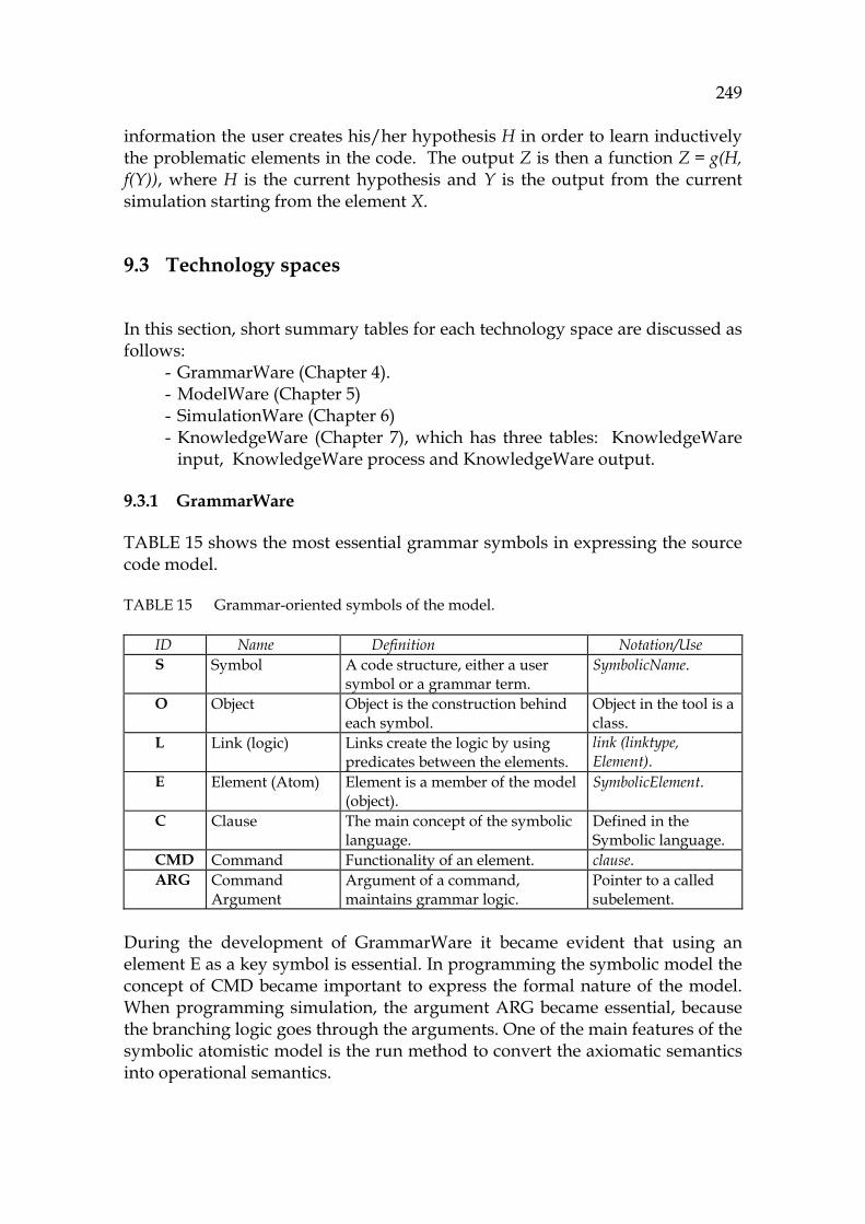
249
information the user creates his/her hypothesis H in order to learn inductively the problematic elements in the code. The output Z is then a function Z = g(H, f(Y)), where H is the current hypothesis and Y is the output from the current simulation starting from the element X.
9.3 Technology spaces
In this section, short summary tables for each technology space are discussed as follows:
- GrammarWare (Chapter 4). - ModelWare (Chapter 5) - SimulationWare (Chapter 6) - KnowledgeWare (Chapter 7), which has three tables: KnowledgeWare
input, KnowledgeWare process and KnowledgeWare output.
9.3.1 GrammarWare
1078HTABLE 15 shows the most essential grammar symbols in expressing the source code model.
TABLE 15 Grammar-oriented symbols of the model.
ID Name Definition Notation/Use S Symbol A code structure, either a user
symbol or a grammar term. SymbolicName.
O Object Object is the construction behind each symbol.
Object in the tool is a class.
L Link (logic) Links create the logic by using predicates between the elements.
link (linktype, Element).
E Element (Atom) Element is a member of the model (object).
SymbolicElement.
C Clause The main concept of the symbolic language.
Defined in the Symbolic language.
CMD Command Functionality of an element. clause. ARG Command
Argument Argument of a command, maintains grammar logic.
Pointer to a called subelement.
During the development of GrammarWare it became evident that using an element E as a key symbol is essential. In programming the symbolic model the concept of CMD became important to express the formal nature of the model. When programming simulation, the argument ARG became essential, because the branching logic goes through the arguments. One of the main features of the symbolic atomistic model is the run method to convert the axiomatic semantics into operational semantics.

250
Results
Some of the clearest observations from 1079HTABLE 15 are the following: - Traceability: All information in the model can be traced backwards to the
original source code. - All information in the model is in the notation of a clause. This makes
programming rather straightforward.
9.3.2 ModelWare
Due to the atomisticity of the model the concept of the model itself should be very reduced, because the elements should form the strong part in the model. The main symbols related to the symbolic model are given in 1080HTABLE 16.
TABLE 16 The main symbols of the atomistic model.
ID Name Definition Notation/Use M Model A container to hold model
elements. SymbolicModel, an object inherited from SymbolicElement .
A Analysis A function to derive specific information from the model.
Traversing algorithms, a metaiterator.
Q Query Query is a command to start an analysis.
An interface to the model.
Results
The observations are:
- A class named SymbolicModel, describing the symbol M, was established to contain element handles for XMI generation and for user interface.
- The conclusion after the development was that there is no need to refer to the class SymbolicModel in simulation. This is very important in strengthening the idea of atomism. Instead, the references were made to the elements E directly.
- The greatest need for the concept of the model M was in the practical approach when programming maintenance tasks, because in problem formulating there is a strong need for the user to be able to freely connect the different parts of the model in order to make a query, Q. The specific needs in problem formulation were responding to the concept A, and searching constructors and cross-cuttings within objects. These were implemented by high level metaiterators that traverse through the model seeking wanted elements.
- The use of a query Q as the main symbol was replaced later by the Turing model.
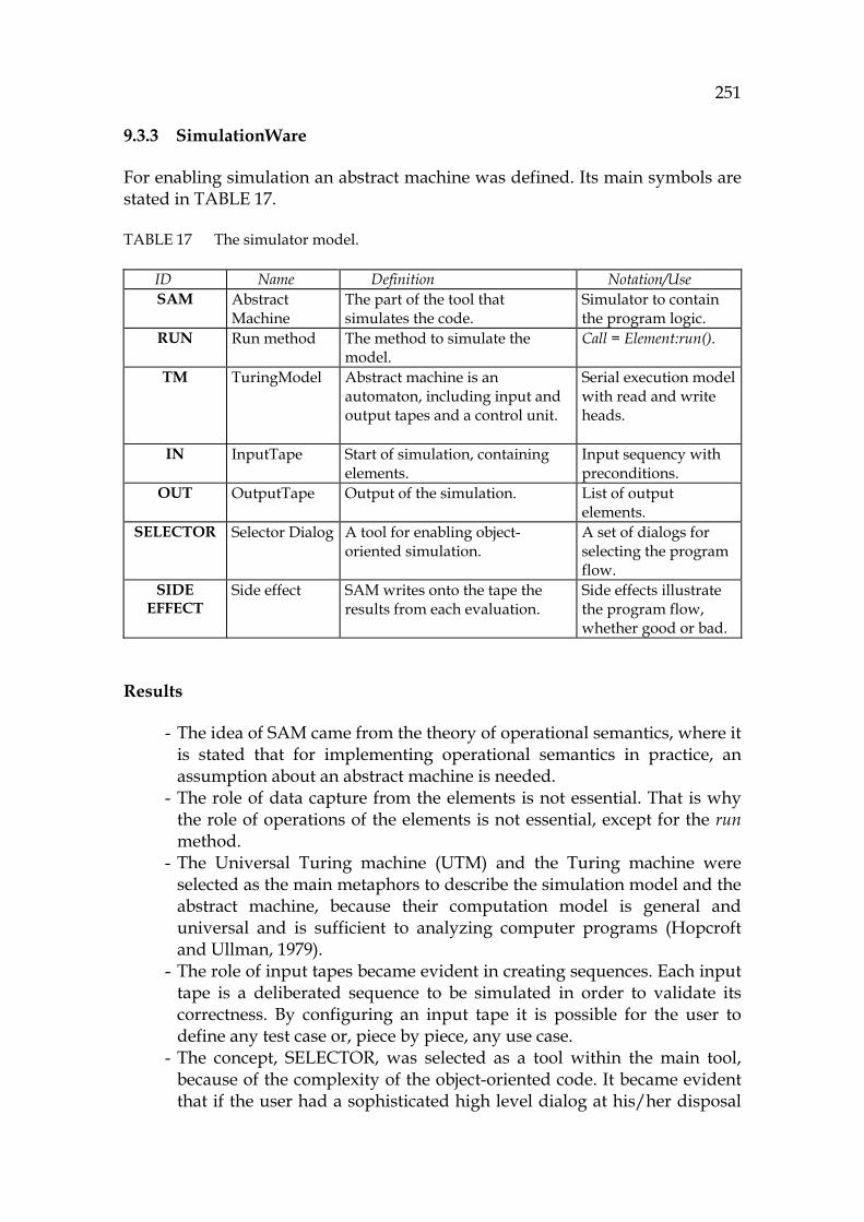
251
9.3.3 SimulationWare
For enabling simulation an abstract machine was defined. Its main symbols are stated in 1081HTABLE 17.
TABLE 17 The simulator model.
ID Name Definition Notation/Use SAM Abstract
Machine The part of the tool that simulates the code.
Simulator to contain the program logic.
RUN Run method The method to simulate the model.
Call = Element:run().
TM TuringModel Abstract machine is an automaton, including input and output tapes and a control unit.
Serial execution model with read and write heads.
IN InputTape Start of simulation, containing elements.
Input sequency with preconditions.
OUT OutputTape Output of the simulation. List of output elements.
SELECTOR Selector Dialog A tool for enabling object-oriented simulation.
A set of dialogs for selecting the program flow.
SIDE EFFECT
Side effect SAM writes onto the tape the results from each evaluation.
Side effects illustrate the program flow, whether good or bad.
Results
- The idea of SAM came from the theory of operational semantics, where it is stated that for implementing operational semantics in practice, an assumption about an abstract machine is needed.
- The role of data capture from the elements is not essential. That is why the role of operations of the elements is not essential, except for the run method.
- The Universal Turing machine (UTM) and the Turing machine were selected as the main metaphors to describe the simulation model and the abstract machine, because their computation model is general and universal and is sufficient to analyzing computer programs (Hopcroft and Ullman, 1979).
- The role of input tapes became evident in creating sequences. Each input tape is a deliberated sequence to be simulated in order to validate its correctness. By configuring an input tape it is possible for the user to define any test case or, piece by piece, any use case.
- The concept, SELECTOR, was selected as a tool within the main tool, because of the complexity of the object-oriented code. It became evident that if the user had a sophisticated high level dialog at his/her disposal

252
when selecting among alternatives such as methods and logic paths, then that user could get a complete analyzing coverage for the whole code.
- The importance of side effects became obvious when building the atomistic model; the problem was how to keep the model atomistic during the whole simulation process while including all the intermediate information and side effects. An independent class in the class hierarchy of SymbolicElements was selected as side effects in order just to hold the model atomistic during the successive simulating phases.
9.3.4 KnowledgeWare
A reductionist approach to the maintenance was opted for the main principle of KnowledgeWare, in the beginning of the work. Hence, the main purpose was to support maintenance tasks that had been started as a notation of a change request (CR). The main concepts of KnowledgeWare are listed in 1082HTABLE 18.
9.3.4.1 Input of KnowledgeWare
TABLE 18 Maintenance approach.
ID Name Definition Notation/Use T Task Maintenance task, often vague,
informal. A record in a bug system or other.
P Process A process to solve the maintenance task
Iterative, hierarchical work.
H Hypothesis An assumption of the code behavior.
Preliminary information for a query.
CR ChangeRequest A definition about what to change in the program.
A record. See the task, T, above.
Results
- Using a change request as the main use case of the tool was a good selection and there were no need to alter that decision.
- In order to maximize the potential of the maintenance tool under development, it was important to define a process describing how to execute the whole maintenance task as completely as possible by using a top-down approach.
- As seen outside, there was a need to divide these actions into subprosesses for searching information for the model (SP), for verifying parts of the code (VP), and for supporting troubleshooting (TSP).
- The role of the hypothesis (H) was to define the rigorous constraints which the sequence should satisfy or fail. These conditions form either validation criteria to accept the code or refutation criteria to discard the

253
code. The hypotheses consist of theorems that are built by using only operands and constraints between model elements.
Next evaluating the maintenance approach is described in more detail.
9.3.4.2 Process of KnowledgeWare
Computational semiotics was a useful theory in the development of KnowledgeWare. The concept, KU (see 1083HTABLE 19), opens the systematic part of the user's mind. It was natural, in the beginning on creating the atomistic model, that the knowledge unit (KU) should have strong connections to the concept of the atom in the atomistic model.
TABLE 19 Foundation for KnowledgeWare.
ID Name Definition Notation/Use KU Knowledge
Unit KU is meaningful data captured by the user.
Computational semiotics.
G/Q Problem, Goal, and Question
The highest level of executing a task is a problem. The user transforms it to a goal by using questions.
Goal is a subset of a task expressing a meaning. Goal is transformed to actions.
ACTION Action An activity created by the user.
Skill, Rule, Meta or Knowledge Action.
SKILL ACTION
Skill Action
An immediate action based on perceptions.
Similar to a chunk.
RULE ACTION
Rule Action Deductive process to infer information by using existing information.
Scanning a program sequence (Turing output tape).
KNOW-LEDGE
ACTION
Knowledge Action
Formulating a hypothesis and a query for that.
A crosscutting problem for solving complex dependencies.
META ACTION
Meta Action Getting information above the level of the atomistic model, similar to UML information.
Associations, diagrams and data requests, as in UML.
Results
- Computational semiotics introduced the Peircean taxonomy (1958) to contain several types of knowledge. This was essential in developing features for the tool.
- During the development the theory ACT-R became relevant (ACT-R, 2007), because it emphasizes the atomistic nature of human thinking (Anderson, and Lebiere, 1998).
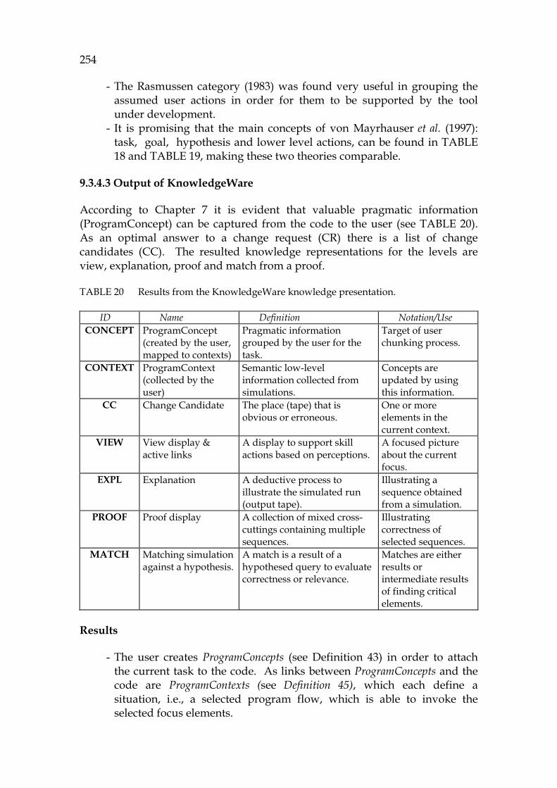
254
- The Rasmussen category (1983) was found very useful in grouping the assumed user actions in order for them to be supported by the tool under development.
- It is promising that the main concepts of von Mayrhauser et al. (1997): task, goal, hypothesis and lower level actions, can be found in 1084HTABLE 18 and 1085HTABLE 19, making these two theories comparable.
9.3.4.3 Output of KnowledgeWare
According to Chapter 7 it is evident that valuable pragmatic information (ProgramConcept) can be captured from the code to the user (see 1086HTABLE 20). As an optimal answer to a change request (CR) there is a list of change candidates (CC). The resulted knowledge representations for the levels are view, explanation, proof and match from a proof.
TABLE 20 Results from the KnowledgeWare knowledge presentation.
ID Name Definition Notation/Use CONCEPT ProgramConcept
(created by the user, mapped to contexts)
Pragmatic information grouped by the user for the task.
Target of user chunking process.
CONTEXT ProgramContext (collected by the user)
Semantic low-level information collected from simulations.
Concepts are updated by using this information.
CC Change Candidate The place (tape) that is obvious or erroneous.
One or more elements in the current context.
VIEW View display & active links
A display to support skill actions based on perceptions.
A focused picture about the current focus.
EXPL Explanation A deductive process to illustrate the simulated run (output tape).
Illustrating a sequence obtained from a simulation.
PROOF Proof display A collection of mixed cross-cuttings containing multiple sequences.
Illustrating correctness of selected sequences.
MATCH Matching simulation against a hypothesis.
A match is a result of a hypothesed query to evaluate correctness or relevance.
Matches are either results or intermediate results of finding critical elements.
Results
- The user creates ProgramConcepts (see 1087HDefinition 43) in order to attach the current task to the code. As links between ProgramConcepts and the code are ProgramContexts (see 1088HDefinition 45), which each define a situation, i.e., a selected program flow, which is able to invoke the selected focus elements.
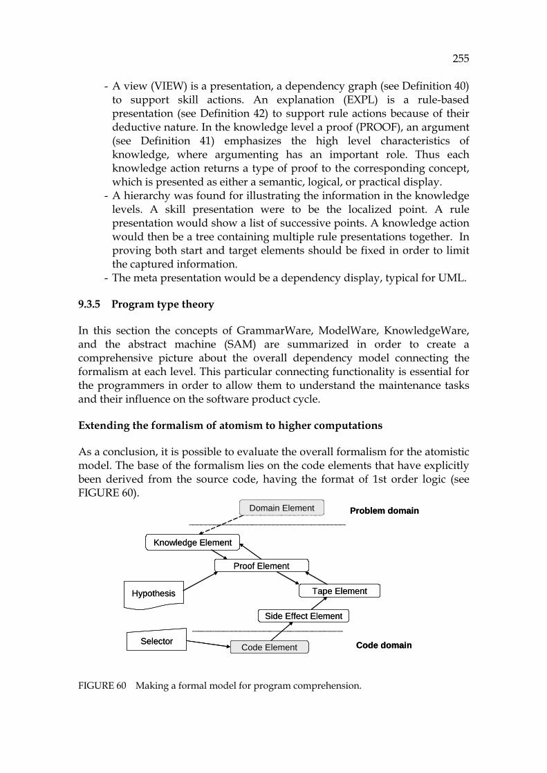
255
- A view (VIEW) is a presentation, a dependency graph (see 1089HDefinition 40) to support skill actions. An explanation (EXPL) is a rule-based presentation (see 1090HDefinition 42) to support rule actions because of their deductive nature. In the knowledge level a proof (PROOF), an argument (see 1091HDefinition 41) emphasizes the high level characteristics of knowledge, where argumenting has an important role. Thus each knowledge action returns a type of proof to the corresponding concept, which is presented as either a semantic, logical, or practical display.
- A hierarchy was found for illustrating the information in the knowledge levels. A skill presentation were to be the localized point. A rule presentation would show a list of successive points. A knowledge action would then be a tree containing multiple rule presentations together. In proving both start and target elements should be fixed in order to limit the captured information.
- The meta presentation would be a dependency display, typical for UML.
9.3.5 Program type theory
In this section the concepts of GrammarWare, ModelWare, KnowledgeWare, and the abstract machine (SAM) are summarized in order to create a comprehensive picture about the overall dependency model connecting the formalism at each level. This particular connecting functionality is essential for the programmers in order to allow them to understand the maintenance tasks and their influence on the software product cycle.
Extending the formalism of atomism to higher computations
As a conclusion, it is possible to evaluate the overall formalism for the atomistic model. The base of the formalism lies on the code elements that have explicitly been derived from the source code, having the format of 1st order logic (see 1092HFIGURE 60).
FIGURE 60 Making a formal model for program comprehension.
Domain Element
Code Element
Side Effect Element
Tape Element
Proof Element
Knowledge Element
Hypothesis
Selector
Problem domain
Code domain
Domain Element
Code Element
Side Effect Element
Tape Element
Proof Element
Knowledge Element
Hypothesis
Selector
Problem domain
Code domain
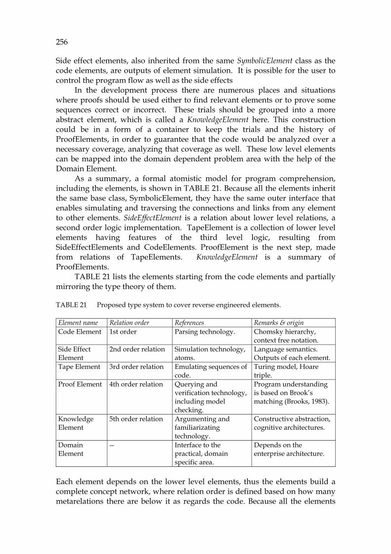
256
Side effect elements, also inherited from the same SymbolicElement class as the code elements, are outputs of element simulation. It is possible for the user to control the program flow as well as the side effects
In the development process there are numerous places and situations where proofs should be used either to find relevant elements or to prove some sequences correct or incorrect. These trials should be grouped into a more abstract element, which is called a KnowledgeElement here. This construction could be in a form of a container to keep the trials and the history of ProofElements, in order to guarantee that the code would be analyzed over a necessary coverage, analyzing that coverage as well. These low level elements can be mapped into the domain dependent problem area with the help of the Domain Element.
As a summary, a formal atomistic model for program comprehension, including the elements, is shown in 1093HTABLE 21. Because all the elements inherit the same base class, SymbolicElement, they have the same outer interface that enables simulating and traversing the connections and links from any element to other elements. SideEffectElement is a relation about lower level relations, a second order logic implementation. TapeElement is a collection of lower level elements having features of the third level logic, resulting from SideEffectElements and CodeElements. ProofElement is the next step, made from relations of TapeElements. KnowledgeElement is a summary of ProofElements.
1094HTABLE 21 lists the elements starting from the code elements and partially mirroring the type theory of them.
TABLE 21 Proposed type system to cover reverse engineered elements.
Element name Relation order References Remarks & origin Code Element 1st order Parsing technology. Chomsky hierarchy,
context free notation. Side Effect Element
2nd order relation Simulation technology, atoms.
Language semantics. Outputs of each element.
Tape Element 3rd order relation Emulating sequences of code.
Turing model, Hoare triple.
Proof Element 4th order relation Querying and verification technology, including model checking.
Program understanding is based on Brook’s matching (Brooks, 1983).
Knowledge Element
5th order relation Argumenting and familiarizating technology.
Constructive abstraction, cognitive architectures.
Domain Element
-- Interface to the practical, domain specific area.
Depends on the enterprise architecture.
Each element depends on the lower level elements, thus the elements build a complete concept network, where relation order is defined based on how many metarelations there are below it as regards the code. Because all the elements
257
are inherited from the same base class, SymbolicElement, the whole model is atomistic and therefore will support atomistic thinking. As an example, the user can think of the relations of any bug (Domain Element) expressed by loops (Code Element) and variable instantiations (Side Effect Element) in specified sequences (Tape Element) in order to build a mental image about whether a certain element (class as a Code Element) is correct or not against the requirements that easily can be configured to the Theorem Prover dialog for establishing a proof (Proof Element). The atomistic model allows the user to connect these very different concepts freely together
9.3.6 Mental or automated simulation
The human and computer models of computation are combined in the TM model and in the action model as well. Most of the maintenance activities can be automated. These include information search and analyzing a program flow.
In a skill level action the experience of the user can be very valuable to detect what is wrong, resembling an invocation parameter in a method call. In analyzing sequences the power of the computer can be very valuable in order to find problems or to find situations that are incorrect. For finding them, a specification for the computer should be created by the user. This process is called program verification.
In the rule level the person works like a TM, saving information and using existing information in order to explain how a program sequence works in each phase. Most of the information from an analysis process is temporary and can be forgotten after the session. Evaluation information becomes crucial in troubleshooting where a contradiction or a mismatch is looked for in order to solve a problem, or in verification which seeks to show that some element or sequence is valid against the selected hypotheses.
A feature, similar to minimizing information by an atomistic model and developing the software further, can be found in refactoring. If there are only a few invocations for a use case or a component and the units are strong inside and have only light connections to outer elements, then an optimum has been obtained. All exceptions into a direction where either fan-ins or fan-outs of the modules are too complex cause poor quality and problems for future maintenance.
9.4 Summary about research goals
In this section conclusions for the goals of Chapter 3 are shortly recapitulated.
Goal 1: To find an atomistic representation of source code as a basis for higher-order model, simulation, and user interaction
- “Atomistic presentation for code information:”
258
An atom was selected as a foundation with traceability to the Symbolic language. It is an element in each Turing tape, thus it helps in understanding the code. The whole methodology described in Chapters 4 to 10 and the Appendixes 1 and 3 is based on this goal. See the definition 1095HDefinition 19.
Goal 2: The main concepts express the metatheoretical relations of the proposed PC according to Peirce's semiotics
- “Metaconcepts illustrating the flow of the methodology” GrammarWare means syntax, ModelWare semantics, SimulationWare executing the semantics and KnowledgeWare the captured information which can be transformed into knowledge. This research ideally connects the four main technology spaces. See Section 1096H9.3 for the results. The proximity of these approaches can best be seen in the evaluation results in Appendix 3. See 1097HTABLE 28.
Goal 3: To emphasize the meaning of the symbolic language: both in translating source code into an internal language and further into a metalanguage for user interpretations
- “Symbolic language” The symbolic language, Symbolic, is a novel ontology to contain a high-abstraction model for Java and the corresponding meta-language, too. It is the foundation for the architecture of the tool (see Section 1098H8.2.1). See Section 1099H4.6.1 for the details.
Goal 4: To establish a convention to define an element for symbolic presentation
- “Naming convention” The Symbolic language has the definition for a symbolic name for each symbol type. The main elements for the language are described in 1100HDefinition 10 and 1101HDefinition 12 for the naming convention.
Goal 5: To implement GrammarWare using an symbolic formalism
- “Implementing GrammarWare”

259
Chapter 5 illustrates the principles of GrammarWare. There are three automata: A1, A2 and A3 that prepare code information to be used in the symbolic model. See Section 1102H4.1.4 for conclusions.
Goal 6: To create a model weaver for ModelWare in order to build a reductionist model for embedding Java semantics to it for simulation purposes
- “ModelWare, especially Model weaver” ModelWare has been described in Chapter 5 and defined in Section 1103H5.1. Algorithms for the model weaver to be expressed as Automaton A4 (see Section 1104H5.1.1) were built so that the resulted model contains the original grammar commands (1:1) as static Java semantics as well as capabilities to model dynamic Java behavior.
Goal 7: To describe formalism for source code simulation according to automata theory as well as to create a platform for partial simulation
- “Simulation platform” Simulation was modelled by using the Turing machine metaphor with its variations and the Chomsky hierarchy in Chapter 6. See Section 1105H6.1 for the foundation.
Goal 8: To create a bridge between the code model and the user language supporting the maintenance approach based on KnowledgeWare
- “KnowledgeWare” KnowledgeWare, described in Chapter 7, makes a synthesis using several models for knowledge (see 1106HTABLE 12). For making knowledge atomistic, an extension to the Symbolic language was built for expressing KnowledgeUnits ( 1107HDefinition 39), the necessary causal and parallel relations in order to present explanations, proofs and views. Information model for KnowlegeWare is presented in Section 7.3 and the corresponding action model in Section 7.4. For using them in solving a maintenance task a method is described in Section 7.5 with the process description in Section 7.6.
Goal 9: To describe transformations between the technology spaces as automata
- “Using the automata theory in the models “

260
It was stated (Chapters 6, 7, and 8) that all the models and even subfunctions of this research are equivalent with Turing machines or lower order models (like finite automata). Each has a simple formalism. The transformation model is shown in 1108HFIGURE 5.
Goal 10: To express the main relations of the captured knowledge as nested types
- “Internal relation model including its extensions to type theory” For understanding relations a type theory is needed to descibe nested relations. For that purpose, Section 9.3.5 describes an extension to the atomistic model to contain tapes and hypotheses and proofs and knowledge elements. Therefore, all of them can be thought of as chunks. These different model elements are unified in the atomistic architecture (see Section 1109H5.1.2).
Goal 11: To realize a knowledge access interface containing the three semiotic layers
- “Knowledge access” The access was principally defined by the action levels: Skill action, Rule action, and Knowledge action, and more concretely in the tool in Chapter 8 relating to the TM interface. The symbolic flow is described in Section 1110H6.9.3. The principles for obtaining information are described in Section 1111H7.4.
Goal 12: To create a sequential computation model for SimulationWare
- “Sequential computation model, the abstract Turing model” It was interesting to see that the Turing model metaphor works as a simulation model for an application, for any program sequence (Turing, 1936) having the Symbolic formalism, as well as for a single atom. Side effects (1112HDefinition 31) are extensions to the original code model that should be considered in simulating necessary successive sequences. The created computation model is summarized in Section 1113H6.8.
Goal 13: To investigate how to implement parallel activities, e.g., threads in order to capture program flows
- “Implementing necessary parallel computation for capturing program flows”

261
We created some features typical for threads in order to enable tracing thread activations by the tool for the practical case (see Section 1114H8.5.1). Although this functionality is not complete covering only some details of threads, it made it possible to understand applications when starting threads.
Goal 14: To plan a hierarchical action model to support solving maintenance tasks in the known cognition layers
- “Hierarchical action model” The Rasmussen SRK specialization model is the foundation for the action model in Chapter 7. It is described in Section 7.4. Related tool actions are described in Section 8.5.
Goal 15: To express user’s questions and hypotheses in a formal way referring to a singular element or a flow of the model or to a derived tree
- “Question and query formalism” A protocol of how to transform a maintenance task into problem formulations, questions, hypotheses, queries and, further, to analyses with the results is shown in Section 7.6.4. Examples about question formulation are also descibed in Sections 1115H7.6.5 and 1116H8.5.1 considering the practical example.
Goal 16: To build a demonstration for simulating an example and a theoretical approach considering the captured PC flow using hypotheses
- “Demonstration for a problem formalism” The maintenance task formalism was introduced in Chapter 7. In the tool there is a prototype for a computer-aided problem formulation and verification method for source code (see 8.4.3).
Goal 17: To validate the process - including all technology spaces - by a small sample program by comparing its output tape with the manually estimated program flow
- “Validating the process with Java code” The process was validated in the tool by using a small sample file, Server.java (Flanagan, 2000). There is evaluation information for it in Appendix 3. All method invocations in the main flow of the Server-program were checked.

262
Atomistic models were validated by taking samples of several typical code statements and class hierarchy combinations.
Goal 18: To create a hybrid construction, combining the benefits of OOP and logicprogramming
- “Atomistic architecture” The atomistic architecture was programmed to seamlessly combine object-oriented programming and logic programming (see 1117HDefinition 26). This object model is based on an atomistic hybrid object, AHO. Its correctness has been validated in several displays of the tool. Results from simulation are shown as simulation outputs in Appendix 3.
Goal 19: To show how a PC process works leading to low-level actions
- “Convergence of a typical maintenance task” A process of how to use the KnowledgeWare methodology in solving maintenance tasks was proposed in Section 7.6. This iterative and deepening principle uses the method of Section 7.5, which is based on the information model of Section 7.3 and action model of Section 7.4 (Goal 14). There is a use case for the convergence of the code of Appendix 1 in Section 7.6.5.
Goal 20: To formalize the main features of the research in Visual Prolog and to program the corresponding tool, JavaMaster
- “The tool and the Visual Prolog formulation” The most essential data structures, domains, interfaces, and formulations are presented in Visual Prolog in Chapters 4, 5, 6, 7, and 8. There is a multi-layer architecture in the JavaMaster tool (Chapter 8), which has the Symbolic language as the lowest level and the atomistic construction as the second level. The other levels complete the architecture with presentations, a controller with the user interface, and a mediator to connect the technology spaces and their elements with each other. The PC functionality of the tool was demonstrated in pictures from FIGURE 50 to FIGURE 56, where the best-known PC information needs are shown as symbolic flows for the code of Appendix 1.
As a conclusion, all the goals were completed in the research either partially or completely. However, there are some limitations in simulating, showing that not all commands can automatically be simulated in the category otherClause. The complexity of object-oriented programs was analyzed and for the ambiguous situations a formalism for the user was proposed in order to control program flow. The tool is not complete in respect to simulating some combinations of operations and references.
263
9.4.1 Explaining the main theories by the concepts of systems science
Brief generalizations for the created “Wares” are described next in order to find what is their relation to systems science (Hofkirchner, 1999) and how to argue why just these Wares are correct selections for this research:
- GrammarWare is a theory to help in understanding languages, especially for handling syntax. Languages are symbol-oriented, which approach extends the scope to symbolism, which is a synonym for representationism.
- ModelWare handles semantics and especially connections between elements. That approach is similar to the one of connectionism.
- SimulationWare is a theory for executing computations of the commands to be simulated. Therefore it is natural to extend its approach further to computationism, which keeps the Turing machine model as its foundation.
- KnowledgeWare is a process to learn features from the model. This approach, where the elements themselves are not as essential as the structures connecting the elements, leads to the goal of constructivism.
Once new knowledge has been obtained, it is possible for the user to make the code more reliable than it would be without this new information. This new feedback is then capable of connecting KnowledgeWare to GrammarWare for completing the maintenance task.
9.5 Summary of results
The main areas of the atomistic model were discussed in this chapter. The formalism to cover the area from a domain specific problem to code elements was proposed so that these high level elements could also be atomistic. This versatile atomistic conceptualism can act as a platform for building program comprehension tools that are able to maintain all the browsing history for each session in order to suggest to the user the possible locations for maintenance tasks that require more investigation.
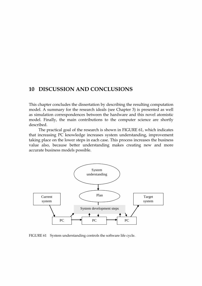
264
10 DISCUSSION AND CONCLUSIONS
This chapter concludes the dissertation by describing the resulting computation model. A summary for the research ideals (see Chapter 3) is presented as well as simulation correspondences between the hardware and this novel atomistic model. Finally, the main contributions to the computer science are shortly described.
The practical goal of the research is shown in 1118HFIGURE 61, which indicates that increasing PC knowledge increases system understanding, improvement taking place on the lower steps in each case. This process increases the business value also, because better understanding makes creating new and more accurate business models possible.
FIGURE 61 System understanding controls the software life cycle.
System development steps
Systemunderstanding
Currentsystem
Targetsystem
Plan
PC PC PC
System development steps
Systemunderstanding
Currentsystem
Targetsystem
Plan
PC PC PC
265
10.1 Unified computation model for maintenance
In this section the data flow of the atomistic model with its contributions is described as a unified computation model including the relevant goals of Chapter 3.
1. Using grammars and parsers
- Description in Chapter 4 considering • Goal 5
- Typically grammar tools create non-symbolic parsers. Their drawback is that in the resulting code the semantics and the syntactical structures are separated from each other, which makes programming analysis tools hard, because semantics must be hardcoded into the software. Instead, in this research the grammar terms are packed into predicates that contain both semantics and syntax tightly. It enables symbolic analysis and symbolic execution in a formal way.
2. Abstracting code
- Description in Chapter 4 considering • Goal 4 and • Goal 2
- Currently there are a few abstraction methods, most of them mathematical or purely logic. Their biggest problem is their coverage, because program code contains many kinds of formulations (cf. flows). Each of them requires specific processing, although there is a generic need to understand flows independent of their contents. The problem of how to unify all information is solved in this research by using a high abstraction language, Symbolic.
3. Symbolic language
- Description in Chapter 4 considering • Goal 3
- Currently symbolic languages are not widely used for code analysis. Furthermore, symbolic execution is implemented by programming the semantics based on the low-level program model. We, however, created a formal modeling notation for Java by the Symbolic language. It includes Java semantics.
4. Expressing semantics of Java
- Description in Chapter 6 considering • Goal 6 and • Goal 3

266
- Currently several semantic notations are known, but these presentations are external languages or libraries causing their own complexity. To avoid this we created an atomistic semantics between atoms. Unlike traditional semantics, it is object-oriented. For each command, captured from Java, we defined a run method to illustrate its semantics as a Turing-machine. It is an extremely reductionist implementation, but still useful, because almost all commands of modern languages work in the call/return principle.
5. Source code model
- Description in Chapter 5 considering • Goal 1
- Traditional source code models don’t have exact semantics. For eaxmple, the members of the AST nodes are not formal, because they are independent variables in their host class. Furthermore, there are often gaps between layers of code models (like in UML). In order to correct these problems in this work, an atomistic model is presented.
6. Model information (contents)
- Description in Chapter 5 considering • Goal 6
- Currently the elements of the code models have mainly been designed for forward engineering containing much information that is not relevant in reverse engineering. Excessive information causes much unnecessary work and can prevent from focusing on the main problem. Instead, in this work a minimized model was presented. It contains only a command and the necessary links for each atom.
7. Model traversers
- Description in Chapter 5 considering • Goal 6
- Currently, because of complexity of the models and the elements, typical model visitors are rather complex and hard to program and update. In order to avoid complexity in this research we propose a traversing principle, which is based on a graph theory based on simple graph traversers. This simplification is possible, because all the links in our model are similar predicates.
8. Analyzing theories
- Description in Chapter 5 considering • Goal 10

267
- Currently there are many independent theories for source code analysis, whose drawback is that most of them are incompatible with each other. That’s why they cannot be connected and commercialised in tools. In order to eliminate this problem we created a unified simulation model that uses only the run method of each element. It is based on a symbolic extension to the Turing machine formalism.
9.Analysis environment
- Description in Chapter 6 considering • Goal 10 and • Goal 11
- Currently, static analysis gives insufficient information about program behavior. Dynamic analysis, on the other hand, is insufficient to be used for PC. In order to eliminate their problems, we created an intermediate form between them, a symbolic analysis, in which symbolic predicates make its foundation. Because of the logical background of the research architecture (Visual Prolog) and the Symbolic language, creating theorem provers is rather straightforward. This novel approach enables interactive code verification, and partial simulation, which can be directed to any part of the source code.
10. Abstract machine
- Description in Chapter 6 considering • Goal 8, Goal 12 and • Goal 13
- Currently most source code analysis tools are hardcoded by specific algorithms like slicing. These algorithms use problem and situation specific data structures and low level solutions, which are far from the abstract definition of the original task. In order to maintain a direct connection between the original task and the code of the analysis, we created an abstract machine, which only specifies a state table for each element type. This novel solution is declarative and transparent, because it can be abstracted as a state transition table.
11. Analyzing object-oriented code
- Description in Chapter 6 considering • Goal 7
- It is widely known that it is not possible to analyze OOP code statically well. There are more than 10 different barriers that prevent this. In order to eliminate the barriers for obtaining PC information from code, we created a model construction, which contains the necessary intermediate information about class hierarchies and about polymorhistic functions so that simulation is possible with user aid (the Selector function).

268
12. Information model for PC
- Description in Chapter 6 considering • Goal 10 and • Goal 11
- Currently there are some information models for PC and some models of analysis. All the dependency information, as well as the program and data flows are important. However, in general the PC methods are fragmented. In order to find a connecting factor combining the best known information models for PC we created a unified symbolic flow with a semiotic base. Because it includes all behavior information, this new construction can be regarded as a server, which is capable of answering to queries.
13. Method to support PC hypotheses
- Description in Chapters 7 and 8 considering • Goal 8
- Currently it is known that the developers use frequently hypotheses in exploring code. However, no accurate formalism for these hypotheses has been suggested. In order to formalize the PC exploring process and the queries, we created a user interface to JavaMaster for building hypotheses for theorem proving.
14. Information ladder as a cognitive background
- Description in Chapter 7 considering • Goal 16
- Currently there is much discussion about program flows and slicing and about capturing dependencies, but there is no evident background on how to argument the need of any information in a larger context. In order to explain the relations between the source code information and their importance, we described an information ladder for knowledge capture as a base for gradual learning.
15. Action model for the tool
- Description in Chapter 7 considering • Goal 14
- Currently in theories and models the tasks and actions are seen as separated activities far removed from the tools. Instead, the tools are regarded only as user interfaces, which should produce “complete information” for the user. However, there is no complete information in a PC exploring process. There is only intermediate information, the final information is accumulated into the head of the user. In order to emphasize this approach we built the action stereotypes for the Rasmussen category: skill, rule and knowledge actions. These

269
stereotypes are useful as knowledge representations, because they meet the requirements of human thinking and of tool activities for selecting a new approach (Walenstein, 2002).
16. Maintenance support
- Description in Chapter 7 considering • Goal 16, • Goal 17 and • Goal 19
- Currently there are specific maintenance tools for finding memory problems or detecting deadlocks, bug information systems etc. We argue that the most important part of maintenance without conrete tools, the approach, which also should be mastered by tools, is PC. That’s why we created a stereotype to illustrate a unified maintence task. It covers the most probable use cases for program exploration, implementing the following maintenance task cycle:
1) Problem recognition 2) Problem formulation and analysis 3) Change specification by impact analysis 4) Unit testing (verification) by theorem proving
17 Tool support
- Description in Chapters 4 to 8 considering • Goal 18 and • Goal 20
- Currently tools are often specific, having a narrow scope. It is hard to understand their formalism and the programming approach, because the structures and models are complex having many abstraction layers. In order to remove unnecessary complexity and to have a tool with a transparent principle as its foundation, we created JavaMaster, which uses the PCMEF architecture. It uses state transition tables as its simulation foundation and the Symbolic language as its foundation for all data transfer. As input symbols for this symbolic abstract machine, there are high-level commands that have been transformed from Java. The JavaMaster tool demonstrates the formalism and the theories.
10.1.1 Summarizing the maintenance computation model
Because the research covers several topics of computer and systems science as well as more practical areas relating to software engineering and reverse engineering research, it is not possible to give, in this section, a completed set of the actual references, which should cover all of them. Instead, for getting surveys we found some comprehensive summaries that cover the whole area topic by topic describing the future of software engineering (Jackson and Rinard, 2000), dated in the year 2000. Furthermore, there is an up-to-date report about the future of source code analysis (Binkley, 2007), which is capable of describing the current status of topics 1 to 12. However, concrete efforts in order
270
to extend the general knowledge about the cognitive approach of PC, related to the topics 13, 14, 15, and 16, cannot be found in the literature. That’s why the current comprehension about PC is limited to a set of independent activities conducted by the user.
Some essential conclusions can be drawn from these articles describing current state-of-the-art and a possible future. Discontinuities between formalisms are a big problem. There are gaps between models and grammars and other notations as described in Chapter 2. The lack of grounded theories relating to models (ModelWare) is obvious, which can be seen in the road map for object-oriented models (Engels and Groenewegen, 2000). Hence, the current modeling practice, UML, doesn’t have a grounded theoretical foundation, although it is still widely used in software development world-wide.
Instead, in this research a unified computation model is proposed, which connects the code elements (topic 1) and the models (2, 3, 4, 5, and 6) and the simulation process (topics 8 and 9) with its Turing formalisms (topic 10) even for object-oriented code (topic 11) with the most relevant cognitive theories (topic 13, 14, and 15) for building a formal description for a practical maintenance process, which consists of a few stereotypes for tasks (topic 16) to be implemented in a tool (topic 17) as a sharpening action.
10.2 Scientific ideals
The ideal goals for a research have been defined by Hoare (2006) from the program verification viewpoint, which is relevant to this dissertation, too (see Chapter 3). Next these principles are discussed for the atomistic model.
10.2.1 Purity of the created concepts
For each technology space a pure concept was selected as a foundation: - For grammars it was natural to select the symbolic grammar term,
because we found that a grammar can be defined as a composite object containing only grammar terms. Another foundation illustrating the contents of the symbolic model is the clause notation of the symbolic language.
- For models an atomistic hybrid object (AHO) was selected to be the main element for the symbolic model. Because of the class hierarchy of AHO the model is homogenous.
- For simulation the Turing model with its tape was selected implementing a symbolic abstract machine, SAM. It may be seen as a glass box with a state transition formalism, which can be derived from a large program down to an individual clause.
- For knowledge mining an information ladder was selected as a foundation. It is a symbolic tool for the user to climb upwards from the

271
levels of the previous foundations, the clause, AHO, Turing output tape and the relation models connecting all this information.
10.2.2 Simplicity of the created theories
Some observations about the modules that show the correspondence of current theories and the new approach include:
- GrammarWare. A theory connecting the grammar term to existing practices was introduced. Thus it was shown that the symbolic grammar term is downwards compatible with AST and EBNF notations allowing transformation from the symbolic grammar to currently widely used notations. Upwards compatibility from traditional notations to this novel notation is possible by defining a semantic name for each term instance. 46F
47 - ModelWare. The AHO element was shown to be mostly compatible with
AST nodes, and was easy to compare in the models, too. In this symbolic atomistic model the rules of creating the model are, however, very rigorous in order to comply with the requirements and status of an atomistic model. Therefore, in every element there cannot be more than one definition clause. Links excepted, there cannot be any other element types within an atom. These rigorous rules are a drawback in the development, but benefit it by making the model formal. From an atomistic model it is possible to derive AST models, but the formalism will be lost.
- SimulationWare. The Turing tapes are compatible with finite automata and corresponding models, which make it easy to simulate state machines by using this new approach. In this methodology all the software may be seen as stacked state machines, where parallel features are individual tapes, each.
- KnowledgeWare. The basic element for the investigation and program understanding here is a chunk, which is not an automatic function, but a function that a human originates. The simplest element in this model is an atom expressed in the clause notation. The results derived from the model are sequences or more abstract lists that are not in an execution order. The highest level of information derived from the model is argumentation, either deductive or inductive. This knowledge model leads directly to the taxonomy of Peirce.
The technology spaces can be seen as formalisms in the following way:
47 Furthermore, because of the simplicity of the notation of the symbolic grammar, some
modifications should be used in order to convert optional and nesting structures into smaller individual terms, which is very straightforward work.

272
- GrammarWare. The formalism of a parser is an acceptor, which is defined in a Chomsky category. The translation formalism is a transducer, as in Chomsky.
- ModelWare. The elements of the symbolic atomistic model are individual atoms, which do not know anything about any other atoms, thus making the model extremely modular and purely atomistic. A model is a collection of atoms, in other words.
- SimulationWare. All the models introduced in this work obey the formalism of an already known automaton. For the novel new construction, the AHO element, the new class for semantics was introduced with the name of atomistic semantics. This new formulation hides only the fact that a link between the atoms can be symbolic (the link is not constant then) having a semantic meaning. So in an if-statement the atomistic links bind the connection and the true-branch and the optional else-branch together by call/return-links. The protocol of how they are coded in the run method of the AHO element has been written by using a state table formalism.
- KnowledgeWare. Relating to knowledge capture we create two bridges between the user cognition and the power of the tool. The higher bridge works in the concept level describing the focus of the user in creating free associations considering the current maintenance task. The lower bridge is in the rule level (Rasmussen, 1983), where the user can simulate code mentally or the tool can simulate the code automatically. These two approaches create a symbiosis, a co-operation architecture (Walenstein, 2002), between the user and the tool.
10.2.3 Accuracy of transformations from code to knowledge
Accuracy of transformations describes coherency of the technology, shown in Figure 1 in Chapter 3. The results about accuracy are shown in 1119HTABLE 22. It can be seen that the accuracy is best in all code related automata in parsing and transformations A1, A2 and A3 because of their traditional practices. The accuracy of the model weaver, Automaton A4, depends on the functionality of the tool. We showed in Chapter 6 that the semantics of clauses other than some exceptions (otherClause) can be expressed by using Prolog. The accuracy of Automaton A6 (SAM) is the most complex question to be estimated. JDK references and unknown symbols and values in partial simulation lower the accuracy, because in the KnowledgeWare area, in cases of partial simulation and complex software, the simulation result depends on user actions and the selected evaluation strategy. For maintenance tasks, considering Automaton A7, there are some methods of how to divide complex tasks into smaller actions and how to organize this kind of work so that all the critical actions can be mastered
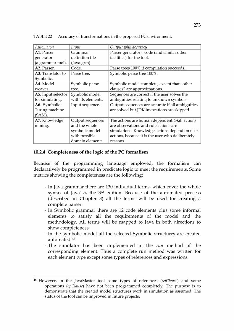
273
TABLE 22 Accuracy of transformations in the proposed PC environment.
Automaton Input Output with accuracy A1. Parser generator (a grammar tool).
Grammar definition file (Java.grm)
Parser generator – code (and similar other facilities) for the tool.
A2. Parser. Code. Parse trees 100% if compilation succeeds. A3. Translator to Symbolic.
Parse tree. Symbolic parse tree 100%.
A4. Model weaver.
Symbolic parse tree.
Symbolic model complete, except that “other clauses” are approximations.
A5. Input selector for simulating.
Symbolic model with its elements.
Sequences are correct if the user solves the ambiguities relating to unknown symbols.
A6. Symbolic Turing machine (SAM).
Input sequence. Output sequences are accurate if all ambiguities are solved but JDK invocations are skipped.
A7. Knowledge mining.
Output sequences and the whole symbolic model with possible domain elements.
The actions are human dependent. Skill actions are observations and rule actions are simulations. Knowledge actions depend on user actions, because it is the user who deliberately reasons.
10.2.4 Completeness of the logic of the PC formalism
Because of the programming language employed, the formalism can declaratively be programmed in predicate logic to meet the requirements. Some metrics showing the completeness are the following:
- In Java grammar there are 130 individual terms, which cover the whole syntax of Java1.5, the 3rd edition. Because of the automated process (described in Chapter 8) all the terms will be used for creating a complete parser.
- In Symbolic grammar there are 12 code elements plus some informal elements to satisfy all the requirements of the model and the methodology. All terms will be mapped to Java in both directions to show completeness.
- In the symbolic model all the selected Symbolic structures are created automated. 47F
48 - The simulator has been implemented in the run method of the
corresponding element. Thus a complete run method was written for each element type except some types of references and expressions.
48 However, in the JavaMaster tool some types of references (refClause) and some
operations (opClause) have not been programmed completely. The purpose is to demonstrate that the created model structures work in simulation as assumed. The status of the tool can be improved in future projects.
274
- For KnowledgeWare a user interface was created in order to demonstrate the functions of GrammarWare, ModelWare and SimulationWare. For obtaining knowledge based results a demonstration for an interactive theorem prover was written, but only some basic rules were programmed in the JavaMaster tool.
Because of the schedule some approximations were done in order to demonstrate some goals like how dynamic binding should happen in method invocations and how partial simulation should work in typical situations relating to concrete and abstract classes with specific modifier selections.
10.2.5 Correctness of programs of the created PC formalism
Because of the great degree of automation most of the software parts are reliable. Some remarks about how we have tested the methodology are included here:
- The parser uses a top-down recursive descent method. Therefore it can parse reliably all nested structures typical for Java and C++. We have used the same technology earlier for parsing Cobol, C++, and Pascal.
- The model weaver uses a recursive method in splitting the Symbolic parse tree into smaller and smaller elements, each creating an atom. There is some complexity in programming tools for analyzing programs that work polymorphically. We have solved this problem of ambiguous situations by saving the possible alternatives (inheritance and polymorphism) as specific references to the host element.
- Because the simulator needs only the run method of the AHO element, which is specified by a state transition table, each atom type can individually be proved, one by one, by using test atoms as a constant, a condition, a loop, a method etc.
- We can resort to verified explanation generation by using small tapes that include typical elements.
- The proof engine has been tested by using a test sequence and some specified patterns, which correspond to a typical hypothesis that contains some trivial logic operators.
Because of its rigorous formalisms and the high level programming language employed, the proving process of the methodology and the tool can recursively be divided into smaller and smaller parts for cases where automatic functional testing is not possible.
10.2.6 Certainty of answers given by the PC formalism
Certainty of the analysis depends on the validity of the model and on the atomistic semantics combining the elements with each other via their dependencies. In our approach, all static dependencies can be saved completely in the symbolic model. Capturing dynamic dependencies is much more

275
difficult. It succeeds best once the whole code has been loaded and selected to be simulated, because all symbols can then be detected. Partial simulation is more challenging. For it we have demonstrated that interactive simulation can produce useful dependency information to the user gradually. That’s why it extends the comprehension of the user towards the current elements, augmenting information in a partial manner.
In cases where the source code model has been partially loaded to memory, very often the type system of the model can warn the user that something is missing in the model. It suggests to the user that he/she should load more code in order to obtain more complete results. In the focused approach, on the other hand, knowing everything is not the point, on the contrary, the point is how to understand the most interesting dependencies of the code.
10.2.7 Relevancy of questions considering the PC formalism
The semiotic and cognitive model created in KnowledgeWare sounds promising, because it combines the Peircean taxonomy, the Rasmussen specialization model, the information ladder, and the atomistic model into a unified model for source code knowledge. It emphasizes the idea of a focused approach, in which symbolic evaluation by using a symbolic tool is the obvious technology.
The abstract machine model with its cognitive interpretation is a relevant approach to describe both the code and the user. Because the formalisms of both of them are comparable in sequential reasoning, in obeying the symbolic paradigm, it is possible to create a platform, a virtual architecture, where the actions can be transferred from the user into a computer and vice versa. This new option opens up numerous possibilities:
- To delegate tasks by using possible agent models. - To automate tasks flexibly with the help of a computer. - To create evaluation models for calculating use cases for PC, including
usability, performance, and coverage of the captured information.
10.3 Connections to Computer Science
Constable (2000) has proposed that relevant topics in research of computer science consist of experiments, theories, knowledge, discoveries, as well as of interdisciplinarity and multidisciplinarity. These topics are discussed next.
10.3.1 Experiments in building PC formalism
A lot of experiments were done during the research, starting with building a grammar for Java. After some trials and modifications it was found that all the grammar terms and the rules are correct, enabling successive parsing of files.
276
The most ambitious experiments were in creating an atomistic structure for the model, because there were rigorous requirements to leave the model element ”almost empty” containing only one predicate per object. Another challenging experiment was how to implement the simulator, the Turing model with a comprehensive architecture.
10.3.2 Created theories for the technology spaces
The main theories created in this research are the technology spaces themselves: - GrammarWare and the corresponding software architecture were
introduced. We showed that it is possible to generate parsers by using only a few theoretical elements. We defined the semantic grammar notation, the corresponding production rule, the grammar file as well as the grammar database as the key concepts for automatic parser generation. A grammar file for Java and a parser for it were generated as well as a perfect language environment for the Symbolic language for abstracting Java.
- Considering ModelWare we showed that Symbolic parse trees can be split into an atomistic model, without losing the original Java semantics.
- Considering SimulationWare we showed that it is possible to simulate each atom and each part of the source code so that the behavior resembles as far as possible that of the Java virtual machine. For unknown types and symbols there is a possibility for the user to control the program flow of simulation.
- Considering KnowledgeWare we showed that the simulation results consisting of atoms are a perfect data set for building higher abstraction knowledge layers. For building we specified the action layers according to the Rasmussen specialization model. This process, starting from low level data, is also called an information ladder. For software maintenance the principal purpose considering KnowledgeWare is to verify and to evaluate the status of the key elements and the key structures of the code for planning changes for them.
10.3.3 Created knowledge to be used in future research
There are three main types of knowledge created in this work: - The unified transformation model to describe the software development
work presented in Chapter 9 is attractive, because it makes it possible to integrate programming tools and UML modeling tools to the same platform.
- The symbolic Turing machine architecture is attractive because of the simplicity of its computation model. By using simple state transition tables we can model modern programming languages.
- The symbolic formalism created in this work, based on the Symbolic language, enables mathematical formulation of the code, creating computation models for each part of the mission-critical software
277
(without defining complex rules) and creating a transformation framework for software production, where the Symbolic language could be the base language replacing complex XML-notations. The most used transformation notation today is XMI.
- Program restructuring and reorganization are areas where current tools are often limited. This approach is important as restructuring has often been skipped in busy programs, which leads to degradation of software, which can sometimes become impossible to correct. We have not shown it, but it is clear that this new construction could provide valuable contribution to current software development by increasing the quality of software by allowing free construction and automatic mapping of source code elements independent of their location.
10.3.4 New discoveries to summarize the research
Some of the most interesting discoveries are: - It is possible to create an atomistic model, where the interface of the
element contains only one method for simulation. The architecture of the atom is a discovery which can help in creating new simple tools, products and research projects. This finding runs against the grain in building multi-layer models, where there is complete, accurate information in each model structure and in which there are tight, modal rules for each association of the model to be validated in each phase of the model construction.
- Symbolic analysis uses propositional calculus as its base, because its origin is the formal language, its grammar terms, the symbolic notation and the Turing machine output tape. Thus, symbolic analysis is deducible.
- Object-oriented code can be simulated, although some arrangements must be done in the model construction, and the user is needed for selecting the program flow, which should be executed in ambiguous situations. Similarity of simulation models of any program regardless of its size and each atom is a finding, too.
- It was found that though the technology spaces are compact areas, it is still possible to transform information from one to another. All three semiotic dimensions of Peirce (1958) - syntactics, semantics and pragmatics - are covered when transforming grammar-based code information via models and simulation into argumentative knowledge.
10.3.5 Interdisciplinarity and multidisciplinarity
This work introduces a novel approach connecting source code analysis and cognitive approach via grammars, models, simulation, and knowledge capture. It has many connections into different theories of computer science (see 1120HFIGURE 62):
278
- The foundation for the computer science consists of logic, number theory, and universal machine (Turing, 1936). We have borrowed the concept of the atom from physics in order to make an extension, which should enable implementing automated applications and creating hybrid theories in order to combine isolated approaches.
- Our approach will allow automata theory to be used in simulation through SimulationWare as well as grammar theory to be used in reading and writing code.
- For enabling simulation we created ModelWare based on objects, which makes it possible to use the graph theory in finding information from the model and results.
- For the software development research we created the symbolic analysis, a methodology to help program comprehension, a part of reverse engineering.
- Considering human interaction, psychology and artificial intelligence, relating to the most philosophical approach of this research, we created KnowledgeWare, which consists of an interface to maintenance tasks including a layered action-model for the user as well as principles for problem formulation.
The common denominator for these theories is the symbolic paradigm with its background in computationalism based on the Turing machine. It is capable of modeling sequentially the approaches of the computer, software, and the symbolic approach of the user, i.e., the theory of mind. Based on the sequential approach the user can build higher-order constructions, e.g., hierarchical mental representations including parallel features.
This research has opened up many new approaches for combining current theories of computer science together by using the atomistic model. It also shows why to select the various Wares for grammars, models, simulation and knowledge as the main theories for this research; in systems science the corresponding larger disciplines can be seen to be symbolism, connectionism, computationalism and constructivism. Due to this extended view we assume that the created construction could be a jump to a possible future, where the following research topics would be in a clear continuum to this work:
- Evaluating performance and usability and memory use of the model. - Visualizing an atomistic model and the simulation results. - Integrating the results with other tools. - Extending the model to other languages (C++ etc). - New approaches for developing tools. - Getting industrial experience of program comprehension processes.
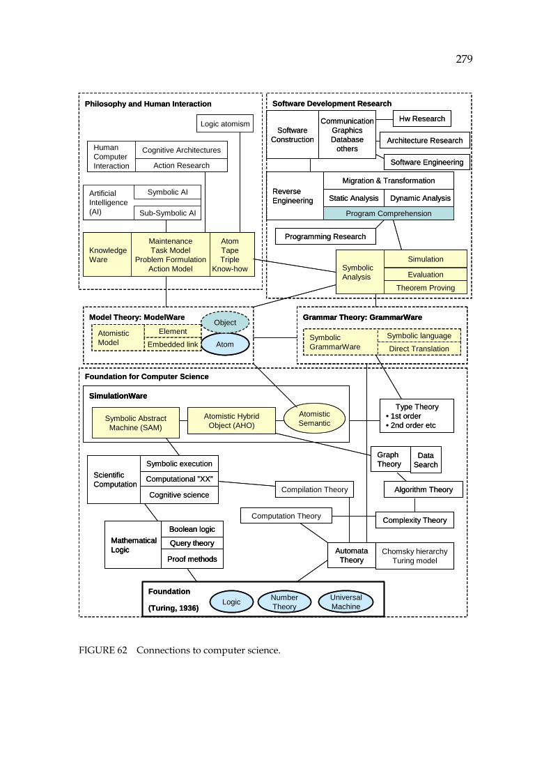
279
FIGURE 62 Connections to computer science.
AutomataTheory
Software Development ResearchPhilosophy and Human Interaction
HumanComputer Interaction
Cognitive Architectures
Action Research
ArtificialIntelligence(AI)
Symbolic AI
Sub-Symbolic AI
KnowledgeWare
AtomTapeTriple
Know-how
MaintenanceTask Model
Problem FormulationAction Model
Hw Research
Software Engineering
SymbolicAnalysis
Simulation
Evaluation
Theorem Proving
Programming Research
Architecture Research
ReverseEngineering
Migration & Transformation
Static Analysis Dynamic Analysis
CommunicationGraphicsDatabase
others
SoftwareConstruction
Grammar Theory: GrammarWare
SymbolicGrammarWare
Symbolic language
Direct Translation
Program Comprehension
Foundation for Computer Science
Compilation Theory
Chomsky hierarchyTuring model
GraphTheory
DataSearch
Foundation
(Turing, 1936)Logic Number
Theory
Atom
UniversalMachine
Model Theory: ModelWare
Atomistic Model
Element
Embedded link
Object
Algorithm Theory
Type Theory• 1st order• 2nd order etc
MathematicalLogic
Boolean logic
Query theory
Proof methods
Computation Theory
ScientificComputation
Symbolic execution
Computational ”XX”
Cognitive science
Complexity Theory
Atomistic HybridObject (AHO)
Symbolic AbstractMachine (SAM)
SimulationWare
AtomisticSemantic
Logic atomism
AutomataTheory
Software Development ResearchPhilosophy and Human Interaction
HumanComputer Interaction
Cognitive Architectures
Action Research
HumanComputer Interaction
Cognitive Architectures
Action Research
ArtificialIntelligence(AI)
Symbolic AI
Sub-Symbolic AI
ArtificialIntelligence(AI)
Symbolic AI
Sub-Symbolic AI
KnowledgeWare
AtomTapeTriple
Know-how
MaintenanceTask Model
Problem FormulationAction Model
KnowledgeWare
AtomTapeTriple
Know-how
MaintenanceTask Model
Problem FormulationAction Model
Hw Research
Software Engineering
SymbolicAnalysis
Simulation
Evaluation
Theorem Proving
SymbolicAnalysis
Simulation
Evaluation
Theorem Proving
Programming Research
Architecture Research
ReverseEngineering
Migration & Transformation
Static Analysis Dynamic Analysis
CommunicationGraphicsDatabase
others
SoftwareConstruction
Grammar Theory: GrammarWare
SymbolicGrammarWare
Symbolic language
Direct Translation
Grammar Theory: GrammarWare
SymbolicGrammarWare
Symbolic language
Direct TranslationSymbolicGrammarWare
Symbolic language
Direct Translation
Program Comprehension
Foundation for Computer Science
Compilation Theory
Chomsky hierarchyTuring model
GraphTheory
DataSearch
Foundation
(Turing, 1936)Logic Number
Theory
Atom
UniversalMachine
Model Theory: ModelWare
Atomistic Model
Element
Embedded linkAtomistic Model
Element
Embedded link
Object
Algorithm Theory
Type Theory• 1st order• 2nd order etc
MathematicalLogic
Boolean logic
Query theory
Proof methods
MathematicalLogic
Boolean logic
Query theory
Proof methods
Computation Theory
ScientificComputation
Symbolic execution
Computational ”XX”
Cognitive science
Complexity Theory
Atomistic HybridObject (AHO)
Symbolic AbstractMachine (SAM)
SimulationWare
AtomisticSemantic
Atomistic HybridObject (AHO)
Symbolic AbstractMachine (SAM)
SimulationWare
AtomisticSemantic
Logic atomism
280
REFERENCES
Aamodt, A. and Nygård, M. (1995). Different roles and mutual dependencies of data, information, and knowledge - an AI perspective on their integration, Data Knowl. Eng. 16(3): 191–222.
Ackoff, R. L. (1989). From data to wisdom, Journal of Applied Systems Analysis 16: 3–9.
ACT-R. (2007). ACT-R, Welcome to ACT-R, URL:http://act-r.psy.cmu.edu/, referred 10.08.2007. ACT-R Research Group, Department of Psychology, Carnegie Mellon University.
ADM. (2007). ADM, Architecture Driven Modernization. URL: 357Hhttp://adm.omg.org, referred 20.9.2007. OMG, Object Management Group.
Akehurst, D. and Patrascoiu, O. (2004). OCL 2.0 - implementing the standard for multiple metamodels, Electronic Notes in Theoretical Computer Science (Proceedings of the Workshop, OCL 2.0 - Industry Standard or Scientific Playground?) 102: 21–41.
Ammons, G. and Larus, J. R. (1998). Improving data-flow analysis with path profiles (with retrospective), 20 Years of the ACM SIGPLAN Conference on Programming Language Design and Implementation 1979-1999, A Selection, ACM Press, 568–582.
Andersen, L. O. (1994). Program Analysis and Specialization for the C Programming Language, PhD thesis, DIKU, University of Copenhagen, Denmark. URL: http://repository.readscheme.org/ftp/papers/topps/D-203.pdf
Anderson, J. R. (2004). Human Symbol Manipulation Within an Integrated Cognitive Architecture, Cognitive Science, Inc 29, 313-341.
Anderson, J. R. and Lebiere, C. (1998). The atomic components of thought, Erlbaum.
Anderson, J. R., and Matessa, M. (1997). A Production System Theory of Serial Memory, URL:http://act-.psy.cmu.edu/files/oldmodels/psych_review, referred 10.08.2007. Psychological Review 104, 728-748.
Anderson, P. and Teitelbaum, T. (2001). Software inspection using CodeSurfer, First Workshop on Inspection in Software Engineering (CAV 2001).
Andrews, T., Qadeer, S., Rajamani, S. K., Rehof, J., and Xie, Y. (2004). Zing: A Model Checker for Concurrent Software, CAV 2004, Springer-Verlag. 484-487.
Arévalo, G. (2005). High Level Views in Object Oriented Systems using Formal Concept Analysis, PhD thesis, University of Bern, Switzerland. URL: http://www.iam.unibe.ch/ scg/cgi-bin/scgphd.cgi
Aßmann, U. (2003). Automatic roundtrip engineering, Electr. Notes Theor. Comput. Sci. 82(5). Proceedings of the Fifth Workshop on Quantitative Aspects of Programming Languages (QAPL 2003).
Atlas. (2005). Atlas-project. URL:ralyx.inria.fr/2005/Raweb/atlas/uid15.html, referred 10.08.2007. Inria.
281
Attali, I., Caromel, D. and Russo, M. (1998). A formal executable semantics for Java, Proceedings of Formal Underpinnings of Java - OOPSLA’98 Workshop.
AttributeGrammars. (1998). Attribute Grammars, Home Page, URL: www-sop.inria.fr/smartool/Didier.Parigot/www/fnc2/AGtexte.html, referred 20.02.2008. Project Oscar, FNC-2 page.
Back, R., (1978). On the Correctness of Refinement Steps in Program Development. PhD-thesis. University of Helsinki, Finland. URL: 358Hweb.abo.fi/~backrj/index.php?page=view&value=Back78:thesis, referred 20.02.2008.
Backus, J. (1978). Can programming be liberated from the von Neumann style?: A functional style and its algebra of programs, Commun. ACM 21(8): 613–641.
Ball, T. and Larus, J. R. (1996). Efficient path profiling, Microarchitecture, 1996. MICRO-29. Proceedings of the 29th Annual IEEE/ACM International Symposium on, IEEE Computer Society, 46 – 57.
Ball, T. (1999). The concept of dynamic analysis, ESEC/FSE-7: Proceedings of the 7th European Software Engineering Conference held jointly with the 7th ACM SIGSOFT International Symposium on Foundations of Software Engineering, Springer, 216–234.
Ball, T. and Rajamani, S. K. (2000). Boolean programs: A model and process for software analysis, Technical Report MSR-TR-2000-14, Microsoft Research.
Bargiela, A. and Pedrycz, W. (2002). Granular Computing: An Introduction, Springer.
Bass, L., Clements, P., and Kazman, R. (2003). Software Architecture in Practice. Addison-Wesley.
Baxter, I. D. and Mehlich, M. (1997). Reverse engineering is reverse forward engineering, WCRE ’97: Proceedings of the Fourth Working Conference on Reverse Engineering (WCRE ’97), IEEE Computer Society, 104–113.
Baxter, I. D., and Mehlich, M. (2002). Transformation Systems: Theory, Implementation, Survey. Semantic Designs, Inc.
Baxter, I. D., Pidgeon, C. and Mehlich, M. (2004). DMS: Program transformations for practical scalable software evolution, ICSE ’04: Proceedings of the 26th International Conference on Software Engineering, IEEE Computer Society, 625–634.
Baxter, I., and Gray, J. (2005). Automated Program and Model Transformation Technology. Architecture Driven Modernization Workshop, VA.
Bellay, B., and Gall, H.. (1998). An Evaluation of Reverse Engineering Tool Capabilities in Journal of Software Maintenance: Research and Practice, 10(5), John Wiley & Sons, 1998, 305-331.
Bennett, K. H., and Rajlich, V. T. (2000). Software Maintenance and Evolution: a Roadmap. in The Future of Software Engineering (Finkelstein, A., ed. ACM Press).
Beyer, D., and Noack, A. (2005). Clustering Software Artifacts Based on Frequent Common Changes, IWPC 2005, pp. 259-268.
282
Bezevin, J. (2003). Object to Model Paradigm Change, 359Hurl:http://rangiroa.essi.fr/cours/systeme2/02-mda.pdf.
Bézivin, J., Jouault, F. and Valduriez, P. (2004). First experiments with a modelweaver, Proceedings of the OOPSLA/GPCE: Best Practices for Model-Driven Software Development workshop, 19th Annual ACM Conference on Object-Oriented Programming, Systems, Languages, and Applications.
Bézivin, J. (2005). On the unification power of models., Software and System Modeling 4(2): 171–188.
Binkley, D. and Gallagher, K. B. (1996). Program slicing., Advances in Computers 43: 1–50.
Binkley, D. (2007). Source code analysis: A road map, FOSE ’07: 2007 Future of Software Engineering, IEEE Computer Society, 104–119.
Blieberger, J., Burgstaller, B. and Scholz, B. (1999). Interprocedural symbolic evaluation of ADA programs with aliases, Ada-Europe ’99: Proceedings of the 1999 Ada-Europe International Conference on Reliable Software Technologies, Springer, 136–145.
Blieberger, J., Burgstaller, B. and Scholz, B. (2000). Symbolic data flow analysis for detecting deadlocks in ada tasking programs., in H. B. Keller and E. Plödereder (eds), Proceedings of the 5th Ada-Europe International Conference on Reliable Software Technologies, Vol. 1845, Springer, 225–237.
Boehm, B. W. (1981). Software Engineering Economics, Prentice Hall PTR. Boehm, B. W. (1991). Software risk management: Principles and practices, IEEE
Softw. 8(1): 32–41. Boman, M., Bubenko, J. J. A., Johannesson, P. and Wangler, B. (1997). Conceptual
Modelling, Prentice-Hall, Inc. Bozga, M., Maler, O., Pnueli, A. and Yovine, S. (1997). Some progress in the
symbolic verification of timed automata., in O. Grumberg (ed.), Proceedings of the 9th International Conference on Computer Aided Verification, Vol. 1254, Springer, 179–190.
Boyer, R. S., Elspas, B. and Levitt, K. N. (1975). SELECT - a formal system for testing and debugging programs by symbolic execution, Proceedings of the International Conference on Reliable Software, ACM Press, 234–245.
Briand, L. C., Labiche, Y. and Leduc, J. (2006). Toward the reverse engineering of uml sequence diagrams for distributed Java software., IEEE Trans. Software Eng. 32(9): 642–663.
Brooks, R. E. (1983). Towards a theory of the comprehension of computer programs., International Journal of Man-Machine Studies 18(6): 543–554.
Brooks, F. P. (1987). No silver bullet: Essence and accidents of software engineering, IEEE Computer 20(4): 10–19.
Brown, W. J., Malveau, R. C., III, H. W. M. and Mowbray, T. J. (1998). AntiPatterns: Refactoring Software, Architectures, and Projects in Crisis, John Wiley & Sons.
Burkhardt, J.-M., Détienne, F. and Wiedenbeck, S. (2002). Object-oriented program comprehension: Effect of expertise, task and phase., Empirical Software Engineering 7(2): 115–156.

283
Byrne, M. D. (2003). Cognitive Architecture, 97--117, URL: http://citeseer.ist.psu.edu/byrne03cognitive.html , referred 10.08.2007. Erlbaum, Hillsdale, NJ.
Caprile, B., Potrich, A., Ricca, F. and Tonella, P. (2003). Model centered interoperability for source code analysis, International Workshop on Software Analysis and Maintenance: Practices, Tools, Interoperability, IEEE International Conference on Software Maintenance, ICSM’2003. URL:star.itc.it/Papers/2003/step2003.html.
Cavada, R., Cimatti, A., Jochim, C. A., Keighren, G., Olivetti, E., Pistore, M., Roveri, M., and Tchaltsev, A. (2005). NuSMV 2.4 User Manual, URL:http://nusmv.irst.itc.it, referred 10.09.2007. CMU and ITC-irst.
Chapin, N., Hale, J. E., Ramil, J. F. and Tan, W.-G. (2001). Types of software evolution and software maintenance, Journal of Software Maintenance and Evolution: Research and Practice 13(1): 3–30.
Cheatham, T., Holloway, G., and Townley, J. (1979). Symbolic Evaluation and the Analysis of Programs, IEEE Trans. Software Eng. 5(4): 402–417.
Chikofsky, E. and Cross, J. (1992). Reverse engineering and design recovery: A taxonomy, in R. S. Arnold (ed.), Software Reengineering, IEEE Computer Society, 54–58.
Chomsky, N. (1956). Three models for the description of language, IEEE Transactions on Information Theory 2(3): 113– 124.
Chomsky, N., and Schützenberger, M. P. (1963). Computer Programming and Formal Languages. In The algebraic theory of context free languages, 118-161 (Braffort, P., and Hirschberg, D., eds.). Amsterdam: North Holland.
Church, A. (1936). An unsolvable problem of elementary number theory, Vol. 58, 345–363.
Clarke, L. (1975). A system to generate test data and symbolically execute programs, Technical Report CU-CS-060-75, U. of Colorado, Dep. of Computer Sci.
Clarke, E. M., McMillan, K. L., Campos, S. V. A. and Hartonas-Garmhausen, V. (1996). Symbolic model checking, Computer Aided Verification, 8th International Conference, CAV ’96, Proceedings, Springer, 419–427.
Cleveland, H. (1982). Information as resource. Futurist, 16, 34-39. Clocksin, W. F. and Mellish, C. (1981). Programming in Prolog, Springer. Constable, R. L. (2000). Computer Science: Achievements and Challenges circa
2000, URL:www.cs.cornell.edu/cis-dean/bgu.pdf, referred 10.08.2007. Copeland, B. J. (2004). The Essential Turing: Seminal Writings in Computing, Logic,
Philosophy, Artificial Intelligence, and Artificial Life plus The Secrets of Enigma, Oxford University Press.
Cordy, J. R., Lämmel, R. and Winter, A. (2006). 05161 Executive summary – transformation techniques in software engineering, in J. R. Cordy, R. Lämmel and A. Winter (eds), Transformation Techniques in Software Engineering, Internationales Begegnungs- und Forschungszentrum fuer Informatik (IBFI), Schloss Dagstuhl, Germany.
284
Cousot, P. and Cousot, R. (1977). Abstract interpretation: A unified lattice model for static analysis of programs by construction or approximation of fixpoints., POPL ’77: Proceedings of the 4th ACM SIGACT-SIGPLAN Symposium on Principles of Programming Languages, ACM Press, 238–252.
Curtis, B. (1981). Substantiating programmer variability, Proceedings of the IEEE, 69(7): 846– 846.
Dams, D. and Namjoshi, K. S. (2005). Automata as abstractions., in R. Cousot (ed.), Verification, Model Checking, and Abstract Interpretation, 6th International Conference, VMCAI 2005, Proceedings, Springer, 216–232.
Davies, S. P. (1993). Externalising information during coding activities: effects of expertise, environment and task. 42-61. Ablex Publishing, Norwood, NJ.
Davis, M. and Weyuker, E. (1983). Computability, Complexity, and Languages, Academic Press.
Dean, T. R., Cordy, J. R., Malton, A. J. and Schneider, K. A. (2002). Grammar programming in TXL., SCAM ’02: Proceedings of the Second IEEE International Workshop on Source Code Analysis and Manipulation, IEEE Computer Society, 93–102.
Dean, J. (2004). Ontological adaptive integration of reverse engineering tools. PhD thesis, Queen’s University (Canada), 2004.
Demeyer, S., Tichelaar, S. and Steyaert, P. (1999). FAMIX 2.0: The FAMOOS information exchange model, Technical report, University of Berne.
Demeyer, S., Ducasse, S. and Nierstrasz, O. (2003). Object-Oriented Reengineering Patterns, Morgan Kaufmann.
Deming, W. E. (2000). Out of the Crisis, MIT Press. Paperback. Originally published by MIT-CAES in 1982.
Denker, M., Greevy, O. and Lanza, M. (2006). Higher abstractions for dynamic analysis, 2nd International Workshop on Program Comprehension through Dynamic Analysis, co-located with the 13th Working Conference on Reverse Engineering (WCRE’06), Universiteit Antwerpen,32–38. URL: http://www.lore.ua.ac.be/Events/PCODA2006/.
Detienne, F. (2001). Software Design: Cognitive Aspects, Springer. Dijkstra, E. W. (1968). Go To Statement Considered Harmful, Communications
of the ACM 11, 147 – 148. Duffy, D. A. (1991). Principles of Automated Theorem Proving. John Wiley &
Sons. Dunsmore, A. P. (1998). Comprehension and visualisation of object-oriented
code for inspections, Technical Report EFoCS-33-98, University of Strathclyde, Glasgow, UK. URL: citeseer.ist.psu.edu/dunsmore98comprehension.html.
Dwyer, M. B. and Clarke, L. A. (1996). A flexible architecture for building data flow analyzers., ICSE ’96: Proceedings of the 18th international conference on Software engineering, IEEE Computer Society, 554–564.
DynamicJava. (2007). DynamicJava. URL:http://koala.ilog.fr/djava/#use, referred 01.08.07.
EBNF (2001). Information technology - syntactic metalanguage - extended BNF, ISO/IEC 14977, International Organization for Standardization.

285
Eck., D. (1996). The Most Complex Machine, A Survey of Computers and Computing. A K Peters Ltd.
Eclipse. (2007). IBM Eclipse. Eclipse Research Community: . Eclipse, Open Source Project.
Emerson, E. A. (1990). Temporal and modal logic., Handbook of Theoretical Computer Science, Volume B: Formal Models and Semantics (B), 995–1072.
Engels, G., and Groenewegen, L. (2000). Object-Oriented Modeling: A Roadmap. In The Future of Software Engineering (Finkelstein, A., ed. ACM Press.
Fabro, M. D. D., Bezivin, J., Jouault, F., Breton, E. and Gueltas, G. (2005). AMW: a generic model weaver, Proceedings of the 1ère Journée sur l’Ingénierie Dirigée par les Modèles (IDM05).
Falkenberg, E. D., Hesse, W., Lindgreen, P., Nilsson, B. E., Oei, J. L. H., Rolland, C., Stamper, R. K., Assche, F. J. M. V., Verrijn-Stuart, A. A. and Voss, K. (1996). Frisco: A framework of information system concepts, Technical report, The IFIP WG 8. 1 Task Group FRISCO.
Flanagan, D. (2000). Java Examples in a Nutshell: Example 7-5 (Server.java), FTP: ftp://ftp.ora.com/examples/nutshell/java/examples, referred 10.08.2007. O'Reilly.
Fodor, J. A. (1957). The Language of Thought, Crowell. Fowler, M., Beck, K., Brant, J., Opdyke, W. and Roberts, D. (1999). Refactoring:
Improving the Design of Existing Code, Addison-Wesley Professional. Fowler, M. (2005). Language Workbenches: The Killer-App for Domain Specific
Languages? URL:martinfowler.com/articles/languageWorkbench.html, referred 20.9.2007.
Fracchia, F. D., Storey, M.-A., and Mueller., H. (1999). Cognitive design elements to support the construction of a mental model during software exploration. Journal of Systems and Software, 44, 171-185.
Fung, K. Y. (2000). XSLT: Working with XML and HTML, Addison-Wesley. Gallagher, K. B. and Lyle, J. R. (1991). Using program slicing in software
maintenance, IEEE Trans. Softw. Eng. 17(8): 751–761. Gamma, E., Helm, R., Johnson, R. E. and Vlissides, J. (1995). Design Patterns.
Elements of Reusable Object-Oriented Software., Addison-Wesley, New York. Gansner, E., Koutsofios, E. and North, S. (2006). Drawing graphs with dot,
Technical report. URL: http://www.graphviz.org/Documentation/dotguide.pdf. Garcia, S. and Turner, R. (2006). CMMI Survival Guide: Just Enough Process
Improvement, Addison-Wesley Professional. Garlan, D., and Shaw, M. (1993). An Introduction to Software Architecture,
Volume I, World Scientific. Advances in Software Engineering and Knowledge Engineering, 1.
Gilb, T. (1988). Principles of Software Engineering Management, Addison-Wesley Professional.
Gilb, T. (2005). Competitive Engineering, Elsevier. Gosling, J., Joy, B., Steele, G., and Bracha, G. (2005). The Java Language
Specification, Third Edition Addison-Wesley, Boston, Mass.

286
Gough, J. (2001). Compiling for the .Net Common Language Runtime (CLR). Prentice Hall.
Grant, S. (1994). Modeling complex cognition: Contextual modularity and transitions, Proc. of the Fourth International Conference on User Modeling, 157–162.
Grant, S. (1996). Developing cognitive architecture for modelling and simulations of cognition and error in complex tasks, Technical report. Meeting of the RoHMI project, Valenciennes. URL: http://simongrant.org/pubs/val/.
GraphViz. (2007). GraphViz - a graph visualization, URL: 360Hhttp://www.research.att.com/ sw/tools/graphviz/, referred 10.08.2007.
Gries, D. (1981). The Science of Programming, Springer. Grune, D. and Jacobs, C. J. (1991). Parsing Techniques - A Practical Guide, Ellis
Horwood. Gudwin, R. and Queiroz, J. (2006). Semiotics and Intelligent Systems Development,
Idea Group Publishing. Halpern, J. Y., and Fagin, R. (1985). A Formal Model of Knowledge, Action, and
Communication in Distributed Systems: Annual ACM Symposium on Principles of Distributed Computing. 224-236.
Harsu, M. (1997). Automated conversion of PL/M to C, Technical Report A-1997-7, University of Tampere, Finland.
Havlak, P. (1994). Interprocedural Symbolic Analysis, PhD thesis, Rice University, Houston, USA, 1994.
Havlak, P. (1997). Nesting of reducible and irreducible loops., ACM Trans. Program. Lang. Syst. 19(4): 557–567.
Heering, J. and Klint, P. (2000). Semantics of programming languages: A tool-oriented approach., SIGPLAN Not. 35(3): 39–48.
Hein, J. L. (1996). Theory of computation: an introduction, Jones and Bartlett Publishers, Inc.
Henriksson, A. and Larsson, H. (2003). A definition of round-trip engineering, Technical report, Linköpings University, Sweden. URL: http://www.ida.liu.se/ henla/papers/roundtrip-engineering.pdf.
Henzinger, T. A., Nicollin, X., Sifakis, J. and Yovine, S. (1994). Symbolic model checking for real-time systems, Inf. Comput. (Special Conference Issue, 1992 IEEE Symposium on Logic in Computer Science) 111(2): 193–244.
Herken, R. (ed.) (1995). The Universal Turing Machine: A Half-Century Survey, Springer.
Hinman, P. G. (2005). Fundamentals of Mathematical Logic, A K Peters Ltd. Hoare, C. A. R. (1969). An axiomatic basis for computer programming.,
Commun. ACM 12(10): 576–580. Hoare, T. (2006). The ideal of verified software, Computer Aided Verification, 18th
International Conference, CAV 2006, Proceedings, Springer, 5–16. Hodges, A. (1988). Alan Turing and the Turing machine, in R. Herken (ed.), The
Universal Turing Machine: A Half-Century Survey, Oxford University Press, 3–15.
287
Hofkirchner, W. (1999) Cognitive Sciences In the Perspective of a Unified Theory of Information. 43rd Annual Conference of ISSS, In Allen, J. K., Hall, M. L. W., Wilby, J. (Eds.), 1999.
Hopcroft, J. E. and Ullman, J. D. (1979). Introduction to Automata Theory, Languages and Computation, Addison-Wesley.
Horwitz, S., Reps, T. W. and Binkley, D. (1990). Interprocedural slicing using dependence graphs., ACM Trans. Program. Lang. Syst. 12(1): 26–60.
ICPC. (2007). I15th IEEE International Conference on Program Comprehension, URL:http://www.cs.ualberta.ca/icpc2007/index.html. Banff, Alberta, Canada.
ISOProlog. (2007). ISO/IEC 13211: Information technology - Programming languages - Prolog. International Organization for Standardization, Geneva.
Jackson, D. and Rinard, M. C. (2000). Software analysis: a roadmap, ICSE ’00: Proceedings of the Conference on The Future of Software Engineering - Future of SE Track, 133–145.
Jambor-Sadeghi, K., Ketabchi, M. A., Chue, J. and Ghiassi, M. (1994). A systematic approach to corrective maintenance., The Computer Journal 37(9): 764–778.
Java (2005). The Java Language Specification, Third Edition, Prentice Hall PTR. URL: http://java.sun.com/docs/books/jls/.
Jensen, L., Hoffman, J., Grønskov, F., and Thorne, M. (1992). Parser Generator, In Prolog Toolbox 3.20, 183-218. Prolog Development Center A/S.
Johnson, P. and Johnson, H. (1989). Knowledge analysis of tasks: Task analysis and specification for human-computer systems, in A. Downton (ed.), Engineering the Human-Computer Interface, McGraw-Hill, 119–144.
Jones, J. (2003). Abstract syntax tree implementation idioms, Proceedings of the 10th Conference on Pattern Languages of Programs (PLoP2003). URL: http://www.hillside.net/plop/plop2003/Papers/Jones-ImplementingASTs.pdf.
Karlsch, M. (2007). A Model-Driven Framework for Domain Specific Languages, Master’s thesis, Hasso-Plattner-Institute of Software Systems Engineering, University of Potsdam, Germany. URL: 361Hhttp://karlsch.com/frodo.pdf, 2001.
Kazman, R., Bass, L., Abowd, G., and Webb, M. (1994). SAAM: A Method for Analyzing the Properties Software Architectures, 81-90.
Kazman, R., Woods, S. G. and Carrière, S. J. (1998). Requirements for integrating software architecture and reengineering models: Corum ii, WCRE ’98: Proceedings of the Working Conference on Reverse Engineering, IEEE Computer Society, 154–163.
Keller, W. (2000). Petri Nets for Reverse Engineering, PhD thesis, University of Zürich, Switzerland. URL: 362Hwww.ifi.uzh.ch/archive/diss/Jahr_2000/ thesis_keller_w/wkeller%5Cpnre.pdf, 2000.
Kerievsky, J. (2004). Refactoring to Patterns, Addison-Wesley. Khurshid, S. and Suen, Y. L. (2005). Generalizing symbolic execution to library
classes., in M. D. Ernst and T. P. Jensen (eds), PASTE ’05: Proceedings of the

288
6th ACM SIGPLAN-SIGSOFT Workshop on Program Analysis for Software Tools and Engineering, ACM, 103–110.
King, J. C. (1976). Symbolic execution and program testing, Commun. ACM 19(7): 385–394.
Kleene, S. C. (1981). Origins of recursive function theory, IEEE Annals of the History of Computing 3(1): 52–67.
Klint, P., Lämmel, R. and Verhoef, C. (2005). Toward an engineering discipline for grammarware, ACM Trans. Softw. Eng. Methodol. 14(3): 331–380.
Kolodner, J. L. (1987). Extending Problem Solver Capabilities Through Case-Based Inference. Morgan Kaufman, Irvine , CA.
Kontogiannis, K., Martin, J., Wong, K., Gregory, R., Müller, H. A. and Mylopoulos, J. (1998). Code migration through transformations: an experience report., in S. A. MacKay and J. H. Johnson (eds), CASCON ’98: Proceedings of the 1998 Conference of the Centre for Advanced Studies on Collaborative Research, IBM Press, p. 13.
Koschke, R. (2000). Atomic Architectural Component Recovery for Program Understanding and Evolution. PhD thesis, University of Stuttgart, 2000.
Koskimies, K., Koskinen, J., Maunumaa, M., Peltonen, J., Selonen, P., Siikarla, M. and Systä, T. (2004). UML työvälineenä ja tutkimuskohteena, Tietojenkäsittelytiede 21. (In Finnish).
Koskinen, J., Kettunen, M., and Systä., T. (2006). Profile-based Approach to Support Comprehension of Software Behavior, ICPC 2006, 202-211.
Koskinen, J., Salminen. A., and Paakki, J. (2004). Hypertext support for the information needs of software maintainers. Journal of Software Maintenance and Evolution: Research and Practice 16 (3), 187-215.
Kurtev, I., Bézivin, J. and Aksit, M. (2002). Technological spaces: An initial appraisal, CoopIS, DOA’2002 Federated Conferences, Industrial track.
Lahdelma (1988a) Lahdelma R.: Case Study Report on Applying AI techniques for Tool Customization (ASTGEN prototype for generating AST-based syntax and semantics checking structure manipulation tools from attribute grammar specifications). document id EAST:NOKIA:SWP:AITICU:RP:0003, EUREKA/EAST local team, Nokia Research Center, 1988, 23 p.
Lahdelma (1988b) Lahdelma R.: Case Study Report on Applying AI techniques for Tool Integration (Integrated editor for concurrent editing of SA, Ada and PDL). document id EAST:NOKIA:SWP:AITICU:RP:0004, EUREKA/EAST local team, Nokia Research Center, 1988, 20 p.
Lahdelma (1988c) Lahdelma R.: AST Grammar for SOKIA (Structure-Oriented Kernel for Integrated Applications). document id EAST:NOKIA:SWP:SOKIA:AST, EUREKA/EAST local team, Nokia Research Center, 1988, 24 p.
Lahdelma (1989) Lahdelma R.: ODA Translator Generator Feasibility Study (Office Document Automation). document id NOKIA:ODAGEN:FSTD, Nokia Research Center, 1989, 24 p.
Laitila, E. (2001). Method for developing a translator and a corresponding system. Patent: W02093371, PRH, Finland.
289
Laitila, E. (2006). Program comprehension theories and Prolog-based methodologies, New Developments in Artificial Intelligence and the Semantic Web - Proceedings of the 12th Finnish Artificial Intelligence Conference STeP 2006, Finnish Artificial Intelligence Society, 133–142.
Lambek, J. and Scott, P. J. (1986). Introduction to Higher Order Categorical Logic, Cambridge University Press.
Lanza, M. (2003). CodeCrawler - lessons learned in building a software visualization tool, CSMR ’03: Proceedings of the Seventh European Conference on Software Maintenance and Reengineering, IEEE Computer Society, 409–418.
Lehman, M. M. and Belady, L. A. (eds) (1985). Program Evolution: Processes of Software Change, Academic Press Professional, Inc.
Lehman, M. M., Perry, D. E. and Ramil, J. F. (1998). Implications of Evolution Metrics on Software Maintenance. Proceedings of International Conference on Software Maintenance, IEEE, 208–217.
Leiss, E. L. (2006). A Programmer's Companion to Algorithm Analysis. Chapman & Hall/CRC.
Letovsky, S. (1986). Cognitive processes in program comprehension, Presented at the First Workshop on Empirical Studies of Programmers on Empirical Studies of Programmers, Ablex Publishing Corp., 58–79.
Levesque, H., Pirri, F., and Reiter, R. (1998). Foundations for a Calculus of Situations, URL:http://www.ep.liu.se/ej/etai/1988/005 (referred 10.08.2007). Electronic Transactions on Artificial Intelligence, 159-178.
Logozzo, F. and Cortesi, A. (2005). Abstract interpretation and object-oriented programming: Quo vadis?, Electronic Notes in Theoretical Computer Science (Proc. of the First Int. Workshop on Abstract Interpretation of Object-oriented Languages (AIOOL 2005) 131: 75–84.
Longworth, N. and Davies, W. K. (1996). Lifelong Learning, Taylor & Francis (Routledge).
Lucia, A. D. (2001). Program slicing: Methods and applications., 1st IEEE International Workshop on Source Code Analysis and Manipulation (SCAM 2001), IEEE Computer Society, 144–151.
Maciaszek, L. A. and Liong, B. L. (2005). Practical Software Engineering. Mak, R. (1996). Writing Compilers and Interpreters, 2nd Edition, John Wiley &
Sons. Mannoury, G. and Vuysje, D. (1955). Semantic and signific aspects of modern
theories of communication, Synthese 9(1): 147–156. McCabe, T. J. (1976). A complexity measure., IEEE Trans. Software Eng. 2(4): 308–
320. MDA (2001). Model driven architecture - a technical perspective, Technical
Report ab/2001-02-01, OMG. Architecture Board MDA Drafting Team Review Draft. URL: 363Hftp://ftp.omg.org/pub/docs/ab/01-02-01.pdf.
Medeiros, J. H., Kafure, L. M. and Jr., B. L. (2000). Taos: A task-and-action oriented framework for user’s task analysis in the context of human-
290
computer interfaces design., 20st International Conference of the Chilean Computer Science, IEEE Computer Society, 24–31.
Mellor, S. J. and Balcer, M. (2002). Executable UML: A Foundation for Model-Driven Architectures, Addison-Wesley.
Mernik, M., Heering, J. and Sloane, A. M. (2005). When and how to develop domain-specific languages, ACM Comput. Surv. 37(4): 316–344.
Miller, D. (1991). Logic, higher-order, in S. Shapiro (ed.), Encyclopedia of Artificial Intelligence: Second Edition, John Wiley & Sons.
Minsky, M. L. (1967). Computation: Finite and Infinite Machines, Prentice-Hall. MOF (2001). Meta object facility (mof) 2.0 core specification, Technical Report
formal/06-01-01, OMG. OMG Available Specification. URL: http://www.omg.org/cgi-bin/doc?formal/2006-01-01.
Moret, B. M. (1998). The Theory of Computation, Addison-Wesley. Morris, C. W. (1971). Writings on the general theory of signs, The Hague, Mouton. Morris, E., O’Brien, L., Smith, D. and Wrage, L. (2005). Smart: The service-
oriented migration and reuse technique, Technical Report CMU/SEI-2005-TN-029, Carnegie Mellon University. URL: http://www.sei.cmu.edu/publications/documents/05.reports/05tn029.html.
Mosses, P. D. (2004). Action Semantics, Home Page, URL: http://www.brics.dk/Projects/AS/, referred 10.08.2007.
Muth, R. and Debray, S. (2000). On the complexity of flow-sensitive dataflow analyses, POPL ’00: Proceedings of the 27th ACM SIGPLAN-SIGACT Symposium on Principles of Programming Languages, ACM Press, 67–80.
Müller, H., Reps, T. and Snelting, G. (eds) (1998). Program Comprehension and Software Reengineering, Daghstuhl Seminar 98101, Report 204, Schloss Dagstuhl.URL: http://www.dagstuhl.de/index.php?id=semhpsemid=-1998101.
Müller, H. A., Jahnke, J. H., Smith, D. B., Storey, M.-A. D., Tilley, S. R. and Wong, K. (2000). Reverse engineering: a roadmap., International Conference on Software Engineering (ICSE ’00): Proceedings of the Conference on The Future of Software Engineering, ACM, 47–60.
Nakamura, M., Monden, A., Itoh, T., ichi Matsumoto, K., Kanzaki, Y. and Satoh, H. (2003). Queue-based cost evaluation of mental simulation process in program comprehension., 9th IEEE International Software Metrics Symposium (METRICS), IEEE Computer Society, 351–360.
Neamtiu, I., Foster, J. S. and Hicks, M. W. (2005). Understanding source code evolution using abstract syntax tree matching., International Conference on Software Engineering (ICSE ’05): Proceedings of the 2005 International Workshop on Mining Software Repositories, MSR 2005, ACM Press, 1–5.
Newell, A. (1994). Unified Theories of Cognition (William James Lectures), Harvard University Press. Third printing.
Ngo, M. N., Tan, H. B. K. and Trinh, D. (2006). Automated extraction of database interactions in web applications., 14th International Conference on Program Comprehension (ICPC 2006), IEEE Computer Society, 117–126.
Nonaka, I., and Takeuchi, H. (1995). The Knowledge Creating Company, Oxford University Press, New York, NY.

291
Olsem, Michael R. (1995). STSC, Reengineering Technology Report, Volume 1, October 1995.
Paakki, J. (1991). Paradigms for Attribute-Grammar-Based Language Implementation, PhD thesis, University of Helsinki, Finland, 1991.
Pacione, M. J., Roper, M. and Wood, M. (2003). A comparative evaluation of dynamic visualisation tools, WCRE ’03: Proceedings of the 10th Working Conference on Reverse Engineering, IEEE Computer Society, 80–89.
Pacione, M. J. (2005). Vanessa: Visualisation abstraction network for software systems analysis, Proceedings of the 21st IEEE International Conference on Software Maintenance - Industrial and Tool volume, ICSM 2005, 85–88. URL:www.inf.u-szeged.hu/icsm2005/postevent/ICSM2005-Industrial_ proceedings.pdf.
Papadimitriou, C. H. (1994). Computational Complexity, Addison-Wesley. Parr, T. J. and Quong, R. W. (1994). Adding semantic and syntactic predicates to
ll(k): pred-ll(k)., in P. Fritzson (ed.), Compiler Construction, 5th International Conference, CC’94, Proceedings, Springer, 263–277.
Parr, T. (2007). The Definitive ANTLR Reference: Building Domain-Specific Languages, Pragmatic Bookshelf.
PartialEvaluationOrg. (2007). Partial Evaluation (home page), 364HURL: www.partialEvaluation.org, referred 02.01.2008.
Paul, S. and Prakash, A. (1994). Querying source code using an algebraic query language, ICSM ’94: Proceedings of the International Conference on Software Maintenance, IEEE Computer Society, 127–136.
Payne, S. and Green, T. R. G. (1989). Task-action grammar: The model for and its development, in D. Diaper (ed.), Task Analysis for Human-Computer Interaction, Ellis Horwood.
Peirce, C. S. (1931-1958). Collected Papers of Charles Sanders Peirce (8 volumes), Harvard University Press.
Pennington, N. (1987). Stimulus structures and mental representations in expert comprehension of computer programs, Cognitive Psychology 19(3): 295–341.
Pnueli, A. (1977). The temporal logic of programs, In Proceedings of the 18th Annual Symposium on the Foundations of Computer Science, 46–57, New York.
Pontelli, E., Ranjan, D., and Gupta, G. (1998). Complexity Analysis of Late Binding in Dynamic Object-Oriented Languages, URL:citeseer.ist.psu.edu/334321.html,referred 10.08.2007. Springer Verlag.
Pratt, T. W. and Zelkowitz, M. (2000). Programming Languages: Design and Implementation, Prentice-Hall.
Pressman, R. S. (2003). Software Engineering: A Practitioner’s Approach, Chapter 14: Architecture Design, McGraw-Hill, 358–393.
Qian, Z. (1999). A Formal Specification of Java Virtual Machine Instructions for Objects, Methods and Subroutines, Formal Syntax and Semantics of Java, Springer, 271–312.
Quemener, Y.-M. and Jéron, T. (1995). Model-checking of CTL on infinite Kripke structures defined by simple graph grammars, Technical Report RR-2563, INRIA, France.
292
Raak, C., Foegen, M., Blattenfeld, J. (2004). CMMI, SPICE, ISO 15504, V1.1. 14.07.2004. URL: 365Hwww.wibas.de/e20/e52/e921/wibas_CMMIundSPICE_de.pdf, referred 27.9.2007.
Rajamani, S. K. (2005). Model checking, abstraction and symbolic execution for software (tutorial), Verification, Model Checking, and Abstract Interpretation, 6th International Conference, VMCAI 2005, Proceedings.
Rasmussen, J. (1983). Skills, rules, and knowledge: signals, signs, and symbols, and other distinctions in human performance models, IEEE Transactions on Systems, Man and Cybernetics 13(3): 257–266.
Reeves, J. W. (2005). Code as design: Three essays, Developer.* . "What Is Software Design?" originally published in C++ Journal, 1992. URL: www.developerdotstar.com/mag/articles/reeves_design_main.html.
Ren, X., Shah, F., Tip, F., Ryder, B. G., and Chesley, O. (2004). Chianti: A Tool for Change Impact Analysis of Java Programs, Vancouver, British Columbia, Canada.
Reps, T., Horwitz, S., Sagiv, M. and Rosay, G. (1994). Speeding up slicing, SIGSOFT ’94: Proceedings of the 2nd ACM SIGSOFT symposium on Foundations of software engineering, ACM Press, 11–20.
Reps, T. and Rosay, G. (1995). Precise interprocedural chopping, SIGSOFT ’95: Proceedings of the 3rd ACM SIGSOFT Symposium on Foundations of Software Engineering, ACM Press, 41–52.
Reps, T. W. (1998). Program analysis via graph reachability: Special issue on program slicing, Information & Software Technology 40(11-12): 701–726.
Richner, T. and Ducasse, S. (1999). Recovering high-level views of object-oriented applications from static and dynamic information, ICSM ’99: Proceedings of the IEEE International Conference on Software Maintenance, IEEE Computer Society, p. 13.
Richner, T. and Ducasse, S. (2002). Using dynamic information for the iterative recovery of collaborations and roles, ICSM ’02: Proceedings of the International Conference on Software Maintenance (ICSM’02), IEEE Computer Society, p. 34.
Rigi. (2007). Rigi URL:http://www.rigi.csc.uvic.ca/, referred 10.08.2007. Robinson, J. A. (1965). A Machine-Oriented Logic Based on the Resolution
Principle, Communications of the ACM 5, 23-41. Rogozhin, Y. (1998). A Universal Turing Machine with 22 states and 2 symbols,
Romanian Journal of Information Science and Technology 1(3): 259–265. Roover, C. D., Michiels, I., Gybels, K., Gybels, K. and D’Hondt, T. (2006). An
approach to high-level behavioral program documentation allowing lightweight verification, ICPC ’06: Proceedings of the 14th IEEE International Conference on Program Comprehension (ICPC’06), IEEE Computer Society, 202–211.
Rumbaugh, J., Jacobson, I. and Booch, G. (1999). The Unified Modeling Language Reference Manual, Addison-Wesley.
Russel, B. (1918). Philosophy of Logical Atomism (Open Court Classics), Open Court Publishing.
293
Sakkinen, M. (1992). A critique of the inheritance principles of C++, Computing Systems 5(1): 69–110.
Sakkinen, M. (2005). Wishes for object-oriented languages (invited paper), LMO 2005 (Langages et Modèles à Objets).
Salcianu, A. and Rinard, M. C. (2005). Purity and side effect analysis for Java programs., in R. Cousot (ed.), Verification, Model Checking, and Abstract Interpretation, 6th International Conference, VMCAI 2005, Proceedings, Vol. 3385, Springer, 199–215.
Sartipi, K., (2003). Software Architecture Recovery based on Pattern Matching. PhD thesis, University of Waterloo, Waterloo, ON, Canada, 2003.
Sawyer, S. (2004). Software development teams, Commun. ACM 47(12): 95–99. SCAM. (2006). Sixth IEEE International Workshop on Source Code Analysis and
Manipulation, Philadelphia, USA, 2006. Schultz, U. (2000). Partial Evaluation for Class-Based Object-Oriented
Languages? LNCS 2053. Springer-Verlag. Schultz, U. (2001). Object-Oriented Software Engineering Using Partial
Evaluation. PhD thesis, devant l'Universite de Rennes 1, France, 2001. Selonen, P. (2005). Model Processing Operations for the Unified Modeling Language,
PhD thesis, Tampere University of Technology, Finland, 2005. Sethi, R. (1996). Programming Languages: Concepts and Constructs, Second Edition,
Addison Wesley. Sierra, J. e. L., and Fern´andez-Valmayor, A. (2006). A Prolog Framework for the
Rapid Prototyping of Language Processors with Attribute Grammars, Electronic Notes in Theoretical Computer Science 164, 19–36.
Slonneger, K. and Kurtz, B. (1995). Formal Syntax and Semantics of Programming Languages: A Laboratory Based Approach, Addison-Wesley.
Smith, B. C. (1985). Prologue to ”Reflection and Semantics in a Procedural Language”, in R. Brachman and H. Levesque (eds), Readings in Knowledge Representation, Morgan Kaufmann, 31–40.
Sneed, H. and Jandrasics, G. (1988). Inverse transformation of software from code to specification, Proceedings of the Conference on Software Maintenance, 1988, 102–109.
Sneed, H. (2004a). A Cost Model for Software Maintenance & Evolution, ICSM ’04, 264-273.
Sneed, H. M. (2004b). Reverse engineering of test cases for selective regression testing, CSMR ’04: Proceedings of the Eighth Euromicro Working Conference on Software Maintenance and Reengineering, IEEE Computer Society, 69–74.
Sowa, J. F. (1976). Conceptual graphs for a data base interface, IBM Journal of Research and Development 20(4): 336–357.
Sowa, J. F. (2000). Knowledge Representation: Logical, Philosophical, and Computational Foundations, Brooks/Cole.
Spice (2007). Spice. software process improvement and capability determination document suite, Technical report, The SPICE Organisation. URL: http://www.sqi.gu.edu.au/spice/.

294
Spinellis, D. (1994). Programming Paradigms as Object Classes: A Structuring Mechanism for Multiparadigm Programming, PhD thesis, Imperial College, London, UK, 1994.
SRAH (1997). Software reengineering assessment handbook, Technical Report JLC-HDBK-SRAH Version 3.0, STSC, U.S. Air Force. URL: http://www.swen.uwaterloo.ca/ kostas/ECE750-3/srah.pdf.
Sterling, L. and Shapiro, E. Y. (1994). The Art of Prolog - Advanced Programming Techniques, 2nd Ed., MIT Press.
Stewart, M. E. M. (2005). Towards a tool for rigorous, automated code comprehension using symbolic execution and semantic analysis, SEW ’05: Proceedings of the 29th Annual IEEE/NASA on Software Engineering Workshop, IEEE Computer Society, 89–96.
Storey, M.-A. D., Fracchia, F. D. and Müller, H. A. (1999). Cognitive design elements to support the construction of a mental model during software exploration, Journal of Systems and Software (Special issue on Program Comprehension) 44(3): 171–185.
Storey, M.-A. D., Wong, K. and Muller, H. A. (2000). How do program understanding tools affect how programmers understand programs?, Science of Computer Programming 36(2-3): 183–207.
Storey, M.-A. (2003). Designing a software exploration tool using a cognitive framework of design elements, in K. Zhang (ed.), Software Visualization: From Theory to Practice, Springer, 113–148.
Storey, M.-A. (2006). Theories, tools and research methods in program comprehension: past, present and future, Software Quality Control 14(3): 187–208.
Studio. (2007). Microsoft (TM) Studio. URL:http://msdn2.microsoft.com/en-us/vstudio/default.aspx,referred 10.08.2007. Microsoft Inc.
Suitiala, R. (1993). Work-oriented development of interactive software tools. PhD thesis, VTT, Espoo, 1993.
Systä, T. (2000). Static and Dynamic Reverse Engineering Techniques for Java Software Systems, PhD thesis, University of Tampere, Finland, 2000.
Systä, T., Koskimies, K. and Müller, H. A. (2001). Shimba - an environment for reverse engineering java software systems., Softw., Pract. Exper. 31(4): 371–394.
Tarski, A. (1941). Introduction to Logic and the Methodology of Deductive Sciences, Oxford University Press.
Tarski, A. (1983). The concept of truth in formalized languages, in J. Corcoran (ed.), Logic, semantics, metamathematics, Hackett Publishing Co., 152–278.
Tewarson, R. (1973). Sparse Matrices, Academic Press. Tichelaar, S. (2001). Modeling Object-Oriented Software for Reverse Engineering and
Refactoring, PhD thesis, University of Bern, Switzerland, 2001. Tools. (2007). A non-exhaustive list of Software Visualization tools. URL:
smallwiki.unibe.ch/codecrawler/nonexhaustivelistofsoftwarevisualizationtools.
295
Tonella, P., Torchiano, M., Du Bois, B., and Systä, T. (2007). Empirical studies in reverse engineering: state of the art and future trends. Empirical Software Engineering 12, 551-571.
Turing, A. M. (1936). On computable numbers, with an application to the Entscheidungsproblem, Proceedings of the London Mathematical Society 2(42): 230–265.
Turing, A. M. (1950). Computing machinery and intelligence, Mind 59: 433–460. Ulrich, W. (2005). Architecture-Driven Modernization 101: Concepts, Strategies
& Justification, Architecture-Driven Modernization Workshop. Tactical Strategy Group, Inc. October 24-27, 2005; Alexandria, VA.
UnderstandJava. (2007). Understand for Java, url=http://www.scitools.com, referred 10.09.2007.
van den Brand, M., van Deursen, A., Heering, J., de Jong, H. A., de Jonge, M., Kuipers, T., Klint, P., Moonen, L., Olivier, P. A., Scheerder, J., Vinju, J. J., Visser, E. and Visser, J. (2001). The ASF+SDF meta-environment: A component-based language development environment, Compiler Construction : 10th International Conference, CC 2001: as Part of the Joint European Conferences on Theory and Practice of Software, ETAPS 2001, Proceedings, Vol. 2027, Springer, 365–370.
van Deursen, A., Klint, P. and Visser, J. (2000). Domain-specific languages: an annotated bibliography, SIGPLAN Not. 35(6): 26–36.
Vans, A. M., von Mayrhauser, A., and Somlo, G. (1999). Program understanding behavior during corrective maintenance of large-scale software. Human-Computer Studies (1999) 51, 31.
Verhoef, C. (2000). Towards automated modification of legacy assets., Ann. Software Eng. 9: 315–336.
Vessey, I. (1985). Expertise in debugging computer programs: A process analysis., International Journal of Man-Machine Studies 23(5): 459–494.
Visser, E. (2001). Stratego: A language for program transformation based on rewriting strategies., in A. Middeldorp (ed.), Rewriting Techniques and Applications, 12th International Conference, RTA 2001, Proceedings, Vol. 2051, Springer, 357–362.
Visser, E. (2004). Program transformation with Stratego/XT: Rules, strategies, tools, and systems in StrategoXT-0.9, Domain-Specific Program Generation, International Seminar,, Spinger, 216–238.
Visser, W., Havelund, K., Brat, G., Park, S. and Lerda, F. (2003). Model checking programs, Automated Software Engineering 10(2): 203–232.
VisualProlog. (2007). Visual Prolog, URL:www.visual-prolog.com, referred 10.08.2007. PDC.
von Mayrhauser, A., Vans, A.M. (1993): From Code Comprehension Model to Tool Capabilities. ICCI 1993, 469-473.
von Mayrhauser, A. and Vans, A. M. (1997). Hypothesis-driven understanding processes during corrective maintenance of large scale software., 1997 International Conference on Software Maintenance (ICSM ’97), Proceedings, IEEE Computer Society, 12–20.

296
von Neumann, J. (1951). The general and logical theory of automata, in L. A. Jeffress (ed.), Cerebral Mechanisms in Behaviour, John Wiley & Sons.
von Neumann, J. (1981). First draft of a report on the EDVAC, in N. B. Stern (ed.), From ENIAC to Univac: An Appraisal of the Eckert-Mauchly Computers, Digital Press.
Walenstein, A. (2002). Cognitive Support in Software Engineering Tools: A Distributed Cognition Framework, PhD thesis, Simon Fraser University, Canada, 2002.
Walenstein, A. (2003). Observing and measuring cognitive support: steps toward systematic tool evaluation and engineering, 11th IEEE International Workshop on Program Comprehension, 185–194.
Walkinshaw, N., Roper, M., and Wood, M. (2005). Understanding Object-Oriented Source Code from the Behavioral Perspective, ICPC 2005, IEEE.
Warren, D. H. D. (1983). An abstract Prolog instruction set, Technical Report 309, AI Center, SRI International. URL: http://www.ai.sri.com/pub_list/641.
Watt, D. A. (1990). Programming Language Concepts and Paradigms, Prentice-Hall. Watt, D. and Brown, D. (2000). Formalising the dynamic semantics of Java
(invited talk), Proceedings of the Third InternationalWorkshop on Action Semantics (AS 2000), 1–18. URL: www.brics.dk/NS/00/6/BRICS-NS-00-6.pdf.
Wegner, P. (1972). The Vienna Definition Language, 5 - 63 ACM Computing Surveys (CSUR) Vol 4.
Weiser, M. (1984). Program slicing., IEEE Trans. Software Eng. 10(4): 352–357. Weizenbaum, J. (1976). Computer Power and Human Reason: From Judgment to
Calculation, W. H. Freeman & Co. Wells, A. (2006). Rethinking Cognitive Computation: Turing and the Science of the
Mind, Palgrave Macmillan. Wilde, N. and Huitt, R. (1992). Maintenance support for object-oriented
programs., IEEE Trans. Software Eng. (Special issue on software maintenance) 18(12): 1038–1044.
Wilde, N., Dietrich, S. and Calliss, F. (1995). Designing knowledge-base tools for program comprehension: A comparison of edats and imca, Technical Report SERC-TR-79-F, Software Engineering Research Center, University of Florida. URL: www.cs.uwf.edu/ wilde/publications/TecRpt79F_ExSum.html.
Willink, E. D. (2001). Meta-Compilation for C++, PhD thesis, University of Surrey, UK. URL: www.computing.surrey.ac.uk/research/dsrg/fog/FogThesis.html, 2001.
Wilson, R. P., and Lam, M. S. (1995). Efficient context-sensitive pointer analysis for C programs ACM SIGPLAN Notices 30.
Wimmer, M., and Kramler, G. (2005). WiSME ‘2005 (Workshop in Software Model Engineering). Bridging Grammarware and Modelware. URL: 366Hwww.big.tuwien.ac.at/teaching/offer/ws05/diss_se_files/wimmer_slides.pd.
Wong, K. (1998). The Rigi User’s Manual - Version 5.4.4, University of Victoria, Department of Computer Science.
Woods, S., and Yang, Q. (1998). Program Understanding as Constraint Satisfaction: Representation and Reasoning Techniques. Conference of Automated Software Engineering, 147-181.
297
Xie, Y., Chou, A. and Engler, D. R. (2003). Archer: using symbolic, path-sensitive analysis to detect memory access errors., ESEC/FSE-11: Proceedings of the 9th European Software Engineering Conference held jointly with 11th ACM SIGSOFT International Symposium on Foundations of Software Engineering, ACM Press, 327–336.
XMI (1998). XML metadata interchange (xmi), Technical Report ad/98-10-05, OMG. URL: 367Hftp://ftp.omg.org/pub/docs/ad/98-10-05.pdf.
XML (1998). Extensible markup language (xml) 1.0, W3C Recommendation REC-xml-19980210, W3C.
XSLT (1999). XSL transformations (xslt) version 1.0, W3C Recommendation REC-xslt-19991116, W3C.
Zachman, J. A. (1987). A framework for information systems architecture, IBM Systems Journal 26(3): 277–293.
Zaidman, A. (2006). Scalability solutions for program comprehension through dynamic analysis., 10th European Conference on Software Maintenance and Reengineering, IEEE Computer Society.
Zeleny, M. (2006). From knowledge to wisdom: on being informed and knowledgeable, becoming wise and ethical., International Journal of Information Technology and Decision Making 5(4): 751–762.
298
SUMMARY
Contrary to what is often thought, information systems and software products are not based on stable solutions that can produce continuous profit for the developers and users during their whole life cycle without incurring extra costs. From the viewpoint of software vendors, each delivery is only a part of a large evolution cycle. Although modifications during this cycle are needed from time to time, any change may inadvertently result in diminishing the quality and increasing the complexity of the product (Lehman, 1985).
Code maintenance is especially important; the area is expensive, non-systematic and demanding. As no systematic method has been found, many organizations are forced to resort to experimentation with their own task-centered practices. This, in turn, has decreased the productivity of these organizations. The focus of this thesis is on the development of a methodology for code comprehension. It is the code that describes the current situation of the system most accurately, providing a standard for operations, without which safe modifications to the code are not possible (Reeves 2007).
Chapter 2 of the thesis describes the current situation in the research. Since the Unix environments of the '70s it has been common knowledge that a computer can retrieve information contents in a code with the help of parser technology. Previously, any further processing was hampered by high equipment costs and unsuitable tools. It took some time before static analysis solutions (Weiser, 1984; Anderson, 2001) appeared. Static analysis, however, is not sufficient for dealing with modern object based languages. The other alternative, dynamic analysis (Zaidman, 2006), being a very narrowly focused specialized method, cannot provide a more general viewpoint to the problem under investigation.
Chapter 3 approaches the area of investigation in a comprehensive manner from the viewpoint of ideal analysis. The aim is to create a new paradigm for analysis, namely symbolic analysis. The chapter lists and describes 20 goals for this novel methodology.
Four main areas for a general methodology in code comprehension are developed in this investigation. The first of these, GrammarWare, described in Chapter 4, parses the code and changes it to the format of symbolic predicate logic in order to make it suitable for modeling purposes. Chapter 5 deals with ModelWare, which creates, from a program or its segment, an object based model, emphasizing its atomisticity. Unlike in traditional model constructions, the model developed here is decomposed into primitives or atoms that are as small as possible. This enables the processing of all different types of code atoms in an identical manner that is not dependent on their original hierarchy level. Obviously, this is a very important consideration whenever unknown structures such as program parts are spontaneously examined here and there. An atom extracted from the code is defined as an object, and a single predicate acting as its command part describes its operation. It is due to this strict

299
limitation that each atom can simultaneously be treated as an object and as a logic statement which connects different atoms. The third main area (Chapter 6) deals with code modeling, i.e., simulation, from which the name SimulationWare. In this thesis, operations of all code statements are abstracted with the help of a state automaton and tapes of the kind used in Turing machine experiments. The starting result produced by the simulation can be compared with a UML sequence chart and the behavior model of object based software. In the interactive simulation phase, the user can influence the process of simulation by selecting a suitable type and initialization data for the ambiguous and polymorphous variable under consideration. This mechanism makes it possible to simulate code piecewise, in chunks, which is a notable advance when compared with the limited opportunities for inspection provided in dynamic analysis. Here the inspection can be accurately focused just on the critical program segment. The fourth main area in the investigation (Chapter 7), dealing with KnowledgeWare, describes how knowledge is obtained from the code. When gathering knowledge the user builds up a mental image in which the atoms of the code can be used as structural components on the lowest level. By combining these elements with the help of the so-called information ladder method (Ackoff, 1989) the user can build up higher level structures based on the results of simulation runs and the corresponding use contexts. The aim here is to provide satisfactory information content for the concepts in a more abstract level. Typically this is related to argumentation, which can give information about whether the functioning of a program segment is correct or incorrect or about its quality or usability. For maintenance tasks there is a general classification with its specialization levels (Rasmussen, 1983), and a hypothesis about code inspection is also presented. With the help of the latter and with the tool made available, the correctly functioning and erroneous segments can be separated from each other in the simulation result. The aim is thus to make code comprehension and error localization easier.
The methodology investigated here is programmed into JavaMaster (Chapter 8), a tool with a multilayer architecture to support symbolic analysis and atomistic model. The tool is a kind of Turing machine which simulates a program described in the Symbolic language and based on Java. It follows the commands contained within the atoms to produce a sequence resembling that of the original Java environment. The tool also demostrates the principle of an interactive theorem prover, which can be used in argumentation and verification tasks. The correct operation of a sequence obtained from a context can be defined, on a higher level, as a possible hypothesis to be examined.
Chapter 9 brings together the results and findings of the investigation. On the programming side we are able to show how to seamlessly combine two programming paradigms: logic programming and object-oriented programming. Logic notation makes it possible to express, as formal predicates, the necessary language structures and the mathematical operations needed in modeling. On the other hand, the abstracting potential inherent in object-oriented technology enables processing atoms the way mathematical symbols

300
are processed, because each atom as seen from outside is simply a reference to a variable. This hybrid object architecture can be used in combining many known theories including the type theory, the theory of categories, automata, grammars and algorithms: all these are based, on their lowest level, on computations which the atom models with its semantics.
Chapter 10 describes the conclusions and the findings of this investigation. It seems surprising that even a quite extensive program structure can be dismantled to the "atomistic level" in such a way that the structure can be traced to the original code and that the semantics, apart from some exclusions, remains original. The complete chain has 17 stages and is described in this chapter, up to the user level, in a form of a computation theory. Atomic modularity, especially, seems promising from the viewpoint of code inspection: the user does not need to inspect code that is not relevant and can, therefore, proceed directly with solving the task with the tool without losing any relevant information. This enables the user to keep in memory a knowledge model consisting of several levels if necessary. Due to the formalisms used, crispness employed in definitions, and the results obtained, this thesis provides numerous novel starting points for further study. The methodology developed can be used as a base for tools covering all the programming languages. It is, therefore, highly likely that a production version can be contemplated in due time.
301
YHTEENVETO (FINNISH SUMMARY)
Toisin kuin yleisesti luullaan tietojärjestelmät ja ohjelmistotuotteet eivät pohjaudu vakaisiin ohjelmistoihin, jotka tuottaisivat ilman panostusta jatkuvaa kassavirtaa kehittäjilleen ja sidosryhmilleen koko elinkaarensa ajan. Ohjelmistotoimittajien näkökulmasta tilanne on päinvastainen, sillä jokainen toimitus on ainoastaan osa laajempaa ylläpitona tunnettua osaa kehityskaaresta, jossa tarvitaan jatkuvia muutoksia, vaikka jokaisella modifikaatiolla on taipumuksena heikentää järjestelmän laatua ja lisätä tuotteen monimutkaisuutta (Lehman, 1985).
Ylläpidon tutkiminen on erityisen tärkeää, sillä se tunnetaan kalliina, epäsystemaattisena ja vaativana alueena. Koska siihen ei ole ollut yleistä systemaattista menetelmää eri organisaatiot ovat joutuneet kokemusperäisesti soveltamaan omia tapauskohtaisia käytäntöjään, mikä on alentanut organisaatioiden tuottavuutta. Tässä tutkimuksessa tarkastelukohteeksi otettiin koodin ymmärtämisen metodologian kehittäminen, koska juuri koodissa on järjestelmän nykyisen tilanteen täsmällisin kuvaus, toiminnan standardi (Reeves, 2007), jota tuntematta ei täysin turvallisia muutoksia ole mahdollista tehdä.
Väitöskirjan luvussa kaksi kuvataan nykyinen tutkimuksen tilanne. Jo 70-luvun Unix-ympäristöistä alkaen on ollut yleisesti tunnettua, että koodin informaatiosisältö voidaan poimia tietokoneelle jäsenninteknologian avulla. Aikanaan sen jatkokäsittelyä haittasivat korkeat laitekustannukset ja työkalujen heikot ominaisuudet. Niinpä kesti aikansa, ennen kuin päästiin staattisen analyysin ratkaisuihin (Weiser 1984). Staattinen analyysi ei kuitenkaan riitä modernien oliopohjaisten kielten käsittelyyn. Toinenkaan vaihtoehto, dynaaminen analysointi, ei kapea-alaisena erikoismenetelmänä tarjoa yleisempää näkemystä tarkasteltavaan ongelmaan.
Luvussa kolme tutkimusaluetta lähestytään monipuolisesti ideaalisen analyysin näkökulmasta tarkoituksena luoda uusi analysointiparadigma, jolle annoimme nimen symbolinen analyysi. Luvussa kuvataan 20 eri tavoitetta tulevalle metodologialle.
Tutkimuksessa kehitettiin neljä pääaluetta lähdekoodin ymmärtämisen yleiseksi metodologiaksi. Luvussa 4 kuvattu ensimmäinen osuus, GrammarWare, jäsentää koodin ja muuttaa sen symboliseen predikaattilogiikan muotoon mallintamista varten. Toinen osuus (luku 5), ModelWare, luo käsiteltävästä ohjelmasta tai sen osasta, oliopohjaisen mallin, jonka erikoispiirteenä on atomistisuus. Toisin kuin perinteisissä mallikonstruktioissa, tässä kehitetty malli on jaettu mahdollisimman pieniin osiin alkioihin, atomeihin, jotta kaikki erityyppiset koodialkiot voitaisiin käsitellä niiden alkuperäisestä hierarkiatasosta riippumatta identtisellä tavalla, mikä vaatimus on ilmeisen tärkeä tutkittaessa tuntemattomia rakenteita kuten ohjelman osia spontaanisti sieltä täältä. Koodista saatu atomi määritellään oliona, jonka toimintaa kuvaavana komento-osana on vain yksi predikaatti. Tämä tiukka
302
rajaus johtaa siihen, että kutakin alkiota voidaan määritellä samalla kertaa sekä oliona että logiikan lauseena, mikä sitoo eri alkioita yhteensä. Kolmas kehitetty osuus (luku 6) liittyy koodin mallintamiseen eli simulointiin, mistä tulee nimitys SimulationWare. Tutkimuksessa kaikkien koodin lauseiden toimintaa abstrahoidaan Turing-koneen mukaisen tila-automaatin ja nauhojen avulla. Simuloinnin tuottamaa lähtötulosta voidaan verrata UML-menetelmän sekvenssikaavioon ja olio-ohjelmistojen käyttäytymismalliin. Interaktiivisessa simulointiosuudessa käyttäjällä on mahdollisuus vaikuttaa simuloinnin etenemiseen valitsemalla käsiteltävälle moniselitteiselle, polymorphistiselle muuttujalle sopiva tyyppi ja alustustieto. Tämä mekanismi mahdollistaa koodin paloittaisen simuloinnin, mikä on merkittävä edistysaskel dynaamisen analyysin hyvin rajoittuneeseen tarkasteluun nähden, sillä fokusoitu tarkastelu voidaan tarkasti kohdentaa vain haluttuun kriittiseen ohjelman osaan. Neljäs tutkimuksen osa (luku 7), KnowledgeWare, kuvaa tietämyksen muodostamisen koodista. Tietämyksen keruu on käyttäjän suorittamaa mielikuvan rakentamista siten, että koodin atomit ovat alimman tason rakenneosia, joista käyttäjä yhdistelee ns. informaatiotikapuiden menetelmän (Ackoff, 1989) mukaan korkeamman tason rakenteita simulointiajon tulosten ja niitä vastaavien käyttökontekstien pohjalta tarkoituksena saavuttaa tyydyttävä tietosisältö abstraktimman tason konsepteille. Tyypillisesti tarkoituksena on argumentointi eli ohjelmanosan toiminnan toteaminen oikeaksi tai vääräksi tai laadun ja käytettävyyden arviointi. Ylläpitotehtäville esitetään yleinen jaottelu erikoistamistasoineen (Rasmussen, 1983) sekä esitys koodin tarkastelun hypoteesista, minkä avulla simulointituloksesta voidaan erottaa työkalun avulla toimivat ja virheelliset osuudet tarkoituksena helpottaa näin koodiin perehtymistä ja vianpaikannusta.
Tutkimuksen metodologia on ohjelmoitu JavaMaster nimiseen työkaluun (luku 8), jossa on asianmukainen monikerrosarkkitehtuuri symbolista analyysiä ja atomistista mallia tukemaan. Työkalu on eräänlainen symbolinen Turing-kone, joka simuloi Javasta muodostettua, symbolisella kielellä kuvattua, ohjelmaa atomien sisältämien komentojen mukaisesti saaden aikaan alkuperäistä Java-ympäristöä muistuttavan sekvenssin. Työkalu demonstroi interaktiivisen teoreeman todistajan periaatetta, jolla käsiteltävästä kontekstista saadun sekvenssin toimivuus voidaan määritellä korkeamman tarkastelutason mukaan tarkasteluhypoteesina.
Tutkimuksen ohjelmistoteknisena antina on yhdistää saumattomasti keskenään kaksi ohjelmointiparadigmaa: logiikkaohjelmointi ja olio-ohjelmointi (luku 9). Logiikan notaatio antaa mahdollisuuden ilmaista tarvittavat kielen rakenteet ja mallintamisessa tarvittavat matemaattiset operaatiot formaalina predikaattina. Toisaalta oliotekniikan tarjoama abstrahointikyky mahdollistaa atomien käsittelyn matematiikan symbolien tavoin, sillä jokainen atomi on ulkoa tarkasteltuna vain muuttujaviittaus. Saavutettu hybridiolion arkkitehtuuri tarjoaa mahdollisuuden yhdistää monia jo tunnettuja teorioita keskenään kuten tyyppiteoria, kategoriateoria, automaatit, kieliopit ja

303
algoritmit, sillä kaikki ne pohjautuvat alimmalla tasollaan tietokoneen komputaatioon, jota atomi mallintaa semantiikallaan.
Tutkimuksen aikana tehtyjä johtopäätöksiä ja havaittuja löytöjä kuvataan luvussa 9. On yllättävää havaita, että laajankin ohjelman rakenne voidaan purkaa “atomitasolle” asti siten, että rakenne on jäljitettävissä alkuperäiseen koodiin ja että semantiikka voidaan säilyttää alkuperäisenä. Saavutettu modulaarisuus on erittäin lupaava asia koodintarkastelun kannalta, sillä käyttäjän ei tarvitse tutkia epärelevanttia koodia, joten hän pääsee tehtävää työkalulla ratkaistessaan suoraan asiaan, mutta silti voi koota tarvittavan monitasoisenkin tietämysmallin muistiinsa. Formalisminsa, selkeytensä ja tulostensa ansiosta väitöskirja tarjoaa lukuisia uusia näkökohtia jatkotutkimuksiksi.
304
APPENDIX 1 : SERVER - EXAMPLE
This appendix contains an example about a typical Java program. Although it contains only three classes and only some pages of source code it is still useful for demonstrating program comprehension challenges and possibilities and using a theorem prover for validating the output tape.
General approach for proving the Server
The example program, Server.java, is an abstract server, which listens to the queries attached into a specified port:
- The main goal is to open a Server-connection and the corresponding objects.
- The program opens for each query an individual data transfer connection.
- There is a user interface, which shows the opened connections. The program has the following lower level features:
- Every connection is processed in an individual thread. - Processing queries is made parallel. - There is an object to remove excessive garbage.
The mapping of the features to the objects is as follows:
- The main object and the corresponding thread is Server, lines 5 – 56. - The object that controls garbage is named Vulture, lines 112 - 135. - The object to process connections is Connection, 58 – 110.
The critical code to open the connection is the following (line numbers left from 1121HEXAMPLE 6): 33 Server::run() try { while(true) { 36 Socket client_socket = listen_socket.accept(); 37 Connection c = new Connection(..)
Overall behavior of the program
1122HFIGURE 63 shows the principal diagram about the Server example. The numbers in it are line numbers from the code below. The three classes can be seen in the picture. All of them are threads. The most important JDK-references, DataInputStream and DataOutputStream are shown as vertical columns, too.
The main control flow goes through the Server:main method to the constructor of Server and to its run-method, which contains a loop for listening client messages. For each message a connection object is created. In the run
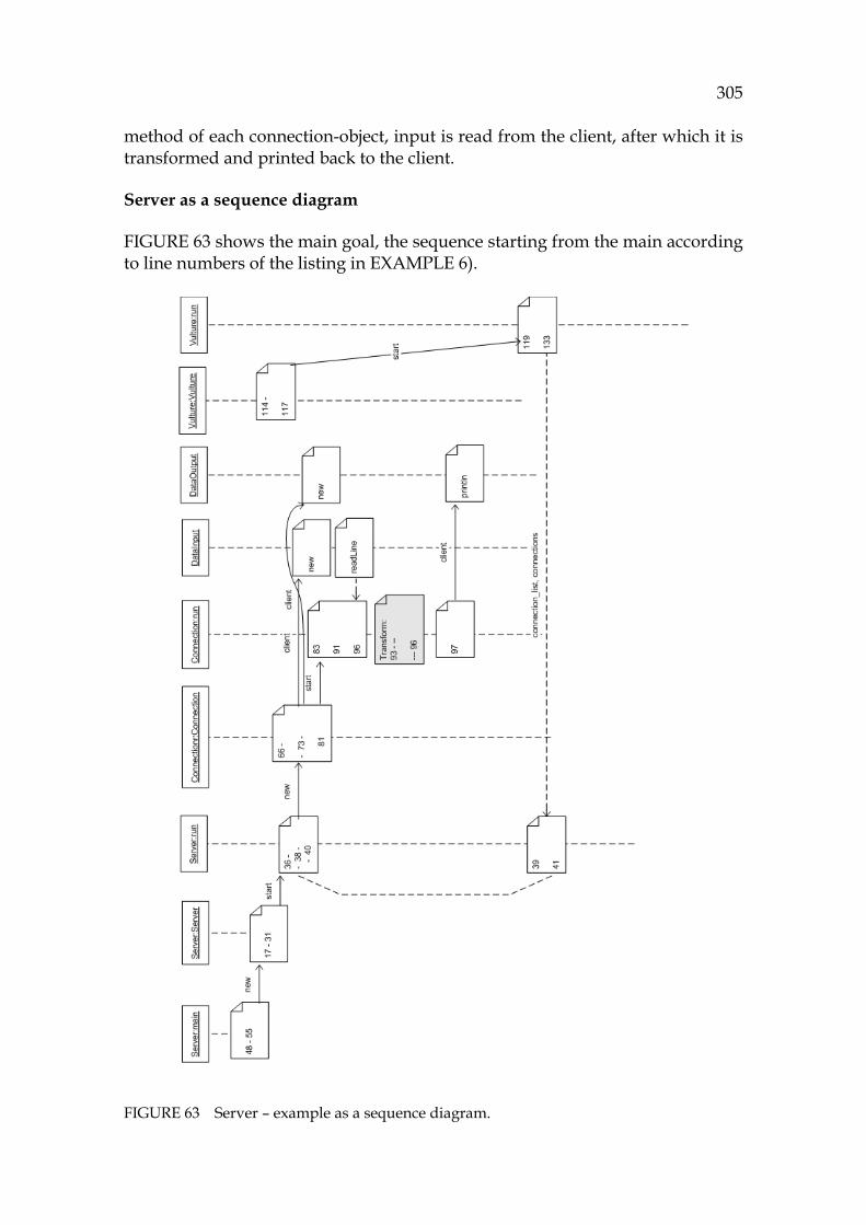
305
method of each connection-object, input is read from the client, after which it is transformed and printed back to the client.
Server as a sequence diagram
1123HFIGURE 63 shows the main goal, the sequence starting from the main according to line numbers of the listing in 1124HEXAMPLE 6).
FIGURE 63 Server – example as a sequence diagram.
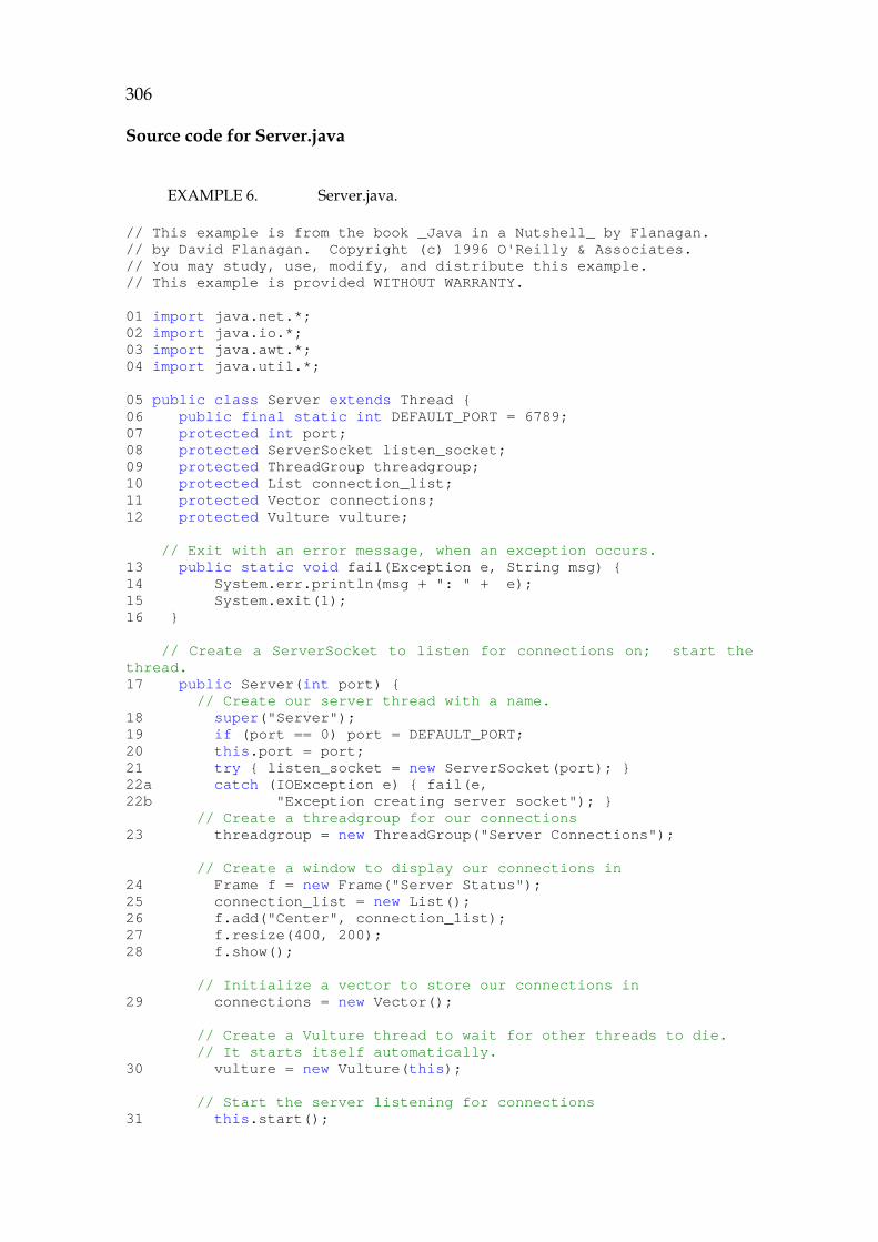
306
Source code for Server.java
EXAMPLE 6. Server.java.
// This example is from the book _Java in a Nutshell_ by Flanagan. // by David Flanagan. Copyright (c) 1996 O'Reilly & Associates. // You may study, use, modify, and distribute this example. // This example is provided WITHOUT WARRANTY. 01 import java.net.*; 02 import java.io.*; 03 import java.awt.*; 04 import java.util.*; 05 public class Server extends Thread { 06 public final static int DEFAULT_PORT = 6789; 07 protected int port; 08 protected ServerSocket listen_socket; 09 protected ThreadGroup threadgroup; 10 protected List connection_list; 11 protected Vector connections; 12 protected Vulture vulture; // Exit with an error message, when an exception occurs. 13 public static void fail(Exception e, String msg) { 14 System.err.println(msg + ": " + e); 15 System.exit(1); 16 } // Create a ServerSocket to listen for connections on; start the thread. 17 public Server(int port) { // Create our server thread with a name. 18 super("Server"); 19 if (port == 0) port = DEFAULT_PORT; 20 this.port = port; 21 try { listen_socket = new ServerSocket(port); } 22a catch (IOException e) { fail(e, 22b "Exception creating server socket"); } // Create a threadgroup for our connections 23 threadgroup = new ThreadGroup("Server Connections"); // Create a window to display our connections in 24 Frame f = new Frame("Server Status"); 25 connection_list = new List(); 26 f.add("Center", connection_list); 27 f.resize(400, 200); 28 f.show(); // Initialize a vector to store our connections in 29 connections = new Vector(); // Create a Vulture thread to wait for other threads to die. // It starts itself automatically. 30 vulture = new Vulture(this); // Start the server listening for connections 31 this.start();
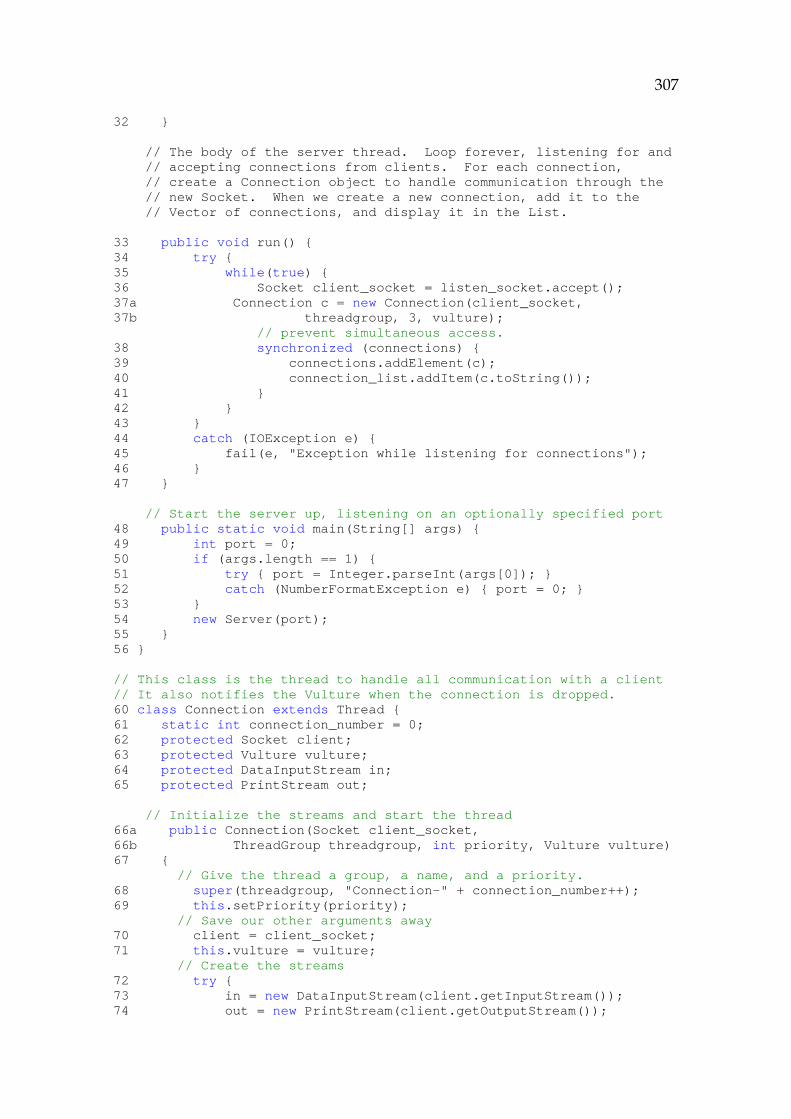
307
32 } // The body of the server thread. Loop forever, listening for and // accepting connections from clients. For each connection, // create a Connection object to handle communication through the // new Socket. When we create a new connection, add it to the // Vector of connections, and display it in the List. 33 public void run() { 34 try { 35 while(true) { 36 Socket client_socket = listen_socket.accept(); 37a Connection c = new Connection(client_socket, 37b threadgroup, 3, vulture); // prevent simultaneous access. 38 synchronized (connections) { 39 connections.addElement(c); 40 connection_list.addItem(c.toString()); 41 } 42 } 43 } 44 catch (IOException e) { 45 fail(e, "Exception while listening for connections"); 46 } 47 } // Start the server up, listening on an optionally specified port 48 public static void main(String[] args) { 49 int port = 0; 50 if (args.length == 1) { 51 try { port = Integer.parseInt(args[0]); } 52 catch (NumberFormatException e) { port = 0; } 53 } 54 new Server(port); 55 } 56 } // This class is the thread to handle all communication with a client // It also notifies the Vulture when the connection is dropped. 60 class Connection extends Thread { 61 static int connection_number = 0; 62 protected Socket client; 63 protected Vulture vulture; 64 protected DataInputStream in; 65 protected PrintStream out; // Initialize the streams and start the thread 66a public Connection(Socket client_socket, 66b ThreadGroup threadgroup, int priority, Vulture vulture) 67 { // Give the thread a group, a name, and a priority. 68 super(threadgroup, "Connection-" + connection_number++); 69 this.setPriority(priority); // Save our other arguments away 70 client = client_socket; 71 this.vulture = vulture; // Create the streams 72 try { 73 in = new DataInputStream(client.getInputStream()); 74 out = new PrintStream(client.getOutputStream());
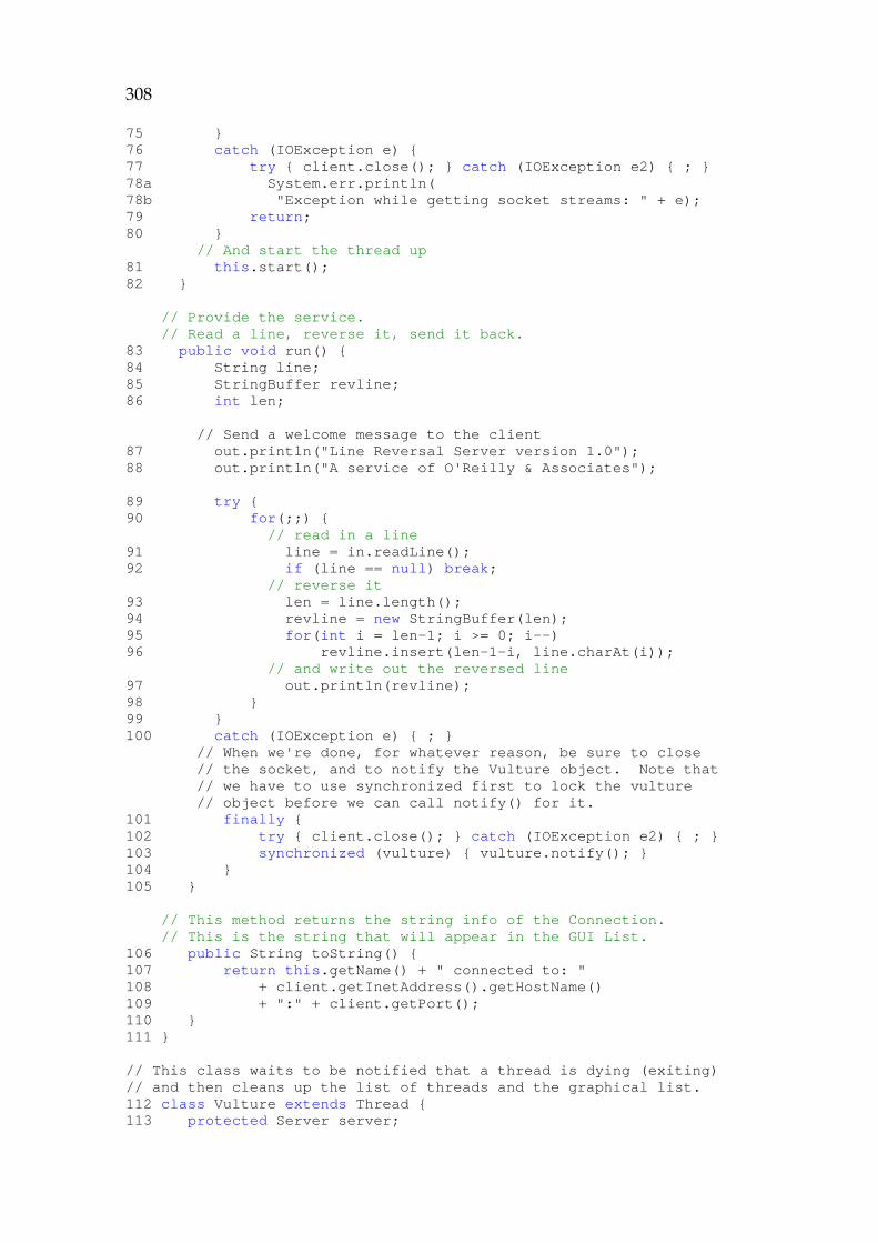
308
75 } 76 catch (IOException e) { 77 try { client.close(); } catch (IOException e2) { ; } 78a System.err.println( 78b "Exception while getting socket streams: " + e); 79 return; 80 } // And start the thread up 81 this.start(); 82 } // Provide the service. // Read a line, reverse it, send it back. 83 public void run() { 84 String line; 85 StringBuffer revline; 86 int len; // Send a welcome message to the client 87 out.println("Line Reversal Server version 1.0"); 88 out.println("A service of O'Reilly & Associates"); 89 try { 90 for(;;) { // read in a line 91 line = in.readLine(); 92 if (line == null) break; // reverse it 93 len = line.length(); 94 revline = new StringBuffer(len); 95 for(int i = len-1; i >= 0; i--) 96 revline.insert(len-1-i, line.charAt(i)); // and write out the reversed line 97 out.println(revline); 98 } 99 } 100 catch (IOException e) { ; } // When we're done, for whatever reason, be sure to close // the socket, and to notify the Vulture object. Note that // we have to use synchronized first to lock the vulture // object before we can call notify() for it. 101 finally { 102 try { client.close(); } catch (IOException e2) { ; } 103 synchronized (vulture) { vulture.notify(); } 104 } 105 } // This method returns the string info of the Connection. // This is the string that will appear in the GUI List. 106 public String toString() { 107 return this.getName() + " connected to: " 108 + client.getInetAddress().getHostName() 109 + ":" + client.getPort(); 110 } 111 } // This class waits to be notified that a thread is dying (exiting) // and then cleans up the list of threads and the graphical list. 112 class Vulture extends Thread { 113 protected Server server;
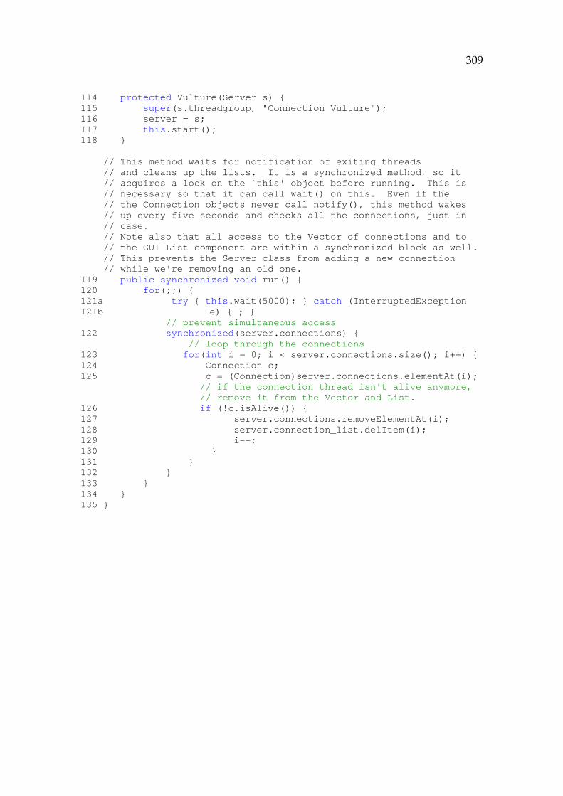
309
114 protected Vulture(Server s) { 115 super(s.threadgroup, "Connection Vulture"); 116 server = s; 117 this.start(); 118 } // This method waits for notification of exiting threads // and cleans up the lists. It is a synchronized method, so it // acquires a lock on the `this' object before running. This is // necessary so that it can call wait() on this. Even if the // the Connection objects never call notify(), this method wakes // up every five seconds and checks all the connections, just in // case. // Note also that all access to the Vector of connections and to // the GUI List component are within a synchronized block as well. // This prevents the Server class from adding a new connection // while we're removing an old one. 119 public synchronized void run() { 120 for(;;) { 121a try { this.wait(5000); } catch (InterruptedException 121b e) { ; } // prevent simultaneous access 122 synchronized(server.connections) { // loop through the connections 123 for(int i = 0; i < server.connections.size(); i++) { 124 Connection c; 125 c = (Connection)server.connections.elementAt(i); // if the connection thread isn't alive anymore, // remove it from the Vector and List. 126 if (!c.isAlive()) { 127 server.connections.removeElementAt(i); 128 server.connection_list.delItem(i); 129 i--; 130 } 131 } 132 } 133 } 134 } 135 }
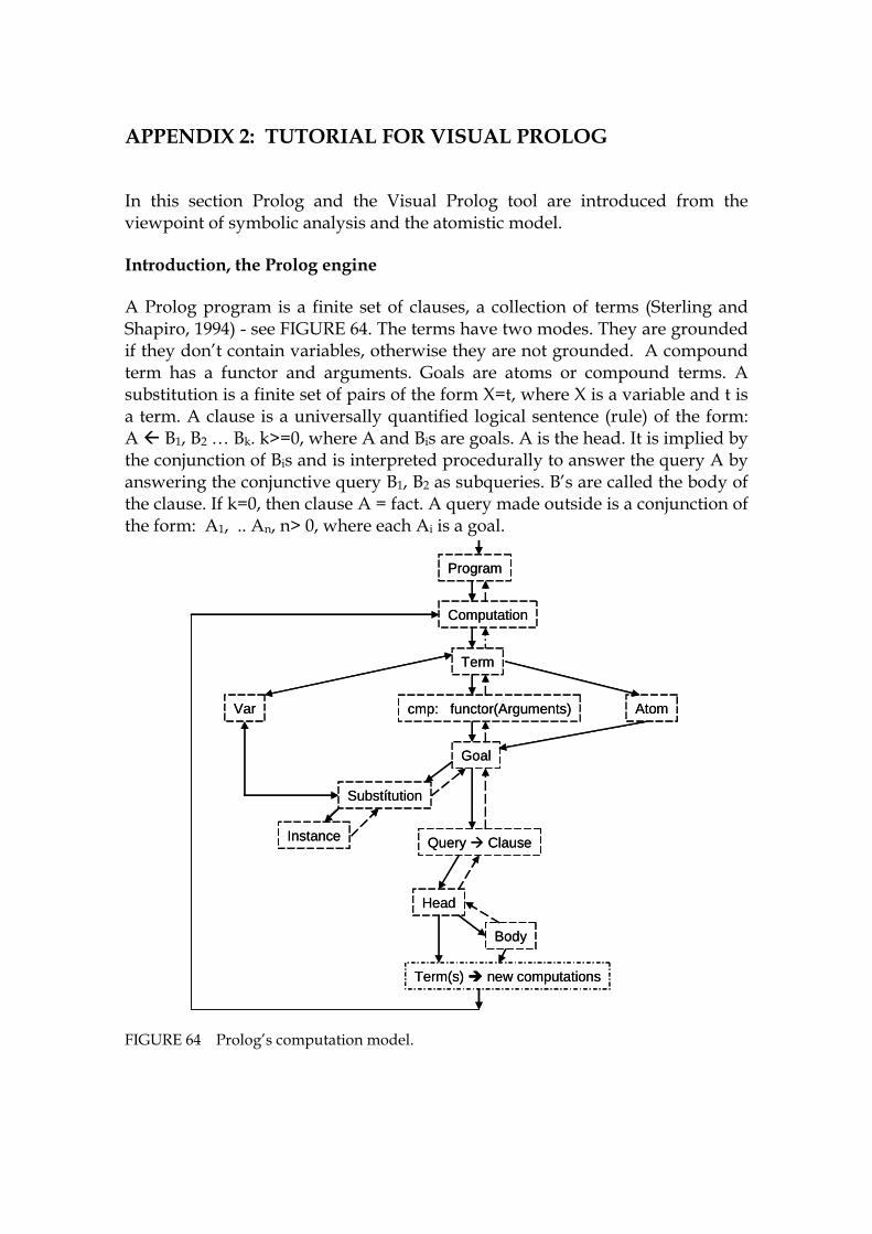
310
APPENDIX 2: TUTORIAL FOR VISUAL PROLOG
In this section Prolog and the Visual Prolog tool are introduced from the viewpoint of symbolic analysis and the atomistic model.
Introduction, the Prolog engine
A Prolog program is a finite set of clauses, a collection of terms (Sterling and Shapiro, 1994) - see 1125HFIGURE 64. The terms have two modes. They are grounded if they don’t contain variables, otherwise they are not grounded. A compound term has a functor and arguments. Goals are atoms or compound terms. A substitution is a finite set of pairs of the form X=t, where X is a variable and t is a term. A clause is a universally quantified logical sentence (rule) of the form: A B1, B2 … Bk. k>=0, where A and Bis are goals. A is the head. It is implied by the conjunction of Bis and is interpreted procedurally to answer the query A by answering the conjunctive query B1, B2 as subqueries. B’s are called the body of the clause. If k=0, then clause A = fact. A query made outside is a conjunction of the form: A1, .. An, n> 0, where each Ai is a goal.
FIGURE 64 Prolog’s computation model.
Computation
Program
AtomVar
Term
cmp: functor(Arguments)
Substítution
Query Clause
Goal
Head
Body
Instance
Term(s) new computations
Computation
Program
AtomVar
Term
cmp: functor(Arguments)
Substítution
Query Clause
Goal
Head
Body
Instance
Term(s) new computations
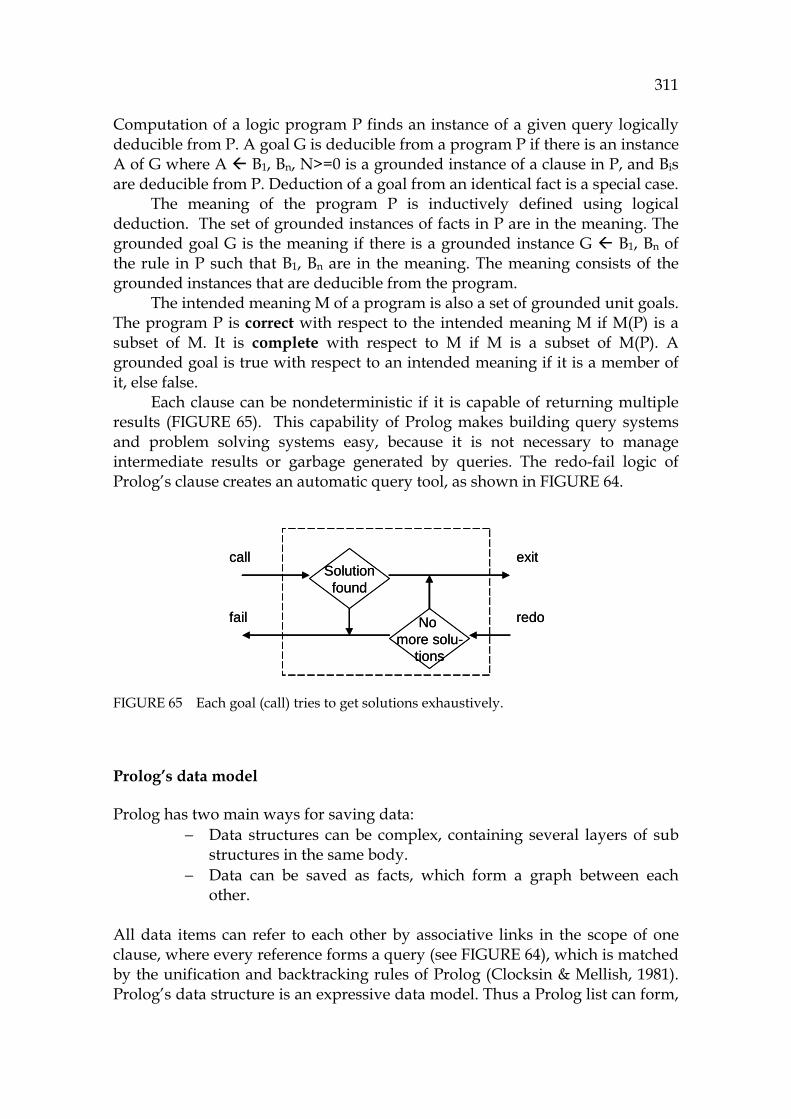
311
Computation of a logic program P finds an instance of a given query logically deducible from P. A goal G is deducible from a program P if there is an instance A of G where A B1, Bn, N>=0 is a grounded instance of a clause in P, and Bis are deducible from P. Deduction of a goal from an identical fact is a special case.
The meaning of the program P is inductively defined using logical deduction. The set of grounded instances of facts in P are in the meaning. The grounded goal G is the meaning if there is a grounded instance G B1, Bn of the rule in P such that B1, Bn are in the meaning. The meaning consists of the grounded instances that are deducible from the program.
The intended meaning M of a program is also a set of grounded unit goals. The program P is correct with respect to the intended meaning M if M(P) is a subset of M. It is complete with respect to M if M is a subset of M(P). A grounded goal is true with respect to an intended meaning if it is a member of it, else false.
Each clause can be nondeterministic if it is capable of returning multiple results (1126HFIGURE 65). This capability of Prolog makes building query systems and problem solving systems easy, because it is not necessary to manage intermediate results or garbage generated by queries. The redo-fail logic of Prolog’s clause creates an automatic query tool, as shown in 1127HFIGURE 64.
FIGURE 65 Each goal (call) tries to get solutions exhaustively.
Prolog’s data model
Prolog has two main ways for saving data: − Data structures can be complex, containing several layers of sub
structures in the same body. − Data can be saved as facts, which form a graph between each
other. All data items can refer to each other by associative links in the scope of one clause, where every reference forms a query (see 1128HFIGURE 64), which is matched by the unification and backtracking rules of Prolog (Clocksin & Mellish, 1981). Prolog’s data structure is an expressive data model. Thus a Prolog list can form,
Solutionfound
No more solu-
tions
call
fail
exit
redo
Solutionfound
No more solu-
tions
call
fail
exit
redo
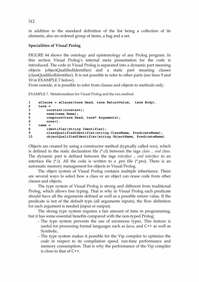
312
in addition to the standard definition of the list being a collection of its elements, also an ordered group of items, a bag and a set.
Specialities of Visual Prolog
1129HFIGURE 64 shows the ontology and epistemology of any Prolog program. In this section Visual Prolog’s internal meta presentation for the code is introduced. The code in Visual Prolog is separated into a dynamic part meaning objects (objectQualifiedIdentifier) and a static part meaning classes (classQualifiedIdentifier). It is not possible to refer to other parts (see lines 9 and 10 in 1130HEXAMPLE 7 below). From outside, it is possible to refer from classes and objects to methods only.
EXAMPLE 7. Metaformalism for Visual Prolog and the run method.
1 aClause = aClause(term Head, term ReturnValue, term Body). 2 term = 3 constant(constant); 4 name(name Name); 5 compound(term Head, term* Arguments); 6 none(). 7 name = 8 identifier(string Identifier); 9 classQualifiedIdentifier(string ClassName, PredicateName); 10 objectQualifiedIdentifier(string ObjectName, PredicateName) Objects are created by using a constructor method (typically called new), which is defined in the static declaration file (*.cl) between the tags class .. end class. The dynamic part is defined between the tags interface .. end interface in an interface file (*.i). All the code is written to a .pro file (*.pro). There is an automatic memory management for objects in Visual Prolog.
The object system of Visual Prolog contains multiple inheritance. There are several ways to select how a class or an object can reuse code from other classes and objects.
The type system of Visual Prolog is strong and different from traditional Prolog, which allows free typing. That is why in Visual Prolog each predicate should have all the arguments defined as well as a possible return value. If the predicate is not of the default type (all arguments inputs), the flow definition for each argument is needed (input or output).
The strong type system requires a fair amount of time in programming, but it has some essential benefits compared with the non-typed Prolog:
- The type system prevents the use of erroneous types. This feature is useful for processing formal languages such as Java, and C++ as well as Symbolic.
- The type system makes it possible for the Vip compiler to optimize the code in respect to its compilation speed, run-time performance and memory consumption. That is why the performance of the Vip compiler is close to that of C++.
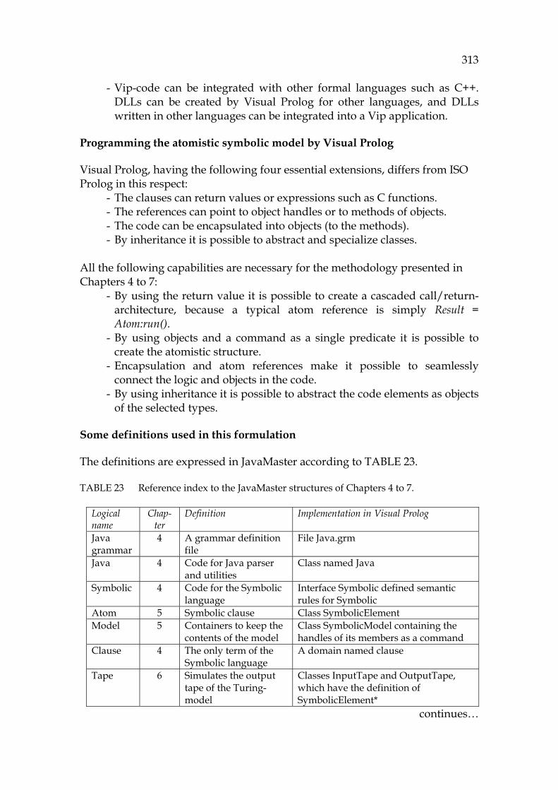
313
- Vip-code can be integrated with other formal languages such as C++. DLLs can be created by Visual Prolog for other languages, and DLLs written in other languages can be integrated into a Vip application.
Programming the atomistic symbolic model by Visual Prolog
Visual Prolog, having the following four essential extensions, differs from ISO Prolog in this respect:
- The clauses can return values or expressions such as C functions. - The references can point to object handles or to methods of objects. - The code can be encapsulated into objects (to the methods). - By inheritance it is possible to abstract and specialize classes.
All the following capabilities are necessary for the methodology presented in Chapters 4 to 7:
- By using the return value it is possible to create a cascaded call/return-architecture, because a typical atom reference is simply Result = Atom:run().
- By using objects and a command as a single predicate it is possible to create the atomistic structure.
- Encapsulation and atom references make it possible to seamlessly connect the logic and objects in the code.
- By using inheritance it is possible to abstract the code elements as objects of the selected types.
Some definitions used in this formulation
The definitions are expressed in JavaMaster according to 1131HTABLE 23.
TABLE 23 Reference index to the JavaMaster structures of Chapters 4 to 7.
Logical name
Chap-ter
Definition Implementation in Visual Prolog
Java grammar
4 A grammar definition file
File Java.grm
Java 4 Code for Java parser and utilities
Class named Java
Symbolic 4 Code for the Symbolic language
Interface Symbolic defined semantic rules for Symbolic
Atom 5 Symbolic clause Class SymbolicElement Model 5 Containers to keep the
contents of the model Class SymbolicModel containing the handles of its members as a command
Clause 4 The only term of the Symbolic language
A domain named clause
Tape 6 Simulates the output tape of the Turing-model
Classes InputTape and OutputTape, which have the definition of SymbolicElement*
continues…
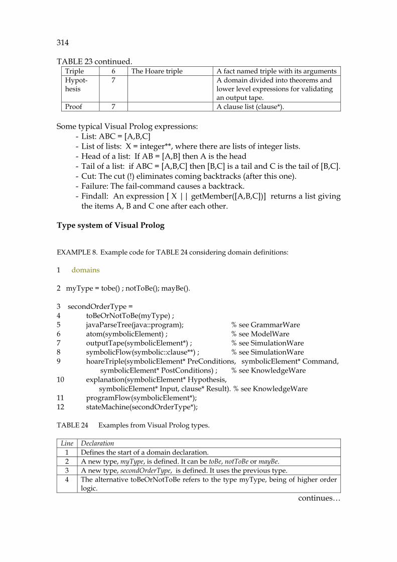
314
1132HTABLE 23 continued. Triple 6 The Hoare triple A fact named triple with its argumentsHypot-hesis
7 A domain divided into theorems and lower level expressions for validating an output tape.
Proof 7 A clause list (clause*). Some typical Visual Prolog expressions:
- List: ABC = [A,B,C] - List of lists: X = integer**, where there are lists of integer lists. - Head of a list: If AB = [A,B] then A is the head - Tail of a list: if ABC = [A,B,C] then [B,C] is a tail and C is the tail of [B,C]. - Cut: The cut (!) eliminates coming backtracks (after this one). - Failure: The fail-command causes a backtrack. - Findall: An expression [ X || getMember([A,B,C])] returns a list giving
the items A, B and C one after each other.
Type system of Visual Prolog
EXAMPLE 8. Example code for 1133HTABLE 24 considering domain definitions:
1 domains 2 myType = tobe() ; notToBe(); mayBe(). 3 secondOrderType = 4 toBeOrNotToBe(myType) ; 5 javaParseTree(java::program); % see GrammarWare 6 atom(symbolicElement) ; % see ModelWare 7 outputTape(symbolicElement*) ; % see SimulationWare 8 symbolicFlow(symbolic::clause**) ; % see SimulationWare 9 hoareTriple(symbolicElement* PreConditions, symbolicElement* Command, symbolicElement* PostConditions) ; % see KnowledgeWare 10 explanation(symbolicElement* Hypothesis, symbolicElement* Input, clause* Result). % see KnowledgeWare 11 programFlow(symbolicElement*); 12 stateMachine(secondOrderType*);
TABLE 24 Examples from Visual Prolog types.
Line Declaration 1 Defines the start of a domain declaration. 2 A new type, myType, is defined. It can be toBe, notToBe or mayBe. 3 A new type, secondOrderType, is defined. It uses the previous type. 4 The alternative toBeOrNotToBe refers to the type myType, being of higher order
logic. continues…
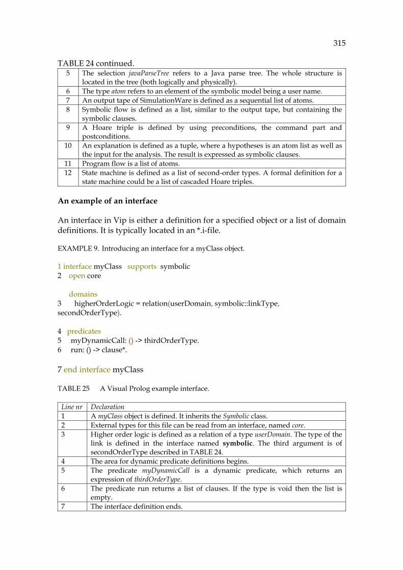
315
1134HTABLE 24 continued. 5 The selection javaParseTree refers to a Java parse tree. The whole structure is
located in the tree (both logically and physically). 6 The type atom refers to an element of the symbolic model being a user name. 7 An output tape of SimulationWare is defined as a sequential list of atoms. 8 Symbolic flow is defined as a list, similar to the output tape, but containing the
symbolic clauses. 9 A Hoare triple is defined by using preconditions, the command part and
postconditions. 10 An explanation is defined as a tuple, where a hypotheses is an atom list as well as
the input for the analysis. The result is expressed as symbolic clauses. 11 Program flow is a list of atoms. 12 State machine is defined as a list of second-order types. A formal definition for a
state machine could be a list of cascaded Hoare triples.
An example of an interface
An interface in Vip is either a definition for a specified object or a list of domain definitions. It is typically located in an *.i-file.
EXAMPLE 9. Introducing an interface for a myClass object.
1 interface myClass supports symbolic 2 open core domains 3 higherOrderLogic = relation(userDomain, symbolic::linkType, secondOrderType). 4 predicates 5 myDynamicCall: () -> thirdOrderType. 6 run: () -> clause*. 7 end interface myClass
TABLE 25 A Visual Prolog example interface.
Line nr Declaration 1 A myClass object is defined. It inherits the Symbolic class. 2 External types for this file can be read from an interface, named core. 3 Higher order logic is defined as a relation of a type userDomain. The type of the
link is defined in the interface named symbolic. The third argument is of secondOrderType described in 1135HTABLE 24.
4 The area for dynamic predicate definitions begins. 5 The predicate myDynamicCall is a dynamic predicate, which returns an
expression of thirdOrderType. 6 The predicate run returns a list of clauses. If the type is void then the list is
empty. 7 The interface definition ends.
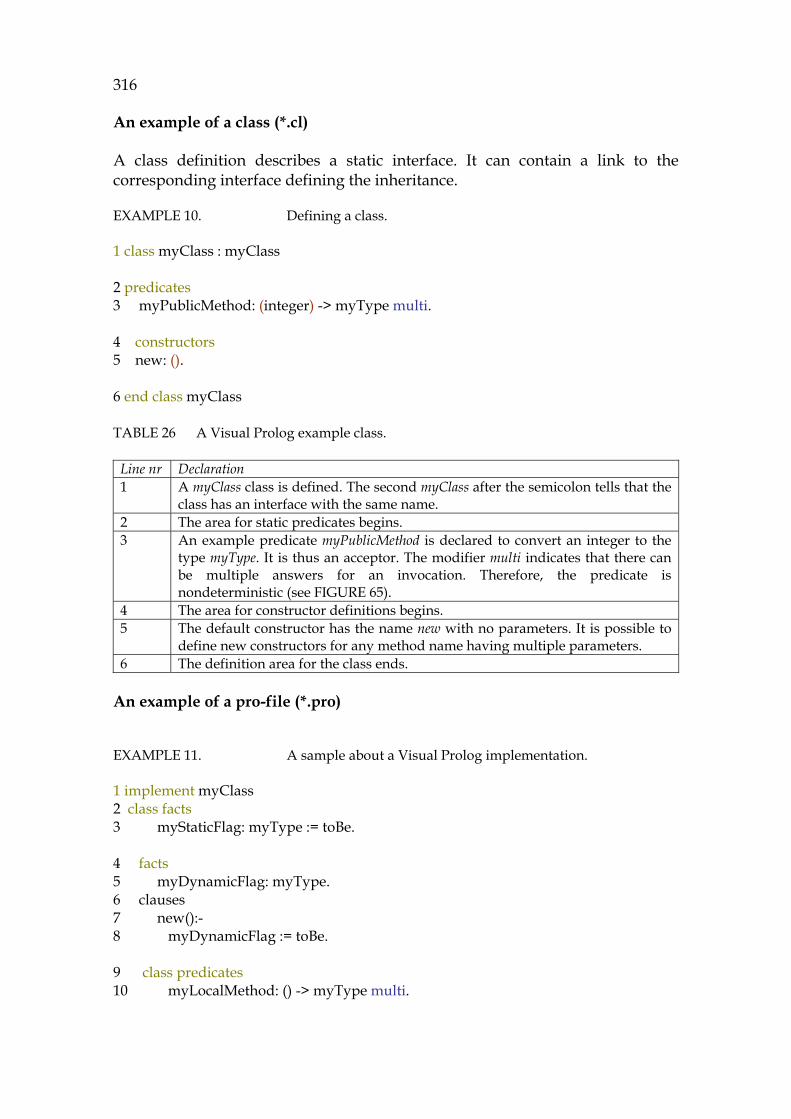
316
An example of a class (*.cl)
A class definition describes a static interface. It can contain a link to the corresponding interface defining the inheritance.
EXAMPLE 10. Defining a class.
1 class myClass : myClass 2 predicates 3 myPublicMethod: (integer) -> myType multi. 4 constructors 5 new: (). 6 end class myClass
TABLE 26 A Visual Prolog example class.
Line nr Declaration 1 A myClass class is defined. The second myClass after the semicolon tells that the
class has an interface with the same name. 2 The area for static predicates begins. 3 An example predicate myPublicMethod is declared to convert an integer to the
type myType. It is thus an acceptor. The modifier multi indicates that there can be multiple answers for an invocation. Therefore, the predicate is nondeterministic (see 1136HFIGURE 65).
4 The area for constructor definitions begins. 5 The default constructor has the name new with no parameters. It is possible to
define new constructors for any method name having multiple parameters. 6 The definition area for the class ends.
An example of a pro-file (*.pro)
EXAMPLE 11. A sample about a Visual Prolog implementation.
1 implement myClass 2 class facts 3 myStaticFlag: myType := toBe. 4 facts 5 myDynamicFlag: myType. 6 clauses 7 new():- 8 myDynamicFlag := toBe. 9 class predicates 10 myLocalMethod: () -> myType multi.

317
11 clauses 12 myPublicMethod(0) = toBe. 13 myPublicMethod(1) = notToBe. 14 myPublicMethod(_) = mayBe. 15 myLocalMethod() = myStaticFlag:- 16 not(isErroneous(myStaticFlag)), !. 17 myLocalMethod() = myPublicMethod(0). 18 myDynamicCall() = typeOf(SecondOrderType):- 19 SecondOrderType = clauseList([symbolic::info("This returns Symbolic info")]). 20 end implement myClass
TABLE 27 A Visual Prolog code file.
Line nr Declaration 1 The implementation area for the class begins. 2 Static attributes, e.g., facts, are defined after these keywords. 3 The fact myStaticFlag has the type myType. Its default value is toBe. 4 Dynamic facts are defined after these keywords. 5 The fact myDynamicFlag has the type toBe. It doesn’t have a default value (it is
given in the constructor). 6 The code area begins by clauses. 7 The constructor new begins. 8 In the constructor a flag myDynamicFlag is set to toBe. 9 Local static predicates are defined after these keywords. 10 The predicate myLocalMethod has no input parameters. It returns an
expression of the type myType, being nondeterministic. 11 The code begins. 12 The first clause (rule) for myPublicMethod, which returns the value toBe for an
argument 0. 13 The second clause (rule) for myPublicMethod, which returns the value notToBe
for 1. 14 The third clause returns the value maybe. However, it is necessary to notice,
that in the previous situations (lines 12 and 13) the predicate myPublicMethod also returns the value mayBe, because there is no cut (!) ending these clauses.
15 The local predicate myLocalMethod returns the value myStaticFlag in cases when its body succeeds (see next line).
16 Here it is tested whether the fact myStaticFlag has a value or not. The cut (!) ends any resolution to this clause, which prevents the later clauses (line 17) to be executed.
17 If the previous clause didn’t succeed, this predicate returns a value by calling directly the predicate myPublicMethod with the argument value 0.
18 The predicate myDynamicCall returns a third order type by converting a variable of the second order type, SecondOrderType, with a domain named typeOf.
19 An input for the variable SecondOrderType is generated by a clause-list, which contains one info-string.
20 The definition for the code of the class myClass ends.

318
Some examples about Visual Prolog data structures
A list is an ordered set of items. This allows querying the contents of an output tape in multiple ways. If the output tape has three items, it can be queried by OutputTape = [Atom1, Atom2, Atom3]. It is functionally the same as [Atom1|Atom2, Atom3] or [Atom1|[Atom2|Atom3]]. The findall function to gather members for a list can be expreessed as follows (it is assumed that the members can be fetched by the method getObject: List = [ X = || getObject(X) ]. Its older notation is findall(X, getObject(X), List).
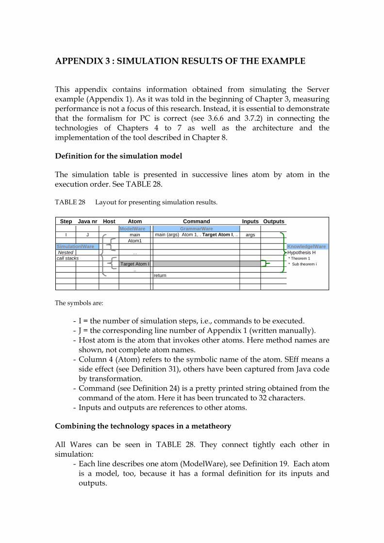
319
APPENDIX 3 : SIMULATION RESULTS OF THE EXAMPLE
This appendix contains information obtained from simulating the Server example (Appendix 1). As it was told in the beginning of Chapter 3, measuring performance is not a focus of this research. Instead, it is essential to demonstrate that the formalism for PC is correct (see 1137H3.6.6 and 1138H3.7.2) in connecting the technologies of Chapters 4 to 7 as well as the architecture and the implementation of the tool described in Chapter 8.
Definition for the simulation model
The simulation table is presented in successive lines atom by atom in the execution order. See 1139HTABLE 28.
TABLE 28 Layout for presenting simulation results.
The symbols are:
- I = the number of simulation steps, i.e., commands to be executed. - J = the corresponding line number of Appendix 1 (written manually). - Host atom is the atom that invokes other atoms. Here method names are
shown, not complete atom names. - Column 4 (Atom) refers to the symbolic name of the atom. SEff means a
side effect (see 1140HDefinition 31), others have been captured from Java code by transformation.
- Command (see 1141HDefinition 24) is a pretty printed string obtained from the command of the atom. Here it has been truncated to 32 characters.
- Inputs and outputs are references to other atoms.
Combining the technology spaces in a metatheory
All Wares can be seen in 1142HTABLE 28. They connect tightly each other in simulation:
- Each line describes one atom (ModelWare), see 1143HDefinition 19. Each atom is a model, too, because it has a formal definition for its inputs and outputs.
Step Java nr Host Atom Command Inputs OutputsModelWare GrammarWare
I J main main (args) Atom 1, . Target Atom I, .. argsAtom1
SimulationlWare KnowledgelWareNested … Hypothesis Hcall stacks * Theorem 1
Target Atom I * Sub theorem i..
return
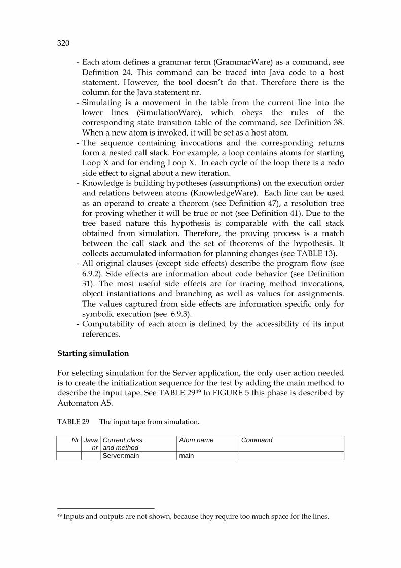
320
- Each atom defines a grammar term (GrammarWare) as a command, see 1144HDefinition 24. This command can be traced into Java code to a host statement. However, the tool doesn’t do that. Therefore there is the column for the Java statement nr.
- Simulating is a movement in the table from the current line into the lower lines (SimulationWare), which obeys the rules of the corresponding state transition table of the command, see 1145HDefinition 38. When a new atom is invoked, it will be set as a host atom.
- The sequence containing invocations and the corresponding returns form a nested call stack. For example, a loop contains atoms for starting Loop X and for ending Loop X. In each cycle of the loop there is a redo side effect to signal about a new iteration.
- Knowledge is building hypotheses (assumptions) on the execution order and relations between atoms (KnowledgeWare). Each line can be used as an operand to create a theorem (see 1146HDefinition 47), a resolution tree for proving whether it will be true or not (see 1147HDefinition 41). Due to the tree based nature this hypothesis is comparable with the call stack obtained from simulation. Therefore, the proving process is a match between the call stack and the set of theorems of the hypothesis. It collects accumulated information for planning changes (see 1148HTABLE 13).
- All original clauses (except side effects) describe the program flow (see 1149H6.9.2). Side effects are information about code behavior (see 1150HDefinition 31). The most useful side effects are for tracing method invocations, object instantiations and branching as well as values for assignments. The values captured from side effects are information specific only for symbolic execution (see 1151H6.9.3).
- Computability of each atom is defined by the accessibility of its input references.
Starting simulation
For selecting simulation for the Server application, the only user action needed is to create the initialization sequence for the test by adding the main method to describe the input tape. See 1152HTABLE 2948F
49 In 1153HFIGURE 5 this phase is described by Automaton A5.
TABLE 29 The input tape from simulation.
Nr Java nr
Current class and method
Atom name
Command
Server:main main
49 Inputs and outputs are not shown, because they require too much space for the lines.
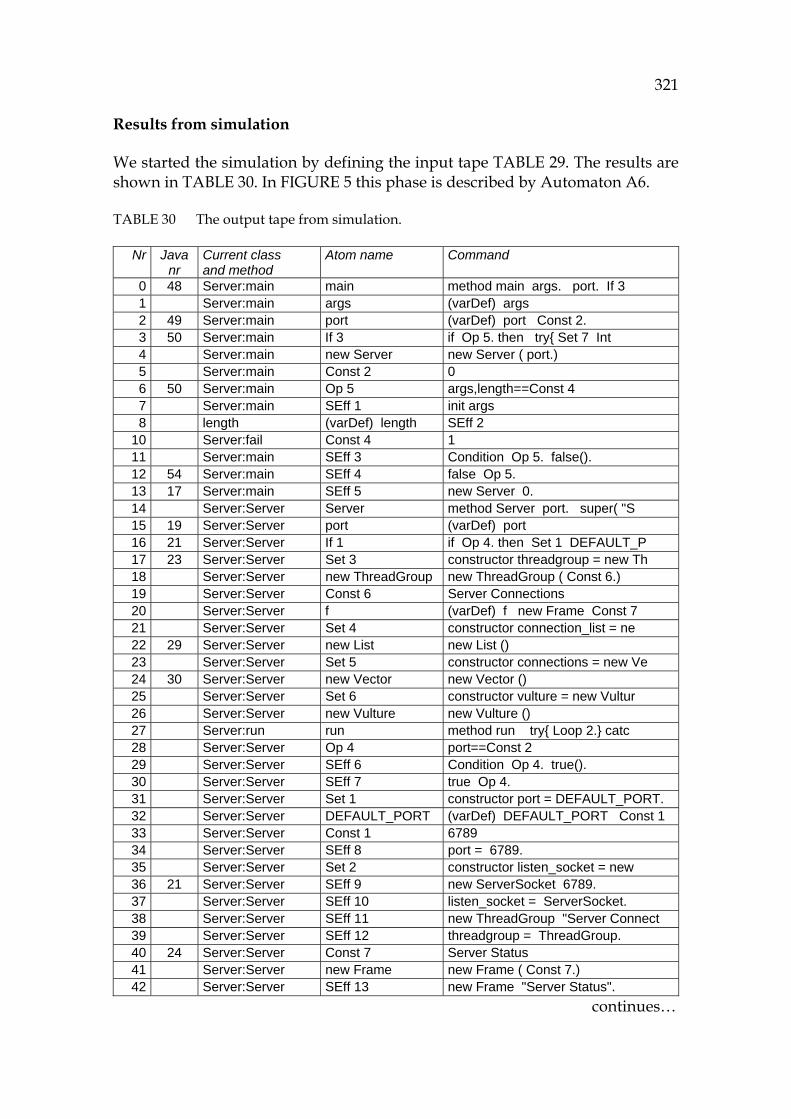
321
Results from simulation
We started the simulation by defining the input tape 1154HTABLE 29. The results are shown in 1155HTABLE 30. In 1156HFIGURE 5 this phase is described by Automaton A6.
TABLE 30 The output tape from simulation.
Nr Java nr
Current class and method
Atom name
Command
0 48 Server:main main method main args. port. If 3 1 Server:main args (varDef) args 2 49 Server:main port (varDef) port Const 2. 3 50 Server:main If 3 if Op 5. then try{ Set 7 Int 4 Server:main new Server new Server ( port.) 5 Server:main Const 2 0 6 50 Server:main Op 5 args,length==Const 4 7 Server:main SEff 1 init args 8 length (varDef) length SEff 2
10 Server:fail Const 4 1 11 Server:main SEff 3 Condition Op 5. false(). 12 54 Server:main SEff 4 false Op 5. 13 17 Server:main SEff 5 new Server 0. 14 Server:Server Server method Server port. super( "S 15 19 Server:Server port (varDef) port 16 21 Server:Server If 1 if Op 4. then Set 1 DEFAULT_P 17 23 Server:Server Set 3 constructor threadgroup = new Th 18 Server:Server new ThreadGroup new ThreadGroup ( Const 6.) 19 Server:Server Const 6 Server Connections 20 Server:Server f (varDef) f new Frame Const 7 21 Server:Server Set 4 constructor connection_list = ne 22 29 Server:Server new List new List () 23 Server:Server Set 5 constructor connections = new Ve 24 30 Server:Server new Vector new Vector () 25 Server:Server Set 6 constructor vulture = new Vultur 26 Server:Server new Vulture new Vulture () 27 Server:run run method run try{ Loop 2.} catc 28 Server:Server Op 4 port==Const 2 29 Server:Server SEff 6 Condition Op 4. true(). 30 Server:Server SEff 7 true Op 4. 31 Server:Server Set 1 constructor port = DEFAULT_PORT. 32 Server:Server DEFAULT_PORT (varDef) DEFAULT_PORT Const 1 33 Server:Server Const 1 6789 34 Server:Server SEff 8 port = 6789. 35 Server:Server Set 2 constructor listen_socket = new 36 21 Server:Server SEff 9 new ServerSocket 6789. 37 Server:Server SEff 10 listen_socket = ServerSocket. 38 Server:Server SEff 11 new ThreadGroup "Server Connect 39 Server:Server SEff 12 threadgroup = ThreadGroup. 40 24 Server:Server Const 7 Server Status 41 Server:Server new Frame new Frame ( Const 7.) 42 Server:Server SEff 13 new Frame "Server Status".
continues…
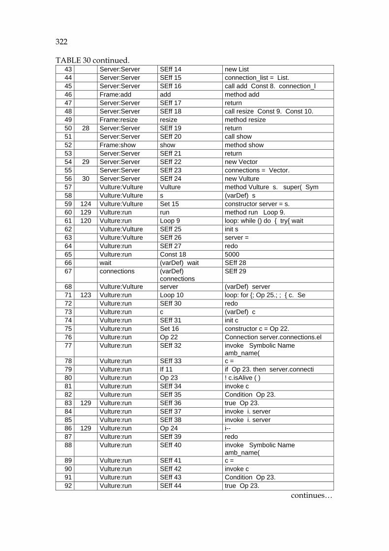
322
1157HTABLE 30 continued. 43 Server:Server SEff 14 new List 44 Server:Server SEff 15 connection_list = List. 45 Server:Server SEff 16 call add Const 8. connection_l 46 Frame:add add method add 47 Server:Server SEff 17 return 48 Server:Server SEff 18 call resize Const 9. Const 10. 49 Frame:resize resize method resize 50 28 Server:Server SEff 19 return 51 Server:Server SEff 20 call show 52 Frame:show show method show 53 Server:Server SEff 21 return 54 29 Server:Server SEff 22 new Vector 55 Server:Server SEff 23 connections = Vector. 56 30 Server:Server SEff 24 new Vulture 57 Vulture:Vulture Vulture method Vulture s. super( Sym 58 Vulture:Vulture s (varDef) s 59 124 Vulture:Vulture Set 15 constructor server = s. 60 129 Vulture:run run method run Loop 9. 61 120 Vulture:run Loop 9 loop: while () do { try{ wait 62 Vulture:Vulture SEff 25 init s 63 Vulture:Vulture SEff 26 server = 64 Vulture:run SEff 27 redo 65 Vulture:run Const 18 5000 66 wait (varDef) wait SEff 28 67 connections (varDef)
connections SEff 29
68 Vulture:Vulture server (varDef) server 71 123 Vulture:run Loop 10 loop: for {; Op 25.; ; { c. Se 72 Vulture:run SEff 30 redo 73 Vulture:run c (varDef) c 74 Vulture:run SEff 31 init c 75 Vulture:run Set 16 constructor c = Op 22. 76 Vulture:run Op 22 Connection server.connections.el 77 Vulture:run SEff 32 invoke Symbolic Name
amb_name( 78 Vulture:run SEff 33 c = 79 Vulture:run If 11 if Op 23. then server.connecti 80 Vulture:run Op 23 ! c.isAlive ( ) 81 Vulture:run SEff 34 invoke c 82 Vulture:run SEff 35 Condition Op 23. 83 129 Vulture:run SEff 36 true Op 23. 84 Vulture:run SEff 37 invoke i. server 85 Vulture:run SEff 38 invoke i. server 86 129 Vulture:run Op 24 i-- 87 Vulture:run SEff 39 redo 88 Vulture:run SEff 40 invoke Symbolic Name
amb_name( 89 Vulture:run SEff 41 c = 90 Vulture:run SEff 42 invoke c 91 Vulture:run SEff 43 Condition Op 23. 92 Vulture:run SEff 44 true Op 23.
continues…

323
1158HTABLE 30 continued. 93 Vulture:run SEff 45 invoke i. server 94 Vulture:run SEff 46 invoke i. server 95 Vulture:run SEff 47 control(toolbreak()) 96 Vulture:run SEff 48 end of Loop 10 97 Vulture:run SEff 49 redo 98 Vulture:run SEff 50 redo 99 Vulture:run SEff 51 invoke
100 Vulture:run SEff 52 c = 101 Vulture:run SEff 53 invoke c 102 Vulture:run SEff 54 Condition Op 23. 103 Vulture:run SEff 55 true Op 23. 104 Vulture:run SEff 56 invoke i. server 105 Vulture:run SEff 57 invoke i. server 106 Vulture:run SEff 58 redo 107 Vulture:run SEff 59 invoke 108 Vulture:run SEff 60 c = 109 Vulture:run SEff 61 invoke c 110 Vulture:run SEff 62 Condition Op 23. 111 Vulture:run SEff 63 true Op 23. 112 Vulture:run SEff 64 invoke i. server 113 Vulture:run SEff 65 invoke i. server 114 Vulture:run SEff 66 control(toolbreak()) 115 30 Vulture:run SEff 67 end of Loop 10 116 Vulture:run SEff 68 control(toolbreak()) 117 36 Vulture:run SEff 69 end of Loop 9 118 Server:Server SEff 70 vulture = Vulture. 119 Server:run Loop 2 loop: while ( Const 4.) do { cl 120 36 Server:run client_socket (varDef) client_socket invoke 121 Server:run c (varDef) c new Connection cl 122 Server:run SEff 71 redo Const 4. 1. 123 37 Server:run SEff 72 call accept 124 ServerSocket:
accept accept method accept
125 Server:run SEff 73 return 126 Server:run new Connection new Connection ( client_socket. 127 Server:Server threadgroup (varDef) threadgroup 128 Server:run Const 11 3 129 Server:Server vulture (varDef) vulture 130 Server:run SEff 74 new Connection ThreadGroup. 3. 131 66 Connection:
Connection Connection method Connection client_socket
132 Connection: Connection
client_socket (varDef) client_socket
133 Connection: Connection
threadgroup (varDef) threadgroup
134 Connection: Connection
priority (varDef) priority
135 Connection: Connection
vulture (varDef) vulture
136 Connection: Conn. setPriority (varDef) 137 70 Connection: Conn Set 9 constructor client = client_sock
continues…
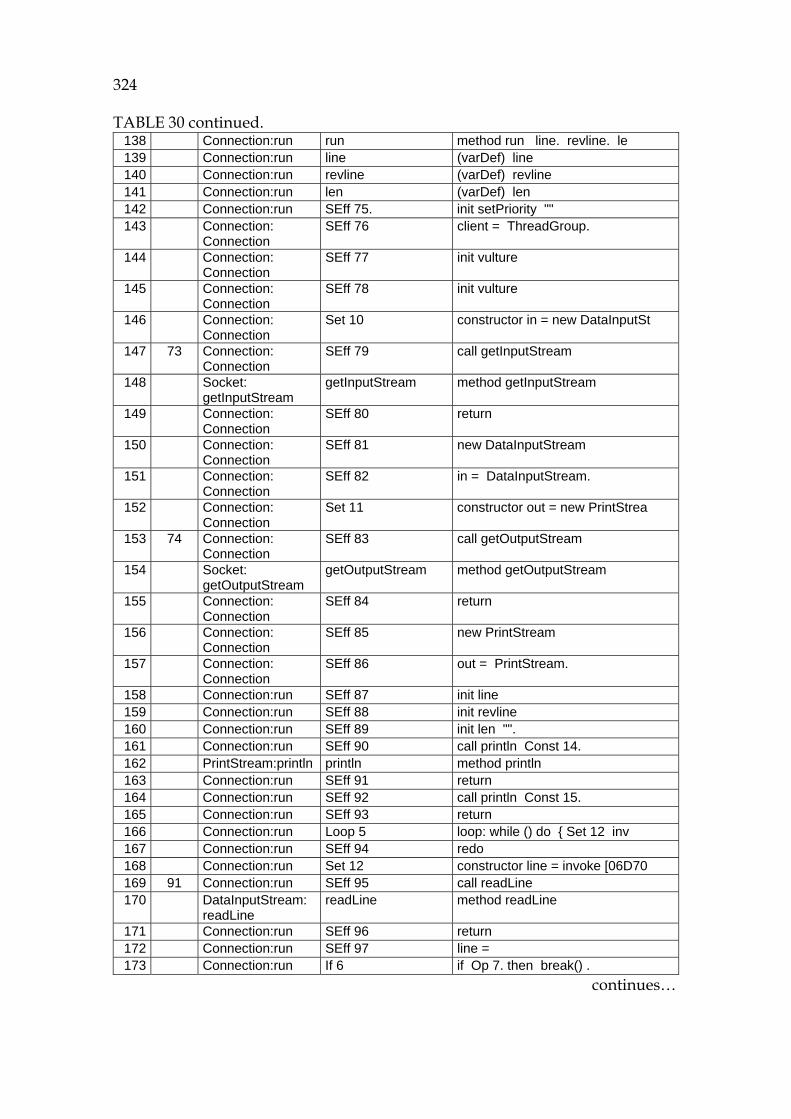
324
1159HTABLE 30 continued. 138 Connection:run run method run line. revline. le 139 Connection:run line (varDef) line 140 Connection:run revline (varDef) revline 141 Connection:run len (varDef) len 142 Connection:run SEff 75. init setPriority "" 143 Connection:
Connection SEff 76 client = ThreadGroup.
144 Connection: Connection
SEff 77 init vulture
145 Connection: Connection
SEff 78 init vulture
146 Connection: Connection
Set 10 constructor in = new DataInputSt
147 73 Connection: Connection
SEff 79 call getInputStream
148 Socket: getInputStream
getInputStream method getInputStream
149 Connection: Connection
SEff 80 return
150 Connection: Connection
SEff 81 new DataInputStream
151 Connection: Connection
SEff 82 in = DataInputStream.
152 Connection: Connection
Set 11 constructor out = new PrintStrea
153 74 Connection: Connection
SEff 83 call getOutputStream
154 Socket: getOutputStream
getOutputStream method getOutputStream
155 Connection: Connection
SEff 84 return
156 Connection: Connection
SEff 85 new PrintStream
157 Connection: Connection
SEff 86 out = PrintStream.
158 Connection:run SEff 87 init line 159 Connection:run SEff 88 init revline 160 Connection:run SEff 89 init len "". 161 Connection:run SEff 90 call println Const 14. 162 PrintStream:println println method println 163 Connection:run SEff 91 return 164 Connection:run SEff 92 call println Const 15. 165 Connection:run SEff 93 return 166 Connection:run Loop 5 loop: while () do { Set 12 inv 167 Connection:run SEff 94 redo 168 Connection:run Set 12 constructor line = invoke [06D70 169 91 Connection:run SEff 95 call readLine 170 DataInputStream:
readLine readLine method readLine
171 Connection:run SEff 96 return 172 Connection:run SEff 97 line = 173 Connection:run If 6 if Op 7. then break() .
continues…

325
1160HTABLE 30 continued. 174 Connection:run Op 7 line==Const 2 175 Connection:run SEff 98 Condition Op 7. false(). 176 Connection:run SEff 99 false Op 7. 177 Connection:run Set 13 constructor len = invoke [0183CC 178 Connection:run SEff 100 call length 179 Connection:run SEff 101 return 0. 180 Connection:run SEff 102 len = 0. 181 94 Connection:run Set 14 constructor revline = new String 182 Connection:run SEff 103 new StringBuffer 0. 183 Connection:run SEff 104 revline = StringBuffer. 184 Connection:run Loop 7 loop: for {; Op 14.; ; { insert 185 Connection:run SEff 105 redo 186 Connection:run SEff 106 call insert Op 11. charAt) ( i 187 96 StringBuffer:insert insert method insert 188 Connection:run SEff 107 return 189 Connection:run SEff 108 redo 190 Connection:run SEff 109 call insert Op 11. charAt) ( i 191 Connection:run SEff 110 return 192 Connection:run SEff 111 control(toolbreak()) 193 Connection:run SEff 112 end of Loop 7 194 97 Connection:run SEff 113 call println revline. 195 Connection:run SEff 114 return 196 Connection:run SEff 115 redo 197 Connection:run SEff 116 call readLine 198 Connection:run SEff 117 return 199 Connection:run SEff 118 line = 200 Connection:run SEff 119 Condition Op 7. false(). 201 Connection:run SEff 120 false Op 7. 202 Connection:run SEff 121 call length 203 Connection:run SEff 122 return 0. 204 Connection:run SEff 123 len = 0. 205 94 Connection:run SEff 124 new StringBuffer 0. 206 Connection:run SEff 125 revline = StringBuffer. 207 Connection:run SEff 126 redo 208 Connection:run SEff 127 call insert Op 11. charAt) ( i 209 Connection:run SEff 128 return 210 Connection:run SEff 129 redo 211 96 Connection:run SEff 130 call insert Op 11. charAt) ( i 212 Connection:run SEff 131 return 213 Connection:run SEff 132 control(toolbreak()) 214 Connection:run SEff 133 end of Loop 7 215 97 Connection:run SEff 134 call println revline. 216 Connection:run SEff 135 return 217 Connection:run SEff 136 control(toolbreak()) 218 Connection:run SEff 137 end of Loop 5 219 Server:Server connections (varDef) connections 220 Server:run SEff 138 call addElement c. 221 39 Vector:addElement addElement method addElement 222 Server:run SEff 139 return 223 Server:run SEff 140 call addItem c. toString.
continues…

326
1161HTABLE 30 continued. 224 List:addItem addItem method addItem 225 Server:run SEff 141 return 226 Server:run SEff 142 redo Const 4. 1. 227 Server:run SEff 143 call addElement c. 228 Server:run SEff 144 return 229 40 Server:run SEff 145 call addItem c. toString. 230 Server:run SEff 146 return 231 Server:run SEff 147 control(toolbreak()) 232 43 Server:run SEff 148 end of Loop 2 234 47 Server:run Seff 149 return 234 32 Server:main Seff 150 return
Observations and limitations:
- The simulation goes through all the assumed statements. We evaluated the program flow by adding the most actual line numbers to Column 2.
- The loops are simulated twice, because that was set in the user option. This limitation is needed, because otherwise the tape would become rather large. Furthermore, often threads contain infinite loops, which should be simulated under user control. When the loop counter has caused an overrun, then a signal toolbreak is inserted to the tape for the user to indicate the reason.
- Complex references are not completely listed in the table.
Filtering information to classify the PC needs
If the tape information is categorized to classes (Pennington, 1987; Burkhardt et. al, 2002), then the tool can help the programmer in focusing on the most relevant type of information (see 1162HFIGURE 50). Depending on the problem either functional (JDK) references, or understanding any flow like control flow, data flow or object flow can be relevant. The tool can help the user in understanding the states of several tapes by accumulating input and output states.
Conclusions
This approach forms a focused way for source code analysis. It was found that the simulator can capture program flows under user control. Several simulation options can be used in order to define how much information the process should cover. The process resembles that of a Turing machine, although this process is much more abstract. This novel approach is extremely modular, because the code can be selectively simulated at any time, and the results can be explored atom by atom.
This trial has demonstrated the implementability of Goal 17 and actual operation of the developed methodology for dealing with object-oriented code in case of Java. It has also explicated the main connections between the concepts on the theoretical and implementation levels of the methodology (see 1163HFIGURE 3).