SWR TRUE Antenna Analyzer Operators Manual - Instruments ...
20
SWR TRUE Antenna Analyzer Operators Manual In partnership with www.instruments4engineers.com
-
Upload
khangminh22 -
Category
Documents
-
view
0 -
download
0
Transcript of SWR TRUE Antenna Analyzer Operators Manual - Instruments ...

SWR TRUE
Antenna Analyzer
Operators Manual
In partnership with
www.instruments4engineers.com

Edition Notice !
This publication applies to COMM-connect A/S SWR True type 3013 SWR
Analyzer product hardware release “2“and software release 3013 suffix 3M.
Copyright©2012
All rights reserved to:
COMM-connect A/S,
Sigerslevostervej 11,
DK-3600 Frederikssund, Denmark.
2

Table of Contents
General Safety 4
General Information 4
Description 4
Battery and Charging 5
Warranty 5
Connections 5
Operating 6
Front Panel 6
Power On/Off 7
Center Frequency 7
Frequency Span 7
Marker 8
Hold and Copy 8
Menus 9
Backlight 9
Y Scale 9
X Scale 9
Time/Date 9
Info 10
Settings 10
Measurements 11
Calibration 12
Specifications 13
XML Feature 14
Accessories 16
Conversion Tables 18
Abbreviations 18
3

General Safety:
SWR TRUE should only be used for its intended purpose and never be connected to cables carrying hazardous voltages.
When handling NiMh batteries great care should be observed preventing polarity reversal and short circuit as the batteries may explode or catch fire.
General Information.
Description:
The SWR TRUE instrument is an Antenna Analyzer for analyzing Antennas
and feeder cable VSWR or Return loss. The instrument measure the return
loss by using a Wheatstone RF bridge, a detector and a RF Generator. The
control of the entire instrument is by a microprocessor. The microprocessor
is running in a MOP (Micro Operating Program) environment. The MOP
schedule and execute all tasks required to handle the LCD Screen, the Key-
board, The RF generator, USB interface, serial interface, time of day clock
and measurement calculations.
The RF generator covers the frequency range from 30 MHz to 2700 MHz by
using two PLL generator covering 650 MHz to 1450 MHz and 1450 MHz to
2700 MHz. The low frequency range from 30 MHz to 650 MHz is covered by
mixing the two PLL generators.
The instrument has a built in time of day clock. This clock is used to identify
the output files going to either USB or serial interface.
The XML Data option, this option will allow the user to enter specific data
into the instrument regarding Operator name, Location of Object, Type of
Object. The feature will have an XML file viewer or the data could be used in
all PC programs supporting XML data format ( Microsoft, LINUX etc.)
Remote Control, this option will allow the instrument to be controlled by the
RS232 serial interface. The setup going to the instrument and the measure-
ment data coming from the instrument can be a part of a large test system.
4
INSTRUMENTS 4 ENGINEERSStockport Business & Innovation CentreBroadstone Mill, Broadstone RoadStockport, Sk5 7DL United KingdomTel: +44 (0) 161 871 7450Email: [email protected]

Battery and Charging:
The batteries used are NiMh. There are four 1.2 Volt cells. In order to
charge the batteries there is a built in constant current circuit, the time need-
ed for a full charge is approximately 14 hours. The 7.5 Volt regulated
charger supplied will allow the instrument being operated directly from the
charger and at the same time charge the batteries when plugged in. Also
the cigarette lighter supplied in the accessory kit can run and charge the
instrument from your 12 Volt car battery at the same time.
Warranty:
The SWR TRUE has a 1 year total warranty covering parts and labor as long as the instrument has been used according to the instructions in this manual, and has not been subject to any abuse. Warranty will cover the
return shipment after repairs.
Connections:
Mini DIN
Programming and RS232
Pin 1 RX Data
Pin 2 TX Data
Pin 3 Pgm Clock
Pin 4 Pgm Data
Pin 5 Pgm Control
USB A Memory Stick
USB B PC Serial Device
DC 7.5 Volt regulated Charger @ 700 mA + on center pin
Mini DIN USB A USB B DC
5

Operating
The Front Panel:
Test Connector
Graphic Display
Icon Line
Keys
Charge indicator
Hold Battery USB PC RF On USB A Busy
Icons
6
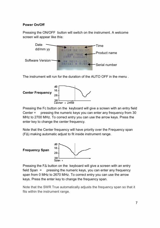
Power On/Off
Pressing the ON/OFF button will switch on the instrument. A welcome
screen will appear like this:
The instrument will run for the duration of the AUTO OFF in the menu .
Center Frequency
Pressing the Fc button on the keyboard will give a screen with an entry field
Center = pressing the numeric keys you can enter any frequency from 30
MHz to 2700 MHz. To correct entry you can use the arrow keys. Press the
enter key to change the center frequency.
Note that the Center frequency will have priority over the Frequency span
(FΔ) making automatic adjust to fit inside instrument range.
Frequency Span
Pressing the FΔ button on the keyboard will give a screen with an entry
field Span = pressing the numeric keys, you can enter any frequency
span from 0 MHz to 2670 MHz. To correct entry you can use the arrow
keys. Press the enter key to change the frequency span.
Note that the SWR True automatically adjusts the frequency span so that it
fits within the instrument range.
Date
dd/mm yy Time
Product name
Software Version
Serial number
7

Marker
The marker functions are controlled by the arrow keys when the instrument
is in sweep mode. By pressing the left or right arrow the marker line moves
across the screen. When the key is held pressed, a mini cursor will be seen
moving across the screen and when the key is released, the marker will
appear in the new position. The marker will display the frequency and the
measured value of the marker position on the bottom line. If you press the
“ENTER” key, the marker position will move to the center of the screen and
adjust the frequency span symmetrical on both side of the new center fre-
quency.
Hold and Copy
When “HOLD” is pressed, the sweep position indicator stops at the current
position and freezes the screen. In “HOLD” mode the frequency sweep is
stopped and depending on the setting of Oscillator, the RF is either On or
Off. (see menus)
The “COPY” key will write the screen contents to the USB Memory stick.
The “COPY” function will create a Directory with the date as directory name
YYYYMMDD e.g. 20121001. In the directory the screen files are written
as .BMP with the time stamp as file name HHMMSS e.g. 164852.BMP.
During write to USB the busy icon is on, when busy goes off, it is safe to
remove the USB device.
8

Menus
Main:
1 Light On will change the setting On/Off of the back light when activated.
2 Y Scale:
The vertical scale can be chosen between return loss in dB and as a numer-
ic VSWR value, in each group you may choose the scale that fits your need
or the auto scale function.
3 X Scale:
The Horizontal scale can be chosen to have different layout.
1 Start frequency, curser frequency with value and stop frequency.
2 Span Frequency FΔ and curser frequency with value.
3 Center Frequency Fc and curser frequency with value.
4 Center Frequency Fc and Span Frequency FΔ.
4 Date and Time:
The date and time can be entered and will run real time as long as the
SWR True is charged and have battery voltage to sustain operation. 9

Menus (cont.)
5 Info:
In this menu Data to be used with the XML Feature can be entered; data is
stored with the time stamp and screen copy in XML format.
6 Settings:
1. “Power Min” Auto power off time to save battery power. The time to auto
power off can be set from 1 to 127 minutes. If the power off time is set to 0
the automatic power save function is disabled.
2. The contrast of the LCD screen can be adjusted, you may adjust from 50
to 99. Factory default is 70.
3. The file system may be selected where 1 is the time/date format and 2 is
the XML format. See XML feature on page 14.
4. The choice of having the RF generator stopped or running during “HOLD”
mode.
10
www.instruments4engineers.com

Making Measurement
Connecting antennas:
Observe the utmost care when connecting antennas via cables , as these
cables can be connected to transmitters and /or power sources! Make sure
you have chosen the antenna you intend to test!! Connection to transmitters
and/or other sources can destroy the instrument or cause hazardous electri-
cal conditions.
When connecting to the “N” female connector on the instrument make sure
you are using either “N” male antenna or cable connector.
If antenna or cable is fitted with another type of connector use appropriate
adapter. Please observe that the use of adapters and cable connections of
poor quality may influence the SWR and give higher readings than the actu-
al antenna SWR. Once the antenna has been connected to the instrument
you switch the SWR True on and select the relevant frequency band by
using the Fc and FΔ. By sweeping the frequencies of interest while observ-
ing the graphs on the screen you should see VSWR or Return Loss curve.
Antennas are usually designed to have a SWR below a given value within
the band for which it is designed. As an example a GSM 900 antenna could
have the following specifications: Range 890 - 960 MHz SWR less than
2.0:1 typical 1.5:1.
Nearby objects
When testing SWR on low gain antennas (Gain <3 dBd) the influence from
nearby objects is small when the objects are more than ½λ away (15 cm at
GSM900). When testing high gain antennas ( e.g. Yagi’s and panel’s) you
should avoid objects in the direction of radiation.
Strong RF fields
When testing SWR on antennas located in strong RF fields, the reading you
will get on the SWR meter may be incorrect, because the strong RF field
present will be indicated as reflected power coming from the antenna. If a
precise reading is needed, you must switch off the disturbing source of RF
or move the antenna under test out of the RF field.
11

Bandwidth
Some antennas may need tuning by adjusting the length of an element or
by other means in order to cover the entire band of interest, please refer to
antenna manufacturers instructions for details.
Duplex operation
When checking antennas to be used for duplex operation, make sure the
antenna SWR is adjusted for the lowest possible SWR in both receive and
transmit band.
General hints
Always refer to antenna manufacturers specification! Antennas may have
more than one resonance frequency! A very narrow resonance frequency
may indicate resonance of cable instead of antenna resonance (Cable bro-
ken or shorted)!
Keep connectors clean and tight!
Calibration
We recommend the "SWR True" to be recalibrated once every 24 month.
On the "Welcome Menu" the “Calibration Due” will appear when the calibra-
tion period is exhausted. The calibration message will not affect the func-
tions and measurement of the SWR True.
12

Specifications:
Model SWR TRUE Type 3013
Application: Measurement of SWR in 50 Ω transmission lines
Frequency range 30->2700 MHz entered as center and span
Center Frequency 30 to 2700 MHz
Span 0 to 2670 MHz
Frequency stability ±50 ppm
Measurement range 1.0<SWR<9.9, 0<dB<-30 dB
Impedance Nom. 50 Ω
Generator output Approx. -4 dBm
Max. input on test terminal 100 mW
Tolerance on SWR reading 30-1000 MHz ± 5%; 1000-1600 MHz ± 10%;
and 1600-2700 MHz ±15%
Operating temperature range 0° C-> + 50° C
Storage temperature range -30° C -> + 50° C
Calibration Every 24 month recommended.
Connectors “N”-female RF test connector.
USB A type for memory key.
USB B type for serial PC communication.
Mini DIN for RS232 up to 38400 Baud
Power supply 4 NiMH type AA 1.2 V 1.8 Ah rechargeable batteries
(Batteries, NiMH rechargeable and 230 VAC/7.5
VDC charger supplied)
Auto Power off For battery economy, SWR TRUE automatically
turns off after user defined time.
Capacity Fully charged: More than 6 hours continuously.
Colour Silver/blue
Width 82 mm
Depth 31 mm
Height 165 mm
Weight 500 gram (incl. Batteries)
EMC Complies with directive 89/336EEC as amended by
92/31EEC and 93/68/EEC
Standards Emissions: EN 61000-6-4: 2001
Immunity: EN 61000-6-2: 2005
13

XML Feature:
In order to use the XML feature this must be
installed. When the feature is installed You
can take advantage of the info menu 5 where
operator, address, device and types can be
entered.
Also you can choose between the stand-
ard .bmp picture copy (File sys 1)or the XML
type where all info is copied onto the USB
memory stick (File sys 2)
Along with the XML Feature is a USB Memory Stick with program files:
After inserting the USB
memory stick into the
SWR True and pressing
“COPY” the Screen is copied to the USB memory stick along with Info data,
time of day, date and table data for each of the 101 data points on screen.
Taking the USB memory stick to your PC you can execute the “merge.bat”
program which will give you all stored data in the following format:
14

XML Feature continued:
On the USB memory stick is a directory called Data, this directory will hold
your stored data including spread sheet data and bmp files.
The .BMP files can be viewed using any picture viewer and from the viewer it
can be zoomed and printed.
The spread sheet files
xxxxyyyy.CSV are files where
the name is xxxx Serial of the
instrument yyyy is the sequen-
tial file number. In the files are
the measurement data for each
point on the screen separated
by commas. Each data entry is
the frequency, reflection
coefficient RHO, Return loss in
dB and the VSWR.
The spread sheet files can be
viewed with the program
CSVIEW located onto the
memory stick
Data in these spread sheets
files can be imported and used
for making all kind of drawings,
statistics and calculations by
standard spreadsheet programs.
15

Optional accessories Kit: Automobile cigarette lighter regulated 7.5Volt charger. With lighter jack and 5.5 mm DC plug.
Coaxial adapters to fit “N” at the Test port:
N male / FME male
N male / BNC female
N male / TNC female
N male / miniUHF female
Soft canvas case Nato approved SWR True-MIL : (NSN 6625-22-623-9610) Ruggedized and Dust proof enhancement. Nato approved accessory kit SWR-ASS: (NSN 6625-22-623-9614)
Professional carrying case that is water-and airtight. The carrying case contains 7.5 Volt Auto Charger with Hella connectors that can be used in vehicles with 12-32 Volts. Furthermore, there is room for 8 pieces N adaptors, and 1 pc. 7/16 adapter. There is extra space for cables and instructions, as well as cuts for SafeOne *
Included Adaptors:
N male / UHF female
N male / BNC female
N male / TNC female
N male / SMA female * SafeOne is a small RF field strength meter that warns the user if the RF
radiation exceeds health authorities' requirements. (WHO ICNIRP) 16

PC Viewer Program Option
In order to run the PC Viewer program with COMM-connect 3013 SWR True
perform the following steps:
Install the program on your PC using defaults.
Make sure .NET Framework version 3.5 is installed on your PC.
( available online at Micro Soft and requested by this installation)
Run the “3013 PC Display Install.msi” from the memory stick; follow the
default installation.
After driver installation etc. you should have an Icon on your Desktop:
To use the program:
Insert memory stick into SWR True.
Connect the USB interface cable from SWR True to your PC.
Power on the SWR True.
After welcome screen has completed on SWR True press “Copy” and
wait for busy to disappear.
Run the “3013 Display” program.
In your PC program select the COM port.
When “Active” is displayed in the bottom of the screen the Viewer is
running.
Note: When running under Windows XP the program will terminate
unexpected if connection to 3013 SWR True is disconnected before the
Viewer program is terminated! 17

Conversion table: Return Loss Reflection VSWR In dB Coefficient, r 1 0.891 17.4 2 0.794 8.72 3 0.707 5.85 4 0.631 4.42 5 0.562 3.57 6 0.501 3.01 7 0.447 2.61 8 0.398 2.32 9 0.355 2.10 10 0.316 1.92 12 0.251 1.67 14 0.199 1.50 16 0.158 1.38 18 0.126 1.29 20 0.100 1.22 25 0.056 1.12 30 0.032 1.07 35 0.018 1.04 40 0.010 1.02 Abbreviations: SWR, VSWR (Voltage) Standing Wave Ratio RF Radio Frequency MHz Mega Hertz PLL Phase Locked Loop USB Universal Serial Bus RS232 EIA Serial Interface SMPS Switched Mode Power Supply GSM Global System for Mobile dBm deciBell referenced to 1 milli Watt dBd deciBell referenced to half wave dipole ppm parts per million LCD Liquid Crystal Display AC Alternating Current NiMH Nickel Metal Hydride
18

Another great product from COMM-connect:
PMR Power Meter
Type 3030
Please visit our webpage for more great products:
www.comm-connect.com
Specifications:
Frequency range: 30MHz - 500MHz· VSWR: < 1.05:1· 50Ohms “N” Female connector· Power Range: 1.5mW to 100W· Display resolution: 128x64 pixels· Calibration stored in EEPROM· USB Serial device (B type)· Operation time: > 5 hours

SWR True 3013 Operators Manual
Version 2 b


![Patch Antenna[1]](https://static.fdokumen.com/doc/165x107/63158e4cc32ab5e46f0d5c89/patch-antenna1.jpg)