SWestinghouse - Regulations.gov
238
SWestinghouse Westinghouse Electric Company Nuclear Power Plants P.O. Box 355 Pittsburgh, Pennsylvania 15230-0355 USA U.S. Nuclear Regulatory Commission Direct tel: 412-374-6206 ATTENTION: Document Control Desk Direct fax: 724-940-8505 Washington, D.C. 20555 e-mail: [email protected] Your ref: Docket Number 52-006 Our ref: DCPNRC_002874 May 21, 2010 References: 1. DCPNRC_002744, Re-submittal of Proposed Changes for AP 1000 Design Control Document Rev. 18, January 20, 2010 2. DCPNRC_002818, Supplementary Information to DCPNRC_002744 - Re-Submittal of Proposed Changes for AP1000 Design Control Document Rev.18, March 12, 2010 3. DCPNRC_002850, Information on Proposed Changes for the AP 1000 Design Control Document Rev. 18, April 26, 2010 Subject: Final Information on Proposed Changes for the AP1000 Design Control Document Rev. 18 This letter is submitted in support of the AP1000 Design Certification Amendment Application (Docket No. 52-006). The information provided is generic and is expected to apply to all Combined License (COL) applicants referencing the AP 1000 Design Certification and the AP 1000 Design Certification Amendment Application. This submittal contains proprietary information of Westinghouse Electric Company, LLC. In, conformance with the requirements of 10 CFR Section 2.390, as amended, of the Commission's regulations, we are enclosing with this submittal one copy of the Application for Withholding, AW- 10- 2817 (non-proprietary, Enclosure 1), and one copy of the associated Affidavit (non-proprietary, Enclosure 2) with Proprietary Information and Copyright Notices. The affidavit sets forth the basis on which the information identified as proprietary may be withheld from public disclosure by the Commission. Pursuant to 10 CFR 50.30(b), "Description of Proposed Changes for AP1000 DCD Rev. 18 - Proprietary" and "Description of Proposed Changes for AP 1000 DCD Rev. 18 - Non-Proprietary" are submitted as Enclosures 3 and 4. Correspondence with respect to the affidavit or Application for Withholding should include our reference number AW-10-2817 and should be addressed to James A. Gresham, Manager, Regulatory Compliance and Plant Licensing, Westinghouse Electric Company, LLC, P. 0. Box 355, Pittsburgh, Pennsylvania 15230-0355. Westinghouse provided preliminary information on changes which it proposed to include in Revision 18 of the AP 1000 Design Control Document (DCD-18) in a January 20, 2010 letter (Reference 1). Supplementary information on some of those changes requested by the NRC was provided in a March 12, 2010 letter (Reference 2). Information was provided in an-April 26, 2010 letter (Reference 3) for seven of the changes identified in the January 20, 2010 that were determined to meet one or more of the Interim Staff Guidance-11 (ISG-1 1) criteria for reporting to the NRC staff. Two of the remaining 50 "elective" 05261jb.doc
-
Upload
khangminh22 -
Category
Documents
-
view
0 -
download
0
Transcript of SWestinghouse - Regulations.gov
SWestinghouse Westinghouse Electric CompanyNuclear Power PlantsP.O. Box 355
Pittsburgh, Pennsylvania 15230-0355USA
U.S. Nuclear Regulatory Commission Direct tel: 412-374-6206ATTENTION: Document Control Desk Direct fax: 724-940-8505Washington, D.C. 20555 e-mail: [email protected]
Your ref: Docket Number 52-006Our ref: DCPNRC_002874
May 21, 2010
References:1. DCPNRC_002744, Re-submittal of Proposed Changes for AP 1000 Design
Control Document Rev. 18, January 20, 20102. DCPNRC_002818, Supplementary Information to DCPNRC_002744 -
Re-Submittal of Proposed Changes for AP1000 Design Control Document Rev.18,March 12, 2010
3. DCPNRC_002850, Information on Proposed Changes for the AP 1000 Design ControlDocument Rev. 18, April 26, 2010
Subject: Final Information on Proposed Changes for the AP1000 Design Control Document Rev. 18
This letter is submitted in support of the AP1000 Design Certification Amendment Application (DocketNo. 52-006). The information provided is generic and is expected to apply to all Combined License(COL) applicants referencing the AP 1000 Design Certification and the AP 1000 Design CertificationAmendment Application.
This submittal contains proprietary information of Westinghouse Electric Company, LLC. In,conformance with the requirements of 10 CFR Section 2.390, as amended, of the Commission'sregulations, we are enclosing with this submittal one copy of the Application for Withholding, AW- 10-2817 (non-proprietary, Enclosure 1), and one copy of the associated Affidavit (non-proprietary, Enclosure2) with Proprietary Information and Copyright Notices. The affidavit sets forth the basis on which theinformation identified as proprietary may be withheld from public disclosure by the Commission.Pursuant to 10 CFR 50.30(b), "Description of Proposed Changes for AP1000 DCD Rev. 18 - Proprietary"and "Description of Proposed Changes for AP 1000 DCD Rev. 18 - Non-Proprietary" are submitted asEnclosures 3 and 4. Correspondence with respect to the affidavit or Application for Withholding shouldinclude our reference number AW-10-2817 and should be addressed to James A. Gresham, Manager,Regulatory Compliance and Plant Licensing, Westinghouse Electric Company, LLC, P. 0. Box 355,Pittsburgh, Pennsylvania 15230-0355.
Westinghouse provided preliminary information on changes which it proposed to include in Revision 18of the AP 1000 Design Control Document (DCD-18) in a January 20, 2010 letter (Reference 1).Supplementary information on some of those changes requested by the NRC was provided in a March 12,2010 letter (Reference 2). Information was provided in an-April 26, 2010 letter (Reference 3) for seven ofthe changes identified in the January 20, 2010 that were determined to meet one or more of the InterimStaff Guidance-11 (ISG-1 1) criteria for reporting to the NRC staff. Two of the remaining 50 "elective"
05261jb.doc

DCPNRC 002874May 21, 2010
Page 2 of 3
items in the January 20 letter (Change Notice numbers 23 and 45) are addressed in RAI responses RAI-SRP 1.3-CHPB-05 and RAI-SRP 1.5-CHPB-05,, respectively. The purpose of this letter is to providefinal information that we propose to include in DCD-l 8 for those 48 items, as supplemented byinformation in the March 12 letter and by responses to action items from our March 17-18 meeting withNRC staff. Final information for these 48 elective changes is provided in Enclosure 3, including thereasons for the changes and the sections of the DCD which are impacted. Enclosure 4 provides a non-proprietary version of the information in Enclosure 3. Enclosure. 5 provides a copy of the revised DCDpages. Enclosure 6 contains sensitive, unclassified, non-safeguards information relative to the physicalprotection of an AP 1000 Nuclear Power Plant that should be withheld from public disclosure pursuant to10CFR2.390(d). This information is associated with CNs 53, 54, and 57. Enclosure 7 provides theredacted version of Enclosure 6 (public version). Enclosure 8 provides the responses to Action Itemsfrom the March 17, 2010 meeting. The information contained in this letter in addition to Reference 3 andthe RAI responses noted above finalizes the information provided in References 1 and 2.
As noted previously, the changes described in this and the referenced letters do not constitute all of thechanges which Westinghouse proposes to include in DCD-l 8. Rather, the changes in this letter are inaddition to those which Westinghouse either has submitted or will submit to the NRC as responses toRequests for Additional Informiation or Safety Evaluation Report Open Items.
Westinghouse will work with the NRC staff to disposition the changes described in this letter asexpeditiously as possible. Questions related to the content of this letter should be directed toWestinghouse. Please send copies of such questions to the prospective COL applicants referencing theAP 1000 Design Certification. A representative for each applicant is included on the cc: list of this letter.
Very truly yours,
4obert Sisk, ManagerLicensing and Customer InterfaceRegulatory Affairs and Strategy
/Enclosures
1. AW-10-2817, Application for Withholding Proprietary Information fromDisclosure, dated May 21, 2010
2. AW-10-2817, Affidavit, Proprietary Information Notice, Copyright Noticedated May 21, 2010
3. Description of Proposed Changes for AP1000 DCD Rev. 18, Proprietary4. Description of Proposed Changes for AP 1000 DCD Rev. 18, Non-
Proprietary5. DCD Pages6. DCD Pages for Change Numbers 53, 54, and 57 - Security Related Information Withheld from
Public7. DCD Pages for Change Numbers 53, 54, and 57 - Public Redacted Version8. Responses to Action Items from March 17, 2010 Meeting, Non-Proprietary
05261jb.doc

DCPNRC_002874May 21, 2010
Page 3 of 3
cc: D. JaffeE. McKennaT. SpinkP. HastingsR. KitchenA. MonroeP. JacobsC. PierceE. SchmiechG. ZinkeR. GrumbirM. Melton
U.S. NRCU.S. NRCTVADuke PowerProgress EnergySCANAFlorida Power & LightSouthern CompanyWestinghouseNuStart/EntergyNuStartWestinghouse
05261jb.doc

DCPNRC 002874May 21, 2010
ENCLOSURE 1
AW-10-2817
APPLICATION FOR WITHHOLDINGPROPRIETARY INFORMATION FROM DISCLOSURE
05261jb.doc

( WestinghouseWestinghouse Electric CompanyNuclear ServicesP.O. Box 355Pittsburgh, Pennsylvania 15230-0355USA
U.S. Nuclear Regulatory CommissionATTENTION: Document Control DeskWashington, D.C. 20555
Direct tel:Direct fax:
e-mail:
Your ref: Docket Number 52-006Our ref: AW-10-2817
May 21, 2010
APPLICATION FOR WITHHOLDING PROPRIETARYINFORMATION FROM PUBLIC DISCLOSURE
Subject: Final Information on Proposed Changes for the AP 1000 Design Control Document Rev. 18
The Application for Withholding is submitted by Westinghouse Electric Company, LLC (Westinghouse),pursuant to the provisions of Paragraph (b) (1) of Section 2.390 of the Commission's regulations. Itcontains commercial strategic information proprietary to Westinghouse and customarily held inconfidence.
The proprietary material for which withholding is being requested is identified in the proprietary versionof the subject report. In conformance with 10 CFR Section 2.390, Affidavit AW-10-2817 accompaniesthis Application for Withholding, setting forth the basis on which the identified proprietary informationmay be withheld from public disclosure.
Accordingly, it is respectively requested that the subject information which is proprietary toWestinghouse be withheld from public disclosure in accordance with 10 CFR Section 2.3 90 of theCommission's regulations.
Correspondence with respect to this Application for Withholding or the accompanying affidavit shouldreference AW- 10-2817 and should be addressed to James A. Gresham, Manager, Regulatory Complianceand Plant Licensing, Westinghouse Electric Company, LLC, P.O. Box 355, Pittsburgh, Pennsylvania,15230-0355.
Very truly yours,
Robert Sisk, ManagerLicensing and Customer InterfaceRegulatory Affairs and Strategy
cc: G. Bacuta - U.S. NRC
05261jb.doc

AW-10-2817May 21, 2010
ENCLOSURE 2
Affidavit
05261jb.doc

AW-10-2817May 21, 2010
AFFIDAVIT
COMMONWEALTH OF PENNSYLVANIA:
ss
COUNTY OF BUTLER:
Before me, the undersigned authority, personally appeared Robert Sisk, who, being by me duly
sworn according to law, deposes and says that he is authorized to execute this Affidavit on behalf of
Westinghouse Electric Company LLC (Westinghouse), and that the averments of fact set forth in this
Affidavit are true and correct to the best of his knowledge, information, and belief:
Robert Sisk, ManagerLicensing and Customer InterfaceRegulatory Affairs and Strategy
Sworn to and subscribed
before me this 0/ -day
of May 2010.
COMMONWEALTHKOF PENNSYLVANIA.Notarial Seal
Linda J. Bugle, Notary PublicCity of Pittsburgh, Allegheny County
My Commission Expires June 18, 2013Member, Pennsylvania Association of Notaries
Nog P -i
05261jb.doc

2 AW-10-2817
(1) 1 am Manager, Licensing and Customer Interface, Westinghouse Electric Company, LLC
(Westinghouse), and as such, I have been specifically delegated the function of reviewing the
proprietary information sought to be withheld from public disclosure in connection with nuclear
power plant licensing and rule making proceedings, and am authorized to apply for its
withholding on behalf of Westinghouse.
(2) 1 am making this Affidavit in conformance with the provisions of 10 CFR Section 2.390 of the
Commission's regulations and in conjunction with the Westinghouse "Application for
Withholding" accompanying this Affidavit.
(3) 1 have personal knowledge of the criteria and procedures utilized by Westinghouse in designating
information as a trade secret, privileged or as confidential commercial or financial information.
(4) Pursuant to the provisions of paragraph (b)(4) of Section 2.390 of the Commission's regulations,
the following is furnished for consideration by the Commission in determining whether the
information sought to be withheld from public disclosure should be withheld.
W The information sought to be withheld from public disclosure is owned and has been held
in confidence by Westinghouse.
(ii) The information is of a type customarily held in confidence by Westinghouse and not
customarily disclosed to the public. Westinghouse has a rational basis for determining
the types of information customarily held in confidence by it and, in that connection,
utilizes a system to determine when and whether to hold certain types of information in
confidence. The application of that system and the substance of that system constitutes
Westinghouse policy and provides the rational basis required.
Under that system, information is held in confidence if it falls in one or more of several
types, the release of which might result in the loss of an existing or potential competitive
advantage, as follows:
(a) The information reveals the distinguishing aspects of a process (or component,
structure, tool, method, etc.) where prevention of its use by any of
Westinghouse's competitors without license from Westinghouse constitutes a
competitive economic advantage over other companies.
05261jb.doc
3 AW-10-2817
(b) It consists of supporting data, including test data, relative to a process (or
component, structure, tool, method, etc.), the application of which data secures a
competitive economic advantage, e.g., by optimization or improved
marketability.
(c) Its use by a competitor would reduce his expenditure of resources or improve his
competitive position in the design, manufacture, shipment, installation, assurance
of quality, or licensing a similar product.
(d) It reveals cost or price information, production capacities, budget levels, or
commercial strategies of Westinghouse, its customers or suppliers.
(e) It reveals aspects of past, present, or future Westinghouse or customer funded
development plans and programs of potential commercial value to Westinghouse.
(f) It contains patentable ideas, for which patent protection may be desirable.
There are sound policy reasons behind the Westinghouse system which include the
following:
(a) The use of such information by Westinghouse gives Westinghouse a competitive
advantage over its competitors. It is, therefore, withheld from disclosure to
protect the Westinghouse competitive position.
(b) It is information that is marketable in many ways. The extent to which such
information is available to competitors diminishes the Westinghouse ability to
sell products and services involving the use of the information.
(c) Use by our competitor would put Westinghouse at a competitive disadvantage by
reducing his expenditure of resources at our expense.
(d) Each component of proprietary information pertinent to a particular competitive
advantage is potentially as valuable as the total competitive advantage. If
competitors acquire components of proprietary information, any one component
05261jb.doc
4 AW-10-2817
may be the key to the entire puzzle, thereby depriving Westinghouse of a
competitive advantage.
(e) Unrestricted disclosure would jeopardize the position of prominence of
Westinghouse in the world market, and thereby give a market advantage to the
competition of those countries.
(f) The Westinghouse capacity to invest corporate assets in research and
development depends upon the success in obtaining and maintaining a
competitive advantage.
(iii) The information is being transmitted to the Commission in confidence and, under the
provisions of 10 CFR Section 2.390, it is to be received in confidence by the
Commission.
(iv) The information sought to be protected is not available in public sources or available
information has not been previously employed in the same original manner or method to
the best of our knowledge and belief.
(v) The proprietary information sought to be withheld in this submittal is that which is
appropriately marked in "Final Information on Proposed Changes for the AP1000 Design
Control Document Rev. 18" in support of the AP1000 Design Certification Amendment
Application, being transmitted by Westinghouse letter (DCPNRC_002874) and
Application for Withholding Proprietary Information from Public Disclosure, to the
Document Control Desk. The proprietary information as submitted by Westinghouse for
the APlOOO Design Certification Amendment application is expected to be applicable in
all licensee submittals referencing the AP1000 Design Certification and the AP1000
Design Certification Amendment Application in response to certain NRC requirements
for justification of compliance of the safety system to regulations.
This information is part of that which will enable Westinghouse to:
(a) Manufacture and deliver products to utilities based on proprietary designs.
05261jb.doc
5 AW-10-2817
(b) Advance the AP 1000 Design and reduce the licensing risk for the application of the
AP 1000 Design Certification
(c) Determine compliance with regulations and standards
(d) Establish design requirements and specifications for the system.
Further this information has substantial commercial value as follows:
(a) Westinghouse plans to sell the use of similar information to its customers for
purposes of plant construction and operation.
(b) Westinghouse can sell support and defense of safety systems based on the
technology in the reports.
(c) The information requested to be withheld reveals the distinguishing aspects of an
approach and schedule which was developed by Westinghouse.
Public disclosure of this proprietary information is likely to cause substantial harm to the
competitive position of Westinghouse because it would enhance the ability of
competitors to provide similar digital technology safety systems and licensing defense
services for commercial power reactors without commensurate expenses. Also, public
disclosure of the information would enable others to use the information to meet NRC
requirements for licensing documentation without purchasing the right to use the
information.
The development of the technology described in part by the information is the result of
applying the results of many years of experience in an intensive Westinghouse effort and
the expenditure of a considerable sum of money.
ln order for competitors of Westinghouse to duplicate this information, similar technical
programs would have to be performed and a significant manpower effort, having the
requisite talent and experience, would have to be expended.
Further the deponent sayeth not.
05261jb.doc
AW-10-2817
PROPRIETARY INFORMATION NOTICE
Transmitted herewith are proprietary and/or non-proprietary versions of documents furnished to the NRCin connection with requests for generic and/or plant-specific review and approval.
In order to conform to the requirements of 10 CFR 2.3 90 of the Commission's regulations concerning theprotection of proprietary information so submitted to the NRC, the information which is proprietary in theproprietary versions is contained within brackets, and where the proprietary information has been deletedin the non-proprietary versions, only the brackets remain (the information that was contained within thebrackets in the proprietary versions having been deleted). The justification for claiming the informationso designated as proprietary is indicated in both versions by means of lower case letters (a) through (f)located as a superscript immediately following the brackets enclosing each item of information beingidentified as proprietary or in the margin opposite such information. These lower case letters refer to thetypes of information Westinghouse customarily holds in confidence identified in Sections (4)(ii)(a)through (4)(ii)(f) of the affidavit accompanying this transmittal pursuant to 10 CFR 2.390(b)(1).
COPYRIGHT NOTICE
The reports transmitted herewith each bear a Westinghouse copyright notice. The NRC is permitted tomake the number of copies of the information contained in these reports which are necessary for itsinternal use in connection with generic and plant-specific reviews and approvals as well as the issuance,denial, amendment, transfer, renewal, modification, suspension, revocation, or violation of a license,permit, order, or regulation subject to the requirements of 10 CFR 2.390 regarding restrictions on publicdisclosure to the extent such information has been identified as proprietary by Westinghouse, copyrightprotection notwithstanding. With respect to the non-proprietary versions of these reports, the NRC ispermitted to make the number of copies beyond those necessary for its internal use which are necessary inorder to have one copy available for public viewing in the appropriate docket files in the public documentroom in Washington, DC and in local public document rooms as may be required by NRC regulations ifthe number of copies submitted is insufficient for this purpose. Copies made by the NRC must includethe copyright notice in all instances and the proprietary notice if the original was identified as proprietary.
05261jb.doc

DCPNRC 002874May 21, 2010
ENCLOSURE 4
Description of Proposed Changes for AP 1000 DCD Rev. 18, Non-Proprietary
05261jb.doc

Westinghouse Non-Proprietary Class 3Final - Proposed Changes for AP1000 DCD Rev 18
a, c
Section/Table/Change Chapter FigureNumber Tier Number Numbers Description of OCO Change
ApplicableRegulatory AssessmentStandard of NRC
that Design ReviewMeets Resources
1
Reported in DCPNRC_002850 (4/26/2010)
4 -,- I. .12 2 Table 3.2-3
(Sh 30/68)
Table 3.9-16(Shs14,15,23/23)
Table 3-11-1(Sh 41/50)
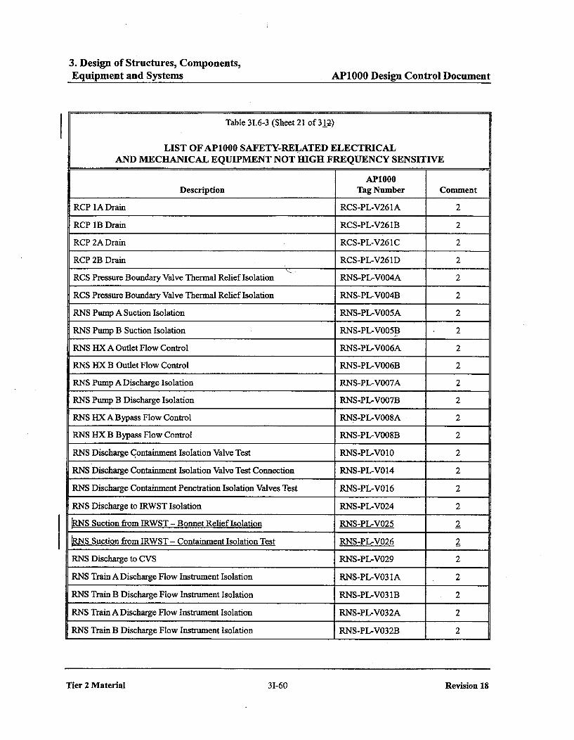
Table 31.6-3(Sh 21/31)
Figure 5.4-7
Table 6.2.3-1(Sh 2, 4/4)
AP1000 Classification ofMechanical and Fluid Systems,Components, and Equipment-add info on affected valvesRNS-PL-V025/V026.
Add Containment IsolationLeak Test to IST Type andFrequency column. DeleteNote 16.
Environmentally QualifiedElectrical and MechanicalEquipment-add info on affectedvalves RNS-PL-V025N026
Add info on RNS-PL-V025N026 to table
RNS P&ID-add detail ofchanges to affected valvesRNS-PL-V025N026 to figure.
Containment MechanicalPenetrations and IsolationValves - add info on valvesRNS-PL-V002A/B. Delete Note6.
Medium
3 2 3 Table 3.9-16 V01 80A/B was changed from The valve was changed ASME Boiler Medium(Sheet 10/23) globe to ball valve, from a globe valve to a ball and Pressure
valve. Vessel Code,6 Section See Enclosure 8, Action Item 9. Section III -
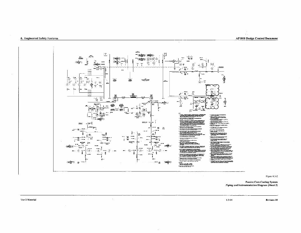
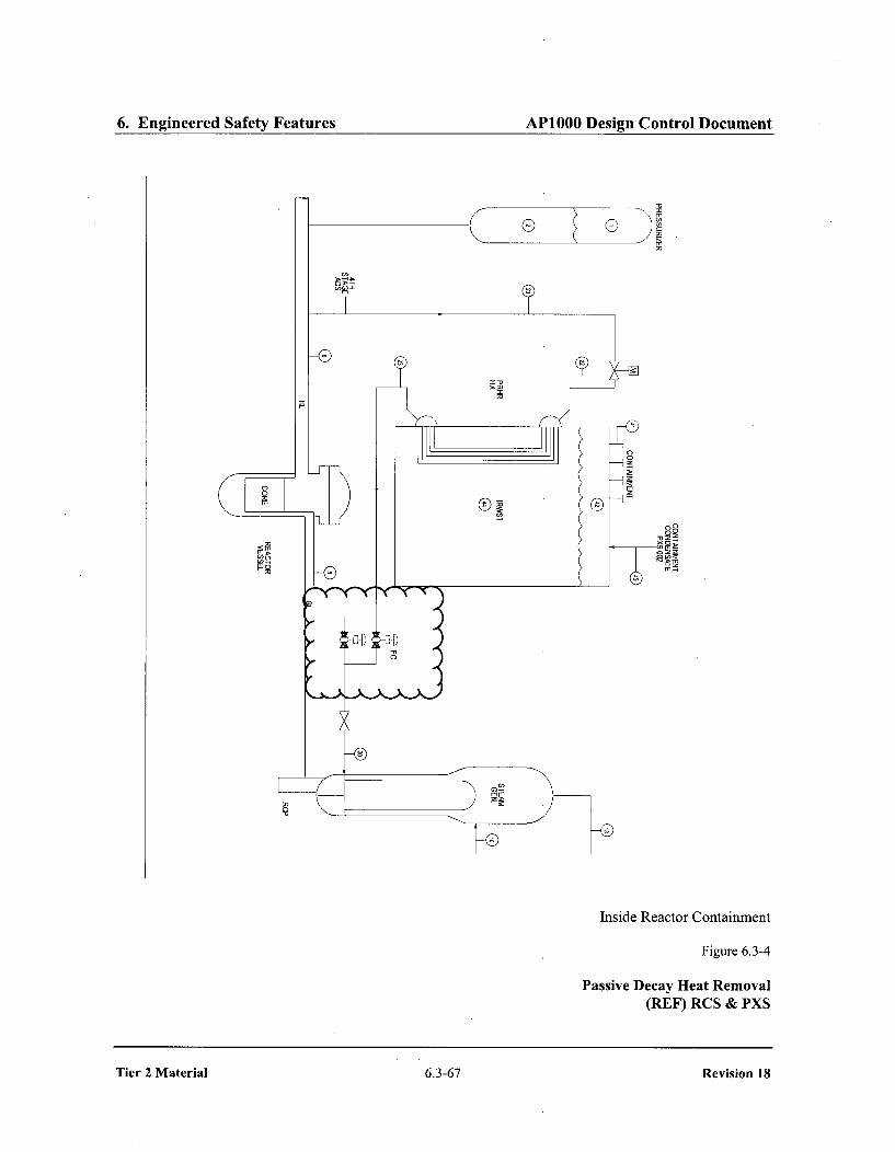
6.3.2.1.2 Class 1Figure 6.3-2Figure 6.3-4

Westinghouse Non-Proprietary Class 3Final - Proposed Changes for AP1000 DCD Rev 18
1a, c
ApplicableRegulatory Assessment
Section/Table/ Standard of NRCChange Chapter Figure Description of Design that Design ReviewNumber Tier Number Numbers Description of DCD Change Change Meets Resources
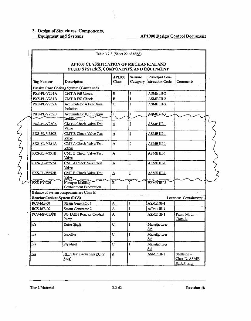
4 2 3 Table 3.2-3 Six test valves added. Remove the system ASME Boiler Medium(sh 22/68) requirements for remote and Pressure
position indication for Vessel Code,Table 3.11-1 Six test valves added. valves PXS-PL-016NB, Section III -(sh 38/50) PXS-PL-017AIB, PXS-PL- Class 1
028A1B and PXS-PL-Table 3.9-16 Four CMT check valves added; 029A/B.(sh 8,9/23), remote position functionNotes removed for accumulator check Change valves PXS-PL-
valves; Note 10 revised to 016A/B, PXS-PL-017A/Bremove quarterly open from swing check to in-lineverification, nozzle check valves.
Table 31.6-3 Six test valves added. Add three test connections(Sh 18/31) for each CMT outlet line to
facilitate testing of the6 Section Delete sentence describing check valves. Add three
6.3.2.2.8.1 check valves. This sentence safety related 1-inchhad described all check valves manual valves to eachas either piston type or swing CMT outlet line.type which is no longer true.
Section Revise valve position indication6.3.7.6.1 description.
Section Delete last sentence because6.3.7.6.2 there is no reference-to
Chapter 7 in Table 6.3-1.
Figure 6.3-1 Revise PXS P&ID
Table 6.3-3 Revise entry for CMT(sh 1/4) discharge line check valves.
Reported in DCPNRC_002850 (4/26/2010)
6Reported in DCPNRC-002850 (4/26/2010)
7 2 6 Figure 6.3-2 Change of position for the(sh 2) PRHR HX flow meter
Westinghouse Non-Proprietary Class 3Final - Proposed Changes for AP1000 DCD Rev 18
a, c
Section/Table/Change Chapter FigureNumber Tier Number Numbers Description of DCD Change
ApplicableRegulatory AssessmentStandard of NRC
that Design ReviewMeets Resources
8Reported in DCPNRC_002850 (4/26/2010)
9Reported in DCP_NRC_002850 (4/26/2010)
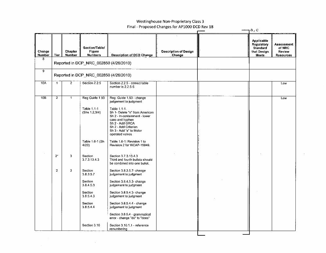
10A 1 2 Section 2.2.5 Section 2.2.5 - correct table Lownumber is 2.2.5-5
10B 2 1 Reg Guide 1.93 Reg. Guide 1.93 - change Lowjudgement to judgment
Table 1.1-1 Table 1.1-1:(Shs 1,2,3/4) Sh 1- Delete "n" from American
Sh 2 - In-containment - lowercase and hyphenSh 2 - Add GRCASh 2 - Add CriterionSh 3 - Add "s" to Motoroperated valves
Table 1.6-1 (Sh Table 1.6-1: Revision 1 to4/20) Revision 2 for WCAP-15949.
2* 3 Section Section 3.7.3.13.4.33.7.3.13.4.3 Third and fourth bullets should
be combined into one bullet.
2 3 Section Section 3.8.3.5.7- change3.8.3.5.7 judgement to judgment
Section Section 3.8.4.5.3- change3.8.4.5.3 judgement to judgment
Section Section 3.8.5.4.3- change3.8.5.4.3 judgement to judgment
Section Section 3.8.5.4.4 - change3.8.5.4.4 judgement to judgment
Section 3.8.5.4 - grammaticalerror - change "do" to "does"
Section 3.10 Section 3.10.1.1 - referencerenumbering
Westinghouse Non-Proprietary Class 3Final - Proposed Changes for AP1000 DCD Rev 18
a,c
IApplicableRegulatory Assessment
Section[Table/ Standard of NRCChange Chapter Figure Description of Design that Design ReviewNumber Tier Number Numbers Description of DCD Change Change I 7A Meets Resources
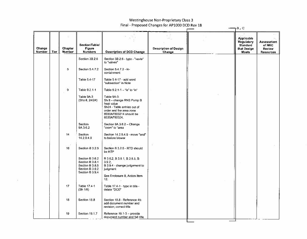
Section 3B.2.6
Section 5.4.7.2
Table 5.4-17
Table 9.2.1-1
Table 9A-3(Shs 8, 24/24)
Section9A.3.6.2
Section14.2.9.4.9
Section B 3.2.5
Section B 3.6.2Section B 3.8.1Section B 3.8.5Section B 3.9.2Section B 3.9.4
Table 17.4-1(Sh 1/8)
Section 18.8
Section 19.1.7
Section 3B.2.6 - typo - "vavle"to "valves"
Section 5.4.7.2 - in-containment
Table 5.4-17 - add word"subsection" in Note
Table 9.2.1-1 - "is" to "in"
Table 9A-3:Sh 8 - change RNS Pump Bheat valueSh24 - Table entries out oforder and fire area zone6030AF603214 should be6030AF60324.
Section 9A.3.6.2 - Change.room" to "area
Section 14.2.9.4.9 - move "and"to before blower
Section B 3.2.5 - RTD shouldbe RTP
B 3.6.2, B 3.8.1, B 3.8.5, B3.9.2,B 3.9.4 - change judgement tojudgment
See Enclosure 8, Action Item12.
Table 17.4-1 - type in title -delete "DCD"
Section 18.8 - Reference 45:add document number andrevision; correct title
Reference 19.1-3 - providedocument number and full title
19

Westinghouse Non-Proprietary Class 3
Final - Proposed Changes for AP1000 DCD Rev 18a, c
ApplicableRegulatory Assessment
Section/Table/ Standard of NRCChange Chapter Figure Description of Design that Design ReviewNumber Tier Number Description of DCD Change Change Meets Resources
Section Section 19.59.6.1 - Change19.59.6.1 judgement to judgment
Section Section 19.59.6.2 -19.59.6.2 Change judgement to judgment
11 2 3 Section Correct flood barrier and Low3.4.1.2.2.1 description of Rooms 11207 -
11209
12 2 9 Section Change the word "shall" to Low9.1.5.2.1.2 should"
Section Change the word "shall" to9.1.5.2.2.2 should"
13 2 8 Table 8.3.1-2 Spent fuel pump horsepower Low(Sheet 4/4)
14
Reported in DCP-NRC-002850 (4/26/2010)
15 2 3 Table 3.3.1 -1 Table 3.3. 1 -1 - add other to Lowheader
Table 3.3.2-1 Table 3.3.2-1 - Page 9 headerspacing
5 Section 5.5.7 Section 5.5.7 - "ensure" to.,ensures"
16 Section B 3.1.9 Section B 3.1.9 - "signalled" to"signaled"
Section B 3.4.1 Section B 3.4.1 - "loadchanges"to "load changes"
Section B 3.6.6 Section B 3.6.6 - "these" to"this"
Section B 3.6.8 Section B 3.6.8 - "a accident" to"an accident"
Westinghouse Non-Proprietary Class 3Final - Proposed Changes for AP1000 DCD Rev 18
a,c
ApplicableRegulatory Assessment
Section/Table/ Standard of NRCChange Chapter Figure Description of Design that Design ReviewNumber Tier Number Numbers Description of DCD Change Change Meets Resources
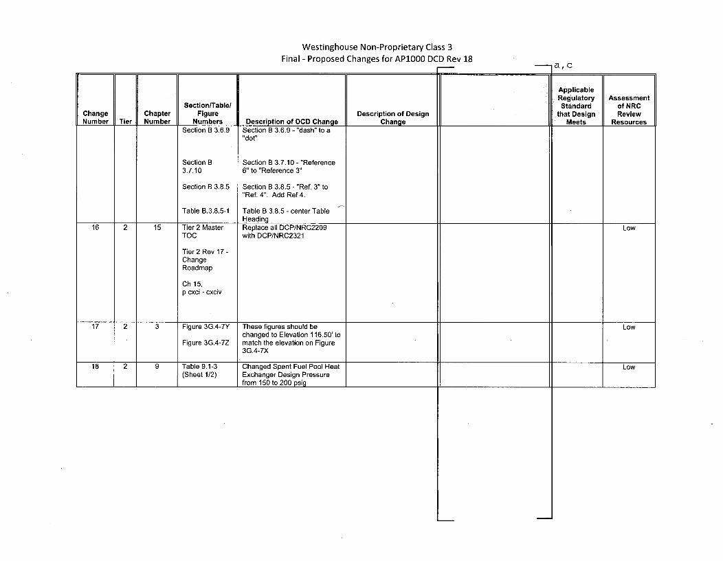
Section B 3.6.9 Section B 3.6.9 - "dash" to a"dot"
Section B Section B 3.7.10 - "Reference3.7.10 6" to "Reference 3"
Section B 3.8.5 Section B 3.8.5 - "Ref. 3" to"Ref. 4". Add Ref 4.
Table B.3.8.5-1 Table B 3.8.5 - center TableHeading
16 2 15 Tier 2 Master Replace all DCP/NRC2209 LowTOC with DCP/NRC2321
Tier 2 Rev 17 -ChangeRoadmap
Ch 15,p cxci - cxciv
17 2 3 Figure 3G.4-7Y These figures should be Lowchanged to Elevation 116.50' to
Figure 3G.4-7Z match the elevation on Figure3G.4-7X
18 2 9 Table 9.1-3 Changed Spent Fuel Pool Heat Low(Sheet 1/2) Exchanger Design Pressure
from 150 to 200 psig
Westinghouse Non-Proprietary Class 3
Final - Proposed Changes for AP1000 DCD Rev 18___*a, c
ApplicableRegulatory Assessment
Section/Table/ Standard of NRCChange Chapter Figure Description of Design that Design ReviewNumber Tier Number Numbers Description of DCD Change Change Meets Resources
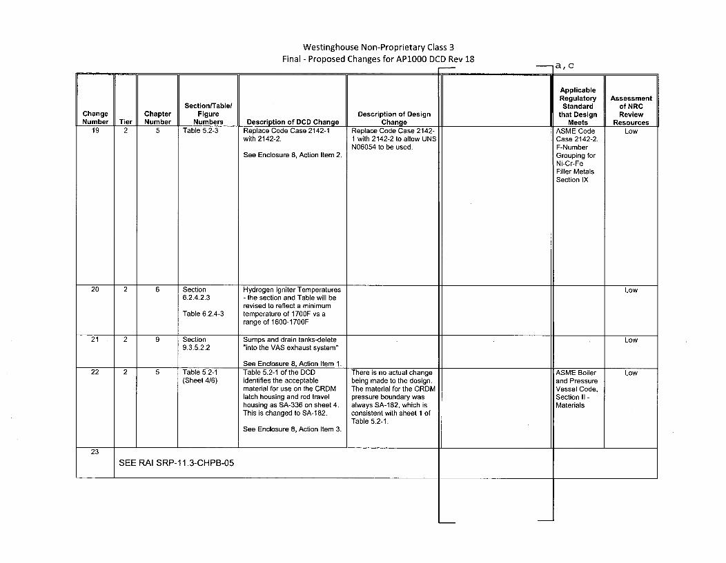
19 2 5 Table 5.2-3 Replace Code Case 2142-1 Replace Code Case 2142- ASME Code Lowwith 2142-2. 1 with 2142-2 to allow UNS Case 2142-2.
N06054 to be used. F-NumberSee Enclosure 8, Action Item 2. Grouping for
Ni-Cr-FeFiller MetalsSection IX
20 2 6 Section Hydrogen Igniter Temperatures Low6.2.4.2.3 - the section and Table will be
revised to reflect a minimumTable 6.2.4-3 temperature of 1700F vs a
range of 1600-1700F
21 2 9 Section Sumps and drain tanks-delete Low9.3.5.2.2 "into the VAS exhaust system"
See Enclosure 8, Action Item 1.22 2 5 Table 5.2-1 Table 5.2-1 of the DCD There is no actual change ASME Boiler Low
(Sheet 4/6) identifies the acceptable being made to the design. and Pressurematerial for use on the CRDM The material for the CRDM Vessel Code,latch housing and rod travel pressure boundary was Section II -housing as SA-336 on sheet 4. always SA-182, which is MaterialsThis is changed to SA-182. consistent with sheet 1 of
Table 5.2-1.See Enclosure 8, Action Item 3.
23
SEE RAI SRP-11.3-CHPB-05

Westinghouse Non-Proprietary Class 3
Final - Proposed Changes for AP1000 DCD Rev 18 -I a, c
Section/Table/Change Chapter Figure Description of DesignNumber Tier Number Numbers Description of DCD Change Change
24 2 9 Section Fire Area 4034 AF 01 - change9A.3.4.14 subdivisions
Table 9A-3 Fire Protection Summary-(Sheets 19, entries in table modified as20/24) appropriate
25 2 5 Section 5.3.1.1
9A
19D
Section9A.3.4.3B
Table 9A-3(Sheet 5/24)
Section19D.8.2.2
Section19D.8.2.13
Added flow skirt to list ofcomponents for which thereactor vessel providessupport.
Change description of FireArea 4002 AF 03
Change combined load andequivalent duration for FireArea 1244 AF 12451, SecurityRoom.
Revised description ofequipment survivabilityassessment for thermocouplesDiscussion of use of float levelsensors in severe accidentmanaciement.
26 2 9 Section 9.2.11.1 Change "compatibility" to Low"habitability"
27 2 10 Table 10.1-1 Steam Generator Outlet LowPressure - Revise value to 821psig from 823 psig
28 2 5 Section 5.4.4.3 Units of pressure differential - LowChange "psig" for the units ofpressure differential to "psi"
29 2 1 Appendix 1A, Criteria wording - Change LowReg. Guide 1.50 "pressurized water heat
transfer" to "post-weld heattreat"

Westinghouse Non-Proprietary Class 3Final - Proposed Changes for AP1000 DCD Rev 18 -a, c
ApplicableRegulatory Assessment
Section/Table/ Standard of NRCChange Chapter Figure Description of Design that Design ReviewNumber Tier Number Numbers Description of DCD Change Change Meets Resources
30 2 3 Table 3.2-3 Adds a class C valve to table This change adds class C 10 CFR 52 Low(sh 10/ 69) 3.2-3, 3.11-1 and 31.6-3. valve PCS-PL-V026 SECY-08-
(Water Bucket Auxiliary 0152Makeup Line Isolation
Table 3.11-1 Valve) to Tables 3.2-3,(sh 33/51) 3.11-1 and 31.6-3
Table 31.6-3(sh 13/32)
31 2 1 Table 1.8-1 Remove Item 1.1 of Table 1.8- Delete Item 1.1 of Table Post-Accident Low(shl/6) 1. 1.8-1 to be consistent with Sampling,
Section 1.9.3 of DCD. NUREG-0737
32 1 2 Table 2.6.9-1 ITAAC number 3 in the LowAcceptance Criteria reads "seeTier 1 material, Table 3.3-6,Item 6". It should be "item 16"
33 2 9 Table 9A-3 Fire Protection Summary-Fire Low(shl2/24) Area 2030AF20300-change
Heat Values for plastic andvolatiles
34 2 9 Table 9.3.3-2 WGS inlet moisture indication - Low(Sheet 3/4) Remove WGS inlet moisture
indication consistent with Ch 11changes to remove moisturemonitor.

Westinghouse Non-Proprietary Class 3
Final - Proposed Changes for AP1000 DCD Rev 18-I a, c
ApplicableRegulatory Assessment
Section/Table/ Standard of NRCChange Chapter Figure Description of Design that Design ReviewNumber Tier Number Numbers Description of DCD Change Change Meets Resources
35 2 9 Table 9.3.4-1 Secondary Sampling System - Low(Sheet 1, 2/2) Clarify the type of specific
conductivity measured.
36 2 1 Section 1.8 Waste Water System - Remove Lowretention basin and raw water
Table 1.8-1 system associations.(Sheet 5/7)
9 Section 9.2.5.337
No Technical Change - PDF Error
38 2 1A Conformance Revised reason for criteria Lowwith Regulatory section C. 5 and C.6.Guides - CriteriaSection C.5 and See Enclosure 8, Action Item 6.C.6 of RG 1.133Rev 1, LoosePart DetectionProgram for thePrimary Systemof Light-Water-CooledReactors
39 2 17 Section 17.6 APP-GW-GL-022 is referenced Lowas Rev. 0. That should be Rev.8.
Westinghouse Non-Proprietary Class 3Final - Proposed Changes for AP1000 DCD Rev 18 -- a, c
ApplicableRegulatory Assessment
Section/Table/ Standard of NRCChange Chapter Figure Description of Design that Design ReviewNumber Tier Number Numbers Description of DCD Change Change Meets Resources
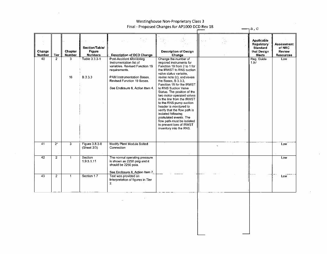
40 2 3 Table 3.3.3-1 Post-Accident Monitoring Change the number of Reg. Guide LowInstrumentation list of required instruments for 1.97variables. Revised Function 19 Function 19 from 2 to 1 forrequirements. the IRWST to RNS suction
valve status variable,16 B.3.3.3 PAM Instrumentation Bases. revise note (c), and revise
Revised Function 19 Bases. the Bases, B 3.3.3,Function 19 for the IRWST
See Enclosure 8, Action Item 4. to RNS Suction ValveStatus. The position of thetwo motor-operated valvesin the line from the IRWSTto the RNS pump suctionheader is monitored toverify that the flow path isisolated followingpostulated events. Theflow path must be isolatedto prevent loss of IRWSTinventory into the RNS.
41 2* 3 Figure 3.8.3-8 Modify Plant Module Bolted Low(Sheet 3/3) Connection
42 2 1 Section The normal operating pressure Low1.9.5.1.11 is shown as 2250 psig and it
should be 2250 psia.
See Enclosure 8, Action Item 7.43 2 1 Section 1.7 Text was provided on Low
Interpretation of figures in Tier2.
Westinghouse Non-Proprietary Class 3
Final. - Proposed Changes for AP1OO0 DCD Rev 18-,a, c
ApplicableRegulatory Assessment
Section/Table/ Standard of NRCChange Chapter Figure Description of Design that Design ReviewNumber Tier Number Numbers Description of DCD Change Change Meets Resources
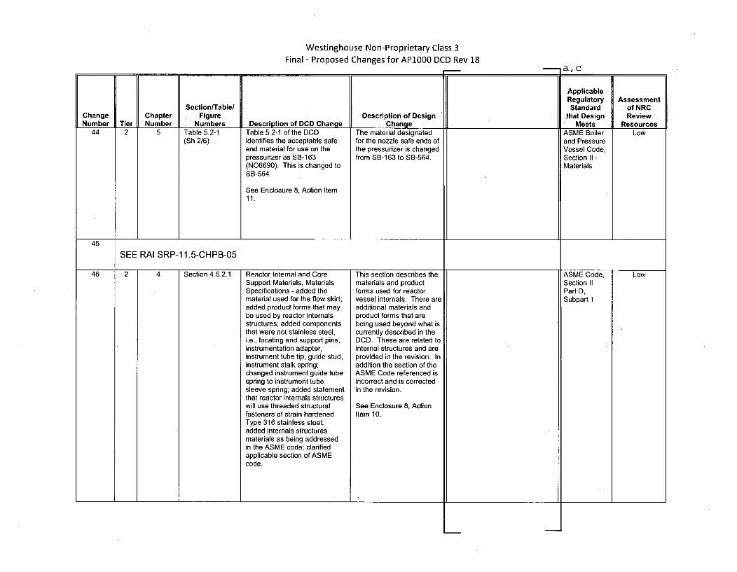
44 2 5 Table 5.2-1 Table 5.2-1 of the DCD The material designated ASME Boiler Low(Sh 2/6) identifies the acceptable safe for the nozzle safe ends of and Pressure
end material for use on the the pressurizer is changed Vessel Code,pressurizer as SB-163 from SB-163 to SB-564. Section II -(N06690). This is changed to MaterialsSB-564.
See Enclosure 8, Action Item11.
45
SEE RAI SRP-11.5-CHPB-05
46 2 4 Section 4.5.2.1 Reactor Internal and Core This section describes the ASME Code, LowSupport Materials, Materials materials and product Section IISpecifications - added the forms used for reactor Part D,material used for the flow skirt; vessel internals. There are Subpart 1added product forms that may additional materials andbe used by reactor internals product forms that arestructures; added components being used beyond what isthat were not stainless steel, currently described in thei.e., locating and support pins, DCD. These are related toinstrumentation adapter, internal structures and areinstrument tube tip, guide stud, provided in the revision. Ininstrument stalk spring; addition the section of thechanged instrument guide tube ASME Code referenced isspring to instrument tube incorrect and is correctedsleeve spring; added statement in the revision.that reactor internals structureswill use threaded structural See Enclosure 8, Actionfasteners of strain hardened Item 10.Type 316 stainless steel;added internals structuresmaterials as being addressedin the ASME code; clarifiedapplicable section of ASMEcode.
Westinghouse Non-Proprietary Class 3Final - Proposed Changes for AP1000 DCD Rev 18
- a,_ c
ApplicableRegulatoryStandard
that DesignMeets
Assessmentof NRCReview
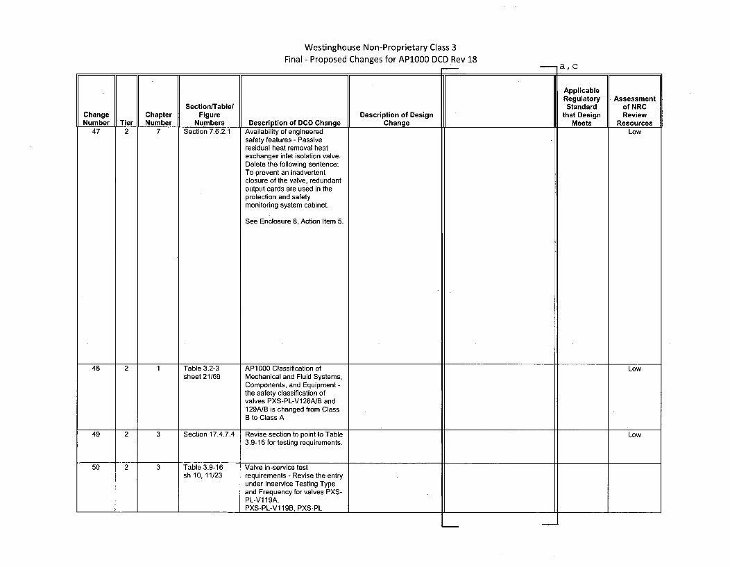
ResourcesDescription of Design
Changeof DCD ChangeAvailability of engineeredsafety features - Passiveresidual heat removal heatexchanger inlet isolation valve.Delete the following sentence:To prevent an inadvertentclosure of the valve, redundantoutput cards are used in theprotection and safetymonitoring system cabinet.
See Enclosure 8, Action Item 5.
Low
48 2 1 Table 3.2-3 AP1000 Classification of Lowsheet 21/69 Mechanical and Fluid Systems,
Components, and Equipment -the safety classification ofvalves PXS-PL-V128A/B and129A/B is changed from ClassB to Class A
49 2 3 Section 17.4.7.4 Revise section to point to Table Low3.9-16 for testing requirements.
50 2 3 Table 3.9-16 Valve in-service testsh 10, 11/23 requirements - Revise the entry
under Inservice Testing Typeand Frequency for valves PXS-PL-V1 19A,PXS-PL-V1 19B, PXS-PL-
Westinghouse Non-Proprietary Class 3Final - Proposed Changes for AP1000 DCD Rev 18
-- a, c
ApplicableRegulatory Assessment
Section/Table/ Standard of NRCChange Chapter Figure Description of Design that Design ReviewNumber Tier Number Numbers Description of DCD Change Change Meets Resources
V122A, PXS-PL-V122B, PXS-PL-V124A and PXSPLV124Bas follows:(1) Remote Position Indication,Exercise/2 years(2) Check-Initial-OpenDifferential Pressure Refueling(3) Check Exercise/RefuelingShutdown
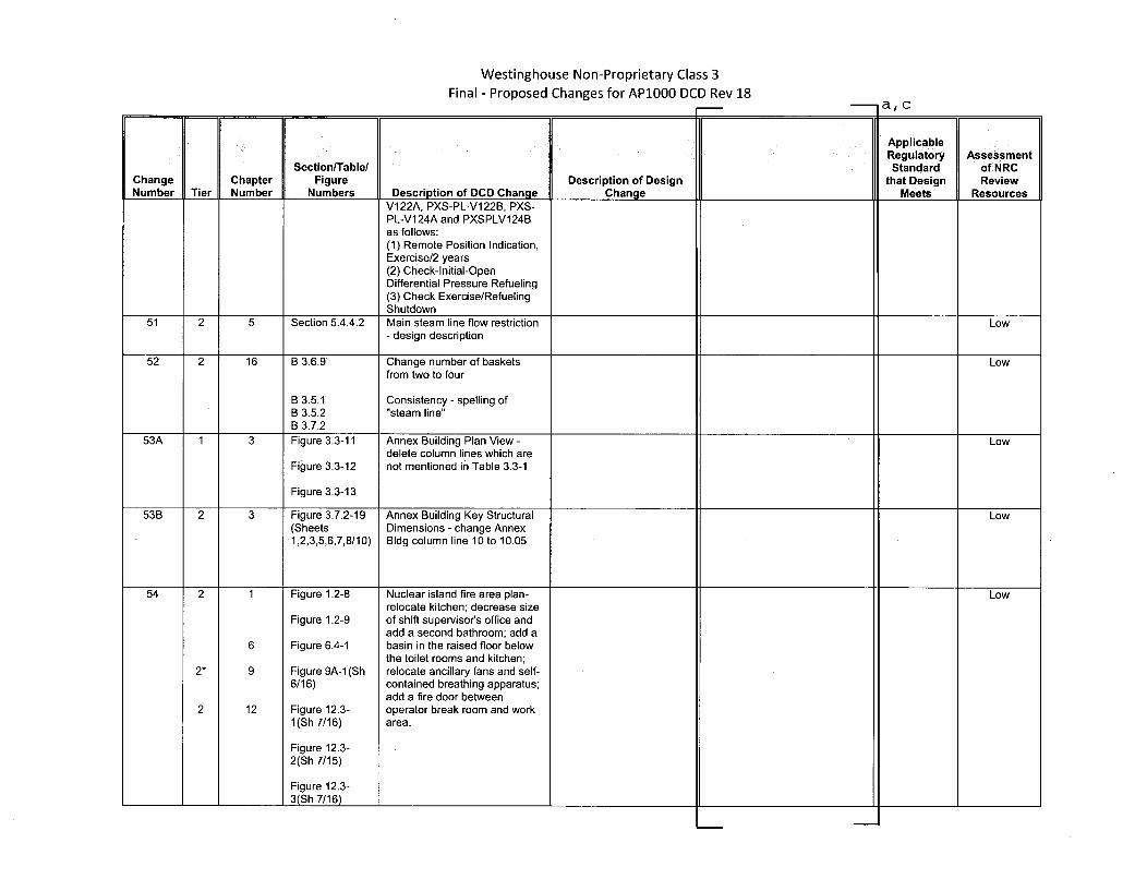
51 2 5 Section 5.4.4.2 Main steam line flow restriction Low- design description
52 2 16 B 3.6.9 Change number of baskets Lowfrom two to four
B 3.5.1 Consistency - spelling ofB 3.5.2 "steam line"B 3.7.2
53A 1 3 Figure 3.3-11 Annex Building Plan View - Lowdelete column lines which are
Figure 3.3-12 not mentioned in Table 3.3-1
Figure 3.3-13
53B 2 3 Figure 3.7.2-19 Annex Building Key Structural Low(Sheets Dimensions - change Annex
•1,2,3,5,6,7,8/10) Bldg column line 10 to 10.05
54 2 1 Figure 1.2-8 Nuclear island fire area plan- Lowrelocate kitchen; decrease size
Figure 1.2-9 of shift supervisor's office andadd a second bathroom; add a
6 Figure 6.4-1 basin in the raised floor belowthe toilet rooms and kitchen;
2* 9 Figure 9A-1 (Sh relocate ancillary fans and self-6/16) contained breathing apparatus;
add a fire door between2 12 Figure 12.3- operator break room and work
1(Sh 7/16) area.
Figure 12.3-2(Sh 7/15)
Figure 12.3-3(Sh 7/16)
Westinghouse Non-Proprietary Class 3Final - Proposed Changes for AP1000 DCD Rev 18
a, c
ApplicableRegulatory Assessment
Section/Table/ Standard of NRCChange Chapter Figure Description of Design that Design ReviewNumber Tier Number Numbers_ Description of DCD Change Change Meets Resources
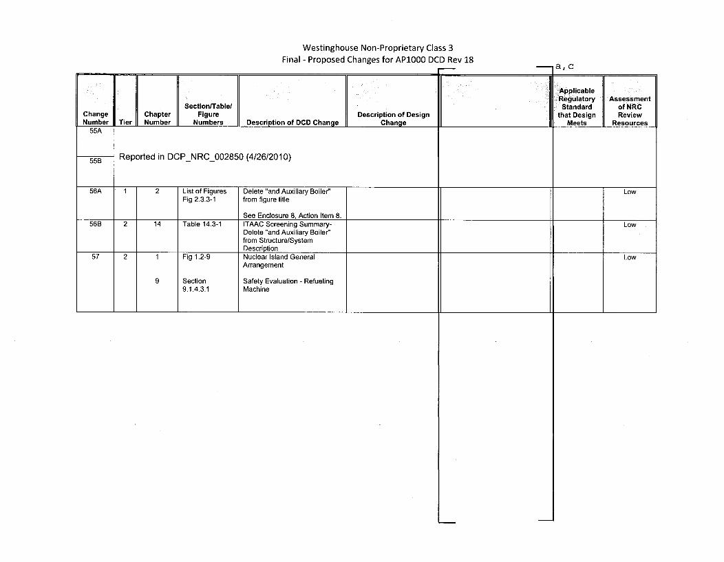
55A
55B Reported in DCP-NRC-002850 (4/26/2010)
56A 1 2 List of Figures Delete "and Auxiliary Boiler' LowFig 2.3.3-1 from figure title
See Enclosure 8, Action Item 8.56B 2 14 Table 14.3-1 ITAAC Screening Summary- Low
Delete "and Auxiliary Boiler"from Structure/SystemDescription
57 2 1 Fig 1.2-9 Nuclear Island General LowArrangement
9 Section Safety Evaluation - Refueling9.1.4.3.1 Machine
I I

DCPNRC 002874May 21, 2010
ENCLOSURE 5
DCD Pages
05261jb.doc

Change Number 2

3. Design of Structures, Components,Equipment and Systems AP1000 Design Control Document
I Table 3.2-3 (Sheet 30 of 6865)
AP1000 CLASSIFICATION"OF MECHANICAL ANDFLUID SYSTEMS, COMPONENTS, AND EQUIPMENT
AP1000 I Seismic I Principal Con-Tag Number Description Class Category struction Code CommentsNormal Residual Heat Removal System (Continued)RNS-PL-VO15B RNS Discharge RCS Pressure A I ASME III-I
BoundaryRNS-PL-V016 RNS Discharge Containment C I ASME 111-3
Penetration Isolation ValvesTest
RNS-PL-VO17A RNS Discharge RCS Pressure A I ASME rn-1Boundary
RNS-PL-VO17B RNS Discharge RCS Pressure A I ASME rn-1Boundary
RNS-PL-V021 RNS HL Suction Pressure B I ASME 111-2Relief
RNS-PL-V022 RNS Suction Header B I ASME 111-2Containment Isolation - ORC
RNS-PL-V023 RNS Suction from IRWST - B I ASME 111-2Containment Isolation
RNS-PL-V024 RNS Discharge to IRWST C I ASME Mn-3Isolation
hNS-PL-V025 RNS Suction from IRWST - C I ASME 111-3Bonnet Relief Isolation
hNS-PL-V026 RNS Suction from IRWST - C I ASME 111-3Containment Isolation Test
RNS-PL-V029 RNS Discharge to CVS C I ASME 111-3RNS-PL-V030A RNS HXIA Shell Drain D NS ANSI B31.1RNS-PL-V030B RNS HX B Shell Drain D NS ANSI B31.1RNS-PL-V03 IA RNS Train A Discharge Flow C I ASME 111-3
Instrument IsolationRNS-PL-V031B RNS Train B Discharge Flow C I ASME MI-3
Instrument IsolationRNS-PL-V032A RNS Train A Discharge Flow C I ASME 111-3
Instrument IsolationRNS-PL-V032B RNS Train B Discharge Flow C I ASME 111-3
Instrument IsolationRNS-PL-V033A RNS Pump A Suction C I ASME 111-3
Pressure Instrument IsolationRNS-PL-V033B RNS Pump B Suction C I ASME 111-3
Pressure Instrument Isolation
Tier 2 Material 3.2-51 Revision 18

3. Design of Structures, Components,Equipment and Systems AP1000 Design Control Document
Table 3.9-16 (Sheet 14 of 23)
VALVE INSERVICE TEST REQUIREMENTS
Valve Tag Valve/Actuator Safety-Related ASME Class/Number Deseripton(" Tlype Missions Safety FunctionsOa IST Category Inservice Testing Tlype and Frequency 1ST Notes
RCS-PL-VO14B Fourth Stage Automatic Depressurization System Isolation Resote MO Maintain Open Remote Position Class I Remote Position Indication, Exercise/2 YearsGATE Category B
RCS-PL-VO14C Fourth Stage Automatic Depressurization System Isolation Remote MO Maintain Open Remote Position Class 1 Remote Position Indication, Exorcise/2 YearsGATE Category B
RCS-PL-VO14D Fourth Stage Automatic Depressurization System Isolation Resnote MO Maintain Open Remote Position Class I Remote Position Indication, Exercisei2 YearsGATE. Category B
RCS-PL-VISOA Reactor Vessel Head Vent Remote SO Maintain Open Active-to-Failed Class I Remote Position Indication, Exercise/2 Years 4,31GLOBE Maintain Close RCS Pressure Boundary Category B Exercise Full Stroke/Cold Shutdown
Transfer Open Remote Position Operability TestRCS-PL-V150B Reactor Vessel Head Vent Remote SO Maintain Open Activo-to-Failed Clss I Remote Position Indication, Exercise/2 Years 4,31
GLOBE Maintain Close RCS Pressure Boundary Category B Exercise Full Stroke/Cold ShutdownTransfer Open Remote Position Operability Test
RCS-PL-VI50C Reactor Vessel Head Vent Remote SO Maintain Open Active-to-Failed Class I Remote Position Indication, Exercise/2 Years 4, 31GLOBE Maintain Close RCS Pressure Boundary Category B Exercise Full Stroke/Cold Shutdown
Transfer Open Remote Position Operability TestRCS-PL-VI50D Reactor Vessel Head Vent Remote SO Maintain Open Active-to-Failed Class I Remote Position Indication, Exerise/2 Years 4, 31
GLOBE Maintain Close RCS Pressure Boundary Category B Exercise Full Stroke/Cold ShutdownTransfer Open Remote Position Operability Test
RCS-K03 Safety Valve Discharge Chamber Rupture Diik, Relief Transfer Open Active Class 3 Inspect and Replace/5 Yeasn/ ) Category BC
RCS-K04 Safety Valve Discharge Chamber Rupture Disk Relief Transfer Open Active Class 3 Inspect and Rcplace/5 YearsI Category BC
RNS-PL-V001A RNS Hot Leg Suction Isolation - Inner Remote MO Maintain Close Active Class I " Remote Position Indication, Exercise/2 Years 15, 31GATE Transfer Close RCS Pressure Boundary CategoryA Exercise Full Stroke/Cold Shutdown
Safety Seat Leakage Pressure Isolation Leak Test/2 YearsRemote Position Operability Test
RNS-PL-VOOIB RNS Hot Leg Suction Isolation - Inner Remote MO Maintain Close Active Class I Remote Position Indication. Exercise/2 Years 15. 31GATE Transfer Close RCS Pressure Boundary Category A Exercise Full Stroke/Cold Shutdown
Safety Seat Leakage Pressure Isolation Leak Test/2 YearsRemote Position Operability Test
RNS-PL-VO02A RNS Hot Leg Suction and Containment Isolation -Outer Remote MO Maintain Close Active Class.I Remote Position Indication, Exercise/2 Years 15, 4-6
r3I
GATE Transfer Close RCS Pressure Boundary Category A Exercise Full Stroke/Cold ShutdownContainment Isolation Pressure Isolation Leak Test/2 YearsSafety Seat Leakage Operability TestRemote Position Containment Isolation Leak Test
Tier 2 Material 3.9-159 Revision 18
3. Design of Structures, Components,Equipment and Systems APIO00 Design Control Document
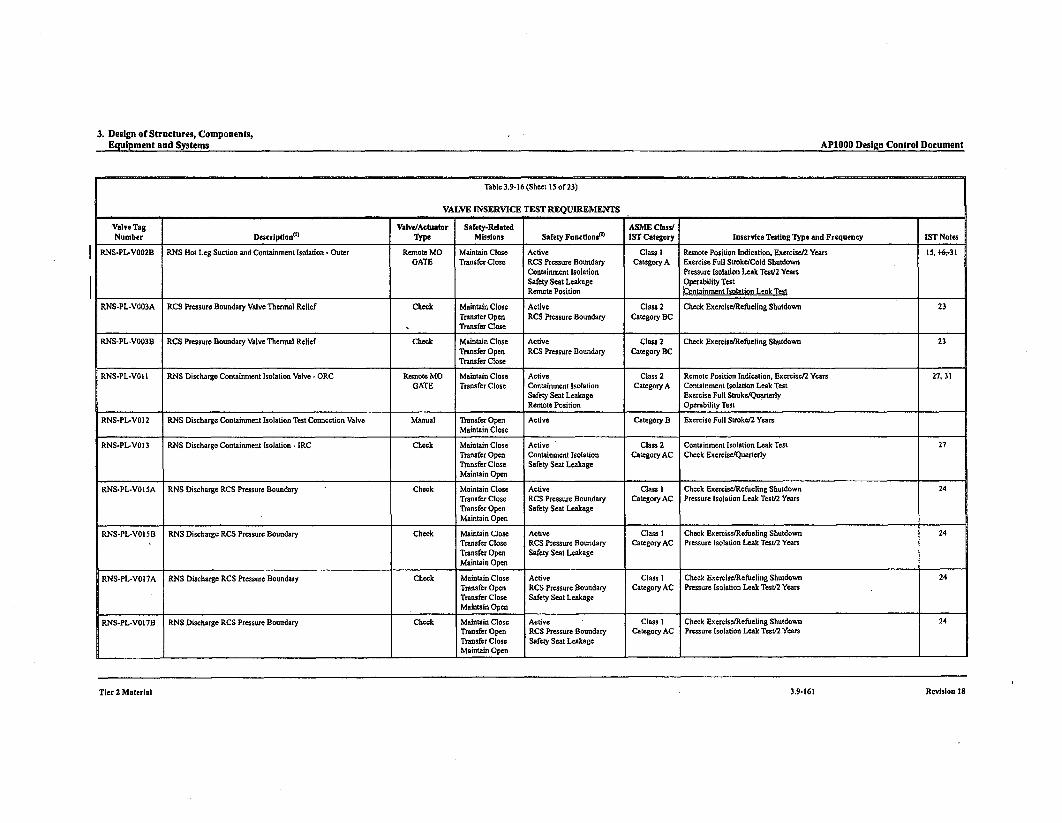
Table 3.9-16 (Sheet 15 of 23)
VALVE INSERVICE TEST REQUIREMENTS
Valve Tag Valve/Actuator Safety-Related ASME Class/Number Description(', Type Missions Safety Functionsr) IST Category Inservtce Testing Type and Frequency IST Notes
RNS-PL-VO02B RNS Hot Leg Suction and Containment Isolation - Outer Remote MO Maintain Close Active Class I Remote Position Indication, Exercise/2 Years 15, 4-6-31GATE Transfer Close RCS Pressure Boundary Category A Exercise Full Stroke/Cold Shutdown
Containment Isolation Pressure Isolation Leak Test/2 YearsSafety Seat Leakage Operability TestRemote Position Containment Isolation Leek Test
RNS-PL-VO03A RCS Pressure Boundary Valve Thermal Relief Check Maintain Close Active Class 2 Check Exercise/Refueling Shutdown 23Transfer Open RCS Pressure Boundary Category BCTransfer Close
RNS-PL-VO03B RCS Preasure Boundary Valve Thermal Relief Check Maintain Close Active Class 2 Check Exercise/Refueling Shutdown 23Transfer Open RCS Pressure Boundary Category BCTransfer Close
RNS-PL-VOI I RNS Discharge Containment Isolation Valve - ORC Remote MO Maintain Close Active Class 2 Remote Position Indication, nerciset2 Years 27. 31GATE Transfer Close Containment Isolation Category A Containment Isolation Leak Test
Safety Seat Leakage Exercise Full Stroke/QuarterlyRemote Position Operability Test
RNS-PL-VO12 RNS Discharge Containment Isolation Test Connection Valve Manual Transfer Open Active Category B Exercise Full Stroke/2 YearsMaintain Close
RNS-PL-V013 RNS Discharge Containment Isolation - IRC Check Maintain Close Active Class 2 Containment Isolation Leak Test 27Transfer Open Containment Isolation Category AC Check Exercise/QuarterlyTransfer Close Safety Seat LeakageMaintain Open
RNS-PL-VO15A RNS Discharge RCS Pressure Boundary Check Maintain Close Active Class I Check Exercise/Refuitling Shutdown 24Transfer Close RCS Pressure Boundary Category AC Pressure Isolation Leak Test/2 YearsTransfer Open Safety Seat LeakageMaintain Open
RNS-PL-VOI5B RNS Discharge RCS Pressure Boundary Check Maintain Close Active Class I Check Exercisa/Refueling Shutdown 24Transfer Close RCS Pressure Boundary Category AC Pressure Isolation Leak Test/2 YearsTransfer Open Safety Seat LeakageMaintain Open
RNS-PL-VO17A RNS Discharge RCS Pressure Boundary Check Maintain Close Active Class I Check Exercise/Refueling Shutdown 24Transfer Open RCS Pressure Boundary Category AC Pressure Isolation Leak Test/2 YearsTransfer Close Safety Seat LeakageMaintain Open
RNS-PL-VO17B RNS Discharge RCS Pressure Boundary Check Maintain Close Active Class I Check Exercise/Refueling Shutdown 24Transfer Open RCS Pressure Boundary Category AC Pressure Isolation Leak Test/2 YearsTransfer Close Safety Seat LeakageMaintain Open
Tier 2 Material 3.9-161 Revision 18

3. Design of Structures, Components,Equipment and Systems
AP1000 Desigon Control Document
12. This note applies to the PXS IRWST injection check valves (PXS-V122A/B, V124A/B).To exercise these checkvalves a testcartmust be moved into containment and temporary connections made to these check valves. In addition, the IRWST injection lineisolation valves must have power restored and be closed. These valves are not exercised during power operations because closingthe IRWST injection valve is not permitted by the Technical Specifications and the need to perfnor significant work insidecontainment. Testing is not performed during cold shutdown for the same reasons. These valves are exercised during refuelingconditions when the IRWST injection lines are not required to be available by TechnicalSpecifications and the radiation levels arereduced.
13. Deleted.
14. Component cooling water system containment isolation motor-operated valves CCS-V200, V207, V208 and check valveCCS-V201 are not exercised during poweroperation. Exercising thesevalves would stop cooling water flow to thereactor coolantpumps and letdown heat exchanger. Loss of cooling water may result in damage to equipment or reactor trip. These valves areexercised during cold shutdowns when these components do not require cooling water,
IS. Normal residual heat removal system reactor coolant isolation motor-operated valves (RNS-V00 IA/B, V002A/B) are notlvied during power operation. Ths aes isolate the high vess RCS fro. the low press. RNS and pas roprerotelingti y~lPXS). Open' uingI Io I 1ia1,u6,po116¢t! 11, aldani a dtel
valves inadvertently opening or closing, resulting in plant or system transients. These valves are exercised during refuelingconditions when system and plant transients would not occur.
19. Primary sampling system containment isolation check valve (PSS-V024) is located inside containment and considerable effort isrequired to install test equipment and cap the discharge line. Exercise testing is not porformedduring cold shutdown operatioss forthe same reasons. Those valves are exercised during refueliag conditions when the radiation levels are reduced.
water to the PCS post-72 hour from a temporary water supply. To exercise the valve, a temporary pump and water supply isconnected using temporary pipe and fittings, and the flow rate is observed using a temporary flow measuring device to confirmvalve operation.
22. Exercise testing ofthe auaxiliary Spray isolation valve (CVS-V084, V05) will result in an undesirable temperature tansient on thepressurizer due to the actuation of auxiliary spray flow, Therefore, quarterly exercise testing will not be performed. Exercisetesting will be performed during cold shutdowns.
23. Thermal relief check valves in the normal residual heat removal suction line (RNS-V003A/B) and the Chemiral and VolumeControl System makeup line (CVS-V100) are located inside containment. To exercise test these valves. entry to the containment isrequired and tersporaryconsections made to gas supplies. Because of the radiation exposure and effort required, this test is notconducted during power operation or during cold shutdowns. Exercise testing is performed during refueling shutdowns.
24. Normal residual heat removal system reactor coolant isolation check valves (RNS-V0ISA/B, V017A/B) are not exercise testedquarterly. During normal power operation these valves isolate the high pressure RCS from the low pressure RNS. Opening duringnormal operation would require a pressure greater than the RCS normal pressure, which is not available. It would also subject theRCS connection to undesirable transients. These valves will be exercised during cold shutdowns.
25. This note applies to the main feedwater control valves (SGS-V250A/B), moisture separator reheater 2nd stage steam isolationvalve (MSS-VOlSA/B), turbine control valves (MTS-VO2A/B, VO4A/B). The valves are not quarterly stroke tested since fillstroke testing would result in a plant transient during power operation. Normal feedwater and turbine control operation provides apartial stroke confirmation of valve operability. The valves will be ffill stroke tested during cold shutdowns.
26. This note applies to containment compartment drain line check valves (SFS-V071, SFS.V072, WLS-V071A/B/C,WLS-V072A/B/C); These check valves are located inside containment and require temporary connections for exercise testing.Because of the radiation exposure and effort required, these valves are not exercised during power operation or during coldshutdowns. The valves will be exercised during refaelings.
27. Containment isolation valves leakage test frequency will be conducted in accordance with the "Primary Containment Leakage RateTest Program" in accordance with 10 CFR 50 Appendix J. Refer to SSAR subsection 6.2.5.
28. This note applies to the chilled water system containment isolation valves (VWS-V058, V062, V082 and V086). Closing any o fthese valves stops the water flow to the containment fan coolers. This water flow may be necessary to maintain the containment airtemperature within Technical Specification limits. As a result, quarterly exercise testing will be deferred when plant operatingconditions and site climatic conditions would cause the containment air temperature to exceed this limit during testing.
29. Exercise testing of the turbine bypass control valves (MSS-V0O01, V002, V003, V004, V005 and V006) will result in anundesirable temperature transient on the turbine, condenser and other portions of the turbine bypass due to the actuation of bypassflow. Therefore, quarterly exercise testing will not be performed. Exercise testing will be performed during cold shutdowns.
30. Deleted.
31 These valves are subject to operability testing perthe requirements of 10 CFR 5 ,55a. he test freouencies areto be established inaccordance with the results of the Joint Owners Group (JOG) vroe am for Periodic verification of desien-basis capability ofsafety-related motor-onerated valves (MOVs) Based on the composition of power-operated valves (POVa) in this table, the JOGairpoach shall be atnlied to all actuator tones. POV risk ranking and functional marein are used to establish the recommendedmaximum periodic verification test (Operabilitv) interval,
ýhgse POVW (motor-oserated. air-poerated, solenoid-onerated. and hvdraulicallv-onerated) shall beaddressed in the owner's POVrossetive ormnram-soecific dcnuments. Attributes of these nmro'ams shall include lessons learned as delineated in the NRC'sRegulatorv Issue Summary (RIS) 2000-3. "Performance of Safety-Related Power-Operated Valves Under Design BasisConditions." ee subsection 3.9.6.2.2 for the factors to be considered in the evaluation of operability testing and subsection 3.9.8.4for the Combined License information item. Th, tzt t-z•u...... 1 ,. e f :;.7 .lL-.zL... S tI .:t::e.
20. This note applies to the main steam isolation valves and main fecdwater isolation valves (SOS-V040A/B, V057A/B). The valvesare not full stroke tested quarterly at power since full valve stroking will result in a plant transient during normal power operation.Therefore, these valves will be full stroke tested on a cold shutdown frequency basis. The full stroke testing will be a full "slow"closure operation. The large size and fast stroking nature of the valve makes it advantageous to limit the number of fast closureoperations which the valve experiences. The timed slow closure supports the continued operability status of the valves in theintervals between fast closure tests and ensures that the valve is not mechanically bound.
21. Post-72 hour check valves that require temporary connections for inservice-testing are exercised every refueling outage. Thesevalves require transport and installation oftemporary test equipment and pressure/fluid supplies. Since the valves are normallyused very infrequently, constructed of stainless steel, maintained in controlled environments, and ofa simple design, there is littlebenefit in testing them more frequently. For example, valve PCS-V039 is a simple valve that is opened to provide the addition of
Tier? Material 3.9-177 Revlslon 18Tier 2 Material3.9-177 Revision 18
3. Design of Structures, Components,Equipment and Systems AP1000 Design Control Document
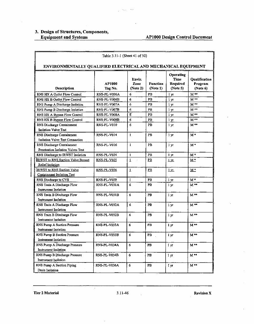
Table 3.11-1 (Sheet 41 of 50)
ENVIRONMENTALLY QUALIFIED ELECTRICAL AND MECHANICAL EQUIPMENT
OperatingEnvir. Time Qualification
AP1000 Zone Function Required ProgramDescription Tag No. (Note 2) (Note 1) (Note 5) (Note 6)
RNS HX A Outlet Flow Control RNS-PL-VO06A 6 PB 1 yr M **
RNS HX B Outlet Flow Control RNS-PL-VO06B 6 PB 1 yr M **RNS Pump A Discharge Isolation RNS-PL-VO07A 6 PB 1 yr M **
RNS Pump B Discharge Isolation RNS-PL-VO07B 6 PB I yr M **
RNS HX A Bypass Flow Control RNS-PL-VO08A -6 PB 1 yr M **RNS HX B Bypass Flow Control RNS-PL-VO08B 6 PB I yr M **
RNS Discharge Containment RNS-PL-V010 6 PB 1 yr M **Isolation Valve Test
RNS Discharge Containment RNS-PL-V014 I PB 1 yr M *Isolation Valve Test Connection
RNS Discharge Containment RNS-PL-V016 I PB I yr M *Penetration Isolation Valves Test
RNS Discharge to IRWST Isolation RNS-PL-V024 I PB 1 yr M *IRWST to RNS Suction Valve Bonnet RNS-PL-V025 1 PB Iyr M *Relief Isolation
IRWST to RNS Suction Valve RNS-PL-V026 1 PB M__.M *
Containment Isolation TestRNS Discharge to CVS RNS-PL-V029 I PB 1 yr M *RNS Train A Discharge Flow RNS-PL-V031A 6 PB 1 yr M **
Instrument IsolationRNS Train B Discharge Flow RNS-PL-V031B 6 PB 1 yr M **Instrument Isolation
RNS Train A Discharge Flow RNS-PL-V032A 6 PB I yr M **
Instrument IsolationRNS Train B Discharge Flow RNS-PL-V032B 6 PB 1 yr M **
Instrument IsolationRNS Pump A Suction Pressure RNS-PL-V033A 6 PB 1 yr M **
Instrument IsolationRNS Pump B Suction Pressure RNS-PL-V033B 6 PB I yr M **Instrument Isolation
RNS Pump A Discharge Pressure RNS-PL-V034A 6 PB 1 yr M **Instrument Isolation
RNS Pump B Discharge Pressure RNS-PL-V034B 6 PB 1 yr M **Instrument Isolation
RNS Pump A Suction Piping RNS-PL-V036A 6 PB 1 yr M **Drain Isolation
Tier 2 Material 3.11-46
Revision X
Tier 2 Material 3.11-46 Revision X
3. Design of Structures, Components,Equipment and Systems AP1000 Design Control Document
Table 31.6-3 (Sheet 21 of 312)
LIST OF AP1000 SAFETY-RELATED ELECTRICALAND MECHANICAL EQUIPMENT NOT HIGH FREQUENCY SENSITIVE
AP1000
Description Tag Number Comment
RCP IA Drain RCS-PL-V261A 2
RCP lB Drain RCS-PL-V261B 2
RCP 2A Drain RCS-PL-V261C 2
RCP 2B Drain RCS-PL-V261D 2
RCS Pressure Boundary Valve Thermal Relief Isolation RNS-PL-VO04A 2
RCS Pressure Boundary Valve Thermal Relief Isolation RNS-PL-VO04B 2
RNS Pump A Suction Isolation RNS-PL-VO05A 2
RNS Pump B Suction Isolation RNS-PL-VO05B 2
RNS HX A Outlet Flow Control RNS-PL-VO06A 2
RNS HX B Outlet Flow Control RNS-PL-VO06B 2
RNS Pump A Discharge Isolation RNS-PL-V007A 2
RNS Pump B Discharge Isolation RNS-PL-VO07B 2
RNS HX A Bypass Flow Control RNS-PL-VO08A 2
RNS HX B Bypass Flow Control RNS-PL-VO08B 2
RNS Discharge Containment Isolation Valve Test RNS-PL-VO10 2
RNS Discharge Containment Isolation Valve Test Connection RNS-PL-V014 2
RNS Discharge Containment Penetration Isolation Valves Test RNS-PL-V016 2
RNS Discharge to IRWST Isolation RNS-PL-V024 2
MNS Suction from IRWST - Bonnet Relief Isolation RNS-PL-V025 2
hNS Suction from IRWST - Containment Isolation Test RNS-PL-V026 2
RNS Discharge to CVS RNS-PL-V029 2
RNS Train A Discharge Flow Instrument Isolation RNS-PL-V031A 2
RNS Train B Discharge Flow Instrument Isolation RNS-PL-V031B 2
RNS Train A Discharge Flow Instrument Isolation RNS-PL-V032A 2
RNS Train B Discharge Flow Instrument Isolation RNS-PL-V032B 2
Tier 2 Material 31-60 Revision 18

5. Reactor Coolant System and Connected Systems API000 Design Control Document
~2A~tZ VP
I-I-,~I
Figure 5.4-7
Normal Residual Heat Removal SystemPiping and Instrument Diagram
Tier 2 Material 5.4-102 Revision X

6. Engineered Safety FeaturesAPI000 Deslin Control Document
Table 6.2.3-1 (Sheet 2 of 4)
CONTAINMENT MECHANICAL PENETRATIONS AND ISOLATION VALVESConetloemet Peoet,-teion lohltoo Devito Test
POSition ClosureSystem Line Flow Cloed Sys IRC Valvefllateh Idaotlettleon h1aistih DCD Suttaettlon N-S-A Sign.[ Times Type- & Note Medino Direstito
PXS N, to accut.latots to No PXS.PL-V042 6.3 O.O-C T std. C Air Fo0,OtrdPXS-PL-V043 C-C-C None NIARNS RCS to RHR pump Out No R.NS.PLýV0002AB - 5.4.7 C-0-C HK. S std. Ait
RNS-PL-VO23- 5.4.7 CO-C HO, S std.FLNS-PL-V022 3.4.7 C-O.C HR.,S atd. C,4 F.-orwdRNS-PL-V021 - 5.4.7 C-C-C None NIA C Fortr.dR.NS.PL-VD61 - 3.4.7 C-O-C aid. C FeorWoPXS.PL-V208A - 6.3 C-C-C Noe. N/A C Fenorwd
RHR pump to RCS In No RNS-PL-V1 . 5.4.7 C-O-C HR., S ad. C,4 Air Fo-sedRI4S-pL-V013 - C-0-C None N/A C,4
SFS IRWST/REf. ca. SFP pump 1o No SPS-PL-V039 0. 9.1.3 C-0-C T std. C's Air Frowtrddischasrge SFS-PL-V037 . C-O-C None N/AIRWST/Re£ sos. purof. out ONt No SFS-PL-V035 b[ 9.1.3 C-0-C T aid. C.5 Air F-orwrd
SFS-PI-VO34 . C-O-C T ttd.SFM-PL-VIO7 7 C-C-C No.e NA
SGS Minosteneolinoei out Yes SGS-Pt-VO4OA 19 10.3 O-C-C MS suc A.2 N2 ForardSGS-PL-V027A(7) 62 0-0-C LSL std.SGS-PL- 11,11L21 C-C-C .Nooe N/A
V030A,31A,32A,33A,34A,35A 2327SOS-PL-V036A 3U 0-0-C MS end.SGS-PL-V240A C-C-C MS sd.
Main steam line 02 Out Yes SOS-pL-V0409 10.3 O-C-C MS 5'.se A,2 N2 Fon-.odSGS-PL-VO27B(7) 62 0-0-C LSI. . $d
SGS-PL- 11,1 821 C-C-C None N/AVO30B,$ IB,.325,330340,35B 2L2
SGS-PLV036B 32 O-O-C MS ind." SGS-PL-V240B 44 C-C-C MS 'Id.
Main feodwotte 01 o Yes SGS-PL-VO57A 12 10.3 O-C-C MF 5es. A,2 H20 FonnosrdMain feedteoter 02 in Yes SGS-PL.V0S7B 10.3 O-C-C MF S ec A.2 H20 For.wdSG blowdoent 0 Out Yes SGS-PL-VO74A 1A 10.3 OO-C PRHR otd. A,2 720 FnoradSO blowdone 02 Out yto SGS-PL-VO74B hI 10.3 o0o0c PRHR sd. A.2 H20 FonosrdSt aop flodwater 01 In Yes SGS-PL-VD67A [5 10.3 C-C-C LTC, SOL I ad. A.2 320 ForwardStotup feedwoto 02 1. Yes SGS-pL-Vd670 27 170.3 C-O-C LTC, SGL I ad. A.2 120 Forward
Tier 2Material6.2-99 Revision IS

6. Engineered Safety FeaturesAP1000 Desig~n Control Document6. Engineered Safety I~aturee
PCDDss CnrlDcmn
Table 6.2.3-1 (Sheet 4 of 4)
CONTAINMENT MECHANICAL PENETRATIONS AND ISOLATION VALVES
Explanation of Heading and Acronyms for Thble 6.2.3-1
System: Fluid system penetrating containment Closure Time:Required valve closure stroke timeContainment Penetration: These fields refer to the penetration itself std: Industry standard for valve type (L 60 seconds)
Line: Fluid system line N/A: Not ApplicableFlow: Direction of flow in or out of containment Test: These fields refer to the penetration testing requirementsClosed Sys IRC: Closed system inside containment as defined in DCD Section 6.2.3.1.1 Type: Required test typeIsolation Device: These fields refer to the isolation devices for a given penetration A: Integrated Leak Rate TestValve/Hatch ID: Identification number on P&ID or system figure B: Local Leak Rate Test -- penetration.ix,.Length; Wominal length of nine to outboard containment isolation valve., feet C: Local Leak Rate Test -- fluid systems
Subsection Containing Figure: Safety analysis report containing the system P&ID or figure Note: See notes belowPosition N-S-A: Device position for N (normal operation) Medium: Test fluid en valve seat
S (shutdown) Direction: Pressurization directionA (post-accident) Forward: High pressure on containment sideSignal: Device closure signal Reverse: High pressure on outboard sideMS: Main steam line isolationLSL: Low steam line pressureMF: Main feedwater isolationLTC: Low T,,asPRHR: Passive residual heat removal actuationT: Containment isolationS: Safety injection signalHR: High containment radiationDAS: Diverse actuation system signalPL2: High 2 pressurizer level signalS+PLl: Safety injection signal plus high 1 pressurizer levelSGL: High steam generator level
I. Containment leak rate tests are designated Type A, B, or C according to 10CFR50, Appendix 1.2. The secondary side ofthe steam generator, including main steam, feedwater, startup feedwater, blowdown and sampling piping from the steam generators to the containment penetration, is considered an extension of the containment. These systems are not part of the reactorcoolant pressure boundary and do not open directly to the containment atmosphere during post-accident conditions. During Type A tests, the secondary side of the steam generators is vented to the atmosphere outside containment to ensure that full test differential pressure isapplied to this boundary.3. The central chilled water system remains water-filled and operational during the Type A test in order to maintain stable containment atmospheric conditions.4. The containment isolation valves for this penetration are open during the Type A test to facilitate testing. Their leak rates are measured separately.5. The inboard valve flange is tested in the reverse direction.6. Reereto vae Tare .t -4bjt tora TP C test. Upstreamoside of PIeS hot vl; i ne! vente . uring leeal leal. fat. test .rt. deuble .FRG8 a: ele.med p..ssu.r. W is n -ing pas! Rt e -t - . o used.7. Refer to DCD Table 1 5.0-4b for PORV block valve closure time.
Tier 2 Material 6.2-103 Revision IsTier 2 Material
6.2-103 Revision 18

Change Number 3

3. Design of Structures, Components,Equipment and Systems
APIOOO Design Control Document
Table 3.9-16 (Sheet 10 of 23)
VALVE INSERVICE TEST REQUIREMENTSValve Tag Valve/Actuator Safety-Related ASME Class/Number DescriptionOt Type Missions Safety Functions,) IST Category Inservice Testing Type and Frequency IST NotesPXS-PL.V043 Nitrogen Supply Containment Isolation MC Check Maintain Close Active Class 2 Remote Position Indication, Exercise/2 Years 27Transfer Close Containment Isolation Category AC Containment Isolation Leak TestSafety Seat Leakage Check Exercise/Quarterly
Remote PositionPXS-PL-V 10l PRHR HX Inlet Isolation Remote MO Maintain Open Remote Position Class I Remote Position Indication, Exercise/2 Years~ ~ H CategoryBPn -PL-V 108A PR.HR HX Co"trol Remote An Maintain Open Active-to-Failed --Class Remote Position Indination, Exerc-ise3 Years 31
ýGBS•gi. Transfer Open Remote Position Category B Exercise Full StrokeVQuarterlyOperability TestPXS-PL,-V 108B PRHR HX Control Remote AO Maintain Open Active-to-Failed Class I Remote Position Indication, Exemcisel2 Years 31•zQBgBall Transfer Open Remote Position Category B Exercise Full Stroke/Quarterly-'-- __ .. . •""• •• .. rability t•PXS-PL-V II 17A Containment Recirculationn solation Remot..MO Maintain Open Remote Position Class 3 Remote Position Indication, Exercis/2 Years3GATE Category BPXS-PL-V I I 7B Containment Recirculation B Isolation Remote MO Maintain Open Remote Position Class 3 Remote Position Indication, Exercise/2-YearsGATE Category B fPXS-PL-V I 18A Containment Recirculation A Isolation Squib Maintain Open Active Class 3 Remote Position Indication, Alternate/2 Years 5Maintain Close Remote Position Category D Charge Test Fire/20% in 2 Years
Transfer OpenPXS-PL-V I 18B Containment Recirculation B Isolation Squib Maintain Open Active Class 3 Remote Position Indication, Ahternatet2 Years 5Maintain Close Remote Position Category D Charge Test Fire/20% in 2 Years
Transfer OpenPXS-PL-VI 19A Containment Recirculation A Check Check Maintain Open Active Class 3 Remote Position Indication, Exercise/2 Years IIMaintain Close Remote Position Category BC Check-initial Open Differential Pressurettkcl"n 24-sTransfer Open Check Exercise/Refueling Shutdown
Transfer ClosePXS-PL-V I 19B Containment Recirculation B Check Check Maintain Open Active Class 3 Remote Position Indication, Exercise/2 Years IIMaintain Close Remote Position Category BC Check-Initial Open Differential Peeturessrefijrcjl2-YeamTransfer Open Check Exercise/Refueling Shutdown
Transfer ClosePXS-PL-V120A Containment Recirculation A Isolation Squib Maintain Open Active Class 3 Remote Position Indication, Altematei2 Years 5Maintain Close Remote Position Category D Charge Test Fire/20% in 2 Years
Transfer OpenPXS-PL-V120B Containment Recirculation B Isolation Squib Maintain Open Active Class 3 Remote Position Indication, Alternate/2 Years
Maintain Close Remote Position Category D Charge Test Fire/20% in 2 YearsTransfer Open
Tier 2 Material3.9-145 Revision 18

6. Engineered Safety Features AP1000 Design Control Document
coolant loops. During normal operation, the core makeup tanks are completely fall of cold,borated water. The boration capability of these tanks provides adequate core shutdown marginfollowing a steam line break.
The core makeup tanks are connected to the reactor co9lant system through a discharge injectionline and an inlet pressure balance line connected to a cold leg. The discharge line is blocked bytwo normally closed, parallel air-operated isolation valves that open on a loss of air pressure orelectrical power, or on control signal actuation. The core makeup tank discharge isolation valvesare diverse from the passive residual heat removal heat exchanger outlet isolation valves discussedabove. They use different glebe-valve body styles and different air operator types.
The pressure balance line from the cold leg is normally open to maintain the core makeup tanks atreactor coolant system pressure, which prevents water hammer upon initiation of core makeuptank injection.
The cold leg pressure balance line is connected to the top of the cold leg and is routedcontinuously upward to the high point near the core makeup tank inlet. The normal watertemperature in this line will be hotter than the discharge line.
The outlet line from the bottom of each core makeup tank provides an injection path to one of thetwo direct vessel injection lines, which are connected to the reactor vessel downcomer annulus.Upon receipt of a safeguards actuation signal, the two parallel valves in each discharge line opento align the associated core makeup tank to the reactor coolant system.
There are two operating processes for the core makeup tanks, steam-compensated injection andwater recirculation. During steam-compensated injection, steam is supplied to the core makeuptanks to displace the water that is injected into the reactor coolant system. This steam is providedto the core makeup tanks through the cold leg pressure balance line. The cold leg line only hassteam flow if the cold legs are voided.
During water recirculation, hot water from the cold leg enters the core makeup tanks, and the coldwater in the tank is discharged to the reactor coolant system. This results in reactor coolant systemboration and a net increase in reactor coolant system mass.
The operating process for the core makeup tanks depends on conditions in the reactor coolantsystem, primarily voiding in the cold leg. When the cold leg is full of water, the cold leg pressurebalance line remains full of water and the injection occurs via water recirculation. If reactorcoolant system inventory decreases sufficiently to cause cold leg voiding, then steam flowsthrough the cold leg balance lines to the core makeup tanks.
Following an event such as steam-line break, the reactor coolant system experiences a decrease intemperature and pressure due to an increase of energy removed by the secondary system as aconsequence of the break. The cooldown results in a reduction of the core shutdown margin due tothe negative moderator temperature coefficient. There is a potential return to power, assuming themost reactive rod cluster control assembly is stuck in its fully withdrawn position. The actuation ofthe core makeup tanks following this event provides injection of borated water via waterrecirculation to mitigate the reactivity transient and provide the required shutdown margin.
Tier 2 Material 6.3-8 Revision 18
6. Engineered Safety Features APIOOO Design Control Document
.__ ' ' " a' ' W• '
__ __ 'V .....
rn-i" " " i. "- -- "•-
j **.-• •: . . . .I-, • - Iii i
_ _....
..... __ -. I .. . l ,-
.. .... / ....
Figure 6.3-2
Passive Core Cooling SystemPiping and Instrumentation Diagram (Sheet 2)
Tier 2 Material 6.3-64 Revision 18
6. Engineered Safety Features AP1000 Design Control Document6.Egiere _aft FetrsA10 einCnrlDcmn
zva
Inside Reactor Containment
Figure 6.3-4
Passive Decay Heat Removal(REF) RCS & PXS
Tier 2 Material 6.3-67 Revision 18

Change Number 4
3. Design of Structures, Components,Equipment and Systems AP1000 Design Control Document
Table 3.2-3 (Sheet 22 of 65k8)
API000 CLASSIFICATION OF MECHANICAL ANDFLUID SYSTEMS, COMPONENTS, AND EQUIPMENT
AP1000 Seismic Principal Con-
Tag Number Description Class Category struction Code j Comments
Passive Core Cooling System (Continued)
PXS-PL-V231A CMT A Fill Check B I ASME I1I-2PXS-PL-V231B CMT B Fill Check B I ASME 1II-2PXS-PL-V232A Accumulator A Fill/rain C I ASME 1II-3
Isolation
PXS-PL-V232B A lve BC___-..__._-__ I
PXS-PL-V250A CMT A Check Valve Test A I ASME 111-1Valve
PXS-PL-V250B CMT B Check Valve Test A I ASME III- IValve
PXS-PL-V251A CMT A Check Valve Test A I ASME Il1- IValve
PXS-PL-V251B CMT B Check Valve Test A I ASME III-IValve
PXS-PL-V252A CMT A Check Valve Test A I ASME III- PValve
PXS-PL-V252B CMT B Check Valve Test C I ASNE Illc-eValve . _,.. ,,
Containment Penetration[Balance of system components are Class E -
Reactor Coolant System (RCS) Location: ContainmentRCS-NM-01 Steam Generator I A !I ASME rIII-lRCS-NM-02 Steam Generator 2 A I ASME 111-1RCS-MP-01AýB SG 1A(B) Reactor Coolant A I ASNM mI-1I Pump Motor -
Pump Class D
Rotor Shaft C _I ManufacturerStd
__ Imreller C I ManufacturerStd
n/__a Flywheel C I ManufacturerStd
ra RCP Heat Exchanger (Tube A I ASME III-I Shellside -Side) Class D. ASME
VIII, Div. I
I
Tier 2 Material 3.2-42
Revision 18
Tier 2 Material 3.2-42 Revision 18
3. Design of Structures, Components,Equipment and Systems AP1000 Design Control Document
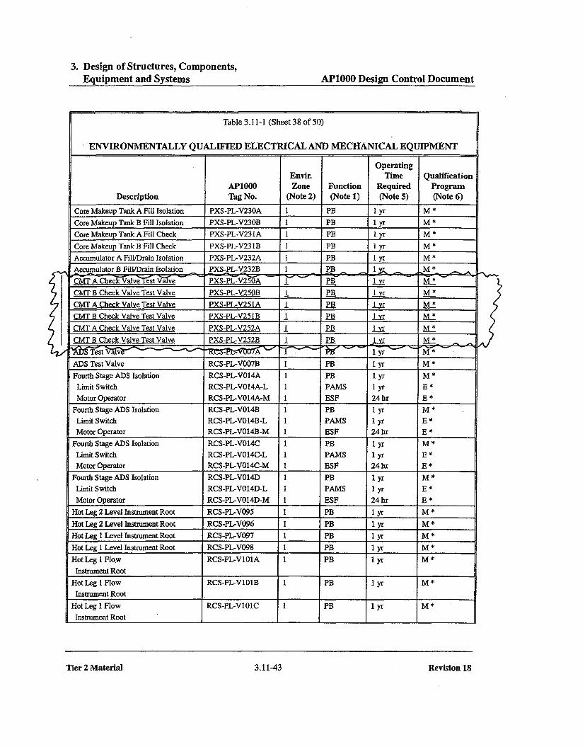
Table 3.11-1 (Sheet 38 of 50)
ENVIRONMENTALLY QUALIFIED ELECTRICAL AND MECHANICAL EQUIPMENT
OperatingEnvir. Time Qualification
AP1000 Zone Function Required ProgramDescription Tag No. (Note 2) (Note 1) (Note 5) (Note 6)
Core Makeup Tank A Fill Isolation PXS-PL-V230A 1 PB 1 yr M *
Core Makeup Tank B Fill Isolation PXS-PL-V230B 1 PB 1 yr M *
Core Makeup Tank A Fill Check PXS-PL-V23 IA 1 PB I yr M *
Core Makeup Tank B Fill Check PXS-PL-V23 1B I PB 1 yr M *
Accumulator A Fill/Drain Isolation PXS-PL-V232A 1 PB I yr M *
Accumulator B Fill/Drain Isolation PXS-PL-V232B 1 PB 1M , M * - .ýCMT A Check Valve est V-yve v PXS-PL-V250A - PB 1_yr M *
CMT B Check Valve Test Valve PXS-PL-V250B I PB 1 yr M *
CMT A Check Valve Test Valve PXS-PL-V251A PB 1_y-r M-*CMT B Check Valve Test Valve PXS-PL-V251B 1_ PB I lr M_*
CMT A Check Valve Test Valve PXS-PL-V252A I PB _ _ M M*CMT B Check Valve Test Valve PXS-PL-V252B I PB -1yr M *-ZW1 f 'y -' -Pa -*/,______' __t ___________ "_____ ______ - lyr M*ADS Test Valve RCS-PL-VO07B I PB 1 yr M *Fourth Stage ADS Isolation RCS-PL-V014A 1 PB 1 yr M *
Limit Switch RCS-PL-V014A-L 1 PAMS 1 yr E *Motor Operator RCS-PL-VO14A-M 1 ESF 24 hr E *
Fourth Stage ADS Isolation RCS-PL-VO14B 1 PB 1 yr M *
Limit Switch RCS-PL-VO14B-L 1 PAMS 1 yr E *Motor Operator RCS-PL-VO14B-M 1 ESF 24 hr E *
Fourth Stage ADS Isolation RCS-PL-VO14C 1 PB 1 yr M *
Limit Switch RCS-PL-V014C-L 1 PAMS 1 yr E *Motor Operator RCS-PL-VO14C-M 1 ESF 24 hr E *
Fourth Stage ADS Isolation RCS-PL-V014D 1 PB 1 yr M *
Limit Switch RCS-PL-VO14D-L I PAMS 1 yr E *
Motor Operator RCS-PL-VO14D-M 1 ESF 24 hr E *Hot Leg 2 Level Instrument Root RCS-PL-V095 I PB 1 yr M *
Hot Leg 2 Level Instrument Root RCS-PL-V096 I PB 1 yr M *
Hot Leg 1 Level Instrument Root RCS-PL-V097 1 PB 1 yr M *
Hot Leg 1 Level Instrument Root RCS-PL-V098 1 PB 1 yr M *
Hot Leg 1 Flow RCS-PL-V101A I PB 1 yr M *Instrument Root
Hot Leg I Flow RCS-PL-VI01B 1 PB I yr M*Instrument Root
Hot Leg 1 Flow RCS-PL-VIO1C 1 PB 1 yr M *
Instrument Root
Tier 2 Material 3.11-43 Revision 18

3. Design of Structures, Components,Eauinment and Systems
API000 Design Control Document
Table 3.9-16 (Sheet 8 of 23)
VALVE INSERVICE TEST REQUIREMENTS
Valve Tag ValvelActuator Safety-Related ASME Class/Number Description(
t) Ty~pe Missions Safety Functionso) IST Category Inservice Testing Ty'pe and Frequency "IST Notes
PSS-PL-V046 Air Sample Line Containment Isolation ORC RemoteAO Maintain Close Active-to-Failed Class 2 Remote Position Indication, Exercise/2 Years 27,31GLOBE Transfer Close Containment Isolation Category A Containment Isolation Leak TestSafety Seat Leakage Exercise Full Stroke/QuarterlyRemote Position Operability Test
IPWS-PL-V4W8 PWS MCR Isolation Valve Manual Trsafer Close Acti Class 3 Exercise Full Stroke2 YearsM~aintain-i Q ClI CoeesB
LpWS-PL-V420 PWS MCR Isolation Valve Manual Transofr Close Ativ Class 3 Exercise Full Stroke/2 Yearsmonaw inw ses CotAW2ry 13
PXS-PL-V009A PWS MCR VTuanm Blreaker Cheek Transfer Open Activ t Class 3 Check EPerciseitio artErleTransfer Clone Category CMAintoje ClIose
ýWg-P6 W424l PAWE A.CR. IqktL..n Vcl'e mnoatm Tanarae-Opens Aeisiv Gewsegy-B &WHeIn-SA JA!"881 e OF9-aa
PXS-PL-VO02A Core Makeup Tank A Cold Leg Inlet Isolation Remote MO Maintain Open Remote Position Class I Remote Position Indication, Exercise/2 YearsGATE Category B
PXS-PL-VOO2B Core Makeup Tank B Cold Leg Inlet Isolation Remote MO Maintain Open Remotet Position Clans I Remote Position Indication, Exereise/2 YearsGATE Category B
PXS-PL-Vt14A Core Makeup Tank A Discharge Isolation Remote AO Maintain Open Active-to-Failed Class I Remote Position Indication, Exercise/2 Years 31GLOBE -Transfer Open Remote Position Category B Exercise Full Stroke/QuarterlyOperability Test
PXS-PL-VOi4B Core Makeup Tank B Discharge Isolation RemoteAn Maintain Open Active-to-Failed Class I Remote Position Indication, Exercise/2 Years 31GLOBE Transfer Open Remote Position Category B Exercise Full Stsoke/Quarterly
Operability Test
PXS-P'L-VOIA Core Makeup Tank A Discharge Isolation Remote AG Maintain Open Active-to-Failed Class I Remote Position Indication, Exercise/2 Years 31GLOBE Transfer Open Remote Position Category B Exercise Full Stroke/Quarterly
Operability 'lestPXS-PL-VOI5B Core Makeup Tank B Discharge Isolation RemoteAn Maintain Open Active-to-Failed Class I Remote Position Indication, Exereisen2 Years 31
GLOBE Transfer Open Remote Position Category B Exercise Full Stroke/Quarterly
PXS-PL-VO16A Core MakeupTankADischarge Check Check Maintain Open A7ctive Class I Rentat , Pas)t>. !..j:a: Fw•e: eP." .e." 10Transfer Open •ma•-e-e esilien Category BC Check ExercisoeRefueling ShutdownTransfer Close
PXS-PL-V016B Core Makeup Tank B Discharge Check Check Maintain Open Active Class I R.mete position idie":e, F..G.e:•2 Y::ee 10Transfer Open Remnae-Pesiiien Category BC Check ExercisetRefueling ShutdownTransfer Close21
)
3.9-147 Revision ISTier 2 Material
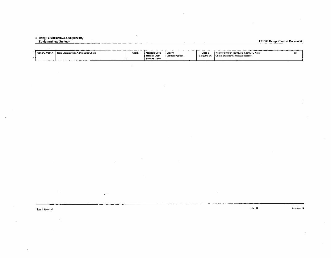
3. Design of Structures, Components,Equipment and Systems
AP1000 Design Control Document
IPXS-PL-VO I7A ICore Makeup Tank A Discharge Check Check Maintain Open Active CClass I I Pefmle Pasill2 ~ E:~'Y.zTransfer Open RetPesawCategory BC Check Exerciac/RefigSudw
11cr 2 MaterIal Rrvlrlsn IS3.9-148 Revision 18
Tier 2 Material

3. Design of Structures, Components,Equipment and Systems AP1000 Design Control Document
Table 3.9-16 (Sheet 9 of 23)
_________________________VALVE INSERVICE TEST REQUIREMENTVa
-~a
CNumber ASHE Claid
VASVE I EV Tc.nr I REQ Category.- tvo"a '..,ot.,ea• a.... .....geLOe~
I• ~ ~ ~ ~ r -. 1-, .- • • •l lIlu m .,. m; 01w :ar Check MaininOpen• - ve
Tranfier Open P..e. S.8104ilWo Category BC
laserv•.e, Testing Type And Frequency
Check Exeae.is/Refueling Shutdown
Remote Position Indication, Ecrolr'.7f'ew
IST Notes
10
Transfer Close
.... Pi-V0I cum ato v n fl lilt t 80l! •n!T -- v
PXS-PLV 21B A .cu l o..n .. ............ n n close Remnote Poaition I category Iso a on
L11
.Au r la n.l.•e 1emote Positson COtege o.B Remote Position Indication, Exereiee/2 YearsPXS-PL-V022A Accumulator A Prure Relief Relief Maintain Close Active Class 3 Class 2/3 Relief Valva Tetss/i0 Yewes and 20% in 4 YeeasTransfer Open Category BCTransfer Close
PXS-PL-V022B Accumuolator B Pressure Relief Relief Maintain Close Active Class 3 Class 2/3 ReliefValve Tests/I0 Yess and 20% in 4 YesrsTransfer Open Category BCTra.dhr Close
PXS-PL-V027A AecunmlatorA Discharge Isolation Remnete MO Maintaln Open Remote Position Class I Remote Position Indication, Enercise/2 YearsOATE Category B
PXS-PL-VO27B Accumulator B Discharge Isolation Remote MO Maintain Open Remote Position Clase I Remote Position Indication, Exearise/2 Years. . . .",-, - , e-,, \ GOATE
PXS-PL-VO28A AcunlatorADicareCheck Cak BMntZnClose, Ative
TransferOpen RCS Pressum Boundary Categoy AC Cheek Exerrise/Re/iteling ShutdownTransfer Cloe '-emee.-Pesitioe Pressure Isolation Leek Test/2 years_________ Safety Seat Leakage
PXS-PL-V028B Acculato•los B Discharege Check Check Meinteins Close Active Class I Remis: Pe:I'!t: a..:t• , ... 9Transfer Open RCS Pressure Boundary CategoryAC Check E.xe'rcistlk eling ShutdownT'rnsefer Clue l-oeseee-Po:isi::s Pressure Isolation Leak Test/2 Years
Safety Sent LeakagePXS-PL-VD29A Accumulator A Discharge Check Check Maintain Close Active Class I K-f::: Po:s.!;' I-li:.:e::. &:e:- '2 .• 9
Traosfer Open RCS Pressure Boundary Category AC Check Excroise/Refueling ShutdownTransfer Clue P.e.-e.tPe.slesw Pressure Isolation Leak Toet/Refueling Shutdown
Safety Seat Leakage IPXS-PL-V029B Accumulator B Discharge Check Check Maintain Close Active Class I Remo..t e -=.:-I .:-- ....... . .Tansfer Open RCS Pressure Boundary CaregoryAC Check = 04ereieiRefeeing ShutdownTransfer ClOse Remeaesioss Pressure Isolation Leak rekstRefeling Shutdown
P X S• P L - V 0 4 2 N itr o g e n S u p p ly C o n ta in m e n t Iso la tio n O R C R e mo e A O M a i na in C lo s e A c tiv e -ta -Fe il d R e mot e P owi c a E n e i a Y e ar n 2 1 . 3 1
aLOBE ansfer Close Containment Isolation Category A Containment Isolation Leak TestSafety Seot Leakage Exercise Full Stroke/Quafterly
,_ Remote Position Operability Test
-4
Tier 2 Material 3.9-149 Revision 18
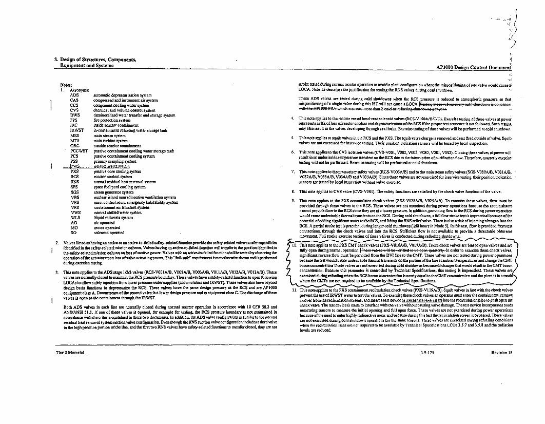
3. Design of Structures, Components,Equipment and Systems
APl000 Design Control Documenqt
1. Acronyms:ADS automatic depressurization systemCAS compressed and instrument air systemCCS component cooling water systemCVS chemical and volume control systemDWS demineratized water transfer and storage systemFPS time protection systemIRC inside reactor containmentIRWST in-containment refueling water storage tankMSS main steam systemMTS main turbine systemORC outside reactor containmentPCCWST passive containment cooling water storage tankPCS passive containment cooling systemPSS primary sampling systeml'WS potable water systemPXS passive core cooling systemRCS reactor coolant systemRNS normal residual heat removal systemSFS spent fuel pool cooling systemSOS steam generator systemVBS nuclear island nonradioactive ventilation systemVES main control room emergency habitability systemVFS containment air filtration systemVWS central chilled water systemWLS liquid radwaste systemAO air operatedMO motor operatedSO solenoid operated
2. Valves listed as having an active oran active-to-failed safety-related function provide the safety-related valve transfercapabilitiesidentified in the safety-related mission column. Valves having an active-to-failed function will transfer to the position identified inthe safety-related mission column on loss of motive power. Valves with an scive-to-failed function shallbe tested by observing theoperation of the actuator upon loss of valve actuating power. This "fail-safe" requirement is not otherwise shown and is perfonredduring exercise testing.
3, This note applies to the ADS stage 1/2/3 valves (RCS-VOOA/B, V002A/B, V003A/B, V01 lA/B, VOI2A/B, V013A/B). Thesevalves are normally closed to maintain the RCS pressure boundasy. These valves have a safety-related finction to open followingLOCAs to allow safety injection from lower pressure water supplies (accumaulstors and IRWST). These valves also have beyonddesign basis functions to depressurize the RCS. These valves have the same design pressure as the RCS and are API000equipment class A. Downstream of the second valve is a lower design pressure and is equipment class C. The discharge of thesevalves is open to the containment through the IRWST.
Both ADS valves in each line aem normally closed during normal reactor operation in accordance with 10 CFR 50.2 andANS/ANSI 51.1. If one of these valves is opened, for example for testing, the RCS pressure boandary is not maintained inaccordance with the criteria contained in these two documents. In addition, the ADS valve configuration is similar to the normalresidual heat removal system suction valve configuration. Even though the RNS suction valve configuration includes a third valvein the high pressure portion of the line, and the first two RNS valves have safety-related lunctions to transfer closed, they are not
stroke tested during normal reactor operation to avoid a plant configuration where the mispositioning of one valve would rausetLOCA, Note 15 describes the justification for testing the RNS valves during cold shutdown.
These ADS valves are tested during cold shutdowns when the RCS pressure is reduced to atmospheric pressure so thatmispositioning of a single valve during this 1ST will sot cause a LOCA. a::.•.", t "he .- vat :.1 a% e l.teeI ..-. .. ,: en
ithl tia AP11000 PR ,.hiel. a .ssumesz.: t'hz. A 2 zzt ir:.¢e:-:g ".n t pd r e'•.•,r
4. This note applies to the reactor vessel head vent solenoid valves (RCS-V S10A/B/C/D). Exercise testing of these valves at powerrepresents a risk of loss ofreactor coolant and depressurization of ths RCS if the proper test sequence is not followed. Such testingmay also result in the valves developing through seat leaks, Exercise testing of these valves will be performed at cold shutdown.
5. This note applies to squib valves in the RCS and the PXS. The squib valve charge is removed and test fired outside of valve. Squibvalves are not exercised for inservice testing. Their position indication sensors will be tested by local inspection.
6. This note applies to the CVS isolation valves (CVS-V0010, V002, V003, V080, V08 1. V082). Closing these valves at power willresult in an undesirable temperature transient on the RCS due to the interruption of purification flow. Therefore, quarterly exercisetesting will not be performed. Exercise testing will be performed at cold shutdown.
7. This note applies to the pressurizer safety valves (RCS-V005A/B) and to the main steam safety valves (SGS-VO30A/B, V03 IA/B,V032A/B, V033A/B, V034A/B and V035A/B). Since these valves are not exercised for inservice testing, their position indicationsensors aem tested by local inspection without valve exercise.
8. This note applies to CVS valve (CVS-VOtl). The safety functions aem satisfied by the check valve function of the valve.
9. This note applies to the PXS accumulator check valves (PXS-VO28A/B, V029A/B). To exercise these valves, flow must beprovided through these valves to the RCS. These valves aem not exercised during power operations because the accumslatorscannot provide flow to the RCS since they are at a lower pressure. In addition, providing flow to the RCS during power operationwould cause undesirable thenrml transients on the RCS. During cold shutdowns, a full flow stroke test is impractical because of thepotential of adding significant water to the RCS, and lifting the RNS relief valve. There is also a risk of injectingnitrogen into theRCS. A partial stroke test is practical during longer cold shutdowns ( •8 hours in Mode 5). In this test, flow is provided from testconnections, through the check valves and into the RCS. Sufficient flow is not available to provide a detectable obturatormovement Full stroke exercise testing of these valves is conducted during refueling shutdowns.
S10. This note applies to the PXS CMT check valves (PXS-VO.IA/B, V017A/B). These check valves are biased open valves and are
pE v en turingno ralopeWtion. wtertot .:es ev alves, T : exerise t ope n che .-va ln order to exercise these check valves,significant reverse flow must be provided from the DVI line to the CMT. These valves are not tested during power operations
because the testwould cause undesirable thermal trasnsients on the portion of the line at ambleesttemperatuses and change the CMTboron concentration These valves are not exercised during cold shutdowns because of'changes, thatwould result in the CMTborenconcentration. Because this poradtoer is contsolled by Technical Specifications, this testing is itpractical. These valves areexercised during refseling wh th RCS boron concentration is nearly equal to the CMT coanentration and the plant is icna modeawhereth CM to em no t required to be available bythe Technical Specifications.7
lee h ar Iedu ed, re
11. This nste applies to the PXS costainmuent recirculation check valves (PXS-VI 19A/B). Squib valves in line with the check valvesprevent the use of IRWST water so test the valves, To exercise these check valves an operator must enter the containmenit, removea cover from the recircuslation screens, and insertsa test device ka mechanical exercixerl into the recirculstion pipe to push open thecheck valve. The test device is made to interface with the valve without causing valve damnage. The test device incorporates loadsmeasurisng sensors to measure the initial opening and fall open force. These valves are not exercised daring power operationsbecause of the need to enter highsly radioactive areas and becsause daring this test the recirculation screen is bypassed. These valvesaem not exercised during cold shutdown operations for the samet reasons. These valves use exercised during refueling conditionswhen the recirculation lines aem sos required to be available by Technical Specifications LCOs 3.5.7 and 3.5.5 and the radiationlevels em reduced.
TIer 2 MaCerlal 3.9-175 RevisIon 15Tier 2 Material
3.9-175 Revision IS
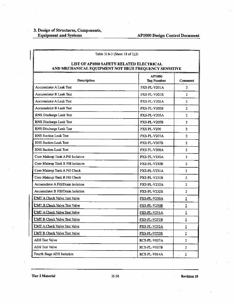
3. Design of Structures, Components,Equipment and Systems AP1000 Design Control Document
Table 31.6-3 (Sheet 18 of 312)
LIST OF AP1000 SAFETY-RELATED ELECTRICALAND MECHANICAL EQUIPMENT NOT HIGH FREQUENCY SENSITIVE
AP1000Description Tag Number Comment
Accumulator A Leak Test PXS-PL-V201A 2
Accumulator B Leak Test PXS-PL-V201B 2
Accumulator A Leak Test PXS-PL-V202A 2
Accumulator B Leak Test PXS-PL-V202B 2
RNS Discharge Leak Test PXS-PL-V205A 2
RNS Discharge Leak Test PXS-PL-V205B 2
RNS Discharge Leak Test PXS-PL-V206 2
RNS Suction Leak Test PXS-PL-V207A 2
RNS Suction Leak Test PXS-PL-V207B 2
RNS Suction Leak Test PXS-PL-V208A 2
Core Makeup Tank A Fill Isolation PXS-PL-V230A 2
Core Makeup Tank B Fill Isolation PXS-PL-V230B 2
Core Makeup Tank A Fill Check PXS-PL-V231A 2
Core Makeup Tank B Fill Check PXS-PL-V231B 2
Accumulator A Fill/Drain Isolation PXS-PL-V232A 2
Accumulator B Fill/Drain Isolation PXS-PL-V232B 2
ýMT A Check Valve Test Valve PXS-PL-V250A 2
LMT B Check Valve Test Valve PXS-PL-V250B 2
CMT A Check Valve Test Valve PXS-PL-V251A 2
kJMT B Check Valve Test Valve PXS-PL-V251B 2
ýMT A Check Valve Test Valve PXS-PL-V252A 2
LMT B Check Valve Test Valve PXS-PL-V252B 2
ADS Test Valve RCS-PL-VO07A 2
ADS Test Valve RCS-PL-VO07B 2
Fourth Stage ADS Isolation RCS-PL-VO14A 2
Tier 2 Material 31-58 "Revision 18

6. Engineered Safety Features AP1000 Design Control Document
A cleanliness program (refer to subsection 6.3.8.1) controls foreign debris introduced into thecontainment during maintenance and inspection operations. The Technical Specifications requirevisual inspections of the screens during every refueling outage.
The design of the containment recirculation screens reduces the chance of debris reaching thescreens. The screens are orientated vertically such that debris settling out of the water will not fallon the screens. The protective plates described above provide additional protection to the screensfrom debris. A 2-foot-high debris curb is provided to prevent high density debris from being sweptalong the floor by water flow to the containment recirculation screens. The screen design providesthe trash rack function. This is accomplished by the screens having a large surface area to preventa single object from blocking a large portion of the screen and by the screens having a robustdesign to preclude an object from damaging the screen and causing by-pass. The screen preventsdebris larger than 0.)625 inches-l-25 from being injected into the reactor coolant system andblocking fuel cooling passages. The screen is a type that has more surface area to accommodatedebris that could be trapped on the screen. The design of the containment recirculation screens isfurther described in APP-GW-GLN-147 (Reference 4).
The screen flow area is conservatively designed, considering the operation of the normal residualheat removal system pumps, which produce a higher flow than the gravity driven IRWSTinj ectionlrecirculation flows. As a result, when the normal residual heat removal system pumps arenot operating there is even more margin in screen clogging.
6.3.2.2.8 Valves
Design features used to minimize leakage for valves in the passive core cooling system include:
* Packless valves are used for manual isolation valves that are 2 inches or smaller.
* Valves which are normally open, except check valves and those which perform controlfunction, are provided with back seats to limit stem leakage.
6.3.2.2.8.1 Manual Globe, Gate, and Check Valves
Gate valves have backseats and external screw and yoke assemblies.
Globe valves, both "T" and "Y" styles, are full-ported with external screw and yoke construction.
sizes 2.5 inches and large. Stai~nles te ~ekvavshv n e~ntation welds other than the(inlet, outlet, and bonnet. T~he check valve hinge is serviced through the bonnet.
The gasket of the stainless steel manual globe and gate valves is similar to those described insubsection 6.3.2.2.8.3 for motor-operated valves.
Tier 2 Material 6.3-23 Revision 18
I
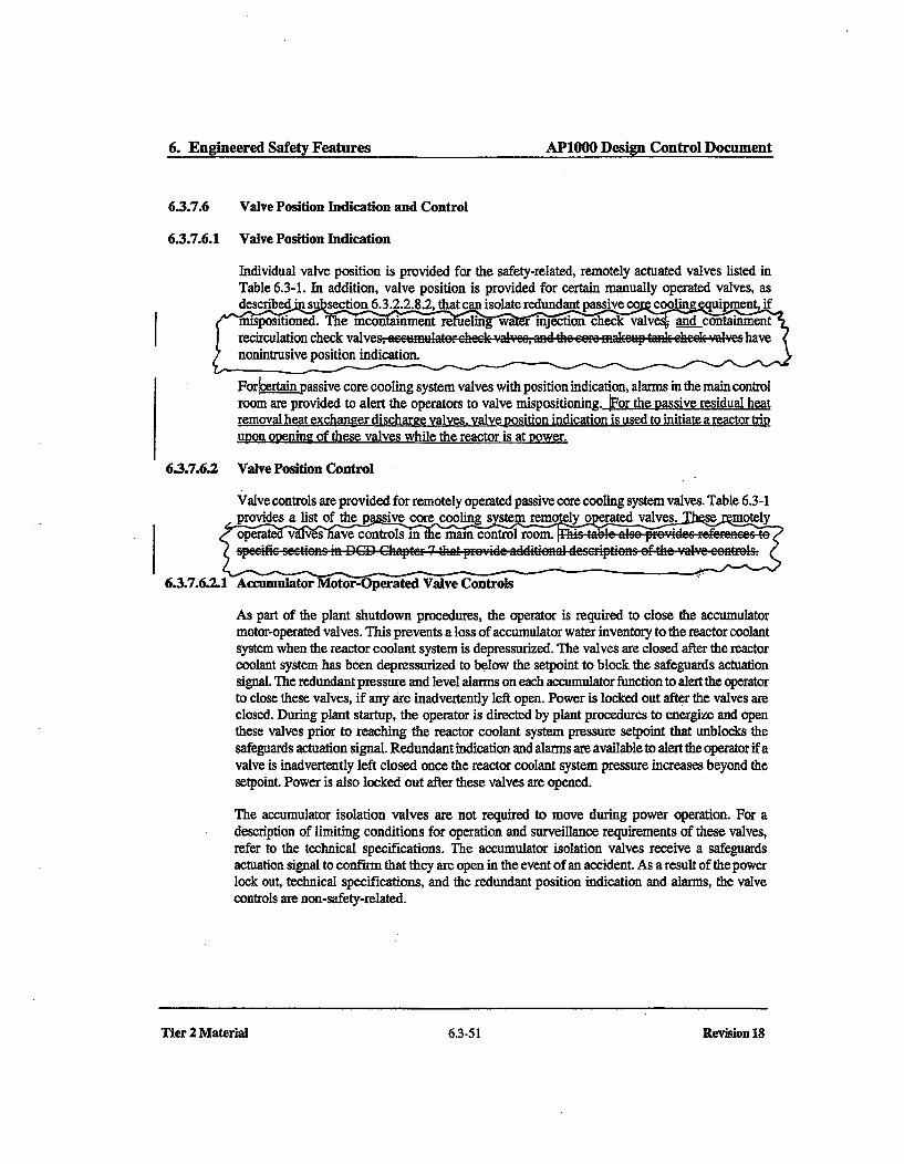
6. Engineered Safety Features AP1000 Design Control Document
6.3.7.6 Valve Position Indication and Control
6.3.7.6.1 Valve Position Indication
Individual valve position is provided for the safety-related, remotely actuated valves listed inTable 6.3-1. In addition, valve position is provided for certain manually operated valves, as
For b assive core cooling system valves with position indication, alarms in the main control
room arc provided to alert the operators to valve mispositioning. sior the passive residual heat
removal heat exchanger discharre valves, valve rosition indication is used to initiate a reactor trip
upon opening of these valves while the reactor is at power.
6.3.7.6.2 Valve Position Control
Valve controls are provided for remotely operated passive core cooling system valves. Table 6.3-1
provides a list of the passive core cooling systtem remotely o ceratedd valves!. s emldy
6.3.7.6.1 Accumulator Motor-Operated Valve Controls
As part of the plant shutdown procedures, the operator is required to close the accumulatormotor-operated valves. This prevents a loss of accumulator water inventory to the reactor coolantsystem when the reactor coolant system is depressurized. The valves are closed after the reactorcoolant system has been depressurized to below the setpoint to block the safeguards actuationsignal. The redundant pressure and level alarms on each accumulator function to alert the operatorto close these valves, if any are inadvertently left open. Power is locked out after the valves areclosed. During plant startup, the operator is directed by plant procedures to energize and openthese valves prior to reaching the reactor coolant system pressure setpoint that unblocks thesafeguards actuation signal. Redundant indication and alarms are available to alert the operator if avalve is inadvertently left closed once the reactor coolant system pressure increases beyond thesetpoint. Power is also locked out after these valves are opened.
The accumulator isolation valves are not required to move during power operation. For adescription of limiting conditions for operation and surveillance requirements of these valves,refer to the technical specifications. The accumulator isolation valves receive a safeguardsactuation signal to confirm that they are open in the event of an accident. As a result of the powerlock out, technical specifications, and the redundant position indication and alarms, the valvecontrols are non-safety-related.
Tier 2 Material 6.3-51
Revision 18
Tier 2 Material 6.3-51 Revision 18
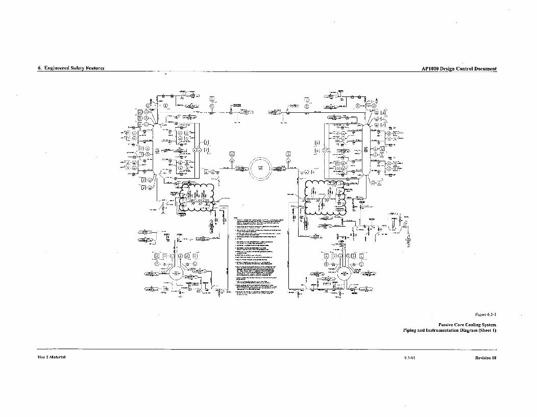
6. Engineered Safety Features API OOO Desion Cnntrnl Docnment6. Enineerd Safty FeturesAPIfitli fesion Conntrol Document
rF.
Figure 6.3-1
Passive Core Cooling System
Piping and Instrumentation Diagram (Sheet 1)
Tier 2 Material 6.3-61 Revision 18
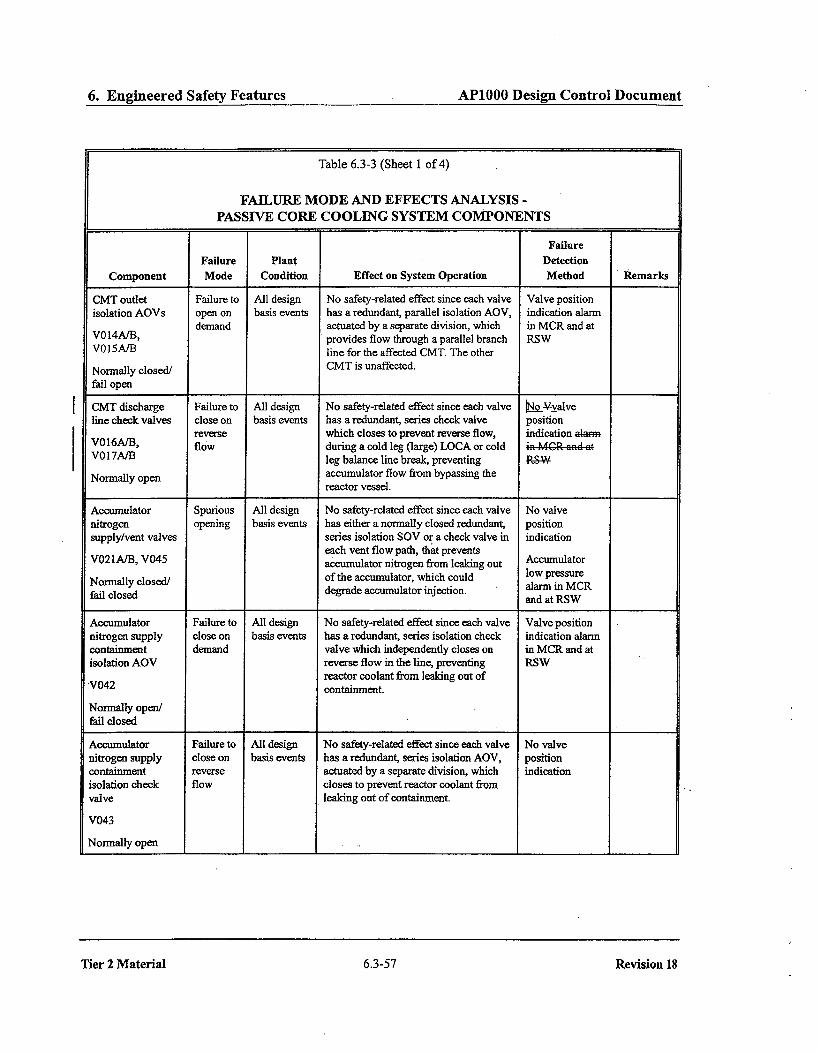
6. Engineered Safety Features AP1000 Design Control Document
Table 6.3-3 (Sheet I of 4)
FAILURE MODE AND EFFECTS ANALYSIS -PASSIVE CORE COOLING SYSTEM COMPONENTS
[
FailureFailure Plant Detection
Component Mode Condition Effect on System Operation Method liRemarks
CMT outlet Failure to All design No safety-related effect since each valve Valve positionisolation AOVs open on basis events has a redundant, parallel isolation AOV, indication alarm
demand actuated by a separate division, which in MCR and atV014A/B, provides flow through a parallel branch RSWV015AIB line for the affected CMT. The other
Normally closed/ CMT is unaffected.
fail open
CMT discharge Failure to All design No safety-related effect since each valve [No 3valveline check valves close on basis events has a redundant, series check valve position
reverse which closes to prevent reverse flow, indication alarmV016A/B, flow during a cold leg (large) LOCA or cold i. .MGR and atV017A/B leg balance line break, preventing
Normally open accumulator flow from bypassing thereactor vessel.
Accumulator Spurious All design No safety-related effect since each valve No valvenitrogen opening basis events has either a normally closed redundant, positionsupply/vent valves series isolation SOV or a check valve in indication
each vent flow path, that preventsVO2AiB, V045 accumulator nitrogen from leaking out Accumulator
Normally closed/ of the accumulator, which could low pressure
fail closed degrade accumulator injection. alarm in MCRand at RSW
Accumulator Failure to All design No safety-related effect since each valve Valve positionnitrogen supply close on basis events has a redundant, series isolation check indication alarmcontainment demand valve which independently closes on in MCR and atisolation AOV reverse flow in the line, preventing RSW
reactor coolant from leaking out ofV042 containment.
Normally open/fail closed
Accumulator Failure to All design No safety-related effect since each valve No valvenitrogen supply close on basis events has a redundant, series isolation AOV, positioncontainment reverse actuated by a separate division, which indicationisolation check flow closes to prevent reactor coolant fromvalve leaking out of containment.
V043
Normally open
Tier 2 Material 6.3-57
Revision 18
Tier 2 Material 6.3-57 Revision 18

Change Number 7
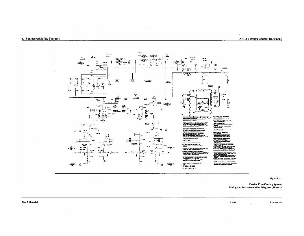
6. Engineered Safety Features AP1000 Design Control Document
7' 7' TT
Z.,t:
Figure 6.3-2
Passive Core Cooling SystemPiping and Instrumentation Diagram (Sheet 2)
Tier 2 Material 6.3-64 Revision 18

Change Number 10 A

2. System Based Design Descriptions and ITAAC AP1000 Design Control Document
7. The VES provides the following safety-related functions:
a) The VES provides a 72-hour supply of breathable quality air for the occupants of the MCR.
b) The VES maintains the MCR pressure boundary at a positive pressure with respect to thesurrounding areas. There is a discharge of air through the MCR vestibule.
c) The heat loads within the MCR, the I&C equipment rooms, and the Class 1E dc equipment roomsare within design basis assumptions to limit the heatup of the rooms identified in Table 2.2.5-4.
d) frhe system provides a passive recirculation flow of MCR air to maintain main control room doserates below an acceptable level during VES operation.
8. Safety-related displays identified in Table 2.2.5-1 can be retrieved in the MCR.
9. a) Controls exist in the MCR to cause those remotely operated valves identified in Table 2.2.5-1 toperform their active functions.
b) The valves identified in Table 2.2.5-1 as having protection and safety monitoring system (PMS)control perform their active safety function after receiving a signal from the PMS.
10. After loss of motive power, the remotely operated valves identified in Table 2.2.5-1 assume theindicated loss of motive power position.
11. Displays of the parameters identified in Table 2.2.5-3 can be retrieved in the MCR.
112. The background noise level in the MCR does not exceed 65 dB(A) at the operator workstations whenthe VES is operating.
Inspections, Tests, Analyses, and Acceptance Criteria
Table 2.P.5--4ýpecifics the inspections, tests, analyses, and associated acceptance criteria for the VES.
Tier 1 Material 2.2.5-2
Revision X
Tier 1 Material 2.2.5-2 Revision X

Change Number 10 B
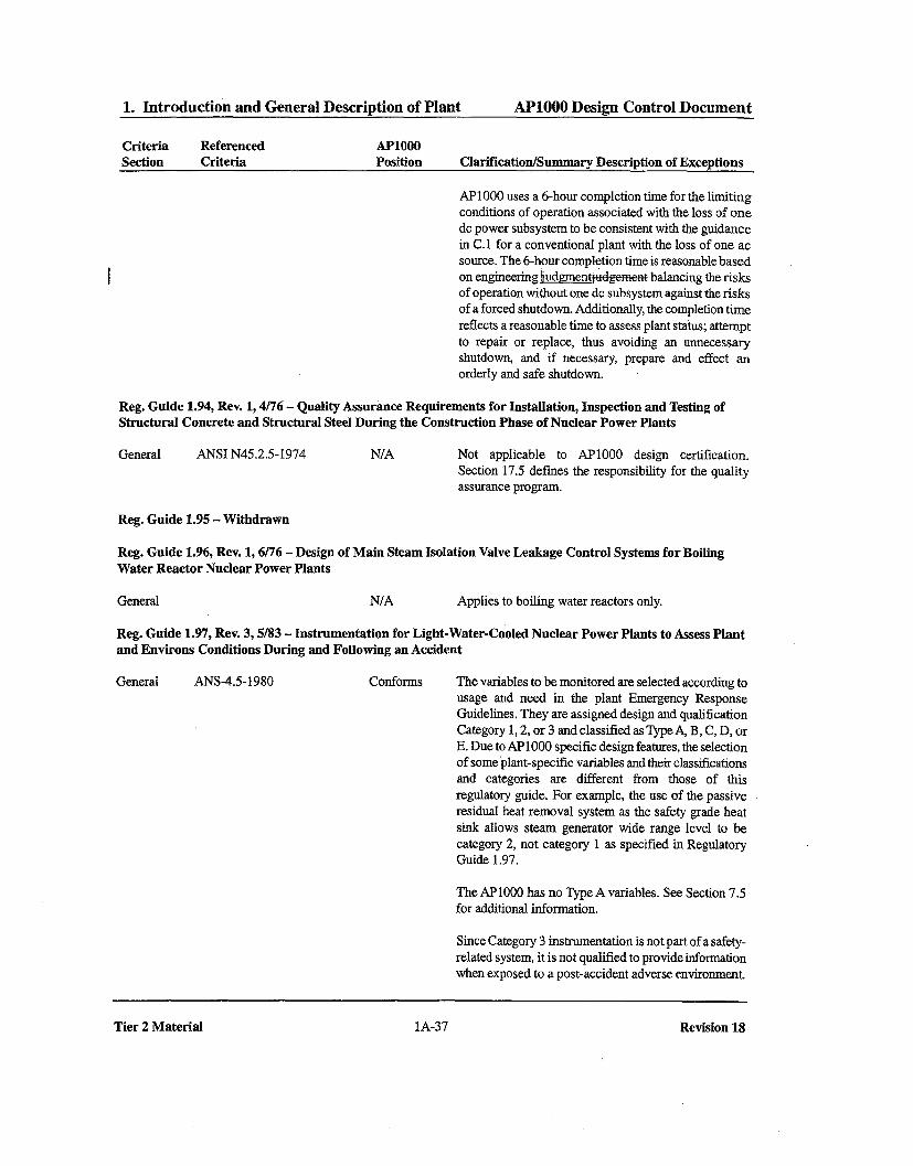
1. Introduction and General Description of Plant AP1000 Design Control Document
Criteria Referenced AP1000Section Criteria Position Clarification/Summary Description of Exceptions
AP1000 uses a 6-hour completion time for the limitingconditions of operation associated with the loss of onedc power subsystem to be consistent with the guidancein C.I for a conventional plant with the loss of one acsource. The 6-hour completion time is reasonable basedon engineering dgmenq ýdgeaat balancing the risksof operation without one dc subsystem against the risksof a forced shutdown. Additionally, the completion timereflects a reasonable time to assess plant status; attemptto repair or replace, thus avoiding an unnecessaryshutdown, and if necessary, prepare and effect an
orderly and safe shutdown.
Reg. Guide 1.94, Rev. 1, 4/76 - Quality Assurance Requirements for Installation, Inspection and Testing ofStructural Concrete and Structural Steel During the Construction Phase of Nuclear Power Plants
General ANSI N45.2.5-1974 N/A Not applicable to AP1000 design certification.Section 17.5 defines the responsibility for the qualityassurance program.
Reg. Guide 1.95 - Withdrawn
Reg. Guide 1.96, Rev. 1, 6/76 - Design of Main Steam Isolation Valve Leakage Control Systems for Boiling
Water Reactor Nuclear Power Plants
General N/A Applies to boiling water reactors only.
Reg. Guide 1.97, Rev. 3, 5/83 - Instrumentation for Light-Water-Cooled Nuclear Power Plants to Assess Plantand Environs Conditions During and Following an Accident
General ANS-4.5-1980 Conforms The variables to be monitored are selected according tousage and need in the plant Emergency ResponseGuidelines. They are assigned design and qualificationCategory 1, 2, or 3 and classified as Type A, B, C, D, orE. Due to AP1O0O specific design features, the selectionof some plant-specific variables and their classificationsand categories are different from those of thisregulatory guide. For example, the use of the passiveresidual heat removal system as the safety grade heatsink allows steam generator wide range level to becategory 2, not category 1 as specified in RegulatoryGuide 1.97.
The AP1000 has no Type A variables. See Section 7.5for additional information.
Since Category 3 instrumentation is not part of a safety-related system, it is not qualified to provide informationwhen exposed to a post-accident adverse environment.
Tier 2 Material 1A-37
Revision 18
Tier 2 Material 1A-37 Revision 18
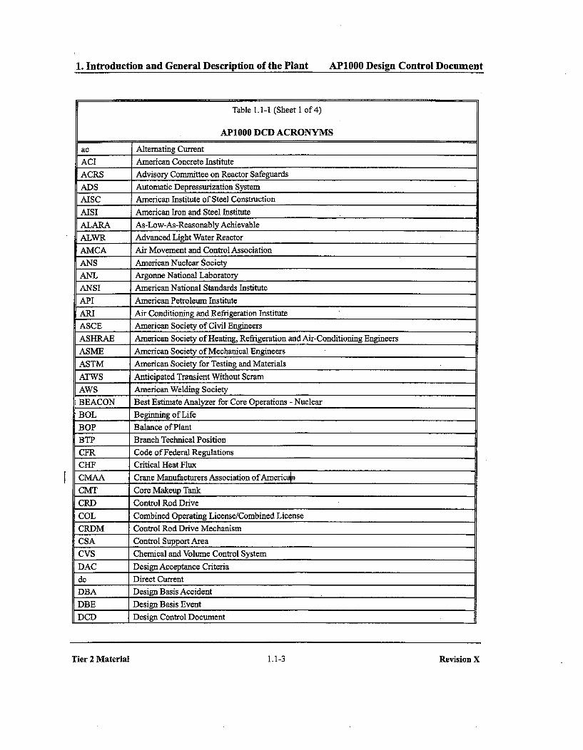
1.~ ~ ~ ~ ~ ~~a Intodutio an(eea esrpino
heePat1of4 -- 10 DeinCnrlDcmn
1. Introduction and General Description of the Plant AP1000 Design Control Document
Table 1.1-1 (Sheet 1 of 4)
AP1000 DCD ACRONYMS
ac Alternating Current
ACI American Concrete Institute
ACRS Advisory Committee on Reactor Safeguards
ADS Automatic Depressurization System
AISC American Institute of Steel Construction
AISI American Iron and Steel Institute
ALARA As-Low-As-Reasonably Achievable
ALWR Advanced Light Water Reactor
AMCA Air Movement and Control Association
ANS American Nuclear Society
ANL Argonne National Laboratory
ANSI American National Standards Institute
API American Petroleum Institute
ARI Air Conditioning and Refrigeration Institute
ASCE American Society of Civil Engineers
ASHRAE American Society of Heating, Refrigeration and Air-Conditioning Engineers
ASME American Society of Mechanical Engineers
ASTM American Society for Testing and Materials
ATWS Anticipated Transient Without Scram
AWS American Welding Society
BEACON Best Estimate Analyzer for Core Operations - Nuclear
BOL Beginning of Life
BOP Balance of Plant
BTP Branch Technical Position
CFR Code of Federal Regulations
CHF Critical Heat Flux
CMAA Crane Manufacturers Association of Americau
CMT Core Makeup Tank
CRD Control Rod Drive
COL Combined Operating License/Combined License
CRDM Control Rod Drive Mechanism
CSA Control Support Area
CVS Chemical and Volume Control System
DAC Design Acceptance Criteria
dc Direct Current
DBA Design Basis Accident
DBE Design Basis Event
DCD Design Control Document
Tier 2 Material 1.1-3
Revision X
Tier 2 Material 1.1-3 Revision X

1. Introduction and General Description of the Plant AP1000 Design Control Document
Table 1.1-1 (Sheet 2 of 4)
AP1000 DCD ACRONYMS
D-EHC Digital Electrohydraulic Control
DEMA Diesel Engine Manufacturers Association
DNB Departure from Nucleate Boiling
DNBR Departure from Nucleate Boiling Ratio
DOE Department of Energy
DPU Distributed Processing Unit
EFPD Effective Full Power Days
EIS Environmental Impact Statement
EMI Electromagnetic Interference
EOF Emergency Offsite Facility
EPA Environmental Protection Agency
EPRI Electric Power Research Institute
ER Environmental Report
ERF Emergency Response Facility
ESF Engineered Safety Features
ESFAS Engineered Safety Features Actuation System
FID Fixed Incore Detector
FM Factory Mutual Engineering and Research Corporation
FMEA Failure Modes and Effects Analysis
FW-PCA Federal Water Pollution Control Act
GDC General Design Criteria Criterion
ORCA Gray Rod Cluster Assembly
GSI Generic Safety Issues
HEPA High Efficiency Particulate Air
HFE Human Factors Engineering
HVAC Heating, Ventilation and Air Conditioning
I&C Instrumentation and Control
ICEA Insulated Cable Engineers Association
IDCOR Industry Degraded Core Rulemaking
IEEE Institute of Electrical and Electronics Engineers,
IES Illumination Engineering Society
ILRT Integrated Leak Rate Test
INEL Idaho National Engineering Laboratory
1/0 Input/Output
IRWST Icc-Containment Refueling Water Storage Tank
ISA Instrument Society of America
IS1 Inservice InspectionIST Inservice Testing
Tier 2 Material 1.1-4 Revision X

1. Introduction and General Description of the Plant AP1000 Design Control Document1. Introduction and General Description of the Plant AP1000 Design Control Document
Table 1.1-1 (Sheet 3 of 4)
AP1000 DCD ACRONYMS
I
ITAAC Inspections, Tests, Analyses and Acceptance Criteria
LBB Leak-Before-Break
LOCA Loss of Coolant Accident
LOF Loss-of-Flow with Failure to Scram
LOFT Loss of Flow Test
LOOP Loss of Offsite Power
LOSP Loss of System Pressure with Degraded ECCS Operation
LPZ Low Population Zone
LSB Last Stage Blade
LWR Light Water Reactor
MAAP Modular Accident Analysis Programs
MCC Motor Control Center
MCR Main Control Room
MCRHS Main Control Room Habitability System
MFCV Main Feedwater Control Valve
MFN V Main Feedwater Isolation Valve
M-MIS Man-Machine Interface System
MOV Motor-operated Valvels
MPC Maximum Permissible Concentration
MSIV Main Steam Isolation Valve
MSLB Main Steam Line Break
MTBE(F) Mean Time Between Event (Failure)
MW Megawatt
MWe Megawatt, electric
MWt Megawatt, thermal
NAE National Academy of Engineering
NAS National Academy of Sciences
NBS National Bureau of Standards
NEC National Electrical Code
NEI Nuclear Energy Institute
NEMA National Electrical Manufacturers Association
NFPA National Fire Protection Association
NPSH Net Positive Suction Head
NRC Nuclear Regulatory Commission
NSSS Nuclear Steam Supply System
NUMARC Nuclear Management and Resources Council (Superseded by NEI)
NUREG Report designator for NRC reports
Tier 2 Material 1,1-5 Revision X

1. Introduction and General Description of Plant AP1000 Design Control Document1. Introduction and General Description of Plant AP1000 Design Control Document
Table 1.6-1 (Sheet 4 of 20)
MATERIAL REFERENCED
DCDSection Westinghouse TopicalNumber Report Number Title
3.7 WCAP 7921-AR Damping Values of Nuclear Power Plant Components, May 1974
WCAP-9903 (P) Justification of the Westinghouse Equivalent Static Analysis Methodfor Seismic Qualification of Nuclear Power Plant AuxiliaryMechanical Equipment, August 1980
3.8 WCAP-13891 (P) AP600 Automatic Depressurization System Phase A Test DataWCAP-14095 Report, May 1994
WCAP-14324 (P) Final Data Report for ADS Phase B 1 Tests, April 1995WCAP-14325
WCAP-15613 (P) AP1000 PIRT and Scaling Assessment, March 2001WCAP-15706
3.9 WCAP-7765-AR Westinghouse PWR Internals Vibrations Summary Three-LoopInternals Assurance, November 1973
WCAP-8766 (P) Verification of Neutron Pad and 17x17 Guide Tube Designs byWCAP-8780 Preoperational Tests on the Trojan 1 Power Plant, May 1976
WCAP-8516-P (P) UHI Plant Internals Vibrations Measurement Program and Pre- andWCAP-8517 Post-Hot Functional Examinations, March 1975
WCAP-10846 (P) Doel 4 Reactor Internals Flow-Induced Vibration MeasurementProgram, March 1985
WCAP-10865 (P) South Texas Plant (TGX) Reactor Internals Flow-Induced VibrationWCAP-10866 Assessment, February 1985
WCAP-8708-P-A (P) MULTIFLEX A FORTRAN-TV Computer Program for AnalyzingVolumes land 2 Thermal-Hydraulic-Structure System Dynamics, February 1976WCAP-8709-AVolumes 1 and 2
WCAP-8446 (P) 17xl 7 Drive Line Components Tests - Phase IB 11, 111 D-LoopWCAP-8449 Drop and Deflection, December 1974
WCAP-9693 (P) Investigation of Feedwater Line Cracking in Pressurized WaterReactor Plants, June 1980
WCAP- 15949-P (P) AP 1000 Reactor Internals Flow-Induced Vibration AssessmentWCAP-15949-NP Program, Revision ý-1-, July 2003
(P) Denotes Document is Proprietary
Tier 2 Material 1.6-5 Revision X
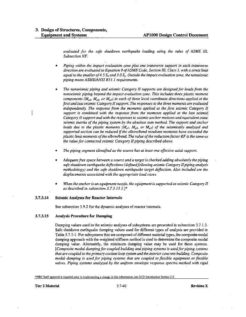
3. Design of Structures, Components,Equipment and Systems AP1000 Design Control Document
evaluated for the safe shutdown earthquake loading using the rules of ASME III,Subsection NF.
" Piping within the impact evaluation zone plus one transverse support in each transversedirection are evaluated to Equation 9 ofASME Code, Section III, Class 3, with a stress limitequal to the smaller of 4.5 Sh and 3.0 Sy. Outside the impact evaluation zone, the nonseismicpiping meets ASME/ANSI B31.1 requirements.
* The nonseismic piping and seismic Category II supports are designed for loads from thenonseismic piping beyond the impact evaluation zone. This includes three plastic momentcomponents (MpI, Mp2 , or Mp3) in each of three local coordinate directions applied at thefirst and last seismic Category II support. The responses to the three moments are evaluatedindependently. The response from the moments applied at the first seismic Category IIsupport is combined with the response from the moments applied at the last seismicCategory II support and with the responses to seismic anchor motions and equivalent staticseismic inertia of the piping system by the absolute sum method. The support and anchorloads due to the plastic moments (Mpl, Mp2, or Mp3) of the seismically analyzed andsupported section can be reduced if the elbow/bend resultant moments have exceeded theplastic limit moments of the elbow/bend. The value of the reduction factor RF is the same asthe value for connected seismic Category II piping described above.
* The piping segment identified as the source has at least one effective axial support.
* Adequate free space between a source and a target is checked adding absolutely the pipingsafe shutdown earthquake deflections (definedfollowing seismic Category HIpiping analysismethodology) and the safe shutdown earthquake target deflection. Also included are thedisplacements associated with the appropriate load cases.
" When the anchor is an equipment nozzle, the equipment is supported as seismic Category IIas described in subsection 3. 7.3.13.3.]*
3.7.3.14 Seismic Analyses for Reactor Internals
See subsection 3.9.2 for the dynamic analyses of reactor internals.
3.7.3.15 Analysis Procedure for Damping
Damping values used in the seismic analyses of subsystems are presented in subsection 3.7.1.3.Safe shutdown earthquake damping values used for different types of analysis are provided inTable 3.7.1-1. For subsystems that are composed of different material types, the composite modaldamping approach with the weighted stiffness method is used to determine the composite modaldamping value. Alternately, the minimum damping value may be used for these systems.[Composite modal damping for coupled building and piping systems is used for piping systemsthat are coupled to the primary coolant loop system and the interior concrete building. Compositemodal damping is used for piping systems that are coupled to flexible equipment or flexiblevalves. Piping systems analyzed by the uniform envelope response spectra method with rigid
*NRC Staff approval is required prior to implementing a change in this information; see DCD Introduction Section 3.5.
Tier 2 Material 3.7-40 Revision X

3. Design of Structures, Components,Equipment and Systems AP1000 Design Control Document
The steel form modules are designed as steel structures according to the requirements ofAISC-N690. This code is applicable since the form modules are constructed entirely out ofstructural steel plates and shapes and the applied loads are resisted by the steel elements.
3.8.3.5.7 Design Summary Report
A design summary report is prepared for containment internal structures documenting that thestructures meet the acceptance criteria specified in subsection 3.8.3.5.
Deviations from the design due to as-procured or as-built conditions are acceptable based on anevaluation consistent with the methods and procedures of Section 3.7 and 3.8 provided thefollowing acceptance criteria are met.
* The structural design meets the acceptance criteria specified in Section 3.8
* The seismic floor response spectra meet the acceptance criteria specified insubsection 3.7.5.4
Dependino 'ations, the evaluation may range from documentation of anengine ng udgnentjudgementto erformance of a revised analysis and design. The results ofthe ev gbedocum m an as-built summary report.
3.8.3.5.8 Design Summary of Critical Sections
3.8.3.5.8.1 Structural Wall Modules
[This subsection summarizes the design of the following critical sections:
* South west wall of the refueling cavity (4 '0 thick)South wall of west steam generator cavity(2 "6"thick)
* North east wall of in-containment refueling water storage tank (2 '6 "thick)]*
[The thicknesses and locations of these walls which are part of the boundary of thein-containment refueling water storage tank are shown in Figure 3.8.3-18. They are theportionsof the structural wall modules experiencing the largest demand The structural configuration andtypical details are shown in Figures 3.8.3-1, 3.8.3-2, 3.8.3-8, 3.8.3-14, 3.8.3-15, and 3.8.3-17.]*The structural analyses are described in subsection 3.8.3.4 summarized in Table 3.8.3-2. Thedesign procedures are described in subsection 3.8.3.5.3.
[The three walls extend from the floor of the in-containment refueling water storage tank atelevation 103'0"to the operating floor at elevation 135' 3 '. The south west wall is also a
boundary of the refueling cavity and has stainless steel plate on both faces. The other walls havestainless steel on one face and carbon steel on the other.]* Design summaries are given inTabl4 3.8.3-4, 3.8.3-5, and 3.8.3-6. See &PP-GW-GLR-045 (Reference 56) for moredetails Appendix 3.. for more detailed disussion.
*NRC Staff approval is required prior to implementing a change in this information; see DCD Introduction Section 3.5.
Tier 2 Material 3.8-36 Revision X

3. Design of Structures, Components,Equipment and Systems AP1OOO Design Control Document
3.8.4.5.2 Supplemental Requirements for Steel Structures
[Supplemental requirements for use of AISC-N690 are as follows:
" In Section QJ.0.2, the definition of secondary stress applies to stresses developed bytemperature loading only.
" In Section Q1.3, where the structural effects of differential settlement arepresent, they areincluded with the dead load, D.
* In Table Q1.5. 7.1, the stress limit coefficients for compression are as follows:
1.3 instead of 1.5 in load combinations 2, 5, and 6.1.4 instead of 1.6 in load combinations 7, 8, and 9.1.6 instead of 1. 7 in load combination 11.
* In Section Q. 5.8, for constrained members (rotation and/or displacement constraint suchthat a thermal load causes sign ificant stresses), supporting safety-related structures, systems,or components, the stresses under load combinations 9, 10, and 11 are limited to thoseallowed in Table Q1.5. 7.1 as modified above.
* Sections Q1.24 and Q1.25.10 are supplemented asfollows:
Shop painting is in accordance with Section M of the Manual of Steel Construction,Load andResistance Factor Design, First Edition. Exposed areas after installation arefield painted in accordance with the applicable portion of Chapter Mofthe Manual ofSteel Construction, Load and Resistance Factor Design, First Edition.]* Seesubsection 6.1.2.1 for additional description of the protective coatings.
3.8.4.5.3 Design Summary Report
A design summary report is prepared for seismic Category I structures documenting that thestructures meet the acceptance criteria specified in subsection 3.8.4.5.
Deviations from the design due to as-procured or as-built conditions are acceptable based on anevaluation consistent with the methods and procedures of Section 3.7 and 3.8 provided thefollowing acceptance criteria are met.
* the structural design meets the acceptance criteria specified in Section 3.8* the seismic floor response spectra meet the acceptance criteria specified in subsection 3.7.5.4
Depending on the extent of the deviations, the evaluation may range from documentation of anengineering ý udgmenttugfgc z to performance of a revised analysis and design. The results ofthe evaluation will be documented in an as-built summary report.
*NRC Staff approval is required prior to implementing a change in this information; see DCD Introduction Section 3.5.
Tier 2 Material 3.8-52 Revision X
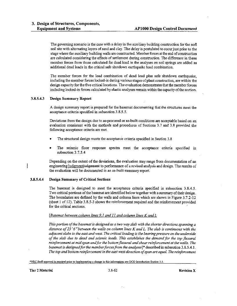
3. Design of Structures, Components,Equipment and Systems AP1000 Design Control Document
The governing scenario is the case with a delay in the auxiliary building construction for the softsoil site with alternating layers of sand and clay. The delay is postulated to occur just prior to thestage where the auxiliary building walls are constructed. Member forces at the end of constructionare calculated considering the effects of settlement during construction. The difference in thesemember forces from those calculated for dead load in the analyses on soil springs are added asadditional dead loads in the critical safe shutdown earthquake load combination.
The member forces for the load combination of dead load plus safe shutdown earthquake,including the member forces locked-in during various stages of plant construction, are within thedesign capacity for the five critical locations. The evaluation demonstrates that the member forcesincluding locked-in forces calculated by elastic analyses remain within the capacity of the section.
3.8.5.4.3 Design Summary Report
A design summary report is prepared for the basemat documenting that the structures meet theacceptance criteria specified in subsection 3.8.5.5.
Deviations from the design due to as-procured or as-built conditions are acceptable based on anevaluation consistent with the methods and procedures of Sections 3.7 and 3.8 provided thefollowing acceptance criteria are met.
• The structural design meets the acceptance criteria specified in Section 3.8
* The seismic floor response spectra meet the acceptance criteria specified insubsection 3.7.5.4
Depending on the extent of the deviations, the evaluation may range from documentation of anengineering udgrnetudgement to performance of a revised analysis and design. The results ofthe evaluation will be documented in an as-built summary report.
3.8.5.4.4 Design Summary of Critical Sections
The basemat is designed to meet the acceptance criteria specified in subsection 3.8.4.5.Two critical portions of the basemat are identified below together with a summary of their design.The boundaries are defined by the walls and column lines which are shown in Figure 3.7.2-12(sheet 1 of 12). Table 3.8.5-3 shows the reinforcement required and the reinforcement providedfor the critical sections.
[Basemat between column lines 9.1 and 11 and column lines K and L
This portion of the basemat is designed as a two way slab with the shorter directions spanning adistance of 23'6 "between the walls on column lines K and L. The slab is continuous with theadjacent slabs to the east and west. The critical loading is the bearing pressure on the undersideof the slab due to dead and seismic loads. This establishes the demand for the top flexuralreinforcement at mid span andfor the bottom flexural and shear reinforcement at the walls. Thebasemat is designedfor the memberforces from the analyses]* described in subsection 3.8.5.4.1.The top and bottom reinforcement in the east west direction of span are equal. The reinforcement
*NRC Staff approval is required prior to implementing a change in this information; see DCD Introduction Section 3.5.
Tier 2 Material 3.8-62 Revision X
3. Design of Structures, Components,Equipment and Systems AP1000 Design Control Document
provided is shown in sheets 1, 2 and 5 of Figure 3.8.5-3. Typical reinforcement details showinguse of headed reinforcement for shear reinforcement are shown in Figure 3H. 5-3.]*
rBasemat between column lines I and2 and column lines K-2 and N
This portion of the basemat is designed as a two way slab with the shorter direction spanning adistance of 22 0 "between the walls on column lines I and 2. The slab is continuous with theadjacent slabs to the north and with the exterior wall to the south. The critical loading is thebearing pressure on the underside of the slab due to dead and seismic loads. This establishes thedemand for the top flexural reinforcement at mid span and for the bottom flexural and shearreinforcement at wall 2. The basemat is designed for the member forces from the analyses onuniform soil springs]* described in subsection 3.8.5.4.1. [The reinforcementprovided is shown insheets 1, 2 and 5 of Figure 3.8.5-3. Typical reinforcement details showing use of headedreinforcement for shear reinforcement are shown in Figure 3H.5-3.]*
Deviations from the design due to as-procured or as-built conditions are acceptable based on anevaluation consistent with the methods and procedures of Sections 3.7 and 3.8 provided thefollowing acceptance criteria are met.
* The structural design meets the acceptance criteria specified in Section 3.8.
" The amplitude of the seismic floor response spectra does not exceed the design basis floorresponse spectra by more than 10 percent.
Depending on the extent of the deviations, the evaluation may range from documentation of anengineering judgmentiu4geflen to performance of a revised analysis and design.
3.8.5.5 Structural Criteria
The analysis and design of the foundation for the nuclear island structures are according toACI-349 with margins of structural safety as specified within it. The limiting conditions for thefoundation medium, together with a comparison of actual capacity and estimated structure loads,are described in Section 2.5. The minimum required factors of safety against sliding, overturning,and flotation for the nuclear island structures are given in Table 3.8.5-1.
[The basemat below the auxiliary building is designed for shear in accordance with theprovisions for continuous deep flexural members in paragraph 11.8.3 of ACI 349-01. Aspermitted by paragraph 11.5.5.1 ofAC1349-01, shear reinforcement is not provided when thefactored shear force, V, is less than one half of the shear strength provided by the concrete,
3.8.5.5.1 Nuclear Island Maximum Bearing Pressures
The foundation will be demonstrated to be capable of withstanding the bearing demand from thenuclear island as described in subsection 2.5.4.5.6.
*NRC Staff approval is required prior to implementing a change in this information; see DCD Introduction Section 3.5.
Tier 2 Material 3.8-63 Revision X
3. Design of Structures, Components,Equipment and Systems AP1000 Design Control Document
Central and Eastern United States rock sites show higher amplitude at high frequency than theCSDRS. Evaluations for high frequency exceedance at AP1000 plant rock sites have beenperformed as described in Appendix 31. It is the conclusion of these evaluations that APIOOOplant systems, structures, and components are qualified for the high frequency seismic responsebased on the CSDRS with the exception of potential high frequency sensitive components(APP-GW-GLN-144, Reference ,3_). Specific models of components are not identified as part ofthe AP1000 certified design and are evaluated for high frequency sensitivity as part of theequipment qualification. Appendix 31 provides the criteria for addressing potential highfrequency sensitive components for plant locations where there is CSDRS exceedance in the highfrequency region.
3.10.1 Seismic and Dynamic Qualification Criteria
3.10.1.1 Qualification Standards
The methods of meeting the general requirements for the seismic and dynamic qualification ofseismic Category I mechanical and electrical equipment and instrumentation as described byGeneral Design Criteria (GDC) 1, 2, 4, 14, 23, and 30 are described in Section 3.1. The generalmethods of implementing the requirements of Appendix B to 10CFR50 are described inChapter 17.
The Nuclear Regulatory Commission (NRC) recommendations concerning the methodsemployed for seismic qualification of mechanical and electrical equipment are contained inRegulatory Guide 1.100, which endorses IEEE 344-1987 (Reference 1).
[AP1000 meets IEEE 344-1987, as modifiedby Regulatory Guide 1.100, by either type testing oranalysis or by an appropriate combination of these methods]* employing the methodologydescribed in Appendix 3D.
The guidance provided in the ASME Code, Section III, is followed in the design of seismicCategory I mechanical equipment to achieve the structural integrity of pressure boundarycomponents. In addition, the AP1000 implements an operability program for active valvesfollowing Regulatory Guide 1.148, as addressed in subsection 1.9.1 and in Section 3.9.
3.10.1.2 Performance Requirements for Seismic Qualification
An equipment qualification data package (EQDP) is developed for the instrumentation andelectrical equipment classified as seismic Category I. Table 3.11-1 of Section 3.11 identifies theseismic Category I electrical equipment and instrumentation supplied for the AP1000. Eachequipment qualification data package contains a section entitled "Performance Requirements."This section establishes the safety-related functional requirements of the equipment to bedemonstrated during and after a seismic event. The required response spectra employed by theAP 1000 for generic seismic qualification are also identified in the section.
For active seismic Category I mechanical components, the performance requirements are definedin the appropriate design and equipment specifications. Requirements for active valves arediscussed in subsection 3.10.2.2. The equipment qualification data packages are referenced in
*NRC Staff approval is required prior to implementing a change in this material; see DCD Introduction Section 3.5.
Tier 2 Material 3.10-2 Revision X
3. Design of Structures, Components,Equipment and Systems AP1000 Design Control Document
Direct vessel injection linesThermal stratification in the direct vessel injection lines, including leakage through the isolation.valvesv4es, is considered in the ASME Code pipe stress and fatigue analysis of these lines.
Main Steam Line
The steam lines are not subjected to thermal stratification by the nature of fluid transported.
Based on the above discussion, thermal stratification does not have an adverse effect on theintegrity of AP1000 leak-before-break piping systems.
3B.2.7 Other Mechanisms
The pipe evaluated for leak-before-break does not operate at temperature for which creep fatiguemust be considered. Creep fatigue is a concern for ferritic steel piping operation at temperaturesabove 700'F and for austenitic stainless steel operation above 800'F.
Pipe degradation or failure by indirect causes such as fires, missiles, and component supportfailures is precluded by criteria for design, fabrication, inspection, and separation of potentialhazards in the vicinity of the safety-related piping. The structures, larger pipe, and components inthe vicinity of pipe evaluated for leak-before-break are safety-related and seismically designed orare seismically supported if nonsafety-related.
Cleavage type failures are not a concern for systems operating temperature and material used inthe stainless steel piping systems. The material used in the main steam line is highly ductile andresistant to cleavage type failure at operating temperatures. The resistance to failure have beendemonstrated by material fracture toughness tests.
3B.3 Leak-Before-Break Bounding Analysis
The methodology used for performing the bounding analysis is consistent with that set forth inGDC-4, SRP 3.6.3 (Reference 1) and NUREG-1061, Volume 3 (Reference 2).
Bounding leak-before-break analysis for the applicable AP1000 piping systems is performed.The analysis criteria and development techniques of the bounding analysis curves (BAC) aredescribed below. The bounding analysis curve allows for the evaluation of the piping system inadvance of the final piping analysis, incorporating leak-before-break considerations early in thepiping design process. The leak-before-break bounding analysis curve is used to evaluate criticalpoints in the piping system. A minimum of two points are required to develop the boundinganalysis curve. One point for the low normal stress case and the other point for the high normalstress case. If variations in pipe size, material, pressure or temperature occur for a specific pipingsystem, an additional bounding analysis curve is generated. These points meet the followingmargins for leak-before-break analysis: (References 1 and 2).
" Margin of 10 on leak detection capability* Margin of 2 on flaw size* Establish margin of 1 on load by using absolute combination method of maximum loads
Tier 2 Material 3B-9 Revision X

5. Reactor Coolant System and Connected Systems AP1000 Design Control Document
5.4.7.1.2.5 Low Temperature Overpressure Protection
The normal residual heat removal system provides a low temperature overpressure protectionfunction for the reactor coolant system during refueling, startup, and shutdown operations. Thesystem is designed to limit the reactor coolant system pressure to the lower of either the limitsspecified in 10 CFR 50, Appendix G, or 110 percent of the normal residual heat removal systemdesign pressure.
5.4.7.1.2.6 Spent Fuel Pool Cooling
The normal residual heat removal system has the capability to supplement or take over the coolingof the spent fuel pool when it is not needed for normal shutdown cooling.
5.4.7.2 System Description
Figure 5.4-6 shows a simplified sketch of the normal residual heat removal system. Figure 5.4-7-shows the piping and instrumentation diagram for the normal residual heat removal system.Table 5.4-13 gives the important system design parameters.
The inside containment portions of the system from the reactor coolant system up to and includingthe containment isolation valves outside containment are designed for fall reactor coolant systempressure. The portion of the system outside containment, including the pumps, valves and heatexchangers, has a design pressure and temperature such that full reactor coolant system pressure isbelow the ultimate rupture strength of the piping-
The normal residual heat removal system consists of two mechanical trains of equipment. Eachtrain includes one residual heat removal pump and one residual heat removal heat exchanger. Thetwo trains of equipment share a common suction line from the reactor coolant system and acommon discharge header. The normal residual heat removal system includes the piping, valvesand instrumentation necessary for system operation.
The normal residual heat removal system suction header is connected to a reactor coolant systemhot leg with a single step-nozzle connection. The step-nozzle connection is employed to i i i ethe likelihood of air ingestion into the residual heat removal pumps during reactor coolant systemmid-loop operations. The suction header then splits into lines with two parallel sets oftwo normally closed, motor-operated isolation valves in series. This arrangement allows fornormal residual heat removal system operation following a single failure of an isolation valve toopen and also allows for normal residual heat removal system isolation following a single failureof an isolation valve to close.
The lines join into a common suction line inside containment. A single line from theiriLside-containment refueling water storage tank is connected to the suction header before it leavescontainment.
Once outside containment, the suction header contains a single normally closed, motor-operatedisolation valve. Downstream of the suction header isolation valve, the header branches intotwo separate lines, one to each pump. Each branch line has a normally open, manual isolation
Tier 2 Material 5.4-40 Revision X

5. Reactor Coolant System and Connected Systems AP1000 Design Control Document
Table 5.4-17
PRESSURIZER SAFETY VALVES - DESIGN PARAMETERS
Number 2
Minimum required relieving capacity per valve (lb/hr) 750,000 at 3% accumulation
Set pressure (psig) 2485 ±25 psi
Design temperature (°F) 680
Fluid Saturated steam
Backpressure
Normal (psig) 3 to 5
Expected maximum during discharge (psig) 500
Environmental conditions
Ambient temperature ('F) 50 to 120
Relative humidity (percent) 0 to 100
Residual Heat Removal Relief Valve - Design Parameters
Number 1
Nominal relieving capacity per valve, ASME flowrate (gpm) 850
Nominal set pressure (psig) 500*
Full-open pressure, with accumulation (psig) 550*
Design temperature ('F) 400
Fluid Reactor coolant
Backpressure
Normal (psig) 3 to 5
Expected maximum during discharge (psig) 21
Environmental conditions
Ambient temperature ('F) 50 to 120
Relative humidity (percent) 0 to 100
Note:* See text 6subsection 5.4.9.3) for discussion of set pressure.
Tier 2 Material 5.4-93
Revision X
Tier 2 Material 5.4-93 Revision X

9. Auxiliary Systems A.P1000 Design Control Document
Table 9.2.1-1
NOMINAL SERVICE WATER FLOWS AND HEAT LOADSAT DIFFERENT OPERATING MODES
I
SWS Pumps andCooling Tower Cells
CCS Pumps and (Number Normally Flow Heat TransferredHeat Exchangers iks Service) (gpm) (Btu/hr)
Normal Operation 1 1 10,500 103xl 06
(Full Load)
Cooldown 2 2 21,000 346x 106
(173x10 6 per cell)Refueling 1 1 10,500 74.9xl06
(Full Core Offload)
Plant Startup 2 2 21,000 75.8x10 6
Minimum to 1 1 10,000 170x10 6
Support ShutdownCooling and SpentFuel Cooling
Tier 2 Material 9.2-46
Revision X
Tier 2 Material 9.2-46 Revision X
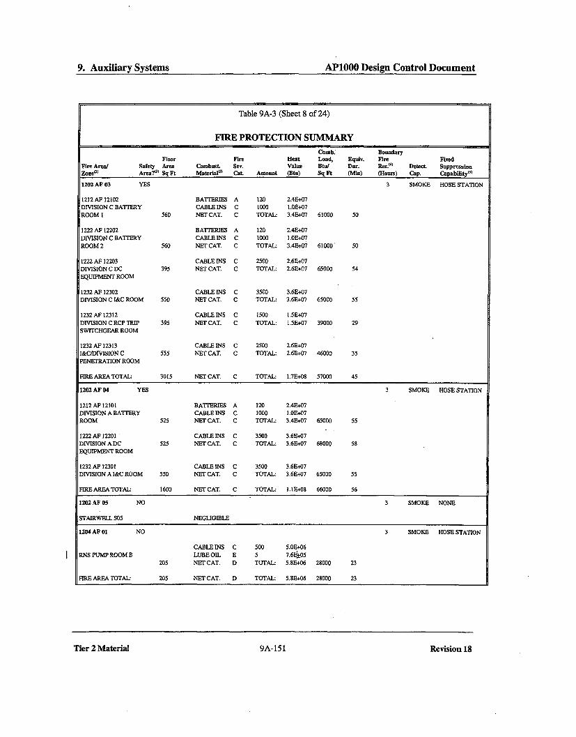
9. Auxiliary Systems AP1000 Design Control Document
Table 9A-3 (Sheet 8 of 24)
FIRE PROTECTION SUMMARYComb. Boundary
Floor Fire Heat Load, Equiv. Fire Fixed
Fire Area] Safety Area Combust. Sev. Value Btu/ Dur. Res.(4) Detect. Suppression
Zone(%) Areami Sq Ft Materialp) Cat. Amount (Btu) Sq Ft (Min) (Hours) Cap. Capability()
1202 AF 03 YES 3 SMOKE HOSE STATION
1212 AF 12102 BATTERIES A 120 2.4E+07DIVISION C BATTERY CABLE INS C 1000 1.0E+07
ROOM 1 560 NET CAT. C TOTAU 3.4E•07 61000 50
1222 AF 12202 BATTERIES A 120 2.4E+07
DIVISION C BATTERY CABLE INS C 1000 1.01E+07
ROOM 2 560 NET CAT. C TOTAL: 3.4E+07 61000 50
1222 AF 12203 CABLE INS C 2500 2.6E+07
DIVISION C DC 395 NET CAT. C TOTAL: 2.6E+07 65000 54
EQUIPMENT ROOM
1232 AF 12302 CABLE INS C 3500 3.6E+07DIVISION C I&C ROOM 550 NET CAT. C TOTAL: 3.6E+07 65000 55
1232 AF 12312 CABLE INS C 1500 1.5E+07
DIVISION C RCP TRIP 395 NET CAT. C TOTAL: 1.5E+07 39000 29
SWITCHGEAR ROOM
1232 AF 12313 CABLEINS C 2500 2.6E+07
I&CIDIVISION C 555 NET CAT. C TOTAL: 2.6E+-07 46000 35
PENETRATION ROOM
FIRE AREA TOTAL: 3015 NET CAT. C TOTAL: 1.7E+08 57000 45
1202 AF 04 YES 3 SMOKE HOSE STATION
1212 AF 12101 BATTERIES A 120 2.4E+07DIVISION A BATIERY CABLE INS C 1000 1.0E,+07ROOM 525 NET CAT. C TOTAL: 3.4E+07 65000 55
1222 AF 12201 CABLE INS C 3500 3.6E+07DIVISION A DC 525 NET CAT. C TOTAL: 3.6E+07 68000 58
EQUIPMENT ROOM
1232 AF 12301 CABLEINS C 3500 3.6E,+07DIVISION A I&C ROOM 550 NET CAT. C TOTAL: 3.6E+07 65000 55
FIRE AREA TOTAL: 1600 NET CAT. C TOTAL: .I1E+08 66000 56
1202 AF 05 NO 3 SMOKE NONE
STAIRWELL S05 NEGLIGIBLE
1204 AF 01 NO 3 SMOKE HOSE STATION
CABLE INS C 500 5.0E+06
RNS PUMP ROOM B LUBE OIL E 5 7.61±05205 NET CAT. D TOTAL: 5.8E+06 28000 23
FIRE AREA TOTAL: 205 NET CAT. D TOTAL: 5.8E-+06 28000 23
Tier 2 Material 9A-151 Revision 18

9. Auxiliary Systems AP1000 Design Control Document
Table 9A-3 (Sheet 24 of 24)
FIRE PROTECTION SUMMARY
Comb. Boundary
Floor Fire Heat Load, Equiv. Fire Fiwxed
Fire Area/ Safety Area Combust. Sev. Value Btu/ Dur. Res.(4) Detect Suppression
Zone() Area?1 0
Sq Ft Materialm Cat. Amount (Btn) Sq Ft (Mlin) (Hours) Cap. Capability()5
6_030 AF 60324 CABLE INS C 100 OE+06 NONE HOSE STATION
TOOL STORAGE AREA PAPER C 50 3.9E+05
PLASTIC D 50 6.6E+05
WOOD C 100 8.4E+05
144 NET CAT. C TOTAL: 2.9E+06 20070 15
6030 AF 60330 CABLE INS C 2000 2.OE+06 NONE HOSE STATION
SECURITY ROOM TRASH B 100 1.9E+05
PAPER C 1000 7.7E+05
PLASTIC D 1000 3.3E+05144 NET CAT. C TOTAL: 3.6E+06 25200 19
FIRE AREA TOTAL: 2328 NET CAT. E TOTAL: 1.4E+08 60140 45
6030 AF 03 NO 3 NONE DRY PIPE
SPRINKLERS
DIESEL FUEL DAY FUEL E 1500 2.2E+08 HOSE STATION
TANK VAULT A OIL
FIRE AREA TOTAL: 100 NET CAT. E TOTAL: 2.2E+08 2160000 1620
6030 AF 04 NO 3 NONE DRY PIPE
SPRINKLERS
DIESEL FUEL DAY FUEL E 1500 2.2E+08 HOSE STATION
TANK VAULT B OIL
FIRE AREA TOTAL: 100 NET CAT. E TOTAL: 2.21+08 2160000 1620
6001 AF01 NO 2 NONE NONE
STAIRWELL NEGLIGIBLE
Notes:1. The first four digits of the fire area and fire zone numbers indicate the building, level and building area in which the
fire area/zone is located. When the third or fourth digit is a zero, the fire area/zone spans more than one level or
building area. The last two digits in a fire area number are a sequence number only. The last five digits in a fire zone
number coincide with the room number of a prominent room in the fire zone.
2. A YES indication in the Safety Area column means that one or more safety-related components are located in the
fire area.3. Estimated quantities of combustible materials are shown. Where the presence of transient combustibles is
anticipated, their presence is indicated by the listing of volatiles or trash. The units and heat of combustion values for
the combustible materials are shown in Table 9A-1.4. The boundary fire resistance for each fire area represents the minimum resistance, in hours, for the surrounding
walls, floor, and ceiling, except that:" A non-rated barrier capable of qualifying as a three-hour barrier is considered to have a resistance of three
hours, provided that penetrations are adequately sealed." Stairwells, elevator shafts and the like, which are enclosed by two-hour (minimum) fire barrier walls, may
comprise a portion of the boundary of a fire area having a three hour resistance." Building exterior walls below grade (soil on the outside) are considered to have a fire resistance of at least three
hours even though they are not fire-rated.
Tier 2 Material 9A-167 Revision 18

9. Auxiliary Systems APIOOO Design Control Document
9A.3.6.2 Fire Area 6030 AF 02
This fire area contains the diesel generator and supporting equipment for one train of the onsitestandby ac power system, tool storage area and security room. The fire area is subdivided into thefollowing fire zones:
Fire Zone Room No.
0 6030 AF 60320 60320 Diesel generator room B0 6030 AF 60321 60321 Service module B0 6030 AF 60323 60323 Combustion air cleaner area B0 6030 AF 60324 60324 Tool storage ýreafeeH+0 6030 AF 60330 60330 Security room
There are no systems in this fire area which normally contain radioactive material.
Fire Detection and Suppression Features
" Fire detectors in the service module" Dry pipe sprinklers in the diesel generator room" Hose station(s)" Portable fire extinguishers (including carbon dioxide)
Smoke Control Features
The diesel generator building ventilation system (VZS) serves this fire area by means of theengine room air handling unit, the service module air handling unit, and the standby exhaust fans.The engine room air handling unit stops upon actuation of the fire suppression system in the firearea or if smoke is detected in the supply air duct from the air handling unit. The service moduleair handling unit stops upon actuation of the fire suppression system in the fire area or if smoke isdetected in the supply air duct from the air handling unit. The standby exhaust fans stop uponactuation of the fire suppression system in the fire area. These actions control the spread of fireand smoke. After the fire, smoke is removed from the fire area by manually turning on theventilation exhaust fans mounted on the roof over the fire area, or by opening the roll-up door andpersonnel doors and utilizing portable exhaust fans.
Fire Protection Adequacy Evaluation
A fire in the diesel generator room is detected through the operation of the dry pipe sprinklersystem which produces an audible alarm locally, and both visual and audible alarms in the maincontrol room and security central alarm station. A fire in the service module is detected by a firedetector which produces an audible alarm locally and both visual and audible alarms in the maincontrol room and the security central alarm station. A fire in the diesel generator room isextinguished by the automatic fire suppression system or manually, using hose streams or portableextinguishers. A fire in the service module is extinguished manually using hose streams orportable extinguishers.
Tier 2 Material 9A-122 Revision 18

14. Initial Test Program AP1000 Design Control Document
General Test Method and Acceptance Criteria
Demineralized water transfer and storage system performance is observed and recorded during aseries of individual component and integrated system testing. The following defense-in-depthtesting verifies that the system functions as described in subsection 9.2.4 and appropriate designspecifications:
a) Proper operation of the system pumps, valves, and blower,-and is verified.
b) Proper calibration and operation of the system instrumentation, controls, actuation signals,and interlocks are verified.
14.2.9.4.10 Compressed and Instrument Air System Testing
Purpose
The purpose of the compressed and instrument air system testing is to verify that the as-installedcomponents properly perform the functions of providing compressed air at the required pressuresto various plant users, as described in the Compressed and Instrument Air portion of Section 9.3.
Prerequisites
The construction testing of the compressed and instrument air system has been completed. Thecomponent cooling water system is operational and providing cooling for the compressor units.Required support systems, electrical power supplies and control circuits are operational.
General Test Method and Acceptance Criteria
Compressed and instrument air system performance is observed and recorded during a series ofindividual component and integrated system testing. The following testing verifies that the systemand its plant users, where applicable, function as described in subsection 9.3.1.4 and appropriatedesign specifications:
a) Proper operation of the system compressors, receivers, prefilters, air dryers, afterfilters,purifiers, and valves is verified.
b) Proper calibration and operation of the system instrumentation, controls, actuation signals,and interlocks are verified.
c) Integral testing is performed to verify that the instrument air subsystem can provide sufficientair pressure to accommodate the maximum number of air-operated valves expected to operatesimultaneously.
d) Testing is performed to verify the fail-safe positioning of safety-related air-operated valvesfor sudden loss of instrument air or gradual loss of pressure as described insubsection 9.3.1.4.
Tier 2 Material 14.2-79
Revision X
Tier 2 Material 14.2-79 Revision X

OPDMS-Monitored ParametersB 3.2.5
BASES
LCO (continued)
Peak kw/ft limits define limiting values for core power peaking thatprecludes peak cladding temperatures above 2200°F during either a largeor small break LOCA. The highest calculated linear power densities inthe core at specific core elevations are displayed for operator visualverification relative to the COLR values.
The determination of FNH identifies the coolant flow channel with the
maximum enthalpy rise. This channel has the least heat removal
capability and thus the highest probability for DNB. Should FNH exceed
the limit given in the COLR, the possibility exists for DNBR to exceed thevalue used as a base condition for the safety analysis.
Two levels of alarms on power distribution parameters are provided to theoperator. One serves as a warning before the three parameters (kw/ft(Z),
FNH, DNBR) exceed their values used as a base condition for the safety
analysis. The other alarm indicates when the parameters have reachedtheir limits.
APPLICABILITY The OPDMS-monitored power 0 palieter limits must bemaintained in MODE 1 above 0' RTPR-TD to eclude core powerdistributions from exceeding th limits assu e n the safety analyses.Applicability in other MODES, an - elow 50% RTP, is notrequired because there is either insufficient stored energy in the fuel orinsufficient energy transferred to the reactor coolant to require a limit onthe distribution of core power. The OPDMS monitoring of SDM isapplicablemuct bc OPE01 ABLE in MODES 1 and 2 with Ke > 1.0.
Specifically for FNH, the design bases accidents (DBAs) that are sensitive
to FNH in other MODES (MODES 2 through 5) have significant margin to
DNB, and therefore, there is no need to restrict FN in these modes.
In addition to the alarms discussed in the LCO section above (alarms onOPDMS-monitored power distribution parameters), there is an alarmindicating the potential inoperability of the OPDMS itself.
Should the OPDMS be determined to be inoperable for other thanreasons of alarms inoperable, this LCO is no longer applicable andLCOs 3.2.1 through 3.2.4 become applicable.
AP1000 B 3.2.5 - 3 Amendment 0Revision X

Containment Air LocksB 3.6.2
BASES
ACTIONS (continued)
A second Note has been added to provide clarification that, for this LCO,separate Condition entry is allowed for each air lock. This is acceptable,since the Required Actions for each Condition provide appropriatecompensatory actions for each inoperable air lock. Complying with theRequired Actions may allow for continued operation, and a subsequentinoperable air lock is governed by subsequent Condition entry andapplication of associated Required Actions.
In the event that air lock leakage results in exceeding the overallcontainment leakage rate, Note 3 directs entry into the applicableConditions and Required Actions of LCO 3.6.1, "Containment."
A.1, A.2, and A.3
With one air lock door in one or more containment air locks inoperable,the OPERABLE door must be verified closed (Required Action A. 1) ineach affected containment air lock. This ensures a leak tight containmentbarrier is maintained by the use of an OPERABLE air lock door. Thisaction must be completed within 1 hour. This specified time period isconsistent with the ACTIONS of LCO 3.6. 1, "Containment," whichrequires containment be restored to OPERABLE status within I hour.
In addition, the affected air lock penetration must be isolated by lockingclosed the OPERABLE air lock door within the 24 hour Completion Time.The 24 hour Completion Time is reasonable for locking the OPERABLEair lock door, considering the OPERABLE door of the affected air lock isbeing maintained closed.
Required Action A.3 verifies that an air lock with an inoperable door hasbeen isolated by the use of a locked and closed OPERABLE air lockdoor. This ensures that an acceptable containment leakage boundary ismaintained. The Completion Time of once per 31 days is reasonablebased on engineering judgýement and is considered adequate in view ofthe low likelihood of a locked door being mispositioned and other -administrative controls. Required Action A.3 is modified by a Note thatapplies to air lock doors located in high radiation areas and allows thesedoors to be verified to be locked closed by administrative means.Allowing verification by administrative means is considered acceptable,since access to these areas is typically restricted. Therefore, theprobability of misalignment of the door, once it has been verified to be inthe proper position, is small.
AP1000 B 3.6.2 - 3 Amendment 0Revision X
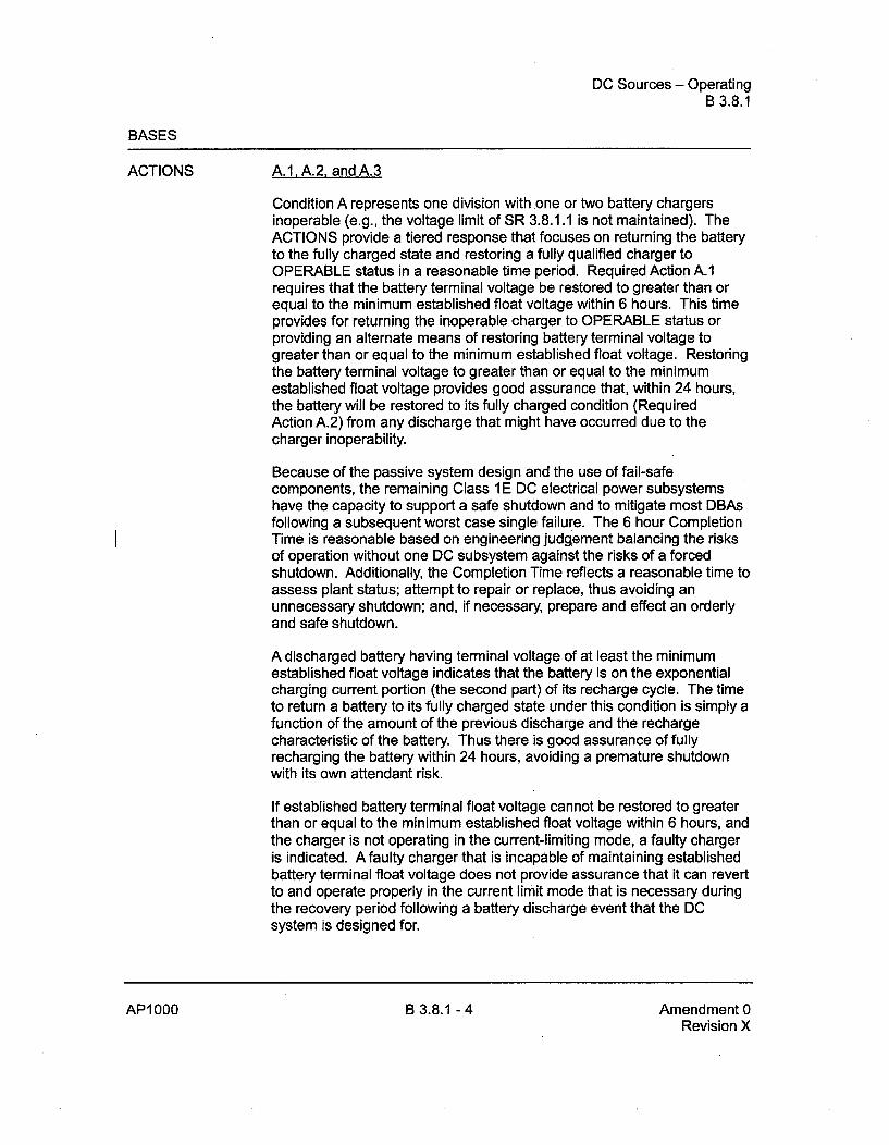
DC Sources - OperatingB 3.8.1
BASES
ACTIONS A.1. A.2, and A.3
Condition A represents one division withone or two battery chargersinoperable (e.g., the voltage limit of SR 3.8.1.1 is not maintained). TheACTIONS provide a tiered response that focuses on returning the batteryto the fully charged state and restoring a fully qualified charger toOPERABLE status in a reasonable time period. Required Action A.1requires that the battery terminal voltage be restored to greater than orequal to the minimum established float voltage within 6 hours. This timeprovides for returning the inoperable charger to OPERABLE status orproviding an alternate means of restoring battery terminal voltage togreater than or equal to the minimum established float voltage. Restoringthe battery terminal voltage to greater than or equal to the minimumestablished float voltage provides good assurance that, within 24 hours,the battery will be restored to its fully charged condition (RequiredAction A.2) from any discharge that might have occurred due to thecharger inoperability.
Because of the passive system design and the use of fail-safecomponents, the remaining Class 1 E DC electrical power subsystemshave the capacity to support a safe shutdown and to mitigate most DBAsfollowing a subsequent worst case single failure. The 6 hour CompletionTime is reasonable based on engineering judgiament balancing the risksof operation without one DC subsystem against the risks of a forcedshutdown. Additionally, the Completion Time reflects a reasonable time toassess plant status; attempt to repair or replace, thus avoiding anunnecessary shutdown; and, if necessary, prepare and effect an orderlyand safe shutdown.
A discharged battery having terminal voltage of at least the minimumestablished float voltage indicates that the battery is on the exponentialcharging current portion (the second part) of its recharge cycle. The timeto return a battery to its fully charged state under this condition is simply afunction of the amount of the previous discharge and the rechargecharacteristic of the battery. Thus there is good assurance of fullyrecharging the battery within 24 hours, avoiding a premature shutdownwith its own attendant risk.
If established battery terminal float voltage cannot be restored to greaterthan or equal to the minimum established float voltage within 6 hours, andthe charger is not operating in the current-limiting mode, a faulty chargeris indicated. A faulty charger that is incapable of maintaining establishedbattery terminal float voltage does not provide assurance that it can revertto and operate properly in the current limit mode that is necessary duringthe recovery period following a battery discharge event that the DCsystem is designed for.
AP1000 B 3.8.1 - 4 Amendment 0Revision X

DC Sources - OperatingB 3.8.1
BASES
ACTIONS (continued)
Because of the passive system design and the use of fail-safecomponents, the remaining Class 1 E DC electrical power subsystemshave the capacity to support a safe shutdown and to mitigate most DBAsfollowing a subsequent worst case single failure. The 6 hour CompletionTime is reasonable based on engineering judgýment balancing the risksof operation without one DC subsystem against the risks of a forcedshutdown. Additionally, the Completion Time reflects a reasonable time toassess plant status; attempt to repair or replace, thus avoiding anunnecessary shutdown; and, if necessary, prepare and effect an orderlyand safe shutdown.
The installed spare battery bank and charger may be used to restore aninoperable Class 1 E DC electrical power subsystem; however, allapplicable Surveillances must be met by the spare equipment used, priorto declaring the subsystem OPERABLE.
D. 1
Condition D represents two divisions with one or more batteriesinoperable. With one or more batteries inoperable, the DC bus is beingsupplied by the OPERABLE battery charger. Any event that results in aloss of the AC bus supporting the battery charger will also result in loss ofDC to that train. The 2 hour limit allows sufficient time to effectrestoration of an inoperable battery given that the majority of theconditions that lead to battery inoperability (e.g., loss of battery charger,battery cell voltage less than 2.07 V, etc.) are identified inSpecifications 3.8.1, 3.8.2, and 3.8.7 together with additional specificcompletion times.
The installed spare battery bank and charger may be used to restore aninoperable Class 1 E DC electrical power subsystem; however, allapplicable Surveillances must be met by the spare equipment used, priorto declaring the subsystem OPERABLE.
E.1
If one of the Class 1 E DC electrical power subsystems is inoperable, theremaining Class I E DC electrical power subsystems have the capacity tosupport a safe shutdown and to mitigate all design basis accidents, basedon conservative analysis.
Because of the passive system design and the use of fail-safecomponents, the remaining Class 1 E DC electrical power subsystemshave the capacity to support a safe shutdown and to mitigate most DBAs
AP1000 B 3.8.1 - 7 Amendment 0Revision X
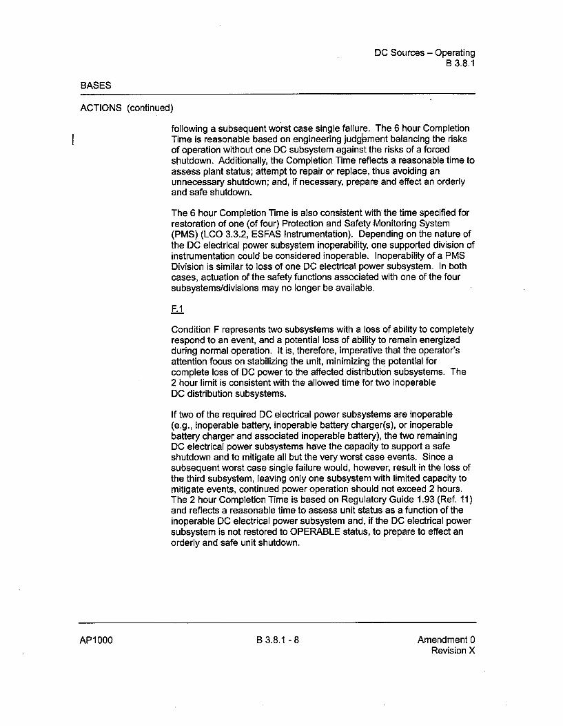
DC Sources - OperatingB 3.8.1
BASES
ACTIONS (continued)
following a subsequent worst case single failure. The 6 hour CompletionTime is reasonable based on engineering judglement balancing the risksof operation without one DC subsystem against the risks of a forcedshutdown. Additionally, the Completion Time reflects a reasonable time toassess plant status; attempt to repair or replace, thus avoiding anunnecessary shutdown; and, if necessary, prepare and effect an orderlyand safe shutdown.
The 6 hour Completion Time is also consistent with the time specified forrestoration of one (of four) Protection and Safety Monitoring System(PMS) (LCO 3.3.2, ESFAS Instrumentation). Depending on the nature ofthe DC electrical power subsystem inoperability, one supported division ofinstrumentation could be considered inoperable. Inoperability of a PMSDivision is similar to loss of one DC electrical power subsystem. In bothcases, actuation of the safety functions associated with one of the foursubsystems/divisions may no longer be available.
F.1
Condition F represents two subsystems with a loss of ability to completelyrespond to an event, and a potential loss of ability to remain energizedduring normal operation. It is, therefore, imperative that the operator'sattention focus on stabilizing the unit, minimizing the potential forcomplete loss of DC power to the affected distribution subsystems. The2 hour limit is consistent with the allowed time for two inoperableDC distribution subsystems.
If two of the required DC electrical power subsystems are inoperable(e.g., inoperable bafteryý inoperable battery charger(s), or inoperablebattery charger and associated inoperable battery), the two remainingDC electrical power subsystems have the capacity to support a safeshutdown and to mitigate all but the very worst case events. Since asubsequent worst case single failure would, however, result in the loss ofthe third subsystem, leaving only one subsystem with limited capacity tomitigate events, continued power operation should not exceed 2 hours.The 2 hour Completion Time is based on Regulatory Guide 1.93 (Ref. 11)and reflects a reasonable time to assess unit status as a function of theinoperable DC electrical power subsystem and, if the DC electrical powersubsystem is not restored to OPERABLE status, to prepare to effect anorderly and safe unit shutdown.
AP1 000 B 3.8.1 - 8 Amendment 0Revision X

Distribution Systems - OperatingB 3.8.5
BASES
APPLICABILITY The Class 1 E AC and DC electrical power distribution subsystems arerequired to be OPERABLE in MODES 1, 2, 3, and 4 to ensure that:
a. Acceptable fuel design limits and reactor coolant pressure boundarylimits are not exceeded as a result of A00s or abnormal transients;and
b. Adequate core cooling is provided, and containment OPERABILITYand other vital functions are maintained in the event of a postulatedDBA.
The Class 1 E AC and DC electrical power distribution subsystemrequirements for MODES 5 and 6 are covered in the Bases forSpecification 3.8.6, "Class 1 E Distribution Systems - Shutdown."
ACTIONS A.1
With one division of the Class I E AC instrument and control businoperable the remaining Class I E AC instrument and control buses havethe capacity to support a safe shutdown and to mitigate all DBAs, basedon conservative analysis.
Because of the passive system design and the use of fail-safecomponents, the remaining Class 1 E AC instrument and control buseshave the capacity to support a safe shutdown and to mitigate most designbasis accidents following a subsequent worst case single failure. The6 hour Completion Time is reasonable based on engineering judg,ýmentbalancing the risks of operation without one AC instrument and controlbus against the risks of a forced shutdown. Additionally, the CompletionTime reflects a reasonable time to assess plant status; attempt to repairor replace, thus avoiding an unnecessary shutdown; and, if necessary,prepare and effect an orderly and safe shutdown.
This 6 hour limit is shorter than Completion Times allowed for mostsupported systems which would be without power. Taking exception toLCO 3.0.2 for components without adequate DC Power, which wouldhave Required Action Completion Times shorter than 6 hours,, isacceptable because of:
a. The potential for decreased safety by requiring a change in unitconditions (i.e., requiring a shutdown) while allowing stableoperations to continue;
AP1000 B 3.8.5 - 3 Amendment 0Revision X
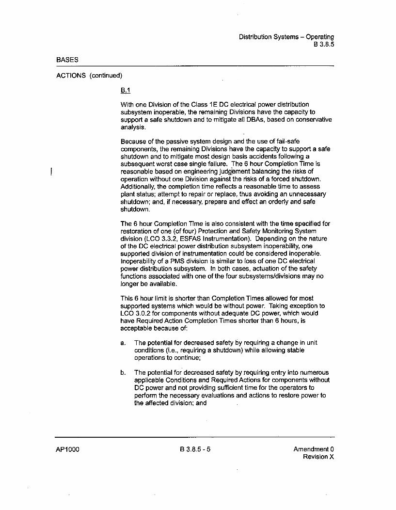
Distribution Systems - OperatingB 3.8.5
BASES
ACTIONS (continued)
B.1
With one Division of the Class 1 E DC electrical power distributionsubsystem inoperable, the remaining Divisions have the capacity tosupport a safe shutdown and to mitigate all DBAs, based on conservativeanalysis.
Because of the passive system design and the use of fail-safecomponents, the remaining Divisions have the capacity to support a safeshutdown and to mitigate most design basis accidents following asubsequent worst case single failure. The 6 hour Completion Time isreasonable based on engineering juclgýement balancing the risks ofoperation without one Division against the risks of a forced shutdown.Additionally, the completion time reflects a reasonable time to assessplant status; attempt to repair or replace, thus avoiding an unnecessaryshutdown; and, if necessary, prepare and eff6ct an orderly and safeshutdown.
The 6 hour Completion Time is also consistent with the time specified forrestoration of one (of four) Protection and Safety Monitoring Systemdivision (LCO 3.3.2, ESFAS Instrumentation). Depending on the natureof the DC electrical power distribution subsystem inoperability, onesupported division of instrumentation could be considered inoperable.Inoperability of a PMS division is similar to loss of one DC electricalpower distribution subsystem. In both cases, actuation of the safetyfunctions associated with one of the four subsystems/divisions may nolonger be available.
This 6 hour limit is shorter than Completion Times allowed for mostsupported systems which would be without power. Taking exception toLCO 3.0.2 for components without adequate DC power, which wouldhave Required Action Completion Times shorter than 6 hours, isacceptable because of:
a. The potential for decreased safety by requiring a change in unitconditions (i.e., requiring a shutdown) while allowing stableoperations to continue;
b. The potential for decreased safety by requiring entry into numerousapplicable Conditions and Required Actions for components withoutDC power and not providing sufficient time for the operators toperform the necessary evaluations and actions to restore power tothe affected division; and
AP1000 B 3.8.5 - 5 Amendment 0Revision X

Unborated Water Source Flow PathsB 3.9.2
BASES
SURVEILLANCE REQUIREMENTS (continued)
walkdown. The 31 day Frequency is based on engineering judgementand is considered reasonable in view of other administrative controls thatwill verify that the valve opening is an unlikely possibility.
REFERENCES 1. Chapter 15, "Accident Analyses."
2. NUREG-0800, Standard Review Plan, Section 15.4.6, "Chemicaland Volume Control System Malfunction that Results in a Decreasein Boron Concentration in the RCS."
AP1000 B 3.9.2 - 3 Amendment 0Revision X

Refueling Cavity Water LevelB 3.9.4
BASES
ACTIONS LCO 3.0.8 is applicable while in MODE 5 or 6. Since irradiated fuelassembly movement can occur in MODE 5 or 6, the ACTIONS have beenmodified by a Note stating that LCO 3.0.8 is not applicable. If movingirradiated fuel assemblies while in MODE 5 or 6, the fuel movement isindependent of shutdown reactor operations. Entering LCO 3.0.8 while inMODE 5 or 6 would require the optimization of plant safety, unnecessarily.
A.1
With a water level of < 23 ft above the top of the reactor vessel flange, alloperations involving movement of irradiated fuel assemblies withincontainment shall be suspended immediately to ensure that a fuelhandling accident cannot occur.
The suspension of fuel movement shall not preclude completion ofmovement to safe position.
SURVEILLANCEREQUIREMENTS
SR 3.9.4 1
Verification of a minimum water level of 23 ft above the top of the reactorvessel flange ensures that the design basis for the analysis of thepostulated fuel handling accident during refueling operations is met.Water at the required level above the top of the reactor vessel flangelimits the consequences of damaged fuel rods that are postulated toresult from a fuel handling accident inside containment (Ref. 2).
The Frequency of 24 hours is based on engineering judgement and isconsidered adequate in view of the large volume of water and the normalprocedural controls of valve positions which make significant unplannedlevel changes unlikely.
REFERENCES I - Regulatory Guide 1. 183, "Alternate Radiological Source Terms forEvaluating Design Basis Accidents at Nuclear Power Reactors."
2. Section 15.7.4, "Fuel Handling Accident."
AP1000 B 3.9.4 - 2 Amendment 0Revision X

17. Quality Assurance AP1000 Design Control Document
R0SK-G Table 17.4-1 (Sheet-I of 8)
RISK-SIGNM ~A 4T S SFKCOPE OF D-RAP
System, Structure, or
Component (SSC)(1) Rationalet2) Insights and Assumptions
System: Component Cooling Water (CCS)
Component Cooling Water EP These pumps provide cooling of the normal residual heat
Pumps removal system (RNS) and the spent fuel pool heat exchanger.
(CCS-MP-01A/B) Cooling the RNS heat exchanger is important to investmentprotection during shutdown reduced-inventory conditions. CCS
valve realignment is not required for reduced-inventoryconditions.
System: Containment System (CNS)
Containment Vessel EP, L2 The containment vessel provides a barrier to steam and
(CNS-MV-01) radioactivity released to the atmosphere following accidents.
Hydrogen Igniters fAW/CCFEIR, The hydrogen igniters provide a means to control H2
(VLS-EH-1 through -64) L2, concentration in the containment atmosphere, consistent with
Regulations the hydrogen control requirements of 10 CFR 50.34f.
System: Chemical and Volume Control System (CVS)
Makeup Pumps EP These pumps provide makeup to the RCS to accommodate
(CVS-MP-01A/B) leaks and to provide negative reactivity for shutdowns, steamline breaks, and ATWS.
Makeup Pump Suction and EP These CVS check valves are normally closed and have to open
Discharge Check Valves to allow makeup pump operation.
(CVS-PL-V1 13, -V1 60A/B)
Letdown Isolation Valves RAW The CVS letdown isolation valves automatically close to
(CVS-PL-V045, -V047) prevent excessive reactor coolant letdown and providecontainment isolation. These containment isolation valves areimportant in limiting offsite releases followine core meltaccidents.
System: Diverse Actuation System (DAS)
DAS Processor Cabinets and RAW The DAS is diverse from the PMS and provides automatic and
Control Panel (used to manual actuation of selected plant features including control
provide automatic and rod insertion, turbine trip, passive residual heat removal
manual actuation) (PRHR) heat exchanger actuation, core makeup tank actuation,
(DAS-JD-001, -002, [0_03 isolation of critical containment lines, and passive containment
-004, OCS-JC-020) cooling system (PCS) actuation.
Annex Building UTPS RAW These panels distribute power to the DAS equipment.
Distribution Panels(EDS1-EA-1, EDS1-EA-14,EDS2-EA-1, EDS2-EA-14)
Tier 2 Material 17-15
Revision 18
Tier 2 Material 17-15 Revision 18

18. Human Factors Engineering AP1000 Design Control Document
43. American National Standards Institute, 1988, "ANSI/B-F 100-1988, American National
Standard for Human Factors Engineering of Visual Display Terminal Workstations,"
(Santa Monica, CA, Human Factors Society, American National Standards Institute).
44. WCAP-14694, "Designer's Input to Determination of the AP600 Main Control Room
Staffing Level," Revision 0, July 1996.
45. MAPP-GW-GL-022, "AP1000 Probabilistic•y Risk Assessment," Revision 8.
[46. WCAP-14396, "Man-in-the-Loop Test Plan Description," Revision 3,
November 2002.]*
47. APP-GW-GLR-082, "Execution and Documentation of the Human System Interface
Design Implementation Plan," Westinghouse Electric Company LLC.
*NRC Staff approval is required prior to implementing a change in this information; see DCD Introduction Section 3.5.
Tier 2 Material 18.8-26 Revision X

19. Probabilistic Risk Assessment APIO00 Design Control Document
19.1.6 Plant Definition
19.1.6.1 General Description
See Chapter 1.
19.1.6.2 AP1000 Design Improvement as a Result of Probabilistic Risk Assessment Studies
Design improvements were incorporated in the AP600 design based on the results of the AP600PRA and other design analyses and are discussed in Reference 19.1-3. These improvements havebeen retained in the AP 1000 design. Additional design changes have been incorporated in theAP 1000 as a result of the AP 1000 PRA. The most significant design changes prompted by theAP1000 PRA are:
* Two recirculation lines, each containing a motor-operated valve and a squib valve or a checkvalve and a squib valve in series, are used to provide recirculation flow from containmentsump to the core through direct vessel injection line. Diversity is provided in the actuation byusing diverse squib valves. The motor-operated valve is designed so that it remains open incase of failure.
* Three parallel supply lines allow water flow from PCCWST to the containment shell.Diversity is provided in the actuation by using motor-operated valves for one path.
19.1.7 References
19.1-1 Advanced Light Water Reactor Requirements Document. Volume In, Appendix A toChapter 1, "PRA Key Assumptions and Groundrules," Revisions 5 and 6,December 1993.
19.1-2 EPRI MAAP 4.0 Users Manual.
19.1-3 ý3W-GL-022, "AP600 Probabilistic Risk Assessment," August 1998AP600 PRA.
Tier 2 Material 19.1-6
Revision X
Tier 2 Material 19.1-6 Revision X
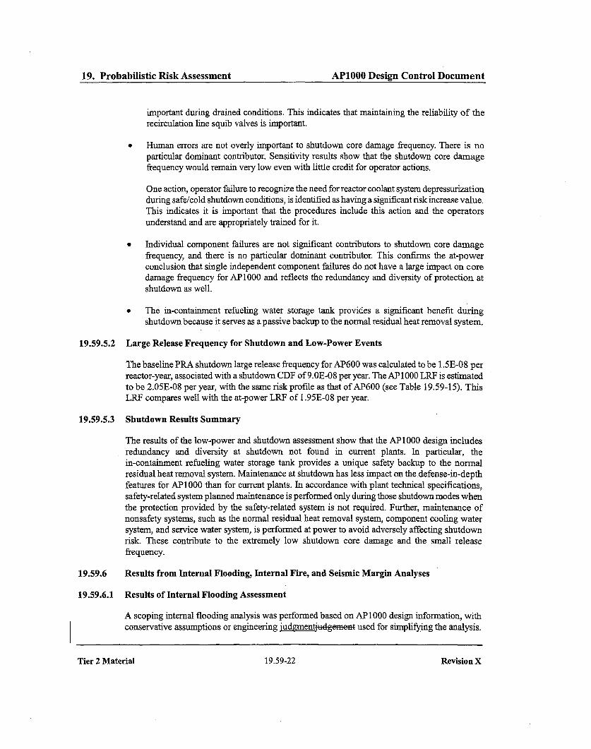
19. Probabilistic Risk Assessment AP1000 Design Control Document
important during drained conditions. This indicates that maintaining the reliability of the
recirculation line squib valves is important.
" Human errors are not overly important to shutdown core damage frequency. There is no
particular dominant contributor. Sensitivity results show that the shutdown core damage
frequency would remain very low even with little credit for operator actions.
One action, operator failure to recognize the need for reactor coolant system depressurization
during safe/cold shutdown conditions, is identified as having a significant risk increase value.
This indicates it is important that the procedures include this action and the operators
understand and are appropriately trained for it.
* Individual component failures are not significant contributors to shutdown core damage
frequency, and there is no particular dominant contributor. This confirms the at-power
conclusion that single independent component failures do not have a large impact on core
damage frequency for AP 1000 and reflects the redundancy and diversity of protection at
shutdown as well.
* The in-containment refueling water storage tank provides a significant benefit during
shutdown because it serves as a passive backup to the normal residual heat removal system.
19.59.5.2 Large Release Frequency for Shutdown and Low-Power Events
The baseline PRA shutdown large release frequency for AP600 was calculated to be 1.5E-08 per
reactor-year, associated with a shutdown CDF of 9.0E-08 per year. The AP 1000 LRF is estimated
to be 2.05E-08 per year, with the same risk profile as that of AP600 (see Table 19.59-15). This
LRF compares well with the at-power LRF of 1.95E-08 per year.
19.59.5.3 Shutdown Results Summary
The results of the low-power and shutdown assessment show that the AP 1000 design includes
redundancy and diversity at shutdown not found in current plants. In particular, the
in-containment refueling water storage tank provides a unique safety backup to the normal
residual heat removal system. Maintenance at shutdown has less impact on the.defense-in-depth
features for AP1000 than for current plants. In accordance with plant technical specifications,
safety-related system planned maintenance is performed only during those shutdown modes when
the protection provided by the safety-related system is not required. Further, maintenance of
nonsafety systems, such as the normal residual heat removal system, component cooling water
system, and service water system, is performed at power to avoid adversely affecting shutdown
risk. These contribute to the extremely low shutdown core damage and the small release
frequency.
19.59.6 Results from Internal Flooding, Internal Fire, and Seismic Margin Analyses
19.59.6.1 Results of Internal Flooding Assessment
A scoping internal flooding analysis was performed based on AP 1000 design information, with
conservative assumptions or engineering judgmentjudgement used for simplifying the analysis.
Tier 2 Material 19.59-22 Revision X

19. Probabilistic Risk Assessment AP1000 Design Control Document
Because the approach taken in performing the internal fire analysis makes various conservative
assumptions and is bounding, the results of uncertainty, sensitivity, or importance analyses would
be biased. Therefore, these analyses were not performed based on the dgrnent ge ne that
they would be of little value in providing additional insights to determine whether fire
vulnerabilities exist for beyond-design-basis fires.
The major reasons for the AP 1000's relatively low overall fire-induced core damage frequency,even on a bounding basis, include the following:
The fire protection design provides, to the extent possible, separation of the alternate
safety-related shutdown components and cabling using 3-hour-rated fire barriers. Forexample, areas containing safety-related cabling or components are physically separated from
one another and from the areas that do not contain any safety-related equipment by3-hour-rated fire barriers. This defense-in-depth feature diminishes the probability of a fire toimpact more than one safety-related shutdown system.
* Since the passive safety-related systems do not require cooling water or ac power, they are
less susceptible to being unavailable due to a fire than currently operating plants' active safeshutdown equipment. As a result, the impact of fires on the shutdown capability is
significantly reduced compared to current plants.
The results of this analysis show that the AP 1000 design is sufficiently robust that internal fires
during either power operation or shutdown do not represent a significant contribution to core
damage frequency.
19.59.6.3 Results of Seismic Margin Analysis
The seismic margin analysis (SMA) shows the systems, structures, and components required for
safe shutdown. The high confidence, low probability of failure (HCLPF) values are greater than or
equal to 0.50g. This HCLPF is determined by the seismically induced failure of the fuel in the
reactor vessel, core assembly failures, IRWST failure, or containment interior failures. The SMAresult assumes no credit for operator actions at the 0.50g review level earthquake, and assumes a
loss of offsite power for all sequences.
The seismic margin analysis shows the plant to be robust against seismic event sequences that
contain station blackout coupled with other seismic or random failures. The analysis also shows
the plant's capability to respond to seismic events without benefit of the operators' actions.
19.59.7 Plant Dose Risk From Release of Fission-Products
The design certification of the AP 1000 included consideration by the NRC of the topic referred to
in this section.
19.59.8 Overall Plant Risk Results
The total plant risk expressed in terms of plant core damage frequency and severe release
frequency for all events studied in this PRA are summarized in Table 19.59-17.
Tier 2 Material 19.59-25 Revision X

Change Number 11

3. Design of Structures, Components,Equipment and Systems AP1000 Design Control Document
The reactor vessel cavity and the two steam generator compartments are interconnected by a largevertical access tunnel. These four compartments are treated, in this discussion, as one largefloodable volume and they are referred to as the reactor coolant system compartment. Flooding ofthis compartment above elevation 107'-2" also includes the maintenance floor outside the curbsaround the other three compartments.
The PXS-A compartment (Room 11206), PXS-B compartment (Room 112074 and the chemicaland volume control system compartment (Room 11 20d) are physically separated and isolatedfrom each other by structural walls and curbs such that flooding in any one of these compartmentsor in the reactor coolant system compartment cannot cause flooding in any of the othercompartments. The access hatch to the PXS-B compartment is located near the containment walland is normally closed to address severe accident considerations. The access hatch to thePXS-B compartment is accessible from Room 11300 on elevation 107'-2".
The fire protection system and the demineralized water transfer and storage system are open-cyclesystems that enter the containment. During plant operation, the containment piping for thesesystems is isolated by containment isolation valves and is not a potential flooding source. Thesesystems are not open systems as defined in Bulletin 80-24 (one that has an essentially unlimitedsource).
Reactor Coolant System Compartment
The reactor coolant system compartment, represented by the reactor vessel cavity, the two steamgenerator compartments, and the large vertical access tunnel, is the largest of the separatefloodable compartments. With the exception of the pressurizer which is at a higher elevation, theprincipal components of the reactor coolant system are contained in this compartment.
The reactor vessel cavity and the adjoining equipment room are at the lowest level in thecontainment. The floor level of these rooms is at elevation 71 '-6" The floor level of the two steamgenerator compartments is at elevation 83'-0". A portion of each compartment has low point areasat elevation 80'-0".
The containment sump pumps are located in the equipment room at elevation 71'-6". Thearrangement for the floor drains from the two passive core cooling system compartments and thechemical and volume control system compartment provide a drain path for each compartment tothe lowest level of containment (elevation 71'-6") where the containment sump is located.Therefore, the source of the flooding in the reactor coolant system compartment is not limited tothe components or systems contained within this compartment.
Any leakage that occurs within the containment drains by gravity to the elevation 71'-6"equipment room. Reverse flow into the two passive core cooling system compartments and thechemical and volume control system compartment is prevented by redundant backflow preventersin each of the three compartment drain lines.
Flooding in any compartment of the containment is detected by the containment sump levelmonitoring system and the containment flood-up level instrumentation.
Tier 2 Material 3.4-8 Revision 18

Change Number 12

9. Auxiliary Systems A.P1000 Design Control Document
Lifting Devices Not Specially Designed
Slings or other lifting devices not specially designed are selected in accordance with ANSI B30.9(Reference 15), except that the load rating is based on the combined maximum static and dynamicloads that could be imparted to the sling.
For the handling of critical loads, dual or redundant slings are used, or a sling having a load ratingtwice that required for a non-critical load is used and khouldshaI4 be constructed of metallicmaterial (chain or wire rope) per NRC Regulatory Issue Summary 2005-25, Supplement 1(Reference 23).
Load Lift Points
The design stress safety factors for heavy load lift points, such as lifting lugs or cask trunnions, areconsistent with the safety factors used for special lifting devices. The design of lift points forcritical loads is in accordance with NUREG-0612, Paragraph 5.1.6.(3).
9.1.5.2.1.3 Instrumentation Applications
Limit switches are used to initiate protective responses to:
* Hoist overtravel* Hoist overspeed* Hoist overload or unbalanced load* Improper winding of hoist rope on the drum" Bridge or trolley overtravel
Redundant limit switches are used with the main hoist and the auxiliary hoists to limit the extentof travel in both the hoisting and lowering directions. The primary protection for each hoist ineach direction is a limit switch which interrupts power to the hoist motor via the control circuitry.Interruption of power to the hoist motor causes the hoist brakes to set. The hoist may be operatedin the safe direction to back out of the overtravel condition.
The secondary protection for each hoist in the raising direction is a block-actuated limit switchwhich directly interrupts power to the hoist motor and causes the brake(s) to set. The secondaryprotection for each hoist in the lowering direction is a limit switch which is mechanically andelectrically independent of the primary switch but also interrupts power to the hoist motor via thecontrol circuitry. Actuation of the secondary limit switches prevents further hoisting or loweringuntil specific corrective action is taken.
A centrifugal-type limit switch, located on the drum shaft, provides overspeed protection for eachhoist. Hoist speeds in excess of 115 percent of the rated lowering speed for a critical load causethe hoist motor to stop and the holding brakes to set.
A load-sensing system is used, to detect overloading of the hoists. Hoisting motion is stoppedwhen the overload setpoint is exceeded. Similarly, an unbalanced load is detected by a system thatstops the hoist motion when there is excessive movement of the equalizer mechanism.
Tier 2 Material 9.1-43 Revision X

9. Auxiliary Systems AP1000 Design Control Document
9.1.5.2.2.2 Component Descriptions
The cask handling crane is designed according to NUREG-0554 supplemented by ASME NOG-l.Table 9.1.5-1 lists the design characteristics of this crane. This subsection describes how the coderequirements are implemented in the design of key safety-related components. Associated liftingdevices and load lift points are also described.
Hoist System
The hoisting rope is wound around the drum in a single layer. If the rope becomes dislodged fromits proper groove, the crane drives are automatically shut down and the brakes are set. Features arealso provided to contain the drum and prevent disengagement of the gearing in the event of drumshaft or bearing failure. A control brake and two redundant holding brakes are provided.
Two separate, redundant reeving systems are used, so that a single rope failure will not result inthe dropping of the load. Two wire ropes are reeved side-by-side through the sheave. Each cablepasses through an equalizer that adjusts for unequal cable length. The equalizer is also a loadtransfer safety system, eliminating sudden load displacement and shock to the crane in the unlikelyevent of a cable break. Overtravel protection is provided (see subsection 9.1.5.2.2.3); however,even in the event of hook overtravel in the raising direction to the point the load block contacts thecrane structure, the ropes cannot be cut or crushed.
The load block provides two separate load attachment points; the main hook is a two-prongedsister hook with safety latches.
Auxiliary Hoist System
The auxiliary hoist system is similar to that of the main hoist.
Special Lifting Devices
Special lifting devices for critical and non-critical loads are designed to meet the applicablerequirements of ANSI N14.6 (Reference 14). The stress design safety factors are based on thecombined maximum static and dynamic loads that could be imparted to the handling device, basedon the characteristics of the crane. Special lifting devices used for the handling of critical loads arelisted in Table 9.1.5-2.
Lifting Devices Not Specially Designed
Slings or other lifting devices not specially designed are selected in accordance with ANSI B30.9(Reference 15), except that the load rating is based on the combined maximum static and dynamicloads that could be imparted to the sling.
For the handling of critical loads, dual or redundant slings are used, or a sling having a load ratingtwice that required for a non-critical load is used and shouldhat4 be constructed of metallicmaterial (chain or wire rope) per NRC Regulatory Issue Summary 2005-25, Supplement 1(Reference 23).
Tier 2 Material 9.1-45 Revision X

Change Number 13

8. Electric Power AP1000 Design Control Document
Table 8.3.1-2 (Sheet 4 of 4)
ONSITE STANDBY DIESEL GENERATOR ZOS MG 02B NOMINAL LOADS
Manual Loads (Note 2)
Time OperatingItem Seq. Event or Rating LoadNo. (see) Load Description (hp/kW) (kW)
53. -- Class 1E Div. B Battery Charger 1 78 kVA 26
54. -- Class 1E Div. B Battery Charger 2 78 kVA 15
55. -- Class 1E Div. D Battery Charger 1 78 kVA 26
56. -- Supplemental Air Filtration 15 hp 15System Fan B
57. Supplemental Air Filtration 20 kW 20System Electric Heater B
58. Backup Group 4B Pressurizer 246 kW 246Heaters
59. -- CRDM Fan 01C 75 hp 62
60. -- CRDM Fan 01D 75 hp 62
61. -- Spent Fuel Cooling Pump B 1i50-2-o5 hp 125200
62. -- Make-Up Pump B 600 hp 498
63. -- Non-lE Regulating XFMR 75 kVA 25EDS2-DT-1
64. Annex Bldg Equipment Room 20 hp 17Return/Exhaust Fan B
65. Annex Bldg Equipment Room 50 hp 42AHU MS02B Fan
66. Annex Bldg Swgr Rm AHU MS 50 hp 4205B Fan
67. Annex Bldg Swgr Rm Ret/Exhaust 25 hp 21Fan 06B
Total Manually Sequenced L1242434-7Loads (kW)
Tier 2 Material 8.3-3 6
Revision X
Tier 2 Material 8.3-36 Revision X

Change Number 15
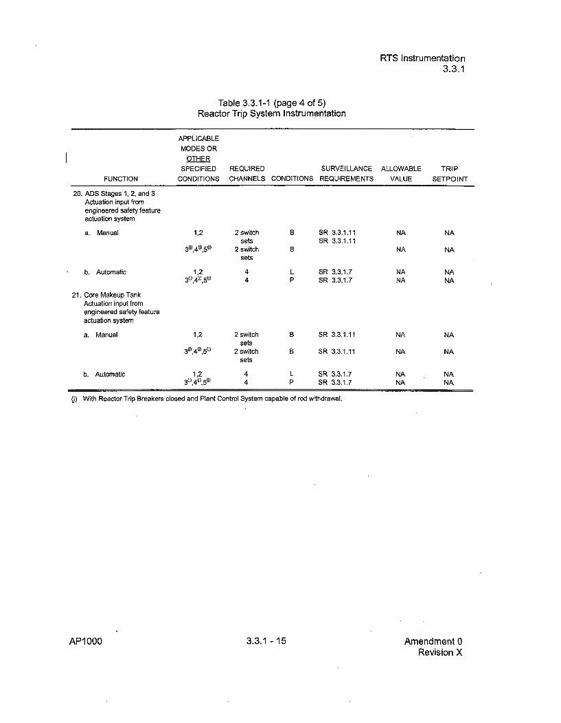
RTS Instrumentation3.3.1
Table 3.3.1-1 (page 4 of 5)Reactor Trip System Instrumentation
APPLICABLE
MODES ORbTHER
SPECIFIED REQUIRED SURVEILLANCE ALLOWABLE TRIP
FUNCTION CONDITIONS CHANNELS CONDITIONS REQUIREMENTS VALUE SETPOINT
20. ADS Stages 1, 2, and 3Actuation input fromengineered safety featureactuation system
a. Manual 1,2 2 switch B SR 3.3.1.11 NA NAsets SR 3.3.1.11
36),40),50) 2 switch B NA NA
sets
b. Automatic 1,2 4 L SR 3.3.1.7 NA NA30),40),5c) 4 P SR 3.3.1.7 NA NA
21. Core Makeup TankActuation input fromengineered safety featureactuation system
a. Manual 1,2 2 switch B SR 3.3.1.11 NA NAsets
30),40),50) 2 switch B SR 3.3.1.11 NA NA
sets
b. Automatic 1,2 4 L SR 3.3.1.7 NA NA30),4t),50) 4 P SR 3.3.1.7 NA NA
U) With Reactor Trip Breakers closed and Plant Control System capable of rod withdrawal.
AP1000 3.3.1 - 15 Amendment 0Revision X

ESFAS Instrumentation3.3.2
Table 3.3.2-1 (page 9 of 13)Engineered Safeguards Actuation System Instrumentation
SVfAce5APPLICABLEMODES OR
OTHERSPECIFIED
CONDITIONSREQUIRED SURVEILLANCE ALLOWABLECHANNELS CONDITIONS REQUIREMENTS VALUE
TRIPSETPOINTFUNCTION
Boron Dilution Block
a. Source RangeNeutron FluxDoubling
b. ReactorTrip
I
I
16. Chemical Volume andControl System MakeupIsolation
a. SG Narrow RangeWater Level - High 2
b. Pressurizer WaterLevel - High 1
Coincident withSafeguards Actuation
c. Pressurizer WaterLevel - High 2
d. ContainmentRadioactivity - High 2
e. Manual Initiation
f. Source RangeNeutron FluxDoubling
q. SG Narrow RangeWater Level High
Coincident withReactor Trip (P-4)
2(f),30),4)m) 4 B,T SR 3.3.2.1 !5 SeumesSR 3.3.2.4 P.aege Flux-XSR 3.3.2.5 in4QSR 3.3.2.6 Minutes
5(') 4 B,P SR 3.3.2.1 !5 $eu-eSR 3.3.2.4 Rage --' XSR 3.3.2.5 2.201 oSR 3.3.2.6 minutes
Refer to Function 1 8.ba (ESFAS Interlocks, Reactor Trip, P-4) for all requirements.
1 ,2 ,3(m),4 0,m) 4 per SG B,R SR 3.3.2.1 !;SR 3.3.2.4SR 3.3.2.5SR 3.3.2.6
1,2,3(m) 4 B,Q SR 3.3.2.1SR 3.3.2.4SR 3.3.2.5SR 3.3.2.6
1,2,3(m) Refer to Function 1 (Safeguards Actuation) for initiating functionsand requirements.
1,2,3,4(m'P) 4 B,T SR 3.3.2.1 ýQ o,%
82%-sWaA
23% span
59% span
SourceRange Flux X
SourceRange Flux X
2~v24eO
SR 3.3.2.4SR 3.3.2.5SR 3.3.2.6
1,2,3(m) 4 BQ SR 3.3.2.1SR 3.3.2.4SR 3.3.2.5SR 3.3.2.6
1,2,3(m),40,m) 2 switches E,R SR 3.3.2.3
r. 6g--R'l 100 R/hr
NA NA
Refer to Function 15.a (Boron Dilution Block, Source Range Neutron Flux Doubling) for allrequirements.
1.2.3"),40') 4 per SG BR SR 3.3.2.1 5 72.85%ASR 3.3.2.4 spanSR 3.3.2.5SR 3.3.2.6
R~f~r ft Fijnr~firn 1R • (F5:.FAR Int•=rfnnkm RP~tdnr Trin P-Al fnr m11 rnniirlanmmnt
72.8% span
Refer to Function 18 a IESFAS Interlocks Reactor Trin P-41 for all rerluirements
(f Not applicable when critical or during intentional approach to criticality.
0) With the RCS not being cooled by the Normal Residual Heat Removal System (RNS).(m) Not applicable for valve isolation Functions whose associated flow path is isolated.
(p) Above the P-1 9 (RCS Pressure) interlock.
AP1000 3.3.2-22 Amendment 0Revision 18

Programs and Manuals5.5
5.5 Programs and Manuals
5.5.6 Technical Specifications (TS) Bases Control Program (continued)
b. Licensees may make changes to Bases without prior NRC approval providedthe changes do not require either of the following:
1. A change in the TS incorporated in the license; or
2. A change to the updated FSAR or Bases that requires NRC approvalpursuant to 10 CFR 50.59.
c. The Bases Control Program shall contain provisions to ensure that theBases are maintained consistent with the FSAR.
d. Proposed changes that meet the criteria of (b) above shall be reviewed andapproved by the NRC prior to implementation. Changes to the Basesimplemented without prior NRC approval shall be provided to the NRC on afrequency consistent with 10 CFR 50.71 (e).
5.5.7 Safety Function Determination Program (SFDP)
This program ensures loss of safety function is detected and appropriate actiontaken. Upon entry into LCO 3.0.6, an evaluation shall be made to determine ifloss of safety function exists. Additionally, other appropriate actions may be takenas a result of the supported system inoperability and corresponding exception toentering supported system Condition and Required Actions. This programimplements the requirement of LCO 3.0.6. The SFDP shall contain the following:
a. Provisions for cross train checks to ensure a loss of the capability to performthe safety function assumed in the accident analysis does not goundetected;
b. Provisions for ensuring the plant is maintained in a safe condition if a loss offunction condition exists;
c. Provisions to ensure that an inoperable supported system's Completion Timeis not inappropriately extended as a result of multiple support systemsinoperabilities; and
d. Other appropriate limitations and remedial or compensatory actions.
AP1000 5.5-7 Amendment 0Revision 18
CVS Demineralized Water Isolation Valves and Makeup Line Isolation ValvesB 3.1.9
BASES
APPLICABILITY (continued)
In MODES 1 and 2, the detection and mitigation of a boron dilution eventdoes not assume the detection of the event by the source rangeinstrumentation. In these MODES, the event would be signalled] by anintermediate range trip, a trip on the Power Range Neutron Flux - High(low setpoint nominally at 25% RTP), or Overtemperature delta T. Thetwo demineralized water isolation valves close automatically upon reactortrip.
In MODE 6, a dilution event is precluded by the requirement in LCO 3.9.2to close, lock and secure at least one valve in each unborated watersource flow path.
ACTIONS A..1
If only one of the demineralized water isolation valve and/or the makeupline isolation valve is/are OPERABLE, the redundant valve must berestored to OPERABLE status in 72 hours. The allowed Completion Timeassures expeditious action will be taken, and is acceptable because thesafety function of automatically isolating the clean water source can beaccomplished by the redundant isolation valve(s).
B.1
If the Required Actions and associated Completion Time of Condition Aare not met, or if both CVS demineralized water isolation valves or bothmakeup line isolation valves are not OPERABLE (i.e., not able to beclosed automatically), then the demineralized water supply flow path tothe RCS must be isolated. Isolation can be accomplished by manuallyisolating the CVS demineralized water isolation valve(s) or by positioningthe 3-way blend valve to only take suction from the boric acid tank.Alternatively, the dilution path may be isolated by closing appropriateisolation valve(s) in the flow path(s) from the demineralized water storagetank to the reactor coolant system.
The Action is modified by a Note allowing the flow path to be unisolatedintermittently under administrative controls. These administrative controlsconsist of stationing a dedicated operator at the valve controls, who is incontinuous communication with the main control room. In this way, theflow path can be rapidly isolated when a need for isolation is indicated.
AP1000 B 3.1.9 - 2 Amendment 0Revision X

RCS Pressure, Temperature, and Flow DNB LimitsB.3.4.1
BASES
ACTIONS (continued)
The 2 hour Completion Time for restoration of the parameters providessufficient time to adjust plant parameters, to determine the cause for theoff normal condition, and to restore the readings within limits, and isbased on plant operating experience.
B.1
If Required Action A. 1 is not met within the associated Completion Time,the plant must be brought to a MODE in which the LCO does not apply.To achieve this status, the plant must be brought to at least MODE 2within 6 hours. In MODE 2, the reduced power condition eliminates the
potential for violation of the accident analysis bounds. The CompletionTime of 6 hours is reasonable to reach the required plant conditions in anorderly manner.
SURVEILLANCE SR 3.4.1.1REQUIREMENTS
Since Required Action A.1 allows a Completion Time of 2 hours to restoreparameters that are not within limit h 1 o u I uency
zqpýofjnw is citlttoyensure heon press•ulrle can boad
_changes and other expected transient operations. The 1 h r ic icie to regularly assess
for potential degradation and to verify operation is within safety analysisassumptions.
SR 3.4.1.2
Since Required Action A.1 allows a Completion Time of 2 hours to restoreparameters that are not within limits, the 12 hour Surveillance Frequencyfor RCS average temperature is sufficient to ensure the temperature canbe restored to a normal operation, steady state condition following loadchanges and other expected transient operations. The 12 hourFrequency has been shown by operating practice to be sufficient toregularly assess for potential degradation and to verify operation is withinsafety analysis assumptions.
SR 3.4.1.3
The 12 hour Surveillance Frequency for RCS total flow rate is performedusing the installed 6differential pressure flow instrumentation. The 12 hourinterval has been shown by operating practice to be sufficient to regularlyassess potential degradation and to verify operation within safety analysisassumptions.
AP1000 B 3.4.1 - 4 Amendment 0Revision X

PCS - OperatingB 3.6.6
BASES
SURVEILLANCE REQUIREMENTS (continued)
either to ý: 1000F, or decreases to:5 500F. Since the maximum tanktemperature variation during the normal surveillance Frequency of 7 daysis only about I *F, the tank temperature cannot exceed its limits before theincreased surveillance Frequency takes effect.
SR 3.6.6.2
Verification that the cooling water volume is above the required minimumensures that a sufficient supply is available for containment cooling.Since the cooling water volume is normally stable and low level isindicated by a main control room alarm, a 7 day Frequency is appropriateand has been shown to be acceptable in similar applications.
SR 3.6.6.3
Verifying the correct alignment of power operated, and automatic valves,excluding check valves, in the Passive Containment Cooling Systemprovides assurance that the proper flow paths exist for system operation.This SR does not apply to valves that are locked, sealed, or otherwisesecured in position since these were verified to be in the correct positionsprior to being secured. This SR does not require any testing or valvemanipulation. Rather, it involves verification, through control roominstrumentation or a system walkdown, that valves capable of potentiallybeing mispositioned are in the correct position. The 31 day Frequency isappropriate because the valves are operated under administrative control,and an improper valve position would only affect a single flow path. ThisFrequency has been shown to be acceptable through operatingexperience.
SIR 3.6.6.4
This SIR requires verification that each automatic isolation valve actuatesto its correct position upon receipt of an actual or simulated actuationsignal. This Surveillance is not required for valves that are locked,sealed, or otherwise secured in the required position under administrativecontrols. The 24 month Frequency is based on the need to performthise-,4, Surveillance under the conditions that apply during a plant outageand the potential for an unplanned transient if the Surveillances wereperformed with the reactor at power. The 24 month Frequency is alsoacceptable based on consideration of the design reliability (and confirmedby operating experience) of the equipment. Operating experience hasshown that these components usually pass the Surveillances whenperformed at the 24 month Frequency. Therefore, the Frequency wasconcluded to be acceptable from a reliability standpoint.
AP1000 B 3.6.6 - 6 Amendment 0Revision X
Containment PenetrationsB 3.6.8
B 3.6 CONTAINMENT SYSTEMS
B 3.6.8 Containment Penetrations
BASES
BACKGROUND Containment closure capability is required during shutdown operationswhen there is fuel inside containment. Containment closure is required tomaintain within containment the cooling water inventory. Due to the largevolume of the IRWST and the reduced sensible heat during shutdown, theloss of some of the water inventory ran be accepted. Further, accidentanalyses have shown that containment closure capability is not requiredto meet offsite dose requirements. Therefore, containment do-es not needto be leak tight as required for MODES 1 through 4.
In MODES 5 and 6, the LCO requirements are referred to as.,containment closure" rather than "containment OPERABILITY."Containment closure means that all potential escape paths are closed orcapable of being closed. Since there is no requirement for containmentleak tightness, compliance with the Appendix J leakage criteria and testsare not required.
In MODES 5 and 6, there is no potential for steam release into thecontainment immediately following ajn accident. Pressurization of thecontainment could only occur after heatup of the IRWST due to PRHR HXoperation (MODE 5 with RCS intact) or after heatup of the RCS withdirect venting to the containment (MODE 5 with reduced RCS inventory orMODE 6 with the refueling cavity not fully flooded) or after heatup of theRCS and refueling cavity (MODE 6 with refueling cavity fully flooded).The time from loss of normal cooling until steam release to thecontainment for four representative sets of plant conditions is shown inFigure B 3.6.8-1 as a function of time after shutdown. Because localmanual action may be required to achieve containment closure it isassumed that the containment hatches, air locks and penetrations mustbe closed prior to steaming into containment.
Figure B 3.6.8-1 provides allowable closure times for four representativesets of plant conditions. The time to steaming is dependent on variousplant parameters (RCS temperature, IRWST temperature, etc.) and plantconfiguration (RCS Pressure Boundary Intact, RCS Open, etc.).Therefore, the actual representation of the time to steaming may bedifferent than that provided in Figure B 3.6.8-1. In determining theminimum time to steaming, conservative assumptions regarding coredecay heat, RCS configuration, and initial RCS inventory are used tominimize the calculated time to steaming. The curves are based on thecore decay heat prior to refueling so that closure times are longerfollowing the core reload.
AP 1000 B 3.6.8 - 1 Amendment 0Revision X

pH AdjustmentB 3.6.9
B 3.6 CONTAINMENT SYSTEMS
B 3.6.9 pH Adjustment
BASES
IBACKGROUND The Passive Core Cooling System (PXS) includes Iourtwe pH adjustmentbaskets which provide adjustment of the pH of the water in thecontainment following an accident where the containment floods.
Following an accident with a large release of radioactivity, the,containment pH is automatically adjusted to greater than or equal to 7.0,to enhance iodine retention in the containment water. Chemical additionis necessary to counter the affects of the boric acid contained in the
-safety injection supplies and acids produced in the post-LOCAenvironment (nitric acid from the irradiation of water and air andhydrochloric acid from irradiation and pyrolysis of electric cableinsulation). The desired pH values significantly reduce formation ofelemental iodine in the containment water, which reduces the productionof organic iodine and the total airborne iodine in the containment. ThispH adjustment is also provided to prevent stress corrosion cracking ofsafety related containment components during long-term cooling.
Dodecahydrate trisodium phosphate (TSP) contained in baskets providesa passive means of pH control for such accidents. The baskets are madeof stainless steel with a mesh front that readily permits contact with water.These baskets are located inside containment at an elevation that isbelow the minimum floodup level. The baskets are placed at least a footabove the floor to reduce the chance that water spills will dissolve theTSP. Natural recirculation of water inside the c w wing aLOCA, is driven by the core decay heat and)vdes mixing o chieve auniform pH. The dodecahydrate form of TS (Na 3PO 4--12H20)' initiallyloaded into the baskets because it is hydrat a d ill r essphysical and chemical change than would anhydrousTSP as a result ofthe humidity inside containment. (Refs. 1 and 2)
APPLICABLESAFETYANALYSES
In the event of a Design Basis Accident (DBA), iodine may be releasedfrom the fuel to containment. To limit this iodine release fromcontainment, the pH of the water in the containment sump is adjusted bythe addition of TSP. Adjusting the sump water to neutral or alkaline pH(pH - 7.0) will augment the retention of the iodine, and thus reduce theiodine available to leak to the environment.
pH adjustment satisfies Criterion 3 of 10 CFR 50.36(c)(2)(ii).
AP1000 B 3.6.9 - 1 Amendment 0Revision X

Steam Generator Isolation ValvesB 3.7.10
BASES
ACTIONS (continued)
action places the flow path in a condition which assures the safetyfunction is performed. The 8 hour Completion Time is reasonable,considering the low probability of an accident occurring during this timeperiod that would require a closure of the SG isolation valves. Theincremental conditional core damage probability with this AOT is morethan an order of magnitude less than the value indicated to have a smallimpact on plant risk in Reference
D.1 and D.2
With two valves in one or more blowdown flow paths inoperable, actionmust be taken to isolate the flow path with a closed valve. This actionplaces the flow path in a condition which assures the safety function isperformed. The 8 hour Completion Time is reasonable, considering thelow probability of an accident occurring during this time period that wouldrequire a closure of the SG isolation valves. The incremental conditionalcore damage probability with this AOT is more than an order ofmagnitude less than the value indicated to have a small impact on plantrisk in Reference 3.
Since the blowdown isolation valve is not deactivated, periodic verificationis required to assure that the flow path remains isolated. This isnecessary to ensure that the assumptions in the safety analysis remainvalid. The 7 day Completion Time is reasonable, based on engineeringjudgment, in view of status indications available in the control room, andother administrative controls, to ensure that the valve remains in theclosed position.
E.1 and E.2
If the SG isolation valves cannot be restored to OPERABLE status or arenot closed within the associated Completion Time, the unit must beplaced in a MODE in which the LCO does not apply. To achieve thisstatus, the unit must be placed at least in MODE 3 within 6 hours, and inMODE 4 with the RCS cooling provided by the RNS within 24 hours. Theallowed Completion Times are reasonable, based on operatingexperience, to reach the required unit conditions in an orderly mannerand without challenging unit systems.
AP1 000 B 3.7.10 - 4 Amendment 0Revision X

Distribution Systems - OperatingB 3.8.5
BASES
ACTIONS (continued)
D.1
With two divisions of DC electrical power distribution subsystemsinoperable, the remaining DC electrical power distribution subsystems arecapable of supporting the minimum safety functions necessary to shutdown the reactor and maintain it in a safe shutdown condition, assumingno single failure. The overall reliability is reduced, however, because asingle failure in the remaining DC electrical power distribution subsystemcould result in the minimum required ESIF functions not being supported.Therefore, the required DC buses must be restored to OPERABLE statuswithin 2 hours by powering the bus from the associated battery orcharger.
Condition D represents two subsystems without adequate DC. power;potentially both with the battery significantly degraded and the associatedcharger nonfunctioning. In this situation, the unit is significantly morevulnerable to a complete loss of all DC power. It is, therefore, imperativethat the operator's attention focus on stabilizing the unit, minimizing thepotential for loss of power to the remaining divisions and restoring powerto the affected divisions.
This 2 hour limit is more conservative than Completion Times allowed forthe vast majority of components that would be without power. Takingexception to LCO 3.0.2 for components without adequate DC power,which would have Required Action Completion Times shorter than2 hours, is acceptable because of:
a. The potential for decreased safety by requiring a change in unitconditions (i.e., requiring a shutdown) while allowing stableoperations to continue;
b. The potential for decreased safety by requiring entry into numerousapplicable Conditions and Required Actions for components withoutDC power and not providing sufficient time for the operators toperform the necessary evaluations and actions for restoring power tothe affected divisions; and
c. The potential for an event in conjunction with a single failure of aredundant component.
The 2 hour Completion Time for DC buses is consistent with RegulatoryGuide 1.93 (Ref.
AP1 000 B 3.8.5 - 8 Amendment 0Revision X
Distribution Systems - OperatingB 3.8.5
BASES
SURVEILLANCE REQUIREMENTS (continued)
readily available for motive as well as control functions for critical systemloads connected to these buses. The 7 day Frequency takes into accountthe redundant capability of the Class 1 E AC and DC electrical powerdistribution subsystems, and other indications available in the controlroom that Plert the operator to subsystem malfunctions.
REFERENCES 1. Section 8.3.2, "DC Power Systems."
2. Chapter 6, "Engineering Safety Features."
3. Chapter 15, "Accident Analyses."
Regulatory Guide 1.93, "Availability of Electric Power Sources,"U.S. Nuclear Regulatory Commission, December 1974.
AP1000 B 3.8.5 - 10 Amendment 0Revision X

IDistribution Systems - OperatingB 3.8.5
/ ~Table B 3.8,.5-1 (page 1 of 1)•,• ass 1 E AC and DC Electrical Power Distribution System
TYPE VOLTAGE DIVISION A* DIVISION B* DIVISION C* DIVISION D*
DC Buses 250 Vdc IDSA-DS-1 IDSB-DS-1 IDSC-DS-1 IDSD-DS-1IDSB-DS-2 IDSC-DS-2
DC Distribution 250 Vdc IDSA-DD-1 IDSB-DD-1 IDSC-DD-1 IDSD-DD-1Panels IDSA-DK-1 IDSB-DK-1 IDSC-DK-1 IDSD-DK-1
AC Instrumentation 120 Vac IDSA-EA-1 IDSB-EA-1 IDSC-EA-1 IDSD-EA-1and Control Buses IDSB-EA-3 IDSC-EA-3
* Each Division of the AC and DC electrical power distribution systems is a subsystem.
AP1000 B 3.8.5 - 11 Amendment 0Revision X

Change Number 16

Tier 2 Revision 17 Change Roadmap AP1000 Design Control Document
TIER 2 REVISION 17 CHANGE ROADMAP (Cont.)
Section
14.214.214.2
Page No.
14.314.3
14.3
14.3
14.314.3
14.3
14.3
14.3
14.314.3
14.3
14.314.314.3
14.414.4
14.4
14.4
14.2-77
14.2-78
14.2-82
14.3-19
14.3-25
14.3-2714.3-34
14.3-45
14.3-49
14.3-16
14.3-25
14.3-28
14.3-33
14.3-33
14.3-34
14.3-4514.3-46
14.3-49
Type of Change
Technical
Technical
Technical
TechnicalTechnical
Technical
Editorial
EditorialEditorial
Technical
EditorialTechnical
Technical
Technical
Technical
Technical
Technical
Technical
EditorialTechnicalTechnical
Editorial
10 CFR 52.63Justification
Keyword (note)
(vi) Improve:
(v) Correct:
(iv) Explain:
(vi) Improve:(v) Correct:
(v) Correct:(v) Correct:
(v) Correct:(v) Correct:
(vii) Standardize:
(v) Correct:(vi) Improve:
(v) Correct:
(vi) Improve:
(iv) Explain:
(iv) Explain:
(vi) Improve:
(ii) Protect:
(v) Correct:(vi) Improve:(vii) Standardize:
Reference NRCLetter
DCP/NRC 2178
DCP/NRC 2111
DCP/NRC 2020
DCP/NRC 2020
DCP/NRC 1869
DCPINRC 1869DCP/NRC 1952
DCP/NRC 2245.
DCP/NRC 2245
DCP/NRC 1895
DCP/NRC 1.823
DCP/NRC 2161,DCP/NRC 1922
14.4-114.4-2
14.4-1
14.4-1
VOLUME 10
15, T of C15, T of C15, T of C15, T of C
15.015.015.015.015.015.015.0
iii thru vviii thru xxv and xvixviii and xxiii
15.0-2315.0-2915.0-3 and 15.0-415.0-515.0-615.0-1315.0-15
EditorialEditorial
Editorial
Editorial
Editorial
Editorial
Technical
Technical
Technical
Technical
Technical
(v) Correct:
(v) Correct:(v) Correct:(v) Correct:(v) Correct:
(v) Correct:(v) Correct:(ii) Protect:(iv) Explain:(v) Correct:(v) Correct:(v) Correct:
DCP/NRC 2020
DCP/NRC 2020
DCP/NRO(c3
Tier 2 Material cxciv Revision X
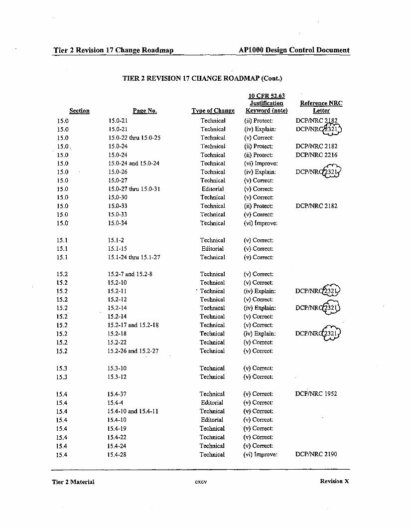
Tier 2 Revision 17 Change Roadmap AP1000 Design Control Document
TIER 2 REVISION 17 CHANGE ROADMAP (Cont.)
Section
15.015.015.015.0.15.015.015.015.015.015.015.015.015.0
Page No.
15.0-2115.0-21
15.0-22 thru 15.0-25
15.0-24
15.0-2415.0-24 and 15.0-24
15.0-26
15.0-27
15.0-27 thru 15.0-31
15.0-30
15.0-3315.0-33
15.0-34
15.1-2
15.1-15
15.1-24 thru 15.1-27
15.2-7 and 15.2-8
15.2-10
15.2-11
15.2-1215.2-14
15.2-14
15.2-17 and 15.2-18
15.2-18
15.2-22
15.2-26 and 15.2-27
Type of Change
TechnicalTechnicalTechnicalTechnicalTechnicalTechnicalTechnicalTechnicalEditorialTechnicalTechnicalTechnicalTechnical
10 CFR 52.63Justification
Keyword (note)
(ii) Protect:(iv) Explain:(v) Correct:(ii) Protect:(ii) Protect:(vi) Improve:(iv) Explain:(v) Correct:(v) Correct:(v) Correct:(ii) Protect:(v) Correct:(vi) Improve:
Reference NRCLetter
DCP/NRC 2,r8DCP/NRC32)
DCP/NRC 2182DCP/NRC 2216
DCP/NRCý3 /
DCP/NRC 2182
15.115.1
15.1
15.2
15.215.2
15.2
15.2
152
15.215.2
15.2
15.2
15.3
15.3
15.4
15.4
15.4
15.4
15.4
15.4
15.4
15.4
TechnicalEditorial
Technical
TechnicalTechnical
Technical
TechnicalTechnical
Technical
Technical
Technical
Technical
Technical
(v) Correct:(v) Correct:(v) Correct:
(v) Correct:(v) Correct:(iv) Explain:(v) Correct:(iv) Explain:(v) Correct:(v) Correct:(iv) Explain:(v) Correct:(v) Correct:
DCP/NRCP232
DCP/NRC&
DCP/NRCC232
15.3-10
15.3-12
Technical (v) Correct:Technical (v) Correct:
15.4-37
15.4-4
15.4-10 and 15.4-11
15.4-10
15.4-19
15.4-22
15.4-24
15.4-28
TechnicalEditorial
TechnicalEditorial
TechnicalTechnicalTechnicalTechnical
(v) Correct:(v) Correct:(v) Correct:(v) Correct:(v) Correct:(v) Correct:(v) Correct:(vi) Improve:
DCP/NRC 1952
DCP/NRC 2190
Tier 2 Material cxcv
Revision X
Tier 2 Material CXCV Revision X
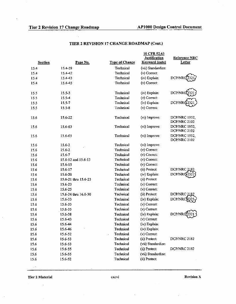
Tir2Rvsin1 hng oda AP1000 Design Control DocumentTier 2 Revision 17 Change Roadmap APlOOO Design Control Document
TIER 2 REVISION 17 CHANGE ROADMAP (Cont.)
Section
15.4
15.4
15.4
15.4
Page No.
15.515.5
15.5
15.5
15.6
15.6
15.6
15.6
15.615.6
15.6
15.6
15.615.6
15.6
15.6
15.6
15.6
15.6
15.615.6
15.615.6
15.6
15.6
15.615.6
15.6
15.6
15.6
15.6
15.4-28
15.4-42
15.4-43
15.4-45
15.5-315.5-4
15.5-7
15.5-8
15.6-22
15.6-63
Type of Change
TechnicalTechnical
Technical
Technical
10 CFR 52.63Justification
Keyword (note)
(vii) Standardize:
(v) Correct:
(iv) Explain:
(v) Correct:
Reference NRCLetter
DCP/NRf2
DCP/NRC32
DCP/NRCO
TechnicalTechnical
Technical
Technical
Technical
(iv) Explain:(v) Correct:(iv) Explain:(v) Correct:
Technical
(vi) Improve: DCP/NRC 1952,DCP/NRC 2102
(vi) Improve: DCP/NRC 1952,DCP[NRC 2102
(vi) Improve: DCP/NRC 1952,DCP/NRC 2102
15.6-65
15.6-2
15.6-2
15.6-7
15.6-12 and 15.6-13
15.6-15
15.6-17
15.6-2015.6-21 thru 15.6-23
15.6-23
15.6-25
15.6-24 thru 16.6-30
15.6-33
15.6-33
15.6-35
15.6-38
15.6-43
15.6-44
15.6-46
15.6-52
15.6-53
15.6-53
15.6-55
15.6-55
15.6-52
Technical
Technical
Technical
TechnicalTechnical
Technical
Technical
TechnicalTechnical
Technical
Technical
Technical
Technical
Technical
Technical
Technical
Technical
Technical
Technical
Technical
Technical
Technical
Technical
Technical
Technical
(vi) Improve:
(v) Correct:(v) Correct:(v) Correct:(v) Correct:(ii) Protect:
(iv) Explain:
(ii) Protect:
(v) Correct:(v) Correct:(ii) Protect:
(iv) Explain:
(v) Correct:(v) Correct:(iv) Explain:
(v) Correct:(iv) Explain:(iv) Explain:
(v) Correct:(ii) Protect:
(vii) Standardize:
(ii) Protect:
(vii) Standardize:
(ii) Protect:
DCP/NRC 2182DCP/NRq2321
DCP/NRC•&p
DCP/NRCV 5 )
DCP/NRCKM21
DCP/NRC 2182
DCP/NRC 2182
Tier 2 Material cxcvi
Revision X
Tier 2 Material cxcvi Revision X

Tier 2 Revision 17 Change Roadmap AP1000 Design Control Document
TIER 2 REVISION 17 CHANGE ROADMAP (Cont.)
Section
15.6
15.6
15.6
15.6
15.615.6
15.6
15.6
15.615.6
15.6
15.6
15.6
15.6
15.6
Page No.
15.6-5615.6-58 thru 15.6-60
15.6-55
15.6-62 thru 15.6-64
15.6-62 and 15.6-6315.6-65
15.6-66
15.6-68 thru 15.6-70
15.6-72
15.6-72
15.6-78
15.6-94 and 15.6-95
15.6-9715.6-99 thru 15.6-111
15.6-210 thru 15.6-221
Type of Change
TechnicalTechnicalTechnicalTechnicalTechnicalTechnicalTechnicalTechnicalTechnicalTechnicalTechnicalTechnicalTechnicalTechnicalTechnical
10 CFR 52.63Justification
Keyword (note)
(v) Correct:
(v) Correct:
(ii) Protect:
(ii) Protect:
(v) Correct:
(v) Correct:
(ii) Protect:
(ii) Protect:
(vi) Improve:
(v) Correct:
(iv) Explain:
(v) Correct:
(v) Correct:
(ii) Protect:
(iv) Explain:
Reference NRCLetter
DCP/NRC 2182
DCP/NRC 2182
DCP/NRC 2182
DCP/NRcf1j
DCP/NRC 2099
DCP/NRC 1952
DCP/NRC 2099
DCP/NRC 2D
DCP/NRC*DCP/NR 23•
DCP/NRC 2204
15.7
15A15A15A15A15A15A15A15A
15.7-6
15A-1815A-515A-15 and 15A-16
15A- 1715 A-4
15A-8 and 15A-9
15A-14 thru 15A-16
15A-17
VOLUME 11
16, T of C
Technical
Technical
Editorial
Technical
TechnicalTechnical
Technical
Technical
Technical
Editorial
Technical
Technical
Editorial
Technical
Technical
Technical
Technical
Editorial
Technical
(iv) Explain:
(iv) Explain:(v) Correct:(iv) Explain:(iv) Explain:(iv) Explain:(iv) Explain:(ii) Protect:(iv) Explain:
(v) Correct:i thru viii
16.116.1
16.116.116.116.116.116.116.1
16.1-2
16.1-2
1.1-5
1.1-63.1.4-13.1.4-4
3.1.8-1
3.3.1-2 thru 3.3.1-6
3.3.1-2 thru 3.3.1-6
(iv) Explain:(i) Regulate:(v) Correct:(vi) Improve:(vii) Standardize:(iv) Explain:(v) Correct:(v) Correct:(iv) Explain:
DCP/NRC 2098
DCP/NRC 2098
DCP/NRC 2183DCP/NRC 2098
Tier 2 Material cxcvii Revision X

Change Number 17
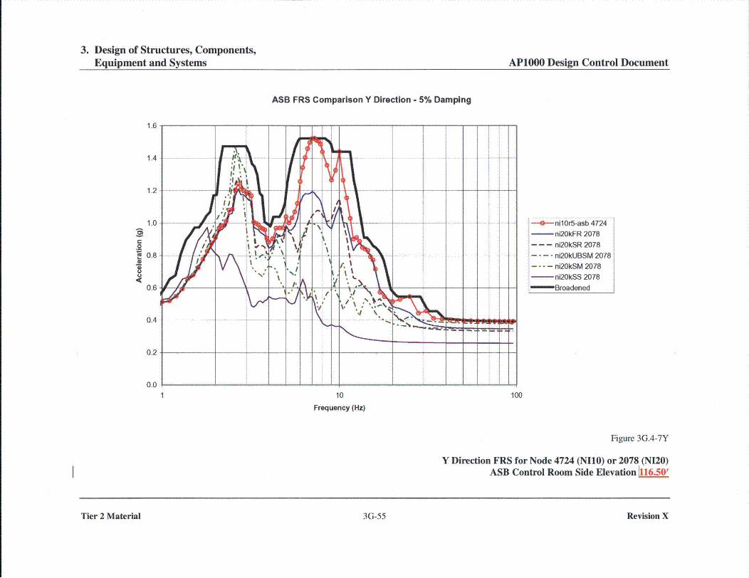
3. Design of Structures, Components,Equipment and Systems AP1000 Design Control Document
ASB FRS Comparison Y Direction - 5% Damping
0
9- nil Or5-asb 4724-ni20kFR 2078
- - - ni20kSR 2078.... ni20kUBSM 2078
....- ni20kSM 2078-ni20kSS 2078
-"Broadened
1 10
Frequency (Hz)
100
Figure 3G.4-7Y
Y Direction FRS for Node 4724 (NIl0) or 2078 (NI20)ASB Control Room Side Elevation 116.50'
Tier 2 Material 3G-55 Revision X
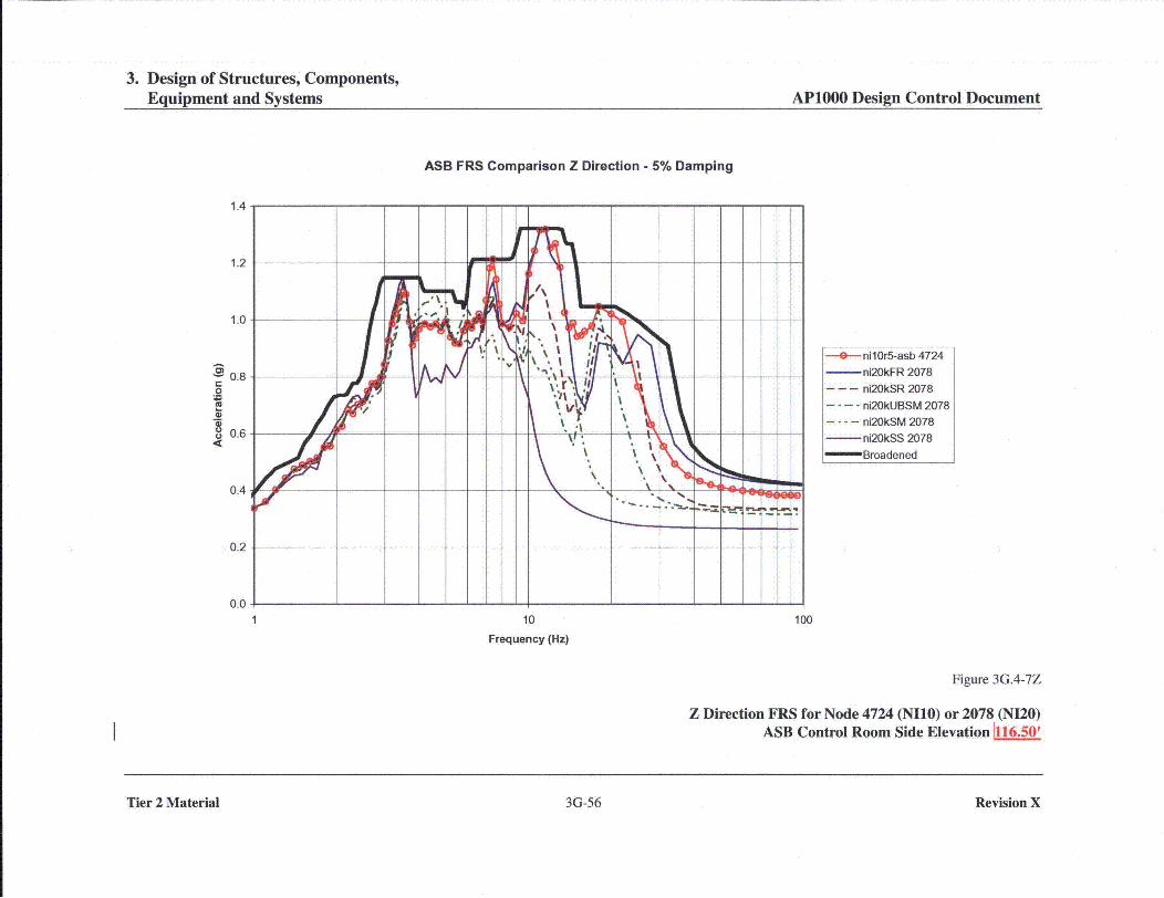
3. Design of Structures, Components,Equipment and Systems AP1000 Design Control Document
ASB FRS Comparison Z Direction - 5% Damping
1.4
1.2
1.0
0.8C
0
S0.6
0.4
0.2
0.0
- nillOr5-asb 4724-ni20kFR 2078
- -- ni20kSR 2078
.... ni20kUBSM 2078
.... ni20kSM 2078-ni20kSS 2078-" Broadened
1 10
Frequency (Hz)
100
Figure 3G.4-7Z
Z Direction FRS for Node 4724 (NIlO) or 2078 (NI20)ASB Control Room Side Elevation 416.50'
Tier 2 Material 3G-56 Revision X

Change Number 18

9. Auxiliary Systems AP1000 Design Control Document9. Auxiliary Systems AP1000 Design Control Document
Table 9.1-3 (Sheet 1 of 2)
COMPONENT DATA -
SPENT FUEL POOL COOLING AND PURIFICATION SYSTEM
Spent Fuel Pool Pump
I
Number 2
Design pressure (psig) 150
Design temperature ('F) 250
Nominal flow (gallons/minute) 1200
Minimum flow to support normal cooling (gpm) 900
Material Stainless Steel
Spent Fuel Pool Heat Exchangers
Number 2
Type Plate
Design heat transfer (Btu/hour) 14.75 x 10⁶
Design capacity (Btu/hour-°F) 24.0 x 10⁵
Minimum capacity to support normal cooling 22.0 x 10'(Btu/hour-°F)
Side 1 Side 2
Design pressure (psig) .004-54 150
Design temperature (*F) 250 250
Nominal flow (pounds/hour) 6.23 x 10' 5.94 x 10'
Inlet temperature (7F), typ. 89.5 120
Outlet temperature (0F), typ. 113.3 95.1
Fluid circulated Component cooling water Spent fuel pool water
Material Stainless steel Stainless steel
Spent Fuel Pool Demineralizers
Number 2
Design pressure (psig) 150
Design temperature ('F) 200
Nominal flow (gallons/minute) 250
Nominal resin volume (cubic feet) 75
Material Stainless steel
Tier 2 Material 9.1-57 Revision 18

Change Number 19
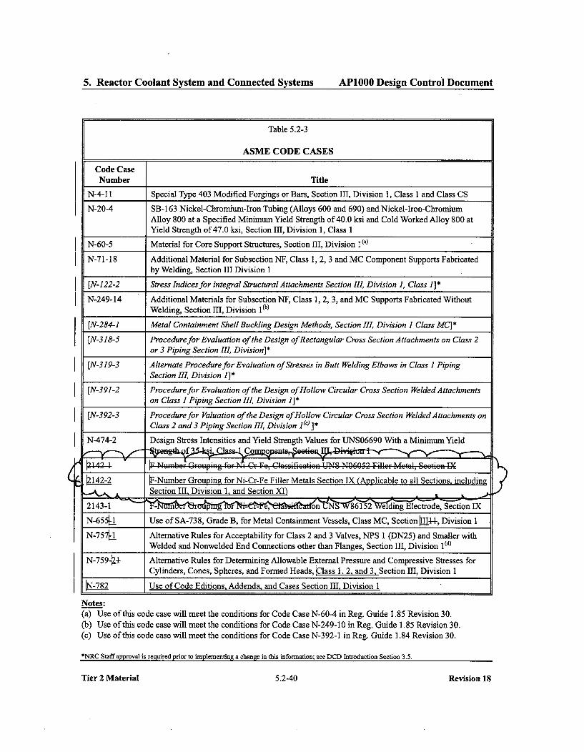
5. Ractr Colan Sysem ndCnnetabed System
AP1000 Design Control Document5. Reactor Coolant System and Connected Systems AP1000 Design Control Document
Table 5.2-3
ASME CODE CASES
4
Code CaseNumber Title
N-4-11 Special Type 403 Modified Forgings or Bars, Section III, Division 1, Class 1 and Class CS
N-20-4 SB- 163 Nickel-Chromium-Iron Tubing (Alloys 600 and 690) and Nickel-Iron-ChromiumAlloy 800 at a Specified Minimum Yield Strength of 40.0 ksi and Cold Worked Alloy 800 atYield Strength of 47.0 ksi, Section III, Division 1, Class I
N-60-5 Material for Core Support Structures, Section III, Division I()
N-71-18 Additional Material for Subsection NF, Class 1, 2, 3 and MC Component Supports Fabricatedby Welding, Section III Division 1
[N-122-2 Stress Indices for integral Structural Attachments Section III, Division 1, Class 1I*
N-249-14 Additional Materials for Subsection NF, Class 1, 2, 3, and MC Supports Fabricated WithoutWelding, Section III, Division 1 (b)
[N-284-1 Metal Containment Shell Buckling Design Methods, Section III, Division I Class MC]*
[N-318-5 Procedure for Evaluation of the Design ofRectangular Cross Section Attachments on Class 2or 3 Piping Section III, Division]*
[N-319-3 Alternate Procedure for Evaluation of Stresses in Butt Welding Elbows in Class 1 PipingSection III, Division J]*
[N-391-2 Procedure for Evaluation of the Design of Hollow Circular Cross Section Welded Attachmentson Class I Piping Section III, Division I]*
[N-392-3 Procedure for Valuation of the Design of Hollow Circular Cross Section Welded Attachments onClass 2 and 3 Piping Section cto, Division 1(c) ]*
N-474-2 Design Stress Intensities and Yield Strength Values for UTNS06690 With a Minimum Yield
2]42-2 kF-Number Groupingz for Ni-Cr-Fe Filler Metals Section IX (Applicable to all Sections, including
S UseofSection EIt, Division 1, and Section XIC Sco is
N-655( U Use of SA-738, Grade B, for Metal Containment Vessels, Class MC, Section 304, Division IN-757ý1 Alternative Rules for Acceptability for Class 2 and 3 Valves, NPS I (DN25) and Smaller with
Welded and Nonwelded End Connections other than Flanges, Section III, Division I1(d)
N-75944-- Alternative Rules for Determining Allowable External Pressure and Compressive Stresses forCylinders, Cones, Spheres, and Formed Heads, •21ass 1, 2, and 3, Section III, Division 1
N-782 Use of Code Editions, Addenda, and Cases Section III, Division 1
Notes:
(a) Use of this code case will meet the conditions for Code Case N-60-4 in Reg. Guide 1.85 Revision 30.(b) Use of this code case will meet the conditions for Code Case N-249-10 in Reg. Guide 1.85 Revision 30.(c) Use of this code case will meet the conditions for Code Case N-392-1 in Reg. Guide 1.84 Revision 30.
*NRC Staff approval is required prior to implementing a change in this information; see DCD Introduction Section 3.5.
Tier 2 Material 5.2-40 Revision 18

Change Number 20
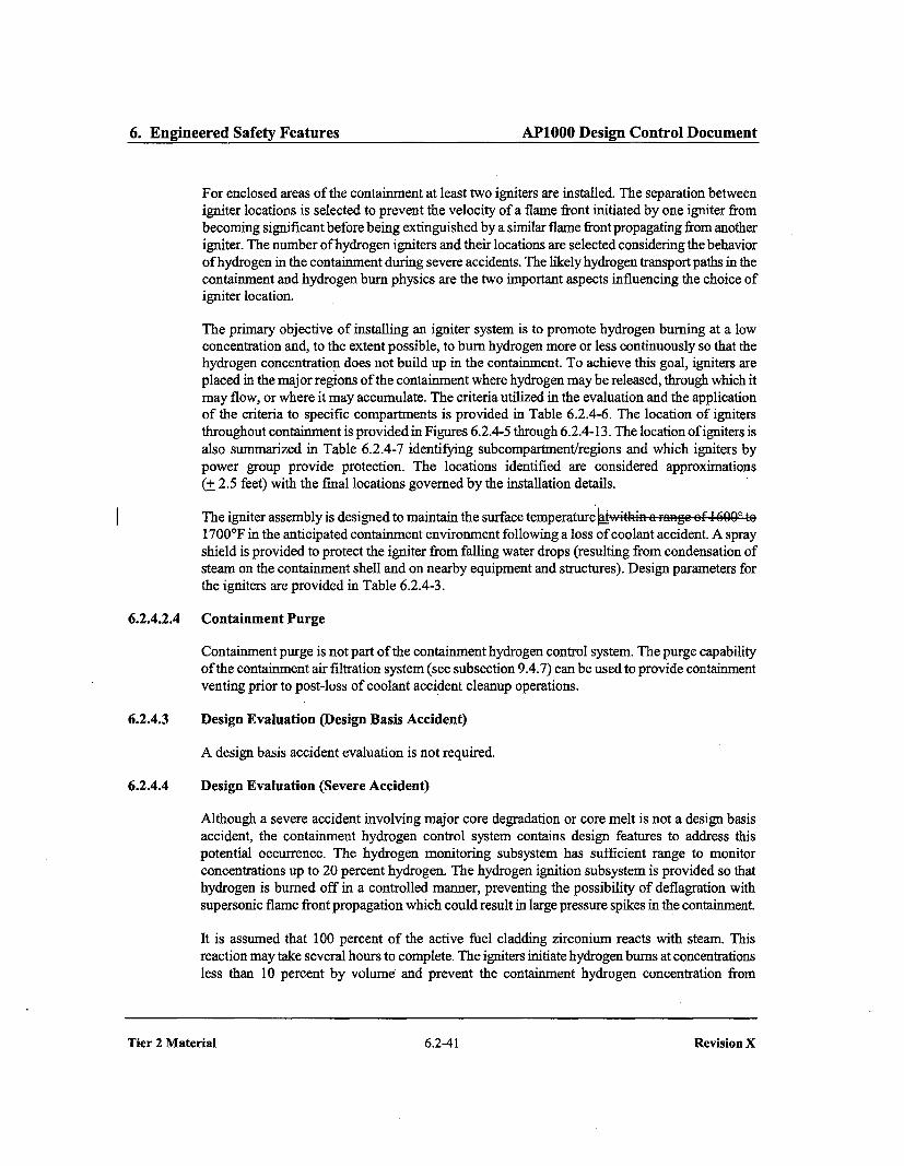
6. Engineered Safety Features APIOOO Design Control Document
For enclosed areas of the containment at least two igniters are installed. The separation betweenigniter locations is selected to prevent the velocity of a flame front initiated by one igniter frombecoming significant before being extinguished by a similar flame front propagating from anotherigniter. The number of hydrogen igniters and their locations are selected considering the behaviorof hydrogen in the containment during severe accidents. The likely hydrogen transport paths in thecontainment and hydrogen bum physics are the two important aspects influencing the choice ofigniter location.
The primary objective of installing an igniter system is to promote hydrogen burning at a lowconcentration and, to the extent possible, to bum hydrogen more or less continuously so that thehydrogen concentration does not build up in the containment. To achieve this goal, igniters areplaced in the major regions of the containment where hydrogen maybe released, through which itmay flow, or where it may accumulate. The criteria utilized in the evaluation and the applicationof the criteria to specific compartments is provided in Table 6.2.4-6. The location of ignitersthroughout containment is provided in Figures 6.2.4-5 through 6.2.4-13. The location of igniters isalso summarized in Table 6.2.4-7 identifying subcompartment/regions and which igniters bypower group provide protection. The locations identified are considered approximations(+ 2.5 feet) with the final locations governed by the installation details.
The igniter assembly is designed to maintain the surface temperature ef 4 690' te1700'F in the anticipated containment environment following a loss of coolant accident. A sprayshield is provided to protect the igniter from falling water drops (resulting from condensation ofsteam on the containment shell and on nearby equipment and structures). Design parameters forthe igniters are provided in Table 6.2.4-3.
6.2.4.2.4 Containment Purge
Containment purge is not part of the containment hydrogen control system. The purge capabilityof the containment air filtration system (see subsection 9.4.7) can be used to provide containmentventing prior to post-loss of coolant accident cleanup operations.
6.2.4.3 Design Evaluation (Design Basis Accident)
A design basis accident evaluation is not required.
6.2.4.4 Design Evaluation (Severe Accident)
Although a severe accident involving major core degradation or core melt is not a design basisaccident, the containment hydrogen control system contains design features to address thispotential occurrence. The hydrogen monitoring subsystem has sufficient range to monitorconcentrations up to 20 percent hydrogen. The hydrogen ignition subsystem is provided so thathydrogen is burned off in a controlled manner, preventing the possibility of deflagration withsupersonic flame front propagation which could result in large pressure spikes in the containment.
It is assumed that 100 percent of the active fuel cladding zirconium reacts with steam. Thisreaction may take several hours to complete. The igniters initiate hydrogen bums at concentrationsless than 10 percent by volume and prevent the containment hydrogen concentration from
Tier 2 Material 6.2-41 Revision X

6. Engineered Safety Features AP1000 Design Control Document6. Engineered Safety Features AP1000 Design Control Document
Tier 2 Material 6.2-107
Revision X
Tier 2 Material 6.2-107 Revision X

Change Number 21

9. Auxiliary Systems AP1000 Design Control Document
do not terminate outside the positive pressure boundary without a closed valve, plugged drain, orwater seal to maintain the integrity of the positive pressure boundary.
Chemical Waste Drains
The radioactive waste drain system collects chemical wastes from the auxiliary building chemicallaboratory and decontamination solution drains from the annex building and directs these wastesto the chemical waste tank of the liquid radwaste system.
Detergent Waste Drains
The laundry and respirator cleaning functions that generate detergent wastes are performed offsite.
Detergent wastes from hot sinks and showers are routed to the chemical waste tank.
Oily Waste Drains
The waste water system collects nonradioactive, oily, liquid waste in drain tanks and sumps. Draintank and sump liquid wastes are pumped through an oil separator prior to further processing. Theoil is collected in a tank for disposal.
Sampling for oil in the waste holdup tank of the liquid radwaste system is provided to detect oilcontamination before the ion exchanger resins are damaged. Oily water is pumped from the tankthrough an oil adsorbing bag filter before further processing. The spent bag filters are transferredto drums and stored in the radwaste building as described in Section 11.4.
9.3.5.2.2 Component Description
General description and summaries of the design requirements for these components are providedbelow. Key equipment parameters are contained in Tables 9.3.5-1 and 11.2-2. Principalconstruction codes and standards and the classification applicable to the floor and equipment
drainage systems are listed in Section 3.2.
Sumps and Drain Tanks
In general, the inlet drain lines to the sump or drain tank are kept submerged a minimum of6 inches below pump shutoff level to prevent backgassing. The containment sump inlet issubmerged.
Sumps are covered to keep out debris. Covers are removable, or manholes are provided for access.The total capacity of each sump includes a 10 percent freeboard allowance to permit operation ofhigh-high level alarms and associated controls before the overflow point is reached.
Each sump is fitted with a vent connection to exhaust potential sump gases •Aete VAS exhai-ssystem. Nonradioactive drain tanks are vented to the atmosphere. The reactor coolant drain tank isvented to the gaseous radwaste system (Section 11.3). Where necessary for the control of airborneradioactivity, the sump vents are routed to the ventilation system exhaust duct for the room.
Tier 2 Material 9.3-18
Revision X
Tier 2 Material 9.3-18 Revision X

Change Number 22
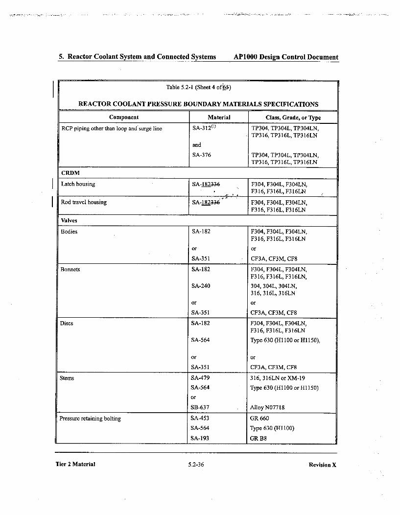
5. Reactor Coolant System and Connected Systems AP1000 Design Control Document
Table 5.2-1 (Sheet 4 of 0)
REACTOR COOLANT PRESSURE BOUNDARY MATERIALS SPECIFICATIONS
Component Material Class, Grade, or TypeRCP piping other than loop and'surge line SA-312(') TP304, TP304L, TP304LN,
TP316, TP316L, TP316LN
and
SA-376 TP304, TP304L, TP304LN,TP316, TP316L, TP316LN
CRDM
Latch housing SA-182.._.6 F304, F304L, F304LN,F316,F316L,F316LN
Rod travel housing SA-182___6 F304, F304L, F304LN,F316, F316L, F316LN
Valves
Bodies SA- 182 F304, F304L, F304LN,F316, F316L, F316LN
or or
SA-351 CF3A, CF3M, CF8
Bonnets SA-182 F304, F304L, F304LN,F316, F316L, F316LN,
SA-240 304, 304L, 304LN,316, 316L, 316LN
or or
SA-351 CF3A, CF3M, CF8
Discs SA-182 F304, F304L, F304LN,F316, F316L, F316LN
SA-564 Type 630 (H1100 or HI150),
or or
SA-351 CF3A, CF3M, CF8
Stems SA-479 316, 316LNorXM-19
SA-564 Type 630 (Hll00 or Hl150)
or
SB-637 Alloy N07718
Pressure retaining bolting SA-453 GR 660
SA-564 Type 630 (HI 100)
SA-193 GR B8
Tier 2 Material 5.2-36
Revision X
Tier 2 Material 5.2-36 Revision X

Change Number 24
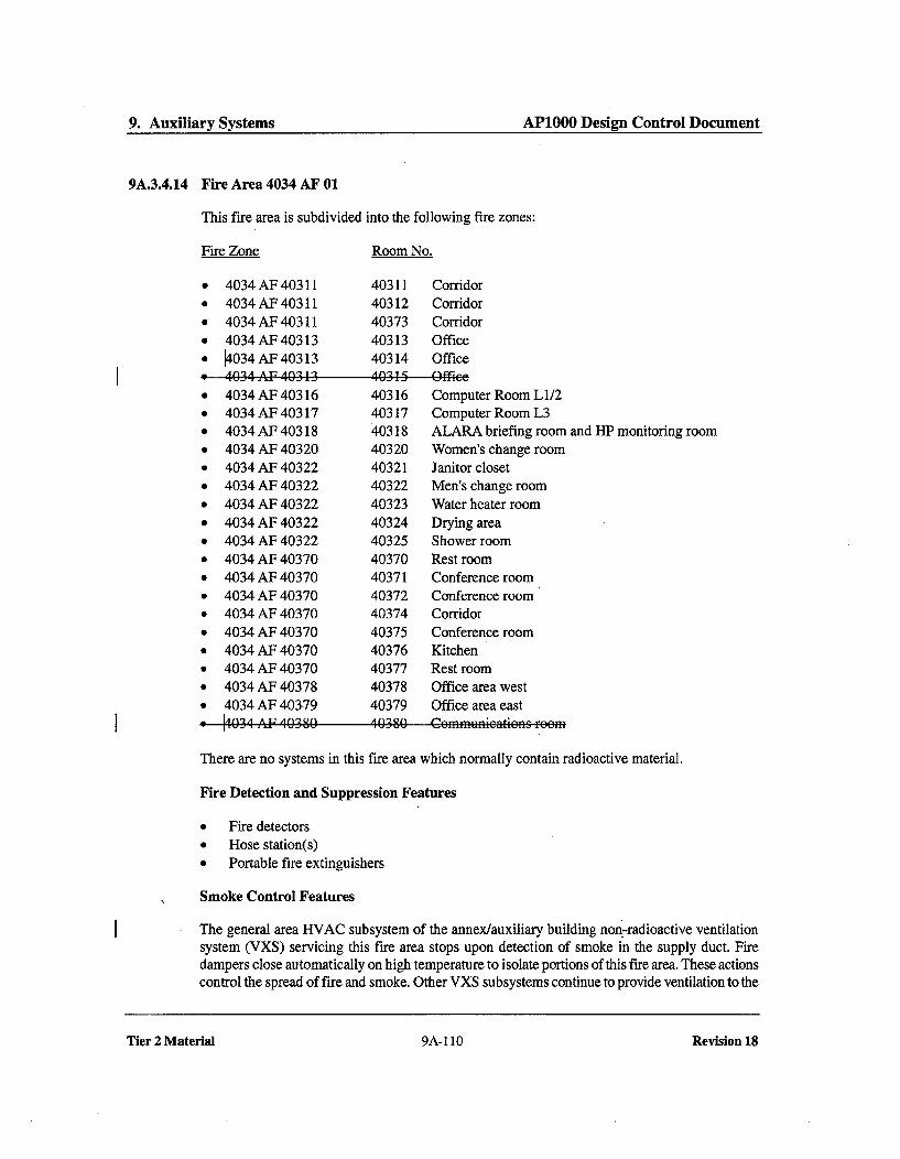
9. Auxiliary Systems AP1000 Design Control Document
9A.3.4.14 Fire Area 4034 AF 01
This fire area is subdivided into the following fire zones:
Fire Zone Room No.
S
0
0
0
0
4034AF 403114034 AF 403 114034 AF 403114034 AF 403134034AF40313AMA A'0 AM 1 *2
4031140312403734031340314A A21 <
CorridorCorridorCorridorOfficeOfficef(U-r,_
4034 AF 403164034 AF 403174034AF 403184034 AF 403204034 AF 403224034 AF 403224034 AF 403224034 AF 403224034 AF 403224034 AF 403704034 AF 403704034 AF 403704034 AF 403704034 AF 403704034 AF 403704034 AF 403704034 AF 403784034 AF 40379Ij n] A A I- A iV3 or%
403164031740318403204032140322403234032440325403704037140372403744037540376403774037840379A n3 OA
Computer Room L1/2Computer Room L3ALARA briefing room and HP monitoring roomWomen's change roomJanitor closetMen's change roomWater heater roomDrying areaShower roomRest roomConference roomConference roomCorridorConference roomKitchenRest roomOffice area westOffice area east
I 0 .- . - -- - 8 M- --- f B-1-1 I I - r-- -A E - 9- -4 is F 0 E) M
There are no systems in this fire area which normally contain radioactive material.
Fire Detection and Suppression Features
" Fire detectors* Hose station(s)* Portable fire extinguishers
Smoke Control Features
The general area HVAC subsystem of the annex/auxiliary building nonjradioactive ventilationsystem (VXS) servicing this fire area stops upon detection of smoke in the supply duct. Firedampers close automatically on high temperature to isolate portions of this fire area. These actionscontrol the spread of fire and smoke. Other VXS subsystems continue to provide ventilation to the
Tier 2 Material 9A-110 Revision 18
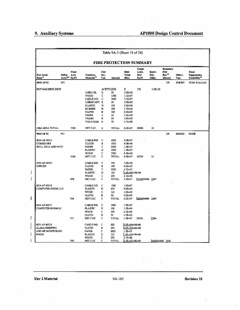
9. Auxiliary Systems AP1000 Design Control Document
Table 9A-3 (Sheet 19 of 24)
FIRE PROTECTION SUMMARY
Comb. BoundaryFloor Fire Heat Load, Equiv. Fire Fixed
Fire Area/ Safety Area Combust Sev. Value Btu/ Dur. Res.0) Detect. SuppressionZone(
1) Area?9) Sq Ft MaterialO, Cat. Amount (Btu) Sq Ft (Min) (Hours) Cap. Capability4s)
4033 AF 01 NO 2/0 SMOKE HOSE STATION
HOT MACHINE SHOP ACETYLENE E 150 3.2E+06
LUBE OIL E 20 3.0E+06WOOD C 1500 1.3E+07CABLE INS C 3610 3.7E+07
LUBRICANT E 30 5.91+05
PLASTIC D 150 2.03+06RUBBER D 300 3.7E+06CLOTH B 100 8.01+05PAPER C 50 3.9E+05
TRASH B 50 3.9E+05VOLATILES E 20 2.7E+.06
FIRE AREA TOTAL: 2290 NET CAT. E TOTAL: 6.6E+07 29000 22
4034 AF 01 NO 2/0 SMOKE NONE
4034 AF 40311 CABLE INS C 4000 4.0E+07
CORRIDORS CLOTH B 1000 8.0E+0640311,40312 AND 40373 PAPER C 2000 1.5E+07
PLASTIC D 1000 1.3E+07WOOD C 1000 8.4E+06
3160 NET CAT. C TOTAL: 8.51+07 26700 21
4034 AF40313 CABLEINS C 100 1.0E+06OFFICES CLOTH B 100 8.0E+05
PAPER C 3500 2.7E+07
PLASTIC D 125 1.6E.-.4&_+04WOOD C 250 2.1E+06
456 NET CAT. C TOTAL: 3.3E+07 2_30_.OO4 5-7
4034 AF 40316 CABLE INS C 1000 1.01+07
COMPUTER ROOM L1/2 PLASTIC D 650 8.6E+06WOOD C 125 1.015+06
CLOTH B 50 4.0E+05
554 NET CAT. C TOTAL: 2.0E+07 6 -36-509 26L69
4034 AF 40317 CABLE INS C 1000 1.01+07
COMPUTER ROOM 13 PLASTIC D 100 1.3E+06
WOOD C 250 2.1E+06CLOTH B 50 4-0E+05
571 NET CAT. C TOTAL: 1.4E+07 24500 G j.O 6
1 4034 AF 40318 CABLE INS C 500 LJ442+O6
ALARA BRIEFING CLOTH B 250AND HP MONITORING PAPER C 2000 1.511+07
ROOM PLASTIC D 125 l .6E+064OWOOD C 250 2.1E+06
799 NET CAT. C TOTAL: L•.ý.+.•0.6.7 •-..-- 2__1535
Tier 2 Material 9A-162
Revision 18
Tier 2 Material 9A-162 Revision 18
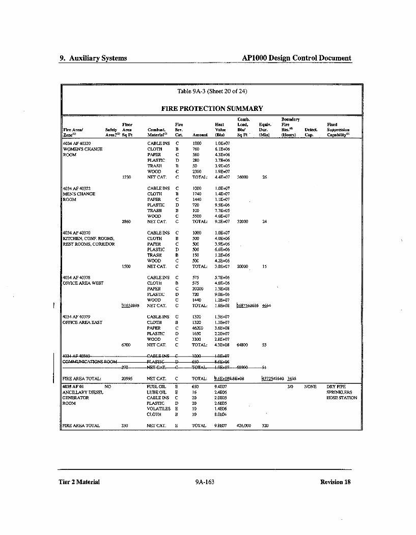
9. Auxiliary Systems AP1000 Design Control Document
Table 9A-3 (Sheet 20 of 24)
FIRE PROTECTION SUMMARYComb. Boundary
Floor Fire Heat Load, Equiv. Fire FixedSafety Area Combust Sev. Value Btu/ Dur. Res.(4) Detect. SuppressionArea?€
51Sq Ft Material
0) Cat. Amount (Btu) Sq Ft ' (Min) (Hours) Cap. Capability("
Fire Area/
4034 AF 40320
WOMEN'S CHANGEROOM
4034 AF 40322MEN'S CHANGEROOM
4034 AF 40370KITCHEN, CONF. ROOMS,REST ROOMS, CORRIDOR
CABLE INS C 1000 1.0E+07CLOTH B 760 6.1E+06PAPER C 560 4.3E+06PLASTIC D 280 3.7E+06TRASH B 50 3.9E+05WOOD C 2300 1.9E+07
1230 NET CAT. C TOTAL: 4.41+07 36000 26
CABLEINS C 1000 1.0E+07CLOTH B 1740 1.4E+07PAPER C 1440 I.1E+07PLASTIC D 720 9.51+06TRASH B 100 7.713+05WOOD C 5500 4.61+07
2860 NET CAT. C TOTAL: 9.2E+07 32000 24
CABLE INS C 1000 1.0E+07CLOTH B 500 4.0E+06PAPER C 500 3.91+06PLASTIC D 500 6.61+06TRASH B 150 1.2E-06WOOD C 500 4.2E+06
1500 NET CAT. C TOTAL: 3.0E+07 20000 15
4034 AF 40378OFFICE AREA WEST
4034 AF 40379OFFICE AREA EAST
CABLE INS C 575 5.7E+06CLOTH B 575 4.6E+06
PAPER C 20200 1.5E+08PLASTIC D 720 9.0E+06WOOD C 1440 1.2E+07
b1652,9 NET CAT. C TOTAL: 1.813+08 b68756-2425 46-4
CABLE INS C 1320 1.3E407CLOTH B 1320 1.11307
PAPER C 46200 3.6E+08PLASTIC D 1650 2.2E+07WOOD C 3300 2.8E+07
6700 NET CAT. C TOTAL: 4.3E+08 64800 55
CP4-wTEC G 5590 1 Q6E:05'.AOh44UNlQCATIONS ROOM
FIRE AREA TOTAL: 20995 NET CAT. C TOTAL: k.E+08&"&O+ 1_57254-50 3L48-
4035 AF 01 NO FUEL OIL E 650 9.4E07 3/0 NONE DRY PIPEANCILLARY DIESEL LUBE OIL E 16 2.4E06 SPRINKLERSGENERATOR CABLE INS C 20 2.0E05 HOSE STATIONROOM PLASTIC D 20 2.6E05
VOLATILES E 10 1.4E06CLOTH B 10 8.0E04
FIRE AREA TOTAL 230 NET CAT. E TOTAL 9.8E07 426,000 320
Tier 2 Material 9A-163 Revision 18

Change Number 25

5. Reactor Coolant System and Connected Systems A.PlOOO Design Control Document
5.3 Reactor Vessel
5.3.1 Reactor Vessel Design
5.3.1.1 Safety Design Bases
The reactor vessel, as an integral part of the reactor coolant pressure boundary will be designed,fabricated, erected and tested to quality standards commensurate with the requirements set forth in10 CFR 50, 50.55a and General Design Criterion 1. Design and fabrication of the reactor vessel iscarried out in accordance with ASME Code, Section III, Class 1 requirements. Subsections 5.2.3and 5.3.2 provide further details.
The performance and safety design bases of the reactor vessel follow:
" The reactor vessel provides a high integrity pressure boundary to contain the reactor coolant,heat generating reactor core, and fuel fission products. The reactor vessel is the primarypressure boundary for the reactor coolant and the secondary barrier against the release ofradioactive fission products.
" The reactor vessel provides support for the reactor internalsý flow skirt, and core to ensurethat the core remains in a coolable configuration.
" The reactor vessel directs main coolant flow through the core by close interface with thereactor internals and flow skirt.
" The reactor vessel provides for core internals location and alignment.
The reactor vessel provides support and alignment for the control rod drive mechanisms andin-core instrumentation assemblies.
The reactor vessel provides support and alignment for the integrated head assembly.
The reactor vessel provides an effective seal between the refueling cavity and sump duringrefueling operations.
The reactor vessel supports and locates the main coolant loop piping.
The reactor vessel provides support for safety injection flow paths.
The reactor vessel serves as a heat exchanger during core meltdown scenario with water onthe outside surface of the vessel.
5.3.1.2 Safety Description
The reactor vessel consists of a cylindrical section with a transition ring, hemispherical bottomhead, and a removable flanged hemispherical upper head (Figure 5.3-1). Key dimensions areshown in Figures 5.3-5 and 5.3-6. The cylindrical section consists of two shells, the upper shelland the lower shell. The upper and lower shells and the lower hemispherical head are fabricated
Tier 2 Material 5.3-1 Revision 18

9. Auxiliary Systems AP1000 Design Control Document
smoke into the stairwell. For fires not affecting the ventilation system, the system continues toprovide ventilation to the stairwell, minimizing the potential for migration of smoke.
9A.3.4.3B Fire Area 4002 AF 03
This fire area is comprised of the elevator shaftn__; elevator iac.hine r••em and security roofim.
[his elevator is enclosed by fire barrier walls having a minimum rating of 2 hours.The.wes- wallof elevatr shaft, elevateor mahine rfoem and seuef.r!ityre are exposed to the annex buildinginter-ior, an;d this vffall is cn~tdwt a conerete/steel eemposite maaterial having iiufir-e r-ating ef 2 hours. The walls of the encelosures that faee the yard area would not be exEpeqed tefthe an~nex building interior-. Therefore, these eutside walls are censtrueted with an exiterior sidingcemenfn te the overall siding used for- the annex building. The w;''all betw'een the elevator: and thestairýAvell also has a fire barrier wall w44ith miknimium_ _rating of .2 hours. The floor- of the security,rooma has a Minimum ratinge Of 2 hours.
Fire Detection and Suppression Features
0
0
0
Fire detectorsHose station(s)Portable fire extinguishers
Smoke Control Features
A wall exhaust fan and air intake louvers provide normal ventilation for the elevator shaft-lelevater machine room. After the fire, smoke is removed from the fire area by using the wallexhaust fan or portable exhaust fan!s and flexible ductwork.
Fire Protection Adequacy Evaluation
A fire in this area is detected by a fire detector which produces an audible alarm locally and bothvisual and audible alarms in the main control room and the security central alarm station. The fireis extinguished manually using hose streams or portable extinguishers.
Combustible materials in this fire area are listed in Table 9A-3, and Leyconsist primarily of cableinsulation and lubricant associated with the elevator hoisting machiner ,papef and eableinsulati•n in the security reom. This is a light hazard fire are• and the rate of fire growth isexpected to be slow. Two-hour fire barriers provide adequate separation from adjacent fire areassince the fire will be contained within this fire area.
9A.3.4.4 Fire Area 4002 AF 02
This fire area is comprised of the following room(s):
Room No.
S04 Stairwell
Tier 2 Material 9A-100
Revision 18
Tier 2 Material 9A-100 Revision 18

9. Auxiliary Systems AP1000 Design Control Document
Table 9A-3 (Sheet 5 of 24)
FIRE PROTECTION SUMMARY
Comb. BoundaryFloor Fire Heat Load, Equiv. Fire Fixed
Fire Area/ Safety Area Combust. Sev. Value Btu/ our. Res.04 Detect. SuppressionZone(,) Area?. Sq Ft Material( Cat. Amount (Btu) Sq Ft (Mn) (Hours) Cap. Capability("•
1250 AF 12561 CABLEINS C 1000 1.0E+07 HOSE STATIONCCS VALVE ROOM AND VOLATILES E 5 6.8E+05ACCESS CORRIDOR 630 NET CAT. D TOTAL: 1.1 E+07 17000 13
1254 AF 12553 CABLEINS C 5000 5.IE+07ELEVATION 135'-3" PAPER C 1000 7.7E+06PERSONNEL ACCESS TRASH B 500 3.9E+06AREA VOLATILES E 10 1.41+06
1350 NET CAT. D TOTAL: 6.4E+07 47000 36
1244 AF 12451 CABLEINS C 400 4.1E+06SECURITY ROO*vS PAPER C 500 3.8E+06
308 NET CAT. C TOTAL: 7.9E+06 L5290GZP L224
1254 AF 12554 CABLE INS C 400 4.1E0+06SECURITY ROOM PAPER C 1000 7.7E+06
268 NET CAT. C TOTAL: 1.21+07 62000 51
1264 AF 12651 CABLEINS C 5000 5.11+07VAS EQUIPMENT LUBE OIL E 10 1.5•+06ROOM VOLATILES E 10 1.41+06
1480 NET CAT. D TOTAL: 5.40+07 36000 27
FIRE AREA TOTAL: 22501 NET CAT. D TOTAL: 6.9E+08 30700 _4-2 HOSE STATION
1200 AF 02 YES 3/0 SMOKE SEE ZONE
1200 AF 12562 CABLE INS C 10000 1.00+08 HOSE STATIONFUEL HANDLING AREA PAPER C 1500 1.2E+07
WOOD C 1000 8.4E+06TRASH B 1000 7.70+06CLOTH B 500 4.0E+06PLASTIC D 500 6.6E+06LUBE OIL E 15 2.3E+06VOLATILES E 5 6.81+05
4725 NET CAT. D TOTAL: 1.4E+08 30000 23
1230 AF 12371 CABLEINS C 3000 3.IE.+07 WET PIPE")RAIL CAR BAY/ PAPER C 1000 7.7E+06 SPRINKLERFILTER STORAGE AREA WOOD C 1000 8.41+06 HOSE STATION
TRASH B 1000 7.71+06LUBE OIL E 10 1.51+06FUEL OIL E 100 1.4E+07
1460 NET CAT. D TOTAL: 7.0E+07 48000. 37
1236 AF 12372 CABLE INS C 200 2.0E+06 HOSE STATIONRESIN TRANSFER PUMP/ LUBE OIL E 5 7.6E+05VALVE ROOM 80 NET CAT. E TOTAL: 2.8E+06 35000 26
1236 AF 12373 CABLE INS C 200 2.0E+06 HOSE STATIONSPENT RESIN TANK ROOM 70 NET CAT. C TOTAL- 2.0E+06 29000 22
1246 AF 12471 CABLE INS C 200 2.01+06 HOSE STATIONWSS VALVE/PIPING AREA 90 NET CAT. C TOTAL: 2.0E+06 23000 17
FIRE AREA TOTAL: 6425 NET CAT. D TOTAL: 2.21+08 34000. 26 HOSE STATION
Tier 2 Material 9A-148 Revision 18

19. Probabilistic Risk Assessment AP1000 Design Control Document
level are required through the second time frame. The only long term application is thecontainment pressige transmitter which may eventually be impacted by the severe accidentradiation dose.
19D.8.2.2 Thermocouples
The function+ defined for severe accident management that utiliz4 thermocouples Le core-exittemperature and centainment water level. The core-exit temperature is only required during TimeFrame 1 knd the•z ntaiam.nt water- level is r.e.uircd thrzugh Time Frame 2. The temperatures towhich the thermocouples are exposed during the defined time frames do not exceed thethermocouple design.
19D.8.2.3 Resistance Temperature Detectors (RTDs)
Both hot and cold leg temperatures are defined as parameters for severe accident management inTime Frame 1. RTDs are utilized for these measurements and will perform until their temperaturerange is exceeded. The hot leg RTDs could fail as the temperature increases well above the designconditions of the RTDs but the cold leg RTDs should perform throughout Time Frame 1. RTDsare also utilized through Time Frame 3 for the containment temperature measurement and areexposed to temperature transients that exceed design basis qualification conditions. EPRINP-4354 documents RTD performance during several temperature transients with acceptableresults.
19D.8.2.4 Hydrogen Monitors
Containment hydrogen is defined as a parameter to be monitored throughout the severe accidentscenarios. Note that the design of the hydrogen monitors has not been finalized and both in-containment and outside containment monitors are being considered. Early in the accident, thehydrogen may be monitored by a device that operates on the basis of catalytic oxidation ofhydrogen on a heated element. The hydrogen monitors are located in the main containment area.The design limits of this device may be exceeded after the first few hours of some of thepostulated accidents and performance may be uncertain. If the device fails, hydrogenconcentration may be determined through online containment hydrogen monitors located in theauxiliary building that take a sample from the containment atmosphere. Also, post-accidentsampling of containment atmosphere using analysis of grab samples may be used to determinecontainment hydrogen concentrations.
19D.8.2.5 Radiation Monitors
Containment radiation is defined as a parameter to be monitored throughout the severe accidentscenarios. The containment radiation monitors are located in the main containment area. Early inthe accident, the design basis event qualified containment radiation monitor provides thenecessary information until the environment exceeds the design limits of the monitor. If the devicefails, containment radiation is determined through the containment atmosphere sampling functionor by portable monitors located against the outside of the containment shell.
Tier 2 Material 19D-18
Revision X
Tier 2 Material 19D-18 Revision X

19. Probabilistic Risk Assessment AP1000 Design Control Document
119aL8.2.13 Float Level Sensors
The function defined for severe accident management that uses float level sensors is containmentwater level. Containment water level is required through Time Frame 2. The temperature to whichthe float level sensors are exposed during the time frame does not exceed the float level sensordesign.
19D.8.2.13JM4 Assessment of Equipment for Sustained Burning
The equipment necessary for equipment survivability in sustained burning environments isdefined in Tables 19D-3 through 19D-5. The equipment in Table 19D-3 includes equipment andinstrumentation operation during Time Frame 1 - core uncovery and heatup, and is prior to therelease of significant quantities of hydrogen. Therefore, it does not have to be qualified forsustained hydrogen burning. Table 19D-7 specifies the equipment and instrumentation used inTime Frames 2 and 3 to provide reasonable assurance of achieving a controlled stable state.
19D.8.3 Equipment Located Outside Containment
Other functions defined for severe accident management are performed outside containment andthe equipment is not subjected to the harsh environment of the event. This equipment includes,but is not limited to:
* Steam line radiation monitor,* Transmitters for monitoring steam line pressure,* Passive containment cooling system flow and tank level,* Containment atmosphere sampling function,• Makeup pumps and flow measurement,* RNS pumps and flow measurement,• SFS pumps and flow measurement,* RNS MOVs* MFW pumps and valves,* SFW pumps and valves,* Steam generator PORVs and main steam bypass valves for depressurization,* Recirculation pumps, PCS valves and fire water pumps and valves for containment heat
removal,* Containment isolation valves (outside containment),* Auxiliary building radiation monitor,* MOV and manual valve from RNS hot leg suction lines to the spent fuel pool and• Fire water, fire pumps, valves and flow measurement used to provide containment spray and
backup containment cooling.
19D.9 Conclusions of Equipment Survivability Assessment
The equipment defined for severe accident management was reviewed for performance during theenvironments postulated for these events. Survivability of the equipment was evaluated based ondesign basis event qualification testing, severe accident testing, and the survival time requiredfollowing the initiation of the severe accident. The equipment that is qualified for design basis
Tier 2 Material 19D-21 Revision 18

Change Number 26

9. Auxiliary Systems AP1000 Design Control Document
Level instrumentation on the surge tank provides both high- and low-level alarms. At tanklow-level, makeup is provided from the demineralized transfer and storage system. At a low-low-level point in the tank, a signal is sent to stop the hot water heating system pumps.
9.2.11 Combined License Information
9.2.11.1 Potable Water
The Combined License applicant will address the components of the potable water system outsideof the power block, including supply source required to meet design pressure and capacityrequirements, specific chemical selected for use as a biocide, and any storage requirementsdeemed necessary. A biocide such as sodium hypochlorite is recommended. Toxic.gases such aschlorine are not recommended. The impact of toxic gases on the main control roomhabitabilityeempatibility is addressed in Section 6.4.
9.2.11.2 Waste Water Retention Basins
The Combined License applicant will address the final design and configuration of the plant wastewater retention basins and associated discharge piping, including piping design pressure, basintransfer pump size, basin size, and location of the retention basins.
9.2.12 References
1. ASME Code, Section IV, Pt. HWL, 1998.2. Uniform Plumbing Code, Section 318, 2000.
Tier 2 Material 9.2-45 Revision X

Change Number 27
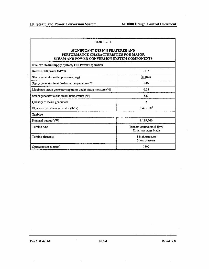
10. Steam and Power Conversion System APIO00 Design Control Document
Table 10.1-1
SIGNIFICANT DESIGN FEATURES ANDPERFORMANCE CHARACTERISTICS FOR MAJOR
STEAM AND POWER CONVERSION SYSTEM COMPONENTS
Nuclear Steam Supply System, Full Power Operation
Rated NSSS power (MWt) 3415
Steam generator outlet pressure (psig) 821•82-
Steam generator inlet feedwater temperature (OF) 440
Maximum steam generator separator outlet steam moisture (%) 0.25
Steam generator outlet steam temperature (OF) 523
Quantity of steam generators 2
Flow rate per steam generator (lb/hr) 7.49 x 10⁶
Turbine
Nominal output (kW) 1,199,500
Turbine type Tandem-compound 6-flow,52 in. last-stage blade
Turbine elements 1 high pressure3 low pressure
Operating speed (rpm) 1800
Tier 2 Material 10.1-4 Revision X

Change Number 28
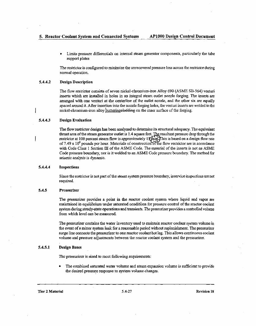
5. Reactor Coolant System and Connected Systems AP1000 Design Control Document
* Limits pressure differentials on internal steam generator components, particularly the tubesupport plates
The restrictor is configured to minimize the unrecovered pressure loss across the restrictor duringnormal operation.
5.4.4.2 Design Description
The flow restrictor consists of seven nickel-chromium-iron Alloy 690 (ASME SB-564) venturiinserts which are installed in holes in an integral steam outlet nozzle forging. The inserts arearranged with one venturi at the centerline of the outlet nozzle, and the other six are equallyspaced around it. After insertion into the nozzle forging holes, the venturi inserts are welded to thenickel-chromium-iron alloy hutteringelding on the inner surface of the forging.
5.4.4.3 Design Evaluation
The flow restrictor design has been analyzed to determine its structural adequacy. The equivalentthroat area of the steam generator outlet is 1.4 square feet. 1 resultant pressure drop through therestrictor at 100 percent steam flow is approximately 1 si . his is based on a design flow rateof 7.49 x 10 pounds per hour. Materials of construction o 9the flow restrictor are in accordancewith Code Class 1 Section 111 of the ASME Code. The material of the inserts is not an ASMECode pressure boundary, nor is it welded to an ASME Code pressure boundary. The method forseismic analysis is dynamic.
5.4.4.4 Inspections
Since the restrictor is not part of the steam system pressure boundary, inservice inspections are notrequired.
5.4.5 Pressurizer
The pressurizer provides a point in the reactor coolant system where liquid and vapor aremaintained in equilibrium under saturated conditibns for pressure control of the reactor coolantsystem during steady-state operations and transients. The pressurizer provides a controlled volumefrom which level can be measured.
The pressurizer contains the water inventory used to maintain reactor coolant system volume inthe event of a minor system leak for a reasonable period without replenishment. The pressurizersurge line connects the pressurizer to one reactor coolant hot leg. This allows continuous coolantvolume and pressure adjustments between the reactor coolant system and the pressurizer.
5.4.5.1 Design Bases
The pressurizer is sized to meet following requirements:
* The combined saturated water volume and steam expansion volume is sufficient to providethe desired pressure response to system volume changes.
Tier 2 Material 5.4-27 Revision 18

Change Number 29
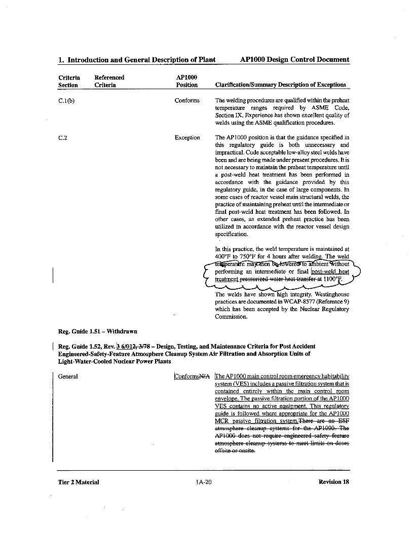
1. Introduction and General Description of Plant AP1000 Design Control Document
Criteria Referenced AP1000Section Criteria Position Clarification/Summary Description of Exceptions
C.1 (b) Conforms The welding procedures are qualified within the preheattemperature ranges required by ASME Code,Section IX. Experience has shown excellent quality of
welds using the ASME qualification procedures.
C.2 Exception The AP1000 position is that the guidance specified inthis regulatory guide is both unnecessary andimpractical. Code acceptable low-alloy steel welds havebeen and are being made under present procedures. It isnot necessary to maintain the preheat temperature untila post-weld heat treatment has been performed inaccordance with the guidance provided by thisregulatory guide, in the case of large components. Insome cases of reactor vessel main structural welds, thepractice of maintaining preheat until the intermediate orfinal post-weld heat treatment has been followed. Inother cases, an extended preheat practice has beenutilized in accordance with the reactor vessel designspecification.
In this practice, the weld temperature is maintained at400*F to 750*1F for 4 hours after welding The weld
The welds have shown high integrity. Westinghousepractices are documented in WCAP-8577 (Reference 9)which has been accepted by the Nuclear RegulatoryCommission.
Reg. Guide 1.51 - Withdrawn
Reg. Guide 1.52, Rev. ý 6/0120-37-8 - Design, Testing, and Maintenance Criteria for Post AccidentEngineered-Safety-Feature Atmosphere Cleanup System Air Filtration and Absorption Units ofLight-Water-Cooled Nuclear Power Plants
General ýonformsN-A The AP 1000 main control room emergency habitabilitysystem (VES) includes a passive filtration system that iscontained entirely within the main control roomenvelope. The passive filtration portion of the AP 1000VES contains no active equipment. This regulatoryguide is followed where appropriate for the AP1000MCR passive filtration system.There aFe no ESF
AP1000 does net reguir-e engineer-ed sa"ct featureatmczspherce eleanup systems te meet limits onf desescffzsite orf enzte.
Tier 2 Material IA-20 Revision 18

Change Number 30

3. Design of Structures, Components,Equipment and Systems AP1000 Design Control Document
I Table 3.2-3 (Sheet 10 of 6-59)
AP1000 CLASSIFICATION OF MECHANICAL ANDFLUID SYSTEMS, COMPONENTS, AND EQUIPMENT
1g 1 AP1000 I Seismic f Principal Con-
Tag Number Description I Class Category struction Code Comments
Passive Containment Cooling System (Continued)
PCS-PL-VO13B Flow Transmitter FT004 Root C I ASME 111-3Valve
PCS-PL-V015 Water Bucket Makeup Line C I ASME IIIDrain Valve
PCS-PL-V016 PCCWST Drain Isolation C I ASME 111-3Valve
PCS-PL-V017 Chemical Addition Tank Vent D NS ANSI 16.34 EquipmentIsolation Valve Anchorage
is SeismicCategory II
PCS-PL-V018 Recirculation Pump Throttle D NS ANSI 16.34 EquipmentValve Anchorage
is SeismicCategory II
PCS-PL-V019 Chemical Addition Tank Fill D NS ANSI 16.34 EquipmentIsolation Valve Anchorage
is SeismicCategory II
PCS-PL-V020 Water Bucket Makeup Line C I ASME 111-3Isolation Valve
PCS-PL-V021 PCCWST TO Recirculation D NS ANSI 16.34 EquipmentPump Suction Isolation Valve Anchorage
is SeismicCategory II
PCS-PL-V022 Chemical Addition Tank D NS ANSI 16.34 EquipmentDrain Isolation Valve Anchorage
is SeismicCategory II
PCS-PL-V023 PCS Recirculation Return C I ASME 111-3Isolation
PCS-PL-V025 Pressure Transmitter PT 031 D NS ANSI 16.34 EquipmentRoot Isolation Valve Anchorage
is SeismicCategory II
PCS-PL-V026 Makeup to Distribution k ASME 111-3Bucket Isolation Valve
PCS-PL-V029 PCCWST Isolation Valve C I ASME 111-3Leakage Detection Drain
Tier 2 Material 3.2-29 Revision 18

3. Design of Structures, Components,Equipment and Systems AP1000 Design Control Document
Table 3.11-1 (Sheet 33 of 50 )
ENVIRONMENTALLY QUALIFIED ELECTRICAL AND MECHANICAL EQUIPMENT
t
Operating
Envir. Time Qualificationescrip 7- -Fncj•.,R Program
Spakeup to Distribution Bucket PCS-PL-V026 7 PB 1 r MIsolation Valve
Detection Drain
PCCWST Isolation Valve Leakage PCS-PL-V030 1 PB 1 yr MDetection Crossco1P
PCCWST Level Instrument Root PCS-PL-V031A 9 PB 1 yr MValve
PCCWST Level Instrument Root PCS-PL-V031B 1 PB I yr MValveI
Recirculation Pump Suction from PCS-PL-V033 10 ESF 2 wks M *
Long Term Makeup Isolation Valve
Spent Fuel Pool Emergency Makeup PCS-PL-VO52 1 PB 1 yr MIsolation
Hot Leg I Sample Isolation PSS-PL-VO12A I PB 1 yr M *
Limit Switch PSS-PL-V001A-L 1 PAMS 1 yr E *
Hot Leg 2 Sample Isolation PSS-PL-Ve01B I PB I yr M
Limit Switch PSS-PL-V001B-L 1 PAMS 1 yr E *
Pressurizer Sample Isolation PSS-PL-V003 1 PB 1 yr M *
PXS Accumulator Sample Isolation PSS-PL-V004A 1 PB 1 yr MPXS Accumulator Sample Isolation PSS-PL-V004B 1 PB I yr M*
PXS CMT A Sample Isolation PSS-PL-V005A I PB 1 yr M *
PXS CMT B Sample Isolation PSS-PL-Ve05B I PB I yr M *
PXS CMT A Sample Isolation PSS-PL-V005C 1 PB 1 yr M *PXS CMT B Sample Isolation PSS-PL-V005D I PB 1 yr M *
Liquid Sample Check Valve PSS-PL-V012A I PB I yr M *
Liquid Sample Check Valve PSS-PL-V012B I PB I yr M *
Containment Testing Boundary PSS-PL-V076A I PB 1 yr M *
Isolation Valve
Containment Testing Boundary PSS-PL-V076B IPB I yr M *Isolation Valve
Containment Isolation Test PSS-PL-V082 IPB 1 yr M *
Connection Isolation ValveContainment Isolation Test PSS-PL-V083 IPB 1 yrM*
Connection Isolation Valve
N4.GR P•'betal W atelnptCheek Valve' PWS PL V414 18 -- tg RR-y M
Tier 2 Material 3.11-38
Revision 18
Tier 2 Material 3.11-38 Revision 18

3. Design of Structures, Components,Equipment and Systems AP1000 Design Control Document
Table 31.6-3 (Sheet 13 of 32)
LIST OF AP1000 SAFETY-RELATED ELECTRICALAND MECHANICAL EQUIPMENT NOT HIGH FREQUENCY SENSITIVE
AP1000
Description Tag Number Comment
Flow Transmitter FT003 Root Valve PCS-PL-VO12B 2
Flow Transmitter FT004 Root Valve PCS-PL-VO13A 2
Flow Transmitter FT004 Root Valve PCS-PL-VO13B 2
PCCWST Drain Isolation Valve PCS-PL-V016 2
Makeup to Distribution Bucket Isolation Valve PCS-PL-V026 2
PCCWST Isolation Valve Leakage Detection Drain PCS-PL-V029 2
PCCWST Isolation Valve Leakage Detection Crossconn PCS-PL-V030 2
PCCWST Level Instrument Root Valve PCS-PL-V031A 2
PCCWST Level Instrument Root Valve PCS-PL-V031B 2
Recirculation Pump Suction from Long Term Makeup Isolation Valve PCS-PL-V033 2
Spent Fuel Pool Emergency Makeup Isolation PLS-PL-V052 2
Hot Leg 1 Sample Isolation PSS-PL-V001A 2
Hot Leg 2 Sample Isolation PSS-PL-VOOB 2
Pressurizer Sample Isolation PSS-PL-V003 2
PXS Accumulator Sample Isolation PSS-PL-VO04A 2
PXS Accumulator Sample Isolation PSS-PL-VO04B 2
PXS CMT A Sample Isolation PSS-PL-VO05A 2
PXS CMT B Sample Isolation PSS-PL-VO05B 2
PXS CMT A Sample Isolation PSS-PL-V005C 2
PXS CMT B Sample Isolation PSS-PL-VO05D 2
Liquid Sample Check Valve PSS-PL-VO12A 2
Liquid Sample Check Valve PSS-PL-VO12B 2
Containment Testing Boundary Isolation Valve PSS-PL-V076A 2
Containment Testing Boundary Isolation Valve PSS-PL-V076B 2
Containment Isolation Test Connection Isolation Valve PSS-PL-V082 2
Tier 2 Material 31-52 Revision 18

Change Number 31

1. Introduction and General Description of the Plant AP1000 Design Control Document
Table 1.8-1 (Sheet 1 of 67)
SUMMARY OF AP1000 PLANT INTERFACESWITH REMAINDER OF PLANT
Matching SectionItem Interface or Sub-No. Interface Interface Type Item section
-14 PcRt accident RPadie Iodine sampling PRequirement-f Cembined Licenseeapability per. NUREG 0737 AP4-00n
2.1 Envelope of AP 1000 plant site related Site Interface Site specific 2.0parameters parameters
2.2 External missiles from man-made hazards Site Interface Site specific 2.2and accidents parameters
2.3 Maximum loads from man-made hazards Site Interface Site specific 2.2and accidents parameters
2.4 Limiting meteorological parameters (X/Q) Site Interface Site specific 2.3for design basis accidents and for routine parametersreleases and other extreme meteorologicalconditions for the design of systems andcomponents exposed to the environment.
2.5 Tornado and operating basis wind loadings Site Interface Site specific 2.3parameters
2.6 External missiles generated by natural Site Interface Site specific 2.3phenomena parameters
2.7 Snow, ice and rain loads Site Interface Site specific 2.3parameters
2.8 Ambient air temperatures Site Interface Site specific 2.3parameters
2.9 Onsite meteorological measurement Requirement of Combined License 2.3.3program AP1000 applicant program
2.10 Flood and ground water elevations Site Interface Site specific 2.4parameters
2.11 Hydrostatic loads on systems, components Site Interface Site specific 2.4and structures parameters
2.12 Seismic parameters Site Interface Site specificpeak ground acceleration parameters 2.5response spectra 2.5shear wave velocity 2.5-
2.13 Required bearing capacity of foundation Site Interface Site specific 2.5
Tier 2 Material 1.8-4 Revision 18

Change Number 32

2. System Based Design Descriptions and ITAAC AP1000 Design Control Document
Table 2.6.9-1Inspections, Tests, Analyses, and Acceptance Criteria
Design Commitment Inspections, Tests, Analyses Acceptance Criteria
1. The external walls, doors, See Tier 1 Material, Table 3.3-6, See Tier I Material, Table 3.3-6,ceiling, and floors in the main item 14. item 14.control room, the central alarmstation, and the secondary alarmstation ýast a..ess contr.l f..nti:nfor access to the proetected area arebullet-resistant •o at leastUnderwriters Laboratory BallisticStandard 752, level 4.
2. 4ot used .Physial barriers c An inspe.tion of the pr.te.ted Physieal ba! aiers at the per.imeter Athe prStected area perimeter are n area perimeter- baier %ill be the prolteMted area arc separted frompart efthe Iital! are,-A- bafirriPers. perzfcrrnd te verify, that physfieal an" ether bafrrier- designated as a vital
baniers at the per-imeter ef the area baffieIproetected area are separated fremany other- batTfler designated as a-v'ital area barri er.
3. Secondary security power supply See Tier 1 Material, Table 3.3-6, Se(1e ~, Material, Table 3.3-6,system for alarm annunciator item 16. it+ 16.equipment and non-portablecommunications equipment islocated within the vital area.
4. Vital areas are locked and See Tier I Material, Table 3.3-6, See Tier 1 Material, Table 3.3-6,alarmed with active intrusion item 17. item 17.detection systems that annunciate inthe central and secondary alarmstations upon intrusion into a vitalarea.
5.•) Security alarm annunciation Test, inspection, or a combination Security alarms annunciation andand video assessment information is of test and inspections of the video assessment information isdisplayed concurrentlvyeoeers in the installed systems will be displayed concurrentlaenn"eiate incentral alarm station and the performed to ensure that secu.ity the centinuously manned centralsecondary alarm station, and the alarms annunciate in th.e cetr.a alarm station and the secondaryvideo image recording with real alarm st-atien and in at least one- alarm station, and the video imagetime playback capability can e"ther cen •.ltinuo....sly manned- recording with real time playbackprovide assessment of activities station. capability provides assessment ofbefore and after each alarm activities before and after alarmannunciation within the perimeter annunciation within the perimeterarea barrierin at least one other barrier..a.te . .it.hin the pro.tectedeontinuously manned station not -are-a fand in; At least one. otheneeessari~ly-easite. ... fntkfinuesly Manned station.
Tier 1 Material 2.6.9-3
Revision X
Tier I Material 2.6.9-3 Revision X

Change Number 33

9. Auxiliary Systems AP1000 Design Control Document
Table 9A-3 (Sheet 12 of 24)
FIRE PROTECTION SUMMARY
Comb. BoundaryFloor Fire Heat Load, Equiv. Fire Fixed
Fire Area/ Safety Area Combust. Sev. Value Btu/ Dur. Res.4) Detect. SuppressionZone(') Area?(Z) Sq Ft Material") Cat. Amount (Btu) Sq Ft (Mln) (Hours) Cap. Capability()
2000 AF 01 NO
I2030 AF 20300ELEVATION 100'-0"(BASE SLAB)GENERAL FLOOR AREA
2038 AF 20300MAIN FEEDWATERPUMP AREA
2039 AF 20301CHEMICALSTORAGE AREA
2040 AF 20400ELEVATION 117'-6"GENERAL FLOOR AREA
0CABLE INS CLUBE OIL EPLASTIC DVOLATILES EFUEL OIL ETRASH B
38062 NET CAT. E
CABLE INS CLUBE OIL EPLASTIC DVOLATILES ETRASH B
4542 NET CAT. E
CABLE INS CLUBE OIL EPLASTIC DVOLATILES ETRASH B
1684 NET CAT. E
CABLE INS CLUBE OIL EPLASTIC DVOLATILES ETRASH B
42,606 NET CAT. E
CABLE INS CLUBE OIL EPLASTIC DVOLATILES EHYDROGEN ETRASH B
378900 NET CAT. E
CABLEINS CLUBE OIL EPLASTIC DTRASH B
149 NET CAT, E
CABLE INS CPAPER CPLASTIC DRUBBER DTRASH B
1231 NET CAT. D
SEE ZONE SEE ZONE87,800 9.0E+084050 6.1E+0812,500 II.6E+0454 4-0g375 1E4.i07-,4R+4125 1.8E+071000 7.7E+06TOTAL: 1.81+09 47,300 35
3000 3.1E1+072250 3.4E+08150 2.OE+0655 7.5E,+06200 1.5E+06TOTAL: 3.8E+08 83670 63
300 3.1E-+06250 3.8E+07125 1.7E+06600 8.2E+07250 1.9E+06TOTAL: 1.3E+08 75000 56
87,800 9.0E+081450 2.2E+086500 8.6E+07180 2.4E+071500 1.2E+07TOTAL: 1.2E+09 28,170 21
HEAT WET PIPESPRINKLERS")HOSE STATION
HEAT PREACTIONSPRINKLERS
HEAT WATER SPRAYHOSE STATION
HEAT WET PIPE
SPRINKLERS
HOSE STATION
HEAT WET PIPE
SPRINKLERSHOSE STATION
2050 AF 20500ELEVATION 135-3"'GENERAL FLOOR AREA
87000 8.9E+085400 8.2E+086000 7.9E+07100 1.4E+0750 7.6E+0650 3.9E+06TOTAL: 1.8E+09 47510 36
2050 AF 20502DEH SKID
600 6. I E+06250 3.8E+07150 2.OE+06100 7.7E+05TOTAL: 4.7E+07 313000 235
SMOKE WATER SPRAY
HOSE STATION
SMOKE HOSE STATION2052 AF 20504HVAC EQUIPMENTAREA
150 3.1E+06250 3.9E+06125 3.3E+0613 3.113+0513 2.OE+05TOTAL: 1.IE+07 8700 7
Tier 2 Material 9A-155 Revision 18

Change Number 34

C
9. Auxiliary Systems AP1O00 Design Control Document
Table 9.3.3-2 (Sheet 3 of 4)
LOCAL SAMPLE POINT NOT IN THE PRIMARY SAMPLING SYSTEM(NORMAL PLANT OPERATIONS)
AvailableNumber Type of
Sample Point Name of Points Sample(a) Process Measurement
21. WLS chemical waste I Grab Tritium, gross radioactivity and identification andtank concentration of principal radionuclide and alpha
emitters
22. WSS spent resin tank I Grab Tritium, gross radioactivity and identification and(liquid) concentration of principal radionuclide and alpha
emitters
23. SWS blowdown 1 Continuous Radiation monitor (See Section 11.5, Table 11.5-1)(service water) 1 Grab Tritium, gross radioactivity and identification and
concentration of principal radionuclide and alphaemitters
24. WWS turbine 2 Grab Tritium, gross radioactivity and identification andbuilding sump concentration of principal radionuclide and alpha
emitters
25. CPS (secondary 1 Grab Tritium, gross radioactivity and identification andcoolant) spent resin concentration of principal radionuclide and alphasluice line (liquid) emitters
Gaseous Sample
26. VES MCR 2 Grab Air quality, oxygen, carbon monoxide, carbon dioxide,emergency air supply contaminantsheaders
27. WGS effluent 1 Continuous Radiation monitor (See Section 11.5, Table 11.5-1)discharge toenvironment
28. WGS inlet 1 Continuous Oxygen, hydrogei meistu,'
29. WGS carbon bed 1 Continuous Hydrogenvault
30. WGS delay bed 2 Grab Moisture, noble gases, iodine, particulates, tritiumoutlets MV02A, B(waste gas holdup)
31. Condenser air I Grab Iodine, noble gases, tritiumremoval system(b)(including hogging)
I
Tier 2 Material 9.3-51
Revision X
Tier 2 Material 9.3-51 Revision X

Change Number 35

9. Auxiliary Systems AP1000 Design Control Document9. Auxiliary Systems AP1000 Design Control Document
Table 9.3.4-1 (Sheet I of 2)
SECONDARY SAMPLING SYSTEM(CONTINUOUS MEASUREMENTS)
Continuous Sample Points Process Measurements
Hotwell (Tube Bundle Condenser Shell A) Specific Conductivityýation Conductivity
Sodium
Hotwell (Tube Bundle Condenser Shell B) Specific Conductivity
Lation Conductivity
Sodium
Hotwell (Tube Bundle Condenser Shell C) Specific ConductivityWation Conductivity
Sodium
Condensate Pump Discharge Specific Conductivity
Cation Conductivity
Sodium-
pHDissolved Oxygen
Deaerator Inlet (Condensate) Specific Conductivity
Cation Conductivity
SodiumpH
Oxygen Scavenger Residual
Dissolved Oxygen
Feedwater Specific ConductivityCation Conductivity
Sodium
Dissolved OxygenpH
Oxygen Scavenger Residual
Steam Generator Blowdown (SG 1) Specific Conductivity
Cation Conductivity
Sodium
pH
Sulfate
Dissolved Oxygen
Tier 2 Material 9.3-53 Revision 18

9. Auxiliary Systems AP1000 Design Control Document
Table 9.3.4-1 (Sheet 2 of 2)
SECONDARY SAMPLING SYSTEM(CONTINUOUS MEASUREMENTS)
Steam Generator Blowdown (SG 2) Specific Conductivity
Cation Conductivity
Sodium
pH
SulfateDissolved Oxygen
.f.
Main Steam System (SG 1) ien-Specific ConductivityMain Steam System (SG 1) anSpecific Conductivity
Cation Conductivity
Sodium
pH
Dissolved Oxygen
Main Steam System (SG 2) Msaten-Specific Conductivity
Cation Conductivity
Sodium
pH
Dissolved Oxygen
Tier 2 Material 9.3-54
Revision 18
Tier 2 Material 9.3 -54 Revision 18

Change Number 36
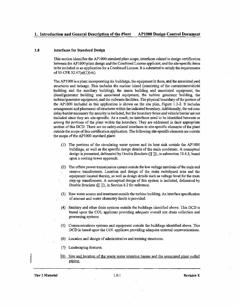
1. Introduction and General Description of the Plant AP1000 Design Control Document
1.8 Interfaces for Standard Design
This section identifies the AP1000 standard plant scope, interfaces related to design certificationbetween the AP 1000 plant design and the Combined License applicant, and the site-specific itemsto be included in an application for a Combined License. It is submitted to satisfy the requirementsof 10 CFR 52.47(a)(1)(vii).
The AP 1000 is a plant incorporating six buildings, the equipment in them, and the associated yardstructures and tankage. This includes the nuclear island (consisting of the containment/shieldbuilding and the auxiliary building), the annex building and associated equipment, thediesel/generator building and associated equipment, the turbine generator building, theturbine/generator equipment, and the radwaste facilities. The physical boundary of the portion ofthe AP1000 included in this application is shown on the site plan, Figure 1.2-2. It includesarrangement and placement of structures within the indicated boundary. Additionally, the red zonedelay barrier necessary for security is included, but the boundary fence and vehicle barrier are notincluded since they are site-specific. As a result, no interfaces need to be identified between oramong the portions of the plant within the boundary. They are addressed in their appropriatesection of this DCD. There are no safety-related interfaces to site-specific elements of the plantoutside the scope of this certification application. The following site-specific elements are outsidethe scope of the AP1000 standard plant:
(1) The portions of the circulating water system and its heat sink outside the AP1000buildings, as well as the specific design details of the main condenser. A conceptualdesign is presented, delineated by Double Brackets ([[]]), in subsection 10.4.5, basedupon a cooling tower approach.
(2) The offsite power transmission system outside the low voltage terminals of the main andreserve transformers. Location and design of the main switchyard area and theequipment located therein, as well as design details such as voltage level for the mainstep-up transformers. A conceptual design of this system is included, delineated byDouble Brackets ([[ ]]), in Section 8.2 for reference.
(3) Raw water source and treatment outside the turbine building. An interface specificationof amount and water chemistry limits is provided.
(4) Sanitary and other drain systems outside the buildings identified above. This DCD isbased upon the COL applicant providing adequate overall site drain collection andprocessing systems
(5) Communications systems and equipment outside the buildings identified above. ThisDCD is based upon the COL applicant providing adequate external communications.
(6) Location and design of administrative and training structures.
(7) Landscaping features.
(8) Size and location of the waste water retention basins and the associated plant outfallpiping._
Tier 2 Material 1.8-1 Revision X

1. Introduction and General Description of the Plant AP1000 Design Control Document
Table 1. 8-1 (Sheet 5 of !k4)
SUMMARY OF AP1000 PLANT INTERFACESWITH REMAINDER OF PLANT
Matching SectionItem Interface or Sub-No. Interface Interface Type Item section
9.5 Requirements for location and arrangement NNS Site 9of raw and sanitary water systems implementation
9.6 Ventilation requirements for diesel- NNS and Not an N/A 9generator room Interface
9.7 Requirements to satisfy fire protection AP 1000 Interface Combined License 9.5.1program applicant program
0.8 Requirements for location and size of waste NNS Site 9water retention basins and associated plant Implementationoutfall
11.1 Expected release rates of radioactive Site Interface Site specific 11.2material from the Liquid Waste System parametersincluding:Location of release pointsEffluent temperatureEffluent flow rateSize and shape of flow
orifices
11.2 Expected release rates of radioactive Site Interface Site specific 11.3materials from the Gaseous Waste System parametersincluding:Location of release pointsHeight above gradeHeight relative to
adjacent buildingsEffluent temperatureEffluent flow rateEffluent velocitySize and shape of floworifices
11.3 Expected release rates of radioactive Site Interface Site specific 11.4material from the Solid Waste System parametersincluding:Location of release pointsMaterial typesMaterial qualitiesSize and shape of material containers
Tier 2 Material 1.8-9 Revision 18

9. Auxiliary Systems AP1000 Design Control Document
* Water heaters provide a storage capacity equal to the probable hourly demand for potable hotwater usage and provide hot water for the main lavatory, shower areas, and other locationswhere needed.
0 A minimum pressure of 20 psig is maintained at the furthermost point in the distributionsystem.
0 No interconnections exist between the potable water system and any potentially radioactivesystem or any system using water for purposes other than domestic water service.
9.2.5.2 System Description
9.2.5.2.1 General Description
Classification of components and equipment for the potable water system is given in Section 3.2.
The source of water for the potable water system is a site-specific water system. The potable watersystem consists of a distribution header around the power block, hot water storage heaters, andnecessary interconnecting piping and valves. All other components of the potable water systemoutside the power block are site-specific and will be addressed in accordance withsubsection 9.2.11.
9.2.5.2.2 Component Description
Hot Water Heaters
Electric immersion heating elements located inside the potable water hot water tank are used toproduce hot water. This hot water is routed to the shower and toilet areas and to other plumbingfixtures and equipment requiring domestic hot water service. Point of use, inline electric waterheating elements are used to generate hot water for the main control room and the turbine buildingsecondary sampling laboratory.
9.2.5.3 System Operation
Filtered water is supplied from a site-specific water source for the potable water distributionsystem.
The onsite water supply system will maintain an appropriate pressure throughout the distributionsystem.
Potable water is supplied to areas that have the potential to be contaminated radioactively. Wherethis potential for contamination exists, the potable water system is protected by a reduced pressurezone type backflow prevention device.
No interconnections exist between the potable water system and any system using water forpurposes other than domestic water service including any potentially radioactive system.14Theeeznmmon supply ffem the ensite raw saz ytmi dcsigne4 toue an air- gap to pr-eventeentaminatien of the petable water- system fr-em other- systeffi supplied by the raw ifftc'r atm.
Tier 2 Material 9.2-26 Revision 18

Change Number 38

1. Introduction and General Description of Plant AP1000 Design Control Document
Criteria Referenced AP1000Section Criteria Position Clarification/Summary Description of Exceptions
Reg. Guide 1.131, Rev. 0, 8/77 - Qualification Tests of Electric Cables, Field Splices and Connections forLight-Water-Cooled Nuclear Power Plants
General IEEE Std. 383-1974 Conforms The insulating and jacketing material for electricalcables are selected to meet the fire and flame testrequirements of IEEE Standard 1202 or IEEEStandard 383 excluding the option to use the alternateflame source, oil or burlap.
C. 1-14 Conforms
Reg. Guide 1.132, Rev. 1, 3/79 - Site Investigations for Foundations of Nuclear Power Plants
General N/A Not applicable to AP1000 design certification.Section 2.5 defines the responsibility for siteinvestigations and the site specific information relatedto basic geological, seismological, and geotechnicalengineering of the site.
Reg. Guide 1.133, Rev. 1, 5/81 - Loose-Part Detection Program for the Primary System ofLight-Water-Cooled Reactors
General Conforms A digital metal impact monitoring system (DMIMS)monitors the reactor coolant system for the presence ofloose metallic parts. The system actuates audible andvisual alarms if a signal exceeds the preset alarm level.The digital metal impact monitoring system is not aClass lE system. It serves as a diagnostic aid to detectloose parts in the reactor coolant system before damageoccurs. Database calibration is made prior to plantstartup and the capability for periodic online channelchecks and channel functional tests are incorporated inthe digital metal impact monitoring system design.
C.i.a-i Conforms
C.2 Conforms
C.3.a N/A Not applicable to AP1000 design certification.Section 13.5 defines the responsibility for developmentof procedures.
C.3.b Conforms
C.41-5 Conforms
Tier 2 Material IA-50 Revision IS

1. Introduction and General Description of Plant AP1000 Design Control Document
Criteria Referenced AP1000Section Criteria Position Clarification/Summary Description of Exceptions
ý.5 N/A Not applicable to API000 design certification. Loosepart detection system excluded from TechnicalSpecification requirements with WCAP-11618(page 79, Loose Parts Monitoring discussion) perNRC-established screening selection criteria, as codedin 10 CFR 50.36(c)(2)(ii).
C.6 N/A Not applicable to AP1000 design certification.ytcpcArig Requiremenat asseeiated with the technical.pe.ification are identified in Tech. Spec. Section 5.6.
DCD subseetion 1.1.1 defines the responsibility tofinalize the techaical speeifi-at4iem. Section 13.5 definesthe responsibility for plant procedures.
Reg. Guide 1.134, Rev. 3,3/98 - Medical Evaluation of Nuclear Power Plant Personnel Requiring OperatorLicenses
General N/A Not applicable to AP1000 plant design certification.DCD Section 13.5 defines the responsibility foradministrative procedures.
Reg. Guide 1.135, Rev. 0, 9/77 - Normal Water Level and Discharge at Nuclear Power Plants
General Conforms The normal ground and surface water levels and surfacewater discharges for the AP 1000 are determined usingthe postulated site parameters. Chapter 2 providesadditional information.
Reg. Guide 1.136, Rev. 2, 6/81 - Materials, Construction, and Testing of Concrete Containments
General N/A
Reg. Guide 1.137, Rev. 1, 10/79 - Fuel-Oil Systems for Stan
The AP1000 does not have a concrete containment.Therefore, this guideline is not applicable to theAPIO00.
dby Diesel Generators
The AP1000 diesel-generators and the associated fuel-oil systems are non-safety-related. Therefore, thisguideline is not applicable to the AP1000.
General N/A
Reg. Guide 1.138, Rev. 0, 4/78 - Laboratory Investigations of Soils for Engineering Analysis and Design ofNuclear Power Plants
General N/A Not applicable to AP1000 design certification.Subsection 2.5.4.6.2 defines the responsibility toestablish the properties of the foundation soils includinglaboratory investigations of underlying materials.
Tier 2 Material lA-SI
Revision 18
Tier 2 Material IA-51 Revision IS

Change Number 39
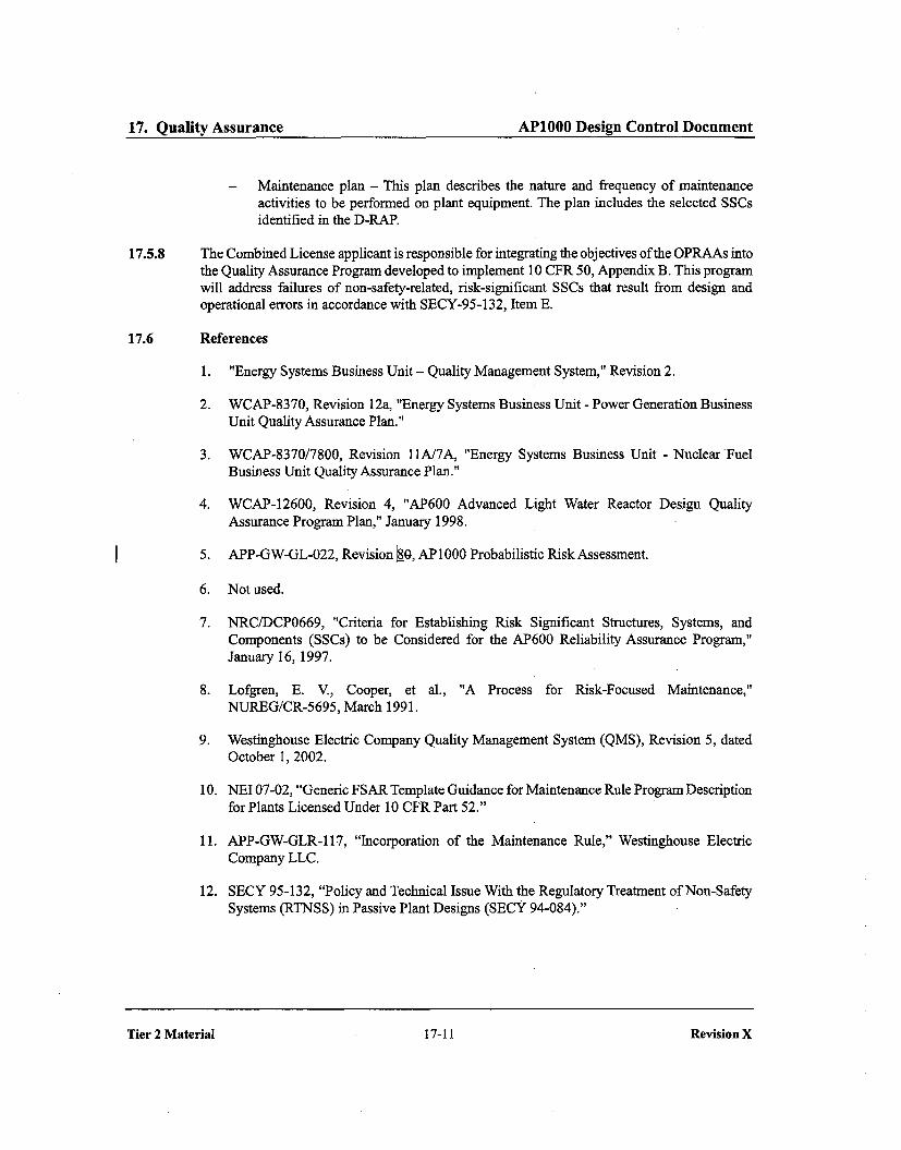
17. Quality Assurance APIO00 Design Control Document
- Maintenance plan - This plan describes the nature and frequency of maintenanceactivities to be performed on plant equipment. The plan includes the selected SSCsidentified in the D-RAP.
17.5.8 The Combined License applicant is responsible for integrating the objectives of the OPRAAs intothe Quality Assurance Program developed to implement 10 CFR 50, Appendix B. This programwill address failures of non-safety-related, risk-significant SSCs that result from design andoperational errors in accordance with SECY-95-132, Item E.
17.6 References
1. "Energy Systems Business Unit - Quality Management System," Revision 2.
2. WCAP-8370, Revision 12a, "Energy Systems Business Unit - Power Generation BusinessUnit Quality Assurance Plan."
3. WCAP-8370/7800, Revision 1 lA/7A, "Energy Systems Business Unit - Nuclear FuelBusiness Unit Quality Assurance Plan."
4. WCAP-12600, Revision 4, "AP600 Advanced Light Water Reactor Design QualityAssurance Program Plan," January 1998.
5. APP-GW-GL-022, Revision 8_0, AP 1000 Probabilistic Risk Assessment.
6. Not used.
7. NRC/DCP0669, "Criteria for Establishing Risk Significant Structures, Systems, andComponents (SSCs) to be Considered for the AP600 Reliability Assurance Program,"January 16, 1997.
8. Lofgren, E. V., Cooper, et al., "A Process for Risk-Focused Maintenance,"NUREG/CR-5695, March 1991.
9. Westinghouse Electric Company Quality Management System (QMS), Revision 5, datedOctober 1, 2002.
10. NEI 07-02, "Generic FSAR Template Guidance for Maintenance Rule Program Descriptionfor Plants Licensed Under 10 CFR Part 52."
11. APP-GW-GLR-I17, "Incorporation of the Maintenance Rule," Westinghouse ElectricCompany LLC.
12. SECY 95-132, "Policy and Technical Issue With the Regulatory Treatment of Non-SafetySystems (RTNSS) in Passive Plant Designs (SECY 94-084)."
Tier 2 Material 17-Il
Revision X
Tier 2 Material 17-11 Revision X

Change Number 40
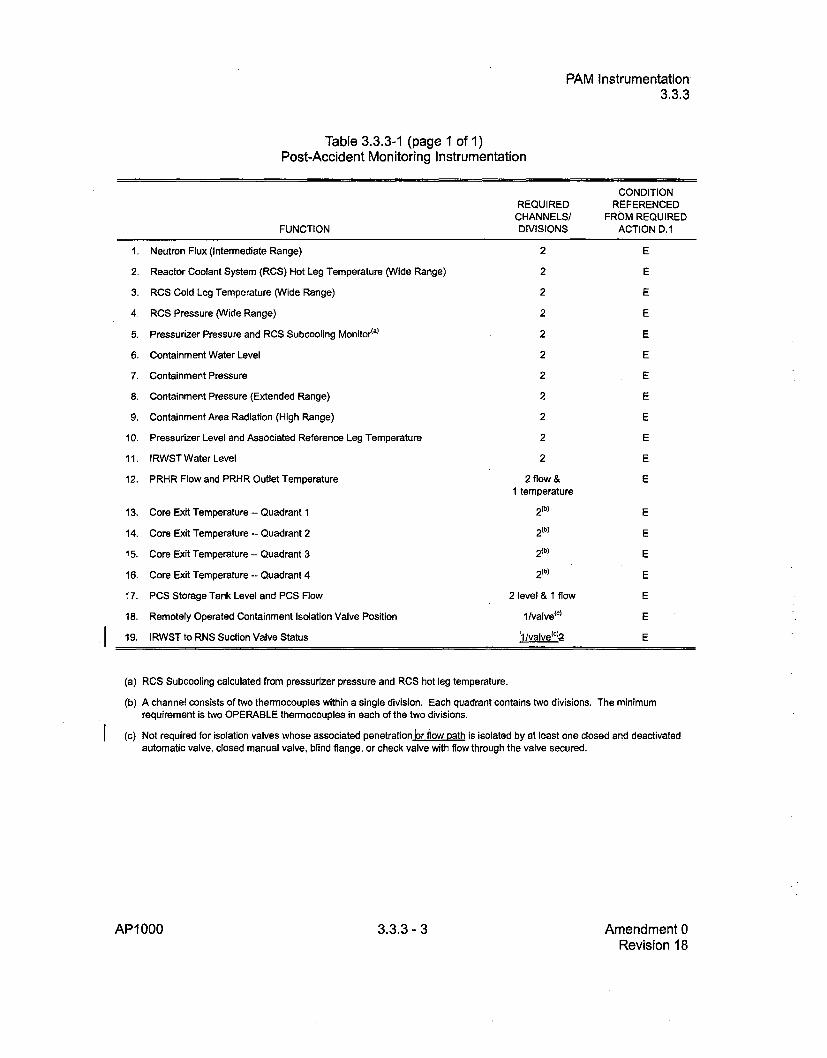
PAM Instrumentation3.3.3
Table 3.3.3-1 (page 1 of 1)Post-Accident Monitoring Instrumentation
FUNCTION
1.
2.
3.
4.
5.
6.
7.
8.
9.
10.
11.
12.
13.
"14.
15.
16.
17.
18.
19.
Neutron Flux (Intermediate Range)
Reactor Coolant System (RCS) Hot Leg Temperature (Wide Range)
RCS Cold Leg Temperature (Wide Range)
RCS Pressure (Wide Range)
Pressurizer Pressure and RCS Subcooling Monitor(')
Containment Water Level
Containment Pressure
Containment Pressure (Extended Range)
Containment Area Radiation (High Range)
Pressurizer Level and Associated Reference Leg Temperature
IRWST Water Level
PRHR Flow and PRHR Outlet Temperature
Core Exit Temperature - Quadrant 1
Core Exit Temperature - Quadrant 2
Core Exit Temperature -- Quadrant 3
Core Exit Temperature - Quadrant 4
PCS Storage Tank Level and PCS Flow
Remotely Operated Containment Isolation Valve Position
IRWST to RNS Suction Valve Status
REQUIREDCHANNELS/DIVISIONS
2
2
2
2
2
2
2
2
2
2
2
2 flow &I temperature
2 (b)
2(b)
2 (b)
2 (b)
2 level & 1 flow
1 /valve(C)
L1/valve(C)2
CONDITIONREFERENCED
FROM REQUIREDACTION D.1
E
E
E
E
E
E
E
E
E
E
E
E
E
E
E
E
E
E
E
(a) RCS Subcooling calculated from pressurizer pressure and RCS hot leg temperature.
(b) A channel consists of two thermocouples within a single division. Each quadrant contains two divisions. The minimumrequirement is two OPERABLE thermocouples in each of the two divisions.
(c) Not required for isolation valves whose associated penetration br flow path is isolated by at least one closed and deactivatedautomatic valve, closed manual valve, blind flange, or check valve with flow through the valve secured.
AP1000 3.3.3 - 3 Amendment 0Revision 18
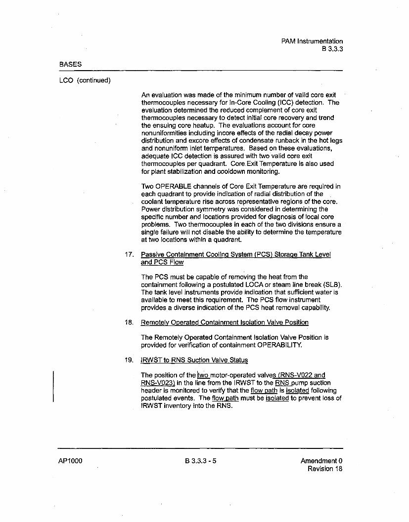
PAM InstrumentationB 3.3.3
BASES
LCO (continued)
An evaluation was made of the minimum number of valid core exitthermocouples necessary for In-Core Cooling (ICC) detection. Theevaluation determined the reduced complement of core exitthermocouples necessary to detect initial core recovery and trendthe ensuing core heatup. The evaluations account for corenonuniformities including incore effects of the radial decay powerdistribution and excore effects of condensate runback in the hot legsand nonuniform inlet temperatures. Based on these evaluations,adequate ICC detection is assured with two valid core exitthermocouples per quadrant. Core Exit Temperature is also usedfor plant stabilization and cooldown monitoring.
Two OPERABLE channels of Core Exit Temperature are required ineach quadrant to provide indication of radial distribution of thecoolant temperature rise across representative regions of the core.Power distribution symmetry was considered in determining thespecific number and locations provided for diagnosis of local coreproblems. Two thermocouples in each of the two divisions ensure asingle failure will not disable the ability to determine the temperatureat two locations within a quadrant.
17. Passive Containment Coolinq System (PCS) Storage Tank Leveland PCS Flow
The PCS must be capable of removing the heat from thecontainment following a postulated LOCA or steam line break (SLB).The tank level instruments provide indication that sufficient water isavailable to meet this requirement. The PCS flow instrumentprovides a diverse indication of the PCS heat removal capability.
18. Remotely Operated Containment Isolation Valve Position
The Remotely Operated Containment Isolation Valve Position isprovided for verification of containment OPERABILITY.
19. IRWST to RNS Suction Valve Status
The position of the •._motor-operated valves (RNS-V022 andRNS-V023) in the line from the IRWST to the RNS pump suctionheader is monitored to verify that the flow path is isolated followingpostulated events. The flow path must be isolated to prevent loss ofIRWST inventory into the RNS.
AP1000 B 3.3.3 - 5 Amendment 0Revision 18

Change Number 41

3. Design of Structures, Components,Equipment and Systems AP1000 Design Control Document
1. - S- sOIS CRft]NG IS
IS0 C C^__lOi0 0.
/-WCC•mlC•C•[CT]0N
/ N
N ___
DETAIL 2
Figure 3.8.3-8 (Sheet 3 of 3)
[Structural Modules - Typical Design Detailsj*
-NXL. S-a1 approval is requlrl pnor to itoplemeang a cnange in -tt inboalnon; see ULL flntrouctbon ection 3A..
Tier 2 Material 3.8-171 Revision 18

Change Number 42
1. Introduction and General Description of Plant AP1000 Design Control Document
removal system design pressure is 900 psig. Therefore the ultimate rupture strength of the systemprevents it from failing when exposed to the normal reactor coolant system operating pressure(2250 psibg). See the position on intersystem LOCA for additional information on the normalresidual heat removal system design against overpressurization.
Steam generator tube rupture core melt frequency is reduced by incorporating multiple levels ofdefense that are both redundant and diverse. The first level of defense relies on the use ofnonsafety-related active systems and operator action. The second level of defense uses safety-related passive systems and equipment, such as the core makeup tanks and passive residual heatremoval heat exchangers, without the safety-related automatic depressurization of the reactorcoolant system. The third level of defense uses the redundant and diverse safety-related automaticdepressurization system valves to depressurize the reactor coolant system and initiate low-pressurepassive injection. Any of these levels of defense can prevent core damage during a steamgenerator tube rupture event.
Finally, containment isolation capabilities are substantially improved by reducing the number ofpenetrations and the number of open paths. Most of the open containment penetration lines usefail-closed valves for automatic isolation.
1.9.5.1.12 ABWR Containment Vent Design
This issue is specific to BWRs and PWRs with ice condenser containments. Therefore this issuedoes not apply to the AP1000 design.
1.9.5.1.13 Equipment Survivability
NRC Position:
Safety-related equipment used to mitigate design basis events is subject to a comprehensive set ofcriteria such as redundancy, diversity, environmental qualification, and quality assurance toprovide reasonable assurance that they perform their intended functions, if needed. However,equipment used to mitigate the effects of severe accidents should not be treated in the samemanner because of large differences in the likelihood of occurrence. There should be reasonableassurance that the equipment will operate in the severe accident environment for which they areintended and over the time span for which they are needed. However, equipment provided onlyfor severe accident protection need not be subject to the 10 CFR 50.49, environmentalqualification requirements, 10 CFR 50, Appendix B quality assurance requirements, and10 CFR 50 Appendix A, redundancy and diversity requirements.
AP1000 Response:
The equipment used to mitigate severe accidents is identified in the AP1000 PRA evaluationreport. Because of the nature of the passive safety features of the AP1000, there is very littleequipment in this category. Equipment used to mitigate severe accidents is designed to survive theenvironmental conditions identified in the AP1000 PRA evaluation.
Tier 2 Material 1.9-83 Revision X
Tier 2 Material 1.9-83 Revision X

Change Number 43
1. Introduction and General Description of the Plant AP1000 Design Control Document
1.7 Drawings and Other Detailed Information
bhe figures referenced in subsections 1.7.1 and 1.7.2 may represent a functional diagram, generalstructural representation, or another general illustration. For instrumentation and control (I&C)systems, figures may also represent aspects of the relevant logic of the system or part of thesystem. Unless specified explicitly, the figures are not indicative of the scale, location,dimensions, shape, or spatial relationships of as-built structures, systems, and components. Inparticular, the as-built attributes of structures, systems, and components may vary from theattributes depicted on the figures, provided that those safety functions discussed in the designdescription pertaining to the figure are not adversely affected.
1.7.1 Electrical and Instrumentation and Control Drawings
Instrument and control functional diagrams, electrical one-line diagrams, and onsite standby dieselgenerator loading sequence and initiating circuit logic diagrams are listed in Table 1.7-1.
The legend for electrical power, control, lighting, and communication drawings is provided inFigure 1.7-1, sheets 1, 2, and 3. The index, notes, and symbols for instrument and controlfunctional diagrams are provided in Figure 7.2-1.
1.7.2 Piping and Instrumentation Diagrams
Table 1.7-2 contains a list of piping and instrumentation diagrams (P&IDs) and the correspondingDCD figure numbers. The three letter system names are provided in Table 1.7-2. Figures appear atthe end of the respective text section. The P&ID legend, Figure 1.7-2, sheets 1, 2, and 3, providesan explanation of AP 1000 symbols and characters used in these DCD figures.
1.7.3 Combined License Information
This section has no requirement for additional information to be provided in support of thecombined license application.
Tier 2 Material 1.7-1 Revision X

Change Number 44

5. Reactor Coolant System and Connected Systems AP1000 Design Control Document
Table 5.2-1 (Sheet 2 of -)
REACTOR COOLANT PRESSURE BOUNDARY MATERIALS SPECIFICATIONS
I
Component Material Class, Grade, or TypeVent pipe SB-166 N06690
SB- 167 N06690
or
SA-312() TP304, TP304L, TP304LN,TP316, TP316L, TP316LN
SA-376 TP304, TP304LN,TP316, TP316LN
Steam Generator Components
Pressure plates SA-533 Type B, CL I or CL 2Pressure forgingsq(including primary side nozzles SA-508 Gb1IA ef-GR 3, CL 2and tube sheet)
Nozzle safe ends SA-182 F316, F316L, F316LN
SA-336 F316LN
or
SB-564 N06690
Channel heads SA-508 GR 3, CL 2Tubes SB-163 N06690
Manway studs/ SA-193 GR B7Nuts SA-194 GR 7
Pressurizer Components
Pressure plates SA-533 Type B, CL 1
Pressure forgings SA-508 GR 3, CL 2
Nozzle safe ends SA-182 F316, F316L, F316LN
SA-b6-3-34 F316, F316L, F316LN
SB.-444- N06690
Manway studs/ ! GR B7Nuts SA-194 GR 7
I
Tier 2 Material 5.2-34 Revision 18

Change Number 46

4. Reactor AP1000 Design Control Document
The springs in the control rod drive mechanism are made from nickel-chromium-iron alloy(Alloy 750), ordered to Aerospace Material Specification (AMS) 5698 or AMS 5699 withadditional restrictions on prohibited materials. Operating experience has shown that springs madeof this material are not subject to stress-corrosion cracking in pressurized water reactor primarywater environments. Alloy 750 is not used for bolting applications in the control rod drivemechanisms.
4.5.1.4 Contamination Protection and Cleaning of Austenitic Stainless Steel
The control rod drive mechanisms are cleaned prior to delivery in accordance with the guidanceprovided in NQA-1 (see Chapter 17). Process specifications in packaging and shipment arediscussed in subsection 5.2.3. Westinghouse personnel conduct surveillance of these operations toverify that manufacturers and installers adhere to appropriate requirements as described insubsection 5.2.3.
Tools used in abrasive work operations on austenitic stainless steel, such as grinding or wirebrushing, do not contain and are not contaminated with ferritic carbon steel or other materials thatcould contribute to intergranular cracking or stress-corrosion cracking.
4.5.2 Reactor Internal and Core Support Materials
4.5.2.1 Materials Specifications
The major core support material for the reactor internals is SA- 182, SA-336, SA-376, SA-479, orSA-240 Types 304, 304L, 304LN, or 304H stainless steels. Fabricators performing welding of anyof these materials are required to qualify the welding procedures for maximum carbon content andheat input for each welding process in accordance with Regulatory Guide 1.44. For threadedstructural fasteners, the material used is strain hardened Type 316 stainless steel, and for the clevisinsert-to-vessel bolts, either UNS N07718 or N07750. Remaining 6itemaks-parts not fabricatedfrom Types 304, 304L, 304LN, or 304H stainless steels typically include wear surfaces such ashardfacing on the radial keys, clevis inserts, .ndalignment -plates (StelliteTM 6 or 156 or lowcobalt hardfaces); dowel pins (Type 316); held do.wn spring (Ty-p 103 stainless steel (....dified));•_dclevis inserts (UNS N06690; and irradiatin . ........ . rings (UNS N07:750).
jAdditional product forms that may be used by the reactor internals structures are SA- 193, SA-213,SA-312, SA-358, SB-166, SB-168, and SB-637. Reactor internals structures.ast...ent. -guiassembly materials that are not Types 304, 304L, 304LN, or 304H stainless steel are the guidebushings, locating and support pins, instrumentation adapter, instrument tube tip, instrument tubesleeve top,and-guide stud t-ipk UNS S21800), Swagelok fitting (Type 316), hold down spring(Type 403 stainless steel rmodified]), irradiation specimen access plug springs and instrumentstalk springs (UNS N07750), and-the-instrument guide-tube Wleeve spring (UNS N07718),andflow skirt (UNS N06690). ýdditionally, reactor internals structures will use either threadedstructural fasteners of strain hardened Type 316 stainless steel, UNS N07718 or N07750.
Core support structure,, internals structures, and threaded structural fastener materials are specifiedin the ASME Code, Section I14, Part D, Subpart 1, Tables 2A, 2B, and 4Appen.di*- assupplemented by Code Cases N-60 and N-4. The qualification of cobalt free wear resistant alloysfor use in reactor coolant is addressed in subsection 4.5.1.3.
Tier 2 Material 4.5-3 Revision 18

Change Number 47

7. Instrumentation and Controls AP1000 Design Control Document
performing periodic operability testing of the passive residual heat removal heat exchangerdischarge valves when the reactor is operating. Once the manual operation is complete, thecontrol circuit returns to automatic operation.
The control circuit has a valve maintain closed actuation function to provide anadministratively controlled manual block of the automatic opening of the valve. This functionallows the valve to be maintained closed if needed for leakage isolation. The maximumpermissible time that a passive residual heat removal heat exchanger inlet isolation valve canbe closed is specified in technical specifications. An alarm is actuated when the maintainclosed function is instated.
The valve is interlocked so that:
* If the maintain closed actuation has not been manually initiated, it opens automatically onreceipt of a confirmatory open signal with the control circuit in automatic control or duringthe manual valve close function.
* It cannot be manually closed when a confirmatory open signal is present.
During plant operation and shutdown, the passive residual heat removal heat exchanger inletisolation valve is open. fe prevent an inad.v...ent alccur of the v.A.e, r-edundant ,-put ear&. ar.used in the p..teetien and sanfty .. n..tering system . abi.• .• Power to this valve is normallylocked out at power to prevent a fire-induced spurious closing.
Figure 7.2-1, sheet 17 illustrates the interlock logic which applies to the passive residual heatremoval heat exchanger inlet isolation valve.
This normally open motor-operated valve has alarms, indicating valve mispositioning (with regardto their passive core cooling function). The alarm actuates in the main control room and theremote shutdown workstation.
An alarm actuates for the passive residual heat removal heat exchanger inlet isolation valve underthe following conditions when the passive residual heat removal heat exchanger is required:
* Sensors on the motor operator for the valve indicate when the valve is not fully open.
" Redundant sensors on the valve stem indicate when the valve is not fully open.
7.6.2.2 Core Makeup Tank Cold Leg Balance Line Isolation Valves
Each core makeup tank has a cold leg balance line which is provided with a normally open, motor-operated, isolation valve. The balance line isolation valves, for each core makeup tank, may bemanually controlled from either the main control room or the remote shutdown workstation. Thegeneration of the confirmatory open signal to these valves is described in subsection 7.3.1.2.3.
A confirmatory open signal to these valves automatically overrides any bypass features that areprovided to allow the balance line isolation valve to be closed for short periods of time. As a result
Tier 2 Material 7.6-3 Revision X

Change Number 48

3. Design of Structures, Components,Equipment and Systems AP1000 Design Control Document
Table 3.2-3 (Sheet 21 of 6-9)
AP1000 CLASSIFICATION OF MECHANICAL ANDFLUID SYSTEMS, COMPONENTS, AND EQUIPMENT
I AP1000 I Seismic I Principal Con"Tag Number Description j Class J Category struction Code CommentsPassive Core Cooling System (Continued)PXS-PL-VI 17B Containment Recirculation B C I ASME 111-3
IsolationPXS-PL-V1 18A Containment Recirculation A C I ASME 111-3
IsolationPXS-PL-V118B Containment Recirculation B C I ASME 111-3
IsolationPXS-PL-V1 19A Containment Recirculation A C ASME 111-3
Check
PXS-PL-V119B Containment Recirculation B C ASME 111-3Check
PXS-PL-V120A Containment Recirculation A C ASM 111-3Isolation
PXS-PL-V120B Containment Recirculation B C ASM 111-3Isolation
PXS-PL-V121A IRWST Line A Isolation C I ASME 111-3PXS-PL-V121B IRWST Line B Isolation C I ASME 111-3PXS-PL-V122A IRWST Injection A Check A I ASME III-1PXS-PL-V122B IRWST Injection B Check A I ASME III-1PXS-PL-V123A IRWST Injection A Isolation A I ASME III-1PXS-PL-V123B IRWST Injection B Isolation A I ASME III-1PXS-PL-V124A IRWST Injection A Check A I ASME III-IPXS-PL-V124B IRWST Injection B Check A I ASME III-1PXS-PL-V125A IRWST Injection A Isolation A I ASME I-- IPXS-PL-V125B IRWST Injection B Isolation A I ASME III-1PXS-PL-V126A IRWST Injection Check Test C I ASME 111-3PXS-PL-V126B IRWST Injection Check Test C I ASME 111-3f'XSgrm.*3-PL- IRWST Iniection Line A C I ASME 111-3V127A Drain 0_ _ ___
PXS-PL-V128A IRWST Injection Check Test A' A I ASMEII DPXS-PL-V128B IRWST Injection Check Test 'a,. K I ASMEIIII_PXS-PL-V129A IRWST Injection Check Test X" A I ASME 11 __1PXS-PL-VI29B IRWST Injection Check Test ý,R" I ASME 11I1__ _
PXS-PL-V130A IRWST Gutter Bypass A I ASME IIIA-AIsolation
Tier2 Maeria 3.241 Rvisin 1
Tier 2 Material 3.2-41 Revision 18

Change Number 49

17. Quafity Assurance AP1000 Design Control Document17.4Quality Asue
17.4.7.2 Not Used
17.4.7.2.1 Not Used
17.4.7.3 Not Used
17.4.7.4 D-RAP Implementation
The following is an example of a system that was reviewed and modified under the D-RAP. Thedesign and analytical results presented here are intended as an example.
The automatic depressurization system, which is part of the reactor coolant system, acts inconjunction with the passive core cooling system to mitigate design basis accidents. The automaticdepressurization system valves are discussed in subsection 5.4.6 of the DCD.
An earlier AP600 automatic depressurization system design contained four depressurizationstages, with motor-operated valves in all stages. Preliminary PRA analysis established that fourthstage failure, in certain combination with failures of other stages, was a major contributor to coredamage frequency. Thus, it was concluded that the fourth stage valves should be diverse in designfrom the valves in other stages to reduce common cause failure.
As a result ofjoint meetings among the AP600 PRA, Design, and staff organizations to discusscore melt frequency improvements, the fourth stage automatic depressurization system waschanged from a motor-operated valve to a squib (explosively actuated) valve. The newconfiguration of the system is shown in the reactor coolant system P&ID (Figure 5.1-5 of theDCD). An example of the analytical results that reflect this change is provided in Table 17.4-2.This design feature is included in the AP1000 design to maintain the core melt frequencyimprovements included in the AP600 design.
As part of the evaluation of the squib valves, a failure modes and effects analysis (FMEA) wasprepared to identify subcomponent failures and critical items that could lead to hazardous orabnormal conditions of the automatic depressurization system and the plant. The identification offailure modes facilitated the development of recommended maintenance and in-service testingactivities to maximize valve reliability.
The squib valve is a completely static electromechanical assembly. Prior to activation, there are nomoving parts. No powered components are needed to holda stem seat or globe in place by torque,solenoid coils, or friction. The explosive actuator is a simple, passive device that is triggered by anapplied voltage.
Because the automatic depressurization system fourth stage valves perform safety-relatedfunctions, they will be subject to in-service testing to verify that they are ready to function in anaccident. Subsection 3.9.6 of the DCD includes in-service testing requirements for these valves.
Example FMEEA results for the fourth stage squib valves and the second and third stagemotor-operated valves are included in DCD Table 6.3-3. ýable 3.9-16DCD subsectien 3.9.6.3.1provides testing recommendations for the second and third stage valves.
Tier 2 Material 17-8 Revision X

Change Number 50
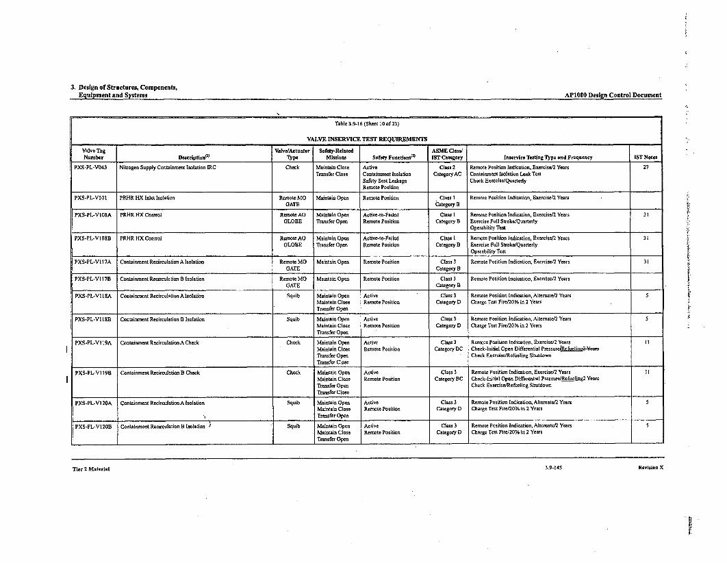
3. Design of Structures, Components,Equipment and Systems AP1000 Desln Control Document
Table 3.9-16 (Sheet 10 of 23)
VALVE INSERVICE TEST REQUIREMENTS
Valve Tag Valve/Actuator Safety-Related ASME Class/Number Descriptiont) T'ype Missions Safety Funetlons" IST Category Inservice Testing Type and Frequency IST Notes
PXS-PL-V043 Nitrogen Supply Containment Isolation IRC Check Maintain Close Active Class 2 Remote Position Indication, Exeraisei2 Years 27Transfer Close Containment Isolation Category AC Containment Isolation Leak Test
Safety Seat Leakage Check Exercise/QuarterlyRemote Position
PXS-PL-VIOI PRHR HX Inlet Isolation Remote MO Maintain Open Remote Position Class 1 Remote Position Indication, Exercise/2 YearsGATE Category B
PXS-PL-VI08A PRHR H4X Control Remote AO Maintain Open Aotive-to-Failed Class I Remote Position Indication, Exercise/2 Years 31GLOBE Transfer Open Remote Position Category B Exercise Full Stroke/Quarterly
Operability Test
PXS-PL-VIOSB PRHR HX Control Remote AO Maintain Open Active-to-Failed Class 1 Remote Position Indication, Exercise/2 Years 31GLOBE Transfer Open Remote Position Category B Exercise Full Stroke/Quarterly
Operability Test
PXS-PL-VI17A Containment Recirculation A Isolation Remote MO Maintain Open Remote Position Class 3 Remote Position Indication, Excrcise/2 Years 31GATE Category B
PXS-PL-VI17B Containment Recirculation B Isolation Remote MO Maintain Open Remote Position Class 3 Remote Position Indication, Exercise/2 YearsGATE Category B
PXS-PL-VIS1A Containment Recirculation A Isolation Squib Maintain Open Active Class 3 Remote Position Indication, Alternate/2 YearsMaintain Close Remote Position Category D Charge Teat Firc/20% in 2 YearsTransfer Open
PXS-PL-VI 18B Containment Recircaulation B Isolation Squib Maintain Open Active Class 3 Remote Position Indication, Alternate/2 Years 5Maintain Close Remote Position Category D Charge Test Fire/20% in 2 YearsTransfer Open
PXS-PL-VI19A Containment Recirculation A Check Check Maintain Open Active Class 3 Remote Position Indication, Exercise/2 Years IIMaintain Close Remote Position Category BC Check-Initial Open Differential PmssurciscliunglaTransfer Open Check Exercise/Refueling ShutdownTransfer Close
PXS-PL-VI 19B Containment Recirculation B Check Check Maintain Open Active Class 3 Remote Position Indication, Exercise/2 Years I IMaintain Close Remote Position Category BC Check-Initial Open Differential Pressur-efueling24.arsTransfer Open Check Exercise/Refueling ShutdownTransfer Close
PXS-PL-VI 20A Containment Recirculation A Isolation Squib Maintain Open Active Class 3. Remote Position Indication, Altemate/2 Years 5Maintain Close Remote Position Category D Charge Test Firet20% in 2 YearsTransfer Open
PXS-PL-V120B Containment Recirculation B Isolation ' - Squib Maintain Open Active Class 3 Remote Position Indication, Altematet2 YearsMaintain Close Remote Position Category D Charge Test Fire/20% in 2 YearsTransfer Open
TIer 2 MaterIal 3.9-143 Revinists X
Tier 2 Material 3.9-145 Revision X
|.

3. Design of Structures, Components,Equipment and Systems ADIflAnn . d, . In
es gn onUs .UI *.VUtUmeII
Table 3.9-16 (Sheet I1 of23)
VALVE INSERVICE TEST REQUIREMENTS
Valve Tag ValvelActuator Safety-Related ASME Class/Number Description("t TIpe Missions Safety Functionsea IST Category Inservice Testing Type and Frequency IST Notes
PXS-PL-VI21A IRWST LineA Isolation Remote MO Maintain Open Remote Position Class 3 Remote Position Indication, Exercise/2 YearsGATE Category B
PXS-PL-VI21B IRWST Line B Isolation Remote MO Maintain Open Remote Position Class 3 Remote Position Indication, Exercise/2 YearsGATE Category B
PXS-PL-V122A IRWST Injection A Check Check Maintain Open Active Class I Remote Position Indication, Exercise/2 Years 12Maintain Close RCS Pressure Boundary Category BC Check-Initial Open Differential Pressuret -lin2-44-eaTransfer Open Remote Position Check Exercise/Refueling ShutdownTransfer Close
PXS-PL-V122B IRWST Injection B Check Check Maintain Open Active Class I Remote Position Indication, Exeraise/2 Years 12Maintain Close RCS Pressure Boundary Category BC Check-Initial Open Differential PressurceRefucline a osTransfer Open Remote Position Check Exercise/Refueling ShutdownTransfer Close
PXS-PL-V123A IRWST Injection A Isolation Squib Maintain Open Active Class I Remote Position Indication, Altemate/2 Years 5Maintain Close RCS Pressure Boundary Category D Charge Test Fire/20% in 2 YearsTransfer Open Remote Position
PXS-PL-V123B IRWST Injection B Isolation Squib Maintain Open Active Class I Remote Position Indication, Alternate/2 YearsMaintain Close RCS Pressure Boundary Category D Charge Test Fire/20% in 2 YearsTransfer Open Remote Position
PXS-PL-V124A IRWST Injection A Check Check Maintain Open Active Class I Remote Position Indication, Exercise/2 Years 12Maintain Close RCS Pressure Boundary Category BC Check-Initial Open Differential PressureASeftl2=1ZeoTransfer Open Remote Position Check Exercise/Refueling ShutdownTransfer Close
PXS-PL-VI24B IRWST Injection B Check Check Maintain Open Active Class I Remote Position Indication, Exercise/2 Years 12Maintain Close RCS Pressure Boundary Category BC Check-Initial Open Differential Pressurc-_ef•elise wsTransfer Open Remote Position Check Exercise/Refueling ShutdownTransfer Close
PXS-PL-V125A IRWST Injection A Isolation Squib Maintain Open Active Class I Remote Position Indication, Alternate/2 Years 5Maintain Close RCS Pressure Boundary Category D Charge Test Fire/20% in 2 YearsTransfer Open Remote Position
PXS-PL-V 125B IRWST Injection B Isolation Squib Maintain Open Active Class I Remote Position Indication, Alternate/2 Years 5Maintain Close RCS Pressure Boundary Category D Charge Test Fire/20% in 2 YearsTransfer Open Remote Position
PXS-PL-V 130A IRWST Gutter Isolation Remote AG Maintain Close Active-to-Failed Class 3 Remote Position Indication, Exercise/2 Years 31GLOBE Transfer Close Remote Position Category B Exercise Full Stroke/Quarterly
Operability Test
Tier 2 Material 3.9-147 Revision X

Change Number 51
5. Reactor Coolant System and Connected Systems APIO00 Design Control Document
* Limits pressure differentials on internal steam generator components, particularly the tubesupport plates
The restrictor is configured to minimize the unrecovered pressure loss across the restrictor duringnormal operation.
5.4.4.2 Design Description
The flow restrictor consists of seven nickel-chromium-iron Alloy 690 (ASME SB-564) venturiinserts which are installed in holes in an integral steam outlet nozzle forging. The inserts arearranged with one venturi at the centerline of the outlet nozzle, and the other six are equallyspaced around it. After inse he nozzle forging holes, the venturi inserts are welded to thenickel-chromium-iron allolnu lge 4g on the inner surface of the forging.
5.4.4.3 Design Evaluation
The flow restrictor design has been analyzed to determine its structural adequacy. The equivalentthroat area of the steam generator outlet is 1.4 square feet. The resultant pressure drop through therestrictor at 100 percent steam flow is approximately 15 psiý. This is based on a design flow rateof 7.49 x 10⁶ pounds per hour. Materials of construction of the flow restrictor are in accordancewith Code Class I Section LU of the ASME Code. The material of the inserts is not an ASMECode pressure boundary, nor is it welded to an ASME Code pressure boundary. The method forseismic analysis is dynamic.
5.4.4.4 Inspections
Since the restrictor is not part of the steam system pressure boundary, inservice inspections are notrequired.
5.4.5 Pressurizer
The pressurizer provides a point in the reactor coolant system where liquid and vapor aremaintained in equilibrium under saturated conditions for pressure control of the reactor coolantsystem during steady-state operations and transients. The pressurizer provides a controlled volumefrom which level can be measured.
The pressurizer contains the water inventory used to maintain reactor coolant system volume inthe event of a minor system leak for a reasonable period without replenishment. The pressurizersurge line connects the pressurizer to one reactor coolant hot leg. This allows continuous coolantvolume and pressure adjustments between the reactor coolant system and the pressurizer.
5.4.5.1 Design Bases
The pressurizer is sized to meet following requirements:
* The combined saturated water volume and steam expansion volume is sufficient to providethe desired pressure response to system volume changes.
Tier 2 Material 5.4-27 Revision 18

Change Number 52
pH AdjustmentB 3.6.9
B 3.6 CONTAINMENT SYSTEMS
B 3.6.9 pH Adjustment
BASES
1BACKGROUND The Passive Core Cooling System (PXS) incluees oourtwe pH djustmentbaskets which provide adjustment of the pH of ..containment following an accident where the containment floods.
Following an accident with a large release of radioactivity, thecontainment pH is automatically adjusted to greater than or equal to 7.0,to enhance iodine retention in the containment water. Chemical additionis necessary to counter the affects of the boric acid contained in thesafety injection supplies and acids produced in the post-LOCAenvironment (nitric acid from the irradiation of water and air andhydrochloric acid from irradiation and pyrolysis of electric cableinsulation). The desired pH values significantly reduce formation ofelemental iodine in the containment water, which reduces the productionof organic iodine and the total airborne iodine in the containment. ThispH adjustment is also provided to prevent stress corrosion cracking ofsafety related containment components during long-term cooling.
Dodecahydrate trisodium phosphate (TSP) contained in baskets provides-a passive means of pH control for such accidents. The baskets are madeof stainless steel with a mesh front that readily permits contact with water.These baskets are located inside containment at an elevation that isbelow the minimum floodup level. The baskets are placed at least a footabove the floor to reduce the chance that water spills will dissolve theTSP. Natural recirculation of water inside the containment, following aLOCA, is driven by the core decay heat and provides mixing to achieve auniform pH. The dodecahydrate form of TSP (Na3PO4.-ý1 2H20) is initiallyloaded into the baskets because it is hydrated and will undergo lessphysical and chemical change than would anhydrous TSP as a result ofthe humidity inside containment. (Refs. 1 and 2)
APPLICABLESAFETYANALYSES
In the event of a Design Basis Accident (DBA), iodine may be releasedfrom the fuel to containment. To limit this iodine release fromcontainment, the pH of the water in the containment sump is adjusted bythe addition of TSP. Adjusting the sump water to neutral or alkaline pH(pH > 7.0) will augment the retention of the iodine, and thus reduce theiodine available to leak to the environment.
pH adjustment satisfies Criterion 3 of 10 CFR 50.36(c)(2)(ii).
AP1000 B 3.6.9 - 1 Amendment 0Revision X
AccumulatorsB 3.5.1
BASES
BACKGROUND (continued)
The accumulator size, water volume, and nitrogen cover pressure areselected so that both of the accumulators are sufficient to recover thecore cooling before significant clad melting or zirconium water reactioncan occur following a large break LOCA. One accumulator is adequateduring a small break LOCA where the entire contents of one accumulatorcan possibly be lost via the pipe break. This accumulator performance isbased on design basis accident (DBA) assumptions and models (Ref. 3).The Probabilistic Risk Assessment (PRA) (Ref. 4) shows that one of thetwo accumulators is sufficient for a large break LOCA caused by spuriousADS actuation and that none of the accumulators are required for smallbreak LOCAs, assuming that at least one core makeup tank (CMT) isavailable. In addition, both accumulators are required for a large breakLOCA caused by the break of a cold leg pipe; the probability of this breakhas been significantly reduced by incorporation of leak-before-break.
APPLICABLE The accumulators are assumed to be OPERABLE in both the large and.SAFETY small break LOCA analyses at full power (Ref. 3) that establish theANALYSES acceptance limits for the accumulators. Reference to the analyses for
these DBAs is used to assess changes in the accumulators as they relateto the acceptance limits.
For a small break LOCA, a large range of break sizes and locations wereanalyzed to verify the adequacy of the design. The cases analyzedinclude the rupture of one 8 inch direct vessel injection line and severalsmaller break sizes. Acceptable PXS performance was demonstrated.
For a larger LOCA, including a double ended RCS piping rupture, thePXS can provide a sufficiently large flow rate, assuming bothaccumulators are OPERABLE, to quickly fill the reactor vessel lowerplenum and downcomer. Both accumulators, in conjunction with theCMTs, ensure rapid reflooding of the core. For a large LOCA, both linesare available since an 8 inch line break would be a small LOCA.
Following a non-LOCA event such as a steamLline break, the RCSexperiences a decrease in temperature and pressure due to an increasein energy removal by the secondary system. The cooldown results in areduction of the core SHUTDOWN MARGIN with a potential for return topower. During such an event the accumulators provide injection ofborated water to assist the CMT's boration to mitigate the reactivitytransient and ensure the core remains shut down.
The accumulators satisfy Criterion 3 of 10 CFR 50.36(c)(2)(ii).
AP1000 B 3.5.1 - 2 Amendment 0Revision 18

CMTs - OperatingB 3.5.2
BASES
APPLICABLE The CMTs are assumed to be OPERABLE to provide emergency borationSAFETY and core makeup when the Chemical and Volume Control System (CVS)ANALYSES is inoperable, and to mitigate the consequences of any DBA which
requires the safety injection of borated water (Ref. 2).
Following a non-LOCA event such as a steamLline break, the RCSexperiences a decrease in temperature and pressure due to an increasein energy removal by the secondary system. The cooldown results in areduction of the core SHUTDOWN MARGIN due to the negativemoderator temperature coefficient, with a potential for return to power.The actuation of the CMTs following this event provides injection ofborated water to mitigate the reactivity transient and ensure the coreremains shut down.
In the case of a steam generator tube rupture (SGTR), CMT injectionprovides borated water to compensate for RCS LEAKAGE.
In the case of an RCS leak of 10 gallons per minute, the CMTs can delaydepressurization for at least 10 hours, providing makeup to the RCS andremain able to provide the borated water to compensate for RCSshrinkage and to assure the RCS boration for a safe shutdown.
In the case of a LOCA, the CMTs provide a relatively large makeup flowrate for approximately 20 minutes, in conjunction with the accumulators toprovide the initial core cooling.
CMTs satisfy Criterion 3 of 10 CFR 50.36(c)(2)(ii).
LCO This LCO establishes the minimum conditions necessary to ensure thatsufficient CMT flow will be available to meet the initial conditions assumedin the safety analyses. The volume of each CMT represents 100% of thetotal injected flow assumed in LOCA analysis. If the injection line from asingle CMT to the vessel breaks, no single active failure on the other CMTwill prevent the injection of borated water into the vessel. Thus theassumptions of the LOCA analysis will be satisfied.
For non-LOCA analysis, two CMTs are assumed. Note that for non-LOCAanalysis, the accident cannot disable a CMT.
AP1000 B 3.5.2 - 2 Amendment 0Revision 18

MSIVsB 3.7.2
B 3.7 PLANT SYSTEMS
B 3.7.2 Main Steam Isolation Valves (MSlVs)
BASES
IBACKGROUND Each main steamLline has one safety related MSIV to isolate steam flowfrom the secondary side of the steam generators following a high energyline break. MSIV closure terminates flow from the unaffected (intact)steam generator.
One MSIV is located in each main steam line outside containment. TheMSIVs are downstream from the main steam safety valves (MSSVs).Downstream from the MSIVs, main steam enters the high pressureturbine through four stop valves and four governing control valves.Closing the MSIVs isolates each steam generator from the other andisolates the turbine bypass system, and other steam supplies from thesteam generator.
The MSIVs, turbine stop and control valves, turbine bypass valves, andmoisture separator reheater 2nd stage steam isolation valves close on amain steam isolation signal generated by either low steam line pressure,high containment pressure, Low T,,Id, or high negative steam pressurerate. The MSIVs fail closed on loss of control air or actuation signal fromeither of two 1 E power divisions.
Each MSIV has an MSIV bypass valve. Although these bypass valvesare normally closed, they receive the same emergency closure signal asdo their associated MSIVs. The MSIVs may also be actuated manually.
A description of the MSIVs is found in the Section 10.3 (Ref. 1).Descriptions for the turbine bypass valves, and moisture separatorreheater 2nd stage steam isolation valves are found in the Section 10.4(Ref. 6).
APPLICABLESAFETYANALYSES
The design basis of the MSIVs is established by the containment analysisfor the large steam line break (SLB) inside containment, discussed in theSection 6.2 (Ref. 2). It is also affected by the accident analysis of theSLB events presented in the Section 15.1 (Ref. 3). The design precludesthe blowdown of more than one steam generator, assuming a singleactive component failure (e.g., the failure of one MSIV to close ondemand).
Design basis events of concern for containment analysis are SLB insidecontainment with the failure of the associated MSIV to close, or a mainfeedline break with the associated failure of a feedline isolation or control
AP1000 B 3.7.2 - I Amendment 0Revision 18
MSIVsB 3.7.2
BASES
APPLICABLE SAFETY ANALYSES (continued)
MSIV closure, steam is discharged into containment only from theaffected steam generator and from the residual steam in the mainsteam header downstream of the closed MSIV in the unaffectedloop. Closure of the MSIV isolates the break from the unaffectedsteam generator.
b. A break outside of containment, and upstream or downstream fromthe MSIVs, is not a containment pressurization concern. Theuncontrolled blowdown of more than one steam generator must beprevented to limit the potential for uncontrolled RCS cooldown andpositive reactivity addition. Closure of the MSIVs or alternatedownstream valves isolates the break, and limits the blowdown to asingle steam generator.
c. Following a steam generator tube rupture, closure of the MSIVsisolates the ruptured steam generator to minimize radiologicalreleases.
d. The MSIVs are also utilized during other events such as a feedwaterline break; however, these events are less limiting so far as MSIVOPERABILITY is concerned.
The MSIVs and the alternate downstream valves satisfy Criterion 3 of10 CFR 50.36(c)(2)(ii).
Following an SLB and main steam isolation signal, the analyses assumecontinued steam loss through the steanrline condensate drain lines,turbine gland seal system, and the main steam to auxiliary steam headerwhich supplies the auxiliary steam line to the deaerator. Since thesevalves are not assumed for steam isolation, they do not satisfy the10 CFR 50.36(c)(2)(ii) criteria.
LCO This LCO requires that one MSIV in each of the two steam lines beOPERABLE. The MSIVs are considered OPERABLE when their isolationtimes are within limits, and they close on an isolation actuation signal.
This LCO requires that four turbine stop valves or their associated turbinecontrol valve, six turbine bypass valves, and two moisture separatorreheater 2nd stage steam isolation valves be OPERABLE. A valve isconsidered OPERABLE when its isolation time is within the safetyanalysis isolation time limit of 5 seconds and it closes on an MSIV
AP1000 B 3.7.2 - 3 Amendment 0Revision 18

Change Number 56 A

Table of Contents AP1000 Design Control Document
TIER 1 LIST OF FIGURES
0iim Title PRO
2.1.2-1 Reactor Coolant System 2.1.2-302.1.2-2 Flow Transient for Four Cold Legs in Operation, Four Pumps Coasting Down 2.1.2-322.1.3-1 Reactor Upper Internals Rod Guide Arrangement 2.1.3-132.1.3-2 Rod Cluster Control and Drive Rod Arrangement 2.1.3-142.1.3-3 Reactor Vessel Arrangement 2.1.3-152.2.1-1 Containment System 2.2.1-172.2.2-1 Passive Containment Cooling System 2.2.2-162.2.3-1 Passive Core Cooling System 2.2.3-292.2.4-1 Steam Generator System 2.2.4-232.2.5-1 Main Control Room Emergency Habitability System 2.2.5-166.2.3.1-1 Component Cooling Water System 2.3.1-52.3.2-1 4 h 2.3.2-152 2.3.3-1 Stnb Diesel Oil Syem 2.3.3-52.3.4- 1ira o on ystem 2.3.4-72.3.6-1 Normal Residual Heat Removal System 2.3.6-172.3.7-1 Spent Fuel Pool Cooling System 2.3.7-112.3.8-1 Service Water System 2.3.8-52.3.10-1 Liquid Radwaste System 2.3.10-92.3.11-1 Gaseous Radwaste System 2.3.11-62.3.13-1 Primary Sampling System 2.3.13-82.3.29-1 Radioactive Waste Drain System 2.3.29-32.4.1-1 Main and Startup Feedwater System 2.4.1-42.5.2-1 Protection and Safety Monitoring System 2.5.2-202.6.1-1 Main ac Power System 2.6.1-112.6.2-1 Non-Class 1E do and Uninterruptible Power Supply System 2.6.2-42.6.3-1 Class 1E dc and Uninterruptible Power Supply System 2.6.3-162.7.1-1 Nuclear Island Nonradioactive Ventilation System 2.7.1-102.7.2-1 Central Chilled Water System 2.7.2-52.7.3-1 Annex/Auxiliary Building Nonradioactive Ventilation System 2.7.3-52.7.4-1 Diesel Generator Building Ventilation System 2.7.4-52.7.6-1 Containment Air Filtration System 2.7.6-53.2-1 Human Factors Engineering (HFE) Design and Implementation Process 3.2-73.3-1 Nuclear Island Section A-A 3.3-393.3-2 Nuclear Island Section B-B 3.3-413.3-3 Nuclear Island Plan View at Elevation 66'-6" 3.3-433.3-4 Nuclear Island Plan View at Elevation 82'-6" 3.3-453.3-5 Nuclear Island Plan View at Elevation 96'-6" 3.3-473.3-6 Nuclear Island Plan View at Elevation 100'-0" 3.3-493.3-7 Nuclear Island Plan View at Elevation 117'-6" 3.3-513.3-8 Nuclear Island Plan View at Elevation 135'-3" 3.3-533.3-9 Nuclear Island Plan View at Elevation 153'-3" and 160'-6" 3.3-553.3-10 Nuclear Island Plan View at Shield Building Roof 3.3-573.3-11 Annex Building Plan View at Elevation 100'-0" 3.3-59
Tier 1 Material V Revision X

2. System Based Design Descriptions and ITAAC AP1000 Design Control Document
im
--JILtii
(,AU)
103N
_1iWI-
(A.l
cu0JHcI :
C3m(A0
cuJI-
U-Li. C
LL a-
wL
En-10'
C3
ri0i-Li
0Li
JLz
>-
-J..a--4:
U
cu
C3£
0ý
Li
Li
--
(A
Li
-JJ
z
(ULii
0-O
La
I-
(A•
0
I.-
C301
02:4:
~1Li(ALiS
0
.- ,::0 4
04: 2
H
CY)
C3
Li~ (A
IFigure 2.3.3-1
Standby Diesel ýHd ?m='!aFY Fuel Oil System
Tier 1 Material 2.3.3-5
Revision X
Tier 1 Material 2.3.3-5 Revision X

Change Number 56 B
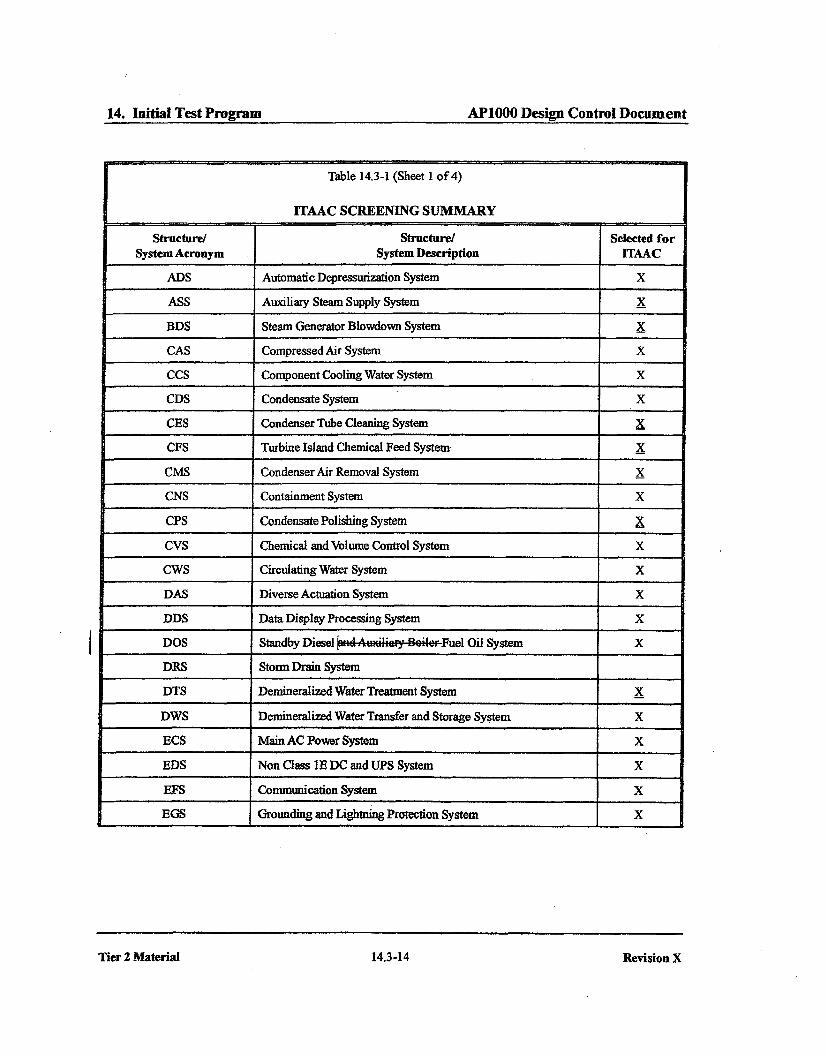
14. Initial Test Program AP1000 Design Control Document
Table 14.3-1 (Sheet 1 of 4)
ITAAC SCREENING SUMMARY
Structure/ Structure/ Selected forSystem Acronym System Description ITAAC
ADS Automatic Depressurization System X
ASS Auxiliary Steam Supply System X
BDS Steam Generator Blowdown System X
CAS Compressed Air System X
CCS Component Cooling Water System X
CDS Condensate System X
CES Condenser Tube Cleaning System X
CFS Turbine Island Chemical Feed System X
CMS Condenser Air Removal System X
CNS Containment System X
CPS Condensate Polishing System X
CVS Chemical and Volume Control System X
CWS Circulating Water System X
DAS Diverse Actuation System X
DDS Data Display Processing System X
DOS Standby Diesel -a A.,_iai-y e,'r-Fuel Oil System X
DRS Storm Drain System
DTS Demineralized Water Treatment System X
DWS Demnneralized Water Transfer and Storage System X
ECS Main AC Power System X
EDS Non Class IE DC and UPS System X
EFS Communication System X
EGS Grounding and Lightning Protection System X
I
Tier 2 Material 14.3-14
Revision X
Tier 2 Material 14.3-14 Revision X

DCPNRC 002874May 21, 2010
ENCLOSURE 7
DCD Pages for Change Numbers 53, 54, and 57
(Public Redacted Version)
05261jb.doc

Change Number 53 A

3. Non-System Based DesignDescrimtions & ITAAC APIOOO Desion Control Document
Security-Related Information, Withhold Under 10 CFR 2.390d
-- SRI
Figure 3.3-11Annex Building Plan View at Elevation 100'-0"

3. Non-System Based DesignDescriptions & ITAAC AP1000 Design Control Document
Security-Related Information, Withhold Under 10 CFR 2.390d
--__ SRI
Figure 3.3-12Annex Building Plan View at Elevation 117 '-6"
3. Non-System Based DesignDescriptions & ITAAC APIO00I Desion Control Document
APIOOO Design Control DocumentSecurity-Related Information, Withhold Under 10 CFR 2.390d ---- 1 SRI
Figure 3.3-13Annex Building Plan View at Elevation 135 -3"

Change Number 53 B
3. Design of Structures, Components,Equipment and Systems AP1000 Design Control Document
-- SRISecurity-Related Information, Withhold Under 10 CFR 2.390d
Figure 3.7.2-19 (Sheet I of 10)
Annex Building Key Structural DimensionsPlan at Elevation 100'-0"
Tier 2 Material
3.7-2 Revision 18
Tier 2 Material 3.7-2 Revision 18

3. Design of Structures, Components,Equipment and Systems APIOO Design Control Document
-- SRISecurity-Related Information, Withhold Under 10 CFR 2.390d
Figure 3.7.2-19 (Sheet 2 of 10)
Annex Building Key Structural DimensionsPlan at Elevation 107'-2" and 117'-6"
Tier 2 Material 3.7-3 Revision 18

3. Design of Structures, Components,Equipment and Systems API000 Design Control Document
SRI
Security-Related Information, Withhold Under 10 CFR 2.390d
Figure 3.7.2-19 (Sheet 3 of 10)
Annex Building Key Structural DimensionsPlan at Elevation 135'-3"
Tier 2 Material 3.7-5 Revision 18

3. Design of Structures, Components,Equipment and Systems APIOOO Design Control Document
i SRI
Security-Related Information, Withhold Under 10 CFR 2.390d
Figure 3.7.2-19 (Sheet 5 of 10)
Annex Building Key Structural DimensionsRoof Plan at Elevation 154'-0" and 181'-II 3/4"
Tier 2 Material 3.7-9 Revision 18
Tier 2 Material 3.7-9 Revision 18
3. Design of Structures, Components,Equipment and Systems API000 Design Control Document
Security-Related Information, Withhold Under 10 CFR 2.390d SRI
Figure 3.7.2-19 (Sheet 6 of 10)
Annex Building Key Structural DimensionsSection A - A
Tier 2 Material 3.7-11 Revision 18

3. Design of Structures, Components,Equipment and Systems API000 Design Control Document
Security-Related Information, Withhold Under 10 CFR 2.390d SRI
Figure 3.7.2-19 (Sheet 7 of 1t)
Annex Building Key Structural DimensionsSection B - B
Tier 2 Material 3.7-13 Revision 18

3. Design of Structures, Components,EGuinment and Svstems APIOOO Desi-n Control Document
-- SRISecurity-Related Information, Withhold Under 10 CFR 2.390d
Figure 3.7.2-19 (Sheet 8 of 10)
Annex Building Key Structural DimensionsSection C - C
Tier 2 Material 3.7-15 Revision 18

Change Number 54
1. Introduction and General Description of the Plant API000 Design Control DocumentSRI
Security-Related Information, Withhold Under 10 CFR 2.390d
Figure 1.2-8
Nuclear Island General ArrangementPlan at Elevation 117-6" & 130'-0"
Tier 2 Material 1.2-1 Revision 18
1. Introduction and General Description of the Plant APIO00 Desian Control Document1. Introduction and General Description of the Plant APIOOO Desien Control Document
Security-Related Information, Withhold Under 10 CFR 2.390d-- SRI
Figure 1.2-9
Nuclear Island General ArrangementPlan at Elevation 117-6" with Equipment
Tier 2 Material 1.2-3 Revision 18

6. Engineered Safety Features AP1000 Design Control Document
Security-Related Information, Withhold Under 10 CFR 2.390d
SRI
Figure 6.4-1
Main Control Room Envelope
Tier 2 Material 6.4-1 Revision 18
9. Auxiliary Systems AP1000 Design Control Document
Security-Related Information, Withhold Under 10 CFR
SRI
Figure 9A-I (Sheet 6 of 16)
[Nuclear Island Fire AreaPlan at Elevation 117'-6"1 *
*NRC Staffapproval is required prior to implemerting a change in this information; see DCD Introduction Section 3.5.
Tier 2 Material 9A-5 Revision 18

12. Radiation Protection AP1000 Design Control Document
Security-Related Information, Withhold Under 10 CFR
SRI
Figure 12.3-1 (Sheet 7 of 16)
Radiation Zones, Normal Operations/ShutdownNuclear Island, Elevation 117'-6"
Tier 2 Material 12.3-3 Revision 18
12. Radiation Protection AP1000Degn ControlDocumnent
Security-Related Information, Withhold Under 10 CFR
SRI
Figure 12.3-2 (Sheet 7 of 15)
Radiation Zones, Post-Accident
Nuclear Island, Elevation 117'-6"
Tier 2 Material 12.3-3 Revision 18

12. Radiation Protection AP1000DewControlDocmuent
Security-Related Information, Withhold Under 10 CFR
SRI
Figure 12.3-3 (Sheet 7 of 16)
Radiological Access Controls, Normal Operations/Shutdown
Nuclear Island, Elevation 117'-6"
Tier 2 Material 12.3-5 Revision 18
Tier 2 Material 12.3-5 Revision 18

Change Number 57
1. Introduction and General Description of the Plant
Security-Related Information, Withhold Under 10 CFR 2.390d
AP1000 Design Control Document
Figure 1.2-9
Nuclear Island General ArrangementPlan at Elevation l17-6" with Equipment
3 Revision 18
SRI
Tier 2 Material 1.2-

DCPNRC 002874May 21, 2010
ENCLOSURE 8
Responses to Action Items from March 17, 2010 Meeting, Non-Proprietary
05261jb.doc
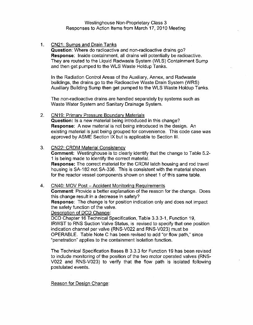
Westinghouse Non-Proprietary Class 3Responses to Action Items from March 17, 2010 Meeting
1. CN21: Sumps and Drain TanksQuestion: Where do radioactive and non-radioactive drains go?Response: Inside containment, all drains will potentially be radioactive.They are routed to the Liquid Radwaste System (WLS) Containment Sumpand then get pumped to the WLS Waste Holdup Tanks.
In the Radiation Control Areas of the Auxiliary, Annex, and Radwastebuildings, the drains go to the Radioactive Waste Drain System (WRS)Auxiliary Building Sump then get pumped to the WLS Waste Holdup Tanks.
The non-radioactive drains are handled separately by systems such asWaste Water System and Sanitary Drainage System.
2. CN19: Primary Pressure Boundary MaterialsQuestion: Is a new material being introduced in this change?Response: A new material is not being introduced in the design. Anexisting material is just being grouped for convenience. This code case wasapproved by ASME Section IX but is applicable to Section II1.
3. CN22: CRDM Material ConsistencyComment: Westinghouse is to clearly identify that the change to Table 5.2-1 is being made to identify the correct material.Response: The correct material for the CRDM latch housing and rod travelhousing is SA-1 82 not SA-336. This is consistent with the material shownfor the reactor vessel components shown on sheet 1 of this same table.
4. CN40: MOV Post - Accident Monitoring RequirementsComment: Provide a better explanation of the reason for the change. Doesthis change result in a decrease in safety?Response: The change is for position indication only and does not impactthe safety function of the valve.Description of DCD Change:DCD Chapter 16 Technical Specification, Table 3.3.3-1, Function 19,IRWST to RNS Suction Valve Status, is revised to specify that one positionindication channel per valve (RNS-V022 and RNS-V023) must beOPERABLE. Table Note C has been revised to add "or flow path," since"penetration" applies to the containment isolation function.
The Technical Specification Bases B 3.3.3 for Function 19 has been revisedto include monitoring of the position of the two motor operated valves (RNS-V022 and RNS-V023) to verify that the flow path is isolated followingpostulated events.
Reason for Design Change:

Westinghouse Non-Proprietary Class 3Responses to Action Items from March 17, 2010 Meeting
DCD Chapter 16 Technical Specification, Table 3.3.3-1 currently requiresthe In - Containment Refueling Water Storage Tank (IRWST) to NormalResidual Heat Removal System (RNS) Suction Valve Status (RNS-V023) tohave two Required Channels/Divisions. Function 19, IRWST to RNSSuction Valve Status, which is equivalent to Function 18, RemotelyOperated Containment Isolation Valve Position, is being revised sinceredundant indication of flow path isolation is provided by one 1 E positionindicator on each of the two valves (RNS-V022 and RNS-V023).
The Technical Specification Bases B 3.3.3 for Function 19 has been revisedto include monitoring of the position of the two motor operated valves (RNS-V022 and RNS-V023) to verify that the flow path is isolated followingpostulated events to prevent loss of IRWST inventory into the RNS.
5. CN47: PRHR Inlet Isolation ValveComment: Westinghouse shall provide a better explanation of this changein order to clarify that this is an errata change and not something thatreduces safety system functionality.Response:Description of DCD Change:Remove the following sentence from DCD 7.6.2.1 describing the PassiveResidual Heat Removal Heat Exchanger Inlet Isolation Valve: to prevent aninadvertent closure of the valve, redundant output cards are used in theprotection and safety monitoring system cabinet.
Reason for Design Chanqe:DCD 6.3.2.2.8.4, Motor-Operated Valve Controls includes the following:Spurious movement of a motor-operated valve due to an electrical fault inthe motor actuation circuitry, coincident with loss of coolant accident, hasbeen analyzed and found to be an acceptably low probability event. Inaddition, power lockout in accordance with Branch Technical Position ICSB-18 is provided for those valves whose spurious movement could result indegraded passive core cooling system performance.
Table 6.3-1 provides a list of the remotely operated isolation valves in thepassive core cooling system. These valves have various interlocks,automatic features, and position indication. Some valves have their controlpower locked out during normal plant operation. Periodic visual inspectionand operability testing of the motor-operated valves in the passive corecooling system confirm valve operability.
Redundant controllers are provided for valves that are normally in thecorrect post-accident position that do not have power removed and lockedout. This valve is normally in the correct post-accident position with powerremoved and locked out; therefore, redundant controllers are not required.

Westinghouse Non-Proprietary Class 3Responses to Action Items from March 17, 2010 Meeting
This design is consistent with the DCD 6.3.2.5.1 and DCD Table 6.3-1 valverequirements.
6. CN38: Loose Parts DetectionComment: Clarify the reason for this change.Response: The reason that NA is not applicable for C.6 has been revisedto be similar to the reason given for C.3.a. Reporting requirements will beaddressed by the COL applicants in accordance with 1OCFR50.72 and50.73 utilizing the guidance of NUREG-1022.
7. CN42: Operating PressureQuestion: The NRC asked that Westinghouse be clearer with respect toconsistency issues and state what is right and what we are being consistentwith.Response: The correct units for operating pressure in this case are psia.
8. CN56: Deletion of "and Auxiliary Boiler" from Figure TitlesComment: The NRC requested better justification. They askedWestinghouse to indicate where in the DCD the correct information is found.Response: The diesel fired boiler was changed to an electric boiler sinceutilities reported problems with fuel fouling in stand-by diesel boilers withsignificant periods of downtime. This design change was incorporated intoDCD-1 7 and necessitated a change to the title of the DOS system fromStandby Diesel and Auxiliary Boiler Fuel Oil System to Standby Diesel FuelOil System everywhere it appears in Tier 1 and 2 of the DCD. These placesincluded: Tier 1 - Master Table of Contents page i; List of Figures, page iv,Sections 1.4 and 2.3.3; Tier 2 - Master Table of Contents page xvi; page3.2-15, Table 3.2-4, Chapter 9 TOC, pages vi and x; Chapter 9 list of figures,page xi; Section 9.5 (several places); Title of Fig 9.5-4 sheets 1, 2, and 3.The list of figures and title of Fig 2.3.3-1 in Tier 1 and title of Table 14.3-1were missed.
9. CN3: Change PRHR Valves from Globe Valve to Ball ValveComment: The NRC asked Westinghouse to confirm that there is nodegradation in safety due to changing PRHR valves from globe to ball type.Response: No new failure modes were introduced by changing from aglobe valve to a ball valve. Both valves are designed to fail open. Changingto the ball valve is an improvement in safety as the stroke time for the ballvalve is less than that of the globe valve. Additionally, the weight of the ballvalve is approximately half of that of the globe valve which is a benefit in theseismic and piping analysis. Finally, with the ball valve design, Class VIshutoff may be achieved. There are no additional or degraded safetyrequirements resulting from this change.
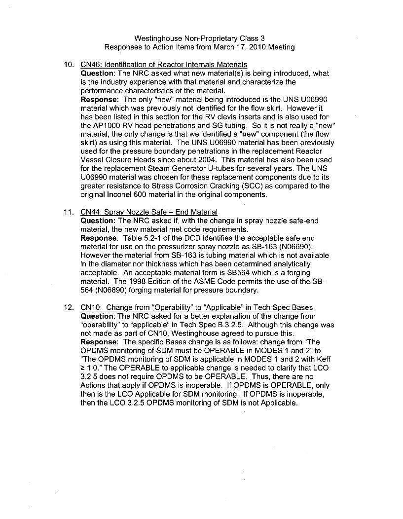
Westinghouse Non-Proprietary Class 3Responses to Action Items from March 17, 2010 Meeting
10. CN46: Identification of Reactor Internals MaterialsQuestion: The NRC asked what new material(s) is being introduced, whatis the industry experience with that material and characterize theperformance characteristics of the material.Response: The only "new" material being introduced is the UNS U06990material which was previously not identified for the flow skirt. However ithas been listed in this section for the RV clevis inserts and is also used forthe AP1000 RV head penetrations and SG tubing. So it is not really a "new"material, the only change is that we identified a "new" component (the flowskirt) as using this material. The UNS U06990 material has been previouslyused for the pressure boundary penetrations in the replacement ReactorVessel Closure Heads since about 2004. This material has also been usedfor the replacement Steam Generator U-tubes for several years. The UNSU06990 material was chosen for these replacement components due to itsgreater resistance to Stress Corrosion Cracking (SCC) as compared to theoriginal Inconel 600 material in the original components.
11. CN44: Spray Nozzle Safe - End MaterialQuestion: The NRC asked if, with the change in spray nozzle safe-endmaterial, the new material met code requirements.Response: Table 5.2-1 of the DCD identifies the acceptable safe endmaterial for use on the pressurizer spray nozzle as SB-163 (N06690).However the material from SB-163 is tubing material which is not availablein the diameter nor thickness which has been determined analyticallyacceptable. An acceptable material form is SB564 which is a forgingmaterial. The 1998 Edition of the ASME Code permits the use of the SB-564 (N06690) forging material for pressure boundary.
12. CN10: Change from "Operability" to "Applicable" in Tech Spec BasesQuestion: The NRC asked for a better explanation of the change from"operability" to "applicable" in Tech Spec B.3.2.5. Although this change wasnot made as part of CN10, Westinghouse agreed to pursue this.Response: The specific Bases change is as follows: change from "TheOPDMS monitoring of SDM must be OPERABLE in MODES 1 and 2" to"The OPDMS monitoring of SDM is applicable in MODES 1 and 2 with Keff> 1.0." The OPERABLE to applicable change is needed to clarify that LCO3.2.5 does not require OPDMS to be OPERABLE. Thus, there are noActions that apply if OPDMS is inoperable. If OPDMS is OPERABLE, onlythen is the LCO Applicable for SDM monitoring. If OPDMS is inoperable,then the LCO 3.2.5 OPDMS monitoring of SDM is not Applicable.