Service Bulletin - Regulations.gov
169
Commercial Airplane Group 727 Service Bulletin Number: 727-57-0112 Revision Transmittal Sheet Date: September 2, 1970 Revision 5: July 31, 1997 ATA System: 5712 SUBJECT: WINGS - RIB UPPER CHORD AT BL 70.5 - INSPECTION, MODIFICATION, AND REPAIR This revision includes all pages of the service bulletin. COMPLIANCE INFORMATION RELATED TO THIS REVISION No more work is necessary on airplanes changed by Revision 4 of this service bulletin. More work is necessary on Group 1 airplanes changed by Revisions 2 or 3, Part V of the Accomplishment Instructions of this service bulletin. On Group 1 Airplanes with the Major Repair/Preventive Modification installed, it is necessary to make an inspection at BL 70.5 for a repair strap. If a strap is not installed, it is necessary to make an inspection of the frame for cracks. SUMMARY This revision is sent to tell operators that new kits are available for Group 1 and 2 Airplanes. The drawings used to install the kits are sent with this revision (the drawings have been revised since the release of Notice of Status Change 3). The format used to show the removal of parts and installation of the kits has changed. Also repairs, that operators have requested, are included, and the compliance information has been clarified. This revision is sent to tell the 727 airplane operators that this service bulletin has been identified by the 727 Structures Working Group (SWG), and the structural change and inspection given in this service bulletin are recommended to be included on applicable 727 airplanes. The change and inspection given in this service bulletin must be included at the times given in the Description and Accomplishment Instructions. As a result of the Aging Fleet Conference held by the FAA, the 727 SWG was made and included 727 airline operators from a large part of the high time 727 fleet, persons from the Boeing Company, and monitors from the FAA. The SWG examined the structural changes and inspections given in applicable Boeing service bulletins. A selection of these service bulletins was made that contain structural changes and inspections that are important to the continued structural airworthiness of 727 airplanes. The structural changes given in these service bulletins are recommended to be included, and the inspections are recommended to be a part of the regularly scheduled maintenance on applicable 727 airplanes. The data given in Notice of Status Change 727-57-0112 NSC 1, 2 and 3 are included in this revision. Paragraph I.A., Effectivity, shows changes of airplane operators. Each operator should examine the Effectivity paragraph for changes. Vertical lines are put on the left edge of each page, except in Paragraph I.A., Effectivity, to show the location of important changes. Pages with a revision number and date, but no vertical lines, have no important changes. REVISION HISTORY Initial Release: September 2, 1970 Revision 1: April 23, 1976 Revision 2: May 19,1988 Revision 3: December 21, 1989 Revision 4: October 29, 1992 Revision 5: July 31, 1997 BOEING COMMERCIAL AIRPLANE GROUP P.O. BOX 3707 SEATTLE, WASHINGTON 98124-2207
-
Upload
khangminh22 -
Category
Documents
-
view
0 -
download
0
Transcript of Service Bulletin - Regulations.gov

CommercialAirplaneGroup
727Service Bulletin
Number: 727-57-0112 Revision Transmittal SheetDate: September 2, 1970Revision 5: July 31, 1997ATA System: 5712
SUBJECT: WINGS - RIB UPPER CHORD AT BL 70.5 - INSPECTION, MODIFICATION, AND REPAIR
This revision includes all pages of the service bulletin.
COMPLIANCE INFORMATION RELATED TO THIS REVISION
No more work is necessary on airplanes changed by Revision 4 of this service bulletin.
More work is necessary on Group 1 airplanes changed by Revisions 2 or 3, Part V of the AccomplishmentInstructions of this service bulletin. On Group 1 Airplanes with the Major Repair/Preventive Modificationinstalled, it is necessary to make an inspection at BL 70.5 for a repair strap. If a strap is not installed, it isnecessary to make an inspection of the frame for cracks.
SUMMARY
This revision is sent to tell operators that new kits are available for Group 1 and 2 Airplanes. The drawingsused to install the kits are sent with this revision (the drawings have been revised since the release of Noticeof Status Change 3). The format used to show the removal of parts and installation of the kits has changed.Also repairs, that operators have requested, are included, and the compliance information has been clarified.
This revision is sent to tell the 727 airplane operators that this service bulletin has been identified by the 727Structures Working Group (SWG), and the structural change and inspection given in this service bulletin arerecommended to be included on applicable 727 airplanes. The change and inspection given in this servicebulletin must be included at the times given in the Description and Accomplishment Instructions.
As a result of the Aging Fleet Conference held by the FAA, the 727 SWG was made and included 727 airlineoperators from a large part of the high time 727 fleet, persons from the Boeing Company, and monitors fromthe FAA. The SWG examined the structural changes and inspections given in applicable Boeing servicebulletins. A selection of these service bulletins was made that contain structural changes and inspectionsthat are important to the continued structural airworthiness of 727 airplanes. The structural changes given inthese service bulletins are recommended to be included, and the inspections are recommended to be a partof the regularly scheduled maintenance on applicable 727 airplanes.
The data given in Notice of Status Change 727-57-0112 NSC 1, 2 and 3 are included in this revision.
Paragraph I.A., Effectivity, shows changes of airplane operators. Each operator should examine theEffectivity paragraph for changes.
Vertical lines are put on the left edge of each page, except in Paragraph I.A., Effectivity, to show the locationof important changes. Pages with a revision number and date, but no vertical lines, have no importantchanges.
REVISION HISTORY
Initial Release: September 2, 1970 Revision 1: April 23, 1976 Revision 2: May 19,1988Revision 3: December 21, 1989 Revision 4: October 29, 1992 Revision 5: July 31, 1997
BOEING COMMERCIAL AIRPLANE GROUP P.O. BOX 3707 SEATTLE, WASHINGTON 98124-2207


CommercialAirplaneGroup
727Service Bulletin
Number: 727-57-0112 SummaryDate: September 2, 1970Revision 5: July 31, 1997ATA System: 5712
SUBJECT: WINGS - RIB UPPER CHORD AT BL 70.5 - INSPECTION, MODIFICATION, AND REPAIR
BACKGROUND
The Structures Working Group (SWG) hasexamined the structural change and inspection inthis service bulletin, and recommends that thechange and inspection be included on 727airplanes.
During a 727 primary fatigue test at Boeing, twocracks were found in the upper vertical flange of thewing-to-body rib upper chord at Body Station 760.One crack in the rib upper chord was between thetwo aft fastener holes of the frame at Body Station760.95. The other crack in the rib upper chord wasimmediately aft of the lower fastener hole in theframe.
To increase the fatigue life of the rib chord and toreduce the risk of repair and maintenance notscheduled, make the change given in this servicebulletin.
ACTION (PRR 24791-R and PRR 24803-R)
As recommended by the 727 SWG, make thePreventive Modification or Large Repair structuralchange given in the Accomplishment Instructions ator before the airplane collects a total of 60,000flights, and make the inspection given in theAccomplishment Instructions, Part II.A.1, Inspection,at or before the airplane collects a total of 14,000flights, or within 3,000 flights, whichever occurslater.
If no cracks are found, increase the hole diameter,cold work the hole, and install a new fastener in sixplaces. Continue the inspection at regularlyscheduled times as given in the AccomplishmentInstructions, Part II.A.2, or B.1, Inspection. Theapproved time between one inspection and thesubsequent inspection must not be more than14,000 flights. To stop the inspection given in thisservice bulletin, do the preventive modification orlarge repair.
If cracks are found, make a change to the rib upperchord as given in this service bulletin.
EFFECTIVITY
All 727 airplanes, divided into 2 groups.
MANPOWER
See Service Bulletin
MATERIAL INFORMATION
Boeing supplied kits and Operator supplied Parts.Refer to Paragraph I.G., Material - Price andAvailability.
BOEING COMMERCIAL AIRPLANE GROUP P.O. BOX 3707 SEATTLE, WASHINGTON 98124-2207 Summary Page 1 of 2

BOEING SERVICE BULLETIN 727-57-0112
STA
660
760.95
STA
STA
870
970
STA
MODIFICATION OR REPAIR
INSTALL PREVENTIVE
RIB UPPER CHORD
INSPECT 6 FASTENER
HOLES IN WING−TO−BODY
R44683
Sep 2/70REV 5: Jul 31/97 Summary Page 2 of 2

CommercialAirplaneGroup
727Service Bulletin
Number: 727-57-0112Date: September 2, 1970Revision 5: July 31, 1997ATA System: 5712
SUBJECT: WINGS - RIB UPPER CHORD AT BL 70.5 - INSPECTION, MODIFICATION, AND REPAIR
I. PLANNING INFORMATION
A. Effectivity
1. Airplanes
Refer to Service Bulletin Index Document D6-9825, Part 3 for Airplane Variable Number, LineNumber, and Serial Number data.
IDENTIFICATION BY CUSTOMER, CUSTOMER CODE, GROUP AND VARIABLE NUMBER
A.J. WALTER AVIATION LTD (AJW)1 E0210 E3343
ACES (ACE)1 E3781 E3783 QA633 QB619 QD031 QD5042 QD904
ADC AIRLINES (ADN)1 QA517 QA521
AECA AIRLINES (AED)1 E0341
AERO CONTROLS, INC (AEO)1 QA415 QA418 QA422
AERO COSTA RICA (AOR)1 E0305
AERO PERU (PER)1 E3286-E3288 QA040 QD6072 QD685
AERO REPUBLICA (REU)1 E3146 E3149
AERO UNION (AUC)1 E0328
AEROCAR AVIATION CORPORATION (AAH)1 QA872 QA874 QA917
Sep 2/70 727-57-0112REV 5: Jul 31/97 Page 1 of 163

BOEING SERVICE BULLETIN 727-57-0112
AEROEJECUTIVO (AEJ)1 E0404 E0423 QA225 QA608 QA611 QA628
QA632 QD001 QD004 QD007-QD012
AEROLINEAS ARGENTINAS (ARG)1 E3222 QD603
AEROLINEAS CARGUERAS S.A. (AEROCAR) (CRQ)1 E3071 E3575
AEROLINEAS INTERNACIONALES (MXC)1 E0325 E0334 QA129
AEROMEXPRESS (MEX)2 QD972
AERON EQUITIES CORP (AAV)1 E3148 QA618 QA622
AEROSUCRE S.A. (SUS)1 E0346 E3221 E3402 QA021
AEROSUR S.A. (REO)1 E0312 E0332 E0345
AGASSI ENTERPRISES (AGA)1 E3420
AIMS LTD (MES)1 E0212
AIR ALFA (ALV)1 QB102
AIR ALGERIE (ALG)1 QA574-QA576 QB451-QB458
AIR ATLANTIC NIGERIA LTD (NGE)1 E0041
AIR COLOMBIA (CLM)1 E3519
AIR DABIA (DBI)1 QA701
AIR FRANCE (AFA)1 QA5622 QD764-QD765
AIR GABON S.A. (GBN)2 QD763
AIR JAMAICA (JAM)2 QD282-QD283
AIR NACOIA LDA (NAO)1 E5114 QA871
Sep 2/70 727-57-0112REV 5: Jul 31/97 2

BOEING SERVICE BULLETIN 727-57-0112
AIR SLOVAKIA (SLO)1 QB103-QB104
AIR TRANSPORT OFFICE (TOZ)1 QA501
AIR 4000 INC (FTO)1 QA333
AIRCRAFT MANAGEMENT COMPANY LTD (AMI)1 E3509
AL-ANWA EST. (SVE)2 QD407
AL-ATHEER EST (ALN)1 E3410
ALLCANADA EXPRESS LTD. (EXM)1 E36522 QD662-QD663
ALLEGRO AIR (AEG)1 QA675 QA902 QA906
AMERICAN AIRLINES, INC. (AAL)1 QA114 QA119-QA120 QA123-QA124 QA136 QA142-QA149 QA158-QA199
QA854 QA856-QA869 QB801-QB810
AMERICAN INTERNATIONAL AIRWAYS, INC. (CKF)1 E0336 E5050 QA107-QA109 QA111-QA113 QA117 QA132
QA135 QA139 QA155 QA157 QA705
AMERICAN TRANS AIR (AAT)1 QA374-QA376 QA378 QA928 QB066-QB068 QB618 QB620-QB623
QB625-QB628 QD702 QD7912 QD683 QD951-QD952
AMERICANA DE AVIATION S. A. (AMY)1 E3751 QB305
AMERIJET INTERNATIONAL, INC. (AMJ)1 E0344 E3028 E3145 E5161 E5403 QA336
QA727 QA875 QA8862 QD206 QD211-QD212 QD781
AMWAY CORPORATION (AMA)1 E3681
ANGOLA AIR CHARTER (AOH)1 E0333
ANSETT AUSTRALIA (ANS)1 QD034 QD0402 QD043-QD046
Sep 2/70 727-57-0112REV 5: Jul 31/97 3

BOEING SERVICE BULLETIN 727-57-0112
ARIANA AFGAN AIRLINES CO., LTD (AFG)1 E5410 E54242 QD767-QD768
ARRIVA AIR INTERNATIONAL (ARV)1 QA002
ASIAN EXPRESS AIRLINES (EXZ)2 QL007
ATASCO USA, INC. (ATJ)1 E0032 QB301-QB304
AVENSA (AVN)1 E0034 E0036 E3072 E3244 E3246 E3248
E3511 E3654 QA036 QA039 QA042-QA043 QA853QD121 QD124-QD126 QD444
AVIANCA (AVI)1 QA572 QD553-QD554
AVIATION CAPITAL CORPORATION (ACD)1 E0039
AVIATION LEASING GROUP (ALW)1 E0317
AVIATION PROFESSIONAL CORP (PRP)1 QA630-QA631
AVIOGENEX AIR TRANSPORT (AVG)1 QD191-QD192 QD518
AZERBAIJAN AIRLINES (BAKU) (AHY)1 QA211-QA212
BAHRIAN AMRI FLIGHT (BHR)1 QD451
BAKRIE AVIATION INC. (FES)1 E3346
BELGIAN AIR FORCE (BLG)1 E5351-E5352
BIN MAHFOOZ AVIATION (BMV)1 QA566-QA567
BLENHEIM AVIATION (BLM)1 QD305
BRADLEY AIR SERVICES/FIRST AIR (BRS)1 E3065 E5112 E5141 E5482 QA6142 QD207 QD210
C-S AVIATION SERVICES INC. (CSV)1 E0302-E0303 E0307 E0315 E0320 E0326
Sep 2/70 727-57-0112REV 5: Jul 31/97 4

BOEING SERVICE BULLETIN 727-57-0112
CAPITAL CARGO AIRLINES (CCA)1 QA371 QD087 QD701
CAPRICORN FLIGHTS (CPR)1 E3075 E3520
CARNIVAL AIR (CVL)1 QA636 QA641 QD3042 QD822-QD823 QD953
CHINESE AIR FORCE (CAF)1 E3506 E3512 E5409 E5435
CIS AIR HOLDINGS, LTD. (CIS)1 QA718 QA721-QA722
CLAY LACY AVIATION, INC. (CYA)1 E3035 E3077
COMPAGNIE AERIENNE BELAIR ILE DE FRANCE (SMH)1 QA573
CONNOR AIRCRAFT (COD)1 QA366
CONSTELLATION INTERNATIONAL AIRLINES (COT)2 QD782
CONTINENTAL AIRLINES, INC. (CAL)1 QA020 QA059-QA061 QA063-QA065 QA067 QA069-QA072 QA331
QA339-QA342 QA345-QA349 QA873 QA882 QA885 QA890-QA896QB034 QB036 QB039-QB040 QB901-QB904 QD501-QD502 QD505QD507-QD510
2 QD905 QD909 QD931-QD932
CONTINENTAL AVIATION SERVICES INC. (CVS)1 E3407
COOK AIRCRAFT LEASING (CKL)1 E3504-E3505
CORP AIR INC. (EKO)1 E5418
CORSAIR (CRA)1 E3011 E3508
CUSTOM AIR SERVICES INC. (CUS)1 E3205 QA343 QA661
CYPRUS TURKISH AIRWAYS (KHT)1 QD321-QD322 QD3242 QD766
D. J. AEROSPACE (DJA)1 E0351
Sep 2/70 727-57-0112REV 5: Jul 31/97 5

BOEING SERVICE BULLETIN 727-57-0112
DALLAH AVCO (AVO)1 E3038
DALLAS AEROSPACE, INC. (DAA)1 QA358
DAVIS OIL CO. (DOC)1 E3206
DELTA AIR LINES, INC. (DAL)1 QA073-QA079 QA081-QA092 QA096-QA099 QA647 QA649 QA663-QA665
QA907 QA909-QA916 QA919-QA921 QA929-QA933 QA939-QA946 QA949QB501-QB558 QB560-QB575
DHL CORPORATION/WORLDWIDE COURIER EXP. (DHL)1 E0030 E0124 E0342 E3622 E5046-E5047 E5273-E5274
E5281 E5382 E5402 QA552-QA553 QA555-QA556 QA563-QA564QA646
2 QD991-QD992
DHL LATIN AMERICA GROUP AIRLINES (DHA)1 E3073 QB038
DIGEX AERO CARGO (DGX)1 E5481
DOMINICANA AIRLINES (DOM)1 E3755 QD351
EAS EUROPE AIRLINES (EUR)1 QA855
EASTERN AIR LINES, INC. (EAL)1 QA643
ECUATORIANA AIRLINES (ECU)1 QD445 QD604
EMERY WORLDWIDE AIRLINES (EAF)1 E0313-E0314
EUROPEAN AIR TRANSPORT (EPT)1 E3074 E3076 E3701-E3703 QA115 QA137 QA150-QA152
QA156 QB307
EUROPEAN AVIATION AIR CHARTER LTD (EUL)1 E3022
EVERGREEN INTERNATIONAL AIRLINES (EVR)1 E3101 E3151 E3276 E5104-E5105 E5108
EXPRESS ONE INTERNATIONAL, INC. (EOI)1 E0421-E0422 E3117 E3347-E3348 E3350 E3602 QA014
QA062 QA101 QA116 QA121 QA125-QA127 QA138QA140-QA141 QA656 QA713 QB624 QD032 QD441QD453
2 QD821 QD824-QD826
Sep 2/70 727-57-0112REV 5: Jul 31/97 6

BOEING SERVICE BULLETIN 727-57-0112
FALCON AIR EXPRESS (FAX)1 QA329 QA716
FAMCO AVIATION AND MARITIME SERVICES LTD (FAM)1 E5353
FAUCETT (COMPANIA DE AVIATION S.A. (FCT)1 E3068 QA901 QB042
FEDERAL AVIATION ADMINISTRATION (FAA)1 E5241
FEDERAL EXPRESS (FED)1 E0120 E0122-E0123 E0125-E0129 E0131-E0132 E0134-E0138 E3256-E3261
E3263-E3274 E3277-E3281 E3283 E3290 E5048-E5049 E5052-E5054E5056-E5057 E5063 E5067 E5101-E5102 E5163-E5164 E5221-E5224E5226 E5230 E5233-E5234 E5238-E5240 E5242 E5408E5420 E5454 QA093-QA095 QA644-QA645 QA648 QA650QA653 QA658 QA677 QA679-QA680 QA897-QA899 QA922-QA926QB601-QB617 QD035-QD039 QD041-QD042
2 QD201-QD205 QD208-QD209 QD213-QD239 QD691-QD692 QL501-QL515
FINOVA (GRB)1 QA627
FIRST SECURITY BANK OF UTAH (FSB)1 QA335 QB114
FLY LINHAS AEREAS (FLF)1 QA579 QA585
FORBES, INC. (FRB)1 E3655
FUNAIR (FUN)1 E3419
GE CAPITAL AVIATION SERVICES, INC. (GEH)1 E0038 E0040 E3241 E3245 E3247 E3253
QA206 QA304 QA306 QA310 QA313-QA314 QA325QA328
GENERAL AVIATION PTY LTD (GEL)1 QB316
GEORGETOWN AIRCRAFT SERVICES (GEO)1 E0216
GLENHOLME ENTERPRISES INC. (GLE)1 E3144
GLOBAL AIRCRAFT SALES (GAC)1 QA057 QA851
GM AIRLINES (GMA)1 QB110
Sep 2/70 727-57-0112REV 5: Jul 31/97 7

BOEING SERVICE BULLETIN 727-57-0112
GOMAIR (GOM)1 E3753
GOVERNMENT OF SENEGAL (SEN)2 QD402
GOVT. OF BURKINA FASO (HTV)1 E3176
GPA GROUP LTD. (GUI)1 QB037 QD571
GRAND HOLDINGS (GRD)1 E3510 QA105 QA122 QA337-QA338
HAPAG LLOYD (HAP)1 E3114
HCL AVIATION, INC. (HCL)1 E0308 E0316 E0324 E0338 QA638 QA671
QD5812 QD902 QD954
HMS AIRWAYS (HSA)1 E30052 QD401
HOLIDAY AIR (HOI)1 QA642
HUNTING CARGO AIRLINES INC. (HCA)1 QA022 QA033 QA037 QA106 QA118 QA131
QA133 QA615 QA888 QD506
IBERIA (LINEAS AEREAS DE ESPANA S.A.) (IBE)1 QB124 QB127 QB129-QB133 QB135-QB145 QB147-QB149 QB151-QB153
QB155-QB158
IDG (CAYMAN) LTD (IDG)1 E3150
IMPERIAL PALACE AIR LTD. (IPA)1 E0213
INTER AIR (ITI)1 E0318-E0319
INTERNATIONAL AIR LEASES (IAL)1 QA673-QA674 QA676 QA918
INTERNATIONAL AIRLINE SUPPORT GROUP (ASG)1 E0202 E0205
INTERNATIONAL PACIFIC TRADING CO. (IPT)1 E3032-E3033 E3069 E3289
Sep 2/70 727-57-0112REV 5: Jul 31/97 8

BOEING SERVICE BULLETIN 727-57-0112
IRAN AIR (IRN)1 E0204 E3118 E3472-E3473 QD101-QD1042 QD761-QD762
IRAQI AIRWAYS (IRQ)2 QD421-QD426
ISLENA DE AVIACION (ISD)1 E3345 QA704 QB002
ISTANBUL AIRLINES (IST)1 QA557-QA558 QB310-QB314
ITAPEMIRIM TRANSPORTES AEREOS S.A. (ITP)1 E3152 E3344 E5279 E5406 QA678 QD583
JET AVIONICS SYSTEMS INC (JAV)1 QA602
JETAIR TRADING & LEASING INT'L, INC. (JTL)1 QB033
JUGOSLOVENSKI AEROTRANSPORT (JAT)1 QD142-QD149
KABO AIR LIMITED (KAB)1 E0103 E0107 QA019 QA330 QA332 QA334
QA604 QA620
KELOWNA FLIGHTCRAFT AIR CHARTER LTD. (KEL)1 E5001 E5059-E5062 E5201 E5228-E5229 E5428 QA359
QA609-QA610 QA870 QA876 QA879-QA880 QA883-QA884
KITTY HAWK AIR CARGO, INC. (KHC)1 QA110 QA128 QA134 QA153-QA154 QA344 QA372-QA373
QA728-QA7292 QD281 QD284
KIWI INTERNATIONAL AIR LINES (KIW)1 QA629 QA635 QA637 QA639-QA640 QA654-QA655 QA657
QA708-QA709 QA714 QB115
KUWAIT AIRWAYS CORPORATION (KUW)2 QD801
LAKER AIRWAYS (LAK)1 QD085-QD086
LEAR ASTRONICS (LEA)1 QA411
LIBYAN ARAB (LAA)1 QA316 QA318-QA322 QB6512 QA323-QA324
LINEAS AEREAS CANARIAS (LCI)1 QD601-QD602
Sep 2/70 727-57-0112REV 5: Jul 31/97 9

BOEING SERVICE BULLETIN 727-57-0112
LINEAS AEREAS SURAMERICANAS (LAR)1 E0119 E5451 E5453
LLOYD AERO BOLIVIANO (LAB)1 E3102 E3522 E5421 QD1612 QD162-QD163 QL006
LUFTHANSA CARGO INDIA PRIVATE LTD (LUI)1 QD512-QD513 QD516-QD517
MEXICAN AIR FORCE (MXA)1 E3171-E3172 E3175
MEXICANA (CMA)1 QA041 QB043-QB049 QB051-QB058 QB060-QB064 QD556-QD557 QD605
MEXICARGO (MXO)1 QA616
MIAMI AIR INTERNATIONAL INC. (MIB)1 QA659-QA660 QA662 QA669-QA670 QA6722 QB219
MIBA MINING CO. (MIZ)1 E3275
MID EAST JET INC (SKL)1 E3421
MILLION AIR (MIL)1 E0301 E0322 E0329-E0330
MMG AVIATION (MME)1 E0209
MONGOLIAN AIRLINES MIAT (MNG)1 QA015 QA034-QA035
NATIONAL AIRLINES (NAW)1 QD446
NATIONS AIR EXPRESS (NAX)1 QA504
NATIONWIDE AIR (NWR)1 E3517 E3573
NEW ACS LIMITED (NEC)1 QA355
NIGERIA, GOV OF (NGA)2 QL081
NOMADS, INC. (NOM)2 QD827
NORTHERN AIR CARGO (NAC)1 E0340
Sep 2/70 727-57-0112REV 5: Jul 31/97 10

BOEING SERVICE BULLETIN 727-57-0112
NORTHWEST AIRLINES, INC. (NWA)1 QA651-QA652 QA667-QA668 QA681-QA684 QA686 QA706 QA725
QA734-QA743 QA745-QA753 QD442 QD447-QD4492 QD711-QD717
OCCIDENTAL PETROLEUM CORP (OCP)1 E3004
OKADA AIR (OKD)1 QA703 QB116 QB308
OLYMPIC AIRWAYS (OLY)1 QA001 QA801-QA805 QB117-QB118 QB309
OMNI AIR EXPRESS (OAX) (OAE)1 E5142 QA427-QA428
ORCA BAY AVIATION (OBA)1 QA066
ORIENT EXPRESS (CAK)1 QA606 QA626 QA889
PACIFIC AIR EXPRESS AUSTRALIA PTY LTD (PAE)1 QA044
PACIFIC INTERNATIONAL AIRLINES, S.A. (PCF)1 E0304 E0310
PANAGRA AIRWAYS (PAG)1 E0349
PANAVIA (PVI)1 E3341
PEGUSUS CAPITAL CORPORATION (PSS)1 QA024 QA702 QA720 QA723 QD088 QD450
QD606
PLM TRANSPORTATION EQUIPMENT CORP. (PLI)1 QA711
PRECISION AIR LTD (PRT)2 QD906
PRESTIGE AIRWAYS (PAR)1 QA505 QA518 QA523 QA581
QATAR AIRWAYS (QTA)1 QB065 QD452 QD5722 QD475
QATAR AMIRI FLIGHT (QAT)2 QD403
QUAKER COAL COMPANY (QCC)1 E3014 QA045-QA046 QA068
Sep 2/70 727-57-0112REV 5: Jul 31/97 11

BOEING SERVICE BULLETIN 727-57-0112
R. B. HARIRI (RBH)2 QD973 QE002
RATHEON E-SYSTEMS INC (ESM)2 QD908
REEVE ALEUTIAN AIRWAYS, INC. (RVV)1 E5035 E5040
RELIANCE GROUP, INC. (RGI)1 E3285
REPUBLIC OF CAMEROON (CMR)2 QD410
REPUBLIC OF ZAIRE (ZAR)1 E0214
ROTHSCHILD AUSTRALIA AIRCRAFT LEASING (ROI)1 E5501
ROYAL AIR MAROC (RAM)1 QA583-QA584
ROYAL AIRLINES (ROY)1 QB035 QD0332 QD903 QL003 QL008 QL031-QL032
ROYAL NEW ZEALAND AIR FORCE (RNZ)1 E5065 E5068
RYAN INTERNATIONAL AIRLINES (RYN)1 E0418 E0420 E3003 E3201 E3411 E3415-E3418
E5003 E5007-E5011 E5031-E5032 E5039 E5041-E5042 E5058E5381 E5411 E5413 E5415 E5433 E5483E5502 QA416 QA419-QA421 QA423-QA426 QA666
SABRE AIRWAYS (SBE)1 QD005 QD123
SAETA S.A. (SAE)1 E0414 E3576 QA733 QA744 QD302
SAFAIR FREIGHTERS (PTY) LTD. (SFA)1 E0331 QB106 QB108 QB119 QB351-QB3522 QD661 QD971
SAMCO (SMO)1 E3604
SCIBE-AIRLIFT KINSHASA (SAK)1 E0208 E3451
SEAGREEN AIR TRANSPORT (SEG)1 E0104 E0211 E5419
SERVICIOS AEREOS NACIONALES, S.A. (SAN)1 E3684
Sep 2/70 727-57-0112REV 5: Jul 31/97 12

BOEING SERVICE BULLETIN 727-57-0112
SIGAIR (SIG)1 E0207
SKY TREK (SKY)1 QA717 QB107 QD006
SKYLINE INTERNATIONAL, LTD. (SKT)1 E3006
STARCOM LTD (STK)1 QA369-QA370
STELLAR AVIATION (STL)1 E0347
STERLING EUROPEAN AIRLINES (STR)1 QD4432 QD164 QD427 QD684 QD907 QL001
SUN COUNTRY AIRLINES (SCA)1 QA687-QA688 QA710 QB629 QD303 QD555 QD558
QD5822 QL002 QL004-QL005
SUN PACIFIC INTERNATIONAL (SUI)1 E3452 QA877 QA881 QD5032 QD828
SUNWORLD INTERNATIONAL AIRLINES (SUO)1 QA732
SYRIAN ARAB AIRLINES (SYR)1 QD471-QD4732 QD802-QD804
TAESA (TES)1 E0035 E0311 E0348 E0413 E3024 E3174
E3553 E5455
TATARSTAN FLIGHT LTD. (TAK)1 E3507
THE AGES GROUP (AGJ)1 QB101
THE K. B. A. FOUNDATION (KBA)1 E3574
THE LIMITED, INC. (LII)1 E3704
TOP AIR (TOP)1 QD325 QD330 QD511
TRACINDA CORPORATION (TRD)1 E3284
Sep 2/70 727-57-0112REV 5: Jul 31/97 13

BOEING SERVICE BULLETIN 727-57-0112
TRANS WORLD AIRLINES, INC. (TWA)1 E0406-E0408 E0412 E0416-E0417 E0419 QA502 QA509-QA515
QA519-QA520 QA522 QA525-QA527 QA529-QA537 QB201-QB2032 QB204-QB218 QB220
TRANSAFRIK (TCL)1 E0335 E0343 E3025 E3242 E3577 E3601
TRANSMERIDIAN AIRLINES (TAL)1 QA730-QA731
TRANSPORTES AEREOS MILITAR EQUATORIANOS (TAM)1 E3513 E3516 E3682 QB105 QB109 QB3152 QD741
TRANSPORTES AEREOS PRESIDENCIALES (MXG)1 E3037
TRANSTEL S.A. (TTL)1 QA508 QD514
TRIANGLE AIRCRAFT SERVICES CORP. (TRI)2 QD910
TRIAX AIRLINES (TIX)1 E3603 QB031
TRITON ENERGY (TRY)1 E0206
TUNISAIR (TUN)1 QA571 QB401-QB405 QB407
TUR EUROPEAN AIRWAYS (TOU)1 QB306
TURKISH AIRLINES (THY)1 QD327-QD329
UNITED AIR LINES, INC. (UAL)1 QA401-QA402 QA404-QA405 QA408 QA429-QA473 QA475-QA499 QB701-QB705
UNITED PARCEL SERVICE (UPS)1 E5002 E5004-E5006 E5033-E5034 E5036 E5038 E5043-E5045
E5051 E5106-E5107 E5109-E5111 E5113 E5115-E5116 E5162E5225 E5227 E5231-E5232 E5235-E5237 E5243-E5245 E5251-E5252E5271 E5275-E5276 E5280 E5301-E5306 E5401 E5405E5417 E5422-E5423 E5426-E5427 E5429 QA927 QA934-QA938QD551-QD552
UNITED STATES AIR FORCE (USF)1 E3061 E3063 E3066-E3067
UNITED STATES MARSHAL'S SERVICE (USV)1 E0215 E3059 QA726
Sep 2/70 727-57-0112REV 5: Jul 31/97 14

BOEING SERVICE BULLETIN 727-57-0112
USAIR SHUTTLE (TSI)1 QA010-QA012 QA017-QA018 QA617 QA619 QA623 QA625
QA878 QA8872 QD474
USAIR, INC. (USA)1 QA026-QA028 QA030-QA0322 QD681-QD682
USAL, LTD. (ULL)1 E3523
VALLEJO CORPORATION (VAC)1 E3683
VARIG AIRLINES (VAR)1 E3752 E3754 E5272 E5407 E5412
VASP (VSP)1 QB041 QD515
VIASA AIRWAYS (VIA)1 QB123 QB125-QB126 QB128 QB134
VICA - VIACAO CHARTER AEREA LTDA (TCT)1 QA908
WEDGE TRANSPORTATION (WST)2 QE001
WESTFIELD AVIATION LTD. (WEF)1 E0350
WETRAFA AIRLIFT (WET)1 E0140
WILMINGTON TRUST CO. (WTC)1 QA601 QA603 QA605 QA612-QA613 QA624
YEMEN AIRWAYS (YEM)2 QD621-QD624 QD641
Sep 2/70 727-57-0112REV 5: Jul 31/97 15

BOEING SERVICE BULLETIN 727-57-0112
IDENTIFICATION BY VARIABLE NUMBER
GROUP 1E0001-E0042 E0101-E0140 E0201-E0216 E0301-E0351 E0401-E0423 E3001-E3006E3011-E3014 E3021-E3040 E3059 E3061-E3077 E3101-E3103 E3111-E3118E3141-E3152 E3171-E3177 E3201-E3206 E3221-E3224 E3241-E3290 E3341-E3350E3401-E3421 E3451-E3452 E3471-E3474 E3501-E3513 E3516-E3523 E3551-E3553E3571-E3578 E3601-E3604 E3621-E3622 E3651-E3655 E3677 E3681-E3684E3701-E3704 E3751-E3755 E3781-E3784 E5001-E5011 E5031-E5068 E5101-E5116E5141-E5143 E5161-E5164 E5201-E5203 E5221-E5245 E5251-E5252 E5271-E5281E5301-E5306 E5351-E5353 E5381-E5382 E5401-E5424 E5426-E5429 E5433E5435 E5451-E5455 E5481-E5483 E5501-E5502 QA001-QA046 QA051-QA099QA101-QA199 QA201-QA225 QA301-QA322 QA325-QA349 QA351-QA376 QA378QA401-QA499 QA501-QA537 QA551-QA579 QA581-QA585 QA601-QA688 QA701-QA753QA801-QA805 QA851-QA899 QA901-QA946 QA949 QB001-QB002 QB031-QB049QB051-QB068 QB101-QB110 QB114-QB119 QB121-QB149 QB151-QB158 QB201-QB203QB301-QB316 QB351-QB352 QB401-QB407 QB451-QB458 QB501-QB575 QB601-QB629QB651 QB701-QB705 QB801-QB810 QB901-QB904 QD001-QD012 QD031-QD042QD085-QD088 QD101-QD105 QD121-QD127 QD141-QD149 QD161 QD191-QD192QD301-QD305 QD321-QD330 QD351 QD441-QD453 QD471-QD473 QD501-QD518QD551-QD558 QD571-QD572 QD581-QD583 QD601-QD607 QD701-QD702 QD791
GROUP 2QA323-QA324 QB204-QB220 QD043-QD046 QD162-QD164 QD201-QD239 QD281-QD284QD401-QD403 QD407 QD410 QD421-QD427 QD474-QD475 QD621-QD624QD641 QD661-QD663 QD681-QD685 QD691-QD692 QD711-QD717 QD741QD761-QD769 QD781-QD782 QD801-QD804 QD821-QD828 QD901-QD910 QD931-QD932QD951-QD954 QD971-QD973 QD991-QD992 QE001-QE002 QL001-QL008 QL031-QL032QL081 QL501-QL515
2. Spares
None
Sep 2/70 727-57-0112REV 5: Jul 31/97 16
BOEING SERVICE BULLETIN 727-57-0112
B. Reason
As a result of the Aging Fleet Conference held by the FAA, the 727 Structures Working Group (SWG)was made and included 727 airline operators from a large part of the high time 727 fleet, personsfrom the Boeing Company, and monitors from the FAA. The SWG examined the structural changesand inspections given in applicable Boeing service bulletins. A selection of these service bulletinswas made that contain structural changes and inspections that are important to the continuedstructural airworthiness of 727 airplanes. The structural change given in this service bulletin isrecommended to be included, and the inspection are recommended to be a part of the regularlyscheduled maintenance on applicable 727 airplanes.
During a 727 primary fatigue test at Boeing, two cracks were found in the upper vertical flange of thewing-to-body rib upper chord at Body Station 760. One crack in the rib upper chord was between thetwo aft fastener holes of the frame at Body Station 760.95. The other crack in the rib upper chordwas immediately aft of the lower fastener hole in the frame.
To increase the fatigue life of the rib upper chord and to reduce the risk of repair and maintenancenot scheduled, make the change given in this service bulletin.
The initial release of this service bulletin recommended that operators cold work six holes in thewing-to-body rib upper chord to extend the chord fatigue life. Cold work the holes at a primaryoverhaul near 30,000 total flight cycles, but before 35,000 total flight cycles.
Revision 1 of this service bulletin decreased the time permitted before the operator should make thechange given in this service bulletin. Also, information was given to repair cracked holes in thevertical flange of the rib upper chord. Since the initial release of this service bulletin, two operatorsreported cracks in these holes on three airplanes. These airplanes had between 19,700 and 24,500flight cycles.
Revision 2 of this service bulletin added new inspection information and repair instructions for the ribupper chord. Since the release of Revision 1 of this service bulletin, seven operators reported longcracks in the rib upper chord and the repair was not given in the service bulletin on six airplanes.These airplanes had between 34,000 and 54,000 flight hours and between 27,000 and 49,000 flightcycles.
Revision 3 of this service bulletin was sent to give the recommendation of the 727 SWG (renamedthe Structures Task Group (STG)).
Revision 4 was sent to tell operators that new kits are available for Group 1 and 2 Airplanes. Thereare separate kits for modifications to airplanes with small cracks or no cracks, and for repairs toairplanes with larger cracks. This revision also gives instructions and figures to show partsinstallation details for the new kits. It is necessary for Group 1 Airplanes with the MajorRepair/Preventive Modification installed to be inspected at BL 70.5 for a repair strap. If a repair strapis not installed, it is necessary to make an inspection of the frame for cracks, see Service Bulletin727-53-0197. Install the repair strap when the repair or preventive modification shown in ServiceBulletin 727-53-0197 is installed, or at a convenient maintenance time. If cracks are found, do therepair shown in Service Bulletin 727-53-0197.
Revision 4 can also be used as a guide to install the Kits 65C33202-1, and -2. See the drawing sentwith Revision 3 of the bulletin for the part numbers, the hole diameters and fastener callout.Revision 4 gives information on the limits the angles in Kits 65C33202-1, and -2 can be trimmed.
If the strap from Service Bulletin 727-53-0197 is installed at Body Station 760.95, or will be installedconcurrent with this service bulletin, use the strap from Service Bulletin 727-53-0197 in place of thestrap shown in this service bulletin.
Sep 2/70 727-57-0112REV 5: Jul 31/97 17

BOEING SERVICE BULLETIN 727-57-0112
Since the recommendation of the inspection called out in this service bulletin was made by the STGthere have been numerous reports of cracks. It has been necessary to install the PreventiveModification or Large Repair for many of the cracks. Most cracks have been in the forward two holes.
Revision 5 is sent to tell operators that new kits are available to order for Group 1 and 2 Airplanes.The drawings used to install the kits are sent with this revision (the drawings have been revised sincethe release of Notice of Status Change 3). The format used to show the removal of parts andinstallation of the kits has changed. Also the compliance information has been clarified.
Also, for Group 1 airplanes that were changed by Revisions 2 or 3, Part V of the AccomplishmentInstructions of this service bulletin there are changes to the instructions. If the repair strap has notbeen installed, a new repair strap is shown. The new strap is the same as the strap installed in thenew "Large Repair" and new "Preventive Modification " kits.
Revision 5 is also sent to give the inspection recommendation of the 727 STG. Also repairs, thatoperators have requested, are included.
C. Description
The STG has examined the structural change and inspection in this service bulletin, andrecommends that the Preventive Modification or Large Repair structural change given in theAccomplishment Instructions be included at or before the airplane collects a total of 60,000 flights,and to do the inspection given in the Accomplishment Instructions, Part II.A.1, Inspection, at or beforethe airplane collects a total of 14,000 flights, or within 3,000 flights, whichever occurs later.
If no cracks are found, increase the hole diameter, cold work the hole, and install a new fastener insix places. Continue the inspection at regularly scheduled times as given in the AccomplishmentInstructions, Part II.A.2, or B.1, Inspection. The approved time between one inspection and thesubsequent inspection must not be more than 14,000 flights. To stop the inspection given in thisservice bulletin, do the preventive modification or large repair.
If cracks are found, make a change to the rib upper chord as given in this service bulletin.
It is necessary for Group 1 Airplanes with the Major Repair/Preventive Modification installed to beinspected at BL 70.5 for a repair strap at a maintenance check before 3000 flight cycles. If a repairstrap is not installed, it is necessary to make an inspection of the frame for cracks. Continue theinspection of the frame for cracks as given in Service Bulletin 727-53-0197. If cracks are found, dothe repair shown in Service Bulletin 727-53-0197.
The airplane effectivity is divided in two groups. Group 1 airplanes are basic weight and Group 2 arehigh gross weight airplanes.
It is recommended that the changes shown in Service Bulletin 727-53-0197 be done at the same timethat the work for Service Bulletin 727-57-0112 is done.
NOTES:
1. Boeing Document D6-54860, "Aging Airplane Service Bulletin Structural Modification andInspection Program", is applicable to this service bulletin.
Sep 2/70 727-57-0112REV 5: Jul 31/97 18

BOEING SERVICE BULLETIN 727-57-0112
2. If the damaged area is more than the specified limits, write to Boeing for repair instructions. Tohelp Boeing send a reply, give the limits and location of the damage. When possible, sendsketches and photographs. If the damage includes corrosion, send data on the length, width,and largest depth of clean up.
SEND TO:BOEING COMMERCIAL AIRPLANE GROUPATTENTION: MANAGER, AIRLINE SUPPORT
An evaluation form is attached to this service bulletin. Please use this form to tell us what you thinkof the quality of this service bulletin.
D. Approval
This service bulletin was examined by the Federal Aviation Administration (FAA). The changesspecified in this service bulletin comply with the applicable Federal Aviation Regulations (FAR) andare FAA approved. This service bulletin and the FAA approval were based on the airplane in itsoriginal Boeing delivery configuration or as modified by other FAA approved Boeing changes.
If an airplane has a non-Boeing modification or repair that affects a component or system alsoaffected by this service bulletin, the operator is responsible for obtaining appropriate regulatoryagency approval before incorporating this service bulletin.
E. Manpower
The data below shows an estimate of the man-hours necessary to do this change for each wing. Thisestimate is for direct labor only, done by an experienced crew. Adjust the estimate with operatorman-hour data if necessary. The estimate does not include lost time. These are some examples oflost time:
- Time to adjust to the workplace- Time to schedule the work- Time to examine the work- Time to cure the materials- Time to make the parts- Time to find the tools.
Sep 2/70 727-57-0112REV 5: Jul 31/97 19

BOEING SERVICE BULLETIN 727-57-0112
Small Repair Number of Persons Man-Hours Elapsed Time (Hours)Open Access 4 24 6Inspection 2 6 3Modification 1 24 24Restoration 4 24 6TOTAL FOR EACH WING 72 36Preventive Modification/Large Repair Number of Persons Man-Hours Elapsed Time (Hours)Open Access 4 24 6Inspection 2 6 3Modification 3 246 82Restoration 4 24 6TOTAL FOR EACH WING 300 97Inspection for andInstallation of Repair Strap Number of Persons Man-Hours Elapsed Time (Hours)Open Access 4 24 6Inspection 1 .5 .5Inspection of Strap 1 8 8Restoration 4 24 6TOTAL FOR EACH WING 56.5 20.5
F. Material - Price and Availability
Boeing can supply the kits shown in Paragraph II.A., Parts Necessary For Each Airplane, (andParagraph II.B., Parts Necessary to Change Spares,) as shown below. If there is a limit to thequantity of available kits, a supply sequence is given by Spares. More kits become available asshown in the Reorder Lead Time (ROLT). ROLT is calculated from the date Boeing gets thepurchase order.
Kit Number Name Date QuantityROLT
(weeks)Unit Price thru
Dec 30/9765-68492-1 (a) Upper Rib Chord Repair - - - -65-68492-2 (a) Upper Rib Chord Repair - - - -65-68492-9 (a) Strap - - - -65-68492-10 (a) Strap - - - -65-68492-11 (a) Upper Rib Chord Repair - - - -65-68492-12 (a) Upper Rib Chord Repair - - - -65-68492-17 (a) Upper Rib Chord Repair - - - -65-68492-18 (a) Upper Rib Chord Repair - - - -65-68492-25 (a) Upper Rib Chord Repair - - - -65-68492-26 (a) Upper Rib Chord Repair - - - -65-68492-33 Upper Rib Chord Repair - - 34 $3,346.0065-68492-34 Upper Rib Chord Repair - - 34 $3,346.0065-68492-35 Upper Rib Chord Repair - - 34 $3,095.0065-68492-36 Upper Rib Chord Repair - - 34 $3,095.0069-78758-1 (a)(b) Strap - - - -
Sep 2/70 727-57-0112REV 5: Jul 31/97 20

BOEING SERVICE BULLETIN 727-57-0112
(Continued)
Kit Number Name Date QuantityROLT
(weeks)Unit Price thru
Dec 30/9769-78758-2 (a)(b) Strap - - - -69-78758-3 (a)(c) Strap - - - -69-78758-4 (a)(c) Strap - - - -69-78758-5 (b) Strap - - 32 $192.0069-78758-7 (c) Strap - - 32 $192.0065C33202-1 (a) Repair Installation - - - -65C33202-2 (a) Repair Installation - - - -65C33202-19 (a) Large Repair - - - -65C33202-20 (a) Large Repair - - - -65C33202-21 (a) Preventive Modification - - - -65C33202-22 (a) Preventive Modification - - - -65C33202-23 (a) Preventive Modification - - - -65C33202-24 (a) Preventive Modification - - - -65C33202-61 (a) Large Repair - - - -65C33202-62 (a) Large Repair - - - -65C33202-73 (a) Large Repair - - - -65C33202-74 (a) Large Repair - - - -65C33202-79 (a) Preventive Modification - - - -65C33202-80 (a) Preventive Modification - - - -65C33202-91 (a) Large Repair - - - -65C33202-92 (a) Large Repair - - - -65C33202-93 (a) Preventive Modification - - - -65C33202-94 (a) Preventive Modification - - - -65C33202-97 Large Repair - - 38 $12,139.0065C33202-98 Large Repair - - 38 $12,139.0065C33202-99 Preventive Modification - - 38 $11,006.0065C33202-100 Preventive Modification - - 38 $11,006.0065C33202-101 Large Repair - - 38 $12,040.0065C33202-102 Large Repair - - 38 $12,040.0065C33202-103 Preventive Modification - - 38 $10,614.0065C33202-104 Preventive Modification - - 38 $10,614.00(a) Inactive for procurement(b) 727-200 Airplanes(c) 727-100 Airplanes
The kits are subject to the terms and conditions of the Boeing standard purchase orderacknowledgment. After the Unit Price date, new price (and ROLT) data is applicable. Prices are inUnited States Dollars. Terms: Net 30 days.
Send purchase orders and letters about the supply data to the Director of Spares and refer to thisservice bulletin number.
Sep 2/70 727-57-0112REV 5: Jul 31/97 21

BOEING SERVICE BULLETIN 727-57-0112
G. Special Tools - Price and Availability
The 727 Structural Repair Manual Subject 51-30-10 gives data about cold working tools and sleevesnecessary to do the work given in this service bulletin. These tools are available from industrysources.
Engineering, service, and a kit of cold working tools made for this change are available from FatigueTechnology, Inc. or West Coast Industries, Inc.
Refer To:
FTI Kit Number: FTI-727-57-0112-1Fatigue Technology, Inc.P.O. Box C-88388Seattle, WA 98188Phone Number (206) 246-2010Fax (206) 244-9886
Refer To:
WCI Kit Number: WCI-727-57-0112West Coast Industries, Inc.14900 Whitman Avenue NorthSeattle, WA 98133-6532Phone Number (206) 365-7513Fax (206) 365-7483
H. Weight and Balance
Airplane/EngineChange in Weight
(Pounds)Change in Moment
(Pound-Inches)
Group 1 +(-) +(-)
Small Repair - Part III +3.4 +2,587
Large Repair - Part IV +9.5 +7230
Preventive Modification - Part V +7.7 +5860
Installation of Repair Strap +0.2 +152
Group 2
Small Repair - Part III +2.2 +1674
Large Repair - Part IV
65C33202-101 (left) +11.4 +8675
65C33202-102 (right) +11.2 +8523
Preventive Modification - Part V
65C33202-103 (left) +7.7 +5860
65C33202-104 (right) +7.1 +5403
Sep 2/70 727-57-0112REV 5: Jul 31/97 22

BOEING SERVICE BULLETIN 727-57-0112
I. References
1. Existing Data:
a Engineering Change Memo PRR 24791-R
b 727 Maintenance Manual Subjects 12-30-2, 25-20-31, 25-20-32, 25-21-1, 25-22-0, 27-81-0,28-10-0, 28-11-0, 28-11-21, 28-12-11, 28-12-1, 28-12-21, 28-12-31, 28-23-0, 51-30-1 and53-20-11
c 727 Structural Repair Manual Subjects 51-10-1, 51-30-8 and 51-30-10
d 727 Nondestructive Test Manual, D6-48875, Part 6, Subject 51-00-00, Figures 1 and 4
e Boeing Document D6-54860 "Aging Airplane Service Bulletin Structural Modification andInspection Program - Model 727"
f Boeing Service Bulletin 727-53-0197, FUSELAGE - MAIN FRAME - FRAMES ANDBULKHEADS - INSPECTION, REPAIR, AND PREVENTIVE MODIFICATION AT BODYSTATION 760.95, 783.95, 825.95, AND 848.95.
g Boeing Standard Overhaul Practices Manual 20-42-10.
2. Data supplied with this service bulletin:
a. Drawings:
Drawing Number Sheet DCN ADCN Title65C36390 PL - 1 "Rib Chord Repair Installation - Fairing
1 - 1 Rework (Kit)"65-68492 PL B - "Uppr Rib Chord Repair - BBL 70.5
4 - - Body Station 760.95 Kit"65C33202 1 F - Rib Chord Repair Installation Upper,
7 B - BBL 70.5, S-16 thru S-218 B -11 A -12 A -
3. Installation Drawings
Boeing Process Specifications referred to on the drawings are not given in this service bulletinsince these procedures are frequently used as standard shop practices.
J. Publications Changed
Publication Chapter-Section727 Structural Repair Manual 57-10
Sep 2/70 727-57-0112REV 5: Jul 31/97 23

BOEING SERVICE BULLETIN 727-57-0112
II. MATERIAL INFORMATION
A. Parts Necessary For Each Airplane
1. Kits:
To get the kits shown below, refer to Paragraph I.H., Material - Price and Availability.
NOTE: Two top kits and the items shown in Paragraph II.A.2., Parts and Materials Supplied by theOperator, are necessary for each airplane.
65-68492 UPR RIB CHORD REPAIR - BBL 70.5 B. STA 760.95 KIT
-36 -35 -34 -33
Quantity Part Number Name
. . . - 65-68492-33 Top Kit, Upper Rib Chord - Small Repair(Left) - Group 1
. . - . 65-68492-34 Top Kit, Upper Rib Chord - Small Repair(Right) - Group 1
. - . . 65-68492-35 Top Kit, Upper Rib Chord - Small Repair(Left) - Group 2
- . . . 65-68492-36 Top Kit, Upper Rib Chord - Small Repair(Right) - Group 2
. . . 1 65-68492-37 Strap
. . 1 . 65-68492-38 Strap
. . . 1 65-68492-39 Angle
. . 1 . 65-68492-40 Angle
. 1 . 1 65-68492-41 Strap
1 . 1 . 65-68492-42 Strap
. . . 1 65-68492-43 Strap
. . 1 . 65-68492-44 Strap
. . 1 1 65-68492-45 Plate
. . 1 1 65-68492-46 Stock Plate
. . 1 1 65-68492-47 Stock Strap
1 1 . . 65-68492-48 Plate
. 1 . 1 65-68492-49 Stock Angle
1 . 1 . 65-68492-50 Stock Angle
. 1 . . 65-68492-51 Strap
1 . . . 65-68492-52 Strap
. 1 . . 65-68492-53 Angle
1 . . . 65-68492-54 Angle
1 1 . . 65-68492-55 Stock Plate
1 1 . . 65-68492-56 Stock Strap
. 1 . 1 65-68492-57 Tee Clip
1 . 1 . 65-68492-58 Tee Clip
1 1 1 1 65-68492-59 Shim-Laminated
1 1 1 1 65-68492-60 Shim-Laminated
Sep 2/70 727-57-0112REV 5: Jul 31/97 24

BOEING SERVICE BULLETIN 727-57-0112
(Continued)
65-68492 UPR RIB CHORD REPAIR - BBL 70.5 B. STA 760.95 KIT
-36 -35 -34 -33
Quantity Part Number Name
1 1 1 1 65-68492-61 Shim-Laminated Stock
1 1 1 1 65-68492-62 Shim-Laminated Stock
. 1 . 1 65C37221-7 Stock Tee Clip
1 . 1 . 65C37221-8 Stock Tee Clip
1 1 1 1 69-78758-5 Stock Strap
. . 1 1 69-78758-7 Stock Strap
2 2 2 2 BACB30MY8K11Y Hi-Lok, 1/32 Oversized
4 4 4 4 BACB30MY8K7Y Hi-Lok, 1/32 Oversized
. . 2 2 BACB30NW8K12Y Hi-Lok, 1/32 Oversized
1 1 . . BACB30NW8K13Y Hi-Lok, 1/32 Oversized
. . 3 3 BACB30NW8K14Y Hi-Lok, 1/32 Oversized
. . 3 3 BACB30NX10K12Y Hi-Lok, 1/32 Oversized
. . 1 1 BACB30NX10K14 Hi-Lok
. . . 1 BACB30NX10K15Y Hi-Lok, 1/32 Oversized
. . 5 5 BACB30NX10K16Y Hi-Lok, 1/32 Oversized
1 1 1 1 BACB30NX10K17 Hi-Lok
. . 1 1 BACB30NX10K19 Hi-Lok
. . 1 . BACB30NX10K19Y Hi-Lok, 1/32 Oversized
1 1 . . BACB30NX10K20 Hi-Lok
. . 1 . BACB30NX10K21Y Hi-Lok, 1/32 Oversized
1 1 . . BACB30NX10K22 Hi-Lok
. . 1 . BACB30NX12K14Y Hi-Lok, 1/32 Oversized
. . . 1 BACB30NX12K15Y Hi-Lok, 1/32 Oversized
. . 3 3 BACB30NX12K16Y Hi-Lok, 1/32 Oversized
. . 2 3 BACB30NX12K19Y Hi-Lok, 1/32 Oversized
. . . 1 BACB30NX12K21Y Hi-Lok, 1/32 Oversized
3 3 . . BACB30NX14K12Y Hi-Lok, 1/32 Oversized
1 1 . . BACB30NX14K13Y Hi-Lok, 1/32 Oversized
4 2 . . BACB30NX14K14Y Hi-Lok, 1/32 Oversized
4 7 . . BACB30NX14K16Y Hi-Lok, 1/32 Oversized
3 2 . . BACB30NX14K18Y Hi-Lok, 1/32 Oversized
1 2 . . BACB30NX14K20Y Hi-Lok, 1/32 Oversized
3 3 . . BACB30NX8K10Y Hi-Lok, 1/32 Oversized
. . 1 1 BACB30NX8K12Y Hi-Lok, 1/32 Oversized
1 1 . . BACB30NX8K13Y Hi-Lok, 1/32 Oversized
. . 2 2 BACB30NX8K14 Hi-Lok
. . 1 1 BACB30NX8K14Y Hi-Lok, 1/32 Oversized
1 1 . . BACB30NX8K17Y Hi-Lok, 1/32 Oversized
Sep 2/70 727-57-0112REV 5: Jul 31/97 25

BOEING SERVICE BULLETIN 727-57-0112
(Continued)
65-68492 UPR RIB CHORD REPAIR - BBL 70.5 B. STA 760.95 KIT
-36 -35 -34 -33
Quantity Part Number Name
. . 3 3 BACB30NX8K9Y Hi-Lok, 1/32 Oversized
. . 5 4 BACB30NY10K12Y Hi-Lok, 1/32 Oversized
. . 1 1 BACB30NY10K14 Hi-Lok, 1/32 Oversized
2 2 2 2 BACB30NY10K17 Hi-Lok, 100 Deg
. . 1 1 BACB30NY10K19 Hi-Lok, 100 Deg
2 2 1 1 BACB30NY10K20 Hi-Lok, 100 Deg
2 2 . . BACB30NY10K22 Hi-Lok, 100 Deg
3 3 . . BACB30NY8K10Y Hi-Lok, 1/32 Oversized
. . 1 1 BACB30NY8K12Y Hi-Lok, 1/32 Oversized
1 1 . . BACB30NY8K13Y Hi-Lok, 1/32 Oversized
. . 3 3 BACB30NY8K14 Hi-Lok, 100 Deg
. . 1 1 BACB30NY8K14Y Hi-Lok, 1/32 Oversized
4 4 . . BACB30NY8K17 Hi-Lok, 100 Deg
4 4 . . BACB30NY8K17Y Hi-Lok, 1/32 Oversized
. . 3 3 BACB30NY8K9Y Hi-Lok, 1/32 Oversized
13 13 10 10 BACC30AC8 Collar
7 7 11 11 BACC30R8 Collar
9 9 8 8 BACC30X10 Collar
4 4 5 5 BACC30X8 Collar
. . 15 13 HL375-10AW Collar, Self-Align
. . 6 8 HL375-12AW Collar, Self-Align
15 14 . . HL375-14AW Collar, Self-Align
65C33202 - RIB CHORD REPAIR INSTALLATION - UPPER, BBL 70.5, S-16THRU S-21 - GROUP 1
-100 -99 -98 -97
Quantity Part Number Name
. . . - 65C33202-97 Repair Installation - Left (Large Repair)
. . - . 65C33202-98 Repair Installation - Right (LargeRepair)
. - . . 65C33202-99 Repair Installation - Left (PreventiveModification)
- . . . 65C33202-100 Repair Installation - Right (PreventiveModification)
1 . 1 . 65C33202-10 Filler - Outboard
. 1 . 1 65C33202-105 Angle - Outboard
1 . 1 . 65C33202-106 Angle - Outboard
. 1 . 1 65C33202-107 Angle - Inboard
Sep 2/70 727-57-0112REV 5: Jul 31/97 26

BOEING SERVICE BULLETIN 727-57-0112
(Continued)
65C33202 - RIB CHORD REPAIR INSTALLATION - UPPER, BBL 70.5, S-16THRU S-21 - GROUP 1
-100 -99 -98 -97
Quantity Part Number Name
1 . 1 . 65C33202-108 Angle - Inboard
. 1 . 1 65C33202-11 Filler - Tapered
1 1 1 1 65C33202-113 Fitting
. 1 . 1 65C33202-117 Angle - Forward, Inboard
1 . 1 . 65C33202-118 Angle - Forward, Inboard
1 . 1 . 65C33202-12 Filler - Tapered
. 1 . 1 65C33202-15 Spacer
1 . 1 . 65C33202-16 Spacer
. . 1 1 65C33202-67 Filler
. . 1 1 65C33202-85 Shim - Laminated
1 1 . . 65C33202-86 Shim - Laminated
1 . 1 . 65C33202-87 Filler
1 . 1 . 65C33202-88 Shim - Laminated
. 1 . 1 65C33202-89 Filler
. 1 . 1 65C33202-9 Filler - Outboard
1 1 1 1 65C33202-90 Shim - Laminated
4 4 4 4 65C21524-14 Filler - Radius
. 1 . 1 65C21524-19 Angle - Outboard
1 . 1 . 65C21524-20 Angle - Outboard
. 1 . 1 65C21524-21 Angle - Inboard
1 . 1 . 65C21524-22 Angle - Inboard
1 1 1 1 65C37221-1 Tension Tie - Inboard Upper
2 2 2 2 65C37221-10 Filler - Radius
1 1 1 1 65C37221-11 Filler - Radius
2 . 2 . 65C37221-12 Filler - Radius
. 1 . 1 65C37221-13 Filler - Radius
2 . 2 . 65C37221-14 Filler - Radius
. 2 . 2 65C37221-15 Filler - Radius
. 1 . 1 65C37221-16 Filler - Radius
1 1 1 1 65C37221-2 Tension Tie - Inboard Lower
. 1 . 1 65C37221-3 Tension Tie - Outboard
1 . 1 . 65C37221-4 Tension Tie - Outboard
. 1 . 1 65C37221-7 Tee - Frame Attachment
1 . 1 . 65C37221-8 Tee - Frame Attachment
2 2 2 2 65C37221-9 Filler - Radius
15 15 29 29 66-2955-57 Washer - Countersink Repair
1 1 1 1 69-78758-5 Strap
Sep 2/70 727-57-0112REV 5: Jul 31/97 27

BOEING SERVICE BULLETIN 727-57-0112
(Continued)
65C33202 - RIB CHORD REPAIR INSTALLATION - UPPER, BBL 70.5, S-16THRU S-21 - GROUP 1
-100 -99 -98 -97
Quantity Part Number Name
1 1 1 1 69-78758-7 Strap
2 2 2 2 BACB30MY8K11Y Bolt - 1/32 Oversized
4 4 4 4 BACB30MY8K7Y Bolt - 1/32 Oversized
2 . 2 . BACB30NW10K15Y Bolt - 1/32 Oversized
1 1 1 1 BACB30NW8K12Y Bolt - 1/32 Oversized
3 3 3 3 BACB30NW8K13Y Bolt - 1/32 Oversized
2 2 2 2 BACB30NW8K14Y Bolt - 1/32 Oversized
4 4 4 4 BACB30NW8K18Y Bolt - 1/32 Oversized
1 1 1 1 BACB30NW8K19Y Bolt - 1/32 Oversized
2 2 4 4 BACB30NX10K13Y Bolt - 1/32 Oversized
9 9 14 14 BACB30NX10K14Y Bolt - 1/32 Oversized
10 12 14 16 BACB30NX10K15Y Bolt - 1/32 Oversized
4 6 6 8 BACB30NX10K16Y Bolt - 1/32 Oversized
1 1 1 1 BACB30NX10K23 Bolt - 1/32 Oversized
1 1 1 1 BACB30NX10K25 Bolt - 1/32 Oversized
1 1 1 1 BACB30NX10K26 Bolt - 1/32 Oversized
1 1 1 1 BACB30NX10K28 Bolt - 1/32 Oversized
3 3 3 3 BACB30NX10K4 Bolt - 1/32 Oversized
1 1 2 2 BACB30NX12K15Y Bolt - 1/32 Oversized
7 7 9 9 BACB30NX12K16Y Bolt - 1/32 Oversized
7 7 13 13 BACB30NX12K17Y Bolt - 1/32 Oversized
6 5 14 13 BACB30NX12K18Y Bolt - 1/32 Oversized
4 4 8 8 BACB30NX12K19Y Bolt - 1/32 Oversized
1 1 1 1 BACB30NX12K20 Bolt
1 . 1 . BACB30NX12K21Y Bolt - 1/32 Oversized
. 1 . 1 BACB30NX12K23Y Bolt - 1/32 Oversized
2 2 2 2 BACB30NX8K12Y Bolt - 1/32 Oversized
14 14 25 25 BACB30NX8K16Y Bolt - 1/32 Oversized
. . 3 3 BACB30NX8K17Y Bolt - 1/32 Oversized
4 4 4 4 BACB30NX8K20 Bolt
5 5 5 5 BACB30NX8K20Y Bolt - 1/32 Oversized
1 1 1 1 BACB30NX8K23Y Bolt - 1/32 Oversized
1 1 1 1 BACB30NX8K26 Bolt
1 1 1 1 BACB30NY10K23 Bolt
1 1 1 1 BACB30NY10K25 Bolt
1 1 1 1 BACB30NY8K19Y Bolt - 1/32 Oversized
1 1 1 1 BACB30NY8K20Y Bolt - 1/32 Oversized
Sep 2/70 727-57-0112REV 5: Jul 31/97 28
BOEING SERVICE BULLETIN 727-57-0112
(Continued)
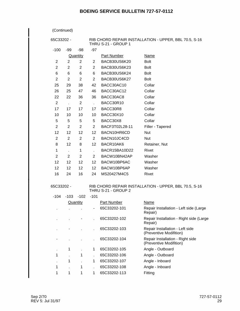
65C33202 - RIB CHORD REPAIR INSTALLATION - UPPER, BBL 70.5, S-16THRU S-21 - GROUP 1
-100 -99 -98 -97
Quantity Part Number Name
2 2 2 2 BACB30US6K20 Bolt
2 2 2 2 BACB30US6K23 Bolt
6 6 6 6 BACB30US6K24 Bolt
2 2 2 2 BACB30US6K27 Bolt
25 29 38 42 BACC30AC10 Collar
26 25 47 46 BACC30AC12 Collar
22 22 36 36 BACC30AC8 Collar
2 . 2 . BACC30R10 Collar
17 17 17 17 BACC30R8 Collar
10 10 10 10 BACC30X10 Collar
5 5 5 5 BACC30X8 Collar
2 2 2 2 BACF3T02L28-11 Filler - Tapered
12 12 12 12 BACN10HR6CD Nut
2 2 2 2 BACN10JC4CD Nut
8 12 8 12 BACR10AK6 Retainer, Nut
1 . 1 . BACR15BA10D22 Rivet
2 2 2 2 BACW10BN42AP Washer
12 12 12 12 BACW10BP6AC Washer
12 12 12 12 BACW10BP6AP Washer
16 24 16 24 MS20427M4C5 Rivet
65C33202 - RIB CHORD REPAIR INSTALLATION - UPPER, BBL 70.5, S-16THRU S-21 - GROUP 2
-104 -103 -102 -101
Quantity Part Number Name
. . . - 65C33202-101 Repair Installation - Left side (LargeRepair)
. . - . 65C33202-102 Repair Installation - Right side (LargeRepair)
. - . . 65C33202-103 Repair Installation - Left side(Preventive Modifition)
- . . . 65C33202-104 Repair Installation - Right side(Preventive Modifition)
. 1 . 1 65C33202-105 Angle - Outboard
1 . 1 . 65C33202-106 Angle - Outboard
. 1 . 1 65C33202-107 Angle - Inboard
1 . 1 . 65C33202-108 Angle - Inboard
1 1 1 1 65C33202-113 Fitting
Sep 2/70 727-57-0112REV 5: Jul 31/97 29

BOEING SERVICE BULLETIN 727-57-0112
(Continued)
65C33202 - RIB CHORD REPAIR INSTALLATION - UPPER, BBL 70.5, S-16THRU S-21 - GROUP 2
-104 -103 -102 -101
Quantity Part Number Name
1 1 1 1 65C33202-115 Radius Filler
. 1 . 1 65C33202-117 Angle - Forward, Inboard
1 . 1 . 65C33202-118 Angle - Forward, Inboard
1 1 1 1 65C33202-44 Angle - Inoard
. 1 . 1 65C33202-45 Angle - Outboard
1 . 1 . 65C33202-46 Angle - Outboard
1 1 1 1 65C33202-47 Spacer
1 1 1 1 65C33202-48 Filler - Tapered
1 1 1 1 65C33202-50 Filler - Outboard
1 1 1 1 65C33202-51 Shim - Laminated
. . 1 1 65C33202-52 Shim - Laminated
1 1 1 1 65C33202-53 Shim - Laminated
1 1 1 1 65C33202-54 Angle - Pressure Retaining
1 . 1 . 65C33202-55 Filler
1 . 1 . 65C33202-56 Shim - Laminated
. 1 . 1 65C33202-59 Shim - Laminated
. 1 . 1 65C33202-60 Filler
4 4 4 4 65C33202-68 Radius Filler
1 1 1 1 65C33202-69 Filler
. . 1 1 65C33202-71 Shim - Circular
. 1 . 1 65C33202-95 Shim - Laminated
1 . 1 . 65C33202-96 Shim - Laminated
1 1 1 1 65C37073-1 Tension Tie
1 . 1 . 65C37073-2 Tension Tie
2 . 2 . 65C37073-3 Radius Filler
2 . 2 . 65C37073-4 Radius Filler
. 1 . 1 65C37083-1 Tension Tie
. 1 . 1 65C37083-2 Radius Filler
. 1 . 1 65C37083-3 Radius Filler
. 1 . 1 65C37083-4 Radius Filler
. 1 . 1 65C37083-5 Radius Filler
. 1 . 1 65C37221-7 Tee Clip
1 . 1 . 65C37221-8 Tee Clip
1 1 1 1 69-78758-5 Strap
2 2 2 2 BACB30MY14K7Y Bolt - 1/32 oversized
. 2 . 2 BACB30MY14K10Y Bolt - 1/32 oversized
Sep 2/70 727-57-0112REV 5: Jul 31/97 30

BOEING SERVICE BULLETIN 727-57-0112
(Continued)
65C33202 - RIB CHORD REPAIR INSTALLATION - UPPER, BBL 70.5, S-16THRU S-21 - GROUP 2
-104 -103 -102 -101
Quantity Part Number Name
2 2 2 2 BACB30MY14K13Y Bolt - 1/32 oversized
2 2 2 2 BACB30MY14K14Y Bolt - 1/32 oversized
1 1 . . BACB30MY8K10Y Bolt - 1/32 oversized
3 3 2 2 BACB30MY8K11Y Bolt - 1/32 oversized
. . 2 2 BACB30MY8K12Y Bolt - 1/32 oversized
2 2 . . BACB30MY8K13Y Bolt - 1/32 oversized
2 6 2 6 BACB30MY8K6Y Bolt - 1/32 oversized
4 4 4 4 BACB30MY8K7Y Bolt - 1/32 oversized
2 2 2 2 BACB30NW8K12Y Bolt - 1/32 oversized
1 1 1 1 BACB30NW8K13Y Bolt - 1/32 oversized
1 1 1 1 BACB30NW8K14Y Bolt - 1/32 oversized
. 1 . 1 BACB30NX10K19 Bolt
2 1 2 1 BACB30NX10K20 Bolt
2 3 2 3 BACB30NX10K21 Bolt
1 3 1 3 BACB30NX10K23 Bolt
1 . 1 . BACB30NX10K24 Bolt
2 1 2 1 BACB30NX10K25 Bolt
3 3 5 6 BACB30NX14K14Y Bolt - 1/32 oversized
6 6 7 8 BACB30NX14K15Y Bolt - 1/32 oversized
10 12 12 14 BACB30NX14K16Y Bolt - 1/32 oversized
5 4 8 8 BACB30NX14K17Y Bolt - 1/32 oversized
9 8 21 21 BACB30NX14K18Y Bolt - 1/32 oversized
. . 8 8 BACB30NX14K19Y Bolt - 1/32 oversized
4 4 5 4 BACB30NX14K20Y Bolt - 1/32 oversized
12 14 26 28 BACB30NX8K17Y Bolt - 1/32 oversized
4 2 4 2 BACB30NX8K20 Bolt
4 4 4 4 BACB30NX8K21Y Bolt - 1/32 oversized
1 1 1 1 BACB30NY10K18 Bolt
1 1 1 1 BACB30NY10K19 Bolt
2 2 2 2 BACB30NY10K20 Bolt
1 1 1 1 BACB30NY10K21 Bolt
2 2 2 2 BACB30NY10K23 Bolt
1 1 1 1 BACB30NY10K25 Bolt
3 3 3 3 BACB30NY8K18Y Bolt - 1/32 oversized
2 . 2 . BACB30US7K20 Bolt
1 1 1 1 BACB30US7K20Y Bolt - 1/32 oversized
3 2 3 2 BACB30US7K24Y Bolt - 1/32 oversized
Sep 2/70 727-57-0112REV 5: Jul 31/97 31

BOEING SERVICE BULLETIN 727-57-0112
(Continued)
65C33202 - RIB CHORD REPAIR INSTALLATION - UPPER, BBL 70.5, S-16THRU S-21 - GROUP 2
-104 -103 -102 -101
Quantity Part Number Name
. 1 . 1 BACB30US7K25Y Bolt - 1/32 oversized
2 4 2 4 BACB30US7K26Y Bolt - 1/32 oversized
2 2 2 2 BACB30US7K27Y Bolt - 1/32 oversized
2 2 2 2 BACF3T02M26-12 Filler - Tapered
37 37 66 69 BACC30AC14 Collar
19 21 33 35 BACC30AC8 Collar
6 8 6 8 BACC30R14 Collar
16 20 14 18 BACC30R8 Collar
16 17 16 17 BACC30X14 Collar
4 2 4 2 BACC30X8 Collar
10 10 10 10 BACN10HR7 Nut
1 1 1 1 BACS40R019E036F Shim - Laminated
8 8 8 8 BACR10AK7 Retainer, Nut
2 . 2 . BACW10BP7AC Washer
8 10 8 10 BACW10BP72AC Washer
2 . 2 . BACW10BP7AP Washer
8 10 8 10 BACW10BP72AP Washer
8 8 8 8 MS20427M4C10 Rivet
8 8 8 8 MS20427M4C5 Rivet
Sep 2/70 727-57-0112REV 5: Jul 31/97 32

BOEING SERVICE BULLETIN 727-57-0112
2. Parts and Materials Supplied by the Operator:
Quantity Part Number (Specification) Name
As Necessary RTV 174 (a), (b) Silicone Rubber Adhesive
As Necessary BMS 5-26, Type II, Class B Integral Fuel Tank Sealant
As Necessary BMS 5-95 Sealant
As Necessary BMS 10-11, Type I Primer
As Necessary BACB30NW10K( ) (c)(k) Bolt
As Necessary BACB30MY10K( ) (c)(l) Bolt
1 65C37221-7 (j) Tee
1 65C37221-8 (j) Tee
1 69-78758-5 (d) (e) Strap (On 727-200 Airplanes)
1 69-78758-7 (d) (e) Strap (On 727-100 Airplanes)
(g) BACC30M8 (d), (e) Collar
6 BACC30M10 (c) Collar
1 BACC30M12 (e) Collar
1 BACB30MK8K16 (e) Fastener
1 BACB30MK8K20 (e) Fastener
3 BACB30MK8K16Y (e) Fastener
2 BACB30MK8K18Y (e) Fastener
(h) BACB30MK8K20Y (d), (e) Fastener
1 BACB30MK12K20Y (e) Fastener
2 BACB30NW8K12Y (d), (e) Fastener
2 BACB30NW8K13Y (d), (e) Fastener
1 BACB30NW8K14Y (d), (e) Fastener
1 BACB30NW8K15Y (d), (e) Fastener
1 BACB30NW8K20Y (d), (e) Fastener
2 BACN10HR6 (e) Nut
As Necessary 2024-T3 Aluminum Alloy (i) Shim
As Necessary 7075-T6 Aluminum Alloy (i) Shim
As Necessary BAC1506-855 x 4 (j) Tee extrusion
As Necessary 7075-T73511 Aluminum (j) Tee
(a) General Electric Co. (V9172)Materials Information Services1285 Boston Ave. Bldg 29EEBridgeport, Connecticut 06602, USA
(b) RTV 102, and DC Q3-7063 are optional to RTV 174. The DC Q3-7063 isavailable from:Dow Corning Corporation (V71984)3901 South Saginaw RoadMidland, Michagan 48641-2721, USA
(c) Necessary to make the change given in Figure 2. On 727-100 Airplanesthe grip lenths can range from -9 to -14. The grip lengths on 727-200Airplanes can range from -12 to -18. Larger diameters can be necessary ifcracks were found in Figure 1.
Sep 2/70 727-57-0112REV 5: Jul 31/97 33
BOEING SERVICE BULLETIN 727-57-0112
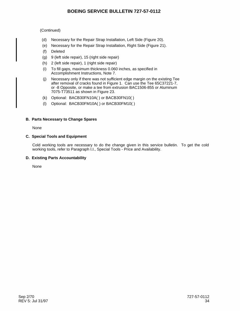
(Continued)
(d) Necessary for the Repair Strap Installation, Left Side (Figure 20).
(e) Necessary for the Repair Strap Installation, Right Side (Figure 21).
(f) Deleted
(g) 9 (left side repair), 15 (right side repair)
(h) 2 (left side repair), 1 (right side repair)
(i) To fill gaps, maximum thickness 0.060 inches, as specified inAccomplishment Instructions, Note 7.
(j) Necessary only if there was not sufficient edge margin on the existing Teeafter removal of cracks found in Figure 1. Can use the Tee 65C37221-7,or -8 Opposite, or make a tee from extrusion BAC1506-855 or Aluminum7075-T73511 as shown in Figure 23.
(k) Optional: BACB30FN10A( ) or BACB30FN10( )
(l) Optional: BACB30FM10A( ) or BACB30FM10( )
B. Parts Necessary to Change Spares
None
C. Special Tools and Equipment
Cold working tools are necessary to do the change given in this service bulletin. To get the coldworking tools, refer to Paragraph I.I., Special Tools - Price and Availability.
D. Existing Parts Accountability
None
Sep 2/70 727-57-0112REV 5: Jul 31/97 34
BOEING SERVICE BULLETIN 727-57-0112
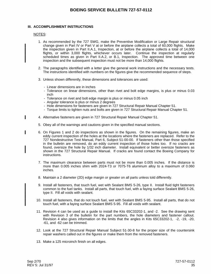
III. ACCOMPLISHMENT INSTRUCTIONS
NOTES:
1. As recommended by the 727 SWG, make the Preventive Modification or Large Repair structuralchange given in Part IV or Part V at or before the airplane collects a total of 60,000 flights. Makethe inspection given in Part II.A.1, Inspection, at or before the airplane collects a total of 14,000flights, or within 3,000 flights, whichever occurs later. Continue the inspection at regularlyscheduled times as given in Part II.A.2, or B.1, Inspection. The approved time between oneinspection and the subsequent inspection must not be more than 14,000 flights.
2. The paragraphs identified with a letter give the general work instructions and the necessary tests.The instructions identified with numbers on the figures give the recommended sequence of steps.
3. Unless shown differently, these dimensions and tolerances are used:
- Linear dimensions are in inches- Tolerance on linear dimensions, other than rivet and bolt edge margins, is plus or minus 0.03
inch- Tolerance on rivet and bolt edge margin is plus or minus 0.05 inch- Angular tolerance is plus or minus 2 degrees- Hole dimensions for fasteners are given in 727 Structural Repair Manual Chapter 51.- Torque limits to tighten nuts and bolts are given in 727 Structural Repair Manual Chapter 51.
4. Alternative fasteners are given in 727 Structural Repair Manual Chapter 51.
5. Obey all of the warnings and cautions given in the specified manual sections.
6. On Figures 1 and 2 do inspections as shown in the figures. On the remaining figures, make aneddy current inspection of the holes at the locations where the fasteners are replaced. Refer to the727 Nondestructive Test Manual, Part 6, Subject 51-00-00. If fasteners other than those specifiedin the bulletin are removed, do an eddy current inspection of those holes too. If no cracks arefound, oversize the hole by 1/32 inch diameter. Install equivalent or better oversize fasteners asshown in the 727 Structural Repair Manual. If cracks are found contact the Boeing Company forinstructions.
7. The maximum clearance between parts must not be more than 0.005 inches. If the distance ismore than 0.005 inches shim with 2024-T3 or 7075-T6 aluminum alloy to a maximum of 0.060inches.
8. Maintain a 2 diameter (2D) edge margin or greater on all parts unless told differently.
9. Install all fasteners, that touch fuel, wet with Sealant BMS 5-26, type II. Install fluid tight fastenerscommon to the fuel tanks. Install all parts, that touch fuel, with a faying surface Sealant BMS 5-26,type II. Fill all voids with sealant.
10. Install all fasteners, that do not touch fuel, wet with Sealant BMS 5-95. Install all parts, that do nottouch fuel, with a faying surface Sealant BMS 5-95. Fill all voids with sealant.
11. Revision 4 can be used as a guide to install the Kits 65C33202-1, and -2. See the drawing sentwith Revision 3 of the bulletin for the part numbers, the hole diameters and fastener callout.Revision 4 also gives information on the limits that the angles in Kits 65C33202-1, -2, -19, -20,-61, and -62 can be trimmed.
12. Look at the 727 Structural Repair Manual Subject 51-30-8 for the proper size of the countersinkrepair washers called out in the figures or make them from the removed fasteners.
13. Make a 125 microinch finish on all edges.
Sep 2/70 727-57-0112REV 5: Jul 31/97 35

BOEING SERVICE BULLETIN 727-57-0112
14. Group 1 - The Repair Strap, installed at Body Station 760.95, in the preferred Kit 65C36279-35, or-36 used in Service Bulletin 727-53-0197 Revision 2 is identical to the strap used in this servicebulletin. If a strap from an earlier revision of Service Bulletin 727-53-0197 has been installed, usethe strap shown in this service bulletin.
15. Group 2 - If the Repair Strap 65C36279-14, 65C36279-35, or -36, from Service Bulletin727-53-0197 is installed at Body Station 760.95, or will be installed concurrent with this servicebulletin, use the strap shown in Service Bulletin 727-53-0197.
PART I - ACCESS
A Remove the seats as necessary to get access to the center section upper surface, Body Station 740through 783. Refer to the 727 Maintenance Manual Subject 25-22-0.
B Remove the carpets as necessary to get access to the center section upper surface, Body Station 740through 783. Refer to the 727 Maintenance Manual Subject 25-20-31 for standard passengerairplanes or 25-20-32 for passenger/cargo convertible airplanes.
C Remove the floor panels as necessary to get access to the center section upper surface, Body Station740 through 783. Refer to the 727 Maintenance Manual Subject 53-20-11.
D Remove the interior access panels as necessary to get access to the center section upper surface,Body Station 740 through 783. Refer to the 727 Maintenance Manual Subject 25-21-1.
E Remove the pressure seal and the pressure pan to get access to the chord, Body Station 740 through760. Refer to the 727 Maintenance Manual Subject 51-30-1.
F Remove the wing-to-body fairing as necessary to get access to Body Station 740 through 783. Referto the 727 Maintenance Manual Subject 12-30-2.
PART II - INSPECTION
A Airplanes not changed as given in Figure 2.
1 Make an inspection for cracks as given in Figure 1, at or before the airplane collects a total of14,000 flight cycles, or in 3,000 flights, whichever occurs later.
2 If no cracks are found, cold work the holes as given in Figure 2, install the size and type of fastenershown in Figure 2 and return the airplane to a serviceable condition as given in Part VI. Make theinspection as given in Figure 1 at regularly scheduled times. The time between one inspection andthe subsequent inspection must not be more than 14,000 flight cycles. To stop the inspectionmade necessary by this service bulletin, make the change as given in Part V - PREVENTIVEMODIFICATION.
Sep 2/70 727-57-0112REV 5: Jul 31/97 36

BOEING SERVICE BULLETIN 727-57-0112
3 If cracks are found:
a That are less than one inch total in length and do not go into the horizontal flange.
NOTE: The length includes the fastener hole diameter, the crack length and the final stop holediameter.
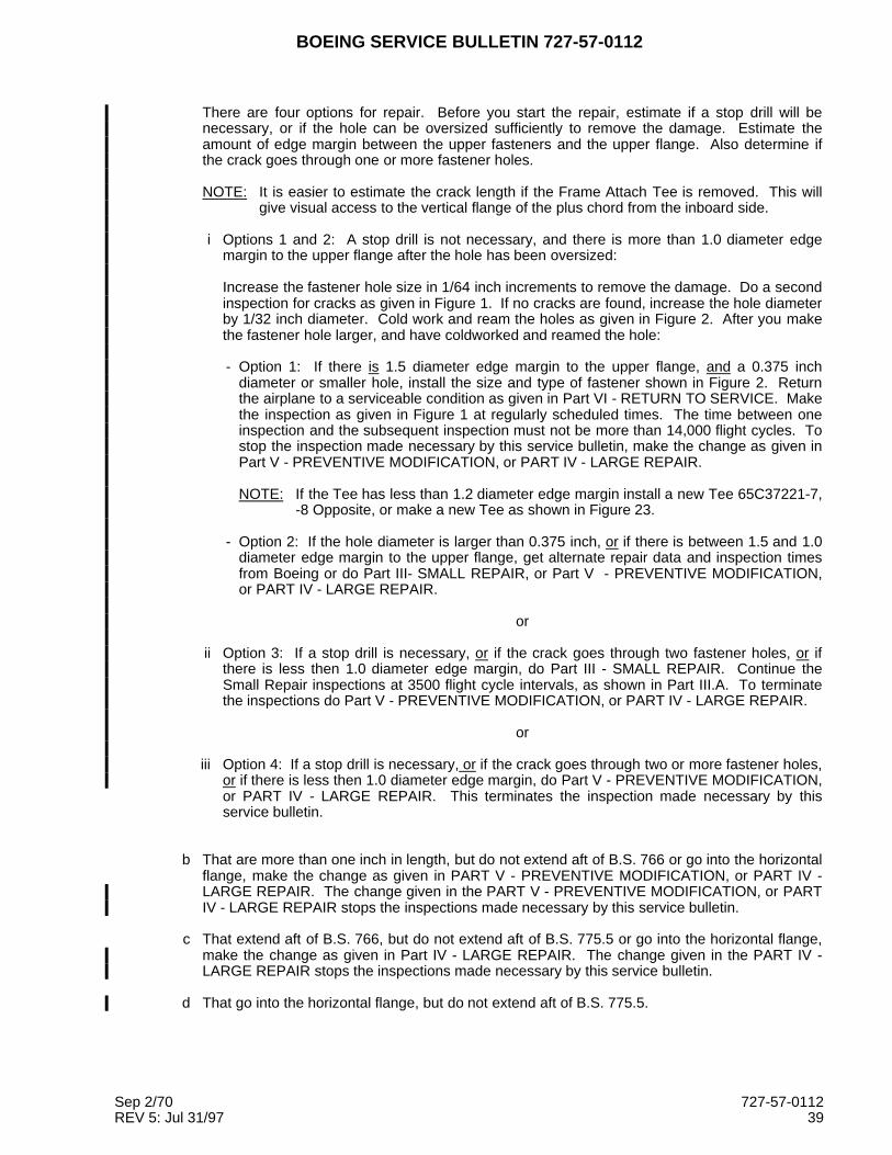
There are four options for repair. Before you start the repair, estimate if a stop drill will benecessary, or if the hole can be oversized sufficiently to remove the damage. Estimate theamount of edge margin between the upper fasteners and the upper flange. Also determine ifthe crack goes through one or more fastener holes.
NOTE: It is easier to estimate the crack length if the Frame Attach Tee is removed. This willgive visual access to the vertical flange of the plus chord from the inboard side.
i Options 1 and 2: A stop drill is not necessary, and there is more than 1.0 diameter edgemargin to the upper flange after the hole has been oversized:
Increase the fastener hole size in 1/64 inch increments to remove the damage. Do a secondinspection for cracks as given in Figure 1. If no cracks are found, increase the hole diameterby 1/32 inch diameter. Cold work and ream the holes as given in Figure 2. After you makethe fastener hole larger, and have coldworked and reamed the hole:
- Option 1: If there is 1.5 diameter edge margin to the upper flange, and a 0.375 inchdiameter or smaller hole, install the size and type of fastener shown in Figure 2. Returnthe airplane to a serviceable condition as given in Part VI - RETURN TO SERVICE. Makethe inspection as given in Figure 1 at regularly scheduled times. The time between oneinspection and the subsequent inspection must not be more than 14,000 flight cycles. Tostop the inspection made necessary by this service bulletin, make the change as given inPart V - PREVENTIVE MODIFICATION, or PART IV - LARGE REPAIR.
NOTE: If the Tee has less than 1.2 diameter edge margin install a new Tee 65C37221-7,-8 Opposite, or make a new Tee as shown in Figure 23.
- Option 2: If the hole diameter is larger than 0.375 inch, or if there is between 1.5 and 1.0diameter edge margin to the upper flange, get alternate repair data and inspection timesfrom Boeing or do Part III- SMALL REPAIR, or Part V - PREVENTIVE MODIFICATION,or PART IV - LARGE REPAIR.
or
ii Option 3: If a stop drill is necessary, or if the crack goes through two fastener holes, or ifthere is less then 1.0 diameter edge margin, do Part III - SMALL REPAIR. Continue theSmall Repair inspections at 3500 flight cycle intervals, as shown in Part III.A. To terminatethe inspections do Part V - PREVENTIVE MODIFICATION, or PART IV - LARGE REPAIR.
or
iii Option 4: If a stop drill is necessary, or if the crack goes through two or more fastener holes,or if there is less then 1.0 diameter edge margin, do Part V - PREVENTIVE MODIFICATION,or PART IV - LARGE REPAIR. This terminates the inspection made necessary by thisservice bulletin.
Sep 2/70 727-57-0112REV 5: Jul 31/97 37

BOEING SERVICE BULLETIN 727-57-0112
b That are more than one inch total in length, but do not extend aft of B.S. 766 or go into thehorizontal flange, make the change as given in PART V - PREVENTIVE MODIFICATION, orPART IV - LARGE REPAIR. The change given in the PART V - PREVENTIVEMODIFICATION, or PART IV - LARGE REPAIR stops the inspections made necessary by thisservice bulletin.
c That extend aft of B.S. 766, but do not extend aft of B.S. 775.5 or go into the horizontal flange,make the change as given in Part IV - LARGE REPAIR. The change given in the PART IV -LARGE REPAIR stops the inspections made necessary by this service bulletin.
d That go into the horizontal flange, but do not extend aft of B.S. 775.5.
CAUTION: IF THE CRACK GOES INTO THE HORIZONTAL FLANGE, DO NOT DRILL ASTOP HOLE VERTICALLY INTO THE HORIZONTAL FLANGE. THE REPAIRWITH A VERTICAL STOP HOLE TAKES MORE TIME THAN THE REPAIR WITHA HORIZONTAL STOP HOLE.
i. Remove the crack as shown in Figure 22.
ii. After the crack is removed write to Boeing for instructions. Include the information shownbelow:
- The distance (dimension "A") from the upper surface of the inboard horizontal flange tothe deepest point of the blend out.
- A side view that shows where the blendout starts and ends. Indicate the blendout lengthsand widths.
- The blend out lengths forward to aft (dimension "C"), and inboard to outboard (dimension"B").
- If possible, the minimum remaining thickness of the rib chord in the area of the blend out.Measure ultrasonically.
e That extend aft of B.S. 775.5, write to Boeing for instructions.
B Airplanes changed as given in Figure 2. Make the inspection as given in Figure 1 at the next D check(or equivalent major inspection) or before the airplane collects 14,000 more flight cycles, since thechange. Use the time or flight cycles that occurs first.
1 If no cracks are found, install new fasteners. Install the size and type of fastener shown in Figure 2and return the airplane to a serviceable condition as given in Part VI - RETURN TO SERVICE.Make the inspection as given in Figure 1 at regularly scheduled times. The time between oneinspection and the subsequent inspection must not be more than 14,000 flight cycles. To stop theinspection made necessary by this service bulletin, make the change as given in Part V -PREVENTIVE MODIFICATION.
2 If cracks are found:
a That are less than one inch total in length, and do not go into the horizontal flange.
NOTE: The length includes the fastener hole diameter, the crack length and the final stop holediameter.
Sep 2/70 727-57-0112REV 5: Jul 31/97 38
BOEING SERVICE BULLETIN 727-57-0112
There are four options for repair. Before you start the repair, estimate if a stop drill will benecessary, or if the hole can be oversized sufficiently to remove the damage. Estimate theamount of edge margin between the upper fasteners and the upper flange. Also determine ifthe crack goes through one or more fastener holes.
NOTE: It is easier to estimate the crack length if the Frame Attach Tee is removed. This willgive visual access to the vertical flange of the plus chord from the inboard side.
i Options 1 and 2: A stop drill is not necessary, and there is more than 1.0 diameter edgemargin to the upper flange after the hole has been oversized:
Increase the fastener hole size in 1/64 inch increments to remove the damage. Do a secondinspection for cracks as given in Figure 1. If no cracks are found, increase the hole diameterby 1/32 inch diameter. Cold work and ream the holes as given in Figure 2. After you makethe fastener hole larger, and have coldworked and reamed the hole:
- Option 1: If there is 1.5 diameter edge margin to the upper flange, and a 0.375 inchdiameter or smaller hole, install the size and type of fastener shown in Figure 2. Returnthe airplane to a serviceable condition as given in Part VI - RETURN TO SERVICE. Makethe inspection as given in Figure 1 at regularly scheduled times. The time between oneinspection and the subsequent inspection must not be more than 14,000 flight cycles. Tostop the inspection made necessary by this service bulletin, make the change as given inPart V - PREVENTIVE MODIFICATION, or PART IV - LARGE REPAIR.
NOTE: If the Tee has less than 1.2 diameter edge margin install a new Tee 65C37221-7,-8 Opposite, or make a new Tee as shown in Figure 23.
- Option 2: If the hole diameter is larger than 0.375 inch, or if there is between 1.5 and 1.0diameter edge margin to the upper flange, get alternate repair data and inspection timesfrom Boeing or do Part III- SMALL REPAIR, or Part V - PREVENTIVE MODIFICATION,or PART IV - LARGE REPAIR.
or
ii Option 3: If a stop drill is necessary, or if the crack goes through two fastener holes, or ifthere is less then 1.0 diameter edge margin, do Part III - SMALL REPAIR. Continue theSmall Repair inspections at 3500 flight cycle intervals, as shown in Part III.A. To terminatethe inspections do Part V - PREVENTIVE MODIFICATION, or PART IV - LARGE REPAIR.
or
iii Option 4: If a stop drill is necessary, or if the crack goes through two or more fastener holes,or if there is less then 1.0 diameter edge margin, do Part V - PREVENTIVE MODIFICATION,or PART IV - LARGE REPAIR. This terminates the inspection made necessary by thisservice bulletin.
b That are more than one inch in length, but do not extend aft of B.S. 766 or go into the horizontalflange, make the change as given in PART V - PREVENTIVE MODIFICATION, or PART IV -LARGE REPAIR. The change given in the PART V - PREVENTIVE MODIFICATION, or PARTIV - LARGE REPAIR stops the inspections made necessary by this service bulletin.
c That extend aft of B.S. 766, but do not extend aft of B.S. 775.5 or go into the horizontal flange,make the change as given in Part IV - LARGE REPAIR. The change given in the PART IV -LARGE REPAIR stops the inspections made necessary by this service bulletin.
d That go into the horizontal flange, but do not extend aft of B.S. 775.5.
Sep 2/70 727-57-0112REV 5: Jul 31/97 39

BOEING SERVICE BULLETIN 727-57-0112
CAUTION: IF THE CRACK GOES INTO THE HORIZONTAL FLANGE, DO NOT DRILL ASTOP HOLE VERTICALLY INTO THE HORIZONTAL FLANGE. THE REPAIRWITH A VERTICAL STOP HOLE TAKES MORE TIME THAN THE REPAIR WITHA HORIZONTAL STOP HOLE.
i. Remove the crack as shown in Figure 22.
ii. After the crack is removed write to Boeing for instructions. Include the information shownbelow:
- The distance (dimension "A") from the upper surface of the inboard horizontal flange tothe deepest point of the blend out.
- A side view that shows where the blendout starts and ends. Indicate the blendout lengthsand widths.
- The blend out lengths forward to aft (dimension "C"), and inboard to outboard(dimension "B").
- If possible, the minimum remaining thickness of the rib chord in the area of the blend out.Measure ultrasonically.
e That extend aft of B.S. 775.5, write to Boeing for instructions.
C On Group 1 Airplanes that had the Major Repair/ Preventive Modification (65C33202-1, -2 Opposite)done as shown in Revision 2, or 3, a repair strap was omitted from the drawings and kits for Revision2, and 3. It is necessary for Group 1 Airplanes that have the Major Repair/Preventive Modificationinstalled, as shown in Revision 2 or 3, to make an inspection at BL 70.5 for the repair strap as follows:
NOTE: Some operators have installed the strap used in Service Bulletin 727-53-0197, or anoperator-furnished strap
1. Make an inspection for the repair strap at a maintenance check before the airplane collects a totalof 3,000 more flight cycles, see Figure 19.
2. If the strap was not installed, refer to Service Bulletin 727-53-0197 for the inspection of the BS760.95 frame. Install the repair strap when the repair or preventive modification shown in ServiceBulletin 727-53-0197 is installed, or at a convenient maintenance time, as shown below.
a. Left Side:
1. Make the changes to the left side as shown in Figure 20.
2. Return the airplane to serviceable condition as given in Part VI.
b. Right Side:
1. Gain access to the wing upper surface and the wing fuel cell. Use the appropriate accessinstructions given in Part IV - LARGE REPAIR. A - Access.
2. Make the changes to the right side as shown in Figure 21.
3. Close access to the wing upper surface and the wing fuel cell. Use the appropriate accessinstructions given in Part IV - LARGE REPAIR. E - Restoration.
3. If the strap was not installed, and there are cracks, do Service Bulletin 727-53-0197.
Sep 2/70 727-57-0112REV 5: Jul 31/97 40
BOEING SERVICE BULLETIN 727-57-0112
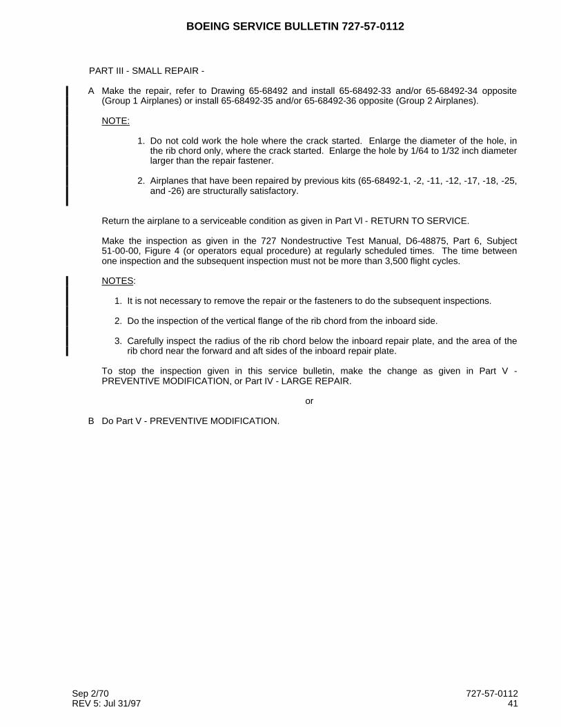
PART III - SMALL REPAIR -
A Make the repair, refer to Drawing 65-68492 and install 65-68492-33 and/or 65-68492-34 opposite(Group 1 Airplanes) or install 65-68492-35 and/or 65-68492-36 opposite (Group 2 Airplanes).
NOTE:
1. Do not cold work the hole where the crack started. Enlarge the diameter of the hole, inthe rib chord only, where the crack started. Enlarge the hole by 1/64 to 1/32 inch diameterlarger than the repair fastener.
2. Airplanes that have been repaired by previous kits (65-68492-1, -2, -11, -12, -17, -18, -25,and -26) are structurally satisfactory.
Return the airplane to a serviceable condition as given in Part Vl - RETURN TO SERVICE.
Make the inspection as given in the 727 Nondestructive Test Manual, D6-48875, Part 6, Subject51-00-00, Figure 4 (or operators equal procedure) at regularly scheduled times. The time betweenone inspection and the subsequent inspection must not be more than 3,500 flight cycles.
NOTES:
1. It is not necessary to remove the repair or the fasteners to do the subsequent inspections.
2. Do the inspection of the vertical flange of the rib chord from the inboard side.
3. Carefully inspect the radius of the rib chord below the inboard repair plate, and the area of therib chord near the forward and aft sides of the inboard repair plate.
To stop the inspection given in this service bulletin, make the change as given in Part V -PREVENTIVE MODIFICATION, or Part IV - LARGE REPAIR.
or
B Do Part V - PREVENTIVE MODIFICATION.
Sep 2/70 727-57-0112REV 5: Jul 31/97 41

BOEING SERVICE BULLETIN 727-57-0112
PART IV - LARGE REPAIR
A. Access
1 Provide System B hydraulic power. Refer to the 727 Maintenance Manual Subject 27-81-0.
2 Fully extend the leading edge slats. Refer to the 727 Maintenance Manual Subject 27-81-0.
3 Remove System B hydraulic power. Refer to the 727 Maintenance Manual Subject 27-81-0.
4 Defuel the left wing tank, right wing tank, and center section tank. Refer to the 727 MaintenanceManual Subject 28-23-0.
5 Purge the center section fuel cells and the necessary wing fuel tank(s). Refer to the 727Maintenance Manual Subject 28-10-0.
6 Remove and keep the center section access panel. Refer to the 727 Maintenance Manual Subject28-11-21.
7 Remove and keep the center section fuel cell access panel. Refer to the 727 Maintenance ManualSubject 28-12-11.
8 If fuel cell bladders are installed and the Number 1 fuel cell bladder is not installed remove theintercell access panel. Refer to the 727 Maintenance Manual Subject 28-12-31.
9 Remove and keep the intercell baffle plate(s). Refer to the 727 Maintenance Manual Subject28-12-21.
10 If fuel cell bladders are installed remove and keep the fuel cell bladder. Refer to the 727Maintenance Manual Subject 28-12-1.
11 Remove and keep the fuel tank access panel in the wing front spar. Refer to the 727 MaintenanceManual Subject 28-11-21.
12 Remove and keep the forward retainer strip used to hold the fairing to the body.
B. Cracks
1. Drill a stop hole at the end of the cracks that do not terminate in a fastener hole (use the 727Structural Repair Manual Subject 51-10-1). If the hole will be farther than 1 inch aft of thereference holes, shown in Figure 1, increase the stop hole diameter to 0.625 inch. Deburr theholes and make a 32 microinch finish in the holes.
2. Oversize all of the fastener holes, in the chord only, that are cracked. Increase the diameter ofthese holes an additional 1/64 to 1/32 inch larger than final hole size shown in Figures 4, 6, 8, 10.Only increase the hole size in the chord, not the hole size in the body skin or the structures to beadded in this bulletin. The oversized holes in the chord are oversized more than the diameter ofthe fasteners installed through these holes. This is done so that no load is transferred from thefastener to the chord, at the crack locations.
C. Change (Group 1 Airplanes):
1 Left Chord: Make the changes shown in Figures 3 and 4.
2 Right Chord: Make the changes shown in Figures 5 and 6.
Sep 2/70 727-57-0112REV 5: Jul 31/97 42

BOEING SERVICE BULLETIN 727-57-0112
D. Change (Group 2 Airplanes):
1 Left Chord: Make the changes shown in Figures 7 and 8.
2 Right Chord: Make the changes shown in Figures 9 and 10.
E. Restoration
1 Install the access panels on the vent stringers, use the fasteners kept and Sealant BMS 5-26,type II.
2 Install the fuel tank access panel in the wing front spar. Refer to the 727 Maintenance ManualSubject 28-11-21.
3 Install the fuel cell bladders if they were removed. Refer to the 727 Maintenance Manual Subject28-12-1.
4 Install the intercell baffle plate(s). Refer to the 727 Maintenance Manual Subject 28-12-21.
5 If the fuel cell bladders were installed and the Number 1 fuel cell bladder was not installed installthe intercell access panel. Refer to the 727 Maintenance Manual Subject 28-12-31.
6 Install the center section fuel cell access panel. Refer to the 727 Maintenance Manual Subject28-12-11.
7 Install the center section access panel. Refer to the 727 Maintenance Manual Subject 28-11-21.
8 Fuel the left wing tank, right wing tank, and center section tank and check for leaks. Refer to the727 Maintenance Manual Subject 28-11-0.
9 Provide System B hydraulic power. Refer to the 727 Maintenance Manual Subject 27-81-0.
10 Fully retract the leading edge slats. Refer to the 727 Maintenance Manual Subject 27-81-0.
11 Remove System B hydraulic power. Refer to the 727 Maintenance Manual Subject 27-81-0.
12 Return the airplane to serviceable condition as given in Part VI.
Sep 2/70 727-57-0112REV 5: Jul 31/97 43

BOEING SERVICE BULLETIN 727-57-0112
PART V - PREVENTIVE MODIFICATION
A Access
1 Provide System B hydraulic power. Refer to the 727 Maintenance Manual Subject 27-81-0.
2 Fully extend the leading edge slats. Refer to the 727 Maintenance Manual Subject 27-81-0.
3 Remove System B hydraulic power. Refer to the 727 Maintenance Manual Subject 27-81-0.
4 Defuel the left wing tank, right wing tank, and center section tank. Refer to the 727 MaintenanceManual Subject 28-23-0.
5 Purge the center section fuel cells and the necessary wing fuel tank(s). Refer to t.0he 7270..0Maintenance Manual Subject 28-10-0.
6 Remove and keep the center section access panel. Refer to the 727 Maintenance Manual Subject28-11-21.
7 Remove and keep the center section fuel cell access panel. Refer to the 727 Maintenance ManualSubject 28-12-11.
8 If fuel cell bladders are installed and the Number 1 fuel cell bladder is not installed remove theintercell access panel. Refer to the 727 Maintenance Manual Subject 28-12-31.
9 Remove and keep the intercell baffle plate(s). Refer to the 727 Maintenance Manual Subject28-12-21.
10 If fuel cell bladders are installed remove and keep the fuel cell bladder. Refer to the 727Maintenance Manual Subject 28-12-1.
11 Remove and keep the fuel tank access panel in the wing front spar. Refer to the 727 MaintenanceManual Subject 28-11-21.
12 Remove and keep the forward retainer strip used to hold the fairing to the body.
B Cracks
1. Drill a stop hole at the end of the cracks that do not terminate in a fastener hole (use 727 StructuralRepair Manual Subject 51-10-1). If the hole will be farther than 1 inch aft of the reference holes,shown in Figure 1, increase the stop hole diameter to 0.625 inch. Deburr the holes and make a 32microinch finish in the holes.
2. Oversize all of the fastener holes, in the chord only, that are cracked. Increase the diameter ofthese holes an additional 1/64 to 1/32 inch larger than final hole size shown in Figures 12, 14, 16,18. Only increase the hole size in the chord, not the hole size in the body skin or the structures tobe added in this bulletin. The oversized holes in the chord are oversized more than the diameter ofthe fasteners installed through these holes. This is done so that no load is transferred from thefastener to the chord, at the crack locations.
C Change (Group 1 Airplanes):
1 Left Chord: Make the changes shown in Figures 11 and 12.
2 Right Chord: Make the changes shown in Figures 13 and 14.
Sep 2/70 727-57-0112REV 5: Jul 31/97 44

BOEING SERVICE BULLETIN 727-57-0112
D Change (Group 2 Airplanes):
1 Left Chord: Make the changes shown in Figures 15 and 16.
2 Right Chord: Make the changes shown in Figures 17 and 18.
E Restoration
1 Install the access panels on the vent stringers, use the fasteners kept and Sealant BMS 5-26,type II.
2 Install the fuel tank access panel in the wing front spar. Refer to the 727 Maintenance ManualSubject 28-11-21.
3 Install the fuel cell bladders if they were removed. Refer to the 727 Maintenance Manual Subject28-12-1.
4 Install the intercell baffle plate(s). Refer to the 727 Maintenance Manual Subject 28-12-21.
5 If the fuel cell bladders were installed and the Number 1 fuel cell bladder was not installed installthe intercell access panel. Refer to the 727 Maintenance Manual Subject 28-12-31.
6 Install the center section fuel cell access panel. Refer to the 727 Maintenance Manual Subject28-12-11.
7 Install the center section access panel. Refer to the 727 Maintenance Manual Subject 28-11-21.
8 Fuel the left wing tank, right wing tank, and center section tank and check for leaks. Refer to the727 Maintenance Manual Subject 28-11-0.
9 Provide System B hydraulic power. Refer to the 727 Maintenance Manual Subject 27-81-0.
10 Fully retract the leading edge slats. Refer to the 727 Maintenance Manual Subject 27-81-0.
11 Remove System B hydraulic power. Refer to the 727 Maintenance Manual Subject 27-81-0.
12 Return the airplane to serviceable condition as given in Part VI.
PART VI - RETURN TO SERVICE
A Install the pressure seal and the pressure pan removed to get access to the chord, Body Station 740through 760. Refer to the 727 Maintenance Manual Subject 51-30-1.
B Install the interior access panels removed to get access to the center section upper surface, BodyStation 740 through 783. Refer to the 727 Maintenance Manual Subject 25-21-1.
C Install the floor panels removed to get access to the center section upper surface, Body Station 740through 783. Refer to the 727 Maintenance Manual Subject 53-20-11.
D Install the carpets removed to get access to the center section upper surface, Body Station 740through 783. Refer to the 727 Maintenance Manual Subject 25-20-31 for standard passengerairplanes or 25-20-32 for passenger/cargo convertible airplanes.
E Install the seats removed to get access to the center section upper surface, Body Station 740 through783. Refer to the 727 Maintenance Manual Subject 25-22-0.
F Install the forward retainer strip and the wing-to body fairing. If changes are necessary use Drawing65C36390 Rib Chord Repair Installation - Fairing Rework.
Sep 2/70 727-57-0112REV 5: Jul 31/97 45

BOEING SERVICE BULLETIN 727-57-0112
FIGURE TABLE OF CONTENTS
Title Page
FIGURE 1. INSPECTION . . . . . . . . . . . . . . . . . . . . . . . . . . . . . . . . . . . . . . . . . . . . . . . . . 47
FIGURE 2. COLD WORKING . . . . . . . . . . . . . . . . . . . . . . . . . . . . . . . . . . . . . . . . . . . . . . 49
FIGURE 3. GROUP 1, LARGE REPAIR, LEFT SIDE, REMOVAL . . . . . . . . . . . . . . . . . . 52
FIGURE 4. GROUP 1, LARGE REPAIR, LEFT SIDE, INSTALLATION . . . . . . . . . . . . . . 58
FIGURE 5. GROUP 1, LARGE REPAIR, RIGHT SIDE, REMOVAL. . . . . . . . . . . . . . . . . 64
FIGURE 6. GROUP 1, LARGE REPAIR, RIGHT SIDE, INSTALLATION. . . . . . . . . . . . . 70
FIGURE 7. GROUP 2, LARGE REPAIR, LEFT SIDE, REMOVAL . . . . . . . . . . . . . . . . . . 76
FIGURE 8. GROUP 2, LARGE REPAIR, LEFT SIDE, INSTALLATION . . . . . . . . . . . . . . 82
FIGURE 9. GROUP 2, LARGE REPAIR, RIGHT SIDE, REMOVAL. . . . . . . . . . . . . . . . . 89
FIGURE 10. GROUP 2, LARGE REPAIR, RIGHT SIDE, INSTALLATION. . . . . . . . . . . . 95
FIGURE 11. GROUP 1, PREVENTIVE MODIFICATION, LEFT SIDE, REMOVAL. . . . . . 102
FIGURE 12. GROUP 1, PREVENTIVE MODIFICATION, LEFT SIDE,INSTALLATION . . . . . . . . . . . . . . . . . . . . . . . . . . . . . . . . . . . . . . . . . . . . . . . 108
FIGURE 13. GROUP 1, PREVENTIVE MODIFICATION, RIGHT SIDE, REMOVAL . . . . 114
FIGURE 14. GROUP 1, PREVENTIVE MODIFICATION, RIGHT SIDE,INSTALLATION . . . . . . . . . . . . . . . . . . . . . . . . . . . . . . . . . . . . . . . . . . . . . . . 120
FIGURE 15. GROUP 2, PREVENTIVE MODIFICATION, LEFT SIDE, REMOVAL. . . . . . 126
FIGURE 16. GROUP 2, PREVENTIVE MODIFICATION, LEFT SIDE,INSTALLATION . . . . . . . . . . . . . . . . . . . . . . . . . . . . . . . . . . . . . . . . . . . . . . . 132
FIGURE 17. GROUP 2, PREVENTIVE MODIFICATION, RIGHT SIDE, REMOVAL . . . . 139
FIGURE 18. GROUP 2, PREVENTIVE MODIFICATION, RIGHT SIDE,INSTALLATION . . . . . . . . . . . . . . . . . . . . . . . . . . . . . . . . . . . . . . . . . . . . . . . 145
FIGURE 19. INSPECTION FOR THE REPAIR STRAP AT BS 760.95 FRAME. . . . . . . . 151
FIGURE 20. INSTALLATION OF THE REPAIR STRAP AT BS 760.95 FRAME -LEFT SIDE . . . . . . . . . . . . . . . . . . . . . . . . . . . . . . . . . . . . . . . . . . . . . . . . . . . 154
FIGURE 21. INSTALLATION OF THE REPAIR STRAP AT BS 760.95 FRAME -RIGHT SIDE. . . . . . . . . . . . . . . . . . . . . . . . . . . . . . . . . . . . . . . . . . . . . . . . . . 156
FIGURE 22. CRACK REMOVAL. . . . . . . . . . . . . . . . . . . . . . . . . . . . . . . . . . . . . . . . . . . . 160
FIGURE 23. MAKE NEW FRAME ATTACH TEE . . . . . . . . . . . . . . . . . . . . . . . . . . . . . . . 163
Sep 2/70 727-57-0112REV 5: Jul 31/97 46

BOEING SERVICE BULLETIN 727-57-0112
FWD
DETAIL I
6 PLACES1 2
SEE DETAIL I
BODY SKIN
VERTICAL FLANGE
RIB CHORD UPPER
REINFORCING ANGLE
A
A
BODY FRAME
REFERENCE HOLES
STA
970
STA
870
760.95
STA
STA
660
STA
760.95
R48142
FIGURE 1. INSPECTION
Sep 2/70 SHEET 1 OF 2 727-57-0112REV 5: Jul 31/97 47

BOEING SERVICE BULLETIN 727-57-0112
3
1 2
70.5
BBL
INBD
RIB CHORD
WING UPPER SKIN
FILLER
REINFORCING ANGLE
BODY SKIN
SECTION A−A
R44700
The step numbers shown below agree with the numbers shown in the circle symbols in the figure.
STEP TASK NAME PROCEDURE REFERENCES NOTES
1 Remove Fastener - -
2 Examine Hole High Freqency EddyCurrent
727 NDT, D6-48875,Part 6, 51-00-00,Figures 1 and 4
3 Examine Radius Close Visual - Examine the radius ofthe upper rib chordfor cracks
FIGURE 1. INSPECTION
Sep 2/70 SHEET 2 OF 2 727-57-0112REV 5: Jul 31/97 48

BOEING SERVICE BULLETIN 727-57-0112
FWD
BODY SKIN
RIB CHORD UPPER
VERTICAL FLANGE
REINFORCING ANGLE
6 PLACES (TYPICAL)21
BODY FRAME
A
A
STA
760.95
B
A
B
AA
B
SEE DETAIL I
970
STA
870
STA
STA
760.95
660
STA
DETAIL I
R44705
FIGURE 2. COLD WORKING
Sep 2/70 SHEET 1 OF 3 727-57-0112REV 5: Jul 31/97 49

BOEING SERVICE BULLETIN 727-57-0112
INBD
SECTION A−A
RIB CHORD
1 2
BODY SKIN
REINFORCING ANGLE
FILLER
WING UPPER SKIN
BBL
70.5
R44708
The step numbers shown below agree with the numbers shown in the circle symbols in the figure.
STEP TASK NAME PART NUMBER QTY NOTES
1 Cold Work Hole - 6 (a)
2 Install Fastener - 6
(a) Low interference cold work the hole. Refer to the SRM 51-30-10 for the start hole diameter and thefinal hole diameter. If the final edge margin is less then 1.5D (except the Frame Attach Tee), write toBoeing for instructions.
FIGURE 2. COLD WORKING
Sep 2/70 SHEET 2 OF 3 727-57-0112REV 5: Jul 31/97 50

BOEING SERVICE BULLETIN 727-57-0112
The codes given below agree with the letter shown in the upper left corner of the fastener symbols in thefigure. A number in the lower right corner gives the grip length of the fastener.
CODE NAME PART NUMBER HOLE DIA NOTES
A Bolt BACB30NW10K( ) (a)(e)
- Increase the countersink diameterof the hole. Refer to SRM51-30-08. Install wet with BMS5-95 Sealant.
Collar BACC30M10 (e)
B Bolt BACB30MY10K( )(b)(e)
- (c)
BACB30NW10K( )(a)(e)
(c), (d)
Collar BACC30M10 (e)
(a) Optional BACB30FN10A( ) or BACB30FN10( ).
(b) Optional BACB30FM10A( ) or BACB30FM10( ).
(c) Install a fastener with a shear protuding head or a shear flush head as necessary to agree with thestructure. Install wet with BMS 5-95 sealant.
(d) If a fastener with a shear flush head is installed, increase the countersink diameter of the hole.
(e) The fastener diameter is a "10" if the hole has not been oversized to remove damage. If the hole hasbeen made larger to remove damage, use an equivalent fastener in a size to agree with the holediameter, after the hole has been coldworked.
FIGURE 2. COLD WORKING
Sep 2/70 SHEET 3 OF 3 727-57-0112REV 5: Jul 31/97 51

BOEING SERVICE BULLETIN 727-57-0112
INBDFWD
660
STA
STA
970
SEE DETAIL I
WING SKIN
1
52
760.95
BS
1
4
SEE DETAIL IV
SEE DETAIL II
BODY SKIN
BBL
70.5
STA
760.95
870
STA
R44803
FIGURE 3. GROUP 1, LARGE REPAIR, LEFT SIDE, REMOVAL
Sep 2/70 SHEET 1 OF 6 727-57-0112REV 5: Jul 31/97 52

BOEING SERVICE BULLETIN 727-57-0112
INBDFWD
DETAIL I
RIB WEB
2 5
2
1 ACCESS PANEL
S−19
S−20
R44815
FIGURE 3. GROUP 1, LARGE REPAIR, LEFT SIDE, REMOVAL
Sep 2/70 SHEET 2 OF 6 727-57-0112REV 5: Jul 31/97 53

BOEING SERVICE BULLETIN 727-57-0112
FWD
INBD
DETAIL II
CENTER SECTION SKIN
BS
760.95
4
BODY SKIN
52
52
DETAIL III
SEE
BBL
70.5
R44817
FIGURE 3. GROUP 1, LARGE REPAIR, LEFT SIDE, REMOVAL
Sep 2/70 SHEET 3 OF 6 727-57-0112REV 5: Jul 31/97 54
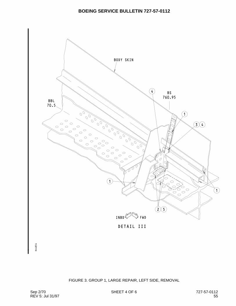
BOEING SERVICE BULLETIN 727-57-0112
FWDINBD
DETAIL III
52
1
1
3 4
1
4
BODY SKIN
BBL
70.5
BS
760.95
R44854
FIGURE 3. GROUP 1, LARGE REPAIR, LEFT SIDE, REMOVAL
Sep 2/70 SHEET 4 OF 6 727-57-0112REV 5: Jul 31/97 55

BOEING SERVICE BULLETIN 727-57-0112
FWDINBD
2
RIB WEB
1
PANELS
ACCESS
2 5
CENTER SECTION SKIN
DETAIL IV
S−19C
S−20C
BBL
70.5
R44858
FIGURE 3. GROUP 1, LARGE REPAIR, LEFT SIDE, REMOVAL
Sep 2/70 SHEET 5 OF 6 727-57-0112REV 5: Jul 31/97 56

BOEING SERVICE BULLETIN 727-57-0112
The step numbers shown below agree with the numbers shown in the circle symbols in the figure. Referto Drawing 65C33202, Sheet 7, to the structural changes shown below.
STEP TASK NAME PART NUMBER QTY NOTES
1 Removeand Keep
Foam Seal - 1
Nutplate - 2
Access Panel - 3
Filler - 1
Angle - 3
2 Remove Sealant - -
Fastener - -
3 Cut Strap - 1 See Zone B7, Section 1D8
4 Remove Angle - 2
Filler - 1
Tee - 1
Strap (lower section) - 1
5 Examine Hole - - NDT Subject 51-00-00, Figures1 and 4
FIGURE 3. GROUP 1, LARGE REPAIR, LEFT SIDE, REMOVAL
Sep 2/70 SHEET 6 OF 6 727-57-0112REV 5: Jul 31/97 57

BOEING SERVICE BULLETIN 727-57-0112
FWDINBD
1
1
3
2
SEE DETAIL II
ACCESS PANEL14
ACCESS PANEL
4
CENTER SECTION SKIN
SEE DETAIL IV
SEE DETAIL I
S−20C
BBL
70.5
S−19C
14
R45312
FIGURE 4. GROUP 1, LARGE REPAIR, LEFT SIDE, INSTALLATION
Sep 2/70 SHEET 1 OF 6 727-57-0112REV 5: Jul 31/97 58

BOEING SERVICE BULLETIN 727-57-0112
FWD INBD
6
DETAIL I
70.5
BBL
S−20
S−19
5
14PANEL
ACCESS
7
RIB
R45346
FIGURE 4. GROUP 1, LARGE REPAIR, LEFT SIDE, INSTALLATION
Sep 2/70 SHEET 2 OF 6 727-57-0112REV 5: Jul 31/97 59

BOEING SERVICE BULLETIN 727-57-0112
INBD
FWD
DETAIL II
SEE DETAIL III
8
8
9
BBL
70.5
BODY SKIN
CENTER SECTION SKIN
BS
760.95
R45370
FIGURE 4. GROUP 1, LARGE REPAIR, LEFT SIDE, INSTALLATION
Sep 2/70 SHEET 3 OF 6 727-57-0112REV 5: Jul 31/97 60

BOEING SERVICE BULLETIN 727-57-0112
FWDINBD
DETAIL III
CENTER SECTION SKIN
14
14
10
10
BODY SKIN
760.95
BS
BBL
70.5
R45384
FIGURE 4. GROUP 1, LARGE REPAIR, LEFT SIDE, INSTALLATION
Sep 2/70 SHEET 4 OF 6 727-57-0112REV 5: Jul 31/97 61

BOEING SERVICE BULLETIN 727-57-0112
INBDFWD
DETAIL IV
11
13
12
12
BODY SKIN
WING SKIN
BS
760.95
70.5
BBL
R45415
FIGURE 4. GROUP 1, LARGE REPAIR, LEFT SIDE, INSTALLATION
Sep 2/70 SHEET 5 OF 6 727-57-0112REV 5: Jul 31/97 62
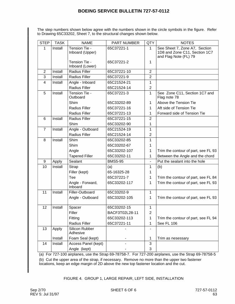
BOEING SERVICE BULLETIN 727-57-0112
The step numbers shown below agree with the numbers shown in the circle symbols in the figure. Referto Drawing 65C33202, Sheet 7, to the structural changes shown below.
STEP TASK NAME PART NUMBER QTY NOTES1 Install Tension Tie -
Inboard (Upper)65C37221-1 1 See Sheet 7, Zone A7, Section
1D8 and Zone C11, Section 1C7and Flag Note (FL) 79
Tension Tie -Inboard (Lower)
65C37221-2 1
2 Install Radius Filler 65C37221-10 23 Install Radius Filler 65C37221-9 24 Install Angle - Inboard 65C21524-21 1
Radius Filler 65C21524-14 25 Install Tension Tie -
Outboard65C37221-3 1 See Zone C11, Section 1C7 and
Flag note 78Shim 65C33202-89 1 Above the Tension TieRadius Filler 65C37221-16 1 Aft side of Tension TieRadius Filler 65C37221-13 1 Forward side of Tension Tie
6 Install Radius Filler 65C37221-15 2Shim 65C33202-90 1
7 Install Angle - Outboard 65C21524-19 1Radius Filler 65C21524-14 2
8 Install Shim 65C33202-85 1Shim 65C33202-67 1Angle 65C33202-107 1 Trim the contour of part, see FL 93Tapered Filler 65C33202-11 1 Between the Angle and the chord
9 Apply Sealant BMS5-95 - Put the sealant into the hole10 Install Strap (a) 1 (b)
Filler (kept) 65-16325-28 1Tee 65C37221-7 1 Trim the contour of part, see FL 84Angle - Forward,Inboard
65C33202-117 1 Trim the contour of part, see FL 93
11 Install Filler-Outboard 65C33202-9 1Angle - Outboard 65C33202-105 1 Trim the contour of part, see FL 93
12 Install Spacer 65C33202-15 1Filler BACF3T02L28-11 2Fitting 65C33202-113 1 Trim the contour of part, see FL 94Radius Filler 65C37221-11 1 See FL 106
13 Apply Silicon RubberAdhesive
- -
Install Foam Seal (kept) - 1 Trim as nesessary14 Install Access Panel (kept) - 3
Angle (kept) - 3(a) For 727-100 airplanes, use the Strap 69-78758-7. For 727-200 airplanes, use the Strap 69-78758-5(b) Cut the upper area of the strap, if necessary. Remove no more than the upper two fastenerlocations, keep an edge margin of 2D above the new top fastener location and the cut.
FIGURE 4. GROUP 1, LARGE REPAIR, LEFT SIDE, INSTALLATION
Sep 2/70 SHEET 6 OF 6 727-57-0112REV 5: Jul 31/97 63
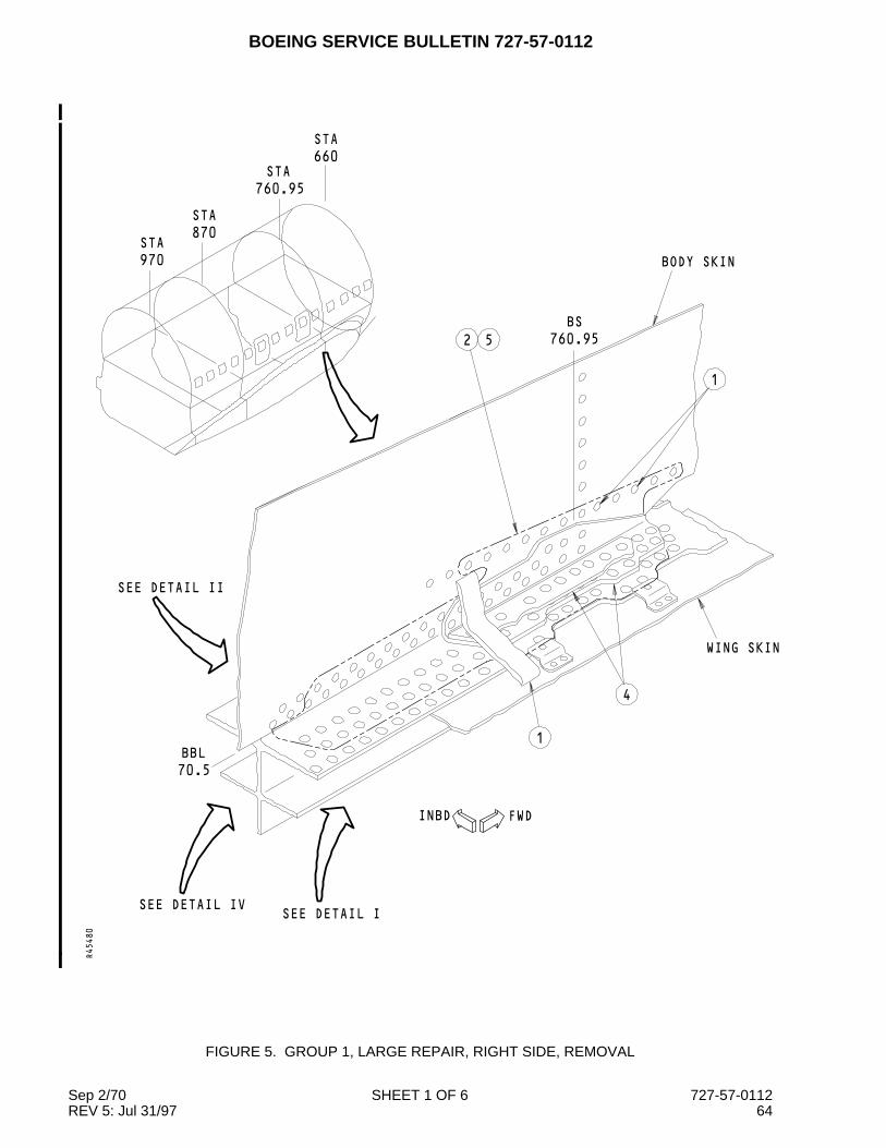
BOEING SERVICE BULLETIN 727-57-0112
FWDINBD
1
WING SKIN
SEE DETAIL ISEE DETAIL IV
BBL
70.5
SEE DETAIL II
2 5 760.95
BS
BODY SKIN
4
STA
970
STA
870
STA
760.95
660
STA
1
R45480
FIGURE 5. GROUP 1, LARGE REPAIR, RIGHT SIDE, REMOVAL
Sep 2/70 SHEET 1 OF 6 727-57-0112REV 5: Jul 31/97 64

BOEING SERVICE BULLETIN 727-57-0112
FWDINBD
DETAIL I
RIB WEB
52
WING SKIN
62
ACCESS PANEL1
S−20
S−19
BBL
70.5
R45497
FIGURE 5. GROUP 1, LARGE REPAIR, RIGHT SIDE, REMOVAL
Sep 2/70 SHEET 2 OF 6 727-57-0112REV 5: Jul 31/97 65

BOEING SERVICE BULLETIN 727-57-0112
FWD
INBD
DETAIL II
BODY SKIN
CENTER SECTION SKIN
SEE
DETAIL III
BS
760.95
BBL
70.5
2 5
4
R45506
FIGURE 5. GROUP 1, LARGE REPAIR, RIGHT SIDE, REMOVAL
Sep 2/70 SHEET 3 OF 6 727-57-0112REV 5: Jul 31/97 66

BOEING SERVICE BULLETIN 727-57-0112
INBDFWD
DETAIL III
1
52
1
4
43
BODY SKIN
1
BBL
70.5
BS
760.95
R45537
FIGURE 5. GROUP 1, LARGE REPAIR, RIGHT SIDE, REMOVAL
Sep 2/70 SHEET 4 OF 6 727-57-0112REV 5: Jul 31/97 67

BOEING SERVICE BULLETIN 727-57-0112
INBDFWD
DETAIL IV
CENTER SECTION SKIN
1
ACCESS
PANELS
70.5
BBL
RIB WEB
52
S−20C
S−19C
2
R45540
FIGURE 5. GROUP 1, LARGE REPAIR, RIGHT SIDE, REMOVAL
Sep 2/70 SHEET 5 OF 6 727-57-0112REV 5: Jul 31/97 68

BOEING SERVICE BULLETIN 727-57-0112
The step numbers shown below agree with the numbers shown in the circle symbols in the figure. Referto Drawing 65C33202, Sheet 7, to the structural changes shown below.
STEP TASK NAME PART NUMBER QTY NOTES
1 Removeand Keep
Foam Seal - 1
Nutplate - 2
Access Panel - 3
Filler - 1
Angle - 3
2 Remove Sealant - -
Fastener - -
3 Cut Strap - 1 See Zone B7, section 1D8
4 Remove Angle - 2
Filler - 1
Tee - 1
Strap (lower section) - 1
5 Examine Hole - - NDT Subject 51-00-00, Figures1 and 4
6 Install Rivet - 1 Install aluminum rivet,countersink, and shave smooth
FIGURE 5. GROUP 1, LARGE REPAIR, RIGHT SIDE, REMOVAL
Sep 2/70 SHEET 6 OF 6 727-57-0112REV 5: Jul 31/97 69

BOEING SERVICE BULLETIN 727-57-0112
1
3
4
12
14
14
INBDFWD
SEE DETAIL I
70.5
BBL
ACCESS PANEL
SEE DETAIL IV
CENTER SECTION SKIN
SEE DETAIL IIACCESS PANEL
S−20C
S−19C
R45546
FIGURE 6. GROUP 1, LARGE REPAIR, RIGHT SIDE, INSTALLATION
Sep 2/70 SHEET 1 OF 6 727-57-0112REV 5: Jul 31/97 70
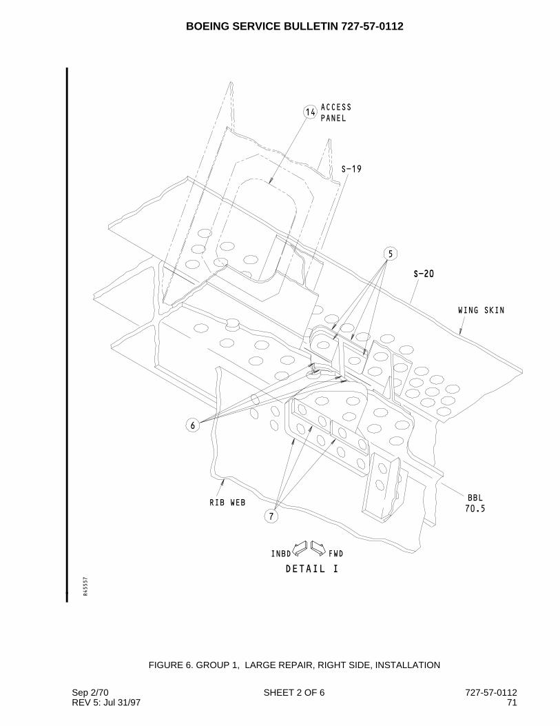
BOEING SERVICE BULLETIN 727-57-0112
INBD FWD
S−20
14PANEL
ACCESS
S−20
S−19
5
WING SKIN
DETAIL I
BBL
70.57
6
RIB WEB
R45557
FIGURE 6. GROUP 1, LARGE REPAIR, RIGHT SIDE, INSTALLATION
Sep 2/70 SHEET 2 OF 6 727-57-0112REV 5: Jul 31/97 71

BOEING SERVICE BULLETIN 727-57-0112
FWD
INBD
8
DETAIL II
CENTER SECTION SKIN
BS
760.95
SEE DETAIL III
BBL
70.5
BODY SKIN
9
8
R45559
FIGURE 6. GROUP 1, LARGE REPAIR, RIGHT SIDE, INSTALLATION
Sep 2/70 SHEET 3 OF 6 727-57-0112REV 5: Jul 31/97 72

BOEING SERVICE BULLETIN 727-57-0112
10
10
INBDFWD
DETAIL III
BODY SKIN
14
14
CENTER SECTION SKIN
70.5
BBL
760.95
BS
R45564
FIGURE 6. GROUP 1, LARGE REPAIR, RIGHT SIDE, INSTALLATION
Sep 2/70 SHEET 4 OF 6 727-57-0112REV 5: Jul 31/97 73

BOEING SERVICE BULLETIN 727-57-0112
BBL
70.5
FWDINBD
DETAIL IV
BODY SKIN
13
12
11
WING
SKIN
12
R45569
FIGURE 6. GROUP 1, LARGE REPAIR, RIGHT SIDE, INSTALLATION
Sep 2/70 SHEET 5 OF 6 727-57-0112REV 5: Jul 31/97 74

BOEING SERVICE BULLETIN 727-57-0112
The step numbers shown below agree with the numbers shown in the circle symbols in the figure. Referto Drawing 65C33202, Sheet 7, to the structural changes shown below.
STEP TASK NAME PART NUMBER QTY NOTES1 Install Tension Tie -
Inboard (Upper)65C37221-1 1 See Sheet 7, Zone A7, Section
1D8 and Zone C11, Section 1C7and Flag Note (FL) 79
Tension Tie -Inboard (Lower)
65C37221-2 1
2 Install Radius Filler 65C37221-10 23 Install Radius Filler 65C37221-9 24 Install Angle - Inboard 65C21524-22 1
Radius Filler 65C21524-14 25 Install Tension Tie -
Outboard65C37221-4 1 See Zone D3, Section 1B4, and
Flag Note 78Shim 65C33202-88 1 Above the Tension TieFiller 65C33202-87 1 between the shim and the wing
skinRadius Filler 65C37221-14 2
6 Install Radius Filler 65C37221-12 2Shim 65C33202-90 1
7 Install Angle - Outboard 65C21524-20 1Radius Filler 65C21524-14 2
8 Install Shim 65C33202-85 1Shim 65C33202-67 1Angle 65C33202-108 1 Trim the contour of part, see FL 93Tapered Filler 65C33202-12 1 Between the Angle and the chord
9 Apply Sealant BMS5-95 - Put the sealant into the hole10 Install Strap (a) 1 (b)
Filler (kept) 65-16325-28 1Tee 65C37221-8 1 Trim the contour of part, see FL 84Angle - Forward,Inboard
65C33202-118 1 Trim the contour of part, see FL 93
11 Install Filler-Outboard 65C33202-10 1Angle - Outboard 65C33202-106 1 Trim the contour of part, see FL 93
12 Install Spacer 65C33202-16 1Filler BACF3T02L28-11 2Fitting 65C33202-113 1 Trim the contour of part, see FL 94Radius Filler 65C37221-11 1 See FL 106
13 Apply Silicone RubberAdhesive
- -
Install Foam Seal (kept) - 1 Trim as nesessary14 Install Access Panel (kept) - 3
Angle (kept) - 3(a) For 727-100 airplanes, use the Strap 69-78758-7. For 727-200 airplanes, use the Strap 69-78758-5(b) Cut the upper area of the strap, if necessary. Remove no more than the upper two fastenerlocations, keep an edge margin of 2D above the new top fastener location and the cut.
FIGURE 6. GROUP 1, LARGE REPAIR, RIGHT SIDE, INSTALLATION
Sep 2/70 SHEET 6 OF 6 727-57-0112REV 5: Jul 31/97 75

BOEING SERVICE BULLETIN 727-57-0112
INBDFWD
SEE DETAIL I
SEE DETAIL IV
660
STA
STA
760.95
870
STA
STA
970
BODY SKIN
SEE
DETAIL II
WING SKIN
1
1
4
760.95
BS
2 5
70.5
BBL
R45581
FIGURE 7. GROUP 2, LARGE REPAIR, LEFT SIDE, REMOVAL
Sep 2/70 SHEET 1 OF 6 727-57-0112REV 5: Jul 31/97 76

BOEING SERVICE BULLETIN 727-57-0112
INBDFWD
S−19
DETAIL I
52
RIB WEB
2
ACCESS PANEL1
S−20
2
R45583
FIGURE 7. GROUP 2, LARGE REPAIR, LEFT SIDE, REMOVAL
Sep 2/70 SHEET 2 OF 6 727-57-0112REV 5: Jul 31/97 77

BOEING SERVICE BULLETIN 727-57-0112
SEE
DETAIL III
BODY SKIN
DETAIL II
FWD
INBD
CENTER SECTION SKIN
70.5
BBL
4
760.95
BS
2 5
R45585
FIGURE 7. GROUP 2, LARGE REPAIR, LEFT SIDE, REMOVAL
Sep 2/70 SHEET 3 OF 6 727-57-0112REV 5: Jul 31/97 78

BOEING SERVICE BULLETIN 727-57-0112
FWDINBD
DETAIL III
CENTER SECTION SKIN
2 5
1
BODY SKIN
43
760.95
BS
4
1
BBL
70.5
1
R45588
FIGURE 7. GROUP 2, LARGE REPAIR, LEFT SIDE, REMOVAL
Sep 2/70 SHEET 4 OF 6 727-57-0112REV 5: Jul 31/97 79

BOEING SERVICE BULLETIN 727-57-0112
FWDINBD
DETAIL IV
PANELS
ACCESS
CENTER SECTION SKIN
1
BBL
70.5
52
RIB WEB
2
S−20C
S−19C
R45597
FIGURE 7. GROUP 2, LARGE REPAIR, LEFT SIDE, REMOVAL
Sep 2/70 SHEET 5 OF 6 727-57-0112REV 5: Jul 31/97 80

BOEING SERVICE BULLETIN 727-57-0112
The step numbers shown below agree with the numbers shown in the circle symbols in the figure. Referto Drawing 65C33202, Sheet 11, to the structural changes shown below.
STEP TASK NAME PART NUMBER QTY NOTES
1 Removeand Keep
Foam Seal - 1
Nutplate - 2
Access Panel - 3
Filler - 1
Angle - 3
2 Remove Sealant - -
Fastener - -
3 Cut Strap - 1 See Zone B7, Section D8
4 Remove Angle - 2
Filler - 1
Tee - 1
Strap (lower section) - 1
5 Examine Hole - - NDT Subject 51-00-00, Figures1 and 4
FIGURE 7. GROUP 2, LARGE REPAIR, LEFT SIDE, REMOVAL
Sep 2/70 SHEET 6 OF 6 727-57-0112REV 5: Jul 31/97 81

BOEING SERVICE BULLETIN 727-57-0112
BBL
70.5
FWDINBD
ACCESS
PANEL14
ACCESS
PANEL14
SEE DETAIL II
CENTER SECTION SKIN
SEE DETAIL IV
RIB WEB
SEE DETAIL I
S−20C
S−19C
2
1
R45696
FIGURE 8. GROUP 2, LARGE REPAIR, LEFT SIDE, INSTALLATION
Sep 2/70 SHEET 1 OF 7 727-57-0112REV 5: Jul 31/97 82

BOEING SERVICE BULLETIN 727-57-0112
FWD INBD
BBL
70.5
S−19
S−20
6
WING SKIN14
ACCESS
PANEL
4
DETAIL I
3
5
RIB
R45731
FIGURE 8. GROUP 2, LARGE REPAIR, LEFT SIDE, INSTALLATION
Sep 2/70 SHEET 2 OF 7 727-57-0112REV 5: Jul 31/97 83

BOEING SERVICE BULLETIN 727-57-0112
BODY SKIN
BBL
70.5
760.95
BS
FWD
DETAIL II
INBD
7
SEE
DETAIL III
CENTER SECTION SKIN
7
7
R45744
FIGURE 8. GROUP 2, LARGE REPAIR, LEFT SIDE, INSTALLATION
Sep 2/70 SHEET 3 OF 7 727-57-0112REV 5: Jul 31/97 84

BOEING SERVICE BULLETIN 727-57-0112
14
14
9
70.5
BBL
FWDINBD
BS
760.95
DETAIL III
BODY SKIN
CENTER SECTION SKIN
7
8
R45770
FIGURE 8. GROUP 2, LARGE REPAIR, LEFT SIDE, INSTALLATION
Sep 2/70 SHEET 4 OF 7 727-57-0112REV 5: Jul 31/97 85

BOEING SERVICE BULLETIN 727-57-0112
INBDFWD
BODY SKIN
WING SKIN
DETAIL IV
BS
760.95
11
10
13
10
11
12
R45777
FIGURE 8. GROUP 2, LARGE REPAIR, LEFT SIDE, INSTALLATION
Sep 2/70 SHEET 5 OF 7 727-57-0112REV 5: Jul 31/97 86

BOEING SERVICE BULLETIN 727-57-0112
The step numbers shown below agree with the numbers shown in the circle symbols in the figure. Referto Drawing 65C33202, Sheet 11, to the structural changes shown below.
STEP TASK NAME PART NUMBER QTY NOTES
1 Install Tension Tie -Inboard
65C37073-1 1 See Sheet 11, Zone A7, SectionD8
Shim BACS40R019E036F 1
2 Install Angle - Inboard 65C33202-44 1
Radius Filler 65C33202-68 2
3 Install Tension Tie -Outboard
65C37083-1 1 See Zone B1, Section 1C7 andZone C9, Section D7 and FlagNotes (FL) 44 and 86
Shim 65C33202-59 1 Above the Tension Tie
Filler 65C33202-60 1 Between the Tension Tie and thewing skin
4 Install Radius Filler 65C37083-3 1 Aft side of Tension Tie
Radius Filler 65C37083-5 1 Forward side of Tension Tie
5 Install Radius Filler 65C37083-2 1 Aft side of Tension Tie
Radius Filler 65C37083-4 1 Forward side of Tension Tie
Shim 65C33202-95 1
6 Install Angle - Outboard 65C33202-45 1
Radius Filler 65C33202-68 2
7 Install Shim 65C33202-51 1
65C33202-52 1
65C33202-53 1
Pressure RetainingAngle
65C33202-54 1
Angle 65C33202-107 1 Trim the contour of part, see FL 93
Tee 65C37221-7 1 Trim the contour of part, see FL 93
Tapered Filler 65C33202-48 1 Between the Angle and the chord
Filler 65C33202-69 1
8 Install Strap 69-78758-5 1
Filler (kept) 65-16325-80 1
9 Install Angle - Forward,Inboard
65C33202-117 1 Trim the contour of part, see FL 93
10 Install Filler-Outboard 65C33202-50 1
Shim 65C33202-71 1
Angle - Outboard 65C33202-105 1 Trim the contour of part, see FL 93
11 Install Spacer 65C33202-47 1
Filler BACF3T02M26-12 2
FIGURE 8. GROUP 2, LARGE REPAIR, LEFT SIDE, INSTALLATION
Sep 2/70 SHEET 6 OF 7 727-57-0112REV 5: Jul 31/97 87

BOEING SERVICE BULLETIN 727-57-0112
(Continued)
STEP TASK NAME PART NUMBER QTY NOTES
12 Install Fitting 65C33202-113 1 Trim the contour of part, see FL 94
Radius Filler 65C33202-115 1 Optional, see FL 106
13 Apply Silicon RubberAdhesive
- -
Install Foam Seal (kept) - 1 Trim as nesessary
14 Install Access Panel (kept) - 3
Angle (kept) - 3
FIGURE 8. GROUP 2, LARGE REPAIR, LEFT SIDE, INSTALLATION
Sep 2/70 SHEET 7 OF 7 727-57-0112REV 5: Jul 31/97 88

BOEING SERVICE BULLETIN 727-57-0112
INBD FWD
1
SEE DETAIL I
760.95
52
1
4
BS
970
STA
STA
870
STA
760.95
STA
660
BODY SKIN
WING SKIN
SEE DETAIL II
SEE DETAIL IV
BBL
70.5
R45796
FIGURE 9. GROUP 2, LARGE REPAIR, RIGHT SIDE, REMOVAL
Sep 2/70 SHEET 1 OF 6 727-57-0112REV 5: Jul 31/97 89

BOEING SERVICE BULLETIN 727-57-0112
FWDINBD
DETAIL I
RIB WEB
S−19
S−20
ACCESS PANEL1
2
WING SKIN
2 5BBL
70.5
R45801
FIGURE 9. GROUP 2, LARGE REPAIR, RIGHT SIDE, REMOVAL
Sep 2/70 SHEET 2 OF 6 727-57-0112REV 5: Jul 31/97 90

BOEING SERVICE BULLETIN 727-57-0112
FWD
INBD
SEE
DETAIL III
4
BODY SKIN
DETAIL II
CENTER SECTION SKIN
2 5
BBL
70.5
BS
760.95
R45870
FIGURE 9. GROUP 2, LARGE REPAIR, RIGHT SIDE, REMOVAL
Sep 2/70 SHEET 3 OF 6 727-57-0112REV 5: Jul 31/97 91

BOEING SERVICE BULLETIN 727-57-0112
INBDFWD
DETAIL III
CENTER SECTION SKIN
4
BODY SKIN
BBL
70.5
43
760.95
BS
52
11
1
R45872
FIGURE 9. GROUP 2, LARGE REPAIR, RIGHT SIDE, REMOVAL
Sep 2/70 SHEET 4 OF 6 727-57-0112REV 5: Jul 31/97 92
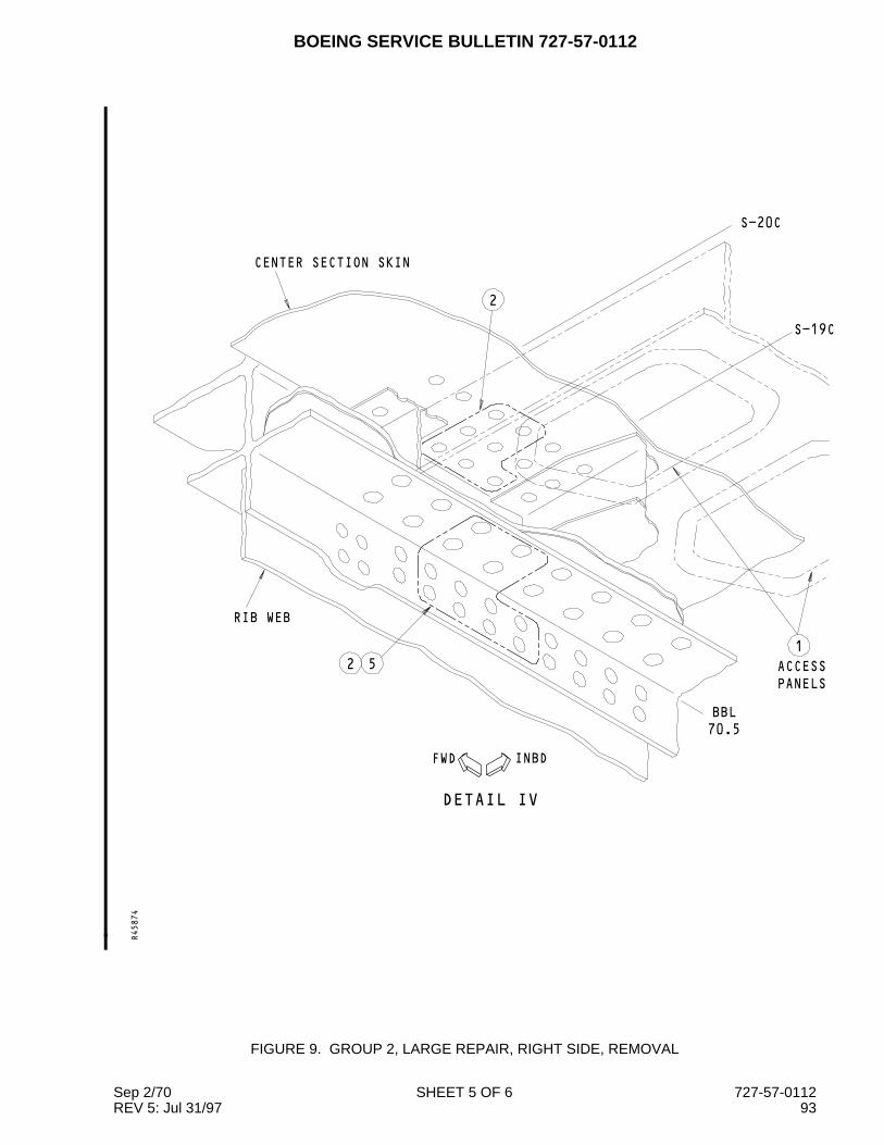
BOEING SERVICE BULLETIN 727-57-0112
INBDFWD
2
CENTER SECTION SKIN
DETAIL IV
RIB WEB
52
S−19C
S−20C
PANELS
ACCESS
1
BBL
70.5
R45874
FIGURE 9. GROUP 2, LARGE REPAIR, RIGHT SIDE, REMOVAL
Sep 2/70 SHEET 5 OF 6 727-57-0112REV 5: Jul 31/97 93

BOEING SERVICE BULLETIN 727-57-0112
The step numbers shown below agree with the numbers shown in the circle symbols in the figure. Referto Drawing 65C33202, Sheet 11, to the structural changes shown below.
STEP TASK NAME PART NUMBER QTY NOTES
1 Removeand Keep
Foam Seal - 1
Nutplate - 2
Access Panel - 3
Filler - 1
Angle - 3
2 Remove Sealant - -
Fastener - -
3 Cut Strap - 1 See Zone B3, Section D2
4 Remove Angle - 2
Filler - 1
Tee - 1
Strap (lower section) - 1
5 Examine Hole - - NDT Subject 51-00-00, Figures1 and 4
FIGURE 9. GROUP 2, LARGE REPAIR, RIGHT SIDE, REMOVAL
Sep 2/70 SHEET 6 OF 6 727-57-0112REV 5: Jul 31/97 94

BOEING SERVICE BULLETIN 727-57-0112
INBDFWD
RIB WEB
SEE DETAIL I
SEE DETAIL II
CENTER SECTION SKIN
SEE DETAIL IV1
ACCESS
PANEL
70.5
BBLPANEL
ACCESS
S−20C
S−19C
2
13
13
R45881
FIGURE 10. GROUP 2, LARGE REPAIR, RIGHT SIDE, INSTALLATION
Sep 2/70 SHEET 1 OF 7 727-57-0112REV 5: Jul 31/97 95

BOEING SERVICE BULLETIN 727-57-0112
FWDINBD
DETAIL I
RIB WEB
WING SKIN
3
S−20
S−19
ACCESS
PANEL
4
4
S−20
70.5
BBL
5
13
R45896
FIGURE 10. GROUP 2, LARGE REPAIR, RIGHT SIDE, INSTALLATION
Sep 2/70 SHEET 2 OF 7 727-57-0112REV 5: Jul 31/97 96

BOEING SERVICE BULLETIN 727-57-0112
INBD
FWD
DETAIL II
CENTER SECTION SKIN
6
SEE
DETAIL III
BODY SKIN
BBL
70.5
BS
760.95
6
6
R45918
FIGURE 10. GROUP 2, LARGE REPAIR, RIGHT SIDE, INSTALLATION
Sep 2/70 SHEET 3 OF 7 727-57-0112REV 5: Jul 31/97 97

BOEING SERVICE BULLETIN 727-57-0112
INBDFWD
DETAIL III
CENTER SECTION SKIN
8
7
BODY SKIN
BBL
70.5
6
BS
760.95
13
13
R45923
FIGURE 10. GROUP 2, LARGE REPAIR, RIGHT SIDE, INSTALLATION
Sep 2/70 SHEET 4 OF 7 727-57-0112REV 5: Jul 31/97 98

BOEING SERVICE BULLETIN 727-57-0112
FWDINBD
BODY SKIN
DETAIL IV
9
9
WING SKIN
10
BS
760.95
10
12
11
R45925
FIGURE 10. GROUP 2, LARGE REPAIR, RIGHT SIDE, INSTALLATION
Sep 2/70 SHEET 5 OF 7 727-57-0112REV 5: Jul 31/97 99

BOEING SERVICE BULLETIN 727-57-0112
The step numbers shown below agree with the numbers shown in the circle symbols in the figure. Referto Drawing 65C33202, Sheet 11, to the structural changes shown below.
STEP TASK NAME PART NUMBER QTY NOTES
1 Install Tension Tie -Inboard
65C37073-1 1 See Sheet 11, Zone A4, SectionD2
Shim BACS40R019E036F 1
2 Install Angle - Inboard 65C33202-44 1
Radius Filler 65C33202-68 2
3 Install Tension Tie -Outboard
65C37073-2 1 See Zone D2, Section C3 andZone A10, Section D3 and FlagNote (FL) 86
Shim 65C33202-96 Above the Tension Tie
Radius Filler 65C37073-4 2
4 Install Radius Filler 65C37073-3 2
Shim 65C33202-56 1 Below the Tension Tie
Filler 65C33202-55 1 Between the shim and the lowerAngle
5 Install Angle - Outboard 65C33202-46 1
Radius Filler 65C33202-68 2
6 Install Shim 65C33202-51 1
65C33202-52 1
65C33202-53 1
Pressure RetainingAngle
65C33202-54 1
Angle 65C33202-108 1 Trim the contour of part, see FL 93
Tee 65C37221-8 1 Trim the contour of part, see FL 93
Tapered Filler 65C33202-48 1 Between the Angle and the chord
Filler 65C33202-69 1
7 Install Strap 69-78758-5 1
Filler (kept) 65-16325-80 1
8 Install Angle - Forward,Inboard
65C33202-118 1 Trim the contour of part, see FL 93
9 Install Filler-Outboard 65C33202-50 1
Shim 65C33202-71 1
Angle - Outboard 65C33202-106 1 Trim the contour of part, see FL 93
10 Install Spacer 65C33202-47 1
Filler BACF3T02M26-12 2
11 Install Fitting 65C33202-113 1 Trim the contour of part, see FL 94
Radius Filler 65C33202-115 1 Optional, see FL 106
FIGURE 10. GROUP 2, LARGE REPAIR, RIGHT SIDE, INSTALLATION
Sep 2/70 SHEET 6 OF 7 727-57-0112REV 5: Jul 31/97 100

BOEING SERVICE BULLETIN 727-57-0112
(Continued)
STEP TASK NAME PART NUMBER QTY NOTES
12 Apply Silicon RubberAdhesive
- -
Install Foam Seal (kept) - 1 Trim as nesessary
13 Install Access Panel (kept) - 3
Angle (kept) - 3
FIGURE 10. GROUP 2, LARGE REPAIR, RIGHT SIDE, INSTALLATION
Sep 2/70 SHEET 7 OF 7 727-57-0112REV 5: Jul 31/97 101

BOEING SERVICE BULLETIN 727-57-0112
INBDFWD
WING SKIN
1
4
SEE DETAIL I
1
52
BODY SKIN
SEE DETAIL II
SEE DETAIL IV
760.95
BS
BBL
70.5
660
STA
STA
760.95
STA
970
870
STA
R45952
FIGURE 11. GROUP 1, PREVENTIVE MODIFICATION, LEFT SIDE, REMOVAL
Sep 2/70 SHEET 1 OF 6 727-57-0112REV 5: Jul 31/97 102

BOEING SERVICE BULLETIN 727-57-0112
INBDFWD
2
S−20
S−19
ACCESS PANEL1
RIB WEB
DETAIL I
52
R45957
FIGURE 11. GROUP 1, PREVENTIVE MODIFICATION, LEFT SIDE, REMOVAL
Sep 2/70 SHEET 2 OF 6 727-57-0112REV 5: Jul 31/97 103

BOEING SERVICE BULLETIN 727-57-0112
BODY SKIN
INBD
DETAIL II
FWD
DETAIL III
SEE
CENTER SECTION SKIN
BS
760.95
BBL
70.5
4
52
R45962
FIGURE 11. GROUP 1, PREVENTIVE MODIFICATION, LEFT SIDE, REMOVAL
Sep 2/70 SHEET 3 OF 6 727-57-0112REV 5: Jul 31/97 104

BOEING SERVICE BULLETIN 727-57-0112
FWDINBD
DETAIL III
1
43
4
BODY SKIN
1
2 5
1
760.95
BS
70.5
BBL
R45969
FIGURE 11. GROUP 1, PREVENTIVE MODIFICATION, LEFT SIDE, REMOVAL
Sep 2/70 SHEET 4 OF 6 727-57-0112REV 5: Jul 31/97 105

BOEING SERVICE BULLETIN 727-57-0112
FWDINBD
DETAIL IV
RIB WEB
2 5
CENTER SECTION SKIN
2
1
PANELS
ACCESS
S−19C
S−20C
BBL
70.5
R45974
FIGURE 11. GROUP 1, PREVENTIVE MODIFICATION, LEFT SIDE, REMOVAL
Sep 2/70 SHEET 5 OF 6 727-57-0112REV 5: Jul 31/97 106

BOEING SERVICE BULLETIN 727-57-0112
The step numbers shown below agree with the numbers shown in the circle symbols in the figure. Referto Drawing 65C33202, Sheet 8, to the structural changes shown below.
STEP TASK NAME PART NUMBER QTY NOTES
1 Removeand Keep
Foam Seal - 1
Nutplate - 2
Access Panel - 3
Filler - 1
Angle - 3
2 Remove Sealant - -
Fastener - -
3 Cut Strap - 1 See Zone B7, Section 1D8
4 Remove Angle - 2
Filler - 1
Tee - 1
Strap (lower section) - 1
5 Examine Hole - - NDT Subject 51-00-00, Figures1 and 4
FIGURE 11. GROUP 1, PREVENTIVE MODIFICATION, LEFT SIDE, REMOVAL
Sep 2/70 SHEET 6 OF 6 727-57-0112REV 5: Jul 31/97 107

BOEING SERVICE BULLETIN 727-57-0112
FWDINBD
1 2
3
1
4
SEE DETAIL I
SEE DETAIL IV
CENTER SECTION SKINSEE DETAIL II
ACCESS PANEL
14
S−20C
BBL
70.5
S−19C
R45984
FIGURE 12. GROUP 1, PREVENTIVE MODIFICATION, LEFT SIDE, INSTALLATION
Sep 2/70 SHEET 1 OF 6 727-57-0112REV 5: Jul 31/97 108

BOEING SERVICE BULLETIN 727-57-0112
INBDFWD
DETAIL I
S−20
S−19
PANEL
ACCESS14
5
7
6
70.5
BBLRIB
R45987
FIGURE 12. GROUP 1, PREVENTIVE MODIFICATION, LEFT SIDE, INSTALLATION
Sep 2/70 SHEET 2 OF 6 727-57-0112REV 5: Jul 31/97 109

BOEING SERVICE BULLETIN 727-57-0112
9
BODY SKIN
8
FWD
DETAIL II
INBD
CENTER SECTION SKIN
DETAIL III
SEE
70.5
BBL
760.95
BS
8
R46042
FIGURE 12. GROUP 1, PREVENTIVE MODIFICATION, LEFT SIDE, INSTALLATION
Sep 2/70 SHEET 3 OF 6 727-57-0112REV 5: Jul 31/97 110

BOEING SERVICE BULLETIN 727-57-0112
10
10
FWDINBD
DETAIL III
CENTER SECTION SKIN
14
14
BODY SKIN
760.95
BS
BBL
70.5
R46084
FIGURE 12. GROUP 1, PREVENTIVE MODIFICATION, LEFT SIDE, INSTALLATION
Sep 2/70 SHEET 4 OF 6 727-57-0112REV 5: Jul 31/97 111

BOEING SERVICE BULLETIN 727-57-0112
INBDFWD
12
13
11
70.5
BBL
DETAIL IV
760.95
BS
R46147
FIGURE 12. GROUP 1, PREVENTIVE MODIFICATION, LEFT SIDE, INSTALLATION
Sep 2/70 SHEET 5 OF 6 727-57-0112REV 5: Jul 31/97 112

BOEING SERVICE BULLETIN 727-57-0112
The step numbers shown below agree with the numbers shown in the circle symbols in the figure. Referto Drawing 65C33202, Sheet 8, to the structural changes shown below.
STEP TASK NAME PART NUMBER QTY NOTES1 Install Tension Tie -
Inboard (Upper)65C37221-1 1 See Sheet 8, Zone A7, Section
1D8 and Zone C11, Section 1C7and Flag Note (FL) 79
Tension Tie -Inboard (Lower)
65C37221-2 1
2 Install Radius Filler 65C37221-10 23 Install Radius Filler 65C37221-9 24 Install Angle - Inboard 65C21524-21 1
Radius Filler 65C21524-14 25 Install Tension Tie -
Outboard65C37221-3 1 See Zone C7, Section 1D8 and
Zone C11, Section 1C7, and FlagNote 78
Shim 65C33202-89 1 Above the Tension TieRadius Filler 65C37221-16 1 Aft side of Tension TieRadius Filler 65C37221-13 1 Forward side of Tension Tie
6 Install Radius Filler 65C37221-15 2Shim 65C33202-90 1
7 Install Angle - Outboard 65C21524-19 1Radius Filler 65C21524-14 2
8 Install Shim 65C33202-86 1Angle 65C33202-107 1 Trim the contour of part, see FL 93Tapered Filler 65C33202-11 1 Between the Angle and the chord
9 Apply Sealant BMS5-95 - Put the sealant into the hole10 Install Strap (a) 1 (b)
Filler (kept) 65-16325-28 1Tee 65C37221-7 1 Trim the contour of part, see FL 84Angle - Forward,Inboard
65C33202-117 1 Trim the contour of part, see FL 93
11 Install Filler-Outboard 65C33202-9 1Angle - Outboard 65C33202-105 1 Trim the contour of part, see FL 93
12 Install Spacer 65C33202-15 1 Delete the reference to FL80Filler BACF3T02L28-11 2Fitting 65C33202-113 1 Trim the contour of part, see FL 94Radius Filler 65C37221-11 1 Optional, see FL 106
13 Apply Silicon RubberAdhesive
- -
Install Foam Seal (kept) - 1 Trim as nesessary14 Install Access Panel (kept) - 3
Angle (kept) - 3(a) For 727-100 airplanes, use the Strap 69-78758-7. For 727-200 airplanes, use the Strap 69-78758-5(b) Cut the upper area of the strap, if necessary. Remove no more than the upper two fastenerlocations, keep an edge margin of 2D above the new top fastener location and the cut.
FIGURE 12. GROUP 1, PREVENTIVE MODIFICATION, LEFT SIDE, INSTALLATION
Sep 2/70 SHEET 6 OF 6 727-57-0112REV 5: Jul 31/97 113

BOEING SERVICE BULLETIN 727-57-0112
FWDINBD
760.95
BS
SEE DETAIL I
70.5
BBL
SEE DETAIL IV
SEE DETAIL II
WING SKIN
BODY SKIN
1
STA
760.95
4
2 5
1
STA
970
STA
870
660
STA
R46150
FIGURE 13. GROUP 1, PREVENTIVE MODIFICATION, RIGHT SIDE, REMOVAL
Sep 2/70 SHEET 1 OF 6 727-57-0112REV 5: Jul 31/97 114

BOEING SERVICE BULLETIN 727-57-0112
INBD FWD
6
2
DETAIL I
BBL
70.5
S−20
S−19
WING SKIN
RIB WEB
1 ACCESS PANEL
52
R46152
FIGURE 13. GROUP 1, PREVENTIVE MODIFICATION, RIGHT SIDE, REMOVAL
Sep 2/70 SHEET 2 OF 6 727-57-0112REV 5: Jul 31/97 115

BOEING SERVICE BULLETIN 727-57-0112
INBD
FWD
DETAIL II
CENTER SECTION SKIN
BODY SKIN
SEE
DETAIL III
BS
760.95
BBL
70.5
2 5
4
R46174
FIGURE 13. GROUP 1, PREVENTIVE MODIFICATION, RIGHT SIDE, REMOVAL
Sep 2/70 SHEET 3 OF 6 727-57-0112REV 5: Jul 31/97 116

BOEING SERVICE BULLETIN 727-57-0112
INBDFWD
DETAIL III
52
BODY SKIN
1
1
4
43
BBL
70.5
BS
760.95
1
R46193
FIGURE 13. GROUP 1, PREVENTIVE MODIFICATION, RIGHT SIDE, REMOVAL
Sep 2/70 SHEET 4 OF 6 727-57-0112REV 5: Jul 31/97 117

BOEING SERVICE BULLETIN 727-57-0112
INBDFWD
DETAIL IV
RIB WEB
2 5
CENTER SECTION SKIN
BBL
70.5
PANELS
ACCESS
1
2
S−19C
S−20C
R46204
FIGURE 13. GROUP 1, PREVENTIVE MODIFICATION, RIGHT SIDE, REMOVAL
Sep 2/70 SHEET 5 OF 6 727-57-0112REV 5: Jul 31/97 118

BOEING SERVICE BULLETIN 727-57-0112
The step numbers shown below agree with the numbers shown in the circle symbols in the figure. Referto Drawing 65C33202, Sheet 8, to the structural changes shown below.
STEP TASK NAME PART NUMBER QTY NOTES
1 Removeand Keep
Foam Seal - 1
Nutplate - 2
Access Panel - 3
Filler - 1
Angle - 3
2 Remove Sealant - -
Fastener - -
3 Cut Strap - 1 See Zone B7, Section 1D8
4 Remove Angle - 2
Filler - 1
Tee - 1
Strap (lower section) - 1
5 Examine Hole - - NDT Subject 51-00-00, Figures1 and 4
6 Install Rivet - 1 Install aluminum rivet,countersink, and shave smooth
FIGURE 13. GROUP 1, PREVENTIVE MODIFICATION, RIGHT SIDE, REMOVAL
Sep 2/70 SHEET 6 OF 6 727-57-0112REV 5: Jul 31/97 119

BOEING SERVICE BULLETIN 727-57-0112
INBDFWD
CENTER SECTION SKIN
3
1
1
2
ACCESS PANEL14
70.5
BBL
ACCESS PANEL
14
SEE DETAIL II
SEE DETAIL IV
SEE DETAIL I
4
S−20C
S−19C
R46231
FIGURE 14. GROUP 1, PREVENTIVE MODIFICATION, RIGHT SIDE, INSTALLATION
Sep 2/70 SHEET 1 OF 6 727-57-0112REV 5: Jul 31/97 120

BOEING SERVICE BULLETIN 727-57-0112
FWDINBD
DETAIL I
RIB WEB
7
S−20
S−19
5
PANEL
ACCESS14
WING SKIN
6
BBL
70.5
S−20
R46233
FIGURE 14. GROUP 1, PREVENTIVE MODIFICATION, RIGHT SIDE, INSTALLATION
Sep 2/70 SHEET 2 OF 6 727-57-0112REV 5: Jul 31/97 121

BOEING SERVICE BULLETIN 727-57-0112
FWD
INBD
CENTER SECTION SKIN
DETAIL II
BODY SKIN
9
8
8
SEE DETAIL III
70.5
BBL
760.95
BS
R46250
FIGURE 14. GROUP 1, PREVENTIVE MODIFICATION, RIGHT SIDE, INSTALLATION
Sep 2/70 SHEET 3 OF 6 727-57-0112REV 5: Jul 31/97 122
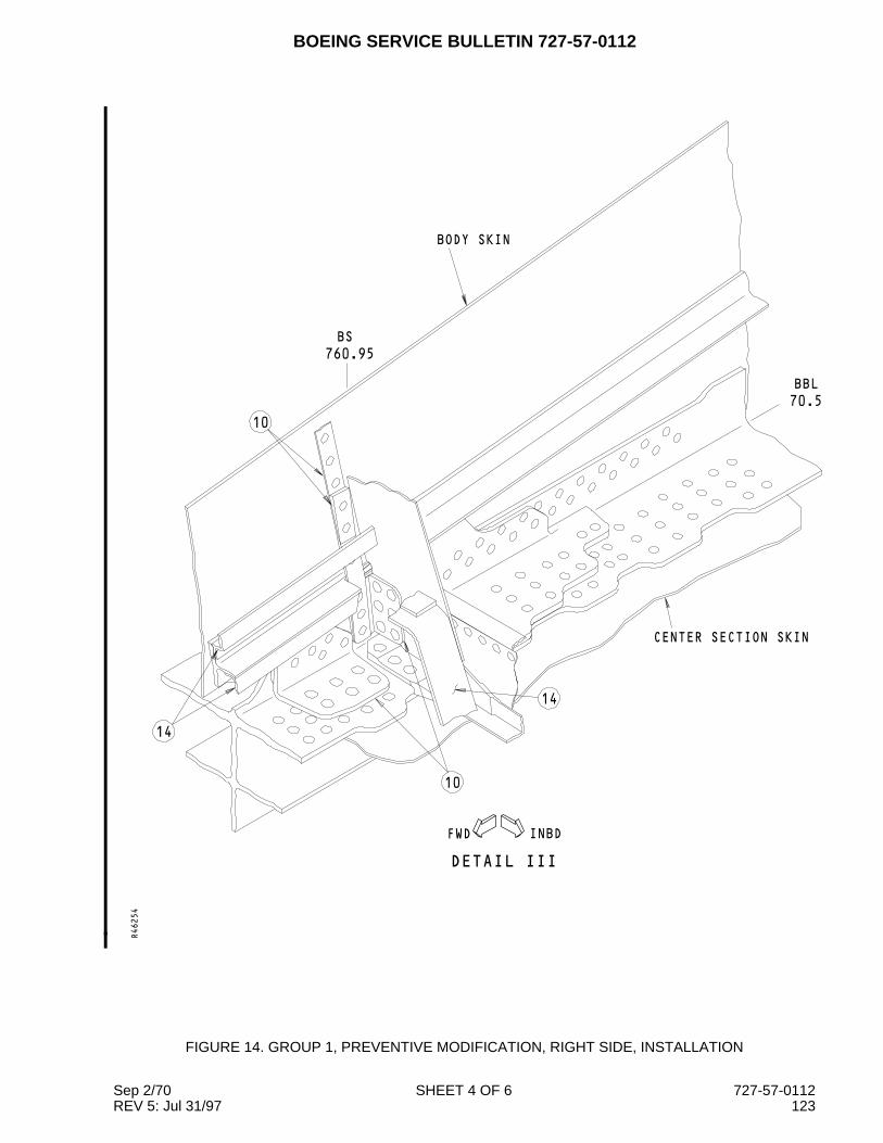
BOEING SERVICE BULLETIN 727-57-0112
10
10
INBDFWD
CENTER SECTION SKIN
DETAIL III
14
14
BODY SKIN
BBL
70.5
BS
760.95
R46254
FIGURE 14. GROUP 1, PREVENTIVE MODIFICATION, RIGHT SIDE, INSTALLATION
Sep 2/70 SHEET 4 OF 6 727-57-0112REV 5: Jul 31/97 123

BOEING SERVICE BULLETIN 727-57-0112
BBL
70.5
FWDINBD
13
12
WING SKIN
BODY SKIN
DETAIL IV
12
11
R46258
FIGURE 14. GROUP 1, PREVENTIVE MODIFICATION, RIGHT SIDE, INSTALLATION
Sep 2/70 SHEET 5 OF 6 727-57-0112REV 5: Jul 31/97 124

BOEING SERVICE BULLETIN 727-57-0112
The step numbers shown below agree with the numbers shown in the circle symbols in the figure. Referto Drawing 65C33202, Sheet 8, to the structural changes shown below.
STEP TASK NAME PART NUMBER QTY NOTES1 Install Tension Tie -
Inboard (Upper)65C37221-1 1 See Sheet 8, Zone A4, Section
2C7 and Flag Note (FL) 79Tension Tie -Inboard (Lower)
65C37221-2 1
2 Install Radius Filler 65C37221-10 23 Install Radius Filler 65C37221-9 24 Install Angle - Inboard 65C21524-22 1
Radius Filler 65C21524-14 25 Install Tension Tie -
Outboard65C37221-4 1 See Zone C11, Section 1C7 and
Zone C4, Section 1B4 and FlagNote 78
Shim 65C33202-88 1 Above the Tension TieFiller 65C33202-87 1 Between the shim and the wing
skinRadius Filler 65C37221-14 2
6 Install Radius Filler 65C37221-12 2Shim 65C33202-90 1
7 Install Angle - Outboard 65C21524-20 1Radius Filler 65C21524-14 2
8 Install Shim 65C33202-86 1Angle 65C33202-108 1 Trim the contour of part, see FL 93Tapered Filler 65C33202-12 1 Between the Angle and the chord
9 Apply Sealant BMS5-95 - Put the sealant into the hole10 Install Strap (a) 1 (b)
Filler (kept) 65-16325-28 1Tee 65C37221-8 1 Trim the contour of part, see FL 84Angle - Forward,Inboard
65C33202-118 1 Trim the contour of part, see FL 93
11 Install Filler-Outboard 65C33202-10 1Angle - Outboard 65C33202-106 1 Trim the contour of part, see FL 93
12 Install Spacer 65C33202-16 1Filler BACF3T02L28-11 2Fitting 65C33202-113 1 Trim the contour of part, see FL 94Radius Filler 65C37221-11 1 Optional, see FL 106
13 Apply Silicone RubberAdhesive
- -
Install Foam Seal (kept) - 1 Trim as nesessary14 Install Access Panel (kept) - 3
Angle (kept) - 3(a) For 727-100 airplanes, use the Strap 69-78758-7. For 727-200 airplanes, use the Strap 69-78758-5(b) Cut the upper area of the strap, if necessary. Remove no more than the upper two fastenerlocations, keep an edge margin of 2D above the new top fastener location and the cut.
FIGURE 14. GROUP 1, PREVENTIVE MODIFICATION, RIGHT SIDE, INSTALLATION
Sep 2/70 SHEET 6 OF 6 727-57-0112REV 5: Jul 31/97 125

BOEING SERVICE BULLETIN 727-57-0112
FWD INBD
70.5
BBL
4
760.95
BS
2 5
1
1
BODY SKIN
760.95
STA
STA
660
870
STA
STA
970
SEE
DETAIL II
SEE DETAIL IVSEE DETAIL I
WING SKIN
R46340
FIGURE 15. GROUP 2, PREVENTIVE MODIFICATION, LEFT SIDE, REMOVAL
Sep 2/70 SHEET 1 OF 6 727-57-0112REV 5: Jul 31/97 126

BOEING SERVICE BULLETIN 727-57-0112
INBDFWD
DETAIL I
2 5
RIB WEB
2
1 ACCESS PANEL
S−19
S−20
2
R46341
FIGURE 15. GROUP 2, PREVENTIVE MODIFICATION, LEFT SIDE, REMOVAL
Sep 2/70 SHEET 2 OF 6 727-57-0112REV 5: Jul 31/97 127
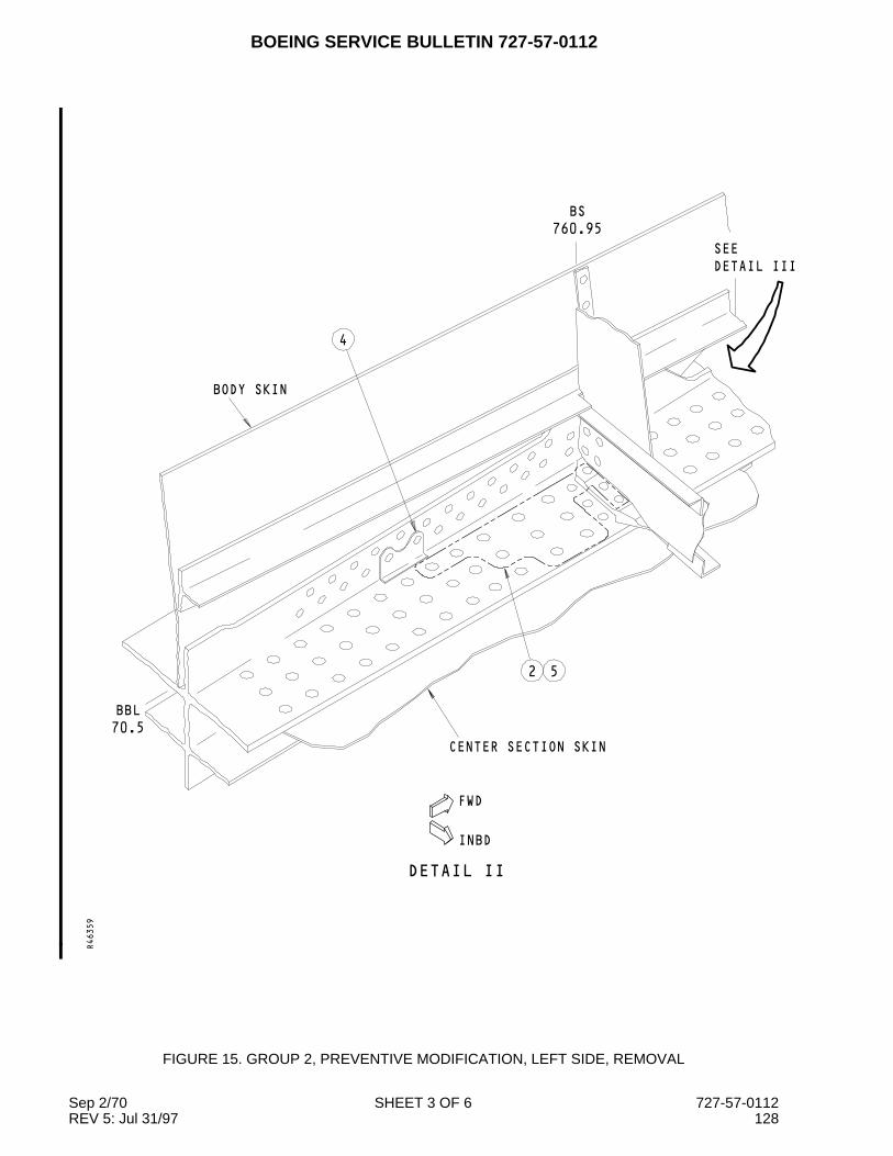
BOEING SERVICE BULLETIN 727-57-0112
FWD
INBD
DETAIL II
BODY SKIN
CENTER SECTION SKIN
SEE
DETAIL III
4
52
70.5
BBL
760.95
BS
R46359
FIGURE 15. GROUP 2, PREVENTIVE MODIFICATION, LEFT SIDE, REMOVAL
Sep 2/70 SHEET 3 OF 6 727-57-0112REV 5: Jul 31/97 128

BOEING SERVICE BULLETIN 727-57-0112
FWDINBD
DETAIL III
BODY SKIN
BBL
70.5
BS
760.95
4
1
3 4
1
52
1
R46365
FIGURE 15. GROUP 2, PREVENTIVE MODIFICATION, LEFT SIDE, REMOVAL
Sep 2/70 SHEET 4 OF 6 727-57-0112REV 5: Jul 31/97 129

BOEING SERVICE BULLETIN 727-57-0112
FWDINBD
BBL
70.5
DETAIL IV
RIB WEB
CENTER SECTION SKIN
S−20
S−19
PANELS
ACCESS
1
2
52
R46369
FIGURE 15. GROUP 2, PREVENTIVE MODIFICATION, LEFT SIDE, REMOVAL
Sep 2/70 SHEET 5 OF 6 727-57-0112REV 5: Jul 31/97 130

BOEING SERVICE BULLETIN 727-57-0112
The step numbers shown below agree with the numbers shown in the circle symbols in the figure. Referto Drawing 65C33202, Sheet 12, to the structural changes shown below.
STEP TASK NAME PART NUMBER QTY NOTES
1 Removeand Keep
Foam Seal - 1
Nutplate - 2
Access Panel - 3
Filler - 1
Angle - 3
2 Remove Sealant - -
Fastener - -
3 Cut Strap - 1 See Zone B7, Section D8
4 Remove Angle - 2
Filler - 1
Tee - 1
Strap (lower section) - 1
5 Examine Hole - - NDT Subject 51-00-00, Figures1 and 4
FIGURE 15. GROUP 2, PREVENTIVE MODIFICATION, LEFT SIDE, REMOVAL
Sep 2/70 SHEET 6 OF 6 727-57-0112REV 5: Jul 31/97 131

BOEING SERVICE BULLETIN 727-57-0112
FWDINBD
SEE DETAIL II
PANEL
ACCESS
2
SEE DETAIL I
RIB WEB
SEE DETAIL IV
CENTER SECTION SKIN
ACCESS
PANEL
S−20C
S−19C
1
BBL
70.5
14
14
R46373
FIGURE 16. GROUP 2, PREVENTIVE MODIFICATION, LEFT SIDE, INSTALLATION
Sep 2/70 SHEET 1 OF 7 727-57-0112REV 5: Jul 31/97 132

BOEING SERVICE BULLETIN 727-57-0112
INBDFWD
5
3
DETAIL I
4
PANEL
ACCESS14
WING SKIN
6
S−20
S−19
70.5
BBL
RIB
R46374
FIGURE 16. GROUP 2, PREVENTIVE MODIFICATION, LEFT SIDE, INSTALLATION
Sep 2/70 SHEET 2 OF 7 727-57-0112REV 5: Jul 31/97 133

BOEING SERVICE BULLETIN 727-57-0112
BBL
70.5
7
BS
760.95
FWD
INBD
DETAIL II
CENTER SECTION SKIN
7
7
BODY SKIN
DETAIL III
SEE
R46377
FIGURE 16. GROUP 2, PREVENTIVE MODIFICATION, LEFT SIDE, INSTALLATION
Sep 2/70 SHEET 3 OF 7 727-57-0112REV 5: Jul 31/97 134

BOEING SERVICE BULLETIN 727-57-0112
70.5
BBL
FWDINBD
BS
760.95
DETAIL III
CENTER SECTION SKIN
BODY SKIN
7
8
14
9
14
R46387
FIGURE 16. GROUP 2, PREVENTIVE MODIFICATION, LEFT SIDE, INSTALLATION
Sep 2/70 SHEET 4 OF 7 727-57-0112REV 5: Jul 31/97 135

BOEING SERVICE BULLETIN 727-57-0112
INBDFWD
BBL
70.5
WING SKIN
BODY SKIN
DETAIL IV
BS
760.95
11
11
12
10
13
R46391
FIGURE 16. GROUP 2, PREVENTIVE MODIFICATION, LEFT SIDE, INSTALLATION
Sep 2/70 SHEET 5 OF 7 727-57-0112REV 5: Jul 31/97 136

BOEING SERVICE BULLETIN 727-57-0112
The step numbers shown below agree with the numbers shown in the circle symbols in the figure. Referto Drawing 65C33202, Sheet 12, to the structural changes shown below.
STEP TASK NAME PART NUMBER QTY NOTES
1 Install Tension Tie -Inboard
65C37073-1 1 See Sheet 12, Zone A6, SectionD8
Shim BACS40R019E036F 1
2 Install Angle - Inboard 65C33202-44 1
Radius Filler 65C33202-68 2
3 Install Tension Tie -Outboard
65C37083-1 1 See Zone B1, Section 1C7 andZone C9, Section D7, and FlagNote (FL) 86
Shim 65C33202-59 1 Above the Tension Tie
Filler 65C33202-60 1 Between the shim and the wingskin
4 Install Radius Filler 65C37083-3 1 Aft side of Tension Tie
Radius Filler 65C37083-5 1 Forward side of Tension Tie
5 Install Radius Filler 65C37083-2 1 Aft side of Tension Tie
Radius Filler 65C37083-4 1 Forward side of Tension Tie
Shim 65C33202-95 1
6 Install Angle - Outboard 65C33202-45 1
Radius Filler 65C33202-68 2
7 Install Shim 65C33202-51 1
Shim 65C33202-53 1
Pressure Retainingangle
65C33202-54 1
Angle 65C33202-107 1 Trim the contour of part, see FL 93
Tee 65C37221-7 1 Trim the contour of part, see FL 93
Tapered Filler 65C33202-48 1 Between the Angle and the chord
Filler 65C33202-69 1
8 Install Strap 69-78758-5 1
Filler (kept) 65-16325-80 1
9 Install Angle - Forward,Inboard
65C33202-117 1 Trim the contour of part, see FL 93
10 Install Filler-Outboard 65C33202-49 1
Angle - Outboard 65C33202-105 1 Trim the contour of part, see FL 93
11 Install Spacer 65C33202-47 1
Filler BACF3T02M26-12 2
12 Install Fitting 65C33202-113 1 Trim the contour of part, see FL 94
Radius Filler 65C33202-115 1 Optional, see FL 106
FIGURE 16. GROUP 2, PREVENTIVE MODIFICATION, LEFT SIDE, INSTALLATION
Sep 2/70 SHEET 6 OF 7 727-57-0112REV 5: Jul 31/97 137

BOEING SERVICE BULLETIN 727-57-0112
(Continued)
STEP TASK NAME PART NUMBER QTY NOTES
13 Apply Silicone RubberAdhesive
- -
Install Foam Seal (kept) - 1 Trim as nesessary
14 Install Access Panel (kept) - 3
Angle (kept) - 3
FIGURE 16. GROUP 2, PREVENTIVE MODIFICATION, LEFT SIDE, INSTALLATION
Sep 2/70 SHEET 7 OF 7 727-57-0112REV 5: Jul 31/97 138

BOEING SERVICE BULLETIN 727-57-0112
INBD FWD
760.95
BS
1
4
70.5
BBL
SEE DETAIL IVSEE DETAIL I
WING SKIN
1
2 5
DETAIL II
SEE
BODY SKIN
760.95
STA
STA
660
870
STA
STA
970
R46395
FIGURE 17. GROUP 2, PREVENTIVE MODIFICATION, RIGHT SIDE, REMOVAL
Sep 2/70 SHEET 1 OF 6 727-57-0112REV 5: Jul 31/97 139

BOEING SERVICE BULLETIN 727-57-0112
FWDINBD
BBL
70.5
DETAIL I
RIB WEB
2 5
2
S−20
S−19
WING SKIN
ACCESS PANEL1
R46396
FIGURE 17. GROUP 2, PREVENTIVE MODIFICATION, RIGHT SIDE, REMOVAL
Sep 2/70 SHEET 2 OF 6 727-57-0112REV 5: Jul 31/97 140

BOEING SERVICE BULLETIN 727-57-0112
FWD
INBD
DETAIL II
CENTER SECTION SKIN
2 5
DETAIL III
SEE
70.5
BBL
BS
760.95
BODY SKIN
4
R46398
FIGURE 17. GROUP 2, PREVENTIVE MODIFICATION, RIGHT SIDE, REMOVAL
Sep 2/70 SHEET 3 OF 6 727-57-0112REV 5: Jul 31/97 141
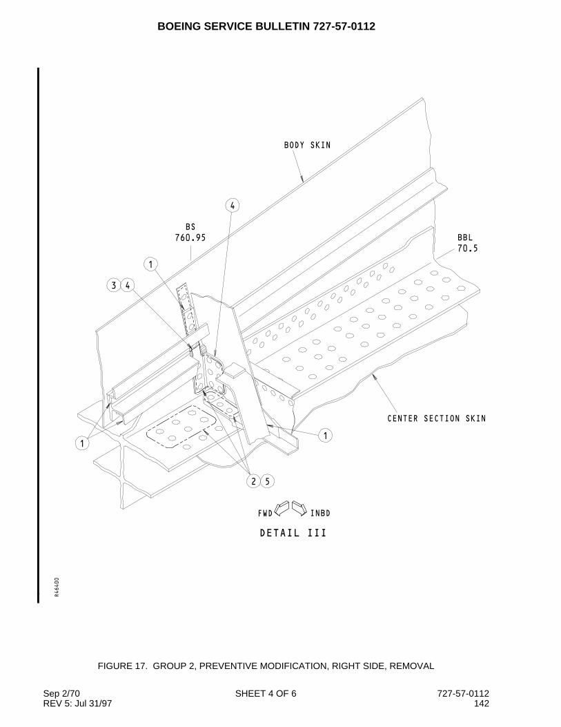
BOEING SERVICE BULLETIN 727-57-0112
INBDFWD
DETAIL III
4
BODY SKIN
BBL
70.5
CENTER SECTION SKIN
43
1
52
1
760.95
BS
1
R46400
FIGURE 17. GROUP 2, PREVENTIVE MODIFICATION, RIGHT SIDE, REMOVAL
Sep 2/70 SHEET 4 OF 6 727-57-0112REV 5: Jul 31/97 142

BOEING SERVICE BULLETIN 727-57-0112
INBDFWD
DETAIL IV
RIB WEB
CENTER SECTION SKIN
70.5
BBL
1
ACCESS
PANELS
S−19C
S−20C
2
2 5
R46402
FIGURE 17. GROUP 2, PREVENTIVE MODIFICATION, RIGHT SIDE, REMOVAL
Sep 2/70 SHEET 5 OF 6 727-57-0112REV 5: Jul 31/97 143

BOEING SERVICE BULLETIN 727-57-0112
The step numbers shown below agree with the numbers shown in the circle symbols in the figure. Referto Drawing 65C33202, Sheet 12, to the structural changes shown below.
STEP TASK NAME PART NUMBER QTY NOTES
1 Removeand Keep
Foam Seal - 1
Nutplate - 2
Access Panel - 3
Filler - 1
Angle - 3
2 Remove Sealant - -
Fastener - -
3 Cut Strap - 1 See Zone B3, Section D2
4 Remove Angle - 2
Filler - 1
Tee - 1
Strap (lower section) - 1
5 Examine Hole - - NDT Subject 51-00-00, Figures1 and 4
FIGURE 17. GROUP 2, PREVENTIVE MODIFICATION, RIGHT SIDE, REMOVAL
Sep 2/70 SHEET 6 OF 6 727-57-0112REV 5: Jul 31/97 144

BOEING SERVICE BULLETIN 727-57-0112
INBDFWD
ACCESS
PANEL
2SEE DETAIL I
RIB WEB
CENTER SECTION SKIN
SEE DETAIL II
PANEL
ACCESS
SEE DETAIL IV
1
S−20C
S−19C
BBL
70.5
13
13
R46406
FIGURE 18. GROUP 2, PREVENTIVE MODIFICATION, RIGHT SIDE, INSTALLATION
Sep 2/70 SHEET 1 OF 6 727-57-0112REV 5: Jul 31/97 145

BOEING SERVICE BULLETIN 727-57-0112
FWDINBD
DETAIL I
5
RIB WEB
3
S−20
S−19
ACCESS
PANEL
4
4
S−20
70.5
BBL
WING SKIN
13
R46408
FIGURE 18. GROUP 2, PREVENTIVE MODIFICATION, RIGHT SIDE, INSTALLATION
Sep 2/70 SHEET 2 OF 6 727-57-0112REV 5: Jul 31/97 146

BOEING SERVICE BULLETIN 727-57-0112
INBD
FWD
SEE
DETAIL III
6
DETAIL II
CENTER SECTION SKIN
6
BS
760.95
6
BODY SKIN
BBL
70.5
R46409
FIGURE 18. GROUP 2, PREVENTIVE MODIFICATION, RIGHT SIDE, INSTALLATION
Sep 2/70 SHEET 3 OF 6 727-57-0112REV 5: Jul 31/97 147

BOEING SERVICE BULLETIN 727-57-0112
INBDFWD
DETAIL III
CENTER SECTION SKIN
8
7
BODY SKIN
760.95
BS
6
70.5
BBL
13
13
R46410
FIGURE 18. GROUP 2, PREVENTIVE MODIFICATION, RIGHT SIDE, INSTALLATION
Sep 2/70 SHEET 4 OF 6 727-57-0112REV 5: Jul 31/97 148
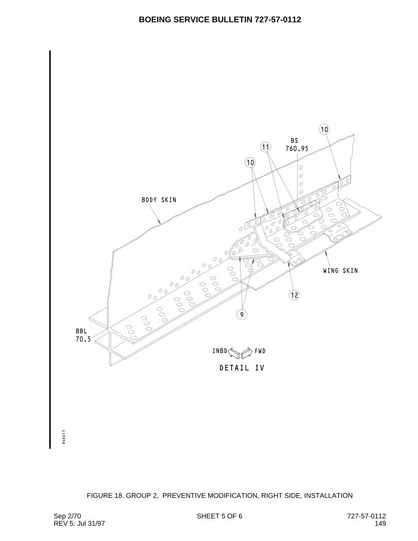
BOEING SERVICE BULLETIN 727-57-0112
FWDINBD
70.5
BBL
WING SKIN
BODY SKIN
DETAIL IV
9
BS
760.95
10
10
11
12
R46411
FIGURE 18. GROUP 2, PREVENTIVE MODIFICATION, RIGHT SIDE, INSTALLATION
Sep 2/70 SHEET 5 OF 6 727-57-0112REV 5: Jul 31/97 149

BOEING SERVICE BULLETIN 727-57-0112
The step numbers shown below agree with the numbers shown in the circle symbols in the figure. Referto Drawing 65C33202, Sheet 12, to the structural changes shown below.
STEP TASK NAME PART NUMBER QTY NOTES1 Install Tension Tie -
Inboard65C37073-1 1 See Sheet 12, Zone A4, Section
D2Shim BACS40R019E036F 1
2 Install Angle - Inboard 65C33202-44 1Radius Filler 65C33202-68 2
3 Install Tension Tie -Outboard
65C37073-2 1 See Zone D2, Section C3 andZone A10, section D3 and FlagNote 86
Shim 65C33202-96 1 Above the Tension TieRadius Filler 65C37073-4 2
4 Install Radius Filler 65C37073-3 2Shim 65C33202-56 1 Below the Tension TieFiller 65C33202-55 1 Between the shim and the Angle
65C33202-465 Install Angle - Outboard 65C33202-46 1
Radius Filler 65C33202-68 26 Install Shim 65C33202-51 1
Shim 65C33202-53 1Pressure Retainingangle
65C33202-54 1
Angle 65C33202-108 1 Trim the contour of part, see FL 93Tee 65C37221-8 1 Trim the contour of part, see FL 93Tapered Filler 65C33202-48 1 Between the Angle and the chordFiller 65C33202-69 1
7 Install Strap 69-78758-5 1Filler (kept) 65-16325-80 1
8 Install Angle - Forward,Inboard
65C33202-118 1 Trim the contour of part, see FL 93
9 Install Filler-Outboard 65C33202-50 1Angle - Outboard 65C33202-106 1 Trim the contour of part, see FL 93
10 Install Spacer 65C33202-47 1Filler BACF3T02M26-12 2
11 Install Fitting 65C33202-113 1 Trim the contour of part, see FL 93Radius Filler 65C33202-115 1 Optional, see FL 106
12 Apply Silicone RubberAdhesive
- -
Install Foam Seal (kept) - 1 Trim as nesessary13 Install Access Panel (kept) - 3
Angle (kept) - 3
FIGURE 18. GROUP 2, PREVENTIVE MODIFICATION, RIGHT SIDE, INSTALLATION
Sep 2/70 SHEET 6 OF 6 727-57-0112REV 5: Jul 31/97 150

BOEING SERVICE BULLETIN 727-57-0112
FWDINBD
CENTER SECTION SKIN
BODY SKIN
EXISTING STRAP
A
A
760.95
BS
REPAIR STRAP1BBL
70.5
R46419
FIGURE 19. INSPECTION FOR THE REPAIR STRAP AT BS 760.95 FRAME
Sep 2/70 SHEET 1 OF 3 727-57-0112REV 5: Jul 31/97 151

BOEING SERVICE BULLETIN 727-57-0112
INBD
2
1
WL
210
S−17
VIEW A−A
(VIEW LOOKS BACKWARD)
LEFT SIDE SHOWN
RIGHT SIDE OPPOSITE
R46420
FIGURE 19. INSPECTION FOR THE REPAIR STRAP AT BS 760.95 FRAME
Sep 2/70 SHEET 2 OF 3 727-57-0112REV 5: Jul 31/97 152

BOEING SERVICE BULLETIN 727-57-0112
The step numbers shown below agree with the numbers shown in the circle symbols in the figure.
STEP TASK NAME PROCEDURE REFERENCES NOTES
1 Examine Repair Strap Visual - (a)
2 Examine Shaded area Close Visual - (b)
(a) If a repair strap for Service Bulletin 727-53-0197 was installed, or an operator furnished repair strapwas installed, no more work is necessary. If no repair strap is install do Step 2.
(b) If cracks are found, repair the frame as shown in Service Bulletin 727-53-0197.
FIGURE 19. INSPECTION FOR THE REPAIR STRAP AT BS 760.95 FRAME
Sep 2/70 SHEET 3 OF 3 727-57-0112REV 5: Jul 31/97 153
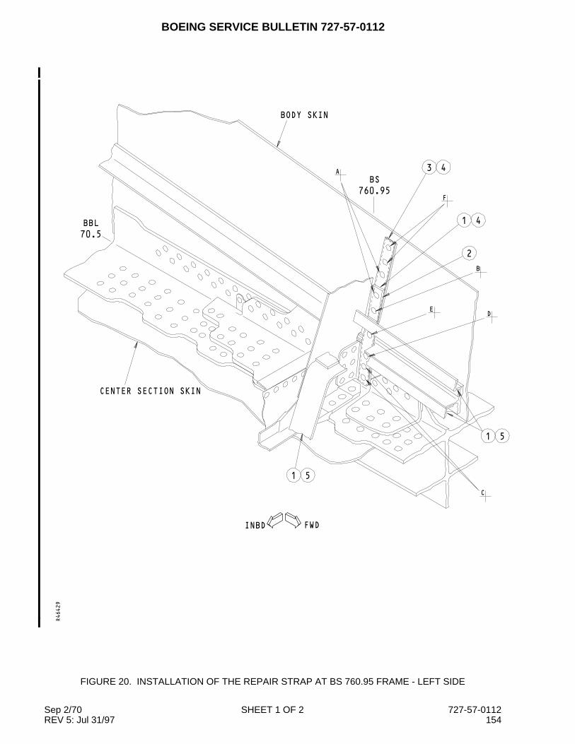
BOEING SERVICE BULLETIN 727-57-0112
FWDINBD
CENTER SECTION SKIN
A
BODY SKIN
43
F
41
2
B
DE
1 5
C
51
70.5
BBL
BS
760.95
R46429
FIGURE 20. INSTALLATION OF THE REPAIR STRAP AT BS 760.95 FRAME - LEFT SIDE
Sep 2/70 SHEET 1 OF 2 727-57-0112REV 5: Jul 31/97 154
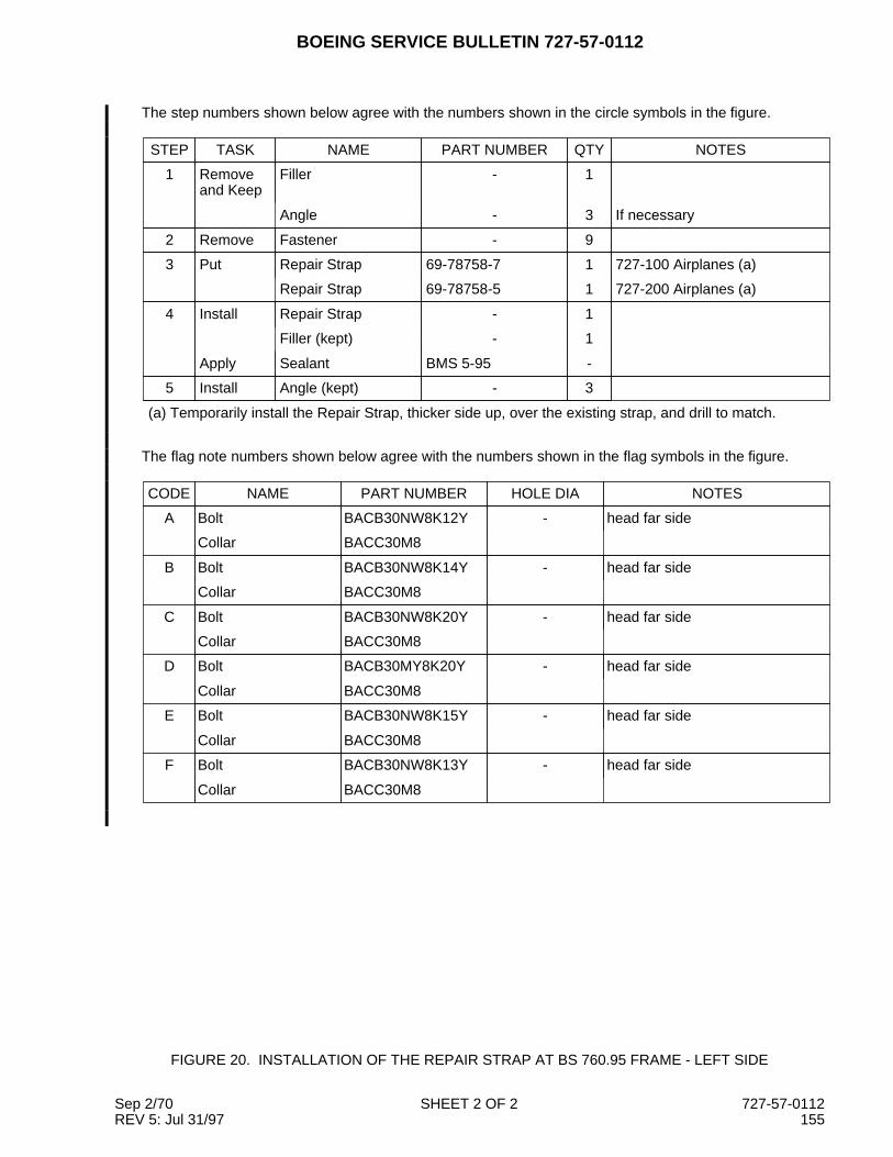
BOEING SERVICE BULLETIN 727-57-0112
The step numbers shown below agree with the numbers shown in the circle symbols in the figure.
STEP TASK NAME PART NUMBER QTY NOTES
1 Removeand Keep
Filler - 1
Angle - 3 If necessary
2 Remove Fastener - 9
3 Put Repair Strap 69-78758-7 1 727-100 Airplanes (a)
Repair Strap 69-78758-5 1 727-200 Airplanes (a)
4 Install Repair Strap - 1
Filler (kept) - 1
Apply Sealant BMS 5-95 -
5 Install Angle (kept) - 3
(a) Temporarily install the Repair Strap, thicker side up, over the existing strap, and drill to match.
The flag note numbers shown below agree with the numbers shown in the flag symbols in the figure.
CODE NAME PART NUMBER HOLE DIA NOTES
A Bolt BACB30NW8K12Y - head far side
Collar BACC30M8
B Bolt BACB30NW8K14Y - head far side
Collar BACC30M8
C Bolt BACB30NW8K20Y - head far side
Collar BACC30M8
D Bolt BACB30MY8K20Y - head far side
Collar BACC30M8
E Bolt BACB30NW8K15Y - head far side
Collar BACC30M8
F Bolt BACB30NW8K13Y - head far side
Collar BACC30M8
FIGURE 20. INSTALLATION OF THE REPAIR STRAP AT BS 760.95 FRAME - LEFT SIDE
Sep 2/70 SHEET 2 OF 2 727-57-0112REV 5: Jul 31/97 155
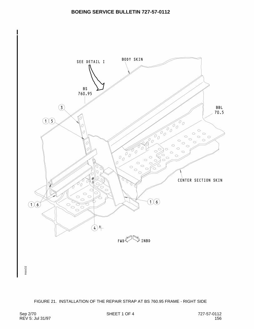
BOEING SERVICE BULLETIN 727-57-0112
INBDFWD
CENTER SECTION SKIN
1 6
SEE DETAIL IBODY SKIN
BS
760.95
70.5
BBL
1 6
4A
3
1 5
R46432
FIGURE 21. INSTALLATION OF THE REPAIR STRAP AT BS 760.95 FRAME - RIGHT SIDE
Sep 2/70 SHEET 1 OF 4 727-57-0112REV 5: Jul 31/97 156
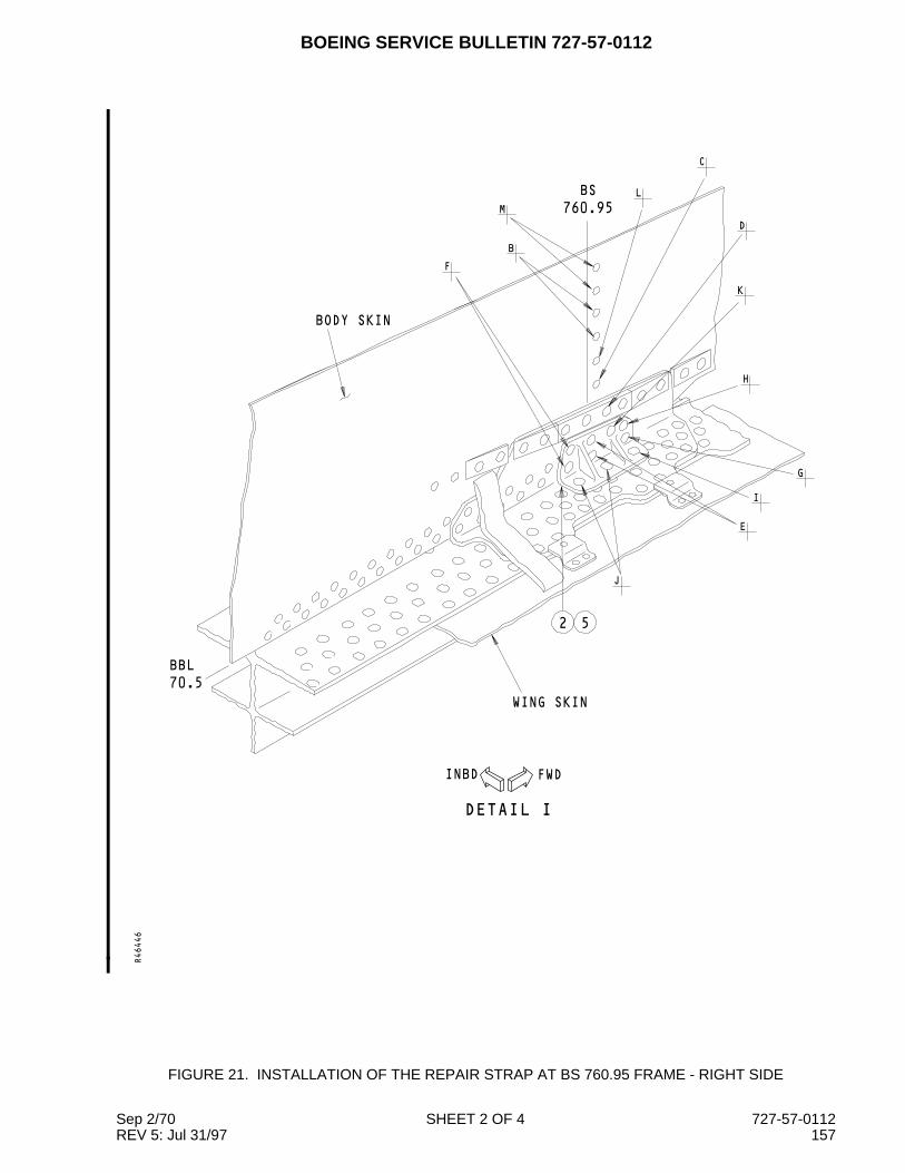
BOEING SERVICE BULLETIN 727-57-0112
760.95
BS
FWDINBD
DETAIL I
BBL
70.5
BODY SKIN
F
B
M
L
C
D
K
H
G
I
E
J
WING SKIN
52
R46446
FIGURE 21. INSTALLATION OF THE REPAIR STRAP AT BS 760.95 FRAME - RIGHT SIDE
Sep 2/70 SHEET 2 OF 4 727-57-0112REV 5: Jul 31/97 157
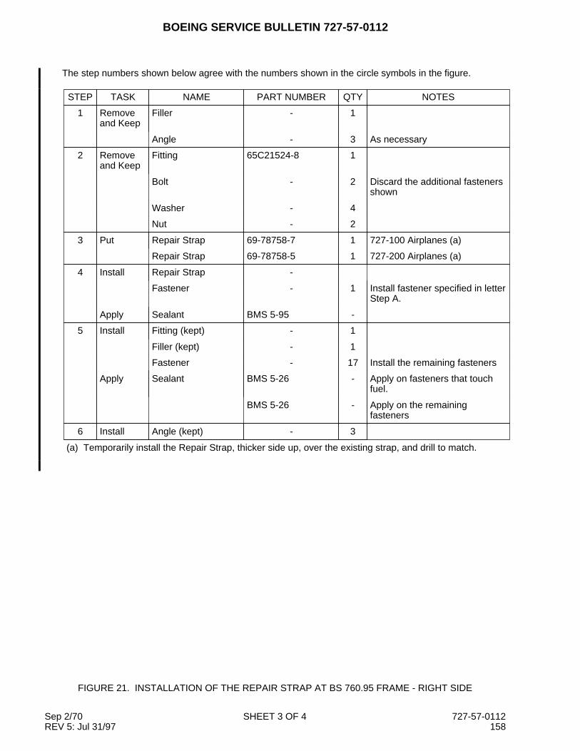
BOEING SERVICE BULLETIN 727-57-0112
The step numbers shown below agree with the numbers shown in the circle symbols in the figure.
STEP TASK NAME PART NUMBER QTY NOTES
1 Removeand Keep
Filler - 1
Angle - 3 As necessary
2 Removeand Keep
Fitting 65C21524-8 1
Bolt - 2 Discard the additional fastenersshown
Washer - 4
Nut - 2
3 Put Repair Strap 69-78758-7 1 727-100 Airplanes (a)
Repair Strap 69-78758-5 1 727-200 Airplanes (a)
4 Install Repair Strap -
Fastener - 1 Install fastener specified in letterStep A.
Apply Sealant BMS 5-95 -
5 Install Fitting (kept) - 1
Filler (kept) - 1
Fastener - 17 Install the remaining fasteners
Apply Sealant BMS 5-26 - Apply on fasteners that touchfuel.
BMS 5-26 - Apply on the remainingfasteners
6 Install Angle (kept) - 3
(a) Temporarily install the Repair Strap, thicker side up, over the existing strap, and drill to match.
FIGURE 21. INSTALLATION OF THE REPAIR STRAP AT BS 760.95 FRAME - RIGHT SIDE
Sep 2/70 SHEET 3 OF 4 727-57-0112REV 5: Jul 31/97 158

BOEING SERVICE BULLETIN 727-57-0112
The codes given below agree with the letter shown in the upper left corner of the fastener symbols in thefigure. A number in the lower right corner gives the grip length of the fastener.
CODE NAME PART NUMBER HOLE DIA NOTES
A Bolt BACB30MY8K16Y - Head far side
Collar BACC30M8
B Bolt BACB30NW8K12Y -
Collar BACC30M8
C Bolt BACB30NW8K14Y -
Collar BACC30M8
D Bolt BACB30NW8K20Y -
Collar BACC30M8
E Bolt BACB30MY8K18Y -
Collar BACC30M8
F Bolt BACB30MY8K16Y -
Collar BACC30M8
G Bolt BACB30MY8K20 -
Collar BACC30M8
H Bolt BACB30MY8K16 -
Collar BACC30M8
I Bolt BACB30MY12K20Y -
Collar BACC30M12
J Bolt BACB30US6K28 - Head near side
Washer BACW10BP6AC Under bolt head
BACW10BP6AP Under nut
Nut BACN10HR6
K Bolt BACB30MY8K20Y -
Collar BACC30M8
L Bolt BACB30NW8K15Y -
Collar BACC30M8
M Bolt BACB30NW8K13Y -
Collar BACC30M8
FIGURE 21. INSTALLATION OF THE REPAIR STRAP AT BS 760.95 FRAME - RIGHT SIDE
Sep 2/70 SHEET 4 OF 4 727-57-0112REV 5: Jul 31/97 159
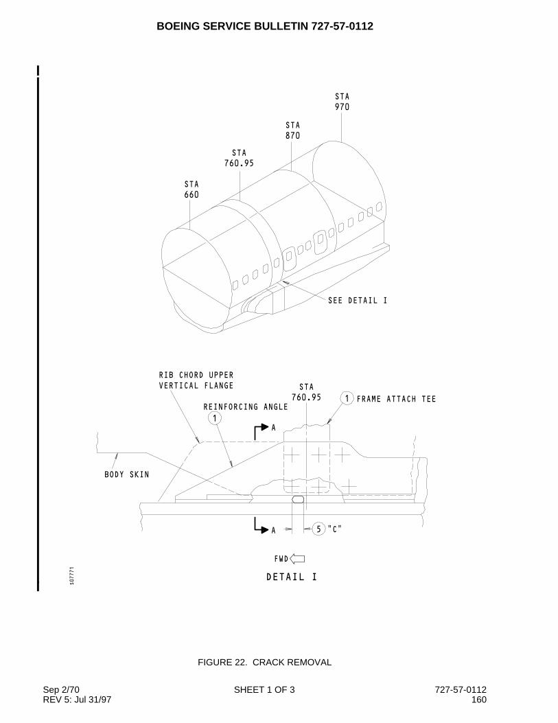
BOEING SERVICE BULLETIN 727-57-0112
1
1
"C"
FWD
FRAME ATTACH TEE
5
RIB CHORD UPPER
VERTICAL FLANGE
REINFORCING ANGLE
BODY SKIN
STA
760.95
SEE DETAIL I
970
STA
870
STA
STA
760.95
660
STA
DETAIL I
A
A
S07771
FIGURE 22. CRACK REMOVAL
Sep 2/70 SHEET 1 OF 3 727-57-0112REV 5: Jul 31/97 160

BOEING SERVICE BULLETIN 727-57-0112
1
5
5
42
3
6
1
INBD
SECTION A−A
ANGLE
"B"
"A"RIB CHORD
1 TEEBODY SKIN
WING UPPER SKIN
BBL
70.5
FILLER
S07788
The step numbers shown below agree with the numbers shown in the circle symbols in the figure.
STEP TASK NAME PART NUMBER QTY NOTES
1 Remove/Keep
Frame Attach Tee - 1 If necessary to get access to theend of the crack
Reinforcing Angle 1
Filler 1
2 Drill Stop Drill - 1 Drill from the inboard side to theoutboard side. Drill as near tothe horizontal flange aspossible. 727 SRM 51-10-1
3 Blend Crack - - Blend out the crack downward,use a 0.5 inch radius. Use 0.03to 0.05 inch increments. Blendout until the crack is not visable.
FIGURE 22. CRACK REMOVAL
Sep 2/70 SHEET 2 OF 3 727-57-0112REV 5: Jul 31/97 161

BOEING SERVICE BULLETIN 727-57-0112
(Continued)
STEP TASK NAME PART NUMBER QTY NOTES
4 Examine Rib Chord - - Do a High Frequency EddyCurrent as shown in 727 NDT,D6-48875, Part 6, 51-00-00,Figure 4. If there is a crackindication do the blend stepbelow. If no crack indication goto Step 5.
Blend Crack - - Blend out the crack downward,use a 0.5 inch radius. Use 0.03to 0.05 inch increments.Continue to blend and examinethe hole until there is no crackremaining.
5 Measure "A" - - Measure the distance from theupper surface of the horizontalflange down to the deepestpoint of the blend out,
"B" - - Measure the blend out inboardto outboard.
"C" - - Measure the blend out forwardto aft.
6 Measure Rib Chord - - Determine the minimumremaining thickness in the blendregion. Can be measured witha digital ultrasonic thicknessgauge.
FIGURE 22. CRACK REMOVAL
Sep 2/70 SHEET 3 OF 3 727-57-0112REV 5: Jul 31/97 162

BOEING SERVICE BULLETIN 727-57-0112
3.41
0.22
1 3
0.50 R
(2 PLACES)
TYPICAL
TYPICAL2
2
3.53
0.25 R
2.21
(4 PLACES)
0.50 R
0.125 R0.160
0.125
S07887
The step numbers shown below agree with the numbers shown in the circle symbols in the figure.
STEP TASK NAME MATERIAL QTY NOTES
1 Make Frame Attach Tee BAC1506-855 x 4 1 7075-T73511 (QQ-A-200/11)
2 Cut Frame Attach Tee - - Trim the tee from 1.5 to 2Diameter edge margin from theexisting holes in the rib chord
3 Apply Alodine - -
Primer BMS 10-11, Type 1 -
FIGURE 23. MAKE NEW FRAME ATTACH TEE
Sep 2/70 SHEET 1 OF 1 727-57-0112REV 5: Jul 31/97 163


CommercialAirplaneGroup
727Service Bulletin
Number: 727-57-0112 Evaluation FormDate: September 2, 1970Revision 5: July 31, 1997ATA System: 5712Prepared By: Jane Beck
SUBJECT: WINGS - RIB UPPER CHORD AT BL 70.5 - INSPECTION, MODIFICATION, AND REPAIR
Use this evaluation form to tell us what you think of the quality of this service bulletin. We will use the datathat you give us to improve the quality of our service bulletins. Please include data about these or otheritems:
- Did this service bulletin meet your estimate of quality?- How easy is this service bulletin to understand?- Are the Planning Information, Material Information and Accomplishment Instructions satisfactory?- Will you do this service bulletin fully? If not, please tell us why.- Is the Manpower estimate satisfactory?
NOTE: Please do not use this evaluation form to tell us to make changes to your manuals. To make thesechanges, please use a Publication Change Request (PCR) form.
Please give us this data:OPERATOR: TODAY'S DATE:
PREPARED BY: TITLE:
ORGANIZATION: TELEX CODE:
TELEPHONE NUMBER: BASE:
COMMENTS:
If you have other comments please use the other side. Thank you for the time you used to complete thisform.
Give the completed evaluation form to your Boeing Field Service Representative or send the evaluation formdirectly to this address:
T.J. Taylor, ManagerService Bulletin EngineeringBoeing Commercial Airplane GroupP.O. Box 3707, Mail Stop 20-85Seattle, WA 98124-2207
BOEING COMMERCIAL AIRPLANE GROUP P.O. BOX 3707 SEATTLE, WASHINGTON 98124-2207