Susheel Kalia Editor - Lignocellulosic Composite Materials
451
Springer Series on Polymer and Composite Materials Susheel Kalia Editor Lignocellulosic Composite Materials
-
Upload
khangminh22 -
Category
Documents
-
view
1 -
download
0
Transcript of Susheel Kalia Editor - Lignocellulosic Composite Materials

Springer Series on Polymer and Composite Materials
Susheel Kalia Editor
Lignocellulosic Composite Materials

Springer Series on Polymer and CompositeMaterials
Series editor
Susheel Kalia, Dehradun, India

More information about this series at http://www.springer.com/series/13173

Susheel KaliaEditor
Lignocellulosic CompositeMaterials
123

EditorSusheel KaliaArmy Cadet College WingIndian Military AcademyDehradunIndia
ISSN 2364-1878 ISSN 2364-1886 (electronic)Springer Series on Polymer and Composite MaterialsISBN 978-3-319-68695-0 ISBN 978-3-319-68696-7 (eBook)https://doi.org/10.1007/978-3-319-68696-7
Library of Congress Control Number: 2017954285
© Springer International Publishing AG 2018This work is subject to copyright. All rights are reserved by the Publisher, whether the whole or partof the material is concerned, specifically the rights of translation, reprinting, reuse of illustrations,recitation, broadcasting, reproduction on microfilms or in any other physical way, and transmissionor information storage and retrieval, electronic adaptation, computer software, or by similar or dissimilarmethodology now known or hereafter developed.The use of general descriptive names, registered names, trademarks, service marks, etc. in thispublication does not imply, even in the absence of a specific statement, that such names are exempt fromthe relevant protective laws and regulations and therefore free for general use.The publisher, the authors and the editors are safe to assume that the advice and information in thisbook are believed to be true and accurate at the date of publication. Neither the publisher nor theauthors or the editors give a warranty, express or implied, with respect to the material contained herein orfor any errors or omissions that may have been made. The publisher remains neutral with regard tojurisdictional claims in published maps and institutional affiliations.
Printed on acid-free paper
This Springer imprint is published by Springer NatureThe registered company is Springer International Publishing AGThe registered company address is: Gewerbestrasse 11, 6330 Cham, Switzerland

Preface
Lignocellulosic materials refer to the organic matter produced by trees, shrubs, andagricultural crops and are major feedstock for the pulp & paper industry, compositeindustry and packaging material. Renewable sources of lignocellulosic materials arenatural fibers, agricultural residues and forest products. These agricultural wastesand forest feedstocks are sufficiently abundant and generate very low net green-house emissions. Forest wood products contain more lignin and less ash content,which makes them attractive to cost-effective transportation in comparison toagricultural residues. Lignocellulosics are being used in food packaging, compos-ites and textile industries due to their advantages over other traditional materialswhich include low cost, renewability, non-toxicity, biodegradability etc.Lignocellulosic biomass is a main raw material for many industrial processes, but itusually displays a very poor microbial and moisture resistance. Lignocellulosicmaterials are attractive materials for a variety of potential applications such as soilconservation, textile applications, as alternate materials especially wood substitutesin the construction market and as reinforcement in composite materials to produceautomotive structural components. Lignocellulosic materials possess sufficientstrength and stiffness but are difficult to use in load bearing applications bythemselves because of their fibrous structure. In fiber-reinforced composites, fibersgave strength and stiffness to the structure while the plastic matrix serves as thebinder to hold the fibers in place.
Physical, chemical and biological pretreatments of lignocellulosic fibers stopmoisture absorption, increase surface roughness and improve other properties also.The main objective of this book is to explicate some important features of ligno-cellulosic materials, their characterization, properties, and applications, pretreat-ments of lignocellulosics and lignocellulosics reinforced composite materials. Firstchapter of this book discusses about lignocellulosic materials, their characterizationand applications in polymer composites. Chapter “Retting Process as a Pre-treatment of Natural Fibers for the Development of Polymer Composites” aims toprovide a classification and an overview of the retting process that have beendeveloped during years and are applied to extract mainly bast fibers. Variousphysical, chemical, mechanical, enzymatic and microbiological retting techniques
v

are discussed in this chapter. Physical, chemical and biological pretreatments ofnatural fibers and their effect on properties of natural fibers are discussed in Chapter“Pretreatments of Natural Fibers for Polymer Composite Materials”.
Chapter “Mechanical and Thermal Properties of Less Common Natural Fibresand Their Composites” addresses with morphological, chemical and physicalproperties of less common natural fibers. Thermoplastic and thermosetting com-posites reinforced with the less common natural fibres are reviewed and comparedwith the traditional and common natural fibres. The development of cellulose-basednanocomposites is also discussed here.
Chapter “Lignocellulosic Fibres Reinforced Thermoset Composites: Preparation,Characterization, Mechanical and Rheological Properties” highlights the origin,structure and chemical composition of lignocellulosic fibers. This chapter alsoincludes the preparation, characterization, mechanical and rheological properties oflignocellulosic fiber reinforced thermoset composites. Applications of lignocellu-losic fiber composites in automobile industry and building sector are also discussedhere. Chapter “Pineapple Leaf Fiber: From Waste to High Performance GreenReinforcement for Plastics and Rubbers” deals with extraction methods ofpineapple leaf fibers. The reinforcing potential of pineapple leaf fibers in polymermatrix composites is also discussed in this chapter.
Chapter “Lightweight Wood Composites: Challenges, Production andPerformance” discusses the production and performance of lightweight woodcomposites. Fiberboards, particleboards, extruded particleboards, and sandwichpanels are included in this chapter. The fabrication techniques of natural fiberpolymer composites are discussed in Chapter “Design and Fabrication of KenafFibre Reinforced Polymer Composites for Portable Laptop Table”. This chapteralso deals with design and fabrication of kenaf fiber reinforced polymer compositesfor portable laptop table. Chapter “Lignocellulosic Materials for Geotextile andGeocomposites for Engineering Applications” presents an extensive overview ofpotential methods for enhancement of durability of lignocellulosic materials.Designing and testing parameters for lignocellulosic materials based geotextiles andgeocomposites are also discussed. Chapter “Lignocellulosic Fibres-basedBiocomposites Materials for Food Packaging” highlights the applications of lig-nocellulosic fibers-based biocomposites materials for food packaging. Chapter“Lignocellulosic Fibres Reinforced Polymer Composites for AcousticalApplications” includes the acoustical applications of lignocellulosic fiber rein-forced polymer composites. Factors affecting the sound absorption coefficients oflignocellulosic fiber reinforced composites are also discussed in this chapter.
All the chapters in this book are contributed by renowned researchers fromacademia and research laboratories across the world. This book will prove to be avery useful for scientists, academicians, research scholars, material engineers andindustries. This book will be supportive for undergraduate and post graduate stu-dents in Institutes of Materials Science & other Technical Institutes, andTechnologists & Researchers from R&D laboratories working in this area.
The Editor would like to express their gratitude to all contributors, who haveprovided excellent contributions in this book. The Editor would like to thank his
vi Preface
research team, who helped him in the editorial work. Finally, I gratefullyacknowledge permissions to reproduce copyright materials from a number ofsources.
Dehradun, India Susheel Kalia
Preface vii

Contents
Lignocellulosic Materials of Brazil––Their Characterizationand Applications in Polymer Composites and Art Works . . . . . . . . . . . 1Kestur G. Satyanarayana, Thais H. S. Flores-Sahagunand Pamela Bowman
Retting Process as a Pretreatment of Natural Fibersfor the Development of Polymer Composites . . . . . . . . . . . . . . . . . . . . . 97L. Sisti, G. Totaro, M. Vannini and A. Celli
Pretreatments of Natural Fibers for PolymerComposite Materials . . . . . . . . . . . . . . . . . . . . . . . . . . . . . . . . . . . . . . . . 137A. Orue, A. Eceiza and A. Arbelaiz
Mechanical and Thermal Properties of Less CommonNatural Fibres and Their Composites . . . . . . . . . . . . . . . . . . . . . . . . . . 177Fabrizio Sarasini
Lignocellulosic Fibres Reinforced Thermoset Composites:Preparation, Characterization, Mechanical and RheologicalProperties . . . . . . . . . . . . . . . . . . . . . . . . . . . . . . . . . . . . . . . . . . . . . . . . 215Hind Abdellaoui, Rachid Bouhfid and Abou El Kacem Qaiss
Pineapple Leaf Fiber: From Waste to High-PerformanceGreen Reinforcement for Plastics and Rubbers . . . . . . . . . . . . . . . . . . . 271Nanthaya Kengkhetkit, Thapanee Wongpreedeeand Taweechai Amornsakchai
Lightweight Wood Composites: Challenges,Production and Performance . . . . . . . . . . . . . . . . . . . . . . . . . . . . . . . . . 293Sandra Monteiro, Jorge Martins, Fernão D. Magalhães and Luísa Carvalho
Design and Fabrication of Kenaf Fibre Reinforced PolymerComposites for Portable Laptop Table . . . . . . . . . . . . . . . . . . . . . . . . . . 323S. M. Sapuan, K. R. Purushothman, M. L. Sanyang and M. R. Mansor
ix

Lignocellulosic Materials for Geotextile and Geocompositesfor Engineering Applications . . . . . . . . . . . . . . . . . . . . . . . . . . . . . . . . . 357Jaideep Adhikari, Suvendu Manna, Sukanya Chowdhury Saha,Prosenjit Saha, Debasis Roy and Basudam Adhikary
Lignocellulosic Fibres-Based Biocomposites Materialsfor Food Packaging . . . . . . . . . . . . . . . . . . . . . . . . . . . . . . . . . . . . . . . . 389H. Angellier-Coussy, V. Guillard, E. Gastaldi,S. Peyron and N. Gontard
Lignocellulosic Fibres Reinforced Polymer Compositesfor Acoustical Applications . . . . . . . . . . . . . . . . . . . . . . . . . . . . . . . . . . . 415Elammaran Jayamani and Muhammad Khusairy Bin Bakri
x Contents

About the Editor
Susheel Kalia is Associate Professor & Head inDepartment of Chemistry at Army Cadet College Wingof Indian Military Academy Dehradun, India. He wasvisiting researcher in the Department of Civil,Chemical, Environmental and Materials Engineering atUniversity of Bologna, Italy in 2013 and held a positionas Assistant Professor in the Department of Chemistry,Bahra University and Shoolini University, India until2015. Kalia has around 80 research articles in interna-tional journals along with 11 books and 11 bookchapters in his academic career. His research interestsinclude polymeric composites, bio- and nanocompos-ites, conducting polymers, nanofibers, nanoparticles,hybrid materials and hydrogels. Kalia is an experiencedbook editor, and he has edited a number of successfulbooks (with Springer & Wiley), such as “CelluloseFibers: Bio- and Nano-Polymer Composites”,“Polymers at Cryogenic Temperatures”,“Polysaccharide Based Graft Copolymers”, “Organic–Inorganic Hybrid Nanomaterials”, “PolymericHydrogels as Smart Biomaterials”, “Biopolymers:Environmental and Biomedical Applications”,“Polymer Nanocomposites based on Organic andInorganic Nanomaterials”, “Biodegradable GreenComposites”, etc. Kalia is the main editor of the“Springer Series on Polymer and CompositeMaterials”. In addition, he is a member of a number ofprofessional organizations, including the Asian
xi

Polymer Association, Indian Cryogenics Council, theSociety for Polymer Science, Indian Society ofAnalytical Scientists, and the International Associationof Advanced Materials.
xii About the Editor

Lignocellulosic Materials of Brazil––TheirCharacterization and Applicationsin Polymer Composites and Art Works
Kestur G. Satyanarayana, Thais H. S. Flores-Sahagunand Pamela Bowman
Abstract Growing environmental concerns in recent years have led to finding newresources to replace the synthetic materials such as glass and carbon fibers in thedevelopment of polymeric and cementitious matrices-based composites. One suchmaterial is lignocellulosic fibers, due to their inherent characteristics such asabundant availability and renewability, low weight, biodegradability, interestingspecific properties, etc. Studies have been carried out throughout the world in theutilization of these fibers particularly in the development of light weight, buthigh-performance composites. Some of their products are already in use in manyapplications. Although these fibers have been used even in sculptures or in arts ingeneral, there is no report on the characteristics required for such applications. Thischapter focuses on the exploration of these aspects particularly about the appear-ance of some plant fibers as well as their texture and potential use in polymericsculptures or in arts. While doing so, the chapter will also present availability,methodologies used for the characterization as well as the reported properties(chemical, physical, mechanical thermal, electrical, environmental, and moistureabsorption) of various Brazilian-based lignocellulosic fibers. It is hoped this will beapplicable to fibers from other parts of the world to open up new areas of their
K. G. Satyanarayana (&)Formerly PIPE & Department of Chemistry, Federal University of Parana,Curitiba, Brazile-mail: [email protected]; [email protected]
K. G. SatyanarayanaPoornaprajna Scientific Research Institute (PPISR), Sy. No. 167, Poornaprajnapura,Bidalur Post, Devanahalli, Bangalore, Karnataka 562 110, India
T. H. S. Flores-SahagunDepartment of Mechanical Engineering, Federal University of Parana,P.O. Box. 19011, Curitiba, CEP 81531-990, Brazile-mail: [email protected]
P. Bowman3033 Navajo Lane, 84604 Provo, UT, USAe-mail: [email protected]
© Springer International Publishing AG 2018S. Kalia (ed.), Lignocellulosic Composite Materials, Springer Series on Polymerand Composite Materials, https://doi.org/10.1007/978-3-319-68696-7_1
1

utilization in a scientific manner enabling new value-added application for theseagro-industrial byproducts, which may otherwise go waste.
Keywords Lignocellulosic materials � Chemical characterizationThermal characterization � Textile properties � Tensile propertiesFlexural and impact properties � Surface treatments � Polymer composites
Contents
1 Introduction.......................................................................................................................... 22 Plant Fibers of Brazil .......................................................................................................... 5
2.1 Plants and Fibers––Availability and Production........................................................ 52.2 About Fibers ............................................................................................................... 82.3 Surface Treatments/Modification of Fibers................................................................ 152.4 Justification for This Chapter and Objectives............................................................ 16
3 Characterization of Plant Fibers.......................................................................................... 183.1 Methods of Characterization (Techniques and Equipment Used)............................. 18
4 Observations of Structure and Properties ........................................................................... 334.1 Physical Characterization ........................................................................................... 334.2 Chemical Characterization.......................................................................................... 384.3 Thermal Characterization ........................................................................................... 434.4 Mechanical Properties (Tensile, Flexural, and Impact Properties)............................ 444.5 Surface Treatments of Lignocellulosic Fibers ........................................................... 474.6 Theoretical Aspects (Weibull Analysis and Artificial Neural Network)................... 484.7 Structural Aspects ....................................................................................................... 54
5 Applications of Lignocellulosic Fibers ............................................................................... 585.1 Nanomaterials ............................................................................................................. 605.2 Composites of Lignocellulosic Fibers of Brazil ........................................................ 625.3 Fiber Used as a Material in Fine Arts ....................................................................... 75
6 Concluding Remarks ........................................................................................................... 84References .................................................................................................................................. 85
1 Introduction
Increasing global pollution and climate changes have been the focus areas forenvironmental safety leading to increased environmental awareness during the pastfew decades. One of the solutions to overcome these is by increasing the use ofbiodegradable and locally available materials in the development of new materials.The use of such renewable materials also helps in increasing the economic con-ditions of the farmers all over the world when such materials are used due to thevalue addition they make. Thus, these natural resources contribute significantly to acountry’s gross domestic product (GDP) in its economic activities, besides con-tributing to the social and economic development particularly in the case of
2 K. G. Satyanarayana et al.

developing countries such as Brazil. In fact, this trend of transition of substitution ofhitherto used and largely produced materials based on dwindling and expensivefossil (petrochemical) or mineral resources by materials from renewable resources(plant and animal based) would lead to a bio-based economy and sustainabledevelopments. This is due to the Kyoto protocols on greenhouse gas reduction andCO2 neutral production, which would lead to high perspectives for plant-based fibermarkets. Besides, increasing quest for new materials since 90s supporting globalsustainability and diversification of non-nutrient areas addressing global environ-ment and stable economy through agricultural industry, and successful use of theircomposites in many sectors (automotive, construction, etc.) and increased use ofsuch materials becomes important for these countries through the development ofnew processes and products.
One such resource, which has attracted the attention of researchers all over theworld, is plant-based materials, particularly the fibers (also called “lignocellulosicfibers”) obtained from different parts of plants. This is particularly so in them beingused to replace the synthetic fibers such glass or carbon fibers in the development ofpolymer or cement/ceramic-based composites (Abdul Khalil et al. 2012; Dickeret al. 2014; La Mantia and Morreale 2011; Satyanarayana et al. 2009a, b; Thakuret al. 2014) due to two reasons. First, these fibers present attractive characteristics.These include abundant availability, low cost, eco-friendly and bio degradability,better stiffness, comparable specific strength, Young’s modulus, etc. Besides, use ofthese renewable and abundantly available materials would contribute to sustainabledevelopment as well as generating employment opportunities to the rural com-munity, where these are available/produced (Satyanarayana et al. 2009a). Suchreplacement calls for complete knowledge of the characteristics of these materials.
Second reason is that greater attention being paid in recent years for the use ofnatural materials in view of the increasing cost of nonrenewable petroleum-basedmatrix and reinforcements in the development of composites. In addition, longertime (about 106 years-geological time) is taken for producing fossil-based materialssuch as fibers from biomass when compared to the shorter time (1–10 years) toconvert them (Narayan 2006). Besides, the petroleum-based materials are contin-uously becoming expensive in addition to their persisting environmental degrada-tion due to the increasing release of CO2.
Plants that are of interest to the readers of this book are those normally referredto as “fiber crops”, which are the crops grown for their fibers and are generallyharvestable after a single growing season. These are distinct from other lignocel-lulosic materials such as trees. The latter ones are typically grown for many yearsbefore being harvested for other purposes (named as wood) such as making fur-niture, building materials (doors, windows, etc), pulp for paper making fiber, etc.Various types of plant fibers are available throughout the world. Names of variousplants, the area under cultivation for these and amount of fibers obtained from theplants annually all over the world are normally published by FAO. These can beseen from the annual reports of FAO. It is reported that of the annual production ofmore than 13 million tons of various fibers, major fiber yielding plants ones are
Lignocellulosic Materials of Brazil––Their Characterization … 3

cotton and flax, while hemp with ramie, jute, and sisal, being less important plantsgrown in small numbers (http://lifeofplant.blogspot.in/2011/02/plant-fibers.html-accessed). Another report has estimated average global production of different plantfibers of about 29.61 million tons of major plant fibers per average in recent yearscompared to that of 3.3 million tons manmade cellulosic fibers (Proceedings of theSymposium on Natural Fibers, Rome 20 October 2008. Available at ftp://ftp.fao.org/docrep/fao/011/i0709e/i0709e.pdf).
Since fibers can be obtained from different parts of the plants, they are broadlyclassified as (a) bast or bark or stem-skin fibers (fibers from different types ofgrasses such as esparto, banana, flax, hemp, jute, kenaf, malva, ramie, sugarcanebagasse, etc); (b) leaf fibers (curauá, pineapple, sisal, etc.); (c) fruit or seed fibers(coconut, cotton, Luffa cylindrica, etc) and finally others such as bamboo anddifferent types of straws (rice, wheat, etc). Short fibers of various types of woodscan also be considered under this. Besides, there is also economic classification ofvarious fibers such as brush fibers (stiff tough fibers, small stems, and twigs are usedin making brooms and brushes), reinforcing or filling fibers (for mattresses, cush-ions, upholstery, packing and in polymer composites as reinforcing or fillers), fibersfor paper industry includes textile fibers and wood fibers, natural fabrics (Frombarks in layers or sheets made of tough interlacing fibers as possible rough sub-stitutes for cloth; For e.g., Luffa cylindrica), rough weaving and plaiting fibers (usedin matting, baskets, hats, footwear, seat chairs, etc.) and finally the textile fibers(possible for twisting, knitting spinning, and weaving) (http://www.faculty.ucr.edu/*legneref/botany/fibers.htm).
These fibers are obtained from different parts of the plants and by differentextraction methods for different fibers practiced by different countries, whichinclude manual, machine, and microbial techniques. More details on this aspect canbe seen in the earlier publications, particularly from the authors group(Satyanarayana and Wypych 2007; Satyanarayana et al. 2009b). These methodsinclude (a) mechanical extractor (coir), (b) decorticator (banana and pineapplefibers); (c) periquita (curauá and sisal fibers), and (d) splitting using knife followedby beating them by wooden mallet (malva and piassava). Some of the other fiberssuch as sugarcane bagasse (byproduct of sugar industry), bamboo and straws of riceand wheat, are mostly available without resorting to any extraction methods.Accordingly, the characteristics of these fibers vary considerably depending on thepart from which they are extracted, the quality of their origin, age of their source,and their preconditioning (Satyanarayana and Wypych 2007). Thus, it can be saidthat the properties of plant fibers depend not only on the location where they areproduced, but also on the method of extraction.
Utilization of these fibers is important in order to avoid these natural resources togo waste and hence studies have been carried out throughout the world toward thisend particularly in the development of light weight, but high-performance com-posites, besides their conventional applications in making ropes, mats, mattresses,etc. Based on the characteristics, many of the products so developed are already inuse in many applications, some of which have become very attractive due to thenatural appearance. For example, less-resistant plant fibers may be efficiently used
4 K. G. Satyanarayana et al.

in applications such as packaging, interior components, etc, while fibers exhibitinghigh strength properties can be used in load-bearing applications. One of the othernonconventional uses of these fibers is in the field of art works considering the greatdiversity and often low cost, which become incentives for their use in nets, pack-aging threads, blankets, and carpets. It may be noted that this is possible includingin making sculptures or in arts in general, even in the absence of any report on thecharacteristics required for such applications.
Considering the above and publication of various reports on the sources andamount of these fibers, characteristics, and applications in various fields, thischapter will present availability of plant-based fibers, their characterization on thesein respect of their reported properties (chemical, physical, mechanical thermal,electrical, environmental, and moisture absorption) and morphology of variousBrazilian-based lignocellulosic fibers and methodologies used for the same. Inaddition, the chapter also presents some attempts made in the country by variousresearchers in the area of lignocellulosic fibers to prepare polymeric compositesusing these fibers and use of these as well as those of fibers themselves in arts.
2 Plant Fibers of Brazil
2.1 Plants and Fibers––Availability and Production
Brazil, one of the fast developing countries, is the fifth in terms of area in the worldand the largest country among the South American countries with about 50% of thisregion, having about 5–6% arable lands, 22% permanent pastures, and 58% forestsand woodlands totaling to an area of about 8.5 million km2 (Satyanarayana et al.2007). It has a large number of natural resources, which play a dominant role in theeconomic activities contributing substantially to its GDP. Besides, this also con-tributes to the social and economic development in the case of developing countriessuch as Brazil. One of these natural resources is the lignocellulosic materials-basedones, which are available to the extent of about 2.5 billion tons and have been usedsince more than 6000 BC (Kozlowski et al. 2004). Table 1a lists harvested area forvarious types of plants (fiber related) in Brazil, quantity of fibers produced, averageyield, value of the production, variation of the production, and the value of theproduction in relation to the previous year of the main products during 2013[IBGE], while Table 1b shows names of some of the fibers and their botanicalnames. Figure 1a shows the resource plants of some of these fibers, particularly notso commonly reported, while Fig. 1b shows some of the fibers. The numbers shownin Fig. 1b (vii and viii) are the lengths of fibers (Naldony et al. 2016). It is reportedthat Brazil produces about 56% of the total global production of sisal thusbecoming the world’s leading producer of sisal (http://www.ipsnews.net/2006/10/ecobreves-brazil-plant-fibers-to-replace-asbestos/).
Lignocellulosic Materials of Brazil––Their Characterization … 5

Table 1 a List of harvested area for various types of plants (fiber related) in Brazil, quantity offibers produced, average yield, value of the production, variation of the production, and the valueof the production in relation to the previous year of the main products during 2013 (IBGE 2013),b some of the Lignocellulosic fibers available in Brazil and their botanical names
Name ofplant
Harvestedarea (ha)
Quantityproduced(tons)
Mediumyield(Kg/ha)
Value ofproduction(in R$1000)
Variationinproductionin relationto thepreviousyear (%)
Variation inthe value oftheproduction inrelation tothe previousyear (%)
Banana 485,075 6,892,622 14,209 5,114,223 −(0.1) 16.3
Cotton 975,046 3378.502 3465 (−)6.9
Curauá
Jute 396 490 1237 822 (−)50.7 (−)50.1
Malva(Fiber)
6612 9502 1437 16,384 12.2 21.8
Piassava
Pineapple 63,204 1,655,887 26,199 1,854,309 (−)2.5 7.3
Ramie 150 495 3300 990 (−)20.7 (−)11.8
Sisal(Fiber)
176,739 150,584 852 188,120 69.0 89.8
Sponge guard
Sugarcanebagasse
10,195,166 768,090,444 75,339 42,946,610 6.5 6.2
As perIBGE,2016
9,681,815 733,824,496 75,794 (−)4.1
Sl. no. Name of fibers Botanical name of fibers
1. Giant cane or reed/wild cane Arundo donax
2. Bamboo Bambusoideae
3. Banana Musa Sapientum
4. Brazil nut Bertholletia excelsa
5. Buriti Mauritia flexuosa
6. Pampas grass Capim-dos-pampas (Cortaderia selloana)
7. Coir Cocus nucifera
8. Cotton Gosspium
9. Curauá Ananas erectifolius
10. Jacitara Desmoncus polyacanthos
11. Jute Corchorus Capsularis
12. Malva Malva sylvestris
13. Piassava Attalea funifera
14. Pineapple Ananas comoscus
15. Mesquite (shrub or small tree) Prosopis juliflora(continued)
6 K. G. Satyanarayana et al.

Table 1 (continued)
Sl. no. Name of fibers Botanical name of fibers
16. Ramie Boehmeria,
17. Sisal Agave sisalana
18. Sponge Gourd Luffa cylindrica
19. Sugarcane bagasse Saccharum officinarum
20. Taquara-lixa Merostachys skvortzovii Sendulsky
21. Various types of straw
22. Various types of wood
Fig. 1 a Photographs of some Brazilian Plants used for fiber extraction: (i) Arundo donax;(ii) Bamboo; (iii) Buriti palm tree; (iv) Capim-dos-pampas (Cortaderia selloana) plant; (v) Curauaplantation (Ananas erectifolius); (vi) Piassava; (vii) Prosopis juliflora; (viii) Ramie plant;(ix) Taquara-lixa (Merostachys skvortzovii Sendulsky); (x) Brazil nut (Bertholletia excelsa) tree;(xi) Brazil nut shell and bur fiber. Except for (x) all others Reproduced from Internet websites;(x) Reproduced from Inamura et al. (2011) with the kind permission of the publishers.b Photographs of some fibers obtained from Brazilian plants: (i) Buriti fiber; (ii) Curauá;(iii) Piassava; (iv) Ramie fiber; (v) taquara-lixa. Reproduced from (i) Monteiro et al. 2011;(ii) Fererira et al. (2010); (iii) Piassava Nascimento et al. (2012); (iv) Monteiro et al. Unpublished);(v) from Neto (2014); (vi) Arundo fibers isolated from the stem Fiore et al. (2014); (vii) Pine fibers,5x; (viii) Eucalyptus fibers, 5x, both showing varying lengths of respective fibers from Naldonyet al. (2016); (ix) Taquara-lixa fiber Neto (2014). Reproduced with the kind permission of theauthors and Publishers
Lignocellulosic Materials of Brazil––Their Characterization … 7

From the above, it becomes evident that these renewable resources are availableabundantly in Brazil in quite good amounts. Similar data is also published for othercountries of the world with updates every year.
According to IBGE, in Brazil, with better climatic conditions for the agriculturalproduction in 2013, the total harvested area during this year was 527, 55, 763 haproducing total 64 crops producing about 188, 052, 443 tons of products yielding avalue of R$ 122, 456 015 (IBGE 2013). This presented 20.4 variations in the valueof the production in relation to that of the previous year.
2.2 About Fibers
Figure 2 shows the classification of various lignocellulosic fibers of Brazil.In the following pages, all the Brazilian fibers will be briefly discussed:
2.2.1 Arundo Donax (Giant Cane or Reed/Wild Cane)
This plant is grown in about 48 countries and is called as “arundo grass” or “bambooreed” or cane or “giant reed” in English and “cana- do-reino” or “cana-do-brejo” or“capim-plumoso” in Portuguese (Brazil). It is tall (about 6 m) and robust grasshaving wide (5 cm) and long (30–61 cm) leaves (http://issg.org/database/species/ecology.asp?si=112&fr=1&sts=sss&lang=EN). It mostly occurs in agriculturalareas, coastland, desert, natural forests and grows near the water tables. Due to itsappearance, it is grown as an ornamental species. It is used in making reeds forwoodwind instruments and also as medicine. Fibers from Arundo donax L.,
Fig. 2 Classification of lignocellulosic fibers of Brazil
8 K. G. Satyanarayana et al.

extracted from the outer part of the stem of the plant are abundant in theMediterranean area and grow naturally in Sicily, representing an invasive andaggressive species.
2.2.2 Bamboo
According to Jessica McMathis of Pennsylvania, USA, “bamboo is MotherNature’s magic material.” This is an abundant plant material that grows in mostdeveloping countries; it is sustainable and strong, and can replace steel in placeswhere it is available in plenty (McMathis 2014).
There are about 80 varieties of bamboo grown in Brazil particularly in sub-tropical and temperate zones with João Santos Industrial group (108 km2) in theNortheast of the country being the largest commercial cultivator (Filho and Bahr2004).
Taquara-lixa (Merostachys skvortzovii Sendulsky) belongs to the family ofbamboo with about 155 taquaras species and bamboos (Liebsch and Reginato 2009;Neto 2014). This is mostly grown in Rio Grande do Sul (Brazil) to a height of about7 m and diameter of about 4–6 cm in with hollow stem having life varying from 3to 120 years (Liebsch and Reginato 2009). Like other varieties of bamboos, this hasa variety of uses including construction sector starting from beams and lightsleepers, light fences, in making baskets and as pipes (indigenous musical instru-ment of Northeast Brazil) (https://pt.wikipedia.org/wiki/Taquara).
2.2.3 Banana Fibers
Brazil ranks third in the production of banana and its fibers (Satyanarayana andWypych 2007; Satyanarayana et al. 2009b; Homma 2001) and therefore it is notsurprising that this fiber has been extensively studied by the researchers here. Thesefibers are obtained from the pseudostem (24% of this) using decorticators with 1–2% of fiber yield on dry weight basis. According to IBGE, annually 7.1 million tonsof fibers are produced in the country (IBGE 2013). The dimensions of these stemsare about 3–9 m long and 200–370 mm in diameter. In view of their existence indifferent layers with different colors, these exhibit different properties. Althoughlarge quantity of these stems are available in the country, only 2% is utilizedannually for artistic works compared to about 10% in other banana-producingcountries both by the artisans, as energy source and in other industrial applications(Satyanarayana et al. 2007; Kozlowski et al. 2004).
2.2.4 Brazil Nut Fibers
Brazil nut fruit (Bertholletia excelsa) is from the tree which mostly available inLatin America, mostly in Amazon basin River in Brazil and partly in Bolivia and
Lignocellulosic Materials of Brazil––Their Characterization … 9

Peru (Inamura et al. 2011; Santos et al. 2010). This tree is large with a possibleheight of about 50 m and a trunk diameter of about 10–12 m. Each tree produces30–1000 burs depending on the age of trees, which range from 200 to 500 years.The nut is characteristically a spherical capsule having bur and shell fibers on it.Considering the increased interest in the use of lignocellulosic fibers characteri-zation of these fibers has been made in respect of their chemical propertiesincluding composition, thermal properties, and morphology (Inamura et al. 2011).
2.2.5 Buriti Fibers
These fibers are obtained from leaves of buriti (Mauritia flexuosa Mart.) or morichepalm, which is “mostly grown in Amazon Forest and Cerrado biomes andthroughout South America” (Cittani and Baruque-Ramos 2016; www.ispn.org.br).This tree is most common and abundant palm tree in the country with its groupingunder about 2000 genera represented by about 1500 species (Henderson et al.1995; Lorenzi et al. 2004). It is reported that rural population of many states inBrazil depend on this tree known as “Tree of Life” as it is a major source of incometo them because of full use of every part of this tree (Cittani and Baruque-Ramos2016). In fact, its fruits, being nutritious, are used for juices, oil extracted from thefruit of this palm is reported to have medicinal value and used by traditional people,while other parts of the palm are used in creams, shampoos, etc. (www.ispn.org.br;http://www.dsenyo.com/blogs/dsenyo/14106133-buriti-a-gift-from-the-tree-of-life#). Its stem is used to make furniture as it is resistant to degradation. The fibers alsocalled as buriti “linen or silk” are obtained from the leaves in their early days(Cittani and Baruque-Ramos 2016; www.ispn.org.br). In general, while these fibersare used in handicrafts (bags, carpets, tablecloths, and toys), there is good scope fortheir use in design and industry.
Good quality fibers are extracted from the leaves (from the petiole or leafstalk)immediately after harvesting using small and sharp knives after carefully pulling amembrane from the leaves (Barbosa et al. 2012; http://www.dsenyo.com/blogs/dsenyo/14106133-buriti-a-gift-from-the-tree-of-life#). In order to make the fibersstrong, they are boiled in water. Then the fibers are dried in sun followed by makingthem into different strands based on the length of the fibers. Further processing offibers depends on their final usage; for example, for crochet work, fibers are twisted,for making handbags they are woven, etc.
2.2.6 Capim-dos-pampas (Cortaderia Selloana) Pampas Grass Fibers
These fibers are obtained from the evergreen grass, which is an ornamental garden(flowering) plant with razor-sharp leaves and silvery white or silvery pink plumes.It is perennial and native of some of the South American countries including Brazil,
10 K. G. Satyanarayana et al.

while it was introduced to some of the European countries, North America andAustralia (https://en.wikipedia.org/wiki/Cortaderia_selloana; http://www.floresefolhagens.com.br/capim-dos-pampas-cortaderia-selloana/). It has different nomen-clature depending on its country of origin. This grass having numerous stems ofabout 1.5–3 m height, is cultivated mainly for its leaf fiber, which is used formaking paper, while its plumes picked and dried immediately when they come out,are used in flower arrangements. These leaves are tender with about 1–2 m long andabout 1 cm wide and having different colors (blue–green or silver–gray). Fibers areextracted from these leaves.
2.2.7 Coconut Fiber or Coir Fiber
Coconut is grown in most parts of Brazil, but is a typical species of northern part ofBrazil with yield per tree being the highest among the coconut-growing countries. Itis grown in about 300, 000 ha with the annual production of about 2.8 million tonsof coconut (IBGE 2013).
Its fiber or “coir” as it is also called is obtained from husks of coconuts (me-socarp of the fruit), which constitutes about 25% of the fruit––coconut. Typical tothis country, green husks are mostly used to extract fibers from mostly immaturecoconuts (plucked after 6–8 months), which are collected from various places suchas the beaches under a social program [Poverty and Environment in the Amazon(POEMA)], where the nuts are used for drinking its tender water. The extractionprocess is by mechanical means and it is reported that 8 tons of fibers are obtainedfrom about 1.2 million nuts per month (Satyanarayana et al. 2009b). It may benoted that properties of these fibers from green coconuts would be different fromthose extracted from mature coconuts (plucked after about 12 months) as will beseen later in the chapter. In fact, this is one of the fibers which has high demand inthe country particularly by the automotive industry and thus provides income tomany families in many parts of the country.
2.2.8 Cotton
This fiber, one of the textile fibers (wool, ramie, silk, and jute), is extracted fromplants of the genus Gossypium (Valadares 2014). The world’s main producers ofthis fiber are China, India, USA, Pakistan with 26, 20, 14, and 9%, respectively,while Brazil contributes only 6%, with other countries accounting for the balance25% of total production during 2012 (Valadares 2014). Brazil having the largestarea planted with cotton and achieves the highest productivity in the country, thisfiber constitutes about 46 and 93% of the natural and chemical fiber production ofthe world and the natural fiber production of Brazil, respectively (Filho et al. 2004;Valadares 2014). Although earlier most of the fiber produced is used for domestic
Lignocellulosic Materials of Brazil––Their Characterization … 11

consumption mainly for textile purposes (Satyanarayana et al. 2007; Valadares2014), in view of large quantities of production of this fiber in the country in recenttimes, Brazil has been one of the most important cotton exporters almost since the80s. During 2016, cotton was cultivated in 975,046 ha and 3,378,502 tons of cottonwas produced. Some of the states in the country that produced cotton wereRoraima, Tocantins, Maranhão, Piauí, Ceará, Rio Grande do Norte, Paraíba,Pernambuco, Alagoas, Bahia, Minas Gerais, São Paulo, Mato Grosso, Mato Grossodo Sul, and Goiás.
2.2.9 Curauá Fibers
Curauá plants are grown in about 100 ha (IBGE 2013). This plant belongs to thepineapple family and is a hygrophilous species from the Amazon region (http://www.revistaagroamazonia.com.br/13-fibras.htm). The leaf of this plant is about1–1.5 m long and 4–5 cm wide with about 5 mm thickness, yielding ca. 8% fiberon dry weight basis. In view of its high strength properties (as will be seen later inthe chapter) and hence most competitive among country’s traditional fibers, there isgreater demand for this fiber particularly from the automotive industry in thecountry, because of which, the area in which this plant is cultivated has beenincreased substantially in recent years
2.2.10 Jute Fibers
This plant was introduced to Brazil between 50s and 80s and the harvested area isabout 396 ha and the amount of fibers produced is about 490 tons per annum during2013 (IGBE 2013). The fibers from this plant belong to the stem fibers variety andthe production of these fibers has dwindled over the years.
2.2.11 Malva Fibers
Herbaceous Malva plants belong to about 25–30 species of annual or biennial orperennial nature (https://en.wikipedia.org/wiki/Malva). These plants are cultivatedmostly in the meadows of rivers with the largest producer being the Amazon regionin the country (http://www.conab.gov.br/download/cas/semanais/Semana07a11022005/Juta%20-2007a11-02-05.pdf). The plants are harvested in an area of about6612 ha (IBGE 2013). The leaves of this plant are not only used for fibers, but alsoin the traditional Austrian medicine (as tea or as baths for treatment of disorders ofthe skin, gastrointestinal tract, and respiratory tract) (https://en.wikipedia.org/wiki/Malva). The fibers belonging to bast or stem variety extracted (Process similar tothat used for jute fibers) from plants and about 9502 tons per annum are produced(IBGE 2013).
12 K. G. Satyanarayana et al.

2.2.12 Piaçava (Piassava) Fibers
Piaçava plant is a special plant of the country, being the type of a palm tree andgrown mostly in Atlantic rainforest region of the country. In view of their low costsinvolved in their planting, maintenance, and exploitation, these plants have becomevery attractive in the country. The fibers also known as “piaçaba” or “piassava”fibers obtained from the leaf stalks of the palm tree belong to the stem fiber varietyand are manually extracted with most production (*90%) coming from the state ofBahia (Satyanarayana et al. 2007, 2009b). The yield of about 8–10 kg of fiber peryear from one plant is reported with the plant being productive for about 20 years.Most of the long fibers thus produced are exported to mainly to Europe and USA,while the shorter varieties are used in the country itself.
2.2.13 Pineapple Fibers
Brazil is the third largest producer of these fibers after Thailand and Philippineswith its northeast part being the major contributor (Satyanarayana et al. 2007). Thetotal harvested area in the country is about 655,887 ha (IBGE 2013). The fiber isextracted using decorticators (called “periquita”) from the leaves, which weighabout 65 g and have dimensions of length, width, and thickness of about 1–1.5 m,4–5 cm and 5 mm, respectively. The fiber yield is about 8% per leaf and the mostcompetitive among the traditional Brazilian fibers.
2.2.14 Prosopis Juliflora
This plant belonging to Fabaceae family is a shrub or small tree and native of SouthAmerica besides Mexico and Caribbean (https://en.wikipedia.org/wiki/Prosopis_juliflora). The height of the plant is about 12 m with its trunk having a diameter ofabout 1.2 m. While the stem of the plant is used as alternate to wood for both fueland construction (Sirmah et al. 2008), its leaves with 12–20 leaflets with 20–30 cmlong are used for extracting fibers (https://en.wikipedia.org/wiki/Prosopis_juliflora).
2.2.15 Ramie Fibers
Ramie plants are cultivated in an area of about 150 ha. Fibers from this plant areobtained from their stems. Brazil was third largest producer of this fiber in the worldin the 90s, while it is reported that the annual production of the fibers is about495 tons (IBGE 2013).
Lignocellulosic Materials of Brazil––Their Characterization … 13

2.2.16 Sisal Fibers
These plants are cultivated in an area of about 243,759 ha (Harvested area:176,739 ha) (IBGE 2013). There are different varieties in agave family with Agavesisalana variety being grown in Brazil with production being largely in small scale.It is reported that in recent years, Brazil is the world’s leading producer of sisal,generating about 56% of the global total (http://www.ipsnews.net/2006/10/ecobreves-brazil-plant-fibers-to-replace-asbestos/). This plant (Agave sisalanavariety) is an important crop in the country, since it provides employment to morethan one million people mostly in northeastern part of Brazil (Satyanarayana et al.2007). This being a leaf fiber with each leaf containing about 700–1400 long fibersof sufficient length produced by using a decorticator (called “Periquita”). Annualproduction of this fiber is about 150,584 tons (IBGE 2013).
2.2.17 Sponge Gourd (Luffa Cylindrica) Fibers
Sponge gourd (Luffa Cylindrica) plant, perennial and trailing herb belonging to ageneric group of eight species known as “vegetable sponges” is another specialfiber of Brazil, being the largest producer of this fiber besides Africa(Satyanarayana et al. 2007, 2009b). These fibers belong to fruit fiber variety and arein the form of mats with multi-direction arrangement in the fruit showing entanglingaround a beehive-like structure of the nucleus. These fibers when used as rein-forcements in polymers are reported to change the failure mode to controlled typefrom abrupt type (Almeida et al. 2000).
2.2.18 Sugarcane Bagasse
Brazil is one of the leading growers of sugarcane, being second after Cuba (Filhoand Bahr 2004). Bagasse being 30% of sugarcane is produced after squeezing thejuice from it and has high potential in view of its good properties, both physical andmechanical (Sartori et al. 2001).
2.2.19 Other Lignocellulosic Fibers
There are many other types of lignocellulosic fibers available in Brazil such asvarieties of wood, straws of rice and wheat, rice husk ash, various types of weeds,etc. All these can be used as fillers in composites (polymer and ceramic/cementmatrices) and other products such as active carbon (Costa et al. 2000;Satyanarayana et al. 2004). However, except for rice straw and wood fibers, noscientific data is available in respect of others in this category and hence briefmention is made on some of these here.
14 K. G. Satyanarayana et al.

Prosopis juliflora bark have been used for fuelwood, fodder and can grow inpoor soils, tolerate high temperatures (48 °C), and a great amount of rain (150–750 mm). Its high amount of cellulose (61.65%) and low density makes it apotential reinforcement for polymeric matrices to prepare composites(Saravanakumar et al. 2013).
Yet another lignocellulosic fiber of Brazil, which has not received much attention,is Amazonian vegetable fiber called jacitara (Desmoncus polyacanthos Mart.). Thisnative from Amazon basin region of Negro River, Brazil is another very commonpalm species (Arecaceae family) (Fonseca et al. 2013). These fibers are extractedfrom the stem of jacitara palm and widely used for preparing handicraft utensils andinstruments by traditional Amazonian communities and thus play an important cul-tural role for these communities. It is widely commercialized in South America. Fromthe point of view of morphology and quality of these fibers, they are similar to theAsian rattans (Calamus spp.), which are used widely in furniture industry due to theirquality. However, except for only one study, there seems to be no other publishedreport on the technical and scientific information about these fibers, which would helpin exploring new applications for this species of Amazon (Fonseca et al. 2013).
2.2.20 Textile Fibers
Textile fibers are fibers that differ in their characteristics from those of normalfibers in that they can be made into yarn or fabric by spinning, knitting, twisting,or braiding (http://textilelearner.blogspot.in/2012/02/what-is-textile-fiber-types-of-textile.html; http://textilelearner.blogspot.in/2011/07/textile-fiber-properties-of-textile.html; http://textilefashionstudy.com/textile-fiber-general-properties-of-textile-fiber/). Thus textile is referred as the filaments, yarns (both being onedimensional) and as woven fabrics (two or three dimensional), which can benatural (cotton, jute, pineapple, etc.) and manmade (synthetic) variety (NurulFazita et al. 2016).
They should be uniform, fine (structural property) having luster, long (min.5 mm or 100 times its diameter or width), flexible with good strength and durable.In addition, they should not be soluble in water or any organic solvent (http://textilelearner.blogspot.in/2011/07/textile-fiber-properties-of-textile.html; https://textileapex.blogspot.in/2015/11/properties-of-textile-fibre.html). Such modifica-tions not only improve their wettability with the polymer matrices, but also reducethe moisture absorption and sometimes impart special properties and ease of pro-cessing (Satyanarayana et al. 2009b).
2.3 Surface Treatments/Modification of Fibers
Hydrophilic characteristics along with their higher polarity of lignocellulosic fiberspose a problem in the adhesion with polymeric or cement matrices (due to
Lignocellulosic Materials of Brazil––Their Characterization … 15

hydrophobicity). This results in fiber pull-outs leading to low mechanical proper-ties. This problem can be overcome by giving surface treatments through chemicalmodification of lignocellulosic fibers or the use of coatings to these fibers or byusing compatibilizers. This not only helps in providing good adhesion between thefibers and the matrix through improved wettability of the fibers (this transfers theapplied load to the fibers through shear stresses at the interface) but also makes thecomposite unsusceptible to moisture. Besides this, sometimes the surface modifi-cations of lignocellulosic fibers impart special properties and ease of processing(Satyanarayana et al. 2009a, b). While the surface modification enhances thestrength properties, the coating of fibers enhances hydrophobicity and degradationresistance when exposed to environment leading to their enhanced durability(Abdelmouleh et al. 2004; Almeida et al. 2000; Amico et al. 2005; Barretto et al.2010; Bisanda 2000; Bledzki and Gassan 1999; Boynard and Almedia 2003;Horeau et al. 2004; John and Venkata Naidu 2004; Mani and Satyanarayana 1990;Mohanty et al. 2000, 2001; Prasad et al. 1983; Ramos 2003;. Ramos et al. 2005;Santos et al. 2006; Satyanarayana 2004; Tanobe et al. 2005; Tomczak et al. 2006;Trindade et al. 2004).
It is relevant at this juncture to note that no surface modification is required forthe fibers in their use for the preparation of biodegradable composites. But attemptshave also been made by some researchers working with such composites to usethese treatments with a view to improve further adhesion and to impart specialfeatures (Satyanarayana et al. 2009a, b). These features include fiber incorporationup to 60–85%, reduction in moisture sensitivity and durability of the compositesand their nonstructural but high-grade applications.
Beside this, processing temperatures also play an important role in the goodperformance (properties) of composites and hence this should be properly selected(Satyanarayana et al. 2007, 2009b). In fact, surface treatment aspects of lignocel-lulosic fibers have been reviewed from time to time (Bledzki and Gassan 1999;Mohanty et al. 2000, 2001, 2002; Nurul Fazita et al. 2016). It seems mostlychemical methods (alkali treatment or mercerization, treating with methacrylamideaqueous solutions) (Nascimento et al. 2012; Simão et al. 2016; Tanobe et al. 2005)and physical methods (subjecting to radiation, steam explosion) (Barbosa et al.2012; Ricardo et al. 2011) have been used by the Brazilian researchers. There seemsto be only one study reported on the matrix treatment (annealing) by Brazilianresearchers (Lomeli Ramirez et al. 2011).
2.4 Justification for This Chapter and Objectives
From the foregoing, it becomes clear that various lignocellulosic materials areavailable in Brazil and some in large quantities. Their prices could be either low orcomparable with international prices. Considering the international scenario aboutthe characteristics and possible and potential uses of some these fibers, one canassume these lignocellulosic materials of Brazil have a good future not only in the
16 K. G. Satyanarayana et al.

composite technology, but also in various other sectors. Thus, if proper attention ispaid to utilize these to their potential, one can safely assume that many of Brazilianlignocellulosic fibers would meet the socioeconomic parameters of the country. Forthis purpose, it is necessary to study, understand their characteristics, and appli-cations in various sectors. Accordingly, in the following sections, these are dis-cussed based on the published reports on the above-mentioned items. For example,dimensions of various fibers including those of wood fibers, their chemical,physical, and mechanical properties, surface modifications of these fibers and theirutilization in applications particularly in composites are reported. Some of theglaring observations from these reports include: (i) limited availability of both juteand ramie although they are good as reinforcements in polymers; (ii) very limitedwork on malva fiber-based composites is done in the country; (iii) no report of suchwork on the use of bamboo fibers, straws of wheat and rice in composites;(iv) although viability of preparing hybrid composites using cotton fibers isestablished in the country, availability of only small amounts of these fibers in viewof most of the available cotton fibers is used for textile purpose, etc. All these pointto the fact that the trends are available in Brazil for the utilization of these fibersboth short-term [synthesis and characterization of composites based on the fibers]and long-term [alternatives for synthetic fibers and as possible substitutes for wood]objectives (Satyanarayana et al. 2005, 2007). More details of the attempts made sofar in the utilization of lignocellulosic fibers in composites will be presented in alater section (Sect. 5.1).
Considering the importance of these fibers for Brazil and the scattered data ontheir availability and properties, an attempt is made in this chapter to bring outconsolidated data on the sources and availability of all the useful Brazilian ligno-cellulosic fibers, organizing the available information on morphology, properties(chemical, physical, mechanical thermal, electrical, environmental, and moistureabsorption), and methodologies used for the same and current uses. In addition,attempts made to prepare polymeric composites using these fibers and use of theseas well as those of fibers themselves in arts will be discussed. It is relevant here tostate that since this book would contain many specific chapters on various aspectsof different types of lignocellulosic fibers available in various countries of the worldand possibly their composites [thermoplastic, thermoset, “green” and nanocom-posites], only brief discussions on the composites developed in Brazil using itsfibers will be presented. This will include fabrication, morphology, properties, andproduct development as well as their applications in various sectors. The specificuse of lignocellulosic fibers of Brazil in arts, an area not generally given duerecognition in many books dealing with these fibers is presented in this chapter,mostly based on the work of two of the present authors. Finally, some futuredirections to be followed for further development of research on these fibersincluding suggestions for better utilization, which may help in the evaluation oftheir so far unknown properties, will be presented as part of concluding remarks.This is aimed at motivating the readers and interested researchers to explore newavenues for these fibers to underline the future potentials of these natural resources,which is expected to contribute toward national development. Besides, it is hoped
Lignocellulosic Materials of Brazil––Their Characterization … 17

that the presentation of the work on lignocellulosic fibers of Brazil attempted herewill be applicable to fibers from other parts of the world, which would help to openup new areas of their utilization in a scientific manner enabling new value-addedapplication for these agro-industrial byproducts, which may otherwise go waste.
3 Characterization of Plant Fibers
Recognizing the facts that (i) globally lignocellulosic fibers have been increasinglyused in the development of composites keeping the environmental concerns and(ii) a number of lignocellulosic fibers are available in the country, but are notproperly utilized thus requiring serious attention for their characterization, properuse, and thus value addition, Brazilian researchers have undertaken characterizationof the available fibers. Of course, some of the fibers have been characterized as partof the development of composite materials in the country (Satyanarayana et al.2007, 2009a, b), but not much attention has been paid for the systematic andcomplete characterization of all the available fibers except for a few. For example,there are studies of some fibers (coir, curauá, and piassava) dealing with thedetermination of tensile properties as functions of the dimensions of fibers andstrain rate (Satyanarayana et al. 2005; Tomczak et al. 2007a, b). In the followingsection, methods of characterization used in the country by various researchers andresults thereon will be presented.
3.1 Methods of Characterization (Techniquesand Equipment Used)
Once the quantity of plant fibers available is known, their complete characterizationbecomes essential for their increased utilization. This includes physical properties,chemical aspects, thermal and mechanical properties, as well as the morphology ofvarious plant fibers along with their fractographs. It is also essential that fibersurfaces have to be modified when they are used in the preparation of composites.This is because of two reasons, viz., in view of these fibers being hygroscopic theyshould be protected from moisture absorption on exposure to the environment.Second, to improve adhesion between the fibers and the matrix used in view of theirhigher polarity and hydrophilic nature. It is reported that sometimes, specialproperties are imparted by such treatments along with ease of processing of com-posites (Satyanarayana et al. 2009a, b). For this purpose, different techniques havebeen used by the researchers both in Brazil and elsewhere. These include physical(exposure to different types of rays or plasma and steam explosion), chemical(mercerization, acetylation, silanation, selective oxidation, etc.), physico-chemical(solvent extraction), mechanical (rolling, swaging, etc).
18 K. G. Satyanarayana et al.

Researchers in Brazil have used both qualitative and quantitative methods tocharacterize the plant fibers for various properties mentioned above in theas-received condition as functions of species, age, location, etc., and on surfacemodification of these fibers. Similarly, even characterization of their composites hasbeen made. For this purpose, various techniques and equipment based on standardmethods of testing such as ASTM, APTCP M-11/77, and TAPPI T13 m standardshave been used. These are discussed in the following pages:
3.1.1 Physical Properties
Physical properties include dimensions (length and diameter) of fibers, their density,helical or micro-fibrillar angle (the angle subtended by the helically wound cellu-lose microfibrils with the fiber axis), crystallinity index (measure of crystallinepart), moisture absorption, electrical resistivity, etc. These are briefly mentioned.
Dimensions of Fibers
Dimensional measurements and morphology studies of fibers have been carried outusing both optical and scanning electron microscopes. Dimension includes lengthand diameters of fibers. While the length of the fibers can be easily and accuratelymeasured using measuring scale as well as using a projection or a stereo micro-scope, reliable diameter measurement by a contact procedure with any kind ofmetallic device (caliper or micrometer) poses problem due to the relatively softnature of most of these fibers (Monteiro et al. 2011a, b). This is due to holding ofthese soft lignocellulosic fibers in between the grips of the metallic device wherebynatural squeezing of the fiber occurs by the application of pressure by the operator.This may result in deforming the surface of the fiber and thus reducing the diameter.Therefore, many researchers have used a reliable way to measure lignocellulosicfiber diameter using a profile projector. In this noncontact technique, amplifiedimage or shadow of the fiber is obtained by the light beam whereby measurementsof one hundredth of a millimeter of precision can be made through amobile-graduated scale (Monteiro et al. 2011a, b). Since lignocellulosic or plantfibers vary in their dimensions, measurements are done at least at 10 distinctpositions along its length. In each of these, both the larger and the smaller diameterscan be recorded to overcome the problem of differing fiber cross section (neithercircular nor uniform along the length). Using these values one can obtain theeffective mean diameters for each fiber. Alternately, one can also use the statisticalmethod from measurements of dimensions made on a random lot of 100 fibersusing the histogram. Some researchers have used scanning electron microscope toget both the longitudinal and cross-sectional features of the fibers using gold-coatedfibers and appropriate voltage and current ratings (normally, 15 kV and 20 mA).
On the other hand, to measure the dimensions of cells or “ultimate” fibers, thesehave to be obtained using the as-received fibers. Normally, the chemical method is
Lignocellulosic Materials of Brazil––Their Characterization … 19

used to extract these cells or “ultimate” fibers, wherein the fibers are softened byheating the soaked fibers in a mixture (1:1) of acetic acid and hydrogen peroxide ina hot air oven at 60 °C (Lomeli Ramirez 2011). Resulting “ultimate” fibers arewashed and colored (saffron) following the standard technique normally used withplant fibers. Dimensions of these “ultimate” fibers are then measured using anappropriate optical microscope with appropriate lenses (magnification) fitted with adigital camera, coupled with suitable software.
Density of Fibers
Density is an important property, which is helpful in determining the characteristicsof a material. Normally researchers working with the plant fibers follow one of thefollowing methods. They are usual Archimedes Principle, the methods used byFoelkel et al., and Brasil (Lomeli Ramirez 2011) using a pycnometer or densitygradient method, which is as per the standard ABNT NBR 11931, which is similarto ASTM D 1505 and ASTM D 792. The latter case is generally used for polymericmaterials.
In the case of Archimedes’s principle first weight of dried fiber (maf) is deter-mined in air using a suitable weighing scale having good accuracy. Then, the fibersare immersed in ethyl alcohol to obtain its apparent weight (mbf) and taking thedensity of ethyl alcohol (qx) at 25 °C as 789 kg m−3, the following equation is usedto obtain the density of the fibers:
qf ¼ maf � qx=ðmaf � mbfÞ ð1Þ
On the other hand, following the standards mentioned above, the density of thefibers is estimated as follows: First, immerse a portion of the sample in a beakercontaining a mixture of miscible solvents (chloroform having a density of1484 kg m−3 and methylene chloride having a density of 1330 kg m−3) of differentdensities. Then, measure the volume of each solvent used and fill the beaker untilthe fibers stay floating at the center of the liquid mass (density of the fiber is equalto that of the liquid mass). Then, the density of the fiber is calculated with theknown volumes and density values of the solvents.
Micro-fibrillar Angle and Crystallinity of Fibers
Due to the interrelation between the mechanical and thermal properties of ligno-cellulosic fibers with their crystallinity, the potential of lignocellulosic fibers asreinforcement in polymer matrices can be determined by the degree of crystallinityof these fibers (Oliveira and Marques 2015). Both crystallinity and microfibrillarangle of lignocellulosic fibers are determined using X-ray diffraction(XRD) method using a diffractometer with monochromatic Cu Ka radiation(k = 1.5418 Å), at selected operating conditions (say, 40 keV, 20 mA, and slits of
20 K. G. Satyanarayana et al.

1°). For this, the fiber sample was cut into a suitable size (say, 0.5–1 mm), to makea sample with a known volume (say, 100 mm3), with a view to obtaining the bestrandom distribution from the fibers to estimate the crystallinity index and themicrofibrillar angle. Some researchers have used a bunch of fibers in view of thebeam width used is 1 mm, while in some cases, with a view to avoiding anyinterference in the results to be obtained, the fiber samples was covered using apolyester film such as Mylar of Dupont (Satyanarayana et al. 2014).
In the method followed using Buschle–Diller and Zeronian (Buschlediller andZeronian 1992), the following equation was used to calculate the crystallinity index:
Icr ¼ 1�IminImax ð2Þ
where Imin is the intensity at the minimum of the crystalline peak (18° < 2h < 19°)and Imax is the intensity at its maximum (22° < 2h < 23°).
The other method using area under the curve in diffractogram, the followingequation is used:
Icr(%Þ ¼ ½Ið2hÞ=Total area� � 100; ð3Þ
where I(2h) is the area of the diffraction peak at the angle (2h) associated with thecrystalline region of the fiber.
On the other hand, micro-fibrillar angle (h) can be determined by single crystalmethod (Laue transmission) using appropriate conditions such as radiation withsuitable filters, voltage and current conditions, the orientation of the fiber sample tothe incident X-ray beam and sample-film distance. Then, using a microdensito-meter, the intensity distribution along the diffraction arcs, microfibrillar angle (h) iscalculated following the Preston method (Preston 1978). In recent times, moderntechniques such as charge-coupled devices are used, which can collect diffractiondata at large solid angles.
However, the micro-fibrillar angles of most of the Brazilian fibers are notdetermined experimentally as mentioned above, but some researchers working withthese fibers have used the following empirical/regression equations correlatingYoung’s modulus (Y) and micro-fibrillar angle or an unified relationship betweentensile properties with cellulose content (C) and structural parameters such as celldimensions (L/D) and micro-fibrillar angle (h) (Caraschi and Leão 2000) reportedby others elsewhere (Almedia et al. 2005; Horeau et al. 2004; Satyanarayana et al.2007; Tomczak et al. 2007a, b; Trindade et al. 2004). The equations used are asfollows:
(a) Empirical equation relating Young’s modulus and micro-fibrillar angle foundapplicable mainly for bast and seed fibers (Treloar 1977):
Yc ¼ Yf � cos 2h; ð4Þ
where Yc and Yf are the axial Young’s modulus values of fiber and cellulose andh is the microfibrillar angle;
Lignocellulosic Materials of Brazil––Their Characterization … 21

(b) Another empirical equation relating Young’s modulus, cellulose content andmicro-fibrillar angle of the fibers found applicable to all fibers (Mc Laughlin1980):
Yf ¼ WcYc cos 2hþWncYnc; ð5Þ
where Yf is the effective modulus, Wc is the weight fraction of the crystallineregion, Yc is the modulus of the crystalline region, Wnc is the fraction of thenoncrystalline region, and Ync is the modulus of the noncrystalline region;
(c) Yet another empirical equation used is the one correlating tensile propertieswith cellulose content (C) and structural parameters such as cell dimensions (L/D) and micro-fibrillar angle (h) (Caraschi and Leão 2000):
Pth ¼ Pobs ¼ KCa1 ðL=DÞa2ha3 þA; ð6Þ
where P denotes the value of one of the properties mentioned above whileK and A being constants. With this, a number of equations can be obtaineddepending on the number of fibers considered. Solutions for these have beenfound with a1, a2, and a3 taking suitable values for the relation to holding good.Then, some regression equations can be derived for tensile strength and %elongation, as explained by Ramos et al. (2005). The above correlation can beused either to calculate microfibrillar angle by knowing other parameters shownin the equation or knowing any two of the structural components of the fibers,one can calculate the strength properties of fibers for which such data are notavailable at present.
It is interesting to note that Brazilian researchers have calculated the crystallinityindex of plant fibers following different methods, such as area method (Tomczaket al. 2007a, b; Tanobe et al. 2005), or intensity method following Buschle–Dillerand Zeronian (Guimarães et al. 2009).
Moisture Absorption of Fibers
Moisture content of lignocellulosic fiber is important from the point of view of theirstability in various conditions. There are standards for this determination such asTAPPI T212 om-02. Determination of this is as follows:
Fiber samples of known weight were taken in a previously weighed crucible andthen thoroughly washed using distilled water. The crucible was kept in a hot airoven for 1 h at some suitable temperature (60–70 °C) followed by cooling aftertaking it out of the oven and then weighed. This procedure should be repeated tillconstant weight is obtained. Then, moisture content is calculated using the equation(Satyanarayana et al. 2013):
22 K. G. Satyanarayana et al.

Mð%Þ ¼ Wf �Wo� �
=Wo � 100; ð7Þ
whereM is the moisture content andWf andWo were the weights of the fibers in wetand dry conditions.
Some Brazilian researchers have used another method as briefly mentionedbelow: In a previously weighed beaker about 2 g of samples are taken (ms) andheated to 105 °C for 24 h in a hot air oven. The samples are then taken out from theoven and kept in desiccators. Then, the final mass of these samples was measured(mu). Moisture content (M) of the fibers is then calculated using the equation
M ¼ ms=mu: ð8Þ
To avoid any discrepancy in the measurement, the experiment is carried out intriplicate.
Electrical Properties
By understanding the electrical properties of lignocellulosic fibers, it would bepossible to find suitable applications (insulating materials for special applications,for example, bushings, gaskets, spacer panels, etc.) for these fibers in any electricsector. These properties include insulation resistance, dielectric strength, whichindicates dielectric constant, current leakages at certain voltages and stability ofthese fibers under the application of electric fields. To determine electrical prop-erties (resistivity and dielectric strength) the fibers should be measured at roomtemperature and relative humidity (*65%) and also at other temperature andhumidity after the fibers were subjected to dry heat at temperature higher than theboiling water (say, about 110 °C) to remove all the moisture in the fibers.
While the electrical resistance of the fibers suitable equipment such as millionmegaohmmeter may be used and the fibers are gripped between the terminals of theequipment, dielectric strength of the fibers can be measured using insulationbreakdown tester.
Then, the volume resistivity (q) of the fibers having an area of cross section A,length l and can be calculated using the following equation:
q ¼ RA=l ð9Þ
where R is a constant. It may be noted that since lignocellulosic fibers do not haveuniform dimensions and hence the area, the density of these fibers can be computedusing the following equation:
R=l� m=l� 1=d ð10Þ
where m is the weight of fibers used and d is the density.
Lignocellulosic Materials of Brazil––Their Characterization … 23

It may be relevant to note here that these properties of lignocellulosic fibersmight not have been measured globally except for one study each in India andBrazil (Barretto et al. 2010; Kulkarni et al. 1981). The former study has suggestedthat most of the lignocellulosic fibers exhibit high electrical resistance and dielectricstrengths indicating their possible substitution of wood in insulating applications.The latter study has reported the effect of chemical treatment of banana fibers ofBrazil on various properties including dielectric permittivity and dielectric loss. Theauthors observed that concentration of alkaline solution dictated the dielectricbehavior (permittivity and the loss factor) of the fiber, while the electrical modulus(observed by the dielectric relaxation) was dependent on the temperature of mea-surement. This could be related to the water molecules present in the fiber (hy-drophilic groups of the anhydroglucose). Based on the observed dielectricproperties, the authors contended that the values of permittivity and the loss factorwere reasonable and therefore the fibers could be utilized as an electronic devicealong with other materials to do a composite phase.
Flammability
Flammability of lignocellulosic fibers, an important property particularly if thefibers or their products are exported, can be overcome by treating these materials bycommercial flame retardant agents such as ammonium phosphate, zinc chloride,boric oxide, etc., or expensive method of fixation of organo-phosphate compounds.However, one of the drawbacks of using these materials is a reduction in tensileproperties of the fibers.
There are certain standard tests such as vertical burning tests (ASTM-E-69-50)to determine the flammability of inflammable materials such as fibers. A laboratorylevel an inexpensive method using urea-diammonium hydrogen orthophosphatewith a coating of phenol formaldehyde has been found to impart fire retardancy tocoir fibers and their products (Venugopal et al. 1990). Reduction of tensile prop-erties of treated fibers and their products has been reported. However, no report onthe flammability of Brazilian fibers seems to be reported till now.
3.1.2 Chemical Characterization
It should be noted that understanding of chemical aspects (chemical composition ofthe plant fibers such as essential oils, cellulose, hemicelluloses, lignin, and sugars),thermal behavior, and predominant functional groups at the fiber surface, etc.) anymaterial including a lignocellulosic fiber is essential and relevant for finding theiruses. In the case of lignocellulosic fibers, this is particularly important for their useas reinforcements in several types of natural and synthetic polymeric matrices.Some of the techniques used for the above include: Fourier transform infrared
24 K. G. Satyanarayana et al.

spectroscopy (FTIR), Raman spectroscopy [for determining the chemical compo-sition], thermogravimetric analysis (TGA) or derivative thermogravimetric analysis(DTG), differential thermal analysis (DTA), differential scanning calorimetry(DSC), and dynamic mechanical thermal analysis (DMA) [for understanding thechemical changes such as oxidation, degradation, and glass transition temperatures,dynamic mechanical properties]. Some of the above are also complimented byXRD and microscopy techniques such as electron spectroscopy for chemicalanalysis (ESCA) also known as X-ray photoelectron spectroscopy (XPS), X-rayfluorescence (XRF), energy-dispersive X-ray spectroscopy (EDS). Details of thesetechniques can be seen in any textbook on Materials Science and hence these arenot given here.
Information about chemical constituents of fibers would help in understandingthe chemical compatibility between the polymer matrix and the lignocellulosicfiber, since interface plays an important role in dictating good adhesion and con-sequently good mechanical properties of their composites. However, one shouldnote that the complete chemical characterization of a specific fiber may be difficultconsidering the fact that the composition of lignocellulosic fibers is affected by anumber of factors (nature, collection place, age, genetic variety, species, type ofsoil, growth conditions, maturity of the coconut at harvesting time, method ofchemical analysis followed as well as the experimental conditions, etc.) (Asasutjaritet al. 2007; Bessadok et al. 2008; Guimarães et al. 2009; Rowell et al. 2000;Satyanarayana et al. 1986; Satyanarayana and Wypych 2007; Sen and JagannathaReddy 2011; Van Dam et al. 2006).
Chemical composition of lignocellulosic fibers can be determined followingsome standards such as Association of Agricultural Chemist (AOAC 2012), TAPPIstandards (Moisture content: TAPPI T212 om-02; Ash content: TAPPI T211om-02standards; Soluble products in cold/hot water: TAPPI T207 cm-99; Solubility in1% NaOH solution: TAPPI T212 om-02; Extraction of fats, greases, some resins,and gums using a mixture of ethanol/toluene and extraction of tannins, gums,sugars, starches, and colored materials using hot water: TAPPI T204 cm-97 andTAPPI T264 cm-97; Soluble and insoluble lignin: TAPPI T222 om-02 standardand cellulose fractions (a, b, and c): TAPPI T203 cm-99 standards) or ASTMstandards. These standards give a detailed methodology for the determination ofeach of the constituents of the lignocellulosic fibers, viz., cellulose, hemicelluloses,lignin, volatile components––soluble and insoluble components, moisture content,wax, etc. Keeping in view the space limitation, no details on the procedure followedin each of these standards is not given here. However, it is suggested to interestedreaders to refer to any of these standards to get the complete procedure for thedetermination of chemical constituents of the fibers.
Spectroscopic methods such as Fourier transform infrared (FTIR) spectroscopytechnique, Raman spectroscopy, etc., have been used for studying the chemicalstructure of the fibers, where one gets the spectra of the fibers. This measurement iscarried out with distilled water cleaned fiber samples. The samples are then dried
Lignocellulosic Materials of Brazil––Their Characterization … 25

and cut into small pieces and pressed into a disk shape along with a standard suchas KBr sample (in a suitable ratio, say 1:3) used for calibration and suitablewavenumber range (say, 4000–400 cm−1) to obtain the spectrum, which is thencompared with that obtained for pure KBr sample. An instrument having a suitableresolution (say, 2 cm−1) is used and required numbers of scans are accumulated.
3.1.3 Thermal Characterization
As mentioned earlier, thermal characterization of fibers is important particularly tounderstand the thermal stability of the fibers while using them for many applica-tions. Besides, such a characterization throws light on the stability of variousconstituents of the fibers, chemical changes such as oxidation and glass transitiontemperatures and dynamic mechanical properties. Equipment used for this char-acterization include differential thermal analyzer (DTA), thermogravimetric ana-lyzer, differential scanning calorimeter, and dynamic mechanical thermal analyzer.Normally, measurements with DTA or TGA are done under chosen operatingconditions (heating rate, say in the range of 40–800 °C), and two atmospheres, viz.,nitrogen and air or oxygen both could be at selected flow rate say, 50 mL/min andat a suitable pressure, say 104 Pa. Finally, the samples are maintained at 800 °C forsome more time, say 10 min. Nitrogen being inert atmosphere, prevents combus-tion, and allows the degradation of components of the fibers to take place one byone. This leads to the possibility to identify the degradation regions of the fibercomponents. On the other hand, with air/oxygen atmospheres, both the reactionsoccur at the same time similar to oxidative atmosphere, because it is not possible toseparate the different degradation processes of the fiber components such ashemicelluloses, cellulose, and lignin, since all the reactions would be very complexand they would be overlapped in the temperature ranges of these reactions(Tomczak et al. 2007a, b).
Differential scanning analysis (DSC) is performed in a suitable instrument with aselected range of temperatures, (say 40–550 °C) at a chosen heating rate (say 10 °C/min) in a selected atmosphere at a chosen pressure (say 104 Pa).
Finally, dynamic mechanical analysis (DMA), which is also known as dynamicmechanical spectroscopy) is another thermal analysis technique used to study andcharacterize materials for their static properties (change in properties under tensile,bend or shear stress conditions and structure with a change in temperature)including lignocellulosic fibers following suitable ASTM standard. By this tech-nique, it is possible to study the viscoelastic behavior of materials such as polymersand lignocellulosic materials. The parameters measured by this technique includeglass transition temperature, storage modulus (characterizes the elastic response of amaterial), loss modulus (characterizes the viscous response of a material), and phaseangle or dissipation factor (tan d-helps in predicting the life expectancy of mate-rials). In this technique, a sinusoidal stress is applied and the resulting strain ismeasured as the temperature is varied.
26 K. G. Satyanarayana et al.

3.1.4 Mechanical Characterization
This includes tensile properties, flexural and impact properties as well as fractureanalysis as applicable to lignocellulosic fibers and their composites. Most of theseare done following available standards such as ASTM standards (such as ASTM D3822) particularly for composites using ASTM D638 M standard. For all thesedeterminations, first as-received fibers should be cleaned with freshwater and driedat a suitable temperature (say, 60–70 °C) and time (say, 24 h) in a hot air oven toremove any absorbed moisture in the fiber or impurity on the surface of the fibers.Selection of temperature for drying the fibers is normally based on the TGA carriedout on the fibers at which the absorbed moisture of hydrophilic fibers begins to bereleased and no degradation occurs (Elzubair et al. 2007). Generally, tensile testingof fibers of a chosen gauge length is carried out at room temperature and relativehumidity using low load cell (Say, 0.5–5.0 kN) and crosshead speed (5–300 mm/min). Pneumatic grips are used to hold the fiber samples with appropriate pressureto avoid any slippage without damaging the fiber. Normally, appropriate gaugelength (200 mm) is chosen, but some researchers have chosen it due to the fol-lowing reason: In order to make reasonably accurate failure analysis by applyingthe Weibull analysis to the obtained tensile properties, small samples are chosenwherein the Weibull model based on the failure of a chain, in which the weakestlink controls rupture and seems to be well adapted to describe a set of tensile testresults carried out at one gauge length (Monteiro et al. 2011a, b).
In the tensile testing, stress–strain curves of fibers are recorded (as a function offiber diameter or at a given diameter), which are used to calculate tensile properties(Young’s modulus–YM, ultimate tensile strength–UTS and % elongation) of thefiber (Monteiro et al. 2008; Tomczak et al. 2007a, b). YM is calculated from thestraight line part of the curve, while strength is calculated using the values of theforce (F) and the area of the curve. Percentage elongation is calculated using thestandard method with monitoring the extension through the displacement observedwithout the use of the extensometer. Tests are carried out with a reasonably largenumber of fibers to take care of the large variation in their dimensions.
Flexural, Charpy, and Izod impact tests of composites have been carried outfollowing mostly ASTM D–790 and ASTM D256 have been followed (Monteiroet al. 2013). Notches of 2.54 mm deep with 45° angle and radius of curvature of0.25 mm at the bottom of the notch were made using a German steel mill as perDIN 847 standards (Din 847 2005).
3.1.5 Theoretical Considerations for Dimensional Analysisand Prediction of Properties
In order to understand the variation in properties of fibers and also to make aprediction of these properties based on its constituents, statistical methods, andmathematical models have been used by various researchers. The statistical method
Lignocellulosic Materials of Brazil––Their Characterization … 27

used is Weibull analysis for the understanding the observed strength properties offibers, while one of the mathematical models used for the prediction of properties offibers is the artificial neural networks (ANN). On the other hand, in the case oflignocellulosic fiber incorporated composites, factorial design of experiments, andstatistical method of analysis of variance (ANOVA) can be used to arrive at properprocessing parameters and to analyze the obtained mechanical properties of pre-pared lignocellulosic fiber-containing polymer composite laminates.
Tensile strength is one of the important properties of fibers (synthetic or natural)required for their use in composite development. This is particularly important inthe case of lignocellulosic fiber, since they are not uniform in their dimensions andnormally possess inherent flaws/defects, which affect the tensile properties. Forexample, tensile strength of sisal is reported to vary from 280 to 700 MPa with orwithout a standard deviation of the sampling (Amico et al. 2005). In view ofnonuniformity of dimensions, although average values of tensile strength areobtained from a number of samples, they do not represent the actual values in viewof the large divergence in the dimensions of fibers. Thus, the inability of suchsimplified analysis is evident and hence this approach poses a problem. Therefore,researchers have been resorting to statistical approaches including Weibull analysisto obtain representative values. However, it should be noted that large number ofsamples are required for the conventional statistical approaches to get correctstrength values (Abernethy 2006; Klaine 2009; Monteiro et al. 2011a, b, 2014a)while with minimum data, even modeling using binomial and Poisson distributionswould not give precise estimations. Further, Weibull analysis has an advantageamong the statistical methods as it requires less number of samples (data) to get themeaningful value of strength of fibers along with reasonably accurate failureanalysis and failure forecasts. Hence, this has been used as one of the methods toevaluate the obtained strength properties. In addition to the above-mentioned meritsof this analysis, other attributes include (i) relation between inherent (due to drasticchange in the cross section of the fibers, sequence of growth of cells) and created(resulted by the fiber processing methods––by extraction or while twisting, etc.)defects of the fibers and the strength of the fibers, (ii) determination of flaw sizedistributions, flaws (Satyanarayana and Wypych 2007; Satyanarayana et al. 2009b).The quantity of these defects depends on both diameter and length of the fibers,both of which in turn dictates strength properties.
Weibull analysis can be made either by two parameter analysis with simplenumerical calculations or three parameter analysis needing laborious computeranalysis. In the former case, the Weibull probability density [f(t)] and cumulativedistribution functions [F(t)] are considered. These are given by Eqs. 11 and 12,respectively:
f ðtÞ ¼ aba
� �ta�1eð�t=bÞa ð11Þ
FðtÞ ¼ 1� eð�t=bÞa ð12Þ
28 K. G. Satyanarayana et al.

where a and b are the shape and scale of the distribution, respectively. It may benoted that a being a dimensionless positive number, it would give the shape ofdistribution to be close to normal distribution for values has in the range 3 � a4. On the other hand, b, the “characteristic life” has its value to be approximately63.2% with the same unit as t. These two parameters can be estimated by twomethods. These are “maximum likelihood technique” and a probability plot.
In the former case, solution for two nonlinear equations is needed, while in thesecond method comprehensive reviews of the features regarding this distributionare considered (Amico et al. 2005). With the aid of an analytic test, it is possible totest whether a set of data follows Weibull distribution or not. For example, if theconcentration of surface treating is low (<5%), more number of tests will have to becarried out to confirm that any treatment actually decreases fiber tensile strength ornot, while confidence level >90% suggests a decrease in strength due to thetreatment. Thus, this methodology can be applied to surface-treated fibers wherebythe severity of the treatment can be assessed (Amico et al. 2005; Monteiro et al.2011a, b, 2014a; Tanobe et al. 2005).
The simpler methodology followed to estimate the defects, also called “weaklinks”, is by correlating the strength (r) of the fiber with its length (L), which givesa linear relationship. Variation of strength with varying diameter and length offibers can be understood by this relationship. A reported number of defects deter-mined by the above methodology in the case of banana, coir, pineapple, and sisalfibers are 1376, 2320, 4461, and 2368 respectively (Satyanarayana et al. 2011).
Another theoretical method used is the ANN, particularly to predict the tensileproperties of lignocellulosic fibers.
In the case of the mathematical modeling technique–– “artificial neural network”(ANN), which is mostly used in many areas of Materials Science, can be consideredas an extension of the statistical approach to develop a comparative study of thebehavior of different natural fibers. This helps in determining the properties ofrequired materials through proper selection of constituents and processes, particu-larly for analyzing the complex materials having different phases such as alloys andcomposites.
It uses mathematical equations interconnecting various groups of nodes (prop-erties) similar to the vast network of neurons in a brain from the output of oneneuron (characteristic of the material) to the input of another to arrive at the desiredmaterial property (https://en.wikipedia.org/wiki/Artificial_neural_network dated 13Dec. 2016).
Initial evaluation of the good performance of ANN in Materials research hasbeen studied by looking at its architecture, training the functions followed bytraining the process and finally evaluation method (Tomczak 2010). Once thenetwork knows the problem based on the training it has undergone, new data shouldbe included to verify the solution. Then, process of creating ANN for the propertiesof materials can be divided into the following stages: (i) Collection and analysis ofdata followed by preprocessing; (ii) training the neural network; (iii) testing ofnetwork and evaluation of its performance and finally (iv) Application of the net-work for simulation.
Lignocellulosic Materials of Brazil––Their Characterization … 29

The ANNs have been found to be very useful in recent times in various engi-neering applications particularly to model the mechanical behavior of materials(Al-Haik et al. 2006; Bezerra et al. 2007; El Kadi 2006; Sha and Edwards 2007;Tomczak 2010). This is because of their high parallel structure, which helps toarrive at an accurate analytical solution in systems having many multivariables forwhich it is very difficult to obtain it (El Kadi and Al-Assaf 2007).
Probably considered to be the first attempt reported to apply this method ofstatistical analysis to the dimensional characterization and tensile properties of somelignocellulosic fibers such as flax, jute, abaca, and sisal was by Piponi et al. (2008).They used semi-parametric algorithms based on the Fiori and co-workers reportedneural network literature (Fiori 2001; Fiori et al. 2001) to estimate the true distri-bution functions. For this purpose, a distribution of the geometrical properties andthe mechanical behavior of the lignocellulosic fibers were used.
Apart from the above, there seems to be only one study carried out on the use ofANN related to lignocellulosic fibers from Brazil (Tomczak 2010) using 13 neuronsin 3 hidden layers have been used. In this study, the researcher has used one of thestrength properties (Strain at break, Tensile strength, and Young’s modulus) rep-resented by a neuron as an output, while one of physico-chemical characteristics(microfibrillar angle, cellulose content, crystallinity, and fiber diameter and testconditions (strain rate and gauge length) of the fibers as inputs. Also, two of thestrength properties were used as inputs while the third one was simulated. One newANN was defined for each of the simulated properties with the same structure as theothers, keeping different inputs and outputs. When the correlation between theexperimental data and the simulated data is better than 90% for any property, themodel is considered to be the best fit.
3.1.6 Textile Properties
As is the case with other fibers, textile fibers are also characterized by 3 basiccharacteristics, viz., physical (length-15–150 mm, fineness: l/d = 1000, density ordenier: number of grams per 9000 m of filaments, cross-sectional shape, crimp,etc.), chemical (reaction to dyes, moisture absorption capability, and resistanttoward light, bacteria and even temperature, etc, and nonsoluble in water or anyorganic solvent) and mechanical properties (tenacity––rupture force per unit size (aswell as denier) where the size is expressed as mass per unit length, elasticity,stiffness, etc.). These properties are essential to meet the requirements of textileaspects such as for spinning, weaving, etc (Franck 2005; Satyanarayana et al.2009b; Wallenberger and Weston 2004). Two other important properties of textilefibers are the refractive index (important for the observation of fibers for fine detailswithout misleading artifacts) and blending. The former helps in the visibility of allcolorless and transparent objects, while the latter helps in reducing the cost alongwith in getting improved properties or to produce fabrics for special applications.
30 K. G. Satyanarayana et al.

3.1.7 Surface Treatments of Lignocellulosic Fibers
Surface treatments of lignocellulosic fibers can be broadly classified under physical,chemical (Oliveira and Marques 2015), physico-chemical, and mechanical methods(El-Sabbagh 2014; Le Moigne et al. 2014; Pereira et al. 2015; Saha et al. 2016;Satyanarayana et al. 2009a, b). In the following, not only a brief of all the methodsare presented, but also advantages and disadvantages of these treatments arementioned by various researchers. These can be seen some of the reviews includingthe recent one (Pereira et al. 2015; Saha et al. 2016; Satyanarayana et al. 2009a, b).
Use of electric discharge using different rays or plasma and corona treatment,steam explosion constitutes physical methods. These methods are the most usedtechniques for surface oxidation activation of lignocellulosic fibers wherein thesurface energy of the fibers are changed without any change in chemical compo-sition, structure and surface properties, while tensile properties show improvement.
Before proceeding further about the surface modification aspects of lignocellu-losic fibers, it may be necessary to briefly mention about the steam explosionbecause this method seems to have attracted the attention of a number of Brazilianresearchers dealing with lignocellulosic materials and not much is reported on theeffect of the steam explosion of plant fibers in many publications. Besides, thistechnique is reported to be the most successful options for fractionating of woodalong with enhancing susceptibility of cellulose to enzymatic attack (Satyanarayanaet al. 2009b). This process being a high pressure steaming, steps involved are(i) heating lignocellulosic materials at high temperatures and pressures and(ii) mechanical disruption of the pretreated material by violent discharge into acollecting tank (explosion). This method has been applied to many lignocellulosicmaterials or biomass materials, sisal and sugarcane bagasse fiber, MiscanthusSinensis wood and wood flour (see References in Satyanarayana et al. 2009b]).Another advantage of this method is zero emissions model for agro-materialsindustry.
Acetylation, alkali treatment or mercerization, silane treatment, silane treatment,and peroxide treatment with various coupling agents, delignification (extractionusing reagents such as alcohol or benzene reagents and with NaOH followed bydrying at room temperature) and others constitute chemical methods. Selectiveoxidation of some units of lignin with furfuryl alcohol is another new chemicalmethod attempted by some researchers in recent times (Satyanarayana et al. 2009a,b). In the case of chemical methods, an important role is played by concentration,time and temperature of these treatments to provide a quality modification to thefiber surface, which in turn help improvement of mechanical and other properties.
The structure (composition) and surfaces (morphology) of fibers are normallyaffected by the chemical methods involving solvents due to the extraction of someof the constituents such as pectin, lignin, and hemicelluloses, which in turn affectthe properties of the fibers as reported in many of published reports mentionedabove. On the other hand, change from hydrophilic fiber surfaces to hydrophobic,improvement in the dispersion of fibers, change in fibers due to the extraction ofsome of its constituents (pectin, lignin, and hemicelluloses) besides the changes in
Lignocellulosic Materials of Brazil––Their Characterization … 31

morphology are observed with chemical methods. In view of these, mostlyimprovement in tensile properties and moisture absorption of the composites resultalong with lowering the viscosity of the composite mixture and reduction instrength of fibers (alkali). Similarly, some treatments such as silane treatment andperoxide treatment with various coupling agents are reported to improve fiberstrength, fiber fitness and fiber-matrix adhesion in natural fiber composites (Pereiraet al. 2015; Saha et al. 2016; Satyanarayana et al. 2009a, b). Besides, high-qualityfibers are reported to have been produced by the common alkali treatment. It is alsoreported that of weight loss and improved tensile strength are observed by the useof commercial oxidative bleaching agents such as alkaline calcium or sodiumhypochlorite and hydrogen peroxide (Pereira et al. 2015). Action of the bleachingagent or alkaline reagent on the noncellulosic constituents of fibers such as hemi-celluloses and lignin are reported to be the reason for the weight losses.
On the other hand, solvent extraction constitutes physicochemical methods,rolling, swaging, splitting etc., attempted by the researchers all over the worldincluding Brazilian researchers constitute mechanical methods for the surfacemodification of natural fibers. While mechanical methods do not seem to have beenemployed in Brazil, steam explosion seems to have attracted their attention(Satyanarayana et al. 2009b).
Even the physicochemical methods improve strength properties and moistureabsorption of composites while the mechanical methods improve bonding andtensile properties (Pereira et al. 2015; Saha et al. 2016; Satyanarayana et al. 2009b).
Effects of surface treatment of various lignocellulosic fibers of Brazil have beenstudied using different experimental techniques, which included FTIR, XPS/ESCA,XRD, TGA, and SEM, has been studied (Barretto et al. 2010; Br´ıgida et al. 2010;Nascimento et al. 2012; de Campos et al. 2013; Monteiro et al. 2008, 2011a, b,2013; Ricardo et al. 2011; Simão et al. 2016; Tanobe et al. 2005; Vilay et al. 2008).Some of the results of microscopic studies are presented in the next section.
3.1.8 Structural Aspects (Morphology and Fractography)
Macro photographs of lignocellulosic fibers are obtained using both optical andscanning electron microscope in both longitudinal and cross-sectional views offibers to understand the nature. For the optical microscopic study, first steel mold isfilled with a mixture of polyester resin with 2% catalyst and 2% initiator to which abunch of fibers are inserted vertically until the resin is set. Then it is cured followedby grinding successively using silicon carbide papers of grit size ranging from 220to 600 mesh sizes. Then, the specimens are polished with a selvyt cloth mounted ondisc polisher using a diamond paste of different sizes. Thus, obtained polishedspecimens are observed in reflected light using a suitable optical microscope.
On the other hand, for scanning electron microscopic observation of fibersamples or fracture surfaces of tensile-tested fibers are attached to a metallic support(brass stud) and coated with gold or platinum to make the fibers conducting. Theywere then observed with SEM at 15 keV and current of about 0.65 A.
32 K. G. Satyanarayana et al.

4 Observations of Structure and Properties
4.1 Physical Characterization
Physical characterization includes determination of dimensions of both the micro-fibers and microfibrillar ones, density, microfibrillar angle, crystallinity, moistureabsorption, electrical properties, flammability of fibers. Techniques used for theabove-mentioned properties have been presented in the previous section. Here inresults obtained of all these determinations are discussed. Table 2 lists availableproperties with respect to most of the Brazilian lignocellulosic fibers. Availableproperties of similar fibers reported globally are also listed for comparison.
4.1.1 Dimensions of Fibers
Figure 3 presents histograms showing the statistical distribution of length anddiameters of some of the Brazilian fibers. It can be seen distribution is different forfibers obtained from different parts of the plants. Values of these reported byvarious researchers for different fibers are listed in Table 2.
4.1.2 Density of Fibers
These measured for various fibers by different researchers are listed in Table 2. Ascan be seen most of these lie between 1000 and 1500 kg m−3 compared to morethan 2000 kg m−3 for synthetic fibers. This property is important from the point ofview in understanding that specific strength properties of these fibers are almostequal or better than those of synthetic fibers thus suggesting the substitution of thesefibers by the lignocellulosic fibers in composites used for different applications.
4.1.3 Microfibrillar Angle and Crystallinity of Fibers
Figure 4 show the XRD patterns of various fibers, which are used to calculate thecrystallinity index of the fibers. These values are also listed in Table 2. It can beseen from the figures that the shape of XRD patterns depends on the fibers obtainedfrom different parts of plants. They also indicate that peak of a crystalline part ineach fiber is almost the same, while the amount of crystalline part in each of thefibers is different for each type of the fiber.
Moreover, the microfibril angle of arundo fibers (i.e., 7.37°) is also found to becomparable to the ones of other natural fibers as jute (8.1°), flax (5°), hemp (6.2°),prosopis juliflora (10.64°), and banana (11–12°), respectively (Kulkarni et al. 1983;Saravanakumar et al. 2013).
Lignocellulosic Materials of Brazil––Their Characterization … 33

Tab
le2
Someph
ysical
prop
ertiesof
Ligno
cellu
losicfibers
ofBrazilandothers
Fiber
Density
(kgm
−3 )
Techn
ical
leng
th(m
m)
Dia
(lm)
Cell
leng
th(m
m)
Diameter
(lm)
Crystallin
ity(%
)Micro-fibrillar
angle(h)
References
Amazon
ianjacitara
palm
(Desmon
cuspo
lycantho
sMart.)
–1.3–4.4
10.1–
24.7
––
–13–15
Fonescaet
al.(201
3)
Bagasse
(sug
arcane)
450–
492
––
0.8–2.8
–47
–48
–Simão
etal.(201
6),Neto(201
4)
Bam
booTaquara-lixain
natura
880–
1210
100–
200
59.0
Liebsch
etal.(200
9),Netoet
al.
(201
4),Mon
teiroet
al.(201
1a)
Banana
670–
1500
6015
039
Satyanarayanaet
al.(200
7),
Mon
teiroet
al.(201
1a),Neto
(201
4)
Cissusqu
adrang
ularis
(CQSF
)/root
fibers
1220
/15
10Indran
etal.(201
4,20
15)
Jute
1300
–
1450
6018–
20/
20–
30
2.3
25–30
507–9
17.1*
Satyanarayanaet
al.(200
5),
(200
9a),Neto(201
4)Mon
teiro
etal.(201
1a,b)
Piassava
1100
–
1450
Mon
teiroet
al.(201
1a)
Ram
ie15
0012
040–
5015
4.0
–7.5–12
Satyanarayanaet
al.,(200
7),
Mon
teiroet
al.(201
1a,b)
Buriti
630–
1120
2000
8.5
Mon
teiroet
al.(201
1a,b),Cittani
andBaruq
ue-Ram
os(201
6)
Pineapple
1440
20–80
1.56
/4.5
108–15
Satyanarayanaet
al.(200
7)
Sisal
1260
–
1500
318
1–8
8–41
72.2
20Satyanarayanaet
al.(200
7),Neto
(201
4),Mon
teiroet
al.(201
1a,b)
(con
tinued)
34 K. G. Satyanarayana et al.

Tab
le2
(con
tinued)
Fiber
Density
(kgm
−3 )
Techn
ical
leng
th(m
m)
Dia
(lm)
Cell
leng
th(m
m)
Diameter
(lm)
Crystallin
ity(%
)Micro-fibrillar
angle(h)
References
Curauá,
570–
920
977–10
&75
.666
.318
.8*
Satyanarayanaet
al.(200
7),Neto
(201
4)Mon
teiroet
al.(201
1a)
Coir
1390
–
1520
10–15
040–
400
0.75
12–14
43–44
47.8–51
Satyanarayanaet
al.(200
7),Neto
(201
4)
Cotton
1510
3519
10–45
33–34
Satyanarayanaet
al.(200
7)
Spon
geGuard
(Luffa
Cylindrica)
820
25–60
59.1
Satyanarayanaet
al.(200
7),Neto
(201
4)
Lignocellulosic Materials of Brazil––Their Characterization … 35

Some Brazilian researchers have also determined the crystallinity ofsurface-modified fibers. For example, Oliveira and Marques (2015) have measuredcrystallinity index of malva fibers with and without surface treatment by variousconcentrations (5–20%) of NaOH. Crystallinity of the surface-treated fibers wasfound to increase from 58.5% for untreated fiber to the value were 64.2 for 5%NaOH-treated fibers for 1 h and to the maximum of 70.6% for fibers treated with7% NaOH for the same time. However, the values varied between 60.3 to 63.2% fortreatments with 10–20% NaOH. These results suggested that it was the concen-tration of NaOH was the predominant factor for the increase in the crystallinity andnot the time for which they were treated contrary to the earlier observation byReddy et al. (2013). A change from cellulose I to cellulose II was observed with thelatter being thermodynamically more stable crystalline polymorphic structure. Theauthors also observed NaOH treatment removed amorphous extractables in thefibers, increased thermal degradation resistance of the fibers as well as their com-posites with polyhydroxy butyrate (PHB).
Fig. 3 Histograms showing statistical distribution: a Bamboo; b Buriti fiber diameter Monteiroet al. (2011a, b); c Piassava; d Sisal; e Curauá length and f Diameters Monteiro et al. (2013);g Ramie fiber length and h Ramie fiber diameter Monteiro et al. (Unpublished); i saw dust particlesSantos et al. (2015). Reproduced with the kind permission of the Authors and Publishers
36 K. G. Satyanarayana et al.

4.1.4 Moisture Absorption of Fibers
Values reported for some of the lignocellulosic fibers of Brazil are listed in Table 2.This is an important property to understand the stability of the products made ofvarious fibers particularly on exposure to the environment and also during theprocessing of composites.
Fig. 4 X-ray diffraction patterns of some Brazilian Fibers: a Coir fiber; b Curauá fiber; c Banana,sponge guard, and sugarcane Bagasse fibers; d Malva; e; f Taquara-Lixa Diffractogramssuperimposed, of the samples in longitudinal and transverse direction. Reproduced a Tomczaket al. (2007a); b Tomczak et al. (2007b); c Guimarães et al. (2009); d Oliveira and Marques(2015); e Neto (2014). With the kind permission of the Publishers
Lignocellulosic Materials of Brazil––Their Characterization … 37

4.1.5 Electrical Properties of Fibers
There seems to be only one study on this aspect in respect of Brazilian fibers (onlybanana fibers) with measurement of dielectric properties as a function of temper-ature (Barreto et al. 2010). For this purpose, banana fibers were taken in the form ofdisks (as capacitors) with and without alkali treatment and using an impedanceanalyzer AC dielectric behavior was detected at room temperature (25 °C). Relativepermittivity [both the real (є′) and imaginary (є″) parts] as well as the dielectric lossfactor (tgd = є″/є′) were measured in the region of 10 Hz to 700 kHz on the disksamples after removing them from the vacuum environment. For the measurementof these properties as a function of temperature (30–90 °C), the authors have usedan oven. Further, the dependence of the interfacial polarization effect (generateselectric charge accumulation around the fiber) on the frequency and temperature,the following equation was used:
M ¼ 1=½e0 � je00� ¼ M0 þ jM 00 ð13Þ
where M is the electric modulus, M′ and M″ are the real and imaginary parts ofmodulus. The value of dielectric permittivity (є′) was found to increase from 5.49for the as-received fibers to a maximum value of 12.59 for fibers treated with 1%NaOH (max. concentration) at 10 Hz. Similarly, the values of dielectric loss (tgd)also increased (approximately between 10−1 and 10−2) with chemical treatmentused in the fibers. These results suggested a dependence of both the dielectricpermittivity and the loss factor on the concentration of the alkaline solution used.These results have been attributed to the partial removal of the amorphous com-ponents, which possess є′ values lower than that of cellulose crystalline phase. Onthe other hand, a variation of these two properties (dielectric permittivity and lossfactor) with frequency was found to be minimum, almost remaining constant afterthe frequency value of 1 kHz. The above results indicated the possibility of use ofthese fibers in a composite phase in conjunction with other materials as an elec-tronic device.
In the case of electric modulus, the dielectric relaxation was found to depend onthe temperature. This was attributed to the presence of water molecules ofanhydroglucose.
4.2 Chemical Characterization
Table 3 compares chemical composition of various Brazilian lignocellulosic fibersalong with available values of similar fibers reported globally. Depending on thesource of cellulose, the length of different types of chains may be found (1–4 linkedß-d-anhydroglucopyranose units) together with the hemicelluloses, a combinationof 5-and 6-ring carbon ring sugars (polysaccharides, except pectin). Lignin, ahighly branched polymer acts as the matrix material along with hemicelluloses
38 K. G. Satyanarayana et al.

Tab
le3
aChemical
compo
sitio
nof
ligno
cellu
losicfibers
ofBrazilandothers,b
comparisonof
FTIR
spectral
data
obtained
insomeof
theBrazilian
ligno
cellu
losicfibers
Fiber
Hollow
cellu
lose/cellulose
%Insoluble
lignin(%
)Ashes
(%)
Total
extractiv
es(%
)References
Amazon
ianjacitara
palm
(Desmon
cus
polycantho
sMart.)
66.9
(85.3)
14.7
1.8
(Minerals)
11.6
Fonescaet
al.(201
3)
Arund
odo
nax
64.09
17.2
1.9
Fioreet
al.(201
4)
Bam
boo
33–45
20–25
–Satyanarayanaet
al.(200
7)
Banana
50.92
17.44
4.14
±0.92
6.2
Guimarãeset
al.(200
9)
Buriti
65–71
21–27
–5.4–6.0
CittaniandBaruq
ue-Ram
os(201
6)
Capim
-dos-pam
pas
––
––
–
Cissusqua
dran
gularis(CQSF
)/root
fibers
82.73/77
.17
11.27/10
.45
–Indran
etal.(201
4),Indran
andRaj
(201
5)
Coir
43.4–53
38.3–40
.77
––
Satyanarayanaet
al.(200
7)
Cotton
90–
––
Satyanarayanaet
al.(200
7)
Curauá
83.1
7.6
3.1
6.2
Tom
czak
etal.(200
7b)
Jute
6015
.9–11
.81.0
–Satyanarayanaet
al.(200
7)
Jute
59–71
11.8–12
.90.7
Satyanarayanaet
al.(200
7)
Piassava
31.6
48.4
––
Satyanarayanaet
al.(200
7)
Pineapple
8312
0.1–1
Satyanarayanaet
al.(200
7)
Prosopisjulifl
ora
77.79
17.11
5.2
Saravana
Kum
aret
al.(201
3)
Ram
ie80–85
0.5
Satyanarayanaet
al.(200
7)
Sisal
74–75
.27.6–7.98
0.14–0.87
–Satyanarayanaet
al.(200
7)
Spon
geGuard
(Luffa
cylin
drica)
82.4
11.2
0.4
3.2
Tanob
eet
al.(200
5),Satyanarayana
etal.(200
7)
SugarcaneBagasse
71.30
23.33
2.75
±0.19
Guimaraeset
al.(200
9)
Taquara-lixa
65.07
27.47
0.78
±0.02
6.67
Neto(201
4)(con
tinued)
Lignocellulosic Materials of Brazil––Their Characterization … 39

Tab
le3
(con
tinued)
Fiber
Hollow
cellu
lose/cellulose
%Insoluble
lignin(%
)Ashes
(%)
Total
extractiv
es(%
)References
Ricestraw
51–70
12–16
15–20
Satyanarayanaet
al.(200
7)
Pine
sawdu
st64
.06
28.98
0.25
6.71
Trombetta
(201
0)
Silk-floss
81.6
15.1
0.62
0.92
Ann
unciadoet
al.(200
5)
Fibers
Hyd
roxy
lband
cm−1
Hyd
rogen-bo
nded
stretching
cm−1
C=O
stretching
cm−1
C=C
stretching
cm−1
C–H
stretching
cm−1
References
Açai
3350
2920
–28
4617
29Gehlen(201
4)
Banana
3430
3600–31
00−34
0010
5817
2516
3515
00–16
0029
2029
10Barreto
etal.(201
0),Guimaraes
etal.(200
9)
Banana
3600–31
0036
0016
5410
26–12
4429
13Beckeret
al.(201
3)
Coir(green)
3500–32
0029
00–27
5017
40Lom
eliRam
irez
(201
1)
Curauá
3330
2920
–28
5317
36Gehlen(201
4)
Sisal
3330
2875
1735
Mochn
az(200
3)
Taquara-lixa
3390
2903
1738
Neto(201
4)
40 K. G. Satyanarayana et al.
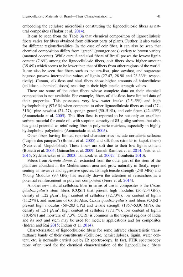
embedding the cellulose microfibrils constituting the lignocellulosic fibers as nat-ural composites (Thakur et al. 2014).
It can be seen from the Table 3a that chemical composition of lignocellulosicfibers varies for fibers obtained from different parts of plants. Further, it also variesfor different regions/localities. In the case of coir fiber, it can also be seen thatchemical composition differs from “green” (younger ones) variety to brown variety(matured coconut). While curauá and sisal fibers of Brazil posses the lowest lignincontent (7.6%) among the lignocellulosic fibers, coir fibers show higher amount(35.4%) which seems to be lower than that of fibers from other regions of the world.It can also be seen that fibers such as taquara-lixa, pine sawdust, and sugarcanebagasse possess intermediate values of lignin (27.47, 28.98 and 23.33%, respec-tively). Curauá, silk-floss and sisal fibers show higher amounts of holocellulose(cellulose + hemicelluloses) resulting in their high tensile strength values.
There are some of the other fibers whose complete data on their chemicalcomposition is not available. For example, fibers of silk-floss have limited data oftheir properties. This possesses very low water intake (2.5–5%) and highhydrophobicity (97.6%) when compared to other lignocellulosic fibers as sisal (27–31%), pine sawdust (21–27), sponge gourd (50–51%), and coir fibers (42–45%)(Annunciado et al. 2005). This fiber-floss is reported to be not only an excellentsorbent material for crude oil, with sorption capacity of 85 g oil/g sorbent, but also,has good potential as reinforcing fiber in polymeric matrices, especially in highlyhydrophobic polyolefins (Annunciado et al. 2005).
Other fibers having limited reported characteristics include cortaderia selloana(“capim dos pampas”) (Bonetti et al. 2005) and silk-floss (similar to kapok fibers)(Neto et al. Unpublished). These fibers are soft due to their low lignin content(Bonetti et al. 2005; Guimarães et al. 2009; Lomeli Ramírez et al. 2014; Neto et al.2015; Sydenstricker et al. 2003; Tomczak et al. 2007a; Trombetta 2010).
Fibers from Arundo donax L., extracted from the outer part of the stem of theplant are abundant in the Mediterranean area and grow naturally in Sicily, repre-senting an invasive and aggressive species. Its high tensile strength (248 MPa) andYoung Modulus (9.4 GPa) has recently drawn the attention of researchers as apotential reinforcement in polymer composites (Fiore et al. 2014).
Another new natural cellulosic fiber in terms of use in composites is the Cissusquadrangularis stem fibers (CQSF) that present high modulus (56–234 GPa),density of 1.22 g/cm3, high content of cellulose (82.73%), low content of lignin(11.27%), and moisture of 6.6%. Also, Cissus quadrangularis root fibers (CQRF)present high modulus (68–203 GPa) and tensile strength (1857–5330 MPa), thedensity of 1.51 g/cm3, high content of cellulose (77.17%), low content of lignin(10.45%) and moisture of 7.3%. CQRF is common in the tropical regions of Indiaand its root and stem may be used for medical applications and for composites(Indran and Raj 2015; Indran et al. 2014).
Characterization of lignocellulosic fibers for some infrared characteristic trans-mittance bands of their constituents (Cellulose, hemicelluloses, lignin, water con-tent, etc) is normally carried out by IR spectroscopy. In fact, FTIR spectroscopymore often used for the chemical characterization of the lignocellulosic fibers
Lignocellulosic Materials of Brazil––Their Characterization … 41

because of its simplicity to identify functional groups and molecules that are presentin the fibers.
Figure 5 shows Fourier Transform Infrared (FTIR) spectra of some of theBrazilian lignocellulosic fibers obtained by various researchers.
As can be seen from the figure, four types of bands occur in almost all thelignocellulosic fibers, peaks occurring at similar frequencies typical of most of thelignocellulosic fibers indicating a complex of lignin and cellulosic materials (cel-lulose and hemicelluloses) in the basic structure. The small variations in the peaksobtained in the FTIR spectra reported for similar fibers from different regions maybe due to the change in the testing methods used and also on the origin of the fiber.These bands represent mostly absorption process, stretching, etc. These are bands at3500–3100, 2900–2300, 1700–1800, 1500–1600, 1328–1374, and 1000–1200 cm−1. Based on the occurrence of these bands (absorption, stretching, etc) it is
Fig. 5 Fourier transform infrared spectra of Brazilian a Arundo fibers b Banana, SugarcaneBagasse and Sponge Guard fibers; c UV visible spectrum of Brazilian Curauá Fibers. Reproducedfrom Refs. a Friore et al. (2014), b Guimarães et al. (2009); c Tomczak et al. (2007b); with thekind permission of the Publishers
42 K. G. Satyanarayana et al.

possible to identify various components of the fibers. This is illustrated in Table 3b.Thus, the spectral lines in the range of 3450–3000 cm−1, which is characteristic ofstretching vibrations of OH group, bonded to cellulose/carbons 2, 3, and 6 carbonsof the glucose (Tomczak et al. 2007a, b, Van Dam et al. 2006). In fact, the abovebroadband may also indicate the presence of moisture in the some of the fibers.Similarly, the peaks in the range of 2900–2360 cm−1 are due to –C=C– stretching,the peaks in the range of 1500–1620 cm−1 to the medium –C=C– stretching and theones in range of 1700–1800 cm−1 is unconjugated C=O stretching, related tocarboxylic ester or acetyl groups (hemicelluloses), the one in the range of 1200–1400 cm−1 is due to C–H rock or absorption of angular strain of CH (celluloseand lignin) (Brigida et al. 2010; Mahato et al. 2013), which is similar in variouslignocellulosic fibers such as coir (Tomczak et al. 2007a, b), okra(Abelmoschusesculentus) (De Rosa et al. 2010), vegetable fibers (Poletto et al.2014), banana, sugarcane bagasse and luffa cylindrica (Guimarães et al. 2009). Insome cases such as coir from a green coconut, some additional bands have alsobeen observed such as a peak at 1080 cm−1 and band at 730 cm−1. While theformer has been attributed to =C–H bends, the latter to aromatic H in the lignin(Oliviera and Marques 2015).
4.3 Thermal Characterization
Figures 6 shows DTA/TGA/DSC curves obtained for some of the Brazilian lig-nocellulosic fibers. These are similar to those obtained for similar fibers elsewhere.From these, degradation temperatures of various constituents of the fibers have beenarrived at. From the figures, a three-stage process is evident in the thermal degra-dation of lignocellulosic fibers with 250–300 °C presenting the first stage, 300–400 °C the second and around 450 °C, the third stage. Researchers working withlignocellulosic fibers have attributed the first stage to the low molecular weightcomponents such as hemicelluloses, the second associated with degradation ofcellulose whereas the third stage to breaking down of lignin (Nurul Fazita et al.2016). It should be noted that one of the crucial aspects in the development oflignocellulosic fiber-incorporated polymer composites is the thermal degradation ofthese fibers, which would certainly pose limitation for the use of some thermo-plastics. Further, porous polymer products can be expected due to the volatilesproduced during the processing of such composites due to the degradation occur-ring at temperatures above 200 °C. Such products would exhibit lower densitiesand inferior mechanical properties.
The data that can be obtained from the above figures is shown in Table 4 for 3Brazilian fibers.
Lignocellulosic Materials of Brazil––Their Characterization … 43

4.4 Mechanical Properties (Tensile, Flexural, and ImpactProperties)
One of the major mechanical properties studied in respect of Brazilian fibers is theirtensile properties. In some cases, these properties are studied as a function ofdiameter and length of the fibers and also as a function of strain rate. For thispurpose first stress–strain curves of the fibers are obtained for from which Young’smodulus (YM), ultimate tensile strength (UTS) and percentage elongation arenormally derived. Figure 7 shows stress–strain curves thus obtained in respect ofcurauá fibers while Table 5 lists tensile properties derived from such curves forvarious Brazilian fibers by different researchers.
Fig. 6 DTA/TGA/DSC curves of some of the Brazilian lignocellulosic fibers: TG/DTG curvesa Arundo fibers Fiore et al. (2014); b Brazilian nutshell fiber in air Inamura et al. (2011);c Brazilian nut bur fiber in air Inamura et al. (2011); d Curauá Fiber in N2 Atmosphere Tomczaket al. (2007b); e Sugarcane Bagasse fibers in air Guimarães et al. (2009); f Sponge Guard fibers inair Guimarães et al. (2009); DSC Curves: g Açaı fiber Martins et al. (2008); h Banana fibersGuimarães et al. (2009); i Sponge Gourd fibers Guimarães et al. (2009) (Reproduced with kindpermission of the Publishers)
44 K. G. Satyanarayana et al.

Table 4 TGA data derived from the curves of Taquara-lixa, açaí and curauá some fibers(Reproduced from Gehlen 2014)
Fiber Mass loss(%)
Peak(◦C)
Observations
Taquara-lixa(Merostachysskvortzoviisendulsky)
7.1 (45 °C)
360 Due to the high lignin content,27.5%, the fiber is stable up to250 °C
67.9(380 °C)
22.3(380–800 °C)
2.7 (800 °C)
Residue
Açai (Euterpe edulis) 8.4 (100 °C)
Loss of water
30.0(257 °C)
Starts the degradation ofhemicelluloses
31.0(338 °C)
Final degradation of lignin andcellulose
5.4 (650 °C)
Residue
Curauá (Ananaserectofolius) 5.9 (80 °C))
Loss of water
65.8(290 °C))
Degradation of nonstructurallignocellulosic materials
7.4 (650 °C)
Residue
Fig. 7 Typical stress–straincurves for different diametersof Curaua fibers of BrazilTomczak et al. (2007b).Reproduced with kindpermission of the Publishers
Lignocellulosic Materials of Brazil––Their Characterization … 45

Table 5 Tensile properties and flexural modulus of some lignocellulosic fibers of Brazil andothers
Fiber Young´sModulus(GPa)
Ultimatetensilestrength(MPa)
Elongationat break(%)
FM/FS (MPa) References
Amazonian jacitarapalm (Desmoncuspolycanthos Mart.)
0.76–1.87
38.3–74.4 – – Fonesca et al. (2013)
Arundo donax 9.4 248 – – Fiore et al. (2014)
Banana 27–32 700–800 – 2–5 Satyanarayana et al. (2007),Monteiro et al. (2011a)
Bamboo 18–55 391–800106–204
391–713 Osório et al. (2011),Monteiro et al. (2011a)
Buriti 129–254 Monteiro et al. (2011a)
Capim-dos-pampas
Cissusquadrangularis(CQSF)/roots
56–234/68–203
1857–5330
Indran et al. (2014), Indranand Raj (2015)
Coir 2.5–4.5 95–174 13.7–41 50–275 Satyanarayana et al. (2007),Tomczak et al. (2007a)
Green coir FromLupitapaper
Cotton 12 400 0.03–0.10 Satyanarayana et al. (2007)
Curauá 30–80@ 1250–3000@
4.5–6@ 87–310 Satyanarayana et al. (2007),Monteiro et al. (2011a)Tomczak et al. (2007b)117–3000 1.3
10.5 439–495(MOR)
1.3–3.2
27.1 117(MOR)/495
Jute 465 0.7 0.3–0.5 Satyanarayana et al. (2007),Monteiro et al. (2011a)13–27 393–800
Malva
Piassava 1.07–4.595-6
134.58–142.9109–1750
6.4–21.9 100; Monteiro et al. (2011a)
Pineapple 82 180 3.2 Satyanarayana et al. (2007)
Ramie 4461–128
500–870400–1620
1.2 – Satyanarayana et al. (2007),Monteiro et al. (2011a)
Sisal 19.009–28
324–329/577287–913
2–2.5 324.2 ± 173.9 Satyanarayana et al. (2007),Sydenstricker et al. (2003),Monteiro et al. (2011a)
Sponge guard
Sugarcane Bagasse 27.1 222 1.1 Satyanarayana et al. (2007)
FM Flexural modulus; FS Flexural strength
46 K. G. Satyanarayana et al.

4.5 Surface Treatments of Lignocellulosic Fibers
Banana fibers have been subjected to alkaline treatment and characterized for thecrystalline fraction, dielectric behavior, metal removal (governed by solution pH)and biodegradation (Barretto et al. 2010). Results indicated this fiber is a low-costalternative for metal removal in aqueous industry effluents. Thus, for regions withlow resources, the biosorbents are an alternative to diminish the impact of pollutioncaused by local industries, besides being a biodegradable product.
Effect of surface treatment by alkali and methacrylamide to sponge gourd fibersusing different techniques, which included FTIR, XPS/ESCA, X-Ray, TGA, andSEM, has been studied Tanobe et al. (2005). The results revealed no change in thefiber integrity along with improvement in surface area and thermal stability alongwith lowering of chemical constituents of the fibers with NaOH treatment. On theother hand, methacrylamide affected the integrity of the fibers besides changed inthe chemical constituents of the fiber.
Alkali treatment of sugarcane bagasse fibers revealed enhancement in chemicalconstituents of the fiber along with the modification of the fiber surface, but withoutany significant change in the thermal resistance of the fibers (Simão et al. 2016).Modification of fiber surface was reflected in the improved impact strength of itscomposites with polypropylene matrix by almost 100%. FTIR studies of thesefibers showed increased peak intensity at certain frequencies and reduction incarbonyl absorption regions suggesting extraction of lignin and other extractivesleading to higher hydrophilic nature of the treated fibers.
On the other hand, similar treatment of sisal and bagasse fibers resulted inimprovement of surface of the fibers, which was reflected in the good dispersion ofthe fibers in the matrix along with enhanced interaction between the fibers and thematrix resulting in improved strength properties (de Campos et al. 2013; Vilay et al.2008).
Steam explosion and alkali treatments have been given to sugarcane bagassefibers (Ricardo et al. 2011). Removal of acid-insoluble lignin by almost 60% wasobserved. On the other hand, steam explosion (physical treatment) of these fibersincreased the amount of lignin along with decreasing the hemicellulose content. Asa result of these, enhancement of properties (density, thermal stability, waterabsorption and thermo-mechanical properties) was observed in their compositeswith polyester suggesting improved chemical modifications, particularly with asteam explosion.
An interesting study was undertaken by the University of Parana´West, Brazil, toevaluate the durability of bamboo for using it as reinforcement of concrete usingbamboo splints and aimed at establishing some design procedures which guaranteethe durability and the safety of structural member (Lima et al. 2008). Tensileproperties of bamboo were measured with and without their exposure to wet and dryconditions in tap water and CaOH2 solution up to 60 cycles. No change in theseproperties of the fibers was observed even after 60 cycles of exposure indicating thatneither exposure to CaOH2 solution nor tap water has any effect on these properties.
Lignocellulosic Materials of Brazil––Their Characterization … 47

4.6 Theoretical Aspects (Weibull Analysis and ArtificialNeural Network)
4.6.1 Weibull Analysis
Although many research groups in Brazil have been working on lignocellulosicfibers and their composites, only a few groups involving the present authors of thischapter seems to have reported on the Weibull analysis related to lignocellulosicfibers with majority of publications coming out from only one group (Amico et al.2001a, b, 2005; Bevitori et al. 2010; Costa et al. 2010, 2011; Inacio et al. 2010;Margem et al. 2010; Monteiro et al. 2011a, b, 2014a; Nascimento et al. 2010;Portela et al. 2010; Santafe et al. 2009; Tanobe et al. 2005).
Recognizing the fact that lignocellulosic fibers exhibit large variation in theirstrength properties, and therefore averaging of the obtained strength values and useof standard deviation may not be proper, Amico and co-workers used Weibullanalysis in their studies on sisal fibers to understand the effect of surface treatmenton tensile strength of fibers (Amico et al. 2001a, b, 2005). They used two methods,viz., the maximum likelihood technique (requiring the solution of two nonlinearequations), and the analytical method. Details of their work can be seen in thereferences given here. Briefly, it is as follows:
They used two approaches in the second method; the first one gave the lowcoefficient of variation indicating a poor Weibull distribution ruling out thenecessity for the use of diameter in their statistical analysis for sisal fiber. In thesecond approach called “Weibull distribution of strength” histograms were usedwith mean single fiber diameter, for all the fibers (0.195 mm for the 100 fibers) andthe actual fiber diameter along with the Weibull parameters obtained by the max-imum likelihood method. Obtained results were tested using a plot of tensilestrength values with both single fiber diameter of the actual fiber diameter withlogarithm fitting. Smaller scatter was observed in the corrected tensile strengthvalues as per this fitting suggesting appropriateness of the model (Weibull proba-bility) used.
On the other hand, correlation between tensile strength and diameter of eightlignocellulosic fibers (sisal, ramie, curauá, jute, bamboo, coir, piassava, and buriti)of Brazil origin has been studied through statistical evaluation using the Weibullanalysis (Bevitori et al. 2010; Costa et al. 2010, 2011; Inacio et al. 2010; Margemet al. 2010; Monteiro et al. 2010, 2011a, b, 2014a; Nascimento et al. 2010, 2011;Portela et al. 2010; Santafe et al. 2009).
For this, Weibull statistical method was applied for the tensile strength valuesobtained for each of the diameter intervals of all the eight fibers shown in Fig. 3with the arbitrarily chosen number of diameter intervals based on the range of thediameter of each fiber studied.
48 K. G. Satyanarayana et al.

Based on the specific Weibull distribution with related deviation, the analysis ofobtained strength values was carried out using a computer program using 4parameters, viz., characteristic strength (q), Weibull modulus (b), statistical preci-sion or adjustment coefficient (R2) and the average strength, rAv. Prepared Weibullplots of Arundo fibers and those of one diameter for all 8 chosen fibers of onediameter are shown in Fig. 8A, B) respectively, while plots of the Weibull averagetensile strength as a function of the equivalent diameter of corresponding statisticalintervals of the chosen fibers are shown in Fig. 8C.
It may be noted that Fig. 8A showing the Weibull distributions for (a) tensilestrength, and (b) Young’s modulus of Arundo fibers has been calculated through anequation and the model used by the authors provides a good fitting of the data(Fiore et al. 2014). This figure also shows the Weibull shape and scale parametersfor both the tensile properties with the shape parameter indicating the reliability ofthe data. No Weibull distribution for % elongation at break is shown although itwould have been complete in respect of tensile properties of this fiber. However, theWeibull scale and shape parameters for % elongation are reported to be 3.24% and5.30, respectively.
On the other hand, Fig. 8B corresponds to double log plot of the reliabilityversus the location parameter and the obtained graphs are unimodal showing astraight line fitting the points within the same diameter interval. Thus, this suggeststhat similar strength behavior of fibers tested belong to a unique group for eachdiameter interval. Further, it also becomes evident that there exists an inverserelationship between the tensile strength (r) and the fiber diameter (d) in the case ofall the tested fibers, which may be hyperbolic type [r = A/d − B, where, A-in MPa.mm and B-in MPa are constants also called as hyperbolic coefficients having dif-ferent value for each fiber]. It has been found that values of A vary from 13 MPa.mm for coir to 260 MPa.mm for Piassava fiber and those of B vary from −349 MPafor piassava to +389 MPa for ramie fiber (Monteiro et al. 2011a, b).
The hyperbolic relation between the tensile strength and the diameter of fibersindicates that smaller the diameter of the chosen fiber, higher is its tensile strengthas in the case of sisal, ramie, curauá, and piassava fibers [see Fig. 8C-(e, f and h)respectively], which show about 1000 MPa as the tensile strength of these fibers.Other interesting points to be noted from the Fig. 8C is a constant value (shown byhorizontal line) going through the limits of error bars as in the case of bamboo, coir,and buriti fibers [see Fig. 8C-(e, f, and h) respectively].
It is also reported that (i) this type of hyperbolic behavior may also be applicableto other fibers of Brazil as well as of other countries and (ii) the role played by thedefects and flaws in the fiber could be responsible for this type of relationshipbetween the fiber tensile strength and its diameter (Monteiro et al. 2011a, b, 2014a).The latter has been supported by the fractographic studies of these fibers as willdiscussed later in the chapter [see sec.—Microstructural and fractographic studies].
Considering that low diameter fibers exhibit higher tensile strength valuescomparable to metallic alloys, Monteiro and his co-workers have suggested thatsuch lignocellulosic fibers should be recognized as a class of engineering materials.With this, they have made an attempt to locate these fibers suitably in tensile
Lignocellulosic Materials of Brazil––Their Characterization … 49

50 K. G. Satyanarayana et al.

strength versus density chart in a specified field in a proper Ashby’s property chart(Monteiro et al. 2011b). This is shown in Fig. 8D. As can be seen, the field forlignocellulosic fibers is of ellipse shape, which includes some of the lignocellulosicmaterials having density values between 0.45 and 1.60 g/cm3 and strength valuesbetween 95 and 3000 MPa based on the observed values of density and tensileproperties of the fibers listed in Tables 2 and 5.
It can also be seen from the figure that location of lignocellulosic fibers in thechart is at the same level as that of a common type of engineering materials (alloysand composites). Furthermore, based on the density values of the fibers, these fiberswould be more preferable from the minimum weight design in the two modes ofloading, [viz., r2/3/q and r1/2/q], in the development of new products particularly inautomobile applications. In support of this, it may be relevant to point out thatMonteiro and coworkers have prepared some polymeric composites with lowdiameter fibers, which exhibited high strength values (Costa et al. 2011). Theforegoing also suggests the need for the development of a methodology to separatelow diameter fibers from the lot obtained from the supplier. In fact, these authorshave developed such a method wherein differences in densities are consideredbased on the use of suitable fluids while determining the density by Archimedes’sprinciple (Monteiro et al. 2011b).
4.6.2 Artificial Neural Network (ANN)
Coir and curauá fibers of Brazil origin have been characterized by some physical,chemical, thermal, and strength properties with the latter as a function of differenttest conditions (fiber dimensions and speed of testing) (Tomczak 2010). In addition,application of ANN in strength properties of these two lignocellulosic fibers hasbeen considered, which is the only pioneering study carried out on this aspect to thebest knowledge of the authors. In this proposed computational model, strengthproperties [YM, UTS, and % elongation––outputs] are studied as a function ofcellulose content, test speed (strain rate), and dimensions (gauge length anddiameter)[inputs] of the fibers. The ANN scheme employed for the simulation ofYM is shown in Fig. 9.
Some of the experimental and simulated values of YM, UTS, and % elongationof curauá fibers are listed in Table 6a–c.
JFig. 8 A Weibull distribution of Arundo fibers for a Tensile stress b Young’s modulus.Reproduced from Fiore et al. (2014) with the kind permission of the Publishers. B Weibull graphsfor the eight lignocellulosic fibers: a Bamboo, b Buriti, c Coir, d Curauá, e Jute, f Piassava,g Ramie and h Sisal. Reproduced from Monteiro et al. (2011b) with the kind permission of thePublishers. C Weibull average strength as a function of the mean diameter associated withintervals in Fig. 3 for the eight fibers considered: a Bamboo, b Buriti, c Coir, d Curauá, e Jute,f Piassava, g Ramie, and h Sisal. Reproduced from Monteiro et al. (2011b) with the kindpermission of the Publishers. D Ashby’s density versus strength chart. Reproduced from Moneiroet al. (2011b) with the kind permission of the Publishers
Lignocellulosic Materials of Brazil––Their Characterization … 51

Fig. 8 (continued)
52 K. G. Satyanarayana et al.

The correlation between the data on the influence of diameter of the fiber, gaugelength, and test speed (strain rate) on experimental and simulated values of YM ofcurauá fibers was found to be 91.25, 99.55, and 94.79% respectively.
The aim of such a study is to enable the researchers to use these fibers from anyregion in any applications such as in composites as the expected results would takecare of variations in the origin of fibers and their related properties. Thus, ANN mayhelp in finding the potential of lignocellulosic fibers of any origin. For the modelingstudy by ANN, suitable software such as Pythia has been used. Experimental dataof strength properties obtained were randomly divided into training data and testdata, while initial experimental data was divided into two sets, one (70%) fornetwork training and the other (30%) for verification. Helical angles, cellulosecontent, crystallinity, diameter of the fibers along with the test speed and gaugelength of the fiber were considered as input signals. For each of these inputs,strength properties were considered as outputs or responses. It may be noted thatany of the tensile property was defined as output when it was not used as an initialsignal. The efficiency of each model was assessed by degree of correlation betweenobserved data and simulated data by drawing graphs between these two data andcalculating the correlation coefficient using a suitable equation. Thus three modelswere proposed, one for each of the evaluated properties.
Thus, this study has revealed feasibility of modeling the strength properties oflignocellulosic fibers using their physical, chemical, and structural characteristics.Probably, other input parameters such as climate and soil type can also be used tofind their influence on ANN for modeling the tensile properties of lignocellulosic
Fig. 9 ANN scheme employed for the simulation of the YM of the fibers
Lignocellulosic Materials of Brazil––Their Characterization … 53

fibers from anywhere. This would enable the expansion of utilization of these fibersin various applications without any limitation of origin of these fibers.
4.7 Structural Aspects
4.7.1 Morphology and Fractography
Figure 10 illustrates the typical cross sections of some of the Brazilian lignocel-lulosic fibers. It can be seen from the figure that depending on the source of fibers
Table 6 a Comparison of experimental and simulated elastic modulus values of Curauá fibers,b comparison of experimental and simulated ultimate tensile strength values of Curauá fibers,c comparison of experimental and simulated % elongation values of Curauá fibers
Speed (mm,min−1)
Distance betweengrips (mm)
Young’s modulusexperimental (MPa)
Young’s modulussimulated (MPa)
5 510152025
26.3943.9144.3246.2551.89
26.1242.7644.4943.9650.00
10 20 47.99 44.59
20 20 47.00 46.31
50 20 53.69 51.64
Speed(mm,min−1)
Distance betweengrips (mm)
Ultimate tensile strengthexperimental (MPa)
Ultimate tensile strengthsimulated (MPa)
5 510152025
2213.002314.001950.051784.591730.61
2185.232236.811806.161661.351608.25
10 20 1898.04 1829.12
20 20 1921.82 1788.80
50 20 2174.67 2077.92
Speed (mm,min−1)
Distance between grips(mm)
Experimentalelongation (%)
Simulatedelongation (%)
5 510152025
10.206.144.834.573.74
10.716.084.894.593.89
10 20 4.70 4.79
20 20 4.52 4.49
50 20 4.49 4.53
54 K. G. Satyanarayana et al.

(stem/leaf/fruit etc.) distinct shapes and sizes exist for the transverse sections ofeach type of lignocellulosic fiber despite all these fibers have cellulose and lignin astheir major constituents. In most cases, these are approximately elliptical with smalleccentricity. In fact, when visually observed, apparent round fibers may displaymicroscopically quite distinct eccentric cross-section shapes as can be seen inFig. 10d–f. Moreover, even in a single fiber, significant changes in cross-sectiondimensions along the axial direction are common features of all lignocellulosic fiberas is evident in these figures. Therefore, as mentioned earlier, a careful measure-ment of the transversal dimensions has to be conducted to permit a reliable esti-mation of the diameter mean value, which will allow an exact determination of thearea for the correct evaluation of the tensile strength.
Fig. 10 Photographs of cross section and longitudinal section of some of the Brazilian fibers:longitudinal sections of a Acai Fiber; b Bagasse; c Luffa cylindrica; d Cross section of Arundofibers; e transverse cross section of Piassava fiber with a number of lacunas at the end of the crosssection and number of cells of different sizes; f cross section of green coir fiber; g longitudinalsection of the piassava fiber showing the surface of the fiber; h cross section Brazilian nutshellfiber; (i) cross-section Brazilian nut fur fiber. Reproduced with the kind permission of authors andPublishers a from Martins et al. (2008); b Simão et al. (2016); c Tanobe et al. (2005); d Friore et al.(2014 e, f Nascimento et al. (2012); f longitudinal section of this fiber; g Cruz et al. (2015); h andi Inamura et al. (2011)
Lignocellulosic Materials of Brazil––Their Characterization … 55

It is interesting to note that shell fiber present different morphology, dependingon the fiber layers while the bur fiber presents irregular fibers, in different direc-tions, like polymers cross-linking. This is reported to hinder fracture of the fiber.
Further, it is assumed that all types of lignocellulosic fibers consist of a numberof continuous cylindrical cells with different arrangements and cell wall thickness.These cells are cemented by the intercellular substances. This substance is isotropic,non-lignocellulosic and ligneous in nature. As can be seen from Fig. 10d–f, there isa cavity termed “lacuna” in all types of fibers, whose position and dimensions differfor each type of fiber. Similarly, there is a cavity at the center of each cell, called“lumen”, whose dimensions also differ from fiber to fiber as is evident from thesefigures.
On the other hand, longitudinal sections of the fibers show surface structures,which also differ for each type of fiber. It is also pertinent to note here that thetensile strength fiber is dictated by the dimensions of the individual cells (l/d ratio),which in turn differ for each type of fiber.
Further, in view of the differences in the structures of these fibers having dif-ferent shapes, sizes, and arrangements of cells, lacuna and lumen, as well asthickness of cell walls, fracture mode of these fibers also differ. Figure 11a–f showsfractographs of various types of fibers revealing differences in their fracture modewith some showing intercellular or intracellular or mixed modes of fracture. Basedon detail study of fractographs of various fiber, it has been reported that inter-granular fracture is observed in fibers having high cellulose content, high length to
Fig. 11 Scanning electron microscopy (SEM) photographs of the fracture surfaces: a Bamboo––transverse section of giant bamboo showing the fracture tip of a thicker bamboo fiber; b ThickBuriti fiber; c Thick Coir fiber; d Thick Curauá fiber; e thick Piassava fiber; f jacitara fiber (in allheight positions of the plant) after mechanical test. Arrows indicate the presence of unbrokenfibers. Reproduced from a Cruz et al. (2015); b–e Monteiro et al. (2011a, b); f Fonseca et al.(2013)
56 K. G. Satyanarayana et al.

diameter ratio (l/d) of cells or microfibrils and low microfibrillar angle exhibitinghigh tensile strength and modulus with low % elongation. On the other hand, theintercellular fracture is observed in fibers having low cellulose content, highmicrofibrillar angle, low l/d ratio exhibiting low strength and modulus values, butlonger % elongation (Satyanarayana et al. 1986).
4.7.2 Results of Surface Treatments
Figure 12a–i shows the photomicrographs depicting the effect of surface treatmentson some of the Brazilian lignocellulosic fibers in terms of morphology and frac-tographs. In the case of Piassava fiber, alkali treatment has led to the removal ofprotrusions and waxy layers, which are normally on the surface of the fibers(Nascimento et al. 2012). It was also observed the degree of removal depended onthe concentration of the alkali and time of treatment. This is illustrated in Fig. 12,
Fig. 12 SEM micrographs of surface treated lignocellulosic fibers of Brazil: a–c Piassava fibersuntreated fiber, 0.1 and 10% alkali treated fibers for 1 min. and 60 min respectively; d surface ofalkali treated bagasse fiber; e and f Longitudinal surface of luffa cylindrical fiber after alkalitreatment and methacrylamide treatment; g–i Tensile ruptured Buriti fibers subjected to electronbeam irradiation doses of i 50, (ii) 250 and (iii) 500 kGy (50X). Reproduced a–c from Ref.Nascimento et al. (2012); d From Simão et al. (2016); e and f Tanobe et al. (2005); g–i fromBarbosa et al. (2012); with the kind permission of the Publishers
Lignocellulosic Materials of Brazil––Their Characterization … 57

which shows photomicrographs of the surface of piassava fiber in untreated as seenin Fig. 12a and alkali-treated conditions with Fig. 12b showing surface morphologyfor 0.1% NaOH for 1 min treatment and Fig. 12c showing that for 10% NaOH for60 min. It can be observed that with the former treatment resulting in partialremoval of the protrusions while the latter one almost complete removal of pro-trusions from the surface of the fiber. In fact, it was found that the former gavebetter adhesion, while the latter poor adhesion. Figure 12d shows the surface ofalkali treated bagasse fiber revealing the effect of alkali on the fiber. On the otherhand, Fig. 12e, f shows a superficial layer of extractives on the untreated fiber andthe surface of the treated Luffa cylindrica fiber, respectively. It can be seen that thelatter does not show any superficial layer, which has been attributed to the removalof hemicelluloses and other extractives from the fiber (Tanobe et al. 2005).
Electron beam irradiation (Physical treatment) of buriti fibers extracted from thepetiole of the palm tree revealed enhancement in tensile strength with a low dosageof 50 kGy, while it decreased with higher dosages (250 and 500 kGy). Theseobservations have been supported by the fractographic studies of the fibers(Fig. 12g–i, which revealed a different type of fracture with lower doze treatedfibers showing the plastic type of fracture (Fig. 12g), while higher doses treatedones showing the brittle type of fracture along with degradation of the surface of thefiber (Fig. 12e, f).
Figure 13a–d shows the morphology of bamboo splints with cement pasteexposed to tap water and Ca(OH)2 solution by alternate wet and dry conditions for60 cycles as observed in SEM (Lima et al. 2008). It may be noted that the surface ofthe fibers was cleaned before taking photographs.
It can be seen from the figure that 60 cycles of wetting and drying changed thesurface of bamboo although the figures show the cement paste on the splintembedded in concrete prism and a layer of Ca(OH)2 deposition in splint aged in asolution of calcium hydroxide. However, there is no observable deterioration of thebamboo fiber after aging except for some changes of the fiber surface close to thesplint surface. Neither deposition of cement products nor crystals of Ca(OH)2 couldbe seen within the veins of the fiber, while completely empty vascular system couldbe seen.
5 Applications of Lignocellulosic Fibers
Considering many lignocellulosic fibers are coarse and strong they have been usedin both conventional and new application areas. The conventional uses include asbrushes, twine, ropes, string, yarn and which can also be woven into carpets, mats,and mattings, in various handicrafts, in papermaking, textiles (buffing cloth), asreinforcements in plastics and rubber, in biogas generation (waste or short fibers)(http://www.fao.org/economic/futurefibres/fibres/sisal/en/-22 Oct. 2016). Almostall the fibers-producing countries have utilized their fibers in these applications.
58 K. G. Satyanarayana et al.

Of the new applications, nanomaterials, composites, and materials in arts arethree important applications, which are being followed in Brazil also. For thispurpose, the country has been supporting research and development activitiesthrough many of its funding agencies such as National Council for Scientific andTechnological Research (CNPq) with a view to open areas for value addition andemployment generation, besides working toward biodegradation and renewal of theecological cycle. One aspect of such endeavor is a presentation of the results ofthese activities by Brazilian composite researchers constituting about 12% of the235 in 2007, which might have grown greater than this in recent times. Materialsand Metallurgical Engineering Groups in the country in both national and inter-national conferences conducted in Brazil on natural resources dealing with ligno-cellulosic fibers and their composites. These groups work in different aspects oflignocellulosic fibers. Furthermore, recognizing the merits and demerits of these
Fig. 13 Scanning electron micrographs of bamboo splint after aging: a splint surface with cementpaste, b splint surface with deposition of Ca(OH)2, c bamboo fibre aspect after being tested in tapwater, d bamboo fibre aspect after being tested in calcium hydroxide solution, e nodal region afteraging in tap water and f vascular system after aging in solution of calcium hydroxide From: Limaet al. (2008)
Lignocellulosic Materials of Brazil––Their Characterization … 59

fibers shown in Table 7, the country follows some of the international trends in thesearch of potentials of lignocellulosic fiber covering various sectors such as auto-motive sector with commercial production and use of some parts and also inbuilding sector (Satyanarayana et al. 2009b). In addition, there has been a trend insome of the countries in adopting better cultivation methods including geneticengineering and treatments to get quality fibers having uniform properties suitablefor different applications (Anandjiwala et al. 2007). In the following pages, somedetails of work in the areas of composites and fine arts are discussed.
5.1 Nanomaterials
Recognizing that lignocellulosic materials are attractive due to their abundance,renewability, and low cost and existence of some limitations for industrial uptake ofthese materials in structural and other applications, reduction in the size of these
Table 7 Merit list for the use of plant fibers incorporated composites (Satyanarayana et al. 2007,2009; Nurul Fazita et al. 2016)
Merits Demerits
Abundant availability, renewable resource andbiodegradable
Heterogeneous quality
Non-brittle fracture on impact Moisture sensitivity
Same performance for lower weight Low durability
Stronger (25–30%) for the same weight Lower mechanical propertiesespecially impact resistance
Low cost—less than the base resin Low thermal stability
Fully and easily recyclable Poor fire resistance
Reduced molding cycle time—up to 30% Poor fiber-matrix adhesion
Non-abrasive to machinery Price fluctuation by harvest resultsor agricultural politics
Natural appearance and non toxic
Low thermal expansion coefficient
Good sound abatement capability
Better energy management characteristics
More shatter resistant
Low mold shrinkage
Easily colored
High flex modulus—up to 5X base resin
High tensile modulus—up to 5X base resin
High notched impact—up to 2X base resin
Lower processing energy requirements
Meets minimum recycle content requirements includingpossibility for thermal recycling
60 K. G. Satyanarayana et al.

materials below the normal microlevel could be one option to overcome theproblem. Reduction of size of lignocellulosic fibers could offer improved behaviorand enhanced properties. Besides, there has been increasing interest in the devel-opment of functional materials. Thus, an advantage in behavior and functionalityexhibited by the nano-sized materials has led to the increasing attempts to thedevelopment and use of nanomaterials along with the need to find new sources toproduce them. Many attempts have been reported to obtain nanomaterials(nanocellulose, nanolignin, and nanosilica) from lignocellulosic materials includingwood (Alemdar and Sain 2008; Anandjiwala et al. 2007; Carneiro et al. 2015;Carpenter et al. 2015; Kalia 2016; Kalia et al. 2011; Pilla 2011; Thakur 2013, 2014;Thakur et al. 2013, 2014; Thomas et al. 2013) although most of nanofibers fromlignocellulosic materials are concerned with nanocellulose. Surface modificationand functionalization of nanocellulose from various sources including natural fiberscan lead to various nanomorphologies which have the potential for application inmany areas of engineering, medicine, etc. All these are possible throughnanotechnology.
Nanotechnology may be defined as the manipulation of materials measuring10 nm or less in at least one dimension. New materials and products may bedeveloped when it is fully understood how materials and their interfaces are con-structed at nano- and atomic scales (Kamel 2007).
It is reported that greater expectations have been placed on various aspects ofnano-related things (Science of nanomaterials, nanotechnology includingnanomanufacturing, etc.) by different persons be they are academicians, investors,governments, and industrial sectors (Serrano et al. 2009; Tuuadaij and Nuntiya2008). This is because both nanomaterials and processes to obtain them(Nanotechnology) exhibit unique characteristics with nanomaterials exhibitingenhanced properties and performance, while the technology having the capability tofabricate new structures at the atomic scale. Therefore, it is not surprising to knowattainment of both industrial and economic reality of these nano-related materialswith estimated worldwide annual sources of naturally occurring nanoparticles to bethe lowest from biomass (*1.8 million tons) (Gaffet 2011). Therefore, it is logicalto explore the use and application of nanotechnology-based methods as a promisingapproach for efficient utilization of the lignocellulosic resources. In the followingpages, brief mention of preparation of nanomaterials (nanocellulose, nanolignin,and nanosilica) from lignocellulosic materials, their characteristics and applicationsis made:
Different nomenclatures such as “crystallites”, “‘nanocrystals”, “whiskers”,“nanofibrils”, and “nanofibers” have been given to these nanosized materials withone dimension in the nanometer range. These have been attracting scientists towardtheir isolation, characterization and possible applications (Klemm et al. 2011).These are called “nanocellulose”, “nanolignin” and “nanosilica” derived fromcellulose, lignin, and silica respectively.
Cellulose nanofibrils represent a unique material due to their low cost whencompared to other types of new materials such as carbon nanotubes that are stronger(nanofibrils have about 25% of the strength of carbon nano tubes), but more
Lignocellulosic Materials of Brazil––Their Characterization … 61
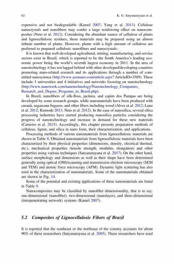
expensive and not biodegradable (Kamel 2007; Yang et al. 2013). Cellulosenanocrystals and nanofibers may confer a large reinforcing effect on nanocom-posites (Neto et al. 2012). Considering the abundant source of cellulose of plantsand lignocellulosic residues, these materials may be prepared using an almostinfinite number of plants. However, plants with a high amount of cellulose arepreferred to prepared cellulosic nanofibers and nanocrystals.
It is known that well-developed agricultural, mining, manufacturing, and servicesectors exist in Brazil, which is reported to be the South America’s leading eco-nomic power being the world’s seventh largest economy in 2011. In the area ofnanotechnology it has not lagged behind with other developed/developing countriespromoting nano-related research and its applications through a number of com-mitted nanoscience (http://www.azonano.com/article.aspx? ArticleID=3589). Theseinclude 3 universities and 4 initiatives and networks focusing on nanotechnology(http://www.nanowerk.com/nanotechnology/Nanotechnology_Companies_Research_and_Degree_Programs_in_Brazil.php).
In Brazil, nanofibers of silk-floss, jacitara, and capim dos Pampas are beingdeveloped by some research groups, while nanomaterials have been produced withcurauá, sugarcane bagasse, and other fibers including wood (Alves et al. 2012; Lunzet al. 2012; Kumode 2013; Neto et al. 2012). In the case of nanosilica, several silicaprocessing industries have started producing nanosilica particles considering theprogress of nanotechnology and increase in demand for these new materials(Carneiro et al. 2015). Accordingly, this chapter presents preparation methods ofcellulose, lignin, and silica in nano form, their characterization, and applications.
Processing methods of various nanomaterials from lignocellulosic materials areshown in Table 8. Obtained nanomaterials from lignocellulosic materials have beencharacterized by their physical properties (dimensions, density, electrical thermal,etc.), mechanical properties (tensile strength, modulus, elongation) and otherproperties using various techniques (Satyanarayana et al. 2017). On the other hand,surface morphology and dimensions as well as their shape have been determinedgenerally using optical (OM)/scanning and transmission electron microscopy (SEMand TEM) and atomic force microscopy (AFM). Dynamic light scattering has alsoused in the characterization of nanomaterials. Some of the nanomaterials obtainedare shown in Fig. 14.
Some of the potential and existing applications of these nanomaterials are listedin Table 9.
Nanocomposites may be classified by nanofiller dimensionality, that is to say,one-dimensional (nanofiber), two-dimensional (nanolayer), and three-dimensional(interpenetrating network) systems (Kamel 2007).
5.2 Composites of Lignocellulosic Fibers of Brazil
It is reported that the southeast or the northeast of the country accounts for about90% of these researchers (Satyanarayana et al. 2005). These researchers have used
62 K. G. Satyanarayana et al.

Table 8 List of processing methods of various nanomaterials from lignocellulosic materials(adopted from Satyanarayana et al. 2017)
Type ofnanomaterial
Processing method and characteristics
NanocelluloseMFCCNC, NFC
Mechanical-shearing and grinding/steam explosion/high pressurehomogenization/chemical- acid hydrolysis, alkaline treatment andbleaching/combined chemical and mechanical treatments/ultrasonication/electro-spinning/EnzymaticDia: 5–60 nm; length: several µmsDia: 5–70 nm; length: 100–250 nm (from plant celluloses)
Nanolignin aPrecipitation method/chemical modification/electrospinning followed bysurface modification/freeze drying followed by thermal stabilization andcarbonization/supercritical anti-solvent technology/chemo-mechanicalmethods/nano Lignin by self-assembly/Lignin nanocontainers bymini-emulsion method/template mediated synthesis
Nano silica Acid treatment ! either mechanical treatment or thermal combustionunder controlled conditions/ activation techniques/combined chemical andthermal treatment or ball milling ! oxidation/grinding ! chemicaltreatment/enzymatic crystallization of amorphous nano silica
MFC Micro-fibrillated cellulose, Nanofibrils, microfibrils, nanofibrillated celluloseCNC Cellulose nanocrystals, crystallites, whiskers, rod-like cellulose microcrystalsNFC Nanofibrillated celluloseaNot known how many of these methods are applicable to lignocellulosic materials
Fig. 14 a AFM image of cellulose whiskers extracted from Kraft pulp of Eucalyptus urograndisNeto et al. (2012); b TEM photograph of nanocellulose of Balsa wood Kumode (2013); c SEM ofsilica nanoparticle obtained from Equisetum arvenses L showing agglomerates (Carneiro et al.2015); d High magnification SEM image of catalyzed material using sugarcane bagasse afterpyrolysis at 1000 °C Alves et al. (2012); e and f TEM micrographs of nanoparticles of Luffacylindrica fiber at two magnifications of 200 and 50 nm respectively Anupama et al. (2017)
Lignocellulosic Materials of Brazil––Their Characterization … 63

both synthetic and natural polymers for the development of composites as has beendone elsewhere globally. In the case of lignocellulosic fibers, they have been usedprimarily for substituting synthetic fibers such as glass fibers with the possibility ofaddressing environmental concerns along with supporting global sustainability anddiversification of nonfood areas enabling stable economy through agro-industry.Besides, Brazilian researchers working with plant fibers have observed success inthe use of lignocellulosic fibers-based composites in various areas such as auto-motive, building, and various engineering sectors (Satyanarayana et al. 2007,2009b). Many such attempts have also reported development of both mono com-posites and hybrid composites involving either only lignocellulosic fibers or in acombination of these with synthetic fibers (Satyanarayana et al. 2009a, b).
One of the nonconventional applications of lignocellulosic fibers has been inusing them as fillers or as reinforcements in the preparation of composites with bothpolymers and ceramic/cement matrices. In the case of polymers both synthetic andnatural types have been used. Figure 15 illustrates progress in the development ofpolymer-based composites during 2000–2014.
The studies carried out on the above (polymer and ceramic/cement based)composites using Brazilian lignocellulosic fibers till the year 2011 have beenalready published by two of the authors (Dr. KGS/Dr. THDS) in journals,Conference Proceedings and in some books (Ramos et al. 2005; Satyanarayana2005, 2006; Satyanarayana and Wypych 2007; Satyanarayana et al. 2004, 2005,
Table 9 Applications of nanomaterials obtained from plant-based materials
Material Applications Reference
Nanocellulose • Biomedical applications ! Artificial skin and cartilage, medicalimplants, tissue engineering, drug delivery, wound-healing,vessel substitutes, cardiovascular applications, etc.
• Dielectric materials ! in oil-filled high-power transformers andcables
• In composite manufacturing for various applications• Advanced functional materials ! Aerogels, composites for lightemitting devices/electronic applications, oil/Water absorbing gelmaterials, water purification systems
• As templates for the chemical synthesis of inorganic materials
Nano lignin • In the development of composites/biobased polymers: asthermoplastic polymer composites, rubber-based lignincomposites, lignin-reinforced biodegradable composites,foam-based composites, besides many others indicating the vastexpansion of application for nanolignin
• In drug delivery• As UV barrier and antibacterial agent ! in finishing process inthe textile industries for functional textiles by coating the fabricsurface to overcome the problem of color change
Nano silica • In composites• In encapsulation of living cells
64 K. G. Satyanarayana et al.

2009a, b; Tomczak et al. 2006). Some of the recent ones are mentioned in thefollowing pages. Besides, some patents have also been taken by one the authors ofthis chapter on the subject matter (Guimaraes et al. 2006a, b).
In view of the above, only publications related to use of lignocellulosic fibers ofBrazil origin including wood/sawdust in composites from 2012 till to date will besummarized in this chapter. Thus, preparation methods of composites and theircharacterization in respect of morphology and properties as well as productdevelopments will be discussed in this chapter considering the fact this book wouldcontain specific chapters on various types of composites [thermoplastic, thermoset,“green” and nanocomposites]. Interested readers for the publications before 2012may see the references mentioned above.
5.2.1 Polymer-Based Composites
One important aspect of use of lignocellulosic materials in composites, particularlyin polymer matrices, is their compatibility with the matrix materials to be used. Thisproblem arises due to the weak fiber/matrix adhesion, which may result in lowermechanical performance of the composite even if a high strength fiber is incor-porated. Of course, one of the reasons for this is the hydrophilic nature of the fibersand the hydrophobic nature of the polymers resulting in weak bond between thetwo. One of the methods used to assess is by measuring interfacial shear strength(IFSS) at the fiber/matrix interface. There are several methods available for thisincluding theoretical modeling and estimation by inferred critical length valuesfrom mechanical tests (Monteiro et al. 2011a, b). The experimental methods include(i) single fiber pull out test, (ii) critical length pull-out curve, (iii) single fiberfragmentation test, (iv) micro-bond test, and (v) micro-compression tests. All these
Fig. 15 Number of publications about natural fibers composites with thermoplastic and thermosetmatrices in the last years from Web of Science database. Reproduced from Pereira et al. (2015)with the kind permission of Publishers
Lignocellulosic Materials of Brazil––Their Characterization … 65

employ almost similar experimental conditions. Of these, very common test used isthe single-fiber pull-out test, wherein a partially embedded single fiber is pulledfrom the block of an intended matrix material. The pull-out tests give values ofshear strength of the interface and energies of debonding and pull-out(Satyanarayana and Wypych 2007). More details on this can be seen in this ref-erence. One of the recent publications gives some details of polyester-malva fibercomposites (Margem et al. 2016).
Processing Aspects of Polymer-Based Composites
The matrix materials used include both thermoset and thermoplastics in syntheticpolymers as well as elastomers. In fact, Brazilian researchers in composites havealso used recycled plastics, besides the use of natural or bio-polymers. Use of thelatter is based on the consideration of environmental concerns, which are easilybiodegradable along with better fiber-matrix adhesion. Table 10a shows the list ofpolymers used while Table 10b lists some of the matrix-fiber-processing methodused by various groups of composite researchers of Brazil. As can be seen from theTable 10b processing of composites of lignocellulosic materials with polymers(synthetic and natural) has been by different researchers in Brazil, which dependedon the available facilities with them and suitable to the systems studied. Moredetails of each system can be seen in the references mentioned therein. However,there are hardly any reports on hybrid composites involving lignocellulosic fibers ofBrazil in recent years.
Some of the Brazilian researchers have used factorial design of experiments (23)considering various process parameters such as composition of constituents (wt/wt),applied load (ton) and processing temperature (°C) (Vanderleia 2009) or size ofreinforcement, amounts of plasticizer (For e.g., glycerin), if used, and pressure/temperature time (Kumode 2013). This methodology helps not only in minimizingthe number of experiments to be carried out and arriving at optimum processingconditions to get the best properties in the final composites, but also to understandthe interaction effects of the processing conditions. For this purpose, suitablesoftware such as Minitab-16 can be used to model the effect of process parametersand the desirability approach can be used to optimize the response parameters,which are normally the strength properties.
Structure-Properties Aspects of Polymer-Based Composites
Table 11a, b lists some of the observed properties of a few polymer (synthetic andnatural)-based composites containing lignocellulosic fibers of Brazil. Of course, it isnot exhaustive, but includes mainly reported by the authors’ group and a few ofother research groups in Brazil. This is mainly due to the length of the chapter,which is already big enough. Interested readers are advised to more details byseeing the given references as well as other Brazilian researchers’ publications.
66 K. G. Satyanarayana et al.

Table 10 a List of polymers used in the preparation of composites, b ma-trix-reinforcement-processing method
Synthetic polymer thermoset/thermoplastics
Natural/bio-polymer Elastomers References
Thermoplastics: Polypropylene,polyethylene, high-densitypolyethylene, high impactpolystyrene; polyvinyl chlorideThermoset: Polyester, polyurethane,epoxy, phenolic, vinylester
ThermosetBiodegradable aliphatic polyester,starches (cassava, corn, castor seedcake), starch/EVOH, Soya protein;Polyhydroxy butyrate
Naturalrubber
Pereiraet al.(2015)
Matrix material Reinforcement Processing method used References
Epoxy Piassava fibers Press-molded Nascimento et al. (2012)
Epoxy Buriti Press-molded Barbosa et al. (2014a, b)
Epoxy Jute Press-molded Monteiro et al. (2014d)
Epoxy Sisal Press-molded Monteiro et al. (2014g, h)
High-density polyethylene(recycled HDPE)
Coconut,eucalyptus andpine
Extrusion Naldony et al. (2015)
Polyester Bamboo Press-molded Monteiro et al. (2014e, f)
Polyester Banana Press-molded Monteiro et al. (2014k)
Polyester Buriti Press-molded Monteiro et al. (2014b, c)
Polyester Curauá Press-molded Ferreira et al. (2010),Monteiro et al. (2013)
Polyester Malva Press-molded Monteiro et al. (2014i)
Polyester Ramie Press-molded Monteiro et al. (2014j)
Polyester Sugarcane bagasse Compression molding Ricardo et al. (2011)
Polyester Sponge guard(Luffa cylindrica)
Compression molding Tanobe et al. (2014)
High-densitybiopolyethylene
Curauá Thermo-molding/extrusion/injectionmolding
Castro et al. (2012)
Polyethylene Jute fabric Press-molded Lima et al. (2012)
Polypropylene Pine saw dust(Pinus Elliotti)
Extrusion/compressionmolding
Santos et al. (2014, 2015)
Cassava starch Green coir Thermo-molding Lomelí Ramírez et al.(2010, 2011, 2014)
Corn starch Green coir Thermo-molding Lomelí Ramírez et al.(2010, 2011, 2014)
Corn starch Banana andsugarcane bagasse
Thermo-molding Guimarães et al. (2010)
Castor oil cake Sugarcane bagasse Thermo-molding Vanderleia (2009)
Castor oil cake – Thermo forming Kumode et al. (2013)
Castor oil cake Banana andsugarcane bagasse
Thermo-molding Guimarães et al. (2014,2016)
Castor oil cake Nanocellulose ofbalsa tree
Thermo-forming Kumode et al. (2016)
Lignocellulosic Materials of Brazil––Their Characterization … 67

Table 11 a List of composite systems with synthetic polymers studied, their tensile and flexuralproperties, b list of composite systems with natural polymers studied, their tensile and flexuralproperties
Composite system Young’smodulus(MPa)
Ultimatetensilestrength(MPa)
Elongation(%)
Flexuralmodulus(MPa/GPa)
Flexuralstrength(MPa)
References
PP-75 sugarcanebagasse
Simãoet al.(2016)PPF – – – 1.1 GPa 18.7
PPFN – – – 0.3 GPa 10.6
PPFS – – – 0.6 GPa 25.1
PPFNS – – – 0.5 GPa 21.4
PP-0.5–1% MAH/20-35 saw dustUncoatedCoated with MAPPCoated with MAPP +0.5–1% DCPCoated with MAPP +1% BPO
1.09–1.501.48–1.900.72–0.821.86–2.16
15.25–19.4521.63–23.0023.37–26.2819.72–25.18
2.46–3.392.64–4.573.75–5.211.95–4.47
–
–
–
36.99–47.5743.87–51.6846.37–50.8342.71–53.38
Lucaset al.(2015)
Polyester-10–50 vol.% Curauá
10.4 GPa 190 – *8000 *160 Oliveiraet al.(2012)
Glycerol-dicarboxylicacid/2-10 Piassava
1098–2247 2.2–3.2 49–63 – – Mirandaet al.(2012)
Recycled PE/5-40 jutefabric (new)
– – – 0.78–2.06 25.2–41.9 Lima et al.(2012)
Recycled PE/5-40 jutefabric (used)
0.74–2.03 17.5–28.7
Compositesystem
Young’smodulus (MPa)
Ultimatetensilestrength(MPa)
Elongation(%)
Flexuralmodulus(MPa/GPa)
Flexuralstrength(MPa)
References
PHBV-20Curauá
3.7 28.5 – – – Beltramiet al. (2014)
COC/RG-25–35 banana(treated)
418–596 0.65–1.36 1.47–1.78 – – Guimaraeset al. (2014)
25–35sugarcanebagasse
303–462 0.85–1.32 1.43–1.57 – –
CS-G/20-35banana(manual)
71–97 3.56–4 10.63–14.96 Guimaraeset al. (2010)
25 banana(automaticcontrol)
484 ± 15180.88 ± 8.81
4.34 ± 2.301.73±0.16
1.20 ± 0.224.50 ± 0.25
CS/RG -30banana(manual)
162 ± 19 4.15 ± 0.2 10.30 ± 1.31
25 bagasse(automaticcontrol)
484.04 ± 150.86 4.34 ± 2.30 1.20 ± 0.22
(continued)
68 K. G. Satyanarayana et al.

One of the methods followed by many of the researchers working on the lig-nocellulosic fibers incorporated polymer/ceramic-based composites to understandthe observed strength properties is the study of their fractographs. Some of these arementioned below:
Figure 16a–l shows SEM photographs of fracture surfaces observed in some ofthe composite systems. These are composites of HDBPE-10 wt% curauá fibers(Fig. 16a), extruded HDBPE- 5% LHPB- 10% curauá fibers (Fig. 16b), dicar-boxylic acid- glycerol -10% piassava fibers (Fig. 16c), corn starch (Amidex-3001)–30% crude glycerin–25% banana fiber (Fig. 16d) (composite showing fracturesurface with some fibers lying parallel to the crack surface, a pulled-out fiber andfiber fracture, pull-outs, and some voids), composites of HDPE-MAPPmatrix-containing pine fiber and eucalyptus fibers (Fig. 16e, f) [in both voids areshown by green arrows and fiber pull-outs by red arrows], wood fiber/sawdustfibers of different sizes (Fig. 16g), polyester- 42.6 vol.% short-Luffa fibers(Fig. 16h) and castor oil cake-30% recovered glycerol (RG) -25% banana fiber(Fig. 16i), [showing pulled-out fiber with plasticizer coating and nonstructuredstarch showing small polymorph granules], PP-75% sugarcane fibers(Fig. 16j),thermoplastic starch-30% green coconut fibers (Fig. 14k) and recycledpolyethlene-30 wt% used jute fabric (Fig. 16l).
Table 11 (continued)
Compositesystem
Young’smodulus (MPa)
Ultimatetensilestrength(MPa)
Elongation(%)
Flexuralmodulus(MPa/GPa)
Flexuralstrength(MPa)
References
CS/RG-25bagasse(manual)
468 ± 59.23 3.85 ± 0.35 2.75 ± 0.46
CaS-G/5-30green coir-UT
10–11 3 LomelíRamírezet al. (2011)CaS-G/5-30
green coir-T� 176 373.5
Naturalrubber/5–10Açaí fiber
Martin et al.(2008)
GT 3.4–4.5 10–13 295–307
IAN-873 4.3–5.2 13–15 329–332
RRIM-600 3.9–5.7 12–16 313–345
GT Gondag Tapen; IAN-873: North Institute of Agronomy; RRIM-600: Rubber Research institute of Malyasia; PPF:25PP+Fiber; PPFN: 25PP+NaOH; PPFS: PP+7SEBS-g-MA; PPFNS: 18 PP+NaOH+7 SEBS-g-MA; HDBPE:High-density biopolyethylene; LHPB: Hydoxyl-terminated polybutadiene; FPIN1: HDPE + Compatibilizer MAPP +pine fiber powder; FPIN2: HDPE + pine fiber powder without compatibilizer; FEUC1: HDPE +compatibilizer MAPP +eucalyptus fiber powder; FOC1: HDPE + compatibilizer MAPP + coconut fiber powder; MAH maleic anhydride; PPpolypropylene; DCP dicumyl peroxide; BPO Benzoyl peroxideCS Corn starch; CaS Cassava starch; COC Castor oil cake; G Pure glycerin; RG Recovered glycerol; PHBVPolyhydroxybutyrate-co-hydrxyvalerate
Lignocellulosic Materials of Brazil––Their Characterization … 69

Fig. 16 SEM photographs of fracture surfaces observed in some of the composite systems.a HDBPE-10 wt% Curaua composites; b HDBPE/5% LHPB/10% fiber extruded.; c dicarboxylicacid- glycerol -10% piassava fiber(X600); d 45% starch (Amidex-3001)–30% crude glycerin–25%banana fiber composite showing fracture surface with some fibers lying parallel to the cracksurface, a pulled-out fiber and fiber fracture, pull-outs and some voids; e HDPE-MAPP-Pine fibercomposite; f HDPE-MAPP-eucalyptus fiber composite-in both voids are shown by green arrowsand fiber pull-outs by red arrows; g wood fiber/sawdust fibers of different sizes (200); h polyester-42.6 vol.% short-Luffa fibers; (i) 70 castor oil cake—30 recovered glycerol (RG) and its compositewith banana fiber showing pulled-out fiber with plasticizer coating and nonstructured starchshowing small polymorph granules; j PP-75% sugarcane Fibers; k Thermoplastic starch-30%green coconut fibers; l PE-30 wt% jute fabric. Reproduced from: a and b Castro et al. (2012);c Miranda et al. (2012); d Guimarães et al. 2010; e and f Nalondy et al. (2015); g Santos et al.(2015); h Tanobe et al. (2014); i Guimarães et al. (2016); j Simão et al. (2016); k Lomeli Ramirezet al. (2011); l Lima et al. (2011a, b)
70 K. G. Satyanarayana et al.

Analysis of the above fractographs reveals the following:SEM studies were carried out on the fracture samples of composites of
high-density biopolyethylene (HDBPE) obtained from ethylene derived from sug-arcane ethanol with and without hydroxyl-terminated polybutadiene (LHPB)compatibilizer reinforced with curauá fiber prepared by two different processes(internal mixed-thermoforming and extruded using twin-screw extruder followedby injection molding). Highly homogeneous fiber distribution along with improvedadhesion at the interface was observed in extruded injection-molded samples(Fig. 16b) resulting in higher flexural and impact strengths compared to thoseobtained by internal mixed-thermo-processing. The latter samples showed detach-ment of the fiber from the matrix (Fig. 16a), while the former confirms the com-patibilizing action of LHPB.
Dicarboxylic acids-glycerol incorporated with 2–10% untreated andNaOH-treated piassava fiber composites prepared by molding and tensile testedshowed improved adhesion between NaOH fiber and matrix due to the alkalitreatment as revealed by the fracture surface (Fig. 16c) (Miranda et al. 2012). Thisresulted in the improved mechanical behavior of the matrix. This study alsorevealed the fiber content was more effective than the surface modification sug-gesting the potential of this material in the industrial marketplace
Fractographic studies of tensile tested green composites of cornstarch plasticizedwith commercial glycerin and reinforced with 20–25% banana and sugarcanebagasse fibers revealed their morphology was dictated by the properties of thefibers. Figure 16d shows fractograph of a composite containing 25% banana fibersrevealing rough fracture surface with some cracks, fiber pull-outs and fibers lyingparallel to the crack surface. These SEM studies helped in understanding observedimproved tensile properties in these composites over those of the matrix.
Optical microscopy studies of flexural and compressive strengths tested recycledhigh-density polyethylene and three lignocellulosic fiber powders (Eucalyptus,pine, and coconut fiber) processed with and without compatibilizer by extrusionsupported observed best results of these two properties of composites with euca-lyptus and pine. Figure 16e, f show the fractographs of composites containingcompatabilizer (MAPP) with pine fiber and eucalyptus fiber, respectively revealingbetter dispersion of fibers in the recycled HDPE+MAPP matrix. Also, fewer voids(shown by green arrows) and pull-outs (shown by red arrows) are evident from thefractographs of eucalyptus fiber-containing composites than those of pinefiber-containing composites. This suggests better fiber/matrix adhesion in these twocomposites, resulting in higher flexural and compressive strength values probablydue to the use of a compatibilizer, which promotes better.
On the other hand, fractographic studies of PP-wood fiber/sawdust compositesprocessed by extrusion revealed (Fig. 16g) the usual cellular nature of the fiber inthe cross section revealing thick cell walls with the large, but irregularly shapedlumen, which is uncommon to many lignocellulosic fibers (Santos et al. 2015).
Studying the effect of chemical treatments on sponge gourd (Luffa cylindrica)fibers of Brazil in their composites with polyester resin) observed poor fiber/matrixadhesion (existence of gaps between the fiber and matrix), presence of voids or
Lignocellulosic Materials of Brazil––Their Characterization … 71

cavities (evidence for fiber debonding) with sizes in the range of 40–50 lm (darkerareas in SEM micrographs—shown by the dotted arrow) and more fiber pull-outs inthe composites (Fig. 16h). These observations have supported the observed lowmechanical strength and brittleness of composites, particularly for composites withand without NaOH treatments.
Fractographic studies of a tensile-tested green composite of castor oilcake-recovered glycerol (plasticizer)-25% banana fiber showed rough fracturedsurface, fiber pull-outs lying parallel to the fracture surface along with nonstruc-tured starch having small polymorph granules (Fig. 16i). Coating of fibers withplasticizer is also evident. These SEM studies supported observed significantimprovement in all the tensile properties of the matrix by the fiber incorporation.A similar observation was made in composites containing sugarcane bagasse fibers.
SEM studies of fractured composite of PP with highly filled (75%) sugarcanebagasse fiber with and without alkali treatment and with and without coupling agent(SEBS-g-MA) prepared using mixer-torque rheometer showed the following:(i) improved of surface topography of the surface-treated fiber underlining that thealkali treatment modified the fiber surface; improved the interfacial adhesionbetween the fibers and the matrix PP due to the addition of coupling agent(Fig. 16j) (Simão et al. 2016).
Another study of green composite dealing with cassava starch plasticized byglycerin and incorporated with Brazilian green coir fibers prepared bythermo-molding reported fractographic studies made using SEM to understand theobserved strength properties (Lomeli Ramirez et al. 2011). The authors observedthat composite containing 30% fiber showing irregular fracture surfaces with cracksand pores in the matrix (Fig. 16k). Besides, pull-out of the coir fibers from thematrix after the test along with many holes are also evident in the figure suggestingnot so good interfacial adhesion in these composites compared to those theyobserved with the composites containing both treated matrix and fibers.
An interesting fractographic study of tested for impact strength (both Charpy andIzod) of composites of recycled polyethylene containing used jute fabrics as well ascontinuous and aligned lignocellulosic fibers prepared by thermal compressionmolding with different percentages up to 40 wt% of jute fabric with oriented yarnshas revealed fractures occurring predominantly by delamination (separation of jutefabric from the PE matrix) longitudinally to the impact direction (Lima et al. 2011a,b). These can be seen in Fig. 16l, which is a fractograph of PE-30% jute fabriccomposite and are attributed to the propagation of cracks following the plan of thefabrics caused by the low shear stress of the fabric/matrix interface. This figure alsoreveals high participation of the fibers in the rupture of the composite thusunderlining the resistance offered to crack propagation due to the contribution ofjute fabric.
Besides, the above there are some more interesting studies published recently oncomposites using bamboo incorporated into epoxy (Cruz et al. 2015), LDPE withand without glycerol and PE-g-MA (Delgadoa et al. 2012), UF and PF (Arrudaet al. 2011), Poly (hydroxybutyrate-cohydroxyvalerate) with curauá fibers(Beltrami et al. 2014), recycled HDPE-micro fibers of sugarcane bagasse for
72 K. G. Satyanarayana et al.

possible use as masonry bricks (Cestari et al. 2016), etc. One of these presentsresults of an epoxy resin reinforced with giant bamboo fiber with ceramic tilebacked by a plate at the front used as multilayered armor subjected to ballistic testswith high-velocity ammunition. While the ceramic layer spalled the projectile, thegiant bamboo fiber composite helped in dissipating the remaining energy indicatingthe composite acted as an efficient barrier for the fragments originated from theceramic brittle rupture. This composite seems to have many advantages such aslightweight and low cost compared to the conventional aramid fabric (Cruz et al.2015). Another bamboo composite with HDPE matrix is reported to be a potentialfood packaging material as it exhibited an interesting antioxidant activity (Delgadoaet al. 2012).
5.2.2 Ceramic/Cement-Based Composites
Another important composite application of lignocellulosic fibers is ceramic/cement-based composites though this area is less researched compared to that ofpolymer-based composites. Since ceramic/cement-based materials are very brittle innature, application of composites technology is very relevant. In fact, asbestosfibers have been used since a long time in these matrices. Considering the ill effectsof asbestos and thus banned its use in many counties along with the advent of theuse of lignocellulosic fibers in polymer composites, use of lignocellulosic fibers hasbeen extended to ceramic/cement matrices. While many publications till 2009 havebeen already reported elsewhere (Satyanarayanan et al. 2009b), a couple ofexamples are presented below for completion purpose.
After the successful feasibility studies on the development of Brazilian giantbamboo fiber (Guadua magna)-reinforced polymer composites for possible appli-cation of particle boards (Arruda et al. 2011), attempts were made to developcement and gypsum-based composites using particles of the same bamboo variety(Araújo et al. 2011). However, recognizing the curing of cement by the addition ofbamboo fibers and thus on the strength development in the resultant product, theauthors used CaCl2 as an additive to accelerate the curing process in view of itsefficiency and its cost. With the addition of CaCl2, density of both the boards didnot vary much (1180–1240 kg m−3), While increases in the values of moisturecontent (7.92–10.5%), swelling thickness (0.92–1.8%), internal bonding (from 0.21to 0.31 N/mm2), modulus of rupture (7.36–7.91 N/mm2), and modulus of elasticity(3000 N/mm2) were observed. But there was a decrease in water absorption (19.32–15.50 for 2 h dipping).
Another study undertaken at the University of Parana´ West, Brazil, has reportedthe durability of bamboo splints reinforced in concrete wherein attempt was toestablish some design procedures to guarantee the safety aspect also of the struc-tural member made of this composite (Lima et al. 2008). Results of durability testrevealed that tensile properties (YM: 23.75–24.99 GPa and UTS: 277.19–277.26 MPa) of the composites remained almost constant even after 60 cycles (eachcycle of exposure to tap water and Ca (OH)2 lasting for 24 h) and up to almost
Lignocellulosic Materials of Brazil––Their Characterization … 73

6 months of aging. SEM studies of these samples taken on samples after cleaningthe surface shown in Fig. 17a–f revealed that surface of the bamboo splint changedafter 60 cycles of wetting and drying. However, one can see the presence of cementpaste on the splint embedded in the concrete prism and a layer of Ca(OH)2deposition in a splint. Neither there is any deposition of cement product nor thecrystals of Ca(OH)2 in the veins of the fiber or the deterioration of bamboo fiber canbe seen in the figure except for those very near to surface of the splint.
Fig. 17 SEM of Bamboo splint after aging: a splint surface with cement paste, b splint surfacewith deposition of Ca(OH)2, c bamboo fiber aspect after being tested in tap water, d bamboo fiberaspect after being tested in calcium hydroxide solution, e nodal region after aging in tap water, andf vascular system after aging in solution of calcium hydroxide. Reproduced from Lima et al.(2008) with the kind permission of the Publishers
74 K. G. Satyanarayana et al.

5.3 Fiber Used as a Material in Fine Arts
It is well known that professionals who work with lignocellulosic fibers in thetechnical areas identify their origins, followed by thorough characterization of thesefibers. Based on these they may suggest applications in various fields such asreinforcing them in other materials such as polymers and ceramics. The latest trendof the applications of lignocellulosic fibers is the nanotechnology, which in turnfinds applications in several areas. Considering the availability of a large variety oflignocellulosic fibers, vegetable nanofibers, and the possibility of developingnanocomposites of these, recent developments in the recent past years is focused ontheir use in various fields including arts.
Artists often develop a personal relationship with their work. They search formaterials and techniques that somehow help them to express feelings, emotions, or,that may be seen as a silent way of communication. When artists use lignocellulosicfibers in their work, values of mechanical, thermal, optical or electrical propertiesdo not matter. The search for specific materials is related to texture, color, sensation,perception, appearance or technique. In this context, this section describes the workof Pamela Bowman, a fine artist who enjoys working with lignocellulosic fibers inartistic installations. Why a specific material has been chosen, among so manyothers is an almost impossible question to be answered. However, engineers andartists may have in common curiosity, doubts, and enquiries that drive them aheadand contribute to building our world. Therefore, a true dialogue between art andtechnology is still a challenge that may benefit both areas, providing new tech-niques and materials for arts and beauty for technology.
As a fine artist Pam Bowman (one of the authors of this chapter) often uses fiberas a primary material in her work. She does this for several reasons; (1) It is amaterial reference to domesticity and relates to the concepts she wishes to portray,(2) the historical context of the use of fiber also relate to the concepts she wishes toportray, (3) she is attracted to its appearance and its tactile nature, more than she isattracted to other more traditional sculptural materials such as steel or stone, and(4) before she was a fine artist she was a craftsman with experience in sewing,weaving, basket making, and other fiber arts.
Pam Bowman’s primary art medium is “Installation”. This is a contemporary artform that is conceptual in nature. She creates large works that fill a space, areusually site-specific, and use a variety of materials and processes that reinforce theconcept of the work.
Bowman endeavors to express the value of the human experience throughinstallations that incorporate natural materials and traditional, labor-intensive pro-cesses. She is particularly interested in exploring how our repetitive tasks andefforts compound, interact, and contribute to a greater sense of purpose.
Materiality is the foundation for Pam Bowman’s installations. Natural materialsand fibers relate to the earth, the lives of men and women throughout time, and tothe work they need to accomplish. String, cordage, and rope are particularly
Lignocellulosic Materials of Brazil––Their Characterization … 75

meaningful as symbols of tools helpful to perform work and as signifiers ofaccomplishment.
The repetitive and labor-intensive processes Bowman uses to manipulatematerials reflect the tasks of living and the steady, continual efforts of life. Many ofthese processes relate to traditional fiber techniques such as weaving, braiding, andquilting. These techniques are reminiscent of ancient repetitive work necessary forhome and life. Their historical associations with work and meticulous constructiveprocesses provide a powerful metaphor for the human experience.
Through small, sustained effort over time, routines, and relationships contributeto the learning and progress of an individual. The rhythms, routines, and rituals oflife intrigue Bowman. Daily routines and interpersonal relationships are repetitive.They are interlinking tasks we perform that create patterns and bonds in our lives.Over time, these small efforts join, connect, and converge creating a whole that isultimately stronger than the individual—much like the accumulation of fibers in arope. Experiences, like fibers, do not idly lineup but pull, cover, tug, and jockey forposition in a complex, are shared the journey.
Through natural, relatable materials, and laborious, repetitive processes, PamBowman’s installations give voice to the mundane and ordinary. They reveal withthe magnitude and grace the extraordinary results of simply living.
5.3.1 Fiber as a Material Reference and Historical Referenceto Domesticity
Throughout time people have used string or string-like materials to accomplishmany tasks. Fiber has been used since ancient times for making objects that areuseful for daily living. Traditional fiber techniques such as sewing, weaving, bas-ketry, braiding, and rope making use fibrous materials that have been made intothread, cordage or yarn. The gathering of the materials was careful and laborintensive, and the building techniques repetitive. Hands performed the samemovements over and over, developing skill and rhythm. Few people today weavetheir own fabric or make their own ropes, but we still use a string as a tool to help usaccomplish many different tasks.
Many of the tasks that are traditionally thought of as women’s tasks are repet-itive in nature. Cooking, laundry, and cleaning are all tasks that are performed overand over. While the division of labor varies within cultures and within families,there are some tasks that have traditionally belonged to women throughout historyand within most cultures. Bowman was interested in why the labor of home andfamily has been structured this way.
The research of Judith Brown explains the division between men’s and women’sactivities. She states:
Nowhere in the world is the rearing of children primarily the responsibility ofmen, and in only a few societies are women exempted from participation in sub-sistence activities. Societies are able to draw on womanpower because their sub-sistence activities are compatible with simultaneous child watching. Such activities
76 K. G. Satyanarayana et al.

have the following characteristics: they do not require rapt concentration and arerelatively dull and repetitive; they are easily interruptible and easily resumed onceinterrupted; they do not place the child in potential danger, and they do not requirethe participant to range very far from home (Barber 1991).
This would explain the pervasiveness of work that is traditionally seen as“women’s work”, such as making clothing, preparing food, and childcare.
Making clothing and preparing food fit the model that Brown has determined areappropriate tasks while caring for children. Before industrialization, makingclothing included spinning, weaving, and sewing. Barber has shown that the textilearts have been dominated by women for 20,000 years (see Women’s Work: the first20,000 years, by E.J.W. Barber.) “Domestic spinning, weaving, fiber preparation,etc. have been found the world around to be ideal for women’s chores: they are notdangerous to the children, they can be done at home, and they are repetitious andsimple enough to be interrupted and resumed easily around the frequent little crisesof child raising” (Barber 1995). In today’s industrialized world, some of the reasonsfor this division of labor are no longer valid. Nevertheless, women have a longhistory with repetitive tasks and with fiber.
Figure 18 shows the Webwork references of the historical domestic tasks ofweaving, braiding, and rope making.
Fig. 18 Webwork, cottonstring, cotton rope, loom,2015. Reproduced courtesy ofthe artist
Lignocellulosic Materials of Brazil––Their Characterization … 77

With Becoming the viewer first approaches a wall with cascading strings (seeFig. 19a). As they walk around the wall they see the same strings go through thewall and into a large form made of coiled rope, appearing as if the strings take thisthe form shown in Fig. 19b. Each string represents many repetitive acts of serviceperformed over a lifetime.
As they accumulate, that lifetime of service becomes something of magnitudeand significance. Repetitive works can be domestic in nature or other types ofservice such as going to a job daily, church and community service, or time spent ininterpersonal relationships.
Traditional fiber techniques that are referenced in this work are weaving, coiledbasketry, sewing, and rope making.
5.3.2 Choosing Fiber for Its Aesthetic Appearance and Tactile Nature
Every artist has materials of preference. Often artists will choose a certain mediumbecause they enjoy the tasks associated with that medium. Those who work withsteel typically enjoy welding for example. Artists also make choices based on theirappreciation of the appearance or the feel of that medium—the beauty and feel ofstone for example. Pam Bowman loves the look and feel of fiber and enjoysworking with it. With fiber, she can portray expressions of beauty and goodness.The following discussion explains her interpretation of that expression and itsimportance.
The principles of morality, beauty, goodness, acceptance, and unity combinedtogether form an elegant and graceful whole. Such a harmonious whole hasconcinnity, which can be defined as (1) Harmony in the arrangement of parts with
Fig. 19 a Wall hanging: Cotton rope, cotton string, wood, steel, paint, 2013. Reproducedcourtesy of the artist. b Cotton rope. Reproduced courtesy of the artist
78 K. G. Satyanarayana et al.

respect to a whole, (2) Studied elegance and facility in the style of expression, and(3) An instance of harmonious arrangement or studied elegance and facility.
Bowman sees a connection between aesthetics and morality, beauty, andgoodness. Such terms are difficult and complex and deserve definition. Beauty hasbeen discussed at length by artists, critics, and theorists. Within some contemporarycircles, it has been dismissed as no longer relevant. For example, Wittgenstein said,“‘Beautiful’ is an odd word to talk about because it’s hardly ever used” (Proudfoot1996). Within the bounds of this paper, beauty is that which gives visual pleasureand exalts the mind and spirit. Too often beauty is thought of only in terms offormal elements such as line, form, and composition. Over time a canon ofacceptability has developed that helps us agree on such elements. Certainly, art canmeet the formal criteria for elements and principles of design and have anappearance that is pleasing to the eye, yet have disparaging content. Dave Hickeyelaborates on this type of situation in a discussion of Robert Mapplethorpe’s work.Hickey feels it is the discontinuity between the formal beauty and the subject matterthat makes the work so charged. In other cases, works are visually appealing butcontain no content at all. They fall into the realm of pretty, but do not move theviewer. Bowman feels art must promote positive feelings in the viewer in order tobe truly beautiful. Beauty has consistency in form and content, and it is connectedwith goodness and unity.
Goodness is probity, virtue, excellence, and light. It feeds your soul, enlargesyou, and ennobles you. Goodness gives hope, helps you move forward, and canmake it possible for you to look outward to others. Goodness is connected toreverence, benevolence, compassion, and wholeness. In contrast, darkness drainsyour energy, makes you lose interest in what is around you, and turns your thoughtsinward to your fears, inadequacies, and aspects of you that are incomplete.Darkness makes you feel that your path forward is hopeless. Goodness and virtuehave been studied for centuries in the field of ethics, also called moral philosophy,which “involves systematizing, defending, and recommending concepts of right andwrong behavior.” [Fieser]The fact that this has been an area of study for so long,and continues to be a viable part of academia attests to the validity and importanceof morality and goodness in society.
These principles of morality, beauty, and goodness build upon each other andcreate an elegant harmony. This concinnity of ideals that influence Bowman’s workwould not be complete, however, without including acceptance, and unity.Acceptance can mean contentment, peace of mind, resignation, and reconciliation.Acceptance within a relationship entails respect, patience, forgiveness, andunconditional love. In relationships between parent and child, and between personand God, there is also an element of submission. If family relationships haveacceptance and unity, they can get closer to the ideal of “home”.
Pam Bowman describes such a home as a place where you have feelings ofcomfort, familiarity, and security. You feel free to be yourself and express yourideas because it is safe to do so. Family members do not control or manipulate eachother, and their communication is open and thoughtful. It is a place where you feelvalued and needed. You like to be at home because you feel happy there, and your
Lignocellulosic Materials of Brazil––Their Characterization … 79

happiness enables you to reach out to others instead of being self-centered. Theideal home has a feeling of sacredness within it. The possibility of this type of“home” is something that influences the work of Pam Bowman. It is a harmoniouswhole, a home of concinnity.
Bowman feels that she can best portray concepts of such a home and the valuesof morality, beauty, and goodness when she uses fiber as her primary material. Shealso likes to use ceramics, wood, steel, and other materials, but fiber is usually theprimary material (see Fig. 20a, b).
5.3.3 Taking the Craft of Fiber Arts into the Realm of Fine Art
Pam Bowman has always been an object maker. Before she was an artist she was acraftsperson. She developed an expertise with fiber arts, particularly needleworkand basketry. As she becomes more involved in art, she became more aware of thehierarchal relationship between art and craft. Bowman likes to use fiber arts andfurniture in her installations. Both speak of domesticity, but one is thought of astypically female while the other is thought of as typically male. Both are given lowstatus in a hierarchal relationship to painting and sculpture. During the modern era,crafts such as needlework and weaving were viewed as insignificant compared tofine art.
Feminist theory has helped to redefine such boundaries. “In its broadest terms,we would define the impact of feminism on art history as an adjustment of historicalperspective”.
Fig. 20 a Seamless (Detail), Dyed Cotton, cotton warp thread, handmade rope, historical artifacts(2012); b Seamless, Dyed cotton, cotton warp thread, handmade rope, historical artifacts (2012).Reproduced courtesy of the artist. (Note The title of the artwork (in this case, seamless), is initalics, and the materials used are not. Also, Fig. 20b has been altered in the ratio of its dimensions.It is “squished” to fit this format. The appearance of the images is important and should not bealtered from the original. They can be made larger or smaller, but the ratio cannot be changed.)
80 K. G. Satyanarayana et al.

Broude and Garrard say, “But the issue of folk arts and the crafts and theirassociation with women also poses a larger question for art historical revision. Thecreation of hierarchies of value in the arts, in which the so-called fine arts ofpainting, sculpture, and architecture are held to be more significant than the craftsand decorative arts, has been the work both of artists, who since the Renaissancehave controlled the art academies and defined their values, and of subsequenthistorians, who have selected out and emphasized the achievements of those inpositions of cultural authority (or those in self-conscious rebellion against thatauthority). The resulting devaluation of what are called the ‘minor arts’ has led tothe exclusion from our histories of such non-fine art activities as weaving,needlework, and quilt making. But in the broadest historical sense, when the smalltrickle of “high art” activity that has occurred in a few centuries at our own end ofthe historical spectrum are measured against the endless millennia in whichweaving and pot making were the world’s principal forms of art-making, one mayconclude that it is not the crafts and traditional arts, but the fine arts, that arehistory’s aberration (Broude and Garrard 1979).
Contemporary art practice has opened the way for artists to use a variety ofcommon and mundane materials, yet artists still struggle at times with issues ofhierarchy. Bowman has been successful at using fiber and referencing fiber artswithin a fine art setting (see Fig. 20a–c). It may be noted that Fig. 20c has beenagain “squished”—the ratio of it has been altered (Fig. 21).
In conclusion, as a fine artist, Pam Bowman usually prefers to use fiber as aprimary material in her work. By doing this, she is able to reference domesticity aswell as allude to the historical meanings of fiber and their uses in many cultures.She also uses fiber because she is able to best express her feelings of morality,beauty, and goodness when she builds installations that use fiber. Finally, Bowmanis able to build upon a lifetime of experience when she uses skills related to fiber
Fig. 21 a Aggregation, Cotton fabric and batting, thread, found objects, steel (2015);b Aggregation (detail), Cotton fabric and batting, thread, found objects, steel, (2015);c Aggregation (Detail), Cotton fabric and batting, thread, found objects, steel, (2015).Reproduced courtesy of the artist
Lignocellulosic Materials of Brazil––Their Characterization … 81

arts and crafts. She is able to elevate them to the realm of fine art as she portrays thehuman experience, with its routines, relationships, and progressions with magnitudeand grace.
5.3.4 Lignocellulosic Fiber Composites in Arts
While technologists address environmental issues in many ways, artists may add asignificant amount of representativeness to it with their work by exploring themeanings of technologies for both the innovations and inventors as well as forsociety as a whole (Gangadharan 2009). This intersection between art and tech-nology seems like an oxymoron, but it could be the new frontier for those who workwith creative technology (Harvey 2011). The idea of connecting art to technologymay also be enriched by thermoplastic texts. It is interesting to note that polymerscience and technology, being an extraordinary field, has been contributingimmensely to enhance the quality of life of people by offering them the possibilityof developing new products and improved processes that bring comfort, safety, andlower cost goods (Flores-Sahagun et al. 2017). However, despite its many devel-opments in polymerization techniques, new polymers, Ziegler–Natta catalysts,molding processes, etc., professionals in the field always deal with very technicalissues.
One of the early uses of lignocellulosic fiber-based composites is based onthermoplastic molding techniques, wherein attempts have been made in developinga dialogue between art and technology by cognition in both fields. This wouldeventually lead not only to enhance potentials of thermoplastic molding, but alsoresult in the effects, beauty, and textures of sculptures (Flores-Sahagun et al. 2017).The first reported work on the use of polymer-based composites in arts andsculptures seems to be of viscous Aspen wood fiber/polypropylene composites in1998 using Haake Rheomix 600 extruder and a small silicone rubber mold of afeminine figure named Organic Beauty, whose original sculpture was made usingmolds having distinctive and flawless geometric shapes as found in many Egyptianarts. This is shown in Fig. 22. Because of random viscous flow of the polymer used,there was no repetition of the flow of polymer and thus uniqueness was observed inthe resultant sculptures. Observed defects in the sculptures by the technical person,if any, found in the sculptures were termed as the effects by the artist embraced thusunderlining the different views by the two different types of persons.
Recently, one of the authors of this chapter has made the Organic Beauty onmajor scale using Pinus wood fiber-polypropylene composites in the form of vis-cous filaments to fill a bigger mold of the same Organic Beauty sculpture. For thispurpose, initially they conducted some laboratory experiments using a Braskem(H503) PP or low-density polyethylene (LDPE) having melt flow indices (MFI) of3.2 g/10 min as matrix, maleated polypropylene (MAPP) (F4, MFI equal to 53.8 g/10 min. and F6, MFI 108.1 g/10 min) with 5 wt% pine wood powder. Thesecomposite mixtures were prepared using a bowl before feeding to the extruder. Thiswas earlier prepared and characterized by Santos et al. (2015). It was observed that
82 K. G. Satyanarayana et al.

the resulting filaments with compatibilizer F6 MAPP were more opaque and dif-ficult to compact into the mold resulting in a sandy texture, while the filaments withcompatibilizer F4, MFI filling approximately two-thirds of the mold using a LDPEwas very sticky within the extruder temperatures used having a sandy texture.
Flores-Sahagun et al. (2017) have observed the identification of the best com-posite composition and processing conditions were some of the challenges in theirwork. It was found that a polymer melt flow index (MFI) was very important, whilethe added amount of fiber dictated the flexibility of filaments as revealed by enoughflexibility of composite mixture containing up to 10 wt% of fibers to manipulate.They also reported the composition of the composite dictated the color of theproduct with the addition of fiber turning to darker from the initial brown material.Also, the drying temperature of fibers and composites may affect the material color.Another factor that had its influence was the temperature with the observation ofdegradation of the product (darker product) at higher temperatures (100 °C andabove for about 8 h), while no change in color of the product was observed whenprocessed at 60 °C even for 24 h. However, considering the importance of the workunderlining change of color of filaments and flexibility for the preparing sculpturesand not for improving the strength properties, the researchers used mainly 5 wt%pine wood powder and drying at the highest temperature of 120 °C for 8 h resultingin darker brown product with apparently no reduction in mechanical strength. It wasinferred that to obtain a special effect long vegetable fibers might be used insculptures whereby instead of a chemical bonding in the composite possibility amechanical anchoring is used. Accordingly, seven different vegetable fibers[Pampas grass (Cortaderia selloana), silk-floss, curauá (Ananas erectifolius), coirfibers, sponge gourd (Luffa cylindrical) and sisal (Agave sisalana)] were used withprocessing condition of 170 °C temperature in a extruder at 25 rpm and a PP ofMFI equal to 80 g/10 min. to evaluate the appearance of some Brazilian fibers inthese sculptures. As mentioned earlier their characteristics are known (Annunciado
Fig. 22 Original composite sculptures of the 1998 Organic beauty: a Lateral image b Frontalimage. Reproduced from Flores-Sahagun et al. (2017) with the kind permission of the Publishers
Lignocellulosic Materials of Brazil––Their Characterization … 83

et al. 2005; Tomczak et al. 2007a, b; Tanobe et al. 2005; Sydentstricker et al. 2003;Naldony et al. 2015).
However, Sydentstricker et al. (2015) used finally MAPP, (F5) (Santos et al.2015) having a MFI of 27.8 g/10 min. as a compatibilizer. The PP/MAPP blendwas then used to coat the dried Pinus wood fibers for its use in preparing thecomposite. This procedure was followed by molding other sculptures as well(Flores-Sahagun et al. 2017). They have also explored the possibility of making thefinished sculptures without using any mold, but using only the filaments. In bothcases they used a rotatory base. It is reported that with the help of a sculptor forartistic manipulation to create the products, these researchers produced a horse, ahippopotamus, a rhinoceros, and a delicate ballerina. These are shown in Fig. 23,which had 5 wt% reinforcements, and were found to be unique. With these, theyhave identified technical aspects that would affect the final composite products. Itwas concluded that the molding using viscous filaments may add value to recycledproducts.
6 Concluding Remarks
From the foregoing, it becomes evident that Brazil has abundant availability of oneof the renewable resources for lignocellulosic fibers. Data on the cultivated har-vested land of these lignocellulosic materials, annual production of various types offibers produced in the country, methods of their extraction are mentioned. Attemptshave been made to collate the data on the physical, chemical, thermal, andmechanical properties as well the structural aspects of various lignocellulosic fibersof the country. Besides, methods/techniques to obtain values of these properties arementioned. Also, two of the theoretical aspects (Weibull Analysis and artificialneural network) used in the characterizing of these fibers have been presented.While presenting the applications of these fibers, main attention has been focusedon two unique ones; viz., in composites and fine arts. In the case of application ofthese fibers in composites, development of composite materials with the polymer
Fig. 23 Sculptures of a Horse; b Rhinoceros; c Hippopotamus. Reproduced from Flores-Sahagunet al. (2017) with the kind permission of the Publishers
84 K. G. Satyanarayana et al.

and ceramic matrices, fabrication, structure, properties and product development ofsuch composites are presented to underline many benefits to the society in general.This may be the first attempt to present these particularly on fine arts. Such studieswould not only generate a good wealth of data on their structure and properties, butalso help to open up new avenues for exploiting their full potential. These includeopening up new uses for the fibers thus minimizing their non-utilization and thusgoing to waste, which would address the environmental safety along with gener-ation of employment particularly in rural sectors. It should be noted that all thesewould contribute to the sustainable world order. Some of the perspectives thatwould enhance their utilization include bringing in improvements in the processingof these fibers and their composites leading to better properties. These, would inturn, present a bright future for the above-said applications.
Acknowledgements At the outset, the authors express their sincere thanks to Prof. Susheel Kalia,Editor of this book for inviting us to contribute this chapter. The authors place on record andappreciate the kind permission given by some of the authors (who have given permission to usetheir figures), M/s. Elsevier Inc Publishers, Springer, Wiley Publishers, SAGE Publications toreproduce some of the figures from their publications free of charges.The authors wish to thank the National Council for Scientific and Technological Research
(CNPq, process 310272/2014-9) for the fellowship given. Funding the authors also wish to thankthe National Council for Scientific and Technological Research (CNPq, process 446263/2014-1)for the financial support given.
References
Abdelmouleh M, Boufi S, Belgacem MN, Durante AP, Salha B, Gandini A (2004) Modification ofcellulosic fibers with functionalised silanes: development of surface properties. Intern J AdhesAdhes 24:43–54
Abdul Khalil HPS, Bhat AH, Ireana Yusra AF (2012) Green composites from sustainable cellulosenanofibrils: a review. Carbohydr Polym 87:963–979
Abernethy RB (Ed. & Publisher) (2006) The new Weibull handbook, 5th edn., Reliability andstatistical analysis for predicting life, safety, supportability, risk, cost and warranty claims, 5thedn. The New Weibull Handbook, Florida, USA. ISBN 0-9653062-3-2
Alemdar A, Sain M (2008) Isolation and characterization of nanofibers from agricultural residues—Wheat straw and soy hulls. Bioresour Technol 99:1664–1671
Al-Haik MS, Hussaini MY, Garmestani H (2006) Prediction of nonlinear viscoelástico behaviourof polymeric composites using an artificial neural network. Int J Plast 22:1367–1392
Almeida JMR, Boynard CA, Monteiro SN (2000) Effect of chemical treatments on the surfacemorphology of sponge gourd (Luffa cylindrica) fibers. In ISNaPol 2000:27–31
Almeida JMR, Acquino RCMP, Monteiro SN (2005) Tensile mechanical properties, morpholog-ical aspects and chemical characterization of piassava (Attalea Funifera) fibers. Compos-Part A37:1473–1479
Alves JO, Tenório JAA, Zhuo C, Levendis YA (2012) Characterization of nanomaterials producedfrom sugarcane Bagasse. J Mater Res Technol 1(1):31–34
Amico SC, Costa THS, Silva PS (2001a) Tensile strength of sisal fibers I: the Weibull distribution.In: Proceedings of 11th international molecular colloquium and 6th Brazil polymers congress,Gramado, pp 1537–1540
Lignocellulosic Materials of Brazil––Their Characterization … 85

Amico SC, Costa THS, Monachnacz S (2001b) Tensile strength of sisal fibers II: influence ofchemical treatment from the point of view of a Weibull distribution. In: Proceedings of 11thinternational molecular colloquium and 6th Brazil polymers congress, Gramado, pp 1541–1544
Amico SC, Sydenstricker THD, Silva PSCP (2005) Evaluation of the influence of chemicaltreatment on the tensile strength of sisal fibres by a Weibull distribution analysis. Met MaterProces 17(3–4):233–242
Anandjiwala R, Hunter L, Kozlowski R, Zaikov G (eds) (2007) Nova Publishers Inc., New York(USA); ISBN No: 978-1-60021-559-9 (hardcover)
Annunciado TR, Sydenstricker THD, Amico SC (2005) Experimental investigation of variousvegetable fibers as sorbent materials for oil spills. Mar Pollut Bull 50:1340–1346
AOAC Official Methods of Analysis-AOAC international, 19th edn. 2012Araújo PC, Arruda LM, Del Menezzi CHS, Teixeira DE, Souza MR (2011) Lignocellulosic
composites from Brazilian giamt bamabo (Guadua mana). Part 2: properties of cement andgypsum bonded particleboarda. Maderas Ciencia Tecnol 13(3):297–306
Arruda LM, Del Menezzi CHS, Teixeira DE, De Araújo PC (2011) Lignocellulosic compositesfrom Brazilian giant bamboo (Guadua magna) part 1: properties of resin bondedparticleboards. Maderas Ciencia Tecnol 13(1):49–58
Asasutjarit C, Hirunlabh J, Khedari J, Charoenvai S et al (2007) Development of coconutcoir-based lightweight cement board. Constr Build Mater 21(2):277–288
ASTM D 256 84, Standard test method for impact resistance of plastic and electrical insulatingmaterials. USA: ASTM; 1984. pp 81–102; (b) ASTM D 790—Flexural strength testing ofplastics
Barber EJW (1991) Prehistoric textiles: the development of cloth in the neolithic and bronze ageswith special reference to the Aegean. Princeton University Press, Princeton (USA)
Barber EJW (1995) Women’s work: the first 20,000 Years—Women, cloth, and society in earlytimes paperback. W.W. Norton & Co., New York. ISBN: 0-393-31348-3
Barbosa AP, Costa LL, Portela TGR, Moura EA, Del Mastro NL, Satyanarayana KG,Monteiro SN (2012) Effect of electron beam irradiation on the mechanical properties of buritifiber. Materia Revista 17(4):1135–1143
Barbosa AP, Picanço OM, Giulio RA, Margem FM, Monteiro SN (2014a) Charpy impact test ofepoxy matrix composites reinforced with Buriti fibers. Mater Sci Forum 775–776:296–301
Barbosa AP, Picanço OM, Giulio RA, Margem FM, Monteiro SN (2014b) Manufacturing ofepoxy composites incorporated with Buriti fibers and evaluation of thermogravimetricbehavior. Mater Sci Forum (Online) 805:460–465
Barreto ACH, Costa MM, Sombra ASB, Rosa DS, Nascimento RF, Mazzetto SE, Fechine PBA(2010) Chemically modified banana fiber: structure, dielectrical properties and biodegradabil-ity. J Polym Environ 18:523–531. doi:10.1007/s10924-010-0216-x
Beltrami LVR, Bandeira JAV, Scienza LC, Zattera AJ (2014) Biodegradable composites:morphological, chemical, thermal, and mechanical properties of composites of poly(hydroxybutyrate-cohydroxyvalerate) with curaua fibers after exposure to simulated soil.J Appl Polym Sci.DOI 10.1002/APP.40712 (8 pages)
Bessadok A, Marais S, Roudesli S, Lixon C, Metayer M (2008) Influence of chemicalmodifications on water-sorption and mechanical properties of Agave fibres. Compos A 39(1):29–45
Bevitori AB, Silva ILA, Monteiro SN et al (2010) Weibull analysis of the tensile strength variationwith diameter for jute fibers, In: Biomaterials symposium, first TMS-ABM internationalmaterials congress, Rio de Janeiro, Brazil, pp 1–10
Bezerra EM, Ancelotti AC, Pardini LC, Rocco JAFF, Iha K, Ribeiro CHC (2007) Artificial neuralnetworks applied to epoxy composites reinforced with carbon and E-glass fibers: analysis ofthe shear mechanical properties. Mater Sci Eng A 464:177–185
Bisanda EST (2000) The effect of alkali treatment on the adhesion characteristics of sisal fibers.Appl Compos Mater 7:331–339
86 K. G. Satyanarayana et al.

Bledzki AK, Gassan J (1999) Composites reinforced with cellulose based fibers. Prog Polym Sci24:221–274
Bonetti TF, Sydenstricker THD, Amico SC (2005) Avaliação da Cortaderia selloana(Capim-dos-Pampas) na forma de fibras e mantas como material sorvente para o setor dopetróleo. Biomassa Energia 2(4):311–317
Boynard CA, Almedia JRM (2003) Aspects of alkali treatment of sponge gourd (luffa cylindrica)—polyester matrix composite. J Appl Polym Sci 87(12):1927–1932
Br´ıgida A, Calado V, Gonc¸alves L, Coelho M (2010) Effect of chemical treatments on propertiesof green coconut fiber. Carbohydr Polym 79(4):832–838
Buschlediller G, Zeronian SH (1992) Enhancing the reactivity and strength of cotton fibers. J ApplPolym Sci 45(6):967–979
Caraschi JC, Leão AL (2000) Mechanical properties of curauá fiber reinforced polypropylenecomposites, in ISNaPol, pp 450–453, (CD-ROM)
Carneiro ME (2012) Obtaining nano silica from Equisetum arvenses L and their use in themodification of veneers of schizolobium parahyba var. amazonicum (Huber ex Ducke) wood.Ph.D. thesis, Federal University of Parana, Curitiba, Brazil (in Portuguese)
Carneiro ME, Magalhães WLE, Muñiz GIB, Nisgoski S, Satyanarayana KG (2015) Preparationand characterization of nano silica from Equisetum arvenses. J Bioprocess Biotech 5:205.doi:10.4172/2155-9821.1000205
Carpenter AW, De Lannoy CF, Wiesner MR (2015) Cellulose nanomaterials in water treatmenttechnologies. Environ Sci Technol 49(9):5277–5287
Carrijo OA, Liz RS, Makishima N (2002) Fibra da casca do coco verde como substrato agrícola.Hortic Brasil Brasília-DF 20(4):533–535
Cestari SP, Mendes LC, Altstädt V, Lopes LMA (2016) Upcycling polymers and natural fiberswaste- properties of a potential building material. Recycling 2016(1):205–218
Cittani IM, Baruque-Ramos J (2016) Brazilian Buriti fiber. In: Fangueiro R, Rana S (eds) Naturalfibres: advances in science and technology towards industrial applications-from science tomarket. Springer USA, 456 pages. ISBN: 978-94-017-7513-7
Costa HM, Visconte LY, Nunes RR, Furtado CR (2000) Rice husk ash—a new resource of silicafor natural rubber compounds. In: International symposium ISNaPol, pp 37–42
Costa LL, Loiola RL, Monteiro SN (2010) Tensile strength of bamboo fibers: Weibull analysis tocharacterize the diameter dependence. In: Biomaterials symposium, first TMS-ABM interna-tional materials congress, Rio de Janeiro, Brazil, pp 1–10
Costa LL, Monteiro SN, Loiola RL (2011) Title of the paper? Proceedings of characterization ofminerals, metals and materials symposium–TMS conference, San Diego, pp 1–8
Costalonga AM, Pessin RL, Helena GF, Jonas A, Garcez AAR, Monteiro SN (2014) Bananaaqueous extract as a potential addition to clay ceramics. Mater Sci Forum (online) 798–799:246–250
Cruz RB, Lima Jr EP, Monteiro SN, Louro LHL (2015) Giant Bamboo fiber reinforced epoxycomposite in multilayered ballistic armor. Mat Res 18(supl 2):70–75. http://dx.doi.org/10.1590/1516-1439.347514
de Campos A, Tonoli GH, Marconcini JM, Mattoso LH, Klamczynski A, Gregorski KS et al(2013) Composite reinforced with treated sisal fibers: property, biodegradation andwater-absorption. J Polym Environ 21(1):1–7. http:// dx.doi.org/10.1007/s10924-012-0512-8
De Rosa IM, Kenny JM, Puglia D, Santulli C, Sarasini F (2010) Morphological, thermal andmechanical characterization of okra (abelmoschus esculentus) fibers as potential reinforcementin polymer composites. Compos Sci Technol 70(1):116–122
Delgado PS, Lana SLB, Ayres E, Patrício POS, Oréfice RL (2012) The potential of bamboo in thedesign of polymer composites. Mater Res 15(4):639–644
Dias DSAMF, Rosane T, Scarpini CV, Monteiro SN, Fontes VCM, Fernando V, Matheus M(2014a) Influence of firing temperature on the behavior of clay ceramics incorporated withelephant grass ash. Mater Sci Forum (online) 798–799:526–531
Dias DSAMF, Albernaz SK, Scarpini CV, Monteiro SN, Fontes VCM (2014b) Characterization ofelephant grass ash as a potential clay ceramic addition. Mater Sci Forum (online) 805:585–590
Lignocellulosic Materials of Brazil––Their Characterization … 87

Dicker MPM, Duckworth PF, Baker AB, Francois G, Hazzard MK, Weaver PM (2014) Greencomposites: a review of material attributes and complementary applications. Compos Part AAppl Sci Manuf 56:280–289
DIN Standard-847 (2005) DIN standards committee tools and clamping devicesEl Kadi HA (2006) Modeling the mechanical behavior of fiber-reinforced polymeric composite
materials using artificial neural networks—a review. Compos Struct 73:1–23El Kadi HA, Al-Assaf Y (2007) The use of neural networks in the prediction of the fatigue life of
different composite materials. In: Kageyama K, Ishikawa T, Takeda N, Hojo M, Sugimoto S,Ogasawara T (eds) Proceedings of ‘A giant step towards environmental awareness: from greencomposites to aerospace’, 16th international conference on composite materials (ICCM-16), 7–13 Jul, 2007, Kyoto Japan, organized by Japan Society for Composite Materials. 9 pages
El-Sabbagh A (2014) Effect of coupling agent on natural fibre in natural fibre/polypropylenecomposites on mechanical and thermal behaviour. Compos Part B Eng 57:126–135
Elzubair A, Bonelli CMC, Rademaker H, Suarez JCM, Mano EB (2007) Morphological,structural, thermal and mechanical characterization of piassava fibers. J Nat Fibers 4(2):13–31
Ferriera AS, Monteiro SN, Lopes FPD et al (2009) Curaua fiber mechanical properties evaluationby the Weibull analysis (in Portuguese). In: 64th international congress of the BrazilianAssociation for metallurgy and materials, Belo Horizonte, Brazil, pp 1–12
Ferreira AS, Lopes FPD, Monteiro SN, Satyanarayana KG (2010) Charpy impact resistance ofalkali treated Curaua reinforced polyester Composites. Revista Matéria 15(2):132–139. http://www.materia.coppe.ufrj.br/sarra/artigos/artigo11206
Fieser J (1995) Ethics, The internet Encyclopedia of Philosophy. www.iep.utm.edu/ethics, p 1Filho PA, Bahr O (2004) Biomass resources for energy in North-Eastern Brazil. Appl Energy 77
(1):51–67Filho NOL, Ladchumananandasivam R, Veri´ssimo SA, Medeiros JI (2004) The importance of
cotton fibre in the Brazilian market and its perspectives. In: Conference on textile engineering(SINTEX II), September 2004-Paper No. TTN-A-015.pdf
Fiore V, Scalici T, Valenza A (2014) Characterization of a new natural fiber from Arundo donax L.as potential reinforcement of polymer composites. Carbohydr Polym 106:77–83
Fiori S (2001) Probability density function learning by unsupervised neurons. Int J Neural Syst 11(5):399–417. doi http://dx.doi.org/10.1142/S0129065701000898
Fiori S, Bucciarelli P (2001) Probability density estimation using adaptive activation functionneurons. Neural Process Lett 13, 31. doi:10.1023/A:1009635129159
Flores-Sahagun THS, Veroneze SMA, Carneiro NR, Paredes RSC (2015) Processos de moldagempara obtenção de peças plásticas poliméricas revestidas ou não com metais a partir defilamentos poliméricos, BR1020150076959 (deposition), assigned to Universidade Federal doParaná and Universidade Federal do Rio de Janeiro
Flores-Sahagun THS, Carneiro NR, Flores-Sahagun DL (2017) Thermoplastic polymericcomposites and polymers: their potentialities in a dialogue between art and technology. In:Thakur VK, Thakur MK, Kessler MR (eds) Handbook of composites from renewablematerials, vol 2. Scrivener Publishing LLC, pp 263–286
Fonseca AS, Mori FA, Tonoli GHD, Savastano H Jr (2013) Properties of an Amazon vegetablefiber as a potential reinforcing material. Ind Crop Prod 47:43–50
Franck RR (ed) (2005) Bast and other plant fibers. Woodhead Publishing Ltd. & CRC Press,Cambridge England (UK), 432 pages
Gaffet E (2011) Nanomaterials: a review of the definitions, applications, health effects. How toimplement secure development. Compt Rend Phys 12(7):648–658
Ganadharan SP (2009) Mail art: networking without technology. New Media Soc 11(1–2):279Gehlen LR (2014) Effect of use of lignocellulosic fibers (açai and curauá fibers) in unsaturated
polyester resin matrix. Dissertation submitted as partial fulfillment to get Master’s degree inEngineering and Materials Science, Post-Graduate program in Materials Science &Engineering, Federal University of Parana, Curitiba (PR-Brazil). 104 pages
Guimarães JL, Satyanarayana KG, Wypych F, Ramos LP (2006a) Thermally molded direct-rolledplastic composites is based on starch with glycerol hydrate reinforced with fibers of vegetable
88 K. G. Satyanarayana et al.

or mineral and use of degradable polymer materials. International patent, BR200602428-A,2006
Guimarães JL, Satyanarayana KG, Wypych F, Ramos LP, Cursino ACT (2006b) Method forthermal molding for deriving and extracting vegetable oil from castor bean cake for using thesematerials in packaging industry, involves using plastic with glycerol derivative. Internationalpatent, BR200605742-A, 2006
Guimarães JL, Frollini E, da Silva CG, Wypych F, Satyanarayana KG (2009) Characterization ofbanana, sugarcane bagasse and sponge gourd fibers of Brazil. Indus Crops Prod 30:407–415
Guimarães JL, Cursino ACT, Saul CK, Sierrakowski MR, Ramos LP, Wypych F,Satyanarayana KG (2016a) Effect of processing conditions on tensile properties of greencomposites of castor oil cake starch-plant fibers. Guimarães et al. J Bioproces Biotech 2014,5:1 (8 pages). http://dx.doi.org/10.4172/2155-9821.1000198
Guimarães JL, Cursino ACT, Saul CK, Sierrakowski MR, Ramos LP, Satyanarayana KG (2016b)Evaluation of castor oil cake starch and recovered glycerol and development of “Green”composites based on those with plant fibers. Materials 9, 76 (18 pages); doi:10.3390/ma9020076
Harvey KC (2011) Art + technology: the new frontier of creativity and innovation. ACM SiggraphComp Graph 45(1):1
Henderson A, Galeano G, Bernal R (1995) Field guide to the palms of the Americas. PrincetonUniversity Press, New Jersey, 414 pages
Homma AKO (2001) O Desenvolvimento da agroindústria no estado do Pará, http://www.captu.embrapa.br/pup_outros/rev20011213_08.pdf. Accessed 10th Dec 2016
Horeau W, Trindade WG, Siegmund B, Castelan A, Frollini E (2004) Sugarcane bagasse andcurauá lignins oxidised and reacted with furfuryl alcohol: characterization and stability. PolymDegrad Stab 86:567–576
https://en.wikipedia.org/wiki/Artificial_neural_network dated 13 Dec 2016https://pt.wikipedia.org/wiki/Taquara dated 24th Nov 2016http://www.floresefolhagens.com.br/capim-dos-pampas-cortaderia-selloana/- Accessed 24 Nov
2016http://www.fao.org/economic/futurefibres/fibres/sisal/en/. 22 Oct 2016https://en.wikipedia.org/wiki/Prosopis_juliflora. 24 Nov 2016http://www.azonano.com/article.aspx?ArticleID=3589. Accessed 1st Feb 2017http://www.faculty.ucr.edu/*legneref/botany/fibers.htm. Accessed 23 Oct 2016https://en.wikipedia.org/wiki/Cortaderia_selloana. Accessed 24 Nov 2016http://www.revistaagroamazonia.com.br/13-fibras.htm. Accessed February 2005http://lifeofplant.blogspot.in/2011/02/plant-fibers.html-accessed on 24th Oct. 2016http://textilelearner.blogspot.in/2011/07/textile-fiber-properties-of-textile.html. textile fashion-
study.com/ textile-fiber- general-properties-of-textile-fiber/http://textilelearner.blogspot.in/2011/07/textile-fiber-properties-of-textile.htmlhttp://textilelearner.blogspot.in/2012/02/what-is-textile-fiber-types-of-textile.htmlhttp://www.conab.gov.br/download/cas/semanais/Semana07a11022005/Juta%20-2007a11-02-05.
pdfhttp://www.dsenyo.com/blogs/dsenyo/14106133-buriti-a-gift-from-the-tree-of-life#. 23rd Nov
2016http://www.ipsnews.net/2006/10/ecobreves-brazil-plant-fibers-to-replace-asbestos/. Accessed 22
Oct 2016http://www.nanowerk.com/nanotechnology/Nanotechnology_Companies_Research_and_Degree_
Programs_in_Brazil.php-Accessed on 1st Feb 2017https://en.wikipedia.org/wiki/Malva!24 Nov. 2016https://textileapex.blogspot.in/2015/11/properties-of-textile-fibre.html]IBGE-Municipal agricultural production, temporary and permanent crops 2013. (2013) Prod Agric
Munic, Rio de Janeiro, 40, 1–102
Lignocellulosic Materials of Brazil––Their Characterization … 89

Inacio WP, Lopes FPD, Monteiro SN (2010) Tensile strength as a function of sisal fiber diameterthrough a Weibull analysis, In: Biomaterials symposium, first TMS-ABM internationalmaterials congress, Rio de Janeiro, Brazil, pp 1–10
Inamura PY, Kraide FK, Armelin MJA, Scapin MA, Moura EAB, del Mastro NL (2011)Characterization of Brazil nut fibers. https://www.ipen.br/biblioteca/2011/eventos/17481
Indran S, Raj RE (2015) Characterization of new natural cellulose fiber from Cissusquadrangularis stem. Carbohydr Polym 117:392–399
Indran S, Raj RE, Sreenivasan VS (2014) Characterization of new natural cellulosic fiber fromCissus quadrangularis root. Carbohydr Polym 110:423–429
John K, Venkata Naidu S (2004) Sisal fiber-glass fiber hybrid composites: the impact andcompressive properties. J Reinf Plast Comp 23(12):1253–1258; 23(15), 1601–1605 and 23(17), 1815–1819
Kalia S (ed) (2016) Biodegradable green composites. Wiley, Hoboken. ISBN: 9781118911099(Print)
Kalia S, Kaith BS, Kaur I (eds) (2011) Cellulose fibers: bio- and nano-polymer composites: greenchemistry and technology. Springer, New York ISBN: 978-3-642-17369-1 (Print)
Kamel S (2007) Nanotechnology and its applications in lignocellulosic composites, a mini review.eXPRESS Polym Lett 1(9):546–575
Klaine C (2009) Characteristic strength, Weibull modulus, and failure probability of fused silicagalss. Optical Eng 48(11):113401 (pages: 1–10). doi: 10.1117/1.3265716
Klemm D, Heublein B, Fink HP, Bohn A (2005) Cellulose: fascinating biopolymer and sustainableraw material. Angew Chem Int Ed 44:3358–3393
Klemm D, Kramer F, Moritz S, Lindstrom T, Ankerfors M, Gray D, Dorris A (2011)Nanocelluloses: a new family of nature-based materials. Angewand Chem-Internat Edn 50(24):5438–5466
Kozlowski R, Rawluk M, Barriga J (2004) State of the art-production, processing and applicationsof fibrous plants. In: Sivam RL, Araújo RC (eds) Proceedings of 2nd international conferenceon textile engineering (SINTEX—2004), Sept 7–11, 2004, Natal, in CDROM, PaperNo. TIP-1-007
Kulkarni AG, Satyanarayana KG, Rohatgi PK (1981) Electrical resistivity and dielectrical strengthof plant fibers. J Mater Sci 16:1719–1726
Kulkarni AG, Satyanarayana KG, Rohatgi PK (1983) Weibull analysis of strengths of coir fibres.Fibre Sci Technol 19(1):59–76
Kumode MMN (2013) Potential of the use of the castor oil cake (Ricinus communis L.) as matrixfor the production of composites and nanocomposites [Potencial do Uso da a Torta de Mamona(Ricinus communis L.) Como Matriz Para Produção de Compósitos e Nanocompósitos]. Ph.D.thesis, Engineering and Materials Science. Federal University of Parana, Curitiba (PR-Brazil),(in Portuguese)
Kumode MMN, Magalhães WLE, Satyanarayana KG, Lengowski EC (2013) Evaluation ofphysical and mechanical properties of nanocomposites of castor oil cake and glycerol withnanocellulose: In: Proceedings of Embrapa Instrumentação, São Carlos (Brazil), 10–13 June2013, pp 241–243
La Mantia FP, Morreale M (2011) Green composites: a brief review. Compos Part A Appl SciManuf 42:579–588
Le Corre D, Bras J, Dufresne A (2009) Nanoparticles for eco‐efficient packaging: influence ofbotanic. In: Jimenez A (ed) 2nd international conference on biodegradable polymers andsustainable composites (BIOPOL 2009), Alicante, Spain (6 pages)
Le Moigne N, Longerey M, Taulemesse JM, Bénézet JC, Bergeret A (2014) Study of the interfacein natural fibres reinforced poly(lactic acid) biocomposites modified by optimized organosilanetreatments. Ind Crop Prod 52:481–494
Liebsch D, Reginato MR (2009) Florescimento e frutificação de Merostachys skvortzoviiSendulsky (taquara-lixa) no estado do Paraná. IHERINGIA, Sér. Bot., Porto Alegre 64(1):53–56, jan./jun. 2009 (Available at https://www.researchgate.net/publication/286889771. 24 Nov2016)
90 K. G. Satyanarayana et al.

Lima HC Jr, Willrich FL, Barbosa NP, Rosa MA, Cunha BS (2008) Durability analysis of bambooas concrete reinforcement. Mater Struct 41:981–989
Lima AC, Monteiro SN, Satyanarayana KG (2011a) Recycled polyethylene composites reinforcedwith jute fabric from Sackcloth: part II-impact strength evaluation. J Polym Environ 19:957–965
Lima AC, Monteiro SN, Satyanarayana KG (2011b) Recycled polyethylene composites reinforcedwith jute fabric from Sackcloth: part i-preparation and preliminary assessment. J PolymEnviron 20:245–253
Lomelí Ramírez MG (2011) Development of biocomposites of thermoplasticized starch reinforcedwith green coconut fiber. Ph.D. dissertation, Federal University of Parana, Curitiba (PR),Brazil, 168 pages
Lomeli-Ramírez MGL, Satyanarayana KG, Manríquez-González R, Seitsu IS, Graciela IBM,Sydenstricker THF (2014) Bio-composites of cassava starch-green coconut fiber: part II—structure and properties. Carbohydr Polym 102:576–583
Lomelí-Ramírez MG, Satyanarayana KG, Seitsu I, Graciela IBM, Tanobe VOA,Sydenstricker THF (2011) Study of the properties of biocomposites: part I—Cassavastarch-green coir fibers of Brazil. Carbohydr Polym 86(4):1712–1722
Lorenzi H, Souza HM, Madeiros-Costa JT, Cerqueira LSC, Ferreira E, Costa JTM (2004)Palmeiras Brasileiras e Exóticas Cultivadas. São Paulo, Plantarum, p 242
Lunz JN, Cordeiro SB, Mota JCF, Marques MFV (2012) Statistical experimental design forobtaining nanocellulose from curaua fiber. Macromol Symp 2012(319):99–107
Mahato DN, Mathur BK, Bhattacherjee S (2013) DSC and IR methods for determination ofaccessibility of cellulosic coir fibre and thermal degradation under mercerization. Indian J FibreText Res 38(1):96–100
Mani P, Satyanarayana KG (1990) Effect of surface treatment of lignocellulosic fibres on theirdebonding stress. J Adhes Sci Technol 4(1):17–24
Margem FM, Neto BJ, Monteiro SN (2010) Ramie fibers mechanical properties evaluation by theWeibull analysis (in Portuguese). In: Brazilian congress on materials science and engineering.Campos do Jordão, Brazil, pp 1–10
Margem JI, Vinicius AG, Margem MF, Gomes Dias RC, Fabio OB, Monteiro SN (2016) Pullouttests behavior of polyester matrix reinforced with malva fiber. Mater Sci Forum (online)869:371–376
Martins MA, Pessoa JDC, Gonc¸alves PS, Souza FI, Mattoso LHC (2008) Thermal andmechanical properties of the açaı´ fiber/natural rubber composites. J Mater Sci 43:6531–6538.doi 10.1007/s10853-008-2842-4
McLaughlin EC, Tait EC (1980) Fracture mechanism of plant fibers. J Mater Sci 5:89–95McMathis J (2014) Could a bamboo fiber composite replace steel reinforcements in concrete?
American Ceramic Society. Post Published on 22nd Aug 2014Miranda CS, Fiuza RP, Oliveira J, Carvalho RF, Guimarães DH, Jose NM (2012) Thermal,
mechanical and morphological properties of composites developed from glycerol anddicarboxylic acids reinforced with piassava fiber. Macromol Symp 319:74–82
Mochnaz S (2003) Preparation and characterization of sisal (Agave Sisalana) fibers for use inpolymeric composites. Dissertation submitted as partial fulfillment to get Master’s degree inEngineering and Materials Science, Post-Graduate program in Materials Science &Engineering, Federal University of Parana, Curitiba (PR-Brazil). 79 pages
Mohanty AK, Misra M, Hinrichsen H (2000) Biofibres, biodegradable polymers and biocompos-ites: an overview. Macromol Mater Eng 276(3–4), 1–24
Mohanty AK, Misra M, Drzal LT (2001) Surface modifications of natural fibers and performanceof the resulting biocomposites: an overview. Comp Interfaces 8(5):313–343
Mohanty AK, Misra M, Drzal LT (2002) Sustainable biocomposites from renewable resources,opportunities and challenges. J Polym Environ 10:19–26
Monteiro SN (2009) Properties and structure of Attalea funifera piassava fibers for compositereinforcement—a critical discussion. J Nat Fibers 6:191–203
Lignocellulosic Materials of Brazil––Their Characterization … 91

Monteiro SN, Margem FM, Lima ES, Bevitori AB, Satyanarayana KG, Drelich J Reinforcement ofpolyester with renewable Ramie Fibers (Unpublished)
Monteiro SN, Terrones LAH, Almeida JRM (2008) Mechanical performance of coir fiber/polyester composites. Polym Test 27:591–595
Monteiro SN, Lopes FPD, Barbosa AP, Bevitori AB, Silva ILA, Costa LL (2011a) Naturallignocellulosic fibers as engineering materials—an overview. Met Mater Trans A 42:2963–2974
Monteiro SN, Satyanarayana KG, Ferreira A, Nascimento D, Lopes F, Silva I, Bevitori A,Inacio A, Bravo Neto J, Portela T (2011b) Selection of high strength natural fibers. Rev Mater15(4):488–505
Monteiro SN, Satyanarayana KG, Margem FM, Ferreira A, Nascimento DCO, Santafe Jr HPG,Lopes FPD (2011c) Interfacial shear strength in lignocellulosic fibers incorporated polymericcomposites. In: Susheel Kalia BS, Kaith, Kaur I (eds) Cellulose fibers: bio- and nano-polymercomposites, green Chemistry and Technology, Springer, New York. Chapter 9, pp 241–262
Monteiro SN, Felipe Perisse DL, Nascimento DCO, Ferreira AS, Satyanarayana KG (2013)Processing and properties of continuous and aligned curauá fibers incorporated polyestercomposites. J Mater Res Technol 2(1):2–9
Monteiro SN, Margem FM, Santafé HPG Jr, Martins LBS, Oliveira MP (2014a) Correlationbetween the diameter and the density of coir fiber using the Weibull statistical methodology.Mater Sci Forum 775–776:266–271
Monteiro SN, Margem FM, Giulio RA, Leite LR, Oliveira MP (2014b) Tensile strength ofpolyester composites reinforced with thinner buriti fibers. Mater Sci Forum (online) 775–776:183–188
Monteiro SN, Margem FM, Oliveira MP, Giulio RA (2014c) Impact tests with polyester matrixreinforced with buriti fibers. Mater Sci Forum (online) 775–776:330–335
Monteiro SN, Margem FM, Leao SI, Bevitori A, Oliveira MP (2014d) Bending mechanicalbehavior of epoxy matrix reinforced with jute fiber. Mater Sci Forum (online) 775–776:314–318
Monteiro SN, Margem FM, Barboza DSML, Liete LR, Oliveira MP (2014e) Dynamic-mechanicalanalysis of polyester composites reinforced with giant bamboo (Dendrocalmus giganteus)Fiber. Mater Sci Forum (online) 775–776:302–307
Monteiro SN, Margem FM, Barboza DSML, Liete LR, Oliveira MP (2014f) Tensile strength ofpolyester matrix composites reinforced with giant bamboo (Dendrocalmus giganteus) fibers.Mater Sci Forum (online) 775–776:308–313
Monteiro SN, Margem FM, Wellington PI, Arthur CP, Oliveira MP (2014g) Tensile properties ofepoxy composites reinforced with continuous sisal fibers. Mater Sci Forum (online) 775–776:284–289
Monteiro SN, Margem FM, Arthur CP, Noan S, Oliveira MP (2014h) Charpy impact tests inepoxy matrix composites reinforced with continuous sisal fiber. Mater Sci Forum (online) 775–776:290–295
Monteiro SN, Margem FM, Margem JI, De Souza MLB, Goncalves OC, Oliveira MP (2014i)Dynamic-mechanical behavior of malva fiber reinforced polyester matrix composites. MaterSci Forum (online) 775–776:278–283
Monteiro SN, Margem FM, Bevitori A, Leao SI, Oliveira MP (2014j) Thermal characterization ofpolyester composites reinforced with ramie fibers. Mater Sci Forum (online), 775–776, 272–277
Monteiro SN, Margem FM, Salgado DAF, Leite LR, Oliveira MP (2014k) Izod impact tests inpolyester matrix composites reinforced with banana fibers. Mater Sci Forum (online), 775–776,261–265
Naldony P, Flores-Sahagun THS, Satyanarayana KG (2016) Effect of the type of fiber (coconut,eucalyptus, or pine) and compatibilizer on the properties of extruded composites of recycledhigh density polyethylene. J Compos Mater 50(1):45–56
92 K. G. Satyanarayana et al.

Narayan R (2006) Biobased and biodegradable polymer materials: principles, concepts andtechnology exemplars. World polymer congress and 41st international symposium onmacromolecules, MACRO-2006, Rio de Janeiro, Brasil 16–21 July, CD-ROM, paper No. 2103
Nascimento DCO, Motta LC, Monteiro SN (2010) Weibull analysis of tensile tested piassavafibers with different diameters. In: Characterization of minerals, metals and materials—TMS2010, Seattle, USA, pp 1–8
Nascimento DCON, Ferreira AS, Monteiro SN, Aquino RCMP, Satyanarayana KG (2012) Studieson the characterization of piassava fibers and their epoxy composites. Composites: Part A43:353–362. doi:10.1016/j.compositesa. 2011.12. 004
Neto CB (2014) Development of epoxy resin and taquara-lixa (Merostachysskvortzoviisendulsky)fibers composites for structural applications. Dissertation submitted for Doctoral degree inEngineering and Materials Science, Post-Graduate program in Materials Science &Engineering, Federal University of Parana, Curitiba (PR-Brazil), 214 pages
Neto WPF, Silve´rio HA, Vieira JG, Alves HCS, Pasquini S, Nascimento de Assunca˜o RM,Dantas NO (2012) Preparation and characterization of nanocomposites of carboxymethylcellulose reinforced with cellulose nanocrystals. Macromol Symp 319:93–98
Neto CB, Sydenetricker THF, de Andrade AS, Mazzaro I (2015) Caracterização de fibras detaqura-lixa (MerostachysskvortzoviiSendulsky) Utilizáveis em compósitos poliméricos.Anais do 13º Congresso Brasileiro de Polímeros, 18 a 22 de outubro de 2015, Natal, RN
Neto BC, Flores-Sahagun THS, Andrade AS, Mazzaro I (2016) Characterization of taquara-lixa(Merostachys skvortzovii Sendulsky) fibers for use in polymer composites (Unpublished)
Nurul Fazita MR, Krishnan J, Bhattacharyya D, Mohammad Hafiz MK, Saruabh CK, HazwanHussain M, Abdul Khalil HPS (2016) Green composites made of bamboo fabric and poly(Lactic) acid for packaging applications—a review. Materials 9(6):435 (29 pages); doi:10.3390/ma9060435
Oliveira PF, Marques MFV (2015) Chemical treatment of natural malva fibers and preparation ofgreen composites with poly(3-hydroxybutyrate). Chem Chem Techmol 9(2):211–222
Osorio L, Trujillo E, Van Vuure AW, Verpoes I (2011) Morphological aspects and mechanicalproperties of single bamboo fibers and flexural characterization of bamboo/epoxy composites.J Reinf Plast Compos 30(5):396–408
Peponi L, Biagiotti J, Torre L, Kenny JM, Mondragòn I (2008) Statistical analysis of themechanical properties of natural fibers and their composite materials. I. Natural fibers PolyCompos 29(3):313–320
Pereira BM, Nascimento DOC, Soares MP Jr, Fontes VCM, Monteiro SN, Jonas A (2014) Effectof banana fiber in the properties of clayey ceramic. Mater Sci Forum (online) 798–799:229–234
Pereira PHP, Rosa MF, Cioffi MOH, Benini KCCC, Milanese AC, Voorwald HJC, Mulinari DR(2015) Vegetal fibers in polymeric composites: a review. Polímeros 25(1):9–22
Pilla S (ed) (2011) Handbook of bioplastics and biocomposites engineering applications. ScrivenerPublishing/Wiley, USA, ISBN: 978 0-470-62607-8
Poletto M, Ornaghi HL Jr, Zattera AJ (2014) Native cellulose: structure, characterization andthermal properties. Mater 7(9):6105–6119
Portela TGR, Costa LL, Lopes FPD et al (2010) Characterization of fibers from different parts ofthe buriti palm tree. Characterization of minerals, metals and materials—TMS 2010. Seattle,USA, pp 1–7
Prasad SV, Pavithran C, Rohatgi PK (1983) Alkali treatment of coir fibers for coirpolyestercomposites. J Mater Sci 18:1443–1454
Preston RD (1978) Physical biology of plant cell walls. Chapman & Hill, LondonProudfoot M (1996) Aesthetics, an encyclopedia of philosophy. In: Parkinson GHR (ed) Florence,
KY, Routledge, 851Ramos LP (2003) The chemistry involved in the pretreatment of lignocellulosic materials. Quimica
Nova, 863–871 (in Portuguese)
Lignocellulosic Materials of Brazil––Their Characterization … 93

Ramos LP, Silva TA, Martins LF, Satyanarayana KG (2005) Conversion of lignocellulosics tofuels, chemicals and environmentally-friendly materials: Met. Mater Processes 17(3–4):299–318
Rangan A, Manchiganti MV, Rajendran TM, Satyanarayana KG, Menon R (2017) Novel methodfor the preparation of Lignin-1 rich nanoparticles from lignocellulosic fibers. (Being acceptedby Ind. Crops Prod)
Reddy OK, Uma Maheswari C, Shukla M, Song JI, Varada Rajulu A (2013) Tensile and structuralcharacterization of alkali treted Borassus fruit fine fibers. Compos Part B 44(1):433–438
Ricardo JB, Satyanarayana KG, Wypych F, Ramos LP (2011) The effect of steam explosion on theproduction of sugarcane bagasse/polyester composites. Compos A 42:364–370. doi:10.1016/j.compositesa.2010.12.009
Rowell RM, Han JS, Rowell JS (2000) Characterization and factors effecting fiber properties. In:Frollini E, Leão AL, Mattoso LHC (eds) Natural polymers and agrofibers composites. Pub.Embrapa Instrumentação Agropecurária, São Carlos, Brasil, pp 115–134
Saha P, Chowdhury S, Roy D, Adhikari B, Kim JK, Thomas S (2016) A brief review on thechemical modifications of lignocellulosic fibers for durable engineering composites. Poly Bull73:587–620
Santafe HPG Jr, Monteiro SN, Costa LL et al (2009) Weibull distribution as an instrument ofstatistical analysis for coir fiber tensile tests (in Portuguese), In: 64rd international congress ofthe Brazilian association for metallurgy and materials, Belo Horizonte, Brazil, pp 1–12
Santos AM, Sydenstricker THD, Amico SC (2006) The study of hybrid polypropylene/ glass andcoir fiber composites for engineering applications, ibid, paper No.1623
Santos OV, Lopes AS, Azevedo GO, Santos AC (2010) Processing of Brazil-nut flour:characterization, thermal and morphological analysis. Ciênc Tecnol Aliment, Campinas, 30(Supl.1):264–269
Santos LP, Flores-Sahagun THS, Satyanarayana KG (2015) Effect of processing parameters on theproperties of polypropylene–sawdust composites. J Compos Mater 49(30):3727–3740
Santos LP, Trombetta E, Flores-Sahagun THS, Satyanarayana KG (2016) Effect of domesticcompatabilizer on the performance of polypropylene-sawdust composites. J Compos Mater 50(10):1353–1365
Saravanakumar SS, Kumaravel A, Nagarajan T, Sudhakar P, Baskaran R (2013) Characterizationof a novel natural cellulosic fiber from Prosopis juliflora bark. Carbohydr Polym 92:1928–1933
Sartori MMP, Florentino HO, Basta C, Lea˜o AL (2001) Determination of optimum quantity ofcrop residues for energy in sugarcane crop using linear programming in variety selection andplanning strategy. Energy 26:1031–1040
Satyanarayana KG (2004) Steam explosion- a boon for value addition to renewable resources.Metal News 22:35–40
Satyanarayana, KG, Wypych F (2007) Characterization of natural fibers. In: Fakirov S,Bhattacharyya D (eds) Engineering biopolymers: homopolymers, blends and composites, vol1. Auckland, New Zealand, Munich: Hanser Publishers, pp 3–47. ISBN No:978-3-446-40591-2
Satyanarayana KG (2015) Recent developments in ‘Green’ composites based on plant fibers-preparation, structure property studies. J Bioprocess Biotech 5(2):206 (12pages) doi:10.4172/2155-9821.1000206
Satyanarayana, KG, Anupama R, Prasad VS, Magalhães WLE (2017) Preparation, characteriza-tion, and applications of nanomaterials (Cellulose, Lignin, and Silica) from renewable(lignocellulosic) resources. In: Vijay Kumar Thakur (ed) Book: handbook of composite fromrenewable materials. Wiley-Scrivener, USA, 66 pages (in print)
Satyanarayana KG, Sukumaran K, Mukherjee PS, Pillai SGK (1986) Materials science of somelignocellulosic fibers. Metallography 19:389–400
Satyanarayana KG, Ramos LP, Wypych F (2004) Development of new materials based on agroand industrial wastes towards ecofriendly society. In: Ghosh TK, Chakrabarti T, Tripathi G
94 K. G. Satyanarayana et al.

(eds) Biotechnology in energy management, vol. II. New Delhi: APH Publishing Corporation,pp 583–624
Satyanarayana KG, Wypych F, Guimarães JL, Amico CS, Sydenstricker THD, Ramos LP (2005)Studies on natural fibers of Brazil and green composites. Met Mater Proc 17(3–4):183–194
Satyanarayana KG, Guimarães JL, Wypych F (2007) Studies on lignocellulosic fibers of Brazil.Part I—source, production, morphology. Prop Appl Compos Part A 38:1694–1709
Satyanarayana KG, Gregorio AC, Wypych F (2009a) Biodegradable composites based onlignocellulosic fibers-an overview. Prog Polym Sci 34:982–1021
Satyanarayana KG, Ramos LP, Wypych F (2009b) Comparative study of Brazilian natural fibersand their composites with others. In: Thomas S, Pothan LA (eds) Natural fiber reinforcedpolymer composites. Chapter 18. Publishers: Old City Publishing, Inc., USA, pp 473–522.ISBN No: 978-2-914610-99-5
Satyanarayana KG, Monteiro SN, Felipe Perisse DL, Frederico MM, Helvio Pessanha GS Jr, daCosta LL (2011) Dimensional analysis and surface morphology as selective criteria oflignocellulosic fibers as reinforcement in polymeric matrices. In: Susheel Kalia BS, Kaith,Kaur I (eds) Cellulose fibers: bio- and nano-polymer composites, green chemistry andtechnology. Springer, New York (USA). Chapter 8, pp 215–240
Satyanarayana KG, Sydentstricker THF, Lucas PDS, Juliana DS, Mazzaro I, Mikowski A (2013)Characterization of blue agave bagasse fibers of Mexico. Compos A 45:153–161
Satyanarayana KG, Sydentstricker THF, Irineu M, Sukumaran K, Pillai SGK, Ravikumar KK(2014) Characterization of Aechmea magadalenae leaf fiber yarns. J Biobased Mater Bioener8:184–191. doi:10.1166/jbmb.2014.1415
Sen T, Jagannatha Reddy HN (2011) Application of sisal, bamboo, coir and jute naturalcomposites in structural upgradation. Int J Innov Manage Technol 2(3):186–191
Serrano E, Rus G, García-Martínez J (2009) Nanotechnology for sustainable energy. RenewSustain Ener Rev 13:2373–2384
Sha W, Edwards KL (2007) The use of neural networks in materials science based research. MaterDes 28:1747–1754
Simão JA, Vitor Brait C, Marconcini JM, Mattoso LHC, Barsberg ST, Sanadi AR (2016) Effect offiber treatment condition and coupling agent on the mechanical and thermal properties inhighly filled composites of sugarcane Bagasse fiber/PP. Mater Res 19(4):746–751. doi:10.1590/1980-5373-MR-2015-0609
Sirmah P, Muisu F, Mburu S, Dumarçay P, Gérardin P (2008) Evaluation of Prosopis julifloraproperties as an alternative to wood shortage in Kenya. Bois et Fortêts Des Tropiqes No 298(4):25–35
Spinacé MAS, Lambert CS, Formoselli KKG et al (2009) Characterization of lignocellulosiccuraua fibers. Carbohyd Polym 77:47–53
Sydenstricker THD, Mochnaz S, Amico SC (2003) Pull-out and other evaluations insisal-reinforced polyester biocomposites. Polym Test 22:375–380
Tanobe VOA, Munaro M, Syndenstricker THD, Amico SC (2005) A comprehensive chemicallytreated Brazilian sponge gourds (luffa cylindrica). Polym Test 24:474–482
Tanobe VOA, Flores-Sahagun THS, Amico SC, Muniz GIB, Satyanarayana KG (2014) SpongeGourd (Luffa Cylindrica) reinforced polyester composites: preparation and properties. Def Sci J64(3):273–280. doi:10.14429/dsj.64.7327
Thakur VK (ed) (2013) Green composites from natural resources. ISBN: 978-1-466-57069-6Thakur VK (ed) (2014) Lignocellulosic polymer composites: processing, characterization, and
properties. ISBN: 978-1-118-77357-4Thakur VK, Thakur MK, Kessler MR (eds) (2013) Handbook of composites from renewable
materials, structure and chemistry. Scrivener Publishing/Wiley, USA. ISBN:978-1-119-22362-7
Thakur VK, Thakur MK, Gupta RK (2014) Review: raw natural fiber-based polymer composites.Int J Polym Anal Charact 19:256–271
Thomas S, Visakh PM, Mathew AP (eds) (2013) Advances in natural polymers: composites andnanocomposites. Springer, Berlin Heidenberg. ISBN:978-3-642-20939-0
Lignocellulosic Materials of Brazil––Their Characterization … 95

Tomczak F (2010) Studies on the structure and properties of Brazilian coconut and curauá fibers(Estudos sobre a estrutura e propriedades de fibras de coco e curauá do Brasil), Post graduationProgram in Materials Engineering and Science (PIPE), Federal University of Parana,Curitiba-PR, Brazil. 140 pages (in Portuguese)
Tomczak F, Syndenstricker THD, Satyanarayana KG, Gondak MO (2006) The influence of time inthe alkali treatment of coir fibers in PP-coir composites in world polymer congress and 41stinternational symposium on macromolecules—MACRO 2006, 11–16 July 2006, Rio deJaneiro, Brazil, [CD-ROM], paper No. 1011
Tomczak F, Sydenstricker THD, Satyanarayana KG (2007a) Studies on lignocellulosic fibers ofBrazil. Part II: morphology and properties of Brazilian coconut fibers. Compos Part A38(7):1710–1721
Tomczak F, Sydenstricker THD, Satyanarayana KG (2007b) Studies on lignocellulosic fibers ofBrazil: Part III—morphology and properties of Brazilian curaua fibers. Compos A 38:2227–2236
Treloar LRG (1977) Physics of textiles. Phys Today 30(12):23–30Trindade WG, Horeau W, Ruggiero IAT, Frollini E, Castelan A (2004) Phenolic thermoset matrix
reinforced with sugarcane bagasse fibers: attempt to develop a new fiber surface chemicalmodification involving formation of quinines followed by reaction with furfuryl alcohol.Macromolec Mater Eng 289:728–736
Trombetta E (2010) Utilization of natural fiber (saw dust) of pine reinforced in polypropylenecomposites for automotive components. Master thesis (in Portuguese), University of Paraná(UFPR), Curitiba, Brazil
Tuuadaij N, Nuntiya A (2008) Preparation of nano silica powder from rice husk ash byprecipitation method. Chiang Mai J Sci 35:206–211
Valadares LF (2014) Biobased fibers and materials in Brazil. Chem Biol Technol Agri 1:16(6 pages)
Van Dam JEG, Van Den Oever MJA, van den Teunissen W et al (2006) Process for production ofhigh density/high performance binder less boards from whole coconut husk Part 2: coconuthusk morphology, composition and properties. Indust Crops Prod 24:96–104
Vanderleia A (2009) Obtaining of thermolded composites through the use of castor oil cakeplastified with glycerol, derivative of the transesterefication of oils anf fats. Masters’ thesis,Federal University of Parana (UFPR), Curitiba (PR-Brasil). (In Portuguese) Obtenção decompósitos termomoldados a partir da torta de mamona plastificada com glicerol, derivado doprocesso de transesterificação de óleos e gorduras. Dissertação (Mestrado)—UFPR, Curitiba,Paraná, Brazi
Venugopal B, Pillai CKS, Satyanarayana KG (1990) Studies on fire retardance of needle-felt coirfibers. Res Ind 35:108–110
Vilay V, Mariatti M, Taib MR, Todo M (2008) Effect of fiber surface treatment and fiber loadingon the properties of bagasse fiber–reinforced unsaturated polyester composites. Compos SciTechnol 68(3–4):631–638. http://dx.doi.org/10.1016/j.compscitech. 2007.10.005
Wallenberger FT, Weston N (eds) (2004) Natural fibers, plastics and composites. KluwerAcademic Publishers, New York
www.ispn.org.br. Accessed 23-Nov 2016Yang HS, Kiziltas A, Gradner DJ (2013) Thermal analysis and crystallinity study of cellulose
nanofibril-filled polypropylene composites. J Therm Anal Calorim 113:673–682
96 K. G. Satyanarayana et al.

Retting Process as a Pretreatmentof Natural Fibers for the Developmentof Polymer Composites
L. Sisti, G. Totaro, M. Vannini and A. Celli
Abstract The development of high-performance materials made from naturalresources is increasing worldwide. Within this framework, natural fiber reinforcedpolymeric composites now experience great expansion and applications in manyfields, ranging from the automotive to the construction sector. The great challengein producing composites containing natural fibers and with controlled features isconnected to the great variation in properties and characteristics of fibers. Thequality of the natural fibers is largely determined by the efficiency of the treatmentprocess and can dramatically influence the properties of the final composites. Theoverall fiber extraction processes, applied to vegetable fibers, is called retting andconsists in the separation of fiber bundles from the cuticularized epidermis and thewoody core cells. Today, many efforts are being made to optimize the rettingmethods in terms of fiber quality production, reduction of environmental issues andproduction costs. This chapter aims to provide a classification and an overview ofthe retting procedures that have been developed during years and are applied toextract mainly bast fibers.
Keywords Plant fibers � Retting � Polymer composites
Contents
1 Introduction.......................................................................................................................... 982 Plant Fibers as Renewable Resources for Polymer Composites ........................................ 993 The Retting Techniques ...................................................................................................... 101
3.1 Microbiological Retting.............................................................................................. 1023.2 Enzymatic Retting ...................................................................................................... 1053.3 Mechanical Retting..................................................................................................... 107
L. Sisti (&) � G. Totaro � M. Vannini � A. CelliDipartimento di Ingegneria Civile, Chimica, Ambientale e dei Materiali,Università di Bologna, Via Terracini 28, 40131 Bologna, Italye-mail: [email protected]
© Springer International Publishing AG 2018S. Kalia (ed.), Lignocellulosic Composite Materials, Springer Series on Polymerand Composite Materials, https://doi.org/10.1007/978-3-319-68696-7_2
97

3.4 Physical Retting.......................................................................................................... 1103.5 Chemical Retting ........................................................................................................ 111
4 Retted Fibers in Polymer Composites Application ............................................................ 1134.1 Flax ............................................................................................................................. 1174.2 Hemp........................................................................................................................... 1204.3 Kenaf........................................................................................................................... 1224.4 Jute .............................................................................................................................. 1244.5 Other ........................................................................................................................... 126
5 Conclusions and Future Prospectives ................................................................................. 128References .................................................................................................................................. 128
1 Introduction
Increasing environmental concerns and depletion of petroleum resources are drivingenergy and chemical industries to move from petrochemical to renewable resources.As a major renewable resource, lignocellulosic fibers derived from structural planttissues will play an important role in this transition. Fiber crops are the commoditieswith the longest tradition among technical and nonfood agricultural products.Actually, bio-fibers have gained popularity especially for the development of sus-tainable materials, thanks to their great potential for use in composite materials forapplications in packaging, automotive, and other industries (Dicker et al. 2014;Frollini et al. 2013, 2015; Miller 2013), especially as reinforcing fibers.
Up to now man-made fibers, such as glass, aramid, and carbon fibers were thepredominant reinforcing fibers for polymers, but they feature environmentalproblems both during the production and disposal processes. Natural fibers, instead,have many remarkable advantages over the synthetic ones, such as lightweight, lowcost, and biodegradability. However, at present, the offer of natural fibers does notfulfill industrial demand. In fact, the intensive cultivation of some fiber crops, suchas hemp, flax, kenaf, and jute has increased, while stalk processing, for theextraction of fibers, relies on the traditional methods. Natural fibers from fibercrops, as a commodity, are facing competition on two sides: synthetic fibers on theconsumer’s side, and more remunerative crops on the grower’s side. In order to facesuch dual challenges, the production of fiber crops must adopt a strategy based onthe agricultural and industrial research and development and market promotion ofboth traditional and diversified fiber crops products (van Dam and Bos 2004). Theimprovements in fiber processing techniques play a significant role in obtainingfibers with enhanced standardized quality, capable to match the high performancesrequired in composite materials but also in what concerns control and a lowerenvironmental impact in terms of energy and water waste and consumption. Thepresent essay will provide an overview of the traditional and new emerging fiberextraction processing techniques, which are known as retting or degumming andwhich involve the extraction of fibers or fiber bundles from harvested stems.
98 L. Sisti et al.

Moreover, the effect of these treatments on the performance of the resulting naturalfibers in the composite application is addressed.
2 Plant Fibers as Renewable Resources for PolymerComposites
The species producing fibers of commercial relevance are mainly jute, flax, ramie,hemp, and kenaf, because they are much stronger than other fibers; they are alsoreferred to, usually, as bast fibers. Plant fibers are classified by the part of the plantfrom which they are obtained, such as leaf, seed, fruit, stem, and bast. As its nameimplies, bast fibers are obtained from the outer layer of bast surrounding the plantstem. Since the bast fiber task is to act as reinforcement within the plant and toprovide stability, they supply a good reinforcement in composite materials. Leaffibers are reported to impart improved toughness in composites and the insertion ofseed or fruit fibers gives elastomeric type properties to the component under con-sideration. Figure 1 lists the classification of plant fibers and Table 1 reports themain bast fibers along with their cultivation area and production capacities.
Bast fibers develop as bundles of cells embedded within other tissues in thestem. The process of separation and extraction of fibers from the nonfibrous tissuesand woody part of the stem through separation, dissolution, and decomposition ofpectins, gums, and other mucilaginous substances is called retting (Pallesen 1996;Dasgupta et al. 1976). The quality of the fiber is largely determined by the effi-ciency of the retting process, which relies on the breakdown of pectic materialsthrough which fibers are liberated. Knowing the physical and chemical structure ofplants is really crucial in designing fiber processing since these factors affect the
Fig. 1 Classification of plant natural fibers according to which part of the plant they are obtainedfrom
Retting Process as a Pretreatment of Natural Fibers … 99

quality of the final fibers. In general, bast fibers consist of cellulose, hemicellulose,and lignin in various proportions. Other compounds, such as pectin, wax, minerals,and water-soluble compounds, are present in addition to the main components.Pectin serves as a glue to hold fibers together in bundles and bundles to nonfibroustissues. Hemicelluloses, pectin, and lignin act like a matrix, whereas cellulose actsas reinforcement to the matrix contributing to the strength of the fiber (Thomas et al.2011). In Fig. 2 major bast fibers and the most common leaf, seed, fruit, and grassfibers are shown while their chemical composition is reported in Table 2.
The big disadvantage of natural fibers, as compared to synthetic ones, is that theydo not have the same consistency in composition and therefore in quality. Thisinconsistency is due to a variety of reasons, such as climate, crop variety, rettingprocess, and processing equipment used for fibers (Thomsen et al. 2006). In naturalfibers, climatic conditions play an important role in fiber production. For example,low temperature and high relative humidity during the growing season contribute tofineness and length of fibers. The role of retting in obtaining high-quality stan-dardized fibers is crucial and research and development are heading toward theindustrialization of treatment processes.
Table 1 Cultivation area and production capacity of commercial important bast fibers and of theprincipal leaf, seed, fruit, and grass fibers (Yan et al. 2014; Faruk et al. 2012)
Fiber Botanical name Main producercountries
Production capacitiesper year (106 t)
Bast Jute Corchorus capsularis,Corchorus olitorius
IndiaBangladesh
2.5
Kenaf Hibiscus cannabinus ChinaIndiaThailand
0.45
Flaxa Linus usatissimum ChinaEurope
0.5–1.5
Ramie Boehmeria nivea China 0.15
Hemp Cannabis sativa L. ChinaEurope
0.10
Leaf Sisal Agave sisalana BrazilChinaTanzania
0.30
Seed Cotton Gossypium sp. ChinaUSAIndiaPakistan
25
Fruit Coconut Cocus nucifera IndiaSri Lanka
0.45
Grass Bamboo Bambusa vulguaris China 30aThe real production of flax is understimated because it does not take into consideration theproduction of Canada
100 L. Sisti et al.

3 The Retting Techniques
The retting process, also known as degumming, involves the extraction of fiberbundles from the harvested stem. To date, several retting methods are applied; themost traditional, still widely used approaches, i.e., water retting and dew retting(Tamburini et al. 2004) are based on the microbiological retting. Other approaches
Fig. 2 Common bast fibers
Table 2 Chemical composition of major bast fibers and of the most common leaf, seed, fruit, andgrass fibers (Gurunathan et al. 2015; Faruk et al. 2012; Wang et al. 2010)
Fiber Cellulose(wt%)
Hemicellulose(wt%)
Lignin(wt%)
Pectin(wt%)
Watersoluble (wt%)
Wax(wt%)
Bast Hemp 70.2–74.4 17.9–22.4 3.7–5.7 0.9 2.1 0.8
Jute 61–71.5 13.6–20.4 12–13 0.2 1.2 0.5
Flax 71–78 18.6–20.6 2.2 2.3 3.9–10.5 1.7
Kenaf 45–57 21.5–23 8–13 3–5 – –
Ramie 68.6–76.2 13.1–16.7 0.6–0.7 1.9 6.1 0.3
Leaf Sisal 67–78 10–14 8–11 10 1.3 2
Seed Cotton 85–90 5.70 0.7–1.6 0–1 1.0 0.6
Fruit Coconut 36–43 0.15–0.25 41–45 3–4 5.2–16.0 –
Grass Bamboo 26–73.8 12.5–30 10.2–31 0.4 3.2 –
Retting Process as a Pretreatment of Natural Fibers … 101

involve mechanical, physical, chemical, and enzymatic retting. The latter is verypromising but not yet practiced on an industrial scale. Figure 3 shows a rational-ization of all the retting treatments.
3.1 Microbiological Retting
Microbiological retting is a traditional and highly widespread retting method. Twodifferent types of microbiological retting are mainly adopted: dew and water retting.Both of them are carried out by pectin enzymes secreted by indigenous microflora.
3.1.1 Dew Retting
In dew retting, also called field retting, harvested plants are thinly spread out for2–10 weeks in fields (Fig. 4). During this period, microorganisms, mainly fila-mentous fungi or aerobic bacteria present in soil and on plants, attack noncellulosiccell types, removing pectins, and hemicelluloses from parenchyma cells and themiddle lamellae, without attacking cellulose fibers. In this process, the colonizingfungi possess a high level of pectinase activity and the capacity to penetrate thecuticular surface of the stem: thus, fiber bundles come out separated into smallerbundles and individual fibers. Several fungal species and bacteria have been iso-lated from dew retted plants: Cladosporium sp., Penicillium sp., Aspergillus andRhodotorula sp. (Ribeiro et al. 2015; Fogarty et al. 1972; Ahmed and Akhter 2001).During flax dew retting, other fungi were isolated, such as Cladosporium her-barum, Epicoccum nigrum, Alternaria alternate, Fusarium sp., Aureobasidiumpullulans, Phoma sp., Mucor sp., Rhizomucor pusillus, and Rhizopus oryzae(Akin et al. 1998; Henriksson et al. 1997; Sharma 1986; Xiao et al. 2008;
Fig. 3 Retting techniques
102 L. Sisti et al.

Molina et al. 2001; Booth et al. 2004). For more lignified fibers different enzymesare needed and often a mechanical step is added to separate the fibers (Ribeiro et al.2015).
Currently, dew retting is the most used process for the industrial production ofbast fibers, mainly flax and jute, because of its low cost (Bacci et al. 2010).Unfortunately, the method is limited to geographic regions, where the weather issuitable for fungi proliferation. Moreover, often low and inconsistent fiber quality isproduced as compared to other methods, such as water retting. Risks of underretting and over retting are also reported: they may cause difficulties in separation orweaken the fiber (Jankauskiene et al. 2015). For example, cellulotyc enzymessecreted by the microbiota can damage the fibers if exposition lasts too long.Therefore, it is necessary to monitor the retting process to ensure the quality of thefibers. Occupation of lands for several weeks during retting and the presence of aproduct contaminated with soil and fungi are other drawbacks affecting thistreatment.
As far as artificial dew retting is concerned, during the last few years, theemployment of fungi in a more controlled environment for the extraction of naturalfibers is being investigated. The controlled parameters involve the type of fungi,temperature, and period of treatment, in order to provide retting treatments withlower costs, higher efficacy, and environmentally friendly alternatives (Pickeringet al. 2007a).
Among fungi, the white rot fungus (basidiomycetes) has been shown to be theonly one able to degrade noncellulosic compounds from natural fibers, thusimproving the mechanical properties of the resulting natural fiber reinforcedcomposites (Pickering et al. 2007a).
Fig. 4 Dew retting (Flaxcomposites 2014)
Retting Process as a Pretreatment of Natural Fibers … 103
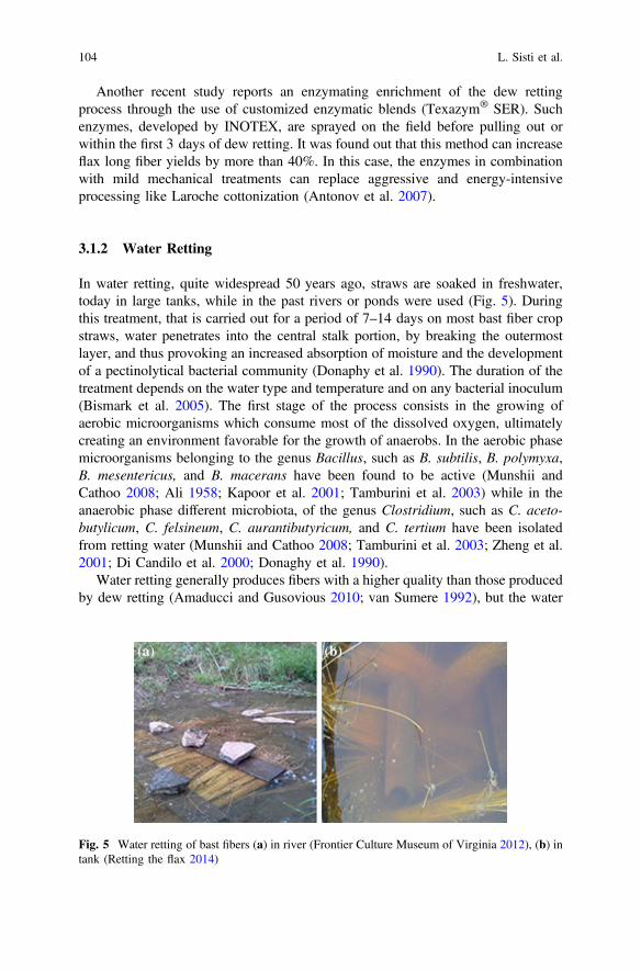
Another recent study reports an enzymating enrichment of the dew rettingprocess through the use of customized enzymatic blends (Texazym® SER). Suchenzymes, developed by INOTEX, are sprayed on the field before pulling out orwithin the first 3 days of dew retting. It was found out that this method can increaseflax long fiber yields by more than 40%. In this case, the enzymes in combinationwith mild mechanical treatments can replace aggressive and energy-intensiveprocessing like Laroche cottonization (Antonov et al. 2007).
3.1.2 Water Retting
In water retting, quite widespread 50 years ago, straws are soaked in freshwater,today in large tanks, while in the past rivers or ponds were used (Fig. 5). Duringthis treatment, that is carried out for a period of 7–14 days on most bast fiber cropstraws, water penetrates into the central stalk portion, by breaking the outermostlayer, and thus provoking an increased absorption of moisture and the developmentof a pectinolytical bacterial community (Donaphy et al. 1990). The duration of thetreatment depends on the water type and temperature and on any bacterial inoculum(Bismark et al. 2005). The first stage of the process consists in the growing ofaerobic microorganisms which consume most of the dissolved oxygen, ultimatelycreating an environment favorable for the growth of anaerobs. In the aerobic phasemicroorganisms belonging to the genus Bacillus, such as B. subtilis, B. polymyxa,B. mesentericus, and B. macerans have been found to be active (Munshii andCathoo 2008; Ali 1958; Kapoor et al. 2001; Tamburini et al. 2003) while in theanaerobic phase different microbiota, of the genus Clostridium, such as C. aceto-butylicum, C. felsineum, C. aurantibutyricum, and C. tertium have been isolatedfrom retting water (Munshii and Cathoo 2008; Tamburini et al. 2003; Zheng et al.2001; Di Candilo et al. 2000; Donaghy et al. 1990).
Water retting generally produces fibers with a higher quality than those producedby dew retting (Amaducci and Gusovious 2010; van Sumere 1992), but the water
Fig. 5 Water retting of bast fibers (a) in river (Frontier Culture Museum of Virginia 2012), (b) intank (Retting the flax 2014)
104 L. Sisti et al.

retting process impacts the environment due to the consumption and contaminationof large amounts of water (van Dam and Bos 2004) and energy (Van der Werf andTurunen 2008). With freshwater resources becoming increasingly scarce, analternative or improvement in water retting will have to be foremost in dealing withwater scarcity and pollution reduction. Enzyme retting, for example, which will bediscussed in the next paragraph, has been evaluated as a replacement for currentretting methods. Moreover, Zhang et al. (2008a, b) have explored the possibility ofsubstituting freshwater with seawater, which is a natural resource considered to beinexhaustible and abundant. They demonstrated that seawater retting treatmentsyield good retting results and good pectinolytic strains belonging to S. maltophiliaspecies and O. antrophi species. Artificial water retting, employing warm water andbacterial inoculum, has also been used to produce homogeneous and cleanhigh-quality fibers in 3–5 days (Bismark et al. 2005; Sisti et al. 2016).
3.2 Enzymatic Retting
A modification of water retting is the enzymatic treatment, also called bioscouring,where degrading enzymes are directly added to tank water or in a bioreactor (Ouajaiand Shanks 2005). This technique has been demonstrated to be a promisingreplacement for traditional retting methods in terms of time-saving, ecologyfriendliness, and convenient characteristics. The duration of enzymatic rettingranges from 8 to 24 h. The high energy input and nonreusability of enzymes are themain concerns, which affect the cost-effectiveness of the process (Tahir et al. 2011).
Pectinases are the main enzymes employed for retting, in order to free the fibersfrom other tissues. Today, with the advancement of biotechnological tools, pecti-nases or pectinolytic enzymes are of significant importance thanks to their allembracing applications, such as in fruit juice extraction and its clarification,scouring of cotton, degumming of plant fibers, wastewater treatment, vegetable oilextraction, tea and coffee fermentation, bleaching of paper, in poultry feed addi-tives, and in the alcoholic beverages and food industries (Jayani et al. 2005).Pectinolytic enzymes are a heterogeneous group of related enzymes that hydrolizethe pectic substances, mostly present in plants. They are widely distributed inhigher plants and microorganisms (Mohnen 2008), since they help in cell wallextention and in softening some plant tissues during maturation and storage. Theyalso help maintain ecological balance by causing decomposition and recycling ofwaste plant materials (Ridley et al. 2001). Plant pathogenity and spoilage of fruitsand vegetables by rotting are some other major manifestations of pectinolyticenzymes. Pectinolytic enzymes, which are classified according to the main mech-anism catalyzing the respective reactions, gather pectin esterase, polygalacturonase,and pectin lyase. Evans et al. and Zhang et al. reported that polygalacturonaseactivity plays a fundamental role during the retting process (Evans et al. 2002;Zhang et al. 2000), but also pectate lyase has been shown to be potentiallyimportant for retting bast plants (Akin et al. 2007; Bruhlmann et al. 2000).
Retting Process as a Pretreatment of Natural Fibers … 105

Polygalacturonase and pectate lyase are both depolymerizing enzymes for pectin.Polygalacturonases are the pectinolytic enzymes that catalyze the hydrolyticcleavage of the polygalacturonic acid chain (Jayani et al. 2005), while pectate lyasecarries out a non-hydrolitic breakdown of pectates and pectinases by a transelim-ination split of the pectic polymer (Sakai et al. 1993).
Pectinases can be produced from bacteria (Dosanjh and Hoondal 1996; Kapooret al. 2001), yeast (Blanco et al. 1999), fungi (Singh et al. 1999), and actinomycetes(Beg et al. 2000). Most commercial preparations of pectinases are produced fromfungal sources (Henriksson et al. 1997). Aspergillus niger is the most commonlyused fungal species in the industrial production of pectinolytic enzymes (Jayaniet al. 2005). Among bacteria sources, certain genera namely Bacillus,Lactobacillus, Pediococcus, and Leuconostoc are known to be effective during thefermentation process to produce pectinolytic enzymes (Kouhoundè et al. 2014).
Enzyme retting via the pectinases is capable of producing consistent highstrength renewable fibers with variable fineness values for use in novel resins(Foulk et al. 2011). Some of the major commercialized enzymes are shown below.
Viscozyme® L, produced by Novozymes, is a multienzymatic solution con-taining a wide range of carbohydrases, including arabase, cellulose, b-glucanase,hemicellulose, and xylase. It has been tested by different authors in flax fiberextraction (Bacci et al. 2010; Foulk et al. 2008; Akin et al. 2003; Adamsen et al.2002; Evans et al. 2002).
Pectinex® Ultra SP-L, produced by Novozymes, is a highly active pectolyticenzyme obtained by a selected strain of Aspergillus aculeatus that contains pec-tolytic and a range of hemicellulolytic activities that can disintegrate plant cell walls(Bacci et al. 2010).
Scourzyme® L has been developed by Novozymes for the bioscouring tech-nique; it contains an alkaline pectate lyase, which degrades the pectin from theprimary cell wall of fibers without degrading the fiber itself (Oujai and Shanks2005).
Flaxzyme®, a commercial enzyme mixture from Novo Nordisk, consists ofpectinases, hemicellulases, and cellulases and was developed specifically forenzyme retting (Akin et al. 1999).
BioPrep® 3000 L was developed by Novozymes as the first commerciallyavailable alkaline pectate lyase. It was isolated and produced for its unique ability todegrade the pectin layer between the waxy cuticle and cellulosic fabric cotton(Durden et al. 2001; Etters et al. 2001).
Texazyme® BFE was developed by Inotex for elementarization of bast fibersthrough the degradation of pectin layers. It consists of a multicomponent productwithout cellulase activity (Foulk et al. 2008).
For each enzyme, specific conditions are identified for employment in retting,since the activity can change dramatically with pH, temperature, and enzymeconcentration. Moreover, chelators and surfactants are usually employed in for-mulations to improve activity. For example, the role of Ca(II) chelators, such asethylenediaminetetracetic acid (EDTA), is well known (Akin et al. 2004) toimprove retting, particularly, in removing the epidermal/cuticle material from the
106 L. Sisti et al.

fiber and fiber bundles. In fact, EDTA acts by destabilizing bridges between Ca(II)and polygalacturonic acid, thus leading to the disruption of tissues.
Foulk et al. (2008) reported that, with a specific knowledge of the composition ofthe enzyme mixture, enzyme retting could be used to tailor fibers/fiber bundles withparticular properties, such as strength and fineness, and for specific applications.Strength, for example, which is a major concern in many applications, is preservedby retting with relatively pure pectinase, either pectate lyase, or polygalacturonase.However, a mixed enzyme preparation containing cellulase could be used foradvantageous applications where the fibers will be shortened, such as for paper/pulpor injection molding. In fact, it has been found that enzyme formulations likeViscozyme, containing cellulase as a component, can weaken the bast fibers, sincethe nodes of the fibers are particularly sensitive to the attack by this enzyme (Foulket al. 2008). The final application, therefore determines the retting formulation.
3.3 Mechanical Retting
The mechanical extraction of fibers consists of various steps, as developed sinceancient times, mainly to recover hemp and flax fibers (Fig. 6). Today, this treatmentis a completely automated process but steps have not changed (Fig. 7): a firstseparation is carried out by breaking, that is the stalks are passed between flutedrollers to crush and break the woody core (shive) into short pieces (hurds); theremaining fibers and hurds are subjected to scutching (traditionally performed withboards and hammers), by which the fiber bundles are gripped between rubber beltsor chains and carried past revolving drums with projecting bars that beat the fiberbundles, separating the hurds, and broken short fibers (tow) from the remaininglong fibers. Finally, in the hackling (realized in the past by pulling the fibersthrough a set of pins) thick fibers are divided by passing the long fibers through aseries of combs of increasing fineness to clean and align the long fibers and separatethe remaining tow and debris. Interestingly, the modern mills maintain the integrityof the long fibers, by disentangling and aligning the fibers, without destroyinglength. Another process currently used to mechanically separate the fibers is calleddecortication and can be performed by hammermilling or rollermilling(Deyholos and Potter 2014). In the first case (Fig. 8), single or multiple concurrentdrums rotating with hammers projecting transversely from the drum surface beat thestraw until the separated hurd/shive and fiber particles can pass freely through somemeshes placed inside the machine. In the second case, (Fig. 9), long cylindricalcorrugated rollers are assembled in such orientations as to crack the straw stalkswhile producing minimal damage to the fiber. The two processes differ in the proand con: if the hammermilling is characterized by higher throughput capability, therollermilling gives much greater length control, producing even very long fibers andwill better preserve the integrity of the fibers, without damages or entanglements.
The choice of the preferable mechanical retting depends on the type of the fiber,its final application, type of ensuing treatments. Therefore, with these multiple
Retting Process as a Pretreatment of Natural Fibers … 107

Fig. 6 Traditional retting of hemp fibers: scutching (a and b frames) and hackling (c andd frames) (Weald and Downland Open Air Museum 2016)
Fig. 7 Mechanical processing of fibers
108 L. Sisti et al.

variables in mind, it is continuously under investigation. However, it is well knownthat mechanical retting tends to disrupt the fiber cell wall structures, leading todislocations, kink bands, or nodes, which negatively affect the tensile mechanicalproperties (Davies and Bruce 1998; Baley 2002, 2004) and could even impair thecomposite performances (Huges et al. 2000; Hänninen et al. 2012). Although on theone hand, it was established that the defect extent of the mechanical retting isstrongly related to the previous retting treatments (Van de Weyenberg et al. 2003),on the other hand, some researchers found that the fibers can be decorticatedwithout significant damage and can be produced with high quality, even when nopretreatments are carried out (Hobson et al. 2001; Gañán et al. 2008; Bacci et al.2010; Kengkhetkit and Amornsakchai 2012).
These findings are important and noteworthy: indeed, the elimination ofpre-decortication enzymatic or microbiologic treatments should prove advanta-geous in terms of market costs, as it would reduce the variability of fiber quality, theuncertainties of production, and the amount of time necessary for the field to beavailable for the next crop. Moreover, new decortication methods can be developedin order to obtain better quality fibers and to reduce production costs by decreasingthe times and increasing the treated biomass volumes.
Fig. 8 Automateddecortication byhammermilling
Fig. 9 Automateddecortication by rollermilling
Retting Process as a Pretreatment of Natural Fibers … 109

3.4 Physical Retting
Among the physical treatments of fibers, the processes using electromagneticradiation, high temperature, and/or pressure can be considered.
Steam explosion is an autohydrolysis process involving the use of saturatedsteam at high pressure followed by a sudden decompression, which causes thesubstantial breakdown of the lignocellulosic structure, the hydrolysis of the hemi-cellulose fraction, the depolymerization of the lignin components, and the defib-rillation. High decompression rates lead to improved fiber freeness but shorter fiberlength. During the process, high temperature softens the material and mechanicalaction during the high-pressure discharge results in fiber separation: the partiallydepolymerized lignin becomes more or less soluble in various organic solvents,such as alcohols, acetone, and in alkaline solutions, whereas the cellulose, muchmore resistant to hydrolysis than pectinic and hemicellulosic polysaccharides,retains its structure. The steam explosion treatment is a fast and well-controlledprocess, with a low cost and very flexible treatment parameters and is well adaptedfor the processing of various fibers, including those not previously retted (Zhanget al. 2008a, b). It is successfully applied on banana fibers (Sheng et al. 2014),semi-retted hemp fibers (Thomsen et al. 2006; Garcia-Jaldon et al. 1998), coir fibers(Abraham et al. 2013), flax (Kessler et al. 1998), and wheat straw (Zhang et al.2008a, b). The steam explosion can be considered as a pretreatment that facilitatesthe ensuing retting processes (Zhang et al. 2008a, b). It can be carried out down-stream, after alkali treatments, bleaching, and sometimes acid hydrolysis (Abrahamet al. 2013; Sheng et al. 2014) in order to completely degrade the hemicellulose andlignin fractions. Usually, steam explosion is combined with an alkaline pre-soakingto favor the cleavage of lignin-hemicelluloses bonds. The reaction results in theincreased solubility of the lignin alkaline solvent and in an enhanced water solu-bilization of hemicellulose (Sheng et al. 2014; Thomsen et al. 2006; Garcia-Jaldonet al. 1998; Abraham et al. 2013).
Another interesting physical treatment to extract the fibers is based on the hy-drothermal method: the lignins and hemicellulose are degraded by using water atelevated pressure and temperature. This approach has been applied on hemp fibersby Thomsen (Thomsen et al. 2006) and on flax fibers by Stamboulis (Stambouliset al. 2000), who carried out the so-called Duralin treatment, a sort of curing processat different times and temperatures, that leads to an easy separation of the fibersfrom the stem by a simple breaking and scutching operation. The fibers obtained viasuch procedures are fiber bundles rather than individual fibers and they exhibitimproved moisture resistance and a somewhat higher and more uniform strength.
Recently, a Polish group (Konczewicz and Wojtysiak 2015; Kozlowski et al.2013) has developed a new osmotic degumming of flax fibers. The degummingmechanism is based on the diffusive penetration of water inside the stem, where thelong bundles of cellulosic fibers are clustered in slivers with polysaccharides,mostly pectins. The pectins, which are highly absorbent, increase their volumeseveral times, which results in a considerable increase of hydrostatic pressure inside
110 L. Sisti et al.

the stem and leads to pressing the epidermis. As the peripheral tension is strongerthan the longitudinal one, cracks of the epidermis occur lengthwise, withoutbreaking and shortening the fibers. Since the pectins become diluted and solved(together with other bast substances) in water, the technological liquid is subjectedto proper filtration, which also serves to recover pectins for further use in thecosmetic industry. This osmotic method produces fibers characterized by goodtenacity, divisibility, and soft touch. It is equally as efficient as the warm waterretting method and could be applied to other bast fibers by simply changing thedegumming parameters (temperature, flow velocity, and process duration).
To specifically modify the surface of fibers in order to improve their compati-bility with polymeric matrix, the plasma treatment is an effective physical method,which can be performed at both atmospheric and high pressure under the flow ofdifferent types of gas (usually oxygen or argon).
Depending on the material to be treated, plasma flow can cause ablation,cross-linking or surface activation. Ablation consists in the removal of organicresidues as well as surface layers at a molecular level. Cross-linking occurs as aresult of the interaction between two or more radicals leading to the formation ofcovalent links while surface activation increases the surface energy as a result of thegeneration of polar groups on the reinforcement surface (Kafi et al. 2011). Exposuretimes, pressures, and discharge power are the variables that must be carefullyconsidered to achieve the best results in terms of the surface modification. This kindof treatment is widely used for common natural fibers as flax, cane, coir, andbamboo (Bozaci et al. 2013; Scalici et al. 2016; Praveen et al. 2016; Xu et al. 2006)because, unlike chemical treatments, it is a simple nonpolluting process that can beconsidered as dry and clean.
The physical treatments are surely not yet completely developed and only fewpapers describe their use. However, they are characterized by high quickness, easyscalability, and process flexibility, that make this kind of retting noteworthy offurther investigation.
3.5 Chemical Retting
With respect to water retting or dew retting, chemical processes are sometimespreferable since they produce fibers characterized by high-constant quality,regardless of weather conditions, usually in shorter times. Numerous chemicaltreatments can be performed on the fibers depending on their type, the ensuingretting process to be applied, their final applications. The most used chemicalprocess is alkalization, a treatment aimed at removing hemicelluloses: it is usuallycarried out with sodium hydroxide, added as an aqueous solution at a variableconcentration in the range 1–25% by weight. Considering the coir fibers, the NaOHeffect is sometimes ambiguous and the reported results are controversial: indeed, ifthe alkali treatment seems to increase the elongation at break and the surfaceroughness (Silva et al. 2000) while improving the ultimate tensile strength, the
Retting Process as a Pretreatment of Natural Fibers … 111

initial modulus, the electrical properties, and the thermal stability (Mahato et al.1993, 1995), at the same time it decreases the fiber tensile strength with increasingNaOH concentration, demonstrating that the alkalization could induce damages onfiber (Gu 2009). In order to minimize the fiber deterioration, a combination ofsodium hydroxide, sodium carbonate, and sodium sulfide and short soaking treat-ments (only 2 h) have been successfully used on raw coconut fibers (Basu et al.2015), achieving a reduction in diameter, linear density, and flexural rigidity offibers.
Similar considerations also apply to kenaf: the alkali retting produces stronger,more flexible and less brittle fibers (Parikh et al. 2002a; Amel et al. 2013) but thebase concentration influences the fiber morphology (Ramesh et al. 2015) becausethe high alkaline medium increases the microvoid volume fractions, leading to thereduction of the tensile strength of the fibers (Kawahara et al. 2005). Milder con-ditions prevent the degradation of kenaf fibers: the use of a weak base as sodiumsulfite leads to cleaner and brighter fibers, smoother, and softer materials, havingthe higher tensile strength (Umoru et al. 2014). The same reagents have been testedon hemp fibers (Hurren et al. 2002) and it turns out that the combination of NaOHand Na2SO3 produces fibers with the whitest color and the finer diameter but not thebest spinnability (obtained after acidic treatment with HCl). The need to select weakalkali treatments even on flax fibers has been highlighted by Van de Weyenbergwho demonstrates that soaking in a diluted NaOH solution for only 45 s enablesbetter adhesion between flax fibers and epoxy matrix, improving the mechanicalproperties of the resulting materials (Van de Weyenberg et al. 2006).
To completely remove the lignins and most hemicelluloses, aqueous ammoniatreatments are an interesting alternative to alkali retting. Ammonia pretreatmenttechniques include the ammonia recycle percolation (ARP) and the soaking inaqueous ammonia (SAA). With ARP the biomass is pretreated with aqueousammonia in a flow-through column reactor; after the reaction, the solid fraction ofthe biomass is separated whereas the liquid fraction is sent into a steam-heatedevaporator in order to separate lignin, sugars, and ammonia, that will be furtherrecycled. This pretreatment was first proposed by Iyer (Iyer et al. 1996) who triedthe alkali hydrolysis on herbaceous biomass, as corn cobs and stover mixture andswitchgrass, obtaining high efficiency of delignification but preserving the cellulosechains, after only 1 h or less of reaction at 170 °C (Kim et al. 2003). On the otherhand, even at low temperatures, the SAA efficiently removes the lignin in the rawmaterial by minimizing the interaction with hemicellulose and leading to anincrement of surface area and pore size. The SAA has been applied on barley hulls(Kim et al. 2008) and the scientists obtained 66% of lignin solubilization whentreating biomass with 15% aqueous ammonia at 75 °C during 48 h.
A further method to remove the lignin is by oxidative degradation that iscommonly used when the target is the complete degradation and consumption ofthe lignocellulosic mass in order to recover the residues for the chemicals industryor for fuel production. In these cases, degradation is realized using peroxides andthe raw biomasses are really varied: wheat straw (Klinke et al. 2002; Bjerre et al.1996), mulberry (Cong and Dong 2007), poplar wood (Chang and Holtzapple
112 L. Sisti et al.

2000). Interestingly, the pretreatment with hydrogen peroxide of cane bagassegreatly enhances the fiber susceptibility to further enzymatic hydrolysis (Azzam1989): the reported results show that about 50% of lignin and most of the hemi-cellulose content of cane bagasse have been solubilized by 2% alkaline hydrogenperoxide within 8 h.
A similar bleaching treatment on kenaf fibers (Shi et al. 2011) completelyremoves the hemicellulose (the lignin was already eliminated by alkali retting)within only 1 h, retaining the fiber diameter and increasing its crystallinity.Recently, a thorough investigation on the better oxidizing agent, among H2O2,NaOCl, NaClO/NaOH, for delignification of green coconut fibers has beendescribed (Brígida et al. 2010). The latter study reports that hydrogen peroxide ismore effective to eliminate waxes and fatty acids from the fiber surface but thetreatment with NaOCl/NaOH is the most efficient in hemicellulose removal and,consequently, in cellulose exposition (which determines the inherent hydrophilicityand is useful for further functionalization).
A different method to prepare the fibers for ensuing treatments is based on theacidic retting: in such case, the risk to degrade the cellulosic fraction is quite highand the management of the processing waste is likewise complex. Therefore, suchmethodology is not popular and only a few papers describe this treatment. The useof concentrated strong acids, such as H2SO4 and HCl to treat lignocellulosicmaterials is widely reported when the main target is the complete cellulosehydrolysis (Sun and Cheng 2002). More frequently, strong acids were used indiluted solutions in processes exploiting less severe conditions (Shi et al. 2011a) butusually leading to sugar recovery (i.e., cellulose degradation) (Chen et al. 2007).A fascinating alternative to inorganic acids consists in the organic acids, like maleicand fumaric acids, which can be used for a diluted acid pretreatment (Kootstra et al.2009). All acids, tested on the retting of wheat straw, drive to sugar formation.
Certainly, chemical treatments are an effective alternative to microbial dewretting which suffers from climatic risks leading to substantial harvest losses.Indeed, chemical retting is not affected by weather variability and can retain thefiber quality. However, difficulties in waste-management and the moderate risk todegrade the fibers currently make such treatments less attractive than in the past.
4 Retted Fibers in Polymer Composites Application
The use of natural fibers for composites is an attractive field from an environmentaland sustainable perspective. In particular bast fibers, given their high cellulose andlow lignin content, are particularly suited to composite applications and are themost promising replacement for glass fibers in composites (Deyholos and Potter2014).
Some European countries, where a great environmental consciousness exists,have already introduced the use of lignocellulosic fibers in polymer composites forautomotive applications and a great amount of products have been exported to the
Retting Process as a Pretreatment of Natural Fibers … 113

US and other countries. Such materials are mostly characterized by nondegradablepolymeric matrices, such as polyester, poly(propylene) (PP), epoxy, and phenolformaldehyde (PF). However, recent EU directives establish that all new vehiclesmust use 95% of recyclable materials in order to mitigate environmental impacts,and this boosted the development of commercially viable biodegradable compos-ites. Therefore, bio-based lignocellulosic composites have a steadily growingmarket, with a growth projection in North America from US$ 155 million in 2000to US$ 1.38 billion by 2025 (Satyanarayana et al. 2009).
Natural vegetable fibers can be used to reinforce thermosetting resins (e.g.,unsaturated polyesters, epoxy, etc.), thermoplastics (e.g., polypropylene, poly-ethylene, etc.), and natural polymers (e.g., polylactic acid, polyhydroxybutirric acid,etc.). The most commonly used polymers in natural fibers composites matrices, andan overview of their properties are schematically shown in Tables 3 and 4.
It is well known that lignocellulosic fibers have been used in the field of com-posites since historical times, and one of their specific applications in aircraft tookplace as early as the 1940s. In the last decades, reasons for their use have increased,
Table 3 Most commonly used polymeric matrices for composites with natural fibers
Matrix material
Thermosetting plastics Thermoplastics Rubber and natural polymers
Phenolic Polypropylene India-rubber
Epoxy Polyamide Modifies starch
Polyester Polyethylene Polylactic acid
Polyimide Polystyrene Cellulose esters
Polyurethane Polyvinyl chloride Polyhydroxybutirric acid
Table 4 Overview of the properties of some polymers commonly used in composite applications(Dicker et al. 2014)
Polymertype
Density(kg/m3)
GlasstransitionT (°C)
MeltT (°C)
Young’smodulus(GPa)
Tensilestrength(MPa)
Elongation(%)
Bio PLA 1210–1250
45–58 150–162
0.35–3.83 21–60 2.5–6
PHB 1180–1260
4–15 168–182
3.5–4 24–40 5–8
Starch 1000–1390
– 110–115
0.125–0.85 5–6 31–44
Synthetic Epoxies 1110–1400
66.9–167 – 2.35–3.08 45–89.6 2–10
Polyester 1040–1400
147–207 – 2.07–4.41 41.4–89.6 2–2.6
PP 890–910
0.9–1.55 – 0.9–1.55 28–41 100–600
114 L. Sisti et al.

because of (i) the abundance of sources throughout the world, which representvalue-added opportunities for agricultural industries and the possibility to createrural jobs, (ii) the possibility of reducing the dependence on petroleum products,(iii) the availability of complete data concerning fiber structure and properties.Other reasons for their increased use are related to the reduced cost, weight, andenergy content in comparison with synthetic fibers (such as glass, kevlar, andcarbon) along with comparable tensile strength values, as well as a lower abra-siveness for tooling and the absence of airborne particles, thus reducing respiratoryproblems for workers (Satyanarayana et al. 2009; Frollini et al. 2013). More indetail, lignocellulosic fibers present unique attributes such as: non-brittle fracture onimpact, high flex and tensile modulus, high notched impact, low-thermal expansioncoefficient, good sound abatement capability, natural appearance, and the fact thatthey can be easily colored (useful for textiles applications), full recyclability(Satyanarayana et al. 2009). In Table 5, some properties of the most employedlignocellulosic fibers are reported and compared with those of some man-madefibers. Such properties result from their structure and chemical composition.
Several factors limit the use of bast fibers in composites. The first problem is thelack of homogeneity. As with many natural products, there is large variation in fibercharacteristics and composition according to sources (even in fibers grown in thesame field and season). Quality production efficiency depends on the environmentalconditions, on the cultivar and on growing, harvesting, and primary processingconditions. This lack of homogeneity greatly complicates optimization and stan-dardization of manufacturing processes, where high reliability and stability arerequired (Deyholos and Potter 2014).
Table 5 Typical properties of some fibers commonly used in composite applications (Dickeret al. 2014; Callister 2007)
Fiber Density(kg/m3)
Tensilestrength(MPa)
Young’smodulus(GPa)
Elongationat break (%)
Moistureabsorption(%)
Synthetic CarbonHS
1800–1840 4400–4800 225–260 0 –
E-glass 2550–2600 1900–2050 72–85 1.8–4.8 –
Kevlar49™
1444 3600–4100 131 2.8 –
Bast Flax 1420–1520 750–940 75–90 1.2–1.8 8–12
Hemp 1470–1520 550–920 55–70 1.4–1.7 6.2–12
Jute 1440–1520 400–860 35–60 1.7–2 12.5–13.7
Ramie 1450–1550 500–680 38–44 2–2.2 7.5–17
Kenaf 1435–1500 195–666 60–66 1.3–5.5 –
Fruit Coconut 1150–1220 135–240 4–6 15–35 8
Seed Cotton 1520–1560 350–800 7–12 5–12 7.8–8.5
Leaf Sisal 1400–1450 550–790 10–25 4–6 10–22
Grass Bamboo 600–1100 140–800 11–32 2.5–3.7 –
Retting Process as a Pretreatment of Natural Fibers … 115

The retting process, which represents the focus of this chapter, is a successfulpretreatment for the improvement of matrix/fiber adhesion and the development ofhigh-grade composites. An optimal retting process allows an optimum rettingdegree, which means that the elementary fibers are released well from the technicalfibers and separated from each other by less non-fiber tissue attached on the surface.The performances of the materials increase accordingly, due to the increase ofcellulose portions left on the fiber surface, and also by the higher fiber aspect ratio(length/diameter) due to the extent of the separation of elementary fibers. When theretting degree is low, impurities (pectin, lignin, hemicelluloses, etc.) between thefibers can cause stress concentrations in composites and lead to an early fracture(Hu et al. 2012a, b). The development of lignocellulosic fibers-based biocompositesrequires the selection of an appropriate biopolymer matrix, suitable surface treat-ments of the fibers, along with low-cost but high-speed fabrication techniques.Many attempts were made to apply and adapt conventional polymer processingmethods, such as compression molding and extrusion followed by injectionmolding, to the vegetal fiber composite preparation. However, some importantaspects of composite manufacturing should be taken into account: preservation ofmechanical properties of the lignocellulosic fibers by minimizing attrition andthermal degradation, attaining a high degree of fiber dispersion with control of fiberorientation and ensuring good wettability, despite of incorporation of a high volumefraction of fibers. In general, natural fiber reinforced composites can be manufac-tured via most production techniques, without using high temperatures (Fig. 10).
Fig. 10 Most common manufacturing techniques for natural fiber reinforced composites (Nuplex2014)
116 L. Sisti et al.

Press molding seems to be the best preferred technique (Satyanarayana et al.2009) since extrusion or melt mixing do not allow to take advantage of fiber length.
A wide range of biodegradable products has been produced using biopolymerscontaining lignocellulosic fibers for different applications, ranging from automotivevehicles including trucks, construction, and insulation panels, to special textiles(geotextiles and nonwoven textiles). Other identified uses for these materialsinclude bathtubs, archery bows, golf clubs, boat hulls, maintenance-free roofingpanels, and longer lasting and better-looking lightweight components, such ascosmetic packaging, tableware, and furniture. Furthermore, thanks to their load-bearing potential, the use of natural fiber-based composites has spread to varioussectors, including aircraft, grain and fruit storage, and footwear. Thanks to theidentification of all such new applications, a remarkable growth of the market forthese new biocomposites is expected in a next future (Satyanarayana et al. 2009).
4.1 Flax
Flax (Linum usitatissimum L.) is an important agricultural crop. It is one of the firstnatural fibers to be extracted, spun, and woven into textiles and now widely used.Flax fibers are produced from the stems of flax bast plants. Like cotton, flax fiber isrich in cellulose, but its cellulose structure is more crystalline, making it stronger,crisper, and stiffer to handle, and more easily wrinkled.
The mechanical properties of flax fibers are reported to be highly dependent onthe stem section used to obtain them. Fibers with a different chemical composition(e.g., in terms of cellulose, pectin, and lignin) resulting in different characteristics(e.g., depectinization efficiency and selectivity) are obtained from different stemsections. Fibers from the middle section exhibit higher strength than the fibers fromthe bottom section (Liu et al. 2015a). Lower fiber grades are used as reinforcementand filler in composites for automotive interior substrates and furniture (Yan et al.2014).
Concerning the flax retting, Sharma et al. (1999) compare dew-, water-, andenzymatic retted fibers in terms of fiber fineness, strength, ash, and weight-losses,that are the key parameters for determining fiber quality. They are strictly connectedto the proportion of residual pectins, hemicelluloses, lignin, and lipids present in theretted fiber, coming from differences in the activities of the polysaccharide-degrading enzymes involved.
In particular, in dew retting, pectinases, and hemicellulases released by thefungal colonists ret the flax slowly in 5–8 weeks. In contrast, water or enzymaticretting can be performed rapidly in 3–7 days, and seem to result in a superior rettedmaterial. Most of the pectin from the fiber can be hydrolyzed to improve fiberfineness, but only a limited proportion (nearly 10%) of hemicellulose can beremoved without lowering the fiber strength. Removal of residual hemicellulosesbound with lignin will reduce fiber strength. This study, although based on a limitedsample size, revealed the superiority of water retted fibers compared to the others.
Retting Process as a Pretreatment of Natural Fibers … 117

As far as the enzymatic treatment of flax is concerned, Foulk compared somepectinase-rich commercial enzyme products and demonstrated that Texazym® BFEand Bioprep® 3000 L, as well as Viscozyme®, confer higher tenacity to the fibers,but indicate a potential advantage for Bioprep® 3000 L, in view of its monocom-ponent nature, commercial availability, price, and ability to ret flax, in combinationwith ethylenediaminetetraacetic acid (EDTA) at high pH (Foulk et al. 2008).
Good flax fiber quality with a minimum loss in fiber yield was also obtained bysteam explosion treatment of flax following dew retting (Kessler et al. 1998).
On the other hand, Van Der Velde et al. test the tensile properties of scutched andhackled long flax fibers on individual fibers and on bundles and notice no significantinfluence of the retting degree on tensile strength (Van Der Velde and Baetens 2001).Pillin et al. also validate such conclusion in a study about the mechanical propertiesof oleaginous flax fibers as a function of variety, culture year, dew retting degree andagronomic factors. Despite the interesting mechanical properties obtained, they arenot affected by the retting degree. The same conclusion is obtained with agronomicfactors, such as seeding rate and plant height (Pillin et al. 2011).
In any case, numerous Authors discuss about the great importance of the rettingto achieve high-performance materials.
Some representative examples of retted flax composites are discussed below.Two kinds of retted Canadian linseed flax fibers, dew, and enzymatic retted
fibers, are used in PP composites. The aspect ratio of the enzymatic retted fibers ismuch higher than that of dew retted as the elementary fibers are better separated.Indeed, the elementary fibers in dew retting remain tightly bundled into technicalfiber wrappings with more noncellulose portions. This result induces a lower rettingdegree and is responsible for a lower thermal stability of dew retted fiber. Moreover,a better retting degree and fewer damages on enzymatic retted flax fibers endowedbetter tensile properties, thus resulting in a better reinforcement in composites (Huet al. 2012a, b).
Enzymatic and dew retted short flax fiber composites with recycled high-densitypolyethylene (HDPE) were prepared and compared with similar products made withwood pulp, glass, and carbon fibers. The composites, with a 30 wt% of fiberloading, were easily blended with a Brabender mixer, because the flax fibers lengthwas 0.21–0.40 mm. A commercial multienzyme product, Viscozyme® L, wascombined in varying amounts with a commercial chelator product (Mayoquest®
200). Enzyme and chelator concentrations were denoted: low (0.05% and 5 mm),middle (0.1% and 10 mm), and high (0.3% and 25 mm). Dew retted fiber com-posites resulted in both lower strength and percent elongation, confirming thatenzymatic retting is more efficient in producing fibers suitable for compositepreparation. Moreover, enzyme and chelator concentrations did not much affect thefinal composites properties. Flax fibers improve the elastic modulus with respect towood pulp/HDPE composites and HDPE alone (Foulk et al. 2004).
Enzymatic retted flax fibers and polylactic acid (PLA) were blended with atwin-screw extruder. The flax fiber content was 30 and 40 wt%. Triacetin was addedas a plasticizer, in order to improve the impact properties, because of the brittle natureof PLA. The material properties have been studied and compared to those of PLA and
118 L. Sisti et al.

PP/flax fiber composite. Preliminary results reveal that the thermal properties of PLAimprove with the addition of flax fibers. Moreover, the composite strength isenhanced with respect to that of PP/flax fiber composite, even if a poor interfacialadhesion is observed by morphological characterization (Oksman et al. 2003).
Short flax fibers/PP composites have been prepared by Martin et al., who assessthe influence of the degree of dew retting of flax on the properties of composites.The length of the fibers was 3 mm, therefore, it was possible to prepare the com-posites by extrusion, with a 20% of volume fraction. The matrix was grafted with4 wt% of maleic anhydride, in order to improve the compatibility. Water sorptionstudies indicate a higher water uptake for fibers with a low retting degree. Thetensile properties of single fibers increased with the degree of retting in terms ofboth Young’s modulus and strength at break. A high degree of retting enables easiersplitting of the fiber bundles during fiber/matrix extrusion and injection molding,resulting in smaller fiber bundle diameters and a higher aspect ratio. Moreover, askin/core effect is highlighted: defects are mostly located in the core of samplesbecause the fibers are oriented parallel to the flow mostly in skin areas, resulting inbetter tensile properties (Martin et al. 2013).
Bodros et al. prepared natural fiber reinforced thermoplastic composites using afilm-stacking technique. The materials were manufactured with a 20–30% of vol-ume fraction of dew retted flax fibers 10 mm long, and various thermoplastics, suchas PLA, poly(L-lactide) (PLLA), poly(3-hydroxybutyrate) (PHB),poly-e-caprolactone (PCL), thermoplastic starch (MaterBi® Z), poly(butylene suc-cinate) (PBS), and poly(butylene adipate-co-terephtalate) (PBAT). The tensileproperties are compared to those of PP/flax composites. Preliminary results showthat the tensile properties are improved by increasing the fiber volume fraction. Thetensile strength and Young’s modulus of PLLA and PLA flax composites prove tobe higher than those of similar PP/flax fiber composites. The tensile strength andmodulus of flax fiber/PLLA composite are very close to those of glass fiberpolyester composites (Bodros et al. 2007).
Chemical treatments are often associated with other types of retting. Baley et al.prepared flax/unsaturated polyester resin composites using dew retted fibers(33 mm long), further subjected to sodium hydroxyde/acetic anhydride or formicacid-based treatments. This classical treatment induces a general increase of the flaxfiber/polyester adhesion. The microbond test of a unique microdrop of the matrix onflax fibers allows the assessment of the interfacial adhesion, showing a goodmechanical anchorage (Baley et al. 2006).
The chemical treatment with sodium hydroxide, sodium carbonate, and hydro-gen peroxide, in addition to a microbiological retting was explored by Abdel-Halimet al. They prepared flax-reinforced epoxy composites by hot pressing from raw,scoured (NaOH + Na2CO3) and bleached (NaOH + H2O2) retted, and semi rottedflax fibers in order to investigate the effect of the retting degree as well as subse-quent chemical treatments on the mechanical properties of the composites. Thefibers were 1 cm long and were loaded in a high amount (almost 67 wt%). Thechemical treatment improved the fiber fineness and the surface energy of the flaxfibers, thus enhancing the mechanical properties of the composite. Such
Retting Process as a Pretreatment of Natural Fibers … 119

improvement follows the order: bleached fibers > scoured fibers > raw fibers.Among raw fibers, retted fiber composites had better mechanical properties thansemi-retted ones. No improvement is obtained by the use of a titanate on modifyingthe fiber surface (Abdel-Halim et al. 2008).
4.2 Hemp
Hemp (Cannabis sativa L.) fiber plant is one of the world’s oldest cultivated annualcrops, traditionally grown for its long and strong bast fibers and seeds. In mostwestern countries the cultivation of hemp was interrupted for decades (after 1980)as a result of competition with other feedstock, such as cotton and synthetic fibers,high labor costs, and the prohibition of cultivation due to the use of cannabis(C. indica) as a narcotic. The crop can grow in a wide range of geographic andclimatic zones, and adjusts well to most regions of the world.
Hemp is used for a wide range of products, and has integrated manyagro-industrial fields such as agriculture, textile, biocomposites, paper-making,automotive, constructions (as materials for building and insulation), bio-fuel, food,oil, cosmetics, personal care, household electrical appliances, packaging, andpharmaceutical industry (Salentijn et al. 2015).
Hemp hurds (also termed “shives”), i.e., the woody and lignified core tissues ofthe stems, are used as horse-bedding, pulping, and concreting. In addition to thetraditional uses, novel applications for fiber hemp are being developed. The highcellulose content of hemp cell walls together with the [its??? Riferito a biomass]relatively high productivity make hemp biomass an interesting renewable feedstockfor energy production, for the production of second generation bio-ethanol and as areinforcement in “green composite” materials and concrete. It is estimated that theglobal market for hemp consists of more than 25,000 products (Salentijn et al.2015). Hemp is more lignified than flax.
As reported for flax fibers, the effect of the stem section on the mechanicalproperties of hemp fibers is notable: fibers from the middle section of stems exhibithigher tensile strength and elongation than fibers from the bottom and thetop. Compared to flax fibers, the most disadvantageous feature in hemp fibers is thepresence of inferior secondary fibers (Liu et al. 2015a). In general, hemp bast fiberis organized in layers from the innermost xylem toward the surface consisting ofcambium, secondary, and primary fibers, epidermis, and cuticle, as described byLiu et al. (2015b). Secondary fibers in hemp are primarily located at the bottom ofthe plant stem and are much shorter (approx. 2 mm long) and thinner (approx. 6 lmin diameter) than the primary fibers (approx. 20 mm long and 10–40 lm indiameter). The presence of secondary fibers may contribute to make the fibers in thebottom stem section poorer. Moreover, as already expressed, fibers from differentsections show a different chemical composition, which may affect fiber extractionwith biological methods, resulting in different responses (e.g., depectinizationefficiency and selectivity) at different stem sections (Liu et al. 2015a).
120 L. Sisti et al.

The optimal growth stage for harvesting hemp fibers for use in composites isreported to be at the beginning of flowering when blooming begins (Liu et al.2015b). Authors noticed that fibers harvested at an early blooming stage exhibithigh tensile strength and strain, which decrease with plant maturity. Reduction instrength was related to the increase in the proportion of secondary fibers anddecrease in cellulose deposition leading to inferior properties of fibers. The sameAuthors also noticed that extended retting dew (i.e., 70 days) had a detrimentaleffect on the mechanical performance of the fibers, presumably due to the accel-erated degradation of cellulose by the action of microorganisms (Liu et al. 2015b).
Some representative examples of various types of retted hemp composites arediscussed below.
Composites of PBS with retted and unretted hemp fibers were prepared bycompression molding. The fiber content was 10, 20, and 30 wt%, while the fiberlength was 3 cm. The efficiency of the retting process, carried out with warminoculated water, was evaluated by analyzing the final performances of the mate-rials. All the composites showed good mechanical properties, in particular, thecomposition of 20 wt% retted hemp fibers provided the best performances thanks toa stronger interface between fibers and matrix (Sisti et al. 2016).
Two low-cost retting methods were exploited for the preparation of short hempfibers/PP composites. The fibers were retted in a bag in the first case, and in thepresence of white rot fungi in a second experiment. The composites were preparedby extrusion, with 40 wt% of hemp fibers content (10 mm long). It was found thatall the treatments increase the tensile strength of composites. In particular, com-posites prepared with white rot fungi Schizophyllum commune (S. com) have thehighest tensile strength (Li et al. 2009).
Physical retting treatments have also been reported. Keller et al., for example,used hemp fibers with different length for the extrusion of poly(3-hydroxybutyrate-co-hydroxyvalerate) (PHBV) and copolyester amide (PEA) composites. The fibers,8 mm long, were separated by a steam explosion process, while other fibers, 15 mmlong, were degummed by biological processes. Composites with a fiber volumefraction of up to 42% could be achieved. The tensile strength and the Youngmodulus of PEA were improved by the reinforcement with 27% of fibers. In case ofthe brittle matrix PHBV instead, no improvement of the tensile strength wasachieved, whereas its Young modulus was increased by short-fiber reinforcement,though this was at the expense of impact strength (Keller 2003).
PP/hemp fibers composite films with various amount of fibers (0–30 wt%) wereprepared by melt blending and hot pressing. The fibers were chemically treated andthen steam exploded. The mechanical properties of the materials resulted to beimproved, in particular after a surface fiber treatment with polypropylene-maleicanhydride copolymer (Vignon et al. 1996). Similar materials have also been pre-pared by Pickering et al., who obtained the best mechanical results with thecomposite containing PP, 40 wt% of chemical retted hemp fibers and 3 wt% of amaleated polypropylene coupling agent (Pickering et al. 2007b).
Moreover, Bledzki et al. used alkali retted hemp fibers for PP and epoxycomposites processed by the film-stacking technique in combination with the
Retting Process as a Pretreatment of Natural Fibers … 121

filament winding system (30–35 vol.% fiber content). Retted fibers and/or fiberstreated with maleic anhydride-polypropylene copolymer were employed, obtaininggood tensile strength (Bledzki et al. 2004).
Mwaikambo and Ansell observed an increase in the tensile properties of hempfiber reinforced cashew nut shell liquid composites following alkalization of fibers.Nonwoven fiber mats and unidirectional fiber composites were manufactured byhand layup compression molding and the increase was observed for both types ofcomposites (Mwaikambo and Ansell 2003).
The alkali treatmentwas successfully used byMehta et al., whoprepared hempfibermats/polyester resin composites by compressionmolding and thematerials showed anincrease in mechanical properties. The only exception was their impact strength whichwas found to decrease following alkalization treatment (Mehta et al. 2006).
Aziz and Ansell studied the mechanical properties of hemp and kenaf-fiberreinforced polyester composites, untreated and with alkali treatment. The compositeshave been prepared with short, long, and random mat fibers by hot pressing. Thealkali treated fibers of both types of composites showed superior flexural strengthand flexural modulus values compared to untreated fibers (Aziz and Ansell 2004).
4.3 Kenaf
Kenaf (Hibiscus cannabinus L.) belongs to the Malvaceae family, and is a fastgrowing, multipurpose crop with several harvested components: leaves and tendershoots are suitable for forage; seeds have an oil and protein composition similar tocotton seeds; the woody core can be a substitute for a number of different forestproducts; and the long bast fibers, traditionally used for cordage, are expanding intothe field of composite materials (Ramesh et al. 2015). Kenaf grows in tropical andsubtropical areas, 4–5 months after planting, with heights of 4–5 m and 25–35 mmin diameter (Umoru et al. 2014).
This plant features the highest carbon dioxide absorption among other plants (1 tof kenaf absorbs 1.5 t of atmospheric carbon dioxide). Kenaf fiber has a pale colorbecause it contains less noncellulosic compounds than jute. Its fibers are coarse andquite brittle. It exhibits breaking strength similar to jute (Bledzki et al. 2015).
Kenaf bast fiber has been used for the production of fiber board and particleboard, textiles, a fuel, and as a reinforcement material for composites (Amel et al.2013). Applications of kenaf include newsprint, textiles, chemical sorbents, insu-lating, and noise-absorbing nonwoven materials for automobiles and structuralapplications and composite consumer products, such as laptops and cell phonecases (Ramesh et al. 2015).
Some representative examples of various types of retted kenaf composites arediscussed below. The most common treatment seems to be the chemical retting.
Xia et al., for example, used kenaf fibers, 50.8 mm long, impregnated withaluminum hydroxide and alkali retted, to reinforce unsaturated polyester compos-ites by the vacuum-assisted resin transfer molding process. The results show that
122 L. Sisti et al.

the elastic modulus, tensile modulus, and tensile strength of the composites, as wellas their water resistance, increase compared to those of composites made withuntreated fibers. The presence of Al(OH)3 proves to be advantageous in improvingthe interfacial compatibility between fibers and resin matrix (Xia et al. 2016).
Shi et al. prepared PP/kenaf composites by sheet molding. The fibers, 50.8 mmlong, were alkali retted, impregnated with calcium carbonate and then compoundedwith PP films in the weight ratio of 50:50. First of all, the tensile strength of theindividual fibers increases significantly (more than 20%) after the treatments andthe compatibility fibers/matrix is improved by the inorganic particles. The tensilemodulus and tensile strength of the composites, compared to those reinforced withuntreated kenaf fibers, increase by 25.9 and 10.4%, respectively (Shi et al. 2011b).
Biocomposites based on the alkali retted kenaf fibers and natural polymer starchhave been prepared by Song and Kim, by hot press. 20 wt% of fibers, 50 or 1 mmlong, were used in composites. Various plasticizers, such as polyvinyl alcohol (PVA),polyethylene glycol (PEG), and glycerol (G), were added and the results show that theinterfacial adhesion in the case of G and PVA is better, whereas in the case of PEG, adetachment of the fiber from starch was observed. Hence, the mechanical propertiesfollow the general trend G > PVA > PEG (Song and Kim 2013).
Shi et al. applied progressive chemical treatments to kenaf fibers in order toprepare nano-scale to macro-scale cellulosic fibers from kenaf bast fibers. Thechemical treatments included alkaline retting, bleaching, and acidic hydrolysis toobtain both pure-cellulose microfiber and cellulose nanowhisker (CNW). Thechemical components of the different scale fibers were analyzed and CNWs wereused for polyvinyl alcohol (PVA) composite reinforcement, prepared by filmcasting. The incorporation of 9 wt% of CNWs fiber (lengths of 100–1400 nm) inPVA composites increases the tensile strength by 46% with respect to thehomopolymer (Shi et al. 2011a).
The successful use of chemically retted kenaf fibers in thermoformable com-posites with recycled polyester and off-quality polypropylene for automotive inte-riors has been reported by Parikh et al. (2002b).
Yang et al. prepared by compression molding a series of composites based on poly(hydroxybutyrate-co-valerate)/poly(butylene adipate-co-terephthalate) (80/20) andretted kenaffibers. Twofiber lengths, 5 and 10 mm, and a hybrid 1:1 fibermixturewasutilized in composites. Both alkali and pectinase rettings were conducted on fibers.The alkali rettedfibers showed synergistic benefits of the use of hybridfiber lengths onmodulus, that is to say, that the Young modulus of the composite containing the twolength fiber mixture (5 + 10 mm) was higher respect to the samples with 5 mm and10 mm alkali treated fibers. Such specific effect was not noticed with pectinase rettedfiber samples, but in general, these composites outperformed the correspondingcomposites with alkali retted fibers (Yang et al. 2014).
Good mechanical properties have been obtained also by Bledzki et al. Theyprepared by extrusion a series of PP biocomposites with different types of fibers,obtaining the best performances with the sample containing 40 wt% of water rettedkenaf fibers, 2 mm long, in comparison with abaca, jute, and wood microfiberscomposites (Bledzki et al. 2015).
Retting Process as a Pretreatment of Natural Fibers … 123

Du et al. used mechanically retted short kenaf bast fibers, with different lengths(1.72–2.75–3.30 mm), to reinforce unsaturated polyester composites fabricated bycompression molding. The effects of fiber loadings and aspect ratios on compositetensile properties were predicted using classical models in micromechanics. Theresults show that both composite tensile moduli and strengths increase consistentlywhen increasing fiber loadings up to 75 vol.% (Du et al. 2010).
4.4 Jute
Jute is a long, soft, shiny fiber that can be spun into coarse, strong threads. Likecotton, it is cultivated just for its fiber. Jute fibers are extracted from the bark of thewhite jute plant (Corchorus capsularis) and from tossa jute (C. olitorius) by eitherbiological or chemical retting process. It is also named “the Golden Fiber,” becauseof its golden and silky shine. The length of a single fiber can range from 1 to 4 m.The structure of a jute fiber, consisting mostly of cellulose and lignin, has apolygonal section of various sizes, which results in an uneven thickness of fiber cellwalls, and this, in turn causes variations in strength. Similarly to other lignocel-lulosic fibers, jute bast fiber is separated from the pith thanks to retting. In the caseof water retting, cut jute stalks are placed in ponds for several weeks. Microbialaction in the pond softens the jute fiber and weakens the bonds between the indi-vidual fibers and the pith. The fiber strands are then manually stripped from the jutestick and hung on racks to dry (Bledzki et al. 2015).
In hot and humid climates jute plants can be harvested in 4–6 months, thereforethe suitable climate for growing jute is the monsoon season. Temperatures rangingfrom 20 to 40 °C and a relative humidity of 70–80% are favorable for successfulcultivation. Jute requires a weekly rainfall of 5–8 cm with an extra amount duringthe sowing period. It is cultivated in the world and extensively grown inBangladesh, China, India, Indonesia, and Brazil but the best quality comes fromBangladesh (Ahmed and Nizam 2008).
Jute fiber is a good insulator, has antistatic properties and moderate moistureretention. Due to a high lignin content (up to 20%), jute fibers are brittle, but strongand have a low extension to break (about 1.5%) (Bledzki et al. 2015). Due to itsgood spinning quality, it is a good textile fiber. It is suited for making jeans andother heavy-duty types of fabrics (Tahir et al. 2011). Jute fibers are used in manysectors of industry, like fashion, travel, luggage, furnishing, and in the productionof carpets and other floor coverings, and, last but not least, as a reinforcement inbiocomposites (Bledzki et al. 2015).
Some representative examples of various types of retted jute composites arediscussed below.
Prasad et al. reported an example of composite made by chemical retted jutefibers and PP. More in detail, the materials have been prepared by injection moldingwith different fiber loading (0, 5, 10, 15, 20, 25 wt%) and fiber condition (untreated,NaOH treated at different concentrations followed by bleaching with H2O2).
124 L. Sisti et al.

The fiber length was 3 mm. The results showed that tensile strength increases withincrease in the fiber loading up to 20%, and then there is a reduction. Regarding thealkali treatment, it seems that concentrations higher than 10% of NaOH, may causestrength deterioration. The tensile modulus of the composite with treated fibers hasincreased considerably when compared to plain PP and untreated fiber reinforcedPP composite (Prasad et al. 2014).
Another example of chemical retted jute fibers has been reported by Gracerajet al. The Authors prepared composites based on a mixture of cashew nut shellliquid (CNSL) resin and polyester resin with alkali treated fibers, by hand layuptechnique. CNSL was used for the improvement of biocompatibility. The fiberswere knitted in the mold, therefore, they were 250 mm long. Different amounts ofCNSL (5–10–15%) and fiber volume fraction (5–10–15%) have been used. Thefatigue strength could be controlled by the optimization of the compositionparameters, that is almost 5–7% of CNLS, 8–24 h of NaOH treatment and 7.5–15%of volume fraction (Graceraj et al. 2016).
The water retting process was instead exploited by Gowda et al. The Authorsevaluated the mechanical properties of jute-reinforced polyester composites madeby hand layup. Microorganisms (mainly bacillus bacteria) decomposed the gumsand softened the tissues in 5–30 days, depending on the temperatures (27 °C wasthe optimum) and the type of water used. The jute fibers contained a large numbersof short fibers and few long ones. The Authors tested the mechanical properties andconcluded that the composites have better strengths than wood composites.Therefore, they could be suitable for indoor applications, such as shelves, partitions,wash basins, and table tops, and for outdoor uses, such as roofing, drainage pipes,automobile components, electrical fittings as well as larger items, such as light-weight fishing boats (Gowda et al. 1999).
Hassan studied the mechanical properties of phenol formaldehyde resin/jutecomposites. The fibers have been acetylated or steamed in a rotating autoclave andthen sprayed with different levels of PF resin; 12 sheets were overlaid and pressed.The effect of the amount of resin (12–30%), on the flexural strength, tensilestrength, water absorption, and thickness swelling of the composites was studied, aswell as the effect of steaming and acetylation on the structure and thermal stabilityof jute fibers. Steaming resulted to be superior to acetylation in improving thedimensional stability. However, the Authors concluded that, due to the lowerthermal stability of the steamed and acetylated jute as compared to untreated jute,the use of a resin having curing temperature <160 °C, for example, ureaformaldehyde, is recommended, if high-mechanical properties along withhigh-dimensional stability are required (Hassan 2003).
Unfortunately, various authors do not specify exactly the type of retting in caseof jute fibers. For example, Hu et al. used the film-stacking hot pressed method toprepare composites with polylactide film (0.3 mm thickness) and short jute rettedfibers (10–15 mm length) in a volume fraction of 30, 40, and 50%. The Authorsconcluded that, when the volume fraction of fibers in the composite was 40%, thecomposite had better mechanical properties (Hu et al. 2007). Moreover, Hu et al.employed a more uniform fiber blending method to fabricate composites with retted
Retting Process as a Pretreatment of Natural Fibers … 125

jute fiber (100 mm) and short PLA fibers, reaching the 70% of fiber volume frac-tion. The fabrication process includes two steps: felt making and hot pressedmolding. The composites showed very good formability and processability(Hu et al. 2012a, b).
Roe et al. used retted jute fibers and a polyester resin matrix to form uniaxiallyreinforced composites containing up to 60 vol.% of fibers. The composites werefabricated in a lossy mold comprising demountable steel plates forming interleavedtroughs 12.7 mm wide and 40 mm deep and the fibers were cut exactly to the lengthof the mold. The tensile strength and Young’s modulus, work of fracture determinedby Charpy impact and interlaminar shear strength have been measured as a functionof fiber volume fraction. The Authors conclude that the resin forms an intimate bondwith jute fibers up to a volume fraction of 0.6, above which the quantity of resin wasinsufficient to wet fibers completely. Therefore, good quality composites with veryacceptable specific properties were assessed (Roe and Ansell 1985).
Good mechanical performances have been achieved also in some mixed systemsas reported, for example, by Ramnath et al., who prepared composites by handlayup technique with layers of abaca and retted jute fibers with different orientation.The materials were laminated on top and bottom with glass fibers, in order toimprove the surface finish and strength (Ramnath et al. 2013). Sature et al. alsoreported about the good mechanical reinforcement given by jute/hemp epoxycomposites laminated with woven glass mat on top and bottom by hand layuptechnique. Water retting was applied to jute fibers (Sature and Mache 2015).
Finally, examples of retted jute/epoxy composites made with thevacuum-assisted resin infiltration have been reported by Hossain et al. (2013), whilea mixed system based on the hemp and jute/polyester composites has been reportedby Hughes et al. (2002).
4.5 Other
In addition, the literature also reports examples of composites based on the othertypes of fibers, deriving from leaves (such as palm, abaca, sisal, etc.) or grasses(such as bamboo, elephant grass, etc.).
For example, sugar palm fibers, treated by a seawater retting process, weresuccessfully used to reinforce epoxy composites. The results showed that the tensileand flexural strengths of the composites increased proportionally to the fibertreatment duration thanks to a good fiber-matrix bond (Leman et al. 2010).
Epoxy composites have been also reinforced with different fiber contents ofroyal palm fibers. The fibers were collected from a royal palm tree through theprocess of water retting and mechanical extraction, and further subjected to alkalitreatment which resulted to be effective in improving the tensile and flexuralproperties while the impact strength decreased, with respect to the untreated fibercomposite (Goud and Rao 2011).
126 L. Sisti et al.

Moreover, retted royal palm and bamboo fibers were used to reinforce apolyester resin matrix, tested for tensile, flexural, and dielectric properties andcompared with similar sisal and banana fiber composites. It has been observed thatthe tensile and flexural properties increase in composites containing palm andbamboo fibers, as well as the dielectric strength in palm fiber composites, useful forelectrical insulation applications (Rao et al. 2010).
Bamboo fibers, retted by the action of bacteria and moisture and thenmechanically extracted, have been used as reinforcements in polyester resins forinsulating materials. The results showed indeed that the thermal conductivity ofcomposites decreased with the increase in fiber content (volume fraction 0.1–0.3).Therefore, this composite can be used in the building and automotive industries tosave energy by reducing the rate of heat transfer (Mounika et al. 2012).
Polyester resin composites were also prepared with jowar. Experiments of tensileand flexural tests were carried out, and the samples were compared with sisal andbamboo composites. The fibers were extracted by water retting and manual process.The composites present high strength and rigidity, suitable for lightweight applica-tions compared to conventional sisal and bamboo composites (Prasad and Rao 2011).
Sisal fibers extracted by field retting process were subjected to a chemicalmercerization treatment and used for the production of PP composites, leading tobetter flexural and tensile properties, when compared to untreated and unreinforcedPP matrix (Oladele and Agbabiaka 2015). Moreover, sisal fibers were used toreinforce unsaturated polyester resin composites. The fibers were subjected to bothfield and chemical retting (NaOH, KOH, H2O2, and ethanol). The tensile andhardness properties of the polyester composites turned out to be enhanced withKOH treatment (Oladele et al. 2014).
Other types of fibers investigated for polyester resin composites are wildcanegrass fibers, that were water retted, in order to produce inexpensive materials withhigh toughness (Prasad et al. 2011). Elephant grass stalk fibers were incorporated ina polyester matrix in order to obtain materials with enhanced mechanical properties.The fibers were extracted using water retting or chemical treatment and the latterproved to be more promising (Rao et al. 2007). Chemically retted elephant grassfibers were also used to reinforce PLA composites, resulting in materials withhigher tensile and impact strength when compared to similar lignocellulosic fibers/PLA composites (Gunti et al. 2016).
Cornhusk fibers instead were used in PP composites. The fibers were alkali andenzymatic (pulpzyme and cellulase) retted. The composites resulted in increasedmechanical and sound absorption properties, therefore a possible application ofthese composites may be in structural components for automotive interiors such asheadliner substrate (Huda and Yang 2008).
Retting Process as a Pretreatment of Natural Fibers … 127

5 Conclusions and Future Prospectives
The main disadvantages of natural fibers in the reinforcement of composites are thepoor compatibility between fiber and matrix and their relatively high moistureabsorption. Therefore, natural fiber modifications trough extraction processes arenecessary to improve their adhesion with different matrices. In recent years, thevarious retting techniques have experienced a sizable evolution and improvementsthat tend to minimize the lack of consistency in fiber qualities and the high levels ofvariability in fiber properties. As described above, the technology based onenzymes seems to be the most promising retting technique, due to its environmentalfriendliness, shorter processing times, and acceptable fiber quality. However, atpresent, it is not yet feasible and developed on a large scale, due to the high cost ofthe process.
References
Abdel-Halima ES, El-Rafie MH, Kohler R (2008) Surface characterization of differently pretreatedflax fibers and their application in fiber-reinforced composites. Polym Plast Technol Eng47:58–65
Abraham E, Deepa B, Pothen LA, Cintil J, Thomas S, John MJ, Anandjiwala R, Narine SS (2013)Environmental friendly method for the extraction of coir fibre and isolation of nanofiber.Carbohydr Polym 92:1477–1483
Adamsen APS, Akin DE, Rigsy LL (2002) Chelating agents and enzyme retting of flax. Text Res J72:296–302
Ahmed Z, Akhter F (2001) Jute retting: an overview. J Biol Sci 1(7):685–688Ahmed Z, Nizam SA (2008) Jute—microbiological and biochemical research. Plant Tissue Cult
Biotechnol 18:197–220Akin DE, Condon B, Sohn M, Foulk JA, Dodd RB, Rigsby LL (2007) Optimization for
enzyme-retting of flax with pectate lyase. Ind Crops Prod 25:136–146Akin DE, Henriksson G, Evans JD, Adamsen APS, Foulk JA, Dodd RB (2004) Progress in
enzyme retting of flax. J Nat Fibers 1:21–47Akin DE, Morrison WH III, Rigsby LL, Evans JD, Foulk JA (2003) Influence of water presoak on
enzyme-retting of flax. Ind Crops Prod 17:149–159Akin DE, Rigby LL, Perkins W (1999) Quality properties of flax fibers retted with enzymes. Text
Res J 69:747–753Akin DE, Rigsy LL, Henriksson G, Eriksson KL (1998) Structural effects on flax stems of three
potential retting fungi. Text Res J 68:515–519Ali MM (1958) Aerobic bacteria involved in the retting of jute. Appl Microbiol 6:87–89Amaducci S, Gusovious HJ (2010) Hemp cultivation, extraction and processing. In: Mussig J
(ed) Industrial application of natural fibres: properties and technical application. Wiley, UKAmel BA, Paridah MT, Sudin R, Anwar UMK, Hussein AS (2013) Effect of fiber extraction
methods on some properties of kenaf bast fiber. Ind Crops Prod 46:117–123Antonov V, Marek J, Bjelkova M, Smirous P, Fisher H (2007) Easily available enzymes as natural
retting agents. Biotechnol J 2:342–346Aziz SH, Ansell MP (2004) Optimising the properties of green composites. In: Baillie CA
(ed) green composites. Woodhead Publishing Limited, Cambridge
128 L. Sisti et al.

Azzam AM (1989) Pretreatment of cane bagasse with alkaline hydrogen peroxide for enzymatichydrolysis of cellulose and ethanol fermentation. J Environ Sci Heal B 24:421–433
Bacci L, Di Lonardo S, Albanese L, Mastromei G, Perito B (2010) Effect of different extractionmethods on fiber quality of nettle (Urtica Dioica L.). Text Res J 81:827–837
Baley C (2002) Analysis of the flax fibres tensile behaviour and analysis of the tensile stiffnessincrease. Compos Part A-Appl S 33:939–948
Baley C (2004) Influence of kink bands on the tensile strength of flax fibers. J Mater Sci 39:331–334
Baley C, Busnel F, Grohens Y, Sire O (2006) Influence of chemical treatments on surfaceproperties and adhesion of flax fibre–polyester resin. Compos Part A-Appl S 37:1626–1637
Basu G, Mishra L, Jose S, Samanta AK (2015) Accelerated retting cum softening of coconut fibre.Ind Crops Prod 77:66–73
Beg QK, Bushan B, Kappor M, Hoondal GS (2000) Production and characterization ofthermostable xylanase and pectinase from Streptomycetes spp. QG-11-3. Res Bull Panjab UnivSci 51:71–78
Bismark A, Mishra S, Lampke T (2005) Plant fibers as reinforcement for green composites. In:Mohanty AK, Misra M, Drzal LT (eds) Natural fibers, biopolymers, and biocomposites. CRCPress, Boca Raton
Bjerre AB, Olesen AB, Fernqvist T, Ploger A, Schmidt AS (1996) Pretreatment of wheat strawusing combined wet oxidation and alkaline hydrolysis resulting in convertible cellulose andhemicellulose. Biotechnol Bioeng 49:568–577
Blanco P, Sieiro C, Villa TG (1999) Production of pectic enzymes in yeast. FEMS Microbiol Lett175:1–9
Bledzki AK, Fink HP, Specht K (2004) Unidirectional hemp and flax EP- and PP-composites:influence of defined fiber treatments. J Appl Polym Sci 93:2150–2156
Bledzki AK, Franciszczak P, Osman Z, Elbadawi M (2015) Polypropylene biocompositesreinforced with softwood, abaca, jute, and kenaf fibers Ind Crops. Prod 70:91–99
Bodros E, Pillin I, Montrelay N, Baley C (2007) Could biopolymers reinforced by randomlyscattered flax fibre be used in structural applications? Compos Sci Technol 67:462–470
Booth I, Goodman AM, Grishanov SA, Harwood RJ (2004) A mechanical investigation of theretting process in dew-retting hemp (Cannabis sativa). Ann Appl Biol 145:51–58
Bozaci E, Sever K, Sarikanat M, Seki Y, Demir A, Ozdogan E, Tavman I (2013) Effects of theatmospheric plasma treatments on surface and mechanical properties of flax fiber and adhesionbetween fiber–matrix for composite materials. Compos Part B-Eng 45:565–572
Brígida AIS, Calado VMA, Gonçalves LRB, Coelho MAZ (2010) Effect of chemical treatments onproperties of green coconut fiber. Carbohydr Polym 79:832–838
Bruhlmann F, Leupin M, Erismann KH, Fiechter A (2000) Enzymatic degumming of ramie bastfibers. J Biotechnol 76:43–50
Callister WD Jr (2007) Composites. In: Callister WD Jr (ed) Materials science and engineering: anintroduction, 7th edn. Wiley, New York
Chang VS, Holtzapple MT (2000) Fundamental factors affecting biomass enzymatic reactivity.Appl Biochem Biotechnol 84–86:5–37
Chen Y, Sharma-Shivappa RR, Keshwani D, Chen C (2007) Potential of agricultural residues andhay for bioethanol production. Appl Biochem Biotechnol 142:276–290
Cong R, Dong W (2007) Structure and property of mulberry fiber. Mod Appl Sci 1:14–17Dasgupta PC, Sardar D, Majumdar AK (1976) Chemical retting of jute. Food Farming Agric 8:7–9Davies DC, Bruce DM (1998) Effect of environmental relative humidity and damage on the tensile
properties of flax and nettle fibers. Text Res J 68:623–629Deyholos MK, Potter S (2014) Engineering bast fiber feedstocks for use in composite materials.
Biocatal Agric Biotechnol 3:53–57Di Candilo M, Ranalli P, Mastromei G, Polsinelli M, Bozzi C, Focher B (2000) Optimum
conditions for microbial retting of hemp in tanks. In: Bioresource Hemp. Wolfsburg: www.nova-institut.de
Retting Process as a Pretreatment of Natural Fibers … 129

Dicker MPM, Duckworth PF, Baker AB, Francois G, Hazzard MK, Weaver PM (2014) Greencomposites: a review of material attributes and complementary applications. Compos PartA-Appl S 56:280–289
Donaphy JA, Levette PN, Haylock RW (1990) Changes in microbial populations during anaerobicflax retting. J Appl Bacteriol 69:634–641
Dosanjh NS, Hoondal G (1996) Production of constitutive, thermostable, hyper activeexo-pectinase from Bacillus GK-8S. Biotechnol Lett 18:1435–1438
Durden D, Etters JN, Sarkar AK, Henderson LA, Hill JE (2001) Advances in commercialbiopreparation of cotton with alkaline pectinase. AATCC Rev 1:28–31
Du Y, Zhang J, Yu J, Lacy TE Jr, Xue Y, Toghiani H, Horstemeyer MF, Pittman CU Jr (2010)Kenaf bast fiber bundle-reinforced unsaturated polyester composites. IV: effects of fiberloadings and aspect ratios on composite tensile properties. Forest Prod J 60:582–591
Etters JN, Sarkar AK, Henderson LA, Liu J (2001) The influence of biopreparation of cotton withalkaline pectinase on dyeing properties. AATCC Rev 1:22–24
Evans JD, Akin DE, Foulk JA (2002) Flax-retting by galacturonase-containing enzyme mixturesand effects on fiber properties. J Biotechnol 97:223–231
Faruk O, Bledzki AK, Fink HP, Sain M (2012) Biocomposites reinforced with natural fibers:2000–2010. Prog Polym Sci 37:1552–1596
Flax composites (2014) http://flaxcomposites.comFogarty M, Ward OP (1972) Pectic substances and pectolytic enzymes. Process Biochem 7:17–31Foulk JA, Akin DE, Dodd RB (2008) Influence of pectinolytic enzymes on retting effectiveness
and resultant fiber properties. BioResources 3:155–169Foulk JA, Chao WY, Akin DE, Dodd RB, Layton PA (2004) Enzyme-retted flax fiber and
recycled polyethylene composites. J Polym Environ 12:165–171Foulk JA, Rho D, Alcock MM, Ulven CA, Huo S (2011) Modifications caused by enzyme-retting
and their effect on composite performance. Adv Mater Sci Eng 9:121–129Frollini E, Bartolucci N, Sisti L, Celli A (2013) Poly(butylene succinate) reinforced with different
lignocellulosic fibers. Ind Crops Prod 45:160–169Frollini E, Bartolucci N, Sisti L, Celli A (2015) Biocomposites based on poly(butylene succinate)
and curaua: mechanical and morphological properties. Polym Test 45:168–173Frontier Culture Museum of Virginia (2012) http://frontierculturemuseum.blogspot.it/2012/08/
retting-flax.htmlGañán P, Zuluaga R, Restrepo A, Labidi J, Mondragon I (2008) Plantain fibre bundles isolated
from Colombian agro-industrial residues. Bioresource Technol 99:486–491Garcia-Jaldon C, Dupeyre D, Vignon MR (1998) Fibres from semi-retted hemp bundles by steam
explosion treatment. Biomass Bioenergy 14:251–260Goud G, Rao RN (2011) Effect of fibre content and alkali treatment on mechanical properties of
Roystonea regia-reinforced epoxy partially biodegradable composites. Bull Mater Sci34:1575–1581
Gowda TM, Naidu ACB, Chhaya R (1999) Some mechanical properties of untreated jutefabric-reinforced polyester composites. Compos Part A-Appl S 30:277–284
Graceraj PP, Venkatachalam G, Shankar AG, Kumar K (2016) Investigation on fatigue strength ofthe jute fiber reinforced hybrid polymer matrix composites. UPB Sci Bull Series D 78:185–196
Gu H (2009) Tensile behaviours of the coir fibre and related composites after NaOH treatment.Mater Des 30:3931–3934
Gunti R, Prasad AVR, Gupta AVSSKS (2016) Mechanical and degradation properties of naturalFiber reinforced PLA composites: jute, sisal, and elephant grass. Polym Compositedoi:10.1002/pc
Gurunathan T, Mohanthy S, Nayak SK (2015) A review of the recent developments inbiocomposites based on natural fibres and their application prespectives. Compos Part A-ApplS 77:1–25
Hänninen T, Thygesen A, Mehmood S, Madsen B, Hughes M (2012) Mechanical processing ofbast fibres: the occurrence of damage and its effect on fibre structure. Ind Crops Prod 39:7–11
130 L. Sisti et al.

Hassan ML (2003) Recycling of jute textile in phenol formaldehyde–jute composites. J ApplPolym Sci 90:3588–3593
Henriksson G, Akin DE, Hanlin RT, Rodriguez C, Archibald DD, Rigsby LL, Eriksson KL (1997)Identification and retting efficiencies of fungi isolated from dew-retted flax in in the UnitedStates and Europe. Appl Environ Microbiol 63:3950–3956
Hobson RN, Hepworth DG, Bruce DM (2001) Quality of fibre separated from unretted hempstems by decortication. J Agric Eng Res 78:153–158
Hossain MR, Islam MA, Vuurea AV, Verpoest I (2013) Effect of fiber orientation on the tensileproperties of jute epoxy laminated composite. J Sci Res 5:43–54
Hu RH, Lim JK, Kim CI, Yoon HC (2007) Biodegradable composites based on polylactic acid(PLA) and China jute fiber. Key Eng Mater 353–358:1302–1305
Hu RH, Ma ZG, Zheng S, Li YN, Yang GH, Kim HK, Lim JK (2012a) A fabrication process ofhigh volume fraction of jute fiber/polylactide composites for truck liner. Int J Precis Eng Man13:1243–1246
Hu W, Ton-That MT, Denault J, Rho D, Yang J, Lau PCK (2012b) Comparison betweendew-retted and enzyme-retted flax fibers as reinforcing material for composites. Polym Eng Sci52:165–171
Huda S, Yang Y (2008) Chemically extracted cornhusk fibers as reinforcement in light-weightpoly(propylene) composites. Macromol Mater Eng 293:235–243
Huges M, Sèbe G, Hague J, Hill C, Spear M, Mott L (2000) An investigation into the effects ofmicro-compressive defects on interphase behaviour in hemp-epoxy composites usinghalf-fringe photoelasticity. Compos Interface 7:13–29
Hughes M, Hill CAS, Hague JRB (2002) The fracture toughness of bast fibre reinforced polyestercomposites part 1 evaluation and analysis. J Mater Sci 37:4669–4676
Hurren CJ, Wang X, Dennis HGS, Clarke AFK (2002) Evaluation of bast fibre retting systems onhemp. In: Proceedings of the 82nd Textile Institute World Conference, Cairo, Egypt
Iyer PV, Wu Z-W, Kim SB, Lee YY (1996) Ammonia recycled percolation process forpretreatment of herbaceous biomass. Appl Biochem Biotechnol 57–58:121–132
Jankauskiene Z, Butkute B, Gruzdeviene E, Ceseviciene J, Fernando AL (2015) Chemicalcomposition and physical properties of dew- and water-retted hemp fibers. Ind Crops Prod75:206–211
Jayani RS, Saxena S, Gupta R (2005) Microbial pectinolytic enzymes: a review. Process Biochem40:2931–2944
Kafi AA, Magniez K, Fox BL (2011) A surface-property relationship of atmospheric plasmatreated jute composites. Compos Sci Technol 71:1692–1698
Kapoor M, Beg QK, Bhushan B, Singh K, Dadich KS, Hoondal GS (2001) Application of alkalineand thermostable galacturonase from Bacillus sp. MG-cp-2 in degumming of ramie(Boehmeria nivea) and sunn hemp (Crotolaria juncia) bast fibers. Process Biochem 36:803–807
Kawahara Y, Tadokoro K, Endo R, Shioya M, Sugimura Y, Furusawa T (2005) Chemically rettedkenaf fibers. Sen’I Gakkaishi 61:115–117
Keller A (2003) Compounding and mechanical properties of biodegradable hemp fibre composites.Compos Sci Technol 63:1307–1316
Kengkhetkit N, Amornsakchai T (2012) Utilisation of pineapple leaf waste for plasticreinforcement: 1. A novel extraction method for short pineapple leaf fiber. Ind Crops Prod40:55–61
Kessler RW, Becker U, Kohler R, Goth B (1998) Steam explosion of flax—a superior techniquefor upgrading fibre value. Biomass Bioenergy 14:237–249
Kim TH, Kim JS, Sunwoo C, Lee YY (2003) Pretreatment of corn stover by aqueous ammonia.Bioresource Technol 90:39–47
Kim TH, Taylor F, Hicks KB (2008) Bioethanol production from barley hull using SAA (soakingin aqueous ammonia) pretreatment. Bioresource Technol 99:5694–5702
Klinke HB, Ahring BK, Schmidt AS, Thomsen AB (2002) Characterization of degradationproducts from alkaline wet oxidation of wheat straw. Bioresource Technol 82:15–26
Retting Process as a Pretreatment of Natural Fibers … 131

Konczewicz W, Wojtysiak J (2015) The effect of physical factors on the process ofphysical-mechanical degumming of flax fibers. Text Res J 85:391–403
Kootstra AMJ, Beeftink HH, Scott EL, Sanders JPM (2009) Comparison of dilute mineral andorganic acid pretreatment for enzymatic hydrolysis of wheat straw. Biochem Eng J 46:126–131
Kouhoundè SHS, Adeati K, Delvigne F, Savadogo A, Traore AS, Thonart P (2014) The use ofMicrorganisms of cassava retting for the production of pectinolytic enzymes. J MicrobiolBiotech Food Sci 4:277–281
Kozlowski R, Konczewicz W, Wojtysiak J, Podsiedlik W (2013) Device for processing fibrousraw materials and method of fibrous plants processing. European Patent EP 2 242 876 B1
Leman Z, Sapuan SM, Ishak MR, Ahmad MMHM (2010) Pre-treatment by water retting toimprove the interfacial bonding strength of sugar palm fiber reinforced epoxy composite.Polymers from Renewable Resources 1:35–45
Li Y, Pickering KL, Farrell RL (2009) Analysis of green hemp fibre reinforced composites usingbag retting and white rot fungal treatments. Ind Crops Prod 29:420–426
Liu M, Fernando D, Meyer AS, Madsen B, Daniel G, Thygesen A (2015a) Characterization andbiological depectinization of hemp fibers originating from different stem sections. Ind CropsProd 76:880–891
Liu M, Fernando D, Daniel G, Madsen B, Meyer AS, Tutor Ale M, Thygesen A (2015b) Effect ofharvest time and field retting duration on the chemical composition, morphology andmechanical properties of hemp fibers. Ind Crops Prod 69:29–39
Mahato DN, Mathur BK, Bhattacherjee S (1993) Effects of alkali treatment on electrical andspectral properties of coir fibre. J Mater Sci Lett 12:1350–1353
Mahato DN, Mathur BK, Bhattacherjee S (1995) Effects of alkali treatment on thermal stabilityand moisture retention of coir fibre. Indian J Fibre Text 20:202–205
Martin N, Mouret N, Davies P, Baley C (2013) Influence of the degree of retting of flax fibers onthe tensile properties of single fibers and short fiber/polypropylene composites. Ind Crops Prod49:755–767
Mehta G, Drzal LT, Mohanty AK, Misra M (2006) Effect of fiber surface treatment on theproperties of biocomposites from nonwoven industrial hemp fiber mats and unsaturatedpolyester resin. J Appl Polym Sci 99:1055–1068
Miller SA (2013) Sustainable polymers: opportunities for the next decade. ACS Macro Lett 2:551–554
Mohnen D (2008) Pectin structure and biosynthesis. Curr Opin Plant Biol 11:266–277Molina SMG, Pelissari FA, Vitorello CBM (2001) Screening and genetic improvement of
pectinolytic fungi for degumming of textile fibers. Braz J Microbiol 32:320–326Mounika M, Ramaniah K, Prasad AVR, Rao KM, Reddy KHC (2012) Thermal conductivity
characterization of bamboo fiber reinforced polyester composite. J Mater Environ Sci 3(6):1109–1116
Munshii TK, Cathoo B (2008) Bacterial population structure of the jute retting environment.Microbial Ecol 56:270–282
Mwaikambo LY, Ansell MP (2003) Hemp fibre reinforced cashew nut shell liquid composites.Compos Sci Technol 63:1297–1305
Nuplex (2014) www.nuplex.com/composites/processesOksman K, Skrifvars M, Selin JF (2003) Natural fibres as reinforcement in polylactic acid
(PLA) composites. Compos Sci Technol 63:1317–1324Oladele IO, Agbabiaka OG (2015) Investigating the influence of mercerization treatment of sisal
fiber on the mechanical properties of reinforced polypropylene composites and modeling of theproperties. Fiber Polym 16:650–656
Oladele IO, Daramola OO, Fasooto S (2014) Effect of chemical treatment on the mechanicalproperties of sisal fibre reinforced polyester composites. Leonardo Electron J Pract Technol24:1–12
Ouajai S, Shanks RA (2005) Morphology and structure of fiber after bioscouring. MacromolBiosci 5:124–134
132 L. Sisti et al.

Pallesen BE (1996) The quality of combine-harvested fibre flax for industrials purpuses dependson the degree of retting. Ind Crops Prod 5:65–78
Parikh DV, Calamari TA, Sawhney APS, Blanchard EJ, Screen FJ, Warnock M, Muller DH,Stryjewski DD (2002a) Improved chemical retting of kenaf fibers. Text Res J 72:618–624
Parikh DV, Calamari TA, Swahney APS, Blanchard EJ, Screen FJ (2002b) Thermoformableautomotive composites containing kenaf and other cellulosic fibers. Text Res J 72:668–672
Pickering KL, Farrell RL, Lay MC (2007a) Interfacial modification of hemp fiber reinforcedcomposites using fungal and alkali treatment. J Biobased Mater Bio 1:109–117
Pickering KL, Beckermann GW, Alam SN, Foreman NJ (2007b) Optimising industrial hemp fibrefor composites. Compos Part A-Appl S 38:461–468
Pillin I, Kervoelen A, Bourmaud A, Goimard J, Montrelay N, Baley C (2011) Could oleaginousflax fibers be used as reinforcement for polymers? Ind Crops Prod 34:1556–1563
Prasad AVR, Rao KM (2011) Mechanical properties of natural fibre reinforced polyestercomposites: Jowar, sisal and bamboo. Mater Design 32:4658–4663
Prasad AVR, Rao KM, Gupta AVSSKS, Reddy BV (2011) A Study on flexural properties ofwildcane grass fiber-reinforced polyester composites. J Mater Sci 46:2627–2634
Prasad GLSR, Kumar MVHS, Rajesh G (2014) Effect of fibre loading and successive alkalitreatments on tensile properties of short jute fibre reinforced polypropylene composites. Int JEng Sci 3:30–34
Praveen KM, Thomas S, Grohens Y, Mozetič M, Junkar I, Primc G, Gorjanc M (2016)Investigations of plasma induced effects on the surface properties of lignocellulosic natural coirfibres. Appl Surf Sci 368:146–156
Ramesh D, Ayre BG, Webber CL, D’Souza NA (2015) Dynamic mechanical analysis, surfacechemistry and morphology of alkali and enzymatic retted kenaf fibers. Text Res J 85:2059–2070
Ramnath BV, Kokan SJ, Raja RN, Sathyanarayanan R, Elanchezhian C, Prasad AR,Manickavasagam VM (2013) Evaluation of mechanical properties of abaca–jute–glass fibrereinforced epoxy composite. Mater Design 51:357–366
Rao KMM, Prasad AVR, Babu MNVR, Rao KM, Gupta AVSSKS (2007) Tensile properties ofelephant grass fiber reinforced polyester composites. J Mater Sci 42:3266–3272
Rao KMM, Rao KM, Prasad AVR (2010) Fabrication and testing of natural fibre composites:Vakka, sisal, bamboo and banana. Mater Design 31:508–513
Retting the flax (2014) https://blumenkinderheirlooms.wordpress.com/2014/08/30/retting-the-flax/Ribeiro A, Pochart P, Day A, Mennuni S, Bono P, Baret JL, Spadoni JL, Mangin I (2015)
Microbial diversity observed during hemp retting. Appl Microbiol Biothechnol 99:4471–4484Ridley BL, O’Neill MA, Mohnen D (2001) Pectins: structure, biosynthesis, and
oligogalacturonide-related signaling. Phytochemistry 57:929–967Roe PJ, Ansell MP (1985) Jute-reinforced polyester composites. J Mater Sci 20:4015–4020Sakai T, Sakamoto T, Hallaert J, Vandamme EJ (1993) Pectin, pectinaseand protopectinase:
production, properties and applications. Adv Appl Microbiol 39:231–294Salentijn EMJ, Zhang Q, Amaducci S, Yang M, Trindad LM (2015) New developments in fiber
hemp (Cannabis sativa L.) breeding. Ind Crops Prod 68:32–41Sature P, Mache A (2015) Mechanical characterization and water absorption studies on jute/hemp
reinforced hybrid composites. Am J Mater Sci 5:133–139Satyanarayana KG, Arizaga GGC, Wypych F (2009) Biodegradable composites based on
lignocellulosic fibers-an overview. Progr Polym Sci 34:982–1021Scalici T, Fiore V, Valenza A (2016) Effect of plasma treatment on the properties of Arundo donax
L. leaf fibres and its bio-based epoxy composites: a preliminary study. Composites Part B-Eng94:167–175
Sharma HSS (1986) An alternative method of flax retting during dry weather. Ann Appl Biol109:605–611
Sharma HSS, Faughey G, Lyons G (1999) Comparison of physical, chemical, and thermalcharacteristics of water-, dew-, and enzyme-retted flax fibers. J Appl Polym Sci 74:139–143
Retting Process as a Pretreatment of Natural Fibers … 133

Sheng W, Gao J, Jin Z, Dai H, Zheng L, Wang B (2014) Effect of steam explosion on degummingefficiency and physicochemical characteristics of banana fiber. J Appl Polym Sci 131:40598–44606
Shi J, Shi SQ, Barnes HM, Pittman CU Jr (2011a) A chemical process for preparing cellulosicfibers hierarchically from kenaf bast. BioRes 6:879–890
Shi J, Shi SQ, Barnes HM, Horstemeyer MF, Wang G (2011b) Kenaf bast fibers—part II:inorganic nanoparticle impregnation for polymer composites. Int J Polym Sci 2011:1–7
Silva GG, De Souza DA, Machado JC, Hourston DJ (2000) Mechanical and thermalcharacterization of native Brazilian coir fiber. J Appl Polym Sci 76:1197–1206
Singh SA, Ramakrishna M, Rao AGA (1999) Optimization of downstream processing parametersfor the recovery of pectinase from the fermented broth of Aspergillus Carbonarious. ProcessBiochem 35:411–417
Sisti L, Totaro G, Vannini M, Fabbri P, Kalia S, Zatta A, Celli A (2016) Evaluation of the rettingprocess as a pre-treatment of vegetable fibers for the preparation of high-performance polymerbiocomposites. Ind Crops Prod 81:56–65
Song KH, Kim IS (2013) Effects of plasticizer on the mechanical properties of kenaf/starchbio-composites. Fiber Polym 14:2135–2140
Stamboulis A, Baillie CA, Garkhail SK, Van Melick HGH, Peijs T (2000) Environmentaldurability of flax fibres and their composites based on polypropylene matrix. Appl ComposMater 7:273–294
Sun Y, Cheng J (2002) Hydrolysis of lignocellulosic materials for ethanol production: a review.Bioresource Technol 83:1–11
Tahir P, Ahmed AB, Saifulazry SOA, Ahmed Z (2011) Retting process of some bast plant fibresand its effect on fibre quality: a review. BioResources 6:5260–5281
Tamburini E, Gordillo León A, Perito B, Di Candilo M, Mastromei G (2004) Exploitation ofbacterial pectinolytic strains for improvement of hemp water retting. Euphytica 140:47–54
Tamburini E, Leon AG, Perito B, Mastromei G (2003) Characterization of pectinolytic strainsinvolved in the water retting process. Environ Microbiol 5:730–736
Thomas S, Paul SA, Pothan LA, Deepa B (2011) Natural fibres: structure, properties andapplications. In: Kalia S, Kaith BS, Kaur I (eds) Cellulose fibers: bio- and nano-polymercomposites. Springer, Berlin
Thomsen AB, Thygesen A, Bohn V, Vad Nielsen K, Pallesen B, Jørgensen MS (2006) Effect ofchemical-physical pretreatment processes on hemp fibres for reinforcement of composites andfor textiles. Ind Crops Prod 24:113–118
Umoru PE, Boryo DEA, Aliyu AO, Adeyemi OO (2014) Processing and evaluation of chemicallytreated kenaf bast (Hibiscus cannabinus). Int J Sci Technol Res 3:1–6
Van Dam JEG, Bos HL (2004) The environmental impact of fibre crops in industrial applications.Hintergrundpapier zu
Van de Velde K, Baetens E (2001) Thermal and mechanical properties of flax fibres as potentialcomposite reinforcement. Macromol Mater Eng 286:342–349
Van de Weyenberg I, Ivens J, De Coster A, Kino B, Baetens E, Verpoest I (2003) Influence ofprocessing and chemical treatment of flax fibres on their composites. Compos Sci Technol63:1241–1246
Van de Weyenberg I, Truong TC, Vangrimde B, Verpoest I (2006) Improving the properties ofUD flax fibre reinforced composites by applying an alkaline fibre treatment. Composi PartA-Appl S 37:1368–1376
Van der Werf HMG, Turunen L (2008) The environmental impacts of the production of hemp andflax textile yarns. Ind Crops Prod 27:1–10
Van Sumere CF (1992) Retting of flax with special reference to enzyme retting. In: Sharma HSS,Van Sumere CF (eds) The biology and processing of flax. M. Publications, Belfast
Vignon MR, Dupeyre D, Garcia-Jaldon C (1996) Morphological characterization of steamexploded hemp fibers and their utilization in polypropylene-based composites. BioresourceTechnol 58:203–215
134 L. Sisti et al.

Wang YP, Wang G, Cheng HT (2010) Structure of bamboo fiber for textiles. Text Res J 80:334–343
Weald & Downland Open Air Museum (2016) www.wealddown.co.ukXia C, Zhang S, Shi SQ, Cai L, Huang J (2016) Property enhancement of kenaf fiber reinforced
composites by in situ aluminum hydroxide impregnation. Ind Crops Prod 79:131–136Xiao Z, Wang S, Bergeron H, Zhang J, Lau PCK (2008) A flax retting
endopolygalacturolase-encoding gene from Rhizopus oryzae. Antonie Van Leeuwenhoek94:563–571
Xu X, Wang Y, Zhang X, Jing G, Yu D, Wang S (2006) Effects on surface properties of naturalbamboo fibers treated with atmospheric pressure argon plasma. Surf Interface Anal 38:1211–1217
Yan L, Chouw N, Jayaraman K (2014) Flax fibre and its composites—a review. Compos PartB-Eng 56:296–317
Yang B, Nar M, Visi DK, Allen M, Ayre B, Webb er CL III, Lu H, D’Souza NA (2014) Effects ofchemical versus enzymatic processing of kenaf fibers on poly(hydroxybutyrate-co-valerate)/poly(butylene adipate-co-terephthalate) composite properties. Compos Part B-Eng 56:926–933
Zhang J, Henriksson G, Johanssson G (2000) Polygalacturonase is the key component inenzymatic retting of flax. J Biotechnol 81:85–89
Zhang L, Li D, Wang L, Wang T, Zhang L, Chen KD, Mao Z (2008a) Effect of steam explosion onbiodegradation of lignin in wheat straw. Bioresource Technol 99:8512–8515
Zhang LL, Zhu RY, Chen JM, Feng XX (2008b) Seawater-retting treatment of hemp andcharacterization of bacterial strains involved in the retting process. Process Biochem 43:1195–1201
Zheng L, Du Y, Zhang J (2001) Degumming of Ramie fibers by alkalophilic bacteria and theirpolysaccharide-degrading enzymes. Bioresource Technol 78:89–94
Retting Process as a Pretreatment of Natural Fibers … 135

Pretreatments of Natural Fibersfor Polymer Composite Materials
A. Orue, A. Eceiza and A. Arbelaiz
Abstract The use of lignocellulosic fibers as reinforcement in polymer compositesis attracting interest due to their properties such as mechanical properties andenvironmental benefits. Nevertheless, the hydrophilic character of lignocellulosicfibers reduces the compatibility with the hydrophobic matrices resulting in com-posites with poor mechanical properties. Therefore, in order to reduce the hydro-philic character of fiber and improve the fiber/matrix adhesion, is necessary tomodify the fiber surface morphology. In this chapter, different lignocellulosic fibertreatments and the effect of these treatments on fiber properties as well as oncomposite mechanical performance were discussed. Even though chemical treat-ments are the most widely used, physical and biological treatments are environ-mentally friendly and promising alternatives.
Keywords Lignocellulosic fiber � Treatments � Surface modificationAdhesion � PropertiesAbbreviations
AC Alternating currentCDT Corona discharge treatmentDBD Dielectric-barrier dischargeFTIR Fourier Infrared SpectroscopyHDPE High-density polyethyleneIFSS Interfacial shear strengthILSS Interlaminar shear strengthMA Maleic anhydrideMAPE Maleic anhydride grafted polyethyleneMAPP Maleic anhydride grafted polypropyleneMDI 4,4′-diphenylmethane diisocyanate
A. Orue � A. Eceiza � A. Arbelaiz (&)Materials + Technologies Group, Chemical & Environmental Engineering Department,University of the Basque Country, Plaza Europa 1, 20018 Donostia-San Sebastián, Spaine-mail: [email protected]
© Springer International Publishing AG 2018S. Kalia (ed.), Lignocellulosic Composite Materials, Springer Series on Polymerand Composite Materials, https://doi.org/10.1007/978-3-319-68696-7_3
137

PBS Polybutylene succinatePE PolyethylenePLA Poly(lactic acid)PP PolypropyleneSEM Scanning electron microscopySFE Steam flash explosionSFE-AT Steam flash explosion with alkali solutionTAPPI Technical Association of Pulp and Paper IndustryTCB 1,2,4-trichlorobenzeneTGA Thermogravimetric analysisVTMO VinyltrimethoxysilaneXPS X-ray photoelectron spectroscopyXRD X-ray diffraction
Contents
1 Introduction.......................................................................................................................... 1382 Fiber-Matrix Adhesion ........................................................................................................ 1393 Lignocellulosic Fiber ........................................................................................................... 1394 Surface Modification of Lignocellulosic Fiber ................................................................... 141
4.1 Chemical Treatments .................................................................................................. 1424.2 Physical Treatments.................................................................................................... 1614.3 Biological Treatments................................................................................................. 166
5 Conclusion ........................................................................................................................... 169References .................................................................................................................................. 170
1 Introduction
Synthetic fiber reinforced plastics have proven to meet the structural and durabilityrequirements of components for various applications. Nevertheless, the growingglobal energy crisis and ecological risks have focused more research interests innatural fiber reinforced polymer composites due to their potential (Praveen et al.2016). Lignocellulosic fibers can be used as reinforcement in polymeric matrixcomposites due to their characteristics. Among other properties, lignocellulosicfibers have acceptable specific properties, low density, biodegradability, low cost,and recyclability (Yu et al. 2014; Lu et al. 2014; Arbelaiz et al. 2005c).
The mechanical properties of polymeric composites are governed by the indi-vidual properties of the components and by the interface formed between the matrixand fiber. A critical factor in reinforced polymeric composites is the strength of thebond between the fiber and polymer matrix. The load is transmitted through thefiber-matrix interface and consequently, the optimal mechanical performance of
138 A. Orue et al.

fiber reinforced composite depends, among other variables, on the interfacial bondbetween fiber and polymer matrix (Praveen et al. 2016).
2 Fiber-Matrix Adhesion
The adhesion between fiber and polymeric matrix is sustained by the interfacialforces. These forces can be broadly divided into primary forces and secondaryforces. Primary forces, also known as short-range forces, arise from chemicalbonding. Chemical bonding compromises of interlinking between molecules of thesubstrate by covalent, ionic or metallic bonds. The secondary or intermolecularforces, such as Van der Waals forces, are caused from the physical attractionbetween two substrates (Kim and Pal 2010). There is no single theory of adhesionwhich can satisfactorily explain the mechanism of adhesion between lignocellulosicfiber and the polymeric matrix. Many adhesion mechanisms, such as mechanicalinterlocking, adsorption, and diffusion theory, and boundary layer theory aredeveloped in order to explain lignocellulosic fiber/polymeric matrix adhesion (Kimand Pal 2010). In the literature, fibers are modified using different treatments inorder to improve fiber/matrix adhesion. A brief discussion of different lignocellu-losic fiber treatments and the effect of these treatments on fiber properties as well ason composite mechanical performance is given in this chapter.
3 Lignocellulosic Fiber
Natural fibers can be classified according to their source; plant, animal, or mineral(Saba et al. 2014). Plant fibers or lignocellulosic fibers are mainly composed ofcellulose, hemicelluloses, and lignins. Table 1 shows the chemical composition ofsisal, flax, and hemp lignocellulosic fibers determined by using the standardsmethods of Technical Association of Pulp and Paper Industry (TAPPI).
Cellulose, the main component of lignocellulosic fibers, is the most abundantnatural organic compound which performs structure-forming functions in plant-cellwall (Daintith 2000; Allaby 1998). Cellulose is a semicrystalline polysaccharideconsisting of a linear chain of hundreds to thousands of b-(1,4)-glycosidic bonds
Table 1 Chemical composition of sisal, hemp, and flax lignocellulosic fibers (Mondragon et al.2014)
Fiber Cellulose (%) Lignins (%) Hemicelluloses (%) Others (%)
Sisal 60–65 7–9 10–15 11–23
Hemp 67–74 3–5 13–18 3–17
Flax 63–70 2–3 16–22 5–19
Pretreatments of Natural Fibers for Polymer Composite Materials 139

linked D-glucopyranose with the presence of a large amount of hydroxyl groups(Zhou et al. 2016). The repeating unit of cellulose is shown in Fig. 1.
Hemicelluloses have a heterogeneous monosaccharide composition mainlybased on pentoses (D-xylose and L-arabinose), hexoses (D-glucose, D-galactose,D-mannose, L-rhamnose) and uronic acid units (D-galacturonic acid andD-glucuronic acid) (Egües 2013). Hemicelluloses are often referred to as matrixcomponents and may be found in the middle lamellae that bind cell walls of fibers,in the primary wall regions and in the thicker, cellulose-rich, secondary layer of theplant-cell wall (Focher 1992). The heterogeneity of hemicelluloses extends tobranching polymers, thus giving new dimensions and complexities within the cellwall (Focher 1992). However, the degree of polymerization of nature cellulose is10–100 times higher than that of hemicellulose ones (Bledzki and Gassan 1999).
Lignins are phenolic complex, cross-linked polymer, comprising both aliphaticand aromatic constituents, that is found in plant-cell walls. Its function appears to becement together and anchor cellulose fibers, to stiffen the cell wall and provideprotection against microbial attacks, external agents, moisture, and weathering(Egües 2013). Structures of the three major precursors of lignin are shown in Fig. 2.
O
OH
OH
OH
O
O
OH
OH
OH
O
O
n
Fig. 1 The repeating unit of cellulose
OH
O CH3OCH3
OH
OH
O CH3
OH
OH
OH
Sinapyl alcohol Coniferyl alcohol p-coumaryl alcohol
Fig. 2 Structures of the three major precursors of lignins
140 A. Orue et al.

4 Surface Modification of Lignocellulosic Fiber
The use of natural fibers as reinforcement in polymer composites is attracting muchinterest due to its potential, however, the hydrophilic character of the fibers reducesthe compatibility with the hydrophobic matrices resulting in composites with poormechanical properties (Lu et al. 2014; Arbelaiz et al. 2005c). Most of the researchrelated to lignocellulosic fibers and polyolefin matrices showed that the adhesionbetween the lignocellulosic fiber and polymers such as polypropylene (PP) orpolyethylene (PE) was poor (Arbelaiz et al. 2005c; Merkel et al. 2014; Ranganathanet al. 2016). Other polymers such as poly(lactic acid) (PLA) presents moderatepolarity induced by the presence of ester bonds (Orue et al. 2015; Jiang et al. 2012)and could form hydrogen bonds with the hydroxyl groups of lignocellulosic fibers.It was observed that the surface tension value of PLA is close to sisal fibersresulting in good fiber wettability with PLA matrix (Orue et al. 2015). Even thoughthe wettability of lignocellulosic fiber with PLA polymer is good, the adhesionbetween them was not good enough to improve PLA strength after fiber addition(Orue et al. 2016b).
The adhesion between lignocellulosic fiber and polymer matrix can be improved(i) modifying the surface of fibers, (ii) modifying the polymer or (iii) modifyingboth of them at the same time. Surface modification is essential to reduce thehydrophilic character of the lignocellulosic fibers, improve the wettability betweenthe fiber and matrix and to improve fiber/polymer matrix adhesion (Bledzki andGassan 1999; Bledzki et al. 1996). In the literature, lignocellulosic fibers are sub-jected to several surface treatments such as chemical treatments (Arbelaiz et al.2005c; Orue et al. 2015; Zou et al. 2012; Goriparthi et al. 2012; Chen et al. 2012;Sun et al. 2016; Datta and Kopczynska 2015; Paul et al. 2010b), physical treatments(Hou et al. 2014; Bozaci et al. 2013; Li et al. 2014), and biological treatments(Pickering et al. 2007; George et al. 2014). Chemical treatments provide the meansof permanently modifying the nature of fiber cell walls by grafting polymer onto thefibers, crosslinking of the fiber cell walls, or by using coupling agents (Zhou et al.2016; Xie et al. 2010). Physical treatments change the structural and surfaceproperties of the lignocellulosic fiber by introducing surface crosslinking, modi-fying the surface energy and/or generating reactive free radicals and groups, andthereby influence the mechanical bonding to the matrix (Zhou et al. 2016).Biological treatments employ microorganisms, mainly white and soft-rot fungi,actinomycetes, and enzymes which degrade lignin through the action oflignin-degrading enzymes, such as peroxidases and laccases (Saritha et al. 2012).The main lignocellulosic surface treatments are summarized in Fig. 3.
Pretreatments of Natural Fibers for Polymer Composite Materials 141

4.1 Chemical Treatments
4.1.1 Alkali Treatment
Alkali treatment is a simple and efficient method to improve lignocellulosic fiber/polymer matrix adhesion (Orue et al. 2016b; Raj et al. 2011). Usually, in alkalitreatments, lignocellulosic fibers were treated with NaOH or KOH solutions for aspecified time to remove noncellulosic compounds, such as lignin, hemicellulosesand other organics (Orue et al. 2015, 2016b). The removal of noncellulosic com-pounds could create voids in the fiber structure (Orue et al. 2016b), and alkalitreatment could depolymerize the native cellulose structure and expose cellulosecrystallites (Li et al. 2007; Mohanty et al. 2001). Figure 4 presents the schematicview of the cellulose fiber structure, before and after an alkali treatment. The effectof alkali treatment on the properties of lignocellulosic fibers depends on the alkalitreatment conditions, such as NaOH concentration and temperature (Gassan andBledzki 1999). For example, severe alkali conditions can damage the fiber structuredecreasing the properties of lignocellulosic fibers (Li et al. 2007; Wang et al. 2007).Therefore, all these conditions are important factors that must be optimized for eachfiber type.
In previous works (Orue et al. 2015, 2016b) sisal fibers were pretreated with2 wt% NaOH solution at 20 °C for overnight and after with 7.5 wt% NaOHsolution under reflux at 100 °C for 90 min. The density values of alkali treated sisalfibers were higher than untreated fiber ones suggesting that the alkali treatmentremoved noncellulosic compounds increasing the cellulose fraction in sisal fiber.Although cellulose is the compound that gives the strength to the lignocellulosicfibers, Fig. 5 showed that the tensile strength and modulus values of alkali treated
Surface treatment
Chemical treatments
Alkali Silane
Esterification Etherification
Benzoylation Isocyanate
Oxidation Peroxide
Physical treatments
Plasma Steam-explosion
Corona Dielectric-barrier
Thermo-mechanical
Biological treatments
Fungal Enzymatic
Fig. 3 Main lignocellulosic surface treatments
142 A. Orue et al.

Fig. 4 Typical structure of (a) untreated and (b) alkali treated cellulose fiber. Reprinted from(Mwaikambo and Ansell 2002) with permission from John Wiley and Sons
5 10 20 400
200
400
Tens
ile st
reng
th (M
Pa)
Gauge length (mm)
Untreated NaOH treated
5 10 20 400
5
10
15
20
You
ng m
odul
us (G
Pa)
Gauge length (mm)
Untreated NaOH treated
5 10 20 400
2
4
6
8
10
Def
orm
aion
at b
reak
(%)
Gauge length (mm)
Untreated NaOH treated
Fig. 5 Tensile strength, Young modulus, and deformation at break values of untreated and alkalitreated sisal fiber at different gauge lengths
Pretreatments of Natural Fibers for Polymer Composite Materials 143

fibers were lower than untreated ones. A possible explanation could be that theremoval of noncellulosic compounds could create voids in the sisal fiber structureresulting in lower tensile strength and modulus values (Orue et al. 2016b).
The removal of noncellulosic compounds was corroborated by Fourier InfraredSpectroscopy (FTIR) analysis in Fig. 6. After alkali treatment, the chemical com-position of sisal fibers changed since the prominent bands of the raw fiber around1740 and 1250 cm−1 were disappeared almost completely indicating that alkalitreatment removed noncellulosic compounds. The band around 1740 cm−1 wasascribed to the acetyl and ester groups of hemicelluloses and aromatic componentsof lignin (Mondragon et al. 2014; De Rosa et al. 2010; Haiping et al. 2007) whilethe band at 1250 cm−1 was related to the C–O stretching vibration of hemicellu-loses component (De Rosa et al. 2011) or aryl-alkyl ether compounds present inlignin (Mondragon et al. 2014). Moreover, thermogravimetric analysis(TGA) results indicated that the removal of noncellulosic compounds resulting in abetter thermal stability of alkali treated fibers (Orue et al. 2015).
The optical microscopy images of untreated and alkali treated sisal fibers areshown in Fig. 7. It was observed that untreated sisal fibers showed a smoothsurface, whereas, after alkali treatment, sisal fibers surface roughness was consid-erably increased and created fibers with smaller diameters probably due to theremoval of noncellulosic compounds. Moreover, after treating sisal fibers withNaOH solution, slightly higher contact angles with a drop of water were obtained.Untreated sisal fibers showed a contact value of 68.2°, whereas alkali treated sisalfibers showed a value 75.4° suggesting that the alkali treated fibers were morehydrophobic than untreated ones thus improving the wettability with hydrophobicpolymer matrices (Orue et al. 2015, 2016a).
In a previous work (Orue et al. 2016b), PLA/sisal fibers composites werecompounded varying the loading of fibers from 20 to 40 wt%. Even though thetensile properties of alkali treated sisal fibers was lower than untreated ones,Table 2 showed that composites based on the alkali treated sisal fibers showed
4000 3000 2000 1000
a
Tran
smitt
ance
(a.u
.)
Wavenumber (cm-1)
b
Fig. 6 FTIR spectra of(a) untreated and (b) alkalitreated sisal fibers
144 A. Orue et al.

higher tensile strength values than neat PLA matrix. This fact suggested that alkalitreatment improved fiber/PLA matrix adhesion. One possible reason could be thatin the injection process, the viscosity of melted polymer decreased considerablyfilling fiber voids and improving the mechanical interlocking adhesion betweensisal fiber and PLA polymer matrix.
Scanning electron microscopy (SEM) micrographs of the fractured surface ofcomposites based on the untreated sisal fibers showed pulled-out fibers and holessuggesting a poor interfacial adhesion between fibers and PLA. However, in SEMmicrographs of composite based on alkali treated fibers hardly pulled-out fibers canbe observed and it was difficult to distinguish fibers from the matrix suggesting thatsisal fibers were coated with PLA polymer matrix and consequently fiber/matrixadhesion was improved.
In previous works (Arbelaiz et al. 2005a, b) flax fibers were soaked in a 20 wt%aqueous solution of sodium hydroxide for 1 h at room temperature. After that, flaxfibers were washed for several times in distilled water and dried in an oven. It wasobserved that after alkalization, the surface roughness of the flax fibers was con-siderably increased improving the flax fiber/polypropylene interfacial shear strengthvalues. Furthermore, surface energy measurements reported that after alkali
Fig. 7 Optical images of (a) untreated and (b) alkali treated sisal fibers. Reprinted from (Orueet al. 2015), Copyright (2015) with permission from Elsevier
Table 2 Tensile strength, Young modulus, and deformation at break values of PLA matrix andcomposites based on the untreated and alkali treated fiber
System Fiber loading(%)
Strength(MPa)
Young modulus(GPa)
Elongation at break(%)
PLA 0 66.1 ± 1.7 3.9 ± 0.5 2.4 ± 0.3
Untreated 20 53.8 ± 0.9 5.5 ± 0.9 1.8 ± 0.4
30 47.3 ± 1.7 5.9 ± 0.7 1.1 ± 0.3
40 39.3 ± 3.4 6.4 ± 1.0 0.8 ± 0.1
NaOH 20 66.1 ± 3.2 6.5 ± 0.4 1.6 ± 0.3
30 74.8 ± 3.5 7.2 ± 0.7 1.5± 0.1
40 81.5 ± 1.4 8.1 ± 0.8 1.4 ± 0.1
Pretreatments of Natural Fibers for Polymer Composite Materials 145

treatment the polar component of surface energy of flax fibers decreased suggestingthat alkali fibers became more hydrophobic. As a consequence, alkali treatmentcould improve the wettability with hydrophobic polymer matrices. In order to studythe influence of fiber modification on the mechanical properties of composites,flax/PP composites were compounded with 30 wt% fiber content. It was observedthat the addition of untreated flax fiber bundle decreased the tensile strength of neatPP, indicating lack of stress transfer from the matrix to the fiber. Even though, alkalitreatment improved significantly the wettability and the interfacial shear strengthdetermined by pull-out test, tensile, and flexural strength values were not changedafter the addition of alkali treated flax fiber. It must be mentioned that the methodsbased on the single fiber tests to determine fiber/polymer adhesion could deviatesignificantly from the real composite performance.
Fernandes et al. (2013) treated sisal fibers in NaOH solution (5% w/v) for 2 h atroom temperature and they observed by FTIR analysis and TGA the removal ofnoncellulosic compounds. In addition, X-ray diffraction (XRD) results showed thatafter removal lignin, hemicelluloses and other surface impurities the crystallinityindex of alkali treated sisal fibers increased and consequently a small increase indensity values was observed. They also observed a decrease of mechanical prop-erties of alkali treated sisal fibers. They reinforced high-density polyethylene(HDPE)/cork blends with 10 wt% of untreated and alkali treated sisal fibers andthey observed that composites based on the alkali treated fibers showed highertensile strength and Young modulus values than untreated ones. They suggestedthat this fact could be related to the increase of fiber surface roughness after alkalitreatment improving fiber/HDPE adhesion.
4.1.2 Silane Treatment
Silanes are considered versatile coupling agents that could improve the interfacebetween lignocellulosic fiber and polymer matrix (Orue et al. 2016b; Le Moigneet al. 2014). Silane is a multifunctional molecule which can form a chemical linkwith the fiber surface through a siloxane bridge. A typical general structure of silanecoupling agent is shown in Fig. 8.
During the treatment process of the fiber, silane forms silanols in the presence ofwater and by a condensation process, one end of silanol could react with thecellulose hydroxyl groups. Finally, when silane modified fibers are blended with thepolymeric matrix, the other functional groups of silane react with the matrixfunctional group (Kabir et al. 2012; Zhang et al. 2005). Therefore, it is important tochoose a silane agent which is suitable to react with functional groups of fiber andthe polymeric matrix. On the contrary, the stress would not transfer efficiently from
( )3
´R Si O R− − −
Fig. 8 Typical general structure of silane coupling agent
146 A. Orue et al.

polymer matrix to lignocellulosic fibers and consequently, the mechanical proper-ties of composites would not improve. The possible reaction scheme between silaneagent and lignocellulosic fiber is shown in Fig. 9.
Silane chemical agent concentration, the medium used (water, organic solvent,or mixtures), the soaking time, the drying temperature, and time are all importantfactors to carry out silane treatment (Arbelaiz et al. 2016).
In previous works (Orue et al. 2015, 2016b) the effect of silane treatment on sisalfiber properties as well as on composite mechanical performance was studied. Sisalfibers were soaked in silane aqueous solution (2% w/v) under continuous stirringfor 3 h. The pH of the solution was adjusted to 3–4 with glacial acetic acid andsilane/fiber weight ratio used was 2:1 (w/w). 3-(2 aminoethylamino)propyltrimethoxysilane chemical agent was used as silane chemical agent and itwas thought that the silane concentration employed could produce a multilayerpolysiloxane network on the sisal fibers bundles (Abdelmouleh et al. 2002).
FTIR spectra of untreated and silane treated sisal fiber are shown in Fig. 10. Itcan be confirmed that silane treated fibers showed a new absorption band around1560 cm−1 related to NH2 bending vibration of organosilane agent. Moreover, itwas observed in the thermogravimetric analysis that fibers treated with silanechemical agent showed a higher percentage of char which could be related to thepresence of grafted silane (Rachini et al. 2012).
After treating sisal fibers with silane chemical agent, the contact angle with adrop of water increased from 68.2° to 88.2° suggesting that the silane treated fibers
( ) ( )2 33´ 3 ´ 3R Si O R H O R Si OH R OH− − − + → − − + − Hydrolysis step
( ) ( ) 223´´R Si OH Fiber OH R Si OH O Fiber H O− − + − → − − − − + Condensation step
Fig. 9 Proposed reaction scheme for silane and lignocellulosic fiber
4000 3000 2000 1000
a
Tran
smitt
ance
(a.u
.)
Wavenumber (cm-1)
b
Fig. 10 FTIR spectra of(a) untreated and (b) silanetreated sisal fibers
Pretreatments of Natural Fibers for Polymer Composite Materials 147

were more hydrophobic than untreated ones (Orue et al. 2015, 2016a). Figure 11showed that after silane treatment, the tensile strength values of sisal fibersdecreased slightly. This reduction could be related to the acid medium used forsilane treatment that might decrease cellulose molecular weight resulting in lowermechanical properties (Orue et al. 2016b; Klemm et al. 1998).
As observed in Table 3, tensile strength values of composites based on silanetreated sisal fibers increased slightly as fiber bundle content increased indicatingthat the adhesion between the polymer and fiber was improved (Orue et al. 2016b).
The improvement of adhesion between silane treated sisal fiber and PLA matrixwas corroborated by pull-out test, being the interfacial shear strength value of silanetreated fibers slightly higher than untreated fibers ones. This improvement wasattributed to the chemical bond between PLA matrix and amino groups of silaneagent linked to the fiber surface (Orue et al. 2015). In SEM, micrographs ofcomposites based on the silane treated fibers, sisal fibers cannot be clearly distin-guished suggesting that the fiber bundle adhesion was improved. However, a fewamount of pulled-out fibers and holes were observed which meant that the adhesionwas not very strong (Orue et al. 2016b).
Zou et al. (2012) studied the effect of silane treatment on the properties of shortsisal fiber/PLA biocomposites. For this purpose, sisal fibers were soaked in 5% w/v
5 10 20 400
100
200
300
400
500
Tens
ile st
reng
th (M
Pa)
Gauge length (mm)
Untreated Silane treated
5 10 20 400
5
10
15
20
You
ng m
odul
us (G
Pa)
Gauge length (mm)
Untreated Silane treated
5 10 20 400
2
4
6
Def
orm
aion
at b
reak
(%)
Gauge length (mm)
Untreated Silane treated
Fig. 11 Tensile strength, Young modulus, and deformation at break values of untreated and silanetreated sisal fiber at different gauge lengths
148 A. Orue et al.

c-amine propyl triethoxysilane ethanol solution at room temperature for 2 h. ThepH of the solution was adjusted to 4–5 with acetic acid and fibers were washed withethanol and dried under vacuum at 70 °C before the preparation of the biocom-posites. Composites with 10 wt% untreated and treated sisal fibers were com-pounded by compression molding technique and they observed that silane treatmentimproved the mechanical properties. They suggested that silane with ethoxy groupscan be hydrolyzed in water and produced silanols which reacted with the hydroxylgroups of sisal fibers forming covalent bonds on the fiber surface. Furthermore,amine groups from the silane may further react with terminal groups of PLA matrix.The bridge formed at the interface led to the improvement of sisal fiber/PLA matrixadhesion.
In previous works, (Arbelaiz et al. 2005a, b) flax fibers were treated withvinyltrimethoxysilane (VTMO) chemical agent. It was observed that the polarcomponent of surface energy was decreased considerably indicating that silanetreated flax fibers could be better wetted out by nonpolar polymer matrices.However, when silane treated flax fiber/PP composites were compounded, thetensile and flexural strength were not improved suggesting that stress transfer fromthe matrix to the fiber occurred with a disappointing lack of efficiency. This factcould indicate that the vinyl group was not able to react with PP chains andconsequently fiber/polymer matrix adhesion was not improved.
4.1.3 Esterification
Esterification with Acetyl Groups
Acetylation treatment of lignocellulosic fibers is an esterification reaction and it wasreported that the treatment improved the lignocellulosic fiber/matrix adhesion (Liet al. 2007; Kabir et al. 2012; Kumar et al. 2011). Usually, the procedure includedan alkali treatment initially, followed by acetylation treatment (Li et al. 2007;Kumar et al. 2011; Efanov and Ovchinnikov 2012). Among other reactive, aceticanhydride and acetic acid can be used (Paul et al. 2010b; De Rosa et al. 2011; Hill
Table 3 Tensile strength, Young modulus, and deformation at break values of PLA matrix andcomposites based on the untreated and silane treated fiber
System Fiber loading(%)
Strength(MPa)
Young modulus(GPa)
Elongation at break(%)
PLA 0 66.1 ± 1.7 3.9 ± 0.5 2.4 ± 0.3
Untreated 20 53.8 ± 0.9 5.5 ± 0.9 1.8 ± 0.4
30 47.3 ± 1.7 5.9 ± 0.7 1.1 ± 0.3
40 39.3 ± 3.4 6.4 ± 1.0 0.8 ± 0.1
Silane 20 57.6 ± 2.9 4.4 ± 0.7 1.9 ± 0.3
30 59.9 ± 1.5 6.4 ± 0.7 1.5 ± 0.3
40 61.8 ± 3.1 7.5 ± 0.6 1.0 ± 0.2
Pretreatments of Natural Fibers for Polymer Composite Materials 149

et al. 1998). The hydrolysis of acetic anhydride to acetic acid is a moderately highlyexothermic fast reaction (Hirota et al. 2010) and the reaction with acetic anhydrideinvolves the generation of acetic acid as by-product which must be removed fromthe lignocellulosic fibers (Hill et al. 1998). The hydroxyl groups of the lignocel-lulosic fibers react with the acetyl reducing the hydrophilic character of the fiber.The possible reaction between the hydroxyl groups of lignocellulosic fiber andcarboxylic groups of acid is shown in Fig. 12.
The use of catalyst increases the rate of acetylation and the most commoncatalyst that can be used are pyridine, sulfuric acid, potassium, and sodium acetate.Nevertheless, strong acid catalyst conditions could damage the fiber structure(Kabir 2012). Therefore, selection of catalyst conditions is an important factor forthe acetylation treatment.
De Rosa et al. (2011) studied the effect of acetic acid treatment on themechanical properties of okra (Abelmoschus esculentus) fibers. They treated lig-nocellulosic fibers with 10% acetic acid and they observed that after the treatmentthe tensile strength and Young modulus values of okra fibers decreased consider-ably. The fracture surface of untreated and acetylated fiber was observed by SEMand they observed that the acetylation treatment tended to expose the lumen oflignocellulosic fibers and the acetylated fibers appear to be “cleaner” than rawmaterials. Untreated and acetylated fibers exhibited adsorption bands in the regions1730–1745 and 1235–1240 cm−1 attributed to the C=O stretching of carbonyl inthe ester and C–O stretching of acetyl groups, respectively. However, the lowintensity of absorbance bands in the analyzed regions indicated that the fibers havea low degree of acetylation. Comparison of relative weight loss, defined as(Wo − Wf)/Wo in which Wo is the weight of the sample at time 0 and Wf is theweight at the end of the test after drying at 70 °C for 2 h, confirmed that acetylationtreatment reduced the hydrophilic character suggesting a better wettability withhydrophobic polymer resins could be achieved.
Zou et al. (2012) studied the effect of esterification treatment on the properties ofshort sisal fiber/PLA biocomposites. Chopped sisal fiber was soaked in aceticanhydride solution at room temperature for 2 h. The fibers were then filtered off andwashed with distilled water until free from acid and dried under vacuum at 70 °C.After that, composites with 10 wt% treated sisal fibers and PLA polymer matrixwere compounded by compression molding technique. They observed that theacetylation treatment improved the mechanical properties of composites suggestingthat the anhydride groups covalently link with sisal fiber enhanced the interfacialadhesion.
2Fiber OH R COOH Fiber O CO R H O− + − → − − − +
Fig. 12 Proposed reaction for hydroxyl groups of lignocellulosic fiber and carboxylic groups ofacid
150 A. Orue et al.

Esterification with Fatty Acids
Fatty acids, such as stearic acid, or fatty acid salts are used to esterify the hydroxylgroups of lignocellulosic fibers (Saha et al. 2016). The hydroxyl groups of ligno-cellulosic fibers react with the carboxyl groups reducing the hydrophilic characterof the fiber and improving the wettability between lignocellulosic fibers andhydrophobic polymer matrices. Therefore, the adhesion between lignocellulosicfibers and polymer matrix could be improved and better mechanical performancewould achieve. The possible reaction between hydroxyl groups of lignocellulosicfibers and stearic acid is given in Fig. 13.
Paul et al. (2010b) studied the influence of esterification treatment on themechanical properties of composites based on PP matrix and short banana fibers.Alkali pretreated banana fibers were soaked in 1% stearic acid in alcohol for 1 hand dried in an air oven at 60 °C for 1 h. They observed that the carboxyl groups ofthe stearic acid reacted with hydroxyl groups of the fiber through an esterificationreaction, and hence, the treatment reduced the number of hydroxyl groups availablefor bonding with water molecules. As a consequence, they reported that the stearicacid treatment lowered the acidity and polarity values of banana fiber improving thewettability with hydrophobic polymer matrices. SEM micrographs of the stearicacid treated fiber surface revealed more fibrillation and roughness than untreatedbanana fibers. Therefore, the mechanical adhesion between banana fiber and PPcould be improved. They characterized PP/banana fiber composites mechanicalproperties with 50% fiber loading and they observed that stearic acid treated fibercomposites showed a slight enhancement of tensile and flexural properties com-pared to the composites based on the untreated fibers.
Esterification with Maleate Groups
Maleate coupling agents could provide an efficient link between the fiber surfaceand matrix. During grafting, maleic anhydride functional groups react with thehydroxyl groups of lignocellulosic fibers (Kabir et al. 2012). Maleic anhydride isnot only used to modify fiber surface but also the polymer matrix, such as PP andPE, to achieve better interfacial bonding and mechanical properties in composites(Gassan and Bledzki 1997; Joseph et al. 2003; Lu and Chung 2000). For example,the PP and PE chains allow maleic anhydride to be cohesive and produce maleicanhydride grafted polypropylene (MAPP) and polyethylene (MAPE) copolymers,respectively. After that, the treatment of cellulose fibers with hot MAPP and MAPEcopolymers provides covalent bonds across the interface (Bledzki and Gassan 1999;Li et al. 2007). The mechanism of reaction between maleate copolymer and
( ) ( )3 2 2 3 216 16Fiber OH CH CH COOH Fiber O CO CH CH H O− + → − − − +
Fig. 13 Proposed reaction for hydroxyl groups of lignocellulosic fiber and stearic acid
Pretreatments of Natural Fibers for Polymer Composite Materials 151

lignocellulosic fiber consisted on the activation of the copolymer by heating and thesubsequent esterification of cellulose fiber (Bledzki et al. 1996). After the treatment,the surface energy of lignocellulosic fiber is increased to a level much closer to thesurface energy of the matrix improving the wettability of fiber and esterificationprovides higher interfacial adhesion between fiber and polymer matrix (Li et al.2007).
In previous works (Arbelaiz et al. 2005a, b) flax fibers were treated with maleicanhydride (MA) and with maleic anhydride polypropylene copolymer (MAPP). Itwas observed that untreated fiber showed a tensile strength and modulus of802 MPa and 46.9 GPa, respectively. After MA treatment, tensile strength, andmodulus decreased around 15 and 30%, respectively. However, MAPP treated flaxfibers showed slightly higher tensile strength values whereas the Young modulus ofMAPP treated fibers were similar to untreated flax fibers. It was suggested that theincrements could be explained by the deposition of MAPP copolymer on the sur-face of the unit cells becoming the surface uniform and smooth. Contact anglemeasurements showed that after treating flax fibers, they became more hydrophobicbeing the polar component of surface energy similar to that for neat PP. Moreover,it was observed that after the treatment with MAPP, the interfacial shear strength(IFSS) value was improved around 15%. Flexural and tensile properties of flax/PPcomposites with 30 wt% fiber content showed that MAPP treatment increasedflexural and tensile strength indicating an improvement of stress transfer from thematrix to flax fiber bundle. However, it was reported that MA treatment seemed notto act as stress transfer bridge between PP and flax fiber bundle. Even though thewettability was improved after MA treatment, composite tensile, and flexural resultswere not improved due to lack of adhesion efficiency.
Cisneros-Lopez et al. (2016) studied the effect of fiber surface treatment withmaleic anhydride grafted polyethylene copolymer (MAPE) on the mechanicalproperties of PE/agave fiber composites. In this case, 1 wt% of MAPE was dis-solved in 1,2,4-trichlorobenzene (TCB) at 90 °C. Then, alkali pretreated agavefibers were left for 30 min in the solution at the same temperature underhigh-intensity mixing. At least, the MAPE treated fibers were dried for 5 days in anoven at 80 °C for complete TCB removal. They observed that the MAPE treatedfiber FTIR spectrum showed two strong bands at 2918 and 2852 cm−1 which arethe characteristic bands of the vibration C–H groups of alkane associated with thepolyethylene chains of MAPE that were grafted on the fiber surface (Benitez et al.2013; Mohanty and Nayak 2006). SEM micrographs of MAPE treated fibersshowed a smoother surface than untreated fibers with a more uniform textureconfirming that MAPE was effectively grafted on the agave sisal surface. Moreover,they said that the significant decrease in fiber surface porosity observed as a resultof MAPE treatment was also a sign that MAPE was able to penetrate this porosityand grafted with the alkali pre-treated fibers. Both phenomena will have a positiveeffect on fiber/matrix interactions in terms of adhesion, wettability, and dispersion(Jandas et al. 2013). After that, they compounded PE/agave fiber composites with afiber content of 15 wt%. Composited based on the MAPE treated fibers showedsignificant improvements in tensile strength by up to 38% (from 13 to 18 MPa)
152 A. Orue et al.

compared with composites based on untreated fibers and 13% with respect to neatpolymer matrix. Same behavior was observed in flexural and impact properties.They suggested that the improvements were related to better affinity, compatibility,and adhesion between agave fiber and PE polymer matrix.
4.1.4 Reaction with Free Radicals
Peroxide Treatment
Peroxide is a chemical compound with the specific functional group RO–ORcontaining the divalent ion bond O–O (Zhou et al. 2016). Lignocellulosic fibersurface can be modified with organic peroxides such as benzoyl peroxide,(C6H5CO)2O2, and dicumyl peroxide, (C6H5C(CH3)2O)2 (Zhou et al. 2016; Li et al.2007). Fibers were soaked with an organic peroxide in an acetone solution for about30 min after alkali pretreatment (Paul et al. 2010b; Sreekala et al. 2000). Organicperoxides are highly reactive and decompose to create free radicals RO�ð Þ whichcan be grafted onto cellulose and polymer matrix chain by reacting with thehydrogen groups of lignocellulosic fiber and polymer matrix (Zhou et al. 2016; Liet al. 2007). The free radical reaction initiated by peroxide compound between thepolymer matrix and cellulose fibers is shown in Fig. 14.
Goriparthi et al. (2012) soaked jute fibers in 6% benzoyl peroxide acetonesolution for about 30 min after alkali pretreatment and jute/PLA composites werecompounded containing 50 wt% jute fibers. They observed that after the peroxidetreatment, the tensile strength and moduli values of the composites were increasedconsiderably. They suggested that the peroxide treatment produced many structuraland chemical modifications on jute fiber surface improving the interfacial bondingmechanism between the fiber and the matrix. The same behavior was observed inflexural properties of peroxide treated composites. Izod impact strength of peroxidetreated composites was slightly lower than the untreated composites. Debonding,pull-out, and fiber fractures are the mechanisms of energy absorption during impactand they mentioned that fiber pull-out requires higher energy than that of thefracture of fiber and debonding (Goriparthi et al. 2012). They suggested that highimpact strength of untreated composites may be attributed to more fiber pull-outsdue to weak interface between the fiber and the matrix. However, in the case ofperoxide treated composites, fiber fracture occurred, being the reason for lowerimpact strength of peroxide treated composites compared to untreated composites.
2RO OR RO
RO Polymer ROH Polymer
RO Cellulose ROH Cellulose
Polymer Cellulose Polymer Cellulose
− → •
• + → + •
• + → + •
• + • → −
Fig. 14 Proposed reactionscheme for the free radicalreaction initiated by peroxide
Pretreatments of Natural Fibers for Polymer Composite Materials 153

Acrylonitrile Grafting
Grafting acrylonitrile groups on fiber surface is an effective method of surfacemodification. Acrylonitrile initiates free radicals to react with the cellulose mole-cules by dehydrogenation and oxidation. Then, the activated free radical sitesinteract with the matrix. The resulting bond between the fiber and matrix enhancesthe interlocking efficiency at the interface (Kabir et al. 2012; Kalia et al. 2009).
Khan et al. (2015) grafted bleached jute fibers by acrylonitrile monomer (50 wt%of fiber) in the presence of K2S2O8 as initiator (1 wt% of fiber), and FeSO4 as acatalyst for 90 min at 70 °C in a water bath. Untreated and treated fibers were usedfor compounding jute/PLA composites by compression molding technique. In orderto study the effect of acrylonitrile grafting, bleached jute composites were taken asreference material for comparison. They observed that the tensile, flexural, andimpact strengths were increased by 14, 8, and 10%, respectively, in comparison ofcomposites based on bleached fibers suggesting that the compatibility between thepolymer matrix and jute fibers was improved after modification. SEM micrographsof the fractured surface of composites based on bleached fibers showed interfacialfailure and fiber pull-out suggesting that the fiber/PLA adhesion was not verystrong. In the case of acrylonitrile modified composites, the failure surface showedfibers completely covered with the matrix with no fiber pull-out. Therefore, theyconcluded that the increase of tensile and flexural strength of the composite was dueto the improvement of the fiber/matrix interface.
Acrylate Grafting
Acrylate groups can be grafted on fiber surface by (i) reaction with free radicals (Liet al. 2007; Kalia et al. 2009) or (ii) an esterification reaction (Kabir et al. 2012).Depending on the polymer matrix used, the most interesting via should be used. Inthe first via, the acrylate groups can be grafted to cellulose molecule radicals.Cellulose can be treated with high-energy radiation to generate radicals togetherwith chain scission (Li et al. 2007). In the second via, the acrylic acid can react withthe cellulosic hydroxyl groups of the fiber and provide more access of reactivecellulose macro radicals to the polymerization medium. The carboxylic acids fromcoupling agents create ester linkages with the cellulose hydroxyl groups reducingthe hydrophilic character of fiber and improving moisture resistance properties(Kabir et al. 2012). The reaction between the hydroxyl groups of lignocellulosicfibers and acrylic acid is given in Fig. 15. Afterward, the grafting of treated lig-nocellulosic fiber onto the matrix can be initiated by peroxides.
2 3 2 3 2Fiber OH C H COOH Fiber O CO C H H O− + → − − − +
Fig. 15 Proposed reaction for hydroxyl groups of lignocellulosic fiber and acrylic acid
154 A. Orue et al.

Zhang et al. (2013) immersed alkali pretreated wood fiber in a 0.3 M acrylic acidand 0.01 M benzoyl peroxide solution for 1 h at 85 °C. The volume ratio of waterto benzene was 9:1 and benzoyl peroxide was used as an initiator. The acrylic acidtreated fibers were soaked in a 6 M sodium chloride and 1 M sodium hydroxidesolution or 15 min at room temperature. Then, wood fiber was removed and washedwith an abundant amount of distilled water until the unreacted acrylic acid waseliminated. Finally, fibers were dried in an oven at 90 °C for 12 h. After that, thetreated wood fiber was mixed with unsaturated polyester resin and composites werecompounded. They observed that the flexural and tensile strength values increasedas wood fiber content was increased suggesting that the chemical treatments couldremove the impurities on the fiber surface and enhance the roughness improving thefiber/polymer adhesion. SEM micrographs of the impact-fractured surface ofcomposites based on the untreated fiber evidenced a poor adhesion between thewood fiber and unsaturated polyesters. Nevertheless, they observed that aftertreating wood fibers with acrylic acid, SEM micrograph of the impact-fracturedsurfaces of composites suggested that fiber/polymer interfacial adhesion wasimproved.
Prasad et al. (2016) soaked alkali pretreated banana fibers in a 1% acrylic acidsolution maintaining fiber/solution ratio of 1:15 (w/v) for 20 min. Then, theywashed and dried the banana fibers in an air oven at 70 °C for 48 h to obtain acrylicacid treated fibers. By FTIR analysis they observed that the absorbance bands atabout 2919 and 2854 cm−1 appeared to be slightly stronger for the acrylic acidtreated fiber than untreated fiber, corresponding to the introduction of–CH– and –CH2–groups by the acrylic acid treatment. Furthermore, they observedthat the band near 1632 cm−1 for acrylic acid treated fibers was found to be broader,suggesting that some ester groups were grafted on banana fibers. Finally, theyobserved that the alkali treatment removed noncellulosic compounds. The absor-bance band at about 1733 cm−1 related to the carbonyl of hemicelluloses, pectinand wax was not observed in the spectrum of acrylic acid treated fibers. In the sameway, the change in the band near 1252 cm−1 was due to the C–O stretchingvibration of acetyl groups of lignin which was related to the removal of lignin. Thesurface of untreated and treated banana fiber was studied by SEM. They observedthat untreated banana fibers surface showed the presence of impurities, globularparticles, wax, and fatty substances. However, the acrylic acid treated banana fibersurface appeared to be rough with the slight disintegration of the fiber along withfibrillation, which was attributed to the removal of noncellulosic compounds. Afterthat, they compounded LDPE/banana fiber composite with 25 wt% fiber loading.After the acrylic acid treatment, the tensile strength of composites increased around10% whereas the modulus of composites did not change compared to compositesbased on the untreated fibers. The increment of tensile strength was related to animprovement in the fiber wetting and bonding with LDPE matrix. In order to studythe fractured surface of composites, SEM analysis was carried out. In SEMmicrograph of untreated fiber composite, fibers seemed to be detached from theLDPE matrix and pulled-out fibers and voids were observed indicating poorinterfacial bonding between fiber and matrix. Nevertheless, after acrylic acid
Pretreatments of Natural Fibers for Polymer Composite Materials 155

treatment, no pull-out fibers and holes were observed, indicating better interlockingbetween banana fibers and the polymer matrix.
4.1.5 Etherification Reactions
Modification of cellulosic fibers by etherification reaction can change fiber prop-erties and make it more useful and acceptable for some applications (Kalia et al.2009; Mansour et al. 1994). Sodium hydroxide plays an important role in forming acharged intermediate species with the fiber, which allows the faster nucleophilicaddition of epoxides, alkyl halides, and benzyl chloride (Kalia et al. 2009; Matsuda1996).
Chen et al. (2012) added 10 g kenaf fiber and 100 ml of 40 wt% NaOH aqueoussolution into a three neck round bottom flask with strong mechanically stirring andrefluxing with water. The temperature was raised to 110 °C and 50 ml of benzylchloride was added into the mixture and the reaction was allowed to proceed fordifferent periods of time (90, 180 and 300 min). Then, benzylated kenaf fibers werewashed with ethanol and water and dried in the vacuum oven at 60 °C. Theyobserved that the chemical structure of kenaf fibers after the introduction of thebenzyl group varied according to the reaction time. All benzylated kenaf fibersspectrum showed that the hydroxyl vibration absorption at about 3500 cm−1 wasdecreased after benzylation, while the absorptions at 1800–1950, 1600, 736, and695 cm−1 increased, indicating the formation of mono-substituted benzene rings.Moreover, the band of benzylated kenaf at 1206–1207 cm−1 was assigned to theasymmetric and symmetric axial deformation of the C–O–C bonds of alkyl-arylether, which were not observed for the untreated kenaf fiber. In addition, theyobserved that the benzylation decreased considerably the hydrophilic character ofthe kenaf fibers because higher contact angle values with a drop of water wereobserved.
Sun et al. (2016) mixed 10 g of alkali pretreated bamboo fibers with 20 ml ofbenzyl chloride at 35 °C in a double glass reaction kettle equipped with a refluxcondenser and a stirring bar. Then, the solution was heated to 120 °C and thereaction was carried out for 1 h. Finally, benzylated bamboo fibers were washedand dried in a vacuum oven at 73 °C at a pressure of 0.08 MPa for 12 h. Finally,bamboo fiber/PE composites panels containing 10, 20, and 30 wt% fiber loadingwere prepared using a hot press molding technique. After the benzylation treatment,they observed that the flexural and tensile strength values of composites increasedconsiderably. The tensile and flexural strength of composites with a 30:70 fiber/PEmass ratio increased up to 24.2 and 26.7%, respectively, compared to the valuesobtained for the untreated bamboo fiber/PE composites. They suggested that theimprovement of the mechanical properties of the benzyl treated fiber compositeswas mainly attributed to the enhancement of the interface compatibility.
156 A. Orue et al.

4.1.6 Benzoylation Treatment
Benzoylation treatment, an important transformation in organic synthesis, is anothertreatment used to decrease the hydrophilic character of lignocellulosic fiber andimprove fiber/matrix interfacial adhesion (Zhou et al. 2016; Kalaprasad et al. 2004).Prior to react lignocellulosic fiber with benzoyl groups, the lignocellulosic fibershould be initially pretreated with NaOH aqueous solution in order to activate andexpose the hydroxyl groups on the fiber surface (Zhou et al. 2016; Kabir et al.2012). Afterward, the lignocellulosic fiber was treated with benzoyl chloride.
Sampathkumar et al. (2014) activated the hydroxyl groups of areca natural fibersusing 6 wt% NaOH solution. For this purpose, areca fibers were soaked in 6 wt%NaOH solution and agitated with benzoyl chloride for 15 min. Then, the treatedareca fibers were soaked in ethanol solution for 1 h to remove benzoyl chloride andfibers were washed thoroughly using distilled water and dried in air. They observedthat FTIR spectra of benzoylated areca fibers showed an absorption band in therange of 1400–1600 cm−1 due to the C=C stretching of aromatic rings in the treatedfibers. The alkali pretreatment resulted in the absence of 1727 cm−1 band sug-gesting that the alkali pretreatment removed the noncellulosic compounds of arecafibers. Nevertheless, after benzoyl chloride treatment, they observed a carbonylgroup absorption in the range of 1700 cm−1 suggesting the ester linkage in thebenzoyl chloride treated areca fiber. The SEM micrograph of untreated areca fibershowed a network structure in which the fibrils were bound together by hemicel-luloses and lignin. On the other hand, they observed that benzoyl chloride treatedfibers showed a large number of pits and much more rough surface due to theremoval of noncellulosic compounds. Finally, they reported that after treating withbenzoyl chloride, the areca fibers reduced its hydrophilic character and becamemore compatible with the polymer matrix.
Paul et al. (2010b) soaked chopped banana fiber in 2 wt% NaOH solution for90 min and agitated with benzoyl chloride for 30 min. Banana fibers were washedwith water and dried in air oven at 70 °C. After that, they compounded PP/bananafiber composites with untreated and treated fiber with 50 wt% fiber loading and themechanical properties of composites were studied. They observed that the tensileand flexural properties of benzoylated fiber composite were found to be higher thanthose untreated fiber composites. The tensile strength of benzoylated fiber com-posites improved around 13% whereas the flexural strength improved 6%. On theother hand, they observed that the Young modulus increased from 1521 to1595 MPa while the flexural modulus improved from 1400 to 1520 MPa. Theimprovement in mechanical properties of composites based on the benzoylatedtreated fibers was attributed to the reduction in the hydrophilicity of fibers (Nairet al. 1996; Joseph et al. 2002). In another work, Paul et al. (2010a) studied thefractured surface of PP/banana composites by SEM analysis and they observed thattensile fractured surface of composites based on the benzoylated treated fibersshowed a fiber breakage rather than fiber debonding due to better banana fiber/PPadhesion. In SEM micrograph of untreated banana/PP composites can be observedthat the tensile rupture was accompanied by the debonding of the banana fibers
Pretreatments of Natural Fibers for Polymer Composite Materials 157

leaving holes, which indicated a poor adhesion between PP matrix and untreatedbanana fibers.
4.1.7 Isocyanate Treatment
Isocyanate is reported to work as coupling agent in fiber reinforced composites(Paul et al. 1997; Joseph and Thomas 1996, Sreekala and Thomas 2003). Theisocyanate functional group (–N=C=O) reacts with the hydroxyl groups of celluloseand lignins of fiber and a urethane linkage is formed (Li et al. 2007; Kabir et al.2012). Isocyanate also reacts with the moisture present on the fiber surface andforms urea which can further react with the hydroxyl groups of the celluloses(George et al 2001). This secondary reaction results in higher moisture resistanceproperties of the fiber and provides better bonding with the matrix to enhancecomposite properties (Kalia et al. 2009; Kabir et al. 2012). The reaction between thefiber and isocyanate coupling agent is shown in Fig. 16, where R could be differentchemical groups such as alkyl which react with the polymer matrix.
Datta and Kopczynska (2015) studied the effect of kenaf modification on mor-phology and mechanical properties of thermoplastic polyurethane materials.Among other treatments, modification of a blocked isocyanate was carried out. Inorder to obtain blocked isocyanate, the molten 4,4′-diphenylmethane diisocyanate(MDI) was mixed with methanol in a molar ratio of 1:1 for 30 min to obtaina 20 wt% solution of MDI and methanol in acetone. Then, fibers were soaked in thissolution for one week and washed repeatedly with acetone and dried at 100 °C for2 h. Spectra of blocked isocyanate treatment showed a band at 1595 cm−1 whichwas associated to the benzene rings of MDI structure and a band at 1541 cm−1 wasrelated to the amide symmetric stretching vibration. SEM micrographs of untreatedfibers showed a relatively smooth surface, and small particles of impurities attachedto the surface were also observed. In order to study the effect of isocyanate treat-ment on kenaf/thermoplastic polyurethane composites, they compounded com-posites with 10 and 30 wt% fiber contents. They observed that isocyanate treatedfibers improved the tensile strength values of composites with fiber loading of10 wt%. However, with 30 wt% content of fibers, they observed that compositetensile strength was not improved. They reported that this fact was due to fiberagglomerations and poor adhesion between matrix and kenaf fibers.
R NCO Fiber OH R NH CO O Fiber− + − → − − − −
Fig. 16 Proposed reaction between lignocellulosic fiber and isocyanate coupling agent
158 A. Orue et al.

4.1.8 Oxidation Reactions
Permanganate Treatment
Permanganate treatment on natural fibers is conducted by potassium permanganate(KMnO4) in acetone solution (Kabir et al. 2012). In permanganate treatment, highlyreactive permanganate ions can react with cellulose hydroxyl groups. This treat-ment could enhance the chemical interlocking at the interface and also providebetter adhesion with the matrix (Rahman et al. 2007). Furthermore, permanganateions could also react with the hydroxyl groups located in lignin constituentsreducing the hydrophilic character of the fiber (Kabir et al. 2012; Paul et al. 1997).Higher concentrations than 1% of KMnO4 could degrade the fiber properties (Liet al. 2007; Paul et al. 1997).
Paul et al. (2010b) soaked alkali pretreated banana fiber in 0.5% KMnO4 inacetone for 90 min. By SEM analysis, they found that permanganate could etch thefiber surface and made it physically rougher than untreated ones. In addition, theyobserved that the contact area between the fiber and the matrix was also increasedafter treatment as a result of the fiber roughness increment. In consequence,interfacial properties can be improved by mechanical interlocking. Empiricalpolarity parameters calculated in terms of Kamlet–Taft solvent polarity scalerevealed that permanganate treatment lowered the acidity as well as the polarity ofthe banana fibers improving the wettability of permanganate treated fiber andpolymer matrices. They said that the fiber/matrix interactions were dependent onthe polarity parameters of the modified banana fiber surface and they suggested thatlower polarity of the banana fibers led to better compatibility with PP matrix. Thus,they observed that the tensile and flexural properties were slightly increased forpermanganate treated banana fiber/polypropylene (PP) composites.
Zou et al. (2012) studied the effect of permanganate treatment on the propertiesof short sisal fiber/PLA biocomposites. The chopped sisal fibers were soaked in0.1% KMnO4/acetone solution for 2 h. Fibers were then taken out and washedmany times with distilled water. Finally, sisal fibers were dried in vacuum at 70 °C.Scanning electron microscopy (SEM) micrographs showed that the permanganatetreatment roughened the sisal surface improving the interfacial bonding betweenpermanganate treated sisal fiber and the polymer matrix. Composites with PLAmatrix and 10 wt% of untreated and permanganate treated sisal fibers were pre-pared. They observed that permanganate treated sisal fiber reinforced compositesshowed an improvement in the tensile and impact properties compared to thecomposites based on untreated sisal fibers. Moreover, fractured surfaces of com-posites showed that the sisal fibers were tightly connected with PLA matrix sug-gesting that the adhesion between sisal fiber and PLA was improved afterpermanganate treatment.
Pretreatments of Natural Fibers for Polymer Composite Materials 159

Furfuryl Alcohol Modification
This modification is based on the selective oxidation by chlorine dioxide of gua-iacyl and syringyl phenols of the lignin, generating ortho- and para- quinones ableto react Diels-Alder reaction with furfuryl alcohol (Trindade et al. 2004). The latterwere reacted with furfuryl alcohol, creating a coating around the fiber. This mod-ification favored the fiber-matrix interaction at the interface but caused some fiberdegradation that affected the mechanical properties (Trindade et al. 2005). The fibermodified with furfuryl alcohol exhibited degradation of hemicelluloses, but cellu-lose maintained most of its crystallinity (Trindade et al. 2004).
Saw et al. (2011) oxidized coir fiber with an aqueous chlorine dioxide solution,which was prepared by reactions between sodium chlorite and acetic acid inaqueous medium. After oxidation reaction, the yellow-red colored fibers werewashed with distilled water until neutrality. Then, the oxidized coir fibers wereimpregnated with furfuryl alcohol and heated at 100 °C for 4 h in presence of N2
flow. The excess of furfuryl alcohol was removed by soxhlet extraction usingethanol for 15 h. Finally, fibers were dried at 50 °C for 24 h. They observed that abroad adsorption band at 3700–3300 cm−1 region characteristic of the polymericassociation of the hydroxyl groups and bonded –OH stretching vibration present incellulose, hemicellulose, and lignins, decreased after the chemical treatment. Theyexplained that the results reflected the decrease of phenolic/aliphatic hydroxylgroups in the fiber lignins after the oxidation reaction. Furthermore, they observedthat after the modification of fibers, a decrease in intensity was observed for anaromatic band of lignin unit at 1606, 1512, and 1424 cm−1. Scanning electronmicrographs of untreated coir fibers showed the presence of a large number ofregularly placed holes or pits and layer over layers of sheet substances like wax offatty substances on the surface of unmodified fibers. After oxidation, the surfaces ofthe fibers became rougher due to the removal of the inter-cellulose binding mate-rials and the amorphous waxy cuticle layer. Nevertheless, the SEM image of fur-furyl alcohol grafted fibers showed lower surface roughness compared to oxidizedtreated fibers. Furthermore, to determine the surface roughness of the untreated andtreated fiber, atomic force microscope was used. They observed that the untreatedand oxidized treated coir fibers exhibited a root mean square roughness values of 71and 135 nm, respectively, whereas the furfuryl alcohol grafted fiber exhibited asurface roughness of 85 nm proving that the surface of the fiber was covered withfurfuryl alcohol. This results suggested that the mechanical adhesion betweenmodified coir fibers and polymer matrix could be improved. They also observedthat the oxidation and furfuryl alcohol modifications increased the water contactangle of coir fiber but, decrease the contact angle with other low-polar liquids likeglycerol or ethylene glycol indicating the reduction of hydrophilic character of themodified fiber. This meant that the wettability between the modified coir fibers andhydrophobic polymer matrix could be improved.
In another work, Saw et al. (2013) studied the effect surface treatments on luffafiber reinforced epoxy composites. Luffa fibers were firstly oxidized and thenfurfuryl alcohol was grafted on oxidized luffa fiber as detailed previously (Saw et al.
160 A. Orue et al.

2011). After that, untreated and treated luffa fibers mats were separately impreg-nated with epoxy resin for fabricating the composites. In each composite, theweight ratio of matrix to fiber was maintained at 70:30. They observed that thechemical treatment of the fiber improved chemical bonding and helped it towithstand high tensile load by the composites made of modified luffa fibers. Theyobserved that for furfuryl alcohol grafted fiber composites, the tensile strength andmodulus values were increased by 100 and 123%, respectively, due to the wetta-bility and the mechanical adhesion between modified luffa fiber and epoxy polymermatrix were improved. Finally, they found by SEM images that furfuryl alcoholgrafted luffa fibers were well embedded in the epoxy matrix and many fewer fiberpull-out and holes were observed compared to that of composites based onuntreated fibers suggesting that the furfurylation is an adequate surface treatment toimprove the mechanical adhesion between lignocellulosic fiber and the epoxypolymer matrix.
4.2 Physical Treatments
Physical treatments do not change considerably the chemical composition of thelignocellulosic fibers but structural and surface properties of the fiber changeconsiderably. Usually, physical treatments are used as a preparation stage forchemical treatments (Bataille et al. 1994). By physical treatments, fiber bundles canbe separated into individual filaments or fiber surface can be modified(Mukhopadhyay and Fangueiro 2009). Methods like a steam explosion is used,when a separation of the bundles into individual filaments is required. However,plasma treatments, dielectric-barrier discharge technique or corona dischargetreatments are employed when modification of the fiber surface is desired.
4.2.1 Steam Explosion Treatment
Steam explosion process separates the lignocellulosic fiber into its main compo-nents, namely cellulose, lignins, and hemicelluloses (Josefsson et al. 2002). Thisprocess involves heating lignocellulosic fibers at high temperature and pressures,followed by mechanical disruption of the pretreated materials by violent dischargeinto a collecting tank (Kestur et al. 2009). Steam explosion process can includecatalysts at different concentrations and different conditions of temperatures, pres-sures, and times are used. The conditions used in steam explosion process dependon lignocellulosic fiber type (Kestur et al. 2009).
Hou et al. (2014) prepared lightweight composites based on PP and cotton stalkfibers treated with steam flash explosion (SFE) process. Treated cotton stalk fiberswere carded with the flip cotton machine for two times and then blended with PPmatrix to prepare composites using compression molding technique. They noticedthat after treating SFE fibers with an alkali solution (SFE-AT), composite tensile
Pretreatments of Natural Fibers for Polymer Composite Materials 161

strength and Young modulus values were 47.5 and 27.0% higher than the valuesobtained for composites reinforced with SFE treated fibers. The fractured surface ofcomposites was studied by SEM and they observed that in composites reinforcedwith SFE treated fibers, cotton stalks fibers were pulled-out and fibers were hardlycoated by PP matrix, which revealed a poor fiber-matrix adhesion. In contrast, incomposites reinforced with SFE-AT fibers, cotton stalks fibers were coated by thePP matrix. Moreover, most of the fibers were fractured suggesting that the cottonstalk fibers were strained up to their breaking point. Therefore, they suggested thatthe interfacial adhesion was improved due to the removal of noncellulosic com-pounds and lower moisture regain of alkali treated fibers. SEM micrographsshowed that SFE-AT cotton stalks fiber had a smaller diameter and more grooveson the surface compared with the non-alkali treated SFE fibers. Besides, SEMmicrographs suggested that alkali treatment removed noncellulosic compoundsfrom fiber surface (Wang et al. 2009) and steam explosion could dissolve somepectin and hemicelluloses (Ibrahim et al. 2010). On the other hand, PP compositesreinforced SFE-AT fibers exhibited the smallest thickness swelling due to waterabsorption. They suggested that the water absorption of composites was mainly dueto the diffusion of water molecules into the interface between cotton stalk fibers andPP. A better adhesion between PP and SFE-AT fibers was obtained and conse-quently, there was less space in the interfacial region where water molecules candiffuse.
4.2.2 Plasma and Corona Treatments
The plasma discharge can be generated by either corona treatment or cold plasmatreatment. Both methods are considered plasma treatment when ionized gas has anequivalent number of positive and negative charged molecules that react with thesurface of the present material (Young 1992). The difference between the coronatreatments and cold plasma treatments is the frequency of the electric discharge. Athigh-frequency, cold plasma can be produced by microwave energy, while a lowerfrequency alternating current discharge at atmospheric pressure produces a coronaplasma (Young 1992). Depending on the nature and composition of feed gases, awide range of surface modifications can be achieved. One advantage of plasmatreatment, among others, is the short time required for surface treatment.
Bozaci et al. (2013) studied the effect of plasma treatment on flax fiber surfaceproperties and flax fiber/high-density polyethylene (HDPE) adhesion. Flax fiberswere treated during 2 min by air and argon gas at different plasma powers; 100,200, and 300 W, respectively. They observed that argon plasma treatment wasslightly more harmful than air plasma treatment because worst tensile strengthvalues were obtained. In fact, after air and argon plasma treatment of flax fibers at300 W, tensile strength decreased at about 9 and 12%, respectively, respect tountreated fibers ones. The fiber surface observed by SEM showed a smooth surfacefor untreated flax fiber whereas plasma treated fiber surface exhibited tiny grainsand roughness, increasing surface roughness when plasma power was increased.
162 A. Orue et al.

They observed that argon plasma treated fibers had more grooves and grains thanair plasma treated ones due to the higher etching tendency of the argon plasma.Consequently, air plasma treated flax fibers seemed to be smoother than that argonplasma treated flax fiber ones. Pull-out test results showed that after plasma treat-ment, flax fiber/HDPE interfacial shear strength (IFSS) values became higher thanthat of untreated flax fiber. They suggested that IFSS value improved due to theincrease of roughness and contact area between the flax fiber and the HDPEpolymer matrix.
Sever et al. (2011) studied the mechanical properties of jute/HDPE composites.Jute fibers were modified by oxygen plasma with different frequencies and dis-charge powers for 15 min. Jute/HDPE composites were prepared using two plies ofjute fiber mats and three plies of HDPE sheets. Then, the composite laminate washeated beyond its melting temperature without applying any pressure. In the secondstep, the composite laminate was pressed at 195 °C at a pressure of 10 MPa for15 min. For jute fiber/HDPE composites, they observed that after oxygen plasmatreatment, the interlaminar shear strength (ILSS) value of composites was increased.In low frequency, ILSS value of oxygen plasma treated jute/HDPE compositeincreased up to 7.7 and 8.5 MPa, respectively, when 30 and 60 W of plasma powerwas applied. On the other hand, in radio frequency, the ILSS values of compositeswere enhanced when the plasma power rose up to 90 W increasing ILSS values ofthe composites by 65% for 30 W, 84% for 60 W, and 189% for 90 W in com-parison with composites based on the untreated fiber ones. They suggested that theincrement was related to the improved interfacial adhesion between the fiber surfaceand the HDPE matrix. The flexural and tensile strength values of jute fiber/HDPEcomposites improved after plasma treatment. In low frequency, when jute fiberswere treated with oxygen plasma power at 60 W, the tensile, and flexural strengthvalues of jute fiber/HDPE composites were increased around 31 and 45%,respectively. On the other hand, in radio frequency, they observed that the tensileand flexural strength values improved with increasing the plasma power. Eventhough jute fibers were treated with greater radio frequency plasma power, thetensile, and flexural strength of composites did not decrease suggesting that theinterfacial adhesion between fiber surface and HDPE polymer matrix wasimproved. SEM micrographs of the fractured surface of untreated jute fiber/HDPEshowed that jute fibers were pulled-out from the thermoplastic matrix and the fibershad a smooth and clean surface with no matrix adhered suggesting that interfacialadhesion between untreated jute fibers and HDPE matrix was very poor. In SEMmicrographs of composites reinforced with oxygen plasma treated fibers, fibersurface was covered with large quantities of the matrix and a great number of fiberswere appeared to be embedded in HDPE matrix, indicating a better fiber/matrixadhesion.
Sinha and Panigrahi (2009) studied the effect of plasma treatment on structureand wettability of jute fibers as well as on the flexural strength of jute/unsaturatedpolyester composites. Jute fibers were treated by argon at a plasma power of 20 Wvarying the exposing time from 5 to 15 min. They compounded unsaturatedpolymer resin composites with 15 wt% of untreated and plasma treated jute fibers.
Pretreatments of Natural Fibers for Polymer Composite Materials 163
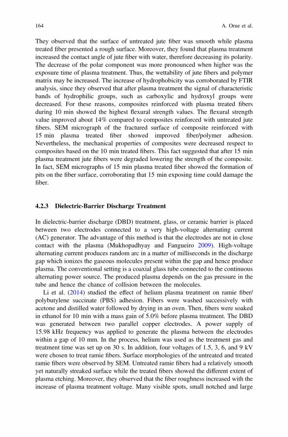
They observed that the surface of untreated jute fiber was smooth while plasmatreated fiber presented a rough surface. Moreover, they found that plasma treatmentincreased the contact angle of jute fiber with water, therefore decreasing its polarity.The decrease of the polar component was more pronounced when higher was theexposure time of plasma treatment. Thus, the wettability of jute fibers and polymermatrix may be increased. The increase of hydrophobicity was corroborated by FTIRanalysis, since they observed that after plasma treatment the signal of characteristicbands of hydrophilic groups, such as carboxylic and hydroxyl groups weredecreased. For these reasons, composites reinforced with plasma treated fibersduring 10 min showed the highest flexural strength values. The flexural strengthvalue improved about 14% compared to composites reinforced with untreated jutefibers. SEM micrograph of the fractured surface of composite reinforced with15 min plasma treated fiber showed improved fiber/polymer adhesion.Nevertheless, the mechanical properties of composites were decreased respect tocomposites based on the 10 min treated fibers. This fact suggested that after 15 minplasma treatment jute fibers were degraded lowering the strength of the composite.In fact, SEM micrographs of 15 min plasma treated fiber showed the formation ofpits on the fiber surface, corroborating that 15 min exposing time could damage thefiber.
4.2.3 Dielectric-Barrier Discharge Treatment
In dielectric-barrier discharge (DBD) treatment, glass, or ceramic barrier is placedbetween two electrodes connected to a very high-voltage alternating current(AC) generator. The advantage of this method is that the electrodes are not in closecontact with the plasma (Mukhopadhyay and Fangueiro 2009). High-voltagealternating current produces random arc in a matter of milliseconds in the dischargegap which ionizes the gaseous molecules present within the gap and hence produceplasma. The conventional setting is a coaxial glass tube connected to the continuousalternating power source. The produced plasma depends on the gas pressure in thetube and hence the chance of collision between the molecules.
Li et al. (2014) studied the effect of helium plasma treatment on ramie fiber/polybutylene succinate (PBS) adhesion. Fibers were washed successively withacetone and distilled water followed by drying in an oven. Then, fibers were soakedin ethanol for 10 min with a mass gain of 5.0% before plasma treatment. The DBDwas generated between two parallel copper electrodes. A power supply of15.98 kHz frequency was applied to generate the plasma between the electrodeswithin a gap of 10 mm. In the process, helium was used as the treatment gas andtreatment time was set up on 30 s. In addition, four voltages of 1.5, 3, 6, and 9 kVwere chosen to treat ramie fibers. Surface morphologies of the untreated and treatedramie fibers were observed by SEM. Untreated ramie fibers had a relatively smoothyet naturally streaked surface while the treated fibers showed the different extent ofplasma etching. Moreover, they observed that the fiber roughness increased with theincrease of plasma treatment voltage. Many visible spots, small notched and large
164 A. Orue et al.

area of protuberances were observed especially for fibers treated with 9 kV. Thisfact suggested that treatment conditions could damage ramie fiber properties. Theeffect of different plasma treatment voltage on surface wettability of ramie fiberswas investigated using dynamic contact angle analysis. They found that theadvancing contact angle of untreated ramie fiber was 55.9° and plasma treated fiberwith 1.5 kV voltage showed similar contact angle. Nevertheless, the contact anglesof fibers treated with 3, 6, and 9 kV notably increased probably due to the plasmatreatment induced grafting of ethyl groups onto the fiber surface. Additionally, theycorroborated this suggestion by X-ray photoelectron spectroscopy (XPS) technique.Therefore, it was thought the fiber/matrix adhesion would be improved since thewettability of ramie fibers and the fiber surface roughness was increased. Thus, theIFSS values of ramie/PBS composites were determined using microbond pull-outtest. Compared with untreated ramie fiber/PBS, the IFSS value for fiber treated withthe lowest voltage, 1.5 kV, did not show significant differences with respect tountreated fiber/PBS system. Meanwhile, the IFSS value for fibers treated with 3, 6,and 9 kV raised about 29.6, 45.5, and 19.4%, respectively, compared to untreatedfiber ones due to the combination of the better chemical compatibility and improvedmechanical interlocking between the fiber and polymeric matrix.
Ragoubi et al. (2012) treated miscanthus fibers by corona discharge treatment(CDT). Fibers were treated in CDT device on a dielectric barrier technique. Thetreatment was assured by a low-frequency high-voltage generator (typically 15 kV,50 Hz) and the samples were disposed between the electrodes and treated forseveral minutes. After the CDT, obtained XPS results evidenced that in treatedsamples there was an increase in oxygen content and a decrease in carbon contentone. The increase of the O/C ratio was attributed to the surface oxidation generatedby the corona treatment. On the other hand, SEM micrographs showed that aftertreating fiber for 15 min, some little cracks appeared on the surface of miscanthusfiber. For longer treatment time, the fibrils were pulled-off of the fibers resulting inthe formation of some cavities that could be observed after 45 min. They observedthat CDT produced many activated sites that could react with oxygen to giveetching effect. In order to confirm this suggestion, they compounded compositesbased on miscanthus fiber using PP and PLA as matrices. For PP/treated miscanthussystem, an increase in Young modulus, stress, and strength at yield values wereobserved compared with those values obtained for composites based on untreatedfibers. They suggested that the wettability of miscanthus fibers was increased byCDT. Also, they suggested that the improvement of interfacial properties could beattributed mainly to a mechanical anchorage. The fractured surface of compositeswas observed by SEM and they reported that in PP composites reinforced withuntreated miscanthus, the fiber surface appeared smooth and clean. At highermagnification, the pull-out fiber was observed indicating poor fiber/PP interfacialadhesion. On the other hand, fractured surfaced of composites based on the treatedfibers showed that miscanthus fibers were covered with matrix and there were nosigns of pull-out fiber which means that the interfacial adhesion between PP andmiscanthus fiber was improved by corona treatment. Similar behavior was reportedon the mechanical properties of PLA/miscanthus fibers after treating fibers by CDT.
Pretreatments of Natural Fibers for Polymer Composite Materials 165

4.3 Biological Treatments
Biological treatments are a promising technology due to its several advantages likelow energy requirements and mild environmental conditions which make themeco-friendly and economically viable strategy (Kumar et al. 2009). Furthermore,biological modifications can selectively remove noncellulosic materials (Georgeet al. 2014). Biological treatments with microorganisms, such as fungi, bacteria, andenzymes have been used for lignocellulosic fibers treatments (Buschle-Diller et al.1999).
4.3.1 Fungal Treatment
Fungal treatments produce extracellular enzymes that degrade lignins, as well asextensive range of other noncellulosic materials (Li et al. 2009). It has been reportedthat fungal treatments produce an extensive system of hyphae which can make fineholes on the lignocellulosic fiber surface and may roughen the surface of thelignocellulosic fiber (Li et al. 2009; Daniel et al. 2004).
Pickering et al. (2007) modified hemp fibers using fungal treatments. Hempfibers were sterilized in an autoclave for 15 min at 121 °C before fungal treatment.The fungi:hemp ratio was approximately 10:12 (mg/g) and incubation were carriedout at 27 °C for 2 weeks. After fungal treatment, fibers were sterilized and washedfor 10 min before being dried in an oven at 80 °C. The fungi used for hemp fibertreatment were Phanerochaete sordida, Pycnoporus species, Schizophyllum com-mune, Absidia, and Ophiostomn floccosun. The first three belong to white rot fungigroup, whereas the fourth and the fifth belong to zygomycetes and ascomycetesgroups, respectively. They observed that the untreated fiber surface appearedsmooth and glossy, whereas after fungal treatment with white rot fungi, the surfaceof fibers led to less glossy and striations becoming more visible along the fiber.They observed by XRD analysis that after all fungal treatments, crystallinity valuesof fungal treated fibers increased slightly respect to untreated fibers supporting theremoval of noncellulosic compounds. In addition, the removal of noncellulosiccompound was corroborated by TGA analysis since after the fungal treatment hempfiber were thermally more stable than untreated ones. However, they observed thatafter the fungal treatment, the tensile strength values of treated fibers were reducedrespect to untreated fibers, especially, when hemp fibers were treated withSchizophyllum commune fungal. They observed that tensile strength reduced about50% suggesting that the fiber strength reduction could be related to the cellulosedegradation during fungal treatment. After the characterization of untreated andfungal treated fibers, they compounded composites with 40 wt% hemp fibers andPP matrix and they added 3 wt% MAPP coupling agent. Despite the tensile strengthvalues of all fungal treated fibers were reduced respect to untreated fibers, com-posites reinforced with fungal treated fiber showed higher tensile strength valuesthan composites reinforced with untreated hemp fibers. Thus, the highest tensile
166 A. Orue et al.

strength value was observed in composites based on fibers treated withSchizophyllum commune. Hemp fiber treated with Schizophyllum commune showedthe lowest fiber tensile strength value, therefore, composites tensile strength datasuggested that the interfacial bonding between PP and hemp fibers were greatlyimproved due to the removal of noncellulosic compounds and the increment of fibersurface roughness.
Li et al. (2009) carried out an analysis of hemp/PP composites using white rotfungal treatments. For fungal treatments, dried hemp fibers were sterilized usinggamma radiation. Irradiated fibers were inoculated with white rot fungi for 2 weeksat 27 °C and water was added for all fungal treatments to give a moisture content of60 wt%. The fungi used for hemp fiber treatment were Phanerochaete sordid,Pycnoporus species, and Schizophyllum commune, respectively. They observed thatall fungal treatments reduced the amount of wax, pectin, hemicelluloses, and ligninin the hemp fiber. FTIR spectra of fungal treated fibers showed that the band around1736 cm−1 attributed to the presence of the carboxylic ester in pectins showed asignificant intensity reduction supporting the removal of pectins. In addition, theband around 1268 cm−1, related to the COO stretching in lignins was disappearedin white rot fungi treated fibers. The surface morphology of untreated and treatedfibers was characterized by SEM. Untreated hemp fiber showed a large amount ofdebris adhering to the surface of the fiber bundles, because they were coated withnoncellulosic material. After fungal treatment, relatively cleaner surface wasobserved which supported the removal of noncellulosic compound. Nevertheless,they mentioned that the resolution of the available SEM was inadequate to detectfine holes caused by fungal hyphae attack on fungal treated fiber surfaces. Theremoval of noncellulosic compound was also corroborated by XRD analysis sincethe crystallinity values were improved after the white rot fungal treatment. Thestrength values of white rot fungi treated fibers were lower than untreated fibers.They observed that the tensile strength values of fungal treated hemp fiberdecreased at least 23% and the highest decrease, around 38%, was observed forSchizophyllum commune treated fiber. They suggested that the decrease of tensilestrength values was related to the creation of fine holes in the fiber surface. Afterthat, they compounded PP/hemp composites with 40 wt% fiber content using 3 wt%MAPP coupling agent. Despite the fungal treatments reduced hemp fiber tensilestrength value, the tensile strength values of composites reinforced with white rotfungi treated fibers were higher than composites based on the untreated ones. Thisfact suggested that the interfacial bonding adhesion between fiber and matrixseemed to be improved due to the removal of noncellulosic compounds and theincrease of surface roughness.
4.3.2 Enzyme Treatment
Enzymes are biocatalysts that accelerate biomechanical reactions acting on aspecific reactant called “substrate”. All substrates have their own enzymes such ascellulase for cellulose, xylanase for hemicellulose, laccase for lignins, etc.
Pretreatments of Natural Fibers for Polymer Composite Materials 167

(Karaduman et al. 2012). Enzyme treatments are environmentally friendly andrequire mild operating conditions (George et al. 2016).
George et al. (2014) studied the surface morphology and thermal properties oflignocellulosic fibers treated with enzymes. Hemp and flax fibers were treated withdifferent enzymes such as xylanase, xylanase + 10% cellulase, polygalacturonase,laccase, and pectinmethylesterase, respectively. The liquid to fiber ratio wasmaintained at 50:1 (v/w) to facilitate complete wetting of fiber. Enzymatic treat-ments were conducted for 90 min under constant agitation of 80 rpm at optimumpH and temperature conditions (see Table 4) and enzymes were deactivated byheating at 90 °C for 10 min.
They observed that after treating lignocellulosic fibers with xylanase + 10%cellulase enzymes, hemp, and flax fibers showed a reduction in the cellulosiccontent whereas lignocellulosic fibers treated with pectinases enzymes (poly-galacturonase and pectinmethylesterase) showed a decrease in the hemicellulosescontent. In addition, laccase treated flax fibers showed a significant reduction in thelignin content. It was observed from SEM micrographs that after enzyme treatmentthe elementary fibers became more visible compared to the surface of untreatedfibers. On the other hand, they observed that a combination of xylanase and cel-lulase, and polygalacturonase treated samples exhibited an increase in surfaceroughness. The onset degradation temperature of enzyme treated hemp and flaxfibers were improved due to the removal of pectin and hemicellulose materials. Thisimprovement was achieved when lignocellulosic fibers were treated with xylanaseand pectinases enzyme. However, no change in the onset degradation temperaturewas observed when lignocellulosic fibers were treated with laccase enzyme. On theother hand, they reported that the enzyme treatment resulted in higher surfacehydrophilicity because of the removal of lignin and hemicellulose, thereby exposingthe cellulosic backbone. In summary, enzyme treatment of lignocellulosic fibers canbe used to selectively degrade components that limit the thermal stability and tomodify the fiber surface characteristic.
George et al. (2016) studied the mechanical and moisture absorption of enzymetreated fibers/PP composites with 20 wt% of fiber content. They observed that afterthe enzyme treatment there was no change in mechanical properties. By TGAanalysis, they observed that enzymatic treatment improved the thermal properties ofthe resulting composites. Furthermore, composites based on the enzyme treatedfiber showed lower moisture absorption values than untreated fiber composites.
Table 4 Optimum pH and temperature conditions for each enzymatic reaction (George et al.2014)
Enzyme Xylanase Xylanase+10%cellulase
Polygalacturonase Laccase Pectinmethylesterase
pH 7 6 4 7 5
Temperature(°C)
70 50 45 50 45
168 A. Orue et al.

Xylanase + cellulase treatments provided the greatest reduction in moisture bothfor hemp and flax fiber composites. After 4 weeks of immersion in water at roomtemperature, they observed that the xylanase + cellulase treatment decreased theaverage moisture absorption of composites based on the hemp fiber around 250%whereas the average moisture absorption of flax fibers reduced around 200%.Finally, in order to study the fiber/matrix adhesion, the fractured surface of thecomposite was observed by SEM. Composites based on the untreated fibers showedpulled-out fibers due to the poor interfacial adhesion. However, composites basedon the enzyme treated samples revealed a better distribution of fibers indicating abetter fiber dispersion and fiber/matrix adhesion.
Hanana et al. (2015) treated alfa fibers with several enzymes. The enzymetreatments were carried out after alfa fiber were treated with 0.5 M NaOH solutionin autoclave for 20 min at 120 °C with a pressure of 1 bar. The optimal pH andtemperature conditions of enzyme treatment are listed in Table 5. For all experi-ments, the liquid to fiber ratio was maintained at 150:1 (v/w) to facilitate completewetting of fiber and different enzyme reaction times were used, 2, 4, and 8 h,respectively.
In enzyme treated fibers, the cellulose micro-fibrils were visible indicating thatthe lignin and other noncellulosic materials were greatly removed from the fibersurface becoming fiber surface rougher. They reported that pectinase enzymetreatment was the most effective for separating alfa fiber into smaller and singlefiber due to the removal of materials from the fiber surface and the degradation ofpolygalacturonan. In consequence, they observed that pectinase enzyme treatmentimproved the mechanical properties of composite based on the alfa fibers. Thetensile strength values of composites based on the pectinase treated fiber improvedaround 30% compared to alkali treated composites. However, the tensile strengthvalues of composites based on the laccase and xylanase treated fibers did notobserve important changes.
5 Conclusion
The use of natural fibers as reinforcement in polymer composites is attracting a lotof interest due to its mechanical properties, processing advantages, and environ-mental benefits. However, the hydrophilic character of the fibers lowers the com-patibility with the hydrophobic matrix which results in poor mechanical propertiesof the composites. Therefore, it is necessary to modify the fiber surface morphologyin order to reduce the hydrophilic character of the fibers and improve the fiber/
Table 5 Characteristic ofeach enzyme system withcorresponding activity atoptimum conditions (Hananaet al. 2015)
Enzyme Xylanase Laccase Pectinase
pH 7 5 4.8
Temperature (°C) 55 50 50
Pretreatments of Natural Fibers for Polymer Composite Materials 169

matrix adhesion. The fiber treatments could modify tensile properties of treatedfibers, being often lower than untreated fibers. Nevertheless, composites based onthe treated fibers could show higher tensile strength values than composites basedon untreated fibers due to the adhesion improvement between the lignocellulosicfiber and polymer matrix after the surface treatments. The adhesion improvementfor each fiber/polymer system depends on the fiber treatment type chosen as well asthe chemical composition and morphological features of the composite compo-nents. In composites based on the lignocellulosic fibers, usually, the chemicaltreatments are used for fiber surface modification, such as alkali, silane, andacetylation among others. Inadequate treatment conditions could damage fiberstructure, decreasing considerably fiber mechanical properties and consequently,the optimization of surface treatment conditions is a key factor to prepare com-posites with superior mechanical performance. Chemical treatments are the mostused to modify fiber surface, however, physical and especially biological treat-ments, could be promising alternatives to improve lignocellulosic fiber/matrixadhesion because they are more environmentally friendly treatments than chemicalones. In most cases, physical and biological treatments are combined with chemicaltreatments in order to make more effective treatments.
References
Abdelmouleh M, Boufi S, Salah A, Belgacem MN, Gandini A (2002) Interaction of silanecoupling agents with cellulose. Langmuir 18:3203–3208
Allaby M (1998) A dictionary of plant sciences, 2nd edn. Oxford University Press, OxfordArbelaiz A, Cantero G, Fernández B, Mondragon I, Gañán P, Kenny JM (2005a) Flax fiber surface
modifications: effects on fiber physico mechanical and flax/ polypropylene interface properties.Polym Compos 26:324–332
Arbelaiz A, Fernandez B, Cantero G, Llano-Ponte R, Valea A, Mondragon I (2005b) Mechanicalproperties of flax fiber/polypropylene composites. Influence of fiber/matrix modification andglass fiber hybridization. Composites, Part A 36(2):637–644
Arbelaiz A, Fernandez B, Ramos JA, Retegi A, Llano-Ponte R, Mondragon I (2005c) Mechanicalproperties of short flax fiber bundle/polypropylene composites: influence of matrix/fibermodification, fiber content, water uptake and recycling. Compos Sci Technol 65(10):1582–1592
Arbelaiz A, Trifol J, Peña-Rodriguez C, Labidi J, Eceiza A (2016) Modification of Poly(lacticacid) matrix by chemically modified flax fiber bundles and Poly(ethylene glycol) plasticizer. In:Visakh PM, Sigrid L (eds) Polyethylene-based biocomposites and bionanocomposites. ISBN:978-1-119-03845-0
Bataille P, Dufourd M, Sapieha S (1994) Copolymerization of styrene on to cellulose activated bycorona. Polym Int 34(4):387–391
Benitez AN, Monzón MD, Angulo I, Ortega Z, Hernandez PM, Marrero MD (2013) Treatmentof banana fiber for use in the reinforcement of polymeric matrices. Measurement 46(3):1065–1073
Bledzki AK, Gassan J (1999) Composites reinforced with cellulose based fibres. Prog Polym Sci24:221–274
Bledzki AK, Reihmane S, Gassan J (1996) Properties and modification methods for vegetablefibers for natural fiber composites. J Appl Polym Sci 59:1329–1336
170 A. Orue et al.

Bozaci E, Sever K, Sarikanat M, Seki Y, Demir A, Ozdogan E (2013) Effects of the atmosphericplasma treatments on surface and mechanical properties of flax fiber and adhesion betweenfiber—matrix for composite materials. Compos B 45(1):565–572
Buschle-Diller G, Fanter C, Loth F (1999) Structural changes in hemp fibers as a result ofenzymatic hydrolysis with mixed enzyme systems. Text Res J 69(4):244–251
Chen C, Cho M, Kim B, Nam J, Lee Y (2012) Thermo plasticization and characterization of kenaffiber by benzylation. J Ind Eng Chem 18(3):1107–1111
Cisneros-Lopez EO, Perez-Fonseca AA, Fuentes-Talavera FJ, Anzaldo J (2016) Rotomoldedpolyethylene-agave fiber composites: effect of fiber surface treatment on the mechanicalproperties. Polym Eng Sci 56(8):856–865
Daintith J (2000) A dictionary of chemistry, 4th edn. Oxford University Press, OxfordDaniel G, Volc J, Niku-Paavola ML (2004) Cryo-FE-SEM & TEM immune-techniques reveal new
details for understanding white-rot decay of lignocellulose. C R Biol 327(9–10):861–871Datta J, Kopczynska P (2015) Effect of kenaf fibre modification on morphology and mechanical
properties of thermoplastic polyurethane materials. Ind Crops Prod 74:566–576De Rosa IM, Kenny JM, Puglia D, Santulli C, Sarasini F (2010) Morphological, thermal and
mechanical characterization of okra (Abelmoschus esculentus) fibres as potential reinforcementin polymer composites. Compos Sci Technol 70:116–122
De Rosa IM, Kenny JM, Maniruzzaman M, Moniruzzaman Md, Monti M, Puglia D, Santulli C,Sarasini F (2011) Effect of chemical treatments on the mechanical and thermal behaviour ofokra (Abelmoschus esculentus) fibres. Compos Sci Technol 71:246–254
Efanov MV, Ovchinnikov PV (2012) Acetylation of alkali treated peat. Solid Fuel Chem 46(2):138–141
Egües I (2013) Lignocellulosic materials as new renewable resources: extraction, purification andpotential use of hemicelluloses. Ph.D. thesis, Faculty of Engineering, Gipuzkoa, Spain
Fernandes EM, Mano JF, Reis RL (2013) Hybrid cork-polymer composites containing sisal fibre:morphology, effect of the fibre treatment on the mechanical properties and tensile failureprediction. Compos Struct 105:153–162
Focher B (1992) Physical characteristics of flax fibre. In: Sharma HSS, Van Sumere CF (eds) Thebiology and processing of flax. M. Publications, Belfast, UK, pp 11–32
Gassan J, Bledzki AK (1997) The influence of fiber-surface treatment on the mechanical propertiesof jute-polypropylene composites. Compos A 28(12):1001–1005
Gassan J, Bledzki AK (1999) Alkali treatment of jute fibers: relationship between structure andmechanical properties. J Appl Polym Sci 71(4):623–629
George J, Sreekala MS, Thomas S, George J, Sreekala MS, Thomas S (2001) A review oninterface modification and characterization of natural fiber reinforced plastic composites.Polym Eng Sci 41(9):1471–1485
George M, Mussone PG, Bressler DC (2014) Surface and thermal characterization of natural fibrestreated with enzymes. Ind Crops Prod 53:365–373
George M, Mussone PG, Alemaskin K, Chae M, Wolodko J, Bressler DC (2016) Enzymaticallytreated natural fibres as reinforcing agents for biocomposite material: mechanical, thermal, andmoisture absorption characterization. J Mater Sci 51(5):2677–2686
Goriparthi BK, Suman KNS, Mohan N (2012) Effect of fiber surface treatments on mechanical andabrasive wear performance of polylactide/jute composites. Compos A 43(10):1800–1808
Haiping Y, Rong Y, Hanping C, Dong HL, Chuguang Z (2007) Characteristics of hemicellulose,cellulose and lignin pyrolysis. Fuel 86:1781–1788
Hanana S, Elloumi A, Placet V, Tounsi H (2015) An efficient enzymatic-based process for theextraction of high-mechanical properties alfa fibres. Ind Crops Prod 70:190–200
Hill CAS, Abdul Khalil HPSA, Hale MD (1998) A study of the potential of acetylation to improvethe properties of plant fibres. Ind Crops Prod 8:53–63
Hirota WH, Rodrigues RB, Sayer C, Giudici R (2010) Hydrolysis of acetic anhydride:non-adiabatic calorimetric determination of kinetics and heat exchange. Chem Eng Sci65:3849–3858
Pretreatments of Natural Fibers for Polymer Composite Materials 171

Hou X, Sun F, Yan D, Xu H, Dong Z, Li Q (2014) Preparation of lightweight polypropylenecomposites reinforced by cotton stalk fibers from combined steam fl ash-explosion and alkalinetreatment. J Cleaner Prod 83:454–462
Ibrahim MM, Agblevor FA, El-Zawawy WK (2010) Isolation and characterization of cellulose andlignin from steam-exploded lignocellulosic biomass. BioResources 5(1):397–418
Jandas PJ, Mohanty S, Nayak SK (2013) Surface treated banana fiber reinforced poly (lactic acid)nanocomposites for disposable applications. J Cleaner Prod 52:392–401
Jiang A, Xi J, Wu H (2012) Effect of surface treatment on the morphology of sisal fibers in sisal/polylactic acid composites. J Reinf Plast Compos 31:621–630
Josefsson T, Lennholm H, Gellerstedt G (2002) Steam explosion of aspen wood. Characterisationof reaction products. Holzforschung 56(3):289–297
Joseph K, Thomas S (1996) Effect of chemical treatment on the tensile properties of short sisalfibre-reinforced polyethylene composites. Polymer 37(23):5139–5149
Joseph PV, Joseph K, Thomas S (2002) Short sisal fiber reinforced polypropylene composites: therole of interface modification on ultimate properties. Compos Interfaces 9:171–205
Joseph PV, Joseph K, Thomas S, Pillai CKS, Prasad VS, Groeninckx G, Sarkissova M (2003) Thethermal and crystallization studies of short sisal fiber reinforced polypropylene composites.Compos A 34(3):253–266
Kabir MM (2012) Effects of chemical treatments on hem fibre reinforced polyester composites. Ph.D. thesis, Faculty of Engineering and Surveying, University of Southern Queensland,Toowoomba, Australia
Kabir MM, Wang H, Lau KT, Cardona F (2012) Chemical treatments on plant-based natural fiberreinforced polymer composites: an overview. Compos B 43(7):2883–2892
Kalaprasad G, Francis B, Thomas S, Kumar CR, Pavithran C, Groeninckx G, Thomas S (2004)Effect of fibre length and chemical modifications on the tensile properties of intimately mixedshort sisal/glass hybrid fibre reinforced low density polyethylene composites. Polym Int 53(11):1624–1638
Kalia S, Kaith BS, Kaur I (2009) Pretreatments of natural fibers and their application as reinforcingmaterial in polymer composites—a review. Polym Eng Sci 49(7):1253–1272
Karaduman Y, Gokcan D, Onal L (2012) Effect of enzymatic pretreatment on the mechanicalproperties of jute fiber-reinforced polyester composites. J Compos Mater 47(10):1293–1302
Kestur SG, Ramos LP, Wypych F (2009) Comparative study of Brazilian natural fibers and theircomposites with other. In Thomas S, Pothan LA (eds) Natural fibre reinforced polymercomposites: from Macro to Nanoscale. Old City Publishing, Inc. Philadelphia, USA
Khan GMA, Shaikh H, Alam MS, Gafur MA (2015) Effect of chemical treatments on the physicalproperties of non-woven Jute/PLA. BioResources 10(4):7386–7404
Kim JK, Pal K (2010) Surface modifications in WPC with pre-treatment methods. In: Kim JK,Pal K (eds) Recent advances in the processing of wood-plastic composites. Springer, Berlin,pp 23–57
Klemm D, Philipp B, Heinze T, Heinze U, Wagenknecht W (1998) Comprehensive cellulosechemistry: fundamentals and analytical methods, vol 1. Wiley-VCH, Weinheim
Kumar P, Barrett DM, Delwiche MJ, Stroeve P (2009) Methods for pretreatment of lignocellulosicbiomass for efficient hydrolysis and biofuel production. Ind Eng Chem Res 48(8):3713–3729
Kumar R, Obrai S, Sharma A (2011) Chemical modifications of natural fiber for compositematerial. Chem Sin 2(4):219–228
Le Moigne N, Longerey M, Taulemesse J, Bénézet J, Bergeret A (2014) Study of the interface innatural fibres reinforced poly (lactic acid) biocomposites modified by optimized organosilanetreatments. Ind Crops Prod 52:481–494
Li X, Tabil LG, Panigrahi S (2007) Chemical treatments of natural fiber for use in naturalfiber-reinforced composites: a review. J Polym Environ 15:25–33
Li Y, Pickering KL, Farrell RL (2009) Analysis of green hemp fibre reinforced composites usingbag retting and white rot fungal treatments. Ind Crops Prod 29(2–3):420–426
Li Y, Zhang J, Cheng P, Shi J, Yao L, Qiu Y (2014) Helium plasma treatment voltage effect onadhesion of ramie fibers to polybutylene succinate. Ind Crops Prod 61:16–22
172 A. Orue et al.

Lu B, Chung TC (2000) Synthesis of maleic anhydride grafted polyethylene and polypropylene,with controlled molecular structures. J Polym Sci, Part A-1: Polym Chem 38:1337–1343
Lu T, Liu S, Jiang M, Xu X, Wang Y, Wang Z, Gou J, Hui D, Zhou Z (2014) Effects ofmodifications of bamboo cellulose fibers on the improved mechanical properties of cellulosereinforced poly (lactic acid) composites. Compos B 62:191–197
Mansour OY, Nagaty A, El-Zawawy WK (1994) Variables affecting the methylation reactions ofcellulose. J Appl Polym Sci 54(5):519–524
Matsuda H (1996) Chemical modification of solid wood. In: Hon DNS (ed) Chemical modificationof lignocellulosic materials. Marcel Dekker Inc, New York, pp 159–184
Merkel K, Rydarowski H, Kazimierczak J, Bloda A (2014) Processing and characterization ofreinforced polyethylene composites made with lignocellulosic fibres isolated from waster plantbiomass such as hemp. Compos B 67:138–144
Mohanty S, Nayak SK (2006) Mechanical and rheological characterization of treated jute-HDPEcomposites with different morphology. J Reinf Plas Compos 25(13):1419–1439
Mohanty AK, Misra M, Drzal LT (2001) Surface modifications of natural fibers and performanceof the resulting biocomposites: an overview. Compos Interfaces 8(5):313–343
Mondragon G, Fernandes S, Retegi A, Peña C, Algar I, Eceiza A, Arbelaiz A (2014) A commonstrategy to extracting cellulose nanoentities from different plants. Ind Crops Prod 55:140–148
Mukhopadhyay S, Fangueiro R (2009) Physical modification of natural fibers and thermoplasticfilms for composites—a review. J Thermoplas Compos Mater 22(2):135–162
Mwaikambo LY, Ansell MP (2002) Chemical modification of hemp, sisal, jute, and kapok fibersby alkalization. J Appl Polym Sci 84:2222–2234
Nair KCM, Diwan SM, Thomas S (1996) Tensile properties of short sisal fiber reinforcedpolystyrene composites. J Appl Polym Sci 60:1483–1497
Orue A, Jauregi A, Peña-Rodriguez C, Labidi J, Eceiza A, Arbelaiz A (2015) The effect of surfacemodifications on sisal fiber properties and sisal/poly (lactic acid) interface adhesion. Compos B73:132–138
Orue A, Eceiza A, Peña-Rodriguez C, Arbelaiz A (2016a) Water uptake behavior and Youngmodulus prediction of composites based on treated sisal fibers and poly (lactic acid). Materials9(5):400–414. https://doi.org/10.3390/ma9050400
Orue A, Jauregi A, Unsuain U, Labidi J, Eceiza A, Arbelaiz A (2016b) The effect of alkaline andsilane treatments on mechanical properties and breakage of sisal fibers and poly (lactic acid)/sisal fiber composites. Compos A 84:186–195
Paul A, Joseph K, Thomas S (1997) Effect of surface treatments on the electrical properties oflow-density polyethylene composites reinforced with short sisal fibers. Compos Sci Technol57(1):67–79
Paul SA, Sinturel C, Joseph K, Mathew GDG, Pothen LA, Thomas S (2010a) Dynamicmechanical analysis of novel composites from commingled polypropylene fiber and bananafiber. Polym Eng Sci 50(2):384–395
Paul SA, Joseph K, Mathew GDG, Pothen LA, Thomas S (2010b) Influence of polarity parameterson the mechanical properties of composites from polypropylene fiber and short banana fiber.Compos A 41(10):1380–1387
Pickering KL, Li Y, Farrell RL, Lay M (2007) Interfacial modification of hemp fiber reinforcedcomposites using fungal and alkali treatment interfacial modification of hemp fiber reinforcedcomposites using fungal and alkali treatment. J Biobased Mater Bioenergy 1:109–117
Prasad N, Kumar V, Shishir A (2016) Banana fiber reinforced low—density polyethylenecomposites: effect of chemical treatment and compatibilizer addition. Iran Polym J 25(3):229–241
Praveen KM, Thomas S, Grohens Y, Mozetic M, Junkar I, Primc G, Gorjanc M (2016) Appliedsurface science investigations of plasma induced effects on the surface properties oflignocellulosic natural coir fibres. Appl Surf Sci 368:146–156
Rachini A, Le Troedec M, Peyratout C, Smith A (2012) Chemical modification of hemp fibers bysilane coupling agents. J Appl Polym Sci 123(1):601–610
Pretreatments of Natural Fibers for Polymer Composite Materials 173

Ragoubi M, George B, Molina S, Bienaimé D, Merlin A, Hiver J, Dahoun A (2012) Effect ofcorona discharge treatment on mechanical and thermal properties of composites based onmiscanthus fibres and polylactic acid or polypropylene matrix. Compos A 43(4):675–685
Rahman MM, Mallik AK, Khan MA (2007) Influences of various surface pretreatments on themechanical and degradable properties of photografted oil palm fibers. J Appl Polym Sci 105(5):3077–3086
Raj G, Balnois E, Baley C, Grohens Y (2011) Role of polysaccharides on mechanical andadhesion properties of flax fibres in flax/PLA biocomposite. Int J Polym Sci 2011:1–11
Ranganathan N, Oksman K, Nayak SK, Sain M (2016) Structure property relation of hybridbiocomposites based on jute, viscose and polypropylene: The effect of the fibre content and thelength on the fracture toughness and the fatigue properties. Compos A 83:169–175
Saba N, Tahir P, Jawaid M (2014) A review on potentiality of nano filler/natural fiber filledpolymer hybrid composites. Polymers 6:2247–2273
Saha P, Chowdhury S, Roy D, Adhikari B, Kuk J (2016) A brief review on the chemicalmodifications of lignocellulosic fibers for durable engineering composites. Polym Bull 73(2):587–620
Sampathkumar D, Punyamurthy R, Bennehalli B, Ranganagowda RP, Venkateshappa SC (2014)Natural areca fiber: surface modification and spectral studies. J Adv Chem 10(10):3263–3273
Saritha M, Arora A, Lata (2012) Biological pretreatment of lignocellulosic substrates for enhanceddelignification and enzymatic digestibility. Indian J Microbiol 52(2):122–130
Saw SK, Sarkhel G, Choudhury A (2011) Applied surface science surface modification of coirfibre involving oxidation of lignins followed by reaction with furfuryl alcohol: characterizationand stability. Appl Surf Sci 257(8):3763–3769
Saw SK, Purwar R, Nandy S, Ghose J, Sarkhel G (2013) Fabrication, characterization, andevaluation of luffa cylindrica fiber reinforced epoxy composites. BioResources 8(4):4805–4826
Sever K, Erden S, Gülec HA, Seki Y, Sarikanat M (2011) Oxygen plasma treatments of jute fibersin improving the mechanical properties of jute/HDPE composites. Mater Chem Phys 129(1–2):275–280
Sinha E, Panigrahi S (2009) Effect of plasma treatment on structure, wettability of jute fiber andflexural strength of its composite. J Compos Mater 43(17):1791–1802
Sreekala MS, Thomas S (2003) Effect of fibre surface modification on water-sorptioncharacteristics of oil palm fibres. Compos Sci Technol 63(6):861–869
Sreekala MS, Kumaran MG, Joseph S, Jacob M, Thomas S (2000) Oil palm fibre reinforcedphenol formaldehyde composites: influence of fibre surface modifications on the mechanicalperformance. Appl Compos Mater 7(5):295–329
Sun E, Sun F, Dong Y (2016) Interface morphology and thermoplasticization behavior of bamboofibers benzylated with benzyl chloride. Surf Interface Anal 48:64–72
Trindade WG, Hoareau W, Razera IAT, Ruggiero R, Frollini E, Castellan A (2004) Phenolicthermoset matrix reinforced with sugar cane bagasse fibers: attempt to develop a new fibersurface chemical modification involving formation of quinones followed by reaction withfurfuryl alcohol. Macromol Mater Eng 289:728–736
Trindade WG, Hoareau W, Megiatto JD, Razera IAT, Castellan A, Frollini E (2005) Thermosetphenolic matrices reinforced with unmodified and surface-grafted furfuryl alcohol sugar canebagasse and curaua fibers: properties of fibers and composites. Biomacromol 6(5):2485–2496
Wang B, Panigrahi S, Tabil L, Crerar W (2007) Pre-treatment of flax fibers for use in rotationallymolded biocomposites. J Reinf Plast Compos 26(5):447–463
Wang K, Jiang JX, Xu F, Sun RC (2009) Influence of steaming pressure on steam explosionpretreatment of Lespedeza stalks (Lespedeza crytobotrya): Part 1. Characteristics of degradedcellulose. Polym Degrad Stab 94(9):1379–1388
Xie Y, Hill CAS, Xiao Z, Militz H, Mai C (2010) Silane coupling agents used for natural fiber/polymer composites: a review. Compos A 41(7):806–819
Young R (1992) Activation and characterization of fiber surfaces for composites. In: Rowell R,Shulz TP, Narayan R (eds) Emerging technologies for materials and chemicals from biomass.American Chemical Society, Washington D.C., pp 115–135
174 A. Orue et al.

Yu Y, Huang X, Yu W (2014) A novel process to improve yield and mechanical performance ofbamboo fiber reinforced composite via mechanical treatments. Compos B 56:48–53
Zhang SM, Liu J, Zhou W, Cheng L, Duo XD (2005) Interfacial fabrication and property ofhydroxyapatite/polylactide resorbable bone fixation composites. Curr Appl Phys 5:516–518
Zhang H, Cui Y, Zhang Z (2013) Chemical treatment of wood fiber and its reinforced unsaturatedpolyester composites. J Vinyl Addit Technol 19(1):18–24
Zhou Y, Fan M, Chen L (2016) Interface and bonding mechanisms of plant fibre composites: anoverview. Compos B 101:31–45
Zou H, Wang L, Gan H, Yi C (2012) Effect of fiber surface treatments on the properties of shortsisal fiber/poly(lactic acid) biocomposites. Polym Compos 33:1659–1666
Pretreatments of Natural Fibers for Polymer Composite Materials 175

Mechanical and Thermal Propertiesof Less Common Natural Fibresand Their Composites
Fabrizio Sarasini
Abstract Interest in the utilization of renewable resources is increasing because ofdepleting natural resources, environmental awareness and economic considerations.Natural fibre composites (biocomposites) have already attracted significant attentionfrom the academic and industry (mainly automotive) fields. Natural fibres likekenaf, hemp, sisal, flax and jute have been the subject of extensive investigationsfor composite applications and therefore the focus of this chapter is on less commonlignocellulosic fibres which are inexpensive and abundantly available at present.These fibres will be presented in terms of extraction methods, chemical, morpho-logical, thermal and mechanical properties with a view to assessing their suitabilityas biofibres in composite applications. The introduction of these less commonnatural fibres in thermoplastic and thermosetting matrices is reviewed and com-pared with the traditional and much more common natural fibres, while the very lastpart of the chapter is dedicated to the development of cellulose-based nanocom-posites, which is perceived as one of the most promising research fields related tolignocellulosic-based products.
Keywords Less common natural fibres � Agricultural residuesBiobased composites � Nanocellulose extraction � Chemical compositionMechanical properties � Thermal stability
Contents
1 Introduction.......................................................................................................................... 1782 Morphological, Chemical and Physical Properties of Less Common Natural Fibres ....... 179
2.1 Okra ............................................................................................................................ 1792.2 Borassus ...................................................................................................................... 1832.3 Arundo donax ............................................................................................................. 1842.4 Isora ............................................................................................................................ 186
F. Sarasini (&)Department of Chemical Engineering Materials Environment,Sapienza-Università di Roma, Via Eudossiana 18, 00184 Rome, Italye-mail: [email protected]
© Springer International Publishing AG 2018S. Kalia (ed.), Lignocellulosic Composite Materials, Springer Series on Polymerand Composite Materials, https://doi.org/10.1007/978-3-319-68696-7_4
177

2.5 Napier Grass Fibres .................................................................................................... 1862.6 Cissus Quadrangularis ................................................................................................ 187
3 Thermal and Mechanical Properties of Less Common Natural Fibres .............................. 1883.1 Okra ............................................................................................................................ 1923.2 Borassus ...................................................................................................................... 1933.3 Arundo Donax ............................................................................................................ 1943.4 Isora ............................................................................................................................ 1953.5 Napier Grass Fibres .................................................................................................... 1963.6 Cissus Quadrangularis ................................................................................................ 197
4 Mechanical Properties of Less Common Natural Fibre Reinforced Composites .............. 1995 Conclusions and Future Perspectives.................................................................................. 206References .................................................................................................................................. 206
1 Introduction
Over the last decades, a resurgent interest in biocomposites has been recorded.Biocomposites are generally defined as composites derived from a polymer matrixand fibres coming from renewable resources, in general, natural fibres of plantorigin. The interest in natural fibres was at first mainly academic but soon afternatural fibre composites gained an increased attention in several industrial fields,being the automotive and the construction sectors the key drivers. This resurgentinterest has been motivated by serious environmental concerns related not only tothe unsustainable production processes of synthetic fibres and polymers, but also tothe limited recyclability of conventional composites and their end of life disposaloptions. Natural fibres are usually classified as vegetal and animal ones, dependingon their respective origin (Bledzki and Gassan 1999; John and Thomas 2008).Among the animal fibres, the most famous are silk and wool, which are widelydiffused in the textile industry. As regards the use of natural fibres as reinforcementin polymer composites, the vegetal ones show the most promising results. Two arethe main sources of vegetal fibres suitable for being used in composite materials:agricultural waste products or byproducts (such as bagasse from sugarcane or cerealstraw) and plants that are intentionally cultivated for the extraction of fibres (such astextile fibres). Vegetal fibres can be extracted from many different parts of the plant,but mainly from the leaves (such as in the case of date palm, banana, agave, sisal) orfrom the bast (such as in the case of Malvaceae or Linaceae). Some attempts havealso been made for leguminosae, grasses and Urticaceae due to their availability andspontaneity. Bast fibres, in particular hemp, flax, and kenaf, are generally consid-ered to be the most promising because of their properties and availability. It is notsurprising that they have been the subject of extensive investigations that led toseveral specific reviews (Summerscales et al. 2010a, b, 2013; Shahzad 2011; Akilet al. 2011; Yan et al. 2014; George et al. 2016). More recently, due to the growingindustrial demand for vegetable fibres, the level of production is experiencingdifficulties in meeting the demand. Moreover, there is an increasing quantity of
178 F. Sarasini

byproducts coming from commodity crops, which are expensive and renewableresources suitable for fibre production. According to Huda and co-workers (Hudaet al. 2007), about 2000 million tonnes of byproducts are produced worldwideevery year from the major crops such as corn, wheat, rice, soybeans and sugarcane.Most byproducts are composed of considerable amounts of cellulose that can beextracted in the form of fibres and used as potential fillers in composites. This hugeavailability of fibres from byproducts of currently limited use can definitely enhancethe sustainability of the fibre industry while adding value and increasing the incomefrom the agricultural crops. Moreover, problems associated with the disposal ofsuch byproducts after harvest could also be reduced if they can find suitableindustrial applications. In addition to fillers obtained by byproducts, the integrationof new natural fibres with acceptable properties can contribute to meet the demandof natural and renewable materials. In this framework, the present chapter dealswith the review of properties and attributes of less common natural fibres envisagedas potential reinforcement in composites.
2 Morphological, Chemical and Physical Propertiesof Less Common Natural Fibres
The present paragraph addresses the physico-chemical properties of several naturalfibres which are suitable to be used as reinforcement in polymer matrix composites.For better clarity, the chemical composition and the density of several less commonnatural fibres are reported and compared with those of commonly used naturalfibres in Table 1.
2.1 Okra
Okra (Abelmoschus esculentus L.) is a member of the Malvaceae family which iscurrently grown throughout tropical Asia, Africa, the Caribbean and the southernUnited States. It represents the only vegetable crop in the Malvaceae family whoseproducts are used in the food sector. Okra plant can be as high as 2 m and hasleaves 10–20 cm long and broad, with lobes ranging from 5 to 7. The edible part ofthe plant is represented by the immature young seed pods. Aside from seed pods,this plant is also specifically cultivated for the edible oil that can be extracted fromthe seeds, in addition to the ripe seeds which can be roasted and ground, and used asa substitute for coffee. Therefore, this plant is not specifically grown for the fibresthat can be obtained from the stem but this could represent an additional envi-ronmental advantage if one considers that the stems are usually treated as anagricultural waste product (Arifuzzaman Khan et al. 2009; Hakeem et al. 2014).
Mechanical and Thermal Properties of Less Common Natural Fibres … 179

Tab
le1
Physico-chem
ical
prop
ertiesof
common
andless
common
naturalfibres
Category
Fibretype
Species
Cellulose
(%)
Hem
icellulose
(%)
Lignin
(%)
Density
(g/cm
3 )So
urce
Leaf
Sisal
Aga
vesisalana
56.5–78
5.6–16
.58–
141.45
Bledzki
etal.(199
6),Malkapu
ram
etal.
(200
9),Fu
quaet
al.(201
2)
New
Zealand
Flax
Pho
rmium
Tena
x45
.1–72
.030
.111
.2–
Carretal.(20
05),DeRosaetal.(20
10c),
Fuqu
aet
al.(201
2)
Abaca
Musatextilis
56–63
20.8
7–12
.41.5
Sunet
al.(199
8),Moh
anty
etal.(200
5),
Fuqu
aet
al.(201
2)
Henequen
Aga
vefourcroydes
77.6
4–8
13.1
1.2
Malkapu
ram
etal.(200
9),Fu
quaet
al.
(201
2)
Pineapple
Ana
nas
comosus
70–82
15–19
5–12
1.44
Saha
etal.(199
0),Malkapu
ram
etal.
(200
9),Fu
quaet
al.(201
2)
Banana
Musa
acum
inata
63–64
10–19
51.35
Moh
anty
etal.(200
5),Fu
quaet
al.
(201
2)
Curaua
Ana
nas
erectifolius
70.2–73
.69.9–18
.37.5–
9.3
1.38
Hoareau
etal.(200
4),Corrêaet
al.
(201
0),Fu
quaet
al.(201
2)
Datepalm
Pho
enix
dactylifera
33.9
26.1
27.7
0.92
Kaddamiet
al.(200
6),Fu
quaet
al.
(201
2)
Sansevieria
Sansevieria
cylin
drica
79.7
10.13
3.8
0.91
Sreenivasanet
al.(201
1)
Buriti
Mau
ritia
flexuosaL.f.
65–71
*21
–27
0.63
–
1.12
Fang
ueiroandRana(201
6),Ornaghi
Júnior
etal.(201
6)
Bast
Flax
Linu
musita
tissimum
71–81
18.6–20
.62.2–
31.51
–
1.54
Bledzki
etal.(19
96),Fu
quaet
al.(20
12)
Hem
pCan
nabis
sativa
70.2–74
.417
.9–22
.43.7–
5.7
1.48
Bledzki
etal.(19
96),Fu
quaet
al.(20
12)
(con
tinued)
180 F. Sarasini

Tab
le1
(con
tinued)
Category
Fibretype
Species
Cellulose
(%)
Hem
icellulose
(%)
Lignin
(%)
Density
(g/cm
3 )So
urce
Jute
Corchorus
capsularis
61–73
.213
.6–20
.412
–16
1.3–
1.45
Bledzki
etal.(19
96),Fu
quaet
al.(20
12)
Ram
ieBoehm
eria
nivea
68.6–76
.213
.1–16
.70.6–
11.45
Bledzki
etal.(19
96),Fu
quaet
al.(20
12)
Articho
keCynara
cardun
culus
L.
75.3
±1.2
–4.3±
0.5
1.58
Fioreet
al.(201
1)
–Arund
odo
nax
L.43
.220
.517
.21.17
Fioreet
al.(201
4b)
Okra
Abelmoschus
esculentus
60–70
15–20
5–10
0.88
Sham
sulAlam
andArifuzzam
anKhan
(200
7),Arifuzzam
anKhanet
al.(200
9),
Srinivasababuet
al.(201
5)
Veldt
grape
Cissus
quad
rang
ularis
82.73
7.96
11.27
1.21
–
1.22
Indran
andRaj
(201
5),Mayandi
etal.
(201
5a),(201
6)
Isora
Helicteres
IsoraLinn
.74
.8–
23.0
1.35
–
1.39
Joshyetal.(20
07a),M
athewetal.(20
07)
Thespesia
Thespesia
Lampa
s60
.63
26.64
12.70
–Reddy
etal.(201
4)
Marshmallow
Alth
aea
officina
lisL.
44.6
13.5
2.7
1.18
Sarikanatet
al.(201
4)
Chakshir
Ferula
commun
is53
.38.5
1.4
1.24
Seki
etal.(201
3)
–Lygeum
spartum
L.–
––
1.50
Belou
adah
etal.(201
5)
(con
tinued)
Mechanical and Thermal Properties of Less Common Natural Fibres … 181

Tab
le1
(con
tinued)
Category
Fibretype
Species
Cellulose
(%)
Hem
icellulose
(%)
Lignin
(%)
Density
(g/cm
3 )So
urce
Hop
Hum
ulus
lupu
lusL.
84–
6–
Reddy
andYang(200
9)
–Prosopis
julifl
ora
61.65
16.14
17.11
0.58
Saravanaku
mar
etal.(201
3)
Fruit/
seed
Coir
Cocos
nucifera
32–47
0.3–20
31–45
1.15
–
1.45
Bledzki
etal.(199
6),Hill
andAbd
ulKhalil
(200
0),Fu
quaet
al.(201
2)
Cotton
Gossypium
sp.
82.7–92
5.7–6
01.5–
1.6
Malkapu
ram
etal.(200
9),Fu
quaet
al.
(201
2)
Borassus
Borassus
flabelliferL.
45.67–
53.40
29.60–
32.76
17–21
.53
0.78
–
0.80
SaravananandPallavi
(200
8),Reddy
etal.(200
9a)Obi
Reddy
etal.(201
3)
Grasses
Alfa
(Esparto)
Stippa
tena
cissima
45.4
38.5
14.9
0.89
Hattalli
etal.(20
02),Fu
quaet
al.(20
12)
Straw-W
heat
28.8–48
.835
.4–39
.117
.1–
18.6
1.49
Kaushik
etal.(20
10),Fu
quaetal.(20
12)
Bam
boo
Bam
buseae
ge.
48.2–60
.825
.12.1–
32.2
0.6–
1.1
Jain
etal.(199
2),Fu
quaet
al.(201
2)
Napiergrass
orEleph
ant
grass
Pennisetum
purpureum
45.66
33.67
20.60
0.88
–
1.08
Rao
etal.(200
7),Reddy
etal.(201
2),
Ridzuan
etal.(201
6a)
Roo
tVeldt
grape
Cissus
quad
rang
ularis
77.17
11.02
10.45
1.51
Indran
etal.(201
4)
*Holocellulose
(cellulose
+hemicelluloses)
182 F. Sarasini

The fibres can be obtained from the stems of okra plants by water retting for about15–20 days (Arifuzzaman Khan et al. 2009; De Rosa et al. 2010b).
Okra fibres exhibit the typical polygonal shape of most natural fibres as can beseen in Fig. 1 with a diameter in the range 40–180 lm and cell wall thickness andlumen diameter in the range 1–10 and 0.1–20 lm, respectively (De Rosa et al.2010b). As regards the chemical composition, the amount of cellulosic andnon-cellulosic constituents (Table 1) is similar to that found in other common bastand leaf fibres.
2.2 Borassus
These fibres are extracted from dried ripened fruits after being dipped in water for2 weeks and subsequent removal of the black skin. Under this skin, usually, twodifferent types of fibres can be found, long coarse and short fine fibres. The formeris present in fruit nut edge to edge whilst the latter are well-adhered to the shell ofthe fruit (Reddy et al. 2009a; Obi Reddy et al. 2013). Figure 2 shows the Borassustree, the fruit bunch and the extracted coarse and fine fibres whilst Fig. 3 reports theSEM micrographs of single borassus fibre in terms of longitudinal surface and crosssection.
Based on 100 single fibres, Reddy et al. (2009a) showed that the average length,diameter, and aspect ratio of the coarse fibres are 20, 0.028 and 610 cm, respec-tively whereas for fine fibres these parameters are 12, 0.013 and 556, respectively.
Fig. 1 SEM micrographs of okra fibre a cross section and b longitudinal surface
Mechanical and Thermal Properties of Less Common Natural Fibres … 183

The chemical composition, reported in Table 1, was found to be similar to that ofother fruit fibres, such as coir, in terms of lower amount of cellulose and lowerdegree of crystallinity compared to bast or leaf fibres. The degree of crystallinitywas estimated to be equal to 27.46 and 32.0 for coarse and fine fibres, respectively(Reddy et al. 2009a). It is also to be mentioned the notably low density of thesefibres which is in the range of 0.778–0.800 g/cm3 (Saravanan and Pallavi 2008).
2.3 Arundo donax
Giant reed (Arundo donax L.) belongs to the subfamily Arundinoideae of theGramineae family (Andreu-Rodriguez et al. 2013). This plant is thought to benative to Asia but it is now common in southern Europe, North Africa, the MiddleEast, Australia, North and South America (Boose and Holt 1999). This plant cangrow to 8–9 m with hollow stems of 2–3 cm and a growth rate of 0.3–0.7 m per
Fig. 2 Photographs of a Borassus tree b fruit bunch c coarse fibres and d fine fibres [Reprintedwith permission by Elsevier (Obi Reddy et al. 2013)]
Fig. 3 SEM micrographs of borassus fibre a longitudinal surface and b cross section
184 F. Sarasini

week in ideal conditions (Andreu-Rodriguez et al. 2013). Arundo donax has beencultivated for thousands of years for horticultural and medicinal purposes and,most notably, for production of reeds for musical instruments (Mariani et al. 2010),paper (Ververis et al. 2004) and energy feedstock (Angelini et al. 2005, 2009).Many of these uses have been currently discarded and Arundo donax is consideredas an invasive and unwanted plant able to alter wildlife, affect flood control andcreate serious fire hazards (Thornby et al. 2007). Physical removal is the primarymeans of controlling this weed even if it is highly ineffective because of prolificasexual reproduction from an extensive rhizome system (Boose and Holt 1999).Another way to cope with the widespread diffusion and related disposal issues is toobtain fibres to be used in polymer matrix composites. Typical Arundo donax plantand morphology of fibres extracted from the stem are reported in Fig. 4. In thiscase, the stems are at first separated from the foliage and then cut into small parts
Fig. 4 SEM micrographs of a–b cross section and c longitudinal surface of arundo fibres alongwith the typical d Arundo donax plant. [Reprinted with permission from Elsevier (Fiore et al.2014b; Scalici et al. 2016)]
Mechanical and Thermal Properties of Less Common Natural Fibres … 185
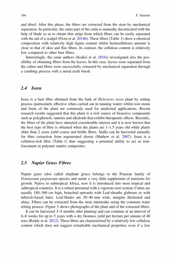
and dried. After this phase, the fibres are extracted from the stem by mechanicalseparation. In particular, the outer part of the culm is manually decorticated with thehelp of blade so as to obtain thin strips from which fibres can be easily separatedwith the aid of a scalpel (Fiore et al. 2014b). These fibres (Table 1) show a chemicalcomposition with relatively high lignin content whilst hemicelluloses amount isclose to that of okra and flax fibres. In contrast, the cellulose content is relativelylow compared to other bast fibres.
Interestingly, the same authors (Scalici et al. 2016)) investigated also the pos-sibility of obtaining fibres from the leaves. In this case, leaves were separated fromthe culms and fibres were successfully extracted by mechanical separation througha combing process with a metal teeth brush.
2.4 Isora
Isora is a bast fibre obtained from the bark of Helicteres isora plant by rettingprocess (particularly effective when carried out in running water) whilst root stemsand fruits of the plant are commonly used for medicinal applications. Recentresearch results suggested that this plant is a rich source of bioactive compoundssuch as polyphenols, tannins and alkaloids that exhibit therapeutic effects. Recently,the fibres of the plant have attracted considerable interest and it is now known thatthe best type of fibre is obtained when the plants are 1–1.5 years old while plantsolder than 2 years yield coarse and brittle fibres. Stalks can be harvested annuallyfor fibre extraction from regenerated shoots (Mathew et al. 2007). Isora is acellulose-rich fibre (Table 1) thus suggesting a potential ability to act as rein-forcement in polymer matrix composites.
2.5 Napier Grass Fibres
Napier grass (also called elephant grass) belongs to the Poaceae family ofPennisetum purpureum species and needs a very little supplement of nutrients forgrowth. Native to subtropical Africa, now it is introduced into most tropical andsubtropical countries. It is a robust perennial with a vigorous root system. Culms areusually 180–360 cm high, branched upwards with Leaf-sheaths glabrous or withtubercle-based hairs. Leaf-blades are 20–40 mm wide, margins thickened andshiny. Fibres can be extracted from the stem internodes using the common waterretting process. Figure 5 shows photographs of the plant and of the extracted fibres.
It can be harvested 3–4 months after planting and can continue at an interval of6–8 weeks for up to 5 years with a dry biomass yield per hectare per annum of 40tons (Reddy et al. 2012). These fibres are characterized by a relatively low cellulosecontent which does not suggest remarkable mechanical properties even if a low
186 F. Sarasini

density has been reported (Rao et al. 2007). The morphology is the typical multi-cellular structure highly porous in nature, as can be seen in Fig. 6.
2.6 Cissus Quadrangularis
Cissus quadrangularis is a perennial plant belonging to the Vitaceae (grape) familythat is probably native to India or Srilanka, but is also found in Africa, Arabia andSouth Asia (Indran et al. 2014). This plant has medicinal value (Panthong et al.2007; Bhujade et al. 2012; Sapsrithong et al. 2012) and is rich in fibre content in itsroots as well as in the stem. This perennial climber can reach a height of around2.5 m and has quadrangular sectioned stems with internodes of 1.5–1.8 cm widthand 10–15 cm length (Indran et al. 2014) (Fig. 7).
Fig. 5 a Pennisetum purpureum grass and b the extracted P. purpureum fibres [Reprinted withpermission from Elsevier (Ridzuan et al. 2016a)]
Fig. 6 SEM micrograph ofthe cross section ofPennisetum purpureum fibre[Reprinted with permission byElsevier (Ridzuan et al.2016a)]
Mechanical and Thermal Properties of Less Common Natural Fibres … 187

Stem and root fibres can be extracted through water soaking to allow formicrobial degradation. After being washed and dried in natural sunlight, combingwas used with a metal brush to obtain long and uniform fibres. From a chemicalpoint of view, stem and root fibres were found to exhibit similar percentages ofmain constituents, i.e. cellulose, hemicelluloses and lignin. In particular, both fibresshowed a high content of cellulose (higher than 70%) which ensures goodmechanical properties and a relatively low hemicellulose content (about 10%)which is the main hydrophilic constituent in natural fibres. It is also worth notingthe low wax content (less than 0.2%) which could be responsible for a betterbonding with polymer matrices. A low microfibril angle (about 5°) was found forboth fibres with a degree of cellulose crystallinity around 50% which is in line withvalues of other bast and leaf fibres (Sreenivasan et al. 2011). These fibres exhibiteda surface morphology characterized by the presence of shallow pores and impuritieswhich increase the surface roughness of the fibres, as can be clearly noted in Fig. 8.
3 Thermal and Mechanical Properties of Less CommonNatural Fibres
This paragraph addresses the thermal and mechanical properties of several naturalfibres which are suitable to be used as reinforcement in polymer matrix composites.For better clarity, the mechanical properties of several less common natural fibresare reported and compared with those of commonly used natural fibres in Table 2.
Fig. 7 Cissus quadrangularis plant with its extracted a root and b stem fibres [Reprinted withpermission from Elsevier (Indran et al. 2014; Indran and Raj 2015)]
188 F. Sarasini

Fig. 8 SEM micrographs of Cissus quadrangularis fibres extracted from a stem and b root[Reprinted with permission from Elsevier (Indran et al. 2014; Indran and Raj 2015)]
Mechanical and Thermal Properties of Less Common Natural Fibres … 189

Tab
le2
Mechanicalprop
ertiesof
common
andless
common
naturalfibres
Category
Fibretype
Diameter
(lm)
Tensile
strength
(MPa)
Young
’smodulus
(GPa)
Elongationat
break
(%)
Source
Leaf
Sisal
50–200
80–640
1.46
–15.8
3–7
Jayaraman
(2003),Mishraet
al.(2004),Fu
quaet
al.(2012)
Abaca
28756
31.1
2.9
Shibataet
al.(2002)
Henequen
180
500
13.2
4.8
Herrera-FrancoandValadez-G
onzalez(2005)
Pineapple
20–80
413–
1627
34.5–82.5
0.8–
1.6
Mishraet
al.(2004)
Banana
50–280
529–
914
7.7–
321.8–
3.7
Fuquaet
al.(2012)
Curaua
9–10
913
303.9
Gom
eset
al.(2007)
Datepalm
100–
1000
170–
275
5–12
5–10
Al–Khanbashi
etal.(2005)
Phormium
tenax
100–
140
465–
770
23–27
2–5
DeRosaet
al.(2010a)
Sansevieria
80–90
630–
670
5–7.5
10–12
Munaw
aret
al.(2006),Sreenivasanet
al.(2011)
Buriti
150–
170
735±
168
27±
52.7±
0.4
Ornaghi
Júnior
etal.(2016)
Bast
Flax
30–110
450–
1500
27.6–38
1.5–
3.2
Barkoulaetal.(2009
),Malkapuram
etal.(2009
),Arias
etal.
(2013)
Hem
p53.7
690–
873
9.93
1.6–
4.7
Graupneret
al.(2009),Fu
quaet
al.(2012)
Jute
25–200
393–
773
2.5–
26.5
1–2
Malkapuram
etal.(2009),Fu
quaet
al.(2012)
Kenaf
43.3–140
223–
624
11–14.5
2.7–
5.7
Malkapuram
etal.(2009),Fu
quaet
al.(2012)
Ram
ie34
400–
938
24.5–128
1.2–
3.8
Angeliniet
al.(2000),Godaet
al.(2006b
)
Okra
40–180
234–
380
5–13
1.8–
2.1
DeRosaet
al.(2010b
),(2011)
Arundodonax
450–
700
248
9.4
3.24
Fioreet
al.(2014b
)
Veldt
grape(1)
770–
870
2300
–5479
56–234
3.75
–11.14
Indran
andRaj
(2015)
Veldt
grape(2)
–61.42±
17.3
1.1±
0.3
5.6±
1.37
Mayandi
etal.(2015a)
Isora
10561–
600
19–22
5–6
Joshyet
al.(2007a),Mathew
etal.(2007)
Thespesia
64573±
1561.2
±12
0.79
±0.11
Reddy
etal.(2014)
(con
tinued)
190 F. Sarasini

Tab
le2
(con
tinued)
Category
Fibretype
Diameter
(lm)
Tensile
strength
(MPa)
Young
’smodulus
(GPa)
Elongationat
break
(%)
Source
Marshmallow
156–
194
415.2±
11.5
65.4
±7.2
3.9
Sarikanatet
al.(2014)
Chakshir
90–300
475.6±
15.7
52.7
±3.7
4.2±
0.2
Seki
etal.(2013)
Lygeum
spartum
180–
433
64.63–
280.03
4.47
–13.27
1.49
–3.74
Belouadah
etal.(2015)
Hop
–4.1±
1.9(g/den)
161±
57(g/den)
3.3±
1.2
Reddy
andYang(2009)
Prosopis
julifl
ora
–558±
13.4
–1.77
±0.04
Saravanakumar
etal.(2013)
Artichoke
100–
300
100–
300
5–15
2.5–
3Fioreet
al.(2011)
Fruit/
seed
Cotton
15.6–21
287–
800
1.1–
12.6
6–9.7
Malkapuram
etal.(2009),Fu
quaet
al.(2012)
Coir
40–450
106–
175
1.27
–6
15–59.9
Satyanarayanaet
al.(1986),Malkapuram
etal.(2009)
Borassus
130–
280
50.9–65.2
1.22
–4.91
41.2–47.2
Reddy
etal.(2009a)
Grasses
Straw-W
heat
84–94
59–140
3.7–
4.8
–Sain
andPanthapulakkal
(2006,
Fuquaet
al.(2012)
Alfa(Esparto)
–350
225.8
Fuquaet
al.(2012)
Bam
boo
88–125
140–
441
11–36
1.3–
8Okubo
etal.(2004),Fu
quaet
al.(2012)
Napiergrass
210–
270
73–75
5.68
–6.8
1.4–
2.8
Reddy
etal.(2012),Ridzuan
etal.(2016a)
Root
Veldt
grape
610–
725
1857
–5330
68–203
3.57
–8.37
(Indranet
al.2014
)
Manmade
E-glass
9.8–
172000
–3500
700.5–
4.8
Thomason
(1999),Fu
quaet
al.(2012)
Aramid
123000
–3150
63–130
3.3–
3.7
Fuquaet
al.(2012)
Carbon
5–17
4000
230–
240
1.4–
1.8
Fuquaet
al.(2012)
Mechanical and Thermal Properties of Less Common Natural Fibres … 191

3.1 Okra
Comparing the chemical composition of okra fibres to that of other bast or leaffibres (Table 1), similarities are evident that suggest also comparable thermalbehaviour and stability. It is well-known that a key limiting factor in the use ofnatural fibres as reinforcement in biocomposites is their low thermal stability. Thethermal stability of okra fibres was investigated by thermogravimetric analysis byDe Rosa et al. ( 2010b) in nitrogen atmosphere (250 ml/min) from 30 to 600 °C at aheating rate of 10 °C/min. In Fig. 9 are reported the typical TG and DTG curves ofokra fibres.
The thermogravimetric signal showed three weight loss steps, while thedecomposition occurred in two main stages. An initial weight loss (*8%) wasobserved between 30 and 110 °C which was related to the vaporization of thewater, whilst the onset degradation for the okra fibres was found to occur after220 °C. Above this temperature, the thermal stability gradually decreased. In par-ticular, the first stage TI (220–310 °C) was due to the thermal depolymerization ofhemicellulose, pectin and the cleavage of glycosidic linkages of cellulose (weightloss of 16.1%) whilst the second one (TII) occurred in the range (310–390 °C) andcorresponded to the degradation of a-cellulose in the fibre (weight loss of 60.6%).In general, the decomposition of lignin, owing to its complex structure, tends tooccur within the whole temperature range. These results are also confirmed by DTGcurve where the maximum decomposition rates for the weight losses are shown.Furthermore, it has been observed a residual weight percentage of 7.6% which canbe ascribed to carbonaceous residues and possible undegraded fillers. From theseresults, it can be concluded that the thermal stability of okra fibres is comparable tothat of many vegetable fibres (Wielage et al. 1999; Ouajai and Shanks 2005; Yao
Fig. 9 TG and DTG curves of okra fibres [Reprinted with permission by Elsevier (De Rosa et al.2010b)]
192 F. Sarasini

et al. 2008). As regards the mechanical properties, okra fibres exhibited a brittlebehaviour and also a large scatter in data from single fibre tensile tests which wassuccessfully modelled with a two-parameter Weibull distribution (Weibull modulusequal to 1.91) (De Rosa et al. 2010b). From Table 2 it can be concluded thatcomparable mechanical behaviour with soft bast fibres, such as kenaf, and leaffibres, such as date palm, henequen and sisal, is evident. From these results, thesuitability of okra fibres as reinforcement in polymer matrix composites can beeasily inferred (Hakeem et al. 2014). In an attempt to increase the interfacialinteraction with polymer matrices, De Rosa et al. (2011) investigated the effects ofseveral chemical treatments on the thermal and mechanical properties of okra fibres.As a general comment, all chemical treatments caused some decrease in mechanicalproperties, particularly of Young’s modulus. In particular, treatments involvingacetylation resulted in a lower level of fibre degradation, whilst bleaching, scouringand particularly permanganate treatment appeared all, at some extent (and ingrowing order), damaging to the fibres. As regards the thermal stability, acetylationand sodium sulphate treatments decreased the thermal stability of the fibre, while inthe case of bleached fibres there was no significant difference in the thermalbehaviour of the treated fibres (both for acetylation and sodium hydroxidetreatment).
3.2 Borassus
Thermal stability of fine and coarse borassus fibres was investigated in (Reddy et al.2009a) using a nitrogen atmosphere at a heating rate of 10 °C/min from 50 to 600 °C.The authors found no significant differences between fine and coarse fibres sug-gesting their use as reinforcement in thermoplastic matrix materials whose processingtemperature is below 270 °C. A slightly higher thermal stability was reported forborassus fibres previously treated in a 5% aqueous sodium hydroxide solution atroom temperature, maintaining a liquor ratio of 30: 1 for 30 min. A marginal dif-ference in the thermal stability of untreated and alkali-treated borassus fibres fordifferent treatment durations (1, 4, 8 and 12 h) in a 5% aqueous sodium hydroxidesolution at room temperature was reported by (Obi Reddy et al. 2013). Alkalitreatment was found not to affect in a significant way the thermal stability of the fibreseven if the mechanical properties were remarkably enhanced after this treatment. Firstof all the authors highlighted the better mechanical properties offine fibres comparedto coarse fibres and secondly the alkali treatment up to a duration of 8 h increasedtensile strength, Young’s modulus and elongation at break with maximumimprovements of 41, 69 and 40%, respectively. A treatment of 12 h was found to bedetrimental for the mechanical properties due to degradation of cellulose occurring atlonger durations. It is to be noted that despite the low mechanical properties ofborassus fibres, the elongation at break is significantly higher compared to bast andleaf fibres, thus suggesting their potential use in hybrid systems aiming at increasingthe ductility of composites while preserving considerable strength and stiffness.
Mechanical and Thermal Properties of Less Common Natural Fibres … 193

3.3 Arundo Donax
The thermal stability of Arundo donax fibres extracted from the stem of the plantwas investigated in (Fiore et al. 2014b) from 30 to 750 °C at a heating rate of10 °C/min in an air atmosphere. The results of the thermogravimetric analysis areshown in Fig. 10.
In addition to the first peak (40–115 °C), due to vaporization of absorbed water, theDTG curve of arundo fibres showed four additional peaks. Thermal degradation ofarundo fibres began at 275 °C (onset degradation temperature) with the first degrada-tion peak occurring at about 295 °C due to the thermal depolymerization of hemicel-luloses and pectin, and the glycosidic linkages of cellulose (12% weight loss). Thesecond peak (320 °C) is ascribed to the degradation of a-cellulose (70% weight loss)with similar degradation occurring at 308.2, 298.2 and 309.2 °C for hemp, jute andkenaffibres, respectively (Yao et al. 2008). The two small peals at 435 °C and 518 °Care instead due to oxidative degradation of the charred residue. Similar thermal stabilitywas found also for arundo fibres extracted from the leaves of the plant, even if thesefibres were reported to be stable until around 210 °C and no additional peaks weredetected after the degradation peak of the a-cellulose at 340 °C, as this time the analysiswas performed in inert atmosphere (Fig. 11) (Scalici et al. 2016).
Plasma treatment did neither affect the thermal behaviour nor the mechanicalproperties of arundo leaf fibres (Scalici et al. 2016) which exhibited lowermechanical properties compared to fibres extracted from the stem. Also, in this
Fig. 10 TG and DTG curves of arundo fibres extracted from stem [Reprinted with permissionfrom Elsevier (Fiore et al. 2014b)]
194 F. Sarasini

case, the mechanical properties were interpreted based on a two-parameter Weibulldistribution (Weibull modulus equal to 1.42 and 3.12 for leaf and stem fibres,respectively). It is also evident that the mechanical properties of arundo fibres arecomparable to those of other natural fibres currently investigated as potentialreinforcement in polymer matrix composites. Moreover, the microfibril angle ofarundo fibres (i.e. 7.37°) is also similar to one of the other natural fibres such as jute(8.1°), flax (5°) and hemp (6.2°), thus confirming their suitability as reinforcementin polymer matrices.
3.4 Isora
Isora fibres exhibited an enhanced thermal stability when treated with alkali and thiswas achieved for two different treatment durations and NaOH concentrations,namely 1% aqueous alkali at 30 °C for 4 h (Joshy et al. 2007a) and 5% NaOH for4 h (Mathew et al. 2007). Major weight loss of untreated fibres took place at about360 °C but this temperature was raised to about 380 °C by mercerization. Thermalstability was also enhanced by a silane treatment even if this effect was less evidentcompared to the alkali treatment (Mathew et al. 2007). These surface treatmentswere beneficial to the thermal stability but affected in a negative way themechanical properties of single isora fibres. In particular, tensile strength decreased
Fig. 11 TG and DTG curves of arundo leaf fibres [Reprinted with permission from Elsevier(Scalici et al. 2016)]
Mechanical and Thermal Properties of Less Common Natural Fibres … 195

from 561 MPa for untreated fibres to 500 and 474 MPa after alkali and silanetreatments, respectively (Mathew et al. 2007). Also, elongation at break wasreported to be slightly influenced by the surface treatments whilst no informationwas provided for Young’s modulus. The decrease in mechanical properties wasascribed by the authors to the partial removal of lignin after chemical treatments.Despite the negative influence of surface treatments, Isora fibres still show a sat-isfactory combination of strength and ductility (*4–5%) to suggest their use incomposite materials.
3.5 Napier Grass Fibres
Mechanical and thermal properties of Napier grass fibres have been the subject ofseveral investigations. Haameem et al. (2014) recently determined that the maxi-mum tensile strength (106.24 MPa) of Pennisetum purpureum single fibres wasachieved with 10% alkali treatment (for 24 h) with 2.19 GPa modulus of elasticity.However, this is in contrast with the results of Reddy et al. (2012) who determinedthat the maximum tensile strength (136 MPa) and Young’s modulus (10.5 GPa)were achieved with 5% alkali treatment (for 30 min at room temperature). Ridzuanet al. (2016a) performed an extensive investigation of the effects of differentalkaline treatments. Alkali solutions of 5, 7, 10, 12 and 15% were applied to thefibres for 24 h at room temperature. The effects of different alkali concentration ontensile strength and Young’s modulus are reported in Fig. 12. With increasingconcentration, the authors noted a reduction in fibre diameter and in moisture
Fig. 12 Tensile strength and Young’s modulus of Napier grass fibres as a function of alkaliconcentration (Ridzuan et al. 2016a)
196 F. Sarasini
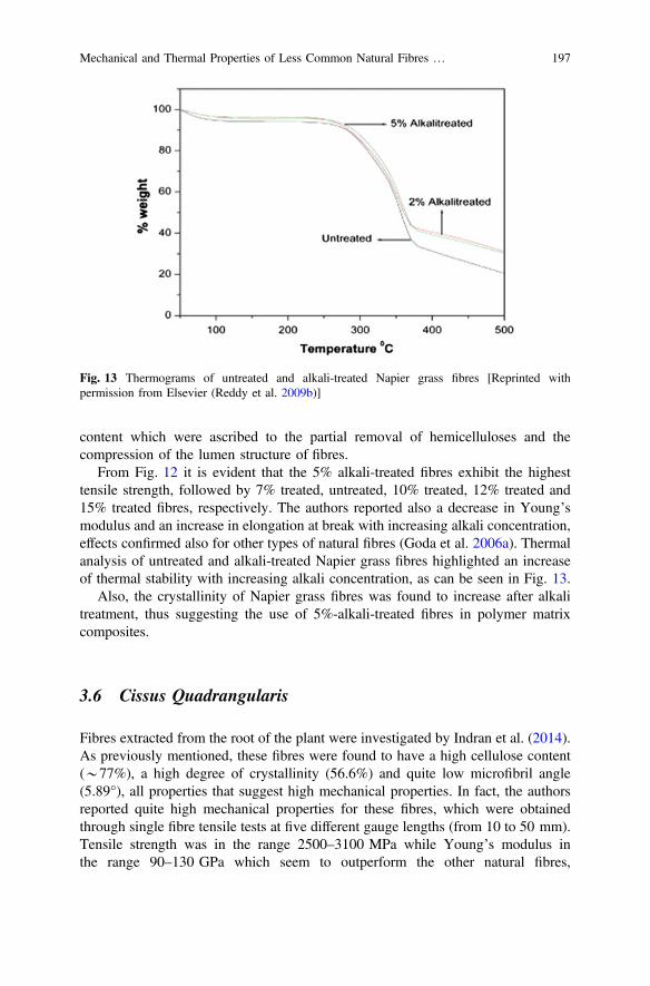
content which were ascribed to the partial removal of hemicelluloses and thecompression of the lumen structure of fibres.
From Fig. 12 it is evident that the 5% alkali-treated fibres exhibit the highesttensile strength, followed by 7% treated, untreated, 10% treated, 12% treated and15% treated fibres, respectively. The authors reported also a decrease in Young’smodulus and an increase in elongation at break with increasing alkali concentration,effects confirmed also for other types of natural fibres (Goda et al. 2006a). Thermalanalysis of untreated and alkali-treated Napier grass fibres highlighted an increaseof thermal stability with increasing alkali concentration, as can be seen in Fig. 13.
Also, the crystallinity of Napier grass fibres was found to increase after alkalitreatment, thus suggesting the use of 5%-alkali-treated fibres in polymer matrixcomposites.
3.6 Cissus Quadrangularis
Fibres extracted from the root of the plant were investigated by Indran et al. (2014).As previously mentioned, these fibres were found to have a high cellulose content(*77%), a high degree of crystallinity (56.6%) and quite low microfibril angle(5.89°), all properties that suggest high mechanical properties. In fact, the authorsreported quite high mechanical properties for these fibres, which were obtainedthrough single fibre tensile tests at five different gauge lengths (from 10 to 50 mm).Tensile strength was in the range 2500–3100 MPa while Young’s modulus inthe range 90–130 GPa which seem to outperform the other natural fibres,
Fig. 13 Thermograms of untreated and alkali-treated Napier grass fibres [Reprinted withpermission from Elsevier (Reddy et al. 2009b)]
Mechanical and Thermal Properties of Less Common Natural Fibres … 197

being comparable to the absolute values of glass fibres. These results are quitesurprising, even considering that the authors found an increasing tendency of bothstrength and Young’s modulus with increasing gauge length. Tensile strength andYoung’s modulus are indeed highly dependent on gauge length but usually, at shortgauge lengths the strength values are higher and decrease with increasing fibrelength (Defoirdt et al. 2010; De Rosa et al. 2010a; Bezazi et al. 2014; Sarasini et al.2015). The dependence of failure strength on clamping length is a well-knowncharacteristic of all fibres, which can be explained by the distribution of defectswithin the fibres. The longer the stressed length, the higher the number of defectspresent in the stressed fibre portion, contributing to the weakening of its structure.As regards the thermal stability, an initial weight loss was reported at around 89 °C,which was attributed to the removal of moisture content from the fibre. The fibrewas thermally stable up to around 230 °C. After 230 °C and up to 330 °C a weightreduction, corresponding to the thermal decomposition of the hemicellulose andglycosidic linkages of cellulose, occurred. Two additional small peaks wereobserved at 481 and 696 °C due to degradation and pyrolysis of lignin, respec-tively. The same authors reported also the characterization (Indran and Raj 2015) offibres extracted from the stem of the same plant. Also, in this case, the fibresshowed extremely high mechanical properties, with tensile strength in the range2300–4200 MPa and Young’s modulus in the range 56–130 GPa.
The thermal stability was found to be higher compared to that of fibres extractedfrom the root even if the degradation pattern was similar, as confirmed by thethermogram reported in Fig. 14. These results are in contrast with what reported byMayandi et al. (2015a) who, while comparing the properties of Cissus quadran-gularis and Phoenix reclinata natural fibres, reported a high value of cellulose
Fig. 14 TG and DTG curves of the Cissus quadrangularis stem fibres [Reprinted with permissionfrom Elsevier (Indran and Raj 2015)]
198 F. Sarasini
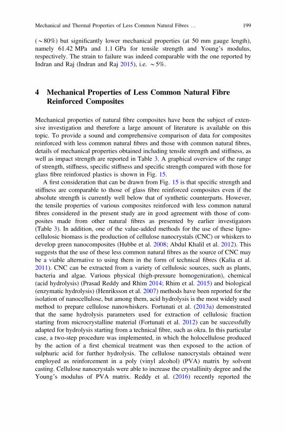
(*80%) but significantly lower mechanical properties (at 50 mm gauge length),namely 61.42 MPa and 1.1 GPa for tensile strength and Young’s modulus,respectively. The strain to failure was indeed comparable with the one reported byIndran and Raj (Indran and Raj 2015), i.e. *5%.
4 Mechanical Properties of Less Common Natural FibreReinforced Composites
Mechanical properties of natural fibre composites have been the subject of exten-sive investigation and therefore a large amount of literature is available on thistopic. To provide a sound and comprehensive comparison of data for compositesreinforced with less common natural fibres and those with common natural fibres,details of mechanical properties obtained including tensile strength and stiffness, aswell as impact strength are reported in Table 3. A graphical overview of the rangeof strength, stiffness, specific stiffness and specific strength compared with those forglass fibre reinforced plastics is shown in Fig. 15.
A first consideration that can be drawn from Fig. 15 is that specific strength andstiffness are comparable to those of glass fibre reinforced composites even if theabsolute strength is currently well below that of synthetic counterparts. However,the tensile properties of various composites reinforced with less common naturalfibres considered in the present study are in good agreement with those of com-posites made from other natural fibres as presented by earlier investigators(Table 3). In addition, one of the value-added methods for the use of these ligno-cellulosic biomass is the production of cellulose nanocrystals (CNC) or whiskers todevelop green nanocomposites (Hubbe et al. 2008; Abdul Khalil et al. 2012). Thissuggests that the use of these less common natural fibres as the source of CNC maybe a viable alternative to using them in the form of technical fibres (Kalia et al.2011). CNC can be extracted from a variety of cellulosic sources, such as plants,bacteria and algae. Various physical (high-pressure homogenization), chemical(acid hydrolysis) (Prasad Reddy and Rhim 2014; Rhim et al. 2015) and biological(enzymatic hydrolysis) (Henriksson et al. 2007) methods have been reported for theisolation of nanocellulose, but among them, acid hydrolysis is the most widely usedmethod to prepare cellulose nanowhiskers. Fortunati et al. (2013a) demonstratedthat the same hydrolysis parameters used for extraction of cellulosic fractionstarting from microcrystalline material (Fortunati et al. 2012) can be successfullyadapted for hydrolysis starting from a technical fibre, such as okra. In this particularcase, a two-step procedure was implemented, in which the holocellulose producedby the action of a first chemical treatment was then exposed to the action ofsulphuric acid for further hydrolysis. The cellulose nanocrystals obtained wereemployed as reinforcement in a poly (vinyl alcohol) (PVA) matrix by solventcasting. Cellulose nanocrystals were able to increase the crystallinity degree and theYoung’s modulus of PVA matrix. Reddy et al. (2016) recently reported the
Mechanical and Thermal Properties of Less Common Natural Fibres … 199

Tab
le3
Com
parisonof
mechanicalprop
ertiesof
less
common
naturalfibrecompo
siteswith
othercommon
naturalfibrereinforced
compo
sites
Fibre
Matrix
Fibrecontent(%
)(w
forweightand
vforvolume)
Tensile
strength
(MPa)
Young
’smodulus
(GPa)
Charpy(c)or
Izod
(i)im
pact
strength
(kJ/m
2or
J/m)
Notes
References
Sisal
(unidirectional)
Epoxy
50(v)
*270
*9
–Com
pression
moulding/untreated
Ronget
al.(2001)
Sisal
(unidirectional)
Epoxy
50(v)
*340
*5.8
–Com
pression
moulding/alkali-treated
Ronget
al.(2001)
Sisal
(unidirectional)
Epoxy
50(v)
*260
*4
–Com
pression
moulding/acetylated
Ronget
al.(2001)
Flax
(unidirectional)
Epoxy
42(v)
280
35–
Resin
transfer
moulding/enzymeextracted
Oksman
(2001)
Flax
(unidirectional)
Epoxy
32(v)
132
15–
Resin
transfer
moulding/traditionally
retted
Oksman
(2001)
Flax
(unidirectional)
Epoxy
40(v)
133
28–
Autoclave/untreated
Van
deWeyenberg
etal.(2003)
Phormium
tenax
(unidirectional)
Epoxy
55(w
)223
16.8
–Com
pression
moulding/untreated
LeandPickering
(2015)
Sisal(unidirectional)
Epoxy
46(v)
211
19.7
–Resin
transfer
moulding/untreated
Oksman
etal.(2002)
Flax
(unidirectional)
Epoxy
32(v)
132
15–
Resin
transfer
moulding/untreated
Oksman
etal.(2002)
Flax
(unidirectional)
Epoxy
42(v)
378
39.9
–Autoclave
(prepregs)
Baetset
al.(2014)
Alfa
(alig
ned)
Polyester
32(v)
118
10.2
–Wet
layup/alkalitreatedthen
bleached
Brahim
andCheikh
(2007)
Flax
(random)
Polyester
30(v)
616.3
13.2
(c)
Vacuum
infusion/untreated
Rodriguez
etal.(2005)
Flax
(random)
Acrylic
30(v)
526.3
15.0
(c)
Vacuum
infusion/untreated
Rodriguez
etal.(2005)
Sisal
(random)
Polyester
30(v)
245.3
12.2
(c)
Vacuum
infusion/untreated
Rodriguez
etal.(2005)
(con
tinued)
200 F. Sarasini

Tab
le3
(con
tinued)
Fibre
Matrix
Fibrecontent(%
)(w
forweightand
vforvolume)
Tensile
strength
(MPa)
Young
’smodulus
(GPa)
Charpy(c)or
Izod
(i)im
pact
strength
(kJ/m
2or
J/m)
Notes
References
Sisal
(random)
Acrylic
30(v)
313.4
12.7
(c)
Vacuum
infusion/untreated
Rodriguez
etal.(2005)
PALF
(random)
Polyester
30(w
)52.9
2.29
24.2
(c)
Com
pression
moulding/untreated
UmaDeviet
al.(1997)
PALF
(random)
Polyester
30(w
)55.4
1.46
–Com
pression
moulding/alkalitreated
UmaDeviet
al.(1997)
Flax
(alig
ned)
PP51
(v)
287.5
28.7
–Com
pression
moulding/untreated
MadsenandLilh
olt
(2003)
Flax
(unidirectional)
PP43
(v)
251
26.9
–Com
pression
moulding/untreated
MadsenandLilh
olt
(2003)
Hem
p(unidirectional)
PP42
(v)
215
21.1
–Com
pression
moulding/untreated
Madsenet
al.(2009)
E-glass
(unidirectional)
PP35
(v)
700
26.5
–Com
pression
moulding
Shah
(2013)
Flax
(2D-random)
Epoxy
22(v)
609.2
13.09(c)
Autoclave
moulding/alkalitreated(1%)
Georgeet
al.(1999)
Flax
(2D-random)
Epoxy
22(v)
62.54
9.83
8.41
(c)
Autoclave
moulding/3-am
inopropyltriethoxysilane
Georgeet
al.(1999)
Flax
(2D-random)
Epoxy
22(v)
53.40
7.86
10.47(c)
Autoclave
moulding/untreated
Georgeet
al.(1999)
Flax
(3D-random)
PP30
(w)
271.7
–Injectionmoulding/untreated
Arbelaizet
al.(2005)
Flax
(3D-random)
PP30
(w)
36.9
2.13
–Injectionmoulding/5wt%
MAPP
Arbelaizet
al.(2005)
Hem
p(3D-random)
PP30
(w)
301.5
–Injectionmoulding/alkylketene
dimmer
Mutje
etal.(2006)
(con
tinued)
Mechanical and Thermal Properties of Less Common Natural Fibres … 201

Tab
le3
(con
tinued)
Fibre
Matrix
Fibrecontent(%
)(w
forweightand
vforvolume)
Tensile
strength
(MPa)
Young
’smodulus
(GPa)
Charpy(c)or
Izod
(i)im
pact
strength
(kJ/m
2or
J/m)
Notes
References
E-glass
(3D-random)
PP30
(w)
492.2
–Injectionmoulding
Mutje
etal.(2006)
Jute
(3D-random)
PP60
(w)
7411
195(i)
Injectionmoulding/3wt%
MAPP
Ranaet
al.(1998)
Ram
ie(3D-random)
PLA
30(v)
52.5
–10
(i)
Two-rollmill/untreated
Yuet
al.(2010)
Ram
ie(3D-random)
PLA
30(v)
59.3
–17
(i)
Two-rollmill/3-A
minopropyltriethox
ysilane
Yuet
al.(2010)
Ram
ie(3D-random)
PLA
30(v)
66.8
–22.5
(i)
Two-rollmill/alkalitreated(5%
w/v)
Yuet
al.(2010)
Flax
(2D-random)
PHB
30(v)
404.2
–Com
pression
moulding/untreated
Bodroset
al.(2007)
Okra
(2D-random)
Starch
25(w)
2.21
0.24
–Com
pression
moulding/untreated
Guleira
etal.(2016)
Okra
(3D-random)
PLA
30(w)
58.8
4.6
–Injectionmoulding/untreated
Fortunatiet
al.(2013b
)
Okra
(3D-random)
PLA
30(w)
55.3
3.86
–Injectionmoulding/alkalitreated
Fortunatiet
al.(2013b
)
Borassusfine
fibres
(3D-random)
PP
15(w)
282.5
27.5
(i)
Injectionmoulding/alkalitreated(4%)+5wt%
MAPP
Sudhakaraet
al.
(2013a)
Borassusfine
fibres
(3D-random)
PP
5(w)
231.4
25(i)
Injectionmoulding/alkalitreated(4%)+5wt%
MAPP
Sudhakaraet
al.
(2013b
)
Borassusfine
fibres
(3D-random)
HDPE
20(w)
20.1
0.53
80(i)
Injectionmoulding/untreated
Maheswarietal.(2013)
Borassusfine
fibres
(3D-random)
HDPE
20(w)
23.2
0.64
95(i)
Injectionmoulding/5wt%
MA-g-H
DPE
Maheswarietal.(2013)
(con
tinued)
202 F. Sarasini
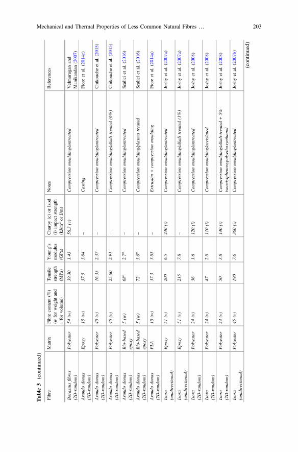
Tab
le3
(con
tinued)
Fibre
Matrix
Fibrecontent(%
)(w
forweightand
vforvolume)
Tensile
strength
(MPa)
Young
’smodulus
(GPa)
Charpy(c)or
Izod
(i)im
pact
strength
(kJ/m
2or
J/m)
Notes
References
Borassusfibres
(2D-random)
Polyester
54(w)
39.30
1.43
56.3
(c)
Com
pression
moulding/untreated
Velmurugan
and
Manikandan(2007)
Arundodonax
(3D-random)
Epoxy
15(w)
37.5
3.04
–Castin
gFioreet
al.(2014c)
Arundodonax
(2D-random)
Polyester
40(v)
16.35
2.37
–Com
pression
moulding/untreated
Chikouche
etal.(2015)
Arundodonax
(2D-random)
Polyester
40(v)
25.60
2.91
–Com
pression
moulding/alkalitreated(6%)
Chikouche
etal.(2015)
Arundodonax
(2D-random)
Bio-based
epoxy
5(w)
68a
2.7a
–Com
pression
moulding/untreated
Scaliciet
al.(2016)
Arundodonax
(2D-random)
Bio-based
epoxy
5(w)
72a
3.0a
–Com
pression
moulding/plasmatreated
Scaliciet
al.(2016)
Arundodonax
(2D-random)
PLA
10(w)
37.3
3.85
–Extrusion
+compression
moulding
Fioreet
al.(2014a)
Isora
(unidirectional)
Epoxy
51(v)
200
6.5
240(i)
Com
pression
moulding/untreated
Joshyet
al.(2007a)
Isora
(unidirectional)
Epoxy
51(v)
215
7.8
–Com
pression
moulding/alkalitreated(1%)
Joshyet
al.(2007a)
Isora
(2D-random)
Polyester
24(v)
361.6
120(i)
Com
pression
moulding/untreated
Joshyet
al.(2008)
Isora
(2D-random)
Polyester
24(v)
472.8
110(i)
Com
pression
moulding/acetylated
Joshyet
al.(2008)
Isora
(2D-random)
Polyester
24(v)
503.8
140(i)
Com
pression
moulding/alkali-treated+5%
isooctylphenoxypolyethoxyethanol
Joshyet
al.(2008)
Isora
(unidirectional)
Polyester
45(v)
190
7.6
360(i)
Com
pression
moulding/untreated
Joshyet
al.(2007b
)
(con
tinued)
Mechanical and Thermal Properties of Less Common Natural Fibres … 203

Tab
le3
(con
tinued)
Fibre
Matrix
Fibrecontent(%
)(w
forweightand
vforvolume)
Tensile
strength
(MPa)
Young
’smodulus
(GPa)
Charpy(c)or
Izod
(i)im
pact
strength
(kJ/m
2or
J/m)
Notes
References
Isora
(unidirectional)
Polyester
45(v)
230
8.4
–Com
pression
moulding/alkalitreated(1%)
Joshyet
al.(2007b
)
Isora
(3D-random)
Natural
rubber
15(w)
142.71
MPa
–Tw
o-rollmixing/untreated
Mathew
andJoseph
(2007)
Napiergrass
(unidirectional)
Polyester
31(v)
118
2.17
–Com
pression
mouldingchem
ically
extracted
(NaO
H)
Rao
etal.(2007)
Napiergrass
(2D-random)
Polyester
25(v)
18.17
2–
Com
pression
moulding/untreated
Haameem
etal.(2016)
Napiergrass
(2D-random)
Epoxy
30(v)
211.9
–Vacuum
infusion/untreated
Ridzuan
etal.(2016b
)
Cissusquadrangularis
(2D-random)
Polyester
40(w)
27.34
1.19
39.91(i)
Com
pression
moulding/untreated
Mayandi
etal.(2016)
Cissusquadrangularis
(2D-random)
Polyester
40(w)
33.41
1.84
43.1
(i)
Com
pression
moulding/alkalitreated(5%)
Mayandi
etal.(2016)
Cissusquadrangularis
(2D-random)
Polyester
40(w)
35.62
2.20
44.75(i)
Com
pression
moulding/Ca(OH) 2
treated
Mayandi
etal.(2016)
Cissusquadrangularis
(2D-random)
Polyester
40(w)
31.38
1.75
41.28(i)
Com
pression
moulding/NaO
H+silane
treated
(trichloro
vinylsilane)
Mayandi
etal.(2016)
Cissusquadrangularis
(2D-random)
Polyester
40(w)
27.34
1.19
39.91(i)
Com
pression
moulding/untreated
Mayandi
etal.(2015b
)
aFlexural
properties
PP=polypropylene
PLA
=poly-lactic
acid
PHB=poly
(3-hydroxylbutyrate
HDPE=High-density
polyethylene
204 F. Sarasini

extraction of cellulose microfibers from Borassus fibres by acidified chlorinationwith alkalization and subsequent acid hydrolysis. The values of crystallinity cal-culated for raw fibres and cellulose microfibres were found to be 40.6 and 77.3%,respectively. Thermal stability of the cellulose microfibres was considerablyimproved with the onset decomposition at 250 °C, 40° higher than the one of theraw fibres. Chirayil et al. (2014a) successfully isolated cellulose nanofibrils fromisora fibres by steam explosion method. Fibres were first treated with 2 wt% NaOHin an autoclave and kept under 25 psi pressure and at a temperature of 110 °C for1 h. Then the pressure was released immediately and the fibres were washed inwater. Then the fibres were bleached (NaOH and acetic acid), washed and driedbefore being subjected to acid hydrolysis using 10% oxalic acid under a pressure of25 psi in an autoclave for 15 min. The pressure was released immediately and theprocess was repeated eight times. The fibres were finally taken out, washed, sus-pended in water and homogenized under continuous stirring. Atomic forcemicroscopy indicated a width of 20 ± 10 nm with an aspect ratio of 15 for isorananofibrils. These nanofibrils exhibited also a high crystalline nature (90%) andgood thermal stability. Isora nanofibrils were used as a reinforcement in a polyestermatrix (Chirayil et al. 2014b) and the resulting nanocomposites exhibited a per-centage increase in tensile strength at 0.5 wt% of nanofibrils of 57% compared tothe neat matrix. The presence of isora nanofibrils at a concentration of 0.5 wt% was
Fig. 15 Comparison of the absolute and specific tensile properties of plant fibre reinforcedplastics (PFRPs) with E-glass reinforced plastics (GFRPs) [Reprinted with permission fromElsevier (Shah 2014)]
Mechanical and Thermal Properties of Less Common Natural Fibres … 205

found also to increases the Tg of the polyester matrix by 10 °C. In this case, a strongpolymer chain confinement effect associated with network formation amongnanofibrils and hydrogen bonding interaction between nanofibrils and polyesterchains elucidated the superior mechanical and barrier properties of the nanocom-posites. Lu et al. (2014) used Pennisetum sinese Roxb as a cellulose source for theextraction of cellulose nanocrystals. Pennisetum sinese is a kind of hybrid ofPennisetum purpureum and Pennisetum americanum, a perennial grass that formsin robust bamboo-like clumps. Cellulose was extracted from Pennisetum sinesewith alkaline hydroxide and then bleached with sodium hypochlorite. From thiscellulose, CNCs were obtained through hydrolysis with 50% sulfuric acid at 65 °Cunder ultrasonic treatment with continuous stirring. The extracted CNC showed arod-like shape with a diameter in the range 20–30 nm and a length of 200–300 nm,forming an interconnected web-like structure with a crystallinity index of about77.3%, thus confirming its application in polymer nanocomposites.
5 Conclusions and Future Perspectives
Several unusual natural fibres have been investigated and their thermal andmechanical behaviour compared with the one typical of common natural fibres suchas sisal, hemp, flax and jute. The results suggest that there is scope in continuing theintegration of new natural fibres in polymer composites with a view to contributingto increase the production of natural reinforcements and expand their use into newapplications. Despite the promising and in some cases comparable results withstandard natural fibres, a more detailed investigation of the mechanical properties ofsingle fibres as well as the effects of surface treatments on the behaviour of singleplant fibres is strongly advised and necessary. Another issue that needs to beaddressed is the fabrication of hybrid composites by combining all these lignocel-lulosics to achieve further performance improvements. There is also a strong need toaddress the durability of the resulting composites along with the biodegradabilitywhen aiming to 100% bio-based composites application, especially when dealing forinstance with semi-structural parts of exterior panels for future automotive appli-cations. More aspects have to be considered such as reproducibility of these com-posites’ properties and their long life cycle, all topics that are lacking in the currentavailable literature. Despite these concerns, the use of these fibres in compositeapplications can definitely establish an entirely new value chain for the crops.
References
Abdul Khalil HPS, Bhat AH, Ireana Yusra AF (2012) Green composites from sustainable cellulosenanofibrils: A review. Carbohydr Polym 87:963–979. doi:10.1016/j.carbpol.2011.08.078
Akil HM, Omar MF, Mazuki AAM et al (2011) Kenaf fiber reinforced composites: a review. MaterDes 32:4107–4121. doi:10.1016/j.matdes.2011.04.008
206 F. Sarasini

Al-Khanbashi A, Al-Kaabi K, Hammami A (2005) Date palm fibers as polymeric matrixreinforcement: fiber characterization. Polym Compos 26:486–497
Andreu-Rodriguez J, Medina E, Ferrandez-Garcia MT et al (2013) Agricultural and industrialvalorization of Arundo donax L. Commun Soil Sci Plant Anal 44:598–609. doi:10.1080/00103624.2013.745363
Angelini L, Lazzeri A, Levita G et al (2000) Ramie (Boehmeria nivea L.) and Spanish Broom(Spartium junceum L.) fibres for composite materials: agronomical aspects, morphology andmechanical properties. Ind Crops Prod 11:145–161
Angelini LG, Ceccarini L, Bonari E (2005) Biomass yield and energy balance of giant reed(Arundo donax L.) cropped in central Italy as related to different management practices. Eur JAgron 22:375–389. doi:10.1016/j.eja.2004.05.004
Angelini LG, Ceccarini L, Nassi o Di Nasso N, Bonari E (2009) Comparison of Arundo donax L.and Miscanthus x giganteus in a long-term field experiment in Central Italy: Analysis ofproductive characteristics and energy balance. Biomass Bioener 33:635–643. doi:10.1016/j.biombioe.2008.10.005
Arbelaiz A, Fernández B, Cantero G et al (2005) Mechanical properties of flax fibre/polypropylenecomposites. Influence of fibre/matrix modification and glass fibre hybridization. ComposPart A Appl Sci Manuf 36:1637–1644. doi:10.1016/j.compositesa.2005.03.021
Arias A, Heuzey M-C, Huneault MA (2013) Thermomechanical and crystallization behavior ofpolylactide-based flax fiber biocomposites. Cellulose 20:439–452
Arifuzzaman Khan GM, Shaheruzzaman M, Rahman MH et al (2009) Surface modification ofokra bast fiber and its physico-chemical characteristics. Fibers Polym 10:65–70
Baets J, Plastria D, Ivens J, Verpoest I (2014) Determination of the optimal flax fibre preparationfor use in unidirectional flax-epoxy composites. J Reinf Plast Compos 33:493–502. doi:10.1177/0731684413518620
Barkoula N, Garkhail S, Peijs T (2009) Effect of compounding and injection molding on themechanical properties of flax fiber polypropylene composites. J Reinf Plast Compos 29:1366–1385
Belouadah Z, Ati A, Rokbi M (2015) Characterization of new natural cellulosic fiber from Lygeumspartum L. Carbohydr Polym 134:429–437. doi:10.1016/j.carbpol.2015.08.024
Bezazi A, Belaadi A, Bourchak M et al (2014) Novel extraction techniques, chemical andmechanical characterisation of Agave americana L. natural fibres. Compos Part B Eng 66:194–203. doi:10.1016/j.compositesb.2014.05.014
Bhujade AM, Talmale S, Kumar N et al (2012) Evaluation of Cissus quadrangularis extracts as aninhibitor of COX, 5-LOX, and proinflammatory mediators. J Ethnopharmacol 141:989–996.doi:10.1016/j.jep.2012.03.044
Bledzki A, Gassan J (1999) Composites reinforced with cellulose based fibres. Prog Polym Sci24:221–274
Bledzki A, Reihmane S, Gassan J (1996) Properties and modification methods for vegetable fibersfor natural fiber composites. J Appl Polym Sci 59:1329–1336
Bodros E, Pillin I, Montrelay N, Baley C (2007) Could biopolymers reinforced by randomlyscattered flax fibre be used in structural applications? Compos Sci Technol 67:462–470. doi:10.1016/j.compscitech.2006.08.024
Boose AB, Holt JS (1999) Environmental effects on asexual reproduction in Arundo donax. WeedRes 39:117–127. doi:10.1046/j.1365-3180.1999.00129.x
Ben Brahim S, Ben Cheikh R (2007) Influence of fibre orientation and volume fraction on thetensile properties of unidirectional Alfa-polyester composite. Compos Sci Technol 67:140–147. doi:10.1016/j.compscitech.2005.10.006
Carr D, Cruthers N, Laing R, Niven B (2005) Fibers from three cultivars of New Zealand flax(phormium tenax). Text Res J 75:93–98
Chikouche MDL, Merrouche A, Azizi A et al (2015) Influence of alkali treatment on themechanical properties of new cane fibre/polyester composites. J Reinf Plast Compos 34:1329–1339. doi:10.1177/0731684415591093
Mechanical and Thermal Properties of Less Common Natural Fibres … 207

Chirayil CJ, Joy J, Mathew L et al (2014a) Isolation and characterization of cellulose nanofibrilsfrom Helicteres isora plant. Ind Crops Prod 59:27–34. doi:10.1016/j.indcrop.2014.04.020
Chirayil CJ, Joy J, Mathew L et al (2014b) Nanofibril reinforced unsaturated polyesternanocomposites: morphology, mechanical and barrier properties, viscoelastic behavior andpolymer chain confinement. Ind Crops Prod 56:246–254. doi:10.1016/j.indcrop.2014.03.005
Corrêa AC, Morais Teixeira E, Pessan LA, Mattoso LHC (2010) Cellulose nanofibers from curauafibers. Cellulose 17:1183–1192. doi:10.1007/s10570-010-9453-3
De Rosa IM, Kenny JM, Maniruzzaman M et al (2011) Effect of chemical treatments on themechanical and thermal behaviour of okra (Abelmoschus esculentus) fibres. Compos SciTechnol 71:246–254. doi:10.1016/j.compscitech.2010.11.023
De Rosa IM, Kenny JM, Puglia D et al (2010a) Tensile behavior of New Zealand flax (Phormiumtenax) fibers. J Reinf Plast Compos 29:3450–3454. doi:10.1177/0731684410372264
De Rosa IM, Kenny JM, Puglia D et al (2010b) Morphological, thermal and mechanicalcharacterization of okra (Abelmoschus esculentus) fibres as potential reinforcement in polymercomposites. Compos Sci Technol 70:116–122. doi:10.1016/j.compscitech.2009.09.013
De Rosa IM, Santulli C, Sarasini F (2010c) Mechanical and thermal characterization of epoxycomposites reinforced with random and quasi-unidirectional untreated Phormium tenax leaffibers. Mater Des 31:2397–2405. doi:10.1016/j.matdes.2009.11.059
Defoirdt N, Biswas S, De Vriese L et al (2010) Assessment of the tensile properties of coir,bamboo and jute fibre. Compos Part A Appl Sci Manuf 41:588–595. doi:10.1016/j.compositesa.2010.01.005
Fangueiro R, Rana S (eds) (2016) Natural fibres: advances in science and technology towardsindustrial applications. Springer, Netherlands, Dordrecht
Fiore V, Botta L, Scaffaro R et al (2014a) PLA based biocomposites reinforced with Arundo donaxfillers. Compos Sci Technol 105:110–117. doi:10.1016/j.compscitech.2014.10.005
Fiore V, Scalici T, Valenza A (2014b) Characterization of a new natural fiber from Arundo donaxL. as potential reinforcement of polymer composites. Carbohydr Polym 106:77–83. doi:10.1016/j.carbpol.2014.02.016
Fiore V, Scalici T, Vitale G, Valenza A (2014c) Static and dynamic mechanical properties ofArundo Donax fillers-epoxy composites. Mater Des 57:456–464. doi:10.1016/j.matdes.2014.01.025
Fiore V, Valenza A, Di Bella G (2011) Artichoke (Cynara cardunculus L.) fibres as potentialreinforcement of composite structures. Compos Sci Technol 71:1138–1144. doi:10.1016/j.compscitech.2011.04.003
Fortunati E, Armentano I, Zhou Q et al (2012) Multifunctional bionanocomposite films of poly(lactic acid), cellulose nanocrystals and silver nanoparticles. Carbohydr Polym 87:1596–1605.doi:10.1016/j.carbpol.2011.09.066
Fortunati E, Puglia D, Monti M et al (2013a) Cellulose nanocrystals extracted from okra fibers inPVA nanocomposites. J Appl Polym Sci 128:3220–3230. doi:10.1002/app.38524
Fortunati E, Puglia D, Monti M et al (2013b) Okra (Abelmoschus esculentus) fibre based PLAcomposites: mechanical behaviour and Biodegradation. J Polym Environ. doi:10.1007/s10924-013-0571-5
Fuqua MA, Huo S, Ulven CA (2012) Natural fiber reinforced composites. Polym Rev 52:259–320.doi:10.1080/15583724.2012.705409
George J, Verpoest I, Ivens J (1999) Mechanical properties of flax fibre reinforced epoxycomposites. Die Angew Makromol Chemie 272:41–45. doi:10.1002/(SICI)1522-9505(19991201)272:1<41:AID-APMC41>3.0.CO;2-X
George M, Chae M, Bressler DC (2016) Composite materials with bast fibres: structural, technical,and environmental properties. Prog Mater Sci 83:1–23. doi:10.1016/j.pmatsci.2016.04.002
Goda K, Sreekala M, Gomes A et al (2006a) Improvement of plant based natural fibers fortoughening green composites-effect of load application during mercerization of ramie fibers.Compos Part A Appl Sci Manuf 37:2213–2220
208 F. Sarasini

Goda K, Sreekala MS, Gomes A et al (2006b) Improvement of plant based natural fibers fortoughening green composites—effect of load application during mercerization of ramie fibers.Compos Part A Appl Sci Manuf 37:2213–2220. doi:10.1016/j.compositesa.2005.12.014
Gomes A, Matsuo T, Goda K, Ohgi J (2007) Development and effect of alkali treatment on tensileproperties of curaua fiber green composites. Compos Part A Appl Sci Manuf 38:1811–1820.doi:10.1016/j.compositesa.2007.04.010
Graupner N, Herrmann AS, Mussig J (2009) Natural and man-made cellulose fibre-reinforced poly(lactic acid) (PLA) composites: an overview about mechanical characteristics and applicationareas. Compos Part A Appl Sci Manuf 40:810–821
Guleira A, Singha AS, Rana R (2016) Mechanical, thermal, morphological, and biodegradablestudies of Okra cellulosic fiber reinforced starch-based biocomposites. Adv Polym Technoln/a–n/a. doi:10.1002/adv.21646
Haameem JAM, Abdul Majid MS, Afendi M et al (2016) Mechanical properties of Napier grassfibre/polyester composites. Compos Struct 136:1–10. doi:10.1016/j.compstruct.2015.09.051
Haameem MJA, Abdul Majid MS, Haslan M et al (2014) Effects of alkaline treatments on thetensile strength of Napier grass fibres. Appl Mech Mater 695:340–343. doi:10.4028/www.scientific.net/AMM.695.340
Hakeem KR, Jawaid M, Rashid U (eds) (2014) Biomass and bioenergy. Springer InternationalPublishing, Cham
Hattalli S, Benaboura A, Castellan A (2002) Adding value to Alfa grass (Stippa tenacissima L.)soda lignin as phenolic resins. Polym Degrad Stab 75:259–264
Henriksson M, Henriksson G, Berglund LA, Lindström T (2007) An environmentally friendlymethod for enzyme-assisted preparation of microfibrillated cellulose (MFC) nanofibers. EurPolym J 43:3434–3441. doi:10.1016/j.eurpolymj.2007.05.038
Herrera-Franco PJ, Valadez-Gonzalez A (2005) A study of the mechanical properties of shortnatural fiber reinforced composites. Compos Part B Eng 36:597–608
Hill C, Abdul Khalil H (2000) Effect of fiber treatments on mechanical properties of coir or oilpalm fiber reinforced polyester composites. J Appl Polym Sci 78:1685–1697
Hoareau W, Trindade W, Siegmund B et al (2004) Sugar cane bagasse and curaua lignins oxidizedby chlorine dioxide and reacted with furfuryl alcohol: characterization and stability. PolymDegrad Stab 86:567–576
Hubbe M, Rojas O, Lucia L, Sain M (2008) Cellulosic nanocomposites: a review. bioresources3:929–980
Huda S, Reddy N, Karst D et al (2007) Nontraditional biofibers for a new textile industry.J Biobased Mater Bioenergy 1:177–190. doi:10.1166/jbmb.2007.022
Indran S, Raj RE (2015) Characterization of new natural cellulosic fiber from Cissusquadrangularis stem. Carbohydr Polym 117:392–399. doi:10.1016/j.carbpol.2014.09.072
Indran S, Raj RE, Sreenivasan VS (2014) Characterization of new natural cellulosic fiber fromCissus quadrangularis root. Carbohydr Polym 110:423–429. doi:10.1016/j.carbpol.2014.04.051
Jain S, Kumar R, Jindal U (1992) Mechanical behaviour of bamboo and bamboo composite.J Mater Sci 27:4598–4604
Jayaraman K (2003) Manufacturing sisal/polypropylene composites with minimum fibredegradation. Compos Sci Technol 63:367–374
John M, Thomas S (2008) Biofibres and biocomposites. Carbohydr Polym 71:343–364. doi:10.1016/j.carbpol.2007.05.040
Joshy MK, Lovely M, Rani J (2007a) Effect of alkali treatment on properties of unidirectional isorafibre reinforced epoxy composites. 36:259–266. doi:10.1179/174328907X229682
Joshy MK, Mathew L, Joseph R (2008) Influence of Fiber surface modification on the mechanicalperformance of isora-polyester composites. Int J Polym Mater 58:2–20. doi:10.1080/00914030802461824
Joshy MK, Mathew L, Joseph R (2007b) Studies on interfacial adhesion in unidirectional isorafibre reinforced polyester composites. Compos Interfaces 14:631–646. doi:10.1163/156855407782106429
Mechanical and Thermal Properties of Less Common Natural Fibres … 209

Kaddami H, Dufresne A, Khelifi B et al (2006) Short palm tree fibers-thermoset matricescomposites. Compos Part A Appl Sci Manuf 37:1413–1422
Kalia S, Dufresne A, Cherian BM et al (2011) Cellulose-based Bio- and Nanocomposites: areview. Int J Polym Sci 2011:1–35. doi:10.1155/2011/837875
Kaushik A, Singh M, Verma G (2010) Green nanocomposites based on thermoplastic starch andsteam exploded cellulose nanofibrils from wheat straw. Carbohydr Polym 82:337–345
Le TM, Pickering KL (2015) The potential of harakeke fibre as reinforcement in polymer matrixcomposites including modelling of long harakeke fibre composite strength. Compos Part AAppl Sci Manuf 76:44–53. doi:10.1016/j.compositesa.2015.05.005
Lu Q, Tang L, Wang S et al (2014) An investigation on the characteristics of cellulose nanocrystalsfrom Pennisetum sinese. Biomass Bioenerg 70:267–272. doi:10.1016/j.biombioe.2014.09.012
Madsen B, Lilholt H (2003) Physical and mechanical properties of unidirectional plant fibrecomposites—an evaluation of the influence of porosity. Compos Sci Technol 63:1265–1272.doi:10.1016/S0266-3538(03)00097-6
Madsen B, Thygesen A, Lilholt H (2009) Plant fibre composites—porosity and stiffness. ComposSci Technol 69:1057–1069. doi:10.1016/j.compscitech.2009.01.016
Maheswari CU, Reddy KO, Muzenda E et al (2013) A comparative study of modified andunmodified high-density polyethylene/borassus fiber composites. Int J Polym Anal Charact18:439–450. doi:10.1080/1023666X.2013.814027
Malkapuram R, Kumar V, Negi YS (2009) Recent development in natural fiber reinforcedpolypropylene composites. J Reinf Plast Compos 28:1169–1189
Mariani C, Cabrini R, Danin A et al (2010) Origin, diffusion and reproduction of the giant reed(Arundo donax L.): a promising weedy energy crop. Ann Appl Biol 157:191–202. doi:10.1111/j.1744-7348.2010.00419.x
Mathew L, Joseph KU, Joseph R (2007) Isora Fibre. J Nat Fibers 3:13–27. doi:10.1300/J395v03n04_02
Mathew L, Joseph R (2007) Mechanical properties of short-isora-fiber-reinforced natural rubbercomposites: effects of fiber length, orientation, and loading; alkali treatment; and bondingagent. J Appl Polym Sci 103:1640–1650. doi:10.1002/app.25065
Mayandi K, Rajini N, Pitchipoo P et al (2015a) A comparative study on characterisations of Cissusquadrangularis and Phoenix reclinata natural fibres. J Reinf Plast Compos 34:269–280.doi:10.1177/0731684415570045
Mayandi K, Rajini N, Pitchipoo P, et al (2016) Properties of untreated and chemically treatedCissus Quadrangularis natural fibers and their composites with polyester as the matrix. PolymCompos n/a–n/a. doi:10.1002/pc.24011
Mayandi K, Rajini N, Pitchipoo P et al (2015b) Mechanical performance of Cissus quadran-gularis/polyester composite. Mater Today Commun 4:222–232. doi:10.1016/j.mtcomm.2015.08.001
Mishra S, Mohanty AK, Drzal LT et al (2004) A review on pineapple leaf fibers, sisal fibers andtheir biocomposites. Macromol Mater Eng 289:955–974. doi:10.1002/mame.200400132
Mohanty A, Misra M, Drzal L (eds) (2005) Natural fibers, biopolymers, and biocomposites. Taylor& Francis, Boca Raton (FL)
Munawar SS, Umemura K, Kawai S (2006) Characterization of the morphological, physical, andmechanical properties of seven nonwood plant fiber bundles. J Wood Sci 53:108–113. doi:10.1007/s10086-006-0836-x
Mutje P, Gironès J, Lòpez A et al (2006) Hemp Strands: PP composites by injection molding:effect of low cost physico-chemical treatments. J Reinf Plast Compos 25:313–327. doi:10.1177/0731684406059784
Obi Reddy K, Uma Maheswari C, Shukla M et al (2013) Tensile and structural characterization ofalkali treated Borassus fruit fine fibers. Compos Part B Eng 44:433–438. doi:10.1016/j.compositesb.2012.04.075
Oksman K (2001) High quality flax fibre composites manufactured by the resin transfer mouldingprocess. J Reinf Plast Compos 20:621–627. doi:10.1177/073168401772678634
210 F. Sarasini

Oksman K, Wallström L, Berglund LA, Filho RDT (2002) Morphology and mechanical propertiesof unidirectional sisal-epoxy composites. J Appl Polym Sci 84:2358–2365. doi:10.1002/app.10475
Okubo K, Fujii T, Yamamoto Y (2004) Development of bamboo-based polymer composites andtheir mechanical properties. Compos Part A Appl Sci Manuf 35:377–383
Ornaghi Júnior HL, De Oliveira Moraes AG, Poletto M et al (2016) Chemical composition, tensileproperties and structural characterization of buriti fiber. Cellul Chem Technol 5:15–22
Ouajai S, Shanks RA (2005) Composition, structure and thermal degradation of hemp celluloseafter chemical treatments. Polym Degrad Stab 89:327–335. doi:10.1016/j.polymdegradstab.2005.01.016
Panthong A, Supraditaporn W, Kanjanapothi D et al (2007) Analgesic, anti-inflammatory andvenotonic effects of Cissus quadrangularis Linn. J Ethnopharmacol 110:264–270. doi:10.1016/j.jep.2006.09.018
Prasad Reddy J, Rhim J-W (2014) Isolation and characterization of cellulose nanocrystals fromgarlic skin
Rana AK, Mandal A, Mitra BC et al (1998) Short jute fiber-reinforced polypropylene composites:effect of compatibilizer. J Appl Polym Sci 69:329–338. doi:10.1002/(SICI)1097-4628(19980711)69:2<329:AID-APP14>3.0.CO;2-R
Rao KMM, Prasad AVR, Babu MNVR et al (2007) Tensile properties of elephant grass fiberreinforced polyester composites. J Mater Sci 42:3266–3272. doi:10.1007/s10853-006-0657-8
Reddy KO, Ashok B, Reddy KRN et al (2014) Extraction and characterization of novelLignocellulosic fibers From Thespesia Lampas Plant. Int J Polym Anal Charact 19:48–61.doi:10.1080/1023666X.2014.854520
Reddy KO, Guduri BR, Rajulu AV (2009a) Structural characterization and tensile properties ofBorassus fruit fibers. J Appl Polym Sci 114:603–611. doi:10.1002/app.30584
Reddy KO, Maheswari CU, Dhlamini MS, Kommula VP (2016) Exploration on the characteristicsof cellulose microfibers from Palmyra palm fruits. Int J Polym Anal Charact 21:286–295.doi:10.1080/1023666X.2016.1147799
Reddy KO, Maheswari CU, Reddy DJP, Rajulu AV (2009b) Thermal properties of Napier grassfibers. Mater Lett 63:2390–2392. doi:10.1016/j.matlet.2009.08.035
Reddy KO, Maheswari CU, Shukla M, Rajulu AV (2012) Chemical composition and structuralcharacterization of Napier grass fibers. Mater Lett 67:35–38. doi:10.1016/j.matlet.2011.09.027
Reddy N, Yang Y (2009) Properties of natural cellulose fibers from hop stems. Carbohydr Polym77:898–902. doi:10.1016/j.carbpol.2009.03.013
Rhim JW, Reddy JP, Luo X (2015) Isolation of cellulose nanocrystals from onion skin and theirutilization for the preparation of agar-based bio-nanocomposites films. Cellulose 22:407–420.doi:10.1007/s10570-014-0517-7
Ridzuan MJM, Abdul Majid MS, Afendi M et al (2016a) Characterisation of natural cellulosicfibre from Pennisetum purpureum stem as potential reinforcement of polymer composites.Mater Des 89:839–847. doi:10.1016/j.matdes.2015.10.052
Ridzuan MJM, Abdul Majid MS, Afendi M et al (2016b) Moisture absorption and mechanicaldegradation of hybrid Pennisetum purpureum/glass–epoxy composites. Compos Struct141:110–116. doi:10.1016/j.compstruct.2016.01.030
Rodriguez E, Petrucci R, Puglia D et al (2005) Characterization of composites based on naturaland glass fibers obtained by vacuum infusion. J Compos Mater 39:265–282. doi:10.1177/0021998305046450
Rong MZ, Zhang MQ, Liu Y et al (2001) The effect of fiber treatment on the mechanical propertiesof unidirectional sisal-reinforced epoxy composites. Compos Sci Technol 61:1437–1447.doi:10.1016/S0266-3538(01)00046-X
Saha S, Das B, Ray P et al (1990) SEM studies of the surface fracture morphology of pineappleleaf fibres. Text Res J 60:726–731
Sain M, Panthapulakkal S (2006) Bioprocess preparation of wheat straw fibers and theircharacterization. Ind Crops Prod 23:1–8
Mechanical and Thermal Properties of Less Common Natural Fibres … 211

Sapsrithong T, Kaewprem W, Tongumpai S et al (2012) Cissus quadrangularis ethanol extractupregulates superoxide dismutase, glutathione peroxidase and endothelial nitric oxide synthaseexpression in hydrogen peroxide-injured human ECV304 cells. J Ethnopharmacol 143:664–672. doi:10.1016/j.jep.2012.07.027
Sarasini F, Tirillò J, Puglia D et al (2015) Effect of different lignocellulosic fibres on poly(e-caprolactone)-based composites for potential applications in orthotics. RSC Adv 5:23798–23809. doi:10.1039/C5RA00832H
Saravanakumar SS, Kumaravel A, Nagarajan T et al (2013) Characterization of a novel naturalcellulosic fiber from Prosopis juliflora bark. Carbohydr Polym 92:1928–1933. doi:10.1016/j.carbpol.2012.11.064
Saravanan D, Pallavi N (2008) Investigations into structural aspects of Borassus flabellifer L(palmyrah palm) fruit fibres. J Text Inst. doi:10.1080/00405000701570914
Sarikanat M, Seki Y, Sever K, Durmuşkahya C (2014) Determination of properties of Althaeaofficinalis L. (Marshmallow) fibres as a potential plant fibre in polymeric composite materials.Compos Part B Eng 57:180–186. doi:10.1016/j.compositesb.2013.09.041
Satyanarayana KG, Sukumaran K, Kulkarni A et al (1986) Fabrication and properties of naturalfibre reinforced polyester composites. Composites 17:329–333
Scalici T, Fiore V, Valenza A (2016) Effect of plasma treatment on the properties of ArundoDonax L. leaf fibres and its bio-based epoxy composites: a preliminary study. Compos Part BEng 94:167–175. doi:10.1016/j.compositesb.2016.03.053
Seki Y, Sarikanat M, Sever K, Durmuşkahya C (2013) Extraction and properties of Ferulacommunis (chakshir) fibers as novel reinforcement for composites materials. Compos Part BEng 44:517–523. doi:10.1016/j.compositesb.2012.03.013
Shah DU (2014) Natural fibre composites: comprehensive Ashby-type materials selection charts.Mater Des 62:21–31. doi:10.1016/j.matdes.2014.05.002
Shah DU (2013) Developing plant fibre composites for structural applications by optimisingcomposite parameters: a critical review. J Mater Sci 48:6083–6107
Shahzad A (2011) Hemp fiber and its composites—a review. J Compos Mater 46:973–986. doi:10.1177/0021998311413623
Shamsul Alam M, Arifuzzaman Khan GM (2007) Chemical analysis of okra bast fiber(Abelmoschus Esculentus) and its physico-chemical properties. J Text Apparel Technol Manag5:1–9
Shibata M, Takachiyo K-I, Ozawa K et al (2002) Biodegradable polyester composites reinforcedwith short abaca fiber. J Appl Polym Sci 85:129–138. doi:10.1002/app.10665
Sreenivasan V, Somasundaram S, Ravindran D et al (2011) Microstructural, physico-chemical andmechanical characterisation of Sansevieria cylindrica fibres-An exploratory investigation.Mater Des 32:453–461
Srinivasababu N, Thomas MJJ S, A ST and LP, et al (2015) An overview of okra fibre reinforcedpolymer composites. IOP Conf Ser Mater Sci Eng 83: 012003. doi:10.1088/1757-899X/83/1/012003
Sudhakara P, Jagadeesh D, Wang Y et al (2013a) Fabrication of borassus fruit lignocellulose fiber/PP composites and comparison with jute, sisal and coir fibers. Carbohydr Polym 98:1002–1010. doi:10.1016/j.carbpol.2013.06.080
Sudhakara P, Kamala Devi AP, Venkata Prasad C et al (2013b) Thermal, mechanical, andmorphological properties of maleated polypropylene compatibilized Borassus fruit fiber/polypropylene composites. J Appl Polym Sci 128:976–982. doi:10.1002/app.38135
Summerscales J, Dissanayake N, Virk A, Hall W (2010a) A review of bast fibres and theircomposites. Part 2—composites. Compos Part A Appl Sci Manuf 41:1336–1344. doi:10.1016/j.compositesa.2010.05.020
Summerscales J, Dissanayake N, Virk A, Hall W (2010b) A review of bast fibres and theircomposites. Part 1—fibres as reinforcements. Compos Part A Appl Sci Manuf 41:1329–1335
Summerscales J, Virk A, Hall W (2013) A review of bast fibres and their composites: Part 3—modelling. Compos Part A Appl Sci Manuf 44:132–139. doi:10.1016/j.compositesa.2012.08.018
212 F. Sarasini

Sun R, Fang J, Goodwin A et al (1998) Fractionation and characterization of polysaccharides fromabaca fibre. Carbohydr Polym 37:351–359
Thomason J (1999) The influence of fibre properties on the performance of glass fibre reinforcedpolyamide 6,6. Compos Sci Technol 59:2315–2328
Thornby D, Spencer D, Hanan J, Sher A (2007) L-DONAX, a growth model of the invasive weedspecies, Arundo donax L. Aquat Bot 87:275–284. doi:10.1016/j.aquabot.2007.06.012
Uma Devi L, Bhagawan SS, Thomas S (1997) Mechanical properties of pineapple leaffiber-reinforced polyester composites. J Appl Polym Sci 64:1739–1748
Van de Weyenberg I, Ivens J, De Coster A et al (2003) Influence of processing and chemicaltreatment of flax fibres on their composites. Compos Sci Technol 63:1241–1246. doi:10.1016/S0266-3538(03)00093-9
Velmurugan R, Manikandan V (2007) Mechanical properties of palmyra/glass fiber hybridcomposites. Compos Part A Appl Sci Manuf 38:2216–2226. doi:10.1016/j.compositesa.2007.06.006
Ververis C, Georghiou K, Christodoulakis N et al (2004) Fiber dimensions, lignin and cellulosecontent of various plant materials and their suitability for paper production. Ind Crops Prod19:245–254. doi:10.1016/j.indcrop.2003.10.006
Wielage B, Lampke T, Marx G et al (1999) Thermogravimetric and differential scanningcalorimetric analysis of natural fibres and polypropylene. Thermochim Acta 337:169–177.doi:10.1016/S0040-6031(99)00161-6
Yan L, Chouw N, Jayaraman K (2014) Flax fibre and its composites—a review. Compos Part BEng 56:296–317. doi:10.1016/j.compositesb.2013.08.014
Yao F, Wu Q, Lei Y et al (2008) Thermal decomposition kinetics of natural fibers: activationenergy with dynamic thermogravimetric analysis. Polym Degrad Stab 93:90–98. doi:10.1016/j.polymdegradstab.2007.10.012
Yu T, Ren J, Li S et al (2010) Effect of fiber surface-treatments on the properties of poly(lacticacid)/ramie composites. Compos Part A Appl Sci Manuf 41:499–505. doi:10.1016/j.compositesa.2009.12.006
Mechanical and Thermal Properties of Less Common Natural Fibres … 213

Lignocellulosic Fibres ReinforcedThermoset Composites: Preparation,Characterization, Mechanicaland Rheological Properties
Hind Abdellaoui, Rachid Bouhfid and Abou El Kacem Qaiss
Abstract Due to the biodegradability, renewability and important specific prop-erties, the lignocellulosic fibres become a celebrity in the composite materials fields.This interest is essentially forms elements of the strategic outline of sustainabledevelopment and environmental respect. In this context, this chapter is obviouslyfocused on thermoset composites reinforced by lignocellulosic fibres. We present inthis chapter the different thermoset matrices and a deep depiction of lignocellulosicfibres from their morphological structures to their mechanical properties. Then, wepresent a review of the largest part of an eloquent work of literature that have paidattention to the exploration of the mechanical and rheological properties of com-posite lignocellulosic fibres and realm of application of this new category ofmaterials.
Keywords Lignocellulosic fibers � Composite � Thermoset � MechanicalRheological � Biodigradability
Contents
1 Environmental Context........................................................................................................ 2162 Introduction.......................................................................................................................... 2173 Thermosetting Matrices ....................................................................................................... 2184 Cellulosic Fibres .................................................................................................................. 221
4.1 Origin of Natural Fibres ............................................................................................. 2214.2 Structure of Lignocellulosic Fibres ............................................................................ 2224.3 Chemical Composition of Cellulosic Fibres .............................................................. 2244.4 The Lignocellulosic Fiber Preparation ....................................................................... 229
H. Abdellaoui � R. Bouhfid (&) � A. E. K. QaissMoroccan Foundation for Advanced Science, Innovation and Research (MASCIR),Laboratory of Polymer Processing, Institute of Nanomaterials and Nanotechnology,Rabat, Moroccoe-mail: [email protected]
© Springer International Publishing AG 2018S. Kalia (ed.), Lignocellulosic Composite Materials, Springer Series on Polymerand Composite Materials, https://doi.org/10.1007/978-3-319-68696-7_5
215

4.5 Advantages and Disadvantages .................................................................................. 2294.6 Weave Architecture of Reinforcement....................................................................... 2304.7 Types of Lignocellulosic Fibres................................................................................. 2314.8 Lignocellulosic Fibres Properties ............................................................................... 2344.9 Lignocellulosic Fiber Modification ............................................................................ 235
5 Thermoset Composites Reinforced Lignocellulosic Fiber.................................................. 2415.1 Classification of Composites ...................................................................................... 2415.2 Processing of Lignocellulosic Fiber Composites....................................................... 2425.3 Characterization of Lignocellulosic Fiber Composites .............................................. 245
6 Mechanical and Rheological Properties of Lignocellulosic Fibres Composites ................ 2506.1 Flexural Properties...................................................................................................... 2506.2 Tensile Properties ....................................................................................................... 2526.3 Rheological Properties................................................................................................ 254
7 Improvement of Mechanical Properties of Lignocellulosic Fibres Composites ................ 2567.1 Effect of Fiber Treatment ........................................................................................... 2567.2 Effect of Hybridization ............................................................................................... 2577.3 Effect of Fiber Stacking ............................................................................................. 260
8 Application of Lignocellulosic Fiber Composites .............................................................. 2638.1 Automobile Industry................................................................................................... 2638.2 Building Sector ........................................................................................................... 265
9 Conclusion ........................................................................................................................... 267References .................................................................................................................................. 268
1 Environmental Context
“We do not inherit the earth, we borrow it from our children”, as Antoine deSaint-Exupéry defends its vision to protect the planet, conserve resources and saveit from all usurpation which destroys it more and more. Currently, with thedepletion of fossil resources and many natural phenomena that reflect the anger ofthe earth, an appeal to preserve nature tenderly by exploiting its renewableresources to be useful to the human needs and comfort, proves irremediably nec-essary. The preservation of the earth brings to the introduction of sustainabledevelopment at all levels: social, economic and especially environmental.
The sustainable development, as defined by the World Commission onEnvironment and Development of the United Nations in 1983, is the “Social andeconomic advance to assure human beings a healthy and productive life, but onethat did not compromise the ability of future generations to meet their own needs”.According to this definition, environmental and social effects are at the same levelof importance as the economic benefits. Hence, reducing the exploitation of harmfulsubstances, the implementation of appropriated health and security procedures andthe necessity of design and manufacture of ecofriendly materials, is unquestionablythe right remedy (Vilaplana et al. 2010).
The materials design must consider the option of renewable resources as rawmaterials for their production. For the composite materials produced by using naturalcomponents, the central issue lies in the design of products that are structurally andfunctionally stable on their application (Bodros et al. 2007; Alves et al. 2010).
216 H. Abdellaoui et al.

The Composites manufactured by natural constituents must meet the followingrequirements (Vilaplana et al. 2010; Lucas et al. 2008):
(a) Use of renewable and/or biodegradable,(b) Elimination of environmental and toxicological effects (emissions of degrada-
tion components, additives or fillers…) that may possibly take place at anystage of the product life cycle,
(c) Implementation of an option for waste managing (recycling, composting andincineration) to guarantee the return of the energetic cost of the product.
Several research studies have been available since the years 2000 on compositematerials with natural constituents, including various matrices of biological originaland natural lignocellulosic reinforcements, their preparation, modification, proper-ties and their applications. In this chapter, the focus is granted to thermosettingcomposite reinforced by lignocellulosic fibres.
2 Introduction
In recent years, tremendous interest was expressed for composites and the inte-gration of these materials in many industrial fields. The composite utilization ratevaries for certain sectors from 60 to 100% as in the areas of aerospace, military andcivilian. Comparing with traditional materials, the composites possess significantadvantages that ensure competition. They make possible the design lightweightstructures and complex shapes. The composites are commonly elaborated with anorganic matrix and glass or carbon fibres (Abdellaoui and Echaabi 2014).
Currently, in the face of more stringent economic and environmental constraints,using the lignocellulosic fibres to reinforce the organic matrix composites, in par-ticular reinforcement of the thermoset matrix appears as an alternative choice.Lignocellulosic fibres are increasingly attractive due to their good specific prop-erties, biodegradability, renewable, abundant, and low cost. These advantages arerelevant for structural applications in various fields, including the automotiveindustry, which requires lightweight materials with high performance, an envi-ronmental respect, and the material cost reduction (Alves et al. 2010).
Several lignocellulosic fibres like flax, jute, kenaf, coir, sisal and doum arestudied by researchers to replace glass fibres in thermoset composites (Malha et al.2013; Abdellaoui et al. 2015; Silva et al. 2008; Defoirdt et al. 2010; Le Duigouet al. 2010). However, the hydrophilic nature of lignocellulosic fibres thanks to theexistence of hydroxyl groups constitutes a restriction to the excellent interfacialadhesion with the hydrophobic polymer matrix. Good interfacial adhesion has apositive influence on the rheological and mechanical properties of composites,being strongly correlated to the interface properties. Various investigations havealready done on surface fiber modification to improve the adhesion with the syn-thetic polymer. It has been confirmed that appropriate treatment applied (alkali
Lignocellulosic Fibres Reinforced Thermoset … 217

treatment, silane…). On the fibres may enhance the compatibility of natural fibresand the polymer matrix. Different methods of surface fiber modification werementioned in the literature as the alkaline treatment, silane treatment, acetylation,the compatibilizers, etc.
A series of studies realized on composite lignocellulosic fibres tell that themechanical properties of composites are not only influenced by improving theinterfacial fiber-matrix adhesion. Certainly, the interfacial adhesion is of crucialinterest, but there are other factors that impact on the progress of the mechanicalperformance of the composite such as the content and orientation fiber, reinforce-ment architecture, hybridization (natural fiber/natural fiber or traditional syntheticfiber/natural fiber), etc. (Abdellaoui et al. 2015; Defoirdt et al. 2010; Essabir et al.2014; Gassan and Bledzki 1999; Umer et al. 2011; Ben Brahim and Ben Cheikh2007). Enhancement of mechanical and rheological properties of composite care-fully imposes a mastery of these implementation parameters.
This chapter is in its entirety, an exploratory study of thermoset compositesreinforced by lignocellulosic fibres, which their development now exceeds theembryonic stage. A summary of the different thermosetting matrices correlated witha descriptive representation of lignocellulosic fibres (structure, advantages anddisadvantages, and properties…) leads to the composite manufacturing field, inwhich we treat different manufacturing processes, and characterization tests oflignocellulosic fibres composite. Afterwards, a literary analysis of the mechanicalproperties of lignocellulosic fibres reinforcing the composite, led to many studiesdealing with enhancement the mechanical behavior of composites, respecting thevariability of certain manufacturing parameters. As achievement, some applicationsof lignocellulosic fibres composite are cited in this chapter, especially applicationsin niche areas such as the automobile industry and the building sectors.
3 Thermosetting Matrices
Thermosetting matrices have the function of binding the reinforcing fibres, dis-tribute loads, bring the thermal resistance of the structure and provide the desiredshape to the ultimate product. The general composite characteristics are associatedwith the nature of the matrix, particularly for long-term keeping. The Table 1summarized several properties of the commonly used thermosetting matrices(Regional centre of animation in advanced materials 2004).
The thermosetting structure has the shape of a three-dimensional network thatlaying (double bond polymerization) to cure in the form of permanently duringheating. The transformation is irreversible. Some matrices are commonly used:
Unsaturated polyester matrix is the frequently used resin in composite applica-tions, particularly in the marine industry. Many applications like yachts, dinghiesand workboats are manufactured by composite with glass fiber and polyestermatrix. The unsaturated polyester matrix contains an unsaturated monomer (Fig. 1),
218 H. Abdellaoui et al.

usually styrene. This monomer is formed by a cross-linking at room temperature byadding an accelerator and an organic peroxide catalyst. This matrix is distinguishedby a good chemical resistance and less onerous compared to other TD matrices, butit is flammable and hygienic conditions are less suitable. There are different vari-eties of unsaturated polyester (Regional centre of animation in advanced materials2004; Ray et al. 2002), which are:
– Orthophthalic: the most common;– Isophtalic: giving better resistance to moisture;– Chlorinated: providing a self-extinguishing;– Bisphenol: possessing excellent chemical and thermal characteristics.
Epoxy matrices are a big family of high performance resins. It’s consequencefrom the polyaddition of epichlorohydrin with a polyhydric alcohol (Fig. 2). Twoepoxy matrix classes are distinguished based on hardener (hot or cold) and thetemperature resistance (120–130 or 180–200 °C).
Epoxy is distinguished by good mechanical, thermal and chemical strength,which led to its exploitation in the field of aircraft. However, it is a bit expensive(Sarkar et al. 2015).
Table 1 Comparative study of certain properties of polyester, epoxy and vinyl ester matrices(Regional centre of animation in advanced materials 2004; Megiatto et al. 2009)
Properties Polyester Epoxy Vinyl ester
Density (Mg3) 1.2–1.5 1.1–1.4 1.2–1.4
Young’s modulus (GPa) 2–4.5 3–6 3.1–3.8
Tensile strength (MPa) 40–90 35–100 69–83
Compressive strength (MPa) 90–250 100–200 –
Tensile elongation to break (%) 2 1–6 4–7
Water absorption 24 h at 20 °C 0.1–0.3 0.1–0.4 –
Fig. 1 Chemical structure of polyester
Fig. 2 Chemical structure of epoxy
Lignocellulosic Fibres Reinforced Thermoset … 219

Phenolic matrices are resultant from the polycondensation of phenol andformaldehyde (Fig. 3). It has good fire resistance and low chemical emissionsduring the cure phase which is relatively fast. However, it remains fragile, sus-ceptible to humidity and difficult to color (Regional centre of animation in advancedmaterials 2004).
Vinylester matrices are considered as variant of polyester produced based onacrylic acid (Fig. 4). They combine the ease of manufacturing and rapid curingcharacteristics of polyester matrix and the admirable chemical resistance andthermal and mechanical properties of epoxy matrix. They have good fatigueresistance and excellent corrosion behavior, but they are combustible (Stocchi et al.2007).
There are other kinds of thermosetting matrices, but they are seldom used inindustrial applications like (Regional centre of animation in advanced materials2004):
Polyurethanes and polyureas matrices In the composite application, are mainlyused elastomeric formulas whose low viscosity makes a good fill of the mold. Thecomponents are distributed to the state liquid prepolymers:
– Polyols + polyisocyanates = Polyurethane;– Polyethers + Polyamines = Polyureas.
They are distinguished by good chemical and aging resistance, but theirmechanical strength is reduced.
Polyamides matrices are mainly employed in high performance composites HP,when looking for a good stability at high temperatures (>250 °C). They still remainvery expensive and difficult to implement.
Bis-maleimides matrices less used. They are highly resistant to both impact andtemperature, but are difficult to implement.
Fig. 3 Chemical structure ofpolyphenol
Fig. 4 Chemical structure of vinyl ester
220 H. Abdellaoui et al.

4 Cellulosic Fibres
4.1 Origin of Natural Fibres
Natural fibres are employed for nearly 3000 years in composite materials, forexample, in very old Egypt (time of the Pharaohs), where straw and clay weremixed for making walls. During the last decade, the composite reinforced naturalfiber had a great interest from the academia and various industries (Saheb and Jog1999). There are an extensive variety of natural fibers that may be used for rein-forcement or as fillers for thermosetting matrices (Gassan and Bledzki 1999; Jeonget al. 2011; Pizzi et al. 2009).
Natural fibres are subdivided depending on their origin and provenance (plant,animal or mineral) as summarized in Fig. 5:
• Vegetable fibres, which are lignocellulosic fibres contain three varietiesdepending on their origin (John and Thomas 2008):
– Fibres extracted from seminal seed bristles, such as cotton kapok,– Bast fibres from plant stems such as jute, flax, hemp, ramie…– Hard fibres derived from the leaves like sisal, from the trunks as manila,
from fruit envelope as coconut.
Fig. 5 Different origin of natural fiber (Abdelmouleh et al. 2007)
Lignocellulosic Fibres Reinforced Thermoset … 221
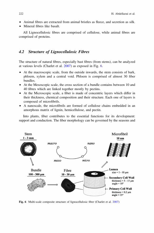
• Animal fibres are extracted from animal bristles as fleece, and secretion as silk.• Mineral fibres like basalt.
All Lignocellulosic fibres are comprised of cellulose, while animal fibres arecomprised of proteins.
4.2 Structure of Lignocellulosic Fibres
The structure of natural fibres, especially bast fibres (from stems), can be analyzedat various levels (Charlet et al. 2007) as exposed in Fig. 6.
• At the macroscopic scale, from the outside inwards, the stem consists of bark,phloem, xylem and a central void. Phloem is comprised of almost 30 fiberbundles.
• At the Mesoscopic scale, the cross section of a bundle contains between 10 and40 fibres which are linked together mostly by pectins.
• At the Microscopic scale, a fiber is made of concentric layers which differ intheir thickness, chemical composition and their structure. Each one of layers iscomposed of microfibrils.
• A nanoscale, the microfibrils are formed of cellulose chains embedded in anamorphous matrix of lignin, hemicellulose, and pectin.
Into plants, fiber contributes to the essential functions for its development:support and conduction. The fiber morphology can be governed by the seasons and
Fig. 6 Multi-scale composite structure of lignocellulosic fiber (Charlet et al. 2007)
222 H. Abdellaoui et al.

the constraints affecting the plants (Charlet et al. 2007; Harish et al. 2009). The fibercontains the following parts (Fig. 7):
• The middle lamella M: thickness of 0.5 to 2 lm in the periphery, which iscommon to neighboring cells. It is mainly composed of lignin (70%) associatedwith other organic components such as hemicellulose, pectin, and cellulose.
• The primary wall P: very thin (0.03–0.1 l). It is made of a fibrillar structurecoated with a combination of lignin, pectin, and hemicellulose (Fig. 8).
• The secondary wall, the main component of the fiber which comprises threedistinct parts:
– The outer wall S1: Thin 0.1–0.2 um, wherein the fibrils are wound in parallelhelices and of opposite direction.
– The central wall S2: thicker (0.5–8 um), the fibrils are arranged in parallelhelices. The fiber stiffness is detached to the thickness of this wall.
– The inner wall or tertiary S3: thin (0.04–0.1 l), is adjacent to lumen W.between the fibres, there are spaces that are partially composed of lignin andhemicellulose.
Fig. 7 Structure of lignocellulosic fibres (multi-scale observations)
Lignocellulosic Fibres Reinforced Thermoset … 223

4.3 Chemical Composition of Cellulosic Fibres
Lignocellulosic fibres consist mainly of lignin, cellulose, and hemicellulose. Othercomponents such as proteins, pectins, starch and inorganic salts are also existing butin low proportion. The holocellulose proportion (cellulose and hemicellulose) andlignin varies significantly following the origin of the natural fiber (wood, jute, sisal,kenaf, etc.) (Saheb and Jog 1999). The chemical composition of the fibres dependsconsiderably on climatic conditions, growth condition, age and nature of the fiber.Table 2 gathers the chemical composition of different natural fibres (Saheb and Jog1999; Xie et al. 2010).
Fig. 8 The primary wall: Three-dimensional structure
Table 2 The composition of several lignocellulosic fibres (Saheb and Jog 1999)
Fibres Cellulose (%) Lignin (%) Hemicellulose (%) Pectin (%)
Stem fibres
Flax 71 2.2 18.6–20.6 2.3
Kenaf 31–57 15–19 21.5–23 –
Jute 45–71.5 12–26 13.6–21 0.2
Hemp 57–77 3.7–13 14–22.4 0.9
Ramie 68.6–91 0.6–0.7 5–16.7 1.9
Leaves fibres
Abaca 56–63 7–9 15–17 –
Sisal 47–78 7–11 10–24 10
Henequen 77.6 13.1 4–8 –
224 H. Abdellaoui et al.

4.3.1 Cellulose
The cellulose is considered as a natural polymer consisting of molecules formed bylong chains. These chains are mainly composed of D-anhydroglucopyranoses(C6H11O5) linked by bonds b-(1,4)-glycosidic in position C1 and C4 (Fig. 9). Thedegree of polymerization is estimated about 10,000, which varies depending onlignocellulosic fiber. Each repeated unit is composed of three hydroxyl groupswhich the crystallinity is conditioned by the aptitude of these groups to makehydrogen bonds (Gilberto et al. 2010).
The chains of cellulose are combined to form basic structures called microfibrilsas elucidated by a study carried by transmission electron microscope (Saheb andJog 1999). The microfibrils diameter (Fig. 10) is average of 2–20 nm which eachmicrofibril is considered as crystals chains linked amorphous fields (John andThomas 2008). The cellulose properties are strongly correlated to the high densityof hydrogen bonds that develop between chains. Comparing to other amorphouscomponents of the fiber, the cellulose has a crystalline structure at a high propor-tion. Crystalline cellulose is treated as a polymer having the highest elasticitymodulus is about 136 GPA compared to that of fibreglass 75 GPA (Gilberto et al.2010).
Fig. 9 Cellulose molecule (Gilberto et al. 2010)
Fig. 10 Structure of the cellulose microfibril
Lignocellulosic Fibres Reinforced Thermoset … 225

Cellulose is located in the wall of the fiber and is the main abundant organicsubstance in nature, with an estimated global production of about 1.3 � 1010 tonsper year. To scale a tree, this corresponds to the development of 10 g of celluloseper day. The cellulose is highly hydrophilic, and without water solubility character.It is resistant to strong alkalis, but easily hydrolyzed by acids (John and Thomas2008). Also, for a given percentage of cellulose, more the microfibrillar angle issmall and more the fiber stiffness is important (Saheb and Jog 1999). The Table 3shows, for different fibres, the cellulose content, microfibril angle, and fiber size.
4.3.2 Hemicellulose
Hemicellulose comprises a group of polysaccharides containing a combination ofcycles at 5 and 6 carbons such as represented in the example of Fig. 11. Thehemicelluloses are distinguished by their solubility in dilute alkaline solutions.Typically, a solution of 10 g of sodium hydroxide is required to extract hemicel-luloses remaining in the medium neutralization (Saheb and Jog 1999; John andThomas 2008).
Table 3 Chemical composition of lignocellulosic fibres (Saheb and Jog 1999)
Cellulose content(%)
Microfibrillar angle(degree)
Diameter(µm)
Length(mm)
Flax 64–71 10 5–76 4–77
Ramie 83 7.5 16–126 40–250
Hemp 78 6.2 10–51 5–55
Jute 61–71 8 25–200 –
Sisal 67–78 20 7–47 0.8–8
coir 43 45 12–24 0.3–1
Fig. 11 Structure of xyloglucans
226 H. Abdellaoui et al.
Hemicellulose has a chemical structure that varies following the plant, the celltype, location in the wall and the maturity of the tissue. Among the commonlyknown hemicellulose are the mannans, xylans, galactans, the most studied arexyloglucans (John and Thomas 2008).
Hemicellulose cellulose differs in some aspects (Saheb and Jog 1999), whichare:
• Hemicellulose consisted of neutral sugars: xylose, arabinose, galactose, glucose,mannose and uronic acids, while cellulose contains only 1,4- b-D-glucopyranose units.
• In nature, it has a degree of polymerization between 50 and 300, while that ofthe primitive cellulose is 10–100 times higher.
Structurally, if the fiber is treated as a composite material, where the cellulose isthe fiber reinforcement and the lignin is the matrix, the hemicellulose acts ascompatibilizer at the interface between the cellulose and the lignin elements (Saheband Jog 1999).
4.3.3 Lignin
Lignin is an aromatic polymer extremely heterogeneous. It’s composed of athree-dimensional molecule consisting of phenyl propane units (Fig. 12). Primaryunits (monolignols) constituting lignin are coniferyl alcohol, sinapyl alcohol and p-coumaryl alcohol (Fig. 13). During the lignifications process, vegetable phe-noloxidases such as laccases are involved and allow the polymerization of thevarious elementary units. Once synthesized, the lignin is related to the variouspolysaccharides to make a constitutive matrix of the wall of plant (John andThomas 2008).
Also, it is essential to reminder that in the plant, lignin is correlated to thepolysaccharide by covalent bonds which improve adhesiveness between the matrixand the cellulosic fibres. These aromatic polymers appear in secondary tissues ofhigher plants. They constitute a three dimensional network which gives the wall itsimpermeability and its resistance against microbial attack. The lignin is completelyamorphous and hydrophobic. It is not hydrolyzed by acids, but soluble in a hotsodium hydroxide solution (Bodros et al. 2007).
4.3.4 Pectins
Pectins are acidic polysaccharides, which the main chain is composed of uronic acidmonomers bonded to 1–4 as presented in Fig. 14. Regularly, rhamnose moleculesare inserted between these monomers by links 1–2 and 1–4. Some of theserhamnose units bear side chains composed of neutral monosaccharide from whichgalactose and arabinose are the most abundant. The macromolecule of pectin
Lignocellulosic Fibres Reinforced Thermoset … 227

appears as a zigzag. This arrangement gives it special properties. It provides flex-ibility to plants (John and Thomas 2008).
4.3.5 Waxes
The waxes are constituents of natural fibres, which could be extracted with organicsolutions. These materials consist of diverse types of water-insoluble alcohols and
Fig. 12 Schematic illustration of the lignin (Saheb and Jog 1999)
Fig. 13 Structure precursors of lignin (Saheb and Jog 1999)
228 H. Abdellaoui et al.

various acids such as palmitic acid, stearic acid and oilseed acid (John and Thomas2008).
4.4 The Lignocellulosic Fiber Preparation
Fiber preparation is performed depending to the following four steps: retting,scutching, combing, and dubbing/stretching (Basu et al. 2009).
The retting: is a natural reaction carried out thanks to the weather. Aftergrubbing, the stems of the plant are placed on the soil in the form of windrows toundergo the action of natural microorganisms. Degradation of pectin cements isfavored by alternating warmth and humidity. That provides a first separation of thefibres and wood.
The scutching: consists in extracting the fiber from the stems by crushing andthreshing straws. The mechanical actions exerted on the fibres are sorting, thresh-ing, grinding between two fluted rollers, stretching from differential rolling.
The combing: is to keep the fiber wicks in a succession of increasingly finecombs.
The dubbing/stretching: conglomerate of fibres permits them to take a ribbonof several meters useable by spinning. Ribbons are officially approved by themixture of fibres from different sources.
4.5 Advantages and Disadvantages
Lignocellulosic fibres are an attractive substitute to synthetic fibres, particularlyglass fibres, owing to their environmentally promising characteristics. The fibrespossess various advantages as reinforcement of composite materials. However,some disadvantages may be a brake at the industrial development (Vilaplana et al.2010; Bodros et al. 2007; John and Thomas 2008).
Fig. 14 Structure of a polygalacturonic acid chain (Saheb and Jog 1999)
Lignocellulosic Fibres Reinforced Thermoset … 229

The main advantages of lignocellulosic fibres are:
– Lignocellulosic fibres are determined by low density, which ensures highspecific mechanical properties when it is compared with synthetic fibres.
– Economical production, i.e. fabrication imposing little energy.– They present safer handling and non abrasive with few requirements for
apparatus.– They are renewable and biodegradable thanks to natural organisms.– The lignocellulosic fibres have a carbon dioxide neutral character, particularly
while they are combusted or composted.– Hollow cell structure provides good acoustic insulation properties.– Worldwide availability remains a subsidiary factor.
Notwithstanding the advantages mentioned above, the lignocellulosic fibrespossess some disadvantages, which are:
– Lignocellulosic fibres present a polar and hydrophilic aspect owing to theexistence of hydroxyl and other oxygen groups containing in the fiber. Thematrices are mostly non polar and hydrophobic. This results in poor dispersionof fibres in the matrix.
– High moisture absorption, which the lignocellulosic fibres absorb variablybetween 5 and 10%. This brings to reduced mechanical properties and decreasesdimensional stability of the composites.
– Lignocellulosic fibres acquire little microbial resistance and susceptibility todecay. These properties are serious problems during the transport, storage,processing and implementation of composites.
– The variation in properties into the same fiber can create problems in producingcomposites with uniform properties.
– The lignocellulosic fibres are susceptible to degradation at high temperature ofmanufacturing, which limits the choice of matrix. The thermal degradation offibres is a two stages process, during the temperature range 220–280 °C andanother in the range 280–300 °C. The low temperature degradation of manu-facturing process is related with degradation of hemicellulose, whereas, the hightemperature process is owing to lignin.
It is obvious that the advantages compensate the disadvantages. Most of thedeficiencies have corrective measures in the form of treatments or modifications inthe fiber.
4.6 Weave Architecture of Reinforcement
The development of textile structures such as weaving, braiding and knitting hasallowed the realization of composites having remarkable mechanical properties(John and Thomas 2008).
230 H. Abdellaoui et al.

The weave structure elaborated by the entanglement of the warp fibres (0°) andweft fibres (90°) in a regular model as illustrated in Fig. 15a.
A description of various architectures commonly found in weaving structures:Unidirectional weave: in a UD fabric, the fibres are assembled parallel com-
pared relatively to each other with a very light weft (Fig. 15b).Plain weave: each warp fiber moved over and below each weft fiber alternately.
The fabric is symmetrical with good planicidad and relative rigidity. However, thefabric is not very deformable at the implementation. Many successive intersectionsgenerate significant crimp, which resulted in a diminution in mechanical properties.
Serge weave: each warp fiber runs over two or more weft fibers weft fiber, andeach fiber weft runs over two or more warp fiber. Serge structure is distinguished bya smooth surface and slightly higher mechanical properties. Also the structure isvery flexible relative to the plain weave (Fig. 16b).
Satin weave: each warp fiber passes over a number (n − 1) of weft fibresalternately. Satin structure is flexible with a high degree of drape. Thus, satin hasgood mechanical properties, but it remains an asymmetric structure (Fig. 16c).
Basket weave: it is mainly the similar as the plain weave, exception that two ormore warp fibres pass alternately in excess of two or more weft fibres. Thisstructure is very flexible, but it is poorly stable (Fig. 16d).
It is as well possible to make hybrid structures reinforcements by weaving fibresof different natures or, by superimposing fabrics or layers of different fiberreinforcements.
4.7 Types of Lignocellulosic Fibres
Being an interesting renewable resource, the lignocellulosic fibres extracted fromvegetable plants will have an important role in the conversion to a sustainableeconomy and more environmentally friendly. There are different kinds of natural
Fig. 15 a Weave structure and b Unidirectional weave
Lignocellulosic Fibres Reinforced Thermoset … 231

fibres like doum, sisal kenaf, jute, flax, etc. these fibres are different in botanicalorigin, climate, instead of growth (Mwaikambo and Ansell 2002). A description ofcertain types of lignocellulosic fibres:
Flax fibres: The Flax (Linum Usitatissimum) is an yearly plant of the Linaceaefamily (Fig. 17a), cultivated in Europe and Asiatic countries as China. Flax fibres,length 40–50 mm, are contained in the stem of a length of 60–120 cm and adiameter of 1–3 mm. flax fibres are 2–3 times more resistant than cotton fibres.They have a low elasticity, but are highly absorbent and good conductors of heat.Currently, these fibres are applied in papermaking (Le Duigou et al. 2010; Charletet al. 2010).
Hemp fibres: The hemp (Cannabis sativa) is an yearly plant of the cannabaceaefamily (Fig. 17b), with a height of 1–3 m, cultivated in countries with temperateclimate such as Eastern Europe, in France and in Italy. Bast fiber is flattened andslightly woodier than flax. It can absorb until 30% of moisture and holds almost95% of UV rays. It burns without leaving any waste. Hemp fiber is applied intextiles, geotextiles and erosion control fabric (Amaducci et al. 2008).
Sisal fibres: The sisal (Agave sisalana) or Heineken is a plant of the Agavaceaefamily (Fig. 17c). It is a tropical plant, mainly grown in Brazil, Tanzania andKenya. sisal fibres are mined from the leaves of the plant, in which each leaves
Fig. 16 a Plain weave, b Satin weave, c Serge weave and d Basket weave
232 H. Abdellaoui et al.

contains 1000–1200 packets with an average fiber length of 3 mm. the fiber is veryresistant. The sisal fibres are applied for manufacturing ropes, fabrics and carpets(Silva et al. 2008).
Jute fibres: The Jute (Corchorus capsularis) of the Malvaceae family (Fig. 17d)is a plant grown in tropical regions, mainly in Bangladesh and India. Jute fibres areextracted from a stem from a height of 4–6 m and a diameter of about 3 cm; thefibres have a length of 2 mm and a width of 20 µm. The ultimate fiber is very shortand lignified. Jute fibres are used in papermaking and rope (WinklerPrins 2006).
Kenaf fibres: The Kenaf (Hibiscus cannabinus L.) of the Malvaceae family(Fig. 17e) is an herbaceous plant whose stem reaches 3 m high and almost 2 cm indiameter. It is grown in tropical regions and in South America. The kenaf fiber of1.5 mm in length is between that of hardwood fibres and the resinous fibres. Thekenaf fibres are intended only for the papermaking field (Mwaikambo and Ansell2002).
Cotton fibres: The Cotton (Gossypium) is a shrub of the Malvaceae family(Fig. 17f), from 1 to 1.5 m high. It is grown in warm areas of America, Africa, Asiaand Europe (Spain). The cotton fibres come from cotton seeds. this fiber isemployed for its good mechanical and physical characteristics, including luxurypapers, bank notes and textiles (Saheb and Jog 1999).
Abaca fibres: The abaca (Musa textilis) or manila abaca is a family of Musaceaethat grows to Philippines (Fig. 17g). Abaca fiber is mined from the oblong leaves
Fig. 17 a Flax plant, b Hemp plant, c Sisal plant, d Jute plant, e Kenaf plant, f Cotton plant,g Abaca plant, h Ramie plant, i Coir plant, and j Doum plant
Lignocellulosic Fibres Reinforced Thermoset … 233

and stems. It has a length of 6 mm and a diameter of 22 l. The abaca fibres areprincipally used for rope-making, and also in the composition of filter papers andteabags (Regional centre of animation in advanced materials 2006).
Ramie fibres: The ramie (Boehmeria nivea L.) of the nettles family is a shrubbyplant (Fig. 17h), native to the Far East. The main producers of ramie fiber are Chinaand Japan. The ramie fiber has an average length between 40 and 250 mm and anaverage diameter of 45 l. These fibres are similar to flax fibres, but are still longerand more rigid. Ramie fibres are produced for artisanal uses (Regional centre ofanimation in advanced materials 2006).
Coir fibres: The coconut (Cocos nucifera) is a species of palm of the Cocoeaefamily (Fig. 17i). It is acclimated in most tropical countries. The coir fibres comefrom the fibrous layer that surrounds the coconut. The coir fibres are highly resistantand insulating (Defoirdt et al. 2010).
Doum fibres: The doum (chamaerops L) is a small palm of the Coryphoideaefamily (Fig. 17j). It is originally from the regions bordering of the westernMediterranean Sea. The doum fibres are extracted from the leaves of the plant.Doum mainly is applied for decorating gardens (Malha et al. 2013).
4.8 Lignocellulosic Fibres Properties
Lignocellulosic fibres properties Structure, defects, cell dimensions, and thechemical composition of lignocellulosic fibres are of the key variables that influencethe natural fiber. Usually, the tensile measurements (strength and the Young’smodulus) of lignocellulosic fibres increase with increasing cellulose (Saheb and Jog1999; Singh et al. 2008). The major properties of lignocellulosic fibres are gathersin Table 4.
Table 4 The physical properties of several natural fibres (Regional centre of animation inadvanced materials 2006)
Density(g/cm3)
Tensilestress (MPa)
Young’smodulus (GPa)
Specific Young’smodulus (GPa)
Deformation(%)
Flax 1.45 500–900 50–70 48 1.5–4
Hemp 1.48 350–800 30–60 41 1.6–4
Kenaf 1.3 400–700 25–50 38 1.7–2.1
Jute 1.3 300–700 20–50 38 1.2–3
Bamboo 1.4 500–740 30–60 36 2
Sisal 1.5 300–500 10–30 20 2–5
Coir 1.2 150–180 4–6 5 20–40
Glassfiber
2.5 1200–1800 72 29 2.5
Carbonfiber
1.4 4000 235 168 2
234 H. Abdellaoui et al.

Comparing with properties of synthetic fibres, it is obvious that the glass fibresmodulus is greater than that of lignocellulosic fibres. In contrast, if specific prop-erties are considered, it will be noted that the specific modulus of lignocellulosicfiber is comparably high that the synthetic fiber modulus.
4.9 Lignocellulosic Fiber Modification
The fiber-matrix interface quality is very significant for using the natural fibres asfibrous reinforcement for the thermosetting polymers. However, the lignocellulosicfibres present an incompatibility with hydrophobic polymers. Consequently, it hasproved necessary to treat the fiber surface in order to enhance this interface. Thecore idea is to amend the nature of the fiber by adding functional groups that havemore affinity with the polymer matrix (Mwaikambo and Ansell 2002).
The lignocellulosic fibres may be modified by chemical or physical methods.Physical methods, such as stretching, calendering, heat treatment, laser, gammarays, UV, plasma, used to change the surface and structural properties of the fiber.Chemical modifications include treatment with sodium hydroxide, the silane (sili-con alkoxide functionalized), acetic acid, or based molecules of benzoyl, iso-cyanate, triazine or imidazolidinone, etc. (Mwaikambo and Ansell 2002; Saheb andJog 1999).
Chemical coupling method stays one of the chemical methods, which allowsimproving the interfacial adhesion. The chemical composition of the couplingagents allows their reaction with the surface of the fibres by forming a bridge ofchemical bond that associates the fibres with the matrix. In general, the couplingagents are molecules that having two functions, the first function reactive with the -OH groups of the cellulose and the second with the functional groups of the matrix(Xie et al. 2010).
To enhance the compatibility between two incompatible materials, it is possibleto incorporate another material having intermediate properties. The most frequentlyused methods are the alkali treatment firstly often followed by silanization oracetylation or adding a compatibilizers (Malha et al. 2013; Corrales et al. 2007; Xieet al. 2010). Table 5 shows the values of various mechanical properties in functionof the treatment of the fiber.
4.9.1 Alkaline Treatment
Treatment with NaOH or also called mercerizing is one of the used treatments totreat natural fiber. According to ASTM 1965, that is a process which consists tosubject the vegetable fiber in an interaction with a concentrated aqueous solution ofa strong base, so as to cause substantial swelling resulting in variations in the finestructure, the size, morphology and the mechanical properties (Mwaikambo andAnsell 2002).
Lignocellulosic Fibres Reinforced Thermoset … 235

The major modification by the alkali treatment is the decrease of hydrogen bondsbetween the cellulose and the two others constituents: hemicellulose and lignin.Also, this treatment banishes wax, pectin and a part of the lignin and hemicellulose,which are amorphous structures, and therefore they lead to a low tensile strength.
Besides, after the soda treatment, many –OH groups are present on the fibersurface (Fig. 18) and the fibres may be simply treated with other chemical con-stituents such as silanes, acetic acid and others (Mwaikambo and Ansell 2002).
NaOH concentration should be considered when treating fibres, as it affects thedegree of swelling, and thus the degree of cellulose conversion. In one study, whenthe bamboo fibres are treated in alkaline solution at a concentration less than 5%,the density of bamboo fiber increases owing to the elimination of most of hemi-cellulose and lignin. This allows approximation of the cellulose microfibrils,
Table 5 Mechanical properties of untreated and treated sisal fiber (Sood et al. 2015)
Treatment Tensile strength(g/tex)
Tensile modulus(103 g/tex)
Elongation atbreak (%)
Untreated fiber 30.7 1.18 2.5
Benzol treatment 38.8 0.99 3.7
Acetic acid treatment 9.3 0.39 2.6
Alkaline treatment 31.7 0.53 7.5
Acetate treatment 33.2 0.35 8.3
Heat treatment 42 1.22 3.5
Alkaline followed bythermal treatment
27.6 0.7 4.7
Thermal followed byalkaline treatment
25.7 0.71 4.4
Fig. 18 Reaction of alkali treatment (Mwaikambo and Ansell 2002)
236 H. Abdellaoui et al.

leading to a more compact and increasing the density. At a NaOH concentration ofabove 5%, the density decreases as a result of the disappearance of other substancessensitive to alkalis, this brings to the creation of microvoids (Bessadok et al. 2007;Kim and Netravali 2010).
The alkali treatment influences the thermal and physical properties of the fibresnatural. Loan studied the modification of the jute fiber surface. They proved that thetreatment with soda (NaOH 1%, 4 h) improves the fiber strength (Fig. 19). Due tothe alkaline treatment, lignin and hemicellulose are removed; the interfibrillaryregion is less dense and less rigid, allowing the fibrils to reorganize in the sense oftraction. When the fibres are stretched, into such arrangements between the fibrilswould result in a better load sharing (Loan 2006).
Altogether, the alkali treatment may affect the fiber in two ways: (1) it enhancesthe surface roughness, and (2) it increases the quantity of cellulose which covers thefiber surface, expanding the number of possible reaction sites (OH groups). (Kimand Netravali 2010; Loan 2006) Therefore, the effect of alkali treatment is durableon the mechanical behavior of fibres, particularly on their strength and rigidity.After the alkali treatment, the fibres are often treated with silane, acetic acid, etc., tofurther improve the adhesion fiber—matrix.
4.9.2 Treatment with Silanes
Silanes or silica functionalized alkoxide, represented by R’-Si(OR)3, are hydro-philic compounds with different groups associated with the silicon such that oneend interacts with the matrix and the other with the hydrophilic fiber, acting as abridge between them. The silane absorption is greatly dependent on a certainquantity of factors, such as hydrolysis time, functionality, the temperature and pH.The silicon alkoxides are able of forming bonds with the hydroxyl groups.
Fig. 19 Tensile test ontreated jute fibres withdifferent solutions of sodiumhydroxide (Loan 2006)
Lignocellulosic Fibres Reinforced Thermoset … 237

Silanols may form polysiloxanes by reaction with the hydroxyl groups of the fiber(Seki 2009). The chemical reaction is schematized in Fig. 20.
Silane solutions in a blend of water and ethanol at a concentration of 0.033%were used by Valadez et al. (Seki 2009) to treat the fibres. They found that the effectof treatment by the silane resulted in a higher tensile resistance than the alkalitreatment.
According to Nguyen Huy Tuong et al. (Seki 2009), when the mass concen-tration of silane is increased by 0.5–1%, the shear strength is increased at theinterface. However, no variation was noted when the silane concentration is raisedfrom 1 to 2%. With the silane concentration increasing, the alkoxides groups reactwith the bamboo fiber and the surface is more active. But when the silane con-centration is 2%, the silane concentration contained in the fiber surface cannot risebecause this one is saturated. The silane not improves the surface activation. Anamount of 1% silane is sufficient to cover the entire surface of the bamboo fibres.
4.9.3 Acetylation
The acetylation allows modifying the natural fibres surface which makes it morehydrophilic. It has been employed to decrease swelling of the wood in water. Theconcept of the method is to react the hydroxyl groups (–OH) of the fiber with the
Fig. 20 Chemical reactions of treatment with a functionalized silica alkoxide (Seki 2009)
238 H. Abdellaoui et al.

acetyls groups (CH3–CO–), and thus make the surface more hydrophobic fiber. Thehydroxyl groups that react are hemicellulose and lignin and amorphous part of thecellulose. The hydroxyl groups of crystalline regions in the fibres are tightlycompacted with strong intermolecular bonds, and are inaccessible to chemicalreagents (Bessadok et al. 2007). The acetylation of the OH group is shown below:
– Acetylation with an acid catalyst:
Cell OH CH3COOH Cell O CO
CH3 H2O+ +(CH3CO)2O
H2SO4
– Acetylation without acid catalyst:
Cell OH CH3C O C CH3OO
Cell O CO
CH3 CH3COOH++
Because acetic acid does not respond sufficiently to the reaction with the cel-lulose, it is estimable to employ acetic anhydride. However, acetic anhydride is nota good swelling agent for the cellulose, and then to accelerate the reaction, thecellulose is first steeped in acetic acid and then treated with acetic anhydride for 1–3 h. In composite reinforced by natural fibres, acetylation of the hydroxyls groupsswells the wall of plant cells significantly reducing hygroscopic nature of cellulosefibres. This brings to dimensional stability of the composites, because no waterabsorption can lead to swelling or shrinkage of the composite material (Bessadoket al. 2007; Saheb and Jog 1999; Seki 2009).
Rana et al. (Rana et al. 1997) worked on the thermal properties and morphologyof acetylated jute fiber surface. The thermogravimetric analysis curves of acetylatedjute fibres show that the decomposition of the hemicellulose has disappeared, andthat the losing weight allied with the main degradation step (373 °C) increased. Themain decomposition temperature increased from 363 to 373 °C, indicating that thethermal stability of acetylated jute fibres is higher than that of the untreated fibres.The same conclusions were made by Albano et al. (Albano et al. 1999) during thestudy acetylation sisal fibres
4.9.4 Compatibilizers
Among the organic coupling agents, anhydrides such as maleic anhydride, aceticanhydride, succinic anhydride and phthalic anhydride are the most employedcoupling agents for the reinforced natural fibres composite. Acetic anhydride,succinic anhydride and phthalic anhydride have two functional groups (e.g. –COO–carboxylate), which may be related to lignocellulosic fibres by esterification andhydrogen bonding (Fig. 21) (Malha et al. 2013; Bessadok et al. 2007).
Lignocellulosic Fibres Reinforced Thermoset … 239

Maleic anhydride is an unsaturated carbonyl compound containing acarbon-carbon double bond (–C = C–) and two carboxylate groups (–COO–). Thisstructure considerably increases the reactivity of the carbon-carbon bond with thehydrophobic matrix, ensuing in a reaction or strong adhesion at the interface (Malhaet al. 2013).
Mohammad (Beg 2007) studied polypropylene/kraft fibres composites (10–60%by weight of fibres) containing polypropylene modified with maleic anhydride(MAPP) as a coupling agent (1–4% by weight). The optimal result is obtained with50% by weight of fibres and 3% by weight of MAPP. The stress is increased withfiber content to 50% by weight of fibres, but a decrease is observed for 60% byweight of fibres, which could be due to the increased viscosity, ensuing in poordistribution of the fibres. The increase in stress and the elastic modulus of thesamples containing MAPP seems to be due to better interfacial bonding.
Fig. 21 Scheme of the chemical treatments: maleic anhydride, styrene, acrylic acid and aceticanhydride (Bessadok et al. 2007)
240 H. Abdellaoui et al.

5 Thermoset Composites Reinforced Lignocellulosic Fiber
The record of plastic reinforced fibres began in 1908 with the cellulose fiber inphenolic compounds, passing subsequently through the melamine fiber to the glassfiber. The massive and exorbitant use of oil resources has evoked the developmentefforts of biodegradable plastics. This is based on plants of natural origin andagricultural products that can compete in markets dominated by synthetic product(Vilaplana et al. 2010).
The manufacture of materials at 100% of natural origin as substitute for syntheticproducts is not an economically profitable solution. A more practicable and optimalsolution would be to combine synthetic biodegradable products and natural prod-ucts. Biopolymers or synthetic polymers reinforced natural fibres are a gainfuloption to glass fiber composites. Scientists are studying the different possibilities ofcombining the lignocellulosic fibres with polymer matrices, including thermosetmatrices (John and Thomas 2008).
5.1 Classification of Composites
5.1.1 Green Composites
Green composites are fully biodegradable composite, combining lignocellulosicfibres with biodegradable resins. Green composites are attractive because they areenvironment friendly, wholly degradable and durable. At the ending of their life,they be simply able to be removed or composted undoubtedly without detractingthe environment (Vilaplana et al. 2010; Bodros et al. 2007).
The biodegradable polymers are classified according to four families. The firstfamily’s agro-polymer (e.g. polysaccharides) obtained from biomass fractionation.The second and the third family are the polyesters obtained respectively by fer-mentation from biomass or genetically adapted plants (e.g. polyhydroxyalkanoate)and synthesis from monomers (e.g. polylactic acid). The fourth family are totallypolyesters synthesized by petrochemical process (e.g. polyesteramine). Many ofthese polymers are commercially available (Saheb and Jog 1999).
5.1.2 Thermoset Composites
For thermoset composites, the lignocellulosic fibres are combined with phenolicmatrices, epoxy, and polyester resins to shape composites. Thermosetting polymersare three-dimensional structures containing reactive groups, which help thedevelopment of the interface. These thermosetting matrices, owing to their struc-ture, acquire during crosslinking a form which cannot subsequently be changed by
Lignocellulosic Fibres Reinforced Thermoset … 241

rising the temperature. The most developed applications for automotive parts (bodyparts: hood, tailgate), recreation (boat hulls) (Megiatto et al. 2009).
Most resins employed in composite applications are thermosetting, which theepoxy resins are the most accustomed. Thermosets may moreover be charged withorganic fillers like inorganic carbonates or natural fillers like clay to purpose ofincreasing its mechanical properties. In a study of jute fibres reinforced polyestercomposites, it is found that the mechanical properties were influenced by thechemical bond between the jute fiber and the polyester matrix; and the same resultsobtained with the use of epoxy and vinylester matrix (Gassan and Bledzki 1999;Stocchi et al. 2007; Sangthong et al. 2009).
5.1.3 Hybrid Composites
The integration of several types of fibres into one matrix allows the fabrication ofhybrid composites. Hybrid composites have the advantage of using several types offibres that are complementary in function of mechanical, chemical or physicalproperties. Accordingly, a equilibrium of cost and performance could be achievedby dint of the implementation of these composites (Khan et al. 2009).
The properties of the hybrid composites depend essentially on the fiber, thelength of the individual fibres, the orientation and arrangement of the fibres. Theresistance of the hybrid composite is also function of the strain at break of eachfiber. Hybrid composite can be realized by synthetic fibres and natural fibres in amatrix or by mixture of two kinds of natural fibres in the matrix. Hybridization withthe glass fibres provides a way for improving the mechanical properties of thecomposite natural fiber (Jawaid et al. 2010).
5.2 Processing of Lignocellulosic Fiber Composites
The majority of frequent processes for manufacturing composites with lignocellu-losic fibres are contact molding, compression molding, injection and infusion.These processes involve the implementation of the unhardened composite in a moldso that the material can be shaped into the final piece. Some other methods likecentrifugal casting, filament winding, pultrusion, are used for thermoset composites,but the employ of these processes for lignocellulosic fibres composites stillimpracticable (Abdellaoui et al. 2015).
In thermosetting matrices, the fibres are used as mats or woven structures(unidirectional, fabric, satin…). Also, the type of employed process influencesdirectly the properties of the material by the porosity rate, mastery of reinforcementorientation and the quality of the impregnation.
242 H. Abdellaoui et al.

5.2.1 Hand Lay up
This is a manual process, performed at an ambient temperature and without pres-sure. The reinforcements are deposited on the mold and impregnated with liquidthermosetting resin, catalyzed and accelerated, to be formed gradually by airingsystem (bubble withdraw and brushes). After the cure of the resin as revealed in theFig. 22, the part is separated from the mold and trimmed (Regional centre ofanimation in advanced materials 2004).
This process is applied for small series from 1 to 1000 pieces/year. It is brandedby obtaining the piece with one smooth gelcoated surface, and average to highmechanical properties. However, it gives a low production rate per mold and thehomogeneity of the part strongly accorded to the operator which manufactures thepart. It is used in the fields of transport auto body, public works (formwork),swimming pools and water sports (Regional centre of animation in advancedmaterials 2004).
5.2.2 Injection Molding—RTM
Injection molding of liquid resin RTM (Resin Transfer Molding) occurs betweentwo rigid mold parts (male and female). The reinforcement (mats, perform,optionally tissues) is disposed in the mold. Once it securely closed, resin, accel-erated and catalyzed, is injected under low pressure (1.5–4 bars) through thereinforcement to complete the fill of the cavity as schematized in Fig. 23. Aftercuring the resin, the mold is opened to remove the shaped piece (Abdellaoui andEchaabi 2014; Le Riche et al. 2003; Deleglise et al. 2006).
This process is distinguished by the fabrication of relatively complex forms withexcellent precision, elevated production rate and good working conditions.However, the reinforcement rate is limited (30–40%) and need to conduct postmolding finishes. it is applied primarily in auto body parts for passenger vehiclesand utility vehicles, cowlings, tennis racket, bicycle fork, and various industrialparts (Deleglise et al. 2006).
Fig. 22 Han lay-up process
Lignocellulosic Fibres Reinforced Thermoset … 243

This process is considered environmentally friendly thanks to the use of theclosed mold, which prevents the release of noxious odors thermosetting resins(styrene).
5.2.3 Infusion
The principle of the infusion remains comparable to the RTM except that the uppermold is replaced by a flexible tarpaulin. The resin is injected and distributed onreinforcements until complete impregnation of them. The Fig. 24 reports the infu-sion process. Injection occurs at room temperature, even if the resin can be heatedduring injection to optimize the conditions of polymerization and viscosity. Thevacuum is drawn from the sheet in order to accelerate the diffusion of the resin on thereinforcement and reduce levels of porosity (Park and Kang 2003; Han et al. 2003).
Infusion allows to acquire a significant reinforcement rate which varies fol-lowing to the depression applied to the part and to ensure reproducibility of theparts manufacturing conditions (Park and Kang 2003).
Fig. 23 Resin transfermolding process
Fig. 24 Infusion process(Regional centre of animationin advanced materials 2004)
244 H. Abdellaoui et al.

5.2.4 Compression Molding
Molding using a press to compression between the rigid parts of the mold, initiallywithout external heat supply. Open mold, the reinforcement is laid on the lower partof the mold and then the resin provided with a highly reactive catalyst system ispoured loose on the reinforcement (Abdellaoui et al. 2015; Bickerton and Abdullah2003) as shown in the Fig. 25.
The mold is closed under pressure (2–4 bars) causes distribution of the resininside the mold cavity and impregnating the reinforcement. Curing of the resin isgradually accelerated by the mold temperature rise thanks to the exothermicity ofthe reaction, allowing a fast release (Kelly and Bickerton 2009).
This process is distinguished by a elevated production rate, and normal workingconditions. However, it is limited to the dimensions and some complex shapes. It ismainly applied for cowlings and bins (Regional centre of animation in advancedmaterials 2004).
5.3 Characterization of Lignocellulosic Fiber Composites
For composite as for all engineering materials, the mechanical properties are fun-damental because they allow the dimensioning and designing structure that mustcontinue to last.
Fig. 25 Compression molding (Regional centre of animation in advanced materials 2004)
Lignocellulosic Fibres Reinforced Thermoset … 245

To characterize the mechanical properties of the composite with different lig-nocellulosic fibres, it is required to carry out certain tests such as tensile, bending,and torsion tests. Before proceeding to mechanical testing, it is as well important tostudy the density of the manufactured structures
5.3.1 Physical Control
The mainstream of thermoset composite structures are laminates structures atvarious numbers of layers. Experimentally, it is useful to define the intrinsiccharacteristics of manufactured parts, which may be summarized in experimentaldensity, reinforcement and resin content. The void content in the structure is alsoconsidered by calculating the experimental and theoretical densities (Abdellaouiet al. 2015).
(a) Mass content
• Reinforcement mass content:
Mf ¼ Reinforcementmass contain in compositeTotal mass of composite
ð1Þ
• Resin mass content:
Mm ¼ Resinmass contain in compositeTotal mass of composite
ð2Þ
With:
Mf ð%ÞþMmð%Þ ¼ 100% ð3Þ
(b) Experimental density:
qexp ¼Weight of compositeVolume of composite
ð4Þ
(c) Theoretical density:
qtheor ¼ qf Vf þ qmVm ð5Þ
Where Vm and Vf are the matrix and fiber volume fraction, respectively.
246 H. Abdellaoui et al.

Vf ¼Mf =qf
Mf =qf þMm=qmand Vm ¼ Mm=qm
Mm=qm þMf =qf
where qf and qm are the fiber and matrix density, respectively.The void content is calculated by:
qExp ¼ 1� #voidð ÞqTheo þ#void � qvoid ð6Þ
With
#void � qvoid ¼ 0
Then
#void ¼ 1� qExpqTheo
ð7Þ
In a novel study (Abdellaoui et al. 2015), they fabricated a laminates based onepoxy resin reinforced with jute fibres by a compression process. For the variouslaminates, they calculated the theoretical and experimental densities which thefollowing Table 6 summarizes the obtained results.
The void content reaches moderately almost of 16.2% in the manufacturedcomposites. The presence of the void in the composite structure generates a stressconcentration, leading to an early phenomenon of delamination. Also, this includedvoid can affect the mechanical characteristics of elaborated composite (Abdellaouiet al. 2015).
5.3.2 Flexural Test
The bending test is used to test the composite flexural strength, which results in adeformation in the form of a curvature.
The principle of this test is to measure a displacement (arrow y) from a force(F) in the centre of two supports. Relationships from the materials resistance used tomake the connection between the two variables (y and F), the geometry of the part(L, h and b) and the material characteristics (r, e and E). The bending curves (r = f(e)) are used to define the flexural modulus, the stress at break and strain at break(Regional centre of animation in advanced materials 2004).
Table 6 Average characteristics of developed composite
Composite Mf
(%)Mm
(%)qExp(g/cm3)
qTh�eo(g/cm3)
Vf
(%)Vm
(%)#void
(%)
49 51 1.03 1.23 41 59 16.2
Lignocellulosic Fibres Reinforced Thermoset … 247

The rectangular specimen, supported as a beam, is subjected to bending in thecentre of the range (3 three-point bending) at a constant rate until failure of thesample as mentioned in the Fig. 26. The different characteristics can be assessed bymeans of the following relation the following relationships (Jawaid et al. 2011):
rf ¼ 3:F:D2:b:h2
ð8Þ
ef ¼ 6:h:YD2 ð9Þ
E ¼ D3:F4:b:h3:y
ð10Þ
5.3.3 Tensile Test
The tensile test used to measure the level of material strength at break. It consists ofplacing a sample between the chuck jaws of a tensile testing machine (Abdellaouiet al. 2015), which pulls the sample until it breaks as demonstrated in the Fig. 27.
The machine software registers the elongation and the applied force, which arethen converted into deformation and stress.
r ¼ FS
ð11Þ
and
e ¼ DLL
ð12Þ
The tensile test gives some several values as:The Young’s modulus, the tensile strength, and elongation at break measures the
aptitude of a material to elongate under load before rupture.
Fig. 26 Flexural test (Regional centre of animation in advanced materials 2004)
248 H. Abdellaoui et al.

5.3.4 Rheological Test
The rheology allows characterizing the viscoelasticity of viscoelastic material(polymers and composites) through a dynamic torsional test. Contrary to the simpletorsional test, the dynamic torsional test is performed on a Rheometer ARES usingrectangular torsion mode with prismatic samples (Abdellaoui et al. 2015) asrevealed in Fig. 28.
The test consists firstly in select strain amplitude through a sweep deformationand fixing the frequency. Thereafter, a frequency sweep is performed by fixing thestrain at the selected amplitude value. The torsion complex modulus G*, obtainedby oscillatory tests performed in frequency sweep mode (0.1–40 Hz) (Abdellaouiet al. 2015), is given by:
G� ¼ffiffiffiffiffiffiffiffiffiffiffiffiffiffiffiffiffiffiffiffi
G0 2 þG00 2p
ð13Þ
With G′ and G″ are respectively the storage modulus indicating the elastic partand the loss modulus indicating the viscous part of the viscoelastic material. Thismodule is comparable to the simple torsion in the case of low frequency (0.1 Hz).
Thus, the loss factor can be calculated using:
tan d ¼ G00
G0 ð14Þ
It measures the ratio of energy dissipated by amortization and the elastic energystored during the dynamic deformation.
Fig. 27 Tensile test (Abdellaoui et al. 2015)
Lignocellulosic Fibres Reinforced Thermoset … 249

The viscoelastic properties of the material depend mainly on the time, frequencyand temperature, which temperature effect is the reverse of that frequency.
6 Mechanical and Rheological Propertiesof Lignocellulosic Fibres Composites
The mechanical strength of the thermoset matrices increases appropriately with thelignocellulosic fiber content, simply because the mechanical properties of the fibresare greatly superior to the properties of the matrix (Abdellaoui et al. 2015). Butthere is a limit to this phenomenon since the fibres must be absolutely covered withpolymer to be effective (to have a good adhesion). There have been numerousstudies on the mechanical properties of the lignocellulosic fiber reinforced thethermoset composites (Saheb and Jog 1999). A brief review following the mainlyimportant works carried out on the thermoset composites reinforced lignocellulosicfibres.
6.1 Flexural Properties
Flexural properties are essentially depending on the fiber content, the void fractionand the fiber-matrix interfacial adhesion.
Mishra et al. (Mishra and Biswas 2013) have treated composites fabricated withbidirectional jute fiber mat and epoxy resin by the method of hand lay-up, which theaim is to study the fiber loading effect on the mechanical properties. The results of
Fig. 28 Dynamic torsional test (Abdellaoui et al. 2015)
250 H. Abdellaoui et al.

three-point bending test show a diminution in the flexural properties of specimenwith 12 wt% fiber loading. This diminution is mainly caused by a fragile interfacialbonding and existence of voids in the composite structure. The flexural strength andmodulus increase with the augment in the fiber loading after 12 wt% fiber loading.The maximal flexural properties are obtained at 48 wt% fiber loading, which theflexural modulus is increased by 37% in comparison to virgin epoxy. The jute fiberinclusions improve the load bearing capacity and ability to withstand bending of thecomposite. The results are shown in the Fig. 29.
In other recent innovative study, Rout et al. (2001) have fabricated compositeson the basis of polyester reinforced by unidirectional non woven coir mat, whichthe fiber content in composite was changed from 0 to 33%. It was noted that theoptimal mechanical properties of coir/polyester composite were earned at 25 wt%fiber loading. The flexural strength of composite at 25 wt% of fiber loading wassuperior to that of the virgin polyester matrix. Depending on the authors, that atlower fiber loading a fragile interface was produced because of the poor wetting ofthe fibres in the matrix. However, at elevated fiber loading (17 and 25 wt%),adequate fiber loading in the composite led to better wetting. The effect variousloading fiber on the flexural strength is specified in Table 7.
Fig. 29 Effect of fiber loading on the flexural measurements (Mishra and Biswas 2013)
Table 7 Flexural strength atdifferent fiber loading (Routet al. 2001)
Fiber (wt%) Flexural strength (MPa)
0 26.60
10 15.22
17 21.30
25 26
33 24.55
Lignocellulosic Fibres Reinforced Thermoset … 251

In a comparative study, Gopinath et al. (2014) have prepared composites withepoxy and polyester reinforced by jute fibres of length 5–6 mm. The composites aresynthesized with 18 wt% of fiber and 82 wt% of resin. The three points bendingresults carried out on two types of composites jute/epoxy and jute/polyester showthose two composites were deemed to be brittle in nature as it underwent a suddenfailure as shown in the Fig. 30. As revealed in results, the jute reinforced epoxycomposite indicated good flexural strength compared to the jute reinforced polye-ster composites. It appears that the jute reinforced epoxy composite has a higherstrain to failure and ultimate strength than the other reinforcement impregnated bycross-linking resins.
6.2 Tensile Properties
The tensile properties are especially depending on the volume fraction of fiber,number of layers, fibre direction, grammage, and yarn size.
Mir et al. (2009) have carried out laminates structures elaborated with jute fibresand epoxy by the infusion process. The fabrics are stacked in the followingsequence [0°] S, [90°] S and [+ 45°/−45°] S, which the behavior of fabrics isstrongly influenced by weft and warp weaving. The tensile results reveal that themanufactured composites have an elastic behavior before the appearance of a cleanbreak as indicated in the Fig. 31. This rigid behavior occurs in both the chain andthe weft direction. The only difference remains the value at which the rupture isdone. This value is 5400 N in the chain direction and 7800 N in the weft directionas demonstrated in Fig. 32.
In the equal work of Mishra and Biswas (2013) mentioned above, they studiedthe tensile properties of epoxy reinforced bidirectional jute fabrics. The results pointout that the increasing of fiber content in the matrix brings to a raise of the tensilestrength and modulus. There is explained by a proper conduction and distribution of
Fig. 30 Flexural stress-straincurves for jute/epoxy andjute/polyester composites(Gopinath et al. 2014)
252 H. Abdellaoui et al.

the applied stress by the epoxy resin resulting in higher strength. According toauthors, the bidirectional jute fiber composite can bear higher load before failurecompared to virgin epoxy. The tensile strength changes from 43 to 110 MPa andthe tensile modulus from 0.15 to 4.45 GPa with the fiber changes from 0 to 48 wt%as demonstrated in Fig. 33.
In another study, Roe and Ansell (John and Thomas 2008) are also studied thetensile properties of composites based jute/polyester by the press molding process.The fabricated samples allow a maximum loading of fiber volume fraction at 0.6. Atthis value, the polyester resin forms an intimate link with the jute fibres, abovewhich the quantity of resin was insufficient to impregnate totally the fibres. At thisoptimal fiber volume fraction, the composite tensile strength was 250 MPa and theYoung’s modulus was 35 GPa.
For Sanadi et al. (Saheb and Jog 1999), they have treated the mechanicalproperties of polyester reinforced sunhemp fibres. The tensile measurements
Fig. 31 Tensile curve (Miret al. 2009)
Fig. 32 View of the jutefabric structure (Mir et al.2009)
Lignocellulosic Fibres Reinforced Thermoset … 253

(tensile strength and young’s modulus) augment linearly with raising the fibercontent following the mixing law. The enhancement of the tensile properties wasnoted only when the fiber content exceeds to 19%.
As was noted in literature, the best part of research is conducted on compositesreinforced by jute fiber, because they are one of lignocellulosic fibres widelyemployed as reinforcement of composites.
6.3 Rheological Properties
The rheological properties of lignocellulosic fiber composites are determined by adynamic torsional test. Like the bending and tensile properties, the torsionalproperties are also depending on the fiber loading and the interfacial adhesionfiber-matrix. Unfortunately, the torsional properties of composites based on ther-moset matrix and lignocellulosic fiber are rarely considered by researchers inliterature.
In a new study, Abdellaoui et al. (2015) have fabricated laminates structures onbasis of epoxy and jute fibres by a compression process. Laminates are performed atdifferent number of layers (1, 3, 5 and 7) layers. The progression of the torsionmodulus G* and the loss factor tan d according to frequency (frequency rangebetween 0.1 and 40 Hz) and the number of layers is publicized in Figs. 34 and 35.The results explain that the complex modulus G* increases significantly withincreasing frequency (from 0.1 to 40 Hz). This increasing permits to deduct that themanufactured composite behave as a solid at elevated frequencies. So through thedeformation phase, the fibres can spin satisfactorily as to be transporting part of
Fig. 33 Effect of fiber loading on the tensile measurements (Mishra and Biswas 2013)
254 H. Abdellaoui et al.

the load. Also, the complex modulus diminished slightly with increasing number oflayers from 1 to 7. According to authors, at a higher number of layers, the adhesionbetween fibres and matrix diminished, which increase fibre–fibre interaction leadingto decrease in the shear stress modulus at the interface fibre–matrix.
The tan d is used to indicate the rate of the elastic portion and that of the viscousportion in the produced composites. According to Fig. 34, it is obvious that theviscous portion doesn’t exceed 4% in the laminates. This progression validates thatthe composite behave as an elastic solid material. This elasticity chiefly owes to theelastic behaviour of jute fibres (Abdellaoui et al. 2015).
Fig. 34 Complex modulusG* for epoxy/jute composite(Abdellaoui et al. 2015)
Fig. 35 Loss factor tan d ofmanufactured laminates(Abdellaoui et al. 2015)
Lignocellulosic Fibres Reinforced Thermoset … 255

7 Improvement of Mechanical Propertiesof Lignocellulosic Fibres Composites
In composite structures, it’s important to enhance the mechanical properties ofequally matrix and fiber. The tensile strength is more susceptible to the matrixproperties, whereas the fiber properties affect more the modulus.
The mechanical properties can be improved thanks to strong interfacial adhesionfiber-matrix, fiber orientation, and wettability of fibres, hybridization of fibres andthe used manufacturing process. Also, the fiber length can affect greatly the strongof composites when this one exceed to the critical length (Saheb and Jog 1999).
7.1 Effect of Fiber Treatment
The modification of the hydrophilic surface of the lignocellulosic fiber ensures goodcompatibility with the hydrophobic matrix. Thereafter, the excellent interfacialadhesion improves the mechanical properties of the produced composite structures.
In one study,
Cell OH CH3COOH Cell O CO
CH3 H2O+ +(CH3CO)2O
H2SO4
Seki (2009) has fabricated composites by using unsaturated polyester and epoxyreinforced by jute fibres. The adhesion among jute fiber and thermoset matrix wasimproved by alkaline and oligomeric siloxane treatments of jute fibres. The tensileresults divulge that the alkalized jute/epoxy composite (AJE) shows better tensilestrength that the jute/epoxy composite (JE). The alkali treatment can lead to 8%raise in tensile strength, owing to the deletion of pectin and waxes. The Young’smodulus of Alkalized jute/Epoxy composite augmented by 17% due to alkalitreatment as compared to that of Jute/Epoxy composite as elucidated in the Fig. 36.Young’s modulus of Jute/Epoxy composite was 48% elevated as compared withthat of jute/ polyester (Jute/Polyster) composite.
Concerning the siloxane treatment, the results confirm that the Young’s modulusof Alkalized siloxane treated jute/epoxy (ASJE) composite has increased to 9.5% ascompared with that of Alkalized jute/Epoxy composite, while the alkalized siloxanetreated jute/polyester (ASJP) composite has improved by 8.4% compared to that ofAlkalized Jute/Epoxy composite. The siloxane treatment allows enhancing theinterfacial adhesion fiber-matrix, and then, improving the mechanical properties ofcomposites.
In other case, Ray el al. (2001) have prepared composites with jute fiber andvinylester matrix. The jute fibres were treated in alkaline solution with 5% NaOHdesigned for four different times (2, 4, 6 and 8 h). The results tell that the flexural
256 H. Abdellaoui et al.

properties of elaborated composites were improved with the use of treated jutefibres. The maximum upgrading in the flexural properties was noted at 4 h of alkalitreatment. According to the authors, this enhance in fiber strength properties isowing to the reduction of the linear density of the fibres on alkali treatment and alsoto the closer packing of the cellulose chains and molecular reorientation on pro-longed soaking in the alkali solutions (4–8 h). The results are summarized inTable 8.
For the coir/polyester composites, Rout et al. (2001) have improved the inter-facial adhesion of composites by a chemically modification of coir fiber throughmany methods as alkali treatment, cyanoethylation, dewaxing, bleaching, and vinylpolymer grafting. The mechanical properties of a variety of elaborated compositesare resumed in Table 9. As exposed by various studies of literature, all methodslignocellulosic fiber surface modification can get better the mechanical properties ofthe prepared composites.
7.2 Effect of Hybridization
The hybridization implies the integration of several different types of fibres in thesame matrix in order to enhance the mechanical properties of biocomposites. Thelignocellulosic fiber hybrid composite permits to incorporate natural fiber/naturalfiber or natural fiber/glass fiber in the thermoset matrix.
Many researchers are focused on the study of hybrid composite reinforced bylignocellulosic fiber and glass fiber as Mishra et al. (2003). They proceeded tomanufacture hybrid composites with properties similarly comparable to the syn-thetic composites based on glass fiber. Mishra et al. (Singh and Gupta 2005)have fabricated hybrid composites on basis of polyester matrix reinforced byPineapple leaf fibres (PALF)/glass fibres and sisal fibres/glass fibres in the aim tostudy the effect of the glass fibres loading on the enhancement of the mechanical
Fig. 36 Young’s modulus oftreated jute composites (Seki2009)
Lignocellulosic Fibres Reinforced Thermoset … 257

properties of biocomposites. The results divulge that the tensile strength ofPALF-polyester composite is significantly improved by incorporating the glassfiber, which the adding of glass fiber by about 8.6 wt% increases the ultimate tensilestrength of hybrid composite by average 66%. However, further increase in weightfraction of glass fiber to 12.9 wt% decreases the tensile strength of PALF/glass fiberhybrid polyester composite by about 10% as illustrated in Fig. 37.
Table 8 Flexural properties of Untreated/Alkali treated jute fibres and vinylester composites(Rout et al. 2001)
Jute volumefraction (%)
Fiberstage
Modulus (GPa) Meanvalue
Flexural strength(MPa) Mean value
0 – 2.91 120.70
8 UntreatedTreated2 hTreated4 hTreated6 hTreated8 h
4.223.444.203.963.13
106.396.27120.20101.893.97
23 UntreatedTreated2 hTreated4 hTreated6 hTreated8 h
7.358.069.388.547.13
145.70157.70172.70155.40145.80
30 UntreatedTreated2 hTreated4 hTreated6 hTreated8 h
10.0310.9912.8512.4911.17
180.60189.40218.15195.90197.50
35 UntreatedTreated2 hTreated4 hTreated6 hTreated8 h
11.8912.7014.6914.8912.32
199.10205.20238.90232.00204.20
258 H. Abdellaoui et al.

Concerning, the hybrid sisal fiber/glass fiber reinforced the polyester composite(Singh and Gupta 2005), the integration of glass fibrin composite increased thetensile strength of the sisal fiber/glass fiber reinforced polyester hybrid composite ascompared to composites with sisal-polyester, which saturated at 5.7 wt% of glassfiber loading as represented in the Fig. 38. The enhancement of tensile strength ofthe composite at low wt% of glass fiber loading will be caused by the fact that at
Table 9 Mechanicalproperties of chemicallymodified coir (17 wt%)/polyester composites (Mishraet al. 2003)
Sample Tensile strength(MPa)
Flexural strength(MPa)
Untreated 21.30 51.49
Dewaxed 22.94 55.75
Alkali treatment
2% 26.8 59.01
5% 24.70 60.45
10 17.34 49.3
Cyanoethylation
50 °C 22.58 53.86
60 °C 26.30 54.13
70 °C 24.27 53.09
Bleaching
65 °C 20.32 61.65
75 °C 19.27 57.80
85 °C 17.91 55.32
PMMA grafting
5% 25.01 63.68
10% 21.58 57.26
20% 14.81 37.81
Fig. 37 Curve of Tensilestrength versus glass fibercontent in case of hybridPAFL/glass fiber reinforcedpolyester composite (Jawaidet al. 2011)
Lignocellulosic Fibres Reinforced Thermoset … 259

these particular compositions, the sisal fiber can efficiently transmit the load fromthe glass fiber.
The same case for the work of Bakar et al. (John and Thomas 2008) they studythe tensile properties of hybrid oil palm fiber/glass fiber reinforced epoxy matrix.The hybridization of the oil palm fiber and glass fiber increased the tensile mea-surements (strength, Young’s modulus and elongation at break) of the composites.
In other hand, a several studies were performed on the hybrid composite bycombining two kinds of lignocellulosic fibres. Jawaid et al. (2011) have preparedhybrid composite based on tri layer empty fruit bunches (EFB)/jute woven(JW) reinforced epoxy hybrid composite. The composites were made-up by handlayup process. Composites realized with Pure EFB and pure jute is also prepared inorder to prove the hybridization effect on getting better the mechanical properties ofthe composite. The Fig. 39 represents the hybrid composite stacking. The resultsillustrate that the pure jute woven fabric composite reveals elevated tensile strengthand modulus compared to the pure EFB composites. This is because the woven jutestructure is more strong and rigid than the mat structure of EFB. The hybridizationof oil palm empty fruit (EFB) with the jute woven permits an increase of tensilestrength and modulus of the pure EFB composite. This is owing to the position ofjute woven fabric at the two surfaces (Fig. 39). The tensile measurements (strengthand modulus) of the hybrid composite JW/EFB/JW is softly higher that hybridcomposite EFB/JW/EFB as showed in the Fig. 40.
7.3 Effect of Fiber Stacking
The fiber stacking sequence effect is increasingly studied because of its influence onthe mechanical properties of composite structures.
Fig. 38 Curve of Tensilestrength versus glass fibercontent in case of hybridsisal/glass fiber reinforcedpolyester composite (Jawaidet al. 2011)
260 H. Abdellaoui et al.

For example, in the work of Abdellaoui et al. (2015), they realized laminatedcomposite at different number of layers (1, 3, 5, 7) and in two stacking sequences[0°] and [45°]. The composites are cut in two orientations 0° and 45°. The obtainedvarious cases are as follows: [0°/0°/0°], [45°/45°/45°], [0°/45/°0/45°] and[45°/0°/45°/0°]. The results demonstrate that more the layers are oriented at 0° morethe tensile strength and Young’s modulus, are high. This is explained by the load
Fig. 39 Different layer stacking of hybrid composite (Jawaid et al. 2011)
Fig. 40 Curve of tensile strength and modulus of jute woven and chopped jute fibre hybridcomposites (Jawaid et al. 2011)
Lignocellulosic Fibres Reinforced Thermoset … 261

that is maintained by the length of the unidirectional fibres in the longitudinal senseof fibres, i.e. (0°), while out of this direction (45°), the axial load forms an anglewith yarns in both sides. Also, an augment in Young’s modulus was noted at 5layers, which may be due relatively to the perfect adhesion between jute fibres andmatrix compared to other cases as remarked in the Fig. 41.
In other work, the investigators (Jawaid et al. 2011) were studied epoxy hybridcomposites reinforced by empty fruit bunch (EFB) mat and jute woven (JW). Theobtained samples were carried out as: [EFB mat/EFB mat/ EFB mat], [JW/JW/JW],[EFB mat/JW/EFB mat], and (JW/EFB mat/JW]. The tensile results divulge that thecomposite realized with only jute woven indicated an elevated tensile strength andYoung’s modulus compared to the pure EFB composite. This is because the wovenstructure is stiffer than the mat structure. Also, the hybrid composite [EFBmat/JW/EFB] mat show an increase of tensile measurement compared to [EFBmat/EFB mat/ EFB mat]; and the hybrid structure [JW/EFB mat/JW] is slightly
Fig. 41 Young’s modulus oflaminated at different stackingsequences (Abdellaoui et al.2015)
262 H. Abdellaoui et al.

strong than the [EFB mat/JW/ EFB mat] as represented in Fig. 42. Researchershighlighted that stacking model of the different elements in hybrid laminatesstructures occupy a significant function in influencing the mechanical properties ofthe hybrid composites (Jawaid et al. 2011).
8 Application of Lignocellulosic Fiber Composites
The lignocellulosic fibres attracted more interest as alternate industrial materials,especially with wood fiber, which their use has spread to virtually all areas (au-tomotive, construction, furniture). Thermoset composites reinforced by wood fibresare applied in many applications in desks, docks, windows frames, and panelcomponents (John and Thomas 2008). Pipes, panels and pultruded profiles fabri-cated with polyester resin are also very popular.
Nowadays, a revival of the use of lignocellulosic fibres as reinforcement intechnical applications is in progress, mainly in the automobile manufacturing andthe building sector (John and Thomas 2008).
8.1 Automobile Industry
The car market is in perpetual growth in terms of quantity, quality and variety ofproducts, where energy efficiency is seen as a key factor for future growth. A 25%reduction in vehicle weight is equivalent to a saving of about 250 million barrels ofoil and the reduction of CO2 emission of about 220 billons pounds per year.
Fig. 42 Tensile measurements of hybrid EFB mat/woven jute fiber composites (Jawaid et al.2011)
Lignocellulosic Fibres Reinforced Thermoset … 263

Then, the use of natural fibres is an alternative of great significance due to their lowweight and lower costs, significant specific characteristics (Alves et al. 2010).
The automobile industry is one of the biggest users of lignocellulosic fibrescomposites in interior applications like door panels and boot trim (Alves et al.2010). The Figure 43 shows the various auto parts from lignocellulosic fibercomposite. The first applications were introduced in the 1930s and 1940s whenHenry Ford began with the use of hemp fibres to reinforce soya resin to producebody panels (Alves et al. 2010; John and Thomas 2008).
Virtually, all major automakers in Germany (Daimler Chrysler, Mercedes,Volkswagen, Audi, BMW, Ford and Opel) now use the lignocellulosic fibrescomposites in various applications. Cotton fibres impregnated with polyester resinwere used in car body ‘Trabant’ since the 70 s by German automakers. An auxiliaryof the Mercedes-Benz company has launched this concept with ‘Beleem project’
Fig. 43 a Parts of Mercedes A class based on composites with banana fibres. b Automotivecomponents based on different lignocellulosic fiber composites (John and Thomas 2008)
264 H. Abdellaoui et al.

based in Sao Paulo, Brazil. In this case, the coconut fibres were employed inutilitarian vehicles. Mercedes also used jute door panels in the E-Class vehicles in1996. Dailmer-Benz explored the idea of substituting glass fibres by natural fibresin automotive components since 1991. Actually, Dailmer-Chrysler has increased itsresearch and development in based composites reinforced polyester flax fibres forexternal applications (Alves et al. 2010; John and Thomas 2008).
8.2 Building Sector
The lignocellulosic fiber composites have enormous potential as alternative materialin the building market and furnishings. Various lignocellulosic fibres based com-posite products like laminates/panels, door frames, roofing and shutters, have beenproduced.
Laminates/panelsThe laminates panels have fabricated by using polyester, phenolic or polyurethanematrix reinforced by sisal, jute or coir fibres with non woven or woven structures(Fig. 44). The laminates are elaborated by compression molding process (Singh andGupta 2005).
Door shuttersThe door shutters have prepared by bonding the jute/sisal laminates face sheets withstiff foam cores, which the core made from polyester-polyurethane hybrid resin(Fig. 45a). Also, the jute composite doors can be realized by using jute stick blocksas a core and jute/polyester laminates as a face sheet (Fig. 45b) (Singh and Gupta2005).
Jute pultruded door framesComposite profiles have prepared from jute hessian fabrics and phenolic resin bythe pultrusion process. The cured profiles contain 50–60% jute fibres (Fig. 46)(Singh and Gupta 2005).
Fig. 44 Laminates panels(Jawaid et al. 2011)
Lignocellulosic Fibres Reinforced Thermoset … 265

Fig. 45 Jute/Sisal doors:a Prototype of door and panel,b Composite door shutters(Jawaid et al. 2011)
Fig. 46 Jute frames (Jawaidet al. 2011)
266 H. Abdellaoui et al.

Roofing sheetsThe roofing sheets have prepared from chopped sisal strand mats fibrous filler,antiaging agent and unsaturated polyester resin (Fig. 47). In many situations, theroofing represents more than 25–30% of the total construction cost of a low costhouse (Singh and Gupta 2005).
9 Conclusion
This chapter covers the thermoset composites reinforced by lignocellulosic fibreswhich experienced their rise in recent years thanks to a diversity of environmentalconsiderations. A review of the most extensive works performed on mechanical andrheological properties of thermoset composites reinforced by lignocellulosic fibres,has been elucidated while previously explaining the most extensively used manu-facturing processes and characterizing tests for these composites in expandingphase. Thus, this chapter holds its entirety thanks to a complete elucidation of themorphological structure, chemical composition, advantages and disadvantages andmechanical properties of lignocellulosic fibres, and also a reminder of the diversethermosetting matrices used in composites.
Fig. 47 Sisal/polyesterroofing sheet (Jawaid et al.2011)
Lignocellulosic Fibres Reinforced Thermoset … 267

References
Abdellaoui H, Echaabi J (2014) Rheological models for modeling the viscoelastic behavior inliquid composite molding processes (LCM) review. J Reinf Plast Compos 33:714–732
Abdellaoui H, Bensalah H et al (2015a) Fabrication, characterization and modelling of laminatedcomposites based on woven jute fibres reinforced epoxy resin. J Mater 68:104–113
Abdellaoui H, Bouhfid R et al (2015b) Experimental and modeling study of viscoelastic behaviourof woven dried jute under compressive stress. J Reinf Plast Compos 34:405–420
Abdelmouleh M, Boufi S et al (2007) Short natural-fibre reinforced polyethylene and naturalrubber composites: effect of silane coupling agents and fibres loading. Compos Sci andTechnol 67:1627–1639
Albano C, Gonzalez J et al (1999) Thermal stability of blends of polyolefins and sisal fiber.J Polymer Degrad Stab 66:179–190
Alves C, Ferrão PMC, Silva AG et al (2010) Ecodesign of automotive components making use ofnatural jute fiber composites. J Clean Prod 18:313–327
Amaducci S, Zatta A et al (2008) Influence of agronomic factors on yield and quality of hemp(Cannabis sativa L.) fibre and implication for an innovative production system. F Crop Res107:161–169
Basu G, De SS, Samanta AK (2009) Effect of bio-friendly conditioning agents on jute fibrespinning. Ind Crops Prod 29:281–288
Beg MDH (2007) The improvement of interfacial bonding, weathering and recycling of wood fibrereinforced polypropylene composites. Doctoral thesis, University of Waikato, Hamilton, NewZealand
Ben Brahim S, Ben Cheikh R (2007) Influence of fibre orientation and volume fraction on thetensile properties of unidirectional Alfa-polyester composite. Compos Sci Technol 67(1):140–147
Bessadok A, Marais S et al (2007) Effect of chemical treatments of Alfa (Stipa tenacissima) fibreson water-sorption properties. Compos Sci Technol 67:685–697
Bickerton S, Abdullah MZ (2003) Modeling and evaluation of the filling stage ofinjection/compression moulding. Compos Sci Technol 63:1359–1375
Bodros E, Pillin I et al (2007) Could biopolymers reinforced by randomly scattered flax fibre beused in structural applications? Compos Sci Technol 67:462–470
Charlet K, Baley C et al (2007) Characteristics of Hermès flax fibres as a function of their locationin the stem and properties of the derived unidirectional composites. Compos Part A Appl Sci.Manuf 38:1912–1921
Charlet K, Jernot JP et al (2010) Scattering of morphological and mechanical properties of flaxfibres. Ind Crops Prod 32:220–224
Corrales F, Vilaseca F et al (2007) Chemical modification of jute fibers for the production ofgreen-composites. J Hazard Mater 144(3):730–735
Defoirdt D, Biswas S et al (2010) Assessment of the tensile properties of coir, bamboo and jutefibre. Compos Part A Appl Sci Manuf 41:588–595
Deleglise M, Binetruy C et al (2006) Simulation of LCM processes involving induced or forceddeformations. Compos Part A Appl Sci Manuf 37:874–880
Essabir H, Bensalah MO et al (2014) Fabrication and characterization of apricot shells particlesreinforced high density polyethylene based bio-composites: mechanical and thermal properties.J Biobased Mater Bioenergy 8:344–351
Gassan J, Bledzki AK (1999) Possibilities for improving the mechanical properties of jute/epoxycomposites by alkali treatment of fibres. J. Compos Sci Technol 59:1303–1309
Gilberto S, Bras J, Dufresne A (2010) Cellulosic Bionanocomposites: a review of preparation,properties and applications. Polym J 2:728–765
Gopinath A, Kumar S, Elayaperumal A (2014) Experimental investigations on mechanicalproperties of jute fiber reinforced composites with polyester and epoxy resin matrices. Procedengin 97:2052–2063
268 H. Abdellaoui et al.

Han N, Suh S et al (2003) Resin film infusion of stitched stiffened composite panels. ComposPart A Appl Sci Manuf 34:227–236
Harish S, Michael DP et al (2009) Mechanical property evaluation of natural fiber coir composite.Mater Charact 60:44–49
Jawaid M, Abdul Khalil HPS, Abu Bakar A (2010) Mechanical performance of oil palm emptyfruit bunches/jute fibres reinforced epoxy hybrid composites. Mater Sci Eng, A 527:7944–7949
Jawaid M, Abdul Khalil HPS, Abu Bakar A (2011) Woven hybrid composites: Tensile andflexural properties of oil palm-woven jute fibres based epoxy composites. Mater Sci Eng A528:5190–5195
Jeong E, Lim JW et al (2011) Effects of physicochemical treatments of illite on thethermo-mechanical properties and thermal stability of illite/epoxy composites. J Ind EngChem 17:77–82
John M, Thomas S (2008) Biofibres and biocomposites. Carbohydr Polym 71:343–364Kelly P, Bickerton S (2009) A comprehensive filling and tooling force analysis for rigid mould
LCM processes. Compos Part A Appl Sci Manuf 40:1685–1697Khan MA, Ganster J et al (2009) Hybrid composites of jute and man-made cellulose fibers with
polypropylene by injection moulding. Compos Part A Appl Sci Manuf 40:846–851Kim JT, Netravali AN (2010) Mercerization of sisal fibers: effect of tension on mechanical
properties of sisal fiber and fiber-reinforced composites. Compos Part A Appl Sci Manuf41:1245–1252
Le Duigou A, Davies P et al (2010) Interfacial bonding of Flax fibre/Poly(l-lactide)bio-composites. Compos Sci Technol 70:231–239
Le Riche R, Saouab A, Bréard J (2003) Coupled compression RTM and composite layupoptimization. Compos Sci Technol 63:2277–2287
Loan DTT (2006) Iinvestigation on jute fibres and their composites based on polypropylene andepoxy matrices. Doctoral thesis, Dresden university, German
Lucas N, Bienaime C, Belloy C et al (2008) Polymer biodegradation: mechanisms and estimationtechniques. Chemosphere 73:429–442
Malha M, Nekhlaoui S et al (2013) Mechanical and thermal properties of compatibilizedpolypropylene reinforced by woven doum. J Appl Polym Sci 130:4347–4356
Megiatto JD, Silva CG et al (2009) Thermoset matrix reinforced with sisal fibers: Effect of the curecycle on the properties of the biobased composite. Polym Test 28:793–800
Mir A, Zitoune R et al (2009) Caractérisation mécanique et thermomécanique d’un stratifié Jute/époxy Mechanical and thermomechanical characterization of jute/epoxy laminate, proceedingsof the JNC 16, Toulouse, 2009
Mishra V, Biswas S (2013) Physical mechanical properties of bi-directional jute fiber epoxycomposites. J Proced Engin 51:561–566
Mishra S, Mohanty AK et al (2003) Studies on mechanical performance of biofibre/glassreinforced polyester hybrid composites. Compos Sci Technol 63:1377–1385
Mwaikambo LW, Ansell MP (2002) Chemical modification of hemp, sisal, jute, and kapok fibersby alkalization. J Appl Polym Sci 84:2222–2234
Park J, Kang MK (2003) A numerical simulation of the resin film infusion process. Compos Struct60:431–437
Pizzi A, Kueny K et al (2009) High resin content natural matrix–natural fibre biocomposites. IndCrops Prod 30:235–240
Rana AK, Basak RK, Mitra C et al (1997) Studies of Acetylation of jute using simplifiedprocedure and its characterization. J Appl Polym Sci 64(8):1517–1523
Ray D, Sarkar BK et al (2001) The mechanical properties of vinylester resin matrix compositesreinforced with alkali-treated jute fibres. Compos Part A 32:119–127
Ray D, Sarkar BK et al (2002) Dynamic mechanical and thermal analysis of vinylester resin matrixcomposites reinforced with untreated and treated jute fibres. Compos Sci Technol 62:911–917
Regional centre of animation in advanced materials (2004) Glossary of composite materialsRegional centre of animation in advanced materials (2006) Glossaire des matériaux composites
renforcés de fibres d’origine renouvelable
Lignocellulosic Fibres Reinforced Thermoset … 269

Rout J, Misra M, Tripathy SS et al (2001) The influence of fibre treatment on the performance ofcoir-polyester composites. Compos Sci technol 61:1303–1310
Saheb DN, Jog JP (1999) Natural fiber polymer composites: a review. Adv Polym Technol18:351–363
Sangthong S, Pongprayoon T, Yanumet N (2009) Mechanical property improvement ofunsaturated polyester composite reinforced with admicellar-treated sisal fibers. ComposPart A Appl Sci Manuf 40:687–694
Sarkar P, Modak N et al (2015) Reciprocationg friction behavior of Al Particulate glass fiberreinforced epoxy composite. Mater Today 2:2708–2717
Seki S (2009) Innovative multifunctional siloxane treatment of jute fiber surface and its effect onthe mechanical properties of jute/thermoset composites. Mater Sci Eng A 508:247–252
Silva FDA, Chawla N et al (2008) Tensile behavior of high performance natural (sisal) fibers.Compos Sci Technol 68:3438–3443
Singh B, Gupta M (2005) Natural fiber composites for building applications. Natural fibres,biopolymers, and biocomposites. Taylor & Francis, United strates of America, pp 261–290
Singh S, Mohanty AK et al (2008) Renewable resource based biocomposites from natural fiber andpolyhydroxybutyrate-co-valerate (PHBV) bioplastic. Compos Part A Appl Sci Manuf 39:875–886
Sood M, Dharmpal D, Gupta VK (2015) Effect of fiber chemical treatment on mechanicalproperties of sisal fiber/recycled HDPE composite. Mater Today 2:3149–3155
Stocchi A, Lauke B et al (2007) A novel fiber treatment applied to woven jute fabric/vinylesterlaminates. Compos Part A Appl Sci Manuf 38:1337–1343
Umer R, Bickerton S et al (2011) The effect of yarn length and diameter on permeability andcompaction response of flax fibre mats. Compos Part A Appl Sci Manuf 42(7):723–732
Vilaplana F, Strömberg E et al (2010) Environmental and resource aspects of sustainablebiocomposites. Polym Degrad Stab 95:2147–2161
WinklerPrins AMG (2006) Jute cultivation in the Lower Amazon, 1940–1990: an ethnographicaccount from Santarém, Pará, Brazil. J Hist. Geogr 32:818–838
Xie Y, Hill CAS et al (2010) Silane coupling agents used for natural fiber/polymer composites: areview. Compos Part A Appl Sci Manuf 41:806–819
270 H. Abdellaoui et al.

Pineapple Leaf Fiber: From Wasteto High-Performance GreenReinforcement for Plastics and Rubbers
Nanthaya Kengkhetkit, Thapanee Wongpreedeeand Taweechai Amornsakchai
Abstract Various kinds of plant natural fibers have been studied. Many of theseare purposely grown for the fiber while some are derived from agricultural waste. Afew types of plant natural fibers have been produced on a commercial scale. Withvarious current problems facing us all today, the needs of plant natural fibers areeven greater. There remains some fiber containing agricultural wastes which areunderutilized. One of these is pineapple leaf waste. Pineapple leaf fiber (PALF) isknown to possess high mechanical properties and can be obtained from pineappleleaf waste using different extraction methods. However, most of these methods arenot suitable for large-scale production of the fiber for industrial uses. In addition,PALF produced with these methods is normally large in size, and this limits itsapplications. Recently, a novel method for the extraction of PALF has been pre-sented. The method allows short and fine PALF to be produced. This PALF hasdiameter as small as 3 lm and with a cut length of 6 mm, the aspect ratio (length todiameter ratio) could be up to 2000. These characteristics make this PALF verysuitable for the effective reinforcement of both plastics and rubbers. It will bedemonstrated how to best utilize this PALF. This PALF could be surface treated orused in conjunction with compatibilizer or adhesion promoter as in other cellulosefibers. Recent progress will be presented and potential applications will bereviewed.
N. KengkhetkitFaculty of Sciences and Agricultural Technology, Rajamangala Universityof Technology Lanna, Phitsanulok Campus, Muang, Phitsanulok 65000, Thailande-mail: [email protected]
T. WongpreedeeProgram in Materials Science and Engineering, Faculty of Science,Mahidol University, Salaya, Nakhon Pathom 73170, Thailande-mail: [email protected]
T. Amornsakchai (&)Center of Sustainable Energy and Green Materials, Department of Chemistryand Center of Excellence for Innovation in Chemistry, Faculty of Science, MahidolUniversity, Salaya, Nakhon Pathom 73170, Thailande-mail: [email protected]
© Springer International Publishing AG 2018S. Kalia (ed.), Lignocellulosic Composite Materials, Springer Series on Polymerand Composite Materials, https://doi.org/10.1007/978-3-319-68696-7_6
271
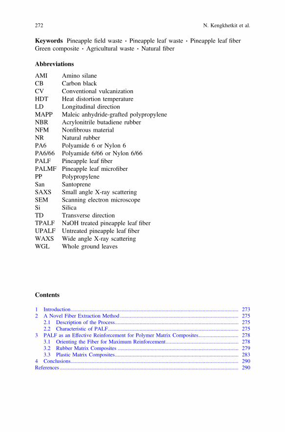
Keywords Pineapple field waste � Pineapple leaf waste � Pineapple leaf fiberGreen composite � Agricultural waste � Natural fiberAbbreviations
AMI Amino silaneCB Carbon blackCV Conventional vulcanizationHDT Heat distortion temperatureLD Longitudinal directionMAPP Maleic anhydride-grafted polypropyleneNBR Acrylonitrile butadiene rubberNFM Nonfibrous materialNR Natural rubberPA6 Polyamide 6 or Nylon 6PA6/66 Polyamide 6/66 or Nylon 6/66PALF Pineapple leaf fiberPALMF Pineapple leaf microfiberPP PolypropyleneSan SantopreneSAXS Small angle X-ray scatteringSEM Scanning electron microscopeSi SilicaTD Transverse directionTPALF NaOH treated pineapple leaf fiberUPALF Untreated pineapple leaf fiberWAXS Wide angle X-ray scatteringWGL Whole ground leaves
Contents
1 Introduction.......................................................................................................................... 2732 A Novel Fiber Extraction Method ...................................................................................... 275
2.1 Description of the Process.......................................................................................... 2752.2 Characteristic of PALF............................................................................................... 275
3 PALF as an Effective Reinforcement for Polymer Matrix Composites............................. 2783.1 Orienting the Fiber for Maximum Reinforcement..................................................... 2783.2 Rubber Matrix Composites ........................................................................................ 2793.3 Plastic Matrix Composites.......................................................................................... 283
4 Conclusions.......................................................................................................................... 290References .................................................................................................................................. 290
272 N. Kengkhetkit et al.

1 Introduction
Pineapple is grown in Africa, tropical America, and Asian countries with totalplantation area of approximately 1 million hectares. The biggest pineapple fruitproducing countries in the world are Thailand and the Philippines. Thailand’spineapple cultivation area is about 100,000 ha. Figure 1 displays a pineapple cul-tivation area in Rayong province, east of Thailand. A large amount of pineapple leafwaste is left in the field waiting for farmers to deal with after the fruits have beenharvested. Figure 2 displays different ways which farmers deal with their pineappleleaf waste in the field. Although different methods exist for the extraction ofpineapple leaf fiber (PALF), the utilization of pineapple leaf waste is still verylimited. Mostly, PALF is used for textile materials and paper for handcrafts.
Pineapple leaf fiber (PALF) is known to possess high mechanical properties, andits properties rank among the top of plant natural fibers as shown in Table 1.Properties of some synthetic fibers are included in the bottom part of the table forcomparison. It is clear that PALF’s properties are comparable to that of glass andaramid fibers, especially when compared in terms of specific properties (propertydivided by density). Glass fiber is normally used to reinforce plastic materials forimproved mechanical properties while aramid fiber is gaining more acceptances forrubber reinforcement. Thus, considering that PALF is obtained from abundantwaste and it has very attractive mechanical properties, PALF is a good candidate forboth plastic and rubber reinforcements.
So far, PALF obtained with conventional extraction methods has been studied asreinforcement for various types of polymer matrices including plastics (Chollakupet al. 2011; George et al. 1995; Kaewpirom and Worrarat 2014; Luo and Netravali1999; Threepopnatkul et al. 2009), rubbers (Lopattananon et al. 2006, 2011;Lopez-Manchado and Arroyo 2002), and epoxy resin (Devi et al. 1997; Payae andLopattananon 2008). A few excellent reviews on this subject can be found
Fig. 1 Pineapple cultivation area in Rayong province, east of Thailand
Pineapple Leaf Fiber: From Waste to High-Performance … 273

(Leao et al. 2015; Mishra et al. 2004; Sapuan et al. 2011). However, these PALFreinforced composites did not display any distinct properties compared to otherfibers. Thus, opportunities for the utilization of PALF in polymer matrix compositesremain high if a proper fiber extraction and composite preparation methods are
Fig. 2 Different methods of dealing with pineapple leaf waste. Top: waste leaves are pushed tothe side of the field and left to dry; bottom: waste leaves are chopped into smaller pieces (with amachine) and left to dry in the field before tillage for the next cycle
Table 1 The properties of natural fibers and synthetic fibers (adapted from Satyanarayana et al.1982; Kalia et al. 2009)
Fibers Young’smodulus(GPa)
Tensile strength(MPa)
Elongation atbreak (%)
Diameter(lm)
Density(g/cm3)
Ramie 61.4–128 400–938 1.2–3.8 – 1.5
PALF 34.5–82.5 413–1627 0.8–1.6 20–80 1.44
Flax 27.6 45–1100 2.7–3.2 – 1.5–3
Jute 13–26.5 393–773 7–8 20–200 1.3–1.45
Sisal 9.4–22 468–640 3–7 50–200 1.45
Banana 7.7–20.0 529–754 1.0–3.5 – 1.35
Cotton 5.5–12.6 287–800 7–8 – 1.5–1.6
Coir 4–6 131–175 15–40 100–450 1.15
Hemp – 690 1.6 – –
E-glass 70 2000–3500 2.5 – 2.5
S-glass 86 4570 2.8 – 2.5
Aramid 63–67 3000–3150 3.3–3.7 – 1.4
Carbon 230–240 4000 1.4–1.8 – 1.7
274 N. Kengkhetkit et al.

used. Here, we will show that with a new type of fiber extraction method, short andfine PALF suitable for both plastic and rubber reinforcements could be obtained. Itwill also be shown how to best utilize the fiber.
2 A Novel Fiber Extraction Method
Traditional methods for PALF extraction include manual or hand scraping, machinedecortication, and retting. PALF obtained from these methods is in the form of longfiber bundles. The long fiber is not suitable for reinforcement of polymer com-posites unless continuous reinforcement is required. The most suitable and con-venient form to use is short fiber. Recently, a novel extraction method for shortPALF was reported (Kengkhetkit and Amornsakchai 2012).
2.1 Description of the Process
Fresh pineapple leaves are chopped into pieces of 6 mm in length and then milledwith stone grinder or other suitable machines. The soft tissue will be ground intopaste while fiber bundles will be broken into smaller bundles or even single fiberwith the same length. The material in this stage is composed of fibrous and non-fibrous materials and is called whole ground leaf or WGL. After drying, the WGL issieved with a relatively coarse screen to separate the fibrous and nonfibrousmaterials. The former is PALF and the latter NFM. PALF tangles to form a bulkymass and stay on the screen while NFM stays as separate small particles and fallthrough the screen. Figure 3 displays steps in the process for the extraction of shortPALF. Unlike conventional methods for which long and perfect leaves are pre-ferred, the new method can receive any type of leaves. The only requirement is thatthe leaves must not be dry. Otherwise, PALF will lose its strength (Kengkhetkit andAmornsakchai 2012).
2.2 Characteristic of PALF
The morphology of PALF obtained by mechanical grinding method is shown inFig. 4. It is seen that the PALF is a mixture of small microfibers and bundles ofmicrofibers as shown in Fig. 4a. High magnification image of fiber bundle end inFig. 4b clearly reveals elementary microfibers of size approximately 3 lm(Kengkhetkit and Amornsakchai 2012).
PALF obtained from the grinding method described above is finer than thatobtained from other conventional methods. Kengkhetkit and Amornsakchai (2012)compared the diameter of PALF obtained from two conventional methods,
Pineapple Leaf Fiber: From Waste to High-Performance … 275

i.e., hand scraping (S-PALF) and water retting (R-PALF), and that obtained frommechanical methods, i.e., ball-milling (BM-PALF) and milling (M-PALF). Theresults are shown in Fig. 5. It is seen that mechanical methods give PALF with highfraction of finer diameter. Although ball-milling gives the highest fraction of finerPALF, it is much slower than normal milling machine.
Fig. 3 Steps in the process for the extraction of short PALF
276 N. Kengkhetkit et al.

Chemical compositions including lignin, hemicellulose, and cellulose content ofwhole ground leaves (WGL), short PALF, and nonfibrous material (NFM) areshown in Table 2. The fibrous material or PALF displays high cellulose content.
The above PALF can be further treated with sodium hydroxide and mechanicalforces from high-speed mixer to produce micro-size PALF or pineapple leafmicrofiber (PALMF) as shown in Fig. 6. This PALMF has much narrower sizedistribution than normal PALF discussed above. It also has very high aspect ratiowhich could be up to 2000 (cut length of 6 mm and diameter of 3 lm). Since bothPALF and PALMF have high mechanical properties and also very high aspect ratio,they both have high potential as reinforcement for polymer matrix composites.
Fig. 4 SEM images of PALF obtained by mechanical grinding method at low and highmagnifications
Fig. 5 The distribution of diameter of PALF prepared by different extraction methods. (adaptedfrom Kengkhetkit and Amornsakchai 2012) For codenames see text
Pineapple Leaf Fiber: From Waste to High-Performance … 277

3 PALF as an Effective Reinforcement for PolymerMatrix Composites
It is known that reinforcing efficiency of any filler will depend on its size, shape,and aspect ratio (the ratio of the largest dimension to the smallest dimension).Particulate fillers with aspect ratio close to unity have the lowest reinforcing effi-ciency while those with platelet or fibrous shapes would have much greater rein-forcing efficiencies. Thus, when using PALF (with characteristics described above),one could expect that it will be an effective reinforcement for polymer matrixcomposites. The degree of reinforcement is highest when the fiber is uniaxiallyaligned and lowest when it is randomly oriented. Thus, it is clear that for maximumreinforcement, one should aim for uniaxial alignment of PALF.
3.1 Orienting the Fiber for Maximum Reinforcement
PALF can be incorporated into polymer matrix using conventional methods that areappropriate for the matrix. For example, melt mixing with plastic materials can becarried out in any type of mixer, be it twin screw extruder, internal mixer, or evenheated two-roll mill to get a homogeneous mix. A similar machine can be used for
Table 2 Chemical compositions of whole ground leaves (WGL), short PALF, and nonfibrousmaterial (NFM) (adapted from Kengkhetkit and Amornsakchai 2014)
Lignin (%) Hemicellulose (%) Cellulose (%)
Whole ground leaves (WGL) 4.57 ± 0.13 34.38 ± 0.66 46.65 ± 0.83
Fibrous material (PALF) 1.98 ± 0.08 19.80 ± 0.21 70.98 ± 0.93
Nonfibrous material (NFM) 7.70 ± 0.16 36.53 ± 0.23 43.69 ± 0.78
Fig. 6 SEM images of PALMF (left) and its size distribution (right)
278 N. Kengkhetkit et al.

rubber matrices. To get proper fiber orientation in the matrix, two-roll mill proof tobe a very convenient tool.
The most important step in getting the fiber align in the machine direction is thetaking out step for both plastic and rubber matrices. A very narrow nip between thetwo rollers is set. The rollers should be run at low speed. The mix is then passedthrough the nip. This will force the fiber to align along the machine direction.Gently pull the mix with slight tension to keep the fiber align as shown in Fig. 7.The compound will be in the form of a thin and long sheet (or prepreg) ready for thenext compression molding step.
It is important that the fiber alignment is kept the same during subsequentcompression molding. This is achieved by stacking the thin sheet of materials suchthat its dimensions are very close to that of the mold cavity, and the thickness isslightly greater than the required thickness. If needed, other types of fiber alignmentsuch as angle-ply or cross-ply can be prepared.
When successful fiber alignment is obtained, the composite will display veryhigh anisotropic properties, i.e., its properties in two directions will be verydifferent. It will have a very high modulus in the machine direction and lowmodulus in the transverse direction.
3.2 Rubber Matrix Composites
Normally, rubbers are reinforced with particulate fillers such as carbon black, silica,or calcium carbonate. In certain applications where excessive deformation isundesirable, rubbers are reinforced with fabric. Short fibers have also been studiedas reinforcement for rubbers as there are several advantages. With proper fiberorientation, fiber reinforced rubber has very unique properties of very highstretching stress at low strains. Since properties of the rubber matrix depend on
Fig. 7 The step of PALF alignment on a two-roll mill during the preparation of uniaxially alignedPALF reinforced rubber composite
Pineapple Leaf Fiber: From Waste to High-Performance … 279

many factors such as rubber type, filler type and content, and cross-link type anddensity, it is conceivable that fiber reinforced rubber with very wide range ofproperties can be prepared.
PALF reinforced acrylonitrile butadiene rubber (NBR) was the first rubbercomposite reported by our group (Wisittanawat et al. 2014a). NBR was chosen todemonstrate the effectiveness of PALF in the reinforcement because it is a polarrubber. Formulations and mixing sequences for the preparation of PALF reinforcedrubbers are shown in Tables 3 and 4, respectively. NBR-PALF composites havevery different stress–strain behavior from that of NBR. Stress–strain behavior ofNBR-PALF in the longitudinal direction (LD) is very different from that in thetransverse direction (TD), indicating a high degree of PALF alignment, as shown inFig. 8. Stress in the LD rises sharply when the composite is stretched and then failsat the relatively low strain. Modulus and tensile strength increase with increasingPALF content while elongation at break decreases. Stress–strain behavior in the TDdoes not change much with the addition of PALF.
Failure of NBR-PALF composites shown in Fig. 8 dominates by fiber pull-out(Wisittanawat et al. 2014a). This has led Wisittanawat et al. to incorporate anadhesion promoter in order to improve the adhesion between the fiber and therubber matrix. As expected, modulus, tensile strength, and tear strength of thecomposites increased. Failure of the composites changed to fiber breakage.However, the composites still failed at very low strain, which could limit theirapplications.
In order to solve the low elongation at break of the NBR-PALF composites,hybrid filler system was utilized. It was hypothesized that PALF would provide
Table 3 Formulations of rubber compounds
Ingredient Amount (phr)
Rubber 100
ZnO 5
Steric acid 2
PALF 10, 20, 30
CBS 1
Sulfur 2
Table 4 Steps of mixing of NBR and NR composites (adapted from Wisittanawat et al. 2014b;Wongpreedee and Amornsakchai 2015)
Ingredient Mixing time (min) Ingredient Mixing time (min)
NBR 0–1 NR 0–2
Sulfur 1–2 PALF 2–8
PALF 2–11 ZnO and stearic acid 8–11
ZnO and stearic acid 11–17 CBS 11–13
CBS 17–20 Sulfur 13–15
Total 20 Total 15
280 N. Kengkhetkit et al.

reinforcement at low elongation while the other filler would provide reinforcementat high elongation (Wisittanawat et al. 2014b). Silica was selected as the hybridfiller as it is well known for effective reinforcement for rubbers. Figure 9 displaysselected results extracted from the work reported by Wisittanawat et al. It is clearlyseen that addition of silica improves the elongation at break of the compositessignificantly. The modulus at low strain is slightly improved due to the increased instiffness of the rubber matrix (with silica). Thus, it can be concluded that by usinghybrid filler system of PALF-silica, rubber composites with very distinct propertiescan be obtained.
Later work on the use of carbon black as hybrid filler confirms the above concept(Prukkaewkanjana et al. 2015). This is shown in Fig. 10. It is now seen thatNBR-PALF10-CB30 displays stress–strain curve with three distinct zones. A verysharp rise in stress is seen in the low strain zone. The end of the first zone marks the
Fig. 8 Stress–strain curve ofNBR and NBR-PALFcomposites containing 10 and30 phr of PALF inlongitudinal direction(LD) and transverse direction(TD) (adapted fromWisittanawat et al. 2014a)
Fig. 9 Stress–strain curvesof NBR and NBR-PALF-Sicomposites (adapted fromWisittanawat et al. 2014b)
Pineapple Leaf Fiber: From Waste to High-Performance … 281

position at which pulling out of the reinforcing fiber (PALF) occurs. In the secondzone, the stress remains roughly constant with increasing strain. In this region, thefibers are still carrying some loads via frictional stress transfer. In the final zone,the stress upturn is seen. The result of NBR-CB30 indicates that the final zone is thecharacteristic of the CB filled NBR. It is now seen that with proper combination offiber and particulate filler, reinforced rubber with very high stretching stress at lowelongation and high tensile strength and high elongation at break could be prepared.The shape of the stress–strain curve of the composite can be adjusted by changingthe amount of particulate filler.
Recently, Pittayavinai et al. have shown, by using NR-PALF-CB system, thatthe stress–strain behavior of rubber matrix composites can be adjusted by changingeither CB content or cross-linking density (Pittayavinai et al. 2016). For NR system,the adhesion between PALF and the matrix is not as good as NBR. As a result, themaximum stress reached in the first zone is lower than that observed in NBRsystem. The stress–strain curve still displays three stress zones as shown in Fig. 11.With increasing cross-link density, the length of the second stress zone becomesshorter, and the stress upturn occurs at a lower elongation at break.
Wongpreedee and Amornsakchai studied NR-PALF composites using two typesof PALF, i.e., untreated or as-prepared PALF (UPALF) and sodium hydroxidetreated PALF (TPALF) (Wongpreedee and Amornsakchai 2015). Both types ofPALF gave composites with similar stress–strain curves in the low strain region asshown in Fig. 12. At high strains, however, composite containing TPALF exhibitedstress upturn at lower strains than that with UPALF. Synchrotron wide-angle X-rayscattering technique was used to follow the crystallization of NR during stretchingof the composites. The presence of PALF caused the onset of strain-inducedcrystallization to occur at much lower strain than normal NR. The early stressupturn in the system containing treated PALF was attributed to better stress transferto the fiber.
From the results shown above, it is clear that PALF is an effective reinforcementfor rubber matrix composites. Since fiber pull-out still be a major failure
Fig. 10 Stress–strain curvesof NBR and NBR-PALF-CBcomposites (adapted fromPrukkaewkanjana et al. 2015)
282 N. Kengkhetkit et al.

mechanism, there are still rooms for the improvement in low strain properties. Thiscould be achieved by improving the adhesion between the fiber and the rubbermatrix.
Rubber composites with the above characteristics can be useful in many differentapplications where flexibility is still needed but large or excessive deformation isnot acceptable. Examples of products with such requirements are power trans-mission belts, conveyor belts, pressure hoses, roller covering rubbers, and tires.
3.3 Plastic Matrix Composites
The use of cellulosic fillers such as sawdust or wood flour in plastic matrix com-posites has received wide acceptance, especially in wood replacement applications.
Fig. 11 Stress–strain curvesof NR and NR-PALF-CBcomposites (adapted fromPittayavinai et al. 2016)
Fig. 12 Stress–strain curvesof NR and NR-PALFcomposites. Insets are WAXSpatterns of indicatedcomposites stretched to 50%strain (adapted fromWongpreedee andAmornsakchai 2015)
Pineapple Leaf Fiber: From Waste to High-Performance … 283

Since this type of cellulosic filler has particulate shape, large improvement inmechanical properties cannot be expected. The main objective is to reduce the useof expensive oil-derived plastics.
Cellulosic or natural fiber, due to its shape, could provide much greater rein-forcement than sawdust. For this reason, the use of natural fiber for the rein-forcement of plastic matrix is getting greater attention. There are many reviews onthis (Karnani et al. 1997; Mishra et al. 2004; Sapuan et al. 2011). Natural fiberreinforced plastic can be used in various areas of applications such as aerospace,automotive parts, construction, marine, electronic component, and sportsequipment.
PALF possesses high mechanical properties. Thus, it can be used to reinforceplastic matrix composites like other natural fibers. It has been shown that all parts ofpineapple leaf including WGL, PALF, and NFM prepared by the novel fiberextraction method present in Sect. 2 could be used (Kengkhetkit and Amornsakchai2014). However, different degree of reinforcement would be obtained as shown inFig. 13 for PP composites. It is clear that PALF provides the highest degree ofreinforcement, followed with WGL and NFM. Therefore, only the use of PALF willbe covered in more detail in this section.
PALF has been tested as reinforcement for nylon, which requires much higherprocessing temperature than PP. Due to practical problem with nylon on two-rollmill, the mix was prepared with a laboratory twin screw extruder and then injectionmolded. PALF could be aligned along the flow direction. The results for PA6 andPA6/66 systems filled with PALF show the improvement in both tensile modulusand tensile strength as shown in Fig. 14.
When PALF is incorporated in thermoplastic PP and Santoprene (San) andaligned according to the method described in Sect. 3.1, it displays very effectivereinforcement in both matrices. Longitudinal properties are improved significantlywhile transverse properties are relatively unaffected as shown in Fig. 15. Thus, itcan be assumed that a high degree of fiber alignment is also obtained in thesesystems.
Fig. 13 Mechanicalproperties of PP-PALF,PP-WGL and PP-NFMcomposites containing 30% ofpineapple leaf materials(adapted from Kengkhetkitand Amornsakchai 2014)
284 N. Kengkhetkit et al.

The presence of PALF in thermoplastic composite not only improves ambientproperties but also improves high-temperature properties. This is seen from theincrease in heat distortion temperature (HDT) of both PP composites and nyloncomposites as shown in Fig. 16. This can be considered very distinct improvementand is not normally reported for natural fiber reinforced plastics. The improvementin HDT would certainly widen the applications of PALF reinforced plastics inhigh-temperature environments.
Since PALF is cellulosic fiber, properties of PALF-thermoplastic compositescould be enhanced by using established methods for other natural fibers. Thisincludes the use of various types of commercial coupling agents such as silanecoupling agent and maleic anhydride-grafted polymer. Addition of coupling agentin PALF thermoplastic systems provides the enhancement of mechanical propertiesof composites due to the improved interfacial interaction between fiber and matrix.Figure 16 shows the effect of silane coupling agent on properties of composites.
Fig. 14 Tensile properties ofPA6/66, PA6/66-PALFcomposite, PA6, andPA6-PALF composite(adapted from Nopparut andAmornsakchai 2016;Panyasart et al. 2014)
Fig. 15 Strengthperformance of PP-PALFcomposites and San-PALFcomposites both inlongitudinal and transversedirections (adapted fromKalapakdee andAmornsakchai 2014;Kengkhetkit 2014)
Pineapple Leaf Fiber: From Waste to High-Performance … 285

Composites with silane coupling agent also have higher HDT than compositeswithout silane coupling agent and neat polymers. In addition, the use of silanecoupling agent in nylon composites provides the improvement in tensile strength inboth PA6 and PA6/66 composites as shown in Fig. 17.
MAPP was used to improve the adhesion between filler and PP matrix in alignedPP-PALF composites. Enhancement of the performance of composite was observed(Kengkhetkit and Amornsakchai 2014). With the addition of 5%wt MAPP intoPP-PALF composite, the flexural stress–stain curve of PALF composite changedsignificantly, and the composite exhibited greater toughness than that of compositeswithout MAPP. This is shown in Fig. 18.
In plastic matrix composites, there can be an additional effect of chain orien-tation, in addition to PALF orientation, on mechanical properties of the composites.This has been demonstrated by Kalapakdee and Amornsakchai (2014). San, aPP-based thermoplastic elastomer, was used as the matrix. After aligning PALF,
Fig. 16 Heat distortiontemperature of PP, PP-PALFcomposites, PA6/66, andPA6/66-PALF composites(adapted from Kengkhetkit2014; Nopparut andAmornsakchai 2016)
Fig. 17 Tensile modulus andtensile strength of PA6/66 andPA6 composites with andwithout silane coupling agent(adapted from Nopparut andAmornsakchai 2016;Panyasart et al. 2014)
286 N. Kengkhetkit et al.

crystalline orientation was also obtained. The orientation of PP is in the samedirection as PALF. If subsequent compression molding is carried out at temperaturelow enough, such crystalline orientation can be retained, and this would provideadditional reinforcement. Too high compression molding temperature woulddestroy the crystalline orientation, leaving only PALF orientation to reinforce thecomposite as shown in Fig. 19.
The combined effects of PALF alignment and matrix crystalline orientation onthe mechanical properties of thermoplastic composite are also seen in PP with agreater degree of enhancement. Kengkhetkit showed that properties of PP-PALFprepreg that prepared according to the method described in Sect. 3.1 had relativelyhigh mechanical properties (Kengkhetkit 2014). When the prepreg was compressedto form a thicker sheet of uniaxially aligned composites, the properties depended oncompression molding temperature. This is illustrated in Fig. 20. Prepreg displays
Fig. 19 Tensile modulus at 10% strain (a) and tear strength (b) of San-PALF compositescompressed at two different temperatures (Adapted from Kalapakdee and Amornsakchai 2014)
Fig. 18 Flexural stress–strain curve of PP and PP-PALF composites without and with 5%wtMAPP
Pineapple Leaf Fiber: From Waste to High-Performance … 287

high mechanical properties due to the combined effect of PALF orientation and PPmolecular orientation. During the subsequent compression molding, the prepregwas reheated again and molecular relaxation occurred. If the compression moldingtemperature is low enough just to melt the prepreg surface to give good bonding,limited molecular relaxation can occur and the composites only drop slightly.Otherwise, complete molecular relaxation occurs at high compression moldingtemperature. Under this situation, only PALF provides the reinforcement.
SEM photographs of etched PP-PALF30 samples in Fig. 21 reveal the strongdifference of PP structure in prepreg and sheet pressed at 195 °C. Prepreg showsdifferent morphology in parallel and perpendicular directions indication highmolecular orientation while the sheet pressed 195 °C displays similar spheruliticstructure in both directions.
In addition, the change in molecular orientation was confirmed with wide-angleX-ray scattering (WAXS). Prepreg and sheet compressed at 175 °C display crys-talline and lamellar orientations. Azimuthal scans of the (110) reflections in Fig. 22clearly indicate so.
It is clearly demonstrated, although from a limited set of examples, that PALFcan be used to reinforce both commodity plastics like PP and high melting tem-perature engineering plastics like nylon. Mechanical properties and HDT of theplastic matrix can be significantly improved. It is important to note that improve-ment in HDT is not easily obtained from most mineral and cellulosic fillers andfibers. PALF reinforced plastics have several advantages over mineral filled plas-tics. These include lower density, lower carbon footprint, biodegradability, andincineratability (at the end of product’s useful life). These composites can be used
Fig. 20 Tensile moduli (a) and strengths (b) of PP-PALF prepregs and sheets containing differentPALF content compressed at 175 °C and 195 °C
288 N. Kengkhetkit et al.

Fig. 21 SEM images of etched surface of PP-PALF30 prepreg (top row) and compressed sheet at195 °C (bottom row) in the longitudinal (left column) and transverse (right column) directions
Fig. 22 Azimuthal scan ofthe (110) reflections for PP(o) and 30PALF-PP(x) prepregs (black) andsheets compressed at 175 °C(dark gray) and 195 °C (lightgray)
Pineapple Leaf Fiber: From Waste to High-Performance … 289

as automotive parts, engineering components, garden products, housewares, andcontainers.
4 Conclusions
The new concept of producing short and fine PALF as reinforcement for plasticsand rubbers is very interesting and challenging. This will not only help farmers indealing with their wastes but also make use of them as renewable materials toreplace, in parts, petroleum-based materials. As-produced PALF provides veryeffective reinforcement for both commodity and engineering plastics. Significantimprovement in HDT can be obtained. Similarly, PALF is also an effective rein-forcement for rubbers. It provides rubbers with very distinct mechanical propertiesthat cannot be obtained with common particulate fillers. PALF can be furthertreated to produce PALMF for even better reinforcement. The use of PALF asreinforcement for plastics and rubbers not only extends the applications of commonplastics and rubbers to cover wider area but also makes them greener and moreenvironmental friendly.
Acknowledgements We thank the following agencies for their kind financial support to theproject: National Research Council of Thailand (NRCT), Thailand Textile Institute (THTI), andPERCH-CIC.
References
Chollakup R, Tantatherdtam R, Ujjin S, Sriroth K (2011) Pineapple leaf fiber reinforcedthermoplastic composites: effect of fiber length and fiber content on their characteristics. J ApplPolym Sci 119:1952–1960
Devi LU, Bhagawan SS, Thomas S (1997) Mechanical properties of pineapple leaf fiber-reinforcedpolyester composites. J Appl Polym Sci 64:1739–1748
George J, Bhagawan SS, Prabhakaran N, Thomas S (1995) Short pineapple leaf fiber reinforcedlow-density polyethylene composites. J Appl Polym Sci 57:843–854
Kaewpirom S, Worrarat C (2014) Preparation and properties of pineapple leaf fiber reinforced poly(lactic acid) green composites. Fiber Polym 15:1469–1477
Kalapakdee A, Amornsakchai T (2014) Mechanical properties of preferentially aligned shortpineapple leaf fiber reinforced thermoplastic elastomer: Effects of fiber content and matrixorientation. Polym Test 37:36–44
Kalia S, Kaith BS, Kaur I (2009) Pretreatments of natural fibers and their application as reinforcingmaterial in polymer composites—a review. Polym Eng Sci 49:1253–1272
Karnani R, Krishnan M, Narayan R (1997) Biofiber-reinforced polypropylene composites. PolymEng Sci 37:476–483
Kengkhetkit N (2014) Novel preparation and surface modifications of short pineapple leaf fiber forreinforcement of polypropylene. Ph. D. thesis, Faculty of Graduate Studies, MahidolUniversity, Thailand
290 N. Kengkhetkit et al.

Kengkhetkit N, Amornsakchai T (2012) Utilization of pineapple leaf waste for plasticreinforcement: 1. A new extraction method for short pineapple leaf fiber. Ind Crops Prod40:55–61
Kengkhetkit N, Amornsakchai T (2014) A new approach to “Greening” plastic composites usingpineapple leaf waste for performance and cost effectiveness. Mater Des 55:292–299
Leao AL, Cherian BM, Narine S, Souza SF, Sain M, Thomas S (2015) In: Faruk O, Sain M(eds) Biofiber reinforcements in composite materials. Elsevier, UK
Lopattananon N, Panawarangkul K, Sahakaro K, Ellis B (2006) Performance of pineapple leaffiber–natural rubber composites: the effect of fiber surface treatments. J App Polym Sci102:1974–1984
Lopattananon N, Jitkalong D, Seadan M (2011) Hybridized reinforcement of natural rubber withsilane-modified short cellulose fibers and silica. J Appl Polym Sci 120:3242–3254
Lopez-Manchado MA, Arroyo M (2002) Short fibers as reinforcement of rubber compounds.Polym Compos 23:666–673
Luo S, Netravali AN (1999) Mechanical and thermal properties of environment-friendly “green”composites made from pineapple leaf fibers and poly(hydroxybutyrate-co-valerate) resin.Polym Compos 20:367–378
Mishra S, Mohanty AK, Drzal LT, Misra M, Hinrichsen G (2004) A review on pineapple leaffibers, sisal fibers and their biocomposites. Macromol Mater Eng 289:955–974
Nopparut A, Amornsakchai T (2016) Influence of pineapple leaf fiber and it’s surface treatment onmolecular orientation in, and mechanical properties of, injection molded nylon composites.Polym Test 52:141–149
Panyasart K, Chaiyut N, Amornsakchai T, Santawitee O (2014) Effect of surface treatment on theproperties of pineapple leaf fibers reinforced polyamide 6 composites. Energy Procedia56:406–413
Payae Y, Lopattananon N (2008) Adhesion of pineapple leaf fiber to epoxy matrix: the role ofsurface treatments. Songklanakarin J Sci Technol 31:189–194
Pittayavinai P, Thanawan S, Amornsakchai T (2016) Manipulation of mechanical properties ofshort pineapple leaf fiber reinforced natural rubber composites through variations in cross-linkdensity and carbon black loading. Polym Test 54:84–89
Prukkaewkanjana K, Thanawan S, Amornsakchai T (2015) High performance hybrid reinforce-ment of nitrile rubber using short pineapple leaf fiber and carbon black. Polym Test 45:76–82
Sapuan SM, Mohamed AR, Siregar JP, Ishak MR (2011) In: Kalia S et al (eds) Cellulose fibers:bio- and nano-polymer composites. Springer, New York
Satyanarayana KG, Pillai CKS, Pillai SGK, Sukumaran K (1982) Structure property studies offibers from various parts of the coconut tree. J Mater Sci 17:2453–2462
Threepopnatkul P, Kaerkitcha N, Athipongarporn N (2009) Effect of surface treatment onperformance of pineapple leaf fiber-polycarbonate composites. Compos Part B-Eng 40:628–632
Wisittanawat U, Thanawan S, Amornsakchai T (2014a) Mechanical properties of highly alignedshort pineapple leaf fiber reinforced - Nitrile rubber composite: Effect of fiber content andbonding agent. Polym Test 35:20–27
Wisittanawat U, Thanawan S, Amornsakchai T (2014b) Remarkable improvement of failure strainof preferentially aligned short pineapple leaf fiber reinforced nitrile rubber composites withsilica hybridization. Polym Test 38:91–99
Wongpreedee T, Amornsakchai T (2015) Synchrotron X-ray diffraction study of pineapple leaffiber reinforced natural rubber composites during stretching. Suranaree J Sci Technol 22:253–263
Pineapple Leaf Fiber: From Waste to High-Performance … 291

Lightweight Wood Composites:Challenges, Production and Performance
Sandra Monteiro, Jorge Martins, Fernão D. Magalhãesand Luísa Carvalho
Abstract Wood composites are materials made by bonding together wood andadhesives into a large material that can be used for different purposes. Nowadays,lightweight materials play an important role in several industries: aerospace,building and furniture. The reduction of weight is desirable for economic reasons(materials and transportation costs) and environmental reasons (resources,eco-efficiency). Once wood composites are employed in these industries, lowdensity is a desired property. There are several options in the market to reduce theweight of composites, such as the use of low-density wood species, lower com-paction of the wooden mat, incorporation of light fillers in the core layer of thepanel, or use of sandwich panels with honeycomb core. All these strategies havechallenges with respect to manufacturing, machinability (connections and lamina-tion of the edges) and performance (physico-mechanical properties).
Keywords Lightweight � Wood-based panels � Sandwich panels
S. Monteiro � F. D. Magalhães � L. Carvalho (&)LEPABE—Laboratory for Process Engineering, Environment, Biotechnology and Energy,Faculdade de Engenharia da Universidade do Porto, Rua Dr. Roberto Frias,s/n 4200-465 Porto, Portugale-mail: [email protected]
S. Monteiroe-mail: [email protected]
F. D. Magalhãese-mail: [email protected]
J. Martins � L. CarvalhoDEMAD—Departamento de Engenharia de Madeiras, Escola Superior de Tecnologia eGestão de Viseu-IPViseu, Campus Politécnico de Repeses, 3504-510 Viseu, Portugale-mail: [email protected]
© Springer International Publishing AG 2018S. Kalia (ed.), Lignocellulosic Composite Materials, Springer Series on Polymerand Composite Materials, https://doi.org/10.1007/978-3-319-68696-7_7
293

Contents
1 Introduction to Lightweight Wood-Based Composite ........................................................ 2942 Fibreboard............................................................................................................................ 296
2.1 Wet Process Fibreboards: Softboard .......................................................................... 2982.2 Dry Process Fibreboards: Light MDF and Ultra-Light MDF ................................... 299
3 Particleboard ........................................................................................................................ 3043.1 Particleboard Manufacture.......................................................................................... 3043.2 Particleboards Made from Light Wood Species ........................................................ 3063.3 Particleboards with Light fillers ................................................................................. 308
4 Extruded Particleboards....................................................................................................... 3115 Sandwich Panel ................................................................................................................... 311
5.1 Sandwich Assembly ................................................................................................... 3125.2 Types of Sandwich Core Materials............................................................................ 313
6 Conclusion and Future Perspectives ................................................................................... 319References .................................................................................................................................. 320
1 Introduction to Lightweight Wood-Based Composite
Wood composites arematerials made by bonding together woodwith different shapesand sizes and adhesives, forming a large material which can be used for a variety ofproducts with the required physico-mechanical properties: furniture, flooring, roof-ing, palettes, decking, structural beams, marine applications, aircraft materials, etc.
The advantages of using wood-based composites, in relation to solid wood, are(1) use of small diameter trees, (2) use of waste wood from industrial processingand agriculture residues, (3) products with uniform and defect-free appearance,(4) better strength than solid wood, (5) products with unique shapes and dimensionsand (6) products with special properties such as low thermal conductivity, fireresistance and better biological durability (Matuana and Heiden 2004).
Several factors have a huge impact on the mechanical properties of wood-basedcomposites such as: wood species, forest management regimes (naturally regen-erated, intensively managed), kind of adhesive used, shape (fibres, flakes, strands,particles, veneer, lumber) and the arrangement of wood elements in composite andthe final composite density. The performance of wood composites can be charac-terized according to several engineering properties. Structural and non-structuralapplications are defined by the mechanical properties of the composite.
Static elasticity and strength are the key properties used to choose the materialsor set up the design and the specifications (Cai 2012).
Nowadays, the use of lightweight materials becomes a topical issue in manydeveloped industrial countries. The trend concerning lightweight materials is noto-rious in many industries and the furniture and wood-based panels industries do notmiss out. The increase of the mobility of people demands that materials should belightweight and should also have proper physico-mechanical properties. Generally, alightweightmaterial bringsmany advantages for producers, designers and consumers:(1) lower costs in consequence of mass reduction and transportation, (2) possibility of
294 S. Monteiro et al.

obtaining thick elements, answering current design trends, (3) more rational use ofwood, when its price is high or availability is scarce, (4) ease of transportation byproducer and final costumer, with lower environmental impacts (Shalbafan 2013).According to CEN/TS 16368, panels with density below 600 kg/m3 are classified aslightweight materials. Materials such as tubular board, honeycomb panel and panelswith foam core are included in this group. Figure 1 shows the different ranges ofdensity for wood-based materials, emphasizing those considered as lightweight.
The different strategies available for obtaining the lightweight wood compositesalready available in the market are summarized in Fig. 2 (Shalbafan et al. 2016b;Wang 2009; Dziurka and Mirski 2013).
Panels such asMDF and particleboardswith lowdensity are producedbyusing lowercompaction of the wood mat. Another strategy is using very light wood species likeOchroma spp. (50–300 kg/m3) or Ceiba spp. (300 kg/m3) from North America andSouth America, respectively. Populus spp. (450 kg/m3) (Trischler et al. 2014) fromEurope is another type of lightwood also used in the production of lightweight parti-cleboards. Extruded tubular boards are frequently usedand the density achievedwith thismethod may vary between 250 and 400 kg/m3. Sandwich panels with foam core (madeof polyurethane or polystyrene foam) or paper-based honeycomb structures are a majortrend in the industry, achieving densities from 100 to 350 kg/m3. However, lightweightpanels have certain restrictions, which constitute challenges to overcome as follows:
Fig. 1 Density of wood-based materials and for cell wall: foam core panel, honeycomb panel,tubular boards, ultra-light and light MDF (medium density fibreboard), veneer plywood, orientedstrand board (OSB), particleboard, medium density fibreboard (MDF), high-density fibreboard(HDF), wood plastic composites (WPC), pregwood and solid wood adapted from Thoemen (2008)
Lightweight Wood Composites: Challenges … 295

• Reduction of mechanical properties, which disallows the use of panels inapplications requiring load-bearing capacity,
• The use of agricultural residues requires higher amount of resin,• Difficult storage of non-wood bio-based materials such as agriculture crops,• Limitations in terms of surface finishing and post-forming,• Increase of production cost associated to the need of new additives due to lower
bonding strength of the new rawmaterials (Balducci et al. 2008; Shalbafan 2013).
2 Fibreboard
Fibreboard is a wood-based panel with a nominal thickness of 1.5 mm or greater,manufactured from lignocellulosic fibres with the application of heat and/or pres-sure (EN 316). The bond is derived either from the felting of the fibres and theirinherent adhesive properties or from a synthetic binder added to the fibres. Otheradditives can be included (EN 622-5).
Fig. 2 Strategies for panel weight reduction
296 S. Monteiro et al.

The most commonly used lignocellulosic fibres are wood, but other plant fibrescan be used such as bagasse and cereal straws. Thermo-mechanical pulping(TMP) is the process commonly used to make fibreboards. This process consists inbreaking the bonds between the wood cells by combining the action of heat andmechanical energy. The lignin present in the wood has the ability to absorb smallamounts of water; therefore, its softening temperature is dependent on moisturecontent. The TPM process uses high temperature (170–195 °C) and humidity (60–120%) that increase the probability of breaking the wood cells, when subjected to amechanical energy during the refining process (Donaldson and Lomax 1989;Thoemen et al. 2010).
The methods of wood-based fibreboard manufacture are generally divided intowet and dry process. The definitions of fibreboards are formulated in the Europeanstandard (EN 622-5). Fibreboards are classified by their production process asfollows:
– Wet process fibreboards (fibre distribution in water)– Dry process fibreboards (fibre distribution in air).
Wet process boards are fibreboards having fibre moisture content of more than20% at the stage of forming. Additionally, wet process boards are classifiedaccording to density, as follows:
–Hardboards (HB) Boards with density � 900 kg/m3
–Medium boards (MB) Boards with density � 400 to <900 kg/m3
–Softboards (SB) Boards with density <400 kg/m3
Dry process fibreboards (MDF) are fibreboards having a fibre moisture contentof less than 20% at the stage of forming and having a density � 450 kg/m3.Medium density fibreboard (MDF) is one of the most rapidly growing compositepanel products in forest products market.
Raw materials namely wood, binders and other additives and the productionparameters are the factors that have a major effect on physico-mechanical propertiesof MDF (Akbulut and Ayrilmis 2004). When wood is considered as a raw material,wood fibre properties such as fibre structure and strength, anatomical and chemicalproperties of fibre, and fibre composition (percentages of whole and broken fibresand fines) are considered to be basic characteristics influencing fibreboard prop-erties, since they occupy a large portion of the total panel volume. For marketingpurposes, MDF of specific density range can be given different denominations. Forexample, the following density-related marketing terms for MDF have becomeestablished:
–HDF MDF with density � 800 kg/m3
–Light MDF MDF with density � 650 kg/m3
–Ultra-light MDF MDF with density � 550 kg/m3
Lightweight Wood Composites: Challenges … 297

2.1 Wet Process Fibreboards: Softboard
Softboards are usually used in the interior of walls and floors, and as underlays inroofs, in order to provide heat insulation properties. The low density leads to a moreenergy efficiency caused by the many air voids in the panel (Rowell et al. 1995;Kollmann et al. 1975).
Softboards can be produced via a wet process (Fig. 3), which is really anextension of paper manufacturing technology.
Wood enters a chipper to be reduced in size (with sizes of approximately 25 and5 mm thick). The chips are screened to remove undersized (<2 mm) and oversized(>50 mm) particles. The chips are washed to remove contaminants and to facilitatedefibration, and then fed into the pre-heater or digester, where they are heated withoverheated steam at 6–10 bar and at a temperature of 175–195 °C for 3–7 min. Thesteam treatment softens the lignin, which binds the fibres together allowing theirseparation in a pressurized discs’ refiner under saturated steam at 8–10 bar. Here,the steamed chips are transformed into fibres. Some wet process boards are madewithout additional binders. If the lignocellulosic materials contain sufficient lignin,this compound can serve as a binder, as long as it is retained during the refiningoperation. Under heat and pressure, lignin will flow and act as a thermosettingadhesive, enhancing the naturally occurring hydrogen bonds. The fibres are dis-charged from the defibrator and then water is added to form a slurry (water is usedas the dispersion medium for forming the fibres into a mat; this is the reason whythe process is called wet process). This slurry is introduced into a wire meshconveyer belt to form the board, losing its water prior to drying. The boards arelightly compressed and dried in an oven. The voids created after the evaporationprovide the board its good thermal properties.
Contrary to other wood-based boards, fibre-based insulation materials are notrequired to display high strength. Surface appearance, internal bond and bendingstrength are also not of primary importance for softboards. The typical properties ofthese boards are presented in Table 1.
There are several insulation products available in the market. The board prop-erties vary with production technologies, final application and specific require-ments. Table 2 gathers examples of few commercial softboards and their properties.
Fig. 3 Wet process manufacture adapted from Suchsland and Woodson (1986)
298 S. Monteiro et al.

Themajor benefit of this production process is the lowVOC emission level causedby the low amount of resin used and the drying time that is longer. The density(>150 kg/m3) and the board thickness (<40 mm) are the twomainly restrictions in thewet process. Panels with higher thickness need a longer drying time which causes anincrease in production costs (Barbu and Pieper 2008; Porter 2012).
2.2 Dry Process Fibreboards: Light MDFand Ultra-Light MDF
Light MDF and ultra-light MDF are widely used in the manufacture of furniture,doors and walls due to many excellent properties such as low density, low thermalconductivity and good sound absorption (Chen et al. 2016). These types of panelsare manufactured by using what is called a dry process (Fig. 4).
Table 1 Typical properties of softboards (Kollmann et al. 1975)
Property Values
Density 170–280 kg/m3
Flexural strength 1.0–2.7 MPa
Modulus of elasticity 80–400 MPa
Maximum thickness swelling 12–20%
Sound absorption of acoustical board (522 Hz) 50–85%
Table 2 Comparison of properties of different softboards available in market (Barbu and Pieper2008)
Product Applicationarea
Thickness(mm)
Density(kg/m3) EN1602
Heatconductivity[W/(m K)]
Materials andadditives
HolzFlex® Intermediaterafterframework
40–200 40 0.038 –Wood fibres–Polyolefin fibres–Ammoniumpolyphosphate
Steico-flex Intermediaterafterframework
40–200 50 0.038 –Wood fibres–Polyolefin fibres–Ammoniumsulphate
AgepanTHDN+F 230
Over rafter 40/60/80 230 0.047 –Wood fibres–Polyurethaneresin
Thermosafehomogen
Universalinsulatingboard
20–240 <110 0.037 –Wood fibres–diphenylmethanedi-isocyanate(PMDI)
Lightweight Wood Composites: Challenges … 299

In this process, the fibres are produced in the same way as the wet process. Afterthe defibration process, wood fibres are discharged into a pressurized blowline, atube with 80–120 mm of diameter, which transports wet fibres to the dryer. In theblowline, when the fibre is blended under high pressure, the resin is more easilydistributed due to the steam expansion that causes the separation of fibres (Thoemenet al. 2010).
Resins like polymeric diphenylmethane di-isocyanate (PMDI),urea-formaldehyde (UF) and phenol formaldehyde (PF) are used as adhesives(Suhaily et al. 2012). The adhesives, as well as other additives, are injected into theblowline through a 3–5 mm nozzle at high pressure (12–14 bars). The adhesiveload is usually between 8 and 15% (resin solids/oven-dry wood). The wet resinatedfibres are then blown through a flash tube dryer (with around 100 m long and 1–3 m in diameter) at around 30 m/s. At the end of the tube, cyclones separate thedried fibre from steam. After drying, fibres have approximately 8–12% moisturecontent. The dry fibre is conducted to mat formers. These are made with thepurpose of distributing an even layer of fibres onto a continuously moving belt.Here, the panel thickness is controlled by monitoring the speed belt. The forminghead spread fibre mattress homogenously. In the case of an 18 mm thick MDFboard, the mat is around 680 mm high and has a bulk density of 23 kg/m3. Afterpassing a continuous prepress to reduce its height, the mat is then pressed in acontinuous hot press with temperature in the range of 180–210 °C and pressurebetween 0.5 and 5.0 MPa (Thoemen et al. 2010). The pressing stage can be used tomanipulate panel properties by changing the panel density profile. This operationhas a major effect on the balance of properties of the resulting panel: a rigorouscontrol of all processing variables is necessary to achieve appropriate productquality and to minimize pressing time (Carvalho and Costa 1998). Immediatelyafter pressing the panels are fed into a star shape cooler where boards are stood ontheir edges to expose their faces to ambient air to facilitate rapid cooling. Finally,boards are subjected to finishing operations, which includes trimming, sanding andcut to size. Nowadays manufacturer also includes several surface treatments such aslaminating, profiling and painting.
Light and ultra-light MDF are produced in the same way as MDF, but lowerpressing pressure is used to attain lower density MDF. The main advantage of thisprocess is the decrease of the density to 50 kg/m3 and an extensive range ofthicknesses (<200 mm). A disadvantage of the dry technology is the high-levelamount of resins that is needed to strengthen the fibre bonds (Barbu and Pieper2008).
Fig. 4 Dry process manufacture adapted from Suchsland and Woodson (1986)
300 S. Monteiro et al.

Light MDF is used in situations where weight reduction is required in the rangeof 15–20% and where the machinability performance is not a limiting factor.
In the manufacturing of MDF, several important factors have direct effects onmechanical properties and stability of the panel, namely the resin system, moisturecontent, hot-pressing conditions and wood fibre characteristics. The structure andmorphology of fibres have more influence than their mechanical characteristics onthe board properties. Fibres with different morphologies have different specificsurface areas (Xing et al. 2004). Short fibres need a higher amount of resin whencompared with longer fibres, which generally results in better mechanical propertiesfor the panels. When the resin content of the panels increases from 6 to 12%, anincrease in mechanical properties (internal bonding, modulus of rupture andmodulus of elasticity) is observed, while thickness swelling and water absorptiondecrease. In the thermo-mechanical pulping process, usually used to refine fibres,refining pressure and time are two important features that affect the final propertiesof the board. With the exception of water absorption, refining pressure has greatinfluence in overall panel properties. On the other hand, refining time does not alterthe properties of fibre and board (Nayeri et al. 2014). The effect of moisture contentchange on panel flatness is difficult to predict because of the characteristic variationof the density level throughout the thickness, or vertical density profile.
The panel properties depend on the compaction ratio of each layer that forms thepanel. Generally, the difference between the layers is defined by the compactionratio, since that no differences exist in geometry fibre and resin amount in the wholepanel (Ganev et al. 2005).
The requirements for light MDF are different depending on its use in dry orhumid conditions. Panels in humid conditions have to withstand the presence ofwater vapour in the surrounding air and casual contact with water on the surface.Table 3 specifies the requirements for light MDF boards for use in dry and humidconditions, particularly interior fitments including furniture.
Concerning ultra-light MDF, the requirements are different from light MDF. Inthis case, panels are divided into two groups:
– Ultra-light MDF Type 1 (UL1-MDF), these boards are typically used as insu-lation panels providing limited mechanical stiffness;
– Ultra-light MDF Type 2 (UL2-MDF), these boards are typically used as panelswith stiffening function; they also can be used with fasteners. These panels haveinsulating properties.
The next table specifies the requirements for these two types of panels under dryconditions (Table 4).
The most important feature of low-density MDF is its homogeneous densityprofile along the thickness, which allows turning and edge profiling operations. Thepossibility of surface and edges finishing is one of the main advantages of thismaterial over other wood composites.
There are several options of traditional light and ultra-light MDF in the market,in Table 5 are presented some examples.
Lightweight Wood Composites: Challenges … 301

There is a new technology to produce low-density fibreboards different fromtraditional manufacturing. Dascanova® developed a unique mat modificationtechnology that alters the compressibility of selected particles before pressing thefinal board. This allows redistribution of the density inside the board. Unlikeconventional fibreboards that have homogeneous density in the core and higherdensity on the surfaces, Dascanova fibreboard has a vertical density profile thatchanges along the entire board (Fig. 5).
The ideal construction form is the triangular or wave structure. In comparison tostandard technology, up to 30% less raw materials (incl. resin and other chemicalcomponents) are needed for producing Dascanova Fibreboard. The mechanicalproperties are similar to standard fibreboard, while internal bond strength (IB) isimproved due to this special internal structure. The panels produced have anaverage density of 428 kg/m3 with a bending strength and modulus of elasticity of9.2 and 2.097 N/mm2, respectively, (Denesi 2012).
Table 3 Requirements for light MDF boards for use in dry and humid conditions (EN 622-5)
Property Conditions Testmethod
Unit Ranges of nominal thickness
>6–9
>9–12
>12–19
>19–30
>12–19
>45
Swelling inthickness 24 h
Dry EN317
% 20 16 14 12 11 11
Humid 18 16 13 12 11 10
Internal bond Dry EN319
N/mm2
0.45 0.45 0.45 0.45 0.40 0.40
Humid
Bendingstrength
Dry EN310
N/mm2
20 20 18 15 14 14
Humid 20 20 18 16 16 14
Modulus ofelasticity inbending
Dry EN310
N/mm2
1700 1700 1600 1500 1400 1200
Humid
Table 4 Requirements for ultra-light MDF boards for use in dry conditions (type UL1-MDF andtype UL2-MDF) (EN 622-5)
Property Conditions Testmethod
Unit Ranges of nominal thickness
>9–12
>12–19
>19–30
>30–45
>45
Swelling in thickness24 h
UL1-MDF EN 317 % 18 14 13 12 12
UL2-MDF
Internal bond UL1-MDF EN 319 N/mm2
0.15 0.15 0.15 0.13 0.13
UL2-MDF 0.35 0.35 0.35 0.30 0.30
Bending strength UL1-MDF EN 310 N/mm2
7.7 6.9 6 5.1 5.1
UL2-MDF 18 16 14 12 12
Modulus of elasticityin bending
UL1-MDF EN 310 N/mm2
600 560 510 470 470
UL2-MDF 1400 1300 1200 1100 1100
302 S. Monteiro et al.

Table 5 Mechanical properties of some light and ultra-light MDF available in the market for dryconditions. Information taken from the products’ datasheets
Product Application area Thickness(mm)
Internalbond(N/mm2)
Swellinginthickness,24 h (%)
Bendingstrength(N/mm2)
Kronospan Building material for asubstitute for timber innon-load-bearing walls,ceilings, partitions
15–18 � 0.80 12 45
Fibrapan Loudspeaker boxes for soundequipments, doors, decorativemouldings
6–45 0.50–0.55
9–18 15–20
Caberwood General-purpose joinery 12–25 0.45 12 20
Mediteultra-light
FurnitureCeilingsPicture framesMobile home components
12–18 0.35 10–15 15
Fibrapanultra-light
Used in the constructionindustry and in the setting-upof exhibitions and fairs
9–28 0.50 13–17 14–18
Caberwoodultra-light
Theatre sceneryFilm sets and exhibitions
12–25 0.35 13–18 14–18
Fig. 5 Scheme of the comparison between the standard technology of fibreboard production andthe developed Dascanova technology adapted from (www.wbpionline.com)
Lightweight Wood Composites: Challenges … 303

3 Particleboard
As defined in European Standard EN 309, particleboard is a ‘wood-based panelmanufactured under pressure and heat from particles of wood (wood flakes, chips,shaving, sawdust and similar) and/or other lignocellulosic material in particle form(flax shives, hemp shives, bagasse fragments and similar) with the addition of anadhesive’. As said before, particleboards with a density below 600 kg/m3 aredefined as lightweight particleboard (European technical specification CEN/TS16368). These panels are commonly used in furniture, being overlaid with differentmaterials for decorative purposes. Particleboard can also be employed in flooringsystems, in house construction, for stair treads and as underlayment (Maloney1989). These applications require high mechanical strength and good dimensionalstability, once the panels are exposed to bending stress, static and impact forces.Besides that, particleboards must be resistant to water absorption (Nemli andDemirel 2007). Particleboard is the most popular wood-based panel in the marketdue to its lower cost, which results from the use of recycled wood, and to itsintrinsic relatively low density compared with other boards.
3.1 Particleboard Manufacture
The raw materials used in particleboard manufacture consist of wood residues fromsawmills, recycled cellulosic materials and plant residues such as wheat straw andbagasse. The initial step in particleboard production is the reduction of the woodinto smaller sizes. For this, large particles are chipped in the Breakdown Machines,using hammer mills and flakers. The shape and integrity of the wood particles havea huge influence in the final properties of particleboard. The use of homogeneousraw material is very important to produce panels with good strength, smooth sur-faces and similar swelling. After the particles are cut to the desired size, they aresent to the dryer in order to obtain the intended moisture content, usually in therange of 2–8%, depending on the resin chosen to produce the board. Higher valuesof moisture content can generate a large amount of water vapour during pressing,causing the lamination of the panel. The adhesive system must be preparedaccording to the formulation. Different amounts of adhesive are used in the surfaceand core layers. The adhesive content is calculated on a solid adhesive to oven-drywood basis. Normally, particleboards have three layers, a core layer with coarserparticles and a lower density and two surface layers with finer particles and higherdensities (Maloney 1989). The smaller particles contribute to improve the surfacequality and the larger one provides better mechanical properties like bending.
After being mixed with the resin, the particles are formed into a mat and thentransferred to the hot press for the panel curing process. This step is critical andrequires carefully controlled temperature, pressure and timing. The press time andtemperature are very important since it is necessary to get a high enough
304 S. Monteiro et al.

temperature in the core to cure the adhesive, at the same time as the temperature atthe surface should not be too high to avoid thermal degradation. Typical pressuresare 2–4 MPa and temperatures 200–220 °C. After pressing, the boards are cut,sanded and finally, the edges are trimmed. Boards may also be subjected to differentfinishing. They can be veneered or overlaid with other materials, like impregnatedpaper laminates. Paint and lacquer can also be used in the board finishing (Nemliet al. 2005). A schematic example of particleboard production can be seen in Fig. 6.
The resins most commonly used in particleboard production areurea-formaldehyde (UF), melamine formaldehyde (MF) and phenol formaldehyde(PF), the last one being used to a much lesser extent. Other types can be used suchas isocyanate resin (diphenylmethane di-isocyante—MDI and polymericdiphenylmethane di-isocyante—pMDI) (Dunky 1998; Stoeckel et al. 2013).
Fig. 6 Particleboardmanufacture diagram
Lightweight Wood Composites: Challenges … 305

The advantage of UF resins when compared with the other ones is their highreactivity, fast curing, good adhesion to wood, and low cost (Costa et al. 2013).
Usually, physico-mechanical properties are evaluated according to Europeanstandards. The mechanical properties specifications for general-purpose lightweightboards (type one—LP1) and for use in dry conditions (type two—LP2) are pre-sented in Table 6.
3.2 Particleboards Made from Light Wood Species
One of the interesting strategies used by the lightweight wood-based panel industryto achieve the density reduction of particleboard is the use of light available woodspecies. With this strategy, it is possible to achieve maximum reduction of one-thirdof the initial density. However, to maintain the mechanical properties such asinternal bond and bending strength at acceptable values, producers had to increasethe amount of used resin and optimize the board’s density profile. On the otherhand, the use of light wood species is strongly dependent on the availability andseasonality of wood, the global resources are limited and they are not sufficient tomeet market needs. The production cost caused by the increasing of resin in themanufacture of boards also is a huge concern to the producers. Usually, the materialcosts related to this type of product are more than half of the production costs(Barbu et al. 2010).
In literature, there are a few examples of particleboards produced with woodlight species such as poplar (Populus spp.) (Boruszewski et al. 2016) Seraya(Shorea spp.) (Kawai et al. 1986), paulownia (Paulownia tomentosa) (Kalayciogluet al. 2005), kelempayan (Neolamarckia cadamba) (Lias et al. 2014). Figure 7shows the internal section of particleboard made from Populus spp. wood.
Particleboards produced with these light wood species have a range of densitybetween 300 and 600 kg/m3. In these studies, an isocyanate adhesive is usuallyused as the binder, due to its ability to form covalent bonds with the hydroxyl
Table 6 General purpose lightweight boards LP1 and LP2 for use in dry conditions (CEN/TS16368)
Type Property Testmethod
Unit Requirement
Thickness range (mm, nominal)
>6–13
>13–20
>20–25
>25–32
>32–40
>40
LP1 Bending strenght EN 310 N/mm2
4.0 3.5 3.0 2.5 2.0 2.0
LP2 8.0 7.0 6.0 5.0 4.5 4.0
LP1 Modulus of elasticityin bending
EN 310 N/mm2
550 500 475 450 400 375
LP2 1000 950 900 850 750 650
LP1 Internal bond EN 319 N/mm2
0.28 0.24 0.20 0.17 0.14 0.14
LP2 0.35 0.30 0.25 0.20 0.17 0.17
306 S. Monteiro et al.

groups on the wood surface. This high reactivity allows faster cure rates whencompared with the amino and phenolic resins, and lower adhesive loads. In generalterms, the properties of particleboards are significantly affected by the density of theraw materials; panels produced with light wood species may lead to panels withhigher strength when compared with higher density species. This occurs becauselight species have higher compaction ratio, which allows a greater contact areabetween the wood particles during the pressing operation obtaining a good bonding.To obtain maximum bonding a certain amount of pressure is needed; the adequatepressure depends on the ratio between the board density and the wood speciesdensity. To produce particleboards with medium density, the required ratio iscommonly higher than 1.3 (typically ratio in boards produced with amino resins).Boards produced with high-density species with admissible properties for use inmost applications have high density. It is possible to obtain a reduction of densityby mixing high and low-density species. On the other hand, the use of raw materialswith different density can cause problems in some steps of the manufacturingprocess such as the following:
– milling operation—particles with different densities are milled differently;– drying operation—loss of moisture content is affected by density;– pressing operation—particle compressibility depends on density.
The amount of resin to be used can also be affected by the different character-istics of the wood material (Xu et al. 2004; Maloney 1989).
Fig. 7 Internal section of particleboard made from Populus spp. wood
Lightweight Wood Composites: Challenges … 307

Boruszewski et al. studied the effect of technological parameters on mat com-pression during the producing of lightweight particleboards (500 kg/m3) made oftwo low-density species (Populus spp. and Pinus spp.). Three series of panels wereproduced: one made with only pine, other made only with poplar, and the last onewith a mixture of the two wood species. The results showed that the characteristicsof the species used, such as heat transfer coefficients, and moisture content affectsignificantly the compression process. Lower density species require higherpressing times or higher heat transfer in the panel core layer. With regard tomechanical properties, the modulus of rupture (MOR) and the modulus of elasticity(MOE) had higher values for panels made with poplar wood. This is related to thelow density of poplar wood, which leads to higher compaction. However, boardsproduced with mixed poplar-pine revealed the best performance in terms of theinternal bond (IB). This result is explained by the density difference of the twowood species used, which requires the use of higher resin amount. Another reasonis the higher extent of compaction of poplar face layers in the mixed boards, due tothe lower density of this wood furnish (Boruszewski et al. 2016).
Studies carried out by Kalaycioglu et al. showed that particleboards producedwith paulownia with a density of 550 kg/m3 had MOE and MOR strength valuesthat meet the requirements for general uses and interior fitments established in ENstandards. As expected, the panels produced with a density of 650 kg/m3 presentedbetter mechanical properties (Kalaycioglu et al. 2005).
Another trend of lightweight wood-based panel industry is the use of alternativeraw materials such as agricultural residues and annual/perennial plants to produceparticleboards Dziurka et al. studied particleboards made from wood and rape strawparticles to produce particleboards with density in the range of 350–550 kg/m3. Theresults revealed that, as established, the reduction of density in both series ofproduced panels (wood and rape straw) lead to a reduction of bending strength andmodulus of elasticity. Panels manufactured with rape straw showed a reduction ofstrength of 32% when the density of the boards is reduced from 550 to 350 kg/m3.For the same density variation, strength reduction was 18% for particleboardsproduced from wood. The modulus of elasticity showed the same trend. The use ofveneer on panel’s surface improves significantly the bending strength. All producedboards meet the requirements of boards for interior decoration and furnitureapplications (lightweight boards LP2) (Dziurka and Mirski 2013).
3.3 Particleboards with Light fillers
In recent years, the competition for wood has been increasing, particularly due tothe extensive use of this resource in the construction and furniture sectors.Therefore, the use of non-wood raw materials to reduce the weight of particleboardsis an interesting approach. Materials like expanded polymeric particles, starchgranulates or even popcorn (Kharazipour and Bohn 2012) have been mixed withwood in the core layer of panels. In low-density particleboards, the light fillers fill
308 S. Monteiro et al.

the voids between wood particles, allowing for improved machinability of paneledges (Shalbafan et al. 2016a).
BASF Company developed Kaurit Light, with a core made from a mix ofexpanded polystyrene foam (EPS) and wood particles (Fig. 8), with 30% lowerweight than a conventional particleboard, while maintaining the same strength asstandard (Peretolchin 2009). The size range of the EPS particles used is 0.3–0.8 mm.
To produce expanded polystyrene foam, deionized water, styrene and the mix-ture initiator are added to the reactor under agitation at ambient temperature. Thenthe stabilizer is added to the reactor. The stabilizer consists of insoluble inorganicsalts such as magnesium carbonate, which prevent the monomer droplets fromcoalescing. It is during the heat cycle that occurs the development of droplet size.After polymerization, when the spherical particles are formed, the mixture is cooledand centrifuged to separate the water from the polymer beads and then the beads aredried. The beads and the water are added to the impregnation reactor. Duringheating, the reactor is pressurized with blowing agent, usually n-pentane, at 5–7%w/w with respect to the polymer. During this step, the blowing agent diffuses intothe beads. At the end of this stage, the system is cooled down and the excess of thestabilizer is removed from the particle surface in a washer tank. The separation ofpolymer beads from water is made by centrifugation. Then the particles are dried.
Fig. 8 Internal section of particleboard produced with expanded polystyrene foam (EPS) mixedwith wood particles in core layer
Lightweight Wood Composites: Challenges … 309

In the final processing, the EPS beads are heated, usually with steam that causes thebeads to expand by foaming and their volume to increase (Kannan et al. 2007).
Another type of expanded material usually used in the core layer of particle-boards is expandable microspheres (MS). This filler is commercially availableunder the name of Expancel and is produced by AkzoNobel company. Themicrospheres consist of a polymer shell (typically acrylonitrile or vinylidenechloride copolymerized with methyl methacrylate or methyl acrylate) encapsulatinga gas (isobutene) (Magnus 2010). Increasing temperature above 85 °C causes thepolymer shell to soften, which, in combination with the increased pressure of theencapsulated gas, results in sphere expansion. The particle size of MS is approxi-mately 15 µm before expansion (Shalbafan et al. 2012), and 40 µm after expansion.
The main difference between MS and EPS is that the first is added to the corelayer in the unexpanded state, having micrometric sizes. EPS particles are alreadyexpanded, having sizes of few millimetre. For this reason, MS can be more difficultto scatter in the core layer. Another important difference is the glass transitiontemperature (Tg): EPS particles have a higher Tg (103 °C) compared to MS(85 °C). This property affects the processing conditions of the panel. Theinflammability of the blowing agents used in both fillers is the main limitation; thisimplies restrictions in some applications (Shalbafan 2013).
In the studies carried out by Shalbafan et al, the mechanical properties ofmulti-layered lightweight panels produced with MS core layer with different surfacethickness (3, 4 and 5 mm) were evaluated. The target density of particleboardsvaried from 300 to 500 kg/m3. The study revealed that the IB of the panels with MSin the core layer increased when the face layer thickness is raised. The same appliesto bending strength. This is explained by the increase of density in the board core(120–180 kg/m3), which promotes a better interaction between wood particles andMS. However, when compared with conventional panels, only particleboards withMS with higher density (500 kg/m3) had IB higher than 0.24 N/mm2
(IB requirement for lightweight particles boards’ type 1) (Shalbafan et al. 2012).In another study developed by Shalbafan et al., different amounts of expanded
polystyrene particles (5, 10 and 15% based on the dry mass of wooden particles)were used to produce particleboards with two different densities (450 and 500 kg/m3). The research showed that the use of these fillers affects the physical andmechanical properties of the particleboards. Fillers absorb lower amounts of resinwhen compared with wood particles, which improved the efficiency of the adhesive.As expected, panels with higher density had better flexural properties. Panels with adensity of 500 kg/m3 had higher IB when compared with conventional particle-boards, due, according to the authors, to a bonding reinforcement effect caused bythe fillers in panel core layer. Concerning physical properties, low-density parti-cleboards had lower thickness swelling compared to conventional particleboards,mostly due to the presence of an hydrophobic filler. The same trend was observedfor water absorption (Shalbafan et al. 2016a).
310 S. Monteiro et al.

4 Extruded Particleboards
Extruded boards, also called tubular boards, are a type of particleboard produced byextrusion (Kreibaum process), while the conventional particleboards are manufac-tured by flat-pressing (Fahrni process) (Zhang and Lu 2015). In the extrusionprocess, wood residues and vegetable waste can be used if they are reduced to shortparticles. Glued wood particles are introduced in a hot press, compressed using apiston driven by an eccentric flywheel, and extruded through the hot section of thepress, forming a board. Different types of hollow tubes are formed, depending onthe diameters of the heated rods used (Fig. 9) (Wittmann and Wolf 2014).
Extruded boards are used in the production of furniture components such aslow-density core for doors, tabletops and wall boards. They can also be employedin the production of prefabricated houses. Tubular boards have low strength in thelongitudinal direction, higher linear swelling and lower perpendicular swellingwhen compared to the flat pressed boards. Usually, this type of boards is reinforcedby using surface veneers (Kollmann et al. 1975; Borgin 1958).
5 Sandwich Panel
Sandwich panels are multilayer structures with two thin facings adhesively bondedto a thick core produced from lightweight material (Fig. 10). This type ofarrangement leads to an increase of the strength and stiffness without much increaseof the weight (Alessandro et al. 2013; Petras and Sutcliffe 1999).
This type of panel has several applications in fields where high performance(higher strength, damage tolerance and thermal resistance) and low weight are
Fig. 9 Scheme of cross section of tubular boards with identical (top) and different (bottom)diameters of hollow tubes
Lightweight Wood Composites: Challenges … 311

required, such as aerospace and marine industries, furniture and automotive con-structions (Schubel et al. 2005; Meraghni et al. 1999).
The appropriate selection of facing and core material enable obtaining a productwith the desired characteristics. A waterproof facing can be used in several housespanels, a facing with abrasion resistance can be applied to floors. In addition, fordecorative purposes, plastic facings could be applied to walls, doors and furnish-ings. The type of material used in the core can be selected to confer thermalinsulation, fire and degradation resistance to the panel (Kollmann et al. 1975).
5.1 Sandwich Assembly
The crucial step in the assembly of the sandwich composite is gluing the faces tothe core of the panel. This process could be carried out in a hot or cold press, in acontinuous press or by moulding. Low pressures must be used to avoid crushing thecore. In addition, the press plates must be precisely parallel; otherwise, the core cancrush gradually.
Timber-based boards can be used as facing materials. However, this disallowsuse in continuous foaming lines and commonly the board’s lengths are lower than3.5 m. This type of facing is more suitable to the mould foaming and bondingmethods. It is necessary to use appropriate joints to produce long panels.Wood-based chipboard or plywood can be applied to low humidity environments,however, if the panel is subject to long-term loading, core and face deformationmay occur. Plywood is made from thin layers of wood veneers, designated pliesthat are glued and pressed to form the panel (Matuana and Heiden 2004). The usualthickness is in the range of 4–27 mm and the density varies between 550 and
Fig. 10 Schema of sandwich structure adapted from Petras and Sutcliffe (1999)
312 S. Monteiro et al.

700 kg/m3. Chipboard is produced from wood chips with a thickness between 0.2and 0.4 mm that are bonded together employing temperature and high pressure.The thickness is usually in the range of 2–25 mm with a density between 600 and750 kg/m3 (Davies 2001).
The preparation of cores in sandwich structures commonly involves cutting toadequate thickness and expanding honeycomb cores to obtain the intended cell size,if the core was acquired in the unexpanded form. Foams cores may be pre-formedinto a block or foamed in situ, between the faces (Karlsson and TomasÅström1997). An adhesive is used to bond the faces to the core. A low viscosity adhesivecan be applied by spraying, in successive coats, while an adhesive with higherviscosity can be applied with a brush or hand roller (Kollmann et al. 1975).
5.2 Types of Sandwich Core Materials
Usually, the core of the panel is produced with low strength materials. However, thehigh thickness provides higher bending stiffness to the sandwich construction.Structurally, the core has two functions: (1) separate the faces and prevent defor-mation in the direction perpendicular to the face plane and (2) confer some degree ofshear rigidity along the planes that are perpendicular to the face. Table 7 shows someproperties of different materials that can be used as a core in a sandwich construction.
In the design of sandwich panels it is necessary to take into account the fol-lowing factors: (1) the specific characteristics of the core, which can vary dependingon the material used; (2) the effect of shear flexibility of the core; (3) the effect ofthe core on the buckling of the faces; (4) the effect of temperature in causingstresses and deflections and (5) the deformation behaviour (Davies 1993).Non-structural features like thermal conductivity, permeability, weight and mois-ture sorption should be considered in the design of the panel (Kollmann et al. 1975).
It is possible to distinguish two types of the core layer in sandwich panels as:homogeneous and non-homogeneous (Wang and Wang 2016). The first groupincludes cores made from hardwood strips (Ochroma spp., Populus spp.,low-density Pinus spp.). Thermosetting or thermoplastic foams with open or closedcells are also used to produce a sandwich panel with the homogeneous core. Thefoams are produced from polymers like polyurethane, polystyrene and polyvinylchloride (Pishan et al. 2014; Karagiozova et al. 2009; Bull and Edgren 2004). Thegroup of non-homogenous cores includes textile, corrugated and honeycomb cores(Fig. 11). Honeycomb cores can be made of metal, plastic or paper.
Foamed core panelsFigure 12 shows a board with a foam core. There are several methods for
manufacturing a sandwich panel with foam core.In the batch process, the prefabricated layers are assembled together with the
adhesive and the stack is pressed under temperature and pressure needed to cure theadhesive and form the final sandwich panel (Karlsson and TomasÅström 1997).
Lightweight Wood Composites: Challenges … 313

Table 7 Properties of different core materials (Kollmann et al. 1975)
Core material Density(kg/m3)
Elastic modulus(MPa)
Shearmodulus(MPa)
Shear strength(MPa)
TLa TWb TL TW
Balsa wood 80 1530 68 84 1.1 1.0
112 103 145 1.6 1.4
144 138 205 2.1 1.8
176 174 264 2.6 2.2
Paper honeycomb 27 – – 17 – 0.21
32 – – – – –
50 – – 53 – 0.76
Polystyrene foam 28 8 8 – 0.22 –
48 14 12 – 0.39 –
72 21 18 – 0.39 –
Polyurethane foam 96 28 12 12 0.83 0.76
144 83 25 28 0.65 0.69
160 62 24 19 1.6 1.4aTL-parallel to the core ribbon directionbTW-perpendicular to the core ribbon direction
Fig. 11 Scheme of varies types of sandwich cores adapted from Pflug et al. (2002)
314 S. Monteiro et al.

The high production costs necessary for this manufacturing process and the limitedsizes countervail the weight reduction achieved with this method (Barbu et al.2010). Another process is mould forming. In this case, an exact amount of foam isdirectly introduced into the cavity between two faces to fill the mould. It is adiscontinuous process where the board is produced in a closed mould whosedimensions are the same as the final panel. The upper face is supported by spacersin order to maintain it in position. If edge profiles are required, these must be placedat this stage. The mould structure must be rigid enough to withstand the highpressures reached during foam formation. After the introduction of foam in themould, the panel is left in the mould for a defined period of time and then isremoved. The main advantage of this method is allowing the production of panelswith complex shapes. However, this is a relatively slow process that can cause voidspaces within the panel, due to the non-uniformity of foam flow (Davies 2001).
For the mass production of foam sandwich panel, a continuous process can beused. The face material run through the roll formers into coils, that creates thesurface and edge profiles. In this process foils or impregnated paper are used forprefabricated facings and the core is usually foamed between the faces. Dependingon the properties of the foam, an additional adhesive layer may be needed. Forexample, if the core layer is a polyurethane foam, the additional layer of adhesive isnot used. The foam liquid is introduced by injection in the panel line. The foamexpands and then the panel is cooled down and cut to the desired length (Fig. 13).
Fig. 12 Sandwich panel with a polystyrene foam core and wood-based particleboard in thefacings
Lightweight Wood Composites: Challenges … 315

The main advantage of this process is to have less production steps, compared tothe other process described above, which leads to a higher efficiency in time,material and human resources. This aspect had a huge effect on the final panel cost(Shalbafan 2013).
Honeycomb core panelsA honeycomb panel is constituted by a honeycomb-type core (typically with
hexagonal cells) bonded to the surfaces (Nilsson and Nilsson 2002). Hexagonalcells are the most usual configuration; but there are others, such as the square,rectangular, corrugated, flex-core and reinforced cells shown in Fig. 14.
The type of surfaces chosen for a particular application is determined by func-tional requirements such as strength, stiffness, damage tolerance and appearance atminimum overall cost. In this kind of composite, the bending loads (compressionand tension) are supported by the faces and the shear loads are supported by thecore (Nilsson and Nilsson 2002). As said before, the core materials can be plastic,metallic or paper. Paper honeycomb panels (Fig. 15) have been widely used for theproduction of door leaves not only in the construction or furniture but also inaerospace and automobile sectors.
In general, any type of wood-based panel can be used for the faces, but the mostcommon are particleboards and MDF, due to their low cost (Barboutis andVassiliou 2005). Paper honeycomb can be produced by two different processes:expansion manufacturing and corrugation manufacturing (Fig. 16).
This process begins with cutting flat sheets of paper from a roll fixed on arotating drum. As the sheets are stacked, alternating lines of glue are printed oneach sheet. After the sheets are stacked the adhesive is cured. Slices of the unex-panded bock are cut with the required thickness (typically above 10 mm) and thesheets are pulled apart, causing the expansion of the hexagonal honeycomb core.After expansion, the residual stress is reduced by the controlled application of heatand moisture.
The corrugation process is another way to produce honeycombs (Fig. 17). Herethe material is corrugated or folded into a certain shape and then the shaped layersare glued into a honeycomb block. The block can be then sliced into pieces of therequired size (Pflug et al. 2002).
Honeycomb panels present good load-bearing behaviour, despite the weightreduction. However, they have some limitations as follows:
Fig. 13 Continuous line of foam production adapted from Davies (2001)
316 S. Monteiro et al.

Fig. 14 Different honeycomb cells configurations: a hexagon, b square cell, c reinforced hexagonand d flex-core adapted from Bitzer (1997)
Fig. 15 Sandwich panel with paper honeycomb core
Lightweight Wood Composites: Challenges … 317

– mechanical properties of the structure without the frame are usually lower thanfor particleboards;
– it is necessary to develop specific fittings and edge connections to improve themechanical integrity of the structure;
– edges lamination is very difficult;
Fig. 16 Manufacture process by expansion of honeycomb adapted from Bitzer (1997)
Fig. 17 Scheme of corrugated production process adapted from Bitzer (1997)
318 S. Monteiro et al.

– low resistance to parallel loads;– low moisture resistance of the core;– the board shows low resistance to highly localized external loads, as in case of
impact;– shear properties have different values if the tests are made along the length or
across the face width (Aktay et al. 2008; Barboutis and Vassiliou 2005;Thoemen 2008).
6 Conclusion and Future Perspectives
Lightweight wood composites are in high demand for many different industries.A lightweight material can bring many advantages that appeal to manufacturers,designers and consumers. These include, lower raw material and transportationcosts; new design possibilities, involving thicker elements; more rational use ofwood, providing alternatives in case of wood shortages or high cost; easier trans-portation of the final product.
Different approaches have been adopted in the last decades to produce lightweightwood composites with varying density ranges and properties. The most commonlyused products are lightweight fiberboards, particleboards and sandwich panels.
The biggest challenges faced by the manufacturers of these composites involvethe reduction of mechanical performance that results from lowered density, thedifficulties in edges connection/ lamination, and the low machinability. Furtherdevelopments should provide strategies to overcome these limitations.
Acknowledgements This work was financially supported by: Project POCI-01-0145-FEDER-006939 (Laboratory for Process Engineering, Environment, Biotechnology and Energy—UID/EQU/00511/2013) funded by the European Regional Development Fund (ERDF), throughCOMPETE2020—Programa Operacional Competitividade e Internacionalização (POCI) and bynational funds, through FCT—Fundação para a Ciência e a Tecnologia. Project NORTE‐01‐0145‐FEDER‐000005–LEPABE-2-ECO-INNOVATION, supported by North Portugal RegionalOperational Programme (NORTE 2020), under the Portugal 2020 Partnership Agreement, throughthe European Regional Development Fund (ERDF).Authors would like to thank Marcelo Oliveira, Department of Wood Engineering Polytechnic
Institute of Viseu for helping with figures design.
References
Akbulut T, Ayrilmis N (2004) Influence of compression wood on physical and mechanicalproperties of medium density fiberboard. Wood Res 49:17–24
Aktay L, Johnson AF, Kröplin BH (2008) Numerical modelling of honeycomb core crushbehaviour. Eng Fract Mech 75:2616–2630
Alessandro VD, Petrone G, Franco F, De Rosa S (2013) A review of the vibroacoustics ofsandwich panels: models and experiments. J Sandw Struct Mater 15:541–582
Lightweight Wood Composites: Challenges … 319

Balducci F, Harper C, Meinlschmidt P, Dix B, Sanasi A (2008) Development of innovativeparticleboard panels. Drv Ind 59:131–136
Barboutis I, Vassiliou V (2005) Strength properties of lightweight paper honeycomb panels for thefurniture. In: Proceedings of international scientific conference 10th anniversary of engineeringdesign (Interior and furniture design). Sofia, pp 1–6
Barbu MC, Pieper O (2008) Light fibreboards for insulation purposes. In: Lightweight wood–based composites production, properties and usage. Proceedings of COST action E49processes and performance of wood–based panels. Slovenia, pp 34–51
Barbu MC, Ludtke J, Thomen H, Welling J (2010) Innovative production of wood-basedlightweight panels. Processing technologies for the forest and bio-based products industries.Kuchl, Austria, pp 115–122
Bitzer T (1997) Honeycomb technology. Springer, NetherlandsBorgin K (1958) Development of the particle board industry in europe. J South African For Assoc
32:56–71Boruszewski P, Borysiuk P, Mamiński M, Czechowska J (2016) Mat Compression Measurements
During Low-Density Particleboard Manufacturing. BioResources 11:6909–6919Bull PH, Edgren F (2004) Compressive strength after impact of CFRP-foam core sandwich panels
in marine applications. Compos Part B Eng 35:535–541Cai Z (2012) Wood-based composite board. Wiley Encyclopedia of composites, pp 1–11Carvalho LH, Costa CAV (1998) Modeling and simulation of the hot-pressing process in the
production of medium density fiberboards (MDF). Chem Eng Commun 170:1–21CEN/TS 16368, Lightweight Particleboards-SpecificationsChen T, Liu J, Wu Z et al (2016) Evaluating the effectiveness of complex fire-retardants on the fire
properties of ultra-low density fiberboard. BioResour 11:1796–1807Costa NA, Martins D, Pereira J et al (2013) C NMR Study of presence of uron structures in amino
adhesives and relation with wood-based panels performance. J Appl Polym Sci 130:1–8Davies JM (1993) Sandwich panels. Thin-Walled Struct 16:179–198Davies JM (1rd) (2001) Lightweight sandwich construction. Blackwell Science Ldt, LondonDenesi M (2012) Method for producing a particle-based element. US Patent 2012/032539 A1,
27 Dec 2012Donaldson LA, Lomax TD (1989) Adhesive/fibre interaction in medium density fibreboard. Wood
Sci Technol 23:371–380Dunky M (1998) Urea-formaldehyde (UF) adhesive resins for wood. Int J Adhes Adhes
18:95–107Dziurka D, Mirski R (2013) Lightweight boards from wood and rape straw particles. Drewno
56:19–31EN 622-5, Fibreboards-Specifications-Part: 5 Requirements for dry process boards (MDF)Ganev S, Gendron G, Cloutier A, Beauregard R (2005) Mechanical properties of MDF as a
function of density and moiture content. Wood Fiber Sci 37:314–326Kalaycioglu H, Deniz I, Hiziroglu S (2005) Some of the properties of particleboard made from
paulownia. J Wood Sci 51:410–414Kannan P, Biernacki JJ, Visco DP Jr (2007) A review of physical and kinetic models of thermal
degradation of expanded polystyrene foam and their application to the lost foam castingprocess. J Anal Appl Pyrol 78:162–171
Karagiozova D, Nurick GN, Langdon GS, Chung Kim Yuen S, Chi Y, Bartle S (2009) Responseof flexible sandwich-type panels to blast loading. Compos Sci Technol 69:754–763
Karlsson KF, TomasÅström B (1997) Manufacturing and applications of structural sandwichcomponents. Compos Part A Appl Sci Manuf 28:97–111
Kawai S, Sasaki H, Nakaji M, Makiyama S, Morita S (1986) Physical properties of low-density.Wood Res 72:27–36
Kharazipour A, Bohn C (2012) Use of popcorn for timber and composite materials. US Patent8,168,303 B2, 1 May 2012
Kollmann FFP, Kuenzi EW, Stamm AJ (1975) Principles of wood science and technology II woodbased materials. Springer, Berlin
320 S. Monteiro et al.

Lias H, Kasim J, Atiqah N, Johari N, Lyana I, Mokhtar M (2014) Influence of board density andparticle sizes on the homogenous particleboard properties from kelempayan (Neolamarckiacadamba). Int J Latest Res Sci Technol 3:173–176
Magnus J (2010) Thermally expandable microspheres prepared via suspension polymerization-synthesis, characterization and application. Technical University of Denmark
Maloney TM (3 rd) (1989) Modern particle board & dry-process fiberboard manufacturing. MillerFreeman Publications, San Francisco
Matuana L, Heiden P (2004) Wood Composites. Encycl Polym Sci Technol 12:521–546Meraghni F, Desrumaux F, Benzeggagh ML (1999) Mechanical behaviour of cellular core for
structural sandwich panels. Compos—Part A Appl Sci Manuf 30:767–779Nayeri MD, Tahir PM, Jawaid M, Ashaari Z, Abdullah LC, Bakar ES, Namvar F (2014) Medium
density fibreboard made from Kenaf (Hibiscus cannabinus L.) stem: effect ofthermo-mechanical refining and resin content. BioResour 9:2372–2381
Nemli G, Demirel S (2007) Relationship between the density profile and the technologicalproperties of the particleboard composite. J Compos Mater 41:1793–1802
Nemli G, Ors Y, Kalaycioglu H (2005) The choosing of suitable decorative surface coatingmaterial types for interior end use applications of particleboard. Constr Build Mater19:307–312
Nilsson E, Nilsson AC (2002) Prediction and measurement of some dynamic properties ofsandwich structures with Honeycomb and foam cores. J Sound Vib 251:409–430
Peretolchin M (2009) Kaurit Light-the solution for lightweight furniture. In: International panelproducts symposium. Nantes, France, pp 139–143
Petras A, Sutcliffe MPF (1999) Failure mode maps for honeycomb sandwich panels. ComposStruct 44:237–252
Pflug J, Xinyu F, Vangrimde B, Verpoest I (2002) Development of a sandwich material withpolypropylene/natural fibre skins and paper honeycomb core. In: Proceedings of the 10thEuropean conference on composites materials. Belgium
Pishan S, Ghofrani M, Kermanian H (2014) Study on mechanical properties of lightweight panelsmade of honeycomb and polyurethane cores. Lignocellulose 3:59–68
Porter B (3rd) (2012) Carpentry and joinery. Routledge Taylor & Francis Group, New YorkRowell RM, Kawai S, Inoue M (1995) Dimensionally stabilized, very low density fiberboard.
Wood Fiber Sci 27:428–436Schubel PM, Luo J, Daniel IM (2005) Low velocity impact behavior of composite sandwich
panels. Compos Part A Appl Sci Manuf 36:1389–1396Shalbafan A (2013) Investigation of foam materials to be used in lightweight wood-based
composites. University of HamburgShalbafan A, Luedtke J, Welling J, Thoemen H (2012) Comparison of foam core materials in
innovative lightweight wood-based panels. Eur J Wood Wood Prod 70:287–292Shalbafan A, Tackmann O, Welling J (2016a) Using of expandable fillers to produce low density
particleboard. Eur J Wood Wood Prod 74:15–22Shalbafan A, Welling J, Luedtke J (2016b) Effect of processing parameters on mechanical
properties of lightweight foam core sandwich panels. Wood Mater Sci Eng 7:69–75Stoeckel F, Konnerth J, Gindl-Altmutter W (2013) Mechanical properties of adhesives for bonding
wood—A review. Int J Adhes Adhes 45:32–41Suchsland O, Woodson GE (1986) Fiberboard manufacturing Practices In the United States.
USDA Forest Service, VirginaSuhaily SS, Jawaid M, Abdul Khalil HPS, Mohamed AR, Ibrahim F (2012) A review of oil palm
biocomposites for furniture design and applications: potential and challenges. BioResour7:4400–4423
Thoemen H (2008) Lightweight panels for the furniture industry: some recent developments. In:Lightweight wood–based composites production, properties and usage, Proceedings of COSTaction E49 processes and performance of wood–based panels. Slovenia
Thoemen H, Irle M, Milan S (2010) Wood-based panels an introduction for specialists. BrunelUniversity Press, London, England
Lightweight Wood Composites: Challenges … 321

Trischler J, Sandberg D, Thörnqvist T (2014) Evaluating the competition of lignocellulose rawmaterials for their use in particleboard production, thermal energy recovery, and pulp-andpapermaking. BioResour 9:6591–6613
Wang D (2009) Impact behavior and energy absorption of paper honeycomb sandwich panels.Int J Impact Eng 36:110–114
Wang X, Wang Y (2016) Static analysis of sandwich panels with non-homogeneous soft-cores bynovel weak form quadrature element method. Compos Struct 146:207–220
Wittmann O, Wolf F (2014) Wood-based materials. Ullmann´s Encyclopedia of IndustrialChemistry, Wiley, New York
Xing C, Riedl B, Cloutier A (2004) Measurement of urea-formaldehyde resin distribution as afunction of MDF fiber size by laser scanning microscopy. Wood Sci Technol 37:495–507
Xu J, Sugawara R, Widyorini R (2004) Manufacture and properties of low-density binderlessparticleboard from kenaf core. J Wood Sci 50:62–67
Zhang H, Lu X (2015) Elastic properties of the extruded tubular particleboard. Wood Mater SciEng 10:185–188
www.wbpionline.com. Accessed 20 Sep 2016
322 S. Monteiro et al.

Design and Fabrication of Kenaf FibreReinforced Polymer Compositesfor Portable Laptop Table
S. M. Sapuan, K. R. Purushothman, M. L. Sanyang andM. R. Mansor
Abstract Natural fibre is an emerging material that can help to reduce thedependency on non-renewable resources and sustains the ecological balance. Thisresearch focuses on the design and fabrication of a laptop table using kenaf fibrereinforced polymer composite. A composite portable laptop table was developedusing standard design method and the manufacturing method used was hand lay-up.Market investigation, product design specification, conceptual design, detail designfollowed by fabrication were performed accordingly throughout this project. Stressdistribution and deformation of the end product was tested using simulation soft-ware. This research has enabled to produce a strong, stable and aesthetic furniturewhich is made from composite material.
Keywords Kenaf � Biocomposites � Conceptual design � Hand lay-upLaptop table
Contents
1 Background........................................................................................................................ 3242 Natural Fibre...................................................................................................................... 326
2.1 Kenaf Fibre ............................................................................................................. 3272.2 Characterists and Properties of Kenaf Fibre .......................................................... 327
3 Matrix ................................................................................................................................ 328
S. M. Sapuan (&) � K. R. PurushothmanDepartment of Mechanical and Manufacturing Engineering, Universiti Putra Malaysia, 43400UPM Serdang, Selangor, Malaysiae-mail: [email protected]
S. M. Sapuan � M. L. SanyangLaboratory of Biocomposite Technology, Institute of Tropical Forestry and Forest Products,Universiti Putra Malaysia, 43400 Upm Serdang, Selangor, Malaysia
M. R.MansorFaculty of Mechanical Engineering, Universiti Teknikal Malaysia Melaka, 76100 DurianTunggal, Melaka, Malaysia
© Springer International Publishing AG 2018S. Kalia (ed.), Lignocellulosic Composite Materials, Springer Series on Polymerand Composite Materials, https://doi.org/10.1007/978-3-319-68696-7_8
323

3.1 Biodegradable Polymer .......................................................................................... 3284 Factors Controlling Performance of Fibre Reinforced Composites ................................. 329
4.1 Thermal Stability .................................................................................................... 3294.2 Fibre Hydrophilic Nature ....................................................................................... 329
5 Role of Natural Fibre in Global Industries....................................................................... 3306 Natural Fibre Composites Fabrication Techniques........................................................... 331
6.1 Hand Lay-up........................................................................................................... 3316.2 Pultrusion ................................................................................................................ 3316.3 Filament Winding ................................................................................................... 3326.4 Compression Moulding .......................................................................................... 3326.5 Resin Transfer Moulding........................................................................................ 332
7 Methodology...................................................................................................................... 3337.1 Product Design Specification ................................................................................. 3337.2 Conceptual Design.................................................................................................. 3347.3 Detail Design .......................................................................................................... 334
8 Fabrication of Composite Table........................................................................................ 3358.1 Market Investigation............................................................................................... 3358.2 Product Design Specifications (PDS)..................................................................... 3368.3 Conceptual Design.................................................................................................. 3388.4 Concept Generation ................................................................................................ 3388.5 Design Evaluation................................................................................................... 3418.6 Detail Design .......................................................................................................... 3418.7 Specification of the Table ...................................................................................... 3418.8 Laptop Platform Design Consideration.................................................................. 342
9 Fabrication of Composite Portable Table ......................................................................... 3479.1 Fibre Preparation .................................................................................................... 3479.2 Matrix Preparation .................................................................................................. 3489.3 Mould Preparation .................................................................................................. 3489.4 Hand Lay-Up Process............................................................................................. 3499.5 Joining and Finishing Process................................................................................ 350
10 Results................................................................................................................................ 35011 Discussion.......................................................................................................................... 35212 Conclusion ......................................................................................................................... 354References .................................................................................................................................. 354
1 Background
The urge to maintain a sustainable and environmental-friendly raw resource came tolight when scientists predicted that the fossil fuels primarily the petroleum can onlylast for another 20–30 years according to the current demand and growth of theworld. Other natural resources such as iron, wood and coal also face the sameproblem which is depleting at an alarming rate. The need for a renewable resourcealleviates following to global warming issues (results from carbon footprints) wherethe condition of the existing environment worsens. This occurrence awakens theconscience of many people that includes the government, non-government bodiesand also the public regarding the dependency towards non-renewable resources andtheir effects towards the environment. The dilemma choosing the correct substituentto replace the petroleum-based thermoplastic materials which have excelled in
324 S. M. Sapuan et al.

many factors have led both engineers and researchers to squeeze their brain in orderto come up with a solution. It is then discovered the answer lays surrounding us; thenatural fibre crops which are the products from any parts of the plant. These naturalfibre crops actually have been cultivated ever since the prehistory era to makecertain essential tools such as ropes and textiles. It can be classified into threegroups namely plants, animals or minerals.
With the aid of engineering research and sustainable technology, natural fibresare able to produce lighter composites and lower cost compared to glass fibres andother synthetic polymers in various engineering needs. Natural fibres arebiodegradable hence reverts the issue of limiting landfills besides does not releasetoxic fumes when burned. This biorenewable natural cellulosic polymer hasremarkable mechanical characteristics such as relative high specific strength, lessabrasive, favourable fibre aspect ratio, as well as good thermal, electric and acousticinsulating value (Asilah 2011).
However, there are certain disadvantages of natural fibres when it is used asreinforcement in polymer. The properties of resulting composites diminish whenthe dispersion of fibre is not uniform due to hydrophilic and intrinsic polar nature ofthe plant fibre combined with the nonpolar attributes of the most polymer matrix.On the other hand, another vital disadvantage of plant fibre is its hydrophilicity. Itabsorbs high moisture content and causes to swell and void at the interface. Thisimpairs the dimensional stability of the composite. The properties of plant fibre varyaccording to cultivating environment whereby it may influence the shape, size andstrength of its fibres. This directly alters the mechanical property of resulting naturalfibre reinforced polymer matrix.
This overview tends to focus on kenaf fibre, one of the recognized constituentsof natural fibre reinforced plastic composites throughout South East Asia region. Itis a traditional crop came after wood and bamboo dominated the industrial purpose.It grows in warm and temperate region and related to hibiscus, cotton and okra.Kenaf is widely used in pulp and paper industries as a replacement for wood andcurrently serving as non-woven mats in the automotive industries. This natural fibreis discovered to have exceptional flexural strength combined with tensile strengththat caught the attention for a vast range of moulded, extruded and non-wovenproducts.
Manufacturing process selection is an important process of choosing the mostsuitable process to develop a product. The necessity of manufacturing processselection at an infant stage of producing a product has been addressed by manywriters. In general, the selection process is carried out at the detail design stage. Itleads to late spotting of errors at the final stage of the whole manufacturing process.At that point, the errors discovered in the manufacturing process will be lamentedfor redesigning and remanufacturing. It is also tough task to select a suitable fab-rication process at early stage due to varying factors such as empirical knowledgeand previous experience.
The primary aim of the current study is to carry out total design process as wellas fabricate a laptop table from kenaf fibre reinforced unsaturated polyestercomposite.
Design and Fabrication of Kenaf Fibre Reinforced … 325

2 Natural Fibre
The demand for natural fibre keeps growing as the environmental issues regardingsynthetic polymer worsens. Natural fibre can be described as the product obtainedfrom plants and animals that can be shaped into filaments, thread or even rope. Theyexist like hair-like materials which are uninterrupted filaments or in distinct elongatedpieces. They can be used as one of the constituent materials in producing a componentor a product. The main reason for natural fibre are much preferable compared tosynthetic fibre such as glass is because they have wide ranges fibres and easilyavailable besides being environmentally friendly. Natural fibres are also famous fortheir excellent properties such as low density, high specific strength and effectualcosting (Asilah 2011; Faruk et al. 2012; Khalil et al. 2012; Sanyang et al. 2016).
Cultivated since prehistoric era, the natural fibre used then was flax and wool.Several vegetable fibres such as hemp were cultivated vastly and expanded all overSoutheast Asia back at 4500 BC. In eighteenth and nineteenth century, IndustrialRevolution forced the invention of machines processing natural fibre which pro-duced an upsurge demand in natural fibre. In particular, natural fibre composites aremuch preferred in automotive industry for their minimal cost and low density. Glassfibre has a density of 2.6 g/cm3 and comes in price between $1.30 and $2.00/kg. Onthe other hand, flax costs only $0.22 to $1.10/kg and has remarkable low density of1.5 g/cm3 (Jonn et al. 2000).
Unlike most synthetic fibres, all natural fibres are non-thermoplastic whichmeans they do not soften when heated or flamed. At temperatures under the pointthey disintegrate, they show less response to dry heat, and there is no shrinkage orgreater extensibility upon heating. Natural fibre does not become brittle if cooled tobelow freezing. Polypropylene has extensive melt flow index which is normallyused to help in matrix adhesion and to obtain appropriate wetting of the fibres. In astudy, samples with 40% fibre content of kenaf, coir, sisal, hemp and jute weremanufactured. They were then piloted for tensile and impact test in order to dif-ferentiate their properties with glass fibre composites. The tensile strength matchesthe strength of glass fibre excluding coir. However, hemp obtained similar flexuralstrength as glass fibre. Furthermore, it was proven that kenaf fibre with greater fibreweight fraction improves ultimate strength, tensile modulus, and impact strengthcompared to glass mat composites. This study proves that natural fibre was able tooutstand glass fibre in industries that do not involve heavy load (Wambua et al.2003). A comparison between natural fibre and glass fibre (Table 1).
Natural fibre with these properties is very useful in reducing the greenhouseeffect as it does not pollute the environment. Moreover, the processing of naturalfibre is not as complex as processing synthetic fibre hence reducing the dependencyon non-renewable sources such as petroleum. More extensive research will beneeded on the relative environmental impacts of natural fibre composites andconventional composites in order to understand and extract further the better side ofnatural fibre (Joshi et al. 2003). Hence, the current work focuses on Kenaf fibre dueto its rapid growth, high yield and excellent fibre quality.
326 S. M. Sapuan et al.

2.1 Kenaf Fibre
Kenaf fibre with its scientific name Hibiscus cannabinus L. is a short day, an annualherbaceous plant that came from Africa (Akil et al. 2009). It has been then culti-vated all around the world since it originates from Malvaceae, a species that is wellknown for economic and horticultural importance. Kenaf has a high growth rate,growing from 12–18 feet in about 4 months and yields 6–10 tonnes of dry weightper acre per year. Kenaf belongs to bast fibres category which consists of inner corefibre (60–75%) that are used for low-quality pulp. Meanwhile, the outer bast fibre(25–40%) produces better quality pulp (Akil et al. 2009).
Kenaf’s main system can grow as deep as two metres in the soil. Similar to jute,kenaf exhibits adventitious roots on the base of the stems during water logging.That enables it to survive during harsh conditions. Apart from that, kenaf is pri-marily used for preparing ropes, canvas and sacking. Being a lignocellulosic fibre,kenaf is preferred for its economical and ecological benefits. Besides, it is wellknown for its non-abrasiveness during manufacturing, biodegradability, low densityand greater specific mechanical properties (Bernard et al. 2011). In a study, kenafwas found to acquire carbon dioxide at an exorbitant rate as well as absorbingnitrogen and phosphorus from the soil (Rassmann et al. 2011).
2.2 Characterists and Properties of Kenaf Fibre
The composition of kenaf comprises of 75% cellulose and 15% lignin, indicatesthat it is able to degrade naturally (Karnani et al. 1997). It can be further classifiedas bast and core comprising 35 and 65%, respectively. Each fibre has its owndistinctive usage, enabling zero wastage. Brief information on the chemical com-position of different fractions of kenaf fibres is shown in Table 2.
Table 1 Comparison between natural fibre and glass fibre (Wambua et al. 2003)
Natural fibres Glass fibres
Density Low Double than that of natural fibre
Cost Low Comparatively higher than natural fibre
Renewability Yes No
Recyclability Yes No
Energy consumption Low High
Distribution Wide Wide
CO2 neutral Yes No
Abrasion to machines No Yes
Health risk when inhaled No Yes
Disposal Biodegradable Non-biodegradable
Design and Fabrication of Kenaf Fibre Reinforced … 327

3 Matrix
When fabricating a composite product, the adhesion of fibre-matrix is very crucial.In a particular product, matrix plays a big role in shifting the load to the stiff fibresthrough shear stress at the interface. To achieve this unique response, the bondingbetween polymeric matrix and fibre must be better. Otherwise, weak adhesion at theinterface can defer the good qualities of the product, leaving it susceptible toenvironmental attacks as well as decreasing the life shell (Nishino et al. 2003).
Natural fibres are primarily made up of cellulose, where the base unit, anhydrousd-glucose, contains three hydroxyl (-OH) groups. As a result, these groups formintramolecular and intermolecular bonds, making the nature of plant fibres to behydrophilic. Consequently, the adhesion ability of plant fibres generally reduced.To overcome this problem, many experiments have been conducted wherebyalkaline solution is used to regenerate the damaged cellulose and to disintegrate theunused microscopic pits and cracks on the fibre, providing a better surface adhe-sion. On the other hand, the usage of coupling agents to repair the surface adhesionof fibre was discovered. It was designed to react with the hydroxyl group of thecellulose and to interact with the functional group of the matrix through distributingthe stress transfer between the fibre and matrix (George et al. 2001).
3.1 Biodegradable Polymer
In common manufacturing process, the use of polymers such as polystyrene (PS) andpolyvinyl chloride (PVC) has been used for ages.With the aid of research and technicaldevelopment, the properties of regular polymer have been upgraded tremendouslyespecially for short-term use such as party forks and spoon, plastic bags, plastic bottlesand so on. Unfortunately, these polymers are too tough to be degraded in a matter oftime. The products made from conventional polymers takes up majority of space inmost landfills, provoking insufficiency in land space as well as health issues caused bythe incineration of these products. Often, these products are discarded with food stainsand residues hence making the degradation process becomes more complex (Vromanand Tighzert 2009).
Table 2 Chemical composition of different fractions of kenaf fibres (Nishino et al. 2003)[Waiting for permission]
Kenaf whole(core + bast)
Kenaf core Kenaf bast Softwood Hardwood
Extractive, % 6.4 4.7 5.5 0.2–8.5 0.1–7.7
Holocellulose, % 87.7 87.2 86.8 60–80 71.89
a-Cellulose, % 53.8 49.0 55.0 30–60 31–64
Lignin, % 21.2 19.2 14.7 21–37 14–34
Ash, % 4.0 1.9 5.4 <1 <1
328 S. M. Sapuan et al.

Following to that concern, biodegradable polymer was brought to light. Firstintroduced in 1980s, the main objective of this invention is to be degraded naturallyby mean of microorganism. Normally, polymers are non-metallic compounds, solidand high in molecular weight. They are made up of reiterating macromolecules withchanging characteristics where the purpose of the materials and mode of degra-dation depends highly on composition and processing method that is used(Kolybaba et al. 2003).
These polymers now can be divided into two groups namely natural and syn-thetic (Ikada and Tsuji 2000). The sources for natural polymers are abundant whilethe sources for synthetic polymers came from non-renewable petroleum. The usageof biodegradable polymers can be seen in the manufacturing process of productssuch as cling wrap, flushable sanitary products, sheet and non-woven packaging.
4 Factors Controlling Performance of Fibre ReinforcedComposites
There are several factors controlling the performance of fibre-reinforced compositessuch as thermal stability and fibre hydrophilic nature.
4.1 Thermal Stability
To prevent the damage of surface properties, the manufacturing of natural fibrecomposite products must not be at high temperature (Keener and Stuart 2004). Themain concern for the avoidance is because it can cause fibre degradation andvolatile emissions that can affect the characteristics of the composite when exposedat high temperature. The ideal processing temperature is set to be around 200 °Ceven though the temperature can be increased but in short intervals. This causes adrawback that prohibits the processing of conventional thermoplastic such aspolyethylene (PE), polyvinyl chloride (PVC), polypropylene (PP) and polystyrene(PS) (Rowell et al. 1999). However, Shibata discovered that the tensile strength ofkenaf fibre decreased when exposed at 180 °C for 60 min. From their research, theyconcluded that fabrication of kenaf fibre composite must be below 200 °C (Shibataet al. 2006).
4.2 Fibre Hydrophilic Nature
The manufacturing process of kenaf fibre reinforced polymer composite becameintricate because of the hydrophilic nature of both polymer matrix and natural fibre.
Design and Fabrication of Kenaf Fibre Reinforced … 329

Even though both absorb moisture, natural fibre tends to absorb more moisturecompared to the synthetic polymer. This causes instability in the structure of thecomposite product (Abdullah et al. 2007). The immanently polar and hydrophilicnature of lignocellulosic fibres as well as the nonpolar properties of most polymerresults in non-uniform dispersion of fibres in a matrix, eventually causing distortionin properties of the resulting composite (Liu et al. 2007).
In order to overcome this problem, many research and studies have been carriedout. To improve the surface properties and performance of composites, chemicalpreparations such as delignification, dewaxing, acetylation and chemical gratinghave been conducted (Sahed and Jog 1999). Alkaline treatment is used to improvethe surface roughness of fibre to provide better mechanical interlocking and also toraise the amount of cellulose in order to facilitate more reaction sites. Alkalinetreatment is able to upgrade fibre surface area in an experiment conducted toinvestigate the fibre-matrix interphase physicochemical interactions of a naturalfibre reinforced plastic (Gonzaleza et al. 1999).
Another new eco-friendly technology has been developed named plasma treat-ment where it is able to change the surface properties of the natural fibre withoutaffecting their bulk properties. In another separate study, the researcher was able toutilize SF6 plasma treatment to refine the hydrophobic property of silk fibre. Thedifference in hydrophobic property of the treated and untreated specimen wasobvious (Chaivan et al. 2005).
5 Role of Natural Fibre in Global Industries
Malaysia is the ninth largest wood orientated commodities exporter in the world(www.miti.gov). Delivering up to 160 countries, the total value of the trade duringthe year 2011 alone exceeds RM 6.2 billion. Even though wood resources are stillabundant in Malaysia, rampant illegal wood logging slowly reducing the advantagebehold by National Timber Industry Policy (NATIP). At the current rate, excessivewood harvesting can cause a severe reduction in the area of forest up to 30%compared to the 19% value estimated by National Forestry Council (NFC). Theconsequence of this reduction does not only endanger the rich flora and fauna butalso threatens the life of indigenous people besides risking pollution issues andglobal warming. Hence, in cooperating natural fibre in wood-based appliances havegreat potentials in dropping a number of trees logged. Natural fibres which can becommercially grown have faster growth and high yield. The main reason whynatural fibre can be the suitable candidate to reduce wood consumption is becausethey are renewable, biodegradable and carbon neutral. The unique eco-balance ofnature can be preserved and conserved in a much efficient way if natural fibre isused progressively (www.wildfibres.co.uk).
As for now, natural fibre has already begun contributing in automotive industryas a replacement for fibreglass in reinforcing components. Plant fibres are preferredas they are light and mechanically strong besides being easy for moulding process.
330 S. M. Sapuan et al.

They cost less and reduce the car weight in a considerable amount. Car seats cannow use coir as cushioning pads (Nor et al. 2010) and kenaf fibre compositepolymer in parking brake lever (Mansor et al. 2014). On the other hand, aerospaceindustry took a leap in revolutionizing aircraft panels with natural fibre. Flax andramie and hemp are being used to create internal aircraft parts especially cabinutilities (Nirmal et al. 2015). Weighing the developments in other major industries,natural fibre could play a larger role in creating sustainable furniture products thatcan perform as better as wood and aesthetically pleasing. In future run, moreappliances in our daily life can be improvised with the use of natural fibre withoutharming the environmental balance.
6 Natural Fibre Composites Fabrication Techniques
There are various methods of fabrication of natural fibre composites namely handlay-up, pultrusion, filament winding, compression moulding and resin transfermoulding.
6.1 Hand Lay-up
Hand lay-up or more known as wet lay-up can be regarded as the most establishedway to manufacture composite products. This method can produce products withamazing surface finishing with low tooling expense; however, it is only on the sidewhere it touches the mould. It also needs exquisite labour skill as well as certainlevel of automated tool. This process requires an open mould where the innersurface will be leveled with the composite material. Some examples of parts pro-duced using this method are boat, swimming pool and car bodies where the fibreswill be applied on the inner surface of the mould. With the aid of releasing agent,the composite will not be stick on the mould, easing the process during removal.A gel coating is then applied for finishing touch and protection purpose (Mazumdar2002). A study was conducted by Sapuan et al. (2006) to investigate mechanicalproperties of woven banana fibre reinforced epoxy composite. Hand lay-up tech-nique was carried out on a rectangular plywood mould and pressed evenly for 24 hfor curing before being tested.
6.2 Pultrusion
Pultrusion came from the combination of the word ‘pull’ and ‘extrusion’. It is usedto fabricate natural fibre composite products by providing continuous fibrerovingson a creel and pulling it passing through a resin bath. This resin impregnation
Design and Fabrication of Kenaf Fibre Reinforced … 331

system normally contains epoxy or unsaturated polyester covers the fibre thor-oughly and transfers the composite to a preform by the means of gripper. Thepreform determines the shape of the intended product before being heated at dif-ferent temperatures for the curing process. Pultrusion can be used to produce solidor hollow objects of constant-profile sections (Mayer and Hancox 1993).
6.3 Filament Winding
Filament winding is similar to pultrusion in terms of providing continuous fibres(rovings) or tapes through a resin bath. This method differs from pultrusion as it isan automated process as it involves continuously rotating mandrel that wounds thefibre in helical, hoop and polar direction. Lilholt et al. used filament winding toproduce a product from flax and hemp fibre reinforced polymer composite. Thecomposite was wound circling the mandrel till reaching the intended length. Theproduct can be removed upon completion. To ensure the placement of tow, layerthickness, and resin content, fibre tensioner comes in handy (Hyer 2009).
6.4 Compression Moulding
For mass production industries, compression moulding is preferred as it is fullyautomated and more efficient especially in automotive industries (Mazumdar 2002).It can be used to create flat or slightly curved parts using a heated die.Thermoplastics and thermosets undergo different steps in compression moulding.Thermoplastics require high heat and pressure because of its greater viscosity. Theprocess begins when two open moulds containing the material is placed betweenheating plates. After being heated, required pressurized gas is supplied into themould for it to take shape. The product will be removed after cooling (Biron 2012).
6.5 Resin Transfer Moulding
Also regarded as liquid transfer moulding, dry perform (composite) is placed in aclosed mould that has the shape of the final product. Following it, the thermosettingresin will be injected into the closed mould and pre-impregnated onto the exterior toreform. Using a dispensing equipment, resin hardener, catalyst, colour and filler areinjected prior to curing. Resin transfer moulding is preferred in automotive andaerospace industries because of its remarkable surface finish on both sides besidesable to produce complex and large surface area objects. Mazumdar (Mazumdar2002) found that this method was able to produce objects such as doors, hockeysticks, helmets and automotive panels.
332 S. M. Sapuan et al.

7 Methodology
The possible sequence of procedures for overall project from the beginning isshown by a flowchart in Fig. 1. Details are further discussed in the followingsections (Fig. 1).
7.1 Product Design Specification
Before starting the manufacturing process, a product design specification wasneeded to ensure the necessity of the product meets the project maturity. A basicdesign model chart is useful to guide the entire fabrication process as in Fig. 2.
The product design specification (PDS) was essential for the project progress asit has the necessary information regarding the product’s result. The boundaryconditions also must be realistic and prevent the forecast of the outcome. Inaddition, all areas related to the product foreword process should involve in itsgeneration and only can be changed if entire related agrees. The PDS has beenpresented in written document as shown in Fig. 3.
End
Conclusion
Results and Discussion
Product design specifica on
Literature review
Determine objec ve and extent
Start
Fig. 1 Process flowchart for the entire project
Design and Fabrication of Kenaf Fibre Reinforced … 333

7.2 Conceptual Design
This phase is the initial step of the whole project and requires intellectual process ofshaping a research idea into a working and realistic object or product. This con-sumes time and relies on the complexity of product. Sapuan and Maleque (2005), inhis research, have compared nine different designs of composite telephone standand selected the best design based on the highest score in characteristics, ergo-nomics, stability and many more.
7.3 Detail Design
A detailed engineering design was required to facilitate the fabrication process asthe details on the dimensions and shape of the composite table is available. Anorganized engineering drawing has been presented in the next chapter.
Sale
Fabrica on
Detail Design
Conceptual Design
Product Design Specifica on
Customer Requirement
Fig. 2 Basic design model
334 S. M. Sapuan et al.

8 Fabrication of Composite Table
Fabrication of composite laptop table was carried out using hand lay-up technique.It is an open moulding form where it involves only one surface which follows thedesignated shape. A detailed drawing of the mould has been also prepared prior tothe fabrication process. Mechanical fasteners are used to join the components of thetable together and to ensure they hold together firmly to provide a steady anddurable composite table.
8.1 Market Investigation
In the standard engineering design approach, all important information regardingthe intended product design was gathered through market investigation. Throughthis step, various solutions and constraints can be identified that other designersmay have included in their product (Salit 2014).
Product Design
Specifica on
Safety
Materials
Performance
Quan ty Weight
Aesthe cs
Size
Product Cost
Fig. 3 Eight elements of Product design specification considered for composite laptop table
Design and Fabrication of Kenaf Fibre Reinforced … 335

Working on a laptop is usually exhausting and painful. This is even prominentfor anyone with health and mobility issues. Commonly, laptop users place theirlaptops on a solid and wide surface such as desk and tables. Prolong use on thissurface cause neck and backbone pain. Moreover, laptops are being placed on lapsas the name ‘Laptop’ derived; users find difficulty upon such use. The heat gen-erated from the laptops brings discomfort and sores the thigh muscle. To overcomethis, portable laptop table are widely used as they can be brought anywhere besidesimproving ergonomics instead of painfully sitting, overheating and cramping to usea laptop. It eliminates boredom and fatigue, improving productivity and comfort.
Based on market data analysis, portable laptop table are made from aluminium,plastics and wood. The average dimension of a portable laptop table is500 � 300 mm and weighs less than 8 kg. In this project, kenaf fibre polymercomposite is suitable to be used to fabricate a lightweight portable laptop table forits lightweight benefits and environmentally friendly properties such as recyclableand renewable.
8.2 Product Design Specifications (PDS)
In general, there are 32 elements of PDS specified in a design of a product (Pugh1991). In this project, eight elements have been chosen to be implemented in thedesign of composite laptop table. Firstly, the performance of the composite laptoptable must be comparable to with the conventional laptop tables which are madefrom wood or plastic. These tables are not meant to withstand extreme loads sincethe laptops are generally light. Performance can be seen when the table remains firmand stable after the laptop is placed on it. Secondly, the weight and size are twoelements that must be included in this project. Laptop table does not exceed500 mm in length and 800 mm in width. Following that, the weight is also notheavy measuring less than 8 kg. These elements are one of the key factors whenusers consider purchasing a laptop table.
On the other hand, material selection and product cost criteria are included inthis project. Since this project encompasses on kenaf fibre reinforced polymercomposite, the laptop table must be fabricated using this material. Combining partsmade from natural fibre and wood creates a unique yet firm and strong product. Thecost of the product must be considered since overpriced products are not mar-ketable. Taking into consideration that natural fibre is slightly expensive than wood,the total fabrication cost for kenaf reinforced polymer composite laptop table mustbe regulated to excessive expenditure.
In addition, safety element was chosen because laptop table is used in closeproximity. The distance body and table are close, so if the table topples, it shouldnot harm or injure the user. An engineer or designer is responsible to designproducts that are safe to use, complying the code of ethics. To be marketable, theproduct must have attractable look. Aesthetic criteria behold the factor of a suc-cessful product. Besides being unique, the design and finishing of the product must
336 S. M. Sapuan et al.

be innovative and appealing. Lastly, to fabricate and assemble all the parts, themethod of manufacturing must be considered. This element influences the outcomeof the design and its manufacturability.
Detailed explanation of product design specification element is provided below;
(1) Performance
The laptop table should be able to withstand the weight of a conventional laptopas well as the force exerted by the hand on it. This combined force was a key factorin selecting the suitable design. To simulate this, the design of the portable laptoptable was analyzed through Abaqus FEA (Finite Element Analysis)software. Thestress and deformation of the design can be observed.
(2) Weight
The weight of the portable table should not exceed 8 kg and should be kept aslight as possible without compromising the strength and quality of the product. Lessweight means the user will be able to carry the product anywhere with less ease.
(3) Product cost
The total expenses of this product must be reasonable as too low expenditureconstricts the use of quality components. Too high expenditure can also decreasethe marketability of this product since average costs of a portable laptop table doesnot exceed RM 500.
(4) Materials
The raw material needed for this project is kenaf fibre and unsaturated polyesterresin for the table platform. Meanwhile, plywood and silicon glue were needed tocreate the mould for the portable table components. The criteria of other compo-nents include easy fabrication, does not break or rot when exposed to theenvironment.
(5) Safety
The portable table does have smooth and regular surface. Any sharp edgestrimmed to avoid unwanted injuries. The joints concealed carefully so that it doesnot protrude during usage.
(6) Aesthetics
The portable laptop table has decent finishing and looks presentable. Attractivepresentation able to attract customers and increases its marketability.
(7) Size
The maximum length of the table is 500 mm and width did not exceed 800 mm.
Design and Fabrication of Kenaf Fibre Reinforced … 337

(8) Manufacturing Process
The manufacturing of the composite portable laptop table was based on cus-tomer orders. The selected method of fabrication is using hand lay-up, the quantityproduced be low because it depends heavily on labour skills and time.
8.3 Conceptual Design
In order to select a final design, design evaluation must be made based on severaldesigns. By doing this, a final design can be obtained that satisfies all the designcriteria. This enables the end product to have a quality and satisfying characteristics.There are many ways to do concept evaluation to select the best design.
Sapuan and Maleque (2005) and Sapuan et al. (2007) carried out their designconcept evaluation by using the weighted objective method. In their project whichwas to fabricate telephone stand from banana pseudostem woven fibre reinforcedepoxy composite and multipurpose table accordingly, they have successfully chosenthe best design by comparing with several other design concepts. In this method, allvital elements of the design such as ergonomics, manufacturability and many moreare evaluated and ranked appropriately. Each design will be given a weighted scoreand it was multiplied with the respective utility score which will be given by thedesigner. The design with highest total score will be selected for the final design.
Another method that was used to evaluate design concepts is by using Pugh eval-uation method (Pugh 1991). In this method, several nominee designs were comparedwith a current design labeled as Datum. A positive score ‘+’ was given if the conceptperforms better than Datum in the design criteria. Otherwise, negative score ‘−’ wasgiven if it yields lower than theDatum. If it yields equal performance asDatum, ‘S’wasgiven. Finally, the design with utmost difference between ‘+’ and ‘−’ was finalized.
In this project, Pugh evaluation method was used to choose the best designconcept. Seven design ideas have been generated and by comparing to the basemodel, only one final design was selected through the evaluation method.
8.4 Concept Generation
The following design ideas are sketched and the following are its characteristics.
(a) First Concept
This laptop table was designed to have good stability and strength. Wider basearea and short legs make this design to be resilient to various loads. Besides beingeasy to manufacture, this table has an added stand for mouse pad. But it was notportable since it has fixed legs and laptop pad. This design only offered a planehorizontal stand for laptop and cannot be adjusted to different viewing angle. Thefirst concept is shown in Fig. 4.
338 S. M. Sapuan et al.

(b) Second Concept
Second design concept shows a better performance in terms of gapped main-frame as it offered better ventilating advantage for the laptop. This design alsopossessed good strength that comes from its frame. However, this table was notportable and heavier. The second concept is shown in Fig. 5.
(c) Third Concept
Third concept was designed to have a fixed frame and a base. This was thesimplest design of all and needs the minimum ease of manufacture. This designdoes not have additional space for mouse pad and not portable. The performance ofthis stand was the least of all. The third concept is depicted in Fig. 6.
(d) Fourth Concept
The fourth concept of the design process has yielded in a portable manner wherethe legs of the table can be folded. Besides, the performance of this design wasimproved by the adjustable laptop platform angle. The wide base area offers good
Fig. 4 First concept
Fig. 5 Second concept
Fig. 6 Third concept
Design and Fabrication of Kenaf Fibre Reinforced … 339

stability and the frame of the table provides good strength. It was easy to befabricated within the reasonable weight specification. The fourth concept is shownin Fig. 7.
(e) Fifth Concept
The fifth design concept of the laptop table shows a portable product where ithas holders on its sides so that the table can be lifted easily. The legs are wide andhave a good stability which is foldable. The slanting leg was a big challenge forfabrication besides the cost of the manufacture was high since special hinge wasrequired for the fitting process. The fifth concept is shown in Fig. 8.
(f) Sixth Concept
This design has good performance criteria since the legs and laptop platform wasadjusted in various angle and height decision. It also weighs less as the legs most ofthe part consist of hinges. It was also portable and can be brought anywhere. Thedrawbacks are the compromised stability and high cost of manufacture. The sixthconcept is shown in Fig. 9.
Fig. 7 Fourth concept
Fig. 8 Fifth concept
Fig. 9 Sixth concept
340 S. M. Sapuan et al.

(g) Seventh Concept
The seventh concept shows a laptop stand with three legs and a single platform.This design offered good stability and has unique artistic value. It also has fairlygood strength and performance. The manufacturability was difficult since itinvolves tight angle of operation. The cost to produce this table was accordinglyhigh. The seventh concept is illustrated in Fig. 10.
8.5 Design Evaluation
By comparing the model design, seven design ideas were produced. Creative andinnovative variations have been made in order to add value to the product besidesfabricated using a natural fibre. In this step, one final design has to be selected forthis project. Table 3 shows the selection of best design concept using Pugh eval-uation method.
8.6 Detail Design
After selecting the final design concept, which was the fourth design concept, detaildesign was carried out to view the complete structure of the intended product,which are the dimensions, weight and structure of the laptop table. Computer-aideddrawing software; CATIA (Computer Aided Three-dimensional InteractiveApplication) was used to design a three-dimensional view of the final product andits assembly (refer Appendix A). In order to identify the stress analysis when load isplaced on the table, Abaqus FEA (Finite Element Analysis) simulation softwarewas used after the completing the fabrication process.
8.7 Specification of the Table
To fabricate this design concept, a mould was needed to fabricate the compositematerial part, which was the laptop and mouse platform. Kenaf fibre was reinforced
Fig. 10 Seventh concept
Design and Fabrication of Kenaf Fibre Reinforced … 341
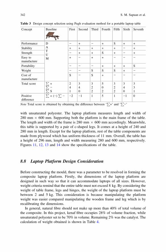
with unsaturated polyester. The laptop platform measures length and width of280 mm � 600 mm. Supporting both the platform is the main frame of the table.The length and width of the frame is 280 mm � 600 mm accordingly. Meanwhile,this table is supported by a pair of c-shaped legs. It comes at a height of 240 and280 mm in length. Except for the laptop platform, rest of the table components aremade from plywood which has uniform thickness of 11 mm. Overall, the table hasa height of 296 mm, length and width measuring 280 and 600 mm, respectively.Figures 11, 12, 13 and 14 show the specifications of the table.
8.8 Laptop Platform Design Consideration
Before constructing the mould, there was a parameter to be resolved in forming thecomposite laptop platform. Firstly, the dimensions of the laptop platform aredesigned in such way so that it can accommodate laptops of all sizes. However,weight criteria remind that the entire table must not exceed 8 kg. By considering theweight of table frame, legs and hinges, the weight of the laptop platform must bebetween 2 and 5 kg. This consideration is because manipulating the platformweight was easier compared manipulating the wooden frame and leg which is byrecalibrating the dimensions.
In general, natural fibre should not make up more than 40% of total volume ofthe composite. In this project, kenaf fibre occupies 28% of volume fraction, whileunsaturated polyester set to be 70% in volume. Remaining 2% was the catalyst. Thecalculation of weight obtained is shown in Table 4.
Table 3 Design concept selection using Pugh evaluation method for a portable laptop table
Concept Baseline First Second Third Fourth Fifth Sixth Seventh
Performance DATUM
− + − + S + +
Stability + + + + + − +
Strength − + + S + − +
Easy tomanufacture
+ − + + − − −
Portability − − − + + + S
Weight − − S S S + −
Cost ofmanufacture
S − S + − − −
Total scoreP
+P−PS
241
340
322
502
322
340
331
Positivedifference
P+ (−)
P− −2 −1 1 5 1 −1 0
Note Total score is obtained by obtaining the difference between ‘P
+’ and ‘P
−’
342 S. M. Sapuan et al.

Fig. 11 a Drawing of table bottom frame (mm) b Design of table bottom frame
Design and Fabrication of Kenaf Fibre Reinforced … 343

Fig. 12 a Drawing of table leg (mm) b Design of table leg
344 S. M. Sapuan et al.

Fig. 13 a Laptop platform drawing (mm) b Drawing of mould (mm) c Mould design
Design and Fabrication of Kenaf Fibre Reinforced … 345

Fig. 14 a Drawing of assembly of composite laptop table (mm) b Assembly design of laptoptable
346 S. M. Sapuan et al.

9 Fabrication of Composite Portable Table
The method of fabricating this composite portable table was hand lay-up asdescribed earlier. This traditional method was used to produce products at minimumquantity and hence assuring good finishing and will be aesthetically attracting.There are several processes involved in fabricating the composite table. Firstly, itbegun with fibre preparations, matrix preparation, followed by mould preparation,hand lay-up process and finally joining.
9.1 Fibre Preparation
The natural fibre chosen in this project was kenaf. It is one of the most commonfibre used in trending green furniture industries as a replacement for wood andplastic. Non-woven kenaf fibre mat as shown in Fig. 15 was obtained fromInnovative Pultrusion Sdn. Bhd, Malaysia.
Table 4 Calculation of required weight of matrix, catalyst and fibre
Volume of composite mould 70% of unsaturatedpolyester 2% of MEKP 28% of fibres
¼60 cm � 28 cm � 2 cm¼3360 cm3
¼0.7 � 3360 cm3 � 1.12 (g/cm3)¼2634.24 g¼0.02 � 3360 cm3 � 1.55 (g/cm3)¼104.16 g¼0.28 � 3360 cm3 � 1.4 (g/cm3)¼1317.12 g
Total weight ¼2634.24 g + 104.16 g + 1317.12¼4055.52 g
Fig. 15 Non-woven kenaffibre mat
Design and Fabrication of Kenaf Fibre Reinforced … 347

9.2 Matrix Preparation
The preparation of matrix was carried out at Mechanical Lab in Faculty ofEngineering. To bind the kenaf fibre, unsaturated polyester matrix was used toge-ther with methyl ethyl ketone peroxide (MEKP) as the catalyst. A total of 10 kg ofresin were obtained from Berjaya Bintang Timur Sdn. Bhd., Cheras, Kuala Lumpur.The characteristics of resin are shown in Table 5. In order to obtain a good mixingproperty, both the solutions were measured prior to mixing. This is becauseincorrect mixing ratio will lead to poor bonding ability. Besides, it can cause theresin to harden too quickly even before the fabricating process finishes. The catalystquantity was set to be 2% from the total weight of resin. The quantity of bothchemicals is measured and poured into a metal container that was well cleaned. Thesolution was stirred gently so that no air bubbles form. This avoids porosity in theend product as shown in Fig. 16.
9.3 Mould Preparation
The laptop platform was fabricated using open mould method. Plywood was usedas the mould since it has good even and clean surface. It was easy to handle andrelatively cheap. Since the mould is in square shape, all the plywood pieces were
Table 5 Characteristics ofunsaturated polyester resin
Characteristics Value
Specific gravity 1.12
Viscosity-brookfield #3/60 450–600
Tensile strength, MPa 62
Elongation at break, % 2.2
Fig. 16 The mixing ofunsaturated polyester andcatalyst
348 S. M. Sapuan et al.

cut in similar length of 900 mm. The thickness of the plywood is 20 mm and thatset the thickness of the composite product. To join the plywood pieces, round headnails were used. The joining was done meticulously to avoid gaps that allow resinto seep out from the mould.
Once completed, moulding wax was applied on the base once an hour, con-tinuously for 5 h. It was to make sure the composite can be removed easily from themould surface after curing process. This wax also allowed the composite to havewell even and shinny surface. The mould was prepared as shown in Fig. 17.
9.4 Hand Lay-Up Process
To begin with the fabrication process, the mould was cleaned and dried to removeunwanted dirt and maintain dry surface. The mould was then covered using a layerof aluminium foil. Next wax spray was applied for easy removal of the compositeas well as to obtain excellent surface finishing. After allowing it to dry for severalminutes, the resin and catalyst that were mixed earlier were poured in the mould.Then, the non-woven kenaf fibre mat was placed evenly on the mould. The fibremat previously trimmed according to the mould shape so that it can fit evenly.
Following that, the resin mixture was applied again on the kenaf fibre mat usinga brush and rolled firmly to disperse the resin mixture throughout the mould. Theprocess was repeated with another two layers of kenaf fibre mat until it reached thedesired thickness of 2 mm. Subsequently, the composite was allowed to cure underroom temperature for duration of 24 h. Finally, the cured composite was detachedfrom the mould as it is shown in Fig. 18. The excess and uneven edges weretrimmed using bench saw and smoothened using grinder.
Fig. 17 Mould prepared forcomposite laptop table
Design and Fabrication of Kenaf Fibre Reinforced … 349

9.5 Joining and Finishing Process
The final step in this project was the assembly or joining process as shown inFigs. 19 and 20. The trimmed composite was joined on the frame using L-bracketand slotted countersunk screw. Hinges were installed on the legs so that it can befoldable.
10 Results
To provide a better finishing look, the table was painted with shellac varnish. Thewooden part of the table was painted thoroughly and gives a pleasingly attractivegolden brown colour. To add better marketability characteristics, an adjustableheight changing mechanism was added behind the laptop platform. It enables theuser to adjust the height and angle of laptop platform to suit according to their
Fig. 18 Cured compositelaptop platform
Fig. 19 Constructing thetable frame
350 S. M. Sapuan et al.

comfort and use. Steel rod of 0.5 mm thickness was used for the locking device,while the locking rail was made up from wood. The illustrations of the finishedproduct are shown in Figs. 21, 22, 23 and 24.
Fig. 20 Folding bracket forthe legs
Fig. 21 Assembledcomposite laptop table
Fig. 22 Side view of thelaptop table
Design and Fabrication of Kenaf Fibre Reinforced … 351

11 Discussion
In order to ensure the fabricated composite laptop table is stable and firm enough towithstand the load of the laptop combined with the force exerted by the user’s hand,stress analysis was performed by using computer-aided simulation software,Abaqus. By using this software, the stress distribution and deformation of the tablecan be seen without performing any physical experiment. This kind of analysissaves material, time and costs besides pinpointing accurate data compared toconventional physical experiments (Table 4).
Fig. 23 Front view whentable is folded
Fig. 24 Functional laptoptable
352 S. M. Sapuan et al.

In this software, few important parameters were needed to simulate the stressanalysis such as the density, Poisson’s ratio and Young’s modulus of kenaf fibrereinforced polyester composite. Since no physical experiments are conducted in thisproject, the Poisson’s ratio and Young’s modulus values were adapted from asimilar project that involved the fabrication of kenaf fibre reinforced polyestercomposite (Kotresh et al. 2014). It was ensured that the density of kenaf fibre, thevolume fraction of kenaf fibre, and type polymer used is similar to this projectbefore adopting its parametric values. The values of parameters are shown inTable 6.
The results of the simulation are shown in Figs. 25 and 26.The simulation reveals composite part of the table which is the laptop platform
experience pressure of 559.7 Pa. Red colour indicates high-stress distribution whiledark blue indicates low-stress distribution. The simulation proved that this table issafe to use since there is no red contour existing on the surface or legs of the table.The rate of deformation was minimum hence this table does not crack or break apartwhen the load was applied on it.
Fig. 25 Front view of laptop table
Table 6 Parameters used forsimulation
Density 1.4 g/cm3
Poisson’s ratio 0.32
Young’s modulus 42 MPa
Load applied 100 N
Design and Fabrication of Kenaf Fibre Reinforced … 353

12 Conclusion
Overall, a composite portable laptop table was able to be produced in this project.The objectives were achieved successfully by manufacturing a composite laptoptable using a systematic approach of the total design process. This composite laptoptable can be brought anywhere by folding its leg inwards and can be carried easilyusing the holder. Besides serving as a laptop stand, the user can read books andnewspaper on it.
In short, opting to natural fibre usage can reduce the dependency onnon-renewable resources and help to conserve the green environment. Sincecomposite furniture can be made from natural fibre, there are many chances theycan be utilized for various purposes. Kenaf fibre reinforced polymer composite isone of the examples of the natural fibres diversity in becoming substituent forpetroleum.
References
Abdullah A, Khalina A, Ali A (2007) Effects of fibre volume fraction on unidirectional kenaf/epoxy compositions: the transition region. Polym Plast Technol Eng 50:1362–1366
Akil HM, Cheng LW, Ishak ZM, Bakar AA, Rahman MA (2009) Water absorption study onpultruded jute fiber reinforced unsaturated polyester composites. Compo Sci Technol 69:1942–1948
Asilah CA (2011) Mechanical performance of kenaf fibre reinforced thermoplastic composite, B.Eng. Thesis, Universiti Malaysia Pahang, pp 24–38
Fig. 26 Lower side view of laptop table
354 S. M. Sapuan et al.

Bernard M, Khalina A, Ali A, Janius R, Faizal M, Hasnah KS, Sanuddin AB (2011) The effect ofprocessing parameters on the mechanical properties of kenaffibre plastic composite. Mater Des32:1039–1043
Biron M (2012) Thermoplastics and thermoplastic composites: technical information for plasticsusers. Elsevier, Oxford
Chaivan P, Pasaja N, Boonyawan D, Suanpoot P, Vilaithong T (2005) Low-temperature plasmatreatment for hydrophobicity improvement of silk. Surf Coat Technol 193:356–360
Faruk O, Bledzki AK, Fink HP, Sain M (2012) Biocomposites reinforced with natural fibers:2000–2010. Prog Polym Sci 37:1552–1596
George J, Sreekala M, Thomas S (2001) A review on interface modification and characterization.Polym Eng Sci 41:1471–1485
Gonzaleza AV, Cervantes-Uca JM, Olayob R, Herrera F (1999) Effect of fiber surface treatment onthe fiber–matrix bond strength of natural fiber reinforced composites. Compos B 30:309–320
http://www.miti.gov [Online] [Cited: May 8,2015.]http://www.wildfibres.co.uk/why-natural-fibres.htm [Online] [Cited: May 8,2015.]Hyer MW (2009) Stress analysis of fiber-reinforced composite materials. DEStech Publications,
IncIkada Y, Tsuji H (2000) Biodegradable polyesters for medical and ecological applications.
Macromol Rapid Commun 21:117–132Jonn A, Foulk Danny EA, Roy BD, David DM (2000) Flax fibre: potential for a new crop in the
Southeast, 364Joshi SV, Drzal LT, Mohanty AK, Arora S (2003) Are natural fiber composites environmentally
superior to glass fiber reinforced composites? Resour Conservation Recycl 33:371–376Karnani R, Krishnan M, Narayan R (1997) Biofiber reinforced polypropylene composites. Polym
Eng Sci 37:476–483Keener TJ, Stuart RK (2004) Maleated coupling agents for natural fibre composite. Compos A
35:357–362Khalil HA, Bhat AH, Yusra AI (2012) Green composites from sustainable cellulose nanofibrils: a
review. Carbohyd Polym 87:963–979Kolybaba M, Tabil LG, Panigrahi S, Crerar WJ, Powell T, Wang B (2003) Biodegradable
polymers: past, present, and future. In: ASAE meeting presentation, pp RRV03–0007Kotresh, VK, Manjunatha (2014) Characterization and Investigation of tensile test on kenaf fiber
reinforced polyester composite material. Int J Res Dev Eng Technol 2:132–136Liu W, Drzal LT, Mohanty AK, Misra M (2007) Influence of processing methods and fiber length
on physical properties of kenaf fiber reinforced soy based biocomposites. Compos B Eng38:352–359
Mansor MR, Sapuan SM, Zainudin ES, Nuraini AA, Hambali A (2014) Conceptual design ofkenaf fiber polymer composite automotive parking brake lever using integrated TRIZ–Morphological Chart-Analytic Hierarchy Process method. Mater Des 54:473–482
Mayer RM, Hancox N (1993) Design with reinforced plastics: a guide for engineers and designers.Springer Science & Business Media
Mazumdar SK (2002) Composites manufacturing: materials, product, and process engineering.CRC Press, Boca Raton
Nirmal U, Hashim J, Ahmad MM (2015) A review on tribological performance of natural fibrepolymeric composites. Tribol Int 83:77–104
Nishino T, Hirao K, Kotera M, Nakamae K, Inagaki H (2003) Kenaf reinforced biodegradablecomposite. Compos Sci Technol 63:1281–1286
Nor MJ, Ayub M, Zulkifli R, Amin N, Fouladi MH (2010) Effect of compression on the acousticabsorption of coir fiber. Am J Appl Sci 7:1285
Pugh S (1991) Total Design, Integrated Methods for Successful Product Engineering.Addison-Wesley Publishers Ltd., Workingham
Rassmann S, Paskaramoorthy R, Reid RG (2011) Effect of resin system on the mechanicalproperties and water absorption of kenaf fibre reinforced laminates. Mater Des 32:1399–1406
Design and Fabrication of Kenaf Fibre Reinforced … 355

Rowell RM, Sanadi A, Jacobson R, Caulfield D (1999) Properties of kenaf/polypropylenecomposites. Kenaf properties, processing and products. Mississippi: Agricultural &Biotechnology Engineering, pp 381–392
Saheb DN, Jog JP (1999) Natural fiber polymer composites: a review. Adv Polym Technol18:351–363
Salit MS (2014) Tropical natural fibre composites: properties, manufacture and applications.Springer, Singapore
Sanyang ML, Sapuan SM, Jawaid M, Ishak MR, Sahari J (2016) Development and character-ization of sugar palm starch and poly(lactic acid) bilayer films. Carbohydr Polym 146:36-45
Sapuan SM, Maleque MA (2005) Design and fabrication of natural woven fabric reinforced epoxycomposite for household telephone stand. Mater Des 26:65–71
Sapuan SM, Leenie A, Harimi M, Beng YK (2006) Mechanical properties of woven banana fibrereinforced epoxy composites. Mater Des 27:689–693
Sapuan SM, Harun N, Abbas KA (2007) Design and fabrication of a multipurpose table using acomposite of epoxy and banana pseudostemfibres. J Tropical Agric 45:66–68
Shibata S, Cao Y, Fukumoto I (2006) Lightweight laminate composites made from kenaf andpolypropylene fibres. Polym Test 25:142–148
Vroman I, Tighzert L (2009) Biodegradable polymers. Materials 2:307–344Wambua P, Ivens J, Verpoest I (2003) Natural Fibre: can they replace glass in fibre reinforced
plastic? Compos Sci Technol 63:259–1264
356 S. M. Sapuan et al.

Lignocellulosic Materials for Geotextileand Geocomposites for EngineeringApplications
Jaideep Adhikari, Suvendu Manna, Sukanya Chowdhury Saha,Prosenjit Saha, Debasis Roy and Basudam Adhikary
Abstract Cost-effectiveness, environment-friendly nature of lignocellulosic(LC) materials have been utilized for geotechnical engineering for value-added enduses, however, so far the efficacy of such LC materials has not been widelyaccepted by the engineers due to lack of their long-term durability. Durability of LCmaterials can be enhanced by altering fibre chemistry or by applying adegradation-resistant surface coating. This chapter will present an extensive over-view of such potential processes for enhancement of durability of LC materialsfollowed by a comprehensive discussion on designing and testing parameters ofgeotextiles and geocomposites using LC materials. A special emphasis has beengiven to erosion control system and stabilization of slopes using jute fibres as apotential LC material.
Keywords Lignocellulose � Geotextile � Geomembrane � GeocompositesErosion control � JuteAbbreviation
ASTM American Society for Testing MaterialAOS Apparent opening sizeFoS Factor of SafetyLC LignocellulosicGT GeotextilesGSM Gram per square metre
J. Adhikari � S. Chowdhury Saha � P. SahaDr. M.N. Dastur School of Materials Science and Engineering, Indian Instituteof Engineering Science and Technology-Shibpur, 711103 Howrah, India
S. Manna � P. Saha (&) � B. AdhikaryMaterials Science Centre, Indian Institute of Technology, 721302 Kharagpur, Indiae-mail: [email protected]
D. Roy (&)Department of Civil Engineering, Indian Institute of Technology,721302 Kharagpur, Indiae-mail: [email protected]
© Springer International Publishing AG 2018S. Kalia (ed.), Lignocellulosic Composite Materials, Springer Series on Polymerand Composite Materials, https://doi.org/10.1007/978-3-319-68696-7_9
357

JGT Jute geotextilePOA Percent open areaPWP Pore water pressure
Contents
1 Introduction.......................................................................................................................... 3581.1 Lignocellulosic Material ............................................................................................. 3591.2 Approach Towards Durable Lignocellulosics............................................................ 361
2 Geotextiles and Geocomposites .......................................................................................... 3622.1 Lignocellulosic Materials for Geotextile and Geocomposites................................... 364
3 Designing of Geotextiles with Lignocellulosic Materials .................................................. 3653.1 Separation ................................................................................................................... 3663.2 Reinforcement............................................................................................................. 3683.3 Drainage (Fluid Transmission)................................................................................... 3703.4 Filtration...................................................................................................................... 3713.5 Erosion Control System and Stabilization of Slopes................................................. 372
4 Designing of Geocomposites with Lignocellulosic Materials ............................................ 3775 Tests and Parameters for Evaluating the Performance of Geotextiles and Geocomposites 379
5.1 Physical Properties Testing—The Index Tests for GT.............................................. 3795.2 Mechanical Testing..................................................................................................... 3815.3 Hydraulic Properties Testing...................................................................................... 3845.4 Serviceability Tests..................................................................................................... 385
6 Applications ......................................................................................................................... 3867 Conclusions.......................................................................................................................... 386References .................................................................................................................................. 387
1 Introduction
Geotextile and geocomposite are classified as important components of geosynthet-ics. American Society for Testing Material (ASTM) D 4439 defines geosynthetics as‘a planner product manufactured from polymeric material used with soil, rock, earthor other geotechnical engineering related material as an integral part of a human-madeproject, structure or system’ (ASTM D4439—15a). Growing demand for geosyn-thetic is basically led by their five key functional attributes, such as, filtration, sepa-ration, drainage, reinforcement and protection. The class of geosynthetic comprisesmainly of geotextiles, geogrid, geonets, geomembranes, clay liners, geopipe andgeocomposite. Among them geotextile is widely used class of geosynthetic which ispermeable in nature and serves typical applications like increment in the stability of
358 J. Adhikari et al.

soil; filtration, decrease the erosion caused by the wind, water. In general, woven,non-woven, knitted, knotted are the types of geotextiles that are used for geotechnicalengineering. Lighter weight geotextiles are used in several applications viz. filtration,separation between soils, erosion control whereas heavier weight geotextiles are usedin reinforcement purpose (Sen Gupta 1991). On the other hand, geocomposites aremanufactured by combining geotextileswith either of geonet, geomembrane, geogrid,polymer core or combining geomembrane with geogrid, geosynthetics with soil, etc.Most of the geosynthetic market is dominated by four synthetic polymers such aspolypropylene, polyethylene, polyester, polyamide. However, growing environ-mental concern leads us towards the development of natural materials.Lignocellulosic materials could be the ideal candidate to fulfil such environmentalrequirement. Natural fibres are suitable for their lower price and technical properties.The main drawback with lignocellulosic materials is their durability issue which canbe modified tactfully by the experts according to the end applications.
1.1 Lignocellulosic Material
Lignocellulosic (LC) materials are any of the several natural, widely available,renewable resource material used in industrial purpose for the upliftment of sus-tainable global economy and constituting several polymers essentially found in thecell walls of a woody plant they are cellulose, hemicellulose and lignin. LCmaterials found their extensive uses in paper and pulp industries, in the productionof biofuel mainly bio-ethanol, in natural fibre reinforced composite and ingeotechnical applications. The mechanical properties of LC material are determinedby its biomass (mainly governed by cellulose, hemicellulose and lignin). Thechemical composition of these plant-based materials varies with geographicallocation, species, climate, processing condition, extraction methods, etc. The basicprocessing stage of LC materials deals with the formation of fibres and subse-quently, they are processed in the form of non-woven mat, felt, yarn, woven orknitted fabrics for different applications. Cellulose molecules being linear in naturecan easily arrange themselves in a periodic nature and forms the crystalline regionof fibres. Overall cellulose molecules are semi-crystalline in nature. The crystallinepart of cellulose provides strength to the fibre. Cellulose molecule contains a largenumber of hydroxyl groups which facilitate water absorption. Along with cellulose,hemicellulose also contributes to water absorption. Hemicellulose molecules arebelieved to be the main reason behind the hydrophilic nature of natural fibres asthey are highly branched molecules and cannot crystalize hence forms an openstructure. Amorphous nature of hemicellulose molecules contains plenty ofhydroxyl groups which emanate from several sugar molecules. Lignin is also ahighly branched molecule, amorphous in nature and exhibits the least influence inwater absorption properties of a lignocellulosic material. Apart from cellulose,hemicellulose and lignin natural, fibres contain pectin (imparts flexibility), which is
Lignocellulosic Materials for Geotextile … 359

a wax-like substance. Pectins are basically hetero-polysaccharides comprises ofpoly galacturonic or pectic acid units. They are removed by treating the fibres inalkaline solution followed by washing with water. Waxes are compounds ofalcohols that are insoluble in water and organic acids (Saha et al. 2016).
Natural fibres can be classified according to their extractive source.Bast or phloem fibres are extracted from the stem of a dicotyledonous plant. By
retting process, fibres are set to free from the cellular and other tissues. Ex.-Flax,Hemp, Jute.
Leaf fibres are extracted by scraping the pulp of leave from the fibres of amonocotyledonous plant. Ex. Abaca, Sisal.
Seed and fruit fibres are intended to protect the seed or fruit of a plant as theseare the most vulnerable parts of a plant. Ex. Coir, cotton.
Some potential natural fibre used in different geotextile and geocomposite aretabulated in Table 1.
Table 1 Some potential natural fibres used in Geotextile and Geocomposites
Fibre Cellulosecontent(wt%)
Hemicellulosecontent (wt%)
Lignincontent(wt%)
Tensilestrength(MPa)
Elongation(%)
References
Jute 61.0–71.5 13.6–20.4 12.0–13.0
393–773 1.16–1.5 Goda et al.(2008), Guptaet al. (2015)
Flax 71.0 18.6–20.6 2.2 345–1100
2.7–3.2 Goda et al.(2008), Chandaet al. (2008)
Sisal 67.0–78.0 10.0–14.2 8.0–11.0
511–635 3–7 Goda et al.(2008), Vermaet al. (2013),Chanda et al.(2008)
Coir 36.0–43.0 0.2–0.3 41.0–45.0
131–175 4.7 Goda et al.(2008), Vermaet al. (2013)
Ramie 68.6–76.2 13.1–16.7 0.6–0.7 400–938 1.2–3.8 Goda et al.(2008), Chandaet al. (2008)
Kenaf 72 20.3 9 743 – Kumar et al.(2011),Komuraiah et al.(2014)
Bamboo 26–43 30 21–31 221–661 3.7 Kumar et al.(2011), Vermaet al. (2013)
Abaca 56–63 20–25 7–9 430–760 – Kumar et al.(2011), Chandaet al. (2008)
Palm – 20.8 28.5 43–263 2.0–5.1 Chanda et al.(2008), Kobaet al. (1990)
360 J. Adhikari et al.

1.2 Approach Towards Durable Lignocellulosics
In a moist environment, the free hydroxyl groups of cellulose attract water mole-cules which cause the LC materials to swell. Cellulose chains of LC materials losetheir integrity under exposure to several chemical environments such as acidity,alkalinity, salinity, UV irradiation, etc. by hydrolysis or oxidation. Biogenicenzymes also affect the cellulosic chains (Rowel 1996). Thus, the technologiesrelated to the modification of cellulose chains for stability against degradation andmechanical strength indeed is a necessary factor to study. Hemicellulose andamorphous cellulose are more prone to any sort of enzymatic degradation caused bycellulolytic bacteria, fungi and insects. Oxidation, hydrolysis and dehydrationreactions occur in the presence of acid and alkali environments, while mechanicaldamages of LC materials occurs in saline environments (Winandy and Rowel2005). The main reason behind the mechanical damage is the surface swelling andshrinkage phenomena which are promoted by hygroscopic and salt-catalyzedhydrolysis action. UV irradiation causes oxidation of lignin and the degradedproduct leached out from the matrix. After delignification, the poorly bonded cel-lulose molecules also wear out from the surface of LC materials. Overall, the tensilestrength of the materials falls significantly (Rowell and Stout 2007). Figure 1describes the different type of degradation and the degrading agent which followsseveral mechanisms to attack the constituents of LCs. Susceptible components inorder of their decreasing susceptibility can be identified from the figure.
The problem of degradation of LC materials can be overcome by three possibleways. The modifications are generally performed on the fibre whereas it can bedone on the fabric and yarn also. The possible ways are
1. By formation of new covalent bond on the reactive sites of the LC fibres2. Changing the fibre chemistry by radiation treatment3. Coating of degradation-resistant chemicals on fibre surface.
Esterification, transesterification, etherification, silane treatment, grafting are themost common and popular chemical treatment method for making the fibresdegradation resistant. Some biological agents such as laccase, protease enzymes arequite commonly used in chemical treatment methods. Cellulase, xylanase, pectinasenatural enzyme, novozymes are used on LC fibres for enhancement in elongation atbreak, tensile strength and hydrophobicity of the materials.
The key mechanism is the removal of the amorphous materials from fibre surfaceand consequent fibrillation which results in enhanced mechanical strength andhydrophobicity.
Radiation method involves ion beam treatment for the alteration of surfaceproperties of the LC materials. Gamma radiation and electron-beam methods arewidely used modification methods. Gamma radiation is used where high pene-trating efficiency and less treatment time is required whereas electron-beam treat-ment has been practiced for energy saving and controlled penetration-basedprocess.
Lignocellulosic Materials for Geotextile … 361

LC materials either in the form of fibre, fabric or felt have been used to coat orblock the sites with phenol–formaldehyde (PF) resin, boric acid–oil emulsion, neemseed extract, vegetable oils and other water repellent reagents to reduce theirhydrophilicity. PF resins include melamine formaldehyde, cashew nut shell liquid–formaldehyde and polymerized cashew nut shell liquid, etc. Cross-linking occursbetween LC materials and resin matrix through hydrogen bonds. Thus, the decreasein water uptake is attributed to the development of weakly bonded networks con-nected through secondary bonds (Saha et al. 2016).
2 Geotextiles and Geocomposites
Initially, Geotextiles were used as filtre fabrics and were envisioned to be a sub-stitute of granular soil filtres. After that permeability, soil retention and otherapplications of GTs evolved and the textiles were tailored such a way that they can
Fig. 1 Degradation reaction of LC materials (Saha et al. 2016)
362 J. Adhikari et al.

be used as suitably engineered materials. In the beginning, geotextiles were onlyintended to be the synthetic ones. Thus, for manufacturing a suitable geotextile typeof polymer, fibre construction and weave design are the major concerned areas. Fora synthetic textile material, the basic flow chart comprises
• Procurement of synthetic polymer• Preparation of synthetic fibres by melt spinning/wet spinning/dry spinning
technique. Most of the synthetic geotextiles are prepared by melt spinningprocess.
• Conversion of fibres into yarn (Monofilament, multifilament, staple fibre yarn,slit-film monofilament and slit-film multifilament)
• Preparation of the fabric by weaving the yarns
In the case of LC-based natural fibres, the fibres were extracted first from dif-ferent sources and they were processed subsequently in the form of yarn andfabrics. The term yarn is used in textile where one or more fibres are drawn paralleland twisted into a single strand. Woven, Non-woven and knitted are the threechoices for the formation of a fabric. For woven fabric weave design determinespermeability, drapability and mechanical strength of the fabric and hence weavedesign is an important parameter for geotextiles and geocomposites. Weave designis determined by the sequence in which the longitudinal threads (known as Warp)are interlaced with the transverse pick (known as weft). Plain, basket and twill arethe most common weave designs that have been already explored in the field ofgeotextiles. Each type of design also has several distinguishable separate patterns orformations, for instance, twill design has steep twill, broken twill, etc. patterns.Non-woven materials can be directly obtained after the fibre stage without con-verting them into yarn. Knitted fabrics can be stretched in any direction giving themmuch more elasticity than the woven fabrics. However, they are seldom used ingeotextiles as they lack in mechanical strength. For the preparation of novelstructures with knitted fabrics, yarns with high strength and low extension areinserted either in weft or warp size. High strength natural yarns are intended to beprepared with jute, flax, sisal, coir, abaca while soft yarns of viscose (regeneratedcellulose), cotton, jute are designed for loop formation (Anand 2008).
Geocomposite material also conforms the basic philosophy of a compositematerial, i.e. combining different material in order to overcome the inadequacies ofeach material with respect to a specifically targeted application. The most con-ventional geocomposites are geotextile-geomembrane, geotextile-geonet,geotextile-geogrid and geomembrane- geogrid composites. Apart from the con-ventional geocomposites sometimes steel strands are also woven with geotextilematerials to form a composite with superior mechanical properties. At times pre-fabricated holes are created with the aim of insertion of steel rods as an anchoredmaterial. Sometimes geotextiles are used in combination with the polymer core asan alternative to the traditional sand drains.
Lignocellulosic Materials for Geotextile … 363

2.1 Lignocellulosic Materials for Geotextileand Geocomposites
Synthetic geotextile offers several advantages like durability, superior mechanicalproperties yet they lack in flexibility and drapability. Rigidness of syntheticmaterials prevents them from fitting with the uneven soil surfaces. So, when aninflexible GT is placed over this surfaces several wide openings are created betweensoil and the GT. Water molecules tend to flow between the openings and causes theGT to swell. Similarly, in the absence of water flow, the material tries to shrink.Thus, the reinforcement or stabilization of soils with GT gets hampered.Synthetic GT materials are also vulnerable to UV irradiation and overall stringentenvironmental policies drive the designers towards LC material for geotextile andgeocomposite applications. As the LC materials are free from toxins and plasti-cizers, there is no possibility to add pollutants in the groundwater or to disturb theecological system. LC materials are generally hydrophilic in nature and at the sametime, their biodegradability rate is very much high. In some applications theseproperties are harmful nevertheless for application where the holding of moisture orwater is necessary these properties are suitable. Moreover, the decomposed LCmaterial adds organic nutrients to the soil. Due to the unique interlacement char-acteristics, woven geotextiles left with a satisfactory amount of open space for theplant to grow between the strands. The open mesh structure helps to pass sunlight,water-absorbing capacity helps to retain the moisture of the soil which in term helpsin the consolidation of soil. Holding moisture and heat of the soil helps in thevegetation of plants. Thus, for this type of application open weave structure alongwith higher GSM fabric is preferred. Sometimes this environmental condition helpsto grow several microorganisms which facilitate crop cultivation. Geotextiles arealso used for weed controlling operation (mulching in agriculture/horticulture),preventing the plant from cold or wilting effect (loss of firmness of non-wooden partof the plant when the rate of loss of water is greater than absorption). Drapabilitycan be defined as a material property having graceful folds under its own weight onretaining over a surface. Drapability of a GT, in the context of stabilization of slope,determines how a textile material will be able to adjust to the contour of slopes(Horrocks and Anand 2000). Degradation of lignocellulose-based GT is controlledby several parameters like type of soil (when exposed to the soil); type of asphalt,bitumen (during the road construction); depth of embedment (for reinforcedmaterial); climatic conditions (effect of moist, neutral, dry environment on agri-cultural applications), etc.
Among the natural LC materials, jute and coir geotextiles have been widelyexplored in India. Sisal, flax, ramie, palm and other LC materials are seldom used inthis geographical location. However, in this part of the world, they are used incombination with Jute and coir. The application areas of these LC materials remainsame as of jute and coir GT.
364 J. Adhikari et al.

• Jute geotextiles found their extensive usage in road construction and pavementstrengthening; under subgrade railway track; stabilization of embankment,slopes; consolidation of soils; prevention of erosion, etc. The use of heavy andcoarse jute yarns makes them the ideal erosion control material for soil slopesunder all climatic conditions. JGT is used in various structural civil engineeringapplications such as concrete slabs, cement mortar, etc. JGT coated withimpervious synthetic non-woven are utilized for prevention of seepage from thestructural civil engineered materials. JGT coated with bitumen enhances thelifetime of the material, nevertheless, bitumen coating makes JGT fabrics stiffand thus they are harsh to handle during installation. So chemically alteredlignocellulosic for durability is preferred over the bitumen coating method.Some of the chemical treatments for enhancement of durability of Jute geo-textiles are transesterification (Saha et al. 2012), coating with phenolic resin(Saha et al. 2012), etc. It is also used to protect or rather to cover dumps andheaps of solid wastes, granular materials (ex. fly ash in thermal power plants).JGT is extensively used in the construction of rural roads, pavements, railwaytracks, concealed drains of hilly areas. Some common agricultural, horticultureand forestry sectors use of JGT are sunscreens, plant nets, harvesting nets,field-nets for protecting the crop from birds, windshield, weed management,mulching, etc. (Sen Gupta 1991, Ghosk 2014).
• Coir Geotextile-Due to their high lignin content, coir fibres are most durableamong the natural fibres and extensively used in erosion control along the steepslopes. Despite the low cellulose content, coir has a very close fibre structurewhich helps them to possess suitable properties. It is primarily used for rein-forcement of temporary clay structures, drainage applications along with pre-vention of soil erosion (Lekha 2004, 2006).
3 Designing of Geotextiles with Lignocellulosic Materials
According to the ASTM definition, GT is a permeable Geosynthetic exclusivelymade with textile material. For a particular application to design a GT severalapproaches are undertaken-
• Cost and availability• Specifications• Functions
Cost and availability method are very simple and basic approach yet it lacks withtechnicalities. Specification method deals with classification and utilization of thematerial according to their expected service life. In functional approach, the primaryfunction of GT is evaluated and according to the purpose Factor of Safety (FoS) ofthat particular property of the material is calculated.
Lignocellulosic Materials for Geotextile … 365

FoS ¼ Ultimate permisible property of the tested sampleRequired property designð Þ of the tested sample
ð1Þ
If the factor of safety of a GT is sufficiently higher than the numerical value 1then the GT material is adequate to be used for that particular application. Inbroader sense, ultimate allowable strength or property of the material must remainsufficiently higher than the required strength or property of the material. Thedesigning of GT according to their function is discussed in the subsequent section.
3.1 Separation
A flexible porous geotextile (GT) segregates two dissimilar materials, preventingtheir intermixing and retaining their integrity and functionality. The purpose ofseparation is to maintain the unique performance of each individual layer andsometimes to improve the properties (Sarsby 2007). When coarse stone aggregatesare placed over the fine soil particles two concurrent incident occurs over time.
The pressure exerts by the stone aggregates forced the soil particles to move intothe voids of stone aggregates, thus the drainage capability is hampered.
While another process involves the reduction in strength of stone aggregate bytrying to intrude into the soil particle.
A porous and flexible GT placed between subsoil and granular sub-base preventsthe intermixing while permitting the free flow of water across the GT. In roadconstruction, it restricts the aggregate to be punched down during initial compactionand during the dynamic loading of vehicles and, etc. Sometimes a temporary haulroad is required during the construction of permanent works. This road is temporaryand dug up after completion of work followed by disposal of it. LC materialswithout any surface modification are suitable for this kind of short-term application.Separation induces natural consolidation—formation of ‘filtre-cake’ in soil. Impact,puncture and tear propagation resistance are some of the mechanical propertiesrequired for separation function during installation, construction and for after use.Along with the mentioned properties Apparent Opening Size (A.O.S.), thickness,UV resistance, chemical stability, etc. of the LC materials are also required to havecontrol over the designing of the GT. (http://www.engr.utk.edu/mse/Textiles/Geotextiles.htm).
GT used as a separator for unpaved, paved, railroads (between subgrade andstone base), for soils of roadways, earth and stone damps (between foundation andembankment), etc.
The basic construction method of a road is represented in Fig. 2. The granulesplaced over GT create many voids in between it. When a load is applied on top ofthe road, the stress is transferred from the surface to the aggregates and furtherthrough the GT it is conveyed to the underlying soil. The soil under stress pushesthe GT upwards which finds it ways in the voids of the stones (Fig. 2). This field
366 J. Adhikari et al.

situation can be imitated according to ASTM D 3786 burst test where a GT isstressed over a gradually increasing hemispherical shape until the GT fails. Thus,for designing a GT to be used as a separator evaluation of burst resistance of GTmaterial is important.
From the field situation Girould suggested a mathematical formula-
T reqd: ¼ 12p0dv f €ð Þ½ � ð2Þ
where Treqd: is the strength required for GT, p0 is the stress on GT which is less thanthe stress pð Þ implied by the tire at the ground surface, dv is the maximum voiddiameter of the stone which can be approximated by 0.33 da:da is the average stonediameter and f €ð Þ½ � is the strain function of the deformed GT.
For estimating the burst strength of GT the modified form of the above formula
Tult ¼ 12ptestdtest f €ð Þ½ � ð3Þ
where Tult is the ultimate strength GT, ptest is the pressure at the time of failure ofGT and dtest is the diameter of the burst test device.
Factor of safety can be calculated as
FoS ¼ Tallowable
T reqd:; Tallowable ¼ Tult:
cumulative reduction factorð4Þ
Another infield analogy was taken into account while designing geotextile, i.e.assessment of grab strength. A GT is sandwiched between two layers of stoneaggregates. So, when the stone aggregate above the GT is forced to the stoneaggregate lying below the GT, a lateral stress is generated within the GT. The loweraggregates must remain in direct contact with the geotextile. Due to the appliedstress, the stone base tries to spread latterly and thus the lignocellulose-based GTalso tries to expand accordingly. Therefore, the analogy to estimate the grabstrength of the material can be visualized. The maximum strain is measured that aGT is able to withstand during the setting down process of the upper granules to thelevel of GT. Mathematical model is used to evaluate this property (Korner 1993).
Fig. 2 Schematicrepresentation of GT used forseparation purpose
Lignocellulosic Materials for Geotextile … 367

The other two common parameters while designing GT for separation arepuncture resistance and impact resistance. During the installation period and later atservice period a GT is exposed to the pressure of several sharp stones, miscella-neous debris, roots, etc. These items can remain either in the beneath or top of thematerial. These materials are able to puncture the GT during the backfilling or at thetime of traffic load imposed on the road. Impact or tear resistance is evaluated tohave the assessment on the extent of material strength subjected to withstand thesudden free fall of any construction equipment or stones.
3.2 Reinforcement
Reinforcement is basically a type of strengthening mechanism. GT as a rein-forcement to soil makes them superior with modified engineered properties. Thesoil has much higher compressive strength compared to its tensile strength. Underload, soil expands and in order to have sufficient shear strength, a strong soil/fabricinterface is required. To have a strong interface and to avoid slippage higher fric-tional coefficient is required between soil and the fabric. Soil and reinforcementmust experience same extension such that the implied stress is shared by each of thereinforcing element and then redistributed in the soil. In this way, stress is confinedinternally. Due to the requirement of the high frictional coefficient and high tensilestrength, heavy grades of geotextiles are used to reinforce earth structures. Innormal condition, if a soil is stressed vertically it tries to expand laterally. In thecase of reinforcement with GT, internal confinement of stress prevents theexpansion of soil laterally. GT exerts confining action on soil and absorbs a part ofthe stress causing shear failure. The method of reinforcing soil can also be utilizedfor stabilizing slopes and embankment. GT acts against rotational slides, lateraldispersion and vertical subsidence when inserted within a soil body at appropriatelevels at initial stages. In the case of road reinforcement, GT helps to reducedeflections, rutting and fatigue cracking and overall help to strengthen the pave-ments. Sisal, Coir (Mwasha 2009), Jute GT are used for soil reinforcement purpose.
In developing countries, for construction of inexpensive short-term projects,utilizing manpower and the abundance of renewable material make senses of uti-lizing the LC materials. The stability of such material is monitored periodically andthe material is replaced when it is unable serve as reinforcement. Furthermore, fromthe environmental concern point of view they enrich the soil without introducingharmful residues.
• Groundwater fills the pores in the soil particles. While constructing theembankments of soft compressible soil base a GT is used. The soft soil does nothave sufficient strength to endure the shear stresses and generally fails underthree modes—splitting, circular and basal. GTs are placed in the verticalincrement in an embankment between the embankment fill and the underlyingsoft soil. A lateral stress is produced which resists the embankment from
368 J. Adhikari et al.

splitting. A uniform compressive forces act on the underlying soil surfaces.Water pressure of pores in the soil is maximum at centre of the embankmentwhile compared to the extremities. The embankment loading increases thiswater pressure in the pores. Pore water pressure (PWP) dissipates with time inthe underlying soft soil. A pressure gradient is set up which enables the water tomigrate sideways beneath the embankment and thus the PWP reduces with time.Hence, the stability of the embankment is improved.As the PWP decreases with time, the force required for stabilization of theembankment also diminishes with time. The stabilizing force to the embank-ment is provided by the GT. This decreasing rate of the required stabilizingforce can be designed with the deterioration rate of the LCs. As LC materialloses its strength due to degradation over a period of time, this feature can beutilized to design LC for the above-mentioned purpose. Sometimes, consoli-dation drains are used to enhance the dissipation of excess PWP.
• Another short-term use of the LC materials is found in the establishment oftemporary road/ structures by the armed forces. The armed forces have toconstruct temporary roads very quickly when dealing with the confrontations.However, these structures are designed to be demolished by machinery orexplosive when the soldiers evacuate the place. The idea is to avoid leaving anyresources which might get exploited by the enemies. By employing indigenouslignocellulosic fibre materials this situation is tackled as the natural geotextilesleft to rot in the soil or set on fire.
Use of GT in road construction (Functions in asphalt overlays)
Stress relief: Restraining of soils subjected to hydrodynamic forces while allowingpassage of water.
Barrier: Paving fabric, properly installed in between an existing road surface anda new asphalt overlay. Hence provides a stress relieving function, as thebitumen-saturated fabric is allowed for slight differential movements between thelayers.
Reinforcement: The use of stress–strain behaviour of a geotextile to improve themechanical properties of soil.
The main reason behind the generation of relative stress cracking in the pave-ment is due to repeated thermal expansion and contraction and also due to the lackof bearing capacity under load. Figure 3 represents the two mechanisms involvedbehind such kind of stress cracking.
Fig. 3 Schematicrepresentation of a thermalinduced fatigue, b Trafficinduced fatigue
Lignocellulosic Materials for Geotextile … 369

The full-width GT used for this applications are coated with asphalt cement orasphalt emulsion and then overlaid with final bituminous. GT should be water-proofed and durable for this kind of applications. Hence, use of LCs for this kind ofapplications is very infrequent in the literature.
Assessment of base failure of GT as reinforcement is evaluated by the shearstrength of the bonding system while top failure and slope failure are assessed bydetermining the tensile strength of GT. Permeability, creep, chemical and degra-dation resistant, etc. are some of the other important properties required for thereinforcement function with GT (http://www.engr.utk.edu/mse/Textiles/Geotextiles.htm).
3.3 Drainage (Fluid Transmission)
A GT can transport fluids or gasses within its plane. Normally the strength of a soilis increased by the decrease in its water content and vice versa. Excess PWP can bedissipated by the drainage system and thus consolidation of soil takes place. Toreduce the drainage path temporary drains with GT is used for limited life spans.These drains are required until the soil consolidation has taken place. Thus, in thisapplication naturally degraded GT is used.
In highways, airfields and railroads GT is used around the perforated pipeunderdrains. Figure 4a shows protection of stones by GT around the perforatedpipe, Fig. 4b shows GT is used directly to protect the perforated pipes with sand inthe backfill and Fig. 4c represents GT wrapped stone with no perforated pipe.Proper designing of geotextile makes it free from soil contamination. Adequate flowcapacity and adequate soil retention capacity are the two main parameters whiledesigning such kind of trench drains.
Fig. 4 Construction of underdrains pipe a GT around the stone, b GT wrapped pipe, c GTwrapped stone
370 J. Adhikari et al.

Drainage behind the reinforced concrete wall:
Behind the conventional reinforced concrete wall, a vertical drainage system isneeded. The water from backfill soil must drain out to reduce the generation ofhydrostatic pressure. This hydrostatic pressure along with the horizontal soilpressure is able to cause failure of the walls. The sand used in this drainage systemmust stay free from clogging for the lifetime. Thus, the sand must be protected withGT filtre. GT can be used in several types of arrangements such as a rigid wall withunderdrain facility, a rigid wall with weep holes, a temporary wall with open sheet,etc. In all type of the retaining walls, GT is used where it serves drainage as aprimary function and protecting the wall as a secondary function.
3.4 Filtration
GT enables to perform two contrasting functions simultaneously such as soilretention and permeability of water through and along the GT. Open pore size ofgeotextile is selected to avoid several interrelated phenomena such as blocking,blinding and clogging. An open geotextile structure is needed to pass the liquidthrough the filtre (GT) in order to avoid excess hydrostatic pore pressure and at thesame time, a close structure is needed in the upstream for soil retention. As theamount of liquid flow through soil is related to the particle size, this kind ofcontradictory design is possible. A common empirical relationship between per-meability coefficient and soil particle size is used in this regard.
k ¼ Cd210 ð5Þ
where k is the permeability coefficient, C is the site-specific constant and d10 is theeffective soil particle size at which 10% of the soil is fine.
Large particle size relates to the high flow conditions requiring a GT withsufficiently larger pore size and smaller particle size relates to low flow conditionsrequiring the GT to be designed with smaller pore size.
Clogging of the geotextile is a process in which fine silt particles settle on or inthe geotextile or at the interface between the geotextile and the soil. Cloggingreduces the flow of water.
When the major fraction of the actual soil close to the geotextile is fat clay orfine silt particles, incorporation of a thin layer of filtre sand between the soil and thegeotextile will be advantageous. It is accepted, that a certain part of the soil issmaller than the pore openings of the geotextile, and there will be a loss of thesmallest soil particles. However, this will stop after a period of time due to theformation of a natural filtre.
Lignocellulosic Materials for Geotextile … 371

3.5 Erosion Control System and Stabilization of Slopes
• Stabilization of steep slope
This application differs from the others in the sense that GTs are directly laid overthe top of the surface without submerging it in the soil. Slopes erode due to themigration of surficial soil particles. The surface run-off is caused by the flow ofwater and severe wind. Slopes can be managed by restricting migration of surficialsoil particles. Different soil erosion zones are described in Fig. 5. Geotextilematerial controls erosion of soil by reducing direct impact of rain droplets, creatingmini check dams and arrest migration of surface soil particles. The mesh-likestructure acts as mini check dams and traps seeds and soil particles during freewater flow. Subsequently, by holding moisture, it assists in creating a microclimateencouraging the germination of seeds and growth of vegetation for the conservationof soil.
Mechanism of surface erosion in slopes
Precipitation, surface flow, subsurface flow and storage can be correlated as-
precipitation ¼ surface flowþ through flow sub� surface flowð Þþ storage
Fig. 5 Schematicrepresentaion of differentzones of erosion
• if throughflow and storage can be increased then surfaceflow gets reduced• through flow depends on soil permeability• if precipitation is high, surfaceflow will dominate• if soil permeability is high, through flow will be dominant• the problem gets complicated as the infiltration rate varies with time• the aspect of storage can be facilitated by creating micro barriers on the slope.
Such micro barriers also curb the intensity of surface flow.
GT, when inserted within an embankment in appropriate layers, can preventrotational slides. Erosion of top soil either on a flat ground or on a slope can be
372 J. Adhikari et al.

effectively prevented by open weave GT. Three-dimensional construction of openweave GT helps to reduce the velocity of surface run-off by interposing successivemicro barriers to the direction of flow and entrap the soil particles; dissociated bythe kinetic energy of raindrops. It has also been reported that LC-based GT addmicronutrients to the soil and do not add nitrogenous product on biodegradation.Moreover, these GT residue is beneficial as it enhances the hydraulic conductivityof the soil. LC material-based GT helps to retain the moisture and soil fertility,therefore helps in crop cultivation process of steep slopes (Vishnudas et al. 2012).
• Stabilization of soil utilizing biofuel co-product:
Lignin or lignin derivative products can reinforce soil directly or by forminghumic acids. Biofuel industry utilizes several lignocellulosic-based biomass. Thecoproducts from biorefinery are used to reinforce sandy soil (Ceylan et al. 2015).
• Slit fencing:
Slit fences are used to prevent the run-off of sediment into the downstream ofrivers. Sometimes a geogrid is also associated with GT and used for this purpose.Slit fences are anchored in a trench. As the material is exposed to sunlight it must beUV stabilized along with other GT properties. In this application GT is first used asa filtre then it clogs with soil particles in the lower part.
Protection of river and canal banks:
Bitumen treated woven JGT has performed satisfactorily in controlling erosionof the river and canal banks in different trials. Woven JGT can serve as a better andcost-effective substitute of the conventional granular filtre. Availability of granularaggregates often poses difficulty, apart from the difficulties encountered in exer-cising quality control. A layer of woven JGT treated with a suitable water repellentadditive may replace the layers of granular aggregates. An armour layer over thefabric is, however, necessary to prevent the fabric displacement and its exposure toweather (Ghosh et al. 2009). The schematic diagram of the mechanism is repre-sented in Fig. 6 and the different installation sequences are described in Fig. 7.
Control of surface soil detachment by GT:
– can prevent rain splash detachment of surficial soil particles and arrest theirmigration. Act as mini check dams.
– reduces surface run-off– reduces erodability coefficient of soil– protects soil and seeds from direct exposure– controls dehydration of soil– allows air and light– adds nutrients to the soil and acts as mulch on biodegradation (natural GT).
Lignocellulosic Materials for Geotextile … 373

Market estimation of Jute Geotextile (JGT) for erosion control application
In Indian scenario JGT has been widely explored especially in the eastern regionand coir-based GT is explored in the southern region. Again needless to say thatselection of material depends on the availability of the material in that particulargeographical location to make the product commercially viable. Acceptable spec-ification that generally used for erosion control applications are presented inTable 2.
Fig. 6 JGT for rever/canal bank-mechanism
Fig. 7 Installation of Jute geotextile (JGT) for prevention of soil erosion a river embankmentb JGT woven fabric
374 J. Adhikari et al.

Tab
le2
General
working
specificatio
nsof
jute
geotextiles
(JGT)
Typ
eof
fabric
Weigh
t(gsm
)Width
(cm)
Threads
Thickness
(mm)
Qualityratio
=Tensile
streng
thof
yarn/cou
ntof
theyarn
x10
0Tensile
streng
th(K
N/m
)
Water
absorptio
ncapacity
(%)
Indicativ
eprice
(Rs/m
2 )
App
lication
areas
MD
CD
MD
CD
B-Twill
wov
entype
1
650
4010
100.5
0.55
(wd),0.50
(wed)
2018
8018–20
River
embank
ment
B-Twill
wov
entype
2
680
4211
120.45
0.65
(wd),0.55
(wed)
2120
7018–20
Do
MD
machine
direction,
CD
crossmachine
direction,
wdwarpdirectionandwed
weftdirection
Lignocellulosic Materials for Geotextile … 375

The estimated market demand of geotextiles only for erosion control applicationfor low/medium income countries has been calculated by considering the marketshare of the countries such as India and Bangladesh and the estimated JGT marketfor high-income countries has been calculated with respect to USA and Canada.Initially, the areas were selected around the world where the annual rainfall is morethan 600 ml, after that the areas where the probability offlood is in higher side (morethan 15 flood in last 30 years) were identified. For each case the total length offlood-prone river dikes in both coastal and non-coastal areas was calculated as perthe information obtained from (http://www.banglapedia.org/docs/HT/R_0207.HTM),Central Water Commission, India, Draft recommendation for a National Levee SafetyProgram, 15 January, 2009. Then the total length was estimated considering the lengthof right bank and left bank of river side as shown in column 3 of Table 3. Thepercentage of potential embankment length out of total length was estimated as per thereport. (http://www.banglapedia.org/docs/E_0049.HTME), Draft recommendation fora National Levee Safety Program, Jan 15, 2009, (www.textileworld.com/Articles/2011/January/Jan_Feb_issue/Geotextiles.html). Percentage of length out of totalembankment length has been estimated as 25% (Ghoshal and Som 1993) and thepotentially JGT requirement out of the length for geotextiles was considered as 10%(Chand 2008).
The most potential areas considered as having emerging markets for JGT all overthe World are Pacific Asia, USA, Japan, Europe, Canada, Australia, South Africaand South America (http://www.the-infoshop.com/report/fd90373-eosynthetics.html). Region wise global market share of JGT is presented in column 2 ofTable 4. Overall world geotextiles market potential was estimated from the annualreports on the construction industry prepared by Business Monitor International(2008), The US market for technical textiles, 2002, report from David RigbyAssociates (2008) (www.textileworld.com/Articles/2011/January/Jan_Feb_issue/Geotextiles.html) and Crosth-waite and Connaughton (2008) considering the USdemand for geotextiles in column 4 of Table 4 Following this the market for rest ofthe countries and rest of the world was calculated and presented in Table 4. Thesame ratio as India and Bangladesh was applied for low-middle income countriesand the ratio of USA-Canada was applied for other higher income countries. Duringthe selection of the rest of the world, the regions with the rainfall less than 500 mmwere not considered for the market estimation of the JGT.
Table 3 Estimated market for Jute Geotextile for erosion control (2012–2013)
Country Flood-proneriver length(km)
Estimatedrepairable lengthof river dikes (km)
Geotextilesneeded(km)a
JGTmarket(Sqm)b
Market(croreINR)
India 24,122 7960c 1990 3,184,104 3.18
Bangladesh 11,307 7462c 1865 1,492,524 1.50
USA 92,339 16,621d 4155 6,648,400 6.64
Canada 9233 1662d 415 664,840 0.66aConsidering that 25% of the repairable length can be captured by geotextiles bLength ofgeotextiles needed � 0.1 � 1000 � 16 cestimates 33% of the length of flood-prone riverdestimates 9% of the length of flood-prone river
376 J. Adhikari et al.

Stability of slope by wave flume test:The stability of the slope is predicted by an actual field analogy-based wave
flume test. Wave flume test consists of two apparatus they are wave generator anddeformation recording system. A metal panel driven by electric motor throughconnecting rod and flywheel is used to generate waves of different energies andfrequencies. Thus the actual condition in the site is simulated. The measurementsystem actually measures the deformation of revetment surface by longitudinallyflexible measurement bar and wire rollers. At the upper part of the revetment, waveexerts excess pore water pressure and results in soil collapse. At middle part soileroded by up and down drag force of the flow and erodes along the inclined bank.These two mechanisms can be explained by seepage along the parallel and per-pendicular direction. Downward seepage parallel to the slope occurs when the waterlevel drops in the front of the slope. Similarly, upward flow normal to the slope alsocauses erosion. In the up rush flow, pore water pressure increases and carries soilupwards. Eroded soil can pass through the GT, leading to an increase in pore waterpressure or it can migrate along the gaps by flowing downwards and finallydeposited on the surface. A thick GT with a low number of constriction isappropriate for protection from the cyclic flow (Faure et al. 2010).
4 Designing of Geocomposites with LignocellulosicMaterials
Erosion control and revegetation:
To offer higher performance and diverse application range with a single product,attributes of different materials are combined. GT alone can be used for erosion
Table 4 Global market estimation of Jute Geotextile for erosion control (2012–2013)
Area %Marketshare
Geotex market(INR Crore)
JGT market (INR Crore) @10% in2012–2013
Asia Pacific 41 155.8 15.58
USA 24 91.2 9.12
Canada 2.4 9.12 0.912
S America 6 22.8 2.28
Japan 10 38 3.38
Europe 11.6 44.08 4.408
Australia 2 7.6 0.76
Africa 1 3.8 0.38
Rest of world 2 7.6 0.76
Total INR(2012–2013)
100 380 38.00
Lignocellulosic Materials for Geotextile … 377

control and revegetation purpose. However, to withstand sunlight, rain, wind andother environmental constraints, specialty geocomposites are beneficial instead ofthe lower GSM fabric-based GT. Erosion process caused by water or wind mediumcan be described by three sequence-detachment, transportation and deposition. Theflexible composites must be anchored with the soil system either wise poor func-tioning will cause the system to fail. Materials can be of two type’s temporaryerosion controllable and permanent erosion controllable. Permanent erosion con-trollable geocomposite materials facilitate revegetation which eventually becomesentangled with the root system of the vegetation and acts as a reinforcement to thesoil. Natural biodegradable materials are very frequently used for the temporaryerosion controllable product. Jute geonet in combination with non-woven geotextilemat is used for mulching application (Ahn 2002).
Reinforcement:
Natural LC materials used as GT have several advantages, however, they lack instrength compared to the conventional GT materials. Thus, to overcome the inade-quacies of a GT, geocomposites are tried as reinforcement. Sometimes lignocellulosicGT materials are combined with the conventional geosynthetic materials. A modifiedGT can be prepared by combining different polymers, or a strengthened GT can beprepared by reinforcing it with fibreglass or steel. The basic purpose of geomembraneis the transportation offluid or vapour, however, single geomembrane lacks in tensilestrength. Thus, geonet and geogrids are utilized to strengthen the geomembranes andthen these material acts as geocomposites. Fibre, meshes, mattresses are used inconjunction with several geosynthetics as reinforcement to the soil. To overcome thebrittle nature of different structural materials, fibres are used as reinforcement. Fibrereinforced building material such as concrete offers greater resistance against crack-ing, shrinkage. LC fibre reinforced concrete allows designing thinner section retainingsufficient strength (Koerner 1993).
Filtration:
In railroad construction, GTs are used and they experience higher abrasion at theupper surfaces. At the same time, filtration is also required for these materials at thelower side. Coarsening of GT or increasing the open pore size of GT does notprovide any solution as they introduce several complexities. To overcome thissituation a common method is to attach different types of geosynthetic familymembers together. The lower part is made of non-woven material and the upper partis prepared by giving an abrasive resistant coating on the GT material. GTs areoften combined with geonets. A GT is placed over the geonets to avoid theextrusion of clay through the geonet. Non-woven GTs are used in such kind ofapplications.
Drainage:
The principle of drainage remains same a discussed in the earlier section.However, for wide and larger planer areas geonets/geotextile composite is used.
378 J. Adhikari et al.

The in plain flow capacity of a geonet/geotextile composite is much higher than theflow capacity of a very thick GT.
Containment or liquid vapour barrier:
This basic mechanism of this type of containment by geocomposite is utilizing aGT which provides strength and a bitumen which provides the moisture barrier. Themajority of this type of product deal with various synthetic materials like fibre glass,high-density polyethylene, polyester film, etc.
5 Tests and Parameters for Evaluating the Performanceof Geotextiles and Geocomposites
To evaluate the performance of Geotextiles most of the test methods are adaptedfrom the textile industry. This includes testing of physical and mechanical prop-erties of the GT nonetheless the modification came in the assessment of propertieslike porosity, environmental factors and degradation rates (Koerner 1993).
5.1 Physical Properties Testing—The Index Tests for GT
Specific gravity:
While designing GT for a specific purpose establishing a relation betweenvolume and density is needed, thus specific gravity of the material needs to beevaluated. According to the ASTM D 792 or ASTM D1505 specific gravity isdefined as the ratio of material’s unit volume to the volume of distilled, de-airedwater at 4 °C.
Mass per unit area:
It gives the proper idea about the weight of a textile material. Gram per squaremetre (GSM) is the most widely used unit in this regard. The test is performedaccording to ASTM D 5261 and ISO 9864.
Thickness:
For filtration, separation type of application measurement of thickness inunavoidable. The thickness is measured at a specific pressure and the tolerance levelof accuracy should remain within 0.02 mm. ASTM D 5199 and ISO 9863 standsdeal with measuring the thickness of a geotextile material. Thickness range between0.25 and 3 mm is used for most of the common GT materials.
Lignocellulosic Materials for Geotextile … 379

Stiffness:
The term stiffness relates to the bending stiffness of the material. Free fall ofmaterial under its own weight is used to perform this kind of test. A strip of 25 mmfabric is slide horizontally over a surface lengthwise. The material bends gravita-tionally under its own weight and touches a plane inclined at an angle of 41.5°. Thisbending length is used for measuring bending modulus and flexural rigidity. Thecommon Shirley apparatus is widely used for calculating the bending length.ASTM D1388 is related to the stiffness (Savile 1999).
C ¼ Lcos 12 h8 tan h
� �13
ð6Þ
where C is the bending length and L is the length of the fabric projecting and h isthe angle with which the fabric bends.
Flexural rigidity
G ¼ M � C3 � 9:807 � 10�6 lNM ð7Þ
M is the fabric mass per unit area GSM.Bending modulus
Bendingmodulus ¼ 12G103
T3 N=m2 ð8Þ
T is the fabric thickness (mm).Stiffness provides a suitable working surface for the installation of GT. High
stiffness is required for soft soils.
Drape:
Knitted fabrics are floppy and easily follow the typical curvatures of the basematerial. However, woven textiles are preferred due to their superior mechanicalproperties over the knitted ones. Woven fabrics are relatively stiff over the knittedfabrics. Hence, sometimes drape measurement is also carried out after stiffnessmeasurement. How the material follows the contour of soil can be evaluated by thistest. In this test, a circular fabric is placed over a disk and hangs under its ownweight. The diameter of the fabric should be greater than that of the disk. The fabricfolds around the disk under its own weight and the shadow is cast on the paper.Then it is cut along the shaded path. From this draped trace paper the area of thesupporting disk is also left out. Finally, the mass of the draped part is measured. Inanother tracing paper the mass of the strip, between fabric diameter and the diskdiameter is measured. The drape coefficient is calculated from the ratio of twomasses.
380 J. Adhikari et al.

5.2 Mechanical Testing
Tensile testing:
Tensile strength is the most important parameter while designing as it directlyrelates to the endurance capacity of a material. For reinforcement purpose, it is aprimary function while for separation, drainage, filtration it acts as a secondaryfunction. Tensile strength of single fibre, fibre bundle, yarn and fabric all can beevaluated by different tensile testing instruments. The need of testing either fibre,yarn or fabric depends on the type of application. Testing (generally for yarn)instruments generally worked under three mechanisms
CRE Constant rate of extensionCRL Constant rate of loadingCRT Constant rate of traverse
CRE and CRL type of instruments are preferred to compute this kind of sci-entific work as precise control over testing speed, gauge length, etc. are possible.In CRE principle rate of increase of specimen length is uniform with time and in thecase of CRL principle increase of the load is uniform with time and rate ofextension is dependent on the load-elongation characteristics of the specimen.In CRE principle specimen experiences a high rate of loading while in CRLprinciple specimen experiences a high rate of extension.
To perform grab tensile test larger width of fabric than the jaw width is usedwhile in strip test fabric width exactly similar to the jaw width is used. Grab testsare performed to measure the fabric assistance of lateral threads, sometimes theeffect of selvage’s are also approximately estimated with this kind of test. When thewider width fabric is stretched under tension the fabric experiences severe poison’sratio effect and it tries to rope up giving higher value of strength (Booth 1996).
Seam strength:
Often in practical purposes, the end of a GT is needed to be stitched togetherwith another GT for making it suitable for application purposes. However, stresstransfers from one GT to another through the seam. Several types of stitching areutilized by the textile industry to improve the efficiency of the stitchedpart. Needless to say that the seam part of the fabric remains much weaker than theoverall GT and hence it is needed to be evaluated before using it. Laboratory gradeseam strength measurements for GT follows ASTM D4884 and ISO 13426 stan-dards. Seam efficiency can be calculated by
Seam efficiency %ð Þ ¼ TseamTGT
� 100 ð9Þ
Lignocellulosic Materials for Geotextile … 381

where Tseam and TGT are the wide width tensile strength of seam and overallgeotextile, respectively.
Burst strength:
The need of burst strength is mentioned above in the separation function of GT.According to ASTM D 3786, a 30 mm diameter-based hemisphere made of rubberis used to deform GT until the failure occurs.
Tear test:
The commonly used tear tests for GT are tongue tear test, trapezoidal tear test,Elmendorf tear test. During installation of GT, a material undergoes a different typeof tear stresses. The chance of a fabric failure occurs from a small tear which acts asan initiator. To mimic this situation, a pre-cut is made in the sample according to thetest requirements. Sample with initiation cut is loaded on the instrument and thestrength or energy required to tear the sample along the path of the initiation cut ismeasured. For trapezoidal tear test, the samples are loaded on a tensile testinginstrument itself. The widely used testing method is Elmendorf type, where apendulum lever system is used tear apart the fabric along the line of initiation cut.Tear tests are performed generally on the woven fabrics only (Booth 1996).
Compressibility:
The compressibility of a geotextile is relatively low and for heavier woven GT itdoes not have any direct consequences on designing. However, for needle-punchednon-woven fabric, used for filtration and transportation of liquid, compressibility isan important parameter for designing. The transfer capacity of the non-woven GTdecreases under compression.
Fatigue testing:
Fatigue resistance is the ability of a material to sustain the repeated cyclicloading until the failure of a material. A typical fatigue test consists of several typesof stress cycles where a GT of wide width variety is stressed (generally in CREprinciple) to a predetermined load below its ultimate strength and then returnedback to a lower or zero load. This stress cycle is repeated until the failure occurs andthe number of cycles required to fail the material is calculated. Several types ofstress cycles are reversible stress cycle, repeated stress cycle, random stress cycle. Itcan be referred easily that the lower value of predetermined load gives a highernumber of loading cycles. Thus, when a GT is exposed to a certain load theresulting lifetime of that material can be correlated with this kind of test. So,increasing the maximum allowable exposure strength of a GT will reduce thelifespan of the material and vice versa.
382 J. Adhikari et al.

Impact test:
Resistance offered by a material under sudden load is estimated in this type oftest. Several construction materials during installation, rocks, stones, etc. canreadily cause puncture and tear to the material. Thus fabric with a sufficiently highimpact resistance is required for field applications. An impacting cone attachmentwith Elmendorf-type tear test can directly give the energy required for fabricbreakage. However, this type of attachment is performed to test fabrics with lowimpact strength. Impact pendulum type devices are used for higher strength fabrics.Drop-cone type of test is another modified impact strength apparatus where a fabricis punctured first followed by tearing of the material.
Puncture test:
Impact resistance measures the performance of a material under dynamic con-ditions. However, the behaviour of a textile material against the impression ofstones, rocks are predicted by the puncture test. A simple method is used where afabric is clamped against a cylinder and a steel rod is forced at a prescribed rate topuncture the material. The resistance to puncture is measured in force units.ASTM D 4833 standard is associated with this test. The small size of theabove-mentioned test apparatus causes large deviation in the test result of the samematerial between its low density and high-density region. So, to avoid the dis-crepancy of the test, larger size puncture test apparatus has been developed. Thistype of test incorporates the conventional soil testing apparatus—CBR (Californiabearing ratio) plunger and mould, used in civil engineering.
Frictional behaviour
A sufficiently high frictional coefficient between GT and soil is required toprevent the slippage or sliding away of material under normal atmospheric condi-tion. A common shear test apparatus in which GT is firmly attached to the one-halfof apparatus and soil remains on the other half. The upper half attached with GT isplaced over the soil part. The required amount of shear force needed for sliding isrecorded. The response between GT to soil and soil to soil is compared, andaccording to that shear strength efficiencies of GT on the cohesion behaviour of soilare measured.
Pull-out test:
Pull-out test estimation is required for GT used in anchored or reinforcementapplications. In these case, GT is covered with soil particles on either side. Thisstrength depends on the normal force applied to the soil. This test greatly resemblesthe direct shear test method used for frictional behaviour. However, they are dif-ferent as in pull-out test they are deformed heavily. Thus the resistance offered by amaterial in this type of test is lower in value than that of the shear test resistancevalues.
Lignocellulosic Materials for Geotextile … 383

5.3 Hydraulic Properties Testing
Porosity:
Porosity is the ability of liquid flow through or within the GT. It is dependentupon the pore size. Porosity of geotextile is defined as the ratio of void volume tothe total volume. Yet, in practical situation, it is indirectly measured by the fol-lowing formula
n ¼ 1� mqt
ð10Þ
where ‘n’ is the porosity, ‘m’ is the mass per unit are (GSM), ‘q’ is the density (g/m3) and ‘t’ is the thickness of fabric (m).
Apparent opening size (AOS) is estimated according to ASTM D 4751 standardin which glass beads of different diameter is sieved through the material. Theknown diameter glass beads are passed through until the weight of the bead passedthrough the specimen remains at 5% by weight. This defines the O95 opening sizestandard. Another test method calculating percent open area (POA) is utilized formonofilament woven geotextile. A light source is passed through the fabric tomeasure POA. The overlapping fibre in non-woven restricts the light source to passhence this method is not applicable for the non-woven.
Permeability:
Filtration through geotextile involves transportation of fluids perpendicularly. Toavoid any hindrance in the path of flow of water, cross-plane permeability underzero stress must be enumerated. The cross-plane permeability values of a fabricchange under applied stresses. So, to make the testing, performance oriented 2–5layers of GT is placed in an open mesh-like grid made of stainless steel. Normalpressure on top of the specimen is applied by implying ceramic balls. So, variationin fabric thickness under normal condition (for LCs) or under compression (for alltype of material) is an issue of major concern for the estimation of in-plane per-meability of a GT. All of the above permeability calculation involves Darcy’sformula
q ¼ kpiA ð11Þ
q ¼ kpi W � tð Þ ð12Þ
kpt ¼ h ¼ qiw
ð13Þ
where ‘q’ is the flow rate (m3/sec), ‘kp’ is the permeability (m/sec), ‘i’ is the hydraulicgradient, ‘W’ is the width of fabric (m) and ‘t’ is the thickness of fabric (m).
384 J. Adhikari et al.

Soil retention:
Soil retention test is obligatory for a GT used in underwater slit curtains, slitfencing purposes. A known amount of slit uniformly mixed in water is allowed topass through the GT and flow rate, the velocity of slit passing through the GT iscalculated. It indicates the void spaces and clogging behaviour of a GT. Fresh wateris constantly added in the mixture of slit to obtain a uniform head during testing.
5.4 Serviceability Tests
Creep tests:
Creep is the elongation of a material under application of prolonged constantstresses. Synthetic polymers are very much sensitive to creep hence this test isunavoidable for synthetic GT. However, the performance of natural lignocellulosicsunder the prolonged application of load needs to be estimated also.
Abrasion tests:
Abrasion tests are basically wearing behaviour of a material where a GT isabraded against another surface. Several ASTM methods are associated with theabrasion test. Comparative tensile properties are evaluated between the abraded andnon-abraded test specimen. After abrasion of a specific number of cycles, thepercentage retention of tensile strength is reported from this kind of tests. Disk kindof test apparatus is very simple (use of abrasion wheels), however, to make the test,field-performance oriented tumbler type of test is preferred where a basalt stonegrade is used for abrasion.
Clogging test
Clogging test is important for prediction of retaining long-term flow capability ofa GT. It is a process in which fine silt particles settle on or in the GT. The soilparticles from the site are procured and placed directly over the GT material whichis subjected to the clogging test. A constant flow head of slit is maintainedthroughout the process of investigation. For natural LC materials, biologicalclogging under leachate (a typical heterogeneous liquid material takes of severalconstituents while passing through the solid material) flow is an area of concern.Biological clogging measurements are very much necessary for drainage and fil-tration purpose. The permeability of a GT decreases with time as several acidogenicconditions promote bacterial growth. Biological clogging is a complex phe-nomenon and several types of research are going for the estimation of cloggingunder constant leachate flow (Palmeira et al. 2008).
Lignocellulosic Materials for Geotextile … 385

Degradation behaviour:
Degradation or loss of material occurs due to the molecular chain scission, bondbreaking and extraction of components. Degradation can be caused by severalfactors such as sunlight (UV degradation), temperature, hydrolytic action, oxidation(polyolefin are mostly susceptible to this kind of degradation), chemical reaction,biological attack (through microorganisms), ageing of material and from severalother mechanisms. Intensities and spectrum of sunlight vary with time of the year.Geographical location, atmospheric pollution, cloud cover, humidity, wind, etc.also affects the UV degradation of LC materials over the time. Laboratory testsshould simulate this factors while considering sunlight degradation. Under hightemperature, the temperature dependent degradation rate of a polymeric materialaccelerates.
GT is used as a base material for most of the geocomposites. Hence the tests forevaluating the properties of geocomposites can be estimated with the discussed testmethods commonly applicable for geotextile.
6 Applications
Application of geotextile and geocomposites has been discussed already accordingto their function (Ghosh et al. 2009). The basic five type of application are asfollows:
i. Filtration—restraining of soils subjected to hydrodynamic forces whileallowing passage of water.
ii. Separation—prevention from intermixing of dissimilar soils.iii. Drainage—collecting and transporting water in the plane of a geotextile.iv. Reinforcement—use of stress–strain behaviour of a geotextile to improve the
mechanical properties of soil.v. Protection—preventing or limiting local damage by the use of a geotextile.
7 Conclusions
Geotextiles and geocomposites are subjected to various kind of exposures (chem-ical, mechanical and physical) and the required functionalities primarily lead thedesigning of geotextiles. Designing is the process where an ideal material isselected by following an optimized parameter to meet the demands of specific enduses. This selection of candidate depends on several properties which are requiredto be estimated depending upon material’s durability under potential exposureconditions to the field. However, the property estimation of a material is based ontypical experimental results.
386 J. Adhikari et al.

Prime importance is given to cost-effectiveness and availability of the materialwhile designing geotextiles and geocomposites. For lignocellulosic (LC) material,the property of the same fibre varies with geographical location. So, selection of anLC material for designing geotextile and geocomposite should consider exposureconditions for end-use application. LC-based geotextiles are suitable in soil erosionprevention, revegetation, restoration and reinforcement applications. Natural fibreshave superiority in many aspects over the synthetic ones such as cost, availability,drapability, etc. Drapability of natural fibre-based mat enables the material to fit inthe contour of the slopes perfectly and thus, it helps in strengthening and stabilizingstream banks, slopes, wetlands, hillside soils, etc. The degraded product helps inadding nutrients to the soil. However, durability of these LC materials are the mostconcerned area of research. Chemical alteration in fibre chemistry ordegradation-resistant surface coating of fibres are the two most commonly usedmethod for durability enhancement of natural fibres.
References
Ahn TB, Cho SD, Yang SC (2002) Stabilization of soil slope using Geosynthetic mulching mat.Geotext Geomembr 20:135–146
Anand S (2008) Designer natural fibre geotextiles—a new concept. Indian J Fibre Text Res33:339–344
ASTM D4439—15a Standard terminology for geosynthetics ASTM international Sept 2015Booth JE (1996) Principles of textile testing: an introduction to physical methods of testing textile
fibres. In: Yarns, Fabrics 3rd edn. CBS Publishers & Distributors Pvt. LtdCeylan H, Kim S, Uzer AU, Yang B (2015) Strength performance of Iowa soils stabilized with
biofuel industry co-product. Procedia Eng 125:317–323Chand V (2008) Market and marketability of jute geotextile. Proceedings international workshop
on jute geotextiles—technical potential and commercial prospectsChand N, Fahim M (eds) (2008) Tribology of natural fiber polymer composites–chapter 1 natural
fibers and their compositesCrosthwaite D, Connaughton J (2008) World construction 2007-2008. Davis Langdon
Management Consulting, London, UKFaure Y-H, Ho CC, Chen R-H, Le Lay M, Blaza J (2010) A wave flume experiment for studying
erosion mechanism of revetments using geotextiles. Geotextiles Geomembranes 28:360–373Ghosh M, Choudhury PK, Sanyal T (2009) Suitability of natural fibres in geotextile applications.
IGC Geotide, pp 497–501Ghosh SK, Bhattacharyya R, Mondal MM (2014) A review on jute geotextile—part 1 International
Journal of Research. Eng Technol 3(2):378–386Ghoshal A, Som N (1993) Geotextiles and geomembranes in India-state of usage and economic
evaluation. Geotext Geomembr 12:193–213Goda K, Takagi H, Netravali AN (2008) Chapter 13-Fully biodegradable green composites
reinforced with natural fibers- Natural fibre reinforced polymer composites: from macro tonanoscale Sabu Thomas. Laly A, Potha
Gupta MK, Srivastava RK, Bisari H (2015) Potential of jute fibre reinforced polymer composites:a review international journal of fiber and textile research 5(3):30–38
Horrocks AR, Anand SC (2000) Handbook of technical textile. Wood head Publishing LimitedKoba Y, Ishizaki A (1990) Chemical composition of palm fiber and its feasibility as cellulosic raw
material for sugar production agric. BioI Chem 54(5):1183–1187
Lignocellulosic Materials for Geotextile … 387

Koerner RM (1993) Designing with Geosynthetics 5th ednKomuraiah A, Kumar NS, Prasad BD (2014) Chemical composition of natural fibers and its
influence on their mechanical properties. Mech Compos Mater 50(3):359–376Kumar R, Obrai S, Sharma A (2011) Chemical modifications of natural fiber for composite
material pelagia research library. Der Chemica Sinica 2(4):219–228Lekha KR (2004) Field instrumentation and monitoring of soil erosion in coir geotextile stabilized
slopes—a case study. Geotext Geomembr 22(5):399–413Lekha KR, Kavitha V (2006) Coir geotextile reinforced clay dykes for drainage of low-lying areas.
Geotext Geomembr 24(1):38–51Mwasha A (2009) Using environmentally friendly geotextiles for soil reinforcement: a parametric
study. Mater Des 30:1798–1803Palmeira EM, Remigio AFN, Ramos MLG, Bernardes RS (2008) A study on biological clogging
of nonwoven geotextiles under leachate flow. Geotext Geomembr 26:205–219Rowell RM (1996) Chemical modification of non wood lignocellulosics, chapter 9. In: Hon DNS
(ed) Chemical modification of lignocellulosic materials. Marcel Dekker, New YorkRowell RM, Stout HP (2007) Jute and Kenaf fibers Chapter 7. In: Lewin M (ed) Handbook of fiber
chemistry, 3rd edn. CRC Press, Boca RatonSaha P, Roy D, Manna S, Ba Adhikari, Sen R, Roy S (2012a) Durability of lignocellulosic fibers
treated with vegetable oil–phenolic resin. Carbohyd Polym 87:1628–1636Saha P, Roy D, Manna S, Adhikari BA, Sen R, Roy S (2012b) Durability of transesterified jute
geotextiles. Geotextiles Geomembranes 35:69–75Saha P, Chowdhury Sukanya, Roy D, Adhikari B, Kim JK, Thomas S (2016) A brief review on the
chemical modifications of lignocellulosic fibers for durable engineering composites Polym.Bull. 73(2):587–620
Sarsby RW (2007) Use of ‘Limited Life Geotextiles’ (LLGs) for basal reinforcement ofembankments built on soft clay. Geotext Geomembr 25:302–310
Savile BP (1999) Physical testing of textiles, 1st edn. CRC Press, Boca RatonSen Gupta AK (1991) Geotextiles: opportunities for natural-fibre products. International Trade
Forumv 27 10(6)Verma D, Gope PC, Shandilya A, Gupta A, Maheshwari MK (2013) Coir fibre reinforcement and
application in polymer composites: a review. J Mater Environ Sci 4(2):263–276Vishnudas S, Savenije HHG, Zaag PV, Anil KR (2012) Coir geotextile for slope stabilization and
cultivation—a case study in a highland region of Kerala. South India Phy Chem Earth 47–48:135–138
Winandy JE, Rowell RM (2005) Chemistry of wood strength. In: Handbook of wood chemistryand wood composites. CRC Press, Boca Raton
www.textileworld.com/Articles/2011/January/Jan_Feb_issue/Geotextiles.htmlwww.engr.utk.edu/mse/Textiles/Geotextiles.htmwww.the-infoshop.com/report/fd90373-geosynthetics.htmlwww.banglapedia.org/httpdocs/HT/R_0207.HTMwww.banglapedia.org/httpdocs/E_0049.HTME
388 J. Adhikari et al.

Lignocellulosic Fibres-BasedBiocomposites Materials for FoodPackaging
H. Angellier-Coussy, V. Guillard, E. Gastaldi, S. Peyronand N. Gontard
Abstract Current requests in the field of food packaging lead to the reasoneddesign of materials able to improve the global environmental balance of the food/packaging system by minimizing the negative environmental impact of the pack-aging material while improving its positive role in the food wastes and lossesreduction that strongly impact our environment. This means to simultaneouslycontrol food degradation reactions while limiting undesirable migrations of addi-tives from packaging towards in respect of our health and remaining economicallycompetitive. The substitution of oil-based materials by ones issued from renewableand non-food resources (e.g. issued from bioconversion of agro-food wastes, forexample) and furthermore, fully biodegradable in natural conditions is also anecessity and represents a significant breakthrough from the research in the field offood packaging. In this context, increasing attention is given to full-biocomposites,i.e. composite materials based on constituents all biosourced and biodegradable.Developing full-biocomposites for food packaging requires taken into accountnumerous factors, and this is even more important for complex biodegradablematerials due to the gap in knowledge on their behaviour and potentialities in usageconditions. The objective of this chapter is to decipher the state of the art onfull-biocomposites by considering the specific stakes relative to the food packagingapplication. After the first part of introduction, the second part will present the role
H. Angellier-Coussy (&) � V. Guillard � E. Gastaldi � S. Peyron � N. GontardUnité Mixte de Recherche Ingénierie Des Agropolymères et Technologies Emergentes,INRA/Université de Montpellier/Montpellier SupAgro/CIRAD, 2 Place Viala, Cedex 1,34060 Montpellier, Francee-mail: [email protected]
V. Guillarde-mail: [email protected]
E. Gastaldie-mail: [email protected]
S. Peyrone-mail: [email protected]
N. Gontarde-mail: [email protected]
© Springer International Publishing AG 2018S. Kalia (ed.), Lignocellulosic Composite Materials, Springer Series on Polymerand Composite Materials, https://doi.org/10.1007/978-3-319-68696-7_10
389

of packaging to ensure food quality and safety and how it should be designed insuch a way to reduce food waste and losses. The third part will present the windowof mass transfer properties of full-biocomposites, which is the main functionalproperty when considering the food packaging application. The fourth part willconsider the economical competitiveness of full-biocomposites, the fifth part willtreat the safety issues and the sixth of the different options of end of life and wastemanagement.
Keywords Biocomposites � Food packaging � Mass transfer propertiesFood safety
Contents
1 Introduction.......................................................................................................................... 3902 The Role of Packaging to Reduce Food Waste and Losses .............................................. 393
2.1 Importance of Mass Transfer in the Food/Packaging System................................... 3932.2 Modelling Tools and Decision Support Systems ...................................................... 394
3 Mass Transfer Properties of Biocomposites for Food Packaging ...................................... 3953.1 Basic Knowledge on Mass Transfers......................................................................... 3953.2 Gas and Water Vapour Transfer Properties in Raw Constituents............................. 3973.3 Gas and Water Vapour Transfer Properties in Biocomposites ................................. 398
4 Economical Competitiveness............................................................................................... 4014.1 Raw Materials: Towards the Valorization of Agro-Residues ................................... 4014.2 Shaping Processes....................................................................................................... 401
5 Safety Issues of Biocomposites........................................................................................... 4035.1 Regulation and Food Contact Ability ........................................................................ 4035.2 Undesirable Migrations from Biocomposites and Challenge Tests .......................... 405
6 Environmental Impact of Biocomposites: End of Life....................................................... 4066.1 Options of Waste Management for Biocomposites ................................................... 4066.2 Nature of the Polymer Matrix: BioSourced and/or Biodegradable........................... 409
7 Conclusion and Perspectives ............................................................................................... 410References .................................................................................................................................. 410
1 Introduction
All long their life cycle, packaging materials consume resources (most of thembeing non-renewable): materials, water and energy, leading to waste and pollutantsaccumulation in air, soils and ocean (e.g. the Great Pacific Garbage Patch, col-lection of plastic debris in the North Pacific Ocean). Eight million tons of plastics,
390 H. Angellier-Coussy et al.

principally packaging, leak into the ocean each year, equivalent to dumping thecontents of one garbage truck into the ocean every minute. If no action is taken,1 in2050, this is estimated to increase to four garbage trucks per minute that will lead tofind 1 kg of plastic per 1 kg of fish in the ocean. Significant efforts have beendeveloped since the beginning of 2000s to encourage the minimization of resourcesuses (light-weighted ‘just-necessary’ packaging materials) the maximization ofmaterial recycling through decontamination or composting (rise of biodegradablepackaging materials). The substitution of oil-based materials by ones issued fromrenewable and non-food resources (e.g. issued from bioconversion of agro-foodwastes, for example) and furthermore fully biodegradable in natural conditions2 is anecessity and represents a significant breakthrough from the research in the field offood packaging. The challenge relies nowadays on the improvement of the globalenvironmental balance of the food/packaging system which is expected to becomemuch more positive than it is now by minimizing the negative environmentalimpact of the packaging material while improving its positive role in the foodwastes and losses reduction that strongly impact our environment. One should keepin mind that when a food product is lost or wasted, a packaging product is alsodiscarded at the same time creating some additional waste management issues.
Among innovative technologies throughout the food supply chain, food pack-aging is a particular key player to improve food preservation, quality, safety andretailing/consuming conditions, and thus to reduce food losses in all countries(FAO 2011; Wikström and Williams 2010; Angellier-coussy et al. 2013a).Packaging is usually wrongly considered as an additional economic and environ-mental cost rather than an added-value for food losses and wastes’ reduction.However, efficient packaging solutions could be a key factor for sustainable foodconsumption by improving food preservation and thus reducing food losses, bybalancing the issue of energy consumption and/or food quality degradation relatedto conventional food processing (for instance, balancing cold chain issues by theuse of modified atmosphere packaging technologies).
Reducing the overall environmental impact of the food/packaging system meansto simultaneously consider the environmental impact of the packaging materialitself, including waste management issues, in addition to its contribution to thereduction of environmental impact of food waste and losses. That means thedevelopment of eco-friendly packaging by reaching a compromise to answer thesometimes contradictory concerns of environmental, economic and social sustain-ability of food. This goal could not be achieved without the use of knowledgeengineering and artificial intelligence methodologies to answer these multi-criteriaand contradictory concerns of all stakeholders of the food chain.
1World Economic Forum, Ellen MacArthur Foundation and McKinsey & Company, The NewPlastics Economy—Rethinking the future of plastics (2016) http://www.ellenmacarthurfoundation.org/publications.2Biodegradable in natural land conditions or home composting conditions in opposition toindustrially compostable materials such as PLA.
Lignocellulosic Fibres-Based Biocomposites Materials … 391

Ensuring the economic sustainability of food also means ensuring the eco-nomical competitiveness of the packaging. Thus, packaging materials should bemanufactured using conventional techniques such as compounding, extrusion,injection or compression moulding by applying the industrial production rates. Theperformance/cost ratio should also always be kept in mind. Finally but not least, thehealth of the consumer has to be ensured by controlling the mass transfer ofcomponents from the packaging towards the food and vice versa.
In this context, lignocellulosic-based biocomposites appear as innovative andpromising materials of future for the food packaging sector. In the objective ofreducing the overall environmental impact of the food/packaging system, increasingattention is given to full-biocomposites, i.e. composite materials based on con-stituents all biosourced and biodegradable (Berthet et al. 2015a).Full-biocomposites are based on a biosourced and biodegradable polymer matrix,i.e. bio-polyesters (e.g. polyhydroxyalcanoates) and agropolymers (e.g. proteins,polysaccharides, etc.), and lignocellulosic particles or fibres as fillers. The cheapestand most environmentally virtuous lignocellulosic fillers would be those derivedfrom agricultural wastes, forestry by-products or food industry solid by-products.The drawbacks hampering currently implementation of full-biocomposites atindustrial scale are mainly their limited processability, unstability in usage condi-tions, high production cost (e.g. bio-polyesters) or controversial environmentalclaims. Developing full-biocomposites for food packaging requires taking intoaccount all the previously presented stakes: reducing the overall environmentalimpact of the food/packaging system by (i) designing materials with functionalproperties that allow ensuring food quality and reducing food waste and losses, and(ii) reducing the environmental impact of the packaging material itself by anappropriate choice of resources and material end of life, while maintaining aneconomical competitiveness using conventional shaping processes at industrialscale, and ensuring food safety and health of the consumer.
The objective of this chapter is to decipher the state of the art onfull-biocomposites by considering the specific stakes relative to the food packagingapplication. The first part will present the role of packaging to ensure food qualityand safety and how it should be designed in such a way to reduce food waste andlosses. The second part will present the window of mass transfer properties offull-biocomposites, which is the main functional property when considering thefood packaging application. The third part will consider the economical competi-tiveness of full-biocomposites, the fourth part will treat of the safety issues and fifthof the different options of end of life and waste management.
392 H. Angellier-Coussy et al.

2 The Role of Packaging to Reduce Food Wasteand Losses
2.1 Importance of Mass Transfer in the Food/PackagingSystem
The main functions of packaging are to protect and stabilize food until its con-sumption. Food preservation could be defined in terms of reduction of degradationreactions, namely physical–chemical and microbial reactions for non-living productsand also physiological reactions for living products. Food quality and safety aredependent on the initial quality of the raw materials and on the rate of degradationreactions, which occur during the processing of the food, storage, distribution andin-home preparations steps (Steele 2004). The rates of degradation reactions of foodare function of temperature, which is controlled by the cold chain, light transmissionand atmosphere composition around the food, which is controlled by packaging.
Indeed, packaging can play a major role by defining around the food, a head-space atmosphere whose composition is controlled via the mass transfer through thepackaging materials from the environment towards the headspace and the food. Itconcerns the transfer of gases and vapours such as O2, CO2 or water vapour, whichare key factors of food quality preservation by controlling food degradation reac-tions (such as oxygen influencing oxidation of vitamins, essential fatty acids, etc.).This technology is called Modified Atmosphere Packaging (MAP) and could bepassive or active (Fig. 1). Passive MAP relies on the modification of internalpackaging atmosphere due to an equilibrium between production/consumption ofgases by respiring products such as fresh fruits and vegetables and gas permeationthrough the packaging material while active MAP relies on the gas depletion or gainby using gas flush associated with barrier packaging film or by using gas or vapoursabsorbing or emitting packaging materials (Floros and Matsos 2005; Ozdemir andFloros 2004; Guillaume et al. 2008; Raouche et al. 2011).
%O2
%CO2
Passive MAP Active MAP
O2 scavenger
Selective pack
O2, H20,Temperature
Quality decay(spoilagedevelopment, …)
No MAP
Respiration
Permeation Permeation
Anti-microbial
Fig. 1 Illustration of the MAP technology
Lignocellulosic Fibres-Based Biocomposites Materials … 393

In addition to the transfer of gases and vapours from the environment towardsthe headspace and the food, mass transfer can also occur from the foodstuff towardsthe packaging, which can be detrimental to the food sensory properties (e.g.scalping of aroma compounds), and also from the packaging towards the food (e.g.undesirable migration of potentially toxic molecules). All these transfers have animpact on food quality and safety. The mathematical modelling of these masstransfers is the basis for a better design and dimensioning of the food packagingsystem. Thus, tailoring of an adequate packaging material means designing it tocontrol all these transfers precisely.
2.2 Modelling Tools and Decision Support Systems
Nowadays, choice of a packaging material is based on a lot of empiricism withoutany (or rarely) use of rational, requirement-driven approaches. Requirement-drivenapproaches consist in characterizing the needs and requirements of the food andthen translating them into mass transfer properties. Once they are known, they areconsidered as a constraint in the choice or conception of the packaging. Thisoptimized approach is based on the use of mathematical modelling tools and avoidsover-testing and over-sizing of the packaging material and overall a better foodquality and safety by adequately targeting the appropriate material and packagingdimensioning to the food requirements (Cagnon et al. 2013; Chaix et al. 2015).Beyond material permeability, the design or selection of packaging includesnumerous other factors such as cost, industrial feasibility, environmental impact,safety and stability, waste management of the packaging material throughout allover the food/packaging life cycle. As these factors cannot be all simultaneouslyoptimal, stakeholders are faced with the difficulty of finding a compromise. Forinstance, the food manufacturer may have the following query: ‘I want optimal gaspermeability in order to guarantee product quality throughout its shelf life and Iwould like a transparent packaging material made from renewable resources witha cost for raw material less than 3 €/kg …’. This query could be completelydifferent from the point of view of another stakeholder, for instance, the consumerwho will favour food quality and safety.
Recent development in the field of knowledge engineering and artificial intelli-gence has permit to carry out a multi-criteria analyses of argued constraints andpreferences of the different stakeholders of the food chain and to provide an answer tomulti-criteria queries in packaging decision (Guillard et al. 2015; Tamani et al. 2015).
For example, in the case of modified atmosphere packaging (MAP) of freshfruits and vegetable, MAP modelling tools have been integrated into a completeDecision Support System (DSS) that takes into account the preferences, accep-tances and needs of the different stakeholders of the food packaging chain.This DSS proposes some argued and ranked packaging solutions for a given pro-duct (Guillard et al. 2015). Modelling tools are based on the fact that in MAP, gasconcentration in the headspace changes according to an interplay between gas
394 H. Angellier-Coussy et al.

permeation through the packaging material, O2 consumption and CO2 productionby the fresh food that respires, and until an equilibrium is reached. In order toextend the storage of the produce, this atmosphere must be as closed as possible tothe optimal and recommended atmosphere. Such gas transfers in food/packagingsystem can be modelled by combining mathematical equations representing gaspermeation through the material (such as Fick’s law) and gas consumption andproduction during respiration (such as Michaelis–Menten-based equations, withpossible carbon dioxide inhibition). Such models can be used either to predict gasevolution, i.e. partial pressures of O2 and CO2, within the food packaging knowingall the other parameters and/or to determine optimal O2 and CO2 permeability of thematerial, knowing all the other parameters and considering optimal recommendedO2 and CO2 partial pressures as a target.
3 Mass Transfer Properties of Biocomposites for FoodPackaging
Biosourced and/or biodegradable materials could display some mass transferproperties more suitable for fresh produces than classically used synthetic ones(Guillaume et al. 2010; Cagnon et al. 2012; Guillaume et al. 2013). In addition,recent outcomes have demonstrated that incorporation of nano- or microparticlessuch as lignocellulosic fibres into biopolymers permits to modulate their gas andwater vapour transfer properties (Berthet et al. 2015b; Berthet et al. 2015c;Angellier-Coussy et al. 2013b) in order to match a specific application. Combiningbiopolymers with relevant active features based on biomolecules is also a solutionto overcome their limitations for developing new application in the food sector(antimicrobial packaging for instance), without limiting sustainability. To achieve atailored design of these eco-efficient food packaging solutions, it is not only nec-essary to understand the functional properties of the material as a whole but alsothose of each raw constituent, in particular, their mass transfer properties.
3.1 Basic Knowledge on Mass Transfers
Considering a composite material as a homogeneous material, mass transfer issupposed to obey to Fick’s law which related the flux (J) to the gradient of con-centration @c
@x
� �through a proportionality coefficient, (D):
J ¼ �D@c@x
� �ð1Þ
Lignocellulosic Fibres-Based Biocomposites Materials … 395

where D is the coefficient of diffusion or diffusivity (m2 s−1) which characterizesthe mobility of a molecular species in the material.
Equation (1) could be easily simplified in case of monodirectional transfer by:
J ¼ �DDCDx
� �ð2Þ
where DC is the difference of concentration on both sides of the plane compositematerial and Dx the thickness of the material.
Henry’s law gives the correspondence between the concentration (C) and thepartial pressure (p) for the dilute system:
C ¼ S� p ð3Þ
where S is the solubility coefficient (mol m−3 Pa−1), a thermodynamic parameterwhich characterizes the number of moles of a molecular species sorbed into thematerial.
By combining Eqs. (2) and (3), the first Fick’s law could be expressed for amonodirectional flux through a plane sheet of material as follows:
J ¼ DS p1 � p2ð ÞDx
ð4Þ
where p1 and p2 are the pressure on the two sides of the film.The mass transfer phenomenon in the biocomposite could be therefore repre-
sented by a sorption–diffusion mechanism (PlasticsEurope 2014) described by thethree coefficients, i.e. solubility (S), diffusivity (D) and permeability (P). The per-meability coefficient combines the effects of diffusion and solubility as follows:
P ¼ D� S ð5Þ
The permeability coefficient is conventionally used to characterize the barrierproperties of plane sheet materials in several fields of science such as membranescience, packaging science, etc., and by extension those of composites consideredas homogeneous materials.
By the addition of permeable particles in a polymer matrix, the P of the com-posite material was a result of the contribution of both permeability of the neatmatrix and that of the particles themselves. The composite material is then con-sidered as a bi-phasic material. A huge part of the work done on mass transferproperties of composite material containing permeable particles have focused on thepredictive modelling of the composite permeability from the permeability in theneat matrix and that in the particle itself.
396 H. Angellier-Coussy et al.

3.2 Gas and Water Vapour Transfer Propertiesin Raw Constituents
Lignocellulosic fillers Due to their chemical composition, lignocellulosic fibresnaturally display a hydrophilic behaviour, allowing the sorption and the diffusion ofwater vapour. Main studies are devoted to explore mechanisms of moisture sorp-tion, which are quite complex because it often involves a continuous change of thestructure of the particles in the case of swelling (Okubayashi et al. 2004). Withincreasing water uptake, the lignocellulosic structure gets looser, favouring theinvasion by water molecules at higher water vapour pressures. Generally, moisturesorption isotherms of cellulose-rich fibres can be fitted using a parallel exponentialkinetics (PEK) model suggesting that moisture exchange relies on two differentmechanisms occurring simultaneously in slow and fast processes, as observed ontextile fibres such as lyocell (Okubayashi et al. 2004), cotton (Okubayashi et al.2004) or viscose (Okubayashi et al. 2005), and cellulosic nanoparticles preparedfrom sisal fibres (Belbekhouche et al. 2011). The fast and slow sorption sites can berelated to different types of amorphous regions, external/internal fibre surfaces anddirect/indirect sorption. Water molecules are known to absorb directly and fast onhydroxyl groups of external surfaces and amorphous regions, while it is moreslowly on inner surface of micro-cavities and crystallites (even if crystalline regionsare often considered to be impermeable to vapour molecules) (Okubayashi et al.2004; Luduena et al. 2012). Additional water molecules can absorb on the watermolecules binding the fibre directly. In the case of fibre treatment, removingamorphous components (e.g. cellulose crystals isolation) and hydrophilic groups(e.g. surface treatment) may result in a lower water sorption.
Belbekhouche et al. (2011) observed on cellulosic nanoparticles prepared fromsisal fibres that the first-half sorption–diffusion coefficient, corresponding to thediffusion of water through the surface of particles, was higher than the second-halfsorption–diffusion coefficient, more representative of the diffusion at the core. It isan indication that the diffusion of water is rather controlled by the surface than bythe core, probably because of a barrier effect related to the presence of water at thesurface during sorption kinetics. Indeed, the Park model generally well fitting themoisture sorption isotherms of cellulose-rich (Okubayashi et al. 2004) and ligno-cellulosic fibres (Bessadok et al. 2009a), it can be considered that water moleculescondense layer by layer on the adsorption sites.
All published moisture sorption kinetics are performed on either cellulose-richfibres (Okubayashi et al. 2004; Belbekhouche et al. 2011; Lavoine et al. 2012;Mannan 1997) or lignocellulosic long fibres (length of the order of several mil-limetres) (Bessadok et al. 2009a; Célino et al. 2013; Gouanvé et al. 2007).Furthermore, very few studies are dealing with the identification of moisture dif-fusivity in lignocellulosic fibres, with diffusion coefficients ranging from around2.2�10−8 m2 s−1 (Bessadok et al. 2009b) to 3.4�10−13 m2 s−1 (Mannan 1997),depending on the substrate and the used methodology. Currently, no reliablemethodology has been published to evaluate moisture diffusion in short
Lignocellulosic Fibres-Based Biocomposites Materials … 397

lignocellulosic fibres (sizes ranging from 15 to 300 lm) that are, for example,obtained by successive dry grinding of raw lignocellulosic biomass such as wheatstraw (Berthet et al. 2015b; Ghizzi et al. 2011). Indeed, Wolf et al. (Wolf et al.2016). showed through modelling tools that it was not possible to extrapolate themoisture diffusivity obtained for a piece of native wheat straw internode to one ofground particles, due to huge differences of structure. In this perspective, futureresearch should focus on a methodology to identify the moisture diffusivity in shortlignocellulosic fibres. Finally, to the best of our knowledge, no data are availableconcerning the diffusivity and sorption of gas such as O2 and CO2 in lignocellulosicfibres.
Biosourced and biodegradable matrices. On the first hand, agro-polymers (e.g.starch, proteins, cellulose, lignin, chitosan), which are directly extracted from theplant and are available at a reasonable cost (around 1€/kg), generally display a highintrinsic reactivity and relatively poor moisture and gas barrier properties (Berthetet al. 2015a). As an example, the water vapour permeability (WVP) values ofprotein-based films (values ranging from 6�10−11 to 5�10−12 mol m−1 s−1 Pa−1
for wheat gluten-based films depending on the film preparation process(Angellier-coussy et al. 2011)) are normally 2–4 orders of magnitude higher thanthat of low-density polyethylene (LDPE) (WVP = 0.05�10−12 mol m−1 s−1 Pa−1)(Series 1995). This is due to the presence of free hydroxyl groups in the matrix,which interact strongly with migrating water molecules. Relative humidity con-siderably affects the WVP and gas permeability of protein films, due to the plas-ticization of the protein network. This effect is even more pronounced for CO2 thanfor O2, which is particularly interesting for the packaging of respiring products suchas fruits and vegetable (Mujica-Paz and Gontard 1997).
On the opposite, polyesters such as microbial polyesters (polyhydroxyal-canoates) and polylactic acid, which are currently available at a cost that remainshigh (between 2 and 5 €/kg), display excellent barrier properties and water resis-tance, close to classical petro-sourced polymers.
3.3 Gas and Water Vapour Transfer Propertiesin Biocomposites
Studies dealing with gas transfer properties in biocomposites are very rare (ValdésGarcía et al. 2014; Sonia and Dasan 2013), but much more numerous concerningwater vapour permeability (Berthet et al. 2015b; Berthet et al. 2015c; Luduena et al.2012; Valdés García et al. 2014; Sonia and Dasan 2013; Berthet et al. 2016; Sirviöet al. 2014; Sanchez-garcia et al. 2008). Available literature highlights that masstransfer properties can be significantly modulated by the incorporation of ligno-cellulosic fillers, resulting in either an increase or a decrease of permeability values,depending on the respective intrinsic properties of the raw constituents, the fillercontent and overall on the structural changes of the material induced by the
398 H. Angellier-Coussy et al.

presence of fillers, including changes in crystallinity, the occurrence of a plasti-cizing effect, the creation of a tortuous pathway preventing the diffusion of mole-cules or the creation of defects and microvoids at the filler/matrix interfacefavouring the diffusion of molecules. As demonstrated by Berthet et al. for PHBV/wheat straw fibre biocomposites (Berthet et al. 2015b; Berthet et al. 2015c), such amodulation in mass transfer properties could very interesting for food packagingpurposes. For example, they showed that modulating filler size (from a d50 of17 lm up to 450 lm) and content (up to 30 wt%) allowed to fulfil the requirementsof respiring fresh produces such as strawberries, thus enabling to preserve them in abetter way than currently used polyolefins (Fig. 2) (Berthet et al. 2015c).
It is clear that lignocellulosic fibres cannot be considered as impermeable towater vapour, which makes more complex the interpretation of data (Berthet et al.2015a). Competitive phenomena are often described to explain the evolution ofwater vapour permeability in full-biocomposites. A decrease in water vapour per-meability could be observed in the case of highly hydrophilic matrices displayingvery low water vapour barrier properties such as polysaccharides (Sirviö et al.2014) and/or highly crystalline cellulose, at least for low filler contents(Sanchez-garcia et al. 2008). This was mainly ascribed to a tortuosity effect, i.e. thecreation of a more tortuous pathway for diffusing molecules. In the case ofalginate-based biocomposites, the increase of the matrix cross-linking induced bythe presence of cellulose was also in favour of a reduction of water vapour per-meability (Sirviö et al. 2014). Increasing fibre content was seen to result in fibreagglomeration and it was thought to cause a reduction in matrix homogeneity andcohesion and lead to preferential penetrant paths and to detrimental effects in barrierproperties (Sanchez-garcia et al. 2008).
0
20
40
60
80
100
120
0 50 100 150 200 250 300 350 450 500
Water
vapo
urtran
smission
rate
(g.m
-2.day
-1)
Wheat straw fibre size (μm)
•
•
•
Fig. 2 Correlation of water vapour transmission rate of PHBV/wheat straw fibres-basedbiocomposites with requirements of some food products
Lignocellulosic Fibres-Based Biocomposites Materials … 399

Most often, an increase in water vapour permeability is observed, particularly inthe case of apolar polymer matrices such as PHBV (Berthet et al. 2015b; Berthetet al. 2015c) or PCL (Luduena et al. 2012; Valdés García et al. 2014) combinedwith lignocellulosic fillers (and not highly crystalline cellulose). Such an effect isgenerally exacerbated by increasing filler contents and large size fibres (Berthetet al. 2015c). An increase in water vapour permeability is first ascribed to a ther-modynamic effect, i.e. an increase of the solubility coefficient, due to the hydro-philic character of lignocellulosic fillers as compared to the polymer matrix. This isalso related to structural changes of the materials induced by the presence of fillersthat result in the creation of a preferential pathway for the diffusion of water vapour,especially at the filler/matrix interface.
Fig. 3 Eco-conversion of lignocellulosic biomass into fillers for biocomposites
400 H. Angellier-Coussy et al.

4 Economical Competitiveness
4.1 Raw Materials: Towards the Valorizationof Agro-Residues
A key feature for enabling biocomposites to be applicable as food packaging relieson developing tailor-made materials from both non-food and low-cost resources.The cheapest and most environmentally virtuous lignocellulosic biomass that couldbe used as raw materials for the production of fillers is the one obtained from eitheragricultural, urban, forestry or food industry solid by-products and wastes (Fig. 3).The conversion of lignocellulosic by-products or wastes as fillers in biocompositeswould be in favour of waste reduction while adding value to the agro-food chain.
Recently, efforts have been carried out to produce fillers with controlled prop-erties (size, morphology, surface reactivity) using solvent-free processes. In theframework of the European project EcobioCAP, biodegradable and functionalfibres with sizes from the order of several micrometres up to the order of themillimetre were simply achieved by successive dry grinding (cut, impact and ballmilling) of wheat straw without any pretreatment (Berthet et al. 2015b; Berthet et al.2015c) (Fig. 3). The size reduction of the lignocellulosic biomass upon successivegrinding also results in changes of morphology and surface reactivity. As anexample, successive grinding of wheat straw leads to a reduction of fibre aspectratio and an increase of the dispersive component of surface energy (Berthet et al.2015c). This is explained by a demasking of hydrophobic compounds such as ligninat the surface of particles. It was thus deduced that the compatibility between fineparticles and apolar polymer matrices would be favoured. However, natural fibresprepared solely with these kinds of processes are generally characterized by broadsize and composition distributions (Berthet et al. 2015c; Averous and Le Digabel2006). This polydispersity is induced by the complex and heterogeneous structureof the available lignocellulosic biomass, especially due to differences in histologicaltissues and anatomic parts throughout the plant. Therefore, a batch of lignocellu-losic fibres prepared only by dry grinding might contain particles with sizes rangingfrom the order of the millimetre (coarse particles) down to few microns (fines ordusts). Different processes are industrially available to sort fibres by separatingcoarse fibres from dusts according to size criterion. The most interesting of them,when considering composite applications, are dry sorting processes, which allow toprevent alteration of the bulk characteristics of particles. They mainly includesieving and air classification.
4.2 Shaping Processes
In order to be widely used for food packaging purposes, materials should bemanufactured using techniques conventionally used for plastics from fossil
Lignocellulosic Fibres-Based Biocomposites Materials … 401

resources, i.e. mainly extrusion, blowing, injection or compression moulding, byapplying the industrial production rates.
Among the disadvantages associated with classical thermal treatments, the mainrisk is the thermal degradation of either the bioplastic used as matrix or the lig-nocellulosic fibres. Indeed, most biopolymers are especially sensitive to tempera-ture, their melting temperature being close to their degradation temperature (e.g.PHBV (Leroy et al. 2012)). In the case of proteins such as wheat gluten, thetemperature of degradation is even below their glass transition temperature,imposing the use of external plasticizers to avoid thermal degradation reactionssuch as Maillard reactions (Montaño-Leyva et al. 2013). Lignocellulosic fibres arealso sensitive to thermal treatments as degradation can occur that weakens thefibres. The inherent moisture that is naturally bound to the hemicellulose compo-nent can change depending on temperature and exposure time. Furthermore, heattreated biomass is known to globally become darker and brittle, due to the loss of itstenacious and fibrous nature resulting from the decomposition of hemicellulosesand partial depolymerization of lignin and cellulose. Several publications haveinvestigated these issues and have generally found that exposure to temperatures ator below 170 °C did not have a significant effect on the strength of the fibres(Gassan and Bledzki 2001). Thermal treatment of lignocellulosic biomass, i.e. mildtorrefaction, can be voluntary and positively used for reinforcing applications.Indeed, it enables to hydrophobize lignocellulosic fillers, as shown for wheat straw,resulting in a better fibre/matrix adhesion (Berthet et al. 2016).
Regarding natural fibres, it is also well known that processes involving shearingsuch as extrusion result in a degradation of fibre length and morphology (Zini et al.2007; Beaugrand and Berzin 2013). The effect is particularly pronounced for longfibres (initial length of several millimetres) (Grande and Torres 2005) and almostnegligible for short fibres with sizes lower than 300 lm in the case of soft extrusionconditions (Bourmaud et al. 2016) and 80 lm for severe processing conditions(Teuber et al. 2016). Depending on the processing conditions, the dispersion levelof the fibres within the composite material might also be affected, thus impacting itsresulting mechanical and barrier properties. Finally, the homogeneous feeding ofmelt extrusion devices could be difficult with some fibres, as reported for brewingspent grains, flax or hemp fibres, thus imposing the use of a force feeder equipment.Attention must also be paid to the moisture content of lignocellulosic fibres at themoment of the manufacturing process. It is generally advised to carefully drynatural fibres before compounding to avoid any alteration of the intrinsicmechanical properties of fibres, a potential hydrolytic degradation of biopolymermatrices or a bad fibre/matrix adhesion. However, it was recently shown that inspite of structural differences induced by the introduction of moist wheat strawfibres in PHBV, tensile properties of resulting biocomposites were not significantlyaffected, leading to the conclusion that the initial fibre moisture content was not apredominant factor for controlling the mechanical properties of PHBV/wheat strawfibres composites (Berthet et al. 2015d). It should be thus studied case by case.
402 H. Angellier-Coussy et al.

5 Safety Issues of Biocomposites
5.1 Regulation and Food Contact Ability
To ensure food safety, the chemical migration of components from the packagingtowards the food should be controlled. In the European Union, an important effortof harmonization on Food Contact Material (FCM) regulations has been undertakensince 1976, when the Framework Directive was adopted laying down the generalprinciples of FCM safety. European regulation 1935/2004 (European Commission2004) is the basic community legislation that sets the general guidelines for thecompliance of all FCMs. The regulation 10/2011/EC translates the requirements offramework regulation 1935/2004 to plastics laying down the limits and conditionsthat must be respected for migration tests. The requirement of inertia for every FCMis assessed by (i) an overall migration limit (OML), i.e. the total mass released bythe packaging material during a migration test, which is set to 60 mg.kg−1 of foodand (ii) a specific migration limit (SML) defined for each substance listed in apositive list on the basis of toxicological data. Interactions between the materialpackaging and the food depend on the characteristics of the food, i.e. its wateractivity, acidity and fat content. So far, for evaluating the chemical safety ofpackaging materials in contact with food, materials shall be tested with food sim-ulants. The recommended conditions migration tests must be applied according toworst case scenario and are in practice applicable only to water-resistant materialseven though the use of water-sensitive materials, such as paper, board or bioplas-tics, is particularly widespread.
The introduction of new materials, such as bioplastics and lignocellulosic fibres,has deeply changed the panorama of food packaging. In absence of specific regu-lation, bioplastics should lie within the scope of European regulation (EC) 1935/2004. So far, very few studies are referenced about the safety assessment ofbiodegradable biopolymer-based packaging. Among the biopolymers issued frombioconversion, the poly(3-hydroxybutyrate-co-3-hydroxyvalerate) (PHBV) is theunique biopolyester obtained by means of bacterial fermentation that may be usedas FCM with a SML of 0.05 mg/dm2 for the crotonic acid (depolymerizationproduct) according to the specification of Annex I (10/2011/EC). In the case ofwater-sensitive materials intended only to contain dry foodstuffs, migration valuestend to be particularly high in common migration tests designed for water-resistantplastic materials and using food-simulating liquids (Gällstedt and Hedenqvist 2004;Mauricio et al. 2010). These results highlighted the difficulty to transfer the controlprovision of synthetic polymers to biodegradable materials and then the inaccuracyof recommended migration tests for such materials. A possible alternative test thatcould be recommended for such materials should be derived from either papertesting methods or active packaging. Paper and board materials are among theoldest biodegradable packaging materials but are not yet regulated by a specificDirective at the European level. The test condition to evaluate migration from papercontaining potential organic migrants and dedicated to be employed in contact with
Lignocellulosic Fibres-Based Biocomposites Materials … 403

dry food is based on the use of Tenax TM [modified poly (phenylene oxide); Varian,Houten, the Netherlands] according to the recommendation set by the EuropeanCommittee for Standardization norm CEN/TC 172 (2014), as successfullydemonstrated by Nerin and Asensio (2007). However, such a limited approach failsto reproduce the variety of foodstuff packed in these materials and only imitates dryfatty and solid products. Furthermore, the use of such an approach rises up theproblem of contact at the interface with the materials since Tenax™ is in the formof powder. In the case of active packaging such as oxygen scavenger, a dedicatedtest was developed to perform a more realistic overall migration experiment withfilter paper soaked with simulant (Dainelli et al. 2008). This method showed muchlower realistic overall migration than with the conventional test with liquidsimulants.
One critical key point of biodegradable packaging is the sensitivity balance inthe respect that the material should be durable enough for protection but stillbiodegradable. The structural and physical–chemical stability of packaging mate-rials under the whole life cycle of packaging materials are the first keys to ensuretheir ability to preserve food safety within defined limits and recommended usageconditions. If moisture, temperature and mechanical stress are well-knownparameters, other ones such as food acidity, water activity or fat content are alsoable to have an influence on biodegradable materials’ properties and stability.Substances arising from physical–chemical material degradation as well as break-down products and/or intentionally added additives could migrate during the con-tact of the materials with the food. A recent study demonstrated that, as evidencedfor other polyesters such as PET, ethanol 95% (v/v) was the most severe foodsimulant for PHBV films, with a strong impact on their physical–chemical andchemical stability (Chea et al. 2015). In the case of ethanol, a high sorption valuewas noticed, together with a significant plasticizing effect and an increase in thewater vapour permeability, which was mainly explained by a decrease in both themolecular weight and the crystallinity degree of PHBV films. However, it wasshown that the occurrence of structural changes, intimately related to the affinitybetween the polymer and the FSL, was not the unique parameter governing thephysical–chemical stability and the inertness of PHBV films. Indeed, in the case ofwater, a decrease in the polymer molecular weight and crystallinity were observedwith no impact on functional properties and overall migration, meaning that suchstructural changes do not fully predict the physical–chemical stability and chemicalsafety of PHBV films. Thus, an in-depth interest should be also given to the affinitybetween potential migrants and FSLs and their migration behaviour.
To conclude, knowledge should still be increased on the dependency betweenchemical safety and the complex physical–chemical and biological instability of thematerial, i.e. potential degradation of polymeric network, breakdown productsformation (non-intentionally added substances), enhanced migration.
404 H. Angellier-Coussy et al.

5.2 Undesirable Migrations from Biocompositesand Challenge Tests
The few studies on the ability of biocomposite materials to be used as FCM havebeen conducted on PLA (Yang et al. 2016; Fortunati et al. 2012) and PHA (Yuet al. 2014; Scarfato et al. 2015; Dhar et al. 2015) including cellulose nanocrystalswith investigations exclusively focused on the impact of the filler inclusion onoverall migration level. On this issue, no drastic detrimental effect of cellulosenanocrystals was evidenced with migration level within standard limits set by thelegislation. However, the production pathway of biocomposites comes along withnew concerns related to the presence of potential toxicological substances able tomigrate towards food, which could be natural contaminants (mycotoxines, phyco-toxines), pesticide residues (including herbicides, insecticides and fungicides) andubiquitous environmental pollutants. Environmental pollutants include polycyclicaromatic hydrocarbons, but also additives used in all life products materials, andespecially plasticizers like phthalates that are commonly used in the formulation ofpackaging materials. The chemical nature of these contaminants is variable and thequestion of their persistence after the processing steps of biocomposites remains acritical point.
A special attention should be thus paid to evaluate the decontamination effi-ciency of the respective production and extraction processes used to prepare lig-nocellulosic fibres. For that purpose, “challenge tests” could be used, whichconsists of voluntary enriching materials with surrogates (molecules representativeof the contaminants) and quantify their residual amount at each step of thepreparation process, as performed in the frame of the EcoBioCAP project (Fig. 4).
The objective of such an approach is to place the decontamination efficiency inthe centre of the human health risk assessment. As conducted in the case of theevaluation process of recycled materials proposed by the European Food SafetyAgency, the strategy is based on (i) the selection of molecules, which are repre-sentative of the potential contaminants and for which toxicological data are avail-able including Maximum Residue Limit (MRL), Acute Reference Doses (ARfD)
Fig. 4 Approach proposed for the safety assessment of food contact biocomposite materials
Lignocellulosic Fibres-Based Biocomposites Materials … 405

and Acceptable Daily Intake (ADI), and (ii) a realistic impregnation of rawmaterials.
6 Environmental Impact of Biocomposites: End of Life
Food packagings are often accused of representing significant amounts of wastesbecause of their very short life duration and single-use and difficulty. In spite of theimprovement of the techniques of recycling, the environmental impact of plasticsstill raises problems due to their fossil origin and by consequence, the fossil carbonwhich enters their composition may be released in the atmosphere in the form ofCO2 at their end of life. To put in perspective, we shall call back, however, thatplastics use for their synthesis only 4% of the world consumption of crude oil(Duval 2014).
To reduce the carbon footprint of packaging materials, the most often followedstrategy is the reduction of the amount of raw materials used, which is generallytranslated by a lightening and/or a decrease of the quantity of used packagings. Thisstrategy may achieve some limits, especially in terms of processability, imposing toconsider all the life cycle of packaging materials. Solutions can be mainly broughtat two steps, i.e. the production of raw materials and the end of life process, andshould be set up in relation to the targeted application and the infrastructure ofwaste management.
6.1 Options of Waste Management for Biocomposites
The possible options for waste management, i.e. landfill, energy recovery, recy-cling, reuse, composting, anaerobic digestion, are strongly dependent on theimplemented policy on a local scale. To make a choice, it is necessary to takevarious criteria into account, including the energy consumption, the potential risksto the health, the transport of the materials, the necessity of a constant supply inquantity and in quality, etc.
Landfill Landfill remains the most used treatment for plastics wastes in themajority of countries, reaching an average value of 38% in Europe (PlasticsEurope2014). In the conditions of burying (darkness and anaerobic conditions),non-biodegradable materials remain relatively stable. Nevertheless, the Europeandirective encourages to limit the use of landfill for biodegradable materials,including biocomposites, because of the release of methane into the atmosphere inabsence of oxygen (European Commission 1999). Methane is characterized by apotential of global reheating approximately 25 times higher than CO2 (on a time-scale of 100 years).
406 H. Angellier-Coussy et al.

Energy recovery The vapour produced during incineration is transformed intoelectricity thanks to an alternator with an efficiency of about 25% or directly used towarm houses with an efficiency of 60%. The interest of this option is that theproduced electric and thermal energies can be used to substitute energies stemmingfrom electric and natural gas productions. Energy recovery is connected to thecarbon content of the material and to its calorific capacity (Table 1). In the EU, onlythe processes answering criteria of energy efficiency (efficiency > 60 or 65%) canbe considered as energy recovery.
Recycling The requirement for recycling is the existence of a functional networkintegrating the various steps as the collection, the sorting and the transformation in arecycled matter. Among the recycling technologies, the mechanical recycling is theonly one applicable to the industrial scale. In reality, plastics are still little recycledwith regard to the other raw materials with a 23% recycling rate against 71% for theglass and 88% for paper and cardboards. The difficulties related to the mechanicalrecycling of plastics are mainly due to the fact that plastic materials considerablydiffer by their nature and structure, what makes them incompatible and leads tomechanical properties often very lower than those of virgin materials. This requireslaborious sorting and cleaning processes. Other reasons limiting their recycling arein connection with degradation reactions (thermal, UV and mechanical) that canoccur upon processing and usage. As regards biocomposites, one key point infavour of their recyclability is the development of materials from a thermoplasticmatrix rather than a thermoset matrix (Faruk et al. 2012). Lignocellulosicfiller-based biocomposites can be reprocessed by means of mechanical processing,
Table 1 Characteristics of materials for food packaging
Material Carboncontent(%)
Renewablecarbon content(%)
Calorificcapacity(MJ/kg)
Biodegradability Ref.
Paper 44.4 100 19.7 + (ECN 2009)
Starch 44.4 100 17.4 + (ECN 2009)
PLA 50.0 100 18.7 ± (Vink et al. 2007)
PHA 70.4 100 36.6 + (Patel et al. 2006)
PHB 55.6 100 23.8 + (Patel et al. 2006)
PHBV 60.0 100 27.4 + (Patel et al. 2006)
PCL 64.0 0 28.2 + (Hermann et al.2011)
PBAT 29.2 0 29.2 + (Hermann et al.2011)
PE 81.9 0 46.2 – (Babrauskas 1992)
PP 68.9 0 46.4 – (Babrauskas 1992)
PS 88.5 0 42.5 – (Babrauskas 1992)
PET 56.4 0 22.2 – (Babrauskas 1992)
Lignocellulosic Fibres-Based Biocomposites Materials … 407

such as successive injection moulding cycles, as shown for example for PLA/flaxfibres biocomposites (Le Duigou et al. 2008). The recyclability is usually guaran-teed up to several reprocessing cycles when considering the preservation ofmechanical properties. However, different degradative effects can occur overreprocessing, such as fibre length reduction and separation of fibre bundles(Bourmaud et al. 2016) and chain scission in the synthetic thermoplastic matrix,which leads to a decrease in the molecular weight and an increase in crystallinity(Vilaplana et al. 2010). Grinding a biocomposite and using resulting milled com-posite particles as reinforcements is another method of recycling, as shown byGrozdanov et al. for PLA/rice husks and kenaf fibres biocomposites that werereused into polymer mortars and concrete structures for the low-cost buildingindustry (Grozdanov et al. 2010). Generally, full-biocomposites have less recy-clability than their neat thermoplastic matrix, because composites are more sensitiveto thermomechanical degradation. That is why composting is supposed to be themost appropriate waste management route for such materials.
Reuse The reuse of the material stemming from packagings is also a way ofinteresting valuation, which could be perfectly integrated into a concept of thecircular economy by allowing the worn product to become a new resource.However, it involves upstream steps, including selective sorting and collection,which are not adapted to all the materials. As an example, the paper-cardboardsector is particularly concerned by this way of valuation with a recycling rate closeto 80%.
Composting Composting is an aerobic biological process involving bacteria andmoulds, which allows converting the organic matter in biofertilizers. Variousstandards can be used to guarantee that a material is compostable or not. In com-parison with home composting, industrial composting imposes higher temperatures(50–60 °C) and a frequent mixture of the biomass, what results in a higher rate ofdegradation. The gas released is mainly CO2, methane being exceptional and that ofprotoxide of nitrogen is very low compared with home composting. Compostingmay be the most appropriate waste management route when a biodegradable matrixis used.
Anaerobic digestion (AD) It is a process of biological degradation of the organicmatter in the presence of a consortium of bacteria and in absence of oxygen, leadingto the production of biogas. Biogas has low economic value due to its high CO2
content that decreases energy content and limits direct uses to heat production orco-generation. AD digestates, resulting from the incomplete degradation of mate-rials into bioenergy, can be used as biofertilizers. But this still raises concerns aboutpossible hygienic (pathogens), environmental (antibiotics, metals) hazards andstorage (degradation and GHG emission) issues, while storage is necessary becauseof the limitation of land disposal imposed by EU nitrogen regulation (Scaglia et al.2015). The use of two-phase AD processes allows increasing conversion yields andallow the concurrent production of bio-hythane, a biogas enriched in H2 (up to 10–20%) with lower impact on GHG emission than conventional catalytic methods
408 H. Angellier-Coussy et al.

(Micolucci et al. 2014). The VFAs rich residual effluents generated by the 2 stagesAD are promising precursor for further conversion to PHAs and derivatives (Reiset al. 2011), which have numerous potential uses as specialty biopolymers formedical, packaging applications (Chen 2009). AD applicability is still poor forlignocellulosic-rich waste streams whose conversion yields are not high enough(Yuan et al. 2014; Sawatdeenarunata et al. 2014).
In conclusion, the environmental footprint of a packaging is closely correlated athis end of life. Landfill and energy recovery are compatible with all the materialswhile composting and anaerobic digestion require that the material is biodegradablein certain conditions. In every case, the end of life of biocomposites will result in arelease of carbon into the atmosphere but according to the origin of this carbon,either fossil or biogene, the environmental impact of these emissions will be moreor less significant. The production of added-value products such as bioenergy,biomolecules or biofertilizers, should be taken into account in the assessment of theoverall environmental impact of a packaging material.
6.2 Nature of the Polymer Matrix: BioSourcedand/or Biodegradable
Among biosourced or partially biosourced plastics, some are realized from poly-mers possessing a structure identical to their counterparts of origin fossil as thepolyethylene stemming from some sugar cane for example. While others as PLA orPHA are characterized by a new and original structure which distinguishes themconventional petrochemical polymers and present besides the advantage to bebiodegradable (in certain conditions). As their conventional counterparts, bio-sourced polyolefins do not have the capacity to biodegrade. The resulting wastes arethus preferentially incinerated or recycled. During their incineration, biosourcedpolymers release CO2 in the atmosphere but contrary to fossil polymers, theirimpact on the global warming is considered as unimportant because it is a carbon ofshort cycle stemming from renewable resources.
It should be specified nevertheless that the production of biosourced polymers isfar from being neutral from an environmental point of view since it is dependent onfossil resources for the production of agricultural resources as well as for thetransformation of raw resources and the shaping of materials. Additionally, eachagricultural production needs water, which is negatively considered in life cycleassessment. Concerns are also related to the availability of the agriculturalresources, the competition between food and non-food usages, the risks of defor-estation as well as to the potential depletion of water. The current researches arefocusing on the conversion of wastes (either liquid or solid) and algaes.
The development of biodegradable packaging materials, either biosourced suchas PHBV or from fossil origin such as PBAT or PBS allows envisaging new waysof waste management. Packaging materials, which are often soiled by food, could
Lignocellulosic Fibres-Based Biocomposites Materials … 409

be treated as biological wastes by composting or anaerobic digestion withoutneeding to be separated from the wet organic waste, which they may contain.
Thus, the production of biosourced plastics is not neutral from an environmentalpoint of view. It is thus advisable to limit them to certain specific uses.
7 Conclusion and Perspectives
Full-biocomposites composed of bioplastics combined to lignocellulosic fibres havebeen widely studied over the last decade. Main applications areas of biocompositesare still focused on automotive, building and sport. Consequently, current availablescientific literature mainly deals with the related improvement of mechanicalproperties, for example by attempting to favour percolation phenomena and astrong fibre/matrix interfacial adhesion. Since food packagings are now identified asa future application area of biocomposites, for example, for the production of rigidfood trays, it becomes necessary to investigate mass transfer properties as keyproperties of food preservation and food safety.
It was evidenced that lignocellulosic fibres often act as defects, which impactboth mechanical and permeability properties, degrading the firsts and increasing theseconds. Increasing material permeability by choosing the appropriate formulationseems to be a valuable approach, especially in the packaging of respiring productssuch as fruits and vegetables. But mechanical properties should remain sufficient topreserve the integrity of packaging materials, thus ensuring their fundamental roleof container and protection towards physical damage. Furthermore, owing to thelarge diversity and complexity of composition and structure of the lignocellulosicbiomass, conclusions are often system dependent. Thus, in order be able to dis-sociate phenomena in the balance, lignocellulosic particles with controlled char-acteristics should be produced.
Finally, whatever the targeted sector of application, the stability of biocom-posites all over their life cycle is a sine qua non condition for sustainability. Oneother bottleneck to the use of full-biocomposites for packaging is their intrinsicreactivity towards thermomechanical treatments and environmental conditions. Weare faced with unstable systems characterized by a dynamical evolution of structureand properties. A better knowledge and control of their stability upon usage con-ditions is still necessary, especially in the case of food contact.
References
Angellier-coussy H, Guillard V, Guillaume C, Gontard N (2013a) Agro. Food Ind 23(4):15–19Angellier-Coussy H, Gastaldi E, Correa F, Gontard N, Guillard V (2013b) Eur Polym J 49:299–306Angellier-coussy H, Guillard V, Guillaume C, Gontard N (2011) In Biopolymers—new materials
for sustainable films and coatings pp 213–232Averous L, Le Digabel F (2006) Carbohydr Polym 66:480–493
410 H. Angellier-Coussy et al.

Babrauskas V (1992) In Babrauskas V, Grayson S (eds) Heat release in fires London, pp 207–223Beaugrand J, Berzin F (2013) J Appl Polym Sci 128(2):1227–1238Belbekhouche S, Bras J, Siqueira G, Chappey C, Lebrun L, Khelifi B, Marais S, Dufresne A
(2011) Carbohydr Polym 83:1740–1748Berthet M-A, Angellier-Coussy H, Guillard V, Gontard N (2015a) J Appl Polym Sci 42528:1–18Berthet M, Angellier-coussy H, Machado D, Hilliou L, Staebler A, Vicente A (2015b) Gontard N
69:110–122Berthet M-A, Angellier-Coussy H, Chea V, Guillard V, Gastaldi E, Gontard N (2015c) Compos.
Part A Appl Sci. ManufBerthet M, Gontard N, Angellier-coussy H (2015d) Compos Sci Technol 117:386–391Berthet M, Commandré J, Rouau X, Gontard N, Angellier-coussy H (2016) Mater Des 92:223–232Bessadok A, Langevin D, Gouanvé F, Chappey C, Roudesli S, Marais S (2009a) Carbohydr
Polym 76:74–85Bessadok A, Roudesli S, Marais S, Follain N, Lebrun L (2009b) Compos Part A Appl Sci Manuf
40:184–195Bourmaud A, Akesson D, Beaugrand J, Le Duigou A, Skrifvars M, Baley C (2016) Polym Degrad
Stab 128:77–88CEN/TC 172 (2014) Practical Guide for Users of European Directives, Unit “Chemical and
physical risks; surveillance” of the Health & Consumer Protection Directorate-General of theEuropean Commission
Cagnon T, Guillaume C, Guillard V, Gontard N. (2012) Packag Technol Sci (Paper Pres)Cagnon T, Méry A, Chalier P, Guillaume C, Gontard N (2013) Innov Food Sci Emerg Technol
20:288–298Chaix E, Couvert O, Guillaume C, Gontard N, Guillard V (2015) Compr Rev Food Sci Food Saf
14:1–21Chea V, Angellier-Coussy H, Peyron S, Kemmer D, Gontard N (2015) J Appl Polym Sci 41850:1–8Chen Guo-Qiang (2009) Chem Soc Rev 38:2434–2446Célino A, Fréour S, Jacquemin F, Casari P (2013) J Appl Polym Sci 130(1):297–306Dainelli D, Gontard N, Spyropoulosc D, Zondervan-van den Beukend E, Tobbacke P (2008)
Trends Food Sci Technol 19:99–108Dhar P, Bhardwaj U, Kumar A, Katiyar V (2015) Polym Eng Sci 55(10):2388–2395Le Duigou A, Pillin I, Bourmaud A, Davies P, Baley C (2008) Compos. Part A Appl Sci Manuf 39
(9):1471–1478Duval C (2014) In: Hamaide T, Deterre R, Feller JF (eds) Impact environnemental des matières
plastiques pp 57–69EC Commission Regulation (EC) No 10/2011 of 14 January 2011 on plastic materials and articles
intended to come into contact with foodECN (2009) The composition of biomass and waste. Phyllis database, version 4.13. Energy
research Centre of the Netherlands (ECN), http://www.ecn.nl/phyllis/European Commission (1999) EU Landfill Directive. Council Directive 1999/31/EC, European
Commission, http://eur-lex.europa.eu/LexUriServ/LexUriServ.do?uri.CELEX:31999L0031:EN:HTML
European Commission (2004) Off J Eur Union 47 (L338):4–17FAO (2011) Appropriate food packaging solutions for developing countriesFaruk O, Bledzki A, Fink H-P, Sain M (2012) Prog Polym Sci 37(11):1552–1596Floros JD, Matsos KI (2005) Introduction to modified atmosphere packaging. In: Jug H. Han
(ed) Innovations in food packaging. Elsevier Academic Press New York, USA, pp 159–172Fortunati E, Peltzer M, Armentano I, Torre L, Jimenez A, Kenny JM (2012) Carbohydr
Polym 90(2):948–956Gassan J, Bledzki AK (2001) J Appl Polym Sci 82:1417–1422Ghizzi D, Silva G, Guilbert S, Rouau X (2011) Powder Technol 208:266–270Gouanvé F, Marais S, Bessadok A, Langevin D, Métayer M (2007) Eur Polym J 43:586–598Grande C, Torres FG (2005) Adv Polym Technol 24(2):145–156Grozdanov A, Avella M, Buzarovska A, Gentile G, Errico M (2010) Polym Eng Sci 50(4):762–766
Lignocellulosic Fibres-Based Biocomposites Materials … 411

Guillard V, Buche P, Destercke S, Tamani N, Croitoru M, Menut L, Guillaume C, Gontard N(2015) Comput Electron Agric 111:131–139
Guillaume C, Chalier P, Gontard N (2008) In: Chiellin E (ed) Environmentally compatible foodpackaging Boca Raton. CRC Press, pp 396–418
Guillaume C, Schwab I, Gastaldi E, Gontard N (2010) Innov. Food Sci Emerg Technol 11(4):690–696Guillaume C, Guehi D, Gontard N, Gastaldi E (2013) J Food Eng 119(2):362–369Gällstedt M, Hedenqvist MS (2004) J Appl Polym Sci 91:60–67Hermann B, Debeer L, De Wilde B, Blok K, Patel M (2011) Polym Degrad Stab 96:1159–1171Lavoine N, Desloges I, Dufresne A, Bras J (2012) Carbohydr Polym 90:735–764Leroy E, Petit I, Luc J, Colomines G, Deterre R (2012) Polym Degrad Stab 97:1915–1921Luduena L, Vazquez A, Alvarez V (2012) Carbohydr Polym 87(1):411–421Mannan KM (1997) Talukder M. A I Polymer (Guildf) 38(10):2493–2500Mauricio M, Guillard V, Peyron S, Gontard N (2010) J Appl Polym Sci 166(5):2526–2535Micolucci F, Gottardo M, Bolzonella D, Pavan P (2014) Int J Hydrogen Energy 39:17563–17572Montaño-Leyva B, Ghizzi Da Silva G, Gastaldi E, Torres-chávez P, Gontard N, Angellier-coussy
H (2013) Ind Crops Prod 43:545–555Mujica-Paz H, Gontard N (1997) J Agric Food Chem 45:4101–4105Nerin C, Asensio E (2007) Anal Bioanalitical Chem 389:589–596Okubayashi S, Griesser UJ, Bechtold T (2004) Carbohydr Polym 58:293–299Okubayashi S, Griesser UJ, Bechtold T (2005) Cellulose 12:403–410Ozdemir M, Floros JD (2004) Crit Rev Food Sci Nutr 44(3):185–193Patel M, Crank M, Dornburg V, Hermann B, Roes L, Hüsing B et al (2006) Medium and
long-term opportunities and risks of the biotechnological production of bulk chemicals fromrenewable resources—the potential of white biotechnology. The BREW project. Final projectreport. Utrecht: Utrecht University, http://www.chem.uu.nl/b
PlasticsEurope (2014) Plastics–the facts 2013. An analysis of European latest plastics production,demand and waste data
Raouche S, Mauricio-Iglesias M, Peyron S, Guillard V, Gontard N (2011) Innov. Food Sci EmergTechnol 12(4):426–434
Reis M, Albuquerque M, Villano M, Majone M (2011) Mixed culture processes forpolyhydroxyalkanoate production from agro-industrial surplus/wastes as feedstocks.Comprehensive biotechnology, Environmental biotechnology and safety, vol 6, pp 669–683
Sanchez-garcia MD, Gimenez E, Lagaron JM (2008) Carbohydr Polym 71:235–244Sawatdeenarunata C, Surendraa KC, Takaraa D, Oechsnerb H, Khanala SK (2014) Bioresour
Technol 178:178–186Scaglia B, Pognani M, Adani F (2015) Sci Total Environ 514:314–321Scarfato P, Di Maio L, Incarnato L (2015) J Appl Polym Sci 132(48)Series PH (ed) (1995) Permeability and other film properties of plastics and elastomers; Plastics
Design Library (PLD). Norwich, NY, USASirviö JA, Kolehmainen A, Liimatainen H, Niinimäki J, Hormi OEO (2014) FoodChem 151:343–351Sonia A, Dasan KP (2013) J Food Eng 118:78–89Steele R (2004) Understanding and measuring the shelf-life of food, 1st ed Steele R
(ed) Woodhead Publishing Limited: Cambridge, UKTamani N, Mosse P, Croitoru M, Buche P, Guillard V, Guillaume C, Gontard N (2015) Comput
Electron Agric 113:174–192Teuber L, Militz H, Krause A (2016) Compos Part A Appl Sci Manuf 84:464–471Valdés García A, Ramos Santonja M, Beltrán Sanahuja A, Garrigós Selva M (2014) del C. Polym
Degrad Stab 108:269–279Vilaplana F, Strömberg E, Karlsson S (2010) Polym Degrad Stab 95(11):2147–2161Vink E, Glassner D, Kolstad J, Wooley R, O’Connor R (2007) Ind Biotechnol 3(1):58–81Wikström F, Williams H (2010) Packag Technol Sci 23(7):403–411
412 H. Angellier-Coussy et al.

Wolf C, Guillard V, Angellier-Coussy H, Ghizzi D, Silva G, Gontard N (2016) J Appl Polym Sci43329:1–10
Yang W, Fortunati E, Dominici F, Giovanale G, Mazzaglia A, Balestra GM, Kenny JM, Puglia D(2016) Int J Biol Macromol 89:360–368
Yu H, Yan C, Yao J (2014) RSC Adv 4(104):59792–59802Yuan X, Wen B, Ma X, Zhu W, Wang X, Chen S, Cui Z (2014) Bioresour Technol 154:1–9Zini E, Focarete ML, Noda I, Scandola M (2007) Compos Sci Technol 67(10):2085–2094
Lignocellulosic Fibres-Based Biocomposites Materials … 413

Lignocellulosic Fibres Reinforced PolymerComposites for Acoustical Applications
Elammaran Jayamani and Muhammad Khusairy Bin Bakri
Abstract In this chapter, an overview of various composites for sound absorptionapplications were reported. It includes composites made of a polymer matrixreinforced with synthetic fibres and natural fibres. New developments dealing withcomposites made of lignocellulosic fibre were discussed in detail and the merits anddemerits of composite made of synthetic fibres and natural fibres have been dis-cussed. In this chapter, procedures for estimating the sound absorption coefficientsof various sound absorbing natural fibres were discussed with a mathematicalmodel. Factors that may influence the sound absorption coefficients of porousmaterials, such as fibre size, porosity, flow resistivity, thickness, tortuosity anddensity were described. Empirical models to predict the flow resistivity and soundabsorption coefficient were also discussed. This chapter also examines the criticalissues and scientific challenges that require further research and development ofpolymer composite materials for their increased acceptance in the modern world forsound absorption purpose.
Keywords Lignocellulosic � Fibres � Reinforced � Polymer � CompositesAcoustical � Applications
Contents
1 Introduction.......................................................................................................................... 4162 Sound Absorbers ................................................................................................................. 4193 Sound Absorbing Materials................................................................................................. 4204 Mechanism of Sound Energy Absorption in Lignocellulosic Fibre Composites .............. 4225 Factors Affecting Sound Absorption Coefficients of Lignocellulosic Fibre Reinforced
Composites .......................................................................................................................... 423
E. Jayamani (&) � M. K. B. BakriFaculty of Engineering, Computing, and Science, Swinburne University of TechnologySarawak Campus, Kuching, Sarawak, Malaysiae-mail: [email protected]
© Springer International Publishing AG 2018S. Kalia (ed.), Lignocellulosic Composite Materials, Springer Series on Polymerand Composite Materials, https://doi.org/10.1007/978-3-319-68696-7_11
415

5.1 Fibre Size.................................................................................................................. 4235.2 Porosity ..................................................................................................................... 4245.3 Flow Resistivity........................................................................................................ 4255.4 Density ...................................................................................................................... 4255.5 Thickness .................................................................................................................. 4265.6 Tortuosity.................................................................................................................. 4275.7 Compression ............................................................................................................. 4275.8 Surface Impedance.................................................................................................... 4285.9 Placement/Design ..................................................................................................... 4285.10 Temperature .............................................................................................................. 429
6 Methods to Measure Sound Absorption Coefficient of Composites.................................. 4296.1 Reverberation Method .............................................................................................. 4306.2 Standing Wave Method............................................................................................ 4306.3 Two-Microphone Transfer Functions Method......................................................... 431
7 Fabrication of Lignocellulosic Fibre Reinforced Polymer Matrix Composites ................. 4338 Sound Absorption Simulations............................................................................................ 434
8.1 Empirical Model for Sound Absorbing Materials ................................................... 4348.2 Empirical Model for the Flow Resistivity ............................................................... 4368.3 Empirical Model for the Sound Absorption Coefficient.......................................... 438
9 Conclusions.......................................................................................................................... 440References .................................................................................................................................. 441
1 Introduction
The sound is mechanical waves that resulted from the vibration in the molecules.The sound of the frequency audible to human ears is approximately in the range of15–16 kHz, which is known as the normal audible frequency range. Furthermore,the human ear is sensitive mostly at frequencies between 3 and 6 kHz (Ver andBeranek 2006). Noise and sound are interrelated, where both are actually audiblepressure fluctuations in the air. However, noise is usually considered to be an‘unwanted sound’ due to its loudness and randomness in vibration. The presence ofnoise in our daily life will definitely have an impact on our health. For example,noise can cause deafness, sleep interference, slack in performance and behaviour,memory acquisition and mental health as well annoyance (Mechel 2008). Due tothe health risks posed by noise, it is important for us to investigate and study hownoise can be controlled or absorbed using various sound absorbers. Something thatcan be heard by the auditory system or diagnosed by the receivers is commonlydefined as sound (Talty 1988). The auditory parts covered the sensory system andorgan (i.e. the ears, eardrumetc.), while receivers covered the electrical input (i.e.microphone, diaphragm sensor etc.). Scientifically, the changes in pressure in amedium that composed of different sets of frequency causes the variation ofoscillation wave that created a sound (Cory 2005; Crocker and Arenas 2007; Talty1988). Sound can be transmitted, transferred and travelled in a different medium,such as air, water and solid and from one another medium except in a vacuum. In asolid medium, sound move in a transverse wave, while in another medium, such asair and water, sound move in longitudinal waves and sometimes with a mixture of a
416 E. Jayamani and M. K. B. Bakri

transverse wave. The speaker is one of the most common sources of sound. Itcreates vibration motion and shock wave on the surface area of speaker soliddiaphragm that forces the air molecules to move and vibrate. According to Talty(1988), the up and down (or back and forth) fluctuation pressure in the surroundingair was created by the speaker diaphragm. Pulsating gases in-car exhaust systemand flowing water or moving fluids in a river also created a similar fluctuating wave(Wakefield Acoustic Ltd 2004).
The inner and middle parts of the structural mechanisms of the ears are known tobe very sensitive to the change of fluctuating air pressure. It caused the vibration inthe inner and middle parts of the ears that is called as hearing sensation. It producedsignals that being transcoded and transmitted to the brain to be evaluated andcategorized as sound. Sound can travel in any directions radiated from its sources.For example, through the motions, the stronger the sound created from source, thebigger the pressure waves, hence, the louder the sound, the faster the vibration atand from source, and the higher the sound frequency. Figure 1 shows the typicalstructure of the human ear.
Approximately, a normal young person can receive 15–16 kHz range of audiblefrequency. Unfortunately, the majority of normal hearing sensitivity can detectaudible frequency up to approximately 3–6 kHz at a pressure of 20 µPa. Whilecomparing the audible frequency at atmospheric pressure (101.3 kPa), the variationfractional may vary approximately up to 2 � 10−10 (Vér and Beranek 2006). Soundfrequency is measured in terms of cycles per second or Hertz (Hz), while the soundlevel is expressed in term of Decibel (dB) (Crocker and Arenas 2007). It is knownthat the speeds of the sound wave that enter mediums varied accordingly. As thesound wave enters different mediums, the speed will vary accordingly. Dependingon the medium density that the sound enters, the sound that move, transmitted or
Fig. 1 Typical structure of human ear
Lignocellulosic Fibres Reinforced Polymer Composites … 417

transfer either become very slow or fast. Table 1 shows the speed of sound indifferent mediums.
Through simple understanding, noise is an undesirable sound that can be heardby human or animal. The definition is completely dependent on the hearer level ofunderstanding of noise. Scientifically, in term of mechanical and physical under-standing, discordant sound resulted from noise is due to the non-periodic andchange of vibration in a medium (Cheremisinoff 1996). The psychological andemotional feeling is created as a response to noise, which is also depending on theconsciousness and sub-consciousness to the hearer feeling. Changes in the certainlevel and variation of sound may psychologically and physiologically causes thehearer to feel anger, frustrated, stressed and distracted. Thus, the noise effect caneven affect our health, behaviour, communication, environment, etc.
The long exposure of noise for a certain intensity and duration normally maylead to hearing damage. Depending on the sensitivity and the situation of the hearer,hearing loss may either be permanent or temporary. It is believed that the significanttemporary hearing loss or threshold shift due to exposure to loud noise may lead toa permanent hearing loss for recurring or prolonged exposure. However, it couldnot be clarified the exact relationship between temporary and permanent hearingloss. At high-frequency ranges, hearing loss might seriously affect the under-standing and way of speech. Thus, at higher frequencies, it is very important todistinguish the speech consonants that carried a lot of information.
There should be more concerns regarding on this matter, even though the evi-dence to support the non-auditory health effects cases may not be as ample as thehearing loss cases. The reason behind this may be due to noise able to alter thenormality function of the neurological, endocrine and cardiovascular systems. Thenoise alternations affect the in-equilibrium disorder in the body system and maycause a rise in blood pressure, constriction of blood vessels and change in heartrhythm. As studies performed on the animal to demonstrate such phenomena, it isnoticed that noise may produce similar effects, or compound effect of, other morecommon stresses. Unfortunately, there is not enough support to show that perma-nent due to recurring noise is due to change in physiology and psychology. In noisyenvironments, the effects of behavioural may range from dulling response up tocertain specify auditory signals that might produce frustration and falling to asensitizing of annoyances that normally would be ignored by some. Table 1 showsthe typical noise levels in different environments.
Table 1 Typical noise levels in different environments
Source of noise Sound level (dB) References
Iron factory 100.4 Ali (2011)
Power plant 91.5 Ali (2011)
Residential areas (in city) 55 Ali (2011)
School yard 55 Sarantopoulos et al. (2014)
Roadside 70 Sarantopoulos et al. (2014)
418 E. Jayamani and M. K. B. Bakri

In work environment, noise can magnify the minor exasperation. It is alsoknown that human performance would also affected by the presence of noise,especially those who involved in gathering, processing and analyzing informationor data. Other than that, prolonged exposure to noise would also affect the health.The issue of prolonged exposure to noise and its undesirable effect on health is notonly limited to the industrial and office workplace, but also at home and outdoorenvironment. Technological advances have provided a lot of new design andengineering system and indirectly becoming one of the major contributions thatproduced a lot of noise to the environment, such as engines, tyres and subways.Sometimes, noise sources from household too can be as severe as industrial sources.Example of household noise sources most probably produced by small machinery,such as chainsaw, lawn mowers, televisions, hand tools, fans, air conditioners andstereos. Sometimes, if these noise levels are left uncontrolled and unmonitored, itmay subsequently affect the unprotected and unregulated occupants. Thus, signif-icantly, these noise levels would indirectly cause hearing impairment.
2 Sound Absorbers
There are three types of the sound absorber, namely porous absorber, Helmholtzresonator and membrane absorber. In the application of noise control or soundabsorption, the porous absorber is the most widely being used as the soundabsorbing material. Porous absorber is a solid material, where its inner structureconsists of numerous cavities, channel or interstices, which enable sound waves toenter through them. Porous absorber can be classified into cellular, fibrous andgranular (Rey et al. 2012). Thus, this encourages the focuses on more research onthe fibrous porous material. While, Helmholtz resonators are commonly used incontrolling narrow band low-frequency noise. The reason behind this was due to theHelmholtz resonator having a cavity connected to the main duct through a neck inwhich the cavity and neck are connected in series that leads to two resonances atlow frequency. Unfortunately, due to the narrow band performance of the resonator,the Helmholtz resonator is not very effective in controlling and absorbing noiseswhich do not have substantial tonal characteristics (Tang et al. 2012).
A membrane absorber has only the vibrating metal membranes on a lightweightmetal honeycomb structure and does not contain porous materials or fibre free.While,membrane absorber has a smooth cover membrane that helps protect againsthumidity and solid particles. This characteristic promotes the use of membraneabsorber in silencers or as surface treatments in architectural applications (Kang andFuchs 1999). When sound is absorbed by the porous material, heat is generated as aresult of the dissipation of acoustical energy. Sound, as a pressure wave, causes airmolecules to vibrate with the frequency of the sound wave when sound approachesa porous material. When a sound wave enters through the interface of a rigid orflexible wall or the skeleton of the porous or fibrous sound absorbing material, thedrag force caused by the interface and fluid (air molecules) will produce friction.
Lignocellulosic Fibres Reinforced Polymer Composites … 419

The flow of sound waves that expand and contract when flowing through irregularpores as well as a change in the direction of flow direction causes the sound wave tolose momentum (Cox and D`Antonio 2009).
A good sound absorber will keep the reflection of sound at the surface as low aspossible. The acoustical energy should be dissipated after entering the absorberbefore it reaches the surface of the absorber again due to being reflected from therigid backing. This implies a need of sufficient thickness of porous material (Verand Beranek 2006). Resonant absorbers involve a mass vibrating against a spring.Losses occurred by damping to remove the sound energy. Damping is at its highestefficiency by placing porous absorbent in the neck of the Helmholtz resonator.Alternatively, viscous losses within the neck can be used to gain absorption forHelmholtz resonators with small openings. This is a technique that allowed res-onators without porous absorbent to be produced (Cox and D`Antono 2009).
3 Sound Absorbing Materials
The sound absorbing materials with different structure have their unique soundabsorbing characteristics upon interacting with a variety of sound frequency andintensity. It includes hollow structure, porous structure, solid composite materialsmulti-dimensional size or length structure. Therefore, a brief review based on thesound absorbing materials and the reason it was replaced with more advancedalternatives were needed to be discussed in order to understand the development ofsound absorbing materials. The first materials that being used as sound insulating orsoundproofing materials were asbestos. Considered as fibrous mineral materials,asbestos is not easily burned, corrode and generally a good electrical insulator.However, it is easily deformed with other materials.
Asbestos is the term name for a specific mineral that takes place in a certainnatural occurring mineral fibre (National Toxicology Program 2011). The naturaloccurring mineral fibre contains in asbestos are actinolite, amosite, anthophyllite,chrysotile, crocidolite and tremolite (National Toxicology Program 2011). Theasbestos first application is reported in the United States in the early 1800s along thelines of the industrial revolution in the country (National Toxicology Program2011; National Park Service 1999). In the 1940–1975 eras, asbestos managed toreach its highest peak demand, although at the first stage introduction of it was veryrare and challenging. Asbestos was widely used in building such as school, office,houses and plant. It is usually designed for soundproof product and fire insulator forceiling and roof.
Unfortunately, throughout the introduction of the asbestos period to industry,there is a lack of understanding on the harmfulness of asbestos towards environ-mental, animal and human health. The risk of asbestos started to reveal after adecade because of the advancement of the technologies and research. Reacted withwater or air in an extensive period of time, the asbestos may release the insignificantamount of poisonous fibrous particle. It is usually from the fibre parts of the
420 E. Jayamani and M. K. B. Bakri

asbestos which is highly volatile and yet insoluble. In other words, the released ofthe poisonous fibrous particle are unreactive and degraded slowly in the environ-ment (Clement International Corporation, United States Public Health Service, andUnited States Agency for Toxic Substance and Disease Registry 2002).
The released of small asbestos particle and when it is inhaled for a long period oftime may cause a health problem. This will cause the small growth deformationcalled cancer. Asbestos (especially tremolite) is inflammatory, extremely strongscouring action when inhaled and bio-persistence. It is considered to be the relatedmain contribution to mesothelioma and lung cancer. It can also exist as an impurityembedded phase within non-asbestos materials and other asbestos fibres such aschrysotile, for instance, vermiculite and talc (Churg et al. 1984; McDonald andMcDonald 1997; Bernstein et al. 2005).
Most of asbestos applications and usage have been reduced in all over thecountries due to the on-going awareness on the bad effect posed by it to the health.While other countries within the European Union (EU) have taking an initiative bycompletely banned the use of asbestos (Kogel et al. 2006). Eventually, factorieshave to halt asbestos production and terminate their operation due to the lowdemand on asbestos due to the tight importing and exporting restriction. However,some company in the industry succeeds to pursue new alternative material madefrom artificial materials such as synthetic fibre materials. As a result, the artificialfibres or synthetic fibres related industry has expanded as the main substitute forasbestos fibres during their introduction. There are more than hundred types ofsynthetic fibre that it is known in the world today.
Often manufactured with cellulose, synthetic fibres are used as a starting materialmodified from natural polymers (Rouette 2001). Due to urgent need and largedemand to replace asbestos material, lack of research on this area lead to theunknown worst effect possessed by synthetic fibre. In the lab, as where the researchconducted, it was found that the synthetic fibre was having characteristic, beha-viour, hazardous and other properties almost similar to those asbestos material.Specifically, it may cause the formation of growth called cancer and injury in thelung, (Su and Cheng 2009). Because of it slow degradation and deterioration rate,the usage of synthetic fibre is bad for the environment. Because of many casesregarding on asbestos and synthetic fibre reported, especially concerning on thehealth and environmental, this had causes emerging of alternative sound absorbingbased on the natural fibre materials research and development. The replacementwith natural fibre materials can help to reduce this problem. It is known that naturalfibre is affordable, biodegradable, processable, recyclable, renewable and sustain-able (Fragomeni and Venkatesan 2010).
Up till now, most of the reported acoustic behaviour obtained did not considerthe result of other properties (i.e. morphological, chemical, mechanical etc.) andwhat affected it in details, although a lot of researches were done on it. Furtherexplanation and interpretation can be done especially on the structure-propertiesrelationship either by mechanical means, chemical functionality group, and fibrepolymer interfaces morphologically. Therefore, a study on using natural fibre
Lignocellulosic Fibres Reinforced Polymer Composites … 421
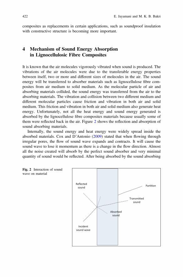
composites as replacements in certain applications, such as soundproof insulationwith constructive structure is becoming more important.
4 Mechanism of Sound Energy Absorptionin Lignocellulosic Fibre Composites
It is known that the air molecules vigorously vibrated when sound is produced. Thevibrations of the air molecules were due to the transferable energy propertiesbetween itself, two or more and different sizes of molecules in the air. The soundenergy will be transferred to absorber materials such as lignocellulose fibre com-posites from air medium to solid medium. As the molecular particle of air andabsorbing materials collided, the sound energy was transferred from the air to theabsorbing materials. The vibration and collision between two different medium anddifferent molecular particles cause friction and vibration in both air and solidmedium. This friction and vibration in both air and solid medium also generate heatenergy. Unfortunately, not all the heat energy and sound energy generated isabsorbed by the lignocellulose fibre composites materials because usually some ofthem were reflected back in the air. Figure 2 shows the reflection and absorption ofsound absorbing materials.
Internally, the sound energy and heat energy were widely spread inside theabsorbed materials. Cox and D’Antonio (2009) stated that when flowing throughirregular pores, the flow of sound wave expands and contracts. It will cause thesound wave to lose it momentum as there is a change in the flow direction. Almostall the noise created will absorb by the perfect sound absorber and very minimalquantity of sound would be reflected. After being absorbed by the sound absorbing
Par onReflected sound
Transmi ed sound
Absorbed sound
Incident sound wave
Fig. 2 Interaction of soundwave on material
422 E. Jayamani and M. K. B. Bakri

material, the sound energy degenerated before it reaches a surface due to reflectionfrom the rigid backed of the material (Vér and Beranek 2006). This also indicatesthat porous materials used should be necessarily thick so that the reflected noise canbe reduced.
5 Factors Affecting Sound Absorption Coefficientsof Lignocellulosic Fibre Reinforced Composites
Sound absorption takes place when a wave of sound passes through a material andresults in a reduction in the acoustic energy. The materials capable of reducingacoustic energy significantly are also called as sound absorptive materials. Thechanges in the parameters (i.e. porosity, density etc.) are important. This needs to beunderstood deeply, because it influences the properties of the materials, whichdictates the outcome of sound absorption properties of a material, such as theabsorption coefficient. Sound absorbing materials were typically used to control anacoustic environment into a certain level of an enclosed volume by reducing theamplitude of the reflected waves. Common factors such as the fibre size, porosity,flow resistivity, density, thickness, etc. affect sound absorption of the materials thatwill be investigated and discussed.
5.1 Fibre Size
Fibre sizes vary depending on different materials being used. The changes in thefibre size imply the change in the fibre diameter or the fibre length itself or both. Itis also one of the main factors that influence the sound absorption properties ofporous materials. The effect due to changes in fibre size can be observed throughrelated studies reported in the literature. Lee and Joo (2003) managed to conduct anexperiment based on the usage of three different types of non-woven fabric mate-rials that were made of recycled polyester fibres which had the same fibre length butdifferent denier. The fibre deniers used were 1.25, 2 and 7 den in diameter with a38 mm in length. For the binding purpose, low-melting point polyester staple fibrewith a 6 den in diameter with 42 mm in length was used. Denier (den) is the unitmeasurement of the fibre linear mass density of fibre size. Lee and Joo (2003)concluded that the fine fibre content increases the sound absorption coefficient ofthe materials due to superior airflow resistance by mean of friction of viscositythrough the vibration of the air.
Koizumi et al. (2002) also reported that a decrease in fibre diameter size leads toan increase in the sound absorption coefficient. The reason behind this was thatsound waves move within the thin fibre more easily when compared to their motionthrough thick fibres. Whereas, according to Sun et al. (1993), by using fine fibre
Lignocellulosic Fibres Reinforced Polymer Composites … 423

denier, more fibres are needed to fulfil or reach the equivalent of its original fibrecontent or same volume density. This results in higher airflow resistance and moretortuous path. A study by Koizumi et al. (2002) also showed that the fine fibredenier that range from 1.5 to 6 dpf (denier per filament) performed acousticallysuperior compared to the coarse denier fibres. Furthermore, it is also reported thatthe micro-denier fibres (less than 1 dpf) can provide a dramatic increase in theacoustical performance of sound absorption in the materials (Koizumi et al. 2002).
5.2 Porosity
The simplest definition of porosity is an empty void or space in materials.According to Allard et al. (1989), the porosity of materials is defined as the ratio ofthe volume of the voids in the porous materials to its total volume. In terms ofmechanical and mathematical perspective, porosity is the fraction of the volume ofmedium voids (i.e. air). Porosity usually traps gas (i.e. air), liquid (i.e. water) orsolid (i.e. starch) form of materials. The porosity in materials is higher, especiallyfor materials with foam type structure or open pores, such as porous silicon andporous rubber. Furthermore, according to Shoshani and Yakubov (2001), anabsorber of non-woven webs has high-sound absorption coefficient. The design ofsuch a structure, the absorber should have increasing porosity along the direction ofpropagation of the sound wave. Based on Canham (1997), porosity can be iden-tified in different ways and it depends on the shape and size packed inside amaterial. The formula for porosity can be identified as below:
Porosity; / ¼ Vv
Vtð1Þ
Whereas, Vv is the volume of medium voids (i.e. air) in the acoustical materials(m3), and Vt is the total volume of the acoustic materials (m3).
According to Sagartzazu et al. (2008), the porosity values are defined within therange of 0–1. In other words, it is measured from 0 to 100%. It is known that theporosity of some porous absorbers, such as polymer foams and fibrous polymer, liebetween the ranges of 0.95–0.99. The influence of porosity has been well presentedthrough the research conducted by Knapen et al. (2003). In their research, theporosity was manipulated and the effect on the sound absorption coefficient againstfrequency was investigated. The high porosity in a material causes high contactbetween the material surface and sound waves. This leads to more acoustical energybeing dissipated. In addition to that, the number, size and types of pores areimportant factors that should be considered while studying sound absorptionmechanism in porous materials. Thus, to allow sound dissipation by friction, thesound waves have to enter the porous materials. In other words, there should beenough pores within the material and on the material surface for the sound to passthrough and get dampened.
424 E. Jayamani and M. K. B. Bakri

5.3 Flow Resistivity
The determination of how much the air enters a porous absorber and the resistanceto the air flow from the entering the structure is called flow resistivity. Thus, flowresistivity is one of the most important aspects that influence the characteristics ofsound absorption in materials. It is also known that the specific flow resistance perunit thickness of the materials influences the sound absorbing properties of fibrousmaterials. Interlocking within the fibres in non-woven materials provides the fric-tion that resists acoustic wave motion. In general, when a sound wave enters thesematerials, the amplitude will decrease due to friction when the waves travel throughthe tortuous and rough passages. The acoustical or sound wave energy was con-verted into heat energy as sound waves energy pass through the frictional rough andtortuous passage of the materials (Conrad 1983). Friction quantity is expressed bythe resistance of the materials to airflow that is called airflow resistance and it isdefined as the following:
Flow Resistivity; Rf ¼ DPDTu
ð2Þ
Where, DP is the differential sound pressure across the thickness of the sample(Pa), DT is the incremental thickness (m), and u is the particle velocity through thesample (ms−1).
Based on Crocker and Arenas (2007), the high flow resistivity materials had ahigh resistance of air flow through the materials. This showed that materials withhigh flow resistivity sometimes tend to reflect more sound it absorbs. Furthermore,according to Ren and Jacobsen (1993), impedance and propagation constantcharacteristics describe the acoustical properties of porous materials. Hence, theflow resistance of the materials are controlled to a great extent. For a porousmaterial, the airflow resistivity per unit thickness is proportional to the shear vis-cosity coefficient of the fluid (i.e. air) involved and inversely proportional to thesquare of pore size characteristics of materials. This implies, with given porosity ofa fibrous material, the flow resistivity per unit thickness is inversely proportional tothe square of fibre diameters (Uno Ingard 1994). According to Cox and D’Antonio(2009), flow resistivity may vary between common porous absorber, thus, this canimply that it is one of the most important factors in the research.
5.4 Density
Density is one of the important parameters that influence the sound absorptioncoefficient behaviour in materials. According to the studies done by Koizumi et al.(2002), for middle and high range frequencies, sound absorption increases withincrease in density. Similar results were found by Ballagh (1996) research while
Lignocellulosic Fibres Reinforced Polymer Composites … 425

working with wool materials with varying bulk density. Based on the both results, itshowed that the low-density type of material absorbs more sound at the low fre-quency. In contrast, higher density materials normally absorb more in the middleand high frequencies. Furthermore, the material starts to perform well with a bigmargin or gap range in higher density at 500 Hz and above. This is due to theincrease in the energy loss as the surface friction increases in a denser material,which leads to an increase in the sound absorption coefficient. Moreover, when theapparent density is high, the quantity of fibres per unit area increases. The soundabsorption coefficient increases as the energy loss increase when the surface frictionincreases. The density of a material composite can be determined according to theformula:
Density; q ¼ Wa
Wa þWw �Wbqwaterð Þ ð3Þ
Where, Wa is the specimen weight in air (kg m−3), Ww is the partly immersedwire specimen holder weight (kg m−3), Wb is the specimen weight fully immersedin distilled water along with the partly immersed wire specimen holder (kg m−3)and qwater is the density of distilled water at testing temperature (kg m−3).
5.5 Thickness
There is an enormous amount of study done for porous materials, especially on thesound absorption behaviour and the effect of its thickness. According to Coates andKierzkowsld (2002), an effective sound absorption of a porous absorber wasachieved when the thickness of the materials is around one-tenth of its incidentsound wavelength by following the rule of thumb. Whereas, according toHirabayashi et al. (1995), peak absorption may occur at one-quarter incident soundwavelength at the resonance frequency. Thus, these showed that there is a rela-tionship between thickness either at low, medium or high-frequency soundabsorption. According to Ibrahim and Melik (1978), as the material increases in thethickness, at the low frequency, the sound absorption will increase as well.However, at a certain high frequency, the sound absorption had an inconsistenteffect.
The effects of thickness against sound absorption were also included inHakamada et al. (2006) report. According to Hakamada et al. (2006), based on theirexperiment on the three samples of material with different thickness at 1, 2 and20 mm, the result clearly showed the effect of thickness difference on the soundabsorption coefficient. It showed that the thicker the material, the more sound itabsorbs. Material thickness can enhance the acoustic impedance for porous mate-rials (Huang et al. 2008). It can be seen clearly in Fatima and Mohanty (2011)results, where the natural rubber latex jute composites showed higher soundabsorption coefficients in thick composites when compared with thin composites.
426 E. Jayamani and M. K. B. Bakri

Meanwhile, Jiang et al. (2012) also reported that the chlorinated polyethylene(CPE) and seven-hole hollow polyester fibres (SHPF) composites show improvedsound absorption when the thickness increased. Ersoy and Küçük (2009) alsoreported that a linear increase in sound absorption coefficient can be observed in thesample results, as the thickness increased.
5.6 Tortuosity
Tortuosity is the measurement of the elongated passage way through the pores incertain thickness of the sample. However, there are many other definitionsdescribing tortuosity. According to Yamashita et al. (2009), tortuosity is defined asa parameter in the internal structure of porous materials that represent the quantityof sound waves that enter the materials air space. However, according to Knapenet al. (2003), tortuosity is the internal structures that influence the acousticalproperties of the material. According to Wassilieff (1996), tortuosity is the mea-surement of how far the pores deviate from the normal, or twist bout the materialaxis. Tortuosity equation can be defined as below:
Tortuosity; s ¼ /Rs
Rfð4Þ
Where, / is the porosity, Rs electrical resistivity of the saturated sample (N.s.m−4) and Rf is the resistivity of the fluid used (N.s.m−4).
Based on Sakagami et al. (1996) report, it appears that the optimum soundabsorption is achieved by the less tortuous materials rather than by the materials thatare more tortuous. Knapen et al. (2003) stated that the more tortuous the materials,the lower absorption coefficient it has. Higher tortuosity causes larger fluctuationsin the sound absorption coefficient. The fluctuations will start manifesting from thelower frequencies as the tortuosity increased. However, Sakagami et al. (1996)stated that tortuosity only had a small effect on the noise transmission coefficient.Horoshenkov and Swift (2001) reported that the tortuosity only affects the locationabout quarter wavelengths of its peaks, whereas the flow resistivity and porositymay involve in affecting the height and width of the peaks. Furthermore, the valueof tortuosity might determine the high-frequency response of sound absorbingporous materials.
5.7 Compression
The effect of compression plays the key role in the field of sound absorption oracoustical absorption. The results of manipulating porous materials such as fibrousmaterials or cellular materials create diverse variants of physical parameters that
Lignocellulosic Fibres Reinforced Polymer Composites … 427

influence sound absorption. The compression of materials causes the soundabsorption to differ in distinct porous materials. According to Castagnede et al.(2000) and Wang et al. (2008), the sound absorption properties decreased as thefibrous mats or porous materials being compressed. On compressing, the variousfibres in the mat were brought nearer to each other without deformation (withoutany change in fibre size) (Castagnede et al. 2000). The compression also resulted ina decrease in thickness and indirectly cooperates with other physical variation(Castagnede et al. 2000).
Based on the study by Castagnede et al. (2000), compression led to an increasein flow resistivity and tortuosity, and indirectly decreased the shape factor (includecharacteristic length) and porosity. Hence, this occasionally caused inconsistenciesin sound absorption behaviour. According to Wang et al. (2008), the large com-pression rate caused the effect on the sound absorption at the lower frequency, asthe final thickness of porous materials is invariable. Unfortunately, these physicalparameter variations in compressed materials are not reason for the drop in soundabsorption directly because it is typically related to the decrease in sample thicknessbased on the experiment Castagnede et al. (2000) conducted. According toKeshavarz and Ohadi (2013), depending on the compression method, it may eithergive negative or positive effects on sound absorption coefficient.
5.8 Surface Impedance
Jayaraman (2005) has investigated the influence of surface impedance on soundabsorption by using air laid samples with different configurations. It can be seen thatthe sound absorption coefficients increased when the surface impedance of thematerials were altered. The surface impedance influences the sound absorptionsignificantly by altering the tortuous path and porosity of the material. Higher soundresistivity was estimated when the material with a given layer of thickness producedhigher dissipation. The reason behind this was due to the surface impedance thatincreased at the same time with a resistivity that caused a greater amount ofreflection, especially on the surface layer that indirectly produces a lower absorptivecapability. Moreover, according to Simón and Pfretzschner (2004), the wholeprocess must be frequency dependent, as the lower frequency bands on the nec-essary layer thickness increases, the resistivity will decrease.
5.9 Placement/Design
According to Everest (2001), the sound absorption of materials may be influencedby the different types of sound absorbers used in different places such as sides, endsand ceilings at different axial modes (can either in transverse, vertical or longitu-dinal axis). Sound absorbing materials placed near corners or along edges of the
428 E. Jayamani and M. K. B. Bakri

room surfaces typically demonstrated effective sound absorption, especially in arectangular room. For example, in the case of speech studios, the absorbingmaterials must be placed at head height on the walls, so that it will be more effectiveat higher audio frequencies. At a certain point, the sound absorption can be twicemore effective as the same material placed elsewhere if it were applied at lowerportions of high walls (Everest 2001). Moreover, the material surfaces should neverface each other.
If there is an air cavity behind the materials, the materials will act as a membraneof a certain mass. This design is frequency dependent. The air inside the materialscavity is analogous to mechanical spring. Significantly, the sound absorption ofmaterials is enhanced by embedding an air gap between the rigid back surface andthe sample (Hakamada et al. 2006). In the research work by Hakamada et al.(2006), it was observed that the air gap increase when the thickness decrease. Asoand Kinoshita (1965) concluded that the greatest absorption coefficient in a thinsample of large porosity slightly decreased as in the depth of the air space increased.Besides, their study revealed that the absorption coefficient in a thick sample isalmost constant, independent with the profundity of its air space.
5.10 Temperature
Srivastava et al. (2006) and Harris (1966) examined the effect of temperature on themineral sound absorption and the outcomes showed that sound absorption wasaffected when there was a change in temperature. Furthermore, Srivastava et al.(2006) had established a theoretical connection between the thermal conductivityusing a least-square regression method and the noise reduction coefficient. Theserelations were done under the distinctive temperature condition.
6 Methods to Measure Sound Absorption Coefficientof Composites
There are two methods or techniques to obtained sound absorption coefficient. Theyare reverberation and impedance tube. In extend, impedance tube was divided intotwo sub-methods or sub-techniques. They are standing wave and two-microphonetransfer function impedance tube. All of these methods or technique usually useconcentration ratio of absorbed sound energy which is the reflected energy toincident energy.
Lignocellulosic Fibres Reinforced Polymer Composites … 429

6.1 Reverberation Method
A method that uses the outcome of reflections of sound in receiving and hearingechoes at certain source locations in a compartment or room is called reverberation.Reverberation in a room is usually calculated in terms of reverberation time. Factorthat affected reverberation time is usually room size and room interior surface soundabsorption. Chen (2011) stated that the reverberation time was determined at thetime required for reflections of the direct sound to attenuate by 60 dB below thelevel of the direct sound. According to Jambrosic et al. (2008), the testing procedureof reverberation is to calculate the empty room reverberation time. The reverber-ation time was repeatedly taken in an empty room where the specimen was placed.Average reverberation time was used to calculate sound absorption performance.Figure 3 shows the reverberation room method.
6.2 Standing Wave Method
The first method to measured sound absorption by using sound speed in a tube wasthe standing wave method (Oldfield 2006). One of the most popular methods forstanding wave is using standing wave ratio (SWR). The magnitude and thesequential minimum and maximum location of the standing wave pattern in the tubewas determined using traversing microphone. Thus, these will produce the acousticreflection coefficient and impedance. Fundamentally, standing wave method createsa standing wave from the transmitting sound sources in the tube before it is reflectedat the end side of the mounted sample. To minimum and maximum of the standingwave were obtained by utilized the measurement of the amplitude by moving themicrophone location. The calculation of sound absorption coefficient was in relation
Fig. 3 Reverberation room method
430 E. Jayamani and M. K. B. Bakri

to the change in frequency. Standing wave method normally standardized inaccordance with ASTM C384-04 (2011) and ISO 10534-1 (1996). Figure 4 showsthe standing wave method.
Based on standing wave method concept, a standing wave is created when thesource of sound being switched on. Along the tube, moving back and forth (up anddown) by using a microphone, the pressure point for the minimum and maximumwere obtained. To get the reading, the microphone is connected to a voltmeter. Thephase and the magnitude of sample location based on the standing wave data werecomputed to obtained sound absorption coefficient. The standing wave method willconsume a lot of time due to the varieties of value and position needed to bedistinguished independently for each related frequency. However, the results areeasy to be interpreted and still reliable.
6.3 Two-Microphone Transfer Functions Method
Alternatively, the sound absorption can also be calculated experimentally by usingthe two-microphone transfer function impedance tube method (Huiping et al. 2006).Since the introduction of the two-microphone transfer function impedance tubemethod, it has replaced the popularity of standing wave method due to it severaladvantages such as accuracyetc. Act as a waveguide cylinder, impedance tube wasused to generate plane wave from the sound source. The two microphones werelocated at two locations near the sample to measure the sound pressure as shown.This method frequency is depending on the distance between the positions of themicrophone and the tube diameter size (Suhanek et al. 2008). Along a waveguide(Lefebvre et al. 2007), the measurement was taken at two different locations con-nected to the object and the impedance sound was taken and evaluated.
Fig. 4 Standing wave method
Lignocellulosic Fibres Reinforced Polymer Composites … 431

In their reported work, Putra et al. (2013) test the coefficient of sound absorptionfor biodegradable sample based on sugar cane fibres by using the two-microphonemethod. Before being dried heated at 80 °C for five minutes to remove theremaining water, the sugar cane was and cut off. During fabrication of test speci-mens, different compositions of sugar cane fibre were bind with polyester andpolyurethane. Then, the different pressure of hot-pressed is used on the mould tocreate different porosity levels. Regardless of different type of the binder in thesugar cane, the result showed that no effect on 40% binder of the total compositionon the performance of the absorption. The fibres started to show a good result of thesound absorption coefficient of 0.5 after the frequency of 3500 Hz and keepincreasing to 0.78 at 4500 Hz. Research made by Putra et al. (2013) provided a lotof information of bio-composites material sound absorption properties and relia-bility of two-microphone method to characterize composite material soundabsorption properties. Figure 5 shows the two-microphone transfer functionimpedance tube method.
The calculation for sound absorption for the two-microphone method is based onthe one-dimensional planar and pressure wave propagation mathematical theory.While, Seybert (1988) explained that in the tube, this method is driven by randomsound. By advantage of using small samples, as a change in parameters, this methodcreates fast measurement of normal incidence wave and also it is easy to be dis-assembled and assembled. Additionally, the results demonstrated by Horoshenkovet al. (2007) shows that the result attained varied at different laboratory conditions.The benefit of the transfer function impedance tube is that the apparatus is smallerand therefore it is more useful for small test specimens. Conversely, it allows thesurface impedance to be measured in addition to the sound absorption (Oldhamet al. 2011). However, the shortcomings are that the sound absorption can only bemeasured at normal incidence wave and uncertainties exist while measuring thesound absorption of materials having a porous structure. Thus, other related char-acterisation needed to be done to reduce the uncertainties.
Fig. 5 The two-microphone transfer function impedance tube method
432 E. Jayamani and M. K. B. Bakri
7 Fabrication of Lignocellulosic Fibre Reinforced PolymerMatrix Composites
Several researchers (Khedari et al. 2003; Khedari et al. 2004; Zulkifli et al. 2008)successfully reported composite made from particle board using agricultural wastes.One of the researchers found out that the sound absorption properties of glass woolfibres were similar to those bamboo fibre (Koizumi et al. 2002). Even though it hadalmost similar density, the enclosed surface fibreboard bamboo materials werefound to have higher sound absorption properties than those plywood materials.Yang et al. (2003) found out that in the range of 500–8000 Hz, randomly cut ricestraws and wood particle composite board exhibits higher sound absorption com-pared with other particleboard, plywood and fibreboard. With further research, itshows that natural fibre composite has becoming more popular due to it superioritysuch as combustible, biodegradable, weighable and recyclable, when comparedwith synthetic fibre composites. It is ranked among high-performance compositesdue to the good physical properties and advantages in the environment and econ-omy (Avella et al. 2000).
According to Simón and Pfretzschner (2004), materials for sound absorbing arechosen based on it materials, types, dimensions and the frequency range it cancontrol. Taking the example of ramie fibre poly (l-lactic) acid composites, it soundsabsorption coefficient is from 0.089 to 0.353 at the frequency of 250–1600 Hz(Chen et al. 2010). Wheat straw polypropylene composites also showed high soundabsorption coefficient from 0.03 to 0.2 at the range of 300–1800 Hz when com-pared with jute fibre polypropylene composites (Zou et al. 2010). Furthermore,Reddy and Yang (2011) showed high sound absorption coefficient form 0.06 to 0.8at the range of 1000–5000 Hz for jute zein composites as compared with jutepolypropylene composites. Rice straw and wood particle commercial ureaformaldehyde composite boards also showed better sound absorption coefficient inthe frequency range of 500–8000 Hz as compared to particleboard, plywood, andfibreboard (Yang et al. 2003). Moreover, Yang et al. (2004) also showed highsound absorption coefficient for commercial rice straw and waste tyre particlepolyurethane composites at the frequency range of 2000–8000 Hz, whereas itsperformance is superior than fibreboard, particleboard, and rice straw-wood particlecomposite boards. Table 2 shows the summary of acoustical properties of naturalfibre.
Today, agricultural raw waste materials are spread widely and being used asreplacement for synthetic fibres and wood-based acoustic absorption materialspurposes. Plentiful of agricultural waste in Malaysia can be used in variousmaterials applications even in the near future, for example, rise husk, coconut, andoil palm fibre (Mohd Nor et al. 2004). Furthermore, it is easy to crush agriculturallignocellulose fibres such as rice straw, wheat straw, and oil palm frond into par-ticles and chips compared with wood particles or synthetic fibres. These fibres arecheaper, nonabrasive, abundant, renewable and less toxic. Thus, through research,current and future applications based on the renewable resources for acoustical
Lignocellulosic Fibres Reinforced Polymer Composites … 433

materials can lead to viable alternatives (Nick et al. 2002; Asdrubali 2006). Table 3shows the summary of acoustical properties of natural fibre composites.
8 Sound Absorption Simulations
8.1 Empirical Model for Sound Absorbing Materials
The properties of sound absorbing material can be determined by phenomenolog-ical and microstructural models. Unfortunately, at certain condition the validity isvery limited. As in formulation of empirical models, generally, the theoretical pointof view were not being considered, neither the structure inside the material takenwere also into account (Ballagh 1996).
In the past decades, several models were developed by researchers (Qunli 1988;Dunn and Davern 1986) built on the principles and model made by Delany andBazley (1970). Subsequently, these models were extendedly modified by Mechel
Table 2 Summary of acoustical properties for natural fibre
Materials Fabricationmethods
Soundabsorptioncoefficient
Specimen parameters References
Bamboo Compression 0.02–0.4(at3000 Hz)
Thickness of 50 mm Koizumiet al. (2002)
Wood Compression 0.1 (at4000 Hz)
Thickness of 25 mm Wassilieff(1996)
Cellulose(isofloc)
– 1.10 (at3000 Hz)
Thickness of 60 mm Asdrubali(2006)
Sheepwool
0.80 (at3000 Hz)
Mineralwool
0.90 (at3000 Hz)
Thickness of 40 mm
Arengapinnata
– 0.40–0.80(at5000 Hz)
Thickness of 10–40 mm anddiameter of 28 mm
Ismail et al.(2010)
Cotton Compression 0.50 (at500 Hz)
Thickness of 50 mm Oldhamet al. (2011)
Kapok – 0.67–0.99(at4000 Hz)
Thickness of 20–60 mm, density of8.3–41.7 kg/m3, and combineddiameter of 30 and 60 mm
Xiang et al.(2013)
Coir Compression 0.78 (at4000 Hz)
Thickness of 20 mm and combineddiameter of 100 and 28 mm
Fouladiet al. (2013)Sugarcane
Grass 0.70 (at4000 Hz)
Corn 0.90 (at4000 Hz)
434 E. Jayamani and M. K. B. Bakri

and Ver (1992). By normalized it with a desired frequency and referred it to theflow resistivity of the materials, the impedance and propagation coefficient char-acteristic of the material can be predicted. Another prediction can be made from the
Table 3 Summary of acoustical properties of natural fibre composites
Materials Fabricationmethods
Soundabsorptioncoefficient
Specimen parameters References
Rice straw/wood ureaformaldehydecomposites
Hotcompression(500 psi140 °C)
0.05–0.5(at8000 Hz)
Thickness of 10 mm,diameter of 25 mm,and fibre loading of 0–30 wt%,
Yang et al.(2003)
Luffa epoxycomposites
Compression(1000 psi)
0.1 at6000 Hz
Thickness of 5 mm,diameter of 25 mm
Jayamaniet al. (2014)
Hemp brick(66%)
– 0.50 (at2000 Hz)
Thickness of 300 mm Asdrubali(2006)
Polystyrene(PST)
0.20 (at3000 Hz)
Thickness of 40 mm
Recycledlatex + coco
0.50 (at3000 Hz)
Rami poly(L-lactic acid)composites
Hotcompression
0.01–0.02(at1800 Hz)
Thickness of 3 mm,diameter of 110 mmand various grade ofPLLA.
Chen et al.(2010)
Wheat straw/polypropylenecomposites
Hotcompression
0.03–0.23(at3000 Hz)
Thickness of 3.2 mm,fibre loading of 40–80wt%, and diameter of63 mm
Zou et al.(2010)
Polyester fibrespolyethylenecomposites
Hotcompression
0.03–0.35(at10,000 Hz)
1st condition:Thickness of 1–3 mmand fibre loading of 0–20 wt%,2nd condition:Thickness of 20 mmand diameter of60 mm
Jiang et al.(2012)
Flax/epoxy Compression(laminated)
0.11 (at2000 Hz)
Thickness of 3 mmand diameter of100 mm
Prabhakaranet al. (2014)
Glass/flax/epoxy Compression(laminated)
0.15 (at2000 Hz)
Oil palm/zeincomposites
Hotcompression
0.11 (at6000 Hz)
Thickness of 5 mmand diameter of25 mm
Jayamaniet al. (2016a)
Banana/epoxycomposites
Compression 0.13 (at6000 Hz)
Thickness of 5 mmand diameter of25 mm
Jayamaniet al. (2016b)
Lignocellulosic Fibres Reinforced Polymer Composites … 435

complex quantities for acoustic properties. Natural wool materials are sometimesoutside of the limits available empirical models, although this method was usedextensively. According to Ballagh (1996), in some of the cases, microstructuremodels are best to used. It is because of the consideration of the internal structureand physical properties of the material were taken to calculate and predict theacoustic performance. Normally, the models used were correlated with parameterslike porosity, tortuosity, flow resistivity, and shape factors. Over the past decades,different models were development by Zwikker and Kosten (1949), Rayleigh(1896), Attenborough (1982), and Biot (1956). Other researchers (Allard andChampoux 1992; Johnson et al. 1987), used shape factors modelled complex modelstructure.
8.2 Empirical Model for the Flow Resistivity
In a material sound absorption, the influenced of flow resistivity is significant. Thefluctuation of sound absorption coefficient decreased and increased is profoundlyrelated with the flow resistivity that changes in the materials. Thus, in modelling ofsound absorption, flow resistivity plays a big role. In modelling of sound absorptioncoefficient, either as constant or variable, the flow resistivity can be manipulated inthe formula. To calculate the flow resistivity, Bies and Hansen (1980), Garai andPompoli (2005) and Mechel (2008) model can be used. Normally, the flow resis-tivity is derived based on the fibre radius, porosity and the bulk density from relatedcalculation and measurement of the materials.
8.2.1 Mechel Model
Based on Mechel (2008) models, by having the same radii for flow resistivity, therelationship between the fibre and the sound incidence derivation were made.Normally, based upon the fibre radius and bulk density or material porosity of thematerials, the equations calculation was made. The equations based on a modelcreated by Mechel (2008) are as below:
Flow Resistivity; r ¼ 10:56gr2
� � l1:531
r2 1� lð Þ3 !
ð5Þ
and
Flow Resistivity; r ¼ 6:8gr2
� � l1:296
r2 1� lð Þ3 !
ð6Þ
436 E. Jayamani and M. K. B. Bakri

Where, g is the viscosity of the medium (i.e. air viscosity for 1:84� 10�5Pa:sÞ,r is the radius of the fibre (m) and l is the massitivity (l ¼ 1� e , where e is theporosity of the material). Equations 5 and 6 can be simplified as below:
Flow Resistivity; r ¼ 10:56g 1� eð Þ1:531r2e3
ð7Þ
and
Flow Resistivity; r ¼ 6:8g 1� eð Þ1:296r2e3
ð8Þ
Where, e is the porosity of the material and r is the radius of fibre (m).From 6 to 10 µm fibre diameter range, Eq. 5 was used and from 20 to 30 µm
fibre diameter range, Eq. 6 was used. Oldham et al. (2011) stated that no closed cellor a small amount of binder material, the porosity, e is given by the equation below:
Porosity; e � 1� qbqm
ð9Þ
Where, qb is material bulk density (kg m−3) and qm, is the material matrixdensity (kg m−3).
8.2.2 Bies and Hansen Model
The model expressed has the same matrix materials with the bulk density as themain functions of porosity (Bies and Hansen 1980). The flow resistivity wasexpressed as below (Bies and Hansen 1980):
Flow Resitivity; r ¼ Kd2q�1:53
mð10Þ
Where, K is the constant value (3:18� 10�9 ), d is the fibre diameter (m), andqm is the bulk density of the material (kg m−3). Oldham et al. (2011) revised themodel and is given as below:
Flow Resistivity; r ¼ 3:18� 10�9
4r2q�1:53 ð11Þ
Where, r is the radius of fibre (m). The above expression was obtained andmeasured by using fibre mineral and fibreglass with approximately 2600 kg m−3
material matrix density (Oldham et al. 2011).
Lignocellulosic Fibres Reinforced Polymer Composites … 437

8.2.3 Garai and Pompoli Model
Oldham et al. (2011) stated that Garai and Pompoli model is improved based on theBies and Hansen model that influence with a variety of the fibre diameter (i.e.between 18 and 48 µm), a mean value (i.e. around 33 µm) with a matrix densitymaterial (approximated 1350 kg m−3). The equation on Garai and Pompoli (2005)is as below:
Flow Resistivity; r ¼ 28:3� 10�9
4r2q�1:404 ð12Þ
Where, r is the radius of fibre (m). The equation revised by Garai and Pompoli(2005) is based on the Bies and Hansen model below:
Flow Resistivity; r ¼ AqBm ð13Þ
Where, qm is the bulk density of the material (kg m−3), and both A and B are thefree parameters of the materials. Thus, an ideal value for A and B needed to decide.To obtain A and B values, Garai and Pompoli (2005) used the least-squarebest-fitting method and managed to get the values of 25.989 and 1.404.
8.3 Empirical Model for the Sound Absorption Coefficient
Garai and Pompoli (2005) and Delany and Bazley (1970) were two models used topredict sound absorption coefficients. Garai and Pompoli (2005) model is improvedversion based on Delany and Bazley (1970) model.
8.3.1 Delany and Bazley Model
By a simple power-law relations, Delany and Bazley model were obtained bybest-fitting a range of fibrous porous absorbers with a big amount of experimentaldata (Oldham et al. 2011). Based on the dimensional and represented in power-lawrelations variable, the data obtained were normalized (usually the flow resistanceand the frequency). The empirical formula below:
Characteristic Impedance; Zc ¼ q0c 1þ 0:0571q0fr
� ��0:754
�j0:087q0fr
� ��0:732 !
ð14Þ
Complex Wave Number; kc ¼ xC
1þ 0:0978q0fr
� ��0:754
�j0:187q0fr
� ��0:732 !
ð15Þ
438 E. Jayamani and M. K. B. Bakri

Where, q0 is the air density (kg m−3), r is the flow resistivity (Ns m−4), f is thefrequency (Hz), and x ¼ 2pf is the angular frequency (rads−1). Based on theequation, the range is limited in 0.01 < q0f
r < 1. The sound propagation wasinfluenced by two complex quantities, coefficient propagation c ¼ aþ jb andcharacteristic impedance, Z ¼ Rþ jX (Delany and Bazley 1970).
8.3.2 Garai and Pompoli
Delany and Bazley improved formula based on Garai and Pompoli model. It isknown that the empirical formula made by Delany and Bazley (1970) unlikelysuitable for other material such as polyester fibre material (Garai and Pompoli2005). For polyester fibre materials, with new impedance model (NMI), equationsare derived from the best-fit model’s value. As shown in Table 4, results ofpolyester material are given and tabulated with a comparison between Delany andBazley the eight coefficient value.
Based on the power-law relationship, new equation was rewritten from dataobtained by Garai and Pompoli (2005), where it can be fit in the range of0:05\ q0f
r \8:4 (Oldham et al. 2011). Below is the simplified equation:
Real Part of Characteristic Impedance; ZR ¼ q0C0 1þC1q0fr
� ��C2" #
ð16Þ
Imaginary Part of Characteristic Impedance; ZI ¼ �q0C0 C3q0fr
� ��C4" #
ð17Þ
Real Part of Propagation Constant; c; a ¼ 2pfC0
C5q0fr
� ��C6" #
ð18Þ
Imaginary Part of Propagation Constant, c; b ¼ 2pfC0
1þC7q0fr
� ��C8" #
ð19Þ
Where, q0 is the air density (kg m−3) and f is the frequency (Hz).
Table 4 Value of the eight coefficient equation from new impendence model (NMI) comparewith Delany and Bazley model value (Garai and Pompoli 2005)
Model C1 C2 C3 C4 C5 C6 C7 C8
Delany andBazley
0.057 0.754 0.087 0.732 0.189 0.595 0.098 0.700
NMI 0.078 0.623 0.074 0.660 0.159 0.571 0.121 0.530
Lignocellulosic Fibres Reinforced Polymer Composites … 439

Based on the equation, the sound absorption coefficient for a rigid backed fibrouslayer at normal incidence can be obtained by using the equation below:
Surface Impedance; Zl ¼ ZR þ iZIð Þ coth aþ ibð Þl½ � ¼ ZlR þ iZlI ð20Þ
Sound Absorption at Normal Incidence; an ¼ 4ZlRq0C0
Zlj j2 þ 2q0C0ZlR þ q0C0ð Þ2 ð21Þ
Where, l is the layer thickness (m) and q0 is the density (kg m−3). In mostapplications that usefully for noise control purposes, the simplified procedure canbe used where it is best fit based on the values of both characteristic impedance andpropagation constant (Delany and Bazley 1970; Dunn and Davern 1986). Inanalogous ways, according to Gardner et al. (2003), the measured values of theabsorption coefficient and surface impedance neural network was obtained andoptimized on the sound absorption coefficient.
9 Conclusions
Over the last decade, the uses of composites have been rapidly evolving as dueto the shortage of mineral materials, in which commonly used as a soundabsorbing material. Thus, a significant research and development were done inorder to improve the sound absorption, especially in the field of polymer matrixcomposites. Furthermore, the natural fibre reinforced with polymer matrixcomposites had gained enormous attention toward engineering, industrial,technologies, and manufacture due to its potentials and advantages for soundabsorption applications and also due to its various environmental concerns.Specifically, with polymer matrix materials, natural fibres have the ability tofunction in many ways, lightweight, renewable, low density, produce less CO2,and environmentally friendly. Furthermore, it is easy to fabricate, manufactureand have properties comparable to those other materials used for soundabsorption. Further research and innovation, especially in material design andfabrication are increasing due to it revolutionize and realization for soundabsorption applications especially in industry and automotive. Thus, this showedthat the future sustainability and growth of composites and polymer fromrenewable sources are reliant on continued research.
440 E. Jayamani and M. K. B. Bakri

References
Ali SA (2011) Industrial noise levels and annoyance in Egypt. Appl Acoust 72(1):221–225Allard JF, Champoux Y (1992) new empirical equations for sound propagation in rigid framed
porous materials. J Acoust Soc America 91(6):3346–3353Allard JF, Depollier C, Guignouard P (1989) Free field surface impedance measurements of
sound-absorbing materials with surface coatings. Appl Acoust 26(3):199–207Asdrubali F (2006) Survey on the acoustical properties of new sustainable materials for noise
control. EuroNoise 30(1):1–10Aso S, Kinoshita R (1965) Maximum sound absorption coefficient of a fiber assembly. J Text
Mach Soc Japan 11(3):81–87ASTM C384-04 (2011) Standard test method for impedance and absorption of acoustical materials
by impedance tube method. In: ASTM International. West Conshohocken, PAAttenborough K (1982) Acoustical characteristics of porous materials. Phys Rep 82(3):179–227Avella M, Rota GL, Martuscelli E, Raimo M, Sadocco P, Elegir G, Riva R (2000) Poly
(3-Hydroxybutyrate-Co-3-Hydroxyvalerate) and wheat straw fibre composites: thermal,mechanical properties and biodegradation behaviour. J Mater Sci 35(4):829–836
Ballagh KO (1996) Acoustical properties of wool. Appl Acoust 48(2):101–120Bernstein DM, Chevalier J, Smith P (2005) Comparison of Calidria chrysotile asbestos to pure
tremolite: inhalation biopersistence and histopathology following short-term exposure.Inhalation, Toxicol: Int Forum Respir Res 17(9):427–449
Bies DA, Hansen CH (1980) Flow resistance information for acoustical design. Appl Acoust 13(5):357–391
Biot MA (1956) Theory of propagation of elastic waves in a fluid-saturated porous solid. I:low-frequency range. J Acoust Soc America 28(2):168–178
Canham LT (1997) Properties of porous silicon, 1st edn. Institution of Engineering andTechnology, London
Castagnede B, Aknine A, Brouard B, Tarnow V (2000) Effects of compression on the soundabsorption of fibrous materials. Appl Acoust 61(1):173–182
Chen Z (2011) Investigation on simulation and measurement of reverberation for small rooms.Int J Adv Comput Sci Appl 2(7):69–73
Chen D, Li J, Ren J (2010) Study on sound absorption property of ramie fiber reinforced poly(L-Lactic acid) composites: morphology and properties. Compos A Appl Sci Manuf 41(8):1012–1018
Cheremisinoff NP (1996) Noise control in industry: a practical guide, 1st edn. William AndrewInc./Noyes Publications, New Jersey
Churg A, Wiggs B, De Paoli L, Kempe B, Stevens B (1984) Lung asbestos content in chrysotileworkers with mesothelioma. Am Rev Respir Dis 130(6):1042–1045
Clement International Corporation, United States Public Health Service and United States Agencyfor Toxic Substance and Disease Registry (2002) Toxicological profile for asbestos, 1st edn.United States Department of Health and Human Services, Washington, DC
Coates M, Kierzkowsld M (2002) Acoustic textile-lighter, thinner and more sound absorbent. TechText Int. International Newsletters
Conrad JH (1983) Engineering acoustics and noise control, 1st edn. Prentice Hall, New JerseyCory W (2005) Fans and ventilation: a practical guide, 1st edn. Elsevier, AmsterdamCox TJ, D’Antonio P (2009) Acoustic absorbers and diffusers: theory, design and application, 2nd
edn. Taylor & Francis, LondonCrocker MJ, Arenas JP (2007) Handbook of noise and vibration control, 2nd edn. Wiley, New
JerseyDelany ME, Bazley EN (1970) Acoustical properties of fibrous absorbent materials. Appl Acoust 3
(2):105–116Dunn IP, Davern WA (1986) Calculation of acoustic impedance of multi-layer absorbers. Appl
Acoust 19(5):321–334
Lignocellulosic Fibres Reinforced Polymer Composites … 441

Ersoy S, Küçük H (2009) Investigation of industrial tea-leaf-fibre waste material for its soundabsorption properties. Appl Acoust 70(1):215–220
Everest FA (2001) The master handbook of acoustics, 4th edn. McGraw-Hill, New YorkFatima S, Mohanty AR (2011) Acoustical and fire-retardant properties of jute composite materials.
Appl Acoust 72(2–3):108–114Fouladi MH, Nassir MH, Ghassem M, Shamel M, Peng SY, Wen SY, Xin PZ, Mohd Nor MJ
(2013) Utilizing Malaysian natural fibers as sound absorber. Modelling and measurementmethods for acoustic waves and for acoustic microdevices, InTech, pp 161–170
Fragomeni S, Venkatesan S (2010) Incorporating sustainable practice in mechanics and structuresof materials, 1st edn. CRC Press, Boca Raton, Florida
Garai M, Pompoli F (2005) A simple empirical model of polyester fibre materials for acousticalapplications. Appl Acoust 66(12):1383–1398
Gardner GC, O’Leary ME, Hansen S, Sun JQ (2003) Neural network for prediction of acousticalproperties of polyurethane foams. Appl Acoust 64(2):229–242
Hakamada M, Kuromura T, Chen Y, Kusuda H, Mabuchi M (2006) High sound absorption ofporous aluminum fabricated by spacer method. Appl Phys Lett 88(25):106–254
Harris CM (1966) Absorption of sound in air versus humidity and temperature. J Acoust SocAmerica 40(1):148–159
Hirabayashi T, McCaa DJ, Rebant RG, Rusch P, Saha P (1995) Application of noise control andheat insulation materials and devices in the automotive industry. SAE Technical Paper
Horoshenkov KV, Khan A, Bécot F-X, Jaouen L, Sgard F, Renault A, Amirouche N, Pompoli F,Prodi N, Bonfiglio P (2007) Reproducibility experiments on measuring acoustical properties ofrigid-frame porous media (round-robin tests). J Acoust Soc America 122(1):345–353
Horoshenkov KV, Swift MJ (2001) The effect of consolidation on the acoustic properties of looserubber granulates. Appl Acoust 62(6):665–690
Huang J, Sun B, Dai G-c (2008) Sound absorption properties of lightweight reinforcedthermoplastic laminates. J Funct Polym 21(1):177
Huiping T, Ping T, Zhengping X, Qiangbing W (2006) Research progress of sintered porousmetal. Rare Met Mater Eng 35(2):428–432
Ibrahim MA, Melik RW (1978) Physical parameters affecting acoustic absorption characteristics offibrous materials. In: Proceedings of the mathematical and physical society of Egypt, pp. 125–130
Ismail L, Ghazali MI, Mahzan S, Ahmad Zaidi AM (2010) Sound absorption of arenga pinnatanatural fiber. World Acad Sci Technol 43(1):804–806
ISO 10534-1 (1996) Acoustics—determination of sound absorption coefficient and impedance inimpedance tubes—part 1: method using standing wave ratio. International Organisation forStandardization, Geneva
Jambrosic K, Horvat M, Domitrovic H (2008) Reverberation time measuring methods. J AcoustSoc America 123(5):3617
Jayaraman KA (2005) Acoustical absorptive properties of nonwoven. North Carolina StateUniversity
Jayamani E, Hamdan S, Rahman MR, Soon KH, Bakri MKB (2014) Processing andcharacterization of epoxy/luffa composites: investigation on chemical treatment of fibers onmechanical and acoustical properties. BioResources 9(3):5542–5556
Jayamani E, Hamdan S, Ezhumalai P, Bakri MKB (2016a) Investigation on dielectric and soundabsorption properties of banana fibers reinforced epoxy composites. Jurnal Teknologi 78(6–10):97–103
Jayamani E, Hamdan S, Soon KH, Rahman MR, Bakri MKB (2016b) Acoustical, thermal, andmorphological properties of zein reinforced oil palm empty fruit bunch fiber bio-composites.J Appl Polymer Sci:1–8
Jiang S, Xu Y, Zhang H, White CB, Yan X (2012) Seven-hole hollow polyester fibers asreinforcement in sound absorption chlorinated polyethylene composites. Appl Acoust 73(3):243–247
442 E. Jayamani and M. K. B. Bakri

Johnson DL, Koplik J, Dashen R (1987) Theory of dynamic permeability and tortuosity influid-saturated porous media. J Fluid Mech 176(1):379–402
Kang J, Fuchs HV (1999) Effect of water-films on the absorption of membrane absorbers. ApplAcoust 56(2):127–135
Keshavarz R, Ohadi A (2013) Effects of compression on the sound absorption of transverselyisotropic fibrous materials at obligue incidence. Appl Acoust 74(1):383–395
Khedari J, Charoenvai S, Hirunlabh J (2003) New insulating particleboards from durian peel andcoconut coir. Build Environ 38(3):435–441
Khedari J, Nankongnab N, Hirunlabh J, Teekasap S (2004) New lowcost insulation particleboardsfrom mixture of durian peel and coconut. Build Environ 39(1):59–65
Knapen E, Lanoye R, Vermeir G, Lauriks W, Van Gemert D (2003) Sound absorption bypolymer-modified porous cement mortars. In: 6th International conference on materials scienceand restoration, vol. 1, no. 1, pp. 347–358
Kogel JE, Trivedi NC, Barker JM, Krukowski ST (2006) Industrial minerals and rocks. In: Societyfor mining, metallurgy, and exploration, 7th edn. Littleton, Colorado
Koizumi T, Tsujiuchi N, Adachi A (2002) The development of sound absorbing materials usingnatural bamboo fibers. High Perform Struct Compos 4(1):157–166
Lee Y, Joo C (2003) Sound absorption properties of recycled polyester fibrous assembly absorbers.Autex Res J 3(2):78–84
Lefebvre A, Scavone GP, Abel J, Buckiewicz-Smith A (2007) A comparison of impedancemeasurements using one and two microphones. Proceedings of ISMA 1(1):1–8
McDonald JC, McDonald AD (1997) Chrysotile, tremolite and carcinogenicity. Ann Occup Hyg41(6):699–705
Mechel FP (2008) Formulas of acoustics, 2nd edn. Springer-Verlag, Berlin Heidelberg, New YorkMechel FP, Ver IL (1992) Sound absorbing materials and sound absorbers. In: Beranek L, Ver IL
(eds) Noise and vibration control engineering: principles and applications. Wiley, pp. 203–243Mohd Nor MJ, Jamaludin N, Tamiri FM (2004) A preliminary study of sound absorption using
multi-layer coconut coir fibers. Electron J Tech Acoust 3(1):1–8National Park Service (1999) Health and safety risk of asbestos: conserve O gram, 1st edn.
Department of the Interior, Washington, DCNational Toxicology Program (2011) Report on Carcinogens, 12th edn. United States Department
of Health and Human Services, North CarolinaNick A, Becker U, Thomas W (2002) Improved acoustic behavior of interior parts of renewable
resources in the automotive industry. J Polym Environ 10(3):115–118Oldfield R (2006) Improved membrane absorbers. The University of SalfordOldham DJ, Egan CA, Cookson RD (2011) Sustainable acoustic absorbers from the biomass. Appl
Acoust 72(6):350–363Prabhakaran S, Krishnaraj V, Kumar MS, Zitoune R (2014) Sound and vibration damping
properties of flax fiber reinforced composites. Procedia Engineering 97(1):573–581Putra A, Abdullah Y, Efendy H, Farid WM, Ayob MR, Py MS (2013) Utilizing sugarcane wasted
fibers as a sustainable acoustic absorber. Procedia Eng 53(1):632–638Qunli W (1988) Empirical relations between acoustical properties and flow resistivity of porous
plastic open-cell foam. Appl Acoust 25(3):141–148Rayleigh JWS (1896) Theory of sound II, 1st edn. Macmillan and Co., LondonReddy N, Yang Y (2011) Novel green composites using zein as matrix and jute fibers as
reinforcement. Biomass Bioenerg 35(8):3496–3503Ren M, Jacobson F (1993) A method of measuring the dynamic flow resistance and reactance of
porous materials. Appl Acoust 29(4):265–276Rey Rd, Alba J, Arenas JP, Sanchis VJ (2012) An empirical modeling of porous sound absorbing
materials made of recycled foam. Appl Acoust 73(6–7):604–609Rouette H-K (2001) ‘Jute’, encyclopedia of textile finishing, 1st edn. Springer, Berlin Heidelberg,
Cambridge, UKSagartzazu X, Hervella L, Pagalday JM (2008) Review in sound absorbing materials. Arch
Comput Methods Eng 15(3):311–342
Lignocellulosic Fibres Reinforced Polymer Composites … 443

Sakagami K, Kiyama M, Marimoto M, Takahashi D (1996) Sound absorption of a cavity-backedmembrane: a step towards design method for membrane-type absorbers. Appl Acoust 49(3):231–241
Sarantopoulos G, Lykoudis S, Kassomenos P (2014) Noise levels in primary school of mediumsized city in Greece. Sci Total Environ 482–483(1):493–500
Seybert AF (1988) Two sensor methods for the measurement of sound intensity and acousticproperties in ducts. J Acoust Soc America 83(6):2233–2239
Shoshani Y, Yakubov Y (2001) Use of nonwovens of variable porosity as noise control elements.Int Nonwovens J 10(4):23–28
Simón F, Pfretzschner J (2004) Guidelines for the acoustic design of absorptive devices. Noise VibWorldwide 35(1):12–21
Srivastava RL, Dhabal RL, Suman BM, Saini A, Panchal P (2006) An estimation of correlation onthermos-acoustic properties of mineral wool. J Sci Ind Res 65(3):232–236
Su W-C, Cheng YS (2009) Deposition of man-made fibres in human respiratory airway casts.J Aerosol Sci 40(3):270–284
Suhanek M, Jambrosic K, Horvat M (2008) A comparison of two methods for measuring thesound absorption coefficient using impedance tubes. In: ELMAR 2008, 50th Internationalsymposium, IEEE, vol.1, no.1, pp. 321–324
Sun F, Banks-Lee P, Peng H (1993) Sound absorption in an anisotropic periodically layeredfluid-saturated porous medium. Appl Acoust 39(1–2):65–76
Talty JT (1988) Industrial hygiene engineering—recognition, measurement, evaluation andcontrol, 2nd edn. William Andrew Inc./Noyes Publications, New Jersey
Tang SK, Ng CH, Lam EYL (2012) Experimental investigation of the sound absorptionperformance of compartmented Helmholtz resonators. Appl Acoust 73(9):969–976
Uno Ingard K (1994) Notes on sound asborption techology, 1st edn. Noise Control Foundation,New York
Vér IL, Beranek LL (2006) Noise and vibration control engineering—principles and application,2nd edn. Wiley, New Jersey
Wakefield Acoustic Ltd (2004) City of vancouver noise control manual, 1st edn. Sound Smart,Victoria, B.C
Wang C-N, Kuo Y-M, Chen S-K (2008) Effects of compression on the sound absorption of porousmaterials with an elastic frame. Appl Acoust 69(1):31–39
Wassilieff C (1996) Sound absorption of wood-based materials. Appl Acoust 48(4):339–356Xiang H-F, Wang D, Liua H-C, Zhao N, Xu J (2013) Investigation on sound absorption properties
of kapok fibers. Chin J Polym Sci 31(3):521–529Yamashita T, Suzuki K, Adachi H, Nishino S, Tomota Y (2009) Effect of microscopic internal
structure on sound absorption properties of polyurethane foam by x-ray computed tomographyobservation. Mater Trans 50(2):373–380
Yang H-S, Kim D-J, Kim H-J (2003) Rice straw-wood particle composite for sound absorbingwooden construction materials. Biores Technol 86(2):117–121
Yang H-S, Kim H-J, Son J, Park H-J, Lee B-J, Wang T-S (2004) Rice-husk flour filledpolypropylene composites; mechanical and morphological study. Compos Struct 63(3–4):305–312
Zou Y, Huda S, Yang Y (2010) Lightweight composites from long wheat straw and polypropyleneweb. Biores Technol 101(6):2026–2033
Zulkifli R, Mohd Nor JM, Mat Tahir MF, Ismail AR, Nuawi MZ (2008) Acoustic properties ofmulti-layer coir fibres sound absorption panel. J Appl Sci 8(20):3709–3714
Zwikker C, Kosten CW (1949) Sound absorbing materials, 1st edn. Elsevier, New York
444 E. Jayamani and M. K. B. Bakri