
Superantenna made of transformation media - CiteSeerX
12
Superantenna made of transformation media Ulf Leonhardt 1 and Tom´ aˇ s Tyc 1,2 1 School of Physics and Astronomy, University of St Andrews, North Haugh, St Andrews KY16 9SS, Scotland 2 Institute of Theoretical Physics and Astrophysics, Masaryk University, Kotlarska 2, 61137 Brno, Czech Republic May 31, 2008 Abstract We show how transformation media can make a superantenna that is either completely invisible or focuses incoming light into a needle-sharp beam. Our idea is based on representating three-dimensional space as a foliage of sheets and performing two-dimensional conformal maps on each sheet. PACS 42.15.-i, 42.15.Eq, 42.15.Dp 1 arXiv:0806.0070v1 [physics.optics] 31 May 2008
-
Upload
khangminh22 -
Category
Documents
-
view
5 -
download
0
Transcript of Superantenna made of transformation media - CiteSeerX

Superantenna made of transformation media
Ulf Leonhardt1 and Tomas Tyc1,2
1School of Physics and Astronomy, University of St Andrews,North Haugh, St Andrews KY16 9SS, Scotland
2Institute of Theoretical Physics and Astrophysics,Masaryk University, Kotlarska 2, 61137 Brno, Czech Republic
May 31, 2008
Abstract
We show how transformation media can make a superantenna that is eithercompletely invisible or focuses incoming light into a needle-sharp beam. Ouridea is based on representating three-dimensional space as a foliage of sheetsand performing two-dimensional conformal maps on each sheet.PACS 42.15.-i, 42.15.Eq, 42.15.Dp
1
arX
iv:0
806.
0070
v1 [
phys
ics.
optic
s] 3
1 M
ay 2
008
1 Introduction
Transformation optics [1, 2, 3, 4, 5, 6, 7] has the potential to transform optics, bothby developing new ideas for the design of optical instruments and by stimulatingresearch into new optical materials. Transformation optics uses the fact [6] thatoptical media alter the geometry of space and time for light.1 A transformationmedium performs an active coordinate transformation: electromagnetism in physi-cal space, including the effect of the medium, is equivalent to electromagnetism intransformed coordinates where space appears to be empty. The sole function of thedevice is to facilitate a transformation from physical to electromagnetic space. Oneof the most striking applications of transformation optics is invisibility [1, 2, 3, 5];a cloaking device creates a coordinate transformation that carries a hole for hidingobjects. But invisibility is by no means the only application: perfect lensing basedon negative refraction also implicitly uses coordinate transformations [6] — multival-ued transformations — although the original argument [8] why negative refractionmakes a perfect lens did not make use of this fact. Similarly, the performance ofcloaking devices can be theoretically verified by other means than coordinate trans-formations [9], but the ideas of transformation optics provide an elegant, visual wayof designing optical devices. Such visual thinking often leads to new insights andinventions.
Here we discuss an idea for a superantenna based on coordinate transformations.This device is either invisible or it condenses a cross section of light into a singlepoint. Ideally, the condensed light would continue to propagate as a needle-sharpbeam in a given direction, but there might be practical limitations to this behavior.Our idea certainly is not the only case where optical condensors based on transforma-tion media have been described [3, 4, 10], but it may have unique three-dimensionalproperties, because it changes the topology of space. Most nontrivial applicationsof transformation media use topology transformations: spaces with holes in the caseof invisibility [6], multivalued spaces for perfect lensing [6], topological bridges forelectromagnetic wormholes [11] and space-time horizons [6] for artificial black holes.Our idea relies on a three-dimensional extension of optical conformal mapping [3, 4]as we describe below.
2 Transformation
Imagine we represent three-dimensional space as a foliage of spherical layers (suchthat it resembles an onion), as illustrated in Fig. 1. Each layer we map onto anindividual plane by stereographic projection [4, 12, 13], each layer is a Riemannsphere [12, 13], see Fig. 2. Expressed in terms of analytical geometry, the Cartesiancoordinates X, Y , Z of physical space are represented by spherical radii r anddimensionless complex numbers z that correspond to the stereographic projectionsof the spherical angles. In formulae,
r =√X2 + Y 2 + Z2 , z =
X + iY
r − Z. (1)
1For a review see Ref. [7].
2

Then we perform a conformal transformation on z, mapping z to w where themapping may vary with the radius r, but w should only depend on z and not on z∗,
w = w(z, r) ,∂w
∂z∗= 0 . (2)
The main advantage of such restricted maps is that they allow us to use the plethoraof tools and insights of complex analysis, because the condition ∂w/∂z∗ = 0 cor-responds to the Cauchy-Riemann differential equations of analytic functions [13].The map w(z) generates a Riemann surface that consists of several Riemann sheets,unless w(z) is a Mobius transformation [12]. Finally we map the w sheets back onthe Riemann sphere of electromagnetic space by the inverse stereographic projection[12, 13]
X ′ + iY ′ =2rw
|w|2 + 1, Z ′ = r
|w|2 − 1
|w|2 + 1. (3)
On each individual Riemann sphere, the transformation (2) is conformal [12, 13, 14]— it preserves the angles between lines — but the transformation is normally notconformal in three-dimensional space, where the Cartesian coordinates X, Y , Z aremapped onto new coordinates X ′, Y ′, Z ′ and vice versa. In the spirit of transfor-mation optics [6], the new coordinates are the coordinates of a virtual space, elec-tromagnetic space, that we assume to be completely empty, where light propagatesalong straight lines. The device transforms the straight light rays of electromag-netic space into appropriately curved rays in physical space. Moreover, it not onlytransforms rays, but complete electromagnetic waves.
An example of a sufficiently simple but interesting conformal transformation isthe Joukowski map (Zhukovsky map) known from aeronautical engineering [15]
w = z +a2(r)
z, z =
1
2
(w ±
√w2 − 4a2(r)
). (4)
Equation (4) describes a conformal map between the z plane and two Riemannsheets in w space. Or, in terms of Riemann spheres, for each radius r, two spheresin electromagnetic space are merged into one sphere in physical space, as illustratedin Fig. 3. The image of each one of the two Riemann spheres occupies a certainspherical angle in physical space.
This topology makes a perfect trap: in electromagnetic space light may passfrom one of the two spheres to the other, and it will stay there. In physical space,however, the spherical angle of the second Riemann sphere may shrink to a pointwhere light is concentrated. The entrance to the trap is marked by the branchpoints in w space, i.e. by the points ±2a(r). These points are variable, because ais a function of the radius r. Therefore, one could catch incoming light by rapidlymaking a(r) very large when the light gets sufficiently close, say for r smaller thana critical radius r0. When the light has passed from the first Riemann sphere tothe second one it will continue to propagate on the second sphere. As the radiusr grows again, the fraction of real space occupied by this sphere is diminishing tozero, the trap closes: light is concentrated and funneled into a needle-sharp beam.
What is the cross section of the captured light? The cross section in physicalspace is identical to the cross section in electromagnetic space, because, outside
3

of the device, physical and electromagnetic space are identical. In electromagneticspace light rays travel along straight lines. Here the portal to the trap is marked bythe line of the branch points ±2a(r). Consequently, the cross section in real space isbounded by the curve of the branch points in electromagnetic space, by the inversestereographic projection of ±2a(r). Figure 4 shows an example that is given by theradius-dependent branch points
a =
{a0
(r − r0r0
)2
: r ≤ r0
0 : r > r0(5)
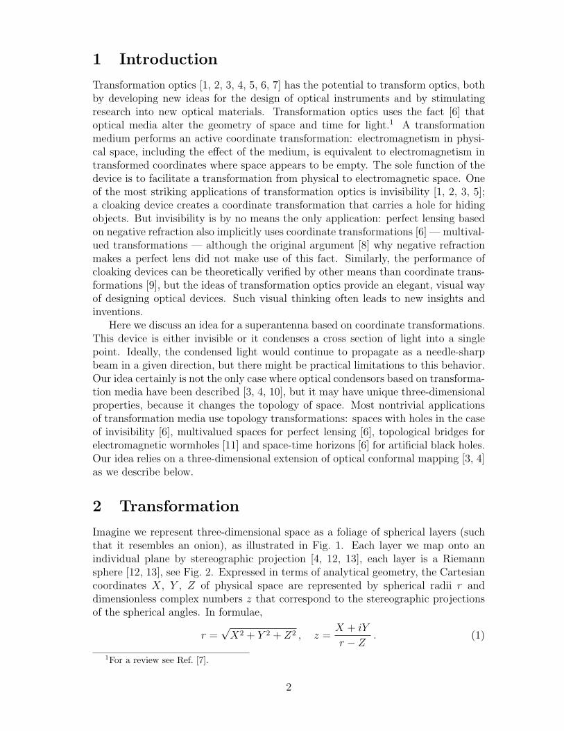
where a0 describes the maximal extension of the branch cut at r = 0. The capturedlight has entered the second Riemann sphere in electromagnetic space that shrinksinto the point z = 0 on the Riemann sphere in physical space when r approachesr0. So, in physical space, the captured light rays are concentrated in the spatialdirection given by the image of z = 0 in the inverse stereographic projection, i.e.along the negative Z axis. Figure 4 shows how the device funnels a captured lightray towards this axis; Fig. 5 illustrates the fate of a circle of light rays. The deviceacts like a superantenna, focusing incident electromagnetic radiation into an areathat is, in principle, infinitely small. Moreover, and quite remarkably, the focus isindependent of the direction of incidence, in contrast to the focusing by normal lensesor mirrors. The theory would suggest that the captured electromagnetic radiationis concentrated in an infinitely narrow beam. In practice, of course, both the focusand the beam will be limited, but assessing these limitations goes beyond the scopeof this paper, beyond the area of transformation optics.
3 Media
What are the requirements to implement such a superantenna in practice? Perhapsthe most elegant way of calculating the material properties of this device is using theconnection between transformation media and general relativity [6, 7]. For this, weneed to establish the geometries that correspond to the stereographic coordinates(1) and their transformation (2). We denote the metric tensor of the stereographiccoordinates by Γ and the metric tensor of the transformed coordinates by G (usingthe notation of Ref. [7]). The line element in physical space is given by
dl2 = dX2 + dY 2 + dZ2 = dr2 +4r2dz dz∗
(|z|2 + 1)2. (6)
The geometry of the transformed coordinates is characterized by the equivalent lineelement (6) in electromagnetic space, but expressed in real-space coordinates,
ds2 = dr2 +4r2dw dw∗
(|w|2 + 1)2with dw =
∂w
∂rdr +
∂w
∂zdz . (7)
For formulating a compact notation for the metric in electromagnetic space we define∇ ≡ (∂/∂r, ∂/∂z, ∂/∂z∗) such that, for example, ∇w = (∂w/∂r, ∂w/∂z, 0). From
4

the line element (7) we read off the matrix of the metric
G = ∇r ⊗∇r +2r2 (∇w ⊗∇w∗ +∇w∗ ⊗∇w)
(|w|2 + 1)2. (8)
We obtain the metric tensor Γ of the stereographic coordinates of real space byputting w = z in G or by directly reading off the tensor from the line element(6). The square root of the determinant of the metric tensor describes the volumeelement. We put the matrix (8) in explicit form and calculate the determinant:
g = detG = − 4r4
(|w|2 + 1)4
∣∣∣∣∂w∂z∣∣∣∣4 , γ = detΓ = − 4r4
(|z|2 + 1)4. (9)
The inverse matrix G−1 describes the contravariant metric tensor and is given by
G−1 =∂z
∂r⊗ ∂z
∂r+
(1 + |w|2)2
2r2
(∂z
∂w⊗ ∂z
∂w∗+
∂z
∂w∗⊗ ∂z
∂w
)(10)
with z defined as the vector of (r, z, z∗) and z understood as a function of w andr. One can verify that Eq. (10) indeed describes the inverse matrix of G using therelations
∇zi · ∂z∂zj
= δij ,
∑i
∇zi ⊗ ∂z
∂zi= ∇⊗ z = 1 . (11)
According to the connection between optical media and geometry [6, 7] the con-travariant electric permittivity tensor in stereographic coordinates is
ε =
√−g√−γ
G−1 =(|z|2 + 1)2
(|w|2 + 1)2
∣∣∣∣∂w∂z∣∣∣∣2G−1 . (12)
The magnetic permeability tensor should be identical to ε (impedance matching).The matrix (12) describes a contravariant tensor; the eigenvalues of ε are not in-variant under coordinate transformations, but the eigenvalues of the mixed tensorεΓ are [7]. Therefore they correspond to the eigenvalues of the electric permittivityin Cartesian coordinates that characterize the dielectric response of the anisotropicmaterial used to implement the coordinate transformation (2). We calculate thethree eigenvalues of εΓ and obtain
ε1 = 1 , ε± =1
2
(A±√A2 − 4B
)(13)
with the abbreviations
A = 1 +B
(1 + 2
√−γ
∣∣∣∣∂w∂r∣∣∣∣2 ∣∣∣∣∂w∂z
∣∣∣∣−2), B =
√−g√−γ
. (14)
One of the eigenvalues, ε1, is always unity, which reflects the fact that the coordinatetransformations (2) act on two-dimensional manifolds, although they cover layer-by-layer the entire three-dimensional physical space as shown in Fig. 1. Close to the
5

focal line of the device at z = 0 (in negative Z direction) we would expect that theeigenvalues of the dielectric tensor become singular. We find for the transformation(4)
ε+ →1
a4, ε− → 1 for z → 0 . (15)
Since a(r) vanishes at r0 one of the eigenvalues indeed is singular. In practice, thedielectric functions will always be finite, which limits the achievable focus of theantenna and may also influence the width of the beam funneled into the negative Zdirection. In order to estimate these effects and to develop the optimal strategy forregularizing the singularity at the focus, one could perhaps use similar mathematicaltechniques as the ones applied for assessing the regularization of invisibility devices[16].
4 Outlook
Our principal ideas are by no means restricted to superantennae, but they could serveto design other novel optical devices as well. One could imagine other foliages ofthree-dimensional space than the Riemann spheres of Fig. 1 and consider conformalmaps on them. The important point is that such three-dimensional foliages allowresearchers to make use of the tools of two-dimensional conformal mapping. In thisway, a rich arsenal of insights, techniques and tools becomes available for designingoptical instruments, the theory of complex analysis and conformal mapping [12, 13,14] that has reached a high level of development and sophistication, and combines,like no other branch of mathematics, analytical techniques with visual thinking.
We are grateful to T. G. Philbin for helpful comments. The paper has beensupported by COVAQIAL and a Royal Society Wolfson Research Merit Award.
References
[1] A. Greenleaf, M. Lassas, and G. Uhlmann, Physiol. Meas. 24, S1 (2003).
[2] A. Greenleaf, M. Lassas, and G. Uhlmann, Math. Res. Lett. 10, 1 (2003).
[3] U. Leonhardt, Science 312, 1777 (2006).
[4] U. Leonhardt, New. J. Phys. 8, 118 (2006).
[5] J. B. Pendry, D. Schurig, and D. R. Smith, Science 312, 1780 (2006).
[6] U. Leonhardt and T. G. Philbin, New J. Phys. 8, 247 (2006).
[7] U. Leonhardt and T. G. Philbin, arXiv:0805.4778, to appear in Prog. Optics.
[8] J. B. Pendry, Phys. Rev. Lett. 85, 3966 (2000).
[9] Z. Ruan, M. Yan, C. M. Neff, and M. Qui, Phys. Rev. Lett. 99, 113903 (2007).
6

[10] A. V. Kildishev and V. M. Shalaev, Opt. Lett. 33, 43 (2008).
[11] A. Greenleaf, Y. Kurylev, M. Lassas, and G. Uhlmann, Phys. Rev. Lett. 99,183901 (2007).
[12] T. Needham, Visual Complex Analysis (Clarendon Press, Oxford, 2002).
[13] M. J. Ablowitz and A. S. Fokas, Complex Variables (Cambridge UniversityPress, Cambridge, 1997).
[14] Z. Nehari, Conformal Mapping (McGraw-Hill, New York, 1952).
[15] J. Anderson, Fundamentals of Aerodynamics (McGraw-Hill, Toronto, 1991).
[16] A. Greenleaf, Y. Kurylev, M. Lassas, and G. Uhlmann, Commun. Math. Phys.275, 749 (2007).
7

Figure 1: Foliage. We present three-dimensional space as a foliage of spherical layers(artificially cut in half to be seen in the picture). Each layer represents a Riemann sphere.A device that performs conformal mappings on these spheres may act like a superantenna.
8

Z
X x
Figure 2: Stereographic projection, mapping the (x, y) plane onto the (X,Y, Z) surfaceof a sphere, shown here at Y = 0 where the plane appears as a line and the sphere as acircle. A line drawn from the North Pole of the sphere through (X, Y, Z) cuts the planeat (x, y). Conversely, in the inverse stereographic projection, the line between the NorthPole and (x, y) cuts the surface of the sphere at (X,Y, Z).
9

Figure 3: Conformal map of the sphere. The top pictures illustrate the conformal map(4) on the complex plane, while the bottom pictures show the corresponding map on thesphere. The red points are the branch points that are connected by the branch cut, alsoshown in red. The pictures on the left column illustrate the topology of electromagneticspace, while the pictures on the right describe physical space. Light that passes fromone branch of electromagnetic space to another is trapped in the corresponding region inphysical space. When light rays approach the device the branch cut opens; it closes whenthe rays leave, but then they are trapped on another Riemann sheet that shrinks to zeroin physical space: light is concentrated in a given direction. The map makes a perfecttrap.
10

Figure 4: Light capture. The left picture shows a light ray in electromagnetic space,whereas the right picture displays the ray trajectory in real space. We used Eq. 5 withthe parameters r0 = 5 and a0 = 2.5. The heart-shaped leaf illustrates the cross section oflight capture; any ray that hits this area is captured. The right figure shows how the lightray is bent and funneled towards the bottom of the device where all captured light rayswould converge in a needle-sharp beam.
11
Figure 5: Capture of light rays. A circle of light rays enter the superantenna (indicatedby the heart-shaped capture cross section). The rays within the cross section are directedtowards the bottom of the device and bundled in an extremely narrow beam. The raysthat escape continue in the original directions; for them the device is invisible.
12