
Sun ONE Portal Server 6.0 Deployment Guide
292
Deployment Guide Sun™ ONE Portal Server Release 6.0 816-6363-10 March 2003
-
Upload
khangminh22 -
Category
Documents
-
view
1 -
download
0
Transcript of Sun ONE Portal Server 6.0 Deployment Guide

Deployment GuideSun™ ONE Portal Server
Release6.0
816-6363-10March 2003

Copyright © 2003 Sun Microsystems, Inc. All rights reserved.
Sun, Sun Microsystems, the Sun logo, iPlanet, the logo iPlanet, Solaris, Solaris Security Toolkit, Java 2 Platform, Enterprise Edition,Javadoc, JavaServer Pages, Java Development Kit, JDK, J2EE, JSP, Java, JVM, JavaBeans, EJB, JMX, Java API for XML Processing,JavaMail, Java HotSpot, Sun Crypto Accelerator 1000, and JavaScript are trademarks or registered trademarks of Sun Microsystems,Inc. in the United States and other countries. Netscape and the Netscape N logo are registered trademarks of NetscapeCommunications Corporation in the U.S. and other countries. Other Netscape logos, product names, and service names are alsotrademarks of Netscape Communications Corporation, which may be registered in other countries. UNIX and UltraSPARC areregistered trademarks in the United States and other countries, exclusively licensed through X/Open Company, Ltd.
Federal Acquisitions: Commercial Software—Government Users Subject to Standard License Terms and Conditions
The product described in this document is distributed under licenses restricting its use, copying, distribution, and decompilation. Nopart of the product or this document may be reproduced in any form by any means without prior written authorization of theSun-Netscape Alliance and its licensors, if any.
THIS DOCUMENTATION IS PROVIDED “AS IS” AND ALL EXPRESS OR IMPLIED CONDITIONS, REPRESENTATIONS ANDWARRANTIES, INCLUDING ANY IMPLIED WARRANTY OF MERCHANTABILITY, FITNESS FOR A PARTICULAR PURPOSEOR NON-INFRINGEMENT, ARE DISCLAIMED, EXCEPT TO THE EXTENT THAT SUCH DISCLAIMERS ARE HELD TO BELEGALLY INVALID.
________________________________________________________________________________________
Copyright © 2003 Sun Microsystems, Inc. Tous droits réservés.
Sun, Sun Microsystems, le logo Sun, iPlanet, le logo iPlanet, Solaris, Solaris Security Tookit, Java 2 Platform, Enterprise Edition,Javadoc, JavaServer Pages, Java Development Kit, JDK, J2EE, JSP, Java, JVM, JavaBeans, EJB, JMX, Java API for XML Processing,JavaMail, Java HotSpot, Sun Crypto Accelerator 1000, et JavaScript sont des marques de fabrique ou des marques déposées de SunMicrosystems, Inc. aux Etats-Unis et d’autre pays. Netscape et le logo Netscape N sont des marques déposées de NetscapeCommunications Corporation aux Etats-Unis et d’autre pays. Les autres logos, les noms de produit, et les noms de service deNetscape sont des marques déposées de Netscape Communications Corporation dans certains autres pays. UNIX et UltraSPARCsont des marques enregistrees aux Etats-Unis et dans d'autres pays et licenciée exclusivement par X/Open Company Ltd.
Le produit décrit dans ce document est distribué selon des conditions de licence qui en restreignent l'utilisation, la copie, ladistribution et la décompilation. Aucune partie de ce produit ni de ce document ne peut être reproduite sous quelque forme ou parquelque moyen que ce soit sans l’autorisation écrite préalable de l’Alliance Sun-Netscape et, le cas échéant, de ses bailleurs de licence.
CETTE DOCUMENTATION EST FOURNIE “EN L'ÉTAT”, ET TOUTES CONDITIONS EXPRESSES OU IMPLICITES, TOUTESREPRÉSENTATIONS ET TOUTES GARANTIES, Y COMPRIS TOUTE GARANTIE IMPLICITE D'APTITUDE À LA VENTE, OU ÀUN BUT PARTICULIER OU DE NON CONTREFAÇON SONT EXCLUES, EXCEPTÉ DANS LA MESURE OÙ DE TELLESEXCLUSIONS SERAIENT CONTRAIRES À LA LOI.

3
Contents
About This Guide . . . . . . . . . . . . . . . . . . . . . . . . . . . . . . . . . . . . . . . . . . . . . . . . . . . . . . . . . . . . . 13
Chapter 1 Overview of Sun ONE Portal Server . . . . . . . . . . . . . . . . . . . . . . . . . . . . . . . . . . . . 19Understanding Sun ONE Portal Server . . . . . . . . . . . . . . . . . . . . . . . . . . . . . . . . . . . . . . . . . . . . . . . . . . . . 19
What Is a Portal? . . . . . . . . . . . . . . . . . . . . . . . . . . . . . . . . . . . . . . . . . . . . . . . . . . . . . . . . . . . . . . . . . . . . 20Overview of the Sun ONE Portal Server 6.0 Product Family . . . . . . . . . . . . . . . . . . . . . . . . . . . . . . . 20Examples of How Sun ONE Portal Server 6.0 Satisfies Business Needs . . . . . . . . . . . . . . . . . . . . . . 21
Case Study: Business-to-Employee Portal . . . . . . . . . . . . . . . . . . . . . . . . . . . . . . . . . . . . . . . . . . . . 21Case Study: Business-to-Consumer Portal . . . . . . . . . . . . . . . . . . . . . . . . . . . . . . . . . . . . . . . . . . . . 23Case Study: Internet Service Provider Portal . . . . . . . . . . . . . . . . . . . . . . . . . . . . . . . . . . . . . . . . . . 24
Sun ONE Portal Server Life Cycle . . . . . . . . . . . . . . . . . . . . . . . . . . . . . . . . . . . . . . . . . . . . . . . . . . . . . . 25Sun ONE Portal Server Resources . . . . . . . . . . . . . . . . . . . . . . . . . . . . . . . . . . . . . . . . . . . . . . . . . . . . . . 25
JavaServer Pages Technology . . . . . . . . . . . . . . . . . . . . . . . . . . . . . . . . . . . . . . . . . . . . . . . . . . . . . . . 26Portal (Desktop) Content . . . . . . . . . . . . . . . . . . . . . . . . . . . . . . . . . . . . . . . . . . . . . . . . . . . . . . . . . . . 27Configuration Data . . . . . . . . . . . . . . . . . . . . . . . . . . . . . . . . . . . . . . . . . . . . . . . . . . . . . . . . . . . . . . . . 27Application Data . . . . . . . . . . . . . . . . . . . . . . . . . . . . . . . . . . . . . . . . . . . . . . . . . . . . . . . . . . . . . . . . . . 27Site Data . . . . . . . . . . . . . . . . . . . . . . . . . . . . . . . . . . . . . . . . . . . . . . . . . . . . . . . . . . . . . . . . . . . . . . . . . 28
Sun ONE Portal Server, Secure Remote Access . . . . . . . . . . . . . . . . . . . . . . . . . . . . . . . . . . . . . . . . . . 28Migrating to a New Version of Portal Server . . . . . . . . . . . . . . . . . . . . . . . . . . . . . . . . . . . . . . . . . . . . 29
Independent Software Vendor Integrations with Sun ONE Portal Server . . . . . . . . . . . . . . . . . . . . . . 29Integration Types . . . . . . . . . . . . . . . . . . . . . . . . . . . . . . . . . . . . . . . . . . . . . . . . . . . . . . . . . . . . . . . . . . . . 30Collaboration and Application Emulation ISVs . . . . . . . . . . . . . . . . . . . . . . . . . . . . . . . . . . . . . . . . . . 31Content and Document Management ISVs . . . . . . . . . . . . . . . . . . . . . . . . . . . . . . . . . . . . . . . . . . . . . . 32Content Syndication ISVs . . . . . . . . . . . . . . . . . . . . . . . . . . . . . . . . . . . . . . . . . . . . . . . . . . . . . . . . . . . . . 33Enterprise Applications ISVs . . . . . . . . . . . . . . . . . . . . . . . . . . . . . . . . . . . . . . . . . . . . . . . . . . . . . . . . . . 33Location-Based Services and Device-Independent Rendering ISV . . . . . . . . . . . . . . . . . . . . . . . . . . 35Personalization, Business Intelligence, and Analysis ISV . . . . . . . . . . . . . . . . . . . . . . . . . . . . . . . . . . 35Rapid Portlet and Web Services Development ISVs . . . . . . . . . . . . . . . . . . . . . . . . . . . . . . . . . . . . . . 36
Types of Portal Deployments . . . . . . . . . . . . . . . . . . . . . . . . . . . . . . . . . . . . . . . . . . . . . . . . . . . . . . . . . . . . 36Business-to-Employee Portal (B2E) . . . . . . . . . . . . . . . . . . . . . . . . . . . . . . . . . . . . . . . . . . . . . . . . . . . . . 37Business-to-Consumer Portal (B2C) . . . . . . . . . . . . . . . . . . . . . . . . . . . . . . . . . . . . . . . . . . . . . . . . . . . . 37

4 Sun ONE Portal Server Deployment Guide • March 2003
Business-to-Business Portal (B2B) . . . . . . . . . . . . . . . . . . . . . . . . . . . . . . . . . . . . . . . . . . . . . . . . . . . . . . 38Portal Deployment Architecture . . . . . . . . . . . . . . . . . . . . . . . . . . . . . . . . . . . . . . . . . . . . . . . . . . . . . . . . . . 39Establishing Quality Goals . . . . . . . . . . . . . . . . . . . . . . . . . . . . . . . . . . . . . . . . . . . . . . . . . . . . . . . . . . . . . . 42
Chapter 2 Sun ONE Portal Server Core Architecture . . . . . . . . . . . . . . . . . . . . . . . . . . . . . . . 43Sun ONE Portal Server Core Components . . . . . . . . . . . . . . . . . . . . . . . . . . . . . . . . . . . . . . . . . . . . . . . . . 43
Deployment Platform . . . . . . . . . . . . . . . . . . . . . . . . . . . . . . . . . . . . . . . . . . . . . . . . . . . . . . . . . . . . . . . . 44Software Components . . . . . . . . . . . . . . . . . . . . . . . . . . . . . . . . . . . . . . . . . . . . . . . . . . . . . . . . . . . . . . . . 45Core Components . . . . . . . . . . . . . . . . . . . . . . . . . . . . . . . . . . . . . . . . . . . . . . . . . . . . . . . . . . . . . . . . . . . 46
Sun ONE Web Server, Sun ONE Application Server, BEA WebLogic, and IBM WebSphereAdvanced Edition . . . . . . . . . . . . . . . . . . . . . . . . . . . . . . . . . . . . . . . . . . . . . . . . . . . . . . . . . . . . . . . . . 47Sun ONE Directory Server . . . . . . . . . . . . . . . . . . . . . . . . . . . . . . . . . . . . . . . . . . . . . . . . . . . . . . . . . 47Sun ONE Identity Server . . . . . . . . . . . . . . . . . . . . . . . . . . . . . . . . . . . . . . . . . . . . . . . . . . . . . . . . . . . 47Java Development Kit . . . . . . . . . . . . . . . . . . . . . . . . . . . . . . . . . . . . . . . . . . . . . . . . . . . . . . . . . . . . . 47
Internal Components . . . . . . . . . . . . . . . . . . . . . . . . . . . . . . . . . . . . . . . . . . . . . . . . . . . . . . . . . . . . . . . . 48Installer . . . . . . . . . . . . . . . . . . . . . . . . . . . . . . . . . . . . . . . . . . . . . . . . . . . . . . . . . . . . . . . . . . . . . . . . . 49Sun ONE Portal Server Providers . . . . . . . . . . . . . . . . . . . . . . . . . . . . . . . . . . . . . . . . . . . . . . . . . . . 49Desktop . . . . . . . . . . . . . . . . . . . . . . . . . . . . . . . . . . . . . . . . . . . . . . . . . . . . . . . . . . . . . . . . . . . . . . . . . 50NetMail . . . . . . . . . . . . . . . . . . . . . . . . . . . . . . . . . . . . . . . . . . . . . . . . . . . . . . . . . . . . . . . . . . . . . . . . . 50Rewriter . . . . . . . . . . . . . . . . . . . . . . . . . . . . . . . . . . . . . . . . . . . . . . . . . . . . . . . . . . . . . . . . . . . . . . . . . 50Search Engine . . . . . . . . . . . . . . . . . . . . . . . . . . . . . . . . . . . . . . . . . . . . . . . . . . . . . . . . . . . . . . . . . . . . 50
Sun ONE Portal Server Add-On Products . . . . . . . . . . . . . . . . . . . . . . . . . . . . . . . . . . . . . . . . . . . . . . . 51Sun ONE Portal Server, Secure Remote Access . . . . . . . . . . . . . . . . . . . . . . . . . . . . . . . . . . . . . . . . 51Sun ONE Instant Messaging . . . . . . . . . . . . . . . . . . . . . . . . . . . . . . . . . . . . . . . . . . . . . . . . . . . . . . . . 52
Service Configuration . . . . . . . . . . . . . . . . . . . . . . . . . . . . . . . . . . . . . . . . . . . . . . . . . . . . . . . . . . . . . . . . 52Sun ONE Portal Server Protocols . . . . . . . . . . . . . . . . . . . . . . . . . . . . . . . . . . . . . . . . . . . . . . . . . . . . . . . . . 54Sun ONE Portal Server Software Interfaces . . . . . . . . . . . . . . . . . . . . . . . . . . . . . . . . . . . . . . . . . . . . . . . . 55
Front-end Interface . . . . . . . . . . . . . . . . . . . . . . . . . . . . . . . . . . . . . . . . . . . . . . . . . . . . . . . . . . . . . . . . . . 56Back-end Interfaces . . . . . . . . . . . . . . . . . . . . . . . . . . . . . . . . . . . . . . . . . . . . . . . . . . . . . . . . . . . . . . . . . . 57Customer and Third-Party Software Interface . . . . . . . . . . . . . . . . . . . . . . . . . . . . . . . . . . . . . . . . . . . 57Users of the Interfaces . . . . . . . . . . . . . . . . . . . . . . . . . . . . . . . . . . . . . . . . . . . . . . . . . . . . . . . . . . . . . . . . 57Exported Interfaces in Sun ONE Portal Server . . . . . . . . . . . . . . . . . . . . . . . . . . . . . . . . . . . . . . . . . . . 58
Sun ONE Portal Server Configuration Files and Directory Structure . . . . . . . . . . . . . . . . . . . . . . . . . . . 61Directories Installed for Portal Server . . . . . . . . . . . . . . . . . . . . . . . . . . . . . . . . . . . . . . . . . . . . . . . . . . 61Configuration Files . . . . . . . . . . . . . . . . . . . . . . . . . . . . . . . . . . . . . . . . . . . . . . . . . . . . . . . . . . . . . . . . . . 62
Sun ONE Portal Server Software Deployment . . . . . . . . . . . . . . . . . . . . . . . . . . . . . . . . . . . . . . . . . . . . . . 62Software Packaging . . . . . . . . . . . . . . . . . . . . . . . . . . . . . . . . . . . . . . . . . . . . . . . . . . . . . . . . . . . . . . . . . . 62Software Categories . . . . . . . . . . . . . . . . . . . . . . . . . . . . . . . . . . . . . . . . . . . . . . . . . . . . . . . . . . . . . . . . . . 62Java Compatibility . . . . . . . . . . . . . . . . . . . . . . . . . . . . . . . . . . . . . . . . . . . . . . . . . . . . . . . . . . . . . . . . . . . 63
Sun ONE Portal Server Desktop . . . . . . . . . . . . . . . . . . . . . . . . . . . . . . . . . . . . . . . . . . . . . . . . . . . . . . . . . . 64Desktop Component . . . . . . . . . . . . . . . . . . . . . . . . . . . . . . . . . . . . . . . . . . . . . . . . . . . . . . . . . . . . . . . . . 64User Experience with the Desktop . . . . . . . . . . . . . . . . . . . . . . . . . . . . . . . . . . . . . . . . . . . . . . . . . . . . . 64User Session . . . . . . . . . . . . . . . . . . . . . . . . . . . . . . . . . . . . . . . . . . . . . . . . . . . . . . . . . . . . . . . . . . . . . . . . 66

5
Sun ONE Portal Server Customization . . . . . . . . . . . . . . . . . . . . . . . . . . . . . . . . . . . . . . . . . . . . . . . . . . . . 68Sun ONE Portal Server Availability and Fault Tolerance . . . . . . . . . . . . . . . . . . . . . . . . . . . . . . . . . . . . . 69Sun ONE Portal Server Security, Encryption, and Authentication . . . . . . . . . . . . . . . . . . . . . . . . . . . . . 70
Chapter 3 Sun ONE Portal Server, Secure Remote Access Architecture . . . . . . . . . . . . . . 71Overview of Sun ONE Portal Server, Secure Remote Access . . . . . . . . . . . . . . . . . . . . . . . . . . . . . . . . . 71
Relation Between Sun ONE Portal Server and Secure Remote Access . . . . . . . . . . . . . . . . . . . . . . . 72Open Mode . . . . . . . . . . . . . . . . . . . . . . . . . . . . . . . . . . . . . . . . . . . . . . . . . . . . . . . . . . . . . . . . . . . . . . 72Secure Mode . . . . . . . . . . . . . . . . . . . . . . . . . . . . . . . . . . . . . . . . . . . . . . . . . . . . . . . . . . . . . . . . . . . . . 73
Sun ONE Portal Server, Secure Remote Access Components . . . . . . . . . . . . . . . . . . . . . . . . . . . . . . . . . 75Secure Remote Access Gateway . . . . . . . . . . . . . . . . . . . . . . . . . . . . . . . . . . . . . . . . . . . . . . . . . . . . . . . 79
Multiple Gateway Instances . . . . . . . . . . . . . . . . . . . . . . . . . . . . . . . . . . . . . . . . . . . . . . . . . . . . . . . . 80Proxy Configuration . . . . . . . . . . . . . . . . . . . . . . . . . . . . . . . . . . . . . . . . . . . . . . . . . . . . . . . . . . . . . . 80Gateway and HTTP Basic Authentication . . . . . . . . . . . . . . . . . . . . . . . . . . . . . . . . . . . . . . . . . . . . 80Gateway and SSL Support . . . . . . . . . . . . . . . . . . . . . . . . . . . . . . . . . . . . . . . . . . . . . . . . . . . . . . . . . 81Gateway Access Control . . . . . . . . . . . . . . . . . . . . . . . . . . . . . . . . . . . . . . . . . . . . . . . . . . . . . . . . . . . 82Gateway Logging . . . . . . . . . . . . . . . . . . . . . . . . . . . . . . . . . . . . . . . . . . . . . . . . . . . . . . . . . . . . . . . . . 82Reverse Proxy (Rproxy) . . . . . . . . . . . . . . . . . . . . . . . . . . . . . . . . . . . . . . . . . . . . . . . . . . . . . . . . . . . . 82
Netlet . . . . . . . . . . . . . . . . . . . . . . . . . . . . . . . . . . . . . . . . . . . . . . . . . . . . . . . . . . . . . . . . . . . . . . . . . . . . . . 85How Does Netlet Work? . . . . . . . . . . . . . . . . . . . . . . . . . . . . . . . . . . . . . . . . . . . . . . . . . . . . . . . . . . . 88Netlet and Authentication . . . . . . . . . . . . . . . . . . . . . . . . . . . . . . . . . . . . . . . . . . . . . . . . . . . . . . . . . . 88Static and Dynamic Port Applications . . . . . . . . . . . . . . . . . . . . . . . . . . . . . . . . . . . . . . . . . . . . . . . 89Encryption Algorithms . . . . . . . . . . . . . . . . . . . . . . . . . . . . . . . . . . . . . . . . . . . . . . . . . . . . . . . . . . . . 90Dynamic Key Exchange . . . . . . . . . . . . . . . . . . . . . . . . . . . . . . . . . . . . . . . . . . . . . . . . . . . . . . . . . . . . 90Netlet Rules . . . . . . . . . . . . . . . . . . . . . . . . . . . . . . . . . . . . . . . . . . . . . . . . . . . . . . . . . . . . . . . . . . . . . . 90Netlet Provider . . . . . . . . . . . . . . . . . . . . . . . . . . . . . . . . . . . . . . . . . . . . . . . . . . . . . . . . . . . . . . . . . . . 91Netlet and Application Integration . . . . . . . . . . . . . . . . . . . . . . . . . . . . . . . . . . . . . . . . . . . . . . . . . . 91Netlet and Split Tunneling . . . . . . . . . . . . . . . . . . . . . . . . . . . . . . . . . . . . . . . . . . . . . . . . . . . . . . . . . 91
Netlet Proxy . . . . . . . . . . . . . . . . . . . . . . . . . . . . . . . . . . . . . . . . . . . . . . . . . . . . . . . . . . . . . . . . . . . . . . . . 92NetFile . . . . . . . . . . . . . . . . . . . . . . . . . . . . . . . . . . . . . . . . . . . . . . . . . . . . . . . . . . . . . . . . . . . . . . . . . . . . . 96
NetFile Components . . . . . . . . . . . . . . . . . . . . . . . . . . . . . . . . . . . . . . . . . . . . . . . . . . . . . . . . . . . . . . 96NetFile Initialization . . . . . . . . . . . . . . . . . . . . . . . . . . . . . . . . . . . . . . . . . . . . . . . . . . . . . . . . . . . . . . 96Server and Shares . . . . . . . . . . . . . . . . . . . . . . . . . . . . . . . . . . . . . . . . . . . . . . . . . . . . . . . . . . . . . . . . . 97Validating Credentials . . . . . . . . . . . . . . . . . . . . . . . . . . . . . . . . . . . . . . . . . . . . . . . . . . . . . . . . . . . . . 97NetFile Access Control . . . . . . . . . . . . . . . . . . . . . . . . . . . . . . . . . . . . . . . . . . . . . . . . . . . . . . . . . . . . 98NetFile Security . . . . . . . . . . . . . . . . . . . . . . . . . . . . . . . . . . . . . . . . . . . . . . . . . . . . . . . . . . . . . . . . . . 98Special Operations . . . . . . . . . . . . . . . . . . . . . . . . . . . . . . . . . . . . . . . . . . . . . . . . . . . . . . . . . . . . . . . . 98NetFile and Multithreading . . . . . . . . . . . . . . . . . . . . . . . . . . . . . . . . . . . . . . . . . . . . . . . . . . . . . . . . 99
Rewriter . . . . . . . . . . . . . . . . . . . . . . . . . . . . . . . . . . . . . . . . . . . . . . . . . . . . . . . . . . . . . . . . . . . . . . . . . . . . 99Rewriter Proxy . . . . . . . . . . . . . . . . . . . . . . . . . . . . . . . . . . . . . . . . . . . . . . . . . . . . . . . . . . . . . . . . . . . . . 100
Sun ONE Portal Server, Secure Remote Access Authentication . . . . . . . . . . . . . . . . . . . . . . . . . . . . . . 100Sun ONE Portal Server, Secure Remote Access Configuration Files and Directory Structure . . . . . 101
Secure Remote Access Directories . . . . . . . . . . . . . . . . . . . . . . . . . . . . . . . . . . . . . . . . . . . . . . . . . . . . . 101
6 Sun ONE Portal Server Deployment Guide • March 2003
Secure Remote Access Configuration Files . . . . . . . . . . . . . . . . . . . . . . . . . . . . . . . . . . . . . . . . . . . . . 102
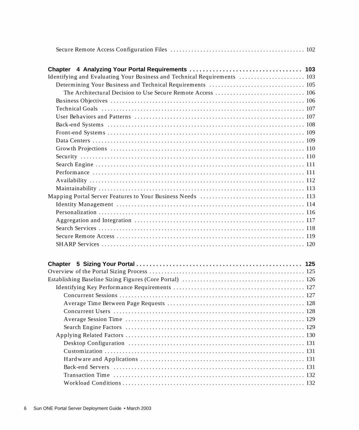
Chapter 4 Analyzing Your Portal Requirements . . . . . . . . . . . . . . . . . . . . . . . . . . . . . . . . . . 103Identifying and Evaluating Your Business and Technical Requirements . . . . . . . . . . . . . . . . . . . . . . 103
Determining Your Business and Technical Requirements . . . . . . . . . . . . . . . . . . . . . . . . . . . . . . . . 105The Architectural Decision to Use Secure Remote Access . . . . . . . . . . . . . . . . . . . . . . . . . . . . . . 106
Business Objectives . . . . . . . . . . . . . . . . . . . . . . . . . . . . . . . . . . . . . . . . . . . . . . . . . . . . . . . . . . . . . . . . . 106Technical Goals . . . . . . . . . . . . . . . . . . . . . . . . . . . . . . . . . . . . . . . . . . . . . . . . . . . . . . . . . . . . . . . . . . . . 107User Behaviors and Patterns . . . . . . . . . . . . . . . . . . . . . . . . . . . . . . . . . . . . . . . . . . . . . . . . . . . . . . . . . 107Back-end Systems . . . . . . . . . . . . . . . . . . . . . . . . . . . . . . . . . . . . . . . . . . . . . . . . . . . . . . . . . . . . . . . . . . 108Front-end Systems . . . . . . . . . . . . . . . . . . . . . . . . . . . . . . . . . . . . . . . . . . . . . . . . . . . . . . . . . . . . . . . . . . 109Data Centers . . . . . . . . . . . . . . . . . . . . . . . . . . . . . . . . . . . . . . . . . . . . . . . . . . . . . . . . . . . . . . . . . . . . . . . 109Growth Projections . . . . . . . . . . . . . . . . . . . . . . . . . . . . . . . . . . . . . . . . . . . . . . . . . . . . . . . . . . . . . . . . . 110Security . . . . . . . . . . . . . . . . . . . . . . . . . . . . . . . . . . . . . . . . . . . . . . . . . . . . . . . . . . . . . . . . . . . . . . . . . . . 110Search Engine . . . . . . . . . . . . . . . . . . . . . . . . . . . . . . . . . . . . . . . . . . . . . . . . . . . . . . . . . . . . . . . . . . . . . . 111Performance . . . . . . . . . . . . . . . . . . . . . . . . . . . . . . . . . . . . . . . . . . . . . . . . . . . . . . . . . . . . . . . . . . . . . . . 111Availability . . . . . . . . . . . . . . . . . . . . . . . . . . . . . . . . . . . . . . . . . . . . . . . . . . . . . . . . . . . . . . . . . . . . . . . . 112Maintainability . . . . . . . . . . . . . . . . . . . . . . . . . . . . . . . . . . . . . . . . . . . . . . . . . . . . . . . . . . . . . . . . . . . . . 113
Mapping Portal Server Features to Your Business Needs . . . . . . . . . . . . . . . . . . . . . . . . . . . . . . . . . . . 113Identity Management . . . . . . . . . . . . . . . . . . . . . . . . . . . . . . . . . . . . . . . . . . . . . . . . . . . . . . . . . . . . . . . 114Personalization . . . . . . . . . . . . . . . . . . . . . . . . . . . . . . . . . . . . . . . . . . . . . . . . . . . . . . . . . . . . . . . . . . . . . 116Aggregation and Integration . . . . . . . . . . . . . . . . . . . . . . . . . . . . . . . . . . . . . . . . . . . . . . . . . . . . . . . . . 117Search Services . . . . . . . . . . . . . . . . . . . . . . . . . . . . . . . . . . . . . . . . . . . . . . . . . . . . . . . . . . . . . . . . . . . . . 118Secure Remote Access . . . . . . . . . . . . . . . . . . . . . . . . . . . . . . . . . . . . . . . . . . . . . . . . . . . . . . . . . . . . . . . 119SHARP Services . . . . . . . . . . . . . . . . . . . . . . . . . . . . . . . . . . . . . . . . . . . . . . . . . . . . . . . . . . . . . . . . . . . . 120
Chapter 5 Sizing Your Portal . . . . . . . . . . . . . . . . . . . . . . . . . . . . . . . . . . . . . . . . . . . . . . . . . . 125Overview of the Portal Sizing Process . . . . . . . . . . . . . . . . . . . . . . . . . . . . . . . . . . . . . . . . . . . . . . . . . . . . 125Establishing Baseline Sizing Figures (Core Portal) . . . . . . . . . . . . . . . . . . . . . . . . . . . . . . . . . . . . . . . . . 126
Identifying Key Performance Requirements . . . . . . . . . . . . . . . . . . . . . . . . . . . . . . . . . . . . . . . . . . . . 127Concurrent Sessions . . . . . . . . . . . . . . . . . . . . . . . . . . . . . . . . . . . . . . . . . . . . . . . . . . . . . . . . . . . . . . 127Average Time Between Page Requests . . . . . . . . . . . . . . . . . . . . . . . . . . . . . . . . . . . . . . . . . . . . . . 128Concurrent Users . . . . . . . . . . . . . . . . . . . . . . . . . . . . . . . . . . . . . . . . . . . . . . . . . . . . . . . . . . . . . . . . 128Average Session Time . . . . . . . . . . . . . . . . . . . . . . . . . . . . . . . . . . . . . . . . . . . . . . . . . . . . . . . . . . . . 129Search Engine Factors . . . . . . . . . . . . . . . . . . . . . . . . . . . . . . . . . . . . . . . . . . . . . . . . . . . . . . . . . . . . 129
Applying Related Factors . . . . . . . . . . . . . . . . . . . . . . . . . . . . . . . . . . . . . . . . . . . . . . . . . . . . . . . . . . . . 130Desktop Configuration . . . . . . . . . . . . . . . . . . . . . . . . . . . . . . . . . . . . . . . . . . . . . . . . . . . . . . . . . . . 131Customization . . . . . . . . . . . . . . . . . . . . . . . . . . . . . . . . . . . . . . . . . . . . . . . . . . . . . . . . . . . . . . . . . . . 131Hardware and Applications . . . . . . . . . . . . . . . . . . . . . . . . . . . . . . . . . . . . . . . . . . . . . . . . . . . . . . . 131Back-end Servers . . . . . . . . . . . . . . . . . . . . . . . . . . . . . . . . . . . . . . . . . . . . . . . . . . . . . . . . . . . . . . . . 131Transaction Time . . . . . . . . . . . . . . . . . . . . . . . . . . . . . . . . . . . . . . . . . . . . . . . . . . . . . . . . . . . . . . . . 132Workload Conditions . . . . . . . . . . . . . . . . . . . . . . . . . . . . . . . . . . . . . . . . . . . . . . . . . . . . . . . . . . . . . 132

7
LDAP Transaction Numbers . . . . . . . . . . . . . . . . . . . . . . . . . . . . . . . . . . . . . . . . . . . . . . . . . . . . . . . . . 133Application Server Requirements . . . . . . . . . . . . . . . . . . . . . . . . . . . . . . . . . . . . . . . . . . . . . . . . . . . . . 134
Refining Baseline Sizing Figures (Core Portal) . . . . . . . . . . . . . . . . . . . . . . . . . . . . . . . . . . . . . . . . . . . . . 134Establishing and Refining Sizing Figures (Secure Remote Access) . . . . . . . . . . . . . . . . . . . . . . . . . . . . 136
Identifying Gateway Key Performance Requirements . . . . . . . . . . . . . . . . . . . . . . . . . . . . . . . . . . . 137Session Characteristics . . . . . . . . . . . . . . . . . . . . . . . . . . . . . . . . . . . . . . . . . . . . . . . . . . . . . . . . . . . . 138Netlet Characteristics . . . . . . . . . . . . . . . . . . . . . . . . . . . . . . . . . . . . . . . . . . . . . . . . . . . . . . . . . . . . . 138
Advanced Gateway Settings . . . . . . . . . . . . . . . . . . . . . . . . . . . . . . . . . . . . . . . . . . . . . . . . . . . . . . . . . 139Page Configuration . . . . . . . . . . . . . . . . . . . . . . . . . . . . . . . . . . . . . . . . . . . . . . . . . . . . . . . . . . . . . . 139Scalability . . . . . . . . . . . . . . . . . . . . . . . . . . . . . . . . . . . . . . . . . . . . . . . . . . . . . . . . . . . . . . . . . . . . . . . 140Secure Portal Pilot Measured Numbers . . . . . . . . . . . . . . . . . . . . . . . . . . . . . . . . . . . . . . . . . . . . . 140
Secure Remote Access Gateway and SSL Hardware Accelerators . . . . . . . . . . . . . . . . . . . . . . . . . . 142About the Sun Enterprise 10000 . . . . . . . . . . . . . . . . . . . . . . . . . . . . . . . . . . . . . . . . . . . . . . . . . . . . . . 143
Portal Sizing Tips . . . . . . . . . . . . . . . . . . . . . . . . . . . . . . . . . . . . . . . . . . . . . . . . . . . . . . . . . . . . . . . . . . . . . 143
Chapter 6 Understanding the Portal Deployment Process . . . . . . . . . . . . . . . . . . . . . . . . . 145Overview of the Portal Deployment Process . . . . . . . . . . . . . . . . . . . . . . . . . . . . . . . . . . . . . . . . . . . . . . 145Creating the Portal Deployment Plan . . . . . . . . . . . . . . . . . . . . . . . . . . . . . . . . . . . . . . . . . . . . . . . . . . . . 146
Defining Project Objectives and Scope . . . . . . . . . . . . . . . . . . . . . . . . . . . . . . . . . . . . . . . . . . . . . . . . . 147Understanding the High-level and Low-level Portal Design . . . . . . . . . . . . . . . . . . . . . . . . . . . . . . . . . 148Implementing and Verifying the Portal . . . . . . . . . . . . . . . . . . . . . . . . . . . . . . . . . . . . . . . . . . . . . . . . . . . 149
Content Aggregation . . . . . . . . . . . . . . . . . . . . . . . . . . . . . . . . . . . . . . . . . . . . . . . . . . . . . . . . . . . . . . . . 149Content Management . . . . . . . . . . . . . . . . . . . . . . . . . . . . . . . . . . . . . . . . . . . . . . . . . . . . . . . . . . . . . . . 150Source Control . . . . . . . . . . . . . . . . . . . . . . . . . . . . . . . . . . . . . . . . . . . . . . . . . . . . . . . . . . . . . . . . . . . . . 150Testing the Portal . . . . . . . . . . . . . . . . . . . . . . . . . . . . . . . . . . . . . . . . . . . . . . . . . . . . . . . . . . . . . . . . . . . 151
Analyzing Performance Test Results . . . . . . . . . . . . . . . . . . . . . . . . . . . . . . . . . . . . . . . . . . . . . . . . 151Conducting the Portal Trial . . . . . . . . . . . . . . . . . . . . . . . . . . . . . . . . . . . . . . . . . . . . . . . . . . . . . . . . . . 152
Creating the Trial Portal Plan . . . . . . . . . . . . . . . . . . . . . . . . . . . . . . . . . . . . . . . . . . . . . . . . . . . . . . 153Moving to a Production Environment . . . . . . . . . . . . . . . . . . . . . . . . . . . . . . . . . . . . . . . . . . . . . . . . . . . . 154
Monitoring and Tuning . . . . . . . . . . . . . . . . . . . . . . . . . . . . . . . . . . . . . . . . . . . . . . . . . . . . . . . . . . . . . 154Documenting the Portal . . . . . . . . . . . . . . . . . . . . . . . . . . . . . . . . . . . . . . . . . . . . . . . . . . . . . . . . . . . . . 155
Chapter 7 Creating Your Portal Design . . . . . . . . . . . . . . . . . . . . . . . . . . . . . . . . . . . . . . . . . 157Portal Design Approach . . . . . . . . . . . . . . . . . . . . . . . . . . . . . . . . . . . . . . . . . . . . . . . . . . . . . . . . . . . . . . . . 157
Overview of High-Level Portal Design . . . . . . . . . . . . . . . . . . . . . . . . . . . . . . . . . . . . . . . . . . . . . . . . 158Overview of Low-Level Portal Design . . . . . . . . . . . . . . . . . . . . . . . . . . . . . . . . . . . . . . . . . . . . . . . . . 159Logical Portal Architecture . . . . . . . . . . . . . . . . . . . . . . . . . . . . . . . . . . . . . . . . . . . . . . . . . . . . . . . . . . 159
Understanding the Goals of Portal High-Level Design . . . . . . . . . . . . . . . . . . . . . . . . . . . . . . . . . . . . . 161Designing Portal SHARP Services . . . . . . . . . . . . . . . . . . . . . . . . . . . . . . . . . . . . . . . . . . . . . . . . . . . . . . . 162
Portal Server and Scalability . . . . . . . . . . . . . . . . . . . . . . . . . . . . . . . . . . . . . . . . . . . . . . . . . . . . . . . . . 162Portal Server and High Availability . . . . . . . . . . . . . . . . . . . . . . . . . . . . . . . . . . . . . . . . . . . . . . . . . . . 163
System Availability . . . . . . . . . . . . . . . . . . . . . . . . . . . . . . . . . . . . . . . . . . . . . . . . . . . . . . . . . . . . . . 164
8 Sun ONE Portal Server Deployment Guide • March 2003
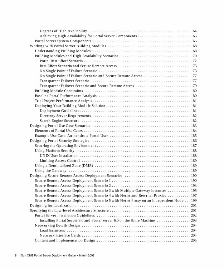
Degrees of High Availability . . . . . . . . . . . . . . . . . . . . . . . . . . . . . . . . . . . . . . . . . . . . . . . . . . . . . . 164Achieving High Availability for Portal Server Components . . . . . . . . . . . . . . . . . . . . . . . . . . . . 165
Portal Server System Components . . . . . . . . . . . . . . . . . . . . . . . . . . . . . . . . . . . . . . . . . . . . . . . . . . . . 165Working with Portal Server Building Modules . . . . . . . . . . . . . . . . . . . . . . . . . . . . . . . . . . . . . . . . . . . . 168
Understanding Building Modules . . . . . . . . . . . . . . . . . . . . . . . . . . . . . . . . . . . . . . . . . . . . . . . . . . . . 168Building Modules and High Availability Scenarios . . . . . . . . . . . . . . . . . . . . . . . . . . . . . . . . . . . . . . 170
Portal Best Effort Scenario . . . . . . . . . . . . . . . . . . . . . . . . . . . . . . . . . . . . . . . . . . . . . . . . . . . . . . . . . 172Best Effort Scenario and Secure Remote Access . . . . . . . . . . . . . . . . . . . . . . . . . . . . . . . . . . . . . . 173No Single Point of Failure Scenario . . . . . . . . . . . . . . . . . . . . . . . . . . . . . . . . . . . . . . . . . . . . . . . . . 173No Single Point of Failure Scenario and Secure Remote Access . . . . . . . . . . . . . . . . . . . . . . . . . 177Transparent Failover Scenario . . . . . . . . . . . . . . . . . . . . . . . . . . . . . . . . . . . . . . . . . . . . . . . . . . . . . 177Transparent Failover Scenario and Secure Remote Access . . . . . . . . . . . . . . . . . . . . . . . . . . . . . 179
Building Module Constraints . . . . . . . . . . . . . . . . . . . . . . . . . . . . . . . . . . . . . . . . . . . . . . . . . . . . . . . . 180Baseline Portal Performance Analysis . . . . . . . . . . . . . . . . . . . . . . . . . . . . . . . . . . . . . . . . . . . . . . . . . 180Trial Project Performance Analysis . . . . . . . . . . . . . . . . . . . . . . . . . . . . . . . . . . . . . . . . . . . . . . . . . . . . 181Deploying Your Building Module Solution . . . . . . . . . . . . . . . . . . . . . . . . . . . . . . . . . . . . . . . . . . . . . 181
Deployment Guidelines . . . . . . . . . . . . . . . . . . . . . . . . . . . . . . . . . . . . . . . . . . . . . . . . . . . . . . . . . . . 181Directory Server Requirements . . . . . . . . . . . . . . . . . . . . . . . . . . . . . . . . . . . . . . . . . . . . . . . . . . . . 182Search Engine Structure . . . . . . . . . . . . . . . . . . . . . . . . . . . . . . . . . . . . . . . . . . . . . . . . . . . . . . . . . . 182
Designing Portal Use Case Scenarios . . . . . . . . . . . . . . . . . . . . . . . . . . . . . . . . . . . . . . . . . . . . . . . . . . . . . 183Elements of Portal Use Cases . . . . . . . . . . . . . . . . . . . . . . . . . . . . . . . . . . . . . . . . . . . . . . . . . . . . . . . . . 184Example Use Case: Authenticate Portal User . . . . . . . . . . . . . . . . . . . . . . . . . . . . . . . . . . . . . . . . . . . 185
Designing Portal Security Strategies . . . . . . . . . . . . . . . . . . . . . . . . . . . . . . . . . . . . . . . . . . . . . . . . . . . . . 186Securing the Operating Environment . . . . . . . . . . . . . . . . . . . . . . . . . . . . . . . . . . . . . . . . . . . . . . . . . . 187Using Platform Security . . . . . . . . . . . . . . . . . . . . . . . . . . . . . . . . . . . . . . . . . . . . . . . . . . . . . . . . . . . . . 188
UNIX User Installation . . . . . . . . . . . . . . . . . . . . . . . . . . . . . . . . . . . . . . . . . . . . . . . . . . . . . . . . . . . 188Limiting Access Control . . . . . . . . . . . . . . . . . . . . . . . . . . . . . . . . . . . . . . . . . . . . . . . . . . . . . . . . . . 189
Using a Demilitarized Zone (DMZ) . . . . . . . . . . . . . . . . . . . . . . . . . . . . . . . . . . . . . . . . . . . . . . . . . . . 189Using the Gateway . . . . . . . . . . . . . . . . . . . . . . . . . . . . . . . . . . . . . . . . . . . . . . . . . . . . . . . . . . . . . . . . . 189
Designing Secure Remote Access Deployment Scenarios . . . . . . . . . . . . . . . . . . . . . . . . . . . . . . . . . . . 190Secure Remote Access Deployment Scenario 1 . . . . . . . . . . . . . . . . . . . . . . . . . . . . . . . . . . . . . . . . . . 190Secure Remote Access Deployment Scenario 2 . . . . . . . . . . . . . . . . . . . . . . . . . . . . . . . . . . . . . . . . . . 193Secure Remote Access Deployment Scenario 3 with Multiple Gateway Instances . . . . . . . . . . . . 195Secure Remote Access Deployment Scenario 4 with Netlet and Rewriter Proxies . . . . . . . . . . . . 197Secure Remote Access Deployment Scenario 5 with Netlet Proxy on an Independent Node . . . 199
Designing for Localization . . . . . . . . . . . . . . . . . . . . . . . . . . . . . . . . . . . . . . . . . . . . . . . . . . . . . . . . . . . . . . 201Specifying the Low-level Architecture Structure . . . . . . . . . . . . . . . . . . . . . . . . . . . . . . . . . . . . . . . . . . . 201
Portal Server Installation Guidelines . . . . . . . . . . . . . . . . . . . . . . . . . . . . . . . . . . . . . . . . . . . . . . . . . . 202Installing Portal Server 3.0 and Portal Server 6.0 on the Same Machine . . . . . . . . . . . . . . . . . . 203
Networking Details Design . . . . . . . . . . . . . . . . . . . . . . . . . . . . . . . . . . . . . . . . . . . . . . . . . . . . . . . . . . 204Load Balancers . . . . . . . . . . . . . . . . . . . . . . . . . . . . . . . . . . . . . . . . . . . . . . . . . . . . . . . . . . . . . . . . . . 204Network Interface Cards . . . . . . . . . . . . . . . . . . . . . . . . . . . . . . . . . . . . . . . . . . . . . . . . . . . . . . . . . . 204
Content and Implementation Design . . . . . . . . . . . . . . . . . . . . . . . . . . . . . . . . . . . . . . . . . . . . . . . . . . 205
9
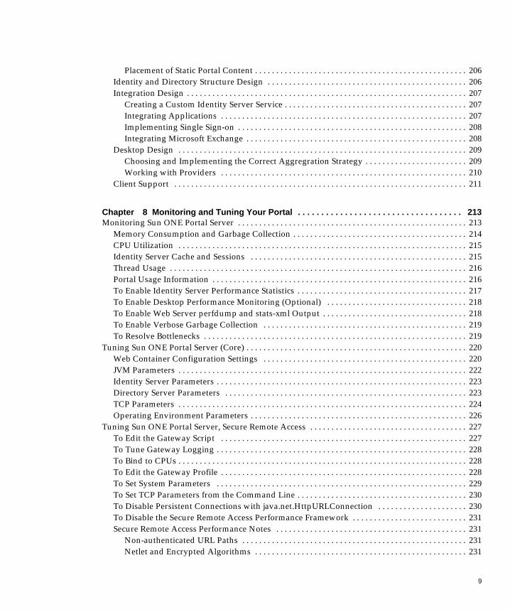
Placement of Static Portal Content . . . . . . . . . . . . . . . . . . . . . . . . . . . . . . . . . . . . . . . . . . . . . . . . . . 206Identity and Directory Structure Design . . . . . . . . . . . . . . . . . . . . . . . . . . . . . . . . . . . . . . . . . . . . . . . 206Integration Design . . . . . . . . . . . . . . . . . . . . . . . . . . . . . . . . . . . . . . . . . . . . . . . . . . . . . . . . . . . . . . . . . . 207
Creating a Custom Identity Server Service . . . . . . . . . . . . . . . . . . . . . . . . . . . . . . . . . . . . . . . . . . . 207Integrating Applications . . . . . . . . . . . . . . . . . . . . . . . . . . . . . . . . . . . . . . . . . . . . . . . . . . . . . . . . . . 207Implementing Single Sign-on . . . . . . . . . . . . . . . . . . . . . . . . . . . . . . . . . . . . . . . . . . . . . . . . . . . . . . 208Integrating Microsoft Exchange . . . . . . . . . . . . . . . . . . . . . . . . . . . . . . . . . . . . . . . . . . . . . . . . . . . . 208
Desktop Design . . . . . . . . . . . . . . . . . . . . . . . . . . . . . . . . . . . . . . . . . . . . . . . . . . . . . . . . . . . . . . . . . . . . 209Choosing and Implementing the Correct Aggregration Strategy . . . . . . . . . . . . . . . . . . . . . . . . 209Working with Providers . . . . . . . . . . . . . . . . . . . . . . . . . . . . . . . . . . . . . . . . . . . . . . . . . . . . . . . . . . 210
Client Support . . . . . . . . . . . . . . . . . . . . . . . . . . . . . . . . . . . . . . . . . . . . . . . . . . . . . . . . . . . . . . . . . . . . . 211
Chapter 8 Monitoring and Tuning Your Portal . . . . . . . . . . . . . . . . . . . . . . . . . . . . . . . . . . . 213Monitoring Sun ONE Portal Server . . . . . . . . . . . . . . . . . . . . . . . . . . . . . . . . . . . . . . . . . . . . . . . . . . . . . . 213
Memory Consumption and Garbage Collection . . . . . . . . . . . . . . . . . . . . . . . . . . . . . . . . . . . . . . . . . 214CPU Utilization . . . . . . . . . . . . . . . . . . . . . . . . . . . . . . . . . . . . . . . . . . . . . . . . . . . . . . . . . . . . . . . . . . . . 215Identity Server Cache and Sessions . . . . . . . . . . . . . . . . . . . . . . . . . . . . . . . . . . . . . . . . . . . . . . . . . . . 215Thread Usage . . . . . . . . . . . . . . . . . . . . . . . . . . . . . . . . . . . . . . . . . . . . . . . . . . . . . . . . . . . . . . . . . . . . . . 216Portal Usage Information . . . . . . . . . . . . . . . . . . . . . . . . . . . . . . . . . . . . . . . . . . . . . . . . . . . . . . . . . . . . 216To Enable Identity Server Performance Statistics . . . . . . . . . . . . . . . . . . . . . . . . . . . . . . . . . . . . . . . . 217To Enable Desktop Performance Monitoring (Optional) . . . . . . . . . . . . . . . . . . . . . . . . . . . . . . . . . 218To Enable Web Server perfdump and stats-xml Output . . . . . . . . . . . . . . . . . . . . . . . . . . . . . . . . . . 218To Enable Verbose Garbage Collection . . . . . . . . . . . . . . . . . . . . . . . . . . . . . . . . . . . . . . . . . . . . . . . . 219To Resolve Bottlenecks . . . . . . . . . . . . . . . . . . . . . . . . . . . . . . . . . . . . . . . . . . . . . . . . . . . . . . . . . . . . . . 219
Tuning Sun ONE Portal Server (Core) . . . . . . . . . . . . . . . . . . . . . . . . . . . . . . . . . . . . . . . . . . . . . . . . . . . . 220Web Container Configuration Settings . . . . . . . . . . . . . . . . . . . . . . . . . . . . . . . . . . . . . . . . . . . . . . . . 220JVM Parameters . . . . . . . . . . . . . . . . . . . . . . . . . . . . . . . . . . . . . . . . . . . . . . . . . . . . . . . . . . . . . . . . . . . . 222Identity Server Parameters . . . . . . . . . . . . . . . . . . . . . . . . . . . . . . . . . . . . . . . . . . . . . . . . . . . . . . . . . . . 223Directory Server Parameters . . . . . . . . . . . . . . . . . . . . . . . . . . . . . . . . . . . . . . . . . . . . . . . . . . . . . . . . . 223TCP Parameters . . . . . . . . . . . . . . . . . . . . . . . . . . . . . . . . . . . . . . . . . . . . . . . . . . . . . . . . . . . . . . . . . . . . 224Operating Environment Parameters . . . . . . . . . . . . . . . . . . . . . . . . . . . . . . . . . . . . . . . . . . . . . . . . . . . 226
Tuning Sun ONE Portal Server, Secure Remote Access . . . . . . . . . . . . . . . . . . . . . . . . . . . . . . . . . . . . . 227To Edit the Gateway Script . . . . . . . . . . . . . . . . . . . . . . . . . . . . . . . . . . . . . . . . . . . . . . . . . . . . . . . . . . 227To Tune Gateway Logging . . . . . . . . . . . . . . . . . . . . . . . . . . . . . . . . . . . . . . . . . . . . . . . . . . . . . . . . . . . 228To Bind to CPUs . . . . . . . . . . . . . . . . . . . . . . . . . . . . . . . . . . . . . . . . . . . . . . . . . . . . . . . . . . . . . . . . . . . . 228To Edit the Gateway Profile . . . . . . . . . . . . . . . . . . . . . . . . . . . . . . . . . . . . . . . . . . . . . . . . . . . . . . . . . . 228To Set System Parameters . . . . . . . . . . . . . . . . . . . . . . . . . . . . . . . . . . . . . . . . . . . . . . . . . . . . . . . . . . . 229To Set TCP Parameters from the Command Line . . . . . . . . . . . . . . . . . . . . . . . . . . . . . . . . . . . . . . . . 230To Disable Persistent Connections with java.net.HttpURLConnection . . . . . . . . . . . . . . . . . . . . . 230To Disable the Secure Remote Access Performance Framework . . . . . . . . . . . . . . . . . . . . . . . . . . . 231Secure Remote Access Performance Notes . . . . . . . . . . . . . . . . . . . . . . . . . . . . . . . . . . . . . . . . . . . . . 231
Non-authenticated URL Paths . . . . . . . . . . . . . . . . . . . . . . . . . . . . . . . . . . . . . . . . . . . . . . . . . . . . . 231Netlet and Encrypted Algorithms . . . . . . . . . . . . . . . . . . . . . . . . . . . . . . . . . . . . . . . . . . . . . . . . . . 231

10 Sun ONE Portal Server Deployment Guide • March 2003
Appendix A Troubleshooting Your Portal Deployment . . . . . . . . . . . . . . . . . . . . . . . . . . . . 233Troubleshooting Sun ONE Portal Server . . . . . . . . . . . . . . . . . . . . . . . . . . . . . . . . . . . . . . . . . . . . . . . . . 233
UNIX Processes . . . . . . . . . . . . . . . . . . . . . . . . . . . . . . . . . . . . . . . . . . . . . . . . . . . . . . . . . . . . . . . . . . . . 233Log Files . . . . . . . . . . . . . . . . . . . . . . . . . . . . . . . . . . . . . . . . . . . . . . . . . . . . . . . . . . . . . . . . . . . . . . . . . . 234Recovering the Search Database . . . . . . . . . . . . . . . . . . . . . . . . . . . . . . . . . . . . . . . . . . . . . . . . . . . . . . 234Stopping and Starting Portal Server . . . . . . . . . . . . . . . . . . . . . . . . . . . . . . . . . . . . . . . . . . . . . . . . . . . 234To Stop and Start Portal Server . . . . . . . . . . . . . . . . . . . . . . . . . . . . . . . . . . . . . . . . . . . . . . . . . . . . . . . 235Working with the Display Profile . . . . . . . . . . . . . . . . . . . . . . . . . . . . . . . . . . . . . . . . . . . . . . . . . . . . . 235To Extract the Display Profile . . . . . . . . . . . . . . . . . . . . . . . . . . . . . . . . . . . . . . . . . . . . . . . . . . . . . . . . 235To Reload the Display Profile . . . . . . . . . . . . . . . . . . . . . . . . . . . . . . . . . . . . . . . . . . . . . . . . . . . . . . . . 235High CPU Utilization for Portal Server Instance . . . . . . . . . . . . . . . . . . . . . . . . . . . . . . . . . . . . . . . . 236To Configure a Sun ONE Portal Server Instance to Use an HTTP Proxy . . . . . . . . . . . . . . . . . . . . 236
Troubleshooting Sun ONE Portal Server, Secure Remote Access . . . . . . . . . . . . . . . . . . . . . . . . . . . . . 237Introduction to shooter . . . . . . . . . . . . . . . . . . . . . . . . . . . . . . . . . . . . . . . . . . . . . . . . . . . . . . . . . . . . . . 237Using shooter . . . . . . . . . . . . . . . . . . . . . . . . . . . . . . . . . . . . . . . . . . . . . . . . . . . . . . . . . . . . . . . . . . . . . . 238
shooter.sh . . . . . . . . . . . . . . . . . . . . . . . . . . . . . . . . . . . . . . . . . . . . . . . . . . . . . . . . . . . . . . . . . . . . . . . 238gctool.pl . . . . . . . . . . . . . . . . . . . . . . . . . . . . . . . . . . . . . . . . . . . . . . . . . . . . . . . . . . . . . . . . . . . . . . . . 238memfoot.sh . . . . . . . . . . . . . . . . . . . . . . . . . . . . . . . . . . . . . . . . . . . . . . . . . . . . . . . . . . . . . . . . . . . . . 239uniq.pl . . . . . . . . . . . . . . . . . . . . . . . . . . . . . . . . . . . . . . . . . . . . . . . . . . . . . . . . . . . . . . . . . . . . . . . . . 239GWDump.class . . . . . . . . . . . . . . . . . . . . . . . . . . . . . . . . . . . . . . . . . . . . . . . . . . . . . . . . . . . . . . . . . . 239
Secure Remote Access Log Files . . . . . . . . . . . . . . . . . . . . . . . . . . . . . . . . . . . . . . . . . . . . . . . . . . . . . . 240
Appendix B Portal Deployment Worksheets . . . . . . . . . . . . . . . . . . . . . . . . . . . . . . . . . . . . . 241Portal Assessment Worksheets . . . . . . . . . . . . . . . . . . . . . . . . . . . . . . . . . . . . . . . . . . . . . . . . . . . . . . . . . . 242Portal Key Design Task List . . . . . . . . . . . . . . . . . . . . . . . . . . . . . . . . . . . . . . . . . . . . . . . . . . . . . . . . . . . . 247
Appendix C Sun ONE Portal Server and Application Servers . . . . . . . . . . . . . . . . . . . . . . . 255Introduction to Application Server Support in Portal Server . . . . . . . . . . . . . . . . . . . . . . . . . . . . . . . . 256Portal Server on an Application Server Cluster . . . . . . . . . . . . . . . . . . . . . . . . . . . . . . . . . . . . . . . . . . . . 257
Overview of Sun ONE Application Server . . . . . . . . . . . . . . . . . . . . . . . . . . . . . . . . . . . . . . . . . . . . . 257Overview of BEA WebLogic Server Clusters . . . . . . . . . . . . . . . . . . . . . . . . . . . . . . . . . . . . . . . . . . . 258Overview of IBM WebSphere Application Server . . . . . . . . . . . . . . . . . . . . . . . . . . . . . . . . . . . . . . . 259
Appendix D Sun ONE Portal Server Quick Start . . . . . . . . . . . . . . . . . . . . . . . . . . . . . . . . . . 261Locating Product Reference Information . . . . . . . . . . . . . . . . . . . . . . . . . . . . . . . . . . . . . . . . . . . . . . . . . 261
Installation Resources . . . . . . . . . . . . . . . . . . . . . . . . . . . . . . . . . . . . . . . . . . . . . . . . . . . . . . . . . . . . . . . 261Administration Resources . . . . . . . . . . . . . . . . . . . . . . . . . . . . . . . . . . . . . . . . . . . . . . . . . . . . . . . . . . . 262Customization Resources . . . . . . . . . . . . . . . . . . . . . . . . . . . . . . . . . . . . . . . . . . . . . . . . . . . . . . . . . . . . 262Development Resources . . . . . . . . . . . . . . . . . . . . . . . . . . . . . . . . . . . . . . . . . . . . . . . . . . . . . . . . . . . . . 262
Installing Portal Server . . . . . . . . . . . . . . . . . . . . . . . . . . . . . . . . . . . . . . . . . . . . . . . . . . . . . . . . . . . . . . . . . 263Portal Server Installation Tips . . . . . . . . . . . . . . . . . . . . . . . . . . . . . . . . . . . . . . . . . . . . . . . . . . . . . . . . 263Sample Portal Server Installation . . . . . . . . . . . . . . . . . . . . . . . . . . . . . . . . . . . . . . . . . . . . . . . . . . . . . 263

11
To Verify That Portal Server Is Running . . . . . . . . . . . . . . . . . . . . . . . . . . . . . . . . . . . . . . . . . . . . . . . 266To Change Font Size for the Administration Console . . . . . . . . . . . . . . . . . . . . . . . . . . . . . . . . . . . . 266
Configuring Portal Server (Post-Installation) . . . . . . . . . . . . . . . . . . . . . . . . . . . . . . . . . . . . . . . . . . . . . . 267To Access the Anonymous Desktop Through the Portal Server Host Name (index.html File) . 267To Create a Sample Portal User . . . . . . . . . . . . . . . . . . . . . . . . . . . . . . . . . . . . . . . . . . . . . . . . . . . . . . . 267To Access the Desktop Attributes Page . . . . . . . . . . . . . . . . . . . . . . . . . . . . . . . . . . . . . . . . . . . . . . . . 268To Configure a Non-tabbed Desktop . . . . . . . . . . . . . . . . . . . . . . . . . . . . . . . . . . . . . . . . . . . . . . . . . . 268To Configure a Tabbed Desktop . . . . . . . . . . . . . . . . . . . . . . . . . . . . . . . . . . . . . . . . . . . . . . . . . . . . . . 268To Add a Tab to JSPTabContainer . . . . . . . . . . . . . . . . . . . . . . . . . . . . . . . . . . . . . . . . . . . . . . . . . . . . 270To Change the Channel Layout for a Table Container . . . . . . . . . . . . . . . . . . . . . . . . . . . . . . . . . . . 272To Deploy New Portal Content . . . . . . . . . . . . . . . . . . . . . . . . . . . . . . . . . . . . . . . . . . . . . . . . . . . . . . . 273
Customizing the Desktop . . . . . . . . . . . . . . . . . . . . . . . . . . . . . . . . . . . . . . . . . . . . . . . . . . . . . . . . . . . . . . 273To Configure the Desktop Banner . . . . . . . . . . . . . . . . . . . . . . . . . . . . . . . . . . . . . . . . . . . . . . . . . . . . . 273To Add Channels and Container Channels to the Desktop . . . . . . . . . . . . . . . . . . . . . . . . . . . . . . . 274To Add a Custom Tab to the Desktop . . . . . . . . . . . . . . . . . . . . . . . . . . . . . . . . . . . . . . . . . . . . . . . . . 276
Creating Custom Providers . . . . . . . . . . . . . . . . . . . . . . . . . . . . . . . . . . . . . . . . . . . . . . . . . . . . . . . . . . . . . 277To Create a Custom Provider . . . . . . . . . . . . . . . . . . . . . . . . . . . . . . . . . . . . . . . . . . . . . . . . . . . . . . . . 277
Index . . . . . . . . . . . . . . . . . . . . . . . . . . . . . . . . . . . . . . . . . . . . . . . . . . . . . . . . . . . . . . . . . . . . . . . 283

12 Sun ONE Portal Server Deployment Guide • March 2003

13
About This Guide
This guide explains how to plan for and deploy Sun™ ONE Portal Server Release6.0. Portal Server provides a platform to create portals for your organization’sintegrated data, knowledge management, and applications. The Portal Serverplatform offers a complete infrastructure solution for building and deploying alltypes of portals, including business-to-business, business-to-employee, andbusiness-to-consumer.
This preface includes the following sections:
• Who Should Read This Book
• What You Need to Know
• How This Book Is Organized
• Document Conventions Used in This Guide
• Where to Find Related Information
• Where to Find This Guide Online
Who Should Read This BookYou should read this guide if you are responsible for deploying Portal Server atyour site.
What You Need to KnowBefore you deploy Portal Server, you must be familiar with the following concepts:
• Basic Solaris™ administrative procedures

14 Sun ONE Portal Server Deployment Guide • March 2003
• HTML
• iPlanet™ Directory Server Access Management Edition (now known as Sun™ONE Identity Server)
• JavaServer Pages™ technology
• LDAP
• Sun™ ONE Directory Server
• Sun™ ONE Web Server
• XML
How This Book Is OrganizedThis book contains the following chapters and appendices:
• About This Guide (this chapter)
• Chapter 1, “Overview of Sun ONE Portal Server”
This chapter describes the basic ideas you need to understand before designingyour portal.
• Chapter 2, “Sun ONE Portal Server Core Architecture”
This chapter describes the architecture, protocols, interfaces, directorystructure, deployment, and customization of the core Portal Server 6.0 product.
• Chapter 3, “Sun ONE Portal Server, Secure Remote Access Architecture”
This chapter describes the Sun™ ONE Portal Server, Secure Remote Accessarchitecture, including the key components of Secure Remote Access withrespect to their role in providing secure remote access to corporate intranetresources from outside the intranet (for example, through the Internet).
• Chapter 4, “Analyzing Your Portal Requirements”
This chapter describes how to analyze your organization’s needs andrequirements that lead to designing your portal deployment.

About This Guide 15
• Chapter 5, “Sizing Your Portal”
This chapter describes how to establish a baseline sizing figure for your portal.With a baseline figure established, you can then refine that figure to accountfor scalability, high availability, reliability, and good performance.
• Chapter 6, “Understanding the Portal Deployment Process”
This chapter provides on overview of the portal deployment process.
• Chapter 7, “Creating Your Portal Design”
This chapter describes how to create a high-level and low-level portal design,and provides information on creating specific sections of your design plan.
• Chapter 8, “Monitoring and Tuning Your Portal”
This chapter describes how to monitor and tune your portal.
• Appendix A, “Troubleshooting Your Portal Deployment”
This appendix describes how to troubleshoot Portal Server and Secure RemoteAccess.
• Appendix B, “Portal Deployment Worksheets”
This appendix provides various worksheets to help in the deployment process.
• Appendix C, “Sun ONE Portal Server and Application Servers”
This appendix provides an overview of Portal Server and its support forvarious application servers.
• Appendix D, “Sun ONE Portal Server Quick Start”
This appendix provides the tasks you need to get started using Sun ONE PortalServer.
Document Conventions Used in This Guide
Monospaced FontMonospaced font is used for any text that appears on the computer screen or textthat you should type. It is also used for file names, distinguished names, functions,and examples.

16 Sun ONE Portal Server Deployment Guide • March 2003
Bold Monospaced FontBold monospaced font is used to represent text within a code example that youshould type. For example, you might see something like this:
./pssetup*******************************************************************
Sun(TM) One Portal Server (6.0 release)
*******************************************************************
Installation log at/var/sadm/install/logs/ipsinstall.13343/install.log
This product will run without a license. However, you must eitherpurchase a Binary Code License from, or accept the terms of a BinarySoftware Evaluation license with, Sun Microsystems, to legally usethis product.
Do you accept? yes/[no]
In this example, ./pssetup is what you would type from the command line andthe rest is what would appear as a result.
Italicized FontAn italicized font is used to represent text that you enter using information that isunique to your installation (for example, variables). It is used for server paths andnames and account IDs.
Square or Straight BracketsSquare (or straight) brackets [] are used to enclose optional parameters. Forexample, in the Portal Server documentation, you will see the usage for thedpadmin command described as follows:
dpadmin list|modify|add|remove [command-specific options]
The presence of [command-specific] indicates that there are optional parametersthat can be added to the dpadmin command.

About This Guide 17
Command-Line PromptsCommand-line prompts (for example, % for a C-Shell, or $ for a Korn or Bourneshell) are not displayed in the examples. Depending on which operating systemenvironment you are using, you will see a variety of different command-lineprompts. However, you should enter the command as it appears in the documentunless specifically noted otherwise.
Where to Find Related InformationIn addition to this guide, Portal Server comes with supplementary information foradministrators as well as documentation for developers. Use the following URL toview all the Portal Server documentation:
http://docs.sun.com/prod/s1portalsrv
Listed below are the additional documents that are available:
• Sun ONE Portal Server 6.0 Administrator’s Guide
• Sun ONE Portal Server 6.0 Developer’s Guide
• Sun ONE Portal Server 6.0 Installation Guide
• Sun ONE Portal Server 6.0 Migration Guide
• Sun ONE Portal Server 6.0 Release Notes
• Sun ONE Portal Server, Secure Remote Access 6.0 Administrator’s Guide
• Sun ONE Portal Server, Secure Remote Access 6.0 Installation Guide
• Sun ONE Portal Server, Secure Remote Access 6.0 Release Notes
• Sun ONE Portal Server 6.0 Installation Supplement for Sun ONE Application Server7.0
• Sun ONE Portal Server 6.0 Installation Supplement for IBM Application Server
• Sun ONE Portal Server 6.0 Installation Supplement for BEA Application Server

18 Sun ONE Portal Server Deployment Guide • March 2003
Where to Find This Guide OnlineYou can find the Sun ONE Portal Server 6.0 Deployment Guide online in PDF andHTML formats. This book can be found at the following URL:
http://docs.sun.com/prod/s1portalsrv

19
Chapter 1
Overview of Sun ONE Portal Server
Sun™ ONE Portal Server is an identity-enabled portal server solution. It providesall the user, policy, and identity management to enforce security, web applicationSingle Sign-on, and access capabilities to end user communities. In addition, SunONE Portal Server combines key portal services, such as personalization,aggregation, security, integration, and search. Unique capabilities that enablesecure remote access to internal resources and applications round out a completeportal platform for deploying robust business-to-employee, business-to-business,and business-to-consumer portals. The Sun™ ONE Portal Server, Secure RemoteAccess add-on product provides additional secure remote access capabilities,providing access to both web- and non-web enabled resources.
This chapter describes the basic ideas you need to understand before designingyour portal. This chapter contains the following sections:
• Understanding Sun ONE Portal Server
• Independent Software Vendor Integrations with Sun ONE Portal Server
• Types of Portal Deployments
• Portal Deployment Architecture
• Establishing Quality Goals
Understanding Sun ONE Portal ServerTo begin understanding Portal Server, and how it fits in your organization, use thissection to gather the necessary background information on the Portal Serverproduct and lifecycle.

Understanding Sun ONE Portal Server
20 Sun ONE Portal Server Deployment Guide • March 2003
What Is a Portal?A portal is an entry point to a set of resources that an enterprise wants to makeavailable to the portal’s users. For some consumer portals, the set of resourcesincludes the entire World-Wide Web. For most enterprise portals, the set ofresources includes information, applications, and other resources that are specificto the relationship between the user and the enterprise. For service providers, theportal provides a point of entry to customer service applications as well as acontrolled content aggregation service.
In general, a portal enables users to:
• Customize the available data content
• Change how channels are generated
• Control how data is displayed
• Create and manage links to other allowable web sites
Resources can include the use of provider applications and utilities such as mail,file management, and storage facilities.
Overview of the Sun ONE Portal Server 6.0Product FamilyThe Sun ONE Portal Server 6.0 product family consists of the Portal Server Core,additional Sun ONE software products that enable the core, and optional add-onproducts, installed on top of the core. The complete Sun ONE Portal Server familyconsists of:
• Sun ONE Portal Server (core)
• Sun™ ONE Directory Server
• iPlanet™ Directory Server Access Management Edition (now known as Sun™ONE Identity Server)
• Sun™ ONE Web Server, or an application server, such as Sun™ ONEApplication Server, BEA WebLogic, or IBM WebSphere Advanced Edition
• Optional add-ons, such as Sun™ ONE Portal Server, Secure Remote Access
In this guide, the use of the term Sun ONE Portal Server (or simply Portal Server)refers to the Portal Server Core.

Understanding Sun ONE Portal Server
Chapter 1 Overview of Sun ONE Portal Server 21
The combination of the above software provides the following capabilities to yourorganization:
• Secure access and authorized connectivity, optionally using encryptionbetween the user’s browser and the enterprise
• Authentication of users before allowing access to a set of resources that arespecific for each user
• Support for abstractions that provide the ability to pull content from a varietyof sources and aggregate and personalize it into a output format suitable forthe user’s device
• A search engine infrastructure to enable intranet content to be organized andaccessed from the portal
• Ability to store user- and service-specific persistent data
• Access to commonly needed applications for accessing services such as mail,calendar, and file storage
• An administration interface enabling delegated and remote administration
Examples of How Sun ONE Portal Server 6.0Satisfies Business NeedsDepending on your organization’s requirements and business needs, your portaldeployment will vary. The following section provides a high-level look at howthree organizations have deployed Sun ONE Portal Server. Use the information inthis section to generate ideas that will help you more effectively deploy PortalServer in your organization.
Case Study: Business-to-Employee PortalThis multinational company, which manufactures a wide range of products, hashundreds of thousands of employees located around the world, grouped inhundreds of business units. Thus, the company has a highly-distributed computingenvironment.
Previously, the company relied on a static portal for employee communications,which proved inefficient in meeting its business needs. The company decided tomove to a dynamic portal where employees could get personalized access tocompany information. The portal needed to be configured to support multipleorganizations and user roles, as well to provide access to internal sites from thecompany’s intranet.

Understanding Sun ONE Portal Server
22 Sun ONE Portal Server Deployment Guide • March 2003
Table 1-1 summarizes this organization’s goals and presents the Portal Serverfeature or capability that meets this goal. In this table, the first column gives thegoal. The second column describes the Portal Server feature or benefit that meetsthis goal.
Table 1-1 Business-to-Employee Portal Server Case Study Goals
Goals Sun ONE Portal Server Feature or Benefit That Meets This Goal
Improve information deliveryto the company’s distributedworkforce
With technology changing at an ever-increasing speed, the companyneeded a solution that would facilitate knowledge sharing andcollaboration among its employees. Divisions within the company arespread across disparate geographic locations and time zones, and so theportal aggregated content from disparate sources. The portal providedemployees with a single point for accessing all their applications, content,and services.
Enable employees toauthenticate just once
Sun ONE Portal Server’s Single Sign-on and authentication wereimplemented with an existing Secure ID infrastructure for security andauthentication, both to the portal and other existing internal sites. Usersonly need sign on one time and are authenticated to all appropriateinternal sites and applications.
Improveemployee-to-employeecommunication
By bridging together different sources of information in their native form,workers were able to easily share information and collaborate in real timeby using web-based email and calendaring.
Provide a portal Desktop for avariety of purposes
The portal Desktop was configured in such a way to use color to indicatechannel function (personal, corporate, or business-related). The Desktopalso included mandatory channels required for all users, which are notremovable by users; default channels, which are automatically selected byan administrator; and available channels, which are created by global ordelegated administrators, that users can select from.
Provide for high-availabilityand reliable access acrossgeographic sites
To meet these requirements, this company developed a portal architecturethat included three separate geographic installations, failover betweenthese main locations, and load balancing within each installation. LDAPreplicas are placed at each installation, obtaining their information from amaster LDAP at the main data center, which is also configured for HAfailover.
Implement a centralizedadministrative model that alsoenables delegatedadministration
Identity Server provides role-based delegated administration capabilitiesto different kinds of administrators to manage organizations, users, policy,roles, channels, and Desktop providers based on the given permissions.For example, within business units, delegated administrators can add orremove channels that for their particular line of business.

Understanding Sun ONE Portal Server
Chapter 1 Overview of Sun ONE Portal Server 23
Case Study: Business-to-Consumer PortalThis travel company markets various vacation destinations and ancillarybusinesses, and needed a business-to-consumer portal to help develop a directrelationship with end customers. The portal needed to serve as the mechanism toexecute a strategy moving away from travel agencies to a direct consumerrelationship.
Table 1-2 summarizes this organization’s goals and presents the Portal Serverfeature or capability that meets this goal. In this table, the first column gives thegoal. The second column describes the Portal Server feature or benefit that meetsthis goal.
Table 1-2 Business-to-Consumer Portal Server Case Study Goals
Goals Sun ONE Portal Server Feature or Benefit That Meets This Goal
Understand customers betterto make it easier to dobusiness with them (servetheir needs)
Portal Server enabled the consolidation of numerous applications,providing single-point access for both customers and employees. Thecompany saw immediate benefits including strengthened customerservice relationships due to this consolidation.
Save money Because the company was spending large amounts of money on IT, withno slowdown foreseen in the future, the company needed to find a way tolower expenses. The portal provided a single point of systemmanagement, helping to reduce the company’s IT complexity and cost.
In addition, rather than manage multiple portal projects that might laterneed to be combined using expensive consulting services that willduplicate effort and infrastructure, Portal Server empowers and enables ITadministrators to learn and manage a single platform.
Offer new products or servicesto customers
Customers access the company’s offerings through a web services portal,which provides access to a broad range of internal and external toolsincluding market research, personalized feeds, pricing and configuration,product data, and presentations. This centralized services portal boostsproductivity by giving customers a single point of access for all data,services, and online resources.
Communicate newinformation consistently andquickly
The portal solution deploys technology that enabled this company tolower operating costs while delivering personalized content to itscustomers. Users were able to customize their portals to deliver the mostimportant and relevant information to them. The portal also providesextended features (such as customer support) to registered customers.
Understanding Sun ONE Portal Server
24 Sun ONE Portal Server Deployment Guide • March 2003
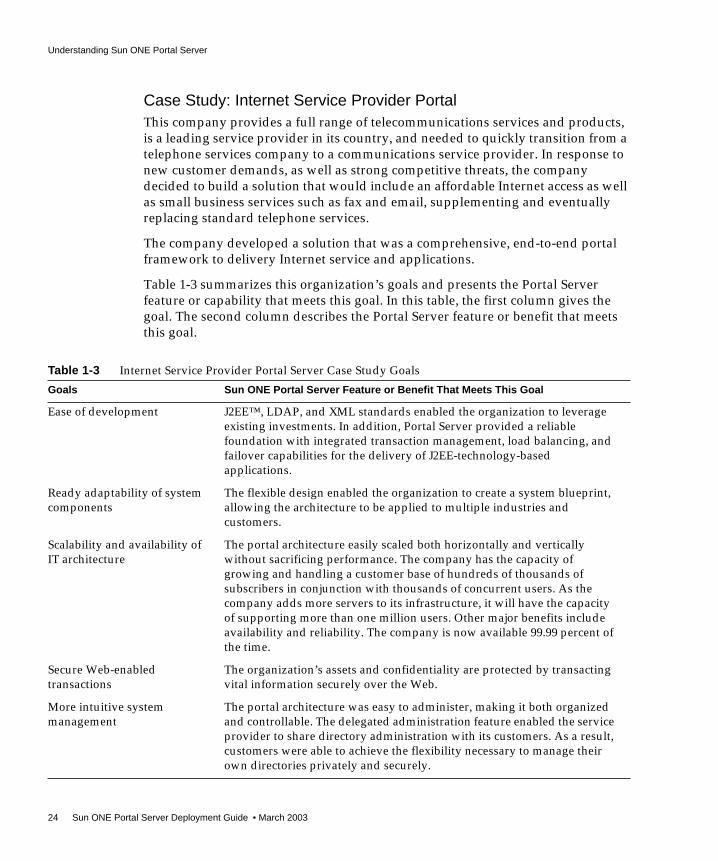
Case Study: Internet Service Provider PortalThis company provides a full range of telecommunications services and products,is a leading service provider in its country, and needed to quickly transition from atelephone services company to a communications service provider. In response tonew customer demands, as well as strong competitive threats, the companydecided to build a solution that would include an affordable Internet access as wellas small business services such as fax and email, supplementing and eventuallyreplacing standard telephone services.
The company developed a solution that was a comprehensive, end-to-end portalframework to delivery Internet service and applications.
Table 1-3 summarizes this organization’s goals and presents the Portal Serverfeature or capability that meets this goal. In this table, the first column gives thegoal. The second column describes the Portal Server feature or benefit that meetsthis goal.
Table 1-3 Internet Service Provider Portal Server Case Study Goals
Goals Sun ONE Portal Server Feature or Benefit That Meets This Goal
Ease of development J2EE™, LDAP, and XML standards enabled the organization to leverageexisting investments. In addition, Portal Server provided a reliablefoundation with integrated transaction management, load balancing, andfailover capabilities for the delivery of J2EE-technology-basedapplications.
Ready adaptability of systemcomponents
The flexible design enabled the organization to create a system blueprint,allowing the architecture to be applied to multiple industries andcustomers.
Scalability and availability ofIT architecture
The portal architecture easily scaled both horizontally and verticallywithout sacrificing performance. The company has the capacity ofgrowing and handling a customer base of hundreds of thousands ofsubscribers in conjunction with thousands of concurrent users. As thecompany adds more servers to its infrastructure, it will have the capacityof supporting more than one million users. Other major benefits includeavailability and reliability. The company is now available 99.99 percent ofthe time.
Secure Web-enabledtransactions
The organization’s assets and confidentiality are protected by transactingvital information securely over the Web.
More intuitive systemmanagement
The portal architecture was easy to administer, making it both organizedand controllable. The delegated administration feature enabled the serviceprovider to share directory administration with its customers. As a result,customers were able to achieve the flexibility necessary to manage theirown directories privately and securely.

Understanding Sun ONE Portal Server
Chapter 1 Overview of Sun ONE Portal Server 25
Sun ONE Portal Server Life CycleThe previous section illustrates an important point in deploying Portal Server,namely the Portal Server product life cycle. In general, any product deploymentcan be broken down into the following sequence of events, or life cycle:
• Planning - In the planning phase, your organization and your Sun ONErepresentatives work to understand your business and its needs, establishbusiness objectives, and scope and collect requirements.
• Developing - In this phase, your organization develops an overall portaldesign based on the requirements you have established and your sizingestimates.
• Designing, Building, and Testing - Once you have arrived at an overallarchitecture, you can begin designing, building, and testing your portal.
• Deploying - In this phase, you install a server instance as a trial and testwhether your portal can handle your user load. If the portal is not adequate asit is, you then adjust your design and test the trial again. Adjust your trialdesign until you have a robust portal that you can confidently introduce toyour organization.
• Production - Once you have put your portal through a trial run and tuned theportal, you need to develop and execute a plan for taking the portal from trialto production.
This guide attempts to use this life cycle to ensure the success of your portaldeployment. See Chapter 6, “Understanding the Portal Deployment Process” formore information on managing a portal project.
Sun ONE Portal Server ResourcesThis section provides general information about Portal Server resources. SeeChapter 2, “Sun ONE Portal Server Core Architecture” for a complete architecturaldescription.
Faster time to market Because there was an integration methodology in place, implementingbest-of-breed commercial off-the-shelf products now requires less time,and generates greater return on investment (ROI).
Table 1-3 Internet Service Provider Portal Server Case Study Goals (Continued)
Goals Sun ONE Portal Server Feature or Benefit That Meets This Goal

Understanding Sun ONE Portal Server
26 Sun ONE Portal Server Deployment Guide • March 2003
JavaServer Pages TechnologyTo generate the rendered Desktop user interface (what the industry refers to as the“presentation”), Portal Server makes use of either JavaServer Pages™ (JSP™)technology or template files (HTML). JSP technology is preferred because itenables a much easier customization process without having to change theprovider Java™ classes. JSP technology also provides a way to enable a strictseparation of business and presentation logic. Specifically, this means having thebusiness logic in the provider classes and presentation logic in JSP technology.
In JavaServer Pages technology, actions are elements that can create and accessprogramming language objects and affect the output stream. JSP technologysupports reusable modules called custom actions. You invoke a custom action byusing a custom tag in a JSP file. A tag library is a collection of custom tags. TheDesktop custom tag library contains tags that you use to perform Desktopoperations for JSP code.
Before tag libraries, JSP code was difficult to maintain because you were forced touse JavaBeans™ components and scriptlets as the main mechanism for performingtasks. Custom actions, that is, a tag library, alleviate this problem by bringing thebenefits of another level of componentization to JSP code. A tag libraryencapsulates recurring tasks so that they can be reused across more than oneapplication.
The Sun ONE Portal Server Desktop tag library consists of six parts:
• Core tags that can be used on any provider or container that implement theProvider Application Programming Interface (PAPI)
• Tags that can be used to operate on a provider or container that support theProviderContext and ContainerProviderContext interfaces
• Tags that operate on specific container building-block providers(SingleContainer, TableContainer, TabContainer, and so on)
• JSP Standard tag libraries from Apache
• Tags that support the Search function.
• Tags that provide theme support in the Desktop
See the Sun ONE Portal Server 6.0 Desktop Customization Guide for more informationon JSP technology and Portal Server.

Understanding Sun ONE Portal Server
Chapter 1 Overview of Sun ONE Portal Server 27
Portal (Desktop) ContentThe Desktop provides the primary end-user interface for Portal Server and amechanism for extensible content aggregation through the Provider ApplicationProgramming Interface (PAPI). The Desktop includes a variety of providers thatenable container hierarchy and the basic building blocks for building some types ofchannels. For storing content provider and channel data, the Desktop implements adisplay profile data storage mechanism on top of an Identity Server service. Youcan edit the display profile and other Desktop service data through the IdentityServer administration console.
Configuration DataAs an Identity Server application, Portal Server defines services that are managedusing the Identity Server service management system. Generally, anyservice-related data that is not server-specific is stored in the directory service.Server-specific data can be stored in properties files that are local to the specificserver.
In addition, Portal Server uses certain files to manage the configuration of theDesktop and Search services. The Desktop configuration file,desktopconfig.properties, defines server-specific parameters.
The Search service uses the following configuration files: classification.conf,filter.conf, filterrules.conf, and robot.conf files. The convert.conf andimport.conf files are generated by the Search server. Do not manually edit thesefiles. The search.conf file lists all the specific search values you have set.
At installation time, you are given the option of defining values or using thedefault values for the base directory (/opt), the deployment URI (/portal) and thedeploy instance (cate.sesta.com).
See the Sun ONE Portal Server 6.0 Administrator’s Guide for more information oncore product configuration files.
Application DataPortal Server stores certain data in the user’s profile that is passed to back-endapplications. For example, the User Preference channel stores NetMail service data(user preferences for using NetMail). Application data also includes Rewriterrulesets.

Understanding Sun ONE Portal Server
28 Sun ONE Portal Server Deployment Guide • March 2003
Site DataPortal Server uses the local file system to store data specific to a particular instanceor node. Site data includes the /opt/SUNWam/lib/AMConfig.properties file andthe /etc/opt/SUNWps/desktop/desktopconfig.properties file file.
Sun ONE Portal Server, Secure Remote AccessThe Sun ONE Portal Server, Secure Remote Access add-on product offersbrowser-based secure remote access to portal content and services from any remotebrowser. Secure Remote Access is a cost-effective, secure access solution that isaccessible to users from any browser enabled with Java technology. Secure RemoteAccess eliminates the need for additional client software. Because Secure RemoteAccess is integrated with Portal Server, users receive secure encrypted access to thecontent and services that they have permission to access.
Using Secure Remote Access, you can install your portal in secure mode. Securemode provides users with secure remote access to required intranet file systemsand applications.
Secure mode uses the Secure Remote Access gateway, which typically resides inthe demilitarized zone (DMZ). The gateway provides a single secure access pointto all intranet URLs and applications, thus reducing the number of ports to beopened in the firewall. All other Portal Server services such as Session,Authentication, and the Desktop reside behind the DMZ in the secured intranet.Communication from the client browser to the gateway is encrypted using HTTPover Secure Sockets Layer (HTTPS). Communication from the gateway to theserver and intranet resources can be either HTTP or HTTPS.
See Chapter 3, “Sun ONE Portal Server, Secure Remote Access Architecture” formore information.
NOTE You can provide secure access to users of web-enabled resources byrunning Portal Server in open mode with the HTTPS protocol.However, without Sun ONE Portal Server, Secure Remote Access,you cannot provide secure remote access to file systems or TCP/IPapplications.

Independent Software Vendor Integrations with Sun ONE Portal Server
Chapter 1 Overview of Sun ONE Portal Server 29
Migrating to a New Version of Portal ServerMigrating from Sun ONE Portal Server 3.0 to Sun ONE Portal Server 6.0 requires adifferent set of deployment requirements that are outside the scope of thisdocument. Several new features in Sun ONE Portal Server 6.0 require formatchanges in the data store of Sun ONE Portal Server 3.0 because of the new accesslayer and iPlanet Directory Server Access Management Edition 5.1 APIs that SunONE Portal Server 6.0 now uses.
The Sun ONE Portal Server 3.0 Data Migration Tool Suite provided with Sun ONEPortal Server 6.0 enables you to migrate the following:
• LDAP data
• Templates
• JavaServer Pages code
• Resource bundles
• Certificates (with the exception of gateway certificates)
• Custom authentication module data
• Properties files from Sun ONE Portal Server 3.0 to Sun ONE Portal Server 6.0or to iPlanet Directory Server Access Management Edition 5.1 as necessary
The Sun ONE Portal Server 3.0 Data Migration Tool Suite does not migrategateway certificates. See the Sun ONE Portal Server 6.0 Migration Guide for moreinformation.
Independent Software Vendor Integrations withSun ONE Portal Server
This section provides an overview of some of the independent software vendor(ISV) integrations that exist for Portal Server. For a complete list of ISVintegrations, contact your Sun ONE representative.

Independent Software Vendor Integrations with Sun ONE Portal Server
30 Sun ONE Portal Server Deployment Guide • March 2003
Integration TypesIn general, there are seven different types of Portal Server integration:
• Application user interface - This integration uses the provider API and SunONE Portal Server, Secure Remote Access for secure access. (Sun ONE PortalServer, Secure Remote Access is not an integration type on its own.) Examplesinclude FatWire, Interwoven, SAP, Tarantella, Documentum, Vignette,PeopleSoft, Siebel, Citrix, Yahoo!, and YellowBrix.
• Security products - This integration uses the Identity Server Login API toenable portal access by using a custom authentication scheme. Examplesinclude RSA and Entrust.
• Products containing searchable data - This integration provides data accessinto Portal Server, enabling searches on the data. An example is CMS (searchCMS database).
• Collaboration software - This integration enables Sun™ ONE InstantMessaging to move a collaboration session from one forum to a another.Examples include WebEx and ThoughtWeb.
• Monitoring - This integration focuses on billing, performance measurement,and diagnostics, for which you rely on log files (or Identity Server’s loggingAPI) and traffic snooping. Examples include Mercury Interactive, Hyperion,and Informatica.
• Portal capability augmentation - This integration enables products to addfunctionality to Portal Server. Examples include Altio, Bowstreet, rule enginesto add group capability, and dynamic Desktop and provider contents (HNC).
• Integratable portal stack - This integration includes products that replaceelements of Portal Server. Examples include Identity Server and LDAP.
The “depth” to which user interface integration occurs with Portal Server indicateshow complete the integration is. Depth is a term used to describe thecomplementary nature of the integration, and points to such items as:
• Application availability through Portal Server itself
NOTE Portal Server cannot currently integrate another LDAP solution.Identity Server and Portal Server rely on features not found in otherLDAP implementations.

Independent Software Vendor Integrations with Sun ONE Portal Server
Chapter 1 Overview of Sun ONE Portal Server 31
• Application available in secure mode (using Secure Remote Access, Netletrules, and so on)
• Ability to use Single Sign-on
In general, the degree to which an application integrates in Portal Server can beviewed as follows:
• Shallow integration - This integration essentially uses the portal server as alaunch point. The user logs in to the portal and clicks a link that starts a webapplication.
• Deep integration - The user accesses the user interface provided by thechannels in Portal Server directly. That is, the integrated software works withinthe portal. No additional windows and no applets will appear.
The following sections provide a look at some of the ISVs by category.
Collaboration and Application Emulation ISVsISVs in this category include:
• Citrix NFuse - Solves access-related problems by delivering a suite of softwareproducts and services that provide access to any device, over any network toany application or information source. Portal Server integrates with Citrix’sNFuse through a portal channel, the NFuse provider. NFuse enablesweb-based access to applications running on MetaFrame servers in a Citrixserver farm. Portal Server’s integration works for both open and secure portalmodes. The NFuse provider is an icon-based interface with features that can bepersonalized.
• Tarantella - Provides browser-based access to back-end applications via theportal, without any code modifications. Tarantella immediately web-enablesUNIX®, Linux, Windows, mainframe, AS/400, and Java applications withoutrewriting code, changing the architecture, or touching the infrastructure. All ofthese capabilities can be displayed through Portal Server.
In conjunction with Sun ONE Portal Server, Secure Remote Access, theTarantella Integration Pack for Portal Server is designed to enable Tarantellatraffic to tunnel through the secure channel provided by the Netlet. TheTarantella Integration Pack provides Single Sign-on authentication for theportal user and channel integration. Users are authenticated once, when theylog in to the portal, and all permitted applications are available to themimmediately.

Independent Software Vendor Integrations with Sun ONE Portal Server
32 Sun ONE Portal Server Deployment Guide • March 2003
Content and Document Management ISVsMost portals provide some support for content management. However, in general,analysts agree that portals need to be supplemented by a dedicated contentmanagement system (CMS). While portals usually handle content through searchand display functions, they generally do not provide for creating and adding portalcontent. This is where a content management system comes in.
ISVs in this category include:
• Documentum - Provides automated processes for production, review,approval, and publishing of document assets within an organization.Documentum enables existing applications (for example, ERP/CRM) withenterprise content, managing business critical documentation.
• FatWire - As a portal content management system, FatWire Spark pCM installsand runs within the Portal Server system. It provides portlets (channels) for allthree content management processes:
❍ CM Home Channel - Provides the business interfaces for creating andmanaging content with a wide array of data types.
❍ CM Control Center Channel - Provides tools for administrative functions,such as managing users and groups, creating content folders, and selectingworkflows.
❍ Content-rich display Channels - SparkpCM is delivered with a selection ofportlets for content display. SparkpCM also includes developer interfacesand integration for rapidly building additional portlets (channels) withinthe portal framework.
• Interwoven - Provides content management software and services for theenterprise web. TeamSite from Interwoven is usually installed on separatemachines. The providers are installed on the machine hosting Portal Server.
Generally, TeamSite users have a TeamSite login and password. The first timeusers log in to Portal Server they must set their login information and TeamSiteworkarea into TeamSiteInfo provider. This information is used by all theTeamSite providers to authenticate with the TeamSite server. TeamSitechannels are not initially configured, and display an error status the first timeusers access them. Once authentication is successful, the sample providersappear without any error status.
• Vignette - Provides content management across multiple web sites, contentinheritance by child sites from parent sites, personalization of content, androle- and policy-based access via Portal Server. Provides various prebuiltportlets (channels) for distribution within Portal Server, including:

Independent Software Vendor Integrations with Sun ONE Portal Server
Chapter 1 Overview of Sun ONE Portal Server 33
❍ Vignette Content Contribution Channel - Displays content types that canbe created by the authorized user
❍ Vignette Content Inbox Channel - Manages the workflow and tasksassigned to the authorized user, and enables the user to preview thecontent and manage the content’s status
❍ Vignette Site and Channel Management Channel - Displays the site andchannel management console, and enables the user to manage contentacross multiple sites and multiple channels
Content Syndication ISVsISVs in this category include:
• Pinnacor (formerly Screaming Media) - Delivers syndicated content to portalchannels, including news stories from nearly 3,000 premium newswires,newspapers, magazine and trade journals, categorized and delivered to yourspecifications. Pinnacor content providers leverage all the functionality ofPortal Server to deliver a high return on your portal investment. Modularcontent provider offerings deploy rapidly, run efficiently with the existingportal framework, and require minimal maintenance with no additionalhardware. Using Pinnacor, you can create a targeted experience with SingleSign-on and multilevel personalization, without extraneous advertising orlink-outs.
• Sun ONE Portal Server for Yahoo! Enterprise Solutions - Providespre-integration into Portal Server, supplying more than 80 channels with localcontent from 25 regions in 13 languages. You can assign channels to users,roles, and organizations, create default preferences, and link to personalMyYahoo! accounts. Sun ONE Portal Server for Yahoo! Enterprise Solutionsincludes support for anonymous users and comes with a free 30 day trialaccount.
Enterprise Applications ISVsISVs in this category include:
• Entrust - The integration between Portal Server and Entrust TruePass enablesTruePass to be used as an authentication mechanism for enabling users accessto the portal. TruePass uses digital signatures to validate the identity of usersseeking access to the portal.

Independent Software Vendor Integrations with Sun ONE Portal Server
34 Sun ONE Portal Server Deployment Guide • March 2003
The integration with Entrust GetAccess enables GetAccess to be used as aprovider of authentication and authorization services for Portal Server. Userstrying to access the portal are authenticated by GetAccess. The policies set forthe user’s Desktop in the GetAccess repository are used to determine theDesktop look.
• Lotus Domino - The integration between Lotus Domino and Portal Serverprovides two channels. One channel is for the Lotus Domino provider, whichenables a user to log in to the Lotus database. After successful login, users canretrieve mail and check and update their calendars. Access to a todo list is alsoprovided. The second channel is for Lotus Domino Collaboration Object. Fromthis channel, users can send mail to other Lotus users, or set entries incalendars.
• PeopleSoft - The PeopleSoft CRM connector for Portal Server enables portalusers to access the PeopleSoft CRM application in Portal Server channels withSingle Sign-on. The PeopleSoft CRM functionality exposed through theconnector includes Customer Contact Information management andOpportunity Management.
• SAP - The integration with SAP can be achieved by using the Java ConnectorArchitecture (JCA). Several vendors write these connectors (for example, Altio,Insevo, and so on). True SSO is not possible at this point since SAP is notIdentity Server aware.
• Siebel - The Siebel eService and ERM Portal Connectors for Portal Serverenable users to access their Siebel ERM (Employee Relationship Management)and eService applications through Portal Server channels.
The eService connector pack installs on Portal Server and provides SingleSign-on with the back-end Siebel eService application. The eService channelsenable users to submit and check status of service requests, view onlineknowledgebases, and provide communication services that organize email,postal mail, and structured feedback forms.
The ERM connector provides access to Employee Relationship Managementapplications including Online Helpdesk, Employee opportunities and projectsmanagement, Performance Management, and Internal News Administration.

Independent Software Vendor Integrations with Sun ONE Portal Server
Chapter 1 Overview of Sun ONE Portal Server 35
Location-Based Services andDevice-Independent Rendering ISVThe ISV in this category is:
• Aligo - Provides a mobile application server that is a development anddeployment platform.
Personalization, Business Intelligence, andAnalysis ISVThe ISV in this category is:
• Fair, Isaac - Provides an integration module that enables Blaze Advisor toprovide rules-based personalization and other services to Portal Server. Usingthis module, you can take advantage of the Blaze Advisor rule syntax andsophisticated design tools while giving portal administrators and users thepower to change their personalization rules using simple web-based interfaces.The scope of the integration is focussed on the following:
❍ Personalization based on the user profile (both internal and external). Theinternal profile is the profile stored on Portal Server. The external profile isstored as part of some other data store to which the Blaze rules engine andPortal Server have access to. This kind of personalization determines thecontent to be displayed on individual channels and can also be used todetermine the combination of channels to be displayed, based on the user.
❍ Personalization based on preferences of other users with similar profiles orpreferences.
❍ Personalization based on the click stream analysis and history of usage.

Types of Portal Deployments
36 Sun ONE Portal Server Deployment Guide • March 2003
Rapid Portlet and Web Services DevelopmentISVsISVs in this category include:
• Altio - AltioLive provides a browser-based visual development environmentto create channels with greater interactivity than HTML. AltioLive cancombine data from multiple systems into the development environment.Developers can link disparate data sources for display in a single portlet(channel).
• Bowstreet - Bowstreet models operate as a channel in Portal Server’senvironment. Bowstreet is integrated with the Profile API and securityservices. Using Bowstreet’s modeling approach, developers are able to:
❍ Create highly customized channels based on the user’s role.
❍ Create “abstract” channels that can regenerate into hundreds of differentchannels. For example, a developer could create the “News” channel as aBowstreet model and use profiling to create the “Sports News” and“Regional News” channels.
❍ Create a reusable “builders” that can be leveraged across differentchannels.
Types of Portal DeploymentsThree general types of portals are in use today: business-to-employee (B2E),business-to-consumer (B2C), and business-to-business (B2B). Each type has its ownspecial needs, and Sun ONE Portal Server has features to support each type.
The following sections describe the various types of portals.
NOTE Another type of portal that deserves mention isbusiness-to-everyone, usually implemented by carriers and ISPs.

Types of Portal Deployments
Chapter 1 Overview of Sun ONE Portal Server 37
Business-to-Employee Portal (B2E)B2E portals provide a collection of information and applications from thecompany’s internal network. These portal services are accessed by employees intheir offices as well as by remote, travelling, and telecommuting employees fromany web-enabled browser on the Internet. B2E portals include features such as:
• Access to applications, including mail, calendaring, and file browsing
• Server access through X Window System, Citrix, and Telnet protocols
• Access to up-to-date company information, including press releases
• News feeds from outside the company
• User-specified features such as local weather reports
Portal Server enables companies to establish secure employee portals usingexisting enterprise authentication mechanisms and additional one-time passwordand certificate-based authentication for Internet-based access. Furthermore, iPlanetPortal Server is capable of presenting employee portals on the intranet using onlystandard HTTP port 80, and on the Internet using only secure HTTPS on port 443.
Business-to-Consumer Portal (B2C)B2C portals generally grant access to anyone on the Internet, without using secureauthentication and encrypted communication. These portals typically sell productsand services to anyone visiting the site. B2C portals often provide extendedfeatures (such as customer support) to registered customers, who also might ormight not be paying customers. It is well known that the longer a user visits a sitethe more likely it is for a purchase to be made. Thus, many portals have increasedtheir “stickiness” through the addition of syndicated content that helps to prolongsite visits.
The Portal Server architecture enables companies to build B2C portals byextending Sun ONE or third-party commerce applications to customers on anyweb-enabled browser. Portal Server’s membership management services can beused to help build user communities through self-administered membership
NOTE When deploying a B2E portal, you can use the Sun ONE PortalServer, Secure Remote Access product to install a gateway, ifdesired. However, most often a B2E portal is only accessible behinda firewall, so Sun ONE Portal Server, Secure Remote Access is notrequired.
Types of Portal Deployments
38 Sun ONE Portal Server Deployment Guide • March 2003
modules. Management services can also enforce policy-based access so thatenhanced services are only provided to customers who have paid for them. Youincorporate applications and content into B2C portals through channels that can beconfigured both by the hosting company and by individuals. Giving users powerto control their portal experience increases the likelihood of return visits. To furtherincrease site stickiness, you can configure search engines and syndicated content(such as news feeds) for user access.
Business-to-Business Portal (B2B)B2B portals establish extranet connections through which companies and theirsuppliers and partners can more effectively communicate and collaborate.Suppliers can better match supplies to demand when they have direct access toERP systems that handle the sales and production process. Consultants can bemore effective when they have direct access to engineering specifications anddiagrams. And company accountants can more quickly meet tax deadlines whenthey can get data directly from company accounting systems. Because B2B portalsare designed for sharing business-critical information with third parties, security isof paramount importance. B2B portals must provide the means to authenticate theidentity of their visitors, and once access is authorized, securely encrypt the data asit passes between the portal and the authorized users.
When used to support B2B portals, Portal Server can be configured to use strongauthentication techniques ranging from one-time passwords to unforgeable X.509certificates. Even before the authentication process is initiated, connections toPortal Server can be encrypted with HTTPS sessions with keys up to 128 bits inlength. Once users are authorized, Portal Server can provide access to companyinformation based on the user’s identity, group, or organization. User access can beas fine-grained as is necessary for your site.
NOTE Open anonymous mode is a good example of how B2C portalsenable non-personalized (non-profiled) access.
NOTE Because security is so important for B2B portals, you need to deploya secure portal running Sun ONE Portal Server, Secure RemoteAccess, for HTTPS sessions. See Chapter 3, “Sun ONE Portal Server,Secure Remote Access Architecture” for more information.
Portal Deployment Architecture
Chapter 1 Overview of Sun ONE Portal Server 39
Portal Server can provide access to just about any kind of information that businesspartners need. Access to UNIX and Microsoft Windows NT applications isprovided through Citrix technologies. Applications using Java technology appletsand even proprietary protocols can be supported through Secure Remote AccessNetlet software. Terminal emulation is also available, giving partners access tocommand-line interfaces ranging from standard Telnet to mainframe applications.
Portal Deployment ArchitectureUsually, but not always, you deploy Sun ONE Portal Server software on thefollowing different portal nodes (servers) that work together to implement theportal:
• Core portal node - The server upon which you install the Portal Server, SunONE Web Server, and Identity Server software. You can also install the PortalServer Search component on this node if desired.
• Search node - Optional. The server upon which you install the Portal ServerSearch component. You can install the Portal Server Search component on itsown server, for performance, scalability, and availability reasons.
• Gateway node - Optional. The server upon which you install the SecureRemote Access gateway component. You can also install the gatewaycomponent on the core portal node, though in general, because you locate thegateway in the DMZ, it will be on a non-portal node.
• Directory server - The server running Sun ONE Directory Server software. Youcan install Directory Server on the core portal node.
• Other servers, such as mail, file, and legacy servers - These servers providebackend support, data, and applications to portal users.
Figure 1-1 on page 41 shows the high-level architecture of a typical installation at acompany site for a business-to-employee portal. In this figure, the gateway ishosted in the company’s DMZ along with other systems accessible from theInternet, including web servers, proxy/cache servers, and mail gateways. The coreportal node, portal search node, and directory server, are hosted on the internalnetwork where they have access to systems and services ranging from individualemployee desktop systems to legacy systems.

Portal Deployment Architecture
40 Sun ONE Portal Server Deployment Guide • March 2003
In Figure 1-1 on page 41, users on the Internet access the gateway from aweb-enabled browser and connect to the gateway at the IP address and port for theportal they are attempting to access. For example, a B2B portal would usuallyallow access to only port 443, the HTTPS port. Depending on the authorized use,the gateway forwards requests on to the core portal node, or directly to the serviceaccess on the enterprise internal network.
Figure 1-1 on page 41 illustrates some of the components of a portal deploymentbut does not address the actual physical network design, single points of failure,nor high availability. See Chapter 7, “Creating Your Portal Design,” more detailedinformation on portal design.
NOTE If you are designing an ISP hosting deployment, which hostsseparate Portal Server instances for business customers who eachwant their own portal, contact your Sun ONE representative. PortalServer requires a number customizations to provide ISP hostingfunctionality.

Portal Deployment Architecture
Chapter 1 Overview of Sun ONE Portal Server 41
Figure 1-1 High-level Architecture for a Business-to-Employee Portal

Establishing Quality Goals
42 Sun ONE Portal Server Deployment Guide • March 2003
Establishing Quality GoalsWhen deploying Sun ONE Portal Server, think about the quality goals you want toestablish for your organization. Some of these goals might include:
• Upgrading all existing Sun ONE Portal Server 3.0 servers and users to SunONE Portal Server 6.0 within a certain timeframe, say 12 months.
• If you are migrating from Sun ONE Portal Server 3.0, your organization’s ITgroup must maintain existing portal services during the migration.
• Setting performance and reliability expectations. You’ll need to establishbaseline measurements and then continue tracking as you move to aproduction environment.
• Maintaining a completely functioning network infrastructure throughout thetransition period from trial to production.
• Eliminating single points of failure for the portal system by developing anarchitecture that includes redundant portal servers, gateways, and directoryreplicas and masters at various service layers.
43
Chapter 2
Sun ONE Portal Server CoreArchitecture
This chapter describes the architecture, protocols, interfaces, directory structure,deployment, and customization of the Sun™ ONE Portal Server 6.0 product.
This chapter contains the following sections:
• Sun ONE Portal Server Core Components
• Sun ONE Portal Server Protocols
• Sun ONE Portal Server Software Interfaces
• Sun ONE Portal Server Configuration Files and Directory Structure
• Sun ONE Portal Server Software Deployment
• Sun ONE Portal Server Desktop
• Sun ONE Portal Server Customization
• Sun ONE Portal Server Availability and Fault Tolerance
• Sun ONE Portal Server Security, Encryption, and Authentication
Sun ONE Portal Server Core ComponentsThis section describes the core Portal Server components, first in terms of theplatform itself and individual components, then in terms of the portal services. SeeChapter 3, “Sun ONE Portal Server, Secure Remote Access Architecture” for detailson the Sun™ ONE Portal Server, Secure Remote Access add-on product.

Sun ONE Portal Server Core Components
44 Sun ONE Portal Server Deployment Guide • March 2003
Deployment PlatformPortal Server is part of the Sun ONE architecture. Within the Sun ONE architecture,Portal Server provides technologies that locate, connect, aggregate, present,communicate, personalize, notify, and deliver content. The content within SunONE is provided by web services. Portal Server does not provide web servicesitself. Rather, it is the mechanism by which a user interface is associated with webservices and by which web services are made useful to people.
In addition, the Sun™ ONE Portal Server 6.0 for Multi Application Servers productcan use the following as its web application container, in place of Sun™ ONE WebServer:
• Sun™ ONE Application Server
• BEA WebLogic
• IBM WebSphere Advanced Edition
Core Portal Server ships with Sun ONE Web Server as its web applicationcontainer. To use one of the above application servers as the web applicationcontainer, obtain the appropriate release:
• Sun ONE Portal Server 6.0 for BEA Application Server
• Sun ONE Portal Server 6.0 for IBM Application Server
• Sun ONE Portal Server 6.0 for Sun ONE Application Server
• Sun ONE Portal Server 6.0 for Multi Application Servers (bundles all threeapplication servers)
The above versions of Portal Server are identical to Sun ONE Portal Server 6.0; onlythe installer has been modified to enable installation of the various applicationservers. The application server versions of Portal Server function exactly as corePortal Server does, and you use the same customization, administration, anddeveloper tasks as described in the core Portal Server documentation.
See Appendix C, “Sun ONE Portal Server and Application Servers,” for moreinformation on deploying an application server as the Portal Server web container.
When installing Portal Server, the product is able to work with previously installedsoftware components. In this case, Portal Server uses the installed software as longas the software is an appropriate version. Each Portal Server add-on product onlyincludes the additional software that is needed for that product. You must installPortal Server before installing an add-on product.

Sun ONE Portal Server Core Components
Chapter 2 Sun ONE Portal Server Core Architecture 45
Software ComponentsFigure 2-1 on page 46 shows the software components that comprise Sun ONEPortal Server. (This figure shows Sun™ ONE Web Server as the web container. Itcould just as well use one of the application servers previously mentioned.) Thesoftware components are arranged in a hierarchy.
The bottom layer is iPlanet™ Directory Server Access Management Edition, nowknown as Sun™ ONE Identity Server. Within it are the following core components:the Java™ API for XML Processing (JAXP), Network Security Services for Java™(JSS), Java™ Development Kit (JDK™), Sun ONE Web Server, and Sun™ ONEDirectory Server.
The next layer is the Sun ONE Portal Server. Within it are the following internalcomponents (services): Desktop, NetMail, Rewriter, and Search Engine.
The top layer contains the add-on components, such as Sun ONE Portal Server,Secure Remote Access.
Throughout the figure, the line type in which a component is drawn indicates thefollowing:
• Dotted lines indicate components that can use their own copies of a containedcomponent or share copies with other components. Other components candirectly use the interfaces from contained components. In addition, containedcomponents can be updated independently from a component. For PortalServer, these components include Sun ONE Identity Server, Java DevelopmentKit, and Sun ONE Directory Server.
• Dashed lines indicate components that have one or more characteristics fromeach of the other two categories. For Sun ONE Portal Server, this component isSun ONE Web Server.
• Solid lines indicate components that use their own copies of the containedcomponent. Other components are not allowed to share the containedcomponent or directly use the interfaces from the contained component. InSPortal Server, these components are the add-on components, Sun ONE PortalServer itself, the Search Engine, Desktop, NetMail, and Rewriter components,and the JAXP and JSS components.

Sun ONE Portal Server Core Components
46 Sun ONE Portal Server Deployment Guide • March 2003
Figure 2-1 Sun ONE Portal Server Software Components
Core ComponentsThis section provides general information about each core component identified inFigure 2-1.

Sun ONE Portal Server Core Components
Chapter 2 Sun ONE Portal Server Core Architecture 47
Sun ONE Web Server, Sun ONE Application Server, BEA WebLogic,and IBM WebSphere Advanced EditionSun ONE Web Server is included with the Sun ONE Identity Server. You cannotinstall Sun ONE Portal Server onto an existing Sun ONE Web Server installation.
Sun ONE Portal Server uses Sun ONE Web Server, or one of the supportedapplication servers, as the web application container for Sun ONE Portal Serverand Sun ONE Portal Server add-on applications. A Portal Server instance runs inthe context of the web container. Components within an instance communicatethrough the JVM™ using Java APIs. An instance is identified by a fully qualifieddomain name and a TCP port number.
See Appendix C, “Sun ONE Portal Server and Application Servers” for moreinformation on deploying an application server as the Portal Server webapplication container.
Sun ONE Directory ServerSun ONE Directory Server provides the primary configuration and user profiledata repository for Portal Server. It is installed by the Identity Server product if it isnot already installed on the Portal Server node. The Sun ONE Directory Server isLDAP compliant and implemented on an extensible, open schema.
Sun ONE Identity ServerSun ONE Identity Server provides user and service management, authenticationand Single Sign-on services, policy management, logging service, debug utility, theadministration console, and client support interfaces for Portal Server.
Java Development KitJava Development Kit provides the Java run-time environment for all Javasoftware in Portal Server and its underlying components. Although Web Serverand Application Server both include Java environments, Portal Server depends onthe JDK that is included with the Sun ONE Identity Server product.
NOTE iPlanet Directory Server Access Management Edition 5.1 in the SunONE Portal Server 6.0 product is exactly the same as the standaloneSun ONE Identity Server 5.1 product, except that the Sun ONEPortal Server 6.0 product includes a patch, 112973-01, also known asiPlanet Directory Server Access Management Edition 5.1SP1. Thispatch is required to run the Sun ONE Portal Server 6.0 software.

Sun ONE Portal Server Core Components
48 Sun ONE Portal Server Deployment Guide • March 2003
Internal ComponentsThis section provides general information about Portal Server internalcomponents. These integrate external components into a system that is easier toinstall and use, provide additional functionality to external components, andprovide backward compatibility for old interfaces. The relationships and interfacesassociated with these components are shown in Figure 2-2.
Figure 2-2 Sun ONE Portal Server Internal Components
NOTE See the Sun ONE Portal Server 6.0 Release Notes for specific versionsof products supported by Sun ONE Portal Server 6.0.

Sun ONE Portal Server Core Components
Chapter 2 Sun ONE Portal Server Core Architecture 49
InstallerThe Portal Server installer handles installation of all integrated componentsthrough packaging dependencies and performs initial system configuration.During a fresh Portal Server installation, the installation program populates theSun ONE directory with the necessary service configuration data. This directorycan already exist with user accounts that are used for other services too, or it can bea directory instance that is created as part of the installation.
The installer also includes a data migration capability to convert data from SunONE Portal Server 3.0 Support Pack 4 into formats that are required for Sun ONEPortal Server Release 6.0. Finally, the installer component includes migration toolsfor upgrading software to the new Sun ONE Portal Server APIs in the Release 6.0release.
For more information on migrating from Sun ONE Portal Server 3.0 Support Pack 4to Sun ONE Portal Server Release 6.0, see the Sun ONE Portal Server 6.0 MigrationGuide.
Sun ONE Portal Server ProvidersProviders create information in specific areas of a user’s Desktop. Portal Serverimplements several content providers as part of the Portal Server product ratherthan in the Desktop component because of dependencies that they have on othersystem components. These providers include:
• JSPProvider - Uses JavaServer Pages™ (JSP™) technology. JSPProviderobtains content from one or more JSP files. A JSP file can be a static document(HTML only) or a standard JSP file with HTML and Java code. A JSP file caninclude other JSP files. However, only the topmost JSP file can be configuredthrough the display profile. The topmost JSP files are defined through thecontentPage, editPage, and processPage properties.
• LoginProvider - Provides access to the Identity Server authentication servicethrough a Desktop channel. This provider enables anonymous Desktop loginso that a user can log in directly from the Desktop.
• UserInfoProvider - Provides a channel for enabling the user to edituser-specific information such as name, preferred locale, and mail server. Thedirectory stores some of this information, so Identity Server direct access isrequired.
• URLScraperProvider - Provides the ability to gather content from anotherweb server and put the content into a channel. This provider depends on theRewriter component.

Sun ONE Portal Server Core Components
50 Sun ONE Portal Server Deployment Guide • March 2003
• XMLProvider - Uses URLScraperProvider to gather content, but rather thanrewriting the content using the Rewriter, content is passed through an XSLTengine to produce the desired markup.
• RSS Channel - Provides a channel that retrieves Rich Site Summary files anddisplays them in the desired markup. This channel is based on XMLProvider.
DesktopThe Desktop provides the primary end-user interface for Portal Server and amechanism for extensible content aggregation through the Provider ApplicationProgramming Interface (PAPI). The Desktop includes a variety of providers thatenable container hierarchy and the basic building blocks for building some types ofchannels. For storing content provider and channel data, the Desktop implements adisplay profile data storage mechanism on top of an Identity Server service. Youcan edit the display profile and other Desktop service data through the IdentityServer administration console.
NetMailThe NetMail component implements the NetMail (based on Java technology) andNetMail Lite email clients. These clients work with standard IMAP and SMTPservers. You can edit NetMail service data through the Identity Serveradministration console.
RewriterThe Rewriter provides a Java class library for rewriting URL references in variousweb languages such as HTML, JavaScript™, and WML, and in HTTP Locationheaders (redirections). The Rewriter defines an Identity Server service for storingrules that define how rewriting is to be done and the data to be rewritten. You canedit Rewriter rules through the Identity Server administration console.
Search EngineThe Search Engine service provides basic and advanced search and browsechannels for the Desktop. It uses a robot to create resource descriptions fordocuments that are available in the intranet, and stores these resource descriptionsin an indexed database. Resource descriptions (RDs) can also be imported fromanother server or from a backup Summary Object Interchange Format (SOIF) file.The Search Engine includes Java and C APIs for submitting resource descriptionsand for searching the database. The Search Engine database can also be used forstoring other, arbitrary content, for example, a shared content cache for othercontent providers. You can edit Search Engine service data through the IdentityServer administration console.

Sun ONE Portal Server Core Components
Chapter 2 Sun ONE Portal Server Core Architecture 51
Sun ONE Portal Server Add-On ProductsPortal Server add-on products are optional. They are not required to run PortalServer but they provide additional functionality. Each product is available forpurchase separately. Because they are separate products, each one has its ownrelease schedule. Contact your Sun sales representative for release information.
Sun ONE Portal Server, Secure Remote AccessThe Sun ONE Portal Server, Secure Remote Access add-on product enables remoteusers to securely access their organization’s network and its services over theInternet. Additionally, it gives your organization a secure Internet portal,providing access to content, applications, and data to any targetedaudience—employees, business partners, or the general public.
See Chapter 3, “Sun ONE Portal Server, Secure Remote Access Architecture” formore information.
Sun ONE Portal Server, Mobile AccessSun ONE Portal Server, Mobile Access makes portal content available to mobileusers. Mobile Access enables users to access the full array of personalized contentand services provided by Sun ONE Portal Server such as email, calendar, addressbook, news, stock quotes, weather, location-based services, short message services(SMS), and enterprise information and applications.
Sun ONE Portal Server: Personalized Knowledge
Sun™ ONE Portal Server: Personalized Knowledge is a software product thatprovides a knowledge management system. It works as a plugin module to PortalServer and facilitates the storage, organization, sharing, and retrieval ofdocuments. Sun ONE Portal Server: Personalized Knowledge simplifiesknowledge management and speeds up data retrieval.
NOTE Currently, Sun ONE Portal Server, Mobile Access is only availablefor the Sun ONE Portal Server 3.0 product. A future release of SunONE Portal Server, Mobile Access will be available for Sun ONEPortal Server 6.0.

Sun ONE Portal Server Core Components
52 Sun ONE Portal Server Deployment Guide • March 2003
Sun ONE Instant MessagingThe Sun™ ONE Instant Messaging add-on product enables portal users across theextended enterprise to collaborate instantly and securely. It provides instantmessaging, chat, alerting, and file sharing capabilities within the context of thePortal Server environment. This enables business users to receive all the benefits ofinstant collaboration while IT ensures that communications are properlyadministered and secure.
Service ConfigurationAs a Sun ONE Identity Server application, Sun ONE Portal Server defines servicesthat are managed using the Identity Server service management system. Generally,any service-related data that is not server-specific is stored in the LDAP directory.Server-specific data can be stored in properties files that are local to the specificserver. See the Sun ONE Portal Server 6.0 Administrator’s Guide for information onthese files.
The Portal Server registers its services into the Identity Server Service ManagementServices (SMS) framework. This occurs during the pre-installation of the PortalServer and post-installation for Identity Server.
Within the Identity Server framework, Portal Server defines services related to thefollowing functional areas:
• Desktop - SunPortalDesktopService includes data associated with theDesktop component, including the display profile and other configurationparameters associated with the Desktop.
• Search Engine - Search defines at least one service, but can use multipleservices.
• NetMail - SunPortalNetMailService includes data associated with theNetMail application primarily consisting of the user’s preferences.
NOTE Currently, Sun ONE Portal Server: Personalized Knowledge is onlyavailable for the Sun ONE Portal Server 3.0 product. A futurerelease of Portal Server will integrate the key features andcapabilities from Sun ONE Portal Server: Personalized Knowledgeand move them to the core portal product, in the same way thatSearch exists today.

Sun ONE Portal Server Core Components
Chapter 2 Sun ONE Portal Server Core Architecture 53
• Rewriter - SunPortalRewriterService includes data associated with theRewriter component, including the named rule sets that control the rewritingoperation. The Rewriter API makes reference to the named rule sets that arestored in the directory.
SMS provides a mechanism for services to define and manage their configurationdata by using an XML file that adheres to the SMS Document Type Definition(DTD). The definition of the configuration parameters through the XML file iscalled the schema for the service. The service configuration schema and the serviceconfiguration data are stored in the directory server using the LDAP DirectoryInformation Tree (DIT) and schema defined by the product. Each Portal Serverservice (Desktop, NetMail, Rewriter, and Search) has its own XML and propertiesfiles for presenting and modifying service specific data.
Configuration data for a service can be classified as global, dynamic, organization,user, and policy. In general, configuration data that is global and notinstance-specific is stored under the root node as ou=service. Configurationinformation that is specific to an organization is stored under the organization’snode as ou=services. Figure 2-3 on page 54 represents the Portal Server servicesthat are common across all organizations. Each organization has its ownconfiguration for Desktop, NetMail, Rewriter, and Search services.

Sun ONE Portal Server Protocols
54 Sun ONE Portal Server Deployment Guide • March 2003
Figure 2-3 DIT to Store Sun ONE Portal Server Service Configuration Information
You administer Portal Server services (as well as the Identity Server services)through the Identity Server administration console. For more information, see theSun ONE Portal Server 6.0 Administrator’s Guide.
Sun ONE Portal Server ProtocolsPortal Server supports the following standard protocols:
• HTTP and HTTPS for web-based access to applications and the administrationconsole
• Authentication protocols, including LDAP, RADIUS, Safeword, SecurID, andUNIX®
• Internet-standard Simple Mail Transfer Protocol (SMTP) service to handle bothinternal and Internet mail messages

Sun ONE Portal Server Software Interfaces
Chapter 2 Sun ONE Portal Server Core Architecture 55
• Internet Mail Access Protocol (IMAP4) service for mailbox retrieval
• FTP, NFS, and SMB for file access
• LDAP for user profile retrieval
Sun ONE Portal Server Software InterfacesThe Portal Server software has the following interfaces:
• The front-end interface enables users to access enterprise resources from theInternet.
• Back-end interfaces are used by Portal Server to access those resources and toprovide the administrative interface.
• Customer and third-party software interfaces are used by developers to addfunctionality to the Portal Server system.
These interfaces are shown in Figure 2-4 on page 56.

Sun ONE Portal Server Software Interfaces
56 Sun ONE Portal Server Deployment Guide • March 2003
Figure 2-4 Sun ONE Portal Server Interfaces
Front-end InterfaceThe front-end interface uses the HTTP or HTTPS protocol with markup languages(such as HTML), JavaScript functions, and Java applets, depending on theapplication. All of these are standard protocols supported by the most commonlyused browser software. When Java applets, which are bundled with Portal Server,are downloaded into the browser, the applets use proprietary protocols layered ontop of the protocols listed above to communicate with other components withinPortal Server. However, since the applet is considered part of the Portal Serversystem, that communication happens within the Portal Server system rather thanexternal to it.

Sun ONE Portal Server Software Interfaces
Chapter 2 Sun ONE Portal Server Core Architecture 57
Back-end InterfacesThe back-end interfaces include:
• Authentication protocols - For example, Radius, NT domain, NIS, token card,and so forth. The use of an external authentication server is optional so thisinterface might not always be used.
• Enterprise resource access protocols - Mail (for example, SMTP, IMAP4, andLDAP); file access (for example, FTP, NFS, and SMB); web browsing andinformation services (HTTP and HTTPS); and calendar (rpc.cmsd and IETFcalendar protocol later). Additional protocols might be used if you addapplications to the system.
• Administration console protocols - HTTP with HTML and other weblanguages as described in the front-end interface.
Customer and Third-Party Software InterfaceThe customer and third-party software interface consists of extension APIs andprotocols that are used to extend the Portal Server system. For more information,see the Sun ONE Portal Server 6.0 Developer’s Guide.
Users of the InterfacesThe three classes of human interfaces to the Portal Server system correspond to thethree types of people who use it:
• End-users - End users interact with the end-user interface, which consists ofseveral web applications that are accessed by a web browser. The Desktopapplication is the primary portal interface, providing web pages that consist ofa collection of channels. Each channel provides an access point into somefunction or information. Users can configure the set of channels that isdisplayed and specific characteristics of each channel. Other web applicationsin the end-user interface provide access to specific resources, such as mail, files,and calendar.

Sun ONE Portal Server Software Interfaces
58 Sun ONE Portal Server Deployment Guide • March 2003
• Administrators - Administrators use the Identity Server console, and IdentityServer and Portal Server command-line utilities, to configure, administer, andmaintain the system. A Portal Server system can have many administrators,each delegated with a specific responsibility. Many administrative tasks can beaccomplished by using the Identity Server administration console, which is aweb application accessed using a web browser. Command-line tools foradministration are also available to facilitate scripting and batch execution.
• Developers - Developers use the programming APIs to extend the PortalServer system. These APIs provide for developing enterprise resourceapplications, authentication modules, and Desktop channel providers.
Exported Interfaces in Sun ONE Portal ServerThis section lists exported interfaces and the components they apply to. Each tablehas two columns. The first column gives the name of the interface with a briefdescription. The second column has a brief description.
Table 2-1 Sun ONE Portal Server Exported Interfaces - Core Components
Exported Interface Description
Sun ONE Identity Server APIs (Use the APIs that ship with this product.)
Sun ONE Directory ServerAPIs
(Use the APIs that ship with this product.)
Sun ONE Web Server APIs (Use the APIs that ship with this product.)
Java Development Kit APIs (Use the APIs that ship with this product.)
JAXP APIs (Use the APIs that ship with this product.)
JSS APIs (Use the APIs that ship with this product.)
Table 2-2 Sun ONE Portal Server Exported Interfaces - Desktop
Exported Interface Description
Desktop Service Definition Defines the Identity Server configuration attributes for the Desktopservice. See the Sun ONE Portal Server 6.0 Administrator’s Guide for moreinformation.
Desktop Display Profile XMLDTD
Defines the display configuration for the Desktop by defining providerand channel objects, and their properties. See the Sun ONE Portal Server 6.0Administrator’s Guide for more information.

Sun ONE Portal Server Software Interfaces
Chapter 2 Sun ONE Portal Server Core Architecture 59
Desktop SDK (PAPI) Supplies provider interfaces, base classes, context, and exceptions. See theSun ONE Portal Server 6.0 Developer’s Guide for more information.
Leaf Building-Block Providers Supplies the URL scraper, XML, and JSP providers. See the Sun ONEPortal Server 6.0 Developer’s Guide for more information.
Container Building-BlockProviders
Supplies the JSP, single, table, tab, and tab container providers, andexceptions. See the Sun ONE Portal Server 6.0 Developer’s Guide for moreinformation.
Desktop Command-LineInterface
Supplies the dpadmin and par command utilities for productadministration. See the Sun ONE Portal Server 6.0 Administrator’s Guide formore information.
Desktop Graphical UserInterface
Provides the primary end-user interface and a mechanism for extensiblecontent aggregation through the Provider Application ProgrammingInterface (PAPI).
Desktop Servlet Routes client requests for content and processing and passes them on tothe specific provider object. See the Portal Server Javadoc™ for moreinformation.
Desktop Template File Format The Desktop HTML templates were used in Sun ONE Portal Server 3.0and are included for backward compatibility only. See the Sun ONE PortalServer 6.0 Desktop Customization Guide for more information.
Desktop JSP Tag Libraries Supplies the tag library descriptor (TLD) files that can be used on anyprovider or container that implement the PAPI interface, that operate on aprovider or container that support the ProviderContext andContainerProviderContext interfaces, and that operate on specificcontainer providers (SingleContainer, TableContainer,TabContainer, and so on). See the Sun ONE Portal Server 6.0 Developer’sGuide for more information.
Desktop Admin ConsoleModule
Supplies the means by which you manage Portal Server services in theIdentity Server framework. See the Sun ONE Portal Server 6.0Administrator’s Guide for more information.
Table 2-3 Sun ONE Portal Server Exported Interfaces - Search
Exported Interface Description
Search Service Definition Defines the Identity Server configuration attributes for the Search service.See the Sun ONE Portal Server 6.0 Administrator’s Guide for moreinformation.
Table 2-2 Sun ONE Portal Server Exported Interfaces - Desktop (Continued)
Exported Interface Description

Sun ONE Portal Server Software Interfaces
60 Sun ONE Portal Server Deployment Guide • March 2003
Search SDK Supplies the C API for customizing the way the robot crawls URLs andgenerates resource descriptions; the Java APIs for searching the database,for submitting data, and for manipulating SOIF objects, such as RDs (RDMand SOIF APIs); and the Search provider tag library and helper beans thatenable you to write customized search JSPs. See the Sun ONE Portal Server6.0 Developer’s Guide for more information.
Search Provider Supplies the search function using the Portal Server Search Engine.
Search CLI Supplies the rdmgr, sendrdm, and StartRobot command-line utilitiesfor product administration. See the Sun ONE Portal Server 6.0Administrator’s Guide for more information.
Table 2-4 Sun ONE Portal Server Exported Interfaces - Rewriter
Exported Interface Description
Rewriter Service Definition Defines the Identity Server configuration attributes for the Rewriterservice. See the Sun ONE Portal Server 6.0 Administrator’s Guide for moreinformation.
Rewriter Rules XML DTD See the Sun ONE Portal Server 6.0 Administrator’s Guide for moreinformation.
Rewriter CLI Supplies the rwadmin command-line utility for product administration.See the Sun ONE Portal Server 6.0 Administrator’s Guide for moreinformation.
Table 2-5 Sun ONE Portal Server Exported Interfaces - Other
Exported Interface Description
pssetup CLI See the Sun ONE Portal Server 6.0 Installation Guide for more information.
Data Migration CLI See the Sun ONE Portal Server 6.0 Migration Guide for more information.
NetMail Service Definition Defines the Identity Server configuration attributes for the NetMailservice. See the Sun ONE Portal Server 6.0 Administrator’s Guide for moreinformation.
NetMail GUI Implements the NetMail (based on Java technology) and NetMail Liteemail clients. These clients work with standard IMAP and SMTP servers.You can edit NetMail service data through the administration console. Seethe Sun ONE Portal Server 6.0 Administrator’s Guide for more information.
Table 2-3 Sun ONE Portal Server Exported Interfaces - Search (Continued)
Exported Interface Description

Sun ONE Portal Server Configuration Files and Directory Structure
Chapter 2 Sun ONE Portal Server Core Architecture 61
Sun ONE Portal Server Configuration Files andDirectory Structure
This section describes the Sun ONE Portal Server directory structure andproperties files used to store configuration and operational data.
Directories Installed for Portal ServerTable 2-6 shows the platform-specific directory structures that are installed forPortal Server. Each table has two columns. The first column describes the directory;the second column provides the directory location.
Table 2-6 Sun ONE Portal Server Directories
Description Location
Default installationdirectory
/opt/SUNWps
Default installationdirectory forconfiguration information
/etc/opt/SUNWps
Default installationdirectory for SDK
/opt/SUNWps/sdk
Temporary files /usr/tmp
Log files /var/opt/SUNWam/log
Container and channeldisplay profile
/opt/SUNWps/samples/desktop/dp-org.xml
Provider display profile /opt/SUNWps/samples/desktop/dp-providers.xml
HTML template files /etc/opt/SUNWps/desktop/default/channelname.template
JSP template files /etc/opt/SUNWps/desktop/default/JSPchannelname
Command-line utilities /opt/SUNWps/bin/
Tag library definitions /etc/opt/SUNWps/desktop/default/tld/*.tld
Display profile DTD /opt/SUNWps/dtd/psdp.dtd
Java properties files /opt/SUNWam/locale

Sun ONE Portal Server Software Deployment
62 Sun ONE Portal Server Deployment Guide • March 2003
Configuration FilesAll Portal Server configuration data is stored using the Identity Server servicesmanagement function. Identity Server provides the bootstrap configuration filethat is needed to find the directory server.
Sun ONE Portal Server Software DeploymentThis section provides information on software deployed in the Portal Server. Itprovides information on the software packaging mechanism, the softwarecategories within the system, and the Java compatibility of the software.
Software PackagingPortal Server uses a “dynamic WAR file” approach to deploy software to thesystem. Portal Server is installed using Solaris™ packages, which consist ofindividual files that comprise web applications, for example, JAR, JSP, template,and HTML files. The packages do not contain WAR or EAR files. The packages docontain web.xml fragments that are used to construct the Portal Server WAR file atinstallation time. This dynamically constructed file is then deployed to the webapplication container. As additional packages are added to the system, forexample, for localization, the web application file is rebuilt and redeployed.
Software CategoriesPortal Server distinguishes between the following kinds of software that it installsonto the Portal Server node:
• Dynamic web applications - Includes Java servlets, JSP files, contentproviders, and other items that the Java web container processes whenaccessed by the user’s browser. For Portal Server, these files are installed in theweb server.
NOTE The WAR file packaging and deployment mechanism is for use onlyby Sun ONE Portal Server products. Customer modifications to theWAR file or any files used to build it are currently not supported.

Sun ONE Portal Server Software Deployment
Chapter 2 Sun ONE Portal Server Core Architecture 63
• Static web content - Includes static HTML files, images, applet JAR files, andother items that can be served up directly by the web server without using theJava web container. For Portal Server, these files are also installed in the webserver.
• Configuration data - Includes data that is installed into the directory, that is,the Identity Server service definitions and any other data that modifies thedirectory at installation time. This includes modifications to the consoleconfiguration data to connect in the Portal Server extensions. Configurationdata is installed only once no matter how many Portal Server nodes there are.
• SDK - This is the JAR file or files that contain the Java APIs that are madeavailable by a component. Developers need to install this package on adevelopment system so that they can compile classes that use the API. If acomponent does not export any public Java APIs, it would not have thispackage.
Java CompatibilityPortal Server Java software falls into three categories:
• Applets
• Web applications
• Stand-alone Java processes
Applets used in Portal Server are compatible with Java 1.1, which is supported bymost browsers.
Web applications are intended to be compatible with the J2EE™ web containerbased on the servlets interface except where uses of special interfaces areidentified. This includes compatibility with Java 2 and later.
Stand-alone Java processes are compatible with Java 2 and later. Some PortalServer software, specifically in the Sun ONE Portal Server, Secure Remote Accessproduct, uses JNI to call C APIs. These calls are necessary to enable the system torun as the user nobody.
NOTE Static web content and dynamic web applications are all groupedtogether into a single WAR file.
Sun ONE Portal Server Desktop
64 Sun ONE Portal Server Deployment Guide • March 2003
Sun ONE Portal Server DesktopThe Desktop is the primary user interface for the Portal Server product. Thissection describes the Desktop, the user experience with the Desktop, and a typicaluser session.
Desktop ComponentThe Desktop is the presentation of the portal. It is the logical component consistingof the Desktop servlet, provider APIs, channels, and various other support APIsand utilities. The Desktop is constructed of a set of channels that can be easilyreplaced. The Desktop also uses a proprietary templating mechanism used bymany Desktop providers to separate static content from compiled Java code.
The Desktop is composed of the following entities:
• Content provider - The programmatic entity responsible for the generation ofcontent. Generated content can consist of entire pages, frames, or channels; anymarkup.
• Channel - A unit of content, usually (but not necessarily) arranged in rows andcolumns. A provider generates a channel.
• Display profile - An XML document describing container management andproperties for channels.
See the Sun ONE Portal Server 6.0 Administrator’s Guide for Desktop administrationtasks. See the Sun ONE Portal Server 6.0 Desktop Customization Guide for tasks onhow to customize the Desktop’s look and feel.
User Experience with the DesktopFigure 2-5 on page 65 shows a sample of the out-of-the-box Desktop front pagefrom Sun ONE Portal Server Release 6.0.

Sun ONE Portal Server Desktop
Chapter 2 Sun ONE Portal Server Core Architecture 65
Figure 2-5 Sun ONE Portal Server Sample Desktop
After the user is authenticated through the Identity Server Authentication service,the user is directed to the Portal Server Desktop. From there, the user can access avariety of services and applications. These services and applications can becategorized as follows:
• Desktop channel applications - Applications based entirely on one or morePortal Server Desktop channels. For example, Portal Server includes abookmark channel that enables users to save bookmarks and use thosebookmarks from any browser that has access to the portal.

Sun ONE Portal Server Desktop
66 Sun ONE Portal Server Deployment Guide • March 2003
• Stand-alone web applications - Applications for which the Portal ServerDesktop provides a link to the web application. This link helps the user startthe application, but there is no application-specific functionality provided onthe Desktop itself. An example of this type of application is NetFile in SunONE Portal Server, Secure Remote Access, which provides access to files inintranet file systems.
• Web applications with front-end channel - Applications in which the PortalServer provides one or more channels as an entry point into the webapplication. In this context, a web application is any application whoseinterface is delivered through a web browser, whether it uses HTML,JavaScript functions, Java applets, plugins, or some other markup language.
User SessionFigure 2-6 on page 67 represents a typical Portal Server user session. Session exit iseither by an explicit Desktop log out or by an implicit session time out event. Thehorizontal line is a Portal Server activity time line. The activities of a single user’ssession is represented. Session activities proceed from left to right and are labeledfrom A to I as follows:
A: User submits request to home page.
B: Portal Server returns the authentication menu.
C: User submits request to authentication module.
D: Portal Server returns authentication form.
E: User submits request login credentials.
F: Portal Server returns initial Desktop display.
G: User submits request to Desktop action.
H: Portal Server returns result of new request.
I: User logs out or exits.
NOTE Items B and C are valid only if more than one authenticationmechanism is enabled. Most organizations use a singleauthentication mechanism, and hence will not see the authenticationmenu.

Sun ONE Portal Server Desktop
Chapter 2 Sun ONE Portal Server Core Architecture 67
Figure 2-6 Sun ONE Portal Server Users Session
During this session:
• From point A to B, Portal Server processes the user’s request to downloadPortal Server’s home page.
• From point B to C, the user views the result of the request and decides whichauthentication method to use.
• From point C to point D, the server computes and returns the authenticationpage for the method that the user selected.
• From point D to Point E, the user, in think mode, enters authenticationcredentials.
• From point E to point F, Portal Server computes and returns the initial Desktopdisplay.
• From point F to point G, the user browses sites referenced by the Desktop. ToPortal Server, this is equivalent to think time.
• From point G to point H, Portal Server executes a new user request.

Sun ONE Portal Server Customization
68 Sun ONE Portal Server Deployment Guide • March 2003
Sun ONE Portal Server CustomizationThe Portal Server user interface is fully customizable and extensible by thecustomer or third-parties. This section describes the various customizations youcan perform on Portal Server.
The methods for customizing Portal Server include:
• Modifying the look and feel of the user interface by using JSP and templatefiles
• Defining additional content channels using built-in content providers
• Writing custom content providers to be used in defining new channels
• Writing custom authentication modules
• Writing custom service administration modules
Customization is provided through templates (JSP or other template languages)that can be edited to modify branding or other look-and-feel characteristics.Extension is possible through the creation of applications and services that use anyof these user interface models.
In addition, you can customize the system by using the capabilities of theunderlying components such as Identity Server and the web container. These typesof customizations include:
• Defining new services, including new data for the directory
• Writing custom web applications (servlet, JSP, and EJB™ applications)
See the Sun ONE Portal Server 6.0 Desktop Customization Guide and the Sun ONEPortal Server 6.0 Developer’s Guide for information on how to customize and developapplications for Portal Server. See the iPlanet Directory Access Management EditionProgrammer’s Guide for information on defining new services and writing customweb applications.

Sun ONE Portal Server Availability and Fault Tolerance
Chapter 2 Sun ONE Portal Server Core Architecture 69
Sun ONE Portal Server Availability and FaultTolerance
Portal Server achieves high availability and fault tolerance through softwarereplication. You can configure Portal Server to run multiple instances of each webapplication, thereby providing a backup if one of the instances fails. In addition,Portal Server uses Identity Server services for session management and non-localdata access. Therefore, the portal system inherits all the benefits and constraints ofIdentity Server with respect to high availability and fault tolerance. The IdentityServer services are either stateless, or they can share context data so that they canrecover to the previous state in case of a service failure. See the Identity Serverdocumentation for more information.
Within the Portal Server web applications, state is not shared among instances.This means that a failure causes the application to be restarted. Usually, end usersdo not notice that this has happened because the state information that isassociated with the Portal Server applications (Desktop, NetMail, and so forth) canbe restored by reading the user’s profile and using information in the request. (Thisrefers to the case where HTTP session replication provided by the application severis being used, so that re-authentication is not necessary.)
Replication eliminates single points of failure in the system. For Sun ONEDirectory Server, this is provided by using a multiple master configuration.However, this solution does not completely address all fault tolerant aspects of thesystem. A data loss can still occur due to a crash during the process of datasynchronization among masters. See the Directory Server documentation for moreinformation.
See Chapter 7, “Creating Your Portal Design,” for details on creating your portaldesign to include high availability.
The high availability features described above are transparent to the client of thoseservices. Portal Server components address high availability natively to differentextent. There is a different level of recovery for different components. For details,check the corresponding Portal Server family products documentation.

Sun ONE Portal Server Security, Encryption, and Authentication
70 Sun ONE Portal Server Deployment Guide • March 2003
Sun ONE Portal Server Security, Encryption, andAuthentication
Portal Server system security relies on the HTTPS encryption protocol, in additionto UNIX system security, for protecting the Portal Server system software. The firstlayer of security is provided by the web container, which you can configure to useSSL if desired. Portal Server also supports SSL for authentication and end-userregistration. By enabling SSL certificates on the web server, the Desktop and otherweb applications can also be accessed securely. You can use the Identity Serverpolicy to enforce URL-based access policy.
The second layer of security is provided by the Sun ONE Portal Server, SecureRemote Access product as an add-on. This product provides a gateway that residesin the DMZ and provides a single secure access point to all intranet URLs andapplications. It uses HTTPS by default for connecting the browser to the intranet.The gateway includes a Reverse proxy that uses the Rewriter, which enables allintranet web sites to be accessed without exposing them directly to the Internet.The gateway also provides URL-based access policy enforcement without havingto modify the web servers being accessed.
Communication from the gateway to the server and intranet resources can beHTTPS or HTTP. Communication within the Portal Server system, for examplebetween web applications and the directory server, does not use encryption bydefault, but it can be configured to use SSL.
Portal Server depends on the authentication service provided by Identity Serverand supports Single Sign-on (SSO) with any product that also uses the IdentityServer SSO mechanism. The SSO mechanism uses encoded cookies to maintainsession state.

71
Chapter 3
Sun ONE Portal Server, SecureRemote Access Architecture
This chapter describes the Sun™ ONE Portal Server, Secure Remote Accessarchitecture. It describes the key components of Secure Remote Access with respectto their role in providing secure remote access to corporate intranet resources fromoutside the intranet (for example, through the Internet).
This chapter contains the following sections:
• Overview of Sun ONE Portal Server, Secure Remote Access
• Sun ONE Portal Server, Secure Remote Access Components
• Sun ONE Portal Server, Secure Remote Access Authentication
• Sun ONE Portal Server, Secure Remote Access Configuration Files andDirectory Structure
Overview of Sun ONE Portal Server, SecureRemote Access
Secure Remote Access offers browser-based secure remote access to portal contentand services from any remote browser. Secure Remote Access is a cost-effective,secure access solution that is accessible to users from any Java™technology-enabled browser, eliminating the need for client software. Integrationwith Sun™ ONE Portal Server ensures that users receive secure encrypted accessto the content and services that they have permission to access.
Overview of Sun ONE Portal Server, Secure Remote Access
72 Sun ONE Portal Server Deployment Guide • March 2003
Secure Remote Access is targeted towards enterprises deploying highly secureremote access portals. These portals emphasize security, protection, and privacy ofintranet resources. The Secure Remote Access architecture is well suited to thesetypes of portals. The gateway, NetFile, and Netlet features of Secure RemoteAccess enable users to securely access intranet resources through the Internetwithout exposing these resources to the Internet.
The gateway, residing in the Demilitarized Zone (DMZ), provides a single secureaccess point to all intranet URLs, file systems, and applications. (A DMZ is a smallprotected network between the public Internet and a private intranet, usuallydemarcated with firewalls on both ends.) All services such as Session,Authentication, and the Desktop reside behind the DMZ in the secured intranet.Communication from the client browser to the gateway is encrypted using HTTPS.Communication from the gateway to the server and intranet resources can beeither HTTP or HTTPS.
Secure Remote Access also provides Netlet technology, which enables a secureconnection between a client running a Java enabled browser and a TCP/IPapplication running on a server in the corporate intranet. For remote file access,Secure Remote Access provides NetFile technology. The Netlet and NetFile appletsare downloaded to the client machine.
Relation Between Sun ONE Portal Server andSecure Remote AccessPortal Server can function in two modes—open and secure—as explained in thefollowing sections.
Open ModeIn open mode, you install Portal Server without Secure Remote Access. The typicalpublic portal, such as my.yahoo, runs without secure access using only the HTTPprotocol. Although you can configure core Portal Server to use the HTTPS protocolin open mode (either during or after installation), secure remote access is notpossible. This means that users cannot access remote file systems and applications.
The main difference between an open portal and a secure portal is that the servicespresented by the open portal typically reside within the demilitarized zone (DMZ)and not within the secured intranet.
If the portal does not contain sensitive information (deploying public informationand allowing access to free applications), then responses to access requests by alarge number of users is faster as compared to the secure mode.

Overview of Sun ONE Portal Server, Secure Remote Access
Chapter 3 Sun ONE Portal Server, Secure Remote Access Architecture 73
Figure 3-1 shows Portal Server configured for open mode. In this figure, PortalServer is installed on a single server behind the firewall. Multiple clients access thePortal Server system across the Internet through the single firewall, or from Webproxy server that itself sits behind a firewall.
Figure 3-1 Sun ONE Portal Server in Open Mode
Secure ModeIn secure mode, you install Portal Server with Secure Remote Access. Secure modeprovides users with secure remote access to required intranet file systems andapplications.
The main advantage of Secure Remote Access is that only the IP address of thegateway gets published to the Internet. All other services and their IP addresses arehidden and never published to a Domain Name Service (DNS) that is running onthe public network (such as the Internet). The result is that your organizationpublishes a single IP address and provides secure access to all your web serversand applications that you integrate with Netlet, Netfile, and Rewriter.
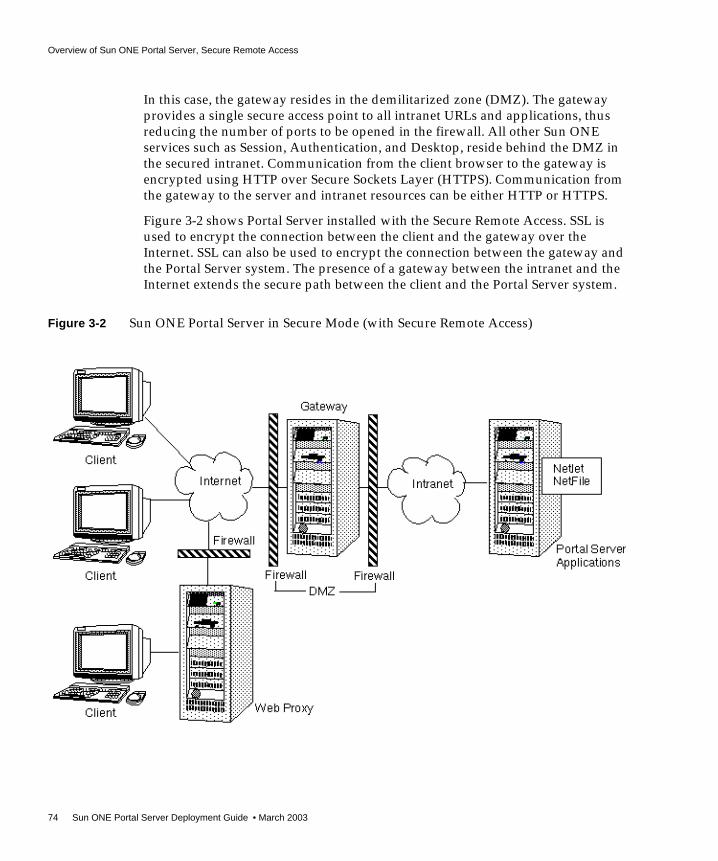
Overview of Sun ONE Portal Server, Secure Remote Access
74 Sun ONE Portal Server Deployment Guide • March 2003
In this case, the gateway resides in the demilitarized zone (DMZ). The gatewayprovides a single secure access point to all intranet URLs and applications, thusreducing the number of ports to be opened in the firewall. All other Sun ONEservices such as Session, Authentication, and Desktop, reside behind the DMZ inthe secured intranet. Communication from the client browser to the gateway isencrypted using HTTP over Secure Sockets Layer (HTTPS). Communication fromthe gateway to the server and intranet resources can be either HTTP or HTTPS.
Figure 3-2 shows Portal Server installed with the Secure Remote Access. SSL isused to encrypt the connection between the client and the gateway over theInternet. SSL can also be used to encrypt the connection between the gateway andthe Portal Server system. The presence of a gateway between the intranet and theInternet extends the secure path between the client and the Portal Server system.
Figure 3-2 Sun ONE Portal Server in Secure Mode (with Secure Remote Access)

Sun ONE Portal Server, Secure Remote Access Components
Chapter 3 Sun ONE Portal Server, Secure Remote Access Architecture 75
You can add additional servers and gateways for site expansion. You can alsoconfigure the components of Secure Remote Access in various ways based on yourbusiness requirements.
Sun ONE Portal Server, Secure Remote AccessComponents
This section describes the Sun ONE Portal Server, Secure Remote Accesscomponents.
To provide the services discussed in “Overview of Sun ONE Portal Server, SecureRemote Access,” on page 71, Secure Remote Access comprises the followingcomponents:
• Secure Remote Access Gateway (consists of EProxy and Rproxy)
• Netlet
• Netlet Proxy
• NetFile
• Rewriter
• Rewriter Proxy
You can install the Secure Remote Access components on the Sun ONE PortalServer node, or on any other individual node (referred as a non-Sun ONE PortalServer node). Table 3-1 on page 76 lists the various installable components and thenodes that they can be installed on. This table has three columns. The first columnlists the installable components of the Secure Remote Access. The second columnlists the nodes that the component can be installed on. The third column describesthe component.

Sun ONE Portal Server, Secure Remote Access Components
76 Sun ONE Portal Server Deployment Guide • March 2003
Secure Remote Access uses Sun™ ONE Identity Server (in Sun ONE Portal Server6.0, it is known as iPlanet Directory Server Access Management Edition 5.1) tostore all its configuration information, except for information about the machines(such as host name, IP address, and so forth), on which the gateway is installed.
Table 3-1 Secure Remote Access Components and Nodes
Component Node Description
Gateway Sun ONE Portal Server,non-Sun ONE PortalServer
The gateway provides the interface and security barrierbetween remote user sessions originating from the Internet andyour corporate intranet.
SecureRemoteAccessSupport
Sun ONE Portal Server This component has three parts:
• Gateway Support - Controls communication between thePortal Server and the various gateway instances.
• NetFile file manager application - Enables remote accessand operation of file systems and directories. NetFilecomprises NetFile Java™ technology, a Java-based userinterface. This is available for Java 1 and Java 2.
• Netlet - Ensures communication between the Netlet appleton the client browser, the gateway, and the applicationservers.
This component is installed by default when you choose “InstallPortal Server” in a fresh installation of Secure Remote Access.
This component is available as a separate installable option ifyou are installing the Secure Remote Access software over anexisting installation of Portal Server.
Netlet Proxy Sun ONE Portal Server,non-Sun ONE PortalServer
Netlet proxy is an optional component. You can choose not toinstall it, or install it later. Netlet proxy extends the securetunnel from the client, through the gateway to the Netlet proxythat resides in the intranet. This restricts the number of openports in a firewall between the demilitarized zone (DMZ) andthe intranet.
Netlet proxy cannot be installed on a gateway node.
RewriterProxy
Sun ONE Portal Server Install the Rewriter proxy to redirect HTTP requests to theRewriter proxy instead of directly to the destination host. TheRewriter proxy in turn sends the request to the destinationserver.

Sun ONE Portal Server, Secure Remote Access Components
Chapter 3 Sun ONE Portal Server, Secure Remote Access Architecture 77
You administer the configuration information stored in Identity Server through theconsole modules of the respective components. These components are installed aspart of the Identity Server administration console. The administration consoleprovides a single point of administration for all Sun ONE Portal Server, SecureRemote Access components.
Figure 3-3 on page 78 shows an installation consisting of all the Sun ONE PortalServer, Secure Remote Access components.
In this figure, two client browsers are redirected by a load balancer, which sits inthe DMZ, to one of two gateways, also located in the DMZ. Client 1 is performinga NetFile transaction. The NetFile traffic is routed by Gateway 1 to Sun ONE
Portal Server 1, whose Rewriter proxy directs the traffic to Other Host 1.Client 2 is performing both Netlet and NetFile transactions. Client 2’s Netletand NetFile requests are handled by Gateway 2, which routes the traffic to Sun
ONE Portal Server 2. The Rewriter proxy on this host directs the NetFile trafficto Other Host 2. The Netlet proxy on this host directs the Netlet request toApplication Host 1.
NOTE This sample configuration illustrates the various components thatyou can use. There can be multiple installations and instances of thegateway and the Netlet proxy.

Sun ONE Portal Server, Secure Remote Access Components
78 Sun ONE Portal Server Deployment Guide • March 2003
Figure 3-3 Secure Remote Access Installation with Multiple Gateways

Sun ONE Portal Server, Secure Remote Access Components
Chapter 3 Sun ONE Portal Server, Secure Remote Access Architecture 79
Secure Remote Access GatewayThe Secure Remote Access gateway is a standalone Java process that can beconsidered to be stateless, since state information can be rebuilt transparently tothe end user. The gateway listens on the configured port(s) to accept HTTP andHTTPS requests. Upon receiving a request, the gateway checks the headerinformation to determine the type of request. The gateway consists of Eproxy(Encrypted proxy) and Rproxy (Reverse proxy) subcomponents. Eproxy isresponsible for handling Netlet components. Rproxy is responsible for allnon-Netlet components. Depending on the type of request, the gateway performsthe following:
• Netlet request - Eproxy checks session validity and routes the request (traffic)to the requested server. The destination of the Netlet traffic is determined bythe Netlet rule that the user clicked in the Desktop. See “Netlet,” on page 85 formore information.
• HTTP(S) traffic - Eproxy forwards the request to the Reverse proxy. When theReverse proxy receives the request, it checks the session validity and forwardsthe request to the server as specified by the HTTP header. Upon receiving aresponse from the server, the Reverse proxy translates the response so that allintranet links within the response will work on the extranet.
If you do not require Netlet functionality, you can disable Eproxy. In Figure 3-3 onpage 78, the requests are directly received and fetched by the Reverse proxy.
All the gateway configuration information is stored in the Identity Server’s LDAPdatabase as a profile. A gateway profile consists of all the configurationinformation related to the gateway except machine-specific information such ashost name and IP address. All machine-specific information is stored in aconfiguration file in the local file system where the gateway is installed. Thisenables one gateway profile to be shared between gateways that are running onmultiple machines.
As mentioned previously, you can configure the gateway to run in both HTTP andHTTPS modes, simultaneously. This helps both intranet and extranet users toaccess the same gateway: extranet users over HTTPS, and intranet users over HTTP(without the overhead of SSL).
You can also run the gateway in chroot environments.

Sun ONE Portal Server, Secure Remote Access Components
80 Sun ONE Portal Server Deployment Guide • March 2003
Multiple Gateway InstancesIf desired, you can run multiple gateway instances on a single machine. Eachgateway instance listens on independent port(s). You can configure gatewayinstances to contact the same Portal Server instance, or different Portal Serverinstances. When running multiple instances of a gateway on the same machine,you can associate an independent certificate database with each instance of thegateway, and bind that gateway to a domain. In essence, this provides theflexibility of having a different gateway server certificate for each domain.
When you configure the gateway with multiple instances of Portal Server, thegateway automatically performs round-robin load balancing by logging in userswith the different servers, alternately. The gateway also keeps a list of activeservers to avoid trying to log in users to an inactive server. This mechanism helpsto avoid single points of failure with Portal Server.
When deploying the Secure Remote Access gateway, you need to decide whetherto have multiple instances on the same machine or on multiple machines.
Proxy ConfigurationThe gateway uses proxies that are specified in its profile to retrieve contents fromvarious web servers within the intranet and extranet. It is possible to dedicateproxies for hosts, and DNS subdomains and domains. Depending on the proxyconfiguration, the gateway uses the appropriate proxy to fetch the requiredcontents. If the proxy requires authentication, it should be stored as part of thegateway profile that the gateway uses automatically while connecting to the proxy.The Rewriter component also uses the proxy information to ensure that any URLthat contains the host, or DNS subdomain or domain, specified in the proxyinformation, is rewritten to ensure that they are routed through the gateway.
Gateway and HTTP Basic AuthenticationThe gateway supports basic authentication, that is, prompting for a user ID andpassword but not protecting those credentials during transmission from the user’scomputer to the site’s web server. Such protection usually requires theestablishment of a secure HTTP connection, typically through the use of SSL.
NOTE Session stickiness is not required in front of a gateway (unless youare using Netlet), although it is recommended for performancereasons. On the other hand, session stickiness to the Portal Serverinstances is enforced by Secure Remote Access.

Sun ONE Portal Server, Secure Remote Access Components
Chapter 3 Sun ONE Portal Server, Secure Remote Access Architecture 81
If a web server requires basic authentication, the client prompts for username andpassword and sends the information back to the requesting server. With thegateway enabled for HTTP basic authentication, it captures the username andpassword information, and stores a copy in the user’s profile in Identity Server forsubsequent authentications and login attempts. The original data is passed by thegateway to the destination web server for basic authentication. The web serverperforms the validation of the username and password.
The gateway also enables fine control of denying and allowing this capability on anindividual host basis.
Gateway and SSL SupportThe gateway supports both SSL v2 and SSL v3 while running in HTTPS mode. Ifnecessary, you can enable or disable SSL v2 support. You use the gatewayadministration module (Identity Server administration console) to enable ordisable specific ciphers. The gateway also supports Transport Layer Security (TLS).
SSLv3 has two authentication modes:
• Mandatory server authentication - The client must authenticate the server.
• Optional authentication - The server is configured to authenticate the client.
Personal Digital Certificate (PDC) authentication is a mechanism that authenticatesa user through SSL client authentication. The gateway supports PDCauthentication with the support of Identity Server authentication modules. WithSSL client authentication, the SSL handshake ends at the gateway. This PDC-basedauthentication gets integrated with the Identity Server’s certificate-basedauthentication. Thus, the client certificate is handled by Identity Server and not bythe gateway.
After the SSL session has been established, the gateway continues to receive theincoming requests, checks session validity, and then forwards the request to thedestination web server.
NOTE You can configure the gateway to use or not use SSL. Likewise, youcan also configure the web server to use or not use SSL. See the SunONE Portal Server, Secure Remote Access 6.0 Installation Guide for moreinformation on installing the gateway to use SSL.

Sun ONE Portal Server, Secure Remote Access Components
82 Sun ONE Portal Server Deployment Guide • March 2003
The gateway server also handles all Netlet traffic. If an incoming client request isNetlet traffic, the gateway checks for session validity, decrypts the traffic, andforwards it to the application server. In case Netlet proxy is enabled, the gatewaychecks for session validity and forwards it to the Netlet proxy. The Netlet proxythen decrypts and forwards it to the application server.
Gateway Access ControlThe gateway enforces access control by using URL Allow and URL Deny lists.Even when URL access is allowed, the gateway checks the validly of the sessionagainst the Identity Server session server. URLs that are designated in the NonAuthenticated URL list bypass session validation, as well as the Allow and Denylists. Entries in the URL Deny list take precedence over entries in the URL Allowlist. If a particular URL is not part of any list, then access is denied to that URL. Thewildcard character, *, can also be used as a part of the URL in either the Allow orDeny list.
Gateway LoggingBecause the entire traffic comes through the gateway for all the services providedby Desktop, Netlet, and NetFile, you can monitor the complete user behavior byenabling logging on the gateway. The gateway uses the Identity Server loggingAPI for creating logs.
Reverse Proxy (Rproxy)The Secure Remote Access Rewriter can also be used as a reverse proxy. A proxyserver serves Internet content to the intranet, while a reverse proxy serves intranetcontent to the Internet. Certain deployments of reverse proxy are configured toserve the Internet content, to achieve load balancing and caching. The Rewritercomponent of core Portal Server achieves the functionality of rewriting the webcontent by reverse proxy.
You can configure the Secure Remote Access gateway as a reverse proxy to serveboth Internet and intranet content to authorized users. Whenever Secure RemoteAccess serves web content, it needs to ensure that all subsequent browser requestsbased on this content are routed through Secure Remote Access. This is achievedby identifying all URLs in this content and rewriting as appropriate.
NOTE Because 40-bit encryption is very insecure, the gateway provides anoption that enables you to reject connections from a 40-bitencryption browser.

Sun ONE Portal Server, Secure Remote Access Components
Chapter 3 Sun ONE Portal Server, Secure Remote Access Architecture 83
The Rewriter component of Secure Remote Access performs this rewriting. Anexternal ruleset identifies the URI in the content.
Any request that needs to be served by Secure Remote Access follows this route:
1. From the request, Secure Remote Access identifies the URI of the intranet pageor Internet page that needs to be served.
2. Secure Remote Access uses the proxy settings in the administration console toconnect to the identified URL.
3. The domain of the URI is used to identify the ruleset to be used to rewrite thiscontent.
4. After fetching the content and ruleset, Secure Remote Access inputs these tothe Rewriter. All the identified URIs are sent through the URI Translator, asubcomponent of the Rewriter.
5. The original URI is replaced with the rewritten URI.
6. This process is repeated until the end of the document is reached.
7. The resultant Rewriter output is routed to the browser.
The URI Translator handles the following types of URIs:
• Relative URI, for example, <a href=‘/abc.html/’>
• Absolute URI, for example. <a href=‘http://sesta.com/abc.html’/>
• JavaScript™ function call that returns a URI on evaluation, for example,window.open(jsVarHome+ ‘index.html’);
The following example shows how a simple URI is rewritten. Here the identifiedURI is a fully qualified URI (absolute URI):
• Identified URI: http://intranet.sesta.com/abc.html
• Secure Remote Access URI: https://sra.company22.com
• Rewritten URI:https://sra.company22.com/http://intranet.sesta.com/abc.html
Rewriter RulesetsA ruleset is an XML file that contains rules for all types of web content, such asHTML rules to identify URIs in HTML content, JavaScript rules to identify URIs inJavaScript, and XML rules to identify URIs in XML content.

Sun ONE Portal Server, Secure Remote Access Components
84 Sun ONE Portal Server Deployment Guide • March 2003
Secure Remote Access defines four types of HTML rules (Attribute, JSToken,Applet, and Form), two types of JavaScript rules (Variable and Function), and twotypes of XML rules (Attribute and TagText), for a total of eight types of rules toidentify URIs in any web content.
You can assign different rulesets for pages belonging to different domains. Thishelps to better manage rulesets as opposed to putting all rules for all domain pagesin a single ruleset. Additionally, this domain-based assignment of rules increasesportal performance, as specific rulesets are smaller in size.
You manage rulesets either through the Identity Server administration console orby using the rwadmin command-line interface.
For more information on managing rulesets, see the Sun ONE Portal Server 6.0Administrator’s Guide and the Sun ONE Portal Server, Secure Remote Access 6.0Administrator’s Guide.
Secure Remote Access provides three rulesets:
• default_ruleset: Used by the URL scraper provider to convert all URIs toabsolute. Secure Remote Access does not use this ruleset.
• default_gateway_ruleset: Contains rules required to handle the Desktopand gateway modules in the Identity Server administration console.
• generic_ruleset: This is the most generalized ruleset and can handle webpages of simple and medium complexity. Complexity here is defined in termsthe amount of JavaScript code present in a web page. The generic ruleset hasreduced the number of rules required for pages containing large amounts ofJavaScript code by almost ten times the number required for previous releasesof Sun ONE Portal Server.
NOTE The number of rules has been reduced considerably in Sun ONEPortal Server 6.0 from Sun ONE Portal Server 3.0. You can also usethe regular expression (*) in all rules, as opposed to limited supportfor certain rules in previous releases.
NOTE Start by adding rules to the generic ruleset. Even if an applicationhas a complex use of JavaScript code, the generic ruleset is sufficientto handle all the rewriting in most cases.

Sun ONE Portal Server, Secure Remote Access Components
Chapter 3 Sun ONE Portal Server, Secure Remote Access Architecture 85
Rewriter and MIME TypesThe Rewriter is rule-based and also decides on which content to rewrite based onthe MIME type for the content. Out of the box, the Rewriter is configured to rewritetext/html, text/htm, application/javascript, and text/xml. You can modifythis to handle different MIME types.
NetletNetlet enables a secure connection between an arbitrary client on a system that isrunning a Java-enabled browser, and a network resource behind a corporatefirewall. The client can be behind a remote firewall and SSL proxy, or directlyconnected to the Internet. Netlet can provide secure access to fixed portapplications and some dynamic port applications that are available on the intranetfrom outside the intranet. All the secure connections made from outside theintranet to the intranet applications through the Netlet are controlled by Netletrules.
Netlet is an applet that runs on the browser. Netlet listens to and acceptsconnections on preconfigured ports, and routes both incoming and outgoing trafficbetween the client and the destination server. Both incoming and outgoing traffic isencrypted using an encryption algorithm selected by the user, or configured by theadministrator. The Netlet rule contains the details of all servers, ports, andencryption algorithms used in a connection. Administrators create Netlet rules byusing the Identity Server administration console. See the Sun ONE Portal Server 6.0,Secure Remote Access Administrator’s Guide for more information.
To provide the required service, Secure Remote Access includes the followingcomponents:
• Netlet applet
• Eproxy (Encryption proxy)
• Netlet proxy
Figure 3-4 on page 87 shows how Netlet fits into the Secure Remote Accessplatform. In this figure, each Netlet connection that is made to the destination hostis described by a rule. The rule also describes the encryption algorithm to be usedfor that particular connection. The Listen Port on the localhost is the clientmachine port on which the Netlet applet listens. The Netlet applet sets up anencrypted TCP/IP tunnel between the remote client machine and intranetapplications on the remote hosts. The applet encrypts the packets and sends themto the gateway, and decrypts the response packets from the gateway and sends

Sun ONE Portal Server, Secure Remote Access Components
86 Sun ONE Portal Server Deployment Guide • March 2003
them to the local application. All client requests are routed through the EProxy.EProxy handles only Netlet requests and passes any other request to the RProxy.EProxy parses the Netlet requests and passes them to the Netlet proxy (if it isenabled) or directly to the destination host.

Sun ONE Portal Server, Secure Remote Access Components
Chapter 3 Sun ONE Portal Server, Secure Remote Access Architecture 87
Figure 3-4 Netlet and the Sun ONE Portal Server, Secure Remote Access Platform

Sun ONE Portal Server, Secure Remote Access Components
88 Sun ONE Portal Server Deployment Guide • March 2003
How Does Netlet Work?The Netlet contains two server-side components and one client-side component.The server side components are:
• Eproxy
• Netlet proxy
The client component is the Netlet applet.
Users invoke Netlet through the Netlet channel on the Desktop. When a user clicksthe appropriate link in a Netlet channel, Portal Server receives a request todownload the Netlet applet. The Netlet applet is downloaded along with apreconfigured rule, which consists of the following information:
• Port to listen to on the client side
• Destination server host name
• Destination server port
• Encryption algorithm to use
See“Netlet Rules,” on page 90 for more information.
After obtaining the appropriate permissions from the user, the Netlet applet startslistening for connections on the preconfigured port(s). Next, it accepts theincoming connections, and routes the traffic through the Eproxy to the destinationserver after encryption. Upon receiving Netlet traffic, the Eproxy decrypts androutes the traffic to the appropriate destination server. Instead of the Eproxydecrypting and routing the traffic to the appropriate destination server, you candesignate a Netlet proxy between the Eproxy and the destination server. In thisscenario, the Eproxy simply forwards the traffic to the Netlet proxy, whichdecrypts and routes the traffic to the destination servers.
Netlet and AuthenticationThough Netlet does not authenticate users, it needs a valid SSO token for carryingout its operations. Netlet passes the SSO token with every request that is sent fromthe client to the Eproxy. Upon successful validation of the SSO token, the traffic isrouted to the destination server. Additionally, the Netlet applet also displays awarning message before accepting any new connections (on the machine where the
TIP For security reasons, Netlet is not enabled for all users by default. Ifdesired, you can register the Netlet service at the organization leveland assign the policy for the Ability to execute SRAP Netlet.

Sun ONE Portal Server, Secure Remote Access Components
Chapter 3 Sun ONE Portal Server, Secure Remote Access Architecture 89
applet is running). The user must acknowledge this message and type the Netletpassword before accepting new connections. You can configure this message to bea check box, or you can force the user to type a password before the connection isallowed.
Static and Dynamic Port ApplicationsStatic port applications run on known or static ports at which they can be contactedby clients. Examples include IMAP and POP servers, and Telnet daemons. In thecase of static port applications, the Netlet rule includes the destination server portso that requests can be routed directly to their destinations.
Dynamic port applications agree upon a port for communication as part of thehandshake. For dynamic applications, you can include the destination server portas part of the Netlet rule. The Netlet needs to understand the protocol and examinethe data to find the port being used between the client and the server. FTP is adynamic port application. In FTP, the port for actual data transfer between theclient and server is specified through the PORT command. In this case, the Netletparses the traffic over the control channel traffic to obtain the data channel portdynamically.
Currently, FTP and Microsoft Exchange are the only dynamic port applicationsthat Portal Server supports.
NOTE Although Exchange 2000 is supported with Netlet, the followingconstraints apply:
• You must configure Exchange to use STATIC ports.
• Netlet does not work with Windows 2000 and XP becauseWindows 2000 and XP clients reserve the Exchange port (port135) for the RPC Portmapper, which Active Directory uses.Previous versions of Windows did not reserve this port. Becausethe port is reserved, you cannot assign Netlet to it, and thus theport cannot provide the necessary tunneling.
• The Outlook 2000 client has the limitation that it does not enableyou to change the port on which you want to connect to theExchange server.

Sun ONE Portal Server, Secure Remote Access Components
90 Sun ONE Portal Server Deployment Guide • March 2003
Encryption AlgorithmsNetlet uses an encryption algorithm to encrypt traffic that is routed by Netlet fromthe client to the destination server. Either the user or the administrator selects theencryption algorithm from the list of available choices. The user or administratoralso specifies the key size for encryptions and decryption. Netlet currentlysupports the following ciphers:
• DES
• TripleDES
• RC4
• AES/Rjindael
• Null
The algorithm and key size to be used for encryption and decryption are specifiedon a per rule basis. This increases the flexibility and security for all Netletconnections between the client and the destination server.
Dynamic Key ExchangeThough the algorithm and key size are specified as part of the Netlet rule, theactual key used for encryption and decryption is decided between the Netlet appletand Eproxy by using the Dynamic Key exchange protocol.
The dynamic key of the specified size is generated on a per user basis and perconnection basis. This means that different keys are generated for each connectionfor different users. In addition, keys vary between one session and another of thesame user, and are used for encrypting and decrypting all Netlet traffic for thatparticular user in that session.
Netlet RulesA Netlet rule contains all the information that is needed for a Netlet connectionbetween the client and the destination server. A Netlet rule consists of thefollowing fields:
• Rule name
• Encryption algorithms
• URL
• Download applet
• Extend session

Sun ONE Portal Server, Secure Remote Access Components
Chapter 3 Sun ONE Portal Server, Secure Remote Access Architecture 91
• Client port
• Target host(s)
• Target port(s)
See the Sun ONE Portal Server, Secure Remote Access 6.0 Administrator’s Guide formore information.
Netlet rules are based on how you specify the destination host. The two types ofNetlet rules are:
• Static rule - Specifies the destination host as part of the rule. In a static rule, theuser cannot specify or change the destination host. For example, you couldhave an IMAP rule that enables connecting to a particular IMAP server, but theuser could not change the IMAP server name.
• Dynamic rule - The destination host is not specified as part of the rule. Theuser can specify the destination host in the Netlet provider. For example, anadministrator defines a Telnet rule in which the user can specify the particularhost for Telnet connection.
Netlet ProviderThe Netlet provider is a Portal Server Desktop provider that supplies a channelwith links for initiating Netlet connections as defined by the rules. The channeldisplays one link for every Netlet connection that can be initiated by a user. TheNetlet provider also supplies the user with an interface to edit dynamic rules.Using dynamic rules, users can add or remove destination hosts as required. Userscan also set the password for validating themselves at the time of invoking a newNetlet connection.
Netlet and Application IntegrationNetlet works with many third parties such as Graphon, Citrix, and pcAnywhere.Each of these products provides secure access to the user’s Desktop from a remotemachine using Netlet.
Netlet and Split TunnelingSplit tunneling is when a VPN client can connect to both secure sites (for example,by using Netlet) and non-secure sites, without having to connect or disconnect theVPN—in this case, Netlet—connection. The client determines whether to send theinformation over the encrypted path, or to send it by using the non-encrypted path.

Sun ONE Portal Server, Secure Remote Access Components
92 Sun ONE Portal Server Deployment Guide • March 2003
The concern over split tunneling is that you could have a direct connection fromthe non-secure Internet to your VPN-secured network, via the client. Turning offsplit tunneling (not allowing both connections simultaneously) reduces thevulnerability of the VPN (or in the case of Netlet) connection to Internet intrusion.
Though Portal Server does not prohibit nor shut down multiple networkconnections while attached to the portal site, it does prevent unauthorized usersfrom “piggybacking” on other users’s sessions in the following ways:
• Only an authenticated portal user can run the Netlet. No portal application canbe run until the user has been successfully authenticated, and no newconnections can be made if an authenticated session does not exist.
• Netlet is an application specific “vpn” and not a general purpose IP router.Netlet only forwards packets that have been defined by a Netlet rule. Thisdiffers from the standard VPN approach that gives you complete LAN accessonce you’ve connected to the network.
• All access controls in place on the application side are still in effect so that anattacker would also have to break in to the back-end application.
• Every Netlet connection results in a dialog box posted by the Netlet (runningin the authenticated user’s JVM™) to the authenticated user’s display. Thedialog box asks for verification and acknowledgement to permit the newconnection. In the current release, this can be a simple check box or can requirethe user to enter a password. For attackers to be able to utilize a Netletconnection, they would need to know that the Netlet was running, the portnumber it was listening on, how to break the back-end application, andconvince the user to approve the connection.
Netlet ProxyMuch like the Rewriter proxy, Netlet proxy also helps in reducing the number ofports that you need to open in your firewall for connecting the Eproxy and thedestination hosts.
For example, consider a configuration where users need Netlet to connect with alarge number of Telnet, FTP, and Microsoft Exchange servers within the intranet.Assume that the Eproxy is in a DMZ. If Eproxy routes the traffic to all thedestination servers, you would need to open a large number of ports in the secondfirewall. To alleviate this problem, you can use a Netlet proxy behind the secondfirewall and configure Eproxy to forward the traffic to the Netlet proxy. The Netlet

Sun ONE Portal Server, Secure Remote Access Components
Chapter 3 Sun ONE Portal Server, Secure Remote Access Architecture 93
proxy then routes all the traffic to the destination servers in the intranet and youreduce the number of open ports required in the second firewall. You can alsodeploy multiple Netlet proxies behind the second firewall to avoid a single point offailure.
Figure 3-5 on page 94 and Figure 3-6 on page 95 show typical deployments thatinclude the Netlet proxy. In Figure 3-5, the Netlet proxy is installed on the samemachine that is running Sun ONE Portal Server. In Figure 3-6, the Netlet proxy isinstalled on a non-Sun ONE Portal Server node.
In both figures, the gateway ensures a secure tunnel between the remote clientmachine and the gateway. Netlet packets are decrypted at the gateway and sent tothe destination servers. However, the gateway needs to access all the Netlet targethosts through the firewall between the demilitarized zone (DMZ) and the intranet.Conceptually, this requires opening a large number of ports in the firewall.However, Netlet proxy enhances the security between the gateway and theintranet by extending the secure tunnel from the client, through the gateway to theNetlet proxy that resides in the intranet. With the proxy, the Netlet packets aredecrypted by the proxy and then sent to the destination server. This reduces thenumber of ports required to be opened in the firewall. Thus, in both figures, onlyone port is opened in the firewall for Netlet traffic. (Another port is opened forPortal Server traffic.)
NOTE Installing the Netlet proxy on a separate node can help with PortalServer response time by offloading Netlet traffic to an independentnode.
NOTE You can run multiple Netlet proxies to avoid a single point of failureand achieve load balancing.

Sun ONE Portal Server, Secure Remote Access Components
94 Sun ONE Portal Server Deployment Guide • March 2003
Figure 3-5 Netlet Proxy Installed on Portal Server Node

Sun ONE Portal Server, Secure Remote Access Components
Chapter 3 Sun ONE Portal Server, Secure Remote Access Architecture 95
Figure 3-6 Netlet Proxy Installed on an Independent Node

Sun ONE Portal Server, Secure Remote Access Components
96 Sun ONE Portal Server Deployment Guide • March 2003
NetFileNetFile enables remote access and operation of file systems that reside within thecorporate intranet in a secure manner, when accessed through the gateway. NetFileincludes NetFile Java 1, an AWT-based user interface, and NetFile Java 2, aSwing-based user interface.
NetFile uses standard protocols such as NFS, SMB, and FTP to connect to any ofthe UNIX® or Windows file systems that are permissible for the user to access.NetFile enables most file operations that are typical to file manager applications.See the Sun ONE Portal Server, Secure Remote Access 6.0 Administrator’s Guide formore information.
NetFile ComponentsTo provide access to various file systems, NetFile has three components:
• NetFile Java 1 Applet - Has an AWT-based user interface. For use with olderbrowsers that cannot support Java 2.
• NetFile Java 2 Applet - Has a Swing-based user interface. For use with newergeneration browsers that support Java plugins.
• NetFile servlet(s) - There are two NetFile servlets present in the web container(of the server of your deployment), one for each kind of NetFile applet. Theservlets are responsible for connecting to different types of file systems,carrying out the operations that NetFile is configured to handle, and sendingthe information back to the applets for display.
NetFile is internationalized and provides access to file systems irrespective of theirlocale (character encodings).
NetFile uses Identity Server to store its own profile, as well as user settings andpreferences. You administer NetFile through the Identity Server administrationconsole.
NetFile InitializationWhen a user selects a NetFile link in the Desktop, the NetFile servlet checks if theuser has a valid Identity Server Single Sign-on (SSO) token (available only onsuccessful authentication with the Identity Server), and permission to executeNetFile. If the user has a valid SSO token and permission to execute NetFile, theapplet is rendered to the browser. The NetFile applet connects back to the servlet toget its own configuration such as size, locale, resource bundle, as well as usersettings and preferences. NetFile obtains the locale information and other user

Sun ONE Portal Server, Secure Remote Access Components
Chapter 3 Sun ONE Portal Server, Secure Remote Access Architecture 97
information (such as username, mail ID, and mail server) using the user’s SSOtoken. The user settings include any settings that the user has inherited from anorganization or role, settings that are customized by the user, and settings that theuser has stored upon exit from a previous NetFile session.
Server and SharesNetFile uses the underlying Network File System (NFS) and File TransportProtocol (FTP) to access file systems on UNIX platforms, Server Message Block(SMB) protocol to access file systems on Windows, and FTP to access file systemson Novell platforms.
All three platforms provide share-based access to their file systems. A share is adirectory tree that you can configure for access from remote systems. On certainplatforms, you can associate a password with the share. You can have multipleshares on a single server, each with a distinct name associated with it. Users canconnect to these systems using a specified protocol, and gain access to files underthese shares after validating their credentials.
Using NetFile, users enter the name of the server and share along with theircredentials. NetFile stores the credentials and reuses them for authentication, if theuser saves the NetFile settings. You can configure the shares (known as commonhosts) that users can access at a organization or role level. Users do not need toenter their credentials to access these shares (but a valid SSO token from IdentityServer is necessary at all times). You can also deny access to common hosts for a setof users by not inheriting this attribute from an organizational or role level.
If a particular share is part of the common hosts, and also part of the denied list,users are denied access to the share.
NetFile supports access to shares from UNIX (as long as there is NFS support),Windows NT, Windows 95, Windows 98, Windows 2000, and FTP over NetWareservers.
Validating CredentialsNetFile uses the credentials supplied by users to authenticate users before grantingaccess to the file systems.
The credentials include a username, password, and NT or Novell domain(wherever applicable). Because it is possible to have an independent password foreach share, users need to enter their credentials for every share (except for commonhosts) that you add.

Sun ONE Portal Server, Secure Remote Access Components
98 Sun ONE Portal Server Deployment Guide • March 2003
NetFile uses UNIX Authentication of the Identity Server to grant access to NFS filesystems. For file systems that are accessed over FTP and SMB protocols, NetFileuses the methods provided by the protocol itself to validate the credentials.
NetFile Access ControlNetFile provides various means of file system access control. You can deny accessto users to a particular file system based on the protocol. For example, you candeny a particular user, role, or organization access to file systems that areaccessible only over NFS.
You can configure NetFile to allow or deny access to file systems at any level, fromorganization, to suborganization, to user. You can also allow or deny access tospecific servers. Access can be allowed or denied to file systems for usersdepending on the type of host, including Windows, FTP, NFS, and FTP overNetWare. For example, you can deny access for Windows hosts to all users of anorganization. You can also specify a set of common hosts at an organization or rolelevel, so that all users in that organization or role can access those hosts withouthaving to add them for each and every member of the organization or role.
As part of the NetFile service, you can configure the Allow or Deny lists to allow ordeny access to servers at the organization, role, or user level. The Deny list takesprecedence over the Allow list. The Allow and Deny lists can contain the *wildcard to allow or deny access to a set of servers under a single domain orsubdomain.
NetFile SecurityWhen you use NetFile with Secure Remote Access configured for SSL, allconnections made from NetFile applets to the underlying file system happen overthe SSL connection established between the gateway and the browser. Because youtypically install the gateway in a DMZ, and open a limited number of ports(usually only one) in the second firewall, you do not compromise security whileproviding access to the file systems.
Special OperationsNetFile is much like a typical file manager application and brings a set of newfeatures that are more appropriate for a remote file manager application. NetFileenables users to upload and download files between the local and remote filesystems (shares). You can limit the size of the upload file (from the local to theremote file system) through the Identity Server administration console.

Sun ONE Portal Server, Secure Remote Access Components
Chapter 3 Sun ONE Portal Server, Secure Remote Access Architecture 99
NetFile also enables users to select multiple files and compress them by using GZIPand ZIP compression. Users can select multiple files and send them in a singleemail as multiple attachments. NetFile also uses the SSO token of Identity Server toaccess the user’s email settings (such as IMAP server, username, password, andreply-to address) for sending email.
Double-clicking a file in the NetFile window launches the applicationcorresponding to the MIME type and opens the file. NetFile comes with a defaultMIME types configuration file that has mappings for most popular file types(extensions) and MIME-types that you can edit for adding new mappings.
You can search for files and display the list in a separate window using NetFile.The results of each search are displayed in a new window while maintaining theprevious search result windows. The type of character encoding to be used for aparticular share is user configurable, and is part of the share’s setting. If nocharacter encoding is specified, NetFile uses ISO-8859-1 while working with theshares. The ISO-8859-1 encoding is capable of handling most common languages.ISO-8859-1 encoding gives NetFile the capability to list files in any language and totransferring files in any language without damaging the file contents.
NetFile does not create any temporary files except during uploading anddownloading files between Windows file systems and the local file systems overthe SMB protocol.
NetFile and MultithreadingNetFile uses multithreading to provide the flexibility of running multipleoperations simultaneously. For example, users can launch a search operation, startuploading files, then send files by using email. NetFile will perform all threeoperations simultaneously and still permit the user to browse through the filelisting.
RewriterThe Rewriter is an independent component that translates all URLs (in both HTMLand JavaScript code) to ensure that the intranet content is always fetched throughthe gateway. You define a ruleset (a collection of rules) that identifies all URLs thatneed to be rewritten in a page. The ruleset is an XML fragment that is writtenaccording to a Document Type Definition (DTD). Using the generic ruleset that
NOTE NetFile does not currently support deletion of remote directories,only files.

Sun ONE Portal Server, Secure Remote Access Authentication
100 Sun ONE Portal Server Deployment Guide • March 2003
ships with the Rewriter, you can rewrite most URLs (but not all) without anyadditional rules. You can also associate rulesets with domains for domain-basedtranslations. See the Sun ONE Portal Server, Secure Remote Access 6.0 Administrator’sGuide for more information.
In a typical scenario, you install the gateway in a DMZ, with firewalls on eitherside (extranet and intranet). For the gateway to access machines on the intranet,you need to open extra ports in the firewall between the gateway and the intranet.T o minimize the number of open ports in the firewall, you use the Rewriter proxy.You install the Rewriter proxy within the intranet and you configure the gatewayto use the Rewriter proxy. Instead of trying to retrieve the contents directly, thegateway simply forwards all requests to the Rewriter proxy, which fetches andreturns the contents to the gateway.
Rewriter ProxyWhen you install the Rewriter proxy, HTTP requests are redirected to the Rewriterproxy instead of directly to the destination host. The Rewriter proxy in turn sendsthe request to the destination server.
Using the Rewriter proxy enables secure HTTP traffic between the gateway andintranet computers and offers two advantages:
• If there is a firewall between the gateway and server, the firewall needs to openonly two ports—one between the gateway and the Rewriter proxy, andanother between the gateway and the Portal Server.
• HTTP traffic is now secure between the gateway and the intranet even if thedestination server only supports HTTP protocol (no HTTPS).
Sun ONE Portal Server, Secure Remote AccessAuthentication
Secure Remote Access uses the authentication features of Identity Server toauthenticate users. Even session validation happens through Identity Server’sSingle Sign-on (SSO) API. In fact, the gateway component treats the login pagesjust like any other content page and passes them to the browser. For PersonalDigital Certificate (PDC) authentication, the gateway obtains the client certificateand passes it to the Identity Server host for authentication.

Sun ONE Portal Server, Secure Remote Access Configuration Files and Directory Structure
Chapter 3 Sun ONE Portal Server, Secure Remote Access Architecture 101
If the session information is not found as part of the HTTP or HTTPS request, thegateway directly takes the user to the authentication page by obtaining the loginURL from Identity Server. Similarly, if the gateway finds that the session is notvalid as part of a request, it takes the user to the login URL and at successful login,takes the user to the requested destination.
After the user has successfully authenticated, the gateway simply presents (afterrewriting) the page returned by Identity Server to the user. In Portal Server, bydefault, this is the Desktop page.
Sun ONE Portal Server, Secure Remote AccessConfiguration Files and Directory Structure
This section describes the Secure Remote Access directory structure andconfiguration files used to store configuration and operational data.
Secure Remote Access DirectoriesTable 3-2 shows the platform-specific directory structures that are installed forSecure Remote Access. This two-column table provides the directory location inthe first column and a description in the second column.
Table 3-2 Sun ONE Portal Server, Secure Remote Access Directories
Description Location
Default installation directory /opt/SUNWps
Default installation directoryfor Identity Serverexecutables, the web server,and the deployed applications
/opt/SUNWam
Default installation directoryfor configuration information
/etc/opt/SUNWps
Log files /var/opt/SUNWam/logs
Debug log files /var/opt/SUNWps/debug

Sun ONE Portal Server, Secure Remote Access Configuration Files and Directory Structure
102 Sun ONE Portal Server Deployment Guide • March 2003
Secure Remote Access Configuration FilesAll Secure Remote Access configuration data is stored using the Identity ServerServices Management function. Identity Server provides the bootstrapconfiguration file that is needed to find the directory server.

103
Chapter 4
Analyzing Your Portal Requirements
This chapter describes how to analyze your organization’s needs and requirementsthat lead to designing your Sun™ ONE Portal Server deployment.
This chapter contains the following sections:
• Identifying and Evaluating Your Business and Technical Requirements
• Mapping Portal Server Features to Your Business Needs
Identifying and Evaluating Your Business andTechnical Requirements
The first step in planning your deployment is identifying your Portal Serverbusiness and technical requirements.
Your business requirements address your organization’s problems andopportunities, and include such factors as:
• Services
• Service availability
• Future growth
• New technologies
• Capital investment
To be useful in formulating design requirements, the business requirements mustaddress detailed goals and objectives.

Identifying and Evaluating Your Business and Technical Requirements
104 Sun ONE Portal Server Deployment Guide • March 2003
Your technical requirements (often called functional requirements) discuss thedetails of your organization’s system needs and desired results, and include suchfactors as:
• Performance
• Security
• Reliability
• Expected performance criteria of the portal
The technical requirements define all functions required of an architecture andprovide guidelines for how each component works and integrates to form an entiresystem. Your organization needs technical requirements to formulate the bestdesign approaches and apply the appropriate technologies to accomplish thedesired architectural solution for your portal. You need to gather both businessand technical requirements before you can address architecture and design issues.
After obtaining both business and technical requirements, carefully evaluate them.Identify how realistic each requirement is. What would be the best designapproach to satisfy each requirement and related requirements? Consider all theassociated constraints (costs, time to deploy, and so forth) and decide if anyrequirements need to be modified before coming up with the deployable solution.Evaluating your business and technical requirements will help you formulate adesign that:
• Meets your business objectives today
• Offers the best available performance
• Provides high availability
• Is highly scalable
• Deploys easily
• Does not contain any single points of failure
• Provides just the right capacity to meet growth for the next several months
• Provides enough capacity to meet above normal peek usage
• Enables upgrade and migration paths
• Is cost-effective
• Can be deployed in a reasonable timeframe (A tight deadline might result inyour changing of the architecture.)

Identifying and Evaluating Your Business and Technical Requirements
Chapter 4 Analyzing Your Portal Requirements 105
Determining Your Business and TechnicalRequirementsThis section provides a series of questions that you use to determine your businessand technical requirements. Answering these questions alone does not provide theultimate answer of what your portal architecture and deployment will look like.Instead, this is the first step in gathering your requirements in such a way as todescribe the problems and opportunities facing your organization but without yetproposing a specific solution.
The questions in this section are grouped in the following areas:
• Business Objectives
• Technical Goals
• User Behaviors and Patterns
• Back-end Systems
• Front-end Systems
• Data Centers
• Growth Projections
• Security
• Search Engine
• Performance
• Availability
• Maintainability
Some questions in these areas will not apply to your portal design, and in somecases, you will identify and have to address issues that are not presented here.
NOTE Many organizations often contain their business and technicalrequirements within a single Requirements Document.

Identifying and Evaluating Your Business and Technical Requirements
106 Sun ONE Portal Server Deployment Guide • March 2003
The Architectural Decision to Use Secure Remote AccessThere are no other questions in this chapter pertaining directly to Sun™ ONEPortal Server, Secure Remote Access. Deploying Secure Remote Access is anarchitectural decision, not an identification of requirements. To illustrate this point,consider the requirement to open a limited number of ports in the firewall. Tosatisfy this requirement, you could use the Netlet proxy that comes with SecureRemote Access. However, there are other solutions outside of Portal Server thatwould work, for example, a SOCKS server.
Business ObjectivesThe business goals of your portal affect sizing decisions. It is important tounderstand your objectives. If you do not understand your business requirements,you can easily make erroneous assumptions that could affect the accuracy of yoursizing estimates.
Use these questions to help you identify your business objectives:
• What are the business goals of this portal? (For example, do you want toenhance customer service? Increase employee productivity? Reduce the cost ofdoing business?)
• What kind of portal do you need? (For example, business-to-business (B2B),business-to-consumer (B2C), business-to-enterprise (B2E), or a hybrid?)
• Who is your target audience?
• What services or functions will the portal deliver to users?
• How will the target audience benefit from the portal?
• What are the key priorities for the portal? (If you plan to deploy your portal inphases, identify key priorities for each phase.)
(Optional) Use these questions to help identify your business objectives if you aredeploying a secure portal:
• Do you need to increase employee productivity (by making your intranetapplications and servers accessible over the Internet)?
• Do you need to provide secure access to your portal?
• Do you need to reduce cost of ownership of an existing Virtual PrivateNetwork (VPN) solution?
• Do you want employees to access intranet applications such as Citrix andpcAnywhere from the Internet?

Identifying and Evaluating Your Business and Technical Requirements
Chapter 4 Analyzing Your Portal Requirements 107
• Do you want your employees to explore intranet servers or machines from theInternet?
• Who is your target audience (all portal users, employees, or customers)?
Technical GoalsThe reasons you are offering your portal have a direct affect on how youimplement your portal. You must define target population, performancestandards, and other factors related to your goals.
Use these questions to help you identify the goals of your portal:
• What is your portal’s biggest priority?
• What applications will the portal deliver?
• What is your target population?
• What performance standard is necessary?
• What transaction volume do you expect? What transaction volume do youexpect during peak use?
• What response time is acceptable during peak use?
• What level of concurrency—the number of users who can be connected at anygiven time—is necessary?
• Should access to the portal be through intranet or Internet?
• Will your portal be deployed in one phase, or many phases? (Describe eachphase and what will change from phase to phase.)
User Behaviors and PatternsStudy the people who will use your portal. Factors such as when they will use theportal and how they have used predecessor systems are keys to identifying yourrequirements. If your organization’s experience cannot provide these patterns, youcan study the experience of other organizations and estimate them.
Use these questions to help you understand users:
• How many end users will you have? What is the size of your target audience?
• Will users log into the portal at the same time each day? Will they use theportal at work or somewhere else?

Identifying and Evaluating Your Business and Technical Requirements
108 Sun ONE Portal Server Deployment Guide • March 2003
• Are users in the same time zone or in different time zones?
• How long do you expect the typical user to be connected, or have a valid portalsession open? What use statistics do you have for existing applications? Doyou have web traffic analysis figures for an existing portal?
• How many visitor sessions, or number of single-visitor visits, are likely withina predefined period of time?
• Is portal use likely to increase over time? Or stay stable?
• How fast will your user base grow?
• How have your users used an application that the portal will deliver to them?
• What portal channels do you expect users to use regularly?
• What expectations about your portal content do your users have? How havethey used predecessor web-based information or other resources that yourportal will offer?
Back-end SystemsExamine your back-end systems to verify that they can support your portal.Scalability, performance, and your data center organization are among the factorsyou need to assess.
Use these questions to help you understand your back-end systems:
• Does your organization have the technical competence and supportorganization to deploy and maintain the portal system?
• Are back-end systems scaled to levels that your portal will need?
• Can back-end systems support concurrent users during normal use? Duringpeak use?
• What is the data bandwidth of your intranet?
• Can your existing back-end systems support the number of concurrent usersexpected for your portal?
• Will response time and other performance metrics of your existing back-endsystems be adequate?
• How many geographic locations are involved? How does traffic in these areasvary?

Identifying and Evaluating Your Business and Technical Requirements
Chapter 4 Analyzing Your Portal Requirements 109
• What response times will back-end systems deliver during normal times?During peak times?
• What type of redundancy do you have?
• How do you manage maintenance and production upgrades?
Front-end SystemsAnalyze the front-end systems that will be used for access to your portal. Thisenables you to identify how your users will connect to your portal and what kindsof browsers they will use. These factors will affect your requirements.
Use these questions to help you understand your front-end systems:
• How will users access your portal?
• What environments do your users have? Will they be using airport kiosks,Internet cafes, homes, or corporate locations?
• What browser features do your users have? Do they have Java™ applications?Is JavaScript™ technology enabled? Is cookie support enabled? Are tablessupported?
Data CentersYour data center structure and requirements often have an affect on your sizingdecisions. The number of data centers and their location are factors to define.Accessing data from remote data centers significantly impacts overall portalresponse times.
Use these questions to help you assess data center requirements for your portal:
• How many data centers are used to host the portal?
• What data center requirements and restrictions exist?
• Where are the data centers located?
• What data bandwidth is available at each data center?
• What are the typical response times between identified data centers?
NOTE Minimum browser requirements will be determined by the types ofapplications you deploy through the portal.
Identifying and Evaluating Your Business and Technical Requirements
110 Sun ONE Portal Server Deployment Guide • March 2003
• How many routers, firewalls, or other devices exist between each data centerand are there any bandwidth throttling devices installed?
Growth ProjectionsIn addition to determining what capacity you need today, assess what capacity youwill need in the future, within a time frame that you can plan for. Growthexpectations and changes in how your portal is used are factors you need toaccommodate growth.
Use these questions to help you set growth projections for your portal:
• What is the projected growth for the portal? How fast will the growth occur?
• How will your business objectives change in the next two or three years?
• What plans do you have for future content?
SecurityDetermine whether security is needed for your portal. If so, you must assess whatkind is appropriate.
Use these questions to help you identify security requirements for your portal:
• Do users need to access intranet information through the Internet?
• Is SSL required for authentication to the portal?
• Is SSL required for any other part of the portal?
• What are your security policies?
• What are your Single Sign-on requirements?
• Are there requirements for running SSL internally between servers, and if so,what is the projected data flow? (This is important to know for sizing.)

Identifying and Evaluating Your Business and Technical Requirements
Chapter 4 Analyzing Your Portal Requirements 111
• Do users have a universal user ID and password? If not, where is the user IDand password information stored and how will the portal access it if SSOfunctionality is required?
Search EngineHow you implement Search affects how you size the server you use for the SearchEngine.
Use these questions to help you identify Search Engine requirements for yourportal site:
• Which organizations will be using Search?
• In each organization how many documents are expected to be indexed in theSearch database?
• How many documents or resource descriptions (RDs) will be in the Searchdatabase?
• How many concurrent Search users are expected? Will use occur at certaintimes of the day? Or at certain times in a business process? When are thesetimes? How many concurrent users will occur at each time?
• How many concurrent searches are expected?
• Will you use document level security?
• Will you use a taxonomy for browsing?
PerformanceThe performance that your portal must deliver directly affects your sizingrequirements. Scalability, capacity, and high availability are some of the standardsyou need to consider.
Use these questions to help you evaluate performance requirements for yourportal:
• What performance requirements exist?
• What high availability requirements exist?
• What response times are acceptable? How do the response times of yourstand-alone systems compare with response time requirements of your portal?

Identifying and Evaluating Your Business and Technical Requirements
112 Sun ONE Portal Server Deployment Guide • March 2003
• If you size your portal infrastructure for good response times during regularhours, can you tolerate a possible degradation in performance during peakload times?
• How many concurrent sessions, or connected users, are likely during peakuse? (Count only users who are active. Do not include users who are, forexample, away on vacation, or on leave.)
• What is the above-normal peak time? How does this information affect yourpeak concurrent user estimate?
• What sort of user activity occurs during peak periods? Logins or reloads?
• How long do you expect the typical user to be connected, or have a valid portalsession open? What use statistics do you have for existing applications? Doyou have web traffic analysis figures for an existing portal?
AvailabilityHow you implement a highly-available system affects the ability of the system toprovide agreed system access levels over time.
Use these questions to help you assess the availability requirements for yourportal:
• What high availability requirements exist specifically for the portal server?
• What are the requirements for preventing any single point of failure to thesystem?
• Have data centers and delivery points, network, and back-end systems beendesigned to be highly available?
• How effective is the production support organization? Does the support staffhave the necessary skills, processes, and procedures in place to adequatelymaintain a production portal system?
• Understand your availability requirements for each component of yourdeployment. Different components might require different levels ofavailability, and hence a different design and configuration approach.
• Are you concerned about denial of service attacks?
• Do the size and availability requirements of your portal warrant the use of aclustered LDAP server? If so, does your organization have the expertise tooperate and maintain the cluster in the event of problems?

Mapping Portal Server Features to Your Business Needs
Chapter 4 Analyzing Your Portal Requirements 113
MaintainabilityDetermine how you want to administer and maintain your portal.
The following type of questions will help you identify maintainabilityrequirements for your portal:
• What are the requirements for backing up and restoring your portal?
• How will user provisioning be handled?
• Will you use delegated administrators for your portal?
• Does your support organization have the processes in place and technicalabilities to troubleshoot and fix portal problems?
• Will you train your support organization in maintenance and operations of theportal?
Mapping Portal Server Features to Your BusinessNeeds
The previous sections posed questions to you about the various areas of the PortalServer platform from a high-level perspective of business and technical needs. Thissection reviews specific technology features with the goal of determining whichtechnologies are most important for your organization. Review these featureswhile keeping in mind your organization’s short-, mid-, and long-term plans.
Use the following sections and tables to assess the benefits of the listed features anddetermine their relative priority for your organization. This will assist you indeveloping a deployment plan in a timely and cost effective manner.
NOTE In all likelihood, your Sun ONE sales representative has previouslydiscussed these topics with you. Thus, this section serves as a reviewof that process.

Mapping Portal Server Features to Your Business Needs
114 Sun ONE Portal Server Deployment Guide • March 2003
Identity ManagementPortal Server uses identity management to control many users spanning a varietyof different roles across the organization and sometimes outside the organizationwhile accessing content, applications and services. The challenges include: Who isusing an application? In what capacity do they serve the organization or company?What do they need to do, and what should they be able to access? How can othershelp with the administrative work?
Table 4-1 shows the identity management features and their benefits. Thisthree-column table lists the feature in the first column, a brief description in thesecond column, and the benefits in the third column.
Table 4-1 Identity Management Features and Benefits
Feature Description Benefit
Directory service Sun ONE Portal Server uses Sun™ ONEIdentity Server and Sun™ ONE DirectoryServer. Portal Server also includesrun-time license for both products at noadditional charge.
Portal Server uses an LDAP directory forstoring user profiles, roles, and identityinformation for the purpose ofauthentication, Single Sign-on, delegatedadministration, and personalization.
Portal Server uses an open schema thatcan reside in a centralized user directory,thereby leveraging an enterprise orservice provider’s investment in theIdentity Server and Directory Serverproducts.

Mapping Portal Server Features to Your Business Needs
Chapter 4 Analyzing Your Portal Requirements 115
User, policy, andprovisioningmanagement
Identity Server enables you to managemany users spanning a variety ofdifferent roles across the organization andsometimes outside the organization whileaccessing content, applications, andservices.
Provides a centralized identitymanagement solution for storing andmanaging identity information, which isintegrated with a policy solution toenforce access rights, greatly simplifyingthese challenges. Extends a commonidentity to handle new applications,enables applications to shareadministrative work, and simplifies tasksnormally associated with building theseservices from scratch.
Consolidates management of users andapplications. Personalizes content andservice delivery. Simplifies andstreamlines information and serviceaccess. Reduces costs associated withmanaging access and delivery.
Provides secure policy-based access toapplications. Ensures secure access asportal deployments expand beyondemployee LAN access.
Web SingleSign-on
Identity Server integrates userauthentication and Single Sign-onthrough an SSO API. Once the user isauthenticated, the SSO API takes over.Each time the authenticated user tries toaccess a protected page, the SSO APIdetermines if the user has the permissionsrequired based on their authenticationcredentials. If the user is valid, access tothe page is given without additionalauthentication. If not, the user isprompted to authenticate again.
Enhances user productivity by providinga consistent, centralized mechanism tomanage authentication and SingleSign-on, while enabling employees,partners and customers access to keycontent, applications, and services. Bybeing more secure, the more cost-effectiveand productive your organization andbusiness will be.
Delegatedadministration
The Identity Server administrationconsole provides role-based delegatedadministration capabilities to differentkinds of administrators to manageorganizations, users, policy, roles,channels, and Desktop providers basedon the given permissions.
Enables IT to delegate portaladministrative duties to free up valuableIT resources and administration.
Table 4-1 Identity Management Features and Benefits (Continued)
Feature Description Benefit

Mapping Portal Server Features to Your Business Needs
116 Sun ONE Portal Server Deployment Guide • March 2003
PersonalizationPersonalization is the ability to deliver content based on selective criteria and offerservices to a user.
Table 4-2 shows the personalization features and their benefits. This three-columntable lists the feature in the first column, a brief description in the second column,and the benefits in the third column.
Security Provides Single Sign-on for aggregatedapplications to the portal.
Security is a key functionality in portals.Security can address many differentneeds within the portal, includingauthentication into the portal, encryptionof the communications between the portaland the end user, and authorization of thecontent and applications to only thoseusers that are allowed access.
Table 4-2 Personalization Features and Benefits
Feature Description Benefit
Deliver contentbased on user’srole
Portal Server includes the ability toautomatically choose which applicationsusers are able to access or to use, based ontheir role within the organization.
Increases employee productivity,improves customer relationships, andstreamlines business relationships byproviding quick and personalized accessto content and services.
Enable users tocustomize content
Portal Server enables end users to choosewhat content they are interested in seeing.For example, users of a personal financeportal choose the stock quotes they wouldlike to see when viewing their financialportfolio.
The information available in a portal ispersonalized for each individual. Inaddition, users can then customize thisinformation further to their individualtastes. A portal puts control of the webexperience in the hands of the peopleusing the web, not those building the websites.
Table 4-1 Identity Management Features and Benefits (Continued)
Feature Description Benefit

Mapping Portal Server Features to Your Business Needs
Chapter 4 Analyzing Your Portal Requirements 117
Aggregation and IntegrationOne of the most important aspects of a portal is its ability to aggregate andintegrate information, such as applications, services, and content. Thisfunctionality includes the ability to embed non-persistent information, such asstock quotes, through the portal, and to run applications within, or deliver themthrough, a portal.
Table 4-3 shows the aggregation and integration features and their benefits. Thisthree-column table lists the feature in the first column, a brief description in thesecond column, and the benefits in the third column.
Aggregate andpersonalizecontent formultiple users
Portal Server enables an enterprise orservice provider to dynamicallyaggregate and deliver personalizedcontent to multiple communities of userssimultaneously.
This enables a company to deploymultiple portals to multiple audiencesfrom one product and manage them froma central management console. Also, newcontent and services can be added anddelivered on demand without the need torestart Portal Server. All of this saves timeand money, and ensures consistency in anIT organization.
Table 4-3 Aggregation Features and Benefits
Feature Description Benefit
Aggregatedinformation
The Desktop provides the primaryend-user interface for Portal Server and amechanism for extensible contentaggregation through the ProviderApplication Programming Interface(PAPI). The Desktop includes a variety ofproviders that enable container hierarchyand the basic building blocks for buildingsome types of channels.
Users no longer have to search for theinformation. Instead, the informationfinds them.
Consistent set oftools
Users get a set of tools like web-basedemail and calendaring software thatfollows them through their entire time atthe company.
Users do not have to use one tool for oneproject, another tool for another location,and so on. Also, because these tools allwork within the portal framework, theyall have a consistent look and feel andwork similarly, reducing training time.
Table 4-2 Personalization Features and Benefits (Continued)
Feature Description Benefit

Mapping Portal Server Features to Your Business Needs
118 Sun ONE Portal Server Deployment Guide • March 2003
Search ServicesPortal Server includes a secure Search Engine, enabling users to search content andreceive only those results that they can access.
Table 4-4 shows the Search features and their benefits. This three-column table liststhe feature in the first column, a brief description in the second column, and thebenefits in the third column.
Collaboration Portal Server provides control and accessto data as a company-wide resource.
In many companies, data is seen as beingowned by individual departments,instead of as a company-wide resource.The portal can act as a catalyst forbreaking down these silos and making thedata available in a controlled way to thepeople who need to use it. This broader,more immediate access can improvecollaboration.
Integration Portal Server enables you to use theDesktop as the sole place for users to gainaccess to or launch applications andaccess data.
Easy integration with existing email,calendar, legacy, or web applicationsenables the portal to serve as a unifiedaccess point, enabling users—be thatemployees, partners, or customers—toaccess the information they need quicklyand easily.
Table 4-4 Search Features and Benefits
Feature Description Benefit
Search Engine Enables the retrieval of documents basedon criteria specified by the end user.
Saves users time by providing easy accessto content.
Categorization Organizes documents into a hierarchy.This categorization is often referred to astaxonomy.
Provides a different view of documentsthat enables easy browsing and retrieval.
Robot The Search Engine robot is an agent thatcrawls and indexes information acrossyour intranet or the Internet.
Automatically searches and extracts linksto resources, describes those resources,and puts the descriptions in the Searchdatabase (also called generation orindexing).
Table 4-3 Aggregation Features and Benefits (Continued)
Feature Description Benefit

Mapping Portal Server Features to Your Business Needs
Chapter 4 Analyzing Your Portal Requirements 119
Secure Remote AccessAdding Sun™ ONE Portal Server, Secure Remote Access software extends yourportal to remote and mobile employees or business partners without the additionalcost of administration and maintenance found in a traditional Virtual PrivateNetwork (VPN) solution.
Table 4-5 shows the Secure Remote Access features and their benefits. Thisthree-column table lists the feature in the first column, a brief description in thesecond column, and the benefits in the third column.
Table 4-5 Secure Remote Access Features and Benefits
Feature Description Benefit
Integratedsecurity
Extranet or Virtual Private Networkcapabilities “on demand” whileproviding user, policy, and authenticationservices. The gateway componentprovides the interface and security barrierbetween remote user sessions originatingfrom the Internet, and your corporateintranet.
Extends an enterprise’s content,applications, files, and services locatedbehind firewalls to authorized suppliers,business partners, and employees.
To prevent denial of service attacks, youcan use both internal and externalDMZ-based gateways.
Remote access Users achieve remote access throughthree components:
• Gateway
• NetFile
• Netlet
The gateway presents content securelyfrom internal web servers and applicationservers through a single interface to aremote user.
NetFile, a file manager application,enables remote access and operation offile systems and directories.
Netlet facilitates the running of popularor company-specific applications onremote computers in a secure manner.After you implement the Netlet at yoursite, users can securely run commonTCP/IP services, such as Telnet andSMTP, and HTTP-based applications suchas pcAnywhere or Lotus Notes.
Universal access Enables web browser based universalaccess with no client software installationor maintenance necessary.
Simplifies the IT administration andmaintenance overhead while dramaticallyreducing the time and cost of deployment

Mapping Portal Server Features to Your Business Needs
120 Sun ONE Portal Server Deployment Guide • March 2003
SHARP ServicesSHARP (Scalability, High Availability, Reliability, and Performance) serviceswithin Portal Server provide horizontal scalability (for example, adding additionalhardware to increase overall system capacity) and vertical scaling (by addingadditional portal instances to maximize hardware utilization).
Table 4-6 on page 121 shows the SHARP features and their benefits. Thisthree-column table lists the feature in the first column, a brief description in thesecond column, and the benefits in the third column.
Netlet proxy Provides an optional component thatextends the secure tunnel from the client,through the gateway to the Netlet proxythat resides in the intranet.
Restricts the number of open ports in afirewall between the demilitarized zone(DMZ) and the intranet.
Rewriter proxy Redirects HTTP requests to the Rewriterproxy instead of directly to thedestination host. The Rewriter proxy inturn sends the request to the destinationserver.
Using the Rewriter proxy enables secureHTTP traffic between the gateway andintranet computers and offers twoadvantages:
• If there is a firewall between thegateway and server, the firewall needsto open only two ports—one betweenthe gateway and the Rewriter proxy,and another between the gateway andthe Portal Server.
• HTTP traffic is now secure betweenthe gateway and the intranet even ifthe destination server only supportsHTTP protocol (no HTTPS).
Table 4-5 Secure Remote Access Features and Benefits (Continued)
Feature Description Benefit

Mapping Portal Server Features to Your Business Needs
Chapter 4 Analyzing Your Portal Requirements 121
Table 4-6 SHARP Features and Benefits
Feature Description Benefit
Scalability You can configure Portal Server to meetthe demands of different deploymentscenarios. You can scale a server verticallyby adding additional software instancesof Portal Server, thus providing faulttolerance on a single server. Verticalscaling can require adding more systemresources, such as CPUs, memory, anddisks. Horizontal scaling requires addingadditional servers to your portal. Theoverall goal is to provide a system that isboth fault tolerant and has no single pointof failure from both a software andhardware perspective.
Scalability enables a system to increaseload or improve overall systemperformance.
Horizontal scaling distributes theworkload among different systems.Horizontal scaling allows for a buildingmodule approach to increasing overallportal system capacity. See “Workingwith Portal Server Building Modules,” onpage 168 for more information.
Vertical scaling enables an organization toincrease fault tolerance and maximize theperformance of an existing system.Within Portal Server, vertical scaling isachieved by running multiple instances ofportal server, each with its own JVM™.

Mapping Portal Server Features to Your Business Needs
122 Sun ONE Portal Server Deployment Guide • March 2003
High Availability Provides redundant services and theability to redirect requests in the event ofa service failure.
High availability is achieved throughsoftware replication. You can configurethe portal system to run multipleinstances of each web application, therebyproviding a backup if one of the instancesfails.
The portal system uses Identity Serverservices for session management andnon-local data access. Therefore, theportal system inherits all the benefits andconstraints of Identity Server with respectto high availability. The Identity Serverservices are either stateless or they canshare context data so that they canrecover to the previous state in case of aservice failure.
Configuring Sun ONE Directory Serverwith multiple masters ensures that userscan always log in and authenticate. If onedirectory master fails, another is able totake over.
Also, Directory Server offers a way toprevent denial of service attacks bysetting limits on the resources allocated toa particular bind DN.
Reliability Provides for no single point of failure(NSPOF) when you use portal buildingmodules in your deployment. SeeChapter 7, “Creating Your Portal Design”for more information.
A portal building module is a hardwareand software construct with limited or nodependencies on shared services. Atypical deployment uses multiplebuilding modules to achieve optimumreliability.
Increased reliability is introduced withload balancing, which is responsible fordetecting Portal Server failures andredirecting users’ requests to a backupbuilding module.
Table 4-6 SHARP Features and Benefits (Continued)
Feature Description Benefit

Mapping Portal Server Features to Your Business Needs
Chapter 4 Analyzing Your Portal Requirements 123
Performance Overall Portal Server performance is acomplex equation involving all aspects ofthe network and the applications it needsfor data retrieval. However, if you designand build the portal system for faulttolerance, no single point of failure, andthe capacity to exceed projected userloads, overall system performance shouldmeet requirements.
When deployed using the buildingmodule configuration (see Chapter 7,“Creating Your Portal Design”), PortalServer shows that performance andcapacity increase linearly whenadditional resources are added within abuilding module (that is, CPU andmemory), and when more buildingmodules are added.
Table 4-6 SHARP Features and Benefits (Continued)
Feature Description Benefit

Mapping Portal Server Features to Your Business Needs
124 Sun ONE Portal Server Deployment Guide • March 2003

125
Chapter 5
Sizing Your Portal
This chapter describes how to establish a baseline sizing figure for your portal, andoptionally, your gateway. With a baseline figure established, you can then refinethat figure to account for scalability, high availability, reliability, and goodperformance.
This chapter contains the following sections:
• Overview of the Portal Sizing Process
• Establishing Baseline Sizing Figures (Core Portal)
• Refining Baseline Sizing Figures (Core Portal)
• Establishing and Refining Sizing Figures (Secure Remote Access)
• Portal Sizing Tips
Overview of the Portal Sizing ProcessThere are four steps to the portal sizing process. You must execute these steps insequence to determine the best sizing estimate for a specific Sun™ ONE PortalServer deployment. The four steps include:
1. Determining the key performance requirements
2. Using the sizing tool to generate first cut recommendation
3. Determining the other factors affecting sizing
4. Refining the sizing
NOTE You need to work with your Sun ONE technical representative touse the sizing tool.

Establishing Baseline Sizing Figures (Core Portal)
126 Sun ONE Portal Server Deployment Guide • March 2003
If you are deploying both core Portal Server and Sun™ ONE Portal Server, SecureRemote Access, you would follow this sequence of steps twice, once for eachproduct.
The following sections describe these steps in detail.
Establishing Baseline Sizing Figures (CorePortal)
Once you have identified your business and technical requirements, and mappedPortal Server features to those needs, your sizing requirements will emerge as youplan your overall Portal Server deployment. Your design decisions will help youmake accurate estimates regarding Portal Server user sessions and concurrency.
You must first establish your core baseline sizing estimate. This baseline figurerepresents what you must have to satisfy your user sessions and concurrencyneeds.
Establishing an appropriate sizing estimate for your Portal Server deployment isan iterative process. You might wish to change the inputs to generate a range ofsizing results. You will then want to test these results against your originalrequirements. You can avoid most performance problems by formulating yourrequirements correctly and setting realistic expectations of Portal Serverperformance.
This section explains the following types of performance factors that the baselinesizing process involves:
• Identifying Key Performance Requirements
• Applying Related Factors
NOTE Sizing requirements for a secure portal deployment using SecureRemote Access are covered in “Establishing and Refining SizingFigures (Secure Remote Access),” on page 136.

Establishing Baseline Sizing Figures (Core Portal)
Chapter 5 Sizing Your Portal 127
Identifying Key Performance RequirementsKey performance factors are metrics that your Sun ONE technical representativeuses as input to an automated sizing tool. The sizing tool calculates the estimatednumber of CPUs your core Portal Server deployment requires.
Identifying these key performance factors and giving them to your Sun ONEtechnical representative is the first step in formulating your baseline sizing figure.
These are the key performance factors:
• Concurrent Sessions
• Average Time Between Page Requests
• Concurrent Users
• Average Session Time
• Search Engine Factors
• Load Peaks
• Baseline load (volatility of the load)
Concurrent SessionsMaximum number of concurrent sessions defines how many connected users a PortalServer deployment can handle.
To calculate your maximum number of concurrent sessions, use this formula:
maximum number of concurrent sessions =expected percent of users online * user base
To identify the size of your user base or pool of potential users for an enterpriseportal, use these suggestions:
• Identify only users who are active. Do not include users who are, for example,away on vacation, or on leave.
• Use a finite figure for user base. For an anonymous portal, estimate thisnumber conservatively.
NOTE After you calculate these key performance factors, give the figures toyour Sun ONE technical representative. Ask that the sizing tool berun to identify the estimated number of CPUs for your core portaldeployment.

Establishing Baseline Sizing Figures (Core Portal)
128 Sun ONE Portal Server Deployment Guide • March 2003
• Study access logs.
• Identify the geographic locations of your user base.
• Remember what your business plan states regarding who your users are.
Average Time Between Page RequestsAverage time between page requests is how often on average a user requests a pagefrom the portal server. Pages could be the initial login page to the portal, or a website or web pages accessed through the Desktop. A page view is a single call for asingle page of information no matter how many items are contained on the page.
Though web server logs record page requests, in general it is not feasible to use thelog to calculate the average time between requests on a user basis. To calculate theaverage time between page requests, you would probably need a commerciallyavailable statistics tool, such as the WebLoad performance testing tool. You canthen use this figure to determine the number of concurrent users.
Concurrent UsersA concurrent user is one connected to a running web browser process andsubmitting requests to or receiving results of requests from Portal Server. Themaximum number of concurrent users is the highest possible number of concurrentusers within a predefined period of time.
Calculate maximum number of concurrent users after you calculate maximum numberof concurrent sessions. To calculate the maximum number of concurrent users, usethis formula:
concurrent users =number of concurrent sessions / average time between hits
For example, consider an intranet Portal Server example of 50,000 users. Thenumber of connected sessions under its peak loads is estimated to be 80% of itsregistered user base. On average, a user accesses the Desktop once every 10minutes.
NOTE Page requests more accurately measure web server traffic than“hits.” Every time any file is requested from the web server countsas a hit. A single page call can record many hits, as every item on thepage will be registered. For example, a page containing 10 graphicfiles will record 11 “hits”—one for the HTML page itself and one foreach of the 10 graphic files. For this reason, page requests gives amore accurate determination of web server traffic.

Establishing Baseline Sizing Figures (Core Portal)
Chapter 5 Sizing Your Portal 129
The calculation for this example is:
40000 / 10 = 4000
The maximum number of concurrent users during the peak hours for this PortalServer site should be 4,000.
Average Session TimeAverage session time is the time between user login and logout averaged over anumber of users. The length of the session time is inversely proportional to thenumber of logins occurring (that is, the longer the session duration, the fewerlogins per second are generated against Portal Server for the same concurrent usersbase). Session time is the time between user login and user logout.
How the user uses Portal Server often affects average session time. For example, auser session involving interactive applications typically has a longer session timethan a user session involving information only.
Search Engine FactorsIf your portal site will offer a Search channel, you need to include sizing factors forthe Search Engine in your sizing calculations. Search Engine sizing requirementsdepend on the following factors:
• The size of index partitions on the active list of the index directory
Partition size is directly proportional to the size and number of indexed andsearchable terms.
• Average disk space requirement of a resource description (RD)
To calculate this, use this formula:
average disk space requirement =database size / number of RDs in database
The average size adjusts for variations in sizes of RDs. A collection of long,complex RDs with many indexed terms and a list of short RDs with a fewindexed terms require different search times, even if they have the samenumber of RDs.
TIP If your portal site will not offer a Search channel, you do not need toprepare figures in the “Search Engine Factors” section below. Youcan now give the above figures to your Sun ONE technicalrepresentative and ask that the sizing tool be run to identify yourestimated number of CPUs.

Establishing Baseline Sizing Figures (Core Portal)
130 Sun ONE Portal Server Deployment Guide • March 2003
RDs are stored in a hierarchical database format, where the intrinsic size of thedatabase must be accounted for, even when no RD is stored.
• The number of concurrent users who perform search-related activities
To calculate this, use this formula:
number of concurrent users / average time between search hits
Use the number of concurrent users value calculated in ““Average TimeBetween Page Requests,” on page 128.”
• The type of search operators used
Types of search functions include basic, combining, proximity, passage andfield operator, and wildcard scans. Each function uses different searchalgorithms and data structures. Because differences in search algorithms anddata structures increase as the number of search and indexed terms increase,they affect times for search result return trips.
Applying Related FactorsRelated performance factors are metrics that affect the number of CPUs a PortalServer deployment requires but that are not used in the automated sizing tool.
Identifying these related performance factors is the second step in formulatingyour baseline sizing figure.
These are the related performance factors:
• Desktop Configuration
• Customization
• Hardware and Applications
• Back-end Servers
• Transaction Time
• Workload Conditions
TIP You can now give the above figures to your Sun ONE technicalrepresentative and ask that the sizing tool be run to identify yourestimated number of CPUs.

Establishing Baseline Sizing Figures (Core Portal)
Chapter 5 Sizing Your Portal 131
Desktop ConfigurationDesktop configuration explicitly determines the amount of data held in memory ona per-session basis.
The more channels on the Desktop, the bigger the size of the session data is, andthe lesser the throughput of Portal Server.
Another factor is how much interactivity the Desktop offers. For example, channelclicks can generate load on Portal Server or on some other external server. Ifchannel selections generate load on Portal Server, a higher user activity profile andhigher CPU overhead occurs on the node that hosts the Desktop than on a nodethat hosts some other external server.
CustomizationCustomizing your Portal Server deployment can greatly affect its performance.
Whenever you implement authentication modules and custom channels, use a trialdeployment to determine your final sizing estimates.
You also must use a trial deployment to size back-end integration, to avoidpotential bottlenecks with Portal Server operations.
Hardware and ApplicationsCPU speed and size of the virtual machine for the Java™ platform (Java™ VirtualMachine or JVM™ software) memory heap affect Portal Server performance.
The faster the CPU speed, the higher the throughput. The JVM memory heap size,along with the heap generations tuning parameters, can affect Portal Serverperformance. See Chapter 8, “Monitoring and Tuning Your Portal” for moreinformation on JVM memory heap size.
Back-end ServersPortal Server aggregates content from external sources. If external contentproviders cannot sustain the necessary bandwidth for Portal Server to operate atfull speed, Desktop rendering and throughput request times will not be optimum.The Desktop waits until all channels are completed (or timed out) before it returnsthe request response to the browser.
NOTE After your Sun ONE technical representative has given you a figurefor your estimated number of CPUs, consider how these relatedperformance factors will affect this figure.

Establishing Baseline Sizing Figures (Core Portal)
132 Sun ONE Portal Server Deployment Guide • March 2003
Plan your back-end infrastructure carefully when you use channels that:
• Scrape their content from external sources
• Access corporate databases, which typically have slow response times
• Provide email content
• Provide calendar content
Transaction TimeTransaction time, which is the delay taken for an HTTP or HTTPS operation tocomplete, aggregates send time, processing time, and response time figures.
You must plan for factors that can affect transaction time. These include:
• Network speed and latency. You need to especially examine latency over aWide Area Network (WAN). Latency can significantly increase retrieval timesfor large amounts of data.
• The complexity of the Desktop.
• The browser’s connection speed. For example, a response time delay is longerwith a connection speed of 33.6 kilobytes per second than with a LANconnection speed. However, processing time should remain constant.Transaction time through a dial-up connection should be faster thantransaction time displayed by a load generation tool because it performs datacompression.
When you calculate transaction time, size your Portal Server so that processingtime under regular or peak load conditions does not exceed your performancerequirement threshold and so that you can sustain processing time over time.
Workload ConditionsWorkload conditions are the most predominantly used system and JVM softwareresources on a system. These conditions largely depend on user behavior and thetype of portal you deploy.

Establishing Baseline Sizing Figures (Core Portal)
Chapter 5 Sizing Your Portal 133
The most commonly encountered workload conditions on Portal Server softwareare those that affect:
• System performance
Portal Server performance is impacted when a large number of concurrentrequests are handled (such as a high activity profile). For example, during peakhours in a business-to-enterprise portal, a significant number of companyemployees connect to the portal at the same time. Such a scenario creates aCPU-intensive workload. In addition, the ratio of concurrent users toconnected users is high.
• System capacity
Portal Server capacity begins to be impacted when large numbers of users login. As more users log in, they use up more of the available memory, andsubsequently, less memory is available to process requests made to the serveritself. For example, in a business-to-consumer web portal, a large number oflogged-in users are redirected to external web sites once the initial Desktopdisplay is loaded. However, as more users continue to log in, theyconsequently create the need for more memory, even though the ratio of userssubmitting requests to Portal Server and those merely logged-in is low.
Depending on the user’s behavior at certain times of the day, week, or month,Portal Server can switch between CPU-intensive and memory-intensiveworkloads. The portal site administrator must determine the most importantworkload conditions to size and tune the site to meet the enterprise’s businessgoals.
LDAP Transaction NumbersUse the following LDAP transaction numbers for an out-of-the-box portaldeployment to understand the impact of the service demand on the LDAP masterand replicas. These numbers will change once you being customizing the system.
• Access to authless anonymous portal - 0 ops
• Login by using the Login channel - 2 BINDS, 2 SRCH
• Removing a channel from the Desktop - 8 SRCH, 2 MOD
• Reloading the Desktop - 0 ops

Refining Baseline Sizing Figures (Core Portal)
134 Sun ONE Portal Server Deployment Guide • March 2003
Application Server RequirementsOne of the primary uses of Portal Server installed on an application server is tointegrate portal providers with Enterprise JavaBeans™ and other J2EE™technology stack constructs, such as JDBC and JCA, running on the applicationserver. These other applications and modules can consume resources and affectyour portal sizing.
Refining Baseline Sizing Figures (Core Portal)Once you have established your core portal baseline sizing figure by estimatingyour CPU requirements and by identifying related factors, your next step is torefine your sizing figure. In this section, you build in the appropriate amount ofheadroom so that you can deploy a portal site that features scalability, highavailability, reliability, and good performance.
Because your baseline sizing figure is based on so many estimates, do not use thisfigure without refining it.
When you refine your baseline sizing figure:
• Use your baseline sizing figure as a reference point.
• Expect variations from your baseline sizing figure.
• Learn from the experience of others.
• Use your own judgement and knowledge.
Considering these factors enables you to develop a sizing figure that is flexible andenables you to avoid risk when your assumptions regarding your portal changefollowing deployment.
To refine your baseline sizing estimate, complete the following steps:
NOTE Refining baseline sizing requirements for a secure portaldeployment using Secure Remote Access is covered in “Establishingand Refining Sizing Figures (Secure Remote Access),” on page 136.

Refining Baseline Sizing Figures (Core Portal)
Chapter 5 Sizing Your Portal 135
1. Apply the SHARP factor to your baseline sizing figure.
The acronym SHARP stands for scalability, high availability, reliability, andgood performance. Applying the SHARP factor to your baseline sizing figureenables you to deploy a portal site with these features and enables you to haveroom for everything else you want to provide.
To calculate your final sizing figure applying the SHARP factor, use this rule ofthumb:
final CPU figure = estimated number of CPUs * n
The estimated number of CPUs value is a result of the sizing tool calculationsmade by your Sun ONE technical representative. (For more information aboutthis value, see “Identifying Key Performance Requirements,” on page 127.)
2. The n value in this rule varies, according to whatever leeway is needed forvariations in factors such as concurrent users or peak time. You must set the nvalue according to whatever your portal site’s priorities are. The goal is thatestimated number of CPUs be no lower than final CPU figure.
Here are two examples of applying this rule of thumb:
Core Portal Example 1Consider a Portal Server solution for 10,000 users and 3,000 concurrent usersessions. With back-end latency that can sustain 500 users for each CPU, aminimum of six CPUs are needed. If you determine that a SHARP factor of*1.5 is appropriate, this is the calculation for identifying the final CPUfigure:
6 * 1.5 = 9
This deployment requires a minimum of nine CPUs.
Core Portal Example 2Using the same user and session figures but with back-end latency that cansustain 2,000 users for each CPU, a minimum of three CPUs are needed. If youdetermine that a SHARP factor of *2 is appropriate, this is the calculation foridentifying the final CPU figure:
3 * 2 = 6
This deployment requires a minimum of six CPUs.
TIP Portal Server deployment experience has shown that the value ofn usually falls somewhere between 1 and 3.

Establishing and Refining Sizing Figures (Secure Remote Access)
136 Sun ONE Portal Server Deployment Guide • March 2003
3. Examine other factors in your deployment.
If the Portal Server deployment involves multiple data centers on severalcontinents and even traffic, you will want a higher final sizing figure than ifyou have two single data centers on one continent with heavy traffic.
4. Plan for changes.
A portal site is likely to experience various changes after you launch it.Changes you might encounter include the following:
❍ An increase in the number of channels
❍ Growth in the user base
❍ Modification of the portal site’s purpose
❍ Changes in security needs
❍ Power failures
❍ Maintenance demands
The resulting figure ensures that your portal site will have:
• Scalability, high availability, reliability, and high performance
• Room for whatever you want to provide
• Flexibility for adjusting to changes
Establishing and Refining Sizing Figures (SecureRemote Access)
Use this section only if your organization is implementing a secure portal byinstalling Secure Remote Access. As you did for core portal, for Secure RemoteAccess you must first establish your gateway instances baseline sizing estimate. (Asingle machine can have one gateway installation but multiple instances. SecureRemote Access enables you to install multiple gateways, each running multipleinstances.) Your design decisions will help you make accurate estimates regardingSecure Remote Access user sessions and concurrency.
You must first establish your gateway instances baseline sizing estimate. Thisbaseline figure represents what you must have to satisfy your gateway usersessions and concurrency needs.

Establishing and Refining Sizing Figures (Secure Remote Access)
Chapter 5 Sizing Your Portal 137
Establishing an appropriate sizing estimate for your Secure Remote Accessdeployment is an iterative process. You might wish to change the inputs togenerate a range of sizing results. You will then want to test these results againstyour original requirements. You can avoid most performance problems byformulating your requirements correctly and setting realistic expectations ofSecure Remote Access performance.
This section explains the following types of performance factors that the gatewayinstances baseline sizing process involves:
• Identifying Gateway Key Performance Requirements
• Advanced Gateway Settings
Identifying Gateway Key PerformanceRequirementsKey performance factors are metrics that your Sun ONE technical representativeuses as input to an automated sizing tool. The sizing tool calculates the estimatednumber of gateway instances your Secure Remote Access deployment requires.
Identifying these key performance factors and giving them to your Sun ONEtechnical representative is the first step in formulating your baseline sizing figure.
These are the key performance factors:
• Session Characteristics
• Netlet Characteristics
NOTE Properly sizing the gateway is difficult, and using the gatewaysizing tool is only the beginning. Gateway performance dependsmore on throughput then on the number of users, active users, oruser sessions. Any sizing information for the gateway has to bebased on a set of assumptions. See “Secure Remote AccessExample,” on page 141 fore more information.
NOTE After you calculate these key performance factors, give the figures toyour Sun ONE technical representative. Ask that the gateway sizingtool be run to identify the estimated number of gateway instances.

Establishing and Refining Sizing Figures (Secure Remote Access)
138 Sun ONE Portal Server Deployment Guide • March 2003
Session CharacteristicsThe session characteristics of the gateway include:
• Total number of Secure Remote Access (gateway) users
This represents the size of your user base or pool of potential users for thesecure portal. See “Concurrent Sessions,” on page 127 for more information onestimating this number.
• Expected percentage of total users using the gateway (at maximum load)
Apply a percentage to your total number of users to come up with this figure.
• Average time between page hits
This is how often on average a user requests a page from the portal server. See“Average Time Between Page Requests,” on page 128 for more information.
• Session average time
This determines how many logins per second that the gateway must sustainfor a given number of concurrent users. See “Average Session Time,” onpage 129 for more information.
Netlet CharacteristicsConsider the following Netlet characteristics of the gateway, which can have aimpact in calculating the number of gateway instances:
• Netlet Enabled in Admin Console
If Netlet is enabled, the gateway needs to determine whether the incomingtraffic is Netlet traffic or Portal Server traffic. Disabling Netlet reduces thisoverhead since the gateway assumes that all incoming traffic is either HTTP orHTTPS traffic. Disable Netlet only if you are sure you do not want to use anyremote applications with Portal Server.
• Expected percentage of total users using Netlet
Apply a percentage to your total number of users to come up with this figure.
• Expected throughput
Determine the expected throughput of your gateway, expressed in kilobits persecond (Kbps).
• Netlet Cipher being used
Choices include Null, RC4, AES/Rijndael, DES, and TripleDES.

Establishing and Refining Sizing Figures (Secure Remote Access)
Chapter 5 Sizing Your Portal 139
Advanced Gateway SettingsUse the settings in this section to obtain more accurate results when estimating thenumber of gateway instances for your deployment. These advanced gatewaysettings are used as input to the automated sizing tool.
These are the advanced gateway settings:
• Page Configuration
• Scalability
• Secure Portal Pilot Measured Numbers
Page ConfigurationIf you are using an authenticated portal, you must specify both Login Type andDesktop Type in the page configuration section of the automated sizing tool.
• Login Type - Describes the type of portal page (content configuration anddelivery method) that end users initially see after submitting username andpassword. Because this process involves checking credentials, initializing thesession, and delivering initial content, it is typically more taxing on the system.
The Measured CPU Performance characteristic associated with the Login Typeis the Initial Desktop Display variable.
• Desktop Type - Describes the type of portal pages (content configuration anddelivery method) that end users see after the initial portal page. These pagesare displayed with each subsequent interaction with the portal, or on Desktoprefresh. Because the session has already been established and cached contentcan be exploited, less system resources are typically required and the pages aredelivered more rapidly.
The Measured CPU Performance characteristic associated with the DesktopType is the Desktop Reload variable.
For both Login Type and Desktop Type, select the appropriate contentconfiguration:
• Light - JSP - Describes a configuration of two tabs with five channels each.
• Regular - JSP - Describes a configuration of two tabs with seven channels each.
NOTE After your Sun ONE technical representative has given you a figurefor your estimated number of CPUs, consider how these relatedperformance factors will affect this figure.

Establishing and Refining Sizing Figures (Secure Remote Access)
140 Sun ONE Portal Server Deployment Guide • March 2003
• Heavy - JSP - Describes a configuration of three tabs with seventeen channelseach.
ScalabilityYou can choose between one, two, and four CPUs per gateway instance. Thenumber of CPUs bound to a gateway instance determines the number of gatewayinstances required for the deployment.
Secure Portal Pilot Measured NumbersIf you have numbers from a pilot of the Secure Remote Access portal, you can usethese numbers in the gateway sizing tool to arrive at more accurate results. Youwould fill in the following:
• Measured CPU Performance - The values used to help calculate the number ofgateway instances include:
❍ Initial Desktop Display, in hits per second per CPU
❍ Desktop Reloads, hits per second per CPU
• Netlet Applications Block Size - This value specifies the Netlet application bytesize. The Netlet dynamically determines the block size based on theapplication that is used. For example, block size determined by Netlet for aTelnet application will be different from that of FTP. It is based on the amountof data transferred. The acceptable values are:
❍ 1 Byte
❍ 2 Bytes
❍ 4 Bytes
❍ 16 Bytes
❍ 32 Bytes
❍ 64 Bytes
❍ 128 Bytes
❍ 512 Bytes
NOTE You do not need to specify the Page Configuration and Scalabilityoptions if you are using trial deployment numbers

Establishing and Refining Sizing Figures (Secure Remote Access)
Chapter 5 Sizing Your Portal 141
Here are two examples for Secure Remote Access:
Secure Remote Access ExampleConsider a Secure Remote Access solution for 25,000 users, with 5,000 peakconcurrent users and 200 peak active users. Assume an average request/responsetime to be 50 Kbytes per second (for light Desktop usage). The peak throughputwould then be:
peak throughput = # peak active users * average request/response
or
200 * 50 Kbytes = 10,000 Kbytes per second
Now assume a Secure Remote Access performance base line to be 640 Kbytes perSecure Remote Access per CPU per second. You can then calculate the number ofSecure Remote Access CPUs needed as follows:
# Secure Remote CPUs = Peak Throughput / SRA baseline
or
10,000 Kbytes / 640 Kbytes = 16 CPUs
In addition, two Secure Remote Access CPUs are required to support one coreportal CPU. Thus, for this example, the total number of required CPUs would be:
• Eight core portal CPUs
• 16 Secure Remote Access CPUs
NOTE Hardware for Secure Remote Access is based on a four CPU SecureRemote Access building module, that is, the four CPU system withSun™ Crypto Accelerator 1000 board. There are two options for coreportal, a four CPU or eight CPU system.
The building module for core Portal Server is one instance on fourCPUs. Based on Secure Remote Access scalability results with thisconfiguration, the Secure Remote Access system is one SecureRemote Access instance on four CPUs with the hardwareaccelerator.
See “Working with Portal Server Building Modules,” on page 168for more information on building modules.
Establishing and Refining Sizing Figures (Secure Remote Access)
142 Sun ONE Portal Server Deployment Guide • March 2003
Secure Remote Access Gateway and SSLHardware AcceleratorsSSL-intensive servers, such as the Secure Remote Access gateway, require largeamounts of processing power to perform the encryption required for each securetransaction. Using a hardware accelerator in the gateway speeds up the executionof cryptographic algorithms, thereby increasing the performance speed.
The Sun Crypto Accelerator 1000 board is a short PCI board that functions as acryptographic co-processor to accelerate public key and symmetric cryptography.This product has no external interfaces. The board communicates with the hostthrough the internal PCI bus interface. The purpose of this board is to accelerate avariety of computationally intensive cryptographic algorithms for securityprotocols in ecommerce applications.
See the Sun One Portal Server, Secure Remote Access 6.0 Administration Guide for moreinformation on the Sun Crypto Accelerator 1000 board.
You could use a hardware accelerator on the Rewriter proxy machine and derivesome performance improvement, as the communication between the gateway andRewriter proxy is HTTPS. Because the Netlet proxy does not use SSL it cannot use ahardware accelerator. The gateway does not decrypt the Netlet traffic if the Netletproxy is enabled, but instead tunnels the Netlet requests to the Netlet proxy.Installing a hardware accelerator in the gateway or Netlet proxy does not helpNetlet traffic.
NOTE The Sun Crypto Accelerator 1000 board supports only SSLhandshakes and not symmetric key algorithms. This is not genericto all other cryptographic accelerators. There are othercryptographic accelerators in the market and some of them cansupport symmetric key encryption. See the following URL for moreinformation:
http://www.zeus.com/products/zws/security/hardware.html

Portal Sizing Tips
Chapter 5 Sizing Your Portal 143
About the Sun Enterprise 10000Normally, for a production environment, you would deploy core Portal Server andSecure Remote Access on separate machines. However, in the case of the SunEnterprise™ 10000, which supports multiple hardware domains, you can installboth core Portal Server and Secure Remote Access on the same Sun Enterprise10000 machine but in different domains. The normal CPU and memoryrequirements that pertain to core Portal Server and Secure Remote Access stillapply; you would implement the requirements for each in the separate domains.
In this type of configuration, pay attention to security issues. For example, in mostcases the Portal Server domain is located on the intranet, while the Secure RemoteAccess domain is in the DMZ.
Portal Sizing TipsThis section contains a few tips to help you in the sizing process.
• A business-to-consumer portal will require that you deploy Secure RemoteAccess to use the gateway and SSL. Make sure you take your this into accountfor your sizing requirements. The rule of thumb is that once you turn on SSL,the performance of the portal can be up to ten times slower than without SSL.
• For a business-to-employee portal, make sure that you have a user profile thatserves as a baseline.
• For any portal, build in headroom for growth. This means not just sizing fortoday’s needs, but future needs and capacity, whether it is for usual peaks afterusers return from a break, such as a weekend or holiday, or if it is increasedusage over time because the portal is more “sticky.”
• If you are deploying your portal solution across multiple geographic sites, youneed to fully understand the layout of your networks and data centers.
• Decide what type of redundancy you need. Consider items such as productiondown time, upgrades, and maintenance work. In general, when you take aportal server out of production, the impact to your capacity should be no morethan one quarter (1/4) of the overall capacity.
• In general, usage concurrencies for a business-to-employee portal are higherthan a business-to-consumer portal.

Portal Sizing Tips
144 Sun ONE Portal Server Deployment Guide • March 2003

145
Chapter 6
Understanding the Portal DeploymentProcess
This chapter provides on overview of the portal deployment process. Use thischapter to help you develop your overall portal deployment project plan.
This chapter contains the following sections:
• Overview of the Portal Deployment Process
• Creating the Portal Deployment Plan
• Understanding the High-level and Low-level Portal Design
• Implementing and Verifying the Portal
• Moving to a Production Environment
Overview of the Portal Deployment ProcessDeploying a complex product such as Sun™ ONE Portal Server requiresconsiderable planning effort. To try and simplify this effort, the followinghigh-level steps break down the portal deployment process into more manageablephases:
1. Creating the deployment plan
2. Creating the high-level portal design
3. Creating the low-level portal design
4. Implementing and verifying the trial portal
5. Rolling out the trial portal to a production deployment

Creating the Portal Deployment Plan
146 Sun ONE Portal Server Deployment Guide • March 2003
6. Ongoing monitoring and tuning of the portal
The following sections in this chapter discuss these deployment phases in moredetail.
Creating the Portal Deployment PlanYour portal deployment plan is essentially a task list that assigns resources tospecific tasks and deliverables. The initial project plan provides importanttask-level information regarding the steps and order of implementation. Compareyour known business and technical requirements against the project plan to lookfor proper alignment, order of execution, appropriate duration, and any tasks thatyou might have overlooked.
Creating a portal project plan assures that your deployment will be successful.Though each organization will differ in its own project plans and projectmanagement approaches, there are similar elements that should be included in aportal project plan for the deployment to be effective. Ultimately, your project planwill become a functional roadmap for your deployment.
Your portal project plan answers questions such as:
• Are the tasks in the appropriate order?
• Are the staff resources appropriate?
• Is the method of integrating third-party products to support the overallsolution appropriate?
• What is the approach to integrating your existing applications and clients withthe portal?
• Have you established reasonable milestones along with signoffs from theappropriate stakeholders?
NOTE The portal deployment plan should be read and understood by allsystem stakeholders with an interest in the detailed workings of thesystem. Most importantly, this includes those individuals who arebuilding the system and those who need to use it to carry out theirbusiness responsibilities.

Creating the Portal Deployment Plan
Chapter 6 Understanding the Portal Deployment Process 147
See Appendix B, “Portal Deployment Worksheets” for a list of the key portaldesign tasks. This list, in the form of a worksheet, will assist you with developingyour project plan. Though these tasks will vary depending on your organizationand the scale of each deployment, the worksheet presented in the appendixrepresents the most common phases and tasks encountered.
Defining Project Objectives and ScopeAs the first step in planning your portal deployment, you define your projectobjectives (what you want to accomplish) and scope (what you plan to include andexclude).
When you define your project objectives, specify your organization’s businessgoals and how Portal Server helps to meet those goals. For example, you mighthave a business goal of having users authenticate once and only once to be able touse web applications and data. Portal Server meets this goal by making use of theSSO API contained within Sun™ ONE Identity Server. By being clear in yourproject’s objectives and scope, you are better able to manage expectations that willarise during the project.
In addition to making sure that your project plan clearly states project objectivesand defines its scope, provide methods and ways to measure successes and theoverall progress. For example, you might use a web site within your organizationto track portal deployment status, or send out regular deployment status emails tostakeholders.
When defining a portal project’s scope, keep in mind the following demands andrequirements that your organization might have:
• Delivery of a portal solution to meet today’s business objectives
• Best performance
• High availability
• Scalability
• Straight-forward, easy deployment
• No single point of failure
• Delivery of the right capacity to meet future growth
• Delivery of enough capacity to meet above normal peak
• Easy migrations and upgrades to future releases

Understanding the High-level and Low-level Portal Design
148 Sun ONE Portal Server Deployment Guide • March 2003
When you scope your portal solution, you must meet the above requirementswhile at the same time balancing these requirements with a solution that isdeliverable within a reasonable timeframe. The ultimate goal of the projectobjectives and scope is to provide hardware and software recommendations, aninitial man-hour estimate for all work, and a recommendation for the networklayout.
Understanding the High-level and Low-levelPortal Design
The high-level and low-level design steps of the deployment process are whereyou create the actual portal design or architecture. The high- and low-level designsrepresent the complete set of designs for your deployment.
In designing your portal architecture, start by describing your high-levelarchitecture and implementation, which arise out of your business requirementsand sizing needs, as identified in Chapter 4, “Analyzing Your PortalRequirements” and Chapter 5, “Sizing Your Portal.” The high-level architecture isintended to communicate the architecture of the system and provide the basis fordeveloping the detailed design for your portal solution.
The low-level design gets into specifics, including such aspects as your complex ofservers, networking considerations, content design and implementation, IdentityServer architecture, and application integration.
TIP To run an efficient project, carefully prioritize the requirements,based on input from all stakeholders, and manage its scope. Toomany projects suffer from developers working on features thedeveloper finds interesting and challenging, rather than focusingearly on tasks that mitigate risk in the project or stabilize thearchitecture of the application.
To make sure that you resolve or mitigate risks in a project as earlyas possible, develop your system incrementally. Carefully chooserequirements for each increment that alleviate known risks in theproject. To do so, you need to negotiate the scope (of each iteration)with the stakeholders of the project. This typically requires goodskills in managing expectations of the output from the project in itsdifferent phases. You also need to have control of the sources ofrequirements, of how the deliverables of the project look, as well asthe development process itself.
Implementing and Verifying the Portal
Chapter 6 Understanding the Portal Deployment Process 149
See Chapter 7, “Creating Your Portal Design” for more information on the high-and low-level design concepts.
Implementing and Verifying the PortalAfter you have completed your high- and low-level portal design, you begin theimplementation and verification stages of deploying your portal. This stageinvolves development, testing, validating against your performance criteria, andtaking all this into account to implement a redesign of the portal architecture, ifnecessary.
Content AggregationContent aggregation is a portal feature that enables content from various disparatesources to be combined and presented to users in a single interface, known as theDesktop. The Portal Server providers produce the content in the form of channelsin the Desktop.
One of the most important aspects of a portal is its ability to integrate applications,services, and content. This functionality includes the ability to embednon-persistent information, such as stock quotes, through the portal, and to runapplications within, or deliver them through, a portal.
Items to consider when developing your portal content include:
• Container and channel display profile definitions
• Whether to use static or dynamic content
• Content feeds
• Caching
• Content licensing and permissions
• Personalization
The availability and response time of the servers providing the content (and sourceof the content) will impact the Desktop in the following ways:
• Channels might appear without data.
• The loading, and overall performance, of the Desktop can be affected if theresponse of content servers is slow.

Implementing and Verifying the Portal
150 Sun ONE Portal Server Deployment Guide • March 2003
Content ManagementContent management functionality is critical to managing your portal content.Content management covers the full life cycle of publishing information to theportal, ranging from content creation and collaboration to workflow, versioncontrol, staging, and publishing of new and updated content to the portal. Whilecontent is most often internal data that is useful to portal users, it can also beexternal news feeds and data sources. Because the portal content might come frommany different sources, content management functionality is required to preventerroneous or unapproved content being placed on the portal.
Source ControlThough not a requirement for Portal Server, using source control software isrecommended. Source control software provides a systematic way of controlling acomplex migration and development process. Using source control provides yourorganization with a definitive snapshot of the production system for any givencode release, and an easy way of reverting to a previous release level if youencounter problems.
Source control software also ensures that a file’s source does not get changedimproperly. This includes making sure that your developers are using the latestversion of the file, and that no two developers edit the file at the same time,resulting in overwritten changes. Source control also ensures that the files are notdeleted, moved, or otherwise changed in such a way that they cannot be rolledback to the original files.
Add all portal files that you will modify to the source control system, includingconfiguration, HTML, JavaServer Pages™ files, and Java™ source code files. PortalServer does not provide a source control system, so you will need to purchase one,if your organization does not already use one.
NOTE Portal Server does not provide tools for creating and adding portalcontent. You must obtain a third-party product to perform contentmanagement. See “Content and Document Management ISVs,” onpage 32 for more information.

Implementing and Verifying the Portal
Chapter 6 Understanding the Portal Deployment Process 151
Testing the PortalYour overall portal testing strategy involves performing a series of complementarytesting activities in a phased approach on all system components. This testingstrategy includes the following:
• Unit testing - Performed by a developers to ensure that modules they developare working per the design document.
• Functional testing - Performed by business test owners and technical testowners to ensure that combinations of individually unit-tested pieces of codeand basic functionality perform as they were designed to, as they are combinedinto a complete subsystem. This testing phase is performed within theapplication, interface, and infrastructure component boundaries.
• Integration testing - Performed by business test owners and technical testowners to ensure that there is proper interoperability between subsystems. Inaddition, cross platform business processes are tested to ascertain they workaccording to specifications. This testing phase is performed across theboundaries of multiple applications, interfaces, and infrastructurecomponents.
• User acceptance testing - Performed by business test owners to verify that allrequirements are met by the system, prior to sign-off.
• Performance and stress testing - Performed by stress testing owners using aload-testing tool. Load balancing and failover are tested at this time.
• Security testing - Performed by an organization’s security group to verify thatusers can access only those functions and data that they have permissions for,and to verify that only those users with access to the systems, applications, anddata are permitted to access them.
Analyzing Performance Test ResultsPerform the following types of analysis on your performance test results:
TIP When you set up your source control directory structure, use onethat is similar to the UNIX® directory structure where the portalsoftware is installed. Also, create “editions” or “tag” your sourcecontrol tree when deploying content to a production system. Thisway you have complete control over the system and know exactlywhat state the system is in.

Implementing and Verifying the Portal
152 Sun ONE Portal Server Deployment Guide • March 2003
• How channel response times degrade under increasing server load - Whenthe server load is light, response times can be acceptable. However, as the loadincreases, performance usually drops off. Comparing a light load test with aheavy load test shows if there is a problem in the channel design.
• How different profile types react under the same load - These test resultsshow how the addition of specific channels introduces latency. The averagepage return time between tests with the same concurrent user loads shouldproduce similar numbers. If significant time discrepancies appear betweentests using different profiles, this identifies a potential problem area. Expectsmall increases in the average page return time between profiles becauseadditional information is being retrieved and rendered each time thecustomized page is displayed.
Conducting the Portal TrialAfter you test your portal design in a non-production environment, such as a lab,you will want to conduct a trial portal deployment in your productionenvironment. A trial portal deployment usually involves a limited number ofusers. Conducting a trial run of your portal deployment minimizes risks that youmight encounter in a full-scale portal deployment.
Benefits of conducting a trial include:
• Verification that your design works in the production environment as expected
• Confirmation that your design meets your organization’s businessrequirements
• Experience in the deployment process with installation, configuration, andcustomization of the product
• Ability to document and revise production deployment documentation, suchas a “run book”
During the trial, users must be able to provide feedback on how the portal worksfor them. You can use this feedback to fix any problems that might arise and todevelop an idea in terms of what kind of support you will need for the full-scaledeployment. A portal trial will ultimately lead you to conclude that a fulldeployment can proceed, or that you need to spend more time resolving issues.
In general, you structure your trial into phases, to further minimize risks duringdeployment.

Implementing and Verifying the Portal
Chapter 6 Understanding the Portal Deployment Process 153
Conducting the trial process is iterative, and involves the following general steps:
1. Creating the trial deployment plan
2. Deploying the trial
3. Supporting and monitoring the trial
4. Obtaining feedback
5. Modifying portal design; if necessary, repeating steps 2 - 4
6. Moving to full-scale deployment
Creating the Trial Portal PlanA plan for your trial portal addresses the following:
• Scope and objectives - Use specific objectives that your trial needs to meet.Also, identify criteria to gauge the trial’s success.
• Who is participating - Establish the appropriate selection criteria to decidewhich users you want to participate in the trial. Choose users who are typicalof your organization.
• Training for participants - Before the trial begins, decide how and when totrain your participants. Be sure to identify your training resources.
• Support plan - Address who in your organization will provide support for thetrial, to what level that support extends, and how users will report problemsand seek resolution.
• How you want to communicate trial status - Describe how the trialparticipants will receive information prior to the start of the trial, and howstatus reports about the trial will be delivered.
• Rollback plan - Develop the rollback procedures needed in case the trial runsinto problems or fails. Include criteria for when to use the rollback plan, andpossibly establish levels of severity for potential problems.

Moving to a Production Environment
154 Sun ONE Portal Server Deployment Guide • March 2003
Moving to a Production EnvironmentThe last phase of your portal deployment process is moving from a trialenvironment to a production environment. Moving to a production environmentoccurs after your have thoroughly tested your portal and operated it as a trialdeployment to test and refine your design.
Factors to consider in your move to a production environment include:
• Staging
• Quality assurance
• Using change control
• Managing the site
• Monitoring and tuning
• Documenting the portal
Monitoring and TuningMonitoring and tuning your portal deployment is an ongoing, cyclical process, inwhich you look for bottlenecks and other performance issues.
With monitoring and tuning your portal, keep the following points in mind:
• Beginning with the trial portal, define a baseline performance for yourdeployment, before you add in the full complexity of the project.
• Using this initial benchmark, define the transaction volume your organizationis committed to supporting in the short term and in the long run.
• Determine whether your current physical infrastructure is capable ofsupporting the transaction volume requirement you’ve defined. Identify whichservices will be the first to max out as you increase the activity to the portal.This will indicate the amount of headroom you have as well as identify whereto expend your energies.
• Measure and monitor your traffic regularly to verify your model.
• Use the model for long-range scenario planning. Understand how dramaticallyyou will have to change your deployment to meet your overall growthprojections for upcoming years.

Moving to a Production Environment
Chapter 6 Understanding the Portal Deployment Process 155
• In a production system, keep the error logging level to ERROR and not MESSAGE.The MESSAGE error level is verbose and can cause the file system to quickly runout of disk space. The ERROR level logs all error conditions and exceptions.
• Run the perftune script on one of your production servers to know if thethread limits are being reached and if you need to further tune web serverparameters.
• There are a number of tools you can use to help with bottleneck resolution. See“To Resolve Bottlenecks,” on page 219.
See the Sun ONE Portal Server 6.0 Installation Guide for more information on theconfiguration parameters for optimizing the performance and capacity of PortalServer. The perftune script (located in the BaseDir/SUNWps/bin directory),bundled with Portal Server, automates most of the tuning process discussed in thisguide. See Chapter 8, “Monitoring and Tuning Your Portal,” in this guide, foradditional monitoring and tuning information.
Documenting the PortalA comprehensive set of documentation on how your portal functions is animportant mechanism to increasing the supportability of the system. The differentareas that need to be documented to create a supportable solution include:
• System architecture
• Software installation and configuration
• Operational procedures, also known as a “run book”
• Software customizations
• Custom code
• Third-party products integration
The run book outlines troubleshooting techniques as well as the step-by-stepdeployment process. Make this book available during the training and transfer ofknowledge phase of the project.
TIP Do not wait until the end of the deployment project, when time andmoney are usually running short, to begin this documentationphase. Documenting your portal should occur as an ongoing activitythroughout the entire deployment.

Moving to a Production Environment
156 Sun ONE Portal Server Deployment Guide • March 2003

157
Chapter 7
Creating Your Portal Design
This chapter describes how to create your high-level and low-level portal designand provides information on creating specific sections of your design plan.
This chapter contains the following sections:
• Portal Design Approach
• Understanding the Goals of Portal High-Level Design
• Designing Portal SHARP Services
• Working with Portal Server Building Modules
• Designing Portal Use Case Scenarios
• Designing Portal Security Strategies
• Designing Secure Remote Access Deployment Scenarios
• Designing for Localization
• Specifying the Low-level Architecture Structure
Portal Design ApproachAt this point in the Portal Server deployment process, you’ve identified yourbusiness and technical requirements, and communicated these requirements to thestakeholders for their approval. Now you are ready to begin the design phase, inwhich you develop your high- and low-level designs.
Your high-level portal design communicates the architecture of the system andprovides the basis for the low-level design of your solution. Further, the high-leveldesign needs to describe a logical architecture that meets the business and technicalneeds that you previously established. The logical architecture is broken down

Portal Design Approach
158 Sun ONE Portal Server Deployment Guide • March 2003
according to the various applications that comprise the system as a whole and theway in which users interact with it. In general, the logical architecture includesPortal Server, Secure Remote Access, high availability, security (including IdentityServer), and Directory Server architectural components. See “Logical PortalArchitecture,” on page 159 for more information.
The high- and low-level designs also need to account for any factors beyond thecontrol of the portal, including your network, hardware failures, and improperchannel design.
Once developed, the high-level design leads toward the creation of the low-leveldesign. The low-level design specifies such items as the physical architecture,network infrastucture, Desktop channel and container design, and the actualhardware and software components. Once you have completed the high- andlow-level designs, you can begin a trial deployment for testing within yourorganization.
Overview of High-Level Portal DesignThe high-level design is your first iteration of an architecture approach to supportboth the business and technical requirements. The high-level design addressesquestions such as:
• Does the proposed architecture support both the business and technicalrequirements?
• Can any modifications strengthen this design?
• Are there alternative architectures that might accomplish this?
• What is the physical layout of the system?
• What is the mapping of various components and connectivity?
• What is the logical definition describing the different categories of users andthe systems and applications they have access to?
• Does the design account for adding more hardware to the system as requiredby the increase in web traffic over time?

Portal Design Approach
Chapter 7 Creating Your Portal Design 159
Overview of Low-Level Portal DesignThe low-level design focuses on specifying the processes and standards you use tobuild your portal solution, and specifying the actual hardware and softwarecomponents of the solution, including:
• The Sun ONE Portal Server complex of servers.
• Network connectivity, describing how the portal complex attaches to the“outside world.” Within this topic, you need to take into account securityissues, protocols, speeds, and connections to other applications or remote sites.
• Information architecture, including user interfaces, content presentation andorganization, data sources, and feeds.
• Identity architecture, including the strategy and design of organizations,suborganizations, roles, groups, and users, which is critical to long-termsuccess.
• Integration strategy, including how the portal acts as an integration point forconsolidating and integrating various information, and bringing peopletogether in new ways.
The low-level design is described in more detail in later portions of this chapter.
Logical Portal ArchitectureYour logical portal architecture defines all the components that make up the portal,including (but not limited to) the following:
• Portal Server itself
• Contents from RDBMs
• Third-party content providers
• Custom developed providers and content
• Integration with messaging and calendaring systems
• Integration with web servers
• Whether the portal runs in open or secure mode (requires Secure RemoteAccess)

Portal Design Approach
160 Sun ONE Portal Server Deployment Guide • March 2003
• Usage estimates, which include your assumptions on the total number ofregistered users, average percentage of registered users logged in per day,average concurrent users that are logged in per day, average login time,average number of content channels that a logged in user has selected, andaverage number of application channels that a logged in user has selected.
Additionally, you need to consider how the following three network zones fit intoyour design:
• Internet - The public Internet is any network outside of the intranet and DMZ.Users securely access the gateway and portal server from here.
• Demilitarized Zone (DMZ) - A secure area between two firewalls, enablingaccess to internal resources while limiting potential for unauthorized entry.The gateway resides here where it can securely direct traffic from theapplication and content servers to the Internet.
• Intranet - Contains all resource servers. This includes intranet applications,web content servers, and application servers. The Portal Server and DirectoryServer reside here.
The logical architecture describes the Desktop look and feel, including potentialitems such as:
• Default page, with its default banner, logo, channels, and so forth; total pageweight, that is, total number of bytes of all the components of the page,including HTML, style sheet, JavaScript™, and image files; total number ofHTTP requests for the page, that is, how many HTTP requests are required tocomplete downloading the page.
• Personalized pages, with channels that users can conceivably display, whatpreferences are available, and so forth.
The logical architecture is where you also develop a caching strategy, if your siterequires one. If the pages returned to your users contain references to largenumbers of images, Portal Server can deliver these images for all users. However,if these types of requests can be offloaded to a reverse proxy type of cachingappliance, you can free up system resources so that Portal Server can serviceadditional users. Additionally, by placing a caching appliance closer to end users,these images can be delivered to end users somewhat quicker, thus enhancing theoverall end user experience.
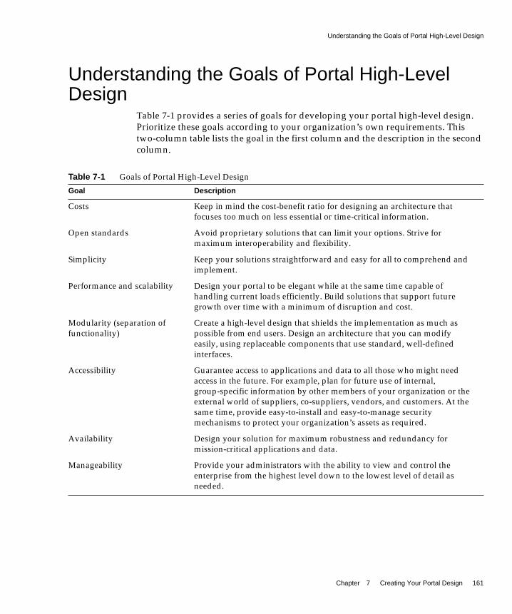
Understanding the Goals of Portal High-Level Design
Chapter 7 Creating Your Portal Design 161
Understanding the Goals of Portal High-LevelDesign
Table 7-1 provides a series of goals for developing your portal high-level design.Prioritize these goals according to your organization’s own requirements. Thistwo-column table lists the goal in the first column and the description in the secondcolumn.
Table 7-1 Goals of Portal High-Level Design
Goal Description
Costs Keep in mind the cost-benefit ratio for designing an architecture thatfocuses too much on less essential or time-critical information.
Open standards Avoid proprietary solutions that can limit your options. Strive formaximum interoperability and flexibility.
Simplicity Keep your solutions straightforward and easy for all to comprehend andimplement.
Performance and scalability Design your portal to be elegant while at the same time capable ofhandling current loads efficiently. Build solutions that support futuregrowth over time with a minimum of disruption and cost.
Modularity (separation offunctionality)
Create a high-level design that shields the implementation as much aspossible from end users. Design an architecture that you can modifyeasily, using replaceable components that use standard, well-definedinterfaces.
Accessibility Guarantee access to applications and data to all those who might needaccess in the future. For example, plan for future use of internal,group-specific information by other members of your organization or theexternal world of suppliers, co-suppliers, vendors, and customers. At thesame time, provide easy-to-install and easy-to-manage securitymechanisms to protect your organization’s assets as required.
Availability Design your solution for maximum robustness and redundancy formission-critical applications and data.
Manageability Provide your administrators with the ability to view and control theenterprise from the highest level down to the lowest level of detail asneeded.

Designing Portal SHARP Services
162 Sun ONE Portal Server Deployment Guide • March 2003
Designing Portal SHARP ServicesA major focus of your portal design concerns SHARP (Scalability, HighAvailability, Reliability, and Performance) services. SHARP services providehorizontal (for example, the directory’s replication mechanisms) and vertical (forexample, multiple instance support) scaling.
In the portal design phase, you need to consider high availability, distributedmulti-site functionality, high performance, and other requirements that will impactor stress the architecture. Also consider any known technical or businessrequirements that are deemed a high-risk. Then address these high risks in thedesign phase, at least in conceptual or strategic terms.
Portal Server and ScalabilityScalability is a system’s ability to accommodate a growing user population, withoutperformance degradation, by the addition of processing resources. The subject ofthis section is the application of scaling techniques to the Portal Server product.
Benefits of scalable systems include:
• Improved response time
• Fault tolerance
• Manageability
• Expendability
• Simplified application development
The two general means of scaling a system are vertical and horizontal scaling. Invertical scaling, CPUs, memory, or other resources are added to one machine. Thisenables more process instances to run simultaneously. In Portal Server, you wantto make use of this by planing and sizing to the number of CPUs you will need. SeeChapter 5, “Sizing Your Portal” for more information.
NOTE This deployment guide does not address high availabilityconfigurations for external content providers, legacy systemapplications, calendar servers, messaging servers, and so on. Referto the documentation on those specific products for moreinformation on high availability scenarios.

Designing Portal SHARP Services
Chapter 7 Creating Your Portal Design 163
In horizontal scaling, machines are added. This also enables multiple simultaneousprocessing, and distributed work load. In Portal Server, you make use of horizontalscaling because you run the Portal Server software on one machine, the DirectoryServer software on another, and so forth. Horizontal scaling can also make use ofvertical scaling, by adding more CPUs, for example.
Additionally, you can scale a Portal Server installation horizontally by installingserver component instances on multiple machines. Each installed servercomponent instance executes an HTTP process, which listens on a TCP/IP portwhose number is determined at installation time. Gateway components use around-robin algorithm to assign new session requests to server instances. While asession is established, an HTTP cookie stored on the client indicates the sessionserver. All subsequent requests go to that server.
The section “Working with Portal Server Building Modules,” on page 168,discusses an approach to a specific type of configuration that provides optimumperformance and horizontal scalability.
Portal Server and High AvailabilityHigh Availability ensures your portal platform is accessible 24 hours a day, sevendays a week. Today, organizations require that data and applications always beavailable. High availability has become a requirement that applies not only tomission-critical applications, but also to the whole IT infrastructure.
System availability is affected not only by computer hardware and software, butalso by people and processes, which can account for up to 80 percent of systemdowntime. Availability can be improved through a systematic approach to systemmanagement and by using industry best practices to minimize the impact ofhuman error.
One important issue to consider is that not all systems have the same level ofavailability requirements. Most applications can be categorized into the followingthree groups:
• Task critical - Affects limited number of users; not visible to customers; smallimpact on costs and profits
• Business critical - Affects significant number of users; might be visible to somecustomers; significant impact on costs and profits
• Mission critical - Affects a large number of users; visible to customers; majorimpact on costs and profits
The goals of these levels are to:

Designing Portal SHARP Services
164 Sun ONE Portal Server Deployment Guide • March 2003
• Improve processes by reducing human error, automating procedures, andreducing planned downtime
• Improve hardware and software availability by eliminatingsingle-point-of-failure configurations and balancing processing load
The more mission critical the application, the more you need to focus onavailability to eliminate any single point of failure (SPOF), and resolve the peopleand processes issues.
Even if a system is always available, instances of failure recovery might not betransparent to end users. Depending on the kind of failure, users can lose thecontext of their portal application, and might have to log in again to get access totheir Desktop.
System AvailabilitySystem availability is often expressed as a percentage of the system uptime. A basicequation to calculate system availability is:
Availability = uptime / (uptime + downtime) * 100
For instance, a service level agreement uptime of four digits (99.99 percent) meansthat in a month the system can be unavailable for about seven hours. Furthermore,system downtime is the total time the system is not available for use. This totalincludes not only unplanned downtime, such as hardware failures and networkoutages, but also planned downtime, preventive maintenance, software upgrade,patches, and so on.
If the system is supposed to be available 7x24 (seven days a week, 24 hours a day),the architecture needs to include redundancy to avoid planned and unplanneddowntime to ensure high availability.
Degrees of High AvailabilityHigh availability is not just a switch that you can turn on and off. There are variousdegrees of high availability that refer to the ability of the system to recover fromfailures and ways of measuring system availability. High availability degreesdepend on your specific organization’s fault tolerance requirements and ways ofmeasuring system availability.
For example, your organization might tolerate the need to reauthenticate after asystem failure, so that a request resulting in a redirection to another login screenwould be considered successful. For other organizations, this might be considereda failure, even though the service is still being provided by the system.

Designing Portal SHARP Services
Chapter 7 Creating Your Portal Design 165
Session failover alone is not the ultimate answer to transparent failover, becausethe context of a particular portal application can be lost after a failover. Forexample, consider the case where a user is composing a message in NetMail Lite,has attached several documents to the email, then the server fails. The user will beredirected to another server and NetMail Lite will have lost the user’s session andthe draft message. Other statefull providers, which store contextual data in thecurrent JVM™, have the same problem.
Achieving High Availability for Portal Server ComponentsMaking Portal Server highly available involves ensuring high availability on eachof the following components:
• Gateway - A load balancer used with the gateway detects a failed gatewaycomponent and routes new requests to other gateways. Routing is restoredwhen the failed gateway recovers. Gateway components are stateless (sessioninformation is stored on the client in an HTTP cookie) so rerouting around afailed gateway is transparent to users.
• Server - In open mode, you can use a load balancer to detect a failed servercomponent and redirect requests to other servers. A load balancer also has theability to intelligently distribute the workload across the server pool. In securemode, gateway components can detect the presence of a failed servercomponent and redirect requests to other servers. (This is valid as long as theweb server is Sun™ ONE Web Server.)
• Directory Server - A number of options make the LDAP directory highlyavailable. See “Building Modules and High Availability Scenarios,” onpage 170 for more information.
• Netlet proxy - In the case of a software crash, a watchdog processautomatically restarts the Netlet proxy. In addition, the gateway performs loadbalancing for the Netlet proxy as well. The gateway also supports failuredetection failover for Netlet proxies.
Portal Server System ComponentsFigure 7-1 on page 166 shows the processes and communication links of a PortalServer system that are critical to the availability of the solution.

Designing Portal SHARP Services
166 Sun ONE Portal Server Deployment Guide • March 2003
Figure 7-1 Portal Server System Components
In this figure, the box encloses the Portal Server instance running on Sun ONE WebServer. Within the instance are the four servlets (Sun™ ONE Identity Serveradministration console, the Authentication service, the Desktop service, and theNetMail service), and the three SDKs (Identity Server SSO, Identity ServerLogging, and Identity Server Management). The Authentication service servlet also

Designing Portal SHARP Services
Chapter 7 Creating Your Portal Design 167
makes use of an LDAP service provider module. Either a user, by using a browserand the HTTP protocol, or the gateway, by using the HTTPS protocol,communicate with Portal Server. This traffic is directed to the appropriate servlet.Communication occurs between the Authentication service’s LDAP module andthe LDAP authentication server; between the NetMail servlet and the SMTP/IMAPmessaging server; between the Identity Server SSO SDK and the LDAP server; andbetween the Identity Server Management SDK and the LDAP server.
Figure 7-1 on page 166 shows that if the following processes or communicationlinks fail, the portal solution becomes unavailable to end users:
• Portal Server instance - Runs in the context of a web container (either SunONE Web Server or certain application servers). Components within aninstance communicate through the JVM™ using Java™ APIs. An instance is afully qualified domain name and a TCP port number. Portal Server services areweb applications that are implemented as servlets or JSP™ files.
Portal Server is built on top of Identity Server for authentication, SingleSign-on (session) management, policy, and profile database access. Thus,Portal Server inherits all the benefits (and constraints) of Identity Server withrespect to availability and fault tolerance.
By design, Identity Server’s services are either stateless or they can sharecontext data so that they can recover to the previous state in case of a servicefailure.
Within Portal Server, Desktop and NetMail services do not share state dataamong instances. This means that an instance redirect causes the user contextto be rebuilt for the enabled services. Usually, redirected users do not noticethis because Portal Server services can rebuild a user context from the user’sprofile, and by using contextual data stored in the request. While thisstatement is generally true for out-of-the-box services, it might not be true forchannels or custom code. Developers need to be careful to not design statefullchannels to avoid loss of context upon instance failover.
• Profile database server - The profile database server is implemented by SunONE Directory Server. Although this server is not strictly part of core PortalServer, availability of the server and integrity of the database are fundamentalto the availability of the system. Indeed, the major focus of this chapter is onmaking the directory highly available.
• Authentication server - This is the directory server for LDAP authentication(usually, the same server as the profile database server). You can apply thesame high availability techniques to this server as for the profile databaseserver.

Working with Portal Server Building Modules
168 Sun ONE Portal Server Deployment Guide • March 2003
• Secure Remote Access gateway and proxies - The Secure Remote Accessgateway is a standalone Java process that can be considered stateless, becausestate information can be rebuilt transparently to end users. The Secure RemoteAccess profile maintains a list of Portal Server instances and does round robinload balancing across those instances. Session stickiness is not required in frontof a gateway, although it is recommended for performance reasons. On theother hand, session stickiness to Portal Server instances is enforced by SecureRemote Access.
Secure Remote Access includes other Java processes called Netlet proxy andRewriter proxy. You use these proxies to extend the security perimeter frombehind the firewall, and limit the number of holes in the DMZ. The Rewriterproxy sits always on the Portal Server node. You can install the Netlet proxy ona different node.
Working with Portal Server Building ModulesBecause deploying Portal Server is a complex process involving many othersystems, this section describes a specific configuration that provides optimumperformance and horizontal scalability. This configuration is known as a Sun ONEPortal Server building module.
A Portal Server building module is a hardware and software construct with limitedor no dependencies on shared services. A typical deployment uses multiplebuilding modules to achieve optimum performance and horizontal scalability.
Understanding Building ModulesIn general, vertical or horizontal scalability solutions are used when planning adeployment. For Portal Server, use the building module horizontal scalabilitysolution that is introduced in this section.
The building module contains multiple Portal Server instances, a search enginedatabase, and a Sun™ ONE Directory Server. Depending on your type ofdeployment, the Directory Server can be a supplier (or master) or a consumer (alsoreferred to as a replica).

Working with Portal Server Building Modules
Chapter 7 Creating Your Portal Design 169
Figure 7-2 shows the building module architecture. This figure shows the buildingmodule components, including Portal Server instances, Directory Server, and theSearch Engine database.
Figure 7-2 Portal Building Module Architecture
NOTE For the building module to be a standalone construct, it mustcontain a local deployment of Portal Server as well as Sun ONEDirectory Server. In general, the directory instance in each buildingmodule is configured as a replica of a master directory, which runselsewhere. However, nothing prevents you from using a masterdirectory as part of the building module.
NOTE The Portal Server building module is simply a recommendedconfiguration. In some cases, a different configuration might resultin slightly better throughput (usually at the cost of addedcomplexity). For example, adding another instance of Portal Serverto a four CPU system might result in up to ten percent additionalthroughput, at the cost of requiring a load balancer even when usingjust a single system.

Working with Portal Server Building Modules
170 Sun ONE Portal Server Deployment Guide • March 2003
Building Modules and High Availability ScenariosThe following outlines the three high availability scenarios for Sun ONE PortalServer Release 6.0:
• Best effort - The system is available as long as the hardware does not fail andas long as the Portal Server processes can be restarted by the watchdogprocess.
• No single point of failure - The use of hardware and software replicationcreates a deployment with no single point of failure (NSPOF). The system isalways available, as long as no more than one failure occurs consecutivelyanywhere in the chain of components. However, in the case of failures usersessions are lost.
• Transparent failover - The system is always available but in addition toNSPOF, failover to a backup instance occurs transparently to end users. Inmost cases, users do not even notice they have been redirected to a differentnode or instance. Sessions are preserved across nodes so that users do not haveto reauthenticate. Portal Server services are stateless or use checkpointingmechanisms to rebuild the current execution context up to a certain point.
Possible supported architectures include the following:
• Single node, single Portal Server instance
• Multi-node, multi-instance configurations
• Using Sun™ Cluster software
• Multi-master Directory Server techniques
This section explains implementing these architectures and leverages the buildingmodule concept, from a high-availability standpoint.
NOTE When Sun ONE Portal Server 6.0 uses the Sun ONE Web Server asits web container, which does not support session failover, thestatelessness and checkpointing of Portal Server applications willvary from one service to another.

Working with Portal Server Building Modules
Chapter 7 Creating Your Portal Design 171
Table 7-2 summarizes these high availability scenarios along with their supportingtechniques. In this table, the first column lists the component requirements. Thesecond column defines if this component is necessary for a best effort deployment.The third column defines if this component is necessary for a no single point offailure (NSPOF) deployment. The fourth column defines if this component isnecessary for a transparent failover deployment.
Table 7-2 Portal Server High Availability Scenarios
ComponentRequirements
Necessary for BestEffort Deployment?
Necessary for NSPOFDeployment?
Necessary for TransparentFailover?
Hardware Redundancy Yes Yes Yes
Portal Server BuildingModules
No Yes Yes
Multi-masterConfiguration
No Yes Yes
Load Balancing Yes Yes Yes
Stateless Applicationsand CheckpointingMechanisms
No No Yes
Session Failover No No Yes. Portal sessions are handledby the Identity Server SSOservice. Session failover ensuresthat session data is alwaysavailable from any portalinstance. Users do not need toreauthenticate after a failure.Identity Server supports sessionfailover on web containers thatsupport HttpSession failover.
Directory ServerClustering
No No Yes
NOTE Load balancing is not provided out-of-the-box with the Sun ONEWeb Server web application container.

Working with Portal Server Building Modules
172 Sun ONE Portal Server Deployment Guide • March 2003
Portal Best Effort ScenarioIn this scenario, you install Portal Server and Directory Server on a single node thathas a secured hardware configuration for continuous availability, such as Sun FireUltraSPARC® III machines. (Securing a Solaris™ Operating Environment systemrequires that changes be made to its default configuration.)
This type of server features full hardware redundancy, including: redundantpower supplies, fans, system controllers; dynamic reconfiguration; CPU hot-plug;online upgrades; and disks rack that can be configured in RAID 0+1 (striping plusmirroring), or RAID 5 using a volume management system, which prevents loss ofdata in case of a disk crash. Mean time between failure (MTBF) on such servers ishigh, and they usually run for several months without interruption.
Portal Server is reliable product provided it is not operated beyond its maximumcapacity. In case of a software crash the web application container is restartedautomatically by a watchdog process.
Figure 7-3 shows a small, best effort deployment using the building modulearchitecture.
Figure 7-3 Portal Best Effort Scenario

Working with Portal Server Building Modules
Chapter 7 Creating Your Portal Design 173
In this scenario, for memory allocation, four CPUs by eight GB RAM (4x8) ofmemory is sufficient for one building module. A load balancer is responsible fordetecting Portal Server failures and redirecting users’ requests to another portalinstance. The Identity Server console is outside of the building module so that itcan be shared with other resources. (Your actual sizing calculations might result ina different allocation amount.)
This scenario might suffice for task critical requirements. Its major weakness is thata maintenance action necessitating a system shutdown results in serviceinterruption.
Best Effort Scenario and Secure Remote AccessIn the case of a software crash, a watchdog process automatically restarts theSecure Remote Access gateway and Netlet proxy. The Rewriter proxy, which runson the Portal Server node, does not have a watchdog process. For that reason, thisscenario is not recommended for the Rewriter proxy.
No Single Point of Failure ScenarioPortal Server natively supports the no single point of failure (NSPOF) scenario.NSPOF is built on top of the Best Effort scenario, and in addition, introducesreplication and load balancing. Figure 7-4 on page 174 shows an NSPOF scenario.

Working with Portal Server Building Modules
174 Sun ONE Portal Server Deployment Guide • March 2003
Figure 7-4 No Single Point of Failure Scenario
In Figure 7-4, two Portal Server building modules are implemented. As statedearlier, a building module consists of a directory consumer (here, a replica) forprofile reads and a Portal Server instance. As such, at least two building modulesare necessary to achieve NSPOF, thereby providing a backup if one of the buildingmodules fails. These building modules consist of eight CPUs by 16 GB RAM (8x16).In addition, the web application container for the Portal Server is Sun ONE WebServer.

Working with Portal Server Building Modules
Chapter 7 Creating Your Portal Design 175
Load balancing is responsible for detecting Portal Server failures and redirectingusers’ requests to a backup building module. Accuracy of failure detection variesamong load balancing products. Some products are capable of checking theavailability of a system by probing a service involving several functional areas ofthe server, such as the servlet engine, the JVM, and so on. In particular, mostvendor solutions from Resonate, Cisco, Alteon, and others enable you to createarbitrary scripts for server availability. As the load balancer is not part of the PortalServer software, you must acquire it separately from a third-party vendor.
Redundancy is equally important to the directory master so that profile changesthrough the administration console or the Desktop, along with consumerreplication across building modules, can be always maintained. Portal Servercomes with Identity Server, which supports multi-mastering. The NSPOF scenariouses a multi-master configuration. In this configuration, two suppliers can acceptupdates, synchronize with each other, and update all consumers. The consumerscan refer update requests to both masters.
The NSPOF architecture presents several advantages:
• If the node supporting the building module crashes, all user requests areredirected to the backup building module by the load balancer.
• If a Portal Server instance crashes, the load balancer detects the failure andredirects all user requests to the backup building module. The survivingreplica is not used.
NOTE In general, the directory instance in each building module isconfigured as a replica of a master directory, which runs elsewhere.However, nothing prevents you from using a master directory aspart of the building module. The use of masters on dedicated nodesdoes not improve the availability of the solution. Use dedicatedmasters for performance reasons.
NOTE Sun ONE Identity Server 5.1 recommends that you set up loadbalancing to enforce sticky session. This means that once a session iscreated on a particular instance, the load balancer needs to alwaysreturn to the same instance for that session. The load balancerachieves this by binding the session cookie with the instance nameidentification. In principle, that binding is reestablished when afailed instance is decommissioned from the cluster. Sticky session isalso recommended for performance reasons.

Working with Portal Server Building Modules
176 Sun ONE Portal Server Deployment Guide • March 2003
• If a directory replica crashes, an alternate communication link handled by theIdentity Server SDK is used to switch over all LDAP requests to a backupreplica.
• Because the supplier-to-consumer replication is maintained by two masters,failure of one of the masters does not interrupt the system. The LDAP SDKused by Identity Server simply switches over LDAP writes to the backupmaster following the LDAP referrals returned by the current replica. Profilechanges initiated from the administration console or the Desktop can then behonored by the backup master.
• When using hardware redundancy, recoveries from a failure in a RAID diskarray, CPU, or memory on the master side that is recovered transparentlysometimes results in performance degradation.
• Because the transaction log is secured by a RAID system, a master restartalways updates the database from the transaction log after the crash, andreinitiates the multi-master replication automatically. For this to work, youneed to enable Directory Server Durable Transactions.
• You can deploy more building module pairs sharing the same multi-masterinfrastructure to cope with scalability requirements. Also, the principle of thearchitecture doesn't change.
Configuration and Implementation NotesIn Sun ONE Directory Server 5.1, the smallest unit of replication is a database. Thismeans that you can replicate an entire database, but not a sub-tree within adatabase. Therefore, when you create your DIT, you must take your replicationplans into consideration. In the case of a large user base, you can split up your DITacross organization boundaries under the Identity Servers’s root entry (defaulto=isp). See the Sun ONE Directory Server Deployment Guide and the Sun ONEDirectory Server Administrator’s Guide for information on setting up your directorytree and replication.
The Identity Server SDK LDAP communication links are defined in theserverconfig.xml configuration file. To enable a backup communication link toan alternate replica modify the <iPlanetDataAccessLayer> clause accordingly:
<Server name="Server1" host="my.sesta1.com" port="389" type="SIMPLE" />
<Server name="Server2" host="my.sesta2.com" port="389" type="SIMPLE" />
Enabling a backup communication link to an alternate directory server for LDAPauthentication follows the same principle. You configure it within the IdentityServer LDAP module of the authentication service by using the administrationconsole.

Working with Portal Server Building Modules
Chapter 7 Creating Your Portal Design 177
No Single Point of Failure Scenario and Secure Remote AccessSecure Remote Access follows the same replication and load balancing pattern ascore portal to achieve no single point of failure (NSPOF). As such, two SecureRemote Access gateways and pair of proxies are necessary in this scenario. TheSecure Remote Access gateway detects a Portal Server instance failure when theinstance does not respond to a request after a certain time-out value. When aninstance is decommissioned, the Secure Remote Access gateway enables users toreauthenticate against a backup instance. After a Portal Server instance isdecommissioned, the Secure Remote Access gateway performs a periodic check foravailability until that instance is up again.
The NSPOF high availability scenario is suitable to business critical deployments.However, some high availability limitations in this scenario might not fulfill therequirements of a mission critical deployment. Those limitations are:
• User sessions are lost after an instance crash, which means users have toreauthenticate.
• Applications cannot use persistent sessions to store checkpointing data.
• There is a risk of database inconsistency following a directory master crash foran undetermined period of time. Consider the following situation. Anadministrator changes a role or an organization profile, and then the masterthat handles the request crashes right after the change is committed in thetransaction log, but before it gets propagated to the other master. The LDAPwrite returns ‘okay’ to the client, hence the change is not available for as longas the crashed master is not restarted. This kind of inconsistency can beproblematic depending on the nature of the change and given the fact that theoperation did not return an error.
Transparent Failover ScenarioThe transparent failover scenario is built on top of the no single point of failure(NSPOF) scenario and goes one step more in high availability features. Figure 7-5on page 178 shows a transparent failover scenario. Two building modules areshown, consisting of eight CPUs by 16 GB RAM (8x16). Load balancing isresponsible for detecting Portal Server failures and redirecting users’ requests to abackup building module.

Working with Portal Server Building Modules
178 Sun ONE Portal Server Deployment Guide • March 2003
Figure 7-5 Transparent Failover Scenario

Working with Portal Server Building Modules
Chapter 7 Creating Your Portal Design 179
In this figure, transparent failover uses the same replication model as the NSPOFscenario but provides additional high availability features, which make the failoverto a backup server transparent to end users. Those high availability featuresdepicted in the figure include:
• Session Failover- Identity Server supports session failover and hence PortalServer does as well, on application servers that support HttpSession failover.(Portal Server does not support HttpSession failover for Sun ONE Web Server.)In Figure 7-5 on page 178, the session repository is part of the applicationserver software, and Portal Server is running in a web container that is part ofthe application server. See Appendix C, “Sun ONE Portal Server andApplication Servers” for more information.
With session failover, users do not need to reauthenticate after a crash. Inaddition, portal applications can rely on session persistence to store contextdata used by the checkpointing. You configure session failover in theAMConfig.properties file by setting thecom.iplanet.am.session.failover.enabled property to true.
This figure shows that if a failure were to occur with Building Block 1, thesessions it had stored in the sessions repository would be retrieved by BuildingBlock 2.
• Clustering of the master directory server - Clustering of the master directoryserver using Sun™ Cluster 3.x or other clustering products (for example,Veritas Cluster) is necessary to prevent the profile database inconsistency issuedescribed in the NSPOF scenario.
This figure shows that the availability scenarios build up on each other.However, the second Sun ONE Directory Server cluster and multi-masterconfiguration depicted in this figure are optional because transparent failovercan be handled by only one Sun ONE Directory Server cluster. Theconfiguration shown in the figure illustrates transparent failover of thedirectory along with database distribution and scalability.
Transparent Failover Scenario and Secure Remote AccessThe Netlet proxy cannot support the transparent failover scenario because of thelimitation of the TCP protocol. The Netlet proxy tunnels TCP connections, and youcannot migrate an open TCP connection to another server. A Netlet proxy crashdrops off all outstanding connections that would have to be reestablished by endusers.
With the introduction of Sun Cluster 3.x, the high availability architecture mightrequire two additional asymmetric standby master servers sharing, by using adual-ported disk array, the profile database.

Working with Portal Server Building Modules
180 Sun ONE Portal Server Deployment Guide • March 2003
Building Module ConstraintsBuilding modules scale near-linearly to an arbitrary number. The constraints onthe scalability of building modules are given by the number of LDAP writesresulting from profile updates and the maximum size of the LDAP database.
Because any LDAP writes issued against a replica are redirected to the master—byusing an LDAP referral—and then to all other replicas, the number of writeoperations remains as a constraint in scalability. However, the number ofconcurrent users performing profile updates at any point in time tends to be small.
Because the performance tuning of a portal deployment involves moving theLDAP_db.[number] files to the /tmp directory, which Solaris™ maps into RAM (ifpossible), the total size of the _db files must not be larger than available RAM.Here, available RAM means physical RAM minus the memory required by theJVM and LDAP processes.
If the analysis at your specific site indicates that the number of LDAP writeoperations is indeed a constraint, some of the possible solutions include creatingbuilding modules that replicate only a specific branch of the directory and a layerin front that directs incoming requests to the appropriate instance of portal.
Baseline Portal Performance AnalysisIn many cases, you can track portal performance problems to infrastructure issuesthat are independent of Portal Server. Given that the sizing tool and buildingmodules concept both predict a specific performance level for a givenconfiguration, being able to match the published performance levels adds a greatdeal of safety to the success of a portal deployment.
In general, this level of analysis, with a simple out-of-the-box portal, uncovers thetypes of issues that are almost impossible to resolve at a later stage in thedeployment. Therefore, as part of the portal best practices for deployment, run abaseline performance analysis that validates the published data at the earliestpossible stage of your portal project.
NOTE If the LDAP server crashes with the _db files in the /tmp directory,most likely they will be gone when the server restarts. This doesimprove performance but also affects availability.

Working with Portal Server Building Modules
Chapter 7 Creating Your Portal Design 181
Trial Project Performance AnalysisSeveral tools can be used to size a portal deployment, but ultimately eachorganization is different and has its own constraints. Custom code, LDAP issues,amount of merging of display profiles—all these issues can cause performance todeviate from published figures.
In many cases, the scalability impact of custom code can only be understood byplacing an appropriate level of load on the customized code. At this point, thedeployment should have validated that the out-of-the-box performance can matchpublished scalability and capacity results and therefore any deviation from thoseresults can be attributed to changes in the custom code, as well as any changes inthe underlying infrastructure since the baseline analysis was performed.
Keep in mind that not all code in a portal deployment is performance-critical. It isnot necessary to measure the performance of all possible user actions. However,generally a critical-path must perform within acceptable response times.
It is those critical areas that must be measured by a trial project as soon as possible.See “Implementing and Verifying the Portal,” on page 149 for more information onthe trial phase of the deployment.
Deploying Your Building Module SolutionThis section describes guidelines for deploying your building module solution.
Deployment GuidelinesHow you construct your building module affects performance. Consider thefollowing recommendations to deploy your building module properly:
• Deploy a building module on a single machine.
• If you use multiple machines, or if your Portal Server machine is running alarge number of instances, use a fast network interconnect. For example, undera high load, a 100 Mbps Ethernet link between a Portal Server machine and aDirectory Server machine can cause performance bottlenecks, so considerusing a 1 GB Ethernet link. In general, monitor the throughput of the PortalServer machine. When the throughput is greater than one third of thetheoretical maximum, upgrade the Ethernet speed.

Working with Portal Server Building Modules
182 Sun ONE Portal Server Deployment Guide • March 2003
• Run Portal Server on top of a dedicated processor set. On servers with morethan eight CPUs, create processor sets with either two or four CPUs. Forexample, if you choose to install two instances of Portal Server on an eight CPUserver, create two four-CPU processor sets. On servers with four CPUs (orless), Portal Server does not need processor sets.
Directory Server RequirementsIdentify your Directory Server requirements for your building moduledeployment. For specific information on Directory Server deployment, see the SunONE Directory Server Deployment Guide.
Consider the following Directory Server guidelines when you plan your PortalServer deployment:
• Run Directory Server on top of a dedicated processor set to ensure that it candeliver the level of performance required by Portal Server.
The amount of needed CPU in the Directory Server consumer replica processorset depends on the number of Portal Server instances in the building module aswell as performance and capacity considerations.
• Dedicate a Directory Server instance for the sole use of the Portal Serverinstances in a building module. (See Figure 7-2 on page 169.)
• Map the entire directory database indexes and cache in memory to avoid disklatency issues.
• When deploying multiple building modules, use a multi-master configurationto work around bottlenecks caused by the profile updates and replicationoverhead to the Directory Server supplier.
Search Engine StructureThe Search Engine is a taxonomy and a database service that is similar to manyInternet search engines. When you deploy the Search Engine as part of yourbuilding module solution, consider the following:
NOTE The optimum level of performance for Portal Server is four CPUsper building module (instance). However, with large servers (eightCPUs and greater), Portal Server reaches peak performance withthree instances.

Designing Portal Use Case Scenarios
Chapter 7 Creating Your Portal Design 183
• In each building module, make sure only one Portal Server instance has theSearch Engine database containing the RDs. The remaining Portal Serverinstances have default empty Search Engine databases.
• Factors that influence whether to use a building module for the portal Searchdatabase include the intensity of search activities in a Portal Serverdeployment, the range of search hits, and the average number of search hits forall users, in addition to the number of concurrent searches. For example, theload generated on a server by the Search Engine can be both memory and CPUintensive for a large index and heavy query load. However, if the query rate ismoderate (less than two per second), and the index is not large (less than 5,000documents), then the load should be acceptable.
• You can install Search on a machine separate from Portal Server, to keep themain server dedicated to portal activity. When you do so, you use thesearchURL property of the Search provider to point to the second machinewhere Search is installed. The Search instance is a normal portal instance. Youinstall the Search instance just as you do the portal instance, but use it just forSearch functionality.
• The size of the Search database dictates whether more than one machine needsto host the Search database by replicating it across machines or buildingmodule. Consider using high-end disk arrays, such as the T3 disk array withcached RAM (364 MB), for the Search database.
• Use a proxy server for caching the search hit results. When doing so, you needto disable the document level security. See the Sun ONE Portal Server 6.0Administrator’s Guide for more information on document level security.
Designing Portal Use Case ScenariosUse case scenarios are written scenarios used to both test and present the system’scapabilities, and they form an important part of your high-level design. Thoughyou implement use case scenarios toward the end of the project, formulate themearly on in the project, once you have established your requirements.
When available, use cases can provide valuable insight into how the system is to betested. Use cases are beneficial in identifying how you need to design the userinterface from a navigational perspective. When designing use cases, comparethem to your requirements to get a thorough view of their completeness and howyou are to interpret the test results.
Designing Portal Use Case Scenarios
184 Sun ONE Portal Server Deployment Guide • March 2003
Use cases provide a method for organizing your requirements. Instead of abulleted list of requirements, you organize them in a way that tells a story of howsomeone can use the system. This provides for greater completeness andconsistency, and also gives you a better understanding of the importance of arequirement from a user perspective.
Use cases help to identify and clarify the functional requirements of the portal. Usecases capture all the different ways a portal would be used, including the set ofinteractions between the user and the portal as well as the services, tasks, andfunctions the portal is required to perform.
A use case defines a goal-oriented set of interactions between external actors andthe portal system. (Actors are parties outside the system that interact with thesystem, and can be a class of users, roles users can play, or other systems.)
Use case steps are written in an easy-to-understand structured narrative using thevocabulary of the domain.
Use case scenarios are an instance of a use case, representing a single path throughthe use case. Thus, there may be a scenario for the main flow through the use caseand other scenarios for each possible variation of flow through the use case (forexample, representing each option).
Elements of Portal Use CasesWhen developing use cases for your portal, keep the following elements in mind:
• Priority - Describes the priority, or ranking of the use case. For example, thiscould range from High to Medium to Low.
• Context of use - Describes the setting or environment in which the use caseoccurs.
• Scope - Describes the conditions and limits of the use case.
• Primary user - Describes what kind of user this applies to, for example, an enduser or an administrator.
• Special requirements - Describes any other conditions that apply.
NOTE The goal of use cases is to describe the “what,” not the “how” of theportal. Do not try to design your system by using use cases.

Designing Portal Use Case Scenarios
Chapter 7 Creating Your Portal Design 185
• Precondition - Describes the prerequisites that must be met for the use case tooccur.
• Minimal guarantees - Describes the minimum that must occur if the use case isnot successfully completed.
• Success guarantees - Describes what happens if the use case is successfullycompleted.
• Trigger - Describes the particular item in the system that causes the event tooccur.
• Description - Provides a step-by-step account of the use case, from start tofinish.
Example Use Case: Authenticate Portal UserTable 7-3 describes a use case for a portal user to authenticate with the portal. Thisis a two-column table. The first column describes the use case item and the secondcolumn provides a description.
Table 7-3 Use Case: Authenticate Portal User
Item Description
Priority Must have.
Context of Use Only authenticated users are allowed to gain access to the portalresources. This access restriction applies to all portal resources, includingcontent and services. This portal relies on the user IDs maintained in thecorporate LDAP directory.
Scope The portal users identify themselves only once for a complete onlinesession. In the case that an idle timeout occurs, the users must reidentifythemselves. If the portal user identification fails more often than aspecified amount of allowed retries, the access to the intranet should berevoked or limited (deactivated) until a system administrator reactivatesthe account. In this case, the portal user should be advised to contact theauthorized person. The identified portal users are able to access only thedata and information they are authorized for.
Primary User Portal end user.
Special Requirements None.
Stakeholders Portal end user.

Designing Portal Security Strategies
186 Sun ONE Portal Server Deployment Guide • March 2003
Designing Portal Security StrategiesSecurity is the set of hardware, software, practices, and technologies that protect aserver and its users from malicious outsiders. In that regard, security protectsagainst unexpected behavior.
You need to address security globally and include people and processes as well asproducts and technologies. Unfortunately, too many organizations rely solely onfirewall technology as their only security strategy. These organizations do notrealize that many attacks come from employees, not outsiders. Therefore, you needto consider additional tools and processes when creating a secure portalenvironment.
Preconditions The portal user is an authorized user.Standard corporate LDAP user ID.Must be provided to each employee.Authorized LDAP entry.Every employee has access to the corporate intranet.No guest account.
Minimal Guarantees Friendly customer-centric message.Status - with error message indicating whom to call.
Success Guarantees Presented with Desktop home page.Authentication.Entitlement.Personal information.
Trigger When any portal page is accessed and the user is not yet logged in.
Description 1. User enters the portal URL.
2. If the customization parameter [remember login] is set, thenautomatically log in the user and provide a session ID.
3. If first time user, prompt for LDAP user ID and password.
4. User enters previously assigned user ID and password.
5. Information is passed to Identity Server for validation.
6. If authentication passes, assign session ID and continue.
7. If authentication fails, display error message, return user to login page;decrement remaining attempts; if pre-set attempts exceed limit, notifyuser and lock out the account
Table 7-3 Use Case: Authenticate Portal User (Continued)
Item Description

Designing Portal Security Strategies
Chapter 7 Creating Your Portal Design 187
Operating Portal Server in a secure environment involves making certain changesto the Solaris™ Operating Environment, the gateway and server configuration, theinstallation of firewalls, and user authentication through Directory Server and SSOthrough Identity Server. In addition, you can use certificates, SSL encryption, andgroup and domain access.
Securing the Operating EnvironmentReduce potential risk of security breaches in the operating environment byperforming the following, often termed “system hardening:”
• Minimize the size of the operating environment installation - Wheninstalling a Sun server in an environment that is exposed to the Internet, or anyuntrusted network, reduce the Solaris installation to the minimum number ofpackages necessary to support the applications to be hosted. Achievingminimization in services, libraries, and applications helps increase security byreducing the number of subsystems that must be maintained.
The Solaris™ Security Toolkit provides a flexible and extensible mechanism tominimize, harden, and secure Solaris Operating Environment systems. Theprimary goal behind the development of this toolkit is to simplify andautomate the process of securing Solaris systems. For more information see:
http://wwws.sun.com/software/security/jass/
The SUNWreq cluster (Solaris Core) contains the packages needed for PortalServer and Secure Remote Access. In addition, you need Perl 5 (SUNWpl5u) toenable the use of the Directory Server online administration scripts(db2bak.pl, bak2db.pl, and so on). You perform the installation with thePortal Server install script, pssetup, which needs the following packages:
❍ SUNWadmc (contains showrev)
❍ SUNWadmfw (contains librariers for showrev)
You can remove these packages from the system after the installation isfinished. However, future patches for Directory Server might need to beinstalled using the pssetup script, necessitating the reinstallation of theremoved packages.
• Track and monitor file system changes - Within systems that require inclusionof security, a file change control and audit tool is indispensable as it trackschanges in files and detects possible intrusion. You can use a product such asTripwire for Servers, or Solaris Fingerprint Database (available from SunSolveOnline).

Designing Portal Security Strategies
188 Sun ONE Portal Server Deployment Guide • March 2003
Using Platform SecurityUsually you install Portal Servers in a trusted network. However, even in thissecure environment, security of these servers requires special attention.
UNIX User InstallationYou can install and configure Portal Server to run under three different UNIXusers:
• root - This is the default option. All Portal Server components are installedand configured to run as the system superuser. Some security implicationsarise from this configuration:
❍ An application bug can be exploited to gain root access to the system.
❍ You need root access to modify some of the templates. This raisespotential security concerns as this responsibility is typically delegated tonon-system administrators who can pose a threat to the system.
• User nobody - You can install Portal Server as the user nobody (uid 60001). Thiscan improve the security of the system, because the user nobody does not haveany privileges and cannot create, read, or modify the system files. This featureprevents user nobody from using Portal Server to gain access to system filesand break into the system.
The user nobody does not have a password, which prevents a regular userfrom becoming nobody. Only the superuser can change users without beingprompted for a password. Thus, you still need root access to start and stopPortal Server services.
• Non-root user - You can run Portal Server as a regular UNIX user. Thesecurity benefits of a regular user are similar to those provided by the usernobody. A regular UNIX user has additional benefits as this type of user canstart, stop, and configure services.
See the Sun ONE Portal Server 6.0 Installation Guide for more information onconfiguring Portal Server to run as nobody or as a non-root user.
Designing Portal Security Strategies
Chapter 7 Creating Your Portal Design 189
Limiting Access ControlWhile the traditional security UNIX model is typically viewed as all-or-nothing,there are alternative tools that you can use, which provide some additionalflexibility. These tools provide the mechanisms needed to create a fine grain accesscontrol to individual resources, such as different UNIX commands. For example,this toolset enables Portal Server to be run as root, while enabling certain usersand roles superuser privileges to start, stop, and maintain the Portal Serverframework.
These tools include:
• Role-Based Access Control (RBAC) - Solaris 8 includes the Role-Based AccessControl (RBAC) to package superuser privileges and assign them to useraccounts. RBAC enables separation of powers, controlled delegation ofprivileged operations to users, and a variable degree of access control.
• Sudo - Sudo is a publicly available software, which enables a systemadministrator to give certain users the ability to run some commands as rootwhile logging the commands and arguments. For more information, see:
http://www.courtesan.com/sudo/sudo.html
Using a Demilitarized Zone (DMZ)Central to security is creating a demilitarized zone (DMZ) where the gatewayservers typically reside. This is where the outermost firewall enables only SSLtraffic from the Internet to the gateways, which then direct traffic to servers on theinternal network. For maximum security, the gateway is installed in the DMZbetween two firewalls.
Using the GatewayThe Secure Remote Access gateway provides the interface and security barrierbetween the remote user sessions originating from the Internet and yourorganization’s intranet. The gateway serves two main functions:
• Provides basic authentication services to incoming user sessions, includingestablishing identity and allowing or denying access to the platform.
NOTE Because Portal Server assigns a special SSL session ID to Netlettraffic, which is not used by any real SSL session, some firewalls willnot pass Netlet packets.

Designing Secure Remote Access Deployment Scenarios
190 Sun ONE Portal Server Deployment Guide • March 2003
• Provides mapping and rewriting services to enable web-based links to theintranet content for users.
For Internet access, use 128-bit SSL, to provide the best security arrangement andencryption for communication between the user’s browser and Portal Server.
Designing Secure Remote Access DeploymentScenarios
The gateway, Netlet, NetFile, Netlet proxy, and Rewriter proxy constitute themajor components of Secure Remote Access.
This section lists some of the possible configurations of these components. Choosethe right configuration based on your business needs. This section is meant only asa guide. It is not meant to be a complete deployment reference.
Secure Remote Access Deployment Scenario 1Figure 7-6 on page 192 shows the most simple configuration possible for SecureRemote Access. The figure shows a client browser running NetFile and Netlet. Thegateway is installed on a separate machine in the demilitarized zone (DMZ)between two firewalls. The Portal Server is located on a machine beyond thesecond firewall in the intranet. The other application hosts that the client accessesare also located beyond the second firewall in the intranet.
The gateway is in the DMZ with the external port open in the firewall throughwhich the client browser communicates with the gateway. In the second firewall,for HTTP or HTTPS traffic, the gateway can communicate directly with internalhosts. This is not recommended for security reasons. Instead, use a proxy betweenthe gateway and the internal hosts. For Netlet traffic, the connection is direct fromthe gateway to the destination host.
TIP To set up the authlessanonymous page to display through thegateway, add /portal/dt to the non-authenticated URLs of thegateway profile. However, this means that even for normal users,portal pages will not need authentication and no session validationis performed.

Designing Secure Remote Access Deployment Scenarios
Chapter 7 Creating Your Portal Design 191
Without a proxy the SSL traffic is limited to the gateway, and the traffic isunencrypted from the gateway to the internal host (unless the internal host isrunning in HTTPS mode). Any internal host to which the gateway has to initiate aNetlet connection should be directly accessible from DMZ. This can be a potentialsecurity problem and hence this configuration is recommended only for thesimplest of installations.
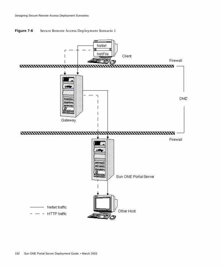
Designing Secure Remote Access Deployment Scenarios
192 Sun ONE Portal Server Deployment Guide • March 2003
Figure 7-6 Secure Remote Access Deployment Scenario 1

Designing Secure Remote Access Deployment Scenarios
Chapter 7 Creating Your Portal Design 193
Secure Remote Access Deployment Scenario 2Figure 7-7 on page 194 shows a scenario similar to Scenario 1 except that Netlet isdisabled. If the client deployment is not going to use Netlet for securely runningapplications that need to communicate with intranet, then use this setup for theperformance improvement that it provides.
You can extend this configuration and combine it with other deployment scenariosto provide better performance and a scalable solution.

Designing Secure Remote Access Deployment Scenarios
194 Sun ONE Portal Server Deployment Guide • March 2003
Figure 7-7 Secure Remote Access Deployment Scenario 2

Designing Secure Remote Access Deployment Scenarios
Chapter 7 Creating Your Portal Design 195
Secure Remote Access Deployment Scenario 3with Multiple Gateway InstancesFigure 7-8 on page 196 shows an extension of Scenario 1. Multiple gatewayinstances run on the same machine. You can start multiple gateway instances withdifferent profiles. Multiple instances of the gateway can also run on multiplemachines. See Chapter 2, “Configuring the Gateway,” in the Sun ONE Portal Server,Secure Remote Access 6.0 Administrator’s Guide for details.
The disadvantage to this configuration is that multiple ports need to be opened inthe second firewall for each connection request. This could cause potential securityproblems. Scenario 4 overcomes this problem by using the Netlet and Rewriterproxies.
NOTE Although Figure 7-8 on page 196 shows a 1-to-1 correspondencebetween the gateway and the Portal Servers, this need notnecessarily be the case in a real deployment. You can have multiplegateway instances, and multiple Portal Server instances, and anygateway can contact any Portal Server depending on theconfiguration.

Designing Secure Remote Access Deployment Scenarios
196 Sun ONE Portal Server Deployment Guide • March 2003
Figure 7-8 Secure Remote Access Deployment Scenario 3

Designing Secure Remote Access Deployment Scenarios
Chapter 7 Creating Your Portal Design 197
Secure Remote Access Deployment Scenario 4with Netlet and Rewriter ProxiesFigure 7-9 on page 198 shows a configuration that overcomes the security issues ofScenario 3 by having a Netlet proxy and a Rewriter proxy on the intranet.
The gateway need not contact the application hosts directly now, but will forwardall Netlet traffic to the Netlet proxy. Since the Netlet proxy is within the intranet, itcan directly contact all the required application hosts without opening multipleports in the second firewall.
Also, to provide end-to-end SSL up to the Portal Server node, you can install aRewriter proxy on the Portal Server node. This ensures that the traffic between thegateway in the DMZ to the Portal Server node within the intranet is also SSL andhence secure.
The traffic between the gateway in the DMZ and the Netlet proxy is encrypted, andgets decrypted only at the Netlet proxy, thereby enhancing security.
If the Rewriter proxy is enabled, all traffic is directed through the Rewriter proxy,irrespective of whether the request is for the Portal Server node or not. This ensuresthat the traffic from the gateway in the DMZ to the intranet is always encrypted.
Including the Netlet and Rewriter proxies in the configuration reduces the numberof ports opened in the second firewall to 2.
Because the Netlet proxy, Rewriter proxy, and Portal Server are all running on thesame node, there might be performance issues in such a deployment scenario. Thisproblem is overcome in scenario 5 where the Netlet proxy is installed on a separatenode to reduce load on the Portal Server node.
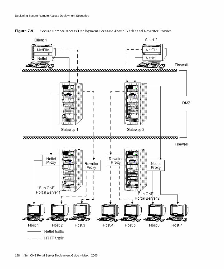
Designing Secure Remote Access Deployment Scenarios
198 Sun ONE Portal Server Deployment Guide • March 2003
Figure 7-9 Secure Remote Access Deployment Scenario 4 with Netlet and Rewriter Proxies

Designing Secure Remote Access Deployment Scenarios
Chapter 7 Creating Your Portal Design 199
Secure Remote Access Deployment Scenario 5with Netlet Proxy on an Independent NodeTo reduce the load on the Portal Server node and still provide same level ofsecurity at increased performance, install the Netlet proxy on a separate node.
This deployment has an added advantage in that you can use a proxy and shieldthe Portal Server from the DMZ. The node that runs Netlet proxy needs to bedirectly accessible from the DMZ.
Figure 7-10 on page 200 shows the Netlet proxy on an independent node. All theNetlet traffic from the gateway is directed to this independent node, which in turndirects the traffic to the required intranet hosts.
You can have multiple instances or installations of the Netlet proxy. You canconfigure each gateway to try to contact various instances of the Netlet proxy in around robin manner depending on availability. See Chapter 3, “Configuring theNetlet,” in the Sun ONE Portal Server, Secure Remote Access 6.0 Administrator’s Guidefor details.

Designing Secure Remote Access Deployment Scenarios
200 Sun ONE Portal Server Deployment Guide • March 2003
Figure 7-10 Secure Remote Access Deployment Scenario 5 with Netlet Proxy on an Independent Node

Designing for Localization
Chapter 7 Creating Your Portal Design 201
Designing for LocalizationThe customizable parts of Portal Server that can be translated to supportlocalization include:
• Template and JSP files
• Resource bundles
• Display profile properties
For advanced language localization, create a well-defined directory structure fortemplate directories. In order to preserve the upgrade path, maintain customcontent and code outside of default directories. See the Sun ONE Portal Server 6.0Developer’s Guide for more information on localization.
Specifying the Low-level Architecture StructureWhen specifying the low-level architecture for your portal, you need detaileddesign for all the aspects considered in the architecture, for example:
• The Portal (Sun ONE) complex of servers - Includes the details on whatsoftware will be installed on which machines, the directory structure if you donot accept the default, how you plan on configuring that software, and soforth.
• Low-level networking considerations - Includes the server names, IPaddresses, interfaces in each box, how they connect, switches, routers, and soforth.
• Content design and implementation - Includes the detailed layout of theDesktop, including containers and tabs, nested containers, and channels andtheir attributes. Also includes the design of how each channel will beconstructed and the necessary code to implement data feeds or contentintegration.
• Identity architecture - Includes the detailed design for implementation ofidentity and directory structures. (See the Sun ONE Directory Server DeploymentGuide for more information.)
• Integration design - Includes the details on connectivity to any applications.Document the APIs, data transforms, performance, security, and other issues.

Specifying the Low-level Architecture Structure
202 Sun ONE Portal Server Deployment Guide • March 2003
The following sections elaborate on the details of the low-level architecture.
Portal Server Installation GuidelinesConsider these guidelines for your portal installation:
• Review the default installation directories used by Portal Server. See “SunONE Portal Server Configuration Files and Directory Structure,” on page 61.Your site might require changing this default directory setup to fit its needs.
• Simplify system administration and monitoring by redirecting all log files to a/logs directory, mounted on a separate file system and partition. Create asubdirectory for each of the different log files, such as /logs/ldap,/logs/portal, and so forth.
• You can install Portal Server on the same machine as Directory Server or on aseparate machine. Directory Server can also be an existing installation.
If you install Portal Server and Directory Server separately, you must installDirectory Server first.
The machine running Portal Server must be able to access the machine runningDirectory Server. Any firewalls between the systems must not blockconnections to the Directory Server port.
The recommended high-level steps to install Directory Server and PortalServer on separate machines are:
❍ Running pssetup on the Directory Server node
❍ Choosing to install Directory Server
❍ Running pssetup on the Portal Server node
❍ Choosing to install Portal Server and configuring it to use an existingdirectory
NOTE In general, focus on your organization’s view (and work required)of the portal as content aggregator. A great deal of work needs tocenter around user management and content management. Inaddition, new functions that have been included as standardfeatures in Sun ONE Portal Server 6.0, such as Search, need to beaddressed in deployment.

Specifying the Low-level Architecture Structure
Chapter 7 Creating Your Portal Design 203
• You must install Portal Server on the same machine as Identity Server. PortalServer can also be installed on an existing installation of Identity Server.
• You cannot install Portal Server on a machine with an existing installation ofSun ONE Web Server. The installation program installs a version of WebServer that is needed for Portal Server. If a web server is already installed,install the Sun ONE Web Server bundled with the Portal Server on a differentport.
Installing Portal Server 3.0 and Portal Server 6.0 on the SameMachineYou can install Sun ONE Portal Server 6.0 onto a machine that is running Sun ONEPortal Server 3.0. This configuration is supported. However, you must be carefulthat none of the ports used by the two products conflict one another. This requiresa non-default install of either of the two versions.
In addition to the port numbers must being different, be aware that both portalsconsume the same set of system resources (for example, CPU, memory, and soforth). Thus, if you are testing Sun ONE Portal Server 6.0, first shut down Sun ONEPortal Server 3.0.
NOTE You must install Directory Server before installing Portal Server. Ifyou did not install Directory Server by using the pssetup command,install patch 113177-01 on the system running Directory Server. Ifyou are installing Portal Server on the machine with an existingDirectory Server installation, pssetup installs the Directory Serverpatch 113177-01. The pssetup command does not install the patchon an existing Directory Server installation on a remote host. Whenthe existing Directory Server is on a remote host, add the DirectoryServer patch as the patch document describes.
NOTE The package name has changed from SUNWips in the Sun ONEPortal Server 3.0 version of to SUNWps in the Sun ONE Portal Server6.0 version.

Specifying the Low-level Architecture Structure
204 Sun ONE Portal Server Deployment Guide • March 2003
Networking Details DesignThis section describes some of the networking issues associated with portal design.
Load BalancersPortal Server supports using a load balancer in core portal deployments. Loadbalancers are network appliances with secure, real-time, embedded operatingsystems that intelligently load balance IP traffic across multiple servers. Loadbalancers optimize the performance of your site by distributing client requestsacross multiple servers, dramatically reducing the cost of providing large-scaleInternet services and accelerating user access to those applications.
Persistent Load BalancingThe Portal Server instance’s physical memory space temporarily stores user sessioninformation. Each time the load balancer moves a user to a different Portal Serverinstance, the user session is transferred, shared, and synced in memory betweenthe different instances. This transfer and syncing operation consumes systemresources. To reduce this consumption, and improve portal availability andperformance, use persistent load balancing techniques.
Load balancer products, such as those from Cisco and Alteon, use cookie name andvalue pairs to achieve a persistent connection to a specific portal instance.However, most load balancers limit the maximum number of cookie name andvalue pairs that they can support. In a large portal deployment, use a server-basedcookie name and value pair load balancing method. This method assigns a cookiename and value pair to each Portal Server instance. Because there are a limitednumber of Portal Server instances, the load balancer only needs to manage alimited number of cookie name and value pairs. The end result is a load balancerthat more effectively manages loads.
Some load balancer products refer to persistent connections as sticky sessionsbased on cookies. Refer to your load balancer product’s documentation for moreinformation.
Network Interface CardsIn addition to considering site failover in your networking design, you need tofocus on the network interface cards (NICs) within the Portal Server machinesthemselves. Use dedicated NICs within the Portal Server machines for thefollowing types of traffic:
• Incoming and outgoing network traffic to and from portal users
• Backup traffic, for backing up the server at regular intervals
Specifying the Low-level Architecture Structure
Chapter 7 Creating Your Portal Design 205
• Security access, including Telnet, FTP, and so forth
• Optional: Back-end traffic, including database systems, LDAP requests,messaging and calendar systems, and so forth
In a portal deployment, mirror all server NICs for redundancy.
For example, using the above information, a four CPU Portal Server productionmachine would require four NICs and four mirrored NICs, for a total of eightNICs.
An eight CPU Portal Server production machine would require ten NICs asfollows:
• One NIC plus a mirrored NIC for incoming traffic from portal users
• One NIC plus a mirrored NIC for outgoing traffic from portal users
• One NIC plus a mirrored NIC for back-end system traffic
• One NIC plus a mirrored NIC for backup traffic
• One NIC plus a mirrored NIC for security access, including Telnet, FTP, and soforth
Content and Implementation DesignThe Desktop provides the primary end-user interface for Portal Server and amechanism for extensible content aggregation through the Provider ApplicationProgramming Interface (PAPI). The Desktop includes a variety of providers thatenable container hierarchy and the basic building blocks for building some types ofchannels. For storing content provider and channel data, the Desktop implements adisplay profile data storage mechanism on top of an Identity Server service.
The various techniques you can use for content aggregation include:
• Creating channels using building block providers
• Creating channels using JSPProvider
• Creating channels using Portal Server tag libraries
• Creating channels using custom building block providers
• Organizing content using container channels
See the Sun ONE Portal Server 6.0 Developer’s Guide and Sun ONE Portal Server 6.0Desktop Customization Guide for more information.
Specifying the Low-level Architecture Structure
206 Sun ONE Portal Server Deployment Guide • March 2003
Placement of Static Portal ContentPlace your static portal content in the BaseDir/SUNWam/public_html directory, or ina subdirectory under the BaseDir/SUNWam/public_html directory (the documentroot for the web server). Do not place your content in theBaseDir/SUNWps/web-apps/https-server/portal/ directory, as this is a privatedirectory. Any content here is subject to deletion when the Portal Server webapplication is redeployed during a patch or other update.
Identity and Directory Structure DesignA major part of implementing your portal involves designing your DirectoryInformation Tree (DIT), which organizes your users, organizations,suborganizations, and so on into a logical or hierarchical structure that enables youto efficiently administer and assign appropriate access to the users assuming thoseroles or contained within those organizations.
The top of the organization tree in Identity Server is called isp by default but canbe changed or specified at install time. Additional organizations can be createdafter installation to manage separate enterprises. All created organizations fallbeneath the top-level organization. Within these suborganizations othersuborganizations can be nested. There is no limitation on the depth to the nestedstructure.
Roles are a new grouping mechanism that are designed to be more efficient andeasier to use for applications. Each role has members, or entries that possess therole. As with groups, you can specify role members either explicitly ordynamically.
The roles mechanism automatically generates the nsRole attribute containing theDN of all role definitions in which the entry is a member. Each role contains aprivilege or set of privileges that can be granted to a user or users. In Sun ONEPortal Server 6.0, multiple roles can be assigned to a single user.
NOTE The top of the tree does not have to be called isp. Your organizationcan change this to fit its needs. However, when a tree is organizedwith a generic top, for example, isp, then organizations within thetree can share roles.

Specifying the Low-level Architecture Structure
Chapter 7 Creating Your Portal Design 207
The privileges for a role are defined in Access Control Instructions (ACIs). PortalServer includes several predefined roles. The Identity Server administrationconsole enables you to edit a role’s ACI to assign access privileges within theDirectory Information Tree. Built-in examples include SuperAdmin Role andTopLevelHelpDeskAdmin roles. You can create other roles that can be sharedacross organizations.
See Sun ONE Portal Server 6.0 Administrator’s Guide and the Sun ONE DirectoryServer Deployment Guide for more information on planning your Identity Server andDirectory Server structure.
Integration DesignThis section provides information on integration areas that you need to account forin your low-level design.
Creating a Custom Identity Server ServiceService Management in Identity Server provides a mechanism for you to define,integrate, and manage groups of attributes as an Identity Server service. Readyinga service for management involves:
1. Creating an XML service file
2. Configuring an LDIF file with any new object classes and importing both theXML service file and the new LDIF schema into Directory Service
3. Registering multiple services to organizations or sub-organizations using theIdentity Server administration console
4. Managing and customizing the attributes (once registered) on a perorganization basis
See the Identity Server documentation for more information.
Integrating ApplicationsIntegrating and deploying applications with Portal Server is one of your mostimportant deployment tasks. The application types include:
• Channel - Provides limited content options; is not a “mini-browser”
• Portal application - Launched from a channel in its own browser window; thePortal Server hosts the application; an example is NetMail; created as anIdentity Server service; accesses Portal and Identity Server APIs

Specifying the Low-level Architecture Structure
208 Sun ONE Portal Server Deployment Guide • March 2003
• Third-party application - Hosted separately from Portal Server, but accessedfrom Portal Server; URL Rewriter can rewrite application interface; usesIdentity Server to enable Single Sign-on
See “Independent Software Vendor Integrations with Sun ONE Portal Server,” onpage 29 for more information on third-party applications that have been integratedto work with Portal Server.
Implementing Single Sign-onSingle Sign-on (SSO) to Portal Server is managed by Identity Server. SSO providesa user with the ability to use any application has its access policy managed byIdentity Server, if allowed through the policy. The user need not re-authenticate tothat application.
Various SSO scenarios include:
• Portal web application - The authentication comes from Identity Server, andthe application validates the user credentials with Identity Server
• Standalone web application - Here, the application is hosted on a separateweb server, and the Identity Server Web Agent is used for authentication. Thisdoes not require application coding. Additionally, you can modify theapplication to validate against Identity Server directly.
• Standalone Java application - In this scenario, you modify the application tovalidate user credentials against Identity Server directly.
• Non-Identity Server aware application - This scenario involves implementinga customized SSO workaround for the application. However, this is not a realSSO solution, as the user needs to re-authenticate.
For more information, see the Identity Server documentation.
Integrating Microsoft ExchangeUsing the JavaMail™ API is one of the primary options for integrating MicrosoftExchange messaging server with Portal Server. The JavaMail API provides aplatform independent and protocol independent framework to build Javatechnology-based mail and messaging applications. The JavaMail API isimplemented as a Java platform optional package and is also available as part ofthe Java™ 2 Platform, Enterprise Edition.
JavaMail provides a common uniform API for managing mail. It enables serviceproviders to provide a standard interface to their standards based or proprietarymessaging systems using the Java programming language. Using this API,applications can access message stores, and compose and send messages.

Specifying the Low-level Architecture Structure
Chapter 7 Creating Your Portal Design 209
Desktop DesignThe performance of Portal Server itself largely depends upon how fast individualchannels perform. In addition, the user experience of the portal is based upon thespeed with which the Desktop is displayed. The Desktop can only load as fast asthe slowest deployed channel. For example, consider a Desktop composed of tenchannels. If nine channels are rendered in one millisecond but the tenth takes threeseconds, the Desktop does not appear until that tenth channel is processed by theportal. By making sure that each channel can process a request in the shortestpossible time, you provide a better performing Desktop.
Choosing and Implementing the Correct Aggregration StrategyThe options for implementing portal channels for speed and scalability include:
• Keeping processing functions on back-end systems and application servers,not on the portal server. The portal server needs to optimize getting requestsfrom the user. Push as much business logic processing to the back-end systems.Whenever possible, use the portal to deliver customized content to the users,not to process it.
• Ensuring the back-end systems are highly scalable and performing. TheDesktop only responds as fast as the servers from which it obtains information(to be displayed in the channels).
• Understanding where data is stored when designing providers, how the portalgets that data, how the provider gets that data, and what kind of data it is. Forexample, is the data dynamic that pertains to an individual user, or is therecode needed to retrieve that customized or personalized data? Or, is the datastatic and shared by a small group of users? Next, you need to understandwhere the data resides (for example, in an XML file, database, flat file, and soforth), and how frequently it is updated. Finally, you need to understand howthe business logic is applied for processing the data, so that the provider candeliver a personalized channel to the user.
• If there is some business logic that the portal must perform, push the logic intoeither the getedit or processingedit method, rather than use thegetcontent method. By moving the business logic out of the getcontentmethod, which users access most of the time, you can improve portalperformance.

Specifying the Low-level Architecture Structure
210 Sun ONE Portal Server Deployment Guide • March 2003
Working with ProvidersConsider the following discussion when planning to deploy providers:
• URLScraperProvider - Typically you use this provider to access dynamiccontent that is supplied by another web server’s web-based system. It usesHTTP calls to retrieve the content. This provider puts high requirements on theback-end system, as the back-end system has to be highly scalable andavailable. Performance needs to be in double-digit milliseconds or hundredthsof milliseconds to show high performance. This provider is very useful forproof of concept in the trial phase of your portal deployment due to thesimplicity of configuration.
URLScraperProvider also performs some level of rewriting every time itretrieves a page. For example, if a channel retrieves a news page that contains apicture that is hosted on another web site, in order for the portal to be able todisplay that picture, the URL of that picture needs to be rewritten. The portaldoes not host that picture, so URLScraperProvider needs to rewrite thatpicture to present it to portal users.
• JSPProvider - Uses JavaServer Pages™ (JSP) technology. JSPProviderobtains content from one or more JSP files. A JSP file can be a static document(HTML only) or a standard JSP file with HTML and Java code. A JSP caninclude other JSP files. However, only the topmost JSP file can be configuredthrough the display profile. The topmost JSP files are defined through thecontentPage, editPage, and processPage properties.
NOTE The URL scraper provider that is part of Sun ONE Portal Server 6.0can also function as a file scraper provider. Previously, thisfunctionality was only available as a separate download for Sun™ONE Portal Server 3.0.
To use URLScraperProvider as a file scraper provider, specify theURL as follows:
<String name="url" value="file://path/filename">
This is the best performing provider, in terms of how fast it is able toretrieve content. On the first fetch of content, performance for thisprovider is usually in the low teen milliseconds. On subsequentrequests, using a built-in caching mechanism, this provider canusually deliver content in one millisecond or less. If applicable,consider using the file scraper provider in place of the URL scraperprovider.

Specifying the Low-level Architecture Structure
Chapter 7 Creating Your Portal Design 211
• XMLProvider - Transforms an XML document into HTML using an XSLT(XML Style Sheet Language) file. You must create the appropriate XSLT file tomatch the XML document type. XMLProvider is an extension ofURLScraperProvider. This provider uses the JAXP 1.1 JAR files that comewith Sun™ ONE Web Server 6.0 SP1.
• LDAP-based provider - This type of provider retrieves information about auser and use of personalization from user profile. It stays efficient as long asthe number of LDAP attributes stored is low. In general, this type of provideris a good performer, second only to the file scraper provider withinURLScraperProvider.
• Database provider - This type of provider utilizes some back-end database forits content. It requires that you build database connection polling and that youuse small queries (either single queries, or no more than a couple). You mightalso have to perform extra work in the way of HTML formatting. In general,this type of provider is the worst performer, due to its use of databaseconnection pooling, large database queries, poor coding, or lack of indexing onthe retrieved data. Additionally, once the data has been retrieved, the portalneeds to perform a large amount of processing to display the data in theDesktop. If you use this type of provider, push as much data processing logicto the database as possible. Also, benchmark your portal performance with andwithout database channels in the user profile.
Client SupportPortal Server supports the following browsers as clients:
• Internet Explorer 5.5 and 6.0
• Netscape™ Communicator 4.7x or higher, and 6.2.1
See the Sun ONE Portal Server 6.0 Release Notes for updates to this list.
TIP In general, use the following guidelines for your channels:
• Disable the channel detach feature.
• Set the refreshTime property to 0 at all times. Otherwise, theMinimize and Maximize policies might not work.

Specifying the Low-level Architecture Structure
212 Sun ONE Portal Server Deployment Guide • March 2003
Multiple clients types, whether based on HTML, WML, or other protocols, canaccess Identity Server and hence Portal Server. For this functionality to work,Identity Server uses the Client Detection service (client detection API) to detect theclient type that is accessing the portal. The client type is then used to select theportal template and JSP files and the character encoding that is used for output.
NOTE Currently, Identity Server defines client data only for supportedHTML client browsers, including Internet Explorer and NetscapeCommunicator. See the Identity Server documentation for moreinformation.

213
Chapter 8
Monitoring and Tuning Your Portal
This chapter describes how to monitor and tune Sun™ ONE Portal Server,including Sun™ ONE Portal Server, Secure Remote Access.
This chapter contains the following sections:
• Monitoring Sun ONE Portal Server
• Tuning Sun ONE Portal Server (Core)
• Tuning Sun ONE Portal Server, Secure Remote Access
Monitoring Sun ONE Portal ServerThis section describes the variables that affect portal performance, as well as theportal monitoring you can perform. Areas to monitor include:
• Sun™ ONE Identity Server
• Desktop
• Sun™ ONE Directory Server
• Java™ Virtual Machine
While there are emerging technologies that will enable you to perform detailedmonitoring of Portal Server components, this section focuses on the basic butextensive set of hardware and software issues that determine the overallperformance of a portal deployment.

Monitoring Sun ONE Portal Server
214 Sun ONE Portal Server Deployment Guide • March 2003
Specifically, portal performance is determined by the throughput and latency ofwhich it is capable over a period of time. As described in Chapter 7, “Creating YourPortal Design,” you must conduct a baseline performance analysis as soon aspossible. The baseline performance analysis confirms that your portal substantiallyconforms to published performance numbers. Establishing a performance baselinehelps you to sort out infrastructure issues that can severely impact the performanceof a production portal.
Nevertheless, when maintaining a properly performing portal, you must look at abroad set of issues. The following sections explain those issues in terms of portalperformance variables and describes rules of thumb for determining portalefficiency.
Memory Consumption and Garbage CollectionBefore reading this section, read the following document on tuning garbagecollection with the Java Virtual Machine, version 1.3.1:
http://java.sun.com/docs/hotspot/gc/index.html
Portal Server requires substantial amounts of memory to provide the highestpossible throughput. In fact, the BaseDir/SUNWps/bin/perftune tuning script setsthe heap size maximum to 2 GB. This size is divided between the new generation,which receives 256 MB (one eighth of the space) and the old generation, whichreceives the rest. (At initialization, a maximum address space is virtually reservedbut not allocated physical memory unless it is needed. The complete address spacereserved for object memory can be divided into the young and old generations.)
Most applications suggest using a larger percentage of the total heap for the newgeneration, but in the case of Portal Server, using only one eighth the space for theyoung generation is appropriate, because most memory used by Portal Server islong-lived. The sooner the memory is copied to the old generation the better thegarbage collection (GC) performance.
Even with a large heap size, after a portal instance has been running undermoderate load for a few days, most of the heap will appear to be used because ofthe lazy nature of the GC. Until the resident set size (RSS) reaches approximately 85percent of the total heap space, the GC will start performing full garbagecollections. Those garbage collections can have a measurable impact onperformance.
NOTE These rules also apply for performance, scalability, and stress tests.

Monitoring Sun ONE Portal Server
Chapter 8 Monitoring and Tuning Your Portal 215
For example, on a 900 MHz UltraSPARC™, a full GC on a 2 GB heap can take overten seconds. During that period of time, the system is unavailable to respond toweb requests. During a reliability test, full GCs are clearly visible as spikes in theresponse time and it is important to understand the impact on performance and thefrequency of full GCs. In production, full GCs will go unnoticed most of the time,but any monitoring scripts that measure the performance of the system need toaccount for the possibility that a full GC might occur.
Measuring the frequency of full GCs is sometimes the only way to determine if thesystem has a memory leak. It is important to conduct an analysis that shows theexpected frequency (of a baseline system) and compare that to the observed rate offull GCs. To record the frequency of GCs, use the vebose:gc JVM™ parameter.
CPU UtilizationWhen deployed using the building module concept (as described in Chapter 7,“Creating Your Portal Design”), Portal Server has a capable, scalable CPUarchitecture that also degrades gracefully under high loads.
However, when monitoring a production site, keep track of CPU utilization overtime. Load usually comes in spikes and keeping ahead of those spikes involves acareful assessment of availability capabilities.
Most organizations find that portal sites are “sticky” in nature. This means that siteusage grows over time even when the size of the user community is fixed, as usersbecome more comfortable with the site. When the size of the user community alsogrows over time a successful portal site can see a substantial growth in the CPUrequirements over a short period of time.
When monitoring a portal server’s CPU utilization, determine the average pagelatency during peak load and how that differs from the average latency.
Expect peak loads to be four to eight times higher than the average load, but overshort periods of time.
Identity Server Cache and SessionsThe performance of a portal system is affected to a large extent by the cache hitratio of the Identity Server cache. This cache is highly tunable, but there is atrade-off between memory used by this cache and the available memory in the restof the heap.

Monitoring Sun ONE Portal Server
216 Sun ONE Portal Server Deployment Guide • March 2003
You can enable the amSSO and amSDKStats logs to monitor the number of activesessions on the server and the efficiency of the Directory Server cache. These logsare located by default in the /var/opt/SUNWam/debug directory. See “To EnableIdentity Server Performance Statistics,” on page 217” for more information. Use thecom.iplanet.am.stats.interval parameter to set the logging interval. Do notuse a value less than five (5) seconds. Values of 30 to 60 seconds give good outputwithout impacting performance.
The com.iplanet.services.stats.directory parameter specifies the loglocation, whether to a file or to the console, and also is used to turn off the logs. Youmust restart the server for changes to take effect. Logs are not created until thesystem detects activity.
The cache hit ratio displayed in the amSDKStats file gives both an internal valueand an overall value since the server was started. Once a user logs in, the user’ssession information remains in cache indefinitely or until the cache is filled up.When the cache is full, oldest entries are removed first. If the server has not neededto remove a user’s entry, it might be the case that on a subsequent login—dayslater, for example—the user’s information will be retrieved from the cache. Muchbetter performance occurs with high hit ratios. As a rule of thumb, a hit ration of aminimum of 80 percent is a good target although (were it possible) an even higherratio is desired.
Thread UsageUse the web server tools to monitor the number of threads being used to servicerequests. In general, the number of threads actually used is generally lower thanmany estimates, especially in production sites where CPU utilization usually is farless than 100 percent.
Portal Usage InformationCurrently, Portal Server does not include a built-in reporting mechanism tomonitor portal usage information by portal users. This includes which channels areaccessed, how long they are accessed, and the ability to build a user behavioralpattern of the portal. However, it is relatively simple to build a simple Java™
NOTE Multiple web server instances write logs to the same file.

Monitoring Sun ONE Portal Server
Chapter 8 Monitoring and Tuning Your Portal 217
servlet that would intercept every Portal Server Desktop request, extract the SSOtoken, save the user access information to a log, then redirect the user to theintended URL. Such a construct would be based on custom attribute extensions toIdentity Server schema.
To Enable Identity Server Performance Statistics1. Edit the BaseDir/SUNWam/lib/AMConfig.properties file as follows:
To minimize overhead, do not set logging_interval below five (5) seconds.
2. Restart the server.
Cache hits ratio statistics are available in the/var/opt/SUNWam/debug/amSDKStats file. SSO token (session) statistics areavailable in the /var/opt/SUNWam/debug/amSSO file. This logs the number ofnew sessions since the last stats interval.
To Enable Desktop Performance Monitoring(Optional)• Specify the following in the
/etc/opt/SUNWps/desktop/desktopconfig.properties file:
The performance output will be logged in the/var/opt/SUNWam/debug/desktop.perf file by default.
com.iplanet.services.stats.state=filecom.iplanet.am.stats.interval=logging_interval
perfLevel=message
NOTE Using a value greater than error for perfLevel impactsperformance.
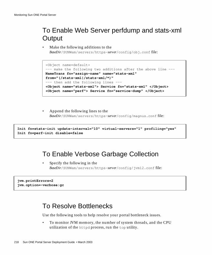
Monitoring Sun ONE Portal Server
218 Sun ONE Portal Server Deployment Guide • March 2003
To Enable Web Server perfdump and stats-xmlOutput• Make the following additions to the
BaseDir/SUNWam/servers/https-server/config/obj.conf file:
• Append the following lines to theBaseDir/SUNWam/servers/https-server/config/magnus.conf file:
To Enable Verbose Garbage Collection• Specify the following in the
BaseDir/SUNWam/servers/https-server/config/jvm12.conf file:
To Resolve BottlenecksUse the following tools to help resolve your portal bottleneck issues.
• To monitor JVM memory, the number of system threads, and the CPUutilization of the httpd process, run the top utility.
<Object name=default>--- make the following two additions after the above line ---NameTrans fn="assign-name" name="stats-xml"from="(/stats-xml|/stats-xml/*)"--- then add the following lines ---<Object name="stats-xml"> Service fn="stats-xml" </Object><Object name="perf"> Service fn="service-dump" </Object>
Init fn=stats-init update-interval="10" virtual-servers="1" profiling="yes"Init fn=perf-init disable=false
jvm.printErrors=2jvm.option=-verbose:gc

Monitoring Sun ONE Portal Server
Chapter 8 Monitoring and Tuning Your Portal 219
• To check all the child processes for a process, run prstat. For example:
prstat -L -p pid_of_web_instance
• To get a stack trace for each lightweight process for a process, run pstack. Forexample:
pstack pid_of_web_instance
• To report on virtual memory statistics regarding process, virtual memory, disk,trap, and CPU activity, use vmstat.
• To report on per-processor statistics, use mpstat.
• To monitor all I/O activity, including CPU utilization, run iostat.
• Examine the /var/adm/messages file for UNIX® system activity or errorconditions.
• Another valuable UNIX tool is SEToolkit. The following tasks in SEToolkit
are useful for a portal deployment: toptool.se, zoom.se, tcp_monitor.se,perfmeter.se, limits.se, and webtune.se.

Tuning Sun ONE Portal Server (Core)
220 Sun ONE Portal Server Deployment Guide • March 2003
Tuning Sun ONE Portal Server (Core)The perftune script (in the BaseDir/SUNWps/bin directory), bundled with PortalServer, automates most of the portal tuning process. See the Sun ONE Portal Server6.0 Installation Guide for details on running perftune.
This section provides additional information on the configuration settings appliedby perftune. Except where noted, configuration settings are automaticallyapplied. The parameters shown here that are not configured by perftune aremostly related to monitoring a portal.
Web Container Configuration SettingsThe perftune script updates the obj.conf, magnus.conf, and server.xml files inthe WEBSERVER/config directory. The web container (in this case, Sun™ ONEWeb Server) reads these files at startup.
See the following document for additional information:
http://docs.sun.com/source/816-5690-10/index.html
In the magnus.conf file:
• RqThrottle - Determines the maximum number of threads that the webcontainer will create to service incoming requests. This is set by the perftunescript to 256.
• RqThrottleMin - Determines the initial number of threads created by the webcontainer to service incoming requests. This value should be less than or equalto RqThrottle and is not set by the perftune script. As a rule of thumb, ifRqThrottle is set to 256, RqThrottleMin can be set to 128.
• ThreadIncrement - Determines the number of threads that are created whenthe web container needs to add more threads. This value is not set by theperftune script. As a rule of thumb, this parameter can be set to 32.
• StackSize - Determines the size of the stack of each thread that the webcontainer uses to service requests. The perftune script sets this parameter to384 KB.
• ConnQueueSize - Determines the number of outstanding (yet to be serviced)connections that the web container can have. This parameter is set by theperftune script to 4,096.

Tuning Sun ONE Portal Server (Core)
Chapter 8 Monitoring and Tuning Your Portal 221
• ListenQ - Determines the maximum number of pending connections on alisten socket. Connections that time out on a listen socket whose backlog queueis full will fail. This parameter is set by the perftune script to 4,096.
At the end of the magnus.conf file, add the following line:
Init fn="stats-init" profiling="on"
In combination with the parameters added to obj.conf (shown below), thisactivates the monitoring of performance and thread usage by the web container.
In the server.xml file:
• acceptorthreads - Determines the number of acceptor threads for the listensocket. The perftune script sets this parameter to a value equal to the numberof CPUs in the system. In a building module configuration, this value shouldbe 4.
In the obj.conf file:
The configuration shown below is not applied by perftune, but is used to monitorthe performance and thread usage by the web container.
At the beginning of the file:
In a separate block:
NameTrans fn=assign-name from="/.perf" name="perf"NameTrans fn="assign-name" name="stats-xml" from="(/stats-xml|/stats-xml/*)"
<Object name="perf">Service fn="service-dump"</Object>

Tuning Sun ONE Portal Server (Core)
222 Sun ONE Portal Server Deployment Guide • March 2003
JVM ParametersAll of these parameters affect the Java HotSpot™ JVM. See the following URL formore information:
http://java.sun.com/docs/hotspot/VMOptions.html
• jvm.minHeapSize and jvm.maxHeapSize - Determine the size of the heap.These parameters correspond to the -ms and -mx parameters of the JVM. Foroptimum throughput over the long term 1 GB is recommended. For largerdeployments use 2 GB.
• jvm.option=server - Tells the web container to use the server JVM, which isoptimized for performance. The -server and -client options invoke twodifferent binaries. They are essentially two different compilers (JITs)interfacing to the same runtime system. The client system is optimal forapplications that need fast startup times or small footprints. The server systemis optimal for applications where the performance is most important. Ingeneral the client system is better on graphical user interfaces. Some of theother differences include the compilation policy used, heap defaults, andinlining policy.
• jvm.option=-Xrs - Reduces use of OS signals by JVM.
• jvm.option=-XX:+OverrideDefaultLibthread - Tells the JVM to use thealternate threading model of Solaris™ 8. This is the default thread model ofSolaris™ 9. In summary, the alternate threading model ensures that each Javathread maps to one LWP (which is the unit of scheduling CPUs at the OSlevel).
• jvm.option=-XX:PermSize=128M and jvm.option=-XX:MaxPermSize=128M -Together, specify the size of the permanent area of the heap. The permanentgeneration holds all the reflective data of the JVM itself, such as class andmethod objects.
• jvm.option=-XX:NewSize=256M and jvm.option=-XX:MaxNewSize=256M -Specify the size of the new generation out of the total size of the heap. Thebigger the young generation, the less often minor collections occur. However,for a bounded heap size, a larger young generation implies a smaller oldgeneration, which increases the frequency of major collections. For PortalServer, it is preferable to have a young generation that is relatively small (oneeighth of total heap size) because many objects created by Portal Sever arelong-lived and therefore, the earlier they are copied to the old generation, thehigher the maximum throughput.

Tuning Sun ONE Portal Server (Core)
Chapter 8 Monitoring and Tuning Your Portal 223
Identity Server ParametersThe perftune script configures parameters for Identity Server that are crucial toachieving maximum throughput and consistent performance.
While the perftune script configures all these parameters programmatically, theycan be verified by using a combination of the web-based interface and text editorwhen troubleshooting any performance issue.
In the serverconfig.xml file:
• minConnPool and maxConnPool - Define the size of the connection pool used toaccess the LDAP server.
In the AMConfig.properties file:
• com.iplanet.am.sdk.cache.maxSize - Specifies the size of the IdentityServer cache, an important parameter for portal performance. As stated in“Monitoring Sun ONE Portal Server,” on page 213, achieving an 80 percentcache hit ratio is a basic goal of a production site. For a large deployment, setthis value to large number, such as 32,768. The maximum value is 35,000.
• com.iplanet.am.session.maxSessions - Specifies the maximum number ofsessions that the Identity Server accepts. In traditional web applications, thisparameter is configured at the web container, by setting the maxSessionsvalue in the web-apps.xml file of the web container. However, for applicationsthat use the Identity Server, this is set in the AMConfig.properties file. Theperftune script sets this value to 5,000. The maximum value is 131,072.
See “To Enable Identity Server Performance Statistics,” on page 217 for instructionson turning on logging for Identity Server.
Directory Server ParametersThe perftune script updates the BaseLDAPDir/config/dse.ldif file. This fileautomatically sets the TCP/IP parameters at boot time. Directory Server reads thisfile at startup. You need to stop Directory Server before making changes to this file.
Under dn: cn=config:
• nsslapd-accesslog-logging-enabled - Determines whether DirectoryServer maintains an access log. While this log is often useful when debugging,you must disable it for a production site, so perftune set this to off.

Tuning Sun ONE Portal Server (Core)
224 Sun ONE Portal Server Deployment Guide • March 2003
• nsslapd-threadnumber - Determines the number of threads that DirectoryServer makes available to service requests. The perftune script sets this to 75for a 4-CPU building module.
Under: dn: cn=config,cn=ldbm database,cn=plugins,cn=config:
• nsslapd-maxthreadsperconn - Determines the maximum number of threadsthat can be used by a single connection. The perftune script sets this value to20, which suffices for all portal deployments.
• nsslapd-db-home-directory - Specifies a subdirectory of a tempfs type filesystem. The perftune script sets this to /tmp/slapd-dsame1. Because Solarisattempts to map into RAM the contents of the /tmp directory, this parameterhas a substantial impact on performance.
TCP ParametersThe perftune script creates the /etc/rc2.d/S99ndd_tcp file. This fileautomatically sets the TCP/IP parameters at boot time.
• tcp_time_wait_interval - Specifies the duration in milliseconds that a portremains unavailable after a connection has been closed. This specifies that anew process does not receive packets intended for a process that has sincedied. On Solaris machines, the default value of tcp_time_wait_interval is240,000 ms (four minutes). It is recommended that this be set at 60000 ms (1minute) or even at 30000 (30 seconds) for better performance in socketcommunication intensive programs. The value can be modified and examinedon a running system.
• tcp_fin_wait_2_flush_interval - Specifies the duration in millisecondsthat a connection can stay in the FIN_WAIT_2 state. The recommended value is60000. Consider decreasing this interval, if netstat -f inet shows manyconnections in the state FIN_WAIT_2. The timer is used only if the connection isactually idle. Mind that after a TCP half close a simplex data transmission isstill available towards the actively closing end.
• tcp_conn_req_max_q0 - Specifies the maximum number of connections withhandshake incomplete. A SYN flood attack could only affect this queue, and aspecial algorithm makes sure that valid connections can still get through.
• tcp_conn_req_max_q - Specifies the maximum number of completedconnections waiting to return from an accept call as soon as the right processgets some CPU time.

Tuning Sun ONE Portal Server (Core)
Chapter 8 Monitoring and Tuning Your Portal 225
In other words, tcp_conn_req_max_q0 specifies the size of the incompleteconnection queue while tcp_conn_req_max_q assigns the maximum length ofthe completed connection queue.
You can determine if you need to modify this set of parameters by examiningthe output of the netstat -sP tcp command. Look for the value oftcpListenDrop, if available on your version of Solaris. (Previous versions ofSolaris do not have this counter.) Any value showing up might indicate aproblem with your server. However, stopping a busy server shuts down itslistening socket, and might increase this counter (and others). If you get manydrops, you might need to increase the appropriate parameter. Becauseconnections can also be dropped, since listen() specifies a too smallargument, you have to be careful interpreting the counter value. On previousversions of Solaris, a SYN flood attack might also increase this counter.
• tcp_ip_abort_interval - Specifies how long retransmissions for aconnection in the ESTABLISHED state should be tried before a RESET segment issent.
• tcp_keepalive_interval - Specifies the interval specified before a keep-aliveprobe can be sent. Keep-alive probes are described in the host requirementsRFC 1122. If a host chooses to implement keep-alive probes, it must enable theapplication to switch them on or off for a connection. Keep-alive probes mustbe switched off by default.
The keep-alive timer becomes significant for web servers, if the client crashesor terminates without the server knowing about it. This condition can be forcedsometimes by quickly pressing the stop button of browsers. Thus thekeep-alive probes do make sense for web servers.
• tcp_rexmit_interval_max - Specifies the maximum wait interval betweentwo retransmissions. When changing this value, also inspect the abort interval.The maximum wait interval should only be reached shortly before the abortinterval timer expires. Additionally, coordinate your interval with the value oftcp_close_wait_interval.
• tcp_rexmit_interval_min - Specifies the wait interval for additionalretransmissions (after the first one).
• tcp_rexmit_interval_initial - Specifies the wait interval for the initialretransmission.
• tcp_slow_start_initial - Provides the slow-start bug discovered in BSDand Windows TCP/IP implementations. To summarize the effect, a serverstarts sending two PDUs at once without waiting for an ACK due to wrongACK counts. The ACK from connection initiation is counted as data ACK.

Tuning Sun ONE Portal Server (Core)
226 Sun ONE Portal Server Deployment Guide • March 2003
Setting the parameter to 2 enables a Solaris machine to behave as though it hasthe slow start bug, too.
• tcp_xmit_hiwat - Influences a heuristic that determines the size of the initialsend window. The actual value will be rounded up to the next multiple of themaximum segment size (MSS).
• tcp_recv_hiwat - Determines the maximum size of the initial TCP receptionbuffer. The specified value will be rounded up to the next multiple of the MSS.From the free space within the buffer the advertised window size isdetermined, that is, the size of the reception window advertised to the remotepeer.
Operating Environment ParametersThe perftune script updates the /etc/system file. This file automatically sets theoperating environment parameters at boot time.
• rlim_fd_max - Defines the hard limit of open files you can have. For mostservers, the number of open file descriptors per user process is among the mostimportant parameters. The number of file descriptors is one limit on thenumber of connections you can have in parallel. You can find out the value ofyour hard limit on a shell by running the following command:
ulimit -Hn
Consider a value of at least 2 * tcp_conn_req_max and provide at least 2 *rlim_fd_cur, where rlim_fd_cur defines the soft limit of open files you canhave. The predicate rlim_fd_cur <= rlim_fd_max must be fulfilled.
• sq_max_size -Specifiesthedepthofthesyncq(numberofmessages)beforeadestination streams queue generates a QFULL. A value of 0 means the number isunlimited.
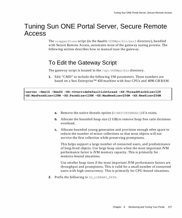
Tuning Sun ONE Portal Server, Secure Remote Access
Chapter 8 Monitoring and Tuning Your Portal 227
Tuning Sun ONE Portal Server, Secure RemoteAccess
The srapperftune script (in the BaseDir/SUNWps/bin/perf directory), bundledwith Secure Remote Access, automates most of the gateway tuning process. Thefollowing section describes how to manual tune the gateway.
To Edit the Gateway ScriptThe gateway script is located in the /opt/SUNWps/bin directory.
1. Edit “CMD” to include the following VM parameters. These numbers arebased on a Sun Enterprise™ 450 machine with four CPUs and 4096 GB RAM.
a. Remove the native threads option (${NATIVETHREAD}) if it exists.
b. Allocate the bounded heap size (1 GB) to remove heap free ratio decisionsoverhead.
c. Allocate bounded young generation and provision enough eden space toreduce the number of minor collections so that most objects will notsurvive the first collection while preserving promptness.
This helps support a large number of connected users, and predominanceof long-lived objects. Use large heap sizes when the most important JVMperformance factor is JVM memory capacity. This is primarily formemory-bound situations.
Use smaller heap sizes if the most important JVM performance factors arethroughput and promptness. This is valid for a small number of connectedusers with high concurrency. This is primarily for CPU-bound situations.
2. Prefix the following to LD_LIBRARY_PATH.
-server -Xms1G -Xmx2G -XX:+OverrideDefaultLibthread -XX:ThreadStackSize=128-XX:MaxPermSize=128M -XX:PermSize=128M -XX:MaxNewSize=256M -XX:NewSize=256M

Tuning Sun ONE Portal Server, Secure Remote Access
228 Sun ONE Portal Server Deployment Guide • March 2003
Using the alternate thread library produces slightly better performance.
To Tune Gateway Logging• In the platform.conf.profile file, set logging to error. Time spent logging
is decreased and only error messages appear.
To Bind to CPUs• Bind the gateway process to one CPU (or the number of CPUs as required).
This helps track and allocate the resources in a controlled manner.
To Edit the Gateway ProfileTo improve gateway performance, use the configuration changes listed here.
1. Use the Gateway service of the Identity Server administration console to makethese changes.
2. Disable the following settings:
❍ Enable Netlet
This step is valid only if your deployment does not require Netlet usage.Using the gateway with Netlet disabled gives better performance.
❍ Enable Logging
❍ Enable Netlet Logging
3. Set the following:
❍ Gateway Timeout to 120000
LD_LIBRARY_PATH="/usr/lib/lwp:$JAVA_HOME/jre/lib/sparc/server:$IPS_HOME/lib/solaris/sparc:$LD_LIBRARY_PATH"
NOTE This is debug logging.

Tuning Sun ONE Portal Server, Secure Remote Access
Chapter 8 Monitoring and Tuning Your Portal 229
For scenarios with short-lived sessions, you can reduce this value to 30000or lower as required.
❍ Cached Socket Timeout to 120000
For scenarios with short-lived sessions, you can reduce this value to 30000or lower as required.
To Set System Parameters• Tune the system by performing the following:
❍ In the /etc/system file, set the following parameters:
❍ Increase the file descriptors - 16384 has been found to be an optimum valuefor 1000 to 10,000 users.
❍ Stream queue size - This is the depth of the syncq (number of messages)before a destination streams queue generates a QFULL.
❍ TCP Connection Hash Size - Should be less than or equal to the number offile descriptors.
See “Operating Environment Parameters,” on page 226 for an explanation of theseparameters.
set rlim_fd_max=16384set rlim_fd_cur=16384set sq_max_size=0set tcp:tcp_conn_hash_size=8192
NOTE Restart the machine for changes in /etc/system to take effect.
NOTE You must set the values manually on the gateway machine. Theperftune script automates the process on the portal node only.

Tuning Sun ONE Portal Server, Secure Remote Access
230 Sun ONE Portal Server Deployment Guide • March 2003
To Set TCP Parameters from the Command Line• Set the following parameters manually each time the machine is rebooted:
ndd -set /dev/tcp tcp_time_wait_interval 60000
ndd -set /dev/tcp tcp_fin_wait_2_flush_interval 60000
ndd -set /dev/tcp tcp_conn_req_max_q 8192
ndd -set /dev/tcp tcp_conn_req_max_q0 8192
ndd -set /dev/tcp tcp_ip_abort_interval 60000
ndd -set /dev/tcp tcp_keepalive_interval 90000
ndd -set /dev/tcp tcp_rexmit_interval_max 6000
ndd -set /dev/tcp tcp_rexmit_interval_min 3000
ndd -set /dev/tcp tcp_rexmit_interval_initial 500
ndd -set /dev/tcp tcp_smallest_anon_port 1024
ndd -set /dev/tcp tcp_slow_start_initial 2
ndd -set /dev/tcp tcp_xmit_hiwat 32768
ndd -set /dev/tcp tcp_recv_hiwat 32768
See “TCP Parameters,” on page 224 for an explanation of these parameters. Thesettings on the gateway machine should be the same as the portal node. The onlydifference is that you must set the values manually on the gateway machine; theperftune script automates the process on the portal node.
To Disable Persistent Connections withjava.net.HttpURLConnectionSecure Remote Access uses JRE 1.3.1_04 by default. Exceptions related to SessionService or [RemoteConfigServlet] (java.io.EOFException or Read requestcontent error) could be reported in theBaseDir/SUNWam/servers/https-server/logs/errors log when using this JRE.
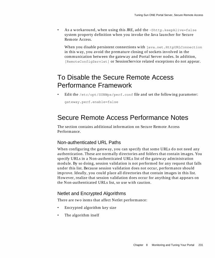
Tuning Sun ONE Portal Server, Secure Remote Access
Chapter 8 Monitoring and Tuning Your Portal 231
• As a workaround, when using this JRE, add the -Dhttp.keepAlive=falsesystem property definition when you invoke the Java launcher for SecureRemote Access.
When you disable persistent connections with java.net.HttpURLConnection
in this way, you avoid the premature closing of sockets involved in thecommunication between the gateway and Portal Server nodes. In addition,[RemoteConfigServlet] or SessionService related exceptions do not appear.
To Disable the Secure Remote AccessPerformance Framework• Edit the /etc/opt/SUNWps/perf.conf file and set the following parameter:
gateway.perf.enable=false
Secure Remote Access Performance NotesThe section contains additional information on Secure Remote AccessPerformance.
Non-authenticated URL PathsWhen configuring the gateway, you can specify that some URLs do not need anyauthentication. These are normally directories and folders that contain images. Youspecify URLs in a Non-authenticated URLs list of the gateway administrationmodule. By so doing, session validation is not performed for any request that fallsunder this list. Because session validation does not occur, performance shouldimprove. Ideally, you could place all directories that contain images in this list.However, realize that session validation does occur for anything that appears onthe Non-authenticated URLs list, so use with caution.
Netlet and Encrypted AlgorithmsThere are two items that affect Netlet performance:
• Encrypted algorithm key size
• The algorithm itself

Tuning Sun ONE Portal Server, Secure Remote Access
232 Sun ONE Portal Server Deployment Guide • March 2003
The higher the encrypted algorithm key length, the higher the security, but thelower the performance. In general, RC4 performs better than AES/Rjindael,TripleDES, and DES. TripleDES gives the worst performance, while Null gives thebest performance.
CAUTION Using Null for your Netlet cipher provides no security. Select Nullonly if you want a significant performance enhancement, and if youare sure that your users are browsing in a safe environment.

233
Appendix A
Troubleshooting Your PortalDeployment
This appendix describes how to troubleshoot Sun™ ONE Portal Server and Sun™ONE Portal Server, Secure Remote Access.
This appendix contains the following sections:
• Troubleshooting Sun ONE Portal Server
• Troubleshooting Sun ONE Portal Server, Secure Remote Access
Troubleshooting Sun ONE Portal ServerThis sections contains troubleshooting information for core Portal Server.
UNIX ProcessesFor the portal to be functioning properly, check that the following root-ownedprocesses are running. Use the ps command to see this output.
Directory Server:
/ns-slapd -D /usr/ldap/slapd-server -i /usr/ldap/slapd-server/logs/pid
Identity Server:
/opt/SUNWam/bin/doUnix -c 8946
Portal Server:
./uxwdog -d /opt/SUNWam/servers/https-server/config
ns-httpd -d /opt/SUNWam/servers/https-server/config

Troubleshooting Sun ONE Portal Server
234 Sun ONE Portal Server Deployment Guide • March 2003
ns-httpd -d /opt/SUNWam/servers/https-server/config
Admin Web Server (optional, but usually running):
./uxwdog -d /opt/SUNWam/servers/https-admserv/config
ns-httpd -d /opt/SUNWam/servers/https-admserv/config
ns-httpd -d /opt/SUNWam/servers/https-admserv/config
Log FilesExamine the following log files for errors.
Web Server (errors and access):
/opt/SUNWam/servers/https-server/logs
Directory Server:
/var/opt/SUNWam/logs
Recovering the Search DatabaseThe Search database maintains recoverable transaction logs. Thus, under normalcircumstances, you do not have to do anything to recover the database. Recoveryfrom errors and transient conditions such as a full disk are straight forward. Ifdesired, maintain Search database archives and restore from an archive in case youlost the entire database. In this scenario, you would copy the archive to the originaldatabase to recover it.
To recover the database, first stop all processes accessing the database, includingthe Portal Server instance. Then use the rdmgr -R command to recover.
Stopping and Starting Portal ServerUse the following commands to stop and start the portal and its associatedprocesses. You do not need to stop the server to restart it. If you start a server thatis already running, the server is stopped and restarted.

Troubleshooting Sun ONE Portal Server
Appendix A Troubleshooting Your Portal Deployment 235
To Stop and Start Portal ServerTo stop Portal Server, type:
/etc/init.d/amserver stop
To start Portal Server, type:
/etc/init.d/amserver start
To start multiple instances of Portal Server, type:
/etc/init.d/amserver startall
Working with the Display ProfileIf you need to troubleshoot the XML contents of your portal’s display profile, it isuseful to extract it to a file for examination. At some point in the troubleshootingprocess, it might be useful to reload the display profile.
To Extract the Display Profile1. Log in as administrator.
2. Use the dpadmin command to extract the display profile. For example:
./dpadmin list -u "uid=amAdmin,ou=People,o=sesta.com,o=isp" -w password -d"o=sesta.com,o=isp" > /tmp/displayxml
This examples puts the contents of the display profile into the/tmp/displayxml file.
To Reload the Display Profile1. Log in as administrator.
2. Use the dpadmin command to reload the display profile. For example:
./dpadmin modify -u "uid=amAdmin,ou=People,o=sesta.com,o=isp" -w password -d"o=sesta.com,o=isp" /tmp/updated_displayxml
This examples reloads the contents of the display profile from the/tmp/updated_displayxml file.
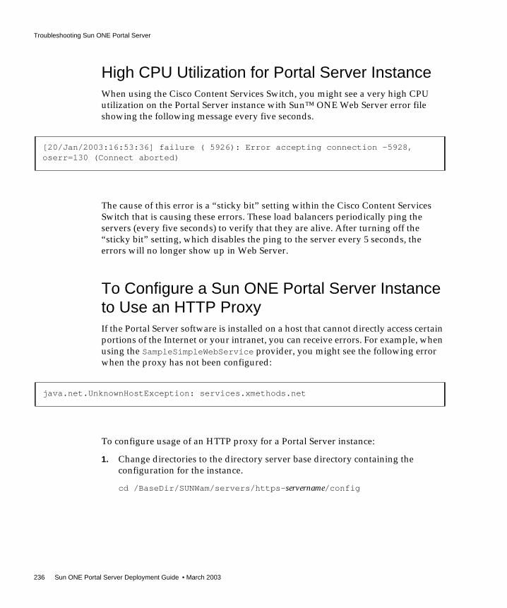
Troubleshooting Sun ONE Portal Server
236 Sun ONE Portal Server Deployment Guide • March 2003
High CPU Utilization for Portal Server InstanceWhen using the Cisco Content Services Switch, you might see a very high CPUutilization on the Portal Server instance with Sun™ ONE Web Server error fileshowing the following message every five seconds.
The cause of this error is a “sticky bit” setting within the Cisco Content ServicesSwitch that is causing these errors. These load balancers periodically ping theservers (every five seconds) to verify that they are alive. After turning off the“sticky bit” setting, which disables the ping to the server every 5 seconds, theerrors will no longer show up in Web Server.
To Configure a Sun ONE Portal Server Instanceto Use an HTTP ProxyIf the Portal Server software is installed on a host that cannot directly access certainportions of the Internet or your intranet, you can receive errors. For example, whenusing the SampleSimpleWebService provider, you might see the following errorwhen the proxy has not been configured:
To configure usage of an HTTP proxy for a Portal Server instance:
1. Change directories to the directory server base directory containing theconfiguration for the instance.
cd /BaseDir/SUNWam/servers/https-servername/config
[20/Jan/2003:16:53:36] failure ( 5926): Error accepting connection -5928,oserr=130 (Connect aborted)
java.net.UnknownHostException: services.xmethods.net

Troubleshooting Sun ONE Portal Server, Secure Remote Access
Appendix A Troubleshooting Your Portal Deployment 237
2. Edit the jvm12.conf file within this directory and add the following lines:
http.proxyHost=proxy_host
http.proxyPort=proxy_port
http.nonProxyHosts=portal_host
where proxy_host is the fully-qualified domain name of the proxy host,proxy_port is the port on which the proxy is run, and portal_host is the fullyqualified domain name of the portal host.
Troubleshooting Sun ONE Portal Server, SecureRemote Access
This section describes how to capture information that Sun ONE support personnelneed to troubleshoot problems in your deployment.
Introduction to shooterThe shooter tool captures all the information that the development and supportteam will require to troubleshoot problems in your deployment of the Sun ONEPortal Server, Secure Remote Access. You can also run this tool on a Portal Servermachine.
This tool captures the following data:
• Installation type - Determines if the installation has Portal Server, Portal Serverwith Secure Remote Access support, or Portal Server with Secure RemoteAccess
• System configuration related information - Determines the host, domain,operating system, version, CPU type and speed, clock speed, and memoryavailable
• Processors, processor sets, and the Secure Remote Access processes bound tothem
• Secure Remote Access installation log
• The platform.conf file(s)
• The settings in the gateway script such as the JVM™ settings including heapusage, and library path

Troubleshooting Sun ONE Portal Server, Secure Remote Access
238 Sun ONE Portal Server Deployment Guide • March 2003
• Gateway service settings
• Tuning settings in various files used for configuring Sun™ ONE IdentityServer, Sun™ ONE Directory Server, and Sun ONE Web Server
• Output of the Java™ garbage collection
• A memory or process footprint while the gateway was being used
• Formatted debug log files
• Rewriter rulesets
Using shooterThe shooter tool includes five files as described below.
shooter.shThis is the main script. Run this script after a test or just before starting a test on theSecure Remote Access installation.
To run shooter, type:
./shooter.sh
This tool collects data under a temporary folder and displays the folder name.
gctool.plThis script collects and formats the garbage collection output from the JVM.
To run gctool, start the gateway, and type the following to redirect the output tothis script and allow collection throughout the test.
/etc/init.d/gateway -n default start | gctool.pl
NOTE This tool collects information only for the instance of the gatewaythat you specified during installation.
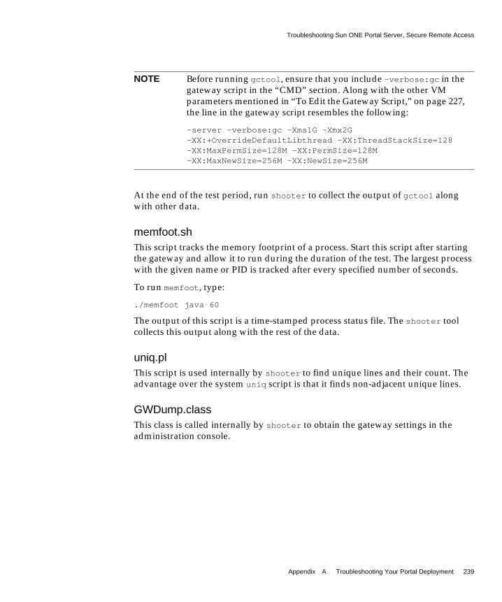
Troubleshooting Sun ONE Portal Server, Secure Remote Access
Appendix A Troubleshooting Your Portal Deployment 239
At the end of the test period, run shooter to collect the output of gctool alongwith other data.
memfoot.shThis script tracks the memory footprint of a process. Start this script after startingthe gateway and allow it to run during the duration of the test. The largest processwith the given name or PID is tracked after every specified number of seconds.
To run memfoot, type:
./memfoot java 60
The output of this script is a time-stamped process status file. The shooter toolcollects this output along with the rest of the data.
uniq.plThis script is used internally by shooter to find unique lines and their count. Theadvantage over the system uniq script is that it finds non-adjacent unique lines.
GWDump.classThis class is called internally by shooter to obtain the gateway settings in theadministration console.
NOTE Before running gctool, ensure that you include -verbose:gc in thegateway script in the “CMD” section. Along with the other VMparameters mentioned in “To Edit the Gateway Script,” on page 227,the line in the gateway script resembles the following:
-server -verbose:gc -Xms1G -Xmx2G-XX:+OverrideDefaultLibthread -XX:ThreadStackSize=128-XX:MaxPermSize=128M -XX:PermSize=128M-XX:MaxNewSize=256M -XX:NewSize=256M

Troubleshooting Sun ONE Portal Server, Secure Remote Access
240 Sun ONE Portal Server Deployment Guide • March 2003
Secure Remote Access Log FilesExamine the following log files for errors.
Gateway:
/var/opt/SUNWam/logs/srapGateway_gateway_hostname_gateway_profile_name
NetFile:
/var/opt/SUNWam/logs/srapNetFile
Netlet:
/var/opt/SUNWam/logs/srapGateway_gateway_hostname_gateway_profile_name

241
Appendix B
Portal Deployment Worksheets
This appendix provides worksheets to help with the portal deployment process.
This appendix contains the following sections:
• Portal Assessment Worksheets
• Portal Key Design Task List

Portal Assessment Worksheets
242 Sun ONE Portal Server Deployment Guide • March 2003
Portal Assessment WorksheetsUse these worksheets to learn more about your organization’s business needs andpotential areas of concern around deploying portals.
Table B-1 General Questions
1. Identify the business reasons why you want a portal (check and elaborate on all that apply):
• Reducing procurement cost
• Reducing the cost of sharing information with customers, suppliers, or partners
• Eliminating the cost of maintaining many point solutions
• Expanding the reach of the customer base for your services
• Reducing the time to deploy new business services
• Securing the access to your data and services
• Making it easier for your customers to do business with you over the Internet
• Reducing the cost and time for integrating business services with suppliers and partners
• To comply with governmental regulations
• Personalizing the user experience
• Needing to gather business intelligence on the usage of services
2. How many portals does your organization already have?
3. What types are they (business-to-employee, business-to-consumer, business-to-business, ISP)?
4. If you have more than one, do you have a need to reduce the number? Integrate? Federate?
5. Do you have departmental portals?
6. What is the extent of your Web presence? How many web sites do you have?
7. List the top ten application services of value to you, that you would like to expose by using Portal Serverto your partners? Suppliers? Customers? Employees?
8. Who is the target community for your portal?
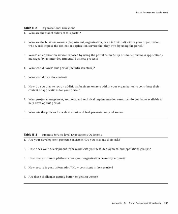
Portal Assessment Worksheets
Appendix B Portal Deployment Worksheets 243
Table B-2 Organizational Questions
1. Who are the stakeholders of this portal?
2. Who are the business owners (department, organization, or an individual) within your organizationwho would expose the content or application service that they own by using the portal?
3. Would an application service exposed by using the portal be made up of smaller business applicationsmanaged by an inter-departmental business process?
4. Who would “own” this portal (the infrastructure)?
5. Who would own the content?
6. How do you plan to recruit additional business owners within your organization to contribute theircontent or applications for your portal?
7. What project management, architect, and technical implementation resources do you have available tohelp develop this portal?
8. Who sets the policies for web site look and feel, presentation, and so on?
Table B-3 Business Service-level Expectations Questions
1. Are your development projects consistent? Do you manage their risk?
2. How does your development team work with your test, deployment, and operations groups?
3. How many different platforms does your organization currently support?
4. How secure is your information? How consistent is the security?
5. Are these challenges getting better, or getting worse?

Portal Assessment Worksheets
244 Sun ONE Portal Server Deployment Guide • March 2003
6. How do you plan to recruit additional business owners within your organization to contribute theircontent or applications for your portal?
7. What project management, architect, and technical implementation resources do you have available tohelp develop this portal?
8. Who sets the policies for web site look and feel, presentation, and so on?
Table B-4 Content Management Questions
1. Do you have a content or document management system?
2. Do you have any defined workflow to manage the development and publication of content?
3. Do you have a taxonomy defined?
4. How well is your information tagged and categorized?
5. How is your enterprise content developed, managed, tracked, and published?
6. Do you have a need for syndicated content on your portal? If so, what?
7. What proportion of your content is dynamic versus static?
Table B-5 User Management and Security Questions
1. How would you segment, categorize, and relate (hierarchically) your user community?
2. What are your current and future security policies?
3. Do various departments own or maintain their private view of the customer?
4. Do you have an enterprise directory?
Table B-3 Business Service-level Expectations Questions (Continued)

Portal Assessment Worksheets
Appendix B Portal Deployment Worksheets 245
Table B-6 Business Intelligence Questions
1. Do you have a need to gather, store, analyze, and provide information for enterprise decision-making?
2. Do you already employ any data analysis or OLAP tools?
3. At what level(s) do you need to collect business intelligence (enterprise-wide, division, department,project, onetime event, and so on)?
Table B-7 Architecture Questions
1. Do you already have an existing architecture strategy?
• Do you have the capabilities to implement a new architecture solution?
• What technologies do you currently use?
• Do you have the staff to implement a new architecture solution?
2. Are there organizational issues that are hindering a successful implementation of a new IT architecture?
3. For the top ten services that you would like deployed by using a portal, what platform and architecturedo you need to support?
4. How do these services authenticate users and manage access control?
5. How do you programmatically gain access to these services?
6. What is your current and future messaging (email) and collaboration architecture?
7. What is your current and future enterprise directory architecture?
8. What technologies are used for application integration?
9. What is the size of the target user community?
10. How many concurrent users?
11. What is the range of portal usage?

Portal Assessment Worksheets
246 Sun ONE Portal Server Deployment Guide • March 2003
12. What is the geographical distribution of your user base?
13. Do you currently have or have a future need for non-Web access (Wireless, Voice/IVR, and so on)
14. Would your customer base require internationalization of content and services?
15. What server platform technologies do you use?
16. What development environments, tools do you use?
17. What development methodologies do you employ?
Table B-7 Architecture Questions (Continued)

Portal Key Design Task List
Appendix B Portal Deployment Worksheets 247
Portal Key Design Task ListTable B-8 lists the major portal deployment phases and key design tasks. Use thistask list in conjunction with Chapter 6, “Understanding the Portal DeploymentProcess,” to help develop your portal project plan.
Though these tasks will vary depending on your organization and the scale of eachdeployment, the worksheet represents the most common phases and tasksencountered.
This table consists of two columns. The first column presents the major tasks. Thesecond column presents the subtasks for each major task.
Table B-8 Key Design Task List (1 of 7)
Major Phases and Tasks Subtasks
1. Project Start and Coordination
Project Planning • Perform general project management
Project Plan Review • Review pre-implementation
• Review business requirements
• Review technical requirements
• Review architectural documents
• Review hardware and infrastructure
Coordinate Resources • Identify skills required
• Identify resources
• Schedule resources
• Assemble project team members
• Review work plan with project team members
Define Requirements • Collect business requirements
• Summarize requirements
• Confirm functional requirements
• Collect technical requirements
• Summarize technical requirements
• Confirm technical requirements
• Prepare combined requirements document
• Deliver requirements
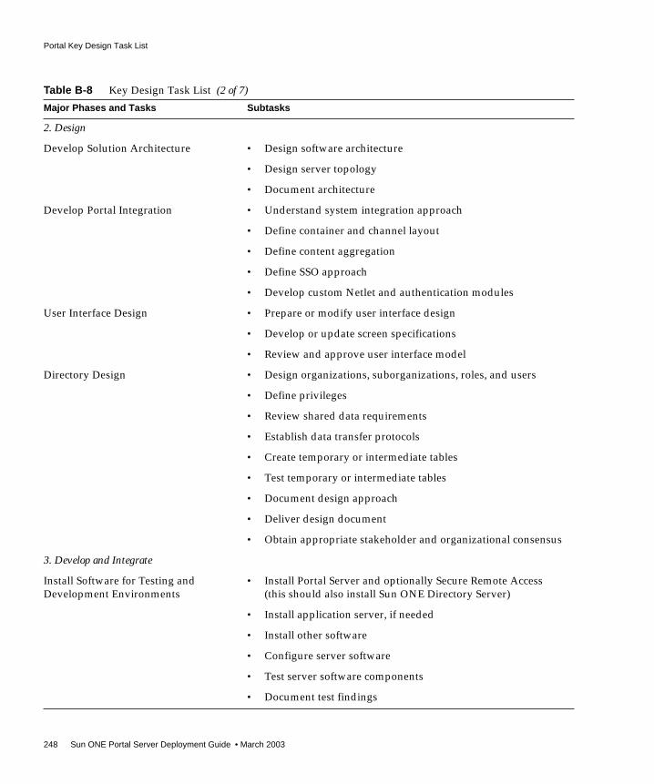
Portal Key Design Task List
248 Sun ONE Portal Server Deployment Guide • March 2003
2. Design
Develop Solution Architecture • Design software architecture
• Design server topology
• Document architecture
Develop Portal Integration • Understand system integration approach
• Define container and channel layout
• Define content aggregation
• Define SSO approach
• Develop custom Netlet and authentication modules
User Interface Design • Prepare or modify user interface design
• Develop or update screen specifications
• Review and approve user interface model
Directory Design • Design organizations, suborganizations, roles, and users
• Define privileges
• Review shared data requirements
• Establish data transfer protocols
• Create temporary or intermediate tables
• Test temporary or intermediate tables
• Document design approach
• Deliver design document
• Obtain appropriate stakeholder and organizational consensus
3. Develop and Integrate
Install Software for Testing andDevelopment Environments
• Install Portal Server and optionally Secure Remote Access(this should also install Sun ONE Directory Server)
• Install application server, if needed
• Install other software
• Configure server software
• Test server software components
• Document test findings
Table B-8 Key Design Task List (2 of 7)
Major Phases and Tasks Subtasks

Portal Key Design Task List
Appendix B Portal Deployment Worksheets 249
Install Server Software forDevelopment Environment
• Install Portal Server and optionally Secure Remote Access(this should also install Sun ONE Directory Server)
• Install application server, if needed
• Install other software
• Test server software components
• Document test findings
Software Configuration • Apply specific software configuration requirements
• Create product configuration matrix
Portal Server, Application Server, andOther Software Modifications
• Review your organization’s requirements and expectations
• Establish modifications for software
• Establish methods for software modifications
• Create software modification plan
• Design software modifications
• Establish software modification teams
• Create modifications
• Test modifications
• Obtain appropriate stakeholder and organizational reviewand approval of modifications
Table B-8 Key Design Task List (3 of 7)
Major Phases and Tasks Subtasks

Portal Key Design Task List
250 Sun ONE Portal Server Deployment Guide • March 2003
LDAP Directory Setup • Confer with stakeholders to establish proper schema
• Establish modifications for software
• Establish methods for software modifications
• Create software modification plan
• Design software modifications
• Establish software modification teams
• Create schema
• Set up LDAP
• Receive and verify data
• Modify mapping as required for LDAP
• Establish data update methods
• Test directory
• Create client user documentation for update methods
Legacy Software Integration(PeopleSoft, SAP, and so on)
• Perform integration
• Prepare package integration test plan
• Perform integration test
• Produce package integration test results
Reporting • Establish reporting requirements for organization
• Create reporting plan
• Establish reporting team
• Design reports
• Create reports
• Test reports
• Review reports with customer
• Provide information and training on report tool
Test • Establish test plan
Table B-8 Key Design Task List (4 of 7)
Major Phases and Tasks Subtasks

Portal Key Design Task List
Appendix B Portal Deployment Worksheets 251
Plan User Acceptance Test • Identify user acceptance test manager
• Develop user acceptance test strategy and procedures
• Review strategy and procedures with customer
• Obtain approval for strategy and procedures
• Develop user acceptance test roles and responsibilities
• Obtain integration test scenarios
• Review test conditions and acceptance criteria and revise
• Develop user acceptance test schedule
• Prepare acceptance test log and update with scenario testassignments
Conduct User Acceptance Test • Execute user acceptance test
• Identify and document user acceptance test discrepancies
• Resolve user acceptance test discrepancies
• Re-execute user acceptance tests and track user acceptancetest progress
• Catalog and prioritize known limitations and processimprovement opportunities identified during testing
• Review test results with quality assurance advisors,summarize and communicate results to stakeholders
• Obtain acceptance test approval from stakeholders
Table B-8 Key Design Task List (5 of 7)
Major Phases and Tasks Subtasks

Portal Key Design Task List
252 Sun ONE Portal Server Deployment Guide • March 2003
Conduct Integration and System Test • Ensure establishment of integration test environment
• Identify test team and assign test scenario ownership
• Train team on integration test procedures, roles, andresponsibilities
• Review and revise integration test execution schedule, asrequired
• Execute integration test
• Identify and document integration test discrepancies
• Resolve integration test discrepancies and document
• Identify required modifications (configuration enhancements,interfaces, reports, and so on)
• Re-execute integration tests
• Update as required
• Track test progress
• Obtain test approval
• Summarize and communicate results to stakeholders
4. Deployment Production
Confirm Approach • Review with stakeholders and establish implementationlocations and configurations
• Develop implementation approach
• Repeat appropriate tasks from development hardware andsoftware installation
Review and Update Deployment • Review existing documentation of results of tests
• Validate scope, objectives, and critical success factors
• Update deployment approach
• Review and approve deployment
Table B-8 Key Design Task List (6 of 7)
Major Phases and Tasks Subtasks

Portal Key Design Task List
Appendix B Portal Deployment Worksheets 253
Implement Deployment • Review and reconcile system operations
• Review organization and system procedures
• Promote to production
• Update current operations
• Revise system release and deployment materials
• Provide transition support
Training • Confirm organization commitment and expectations
• Establish training requirements for all personnel
• Establish training schedules
• Establish training staff
• Prepare materials for training
• Train administrators
• Train maintenance providers
• Capture training feedback
• Incorporate feedback for training improvement
Document Portal • Create “run book” for system administrators
Table B-8 Key Design Task List (7 of 7)
Major Phases and Tasks Subtasks

Portal Key Design Task List
254 Sun ONE Portal Server Deployment Guide • March 2003

255
Appendix C
Sun ONE Portal Server andApplication Servers
This appendix provides an overview of Sun™ ONE Portal Server 6.0 and itssupport for application servers.
This appendix contains the following sections:
• Introduction to Application Server Support in Portal Server
• Portal Server on an Application Server Cluster
For installation and configuration information on the specific application serverssupported by Portal Server, see the following documentation:
• Sun ONE Portal Server 6.0 Installation Supplement for Sun ONE Application Server7.0
• Sun ONE Portal Server 6.0 Installation Supplement for IBM Application Server
• Sun ONE Portal Server 6.0 Installation Supplement for BEA Application Server

Introduction to Application Server Support in Portal Server
256 Sun ONE Portal Server Deployment Guide • March 2003
Introduction to Application Server Support inPortal Server
The Sun™ ONE Portal Server 6.0 for Multi Application Servers release providessupport for the following application servers to be used as the web applicationcontainer, in place of Sun™ ONE Web Server:
• Sun™ ONE Application Server 7.0
• BEA WebLogic Server 6.1 (SP2)
• IBM WebSphere Application Server 4.04
Running Portal Server on an application server enables you to:
• Decouple the portal platform from the application server platform, allowingyou to choose the best combination of Portal Server and application server foryour organization
• Call Enterprise JavaBeans™ and other J2EE™ technologies that run in theapplication server container
• Use application server clustering, which provides scalability and highavailability (currently only available on BEA WebLogic Server and IBMWebSphere Application Server)
• Use session failover in clustering (currently only available on BEA WebLogicServer)
NOTE Portal Server runs in the context of a web application container,which can be either a web server (Sun ONE™ Web Server) or one ofthe application servers mentioned above, depending on yourdeployment. This chapter assumes that the web applicationcontainer is an application server.

Portal Server on an Application Server Cluster
Appendix C Sun ONE Portal Server and Application Servers 257
Portal Server on an Application Server ClusterThis section describes how Sun ONE Application Server, BEA WebLogic Server,and IBM WebSphere Application Server manage application server clustering.Application server clustering is loosely coupled group of application servers thatcollaborate to provide shared access to the services that each server hosts. Thecluster aims to balance resource requests, high availability of resources, andfailover of application logic to provide scalability.
Portal Server and Identity Server are not pure web applications. Instead, they arecomposed of local files residing on a machine and three web applications: portal,amserver, and amconsole. These three web applications run in a web applicationcontainer, which runs in an application server web application container. ThePortal Server installer installs and configures the local files, configures the localapplication server, then deploys the three WAR files on the local web applicationcontainer. The WAR files themselves are not self-contained; they depend on thelocal files and directories on the machine to provide their service.
An application server cluster is a logical entity that groups many application serverinstances, potentially hosted on different machines. Pure web applications aredeployed on a cluster using application server specific deployment tools. Oncedeployed on the cluster, the web applications are deployed to all the serverinstances that the cluster is made of, and managed in a central way.
Because of Portal Server’s dual nature, as a local application as well as a webapplication, install Portal Server on an application server using the following steps:
1. Install Portal Server on all machines using the same configuration settings.
2. Deploy the three web applications (portal, amserver, and amconsole) to thecluster.
The following sections explain what it means to enable Portal Server to run on anapplication server cluster.
Overview of Sun ONE Application ServerSun ONE Application Server 7, Standard Edition Server does not support serverclustering or session failover. However, it does support enhanced web tier supportby enabling you to partition HTTP and HTTPS traffic arriving on the same webserver instance to multiple application servers in the middle tier. This facility inStandard Edition can be used to partition traffic to different application serversfrom the web server tier by using the provided reverse proxy plugin.

Portal Server on an Application Server Cluster
258 Sun ONE Portal Server Deployment Guide • March 2003
While Platform Edition is limited to a single application server instance (that is, asingle JVM™ process) per administrative domain, you can configure the StandardEdition with multiple application server instances per administrative domain.
In addition, the Enterprise Edition supports multi-tiered, multi-machine, clusteredapplication server deployments.
See the following Sun ONE Application Server documentation for moreinformation:
http://docs.sun.com/db/coll/s1_asse_en
Overview of BEA WebLogic Server ClustersThe BEA WebLogic Server product uses the following definitions:
• Domain - An interrelated set of WebLogic Server resources managed as a unit.A domain includes one or more WebLogic Servers, and might includeWebLogic Server clusters.
• Administration Server - A WebLogic Server running the AdministrationService. The Administration Service provides the central point of control forconfiguring and monitoring the entire domain. The Administration Servermust be running to perform any management operation on that domain.
• Managed Server - In a domain with multiple WebLogic Servers, only oneserver is the Administration Server; the other servers are called ManagedServers. Each WebLogic Managed Server obtains its configuration at startupfrom the Administration Server.
See the following documentation for more information:
http://edocs.beasys.com/wls/docs61/cluster/index.html
You start the Administration Server with the following command:
install_dir/config/domain_name/startWeblogic.sh
The local server takes its configuration from theinstall_dir/config/domain_name/config.xml file. To start a Managed Server, usethe following command:
install_dir/config/domain_name/startManagedWebLogic.sh servernameadmin_server_url
Instead of taking its configuration from theinstall_dir/config/domain_name/config.xml local file, the Managed Server takes itfrom the Administration Server, using HTTP.

Portal Server on an Application Server Cluster
Appendix C Sun ONE Portal Server and Application Servers 259
A BEA cluster is a set of managed servers in the same domain, that are declared inthe WebLogic console as a cluster. When deploying a web application, you use thename of the cluster, not the name of the individual servers. After the deployment,the web application is identically deployed to all machines in the cluster.
Session failover in BEA is described in the following document:
http://edocs.beasys.com/wls/docs61/cluster/servlet.html#1009453
Using in-memory replication for HTTP session states requires the followingprerequisites:
• Portal Server supports the use of WebLogic Server clusters with in-memorysession replication. See the BEA documentation for instructions to set up theseclusters. The Sun ONE Portal Server 6.0 Installation Supplement for BEAApplication Server documents the load balancer configuration for such a clusterusing the HttpClusterServlet that ships with BEA. You can also set up otherload balancing hardware and software documented by BEA in the same way.
• Session data must be serializable.
• Use the setAttribute to change the session state.
To install a BEA cluster, your BEA license for each machine participating in thecluster must be a special BEA cluster license. See the BEA documentation for theprocedure to get the license and set up a BEA cluster with HttpClusterServlet.
Overview of IBM WebSphere Application ServerThe IBM WebSphere Application Server product uses the following definitions:
• Administrative domain - The logical space in which the configurations forvarious objects in the WebSphere environment reside. Inside oneadministrative domain you start with an application server. This is the defaultinstallation.
• Server group - A server group is a template for creating additional, nearlyidentical copies of an application server configuration. (This is the equivalentof BEA’s cluster.)
NOTE The default configuration supported for installing Portal Server onBEA WebLogic Server is a single server that is also theAdministration Server for the domain.

Portal Server on an Application Server Cluster
260 Sun ONE Portal Server Deployment Guide • March 2003
• Clones - A copy of the server group, on the same machine or on differentmachines. Clones are the equivalent of BEA’s managed servers.
See the IBM WebSphere Application Server documentation for more information:
http://www-3.ibm.com/software/webservers/appserv/doc/v40/ae/infocenter/was/welcome.html
WebSphere Advanced Server provides a more robust approach to clusteringbecause it includes a database. In Advanced Server, all servers use the database forthe configuration information. You can use the WebSphere administration console,a Swing Java™ application, or the command-line utilities XMLConfig and wscpthen
to manage the servers.

261
Appendix D
Sun ONE Portal Server Quick Start
This appendix provides the tasks you need to get started using Sun™ ONE PortalServer 6.0. This appendix covers installing and configuring the product, andcreating adding channels to the Desktop, and creating custom providers.
This appendix contains the following sections:
• Locating Product Reference Information
• Installing Portal Server
• Configuring Portal Server (Post-Installation)
• Customizing the Desktop
• Creating Custom Providers
Locating Product Reference InformationYou can interact with Portal Server as an administrator, developer, customizer, anduser. At times, these distinctions might overlap. For example, as a developer, youmight use both the Portal Server API and the Sun™ ONE Identity Serveradministration console to customize and configure the availability, content, andlayout of the portal and its providers.
This section provides a set of references to assist you with the specific roles youfulfill in administering, customizing and developing Portal Server.
Installation ResourcesThe Sun ONE Portal Server 6.0 Installation Guide is available online at:
http://docs.sun.com/source/816-6358-10/index.html

Locating Product Reference Information
262 Sun ONE Portal Server Deployment Guide • March 2003
Download the free trial version of the product at:
http://wwws.sun.com/software/download/products/sunone/3dee7b9e.html
Administration ResourcesInformation on understanding the Identity Server product and its administrationconsole is available online at:
http://docs.sun.com/source/816-6359-10/dsameadm.html#23178
The Sun ONE Portal Server 6.0 Administrator’s Guide is available online at:
http://docs.sun.com/source/816-6359-10/index.html
Customization ResourcesThe Sun ONE Portal Server 6.0 Desktop Customization Guide is available online at:
http://docs.sun.com/source/816-6361-10/index.html
Development ResourcesThe Sun ONE Portal Server 6.0 Developer’s Guide is available online at:
http://docs.sun.com/source/816-6362-10/index.html
The Sun ONE Portal Server 6.0 Migration Guide is available online at:
http://docs.sun.com/source/816-6360-10/index.html

Installing Portal Server
Appendix D Sun ONE Portal Server Quick Start 263
Installing Portal ServerThis section provides an overview of and sample output from a Portal Serverinstallation.
Portal Server Installation TipsNote the following when installing Portal Server:
• You need to perform the installation as root.
• Before beginning the installation, check that no services are using ports 80,8088 or 8900 (port 80 is used by Sun™ ONE Web Server, 8088 is used by theWeb Server administration console, and port 8900 is used by the Sun™ ONEDirectory Server administration console). You can change these ports ifdesired, but at a minimum, make sure that they are not already in use.
• If you are deploying on an application server, verify the server’s port usage.For example, on the Sun ONE Application Server, the default administrationconsole port is 4848. (7001 is the default for the BEA WebLogic console, and 900is the default for the IBM WebSphere console.)
• Run ./pssetup in the directory where you unpacked the Portal Serverinstallation file. See the Sun ONE Portal Server 6.0 Installation Guide for details.
Sample Portal Server InstallationThe following sample installation shows the interaction with the Portal Serverpssetup script. It creates an organization test the on host1 in the siroe.comdomain and installs the sample portal.
NOTE This installation is for Portal Server with Sun™ ONE Web Server asthe web application container. When installing an applicationserver, the installation script is slightly different.
Code Example D-1 Sample Portal Server Installation
#./pssetup********************************************************************Portal Server (6.0)

Installing Portal Server
264 Sun ONE Portal Server Deployment Guide • March 2003
********************************************************************Log at /var/sadm/install/logs/pssetup.27678/setup.logSun ONE(tm) Portal Server 6.0
<Legal information>
Sun ONE(tm) Portal Server 6.0 License/Rev 1.130July02/WF
Do you accept? yes/[no] yes
Install options:1) Install Portal Server2) Install Directory Server only3) Install Migration Tools4) ExitChoice? [4] 1Do you want to use an existing JDK? y/[n] nWhat is the installation base directory? [/opt]What is the hostname of this server? [host1]What is the sub-domain name for host1? (. for none) [sjc ] .What is the domain name for host1? [siroe.COM]What is the ip address of host1.siroe.COM? [xxx.xxx.xxx.xxx]Run SSL on host1? y/[n]What port should be used to access the Portal Server? [80]What is the organization name? [siroe.COM] testUse an existing Directory Server? y/[n]What is the Directory Server base directory? [/usr/ldap]What port should be used to access the Directory Server? [389]What is the Directory Server administration port? [8900]What is the root suffix of the directory tree? [o=isp ]What is the directory manager? [cn =Directory Manager]What is the Web Server administrator? [admin]What is the Web Server administration port? [8088]What is the passphrase for this server? Again? <admin_password> twiceWhat is the deployment URI? [/portal]Install the sample portal? [y]
JDK installation summary------------------------Directory: /usr/java_1.3.1_04
Directory Server installation summary-------------------------------------Base Directory: /usr/ldapOrganization: mdeHost: host1.siroe.COMPort: 389Instance: host1Root Suffix: o=ispDirectory Manager: cn=Directory ManagerAdministrator: adminAdministration Port: 8900
Web Server installation summary
Code Example D-1 Sample Portal Server Installation (Continued)

Installing Portal Server
Appendix D Sun ONE Portal Server Quick Start 265
At this point the installation is complete, but Portal Server will not be started by theinstall. To start Portal Server, type:
/etc/init.d/amserver start
or
-------------------------------Base Directory: /optAdministrator: adminAdministration Port: 8088
Identity Server installation summary------------------------------------Base Directory: /optAccess URL: http://host1.siroe.COM:80Administrator: amadmin
Portal Server installation summary----------------------------------Deploying into Web ServerDeploy Instance: host1.siroe.COMBase Directory: /optDeployment URI: /portalSample Portal: y
Use these settings? [y]/n
Installing JDK...Installing Directory Server...Installing Identity Server...Installing Portal Server...
Installation took 14.15 minutes.
Installation took 14.15 minutes.1) Install Migration Tools2) ExitChoice? [2] 1
Migration Tools installation summary------------------------------------Base Directory: /opt
Installing Migration Tools...
Installation took .08 minute.
All available components have been installed.Setup complete.#
Code Example D-1 Sample Portal Server Installation (Continued)

Installing Portal Server
266 Sun ONE Portal Server Deployment Guide • March 2003
InstallDir/SUNWam/bin/amserver start
where InstallDir is the directory selected during installation. The default is the /optdirectory.
To Verify That Portal Server Is Running• In a browser, access the Identity Server administration console:
http://portalhost/amconsole
You must specify the Fully Qualified Domain Name (FQDN) of the PortalServer host, otherwise the login screen displays continually withoutauthenticating. The login name is amadmin and the password is what youspecified during installation as the passphrase.
To Change Font Size for the AdministrationConsoleIf you are using a Netscape browser that causes large fonts to be displayed in theIdentity Server administration console, change the font size as follows:
1. Log in to the Identity Server administration console as administrator.
2. Select Service Management in the View drop-down menu.
3. Click the Properties icon beside Client Detection in the navigation pane.
4. In the Client Types box, click the line that begins withclientType=genericHTML.
5. In the edit box below the list box, scroll to the right and replace UTF-8 withISO-8859-1.
6. Click Remove to delete the current genericHTML entry then click Add to addthe new entry.
7. Click Save.
8. Log out of the administration console then log back in to see the smaller fontsize.
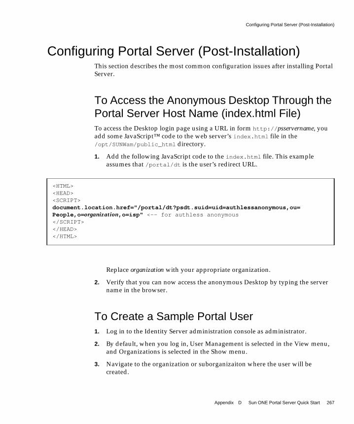
Configuring Portal Server (Post-Installation)
Appendix D Sun ONE Portal Server Quick Start 267
Configuring Portal Server (Post-Installation)This section describes the most common configuration issues after installing PortalServer.
To Access the Anonymous Desktop Through thePortal Server Host Name (index.html File)To access the Desktop login page using a URL in form http://psservername, youadd some JavaScript™ code to the web server’s index.html file in the/opt/SUNWam/public_html directory.
1. Add the following JavaScript code to the index.html file. This exampleassumes that /portal/dt is the user’s redirect URL.
Replace organization with your appropriate organization.
2. Verify that you can now access the anonymous Desktop by typing the servername in the browser.
To Create a Sample Portal User1. Log in to the Identity Server administration console as administrator.
2. By default, when you log in, User Management is selected in the View menu,and Organizations is selected in the Show menu.
3. Navigate to the organization or suborganizaiton where the user will becreated.
<HTML><HEAD><SCRIPT>document.location.href="/portal/dt?psdt.suid=uid=authlessanonymous,ou=People,o=organization,o=isp" <-- for authless anonymous</SCRIPT></HEAD></HTML>

Configuring Portal Server (Post-Installation)
268 Sun ONE Portal Server Deployment Guide • March 2003
4. Choose Users from the Show menu and click New.
The Create User template appears in the data pane.
5. Type in the user information and click Create.
The new user appears in the navigation pane.
To Access the Desktop Attributes Page1. Log in to the Identity Server administration console as administrator.
2. By default, when you log in, User Management is selected in the View menu,and Organizations is selected in the Show menu.
3. Navigate to the organization for which you want to configure the Desktop.
4. Choose Services from the Show menu.
5. Click the Properties arrow beside Desktop.
The Desktop attributes page appears in the data pane.
To Configure a Non-tabbed Desktop1. Access the Desktop Attributes page.
If necessary, see “To Access the Desktop Attributes Page.”
2. Change the Default Channel Name attribute to JSPTableContainer.
3. Click Save.
4. Verify that the non-tabbed Desktop appears by logging out as theadministrator and logging back in as a user.
If necessary, see “To Create a Sample Portal User.”
To Configure a Tabbed Desktop1. Access the Desktop Attributes page.
If necessary, see “To Access the Desktop Attributes Page.”

Configuring Portal Server (Post-Installation)
Appendix D Sun ONE Portal Server Quick Start 269
2. Make sure that the Default Channel Name attribute is JSPTabContainer.
If necessary, make the change and click Save.
3. Edit the tabbed Desktop display profile.
a. Obtain the existing display profile profile by running the dpadmincommand, for example:
This command outputs the display profile for the siroe organization to afile named /tmp/org.xml.
b. Edit the three sample portal tabs as needed:
• MyFrontPageTabPanelContainer - Provides the “front page” tab
• SamplesTabPanelContainer - Contains sample channel providers
• SearchTabPanelContainer - Provides sample search functionality
For example, to change the captions of these tabs as seen on the Desktop,search the display profile output file for the relevant containers within the<TabProperties> and </TabProperties> tags and change the titleproperty. To change channels, edit the channels within the <Selected>and <Available> tags.
c. When done making changes, use the dpadmin command to re-insert thisdisplay profile back into the organization, for example:
The new display profile is active; there is no need to restart Portal Server.
4. Verify that the modified Desktop appears by logging out as the administratorand logging back in as a user.
If necessary, see “To Create a Sample Portal User.”
dpadmin list -u "uid=amAdmin,ou=People,o=siroe,o=isp" -w password -d"o=siroe,o=isp" > /tmp/org.xml
dpadmin modify -u "uid=amAdmin,ou=People,o=siroe,o=isp" -w password -d"o=siroe,o=isp" /tmp/org.xml

Configuring Portal Server (Post-Installation)
270 Sun ONE Portal Server Deployment Guide • March 2003
To Add a Tab to JSPTabContainerA tab is represented by a table container. (A tab can be any container type but ingeneral a table container is sufficient). To add a new tab, you must first define thecontainer, then register that container in JSPTabContainer, which “houses” thetabs.
1. Create the necessary display profile.
a. Define the new collection within <Collection name="TabProperties">
in JSPTabContainer, for example:
b. Add entries to the <Available> and <Selected> tags, for example:
c. Define a container for NewTabPanelContainer, for example:
...<Collection name="TabProperties">
<Collection name="NewTabPanelContainer"><String name="title" value="My Front Page"/><String name="desc" value="Your front page"/><Boolean name="removable" value="false"/><Boolean name="renamable" value="true"/><Boolean name="predefined" value="true"/>
</Collection>...</Collection>...
...<Available>
<Reference value="NewTabPanelContainer"/>...</Available>...<Selected>
<Reference value="NewTabPanelContainer"/>...</Selected>...
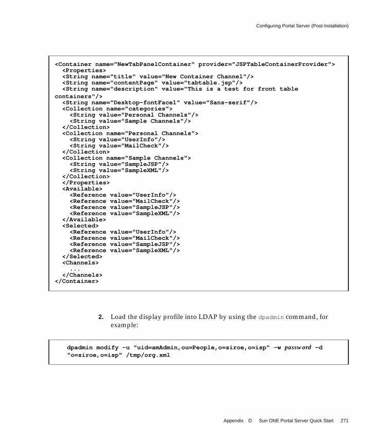
Configuring Portal Server (Post-Installation)
Appendix D Sun ONE Portal Server Quick Start 271
2. Load the display profile into LDAP by using the dpadmin command, forexample:
<Container name="NewTabPanelContainer" provider="JSPTableContainerProvider"><Properties><String name="title" value="New Container Channel"/><String name="contentPage" value="tabtable.jsp"/><String name="description" value="This is a test for front table
containers"/><String name="Desktop-fontFace1" value="Sans-serif"/><Collection name="categories">
<String value="Personal Channels"/><String value="Sample Channels"/>
</Collection><Collection name="Personal Channels">
<String value="UserInfo"/><String value="MailCheck"/>
</Collection><Collection name="Sample Channels">
<String value="SampleJSP"/><String value="SampleXML"/>
</Collection></Properties><Available>
<Reference value="UserInfo"/><Reference value="MailCheck"/><Reference value="SampleJSP"/><Reference value="SampleXML"/>
</Available><Selected>
<Reference value="UserInfo"/><Reference value="MailCheck"/><Reference value="SampleJSP"/><Reference value="SampleXML"/>
</Selected><Channels>
...</Channels>
</Container>
dpadmin modify -u "uid=amAdmin,ou=People,o=siroe,o=isp" -w password -d"o=siroe,o=isp" /tmp/org.xml

Configuring Portal Server (Post-Installation)
272 Sun ONE Portal Server Deployment Guide • March 2003
3. Verify that the modified Desktop appears by logging out as the administratorand logging back in as a user.
If necessary, see “To Create a Sample Portal User.”
To Change the Channel Layout for a TableContainerYou can configure a channel layout for each table container that houses channelsfor a tab (or JSPTableContainer for the channels in a non-tabbed desktop). To dothis, edit the organization display profile XML and add the layout property to thetable container.
1. You can change the layout for a particular table container by modifying (oradding) the following property in the table container’s display profile:
<Integer name="layout" value="value"/>
where value is:
1 = Thin-wide, two columns
2 = Wide-thin, two columns
3 = Thin-wide-thin, three columns
2. Reload the display profile to LDAP by running the dpadmin command with themodify command, loading it at the top-most node in the directory by using the-g option.
For example:
dpadmin modify -u "uid=amAdmin,ou=People,o=sesta.com,o=isp" -w password -gdp-providers.xml
NOTE You can also use the Sun ONE Identity Server administrationconsole to change the channel layout. Use the Channel andContainer Management link for the Desktop service to do so.

Customizing the Desktop
Appendix D Sun ONE Portal Server Quick Start 273
To Deploy New Portal Content• To make existing or new web content available from the Portal Server’s web
server, place the content under the /opt/SUNWam/public_html/ directory. Ifdesired, you can change this directory to something more convenient.
Customizing the DesktopThis section covers a tasks for customizing the Portal Server Desktop.
To Configure the Desktop Banner1. Change to the appropriate container directory.
For example, for the JSPTabContainer,
cd /etc/opt/SUNWps/desktop/default/JSPTabContainer
For the anonymous Desktop banner (excluding the menu bar for Home,Options, Content, Layout, and so on), change to the/etc/opt/SUNWps/desktop/anonymous/JSPTabContainer directory. ChangeJSPTabContainer to JSPTableContainer if you are using the table-basedDesktop.
2. Edit the header.jsp file and modify the following line:
Replace <dt:scontent/>/images/productName.jpg with a reference to analternate image.
For example, if you use /opt/SUNWam/public_html/images/newimage.gif,then use /images/newimage.gif as your replacement text. The<dt:scontent/> tag references image files from the Sun ONE Portal Serverweb application archive. Your own custom images need to be placedelsewhere, so the <dt:scontent/> tag is not used.
<td bgcolor="#333366"><img src="<dt:scontent/>/images/productName.jpg"width="274" height="38" alt="Sun ONE Portal Server"></td>

Customizing the Desktop
274 Sun ONE Portal Server Deployment Guide • March 2003
3. Place your file in the appropriate directory.
You can place your custom image files under the web server document root, bydefault /opt/SUNWam/public_html, or you can deploy them in a custom webapplication archive. See the web server documentation for information on howto deploy a web application archive.
4. Run the touch command on the container’s top-level JSP file.
For example,
touch tab.jsp
5. Reload the Desktop to verify the change.
To Add Channels and Container Channels to theDesktopPortal Server uses channels to generate content for the Desktop. Generally, contentis created by using JSP or template files. You configure channels by usingproperties, which affect the content, position on the Desktop, and channel controls.When you customize the value of properties that a channel receives, you customizethat channel. (If you customize the value of properties for a provider, then allchannels in the Desktop that use this provider are customized.)
Channels that contain other channels are called containers. Containers arrangechannel content on the Desktop.
There are two methods you can use to add containers and channels to the Desktop:
• By using the Identity Server administration console (Edit Channels andChannel and Container Management links).
• By running the dpadmin command to upload an XML file with the necessarychannel additions to the display profile into LDAP.
To add channels and containers by using the Identity Server administrationconsole:
1. Log in to the Identity Server administration console as administrator.
2. Navigate to User Management by choosing View User Management.

Customizing the Desktop
Appendix D Sun ONE Portal Server Quick Start 275
3. Select the organization, suborganization, or role to which you want to add achannel.
When you log in as a delegated administrator, you are automatically taken tothe organization, suborganization, or role to which you have administrativeaccess.
4. Choose Services from the Show menu.
5. Click the properties arrow next to Desktop in the navigation pane.
The Desktop attributes page appears in the data pane.
6. In the Desktop page, click the Channel and Container Management link.
The Channels page appears, with the container path set at the root.
7. Click the Container that you want to add the channel or container to.
Table D-1 on page 275 explains a few of the containers. This is a twocolumn-table. The first column lists the container and the second columnprovides a description.
After you make your selection, the top of the page displays the container pathwhere the channel will be added. Defined channels and container, if any,appear in lists.
8. Click Add to add a container channel or channel.
To add a container channel, click Add under Container Channel. To add achannel, click Add under Channel. The Add Channel page appears.
9. Add the new channel to this container, make the channel available and visibleon the Desktop, type a channel name, and select the type of provider from themenu. Table D-2 on page 276 list the most useful providers. This is a twocolumn table. The first column lists the provider name and the second columnprovides a description.
Table D-1 Partial List of Containers Displayed on the Channels Page
Container Description
JSPTableContainer For non-tabbed Desktops
MyFrontPageTabPanelContainer The Front Page tab
SamplesTabPanelContainer The Samples tab
SearchTabPanelContainer The Search tab

Customizing the Desktop
276 Sun ONE Portal Server Deployment Guide • March 2003
10. Click Create.
You are returned to the Channels page. The added channel appears inChannels list.
11. Click the Edit link next to the added channel.
The Edit Channel page appears.
12. Make changes to the properties as needed then click Save.
13. Verify that the added channel appears in the Desktop logging out as theadministrator and logging back in as a user.
If necessary, see “To Create a Sample Portal User.”
To Add a Custom Tab to the Desktop1. Log in to the portal as a user.
If necessary, see “To Create a Sample Portal User.”
2. Click the Tabs link at the top of the page.
The Current Tab Settings page appears.
3. Click the Make a New Tab link.
The Make a New Tab page appears.
Table D-2 Common Providers
Provider Name Description Template Directory
URLScraperProvider Uses the Rewriter to construct theURL information and an XML fileto describe how to display it.
N/A
BookmarkProvider Enables a user to add or removeURLs from a list of bookmarks.
bookmark
JSPProvider Obtains content from one or moreJSP™ files.
jsp
RSSProvider Enables you to specify a localHTML file for the content.
rss

Creating Custom Providers
Appendix D Sun ONE Portal Server Quick Start 277
4. Fill out the form and click Finished.
If you are making the tab from scratch, a page appears where you select thechannels for the tab. Make your selections and click Finished.
5. The Desktop appears with the new tab.
Creating Custom ProvidersThis section describes how to implement a custom provider. See the Sun ONEPortal Server 6.0 Developer’s Guide for more information. Before starting, create asample user as described in the section titled “To Create a Sample Portal User,” onpage 267.
To Create a Custom Provider1. Choose the type of provider that you want to create.
You can choose between building block providers and content providers. Forexample, BookmarkProvider is a content provider, whereas an XMLProvider isa building block provider. There are three out-of-the box providers:
❍ JSPProvider - Uses JavaServer Pages™ technology to create the contentfor a channel on the Desktop.
❍ URLScraperProvider - Retrieves and displays content from a given URL.
❍ XMLProvider - Converts and displays an XML file according to thespecified style sheet.
2. Choose the presentation method.
There are three choices:
❍ The provider can get the content from JSP or template files.
❍ Channel template files are stored in a directory based on the name of thechannel or the name of the provider that is used by the channel. Thechannel directory for the provider is created under the template rootdirectory. By default, this is:
/etc/opt/SUNWps/desktop/desktoptype/channeldirectory/templatefiles

Creating Custom Providers
278 Sun ONE Portal Server Deployment Guide • March 2003
❍ Some of the JSP files are stored in the/etc/opt/SUNWps/desktop/default/provider directory and some arestored in the /etc/opt/SUNWps/desktop/default directory. Storing thefiles in the /etc/opt/SUNWps/desktop/default directory enables the filesto be shared among multiple channels.
3. Create a provider class file.
a. You specify the provider deployment in the/etc/opt/SUNWps/desktopconfig.properties file. By default, theprovider class base directory is /etc/opt/SUNWps/desktop/classes. Forinstant deployment, drop the JAR file in the directory specified in theproviderClassBaseDir variable in the desktopconfig.properties file.
b. Edit your source class.
For example, create the HelloWorldProvider class file as shown in CodeExample D-2.
Code Example D-2 HelloWorldProviderP.java File
package custom;
import java.net.URL;import javax.servlet.http.HttpServletRequest;import javax.servlet.http.HttpServletResponse;
import com.sun.portal.providers.Provider;import com.sun.portal.providers.ProviderException;import com.sun.portal.providers.UnknownEditTypeException;
public class HelloWorldProviderP implements Provider {public void init(
String name, HttpServletRequest req) throws ProviderException { }
public StringBuffer getContent(HttpServletRequest request, HttpServletResponse response
) throws ProviderException {return new StringBuffer(“Hello World!”);
}
public java.lang.StringBuffer getContent(java.util.Map m) throwsProviderException {
return new StringBuffer("Hello, world!");}
public StringBuffer getEdit(HttpServletRequest request,HttpServletResponse response) throws ProviderException {
// Get the edit page and return it is as a StringBuffer.return null;

Creating Custom Providers
Appendix D Sun ONE Portal Server Quick Start 279
}
public java.lang.StringBuffer getEdit(java.util.Map m) throwsProviderException {
return null;}
public int getEditType() throws UnknownEditTypeException {return 0;
}
public URL processEdit(HttpServletRequest request, HttpServletResponseresponse) throws ProviderException {
return null;}
public java.net.URL processEdit(java.util.Map m) throws ProviderException{
return null;}
public boolean isEditable() throws ProviderException {return false;
}
public boolean isPresentable() {return true;
}
public java.lang.String getTitle() throws ProviderException {return “HelloWorld Channel”;
}
public java.lang.String getName() {return “HelloWorld!”;
}
public java.lang.String getDescription() throws ProviderException {return “This is a sample HelloWorld channel”;
}
public java.net.URL getHelp(javax.servlet.http.HttpServletRequest req)throws ProviderException {
return null;}
public long getRefreshTime() throws ProviderException {return 0;
}
public int getWidth() throws ProviderException {
Code Example D-2 HelloWorldProviderP.java File (Continued)

Creating Custom Providers
280 Sun ONE Portal Server Deployment Guide • March 2003
4. Compile the class and put it in the user defined class directory.
5. Manually install the provider.
a. Copy the file to provider class base directory,/etc/opt/SUNWps/desktop/classes. Or, copy the file to the locationspecified in the /etc/opt/SUNWps/desktop/desktopconfig.propertiesfile.
b. Create a provider definition file (for example, HelloChannelP.xml).
The sample HelloWorldProvider XML fragments for the provider in theHelloProviderP.xml and XML fragments for the channel in theHelloChannelP.xml files are shown in Code Example D-3 and CodeExample D-4 on page 281 respectively.
return 0;}
}
javac -d /etc/opt/SUNWps/desktop/classes -classpathBaseDir/SUNWps/sdk/desktop/desktopsdk.jar:BaseDir/SUNWam/lib/servlet.jarHelloWorldProviderP.java
Code Example D-3 HelloProviderP.xml File
<?xml version="1.0" encoding="utf-8" standalone="no"?><!DOCTYPE DisplayProfile SYSTEM "jar://resources/psdp.dtd">
<Provider name="HelloWorldProviderP" class="custom.HelloWorldProviderP"><Properties></Properties>
</Provider>
Code Example D-2 HelloWorldProviderP.java File (Continued)

Creating Custom Providers
Appendix D Sun ONE Portal Server Quick Start 281
6. Upload the provider and channel XML fragments using the dpadmincommand.
For the sample HelloWorldProvider, upload the HelloProviderP.xml andHelloChannelP.xml XML fragments using the dpadmin command. That is, forexample:
dpadmin add -u dn_amadmin -w password -d distinguishednameHelloProviderP.xml
dpadmin add -u dn_amadmin -w password -d distinguishednameHelloChannelP.xml
7. Verify that the channel works. In a browser, type:
http://hostname:port/portal/dt?provider=HelloWorldP
Code Example D-4 HelloChannelP.xml File
<?xml version="1.0" encoding="utf-8" standalone="no"?><!DOCTYPE DisplayProfile SYSTEM "jar://resources/psdp.dtd">
<Channel name="HelloWorldP" provider="HelloWorldProviderP"><Properties>
<String name="title" value="Hello World Channel"/><String name="description">This is a test of the hello world
provider</String><String name="width" value="thin"/><String name="message" value="Hello World Test!!! - non-localized "/><Locale language="en" country="US">
<String name="message" value="Hello World - I am speaking Englishin the United States!!!"/>
</Locale></Properties>
</Channel>

Creating Custom Providers
282 Sun ONE Portal Server Deployment Guide • March 2003

283
Index
SYMBOLS/etc/opt/SUNWps directory 61/etc/system file 229/opt/SUNWps directory 61/opt/SUNWps/sdk directory 61/var/adm/messages file 219
NUMERICS128-bit SSL 38, 19040-bit encryption 82
Aaccess control 92, 245
gateway 82limiting 189NetFile 98
Access Control Instructions 207accessibility 161accessing anonymous Desktop 267adding
channels and containers 274tab to tab container 270
administration console 27, 47, 50, 77, 81, 83, 84, 85,96, 98, 115, 166, 176, 228, 239, 266, 267protocols 57
AES/Rijndael 90, 138, 232aggregation and integration 117aggregation strategy 209Aligio 35Altio 36AMConfig.properties file 28, 223amSDKStats log 216amSSO log 216anonymous Desktop 49Apache tag libraries 26application data 27application server clustering 257application server requirements 134application server support in Sun ONE Portal
Server 44authentication 22, 29, 30, 31, 33, 49, 70, 80, 88, 96, 97,
98, 100, 110, 114, 115, 116, 131, 167, 176, 189, 208,231
authentication protocols 54, 57authentication server 167availability 112, 161average session time 129average time between page requests 128
Bback-end interfaces 57back-end systems 108banner 160, 273
284 Sun ONE Portal Server Deployment Guide • March 2003
baseline portal performance analysis 42, 126, 127,130, 134, 136, 154, 180
basic authentication 80, 81, 189BEA WebLogic 20, 44, 256, 258binding CPUs 228BookmarkProvider 276, 277bottlenecks 131, 154, 181, 182, 219Bowstreet 36building module 121, 122, 123, 141, 168, 169, 170,
174, 175, 176, 177, 180, 181, 182, 215, 221, 224business objectives 106business requirements 103business-to-business portal 38business-to-consumer portal 23, 37, 143business-to-employee portal 21, 37, 143
Ccache hit ratio 215, 216, 217, 223case studies
business-to-consumer portal 23business-to-employee portal 21Internet Service Provider portal 24
changingchannel layout 272channel layout for table container 272font size of administration console 266
channel layout 248, 272channels 64, 207
adding to the Desktop 274changing layout for table container 272
checkpointing mechanisms 171chroot environments 79Citrix 31, 37, 106client detection API 212client support 211clustering
application server 256, 257master directory server 179session failover 256
collaboration and application emulation ISVs 31concurrent sessions 112, 127, 128
concurrent users 128conducting the portal trial 152configuration data 27, 63configuration files 61, 102configuring
HTTP proxy 236non-tabbed Desktop 268Portal Server 267tabbed Desktop 268
container providers 59containers
adding to the Desktop 274design 158hierarchy 27layout 248organizing channels 205table containers 270, 272
content aggregation 149content and document management ISVs 32content and implementation design 205content management 32, 150, 244content management system 32content provider 64content syndication ISVs 33CPU utilization 215, 236CPUs 121, 127, 129, 130, 131, 135, 139, 140, 141, 162,
182, 221, 222, 228creating
custom Identity Server service 207custom providers 277sample portal user 267trial portal plan 153
custom tab 276customizing
affects on performance 131Desktop 273methods to use 68Portal Server 68Search robot 60

Index 285
Ddata centers 22, 108, 109, 112, 136, 143defining project objectives and scope 147degress of high availability 164delegated administration 22, 24, 115deploying
application server 263application server as web container 44as a phase of the Portal Server life cycle 25B2E portal 37building module solution 181goals of 42new portal content 273
deployment guidelines 181deployment planning
identifying requirements 103overview of process 145
deployment platform 44deployment scenarios
best effort 172best effort and Secure Remote Access 173no single point of failure 173no single point of failure and Secure Remote
Access 177Secure Remote Access 190transparent failover 177transparent failover and Secure Remote
Access 179DES 90, 138, 232designing
content 205for localization 201Secure Remote Access deployment scenarios 190security strategies 186use case scenarios 183
Desktop 268accessing anonymous 267adding channels and containers 274adding custom tab 276components 64configuring non-tabbed 268configuring the banner 273content 27customizing 273design 209
overview 50user experience with 64
Desktop attributes page 268Desktop type 139desktop.perf file 218desktopconfig.properties file 28, 217, 218directories
installed for Portal Server 61installed for Secure Remote Access 101
Directory Information Tree 53, 206, 207directory replica 175, 176disabling persistent connections with
java.net.HttpURLConnection 230display profile 50, 52, 61, 64, 181, 205, 210, 235, 272display profile DTD 61display profile properties 201DIT 53, 54, 176, 206DMZ 72, 77, 92, 100, 143, 160, 189document level security 183documenting the portal 155Documentum 32dpadmin command 235, 269, 271, 272dp-org.xml file 61dp-providers.xml file 61, 272dynamic key exchange 90dynamic port applications 89dynamic rule 91dynamic web applications 62
Eediting
gateway profile 228gateway script 227
enablingDesktop performance monitoring 218Directory Server output 218JMX performance audit system 217performance statistics 217verbose garbage collection 219
encrypted algorithms 85, 231

286 Sun ONE Portal Server Deployment Guide • March 2003
Encrypted proxy 79encryption 21, 70, 82, 90, 116, 142, 187, 190encryption algorithms 88, 90enterprise applications ISVs 33Enterprise JavaBeans 134enterprise resource access protocols 57Entrust 33Eproxy 79, 85, 88, 92establishing
baseline sizing figurescore portal 126, 134Secure Remote Access 136
quality goals 42example use case 185exported interfaces 58extracting the display profile 235
Ffailover 22, 24, 151, 165, 167, 170, 171, 179Fair, Isaac 35FatWire 32fault tolerance 69, 121, 123, 162, 164, 167file compression 99file shares 97font size
changing for administration console 266front-end interface 56front-end systems 109FTP 55, 57, 89, 92, 96, 97
Ggateway 72, 74, 76, 79
access control 82advanced settings 139and HTTP basic authentication 80and SSL support 81high availability 165identifying key performance requirements 137
logging 82multiple instances 80page configuration 139profile 228SSL hardware accelerators 142
gateway script 227gctool.pl tool 238growth projections 110
Hhardware redundancy 171, 172, 176header.jsp file 273heap size 214, 222, 227high availability 69, 122, 163, 165
and building modules 170high-level portal design
goals 161overview 158
horizontal scalability 121, 162HTML rules 84HTTP 79, 101, 167HTTP proxy 236HTTPS 72, 79, 101, 167HttpSession failover 171
IIBM WebSphere Advanced Edition 44IBM WebSphere Application Server 20, 256, 259identifying
gateway key performance requirements 137key portal performance requirements 127requirements 103
identity management 19, 114, 115IMAP 89IMAP4 55implementing Single Sign-on 208implementing the portal 149independent software vendor integrations 29

Index 287
index.html file 267installation guidelines 202installing
as a regular user 188as nobody 188as root 188
installing Portal Server 203, 263integrating applications 207integrating Microsoft Exchange 208integration design 207integration types 30Internet Explorer 211Internet Service Provider portal 24Interwoven 32iostat command 219ISP hosting deployment 40isp organization 206
JJava compatibility 63Java Development Kit 45, 47, 58Java HotSpot 222Java properties files 61Java Virtual Machine parameters 222java.net.HttpURLConnection 230JavaScript 83, 84, 99, 160JavaServer Pages 26, 49, 150, 210, 277JAXP 45, 58JMX 217JSP standard tag libraries 26JSP template files, location 61JSPProvider 49, 205, 276JSS 45, 58jvm12.conf file 219
LLDAP authentication 167, 176
LDAP transaction numbers 133LDAP_db files 180LDIF file 207legacy servers 39life cycle of Sun ONE Portal Server 25limiting access control 189load balancing 173, 175, 204locale file 61localization 201location-based services and device-independent
rendering ISVs 35log files 61, 234, 240logging
gateway 82, 228number of active sessions 216
logical portal architecture 159login type 139Lotus Domino 34low-level architecture structure 201low-level portal design approach 159
Mmagnus.conf file 218, 220maintainability 113manageability 161mandatory server authentication 81mapping Portal Server features to business
needs 113memfoot.sh script 239Microsoft Exchange 89, 92, 208migrating to a new version of Portal Server 29MIME types 85, 99Mobile Access Pack 51modularity 161monitoring active sessions 216monitoring the portal 154, 213moving to a production environment 154mpstat command 219multi-master configuration 171, 182

288 Sun ONE Portal Server Deployment Guide • March 2003
multi-master directory server 170
NNetFile
access control 98Allow and Deny lists 98components 96compression 99initialization 96overview 96security 98validating credentials 97
Netletand Microsoft Exchange 89and split tunneling 91application integration 91characteristics 138enable execute policy for an organization 88encrypted algorithms 231Null cipher 138, 232overview 85
Netlet provider 91Netlet proxy 76, 77, 88, 92, 93, 120, 165Netlet request 79Netlet rules 90NetMail 45, 50, 207NetMail Lite 165Netscape Communicator 211network interface cards 204networking details design 204NFS 55, 57, 96, 97, 98no single point of failure 122, 170non-authenticated URL paths 231Novell domain 97Novell platform 97
Oobj.conf file 218, 220, 221
open mode 72, 159open standards 161operating environment tuning parameters 226optional authentication 81Outlook client 89
PpcAnywhere 106, 119PDC authentication 81, 100PeopleSoft 34perf.conf file 231performance
as a feature of Portal Server 123baseline analysis 214building module 181CPU utilization 215editing the gateway profile 228editing the gateway script 227enabling Desktop performance monitoring 218enabling Directory Server output 218enabling Identity Server statistics 217enabling JMX performance audit system 217enabling verbose garbage collection 219garbage collection 214Identity Server cache and sessions 215memory consumption 214setting system parameters 229thread usage 216tuning gateway logging 228
performance analysis 180, 181perftune script 220, 223, 224persistent load balancing 204Personal Digital Certificate authentication 100personalization 19, 32, 33, 35, 114, 116, 149, 211personalization, business intelligence, and analysis
ISVs 35Personalized Knowledge 51Pinnacor 33placement of portal content 206platform security 188platform.conf.profile file 228

Index 289
portal content 273portal deployment
architecture 39overview of process 145plan 146types of 36
portal designoverall 25questions to aid in 105understanding 148
portal design approach 157portal key design task list 247portal nodes
core 39directory server 39gateway 39Search 39
Portal Server instance 47, 80, 166, 167, 168, 169, 174,175, 177, 182, 183, 234
portal sizing process 125portal sizing tips 143portal testing 151portal usage information 216portal worksheets 241product family, Sun ONE Portal Server 20profile database server 167protocols 54Provider Application Programming Interface 117providers 49, 210
building block 26creating custom 277Netlet 91overview 49
proxy configuration 80prstat command 219psdp.dtd file 61pssetup script 263public_html directory 206
Qquality goals 42
questionsavailability 112back-end systems 108business objectives 106data centers 109front-end systems 109growth projections 110maintainability 113performance 111Search Engine 111security 110techincal goals 107user behaviors and patterns 107
quick start 261
Rrapid portlet and web services development ISVs 36RC4 90, 138rdmgr command 234recovering the Search database 234related performance factors
back-end servers 131customization 131Desktop configuration 131hardware and applications 131transaction time 132workload conditions 132
reliability 24, 42, 104, 122, 134, 136, 215reloading the display profile 235requirements
determining 105identifying 103
resolving bottlenecks 219resource bundles 201Reverse proxy 79, 82reverse proxy 70, 160, 257Rewriter 50, 99
and MIME types 85rulesets 83
Rewriter proxy 76, 77, 100, 120, 142robot 118Role-Based Access Control 189

290 Sun ONE Portal Server Deployment Guide • March 2003
roles 206Rproxy 79RSSProvider 276
Ssample installation 263SAP 34scalability 24, 39, 108, 111, 121, 134, 136, 140, 161,
162, 168, 176, 179, 180, 181, 209, 256, 257Search database
and robot 118recovering 234
Search Engine 111, 118and building modules 182overview 50sizing factors 129structure 182
Search services 118searchURL property 183secure mode 73, 159secure portal pilot measured numbers 140Secure Remote Access framework, disabling 231Secure Remote Access support 76securing the operating environment 187security 70, 98, 110security strategies 186server.xml file 220serverconfig.xml file 223session characteristics 138session failover 165, 171, 179, 256, 259SEToolkit 219SHARP factor 135SHARP services 120, 162shooter tool 237Siebel 34Single Sign-on 31, 33, 34, 47, 70, 110, 116, 208Single Sign-on API 100, 115site data 28sizing 106, 109, 110, 111, 125, 126, 129, 134, 135, 136,
137, 143
sizing tips 143sizing tool 125, 127, 129, 137, 139, 140SMB 55, 57, 96, 97, 98, 99software categories 62software development 62software interfaces 55software packaging 62Solaris Operating Environment
minimizing size of installation 187securing 187
source control 150specifying the low-level architecture structure 201srapperftune script 227SSL 74, 80, 81, 189SSL authentication 110SSL encryption 187SSL hardware accelerators 142starting Portal Server 234static port applications 89static portal content 206static rule 91static web content 63stopping Portal Server 234Sudo 189Sun Cluster 170, 179Sun Crypto Accelerator 1000 board 141, 142Sun Enterprise 10000 143Sun ONE Application Server 44, 256, 257Sun ONE Directory Server 47, 114, 122, 168, 176, 203
clustering 171requirements 182structure design 206tuning parameters 223
Sun ONE Identity Server 47, 77, 79, 115, 175, 203cache and sessions 215enabling performance statistics 217tuning parameters 223
Sun ONE Identity Server Web Agent 208Sun ONE Instant Messaging 52Sun ONE Portal Server
add-on products 51application server support 44building module 168

Index 291
client support 211configuration files 61configuring 267core components 43, 46customization 68deployment platform 44Desktop 64directory structure 61exported interfaces 58high availability 163high availability and fault tolerance 69installer 49installing 263internal components 48life cycle 25migrating 29product family 20protocols 54providers 49quick start 261relation to Secure Remote Access 72resources 25sample installation 263satisfying business needs 21scalability 162security 70service configuration 52software components 45software development 62software interfaces 55starting and stopping 234troubleshooting 233usage information 216verify that the server is running 266
Sun ONE Portal Server for Multi ApplicationServers 44, 256
Sun ONE Portal Server for Yahoo! EnterpriseSolutions 33
Sun ONE Portal Server, Secure Remote Accessauthentication 100components 75directory structure 101log files 240overview 28, 71performance notes 231relation to Portal Server 72troubleshooting 237
Sun ONE Web Server 39, 45, 166, 170, 174SuperAdmin Role 207symmetric key encryption 142system availability 163, 164system capacity 120, 121, 133system parameters 229system performance 133
Ttab.jsp file 274tabbed Desktop 268table container
and tabs 270changing layout 272
tabsadding a custom tab to the Desktop 276adding to tab container 270front page tab 269front page tab container 275samples tab 275Search tab 275
tag library definitions, installed location 61tags
Desktop theme support 26JSP 26Search function 26
Tarantella 31task list 247TCP parameters, setting from command line 230TCP tuning parameters 224technical goals 107technical requirements 103Telnet 37, 39, 89, 91, 92, 119, 140, 205testing the portal 151third-party application 208thread usage 216touch command 274transparent failover 170, 171, 177, 179trial portal 152trial project performance analysis 181

292 Sun ONE Portal Server Deployment Guide • March 2003
TripleDES 90, 138, 232troubleshooting 233, 237tuning parameters
Directory Server 223operating environment 226Sun ONE Identity Server 223TCP 224
tuning the portal 154, 220, 227
Uuniq.pl script 239UNIX authentication 98UNIX processes 233UNIX user installation 188URI Translator 83URL Allow and Deny lists 82URLScraperProvider 49, 276usage information 216use case scenarios 183
example 185user behaviors and patterns 107user session 66users, creating 267
Vverbose garbage collection 219verifying the portal 149verticle scalability 121, 162Vignette 32Virtual Private Network 119vmstat command 219VPN client 91
WWAR file 62, 63, 257web container 256web container configuration settings 220web services 44Windows NT domain 57worksheets 241
XXMLProvider 50
YYahoo! 33