Biodegradable Microfabricated Plug-Filters for Glaucoma Drainage Devices
Upload
khangminh22Category
view
1download
0
sustainability
Article
Summertime Overheating Risk Assessment ofa Flexible Plug-In Modular Unit in Luxembourg
Michaël Rakotonjanahary 1,* , Frank Scholzen 1 and Daniele Waldmann 2
1 Faculty of Science, Technology, and Medicine, Campus Kirchberg, University of Luxembourg,1359 Luxembourg, Luxembourg; [email protected]
2 Faculty of Science, Technology, and Medicine, Campus Belval, University of Luxembourg,4365 Esch-sur-Alzette, Luxembourg; [email protected]
* Correspondence: [email protected]
Received: 31 August 2020; Accepted: 2 October 2020; Published: 14 October 2020�����������������
Abstract: Modular buildings offer faster construction process, provide better construction quality,allow reducing construction waste and are potentially flexible. Frames of modular units can bemade of metal, timber, concrete or mixed materials but lightweight structures do not always allowerecting high-rise buildings and generally present a higher risk of overheating and/or overcooling.To reconcile these pros and cons, a typology of modular building called Slab was designed by a groupof architects. The building is composed on the one hand of a permanent concrete structure namedshelf-structure and on the other hand of several flexible removable timber modular units, also knownas modules. The shelf-structure will host the common utility rooms and will serve as dockinginfrastructure for the housing modules. To provide high flexibility, the Slab building was designedto adapt to any orientation and location in Luxembourg. An energy concept and a HVAC systemsdesign has been developed for the Slab building. Furthermore, a two-fold sustainability analysis wascarried out. The first part of the analysis regards the determination of the minimum required wallthicknesses of the modules in accordance with Luxembourgish regulatory requirements, although thecurrent regulation does not yet consider the Slab building typology. The second part, which isthe subject of this paper, is thermal comfort assessment, more precisely, summertime overheatingrisk assessment of these modules, in compliance with Luxembourgish standard. In this regard,dynamic thermal simulations have been realized on two module variants; the first fulfills the passivehouse requirements, and the second—the current requirements for building permit application,which in principle corresponds to low energy house requirements. Simulations showed that withadequate solar shading and reinforced natural ventilation by window opening, overheating riskcould be avoided for the normal residential use scenario for both module variants.
Keywords: plug-in architecture; modular building; flexible container unit; off-site construction;energy performance; dynamic thermal simulation; summertime overheating assessment
1. Introduction
From 1850–1900 to 2006–2015, the mean land surface air temperature increased by 1.53 ◦C,while the global mean surface (land and ocean) temperature increased by 0.87 ◦C [1]. According toscenarios developed by different organizations, global warming would get worse if no drastic measuresare taken. The worst-case scenario Oceans developed by Shell company jointly with MassachusettsInstitute of Technology, for instance, foresees a global average temperature rise of more than 2.5 ◦Cfrom 1861–1880 to 2100 [2]. Another worst-case scenario proposed by the French National Centrefor Scientific Research (CNRS) jointly with the French Alternative Energies and Atomic EnergyCommission (CEA) and Météo-France forecasts an increase of the global average temperature of
Sustainability 2020, 12, 8474; doi:10.3390/su12208474 www.mdpi.com/journal/sustainability
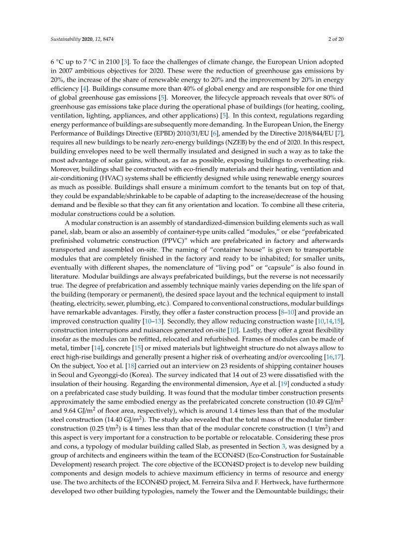
Sustainability 2020, 12, 8474 2 of 20
6 ◦C up to 7 ◦C in 2100 [3]. To face the challenges of climate change, the European Union adoptedin 2007 ambitious objectives for 2020. These were the reduction of greenhouse gas emissions by20%, the increase of the share of renewable energy to 20% and the improvement by 20% in energyefficiency [4]. Buildings consume more than 40% of global energy and are responsible for one thirdof global greenhouse gas emissions [5]. Moreover, the lifecycle approach reveals that over 80% ofgreenhouse gas emissions take place during the operational phase of buildings (for heating, cooling,ventilation, lighting, appliances, and other applications) [5]. In this context, regulations regardingenergy performance of buildings are subsequently more demanding. In the European Union, the EnergyPerformance of Buildings Directive (EPBD) 2010/31/EU [6], amended by the Directive 2018/844/EU [7],requires all new buildings to be nearly zero-energy buildings (NZEB) by the end of 2020. In this respect,building envelopes need to be well thermally insulated and designed in such a way as to take themost advantage of solar gains, without, as far as possible, exposing buildings to overheating risk.Moreover, buildings shall be constructed with eco-friendly materials and their heating, ventilation andair-conditioning (HVAC) systems shall be efficiently designed while using renewable energy sourcesas much as possible. Buildings shall ensure a minimum comfort to the tenants but on top of that,they could be expandable/shrinkable to be capable of adapting to the increase/decrease of the housingdemand and be flexible so that they can fit any orientation and location. To combine all these criteria,modular constructions could be a solution.
A modular construction is an assembly of standardized-dimension building elements such as wallpanel, slab, beam or also an assembly of container-type units called “modules,” or else “prefabricatedprefinished volumetric construction (PPVC)” which are prefabricated in factory and afterwardstransported and assembled on-site. The naming of “container house” is given to transportablemodules that are completely finished in the factory and ready to be inhabited; for smaller units,eventually with different shapes, the nomenclature of “living pod” or “capsule” is also found inliterature. Modular buildings are always prefabricated buildings, but the reverse is not necessarilytrue. The degree of prefabrication and assembly technique mainly varies depending on the life span ofthe building (temporary or permanent), the desired space layout and the technical equipment to install(heating, electricity, sewer, plumbing, etc.). Compared to conventional constructions, modular buildingshave remarkable advantages. Firstly, they offer a faster construction process [8–10] and provide animproved construction quality [10–13]. Secondly, they allow reducing construction waste [10,14,15],construction interruptions and nuisances generated on-site [10]. Lastly, they offer a great flexibilityinsofar as the modules can be refitted, relocated and refurbished. Frames of modules can be made ofmetal, timber [14], concrete [15] or mixed materials but lightweight structure do not always allow toerect high-rise buildings and generally present a higher risk of overheating and/or overcooling [16,17].On the subject, Yoo et al. [18] carried out an interview on 23 residents of shipping container housesin Seoul and Gyeonggi-do (Korea). The survey indicated that 14 out of 23 were dissatisfied with theinsulation of their housing. Regarding the environmental dimension, Aye et al. [19] conducted a studyon a prefabricated case study building. It was found that the modular timber construction presentsapproximately the same embodied energy as the prefabricated concrete construction (10.49 GJ/m2
and 9.64 GJ/m2 of floor area, respectively), which is around 1.4 times less than that of the modularsteel construction (14.40 GJ/m2). The study also revealed that the total mass of the modular timberconstruction (0.25 t/m2) is 4 times less than that of the modular concrete construction (1 t/m2) andthis aspect is very important for a construction to be portable or relocatable. Considering these prosand cons, a typology of modular building called Slab, as presented in Section 3, was designed by agroup of architects and engineers within the team of the ECON4SD (Eco-Construction for SustainableDevelopment) research project. The core objective of the ECON4SD project is to develop new buildingcomponents and design models to achieve maximum efficiency in terms of resource and energyuse. The two architects of the ECON4SD project, M. Ferreira Silva and F. Hertweck, have furthermoredeveloped two other building typologies, namely the Tower and the Demountable buildings; their

Sustainability 2020, 12, 8474 3 of 20
paper [20] provides more details on the design motivation and on the architectural aspect of these threebuilding typologies.
The Slab building is a hybrid modular construction based on the plug-in concept or on Metabolism,from a wider perspective. The plug-in concept was imagined by Le Corbusier around the 1950s whenhe designed the Unité d’habitation (Cité Radieuse) [21] although it has never been realized in anyof his buildings. The plug-in concept involves a primary structure, in which prefabricated housingunits are slotted, whereas Metabolism [22] is a Japanese architectural movement established in thelate 1950s, combining megastructures with the principles of biological growth, in order to allowbuildings to expand/shrink. As a result, the Slab building is composed of a permanent reinforcedconcrete structure named shelf-structure, and several flexible removable timber modules used ashousing units, as presented in Section 3. A two-fold study was carried out on the Slab building.The first part of the study is the development of an energy concept and a HVAC system design forthe whole building. The second part involves a sustainability analysis on the modules, focusing onenergy aspect and on thermal comfort. The sustainability analysis was realized in accordance withLuxembourgish regulatory requirements although the current regulation does not yet consider the Slabbuilding typology. The energy analysis regards the determination of the wall thickness of a module,whereupon two module variants have been dimensioned. The first variant fulfills the requirementsfor AAA energy class, which correspond to the passive house requirements in Luxembourg andwhich is requisite to have a NZEB. The other one fulfills the current requirements for building permitapplication, which in principle corresponds to the low energy house requirements in Luxembourg.Since the two module variants have a relatively low thermal inertia as described in Section 4.2.1,thermal comfort is a sore spot, which deserves particular attention. Thus, this paper aims at assessingthermal comfort of the two module variants, more precisely, summertime overheating risk, which isalso a key step allowing to check the necessity of an active cooling system. To appraise the impact ofthermal mass on overheating, a fictive module version fulfilling the AAA energy class requirementsbut presenting a higher thermal inertia was studied.
2. Literature Review
Articles regarding thermal comfort assessment of modular constructions are scarce in literature.Fifield et al. [17] conducted a summertime overheating assessment of thermally lightweight,well-insulated, naturally ventilated modular healthcare buildings in the UK, according to Britishstandards. Depending on the usage of the rooms, British standards propose two methods to assessoverheating risk; these are modelling and in-use monitoring. The method used in their study wasin-use monitoring, predicated on both static and adaptive overheating criteria. Static overheatingcriteria are only based on indoor environmental factors, more specifically on indoor temperatures(e.g., dry-resultant temperature, operative temperature, air temperature) in contrast with adaptivecriteria, which additionally consider personal factors. The most popular thermal comfort assessmentbased on adaptive criteria is the American Society of Heating, Refrigerating and Air-ConditioningEngineers (ASHRAE) method. It proposes the predicted mean vote (PMV) model, under which thehighest comfort temperature in winter and summer are 24.3 ◦C and 26.7 ◦C (new effective temperature),respectively [23]. Fifield et al. concluded that these modular buildings are at risk of summertimeoverheating in a relatively cool UK summer condition.
Regarding plug-in or flexible modular units, no studies on thermal comfort assessment havebeen found in literature; nonetheless, few ones about thermal analysis, which are closely related tothermal comfort assessment, have been listed. Ulloa et al. [24] realized a study on standard 20-footequivalent unit (TEU) shipping containers made of COR-TEN®steel, reused as service modules(first aid module, shower module and refrigeration module) in the area of humanitarian help orsocial emergency. The purpose of the study was to estimate the peak for the heating and coolingdemands in order to choose the adequate HVAC system for the modules. Modules were studiedin five locations spread in different climate areas according to the Köppen–Geiger classification

Sustainability 2020, 12, 8474 4 of 20
(equatorial, arid, warm temperate, snow and polar climates) [25], whereas their orientation wasfixed (window facing west). The thermal analysis involved dynamic thermal simulations (DTS) inTRNSYS software (v.17, Thermal Energy System Specialists, LLC, Madison, WI, USA) whereby modulesgeometry was modelled on Trimble SketchUp. The heating and cooling demands of the first aid modulewere predicated upon EN ISO 13790 [26] from the temperatures range which allows maintainingthermal comfort for a hospital that is from 22 ◦C to 26 ◦C. Kosir et al. [27] conducted a study toevaluate energy and visual (daylight) efficiency of a flexible prefabricated modular unit of 6.5 mlength, 3.0 m width and 3.4 m height. The module was studied at five different locations (Reykjavik,Hamburg, Munich, Athens and Abu Dhabi) while varying different parameters, namely the orientation,the window-to-wall ratio (WWR), the window distribution, the shading, the thermal transmittance ofthe envelope and the glazing characteristics. The study required the realization of dynamic energysimulations on EnergyPlus software. The set-point temperatures for cooling activation were taken fromthe EN 15232 [28], which are 23 ◦C during the winter period and 26 ◦C during the summer period.
Buildings based on the plug-in concept are barely referenced in literature. Some of them arestill in their pre-project phase, such as the “plug-in hexagonal housing units” [29] or the “plug-inmodules system” [30], and others have been completed, such as the Nakagin Capsule Tower [31] andthe NEST building [32]. Some Kasita living units [33,34] have also been achieved but the rack structureonto which they can be slotted still remains in project phase. No thermal analysis or thermal comfortassessment on these buildings has been found in literature except a post-occupancy evaluation on theNagakin Capsule Tower. Indeed, two architects, L. Soares and F. Magalhães, lived in that building foralmost a year and based on the remaining residents’ observation, the indoor climate of the capsulesis reported as too hot in summer and too cold in winter [35]. The two architects state that this isdue to the fact that all wall surfaces of the capsules are in contact with the exterior. Nevertheless,the preponderant reason for that seasonal discomfort would be the low thermal inertia of the capsules’enclosure, knowing that capsules’ walls are built with lightweight welded steel frames, filled with ironplates and insulated with asbestos [31].
3. The Slab Building
The Slab building has four open floors on the modules side and nine floors on the shaftsside, as depicted in Figure 1c,d. The ground floor will host shops in urban locations and officesor workspaces in suburban areas. The top floor will be used as common space and the four openfloors will accommodate the 48 plug-in modules. Each open floor can receive up to twelve stackedmodules. The interior dimensions of the modules are 3 m width, 9 m length and 2.7 m height,as illustrated in Figure 1a,b; their wall thickness is 40 cm on all sides, as explained in Section 4.2.1.Given their size, the modules will be transported by special convoy since the maximum width allowedfor standard road transport is set to 2.5 m [36] within the European Union. The building envelope ofthe modules will be built as much as possible with wood-based construction materials, seeing thatthese present a low embodied energy and are lightweight, as discussed in Section 1. The framing ofthe modules is made of timber I-beams connected to a timber column-beam structure, as shown inFigure 2c. Ducts and pipes for the HVAC system and for other technical equipment (electrical, sewer,plumbing, etc.) will be integrated into the roof/floor of the modules and will be connected/disconnectedfrom the shelf-structure via a plug-in system, as shown in Figure 1b. A module offers 27 m2 of livingspace but larger housing units can be realized by combining two or up to four units, as shown inFigure 1c. A concept for combining the modules in order to limit thermal bridging is being designed.Regarding the openings, a window of 3 m width and 2.7 m height is located on the front facade,as shown in Figure 2a. To maximize solar gains and daylight penetration, a non-operable window of0.9 m width and 2.1 m height is located on the back facade, as presented in Figure 2b. A non-glazeddoor of 0.9 m width and 2.1 m height is also located on the back facade. The shelf-structure serves asdocking space for the modules, provides building services including HVAC, ensures both vertical andhorizontal circulation and hosts the common utility rooms. Thanks to a rail system, the modules can

Sustainability 2020, 12, 8474 5 of 20
be individually plugged/unplugged from the shelf-structure without affecting the adjacent modules.This allows the Slab building to extend or shrink and the modules to be relocated. These operationscan be executed at any time with the help of a crane. The modules can be reused or recycled at the endof the first service life, depending on their condition and material degradation. If reused, they couldbe sent back to the manufacturing plant to be refurbished and eventually refitted. The Slab buildingis intended to be constructed in Luxembourg; therefore, the modules shall be designed to fit anyorientation and location in Luxembourg to be flexible.
Sustainability 2020, 12, x FOR PEER REVIEW 4 of 22
(a)
(b)
3.00 3.00 3.00
10.2
54.
20
14.4
5
3.00
removal of a moduleinstallation of a module
9.00
3.00 6.90
modulemodule
OPEN CORRIDOR 1.20
9.00
2.70
2.10
0.60
STUDIO
OPEN CORRIDOR
3.60
OPEN CORRIDOR
OPEN CORRIDOR
2.70
1.10
0.80
0.20
9.85
9.80
cable path
rainwater
STUDIO
0.20
3.50
0.30
3.50
removal of a module
installation of a module
for HVAC system
module
1.10
1.10
the ducts and pipes
3.50
module
rail
plug-in system to connect
rail
0.80
Figure 1. Cont.

Sustainability 2020, 12, 8474 6 of 20
Sustainability 2020, 12, x FOR PEER REVIEW 5 of 22
(c) (d)
Figure 1. Drawings and 3D views of the Slab building: (a) Plan view of the current floor; (b) Cross section of the current floor; (c) 3D view of the front facade; (d) 3D view of the back facade.
2. Literature Review
Articles regarding thermal comfort assessment of modular constructions are scarce in literature. Fifield et al. [17] conducted a summertime overheating assessment of thermally lightweight, well-insulated, naturally ventilated modular healthcare buildings in the UK, according to British standards. Depending on the usage of the rooms, British standards propose two methods to assess overheating risk; these are modelling and in-use monitoring. The method used in their study was in-use monitoring, predicated on both static and adaptive overheating criteria. Static overheating criteria are only based on indoor environmental factors, more specifically on indoor temperatures (e.g., dry-resultant temperature, operative temperature, air temperature) in contrast with adaptive criteria, which additionally consider personal factors. The most popular thermal comfort assessment based on adaptive criteria is the American Society of Heating, Refrigerating and Air-Conditioning Engineers (ASHRAE) method. It proposes the predicted mean vote (PMV) model, under which the highest comfort temperature in winter and summer are 24.3 °C and 26.7 °C (new effective temperature), respectively [23]. Fifield et al. concluded that these modular buildings are at risk of summertime overheating in a relatively cool UK summer condition.
Regarding plug-in or flexible modular units, no studies on thermal comfort assessment have been found in literature; nonetheless, few ones about thermal analysis, which are closely related to thermal comfort assessment, have been listed. Ulloa et al. [24] realized a study on standard 20-foot equivalent unit (TEU) shipping containers made of COR-TEN® steel, reused as service modules (first aid module, shower module and refrigeration module) in the area of humanitarian help or social emergency. The purpose of the study was to estimate the peak for the heating and cooling demands in order to choose the adequate HVAC system for the modules. Modules were studied in five locations spread in different climate areas according to the Köppen–Geiger classification (equatorial, arid, warm temperate, snow and polar climates) [25], whereas their orientation was fixed (window facing west). The thermal analysis involved dynamic thermal simulations (DTS) in TRNSYS software (v.17, Thermal Energy System Specialists, LLC, Madison, WI, USA) whereby modules geometry was modelled on Trimble SketchUp. The heating and cooling demands of the first aid module were predicated upon EN ISO 13,790 [26] from the temperatures range which allows maintaining thermal comfort for a hospital that is from 22 °C to 26 °C. Kosir et al. [27] conducted a study to evaluate energy and visual (daylight) efficiency of a flexible prefabricated modular unit of 6.5 m length, 3.0 m width and 3.4 m height. The module was studied at five different locations (Reykjavik, Hamburg, Munich, Athens and Abu Dhabi) while varying different parameters, namely the orientation, the window-to-wall ratio (WWR), the window distribution, the shading, the thermal transmittance of the envelope and the glazing characteristics. The study required the realization of dynamic energy simulations on
Figure 1. Drawings and 3D views of the Slab building: (a) Plan view of the current floor; (b) Crosssection of the current floor; (c) 3D view of the front facade; (d) 3D view of the back facade.
Sustainability 2020, 12, x FOR PEER REVIEW 6 of 21
in Figure 2b. A non-glazed door of 0.9 m width and 2.1 m height is also located on the back facade. The shelf-structure serves as docking space for the modules, provides building services including HVAC, ensures both vertical and horizontal circulation and hosts the common utility rooms. Thanks to a rail system, the modules can be individually plugged/unplugged from the shelf-structure without affecting the adjacent modules. This allows the Slab building to extend or shrink and the modules to be relocated. These operations can be executed at any time with the help of a crane. The modules can be reused or recycled at the end of the first service life, depending on their condition and material degradation. If reused, they could be sent back to the manufacturing plant to be refurbished and eventually refitted. The Slab building is intended to be constructed in Luxembourg; therefore, the modules shall be designed to fit any orientation and location in Luxembourg to be flexible.
(a)
(b)
(c)
Figure 2. 3D views of the module: (a) Front facade; (b) Back facade; (c) Load-bearing structure.
4. Methods
This section is divided into three main parts. The first part explains the basis of the Luxembourgish regulation regarding overheating risk assessment on residential buildings. The second part presents the simulation model and the building model. The third part discusses the simulation parameters.
4.1. Overheating Risk Assessment According to Luxembourgish Regulation
On the basis of the DIN 4108-2, the Luxembourgish regulation on energy performance of residential buildings [37,38] prescribes two methods regarding summertime thermal comfort. The first one is the checking of the minimum requirements for summer thermal protection, and the second one is the assessment of summertime overheating risk, requiring the realization of DTS to check a static overheating criterion. The second method, which is used in this paper, involves a ratio of “overheating period” (OP) over “exploitation period” (EP) where the overheating period is the time during which the free-running ambient indoor temperature exceeds 26 °C. The exploitation period has not been further defined in the regulation; however, DIN 4108-2:2013-2 [39] defines an exploitation period of 24/7. Hence, if this ratio is below 10%, summertime thermal comfort is ensured. Regarding the occupancy schedule, presented in Section 0, and the internal gains, described in Section 0, the Luxembourgish regulation does not dictate to refer to a specific standard.
4.2. Simulation Model and Building Model
DTS have been realized on TRNSYS software according to the simulation model shown in Figure 3.
Figure 2. 3D views of the module: (a) Front facade; (b) Back facade; (c) Load-bearing structure.
4. Methods
This section is divided into three main parts. The first part explains the basis of the Luxembourgishregulation regarding overheating risk assessment on residential buildings. The second part presentsthe simulation model and the building model. The third part discusses the simulation parameters.
4.1. Overheating Risk Assessment According to Luxembourgish Regulation
On the basis of the DIN 4108-2, the Luxembourgish regulation on energy performance of residentialbuildings [37,38] prescribes two methods regarding summertime thermal comfort. The first one isthe checking of the minimum requirements for summer thermal protection, and the second one isthe assessment of summertime overheating risk, requiring the realization of DTS to check a staticoverheating criterion. The second method, which is used in this paper, involves a ratio of “overheatingperiod” (OP) over “exploitation period” (EP) where the overheating period is the time during whichthe free-running ambient indoor temperature exceeds 26 ◦C. The exploitation period has not beenfurther defined in the regulation; however, DIN 4108-2:2013-2 [39] defines an exploitation periodof 24/7. Hence, if this ratio is below 10%, summertime thermal comfort is ensured. Regarding the

Sustainability 2020, 12, 8474 7 of 20
occupancy schedule, presented in Section 4.3.3, and the internal gains, described in Section 4.3.4,the Luxembourgish regulation does not dictate to refer to a specific standard.
4.2. Simulation Model and Building Model
DTS have been realized on TRNSYS software according to the simulation model shown in Figure 3.Sustainability 2020, 12, x FOR PEER REVIEW 7 of 21
Figure 3. TRNSYS model for DTS.
The building model was created in TRNBuild and Sketchup software. The module model comprises a single thermal zone with residential building input characteristics. The module is assimilated to a single-family house implemented on a hosting site, which is none other than the shelf-structure. Module walls can be adjacent to other walls but to consider the worst-case layout, all walls of the module are assumed to be exposed to the outdoor influences. The building components of the shelf-structure create sun shading on the modules that has to be considered. In this regard, the shading/insolation matrix was generated by the 3D data geometry mode, which requires the 3D modelling of the shading. The shading model denoted in Figure 1c represents the worst-case sun shading on a module since this configuration exposes the most walls of the module to the sun; it corresponds to half of the current floor. Note that a shear wall is splitting the current floor into two parts. The 3D sun shading model of the shelf-structure is illustrated in Figure 4. The surfaces on the top, the sides and the back facade of the model represent the shading generated by the slab, the walls and the open corridors, respectively. As the width of the open corridors is variable, the smallest width (1.20 m) was taken.
(a) (b)
Figure 4. 3D sun shading model of the shelf-structure on the module: (a) Front facade; (b) Back facade.
The minimum required wall thicknesses were determined in accordance with the Luxembourgish regulation on energy performance of residential buildings and based on the worst-case orientation (window facing north), which makes the module variants very well thermally insulated. For the current requirements for building permit application, characteristics of walls, windows and door are similar to those found in typical low energy houses. For the requirements for AAA energy class, characteristics of these components were set to very high performance.
4.2.1. Opaque Walls on the Module Envelope
Basically, the six sides of the module envelope have the same structure. However, additional elements could eventually be added, such as a heating floor system, for instance. Energy balance
Figure 3. TRNSYS model for DTS.
The building model was created in TRNBuild and Sketchup software. The module model comprisesa single thermal zone with residential building input characteristics. The module is assimilated toa single-family house implemented on a hosting site, which is none other than the shelf-structure.Module walls can be adjacent to other walls but to consider the worst-case layout, all walls of the moduleare assumed to be exposed to the outdoor influences. The building components of the shelf-structurecreate sun shading on the modules that has to be considered. In this regard, the shading/insolationmatrix was generated by the 3D data geometry mode, which requires the 3D modelling of the shading.The shading model denoted in Figure 1c represents the worst-case sun shading on a module since thisconfiguration exposes the most walls of the module to the sun; it corresponds to half of the currentfloor. Note that a shear wall is splitting the current floor into two parts. The 3D sun shading model ofthe shelf-structure is illustrated in Figure 4. The surfaces on the top, the sides and the back facade ofthe model represent the shading generated by the slab, the walls and the open corridors, respectively.As the width of the open corridors is variable, the smallest width (1.20 m) was taken.
Sustainability 2020, 12, x FOR PEER REVIEW 7 of 21
Figure 3. TRNSYS model for DTS.
The building model was created in TRNBuild and Sketchup software. The module model comprises a single thermal zone with residential building input characteristics. The module is assimilated to a single-family house implemented on a hosting site, which is none other than the shelf-structure. Module walls can be adjacent to other walls but to consider the worst-case layout, all walls of the module are assumed to be exposed to the outdoor influences. The building components of the shelf-structure create sun shading on the modules that has to be considered. In this regard, the shading/insolation matrix was generated by the 3D data geometry mode, which requires the 3D modelling of the shading. The shading model denoted in Figure 1c represents the worst-case sun shading on a module since this configuration exposes the most walls of the module to the sun; it corresponds to half of the current floor. Note that a shear wall is splitting the current floor into two parts. The 3D sun shading model of the shelf-structure is illustrated in Figure 4. The surfaces on the top, the sides and the back facade of the model represent the shading generated by the slab, the walls and the open corridors, respectively. As the width of the open corridors is variable, the smallest width (1.20 m) was taken.
(a) (b)
Figure 4. 3D sun shading model of the shelf-structure on the module: (a) Front facade; (b) Back facade.
The minimum required wall thicknesses were determined in accordance with the Luxembourgish regulation on energy performance of residential buildings and based on the worst-case orientation (window facing north), which makes the module variants very well thermally insulated. For the current requirements for building permit application, characteristics of walls, windows and door are similar to those found in typical low energy houses. For the requirements for AAA energy class, characteristics of these components were set to very high performance.
4.2.1. Opaque Walls on the Module Envelope
Basically, the six sides of the module envelope have the same structure. However, additional elements could eventually be added, such as a heating floor system, for instance. Energy balance
Figure 4. 3D sun shading model of the shelf-structure on the module: (a) Front facade; (b) Back facade.
The minimum required wall thicknesses were determined in accordance with the Luxembourgishregulation on energy performance of residential buildings and based on the worst-case orientation

Sustainability 2020, 12, 8474 8 of 20
(window facing north), which makes the module variants very well thermally insulated. For the currentrequirements for building permit application, characteristics of walls, windows and door are similar tothose found in typical low energy houses. For the requirements for AAA energy class, characteristics ofthese components were set to very high performance.
4.2.1. Opaque Walls on the Module Envelope
Basically, the six sides of the module envelope have the same structure. However, additional elementscould eventually be added, such as a heating floor system, for instance. Energy balance calculationshave shown that a wall thickness of 40 cm is sufficient to fulfil the two requirements explained inSection 4.2. For the AAA energy class requirements, 31 cm of aerogel is required, resulting in a wallU-value of 0.062 W/m2.K. For the current requirements for building permit application, 31 cm of woodwool is sufficient, giving a wall U-value of 0.123 W/m2.K. An additional layer of 5 cm lightweightconcrete was applied on the walls and the floor of the fictive module version, fulfilling the AAAenergy requirements, and this is the only difference between the fictive and the current versions; hence,wall U-value of the fictive module version remains at 0.062 W/m2.K. The structure of the module wallsfor both variants is illustrated in Figure 5.
Sustainability 2020, 12, x FOR PEER REVIEW 8 of 21
calculations have shown that a wall thickness of 40 cm is sufficient to fulfil the two requirements explained in Section 0. For the AAA energy class requirements, 31 cm of aerogel is required, resulting in a wall U-value of 0.062 W/m2.K. For the current requirements for building permit application, 31 cm of wood wool is sufficient, giving a wall U-value of 0.123 W/m2.K. An additional layer of 5 cm lightweight concrete was applied on the walls and the floor of the fictive module version, fulfilling the AAA energy requirements, and this is the only difference between the fictive and the current versions; hence, wall U-value of the fictive module version remains at 0.062 W/m2.K. The structure of the module walls for both variants is illustrated in Figure 5.
Figure 5. Structure of the module walls.
Characteristics of materials on the opaque walls of the module envelope are given in Table 1.
Table 1. Characteristics of materials on the opaque walls of the module envelope.
Building Material Heat Conductivity
W/(m.K) Heat Capacity
Wh/(kg.K) Density (kg/m3)
Chipboard * 0.14 0.47 500 Aerogel a [40] 0.02 0.28 150
Wood wool b [41] 0.04 0.58 50 Wood fiberboard * 0.09 0.69 650
Air blade c,* 0.03 0.28 1.23 Hardwood * 0.18 0.44 700 Softwood * 0.14 0.61 450
Lightweight concrete d,* 1.80 0.28 1400 a Used in the module variant fulfilling the requirements for AAA energy class. b Used in the module variant fulfilling the requirements for building permit application. c The value of the heat conductivity varies according to the thickness and the exchange with external. d Used in the fictive module version of the variant fulfilling the requirements for AAA energy class. * Source of the values: Lesosai software database.
Table 1 indicates that both module variants have a relatively low thermal inertia but the module variant fulfilling the requirements for building permit application has a slightly higher thermal mass.
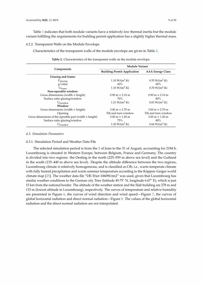
4.2.2. Transparent Walls on the Module Envelope
Characteristics of the transparent walls of the module envelope are given in Table 2.
Figure 5. Structure of the module walls.
Characteristics of materials on the opaque walls of the module envelope are given in Table 1.
Table 1. Characteristics of materials on the opaque walls of the module envelope.
Building Material Heat ConductivityW/(m.K)
Heat CapacityWh/(kg.K)
Density(kg/m3)
Chipboard * 0.14 0.47 500Aerogel a [40] 0.02 0.28 150
Wood wool b [41] 0.04 0.58 50Wood fiberboard * 0.09 0.69 650
Air blade c,* 0.03 0.28 1.23Hardwood * 0.18 0.44 700Softwood * 0.14 0.61 450
Lightweight concrete d,* 1.80 0.28 1400a Used in the module variant fulfilling the requirements for AAA energy class. b Used in the module variantfulfilling the requirements for building permit application. c The value of the heat conductivity varies accordingto the thickness and the exchange with external. d Used in the fictive module version of the variant fulfilling therequirements for AAA energy class. * Source of the values: Lesosai software database.
Sustainability 2020, 12, 8474 9 of 20
Table 1 indicates that both module variants have a relatively low thermal inertia but the modulevariant fulfilling the requirements for building permit application has a slightly higher thermal mass.
4.2.2. Transparent Walls on the Module Envelope
Characteristics of the transparent walls of the module envelope are given in Table 2.
Table 2. Characteristics of the transparent walls on the module envelope.
ComponentsModule Variant
Building Permit Application AAA Energy Class
Glazing and frame:Uglazing 1.10 W/(m2.K) 0.55 W/(m2.K)g-value 60% 60%Uframe 1.10 W/(m2.K) 0.70 W/(m2.K)
Non-operable window:Gross dimensions (width × height) 0.90 m × 2.10 m 0.90 m × 2.10 m
Surface ratio glazing/window 70% 80%Uinstalled 1.21 W/(m2.K) 0.65 W/(m2.K)Window
Gross dimensions (width × height) 3.00 m × 2.70 m 3.00 m × 2.70 mOpening Tilt and turn window Tilt and turn window
Gross dimensions of the operable part (width × height) 3.00 m × 1.20 m 3.00 m × 1.20 mSurface ratio glazing/window 75% 80%
Uinstalled 1.20 W/(m2.K) 0.64 W/(m2.K)
4.3. Simulation Parameters
4.3.1. Simulation Period and Weather Data File
The selected simulation period is from the 1 of June to the 31 of August, accounting for 2184 h.Luxembourg is situated in Western Europe, between Belgium, France and Germany. The countryis divided into two regions: the Oesling in the north (225–559 m above sea level) and the Gutlandin the south (133–440 m above sea level). Despite the altitude difference between the two regions,Luxembourg climate is relatively homogeneous, and is classified as Cfb, i.e., warm temperate climatewith fully humid precipitation and warm summer temperature according to the Köppen–Geiger worldclimate map [25]. The weather data file “DE-Trier-106090.tm2” was used, given that Luxembourg hassimilar weather conditions to the German city Trier (latitude 49.75◦ N, longitude 6.67◦ E), which is just15 km from the national border. The altitude of the weather station and the Slab building are 278 m and133 m (lowest altitude in Luxembourg), respectively. The curves of temperature and relative humidityare presented in Figure 6, the curves of wind direction and wind speed—Figure 7, the curves ofglobal horizontal radiation and direct normal radiation—Figure 8. The values of the global horizontalradiation and the direct normal radiation are not interpolated.

Sustainability 2020, 12, 8474 10 of 20
Sustainability 2020, 12, x FOR PEER REVIEW 9 of 21
Table 2. Characteristics of the transparent walls on the module envelope.
Components Module Variant
Building Permit Application AAA Energy Class
Glazing and frame: Uglazing 1.10 W/(m2.K) 0.55 W/(m2.K)
g-value 60% 60% Uframe 1.10 W/(m2.K) 0.70 W/(m2.K)
Non-operable window: Gross dimensions (width x height) 0.90 m × 2.10 m 0.90 m × 2.10 m
Surface ratio glazing/window 70% 80% Uinstalled 1.21 W/(m2.K) 0.65 W/(m2.K)
Window Gross dimensions (width x height) 3.00 m × 2.70 m 3.00 m × 2.70 m
Opening Tilt and turn window Tilt and turn window Gross dimensions of the operable part (width
x height) 3.00 m × 1.20 m 3.00 m × 1.20 m
Surface ratio glazing/window 75% 80%
Uinstalled 1.20 W/(m2.K) 0.64 W/(m2.K)
4.3. Simulation Parameters
4.3.1. Simulation Period and Weather Data File
The selected simulation period is from the 1 of June to the 31 of August, accounting for 2184 h. Luxembourg is situated in Western Europe, between Belgium, France and Germany. The country is divided into two regions: the Oesling in the north (225–559 m above sea level) and the Gutland in the south (133–440 m above sea level). Despite the altitude difference between the two regions, Luxembourg climate is relatively homogeneous, and is classified as Cfb, i.e., warm temperate climate with fully humid precipitation and warm summer temperature according to the Köppen–Geiger world climate map [25]. The weather data file “DE-Trier-106090.tm2” was used, given that Luxembourg has similar weather conditions to the German city Trier (latitude 49.75°N, longitude 6.67 E), which is just 15 km from the national border. The altitude of the weather station and the Slab building are 278 m and 133 m (lowest altitude in Luxembourg), respectively. The curves of temperature and relative humidity are presented in Figure 6, the curves of wind direction and wind speed—Figure 7, the curves of global horizontal radiation and direct normal radiation—Figure 8. The values of the global horizontal radiation and the direct normal radiation are not interpolated.
Figure 6. Temperature and relative humidity.
Sustainability 2020, 12, x FOR PEER REVIEW 10 of 21
Figure 6. Temperature and relative humidity.
Figure 7. Wind direction and wind speed.
Figure 8. Global horizontal radiation and direct normal radiation.
4.3.2. Occupancy Scenarios and Mechanical Ventilation Airflow
A high and a low occupancy scenario were studied to consider possible worst-case scenarios. For the high occupancy scenario, the studio is occupied by two persons at all times, whereas for the low occupancy scenario, it is unoccupied from 9 a.m. to 6 p.m. on weekdays as well as on weekends. When the room is occupied, the mechanical ventilation provides an airflow of 60 m3/h, based on an airflow per person of 30 m3/h. When the room is unoccupied, the mechanical ventilation provides a minimum hygienic air change rate of 0.35 h−1 corresponding to an airflow of 23.6 m3/h, as required by Luxembourgish regulation. For the two occupancy scenarios, the exploitation period is 2184 h.
4.3.3. Internal Gains
The CIBSE TM59:2017 [42] was used as reference in this work as it proposes internal gain values applicable to studios following a well-defined profile. In CIBSE TM59:2017, the occupancy to consider corresponds to two people occupying the studio at all times on weekdays as well as on weekends. The total peak load from people is 150 W of sensible heat and 110 W of latent heat. Lighting is
Figure 7. Wind direction and wind speed.
Sustainability 2020, 12, x FOR PEER REVIEW 10 of 21
Figure 6. Temperature and relative humidity.
Figure 7. Wind direction and wind speed.
Figure 8. Global horizontal radiation and direct normal radiation.
4.3.2. Occupancy Scenarios and Mechanical Ventilation Airflow
A high and a low occupancy scenario were studied to consider possible worst-case scenarios. For the high occupancy scenario, the studio is occupied by two persons at all times, whereas for the low occupancy scenario, it is unoccupied from 9 a.m. to 6 p.m. on weekdays as well as on weekends. When the room is occupied, the mechanical ventilation provides an airflow of 60 m3/h, based on an airflow per person of 30 m3/h. When the room is unoccupied, the mechanical ventilation provides a minimum hygienic air change rate of 0.35 h−1 corresponding to an airflow of 23.6 m3/h, as required by Luxembourgish regulation. For the two occupancy scenarios, the exploitation period is 2184 h.
4.3.3. Internal Gains
The CIBSE TM59:2017 [42] was used as reference in this work as it proposes internal gain values applicable to studios following a well-defined profile. In CIBSE TM59:2017, the occupancy to consider corresponds to two people occupying the studio at all times on weekdays as well as on weekends. The total peak load from people is 150 W of sensible heat and 110 W of latent heat. Lighting is
Figure 8. Global horizontal radiation and direct normal radiation.

Sustainability 2020, 12, 8474 11 of 20
4.3.2. Occupancy Scenarios and Mechanical Ventilation Airflow
A high and a low occupancy scenario were studied to consider possible worst-case scenarios.For the high occupancy scenario, the studio is occupied by two persons at all times, whereas for thelow occupancy scenario, it is unoccupied from 9 a.m. to 6 p.m. on weekdays as well as on weekends.When the room is occupied, the mechanical ventilation provides an airflow of 60 m3/h, based on anairflow per person of 30 m3/h. When the room is unoccupied, the mechanical ventilation provides aminimum hygienic air change rate of 0.35 h−1 corresponding to an airflow of 23.6 m3/h, as required byLuxembourgish regulation. For the two occupancy scenarios, the exploitation period is 2184 h.
4.3.3. Internal Gains
The CIBSE TM59:2017 [42] was used as reference in this work as it proposes internal gain valuesapplicable to studios following a well-defined profile. In CIBSE TM59:2017, the occupancy to considercorresponds to two people occupying the studio at all times on weekdays as well as on weekends.The total peak load from people is 150 W of sensible heat and 110 W of latent heat. Lighting is switchedon from 6 p.m. to 11 p.m. with a load value of 2 W/m2 of net floor area, thus, 54 W for the studio of27 m2. The equipment peak load is assumed from 6 p.m. to 8 p.m. with a value of 450 W, 200 W from8 p.m. to 10 p.m., 110 W from 9 a.m. to 6 p.m. and from 10 p.m. to 12 p.m., and a base load of 85 W forthe rest of the day. No equipment load is considered when the room is unoccupied. The internal gainsprofile on a daily basis for the two occupancy scenarios is illustrated in Figure 9. In the summer period,the heating system will be turned off and the supply air will be the outside air without any handling.
Sustainability 2020, 12, x FOR PEER REVIEW 11 of 21
switched on from 6 p.m. to 11 p.m. with a load value of 2 W/m2 of net floor area, thus, 54 W for the studio of 27 m2. The equipment peak load is assumed from 6 p.m. to 8 p.m. with a value of 450 W, 200 W from 8 p.m. to 10 p.m., 110 W from 9 a.m. to 6 p.m. and from 10 p.m. to 12 p.m., and a base load of 85 W for the rest of the day. No equipment load is considered when the room is unoccupied. The internal gains profile on a daily basis for the two occupancy scenarios is illustrated in Figure 9. In the summer period, the heating system will be turned off and the supply air will be the outside air without any handling.
(a) (b)
Figure 9. Internal gains profile on a daily basis: (a) Low occupancy scenario; (b) High occupancy scenario.
4.3.4. Sub-Variants
Three sub-variants, S1, S2 and S3, defined according to different shading device configurations, were set up for each module variant mentioned previously in Section 0. S1 involves no shading device, S2—a fixed external shading device and S3—a moveable external shading device. The external shading device was chosen for its higher effectiveness in comparison to the internal since the material and the dimensions are identical [43]. An external shading device will be implemented on all transparent walls. The S2 sub-variant can also be assimilated to the case where the user does not adjust the shading device on purpose or by omission. For this sub-variant, the shading factor was arbitrarily set to a fixed value of 50% at all times as not to compromise daylight penetration. For the S3 sub-variant, the control of the external shading device is automated, according to the global radiation on window, i.e., on the facade. The upper radiation threshold values found in literature depend on the orientation and climatic conditions [44]. Newsham [45] conducted a study on the implication of manual control of window blinds on comfort and energy consumption for the climate of Toronto (Canada). He identified that the radiation value at which most users operated the blinds was 233 W/m2. Lee et al. [46] suggested a value of 200 W/m2 in a study about the evaluation of thermal and lighting energy performance of shading devices on kinetic facades for the climate of Dubai (UAE). Wankanapon [47] found a value of 189 W/m2 for a white roller shade allowing to save cooling energy from 21 to 27% for the climate of Minneapolis (USA). Therefore, the default values of radiation threshold set in TRNBuild were chosen for the simulations, whereby the shading device closes above 180 W/m2 and opens bellow 160 W/m2. For each sub-variant, three different ventilation scenarios are proposed. The first one is without natural reinforced ventilation, the second one with night natural ventilation from 10 p.m. to 7 a.m. and the third one with day and night natural reinforced ventilation. Natural reinforced ventilation will be operated automatically by window opening; the window closes when the room temperature drops to 19 °C and opens at over 22 °C.
4.3.5. Air Exchange Rates
Since the lowest atmospheric pressure is found at the lowest altitude, the module located at the lowest level (worst-case) was chosen for the simulation. The air exchange rates were simulated on
85 0
450200 110 1100
0
54
5454 0150
0
150
150150
150
0
200
400
600
800
0-9 9-18 18-20 20-22 22-23 23-24
Equipment Lighting People
Sens
ible
hea
t loa
d(W
)
Hour
85 110
450200 110 1100 0
54
5454 0150 150
150
150150
150
0
200
400
600
800
0-9 9-18 18-20 20-22 22-23 23-24
Equipment Lighting People
Sens
ible
hea
t loa
d(W
)
Hour
Figure 9. Internal gains profile on a daily basis: (a) Low occupancy scenario; (b) High occupancy scenario.
4.3.4. Sub-Variants
Three sub-variants, S1, S2 and S3, defined according to different shading device configurations,were set up for each module variant mentioned previously in Section 1. S1 involves no shading device,S2—a fixed external shading device and S3—a moveable external shading device. The external shadingdevice was chosen for its higher effectiveness in comparison to the internal since the material andthe dimensions are identical [43]. An external shading device will be implemented on all transparentwalls. The S2 sub-variant can also be assimilated to the case where the user does not adjust the shadingdevice on purpose or by omission. For this sub-variant, the shading factor was arbitrarily set to a fixedvalue of 50% at all times as not to compromise daylight penetration. For the S3 sub-variant, the controlof the external shading device is automated, according to the global radiation on window, i.e., on thefacade. The upper radiation threshold values found in literature depend on the orientation and climaticconditions [44]. Newsham [45] conducted a study on the implication of manual control of windowblinds on comfort and energy consumption for the climate of Toronto (Canada). He identified thatthe radiation value at which most users operated the blinds was 233 W/m2. Lee et al. [46] suggesteda value of 200 W/m2 in a study about the evaluation of thermal and lighting energy performance of

Sustainability 2020, 12, 8474 12 of 20
shading devices on kinetic facades for the climate of Dubai (UAE). Wankanapon [47] found a value of189 W/m2 for a white roller shade allowing to save cooling energy from 21 to 27% for the climate ofMinneapolis (USA). Therefore, the default values of radiation threshold set in TRNBuild were chosenfor the simulations, whereby the shading device closes above 180 W/m2 and opens bellow 160 W/m2.For each sub-variant, three different ventilation scenarios are proposed. The first one is without naturalreinforced ventilation, the second one with night natural ventilation from 10 p.m. to 7 a.m. and thethird one with day and night natural reinforced ventilation. Natural reinforced ventilation will beoperated automatically by window opening; the window closes when the room temperature drops to19 ◦C and opens at over 22 ◦C.
4.3.5. Air Exchange Rates
Since the lowest atmospheric pressure is found at the lowest altitude, the module located atthe lowest level (worst-case) was chosen for the simulation. The air exchange rates were simulatedon TRNFlow according to the network model illustrated in Figure 10a. The “heights of link” of thedifferent airflow network components on the Slab building are illustrated in Figure 10b.
Sustainability 2020, 12, x FOR PEER REVIEW 12 of 21
TRNFlow according to the network model illustrated in Figure 10a. The “heights of link” of the different airflow network components on the Slab building are illustrated in Figure 10b.
(a) (b)
Figure 10. Model and drawing used on TRNFlow: (a) Network model on TRNFlow [48]; (b) Heights of the different airflow components on the Slab building.
No auxiliary node or ducts were modeled as the supply and extract airflow were assumed to be independent of the pressure difference. A tilt opening was considered for the window. If the maximum opening corresponds to an opening factor of 1, a value of 0.25 is chosen to avoid eventual high air velocity on natural ventilation. No natural reinforced ventilation is operating when the room is unoccupied. Regarding the air infiltration through the module envelope, Luxembourgish standard prescribes exchange rates at 50 Pa (n50 or ACH50) of 0.6 h−1 and 1 h−1 for the module variant fulfilling the AAA energy class requirements and the one fulfilling the building permit application requirements, respectively. To simplify, the air infiltration is assumed to occur only through the cracks around the windows and the door. In TRNFlow, the air exchange rates have to be entered in kg/s at 1 Pa and for that, the power law model of airflow through orifice can be used to estimate the airflow at different pressures, since there is a linear correlation between pressure difference and airflow. The power law equation of airflow through orifice is given by the following formula [48,50]: = ∗ ∆ , (1)
where is the airflow expressed in m3/s, is the air leakage coefficient, ∆ is the pressure difference and is the pressure exponent. Most cracks have a mixed flow regime with a flow exponent of 0.6 to 0.7 [48], therefore, a value of 0.65 was chosen. An air density of 1.2 kg/m3 was considered to determine the air mass flow. Table 3 presents the determination of the air mass flow at 1 Pa (Q1).
Table 3. Determination of the airflow at 1 Pa (Q1).
Module Variants n V (m3) ACH50 (h−1) Q50 (m3/h) C Q1 (m3/h) Q1 (kg/s) AAA energy class
0.65 72.9 0.6 43.74 3.43 3.43 11.4 × 10⁻⁴
Building permit application 1 72.90 5.73 5.73 19.1 × 10⁻⁴
The air mass flow coefficient Cs is assumed to be commensurate with the crack length. Table 4 presents the determination of the air mass flow coefficient Cs at 1 Pa for each crack.
9.15
6.05
3.100.
90
Figure 10. Model and drawing used on TRNFlow: (a) Network model on TRNFlow [48]; (b) Heightsof the different airflow components on the Slab building.
No auxiliary node or ducts were modeled as the supply and extract airflow were assumed to beindependent of the pressure difference. A tilt opening was considered for the window. If the maximumopening corresponds to an opening factor of 1, a value of 0.25 is chosen to avoid eventual high airvelocity on natural ventilation. No natural reinforced ventilation is operating when the room isunoccupied. Regarding the air infiltration through the module envelope, Luxembourgish standardprescribes exchange rates at 50 Pa (n50 or ACH50) of 0.6 h−1 and 1 h−1 for the module variant fulfillingthe AAA energy class requirements and the one fulfilling the building permit application requirements,respectively. To simplify, the air infiltration is assumed to occur only through the cracks around thewindows and the door. In TRNFlow, the air exchange rates have to be entered in kg/s at 1 Pa and forthat, the power law model of airflow through orifice can be used to estimate the airflow at differentpressures, since there is a linear correlation between pressure difference and airflow. The power lawequation of airflow through orifice is given by the following formula [49,50]:

Sustainability 2020, 12, 8474 13 of 20
Q = C ∗ ∆Pn, (1)
where Q is the airflow expressed in m3/s, C is the air leakage coefficient, ∆P is the pressure differenceand n is the pressure exponent. Most cracks have a mixed flow regime with a flow exponent of 0.6 to0.7 [48], therefore, a value of 0.65 was chosen. An air density of 1.2 kg/m3 was considered to determinethe air mass flow. Table 3 presents the determination of the air mass flow at 1 Pa (Q1).
Table 3. Determination of the airflow at 1 Pa (Q1).
Module Variants n V (m3) ACH50 (h−1) Q50 (m3/h) C Q1 (m3/h) Q1 (kg/s)
AAA energy class0.65 72.9
0.6 43.74 3.43 3.43 11.4 × 10⁻⁴
Building permit application 1 72.90 5.73 5.73 19.1 × 10⁻⁴
The air mass flow coefficient Cs is assumed to be commensurate with the crack length. Table 4presents the determination of the air mass flow coefficient Cs at 1 Pa for each crack.
Table 4. Determination of the air mass flow coefficient Cs at 1 Pa for each crack.
Cracks around theElement Length (m)
Air Mass Flow Coefficient Cs (kg/s)
“AAA Energy Class”Module
“Building PermitApplication” Module
Door 6 (26%) 2.9 × 10⁻⁴ 4.9 × 10⁻⁴
Non-operable window 6 (26%) 2.9 × 10⁻⁴ 4.9 × 10⁻⁴
Window 11.4 (48%) 5.6 × 10⁻⁴ 9.3 × 10⁻⁴
Total 23.4 (100%) 11.4 × 10⁻⁴ 19.1 × 10⁻⁴
The wind pressure acting on the facades was taken into account and the wind pressure coefficientsCp were defined, as shown in Table 5, section External nodes. Data and parameters entered onTRNFlow are also presented in Table 5.
Table 5. Data and parameters entered on TRNFlow.
Parameters Values
Dual flow ventilation system� Supply/extract airflow (imposed)
- Room unoccupied 0.35 [1/h] = 23.6 m3/h- Room occupied 60 m3/h
� Air density at Test Conditions 1.2 kg/m3
� Air Mass Flow Coefficient Cs (if fan is turned off) 0.2 kg/s at 1 Pa� Air Flow Exponent n (if fan is turned off) 0.65 a
� Height of link relative to “From-Node” 9.15 m� Height of link relative to “To-Node” 3.10 m
Thermal airnode� Reference height 6.05 m� Airnode interior dimensions: height / depth 2.70 m/9.00 m

Sustainability 2020, 12, 8474 14 of 20
Table 5. Cont.
Parameters Values
External nodes� Reference height of Cp-values 9.15 m� Wind direction angle:
Length-to-width ratio: 2:1Shielded (worst-case based on DTS)
- EN001: wind from south-west (front façade): 0◦=−0.32; 45◦=−0.3; 90◦=0.15; 135◦=0.18; 180◦=0.15;225◦=−0.3; 270◦=−0.32; 315◦=−0.2 [51]
- EN002: Wind from north-east (back façade): 0◦=0.15; 45◦=−0.3; 90◦=−0.32; 135◦=−0.2; 180◦=−0.32;225◦=−0.3;270◦=0.15; 315◦=0.18 [51]
Crack around the door/non-operable window� Air Mass Flow Coefficient Cs 2.9 × 10⁻⁴ kg/s at 1 Pa (“AAA energy class” module)
4.9 × 10⁻⁴ kg/s at 1 Pa (“Building permit application” module)� Air Flow Exponent n 0.65 a
� Height of link relative to “From-Node” 6.05 m� Height of link relative to “To-Node” 0 m� Connected to external node EN002
Crack around the window� Air Mass Flow Coefficient Cs 5.6 × 10⁻⁴ kg/s at 1 Pa (“AAA energy class” module)
9.3 × 10⁻⁴ kg/s at 1 Pa (“Building permit application” module)� Air Flow Exponent n 0.65 a
� Height of link relative to “From-Node” 6.05 m� Height of link relative to “To-Node” 0 m� Connected to external node EN001
Window opening� Own height factor 1 (window is in a vertical wall)� Category of opening Bottom hinged sash window/door� Max. width/height of opening 2.75 m / 1.05 m� Height of pivoting axis (A-height) 0.90 m� Discharge coefficient Cd1 b (completely closed) 0.6� Discharge coefficient Cd2 b (completely opened) 0.6� For Closed Opening:
- Flow coefficient Cs per m crack length 0 kg/s/m at 1 Pa as described in Section 4.3.5- Flow exponent n 0.65 a
� Opening factor of window maximum value of 0.25� Connected to external node EN001� Height of link relative to “From-Node” 6.95 m� Height of link relative to “To-Node” 0.90 m
Wind velocity profile� Wind angle direction 0◦
� Wind velocity exponent of building location 0.25 (wood, small city, suburb)a Most cracks have a mixed flow regime with a flow exponent n of 0.6 to 0.7 so the default value of 0.65 is taken. b Forusual situations, a Cd value of 0.6 to 0.7 can be found very often in literature, so the default value of 0.6 is taken.
5. Results and Discussion
DTS showed that the worst-case orientation is window facing south-west, which was taken asreference for the results presented below. Table 6 presents the overheating periods of the two modulevariants for the low and the high occupancy scenarios according to two overheating criteria (>28 ◦Cand >26 ◦C).

Sustainability 2020, 12, 8474 15 of 20
Table 6. Overheating periods of the two module variants for the low and high occupancy according to different overheating criteria.
Module Variants and Sub-Variants
Low Occupancy High Occupancy
Overheating Criteria
Max. RoomTemp. [◦C]
ACH *[h−1]
Overheating Criteria
Max. RoomTemp. [◦C]
ACH *[h−1]>28 ◦C >26 ◦C >28 ◦C >26 ◦C
OP[hrs.]
OP[hrs.]
OP/EP[%]
ODH[◦Ch] Mean Max OP
[hrs.]OP
[hrs.]OP/EP
[%]ODH[◦Ch] Mean Max
“AAA energy class“ moduleS1: Without any external shading device
- without natural reinforced ventilation 2135 2148 98 22,667 52 0.68 0.96 2142 2151 98 23,745 52 0.88 0.96- with night natural reinforced ventilation 810 1146 52 4732 44 1.87 5.20 954 1285 59 5987 46 2.12 5.25- with day and night natural reinforced ventilation 496 816 37 2450 40 2.38 5.07 351 649 30 1716 38 3.41 4.70
S2: With a fixed external shading device- without natural reinforced ventilation 1484 1927 88 7787 40 0.67 0.95 1781 2081 95 10,810 40 0.86 0.95- with night natural reinforced ventilation 218 505 23 872 35 1.60 4.86 424 792 36 1817 37 1.89 4.85- with day and night natural reinforced ventilation 113 284 13 422 33 1.98 4.47 162 337 15 608 34 2.87 4.53
S3: With a moveable external shading device- without natural reinforced ventilation 678 1249 57 2487 33 0.66 0.95 1233 1723 79 5348 35 0.86 0.95- with night natural reinforced ventilation 28 151 7 105 30 1.42 4.38 159 416 19 546 32 1.75 4.60- with day and night natural reinforced ventilation 8 79 4 35 29 1.73 4.30 45 188 9 163 31 2.69 4.40
“Building permit application“ moduleS1: Without any external shading device
- without natural reinforced ventilation 1464 1788 82 9457 46 0.68 1.03 1611 1915 88 11,134 47 0.87 1.03- with night natural reinforced ventilation 601 896 41 3115 42 1.68 4.99 737 1044 48 4103 44 1.93 5.05- with day and night natural reinforced ventilation 378 649 30 1847 38 2.14 4.81 302 565 26 1477 37 3.08 4.40
S2: With a fixed external shading device- without natural reinforced ventilation 504 858 39 2079 36 0.67 1.03 764 1232 56 3544 38 0.86 1.03- with night natural reinforced ventilation 124 308 14 486 34 1.40 4.12 234 516 24 1011 36 1.69 4.52- with day and night natural reinforced ventilation 77 213 10 290 32 1.71 4.31 131 267 12 478 33 2.50 4.50
S3: With a moveable external shading device- without natural reinforced ventilation 95 422 19 376 31 0.67 1.02 378 732 33 1257 33 0.86 1.02- with night natural reinforced ventilation 7 82 4 34 29 1.21 4.13 66 255 12 242 31 1.55 4.33- with day and night natural reinforced ventilation 3 47 2 17 29 1.43 4.17 24 147 7 101 30 2.16 4.24
OP/EP means ratio “overheating period” over “exploitation period”. ODH means overheating degree-hours. * The ACH corresponds to the overall air change rate taking into account theair infiltration, the mechanical ventilation and the natural ventilation.

Sustainability 2020, 12, 8474 16 of 20
As expected, Table 6 shows that the high occupancy scenario corresponds to the worst-casescenario in all aspects. Moreover, it demonstrates that overheating risk is a serious problem if noappropriate measures are taken, even for the low occupancy scenario. By a combination of performantexternal shading with natural ventilation strategy, the overheating period can be limited to below200 h, therefore, less than 10% of the exploitation period (218 h), which is the criterion imposed byLuxembourgish regulation. This is valid for both the “AAA energy class” and the slightly less insulated“building permit application” module variants. DTS showed that for all sub-variant configurations,most of the overheating hours occur when the outside temperature is lower than the room temperature.This means that the heat transfer goes from the interior to the exterior over the majority of theoverheating hours. Since a better insulation performance corresponds to lower heat transfer, the higherinsulation standard of the AAA energy class presents a noticeable disadvantage in terms of overheatinghours as well as of overheating degree-hours. Furthermore, for both module variants, the overheatingperiod of over 28 ◦C is not negligible, although the maximum room temperature reached is notrelatively too high (31 ◦C). Hence, thermal comfort could be optimized, for instance with reference tothe DIN 1946-2 standard [52], as shown in Figure 11.
Sustainability 2020, 12, x FOR PEER REVIEW 17 of 21
As expected, Table 6 shows that the high occupancy scenario corresponds to the worst-case scenario in all aspects. Moreover, it demonstrates that overheating risk is a serious problem if no appropriate measures are taken, even for the low occupancy scenario. By a combination of performant external shading with natural ventilation strategy, the overheating period can be limited to below 200 h, therefore, less than 10% of the exploitation period (218 h), which is the criterion imposed by Luxembourgish regulation. This is valid for both the “AAA energy class” and the slightly less insulated “building permit application” module variants. DTS showed that for all sub-variant configurations, most of the overheating hours occur when the outside temperature is lower than the room temperature. This means that the heat transfer goes from the interior to the exterior over the majority of the overheating hours. Since a better insulation performance corresponds to lower heat transfer, the higher insulation standard of the AAA energy class presents a noticeable disadvantage in terms of overheating hours as well as of overheating degree-hours. Furthermore, for both module variants, the overheating period of over 28 °C is not negligible, although the maximum room temperature reached is not relatively too high (31 °C). Hence, thermal comfort could be optimized, for instance with reference to the DIN 1946-2 standard [52], as shown in Figure 11.
(a) (b)
Figure 1. Room temperatures versus outside temperatures: (a) “AAA energy class” module variant; (b) “Building permit application” module variant.
As a comparison, DTS showed that the overheating period of the “AAA energy class” fictive module version can be limited to 65 h (3% of the exploitation period) and the maximum room temperature to 28 °C, which is even lower than the maximum outside temperature (30 °C). Therefore, the increasing of the thermal mass on the module has fundamentally improved thermal comfort as shown in Figure 12.
Figure 12. Room temperatures versus outside temperatures in the fictive module version.
14161820222426283032
0 5 10 15 20 25 30 35
Room
tem
pera
ture
(°C)
Outside temperature (°C)
"AAA energy class" module variantWith a moveable external shading device combined
with day and night natural reinforced ventilation
DIN 1946-2 standard's thermal comfort boundaries
14161820222426283032
0 5 10 15 20 25 30 35
Room
tem
pera
ture
(°C)
Outside temperature (°C)
"Building permit application" module variantWith a moveable external shading device combined
with day and night natural reinforced ventilation
DIN 1946-2 standard's thermal comfort boundaries
14161820222426283032
0 5 10 15 20 25 30 35
Room
tem
pera
ture
(°C)
Outside temperature (°C)
"AAA energy class" module variant - Fictive versionWith a moveable external shading device combined
with day and night natural reinforced ventilation
DIN 1946-2 standard's thermal comfort boundaries
Figure 11. Room temperatures versus outside temperatures: (a) “AAA energy class” module variant;(b) “Building permit application” module variant.
As a comparison, DTS showed that the overheating period of the “AAA energy class” fictivemodule version can be limited to 65 h (3% of the exploitation period) and the maximum roomtemperature to 28 ◦C, which is even lower than the maximum outside temperature (30 ◦C). Therefore,the increasing of the thermal mass on the module has fundamentally improved thermal comfort asshown in Figure 12.
Sustainability 2020, 12, x FOR PEER REVIEW 17 of 21
As expected, Table 6 shows that the high occupancy scenario corresponds to the worst-case scenario in all aspects. Moreover, it demonstrates that overheating risk is a serious problem if no appropriate measures are taken, even for the low occupancy scenario. By a combination of performant external shading with natural ventilation strategy, the overheating period can be limited to below 200 h, therefore, less than 10% of the exploitation period (218 h), which is the criterion imposed by Luxembourgish regulation. This is valid for both the “AAA energy class” and the slightly less insulated “building permit application” module variants. DTS showed that for all sub-variant configurations, most of the overheating hours occur when the outside temperature is lower than the room temperature. This means that the heat transfer goes from the interior to the exterior over the majority of the overheating hours. Since a better insulation performance corresponds to lower heat transfer, the higher insulation standard of the AAA energy class presents a noticeable disadvantage in terms of overheating hours as well as of overheating degree-hours. Furthermore, for both module variants, the overheating period of over 28 °C is not negligible, although the maximum room temperature reached is not relatively too high (31 °C). Hence, thermal comfort could be optimized, for instance with reference to the DIN 1946-2 standard [52], as shown in Figure 11.
(a) (b)
Figure 1. Room temperatures versus outside temperatures: (a) “AAA energy class” module variant; (b) “Building permit application” module variant.
As a comparison, DTS showed that the overheating period of the “AAA energy class” fictive module version can be limited to 65 h (3% of the exploitation period) and the maximum room temperature to 28 °C, which is even lower than the maximum outside temperature (30 °C). Therefore, the increasing of the thermal mass on the module has fundamentally improved thermal comfort as shown in Figure 12.
Figure 12. Room temperatures versus outside temperatures in the fictive module version.
14161820222426283032
0 5 10 15 20 25 30 35
Room
tem
pera
ture
(°C)
Outside temperature (°C)
"AAA energy class" module variantWith a moveable external shading device combined
with day and night natural reinforced ventilation
DIN 1946-2 standard's thermal comfort boundaries
14161820222426283032
0 5 10 15 20 25 30 35
Room
tem
pera
ture
(°C)
Outside temperature (°C)
"Building permit application" module variantWith a moveable external shading device combined
with day and night natural reinforced ventilation
DIN 1946-2 standard's thermal comfort boundaries
14161820222426283032
0 5 10 15 20 25 30 35
Room
tem
pera
ture
(°C)
Outside temperature (°C)
"AAA energy class" module variant - Fictive versionWith a moveable external shading device combined
with day and night natural reinforced ventilation
DIN 1946-2 standard's thermal comfort boundaries
Figure 12. Room temperatures versus outside temperatures in the fictive module version.

Sustainability 2020, 12, 8474 17 of 20
6. Conclusions
A summertime overheating risk assessment on two module variants of the Slab building was carriedout through the realization of DTS; the first variant fulfills the requirements for “AAA energy class”and the second one for “building permit application.” Although the current Luxembourgish regulationdoes not yet cover the Slab building typology, it was used as a basis for this assessment, whereby theworst-case scenarios were taken as reference. These include the worst-case implementation site(lowest altitude in Luxembourg), the worst-case orientation (window facing south-west), the worst-caseheight (module located on the lowest floor of the Slab building) and the worst-case sun shading.Moreover, a low factor of window opening (tilt opening with an opening factor of 0.25 and 44%of operable part reported to the window surface) was assumed to ensure a comfortable ventilationfor the high and the low occupancy. Three main sub-variants involving different external shadingdevice settings and different natural reinforced ventilation strategies were considered. DTS realizedon TRNSYS software showed that if no natural ventilation is applied, the effect of preventingoverheating by using a moveable external shading device based on solar radiation is less significant inthe “AAA energy class” module variant than in the “building permit application” module variant.Furthermore, the adoption of a good natural ventilation strategy tremendously reduced the overheatingperiod, even without the use of a shading device. This implies that efficient natural ventilation has apreponderant effect in mitigating overheating compared with the use of a performant shading device.DTS results revealed that the overheating period for which the room temperature exceeds 26 ◦C canbe limited to below 10% of the exploitation period, and this is valid for the two module variants.This means that the criteria for overheating defined by Luxembourg regulation are not fulfilled for bothvariants, particularly thanks to a moveable automated external shading device based on solar radiation,in combination with an automated day and night reinforced natural ventilation, which provides anoverall ACH of up to 4.40 h−1 with a mean value of 2.69 h−1. This is quite expectable since the periodfor which the exterior temperature exceeds 26 ◦C for the climate of Luxembourg represents only 4% ofthe exploitation period. However, the overheating period of over 28 ◦C is not negligible although themaximum room temperature reached is not relatively too high (31 ◦C). Hence, thermal comfort can beoptimized by increasing the thermal mass of the module walls, in this instance, with 5 cm of lightweightconcrete. Since this is a simulation study, it has its limitations. Firstly, it focuses on thermal comfortassessment and does not provide an appreciation of visual comfort. Secondly, TRNSYS weather datafiles were updated in 2004 and are subsequently obsolete; moreover, future temperatures are expectedto be higher. Lastly, the eventual impact of the shading device on the openings, and thus on the airexchange rate, was not taken into account. To conclude, Luxembourg regulation on energy efficiencyof residential buildings needs some amendments, in a way that flexible plug-in constructions wouldnot be severely penalized.
Author Contributions: Conceptualization, M.R. and F.S.; methodology, M.R. and F.S.; software, TRNSYS andSketchUp; validation, F.S.; writing—original draft preparation, M.R.; writing—review and editing, F.S. and D.W.;supervision, F.S.; project administration, D.W.; funding acquisition, D.W. All authors have read and agreed to thepublished version of the manuscript.
Funding: This research is in the framework of the ECON4SD (Eco-Construction for Sustainable Development)project, supported by the Luxembourgish EU programme “Investissement pour la croissance etl’emploi”—European Regional Development Fund (2014–2020) (Grant agreement: 2017-02-015-15).
Acknowledgments: The authors would like to express the gratitude to the whole team of the ECON4SD project,particularly to Marielle Ferreira Silva for providing the drawings and the 3D model of the Slab building.
Conflicts of Interest: The authors declare no conflict of interest.
References
1. IPCC. Climate Change and Land: IPCC Report; IPCC: Geneva, Switzerland, 2019; p. 906.2. Shell. Shell Scenarios: Sky-Meeting the Goals of the Paris Agreement; Shell: London, UK, 2018; p. 70.

Sustainability 2020, 12, 8474 18 of 20
3. Boucher, O.; Braconnot, P.; Masson-Delmotte, V.; Salas, D. Changement climatique: Les résultats des nouvellessimulations françaises. In Proceedings of the Conférence de Presse Changement Climatique: Les Résultatsdes Nouvelles Simulations Françaises, Paris, France, 19 September 2019; pp. 1–32.
4. European Commission. A Strategy for Competitive, Sustainable and Secure Energy; European Commission:Brussels, Belgium, 2010.
5. UNEP. Buildings and Climate Change: Summary for Decision Makers; UNEP DTIE Sustainable Consumption &Production Branch: Paris, France, 2009; p. 56.
6. The European Parliament and of the Council of the European Union. Directive 2010/31/EU of the EuropeanParliament and of the Council of 19 May 2010 on the energy performance of buildings (recast). Off. J.Eur. Union 2010, 153, 13–35.
7. The European Parliament and of the council of the European Union. Directive 2018/844/EU of the EuropeanParliament and of the Council of 30 May 2018 on the energy performance of buildings. Off. J. Eur. Union 2018,156, 75–91.
8. Sacks, R.; Eastman, C.M.; Lee, G. Process Model Perspectives on Management and Engineering Proceduresin the Precast/Prestressed Concrete Industry. J. Constr. Eng. Manag. 2004, 130, 206–215. [CrossRef]
9. Kasperzyk, C.; Kim, M.-K.; Brilakis, I. Automated re-prefabrication system for buildings using robotics.Autom. Constr. 2017, 83, 184–195. [CrossRef]
10. Rogan, A.L.; Lawson, R.M.; Bates-Brkljac, N. Value and Benefits Assessment of Modular Construction; The SteelConstruction Institute: London, UK, 2000.
11. Lopez, D.; Froese, T. Analysis of Costs and Benefits of Panelized and Modular Prefabricated Homes.Procedia Eng. 2016, 145, 1291–1297. [CrossRef]
12. Badir, Y.F.; Kadir, M.R.A.; Hashim, A.H. Industrialized Building Systems Construction in Malaysia.J. Arch. Eng. 2002, 8, 19–23. [CrossRef]
13. Boyd, N.; Khalfan, M.M.; Maqsood, T. Off-Site Construction of Apartment Buildings. J. Arch. Eng. 2013, 19,51–57. [CrossRef]
14. Stora Enso Projects -Lintuviita Seinäjoki, Finland. 2013. Available online: https://www.clt.info/en/projekte/
detail/?slideId=4086&category= (accessed on 15 February 2019).15. Dezeen Magazine. World’s Tallest Modular Tower Is Now Clement Canopy in Singapore. 2019. Available online:
https://www.dezeen.com/2019/07/02/clement-canopy-worlds-tallest-modular-tower-bouygues (accessed on20 October 2019).
16. Adekunle, T.O.; Nikolopoulou, M. Thermal comfort, summertime temperatures and overheating inprefabricated timber housing. Build. Environ. 2016, 103, 21–35. [CrossRef]
17. Fifield, L.; Lomas, K.J.; Giridharan, R.; Allinson, D. Hospital wards and modular construction: Summertimeoverheating and energy efficiency. Build. Environ. 2018, 141, 28–44. [CrossRef]
18. Yoo, H.-Y.; Park, Y.-J.; Yoon, J.-Y. A Study on the Improving Direction of Container Housing through FieldSurvey—Based on the Analysis of 12 cases in the Urban Area. J. Korean Hous. Assoc. 2012, 23, 21–30. [CrossRef]
19. Aye, L.; Ngo, T.; Crawford, R.H.; Gammampila, R.; Mendis, P. Life cycle greenhouse gas emissions andenergy analysis of prefabricated reusable building modules. Energy Build. 2012, 47, 159–168. [CrossRef]
20. Silva, M.F.; Jayasinghe, L.B.; Waldmann, D.; Hertweck, F. Recyclable Architecture: Prefabricated andRecyclable Typologies. Sustainability 2020, 12, 1342. [CrossRef]
21. Galinsky. Unité D’habitation (Cité Radieuse), Marseille. 2011. Available online: http://www.galinsky.com/
buildings/marseille/ (accessed on 24 July 2020).22. Tamari, T. Metabolism: Utopian Urbanism and the Japanese Modern Architecture Movement. Theory. Cult. Soc.
2014, 31, 201–225. [CrossRef]23. ANSI/ASHRAE Standard 55-2004. Thermal Eenvironmental Conditions for Human Occupancy; ANSI/ASHRAE:
Sacramento, CA, USA, 2017; Volume 7, p. 6.24. Ulloa, C.; Fariña, E.A.; Rey, G.; Míguez, J.L.; Hernández, J. Recycling COR-TEN® Sea Containers into Service
Modules for Military Applications: Thermal Analysis. Energies 2017, 10, 820. [CrossRef]25. Kottek, M.; Grieser, J.; Beck, C.; Rudolf, B.; Rubel, F. World Map of the Köppen-Geiger climate classification
updated. Meteorol. Zeitschrift 2006, 15, 259–263. [CrossRef]26. International Organization for Standardization. Energy Performance of Buildings—Calculation of Energy Use
for Space Heating and Cooling; ISO 13790:2008; International Organization for Standardization: Geneva,Switzerland, 2008; p. 162.

Sustainability 2020, 12, 8474 19 of 20
27. Košir, M.; Iglic, N.; Kunic, R. Optimisation of heating, cooling and lighting energy performance of modularbuildings in respect to location’s climatic specifics. Renew. Energy 2018, 129, 527–539. [CrossRef]
28. European Committee for Standardization. Energy Performance of Buildings-Impact of Building Automation,Controls and Building Management; CEN EN 15232; European Committee for Standardization: Geneva,Switzerland, 2012.
29. Inhabitat®. Futuristic Vertical City Holds Plug-in Hexagonal Housing Units. 2010. Available online: https://inhabitat.com/plug-your-hexagonal-house-into-this-vertical-city/ (accessed on 2 October 2020).
30. Le Pair, G. Plug-in Architecture, a Modular System to Gain Individual Movability, Extendibility and Personalization;Eindhoven University of Technology: Eindhoven, The Netherlands, 2016.
31. Lin, Z. Nakagin Capsule Tower: Revisiting the Future of the Recent Past. J. Arch. Educ. 2011, 65, 13–32.[CrossRef]
32. Richner, P.; Heer, P.; Largo, R.; Marchesi, E.; Zimmermann, M. NEST-A platform for the acceleration ofinnovation in buildings. Inf. Constr. 2017, 69, 1–8.
33. Forbes. Meet Kasita: The Micro-Housing Start-Up That’s About to Revolutionize Real Estate. 2016.Available online: https://www.forbes.com/sites/petertaylor/2016/07/19/meet-kasita-the-micro-housing-start-up-thats-about-to-revolutionize-real-estate/#51de14486f80 (accessed on 28 October 2019).
34. Dezeen magazine. Kasita Unveils Prefabricated Tiny Houses That Slot Into ‘Racks’ Like Wine Bottles. 2016.Available online: https://www.dezeen.com/2016/08/12/kasita-prefabricated-tiny-micro-house-slots-into-racks-smart-home-technology/ (accessed on 29 October 2019).
35. Soares, L.; Magalhães, F. A Year in the Metabolist Future of 1972. 2014. Available online: https://failedarchitecture.com/a-year-in-the-metabolist-future-of-1972/ (accessed on 2 October 2020).
36. The Council of the European Union. Council Directive 96/53/EC laying down for certain road vehiclescirculating within the Community the maximum authorized dimensions in national and international trafficand the maximum authorized weights in international traffic. Off. J. Eur. Communities 1996, 235, 59–75.
37. Ministère de l’Energie. Journal Officiel du Grand-Duché de Luxembourg–A–N◦ 221–14 Décembre2007–Règlement Grand-Ducal du 30 Novembre 2007 Concernant la Performance Énergétique des BâtimentsD’habitation. 2007. Available online: http://data.legilux.public.lu/file/eli-etat-leg-memorial-2007-221-fr-pdf.pdf(accessed on 14 July 2019).
38. Ministère de l’Energie. “Journal Officiel du Grand-Duché de Luxembourg–A–N◦ 146–1er Aout2016–Règlement Grand-Ducal du 23 Juillet 2016 Concernant la Performance Énergétique des BâtimentsD’habitation et Fonctionnels” 2016. Available online: http://data.legilux.public.lu/file/eli-etat-leg-memorial-2016-146-fr-pdf.pdf (accessed on 16 July 2019).
39. German Institute for Standardization. Wärmeschutz und Energie-Einsparung in Gebäuden Teil_2:Mindestanforderungen an den Wärmeschutz; DIN 4108-2:2013-0239; German Institute for Standardization:Berlin, Germany, 2019.
40. Aspen Aerogels. Technical Guidance Document. Spaceloft Aerogel Blanket Insulation; Aspen Aerogels Inc.:Northborough, MA, USA, 2011; p. 18.
41. Steico. Datasheet STEICO Flex 038. Available online: https://www.steico.com/fileadmin/steico/content/pdf/Marketing/UK/Product_information/flex/STEICOflex_038_en_i.pdf (accessed on 13 June 2019).
42. Chartered Institution of Building Services Engineers. CIBSE TM59:2017—Design Methodology for the Assessmentof Overheating Risk in Homes; Chartered Institution of Building Services Engineers: London, UK, 2017.
43. Ye, Y.; Xu, P.; Mao, J.; Ji, Y. Experimental study on the effectiveness of internal shading devices. Energy Build.2016, 111, 154–163. [CrossRef]
44. Wymelenberg, K.V.D. Patterns of occupant interaction with window blinds: A literature review. Energy Build.2012, 51, 165–176. [CrossRef]
45. Newsham, G.R. Manual Control of Window Blinds and Electric Lighting: Implications for Comfort andEnergy Consumption. Indoor Built Environ. 1994, 3, 135–144. [CrossRef]
46. Lee, D.-S.; Koo, S.-H.; Seong, Y.-B.; Jo, J.-H. Evaluating Thermal and Lighting Energy Performance of ShadingDevices on Kinetic Façades. Sustainability 2016, 8, 883. [CrossRef]
47. Wankanapon, P.; Mistrick, R.G. Roller Shades and Automatic Lighting Control with Solar Radiation ControlStrategies. Built 2011, 1, 35–42.
48. Transsolar. TRNFLOW Manual—A Module of an Air Flow Network for Coupled Simulation with TYPE 56(Multi-Zone Building of TRNSYS); Transsolar: Stuttgart, Germany, 2009; Volume 56.

Sustainability 2020, 12, 8474 20 of 20
49. American Society for Testing and Materials, ASTM International. ASTM Standard E779-87-Test Method forDetermining Air Leakage Rate by Fan Pressurization; American Society for Testing and Materials, ASTM:West Conshohocken, PA, USA, 2010.
50. Sherman, M. A Power-Law Formulation of Laminar Flow in Short Pipes. J. Fluids Eng. 1992, 114, 601–605.[CrossRef]
51. Orme, M.; Liddament, M.W.; Wilson, A. Numerical Data for Air Infiltration and Natural Ventilation Calculations;Air Infiltration and Ventilation Centre: Warwick, UK, 1998.
52. German Institute for Standardization. Raumlufttechnische Anlagen in Arbeits-und Versammlungsräumen;DIN 1946-2:1994; German Institute for Standardization: Berlin, Germany, 1994.
Publisher’s Note: MDPI stays neutral with regard to jurisdictional claims in published maps and institutionalaffiliations.
© 2020 by the authors. Licensee MDPI, Basel, Switzerland. This article is an open accessarticle distributed under the terms and conditions of the Creative Commons Attribution(CC BY) license (http://creativecommons.org/licenses/by/4.0/).
Copyright © 2022 FDOKUMEN