Intuition Versus Analysis- Which Process is Most Appropriate ...
Upload
khangminh22Category
view
3download
0
Open Access.© 2020 L. Song et al., published by De Gruyter. This work is licensed under the Creative Commons Attribution 4.0License
High Temp. Mater. Proc. 2020; 39:10–25
Research Article
Liu Song, Liu Xiaojie, Lyu Qing*, Zhang Xusheng, and Qie Yana
Study on the Appropriate Production Parametersof a Gas-injection Blast Furnacehttps://doi.org/10.1515/htmp-2020-0005Received Jun 15, 2019; accepted Oct 07, 2019
Abstract: The change regulations of the smelting parame-ters in a gas-injection blast furnace are investigated usingtheoretical calculations. The results show that when thevolume of gas injected, the oxygen enrichment rate andthe theoretical combustion temperature of tuyere are 600m3/tHM, 10% and 1950~2200∘C, respectively, the condi-tions meet the smelting requirements of a blast furnace.With the increase of the oxygen enrichment rate, the re-quired air volume decreases, the contents of CO and H2 inthe top gas increase, and the content of CO2 first increasesand then decreases. With an increase of the volume of gasinjected, the coke rate decreases. In addition, when theoxygen enrichment rate and the volume of gas injected are10% and 600 m3/tHM, respectively, the CO content of thetop gas constantly increases with the increase of the cokerate, while the H2 and CO2 contents both decrease. Withthe increase of the H2 content in the gas, the direct reduc-tion degree of iron gradually decreases and the volumeshrinkage burden increases. Apparently, injecting gas intothe blast furnace can prevent the theoretical combustiontemperature from being too high and solve the contradic-tion between the upper cooling and lower heating of theblast furnace.
Keywords:Blast furnace; Gas injection;Manufacturing pa-rameter
*Corresponding Author: Lyu Qing: College of Metallurgy & En-ergy, North China University of Science and Technology, Tangshan,063009, China; Email: [email protected] Song, Liu Xiaojie, Qie Yana: College of Metallurgy & Energy,North China University of Science and Technology, Tangshan,063009, ChinaZhang Xusheng: Hebei Iron and Steel Group Tang Steel Co., Ltd,Tangshan, 063000, China
1 IntroductionIron and steel enterprises compose one of the main en-ergy consumption and greenhouse gas emission indus-tries, and the CO2 emissions directly related to the iron-making process are over 90% [1, 2]. Pulverized coal injec-tion is one of the important measures taken for energysaving and emissions reduction in blast furnaces. How-ever, a large amount of pulverized coal being injectedwill cause many adverse effects on BF smelting [3–7]. Forexample, pulverized coal injected into the blast furnaceinternally will undergo a series of physical and chemi-cal changes that include heating, decomposition, combus-tion, and slagging. As a result, the reaction in the tuyerewill become complicated, and the operation will be diffi-cult. With an increase in the volume of pulverized coal in-jected, the softening-melting zone enlarges, and the cokeis seriously damaged. As a result, the quality of the coke re-stricts the volume of pulverized coal injected. The increaseof the pulverized coal volume will also inevitably lead tothe increase of unburnt pulverized coal, which will fur-ther deteriorate the working state of the softening-meltingzone and the slagging zone. A large amount of ash is pro-duced by the combustion of coke and pulverized coal inthe tuyere of a blast furnace, and it participates in slag-making in the hearth, which causes the basicity of the pri-mary slag to be high and the compositions of the final slagand primary slag to fluctuate greatly. Oxygen enrichmentand pulverized coal injection lead to the heat distributionof the blast furnace differentiating into "upper cooling"and "lower heating", and as a result, some measures haveto be taken tomeet the requirement of heating in the upperpart of the blast furnace. In addition, CO2 emissions areout of control. Consequently, a new process in which oxy-gen and gas both are injected into the blast furnace hasbeen developed [8, 9]. The most important characteristicof this process is that the combustion of pulverized coalin the blast furnace tuyere is moved into the gasifier, andthe BF top gas is also injected into the gasifier. Finally, thegas produced is injected into the blast furnace. This newprocess can overcome the defects of the PCI and increasethe H2 content of the blast furnace bosh gas [10, 11]; there-

Study on the Appropriate Production Parameters of a Gas-injection Blast Furnace | 11
fore, it has strong advantages in some aspects that includethe production efficiency, environmental protection, eco-nomic benefits, etc. [12, 13]. The technological process isshown in Figure 1. In this paper, through the comparisonof the smelting effects between the new process and theconventional blast furnace process, the operating charac-teristics and advantages of the new process are obtained.
1 blast furnace; 2 gas-making furnace; 3 pressure device; 4 gas heatingdevice
Figure 1: GOBF blast furnace process
2 Establishment of themathematical model for agas-injection blast furnace
Based on the actual reaction in a conventional blast fur-nace and the balanced calculations of material and heat,a model of the new process using the components of rawmaterials and actual operating parameters is established,which provides a foundation for research of the new pro-cess and the determination of the optimal parameters.It is proposed that this model can accurately reflect thechanges of the composition and temperature of the blastfurnace after the gas passes through the gasifier and intothe blast furnace, determine the effect laws of different fac-tors affecting the operation of the blast furnace, and ad-dresswhether different parameters canmeet the operatingstability of the whole blast furnace. Therefore, the rationalapplication of this model has important meaning in thestudy of the new process.
2.1 Material balance
The material balance of the blast furnace is divided intotwo parts, income and expenditure, including the calcula-tion of the slag amount, the calculation of the air volume,the calculation of the volume of the top gas, etc. The cal-culation of the material balance is helpful in the compre-hensive and quantitative analysis and the in-depth studyof the blast furnace process, as well as in preparing for thecalculation of the heat balance.
2.1.1 Calculation of the slag amount
The calculation of the slag amount is based on the rawmaterials used in the blast furnace, which are applied todetermine the composition and quantity of the blast fur-nace slag, including MgO, CaO, MnO and other compo-nents. The algorithm is shown in formula 1.
m (X) =∑︁
the amount of various raw materials × Xi (1)
In the formula, Xi represents CaO(i), MgO(i), SiO2(i),Al2O3(i),MnO(i) and S(i), which are the contents of the cor-responding components in each furnace burden. The unitof m (X) is kg.
2.1.2 Calculation of the air volume
The calculation of the air volume is the basis of the bal-anced calculation of the blast furnace burden, which is ofguiding significance in the calculation of the next step ofthe top gas. The blast volume of per ton of iron is deter-mined by the amount of carbon involved in combustionin the front of the tuyere and the amount of oxygen in theblast.
2.1.2.1 Amount of combustion carbon in the front of thetuyere
There are many factors that influence the combustion car-bon content in the front of the tuyere. It is determined bythe calculation of the three parameters of the oxidationcarbon content, the reductive carbon content of the alloyelements, and the carbon consumption due to the directreduction of iron. Each part has a great influence on thefinal result of the calculation. The algorithm is shown informula 2.
Cb = CO − Cda − CdFe (2)
In the formula, Cb, CO, Cda and CdFe represent the car-bon amount in the tuyere, the oxidation carbon content,

12 | L. Song et al.
the reductive carbon content of the alloy elements and thecarbon consumption due to the direct reduction of iron, re-spectively. The unit of Cb is kg/tFe−1.
1. Calculation of the oxidation carbon content COThe oxidation carbon content includes the coke, pul-verized coal (there is no coal injection in the newprocess, so it does not need to be considered), car-bon content in the pig iron and carbon consumptionof the CH4 generated. The algorithm is shown in for-mula 3.
CO = Cf − CC − CCH4 (3)
In the formula, Cf, CC and CCH4 represent the car-bon consumption of coke and pulverized coal, thecarbon content in the pig iron, and the carbon con-sumption of the CH4 generated, respectively.
2. Calculation of the reductive carbon content Cda ofalloy elementsThe reductive carbon content of alloy elements in-cludes the reductive carbon consumption of ele-ments in the pig iron, the reductive carbon con-sumption of CO2 in the limestone and the carbonconsumption of desulphurization. The algorithm isshown in formula 4.
Cda = Celement + Climestone + CS (4)
In the formula, Celement, Climestone and CS representthe reductive carbonconsumptionof elements in thepig iron, the reductive carbonconsumptionof CO2 inthe limestone and the carbon consumption of desul-phurization, respectively.
3. Calculationof the carbonconsumption CdFe in directreductionThe carbon consumption in direct reduction is theamount of carbon needed to smelt one ton of pigiron, and it has a great relationshipwith thedirect re-duction degree. The algorithm is shown in formula 5.
CdFe = 12 × Fe.r × rd/56 (5)
In the formula, Fe.r is the amount of reduced ironin the blast furnace smelting the ton of iron, whichis generally 10[Fe], and rd is the direct reduction de-gree.
2.1.2.2 Oxygen content in the blast (the unit is apercentage)
Themodernblast furnace is in continuouspursuit of ahighoxygen enrichment rate to reduce the coke rate, therefore,the changes of the oxygen content in the blast also have
a great influence on the calculation of the air volume andheat. The algorithm is shown in formula 6.
O2b = 0.21 + 0.29 × φ + (a − 0.21) ×W (6)
In the formula, φ is the blast humidity, W is theamount of enriched oxygen per cubic meter in the blast,a is the purity of oxygen in the enriched oxygen, and (a −0.21) ×W is the oxygen enrichment rate.
1. Blast volume the unit is m3/tFe−1):According to the chemical reaction in the raceway inthe front of the tuyere in the blast furnace, the blastvolume required for one tonof iron is calculated. Thealgorithm is shown in formula7.
Vb =22.4 × Cb24 × O2b
= 0.933 × Cb/O2b (7)
2.1.3 Volume of the top gas (the unit is m3/tFe−1)
The top gas of the blast furnace is composed of six kindsof gas, including CO2, CO, N2, H2, H2O and CH4, and thequantity of each gas is influenced by many factors. The in-jection of the gas made by coal is used in the new process,which has a great influence on the top gas of the furnacecompared with that in the traditional technology.
2.1.3.1 CH4There is not a high content of CH4 in the top gas. Ithas three main sources, including the gas injection, thevolatile matter of coke and the carbon and hydrogen syn-thesis. The algorithm is shown in formula 8.
VCH4 = K × CH4coke × 22.4/16 + VinjectingCH4 (8)+ 22.4CCH4 /12
In the formula, CH4coke is the content of methane inthe coke and VinjectingCH4 is the content of methane in thegas injection.
2.1.3.2 H2The hydrogen in the blast furnace is from four sources—the fuel, the blast humidity, and the crystalline water ofthe raw materials and coal gas injected—and the portioninvolved in the reduction and the production of CH4 is con-sumed,while the rest enters the topgas.Due to the coal gasbeing injected in the new process, to a certain extent, theamount of hydrogen gas in the furnace is increased, whichhas a great influence on the reduction of the blast furnace.

Study on the Appropriate Production Parameters of a Gas-injection Blast Furnace | 13
The calculation of the content of H2 in the top gas is shownin formula 9.
VH2 =∑︁
H2 − H2r − H2CH4 (9)
In the formula,∑︀H2 is the total hydrogen content en-
tering the blast furnace, H2r is the amount of hydrogeninvolved in the reduction according to the utilization rateof hydrogen, and H2CH4 is the hydrogen content of the pro-duced CH4.
2.1.3.3 H2OThe content of H2O is lower in the top gas, and it whichmainly comes from two sources: hydrogen reduction andthe furnace burden. The algorithm is shown in formula 10.
VH2O =∑︁
H2O + H2r (10)
In the formula,∑︀H2O is the total water brought by
the furnace burden.
2.1.3.4 CO2The CO2 in the blast furnace is contributed from twosources: indirect reduction and the furnace burden, andthe former is the main source. The indirect reduction ofCO2 is produced by the reduction of iron and manganeseoxides in the raw materials. The CO2 brought by the fur-nace burden includes the flux, the CO2 in the coke and thedecomposition of limestone at high temperatures. The al-gorithm is shown in formula 11.
VCO2 = VCO2indirectreduction + VCO2furnaceburden (11)
In the formula, VCO2indirectreduction is the amount of CO2produced by indirect reduction and VCO2furnaceburden is theamount of CO2 brought by the furnace burden.
2.1.3.5 CO2CO is the main reducing gas of the blast furnace, whichplays an important role in the reduction of raw materials.The CO in the blast furnace is composed of four sources:the coal gas injected, the volatile matter of coke, oxides re-duction and the combustion of carbon in the front of thetuyere. CO is combined with raw materials during the pro-cess of rising in the blast furnace, and it participates in in-direct reduction reactions, which consume an amount ofCO. The hydrogen content is increased, the direct reduc-tion of the blast furnace is changed, and the coke rate isreduced during the process of injecting the gas made by
coal, which has a great influence on the content of CO inthe top gas. The algorithm is shown in formula 12.
VCO = VCO tuyere + VCO reduction + VCO coke (12)+ VCO injecting − VCO2 indirect reduction
In the formula, VCO tuyere, VCO reduction, VCO coke andV CO injecting represent the amount of CO produced by thecombustion of carbon in the front of the tuyere, theamount of CO produced by oxide reductions, the amountof CO in coke volatilization and the amount of CO in thecoal gas injected, respectively.
2.1.3.6 N2N2 is an inert gas, which is relatively stable in the blast fur-nace and does not participate in any reaction. It is mainlycontributed by the blast, coke and coal gas injected. Thealgorithm is shown in formula 13.
VN2 = VN2 blast + VN2 coke + VN2 injecting (13)
In the formula, VN2 blast is the amount of N2 brought bythe blast, VN2 coke is the amount of N2 brought by the coke,and VN2 injecting is the amount of N2 brought by the coal gasinjected.
The top gas volume is the sum of each component ofthe six gases, and the algorithm is shown in formula 14.
Vg = VCO + VCO2 + VCH4 + VH2 + VN2 + VH2O (14)
2.1.4 Material balance sheet compilation
According to the results, the two parts of the material in-come and expenditure are listed. The relative error is cal-culated to verify the reasonableness of the calculation re-sults. The error algorithm is shown in formula 15.
Absolute error = Total quality ofmaterial income (15)− Total quality ofmaterial expenditure
Relative error = Absolute errorTotalmaterial income × 100%
2.2 Heat balance
The blast furnace heat is divided into income and expen-diture parts. The heat income includes the combustionheat of carbon in the front of the tuyere, the physical heatof the blast, the generated heat of CH4, the heat of slagformation, the physical heat of the furnace burden, etc.

14 | L. Song et al.
The heat expenditure includes the heat consumption of ox-ide decomposition, the heat consumption of desulphuriza-tion, the heat consumption of carbonate decomposition,the heat consumption of water decomposition and evap-oration, the heat taken away by molten iron, slag and topgas, the heat loss, etc. The unit is kJ · t−1.
2.2.1 Heat income
2.2.1.1 Calculation of the combustion heat of carbon inthe front of the tuyere
The combustion heat of carbon in the front of the tuyere isan important source of heat in the blast furnace, and theheat is mainly produced by the combustion of coke andfuel injection in this area. The coal gas injected serves asalternative to pulverized coal in the new process, and theproduction of heat is reduced. The algorithm is shown informula 16.
Qc = 9781.2 × Cb (16)
In the formula, Qc is the combustion heat of carbon in thefront of the tuyere.
2.2.1.2 Physical heat of the blastThe physical heat of the blast is another important item inthe heat income of the blast furnace, which is brought intothe blast furnace during blasting, and the heat of the coalgas injected is also included in the new process. In addi-tion, the wind temperature, the air volume and the humid-ity have a great influence on the physical heat of the blast.The algorithm is shown in formula 17.
Qwind = Vb ×{︀(1 − φ) × qb + φ × qH2O
}︀(17)
+∑︁
Vairinjection × qairinjection
In the formula, φ is the blast humidity and , qH2O andqairinjection represent the enthalpy of air, water and gas atthe temperature of injection, respectively.
2.2.1.3 Generation heat of CH4The generation heat of CH4 is produced by the exothermicbinding of carbon and hydrogen, but the amount of CH4 islower, and its heat is not high. The algorithm is shown informula 18.
QCH4 = 4.18 × 803 × 22.4CCH4
⧸︀12 (18)
2.2.1.4 Heat of slag formationThe heat of slag formation refers to the amount of heat re-leased from the blast furnace slag, which is generated bythe combination of alkaline oxides and acids in the rawmaterial during the blast furnace smelting process. Theheat of slag formation is a small part of the total heat in-come, and the CaO and MgO contained in the flux and theraw ore are mainly considered. The algorithm is shown informula 19.
Qslag = 4.18 × 270 × {MgO + CaO} (19)
In the formula, {MgO + CaO} is the total amount ofCaO andMgObrought from the flux and the raw ore duringthe smelting process.
2.2.1.5 Physical heat of the furnace burdenThe physical heat of the furnace burden is the heat takenaway when the rawmaterial enters the blast furnace; how-ever, the modern blast furnace mostly uses cold materialdirectly in the furnace, and the heat is relatively lower. Thealgorithm is shown in formula 20.
QFurnace burden = GFurnace burden × 25 × 0.6897 (20)
In the formula, GFurnace burden is the total amount ofraw materials entering the blast furnace.
2.2.2 Heat expenditure
2.2.2.1 Heat consumption of oxides decompositionThe heat consumption of oxides decomposition is com-posed of four parts: the heat consumption of iron oxidesreduction, the heat consumption of manganese oxides de-composition, the heat consumption of silicon oxides de-composition and the heat consumption of phosphorus re-duction. Among them, the heat consumption of iron ox-ides reduction is more complex. According to the differ-ent morphologies and reduction processes of iron oxides,the heat consumption of ferric silicate decomposing intoFeO, the heat consumption of Fe3O4 being reduced to FeO,the heat consumption of Fe2O3 being reduced to FeO, theheat consumption of FeO being reduced by H2, the heatconsumption of FeO being reduced by C and the heat con-sumption of FeO being reduced by CO are calculated, re-spectively. The algorithm is shown in formula 21.
Qoxidation = QdFe1 + QdFe2 + QdFe3 + QdFe4 + QdFe5 (21)+ QdFe6 + QdMn + QdSi + QdP

Study on the Appropriate Production Parameters of a Gas-injection Blast Furnace | 15
In the formula, QdFe1 is the heat consumption of fer-ric silicate decomposing into FeO, QdFe2 is the heat con-sumption of Fe3O4 being reduced to FeO, QdFe3 is the heatconsumption of Fe2O3 being reduced to FeO, QdFe4 is theheat consumption of FeO being reduced by H2, QdFe5 isthe heat consumption of FeO being reduced by C, QdFe6 isthe heat consumption of FeO being reduced by CO, QdMnis the heat consumption of manganese oxides decomposi-tion, QdSi is the heat consumption of silicon oxides decom-position, and QdP is the heat consumption of phosphorusreduction.
2.2.2.2 Heat consumption of desulphurizationThe sulfur in the blast furnace is mainly derived from thedecomposition of the fuel, and the sulfur is removed fromthe slag by reaction with CaO. The algorithm is shown informula 22.
Qdesulfuration = 4.18 × 1139 × Sslag (22)
In the formula, Qdesulfuration is the heat consumptionof desulphurization and Sslag is the sulfur content in theslag produced by smelting the ton of iron.
2.2.2.3 Heat consumption of carbonate decompositionThe carbonates in the blast furnace mainly includetwo parts, magnesium carbonate and calcium carbonate,which decompose and absorb a large amount of heat. Inaddition, the calcium carbonate decomposes into CO2 athigh temperatures, and CO2 will combine with carbonto produce carbonous loss reactions in the blast furnace,which consume a certain amount of heat. To simplifythe calculation, the limestone decomposition rate is deter-mined to be 50%. The algorithm is shown in formula 23.
Qdecomposition = Qshs + Qtsm + Qrs (23)
In the formula, Qshs, Qtsm and Qrs represent the heatconsumption of calcium carbonate decomposition, theheat consumption of magnesium carbonate decomposi-tion and the heat consumption of carbon loss reactions,respectively.
2.2.2.4 Heat consumption of water decomposition andevaporation
The water in the blast furnace consists of two parts: themoisture brought by the furnace burden and the humidityin the blast. The furnace burden is added from the upperpart of the blast furnace. In the process of smelting, only
half of the water enters the high-temperature zone and isdecomposed, andwith the increase of the temperature, therest will turn into steam and enter the coal gas. The blastand fuel injection both enter from the blast furnace tuyerearea, and all of the water is decomposed as a result of thehigh temperature of the raceway.
The free water carried by the furnace burden includestwo parts: coke and raw material. The heat consumptionof evaporationmainly refers to the heat needed for heatingthe furnace burden fromnormal temperature to 100∘C andfor evaporating water into steam, and the associated heatconsumption is relatively low. The algorithm is shown informula 24.
QH2O = QH2O - decomposition + Qvaporation (24)
In the formula,QH2O−decomposition is theheat consump-tion of water decomposition and Qvaporation is the evapora-tion heat consumption of the free water in the furnace.
2.2.2.5 Heat taken away by molten iron, slag and topgas
The temperature is higher when the molten iron and slagare out of the blast furnace, and they will also take awaysome heat. The heat taken away by the top gas is affectedby three parts: water vapor, dry gas and furnace dust. Thealgorithm is shown in formula 25.
Qdz = Qmolten iron + Qslag + Qtop gas (25)
In the formula, Qmolten iron is the heat taken away bythe molten iron, Qslag is the heat taken away by the slagand Qtop gas is the heat taken away by the top gas.
2.2.2.6 Heat lossIt is inevitable that the heat loss of the blast furnace ishigher, including the heat taken away by cooling water cir-culation, radiated into the surrounding space, etc. The al-gorithm is shown in formula 26.
Qloss = Qincome − Qexpenditure (26)
2.3 Theoretical combustion temperature ofthe tuyere
The formula for calculating the theoretical combustiontemperature of the tuyere Tf is as follows:
Tf =QC + Qwind − QH2O−decomposition − Qgasification
CcoVhearthco + CH2VhearthH2+ CN2VhearthN2
(27)

16 | L. Song et al.
In the formula, Qgasification is the heat consumptionduring the gasification of carbon, and its unit is kJ · t−1.CCO, CH2 and CN2 are the specific heat capacities of CO, H2and N2 at their theoretical combustion temperatures, re-spectively.Vhearthco ,VhearthH2
andVhearthN2are the gas volumes
of CO, H2 and N2 in the hearth region, respectively, andtheir unit is m3 · t−1.
2.4 Establishment of the mathematicalmodel
Based on the material balance and heat balance of theblast furnace, the mathematical model of a gas-injectionblast furnace is established. The concrete model is shownin Figure 2.
Figure 2:Mathematical model of a gas-injection blast furnace
The relative error in the material balance should becontrolled towithin 0.3%, and the heat loss in the heat bal-ance should be controlled at approximately 5%,which canmeet the operation requirements of theblast furnace. If theerror values exceed this range, the production parametersneed to be modified and recalculated.
3 Study of the change regulationsof the parameters
The rawmaterial used in the process of gas injection is thefield data of a 2500 m3 blast furnace at Handan Iron andSteel Company based on 200 kg pulverized coal, in whichgas serving as the alternative to pulverized coal is injectedinto the blast furnace. Using thematerial balance and heatbalance calculations, the changes of the blast furnace af-
Table 1:Main parameters of the blast furnace
Parameters Numerical valueCoal ratio / (kg/tHM) 0Direct reduction 0.1
Hydrogen utilization ratio / % 0.4Blast humidity / % 1.5
Top gas temperature / ∘C 200Blast temperature / ∘C 1200
Gas composition 30% H2 and 70% CO
Figure 3: Relationships between the volume of the coal gas injectedand the theoretical combustion temperature of the tuyere
ter the coal gas is injected are analyzed, and the parame-ters under different melting conditions are also compared.The parameters involved in the calculation are shown inTable 1.
3.1 Theoretical combustion temperature
The effects of the volume of coal gas injected and the oxy-gen enrichment rate on the theoretical combustion tem-perature are shown in Figure 3 and 4, respectively. It canbe clearly seen from Figure 3, that when the oxygen en-richment rate is 10%, the theoretical combustion tempera-ture decreases with the increase of the volume of coal gasinjected, but it only slightly changes within the range of2050 to 2100∘C. This is because with the increase of coalgas injection, the gas volume of blast furnace hearth in-creases, which leads to the decrease of theoretical combus-tion temperature. As seen from Figure 4, when the volumeof coal gas injected is 600m3/tHM, the theoretical combus-tion temperature increases with the increase of the oxygenenrichment rate. Notably, the theoretical combustion tem-

Study on the Appropriate Production Parameters of a Gas-injection Blast Furnace | 17
Figure 4: Relationships between the oxygen enrichment rate andthe theoretical combustion temperature of the tuyere
perature greatly changes within the range of 1950~2500∘Cas the oxygen enrichment rate increases from 5% to 30%.From the above analyses, it can be concluded that the vol-ume of coal gas injected and oxygen-enriched rate have asynergistic effect, which can keep the theoretical combus-tion temperature within a reasonable range, but the effectof the oxygen enrichment rate on the theoretical combus-tion temperature is greater than that of the gas volume.Through the calculation of the theoretical combustion tem-perature and its comparison with the field blast furnace, itis revealed that when the oxygen enrichment rate is con-trolled at 10%, the target value of the theoretical combus-tion temperature of the tuyere can be controlled between1950 ~ 2200∘C, which can meet the requirements of blastfurnace smelting.
3.2 The oxygen enrichment rate and thevolume of coal gas injected
After the blast furnace oxygen enrichment and coal gas in-jection, the reduction degree of the shaft is not only animportant factor in determining the fuel consumption ofthe blast furnace but is also a significant parameter defin-ing the coke rate, gas-injection volume, oxygen consump-tion, volume of the top gas and other indicators. Therefore,the direct reduction degree is an important parameter tostudy [14, 15]. The relationships of the gas-injection vol-umewith the oxygen enrichment rate and direct reductiondegree are presented in Figure 5. As seen from the figure,under the condition that oxygen enrichment rate is 10%,the direct reduction degree first slows and then decreasesrapidlywith an increasing volume of coal gas injected. Thereason for this effect is that the quality of the gas in thebosh and shaft of the blast furnace is improvedwith the in-
Figure 5: Relationships between the gas-injection volume and theoxygen enrichment rate and direct reduction degree (Online versionin color)
Figure 6: Relationships between the oxygen enrichment rate andthe blast volume and volume of coal gas injected (Online version incolor)
crease of the gas volume and oxygen enrichment rate, andas a result, the concentration of the reducing gas increases,which promotes the reduction of the shaft and contributesto the development of indirect reduction.
Under the conditions of oxygen enrichment and coalgas injection, the relationships of the oxygen enrichmentrate with the blast volume and volume of coal gas injectedare calculated using the mathematical model. The resultis shown in Figure 6. As seen from the figure, when thevolume of coal gas injected is constant, the blast volumefor smelting the unit of pig iron decreases with an increasein the oxygen enrichment rate, but the degree of decreasegraduallyweakens as theoxygenenrichment rate becomesmore than 10%. In addition, with an increase in the vol-ume of coal gas injected, the oxygen enrichment rate in-creases to ensure a suitable theoretical combustion tem-perature in the tuyere.
The relationships of the gas-injection volume with theoxygen enrichment rate and coke rate are shown in Fig-ure 7. As shown in the figure, when the oxygen enrichment

18 | L. Song et al.
Figure 7: Relationships between the gas-injection volume and theoxygen enrichment rate and coke rate (Online version in color)
Figure 8: Effects of different coke rates on the composition of theblast furnace top gas (Online version in color)
rate is constant, the coke rate almost declines linearlywiththe increase of the volume of gas injected. However, whenthe volume of gas injected is more than 800 m3/tHM, thedecreasing trend of the coke rate slows, which indicatesthat the combustion rate and the replacement ratio of thegas both decrease after the volumeof gas injected becomesmore than 800 m3/tHM. In addition, with the increase ofthe volume of coal gas injected, the oxygen enrichmentrate needs to increase to adapt to the change of the theo-retical combustion temperature in the tuyere.
3.3 Composition of the top gas
The effects of the coke ratio, gas-injection volume and oxy-gen enrichment rate on the composition of the blast fur-nace top gas are described in Figure 8 to Figure 10, respec-tively.
From Figure 8, it is easy to observe that under the con-dition that the oxygen enrichment rate is 10% and the vol-ume of coal gas injected is 600 m3/tHM, the CO contentincreases while the contents of H2 and CO2 decrease with
Figure 9: Effects of the gas-injection volume on the composition ofthe blast furnace top gas (Online version in color)
Figure 10: Effects of the oxygen enrichment rate on the compositionof the blast furnace top gas (Online version in color)
the increase of the coke rate. In addition, we can see fromFigure 9 that when the coke rate is 200 kg and the oxygenenrichment rate is 10%, with an increase in the volume ofcoal gas injected, the contents of CO, H2 and CO2 in the topgas of the blast furnace increase, and notably, the contentof the CO increases rapidly. The reason for this effect is thatthe utilization rate of the coal gas which replaces the cokein the reduction reaction decreaseswith the increase of thegas-injection volume, so the amount of CO in the top gaswill increase more quickly.
FromFigure 10,we can see that the oxygenenrichmentrate increases with the increase of the volume of coal gasinjected tomaintain a suitable theoretical combustion tem-perature. When the coke rate is 200 kg and the volume ofcoal gas injected is 600 m3/tHM, the contents of CO andH2 in the top gas increase to different extents. The contentof CO in the top gas increases rapidly when the oxygenenrichment rate is higher than 10%. The reason for thisphenomenon is that the utilization rate of the gas gradu-
Study on the Appropriate Production Parameters of a Gas-injection Blast Furnace | 19
ally increaseswith the increase of the gas-injection volumeand the oxygen enrichment rate. In addition, the contentof CO2 in the top gas first increases and then decreases.The reason for this phenomenon is that the volume of coalgas injected increases with the increase of the oxygen en-richment rate. Notably, when the oxygen enrichment rateis relatively low, the effect of an increasing of oxygen en-richment rate on the volume of the top gas is less than thatof the increase of the gas-injection volume. Therefore, thecontent of CO2 in the top gas first increases and then de-creases.
4 Study on the effect of H2
In the new process of oxygen enrichment and coal gas in-jection, the proportion of H2 in the injected gas is quitehigh, which is different from the case in the smelting ofa traditional blast furnace. In thermodynamics, the abilityof CO to reducewustite is stronger than that ofH2when thetemperature is below 810∘C, and H2 is more effective thanCO when the temperature is above 810∘C. In addition, itis acknowledged that the diffusion coefficient of H2/H2Ois higher than that of CO/CO2 by 3~5 times. Therefore, al-though the temperature is lower than 810∘C, the reductionrate of H2 is higher than that of CO.
Based on the study of the reducing ability of reductivegases, the reduction of iron oxides by H2 and CO mixedgases and by CO alone is compared. The reduction rate ofore with mixed gas is 15% higher than that with CO gasalone. In addition,with an increase in theH2 content of themixed gas by 1%, the reduction rate increases by 3%~5%.The reason for this phenomenon is that the carburizationof CO takes place after forming the initial iron layer, and asa result, the C will diffuse to the interface between the ironandwustite and produce gas. The gaswill form ahigh pres-sure in the interior of the oxide and break the iron mem-brane to open theway for theH2 that has a relatively strongreduction power. Therefore, these results indicate that thecontribution of H2 to reduction is obvious [16, 17].
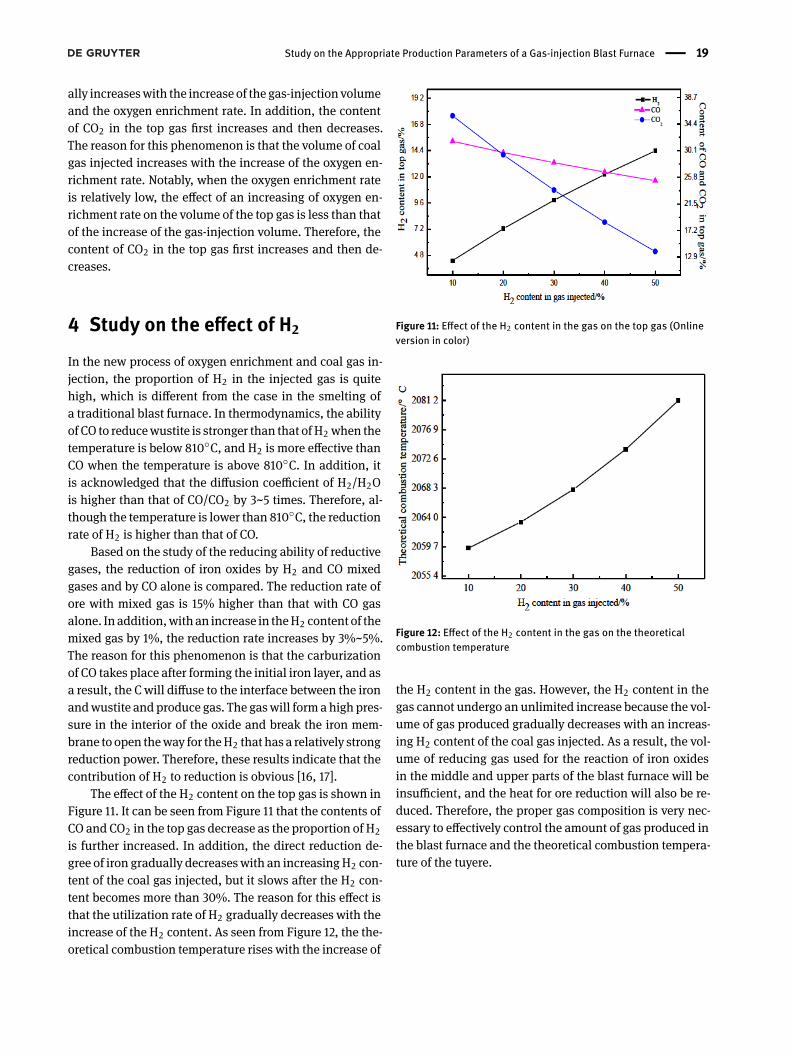
The effect of the H2 content on the top gas is shown inFigure 11. It can be seen from Figure 11 that the contents ofCO and CO2 in the top gas decrease as the proportion of H2is further increased. In addition, the direct reduction de-gree of iron gradually decreaseswith an increasingH2 con-tent of the coal gas injected, but it slows after the H2 con-tent becomes more than 30%. The reason for this effect isthat the utilization rate of H2 gradually decreases with theincrease of the H2 content. As seen from Figure 12, the the-oretical combustion temperature rises with the increase of
Figure 11: Effect of the H2 content in the gas on the top gas (Onlineversion in color)
Figure 12: Effect of the H2 content in the gas on the theoreticalcombustion temperature
the H2 content in the gas. However, the H2 content in thegas cannot undergo an unlimited increase because the vol-ume of gas produced gradually decreases with an increas-ing H2 content of the coal gas injected. As a result, the vol-ume of reducing gas used for the reaction of iron oxidesin the middle and upper parts of the blast furnace will beinsufficient, and the heat for ore reduction will also be re-duced. Therefore, the proper gas composition is very nec-essary to effectively control the amount of gas produced inthe blast furnace and the theoretical combustion tempera-ture of the tuyere.

20 | L. Song et al.
Table 2: Qualities of various materials
Name Mixed ore limestone Coke rate Coal rate slag furnace dustNumber, kg/tHM 1565.30 3 368 150 310.64 10
Table 3: Chemical composition of the pig iron (%)
Si Mn P S C Fe0.42 0 0.101 0.031 4.3 94.65
Table 4: Chemical composition of the slag (%)
Name CaO MgO SiO2 Al2O3 FeO S CaO/SiO2Component, % 38.22 10.59 34.86 14.86 0.41 1.1 1.04
Table 5: Composition analysis of the top gas (%)
CO2 CO N2 H2 CH4 O2 ηCO17.3 24.5 56.6 0.60 0.60 0.40 41.39
5 Comparison of smelting effectbetween new technology and theconventional process
5.1 Smelting effect
The blast furnace in Tangshan Iron and Steel Company isused as the comparison object. The qualities of differentkinds of materials are listed in Table 2, the chemical com-positions of the pig iron and slag are shown in Table 3 andTable 4, respectively, and the composition of the top gas ispresented in Table 5.
The composition of the hot metal that includes Si, Mn,P, and S is determined, but the C content is calculated bythe empirical formula.
[C] = 4.3 + 0.3 × [Mn] − 0.27 × [Si] − 0.32 × [P] − 0.032× [S] = 4.3%
[Fe] = 100 − [C] − [Si] − [Mn] − [P] − [S] = 94.65%
The comparison of the smelting effect between thenew process with oxygen enrichment and coal gas injec-tion and the conventional blast furnace process at Tang-shan Iron and Steel Company is shown in Table 6. FromTable 6, we can infer some results.
1. The coke in the new process mainly plays the role ofa skeleton to maintain the permeability of the stockcolumn, and the required heating agent and reduc-ing agent can be provided by the coal gas and other
sources. Compared with the traditional process, thenew process can significantly reduce the coke ratio.According to the simulation calculations for the newprocess, the blast furnace coke ratio is determinedto be 200 kg/tHM. At present, Baosteel No. 1 BF hasachieved good results with a coal injection ratio of260.6 kg/t and a coke ratio of 249.7 kg/t [18]. Further-more, broad industrial testing of furnace top gas in-jection proves that the coke ratio of a blast furnacecan be reduced by approximately 20% after adopt-ing this process. Therefore, the coke ratio of 200kg/tHM in the blast furnace can be realized theoreti-cally.
2. During the new process of coal gas injection, the de-composition of CO2 and H2O in the lower part of theblast furnace is an endothermic reaction, which ef-fectively solves the issue that the theoretical burningtemperature of the blast furnace tuyere is too high.Moreover, the water equivalent of gas rises with theincrease of H2, and as a result, the heating of burdenin the upper part of the blast furnace is improved,while the contradiction between the upper coolingand the lower heating of the blast furnace is solved.Compared with the traditional process, the theoreti-cal combustion temperature of the new process canbe adjusted flexibly by controlling the volume andcomponents of the coal gas injected,which is a greatadvantage of the blast furnace with coal gas injec-tion.

Study on the Appropriate Production Parameters of a Gas-injection Blast Furnace | 21
Table6:
Comparison
ofthesm
eltin
geff
ectb
etweenthenewprocessandtheconventio
nalblastfurnaceprocess
ProjectN
ame
Calculationresults
inGO
BFofTang
Steel
Calculationresults
inblastfurnace
ofTang
Steel
Coke,kg/tHM
180
200
240
200
Coke
rate,kg/tHM
374.9
Coalrate,kg/tHM
00
00
Coalrate,kg/tHM
150
coalgas
Volume,m3
600
600
500
700
JiaoDing,kg/tHM
17.23
Weigh
t,kg
541.07
541.07
450.89
631.25
Lumpcoal,kg/tHM
3.43
Airvolum
eVo
lume,m3
454.14
498.39
642.32
471.85
Fuelratio
,kg/tHM
545.56
Weigh
t,kg
590.38
647.90
835.02
613.40
Hotair,
kg/tHM
1134
.36
Oxygen
Volume,m3
88.47
97.09
125.13
91.92
oxygen
Volume,m3
44.20
Weigh
t,kg
126.38
138.70
178.75
131.31
Weigh
t,kg
63.14
Furnacetopcoalgas
Volume,m3
1209
.72
1277
.93
1360
.96
1354
.76
Furnacetopcoalgas
Volume,m3
1760
Weigh
t,kg
1559
.48
1641
.46
1784
.61
1690
.84
Weigh
t,kg
2385
.58
CO,%
28.27
29.44
25.52
34.97
CO,%
24.97
H 2,%
10.73
10.26
8.45
11.10
H 2,%
0.61
CO2,%
26.53
24.96
25.15
21.50
CO2,%
17.36
N 2,%
28.69
29.81
36.32
26.44
N 2,%
56.16
H 2O,
%5.78
5.53
4.55
5.98
H 2O,
%0.25
Theoreticalcombu
stiontemperature,∘C
2181
.99
2184
.84
2076
.71
2292
.11
Theoreticalcombu
stiontemperature,∘C
2183
Directredu
ctiondegree
ofiro
n0.1
0.1
0.1
0.1
Directredu
ctiondegree
ofiro
n0.45
Hydrogen
utilizatio
nrate,%
35.03
35.11
35.2
38.7
Hydrogen
utilizatio
nrate,%
0.1
Oxygen
enrichm
entrate,%
1515
1020
Oxygen
enrichm
entrate,%
3Ga
svolumeinbo
sh,m
3 /t
1223
.01
1283
.72
1449
.05
1270
.9Ga
svolumeinbo
sh,m
3 /t
1444
.65
Heatloss,kJ·t−1
−1.07
2.34
4.42
2.46
––

22 | L. Song et al.
3. Through the simulation calculations for the heat bal-ance in the new process, the oxygen enrichmentrate is controlled at approximately 10%, the gas vol-ume injected is approximately 600m3/tHM from theblast furnace tuyere, which can be use as reducingagent to serve as an alternative to coke and pulver-ized coal. The volume of coal gas injected will risewith the increase of the oxygen enrichment rate, butit cannot increase indefinitely. In general, the the-oretical combustion temperature will be too low ifthe volume of coal gas injected is more than 1000m3/tHM, and as a result, the normal physical andchemical reactions in the lower part of the blast fur-nace cannot be guaranteed. In fact, the hydrody-namic factors and the decrease of the output andthe displacement ratio are both important restrictivelinks for the gas injection volume.
4. During the smelting conditions of the new process,the calculation results show that the volume of thereducing gas in the blast furnace greatly increases,and the reduction rate of the ore is not the restrictivelink. Notably, the heating rate and the permeabilityof the burden become the major issues, and the pre-heating of the blast and the combustion of the gaswill provide most of heat. With the increase of theratios of CO and H2 in the top gas, nitrogen, as aheat carrier, will be replaced by H2 and CO in theory.Compared with the conventional smelting process,the direct reduction degree of the gas-injection pro-cess is greatly reduced. Therefore, the heat requiredfor smelting a unit of pig iron is decreased.
5. Under certain conditions of the oxygen enrichmentrate, the calculation based on the heat balance andthermodynamicdata of the reactionbetweenCOandH2reveals that the gas volume burned in the tuyereto serve as an alternative to 200 kg pulverized coalis 148 m3/tHM, and the gas volumes that serve as al-ternatives to coke in the reduction reaction and inthe combustion reaction are 281 m3/tHM and 100m3/tHM, respectively. Therefore, the total volume ofcoal gas injected is 529 m3/tHM. In addition, it canbe seen from the heat balance that the heat incomefrom coke combustion in the tuyere decreases withthe reduction of the coke rate, but it can be compen-sated by the physical heat of the coal gas injectedand the oxidation heat of the reducing gas.
5.2 Relationship between the H2 enrichmentgas and the blast furnace operation
The theoretical and practical results show that the N2 con-tent of the blast in the blast furnace with oxygen enrich-ment and in the coal gas injected is low, and the volume ofgas required for one ton of the unit pig iron decreases. As aresult, the smelting strength is greatly improved [19]. It isproposed that when the coal gas is injected into the blastfurnace, on one hand, using the reduction of the productsof the gas combustion reaction can effectively decreasethe theoretical combustion temperature, and on the otherhand, the heat brought by the gas to the upper part of theblast furnace can meet the heat requirement of this loca-tion.
It can be seen from Figure 13 that the volume changeof iron oxide is obviously differentwhen it is reduced in dif-ferent atmospheres. With the increase of the temperature,the iron oxide expands first and then shrinks in anH2 envi-ronment. The maximum expansion is 180% at 1173K. butthe iron oxide shrinks first and then expands in the envi-ronments of pure CO, 50% H2 and 50% CO, and pure CH4,and it shrinks to the maximum at 1123K, which is −25%,−7%and−11%, respectively. Due to the different propertiesof H2 and CO, iron oxides behave differently during the re-duction process.
The major factor that affects the increase of the uti-lization coefficient of a blast furnace is the resistance losscaused by a large amount of gas passing through the bur-den.When the pressure drops, which is an effect producedby the passage of the gas through the burden, and reachesa certain value, the descent of the burden will be affected.As a result, the operating stability of the blast furnace willbe destroyed. It is generally acknowledged that the pres-sure drop is mainly related to the porosity of the burdenand the flow rate of the gas when the temperature distribu-tion and top pressure are constant. The proportion of H2in the gas produced by the new process blast furnace ismuch higher than that in the ordinary blast furnace. Withthe increase of H2 content in the gas, the reduction rateof the burden is increased [20]. Before entering the melt-ing state, the iron oxide has been completely reduced. Onthe one hand, the content of FeO in the initial slag is low,the amount of liquid initial slag formed is reduced, andthe permeability of the burden in the melting zone is im-proved; On the other hand, a large number of metal ironappears in the burden earlier, and the metal iron also hascertain resistance to the deformation of the burden, whichis also helpful to maintain the permeability of the chargelayer [21]. In addition, the characteristics of H2 include ahigh thermal conductivity, a small atomic radius, easy dif-

Study on the Appropriate Production Parameters of a Gas-injection Blast Furnace | 23
Figure 13: Volume changes of iron oxides reduced under different temperatures and atmospheres
fusion, etc., and the resistance loss caused by H2 passingthrough burden layers with the same porosity is smallerthan that caused by other gases. Studies found that thevolume of iron oxides reduced by CO will expand, but thevolume of iron oxides reduced byH2will shrink. Therefore,the permeability of the burdenwill be improved during theprocess of heating and reduction.
Therefore, with the increase of H2 content, the pen-etration ability of gas is enhanced, the resistance loss ofcharge column is reduced, and the permeability of burdenis obviously improved. In fact, the productivity of themod-ern blast furnace is mainly prevented from increasing bythe flooding phenomenon in the bosh. However, the gen-eration of the flooding phenomenon [22] will be effectivelyavoided after the coal gas is injected into the blast furnace.
6 Conclusion1. When the volume of coal gas injected is constant,
the blast volume needed for smelting a unit of pigiron gradually reduces with the increase of the oxy-gen enrichment rate. When the oxygen enrichmentrate is greater than 10%, the decreasing trend of theblast volume slows.
2. Under the condition of an oxygen enrichment rate of10%, the direct reduction degree greatly decreases,and the coke rate almost linearly decreases withan increasing volume of coal gas injected. Whenthe volume of the gas, however, is greater than 800m3/tHM, the coke rate decreases slowly. With the in-crease of the gas-injection volume, the oxygen en-richment rate is increased to ensure the proper the-oretical combustion temperature of the tuyere.
3. When the oxygen enrichment rate is controlled at ap-proximately 10%and the volume of coal gas injectedis 600 m3/tHM, the CO content of the top gas in-

24 | L. Song et al.
creases with the increase of the coke rate, while theH2 and CO2 contents both decrease. When the cokerate is 200 kg and the volume of coal gas injected is600m3/tHM, with the increase of the oxygen enrich-ment rate, the contents of CO and H2 in the top gasincrease, but the content of CO2 increases first andthen decreases. When the oxygen enrichment rate is10%, the content of CO2 is the highest.
4. With the increase of theH2 content in the coal gas in-jected, the direct reduction degree of iron graduallydecreases, the theoretical combustion temperatureincreases, and the volume shrinkage of the burdenincreases. During the heating and reduction process,the permeability of the burden will not be deterio-rated, and gas injected into blast furnace can effec-tively avoid the flooding phenomenon.
5. When the volume of the gas injected is 600 m3/tHMand the oxygen enrichment rate is controlled atapproximately 10%, the theoretical combustiontemperature of the tuyere can be controlled at1950~2200∘CC, which can serve as a reducing agentto provide alternatives to coke and pulverized coal.This greatly reduces the degree of direct reductionand realizes smooth operation of the blast furnace.In the new process, the coal gas injected into theblast furnace can avoid the theoretical combustiontemperature of the blast furnace tuyere being toohigh and solve the contradiction between the uppercooling and lower heating of the blast furnace.
Acknowledgement: Thanks are given for thefinancial sup-port from the key Program of National Nature ScienceFoundation of China (U1360205).
References[1] Xu, C. B., and D. Q. Cang. A brief overview of low CO2 emission
technologies for iron and steel making. Journal of Iron and SteelResearch International, Vol. 17, No. 3, 2010, pp. 1–7.
[2] Oda, J., K. Akimoto, F. Sano, and T. Tomoda. Diffusion of energyeflcient technologies and CO2 emission reductions in iron andsteel sector. Energy Economics, Vol. 29, No. 4, 2007, pp. 868–888.
[3] Asanuma, M., T. Ariyama, M. Sato, R. Murai, T. Nonaka, I. Okochi,H. Tsukiji, and K. Nemoto. Development of waste plastics injec-tion process in blast furnace. ISIJ International, Vol. 40, No. 3,2000, pp. 244–251.
[4] Shen Y. S., A. B. Yu, P. Austin, and P. Zulli. Modelling in-furnacephenomena of pulverized coal injection in ironmaking blast fur-nace: Effect of coke bed porosities. Minerals Engineering, Vol.33, No. 4, 2012, pp. 54-65.
[5] Ishii, K. Advanced Pulverized Coal Injection Technology andBlastFurnace Operation. Pergamon Press, England, 2000, pp. 1-324.
[6] Mathieson, J. G., J. S. Truelove, and H. Rogers. Toward an under-standing of coal combustion in blast furnace tuyere injection.Fuel, Vol. 84, No. 10, 2005, pp. 1229–1237.
[7] Aoki, H., H. Nogami, H. Tsuge, T. Miura, and T. Furukawa. Simu-lation of transport phenomena around the raceway zone in theblast furnace with and without pulverized coal injection. ISIJInternational, Vol. 33, No. 6, 1993, pp. 646–654.
[8] Usui, T., H. Kawabata, H. Ono-Nakazato, and A. Kurosaka. Funda-mental Experiments on the H_2 Gas Injection into the Lower Partof a Blast Furnace Shaft. ISIJ International, Vol. 42, Supplement,2002, pp. S14–S18.
[9] Jozwiak, W. K., E. Kaczmarek, T. P. Maniecki, W. Ignaczak, andW. Maniukiewicz. Reduction behavior of iron oxides in hydrogenand carbonmonoxide atmospheres. Applied Catalysis A, General,Vol. 326, No. 1, 2007, pp. 17–27.
[10] Maki, A., A. Sakai, N. Takagaki, K. Mori, T. Ariyama, M. Sato, andR. Murai. High Rate Coal Injection of 218 kg/t at Fukuyama No.4Blast Furnace. Transactions of the Iron and Steel Institute ofJapan, Vol. 36, No. 6, 1996, pp. 650–657.
[11] Slaby, S., D. Andahazy, F. Winter, C. Feilmayr, and T. Bürgler.Reducing Ability of CO and H2 of Gases Formed in the Lower Partof the Blast Furnace by Gas and Oil Injection. ISIJ International,Vol. 46, No. 7, 2006, pp. 1006–1013.
[12] Wang, X. L. Iron and Steel Metallurgy: Iron parts, 3rd ed. BeijingMetallurgical Industry Press, Beijing, 2013, pp.1-516.
[13] Khairil, D. Kamihashira, K. Nakayama, and I. Naruse. Fundamen-tal Reaction Characteristics of Pulverized Coal at High Tempera-ture. ISIJ International, Vol. 41, No. 2, 2001, pp. 136–141.
[14] Nogami, H., J. Yagi, and R. S. Sampaio. Exergy Analysis of Char-coal Charging Operation of Blast Furnace. ISIJ International, Vol.44, No. 10, 2004, pp. 1646–1652.
[15] Halim, K. S. A., V. N. Andronov, and M. I. Nasr. Blast furnaceoperation with natural gas injection and minimum theoreticalflame temperature. Ironmaking & Steelmaking, Vol. 36, No. 1,2009, pp. 12–18.
[16] Mehta A. S., V. Sahajwalla, and T. F. Wall. Investigation on modesof consumption of residual char by the slag phase during pulver-ized coal injection in blast furnace. Steelmaking Conf. Proc., Vol.81, 1998, pp. 627–639.
[17] Iwanaga, Y., and K. Takatani. Degradation behavior of coke athigh-temperature zone in blast furnace. Transactions of the Ironand Steel Institute of Japan, Vol. 28, No. 12, 1988, pp. 990–998.
[18] Tao, R. Y., and J. M. Zhu. Changes of energy consumption struc-ture andCO2 emission in large coal injection smelting of Baosteelblast Furnace. Baosteel Technology., Vol. 3, 2000, pp. 6–9. (inChinese)
[19] Kemppainen, A., O. Mattila, E.-P. Heikkinen, T. Paananen, and T.Fabritius. Effect of H2-H2O on the Reduction of Olivine Pellets inCO-CO2 Gas. ISIJ International, Vol. 52, No. 11, 2012, pp. 1973–1978.
[20] Lyu, Q., Y. Qie, X. Liu, C. Lan, J. Li, and S. Liu. Effect of hydrogenaddition on reduction behavior of iron oxides in gas-injectionblast furnace. Thermochimica Acta, Vol. 648, 2017, pp. 79–90.
[21] Hydrogen Addition on Softening and Melting Reduction Behav-iors of Ferrous Burden in Gas-Injection Blast Furnace. Metallurgi-cal and Materials Transactions. B, Process Metallurgy and Mate-rials Processing Science, Vol. 49, No. 5, 2018, p. 2622.

Study on the Appropriate Production Parameters of a Gas-injection Blast Furnace | 25
[22] Fu, S. M., and Y. J. Du. Analysis of flooding and suspension mech-anism in blast furnace. Ironmaking, No. 01, 1984, pp. 59-64. (inChinese)
Copyright © 2022 FDOKUMEN