Study of Nd-doping effect and mechanical cracking on photoreactivity of TiO 2 thin films
7
Study of Nd-doping effect and mechanical cracking on photoreactivity of TiO 2 thin films J.O. Carneiro * , V. Teixeira, A. Joa ˜o, A. Magalha ˜es, C.J. Tavares University of Minho, Physics Department, GRF Group, Azure ´m Campus, 4800-058 Guimara ˜es, Portugal Keywords: Titanium dioxide Photocatalytic activity Nd-doping effect Film cracking abstract Pure and Nd-doped TiO 2 thin films were fabricated by reactive d.c. magnetron sputtering at low- temperature from a pure Ti target. The structure of films was analyzed by X-ray diffraction (XRD). In order to study the Nd-doping effect on TiO 2 photocatalytic activity, some films were deposited on microscope glass substrates under a constant total sputtering pressure and using different Nd-doping concentrations. The effect of different Nd-dopant concentrations and its influence on the photocatalytic efficiency has been explored by measuring the photodegradation of rhodamine-B (RhB) aqueous solution under radiation of UV light. It is principally that for comparison between heat treatment and doping process on TiO 2 photocatalytic efficiency (important under the point of view of energy costs related with industrial sputtering techniques), crystalline TiO 2 films were also produced by thermal annealing. It was found that comparing with annealed pure TiO 2 films, Nd-doping do not improve the photocatalytic activity. At the same time, it was observed that there seems to exist a dopant concentration band for optimal photoreactivity. In order to study the effect of the film mechanical strength on photocatalytic activity, fragmentation tensile tests were also done on TiO 2 /PET (polyethylene terephthalate) substrates at increasing applied strains. It was found that increasing the magnitude of the applied tensile strain, pure TiO 2 becomes more photocatalytic efficient. Ó 2008 Elsevier Ltd. All rights reserved. 1. Introduction Photocatalysis with TiO 2 /UV has been studied extensively [1–3]. The attractiveness of TiO 2 is due to its chemical stability, low-cost, non-toxicity and its industrial applications related with environ- mental problems such as water and air purification or the destruction of microorganisms [4]. The photocatalytic activity has been explained by oxidation and reduction induced by a pair of hole and electron (e /h þ ), separated by light irradiation [5–7]. The photocatalytic activity of TiO 2 is very important not only in envi- ronmental purification by decomposition of organic substances but also in material industry such as mirrors and glasses because of its self-cleaning and antifogging effects [8–10]. However, the major drawback to its wide-spread application is the fact that TiO 2 absorbs near UV light. This band-gap does not match very well with solar light. Several methods have been proposed to increase near UV visible light absorption in TiO 2 . Nanoparticles, with their increased surface area, can provide surface states within the band- gap to effectively reduce the band-gap [11]. Another way to improve the photocatalytic efficiency of TiO 2 is by doping with an appropriate dopant [12]. Doping introduce foreign ions into the lattice of TiO 2 in order to trap the electrons and/or holes and consequently improving the photoreactivity. Trapping of electrons or holes at these sites increases their lifetime and, therefore, it should be expected an increase of the probability that they will reach the surface without suffering recombination and participate in the desired photocatalysis reaction. Some possible dopant ions include Fe þ3 , Cr þ3 or Pd þ4 . Moreover, the selection of dopants depends on the reaction of interest. Not all dopants work efficiently for all reactions. For example, Fe þ3 works well for the degradation of RhB [12], but does not for 2-chlorophenol [11]. In this work, neodymium (Nd is commonly selected as emission agent in optical applications because of its high efficiency and durable emission properties) has been used as dopant agent, and rhodamine-B was chosen as the organic pollutant. In the following chapters we will present some aspects related with Nd-doped TiO 2 films preparation and the experimental tech- niques used to analyze the films structure and its photodegradation ability. Moreover, it will also presented the mechanical testing conditions concerning with films fragmentation. This work ends with the presentation of the experimental results and the discus- sion about the Nd-doping influence on TiO 2 photocatalytic activity and the effect of the film mechanical strength on photocatalytic activity. * Corresponding author. Tel.: þ351 253510477/00; fax: þ351 253510401. E-mail address: carneiro@fisica.uminho.pt (J.O. Carneiro). Contents lists available at ScienceDirect Vacuum journal homepage: www.elsevier.com/locate/vacuum 0042-207X/$ – see front matter Ó 2008 Elsevier Ltd. All rights reserved. doi:10.1016/j.vacuum.2008.03.013 Vacuum 82 (2008) 1475–1481
Transcript of Study of Nd-doping effect and mechanical cracking on photoreactivity of TiO 2 thin films

lable at ScienceDirect
Vacuum 82 (2008) 1475–1481
Contents lists avai
Vacuum
journal homepage: www.elsevier .com/locate/vacuum
Study of Nd-doping effect and mechanical crackingon photoreactivity of TiO2 thin films
J.O. Carneiro*, V. Teixeira, A. Joao, A. Magalhaes, C.J. TavaresUniversity of Minho, Physics Department, GRF Group, Azurem Campus, 4800-058 Guimaraes, Portugal
Keywords:Titanium dioxidePhotocatalytic activityNd-doping effectFilm cracking
* Corresponding author. Tel.: þ351 253510477/00;E-mail address: [email protected] (J.O. Ca
0042-207X/$ – see front matter � 2008 Elsevier Ltd.doi:10.1016/j.vacuum.2008.03.013
a b s t r a c t
Pure and Nd-doped TiO2 thin films were fabricated by reactive d.c. magnetron sputtering at low-temperature from a pure Ti target. The structure of films was analyzed by X-ray diffraction (XRD). Inorder to study the Nd-doping effect on TiO2 photocatalytic activity, some films were deposited onmicroscope glass substrates under a constant total sputtering pressure and using different Nd-dopingconcentrations. The effect of different Nd-dopant concentrations and its influence on the photocatalyticefficiency has been explored by measuring the photodegradation of rhodamine-B (RhB) aqueous solutionunder radiation of UV light. It is principally that for comparison between heat treatment and dopingprocess on TiO2 photocatalytic efficiency (important under the point of view of energy costs related withindustrial sputtering techniques), crystalline TiO2 films were also produced by thermal annealing. It wasfound that comparing with annealed pure TiO2 films, Nd-doping do not improve the photocatalyticactivity. At the same time, it was observed that there seems to exist a dopant concentration band foroptimal photoreactivity. In order to study the effect of the film mechanical strength on photocatalyticactivity, fragmentation tensile tests were also done on TiO2/PET (polyethylene terephthalate) substratesat increasing applied strains. It was found that increasing the magnitude of the applied tensile strain,pure TiO2 becomes more photocatalytic efficient.
� 2008 Elsevier Ltd. All rights reserved.
1. Introduction
Photocatalysis with TiO2/UV has been studied extensively [1–3].The attractiveness of TiO2 is due to its chemical stability, low-cost,non-toxicity and its industrial applications related with environ-mental problems such as water and air purification or thedestruction of microorganisms [4]. The photocatalytic activity hasbeen explained by oxidation and reduction induced by a pair of holeand electron (e�/hþ), separated by light irradiation [5–7]. Thephotocatalytic activity of TiO2 is very important not only in envi-ronmental purification by decomposition of organic substances butalso in material industry such as mirrors and glasses because of itsself-cleaning and antifogging effects [8–10]. However, the majordrawback to its wide-spread application is the fact that TiO2
absorbs near UV light. This band-gap does not match very well withsolar light. Several methods have been proposed to increase nearUV visible light absorption in TiO2. Nanoparticles, with theirincreased surface area, can provide surface states within the band-gap to effectively reduce the band-gap [11]. Another way toimprove the photocatalytic efficiency of TiO2 is by doping with an
fax: þ351 253510401.rneiro).
All rights reserved.
appropriate dopant [12]. Doping introduce foreign ions into thelattice of TiO2 in order to trap the electrons and/or holes andconsequently improving the photoreactivity. Trapping of electronsor holes at these sites increases their lifetime and, therefore, itshould be expected an increase of the probability that they willreach the surface without suffering recombination and participatein the desired photocatalysis reaction. Some possible dopant ionsinclude Feþ3, Crþ3 or Pdþ4. Moreover, the selection of dopantsdepends on the reaction of interest. Not all dopants work efficientlyfor all reactions. For example, Feþ3 works well for the degradationof RhB [12], but does not for 2-chlorophenol [11]. In this work,neodymium (Nd is commonly selected as emission agent in opticalapplications because of its high efficiency and durable emissionproperties) has been used as dopant agent, and rhodamine-B waschosen as the organic pollutant.
In the following chapters we will present some aspects relatedwith Nd-doped TiO2 films preparation and the experimental tech-niques used to analyze the films structure and its photodegradationability. Moreover, it will also presented the mechanical testingconditions concerning with films fragmentation. This work endswith the presentation of the experimental results and the discus-sion about the Nd-doping influence on TiO2 photocatalytic activityand the effect of the film mechanical strength on photocatalyticactivity.

Table 1Deposition parameters and area percentage of Nd-dopant on titanium target in thedeposited TiO2 films
Sample code A A# B C D E F
Substrate PET Glass Glass Glass Glass Glass Glass
Dopant area ratio: A-(Nd/Ti)% – – 1.21 2.42 3.63 4.84 6.10Total pressure: Ptotal (Pa) 0.4 0.4 0.4 0.4 0.4 0.4 0.4Current density: m (A/dm2) 0.25 0.25 0.25 0.25 0.25 0.25 0.25
A#: sample annealed at 500 �C.
J.O. Carneiro et al. / Vacuum 82 (2008) 1475–14811476
2. Experimental
2.1. Preparation of TiO2 films
Doped and pure undoped TiO2 films, with a thickness,tf z 640 nm, were deposited on glass substrates (75� 25�1 mm3)by means of a d.c. reactive magnetron sputtering system schema-tized in Fig. 1.
The target was pure titanium with a total surface area of7854 mm2. The typical deposition parameters and Nd-dopant arearatio A-(Nd/Ti)% are listed in Table 1.
2.2. Film characterization
The crystal structure of the films was determined by X-raydiffraction (XRD) using a Philips PW 1710 X-ray diffractometer witha CuKa radiation source. Thermal annealments were performed onthe pure titania samples in order to enhance crystalline growth. Thephotodegradation efficiency was monitored by measuring thetransmittance (as a function of irradiation time) of the RhB solutionat a wavelength of 554 nm using a Shimadzu UV-310PC scanningspectrophotometer.
The initial concentration of RhB solution used in this study was0.5 mg/L. TiO2 coated specimens were irradiated in a perpendiculardirection using a 200-W mercury tube lamp (wavelength z 254 nm).The transmittance of the solution was measured at about 1 h intervalsfor a total irradiation time of 6 h. An increase in the transmittance ofthe solution should indicate the decomposition of RhB solution byTiO2 photocatalysis.
2.3. Fragmentation tensile tests
Low-temperature pure TiO2 thin films with thickness tf of about640 nm were also deposited on PET substrates by d.c. reactivemagnetron sputtering. The thickness of the PET substrate ts was100 mm. In order to study the effect of the film mechanical strengthon TiO2 photocatalytic activity, three specimens in a rectangularshape (length and width, respectively, equal to 45 mm and 10 mm)
Rotary mechanical pump
High vacuum valve
Diffusion pump
Roughing valve
Vent valve
Backing valve
O2
Ar Target
Deposition chamber
Waterflow tubes
Pressure gauge
Substrate / Substrate holder
Fig. 1. Scheme of the reactive magnetron sputtering system used for coatingdeposition.
were prepared with the same TiO2 thickness. Next, they were set toan increasing tensile strain stage 3 (namely 0.5%, 1%, and 5%) bymeans of a Polymer Laboratories Minimat machine (Fig. 2).
A specimen of PET substrate without TiO2 film was alsoprepared. First, the specimen of PET substrate underwent a tensiletest to record a nominal stress–strain curve (i.e. load/original cross-sectional area, and extension/original length), and to evaluate theYoung’s modulus of the polymer substrate Es within the linearelastic region, where we can take the specimen cross-sectionalarea, A¼ constant. Next, tensile tests of the pure TiO2/PET speci-mens were conducted; observations of multiple fractures in thesurface of pure TiO2 films were performed with an optical micro-scope (OM) (Nikon–Optiphot-100) and recorded by a video camera(Sony, CCD-Iris) together with the count of a clock. A constantstretching speed of 0.2 mm/min was used for all tested specimens.
It is important to note that for higher deformations (beyond theelastic region) a plastic tensile instability occurs, in the form ofa local necking of the specimen. At these deformation stages, theoriginal cross-sectional area of the specimen will be no longermaintained. In fact, after the neck has developed, the stress in thenecked portion of the specimen is much higher than elsewhere,because the specimen actual area is very much less than theoriginal cross-sectional area on which the nominal stress is calcu-lated. Under these conditions (i.e. higher deformations), strainvalues have little meaning since they are based on an extensionwhich is no longer uniform along the length of the specimen.Likewise stress values have little correspondence with actualstresses in the neck of the specimen where the stress state is non-uniform and complex.
LoadCell
Volt meter
x- controller
Computer
Videotimer
O.M.
with
CCD camera
Specimen
Fig. 2. Schematic diagram of instruments used in tensile fragmentation test ofspecimens.

J.O. Carneiro et al. / Vacuum 82 (2008) 1475–1481 1477
3. Results and discussion
3.1. Film characteristics
Using the deposition parameters listed in Table 1, it was observed,by X-ray analysis, that all the as-sputtered TiO2 films were amor-phous. This happened because the deposition temperature is ratherlow (<90 �C) and consequently the TiO2 particles that reach thesubstrate do not have sufficient energy and mobility to crystallize ina regular lattice, such as that associated with the higher energyphases for anatase or rutile. It is important to note that under theindustrial point of view, aspects related with the production of filmswith low-energy costs are of huge importance in an industrial en-vironment. In this sense, low-temperature magnetron sputteringpractices should be pursued in order to minimize processing directcosts. Because of these last aspects, we have intentionally studied thephotocatalytic performance of the low-temperature amorphous Nd-doped TiO2 films in order to compare the results with those onesobtained from annealed pure TiO2 films. In order to obtain crystallineTiO2 films only the as-sputtered pure TiO2 samples were thermallyannealed at 500 �C during 3 h (sample A#). X-ray measurementswere then performed on this heat-treated sample. Fig. 3 depicts itscrystalline texture which is confirmed by the (101) and (004) dif-fraction peaks, and also traces of (200), (105), and (211) peaks.
3.2. Photocatalytic activity
The initial process for photocatalysis of organic compounds byTiO2 is the generation of (e�/hþ) pairs in the TiO2 particles afterthe absorption of a photon with energy equal to or higher than theband-gap of TiO2. The total number of free charge carriers on theTiO2 surface is determined by the rate of charge pair generation,charge recombination, rate of interfacial charge transfer as well ascharge trapping. Acting as electron and/or hole traps is the mostimportant function of transition metal ions dopants. The trap ofcharge carriers can decrease the recombination rate of e�/hþ pairsand then, increase the lifetime of charge carriers. The process ofcharge trapping is as follows [11]:
Ti4þ þ e�cb/Ti3þ
Mnþ þ e�cb/M n�1ð Þþ
Mnþ þ hþvb/M nþ1ð Þþ
OH� þ hþvb/OH,
(1)
10 20 30 40 50 60
(211)(105)
(200)
(004)
Inte
nsit
y (a
rb. u
nits
)
2θ (deg.)
(101)
Fig. 3. XRD spectra associated with crystalline texture of heat-treated pure TiO2 filmsdeposited on glass.
where Mnþ is the metal ion dopant. The energy level of Mnþ/M(n�1)þ lies bellow the conduction band edge and the energy levelof Mnþ/M(nþ1)þ lies above the valence band edge; consequently theenergy level of transition metal ions can affect the trapping effi-ciency. Thus, the trapping of electrons makes it easy for holes totransfer onto the surface of TiO2 and react with OH� in the RhBaqueous solution and form active OH, hydroxyl radicals whichconvert organic species into CO2 and H2O.
The effect of Nd-dopant on photocatalytic kinetics of the titaniacoatings was assessed by combined UV irradiation and trans-mittance measurements. The color of the dye has changed frombright pink to colorless during the irradiation process, hence in-dicating that the chemical oxidation–reduction mechanisms aretaking place on the surface of the Nd-doped TiO2 films. Fig. 4compares the RhB photodegradation rates for heat-treated pureTiO2 sample (sample A#) and Nd-doped TiO2 samples (samples B–F,corresponding to increasing levels of doping concentration). TheRhB photodegradation rates were evaluated through the variationon the concentration C of RhB aqueous solution. It is obvious that C0
represents the initial concentration of RhB (i.e. before UVirradiation).
The change of photocatalytic activity for Nd-doped samples(prepared at low-temperature) is evident from the degradationcurves. It can be observed that the degradation rates for thesamples more strong doped (samples E and F) have not beenenhanced. On the other hand, and concerning with Nd-dopedsamples, it was found that the higher photodegradation rate wasobserved for the moderate Nd-doped TiO2 sample (sample D). Itseems to exist an optimum Nd-doping concentration for theimprovement of the photocatalytic activity; if the Nd concentra-tion is far more than its solubility in the TiO2 structure then,a decrease in photocatalytic activity should be expected as it wasobserved.
Moreover, it can be observed that the heat-treated pure TiO2
sample (sample A#) presents the highest photocatalytic activity.Nevertheless, sample D (Nd area percentage ratio z 3.6%) hasa photocatalytic performance close to sample A#. This is aninteresting situation with respect to a hypothetical industrialapplication; apparently, Nd-doped TiO2 films prepared at low-temperature (i.e. with lower energy industrial costs), makespossible to obtain photocatalytic efficiency similar to TiO2 filmsprepared at high temperatures. The rate constant k for the
0 1 2 3 4 5 6
40
60
80
100
Irradiation time (h)
Samples
A#
BCDEF
(C /
C0)
Fig. 4. Photodegradation of RhB with undoped TiO2 and Nd-doped TiO2 under UVirradiation; C0¼ 0.5 mg/L.

Criticalvalue
L1 L2L3
0
Grips of the instrument
FF
Cracks
σf
X=0 X=L
σ(x)
τ(x)
τ
λ
J.O. Carneiro et al. / Vacuum 82 (2008) 1475–14811478
photocatalytic degradation process can be calculated by means ofa kinetic pseudo-first-order reaction [13]:
lnCC0¼ �kt (2)
Using the experimental data in Fig. 4 and making a plot of ln(C/C0) against ‘‘irradiation time (t)’’, it is possible to obtain the k valuesfrom the slopes of fitting lines. Fig. 5 shows the calculated k valuesfor all TiO2 films deposited on glass substrates.
100 µm
Fig. 6. A one-dimensional model for a film/substrate composite system in tensile testafter multiple cracks is induced in the film. Observation of the multiple cracking ofa TiO2 thin film by optical microscopy. A detail model of stress distributions arounda cracked segment of the film. s, s, and l Are the film tensile stress, interfacial shearstress, and load transfer length.
3.3. Mechanical behavior and multiple cracks
The total stress sf, acting in a thin film is the result of threedifferent contributions: (i) external stresses s, which are due toexternal loading; (ii) thermal stresses, sth, due to the mismatchbetween the thermal expansion coefficients of both substrate andfilm material; and (iii) intrinsic stresses, si, related with theparticular coating microstructure and therefore, the particulargrowing process itself [14,15],
sf ¼ sþ srf (3)
where srf is the temperature-dependent residual stress (being the
sum of sth and si) and the subscript ‘‘f’’ and the superscript ‘‘r’’means film and residual, respectively.
Let us suppose that the TiO2/PET composite system is subjectedto a tensile test. At the beginning of the tensile test, the film andsubstrate already have strains of 3r
f and 3rs, respectively. However,
until initial cracks are induced in the film, the tensile stress istransferred from the grips of the testing machine to the film andsubstrate, and no interfacial shear stress between the film and thesubstrate exists. Under this situation, the applied tensile compositestress sc that is transferred to the film and the substrate, is a sum offilm stress sf and substrate stress ss,
sc ¼ sf þ ss (4)
where
sf ¼ Ef 3ncf ¼ Ef 3c þ 3r
f
� �(5)
ss ¼ Es3nc ¼ Es 3c þ 3r� �(6)
s swhere 3c is the applied composite strain, and the superscript ‘‘nc’’means that no crack exists in the film (to distinguish from the caseof presence of multiple cracks). However, if the magnitude ofapplied stress is increased, then multiple cracks perpendicular to
A# B C D E F0.0
2.0x10⁻⁴
4.0x10⁻⁴
6.0x10⁻⁴
8.0x10⁻⁴
1.0x10⁻³
1.2x10⁻³
1.4x10⁻³
1.6x10⁻³
1.8x10⁻³
2.0x10⁻³
2.2x10⁻³Dopant material : Nd
Con
stan
t deg
rada
tion
rate
,k (
min
-1)
Sample code
Fig. 5. Photodegradation rate constant k of TiO2 films under different neodymiumconcentrations.
the load direction will be induced in the film. As a consequence,films will be divided into many segments with different widths L,according to the one-dimensional model sketched in Fig. 6.
Under the presence of multiple cracks, the load applied by thetesting machine is not transferred directly to the film. In fact, whenone crack occurs in the film, two new fracture surfaces will becreated (see Fig. 6) and naturally the tensile stress is zero in thosesurfaces; in this way, the applied tensile stress cannot propagateinto the film through the cracked surfaces. Thus, the fraction ofenergy absorbed by the thin film, due to the work done on the film/substrate system by the external applied force, will be lower. Thismeans that an additional energy will be absorbed by the substrate,leading to an additional substrate deformation. The mechanism ofthe energy transfer (from the film to the substrate) is done throughthe film/substrate interface (which is the physical boundarybetween them) via a shear stress s across the interface [16],
s xð Þ ¼ Cl
e�xl � e
x�Lð Þl
� �(7)
where C is a factor, which depends on the composite stress andstrain magnitudes, film and substrate residual stresses, thicknessesand elastic modulus of film and substrate, respectively. The detailedformula related with factor C, can be consulted in the publishedpaper indicated in Ref. [16].
Nevertheless, the tensile stress in the film, sf still exists asa consequence of a transfer across the interface of a shear stress intothe film [16],
sf xð Þ ¼ 1tf
Z x
0sdx0 (8)
The film tensile stress near the cracked surfaces is stronglychanged; becoming zero at the film-free edge and reaching themaximum magnitude in the center of the uncracked coatingelement, as indicated in Fig. 6. Substituting Eq. (7) into Eq. (8) andintegrating, the film tensile stress can be written as:
sf xð Þ ¼ Ctf
1þ e�Ll
� �� e
�xl þ e
� x�Lð Þl
� �h i(9)
It is obvious that Eq. (9) is zero at the edges of a film crackedsegment, x¼ 0 and x¼ L. It takes a maximum value at the center ofthe film cracked segment,
smaxf
L2
� �¼ C
tf1� e
�L2l
� �2(10)
The nominal stress–strain curve of the bare substrate was usedto evaluate the Young’s modulus of the polymer material, Es within

0.00 0.01 0.02 0.03 0.04 0.05 0.06 0.07 0.08 0.09 0.100
10
20
30
40
50
60
70
80
90
100
0.00 0.01 0.02 0.03 0.04 0.05 0.06 0.07 0.08 0.09 0.10
0.0
0.5
1.0
1.5
2.0
2.5
3.0
3.5
4.0
Young's modulus, E
s (GPa)Po
lym
er s
tress
, σs (
MPa
)
Polymer strain, ε
(dσ / dε)
Fig. 7. Experimental substrate nominal stress–strain curve (solid curve) and nominalstress–strain derivative, dss/des (dotted line). The PET Young’s modulus, Es is thedss/des derivative value, calculated in the elastic region. Fig. 9. Curled TiO2/PET composite system after film deposition. The differences be-
tween the residual strains were calculated from the radius of curvature r.
J.O. Carneiro et al. / Vacuum 82 (2008) 1475–1481 1479
the linear elastic region where we can take the specimen cross-sectional area, A¼ constant (acceptable only for small de-formations). Fig. 7 shows two curves, as a function of the appliednominal strain, at room temperature. The first one, is the substratenominal stress, ss and the second is obtained by taking the de-rivative dss/d3s. In the elastic region, the derivative curve, dss/d3s isalmost constant; for higher deformations the dss/d3s curve can beuseful to establish the confirmation of the variation of A, fromwhich calculus can be obtained via image video measurementsversus sample constant volume. The stretching speed during thetest was the same as those used in tests for TiO2/PET specimens,which will be described later.
A PET Young’s modulus of Es¼ 3.72 GPa was obtained in theelastic region (maximum nominal strain about 1.5%), from the in-clination of the PET nominal stress–strain curve. It is important tonote that the PET Young’s modulus estimated here (via mechanicaltesting) is a good result when compared with that obtained viaatomic force microscopy [17].
In a similar way, tensile tests were performed on the TiO2/PETspecimens (sample A), and observations with an optical microscope
0.00 0.01 0.02 0.03 0.04 0.05
0
15
30
45
60
75
90
105
120
Stre
ss, σ
(M
Pa)
Strain, ε
composite stress, σc
PET stress, σs
Fig. 8. Comparison of nominal stress–strain curves of the bare substrate (PET) and theTiO2/PET composite system.
were made during the tests. Fig. 8 compares the nominal stress–strain curves for the composite system and bare substrate.
All specimens showed yielding at about 2.5% which roughlycorresponds to the PET yield strain. The value of the film Young’smodulus Ef can be estimated from the elastic regime inclination(dsc/d3c) of the nominal stress–strain curve of TiO2/PET compositesystem [16],
Ef ¼dsc
d3cþ ts
tf
dsc
d3c� Es
� �(11)
According to Eq. (11) the film Young’s modulus estimated here isof about Ef ¼ 78.3 GPa. Because of the residual strains in the filmand the substrate, TiO2/PET specimens curled. The residual stress ofthin film was compressive because the TiO2 films were on theoutside surface of the curl as shown in Fig. 9.
The difference of the residual strains, D3 existing in the film andsubstrate, was calculated from the composite system radius ofcurvature r [18],
D3 ¼ 3rs � 3r
f ¼t2s
6rtf
Ests þ 4Ef tf
Ef ts þ tfð Þ (12)
Both the measured r and the calculated D3, based on Eq. (12) arelisted in Table 2. The critical composite applied strain, 3cc, to initiatefilm cracking is also listed in Table 2. The total stresses (residualplus applied) in TiO2 films just before the crack onset (i.e. thecritical composite stress scc) were estimated using Eq. (5);the calculated value for scc was about 556 MPa. In the experiment,the number of cracks N which showed up in the field of the opticalmicroscope was counted, and a mean crack spacing was deduced bythe average L¼O/N, where O was the width of the field of theoptical microscope. The micrographs of multiple cracking for a 640-nm TiO2 film (sample A) on a PET substrate under an applied strain,
Table 2Data of the measured radius of curvature, r, of the TiO2/PET system, the calculatedmismatch strain, D3, in the TiO2 film relative to the PET substrate, and of the mea-sured critical applied strain, 3cc, for initial film cracking
TiO2 filmthickness,t (nm)
Radius ofcurvature,r (m)
Mismatchstrain,D3 (%)
Substrateresidualstrain, D3r
s (%)
Film residualstrain, D3r
f (%)Criticalcrackingstrain, 3cc (%)
640 0.04 0.34 0.04 �0.29 1.2

Fig. 10. Micrographs of multiple cracking of a pure TiO2 film (sample A), deposited at low-temperature on a PET substrate: 0.5% and 1.2% crack onset strain.
J.O. Carneiro et al. / Vacuum 82 (2008) 1475–14811480
respectively, at 0.5% and 1.2% (i.e. just after the crack onset) areshown in Fig. 10.
The measured crack spacing, Lc just after the crack onset wasabout 26 mm. At a given applied strain, the longest segments wouldbreak into halves with more or less half segments (according toFig. 6). Hence, when the tension is increased again and sf (L/2)exceeds some critical value, a new crack will be generated at thecenter, and the width of the segment becomes half, that causesa stress relief in the segments.
As mentioned before, in order to study the effect of the filmmechanical strength on its photocatalytic activity, fragmentationtensile tests have been performed on a TiO2/PET composite system(sample A) at three different applied strains, 0.5%, 1%, and 5%. Afterstretching, the TiO2 film cracked samples had been immersed ina 0.5-mg/L RhB aqueous solution, and subjected to UV light irra-diation during 6 h. Fig. 11 shows the photodegradation of RhB dyesolution which follows Eq. (2).
The change of photocatalytic activity for stretched samples isevident from the degradation curves. The photocatalytic degrada-tion rates, k were calculated from the slopes of fitting lines. Fig. 12plots the numerical values of photodegradation rates of TiO2/PETspecimens, under tensile strains of 0.5%, 1%, and 5%.
It can be observed that increasing the applied strain from 0% to5%, the photodegradation rate increases more than 32%. We thinkthat a reason for the improvement on photocatalytic activity ofTiO2/PET specimens subjected to higher tensile strains can berelated with film surface area. In fact, an increase of the appliedtensile strain also leads to an increase of the number of cracks in the
0 100 200 300
4.4
4.5
4.6
εc = 5εc = 1.2εc = 0.5εc = 0
ln[c
/c0
( )
]
Time (min)
Sample A
%
Fig. 11. Effect of multiple cracking in the photodegradation of an RhB dye on pure TiO2
films, deposited on PET substrates.
film; as a consequence, the film surface area in contact with the dyeaqueous solution will also increase and thus, leading to animprovement on electron–hole pair charge transfer to adsorbedspecies on the TiO2 film surface from the reactant solution.
Among other industrial applications, titanium dioxide hasenormous application in the field of the painting or photovoltaicsystems. The enhanced performance of multiple cracked TiO2
systems as a photocatalyst, suggests that under an industrialenvironment it is possible to simulate a multiple cracking effect bymeans of a surface treatment; a possible way is to texture the topsurface of the TiO2/PET system. In fact, texturing causes reflectedlight to strike a second surface before it can escape, increasing theprobability that the light will be absorbed, and enhancing thegeneration of (e�/hþ) pairs in the TiO2 particles. Texturing hasbecome routine in industry. Chemical etching can be a possibletechnique to create a textured surface. It makes a pattern of bricksand pyramids, which capture light rays that might otherwise bedeflected away from the TiO2 layer, and redirects them down intothe system (see Fig. 13).
4. Conclusions
This paper proposed a procedure to estimate the photo-degradation rates of TiO2 thin films synthesized by means of d.c.reactive magnetron sputtering.
Amorphous undoped and Nd-doped TiO2 thin films weresuccessfully produced at low-temperature from a pure Ti target.
0 1 2 3 4 5
4.8x10⁻⁴
5.2x10⁻⁴
5.6x10⁻⁴
6.0x10⁻⁴
6.4x10⁻⁴
Deg
rada
tion
rat
e, k
(m
in-1
)
Sample A
Composite strain, εc
Fig. 12. Photodegradation rates of TiO2/PET specimens subjected to increasing tensilestrains.
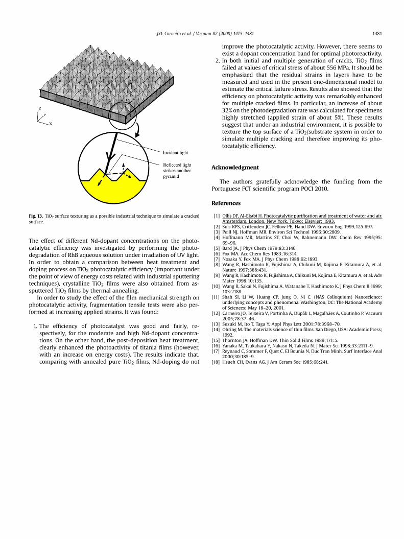
Fig. 13. TiO2 surface texturing as a possible industrial technique to simulate a crackedsurface.
J.O. Carneiro et al. / Vacuum 82 (2008) 1475–1481 1481
The effect of different Nd-dopant concentrations on the photo-catalytic efficiency was investigated by performing the photo-degradation of RhB aqueous solution under irradiation of UV light.In order to obtain a comparison between heat treatment anddoping process on TiO2 photocatalytic efficiency (important underthe point of view of energy costs related with industrial sputteringtechniques), crystalline TiO2 films were also obtained from as-sputtered TiO2 films by thermal annealing.
In order to study the effect of the film mechanical strength onphotocatalytic activity, fragmentation tensile tests were also per-formed at increasing applied strains. It was found:
1. The efficiency of photocatalyst was good and fairly, re-spectively, for the moderate and high Nd-dopant concentra-tions. On the other hand, the post-deposition heat treatment,clearly enhanced the photoactivity of titania films (however,with an increase on energy costs). The results indicate that,comparing with annealed pure TiO2 films, Nd-doping do not
improve the photocatalytic activity. However, there seems toexist a dopant concentration band for optimal photoreactivity.
2. In both initial and multiple generation of cracks, TiO2 filmsfailed at values of critical stress of about 556 MPa. It should beemphasized that the residual strains in layers have to bemeasured and used in the present one-dimensional model toestimate the critical failure stress. Results also showed that theefficiency on photocatalytic activity was remarkably enhancedfor multiple cracked films. In particular, an increase of about32% on the photodegradation rate was calculated for specimenshighly stretched (applied strain of about 5%). These resultssuggest that under an industrial environment, it is possible totexture the top surface of a TiO2/substrate system in order tosimulate multiple cracking and therefore improving its pho-tocatalytic efficiency.
Acknowledgment
The authors gratefully acknowledge the funding from thePortuguese FCT scientific program POCI 2010.
References
[1] Ollis DF, Al-Ekabi H. Photocatalytic purification and treatment of water and air.Amsterdam, London, New York, Tokyo: Elsevier; 1993.
[2] Suri RPS, Crittenden JC, Fellow PE, Hand DW. Environ Eng 1999;125:897.[3] Peill NJ, Hoffman MR. Environ Sci Technol 1996;30:2809.[4] Hoffmann MR, Martins ST, Choi W, Bahnemann DW. Chem Rev 1995;95:
69–96.[5] Bard JA. J Phys Chem 1979;83:3146.[6] Fox MA. Acc Chem Res 1983;16:314.[7] Nosaka Y, Fox MA. J Phys Chem 1988;92:1893.[8] Wang R, Hashimoto K, Fujishima A, Chikuni M, Kojima E, Kitamura A, et al.
Nature 1997;388:431.[9] Wang R, Hashimoto K, Fujishima A, Chikuni M, Kojima E, Kitamura A, et al. Adv
Mater 1998;10:135.[10] Wang R, Sakai N, Fujishima A, Watanabe T, Hashimoto K. J Phys Chem B 1999;
103:2188.[11] Shah SI, Li W, Huang CP, Jung O, Ni C. (NAS Colloquium) Nanoscience:
underlying concepts and phenomena. Washington, DC: The National Academyof Sciences; May 18–20, 2001.
[12] Carneiro JO, Teixeira V, Portinha A, Dupak L, Magalhaes A, Coutinho P. Vacuum2005;78:37–46.
[13] Suzuki M, Ito T, Taga Y. Appl Phys Lett 2001;78:3968–70.[14] Ohring M. The materials science of thin films. San Diego, USA: Academic Press;
1992.[15] Thornton JA, Hoffman DW. Thin Solid Films 1989;171:5.[16] Yanaka M, Tsukahara Y, Nakaso N, Takeda N. J Mater Sci 1998;33:2111–9.[17] Reynaud C, Sommer F, Quet C, El Bounia N, Duc Tran Minh. Surf Interface Anal
2000;30:185–9.[18] Hsueh CH, Evans AG. J Am Ceram Soc 1985;68:241.