Structuring Free Space as a Hypergraph for Roving Robot Path Planning and Navigation
11
IEEE TRANSACTIONS ON PATTERN ANALYSIS AND MACHINE INTELLIGENCE, VOL. PAMI-9, NO. 2, MARCH 1987 Structuring Free Space as a Hypergraph for Roving Robot Path Planning and Navigation KURT D. RUEB AND ANDREW K. C. WONG, MEMBER, IEEE Abstract-This paper presents a method of structuring the free space of a roving robot's environment into a set of overlapping convex re- gions ideally suited to path planning and navigation tasks. The struc- ture of the free space environment is maintained as a hypergraph with each convex region represented by a hyperedge identifying the bound- ary walls of the region. A new methodology reveals the structure of free space and constructs the hypergraph representation through a di- rected search for a set of fundamental circuits in an abstract graphical representation of the environment geometry. Index Terms-Decomposition, free space, graphs, hypergraphs, navigation, path planning, roving robot. INTRODUCTION m WO important tasks required of a roving robot are path planning and navigation. Current path planning methodologies express the constraints on object move- ment to provide a finite approximation of all feasible paths. The visibility graph (VGRAPH), developed in the late 1960's to navigate SHAKEY (an early robot vehicle), consists of a start vertex, the vertices of the obstacles, a goal vertex, and edges connecting any vertices which may be joined by an unobstructed straight line path. The cho- sen path is the shortest start-to-goal path in the VGRAPH, with each edge weighted by the vertex distance [1]. This approach has since been extended for use with any poly- hedral object with a given shape and orientation [2]. Recent methodologies represent the free space of the robot's environment. Free space retraction reduces pos- sible paths to those providing maximal "clearance" from obstacle surfaces [3]. Another approach partitions free space into natural volumes or "freeways" through which the object may be moved [4]. In the HILARE mobile ro- bot project, free space is represented as a connectivity graph of disjoint convex regions along with a higher level of representation defining a topology of "places" such as rooms, work areas, and hallways [5]. The major weakness of current path planning meth- odologies lies not in finding feasible paths or trajectories, but rather in navigation along the chosen path. The diffi- culty experienced in following the path is due to the gap Manuscript received May 17, 1985; revised July 15, 1986. Recom- mended for acceptance by W.E.L. Grimson. This work was supported by the National Sciences and Engineering Research Council of Canada under Strategic Grant G1368 and Operating Grant A4716. The authors are with the Department of Systems Design Engineering, University of Waterloo, Waterloo, Ont. N2L 3G1, Canada. IEEE Log Number 8612402. between the representation domain used for path planning and the information required to navigate that path. This problem can be resolved by representing the path in terms of the free space of the environment and the obstacle boundaries which restrict the path, thus avoiding a rep- resentation consisting of straight line paths completely isolated from the obstacles which constrain the robot's movement. In general, an effective representation for path planning methodologies for guiding roving robots must meet the following objectives: * It must provide a means of locating "navigational landmarks" to help the robot determine its position. * The planning method must efficiently update the world model to reflect changes in the robot's surround- ings. * It should be sufficiently general to allow movement constraints typical of traditional vehicles. All these objectives point to one fundamental problem. How can the global environment be structured or parti- tioned to reflect critical local information? The approach to path planning presented in this paper uses an attributed hypergraph representation to express the characteristics of the obstacle world, to structure the world model, and to represent the topological characteristics of the world. The world graph represents invariant relations between obstacle walls independent of observer position or orientation. A particular region in space, such as a room or corridor, corresponds to a subgraph of the world graph. Efficient algorithms have been developed to match the graph of the local environment and the corresponding subgraph of the world graph [6]. However, there is no apparent way to distinguish a par- ticular region or room from the rest of the world. We solve the problem by enriching the graph to explicitly represent free space. Hyperedges identify sets of walls which form the boundary of well defined "open areas." Every path is described as movement through a two-dimensional ob- stacle space along a series of unobstructed convex regions (primitive "open areas"). This paper presents an efficient algorithm to structure the graph according to the required regions and topolog- ical relations. It introduces a novel approach to the tra- versal or the searching of a graph which is directed to obtain a specific set of fundamental circuits in the graph. We have shown that these circuits correspond to the de- sired decomposition of the free space of the robot's en- vironment. 0162-8828/87/0300-0263$01.00 © 1987 IEEE 263
-
Upload
independent -
Category
Documents
-
view
1 -
download
0
Transcript of Structuring Free Space as a Hypergraph for Roving Robot Path Planning and Navigation

IEEE TRANSACTIONS ON PATTERN ANALYSIS AND MACHINE INTELLIGENCE, VOL. PAMI-9, NO. 2, MARCH 1987
Structuring Free Space as a Hypergraph for RovingRobot Path Planning and Navigation
KURT D. RUEB AND ANDREW K. C. WONG, MEMBER, IEEE
Abstract-This paper presents a method of structuring the free spaceof a roving robot's environment into a set of overlapping convex re-gions ideally suited to path planning and navigation tasks. The struc-ture of the free space environment is maintained as a hypergraph witheach convex region represented by a hyperedge identifying the bound-ary walls of the region. A new methodology reveals the structure offree space and constructs the hypergraph representation through a di-rected search for a set of fundamental circuits in an abstract graphicalrepresentation of the environment geometry.
Index Terms-Decomposition, free space, graphs, hypergraphs,navigation, path planning, roving robot.
INTRODUCTION
m WO important tasks required of a roving robot arepath planning and navigation. Current path planning
methodologies express the constraints on object move-ment to provide a finite approximation of all feasiblepaths.The visibility graph (VGRAPH), developed in the late
1960's to navigate SHAKEY (an early robot vehicle),consists of a start vertex, the vertices of the obstacles, agoal vertex, and edges connecting any vertices which maybe joined by an unobstructed straight line path. The cho-sen path is the shortest start-to-goal path in the VGRAPH,with each edge weighted by the vertex distance [1]. Thisapproach has since been extended for use with any poly-hedral object with a given shape and orientation [2].
Recent methodologies represent the free space of therobot's environment. Free space retraction reduces pos-sible paths to those providing maximal "clearance" fromobstacle surfaces [3]. Another approach partitions freespace into natural volumes or "freeways" through whichthe object may be moved [4]. In the HILARE mobile ro-bot project, free space is represented as a connectivitygraph of disjoint convex regions along with a higher levelof representation defining a topology of "places" such asrooms, work areas, and hallways [5].The major weakness of current path planning meth-
odologies lies not in finding feasible paths or trajectories,but rather in navigation along the chosen path. The diffi-culty experienced in following the path is due to the gap
Manuscript received May 17, 1985; revised July 15, 1986. Recom-mended for acceptance by W.E.L. Grimson. This work was supported bythe National Sciences and Engineering Research Council of Canada underStrategic Grant G1368 and Operating Grant A4716.
The authors are with the Department of Systems Design Engineering,University of Waterloo, Waterloo, Ont. N2L 3G1, Canada.
IEEE Log Number 8612402.
between the representation domain used for path planningand the information required to navigate that path. Thisproblem can be resolved by representing the path in termsof the free space of the environment and the obstacleboundaries which restrict the path, thus avoiding a rep-resentation consisting of straight line paths completelyisolated from the obstacles which constrain the robot'smovement. In general, an effective representation for pathplanning methodologies for guiding roving robots mustmeet the following objectives:
* It must provide a means of locating "navigationallandmarks" to help the robot determine its position.
* The planning method must efficiently update theworld model to reflect changes in the robot's surround-ings.
* It should be sufficiently general to allow movementconstraints typical of traditional vehicles.
All these objectives point to one fundamental problem.How can the global environment be structured or parti-tioned to reflect critical local information?The approach to path planning presented in this paper
uses an attributed hypergraph representation to express thecharacteristics of the obstacle world, to structure the worldmodel, and to represent the topological characteristics ofthe world. The world graph represents invariant relationsbetween obstacle walls independent of observer positionor orientation. A particular region in space, such as a roomor corridor, corresponds to a subgraph of the world graph.Efficient algorithms have been developed to match thegraph of the local environment and the correspondingsubgraph of the world graph [6].However, there is no apparent way to distinguish a par-
ticular region or room from the rest of the world. We solvethe problem by enriching the graph to explicitly representfree space. Hyperedges identify sets of walls which formthe boundary of well defined "open areas." Every pathis described as movement through a two-dimensional ob-stacle space along a series of unobstructed convex regions(primitive "open areas").
This paper presents an efficient algorithm to structurethe graph according to the required regions and topolog-ical relations. It introduces a novel approach to the tra-versal or the searching of a graph which is directed toobtain a specific set of fundamental circuits in the graph.We have shown that these circuits correspond to the de-sired decomposition of the free space of the robot's en-vironment.
0162-8828/87/0300-0263$01.00 © 1987 IEEE
263
IEEE TRANSACTIONS ON PATTERN ANALYSIS AND MACHINE INTELLIGENCE, VOL. PAMI-9, NO. 2, MARCH 1987
ATTRIBUTED HYPERGRAPH REPRESENTATION OF FREESPACE
An OverviewIn our approach, free space is partitioned into a set of
unobstructed convex regions. The convex regions arechosen so that every boundary is a constraint imposed byan obstacle wall. There are no artificial boundaries whichpartition free space but do not relate to visible or move-ment-constraining obstacle walls. An attributed hyper-graph provides an ideal form for this representation. Itsdefinition is as follows [7], [8]:
OBSTACLE SPACE
Obstacle Walls--- Convex RegionO--Overlap Region
HYPERGRAPH
--- Convex Region AOverlap Region II
Fig. 1. Attributed hypergraph representation.
Let X = {x1, x2, . . . , x,, } be a finite set, and let E= {e,, e2, , eni } be a family of subsets of X.The couple H = (X, E) is called a hypergraph. Theelements of X are called the vertices, and the ele-ments of E are called hyperedges. Each vertex or
hyperedge is associated with a list of nominal or nu-
merical attribute values. Hyperedges consisting ofonly two vertices will be referred to simply as edges.An attributed hypergraph composed only of edgesmay also be known as an attributed graph.
Obstacle boundaries or walls are represented by the ver-
tices of the graph. The attribute values for each vertexdescribe the end points of the wall and the direction thewall faces. Edges between the wall vertices indicate theconnection of boundaries which define obstacles or rooms
(Fig. 1). The edge attribute value is the angle containedby the connected walls.The unobstructed convex regions are represented by hy-
peredges which are the sets of wall vertices that form re-
gion boundaries. The overlaps of the convex regions are
used to determine their topological properties. Each over-
lap is represented by a hyperedge with attribute valuesidentifying the intersecting regions and the centroid of theoverlap (see Fig. 1).Once the obstacle space is represented in this way, the
information in the graph is abstracted to form a "roadmap" graph used to plan feasible paths on a symboliclevel. The road map graph is formed with the overlaps as
the nodes or vertices, and the common convex regionsjoining each pair of overlaps as connecting roads or edges.The edges have attribute values specifying the length ofthe path between overlaps, an estimate of the path width,and a pointer to the original convex regions of the lowlevel representation (the set of critical walls for obstacleavoidance and navigation).A feasible path is obtained by finding the shortest path
in the road map from start to goal locations along pathsof sufficient width. A suitable trajectory through the con-
vex regions of the path must then be calculated using theactual movement constraints of the vehicle. Fig. 1 illus-trates a simple obstacle space, and the hypergraph repre-
sentation of a convex region and an overlap region of freespace. The resulting road map with three overlap vertices,the start and goal positions, and the connecting convex
Primaryconvexregion
Regions B a C
oare not primaryconvex regions
Fig. 2. Primary convex regions.
regions is shown, along with a dashed line indicating theshortest path between start and goal vertices.
Basic DefinitionsThis section defines the basic concepts of the free space
representation. The definition provides the essential re-
gion characteristics used to determine the required de-composition of free space.
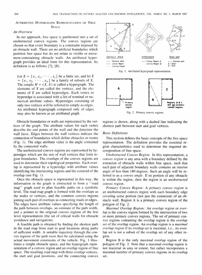
Unobstructed Convex Region: In this representation, a
convex region is any area with a boundary defined by theextension of obstacle walls within free space, such thateach pair of adjacent boundary walls contains an interiorangle of less than 180 degrees. Such an angle will be re-
ferred to as a convex angle. If no portion of any obstacleis within the region, then the region is an unobstructedconvex region.Primary Convex Region: A primary convex region is
an unobsttucted convex region with each boundary edgecovering some portion (not just the extension) of an ob-stacle wall. Region A is a primary convex region of thepolygon of Fig. 2.Maximal Overlap Region: An overlap region or over-
lap is the convex region formed by the intersection of twoor more primary convex regions. The set of primary con-
vex regions containing the overlap region is the overlapset of the overlap region. An overlap region is a maximaloverlap region if its overlap set is maximal, i.e., its over-
lap set is not a subset of the overlap set of any other re-
gion.Region B is the only maximal overlap region of the
polygon of Fig. 3. Note that a maximal overlap region isnot maximal in area or extent, but rather incorporates a
maximal number of primary convex regions in its overlapset.
s '4.
,3.2
B,- I
ROAD MAP
- -- Shortest pathS - StartG - GoalI
264
RUEB AND WONG: ROVING ROBOT PATH PLANNING AND NAVIGATION
Fig. 3. Maximal overlap regions.
Connected Overlap Regions: Two maximal overlap re-gions, A and B, are connected overlap regions if they arewithin a common primary convex region, i.e., the inter-section of the overlap sets of the two regions is not theempty set. More simply, any point in region A may beconnected to any point in region B by an unobstructedstraight line path. (For example, regions II and III of Fig.1 are connected overlap regions.)
If a point P is in a maximal overlap region M, then aline from P to any point in one of the regions of the over-lap set of M will be unobstructed. If there is an unob-structed path from a point P1 to another point P2 thenthere exists a path of unobstructed line segments joiningP1, a sequence of maximal overlap regions and P2.The complete set of all possible primary convex regions
define the free space in the robot's environment. Themaximal overlap regions form the vertices of a connectiv-ity graph describing the topological properties of the pri-mary convex region representation of free space.
Formal Statement of the RepresentationThe free space representation of the environment con-
sists of two components: the hypergraph of free space re-gions and its abstraction, the road map graph.The hypergraph of free space regions is defined as
H = (X, E)
where X is a vertex set
{xi xi represents the ith obstacle wall}
and E is a set of hyperedges:
E=A UPUM
where
A = {ai}
P = {pi }
M = {mi}
and each ai = { xa, Xb } Xa and Xb being theith pair of adjacent obstacle walls.and each pi = { xj xj is a boundary wallof the i th primary convex region }.
and each mi = {xj xj is a boundary wallof the i th maximal overlap region }I.
The road map is an attributed graph
Gm = ( V, E)
where V is a vertex set
{ vi vi corresponds to the ith maximal overlap region }
and each vertex vi has the attributes:
Pi = { p1 } where pj is a primary convex region thatcontains the maximal overlap region cor-responding to vi and
Ci = (x, y) which denotes the centroid of the maxi-mal overlap region vi
and E is a set of edges{ ei = (Va, Vb) v, and Vb correspond to connected
maximal overlap regions }
and each edge ei has the attributes:I N
Pi = {p}I
width
length
where pj is a primary convex region whichconnects the maximal overlap regionscorresponding to v, and Vb,which denotes the minimum width of thepath from v, to Vb, andwhich is an estimate of the path lengthfrom va to Vb.
CHARACTERISTICS OF THE HYPERGRAPHREPRESENTATION
The considerations which guided the selection of thefree space representation are outlined in this section.
Navigational LandmarksThe set of obstacle walls visible to the robot's sensors
may vary continuously with robot position. As a result, afinite representation of all viewpoints is impossible, andthe continually changing reference makes navigation dif-ficult.
In contrast, the primary convex regions provide an idealnavigational reference since the hypergraph representa-tion of the local environment obtained by the robot's sen-sor corresponds exactly to the primary convex regions thatcontain the current position in the global model. The ex-act correspondence between the local view and the globalmodel allows the walls of the primary convex regionscontaining the observation point to serve as a navigationreference (Fig. 4).An important feature of this representation is the con-
tinuity of the navigational reference. A primary convexregion will remain visible while the observation point iswithin the region. It is therefore possible to ensure thatsufficient reference is maintained between scans of the en-vironment. Movement through regions of maximal over-lap ensures maximal representational continuity.
Acquisition and Updating of ModelThe exact correspondence between local and global
representations allows the global representation to be as-sembled gradually as it is revealed by the robot's sensors.Alterations in the environment may also be accommo-dated by updating the global model to reflect changes inthe representation of the local environment. This reducescomputational cost to the evaluation of the set of visiblewalls only, not of the entire world model.
265

IEEE TRANSACTIONS ON PATTERN ANALYSIS AND MACHINE INTELLIGENCE, VOL. PAMI-9, NO. 2. MARCH 1987
GLOBAL MODEL
'I I'
LOCAL SCENE
* Current position
_, Primary convex region,,- ., Obstacle wall
Fig. 4. Local and global primary convex regions.
Fig. 5. Model with global inconsistency.
Acquisition of the world model in this manner also re-
duces the problem of global errors in the acquired knowl-edge since only local consistency of measurements is re-
quired to avoid discontinuities or inaccuracy in the modeldefinition. Fig. 5 illustrates a model definition with in-accuracies which make global evaluation impossible, yetit may be satisfactorily acquired and interpreted whenconstructed from a sequence of local views.
Minimal Representation of Feasible Paths
The primary convex regions completely define freespace. Overlap areas are formed by the intersection ofthese regions, i.e., the overlaps identify how the regionsare connected. The maximal overlaps are the minimal setof overlaps such that every overlap either is a maximaloverlap or contains a maximal overlap. Hence, the max-
imal overlap areas are the smallest set which completelydefine the connection of all primary convex regions. As a
result, the maximal overlap areas provide a very sparse
network of regions from which any two points in freespace may be connected by a sequence of unobstructedstraight line paths. For every feasible path, there is a cor-
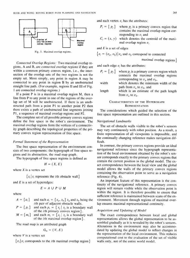
responding path through the maximal overlap regions,with the same minimum width and passing through thesame set of obstacles. The hypergraph provides a compactrepresentation of the feasible paths at the cost of a coarser
estimate of path length as illustrated in Fig. 6.
Estimate of Path LengthPath length is approximated by the sum of the distances
between centroids of the connected maximal overlap re-
gions of the chosen path. This estimate of path length willoccasionally result in the selection of a path longer thannecessary; however, this drawback appears to be un-
avoidable when using any representation which attemptsto be of use for objects of any size or movement charac-
teristics. Further, since the correlation between the timeto traverse a path and the length of the path is not precise,the possible increase in path length is considered accept-able for actual operation.
CONSTRUCTION OF THE HYPERGRAPH REPRESENTATIONOF FREE SPACE
The free space representations of current path planningmethodologies are obtained by partitioning the free spaceaccording to a set of well-defined rules for geometric con-structions. Decomposition of free space is often based onalgorithms for partitioning a polygon into disjoint convexregions and many such algorithms exist [9], [10]. Unfor-tunately, while this class of region decomposition is effi-cient, the resulting representation is not optimal. As anexample, consider Schacter's decomposition based on theDelaunay tesselation of a polygon [ 1]. The decomposi-tion may be efficiently computed in 0 (n2) time; however,the disjoint convex regions produced lack the direct cor-respondence between the decomposition of the locallyperceived environment and the global representation. Inaddition, each convex region is associated with only aminimal number of obstacle walls which may not providesufficient navigational reference.
In contrast, the free space representation of this paperhas been developed by selecting a well-defined represen-tation that provides the best combined suitability for nav-igation and path planning. It is then necessary, however,to develop an efficient decomposition technique in orderto produce such representation.
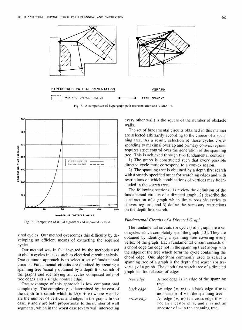
Decomposition of free space into primary convex re-gions may be obtained in a straightforward manner byconsidering all convex regions formed by possible wallcombinations and testing each region for obstruction bythe remaining obstacle walls. Unfortunately, the compu-tational cost of this approach severely limits the complex-ity of the path-planning environment. Experimentationwith this initial algorithm indicated a practical limit of 80to 100 obstacle walls.
In response to this challenge, a more efficient techniqueis introduced. This method is somewhat complex andrather unorthodox (the actual search is conducted using agraphical representation consisting of only abstract con-nectivity relations rather than an explicit geometricmodel). However, its computational complexity permitsthe analysis of complex environments composed ofhundreds of obstacle walls. The relative performance ofboth the initial algorithm and the new improved decom-position method is shown in Fig. 7 (processing time isgiven for Pascal program running on a VAX/750).
This improved method is based upon earlier work byPavlidis [12]. Pavlidis created a fundamental graph of thepolygon which represents each boundary edge by a di-rected arc extended to the limit of the free region. Hepartitioned each wall into a number of individual seg-ments. The maximal overlap and primary convex regionscorrespond to cycles in this graph. Unfortunately, nomethodology was available to efficiently locate the de-
266
RUEB AND WONG: ROVING ROBOT PATH PLANNING AND NAVIGAI ION
HYPERGRAPH PATH REPRESENTATION
MAXIMAL OVERLAP REGION__. _
VGRAPH
. * PATH SEGMENT
Fig. 6. A comparison of hypergraph path representation and VGRAPH.
every other wall) is the square of the number of obstaclewalls.The set of fundamental circuits obtained in this manner
are selected arbitrarily according to the choice of a span-ning tree. As a result, selection of those cycles corre-sponding to maximal overlap and primary convex regionsrequires strict control over the generation of the spanningtree. This is achieved through two fundamental controls:
inolagorithm 1) The graph is constructed such that every possibleoved method --- . directed cycle must correspond to a convex region.
2) The spanning tree is obtained by a depth first searchwith a strictly specified order for searching edges and withrestrictions on which combinations of vertices may be in-cluded in the search tree.The following sections: 1) review the definition of the
fundamental circuits of a directed graph, 2) describe theconstruction of a graph which limits possible cycles toconvex regions, and 3) define the necessary restrictions
120 160 200 on the depth first search.
Fig. 7. Comparison of initial algorithm and improved method.
sired cycles. Our method overcomes this difficulty by de-veloping an efficient means of extracting the requiredcycles.Our method was in fact inspired by the methods used
to obtain cycles in tasks such as electrical circuit analysis.One common approach is to select a set of fundamentalcircuits. Fundamental circuits are obtained by creating a
spanning tree (usually obtained by a depth first search ofthe graph) and identifying all cycles composed only oftree edges and a single nontree edge.One advantage of this approach is low computational
complexity. The complexity is determined by the cost ofthe depth first search which is 0 (v + e) where v and e
are the number of vertices and edges in the graph. In our
case, v and e are both proportional to the number of wallsegments, which in the worst case (every wall intersecting
Fundamental Circuits of a Directed Graph
The fundamental circuits (or cycles) of a graph are a setof cycles which completely span the graph [13]. They are
obtained by identifying a spanning tree covering everyvertex of the graph. Each fundamental circuit consists ofa chord edge (an edge not in the spanning tree) along withthe edges of the tree which form the cycle containing thechord edge. One algorithm commonly used to select a
spanning tree of a graph is the depth first search (or tra-versal) of a graph. The depth first search tree of a directedgraph has four classes of edge:
tree edge A tree edge is an edge of the spanningtree.
back edge An edge (v, w) is a back edge if w isan ancestor of v in the spanning tree.
cross edge An edge (v, W) is a cross edge if vv isnot an ancestor of v, and 2t is not an
ancestor of w in the spanning tree.
z0a
0U
In
w!2I--
0z
0a.
NUMBER OF OBSTACLE WALLS
267

IEEE TRANSACTIONS ON PATTERN ANALYSIS AND MACHINE INTELLIGENCE, VOL. PAMI-9, NO. 2, MARCH 1987
-
tree edgeforward edgecross edgeback edgefundmentalcircuit
througharcs
Segment Graph Region Graph
Fig. 8. Depth first search tree and fundamental circuits of a directed graph.
Fig. 9. Wall segments of obstacle wall.
forward edge An edge (v, w) is a forward edge if wis a descendent of v.
The depth first search tree and fundamental circuits of adirected graph are illustrated in Fig. 8. Unfortunately, theset of fundamental circuits obtained is not unique. Thatis, if a different tree is selected, different fundamental cir-cuits will result. However, the edge and vertex attributevalues of an attributed graph allow the development of asearch strategy to overcome this difficulty.
Representationi of Obstacle SpaceThe robot's environment is modeled as a two-dimen-
sional world with polygonal obstacles. The walls formingthe obstacle boundaries may be mapped from a floor planof the robot's environment or located by fitting line seg-ments to the range plot obtained by the roving robot's sen-sors. The walls are then extended within the free regionsurrounding the obstacle. The intersections of the ex-tended obstacle walls partition each of the intersectingwalls into wall segments. A direction is assigned to eachsegment such that the free or open side is to the left of thewall segment (Fig. 9). Each segment is labeled as a solid,head, or tail segment. The actual wall is partitioned intosolid segments while the preceding or succeeding exten-sions of the wall are partitioned into head and tail seg-ments. This geometric model is then abstracted to formthe region graph which defines the interconnection of wallsegments.Region Graph: The region graph, denoted by Gr (Vr,
Ar), consists of a set of vertices Vr, called region ver-tices, with a one-to-one correspondence to the wall seg-ments, and a set of directed arcs Ar, called region arcs,which represent the interconnection of the wall segments.Region vertices retain the attribute value (solid, head,
or tail) of their associated wall segment. Region arcs con-nect pairs of region vertices that either correspond to twosegments of a single wall or segments of two walls witha contained convex angle. The relationship between thevertices and arcs of the region graph and the connectionof wall segments is illustrated in Fig. 10.Each region arc will take one of the following attribute
values:
Fig. 10. Wall segments and corresponding region graph.
p[F SEGMENTGRAPH
D E
--, J I HPrimory convex region>-~~\ and corresponding
_ g >:\ \ region cycle
REGIONGRAPH
Fig. 11. Region graph representation of free space.
through arc
left arc
A "through" region arc connects two re-gion vertices of segments from a singleobstacle wall.A "left" region arc connects the regionvertices of two segments such that thesecond segment is to the left or free sideof the first.
A convex region is said to correspond to a cycle in theregion graph (a region cycle) if every segment of the re-gion boundary is represented by a vertex of the cycle. Themethod for constructing the region graph ensures that allmaximal overlap and primary convex regions correspondto region cycles. It also follows that it is impossible for aregion cycle to correspond to a nonconvex region. Fig.11 illustrates the process of deriving the region graph fora simple free space region, and demonstrates the interpre-tation of a region cycle as its corresponding primary con-vex region.
Search for Maximal Overlap RegionsBy definition, a maximal overlap region may not be cut
by the boundary of any primary convex region as thesubregion has the additional region in its overlap set. Thiscondition requires that every cycle corresponding to amaximal overlap region must consist only of vertices con-nected by "left" arcs (Fig. 12).
268

RUEB AND WONG: ROVING ROBOT PATH PLANNING AND NAVIGATION
Non - mox imoloverlop region Moximal overlop region
(composed solely of 'left' orcsegment connections /
I< / /Directed wall segments\ .6.J of three primary convex / .*\ sj
k___\ , regions
Note Through orc connectionsbetween wall segments
Fig. 12. Region cycle of a maximal overlap region.
Conversely, a cycle composed only of "left" arcs mustcorrespond to a maximal overlap region. Since the regioncorresponding to the cycle may not be cut by the boundaryof any convex region, it must lie entirely within or with-out every other overlap region. If it lies outside anotheroverlap, it must be contained by some primary convexregion not in the overlap set of the other overlap, since inorder for a boundary to exist between the overlap regions,there must be some primary convex region which does notcontain both overlap regions. If it lies within anotheroverlap, it will have the other's complete overlap set plusthe additional convex region which partitions it from theother overlap region. To obtain all such cycles, the searchmust:
Examine any "left" arc incident on a region vertexbefore any "through" arc of the vertex.
Each fundamental circuit obtained in this manner whichis composed solely of "left" arcs will correspond to amaximal overlap region. Note that the maximal overlapregions may be identified without locating the primaryconvex regions.
Search for Primary Convex RegionsEvery boundary of a primary convex region must cover
some portion of an obstacle wall. As a result, every wallof the region must be associated with a cycle vertex cor-responding to a "solid" wall segment. The following ruledefines the set of valid vertex connections permitted in thesearch tree (see Fig. 13):
A "left" region arc may only be an edge (v, w) ofthe spanning tree if w is not a "head" vertex and vis not a "tail" vertex.
This rule requires the search to begin the traversal of anobstacle wall before or within a solid wall segment (sincea branch to a "head" segment is not allowed), and exitwithin or after the solid wall segments (since a branchfrom a "tail" segment is forbidden).
To ensure the detection of unobstructed regions (re-gions containing no obstacle) in preference to obstructedregions, the search is required to examine "left" arcs be-fore "through" arcs. However, whenever there exist in-terior obstacles inside the outer boundary of the free space,the number of fundamental circuits will be greater than
+ . p (~ Wall segment connectionhead .tOlO forbidden by the vertex rule
Sl(= I-; / 5Woll segment connectiontsil ;4 ~heod permitted by the vertex ule
Fig. 13. Valid wall segment connections of search tree.
the number of primary convex regions since to each cir-cuit of free space surrounding an obstacle there corre-sponds an additional cycle. As a consequence, some ofthe identified cycles will correspond to obstructed re-gions. Each region is unobstructed only if its correspond-ing cycle meets the following requirement:
The segments of any wall cutting the region musthave the same label entering and leaving the region(i.e., all segments within the region must either beonly head segments or only tail segments since nosolid segment may be contained by the region).
Unfortunately, this approach to free space decomposi-tion is complicated by another characteristic of the fun-damental circuits of a directed graph. To form a valid re-gion, every arc of the region cycle must have a consistentorientation (the free side of each boundary wall must betoward the inside of the region). However, the orientationof fundamental circuits defined by cross edges are notconsistent (refer back to Fig. 8). This difficulty does notoccur in the search for maximal overlap regions since thedesired cycles are composed only of "left" arcs and mustnecessarily be defined by a back edge.The desired region cycle associated with each cross
edge may be found by initiating additional searches withthe vertices of the cross edge as the root of the search tree.This ensures that all circuits containing those vertices mustbe defined by a back edge. However, this approach threat-ens to increase the computational complexity from thesame order as the number of wall segments to the squareof this value (as a worst case condition, an increase fromO ( n2 ) to O ( n4) where n is the number of obstacle walls).To prevent this increase, a number of heuristics are em-ployed to limit the search to the local area of the crossedge. The rules permit the search to identify all regioncycles containing the cross edge while avoiding the trav-ersal of cycles of regions with other boundary wall seg-ments. These rules are as follows:
1) The defining back edge of a fundamental circuit mustbe incident on the root vertex; any other back edge con-nection aborts the search along the current branch of thesearch tree.
2) The search is limited to walls capable of forming aconvex polygon with the walls of the cross edge segmentsby requiring that:
Two vertices, v and w, may not be connected by atree edge if the sum of the exterior angles of all"left" connections of the ancestor vertices of v isgreater than 360 degrees.
269

IEEE TRANSACTIONS ON PATTERN ANALYSIS AND MACHINE INTELLIGENCE. VOL. PAMI-9. NO. 2, MARCH 1987
SEGMENT GRAPH
REGION GRAPH
Fig. 14. Wall segments and region graph of a simple environment.
3) When the search of each cross edge is completed,the cross edge is disconnected to prevent duplication ofthe region by later searches starting at another cross edge.While the above rules do not ensure the avoidance of
0(n4) complexity, these measures are quite adequate inpractice. Application of this method to floor plans ofvarying complexity indicate that the cost of the search isproportional to the number of wall segments. The numberof wall segments in the floor plan is typically less than thesquare of the number of obstacle walls and becomes pro-portional to the number of walls as the number of indi-vidual rooms in the floor plan is increased. As a conse-quence, the processing time required to search for theregion cycles requires a smaller portion of the total pro-cessing time as the floor plan becomes large (greater than100 walls). This is discussed further in the section con-cerning implementation of the algorithm.
Free Space Decomposition of a Simple Region GraphThis section provides an example of locating the max-
imal overlap and primaly convex regions of a simple ob-stacle environment. Fig. 14 illustrates an environment andits representation as a region graph.The search tree for the maximal overlap regions is
shown in Fig. 15. The order in which the tree vertices areencountered by the search is indicated by the number be-side each vertex. A left branch in the tree indicates asearch along a "left" region arc, and a right branch in-dicates a search along a "through" arc. Back or crossedges are shown as dashed or dotted lines with the dashedlines indicating back edges defining the desired regioncycles. The directed cycles (P, A, L, K) and (C, D, I, H)correspond to the two maximal overlap regions (the fun-damental circuits composed only of "left" arcs).The search tree for the primary convex regions is shown
in Fig. 16. The directed cycles (0, P, A, L, M, N), (P,
Fig. 15. Search tree for maximal overlap regions.
Fig. 16. Search tree for primary convex regions.
A, B, C, D, I, J, K), and (C, D, E, F, G, H) correspondto the primary convex regions. Since no cross edges arefound, no additional searches are required. Since there areno interior obstacles within the boundary of free space,no region can be obstructed. This is characteristic of ascan obtained by the robot's sensor; however, interior ob-stacles are possible when the region graph is obtained froma floor plan.
CONSTRUCTION OF THE ROAD MAP
This paper has presented an efficient means of decom-posing obstacle space into primary convex regions and thecorresponding maximal overlap regions. The followingsections outline the remaining tasks of constructing theroad map and obtaining a feasible path.
Geometric Representation of Obstacle SpaceIn the following presentation, it is assumed that each
and every obstacle wall may be defined by the position ofits end points expressed in terms of a global coordinatesystem. If the representation was obtained from a floorplan, the coordinate system may be considered globallyor completely consistent. However, if the representationis accumulated from scans of the environment, the coor-dinate system may be only locally consistent.
270

RUEB AND WONG: ROVING ROBOT PATH PLANNING AND NAVIGATION
Fig. 17. Estimation of minimum path width.
A locally consistent area is defined as an area of obsta-cle space in which reasonable coordinate accuracy ismaintained. For example, one might consider two wallsto be in the same local area if the scans which locate eachwall overlap. In general, the definition of a locally con-
sistent area is determined by the precision of the methodused to locate the position of the surrounding obstaclewalls.
Estimation of Path WidthThe primary task in the construction of a road map is
the calculation of the path width associated with each edgein the road map. We begin by identifying the reflex wallcorners (obstacle walls joined at a reflex angle) along theboundary of each primary convex region (reflex wall cor-
ners are identified by noting all connections between re-
gion cycle vertices of a solid wall segment and of a heador tail segment). A list of the locations of all such cornersis recorded for each region.The width of the path between two maximal overlap
regions A and B is obtained through the following proce-dure:
1) Approximate the location of the maximal overlap re-
gions A and B by their centroids ma and mb, respectively.2) Identify the obstacle walls and reflex corners of the
local region. The local region is defined as the set of pri-mary convex regions containing one or both maximaloverlap regions. (Note that this permits the use of a geo-metric representation of obstacle space with a locally con-
sistent coordinate system.)3) For each reflex corner of the local region calculate
the minimum distance to every other corner or wall of thelocal region. The measured distance must cross the pathbetween centroids ma and mb. The minimum path widthis the value of the minimum distance obtained.
Fig. 17 illustrates the estimation of the minimum pathwidth. The possible distances considered are shown as
dotted lines with the minimum path width shown as a
dashed line.
Search for the Shortest Road Map PathThis task is equivalent to finding the shortest path in a
weighted graph. This is a very common task and a numberof efficient algorithms have been developed. In this im-plementation, Dijkstra's algorithm is used [14].The shortest path algorithm may be applied to searching
the road map with one simple modification. To accom-
modate the minimum path width estimate of the road map,it is necessary to assume that the edge length is infinite ifthe minimum path width associated with the edge is less
cjaz0
0w
!2
-
0
zon0
0IL
0 160 20040 80 120
NUMEBER OF OBSTACLE WALLS
Fig. 18. Distribution of processing time for the decomposition of freespace.
than the specified minimum dimension of the roving ro-
bot. In other words, the path is restricted to path segmentsof sufficient width. Note that specification of a path widthdoes not increase the cost of the search, but may in factdecrease the processing required by limiting the complex-ity of the graph (by pruning graph edges).
COMPUTER IMPLEMENTATIONThe processing time required to generate the hyper-
graph representation of the free space within a set of sim-ulated environments of rooms and obstacles of varyingcomplexity is illustrated in Fig. 18. The algorithm was
implemented in Pascal on a VAX/750 running a VMS op-
erating system.Fig. 18 illustrates the total time required to identify the
primary convex regions as well as the portion of this timethat was used to create the region graph. The cost of thesearch is proportional to the number of wall segments inthe region graph. As the number of rooms and corridorsin the floor plan is increased, the number of segments per
wall becomes stable as the walls intersect only within thelocal region, eventually approaching a limit of an average
of 10 to 15 segments per wall. (This limit depends more
on the complexity of the representation of local regionsrather than the total number of rooms or hallways in theoverall floor plan.) As a result, as the number of walls n
is increased, the 0(n2) process of generating the regiongraph tends to dominate processing time, and the cost ofthe search itself becomes proportionally less.
Fig. 19 illustrates the floor plan of a 238 wall environ-ment, its free space representation, and the paths foundfor differently sized objects. Note that the floor plan rep-resents only permanent walls and obstacles (room walls,fixed partitions, study areas, and permanent fixtures suchas computing equipment or bookshelves). Temporary or
moveable obstructions, such as doors or chairs, are notincluded.
30
Primary Convex Regions25 Maximal Overlap Regions
Construction of Region Graph
20
15 / o
I5
I0 ~ ~ ,/ /
S~~~~~~/ /
271

IEEE TRANSACTIONS ON PATTERN ANALYSIS AND MACHINE INTELLIGENCE. VOL. PAMI-9, NO. 2. MARCH 1987
Fig. 19. Free space representation of a simulated environment.
Approximately 35 seconds of processing time was re-
quired to generate the region graph. Locating the funda-mental circuits of the maximal overlap regions and pri-mary convex regions required an additional 16 seconds.Construction of the road map required 147 seconds withthe majority of processing time devoted to calculating theminimum path width associated with each edge in the roadmap.Once the road map is complete, path finding is com-
paratively rapid. For example, the paths for the smallerobject were found in approximately one second. Obtain-ing the path of the larger object required only 600 ms.
Vehicles with complex movement constraints may beaccommodated by varying the minimum path width re-
quirement to provide room to maneuver. Dynamically al-
tering the apparent object width during the search for apath creates no additional computational overhead.
CONCLUSIONSThe path planning methodology presented in this paper
structures the free space of the robot's environment intoa set of overlapping convex regions which permit an ef-ficient representation of the environment in the form of anattributed hypergraph.The approach presented structures free space into a set
of regions obtained from a geometric region definition thatis independent of the method of construction of the rep-resentation. This provides a hypergraph representation offree space that may be obtained either from scans of theenvironment or from a complete floor plan. It has beendemonstrated through simulated experiments that suchrepresentation of free space can be autonomously con-structed from a floor plan of the environment by repre-senting the environment in the form of an attributed graphand then identifying a specific set of fundamental circuits.
This representation of free space permits a path plan-ning methodology capable of representing obstacle envi-ronments of considerable complexity. Experiments withsimulated environments have demonstrated the applica-tion of the planning methodology to the complex environ-ments required for roving robot applications. In addition,the minimal representation of the set of feasible paths pro-vided by the maximal overlap regions permits rapid pathplanning once the representation is complete.
Perhaps the most important quality of this approach topath planning is that it is ideally suited for guiding a rov-ing robot. The local structure provided by the methodol-ogy removes the requirement for an accurate global co-ordinate system. In addition, the position of the robot isexpressed in terms of the surrounding obstacles, avoidingthe need to establish the absolute position of the robot orat least its position relative to the goal. The close corre-spondence between the local and global representations ofthe environment also permits efficient updating of the rep-resentation to reflect changes in the environment sensedby the robot. Finally, the explicit representation of theminimum path width permits efficient path calculation forvehicles with any specified width. Vehicles with complexmovement constraints can therefore be accommodated byvarying the minimum path width requirement to provideroom to maneuver.
REFERENCES[1] N. J. Nilsson, "A mobile automation, an application of artificial in-
telligence techniques," in Proc. Int. Joint Conf. Artif. Intell., 1969,pp. 509-520.
[2] T. Lozano-Perez and M. A. Wesley, "An algorithm for planning col-lision-free paths among polyhedral obstacles," Commun. ACM, vol.22, no. 10, pp. 560-570, Oct. 1979.
[3] K. C. Yap, "Algorithmic motion-planning, a survey," Courant Inst.Math. Sci., New York Univ., New York, 1983.
272

RUEB AND WONG: ROVING ROBOT PATH PLANNING AND NAVIGATION
[4] R. A. Brooks, "Solving the find-path problem by good representationof free space," IEEE Trans. Syst. Man, Cybern., vol. SMC-13, pp.190-197, Mar./Apr. 1983.
[5] G. Giralt, R. Chatila, and M. Vaisset, "An integrated navigation andmotion control system for autonomous multisensory mobile robots,"in First Int. Symp. Robotics Res. Cambridge, MA: M.I.T. Press,1984, pp. 191-214.
[6] A. K. C. Wong and F. A. Akinniy, "An algorithm for the largestcommon subgraph isomorphism using the implicit net," in IEEE Proc.Int. Conf. Systems, Man, Cybern., Bombay, India, 1983, pp. 197-201.
[7] C. Berge, Graphs and Hypergraphs. Amsterdam, The Netherlands:North-Holland, 1973.
[8] A. K. C. Wong and M. You, "Entropy and distance of random graphswith application to structural pattern recognition," IEEE Trans. Pat-tern Anal. Machine Intell., vol. PAMI-7, pp. 599-609, Sept. 1985.
[9] B. M. Chazelle, "Computational geometry and convexity," Carne-gie-Mellon Univ., Pittsburgh, PA, July 1980.
[10] D. T. Lee and F. P. Preparata, "Computational geometry-A sur-vey," IEEE Trans. Comput., vol. C-33, pp. 1072-1101, Dec. 1984.
[11] B. Schacter, "Decomposition of polygons into convex sets," IEEETrans. Comput., vol. C-27, pp. 1078-1082, Nov. 1978.
[12] T. Pavlidis, Structural Pattern Recognition. New York: Springer-Verlag, 1977.
[13] M. N. S. Swamy and K. Thulasiraman, Graphs, Networks, and Al-gorithms. New York: Wiley, 1981.
[14] J. A. Bondy and U. S. R. Murty, Graph Theory with Applications.New York: Elsevier, 1982.
Kurt D. Rueb received the M.A.Sc. degree insystem design engineering from the University ofWaterloo, Waterloo, Ont., Canada, in 1985.
He is currently with the Pattern Analysis andMachine Intelligence Laboratory of the Univer-sity of Waterloo while working toward the Ph.D.degree. His research interests include artificial in-telligence, knowledge-based systems, and com-puter vision.
Andrew K. C. Wong (M'79) received the Ph.D.degree from Carnegie-Mellon University, Pitts-bufgh, PA, in 1968.
For several years, he taught at Carnegie-Mel-lon. He is currently a Professor of Systems DesignEngineering and the Director of the PAMI Group,University of Waterloo, Waterloo, Ont., Canada.In 1984, he also assumed the responsibility of Re-search Director, in charge of the research portionof the Robotic Vision and Knowledge Base Proj-ect at the University. He has authored and co-
authored chapters/sections in several engineering books and published manyarticles in scientific journals and conference proceedings.
Dr. Wong is an Associate Editor of the Journal ofComputers in Biologyand Medicine.
273