Structure Design Manual MARCH 2019 ILLINOIS STATE ...
308
Structure Design Manual MARCH 2019 ILLINOIS STATE TOLL HIGHWAY AUTHORITY
-
Upload
khangminh22 -
Category
Documents
-
view
2 -
download
0
Transcript of Structure Design Manual MARCH 2019 ILLINOIS STATE ...
Structure Design Manual
MARCH 2019
ILLINOIS STATE TOLL HIGHWAY AUTHORITY

STRUCTURE DESIGN MANUAL
The Structure Design Manual dated March 2019 replaces the Structure Design Manual issued March 2018. Revision Summary
Article 1.2: Revised acronym ACOE Army Corps of Engineers to USACE United
States Army Corps of Engineers.
Article 1.2: Revised acronym General Consultant with General Contractor.
Article 1.2: Removed acronym PT for Point of Tangency.
Article 1.3: Revised to further clarify rehabilitation of bridges.
Article 1.4: Remove the date reference for design of all new and replacement
structures.
Article 1.4: Added reference to IDOT ABD Memo 15.3 for live load distribution and
added IDOT Bridge Manual in front of Sections referring to IDOT Bridge Manual.
Article 1.4: Removed reference table to Design Specifications for new,
replacement and reconstruction projects as well as rehab and widening projects.
Article 1.4: Removed section for Design Truck to Section 5.0
Article 1.5: Removed section for Seismic Design and moved to Section 5.0
Figure 1.4.1: Moved Figure from Section 1.0 to Section 5.0 new Figure 5.11.1.
Article 2.2: Revised IDOT Section for evaluating existing foundations for reuse in
replacing, reconstructing or rehabilitations of existing structures.
Article 2.5: Revised the real discount rate from 2.6% to 2.9%.
Article 3.5: Removed references to IDOT and added a statement requiring
subsurface investigations to begin only after reviewed and approved by the Illinois
Tollway and in conformance with minimum requirements in the Geotechnical
Manual.
STRUCTURE DESIGN MANUAL
Article 5.1: Updated the table for live load for new, replacement and reconstructionbridges to match Article 5.11.
Article 5.1: Revised release compressive strength f’ci from 7,000 psi to 6,500 psifor IDOT beams to match latest IDOT base sheets.
Article 5.1: Revised value for compression before losses for Prestressed Concretefrom 0.6f’ci to 0.65f’ci per AASHTO 5.9.2.3.1a.
Article 5.1: Added limit of 0.6ksi for tension after losses (Service III) for PrestressedConcrete per AASHTO Table 5.9.2.3.2b-1.
Article 5.1: Added static and dynamic impact loads for the 72” parapet under theretaining wall design loads.
Article 5.1: Removed AASHTO Guide Specifications for Structural Design ofSound Barriers and reference AASHTO LRFD Bridge Design Specifications,Chapter 15.
Article 5.1: Updated wind loads for LRFD to reflecting loads per the latest editionof AASHTO.
Article 5.1: Clarified reference to Seismic Load requirements for Noise AbatementWalls to be the same as for Bridges.
Article 5.1: Added design criteria for post deflection for Noise Abatement Walls.
Article 5.1: Revised statement for NAW well outside the clear zone to NAW outsidethe clear zone.
Article 5.4: Update to Constant-Slope barrier. Added table to clarify minimumshoulder width in bridge and ramp structures.
Article 5.10: Revised reference from Authority Having Jurisdiction to IllinoisTollway.
Article 5.11: New Article for Design Truck moved from Article 1.4. Replacedmainline and ramp flyover bridges and bridge culverts only with Illinois Tollwaystructures and ramps.

STRUCTURE DESIGN MANUAL
Figure 5.11.1: Figure moved from previous Section 1.0 to Section 5.0.
Article 5.12: New Article for Seismic Design of Bridges moved from previous
Article 1.5.
Article 6.2.4: Revised note 3 reference if required to as required, added
additional clarification of items to include per note 8 and removed reference to
Article 6.2.3.
Article 6.2.5: Added new Article for Performance Based Noise Abatement Walls.
Article 6.3.1: Revised soil borings to borings.
Article 6.3.12: Revised rating requirements so that future wearing surface only
applies when evaluating original superstructure. Other load ratings shall be
based on what is currently in place or what will be constructed when evaluating
proposed overlay.
Figure 6.3.12.1: Included an ‘Other’ option in the rating form for cases not
already included.
Figure 6.7.1: Removed Pay Item and Record Quantity from reinforcement bar list
Bill of Material.
Article 7.1.3: Revised note 6 to indicate Steel Dead Load Fit to follow AASHTO
terminology and referenced Section 12.5.3 for exceptions.
Article 7.1.4: Indicated note 12 to be modified for site specific locations.
Article 7.1.4: Revised note 18 from soil boring logs to boring logs.
Article 7.1.4: Revised note 20 for PPC beams shipping to be consistent with
IDOT’s Manual for Fabrication of Precast Prestressed Concrete Products.
Article 7.1.4: Revised Note 22 and 24 to be consistent to state the case it is used
at the end of note in parentheses and revised beam length in Note 22 from 99
feet to 100 feet.
Article 7.1.4: Revised note 25 to include loads for the case with 6 foot barrier
moment slab.

STRUCTURE DESIGN MANUAL
Article 7.2.3: Provided further guidance on the requirements of the Structural
Assessment Reports and added additional notes to be used for cases where the
structure has reduced load carrying capacity and for minor repairs.
Article 8.3: Added requirements for protective shield on deck scarifications to
extend the out-to-out width of the deck above traffic.
Article 10.2: Added vehicular collision design requirement of Abutment.
Article 10.3: Provided additional guidance on use of MSE walls at integral andsemi-integral abutments
Figure 10.3.1: Revised plan view for Constant-Slope parapet. Added note for jointmaterial to fully extend to top of approach slab / bridge deck.
Figure 10.3.2: Revised Section C-C for Constant-Slope parapet. Revised noteindicating joint material to fully extend to the top of the wingwall.
Figure 10.3.3: Revised detail for Constant-Slope parapet. Added note for jointmaterial to fully extend to top of approach slab / bridge deck.
Figure 10.3.4: Revised plan view for Constant-Slope parapet. Added note for PJFto fully extend over concrete surface.
Figure 10.3.5: Revised Section C-C for Constant-Slope parapet.
Figure 10.3.7: Added note and TL-5 protection barrier in front of MSE wall andadded note to include work for pile sleeve with Pile Casing
Figure 10.3.8: Added note and TL-5 protection barrier in front of MSE wall andadded note to include work for pile sleeve with Pile Casing
Figure 10.3.9: Added note and TL-5 protection barrier in front of MSE wall.
Figure 10.3.10: Revised section for Constant-Slope parapet.
Article 10.5: Revised soil borings to borings.
Article 11.4: Revised soil borings to borings.
Article 11.6: Renamed Section for Pier Crash Walls to Pier Protection Requirements

STRUCTURE DESIGN MANUAL
Article 11.6.1: Added requirement for pier protection from vehicle collision loadsfor piers located within 30.0 feet of edge of roadway.
Article 11.6.2: Added requirement for pier protection from vehicle collision loadsfor piers located within 30.0 feet of edge of roadway.
Article 12.5.3: Updated the requirements for cross frames for steel plate girderbridges.
Article 13.2: Update manual year and article reference.
Article 13.2: Updated reference to IDOT Manual for Fabrication of PrecastPrestressed Products to the latest edition.
Article 13.5.2: Removed last paragraph referring to IDOT ABD 10.3.
Article 13.6: Removed statement allowing the Contractor to ship beams to the siteon or after the 5th calendar day after the beam is cast if the beam has attained thespecified strength and replaced reference to I-beams and T-beams and with PPCbeams.
Article 13.7.10: Revised reference from 42” F-shape concrete parapet to 44”Constant-Slope concrete parapet.
Article 14.1: Added the case where low-profile rocker bearing are used in single
span structures with semi-integral abutments.
Article 15.1: Removed last sentence in first paragraph indicating overlay shall beconsidered structural for composite section properties.
Article 15.1: Added criteria to follow IDOT ABD 17.1 for bridge deck smoothness
grinding policy for new concrete decks, slabs, or new concrete overlays.
Article 15.2: Revised reference to overlay in last paragraph to patch.
Figure 15.2.1: Changed callout from New Epoxy Coated #5 Bars to New Bars
Figure 15.4.1: Revised detail for Constant-Slope parapet and revised note to
indicate laps shown are for epoxy coated bars and to adjust for stainless steel.
Figure 15.5.1.1: Revised detail for Constant-Slope parapet.

STRUCTURE DESIGN MANUAL
Figure 15.5.1.2: Revised details for Constant-Slope parapet and set limit for
maximum variable height extension to 10 inches.
Figure 15.5.1.3: Revised detail for Constant-Slope parapet.
Figure 15.5.1.4: Revised detail for Constant-Slope parapet.
Figure 15.5.1.5: New detail for 72” barrier with structure mounted noise abatement
wall on bridge.
Figure 15.5.1.6: New detail for reinforcement for 72” barrier on bridge deck.
Figure 15.5.1.7: New detail for aluminum parapet joint and interior joint details for72” barrier.
Article 15.5.1: Updated reference and revisions to new Constant-Slopereinforcement for parapets and barriers on structures. Added types of rehabilitatedstructures when 44 inches constant slope shall be used. Removed requirement formedian barriers to be constructed to the same elevation and referenced Figure15.5.1.2.
Article 15.5.2: New section added for Structure Mounted Noise Abatement WallBarriers to include design loads and criteria for 6 foot barrier per Design Bulletin18-02.
Article 15.5.3: Moved section from 15.5.2 to new section 15.5.3.
Figure 15.6.1: Added note to increase minimum recess to ½” for smoothnessgrinding.
Article 15.7: Changed reference from 42” F-Shape to 44” Constant Slope andadded statement to see Figure 15.7.8 for light pole details for 72” barrier.
Figure 15.7.1: Revised plan for Constant-Slope barrier and increased bar d(E) andanchor bolt length for 44” parapet. Increased thread length and revised callout forgalvanized anchor bolt.
Figure 15.7.2: Revised detail for Constant-Slope parapet.
Figure 15.7.3: Revised detail for Constant-Slope parapet.
Figure 15.7.4: Revised detail for Constant-Slope parapet.
STRUCTURE DESIGN MANUAL
Figure 15.7.5: Revised detail for Constant-Slope parapet.
Figure 15.7.6: Revised detail for Constant-Slope parapet.
Figure 15.7.7: Revised detail for Constant-Slope parapet.
Figure 15.7.8: New Figure with elevation view of light pole details for 72” barrier.
Figure 15.7.9: New Figure for plan and details for 72” barrier light pole.
Article 15.8: Replaced reference to IDOT base sheet SFP34-42 with SFP 39-44 and referenced IDOT ABD 19.1.
Article 15.8: Added statement slipforming is not allowed for 72” barrier.
Article 15.11: New section added for bridge deck overhang to address the overhang requirements for 72” barrier with noise abatement wall and minimum overhang thickness and reinforcement requirements.
Article 17.1: Revised last paragraph to indicate joint seals on bridge decks between bridge decks and bridge approach slabs.
Article 17.5: Added preformed pre-compressed, silicone coated, self-expanding sealant system into the types of joint systems to be used.
Figure 17.5.1: Revised detail for Constant-Slope barrier and added note to increase minimum recess to ½” for smoothness grinding.
Article 18.1: Added reference to IDOT ABD 17.1 for bridges using smoothness and grinding criteria.
Article 19.2.1: Added reference to new Tollway base sheets for Precast approach slabs.
Article 20.0: Removed Soil from section title and revised Soil Boring Log to Boring Log.
Article 21.1.1: Removed cross-sectional dimensions already included in the IDOT Culvert Manual.
Article 21.2.1: Revised soil borings to borings.
STRUCTURE DESIGN MANUAL
Article 22.2: Revised soil boring location and soil boring logs to boring locations and boring logs.
Figure 22.3.1.6: Revised section to show barrier extension 6 inch below grade and d(E) bars revised to e(E) bars to match light pole details in Section 15. Added dimensions for 3’-8” barrier.
Figure 22.3.1.7: Revised d(E) bar to e(E) bar and updated anchor bolt detail to match light pole details in Section 15.
Article 22.4.2: Added design criteria for vehicle collision.
Figure 22.5.1.1: Clarified the barrier requirements in ‘*’ note and added 3’-8” dimension.
Figure 22.5.1.3: Revised parapet height from 3’-6” to 3’-8” and added 8.5” dimensions to the top and sloped face.
Article 22.5.3: Added equivalent static load requirements for 72 inch parapet.
Article 22.6: Added the horizontal load requirements for the TL-5 loading used for the 72 inch parapet.
Article 22.12: Revised to address snow storage in front of parapet instead of behind.
Article 22.13: Update to one parapet shape for retaining walls. Remove paragraphs for F-Shape and Single Slope.
Figure 22.12.1: Revised detail for snow storage located in front of the barrier and noise abatement wall attached to the barrier.
Figure 22.12.2: New Figure for reinforcing details for 6ft tall parapet.
Article 22.14: Added requirements for the 72 inch parapet for Structural Capacity and Global Stability sections.
Article 22.14: Added clarification when to use exposed moment slab or buried moment slab designs.
Article 22.14: Updated equivalent static load, resistance factor and load factor for sliding and overturning to include the 6 foot barrier and added reference to NCHRP 22-20(2).
STRUCTURE DESIGN MANUAL
Article 22.14: Updated 42” F-Shape to 44” Constant-Slope.
Article 22.14: Updated Figure references for moment reinforcement.
Figure 22.14.1: Revised expansion joint detail for Constant-Slope parapet.
Figure 22.14.2: Revised detail for Constant-Slope parapet.
Figure 22.14.3: New Figure for cast-in-place buried moment slab.
Figure 22.14.4: New Figure for reinforcement details for cast-in-place buriedmoment slab.
Figure 22.14.5: New Figure for precast buried moment slab.
Figure 22.14.6: New Figure for reinforcement details for precast buried momentslab.
Figure 22.14.7: New Figure for buried moment slab with structure moment noiseabatement wall.
Figure 22.14.8: New Figure for reinforcement details for buried moment slab withstructure mounted noise abatement wall.
Article 22.15: Clarified the requirements for use of safety fence and providing aparapet.
Article 23.2.2: Updated wind loads to 35 psf (LFD) and 50 psf (LRFD) for structure-mounted noise abatement walls and 25 psf (LFD) and 35 psf (LRFD) for groundmounted noise abatement walls.
Article 23.2.2: Revised deflection criteria for posts from H/180 to H/360.
Article 23.2.2: Revised AASHTO LRFD reference for seismic loads from 1.2.1.3 to3.10.
Article 23.2.2: Revised statement for noise abatement walls located well outsidethe clear zone to outside the clear zone.
Article 23.2.2: Removed Shielded and Unshielded cases for Structure mountedNoise Abatement walls within the clear zone and referenced Figures 23.3.4.1 and23.3.4.2.

STRUCTURE DESIGN MANUAL
Article 23.2.2: Added additional check for 4 kip load at 14 feet or highest point for shielded and unshielded ground mounted noise abatement walls.
Article 23.3.1: Added requirements to show all appurtenances on or near the noise abatement wall in the noise abatement wall plans.
Article 23.3.3: Revised statement for noise abatement walls located well outside the clear zone to outside the clear zone.
Article 23.3.3: Indicated that 9 foot gap is not required at locations if alternative access is already provided.
Article 23.3.4: Added reference to Figures 23.3.4.1 and 23.3.4.2 for structure mounted noise abatement walls.
Figure 23.3.4.1: Added new details for structure mounted noise abatement wall on a bridge.
Figure 23.3.4.2: Added new detail for structure mounted noise abatement wall on a moment slab.
Figure 23.3.4.3: Added new detail for alternative noise abatement wall connections using a spacer.
Article 23.5.1: Change 42-inch high F-Shape to 44-inch Constant Slope.
Article 23.5.1: Remove the overhang limit for the 6 foot barrier and reference the new Section 15.5.11 for design loads.
Article 24.4: Revised wording of section related to changes to Illinois Tollway Standard F1 to indicate changes made in previous editions.
Article 25.2: Added PPC IL-Beams, HLMR bearings, Butterfly Sign Structures and Monotube Sign Structures to required shop drawing list and revised Anchor Rods to Anchor Bolts.
Article 26.8: Removed underside of deck repairs not related to FRP
Article 26.10: Clarified the limits of the 3 inch spalls and moved the underside of deck requirements for patching from Article 26.8.
STRUCTURE DESIGN MANUAL
TABLE OF CONTENTS
March 2019 i Illinois Tollway
1.1 Purpose and Use .............................................................................................................................. 1-1
1.2 Abbreviations and Acronyms ..................................................................................................... 1-1
1.3 Definitions .......................................................................................................................................... 1-4
1.4 LRFD and LFD Bridge and Structure Design ......................................................................... 1-4
2.1 Inspection and Testing .................................................................................................................. 2-1
2.2 Preparation of Structure Condition Reports ......................................................................... 2-1
2.3 Hydraulic Analysis .......................................................................................................................... 2-2
2.4 Scour Analysis ................................................................................................................................... 2-2
2.5 Life Cycle Cost Analysis ................................................................................................................. 2-3
3.1 General ................................................................................................................................................. 3-1
3.2 Bridge Type Study ........................................................................................................................... 3-1
3.3 Structure Report .............................................................................................................................. 3-2
3.4 Hydraulic Information ................................................................................................................... 3-2
3.5 Structural Geotechnical Report .................................................................................................. 3-2
4.1 Introduction ....................................................................................................................................... 4-1
4.2 Bridges ................................................................................................................................................. 4-1
4.3 Walls ..................................................................................................................................................... 4-2
5.1 Structural Design Criteria ............................................................................................................ 5-1
5.2 Design Minimum Vertical Clearances ...................................................................................... 5-7
5.3 Design Horizontal Clearances ..................................................................................................... 5-9
5.4 Deck Width ......................................................................................................................................... 5-9
5.5 Minimum Number of Beam Lines .......................................................................................... 5-10
5.6 Dead Loads ...................................................................................................................................... 5-10
5.7 Field Survey .................................................................................................................................... 5-11
5.7.1 General .............................................................................................................................................. 5-11
STRUCTURE DESIGN MANUAL
TABLE OF CONTENTS
March 2019 ii Illinois Tollway
5.7.2 Existing Barrier and Parapet Modifications ....................................................................... 5-11
5.7.3 Bearings ............................................................................................................................................ 5-11
5.7.4 Bridge Deck Widening ................................................................................................................ 5-11
5.8 Construction ................................................................................................................................... 5-12
5.9 Railroad Crossings ....................................................................................................................... 5-13
5.10 Fire Protection Requirements ................................................................................................. 5-14
5.11 Design Truck ................................................................................................................................... 5-14
5.12 Seismic Design of Bridges ......................................................................................................... 5-14
6.1 CADD Standards ............................................................................................................................... 6-1
6.2 Plan Sheet Organization ................................................................................................................ 6-1
6.2.1 Bridges ................................................................................................................................................. 6-1
6.2.2 Culverts................................................................................................................................................ 6-1
6.2.3 Conventional Concrete Retaining Walls ................................................................................. 6-2
6.2.4 Performance Based Retaining Walls ........................................................................................ 6-2
6.2.5 Performance Based Noise Abatement Walls......................................................................... 6-2
6.3 General Plan and Elevation .......................................................................................................... 6-3
6.3.1 Plan and Elevation Views ............................................................................................................. 6-3
6.3.2 Benchmark ......................................................................................................................................... 6-4
6.3.3 Structure Description..................................................................................................................... 6-4
6.3.4 Design Criteria .................................................................................................................................. 6-4
6.3.5 Horizontally Curved Alignments ............................................................................................... 6-5
6.3.6 Profile Sketches ................................................................................................................................ 6-5
6.3.7 Superelevation Transitions ......................................................................................................... 6-5
6.3.8 Location Map ..................................................................................................................................... 6-5
6.3.9 Highway Classification .................................................................................................................. 6-6
6.3.10 Railroad Information...................................................................................................................... 6-6
6.3.11 Waterway Information .................................................................................................................. 6-6
6.3.12 Structure Rating ............................................................................................................................... 6-6
6.3.13 Structural Engineer Seal ............................................................................................................... 6-6
STRUCTURE DESIGN MANUAL
TABLE OF CONTENTS
March 2019 iii Illinois Tollway
6.4 Total Bill of Material ....................................................................................................................... 6-7
6.5 Abbreviations .................................................................................................................................... 6-7
6.6 Index of Sheets .................................................................................................................................. 6-7
6.7 Concrete Reinforcement Detailing ............................................................................................ 6-7
6.8 Beam Numbering ............................................................................................................................. 6-8
6.9 Preliminary Plan Submittal (60% Plans) ............................................................................... 6-9
7.1 Structural General Notes .............................................................................................................. 7-1
7.1.1 Cast-In-Place Concrete .................................................................................................................. 7-1
7.1.2 Reinforcement Bars ........................................................................................................................ 7-1
7.1.3 Structural Steel ................................................................................................................................. 7-2
7.1.4 Construction ...................................................................................................................................... 7-3
7.2 Supplemental General Notes ....................................................................................................... 7-5
7.2.1 Demolition Plan ................................................................................................................................ 7-5
7.2.2 Erection Plan ..................................................................................................................................... 7-6
7.2.3 Structural Assessment Reports for Contractor’s Means and Methods ....................... 7-7
7.3 Additional Notes Included in the Plans. .................................................................................. 7-8
8.1 General ................................................................................................................................................. 8-1
8.2 Temporary Concrete Barriers .................................................................................................... 8-1
8.3 Protective Shield System .............................................................................................................. 8-1
8.4 Temporary Shoring ......................................................................................................................... 8-2
9.1 Substructure Layout ....................................................................................................................... 9-1
9.2 Pile Numbering ................................................................................................................................. 9-1
9.3 Drilled Shaft Numbering ............................................................................................................... 9-1
9.4 Temporary Soil Retention Systems .......................................................................................... 9-1
9.5 Temporary and Permanent Sheet Piling ................................................................................ 9-2
9.6 Cofferdams ......................................................................................................................................... 9-2
9.7 Temporary Sheeting and Bracing for Railroads .................................................................. 9-3

STRUCTURE DESIGN MANUAL
TABLE OF CONTENTS
March 2019 iv Illinois Tollway
9.8 Structural Sub Drains ..................................................................................................................... 9-3
10.1 General .............................................................................................................................................. 10-1
10.2 Design ................................................................................................................................................ 10-1
10.3 Abutment Types ............................................................................................................................ 10-2
10.4 Foundations .................................................................................................................................... 10-3
10.4.1 Piles .................................................................................................................................................... 10-3
10.4.2 Drilled Shafts .................................................................................................................................. 10-4
10.5 Widening Existing Abutments ................................................................................................. 10-4
10.6 Bridge Seats .................................................................................................................................... 10-4
10.7 Slope Paving.................................................................................................................................... 10-5
10.7.1 New Bridges - Grade Separation Structures ...................................................................... 10-5
10.7.2 New Bridges - Stream Crossings ............................................................................................. 10-5
10.7.3 New Bridges - Railroad Crossings .......................................................................................... 10-5
10.7.4 Existing Bridges............................................................................................................................. 10-5
10.7.5 New Bridges - Side Slopes ......................................................................................................... 10-5
10.8 Wing Walls ...................................................................................................................................... 10-5
10.9 Abutment Cap Reinforcement ................................................................................................. 10-6
10.10 Concrete Shoulder Barrier Transition .................................................................................. 10-6
11.1 General .............................................................................................................................................. 11-1
11.2 Design ................................................................................................................................................ 11-1
11.3 Pier Types ........................................................................................................................................ 11-2
11.3.1 Grade Separation .......................................................................................................................... 11-2
11.3.2 Stream Crossing ............................................................................................................................ 11-2
11.3.3 Railroad Crossings ....................................................................................................................... 11-2
11.4 Widening Existing Piers ............................................................................................................. 11-2
11.5 Integral Concrete Pier Caps ...................................................................................................... 11-3
11.6 Pier Crash Walls ............................................................................................................................ 11-4
11.6.1 New or Widened Piers ................................................................................................................ 11-4
STRUCTURE DESIGN MANUAL
TABLE OF CONTENTS
March 2019 v Illinois Tollway
11.6.2 Existing Piers to Remain ............................................................................................................ 11-4
11.7 Pier Columns .................................................................................................................................. 11-4
11.8 Foundations .................................................................................................................................... 11-5
11.8.1 Spread Footings ............................................................................................................................. 11-5
11.8.2 Piles .................................................................................................................................................... 11-5
11.8.3 Drilled Shafts .................................................................................................................................. 11-5
11.9 Pier Cap Reinforcement ............................................................................................................. 11-5
12.1 General .............................................................................................................................................. 12-1
12.2 Design ................................................................................................................................................ 12-1
12.3 Intermediate Vertical Stiffeners ............................................................................................. 12-2
12.4 Bearing Stiffeners ......................................................................................................................... 12-2
12.5 Superstructure Diaphragms ..................................................................................................... 12-2
12.5.1 End Diaphragms and Cross Frames at Expansion Joints .............................................. 12-2
12.5.2 Diaphragms and Cross Frames at Expansion Bearings ................................................. 12-2
12.5.3 Diaphragms and Cross Frames at Intermediate Points ................................................. 12-3
12.5.4 Diaphragms and Cross Frames Design Details.................................................................. 12-3
12.6 Table of Moments and Shears .................................................................................................. 12-3
12.7 Painting of Structural Steel ....................................................................................................... 12-4
12.8 Weathering Steel ........................................................................................................................... 12-4
13.1 General .............................................................................................................................................. 13-1
13.2 Design ................................................................................................................................................ 13-1
13.2.1 IDOT and 28” Illinois Tollway Beams ................................................................................... 13-2
13.2.2 Illinois Tollway Bulb-T Beams ................................................................................................. 13-2
13.2.3 IDOT IL-Beams ............................................................................................................................... 13-2
13.2.4 PPC U-Beams .................................................................................................................................. 13-2
13.3 Details ............................................................................................................................................... 13-3
13.4 Table of Moments and Shears .................................................................................................. 13-3
13.5 Superstructure Diaphragms ..................................................................................................... 13-3
STRUCTURE DESIGN MANUAL
TABLE OF CONTENTS
March 2019 vi Illinois Tollway
13.5.1 Abutment (End) Diaphragms .................................................................................................. 13-3
13.5.2 Pier Diaphragms ........................................................................................................................... 13-3
13.6 Handling, Storage and Transportation of Beams ............................................................. 13-4
13.7 Spliced Girders ............................................................................................................................... 13-4
13.7.1 Introduction .................................................................................................................................... 13-4
13.7.2 Design ................................................................................................................................................ 13-5
13.7.3 Splices and Splice Locations ..................................................................................................... 13-5
13.7.4 Pretension Strand Size and Strength .................................................................................... 13-5
13.7.5 Tendon Layout ............................................................................................................................... 13-5
13.7.6 Camber and Geometry Control................................................................................................ 13-6
13.7.7 Creep Redistributions of Forces and Moments................................................................. 13-6
13.7.8 Elastic Shortening Losses .......................................................................................................... 13-6
13.7.9 Live Load Deflections .................................................................................................................. 13-6
13.7.10Diaphragms .................................................................................................................................. 13-6
14.1 General .............................................................................................................................................. 14-1
14.2 Design ................................................................................................................................................ 14-1
14.2.1 Elastomeric Bearings .................................................................................................................. 14-2
14.2.2 Low Profile Steel Rocker Bearings (Fixed Only) .............................................................. 14-2
14.2.3 High Load Multi-Rotational Bearings ................................................................................... 14-2
15.1 New and Replacement Decks ................................................................................................... 15-1
15.2 Existing Deck Widenings and Repairs .................................................................................. 15-1
15.3 Cross Slopes .................................................................................................................................... 15-2
15.3.1 Tangent Sections ........................................................................................................................... 15-2
15.3.1.1 New, Replacement and Widened Decks ......................................................................... 15-2
15.3.1.2 Overlays ...................................................................................................................................... 15-2
15.3.2 Superelevated Sections .............................................................................................................. 15-2
15.3.2.1 New and Replacement Decks ............................................................................................. 15-3
15.3.2.2 Deck Widenings and Overlays............................................................................................ 15-3
STRUCTURE DESIGN MANUAL
TABLE OF CONTENTS
March 2019 vii Illinois Tollway
15.4 Reinforcement Bars ..................................................................................................................... 15-3
15.5 Parapets and Barriers ................................................................................................................. 15-4
15.5.1 Parapets and Barriers on Structures .................................................................................... 15-4
15.5.2 Structure Mounted Noise Abatement Wall Barrier ......................................................... 15-4
15.5.3 Roadside Barriers ......................................................................................................................... 15-6
15.6 Longitudinal Joints ....................................................................................................................... 15-6
15.7 Bridge Mounted Lighting ........................................................................................................... 15-6
15.8 Slipform Parapet ........................................................................................................................... 15-7
15.9 Deck Pouring Sequence .............................................................................................................. 15-7
15.10 Closure Pour ................................................................................................................................... 15-7
15.11 Bridge Deck Overhang ................................................................................................................ 15-7
16.1 Deck Drains ..................................................................................................................................... 16-1
16.2 Drainage Scuppers ....................................................................................................................... 16-1
16.3 Drain Pipe ........................................................................................................................................ 16-2
16.3.1 Polyvinyl Chloride Pipe .............................................................................................................. 16-2
16.3.2 Reinforced Fiberglass Pipe ....................................................................................................... 16-3
16.3.3 Galvanized Steel Pipe .................................................................................................................. 16-3
16.4 Pipe Supports ................................................................................................................................. 16-3
16.5 Painting............................................................................................................................................. 16-3
16.5.1 Aluminum Tube ............................................................................................................................. 16-3
16.5.2 Polyvinyl Chloride Pipe .............................................................................................................. 16-4
16.5.3 Reinforced Fiberglass Pipe ....................................................................................................... 16-4
16.5.4 Galvanized Steel Pipe .................................................................................................................. 16-4
16.5.5 Pipe Supports ................................................................................................................................. 16-4
17.1 General .............................................................................................................................................. 17-1
17.2 New or Replacement Bridge Decks ....................................................................................... 17-1
17.2.1 Strip Seals ........................................................................................................................................ 17-1
17.2.2 Modular Joints................................................................................................................................ 17-1

STRUCTURE DESIGN MANUAL
TABLE OF CONTENTS
March 2019 viii Illinois Tollway
17.3 Existing Bridge Deck Widenings ............................................................................................. 17-2
17.4 Existing Bridge Deck Repair and Rehabilitation .............................................................. 17-2
17.5 Approach Slabs .............................................................................................................................. 17-2
17.6 Fabrication ...................................................................................................................................... 17-2
18.1 New Bridges .................................................................................................................................... 18-1
18.2 Existing Bridge Deck Overlays................................................................................................. 18-2
19.1 General .............................................................................................................................................. 19-1
19.2 Approach Slabs for Illinois Tollway Bridges ...................................................................... 19-2
19.2.1 Integral and Semi-Integral Abutments ................................................................................. 19-2
19.2.2 Vaulted Abutments ...................................................................................................................... 19-2
19.2.3 Pile Bent/Stub Abutments ........................................................................................................ 19-2
19.3 Approach Slabs for IDOT, County, Township or Municipal Structures ................... 19-3
19.3.1 Integral and Semi-Integral Abutments ................................................................................. 19-3
19.3.2 Vaulted Abutments ...................................................................................................................... 19-3
19.3.3 Pile Bent/Stub Abutments ........................................................................................................ 19-3
19.4 Approach Pile Bent ...................................................................................................................... 19-3
21.1 General .............................................................................................................................................. 21-1
21.1.1 Cast-In-Place Concrete Culverts ............................................................................................. 21-1
21.1.2 Precast Concrete Culverts ......................................................................................................... 21-1
21.2 Plan Preparation ........................................................................................................................... 21-2
21.2.1 General Plan and Elevation ....................................................................................................... 21-2
21.2.2 Design Criteria ............................................................................................................................... 21-3
21.2.3 Bill of Material................................................................................................................................ 21-3
21.2.4 Construction Staging ................................................................................................................... 21-3
21.2.5 Concrete Reinforcement Details ............................................................................................. 21-3
STRUCTURE DESIGN MANUAL
TABLE OF CONTENTS
March 2019 ix Illinois Tollway
22.1 Wall Types ....................................................................................................................................... 22-1
22.2 Retaining Wall Selection Process ........................................................................................... 22-1
22.3 Plan Preparation ........................................................................................................................... 22-3
22.3.1 Plan Sheet Organization ............................................................................................................. 22-3
22.3.2 Naming Convention ..................................................................................................................... 22-3
22.4 Wall Design Criteria ..................................................................................................................... 22-4
22.4.1 Design Specifications .................................................................................................................. 22-4
22.4.2 Design Loads .................................................................................................................................. 22-4
22.4.3 Design Stresses .............................................................................................................................. 22-4
22.4.4 Wall Layout ..................................................................................................................................... 22-5
22.5 Cast-in-Place T-Shaped or L-Shaped Walls ........................................................................ 22-5
22.5.1 Description ...................................................................................................................................... 22-5
22.5.2 Stem ................................................................................................................................................... 22-5
22.5.3 Footing .............................................................................................................................................. 22-5
22.5.4 Stability ............................................................................................................................................. 22-6
22.6 Flexible Retaining Walls ............................................................................................................ 22-7
22.6.1 Mechanically Stabilized Earth (MSE) Retaining Walls................................................... 22-8
22.6.1.1 Location ...................................................................................................................................... 22-8
22.6.1.2 Plans and Specifications ....................................................................................................... 22-8
22.7 Precast Modular Walls ................................................................................................................ 22-9
22.8 Soldier Pile Retaining Walls ..................................................................................................... 22-9
22.9 Permanent Sheet Pile Retaining Walls ................................................................................. 22-9
22.10 Soil Nailed and Other Specialized Wall Systems .............................................................. 22-9
22.11 Temporary Soil Retention Systems ....................................................................................... 22-9
22.12 Snow Storage Area .................................................................................................................... 22-10
22.13 Parapet Shape ............................................................................................................................. 22-10
22.14 Moment Slab on Retaining Wall Design Guides ............................................................. 22-10
22.15 Safety Fencing ............................................................................................................................. 22-12
STRUCTURE DESIGN MANUAL
TABLE OF CONTENTS
March 2019 x Illinois Tollway
23.1 General .............................................................................................................................................. 23-1
23.2 Design Criteria ............................................................................................................................... 23-2
23.2.1 Design Specifications .................................................................................................................. 23-2
23.2.2 Design Loads .................................................................................................................................. 23-3
23.2.3 Design Height ................................................................................................................................. 23-5
23.2.4 Stresses ............................................................................................................................................. 23-5
23.3 Plan Preparation ........................................................................................................................... 23-5
23.3.1 General .............................................................................................................................................. 23-5
23.3.2 Naming Convention ..................................................................................................................... 23-5
23.3.3 Ground Mounted Noise Abatement Wall............................................................................. 23-6
23.3.4 Structure Mounted Noise Abatement Wall ......................................................................... 23-7
23.4 Specifications ................................................................................................................................. 23-7
23.5 Railroad Bridge Fencing for New Illinois Tollway Structures over Railroads ...... 23-7
23.5.1 Waivers ............................................................................................................................................. 23-7
23.5.2 Fence Installation ......................................................................................................................... 23-8
24.1 Design Specifications .................................................................................................................. 24-1
24.2 Sign Structure Type Selection .................................................................................................. 24-1
24.3 Overhead Sign Structure Clearance ....................................................................................... 24-1
24.4 Span Type (Aluminum) .............................................................................................................. 24-2
24.5 Cantilever Type ............................................................................................................................. 24-3
24.6 Monotube Type ............................................................................................................................. 24-3
24.7 Butterfly Type ................................................................................................................................ 24-3
24.8 Bridge Mounted Sign Structures ............................................................................................. 24-4
24.9 Span Type (Steel) ......................................................................................................................... 24-4
24.10 ITS Gantry Frame (Steel) ........................................................................................................... 24-4
24.11 Overhead Sign Structures with End Cantilever(s) .......................................................... 24-4
24.12 Non-Standard Sign Structures ................................................................................................. 24-4
24.13 Naming Convention ..................................................................................................................... 24-5

STRUCTURE DESIGN MANUAL
TABLE OF CONTENTS
March 2019 xi Illinois Tollway
24.14 Foundations for Overhead Sign Structures ........................................................................ 24-5
25.1 General .............................................................................................................................................. 25-1
25.2 Required Shop Drawings ........................................................................................................... 25-1
25.2.1 Structural Steel and Expansion Joints .................................................................................. 25-2
25.2.2 Prestressed Concrete .................................................................................................................. 25-3
25.2.3 Bearings ............................................................................................................................................ 25-3
25.3 Special Requirement Items ....................................................................................................... 25-4
25.4 Miscellaneous Items .................................................................................................................... 25-4
25.5 Erection Plan .................................................................................................................................. 25-5
26.1 General .............................................................................................................................................. 26-1
26.2 Precast Concrete Repairs........................................................................................................... 26-2
26.3 Aluminum Sign Truss Repairs ................................................................................................. 26-3
26.4 Approach Slab Resurfacing and Repairs.............................................................................. 26-3
26.5 Aggregate Slope Paving Repairs ............................................................................................. 26-3
26.6 Metal Culvert Temporary Repairs ......................................................................................... 26-3
26.7 Bearing Repairs ............................................................................................................................. 26-4
26.8 Fiber Reinforced Polymer Repairs ........................................................................................ 26-4
26.9 Deck Drains ..................................................................................................................................... 26-4
26.10 Deck Underside and Concrete Diaphragms ........................................................................ 26-5
27.1 Introduction .................................................................................................................................... 27-1
27.1.1 ABC Overview ................................................................................................................................ 27-1
27.1.2 Illinois Tollway ABC Initiative ................................................................................................. 27-2
27.2 Illinois Tollway ABC Committee ............................................................................................. 27-2
27.3 Decision Framework for ABC ................................................................................................... 27-2
27.3.1 ABC Decision Matrix Tool (DMT) ........................................................................................... 27-3
27.3.2 ABC Bridge Life Cycle Comparison (BLCC) Tool .............................................................. 27-4
STRUCTURE DESIGN MANUAL
TABLE OF CONTENTS
March 2019 xii Illinois Tollway
27.3.3 ABC Design Phase Project Deliverables ............................................................................... 27-6
27.4 ABC Technologies ......................................................................................................................... 27-7
27.4.1 Prefabricated Bridge Elements and Systems (PBES) ..................................................... 27-7
27.4.2 ABC Materials ................................................................................................................................. 27-8
27.4.3 ABC Connections ........................................................................................................................... 27-9
27.4.4 Installation Methods ................................................................................................................. 27-10
27.4.5 Accelerated Foundation Construction Methods ............................................................ 27-13
27.5 ABC Project Delivery Methods ............................................................................................. 27-14
27.6 ABC References .......................................................................................................................... 27-15

STRUCTURE DESIGN MANUAL
March 2019 1-1 Illinois Tollway
INTRODUCTION
1.1 Purpose and Use
This manual is prepared to aid the Designer in the design of new and replacement bridges, culverts, retaining walls, sign structures and noise abatement walls as well as reconstruction and rehabilitation of existing structures. The manual covers current design criteria, submittal requirements, and plan preparation details. The latest edition of the Illinois Department of Transportation Bridge Manual shall be used for design criteria not covered by this manual, subject to the Illinois Tollway’s concurrence or approval.
1.2 Abbreviations and Acronyms
AASHTO American Association of State Highway and Transportation Officials
ABC Accelerated Bridge Construction
ABD All Bridge Designers
ACEC-IL American Council of Engineering Companies of Illinois
ACI American Concrete Institute
AD/AB Alternate Design/Alternate Bid
ADT Average Daily Traffic
ADTT Average Daily Truck Traffic
AISC American Institute of Steel Construction
ANSI American National Standards Institute
ARBTA American Road and Transportation Builders Association
AREMA American Railway Engineering and Maintenance-of-Way Association
ASCE American Society of Civil Engineers
ASD Allowable Stress Design
ASTM American Society for Testing and Materials
AWG American Wire Gauge
AWPA American Wood Preservers Association
AWS American Welding Society
BBS Bureau of Bridges and Structures
B/C Benefit to Cost Ratio
BCR Bridge Condition Report
BDE Bureau of Design and Environment
BLCC Bridge Life Cycle Comparison
BMPR Bureau of Materials and Physical Research
BWA Barrier Warrant Analysis
CADD Computer Aided Design and Drafting
CFA Continuous Flight Auger
CFR Code of Federal Regulations
CFRP Carbon Fiber Reinforced Polymer
CIP Cast in Place
CL Centerline
CM Construction Manager
CM/GC Construction Manager General Contractor
CMP Corrugated Metal Pipe

STRUCTURE DESIGN MANUAL
March 2019 1-2 Illinois Tollway
CORS Continuously Operating Reference Station
CQP Contractor’s Quality Plan
CRS Condition Rating System
CSD Contact Sensitive Design
CSI Construction Specification Institute
CSS Context Sensitive Solutions
CVN Chapy V-Notch
DB Design Build
DBE Disadvantaged Business Enterprise
DCM Design Corridor Manager
DHV Design Hourly Volume
DMS Dynamic Message Sign
DMT Decision Matrix Tool
DSE Design Section Engineer
DUR Design Upon Request
EB Eastbound
EDC Every Day Counts
ESIP Existing Structure Information Package
ESL Equivalent Static Load
FDOT Florida Department of Transportation
FHWA Federal Highway Administration
FRP Fiber Reinforced Polymer
GBSP Guide Bridge Special Provision
GEC General Engineering Consultant
HEC Hydraulic Engineering Circular
HLMR High Load Multi-Rotational
HMA Hot-Mix Asphalt
HPC High Performance Concrete
IBTTA International Bridge, Tunnel and Turnpike Association
I/D Incentive/Disincentive
IDOT Illinois Department of Transportation
IGA Intergovernmental Agreement
INVEST Infrastructure Voluntary Evaluation Sustainability Tool
IRTBA Illinois Road and Transportation Builders Association
ISTHA Illinois State Toll Highway Authority
ITS Intelligent Transportation System
JULIE Joint Utility Locating Information Excavators
LCCA Life Cycle Cost Analysis
LF Linear Feet
LFD Load Factor Design
LRFD Load and Resistance Factor Design
MASH Manual for Assessing Safety Hardware
MOT Maintenance of Traffic
MP Mile Post
MPR Master Plan Report
MSE Mechanically Stabilized Earth
MUTCD Manual on Uniform Traffic Control Devices for Streets and Highways
NAW Noise Abatement Wall
NB Northbound
NBIS National Bridge Inspection Standards
STRUCTURE DESIGN MANUAL
March 2019 1-3 Illinois Tollway
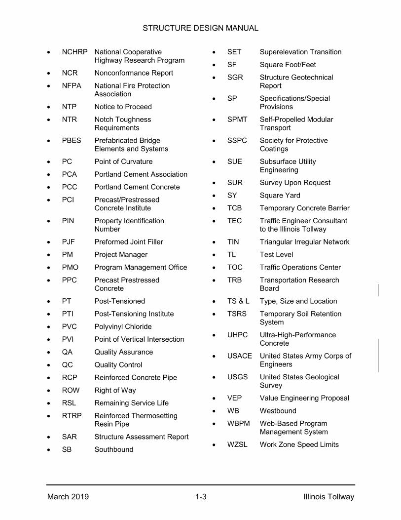
NCHRP National Cooperative Highway Research Program
NCR Nonconformance Report
NFPA National Fire Protection Association
NTP Notice to Proceed
NTR Notch Toughness Requirements
PBES Prefabricated Bridge Elements and Systems
PC Point of Curvature
PCA Portland Cement Association
PCC Portland Cement Concrete
PCI Precast/Prestressed Concrete Institute
PIN Property Identification Number
PJF Preformed Joint Filler
PM Project Manager
PMO Program Management Office
PPC Precast Prestressed Concrete
PT Post-Tensioned
PTI Post-Tensioning Institute
PVC Polyvinyl Chloride
PVI Point of Vertical Intersection
QA Quality Assurance
QC Quality Control
RCP Reinforced Concrete Pipe
ROW Right of Way
RSL Remaining Service Life
RTRP Reinforced Thermosetting Resin Pipe
SAR Structure Assessment Report
SB Southbound
SET Superelevation Transition
SF Square Foot/Feet
SGR Structure Geotechnical Report
SP Specifications/Special Provisions
SPMT Self-Propelled Modular Transport
SSPC Society for Protective Coatings
SUE Subsurface Utility Engineering
SUR Survey Upon Request
SY Square Yard
TCB Temporary Concrete Barrier
TEC Traffic Engineer Consultant to the Illinois Tollway
TIN Triangular Irregular Network
TL Test Level
TOC Traffic Operations Center
TRB Transportation Research Board
TS & L Type, Size and Location
TSRS Temporary Soil Retention System
UHPC Ultra-High-Performance Concrete
USACE United States Army Corps of Engineers
USGS United States Geological Survey
VEP Value Engineering Proposal
WB Westbound
WBPM Web-Based Program Management System
WZSL Work Zone Speed Limits

STRUCTURE DESIGN MANUAL
March 2019 1-4 Illinois Tollway
1.3 Definitions
This article contains definitions of frequently used terms as well as definitions with special or specific meanings as it applies to Illinois Tollway work. Other Articles define infrequently used or technical terms particular to that Article. Whenever in this Manual the following proper nouns are used, their intent and meaning, both singular and plural thereof, shall be as follows:
Bridge Replacement: Complete replacement of the entire bridge.
Bridge Reconstruction: Complete replacement of the bridge superstructure and may include work on the substructure and foundation.
Bridge Rehabilitation: Repair or replacement work on one or more of the major and/or minor components of a bridge may include deck replacement, superstructure widening or substructure widening.
Additional definitions can be found in the Illinois Tollway DSE Manual. NOTE: This manual follows the traditional definitions for shall, should and may. Shall is used to mean something that is required or mandatory, while should is used to mean something that is recommended, but not mandatory and may is used to mean something that is optional and carries no requirement or recommendation.
1.4 LRFD and LFD Bridge and Structure Design
The Illinois State Toll Highway Authority (Illinois Tollway) is transitioning from the American Association of State Highway and Transportation Officials (AASHTO) 2002 Standard Specifications for Highway Bridges – Division I Load Factor Design (LFD) and Allowable Stress Design (ASD) to the latest edition of the AASHTO LRFD Bridge Design Specifications for new bridge construction. It is anticipated that this process will be ongoing over the next few years. As such, this Design Manual refers to both the AASHTO Standard and AASHTO LRFD Specifications.
The design of all new and replacement structures shall be in accordance with the latest edition of the AASHTO LRFD Bridge Design Specifications except as modified by the following Illinois Department of Transportation (IDOT) Manuals: Bridge, Culvert, Drainage, Geotechnical and Sign Structures, or as amended herein by the Illinois Tollway Structure Design Manual. The most current IDOT manuals related to structural policy, documents and procedures are available on the Internet web pages at the following site:
http://www.idot.illinois.gov/
Navigation to technical manuals begins with “Doing Business” then “Procurements”.

STRUCTURE DESIGN MANUAL
March 2019 1-5 Illinois Tollway
The AASHTO LRFD Bridge Design Specifications was not completely adopted by IDOT. Several parts were modified or subjected to interpretation by IDOT. The following examples are representative of some of the changes made by IDOT:
Portions of Live Load Distribution for bridges have been simplified and/or not adopted (IDOT Bridge Manual Section 3.3.1 and IDOT ABD Memo 15.3).
When to apply lateral stresses for steel beam design has been interpreted (IDOT Bridge Manual Section 3.3.5).
Moment Redistribution in LRFD and LFD is not allowed (IDOT Bridge Manual Section 3.3.6).
Seismic design is according to LRFD with some interpretations, but the IDOT Bridge Manual clarifies options in LRFD to use for Illinois (IDOT Bridge Manual Sections 3.7, 3.10 and 3.15).
Vehicle collision design forces and the approach to design have been interpreted by IDOT Bridge Manual Section 3.9.3.7 and ABD Memo 12.1. Unless noted otherwise in this manual the 600-kip force shall be applied to the top of the crashwall.
The resistance factor to use for pile design has been interpreted (IDOT Bridge Manual Section 3.10).
The loading to use for Constructability Checks in LRFD (and LFD) has been clearly specified and interpreted (IDOT Bridge Manual Section 3.3.26).

STRUCTURE DESIGN MANUAL
March 2019 2-1 Illinois Tollway
STRUCTURE INSPECTION AND CONDITION REPORTS
2.1 Inspection and Testing
Inspection of existing bridges, culverts, and retaining walls shall be conducted in accordance with the latest, Federal Highway Administration (FHWA) Bridge Inspector’s Reference Manual and its supplement Inspection of Fracture Critical Bridge Members, and the AASHTO Manual for Bridge Evaluation. Underwater inspections and evaluations when required shall be conducted according to the latest FHWA Manual for Underwater Inspection of Bridges.
The Designer shall compare their findings to those of the latest Illinois Tollway Structure Inspection Field Report. Any discrepancies in ratings shall be explained and justified in the Designer’s Structure Inspection Report. Defects in the structure or approach roadway which are or may become hazardous to the public or railroads shall be reported immediately to the Illinois Tollway.
2.2 Preparation of Structure Condition Reports
Structure condition reports shall be submitted during the master planning or pre-concept phase. Reports shall follow the guidelines of the latest IDOT Bridge Condition Report Procedures and Practices. Existing structures to be abandoned and/or removed or completely replaced shall not be inspected or require a condition report. Only those structures which are to be rehabilitated, reconstructed or widened shall require both in-depth inspections and condition reports.
If a Technical Memorandum is requested by the Illinois Tollway in lieu of a Structure Condition Report, the Technical Memorandum shall include at a minimum:
Inspection Dates
Physical Description of the Structure
Structure Condition Data
Recommended Scope of Work
Photos
Cost Estimate
Retaining walls shall not be inspected nor require a condition report, unless the existing wall(s), or portions thereof, are to be incorporated into the proposed project. In which case, an inspection shall be performed, and a condition report prepared for each wall or section to be utilized in conjunction with the project.
Before any element of a structure and/or its foundations can be considered for reuse in replacing, reconstructing or rehabilitating an existing structure, it shall be evaluated and analyzed in accordance with Section III of IDOT’s Bridge Condition Report Procedures and Practices. The results of these evaluations and analysis shall be summarized and

STRUCTURE DESIGN MANUAL
March 2019 2-2 Illinois Tollway
included in the Structure Condition Report for each structure where reuse is being considered. The backup data and calculations for each summary shall not be submitted for review unless requested by the Illinois Tollway.
If a new structure, replacement structure or complete reconstruction of the existing deck or superstructure is recommended in the Structure Condition Report, the DSE shall evaluate Accelerated Bridge Construction in accordance with Article 27.3.1.
2.3 Hydraulic Analysis
All new structures and existing structures to be replaced, reconstructed, widened or extended which are over or conveying waterways shall require a hydraulic analysis to determine if the resulting waterway opening meets current Illinois Tollway standards and Illinois Department of Natural Resources Office of Water Resources permit requirements. The results of the analysis shall be summarized in a Waterway Information Table which shall be included in the Hydraulic Report for each structure. The report shall also include any recommendations for improving the waterway opening or channel alignment at each structure.
2.4 Scour Analysis
All new structures and existing structures to be replaced, reconstructed or widened which are over waterways, shall require a scour analysis to determine if the resulting or proposed opening will increase the flow and potentially undermine the adjacent structure foundations. The scour analysis shall be performed in accordance with the latest edition of FHWA Publication, Hydraulic Engineering Circular No. 18 (HEC-18) “Evaluating Scour at Bridges”. The latest editions of FHWA Publications HEC-20 ”Stream Stability at Highway Structures” and HEC-23 ”Bridge Scour and Stream Instability Countermeasures” shall be used as a guidance for identifying stream instability problem at highway stream crossings and for countermeasures to mitigate potential scour damage.
Results of the analysis shall be summarized in a Design Scour Elevation Table and the scour critical analysis coding as directed below, and shall be included in the Hydraulic Report, Structure Condition Report and the TS & L plans.
Provide the following information as defined in the Illinois Highway Information System, Structure Information and Procedure Manual:
Scour Critical Evaluation (Item 113)
Scour Critical Analysis Date (Item 113A)
Scour Critical Evaluation Method (Item 113B)
Scour Critical Analysis by Name (Item 113C)
Scour Critical Remark (Item 113D)
Channel & Channel Protection Condition (Item 61)
Waterway Adequacy Appraisal (Item 71)
Pier Navigation Protection (Item 111)
STRUCTURE DESIGN MANUAL
March 2019 2-3 Illinois Tollway
The Scour Critical Evaluation (Item 113) rating shall be in accordance with IDOT All Bridge Designers (ABD) Memorandum 14.2 "Revised Scour Design Policy", issued on November 7, 2014. However, on all Illinois Tollway facilities, the Q500 flood shall be used for the check scour elevation and for the design of all new countermeasures and extensions of existing countermeasures. For Item 113B - Scour Critical Evaluation Method, all foundation types rating shall be A - Analytical method.
The report shall also include any recommendations to mitigate or prevent scour at each structure.
2.5 Life Cycle Cost Analysis
Life Cycle Cost Analysis (LCCA) is required for all replacement versus rehabilitation decisions. LCCA shall be performed in accordance with procedures outlined in Publication No. FHWA-SA-98-079, NCHRP Report 483 Bridge Life-Cycle Cost Analysis and the following guidelines:
1. No inflation (ie. constant dollars) shall be used. Inflation is included in the real discount rate calculation, provided.
2. A real discount rate of 2.9% shall be used (from Equation 14, NCHRP 483). If the DSE is asked to calculate this rate, the following shall be used as the equation variables:
i = Illinois Tollway Bond Rate
q = Anticipated Illinois Tollway Revenue Increase
f = Anticipated Rate of Illinois Tollway Construction Cost Inflation
3. The analysis period shall be 100 years.
4. The life of a new bridge element shall be 100 years, unless fatigue dictates a shorter life.
5. The remaining service life of existing bridge elements shall be based on age and condition.
6. Two scenarios shall be compared.
a. Repair
b. Replacement
7. If the total cost of repair is less than or equal to 10% of the total cost of a new structure, then an LCCA is not necessary and repair shall be recommended.
STRUCTURE DESIGN MANUAL
March 2019 2-4 Illinois Tollway
8. If the total cost of repair is greater than or equal to 80% of the total cost of a new structure, then an LCCA is not necessary and replacement shall be recommended.
9. Deck repair/replacement decisions shall be based on the Deck Repair vs. Replacement Assessment Table and associated requirements in IDOT’s Bridge Condition Report Procedures and Practices Manual. An LCCA is not required to justify a deck replacement.
10. Once deck replacement is determined to be the minimum scope of work, an LCCA is required to determine if it is more economical to replace only the deck, replace the entire superstructure or replace the entire bridge.
11. If deck repairs are recommended and the structure has an older superstructure and/or substructure, an LCCA is required to determine if it is more economical to repair the structure, replace the superstructure or replace the entire bridge.
12. Unit prices, quantities and intervals of repairs shall be established by the Designer and reviewed by the Illinois Tollway.
13. The effects of salt contamination on deterioration from open or expansion joints, adjacent roadways, etc. shall be considered.
14. Additional expenses due to related and necessary activities such as maintenance of traffic, removal, temporary support or movement, adjacent removal and replacement, new dimensions, etc. shall be included.
15. The functionality and strength of the existing structural members shall be considered.
16. The salvage value shall be calculated as the percentage of the design life remaining at the end of the analysis period multiplied by the total cost of the last full bridge replacement.
STRUCTURE DESIGN MANUAL
March 2019 3-1 Illinois Tollway
TYPE, SIZE & LOCATION (TS & L) PLANS
3.1 General
The TS & L Plans form the basis for preparation of Construction Contract Plans. TS & L plans shall be submitted with the 30% design submittal. TS & L Plans are required for new or replacement structures, and all widenings and superstructure replacements. Structures identified for rehabilitation and/or redecking shall not require TS & L Plans. TS & L Plans for Illinois Tollway structures shall not require completion of a Structure Report (BBS Form 153), a Preliminary Bridge Design and Hydraulic Report (Form BLR 10210) or a Plan Development Outline. TS & L Plans for those structures that are either fully or partially funded and/or maintained by IDOT shall follow all guidelines and requirements of Section 2.0 of the latest IDOT Bridge Manual. Prior to submittal of any TS & L Plans, the Plans shall be checked for compliance with Section 2.3.13 of the latest IDOT Bridge Manual.
3.2 Bridge Type Study
A Bridge Type Study is the process by which the most appropriate structure type for a given location is determined. A Bridge Type Study considers the structure types feasible for the site parameters or environmental commitments, provides the reasoning for eliminating or developing particular alternatives, including cost estimates for all alternatives considered, and finally explains the rationale for the selection of the structure type chosen.
A Level 3 Barrier Warrant Analysis (including a Benefit/Cost Analysis) shall also be performed according to the requirements of the latest Illinois Tollway Traffic Barrier Guidelines in order to determine abutment type and location and span configuration for all bridges over the Illinois Tollway. This procedure shall also be followed in determining culvert lengths, except the level of Barrier Warrant Analysis shall be according to the Illinois Tollway Traffic Barrier Guidelines. All Barrier Warrant Analyses shall be submitted and reviewed by the Illinois Tollway prior to submission of TS & L Plans.
The Bridge Type Study is a part of the planning process which justifies the TS & L Plan. For major bridges, bridges that are evaluated for use of Accelerated Bridge Construction (ABC) or when requested by the Illinois Tollway, the Bridge Type Study shall be submitted to the Illinois Tollway for review and acceptance before preparation of the TS & L Plan can commence. Such a study would provide additional written treatments concerning economic evaluations for the viable alternatives, span length versus pier height studies for the approaches, pier type structural and aesthetic studies, main and approach span structure type aesthetic studies, and architectural presentations of the alternative systems presented in the study. The report shall also document unusual design procedures, deviations from or variations of AASHTO Specifications to be used, special materials or details proposed, or tests anticipated.
STRUCTURE DESIGN MANUAL
March 2019 3-2 Illinois Tollway
Beam selection criteria shall be in accordance with the IDOT Bureau of Design and Environment Manual and Sections 12 and 13. All Illinois Tollway bridges shall be designed in accordance with requirements of Article 1.4.
The DSE shall evaluate Accelerated Bridge Construction in accordance with Section 27.0. If required by Article 27.3.1, the DSE shall complete the ABC Bridge Life Cycle Comparison (BLCC) Tool and incorporate the recommended bridge alternatives into the Bridge Type Study and perform a cost comparison to make a final recommendation.
3.3 Structure Report
Structure Reports are not required to construct, reconstruct, widen or extend Illinois Tollway mainline or ramp structures. However, if the Illinois Tollway is planning on constructing, reconstructing, widening or extending a structure that is jointly maintained by the Illinois Tollway, IDOT or a local agency, the Designer is required to complete the appropriate Structure Report as noted above and submit it with the TS & L Plan package for IDOT’s review and approval.
3.4 Hydraulic Information
TS & L Plans for all new structures and existing structures to be replaced, reconstructed, widened or extended which span over or convey waterways shall require a Waterway Information Table, a Design Scour Elevation Table, if required, and the scour critical analysis coding as described in Article 2.4 of this Manual.
3.5 Structural Geotechnical Report
TS & L Plans for all new structures and existing structures to be replaced, reconstructed, widened or extended shall require subsurface investigations and Structure Geotechnical Report (SGR) in accordance with the Illinois Tollway Geotechnical Manual. The Designer along with the Geotechnical Engineer shall develop a subsurface exploration program for each structure. Subsurface investigations shall begin only after the proposed program has been reviewed and approved by the Illinois Tollway for its conformance to the minimum requirements as set forth within the Geotechnical Manual. The subsurface exploration and analyses shall be in accordance with the latest Geotechnical Manual. The data from the exploration program shall be analyzed and the resulting recommendations shall be documented in the SGR in accordance with theTollway Geotechnical Manual. SGRs shall be submitted with the Concept Design Report.
STRUCTURE DESIGN MANUAL
March 2019 4-1 Illinois Tollway
CONTEXT SENSITIVITY AND AESTHETICS
4.1 Introduction
Context Sensitive Solutions (CSS) is an interdisciplinary process, embraced by the Illinois Tollway that seeks effective, multimodal transportation results by working with stakeholders to develop, build and maintain cost-effective transportation facilities which are appropriate to and reflect the project’s surroundings. When implementation of the CSS process has been initiated for a particular project, the DSE is expected to coordinate potential enhancements during the appropriate phase of planning and design. When a formal CSS process is not implemented, the DSE shall consider context of the site as an integral part of the functional and aesthetic design development.
4.2 Bridges
All bridges make an aesthetic impression on the surroundings and the DSE shall consider and control the impact early in the design phase. The main aesthetic of a bridge is primarily a product of the structural members themselves. The structure form and shape, through the use of proper materials, dimensional relationships and proportions shall be used to emphasize the lightness, slenderness and horizontal continuity, allowing the bridge structure to produce the primary aesthetic on its own. Supplemental details such as texture and color can be important but are ordinarily considered secondary or complementary enhancements to the structural shape. Ornamentation shall not be added or shall be kept to a minimum and used only with special requirements for structures of significance.
Detailing and placement for appurtenances such as drain pipes, conduits, utilities, fencing, rails, signage and lighting shall be coordinated for visual compatibility and design consistency. Drain pipes and other conduit systems shall employ simple details and be located as visually unobtrusive as possible.
The standard treatment for a bridge and its overpass and underpass area is the use of a basic utilitarian highway bridge, essential erosion control and seeding in landscape areas, and routine Illinois Tollway signage identifying the crossroad. Upgrade treatments for a bridge and the overpass or underpass area where a response to the significance of the crossroad, physical context, or community has been determined, may include the addition and aesthetic enhancements of architectural elements, landscape treatments and signage components. Throughout design, the DSE shall orchestrate all primary aesthetic structural elements and details for efficiency and economy to minimize cost and to achieve an attractive bridge.
STRUCTURE DESIGN MANUAL
March 2019 4-2 Illinois Tollway
4.3 Walls
Due to the potential size, quantity and location, walls including noise abatement walls and retaining walls are often highly visible components within the Illinois Tollway corridors. The vertical and horizontal alignment, material type, textures and color become important elements of consideration. The primary wall aesthetic theme is to create a natural appearance that blends with the surrounding environment. Walls shall be designed as visual assets from the prospective views of motorists and adjoining communities. The DSE shall develop all wall types together with surrounding structural and non-structural elements to create a visual relationship to one another and provide a harmonious aesthetic throughout the corridor.

STRUCTURE DESIGN MANUAL
March 2019 5-1 Illinois Tollway
DESIGN CRITERIA
5.1 Structural Design Criteria
The following criteria shall be used for the design of structures on the Illinois Tollway. The applicable information shall be shown on the contract plans as discussed in Article 6.3.4. Items indicated in [ ] and bold are notes to the designer to include the latest date for plan presentation.
BRIDGES – New, Replacement and Reconstruction
Design Specifications
AASHTO LRFD Bridge Design Specifications (except as modified by IDOT and Illinois Tollway Structure Design Manual)
[Latest edition and interims]
Illinois Tollway Structure Design Manual [Latest edition]
IDOT Bridge Manual [Latest edition]
Illinois Tollway Geotechnical Manual [Latest edition]
IDOT All Bridge Designers Memorandums (when applicable)
Design Loads
Live Load: (New or Replacement Illinois Tollway Structures & Ramps)
HL-93 and IL-120
Live Load: Other Structures and Superstructure Replacement on Illinois Tollway Mainline Structures & Ramps
HL-93
Future Wearing Surface 50 psf
BRIDGES – Rehabilitation and Widening
Design Specifications
For Existing ASD or LFD Designs: AASHTO Standards Specifications for Highway Bridges
17th Edition
For Existing LRFD Designs: AASHTO LRFD Bridge Design Specifications (except as modified by IDOT and Illinois Tollway Structure Design Manual)
[Latest edition]
Illinois Tollway Structure Design Manual [Latest edition]
IDOT Bridge Manual [Latest edition]
IDOT Structural Services Manual [Latest edition]
Seismic Retrofitting Guidelines for Highway Bridges Report No. FHWA/RD-83/007
For rehabilitation only
Illinois Tollway Geotechnical Manual [Latest edition]
IDOT All Bridge Designers Memorandums
(when applicable)
Design Loads
For Existing ASD or LFD Designs: Live Load: All Structures
HS-20
For Existing LRFD Designs: Live Load: All Structures
HL-93
Future Wearing Surface Match existing design

STRUCTURE DESIGN MANUAL
March 2019 5-2 Illinois Tollway
BRIDGES – Design Stresses
Reinforced Concrete
f’c= Compressive Strength (Class SI) Substructure
3,500 psi
f’c= Compressive Strength (Class BS) Parapets and Barriers
4,000 psi (Design)
f’c= Compressive Strength (Performance Mix) Bridge Decks and Diaphragms, and Bridge Approach, Transition Approach and Transition Approach Shoulder Slabs.
4,000 psi (Design)
Precast Concrete f’c= Compressive Strength (Class PC) Prefabricated Bridge Elements and Systems
4,500 psi (Design)
Reinforcement
fy= Yield Strength (Conventional Reinforcement)
60,000 psi
fs= Tension (Grade 60) (ASD Design) 24,000 psi
fy= Yield Strength (Stainless Steel Reinforcement)
60,000 psi
Prestressed Concrete (LRFD)
f’c=Compressive Strength (IDOT Bms.)
f’c =Compressive Strength (Illinois Tollway Bms.)
6,000 psi (min.) 8,500 psi (max.)
6,000 psi (typ.) and up to 8,000 psi
f’ci = Release Compressive Strength (as required, but less than f’c) (IDOT Bms.)
f’ci = Release Compressive Strength (as required, but less than f’c) (Illinois Tollway Bms.)
4,000 psi (min.) 6,500 psi (max.)
4,000 psi (min.) 6,800 psi (max.)
Compression before losses 0.65 f’ci
Compression after losses (Service I)
Case (a): 0.60φw f’c ; φw = 1 for IDOT members Case (b): 0.45 f’c
Tension after losses (Service III) 0.19√‾f’c (max) ≤ 0.6ksi
Tension before losses 0.24√‾f’c
Fatigue: Compression after losses 0.40f’c
Fatigue: Tension after losses limit for determination of cracked vs. uncracked
Uncracked <=0.095√‾f’c
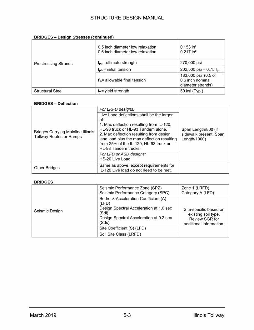
STRUCTURE DESIGN MANUAL
March 2019 5-3 Illinois Tollway
BRIDGES – Design Stresses (continued)
Prestressing Strands
0.5 inch diameter low relaxation 0.6 inch diameter low relaxation
0.153 in² 0.217 in²
fpu= ultimate strength 270,000 psi
fpbt= initial tension 202,500 psi = 0.75 fpu
f’s= allowable final tension 183,600 psi (0.5 or 0.6 inch nominal diameter strands)
Structural Steel fy = yield strength 50 ksi (Typ.)
BRIDGES – Deflection
Bridges Carrying Mainline Illinois Tollway Routes or Ramps
For LRFD designs:
Span Length/800 (if sidewalk present, Span Length/1000)
Live Load deflections shall be the larger of: 1. Max deflection resulting from IL-120,HL-93 truck or HL-93 Tandem alone.2. Max deflection resulting from designlane load plus the max deflection resultingfrom 25% of the IL-120, HL-93 truck orHL-93 Tandem trucks.
For LFD or ASD designs: HS-20 Live Load
Other Bridges Same as above, except requirements for IL-120 Live load do not need to be met.
BRIDGES
Seismic Design
Seismic Performance Zone (SPZ) Seismic Performance Category (SPC)
Zone 1 (LRFD) Category A (LFD)
Bedrock Acceleration Coefficient (A) (LFD) Design Spectral Acceleration at 1.0 sec (Sdl) Design Spectral Acceleration at 0.2 sec (Sds)
Site-specific based on existing soil type. Review SGR for
additional information. Site Coefficient (S) (LFD)
Soil Site Class (LRFD)
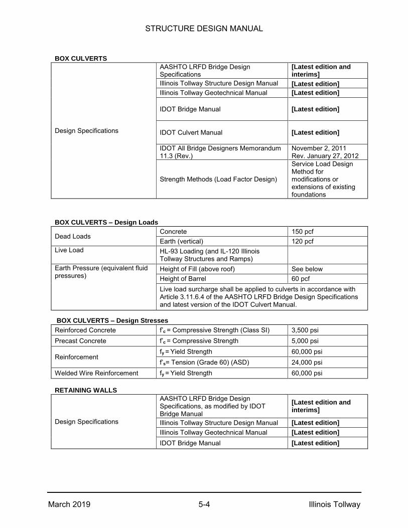
STRUCTURE DESIGN MANUAL
March 2019 5-4 Illinois Tollway
BOX CULVERTS
Design Specifications
AASHTO LRFD Bridge Design Specifications
[Latest edition and interims]
Illinois Tollway Structure Design Manual [Latest edition]
Illinois Tollway Geotechnical Manual [Latest edition]
IDOT Bridge Manual [Latest edition]
IDOT Culvert Manual [Latest edition]
IDOT All Bridge Designers Memorandum 11.3 (Rev.)
November 2, 2011 Rev. January 27, 2012
Strength Methods (Load Factor Design)
Service Load Design Method for modifications or extensions of existing foundations
BOX CULVERTS – Design Loads
Dead Loads Concrete 150 pcf
Earth (vertical) 120 pcf
Live Load HL-93 Loading (and IL-120 Illinois Tollway Structures and Ramps)
Earth Pressure (equivalent fluid pressures)
Height of Fill (above roof) See below
Height of Barrel 60 pcf
Live load surcharge shall be applied to culverts in accordance with Article 3.11.6.4 of the AASHTO LRFD Bridge Design Specifications and latest version of the IDOT Culvert Manual.
BOX CULVERTS – Design Stresses
Reinforced Concrete f’c = Compressive Strength (Class SI) 3,500 psi
Precast Concrete f’c = Compressive Strength 5,000 psi
Reinforcement fy = Yield Strength 60,000 psi
f’s= Tension (Grade 60) (ASD) 24,000 psi
Welded Wire Reinforcement fy = Yield Strength 60,000 psi
RETAINING WALLS
Design Specifications
AASHTO LRFD Bridge Design Specifications, as modified by IDOT Bridge Manual
[Latest edition and interims]
Illinois Tollway Structure Design Manual [Latest edition]
Illinois Tollway Geotechnical Manual [Latest edition]
IDOT Bridge Manual [Latest edition]

STRUCTURE DESIGN MANUAL
March 2019 5-5 Illinois Tollway
RETAINING WALLS – Design Loads
Dead Loads Concrete 150 pcf
Earth 120 pcf
Live Loads
Walls adjacent to roadways Live load surcharge equivalent to 2 feet of earth.
When a parapet or railing is constructed integrally with the top of the wall.
Barrier shall be designed to transfer impact loads to top of wall.
Impact Loads
Overturning & Sliding (Static) Strength (Dynamic)
23 kips over 8 feet (44” parapet) or 106 kips over 10 feet (72” parapet) 124 kips over 8 feet (44” parapet) or 260 kips over 10feet (72” parapet)
Earth Pressure The formula to compute lateral earth pressure is by Coulomb’s equation for the resultant parallel to the backfill slope.
Based on soil data from borings accounting for water level and long-term drained conditions for passive resistance.
RETAINING WALLS – Design Stresses
Reinforced Concrete
f’c = Compressive Strength (Performance Mix) Moment Slabs
4,000 psi (Design)
f’c= Compressive Strength (Class BS) Moment Slab Parapets
4,000 psi (Design)
f’c = Compressive Strength (Class SI) All other retaining wall concrete
3,500 psi
Reinforcement fy = Yield Strength 60,000 psi
f’s= Tension (Grade 60) (ASD) 24,000 psi
Soldier Piles fy = Yield Strength 36,000 psi
Timber Lagging Fb= Extreme Fiber Bending 1,000 psi
NOISE ABATEMENT WALLS
Design Specifications
AASHTO LRFD Bridge Design Specifications, Chapter 15
[Latest edition and interims]
Illinois Tollway Structure Design Manual [Latest edition]
Illinois Tollway Geotechnical Manual [Latest edition]
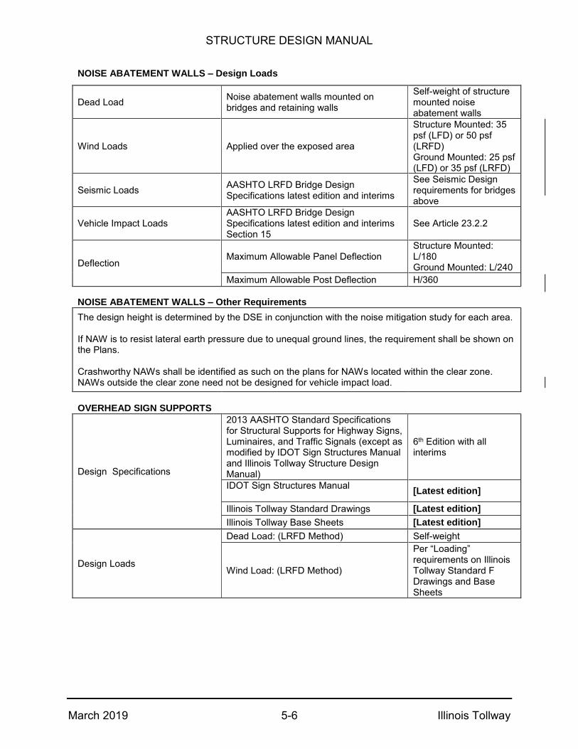
STRUCTURE DESIGN MANUAL
March 2019 5-6 Illinois Tollway
NOISE ABATEMENT WALLS – Design Loads
Dead Load Noise abatement walls mounted on bridges and retaining walls
Self-weight of structure mounted noise abatement walls
Wind Loads Applied over the exposed area
Structure Mounted: 35 psf (LFD) or 50 psf (LRFD) Ground Mounted: 25 psf (LFD) or 35 psf (LRFD)
Seismic Loads AASHTO LRFD Bridge Design Specifications latest edition and interims
See Seismic Design requirements for bridges above
Vehicle Impact Loads AASHTO LRFD Bridge Design Specifications latest edition and interims Section 15
See Article 23.2.2
Deflection Maximum Allowable Panel Deflection
Structure Mounted: L/180 Ground Mounted: L/240
Maximum Allowable Post Deflection H/360
NOISE ABATEMENT WALLS – Other Requirements
The design height is determined by the DSE in conjunction with the noise mitigation study for each area. If NAW is to resist lateral earth pressure due to unequal ground lines, the requirement shall be shown on the Plans. Crashworthy NAWs shall be identified as such on the plans for NAWs located within the clear zone. NAWs outside the clear zone need not be designed for vehicle impact load.
OVERHEAD SIGN SUPPORTS
Design Specifications
2013 AASHTO Standard Specifications for Structural Supports for Highway Signs, Luminaires, and Traffic Signals (except as modified by IDOT Sign Structures Manual and Illinois Tollway Structure Design Manual)
6th Edition with all interims
IDOT Sign Structures Manual
[Latest edition]
Illinois Tollway Standard Drawings [Latest edition]
Illinois Tollway Base Sheets [Latest edition]
Design Loads
Dead Load: (LRFD Method) Self-weight
Wind Load: (LRFD Method)
Per “Loading” requirements on Illinois Tollway Standard F Drawings and Base Sheets

STRUCTURE DESIGN MANUAL
March 2019 5-7 Illinois Tollway
5.2 Design Minimum Vertical Clearances
The following table lists the minimum vertical clearance requirements for all vehicular bridges and railroad bridges over and on the Illinois Tollway. Early coordination with railroads is required to ensure that these minimum vertical clearances are acceptable for railroad bridges over the Illinois Tollway.
Bridge Over Illinois Tollway Type of Work Vertical Clearance
Illinois Tollway Single Interstate Routes (1)
New Bridge or Reconstructing Bridge
16'-5"*
Widening or Rehabilitating
Existing Bridge 16'-0"
Other Illinois Tollway Routes (2)
New Bridge or Reconstructing Bridge
16'-5"* (desirable)
15'-5"** (minimum)
Widening or Rehabilitating
Existing Bridge
15'-5"** (desirable)
Existing Vertical Clearance (minimum)
Illinois Tollway Bridge Over Type of Work Vertical Clearance
All Routes
New Bridge or Reconstructing Bridge
As per IDOT BDE Manual Figure 33-5.A
14'-9" (minimum)
Widening or Rehabilitating
Existing Bridge
As per IDOT BDE Manual Figure 33-5.A
Existing Vertical Clearance (minimum)
* 16’-5" allows for an ultimate 16'-0" clearance after a 5" overlay is constructed.
**15'-5" allows for an ultimate 15'-0" clearance after a 5" overlay is constructed.
(1) The following segments of the Illinois Tollway are considered Single Interstate Routes (Military Defense Route):
Tri-State: All sections shared with I-80 Tri-State: North of Jane Addams Memorial Jane Addams Memorial: West of Tri-State Reagan Memorial: West of Veterans Memorial Veterans Memorial: All sections
STRUCTURE DESIGN MANUAL
March 2019 5-8 Illinois Tollway
(2) The following segments of the Illinois Tollway are considered Other Illinois Tollway Routes:
Tri-State: North of I-80 and south of Jane Addams Memorial Edens Spur: All Sections Jane Addams Memorial: East of Tri-State Reagan Memorial: East of Veterans Memorial Elgin O’Hare: All sections West O’Hare Access: All sections
In addition to the above, vertical clearances shall comply with requirements of the latest IDOT Traffic Manual. If the clearance is less than 14’-6”, the clearance shall be posted on a rectangular “Low Clearance” sign mounted to the structure over the highway. If the clearance is less than 14’-0”, the clearance shall also be posted on a “Low Clearance” sign in advance of the structure over the highway, as a supplement to the sign mounted to the structure.
The following minimum vertical clearances shall be used for all other structures:
Pedestrian overpass structures – 17’-5”.
Overhead sign structures
o Static signs, Dynamic Message Signs (DMS), Lane Control Signs – 17’-5”
Mainline and Ramp Plaza Canopies – 17'-5".
I-PASS overhead equipment truss structures –18’-0”.
Structures over railroads – 23'-0" between top of rail and low structure measured at or within 9'-0" each side of center of outside tracks or as mandated by the operating railroad. On widening structures, not less than the existing, unless written approval is obtained from the railroad. Any clearance less than 21'-6" shall require Interstate Commerce Commission approval.
Stream crossings – 2'-0" measured between design high water and low structure, or 1'-0" between any measured high water and low structure. Use whichever criterion produces the highest low structure.
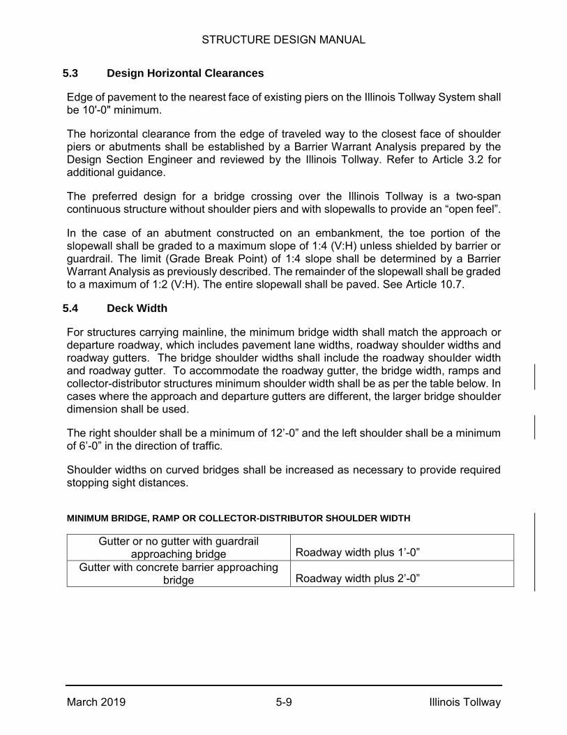
STRUCTURE DESIGN MANUAL
March 2019 5-9 Illinois Tollway
5.3 Design Horizontal Clearances
Edge of pavement to the nearest face of existing piers on the Illinois Tollway System shall be 10'-0" minimum.
The horizontal clearance from the edge of traveled way to the closest face of shoulder piers or abutments shall be established by a Barrier Warrant Analysis prepared by the Design Section Engineer and reviewed by the Illinois Tollway. Refer to Article 3.2 for additional guidance.
The preferred design for a bridge crossing over the Illinois Tollway is a two-span continuous structure without shoulder piers and with slopewalls to provide an “open feel”.
In the case of an abutment constructed on an embankment, the toe portion of the slopewall shall be graded to a maximum slope of 1:4 (V:H) unless shielded by barrier or guardrail. The limit (Grade Break Point) of 1:4 slope shall be determined by a Barrier Warrant Analysis as previously described. The remainder of the slopewall shall be graded to a maximum of 1:2 (V:H). The entire slopewall shall be paved. See Article 10.7.
5.4 Deck Width
For structures carrying mainline, the minimum bridge width shall match the approach or departure roadway, which includes pavement lane widths, roadway shoulder widths and roadway gutters. The bridge shoulder widths shall include the roadway shoulder width and roadway gutter. To accommodate the roadway gutter, the bridge width, ramps and collector-distributor structures minimum shoulder width shall be as per the table below. In cases where the approach and departure gutters are different, the larger bridge shoulder dimension shall be used.
The right shoulder shall be a minimum of 12’-0” and the left shoulder shall be a minimum of 6’-0” in the direction of traffic.
Shoulder widths on curved bridges shall be increased as necessary to provide required stopping sight distances.
MINIMUM BRIDGE, RAMP OR COLLECTOR-DISTRIBUTOR SHOULDER WIDTH
Gutter or no gutter with guardrail approaching bridge Roadway width plus 1’-0”
Gutter with concrete barrier approaching bridge Roadway width plus 2’-0”
STRUCTURE DESIGN MANUAL
March 2019 5-10 Illinois Tollway
5.5 Minimum Number of Beam Lines
The Illinois Tollway preference is to support all of the mainline and directional ramp bridges on a minimum of six lines of beams or girders unless the ramp traffic can be detoured for the duration of construction and/ or reconstruction.
5.6 Dead Loads
The deck dead loads used for interior beams shall include the calculated fillets expected and the deck width center to center of the beam spacing. The deck dead loads used for exterior beams shall include the weight of the deck soffit wedge, the deck width from the outside of the overhang to half the beam spacing, an allowance for the 3½” of deck provided for slip formed parapet if slip forming is not specifically excluded and the expected fillet.
Dead loads from parapets, luminaires, medians, sidewalks, sign structures and other ancillary fixtures shall be distributed based on engineering judgement, and shall not be distributed equally to all beams. Future wearing surface dead loads may be equally distributed to all beams at the designer’s discretion.
Structures with unusual features, such as curved alignments, large skews, very wide beam spacing, flared beam lines, noise abatement walls and large overhangs require more precise methods of analysis.

STRUCTURE DESIGN MANUAL
March 2019 5-11 Illinois Tollway
5.7 Field Survey
General
Prior to the beginning of the conceptual or TS & L designs, a field survey shall be completed and shall include, but shall not be limited to, the items as outlined herein. A stationing system shall be established and all topography within the site which is relevant to the proposed work shall be collected utilizing one of the networks of Continuously Operating Reference Stations (CORS) coordinated by the National Geodetic Survey. Illinois Tollway CORS stations are located at the following Maintenance and or Plaza facilities:
Station Name Station I.D.
Number
ALSIP TM01
GURNEE TM04
SCHAUMBURG TM05
BELVIDERE TM06
ROCKFORD TM07
NAPERVILLE TM08
DEKALB TM11
DIXON TM12
BOLINGBROOK TP89
A permanent Benchmark for each structure shall be established and all elevations taken for the structure shall be tied to this Benchmark.
Existing Barrier and Parapet Modifications
On existing barriers and parapets that are proposed for modification, the joint locations shall be field verified before designing the new longitudinal reinforcement bars.
Bearings
A condition survey shall be made of the existing bearings to verify the recommendations made in the Bridge Condition Report. On bearings proposed for replacement, measurements between the bottom of the beam and the top of the bearing seat shall be taken at all four corners of existing bearings to determine if shims are required.
Bridge Deck Widening
On bridges that are to be widened, the following data shall be obtained or verified:
Elevations along the bottom of the beam adjacent to the widening and elevations at the top of the deck at the same points.
Verification of the locations of existing stiffeners and/or diaphragm connections on steel beams adjacent to the widening.
STRUCTURE DESIGN MANUAL
March 2019 5-12 Illinois Tollway
Verification of existing beam lengths adjacent to the widening.
Verification of substructure skew angles.
Top of seat elevations at each abutment and pier adjacent to the proposed widening.
5.8 Construction
General:
If the designer’s construction scenario requires a special method of work or restriction to the way the Contractor builds the structure, it shall be defined in the contract documents.
An example would be:
Precast Beams:
The precast beams have been designed to accommodate loads arising from normal hoisting, storage and transportation. Specifically:
- The lifting apparatus used to pick the beams shall distribute loads evenly between all the lifting points shown. Furthermore, load distributing slings and pins with the same radius as that shown for lifting loops on the drawings shall be used every time the beams are hoisted including movement in the precast yard.
- Beams shall be supported within a distance equal to 1 1/2 times the depth of the beam from each end of the beam during storage and transportation.
- Beams shall be stored with webs vertical.
- Beams shall be transported on roads and bridges conforming to AASHTO standards with regard to smoothness and maximum superelevation.
If the Contractor wishes to use methods of hoisting, storage and transportation that are different from the parameters listed above, a detailed proposal shall be presented with detailed shop drawings and structural calculations sealed by the Contractor’s Illinois licensed Structural Engineer. No extra payment shall be considered for changes required to conform to the Contractor’s proposed method of work. No work is to proceed without the explicit approval of the Engineer.
The Contractor remains responsible to provide the expert knowledge and necessary care to ensure the delivery and final disposition of the beams in a condition required by the specifications.

STRUCTURE DESIGN MANUAL
March 2019 5-13 Illinois Tollway
5.9 Railroad Crossings
Right of entry, insurance and railroad safety training are required when inspecting and working on railroad right of way. The following information shall be provided on the drawings and within the contract documents for railroad bridges and bridge structures over railroads:
Information Comments
Design Specifications: Grade Separation Manual (Railroad Specific) AREMA (Latest Release) Illinois Tollway Structure Design Manual
Used for design of all railroad bridges.
Loading: Cooper E-80 or Railroad Specific
Used for design of railroad bridges. AREMA and Railroad Specific Grade Separation Manuals shall be used.
Horizontal and vertical clearance diagram
Based on the latest AREMA or Railroad guidelines.
Existing and proposed vertical clearance measured from top of rail to the bottom of lowest beam
For new structures: minimum = 23’-0” For existing structures: not less than existing nor less than 21’-6”
Horizontal dimensions between the center line existing tracks and face of substructure elements
This information is critical for the Contractor to establish work limits, including stock piling of material and storage of construction equipment.
Temporary soil retention systems that support railroad surcharge
These systems shall be designed by the Designer’s Illinois licensed Structural Engineer and submitted to the Illinois Tollway and the Railroad during preliminary plan submittal stage.
Railroad flagging requirements Coordinate with Railroads to determine railroad flagging requirements for the contract. A contract allowance is to be included in the contract for railroad flagging that will be performed by the Railroad during construction and invoiced through the construction contract. Allowance special provisions for railroad flagging are available from the Illinois Tollway.
Specific railroad requirements The Illinois Tollway requires the Designer to include the specific railroad requirements in the special provisions. Such requirements are specific to each railroad but may include contact persons, insurance requirements, flagging requirements, operational restrictions, right-of-entry agreement requirements, railroad safety training, etc.
Number, type and time of trains passing over/under the proposed structure each day
This information is critical for the Contractor to develop an appropriate work plan.
Railroad Milepost Number Obtained from the railroad.
STRUCTURE DESIGN MANUAL
March 2019 5-14 Illinois Tollway
5.10 Fire Protection Requirements
1. The purpose of these requirements is to establish the minimum provisions necessary to
provide protection against loss of life and property from fire.
2. Engineering analysis:
a. For any bridge, regardless of length, a fire engineering analysis shall be performed
in accordance with National Fire Protection Association (NFPA) 502 Standard for
Road Tunnels, Bridges and Other Limited Access Highways Chapter 4.3.1.
b. The analysis shall consider fire risk for events above and below the structure,
including but not limited to those events outlined in NFPA 502 Annex A.6.3.2.
c. The analysis shall consider the consequences of structural collapse and/or major
damage in terms of life safety and impact (interruption) to the affected roadway
network. Where a major disruption to the road network could occur, the Owner
shall determine acceptability of this impact.
d. For bridges, less than 1000-foot in length, where an unacceptable risk to life or
property is identified, fire protection measures shall be included in accordance with
NFPA 502 Chapter 6 to an extent sufficient to mitigate the risk. The fire protection
measures are subject to approval by the Illinois Tollway.
3. Design requirements:
a. All bridge structures greater than or equal to 1000-foot in length shall, at a
minimum, be designed with fire protection elements in accordance with NFPA 502
Chapter 6.
b. At a minimum, where fire protection measures are required, the following
provisions shall be considered in accordance with NFPA 502:
i. Protection of structural elements.
ii. Incident detection.
iii. Standpipe and fire hydrants.
iv. Portable fire extinguishers.
v. Drainage.
vi. Hazardous locations.
vii. Control of hazardous materials.
c. Fire protection analyses and solutions shall be reviewed by and are subject to
approval from the Illinois Tollway. d. Control of hazardous materials shall be applied to:
a) prevent fires occurring; and b) assure that the bridge is not exposed to a fire scenario beyond the design basis. Measures to control hazardous materials shall include the following:
i. Management of vehicular traffic on, under and next to the bridge structure
with consideration of regulated and unregulated cargos (including but not
limited to gasoline tankers) in accordance with NFPA 502 Chapter 14.
ii. Management of and possible prohibition of the short and/or long term
storage of combustible materials on, under or next to the bridge.
iii. A hazard assessment, including identification of control measures where
identified hazards pose an unacceptable consequence in terms of property
damage or life safety. Hazard assessment shall consider hazards including

STRUCTURE DESIGN MANUAL
March 2019 5-15 Illinois Tollway
but not limited to security events (i.e. deliberate actions to damage the
structure), parking on or under the bridge, construction activities and
implications of short-term material storage during a construction project at
or near the facility.
iv. Documentation and communication of the control measures and hazard
assessment (items i through iii above) in a format suitable to the facility
owner and/or agency responsible for operations, to ensure that the control
measures are routinely and continuously implemented, updated and
maintained during the operational life of the structure.
4. Incident response:
Incident response plans shall be developed, in accordance with requirements of the Illinois
Tollway, the local fire protection district and NFPA 502 Chapter 13.
5.11 Design Truck
For New or Replacement Projects on Illinois Tollway structures and ramps, the Design Truck in the AASHTO LRFD Bridge Design Specifications Article 3.6.1.2.2 shall be replaced with the “IL-120” Design Truck as shown in Figure 5.11.1. This truck shall be applied in accordance with AASHTO LRFD Article 3.6.1.3 and is referred to as the “IL-120 loading”. The “IL-120 loading” shall include the IL-120 Design Truck and the Design Lane Load as specified in AASHTO LRFD Article 3.6.1.2.4. The bridge design shall also meet the design requirements for the HL-93 loading. The Design Tandem remains as given in AASHTO LRFD Article 3.6.1.2.3. The structural design shall be based on the maximum force effects resulting from the IL-120 loading, the HL-93 loading and the Design Tandem.
The IL-120 Design Truck shall not be used for fatigue design. All requirements of AASHTO LRFD Article 3.6.1.4 shall apply.
Load factors and combinations shall be according to AASHTO LRFD Article 3.4.
The Inventory and Operating Load Ratings for the HL-93 shall be shown on the General Plan and Elevation sheet. Refer to Article 6.3.12.
The IL-120 Design Truck Diagram (Figure 5.11.1) shall be shown in the plan set. Refer to Article 6.3.4.
Design loads for decks and deck systems shall be in accordance with AASHTO LRFD Article 3.6.1.3.3, using the design truck given in AASHTO LRFD Article 3.6.1.2.2 or the design tandem given in AASHTO LRFD Article 3.6.1.2.3.
For live load deflection evaluation of structures carrying mainline Illinois Tollway routes or ramps, the deflection shall be taken as the larger of:
The maximum deflection resulting from the IL-120, HL-93 truck, or HL-93Tandem alone, or

STRUCTURE DESIGN MANUAL
March 2019 5-16 Illinois Tollway
The deflection resulting from the design lane load plus the maximum deflection resulting from 25 percent of the IL-120, HL-93 truck, or the HL-93 Tandem.
Superstructure replacement projects on Illinois Tollway mainline and ramp bridges and new, replacement and superstructure replacement projects on crossroad bridges over the Illinois Tollway shall meet the requirements shown above, except checks for IL-120 live load are not required.
5.12 Seismic Design of Bridges
Illinois Tollway structures shall be designed to meet the minimum requirements for AASHTO Seismic Performance Zone 1 (LRFD) or Category A (LFD) with a low probability of being exceeded during the normal life expectancy for a bridge. Bridges and their components that are designed to resist Zone 1 (Category A) forces and constructed in accordance with the design details contained in the latest IDOT Bridge Manual should not experience total collapse, but may sustain repairable damage due to seismically induced ground shaking.
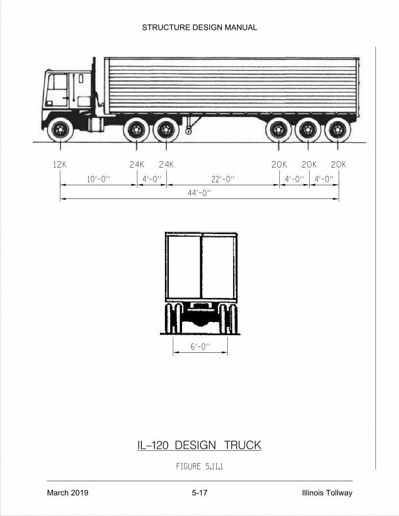
12K 24K 24K 20K 20K 20K
6'-0"
4'-0"4'-0"22'-0"4'-0"10'-0"
IL-120 DESIGN TRUCK
44'-0"
FIGURE 5.11.1
STRUCTURE DESIGN MANUAL
March 2019 5-17 Illinois Tollway
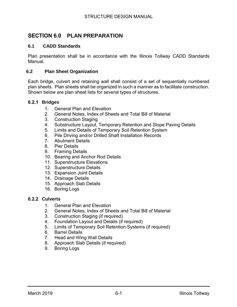
STRUCTURE DESIGN MANUAL
March 2019 6-1 Illinois Tollway
PLAN PREPARATION
6.1 CADD Standards
Plan presentation shall be in accordance with the Illinois Tollway CADD Standards Manual.
6.2 Plan Sheet Organization
Each bridge, culvert and retaining wall shall consist of a set of sequentially numbered plan sheets. Plan sheets shall be organized in such a manner as to facilitate construction. Shown below are plan sheet lists for several types of structures.
Bridges
1. General Plan and Elevation 2. General Notes, Index of Sheets and Total Bill of Material 3. Construction Staging 4. Substructure Layout, Temporary Retention and Slope Paving Details 5. Limits and Details of Temporary Soil Retention System 6. Pile Driving and/or Drilled Shaft Installation Records 7. Abutment Details 8. Pier Details 9. Framing Details 10. Bearing and Anchor Rod Details 11. Superstructure Elevations 12. Superstructure Details 13. Expansion Joint Details 14. Drainage Details 15. Approach Slab Details 16. Boring Logs
Culverts
1. General Plan and Elevation 2. General Notes, Index of Sheets and Total Bill of Material 3. Construction Staging (if required) 4. Foundation Layout and Details (if required) 5. Limits of Temporary Soil Retention Systems (if required) 6. Barrel Details 7. Head and Wing Wall Details 8. Approach Slab Details (if required) 9. Boring Logs
STRUCTURE DESIGN MANUAL
March 2019 6-2 Illinois Tollway
Conventional Concrete Retaining Walls
1. General Plan and Elevation 2. General Notes, Index of Sheets and Total Bill of Material 3. Construction Staging (if required) 4. Substructure Layout and Limits of Temporary Soil Retention System (if required) 5. Existing Pile Driving and/or Drilled Shaft Installation Records (if available) 6. Plans and Elevations Details 7. Sections and Details 8. Rebar Lists and Bending Diagrams 9. Drainage Details 10. Boring Logs and Plan Locations
Performance Based Retaining Walls
Plans included in Contract Documents shall include the following for each wall: 1. General Plan and Elevation 2. General Notes, Index of Sheets and Bill of Material 3. Construction Staging and MOT (as required) 4. Proposed Elevations of Top and Bottom of the Wall, Finished Ground Lines
at the Back and Front Face of the Wall and Existing Surface Profile 5. Existing Pile Driving and/or Drilled Shaft Installation Records (if available) 6. Cross Sections of all Significantly Different Sections 7. Drainage Details 8. Location of utility or drainage interferences, all ancillary structures such as,
light standards, overhead sign structures, drainage openings and noise abatement walls. Location of all appurtenances behind, in front of, under, over, mounted upon, or passing through the wall
9. Boring Logs and Plan Locations 10. Subsurface Data Profile Plot
For Performance Based Retaining Walls, the DSE shall review Working Drawings to ensure they are in accordance with the Plan Sheet requirements.
Performance Based Noise Abatement Walls
Plans included in Contract Documents shall include the following for each ground mounted or structure mounted noise abatement wall: 1. General Plan and Elevation per Article 23.3.1 2. General Notes, Index of Sheets and Bill of Material 3. Construction Staging and MOT (as required) 4. Proposed Elevations of Top and Bottom of the Wall, Finished Ground Lines
at the Back and Front Face of the Wall and Existing Surface Profile (as applicable)
5. Locations of transitions, overlaps, obstructions, utility or drainage interferences and change in noise abatement wall height
6. Location of all appurtenances behind, in front of, under, over, mounted upon, or passing through the noise abatement wall
7. Boring Logs and Plan Locations (Ground Mounted) 8. Subsurface Data Profile Plot (Ground Mounted)
STRUCTURE DESIGN MANUAL
March 2019 6-3 Illinois Tollway
6.3 General Plan and Elevation
Plan and Elevation Views
The plan and elevation views for each bridge shall include at a minimum the following information:
Horizontal and vertical alignments for roadways, waterways and facilities
Skew angles
Bridge and approach roadway widths
Minimum vertical and horizontal clearances
Stations and elevations at the centerline of each pier and back of and centerline of bearing of each abutment
Span lengths and numbers
Type and depth of spans, i.e., 72-inch PPC I-beam or 48-inch Steel Plate Girder, etc.
Location, size, and type of expansion joints
Location of fixed and expansion bearings, deck drainage, signing and lighting
Guardrail anchorage and terminal type
Approach slab lengths
Limits and type of slope paving
Bottom of footing elevations and foundation type including pile or drilled shaft size, length and capacity
Location of borings
Location of all existing and proposed utilities (overhead and buried) and storm sewers in the vicinity of the bridge
Waterway Information Table and Scour Elevation Table (if required)
Illinois Tollway and IDOT Structure Number
Station equations shall not be located between the backs of abutments.
STRUCTURE DESIGN MANUAL
March 2019 6-4 Illinois Tollway
Benchmark
Include location and description of the benchmark in the upper left-hand corner of the General Plan and Elevation Sheet.
Structure Description
Structure Reconstruction or Rehabilitation - Include a description of the existing structure and list of Major Items of Work as well as the required maintenance of traffic (MOT).
Structure Widening - Include a description of the existing structure and required MOT.
Structure Replacement - Include a description of the existing and proposed structure as well as the required MOT.
New Structure - Include a description of the proposed structure and MOT if required. Salvage – For the removal of existing structures, reconstruction and rehabilitation, indicate if any items of the existing bridge will be removed and incorporated into a future Illinois Tollway contract or for future Illinois Tollway use. If no portion of the structure will be removed for reuse in a future contract, indicate “No Salvage.”
Design Criteria
Design criteria are listed in Article 5.1. The design criteria shown on the plans shall include the following:
Design Specifications
Construction Specifications
o Illinois Department of Transportation Guide Bridge Special Provisions (GBSPs)
o Illinois Tollway Supplemental Specifications to the Illinois Department of Transportation Standard Specifications for Road and Bridge Construction [Use latest edition]
o Illinois Department of Transportation Supplemental Specifications and Recurring Special Provisions [Use latest edition]
o Illinois Department of Transportation Standard Specifications for Road and Bridge Construction [Use latest edition]
Items indicated in [ ] and bold are notes to the designer to include the latest date and edition for plan presentation.
Design Live and Future Wearing Surface Loads
Design Stresses
STRUCTURE DESIGN MANUAL
March 2019 6-5 Illinois Tollway
Live Load Deflection Criteria
Seismic Criteria
IL-120 Design Truck Diagram
Horizontally Curved Alignments
For bridges on horizontally curved alignments, provide a "Horizontal Offset Sketch" as shown in Figure 6.3.5.1. The sketch shall establish a local tangent at a stationing point along the horizontal curve.
Distances along the local tangent and offsets from the local tangent shall be shown for the centerline of each pier and abutment.
Profile Sketches
Provide "Profile Grade" sketches for the structure, roadways, waterways and facilities crossed by the bridge. Indicate location and limits of the bridge on the appropriate Profile Grade Sketch. For examples of "Profile Grade" sketches, see Figures 6.3.6.1 and 6.3.6.2.
Superelevation Transitions
Superelevation Transitions (SETs) shall not be located on bridges or approach slabs. A Design Deviation is required if a SET occurs within the limits of the bridge or approach slab. If a SET must be located on a bridge or approach slab, its limits shall be indicated on the General Plan and the appropriate vertical Profile Sketch. The SET diagrams and details shown in the structural and roadway portions of the plans shall also be referenced on the General Plan and Elevation sheet. See Article 15.3 for specific requirements of bridge and approach cross slopes.
Location Map
Provide a "Location Map" containing the following information in the lower right hand corner of the sheet. For an example of a "Location Map" see Figure 6.3.8.1.
Range, Township, Principle Meridian and Section Numbers
North Arrow
Location of Structure(s)
Four Township Numbers
Significant Landmarks

STRUCTURE DESIGN MANUAL
March 2019 6-6 Illinois Tollway
Highway Classification
For grade separations, provide the following information for the Route over and under the proposed structure(s): Route Identification, Class, DHV (existing and future), ADT (existing and future), ADTT (existing and future truck traffic) and Design Speed.
Railroad Information
For railroad crossings, provide the number, type and time of trains passing over/under the proposed structure each day. In addition, all structures on or over railways shall be located by the Railroad Mile Post (MP) number.
Waterway Information
For waterway crossings, provide a waterway information table in accordance with Section 1-303.02 of the latest IDOT Drainage Manual and the scour critical analysis coding as described in Article 2.4 of this Manual. Refer to Figure 6.3.11.1 for an example.
Structure Rating
Load rating shall be performed in accordance with the latest edition of IDOT Structural Services Manual applicable sections, unless noted otherwise in this manual. In general, policies and guidelines stated in the Structural Design Manual for bridge design are also applicable for load ratings.
The Inventory and Operating Rating for each new, reconstructed or widened structure shall be calculated by the Designer and shown on the General Plan and Elevation Sheet. The load rating shall include future wearing surface when evaluating original superstructure design. Other load ratings shall only include the wearing surfaces currently in place or that will be constructed when evaluating a proposed overlay. A load rating is required when a new feature is added to a bridge that increases or redistributes the existing permanent loads on a bridge. Common examples of this are the addition of a new or modified wearing surface or the attachment of new utilities to a bridge.
The Designer shall also complete and submit the “Illinois Tollway Bridge Superstructure Rating Form” shown in Figure 6.3.12.1 to the Illinois Tollway for their review and comment. The “Bridge Superstructure Rating Form” is required to be submitted for all Illinois Tollway mainline bridges and cross road bridges with the pre-final and final submittals. The “Bridge Superstructure Rating Form” may be downloaded from the Illinois Tollway’s internet site at www.illinoistollway.com, under Doing Business, Construction & Engineering, Consultant Resources, Manuals, Bridges & Structures.
Structural Engineer Seal
The General Plan and Elevation sheet for each structure shall include a structural seal of a licensed Structural Engineer in the State of Illinois with signature and expiration date.
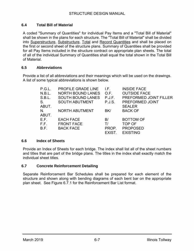
STRUCTURE DESIGN MANUAL
March 2019 6-7 Illinois Tollway
6.4 Total Bill of Material
A coded "Summary of Quantities" for individual Pay Items and a "Total Bill of Material" shall be shown in the plans for each structure. The "Total Bill of Material" shall be divided into Superstructure, Substructure, Total and Record Quantities and shall be placed on the first or second sheet of the structure plans. Summary of Quantities shall be provided for all Pay Items included in the structure contract on appropriate plan sheets. The total of all of the individual Summary of Quantities shall equal the total shown in the Total Bill of Material.
6.5 Abbreviations
Provide a list of all abbreviations and their meanings which will be used on the drawings. A list of some typical abbreviations is shown below.
P.G.L. PROFILE GRADE LINE I.F. INSIDE FACE N.B.L. NORTH BOUND LANES O.F. OUTSIDE FACE S.B.L. SOUTH BOUND LANES P.J.F. PREFORMED JOINT FILLER S. ABUT.
SOUTH ABUTMENT P.J.S. PREFORMED JOINT SEALER
N. ABUT.
NORTH ABUTMENT BK/ BACK OF
E.F. EACH FACE B/ BOTTOM OF F.F. FRONT FACE T/ TOP OF B.F. BACK FACE PROP. PROPOSED EXIST. EXISTING
6.6 Index of Sheets
Provide an Index of Sheets for each bridge. The index shall list all of the sheet numbers and titles that are part of the bridge plans. The titles in the index shall exactly match the individual sheet titles.
6.7 Concrete Reinforcement Detailing
Separate Reinforcement Bar Schedules shall be prepared for each element of the structure and shown along with bending diagrams of each bent bar on the appropriate plan sheet. See Figure 6.7.1 for the Reinforcement Bar List format.

STRUCTURE DESIGN MANUAL
March 2019 6-8 Illinois Tollway
When detailing lengths of reinforcement bars, consideration shall be given to transportation and handling and, where extremely long lengths are contemplated, to availability and special orders. When the location of bar splices is arbitrary, as in the case of the longitudinal reinforcement of deck slabs on beams and girders, the preferred maximum lengths are as follows:
#6 bars and up ...... 36'-0" #4 & #5 bars .......... 30'-0"
Bars shall be detailed to the closest inch of length and the weight of reinforcement bars shown in the Bill of Material shall be to the nearest ten (10) pounds.
To provide uniformity on all structure plans, bar designations used shall be as follows:
a – Deck Slab (Transverse) b – Deck Slab, Sidewalk and Median (Longitudinal) c – Sidewalk and Median (Transverse) d – Barrier Rail (Curb and Parapets) (Vertical) or Dowels (at any location except
Footing to Wall) e – Barrier Rail (Curb and Parapets) (Longitudinal) g – PPC or CIPC Beams h – Substructure and Walls (Horizontal) m – Diaphragm for PPC I-Beams (Horizontal) n – Footing to Wall (Dowels) p – Pile Caps and Pier Caps (Longitudinal) s – Stirrup and Tie Bars t – Footing (Transverse) u – Ends of Pier Caps, Pile Caps and Crash Walls v – Substructure and Walls (Vertical) w – Footing (Longitudinal) x – Deck Slab – Longitudinal Deck Cantilevers at Expansion Joints
In no case shall the same designation be used for reinforcement bars of a different size, length and shape when they are employed in other elements of the structure.
6.8 Beam Numbering
All beam lines shall have a unique beam number. For complete replacement bridges, beams and girders shall be numbered from left to right when looking in the direction of increasing station. When new beams are added to an existing structure, the existing beams shall not be renumbered. The new beams shall be numbered with a suffix consecutively, such as Beam 1A, 1B, 8A, 8B, etc.

STRUCTURE DESIGN MANUAL
March 2019 6-9 Illinois Tollway
6.9 Preliminary Plan Submittal (60% Plans)
The Preliminary 60% plans form the basis of establishing final geometry and dimensions of the structure. The objective of the Preliminary Design Phase (60%) is to incorporate comments from the Conceptual Design Phase (30%), and to demonstrate that the plans are being developed into the Pre-Final Design Phase (95%). The following items shall be included in the 60% submittal:
Address and incorporate all comments from TS & L (30%) submittal.
Plan sheets, details and views shall be included to ensure the sheet index and
layout of sheets has been established per Illinois Tollway guidelines.
Major geometry, dimensions, foundation layout, and elevations shall be set.
Structural details shall be established and developed (rebar detailing and quantities may not be finalized).
Appropriate structural Illinois Tollway Standards shall be listed in the Contract Documents.
Appropriate Illinois Tollway Base Sheets shall be incorporated as plan details into the Contract Plans (the Base Sheets may not be finalized).
A complete list of pay items and special provisions shall be included.

OFFSET SKETCH
20862087
~ BRG.
W. ABUT.
~ PIER 1 ~ PIER 2 ~ BRG.
E. ABUT.
STA. 15+00 (UNDER)
STA. 2086+72.44 ~ (OVER)
~ TOLL HIGHWAY
27'-6"27'-6"51'-6" 51'-6"
SKEW STA.2086+72.44
TANGENT TO
~ TOLL HIGHWAY
‡"
6‡"
1'-
0‡
"
1Œ
"
7ˆ"
1'-
1‚
"
1Œ
"
Ž "
FIGURE 6.3.5.1
STRUCTURE DESIGN MANUAL
March 2019 6-10 Illinois Tollway
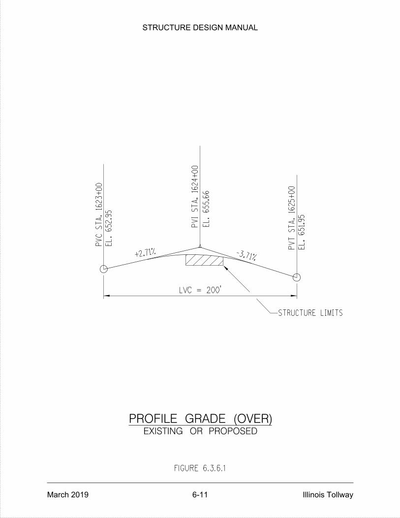
STRUCTURE LIMITS
+2.71%
PV
C
ST
A.
1623
+00
EL.
652.9
5
PVI
ST
A.
1624
+00
EL.
655.6
6
-3.71%
PV
T
ST
A.
1625
+00
EL.
651.9
5
PROFILE GRADE (OVER)EXISTING OR PROPOSED
LVC = 200'
FIGURE 6.3.6.1
STRUCTURE DESIGN MANUAL
March 2019 6-11 Illinois Tollway
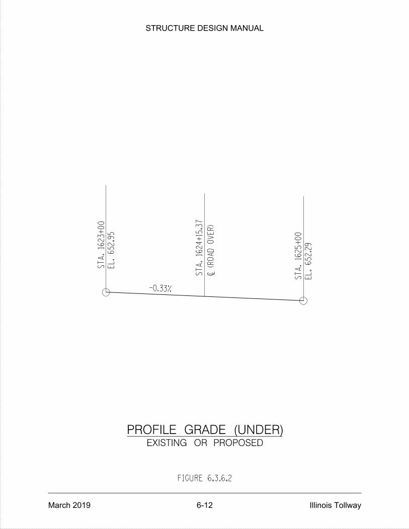
ST
A.
1623
+00
EL.
652.9
5
-0.33%
C (R
OA
D
OV
ER)
L
ST
A.
1625
+00
EL.
652.2
9
PROFILE GRADE (UNDER)EXISTING OR PROPOSED
ST
A.
1624
+15.3
7
FIGURE 6.3.6.2
STRUCTURE DESIGN MANUAL
March 2019 6-12 Illinois Tollway
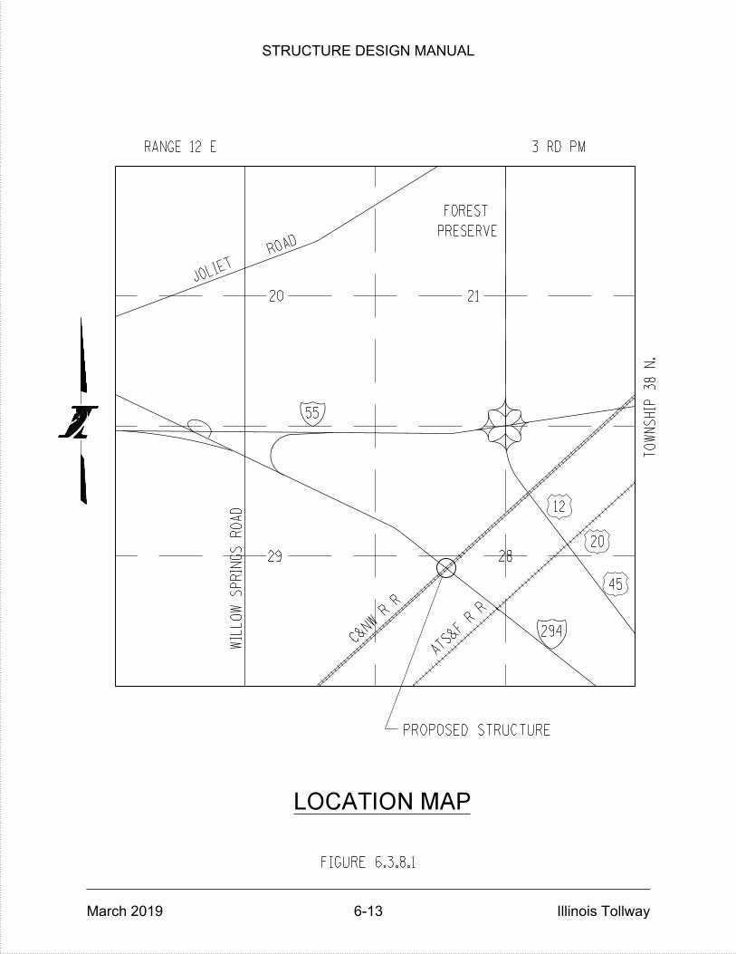
WIL
LO
W
SP
RIN
GS
RO
AD
29
C&NW R
R
ATS&F R R
28
294
20
12
45
3 RD PM
JOLIET
20
ROAD
RANGE 12 E
55
21
PRESERVE
FOREST
PROPOSED STRUCTURE
LOCATION MAP
TO
WN
SHIP 38
N.
FIGURE 6.3.8.1
STRUCTURE DESIGN MANUAL
March 2019 6-13 Illinois Tollway
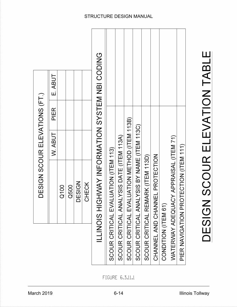
DE
SIG
N S
CO
UR E
LE
VA
TIO
NS (F
T.)
W.
AB
UT
PIE
RE.
AB
UT
Q100
Q500
ILLIN
OIS HIG
HW
AY I
NF
OR
MA
TIO
N S
YS
TE
M N
BI
CO
DIN
G
SC
OU
R C
RITIC
AL R
EM
AR
K (IT
EM 1
13
D)
SC
OU
R C
RITIC
AL E
VA
LU
ATIO
N (IT
EM 1
13)
SC
OU
R C
RITIC
AL A
NA
LY
SIS D
AT
E (IT
EM 1
13
A)
SC
OU
R C
RITIC
AL E
VA
LU
ATIO
N M
ET
HO
D (IT
EM 1
13
B)
SC
OU
R C
RITIC
AL A
NA
LY
SIS B
Y N
AM
E (IT
EM 1
13
C)
CO
NDITIO
N (IT
EM 6
1)
CH
AN
NE
L A
ND C
HA
NN
EL P
RO
TE
CTIO
N
PIE
R N
AVIG
ATIO
N P
RO
TE
CTIO
N (IT
EM 1
11)
WA
TE
RW
AY A
DE
QU
AC
Y A
PP
RAIS
AL (IT
EM 7
1)
FIGURE 6.3.11.1
DE
SIG
N
CH
EC
K
DE
SIG
N S
CO
UR E
LE
VA
TIO
N T
AB
LE
STRUCTURE DESIGN MANUAL
March 2019 6-14 Illinois Tollway
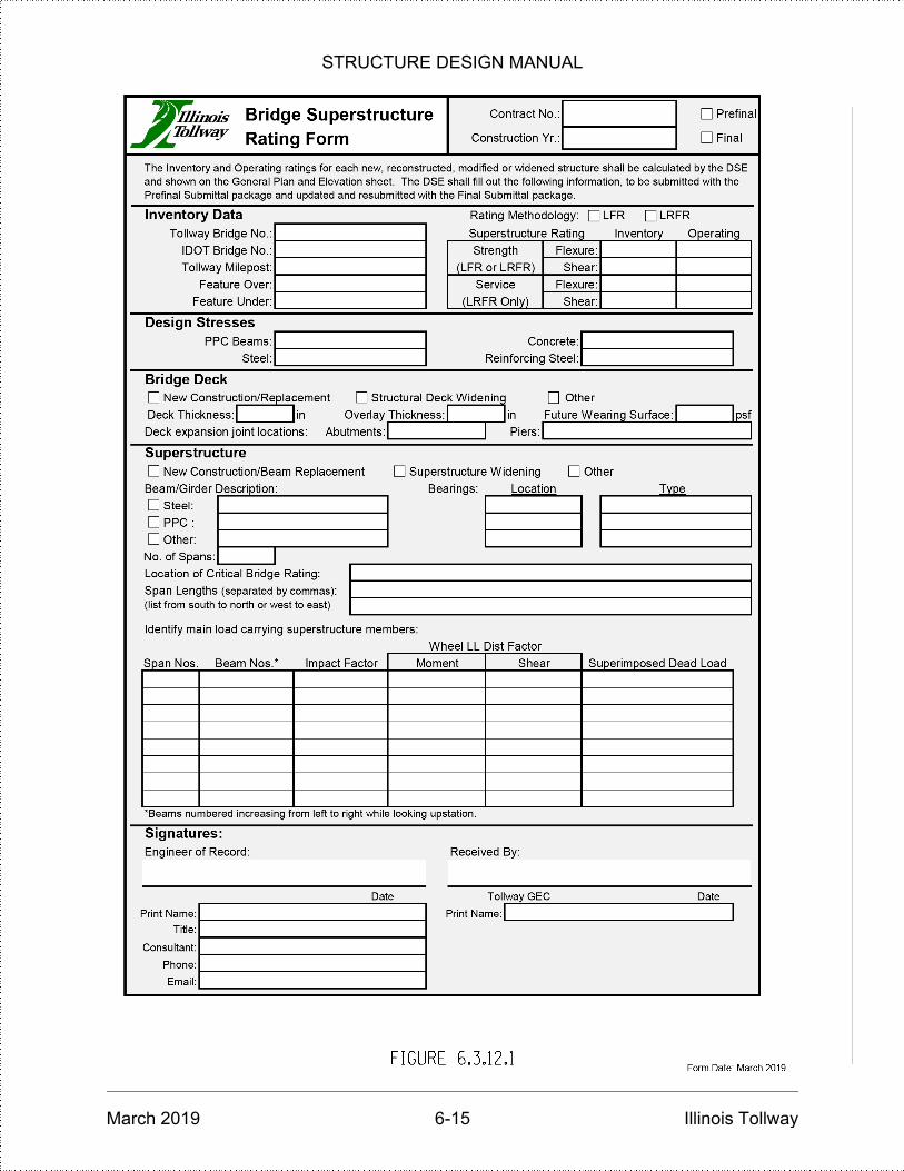
STRUCTURE DESIGN MANUAL
March 2019 6-15 Illinois Tollway

STRUCTURE DESIGN MANUAL
March 2019 6-16 Illinois Tollway

STRUCTURE DESIGN MANUAL
March 2019 Illinois Tollway
THIS PAGE IS INTENTIONALLY LEFT BLANK

STRUCTURE DESIGN MANUAL
March 2019 7-1 Illinois Tollway
GENERAL NOTES
7.1 Structural General Notes
The following general plan notes, in addition to those from Section 3.1.3 of the latest IDOT Bridge Manual, shall be included in the Contract Plans as applicable.
Items indicated in [ ] and bold are notes to the designer and shall be filled in or removed in the plans as applicable.
Cast-In-Place Concrete
1. All exposed concrete edges shall have a ¾" x 45º chamfer, except where shown otherwise. Chamfer on vertical edges shall be continued a minimum of one foot below finished ground level.
2. Cast counter weights at least 48 hours in advance of placing deck slab.
Reinforcement Bars
1. Reinforcement bars, including epoxy-coated reinforcement bars, shall conform to the requirements of AASHTO M-31 (ASTM A706), Grade 60, deformed bars.
2. Reinforcement bars designated "(E)" shall be epoxy coated.
3. Reinforcement bar bending details shall be in accordance with the latest "Manual of Standard Practice for Detailing Reinforced Concrete Structures", ACI 315.
4. Reinforcement bar bending dimensions are out to out.
5. Bars noted thus, 3x2-#5 indicates 3 lines of bars with 2 lengths of bars per line.
6. Cover from the face of concrete to face of reinforcement bars shall be 3" for surfaces formed against earth and 2” for all other surfaces unless otherwise shown.
7. Bridge seat reinforcement shall be carefully placed as detailed in the plans to avoid interference with drilling holes for anchor rods. The beams shall be erected in final position prior to drilling holes for anchor rods. [See Articles 10.9 and 11.9 for details to be shown in the plans for the detailing of the reinforcement to miss anchor rods.]
8. The number of ties as specified shall be doubled for lap splices at the stage construction line of concrete bridge decks when traffic is allowed on the first completed stage during the pouring of the second stage.
9. Slopewalls shall be reinforced with welded wire reinforcement, 6" x 6" - W4.0 x W4.0, weighing 58 pounds per 100 square feet.

STRUCTURE DESIGN MANUAL
March 2019 7-2 Illinois Tollway
Structural Steel
1. All bearing and side retainer anchor rods shall be set before permanently bolting diaphragms or cross frames over supports.
2. All side retainers shall be installed and bolted down prior to forming and pouring the deck slab.
3. Web plates shall be furnished in available mill lengths and widths with a minimum number of web splices. Location of splices shall be subject to the approval of the Designer and shall be a minimum of 1’-0” from stiffeners or flange splices.
4. Bearing stiffeners and ends of beams shall be perpendicular to flange. [For all rolled beam bridges and plate girder bridges with grades of 3% or less and skews of 20 degrees or less]
5. Bearing stiffeners at abutments shall be vertical and ends of beams shall be vertical. Bearing stiffeners at piers shall be perpendicular to flange. [For plate girder bridges with grades greater than 3% or skews greater than 20 degrees]
6. The calculated deflections of the primary beams using steel dead load fit shall be used to detail diaphragms, cross frames and lateral bracing connections, and to erect structural steel such that the beams will be plumb within a tolerance of +/- 1/8 inch per vertical foot throughout. [See Section 12.5.3 for exceptions]
7. Painting of new structural steel shall be accomplished in accordance with Section 506 of the Standard Specifications except field-applying intermediate or final coats of paint on new steel shall not be allowed.
8. Load carrying components – including tension flanges, webs and splice plates – designated “NTR” shall conform to the AASHTO Impact Testing Requirement, Zone 2. [This note shall be included on sheets detailing structural steel main members.]
9. The deck pouring sequence shown on the plans has been used to design the required beam camber and to determine the “Theoretical Grade Elevations Adjusted for Dead Load Deflection” used in the calculation of fillet heights, “t”. Requests for changes to the plan pouring sequence shall be submitted in writing (prior to ordering of steel, prior to the start of building forms for the deck concrete) [Choose applicable phrase]. Modifications, either to the camber diagrams or the “Theoretical Grade Elevations Adjusted for Dead Load Deflection”, resulting from changes to the plan pouring sequence shall be the responsibility of the Contractor. All required plans shall be submitted with the request and shall be sealed by an Illinois Licensed Structural Engineer.

STRUCTURE DESIGN MANUAL
March 2019 7-3 Illinois Tollway
Construction
1. Plan dimensions and details relative to existing structure have been taken from existing plans and are subject to nominal construction variations. It shall be the Contractor's responsibility to verify such dimensions and details in the field and make necessary approved adjustments prior to construction or ordering of materials. Such variations shall not be cause for additional compensation for a change in the scope of work; however, the Contractor shall be paid for the quantity actually furnished at the unit price for the work.
2. Contractor shall not scale dimensions from the Contract Plans for construction purposes. Scales shown are for information only.
3. No construction joints except those shown on the plans shall be allowed unless approved by the Engineer.
4. The Contractor may request copies of existing construction plans that are currently on file with the Illinois Tollway. The request shall be in writing with the understanding that any reproduction cost will be at the Contractor’s expense at no additional cost to the Illinois Tollway.
5. No concrete cutting shall be permitted until the cutting limits have been outlined by the Contractor and approved by the Engineer.
6. It shall be the Contractor's responsibility to verify the location of all utilities prior to starting construction. Contact J.U.L.I.E., 800-892-0123.
7. It shall be the Contractor’s responsibility to verify the location of all fiber optic utilities prior to starting construction. The Contractor shall initiate the location process for the fiber optic cable by completing a “Request Illinois Tollway Utilities Locate” form filled in online at the Illinois Tollway website under “Doing Business” at least four (4) business days prior to starting any underground operations, excavations or digging of any type in the general area of the fiber optic cable.”
8. The Contractor shall use care when excavating around existing foundations. Any damage to the existing structure and/or supporting foundation shall be repaired or replaced at the Contractor's expense at no additional cost to the Illinois Tollway.
9. Existing reinforcement which is to be incorporated into the new construction shall be blast cleaned to gray metal, straightened (without heating), and cut to fit. Cost of which shall be included with “Concrete Removal.” [If used, add incidental items to Special Provision 110.]
10. The protective shield system shall extend a minimum of 10’ beyond the indicated limits of repair shown in the plans or 5’ beyond the actual limits of partial or full depth repair as identified in the field, whichever is greater.

STRUCTURE DESIGN MANUAL
March 2019 7-4 Illinois Tollway
11. Temporary soil retention systems, sheeting, bracing or cofferdams shall be constructed at the locations shown on the plans and/or as required for the excavation to protect the adjacent areas from settling or falling into the excavated areas.
12. Concrete sealer shall be applied to the surfaces of all pier and abutment seats, including backwalls located below roadway expansion joints. Sealer shall also be applied to all exposed surfaces of piers in the median or piers, abutments and wingwalls that are adjacent to the roadway. Existing surfaces shall be power washed in accordance with the applicable portions of Section 592 of the Standard Specifications for Road and Bridge Construction. [Modify note for site specific locations].
13. After the beams (girders) are set, all elevations for determining fillet heights shall be taken at one time.
14. Prior to placing the new concrete for the deck, all loose rust, loose mill scale, loose paint and all other foreign material shall be removed from the embedded portions of steel flanges. The removal shall be accomplished in accordance with the requirements of the SSPC Surface Preparation Specifications SP7 for Brush-Off Blast Cleaning. Cost shall be included with “Concrete Removal.” [Use for bridge rehabilitation projects where the full-depth removal of existing concrete deck is specified, and where cleaning and painting of existing structural steel is not specified as an item of work. If used, add incidental items to Special Provision 110.]
15. The existing aluminum handrail shall be removed and delivered to the Illinois Tollway Maintenance Yard M-[ _ ].
16. Upon completion of each structure, the Contractor shall measure the resulting horizontal and vertical clearances and submit them to the Engineer for review and inclusion in the As Built plans (Record Drawings).
17. The embankment configuration shown shall be the minimum that must be placed and compacted prior to construction of the abutments and bridge approach slabs.
18. The boring logs represent point information. Presentation of this information in no way implies that subsurface conditions are the same at locations other than the exact location of the boring.
19. Whenever any material is deposited into a drainage system or drainage structures, the deposited material shall be removed at the close of each working day. At the conclusion of construction operations, all drainage systems and structures shall be free from dirt and debris deposited during the various construction operations.
20. All PPC beams may be shipped to the job and erected as soon as the beam reaches the specified strength or a minimum of 5 days after casting, whichever is longer. [Single-span bridges less than or equal to 100 feet long]. All PPC beams may be shipped to the job and erected as soon as the beam reaches the
STRUCTURE DESIGN MANUAL
March 2019 7-5 Illinois Tollway
specified strength or a minimum of 45 days after casting, whichever is longer. [Multi-span (continuous) or single span bridges greater than 100 feet long].
21. For structures made continuous for the design of live loads, a minimum period of 60 days between casting of the beam and placing of the concrete deck shall be provided. [Only used for structures made continuous for live load.]
22. The beams may be placed on bearings upon delivery, but the bearings shall be reset after the 60th calendar day after beam casting. The cost of repositioning of the beams on the bearings or resetting of bearings shall be included in the contract unit price for [Insert beam pay item designation. If used, add incidental items to Special Provision 110.] [Only used when specifying concrete beams 100 feet or longer supported on bearing assemblies]
23. The fabricator, the Contractor and the beam transportation company shall provide adequate bracing and support for the PPC beams during handling, transporting, storing and erecting.
24. The Contractor shall submit calculations for lateral stability during shipping, handling, and erection to the Engineer for approval prior to shipping. The calculations shall be sealed and signed by an Illinois licensed Structural Engineer. [See Article 13.3.] [Only used when specifying concrete beams 120 feet or longer]
25. Horizontal design loads for retaining walls with moment slabs shall include the provisions of the AASHTO LRFD Bridge Design Specifications, Article 11.10.10.2 and Test Level 5 (TL-5 for standard height traffic railing) of 1.15 kips per foot and (TL-5 for 6 ft tall traffic railing) of 2.4 kips per foot applied at the top of fill supporting the Moment Slab.
26. The MSE Wall supplier is alerted to the anticipated [ _ ] inches of settlement from Stations [ _ ] to [ _ ] and shall take appropriate measures to accommodate this settlement in the wall design. [Use when 2 or more inches of settlement are expected.]
7.2 Supplemental General Notes
The following general plan notes may be included in the Contract Plans as applicable, with appropriate modifications.
Demolition Plan
1. The Contractor shall submit a demolition plan to the Engineer for review and acceptance, detailing the proposed methods of demolition and the amount, location(s) and type(s) of equipment to be used. With the exception of removal of single box culverts, for work adjacent to or over an active roadway, railroad or navigable waterway, the demolition plan shall include an assessment of the structure’s condition and an evaluation of the structure’s strength and stability
STRUCTURE DESIGN MANUAL
March 2019 7-6 Illinois Tollway
during demolition and shall be signed and sealed by an Illinois Licensed Structural Engineer.
Erection Plan
[Include for both Steel and Precast Prestressed Concrete Beams]
1. The Contractor shall retain the services of an Illinois Licensed Structural Engineer, experienced in the analysis and preparation of complex bridge erection plans, as defined by IDOT prequalification guidelines, for the completion of a project-specific erection plan. The Structural Engineer, herein referred to as the Erection Engineer, shall sign and seal the erection plan, drawings, and calculations for the proposed erection of the [structural steel or precast prestressed concrete beams].
2. Following the placement of each stable segment and prior to the placement of adjacent or continuing segments the Contractor shall survey the horizontal and vertical position of each beam at the center line of all splices and center line of all bearings. The recorded stations and elevations shall be compared to the contract plans and/or the erection plan and significant deviations from the plans shall be reported to the Engineer. [Complex bridges only.]
3. The erection plan shall be complete in detail for all phases, stages, and conditions anticipated during erection. The erection plan shall include structural calculations and supporting documentation necessary to completely describe and document the means, methods, temporary support positions, and loads necessary to safely erect the structural steel in conformance with the contract documents and as outlined herein. The erection plans shall address and account for all items pertinent to the steel erection including items such as sequencing, falsework, geometric control, temporary shoring and/or bracing, beam stability, crane positioning and movement, means of access, pick points, beam shape, permissible deformations and roll, interim/final plumbness, cross frame/diaphragm placement and connections, bolting and anchor bolt installation, sequences and procedures, and blocking and anchoring of bearings. The Contractor shall be responsible for the stability of the partially erected steel structure during all phases of the steel erection.
4. The erection plans and procedures shall be submitted to the Engineer for review and acceptance prior to starting the work. Review, acceptance and/or comments by the Engineer shall not be construed to guarantee the safety or final acceptability of the work or compliance with all applicable specifications, codes, or contract requirements, and shall neither relieve the Contractor of the responsibility and liability to comply with these requirements, nor create liability for the Illinois Tollway. Significant changes to the erection plan in the field shall be approved by the Erection Engineer and accepted by the Engineer.

STRUCTURE DESIGN MANUAL
March 2019 7-7 Illinois Tollway
Structural Assessment Reports for Contractor’s Means and Methods
[Used on a case-by-case basis when an existing bridge is to be removed or rehabilitated based on the following (per discussions and agreement with the Tollway PM): If Structural Assessment Reports (SARs) are deemed required for the removal of existing structures, portions thereof, new construction or for construction utilizing existing components, then use Notes 1 and 2. Use Note 3 when there is deterioration of the existing structure resulting in a reduced load carrying capacity. Use Note 4 when a SAR is not required for miscellaneous repairs such as joint replacement, partial deck repairs, or bearing replacement]
1. A Structural Engineer, licensed in the State of Illinois, shall prepare and submit Structure Assessment Reports (SARs) for the proposed work associated with removing, modifying or reconstructing existing structures or portions thereof. Unless noted otherwise, a SAR shall be required when the Contractor’s means and methods apply loads to the structure or change its structural behavior. A SAR shall be submitted to the Engineer for review and acceptance prior to starting the work, in accordance with the latest IDOT Guide Bridge Special Provision, “Structural Assessment Reports for Contractor’s Means and Methods” prior to beginning the work covered by that SAR. Separate portions of the work may be covered by separate SARs which may be submitted at different times or as dictated by the Contractor’s schedule.
2. An Existing Structure Information Package (ESIP) will be provided by the Illinois Tollway to the Contractor upon request. This package will typically include existing or “As Built” plans, and the latest National Bridge Inspection Standards (NBIS) inspection report. The availability of structural information from the Illinois Tollway is solely for the convenience and information of the Contractor and shall not relieve the Contractor of the duty to make, and the risk of making, examinations and investigations as required to assess conditions affecting the work. Any data furnished in the ESIP is for information only and does not constitute a part of the Contract. The Illinois Tollway makes no representation or warranty, express or implied, as to the information conveyed or as to any interpretations made from the data.
3. The Contractor is advised that the existing structure contains members that are in a deteriorated condition with reduced load carrying capacity. It is the Contractor’s responsibility to account for the condition of the existing structure when developing construction procedures for the complete or partial removal, or replacement of the structure. An Existing Structure Information Package (ESIP) is available upon request as noted in Note 2.
4. The Contractor shall submit written verification, prior to the start of the activity, to the Engineer stating that applied loads on the structure due to construction activities will not exceed 10 tons of total combined weight of equipment and stockpiled materials at any one time. This Structural Assessment Report (SAR) exemption shall not relieve the Contractor from the responsibility of properly applying loads to the structure.
STRUCTURE DESIGN MANUAL
March 2019 7-8 Illinois Tollway
7.3 Additional Notes Included in the Plans.
[See Articles in () for application.]
1. The information shown for TSRS is estimated. It is the Contractor’s responsibility to provide a design and details for each TSRS, complete with calculations and drawings, signed and sealed by an Illinois licensed Structural Engineer, for the Engineer’s review and acceptance before starting work. (9.4)
2. Hard driving may be encountered during the sheet piling installation. The Contractor shall provide the appropriate driving equipment for the soil conditions indicated on the boring logs. (9.5)
3. The information shown for cofferdams is estimated. It is the Contractor's responsibility to provide a design and details for each cofferdam, complete with calculations and drawings, signed and sealed by an Illinois Licensed Structural Engineer, for the Engineer’s review and acceptance before starting work. (9.6)
4. The fabricator, the Contractor and the beam transportation company shall provide adequate bracing and support for the PPC beams during handling, transporting, storing and erecting to ensure the safety of the personnel associated with the construction of the project. (13.3)
5. All stainless-steel hardware for drainage systems shall be coated with antiseize compound. (16.2)
6. Drain pipe for Bridge Drainage System, including all piping, fittings, support brackets, inserts, bolts, and splash blocks shown, shall be as specified in the latest IDOT GBSP for Drainage System, except as modified herein. Drain pipe may be Polyvinyl Chloride (PVC) Pipe, Reinforced Fiberglass Pipe or Galvanized Steel Pipe. (16.3)
7. Polyvinyl Chloride (PVC) Pipe and fittings shall be 8” diameter schedule 80 meeting the requirements of ASTM D1785 (F441), D2464 and D2467 colored to match the adjacent beam and/or column as approved by the Engineer. (16.3.1 & 16.5)
8. Reinforced Fiberglass Pipe and fittings shall be 8” diameter, meeting the requirements of ASTM D2996 RTRP with a 30,000-psi minimum short-time rupture strength hoop tensile stress. The exterior surfaces of fiberglass pipe and fittings shall be pigmented in accordance with the pipe manufacturer’s recommendations or cleaned, given a prewash in accordance with MIL - P – 15328 and top coated with an epoxy-based coating recommended for outdoor applications by the prewash manufacturer. Final color shall be submitted to the Engineer for approval. (16.3.2 & 16.5)
STRUCTURE DESIGN MANUAL
March 2019 7-9 Illinois Tollway
9. The exterior surfaces of aluminum tubes shall be cleaned and given a wash coat pretreatment in accordance with SSPC - SP1 and SSPC - Paint 27. The pretreated surfaces shall be painted with an adhesion bonding primer and top coat per the system recommended by the pretreatment manufacturer for painting aluminum surfaces in an exterior environment. (16.5)
10. A minimum of 6 feet of the barrel shall be poured monolithically with horizontal cantilever wingwalls. (21.1.2)
11. All Culvert concrete shall be Class SI. (21.2)
12. Non-Metallic water seal used in wingwall shall extend from the top of footing to within 6 inches of top of the headwall. (21.2)
STRUCTURE DESIGN MANUAL
March 2019 8-1 Illinois Tollway
CONSTRUCTION STAGING
8.1 General
The plans shall clearly identify and show all stages of construction, both superstructure and substructure details, required to replace, widen or reconstruct each structure, while simultaneously maintaining traffic in one or both directions. For an example of a Construction Staging Plan, see Figure 8.1.1. Construction stage lines shall be shown and located in all plan views and cross sections. The Designer shall verify that the structure and adjacent roadway staging match. Stage lines shall be located along a lane line wherever possible, and at a distance greater than ¼ of the beam spacing from the centerline of any beam (within the middle half of the beam spacing). If stage lines cannot be located along a lane line, they shall be located within the center third of the lane. Pay items for structural removal shall be per bridge.
8.2 Temporary Concrete Barriers
The Construction Staging Plans shall also show the location of all temporary concrete barriers for each stage of construction where barriers are required. The temporary concrete barrier shall be anchored to the existing deck slab when the distance from the back of the barrier to the edge of the slab is less than 3’-9”. Drilling of anchors into new deck slabs shall not be permitted and the 3’-9” distance to the edge of the new slab shall be provided.
8.3 Protective Shield System
A drawing or drawings shall be included in the bridge plans to define the limits of a protective shield system when it is required. The quantity of protective shield system to be installed shall be stated within the Plans. Removal of protective shield system shall not be measured for payment. The cost of designing, furnishing, erecting, maintaining and removing temporary protective shields at the locations and limits shown in plans shall be in accordance with IDOT Standard Specification Section 501. 03. The Contractor is responsible for the convenience and safety of the public during erection and construction of each element of the structure in accordance with Article 107.09 of the latest Illinois Tollway Supplemental Specifications.
A protective shield system shall be required under the superstructure or at the lower level of the superstructure whenever equipment, falling objects or material may cause damage to existing aerial wire lines, railroads, streets, highways, regulatory waterways, vehicular or waterway traffic or injury to pedestrians, bicyclist or individuals traveling in trains, vehicles or water craft.
The limits of the protective shield system for bridge projects limited to full and partial depth deck patching shall be set considering the area of the deck to be improved. The protective shield system shall extend a minimum of 10’ beyond the indicated limits of repair shown in the plans or 5’ beyond the actual limits of partial or full depth repair as identified in the field, whichever is greater.

STRUCTURE DESIGN MANUAL
March 2019 8-2 Illinois Tollway
The lateral limits of the protective shield system are shown in the following table:
Case Construction or Reconstruction
Transverse Limits of Protective Shield System
1 New construction Out-to-out width + 2’ from outside of each new parapet
2 Deck and superstructure widening
Existing fascia beam to outside of new parapet + 2'
3 Deck removal and replacement
Out-to-out width + 5’ from outside of each existing parapet
4 Deck replacement and widening
Out-to-out width + 2’ from outside of each new parapet
5 Deck repair and patching 10’ outside of expected repair limits above traffic
6 Deck scarification Out-to-out width above traffic
8.4 Temporary Shoring
The staging plans shall also indicate the location of all temporary shoring including the applied loads required to support portions of the new or existing structure during each stage of construction. The Contractor is responsible for designing, detailing, erecting, maintaining and removing the temporary shoring utilizing the information shown in the proposed and/or existing plans for his or her particular method of construction.

6'-0"
5'-0" 27'-0" 2'
58'-0"
2' 27'-0"
6'-0"
5'-0"
24'-0"
35'-0" STAGE I REMOVAL
5'-0"
35'-0" STAGE II REMOVAL
27'-0"
STAGE I TRAFFIC
2 LANES @11'-0"=22'
3'2'
2'
1'-0"5'-0"
1'-0"
1'
5'-0"2'
2'
4'
1'
STAGE II TRAFFIC
2 LANES @ 11'-0"=22'1'
6'-0"
1'-0" 1'-0"
DENOTES REMOVALS
FINAL
STAGE I CONST. / STAGE II REMOVAL
STAGE I REMOVAL DENOTES REMOVALS
BONDED CONSTRUCTION JOINT
~ EXISTING ROADWAY AND BRIDGE
FIGURE 8.1.1
~ EXISTING ROADWAY AND BRIDGE
27'-0" 25'-0"
33'-0" STAGE I CONSTRUCTION
~ PROPOSED ROADWAY AND BRIDGE
70'-0" OUT TO OUT DECK
1'-0"
CONSTRUCTION STAGING PLAN
BARRIER (ANCHORED)
TEMPORARY CONCRETEBARRIER (UNANCHORED)
TEMPORARY CONCRETE
STRUCTURE DESIGN MANUAL
March 2019 8-3 Illinois Tollway

STRUCTURE DESIGN MANUAL
March 2019 Illinois Tollway
THIS PAGE IS INTENTIONALLY LEFT BLANK
STRUCTURE DESIGN MANUAL
March 2019 Illinois Tollway
SUBSTRUCTURE AND SHEET PILING LAYOUTS
9.1 Substructure Layout
The basic geometry for the location of the substructure shall be clearly shown on the plans. All elements of the substructure shall be referenced to the same single longitudinal reference line. For an example of a substructure location plan on tangent alignment, see Figure 9.1.1. For an example of a substructure layout on curved alignment, see Figures 3.1.8-2 and 3.1.8-3 of the latest IDOT Bridge Manual.
9.2 Pile Numbering
On any structure, proposed to be supported on piling, a "Pile Driving Record" table shall be included with the substructure layout or on a separate plan sheet. The "Pile Location" and "Pile Number" column shall be completed during design leaving some additional rows for field changes during construction. The pile numbering system will be used to identify the individual pile and its location in the substructure and "Pile Driving Record". For an example of the pile numbering system and driving record, see Figure 9.1.1 and Figure 9.2.1, respectively. This data is for record purposes and shall be filled in by the Engineer during pile driving.
9.3 Drilled Shaft Numbering
On any structure proposed to be supported by drilled shafts, a "Drilled Shaft Installation Record" table shall be included with the substructure layout or on a separate plan sheet. The "Shaft Mark" column shall be completed during design leaving some additional rows for field changes during construction. The drilled shaft numbering system will be used to identify the individual drilled shaft and its location in the substructure and "Drilled Shaft Installation Record". For an example of the drilled shaft installation record, see Figure 9.3.1. This data is for record purposes and shall be filled in by the Engineer during drilled shaft construction.
9.4 Temporary Soil Retention Systems
The location and limits of the Temporary Soil Retention System(s) (TSRS) shall be shown and identified on the substructure location plan and/or separate plan sheets in accordance with Section 3.13 of the latest IDOT Bridge Manual. The Designer shall specify the use of TSRS wherever possible. Temporary sheet piling shall only be used when site conditions and/or constraints preclude the use of TSRS. Cofferdams shall be used to construct elements of the substructure underwater.
9-1

STRUCTURE DESIGN MANUAL
March 2019 Illinois Tollway
The following note shall appear on the substructure location plan when TSRS are required:
“The information shown for TSRS is estimated. It is the Contractor’s responsibility to provide a design and details for each TSRS, complete with calculations and drawings, signed and sealed by an Illinois Licensed Structural Engineer, for the Engineer’s review and acceptance before starting work.”
9.5 Temporary and Permanent Sheet Piling
The location and limits of all temporary and permanent sheet piling shall be clearly shown and identified on the substructure location plan and/or separate plan sheets in accordance with Section 3.13.1 of the latest IDOT Bridge Manual. The cut off elevation for any part that is to remain in place shall also be shown.
The inside face of the temporary sheeting shall be offset 2'-0" from the proposed footing; while the inside face of any permanent sheeting shall be located along the edge of the footing.
The following note shall be added to the plans if a stiff or dense soil layer is present which may require jetting and/or a larger hammer to penetrate:
“Hard driving may be encountered during the sheet piling installation. The Contractor shall provide the appropriate driving equipment for the soil conditions indicated on the boring logs.”
9.6 Cofferdams
Cofferdams shall be used to construct all elements of the substructure which are located in water. When shallow water is present; i.e., less than 2 feet, other methods of dewatering that allow the Contractor maximum flexibility during construction may be considered.
The location and limits of all cofferdams shall be clearly shown and identified on the substructure location plan. The top and bottom elevations of the cofferdam shall also be shown, as well as the cutoff elevation for any part that is to remain-in-place. The inside face of the cofferdam shall be offset 1'-0" from the proposed footing. The cofferdam and seal coat shall be designed in accordance with Section 3.13.3 of the latest IDOT Bridge Manual.
The following note shall appear on the substructure location plan when cofferdams are required:
“The information shown for cofferdams is estimated. It is the Contractor's responsibility to provide a design and details for each cofferdam, complete with calculations and drawings, signed and sealed by an Illinois Licensed Structural Engineer, for the Engineer’s review and acceptance before starting work.”
9-2
STRUCTURE DESIGN MANUAL
March 2019 Illinois Tollway
9.7 Temporary Sheeting and Bracing for Railroads
Excavations adjacent to active railroad tracks or substructure elements supporting railway operations shall be protected by temporary sheeting and bracing system designed and detailed in the Contract Plans. The system shall be designed in accordance with the latest Grade Separation Manual (Railroad Specific), AREMA, AASHTO and IDOT Specifications.
9.8 Structural Sub Drains
The location and limits of structural sub drains behind abutments and wingwalls including invert elevations, slopes, and outfalls shall be shown on the substructure location plan.
9-3

BK. TO BK. APPROACH BENT
A BA
16
15
14
13
15
16
14
12
11
10
12
13
10
11
9
8
7
6
7
8
9
5
4
33
4
5
6
1617
A B
10
11
1213
1415
4
2
5
7
89
1
3
2
11
2
FOOTING
A B A
8
C
13
14
15
16
10
11
12
3
6
7
8
9
7
4
5
6
5
4
3
14
16
15
13
12
11
10
9
2
1
2
1
LEGEND:
H-PILES
SYSTEM OR SHEET PILING
TEMPORARY SOIL RETENTION
& RDWY.
OR P.G.L.
~ BRIDGE
APPR. BENT
BK. WEST
SKEW (TYP.)
~ PIER
APPR. BENT
BK. EAST
FIGURE 9.1.1
* *
*
6
*
**
**
**
*
*
SUBSTRUCTURE LOCATION PLAN
2' MIN.(TYP.)
*
*
*
*
*
**
*
*
*
**
DIMENSIONS REQUIRED FOR ALL SUBSTRUCTURE UNITS*
FOOTING
X'-X" X'-X" X'-X" X'-X"
ABUT.
~ WEST
ABUT.
~ EAST
STRUCTURE DESIGN MANUAL
March 2019 9-4 Illinois Tollway

STRUCTURE DESIGN MANUAL
March 2019 9-5 Illinois Tollway
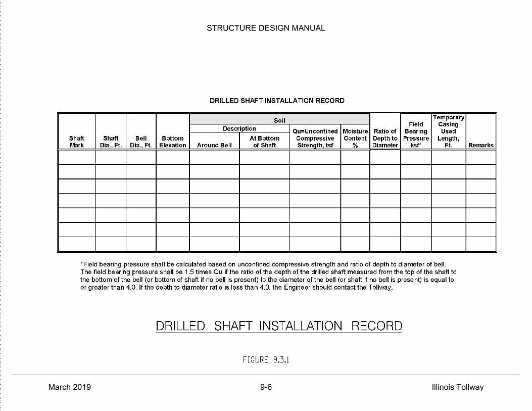
STRUCTURE DESIGN MANUAL
March 2019 9-6 Illinois Tollway
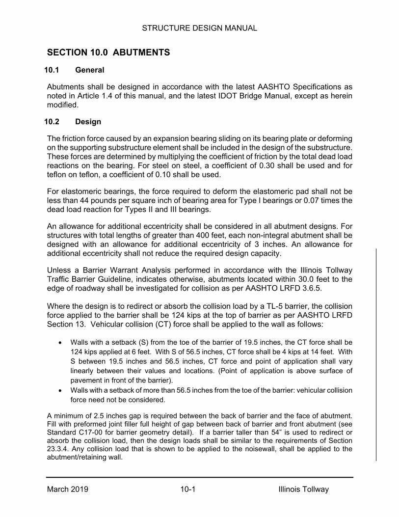
STRUCTURE DESIGN MANUAL
March 2019 10-1 Illinois Tollway
ABUTMENTS
10.1 General
Abutments shall be designed in accordance with the latest AASHTO Specifications as noted in Article 1.4 of this manual, and the latest IDOT Bridge Manual, except as herein modified.
10.2 Design
The friction force caused by an expansion bearing sliding on its bearing plate or deforming on the supporting substructure element shall be included in the design of the substructure. These forces are determined by multiplying the coefficient of friction by the total dead load reactions on the bearing. For steel on steel, a coefficient of 0.30 shall be used and for teflon on teflon, a coefficient of 0.10 shall be used.
For elastomeric bearings, the force required to deform the elastomeric pad shall not be less than 44 pounds per square inch of bearing area for Type I bearings or 0.07 times the dead load reaction for Types II and III bearings.
An allowance for additional eccentricity shall be considered in all abutment designs. For structures with total lengths of greater than 400 feet, each non-integral abutment shall be designed with an allowance for additional eccentricity of 3 inches. An allowance for additional eccentricity shall not reduce the required design capacity.
Unless a Barrier Warrant Analysis performed in accordance with the Illinois Tollway Traffic Barrier Guideline, indicates otherwise, abutments located within 30.0 feet to the edge of roadway shall be investigated for collision as per AASHTO LRFD 3.6.5.
Where the design is to redirect or absorb the collision load by a TL-5 barrier, the collision force applied to the barrier shall be 124 kips at the top of barrier as per AASHTO LRFD Section 13. Vehicular collision (CT) force shall be applied to the wall as follows:
Walls with a setback (S) from the toe of the barrier of 19.5 inches, the CT force shall be124 kips applied at 6 feet. With S of 56.5 inches, CT force shall be 4 kips at 14 feet. WithS between 19.5 inches and 56.5 inches, CT force and point of application shall varylinearly between their values and locations. (Point of application is above surface ofpavement in front of the barrier).
Walls with a setback of more than 56.5 inches from the toe of the barrier: vehicular collisionforce need not be considered.
A minimum of 2.5 inches gap is required between the back of barrier and the face of abutment. Fill with preformed joint filler full height of gap between back of barrier and front abutment (see Standard C17-00 for barrier geometry detail). If a barrier taller than 54” is used to redirect or absorb the collision load, then the design loads shall be similar to the requirements of Section 23.3.4. Any collision load that is shown to be applied to the noisewall, shall be applied to the abutment/retaining wall.
STRUCTURE DESIGN MANUAL
March 2019 10-2 Illinois Tollway
10.3 Abutment Types
Integral or semi-integral abutments shall be utilized whenever possible for new grade separation structures and stream and railroad crossings. High wall abutments may be considered where integral and semi-integral abutments are not feasible.
For bridges over the Illinois Tollway mainline, the preferred abutment type is open abutment with slopewalls and no shielding.
Integral abutments shall be used with steel beams and girders, cast-in-place concrete slabs, or precast, pre-tensioned concrete beams. Beams shall be composite with the cast-in-place concrete deck. The superstructure shall be designed and constructed as a continuous unit between abutments. New integral abutments shall be designed and detailed in accordance with the IDOT ABD Memorandum 12.3, "2012 Integral Abutment Bridge Policies and Details", dated July 25, 2012. See Figures 10.3.1 through 10.3.3 and 10.3.9 for additional details.
Semi-integral abutments shall be utilized where soil conditions require the use of two or more rows of piles to support the proposed loadings. Regardless, the superstructure shall be designed and constructed as a continuous unit between the abutments. The semi-integral concept may also be utilized to eliminate expansion joints at existing stub abutments. However, the existing backwall and part of the approach slab will need to be reconstructed. The existing superstructure may also need to be made composite and continuous between the modified abutments, if it is not already. New semi-integral abutments shall be designed and detailed in accordance with the IDOT ABD Memorandum 12.3, "2012 Integral Abutment Bridge Policies and Details", dated July 25, 2012. See Figures 10.3.3 through 10.3.5 and 10.3.8 for details.
Stub abutments with expansion joints shall be utilized where the existing soil condition and proposed loading (reactions) would require two or more rows of piles for support. They shall also be used when the proposed span length and/or skew angles exceed the maximums specified for integral and semi integral abutments. See Figures 10.3.6 and 10.3.7 for details.
Combinations of retaining walls and pile supported integral, semi integral and stub abutments shall be utilized in lieu of highwall or vaulted abutments to reduce span lengths and increase vertical clearance or eliminate the need for shoulder piers and short end spans. See Figures 10.3.7 and 10.3.10 for details of a pile supported stub abutment with MSE walls. See Figure 10.3.8 for details of a pile supported semi-integral abutment with MSE walls. See Figure 10.3.9 for details of a pile supported integral abutment with MSE walls. MSE walls shall not wrap around directly under the approach slab barrier when integral or semi-integral abutments are used except it can be acceptable when the MSE wall is offset to allow movement of the approach slab.

STRUCTURE DESIGN MANUAL
March 2019 10-3 Illinois Tollway
Conventional cast-in-place concrete highwall abutments founded on spread footings or piles shall not be utilized to support new or replacement structures unless specifically authorized by the Illinois Tollway. Only existing structures which are to be widened and are currently supported by conventional highwall abutments shall utilize the same design to extend the existing abutments and construct new wingwalls.
Vaulted abutments, either sand filled or void, founded on spread footings or piles shall not be utilized to support new or replacement structures unless specifically authorized by the Illinois Tollway. Only existing structures which are to be widened and are currently supported by vaulted abutments shall utilize the same design to extend the existing abutments and construct new curtain walls.
10.4 Foundations
Piles
Piles for foundations shall be designed in accordance with the Section 3.10 of the latest IDOT Bridge Manual.
Abutment piles shall avoid relying on the lateral load carrying capacity of the piles and shall be designed to carry all horizontal loads with the batter component of the pile. The lateral load capacity of soil may be considered when the required batter exceeds 4" in 12". However, the resulting long-term deflection of the pile shall be calculated and accounted for in sizing the joint.
Piles used in integral abutments shall be placed in a single row. Steel "H" piles are preferred for structure lengths up to 200 feet and required for structure lengths between 200 feet and 550 feet.
Consideration shall be given to conflicts with existing buried and overhead utilities or other obstructions when designing pile layouts.
The following information shall be included on Abutment sheets when piles are used:
PILE DATA PILE TYPE AND SIZE: NOMINAL REQUIRED BEARING: FACTORED OR ALLOWABLE RESISTANCE AVAILABLE: ESTIMATED PILE LENGTH: NUMBER OF PILES REQUIRED: _______ plus ______test pile(s) LEGEND - DENOTING THE FOLLOWING: EXISTING PILES EXISTING BATTERED PILES PROPOSED PILES PROPOSED BATTERED PILES TEST PILES
STRUCTURE DESIGN MANUAL
March 2019 10-4 Illinois Tollway
Drilled Shafts
Drilled shafts shall be designed in accordance with Section 3.10 of the latest IDOT Bridge Manual.
10.5 Widening Existing Abutments
In general, abutments shall be widened in kind, especially those which can be viewed by the traveling public. At locations not exposed to the traveling public, such as structures over railroads or streams, other types of designs may be considered. The final selection shall be based on serviceability and economics.
Foundations for widened abutments widened to the outside shall be the same type as the existing. However, construction procedures and type of construction shall be considered when placing new foundations adjacent to existing so as not to reduce the load carrying capacity or cause settlement of existing foundations. Existing borings and new borings (if required) shall also be considered in the final selection. Abutment widenings shall be designed to carry any longitudinal or transverse forces passed through the bearings from the superstructure. Abutments widened to the outside shall be tied to the existing with dowel bars drilled into the existing concrete.
Abutments for structures widened to the inside forming a median closure shall be separated along the centerline of the Illinois Tollway with a preformed joint filler and a 6 inch non-metallic water seal. Abutments widened to the inside shall be tied to the existing with dowel bars drilled into the existing concrete.
10.6 Bridge Seats
The bridge seats shall be constructed in steps poured monolithically with the abutment. The minimum step shall be ¾ inches. Metal shims shall be provided for each bearing where a step is less than ¾ inches. The elevation and height of each step shall be shown on the plans. Steps shall be reinforced when one or more of the preceding steps are equal to or exceed 4 inches; see Figure 10.6.1. In all cases, the bridge seats between the bearings shall be sloped ¼ inch to drain. The bearing seat shall meet the minimum support length requirements specified in the AASHTO Seismic Design Section for Seismic Performance Zone 1 (LRFD) or Category A (LFD).
Concrete sealer shall be applied to the exposed surfaces of all backwalls, bridge seats and bearing pedestals that are located under expansion or rotation joints between the deck and backwall.

STRUCTURE DESIGN MANUAL
March 2019 10-5 Illinois Tollway
10.7 Slope Paving
New Bridges - Grade Separation Structures
Grade separation structures shall have 4-inch thick reinforced concrete slopewalls, as shown in Illinois Tollway Base Sheet M-BRG-525. The 2” vertical dimension of the lip shown in Section A-A shall be increased to 4” for structures with skews of 10° or greater and drainage elements that outlet onto the slopewall.
New Bridges - Stream Crossings
Stream crossings shall have 6-inch thick reinforced concrete slopewalls, as shown in the latest IDOT Bridge Manual, or stone riprap slopewalls, as shown in Illinois Tollway Base Sheet M-BRG-525. For reinforced concrete slopewalls, the 2” vertical dimension of the lip shown in Section A-A shall be increased to 4” for structures with skews of 10° or greater and drainage elements that outlet onto the slopewall.
New Bridges - Railroad Crossings
Railroad crossings shall have 6-inch thick bituminous coated aggregate slope paving, as shown in Illinois Tollway Base Sheet M-BRG-525.
Existing Bridges
Bridge abutment slopes on existing bridges to be rehabilitated shall be repaired and restored to the original design configuration. Slopes on bridges to be widened shall be protected with the same design as the existing bridge. Slopes which do not have any slope protection shall be covered with 6 inches of aggregate slope paving unless there are floor drains in the deck above; in which case, they shall be paved with a 4-inch thick reinforced concrete slopewall.
New Bridges - Side Slopes
Embankment cones shall consist of maximum side slopes 1:2.5 (V:H) with a transition slope wrapping around the abutment to the slopewall. See Figure 10.7.5.
10.8 Wing Walls
The traffic face of the shoulder parapet shall be carried the full length of each wing wall, vaulted span or approach slab. The sloping curb portion of the barrier shall not be battered to a vertical face or clipped at the leaving or entering end of the barrier. See Standard Drawings C9, C10 and C11 for the required end treatment of a barrier or parapet mounted on a wing wall, vaulted span or approach slab. “Dog-ear” style wing walls that are parallel to the centerline of abutment may also be considered for structures with integral abutments. See the latest IDOT integral abutment base sheets for details.

STRUCTURE DESIGN MANUAL
March 2019 10-6 Illinois Tollway
10.9 Abutment Cap Reinforcement
A detail scaled drawing of the reinforcement and the holes drilled for the bearing anchor rods shall be provided in the plans, see Figure 10.9.1. The detail drawing shall include all reinforcement that may interfere with the drilling operation, the reinforcement spacing and the clearances of the reinforcement to the edge of the cap and the future holes.
10.10 Concrete Shoulder Barrier Transition
A Concrete Shoulder Barrier Transition shall be used upstream of a high wall abutment, even if the shoulder width is not transitioning.
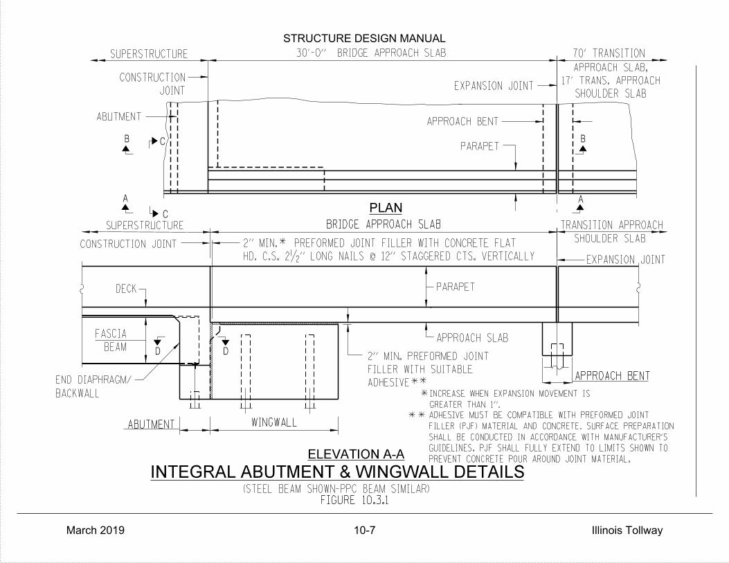
(STEEL BEAM SHOWN-PPC BEAM SIMILAR)
B
A
B
A
C
ABUTMENT
C
JOINT
CONSTRUCTION
SUPERSTRUCTURE
APPROACH SLAB
CONSTRUCTION JOINT
SUPERSTRUCTURE
DECK
BEAM
FASCIA
ELEVATION A-A
WINGWALLABUTMENT
BACKWALL
END DIAPHRAGM/
D D
**
**
INTEGRAL ABUTMENT & WINGWALL DETAILS
PLAN
EXPANSION JOINT
FIGURE 10.3.1
EXPANSION JOINT
*
APPROACH BENTADHESIVE
FILLER WITH SUITABLE
2" MIN. PREFORMED JOINT
70' TRANSITION
TRANSITION APPROACHBRIDGE APPROACH SLAB
GREATER THAN 1".
INCREASE WHEN EXPANSION MOVEMENT IS
SHOULDER SLAB
SHOULDER SLAB
17' TRANS. APPROACH
APPROACH SLAB,
30'-0" BRIDGE APPROACH SLAB
APPROACH BENT
*
HD. C.S. 2•" LONG NAILS @ 12" STAGGERED CTS. VERTICALLY
2" MIN. PREFORMED JOINT FILLER WITH CONCRETE FLAT
PARAPET
PARAPET
PREVENT CONCRETE POUR AROUND JOINT MATERIAL.
GUIDELINES. PJF SHALL FULLY EXTEND TO LIMITS SHOWN TO
SHALL BE CONDUCTED IN ACCORDANCE WITH MANUFACTURER'S
FILLER (PJF) MATERIAL AND CONCRETE. SURFACE PREPARATION
ADHESIVE MUST BE COMPATIBLE WITH PREFORMED JOINT
STRUCTURE DESIGN MANUAL
March 2019 10-7 Illinois Tollway

SHOULDER SLAB
17' TRANS. APPROACH
APPROACH SLAB,
70' TRANSITION
SECTION B-B
CONSTRUCTION JOINT
11
2'-0"
WALL DRAIN
GEOCOMPOSITE
DRAINAGE AGGREGATE
PIPE DRAIN WITH
4"} PERFORATED
FRENCH DRAINS
FABRIC FOR
GEOTECHNICAL
(STEEL BEAM SHOWN, PPC BEAM SIMILAR)
SECTION C-C
DIAPHRAGM/BACKWALL
DECK AND END
INTEGRAL ABUTMENT DETAILS
SECTION D-D
SUPERSTRUCTURE
1'-0"
*
*
FIGURE 10.3.2
APPROACH BENT
BRIDGE APPROACH SLAB
WALL DRAIN
GEOCOMPOSITE
END DIAPHRAGM/
BACKWALL
WING WALL
2" MIN. PREFORMED JOINT FILLERDEC
K
AN
D
AB
UT
MENT
WIN
GW
ALL
SUPERSTRUCTURE.
THE COST OF CONCRETE
VERTICALLY. INCLUDED WITH
NUTS AND WASHERS AT 12" CTS.
PLATE AND •" } ANCHOR BOLTS,
WINGWALL WITH A …"x5" STEEL
DIAPHRAGM/BACKWALL AND
HEIGHT AT EDGES TO THE END
DUROMETER) ATTACHED FULL
…"x 1'-4" NEOPRENE SHEET (55
GRANULAR BACKFILL FOR STRUCTURES EXPANSION JOINT
4" GRANULAR SUBBASE
PA
RAPET
POUR AROUND JOINT MATERIAL.WINGWALL TO PREVENT CONCRETE EXTEND TO THE TOP OF THE JOINT MATERIAL SHALL FULLY EXPANSION LENGTH.DESIGNED CONSIDERING EFFECTIVE THE ACTUAL PJF SIZE TO BE
STRUCTURE DESIGN MANUAL
March 2019 10-8 Illinois Tollway
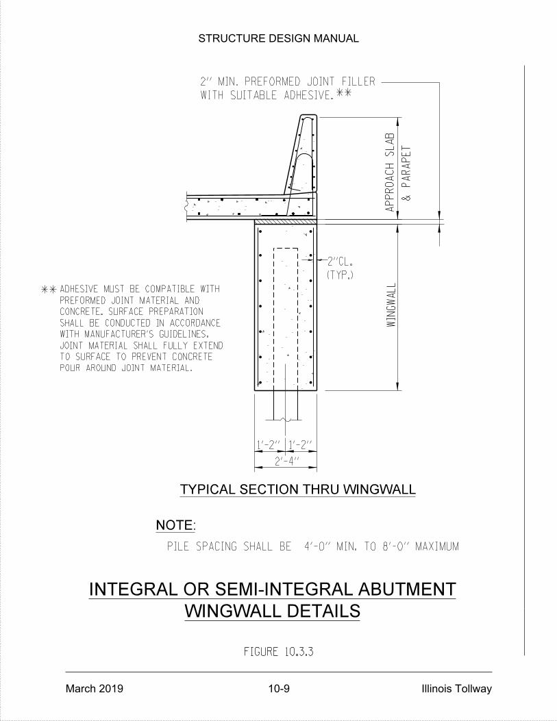
TYPICAL SECTION THRU WINGWALL
PILE SPACING SHALL BE 4'-0" MIN. TO 8'-0" MAXIMUM
NOTE:
WIN
GW
AL
L
2'-4''
AP
PR
OA
CH
SL
AB
(TYP.)
2"CL.
&
PA
RA
PE
T
**
**
FIGURE 10.3.3
WINGWALL DETAILS
INTEGRAL OR SEMI-INTEGRAL ABUTMENT
1'-2'' 1'-2''
WITH SUITABLE ADHESIVE.
2" MIN. PREFORMED JOINT FILLER
POUR AROUND JOINT MATERIAL.
TO SURFACE TO PREVENT CONCRETE
JOINT MATERIAL SHALL FULLY EXTEND
WITH MANUFACTURER'S GUIDELINES.
SHALL BE CONDUCTED IN ACCORDANCE
CONCRETE. SURFACE PREPARATION
PREFORMED JOINT MATERIAL AND
ADHESIVE MUST BE COMPATIBLE WITH
STRUCTURE DESIGN MANUAL
March 2019 10-9 Illinois Tollway

(STEEL BEAM SHOWN-PPC BEAM SIMILAR)
B
A
B
A
C
ABUTMENT
C
JOINT
CONSTRUCTION
SUPERSTRUCTURE
APPROACH SLAB
CONSTRUCTION JOINT
PARAPET
SUPERSTRUCTURE
DECK
BEAM
FASCIA
ELEVATION A-A
WINGWALLABUTMENT
SEMI-INTEGRAL ABUTMENT & WINGWALL DETAILS
~ BEARING ****
APPROACH BENT
PARAPET
ADHESIVE
FILLER WITH SUITABLE
2" MIN. PREFORMED JOINT
BRIDGE APPROACH SLAB
PLAN
SHOULDER SLAB
APPROACH
TRANSITION
SHOULDER SLAB
17' TRANS. APPROACH
APPROACH SLAB,
70' TRANSITION
EXPANSION JOINT
EXPANSION JOINT
BRIDGE APPROACH SLAB
30'-0"
APPROACH BENT
AS SHOWN TO PREVENT CONCRETE POUR AROUND JOINT MATERIAL.
PJF SHALL FULLY EXTEND OVER CONCRETE SURFACE
MANUFACTURER'S GUIDELINES.
PREPARATION SHALL BE IN ACCORDANCE WITH
JOINT FILLER MATERIAL AND CONCRETE. SURFACE
ADHESIVE MUST BE COMPATIBLE WITH PREFORMED
FIGURE 10.3.4
STRUCTURE DESIGN MANUAL
March 2019 10-10 Illinois Tollway

SHOULDER SLAB
17' TRANS. APPROACH
APPROACH SLAB,
70' TRANSITION
SECTION B-B
CONSTRUCTION JOINT
11
SUPERSTRUCTURE
2'-0"
WALL DRAIN
GEOCOMPOSITE
FRENCH DRAINS
FABRIC FOR
GEOTECHNICAL
(STEEL BEAM SHOWN, PPC BEAM SIMILAR)
SECTION C-C
NOTES:DIAPHRAGM/BACKWALL
DECK AND END
SEMI-INTEGRAL ABUTMENT DETAILS
DRAINAGE AGGREGATE
PIPE DRAIN WITH
4" } PERFORATED
*
*
**
**
*
**
FIGURE 10.3.5
ACCORDANCE WITH MANUFACTURER'S GUIDELINES.MATERIAL AND CONCRETE. SURFACE PREPARATION SHALL BE INADHESIVE MUST BE COMPATIBLE WITH PREFORMED JOINT FILLER
INCREASE WHEN EXPANSION MOVEMENT IS GREATER THAN 1 INCH.
1'-0"
APPROACH BENT
BRIDGE APPROACH SLAB
ADHESIVE.1. 2" MIN. PREFORMED JOINT FILLER WITH SUITABLE
ABUTMENT CAP WITH SUITABLE ADHESIVE.2. 2" MIN. PREFORMED JOINT FILLER FULLY BONDED TO
WIN
GW
ALL
NOTE 1
DEC
K
AN
D
PA
RAPET
AB
UT
MENT
GRANULAR BACKFILL FOR STRUCTURES EXPANSION JOINT
NOTE 1
NOTE 2
4" GRANULAR SUBBASE
STRUCTURE DESIGN MANUAL
March 2019 10-11 Illinois Tollway
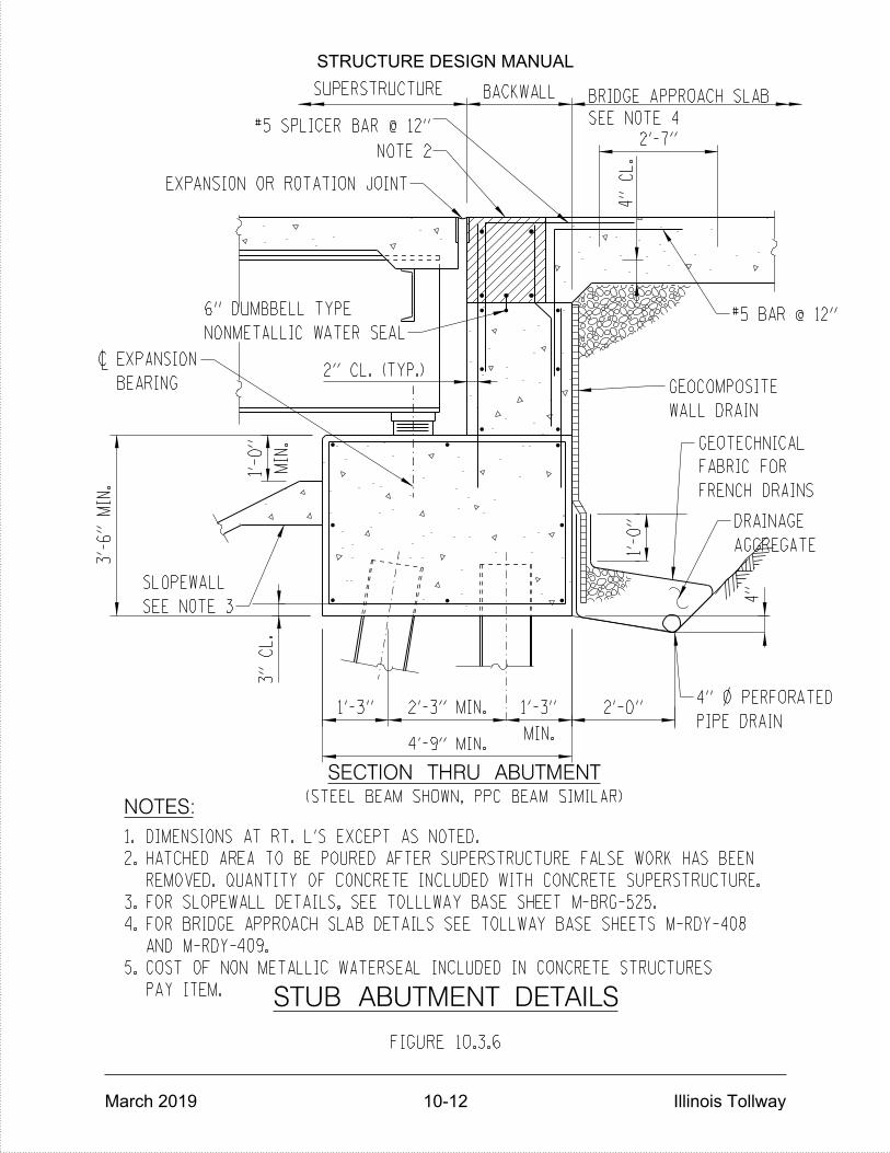
3"
CL.
BACKWALL
2'-7"
4'-9" MIN.
3'-
6"
MIN.
4"
CL.
2" CL. (TYP.)
2'-0"
1'-
0"
4"
MIN.
1'-
0"
MIN.
1'-3"
2'-3" MIN.
1'-3"
SUPERSTRUCTURE
EXPANSION OR ROTATION JOINT
SECTION THRU ABUTMENT
STUB ABUTMENT DETAILS
(STEEL BEAM SHOWN, PPC BEAM SIMILAR)NOTES:
FIGURE 10.3.6
SEE NOTE 4
BRIDGE APPROACH SLAB
PAY ITEM.
COST OF NON METALLIC WATERSEAL INCLUDED IN CONCRETE STRUCTURES
AND M-RDY-409.
FOR BRIDGE APPROACH SLAB DETAILS SEE TOLLWAY BASE SHEETS M-RDY-408
FOR SLOPEWALL DETAILS, SEE TOLLLWAY BASE SHEET M-BRG-525.
REMOVED. QUANTITY OF CONCRETE INCLUDED WITH CONCRETE SUPERSTRUCTURE.
HATCHED AREA TO BE POURED AFTER SUPERSTRUCTURE FALSE WORK HAS BEEN
DIMENSIONS AT RT. L'S EXCEPT AS NOTED.
5.
4.
3.
2.
1.
WALL DRAIN
GEOCOMPOSITE
FRENCH DRAINS
FABRIC FOR
GEOTECHNICAL
AGGREGATE
DRAINAGE
PIPE DRAIN
4" } PERFORATED
SEE NOTE 3
SLOPEWALL
NONMETALLIC WATER SEAL
6" DUMBBELL TYPE
BEARING
~ EXPANSION
NOTE 2
#5 BAR @ 12"
#5 SPLICER BAR @ 12"
STRUCTURE DESIGN MANUAL
March 2019 10-12 Illinois Tollway

*
*
FIGURE 10.3.7
(M.S.E. WALL & STUB ABUTMENT)
COMBINATION HIGHWALL ABUTMENT DETAILS
"H"
MIN.
3'-0"
ABUTMENT
BACK OF
C.I.P. COPING
SOIL MASS
REINFORCED
LIMITS OF
EMBANKMENT
GROUND LINE
EXISTING
SOIL REINFORCEMENT
SELECT FILL
PILES
X'-X"
X'-X"
2'-
0"
1'-6"
MIN.
3'-
6"
PANEL LINE
TOP OF EXPOSED
DRAINAGE AGGREGATE
GEOTECHNICAL FABRIC
GRADE
TOP OF FINISHED
PAD
TOP OF LEVELING
REINFORCEMENT
ABUTMENT SOIL
**
**
MIN.
9"
MIN.
1'-
0"
STRUCTURES (IF REQUIRED).
OF UNSUITABLE MATERIAL FOR
LIMITS OF REMOVAL AND DISPOSAL
PART OF COPING)
TO DRAIN (INCLUDED AS
FACE ABUT ONLY) SLOPE
SEAL AND PJF (FRONT
4" MIN. THICK CONCRETE
0.7 x "H" OR 8'-0" MIN.
PIPE UNDERDRAIN
4" PERFORATED
PROTECTION REQUIREMENT.
VEHICULAR COLLISION LOAD. SEE ARTICLE 10.2 OF THIS MANUAL FOR COLLISION
MSE WALL WITHIN 30 FEET FROM EDGE OF PAVEMENT SHALL BE DESIGNED FOR
TO RESIST A HORIZONTAL FORCE OF _______ KIPS/FT OF ABUTMENT.
THE MSE WALL SUPPLIER SHALL DESIGN THE ABUTMENT SOIL REINFORCEMENT
PRECAST PANELS***
PILE CASING
THE PILE AND SLEEVE WITH CLEAN SAND. WORK SHALL BE INCLUDED WITH PILE CASING.
BEFORE PLACING AND COMPACTING THE SELECT FILL. FILL THE ANNULAR SPACE BETWEEN
SLEEVE EACH PILE FROM BOTTOM OF PROPOSED ABUTMENT TO TOP OF LEVELING PAD
***
STRUCTURE DESIGN MANUAL
March 2019 10-13 Illinois Tollway

FIGURE 10.3.8
(M.S.E. WALL & SEMI-INTEGRAL ABUTMENT)
COMBINATION HIGHWALL ABUTMENT DETAILS
*
"H"
MIN.
3'-0"
ABUTMENT
BACK OFC.I.P. COPING
SOIL MASS
REINFORCED
LIMITS OF
EMBANKMENT
GROUND LINE
EXISTING
SOIL REINFORCEMENT
SELECT FILL
PILES
2'-
0"
1'-6"
MIN.
3'-
6"
PIPE UNDERDRAIN
4" PERFORATED
PANEL LINE
TOP OF EXPOSED
DRAINAGE AGGREGATE
GEOTECHNICAL FABRIC
GRADE
TOP OF FINISHED
PRECAST PANELS
X'-X"
X'-X"
PAD
TOP OF LEVELING
*
**TO RESIST A HORIZONTAL FORCE OF _______ KIPS/FT OF ABUTMENT.
THE MSE WALL SUPPLIER SHALL DESIGN THE ABUTMENT SOIL REINFORCEMENT
REINFORCEMENT
ABUTMENT SOIL
**
MIN.
9"
MIN.
1'-
0"
STRUCTURES (IF REQUIRED).
OF UNSUITABLE MATERIAL FOR
LIMITS OF REMOVAL AND DISPOSAL
PART OF COPING)
TO DRAIN (INCLUDED AS
FACE ABUT ONLY) SLOPE
SEAL AND PJF (FRONT
4" MIN. THICK CONCRETE
0.7 x "H" OR 8'-0" MIN.
LOW MODULUS POLYMER SEALANT.1/4" x 3/4" HOT POURED,
***
***
PROTECTION REQUIREMENT.
VEHICULAR COLLISION LOAD. SEE ARTICLE 10.2 OF THIS MANUAL FOR COLLISION
MSE WALL WITHIN 30 FEET FROM EDGE OF PAVEMENT SHALL BE DESIGNED FOR
PILE CASING.
BETWEEN THE PILE AND SLEEVE WITH CLEAN SAND. WORK SHALL BE INCLUDED WITH
BEFORE PLACING AND COMPACTING THE SELECT FILL. FILL THE ANNULAR SPACE
SLEEVE EACH PILE FROM BOTTOM OF PROPOSED ABUTMENT TO TOP OF LEVELING PAD
STRUCTURE DESIGN MANUAL
March 2019 10-14 Illinois Tollway
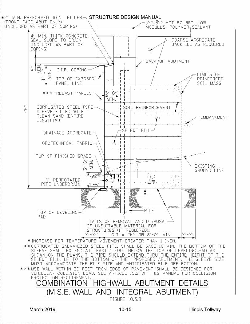
*
"H"
MIN.
3'-0"
C.I.P. COPING
SOIL MASS
REINFORCED
LIMITS OF
EMBANKMENT
GROUND LINE
EXISTING
SOIL REINFORCEMENT
SELECT FILL
X'-X"
X'-X"
2'-
0"
1'-6"
MIN.
3'-
6"
PIPE UNDERDRAIN
4" PERFORATED
PANEL LINE
TOP OF EXPOSED
DRAINAGE AGGREGATE
GEOTECHNICAL FABRIC
PAD
TOP OF LEVELING
PRECAST PANELS
BACKFILL AS REQUIRED
COARSE AGGREGATE
TOP OF FINISHED GRADE
*
MIN.
1'-
0"
MIN.
9"
MIN.
1'-
0"
**LENGTH)
CLEAN SAND (ENTIRE
SLEEVE FILLED WITH
CORRUGATED STEEL PIPE
**INCREASE FOR TEMPERATURE MOVEMENT GREATER THAN 1 INCH.
MODULUS, POLYMER SEALANT
‚"xƒ" HOT POURED, LOW
PILE
BACK OF ABUTMENT
FIGURE 10.3.9
(M.S.E. WALL AND INTEGRAL ABUTMENT)
COMBINATION HIGHWALL ABUTMENT DETAILS
0.7 x "H" OR 8'-0" MIN.
MUST ACCOMMODATE THE PILE SIZE AND ANTICIPATED PILE DEFLECTION.
SELECT FILL, UP TO THE BOTTOM OF THE PROPOSED ABUTMENT. THE SLEEVE SIZE
SHOWN ON THE PLANS. THE PIPE SHOULD EXTEND THRU THE ENTIRE HEIGHT OF THE
SLEEVE SHALL EXTEND AT LEAST 1 FOOT BELOW THE TOP OF LEVELING PAD AS
CORRUGATED GALVANIZED STEEL PIPE, SHALL BE GAGE 10 MIN. THE BOTTOM OF THE
STRUCTURES (IF REQUIRED).
OF UNSUITABLE MATERIAL FOR
LIMITS OF REMOVAL AND DISPOSAL
COPING)
(INCLUDED AS PART OF
SEAL SLOPE TO DRAIN
4" MIN. THICK CONCRETE
(INCLUDED AS PART OF COPING)
(FRONT FACE ABUT ONLY)
2" MIN. PREFORMED JOINT FILLER
***
PROTECTION REQUIREMENT.
VEHICULAR COLLISION LOAD. SEE ARTICLE 10.2 OF THIS MANUAL FOR COLLISION
MSE WALL WITHIN 30 FEET FROM EDGE OF PAVEMENT SHALL BE DESIGNED FOR ***
STRUCTURE DESIGN MANUAL
March 2019 10-15 Illinois Tollway

1'-3"
SELECT FILL
WRAP-AROUND MSE WINGWALLS
FOR STUB ABUTMENT WITH
SECTION THROUGH BRIDGE APPROACH SLAB
*
*
SOIL REINFORCEMENT
3'-
8"
1'-0"
(MAX.
)1:2
6"
1•
"
2"
1'-
0" (M
AX.)
2"
PANEL
PRECAST
PJF
•"
FIGURE 10.3.10
2'-
4•
"
BRIDGE APPROACH SLAB
SLIDING FORCE OF 1.15 KIPS/FT. OF WALL.
PRESSURE SURCHARGE OF 1.0 KSF. AND HORIZONTAL
SHALL ACCOUNT FOR THE APPROACH SLAB'S BEARING
THE M.S.E. WALL SUPPLIER'S INTERNAL STABILITY DESIGN
1'-5"
STRUCTURE DESIGN MANUAL
March 2019 10-16 Illinois Tollway
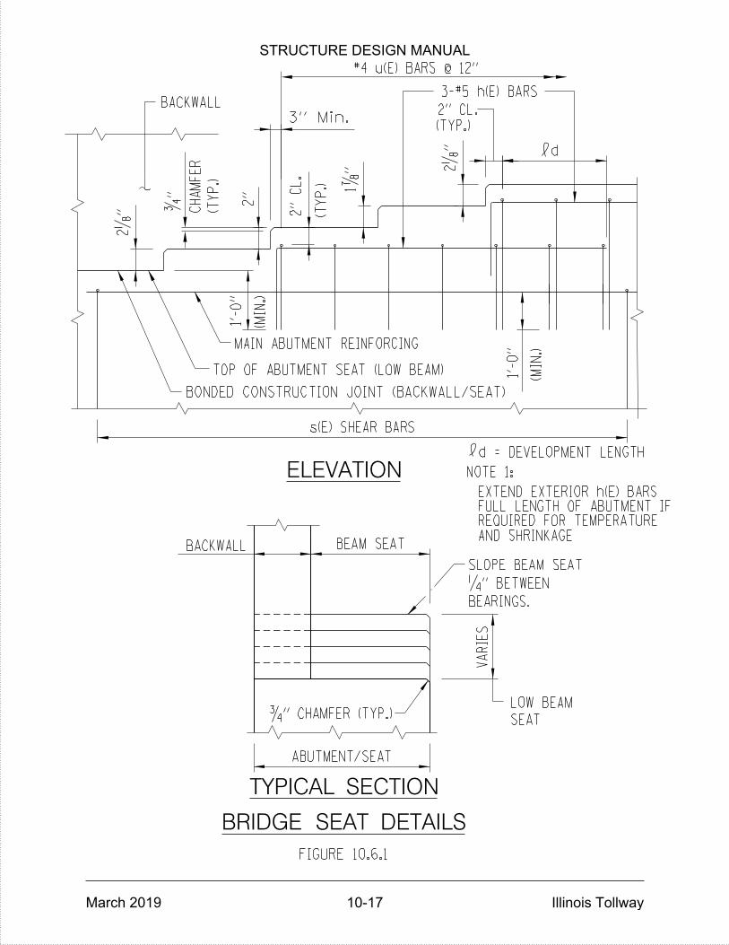
TYPICAL SECTION
BACKWALL
LOW BEAM
SEAT
BEARINGS.
ƒ" CHAMFER (TYP.)
ELEVATION
#4 u(E) BARS @ 12"
3-#5 h(E) BARS
MAIN ABUTMENT REINFORCING
TOP OF ABUTMENT SEAT (LOW BEAM)
BACKWALL
ƒ"
(TY
P.)
2„
"
2"
1‡
" 2„
"
3" Min.
2"
CL.
VA
RIES
(TY
P.)
CH
AM
FE
R
1'-
0"
BRIDGE SEAT DETAILS
FIGURE 10.6.1
d = DEVELOPMENT LENGTH
NOTE 1:
1'-
0"
(MIN.)
AND SHRINKAGEREQUIRED FOR TEMPERATUREFULL LENGTH OF ABUTMENT IFEXTEND EXTERIOR h(E) BARS
s(E) SHEAR BARS
(MIN.)
BONDED CONSTRUCTION JOINT (BACKWALL/SEAT)
BEAM SEAT
SLOPE BEAM SEAT
2" CL.
d
(TYP.)
ABUTMENT/SEAT
‚" BETWEEN
STRUCTURE DESIGN MANUAL
March 2019 10-17 Illinois Tollway
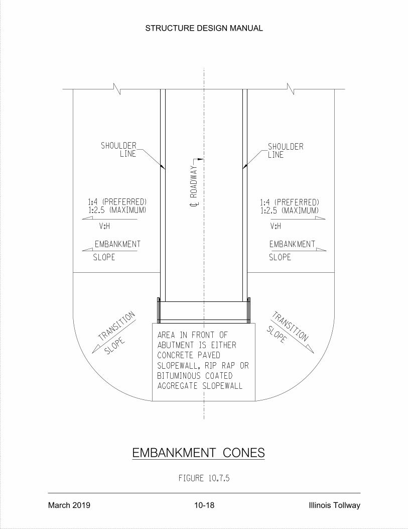
FIGURE 10.7.5
~
RO
AD
WA
Y
V:H V:H
TRANSITIO
N
SLOP
E
TRANSITION
SLOPE
LINESHOULDER
LINESHOULDER
EMBANKMENT
SLOPE
EMBANKMENT
SLOPE
1:2.5 (MAXIMUM)1:4 (PREFERRED)
1:2.5 (MAXIMUM)1:4 (PREFERRED)
AGGREGATE SLOPEWALL
BITUMINOUS COATED
SLOPEWALL, RIP RAP OR
CONCRETE PAVED
ABUTMENT IS EITHER
AREA IN FRONT OF
EMBANKMENT CONES
STRUCTURE DESIGN MANUAL
March 2019 10-18 Illinois Tollway
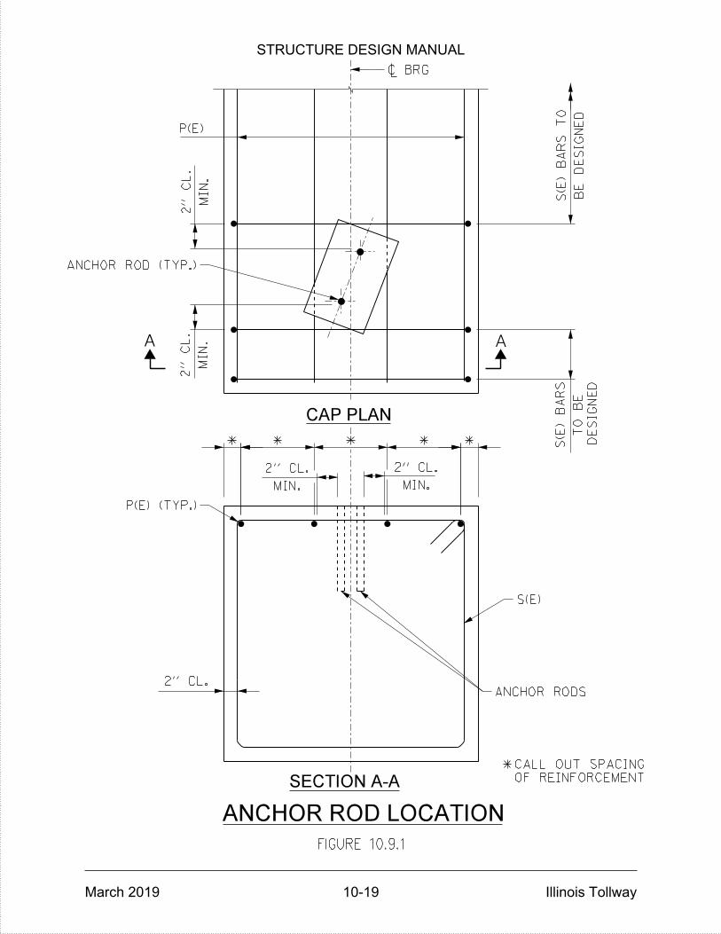
2" CL.
BE
DESIG
NE
D
S(E)
BA
RS
TO
P(E)
MIN.
2"
CL.
MIN.
2"
CL.
TO
BE
S(E)
BA
RS
MIN.
2" CL.
MIN.
2" CL.
FIGURE 10.9.1
AA
ANCHOR ROD LOCATION
CAP PLAN
SECTION A-A
*
* * ** * DESIG
NE
D
OF REINFORCEMENT
CALL OUT SPACING
P(E) (TYP.)
S(E)
ANCHOR RODS
ANCHOR ROD (TYP.)
~ BRG
STRUCTURE DESIGN MANUAL
March 2019 10-19 Illinois Tollway
STRUCTURE DESIGN MANUAL
March 2019 Illinois Tollway
PIERS
11.1 General
Piers shall be designed in accordance with the latest AASHTO Specifications and Section 3.9 of the latest IDOT Bridge Manual, except as herein modified. Multi-column pier shapes, as shown in Figure 11.3.1.1 (except single column hammerhead) and Figure 11.3.1.2, are the most commonly used pier types for grade separation structures. The use of square or round columns is appropriate; however, the standard application of square columns is preferred whenever practical to provide system consistency. A typical 3” offset between the face of column and the face of the pier cap and crash wall is desirable.
Piers under deck joints, in medians or within 12 feet of the outer edge of shoulder shall have all exposed surface areas treated with a concrete sealer. For cases involving structure widening, the existing concrete substructure shall be power washed, and both the new and existing surfaces treated with a concrete sealer.
11.2 Design
The friction force caused by an expansion bearing sliding on its bearing plates or deforming on the supporting substructure element shall be included in the design of the structure. These forces are determined by multiplying the coefficient of friction by the total dead load reactions on the bearing. Coefficients of 0.30 for steel on steel and 0.10 for Teflon on Teflon shall be used.
For elastomeric bearings, the force required to deform the elastomeric pad shall not be less than 44 pounds per square inch of bearing area for Type I bearings or 0.07 times the dead load reaction for Types II and III bearings.
The fixed pier(s) design shall include the “net” frictional force from expansion bearings on adjacent piers.
An allowance for additional eccentricity shall be considered in all pier designs. For structures with total lengths of greater than 400 feet, each pier shall be designed with an allowance for additional eccentricity of 3 inches. An allowance for additional eccentricity shall not reduce the required design capacity.
The bearing seat shall meet the minimum support length requirements specified in the AASHTO Seismic Design Section for Seismic Performance Zone 1 (LRFD) or Category A (LFD).
11-1
STRUCTURE DESIGN MANUAL
March 2019 Illinois Tollway
11.3 Pier Types
Grade Separation
Grade separation piers shall be proportioned in accordance with the dimensions as shown on Figures 11.3.1.1 through 11.3.1.8. Care shall be used in applying these criteria on piers with heights greater than 20'-0" measured from the top of crash wall. The minimum cap and crash wall width for grade separation piers shall be 6” (3” offset each side) greater than the minimum column width of 2’-6”, unless the bearings require a larger seat area. In this case, the width of the cap may be increased by up to 12” (6” offset each side) before the minimum column and crash wall widths would also need to be increased to maintain a minimum offset of 3” on each side of the face of the column to the face of the crash wall.
Grade separation piers used with integral abutments may be supported by a single row of piles, provided the capacity of the piles is not exceeded and the number of spans on either side of the pier are equal and their total lengths are approximately the same (+ 5%). Otherwise, a larger footing with multiple rows of piles shall be used. See Figure 11.3.1.8 for details of an integral pier.
Stream Crossing
Stream crossing piers shall be a solid wall with vertical faces and rounded ends. The minimum width shall be a constant 2’-6” from top to bottom. If a greater width is required for the bearing seats, a wider cap shall be utilized to maintain a constant 2'-6" pier width. Details of a fixed or expansion pier, supported by a pile footing are shown on Figure 11.3.2.1. Expansion piers may also be supported by a single line of encased piles or drilled shafts as shown on Figure 11.3.2.2.
Railroad Crossings
Railroad crossings shall utilize grade separation type piers unless the horizontal clearance to the centerline of the nearest track is less than 25’-0”, in which case they shall be modified with crash walls meeting the requirements of the latest edition of AREMA. and the railroad. See Figure 11.3.3.1 for details.
11.4 Widening Existing Piers
In general, existing piers shall be widened in-kind, especially those which can be viewed by the traveling public, except Article 11.6 shall be followed. At locations not exposed to the traveling public, such as structures over railroads or streams, other designs may be considered. The final selection shall be based on serviceability and economy.
Pier widenings shall be designed to carry all forces which pass through the bearings. All pier widenings shall be tied to the existing cap, column and footing areas with dowel bars drilled into the existing concrete. Minimum depth embedment of dowels in existing concrete shall be 12 inches for vertical bars and the development length for horizontal bars. Maximum spacing shall be 18 inches.
11-2
STRUCTURE DESIGN MANUAL
March 2019 Illinois Tollway
Foundations for widened piers shall be the same type as the existing structure. Existing borings and new borings (if required) shall also be considered. Construction and installation procedures shall be considered when placing new foundations adjacent to existing so as not to reduce the load carrying capacity or cause settlement of existing foundations.
Special attention shall be given to the widening of existing piers that consist of 3-foot diameter hollow precast columns without footings. The extensions shall be designed using 3 foot diameter columns supported on pile foundations.
Generally, piers at dual crossings which are to be widened each side of the centerline of median shall be separated along the centerline with an open joint or preformed joint filler, except for their footings, which shall be constructed without an expansion joint. If a construction joint in the footing is needed, the longitudinal reinforcement shall cross the joint to maintain continuity.
Pier caps with rounded ends shall be attached to the new work as shown in Figure 11.4.1. Pier walls with rounded ends shall be attached to the new work as shown in Figure 11.4.2.
11.5 Integral Concrete Pier Caps
An integral pier cap is a pier cap that is incorporated either entirely or largely within the depth of the superstructure. The cap can be constructed of either concrete or steel. For steel superstructures, the longitudinal beams are typically run continuous through the cap. When the superstructure is constructed of prestressed concrete, a pier segment may run continuous through the cap or the ends of beams may be cast into the integral cap. When the beams are not continuous through the cap, a positive connection is made between the cap and the beams with post-tensioning.
Integral pier caps may be utilized to: Improve vertical clearances, simplify framing, eliminate bearings, improve aesthetics and reduce the mass of the structure which reduces the seismic design forces.
The beams shall be supported on falsework while the caps are constructed. The top surface of the cap is intentionally roughened. Stirrups are extended from the top surface of the cap to provide a positive connection to the deck. After tensioning of cap tendons, the falsework supporting the beams and cap are removed. The deck concrete is then placed according to the deck pouring sequence shown in the plans.
A post-tensioning tendon shall be placed in each corner of the cap along with one or more draped tendons. Strand tendons shall be used rather than bars for simplicity of construction and to allow more flexibility in the tendon profile.
After placement and hardening of the cap concrete but before the deck is cast, tendons shall be tensioned from one end according to a specified sequence. Tendons are then grouted to provide corrosion protection and to provide bond between the strands and the structure.
11-3
STRUCTURE DESIGN MANUAL
March 2019 Illinois Tollway
11.6 Pier Protection Requirements
New or Widened Piers
When shielding is required based on a Level 2 or Level 3 Barrier Warrant Analysis or the pier is located within a distance of 30.0 feet to the edge of roadway:
Provide a crash wall that extends a minimum of 5’-0” above the ground that is built
to withstand a 600 kip impact load at the top of the crash wall. The design of the
crash wall shall be performed in accordance with IDOT All Bridge Designers (ABD)
Memorandum 12.1, except all structures shall be considered “critical or essential”.
The top of crash wall shall be level along the length of the pier.
Existing Piers to Remain
When shielding is required based on a Level 3 Barrier Warrant Analysis or the pier
is located within a distance of 30.0 feet to the edge of roadway:
Existing piers that do not require new walls or columns shall be modified in
accordance with Base Sheets M-BRG-507 and M-BRG-508. Existing crash walls
shall be modified to meet the dimension and reinforcement details shown in these
Base Sheets. Modifications shall be designed for Test Level 5 (TL-5) Crash Load
as specified in Article A13.2 of the AASHTO LRFD Bridge Design Specifications.
Additional dead load to the pier foundation shall be analyzed. A concrete shoulder
barrier transition shall be used upstream of the crash wall, even if the shoulder
width is not transitioning. The barrier height and shape shall transition as shown
on Illinois Tollway Standard Drawing C4.
A concrete barrier designed to meet TL-5 impact loading shall be used to shield
bridge piers when it is not feasible to comply with the above requirements. This is
considered a Design Deviation and shall be documented as such. See Illinois
Tollway Standard C3 for details.
11.7 Pier Columns
If pier columns are over 20 feet high, a bonded construction joint or joints shall be detailed at approximately mid-height or third points.
11-4

STRUCTURE DESIGN MANUAL
March 2019 Illinois Tollway
11.8 Foundations
Spread Footings
The minimum width of any spread footing under an expansion pier shall be one-fourth the distance from the top of the pier to the bottom of the footing. If the spread footing is founded on rock, this ratio may be reduced to one-fifth of the pier height and keyed a minimum of 6 inches into sound rock. The maximum applied and allowable bearing pressure for each pier foundation shall be shown on the appropriate plan sheet.
Any construction joints allowed in pier footings shall be bonded construction joints with continuous reinforcement.
Piles
Piles foundations shall be designed in accordance with Section 3.10 of the latest IDOT Bridge Manual.
The minimum width between the outside rows of piles in a pile supported footing shall be one-fifth of the pier height, but no greater than 8’-0”.
The following information shall be included in the plans for each pier foundation supported by Piles:
PILE DATA PILE TYPE AND SIZE NOMINAL REQUIRED BEARING: FACTORED OR ALLOWABLE RESISTANCE AVAILABLE: ESTIMATED PILE LENGTH: NUMBER OF PILES REQUIRED: _______ plus ______test pile(s) LEGEND - DENOTING THE FOLLOWING: EXISTING PILES PROPOSED PILES PROPOSED BATTERED PILES TEST PILES
Drilled Shafts
Drilled shafts shall be designed and detailed in accordance with Section 3.10 of the latest IDOT Bridge Manual.
11.9 Pier Cap Reinforcement
A detail scaled drawing of the reinforcement and the holes drilled for the bearing anchor rods at expansion bearings and anchor bolts at fixed piers shall be provided in the plans, as shown in Figure 11.9.1. The detail drawing shall include all reinforcement that may interfere with the drilling operation, the reinforcement spacing and the clearances of the reinforcement to the edge of the cap and the future holes.
11-5
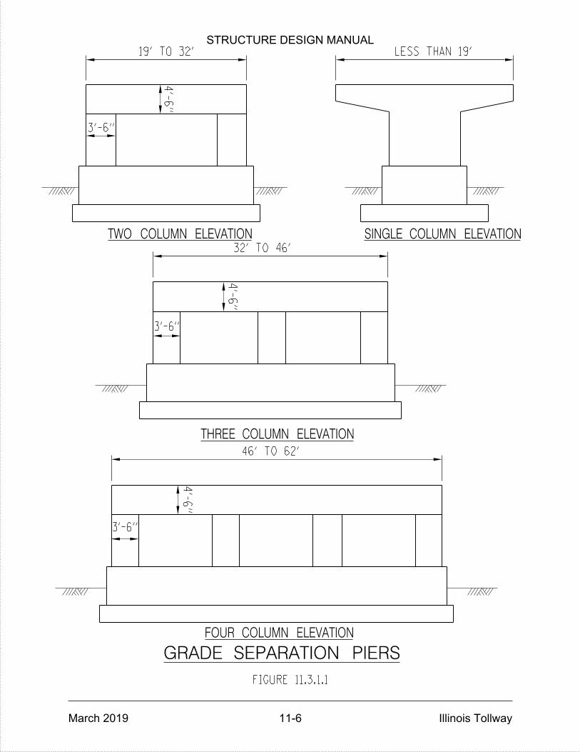
GRADE SEPARATION PIERS
46' TO 62'
FIGURE 11.3.1.1
19' TO 32'
32' TO 46'
LESS THAN 19'
3'-6"
3'-6"
4'-
6"
4'-
6"
4'-
6"
THREE COLUMN ELEVATION
SINGLE COLUMN ELEVATIONTWO COLUMN ELEVATION
FOUR COLUMN ELEVATION
3'-6"
STRUCTURE DESIGN MANUAL
March 2019 11-6 Illinois Tollway

FIGURE 11.3.1.2
62' TO 76'
76' TO 95'
FIVE COLUMN ELEVATION
SIX COLUMN ELEVATION
3'-6"
3'-6"
4'-
6"
4'-
6"
GRADE SEPARATION PIERS
STRUCTURE DESIGN MANUAL
March 2019 11-7 Illinois Tollway
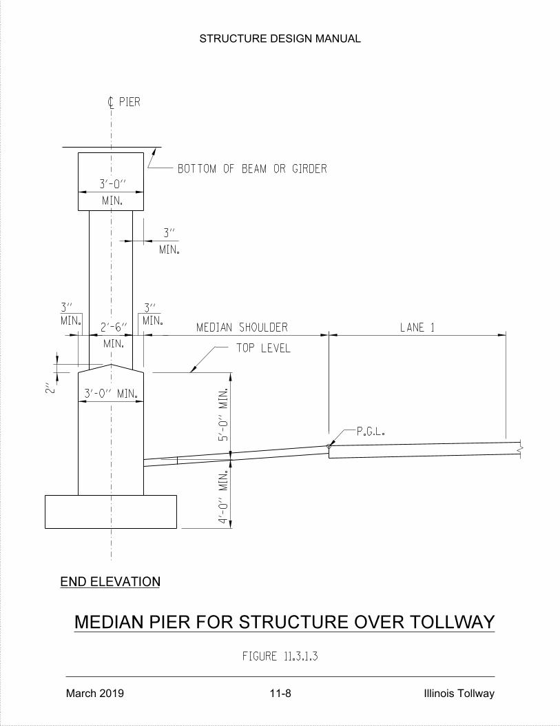
P.G.L.
MEDIAN SHOULDER
MEDIAN PIER FOR STRUCTURE OVER TOLLWAY
FIGURE 11.3.1.3
2"
~ PIER
LANE 1
MIN.
3'-0"
MIN.
2'-6"
BOTTOM OF BEAM OR GIRDER
3" 3"
END ELEVATION
4'-
0"
MIN.
5'-
0"
MIN.
3'-0" MIN.
MIN.MIN.
MIN.
3"
TOP LEVEL
STRUCTURE DESIGN MANUAL
March 2019 11-8 Illinois Tollway

EDGE OF TRAVELED WAY
FIGURE 11.3.1.4
FACE OF PIER CRASH WALL
SHOULDER PIER FOR STRUCTURE OVER TOLLWAY
HORIZONTAL CLEARANCE*
*
1:6 MAX.
AS DETERMINED BY BARRIER WARRANT ANALYSIS
~ PIER
BOTTOM OF BEAM OR GIRDER
END ELEVATION
3"
MIN.
STRUCTURE DESIGN MANUAL
March 2019 11-9 Illinois Tollway
RESERVED
FIGURE 11.3.1.5
STRUCTURE DESIGN MANUAL
March 2019 11-10 Illinois Tollway
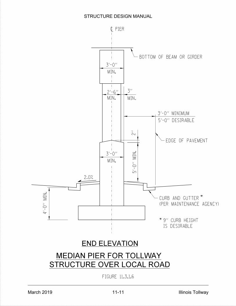
STRUCTURE OVER LOCAL ROAD
FIGURE 11.3.1.6
~ PIER
4'-
0"
MIN.
2"
3'-0" MINIMUM
CURB AND GUTTER *
*
IS DESIRABLE
9" CURB HEIGHT
5'-0" DESIRABLE
EDGE OF PAVEMENT
2.0%
(PER MAINTENANCE AGENCY)
END ELEVATION
MIN.
2'-6"
MIN.
3'-0"
MEDIAN PIER FOR TOLLWAY
MIN.
3'-0"
BOTTOM OF BEAM OR GIRDER
5'-
0"
MIN.
3"
MIN.
STRUCTURE DESIGN MANUAL
March 2019 11-11 Illinois Tollway
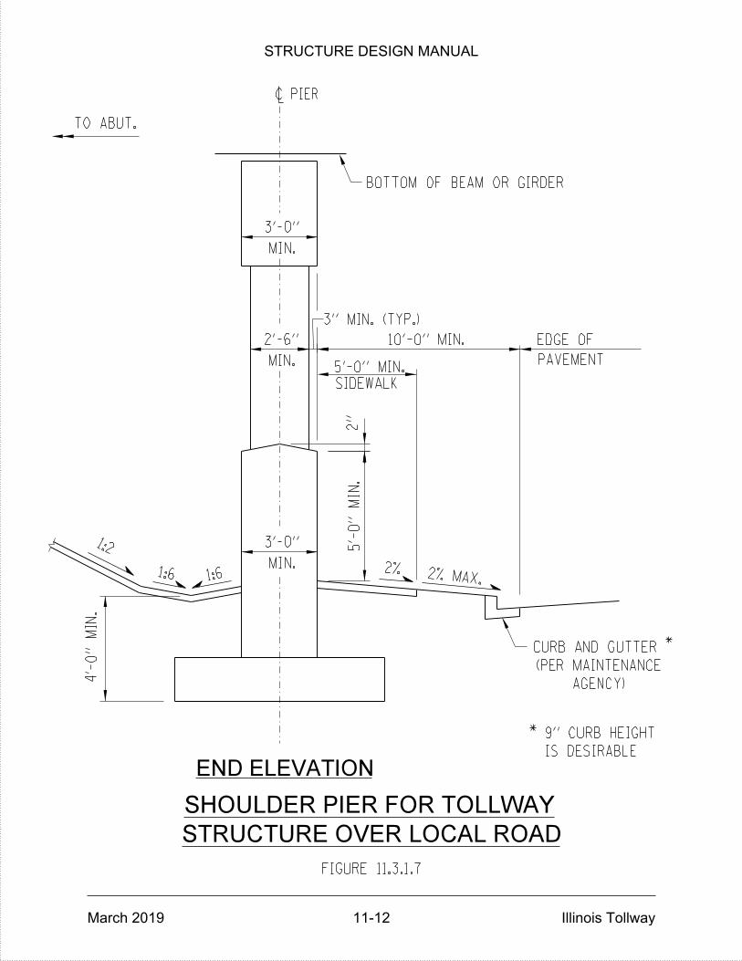
TO ABUT.
1:61:6
1:2
EDGE OF
PAVEMENT
10'-0" MIN.
5'-0" MIN.
SIDEWALK
CURB AND GUTTER
STRUCTURE OVER LOCAL ROAD
2%
AGENCY)
(PER MAINTENANCE
FIGURE 11.3.1.7
4'-
0"
MIN.
~ PIER
END ELEVATION
*
*
IS DESIRABLE
9" CURB HEIGHT
2% MAX.
2"
MIN.
2'-6"
MIN.
3'-0"
SHOULDER PIER FOR TOLLWAY
BOTTOM OF BEAM OR GIRDER
3" MIN. (TYP.)
5'-
0"
MIN.
MIN.
3'-0"
STRUCTURE DESIGN MANUAL
March 2019 11-12 Illinois Tollway

2'-
6"
MINI
MU
M
EM
BE
DM
EN
T
FIGURE 11.3.1.8
END ELEVATION
~ PIER
MIN.
3'-0"
MIN.
2'-6"
2"
BOTTOM OF BEAM OR GIRDER
(FOR USE WITH INTEGRAL ABUTMENT BRIDGE)
4'-
0"
MIN.
5'-
0"
MIN.
3" MIN. (TYP.)
GRADE SEPARATION PIER DETAIL
MIN.
3'-0"
STRUCTURE DESIGN MANUAL
March 2019 11-13 Illinois Tollway
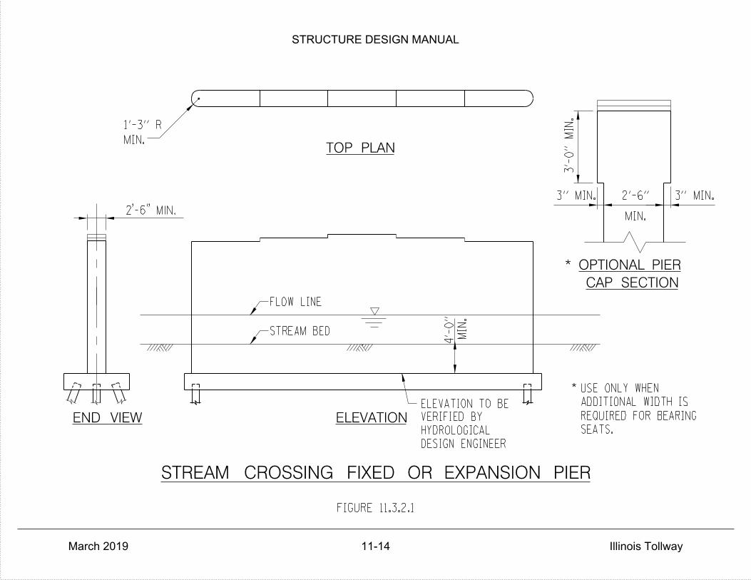
REQUIRED FOR BEARING
ADDITIONAL WIDTH IS
SEATS.
3" MIN.3" MIN. 2'-6"
HYDROLOGICAL
ELEVATION TO BE
VERIFIED BY
DESIGN ENGINEER4'-
0"
MIN.
3'-
0"
MIN.
TOP PLAN
END VIEW ELEVATION
2'-6" MIN.
FIGURE 11.3.2.1
*USE ONLY WHEN
CAP SECTION
OPTIONAL PIER*
MIN.
1'-3" R
STREAM CROSSING FIXED OR EXPANSION PIER
MIN.
STREAM BED
FLOW LINE
STRUCTURE DESIGN MANUAL
March 2019 11-14 Illinois Tollway
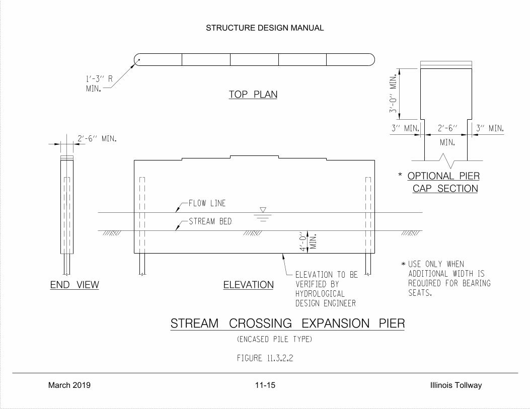
ADDITIONAL WIDTH IS
REQUIRED FOR BEARING
SEATS.
2'-6"3" MIN. 3" MIN.
(ENCASED PILE TYPE)
3'-
0"
MIN.
MIN.
4'-
0"
ELEVATION TO BE
VERIFIED BY
HYDROLOGICAL
DESIGN ENGINEER
TOP PLAN
END VIEW ELEVATION
STREAM CROSSING EXPANSION PIER
2'-6" MIN.
FIGURE 11.3.2.2
*USE ONLY WHEN
MIN.
1'-3" R
MIN.
CAP SECTION
OPTIONAL PIER*
FLOW LINE
STREAM BED
STRUCTURE DESIGN MANUAL
March 2019 11-15 Illinois Tollway
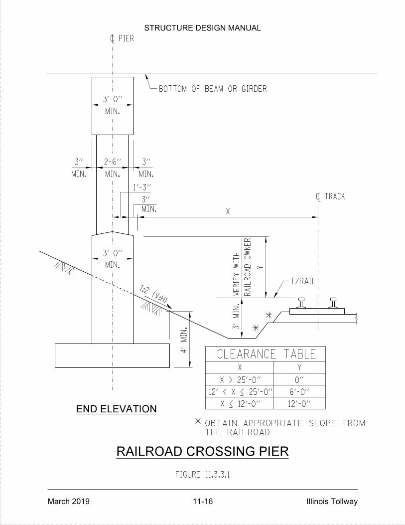
RAILROAD CROSSING PIER
T/RAIL
CLEARANCE TABLEX Y
X > 25'-0" 0"
6'-0"
X < 12'-0" 12'-0"
FIGURE 11.3.3.1
X
Y
~ PIER
~ TRACK
END ELEVATION
3'
MIN.
RAIL
RO
AD
OW
NE
R
VE
RIF
Y
WIT
H
4'
MIN.
12' < X < 25'-0"
MIN.
3'-0"
MIN.
2-6"
1'-3"
**
*THE RAILROAD
OBTAIN APPROPRIATE SLOPE FROM
BOTTOM OF BEAM OR GIRDER
1:2 (V:H)
MIN.
3'-0"
MIN.
3"
MIN.
3"
3"
MIN.
STRUCTURE DESIGN MANUAL
March 2019 11-16 Illinois Tollway

CROSS HATCHED AREAS
INDICATE CONCRETE REMOVAL.
NEW PIER CAP
NOTE:
ELEVATION
EXISTING PIER CAP
COLUMN
EXISTING
PLAN
WIDENING EXISTING PIER CAP
FIGURE 11.4.1
• PIER CAP WIDTH
6"
6"
1" SAW CUT (TYP.)
6"
6"
OF "CONCRETE REMOVAL")
(COST IS INCLUDED WITH THE COST
INCORPORATED INTO THE NEW WORK
STRAIGHTENED AND STRUCTURALLY
BE BLAST CLEANED TO GREY METAL,
EXISTING HORIZONTAL BARS SHALL
STRUCTURE DESIGN MANUAL
March 2019 11-17 Illinois Tollway

WIDENING EXISTING PIER WALL
INDICATE CONCRETE REMOVAL.
NOTE:
ELEVATION
EXISTING HORIZONTAL BARS SHALL BE
PLAN
FIGURE 11.4.2
EXISTING SOLID WALL
PIER OR CRASH WALL
6"
6"
6"
6"
CROSS HATCHED AREAS
1" SAW CUT (TYP.)• WALL WIDTH
NEW SOLID WALL
PIER OR CRASH WALL
EXTENSION
BLAST CLEANED TO GREY METAL,
STRAIGHTENED AND STRUCTURALLY
INCORPORATED INTO THE NEW WORK
OF "CONCRETE REMOVAL")
(COST IS INCLUDED WITH THE COST
STRUCTURE DESIGN MANUAL
March 2019 11-18 Illinois Tollway

MIN.
2" CL.
P(E)
S (E)
BA
RS
TO
BE
S(E)
BA
RS
BE
DESIG
NE
D
S(E)
BA
RS
TO
MIN.
2" CL.
MIN.
2" CL.
2" CL
MIN.
2"
CL.
MIN.
2"
CL.
MIN.
2"
CL.
MIN.
2"
CL.
S (E)
BA
RS
2"
MIN.
2" CL
FIGURE 11.9.1
1
**
**
1
*
~ OF PIER
CAP PLAN
A
A
S(E)
SECTION A-A
ANCHOR ROD LOCATION
ANCHOR RODS (TYP.)
S(E)
S (E)1
* ** * ***
DESIG
NE
D
1**
ANCHOR RODS
RODS
ANCHOR
S (E)1
P(E) (TYP.)
OF REINFORCEMENT
CALL OUT SPACING
ADDITIONAL S (E) BARS
SPACING PROVIDE THE
REQUIRED STIRRUP
GREATER THAN 1.5X THE
IF TOTAL SPACE IS
STRUCTURE DESIGN MANUAL
March 2019 11-19 Illinois Tollway

STRUCTURE DESIGN MANUAL
March 2019 Illinois Tollway
THIS PAGE IS INTENTIONALLY LEFT BLANK

STRUCTURE DESIGN MANUAL
March 2019 12-1 Illinois Tollway
STRUCTURAL STEEL
12.1 General
The design and detailing of steel superstructures shall be in accordance with the appropriate AASHTO Specifications and the provisions of Section 3.3 of the IDOT Bridge Manual except as herein modified.
12.2 Design
Structural steel shall be AASHTO M270 Grade 50 (ASTM A709) unless otherwise noted. Grade 70 steel may be used in areas of high stress, if this will result in a more economical solution.
All horizontally curved structures not considered essentially straight and/or structures with skews greater than 45 deg. shall be designed and/or checked using three-dimensional analysis. If either type of structure is to be constructed in stages, the beams in each stage shall be checked using three-dimensional analysis for stability, and bending, shear and torsion stresses. For these conditions, the Designer shall consider using a closer spacing (15’- 20’) for cross frames or diaphragms and the use of bottom lateral bracing.
Generally, all shop connections shall be welded. All field connections shall be made with ⅞-inch diameter zinc-coated, high-strength bolts per AASHTO M164 (ASTM A325), and shall be designed as friction type connections.
In order to minimize fillet heights on steel structures, the beam or plate girder slopes shall be changed at the splices to conform to the general configuration of the bottom of the formed deck slab.
Plate girders shall be cambered for dead load deflection and vertical curve geometry except where the resulting camber would be less than one inch.
Welded plate girder flange transitions shall be limited to twice the thickness of the thinner plate.
Top of beam or girder web elevations at the center line of each splice and/or bearing shall be shown on the framing plan.
Fracture critical details shall be identified in the plans.
Load carrying components – including tension flanges, webs and splice plates – shall be designated “NTR” on the plans and shall conform to the AASHTO Impact Testing Requirement, Zone 2.

STRUCTURE DESIGN MANUAL
March 2019 12-2 Illinois Tollway
12.3 Intermediate Vertical Stiffeners
Intermediate vertical stiffeners shall be a minimum of 7/16 inch thick and shall be welded to the web with a ¼-inch minimum continuous fillet weld. The distance between the end of the stiffeners and the near edge of the web-to-tension-flange fillet weld shall be no more than six times or less than four times the web thickness. For plate girders with web depths equal to or smaller than 54 inches, it is preferable not to utilize intermediate stiffeners. For plate girders with web depths larger than 54 inches, the web thickness may be increased to a maximum ⅝ inch to eliminate or limit the vertical stiffeners to only one or two locations per span beyond those provided for cross frame attachments. The minimum web thickness of a plate girder shall be 7/16 inch.
12.4 Bearing Stiffeners
Bearing stiffeners need not be welded to either flange of rolled beams or plate girders, except as hereafter indicated. They shall be milled on the bearing end and have a tight fit at the other end.
On all skewed plate girders or rolled beams with skews 45 deg. and larger and on all horizontally curved beams and plate girders, the bearing stiffeners shall be welded to both flanges where these stiffeners are used as connecting plates for cross frames or diaphragms. Welding to the flanges shall be done with fillet welds on both sides of stiffeners. The length of the fillet weld at the mill to bear end shall be the width of the stiffener minus 1 inch (½ inch at each end). The length of the fillet weld at the other end shall be the full width of stiffener. The bearing stiffener plates at the junction of the flanges and the web shall be clipped 1 inch horizontally and a minimum of 1½ inch vertically for rolled beams, or four times the web thickness plus the size of web-to-flange fillet weld for plate girders.
12.5 Superstructure Diaphragms
End Diaphragms and Cross Frames at Expansion Joints
End diaphragms at expansion joints located over piers and/or abutments shall consist of a thickened slab supported on an end diaphragm or cross frame as shown in the latest IDOT Bridge Manual.
Diaphragms and Cross Frames at Expansion Bearings
Steel diaphragms and cross frames at expansion piers or abutments shall be designed to allow for jacking on the diaphragm or cross frame for resetting, repair or replacement of expansion bearings. If jacking cannot be performed on the end diaphragms, then provisions shall be made in the design of the beam seats to allow jacking from directly under the beam. The jacking loads and their locations shall be shown on the drawings. The jacking loads shall be broken down into dead and live load components, so the Contractor has the option of jacking with or without the live load on the structure.
STRUCTURE DESIGN MANUAL
March 2019 12-3 Illinois Tollway
Diaphragms and Cross Frames at Intermediate Points
The connecting plates for the cross frames and diaphragms located near the support within a distance equal to twice the girder depth shall be welded to both flanges. This requirement shall also apply to the cross frames and diaphragms in all other areas for skewed and horizontally curved plate girders only. In these cases, flange stress shall be investigated for fatigue under Category C.
Cross frames for curved plate girders or girders that are straight or with skews less than 20 degrees shall be orientated in a straight line, and perpendicular to the fascia girders.
Cross frames for horizontally curved plate girders and girders with skews more than 20 degrees shall be designed and detailed with top and bottom chord members. Design and detailing of these cross fames should be as per Article 6 of the latest AASHTO LRFD Bride Design Specifications and/or the AASHTO/NSBA “Guidelines for Design for Constructability” 2016. Fit condition for which the cross-frames or diaphragms are to be detailed shall be stated in the contract documents. Steel dead load fit is recommended for most cases with the exception of horizontally curved I-Girder bridges with (L/R)MAX ≥ 0.2 in which L is the span length, bearing to bearing along the centerline of the bridge and R is the radius of the centerline of the bridge cross-section. For this case a no-load fit is recommended unless the additive locked-in force effects are considered. For non-skewed girders, the connecting plates for the cross frames and diaphragms, in all areas other than the areas near the supports, shall be welded to the compression flange and undercut at the tension flange. The distance between the near edge of the web-to-tension-flange weld and the end of the connecting plate shall be six times the web thickness. Special consideration shall be given to the connections between floor beams and the main girder for two-girder system bridges to prevent fatigue cracking in the webs.
Diaphragms and Cross Frames Design Details
The calculated deflections of the primary beams under steel self-weight shall be used to detail diaphragms, cross frames and lateral bracing connections, and to erect structural steel such that the beams will be plumb within a tolerance of +/- 1/8 inch per vertical foot throughout. This requirement shall be added as a note to the General Notes.
12.6 Table of Moments and Shears
To provide ready information for any future analysis of a structure and to provide the reviewing agencies with a basis for checking of the design, all detailed bridge plans shall include, as a part of said plans, a Table of Moments and Shears. Refer to the latest IDOT Bridge Manual Section 3.1.12 for suggested table layouts.

STRUCTURE DESIGN MANUAL
March 2019 12-4 Illinois Tollway
12.7 Painting of Structural Steel
Painting of steel beams shall be performed in accordance with the applicable IDOT GBSPs and All Bridge Designers (ABD) Memorandum 10.1. Desirable finish color is Gray, Munsell No. 5B 7/1. If existing bridge structure contains finish colors that are different than gray, then the Designer shall match this color as closely as possible. A typical color on the Illinois Tollway system other than gray is interstate green with the Munsell No. 7.5G 4/8. Shop Painting is used exclusively for new structural steel, field painting of intermediate and finish coats is not allowed.
12.8 Weathering Steel
Weathering steel may be considered for Illinois Tollway structures over railroads and waterways. Illinois Tollway approval is required during preliminary stages of design.

STRUCTURE DESIGN MANUAL
March 2018 Illinois Tollway
THIS PAGE IS INTENTIONALLY LEFT BLANK
STRUCTURE DESIGN MANUAL
March 2019 13-1 Illinois Tollway
PRECAST PRESTRESSED CONCRETE (PPC)
13.1 General
The design and detailing of PPC I-Beams and Bulb-T beams shall be in accordance with the latest AASHTO LRFD Bridge Design Specification, Section 3.4 of the latest IDOT Bridge Manual and IDOT All Bridge Designers Memorandum 15.2 except as herein modified.
13.2 Design
Twenty-two PPC I-Beam and Bulb-T sections may be used on the Illinois Tollway system. First is a standard 28-inch Illinois Tollway section. The next four are standard 36-inch, 42-inch, 48-inch and 54-inch IDOT I-Beams. The next two sections are 63-inch and 72-inch IDOT Bulb-T beams. The next four sections are the 36-inch, 45-inch, 54-inch and 72-inch Illinois Tollway Bulb-T beams. Refer to Illinois Tollway Base Sheets M-BRG-509-520 for details. Finally, the eleven new IDOT IL-Beam shapes may also be used on Illinois Tollway projects.
The behavior of a skewed bridge is different than that of a square one. The differences
are largely proportional to the skew angle. Structures with skews greater than 45 deg. shall be designed and/or checked using three-dimensional analysis to obtain a better assessment of skewed-structure.
The prestressing strands used in PPC beam designs shall be either 0.5” or 0.6” diameter, low relaxation strands with areas of 0.153 or 0.217 square inches, respectively.
In the design of continuous composite PPC structures, the superimposed dead load, live load and impact stresses shall be computed on the basis of full continuity at the interior supports.
Strand debonding may be considered to reduce the stresses developed at beam ends. The locations of debonded strands shall adhere to the restrictions listed in IDOT All Bridge Designers Memo 15.2, the IDOT Manual for Fabrication of Precast Prestressed Products 2017 with latest addendums and Article 5.9.4.3.3 of the latest Interims to the AASHTO LRFD Bridge Design Specifications.
The final compressive stress in the bottom flange of the PPC beams at piers for continuous designs shall be calculated at the strand load transfer point (assumed to be at the strand transfer length from the end of the beam) and the edge of bearing pad or diaphragm.
Vertical stirrups are required at the ends of all prestressed beams to resist 6% of the total initial prestressing force at 18 ksi located within a distance of ¼ of the beam depth from the end of the beam. For 63-inch and 72-inch beams, the minimum stirrup reinforcement shall be 5 pairs of #6 bars.

STRUCTURE DESIGN MANUAL
March 2019 13-2 Illinois Tollway
IDOT and 28” Illinois Tollway Beams
The 28-day concrete compressive strength for these prestressed beams shall be 6,000 psi and may be increased to a maximum of 7,000 psi. The higher strength, above 6,000 psi, shall be used only when economical. Concrete strengths at strand release shall be a minimum of 4,000 psi and a maximum of 5,200 psi.
The 28-inch I-Beam shall only be used where a proposed widening would require a shallower section to preserve the existing vertical clearance. See Figure 13.3.1 for beam details.
Illinois Tollway Bulb-T Beams
The 28-day concrete compressive strength for these prestressed beams shall be 6,000 psi and may be increased to a maximum of 8,000 psi. Higher strengths above 8,000 psi shall be used only when economical and require Illinois Tollway approval. Concrete strengths at strand release shall be a minimum of 4,000 psi and a maximum of 6,800 psi. The maximum number of 0.6” diameter draped strands shall be 8.
See Figure 13.2.2.1 for maximum lengths of Illinois Tollway Bulb-T PPC Beams.
IDOT IL-Beams
On March 3, 2015, IDOT issued All Bridge Designer Memorandum 15.2, which details eleven new PPC beam sections with six beam depths of 27, 36, 45, 54, 63 and 72 inches. These beams may be selected for use on Illinois Tollway bridges.
PPC U-Beams
U-Beams may be considered for bridge sites that require longer spans, curved alignments, reduced number of girders and piers, aesthetic appearance, fast fabrication and easy maintenance. Shipping and picking weights, transportation route, temporary supports, and other site-specific constraints are some important considerations when using U-Beams. Post-tensioned Spliced U-Beams can be a viable option compared to segmental construction. No specialty contractor, fabricator or equipment is required, fewer splices are needed, they provide better redundancy with multiple webs, and standard girder shapes and non-integral decks can be used. The design and detailing of PPC U-Beams shall be in accordance with the latest AASHTO LRFD Bridge Design Specifications. Both Pre-tensioned and Post-tensioned PPC U-Beams are allowed on the Illinois Tollway System. Three Pre-tensioned (48-inch, 60-inch or 72-inch depths) and Two Post-tensioned Spliced (72-inch or 84-inch) sections can be used. Refer to Illinois Tollway Special Provisions for Design and Erection of U-Beams, Addendum to Manual for Fabrication of Precast Prestressed Concrete Products and Illinois Tollway Base Sheets M-BRG-522, M-BRG-523 and M-BRG-524 for details.
STRUCTURE DESIGN MANUAL
March 2019 13-3 Illinois Tollway
13.3 Details
At all piers supporting continuous spans for beams other than IL-Beams, a minimum of two #8 bars for I-Beams and three #8 bars for Bulb-T beams shall be added to the bottom flange, projecting beyond the beam end in accordance with the details shown in Section 3.4 of the latest IDOT Bridge Manual. For IL-Beams, a minimum of 8 prestressing strands shall extend beyond the beam end at piers. See the latest IDOT and Illinois Tollway Base Sheets.
When beams exceed 100 feet in length, the Designer shall verify that a precaster, certified by the Precast/Prestressed Concrete Institute (PCI) will be capable of fabricating and transporting the beams to the bridge site within the project schedule.
When beams are used for spans in excess of 120 feet, calculations shall be provided for the lateral stability of the beams during shipping, handling, and erection and shall be submitted to the Engineer for approval. The calculations shall be sealed and signed by an Illinois Licensed Structural Engineer.
In order to limit the damage to the top flanges of the PPC Bulb-T beams during deck replacement projects, IDOT issued All Bridge Designers (ABD) Memorandum No. 12.2. The content of this memorandum shall be incorporated into design of PPC Bulb-T beam structures, and as modified for the Illinois Tollway Bulb-T beams.
13.4 Table of Moments and Shears
To provide ready information for any future analysis of a structure and to provide the reviewing agencies with a basis for checking of the design, all detailed bridge plans shall include a Table of Moments and Shears. See Section 3.1.12 of latest IDOT Bridge Manual for an example of a moment and shear table for PPC I-Beams.
13.5 Superstructure Diaphragms
Abutment (End) Diaphragms
End Diaphragms at expansion abutments shall consist of a thickened deck slab as shown on the latest IDOT Base Sheets.
End Diaphragms at integral abutments shall be as shown on the latest IDOT Base Sheets.
Pier Diaphragms
Fixed piers shall be attached to the superstructure by full-depth diaphragms using the details shown in the latest IDOT Base Sheets. Expansion piers shall be separated from the superstructure by partial depth diaphragms and expansion bearings as shown in the latest IDOT Base Sheets and Illinois Tollway Base Sheets M-BRG-510 through M-BRG-520 for Illinois Tollway Bulb-T beams.
STRUCTURE DESIGN MANUAL
March 2019 13-4 Illinois Tollway
Double expansion piers shall be separated from the superstructure by thickening the deck slab on each side of the joint as shown in the latest IDOT Base Sheet and Illinois Tollway Base Sheets M-BRG-510 through M-BRG-520 for Illinois Tollway Bulb-T beams.
The design of diaphragms at expansion joints shall include provisions to allow jacking on the diaphragms to lift the beam ends for resetting, repair or replacement of bearings. If jacking cannot be done on the end diaphragms, provisions shall be made in the design of the beam seat to allow jacking from directly under the beam. The jacking loads and their locations shall be shown on the drawings. The jacking loads shall be broken down into dead and live load components so the Contractor has the option of jacking with or without the live load on the structure.
13.6 Handling, Storage and Transportation of Beams
All handling, storage and transportation of PPC Beams shall be in accordance with the latest version of the IDOT Manual for Fabrication of Precast Prestressed Concrete Products, Section 3.6, except as herein modified. All designers shall include these provisions in the contract documents.
IDOT requires that all PPC I-Beams and Bulb T-Beams on continuous structures shall be a minimum of 45 days old before they are permitted to be shipped to the job site. This waiting period combined with a typical minimum timeframe of 15 days from delivery to casting of the deck results in a period of 60 days minimum between casting of the beam and placing of the concrete deck. In addition, “G6” hook bars are provided at the beam ends made continuous over piers using a cast-in-place concrete diaphragm. These requirements are intended to mitigate the loss of contact between the bottom flange of the beams and the diaphragm over the pier as well as other design and construction problems caused by beam creep, shrinkage, shortening and camber.
For PPC Beams on multi-span, continuous structures (beams with G6 bars), the casting of the deck and continuity diaphragm shall not occur prior to 60 calendar days after casting of the youngest beam. At structures with beams exceeding 100 feet in length and supported on bearing assemblies, the beams may be placed on bearings upon delivery, but the bearings shall be reset after the 60th calendar day after beam casting. Repositioning of the beams on the bearings or resetting of bearings after the 60th calendar day shall be at the Contractor’s expense at no additional cost to the Illinois Tollway.
13.7 Spliced Girders
Introduction
A Spliced Girder is precast prestressed or post-tensioned concrete, fabricated in several long girder segments that are assembled into a single girder in the final bridge structure. Spliced Precast Girders are either conventional Bulb-T or PPC U-Beam shapes that are extended to the 160 to 300-foot span range. Spliced girders have been used to extend spans and/or reduce construction depth.

STRUCTURE DESIGN MANUAL
March 2019 13-5 Illinois Tollway
Spliced girders use constant depth or haunched sections, or a combination of the two, to achieve the spans necessary to satisfy design requirements. While considering this bridge type in the Bridge Type Study prior to TS&L preparation, designers shall survey fabricators to determine if there is capability to fabricate the beams effectively with regard to cost and that the beams can be shipped to the project site.
Design
The design shall include evaluation of the time dependent effects of creep, shrinkage and relaxation on moments, shears and deflections and the effects of sequential construction steps. The method of construction assumed for the design shall be shown in the contract documents. All supports required prior to the splicing of the girder shall be shown on the contract documents, including elevations and reactions. The stage of construction during which the temporary supports are removed shall also be shown on the contract documents. Spliced girders shall not be considered as segmental construction for the purpose of design. The design shall meet the requirements of the latest AASHTO LRFD Bridge Design Specifications. Other sources of design assistance are:
The latest edition of the Precast/Prestressed Concrete Institute (PCI) Bridge
Manual
The latest edition of the Post–Tensioning Institute Post-Tensioning Manual
The latest Florida Department of Transportation (FDOT) Specifications for the
Design and Construction of Spliced I-Girder Bridges
National Cooperative Highway Research Program (NCHRP) Report 517,
“Extending Span Ranges of Precast Prestressed Concrete Girders”
Splices and Splice Locations
Splices shall meet both serviceability and strength requirements.
Pretension Strand Size and Strength
Strands shall not have an area greater than 0.217 square inches, which corresponds to a 0.6-inch diameter and ultimate strength of 270 ksi.
Tendon Layout
The vertical alignment of post-tensioning tendons, if provided, shall be kept as simple as possible. The ducts shall be centered in the web.

STRUCTURE DESIGN MANUAL
March 2019 13-6 Illinois Tollway
Camber and Geometry Control
Vertical alignment control is achieved by chording the individual segments between splices and supports as required to compensate for short- and long-term deflections and to achieve the required vertical geometry. Fillets shall vary, and minimum fillets shall be provided as for standard girder structures. Fillet weights shall be accounted for in design.
Creep Redistributions of Forces and Moments
Creep is the continued shortening of concrete members subjected to permanent compressive forces starting with the application of the prestress load and continuing for up to 30 years after. These effects shall be accounted for in the design.
Elastic Shortening Losses
These losses occur when prestressing and post-tensioning forces compress and thus shorten the concrete member and consequently decrease the forces in them. These losses shall be accounted for in the calculation of prestressing forces. However, the reverse occurs as well and the increase in prestressing forces because of these gains shall also be accounted for.
Live Load Deflections
Live load deflections shall be according to Article 5.1.
Diaphragms
Permanent concrete diaphragms shall be provided at abutments, piers and splices. Temporary steel diaphragms shall be provided for stability of the beams during construction.

STRUCTURE DESIGN MANUAL
March 2019 13-7 Illinois Tollway
Maximum Lengths for Single Span Illinois Tollway Bulb-T PPC Beams
Beam Spacing
(ft)
36” Deep Beam
45” Deep Beam
54” Deep Beam
72” Deep
Beam
4.5 104 123 139 169
5.0 101 119 135 165
5.5 98 117 132 162
6.0 96 114 129 158
6.5 94 111 126 155
7.0 93 110 124 152
7.5 91 107 121 148
8.0 87 103 119 146
8.5 85 101 116 143
9.0 84 99 114 141
The maximum spans provided in the table above were calculated based on the following design parameters:
1. Live Loads consist of Design Truck IL-120, Design Truck HL-93, Design Lane and Design
Tandem loading, following requirements of Article 1.4 of this Manual.
2. Dead loads consist of self-weight of the Bulb-T beams, 2” thick fillet, 8” thick concrete deck,
50-psf future wearing surface and 200 plf of superimposed dead load to account for the 44” Constant-Slope concrete parapet shared by 3 beams.
3. Compressive strengths of 4,000 psi and 8,000 psi used for the bridge deck and BT-beam,
respectively. The BT-Beam concrete strength was assumed to be 6,800 psi at the release.
4. The strands have a 0.60-inch diameter and ultimate strength of 270 ksi. The maximum numbers of straight and draped strands are 36, 40, 42 and 48 for the 36”, 45”, 54” and 72” deep BT-Beams, respectively.
5. For two-equal span bridges, the maximum span lengths presented in the table above may
increase by approximately 5% to 10% due to continuity at the center support.
6. Debonded strands meeting the requirements of AASHTO and IDOT have been used.
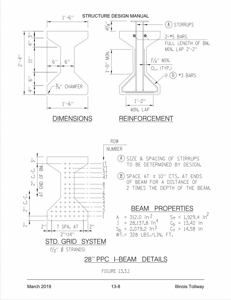
= 328 LBS./LIN. FT.
SIZE & SPACING OF STIRRUPS
TO BE DETERMINED BY DESIGN.
OF BEAM FOR A DISTANCE OF
2 TIMES THE DEPTH OF THE BEAM.
BEAM PROPERTIES
WT.
S
A
I
b
S
C
C
t
b
t
1
2
STD. GRID SYSTEM
DIMENSIONS REINFORCEMENT
28'' PPC I-BEAM DETAILS
1
2
FULL LENGTH OF BM.
CL. (TYP.)
AT
EN
D
OF
BM.
2"
C.-
C.
2"
C.-
C.
2"=14"
3T4T
8
654321
7
MIN. LAP
ROW
NUMBER
1T2T
#3 BARS
STIRRUPS
2-#5 BARS
MIN. LAP 2'-2"
ƒ" CHAMFER
= 14.58 in
FIGURE 13.3.1
A
B
A
B
2'-
4"
11"
4"
3"
6"
4"
6" 6"
1'-6"
1‚" MIN.
1'-6"4„
"
3"
2"
2" 2"7 SPA. AT
(•" } STRANDS)
SPACE AT | 10" CTS. AT ENDS
= 312.0 in = 1,929.4 in
= 28,137.8 in = 13.42 in
= 2,079.2 in
22
4
3
1'-
0"
MIN.
1'-2"
STRUCTURE DESIGN MANUAL
March 2019 13-8 Illinois Tollway
STRUCTURE DESIGN MANUAL
March 2019 14-1 Illinois Tollway
BEARINGS
14.1 General
Bearings shall be designed and detailed in accordance with Section 3.7 of the latest IDOT Bridge Manual and ABD Memo 15.6 except as amended herein. Only High Load Multi-Rotational (HLMR), elastomeric, low profile steel rocker bearings (fixed) and rocker plates are acceptable types. Sliding plate bearings shall not be used.
Elastomeric bearings are generally used with precast prestressed concrete (PPC) beam and steel beam or girder spans having moderate load and movement requirements. Elastomeric bearing assemblies are divided into three types according to the expansion lengths which they will accommodate.
Low profile rocker bearings shall be used as fixed bearings to support PPC beams at fixed piers or fixed abutments with joints and in single span structures with semi-integral abutments. See the latest IDOT Base Sheets for details.
Only fabric or unreinforced elastomeric pads shall be used to support PPC beams at integral abutments.
Low profile rocker bearings shall be used as fixed bearings in combination with elastomeric Types I, II and III expansion bearings to support steel spans. See Figure 3.7.1.2-1 in the latest IDOT Bridge Manual for details.
Rocker plates shall be used to support steel beams or girders at integral abutments. See Figure 3.7.1.2-2 in the latest IDOT Bridge Manual for details.
Only HLMR bearings shall be used to support concrete (segmental or CIP box girders) or steel structures on curved alignments. They may also be used for concrete or steel structures on tangent alignments with high dead load reactions and skew angles and expansion lengths greater than 40° and 450 ft., respectively.
On steel bridge widening projects where the new deck is structurally tied to the existing deck and the extended substructure is discontinuous, the bearings for the new beams or girders resting on the discontinuous portion of the substructure shall be of the HLMR bearing type.
A detail showing the centerline of the bearing over the centerline of the substructure unit and the orientation of the bearing for erection temperatures above and below 50 degrees Fahrenheit shall be provided on the plans.
14.2 Design
Elastomeric and low profile steel rocker bearings including anchor bolts and pintels shall be designed and detailed in accordance with Section 3.7 of the latest IDOT Bridge Manual and ABD Memo 15.6. HLMR bearings shall be designed and detailed by the Designer in accordance with Section 3.7.5 of the latest IDOT Bridge Manual. Inverted Pot Bearings shall not be used.
STRUCTURE DESIGN MANUAL
March 2019 14-2 Illinois Tollway
Elastomeric Bearings
When designing elastomeric bearings, the procedures described and detailed in the IDOT Bridge Manual shall be used. The AASHTO Method B procedure is cost prohibitive for typical Illinois Tollway bridges given the lengthier design procedure and the extensive testing required to verify this bearing design. The current testing requirements in the IDOT Standard Specifications are not sufficient to ensure an acceptable bearing designed by AASHTO Method B.
Pintels and sole plates bonded to elastomeric bearings shall be Type 304 stainless steel conforming to the requirements of ASTM A666 when under an expansion joint. Pintels and sole plates bonded to elastomeric bearings not under an expansion joint shall be galvanized in accordance with AASHTO M232 (ASTM A153). Bearing plates and shear studs embedded in PPC beams shall conform to the requirements of AASHTO M270 (Grade 36) and Article 1006.32 of the latest IDOT Standard Specifications. The bearing plates and shear studs shall be hot dipped galvanized after fabrication, in accordance with AASHTO M232 (ASTM A153).
Masonry and side retainer plates or equivalent rolled shapes shall conform to the requirements of AASHTO M270 (Grade 36). Side retainers and anchors shall be hot dipped galvanized after fabrication in accordance with AASHTO M232 (ASTM A153).
Low Profile Steel Rocker Bearings (Fixed Only)
Pintels, plates and rolled shapes shall conform to the requirements of AASHTO M270 (Grade 50). Rocker bearings including sole plates, pintels, masonry plates and anchors shall be hot dipped galvanized after fabrication in accordance with AASHTO M232 (ASTM A153).
High Load Multi-Rotational Bearings
All bearing plates and rolled shapes shall conform to the requirements of AASHTO M270 (Grade 50). Prior to shipment, the exposed edges and other exposed portions of the structural steel bearing plates shall be cleaned and painted in accordance with Section 506 of the IDOT Standard Specifications. Painting shall be with the paint specified for shop painting of structural steel. During cleaning and painting, the stainless steel, TFE sheet and neoprene shall be protected from abrasion and paint.
It is the designer’s responsibility to also verify the HLMR bearing dimensions and geometry with producers who are approved by IDOT to provide bearings. The overall bearing height and plate thicknesses stated on the Contract Plans shall be chosen such that more than one producer is capable of bidding on the project.
STRUCTURE DESIGN MANUAL
March 2019 14-3 Illinois Tollway
If the service lateral design load is greater than 10%, but less than or equal to 20% of the design vertical load, a larger HLMR bearing may be selected based upon the lateral load. When service lateral design load exceeds a threshold value of 20% of the vertical design load, the designer shall not select a larger HLMR bearing to satisfy the lateral load. Rather, designers shall select a HLMR bearing size based on the vertical design load and the fabricator shall be responsible for modifying any necessary components of the bearing to meet the lateral load requirement. The contract documents shall specify the responsibilities of the fabricator.

STRUCTURE DESIGN MANUAL
March 2019 Illinois Tollway
THIS PAGE IS INTENTIONALLY LEFT BLANK
STRUCTURE DESIGN MANUAL
March 2019 15-1 Illinois Tollway
CONCRETE BRIDGE DECKS, PARAPETS AND BARRIERS
15.1 New and Replacement Decks
Cast-in-place, reinforced concrete decks supported on beams or girders shall be designed in accordance with the latest AASHTO LRFD Bridge Design Specifications, Section 3.2 of the latest IDOT Bridge Manual and IDOT A.B.D. Memo 15.2 except as herein modified. The slab thickness shall be 8 inches for new and replacement bridges. Deck width requirements shall be in accordance with Article 5.4. On bridge replacement or full deck replacement projects for mainline bridges and flyover ramps under the Illinois Tollway jurisdiction that provide direct access to the Illinois Tollway, concrete type shall be determined in accordance with the following policy:
Performance Mix Concrete, f’c=4,000 psi min. shall be used for bridge decks and
diaphragms.
BS Concrete, f’c=4,000 psi min. shall be used for bridge parapets.
Smoothness and grinding criteria shall be considered for new concrete decks, slabs, or new concrete overlays. Mainline bridges and ramps with bridge length greater than 150ft and ADT greater than 10,000 shall follow the criteria set forth in IDOT ABD 17.1.
Cross Road Bridge deck thickness, deck geometry and material property will depend on
the Inter-Governmental Agreement (IGA). The above specified conditions shall be used
if ownership of the bridge deck is under Illinois Tollway’s jurisdiction.
15.2 Existing Deck Widenings and Repairs
For widenings, partial replacements or repairs of existing decks, the deck thickness shall match the existing deck thickness. The top reinforcement bars in the new deck portion shall be placed at the same level as the existing deck bars. The proposed deck widenings shall be designed using the design specifications used for the existing deck in accordance with Section 3.2 of the latest IDOT Bridge Manual. Full bar lap splice shall be provided between the old and new reinforcement bars at the longitudinal construction joint. When the length of the existing reinforcement projecting beyond the construction joint is insufficient to develop a full lap splice, the mechanical splice detail shown in Figure 15.2.1 shall be included in the plans.
When overlaying an existing bridge deck, scuppers shall be adjusted to match the new top of overlay elevations.
Partial depth deck removal and replacement is considered to retain original design capacities. Thus, in both the longitudinal and transverse direction the new concrete patch is considered to act compositely with the remaining deck and no reduction in deck live load capacity is considered. Additionally, an increase in wearing surface thickness above
STRUCTURE DESIGN MANUAL
March 2019 15-2 Illinois Tollway
the original thickness of the deck is not considered to increase capacity in either the transverse or longitudinal direction. In the longitudinal direction the live load capacity of supporting members shall be reduced by the dead load from the additional overlay thickness.
15.3 Cross Slopes
Tangent Sections
15.3.1.1 New, Replacement and Widened Decks
The cross slopes of new, replacement and widened decks shall match that of the approach roadway and/or shoulders. A Design Deviation is required for cross slopes not matching the approach roadway and shoulders.
15.3.1.2 Overlays
For bridges on tangent sections, the cross slopes of the proposed bridge deck overlay, shall match the existing cross slopes; however, the capacity of the existing beams or girders shall be checked. For bridges carrying Illinois Tollway traffic that do not have adequate capacity to carry the IL-120 Design Truck at Inventory Level and for other bridges that do not have adequate capacity to carry the AASHTO Design Loading at Operating Level, the following criteria shall be followed:
For longitudinal grades of 0.3% or less, the minimum cross slope required shall be
1.5% for all lanes.
For longitudinal grades between 0.3% and 1%, a minimum cross slope of 1% for each lane immediately adjacent to the crown line is acceptable, although not desirable. A minimum cross slope of 1.5% is still required for all other lanes.
For longitudinal grades greater than 1%, a minimum cross slope of 1% is acceptable for all lanes, although 1.5% is desirable.
Maximum cross slope for traveled lanes shall be 2.5% and for shoulders shall be 4%.
These criteria apply only to bridge deck overlays and their purpose is to minimize the overlay thickness, while providing a reasonably smooth surface with adequate ability to drain for the safety as well as the comfort of the traveling public. The transition to these cross slopes shall be completed on the roadway, transition slab and roadway shoulder, not on the bridge deck or approach slab.
Superelevated Sections
Superelevation Transitions shall not be located on bridges and approach slabs. See Article 6.3.7.
STRUCTURE DESIGN MANUAL
March 2019 15-3 Illinois Tollway
15.3.2.1 New and Replacement Decks
When a superelevated horizontal curve is located within the limits of a bridge and its approach slabs, the bridge deck and approaches shall be sloped at a constant rate. The approach slab and bridge deck shall be planar. The transition in the approach shoulder break shall occur in the transition slab and roadway shoulders at no greater than a 0.5% relative gradient.
15.3.2.2 Deck Widenings and Overlays
For bridges on superelevated sections, the minimum cross slope required for deck sections shall equal the original design superelevation rate unless the deck is to be replaced.
The procedure for Preparing Profile Worksheets for Bridge Deck Overlays and approach pavement profile transitions is detailed in Article 18.2. See Article 15.3.1.2 for additional requirements for overlays.
15.4 Reinforcement Bars
The top and bottom longitudinal and transverse bars shall not be lapped at the same locations in the deck, except at staged construction joints. Transverse bars shall be lapped at the locations shown in Figure 15.4.1.
On PPC structures made continuous for live load and superimposed dead loads, the additional longitudinal reinforcement bars over the piers shall be designed and checked for fatigue in accordance with the latest AASHTO Specifications and IDOT Bridge Manual. These are the only deck reinforcement bars that need to be checked for fatigue. The additional longitudinal reinforcement shall be placed in the top and bottom of the deck between the #5 bars over the piers for the full width of the superstructure including portions of the deck under parapets, sidewalks, raised medians and median barriers.
Two minimum bar lengths are required for these additional bars; the shorter bars shall be 80% or less of the longer bar. This staggering of bars will help minimize transverse cracking at bar terminations.
On bridge replacement projects for mainline bridges and flyover ramps under Illinois Tollway jurisdiction that provide direct access to the Illinois Tollway, the use of stainless steel reinforcement bars shall be considered. Specifications for stainless steel reinforcement are available from the Illinois Tollway upon request. Standard bar laps and development lengths for uncoated black reinforcement bars shall be used for stainless steel reinforcement.
Stainless steel reinforcement bars are limited in use to bridge decks, parapet walls and beam end diaphragms. The rest of the structure shall use epoxy coated rebar. Stainless steel reinforcement bars shall not be considered for cross road bridge structures.
STRUCTURE DESIGN MANUAL
March 2019 15-4 Illinois Tollway
15.5 Parapets and Barriers
Parapets and Barriers on Structures
The 44” Constant-Slope shoulder and median barrier sections shall be used on all new or rehabilitated structures (deck replacement or superstructure widening) carrying Illinois Tollway mainline and ramp traffic. Cross roads and all other structures shall be per jurisdictional agency’s requirements. If the jurisdictional agency has no requirements, 44” Constant-Slope shoulder and median barrier sections shall be used. For barriers where Noise Abatement Wall is attached to structure refer to Articles 22.14, 23.2.2 and 23.5.1.
The tops of back-to-back median barriers shall be constructed as shown in Figure 15.5.1.2 for the 44” Constant-Slope Median Barrier for differences in vertical elevations of the individual decks at the centerline of the Illinois Tollway. Also, see Figure 15.5.1.1 for 44” Constant-Slope Median Barrier Details when there is no elevation difference.
When a raised median curb is required on structure, the shape of the curb face, the height and the overall width are to match those of the approach roadway.
Reinforcement for parapets and barriers on new or rehabilitated (deck replacement or superstructure widening) structures carrying Illinois Tollway traffic or over Illinois Tollway traffic shall meet the requirements of the AASHTO LRFD Bridge Design Specifications for TL-5 vehicle impact loading. These details shall be used for all 44” barrier walls and parapets mounted on moment slabs, approach slabs and bridge decks carrying Illinois Tollway traffic. Impact loading requirements for bridges not carrying or over Illinois Tollway traffic shall be coordinated with the agency responsible for the roadway.
The following revisions shall replace the provisions of IDOT All Bridge Designers Memorandum 19.1.
The 8” spacing of the #5 front face vertical reinforcement bars shall be reduced to
7”.
The Designer shall also verify the bridge slab and approach slab capacity at the junction with the parapet and barrier wall.
Although these design details are governed by end impact, at parapet ends and joints, these revisions apply to the full length of the 44” parapet and barrier wall. See Figure 15.5.1.3.
1/8” aluminum parapet joints required at piers, abutments and other locations specified in the latest edition of the IDOT Bridge Manual shall be detailed according to Figure 15.5.1.4.
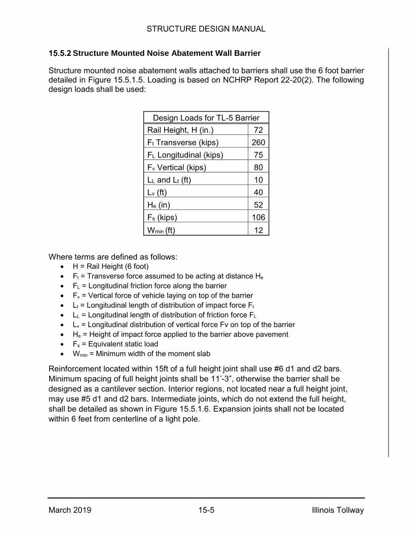
STRUCTURE DESIGN MANUAL
March 2019 15-5 Illinois Tollway
Structure Mounted Noise Abatement Wall Barrier
Structure mounted noise abatement walls attached to barriers shall use the 6 foot barrier detailed in Figure 15.5.1.5. Loading is based on NCHRP Report 22-20(2). The following design loads shall be used:
Design Loads for TL-5 Barrier
Rail Height, H (in.) 72
Ft Transverse (kips) 260
FL Longitudinal (kips) 75
Fv Vertical (kips) 80
LL and Lt (ft) 10
Lv (ft) 40
He (in) 52
Fs (kips) 106
Wmin (ft) 12
Where terms are defined as follows: H = Rail Height (6 foot)
Ft = Transverse force assumed to be acting at distance He
FL = Longitudinal friction force along the barrier
Fv = Vertical force of vehicle laying on top of the barrier
Lt = Longitudinal length of distribution of impact force Ft
LL = Longitudinal length of distribution of friction force FL
Lv = Longitudinal distribution of vertical force Fv on top of the barrier
He = Height of impact force applied to the barrier above pavement
Fs = Equivalent static load
Wmin = Minimum width of the moment slab
Reinforcement located within 15ft of a full height joint shall use #6 d1 and d2 bars.
Minimum spacing of full height joints shall be 11’-3”, otherwise the barrier shall be
designed as a cantilever section. Interior regions, not located near a full height joint,
may use #5 d1 and d2 bars. Intermediate joints, which do not extend the full height,
shall be detailed as shown in Figure 15.5.1.6. Expansion joints shall not be located
within 6 feet from centerline of a light pole.

STRUCTURE DESIGN MANUAL
March 2019 15-6 Illinois Tollway
Roadside Barriers
All rigid roadside barriers adjacent to an Illinois Tollway roadway and not located on a structure (bridge or retaining wall) shall be designed to meet the AASHTO LRFD Bridge Design Specifications for TL-4 impact loading. See Illinois Tollway Standard Drawing C3. Note that the minimum installation length for single face Reinforced Concrete Barrier is 25’. If a shorter installation or different configuration is needed, the Designer shall design the barrier for TL-4 impact loading by varying the footing size and/or the reinforcement. The same design methodology shall be used as outlined in Article 22.14. The magnitude of Equivalent Static Force used to check for sliding and overturning shall be 10 kips. The details shown in Illinois Tollway Standard Drawing C3 can be used with or without fill material behind the barrier. The use of single face barrier wall along a shoulder taper shall be as shown in the Illinois Tollway Traffic Barrier Guidelines.
15.6 Longitudinal Joints
When the distance between the fascia girders exceeds 90 feet, the deck shall be split with an open joint. The joint may be located in parapet sections or in a raised median. Joints in a raised median curb shall be sealed using a 1-3/4 inch preformed joint seal. The open joint is not required if the deck is staged and the total width of the staged pours is less than or equal to 120 feet.
The Illinois Tollway prefers not to utilize open or sealed longitudinal joints unless they are located along the center line of the main line between the median barriers on each side of the joint. Details of a sealed joint are shown on Figure 15.6.1.
Longitudinal construction joints between the edges of shoulders shall not be used unless they fall on a lane line and are located at a distance greater than ¼ of the beam spacing from the centerline of any beam (within the middle half of the beam spacing).
15.7 Bridge Mounted Lighting
The Designer shall identify the location and size of all embedded conduits, expansion fittings and junction boxes on the structural drawings and reference the roadway electrical drawings for details.
Shoulder and median mounted light pole details for the 44” Constant-Slope barrier are shown in Figures 15.7.1 through 15.7.7. Details for the 72” barrier are shown in Figure 15.7.8.

STRUCTURE DESIGN MANUAL
March 2019 15-7 Illinois Tollway
15.8 Slipform Parapet
Slipforming may be used to construct the parapets shown in plans. Slipforming shall be done in accordance with the latest IDOT Guide Bridge Special Provision #61, Base Sheet SFP 39-44 and “All Bridge Designers (ABD) Memoranda 12.4 and 19.1. If one of the conditions from ABD Memo 12.4 which would exclude slipforming is met, with the exception of parapets taller than 42 inches, a note shall be added to the plans indicating that slipforming of the parapet is not permitted. Slipforming is not allowed for the 72” barrier.
15.9 Deck Pouring Sequence
A deck pouring sequence shall be provided in the Contract plans for all new and existing steel superstructures on curved alignments and those with continuous or simple span lengths of 150 feet or greater. The same shall be provided for tangent steel superstructures with a skew angle greater than 40 degrees, regardless of the type of span or length. In addition, the concrete for the bridge deck shall be placed parallel to the skew when it is greater than 40 degrees.
Special care shall be taken when construction staging reduces the width of the pour in relation to span length and/or the number of beams or girders to three or less. In the initial stage, the superstructure framing shall be checked for stability and out of plane displacements and rotation. Required pouring sequences shall consider the impacts to the project schedule and the design project schedule shall include the time required to comply with the required pouring sequences shown on the plans. Wherever possible the number of required pours shall be minimized to allow the Contractor to complete deck pours in a minimal amount of time and avoid waiting 72 hours between pours. The numbering of the pouring sequence sections shall be duplicated whenever possible rather than using separate numbers for each segment. For example, all positive moment pours could be one (1) and all negative pours could be two (2). Reasonable production rates in the bridge area for deck pours shall be considered. See Article 7.1.3 for the note to be included in the plans.
15.10 Closure Pour
On stage constructed bridges where the differential deflection between adjacent stages is 2” or greater, and it is not feasible or economical to use a deeper or stiffer beam or girder section, a closure pour shall be considered. Closure pours will be considered by the Illinois Tollway on a case-by-case basis.
STRUCTURE DESIGN MANUAL
March 2019 15-8 Illinois Tollway
15.11 Bridge Deck Overhang
Bridge deck overhang for 72 in barrier with structure mounted noise abatement wall shall be limited as shown in Figure 15.5.1.5. Minimum deck thickness at the exterior beam shall be 11.5 in. Additional #8 bars shall be used in the overhang for all locations within 15ft of a full height joint in the barrier. These bars may be reduced to #7 bars provided the area of steel for top transverse bars in the deck are a minimum 1.15 sq. in. for maximum overhang limits or 0.86 sq. in. for a minimum overhang limit. Similarly, #6 bars may be used provided the top transverse bars in the deck are a minimum 1.5 sq. in. for maximum overhang limits or 1.23 sq. in. for a minimum overhang limit. All interior regions, not located near a full height joint, may use #6 bar.

MECHANICAL SPLICE DETAIL
EXISTING BARS
LONGITUDINAL BONDED CONSTRUCTION
JOINT SHOWN IN THE PLANS
FIGURE 15.2.1
4" MIN. PROJECTION
FOR EXISTING BARS
MECHANICAL SPLICERS
PPC BEAM SHOWN, STEEL BEAM SIMILARNOTE:
NEW BARS
STRUCTURE DESIGN MANUAL
March 2019 15-9 Illinois Tollway
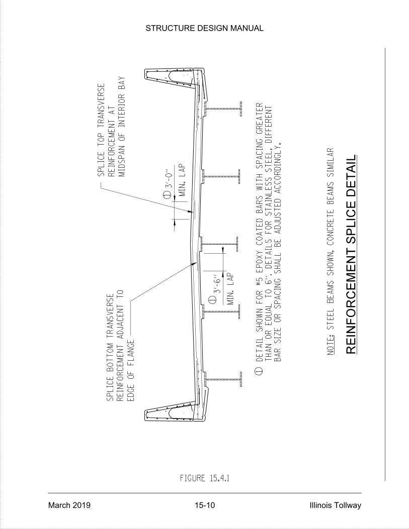
FIGURE 15.4.1
REIN
FO
RC
EM
EN
T S
PLIC
E D
ET
AIL
S
TE
EL
BE
AM
S
SH
OW
N,
CO
NC
RE
TE
BE
AM
S
SI
MIL
AR
NO
TE:
MIN.
LA
P
SP
LIC
E
BO
TT
OM
TR
AN
SV
ER
SE
ED
GE
OF
FL
AN
GE
REIN
FO
RC
EM
EN
T
AT
SP
LIC
E
TO
P
TR
AN
SV
ER
SE
MID
SP
AN
OF IN
TE
RIO
R
BA
Y
MIN.
LA
P
REIN
FO
RC
EM
EN
T
ADJ
AC
EN
T
TO
1
1
13'-
0"
3'-
6"
BA
R
SIZ
E
OR
SP
ACIN
G
SH
AL
L
BE
ADJ
US
TE
D
AC
CO
RDIN
GL
Y.
TH
AN
OR
EQ
UA
L
TO 6".
DE
TAILS
FO
R
ST
AIN
LES
S
ST
EE
L,
DIFF
ER
EN
T
DE
TAIL
SH
OW
N
FO
R #5
EP
OX
Y
CO
AT
ED
BA
RS
WIT
H
SP
ACIN
G
GR
EA
TE
R
STRUCTURE DESIGN MANUAL
March 2019 15-10 Illinois Tollway

(FULL LENGTH)
4''
(NO ELEVATION DIFFERENCE)
(MANDATORY)
BONDED CONSTRUCTION JOINT
LIMITS OF ‚" OPEN JOINT
~ BRIDGE
1'-6''
1ƒ"
ƒ" DRIP NOTCH
9•
"1•
"
1•"
MIN.
NOTES:
2.
1.
FROM OPEN JOINTSHALL BE REMOVEDALL FORM MATERIALSTEEL BEAM SIMILARPPC BEAM SHOWN,
FIGURE 15.5.1.1
8•"9•"
10"
2'-
10"
10"
2'-
10"
CONSTANT SLOPE MEDIAN BARRIER DETAILS
1" 1"
1"
STRUCTURE DESIGN MANUAL
March 2019 15-11 Illinois Tollway
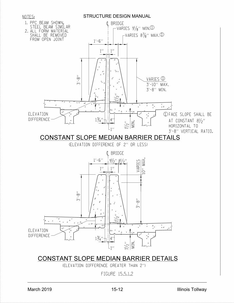
NOTES:
2.
1.
FROM OPEN JOINTSHALL BE REMOVEDALL FORM MATERIALSTEEL BEAM SIMILARPPC BEAM SHOWN,
(ELEVATION DIFFERENCE OF 2'' OR LESS)
ELEVATION
ELEVATION
DIFFERENCE
DIFFERENCE
4''
4''
HORIZONTAL TO
VARIES
3'-8'' MIN.
3'-10'' MAX.
FACE SLOPE SHALL BE
MIN.
MIN.
1
(ELEVATION DIFFERENCE GREATER THAN 2'')
1'-6''
~ BRIDGE
1'-6''
1•
"1ƒ"
1•
"
~ BRIDGE
1•
"
1•
"
1ƒ"
FIGURE 15.5.1.2
1
1
1
AT CONSTANT 8•"
3'-8'' VERTICAL RATIO.
VARIES 8‡" MAX.
VARIES 9„" MIN.
9•" 8•"
CONSTANT SLOPE MEDIAN BARRIER DETAILS
CONSTANT SLOPE MEDIAN BARRIER DETAILS
1" 1"
1"
1" 1"
1"
3'-
8"
VA
RIES
3'-
8"
3'-
8"
10"
MA
X.
STRUCTURE DESIGN MANUAL
March 2019 15-12 Illinois Tollway
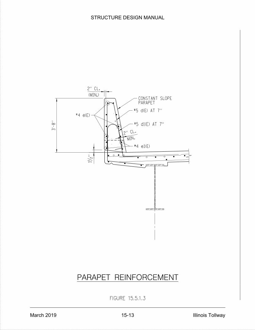
3'-
8"
1•
"
(MIN.)
2" CL.
MIN.2" C
L.
#5 d1(E) AT 7"
#5 d(E) AT 7"
FIGURE 15.5.1.3
PARAPET REINFORCEMENT
PARAPETCONSTANT SLOPE
#4 e(E)
#4 e1(E)
STRUCTURE DESIGN MANUAL
March 2019 15-13 Illinois Tollway

FIGURE 15.5.1.4
*
BRIDGE BASE SHEETS
PER LATEST IDOT
CORK JOINT FILLER,
IDOT BRIDGE MANUAL.
LOCATIONS NOTED IN THE LATEST
ABUTMENTS, AND ADDITIONAL
FOR INTEGRAL AND SEMI-INTEGRAL
REQUIRED AT PIERS, ABUTMENTS*
ALUMINUM PARAPET JOINT DETAILS
SUPERSTRUCTURE
WITH CONCRETE
COST INCLUDED
ALLOY 3003-H14,
OF ASTM B209,
REQUIREMENTS
MEETING THE
FULL HEIGHT
„" ALUMINUM `
ƒ"CHAMFER, TYP.
ƒ"x45°
(FU
LL
HEIG
HT)
AL
UMIN
UM J
OIN
TS
CO
RK J
OIN
T
STRUCTURE DESIGN MANUAL
March 2019 15-14 Illinois Tollway

ON BRIDGE
STRUCTURE MOUNTED NOISE ABATEMENT WALL
FIGURE 15.5.1.5
L (MAX.)
4"
6'-9" MIN. (#8 BAR)
4'-5" MIN. (#6 BAR)
SL
AB
8"
3'-
8"
2'-
4"
8•"10•"
1'-7"
#8 e1(E)
#8 e2(E)
#5 d(E) AT 5"
(TYP.)
#6 e(E)
6'-
0"
11•
"
5"
MA
X.
2"
MIN.
(MIN.)
11•
"
1•
"
2"
(|‚
")
2‚
"
CL.
CL.
1•"
OVERHANG 'L'
STEEL BEAMS
2'-11"
3'-4"
3'-6"
3'-7"
3'-8"
FLANGE WIDTH "W"
W < 18"
36" OR WIDER
18" < W < 24"
24" < W < 30"
30" < W < 36"
OVERHANG 'L'
PRECAST CONCRETE BEAMS
2'-11"
3'-6"
3'-8"
3'-5"
FLANGE WIDTH "W"
W < 16"
24" OR WIDER
16" < W < 20"
20" < W < 24"
DECK REINFORCEMENT
NOTES:
OVERHANG LENGTH.
BEAM SPACE TO TWICE THE
20", LIMIT THE ADJACENT
FOR FLANGE SIZES LESS THAN
WHERE FEASIBLE.
ON A CASE BY CASE BASIS
SUPERSTRUCTURE WIDENING
DECK REPLACEMENT OR
SHALL BE CONSIDERED FOR
RECONSTRUCTION. DETAILS
STRUCTURES AND BRIDGE
WARRANTED FOR NEW
ABATEMENT WALL IS
APPLICABLE WHERE NOISE
DETAILS IN THIS FIGURE ARE
HEREIN.
MODIFICATIONS AS INDICATED
FOR END REGIONS MAKE
FROM EXPANSION JOINTS.
LOCATED MORE THAN 15FT
FOR INTERIOR SECTIONS
TYPICAL DETAIL SHOWN IS
3.
2.
1.
#5 d1(E) AT 5" *
#5 d2(E) AT 5" *
#6 a(E) AT 5" **
***
WALL
ABATEMENT
NOISE
MOUNTED
STRUCTURE
*** INCREASE TO 2•" FOR SMOOTHNESS GRINDING.
BAR SIZE MAY BE REDUCED, SEE ARTICLE 15.11.
** WITHIN 15 FOOT OF A FULL HEIGHT JOINT USE #8 AT 5" SPACING.
* WITHIN 15 FOOT OF A FULL HEIGHT JOINT USE #6 AT 5" SPACING.
STRUCTURE DESIGN MANUAL
March 2019 15-15 Illinois Tollway
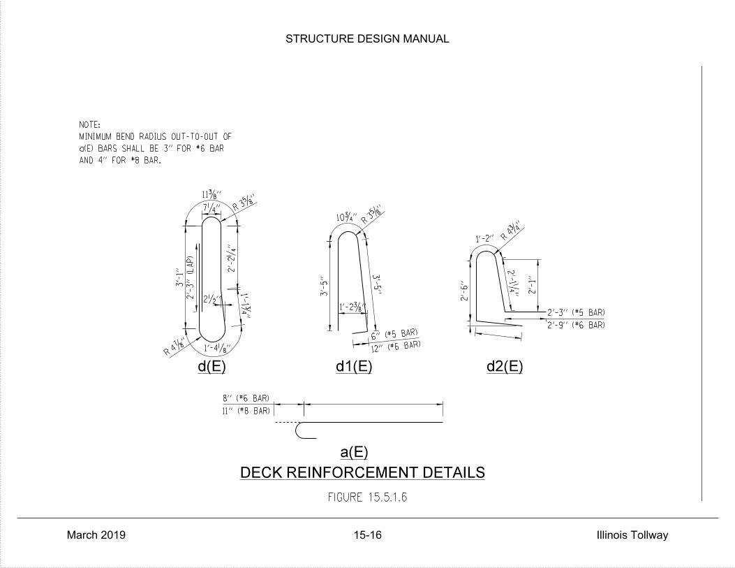
1'-4„"
1'-1ƒ
"
2'-
2‚
"
7‚"
11…"
3'-
1"
2'-
3" (L
AP)
4‡"
R 12" (#6 BAR)
6" (#5 BAR)
3'-
5"
3†"
R10ƒ"
3'-
5"
1'-2…"
2'-
6"
1'-2"4ƒ
"
R
2'-
1‚" 2
'-1"
2'-9" (#6 BAR)
2'-3" (#5 BAR)
2•"
d(E) d1(E) d2(E)
3†"
R
DECK REINFORCEMENT DETAILS
AND 4" FOR #8 BAR.
a(E) BARS SHALL BE 3" FOR #6 BAR
MINIMUM BEND RADIUS OUT-TO-OUT OF
NOTE:
11" (#8 BAR)
8" (#6 BAR)
a(E)
FIGURE 15.5.1.6
STRUCTURE DESIGN MANUAL
March 2019 15-16 Illinois Tollway

PARAPET JOINT DETAILS
FIGURE 15.5.1.7
(TYP.)
1†"
(TYP.)
‡"
(TYP.)
1†"
(TYP.)
‡"
(FU
LL
HEIG
HT)
AL
UMIN
UM J
OIN
TS
(MANDATORY)CONSTRUCTION JOINT
CORK JOINT FILLERSELF-EXPANDING•" PREFORMED
SEALANTPOLYURETHANE
PA
RA
PE
T J
T.
2'-
6"
(MANDATORY)CONSTRUCTION JOINT
SEALANTPOLYURETHANE
PA
RA
PE
T J
T.
5'-
2"
ALUMINUM PARAPET JOINT DETAILS
INTERIOR JOINT DETAIL
CORK JOINT FILLERSELF-EXPANDING
" PREFORMED21
STRUCTURE DESIGN MANUAL
March 2019 15-17 Illinois Tollway

FOR LONGITUDINAL OPEN JOINT
FIGURE 15.6.1
2"
‚"
1ƒ"
DECK OR RAISED MEDIAN
TOP OF CONCRETE
MANUFACTURER'S INSTRUCTIONS.
ADHESIVE IN ACCORDANCE WITH
SEAL, INSTALLED WITH AN
1ƒ" BONDED PREFORMED JOINT
BONDED PREFORMED JOINT SEAL
TYPICAL SECTION
BONDED PREFORMED JOINT SEAL
*
* INCREASE TO •" FOR SMOOTHNESS GRINDING
FINISHED EDGE
‚" BEVELED
STRUCTURE DESIGN MANUAL
March 2019 15-18 Illinois Tollway

1" DIA. ANCHOR BOLT
A
PLAN
A
(ASTM F 1554 GRADE 105)
& WASHER
LEVELING NUT
e(E)
d(E)
TH
RE
AD
CL.
CL.
GALVANIZED LOCKNUT
& WASHER
GALVANIZED
FIGURE 15.7.1
2'-
0"
1'-4"
BAR e (E) BAR d (E)
1•
"
10†"
1'-3"
2'-0"2'-
0"
2'-
3"
9"
4'-
9"
NOTE:
**
*SEE FIGURE 15.7.2 FOR SIZE AND NUMBER OF BARS REQUIRED
~ LIGHT
POLE
SHOULDER MOUNTED LIGHT POLE DETAILS
(TYP.)
2"} PVC CONDUIT
15"} BOLT CIRCLE
1"} ANCHOR BOLT (TYP.)
(BY OTHERS)
16" X 16" BASE `
3'-
3"
1'-
3"
1•"
2'-
6"
1'-
3"
10†
"
PAID FOR SEPARATELY.
PAY ITEM. 2"} PVC CONDUIT SHALL BE
THE COST OF CONCRETE SUPERSTRUCTURE
COST OF ANCHOR BOLTS IS INCLUDED IN
1'-0"
2'-5"
8•" 8•"
FOR CONSTANT SLOPE BARRIER
(4 REQ'D PER LOCATION)GALVANIZED ANCHOR BOLT1" DIA. HOT DIPPED
STRUCTURE DESIGN MANUAL
March 2019 15-19 Illinois Tollway
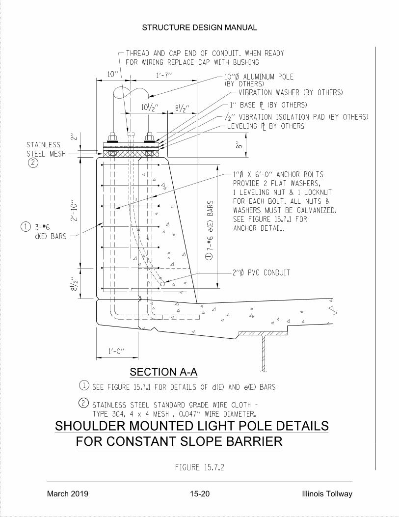
SECTION A-A
THREAD AND CAP END OF CONDUIT. WHEN READY
ANCHOR DETAIL.
2
1
1
1
2
SHOULDER MOUNTED LIGHT POLE DETAILS
3-#6
SEE FIGURE 15.7.1 FOR2'-
10"
10"
d(E) BARS
TYPE 304, 4 x 4 MESH , 0.047'' WIRE DIAMETER.
STAINLESS STEEL STANDARD GRADE WIRE CLOTH -
PROVIDE 2 FLAT WASHERS,
1 LEVELING NUT & 1 LOCKNUT
FOR EACH BOLT. ALL NUTS &
WASHERS MUST BE GALVANIZED.
FOR WIRING REPLACE CAP WITH BUSHING
STEEL MESH
STAINLESS
8•
"
SEE FIGURE 15.7.1 FOR DETAILS OF d(E) AND e(E) BARS
FIGURE 15.7.2
2"
2"} PVC CONDUIT
7-#6 e(E)
BA
RS
10•" 8•"
(BY OTHERS)10"} ALUMINUM POLE
VIBRATION WASHER (BY OTHERS)
1" BASE ` (BY OTHERS)
•" VIBRATION ISOLATION PAD (BY OTHERS)
LEVELING ` BY OTHERS
FOR CONSTANT SLOPE BARRIER
1'-7"
1'-0"
8"
1"} X 6'-0" ANCHOR BOLTS
STRUCTURE DESIGN MANUAL
March 2019 15-20 Illinois Tollway
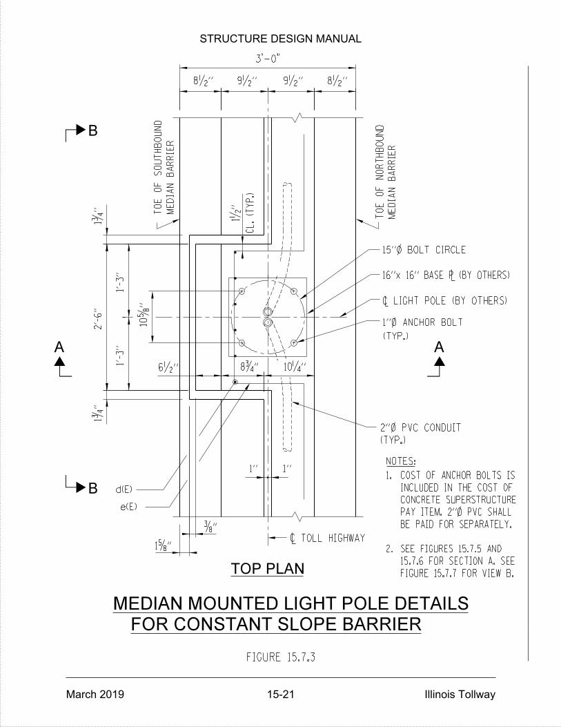
B
TOP PLAN
B
A A
e(E)
d(E)
(TYP.)
(TYP.)
16"x 16" BASE ` (BY OTHERS)
~ LIGHT POLE (BY OTHERS)
1"} ANCHOR BOLT
~ TOLL HIGHWAY
1" 1"
6•"
10†
"
MEDIAN MOUNTED LIGHT POLE DETAILS
3'-0"
FIGURE 15.7.3
2'-
6"
1'-
3"
1'-
3"
1ƒ
"
15"} BOLT CIRCLE
1ƒ
"
9•" 9•"
2"} PVC CONDUIT
ME
DIA
N
BA
RRIE
R
TO
E
OF
SO
UT
HB
OU
ND
ME
DIA
N
BA
RRIE
R
TO
E
OF
NO
RT
HB
OU
ND
NOTES:
FIGURE 15.7.7 FOR VIEW B.
15.7.6 FOR SECTION A. SEE
SEE FIGURES 15.7.5 AND2.
BE PAID FOR SEPARATELY.
PAY ITEM. 2"} PVC SHALL
CONCRETE SUPERSTRUCTURE
INCLUDED IN THE COST OF
COST OF ANCHOR BOLTS IS1.
8•" 8•"
10‚"8ƒ"
…"
1†"
FOR CONSTANT SLOPE BARRIER
CL. (T
YP.)
1•
"
STRUCTURE DESIGN MANUAL
March 2019 15-21 Illinois Tollway
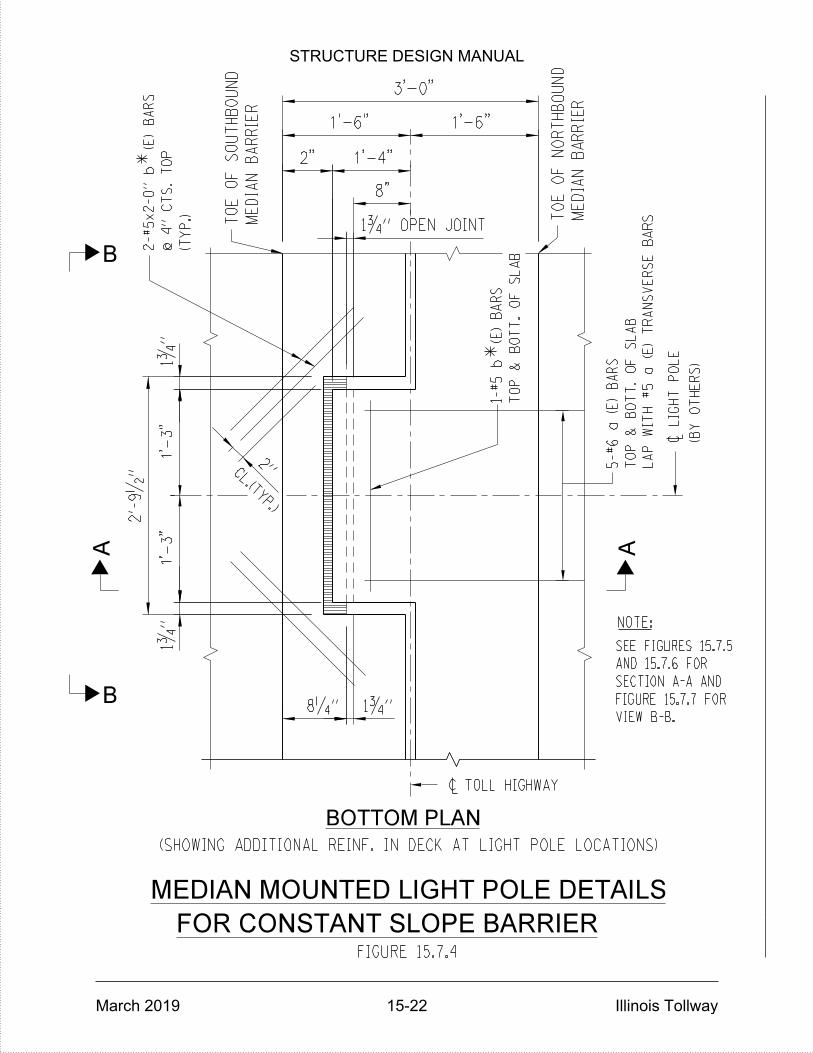
(SHOWING ADDITIONAL REINF. IN DECK AT LIGHT POLE LOCATIONS)
BOTTOM PLAN
CL.(TYP.)
@ 4"
CT
S.
TO
P
(TY
P.)
TO
P
&
BO
TT.
OF
SL
AB
1-#5 b (E)
BA
RS
5-#6 a (E)
BA
RS
TO
P
&
BO
TT.
OF
SL
AB
~ TOLL HIGHWAY
~
LIG
HT
PO
LE
(BY
OT
HE
RS)
LA
P
WIT
H #5 a (E)
TR
AN
SV
ER
SE
BA
RS
MEDIAN MOUNTED LIGHT POLE DETAILS
FIGURE 15.7.4
3'-0"
1'-6" 1'-6"
8"
1'-
3"
1'-
3"
2'-
9•
"
1ƒ
"1ƒ
"
2"
8‚"
1ƒ" OPEN JOINT
*
*
1ƒ"
2-#5x2-0" b (E)
BA
RS
B
B
A ANOTE:
ME
DIA
N
BA
RRIE
R
TO
E
OF
SO
UT
HB
OU
ND
ME
DIA
N
BA
RRIE
R
TO
E
OF
NO
RT
HB
OU
ND
VIEW B-B.
FIGURE 15.7.7 FOR
SECTION A-A AND
AND 15.7.6 FOR
SEE FIGURES 15.7.5
1'-4"2"
FOR CONSTANT SLOPE BARRIER
STRUCTURE DESIGN MANUAL
March 2019 15-22 Illinois Tollway
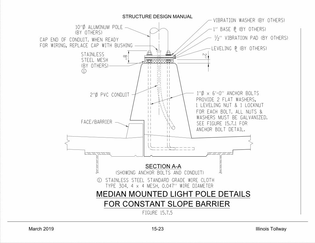
2"
SECTION A-A
(SHOWING ANCHOR BOLTS AND CONDUIT)
STAINLESS
STEEL MESH
FACE/BARRIER
(BY OTHERS)
MEDIAN MOUNTED LIGHT POLE DETAILS
(BY OTHERS)
FOR WIRING, REPLACE CAP WITH BUSHING
CAP END OF CONDUIT. WHEN READY
PROVIDE 2 FLAT WASHERS,
1 LEVELING NUT & 1 LOCKNUT
FOR EACH BOLT. ALL NUTS &
WASHERS MUST BE GALVANIZED.
ANCHOR BOLT DETAIL.
STAINLESS STEEL STANDARD GRADE WIRE CLOTH
TYPE 304, 4 x 4 MESH, 0.047'' WIRE DIAMETER
VIBRATION WASHER (BY OTHERS)
1" BASE ` (BY OTHERS)
LEVELING ` (BY OTHERS)
10"} ALUMINUM POLE
FIGURE 15.7.5
•" VIBRATION PAD (BY OTHERS)
1
1
SEE FIGURE 15.7.1 FOR
2"} PVC CONDUIT
FOR CONSTANT SLOPE BARRIER
8"
1"} x 6'-0" ANCHOR BOLTS
STRUCTURE DESIGN MANUAL
March 2019 15-23 Illinois Tollway
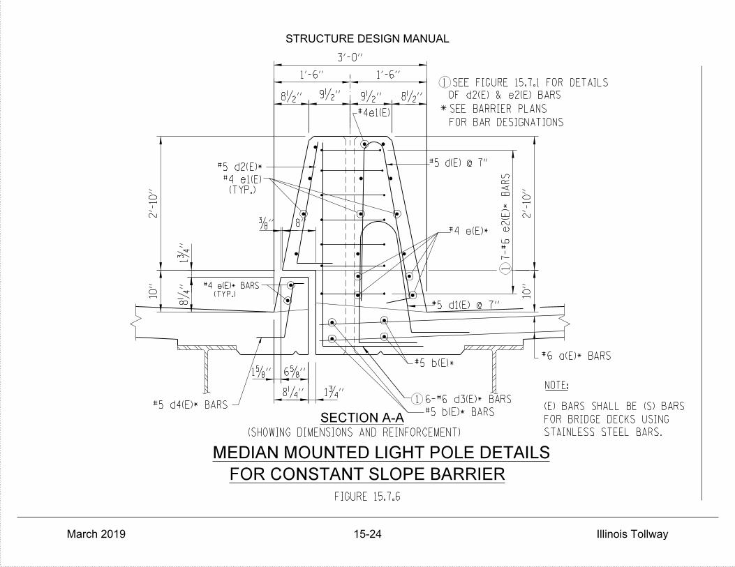
SECTION A-A
SEE BARRIER PLANS
FOR BAR DESIGNATIONS
1 SEE FIGURE 15.7.1 FOR DETAILS
MEDIAN MOUNTED LIGHT POLE DETAILS
FIGURE 15.7.6
8‚"
1'-6" 1'-6"
3'-0"
1ƒ"
(TYP.)
8"
#5 b(E)*
*
#5 d(E) @ 7"
(SHOWING DIMENSIONS AND REINFORCEMENT)
NOTE:
OF d2(E) & e2(E) BARS
STAINLESS STEEL BARS.
FOR BRIDGE DECKS USING
(E) BARS SHALL BE (S) BARS
FOR CONSTANT SLOPE BARRIER
8•"9•"9•"8•"
10"
2'-
10"
8‚
"1ƒ
"
…"
10"
2'-
10"
#5 d4(E)* BARS
#5 d1(E) @ 7"
#4 e(E)*
(TYP.)#4 e1(E)
1 6-#6 d3(E)* BARS
*#6 a(E)* BARS
1 7-#6 e
2(E)
BA
RS
#5 b(E)* BARS
#4 e(E)* BARS
#5 d2(E)*
6†"1†"
#4e1(E)
STRUCTURE DESIGN MANUAL
March 2019 15-24 Illinois Tollway
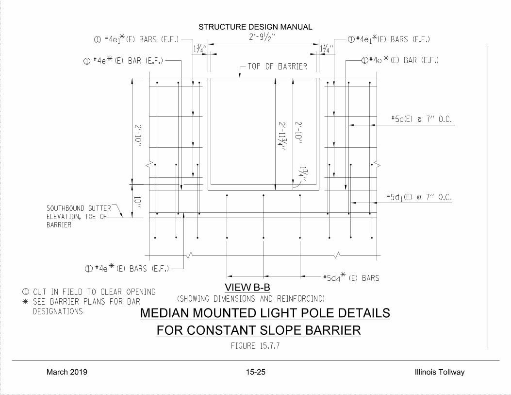
1
*
#4e (E) BAR (E.F.)
1
1
CUT IN FIELD TO CLEAR OPENING
1
MEDIAN MOUNTED LIGHT POLE DETAILS
FIGURE 15.7.7
1ƒ"
1
1
#4e (E) BARS (E.F.)
2'-
10"
10"
2'-
10"
1ƒ"
2'-9•"
1ƒ" *
* *
#5d (E) BARS
*
*
#4e (E) BARS (E.F.)
TOP OF BARRIER
(SHOWING DIMENSIONS AND REINFORCING)
1
1
#5d(E) @ 7" O.C.
#5d (E) @ 7" O.C.
BARRIER
ELEVATION, TOE OF
SOUTHBOUND GUTTER
*
1
4
VIEW B-B
2'-
11ƒ"
FOR CONSTANT SLOPE BARRIER
DESIGNATIONS
SEE BARRIER PLANS FOR BAR
#4e (E) BAR (E.F.)
#4e (E) BARS (E.F.)
STRUCTURE DESIGN MANUAL
March 2019 15-25 Illinois Tollway

LIGHTPOLE DETAILS FOR 6FT BARRIER
FIGURE 15.7.8
5'-
10•
"
12-#6 e(E)
BA
RS
10"
1'-7"
10•"
8•"
10"
8"
2"
2"
2" } PVC CONDUIT
DETAIL.
SEE FIGURE 15.7.9 FOR ANCHOR
WASHERS MUST BE GALVANIZED.
FOR EACH BOLT. ALL NUTS &
1 LEVELING NUT & 1 LOCKNUT
PROVIDE 2 FLANGE WASHERS,
1" } x 8'-2" ANCHOR BOLTS
LEVELING ` BY OTHERS
•" VIBRATION ISOLATION PAD (BY OTHERS)
1" BASE ` (BY OTHERS)
VIBRATION WASHER (BY OTHERS)
(BY OTHERS)
10" } ALUMINIM POLE
WITH BUSHING
FOR WIRING REPLACE CAP
CONDUIT, WHEN READY
THREAD AND CAP END OF
NOISE ABATEMENT WALL
PERFORMANCE BASED
STRUCTURE MOUNTED
STEEL MESH
STAINLESS
d(E) BARS
3-#6
ELEVATION
STRUCTURE DESIGN MANUAL
March 2019 15-26 Illinois Tollway
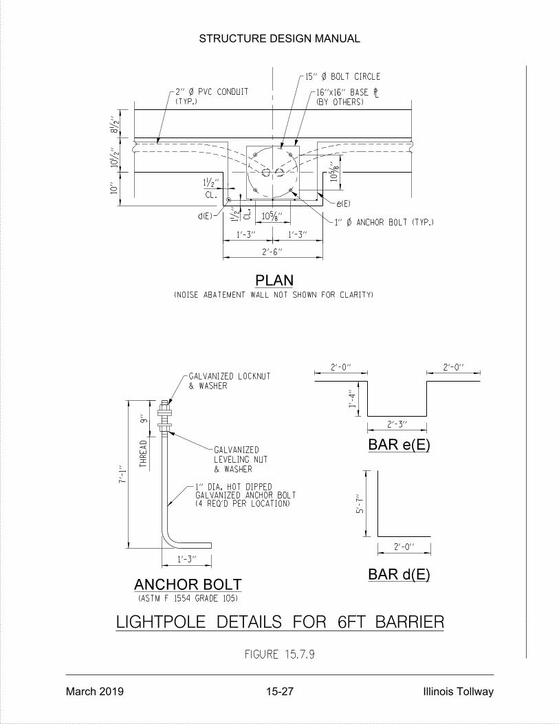
LIGHTPOLE DETAILS FOR 6FT BARRIER
FIGURE 15.7.9
d(E)
(NOISE ABATEMENT WALL NOT SHOWN FOR CLARITY)
TH
RE
AD
e(E)
(BY OTHERS)
16"x16" BASE `
15" } BOLT CIRCLE
(TYP.)
2" } PVC CONDUIT
& WASHER
GALVANIZED LOCKNUT
1" } ANCHOR BOLT (TYP.)
& WASHER
LEVELING NUT
GALVANIZED
10†
"
9"
2'-0"
5'-
7"
2'-0"
1'-
4"
2'-3"
2'-0"
CL.
1•"
CL.
1•
"
8•
"10•
"10"
2'-6"
1'-3"1'-3"
10†"
PLAN
(ASTM F 1554 GRADE 105)
1'-3"
ANCHOR BOLT
BAR e(E)
BAR d(E)
(4 REQ'D PER LOCATION)GALVANIZED ANCHOR BOLT1" DIA. HOT DIPPED
7'-
1"
STRUCTURE DESIGN MANUAL
March 2019 15-27 Illinois Tollway

STRUCTURE DESIGN MANUAL
March 2019 Illinois Tollway
DECK DRAINAGE
Bridge deck drainage shall be designed and detailed in accordance with the applicable portions of Chapters 7 and 8 of the latest IDOT Drainage Manual, Section 3.2.9 of the latest IDOT Bridge Manual, and Section 9.4 and Table 9.3 of the Illinois Tollway Drainage Manual, except as amended herein.
16.1 Deck Drains
When floor drains are required, they shall be uniformly spaced along the gutter line on one or both sides of the bridge deck as indicated in the drainage study. In no case shall the discharge from floor drains be collected in a closed drainage system and piped down and/or off the bridge. The free fall method of discharge shall be permitted except over areas noted herein.
Floor drains may be angled if required to clear the beam or girder flange. Preference shall be given first to the use of 6 inch diameter reinforced fiberglass pipe or aluminum tube. If insufficient space exists between face-of-curb and the girder for a 6 inch diameter drain, consideration shall be given to the use of the 4” x 12” tube. Reinforced fiberglass pipe shall meet the requirements of Article 16.3.2. Aluminum shall be either an extrusion or welded plates meeting the requirements of ASTM B221, Alloy 6061-T6 or ASTM B209, Alloy 6061-T6.
Floor drains shall be omitted from sections of the decks where the discharge would fall on underlying roadways, bikeways, walkways, railroads, aggregate slope paving or unprotected earthen embankments, and other developed or highly erodible areas. Where free fall is not permitted scuppers and a closed drainage system as described below is used. Floor drains shall be located a minimum of 1/2 of the drop height from the face of any abutment or pier. The drop height is defined as the vertical distance between the bottom of the drain pipe and the top of the surface below. Drains shall be located a minimum of 4’ clear of all diaphragms and on the upstream side of bridge deck expansion joints. Drain pipes shall extend a minimum of 6” below the bottom of adjacent superstructure members.
16.2 Drainage Scuppers
The IDOT DS11 or DS12 Drainage Scuppers may be used. Drainage from scuppers may be collected in a closed drainage system and piped off the bridge or allowed to free fall to the ground except in the areas noted herein.
Scupper frames and grates shall be gray cast iron meeting the requirements of AASHTO M105, Class 35B. Stainless steel hold down bolts as specified in the Standard Specifications Article 1006.29(d) shall be used to secure the grates to the frames.
Structural steel weldments of equal sections and of the same configuration may be used in lieu of the gray cast iron frame. Fillet or full penetration welds shall be used for the weldments. Structural steel weldments shall not be used in lieu of the cast iron grates. Structural steel shall meet the requirements of AASHTO M270, Grade 50. Structural steel
16-1
STRUCTURE DESIGN MANUAL
March 2019 Illinois Tollway
frames shall be galvanized according to AASHTO M111. The Contractor shall submit shop drawings of all structural steel weldments to the Engineer for review and acceptance prior to ordering any material or starting the work.
The height at the spigot end of the scupper shall be increased from 7-1/4 inches to 12 inches to allow the flange connection to be made below the deck slab. The connection shall be made with stainless steel bolts, nuts and washers as specified in the Standard Specifications Article 1006.29(d). The following note shall be added to the list of General Notes.
“All stainless steel hardware for drainage systems shall be coated with antiseize compound.”
Freefall type scuppers shall be omitted from sections where the discharge would fall on underlying roadways, bikeways, walkways, railroads, aggregate slope paving, unprotected embankments and other developed or highly erodible areas. Scuppers with free fall discharge shall be located a minimum of 1/2 of the drop height from the face of any element of the substructure. The drop height is defined as the vertical distance between the bottom of the spigot and the top of the surface below. Scuppers shall be located clear of all diaphragms and on the upstream side of bridge deck expansion joints, whenever possible.
16.3 Drain Pipe
Wherever freefall discharge is not feasible, the drainage shall be collected and piped to the ground or lower roadway. Drain pipes shall not be placed on the traffic face of crash walls. Scuppers shall be located directly above downspouts attached to the substructure. Midspan locations that would result in complex, lengthy drain piping shall be avoided wherever possible. Where horizontal (collection) piping is required, horizontal runs shall be 8 inch in diameter. Vertical (downspouts) piping shall also be 8 inches in diameter. Figures 16.3.1 and 16.3.2 illustrate typical drainage system details. Drainage piping and fittings shall be polyvinyl chloride (PVC), reinforced fiberglass or galvanized steel. Cast iron pipe and fittings shall not be used. The following note shall be added to the list of General Notes.
“Drain pipe for Bridge Drainage System, including all piping, fittings, support brackets, inserts, bolts, and splash blocks shown, shall be as specified in the latest IDOT GBSP for Drainage System, except as modified herein. Drain pipe may be Polyvinyl Chloride (PVC) Pipe, Reinforced Fiberglass pipe or Galvanized Steel Pipe.”
Polyvinyl Chloride Pipe
Polyvinyl Chloride (PVC) pipe and fittings shall be 8” diameter schedule 80 meeting the requirements of ASTM D1785 (F441), D2464 and D2467, colored in accordance with Article 16.5. These requirements shall be added as a note to the list of General Notes.
16-2
STRUCTURE DESIGN MANUAL
March 2019 Illinois Tollway
Reinforced Fiberglass Pipe
Reinforced Fiberglass pipe and fittings shall be 8” diameter and meet the requirements of ASTM D2996 RTRP with a 30,000 psi minimum short-time rupture strength hoop tensile stress, pigmented or painted in accordance with Article 16.5. These requirements shall be added as a note to the list of General Notes.
Galvanized Steel Pipe
Seamless and welded pipe and fittings shall be 8” diameter, extra strong, galvanized steel pipe, meeting the requirements of ASTM A53.
16.4 Pipe Supports
Pipe hangers shall be provided for all horizontal (collection) drain pipes at each fitting, cleanout, or change in direction and at intermediate points not more than 5’-0” on centers. Collection pipe hangers shall have an allowable load capacity of not less than 500 lbs. and shall be designed so as not to apply excessive compressive stress to the pipe. See Figures 16.4.1 and 16.4.2 for pipe hanger details. Steel straps, bars and plates shall meet the requirements of AASHTO M270, Grade 36 or 50.
Pipe supports shall be provided for all vertical (downspout) drain pipes at points not more than 12’-0” on centers. See Figures 16.4.3 through 16.4.6 for drain pipe support details. Structural steel shapes shall meet the requirement of AASHTO M270, Grade 36.
All pipe hangers, supports and hardware shall be hot-dipped galvanized after fabrication in accordance with AASHTO M232 (ASTM A153) unless otherwise noted. All bolts, nuts and washers shall be stainless steel. Stainless steel bolts, and washers shall to the Standard Specifications Article 1006.29(d).
16.5 Painting
All exposed surfaces of floor drains, hangers, brackets and piping located on the exterior side of painted fascia beams and/or visible to the motoring public shall be painted or supplied in the appropriate color except stainless steel and galvanized shall not be painted. The color of the final coat shall match that of the adjacent beam and/or column, Munsell numbers 7.5G4/8 Interstate Green or 5B7/1 Gray. Final color shall be submitted to the Engineer for approval.
Aluminum Tube
The exterior surfaces shall be cleaned and given a wash coat pretreatment in accordance with SSPC - SP1 and SSPC - Paint 27. The pretreated surfaces shall be painted with an adhesion bonding primer and top coat per the system recommended by the pretreatment manufacturer for painting aluminum surfaces in an exterior environment. These requirements shall be added as a note to the list of General Notes.
16-3

STRUCTURE DESIGN MANUAL
March 2019 Illinois Tollway
Polyvinyl Chloride Pipe
The PVC pipe and fittings shall be colored to match the adjacent beam and/or column.
Reinforced Fiberglass Pipe
The exterior surfaces of fiberglass pipe and fittings shall be pigmented in accordance with the pipe manufacturer’s recommendations or cleaned, given a prewash in accordance with MIL - P – 15328 and top coated with an epoxy-based coating recommended for outdoor applications by the prewash manufacturer.
Galvanized Steel Pipe
Galvanized Steel Pipe shall not be painted.
Pipe Supports
The exposed surfaces of galvanized pipe supports shall not be painted.
16-4
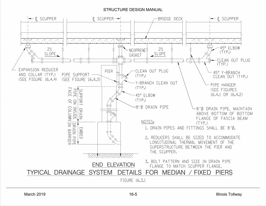
GASKET
NEOPRENE
(TYP.)
FLANGE OF FASCIA BEAM
ABOVE BOTTOM OF BOTTOM
8"} DRAIN PIPE, MAINTAIN8"} DRAIN PIPE
FA
CE
OF
CO
LU
MN
SUPP
OR
T
DR
AIN
EM
BE
D
SLOPE
2%
BRIDGE DECK
CLEAN OUT (TYP.)45° Y-BRANCH
(TYP.)CLEAN OUT PLUG
(TYP.)45° ELBOW
NOTES:
(TYP.)
CLEAN OUT PLUG
(TYP.)
Y-BRANCH CLEAN OUT
(TYP.)
45° ELBOW
END ELEVATION
PIER
~ SCUPPER ~ SCUPPER ~ SCUPPER
PIP
E
ON INSID
E
(SEE FIGURE 16.4.3)
PIPE SUPPORT
16.4.1 OR 16.4.2)
(SEE FIGURES
PIPE HANGER
(SEE FIGURE 16.4.4)
AND COLLAR (TYP.)
EXPANSION REDUCER
FLANGE TO MATCH SCUPPER FLANGE.
3. BOLT PATTERN AND SIZE IN DRAIN PIPE
THE SCUPPER.
SUPERSTRUCTURE BETWEEN THE PIER AND
LONGITUDINAL THERMAL MOVEMENT OF THE
2. REDUCERS SHALL BE SIZED TO ACCOMMODATE
1. DRAIN PIPES AND FITTINGS SHALL BE 8"}.
SLOPE
2%
DR
AIN PIP
E
IN
BA
RRIE
R
TYPICAL DRAINAGE SYSTEM DETAILS FOR MEDIAN / FIXED PIERS
FIGURE 16.3.1
STRUCTURE DESIGN MANUAL
March 2019 16-5 Illinois Tollway
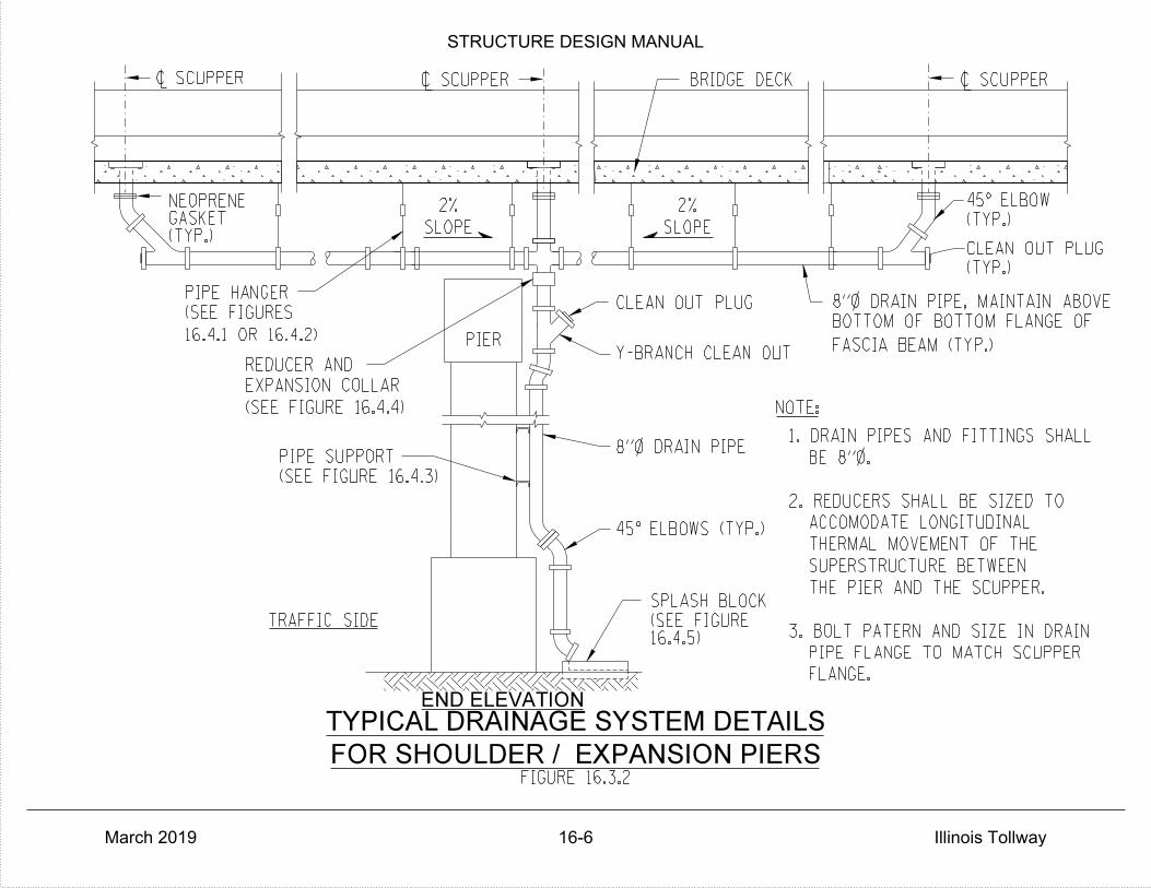
PIER
SLOPE
NOTE:
SPLASH BLOCK
CLEAN OUT PLUG
2%
PIPE SUPPORT
BRIDGE DECK
CLEAN OUT PLUG
(TYP.)
(TYP.)
Y-BRANCH CLEAN OUT
PIPE HANGER
(SEE FIGURES
REDUCER AND
EXPANSION COLLAR
TRAFFIC SIDE
END ELEVATION
FOR SHOULDER / EXPANSION PIERS
TYPICAL DRAINAGE SYSTEM DETAILS
~ SCUPPER ~ SCUPPER
FIGURE 16.3.2
~ SCUPPER
8"} DRAIN PIPE
(TYP.)GASKETNEOPRENE
8"} DRAIN PIPE, MAINTAIN ABOVE
BOTTOM OF BOTTOM FLANGE OF
FASCIA BEAM (TYP.)16.4.1 OR 16.4.2)
(SEE FIGURE 16.4.4)
(SEE FIGURE 16.4.3)
16.4.5)(SEE FIGURE
FLANGE.
PIPE FLANGE TO MATCH SCUPPER
3. BOLT PATERN AND SIZE IN DRAIN
THE PIER AND THE SCUPPER.
SUPERSTRUCTURE BETWEEN
THERMAL MOVEMENT OF THE
ACCOMODATE LONGITUDINAL
2. REDUCERS SHALL BE SIZED TO
BE 8"}.
1. DRAIN PIPES AND FITTINGS SHALL
SLOPE
2%
STRUCTURE DESIGN MANUAL
March 2019 16-6 Illinois Tollway

STRUCTURE DESIGN MANUAL
March 2019 Illinois Tollway
BRIDGE DECK EXPANSION JOINTS
17.1 General
All bridge deck expansion and fixed (rotational) joints shall be sealed to prevent water from penetrating to the bridge elements below the deck surface. Both expansion and fixed (rotational) joints shall be designed and detailed in accordance with Section 3.6 of the latest IDOT Bridge Manual and ABD Memo 15.7 except as herein amended. Integral and semi-integral abutments shall be utilized wherever possible to eliminate the need for expansion joints at these locations. See Section 10.0 for parameters pertaining to the use of these types of abutments.
Expansion and fixed joints installed on bridges with 10 degree skews or greater shall be modified to intersect the barrier or curb line at 90 degrees. This change in direction shall occur 6 inches from the back face of curb or front face of parapet (see Base Sheets M-BRG-500 and M-BRG-501).
Joint seals on bridge decks and between bridge decks and bridge approach slabs shall be one continuous piece for the full length of the joint. Splicing of the gland is not allowed. Spliced glands may be considered at joints between transition approach slabs and approach pavement.
17.2 New or Replacement Bridge Decks
Only Strip Seals and Modular Joints shall be utilized to seal expansion or fixed (rotation) joints in new or replacement decks. Unbonded Preformed Joint Seals, Neoprene, Bituminous, Poured Silicone and steel Finger Plates shall not be used. Only Strip Seals and Modular Expansion Joints currently on the latest IDOT Pre-Qualified products list shall be considered for use by the Illinois Tollway.
Strip Seals
Strip Seals shall be used to seal the deck joints of all new or replacement structures located on tangent alignments where the skew angle(s) are 60 degrees or less and the expansion length is not greater than 305’. They may also be used for structures on curved alignment provided the skew angles(s) are 40 degrees or less and the expansion length is equal to or less than 305’, measured along the center or baseline. The Illinois Tollway will consider the use of greater expansion lengths on a case-by-case basis. See Base Sheets M-BRG-500, M-BRG-501 and M-BRG-502 for details.
Modular Joints
Modular Joints shall be used to seal expansion joints of structures on tangent or curved alignment exceeding the strip seal limits specified above, provided skew angles are 60 degrees or less and the expansion length does not exceed 800 feet.
17-1
STRUCTURE DESIGN MANUAL
March 2019 Illinois Tollway
17.3 Existing Bridge Deck Widenings
Structures that are to be widened on one or both sides shall utilize the same type of joint that is currently installed in the existing deck, provided it is in good condition. If the existing joint is not in good condition, or it is no longer manufactured, it shall be replaced and the deck reconstructed to utilize a Strip Seal or Modular Expansion Joint. Existing Preformed Joint Seals or Poured Silicone Joints shall be completely removed and replaced.
17.4 Existing Bridge Deck Repair and Rehabilitation
When a deck is only being repaired and/or resurfaced and isolated sections of the existing joint are in poor condition, they shall be reconstructed or repaired in-kind, provided the total length of repairs does not exceed 40% of the original length. Regardless of the repair length, the existing seal or gland shall be completely replaced.
Whenever the total length of repairs will exceed 40% of the original, or the entire joint is in poor condition, the existing joint shall be completely reconstructed and sealed with a Strip Seal or a Bonded Preformed Joint Seal.
When reconstructing expansion joints on existing bridges with skews greater than 10 degrees, the joints shall be modified so that they intersect the face of the parapet or curb at a 90 degree angle. This modification typically consists of removing a short section of the existing parapet and relocating the parapet joint so that the modified expansion joint intersects it at a 90 degree angle.
17.5 Approach Slabs
Bonded Preformed Joint Seals, preformed pre-compressed, silcone coated, self-expanding sealant system which are fully adhered to both faces of the open joint shall be utilized to construct the expansion joints between the approach and transition slabs and the transition slab and roadway pavement as detailed in the Base Sheets M-RDY-408 and M-RDY-409.
Joint armor is not required or allowed. See Base Sheets M-RDY-408 and M-RDY-409 and Figure 17.5.1 for details.
17.6 Fabrication
All structural steel for expansion joints shall be hot dipped galvanized after fabrication in accordance with AASHTO M232 (ASTM A153).
17-2
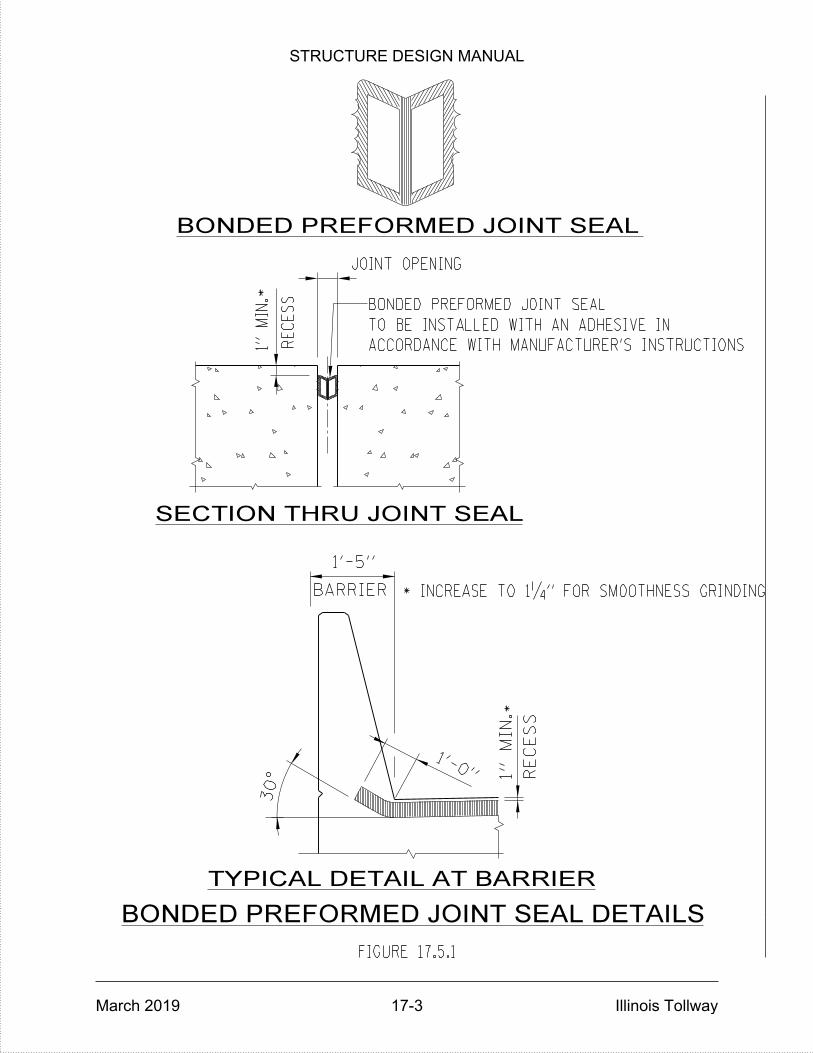
TYPICAL DETAIL AT BARRIER
RE
CES
S
TO BE INSTALLED WITH AN ADHESIVE IN
BARRIER
1'-5"
FIGURE 17.5.1
ACCORDANCE WITH MANUFACTURER'S INSTRUCTIONS1"
MIN.
JOINT OPENING
BONDED PREFORMED JOINT SEAL
RE
CES
S
1"
MIN.
1'-0"
30°
BONDED PREFORMED JOINT SEAL
SECTION THRU JOINT SEAL
BONDED PREFORMED JOINT SEAL DETAILS
*
*
* INCREASE TO 1‚" FOR SMOOTHNESS GRINDING
STRUCTURE DESIGN MANUAL
March 2019 17-3 Illinois Tollway

STRUCTURE DESIGN MANUAL
March 2019 Illinois Tollway
THIS PAGE IS INTENTIONALLY LEFT BLANK

STRUCTURE DESIGN MANUAL
March 2019 18-1 Illinois Tollway
DECK ELEVATIONS
18.1 New Bridges
A table showing top of deck slab elevations along the centerline of each longitudinal beam or girder, stage construction joint, break in cross slope, and profile grade line shall be included in the bridge plans for all structures with steel or concrete stringers. This table is usually in the form of a computer output reduced in tabular form on individual plan sheets. Examples of these sheets are shown in Figures 3.1.9-1 through 3.1.9-4 of the latest IDOT Bridge Manual.
In addition, top of bridge approach slab, transition approach slab, and transition approach shoulder slab elevations along each longitudinal profile grade line, break in cross slope, stage construction joint, edge of pavement or shoulder shall also be provided on separate individual plan sheet(s) after the deck elevation sheet(s). Examples of which are shown in Figures 3.1.9-5 and 3.1.9-6 of the latest IDOT Bridge Manual.
Where the stringer lies below a curb, sidewalk or median section, the elevations shall be given for a theoretical top of slab, which would be the projection of the cross slope from the roadway template to the centerline of stringer.
The increments for elevations along centerline of each web shall be 10 feet with any odd increment not greater than 15 feet or less than 5 feet placed at the end of a span. A new series of 10-foot increments shall begin in each respective span along the structure. In all cases, the increments shall progress in the direction of the stationing on the bridge for the full length of the structure. The theoretical top of slab elevations at these increment points shall be adjusted for dead load deflection and tabulated in a separate column, which will become the finished elevations for construction of the deck slab. Bridges with smoothness and grinding shall follow IDOT ABD 17.1 with theoretical grade elevations adjusted for dead load deflection and grinding.
Actual dead load deflection diagrams (due to weight of concrete deck and all superimposed dead loads except future wearing surface) shall be shown on the top of the slab elevations indicating deflection ordinates at the quarter points and midpoint of all stringers of each span. However, if the variance in deflection between the exterior and interior stringers is one-eighth inch or less, one dead load deflection diagram shall be sufficient for all stringers. Dead load deflection diagrams shall be qualified with the following note:
"The above deflections are not for use in the field if the Engineer is working from the Theoretical Grade Elevations Adjusted for Dead Load Deflection."
If the superstructure will be constructed in stages, any concentrated superimposed dead loads (noise abatement walls, parapets, sidewalks and medians) applied during the initial stage shall only be distributed to a maximum of three adjacent stringers erected in that stage. These initial concentrated superimposed dead loads shall not be considered in the deflection calculations for stringers erected in subsequent stages.
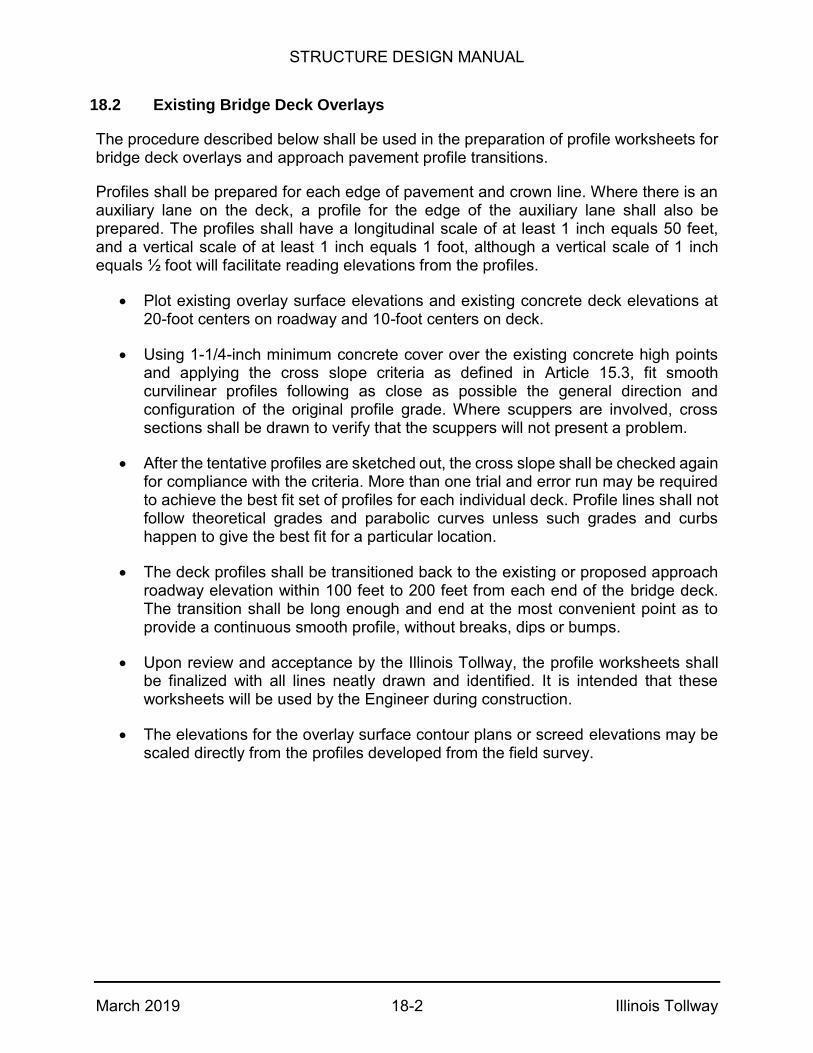
STRUCTURE DESIGN MANUAL
March 2019 18-2 Illinois Tollway
18.2 Existing Bridge Deck Overlays
The procedure described below shall be used in the preparation of profile worksheets for bridge deck overlays and approach pavement profile transitions.
Profiles shall be prepared for each edge of pavement and crown line. Where there is an auxiliary lane on the deck, a profile for the edge of the auxiliary lane shall also be prepared. The profiles shall have a longitudinal scale of at least 1 inch equals 50 feet, and a vertical scale of at least 1 inch equals 1 foot, although a vertical scale of 1 inch equals ½ foot will facilitate reading elevations from the profiles.
Plot existing overlay surface elevations and existing concrete deck elevations at 20-foot centers on roadway and 10-foot centers on deck.
Using 1-1/4-inch minimum concrete cover over the existing concrete high points and applying the cross slope criteria as defined in Article 15.3, fit smooth curvilinear profiles following as close as possible the general direction and configuration of the original profile grade. Where scuppers are involved, cross sections shall be drawn to verify that the scuppers will not present a problem.
After the tentative profiles are sketched out, the cross slope shall be checked again for compliance with the criteria. More than one trial and error run may be required to achieve the best fit set of profiles for each individual deck. Profile lines shall not follow theoretical grades and parabolic curves unless such grades and curbs happen to give the best fit for a particular location.
The deck profiles shall be transitioned back to the existing or proposed approach roadway elevation within 100 feet to 200 feet from each end of the bridge deck. The transition shall be long enough and end at the most convenient point as to provide a continuous smooth profile, without breaks, dips or bumps.
Upon review and acceptance by the Illinois Tollway, the profile worksheets shall be finalized with all lines neatly drawn and identified. It is intended that these worksheets will be used by the Engineer during construction.
The elevations for the overlay surface contour plans or screed elevations may be scaled directly from the profiles developed from the field survey.
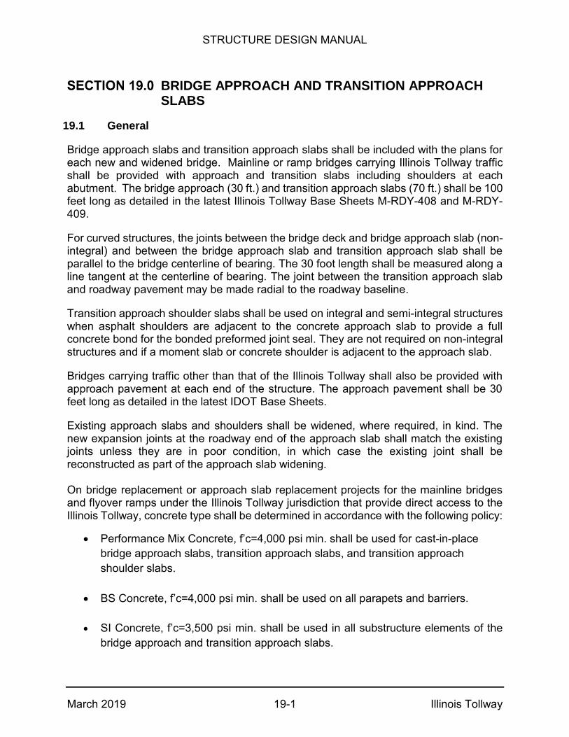
STRUCTURE DESIGN MANUAL
March 2019 19-1 Illinois Tollway
BRIDGE APPROACH AND TRANSITION APPROACH SLABS
19.1 General
Bridge approach slabs and transition approach slabs shall be included with the plans for each new and widened bridge. Mainline or ramp bridges carrying Illinois Tollway traffic shall be provided with approach and transition slabs including shoulders at each abutment. The bridge approach (30 ft.) and transition approach slabs (70 ft.) shall be 100 feet long as detailed in the latest Illinois Tollway Base Sheets M-RDY-408 and M-RDY-409.
For curved structures, the joints between the bridge deck and bridge approach slab (non-integral) and between the bridge approach slab and transition approach slab shall be parallel to the bridge centerline of bearing. The 30 foot length shall be measured along a line tangent at the centerline of bearing. The joint between the transition approach slab and roadway pavement may be made radial to the roadway baseline.
Transition approach shoulder slabs shall be used on integral and semi-integral structures when asphalt shoulders are adjacent to the concrete approach slab to provide a full concrete bond for the bonded preformed joint seal. They are not required on non-integral structures and if a moment slab or concrete shoulder is adjacent to the approach slab.
Bridges carrying traffic other than that of the Illinois Tollway shall also be provided with approach pavement at each end of the structure. The approach pavement shall be 30 feet long as detailed in the latest IDOT Base Sheets.
Existing approach slabs and shoulders shall be widened, where required, in kind. The new expansion joints at the roadway end of the approach slab shall match the existing joints unless they are in poor condition, in which case the existing joint shall be reconstructed as part of the approach slab widening. On bridge replacement or approach slab replacement projects for the mainline bridges and flyover ramps under the Illinois Tollway jurisdiction that provide direct access to the Illinois Tollway, concrete type shall be determined in accordance with the following policy:
Performance Mix Concrete, f’c=4,000 psi min. shall be used for cast-in-place
bridge approach slabs, transition approach slabs, and transition approach
shoulder slabs.
BS Concrete, f’c=4,000 psi min. shall be used on all parapets and barriers.
SI Concrete, f’c=3,500 psi min. shall be used in all substructure elements of the
bridge approach and transition approach slabs.

STRUCTURE DESIGN MANUAL
March 2019 19-2 Illinois Tollway
19.2 Approach Slabs for Illinois Tollway Bridges
Integral and Semi-Integral Abutments
The first 30 feet of the approach slab is designed as a one-way structural slab simply supported on a 12-inch-wide seat at the end diaphragm and an approach slab bent at the other end. The next 70 feet of approach slab is a reinforced concrete slab on grade, used as a transition between the one-way slab and the roadway pavement.
Cast-in-place bridge approach slabs shall be anchored to the end diaphragm as shown in the IDOT All Bridge Designers Memorandum 12.3, “2012 Integral Abutment Bridge Policies and Details”, dated July 25, 2012. The other end shall be separated from the transition approach slab with an expansion joint located over the approach slab pile bent as shown in Illinois Tollway Base Sheets M-RDY-408 and M-RDY-409.
For Integral and semi-integral abutment bridges with a distance from the back of abutment to the centroid of stiffness greater than 130 feet, precast concrete bridge approach slabs shall be considered and detailed in accordance with the Illinois Tollway Base Sheet M-RDY-410.
Vaulted Abutments
The first 30 feet of the approach slab is designed as a one-way slab, simply supported on a 6 inch seat at the abutment end bent and the approach slab bent at the other end. Bridge approach slabs for vaulted abutment bridges shall be detailed in accordance with IDOT base sheets for Vaulted Abutment Approach Spans. The next 70 feet of approach slab is a reinforced concrete slab on grade, used as a transition between the one-way structural approach slab and the approach roadway pavement and shall be detailed in accordance with the Illinois Tollway Base Sheets M-RDY-408 and M-RDY-409 for non-integral bridges.
Pile Bent/Stub Abutments
The first 30 feet of approach slab is designed as a one-way structural slab, simply supported on a 6-inch seat at the abutment and an approach slab bent at the other end. The next 70 feet of approach slab is a reinforced concrete slab on grade, used as a transition between the one-way structural approach slab and the roadway pavement.
The one-way slab shall be anchored to the abutment per Figure 10.3.6. The joints between the abutment and the one-way slab and the one-way slab and the transition approach slabs shall be constructed without any expansion material. The top of these joints shall be tooled or sawed and sealed with hot poured low modulus polymer sealant as shown in Base Sheets M-RDY-408 and M-RDY-409.
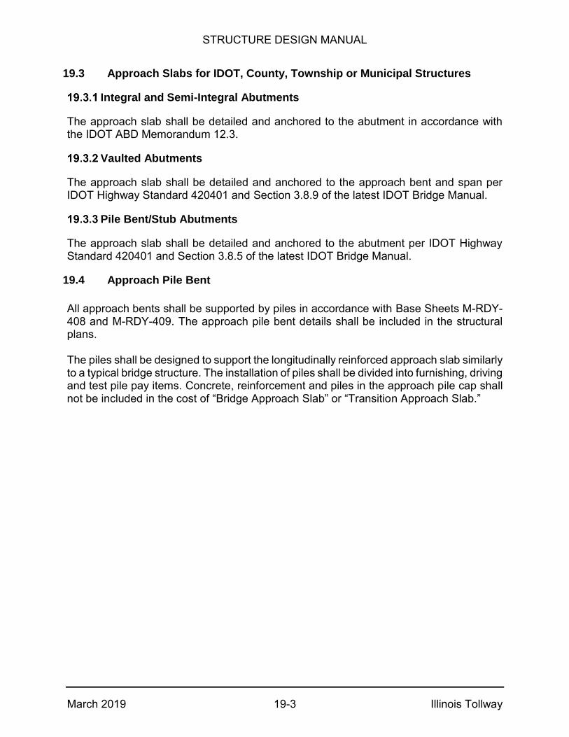
STRUCTURE DESIGN MANUAL
March 2019 19-3 Illinois Tollway
19.3 Approach Slabs for IDOT, County, Township or Municipal Structures
Integral and Semi-Integral Abutments
The approach slab shall be detailed and anchored to the abutment in accordance with the IDOT ABD Memorandum 12.3.
Vaulted Abutments
The approach slab shall be detailed and anchored to the approach bent and span per IDOT Highway Standard 420401 and Section 3.8.9 of the latest IDOT Bridge Manual.
Pile Bent/Stub Abutments
The approach slab shall be detailed and anchored to the abutment per IDOT Highway Standard 420401 and Section 3.8.5 of the latest IDOT Bridge Manual.
19.4 Approach Pile Bent
All approach bents shall be supported by piles in accordance with Base Sheets M-RDY-408 and M-RDY-409. The approach pile bent details shall be included in the structural plans. The piles shall be designed to support the longitudinally reinforced approach slab similarly to a typical bridge structure. The installation of piles shall be divided into furnishing, driving and test pile pay items. Concrete, reinforcement and piles in the approach pile cap shall not be included in the cost of “Bridge Approach Slab” or “Transition Approach Slab.”

STRUCTURE DESIGN MANUAL
March 2019 Illinois Tollway
THIS PAGE IS INTENTIONALLY LEFT BLANK

STRUCTURE DESIGN MANUAL
March 2019 20-1 Illinois Tollway
BORING LOGS
The boring locations shall be shown on the plan view sheet entitled, "General Plan and Elevation", and keyed by a numbering system as described in the Illinois Tollway Geotechnical Manual. The boring logs shall be included with the Final Plans and placed on the last sheets for each structure.
Bottom of footings shall be indicated on the appropriate boring logs and identified as "Bottom of Footing-Pier No.1, etc." Ground water elevations shown on the boring logs shall state "Elevation at time boring was taken." An example Boring Log is shown in Figure 20.1.

)
FIGURE 20.1
140# HAMMER FALLING 30" (TYPE FAIL. B-BULGE S-SHEAR E-ESTIMATED P-PENETROMETER
N = STANDARD PENETRATION TEST: 2" OD SAMPLER,
-20
GRAY CLAY
BROWN TO BROWN
GRAY MOTTLED CLAY
LOAM TILL
LOAM TILL
-15
EL. 699.5
13 4.5
B
12
17 6.0
B
14 4.3
B
11
12
14 2.9
B
12 2.3
13
15
-45
-40
7 14
B
1.6
-35
10
9
14
B
2.1
14
B
2.1
SILTY CLAY
BROWN GRAY
MOTTLED
EL. 704.5
-10
EL. 711.5
-5
BORING NO.
BLACK SILTY
GROUND SURFACE EL. 713.0
STA.
O/S
COUNTY
CLAY
SEC.
TOLLWAY
CONTRACT
DEPTH
0
GRAY CLAY
LOAM TILL
B
4 0.7
B
1.18
30
25
BBOTT./FTG.
EL. 711.4
AT COMPLETION
GRNDWATER EL.
SURF. WATER EL.
N t/sf
Qu W
% AT
STA.
BRIDGE
HRS.
PROP. DITCH
CHECKED BY
BORED BY
DATE
-30
10
11
132.1
13
B
2.7
13
-25
12
124.5
3.5
B
13
B
NDEPTH
B
%
WQu
t/sf
I-355
58-20-1-HB-2
MACON
44+51
702-SB-2
21' RT.
44+47
24
CH 30 OVER N-S TOLLWAY
S.N. 058-124
710
678.0
T.G.B.
WINSCHIEF
4/94
STRUCTURE DESIGN MANUAL
March 2019 20-2 Illinois Tollway

STRUCTURE DESIGN MANUAL
March 2019 21-1 Illinois Tollway
CULVERTS
21.1 General
Culverts shall be designed in accordance with the latest AASHTO LRFD Bridge Design Specifications and IDOT Culvert Manual, except as herein modified.
Box culverts may be single or multi-cell box, three-sided box or three-sided arch sections constructed of cast-in-place or precast concrete. Culverts are most commonly used to carry water under roadways, but they are also used for pedestrian/bicycle underpasses. The minimum size for a pedestrian/bicycle underpass is 10 feet high by 10 feet wide. Typical sections for the most frequently used box culverts are shown in Figure 21.1.1.
For culverts over waterways, a type study shall be performed in accordance with the Illinois Tollway Drainage Design Manual Article 8.1 to ensure that the type selected is in accordance with United States Army Corps of Engineers permits.
Corrugated metal arch or box culverts are not permitted for new or replacement structures. Existing CMP pipes shall be replaced during any reconstruction/rubblization projects.
Hydraulic and geometric requirements of the site shall determine the area and maximum height of the culvert. Once the maximum height and required area are determined, the selection of the type of culvert, its construction and number of cells is determined by economics and site conditions. Barrel lengths are computed to the nearest 6 inch.
The designer shall determine the end of the barrel based on a barrier warrant analysis (see Article 3.2). For multi-cell culverts, the cell widths shall be kept equal.
Wingwalls shall be designed according to the IDOT Culvert Manual. Horizontal Cantilever Wingwalls shall be used for wingwall lengths less than or equal to 16 feet. If longer walls are required, T-Type or L-Type Vertical Cantilever Wingwalls shall be used for lengths of up to 30 feet. Reinforced concrete aprons between the wingwalls and safety end treatments shall be placed at both ends of the culvert. The barrel section of a culvert used for a pedestrian/bicycle under pass shall be covered with a waterproof membrane system, in accordance with Section 581 of the latest IDOT Standard Specifications.
Cast-In-Place Concrete Culverts
All designs shall be in accordance with the latest version and interims of the AASHTO LRFD Bridge Design Specifications and the latest edition of the IDOT Culvert Manual.
All reinforcement bars for cast-in-place concrete box culverts shall be epoxy coated.
Precast Concrete Culverts
Precast concrete culverts are used where labor and materials are not readily available, and when the duplication and installation of identical precast culvert sections would be

STRUCTURE DESIGN MANUAL
March 2019 21-2 Illinois Tollway
more economical than cast-in-place construction. Precast concrete culverts are not suitable in areas where the supporting soils are susceptible to excessive or differential settlements, unless they are supported by a reinforced concrete slab or strip footing founded on piles or if settlement can be reduced by providing subgrade improvement.
A minimum of 6 feet of the barrel shall be poured monolithically with horizontal cantilever wingwalls.
21.2 Plan Preparation
Plan sheets for culverts shall contain the following information:
General Plan and Elevation
The general plan and elevation sheet shall include the following information:
Roadway alignment data, both horizontal and vertical
Roadway and embankment slopes
Station and elevation at the centerline of the culvert, showing locations of the joints, if any
Culvert and wingwall lengths, dimensions and reinforcement bar details
Barrel invert elevations
Slope and direction of flow
Section thru barrel showing all concrete dimensions and reinforcement bar details
Headwall dimensions and reinforcement bar details
General Notes
Index of Sheets
Bill of Material
Location of borings
Design Specifications
Construction Specifications
Design Stresses

STRUCTURE DESIGN MANUAL
March 2019 21-3 Illinois Tollway
Design Criteria
The latest version and interims of the AASHTO LRFD Bridge Design Specifications
IDOT All Bridge Designers (ABD) Memorandum 11.3 (Rev) dated November 2, 2011, (revised January 27, 2012)
The latest IDOT Standard Specifications for Road and Bridge Construction and all subsequent Supplemental Specifications
The latest Illinois Tollway Supplemental Specifications to the IDOT Standard Specifications for Road and Bridge Construction
Bill of Material
Regardless of the placement of a coded “Summary of Quantities” on any other plan sheet, there shall be a “Total Bill of Material” shown in the plans for each box culvert.
Construction Staging
If the culvert is to be constructed in stages, the plans shall clearly identify and show all stages of construction. Construction staging lines shall be shown on all views. The staging plans shall also include the location and details of the temporary concrete barriers and Temporary Construction Works, if required. The temporary construction details shall show removal and placement of the temporary construction during staged construction to properly retain the existing earth as well as the proposed fill built above the proposed culvert in the prior stage.
Concrete Reinforcement Details
A Bar List shall be prepared for each culvert and shown along with bending diagrams of each bent bar on the appropriate plan sheet. See Figure 6.7.1 for the Bar List format.
In no case shall the same designation be used for reinforcement bars of a different size, length and shape when they are employed in other culverts. When detailing lengths of reinforcement bars, consideration shall be given to transportation and handling and, where extremely long lengths are contemplated, to availability and special orders.
All sizes of bars are readily available in lengths up to 60 feet. However, sizes #3, #4, and #5 of more than 40 feet tend to bend in handling and shall be avoided.
Bars shall be detailed to the nearest inch of length and the weight of reinforcement bars shown in the Bill of Material shall be to the nearest ten (10) pounds.

STRUCTURE DESIGN MANUAL
March 2019 21-4 Illinois Tollway
To provide uniformity on all culvert plans, bar designations used shall be as follows:
a – Top Slab (Transverse) b – Top Slab (Longitudinal) h – Barrel Walls and/or Wing Walls (Horizontal) n – Footing to Wall (Dowels) s – Stirrups t – Bottom Slab and /or Footing (Transverse) v – Barrel Walls and/or Wing Walls (Vertical) w – Bottom Slab and/or Footing (Longitudinal)
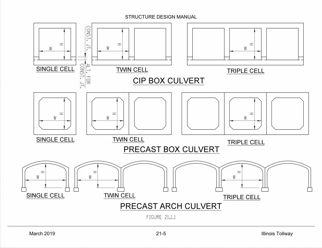
SINGLE CELL TWIN CELL TRIPLE CELL
CIP BOX CULVERT
SINGLE CELL TWIN CELLTRIPLE CELL
SINGLE CELL TWIN CELL TRIPLE CELL
PRECAST BOX CULVERT
PRECAST ARCH CULVERT
CO
NST. JT.
CO
NST. JT.
ALT.
FO
R
WH
W
H
W W
H
W
H
FIGURE 21.1.1
H H
W
W
H H
W W
H
STRUCTURE DESIGN MANUAL
March 2019 21-5 Illinois Tollway
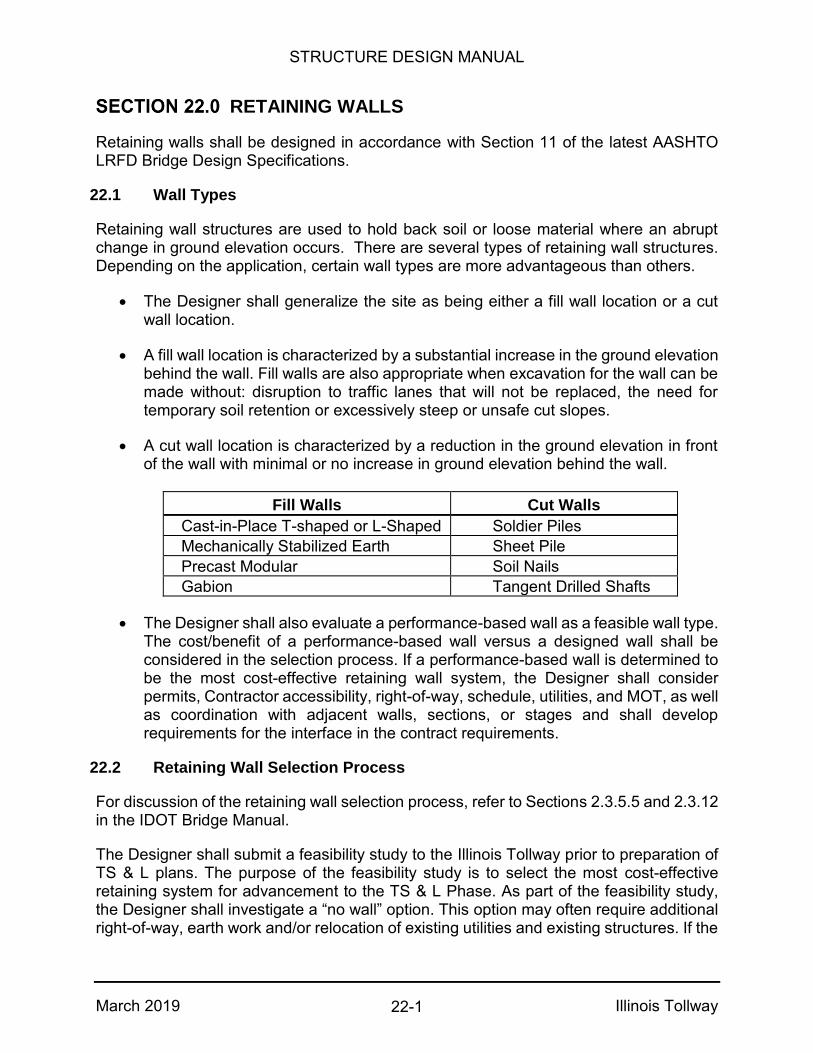
STRUCTURE DESIGN MANUAL
March 2019 Illinois Tollway
RETAINING WALLS
Retaining walls shall be designed in accordance with Section 11 of the latest AASHTO LRFD Bridge Design Specifications.
22.1 Wall Types
Retaining wall structures are used to hold back soil or loose material where an abrupt change in ground elevation occurs. There are several types of retaining wall structures. Depending on the application, certain wall types are more advantageous than others.
The Designer shall generalize the site as being either a fill wall location or a cut wall location.
A fill wall location is characterized by a substantial increase in the ground elevation behind the wall. Fill walls are also appropriate when excavation for the wall can be made without: disruption to traffic lanes that will not be replaced, the need for temporary soil retention or excessively steep or unsafe cut slopes.
A cut wall location is characterized by a reduction in the ground elevation in front of the wall with minimal or no increase in ground elevation behind the wall.
Fill Walls Cut Walls
Cast-in-Place T-shaped or L-Shaped Soldier Piles
Mechanically Stabilized Earth Sheet Pile
Precast Modular Soil Nails
Gabion Tangent Drilled Shafts
The Designer shall also evaluate a performance-based wall as a feasible wall type. The cost/benefit of a performance-based wall versus a designed wall shall be considered in the selection process. If a performance-based wall is determined to be the most cost-effective retaining wall system, the Designer shall consider permits, Contractor accessibility, right-of-way, schedule, utilities, and MOT, as well as coordination with adjacent walls, sections, or stages and shall develop requirements for the interface in the contract requirements.
22.2 Retaining Wall Selection Process
For discussion of the retaining wall selection process, refer to Sections 2.3.5.5 and 2.3.12 in the IDOT Bridge Manual.
The Designer shall submit a feasibility study to the Illinois Tollway prior to preparation of TS & L plans. The purpose of the feasibility study is to select the most cost-effective retaining system for advancement to the TS & L Phase. As part of the feasibility study, the Designer shall investigate a “no wall” option. This option may often require additional right-of-way, earth work and/or relocation of existing utilities and existing structures. If the
22-1

STRUCTURE DESIGN MANUAL
March 2019 Illinois Tollway
“no wall” option is not feasible, the Designer shall study a combination of slopes and wall types to minimize the wall length and height, while remaining aesthetically acceptable and cost effective.
The entirety of the retaining wall shall be constructed within the Illinois Tollway right-of-way. The constructability of the retaining wall shall be considered in the selection, including that construction operations do not encroach on private property.
If a performance based retaining wall is recommended, any alternate retaining wall types not allowed shall be stated in the construction contract specifications.
The feasibility study shall include the following items:
Introduction – Discussion of the project and location of the retaining wall.
Reason for Retaining Wall – Discussion of the improvement, including impact on adjacent property or structures.
Retaining Wall Criteria –Design loads, allowable soil pressures, site constraints and design requirements for the retaining wall.
Retaining Wall Description – Discussion of the location, geometry and other physical features of the retaining wall.
Structural Alternates – Description and cost estimate for each of the wall types investigated including “No Wall” option.
Discussion and Recommendation – Summary of findings for each of the wall types along with a recommendation of which alternate to advance to the TS & L Phase.
The feasibility study shall also include the following exhibits:
Proposed alignment and roadway plan
Proposed roadway cross sections
Preliminary general plan and elevation sketch
Retaining wall typical sections
Retaining wall cost estimates
Boring location map
Boring logs
22-2
STRUCTURE DESIGN MANUAL
March 2019 Illinois Tollway
22.3 Plan Preparation
Plan Sheet Organization
Each retaining wall shall consist of a set of sequentially numbered plan sheets. Plan sheets shall be organized in such a manner as to facilitate construction. The first sheet shall be a plan and elevation view of the entire wall showing its alignment including stations and offsets to each end of the wall and intermediate control points. The location of all lighting, signing, fencing, drainage structures and utilities located under, on, or adjacent to or passing through the wall shall be shown. Also, all design criteria shall be listed.
The TS & L and final plans shall include a true wall section(s) which shows wall offsets to base line(s) and R.O.W.
The second sheet shall contain an index of sheets, general notes, abbreviations, total bill of material, typical wall section and drainage details. Subsequent sheets shall completely detail and dimension each succeeding section of the retaining wall in plan and elevation views. Wall sections and details shall be included on each sheet. See Figures 22.3.1.1 through 22.3.1.7 for retaining wall details.
Each retaining wall plan set shall include pile driving record tables and boring log sheets for the data that pertains to the retaining wall. The bottom of footing elevation shall be shown on the appropriate boring log and identified as “Bottom of Retaining Wall Footing.”
Naming Convention
Retaining walls shall be identified on the plans using the following format: Illinois Tollway Milepost Wall Type, Direction (Ramp) TOLLWAY: EW = Reagan Memorial Tollway (I-88) NS = Veterans Memorial Tollway (I-355) NW = Jane Addams Memorial Tollway (I-90) TS = Tri-State Tollway (I-294 & I-294/I-80) TN = Tri-State Tollway (I-94) ES = Edens Spur (I-94) EO = Elgin-O’Hare Tollway (IL 390) WA = West O’Hare Access (I-490) MILEPOST: Two-decimal lowest wall milepost to the tenth or hundredth if a ¼ mile
post (i.e. 14.75) WALL TYPE: R = Retaining Wall DIRECTION: EB, SB, WB, NB - Inventory direction of the mainline roadway
22-3
STRUCTURE DESIGN MANUAL
March 2019 Illinois Tollway
RAMP: (R) = if lowest milepost is along ramp (omitted if not along ramp) EXAMPLE: TS38.40R,NB(R) for a retaining wall located along the Tri-State Tollway (I-
294) northbound at milepost 38.4 on a ramp If two walls of the same type have identical starting mileposts, the inventory milepost of one of the walls shall be shifted by one hundredth of a mile to create unique names.
22.4 Wall Design Criteria
Design Specifications
See Article 5.1.
Design Loads
Dead Loads
See Article 5.1.
Live Loads
See Article 5.1.
Earth Pressure
See Article 5.1. The formula to compute lateral earth pressure is Coulomb's equation for the resultant parallel to the backfill slope. The maximum angle of
internal friction for granular material shall be = 30 deg.
The formula to compute lateral earth pressure for sloping backfill assumes the mass of earth behind the wall extending to the point of intersection of the two planes (slope plane and failure plane of soil). In many cases the sloping backfill ends at a certain height above the wall where a roadway is intersected. The formula gives conservative results for this case. See Figure 22.4.2.1 for details
Wind Loads
A wind load on the parapet and/or noise abatement wall shall be applied to the exposed surface area in any direction.
Vehicular Collision Loads
See Article 10.2.
Design Stresses
See Article 5.1.
22-4
STRUCTURE DESIGN MANUAL
March 2019 Illinois Tollway
Wall Layout
Slopes in front of all wall types shall not be continued into or away from the wall. A flat area shall be provided in front of the wall for maintenance and to ensure adequate frost line clearance. A 4 foot desirable width and a 2 foot minimum width shall be used for this flat area.
22.5 Cast-in-Place T-Shaped or L-Shaped Walls
Cast-in-place T-shaped and L-shaped walls shall be designed in accordance with Sections 3.10 and 3.11 of the latest IDOT Bridge Manual except as amended herein.
Description
In general, the Illinois Tollway utilizes cantilever T-shaped retaining walls in fill locations up to a height of 25 feet. For details of a T-shaped wall see Figures 22.5.1.1 thru 22.5.1.3. Counterforted I-walls and/or l-shaped walls may also be used for special cases.
Typically, a T-shaped wall is more economical than an L-shaped wall. L-shaped walls are utilized in cases where the face of the wall is located adjacent to or right on the ROW, property line or obstruction.
Stem
The minimum thickness at the top of the stem is 12 inches. For stems requiring thickness greater than 12 inches at the base, batter is provided on the back face of the stem (the face in contact with the earth) in increments of ¼ inch per foot up to a maximum of ¾ inch per foot. The batter shall be held constant for the entire length or section of the retaining wall where it is required. The stem shall be designed to accommodate crash Test Level 5 (TL-5) loading. See the latest AASHTO LRFD Table A.13.2-1 for loading details. The stem shall have sufficient resistance to force the yield line failure pattern to remain within the parapet and shall be designed for the full dynamic load. Drainage behind the stem shall consist of a geocomposite wall drain and porous granular backfill, consistent with Section 3.11.2.3 of the IDOT Bridge Manual, except as modified herein. The geocomposite wall drain shall be continuous. Refer to Figures 22.3.1.2 and 22.5.1.1 for illustration.
Footing
The bottom of footing shall be set below the frost penetration depth, which is generally 4 feet below the top of finished grade. The minimum spread footing thickness shall not be less than 18 inches or the stem thickness at the base plus 3 inches.
For pile supported footings, the minimum thickness shall be 2’-6” and the piles shall be embedded 12 inches. The front row(s) shall be battered if the piles' lateral resistance to sliding is not adequate. The maximum pile spacing shall be as specified in Section 3.10 of the IDOT Bridge Manual. For walls with pile footings it is usually more economical to
22-5
STRUCTURE DESIGN MANUAL
March 2019 Illinois Tollway
use the minimum width of footing where feasible rather than to increase the footing width to reduce the number of piles.
If the top of finished ground is sloped along the face of wall, a stepped footing shall be considered. For details of stepped footings and minimum thickness requirements, see Figures 22.5.3.1 and 22.5.3.2.
The footing shall be designed to accommodate crash Test Level 5 (TL-5) loading. See the latest AASHTO LRFD Table A.13.2-1 for loading details. Guidance on the magnitude of force applied to the footing is limited; however, a reduction in energy will occur as the yield line develops within the parapet and forces are transferred through the stem. The footing and piles shall be designed for the equivalent static load of 23 kips applied over 8 feet at the top of the 44 inch parapet or 106 kips applied over 10 feet at 52 inch above pavement for the 72 inch parapet.
Stability
The eccentricity limits for spread footings on soil or rock shall be according to AASHTO LRFD 11.6.3.3.
Resistance factors for bearing and sliding shall be according to AASHTO LRFD Table 10.5.5.2.2-1. Factors resisting sliding for spread footings:
Friction Between Soil and Concrete
Friction resistance shall be according to Section 10 of the latest AASHTO LRFD Bridge Design Specifications.
Shear Keys for Spread Footings on Soil
The shear key shall be located in line with the front face of the stem except under severe loading conditions. The width and depth of the shear key shall be 1’-0” minimum. The shear key shall be placed against undisturbed material.
The total resistance to sliding shall be based on the soil strength in front of the shear key and adhesion between the footing and soil behind the key.
Shear Keys for Spread Footings on Rock
The width of the key shall be 1’-0” minimum. The footing shall be keyed a minimum depth of 6” into the rock.
22-6

STRUCTURE DESIGN MANUAL
March 2019 Illinois Tollway
Pile Footings
The maximum slope to be used for determining the horizontal resistance of a battered pile shall be 3 inches horizontal per foot vertical.
The lateral resistance of battered or vertical piles, in addition to horizontal component of battered piles, shall be as specified in the Structure Geotechnical Report.
22.6 Flexible Retaining Walls
Flexible retaining walls include; Mechanically Stabilized Earth (MSE), Precast Modular, Soldier Pile, Sheet Pile, Soil Nail and Gabion.
Walls shall be located a minimum of 10'-0" inside of the Illinois Tollway's Right of Way.
The required design life for all elements of retaining wall structures is 75 years except for walls in front of bridge abutments which require a design life of 100 years.
Provide full height expansion joints in the gutter and parapet every 90 feet. The expansion joints shall be detailed as shown in Figures 22.12.1 and 22.14.1. Provide partial height parapet joints in the upper portion of the parapet at 15-foot centers. These partial height joints shall be ½-inch open joints.
Design loads for retaining walls with moment slabs shall include the provisions of the AASHTO LRFD Bridge Design Specifications, Article 11.10.10.2 and Test Level 5 (TL-5). In order to achieve TL-5 crash force protection, all designers shall increase the specified horizontal load applied to the top of the soil mass from 0.5 kip per foot, developed for TL-4, to 1.15 kips per foot (for TL-5) and 2.4 kips per foot (for 72 inch TL-5). The magnitude of the was determined by multiplying the ratio of the TL-5 or 72 inch TL-5 crash force (124 kips or 260 kips) over the TL-4 crash force (54 kips) by 0.5 kip per foot.
When structural steel is in contact with the ground, the effects of corrosion shall be included in the design. The specification and accommodation for the length of the corrosion are the responsibility of the Designer with approval of the Illinois Tollway. Paint used shall be specified by the Designer and shall be consistent with Section 506 of IDOT Standard Specifications. The IDOT Bridge Manual also references concrete encasement and use of additional sacrificial steel section. Paint or concrete in exposed conditions shall generally extend to 3 feet beyond expected exposure line including the fully exposed length. Section 506 of the Standard Specifications for paint shall be used in corrosive soils with or without exposure. If protection is not specified for exposed or corrosive conditions, additional steel section shall be supplied to compensate for losses due to corrosion.
22-7

STRUCTURE DESIGN MANUAL
March 2019 Illinois Tollway
Mechanically Stabilized Earth (MSE) Retaining Walls
Generally, MSE walls shall only be utilized for fill locations or where part of the existing side-slope or fore-slope can be removed without compromising the stability of the embankment. MSE walls shall not be utilized where a Temporary Earth Retention System would be required to construct the reinforced wall mass except in special cases.
The Designer shall be responsible for the analysis of settlement, bearing capacity and overall slope stability for MSE retaining walls and shall coordinate with the Geotechnical Engineer during the Concept (30%) Design Phase.
22.6.1.1 Location
MSE walls are not allowed at water crossings or adjacent to water where hydraulic draw down within the wall limits is possible.
22.6.1.2 Plans and Specifications
The Contractor shall be provided with plans showing a line diagram envelope (Elevation View) of the proposed wall location, grades, and dimensions. Specifications shall be furnished covering the work requirements for design, construction plans, materials procurement, and wall construction. The prequalified retaining wall supplier selected by the Contractor shall submit a complete set of design calculations, detailed plans, and explanatory notes for the designer's review and acceptance prior to ordering any material. The design shall be in accordance with the latest AASHTO LRFD Bridge Design Specifications and the special provisions.
The designer shall prepare plan sheets containing the following information:
Site plan with boring locations
Wall plan with stations and offsets
Top of wall elevations (located at the top of exposed panel line)
Top of ground elevations at front and back face of wall
Safety-parapet railing, or fence requirements
Special coping requirements
Utility accommodations
Drainage requirements
All special design features
Subsurface information (the proprietary wall companies shall be informed of all geotechnical stability and settlement concerns)
22-8

STRUCTURE DESIGN MANUAL
March 2019 Illinois Tollway
Wall surface textures
Wall design criteria
Minimum footing depth (generally 4'-0", which is considered to be the frost penetration depth)
22.7 Precast Modular Walls
Block retaining walls shall be designed in accordance with the applicable parts of Section 3.11.1 of the IDOT Bridge Manual and the latest LRFD AASHTO Bridge Design Specifications except as amended herein. When specifying a proprietary block retaining wall, the special provisions shall state that the wall shall be built according to the manufacturer’s specifications. The manufacturer’s specifications generally need to be supplemented. Material specifications for backfill, leveling pad, drainage systems, fill for hollow blocks, geotextile fabrics or any other special requirements shall be clearly stated in the special provisions.
Modular block retaining walls shall be designed and sealed by the manufacturer’s Illinois Licensed Structural Engineer. Soil reinforcement shall be either galvanized or coated steel or polypropylene or polyester geogrids. In the absence of more accurate data, design loads on the wall shall be based on a non-cohesive material with an angle of internal friction of 34 deg. The minimum size of the concrete leveling pad shall be 6 inches deep by 12 inches wide. All steel components of a system shall be hot dipped galvanized in accordance with the AASHTO M111 (ASTM A123).
22.8 Soldier Pile Retaining Walls
Soldier pile walls shall be designed in accordance with Section 3.11.3 of the latest IDOT Bridge Manual and the latest AASHTO LRFD Bridge Design Specifications except as amended herein. Timber lagging is not permitted as a facing material for permanent soldier pile walls.
22.9 Permanent Sheet Pile Retaining Walls
Permanent sheet pile retaining walls shall be designed in accordance with Section 3.11.4 of the latest IDOT Bridge Manual.
22.10 Soil Nailed and Other Specialized Wall Systems
Soil nailed and other specialized wall systems shall be designed in accordance with Section 3.11.6 of the latest IDOT Bridge Manual.
22.11 Temporary Soil Retention Systems
Temporary soil retention systems, including temporary sheet piling, wire-faced MSE walls, braced excavations and other temporary construction works shall be designed in accordance with Section 3.13 of the latest IDOT Bridge Manual.
22-9

STRUCTURE DESIGN MANUAL
March 2019 Illinois Tollway
22.12 Snow Storage Area
The need for and design of the snow storage area shall be according to the latest version of the Illinois Tollway Roadway Design Criteria Article 2.6.7. Figure 22.12.1 Structure Mounted Noise Abatement Wall on Moment Slab with notes included provide the configuration and design of the parapet for attached noise abatement wall on a moment slab including snow storage as per the notes when needed.
22.13 Parapet Shape
The Illinois Tollway uses 44” Constant-Slope parapet shapes for retaining walls. Parapet shall be designed to accommodate crash Test Level 5 (TL-5). See the latest AASHTO LRFD Table A.13.2-1 for loading details. The Constant-Slope parapet integral with the retaining wall shall extend 6” below finished grade. See Figure 22.5.1.3 as an example.
22.14 Moment Slab on Retaining Wall Design Guides
A moment slab includes both the horizontal slab and the 44” Constant-Slope vertical parapet that is attached to the slab. Design loads for strength that include flexure, shear and torsion are applied in accordance with the AASHTO LRFD Bridge Design Specifications, Section 13, Table A13.2, Test Level 5 (TL-5). Design loads for global stability including sliding and overturning shall follow recommendations of NCHRP 663 for standard height barrier and NCHRP 22-20(2) for 6 foot barrier. Prior to this change, walls and moment slabs were designed in accordance with AASHTO Standard Specifications Load Factor Design (LFD) methodology.
Exposed moment slabs shall be used when a rigid shoulder is used. Figures 22.14.2 and 22.12.1 illustrates typical reinforcement bar details for an exposed moment slab. Buried moment slabs shall be considered whenever a flexible pavement shoulder is used. Other cases may include when a TL-5 barrier is required but site limitations require an L-shape section or a smaller width of slab is preferred over the exposed moment slab details. Buried moment slab may be either cast-in-place per Figure 22.14.1.1 or precast per Figure 22.14.1.3. Details for buried moment slab with noise abatement wall are shown in Figure 22.14.1.5. A minimum 6” thick layer of CA-6 aggregate shall be placed beneath the moment slab to develop friction. This layer is to be detailed on the plans. Concrete for moment slabs under the Illinois Tollway jurisdiction shall be placed in accordance with the following policy:
Performance Mix Concrete, f’c=4,000 psi min. shall be used for moment slabs.
BS Concrete, f’c=4,000 psi min. shall be applied on moment slab parapets.
22-10
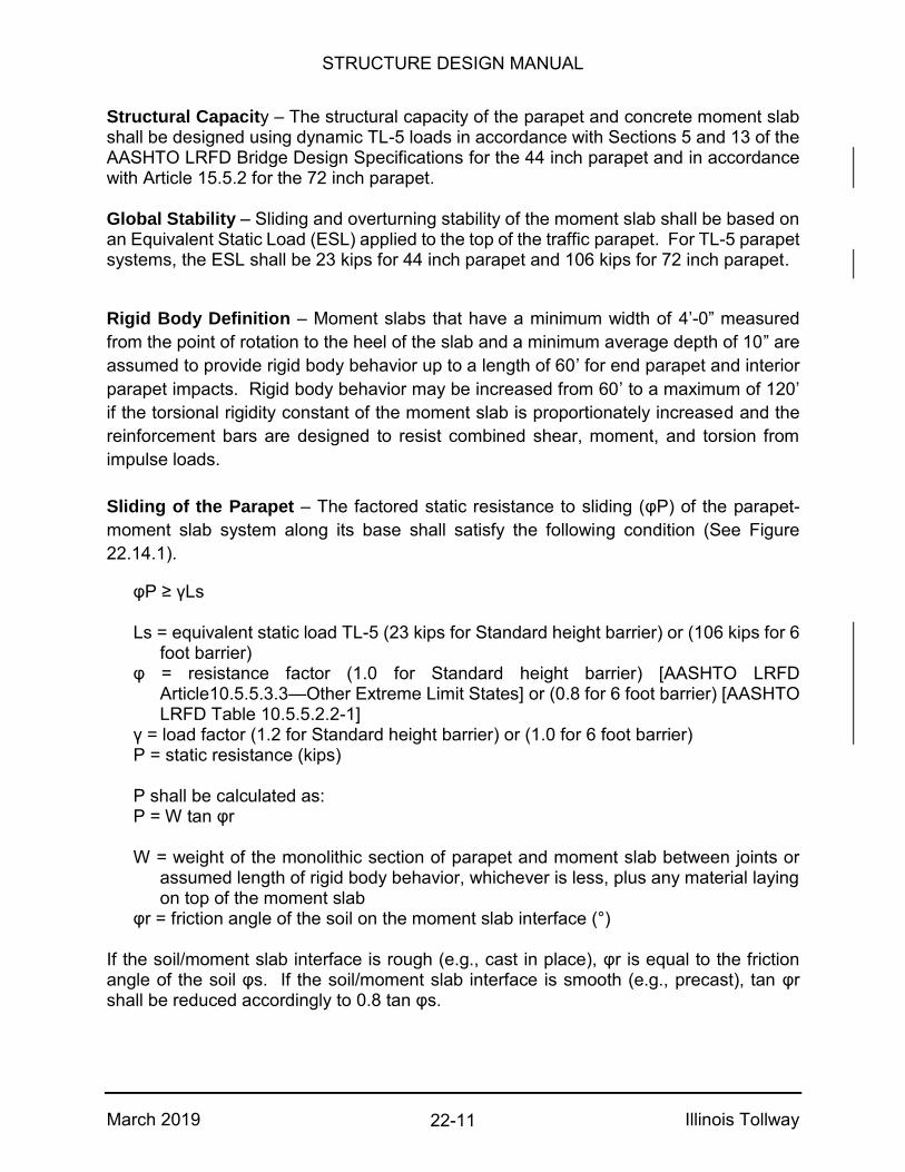
STRUCTURE DESIGN MANUAL
March 2019 Illinois Tollway
Structural Capacity – The structural capacity of the parapet and concrete moment slab shall be designed using dynamic TL-5 loads in accordance with Sections 5 and 13 of the AASHTO LRFD Bridge Design Specifications for the 44 inch parapet and in accordance with Article 15.5.2 for the 72 inch parapet. Global Stability – Sliding and overturning stability of the moment slab shall be based on an Equivalent Static Load (ESL) applied to the top of the traffic parapet. For TL-5 parapet systems, the ESL shall be 23 kips for 44 inch parapet and 106 kips for 72 inch parapet.
Rigid Body Definition – Moment slabs that have a minimum width of 4’-0” measured
from the point of rotation to the heel of the slab and a minimum average depth of 10” are
assumed to provide rigid body behavior up to a length of 60’ for end parapet and interior
parapet impacts. Rigid body behavior may be increased from 60’ to a maximum of 120’
if the torsional rigidity constant of the moment slab is proportionately increased and the
reinforcement bars are designed to resist combined shear, moment, and torsion from
impulse loads.
Sliding of the Parapet – The factored static resistance to sliding (φP) of the parapet-
moment slab system along its base shall satisfy the following condition (See Figure
22.14.1).
φP ≥ γLs
Ls = equivalent static load TL-5 (23 kips for Standard height barrier) or (106 kips for 6 foot barrier)
φ = resistance factor (1.0 for Standard height barrier) [AASHTO LRFD Article10.5.5.3.3—Other Extreme Limit States] or (0.8 for 6 foot barrier) [AASHTO LRFD Table 10.5.5.2.2-1]
γ = load factor (1.2 for Standard height barrier) or (1.0 for 6 foot barrier) P = static resistance (kips) P shall be calculated as: P = W tan φr W = weight of the monolithic section of parapet and moment slab between joints or
assumed length of rigid body behavior, whichever is less, plus any material laying on top of the moment slab
φr = friction angle of the soil on the moment slab interface (°)
If the soil/moment slab interface is rough (e.g., cast in place), φr is equal to the friction angle of the soil φs. If the soil/moment slab interface is smooth (e.g., precast), tan φr shall be reduced accordingly to 0.8 tan φs.
22-11
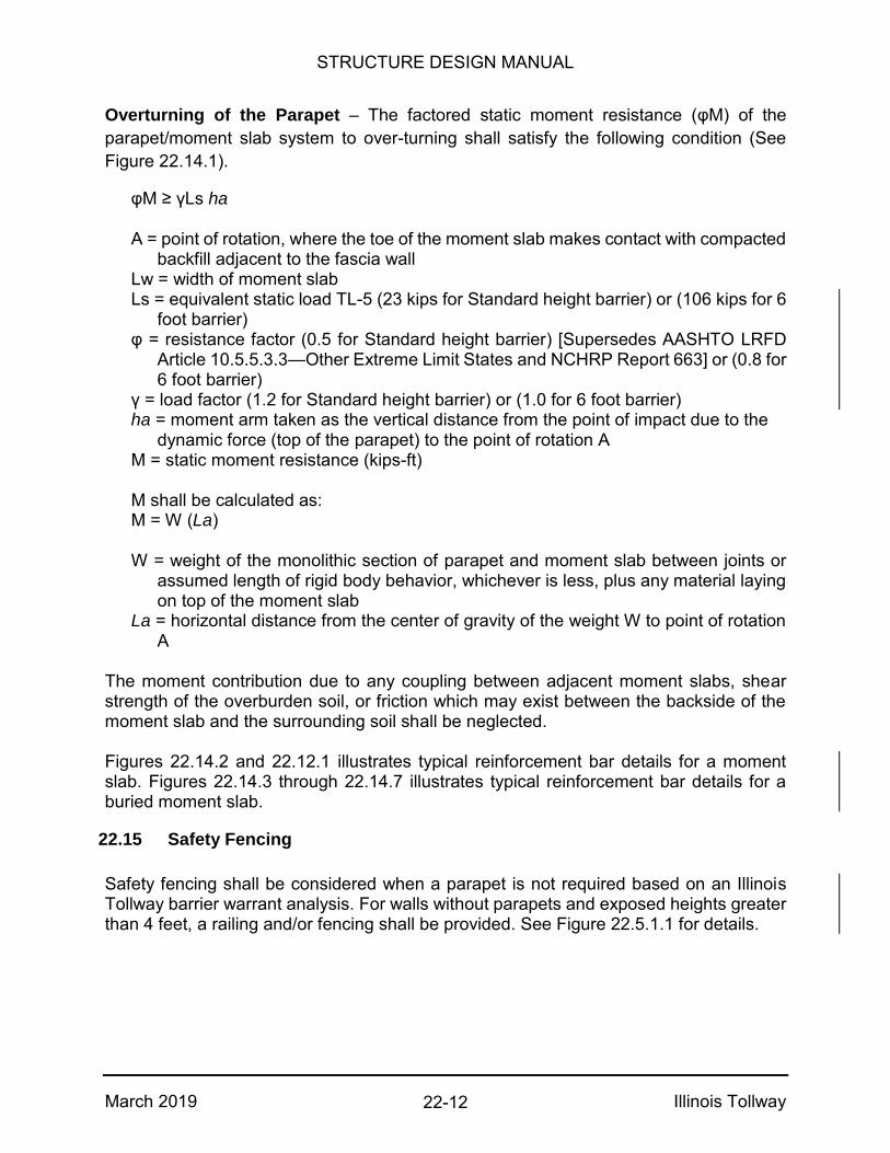
STRUCTURE DESIGN MANUAL
March 2019 Illinois Tollway
Overturning of the Parapet – The factored static moment resistance (φM) of the
parapet/moment slab system to over-turning shall satisfy the following condition (See
Figure 22.14.1).
φM ≥ γLs ha
A = point of rotation, where the toe of the moment slab makes contact with compacted backfill adjacent to the fascia wall
Lw = width of moment slab Ls = equivalent static load TL-5 (23 kips for Standard height barrier) or (106 kips for 6
foot barrier) φ = resistance factor (0.5 for Standard height barrier) [Supersedes AASHTO LRFD
Article 10.5.5.3.3—Other Extreme Limit States and NCHRP Report 663] or (0.8 for 6 foot barrier)
γ = load factor (1.2 for Standard height barrier) or (1.0 for 6 foot barrier) ha = moment arm taken as the vertical distance from the point of impact due to the
dynamic force (top of the parapet) to the point of rotation A M = static moment resistance (kips-ft) M shall be calculated as: M = W (La)
W = weight of the monolithic section of parapet and moment slab between joints or
assumed length of rigid body behavior, whichever is less, plus any material laying on top of the moment slab
La = horizontal distance from the center of gravity of the weight W to point of rotation A
The moment contribution due to any coupling between adjacent moment slabs, shear strength of the overburden soil, or friction which may exist between the backside of the moment slab and the surrounding soil shall be neglected. Figures 22.14.2 and 22.12.1 illustrates typical reinforcement bar details for a moment slab. Figures 22.14.3 through 22.14.7 illustrates typical reinforcement bar details for a buried moment slab.
22.15 Safety Fencing
Safety fencing shall be considered when a parapet is not required based on an Illinois Tollway barrier warrant analysis. For walls without parapets and exposed heights greater than 4 feet, a railing and/or fencing shall be provided. See Figure 22.5.1.1 for details.
22-12
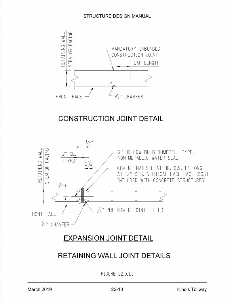
RE
TAININ
G
WA
LL
ST
EM
OR
FA
CIN
G
ST
EM
OR
FA
CIN
G
CEMENT NAILS FLAT HD. C.S. 1" LONG
MANDATORY UNBONDED
CONSTRUCTION JOINT
ƒ" CHAMFER
RETAINING WALL JOINT DETAILS
CONSTRUCTION JOINT DETAIL
EXPANSION JOINT DETAIL
ƒ" CHAMFER
2ƒ"
•"
6"
FRONT FACE
FRONT FACE
RE
TAININ
G
WA
LL
INCLUDED WITH CONCRETE STRUCTURES)
AT 12" CTS. VERTICAL EACH FACE (COST
•" PREFORMED JOINT FILLER
FIGURE 22.3.1.1
(TYP.)
2" CL.
LAP LENGTH
NON-METALLIC WATER SEAL
6" HOLLOW BULB DUMBBELL TYPE,
STRUCTURE DESIGN MANUAL
March 2019 22-13 Illinois Tollway

INTER
ME
DIA
TE
EN
D
CA
P
6" FL
AP (T
YP.)
INTER
ME
DIA
TE
TO
P
CA
P
3'-0"
3'-0"
3'-0"
FIGURE 22.3.1.2
GE
OC
OM
PO
SIT
E W
ALL D
RAIN D
ET
AIL
SBU
TT S
PLIC
E
VE
RTIC
AL C
RO
SS S
EC
TIO
N
TO
P C
OU
RS
E
STRUCTURE DESIGN MANUAL
March 2019 22-14 Illinois Tollway
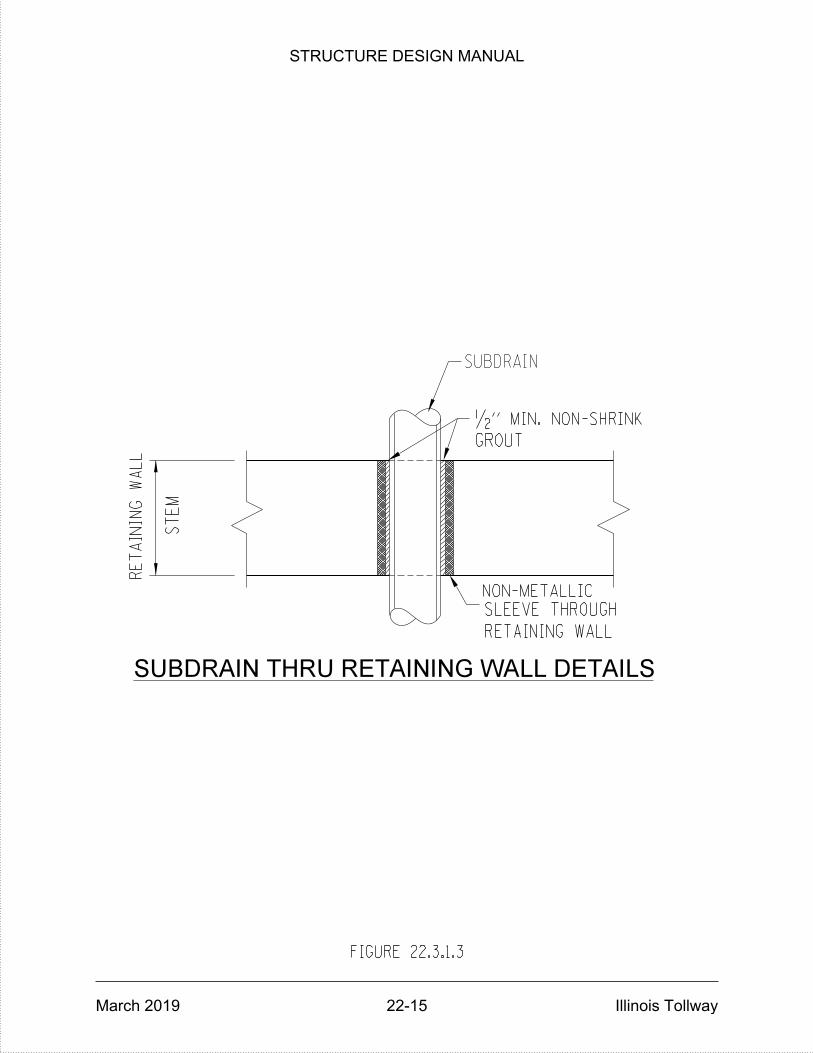
ST
EM
SLEEVE THROUGH
SUBDRAIN THRU RETAINING WALL DETAILS
RE
TAININ
G
WA
LL
GROUT
•" MIN. NON-SHRINK
RETAINING WALL
FIGURE 22.3.1.3
SUBDRAIN
NON-METALLIC
STRUCTURE DESIGN MANUAL
March 2019 22-15 Illinois Tollway
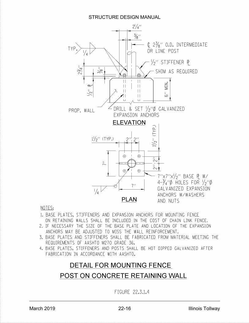
PLAN
2"
ELEVATION
2"
PROP. WALL
TYP.‚
2"
2"
OR LINE POST
7"x7"x•" BASE ` W/
~ 2…" O.D. INTERMEDIATE
1•
" (T
YP.)
1•" (TYP.)
7"
7"
•" `
…"
2ƒ
"
…"
2‚"
‚
6"
MIN.
NOTES:
EXPANSION ANCHORS
DRILL & SET •"} GALVANIZED
4-ƒ"} HOLES FOR •"}
GALVANIZED EXPANSION
ON RETAINING WALLS SHALL BE INCLUDED IN THE COST OF CHAIN LINK FENCE.
3. BASE PLATES AND STIFFENERS SHALL BE FABRICATED FROM MATERIAL MEETING THE
REQUIREMENTS OF AASHTO M270 GRADE 36.
FABRICATION IN ACCORDANCE WITH AASHTO.
2. IF NECESSARY THE SIZE OF THE BASE PLATE AND LOCATION OF THE EXPANSION
ANCHORS MAY BE ADJUSTED TO MISS THE WALL REINFORCEMENT.
FIGURE 22.3.1.4
4. BASE PLATES, STIFFENERS AND POSTS SHALL BE HOT DIPPED GALVANIZED AFTER
1. BASE PLATES, STIFFENERS AND EXPANSION ANCHORS FOR MOUNTING FENCE
AND NUTS
ANCHORS W/WASHERS
DETAIL FOR MOUNTING FENCE
POST ON CONCRETE RETAINING WALL
SHIM AS REQUIRED
•" STIFFENER `
STRUCTURE DESIGN MANUAL
March 2019 22-16 Illinois Tollway
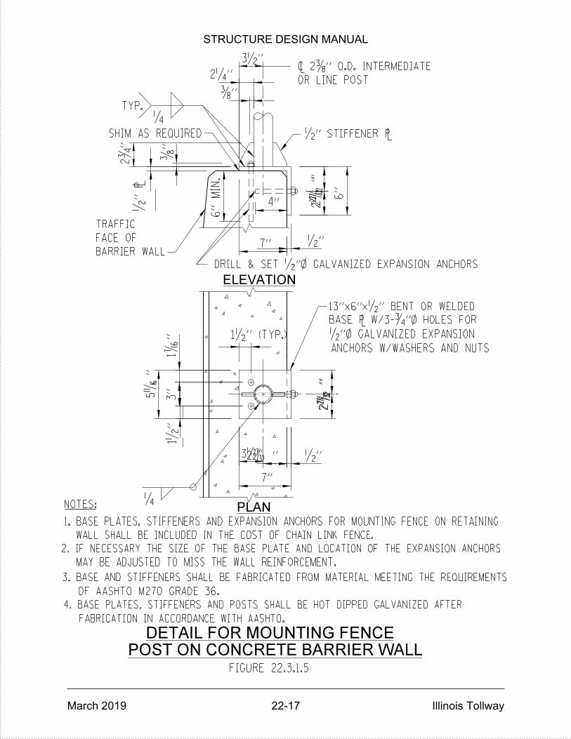
POST ON CONCRETE BARRIER WALL
DETAIL FOR MOUNTING FENCE
‚
ELEVATION
PLAN
‚
TYP.
OR LINE POST
TRAFFIC
FACE OF
BARRIER WALL
~ 2…" O.D. INTERMEDIATE
6"
MIN.
4" 2•
"2•
"
6"
7" •"
2•
"2•
"
7"
2•" •"
NOTES:
2‚"
…"
•" `
…"
1•" (TYP.)
DRILL & SET •"} GALVANIZED EXPANSION ANCHORS
1•
"3"
1‹
"
5•
"
BASE ` W/3-ƒ"} HOLES FOR
13"x6"x•" BENT OR WELDED
•"} GALVANIZED EXPANSION
3. BASE AND STIFFENERS SHALL BE FABRICATED FROM MATERIAL MEETING THE REQUIREMENTS
FABRICATION IN ACCORDANCE WITH AASHTO.
1. BASE PLATES, STIFFENERS AND EXPANSION ANCHORS FOR MOUNTING FENCE ON RETAINING
WALL SHALL BE INCLUDED IN THE COST OF CHAIN LINK FENCE.
OF AASHTO M270 GRADE 36.
FIGURE 22.3.1.5
4. BASE PLATES, STIFFENERS AND POSTS SHALL BE HOT DIPPED GALVANIZED AFTER
ANCHORS W/WASHERS AND NUTS
3•"
2ƒ
"
3•"
MAY BE ADJUSTED TO MISS THE WALL REINFORCEMENT.
2. IF NECESSARY THE SIZE OF THE BASE PLATE AND LOCATION OF THE EXPANSION ANCHORS
SHIM AS REQUIRED •" STIFFENER `
STRUCTURE DESIGN MANUAL
March 2019 22-17 Illinois Tollway

A
A
STAINLESS STEEL STANDARD GRADE
WIRE CLOTH - TYPE 304, 4x4
MESH, 0.047" WIRE DIAMETER
MAX.
CL.
CL.
3-#6 v(E) BARS
1v (E)
v(E)
PROVIDE 2 FLAT WASHERS ,
1 LEVELING NUT & 1 LOCKNUT
FOR EACH BOLT. ALL NUTS &
WASHERS MUST BE GALVANIZED.
ANCHOR BOLT DETAIL.
13-#6 v (E) BARS
BY OTHERS
1
1
LIGHT STANDARD ON RETAINING WALL DETAILS
SECTION A-A
2"
8" 8"4"
8"
10†
"
10"
10†"
1'-3" 1'-3"
2'-6"
1'-
8"
2"
2"
10"} ALUMINUM POLE
15"} BOLT CIRCLE
2"} PVC CONDUIT (TYP.)
THREAD AND CAP END OF
CONDUIT. WHEN READY FOR
BUSHING
WIRING REPLACE CAP WITH
STAINLESS STEEL MESH
VIBRATION WASHER (BY OTHERS)
1" BASE ` (BY OTHERS)
•" VIBRATION PAD (BY OTHERS)
LEVELING ` (BY OTHERS)
7-#6 e(E)
BA
RS
16" x 16" BASE ` (BY OTHERS)
1'-
0"
8"
MIN.
MA
X.
e(E)
10"
4'-
6"
NOTE:
BE PAID FOR SEPARATELY.
ITEM. 2"} PVC CONDUIT SHALL
CONCRETE STRUCTURES PAY
INCLUDED IN THE COST OF
COST OF ANCHOR BOLTS IS
FIGURE 22.3.1.6
2
22
SEE FIGURE 22.3.1.7 FOR
BAR DETAILS.
SEE FIGURE 22.3.1.7 FOR
6"
8"
8•"
3'-
8"
1"} x 6'-0" ANCHOR BOLTS
STRUCTURE DESIGN MANUAL
March 2019 22-18 Illinois Tollway
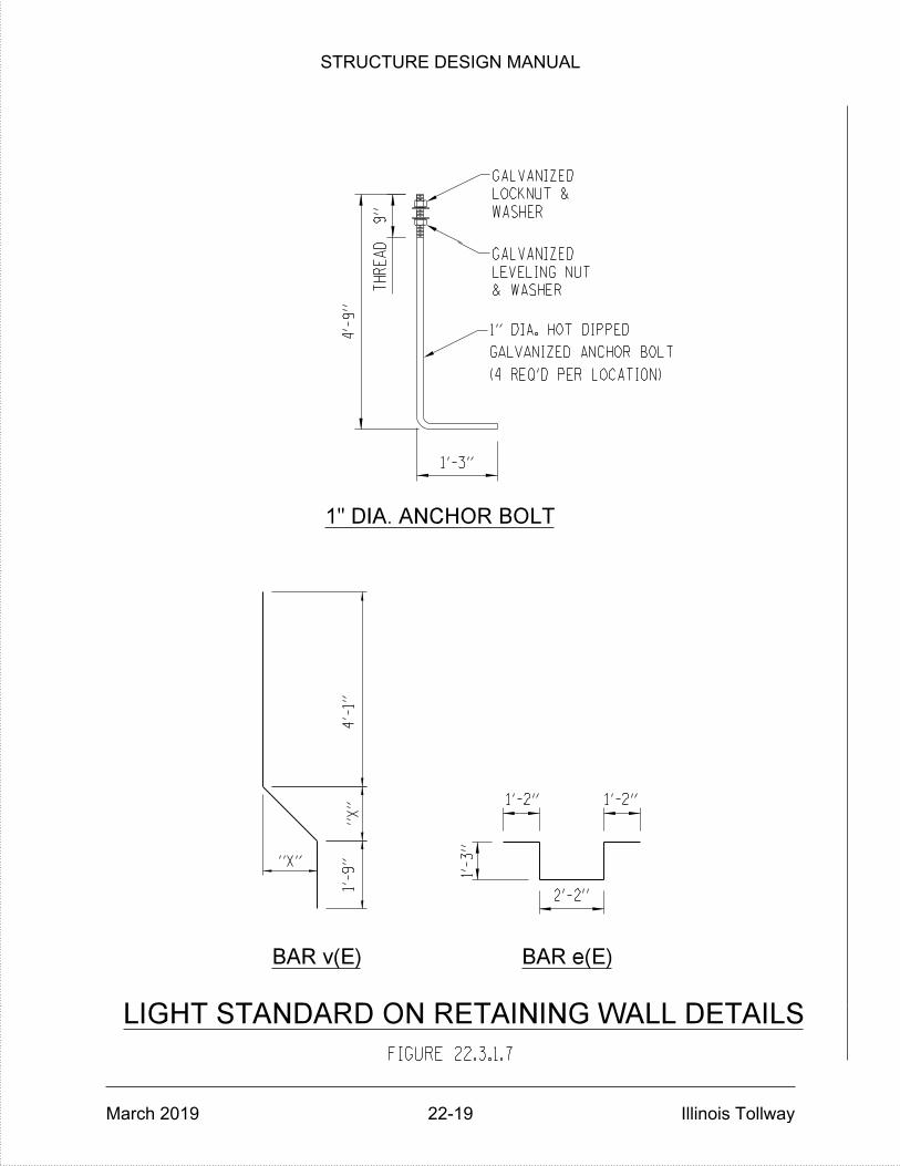
LOCKNUT &
WASHER
& WASHER
LEVELING NUT
TH
RE
AD
LIGHT STANDARD ON RETAINING WALL DETAILS
BAR v(E)
1" DIA. ANCHOR BOLT
1'-3"
1'-
9"
1'-2" 1'-2"
2'-2"
1'-
3"
GALVANIZED
GALVANIZED
BAR e(E)
4'-
1"
4'-
9"
FIGURE 22.3.1.7
"X"
"X"
9"
(4 REQ'D PER LOCATION)
GALVANIZED ANCHOR BOLT
1" DIA. HOT DIPPED
STRUCTURE DESIGN MANUAL
March 2019 22-19 Illinois Tollway

F
d
RANKINE OR COULOMB FORMULA FOR ACTIVE EARTH PRESSURE
F d
F
d
1
1
P
2
1
( )COS + COS - COS
H = TOTAL WALL DEPTH AS SHOWN IN SKETCH, FEET.
= ANGLE OF INTERNAL FRICTION OF SOIL, DEGREES.
= ANGLE OF SLOPE OF BACKFILL, DEGREES.
1
( ) 2
1
2
1=
2=
1P = WH 2 1. - 1. - 0.86603
1. + 1. - 0.86603
2
2
2WH (0.333) 2H (0.04)
22 2
d d F2 2
H
X
H /3
H
DESIGN LOADS
FIGURE 22.4.2.1
WHERE P = TOTAL ACTIVE EARTH PRESSURE, KIPS PER FOOT OF WALL LENGTH.
W = UNIT WEIGHT OF SOIL, KIPS PER CUBIC FOOT.
STRUCTURE DESIGN MANUAL
March 2019 22-20 Illinois Tollway
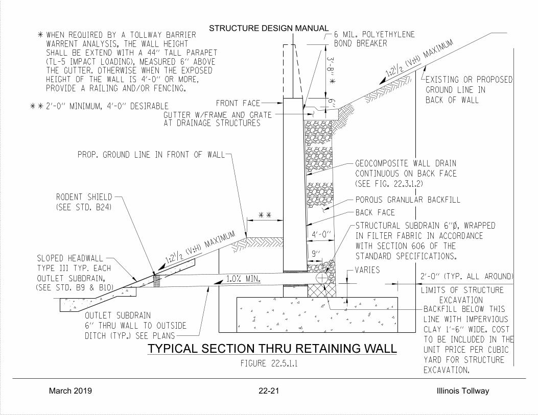
GEOCOMPOSITE WALL DRAIN
CONTINUOUS ON BACK FACE
POROUS GRANULAR BACKFILL
STRUCTURAL SUBDRAIN 6"}, WRAPPED
IN FILTER FABRIC IN ACCORDANCE
TYPICAL SECTION THRU RETAINING WALL
FRONT FACE
PROP. GROUND LINE IN FRONT OF WALL
SLOPED HEADWALL
TYPE III TYP. EACH
OUTLET SUBDRAIN
DITCH (TYP.) SEE PLANS
6" THRU WALL TO OUTSIDE
BACK OF WALL
GROUND LINE IN
EXISTING OR PROPOSED
LINE WITH IMPERVIOUS
CLAY 1'-6" WIDE. COST
TO BE INCLUDED IN THE
UNIT PRICE PER CUBIC
EXCAVATION
BACKFILL BELOW THIS
YARD FOR STRUCTURE
*
BACK FACE
OUTLET SUBDRAIN,
RODENT SHIELD
1.0% MIN.
VARIES
9"
FIGURE 22.5.1.1
*
WITH SECTION 606 OF THE
STANDARD SPECIFICATIONS.
LIMITS OF STRUCTURE
EXCAVATION.
(SEE STD. B9 & B10)
(SEE FIG. 22.3.1.2)
(SEE STD. B24)6"
3'-
8"
1:2• (V:H) MAXI
MUM
1:2•
(V:H)
MAXIMUM
BOND BREAKER
6 MIL. POLYETHYLENE
**
**
4'-0"
AT DRAINAGE STRUCTURESGUTTER W/FRAME AND GRATE
2'-0" MINIMUM, 4'-0" DESIRABLE
PROVIDE A RAILING AND/OR FENCING.
HEIGHT OF THE WALL IS 4'-0" OR MORE,
THE GUTTER. OTHERWISE WHEN THE EXPOSED
(TL-5 IMPACT LOADING), MEASURED 6" ABOVE
SHALL BE EXTEND WITH A 44" TALL PARAPET
WARRENT ANALYSIS, THE WALL HEIGHT
WHEN REQUIRED BY A TOLLWAY BARRIER
2'-0" (TYP. ALL AROUND)
STRUCTURE DESIGN MANUAL
March 2019 22-21 Illinois Tollway

POINT OF MAX.
SOIL PRESSURE
w (E)
CONSTRUCTION JOINT
1
n (E)
v (E)
SP
ECIF
Y
MIN.
x T
FIGURE 22.5.1.2
1•"x3•" KEYWAY
2" CL.
2"
CL.
18"
MIN.
3"
CL.
2" CL.
PR
OJ
EC
TIO
N
AN
D
LA
P
BO
TH
FA
CES
#4v (E) AT 1'-0" CTS.
#4h (E) AT | 2'-0" CTS.
CTS.@ 1'-0"#4n (E)
#4h (E) AT 1'-0" CTS.
*
*
FOOT MAXIMUM.
ZERO TO ƒ" PER
BACK FACE SLOPE =
t
t
TYPICAL CANTILEVER RETAINING WALL
REINFORCEMENT BAR DETAILS
BARS, (E)TOE REINFORCEMENT
b
BARS, (E)HEEL REINFORCEMENT
FRONT FACE BACK FACE
STRUCTURE DESIGN MANUAL
March 2019 22-22 Illinois Tollway

FIGURE 22.5.1.3
RETAINING WALL
BACK FACE OF
1'-7"
MIN.
*
*
0.1'
6"
PAD
CA6 AGGREGATE
CANTILEVER RETAINING WALL DETAILS
JOINT FILLER
•" PREFORMED
(GUTTER )
2'-0" SHOULDER
PAID FOR AS GUTTER
3'-
8"
WITH INTEGRAL CONSTANT SLOPE BARRIER
8•"8•"
BARRIER
SLOPE
CONSTANT
STRUCTURE DESIGN MANUAL
March 2019 22-23 Illinois Tollway
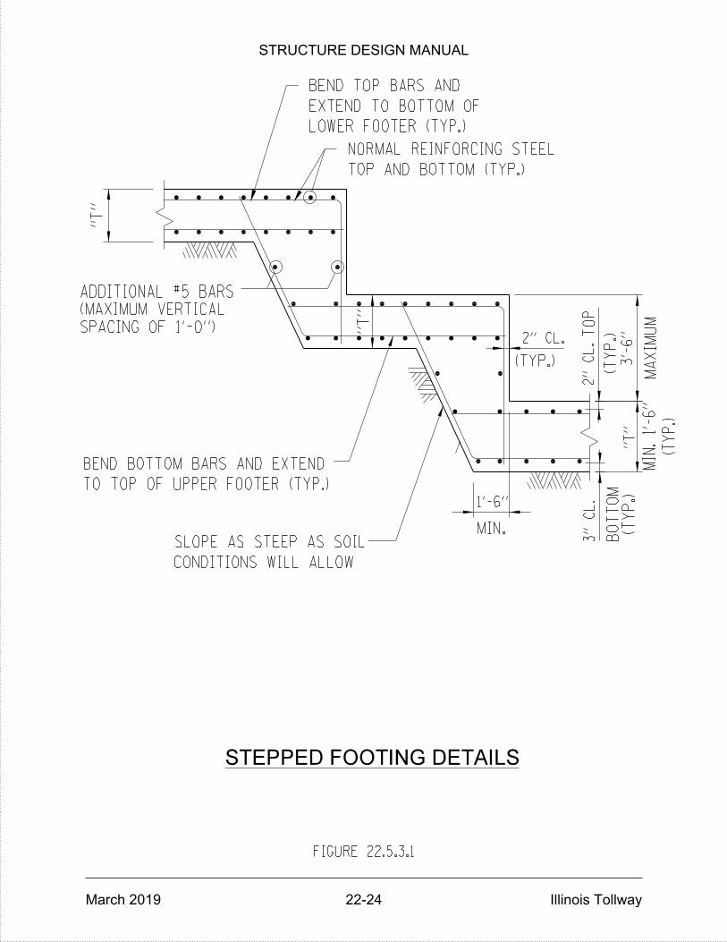
EXTEND TO BOTTOM OF
NORMAL REINFORCING STEEL
TOP AND BOTTOM (TYP.)
MA
XI
MU
M
"T"
"T"
FIGURE 22.5.3.1
BEND TOP BARS AND
LOWER FOOTER (TYP.)
(TYP.)
(TY
P.)
MIN.SLOPE AS STEEP AS SOIL
CONDITIONS WILL ALLOW
BEND BOTTOM BARS AND EXTEND
TO TOP OF UPPER FOOTER (TYP.)
1'-6"
SPACING OF 1'-0")
(MAXIMUM VERTICAL
ADDITIONAL #5 BARS
(TY
P.)
BO
TT
OM
TO
P
2" CL.
3'-
6"
"T"
2"
CL.
3"
CL.
(TY
P.)
MIN.
1'-
6"
STEPPED FOOTING DETAILS
STRUCTURE DESIGN MANUAL
March 2019 22-24 Illinois Tollway

TOP AND BOTTOM (TYP.)
NORMAL REINFORCING STEEL
ADDITIONAL #5 BARS
EXTEND TO BOTTOM OF
MA
XI
MU
M
(MAXIMUM VERTICAL
SPACING OF 1'-0").
BEND BOTTOM BARS AND
EXTEND TO TOP OF
(TYP.)
"T"
3" CL.
1'-6"
"T"
2" CL. (TYP.)
3'-
6"
"T"
FIGURE 22.5.3.2
1'-
0"
1'-
0"
MIN. MIN.
*
*TO CENTER LINE OF PILE AND
END OF LOWER FOOTING
*
OR ONE WALL PANEL LENGTH
BEND TOP BARS AND
LOWER FOOTER (TYP.)
SLOPE AS STEEP AS SOIL
CONDITIONS WILL ALLOW
UPPER FOOTER (TYP.)
1'-6"
(TYP.)
BOTTOM
TOP2" CL.
MINIMUM STEP WIDTH = 12'-0"
(TY
P.)
(MIN.
2'-
6")
STEPPED FOOTING DETAILS WITH PILES
STRUCTURE DESIGN MANUAL
March 2019 22-25 Illinois Tollway
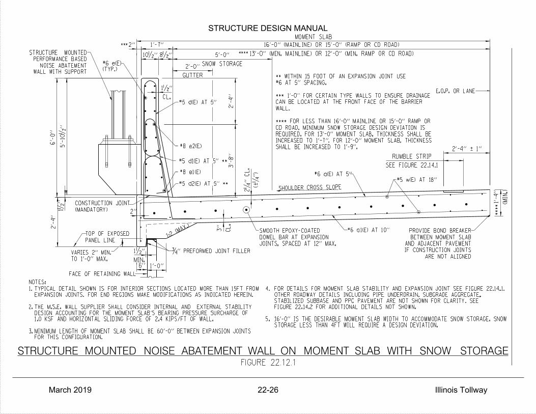
#8 e2(E)
#5 d(E) AT 5"
#5 d1(E) AT 5" **
#5 d2(E) AT 5" **
(TYP.)#6 e(E)
#8 e1(E)
2'-
4"
6'-
0"
5'-
10•
"
1'-0"
6"
(MIN.)
1'-
4"
2'-4" | 1"
SEE FIGURE 22.14.1
RUMBLE STRIP
MOMENT SLAB
13'-0" (MIN. MAINLINE) OR 12'-0" (MIN. RAMP OR CD ROAD)
16'-0" (MAINLINE) OR 15'-0" (RAMP OR CD ROAD)
1'-7"
8•"10•"
GUTTER
2'-0"SNOW STORAGE
5'-0"
2'-
4"
3'-
8"
MIN.
1•"
CL.
3"
(|‚
")
2‚
"
CL.
2"
CL.
1•"
2"
1•
"
SHOULDER CROSS SLOPE
#6 a(E) AT 5"
****
****
NOTES:
ARE NOT ALIGNED
IF CONSTRUCTION JOINTS
AND ADJACENT PAVEMENT
BETWEEN MOMENT SLAB
PROVIDE BOND BREAKER
#5 w(E) AT 18"
#6 a1(E) AT 10"
JOINTS, SPACED AT 12" MAX.
DOWEL BAR AT EXPANSION
SMOOTH EPOXY-COATED1:2 (M
AX.)
TO 1'-0" MAX.
VARIES 2" MIN.
E.O.P. OR LANE
WALL WITH SUPPORT
NOISE ABATEMENT
PERFORMANCE BASED
STRUCTURE MOUNTED
FACE OF RETAINING WALL
PANEL LINE
TOP OF EXPOSED
(MANDATORY)
CONSTRUCTION JOINT
ƒ" PREFORMED JOINT FILLER
***
5.
4.
FOR THIS CONFIGURATION.
MINIMUM LENGTH OF MOMENT SLAB SHALL BE 60'-0" BETWEEN EXPANSION JOINTS
1.0 KSF AND HORIZONTAL SLIDING FORCE OF 2.4 KIPS/FT OF WALL.
DESIGN ACCOUNTING FOR THE MOMENT SLAB'S BEARING PRESSURE SURCHARGE OF
THE M.S.E. WALL SUPPLIER SHALL CONSIDER INTERNAL AND EXTERNAL STABILITY
EXPANSION JOINTS. FOR END REGIONS MAKE MODIFICATIONS AS INDICATED HEREIN.
TYPICAL DETAIL SHOWN IS FOR INTERIOR SECTIONS LOCATED MORE THAN 15FT FROM
STORAGE LESS THAN 4FT WILL REQUIRE A DESIGN DEVIATION.
16'-0" IS THE DESIRABLE MOMENT SLAB WIDTH TO ACCOMMODATE SNOW STORAGE. SNOW
FIGURE 22.14.2 FOR ADDITIONAL DETAILS NOT SHOWN.
STABILIZED SUBBASE AND PPC PAVEMENT ARE NOT SHOWN FOR CLARITY. SEE
OTHER ROADWAY DETAILS INCLUDING PIPE UNDERDRAIN, SUBGRADE AGGREGATE,
FOR DETAILS FOR MOMENT SLAB STABILITY AND EXPANSION JOINT SEE FIGURE 22.14.1.
3.
2.
1.
SHALL BE INCREASED TO 1'-9".
INCREASED TO 1'-7". FOR 12'-0" MOMENT SLAB, THICKNESS
REQUIRED. FOR 13'-0" MOMENT SLAB, THICKNESS SHALL BE
CD ROAD, MINIMUM SNOW STORAGE DESIGN DEVIATION IS
**** FOR LESS THAN 16'-0" MAINLINE OR 15'-0" RAMP OR
WALL.
CAN BE LOCATED AT THE FRONT FACE OF THE BARRIER
*** 1'-0" FOR CERTAIN TYPE WALLS TO ENSURE DRAINAGE
#6 AT 5" SPACING.
** WITHIN 15 FOOT OF AN EXPANSION JOINT USE
STRUCTURE MOUNTED NOISE ABATEMENT WALL ON MOMENT SLAB WITH SNOW STORAGEFIGURE 22.12.1
STRUCTURE DESIGN MANUAL
March 2019 22-26 Illinois Tollway
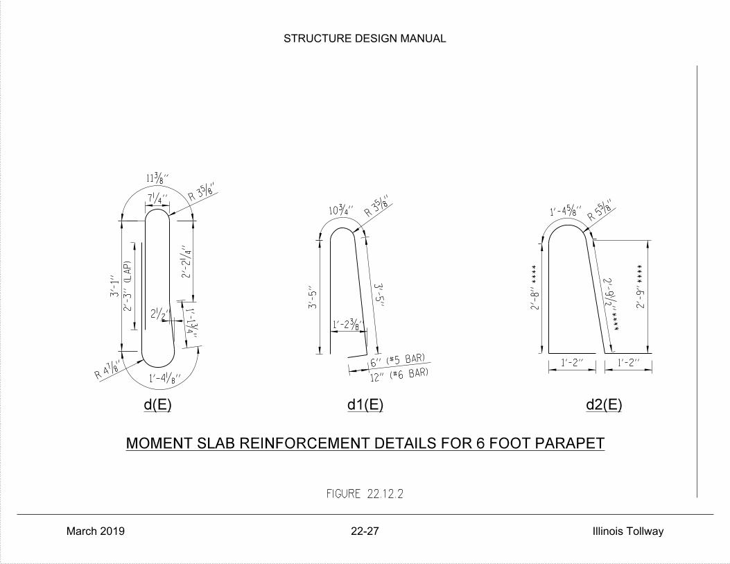
****
****
****
d(E) d1(E) d2(E)
1'-4„"4‡
"
R
2'-
3" (L
AP)
3'-
1"
7‚"
11…"
3†"
R
2'-
2‚
"
1'-1ƒ
"
12" (#6 BAR)
6" (#5 BAR)
3'-
5"
1'-2…"
3'-
5"
2•"
10ƒ" 3†"
R
1'-2"1'-2"
2'-
8"
1'-4†" 5†"
R
2'-
9•
" 2'-
9"
FIGURE 22.12.2
MOMENT SLAB REINFORCEMENT DETAILS FOR 6 FOOT PARAPET
STRUCTURE DESIGN MANUAL
March 2019 22-27 Illinois Tollway

FIGURE 22.12.3
RESERVED
STRUCTURE DESIGN MANUAL
March 2019 22-28 Illinois Tollway
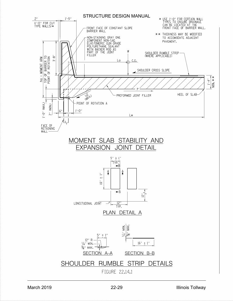
**
PAVEMENT.
TO ACCOMODATE ADJACENT
THICKNESS MAY BE MODIFIED
*
3'-
8"
SHOULDER CROSS SLOPE
(MAX.
)1:2
1'-
0" (M
AX.)
2" (M
IN.)
TO
P
OF
BA
RRIE
R
TO
ha
=
MO
ME
NT
AR
M
POIN
T
OF
RO
TA
TIO
N
C.G.
W
La
POINT OF ROTATION A
WALLRETAININGFACE OF
P
HEEL OF SLAB
2"
TYPE WALLS)(1'-0" FOR CUT
*
PREFORMED JOINT FILLER
FILLERPART OF THE JOINTWITH BACKER ROD ASPOLYURETHANE SEALANTELASTOMERIC GUN GRADECOMPONENT NON-SAGNON-STAINING GRAY ONE
AA
B
B
16" + 1"
5" + 1"
TYP.
_
_
12"
12" LONGITUDINAL JOINT
TYP.
‚"
MIN.
…"
MA
X.
_
_
12" R
‚" MIN.
…" MAX.
PLAN DETAIL A
SECTION B-BSECTION A-A
5" + 1"
1'-0"
Lw
6"
**
EXPANSION JOINT DETAIL
MOMENT SLAB STABILITY AND
1'-
4"
MIN.
FRONT FACE OF BARRIER WALL.CAN BE LOCATED AT THETYPES TO ENSURE DRAINAGEUSE 1'-0" FOR CERTAIN WALL
(WHERE APPLICABLE)SHOULDER RUMBLE STRIP
BARRIER WALLFRONT FACE OF CONSTANT SLOPE
1'-5"
16" + 1"
SHOULDER RUMBLE STRIP DETAILS
FIGURE 22.14.1
STRUCTURE DESIGN MANUAL
March 2019 22-29 Illinois Tollway
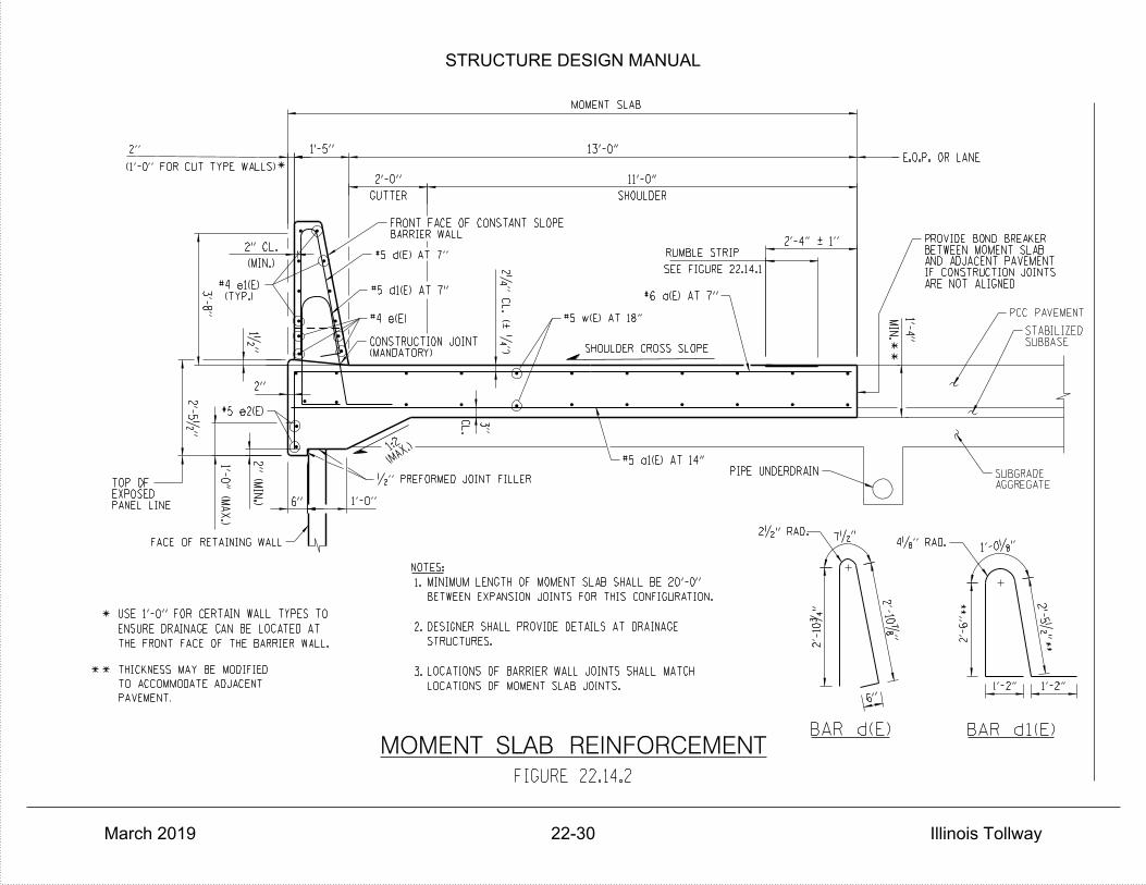
1'-0"6"
FACE OF RETAINING WALL
•" PREFORMED JOINT FILLER
#5 d1(E) AT 7"
#5 d(E) AT 7"
2"
2"
1'-0" (M
AX.)
BAR d(E) BAR d1(E)
*
THE FRONT FACE OF THE BARRIER WALL.
ENSURE DRAINAGE CAN BE LOCATED AT
USE 1'-0" FOR CERTAIN WALL TYPES TO
*(1'-0" FOR CUT TYPE WALLS)
2'-
5•
"
PCC PAVEMENT
SUBBASESTABILIZED
NOTES:
PIPE UNDERDRAIN
MOMENT SLAB
2‚
"
CL. (| ‚
")
PANEL LINEEXPOSEDTOP OF
LOCATIONS OF MOMENT SLAB JOINTS.
LOCATIONS OF BARRIER WALL JOINTS SHALL MATCH
STRUCTURES.
DESIGNER SHALL PROVIDE DETAILS AT DRAINAGE
BETWEEN EXPANSION JOINTS FOR THIS CONFIGURATION.
MINIMUM LENGTH OF MOMENT SLAB SHALL BE 20'-0"
3.
2.
1.
(MANDATORY)CONSTRUCTION JOINT
2'-4" | 1"
**
**
FIGURE 22.14.2
MOMENT SLAB REINFORCEMENT
PAVEMENT.
TO ACCOMMODATE ADJACENT
THICKNESS MAY BE MODIFIED
(TYP.)#4 e1(E)3
'-8"
1•"
#4 e(E) #5 w(E) AT 18"
#6 a(E) AT 7"
#5 a1(E) AT 14"
3"
CL.
2" (MIN.)
1'-4"
MIN.
#5 e2(E)
SEE FIGURE 22.14.1
RUMBLE STRIP
SHOULDER
11'-0"
GUTTER
2'-0"
ARE NOT ALIGNEDIF CONSTRUCTION JOINTSAND ADJACENT PAVEMENTBETWEEN MOMENT SLABPROVIDE BOND BREAKER
E.O.P. OR LANE
AGGREGATESUBGRADE
13'-0"1'-5"
BARRIER WALLFRONT FACE OF CONSTANT SLOPE
6"
2'-
10ƒ
"
7•"
2'-
10‡
"
2•" RAD.
1'-2"
1'-0„"4„" RAD.
1'-2"
2'-
5•
"
2'-
6"
**
**
(MIN.)
2" CL.
(MAX.
)1:2
SHOULDER CROSS SLOPE
STRUCTURE DESIGN MANUAL
March 2019 22-30 Illinois Tollway
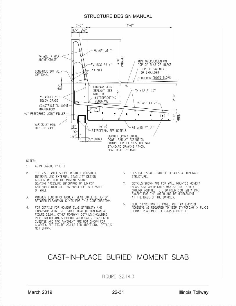
NOTES:
SHOULDER CROSS SLOPE
CAST-IN-PLACE BURIED MOMENT SLAB
1'-0"
(MIN.)
1'-
0"
2'-
4"
7'-0"
8•"8•"
1'-5"
PA
RA
PE
T
3'-
8"
1'-
8"
1•"
ƒ"
1•" (MIN.)
CL.
3"
1•
"
TO 1'-0" MAX.
VARIES 2" MIN.
ƒ" PREFORMED JOINT FILLER
(MANDATORY)
CONSTRUCTION JOINT
BELOW GRADE
#5 e1(E) (TYP.)
(OPTIONAL)
CONSTRUCTION JOINT
ABOVE GRADE
#4 e1(E) (TYP.)
#5 d(E) AT 7"
#5 d1(E) AT 7"
#4 e(E)
NOTE 1)
SEALANT (SEE
HIGHWAY JOINT
MEMBRANE
WATERPROOFING
TOP OF SLAB OF 118PCF
MIN. OVERBURDEN ON
OR SHOULDER
TOP OF PAVEMENT
#5 w(E) AT 18"
#7 a(E) AT 7"
#5 a1(E) AT 14"
STYROFOAM, SEE NOTE 8
6"
DURING PLACEMENT OF C.I.P. CONCRETE.
ADHESIVE AS REQUIRED TO KEEP STYROFOAM IN PLACE
GLUE STYROFOAM TO PANEL WITH WATERPROOF8.
AT THE BASE OF THE BARRIER.
EXCEPT FOR THE NOTCH AND REINFORCEMENT
GROUND MOUNTED TL-5 BARRIER CONFIGURATION,
SLAB. SIMILAR DETAILS MAY BE USED FOR A
DETAILS SHOWN ARE FOR WALL MOUNTED MOMENT7.
STRUCTURE.
DESIGNER SHALL PROVIDE DETAILS AT DRAINAGE5.
NOT SHOWN.
CLARITY. SEE FIGURE 22.14.2 FOR ADDITIONAL DETAILS
SUBBASE AND PPC PAVEMENT ARE NOT SHOWN FOR
PIPE UNDERDRAIN, SUBGRADE AGGREGATE, STABILIZED
FIGURE 22.14.1. OTHER ROADWAY DETAILS INCLUDING
EXPANSION JOINT SEE STRUCTURAL DESIGN MANUAL
FOR DETAILS FOR MOMENT SLAB STABILITY AND4.
BETWEEN EXPANSION JOINTS FOR THIS CONFIGURATION.
MINIMUM LENGTH OF MOMENT SLAB SHALL BE 35'-0"3.
OF WALL.
AND HORIZONTAL SLIDING FORCE OF 1.5 KIPS/FT
BEARING PRESSURE SURCHARGE OF 1.0 KSF
ACCOUNTING FOR THE MOMENT SLAB'S
INTERNAL AND EXTERNAL STABILITY DESIGN
THE M.S.E. WALL SUPPLIER SHALL CONSIDER2.
ASTM D6690, TYPE II1.
SPACED AT 12" MAX.
STANDARD DRAWING A7-03,
JOINTS PER ILLINOIS TOLLWAY
DOWEL BAR AT EXPANSION
SMOOTH EPOXY-COATED
FIGURE 22.14.3
STRUCTURE DESIGN MANUAL
March 2019 22-31 Illinois Tollway
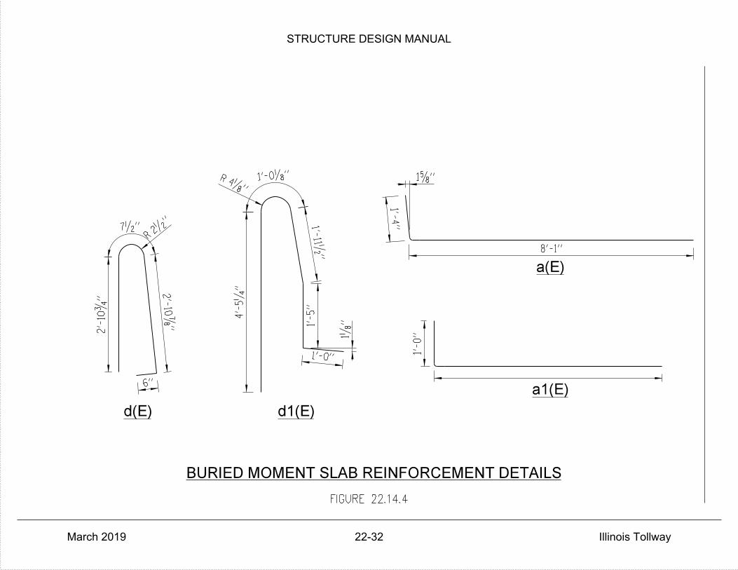
d(E) d1(E)
a(E)
a1(E)
BURIED MOMENT SLAB REINFORCEMENT DETAILS
2'-
10ƒ
"
7•" 2•"
R
2'-
10‡
"
6"
4„"
R 1'-0„"
1'-4"
8'-1"
1'-
0"
1†"
1„
"
4'-
5‚
"
1'-11•
"
1'-
5"
1'-0"
FIGURE 22.14.4
STRUCTURE DESIGN MANUAL
March 2019 22-32 Illinois Tollway
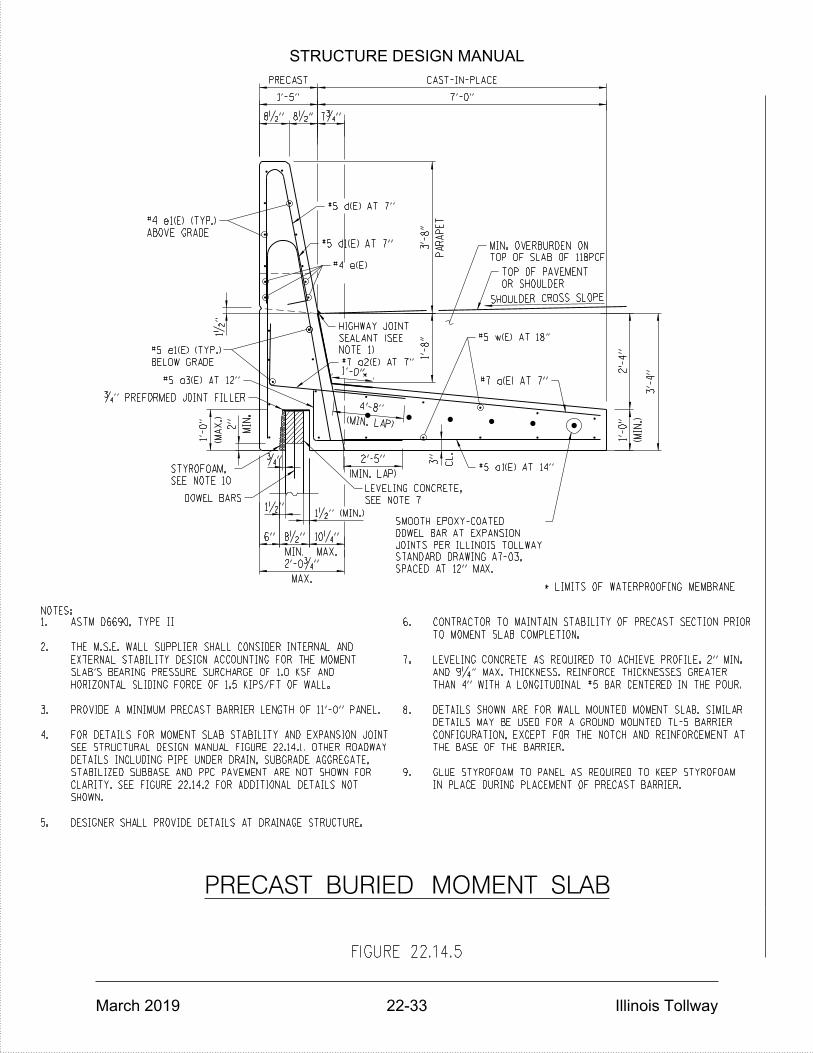
NOTES:
SHOULDER CROSS SLOPE
*
* LIMITS OF WATERPROOFING MEMBRANE
PRECAST BURIED MOMENT SLAB
1'-5"
8•"8•" 7ƒ"
CAST-IN-PLACE
PRECAST
7'-0"
PA
RA
PE
T
3'-
8"
1'-
8"
(MA
X.)
1'-
0"
MAX.
2'-0ƒ"
6"
MIN.
8•"
MAX.
10‚"
(MIN. LAP)
2'-5"
(MIN. LAP)
4'-8"
(MIN.)
1'-
0"
2'-
4"
3'-
4"
1'-0"
1•"
ƒ"
1•" (MIN.)
1•
"
MIN.
2"
CL.
3"
DOWEL BARS
SEE NOTE 10
STYROFOAM,
ƒ" PREFORMED JOINT FILLER
#5 a3(E) AT 12"
BELOW GRADE
#5 e1(E) (TYP.)
ABOVE GRADE
#4 e1(E) (TYP.)
#5 d(E) AT 7"
#5 d1(E) AT 7"
#4 e(E)
NOTE 1)
SEALANT (SEE
HIGHWAY JOINT
#7 a2(E) AT 7"
TOP OF SLAB OF 118PCF
MIN. OVERBURDEN ON
OR SHOULDER
TOP OF PAVEMENT
#5 w(E) AT 18"
#7 a(E) AT 7"
#5 a1(E) AT 14"
SEE NOTE 7
LEVELING CONCRETE,
DESIGNER SHALL PROVIDE DETAILS AT DRAINAGE STRUCTURE.5.
SHOWN.
CLARITY. SEE FIGURE 22.14.2 FOR ADDITIONAL DETAILS NOT
STABILIZED SUBBASE AND PPC PAVEMENT ARE NOT SHOWN FOR
DETAILS INCLUDING PIPE UNDER DRAIN, SUBGRADE AGGREGATE,
SEE STRUCTURAL DESIGN MANUAL FIGURE 22.14.1. OTHER ROADWAY
FOR DETAILS FOR MOMENT SLAB STABILITY AND EXPANSION JOINT4.
PROVIDE A MINIMUM PRECAST BARRIER LENGTH OF 11'-0" PANEL.3.
HORIZONTAL SLIDING FORCE OF 1.5 KIPS/FT OF WALL.
SLAB'S BEARING PRESSURE SURCHARGE OF 1.0 KSF AND
EXTERNAL STABILITY DESIGN ACCOUNTING FOR THE MOMENT
THE M.S.E. WALL SUPPLIER SHALL CONSIDER INTERNAL AND2.
ASTM D6690, TYPE II1.
IN PLACE DURING PLACEMENT OF PRECAST BARRIER.
GLUE STYROFOAM TO PANEL AS REQUIRED TO KEEP STYROFOAM9.
THE BASE OF THE BARRIER.
CONFIGURATION, EXCEPT FOR THE NOTCH AND REINFORCEMENT AT
DETAILS MAY BE USED FOR A GROUND MOUNTED TL-5 BARRIER
DETAILS SHOWN ARE FOR WALL MOUNTED MOMENT SLAB. SIMILAR8.
THAN 4" WITH A LONGITUDINAL #5 BAR CENTERED IN THE POUR.
AND 9‚" MAX. THICKNESS. REINFORCE THICKNESSES GREATER
LEVELING CONCRETE AS REQUIRED TO ACHIEVE PROFILE. 2" MIN.7.
TO MOMENT SLAB COMPLETION.
CONTRACTOR TO MAINTAIN STABILITY OF PRECAST SECTION PRIOR6.
SPACED AT 12" MAX.
STANDARD DRAWING A7-03,
JOINTS PER ILLINOIS TOLLWAY
DOWEL BAR AT EXPANSION
SMOOTH EPOXY-COATED
FIGURE 22.14.5
STRUCTURE DESIGN MANUAL
March 2019 22-33 Illinois Tollway

PRECAST BURIED MOMENT SLAB REINFORCEMENT DETAILS
d(E) d1(E)a3(E)
a2(E)
2'-
10ƒ
"
7•"
2'-
10‡
"
6"
2•"
R
4„"
R 1'-0„"
4'-
7"
3'-3"
1'-
0"
6'-6"
1'-4"
1†"
4'-
5‚
"
FIGURE 22.14.6
STRUCTURE DESIGN MANUAL
March 2019 22-34 Illinois Tollway

SHOULDER CROSS SLOPE
STRUCTURE MOUNTED NOISE ABATEMENT WALL
BURIED MOMENT SLAB WITH
MOMENT SLAB
SNOW STORAGE
5'-0"
DRAINAGE STRUCTURE
2'-0"
1'-7"
8•"10•"
PA
RA
PE
T
6'-
0"
3'-
4"
6"
1'-0"
1'-
8"
3'-
8"
2'-
4"
PA
RA
PE
T
6'-
0"
3'-
4"
(MIN.)
1'-
0"
2'-
4"
CL.
3"
1•" (MIN.)
1•"
ƒ"
1•
"
CL.
1•"
TO 1'-0" MAX.
VARIES 2" MIN.
ƒ" PREFORMED JOINT FILLER
(MANDATORY)
CONSTRUCTION JOINT
BELOW GRADE
#5 e1(E) (TYP.)
(OPTIONAL)
CONSTRUCTION JOINT
(TYP.)
#6 e(E)
5"
#5 d(E) AT 5"
#8 e2(E)
D6690, TYPE II
SEALANT ASTM
HIGHWAY JOINT
#5 d3(E) AT 5"
OR SHOULDER
TOP OF PAVEMENT
TOP OF SLAB OF 118PCF
MIN. OVERBURDEN ON
PAVEMENT
SLAB IN CONTACT WITH
MEMBRANE ON MOMENT
APPLY WATERPROOFING
#6 a(E) AT 5"
#5 w(E) AT 18"
#6 a1(E) AT 10"MEMBRANE
WATERPROOFING
STYROFOAM, SEE NOTE 5
NOTES:
OF C.I.P. CONCRETE.
REQUIRED TO KEEP STYROFOAM IN PLACE DURING PLACEMENT
GLUE STYROFOAM TO PANEL WITH WATERPROOF ADHESIVE AS
EXPANSION JOINTS FOR THIS CONFIGURATION.
MINIMUM LENGTH OF MOMENT SLAB SHALL BE 60'-0" BETWEEN
HORIZONTAL SLIDING FORCE OF 2.4 KIPS/FT OF WALL.
SLAB'S BEARING PRESSURE SURCHARGE OF 1.0 KSF AND
EXTERNAL STABILITY DESIGN ACCOUNTING FOR THE MOMENT
THE M.S.E. WALL SUPPLIER SHALL CONSIDER INTERNAL AND
SLAB.
PROVIDED IN PAVEMENT. EMBED BARS 18" INTO THE MOMENT
PROVIDE DOWELS AT EXPANSION JOINTS. USE SAME JOINT AS
MAKE MODIFICATIONS AS INDICATED HEREIN.
MORE THAN 15'-0" FROM EXPANSION JOINTS. FOR END REGIONS
TYPICAL DETAIL SHOWN IS FOR INTERIOR SECTIONS LOCATED
EXCEPT FOR THE NOTCH AND REINFORCEMENT AT THE BASE OF THE BARRIER.
MAY BE USED FOR A GROUND MOUNTED TL-5 BARRIER CONFIGURATION,
DETAILS SHOWN ARE FOR WALL MOUNTED MOMENT SLAB. SIMILAR DETAILS
SEE FIGURE 22.14.2 FOR ADDITIONAL DETAILS NOT SHOWN.
STABILIZED SUBBASE AND PPC PAVEMENT ARE NOT SHOWN FOR CLARITY.
ROADWAY DETAILS INCLUDING PIPE UNDER DRAIN, SUBGRADE AGGREGATE,
ILLINOIS TOLLWAY STRUCTURE DESIGN MANUAL FIGURE 22.14.1. OTHER
FOR DETAILS FOR MOMENT SLAB STABILITY AND EXPANSION JOINT SEE
5.
4.
3.
2.
1.
7.
6.
#6 AT 6" SPACING.
* WITHIN 15 FOOT OF AN EXPANSION JOINT USE
#5 d1(E) AT 5" *
#5 d2(E) AT 5" *
NOISE ABATEMENT WALL
PERFORMANCE BASED
STRUCTURE MOUNTED
SPACED AT 12" MAX.
STANDARD DRAWING A7-03,
JOINTS PER ILLINOIS TOLLWAY
DOWEL BAR AT EXPANSION
SMOOTH EPOXY-COATED
FIGURE 22.14.7
12'-0"

REINFORCEMENT DETAILS
STRUCTURE MOUNTED NOISE ABATEMENT WALL
BURIED MOMENT SLAB WITH
12" (#6 BAR)
6" (#5 BAR)
3'-
5"
3†"
R
11…"
7‚"3†
"
R
2'-
2‚
"
2'-
3" (L
AP)
3'-
1"
4‡"
R1'-4„"
1'-1ƒ
"
3'-
5"
10ƒ"
1'-2…"
2•"
d(E) d1(E) d2(E)
a1(E)a(E)
d3(E)
1'-2"
1'-6"
1'-
5…
"
1'-
3"
10"
4'-
7ƒ
"
1'-4†"5†
"
R
3'-
3"
4"
1'-
6"
1'-0"
1'-
2"
13'-3"
1'-2"
1…"
2'-
11"
5"
FIGURE 22.14.8
12'-0"
STRUCTURE DESIGN MANUAL
March 2019 Illinois Tollway
NOISE ABATEMENT WALLS AND RAILROAD BRIDGE FENCING
23.1 General
Noise abatement walls shall be designed in accordance with the latest AASHTO Guide Specifications for Structural Design of Sound Barriers and Interims, AASHTO LRFD Bridge Design Specifications, Sections 13 and 15 at Test Level 4 or 5 (TL-4 or TL-5) as applicable and as amended herein.
The noise abatement wall shall be designed to attenuate the sounds generated by highway traffic and achieve a minimum noise reduction of 5 decibels.
Panels shall be embedded a minimum 1’-0” below grade. The noise abatement wall material shall be manufactured from fire retardant material that meets State and local requirements. Structure mounted or ground mounted noise abatement wall types shall be one of the following:
Precast Concrete – The precast concrete noise abatement wall shall consist of either separate panels, or posts and panels spanning between vertical posts. The precast concrete panels of the noise abatement wall may be conventionally reinforced, pre-stressed, post-tensioned, or any combination thereof. The posts of the noise abatement wall may be constructed of precast concrete or galvanized, structural steel. If precast concrete posts are chosen, they may be conventionally reinforced, pre-stressed, post-tensioned, or any combination thereof.
Concrete Masonry – This system consists of a noise abatement wall constructed of manufactured masonry block units. Masonry block walls shall be hand-laid. The posts of the noise abatement wall may be constructed of precast concrete, galvanized steel encased in masonry, or masonry block pilasters. If precast concrete posts are chosen, the posts may be conventionally reinforced, pre-stressed, post-tensioned, or any combination thereof. Concrete Masonry panels shall not be used as bridge or retaining wall mounted noise abatement walls.
Brick Masonry – This system consists of a sound barrier constructed of manufactured brick masonry units. Brick masonry walls shall be hand laid. The brick masonry noise abatement wall shall consist of either separate panels, or posts and panels spanning between vertical posts. The posts of the noise abatement wall may be constructed of precast concrete, galvanized steel, or brick masonry pilasters. If precast concrete posts are chosen, the posts may be conventionally reinforced, pre-stressed, post-tensioned, or any combination thereof. Brick masonry panels shall not be used for bridge or retaining wall mounted or crashworthy ground mounted noise abatement walls.
23-1

STRUCTURE DESIGN MANUAL
March 2019 Illinois Tollway
Composite – The composite noise abatement walls shall be a composite plastic extruded material. The composite noise abatement wall shall consist of separate panels, or posts and panels spanning between vertical posts. The posts of the composite noise abatement wall may be constructed of composite material, precast concrete or galvanized steel. If precast concrete is chosen, the posts may be conventionally reinforced, pre-stressed, post-tensioned, or any combination thereof.
Wood – This system consists of a domestic or Canadian wood sound barrier constructed of treated wood posts, vertically oriented wood panels of tongue and groove construction, and a wood cap board to protect end grain.
Alternate Material Noise Abatement Wall – This system allows the Contractor to bid an alternate material noise abatement wall system that meets the requirements stated in this section and as accepted by the Illinois Tollway.
Wooden noise abatement wall shall be designed for a minimum service life of 25 years; precast concrete and alternate material noise abatement walls shall be designed for a minimum service life of 50 years. The design shall be based on the consideration of the potential long-term effects of weathering, corrosion, spray from de-icing chemicals, and other potentially deleterious environmental factors on each of the material components comprising the noise abatement wall.
Expansion and Contraction Devices
The noise abatement wall shall be designed with consideration of the movements in the wall due to temperature changes, dead loads and wind loads. Locations and spacing of expansion devices shall be as designed by the Contractor and approved by the Illinois Tollway.
Stabilizers
Permanent stabilizers are required between posts and panels to maintain the vertical positions of the panel while resisting the lateral loading primarily due to wind and vehicle impact. The stabilizers shall be spaced at intervals not to exceed 4 feet and shall have a minimum height of 4 inches.
23.2 Design Criteria
Design Specifications
See Article 5.1.
23-2
STRUCTURE DESIGN MANUAL
March 2019 Illinois Tollway
Design Loads
All Loading and Geometric requirements as specified in the latest edition of the AASHTO LRFD Bridge Design Specifications and Interims shall be satisfied.
Dead Load For bridge and retaining wall mounted noise abatement walls, the panel dead weight shall be based on the actual geometry of the panel.
The dead load shall consist of the weight of all the component materials making up the noise abatement wall. For structure-mounted noise abatement walls, the point of action of the weight of the individual components shall be their respective centers of gravity.
Wind Loads
The minimum design wind load for structure-mounted noise abatement walls shall be 35 psf (LFD) or 50 psf (LRFD Strength III). For ground-mounted noise abatement walls, the minimum design wind load shall be 25 psf (LFD) or 35 psf (LRFD Strength III). Other load combinations shall be per the latest AASHTO LRFD Section 3.8.
Design horizontal wind pressures shall account for the direction of wind, height, and elevation of the wall, topography and gust factors. The noise abatement wall shall be designed to withstand wind pressure, applied perpendicular to the wall and separately in each direction.
The maximum allowable panel deflection for wind loads shall be no more than the panel length (L) divided by 240 (L/240) for ground-mounted panels and panel length (L) divided by 180 (L/180) for structure-mounted panels, where L is the length between panel supports. The vertical posts shall have a maximum deflection of (H/360), where H is the height of the post above the foundation or anchors.
Seismic Loads
In accordance with Article 3.10 of the AASHTO LRFD Bridge Design Specifications.
Vehicle Impact Loads
Crashworthy walls shall be specifically identified in the plans and shall meet the “Application of AASHTO LRFD Specifications to Design of Sound Barriers” and the AASHTO LRFD Bridge Design Specifications. The following crash test levels shall be used to determine vehicle impact loads applied to noise abatement walls located within the clear zone or otherwise requiring shielding as determined by a barrier warrant analysis:
23-3

STRUCTURE DESIGN MANUAL
March 2019 Illinois Tollway
o Structure Mounted
TL-5, see Figure 23.3.4.1 for Structure Mounted Noise Abatement Wall on Bridge and Figure 23.3.4.2 for Structure Mounted Noise Abatement Wall on Moment Slab.
o Ground Mounted
Shielded: TL-4, applied in accordance with AASHTO LRFD Article 15.8.4 – Cases 1 through 4
In addition, for all shielded noise abatement walls, noise abatement wall
components with a setback less than 4.0 feet behind a barrier shall be
designed to resist a collision force of 4.0 kips applied at the highest point up
to 14.0 feet above the surface of the pavement in front of the traffic railing.
This load shall be checked independently from the impact loads specified in
the AASHTO LRFD Bridge Design Specifications.
Unshielded: TL-4, applied in accordance with AASHTO LRFD Article 15.8.4 – Case 1
In addition, all unshielded noise abatement walls with setback 4 feet or less
shall be designed to resist a collision force of 4.0 kips applied at the highest
point up to 14.0 feet above the surface of the pavement in front of the traffic
railing. This load shall be checked independently from the impact loads
specified in the AASHTO LRFD Bridge Design Specifications.
The following crash test levels shall be used to determine vehicle impact loads applied to noise abatement walls located outside the clear zone as identified in a barrier warrant analysis:
o Structure Mounted
Shielded: TL-4, applied in accordance with AASHTO LRFD Article 15.8.4 – Cases 1 through 4
Unshielded: TL-4, applied in accordance with AASHTO LRFD Article 15.8.4 – Case 1
o Ground Mounted
Not applicable
Unbalanced Soil Loads
If a noise abatement wall is to account for lateral earth pressure due to unequal ground lines, that requirement shall be shown in the plans.
23-4
STRUCTURE DESIGN MANUAL
March 2019 Illinois Tollway
Design Height
The design height shall be determined by the designer in conjunction with the noise mitigation study for each location.
Stresses
Allowable design stresses for individual materials comprising the different wall types are covered in the Performance Based Special Provision for Noise Abatement Wall.
23.3 Plan Preparation
General
The Designer shall indicate the location of all required noise abatement walls on the appropriate roadway and structure plans. Sufficient information shall be shown on the plans and cross sections so that the manufacturer can design and detail the noise abatement wall to accommodate each: ground-to-structure transition, overlap, obstruction and utility or drainage interference. The Designer shall locate the beginning and end of the noise abatement wall including overlaps and directional changes by station and offset on the appropriate roadway, drainage and lighting plans including cross sections. See Figure 23.3.1.1 for typical details.
An elevation view of each noise abatement wall shall be included in the plans. Each elevation shall show top of noise abatement wall and proposed grade. The location of transitions, overlaps, obstructions, utility or drainage interferences and changes in noise abatement wall height shall also be shown. Changes in noise abatement wall height shall be accomplished using increments no larger than 2 feet and no smaller than 1 foot. The top of wall shall remain horizontal between steps. For an elevation view example, see Figures 23.3.1.2 and 23.3.1.3. The top of the wall shall remain above the Acoustical Profile Line. Plans shall show all appurtenances behind, in front of, under, over, mounted upon, or passing through the noise abatement wall, such as drainage structures, fire hydrant access, highway signage, emergency access or utilities.
Naming Convention
Noise abatement walls shall be identified on the plans using the following format: Illinois Tollway Milepost Wall Type, Direction (Ramp) TOLLWAY: EW = Reagan Memorial Tollway (I-88) NS = Veterans Memorial Tollway (I-355) NW = Jane Addams Memorial Tollway (I-90) TS = Tri-State Tollway (I-294 & I-294/I-80) TN = Tri-State Tollway (I-94) ES = Edens Spur (I-94) EO = Elgin-O’Hare Tollway (IL 390) WA = West O’Hare Access (I-490)
23-5

STRUCTURE DESIGN MANUAL
March 2019 Illinois Tollway
MILEPOST: Two-decimal lowest wall milepost to the tenth or hundredth if a ¼ mile post (i.e. 14.75) WALL TYPE: N = Noise Abatement Wall DIRECTION: EB, SB, WB, NB - Inventory direction of the mainline roadway RAMP: (R) = if lowest milepost is along ramp (omitted if not along ramp) EXAMPLE: TS38.40N,NB(R) for a noise abatement wall located along the Tri-State Tollway (I-294) northbound at milepost 38.4 on a ramp If two walls of the same type have identical starting mileposts, the inventory milepost of one of the walls shall be shifted by one hundredth of a mile to create unique names.
Ground Mounted Noise Abatement Wall
For all Ground Mounted Noise Abatement Walls, a Level-3 Barrier Warrant Analysis shall be performed to determine the wall location with the highest benefit/cost ratio. Variations in noise abatement wall height based on the location of the wall shall be included in the benefit/cost analysis. The traffic face of the noise abatement wall shall be placed outside the clear zone, unless the wall is crashworthy. Refer to the Illinois Tollway Traffic Barrier Guidelines and Base Sheet M-RDY-406.
A 5-foot minimum clearance between the proposed R.O.W. line and the centerline of the noise abatement wall shall be maintained. No utilities shall be located between the noise abatement wall and the proposed R.O.W. line.
Overlapped sections of noise abatement walls shall be separated by a minimum of 9 feet to provide access to the area behind the walls. A section of the wall shall be overlapped for a minimum length of four times the separation or gap distance. See Figure 23.3.3.1 for a typical plan. Overlaps shall also be located at ground to structure transitions unless alternative access is already provided. See Figure 23.3.3.2 for details.
A swale shall be provided on the side of the noise abatement wall that will keep surface water from running under the wall. Field inlets shall be located at low points and connected to the side slope ditch or storm sewer. The Designer is responsible for designing and detailing all swales, ditches, field inlets and storm sewers on the drainage plans and profiles.
Foundations for Ground Mounted Noise Abatement Walls: The bottom of any foundation shall be a minimum of 4 feet below finished grade, unless solid competent rock strata is encountered. If a drilled foundation is used, it shall be a minimum of 6 feet below finished grade line or two times the shaft diameter, whichever is greater, unless solid competent rock strata is encountered.
23-6
STRUCTURE DESIGN MANUAL
March 2019 Illinois Tollway
Structure borings shall be taken at each end of the noise abatement wall and every 100 feet thereafter along the proposed alignment. The boring locations shall be shown on the roadway noise abatement wall plans and the resulting logs shall be plotted on sheets and included in the plans.
Structure Mounted Noise Abatement Wall
Noise abatement walls on retaining walls and bridges shall be designed for the specific site conditions. See Figure 23.3.4.1 for structure mounted noise abatement wall on a bridge and Figure 23.3.4.2 for structure mounted noise abatement wall on moment slab.
23.4 Specifications
The Designer shall modify the performance based special provisions furnished by the Illinois Tollway to suit their particular location and conditions.
23.5 Railroad Bridge Fencing for New Illinois Tollway Structures over Railroads
The Illinois Tollway crosses several railroads that have specific guidelines and drawings for fencing requirements. The Designer shall coordinate with the railroads regarding the need for fencing as early in the design stage as possible.
Waivers
The placement of fencing on top of the bridge parapet is not desirable because of traffic safety concerns and inspection access limitations. The Designer shall propose the following waivers to the railroad prior to initiating modifications to the standard bridge rail: Waiver Alternative I Request a waiver from the Railroad’s standards to provide a 44-inch high Constant-Slope parapet according to the Illinois Tollway’s Structure Design Manual. A waiver should be warranted since the Illinois Tollway does not allow pedestrian traffic or sidewalks on the Illinois Tollway system. Also, the Illinois Tollway provides an 11-foot to 12-foot shoulder between the edge of traveled way and bridge parapet to minimize the likelihood of objects being thrown onto railroad property. The 44-inch high Constant-Slope parapet meets criteria for a Test Level 5, according to the AASHTO LRFD Bridge Design Specifications, which satisfies freeway and large truck requirements. Waiver Alternative II Should Alternative I be found unacceptable by the railway, the Designer shall propose that a 72-inch barrier wall be provided to control the amount of snow and debris falling onto the track. This will provide for “splash boards” being provided on structures where switching or other frequent railroad activities are performed. Parapets that are 6.0 feet above the surface of the pavement shall meet the requirements of Article 15.5.2.
23-7

STRUCTURE DESIGN MANUAL
March 2019 Illinois Tollway
Fence Installation
Where a requirement for fencing on mainline structures has not been waived by the railroad, details for the fence shall be developed in accordance with Illinois Tollway Base Sheets M-BRG-521. Fencing with parapet shall be provided on both sides of all overhead structures crossing Railroad right-of-way. It shall be designed to prevent climbing and provide positive means of protecting the Railroad facility and the safety of Railroad employees below from objects released from the bridge deck above. The limits of the fencing with parapet shall extend to the limits of the Railroad Right-of-Way or a minimum of 25 feet beyond the centerline of the outermost existing track, future track or access road, whichever is greater. All parallel overhead structures that have a gap of 2 feet or more shall be protected with fencing. Structures with a gap of 2 feet or less shall either have the gap covered or be fenced on both sides. The minimum combined height of a parapet with curved fencing shall be 8 feet or with straight fencing shall be 10 feet. On sidewalk or trail facilities the top of the fencing shall be curved to discourage climbing. A minimum 8-foot vertical clearance shall be provided for the full clear width of the trail or sidewalk. To prevent surface water from draining onto the Railroad Right-of-Way, a one-foot parapet is required. Fencing is also requested by the railroads on top of parapet on overhead structures without sidewalks or trails.
23-8
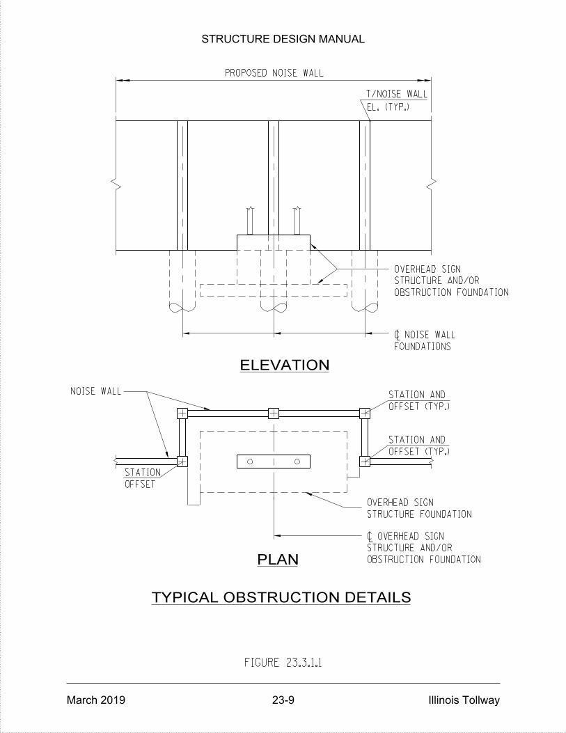
OVERHEAD SIGN
STRUCTURE FOUNDATION
OVERHEAD SIGN
TYPICAL OBSTRUCTION DETAILS
PLAN
OFFSET
STATION
ELEVATION
T/NOISE WALL
PROPOSED NOISE WALL
NOISE WALL
FIGURE 23.3.1.1
~ NOISE WALL
~ OVERHEAD SIGN
EL. (TYP.)
STRUCTURE AND/OR
OBSTRUCTION FOUNDATION
FOUNDATIONS
STATION AND
OFFSET (TYP.)
STATION AND
OFFSET (TYP.)
STRUCTURE AND/OR
OBSTRUCTION FOUNDATION
STRUCTURE DESIGN MANUAL
March 2019 23-9 Illinois Tollway

FIGURE 23.3.1.2
GROUND MOUNTED NOISE ABATEMENT WALL ELEVATION
654.00
630
635
640
650
645
655
665
660
MAT
CH LIN
E ST
A.
1150+00
+00
650.00 65
2.00+0
0+0
0
TOP OF NOISE ABATEMENT WALL
+00
656.00
+32.8
BE
GIN ST
RU
CT
URE
658.00+9
0
+32.8
640.33
+32.8
660.00
ACOUSTICAL PROFILE LINE
(SHAPE TO BE DETERMINED BY DESIGN)
1150+00 1151+ 1152+ 1153+ 1154+ 1155+ 1156+ 1157+ 1158+00
EXISTING PROFILE GRADE
PROFILE GRADE
PROPOSED
(TYP,)
MO
UNTE
D
NOIS
E
WALL
2'-0"
MA
X.
1'-0"
MIN.
TYP.
STRUCTURE DESIGN MANUAL
March 2019 23-10 Illinois Tollway
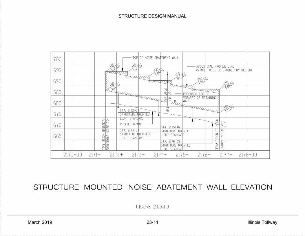
FIGURE 23.3.1.3
STRUCTURE MOUNTED NOISE ABATEMENT WALL ELEVATION
LIGHT STANDARD
PROFILE GRADE
LIGHT STANDARD
STA. 2173+93
STA. 2172+07
STRUCTURE MOUNTED
STRUCTURE MOUNTED
+50
BE
GIN ST
RU
CT
URE
MO
UNTE
D
NOIS
E
WALL
665
670
680
685
675
690
695
700
687.40+5
0
+50
696.00
STRUCTURE MOUNTED
STRUCTURE MOUNTED
PARAPET OR RETAINING
PROPOSED TOP OF
WALL
LIGHT STANDARD
LIGHT STANDARD
STA. 2176+39
+50
TOP OF NOISE ABATEMENT WALL
696.00+5
0
STA. 2175+46
694.00
+50
692.00
MO
UNTE
D
NOIS
E
WALL
+70
BE
GIN
GR
OU
ND
+70
+7069
0.00+5
0
677.20
688.00
(SHAPE TO BE DETERMINED BY DESIGN)
ACOUSTICAL PROFILE LINE
2170+00 2171+ 2172+ 2173+ 2174+ 2175+ 2176+ 2177+ 2178+00
1'-0"
TYP.
MA
X.
2'-0"
MIN.
STRUCTURE DESIGN MANUAL
March 2019 23-11 Illinois Tollway

NOISE WALL
NOISE WALL
"W"
(9'-
0"
MIN.)
~ NOISE WALL
~ NOISE WALL
(4xW MIN.)
OVERLAP
PLAN
AND FOUNDATIONS
AND FOUNDATIONS
FIGURE 23.3.3.1
NOISE WALL OVERLAP DETAILS
(FOR GROUND MOUNTED)
STRUCTURE DESIGN MANUAL
March 2019 23-12 Illinois Tollway
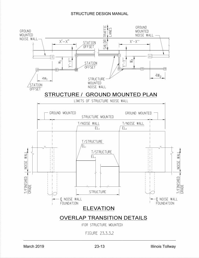
FOUNDATION
OVERLAP TRANSITION DETAILS
ELEVATION
OFFSET
STATION
NOIS
E
WA
LL
EL.
T/NOISE WALL
EL.
T/NOISE WALL
T/STRUCTURE
T/STRUCTURE
EL.
EL.
OFFSET
OFFSET
STATION
STATION
LA
NES
TR
AFFIC
NOIS
E
WA
LL
FOUNDATION
SH
LD
R
~ NOISE WALL
STRUCTURE
STRUCTURE MOUNTED
GROUND MOUNTED GROUND MOUNTED
4W
WW
1
1
2
4W2
NOISE WALL
MOUNTED
GROUND
NOISE WALL
MOUNTED
GROUND
Y'-
Y"
Y'-
Y"
LIMITS OF STRUCTURE NOISE WALL
GR
AD
E
T/
FINIS
HE
D
GR
AD
E
T/
FINIS
HE
D
(FOR STRUCTURE MOUNTED)
NOISE WALL
MOUNTED
STRUCTURE
FIGURE 23.3.3.2
STRUCTURE / GROUND MOUNTED PLAN
X'-X" X'-X"
~ NOISE WALL
STRUCTURE DESIGN MANUAL
March 2019 23-13 Illinois Tollway

ON BRIDGE
STRUCTURE MOUNTED NOISE ABATEMENT WALL
NOTES:
FIGURE 23.3.4.1
5.
4.
3.
2.
1.
DETERMINED BY THE NOISE ABATEMENT WALL MANUFACTURER.
30 KIP FORCE SHALL BE APPLIED TO THE NAW. OFFSET 'S' WILL BE
FRONT OF THE BARRIER. FOR AN OFFSET LESS THAN 10", THE FULL
AT THE HIGHEST POINT UP TO 14FT ABOVE SURFACE OF PAVEMENT IN
* VEHICLE COLLISION FORCE IS THE LOAD APPLIED TO THE NOISEWALL
1'-7"
S
8•"10•"
(SE
E
NO
TE 5)
D
6'-
0"
11•
"
4"
SL
AB
8"
3'-
8"
2'-
4"
5"
MA
X.
2"
MIN.
1•
"
2"
CL.
1•"
(|‚
")
2‚
"
CL.
a(E)
e1(E)
e2(E)
e(E)
OFFSET 'S'
30 KIP
4 KIP
FORCE*
d2(E)
d1(E)
d(E)
(SEE NOTE 3)
WALL WITH SUPPORT
NOISE ABATEMENT
PERFORMANCE BASED
STRUCTURE MOUNTED
S < 29"
29"
OF ALTERNATIVE CONNECTION WITH SPACER.
GAP AND ELIMINATE OVERLAP MAY BE USED, SUBJECT TO APPROVAL BY THE ILLINOIS TOLLWAY. SEE FIGURE 23.3.4.3 FOR EXAMPLE
OVERLAP 'D' SHALL BE 4:1 RATIO OF THE GAP BETWEEN THE NAW AND THE BACK OF THE BARRIER. OTHER MEANS OF FILLING THE
ALLOWED.
CORBELS/OTHERS SHALL BE COORDINATED WITH AND APPROVED BY THE ILLINOIS TOLLWAY. CONTINUOUS CORBELS SHALL NOT BE
MANUFACTURER. POST AND PANEL CONSTRUCTION SHOWN, TYPE, SIZE, SPACING OF POSTS AND POST CONNECTIONS SUCH AS
STRUCTURAL DESIGN MANUAL SECTION 23.2.2. SUCH DESIGN SHALL BE THE RESPONSIBILITY OF THE NOISE ABATEMENT WALL
TO RESIST THE VEHICULAR COLLISION FORCES AS SPECIFIED HEREIN AND OTHER DESIGN LOADS AS PER ILLINOIS TOLLWAY
THE WALL PANELS AND POSTS AND THE POST CONNECTIONS TO THE SUPPORTING TRAFFIC BARRIER SHALL BE DESIGNED
FOR THE NOISE WALL PANEL, POST, CONNECTIONS AND SUPPORT.
MAXIMUM NOISE WALL HEIGHT IS BASED ON 18FT ABOVE SURFACE OF SLAB IN FRONT OF THE BARRIER AND DEAD LOAD OF 1.67KLF
CASE BASIS WHERE FEASIBLE.
BRIDGE RECONSTRUCTION. DETAILS SHALL BE CONSIDERED FOR DECK REPLACEMENT OR SUPERSTRUCTURE WIDENING ON A CASE BY
DETAILS IN THIS FIGURE ARE APPLICABLE WHERE NOISE ABATEMENT WALL IS WARRANTED FOR NEW STRUCTURES AND
SEE FIGURE 15.5.1.5 FOR REINFORCING DETAILS.
STRUCTURE DESIGN MANUAL
March 2019 23-14 Illinois Tollway
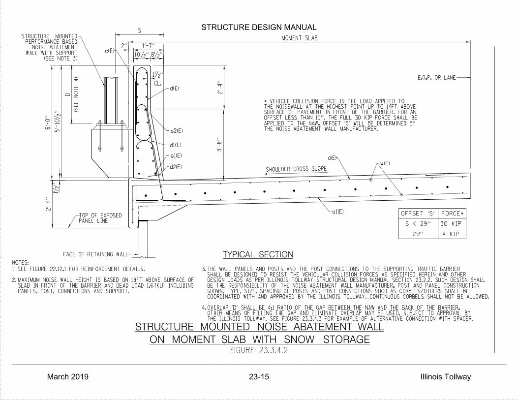
2'-
4"
6'-
0"
5'-
10•
"
MOMENT SLAB
1'-7"
8•"10•"
2'-
4"
3'-
8"
CL.
1•"
2"
1•
"e(E)
(SE
E
NO
TE 4)
D
d(E)
e2(E)
d1(E)
e1(E)
d2(E) SHOULDER CROSS SLOPE
NOTES:
E.O.P. OR LANE
FACE OF RETAINING WALL
PANEL LINETOP OF EXPOSED
w(E)a(E)
a1(E)
TYPICAL SECTION
THE NOISE ABATEMENT WALL MANUFACTURER.APPLIED TO THE NAW. OFFSET 'S' WILL BE DETERMINED BYOFFSET LESS THAN 10", THE FULL 30 KIP FORCE SHALL BESURFACE OF PAVEMENT IN FRONT OF THE BARRIER. FOR ANTHE NOISEWALL AT THE HIGHEST POINT UP TO 14FT ABOVE* VEHICLE COLLISION FORCE IS THE LOAD APPLIED TO
(SEE NOTE 3)WALL WITH SUPPORT
NOISE ABATEMENTPERFORMANCE BASED
STRUCTURE MOUNTED
PANELS, POST, CONNECTIONS AND SUPPORT.SLAB IN FRONT OF THE BARRIER AND DEAD LOAD 1.67KLF INCLUDINGMAXIMUM NOISE WALL HEIGHT IS BASED ON 18FT ABOVE SURFACE OF
SEE FIGURE 22.12.1 FOR REINFORCEMENT DETAILS.
2.
1.
S
4.
3.
THE ILLINOIS TOLLWAY. SEE FIGURE 23.3.4.3 FOR EXAMPLE OF ALTERNATIVE CONNECTION WITH SPACER.OTHER MEANS OF FILLING THE GAP AND ELIMINATE OVERLAP MAY BE USED, SUBJECT TO APPROVAL BYOVERLAP 'D' SHALL BE 4:1 RATIO OF THE GAP BETWEEN THE NAW AND THE BACK OF THE BARRIER.
COORDINATED WITH AND APPROVED BY THE ILLINOIS TOLLWAY. CONTINUOUS CORBELS SHALL NOT BE ALLOWED.SHOWN, TYPE, SIZE, SPACING OF POSTS AND POST CONNECTIONS SUCH AS CORBELS/OTHERS SHALL BEBE THE RESPONSIBILITY OF THE NOISE ABATEMENT WALL MANUFACTURER. POST AND PANEL CONSTRUCTIONDESIGN LOADS AS PER ILLINOIS TOLLWAY STRUCTURAL DESIGN MANUAL SECTION 23.2.2. SUCH DESIGN SHALLSHALL BE DESIGNED TO RESIST THE VEHICULAR COLLISION FORCES AS SPECIFIED HEREIN AND OTHERTHE WALL PANELS AND POSTS AND THE POST CONNECTIONS TO THE SUPPORTING TRAFFIC BARRIER
4 KIP
30 KIP
FORCEOFFSET 'S' *
S < 29"
29"
ON MOMENT SLAB WITH SNOW STORAGE
STRUCTURE MOUNTED NOISE ABATEMENT WALL
FIGURE 23.3.4.2
STRUCTURE DESIGN MANUAL
March 2019 23-15 Illinois Tollway

TOLLWAY.PER APPROVAL OF THE ILLINOISNOISE ABATEMENT WALL ARE ALLOWEDONLY, OTHER MEANS OF CONNECTING THE NOTE: DETAILS SHOWN ARE FOR EXAMPLE
MOMENT SLAB WITH SPACER BRIDGE DECK WITH SPACER
NOISE ABATEMENT WALLPERFORMANCE BASED
STRUCTURE MOUNTED
WALLAND NOISE ABATEMENTBACK OF PARAPETSPACER BETWEEN
SECTION A-A
A A
NOISE ABATEMENT WALLPERFORMANCE BASED
STRUCTURE MOUNTED
CONNECTIONS
ALTERNATIVE NOISE ABATEMENT WALL
FIGURE 23.3.4.3
WALLAND NOISE ABATEMENTBACK OF PARAPETSPACER BETWEEN
STRUCTURE DESIGN MANUAL
March 2019 23-16 Illinois Tollway

STRUCTURE DESIGN MANUAL
March 2019 Illinois Tollway
THIS PAGE IS INTENTIONALLY LEFT BLANK
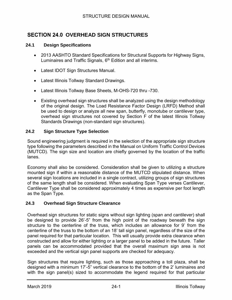
STRUCTURE DESIGN MANUAL
March 2019 24-1 Illinois Tollway
OVERHEAD SIGN STRUCTURES
24.1 Design Specifications
2013 AASHTO Standard Specifications for Structural Supports for Highway Signs, Luminaires and Traffic Signals, 6th Edition and all interims.
Latest IDOT Sign Structures Manual.
Latest Illinois Tollway Standard Drawings.
Latest Illinois Tollway Base Sheets, M-OHS-720 thru -730.
Existing overhead sign structures shall be analyzed using the design methodology of the original design. The Load Resistance Factor Design (LRFD) Method shall be used to design or analyze all new span, butterfly, monotube or cantilever type, overhead sign structures not covered by Section F of the latest Illinois Tollway Standards Drawings (non-standard sign structures).
24.2 Sign Structure Type Selection
Sound engineering judgment is required in the selection of the appropriate sign structure type following the parameters described in the Manual on Uniform Traffic Control Devices (MUTCD). The sign size and location are chiefly governed by the location of the traffic lanes. Economy shall also be considered. Consideration shall be given to utilizing a structure mounted sign if within a reasonable distance of the MUTCD stipulated distance. When several sign locations are included in a single contract, utilizing groups of sign structures of the same length shall be considered. When evaluating Span Type verses Cantilever, Cantilever Type shall be considered approximately 4 times as expensive per foot length as the Span Type.
24.3 Overhead Sign Structure Clearance
Overhead sign structures for static signs without sign lighting (span and cantilever) shall be designed to provide 26’-5” from the high point of the roadway beneath the sign structure to the centerline of the truss, which includes an allowance for 9’ from the centerline of the truss to the bottom of an 18’ tall sign panel, regardless of the size of the panel required for that particular location. This will usually provide extra clearance when constructed and allow for either lighting or a larger panel to be added in the future. Taller panels can be accommodated provided that the overall maximum sign area is not exceeded and the vertical sign panel supports are checked for adequacy. Sign structures that require lighting, such as those approaching a toll plaza, shall be designed with a minimum 17’-5” vertical clearance to the bottom of the 2’ luminaires and with the sign panel(s) sized to accommodate the legend required for that particular

STRUCTURE DESIGN MANUAL
March 2019 24-2 Illinois Tollway
location. For structures with multiple signs, the sign with the largest vertical dimension shall be used to determine the structure height. The height from the high point of the roadway beneath the sign structure to the centerline of the truss shall not be less than 26’-5”. Overhead sign structures for Dynamic Message Signs (DMS) shall be designed to provide 22’-5” from the high point of the roadway beneath the sign structure to the centerline of a cantilever, butterfly or span type sign structure that is intended only for installation of DMS. This includes an allowance for 5’ from the centerline of the truss to the bottom of a 10’ tall DMS, regardless of the size of the DMS required for that particular location.
24.4 Span Type (Aluminum)
Aluminum Span Type Sign Structures shall be selected and detailed in accordance with Standard F1 of the latest Illinois Tollway Standard Drawings. Illinois Tollway Base Sheet M-OHS-720 shall be used in combination with Standard F1. Aluminum Span Type structures can span from 80 to 150 feet and shall support static sign panels only. A Barrier Warrant Analysis shall be completed in accordance with Article 5.5.9 of the Illinois Tollway Traffic Barrier Guidelines. The Illinois Tollway’s sign structure-span type is an aluminum trichord truss supported by steel pipe columns, while IDOT’s sign structure-span types are aluminum and steel box, four chord span system. The steel pipe column support has been designed to accommodate maximum heights as shown in the table on Sheet 1 of Standard F1. Illinois Tollway Standard F1 includes the foundations for the Span Type Sign Structures. The foundations include details as follows:
The shoulder foundation consists of a grade beam (3’-6” width x 18’-0” length) supported on two 3’-0” diameter drilled shafts for all size truss spans. Foundation detail establishes a standard size grade beam for all span truss sizes. This feature simplifies the Traffic Barrier Warrant analysis by having a fixed dimension for any size truss span type structure.
The median foundations consist of a grade beam design and details to match the 7’-0” wide concrete barrier base, supported on two 3’-0” diameter drilled shafts.
The foundations accommodate the maximum column support heights shown on Sheet 1. In addition, the foundation can accommodate an increase in the depth of the grade beam by up to 2’-0”, if additional sign structure height is required.
STRUCTURE DESIGN MANUAL
March 2019 24-3 Illinois Tollway
24.5 Cantilever Type
Cantilever Type Sign Structures shall be selected and detailed in accordance with Standard F4 of the latest Illinois Tollway Standard Drawings. Illinois Tollway Base Sheet M-OHS-721 shall be used in combination with Standard F4. Cantilever Type structures can span from 20 to 50 feet, and shall support either static sign panels or 1 Type 2W DMS Walk-in. A combination of static signs and DMS units is not permitted. A Barrier Warrant Analysis shall be completed in accordance with Article 5.5.9 of the Illinois Tollway Traffic Barrier Guidelines.
The Cantilever Type Sign Structure standard drawings incorporate a concrete and steel post column support system. This detailing enables the maximum steel post to have a 24” diameter with a nominal wall thickness of 1” for cantilever design spans up to 50 feet in length. Also provided are alternate steel grades for the steel support post; API 5L, Grade B, X42 or X52, ASTM 106, Grade B or C and ASTM A53, Type E or S, Grade B.
24.6 Monotube Type
Monotube Type Sign Structures shall be selected and detailed in accordance with Standards F13, F15 or F16 of the latest Illinois Tollway Standard Drawings. Illinois Tollway Base Sheets M-OHS-722, M-OHS-723, M-OHS-725, M-OHS-726 and M-OHS-727 shall be used in combination with Standards F13, F15 or F16. See the latest Illinois Tollway Standard Drawings for span limits and mounting details. Signs that do not meet the requirements shown on the standard drawings are not permitted.
These structures are located at mainline and ramp toll plazas and are used to support electronic toll collection equipment. The foundations have been designed for both single and double face barrier walls, supported by individual drilled shaft foundations of 3’-6” diameter minimum.
24.7 Butterfly Type
Butterfly Type Sign Structures shall be selected and detailed in accordance with Standard F14 of the latest Illinois Tollway Standard Drawings. Illinois Tollway Base Sheet M-OHS-724 shall be used in combination with Standard F14. Butterfly lengths up to 40 feet are permitted. Each face of a Butterfly Type structure may support either static signs or 1 Type 2 DMS. A combination of static sign panels and DMS units on the same face is not permitted. A Barrier Warrant Analysis shall be completed in accordance with Article 5.5.9 of the Illinois Tollway Traffic Barrier Guidelines.
The Overhead Sign Structure-Butterfly Type shall be selected and detailed in accordance with Standard F14 of the latest Illinois Tollway Standard Drawings. Details have been developed for median and shoulder applications. These structures are intended to support dynamic message signs.
STRUCTURE DESIGN MANUAL
March 2019 24-4 Illinois Tollway
24.8 Bridge Mounted Sign Structures
Bridge Mounted Sign Structures shall be designed and detailed in accordance with the latest IDOT Sign Structures Manual.
In cases where the depth of the fascia beam is shallow and/or the profile grade approaches 5%, the location of the horizontal wide flange member between the web of fascia beam and the back of the sign support may vary vertically in order to maintain the luminaire supports in a level position (see Base Sheets M-BRG-503 and M-BRG-504). Alternatively, the location of the horizontal leg of luminaire support could also be varied to keep the luminaire supports level (see Figure 24.8.1).
24.9 Span Type (Steel)
Steel Span Type Sign Structures shall be selected and detailed in accordance with Standard F17 of the latest Illinois Tollway Standard Drawings. Illinois Tollway Base Sheet M-OHS-728 shall be used in combination with Standard F17. Steel Span Type structures can span from 120 to 160 feet, and shall support 1 Type 1 DMS only. Static sign panels are not permitted. A Barrier Warrant Analysis shall be completed in accordance with Article 5.5.9 of the Illinois Tollway Traffic Barrier Guidelines.
24.10 ITS Gantry Frame (Steel)
Steel ITS Gantry Frame Sign Structures shall be selected and detailed in accordance with the latest Illinois Tollway Base Sheets M-OHS-729 and M-OHS-730. See the latest Illinois Tollway Base Sheets for span limits and mounting details. Signs that do not meet the requirements shown on the base sheets are not permitted. A Barrier Warrant Analysis shall be completed in accordance with Article 5.5.9 of the Illinois Tollway Traffic Barrier Guidelines.
24.11 Overhead Sign Structures with End Cantilever(s)
Span Type, overhead sign structures required to cantilever or overhang the supports at one or both ends shall utilize a standard IDOT (box) truss, support legs and foundations. The selected truss shall be analyzed for the proposed end conditions and loads. The truss member sizes may be modified, if necessary, to accommodate the proposed overhang(s) and sign(s). The Designer shall modify and complete required information in the latest IDOT base sheets for the selected overhead truss, supports and foundations for inclusion in the Contract plans.
24.12 Non-Standard Sign Structures
Sign structures that do not fall within the criteria of the latest Illinois Tollway Standard Drawings and/or the latest IDOT Sign Structures Manual shall be designed in accordance with the latest AASHTO Standard Specifications for Structural Supports for Highway Signs, Luminaires, and Traffic Signals.
The Designer shall notify the Illinois Tollway in writing prior to beginning the design of a non-standard sign structure.

STRUCTURE DESIGN MANUAL
March 2019 24-5 Illinois Tollway
24.13 Naming Convention
Overhead sign structures shall be identified on the plans using the following format: Illinois Tollway Milepost Structure Type, Direction (Ramp) TOLLWAY: EW = Reagan Memorial Tollway (I-88) NS = Veterans Memorial Tollway (I-355) NW = Jane Addams Memorial Tollway (I-90) TS = Tri-State Tollway (I-294 & I-294/I-80) TN = Tri-State Tollway (I-94) ES = Edens Spur (I-94) EO = Elgin-O’Hare Tollway (IL 390) WA = West O’Hare Access (I-490) MILEPOST: Two-decimal milepost to the tenth or hundredth if a ¼ mile post (i.e. 14.75) SIGN TYPE: B = Bridge Mounted C = Cantilever and Butterfly Type Trusses T = Span Type Trusses, Monotube and ITS Gantry DIRECTION: EB, SB, WB, NB - Inventory direction of the mainline roadway RAMP: (R) = sign is over a ramp (omitted if not along ramp) EXAMPLE: TS38.40T,NB(R) for a span type truss located along the Tri-State Tollway
(I-294) northbound at milepost 38.40 on a ramp
24.14 Foundations for Overhead Sign Structures
The foundation details shown in the Illinois Tollway Sign Structure Standard Drawings (Section F) and the ITS Gantry Base Sheets M-OHS-729 and M-OHS-730 are designed and detailed based on the common cohesive soil conditions (silty or sandy clay) with an average unconfined compressive strength (Qu) > 1.25 Tons/sq. ft.
The Design Section Engineer (DSE) shall conduct a subsurface investigation at each overhead sign structure foundation to determine the actual soil conditions. Should the investigation reveal soil properties less than average unconfined compressive strength (Qu) = 1.25 Tons/sq. ft. or indicate the presence of rock, the DSE shall design and detail the drilled shaft foundations to meet the actual site conditions and modify the Illinois Tollway Sign Structure Standard Drawings and Base Sheets accordingly.
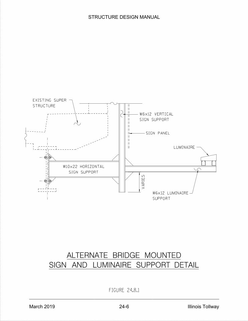
SIGN SUPPORT
W6x12 VERTICAL
SUPPORT
W6x12 LUMINAIRE
SIGN SUPPORT
W10x22 HORIZONTAL
LUMINAIRE
SIGN AND LUMINAIRE SUPPORT DETAIL
ALTERNATE BRIDGE MOUNTED
VA
RIES
STRUCTURE
EXISTING SUPER
FIGURE 24.8.1
SIGN PANEL
STRUCTURE DESIGN MANUAL
March 2019 24-6 Illinois Tollway

STRUCTURE DESIGN MANUAL
March 2019 Illinois Tollway
SHOP DRAWINGS
25.1 General
Shop drawings are detailed fabrication and erection plans prepared by the fabricator, supplier or Contractor which are interpreted from the engineering drawings in the Contract plans. When contracted, the Designer shall be responsible for reviewing the shop drawings for compliance with the design plans and project specifications only.
It is the responsibility of the Engineer to ascertain that the fabricator is supplying the items specified, while it is the Contractor’s responsibility to verify that all items are per contract plan and specifications and fabricated to the correct dimensions. See Article 105.04(d) of the latest Illinois Tollway Supplemental Specifications. Approved shop drawings shall be archived with the as-built plans for each project.
25.2 Required Shop Drawings
Shop drawings are required for the following items:
Plate Girders Wide Flange Beams
Miscellaneous Structural Steel PPC Bulb–T Beams
PPC I–Beams PPC Deck Beams
PPC IL-Beams Precast Concrete Box Culverts
Three Sided Precast Concrete Structures Butterfly Sign Structures
Cantilever Sign Structures Overhead Sign Structures
Monotube Sign Structures Bridge Mounted Sign Structures
Modular Expansion Joints Temporary Shoring, Jacking and Cribbing
Elastomeric Bearings HLMR Bearings
Anchor Bolts Fixed Bearings
Precast Deck Planks Pins and/or Link Plates
Precast Deck Forms Precast Fascia Panels
Mechanically Stabilized Earth Walls Metal Deck Forms
Temporary Soil Retention Systems Noise Abatement Walls and Foundations
Temporary Sheet Piling Prefabricated Pedestrian/Bicycle Trusses
Prefabricated Bridge Elements and Systems
25-1
STRUCTURE DESIGN MANUAL
March 2019 Illinois Tollway
Other project-specific items not included in this list may also require approved shop drawings.
Structural Steel and Expansion Joints
At a minimum the following information shall be reviewed:
Framing plan, showing general layout of the steel beams, cross frames, location of field splices and marking scheme for identifying members.
The number, size and geometry of all members.
The details of all splices, showing the number, size and type of bolts, hole diameters, the type, size and length of all welds and a section showing the size of all splice materials.
The details of all field connections, showing number, size and type of bolts, hole diameters, and the locations where reaming is required.
The number, size and spacing of shear developers. The use of shop welded shear developers is acceptable for embedded bearing plates and expansion joints.
Verify ordinates and geometry at abutments, field splices and interior at piers.
The amount and location of camber and the permissible tolerances.
Material specifications (AASHTO and/or ASTM designation) of the steel to be fabricated and any testing requirements.
The steel surface preparation and the type of shop and/or field coating to be applied.
All notes that appear on the design plans shall be reflected on the shop drawings.
Structural steel weights (shop bills) shall be checked.
Blocking and lifting diagrams.
Check plate bending radiuses
25-2
STRUCTURE DESIGN MANUAL
March 2019 Illinois Tollway
Prestressed Concrete
At a minimum the following information shall be reviewed:
Erection diagram, showing the general layout of the concrete elements.
The number and size of all members.
The number, size and type of prestressing strands or rods, and the forces in these prestressing elements.
Bearing details showing size, type, and materials.
The location and the details of lifting devices and of support points, if the beam does not rest on its bearings while being transported.
The location and type of any inserts required for attachments.
The layout of the casting bed to be used for casting the prestressed beams.
The location of hold-down devices for any draped strands.
The location and length of any bond-breaker.
The details and type of the reinforcement bars.
All notes that appear on the design plans shall be reflected on the shop drawings.
Bearings
At a minimum the following information shall be reviewed:
Location diagram, showing the general layout of the structure and the locations of the bearings.
The number, size and types of all bearings.
The details of the bearings, showing all materials, dimensions and welding.
The steel surface preparation and shop coating details.
Notes listing the material specifications for all parts of the bearings, and the design and specifications used for the design of the bearings.
25-3
STRUCTURE DESIGN MANUAL
March 2019 Illinois Tollway
25.3 Special Requirement Items
The Contractor and/or his supplier are responsible for designing and detailing the following items, which shall bear the seal and signature of an Illinois Licensed Structural Engineer. Shop drawings and computations shall be submitted for review and acceptance by the Designer. Approved shop drawings shall be archived with the as-built plans for each project.
Mechanically Stabilized Earth (MSE) Retaining Walls, Soldier Pile and Lagging Retaining Walls with facing and Sheet Pile and Tie-Back Retaining Walls with facing.
Precast Concrete Box Culvert and Three-Sided Structures.
Seismic Isolation Bearings.
Pedestrian/Bicycle Truss designs and shop drawings for structures crossing over a state or federal route, placed on Illinois Tollway right-of-way, or having spans 150 ft. or longer, shall be submitted for review and approval. If these structures are constructed by another governmental unit (IDOT, county, municipality, park district, IL Dept. of Natural Resources, etc.), that agency is responsible for the review and approval of the designs and drawings.
Noise Abatement Walls including their foundations.
“Stay-In-Place” Metal or Precast Concrete Deck Forms.
Temporary Shoring, Jacking and Cribbing.
25.4 Miscellaneous Items
Shop Drawings for the following items need not be submitted for review unless specified or special (non-standard) details are proposed for routine items:
Fabric Reinforced Elastomeric Mats and/or steel anchor plates for the back of Integral Abutments:
The fabricator shall furnish installation and detail drawings to the Contractor and Engineer for field verification of locations and dimensions. These drawings shall be included in the project record. Shop fabrication inspection is not required, and the Engineer’s final acceptance may be based on proper fit and an overall visual inspection of the finished product. The material supplier is responsible for submitting samples to the BMPR for lot testing.
25-4
STRUCTURE DESIGN MANUAL
March 2019 Illinois Tollway
Bridge Railing & Drainage Systems:
Steel Bridge Rail, Aluminum Bridge Rail, Pedestrian/Bicycle Railing, Pre-Fabricated Inspection Platforms, Scuppers, Drain Piping, Navigation Lights and Mounting Hardware.
The fabricator shall furnish installation and detail drawings to the Contractor and Engineer for field verification of locations and dimensions. These drawings shall be included in the project record. Shop fabrication inspection is not required, and the Engineer’s final acceptance may be based on proper fit and an overall visual inspection of the finished product.
Standard design base sheet notes require permanent tubular steel bridge traffic rail and rail posts to have Charpy V-Notch (CVN) toughness values certified by test. Test results, along with mill certification documentation, are to be submitted to the Engineer. CVN testing is not normally required for bicycle/pedestrian railing. All steel for railing, bolts, anchor bolts and posts shall be domestic. Any paint used shall be accepted by the IDOT Bureau of Materials and Physical Research (BMPR). Current requirements of the BMPR concerning aluminum rail and posts shall be satisfied.
Bridge Joint Seal System (Bonded Preformed Joint Seals) or Strip Seals:
These joints may be prefabricated in convenient lengths, allowing subsequent shop or field cutting to meet project requirements. Since details will be generic, no project-specific review is required. An installation scheme shall be provided by the fabricator to the Contractor and Engineer.
25.5 Erection Plan
General
The Contractor shall submit an erection plan to the Engineer and Designer for each structure in the Contract, in accordance with Article 7.2.2 of this Manual, Article 105.04(c) of the Illinois Tollway Supplemental Specifications and the latest Illinois Tollway GBSP for Erection of Girders.
Copies shall be sent to any railroad company or public agency affected by the proposed erection procedure for their review and comment. These plans shall be received at least 60 days prior to the proposed beginning of erection. All comments or revisions required by the Designer, railroad company, or public agency shall be incorporated in the final submission, for review and acceptance by the Engineer and Designer.
For additional information on the minimum information required on the erection plans see the latest Illinois Tollway GBSP for Erection of Girders.
25-5

STRUCTURE DESIGN MANUAL
March 2019 Illinois Tollway
THIS PAGE IS INTENTIONALLY LEFT BLANK
STRUCTURE DESIGN MANUAL
March 2019 Illinois Tollway
REHABILITATION AND REPAIR
26.1 General
When extensive repairs to a structural member appear necessary, to the extent that the structural capacity of the member during construction may be in doubt, provisions shall be made to temporarily support the member during construction. This also applies to concrete member repairs, whether it is pneumatically applied mortar or formed concrete repairs. The location of proposed temporary supports shall be indicated on the plans.
Refer to the latest edition of the “Structural Services Manual” by the IDOT Bureau of Bridges and Structures. The manual contains information and guidelines for the types of repairs most often required to adequately maintain typical bridge structures during the service life. The Designer and/or Contractor are encouraged to use guidelines provided in the above referenced manual in preparing final repair details associated with the rehabilitation project.
The most common types of repairs/rehabilitation tasks associated with Illinois Tollway projects are listed below, refer to the applicable sections from the above referenced manual.
Bridge Deck Overlay
Expansion Joint Replacement
Bridge Rails and Parapets
Bearing Replacement
Impact Repairs – Steel Beams
Impact Repairs – Concrete Beams
Steel Superstructure Repairs
Concrete Superstructure Repairs
Substructure Repairs
26-1
STRUCTURE DESIGN MANUAL
March 2019 Illinois Tollway
26.2 Precast Concrete Repairs
Even though a higher quality of standards is maintained in a plant-cast prestressed concrete environment, damages or defects can still occur in such products. Examples include voids and cracks in concrete and improperly placed or damaged reinforcement and hardware. These products fall into one of the three following categories:
Products that can be accepted without repair
Products that can be accepted with repair
Products that must be rejected Refer to “Manual for the Evaluation and Repair of Precast, Prestressed Concrete Bridge Products” published by PCI. The Manual also addresses evaluation and repair for damage caused by imperfections or damage occurring during production, handling, transportation and erection. This Manual serves as a resource and a base for developing repair options. The designer and/or Fabricator is required to prepare repair procedures and details using guidelines provided in the above referenced manual while applying sound engineering judgment. The repair procedures and details shall be submitted to the Illinois Tollway for review and approval. In addition to the types of damage discussed above and the normal deterioration due to aging, collisions between over-height vehicles and bridges are becoming more commonplace and can be catastrophic. Collision damage, however, is generally far from catastrophic although sound repair techniques are critical if additional damage (typically related to corrosion) is to be mitigated. A comprehensive study was recently completed by NCHRP to develop criteria to evaluate whether to repair or to replace a prestressed concrete girder damaged by a vehicular impact, identify the gaps in the available information and practices related to repair of collision damage of prestressed girders and prepare a recommended practice report guide. Results of the study are presented in the NCHRP 20-07/Task 307 report, entitled “Updated Research for Collision Damage and Repair of Prestressed Concrete Beams”, dated May 2012. The primary deliverable of the NCHRP 20-07/Task 307 report is the Guide to Recommended Practice for the Repair of Impact-Damaged Prestressed Concrete Bridge Girders, which is included in Appendix A of the report. The Guide serves to update the 1985 NCHRP Report 280: Guidelines for Evaluation and Repair of Prestressed Concrete Bridge Members, which remains a primary reference for this topic. Nine repair techniques are described in the Guide of the NCHRP 20-07/Task 307 report; four are generally recommended as being practical for repairing impact damaged prestressed concrete girders: externally bonded carbon fiber reinforced polymer (EBCFRP); externally bonded post-tensioned CFRP (bPT-CFRP); post-tensioned steel (PT-steel); and internal strand splicing. In addition, external repairs in combination with strand splicing are discussed. The Designer is required to prepare repair procedures and details using guidelines provided in the NCHRP 20-07/Task 307 reference, while applying
26-2
STRUCTURE DESIGN MANUAL
March 2019 Illinois Tollway
sound engineering judgment. The repair procedures and details shall be submitted to the Illinois Tollway for review and approval.
26.3 Aluminum Sign Truss Repairs
Refer to Figures 26.3.1 through 26.3.4 regarding suggested details for repairing existing aluminum sign trusses. These details are to be used as guidelines in preparing repair plans for sign trusses. Figure 26.3.5 provides guidelines for installing damping devices for existing aluminum trusses.
26.4 Approach Slab Resurfacing and Repairs
When resurfacing an existing approach slab, the surface of new overlay shall be string lined to provide a smooth transition from the ends of bridge to the existing road.
Before resurfacing, the spalled areas of existing approach slabs shall be repaired with partial-depth concrete patches and completely deteriorated areas shall be repaired with full-depth patches. Top reinforcement bars exposed in repair areas that show a 50% loss of section due to corrosion or that were damaged during concrete removal shall be supplemented with additional bars equal to the area of the original deteriorated or damaged bar(s) (see Figure 26.4.1). Bottom reinforcement bars exposed in repair areas that show a 20% loss of section due to corrosion or that were damaged during concrete removal shall be supplemented with additional bars equal to the area of the original deteriorated or damaged bar(s).
Existing reinforcement bars that have been cut or damaged by the Contractor shall be provided with supplemental bars at no additional cost to the Illinois Tollway. Otherwise, supplemental bars shall be paid for as “Reinforcement Bars” or “Reinforcement Bars, Epoxy Coated”.
Those areas of approach slabs showing settlement at the abutment backwall shall be removed and replaced in accordance with the details shown in Figure 26.4.2. Existing preformed filler joints at the bridge end of approach slabs shall be replaced wherever possible with the detail shown in Figure 26.4.3.
26.5 Aggregate Slope Paving Repairs
See Figure 26.5.1 for suggested details for repairing eroded or damaged slope paving.
26.6 Metal Culvert Temporary Repairs
See Figures 26.6.1 through 26.6.4 for suggested details to temporarily repair metal arch or half round culverts until they can be programmed for replacement or lining.
26-3
STRUCTURE DESIGN MANUAL
March 2019 Illinois Tollway
26.7 Bearing Repairs
Frequently, existing rocker bearings are found to be tilted and in need of adjustment. The magnitude of the adjustment is determined by comparing the measured horizontal displacement of the rocker with the theoretical displacement for similar temperature conditions. No adjustment is necessary unless the measured displacement exceeds the theoretical by ¾ inch or more. Adjustment is usually made by repositioning the sole plate; however, if a bearing stiffener is present, the stiffener shall remain within the middle third of the repositioned sole plate.
26.8 Fiber Reinforced Polymer Repairs
Fiber Reinforced Polymer (FRP) shall be considered as a cost effective solution to increase structural capacity for various bridge elements. The following guidelines are proposed: FRP shall be considered by the Designer as one of the available repair methods for restoring structural capacity of PPC Beams and other reinforced concrete structural members. For guidance regarding selection of repair techniques including FRP, refer to the NCHRP 20-07/Task 307 report, entitled “Updated Research for Collision Damage and Repair of Prestressed Concrete Beams”, dated May 2012. Also, refer to “ACI 440.2R-08 Guide for the Design and Construction of Externally Bonded FRP Systems for Strengthening Concrete Structures” for design guidance. FRP shall be installed as the final external layer of any PPC Beam or outside face of parapet patching that is located over shoulders, traffic lanes or railroad tracks. The use of FRP over patch areas in locations other than over shoulders, traffic lanes and/or railroad tracks is not recommended. Beam ends shall not be considered for repairs with FRP. In this situation, beam encasement is the preferred option. FRP shall not be used in conjunction with patching of bridge deck underside.
26.9 Deck Drains
Repair plans for major maintenance projects on deck surface of a structure such as overlay projects shall contain details to provide for elimination of existing deck drains, or adjustment of existing deck drains to direct drainage away from the main load-carrying member of the superstructure and substructure units.
26-4
STRUCTURE DESIGN MANUAL
March 2019 Illinois Tollway
26.10 Deck Underside and Concrete Diaphragms
Deck underside and concrete diaphragms where shallow spalls occur, that are less than 3" maximum depth and analysis shows that the missing concrete does not affect the strength of the member, missing concrete may not need to be replaced. However, all exposed reinforcement bars should be cleaned and coated with epoxy to prevent deterioration. Where concrete spalling on cast-in-place concrete diaphragms, is 4" or greater depth, diaphragms shall be repaired with formed concrete repair. A 1/8" tar-paper bond breaker shall be placed between the beam web and the adjacent repair.
Deck underside defects which affect structural capacity shall be addressed with full depth patches. Partial depth patching of bridge deck underside is not allowed.
26-5

SIN
GLE V
ER
TIC
AL DIA
GO
NA
L R
EP
AIR W
ITH
OU
T G
US
SE
T
FIGURE 26.3.1
STRUCTURE DESIGN MANUAL
March 2019 26-6 Illinois Tollway

STRUCTURE DESIGN MANUAL
March 2019 26-7 Illinois Tollway

FIGURE 26.3.3
SIN
GLE V
ER
TIC
AL DIA
GO
NA
L R
EP
AIR W
ITH G
US
SE
T
STRUCTURE DESIGN MANUAL
March 2019 26-8 Illinois Tollway
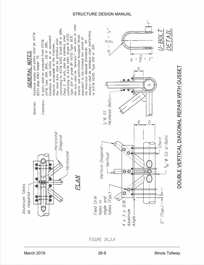
FIGURE 26.3.4
DO
UB
LE V
ER
TIC
AL DIA
GO
NA
L R
EP
AIR W
ITH G
US
SE
T
STRUCTURE DESIGN MANUAL
March 2019 26-9 Illinois Tollway
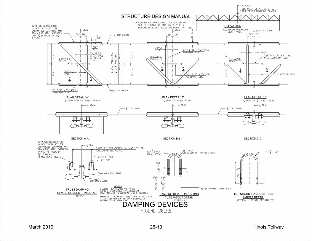
DAMPER: ONE DAMPER PER TRUSS.(31 LBS. STOCKBRIDGE-TYPE ALUMINUM)
MATERIALS: ALUMINUM TUBES SHALL BE ASTM B221
NOTES
ELEVATION
SIGN TRUSSALUMINUM OVERHEAD
FOR TRUSS DAMPING DEVICE
SEE PLAN DETAIL A, B, C,
~ SPAN
* *
HORIZONTALS
C C
DEVICE
~ DAMPING
D D
T / 2
T / 2
T
T / 2
T / 2
4''
1''
2
T
1''
D, ty
p.
2'', TYP.
~ 3 '' } HOLE
12'' 12''
(TYPICAL - DETAIL ''A'' AND ''B'')(TYPICAL)
MOUNTING TUBE
D
2
DAMPING DEVICE
(TYPICAL)
PLAN DETAIL "C"PLAN DETAIL "B"
SECTION B-B SECTION C-C
PLAN DETAIL "A"
SECTION A-A
HORIZONTAL (DETAIL ''C'')
~ CROSS TUBES (DETAIL ''A'' AND ''B'') OR
''C''
PL
AN
DE
TAIL
''A''
AN
D ''B''
PL
AN
DE
TAIL
D2
DEVICE CONNECTION DETAIL
TRUSS DAMPING
ALUMINUM TUBE
2'' } OD x ‚'' WALL
~ TOP CHORD
~ SPAN ~ SPAN
TYP.
2''
TUBE
ALUMINUM
x ‚'' WALL
2•''} OD
DEVICE
~ DAMPING
TUBE
CROSS
~ SPAN BETWEEN PANEL POINTS ~ SPAN AT PANEL POINT ~ SPAN AT ~ CHORD SPLICE
ALUMINUM TUBE
2•'' } OD x ‚'' WALL
ALUMINUM TUBE
2•'' } OD x ‚'' WALL
D
*
BEFORE DRILLING HOLES IN MOUNTING TUBE.
SPLICE DIMENSION MAY VARY. VERIFY
CENTER OF HORIZONTAL TO CENTER OF
T / 2
T / 2
T
AA
~ SPAN ~ SPAN ~ SPAN
~ TOP CHORD~ TOP CHORD
~ SPAN & SPLICE
~ SPAN
(PLAN DETAIL ''A'' AND ''B'')
R = 1•''
(PLAN DETAIL ''C'')
R = + ‚''
BB
''217 ''2
17
''4
1
+ 3
''217 ''2
17
IN MOUNTING TUBE
…" } HOLES
TYP.…'' } HOLES IN
STAINLESS STEEL WASHERS,
GALVANIZED LOCKNUTS AND
U- BOLT WITH HOT DIP
Š"} STAINLESS STEEL
8
FIGURE 26.3.5
TUBECROSS
HOLE
~…''
DEVICE~ DAMPING
COST INCLUDED IN OVERHEAD SIGN STRUCTURE.
ALLOY 6061 TEMPERr T6. COST INCLUDED INOVERHEAD SIGN STRUCTURE.
'' } STAINLESS STEEL U-BOLT165
~ TOP CHORD
WALL ALUMINUM TUBE
2''} OD x ‚'' WALL ‚''
} TUBE
TYP. …''} HOLES IN 2•''
STAINLESS STEEL WASHERS,
GALVANIZED LOCKNUTS AND
U- BOLT WITH HOT DIP
Š''} STAINLESS STEEL
***
+ 2ƒ''
D
2R = + ‚''
DAMPING DEVICES
TUBE U-BOLT DETAIL
DAMPING DEVICE MOUNTING
U-BOLT DETAIL
TOP CHORD TO CROSS TUBE
TY
PE III-
A 5'-
0''
TY
PE II-
A 4'-
6''
TY
PE I-
A 4'-
0''
STRUCTURE DESIGN MANUAL
March 2019 26-10 Illinois Tollway

APPROACH SLAB REPAIR DETAILS
FULL DEPTH
AS DIRECTED BY THE ENGINEER
4" GRANULAR SUB-BASE
IF BOTTOM OF REINFORCING IS EXPOSED
REMOVE CONCRETE 1" BELOW REINFORCING
PARTIAL DEPTH
PROPOSED OVERLAY
PROPOSED OVERLAY
LOCATION AND LIMITS
SHALL BE DETERMINED IN
FIELD BY THE ENGINEER
DURING CONSTRUCTION
APPROXIMATE LOCATION AND AREA
SHALL BE SHOWN ON THE PLANS.
FINAL LIMITS SHALL BE DETERMINED
IN THE FIELD BY THE ENGINEER
CONCRETE REMOVAL
AND REPLACEMENT
ALL AROUND
ALL AROUND
FIGURE 26.4.1
" MAX. CONCRETE814
REMOVAL AND REPLACEMENT
" SAW CUT211
" SAW CUT211
STRUCTURE DESIGN MANUAL
March 2019 26-11 Illinois Tollway
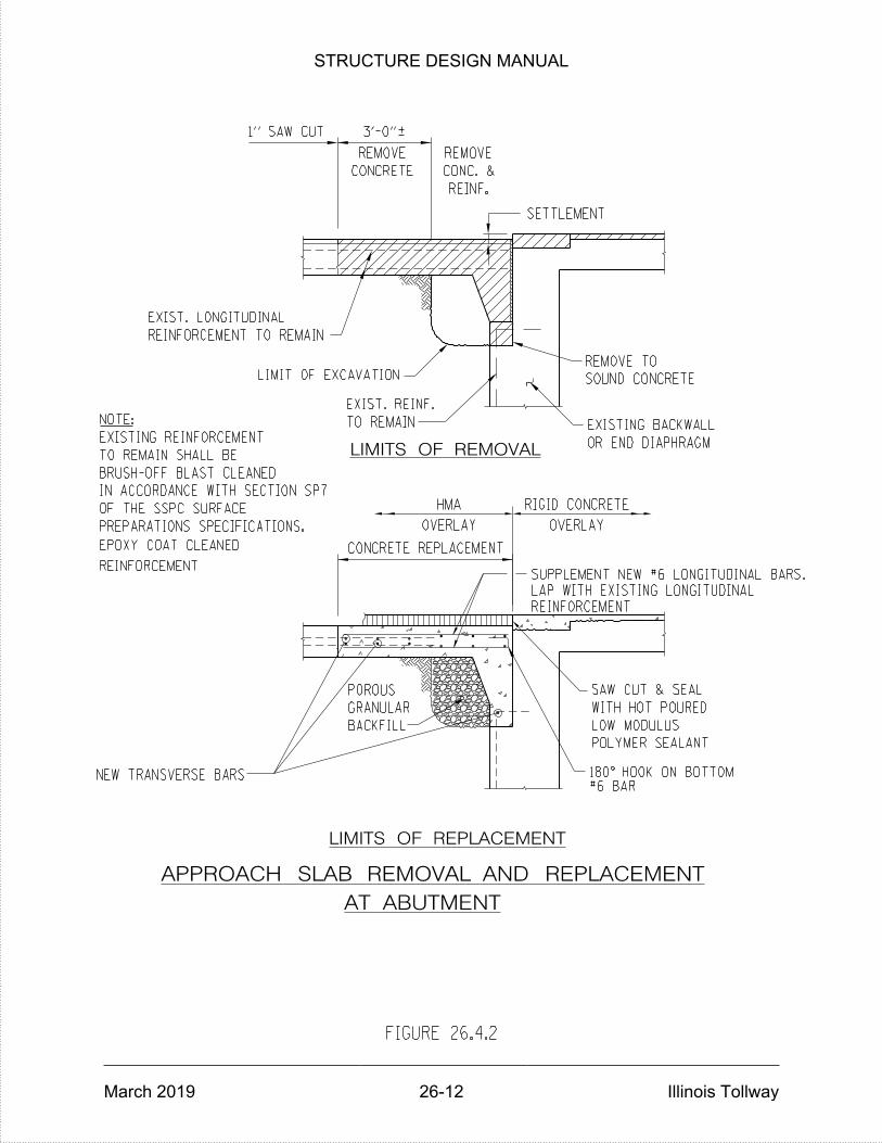
APPROACH SLAB REMOVAL AND REPLACEMENT
AT ABUTMENT
LIMITS OF REPLACEMENT
EXISTING REINFORCEMENT
TO REMAIN SHALL BE
BRUSH-OFF BLAST CLEANED
IN ACCORDANCE WITH SECTION SP7
OF THE SSPC SURFACE
PREPARATIONS SPECIFICATIONS.
NOTE:
LIMITS OF REMOVAL
OVERLAY
TO REMAIN
EXIST. REINF.
LIMIT OF EXCAVATION
SAW CUT & SEAL
LOW MODULUS
WITH HOT POURED
OVERLAY
OR END DIAPHRAGM
EXISTING BACKWALL
REMOVE TO
SOUND CONCRETE
RIGID CONCRETE
CONC. &CONCRETE
1" SAW CUT
REINF.
REMOVE
POLYMER SEALANT
FIGURE 26.4.2
SETTLEMENT
REMOVE
3'-0"|
EXIST. LONGITUDINAL
REINFORCEMENT TO REMAIN
CONCRETE REPLACEMENT
HMA
NEW TRANSVERSE BARS
POROUS
GRANULAR
BACKFILL
#6 BAR180° HOOK ON BOTTOM
REINFORCEMENT
EPOXY COAT CLEANED
REINFORCEMENT
LAP WITH EXISTING LONGITUDINAL
SUPPLEMENT NEW #6 LONGITUDINAL BARS.
STRUCTURE DESIGN MANUAL
March 2019 26-12 Illinois Tollway
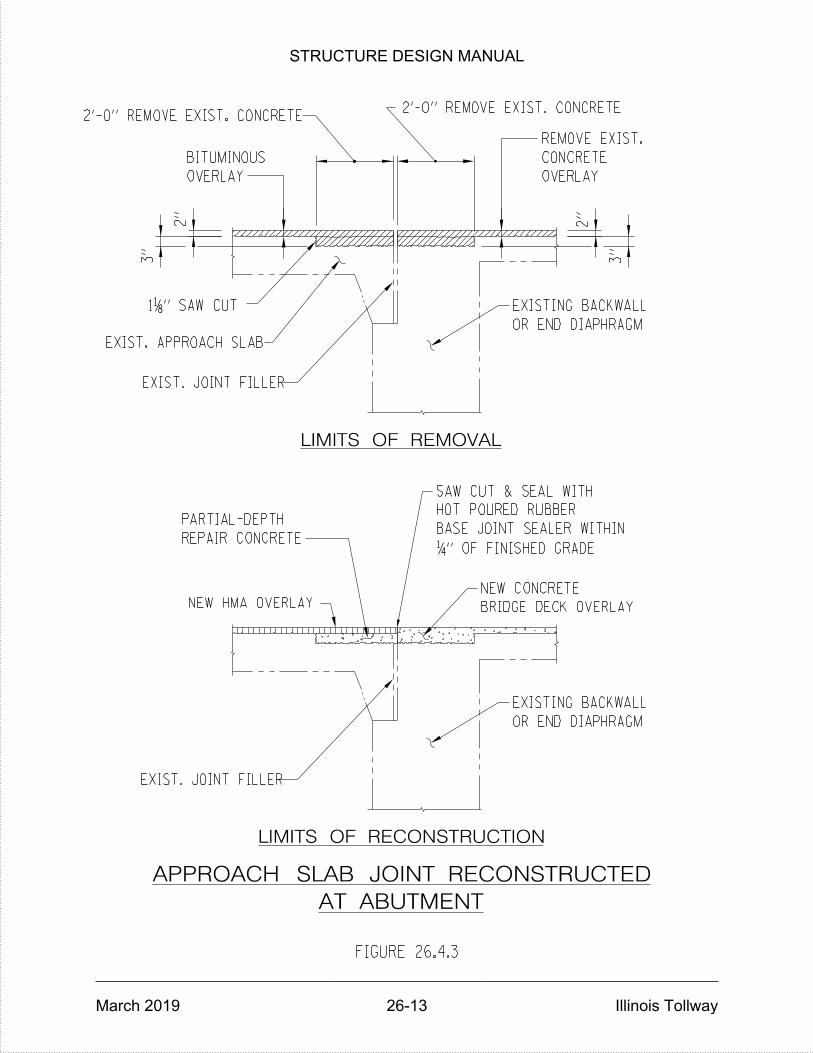
NEW CONCRETE
BRIDGE DECK OVERLAY
BASE JOINT SEALER WITHIN
HOT POURED RUBBER
SAW CUT & SEAL WITH
PARTIAL-DEPTH
REPAIR CONCRETE
NEW HMA OVERLAY
EXIST. JOINT FILLER
LIMITS OF RECONSTRUCTION
OR END DIAPHRAGM
EXISTING BACKWALL
EXIST. JOINT FILLER
EXIST. APPROACH SLAB
OVERLAY
BITUMINOUS
LIMITS OF REMOVAL
OVERLAY
REMOVE EXIST.
CONCRETE
EXISTING BACKWALL
OR END DIAPHRAGM
APPROACH SLAB JOINT RECONSTRUCTED
AT ABUTMENT
" SAW CUT811
FIGURE 26.4.3
" OF FINISHED GRADE41
3"
2"
2"
3"
2'-0" REMOVE EXIST. CONCRETE2'-0" REMOVE EXIST. CONCRETE
STRUCTURE DESIGN MANUAL
March 2019 26-13 Illinois Tollway

FIGURE 26.5.1
CO
MP
AC
TE
D
EA
RT
H
BA
CKFIL
L
AB
UT
ME
NT
SU
PE
RS
TR
UC
TU
RE
1.
HO
RIZ
ON
TA
L
LI
MIT
S
OF
SL
OP
E
PR
OT
EC
TIO
N
SH
AL
L
BE 2
FE
ET
OU
TSID
E
OF
TH
E
OU
TSID
E
SH
AL
L
BE
RE
MO
VE
D
AN
D
AN
Y
ER
OD
ED
PO
RTIO
N
OF
TH
E
SL
OP
ES
SH
AL
L
BE
FIL
LE
D
AN
D
CO
MP
AC
TE
D
WIT
H
SUIT
AB
LE
MA
TE
RIA
LS
TO
TH
E
LIN
ES
AN
D
GR
AD
ES
AS
SH
OW
N
ON
TH
E
PL
AN
S
AN
D/
OR
FA
CE
OF
PA
RA
PE
T.
NO
TES:
AS
DIR
EC
TE
D
BY
TH
E
EN
GIN
EE
R.
AP
PLIE
D
BIT
UMIN
OU
S
MA
TE
RIA
L
EXIS
TIN
G
GR
OU
ND
LIN
E
6"
AG
GR
EG
AT
E
SL
OP
E
PA
VIN
G
EXIS
TIN
G A
GG
RE
GA
TE S
LO
PE P
AVIN
G R
EP
AIR D
ET
AIL
S
EXIS
TIN
G
PIE
R
OR
NE
W
PIE
R
CR
AS
HW
AL
L
2.
AL
L
RU
BBIS
H
AN
D
LO
OS
E
EA
RT
H IN
TH
E
SL
OP
ES
STRUCTURE DESIGN MANUAL
March 2019 26-14 Illinois Tollway
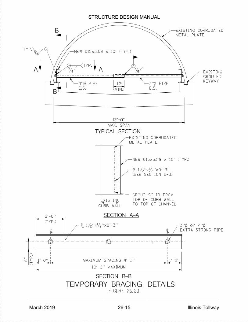
(MIN.)
12"
CURB WALL
EXISTING
10'-0" MAXIMUM
(TY
P.)
6"
(TYP.)
2'-0"
1'-0"
MAXIMUM SPACING 4'-0"
1'-0"
METAL PLATE
EXISTING CORRUGATED
ŠA A
B
B
TYP.
Š
12'-0"
MAX. SPAN
12'-0"
METAL PLATE
EXISTING CORRUGATED
TO TOP OF CHANNEL
TOP OF CURB WALL
GROUT SOLID FROM
` 1•"x•"x0'-3"
~ ~
TEMPORARY BRACING DETAILSFIGURE 26.6.1
(SEE SECTION B-B)
` 1•"x•"x0'-3"
TYP.Š
TYPICAL SECTION
SECTION A-A
SECTION B-B
NEW C15x33.9 x 10' (TYP.)
EXTRA STRONG PIPE
3"} or 4"}
NEW C15x33.9 x 10' (TYP.)
KEYWAY
GROUTED
EXISTING
E.S.
4"} PIPE
E.S.
3"} PIPE
STRUCTURE DESIGN MANUAL
March 2019 26-15 Illinois Tollway

(Min.)
12"
CURB WALL
EXISTING
1'-0"
MAXIMUM SPACING 4'-0"
1'-0"
10'-0" MAXIMUM
(TY
P.)
6"
(TYP.)
2'-0"
17'-0"
MAX. SPAN
ŠA A
B
B
TYP.
Š
KEYWAY
GROUTED
EXISTING
` 1•"x•"x0'-3"
~ ~
TEMPORARY BRACING DETAILS
METAL PLATE
EXISTING CORRUGATED
(SEE SECTION B-B)
` 1•"x•"x0'-3"
TO TOP OF CHANNEL
TOP OF CURB WALL
GROUT SOLID FROM
FIGURE 26.6.2
ŠTYP.
NEW C10x25x10'-0 (TYP.)
TYPICAL SECTION
SECTION A-A
SECTION B-B
PIPE
EXTRA STRONG
3"} or 4"}
3"} X-STRONG PIPE4"} X-STRONG PIPE
NEW C10x25x10'-0 (TYP.)
METAL PLATE
CORRUGATED
EXISTING
STRUCTURE DESIGN MANUAL
March 2019 26-16 Illinois Tollway

A
B
A
B
BB
A
A
SEE DETAIL #1
1'-0"
(MIN.)
C
C
D
DD
D
C
C
F
F
F
F
Š
TYP.
G
G
7•"
3"
Š
ŠTYP.
3"
(TYP.)
W.P.
TEMPORARY BRACING DETAILS
FIGURE 26.6.3
ROOF OF CULVERT
ON DEFORMATION IN
NEW C15x50 CENTERED
TYPICAL SECTION
DETAIL #1
New ƒ" `
(TYP.)
2 - •" `s
STRONG PIPE
3"} EXTRA
METAL PLATE
CORRUGATED
EXISTING
NEW ƒ"`
DEFORMATION
CENTERED UNDER
NEW C15x50
(TYP.)
NEW ƒ" `
PIPE
X-STRONG
NEW 3"}
PIPE
X-STRONG
NEW 4"}
PIPE
X-STRONG
NEW 3"}
PIPE
X-STRONG
NEW 4"}
METAL PLATE
EXISTING CORRUGATED
STRUCTURE DESIGN MANUAL
March 2019 26-17 Illinois Tollway
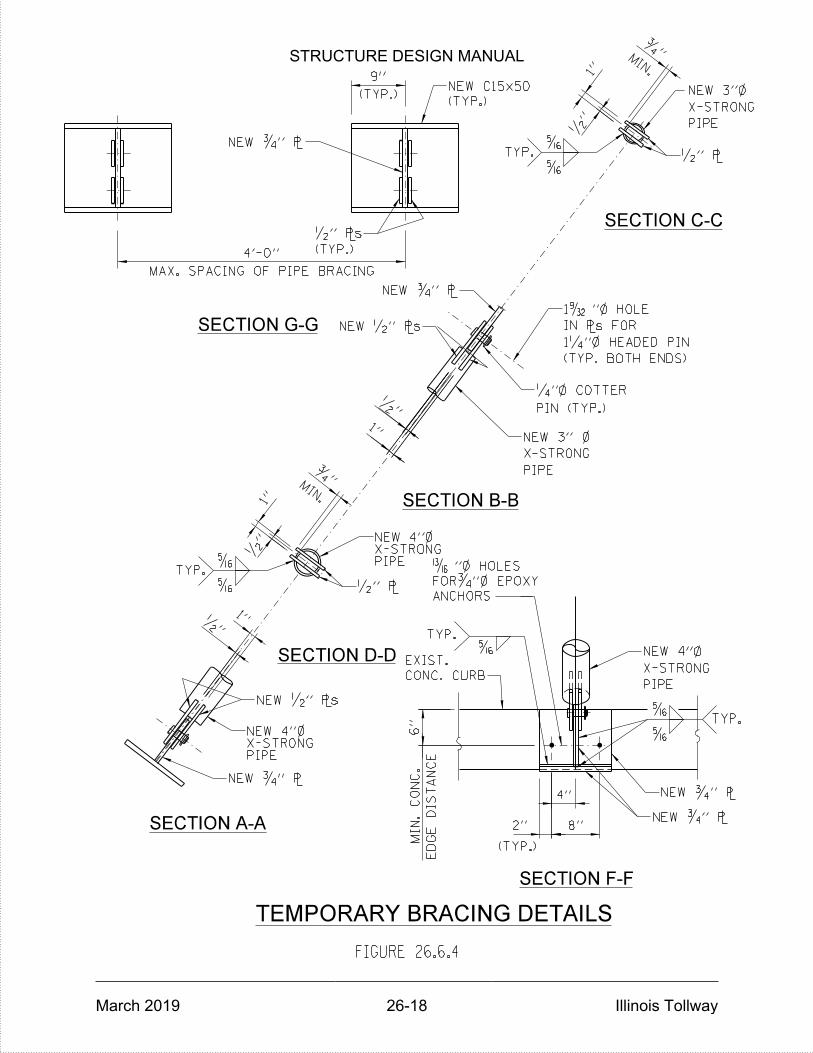
Š
ŠTYP.
4"
8"2"
(TYP.)
ED
GE
DIS
TA
NC
E
MIN.
CO
NC.
6"
Š
TYP.
4'-0"
9"
(TYP.)
MAX. SPACING OF PIPE BRACING
•"
Š
ŠTYP.
1"
1"
ƒ"
MIN.
•" `
1"•"
Š
ŠTYP.
1"
ƒ"
PIPEX-STRONGNEW 4"}
PIPE
X-STRONG
NEW 3"}
•"
•"
TEMPORARY BRACING DETAILS
FIGURE 26.6.4
ANCHORS
FORƒ"} EPOXY
Ž"} HOLES
(TYP. BOTH ENDS)
1‚"} HEADED PIN
IN `s FOR
1”"} HOLE
(TYP.)
•" `s
MIN.
(TYP.)
NEW C15x50
SECTION C-C
SECTION G-G
SECTION B-B
SECTION D-D
SECTION A-A
SECTION F-F
NEW ƒ" `
NEW •" `s
PIPE
X-STRONG
NEW 3" }
PIN (TYP.)
‚"} COTTER
•" `
NEW ƒ" `
NEW •" `s
PIPEX-STRONGNEW 4"}
PIPE
X-STRONG
NEW 4"}
CONC. CURB
EXIST.
NEW ƒ" `
NEW ƒ" `
NEW ƒ" `
STRUCTURE DESIGN MANUAL
March 2019 26-18 Illinois Tollway

STRUCTURE DESIGN MANUAL
March 2019 Illinois Tollway
THIS PAGE IS INTENTIONALLY LEFT BLANK

STRUCTURE DESIGN MANUAL
March 2019 27-1 Illinois Tollway
ACCELERATED BRIDGE CONSTRUCTION
27.1 Introduction
The purpose of the Accelerated Bridge Construction (ABC) section is to provide tools to be used by the DSE to evaluate the use of ABC on a project during the design phase development. These tools provide a consistent approach for evaluating, designing and constructing all projects utilizing ABC technologies. This section is in the beginning stages of development and will continue to evolve in the future as ABC methodologies progress and adoption is instituted by the Illinois Tollway.
ABC Overview
ABC is defined as bridge construction technologies that use innovative planning, design, materials or construction methods in a manner to specifically reduce the onsite construction time and mobility impacts that occur when building or replacing bridges. The most common technologies used in ABC applications are expediting the construction of bridges by using Prefabricated Bridge Elements and Systems (PBES) and the use of bridge movement and installation methods. In addition, there are ABC technologies that deal with materials, connections, foundations and the contractual aspects of project delivery. The combination of one or more of these ABC techniques has the potential to:
Enhance the quality of the project
Accelerate Project Delivery
Encourage Innovation
Increase the safety of the travelling public and workers
Decrease user impacts
Minimize the duration of maintenance of traffic
Reduce project costs
Because of the potential economic and safety impacts, minimizing traffic disruptions is a goal that should be elevated to a higher priority when planning bridge related construction projects.

STRUCTURE DESIGN MANUAL
March 2019 27-2 Illinois Tollway
Illinois Tollway ABC Initiative
The Illinois Tollway is committed to providing its customers the best overall experience when using its system and is continually exploring opportunities to leverage innovations in the delivery of its construction projects. The application of ABC is consistent with the Illinois Tollway’s desire to reduce user impacts during construction while maintaining a high quality product. The Illinois Tollway initiative is to provide DSEs with a basic understanding of the different ABC technologies and project delivery methods available, help guide project specific evaluation and encourage the use of alternate bridge design and construction to meet project goals. Standard tools have been developed to aid the DSE in evaluating ABC technologies for each project. These tools, called the Decision Framework for ABC, include the ABC Decision Matrix Tool (DMT) and the ABC Bridge Life Cycle Comparison (BLCC) Tool. These tools define a comprehensive list of variables that need to be considered by the DSE during the design phase development. With ABC being a new technology, there will be a learning curve for all involved. Learning from other agencies who have implemented ABC successfully, engaging and collaborating with national ABC experts and adopting best practices will help minimize the initial learning curve. ABC is a growing trend within the industry and the Illinois Tollway will continue to collaborate with the industry to advance the state of practice with respect to ABC technologies by encouraging the involvement of local consultants, contractors, and suppliers to help further develop a policy that will continue to improve the delivery of bridge projects along the Illinois Tollway system.
27.2 Illinois Tollway ABC Committee
An Illinois Tollway ABC Committee has been established to identify ABC strategies, review current best practices, make recommendations and continue to develop the Illinois Tollway ABC policy. The committee consists of representatives from multiple disciplines within the Illinois Tollway, PMO and GEC as well as representatives from within the industry and is chaired by an Illinois Tollway Deputy Chief.
27.3 Decision Framework for ABC
This article defines the ABC decision making process during the design phase development. The Decision Framework for ABC helps the DSE “think” through and execute the design process and consists of two steps – completing the ABC DMT to determine if ABC technologies should be evaluated for a given bridge and performing an ABC BLCC (if required) to compare and eliminate different ABC technologies to make a final recommendation. An example to aid DSEs in using the ABC DMT and ABC BLCC Tool is available for download from the Illinois Tollway’s internet site at www.illinoistollway.com, under

STRUCTURE DESIGN MANUAL
March 2019 27-3 Illinois Tollway
Construction & Engineering, Consultant Resources, Manuals, Bridges & Structures. The example shows a step by step procedure to evaluate a structure for ABC, explains logical steps and provides explanations for the assumptions used to fill in the variable inputs in the tools.
ABC Decision Matrix Tool (DMT)
The ABC DMT is a framework to help DSEs determine if ABC technologies shall be evaluated for a particular bridge. The ABC DMT shall be used during the Master Plan or Pre-Conceptual Phase. The tool is a spreadsheet that may be downloaded from the Illinois Tollway’s internet site at www.illinoistollway.com, under Construction & Engineering, Consultant Resources, Manuals, Bridges & Structures. All new bridges or existing bridges to be replaced or reconstructed shall require an ABC DMT to be completed. Rehabilitation, retaining walls and culvert structures do not need to evaluate the use of ABC. An ABC DMT shall be completed for each individual bridge under consideration. For dual structures that have similar geometry, only one ABC DMT shall be required. The ABC DMT is a qualitative assessment of the impact ABC technologies may have on a project when compared to conventional construction and does not identify specific ABC technologies that may be used. Because this is a qualitative process that requires engineering judgment, there is an acknowledged level of subjectivity to the tool. The tool requires the user to assign a score for input variables based on specific scoring criteria and constraint descriptions that have been established to compare ABC to conventional construction. A description of each input variable and basic guidance for the specific scoring criteria are provided in Figures 27.3.1.1, 27.3.1.2 and 27.3.1.3. The user shall fill in the scores and other requested information in only the yellow highlighted cells in the spreadsheet. See Figure 27.3.1.4. The assigned weights, scoring criteria and formulas shall not be changed without prior approval from the Illinois Tollway. The scores are a function of the bridge location and shall be filled in for an individual bridge. The ABC DMT automatically calculates an ABC Rating Score based on the input by the user. See Figure 27.3.1.5. The user shall then use the ABC Rating Score – Decision Flow Chart to work toward a recommendation. See Figure 27.3.1.6. If an ABC Rating score of 30 or less is recorded, Conventional Bridge Construction is the most logical choice to evaluate further. The threshold of 30 is intended to capture any bridge receiving a score of 5 in the most heavily weighted variable, Traffic Impact. If an ABC Rating score of 60 or more is recorded, Accelerated Bridge Construction is the most logical choice to evaluate further. The threshold of 60 is intended to capture any bridge receiving a score of 5 in all three of the most heavily weighted variables, Average Daily Traffic, Traffic Impact, and Maintenance of Traffic. For ABC Rating scores between 30 and 60, the user shall consider additional factors prior to making a final decision on ABC. These factors include project delivery and schedule, traffic volumes, site conditions, project risk and structure geometry. See Figure 27.3.1.6.
STRUCTURE DESIGN MANUAL
March 2019 27-4 Illinois Tollway
Prior to making a final recommendation, the DSE shall take a look at the project from a global perspective and determine if ABC technologies provide a benefit with all the project-specific information considered. If the project contains multiple structures within a corridor, the DCM and DSE shall take into consideration the overall corridor project delivery and MOT schemes. The completed ABC DMT, any supporting material and a summary stating the recommendation from the DSE shall be included in the Master Plan Study or a technical memorandum (if a Master Plan Study is not required). The Master Plan Study or technical memorandum shall provide justification for the recommendation including the major factors affecting the ABC DMT Rating Scores and if ABC technologies provide a benefit with all the project-specific information considered. See article 27.3.3 for a complete list of design phase project deliverables. If the final recommendation is to evaluate ABC further, the DSE shall use the ABC BLCC Tool to help compare potential ABC and conventional construction technologies that meet project specific goals.
ABC Bridge Life Cycle Comparison (BLCC) Tool
The ABC BLCC Tool is a framework to help DSEs compare potential ABC technologies for a given project and help eliminate the ABC technologies that may not be perceived as the most economical. The tool is a spreadsheet that may be downloaded from the Illinois Tollway’s internet site at www.illinoistollway.com, under Construction & Engineering, Consultant Resources, Manuals, Bridges & Structures and shall be used during the Concept Phase. All ABC DMT results that recommend ABC to be evaluated further shall require an ABC BLCC Tool to be completed. If conventional bridge construction was recommended to be evaluated further, then the ABC BLCC Tool is not applicable and no further Decision Framework analysis is required. The ABC BLCC Tool is a qualitative analysis used to evaluate the long-term economic efficiency between bridge alternatives including conventional construction and various ABC technologies, and does not calculate actual life cycle costs. In addition, the tool does not capture impacts due to service disruptions including traveler delay and revenue impacts. Final recommended bridge alternatives may require additional analysis to determine service disruptions if requested by the Illinois Tollway. Because this is a qualitative process that requires engineering judgment, there is an acknowledged level of subjectivity to the tool. The tool makes assumptions about costs and service life. If the DSE determines that cost breakdowns or service life information for a given project is different than the tool’s assumptions, the input scores may be adjusted accordingly by the user. The tool requires the user to assign a score for multiple input variables in three major categories: Initial Costs (IC), Traffic Impact Costs (TIC), and Maintenance Costs (MC).
STRUCTURE DESIGN MANUAL
March 2019 27-5 Illinois Tollway
Initial Costs are intended to capture the direct costs associated with construction, Traffic Impact Costs are intended to capture the indirect costs associated with traffic impact, and Maintenance Costs are intended to capture routine maintenance and future replacement costs. Each input variable is based on specific scoring criteria and constraint descriptions that have been established to help identify lower long-term costs. Higher input variable scores represent the potential for lower costs for the bridge alternative being considered. A description of each input variable and basic guidance for the specific scoring criteria are provided in Figures 27.3.2.1, 27.3.2.2, and 27.3.2.3. The user shall input the scores and other requested information in only the yellow highlighted cells in the spreadsheet. See Figures 27.3.2.4, 27.3.2.5 and 27.3.2.6. The assigned weights, scoring criteria and formulas shall not be changed without prior approval from the Illinois Tollway. The scores are a function of the bridge location, material, equipment, maintenance of traffic and future maintenance, and shall be filled in for an individual bridge. The ABC BLCC Tool automatically calculates individual Rating Scores in each of the three major categories and a Total ABC BLCC Rating Score based on the input by the user. See Figure 27.3.2.7. A higher Total ABC BLCC Rating Score represents a more economical choice when compared to other bridge alternatives. Bridge alternatives may consist of individual ABC technologies or a combination of ABC technologies and at a minimum shall be compared to a conventional construction, bridge alternative with no upper limit on the number of bridge alternatives allowed. The number of bridge alternatives shall be based on engineering judgment, site constraints, and project goals. The user of the tool may elect to add additional bridge alternatives to the ABC BLCC Tool to accurately compare all bridge alternatives. A separate ABC BLCC score shall be calculated for each bridge alternative investigated by creating additional tabs in the spreadsheet. For cross road bridges with an Inter-Governmental Agreement (IGA), the bridge alternatives shall be coordinated with the local agency to ensure the selected ABC technologies are permitted. The Individual and Total ABC BLCC Rating Scores obtained for each bridge alternative shall then manually be entered into the summary tab of the spreadsheet. See Figure 27.3.2.8. The summary provides a visual comparison of individual and overall scores of each bridge alternative considered. Based on the summary of the ABC BLCC analysis, the DSE shall identify the applicable ABC or conventional construction technologies that best fit the project specific goals. It is suggested that multiple bridge alternatives be carried forward to be able to develop costs and determine a final recommendation. The user of the tool may elect to add additional bridge alternatives to the comparison summary. The DSE shall again take evaluate the project from a global perspective and determine if the bridge alternatives with the higher scores provide a benefit with all the project-specific information considered prior to making a final recommendation. The completed ABC BLCC Tool for all bridge alternatives, supporting material and summary stating the recommendations from the DSE shall be incorporated into the Bridge Type Study. The Bridge Type Study shall include a cost summary comparison for the recommended bridge alternatives in accordance with Article 3.2 to determine a final recommendation. Additional analysis may be required to determine a final
STRUCTURE DESIGN MANUAL
March 2019 27-6 Illinois Tollway
recommendation at the request of the Illinois Tollway. The final recommendation shall be incorporated into the Type, Size and Location (TS&L) Plans in accordance with Section 3.0. See article 27.3.3 for a complete list of design phase project deliverables.
ABC Design Phase Project Deliverables
The following is the list of each Design Phase Project Deliverable required for ABC: Master Planning or Pre-Conceptual Phase
The DSE shall develop the Structure Condition Report and Life Cycle Cost
Analysis in accordance with Section 2.0.
o The goal of the Structure Condition Report and Life Cycle Cost
Analysis is to determine rehabilitation versus replacement.
If a new structure, replacement or reconstruction is recommended in the
Structure Condition Report, the DSE shall complete the ABC DMT in
accordance with Article 27.3.1.
The DSE shall incorporate the completed ABC DMT, any supporting material
and a summary stating the ABC recommendation into the Master Plan Study or
technical memorandum (if a Master Plan Study is not required).
Conceptual Design Phase (30%)
If required by the ABC DMT, the DSE shall complete the ABC BLCC Tool in
accordance with Article 27.3.2.
The DSE shall incorporate the recommended bridge alternatives from the ABC
BLCC tool into the Bridge Type Study and perform a cost comparison in
accordance with Article 3.2. The DSE shall make a final recommendation.
Additional analysis at the request of the Illinois Tollway may be required to make
a final recommendation.
The final recommendation shall be incorporated into the Type, Size and
Location (TS&L) Plans in accordance with Section 3.0.
Preliminary (60%), Pre-Final (95%), and Final Design Phases (100%)
The DSE shall refine and implement the final recommendation into the
Construction Documents.
STRUCTURE DESIGN MANUAL
March 2019 27-7 Illinois Tollway
27.4 ABC Technologies
This article defines the different ABC technologies commonly used in the industry and discusses general guidance associated with each technology. This article is not intended to be all inclusive and is provided for general guidance and to encourage the DSE to evaluate alternate bridge design and construction. It is the responsibility of the DSE to determine the types of ABC technologies during the Decision Framework for ABC that best represent the most viable options for the project based on engineering judgment, site constraints, and project goals. It is important to emphasize that the application of ABC design and construction should not reduce the durability of the structure or increase the maintenance costs over the life of the structure when compared to bridges built conventionally in accordance with current standards.
Prefabricated Bridge Elements and Systems (PBES)
Prefabricated Bridge Elements and Systems (PBES) are structural components of a bridge that are fabricated before arriving at the job site and then rapidly assembled. PBES can be fabricated on-site if ROW is available. An entire bridge may be composed of prefabricated elements, or individual bridge elements may be combined with other ABC technologies. The DSE shall consider PBES during the Decision Framework for ABC. PBES are cost effective when repetitive and simple details are used, the number of connections is minimized, and the system provides tolerances to allow for fit-up inconsistencies. The main advantage to PBES is the reduction in time at the project site for concrete forming, installation of rebar, and concrete placement since PBES are constructed in prefabrication plants or at Illinois Tollway approved on-site casting yards. PBES elements shall be sized so that they are able to be moved from where they are fabricated to where they are installed. A staging area with adequate space and clearances to place the prefabricated elements is required. The most commonly used PBES on ABC Projects are as follows:
Precast Concrete Bridge Approach Slabs
Precast Concrete Deck Panels Precast Concrete Pier Caps Precast Concrete Pier Columns Precast Concrete Abutments Precast Concrete Foundations Precast Concrete Wingwalls/ Retaining Walls

STRUCTURE DESIGN MANUAL
March 2019 27-8 Illinois Tollway
Precast Concrete Parapets Prefabricated Superstructure Systems Prefabricated Superstructure/Substructure Systems Prefabricated Total Bridge Systems
Constructability and erection procedures shall be thoroughly investigated prior to consideration of PBES. The DSE shall evaluate the most appropriate and feasible PBES for the bridge based on site constraints, construction procedures, cost and impacts to traffic. For example, the use of precast deck panels may not be cost effective with the use of large wide top flange Bulb-T’s due to large joints between panels and the extensive use of Ultra High Performance Concrete. Precast concrete pier caps and columns may not be cost effective if sufficient head room is not available to place the elements. For all Prefabricated Bridge Elements and Systems, shop drawings will be required in accordance with Section 25.0. The TRB SHRP2 R04 Accelerated Bridge Construction Research Project has generated a “Tool Kit” document that contains sample calculations, details, and specifications for projects ranging from deck work to complete superstructure and substructure replacement with precast concrete elements.
ABC Materials
During the Decision Framework for ABC, the DSE shall consider material choices carefully for implementation on the Illinois Tollway system as service life and durability are important factors for each project. The DSE shall use caution in selecting material types not typically used on Illinois Tollway projects. Coordination with Illinois Tollway Materials is required to select the appropriate materials, pay items, special provisions and construction procedures. The most common ABC Material being utilized is Ultra High Performance Concrete (UHPC). UHPC is a composite material that allows high compressive strengths of 14 ksi in relatively short time periods with ultimate strengths of 20-25 ksi. It consists of fiber reinforcement in densely packed concrete and exhibits high ductility and durability. It has been widely used in field-cast connections between precast elements. UHPC allows for shorter reinforcement development lengths, potential increased durability in severe exposure environments, and potential longer service life if designed and installed properly. The FHWA has published a report “Ultra-High Performance Concrete: A State-of-the-Art Report for the Bridge Community” that provides more specific information and design considerations for UHPC.
STRUCTURE DESIGN MANUAL
March 2019 27-9 Illinois Tollway
Section 15.0 shall also apply to all structures utilizing ABC technologies in which the Illinois Tollway utilizes High Performance Concrete (HPC) Mix Designs and considers stainless steel reinforcement bars in the deck in order to extend the service life of the bridge superstructures by reducing cracking and inhibiting corrosion induced failures. The Illinois Tollway’s objective with current standards for cast-in-place bridges is to obtain a bridge deck service life of at least 50 years and a 75 year or longer service life for bridge decks with HPC and stainless steel reinforcement combined. Similar objectives shall be applied to all structures no matter what ABC technology is used except as noted below:
Precast Modular Concrete Superstructure Elements
o HPC Mix Design with more emphasis on crack control shall be
utilized in order to inhibit chloride penetrations.
Prestressed Precast Modular Concrete Superstructure Elements
o HPC Mix Design with more emphasis on crack control shall be
required.
ABC Connections
The DSE shall consider the type of connections and detailing requirements during the Decision Framework for ABC to help limit durability issues. It is important to simplify the details of these connections both for ease and quickness of construction and to reduce the risk of different elements not fitting together. The most common ABC connections used on ABC Projects are as follows:
Grouted Splice Couplers Concrete Closure Joints Traditional Post-Tensioning Grouted Post-Tensioning Welded Connections Bolted Connections
The FHWA has published a manual entitled “Connection Details for Prefabricated Bridge Elements and Systems” that provides more specific information about the many different types of prefabricated element connections.

STRUCTURE DESIGN MANUAL
March 2019 27-10 Illinois Tollway
Installation Methods
This article defines the available ABC technologies for expediting construction using bridge movement and installation methods. The benefit of these installation methods provides contractors with increased speed in removing and installing bridges. The DSE may consider these installation methods during the Decision Framework for ABC. The most common ABC installation methods used on ABC projects are as follows:
Lateral Sliding Self-Propelled Modular Transporter (SPMT) Longitudinal Launches Crane Based Projects
For all ABC installation methods, an erection plan shall be required in accordance with the Illinois Tollway Special Provisions.
It should be noted that installation methods are considered Contractor’s means and methods. Contracting Provisions shall be established and discussed with the Illinois Tollway to determine how the project will be bid and packaged. 27.4.4.1 Lateral Sliding Lateral Bridge slide-ins consist of building the proposed structure on temporary supports adjacent to an existing bridge, removing the old bridge and transporting the new bridge onto the substructure by sliding or rolling over bearings. In locations where sufficient space exists adjacent to the existing bridge and the site has limited profile changes and limited geometric constraints, bridge slide-in may prove to be a viable option. Lateral sliding is typically used on single span structures. The DSE shall use caution in evaluating lateral slide-ins for a multi-span structure. Several factors shall be considered in the design of these bridge installation methods:
Lateral slide-in is most effective when ADT under the bridge is low and over the
bridge is high.
A staging area parallel to the structure is required to build the superstructure
on temporary supports.
The superstructure may be pushed transversely onto the new substructure
using a hydraulic ram or pulled with winches.
The lateral slide may utilize roller bearings or a smooth low friction surface.
Adequate vertical clearance is required under the existing structure.
Lateral slide-in shall not be used on bridges with high skews.
The number of spans and length of the bridge are key factors.
STRUCTURE DESIGN MANUAL
March 2019 27-11 Illinois Tollway
The superstructure stresses, deflections and drift tolerances during the move
shall be considered.
Concrete and steel girder bridges may both be used in lateral slide-ins.
Abutment selection shall be evaluated to allow the opportunity to jack the bridge
superstructure and mount the various sliding systems.
Loading and stresses of the abutment seat and end diaphragm shall be
considered during the move.
The structure tie-in with the roadway shall be considered.
The FHWA has published a manual “Slide-In Bridge Construction Implementation Guide” that provides more specific information and design considerations. 27.4.4.2 Self-Propelled Modular Transporter (SPMT) SPMT is a motorized vehicle with a combination of multi-axle platforms that are remotely controlled though a computer system capable of transporting very large or heavy loads. The use of SPMT is ideal for carrying large structures, such as bridges from offsite locations, lifting them into their final position, and exiting the site within a very short period of time. In locations where high traffic volumes exist, the structure is over a railroad or navigable waterway, or the project site has overhead constraints, SPMT may prove to be a viable option. Several factors shall be considered in the design of these bridge installation methods:
SPMTs are most effective when ADT is high under or over the bridge.
A staging area with adequate space to build the bridge on a temporary structure
is required.
The travel path from the staging area to the final location shall have sufficient
clearance, proper grades and the appropriate bearing capacity to support the
heavy construction loads.
A geotechnical investigation shall be conducted for the proposed staging and
travel path to determine if the soils can support the SPMT loads.
Concrete and steel girder bridges may both be used with SPMTs.
The design of the superstructure shall consider the SPMT loads during
placement, movement and lifting.
Support conditions shall be checked when the structure is placed on the SPMT.
Pick points shall be identified in the plans and checked for out of plane forces.
Deflections and twist of the superstructure shall be analyzed with respect to the
stroke of the SPMT.
Deflections and twist of the superstructure shall be continuously monitored and
controlled during the bridge move.
STRUCTURE DESIGN MANUAL
March 2019 27-12 Illinois Tollway
The deck and parapet shall be analyzed for potential stress reversal conditions
encountered during the move since any negative moment over the pick points
has the potential to cause cracking.
The FHWA has published a manual “Use of Self-Propelled Modular Transporters to Remove and Replace Bridges” that provides more specific information and design considerations. 27.4.4.3 Longitudinal Launches Longitudinal launching consists of erecting the bridge superstructure in a launching pit and pushing the unit out over the substructure. The most common launches are used in segmental construction. Longitudinal launching is ideal for bridges over areas that are inaccessible by crane such as deep valleys, roadways with a high ADT or heavily travelled waterways. Several factors shall be considered in the design of these bridge installation methods:
Longitudinal bridge launching is effective when ADT under the bridge is high
and over the bridge is low.
A staging area behind the abutments is required to build the superstructure on
temporary supports.
The superstructure may be pushed longitudinally out over the spans using a
sliding or rolling system.
Concrete and steel girder bridges may both be used in longitudinal launches.
Curved structures can utilize longitudinal launches.
This installation method is more complex than lateral slides. Launching systems usually pertain to specialty bridge types (long multi-span type bridges) which are not as common on the Illinois Tollway system. More information on longitudinal launching can be found in an NCHRP report entitled “Bridge Construction Practices using Incremental Launching”. 27.4.4.4 Crane Based Projects Crane based projects consist of using large capacity cranes to lift partial or completed bridge structures into place. These types of cranes are most effective when the structure is over a roadway, railroad or navigable waterway and an accessible staging area is available. Foundation conditions within the staging area must be able to support the heavy loads. Conventional cranes that are used for erection of beams and girders can be used for installation of PBES such as deck panels; however, it is fairly common for heavy lifting cranes to be used in conjunction with PBES.

STRUCTURE DESIGN MANUAL
March 2019 27-13 Illinois Tollway
Gantry cranes are a type of crane built on top of a gantry used to straddle a construction site. These types of cranes are most effective for long viaduct structures, when there is limited access or inaccessible areas under the structure for conventional or heavy lifting cranes and can be used for both demolition and erection procedures. Installation methods are predominantly determined by the Contractor; designers shall carefully evaluate the constructability of the design, develop suggested construction and installation plan details and prepare project special provisions for incorporation into the contract documents. When planning to use cranes to place a bridge, consider the following:
Required crane size
Potential crane locations
Required reach to place sections
Weight of sections placed
Lifting Points and lifting devices
Stresses at lifting points
Connection details
Location of overhead and underground utilities
Method of delivery
Location of delivery
Sequence of construction
Limits of Right-of-Way
Accelerated Foundation Construction Methods
Accelerated foundation construction consists of construction methods that reduce the time for foundation installation. The most common foundation installation methods used on ABC projects are as follows:
Continuous Flight Auger (CFA) Piles – method of constructing deep
foundations that combines augering, injecting concrete and inserting
reinforcement into wet concrete into one continuous process.
Rapid Embankment Construction – use of lightweight Expanded Polystyrene
(EPS) Geofoam blocks to reduce long-term settlement.
Additional means of construction such as advance foundation construction or use of low-boy drilling equipment that allow bridge construction activities to occur without impacting traffic shall also be considered. However, these methods shall not be considered ABC methods and scored in the Decision Framework for ABC.
STRUCTURE DESIGN MANUAL
March 2019 27-14 Illinois Tollway
The FHWA has published a Geotechnical Engineering Circular No. 8 titled “Design and Construction of Continuous Flight Auger Piles” that provides more specific information and design considerations. In addition, more information can be found at the FHWA website.
27.5 ABC Project Delivery Methods
The ABC technologies listed in Article 27.4 are ways to accelerate on-site bridge construction. ABC project delivery and innovative contracting are ways to accelerate bridge construction during the planning stage. These methods can reduce time required to plan, design and bid the project. Two common innovate contracting methods for ABC are Design Build (DB) which combines the design and construction into one contract and Construction Manager General Contractor (CM/GC) which includes the owner as part of the design team and selects bids based on qualifications. Based on current legislation, both of these methods usually are not allowed on Illinois Tollway projects. To accelerate bridge construction during the planning stage, contracting provisions may be incorporated into the project delivery method given the right conditions, application, and support. The DSE shall consider these contracting provisions and provide recommendations during the planning process. The recommendations will be reviewed by the Illinois Tollway and approved on a project by project basis. The most commonly used contracting provisions on ABC projects are as follows:
Best Value Selection – technical evaluation of contractor proposal and bid price
which are combined to determine “best value.”
A+B and A+B+C Bidding – assigns value to base bid price and time component
of construction and low bid is combination of value components.
Incentive/Disincentive (I/D) Clauses – contract provisions that are used to
financially compensate or penalize the contractor for time spent on the
construction of a project. This clause is not part of Liquidated Damages.
Lane Rentals – the contractor is charged for the amount of time that a lane is
out of service during construction and the charge may vary by time or day of
the week. The bid includes a base bid for construction and a secondary bid for
lane rental and a best value selection is made.
Advanced Contracts – consists of expedited contracts in advance of the
construction contract for fabrication of structural elements, procurement of
specialized equipment or material or to minimize traffic impacts.

STRUCTURE DESIGN MANUAL
March 2019 27-15 Illinois Tollway
Alternate Design/Alternate Bid (AD/AB) – contractor is permitted to bid an
alternate concept when contract provisions allow for a specified project benefit.
27.6 ABC References
The following is a brief summary of key references, publications and websites that can be used as resources for Accelerated Bridge Construction. KEY REFERENCES
FHWA through their initiatives, Every Day Counts (EDC) and Highways for LIFE
has been promoting, supporting, and advancing ABC efforts nationwide.
The ABC University Transportation Center (ABC-UTC) supports research and
initiatives to provide the transportation industry with the tools needed to effectively
and economically utilize the principles of ABC. ABC-UTC has assembled a group
of experienced and knowledgeable bridge academics and engineers to engage the
industry and support the use of ABC.
AASHTO Innovation Initiative supports and champions the implementation of ABC
technologies that yield significant economic or qualitative benefits to the users.
PUBLICATIONS
FHWA, “PBES Cost Study: Accelerated Bridge Construction Success Stories”,
2006
FHWA-HFL, Publication No. HIF-12-013, “Accelerated Bridge Construction –
Experience in Design, Fabrication and Erection of Prefabricated Bridge Elements
and Systems – Final Manual”, November 1, 2011.
TRB-SHRP2, Publication No. S2-R04-RR-2, “Innovative Bridge Designs for Rapid
Renewal, ABC Toolkit”, 2013.
FHWA-HFL, Publication No. FHWA-IF-09-010, “Connection Details for
Prefabricated Bridge Elements and Systems”, March 30, 2009.
FHWA, Publication No. FHWA-HRT-13-060, “Ultra-High Performance Concrete: A
State-of-the-Art Report for the Bridge Community”, June 2013.
FHWA, Project #F-ST99 (232), “Slide-In Bridge Construction Implementation
Guide”, November 2013.
STRUCTURE DESIGN MANUAL
March 2019 27-16 Illinois Tollway
FHWA, Manual on Use of Self-Propelled Modular Transporters to Remove and
Replace Bridges, June 2007.
NCHRP Project 20-07, Task 229, “Bridge Construction Practices Using
Incremental Launching”, December 2007.
Proceedings of the 1st International ABC Conference in Miami, FL December,
2014.
Proceedings of the 2nd International ABC Conference in Miami, FL, December,
2015.
FHWA Geotechnical Engineering Circular (GEC) No. 8 “Design and Construction
of Continuous Flight Auger Piles”, April 2007.
WEBSITES
ABC University Transportation Center (ABC-UTC) at Florida International
University. http://www.abc-utc.fiu.edu/
Transportation Research Board (TRB) ABC Subcommittee under TRB AFF10
General Structure Committee. http://www.trbaff103.com/
Federal Highway Administration (FHWA) Accelerated Bridge Construction
website: http://www.fhwa.dot.gov/bridge/abc/
FHWA Every Day Counts (EDC) http://www.fhwa.dot.gov/everydaycounts/
Strategic Highway Research Program (SHRP 2) Innovative Bridge Designs for
Rapid Renewal, Project R04, website http://www.fhwa.dot.gov/goshrp2/
AASHTO Innovation Initiative website http://aii.transportation.org.
FHWA’s Slide-In: Bridge Lateral Move In Technology website:
http://www.slideinbridgeconstruction.com/

STRUCTURE DESIGN MANUAL
March 2019 27-17 Illinois Tollway
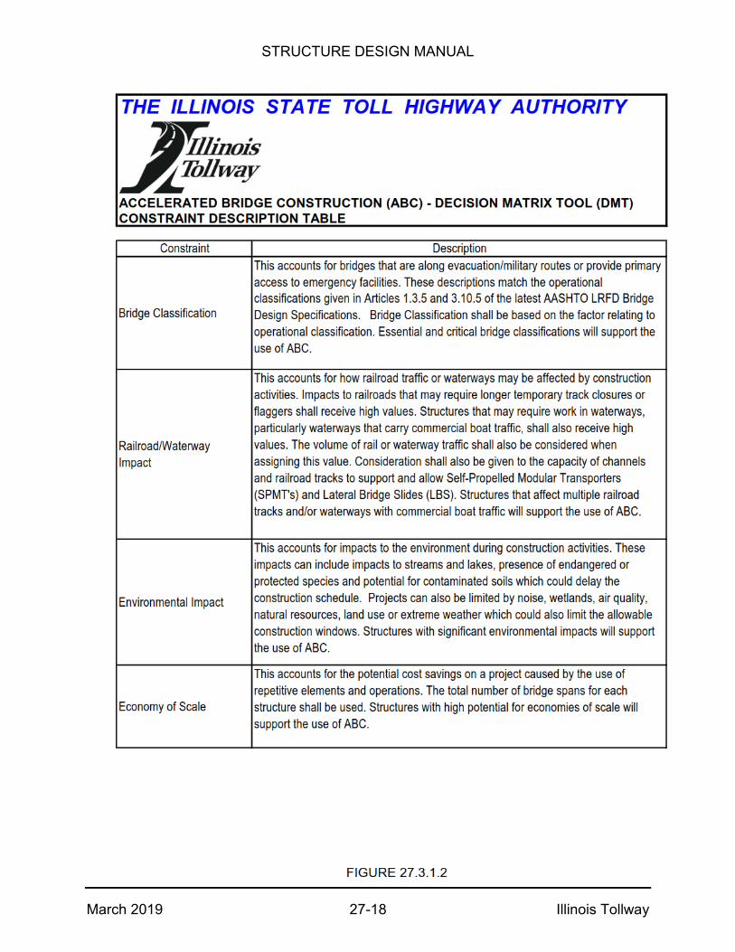
STRUCTURE DESIGN MANUAL
March 2019 27-18 Illinois Tollway

STRUCTURE DESIGN MANUAL
March 2019 27-19 Illinois Tollway
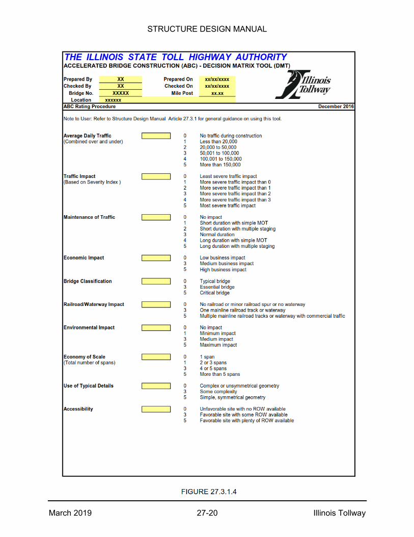
STRUCTURE DESIGN MANUAL
March 2019 27-20 Illinois Tollway

STRUCTURE DESIGN MANUAL
March 2019 27-21 Illinois Tollway
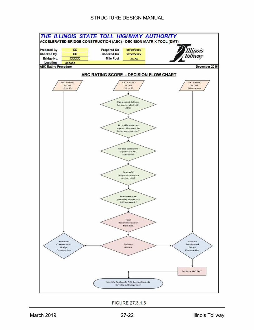
STRUCTURE DESIGN MANUAL
March 2019 27-22 Illinois Tollway
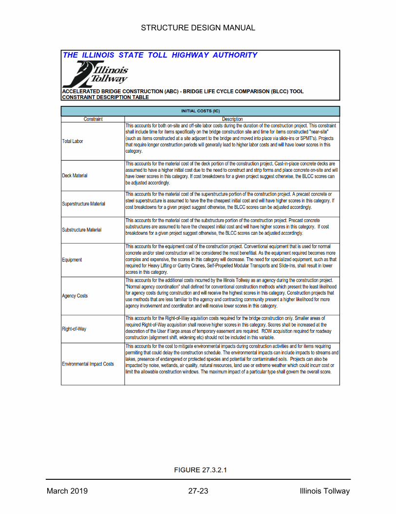
STRUCTURE DESIGN MANUAL
March 2019 27-23 Illinois Tollway

STRUCTURE DESIGN MANUAL
March 2019 27-24 Illinois Tollway
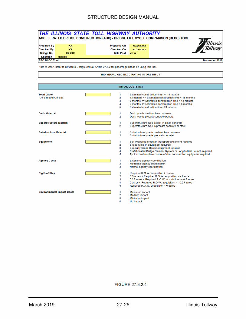
STRUCTURE DESIGN MANUAL
March 2019 27-25 Illinois Tollway
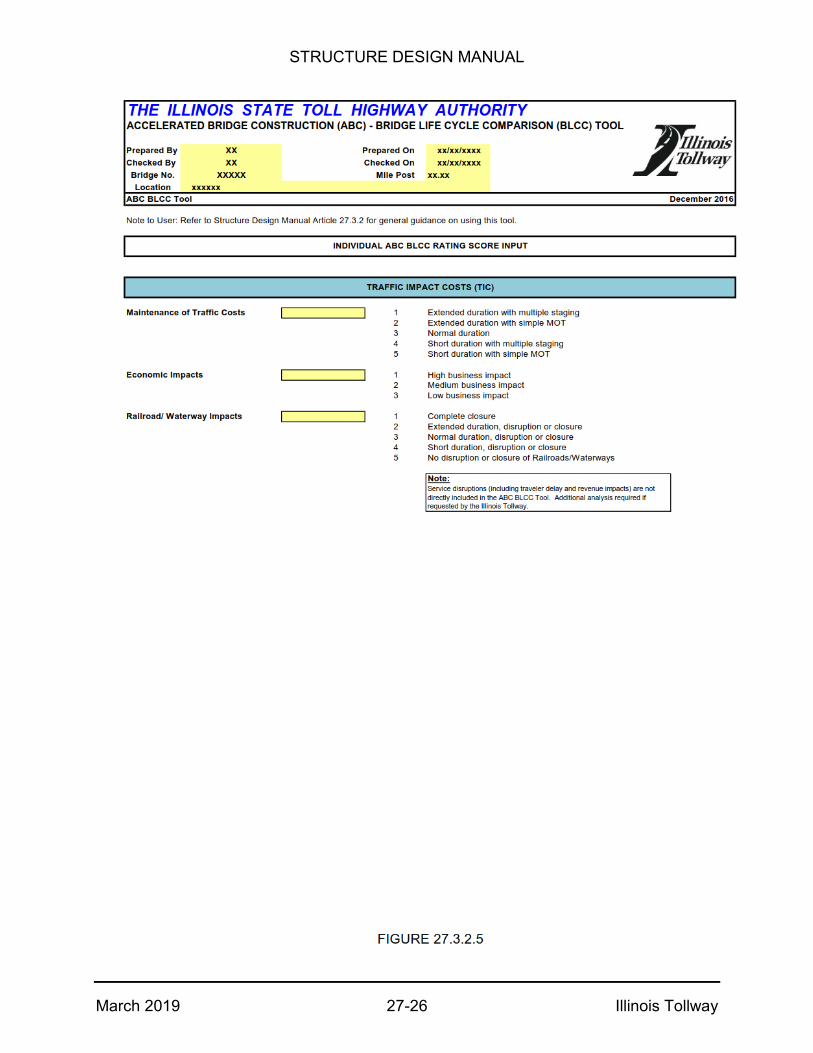
STRUCTURE DESIGN MANUAL
March 2019 27-26 Illinois Tollway

STRUCTURE DESIGN MANUAL
March 2019 27-27 Illinois Tollway

STRUCTURE DESIGN MANUAL
March 2019 27-28 Illinois Tollway