STRUCTURE AND CHEMISTRY OF SULFUR ...
194
STRUCTURE AND CHEMISTRY OF SULFUR TETRAFLUORIDE JAMES T. GOETTEL B.Sc., University of Alberta, 2011 A Thesis Submitted to the School of Graduate Studies of the University of Lethbridge in Partial Fulfilment of the Requirements for the Degree MASTER OF SCIENCE Department of Chemistry and Biochemistry University of Lethbridge LETHBRIDGE, ALBERTA, CANADA © James T. Goettel, 2013
-
Upload
khangminh22 -
Category
Documents
-
view
3 -
download
0
Transcript of STRUCTURE AND CHEMISTRY OF SULFUR ...

STRUCTURE AND CHEMISTRY OF SULFUR TETRAFLUORIDE
JAMES T. GOETTEL
B.Sc., University of Alberta, 2011
A Thesis
Submitted to the School of Graduate Studies
of the University of Lethbridge
in Partial Fulfilment of the
Requirements for the Degree
MASTER OF SCIENCE
Department of Chemistry and Biochemistry
University of Lethbridge
LETHBRIDGE, ALBERTA, CANADA
© James T. Goettel, 2013

iii
ABSTRACT
Sulfur tetrafluoride was shown to be a useful reagent in preparing salts of
ReVII
O2F4−, I
VOF4
−, and I
VIIO2F4
−. Sulfur tetrafluoride reacts with oxo-anions in
acetonitrile or anhydrous HF (aHF) via fluoride-oxide exchange reactions to
quantitatively form oxide fluoride salts, as observed by Raman and 19
F NMR
spectroscopy. Pure Ag[ReO2F4] as well as the new CH3CN coordination compounds
[Ag(CH3CN)2][ReO2F4] and [Ag(CH3CN)4][ReO2F4]•CH3CN were prepared. The latter
was characterized by single-crystal X-ray diffraction. The reaction of [N(CH3)4]IO3 with
SF4 in acetonitrile gave the new [N(CH3)4][IOF4] salt.
Sulfur tetrafluoride forms Lewis acid-base adducts with pyridine and its
derivatives, i.e., 2,6-dimethylpyridine, 4-methylpyridine and 4-
dimethylaminopyridine, which have recently been identified in our lab.
In the
presence of HF, the nitrogen base in the SF4 base reaction systems is protonated,
which can formally be viewed as solvolysis of the SF4•base adducts by HF. The
resulting salts have been studied by Raman spectroscopy and X-ray crystallography.
Crystal structures were obtained for pyridinium salts: [HNC5H5+]F
−•SF4,
[HNC5H5+]F
−[HF2
−]•2SF4; 4-methylpyridinium salt: [HNC5H4(CH3)
+]F
−•SF4,
[HNC5H4(CH3)+][HF2
−]; 2,6-dimethylpyridinium salt:
[HNC5H3(CH3)2+]2[SF5
−]F
−•SF4; 4-dimethylaminopyridinium salts:
[HNC5H4N(CH3)2+]2[SF5
−]F
−•CH2Cl2, [NC5H4N(CH3)2
+][HF2
−]•2SF4; and the 4,4’-
bipyridinium salts: [HNH4C5−C5H4N+]F
−•2SF4, [HNH4C5−C5H4NH
2+]2F
−•4SF4.
These structures exhibit a surprising range of bonding modalities between SF4 and
fluoride and provide an extensive view of SF4 in the solid state.

iv
For the first time, the solid-state structure of SF4 was elucidated by single-
crystal X-ray diffraction. The structure can best be described as a network with weak
intermolecular S---F contacts formed exclusively by the axial fluorines that exhibit
more ionic character. A similar structural motif was found in the novel
[HNC5H3(CH3)2+]2[SF5
−]F
−•4SF4 salt which contains layers of SF4.
Adduct formation of SF4 with oxygen-bases was observed for the first time.
These SF4•O-base adducts (SF4•OC4H8, SF4•(OC4H8)2, SF4•(CH3OCH2)2,
SF4•(O=C5H8)2) were synthesized, isolated, and characterized at low temperatures.
The structures were elucidated by X-ray crystallography and Raman spectroscopy.
The characterization of the SF4•ketone adduct (SF4•O=C5H4) is of great significance,
since SF4 can serve as a fluorinating agent towards carbonyl groups. These adducts
offer the first extensive view of dative O---S(IV) bonds.

v
ACKNOWLEDGEMENTS
I would like to thank my supervisor, Prof. Michael Gerken, for his superior
mentorship during the past few years. Michael always provided me with the highest
quality equipment and reagents, and gave me the freedom to explore a wide range of
chemistry. His expertise, enthusiasm, dedication, and overall professionalism made
him the ultimate supervisor for me.
I would like to thank the other members of my committee, Prof. Paul Hayes
and Prof. Paul Hazendonk, for taking the time out of their busy schedules, especially
considering the time commitment associated with newborns!
I would like to thank my external examiner, Prof. Jennifer Love, for traveling
a great distance for my defence, and for her time spent reviewing my Thesis.
I am grateful to Kris and Heinz Fischer for all their hard work in maintaining
our instruments and especially for fixing the X-ray diffractometer. I am grateful to
Tony Montina for fixing the NMR spectrometer.
I would like to thank all the members of the Gerken group, Praveen, Tyler,
Rudy, Nathan, and Doug, for support and friendship in and outside of the lab. Special
thanks to Nathan, who helped with the research presented in Chapter 4 and was a
pleasure to supervise.
Thank you to the members of the Hayes group, for unofficially adopting me as
one of their own. Special thanks to Breanne Kamenz, who made this adoption
possible and for keeping me well informed and to Kevin Johnson for his helpful
advice.
I would like to thank my friends for the fun and enjoyment that contributed to
my great work-life balance.

vi
I wish to thank my girlfriend, Boram Kim, for emotional support, care and
companionship.
Finally I would like the thank my family and my parents, Mark Goettel and
Karen Toohey, who have provided financial support, insightful advice, and a loving
and caring environment.
vii
TABLE OF CONTENTS
1 Introduction ........................................................................................................ 1
1.1 Sulfur Fluorides ............................................................................................. 1
1.2 Sulfur Tetrafluoride Chemistry ...................................................................... 7
1.2.1 Lewis-Acid and Fluoride-Ion Donor Properties .................................... 7
1.2.2 Sulfur Tetrafluoride as Reagent in Organic Chemistry. ........................ 9
1.3 Sulfur Fluoride Substituents in Organic and Inorganic Chemistry .............. 13
1.3.1 Pentafluorosulfonyl Substituent, SF5 ................................................... 13
1.3.2 SFx (x = 2-4) ......................................................................................... 15
1.3.3 Sulfur Fluorides as Ligands in Transition Metal Chemistry ................ 16
1.4 Goals of Present Research ........................................................................... 17
2 Experimental .................................................................................................... 28
2.1 General Methods .......................................................................................... 28
2.2 Purification and Preparation of Starting Materials ...................................... 31
2.2.1 Purification of Anhydrous HF, SF4, Acetonitrile................................. 31
2.2.2 Oxo-Anions Salts ................................................................................. 32
2.2.3 Nitrogen Bases ..................................................................................... 32
2.2.4 Purification of Toluene, Diethyl Ether, Pentane, THF ........................ 33
2.2.5 Purification of CH2Cl2, CFCl3, CF2Cl2 ................................................ 33
2.3 Preparation of Oxide Fluoride Salts ............................................................. 33
2.3.1 Preparation of [Ag(CH3CN)x][ReO2F4] where ( x = 0, 2, 4) ............... 33
2.3.2 Preparation of KReO2F4 ....................................................................... 34
2.3.3 Preparation of K[IO2F4] ....................................................................... 34
2.3.4 Preparation of [N(CH3)4][IOF4] ........................................................... 35
2.4 Preparation of Hydrolysis Products of SF4•Nitrogen Base Adducts by HF 36
2.4.1 Preparation of [HNC5H5+]F
−•SF4 ......................................................... 36
2.4.2 Preparation of [HNC5H5+][HF2
−]•2SF4 ................................................ 36
2.4.3 Preparation of [HNC5H4(CH3)+]F
−•SF4 ............................................... 37
2.4.4 Preparation of [HNC5H3(CH3)2+]2[SF5
−]F
−•SF4 .................................. 37
2.4.5 Preparation of [HNC5H4N(CH3)2+][HF2
−]•2SF4 .................................. 38
2.4.6 Preparation of [HNC5H4N(CH3)2+]2[SF5
−]F
−•CH2Cl2 ......................... 38
2.4.7 Preparation of [HNH4C5−C5H4N+]F
−•2SF4 ......................................... 39

viii
2.4.8 Preparation of [HNH4C5−C5H4NH2+
]2F−•4SF4 ................................... 39
2.4.9 Crystal Structure of [HNC5H4(CH3)+]HF2
− ......................................... 40
2.5 Solid-State Structure of SF4 ......................................................................... 40
2.5.1 Synthesis of [HNC5H3(CH3)2+]2F
−[SF5
−]•4SF4 .................................... 40
2.5.2 X−Ray Crystallography of Neat SF4 ................................................... 41
2.5.3 X−Ray Crystallography of SF4 from CF2Cl2 ....................................... 41
2.6 SF4 Oxygen Base Adducts ........................................................................... 41
2.6.1 Preparation of the SF4•OC4H6 Adduct ................................................. 41
2.6.2 Preparation of the SF4•(OC4H6)2 Adduct ............................................. 42
2.6.3 Preparation of the SF4•(CH3OCH2)2 Adduct ....................................... 42
2.6.4 Preparation of the SF4•(O=C5H8)2 ....................................................... 43
2.6.5 Attempted Preparation of SF4•OEt2 ..................................................... 43
2.6.6 Attempted Preparation of SF4•acetylacetone ....................................... 43
2.6.7 Attempted Preparation of SF4•4-methylcyclohexanone ...................... 43
2.7 Single Crystal X-ray Diffraction .................................................................. 44
2.7.1 Low-Temperature Crystal Mounting ................................................... 44
2.7.1.1 Special Cases .................................................................................. 45
2.7.2 Data Collection .................................................................................... 46
2.7.3 Solution and Refinement of Structures ................................................ 46
2.7.3.1 Special Cases .................................................................................. 48
2.8 Vibrational Spectroscopy ............................................................................. 49
2.9 NMR Spectroscopy ...................................................................................... 49
3 Sulfur Tetrafluoride as a Fluorinating Agent Towards Main-Group and
Transition-Metal Oxo-Anions. ................................................................................ 51
3.1 Introduction .................................................................................................. 51
3.2 Results and Discussion ................................................................................ 53
3.2.1 Synthesis .............................................................................................. 53
3.2.2 [Ag(CH3CN)4][ReO2F4]•CH3CN, [Ag(CH3CN)x]ReO2F4 (where x = 0,
2) .............................................................................................................. 54
3.2.2.1 Raman Spectroscopy ...................................................................... 54
3.2.2.2 X-ray Crystallography .................................................................... 58
3.2.3 K[IO2F4] ............................................................................................... 62

ix
3.2.3.1 X-ray Crystallography .................................................................... 63
3.2.4 [N(CH3)4][IOF4] ................................................................................... 63
3.2.4.1 Raman Spectroscopy ...................................................................... 63
3.3 Summary and Conclusions .......................................................................... 66
4 Solvolysis Products of SF4•Nitrogen Base Adducts by HF ........................... 69
4.1 Introduction .................................................................................................. 69
4.2 Results and Discussion ................................................................................ 70
4.2.1 General Synthetic Approach ................................................................ 70
4.2.2 Pyridine-HF-SF4 System ...................................................................... 73
4.2.2.1 X−ray Crystal Structures of [HNC5H5+]F
−•SF4 and
[HNC5H5+]HF2
−•2SF4. .................................................................................... 73
4.2.2.2 Raman Spectroscopy ...................................................................... 80
4.2.3 4-Methylpyridine-HF-SF4 System ....................................................... 83
4.2.3.1 X−ray Crystal Structures of [HNC5H4(CH3)+]F
−•SF4 and
[HNC5H4(CH3)+]HF2
− ...................................................................................... 83
4.2.3.2 Raman Spectroscopy ...................................................................... 87
4.2.4 2,6-Dimethylpyridine-HF-SF4 System ................................................ 89
4.2.4.1 X-ray Crystal Structure of [HNC5H3(CH3)2+]2[SF5
−]F
−•SF4 ........ 90
4.2.4.2 Raman Spectroscopy ...................................................................... 94
4.2.5 The 4-Dimethylaminopyridine-HF-SF4 System .................................. 95
4.2.5.1 X−ray Crystal Structures of [HNC5H4N(CH3)2+][HF2
−]•2SF4 and
[HNC5H4N(CH3)2+]2[SF5
−]F
−•CH2Cl2 ............................................................. 95
4.2.5.2 Raman Spectroscopy .................................................................... 102
4.2.6 The 4,4’-Bipyridyl-HF-SF4 System ................................................... 107
4.2.6.1 X−ray Crystal Structures of [HNH4C5−C5H4N+]F
−•2SF4 and
[HNH4C5−C5H4NH2+
]2F−•4SF4 ..................................................................... 107
4.2.6.2 Raman Spectroscopy .................................................................... 114
4.3 Summary and Conclusion .......................................................................... 118
5 Structure of Sulfur Tetrafluoride in the Solid State ................................... 123
5.1 Introduction ................................................................................................ 123
x
5.2 Results and Discussion .............................................................................. 125
5.2.1 [HNC5H3(CH3)2+]2[SF5
−]F
−•4SF4 ...................................................... 125
5.2.1.1 X-ray crystallography ................................................................... 126
5.2.1.2 Raman Spectroscopy .................................................................... 133
5.2.2 Solid State Structure of SF4 ............................................................... 136
5.3 Summary and Conclusion .......................................................................... 140
6 Sulfur Tetrafluoride Oxygen-Base Adducts ................................................ 143
6.1 Introduction ................................................................................................ 143
6.2 Results and Discussion .............................................................................. 143
6.2.1 Synthesis and Properties .................................................................... 143
6.2.2 Crystal Structure of SF4•OC4H6 and SF4•(OC4H6)2 ........................... 147
6.2.3 Raman Spectroscopy of SF4•OC4H6 and SF4•(OC4H6)2 .................... 153
6.2.4 Crystal Structure of SF4•(CH3OCH2)2 ............................................... 157
6.2.5 Raman Spectroscopy of SF4•(CH3OCH2)2 ........................................ 160
6.2.6 Crystal Structure of SF4•(O=C5H8)2 .................................................. 163
6.2.7 Raman Spectroscopy of SF4•(O=C5H8)2 ............................................ 166
6.3 Summary and Conclusion .......................................................................... 170
7 Summary and Directions for Future Work ................................................. 175
7.1 Conclusions ................................................................................................ 175
7.2 Directions for Future Work ........................................................................ 176

xi
LIST OF FIGURES
Figure 1 19
F NMR assignment of FSSF3........................................................................ 2
Figure 1.2 The structures of the lower sulfur fluorides: SF2, SF3SF, FSSF, and SSF2 .. 3
Figure 1.3 The structures of the higher sulfur fluorides: SF4, SF6, and S2F10. .............. 4
Figure 1.4 The structures of some common fluorinating agent replacements for SF4. 10
Figure 2.1 Glass vacuum line system equipped with J. Young PTFE/glass stopcocks, a
Heise gauge (Adapted from Jared Nieboer’s M.Sc. Thesis). ....................................... 29
Figure 2.2 Metal vacuum system; (A) MKS type 626A capacitance manometer (0-
1000 Torr), (B) MKS Model PDR-5B pressure transducers (0-10 Torr), (C) 3/8-in.
stainless-steel high-pressure valves (Autoclave Engineers, 30VM6071), (D) 316
stainless-steel cross (Autoclave Engineers, CX6666), (E) 316 stainless-steel L-piece
(Autoclave Engineers, CL6600), (F) 316 stainless steel T-piece (Autoclave engineers,
CT6660), (G) 3/8-in o.d., 1/8-in. i.d. nickel connectors, (H) 1/8-in o.d., 1/8-in. i.d.
nickel tube. (from Jared Nieboer’s M.Sc. thesis). ........................................................ 30
Figure 2.3 Low-temperature crystal mounting setup, consisting of a 10.5-L Dewar,
equipped with a foam stopper, a glass nitrogen inlet, a silvered glass cold nitrogen
outlet with an 11-cm long aluminum trough (2-cm o.d.). (Adapted from Jared
Nieboer’s M.Sc. thesis) ................................................................................................ 45
Figure 3.1 Raman spectra of AgReO2F4 salts with varying amounts of CH3CN. ....... 55
Figure 3.2 Thermal ellipsoid plot of [Ag(CH3CN)4][ReO2F4]•CH3CN. Thermal
ellipsoids are set to 50% probability. ........................................................................... 61
Figure 3.3 Raman spectrum of [N(CH3)4][IOF4]. Asterisks (*) denote bands arising
from the FEP sample tube. Daggers (†) denote bands arising from the [N(CH3)4+]
cation. ........................................................................................................................... 64
Figure 4.1 Drawings of the nitrogen-bases studied with SF4/HF mixtures. ................ 72
Figure 4.2 Thermal ellipsoid plot of the [HNC5H5+]F
−•SF4 chain with thermal
ellipsoids set to 50% probability. ................................................................................. 77
Figure 4.3 Thermal ellipsoid plot of the [HNC5H5+][HF2
−]•2SF4 double chain. The
fluorines bound to S(1A), S(2A) and S(1B) are omitted for clarity. Thermal ellipsoids
are set to 50% probability. ........................................................................................... 78
Figure 4.4 Raman spectrum of [HNC5H5+][HF2
−]•2SF4. Asterisks (*) denote bands
arising from the FEP sample tube. ............................................................................... 81

xii
Figure 4.5 Thermal ellipsoid plot of the dimer present in the crystal structure of
[HNC5H4(CH3)+]F
−•SF4. Thermal ellipsoids are at 50% probability. ......................... 86
Figure 4.6 Thermal ellipsoid plot of the [HNC5H4(CH3)+]HF2
− ion pair. Thermal
ellipsoids are at 50% probability.................................................................................. 87
Figure 4.7 Raman spectrum of [HNC5H4(CH3)+]F
−•SF4. Asterisks (*) denote bands
arising from the FEP sample tube. ............................................................................... 89
Figure 4.8 Thermal ellipsoid plot of [HNC5H3(CH3)2+]2F
−•SF4[SF5
−]; a) the
[HNC5H3(CH3)2+]2F
−•SF4 moiety and b) the disordered SF5
− anion. Thermal ellipsoids
are at 50% probability. ................................................................................................. 93
Figure 4.9 Thermal ellipsoid plot of the [HNC5H4N(CH3)2+][HF2
−]•2SF4 double
chain. Thermal ellipsoids are at 50% probability. ....................................................... 99
Figure 4.10 Thermal ellipsoid plot of [HNC5H4N(CH3)2+]2[SF5
−]F
−•CH2Cl2,
excluding the SF5− anion. Thermal ellipsoids are at 50% probability. ...................... 101
Figure 4.11 Thermal ellipsoid plot of the SF5− anion in
HNC5H4N(CH3)2+]2[SF5
−]F
−•CH2Cl2. Thermal ellipsoids set at 50% probability. ... 102
Figure 4.12 Raman spectrum of [HNC5H4N(CH3)2+][HF2
−]•2SF4. Asterisks (*) denote
bands arising from the FEP sample tube.................................................................... 103
Figure 4.13 Raman spectrum of [HNC5H4N(CH3)2+]2[SF5
−]F
−•CH2Cl2. Asterisks (*)
denote bands arising from the FEP sample tube. ....................................................... 103
Figure 4.14 Thermal ellipsoid plot of [HNH4C5−C5H4N+]F
−•2SF4 Thermal ellipsoids
are at 50% probability. ............................................................................................... 110
Figure 4.15 Thermal ellipsoid plot of [HNH4C5−C5H4NH2+
]2F−•4SF4 with thermal
ellipsoids set at 50% probability. ............................................................................... 112
Figure 4.16 Thermal ellipsoid plot of [HNH4C5−C5H4NH2+
]2F−•4SF4 packed along
the c-axis. Thermal ellipsoids are set to 50% probability. ......................................... 113
Figure 4.17 Raman spectra of [HNH4C5−C5H4N+]F
−•2SF4 (top) and
[HNH4C5−C5H4NH2+
]2F−•4SF4 (bottom). Asterisks (*) denote bands arising from the
FEP sample tube. ....................................................................................................... 115
Figure 5.1 Proposed structures of SF4 from reference 9. ........................................... 124
Figure 5.2 Thermal ellipsoid view along the a-axis of the packing of
[HNC5H3(CH3)2+]2F
−[SF5
−]•4SF4. Thermal ellipsoids are set at 50 % probability. .. 129
Figure 5.3 Thermal ellipsoid plot of the [HNC5H3(CH3)2+]2F
−---SF4 moiety. Thermal
ellipsoids are set at 50 % probability. ........................................................................ 130

xiii
Figure 5.4 Thermal ellipsoid plot of the SF5− anion in
[HNC5H3(CH3)2+]2F
−[SF5
−]•4SF4. Thermal ellipsoids are set at 50 % probability. .. 130
Figure 5.5 Thermal ellipsoid plot of the coordination environment about the SF4
molecules in the X-ray crystal structure of [HNC5H3(CH3)2+]2F
−[SF5
−]•4SF4; thermal
ellipsoids are drawn at the 50% probability level. ..................................................... 132
Figure 5.6 Raman spectra of (a) [HNC5H3(CH3)2+]2F
−[SF5
−]•4SF4 in FEP tubing and
(b) of solid SF4 in a Pyrex glass 5-mm NMR tube recorded at –100 °C and –135 °C,
respectively, using 1064-nm excitation. Asterisks (*) denote signals arising from the
FEP sample tube. Bands attributed to the 2,6-dimethylpyridinium cation and to the
SF5− anion are denoted by (†) and (§), respectively. ................................................. 136
Figure 5.7 Thermal Ellipsoid Plot of the asymmetric unit of SF4. Thermal Ellipsoids
are set to 50% probability. ......................................................................................... 137
Figure 5.8 Thermal Ellipsoid Plot of the TeF4 chain. Thermal ellipsoids are set at 50%
probability. ................................................................................................................. 139
Figure 5.9 Thermal ellipsoid plot of SeF4, showing contacts to adjacent SeF4
molecules. Thermal ellipsoids are set to 50% probability. ........................................ 140
Figure 6.1 Structures of the oxygen-bases that form Lewis acid-base adducts with SF4.
.................................................................................................................................... 144
Figure 6.2 Structure of Oxygen-bases that were studied and for which no SF4 adducts
could be isolated. ....................................................................................................... 146
Figure 6.3 Thermal ellipsoid plot of the (SF4•OC4H6)2 dimer; thermal ellipsoids are
set at 50% probability. ............................................................................................... 150
Figure 6.4 Thermal ellipsoid plots of the four crystallographically unique
SF4•(OC4H8)2 moieties within the asymmetric unit. .................................................. 152
Figure 6.5 Raman spectra of a) SF4•OC4H6, b) SF4•(OC4H6)2, and c) OC4H6 (room
temperature). Asterisks (*) denote bands arising from the FEP sample tube. ........... 154
Figure 6.6 Thermal ellipsoid plot of the SF4•(CH3OCH2)2 adduct; thermal ellipsoids
are set at 50% probability. ......................................................................................... 158
Figure 6.7 View along the c-axis of the thermal ellipsoid plot of SF4•(CH3OCH2)2.
Thermal ellipsoids set at 50% probability. ................................................................ 159
Figure 6.8 Raman Spectrum of SF4•(CH3OCH2)2 (top) and neat 1,2-dimethoxyethane
(bottom). Asterisks (*) denote bands arising from the FEP sample tube. ................. 161
xiv
Figure 6.9 Thermal ellipsoid plot of the SF4•(O=C5H8)2 adduct; thermal ellipsoids are
set at 50% probability. ............................................................................................... 165
Figure 6.10 Raman spectra of SF4•(O=C5H8)2 (top) and neat cyclopentanone
(O=C5H8) (bottom). Asterisks (*) denote bands arising from the FEP sample tube. 167

xv
LIST OF TABLES
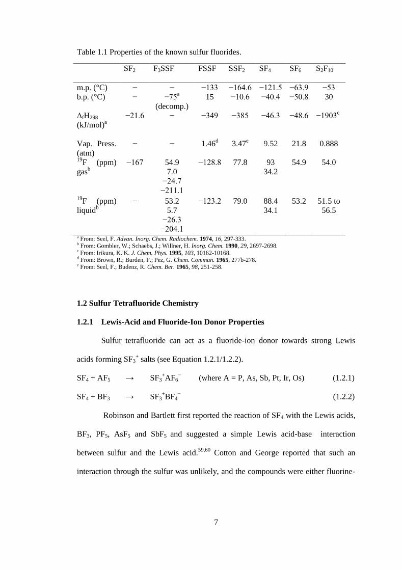
Table 1.1 Properties of the known sulfur fluorides. ..................................................... 7
Table 2.1 X-ray Crystal Structures and Selected Acquisition Parameters. ................ 48
Table 3.1 Raman Frequencies (cm1
) and Tentative Assignments of [Ag(CH3CN)4]-
ReO2F4•CH3CN, [Ag(CH3CN)2]ReO2F4, AgReO2F4, and CH3CN. .......................... 56
Table 3.2 Crystal Data Collection Parameters and Results of
[Ag(CH3CN)4][ReO2F4]•CH3CN. .............................................................................. 59
Table 3.3 Selected Bond Lengths (Å) and Angles (deg.) of
[Ag(CH3CN)4][ReO2F4]•CH3CN. .............................................................................. 60
Table 3.4 Raman Frequencies (cm1
) and Tentative Assignments of [N(CH3)4][IOF4].
.................................................................................................................................... 65
Table 4.1 Crystal Data Collection Parameters and Results of [HNC5H5+]F
−•SF4 and
[HNC5H5+]HF2
−•2SF4 ................................................................................................ 74
Table 4.2 Bond Lengths (Å), Contacts (Å), and Angles (deg.) of [HNC5H5+]F
−•SF4.
.................................................................................................................................... 75
Table 4.3 Bond Lengths (Å), Contacts (Å), and Angles (deg.) of
[HNC5H5+][HF2
−]•2SF4. ............................................................................................. 76
Table 4.4 Raman Frequencies (cm1
) and Tentative Assignments of
[HNC5H5+][HF2
−]•2SF4. ............................................................................................. 82
Table 4.5 Crystal Data Collection Parameters and Results of [HNC5H4(CH3)+]F
−•SF4
and [HNC5H4(CH3)+][HF2
−]. ...................................................................................... 84
Table 4.6 Bond Lengths (Å), Contacts (Å), and Angles (deg.) of
[HNC5H4(CH3)+]F
−•SF4. ............................................................................................ 85
Table 4.7 Bond Lengths (Å), Contacts (Å), and Angles (deg.) of
[HNC5H4(CH3)+]HF2
−. ............................................................................................... 85
Table 4.8 Raman Frequencies (cm1
) and Tentative Assignments of
[HNC5H4(CH3)+]F
−•SF4. ............................................................................................ 88
Table 4.9 Crystal Data Collection Parameters and Results of
[HNC5H3(CH3)2+]2[SF5
−]F
−•SF4. ............................................................................... 91

xvi
Table 4.10 Bond Lengths (Å), Contacts (Å), and Angles (deg.) of
[HNC5H3(CH3)2+]2[SF5
−]F
−•SF4. ............................................................................... 92
Table 4.11 Crystal Data Collection Parameters and Results of
[HNC5H4N(CH3)2+][HF2
−]•2SF4 and [HNC5H4N(CH3)2
+]2[SF5
−]F
−•CH2Cl2. ........... 96
Table 4.12 Selected Bond Lengths (Å), Contacts (Å), and Angles (deg.) of
[HNC5H4N(CH3)2+][HF2
−]•2SF4 ................................................................................ 97
Table 4.13 Selected Bond Lengths (Å), Contacts (Å), and Angles (deg.) of
[HNC5H4N(CH3)2+]2[SF5
−]F
−•CH2Cl2 ....................................................................... 98
Table 4.14 Raman Frequencies (cm1
) and Tentative Assignments of
[HNC5H4N(CH3)2+][HF2
−]•2SF4. ............................................................................. 104
Table 4.15 Raman Frequencies (cm1
) and Tentative Assignments of
[HNC5H4N(CH3)2+]2[SF5
−]F
−•CH2Cl2. .................................................................... 105
Table 4.16 Crystal Data Collection Parameters and Results of
[HNH4C5−C5H4N+]F
−•2SF4 and [HNH4C5−C5H4NH
2+]2F
−•4SF4 ........................... 108
Table 4.17 Selected Bond Lengths (Å), Contacts (Å), and Angles (deg.) of
[HNH4C5−C5H4N+]F
−•2SF4. .................................................................................... 109
Table 4.18 Selected Bond Lengths (Å), Contacts (Å), and Angles (deg.) of
[HNH4C5−C5H4NH2+
]2F−•4SF4. .............................................................................. 109
Table 4.19 Raman Frequencies (cm1
) and Tentative Assignments of
[HNH4C5−C5H4N+]F
−•2SF4. .................................................................................... 116
Table 4.20 Raman Frequencies (cm1
) and Tentative Assignments of
[HNH4C5−C5H4NH2+
]2F−•4SF4. .............................................................................. 118
Table 5.1 Crystal Data Collection Parameters and Results of
[HNC5H3(CH3)2+]2[SF5
−]F
−•4SF4 and SF4. ............................................................. 127
Table 5.2 Selected Bond Lengths (Å), Contacts (Å), and Angles (deg.) of
[HNC5H3(CH3)2+]2F
−[SF5
−]•4SF4 ............................................................................ 128
Table 5.3 Experimental Raman frequencies and Tentative Assignments for
[HNC5H3(CH3)2+]2F
−[SF5
−]•4SF4. ........................................................................... 134
Table 5.4 Bond Lengths (Å), Contacts (Å), and Angles (deg.) of SF4. ................... 138
Table 6.1 Crystal Data Collection Parameters and Results of SF4•OC4H8,
SF4•(OC4H8)2, SF4•(CH3OCH2)2, and SF4•O=C5H8. ................................................ 147
xvii
Table 6.2 Selected Bond Lengths (Å), Contacts (Å), and Angles (°) of SF4•OC4H6.
.................................................................................................................................. 148
Table 6.3 Selected Bond Lengths (Å), Contacts (Å), and Angles (°) of SF4•(OC4H6)2.
.................................................................................................................................. 149
Table 6.4 Raman Frequencies (cm1
) and Tentative Assignments of SF4•OC4H6,
OC4H6, and SF4. ....................................................................................................... 155
Table 6.5 Raman Frequencies (cm1
) and Tentative Assignments of SF4•(OC4H6)2,
OC4H6, and SF4. ....................................................................................................... 156
Table 6.6 Selected Bond Lengths (Å), Contacts (Å), and Angles (°) of
SF4•(CH3OCH2)2 ...................................................................................................... 158
Table 6.7 Raman Frequencies (cm1
) and Tentative Assignments of
SF4•(CH3OCH2)2, (CH3OCH2)2, and SF4. ................................................................ 162
Table 6.8 Selected Bond Lengths (Å), Contacts (Å), and Angles (°) of
SF4•(O=C5H8)2 ......................................................................................................... 164
Table 6.9 Raman Frequencies (cm1
) and Tentative Assignments of SF4•(O=C5H8)2
(−107 °C), O=C5H8, and SF4. ................................................................................... 168
Table 6.10 Selected Structural and Vibrational Data in isolated SF4•O-Base Adducts.
.................................................................................................................................. 172
xviii
LIST OF ABREVIATIONS AND SYMBOLS
General
ax axial
eq equatorial
FEP copolymer of perfluoroethylene and perfluoropropylene
Kel-F chlorotrifluoroethylene
NMR nuclear magnetic resonance
THF tetrahydrofuran
DFT density functional theory
o.d. outside diameter
Ph phenyl
VSEPR valence shell electron pair repulsion
aHF anhydrous hydrogen fluoride
PTFE polytetrafluoroethylene
Nuclear Magnetic Resonance
chemical shift
J scalar coupling constant in Hertz
ppm parts per million
TMS tetramethylsilane
T tesla
X-ray Crystallography
a, b, c,, , cell parameters
V cell volume
wavelength
Z molecules per unit cell
μ absorption coefficient
R1 conventional agreement index
wR2 weighted agreement index
GooF goodness of fit

1
1 Introduction
1.1 Sulfur Fluorides
Sulfur forms several binary fluorides, namely SF2, F3SSF, S2F2, SF4, SF6 and
S2F10.1 All of these sulfur fluorides can be prepared by direct combination of
elemental sulfur with elemental fluorine at varying concentrations and temperatures.1
Due to the high reactivity, low boiling points, and/or difficulties in handling these
compounds, extensive computational studies have been reported to elucidate the
molecular geometries and to fully understand the electronic structures.2-6
Sulfur
difluoride and disulfur difluoride are thermally unstable and remain laboratory
curiosities.1 Sulfur difluoride is only stable as a highly dilute gas,
7 and exists as
dimeric SF3SF in the liquid and solid state.8 Sulfur difluoride is prepared by the
reaction of SCl2 vapour with metal fluorides (AgF, KF, HgF2) at high temperatures
(150 to 160 °C) under vacuum (<10 Torr) (see Equation 1.1.1).9
SCl2 + HgF2 → SF2 + HgCl2 (1.1.1)
The bent geometry (see Figure 1.2) of the monomer was determined by gas-
phase infrared7 and microwave
10 spectroscopy, and matrix-isolation vibrational
spectroscopy.11
The four 19
F NMR spectroscopic signals of FSSF3 (see Figure 1.1) in
the liquid phase at −53.2 (F1), −5.7 (F2), 26.3 (F3), and 204.1 (F4) ppm (2J12 = 86.3,
2J13 = 32.8,
2J23 = 32.2,
3J14 = 40.2,
3J24 = 156.0, and
3J34 = 63.5 Hz) confirmed the
existence of the asymmetric dimer, as well as determined the connectivity of the
atoms.8,12

2
..... .3
4 2
1
Figure 1.1 19
F NMR spectroscopic assignment of FSSF3
An electron diffraction study provided bond lengths and angles of F3SSF (see
Figure 1.2).13
The dimer decomposes above −75 °C into sulfur tetrafluoride, S8, and
other allotropes of sulfur (see Equation 1.1.2).
F3SSF → SF4 + 1/n Sn (1.1.2)
Small amounts of HF can catalyze the decomposition of F3SSF into SF4 and
FSSF instead of SF4 and elemental sulfur (see Equation 1.1.3a and 1.1.3b).1
SF3SF + HF → SF4 + HSF (1.1.3a)
SF2 + HSF → FSSF + HF (1.1.3b)
Disulfur difluoride exists as two isomers, difluorosulfane (FSSF) and
thiothionyl fluoride (SSF2), with SSF2 being the more stable isomer at room
temperature. Both isomers are prepared in a similar fashion to sulfur difluoride
except disulfur dichloride (ClSSCl) is used in place of sulfur dichloride and a
temperature range of 120 to 165 °C is used (see Equation 1.1.4).14
ClSSCl + MF → S2F2 + MCl (where M = Ag, K, Hg) (1.1.4)
At higher temperatures (165 °C), SSF2 is the main product. An alternative method of
preparing disulfur difluoride is by the reaction of nitrogen trifluoride with elemental
sulfur (see Equation 1.1.5).15
NF3 + 3/8 S8 → S2F2 + NSF (1.1.5)

3
The structures of FSSF and SSF2 were elucidated using a combination of
microwave,16
infrared,11
and 19
F NMR8 spectroscopies (see Figure 1.2).
92.2°
1.722 Å
1.624 Å
1.602 Å1.569 Å
105.9°
98.3°
2.040 Å
1.589 Å1.635(10) Å
107.5(1)°
1.860(15) Å
1.598(12) Å
1.888(10) Å92.5(1)°
Figure 1.2 The structures of the lower sulfur fluorides: SF2, SF3SF, FSSF, and SSF2
Sulfur tetrafluoride, sulfur hexafluoride and disulfur decafluoride have been
commercially available, but in recent times, only sulfur hexafluoride is easily
obtainable. Sulfur tetrafluoride is a highly toxic and reactive gas at room
temperature. It is a selective fluorinating agent, which has been used extensively in
organic chemistry (see Section 1.2.2). In contrast to the lower sulfur fluorides, sulfur
tetrafluoride is thermally stable up to very high temperatures (500 to 1000 °C), with
only 1% being converted to SF6 (see Equation 1.1.6) in this temperature range.17
3 SF4 ⇌ 2 SF6 + S (1.1.6)
Sulfur tetrafluoride exhibits a disphenoidal (seesaw) molecular geometry in the
gas and liquid phases (see Figure 1.3). The structure has been well studied in the gas
phase by electron diffraction,18,19
microwave,20
infrared,21-23
and 19
F NMR24
spectroscopies and has been the subject of computational studies.4,5
The structure in
the liquid phase has been studied by variable temperature 19
F NMR,4 Raman, and
infrared spectroscopy.25
Significantly less information has been reported on the
structure in the solid state.26
Using miniature zone-melting techniques, the crystal

4
structure of SF4 has previously been reported to be severely disordered and no
discernible structure could be determined.27
1.574(6) Å
1.547(6) Å
2.274(5) Å1.561(2) Å
1.646(3) Å
1.545(3) Å
101.6(5) °
173.1(5) °
Figure 1.3 The structures of the higher sulfur fluorides: SF4, SF6, and S2F10.
Sulfur tetrafluoride can be prepared by fluorination of elemental sulfur
suspended in CFCl3 at −78 °C with 100% elemental fluorine28
or by direct
fluorination of molten sulfur between 120 to 200 °C with 10% fluorine in nitrogen.29
It can also be conveniently prepared in the laboratory by reaction of SCl2 and Cl2
with metal fluorides, such as NaF, KF, CoF2, between 200 and 300 °C (see Equation
1.1.7).30
SCl2 + Cl2 + 4 NaF → SF4 + 4 NaCl (1.1.7)
Sulfur tetrafluoride is extremely moisture sensitive and reacts with water
producing HF and thionyl fluoride (see Equation 1.1.8). Thionyl fluoride can further
react with water to produce HF and sulfur dioxide (see Equation 1.1.9).
SF4 + H2O → 2 HF + SOF2 (1.1.8)
SOF2 + H2O → 2 HF + SO2 (1.1.9)
Hydrogen fluoride can readily be separated from SF4 by distillation at low
temperatures (<−80 °C) and by the use of HF scavengers (NaF), but the reactivity,

5
melting point (−100 °C), and boiling point of SOF2 (−44 °C) and SF6 (−50 °C
sublimation) make their separation from SF4 difficult. One method of purifying SF4
is by the formation of adducts with Lewis acids (BF3) (see Equation 1.1.10), removal
of SOF2 and SF6 from the solid adduct, and then substitution of SF4 with a base such
as diethyl ether (see Equation 1.1.11).31
SF4 + BF3 → SF3BF4 (1.1.10)
SF3BF4 + Et2O → Et2O•BF3 + SF4 (1.1.11)
Sulfur hexafluoride is an extremely inert and dense gas at room temperature.
Inhalation of SF6 depresses the vibrational frequency of one’s voice, as opposed to
the well-known effect of helium, which increases the vibrational frequency of one’s
voice. Although SF6 is non-toxic, it can sometimes contain toxic impurities (e.g.
S2F10), therefore inhalation of SF6 is not recommended. Due to the high density of
the gas, light objects, such as aluminum boats, can float on gaseous SF6.
Approximately 8,000 tons of SF6 is produced annually (2000), and approximately
75% of the annual production is used as dielectric gas in the electric power industry
and an inert gas for the magnesium industry.32
Although sulfur hexafluoride is
generally inert, it can react with lithium generating large amounts of heat, which
have been used in closed Rankine-cycle propulsion systems (see Equation 1.1.12).33
SF6 + 8 Li → Li2S + 6 LiF (1.1.12)
Sulfur hexafluoride has octahedral geometry (see Figure 1.3) and has
extensively been characterized by Raman,34,35
infrared,35-37
photoelectron,38
and 19
F
NMR39
spectroscopies and by electron40
and neutron41-43
diffraction techniques.
Disulfur decafluoride is a moisture stable, volatile, extremely toxic liquid at
room temperature, and had been considered for use as a war gas in WWII.44
Under

6
exclusion of moisture and air, it can be stored at room temperature. In 1934 it was
isolated and its basic physical properties and reactivity were characterized.45
Disulfur
decafluoride slowly decomposes above 150 °C into SF4 and SF6 in a two-step
mechanism (see Equation 1.1.12a/b).46
S2F10 ⇌ 2 SF5 (fast) (1.1.12a)
2SF5 ⇌ SF6 + SF4 (slow) (1.1.12b)
Disulfur decafluoride is obtained as a by-product of SF6 synthesis. It can be
prepared in the laboratory by photolysis of SF5Br47
(Equation 1.1.13) or by
photochemical reduction of SF5Cl (Equation 1.1.14) with H2 gas.48
2 SF5Br ⇌ S2F10 + Br2 (1.1.13)
2 SF5Cl + H2 ⇌ S2F10 + HCl (1.1.14)
The structure of disulfur decafluoride was initially characterized by infrared
spectroscopy.49
In 1953, an electron diffraction study of the gas provided the metric
parameters.50
In 1989, a reinvestigation of the gas-phase structure of S2F10 by
electron diffraction revised the bond lengths.51
Infrared,52
Raman,52
and 19
F NMR53
spectroscopy have since been used to characterize liquid S2F10. Despite the fact that
disulfur decafluoride is a liquid at room temperature and freezes at a moderate
temperature of −53 °C, there is a dearth of information reported on its structural
characterization in the solid state. Infrared and Raman spectroscopy were performed
on the neat solid54
at liquid nitrogen temperatures and matrix-isolation vibrational
spectroscopy was performed on the solid in an argon matrix at 8 K.55
Computational
chemistry has been used to determine the electronic structure56
and
thermochemistry57
of S2F10 as well as structural properties58
of the potential anion,
S2F11−.
7
Table 1.1 Properties of the known sulfur fluorides.
SF2 F3SSF FSSF SSF2 SF4 SF6 S2F10
m.p. (°C) − − −133 −164.6 −121.5 −63.9 −53
b.p. (°C) − −75a
(decomp.)
15 −10.6 −40.4 −50.8 30
ΔfH298
(kJ/mol)a
−21.6 − −349 −385 −46.3 −48.6 −1903c
Vap. Press.
(atm)
− − 1.46d 3.47
e 9.52 21.8 0.888
19F (ppm)
gasb
−167
54.9
7.0
−24.7
−211.1
−128.8
77.8
93
34.2
54.9
54.0
19F (ppm)
liquidb
− 53.2
5.7
−26.3
−204.1
−123.2 79.0 88.4
34.1
53.2 51.5 to
56.5
a From: Seel, F. Advan. Inorg. Chem. Radiochem. 1974, 16, 297-333. b From: Gombler, W.; Schaebs, J.; Willner, H. Inorg. Chem. 1990, 29, 2697-2698. c From: Irikura, K. K. J. Chem. Phys. 1995, 103, 10162-10168. d From: Brown, R.; Burden, F.; Pez, G. Chem. Commun. 1965, 277b-278. e From: Seel, F.; Budenz, R. Chem. Ber. 1965, 98, 251-258.
1.2 Sulfur Tetrafluoride Chemistry
1.2.1 Lewis-Acid and Fluoride-Ion Donor Properties
Sulfur tetrafluoride can act as a fluoride-ion donor towards strong Lewis
acids forming SF3+ salts (see Equation 1.2.1/1.2.2).
SF4 + AF5 → SF3+AF6
− (where A = P, As, Sb, Pt, Ir, Os) (1.2.1)
SF4 + BF3 → SF3+BF4
− (1.2.2)
Robinson and Bartlett first reported the reaction of SF4 with the Lewis acids,
BF3, PF5, AsF5 and SbF5 and suggested a simple Lewis acid-base interaction
between sulfur and the Lewis acid.59,60
Cotton and George reported that such an
interaction through the sulfur was unlikely, and the compounds were either fluorine-
8
bridged or ionic.61
Gillespie et al. characterized the BF3, PF5, AsF5 and SbF5 adducts
using Raman, infrared, and 19
F NMR spectroscopy, and conductivity
measurements.62
The Raman and infrared spectra contained signals associated with
SF3+ and the respective anions (BF4
−, PF6
−, AsF6
−, and SbF6
−). Conductivity
measurements of SF3BF4 and SF3SbF6, in anhydrous HF solvent, gave similar values
as their respective potassium salts, indicating the presence of ionic species in
solution. The low-temperature 19
F NMR spectra exhibited two distinct resonances,
attributable to the SF3+ cation and the counter anion. All their data support the ionic
model.62
Crystal structures of SF3BF4,63
SF3AsF6,
63 and SF3(HF)SbF6,
64 have since
been reported. Two sulfur tetrafluoride molecules can react with one GeF4 molecule
to form the (SF3)2GeF6 salt, which was also characterized by X-ray crystallography.65
In these crystal structures, the SF3+ cation adopts a trigonal pyramidal geometry and
has three contacts with fluorides on the anion (S---FGeF52−
= 2.420(1)[x2] and
2.367(2) Å; S---FBF3− = 2.593(3) and 2.624(2)[x2] Å). Sulfur tetrafluoride reacts
with the sulfonyl hypohalites, (ClOSO2F, BrOSO2F, and ClOSO2CF3), to form
thermally unstable [SF3+][FSO3
−] and [SF3
+][CF3SO3
−] salts and the covalently
bonded cis/trans-SF4(Cl)OSO2F and trans-SF4(Cl)OSO2CF3 compounds, as shown
by Raman and 19
F NMR spectroscopy.66
Sulfur tetrafluoride can act as a Lewis acid towards fluoride. It can accept a
fluoride from strong fluoride-ion donors such as [N(CH3)4]F and CsF, forming the
SF5− anion (see Equation 1.2.3).
67,68
SF4 + CsF → Cs+SF5
− (1.2.3)
These salts dissociate into SF4 and their respective fluoride salt when heated. The
vapour pressure of SF4 above [N(CH3)4]SF5 is 2-3 Torr at 25 °C, 7 Torr at 38 °C and

9
19 Torr at 60 °C.67
The Rb+ and Cs
+ salts of the SF5
− anion have since been
characterized by vibrational spectroscopy, and the SF5− anion has been studied by
computational means.69-71
The crystal structures of Rb[SF5],69
Cs6[SF5]4[HF2]2,69
and
[Cs(18-crown-6)2][SF5]72
have confirmed the expected square pyramidal geometry of
the SF5– anion. The structures, however, exhibit relatively large uncertainties in bond
lengths (Rb+ and Cs
+ salts) and are disordered ([Cs(18-crown-6)2
+].
The Lewis acidity of SF4 towards nitrogen bases was first reported by
Muetterties et al. in 1959, suggesting the formation of adducts with pyridine and
triethylamine.31,73
This claim was based on crude vapour pressure measurements,
mass balance and 19
F NMR spectroscopy data. In a matrix-isolation study it was
claimed that the formation of 1:1 adducts occurred between SF4 and ammonia,
pyridine, acetone, and methylamine.74
Recently, SF4 adducts with pyridine,75
4-
methylpyridine,75
2,6-dimethylpyridine,75
and triethylamine76
were unambiguously
characterized by Raman spectroscopy, computational studies, and 19
F NMR
spectroscopy (see Equation 1.2.4).64
SF4 + N(C2H5)3 ⇌ SF4•N(C2H5)3 (1.2.4)
Crystal structures of SF4•NC5H5,75
SF4•NC5H5(CH3),75
SF4•NC5H5(N(CH3)2,75
and SF4•N(C2H5)376
provided the experimental geometries
and metric parameters for these adducts.
1.2.2 Sulfur Tetrafluoride as Reagent in Organic Chemistry.
In organic chemistry, sulfur tetrafluoride has been used to convert OH, C=O,
and COOH groups into CF, CF2, and CF3 groups, respectively.77
These reactions are
generally carried out in high-pressure stainless-steel autoclaves. Depending on the
10
reactivity of the substrate, reaction temperatures ranging from −78 to 300 °C have
been employed. In recent years the use of sulfur tetrafluoride has declined due to the
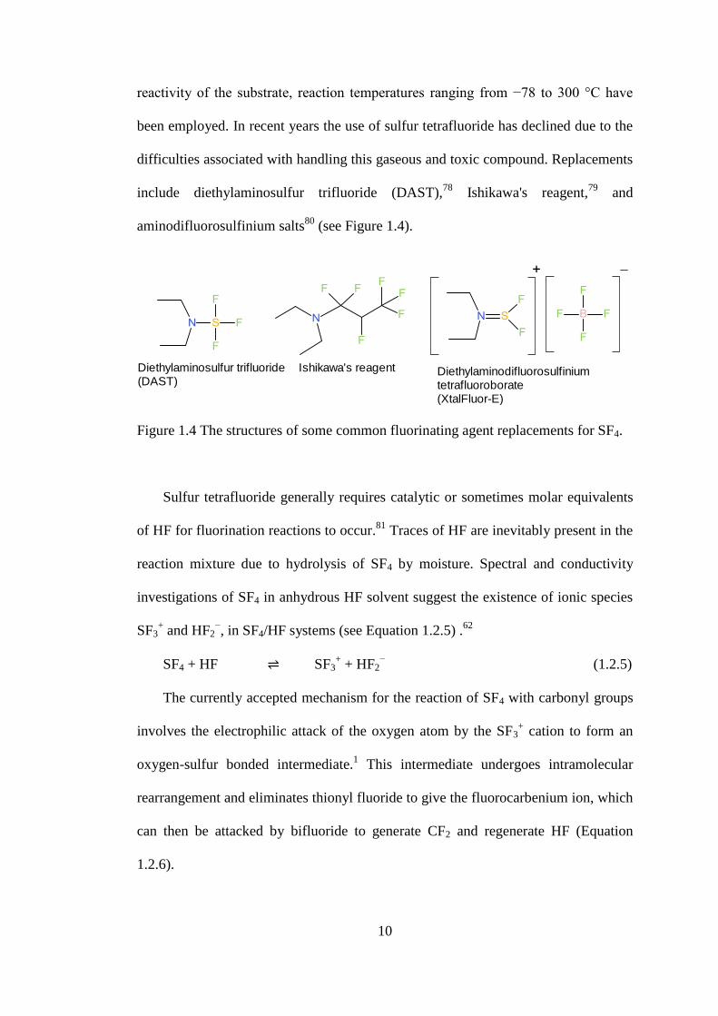
difficulties associated with handling this gaseous and toxic compound. Replacements
include diethylaminosulfur trifluoride (DAST),78
Ishikawa's reagent,79
and
aminodifluorosulfinium salts80
(see Figure 1.4).
Figure 1.4 The structures of some common fluorinating agent replacements for SF4.
Sulfur tetrafluoride generally requires catalytic or sometimes molar equivalents
of HF for fluorination reactions to occur.81
Traces of HF are inevitably present in the
reaction mixture due to hydrolysis of SF4 by moisture. Spectral and conductivity
investigations of SF4 in anhydrous HF solvent suggest the existence of ionic species
SF3+ and HF2
−, in SF4/HF systems (see Equation 1.2.5) .
62
SF4 + HF ⇌ SF3+ + HF2
− (1.2.5)
The currently accepted mechanism for the reaction of SF4 with carbonyl groups
involves the electrophilic attack of the oxygen atom by the SF3+ cation to form an
oxygen-sulfur bonded intermediate.1 This intermediate undergoes intramolecular
rearrangement and eliminates thionyl fluoride to give the fluorocarbenium ion, which
can then be attacked by bifluoride to generate CF2 and regenerate HF (Equation
1.2.6).
Diethylaminosulfur trifluoride(DAST)
Ishikawa's reagent Diethylaminodifluorosulfinium tetrafluoroborate(XtalFluor-E)

11
(1.2.6)
The fluorocarbenium ion can electrophilically attack the oxygen on a second
carbonyl compound which leads to the formation of fluoroethers as by-products.82
The fluorocarbenium cation can be trapped with aromatic hydrocarbons in the
reaction of SF4 with haloacids. For example, the reaction of SF4 with CHCl2COOH
in the presence of p-xylene affords ArCF2CH2Cl83
and haloacetones.84
The reaction of SF4 with substrates containing hydroxyl groups, is generally
much faster than substrates containing carbonyl groups. The proposed mechanism
for the reaction of SF4 with hydroxyl groups involves the formation of the
alkoxysulfur trifluoride (Equation 1.2.7), which can then act as a fluoride-ion donor
towards HF to form ROSF2+ (Equation 1.2.8), containing the excellent leaving group,
OSF2. The ROSF2+ then undergoes a substitution reaction with fluoride (or
bifluoride) (Equation 1.2.9). Dmowski et al. suggest the mechanism can either be
SN1 in the case of structures that form carbenium ions, or SN2 in primary or
secondary alkyl compounds,85,86
whereas Baum et al. propose an internal (SNi)
displacement mechanism.87
ROH + SF3+ → ROSF3 + H
+ (1.2.7)
ROSF3 + HF → ROSF2+ + HF2
− (1.2.8)
ROSF2+ + F
− → RF + SOF2 (1.2.9)
. . .. . .
..
.
.. .. ..
..
.
.. ...
...
. .
...
.
..
.
.
.
..
.
..
...
.
.
. .
.
. .
..
.
.
.
.
.
.
..
.
.
..
.
..
..
..
..
.
12
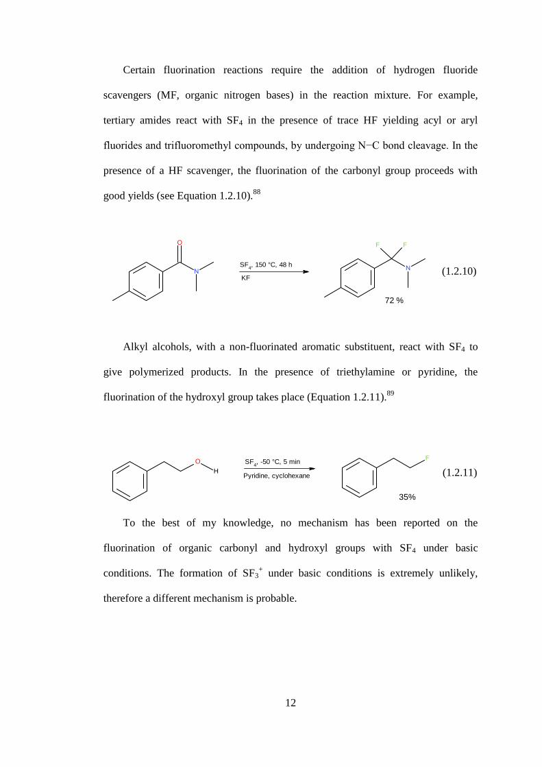
Certain fluorination reactions require the addition of hydrogen fluoride
scavengers (MF, organic nitrogen bases) in the reaction mixture. For example,
tertiary amides react with SF4 in the presence of trace HF yielding acyl or aryl
fluorides and trifluoromethyl compounds, by undergoing N−C bond cleavage. In the
presence of a HF scavenger, the fluorination of the carbonyl group proceeds with
good yields (see Equation 1.2.10).88
(1.2.10)
Alkyl alcohols, with a non-fluorinated aromatic substituent, react with SF4 to
give polymerized products. In the presence of triethylamine or pyridine, the
fluorination of the hydroxyl group takes place (Equation 1.2.11).89
(1.2.11)
To the best of my knowledge, no mechanism has been reported on the
fluorination of organic carbonyl and hydroxyl groups with SF4 under basic
conditions. The formation of SF3+ under basic conditions is extremely unlikely,
therefore a different mechanism is probable.
SF4, 150 °C, 48 h
KF
72 %
SF4, -50 °C, 5 min
Pyridine, cyclohexane
35%
13
1.3 Sulfur Fluoride Substituents in Organic and Inorganic Chemistry
1.3.1 Pentafluorosulfonyl Substituent, SF5
Renewed interest in SF5 as a substituent used in organic compounds is taking
place.90,91
The substituent has shown great promise in synthesizing high-
performance polymers, energetic materials, and liquid crystals, because SF5 is very
electron withdrawing, lipophilic, chemically inert and has more steric bulk when
compared to other fluorinated organic groups such as CF3.92,93
The
pentafluorosulfanyl substituent was discovered accidentally in 1950, when
attempting to synthesize CF3SF by reaction of CH3SF with CoF3 at 250 to 275 °C,
produced CF3SF5.94
Aliphatic SF5 compounds can be prepared in low yields (10 to
30%) by electrochemical fluorination or by direct fluorination of thiols, thioethers,
and other sulfur containing compounds.95-97
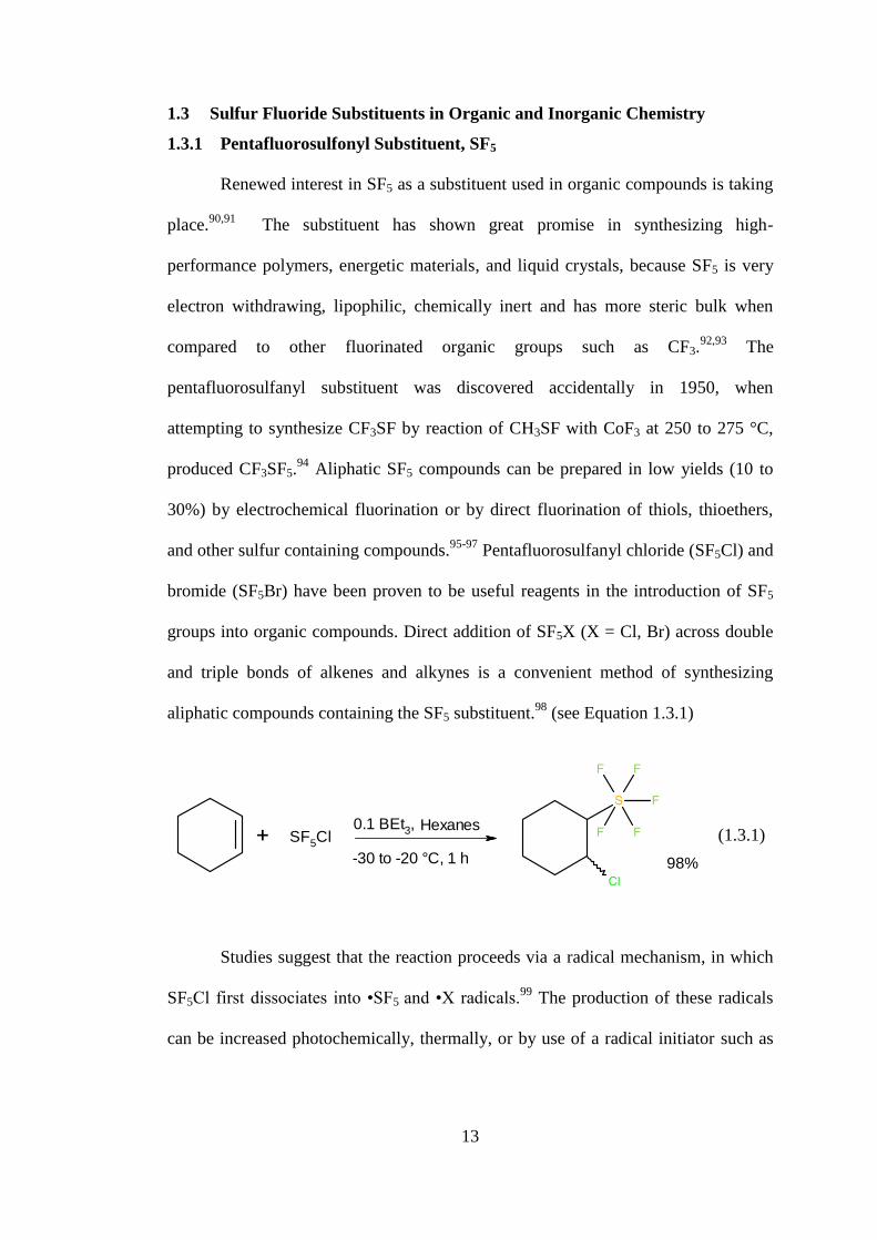
Pentafluorosulfanyl chloride (SF5Cl) and
bromide (SF5Br) have been proven to be useful reagents in the introduction of SF5
groups into organic compounds. Direct addition of SF5X (X = Cl, Br) across double
and triple bonds of alkenes and alkynes is a convenient method of synthesizing
aliphatic compounds containing the SF5 substituent.98
(see Equation 1.3.1)
(1.3.1)
Studies suggest that the reaction proceeds via a radical mechanism, in which
SF5Cl first dissociates into •SF5 and •X radicals.99
The production of these radicals
can be increased photochemically, thermally, or by use of a radical initiator such as
98%
0.1 BEt3, Hexanes
-30 to -20 °C, 1 h
SF5Cl

14
BEt3.100
A competing side reaction is the addition of Cl−F instead of Cl−SF5 (see
Equation 1.3.2).
(1.3.2)
In contrast to aliphatic pentafluorosulfonyl compounds there are very few
reported synthetic methods for preparing aromatic compounds containing the SF5
substituent.101
The direct fluorination of aryl sulfides in acetonitrile at −5 °C, with
elemental fluorine (10% F2/N2 v/v) produces aryl pentafluorosulfides in a yield of
40%.102
More recently, a new method has been developed to synthesize arylsulfur
pentafluorides in high yields.103
The reaction of diaryl disulfides with a mixture of
chlorine and potassium fluoride affords two equivalents of arylsulfur
chlorotetrafluoride (see Equation 1.3.3). Treatment of the arylsulfur
chlorotetrafluoride with a fluoride source, such as such as ZnF2, HF, and Sb(III/V)
fluorides affords the pentafluorosulfonyl arene.
(1.3.3)
17% 14%
Hexanes
RT, 18 h
SF5Cl
2
KF
Cl2 ZnF2
15
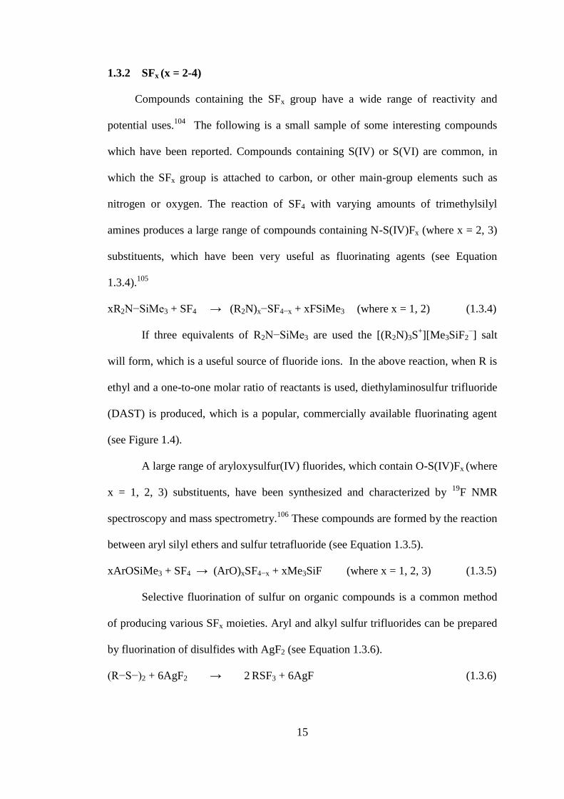
1.3.2 SFx (x = 2-4)
Compounds containing the SFx group have a wide range of reactivity and
potential uses.104
The following is a small sample of some interesting compounds
which have been reported. Compounds containing S(IV) or S(VI) are common, in
which the SFx group is attached to carbon, or other main-group elements such as
nitrogen or oxygen. The reaction of SF4 with varying amounts of trimethylsilyl
amines produces a large range of compounds containing N-S(IV)Fx (where x = 2, 3)
substituents, which have been very useful as fluorinating agents (see Equation
1.3.4).105
xR2N−SiMe3 + SF4 → (R2N)x−SF4−x + xFSiMe3 (where x = 1, 2) (1.3.4)
If three equivalents of R2N−SiMe3 are used the [(R2N)3S+][Me3SiF2
−] salt
will form, which is a useful source of fluoride ions. In the above reaction, when R is
ethyl and a one-to-one molar ratio of reactants is used, diethylaminosulfur trifluoride
(DAST) is produced, which is a popular, commercially available fluorinating agent
(see Figure 1.4).
A large range of aryloxysulfur(IV) fluorides, which contain O-S(IV)Fx (where
x = 1, 2, 3) substituents, have been synthesized and characterized by 19
F NMR
spectroscopy and mass spectrometry.106
These compounds are formed by the reaction
between aryl silyl ethers and sulfur tetrafluoride (see Equation 1.3.5).
xArOSiMe3 + SF4 → (ArO)xSF4−x + xMe3SiF (where x = 1, 2, 3) (1.3.5)
Selective fluorination of sulfur on organic compounds is a common method
of producing various SFx moieties. Aryl and alkyl sulfur trifluorides can be prepared
by fluorination of disulfides with AgF2 (see Equation 1.3.6).
(R−S−)2 + 6AgF2 → 2 RSF3 + 6AgF (1.3.6)

16
The fluorination of a sulfurane (S{C6H4C(CF3)2O}) with BrF3 produced a
trans-difluorosulfurane (SF2{C6H4C(CF3)2O}) if a 2/3rd
BrF3 molar equivalency is
used, and the cis-difluorosulfurane if excess BrF3 was used.107
Alkylidene sulfur
difluorides (R2C=SF2) can be prepared by an addition-elimination reaction (see
Equation 1.3.7).
F3C−CH=CF2 + SF4 → (F3C)2C=SF2 + HF (1.3.7)
Alkylidene sulfur tetrafluorides (R-C=SF4) can be prepared by elimination of
halo-fluorides from FS5CBr(CH3)CF3 or by isomerization of F5S−CH=C=O.108,109
These compounds can then be further dehydrofluorinated to produce R-C≡SF3
compounds, which are unstable.110
An alkylidene sulfur difluoride oxide was
synthesized by the hydrolysis of an alkylidene sulfur tetrafluoride (see Equation
1.3.8).104
O=CF−CH=SF4 + H2O → O=CF−CH=SF2=O + 2HF (1.3.8)
1.3.3 Sulfur Fluorides as Ligands in Transition Metal Chemistry
In 1969, Stocks et al. reported that the reaction between SF5Cl and trans-
stilbenebis(triphenylphosphine)platinum(0) forms (PPh3)2PtClSF5, the first metal
complex to contain a sulfur fluoride directly bonded to a metal.111
The only evidence
provided for the existence of this structure were physical properties and infrared
absorptions at 316 cm−1
(Pt-Cl) and at 891 cm−1
attributed to SF5. Holloway et al.
reported that SF4 oxidatively adds to Vaska-type complexes forming (PR3)2IrXFSF3
(where R = Me, Et, Ph and X = Cl, Br, I) complexes (see Equation 1.3.9).112
17
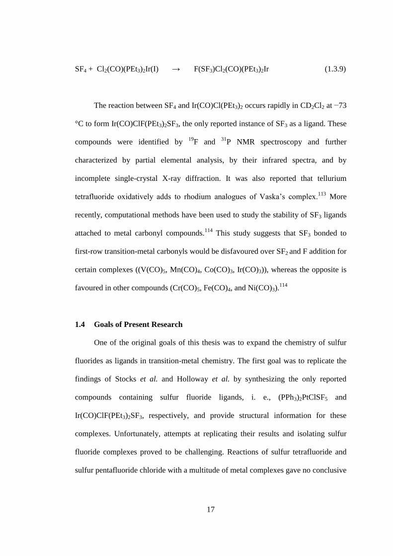
SF4 + Cl2(CO)(PEt3)2Ir(I) → F(SF3)Cl2(CO)(PEt3)2Ir (1.3.9)
The reaction between SF4 and Ir(CO)Cl(PEt3)2 occurs rapidly in CD2Cl2 at −73
°C to form Ir(CO)ClF(PEt3)2SF3, the only reported instance of SF3 as a ligand. These
compounds were identified by 19
F and 31
P NMR spectroscopy and further
characterized by partial elemental analysis, by their infrared spectra, and by
incomplete single-crystal X-ray diffraction. It was also reported that tellurium
tetrafluoride oxidatively adds to rhodium analogues of Vaska’s complex.113
More
recently, computational methods have been used to study the stability of SF3 ligands
attached to metal carbonyl compounds.114
This study suggests that SF3 bonded to
first-row transition-metal carbonyls would be disfavoured over SF2 and F addition for
certain complexes ((V(CO)5, Mn(CO)4, Co(CO)3, Ir(CO)3)), whereas the opposite is
favoured in other compounds (Cr(CO)5, Fe(CO)4, and Ni(CO)3).114
1.4 Goals of Present Research
One of the original goals of this thesis was to expand the chemistry of sulfur
fluorides as ligands in transition-metal chemistry. The first goal was to replicate the
findings of Stocks et al. and Holloway et al. by synthesizing the only reported
compounds containing sulfur fluoride ligands, i. e., (PPh3)2PtClSF5 and
Ir(CO)ClF(PEt3)2SF3, respectively, and provide structural information for these
complexes. Unfortunately, attempts at replicating their results and isolating sulfur
fluoride complexes proved to be challenging. Reactions of sulfur tetrafluoride and
sulfur pentafluoride chloride with a multitude of metal complexes gave no conclusive

18
results. The use of SF4 in some of these reactions led to the study of the structure of
SF4, the use of SF4 as a reagent in inorganic chemistry, and the behavior of SF4 as a
Lewis acid.
Since SF4 has been extensively used in synthetic organic chemistry, the use of
SF4 as a fluorinating agent towards inorganic oxo-anions under ambient conditions
was investigated. At high temperatures and pressures, the reactions of sulfur
tetrafluoride with inorganic oxides yield fluorides,115
but under ambient conditions, it
is not known to what degree fluorination will take place. The reported synthesis of
high-oxidation-state main-group and transition-metal oxide fluorides generally uses
reagents such as xenon hexafluoride or krypton difluoride which are not
commercially available. The use of sulfur tetrafluoride as a fluorinating agent may
provide an alternative cost-effective route to oxide fluorides.
Another goal of the present study is to further elucidate structure and bonding of
sulfur tetrafluoride in the solid state and explore the interaction of sulfur tetrafluoride
with fluoride. At low temperatures it may be possible to isolate and characterize the
actual fluorinating agents which are present in nitrogen-base sulfur tetrafluoride
mixtures that have been used to fluorinate ketone and hydroxyl groups in organic
compounds. Reaction mechanisms have been proposed for the fluorination of organic
substrates in the presence of HF, but not in the presence of organic bases.
The conclusive solid-state structure of SF4 has not been reported prior to this
work. Reports on the structure of SF4 in the solid state varied widely, some
suggesting disorder, dimers, or chains. Full characterization of this important binary
main group fluoride is long overdue. With the use of low-temperature crystal
mounting techniques, the X-ray crystal structure of neat SF4 may be obtained and

19
will provide a conclusive picture of SF4 in the solid state. This fundamental data
would be beneficial to both theoretical and experimental chemists.
The synthesis and characterization of SF4-Lewis base adducts will be extended
from the nitrogen-bases to the oxygen-bases. The SF4-oxygen-base adducts are
expected to be unstable at ambient temperature. For their isolation and
characterization, low-temperature techniques have to be employed, especially low-
temperature mounting techniques for X-ray crystallography. Lewis acid-base adducts
between oxygen and sulfur are rare, dioxane•SO3 adducts being the only reported S-
OR2 adducts studied by X-ray crystallography.116
To the best of my knowledge, there
has yet to be a S(IV)-OR2 adduct.

20
References
(1) Seel, F. Advan. Inorg. Chem. Radiochem. 1974, 16, 297-333.
(2) Leiding, J.; Woon, D. E.; Dunning, T. H. J. Phys. Chem. A 2012, 116, 1655-
1662.
(3) Lee, E. P. F.; Mok, D. K. W.; Chau, F.T.; Dyke, J. M. J. Chem. Phys. 2006,
125, 104304/104301-104304/104313.
(4) Pavone, M.; Barone, V.; Ciofini, I.; Adamo, C. J. Chem. Phys. 2004, 120,
9167-9174.
(5) Oberhammer, H.; Shlykov, S. A. Dalton Trans. 2010, 39, 2838-2841.
(6) Steudel, Y.; Steudel, R.; Wong, Ming W.; Lentz, D. Eur. J. Inorg. Chem.
2001, 2001, 2543-2548.
(7) Deroche, J. C.; Bürger, H.; Schulz, P.; Willner, H. J. Mol. Spectros. 1981, 89,
269-275.
(8) Seel, F.; Budenz, R.; Gombler, W. Chem. Ber. 1970, 103, 1701-1708.
(9) Seel, F.; Heinrich, E.; Gombler, W.; Budenz, R. Chimia 1969, 23, 73-74.
(10) Johnson, D. R.; Powell, F. X. Science 1969, 164, 950-951.
(11) Haas, A. W., H. Ber. Bunsenges. Phys. Chem. 1978, 82, 24.
(12) Gombler, W.; Schaebs, J.; Willner, H. Inorg. Chem. 1990, 29, 2697-2698.
(13) Carlowitz, M. V.; Oberhammer, H.; Willner, H.; Boggs, J. E. J. Mol. Struc.
1983, 100, 161-177.
(14) Seel, F.; Gölitz, H. D. Z. Anorg. Allg. Chem. 1964, 327, 32-50.
(15) Glemser, O.; Biermann, U.; Knaak, J.; Haas, A. Chem. Ber. 1965, 98, 446-
450.

21
(16) Davis, R. W. J. Mol. Spectros. 1986, 116, 371-383.
(17) Smith, W. C.; Engelhardt, V. A. J. Am. Chem. Soc. 1960, 82, 3838-3840.
(18) Ewing, V. C.; Sutton, L. E. Trans. Farad. Soc. 1963, 59, 1241-1247.
(19) Kimura, K.; Bauer, S. H. J. Chem. Phys. 1963, 39, 3172-3178.
(20) Tolles, W. M.; Gwinn, W. D. J. Chem. Phys. 1962, 36, 1119-1121.
(21) Dodd, R. E.; Woodward, L. A.; Roberts, H. L. Trans. Faraday Soc. 1956, 52,
1052-1061.
(22) Raffael, K. D.; Smith, D. M. J. Mol. Spectros. 2002, 214, 21-27.
(23) Raffael, K. D.; Smith, D. M.; Newnham, D. A. J. Mol. Spectros. 2003, 218,
108-113.
(24) Spring, C. A.; True, N. S. J. Am. Chem. Soc. 1983, 105, 7231-7236.
(25) Christe, K. O.; Curtis, E. C.; Schack, C. J.; Pilipovich, D. Inorg. Chem. 1972,
11, 1679-1682.
(26) Berney, C. V. J. Mol. Struc. 1972, 12, 87-97.
(27) Mootz, D.; Korte, L. Z. Naturforsch., B: Anorg. Chem., Org. Chem. 1984,
39B, 1295-1299.
(28) Naumann, D.; Padma, D. Z. Anorg. Allg. Chem. 1973, 401, 53-56.
(29) Fedorova, A.N.; Dromov, G.A.; Antonova, E.I.; Antipenko, G.L. U.S.S.R.
Pat., 823 276, 1981.
(30) Tullock, C. W.; Fawcett, F. S.; Smith, W. C.; Coffman, D. D. J. Am. Chem.
Soc. 1960, 82, 539-542.
(31) Muetterties, E. L.; U.S. Patent 2,729,663: 1959.
(32) Smythe, K. D. In Proceedings of" Conference on SF6 and the Environment:
Emission Reduction Strategies", November 2000, p 2-3.

22
(33) Rhein, R. A. Lithium combustion: a review, DTIC Document, 1990.
(34) Gullikson, C. W.; Nielsen, J. R.; Stair Jr, A. T. J. Mol. Spectros. 1957, 1, 151-
154.
(35) Goyal, S.; Schutt, D. L.; Scoles, G. Phys. Rev. Lett. 1992, 69, 933-936.
(36) Lagemann, R. T.; Jones, E. A. J. Chem. Phys. 1951, 19, 534-536.
(37) Brunet, H.; Perez, M. J. Mol. Spectros. 1969, 29, 472-477.
(38) Frost, D. C.; McDowell, C. A.; Sandhu, J. S.; Vroom, D. A. J. Chem. Phys.
1967, 46, 2008-2009.
(39) Gillespie, R. J.; Quail, J. W. J. Chem. Phys. 1963, 39, 2555-2557.
(40) Bartell, L. S.; Doun, S. K. J. Mol. Struc. 1978, 43, 245-249.
(41) Taylor, J. C.; Waugh, A. B. J. Solid State Chem. 1976, 18, 241-246.
(42) Cockcroft, J. K.; Fitch, A. N. Z. Kristallogr. Kristallgeo. 1988, 184, 123-145.
(43) Strauss, G.; Zweier, H.; Bertagnolli, H.; Bausenwein, T.; Todheide, K.;
Chieux, P. J. Chem. Phys. 1994, 101, 662-671.
(44) Jones, J. P.; Wagner, E. N. Poision Gas Proliferation: Paradox, Politics, and
Law, 1992; Vol. 15.
(45) Denbigh, K. G.; Whytlaw-Gray, R. J. Chem. Soc. 1934, 1346-1352.
(46) Benson, S. W.; Bott, J. Int. J. Chem. Kinet. 1969, 1, 451-458.
(47) Winter, R.; Nixon, P. G.; Gard, G. L. J. Fluorine Chem. 1998, 87, 85-86.
(48) Nyman, F.; Roberts, H. L. J. Chem. Soc. 1962, 3180-3183.
(49) Edelson, D. J. Am. Chem. Soc. 1952, 74, 262.
(50) Harvey, R. B.; Bauer, S. H. J. Am. Chem. Soc. 1953, 75, 2840-2846.
(51) Oberhammer, H. J. Mol. Struc. 1989, 192, 171-175.

23
(52) Dodd, R.; Woodward, L.; Roberts, H. Trans. Faraday Soc. 1957, 53, 1545-
1556.
(53) Harris, R. K.; Packer, K. J. J. Chem. Soc. 1962, 0, 3077-3082.
(54) Wilmshurst, J. K.; Bernstein, H. J. Can. J. Chem. 1957, 35, 191-201.
(55) Smardzewski, R. R.; Noftle, R. E.; Fox, W. B. J. Mol. Spectros. 1976, 62,
449-457.
(56) Novak, I. Inorg. Chim. Acta 1991, 181, 81-83.
(57) Irikura, K. K. J. Chem. Phys. 1995, 103, 10162-10168.
(58) Gutsev, G. L. Zh. Fiz. Khim. 1992, 66, 1820-1827.
(59) Robinson, N. B. a. P. L. Chem. & Ind. 1956, 1351.
(60) Bartlett, N.; Robinson, P. L. J. Chem. Soc. 1961, 3417-3425.
(61) Cotton, F. A.; George, J. W. J. Inorg. Nucl. Chem. 1958, 7, 397-403.
(62) Azeem, M.; Brownstein, M.; Gillespie, R. J. Can. J. Chem. 1969, 47, 4159-
4167.
(63) Gibler, D. D.; Adams, C. J.; Fischer, M.; Zalkin, A.; Bartlett, N. Inorg. Chem.
1972, 11, 2325-2329.
(64) Chaudhary, P., M.Sc. Thesis, Lethbridge, Alta.: University of Lethbridge,
Dept. of Chemistry and Biochemistry, 2011.
(65) Mallouk, T. E.; Rosenthal, G. L.; Mueller, G.; Brusasco, R.; Bartlett, N.
Inorg. Chem. 1984, 23, 3167-3173.
(66) O'Brien, B. A.; DesMarteau, D. D. Inorg. Chem. 1984, 23, 644-648.
(67) Tunder, R.; Siegel, B. J. Inorg. Nucl. Chem. 1963, 25, 1097-1098.
(68) Tullock, C.; Coffman, D.; Muetterties, E. J. Am. Chem. Soc. 1964, 86, 357-
361.
24
(69) Bittner, J.; Fuchs, J.; Seppelt, K. Z. Anorg. Allg. Chem. 1988, 557, 182-190.
(70) Drullinger, L. F.; Griffths, J. E. Spectrochim. Acta A 1971, 27, 1793-1799.
(71) Christe, K. O.; Curtis, E. C.; Schack, C. J.; Pilipovich, D. Inorg. Chem. 1972,
11, 1679-1682.
(72) Clark, M.; Kellen-Yuen, C.; Robinson, K.; Zhang, H.; Yang, Z.-Y.;
Madappat, K.; Fuller, J.; Atwood, J.; Thrasher, J. Eur. J. Solid State Inorg.
Chem. 1992, 29, 809-833.
(73) Muetterties, E. L. J. Am. Chem. Soc. 1960, 82, 1082-1087.
(74) Sass, C. S.; Ault, B. S. J. Phys. Chem. 1985, 89, 1002-1006.
(75) Goettel, J. T.; Chaudhary, P.; Hazendonk, P.; Mercier, H. P. A.; Gerken, M.
In 95th Canadian Chemistry Conference Calgary, Alberta, Canada 2012,
Abstract #353.
(76) Goettel, J. T.; Chaudhary, P.; Hazendonk, P.; Mercier, H. P. A.; Gerken, M.
Chem. Commun. 2012, 48, 9120–9122.
(77) Smith, W. C. Angew. Chem. Int. Ed. Engl. 1962, 1, 467-475.
(78) Hudlický, M. In Organic Reactions; John Wiley & Sons, Inc.: 2004.
(79) Takaoka, A.; Iwakiri, H.; Ishikawa, N. Bull. Chem. Soc. Jpn. 1979, 52, 3377-
3380.
(80) L’Heureux, A.; Beaulieu, F.; Bennett, C.; Bill, D. R.; Clayton, S.; LaFlamme,
F.; Mirmehrabi, M.; Tadayon, S.; Tovell, D.; Couturier, M. J. Org. Chem.
2010, 75, 3401-3411.
(81) Dmowski, W.; Kolinski, R. Pol. J. Chem. 1978, 52, 547; Chem. Abstr. 1978,
89, 41906.
(82) Wojciech, D.; Ryszard, A. K. Pol. J. Chem. 1978, 52, 71-85.
25
(83) ielgat, J.; Domagal a, . J. Fluorine Chem. 1982, 20, 785-789.
(84) ielgat, J.; Domagała, .; Koliński, R. J. Fluorine Chem. 1987, 35, 643-652.
(85) Kollonitsch, J.; Marburg, S.; Perkins, L. J. Org. Chem. 1975, 40, 3808-3809.
(86) Kollonitsch, J.; Marburg, S.; Perkins, L. M. J. Org. Chem. 1979, 44, 771-777.
(87) Baum, K. J. Am. Chem. Soc. 1969, 91, 4594-4594.
(88) Dmowski, W. Pol. J. Chem. 1982, 56, 1369.
(89) Schaefer, T.; Rowbotham, J. B.; Parr, W. J.; Marat, K.; Janzen, A. F. Can. J.
Chem. 1976, 54, 1322-1328.
(90) Thayer, A. M. Chem. Eng. News 2006, 84, 27-32.
(91) Kirsch, P.; Röschenthaler, G. V. Functional Compounds Based on
Hypervalent Sulfur Fluorides. In Current Fluoroorganic Chemistry,
Soloshonok, V. A.; Mikami, A.; Yamazaki, T.; Welch, J. T.; Honek, J. F.,
Eds.; ACS Symposium Series 949; American Chemical Society: Washington,
DC, 2007, Ch. 13; pp 221-243.
(92) Dolbier, W. R. Jr.Chimica Oggi 2003, 21, 66-69.
(93) Sheppard, W. A. J. Am. Chem. Soc. 1962, 84, 3072-3076.
(94) Silvey, G. A.; Cady, G. H. J. Am. Chem. Soc. 1950, 72, 3624-3626.
(95) Clifford, A. F.; El-Shamy, H. K.; Emeleus, H. J.; Haszeldine, R. N. J. Chem.
Soc. 1953, 0, 2372-2375.
(96) Hoffmann, F. W.; Simmons, T. C.; Beck, R. B.; Holler, H. V.; Katz, T.;
Koshar, R. J.; Larsen, E. R.; Mulvaney, J. E.; Rogers, F. E.; Singleton, B.;
Sparks, R. S. J. Am. Chem. Soc. 1957, 79, 3424-3429.
(97) Huang, H. N.; Lagow, R. J.; Roesky, H. Inorg. Chem. 1991, 30, 789-794.
26
(98) Winter, R. W.; Dodean, R. A.; Gard, G. L. SF5-Synthons: Pathways to
Organic Derivatives of SF6. In Fluorine-Containing Synthons, Soloshonok,
V. A., Ed.; ACS Symposium Series 911; American Chemical Society:
Washington, DC, 2005, Ch. 4, pp 87-118.
(99) Berry, A. D.; Fox, W. B. J. Org. Chem. 1978, 43, 365-367.
(100) Dolbier Jr, W. R.; Aït-Mohand, S.; Schertz, T. D.; Sergeeva, T. A.;
Cradlebaugh, J. A.; Mitani, A.; Gard, G. L.; Winter, R. W.; Thrasher, J. S. J.
Fluorine Chem. 2006, 127, 1302-1310.
(101) Sipyagin, A. M.; Bateman, C. P.; Tan, Y.-T.; Thrasher, J. S. J. Fluorine
Chem. 2001, 112, 287-295.
(102) Bowden, R. D.; Comina, P. J.; Greenhall, M. P.; Kariuki, B. M.; Loveday, A.;
Philp, D. Tetrahedron 2000, 56, 3399-3408.
(103) Umemoto, T.; Garrick, L. M.; Saito, N. Beilstein J. Org. Chem. 2012, 8, 461-
471.
(104) Seppelt, K. Angew. Chem. Int. Ed. Engl. 1991, 30, 361-374.
(105) Middleton, W.; Bingham, E. J. Org. Chem. 1980, 45, 2883-2887.
(106) Darragh, J. I.; Hossain, S. F.; Sharp, D. W. A. J. Chem. Soc., Dalton Trans.
1975, 0, 218-221.
(107) Michalak, R. S.; Martin, J. C. J. Am. Chem. Soc. 1982, 104, 1683-1692.
(108) Krügerke, T.; Buschmann, J.; Kleemann, G.; Luger, P.; Seppelt, K. Angew.
Chem. Int. Ed. Engl. 1987, 26, 799-801.
(109) Buschmann, J.; Koritsanszky, T.; Kuschel, R.; Luger, P.; Seppelt, K. J. Am.
Chem. Soc. 1991, 113, 233-238.
27
(110) Poetter, B.; Seppelt, K.; Simon, A.; Peters, E. M.; Hettich, B. J. Am. Chem.
Soc. 1985, 107, 980-985.
(111) Kemmitt, R. D. W.; Peacock, R. D.; Stocks, J. J. Chem. Soc. D 1969, 554.
(112) Cockman, R. W.; Ebsworth, E. A. V.; Holloway, J. H. J. Am. Chem. Soc.
1987, 109, 2194-2195.
(113) Ebsworth, E. A. V.; Holloway, J. H.; Watson, P. G. J. Chem. Soc., Chem.
Commun. 1991, 1443-1444.
(114) Deng, J.; Wang, C.; Li, Q.-s.; Xie, Y.; King, R. B.; Schaefer, H. F. Inorg.
Chem. 2011, 50, 2824-2835.
28
2 Experimental
Caution: Anhydrous HF (aHF) is toxic and highly corrosive. Exposure to aHF will cause
severe burns. Sulfur tetrafluoride is highly toxic and corrosive. At room temperature, the
pressure in the reactor will be close to 10 atmospheres, and therefore there is a danger of
overpressurization. Reactions between SF4 and water are highly exothermic. The
reactions should be performed on small scales at low temperatures.
2.1 General Methods
The chemistry presented in this thesis requires strict exclusion of oxygen and
moisture due to the extremely reactive nature of the compounds used throughout this
work. All operations were carried out under rigorously dried and strictly inert
atmospheres, by the use of glass and metal vacuum lines, and a dry box (Omni Lab,
Vacuum Atmospheres). Edwards two-stage direct-drive RV8 vacuum pumps were used
for the metal and glass vacuum lines, and the antechambers of the glove box. Vacuum on
the glass (ca. 10−5
Torr) and metal lines (ca. 10−4
Torr) were verified by a mercury
McCleod gauge (Labconco). Nitrogen (Praxair), was passed through a column containing
anhydrous calcium sulfate (cobalt chloride indicator), and activated 4Å molecular sieves.
Ultra-high-purity (5.0) argon (Praxair) was used without further purification.
Pyrex-glass vacuum lines, equipped with grease-free 6-mm J. Young glass
stopcocks with PTFE barrels, were used to manipulate volatiles which do not react with
glass (see Figure 2.1). Heise gauges (model CC, 0-1000 mmHg, beryllium/copper
Bourdon tube, Dresser Instruments) were used to measure pressures inside the glass

29
manifold. The final vacuum was monitored by Varian model 801 thermocouple gauges
connected to the vacuum lines between the liquid nitrogen traps and the vacuum pumps.
Figure 2.1 Glass vacuum line system equipped with J. Young PTFE/glass stopcocks, a
Heise gauge (Adapted from Jared Nieboer’s M.Sc. Thesis).
A metal line constructed from nickel, 316 stainless-steel, and equipped with 316
stainless steel valves and fittings (Autoclave Engineers Inc.), PTFE, and FEP, was used to
manipulate volatiles which react with glass (see Figure 2.2). Three vacuum pumps were
connected to the metal line; two pumps for fine vacuum connected to small towers of
activated charcoal, and one roughing pump connected to a fluoride/fluorine trap
consisting of a stainless-steel cylinder (75-cm length, 17-cm outer diameter) packed with
soda lime absorbent (EMD, 4 mesh). The fine vacuum pumps provided high vacuum to

30
each respective side of the metal line. The roughing vacuum provided a method of
removal and disposal of volatile reactive fluorinated compounds for both sides of the
metal lines. Pressures were measured using Baratron capacitance manometers (MKS,
Type 626A, effective range 0-1000 mmHg) having inert wetted surfaces constructed of
Inconel, connected to digital readouts.
Figure 2.2 Metal vacuum system; (A) MKS type 626A capacitance manometer (0-1000
Torr), (B) MKS Model PDR-5B pressure transducers (0-10 Torr), (C) 3/8-in. stainless-
steel high-pressure valves (Autoclave Engineers, 30VM6071), (D) 316 stainless-steel
cross (Autoclave Engineers, CX6666), (E) 316 stainless-steel L-piece (Autoclave
Engineers, CL6600), (F) 316 stainless steel T-piece (Autoclave engineers, CT6660), (G)
3/8-in o.d., 1/8-in. i.d. nickel connectors, (H) 1/8-in o.d., 1/8-in. i.d. nickel tube. (from
Jared Nieboer’s M.Sc. thesis).
31
All preparative work involving reactive fluorinated compounds was carried out in
4-mm, ¼-in., or ¾-in. o.d. FEP reactors which were heat sealed at one end and affixed to
either Kel-F or stainless-steel valves by means of a 45° and 33° flare, respectively. The
FEP reactors were rinsed with acetone, checked for leaks and dried under dynamic
vacuum overnight on a glass vacuum line. The reactors were then passivated with pure
fluorine gas at a pressure greater than 1 atm overnight, and backfilled with nitrogen. The
reactors were weighed underneath using a Sartorius Ag Göttingen balance, with a
suspended copper wire.
Raman spectroscopy was performed on samples in ¼-in. or 4-mm FEP reactors, 5-
mm glass tubes equipped with a J-Young valves, or Pyrex-glass melting-point capillaries.
The Pyrex-glass melting-point capillaries were loaded in the dry box and sealed with Kel-
F grease. They were then heat-sealed outside of the glove box using a standard natural-
gas Bunsen burner.
Nuclear magnetic resonance (NMR) spectroscopy was performed in sealed 4-mm
FEP tubes, inserted into standard 5-mm glass NMR tubes. The 4-mm FEP tubes were
sealed under dynamic vacuum with a heat gun, while the contents remained cooled at
−196 °C.
2.2 Purification and Preparation of Starting Materials
2.2.1 Purification of Anhydrous HF, SF4, Acetonitrile
Anhydrous hydrogen fluoride (Air Products) was stored at room temperature in a
nickel storage vessel equipped with a monel (Autoclave Engineers) valve. Hydrogen
fluoride was pre-dried with fluorine gas in a ¾-in. o.d. FEP vessel equipped with a
stainless-steel valve. The vessel was evacuated and backfilled with approximately 900
Torr of pure fluorine gas. The vessel was agitated periodically for two weeks. Volatiles

32
were pumped off below −80 °C. The HF was then vacuum distilled onto potassium
hexafluoronickelate(IV) in a ¾-in o.d. FEP vessel and backfilled with nitrogen.
Sulfur tetrafluoride (Ozark-Mahoning Co.) was purified by passing the gas
through a column of activated charcoal. Traces of thionyl fluoride and sulfur hexafluoride
were present in the sulfur tetrafluoride, but did not interfere with the chemistry.
Acetonitrile (Sigma-Aldrich) was purified according to the literature procedure
reported by Winfield.1 It was then vacuum distilled and stored on freshly activated 4Å
molecular sieves.
2.2.2 Oxo-Anions Salts
Tetramethylammonium iodate was prepared by neutralization of an aqueous solution of
[N(CH3)4][OH] (Fluka, 95.0%) with a stoichiometric amount of an aqueous solution of
HIO3 (BDH) as previously described.2 Potassium periodate (Sigma, 99.8%), potassium
perrhenate (Strem, 99%), and silver perrhenate (Strem, 99%) were used as received.
2.2.3 Nitrogen-Bases
Both 4-dimethylaminopyridine (Sigma, 99%) and 4,4’-bipyridyl (Sigma, 98%)
were dried under vacuum at ambient temperatures and brought into the glove box.
Pyridine was vacuum distilled onto CaH2. 4-Methylpyridine (Sigma, 99%) was distilled
onto freshly cut sodium, and stirred overnight, and subsequently distilled into dry glass
vessels equipped with J-Young valves. 2,6-Dimethylpyridine (Sigma, 99%) was used as
received.

33
2.2.4 Purification of Toluene, Diethyl Ether, Pentane, THF
The solvents were dispensed directly from an MBraun dry solvent system into a
dry glass flask equipped with a J-Young valve. The solvents were then freeze-thaw
degassed and vacuum distilled onto freshly cut sodium, potassium, or a liquid sodium
potassium alloy. THF was refluxed with benzophenone and sodium, and then distilled
onto freshly cut sodium. Diethyl ether, was vacuum distilled onto freshly cut sodium and
stirred for three days, followed by vacuum distillation onto freshly activated 4Å
molecular sieves. Pentane was vacuum distilled onto liquid Na/K alloy. Toluene was first
vacuum distilled onto activated molecular sieves, however, reactions using this toluene
led to hydrolysis products, which suggested that it was insufficiently dried. The toluene
was then distilled onto a Na/K alloy and sonicated for several hours.
2.2.5 Purification of CH2Cl2, CFCl3, CF2Cl2
Dichloromethane was dispensed from a dry solvent system, and then vacuum
distilled onto freshly activated 4A molecular sieves. Trichlorofluoromethane was vacuum
distilled onto calcium hydride, and vacuum distilled into a dry, evacuated flask.
Difluorodichloromethane (Synquest Labs Inc.) was used as received.
2.3 Preparation of Oxide Fluoride Salts
2.3.1 Preparation of [Ag(CH3CN)x][ReO2F4] where ( x = 0, 2, 4)
Inside the dry box, 0.053 g (0.15 mmol) of AgReO4 was loaded into a ¼-in. o.d.
FEP tube equipped with a Kel-F valve. Excess acetonitrile (0.388 g, 5.96 mmol) was
vacuum distilled onto the solid AgReO4. The reactor was agitated at room temperature to
completely dissolve the solid. Excess SF4 (0.23 g, 2.1 mmol) was vacuum distilled onto
the frozen mixture at –196 °C. After warming and agitation at 0 °C, a pale yellow

34
solution was obtained. Slow cooling to –40 °C led to the formation of large plate-like
crystals. Volatiles were removed under dynamic vacuum at –40 °C. These crystals
([Ag(CH3CN)4][ReO2F4]•CH3CN) were characterized by low-temperature Raman
spectroscopy (see Table 3.1) and X-ray crystallography. Placing the crystals under
dynamic vacuum afforded a cream coloured powder ([Ag(CH3CN)2][ReO2F4]) which was
characterized by room temperature Raman spectroscopy (see Table 3.1). Heating the
powder to approximately 60 °C under dynamic vacuum resulted in a loss of mass, and a
fine light yellow powder (Ag[ReO2F4]) which was characterized by Raman spectroscopy
(see Table 3.1). 19
F NMR (CH3CN, 20 °C, unlocked, 282.4 MHz, δ [ppm]): –54.0 (t,
Fc,t), –63.7 (t, (Fc,c), 2JFax−Feq = 87 Hz.
2.3.2 Preparation of KReO2F4
Inside the dry box, 0.064 g (0.22 mmol) of KReO4 was loaded into a 4-mm o.d.
FEP tube equipped with a Kel-F valve. Approximately 0.05 mL of acetonitrile was
vacuum distilled onto the solid KReO4, and the mixture was agitated. Only a very small
portion of the KReO4 dissolved at room temperature. A large excess of sulfur
tetrafluoride was vacuum distilled into the reactor. The reactor was warmed to room
temperature and cautiously agitated. The mixture was left at room temperature overnight.
A pale yellow solid formed. Volatiles were removed from −40°C to room temperature,
leaving 69 mg of a pale yellow solid (approximately 55% yield). 19
F NMR (CH3CN, 20
°C, unlocked, 282.4 MHz, δ [ppm]): –52.8 (t, Fc,t), –74.9 (t, Fc,c), 2JFax−Feq = 90 Hz.
2.3.3 Preparation of K[IO2F4]
Inside the dry box, 0.081 g (0.35 mmol) of KIO4 was loaded into a ¼-in. o.d. FEP
tube equipped with a Kel-F valve. Approximately 0.1 mL of aHF was vacuum distilled onto

35
the solid, which partially dissolved the solid. Excess SF4 was vacuum distilled onto the
frozen mixture at –196 °C. Warming the reaction mixture to ambient temperature caused
the remaining solid to dissolve upon agitation, yielding a clear colourless solution. The
solvent was removed under dynamic vacuum at –78 °C, yielding 0.094 g (0.34 mmol) of
colourless crystalline powder. 19
F NMR (HF, 20 °C, unlocked, 282.4 MHz, δ [ppm]): 64.4
(Ftrans). Raman (cm−1
): 1078(4), (unidentified impurity); 875(2), (cis νas(IO2); 856(19),
(cis νsym(IO2)); 819(100), (trans νsym(IO2)); 797(2), (KIO4); 609(13), (cis νsym(IF2eq));
577(41), (trans νsym(IF4)in phase); 397(24), (cis δsciss(IO2)); 381(37), (trans δ(OIF4O);
333(10), (cis νtorsion(IO2)); 260(9), (trans νs(IF4)in plane)).
2.3.4 Preparation of [N(CH3)4][IOF4]
Inside the dry box, 0.072 g (0.29 mmol) of [N(CH3)4][IO3] was loaded into a ¼-in.
o.d. FEP tube equipped with a Kel-F valve. Excess acetonitrile (0.563 g, 8.90 mmol) was
vacuum distilled onto the solid [N(CH3)4][IO3]. The reactor was agitated at room
temperature, and only a small amount of solid dissolved. Excess SF4 was distilled onto the
frozen mixture at –196 °C. Warming to –40 °C caused the evolution of gas, and the
solution to turn pale yellow. Warming and agitation at room temperature caused the
solution to turn a light orange. Large thin plates were obtained when the solution was
cooled to −30 °C. The plates were characterized by Raman spectroscopy (see Table 3.1),
19F NMR spectroscopy and single crystal X-ray crystallography. The volatiles were
transferred to a 4-mm o.d. FEP reactor at –80 °C. 19
F NMR (HF, 20 °C, unlocked, 282.4
MHz, δ [ppm]): 10.6

36
2.4 Preparation of Hydrolysis Products of SF4•Nitrogen Base Adducts by HF
2.4.1 Preparation of [HNC5H5+]F
−•SF4
Pyridine (0.014 g, 0.18 mmol) was distilled into a ¼-in. FEP reactor. Sulfur
tetrafluoride (0.057 g, 0.52 mmol) was vacuum distilled at −196 °C. The reactor was
warmed to −80 °C and agitated to form a clear colourless solution. The excess SF4 was
removed by pumping at −75 °C for 2 hours, yielding colourless solid SF4•NC5H5.
Approximately 0.05 mL of toluene, which had been apparently insufficiently dried over
molecular sieves, was vacuum distilled into the reactor at −196 °C. The reactor was
warmed to −60 °C; gas evolution was observed as the adduct dissolved. The reactor was
placed in a cryo-bath at −80 °C. Large colourless crystalline needles formed overnight.
The crystals were characterized by X-ray crystallography.
2.4.2 Preparation of [HNC5H5+][HF2
−]•2SF4
Water (0.013 g, 0.72 mmol) was syringed into a ¼-in. FEP reactor, followed by
vacuum distillation of pyridine (0.109 g, 1.38 mmol) at −196 °C. A large excess of SF4
(ca. 0.04 g, 4 mmol) was distilled at −196 °C. The reactor was warmed slightly to the
melting point of SF4, and the vigorous reaction was quenched by cooling in liquid
nitrogen to control the reaction rate. After no further reaction was observed, the reactor
was allowed to warm to room temperature, resulting in a clear colourless solution. Slow
cooling to −90 °C resulted in crystal formation. Excess SF4 and SOF2 were pumped off at
−90 °C. The product was characterized by low-temperature Raman spectroscopy (see
Table 4.4) and X-ray crystallography.
37
2.4.3 Preparation of [HNC5H4(CH3)+]F
−•SF4
In an open atmosphere, water (0.019 g, 1.05 mmol) was syringed into a ¼-in o.d.
FEP reactor and thoroughly degassed. After vacuum distillation of 4-methylpyridine
(0.185 g, 1.99 mmol), SF4 (0.65 g, 6.4 mmol) was transferred in vacuo at −196 °C onto
the H2O and 4-methylpyridine. The reactor was warmed slightly to the melting point of
SF4, and quenched by cooling in liquid nitrogen to control the reaction rate. After no
further reaction was observed, the reactor was allowed to warm to room temperature,
resulting in a clear colourless solution. Slow cooling to −20 °C resulted in crystal
formation. Excess SF4 and SOF2 were pumped off at −90 °C, yielding a colourless
crystalline solid. The product was characterized by low-temperature Raman spectroscopy
(see Table 4.8) and X-ray crystallography.
2.4.4 Preparation of [HNC5H3(CH3)2+]2[SF5
−]F
−•SF4
Method 1: After 2,6-dimethylpyridine (0.047 g, 0.44 mmol) was syringed into a
¼-in. FEP reactor, excess sulfur tetrafluoride (ca. 1 g, 9 mmol) was distilled at −196 °C.
The reactor was warmed to −80 °C and the reactants mixed. The mixture was placed
under dynamic vacuum at −85 °C until a 1:1 mole ratio of SF4 : 2,6-dimethylpyridine was
obtained. Approximately 0.05 mL of toluene containing traces of water was distilled onto
the adduct at −196 °C. Upon melting of the toluene, the adduct dissolved and gas
evolution was observed. Large plate-like crystals were obtained by cooling from −60 to
−80 °C. A large plate (0.212 × 0.461 × 0.734 mm3) was affixed to the tip of a glass fiber
and mounted on the X-ray diffractometer.
Method 2: Water (0.005 g, 0.3 mmol) was syringed into a ¼-in. FEP reactor followed by
syringing of 2,6-dimethylpyridine (0.086 g, 0.80 mmol) into the reactor. Subsequently,
SF4 (0.375 g, 3.47 mmol) was vacuum distilled at −196 °C onto the frozen. The mixture

38
was warmed slightly and liquid nitrogen was used to quench the vigorous reaction. The
reaction mixture was warmed to −45 °C and mixed, resulting in a clear colourless
solution. Slow cooling to −85 °C resulted in growth of clear colourless crystals. Excess
SF4 and SOF2 were removed at −90 °C under dynamic vacuum. The crystals were
characterized by X-ray crystallography.
2.4.5 Preparation of [HNC5H4N(CH3)2+][HF2
−]•2SF4
Inside a dry box, 4-dimethylaminopyridine (0.026 g, 0.21 mmol) was transferred
to a ¼-in. FEP reactor. Water (0.002 g, 0.1 mmol) was micro-syringed into the reactor,
followed by distillation of an excess of SF4 (ca. 0.04 mL, 0.7 mmol) at −196 °C. The
reactor was slowly warmed to 3 °C, resulting in a clear colourless solution. Slow cooling
to −20 °C resulted in the formation of large needles. Further cooling to −40 °C caused the
crystals to grow considerably. Excess SF4 and SOF2 were removed between −97 and −87
°C, which caused precipitation of a white powder. A large needle, out of many needles,
was selected out of a pile of low density colourless powder, and cut into a block (0.202 ×
0.216 × 0.524 mm3), and then affixed to the end of a cryo-loop for characterization by X-
ray crystallography. The product was also characterized by low-temperature Raman
spectroscopy (see Table 4.14).
2.4.6 Preparation of [HNC5H4N(CH3)2+]2[SF5
−]F
−•CH2Cl2
Inside a dry box, 4-dimethylaminopyridine (0.023 g, 0.19 mmol) was transferred
to a ¼-in. FEP reactor. A large excess of SF4 (ca. 0.04 mL, 0.7 mmol) was vacuum
distilled at −196 °C onto the 4-dimethylaminopyridine, and the reactor was stored at −70
°C in a cryo-bath. Approximately 0.05 mL of CH2Cl2, which apparently contained
moisture, was distilled onto the mixture and the reactor was agitated and warmed to −60

39
°C, resulting in a clear colourless solution. Removal of volatiles under dynamic vacuum
at −80 °C resulted in large needles, with a small amount of yellow powder. The product
was characterized by low-temperature Raman spectroscopy (see Table 4.15) and X-ray
crystallography.
2.4.7 Preparation of [HNH4C5−C5H4N+]F
−•2SF4
Inside a dry box 4,4’-bipyridyl (0.022 g, 0.14 mmol) was added to a ¼-in. FEP
reactor. Water (0.001 g, 0.06 mmol) was micro-syringed into the reactor. A large excess
of SF4 (ca. 0.04 mL, 0.7 mmol) was distilled at −196 °C. The reactor was warmed to −80
°C which caused the brown solid 4,4’-bipyridyl to turn colourless. Further warming
resulted in a clear pale yellow solution. Slow cooling resulted in growth of large needles.
Volatiles were pumped off at −70 °C. A fragment of a needle (0.088 × 0.146 × 0.336
mm3) was affixed onto a cryo-loop and mounted onto the diffractometer. The product was
characterized by low-temperature Raman spectroscopy (see Table 4.19) and X-ray
crystallography.
2.4.8 Preparation of [HNH4C5−C5H4NH2+
]2F−•4SF4
Inside a dry box, 4,4’-bipyridyl (0.009 g, 0.06 mmol) was added to a 1.4-in. FEP
reactor. Water (0.001 g, 0.06 mmol) was micro-syringed into the reactor. A large excess
of SF4 (ca. 0.1 mL) was distilled at −196 °C. Subsequent warming of the reactor to room
temperature caused a portion of the colourless solid to dissolve, but the solubility was
relatively low. Slow cooling to −80 °C, resulted in the formation of large needles. Excess
SF4 and SOF2 were pumped off at −90 °C. The product was characterized by low-
temperature Raman spectroscopy (see Table 4.20) and X-ray crystallography.

40
2.4.9 X-ray Crystal Structure of [HNC5H4(CH3)+]HF2
−
After distillation of 4-methylpyridine (0.073 g, 0.78 mmol) into a ¼-in. FEP
reactor, SF4 (0.23 g, 2.1 mmol) was transferred in vacuo onto the frozen solid. A slow
reaction proceeded at −80 °C, dissolving the solid yielding a clear colourless solution.
Volatiles were removed at −75 °C. The reactor only contained 0.4 mmol of SF4 after
removal of volatiles. The reactor was accidentally warmed to room temperature, causing
the solid to melt and form a colourless yellow liquid. Toluene, containing traces of H2O,
was distilled onto the solid at −196 °C. While the solid dissolved, gas evolved at −60 °C.
The reactor was heat-sealed under vacuum and stored in the cryo-bath at −80 °C for
crystal growth. Large needles formed, which, when mounted on the diffractometer, had
very weak reflections. A needle (0.090 × 0.162 × 0.348 mm3) was affixed onto a cryo-
loop dipped in perfluorinated oil (Fomblin Z-25) at −80 °C.
2.5 Solid-State Structure of SF4
2.5.1 Synthesis of [HNC5H3(CH3)2+]2F
−[SF5
−]•4SF4
Water (0.016 g, 0.89 mmol) was injected into a ¼-in. FEP reactor equipped with
a Kel-F valve using a micro syringe, followed by transfer of 2,6-dimethylpyridine (0.176
g, 1.64 mmol) into the ¼-in. FEP reactor using a syringe in a dry-nitrogen-filled glove
bag. A large excess of SF4 was vacuum-distilled onto the frozen mixture at –196 °C.
Upon melting of SF4 at –120 °C, a vigorous reaction occurred, causing a white insoluble
precipitate to form. Warming the reaction mixture to 0 °C formed a clear colourless
solution. Slow cooling of this solution to –85 °C led to the formation of large needle-like
crystals. Excess SF4 was partially removed under dynamic vacuum at –95 °C, yielding
0.69 g of a white solid, i.e., [HNC5H3(CH3)2+]2F
−[SF5
−]
•4SF4 with small amounts of
41
residual SF4. The product was characterized by low-temperature Raman spectroscopy
(see Table 5.3) and X-ray crystallography.
2.5.2 X−Ray Crystallography of Neat SF4
Sulfur tetrafluoride (0.015 g, 1.4 mmol) was vacuum distilled into a ¼-in. FEP
reactor. Crystals were grown by slowly cooling the liquid SF4 to –150 °C in the ¼-in.
FEP reactor placed inside an aluminium cold trough. After the temperature stabilized, the
FEP tube was cut approximately 6 cm above the frozen SF4. A Pasteur pipette was used
to remove some crystals. A suitable crystal (0.063 0.075 0.117 mm3) was affixed to a
nylon cryo-loop coated in Fomblin Z-15 perfluorinated oil. Crystals were mounted at low
temperature under a stream of dry cold nitrogen as described below.
2.5.3 X−Ray Crystallography of SF4 from CF2Cl2
Sulfur tetrafluoride (0.034 g, 3.1 mmol) was vacuum distilled in a ¼-in. FEP
reactor. Approximately 0.1 mL of CF2Cl2 was vacuum distilled on top of the solid SF4.
Upon melting, two distinct layers were observed. Agitation caused the liquids to mix,
forming a homogeneous solution. Cooling of the solution to –131.8 °C (pentane cold
bath) and reducing the volume of CF2Cl2 under dynamic vacuum led to the formation of
plate-like crystals. The FEP was cut in a cold trough, and the crystals were removed using
a Pasteur pipette. A suitable plate (0.135 0.149 0.173 mm3) was affixed to a ball of
Fomblin Z-15 perfluorinated oil on a nylon cryo-loop, off the end of the pipette tip.
2.6 SF4 Oxygen Base Adducts
2.6.1 Preparation of the SF4•OC4H6 Adduct
An equimolar amount of tetrahydrofuran (0.233 g, 3.23 mmol) and SF4 (0.35 g 3.2
mmol) were condensed into a ¼-in. FEP reactor. arming to −80 °C yielded a solution.
42
Slow cooling caused the solution to freeze at −99 °C. Alternatively, an excess SF4 can be
used and the sample can be placed under dynamic vacuum at −90 °C until a 1:1 mixture is
obtained. The clear colourless solid melts at approximately −95 °C. The product was
characterized by low-temperature Raman spectroscopy (see Table 6.4) and X-ray
crystallography.
2.6.2 Preparation of the SF4•(OC4H6)2 Adduct
Tetrahydrofuran (0.172 g, 2.39 mmol) and subsequently SF4 (0.13 g, 1.2 mmol)
were vacuum distilled into a ¼-in. FEP reactor. arming to −80 °C yielded a
homogeneous mixture. Slow cooling caused the solution to freeze at −106 °C. The solid
melted at approximately −100 °C into a clear colourless solution. The product was
characterized by low-temperature Raman spectroscopy (see Table 6.5) and X-ray
crystallography.
2.6.3 Preparation of the SF4•(CH3OCH2)2 Adduct
1,4-Dimethoxyethane (0.037 g, 0.41 mmol) was pipetted into a ¼-in. FEP reactor.
Excess SF4 (0.231 g, 2.14 mmol) was vacuum distilled onto the frozen 1,4-
dimethoxyethane at −196 °C. The reactor was warmed to approximately −60 °C and
agitated in order to dissolve the 1,4-dimethoxyethane. The clear colourless liquid was
placed under dynamic vacuum at −90 °C to remove excess SF4. Slow cooling of the clear
colourless solution caused the sample to crystallize at −100 °C. The solid (81 mg, 0.41
mmol) melted at approximately −83 °C. The product was characterized by low-
temperature Raman spectroscopy (see Table 6.7) and X-ray crystallography.

43
2.6.4 Preparation of the SF4•(O=C5H8)2
Cyclopentanone (20 mg, 0.24 mmol) was pipetted into a ¼-in. FEP reactor. Sulfur
tetrafluoride (26 mg, 0.24 mmol) was vacuum distilled onto the frozen cyclopentanone at
−196 °C. The reactor was warmed to −50 °C and vigorously agitated until a clear
colourless solution was obtained. The reactor was slowly cooled to −100 °C at which
point it slowly crystallized. The colourless crystalline solid melted at approximately −63
°C. The product was characterized by low-temperature Raman spectroscopy (see Table
6.9) and X-ray crystallography.
2.6.5 Attempted Preparation of SF4•OEt2
An equimolar amount of diethyl ether and SF4 were distilled into a ¼-in. FEP
reactor. The mixture froze when it was slowly cooled to approximately −145 °C.
2.6.6 Attempted Preparation of SF4•acetylacetone
Acetylacetone (39mg, 0.39 mmol), was pipetted into a ¼-in. FEP reactor and
degassed using the freeze-pump-thaw method. Sulfur tetrafluoride (51 mg, 0.47 mmol)
was vacuum distilled onto the acetylacetone and the reactor was warmed to −60 °C and
agitated, until a clear colourless solution was obtained. The reactor was placed under
dynamic vacuum at −80 °C for approximately one hour, when clear colourless plates
formed. Raman spectroscopy showed signals of neat acetylacetone and liquid SF4.
2.6.7 Attempted Preparation of SF4•4-methylcyclohexanone
4-Methylcyclohexanone (58 mg, 0.52 mmol) was pipetted into a ¼-in. FEP reactor
and degassed using the freeze-pump-thaw method. Sulfur tetrafluoride (55 mg, 0.52
mmol) was vacuum distilled onto the frozen 4-methylcyclohexanone at −196 °C. The

44
mixture was warmed to −80°C and agitated to form a clear colourless solution. The
mixture was slowly cooled and froze at approximately −120 °C.
2.7 Single Crystal X-ray Diffraction
2.7.1 Low-Temperature Crystal Mounting
Low-temperature crystal mounting was used for thermally unstable and moisture-
sensitive crystals. (Figure 2.3) The temperature of the trough was measured with a
copper-constantan thermocouple and adjusted to the appropriate temperature (between
−70 and −150 °C) before the samples were introduced to the trough. For dry samples
containing crystals in FEP tubes (4 mm or ¼-in.), the FEP tube was cut under a stream of
dry nitrogen while maintaining the crystals at −78 °C in packed dry ice. The crystals were
then transferred into the metal trough that had previously been cooled to approximately
−80 °C. Alternatively, the samples in the FEP tubes were removed from an ethanol cold
bath (below −80 °C), quickly wiped to remove the ethanol, and placed in the cold trough.
The FEP tube was then cut at the end of the trough with scissors, and the crystals could be
removed using a glass pipette or by inverting the FEP tube with tweezers. For wet
samples, the cut FEP tubes were manipulated in the cold trough, at temperatures just
above the freezing point of the solvent. Solvents were removed using a combination of
glass pipettes, and capillary action of Kimwipes®. For extra sensitive crystals, the crystals
were removed with the tip of a glass pipette and were directly affixed onto either a glass
fiber, or a nylon cryo-loop dipped in inert perfluorinated polyethers, Fomblin Z-25 or Z-
15 (Ausimont Inc.). The use of a round FEP tray, inside the trough, was also used to
manipulate crystals which decomposed on contact with the metal troughs.
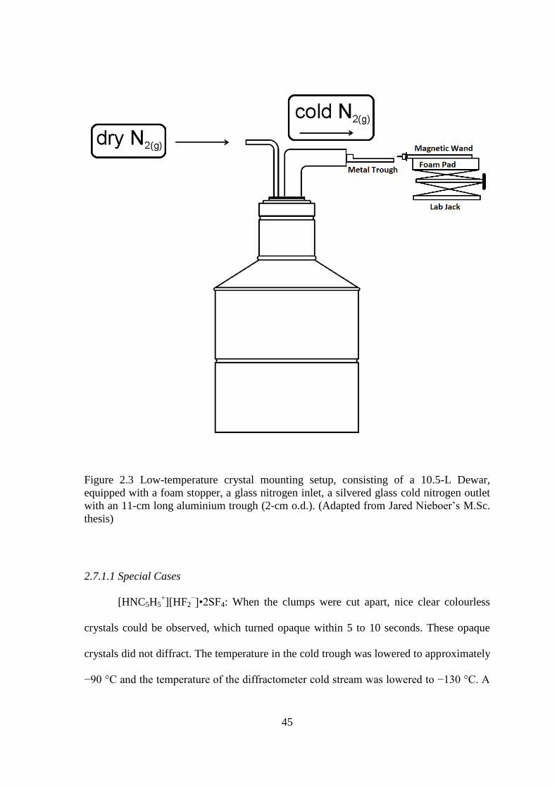
45
Figure 2.3 Low-temperature crystal mounting setup, consisting of a 10.5-L Dewar,
equipped with a foam stopper, a glass nitrogen inlet, a silvered glass cold nitrogen outlet
with an 11-cm long aluminium trough (2-cm o.d.). (Adapted from Jared Nieboer’s M.Sc.
thesis)
2.7.1.1 Special Cases
[HNC5H5+][HF2
−]•2SF4: When the clumps were cut apart, nice clear colourless
crystals could be observed, which turned opaque within 5 to 10 seconds. These opaque
crystals did not diffract. The temperature in the cold trough was lowered to approximately
−90 °C and the temperature of the diffractometer cold stream was lowered to −130 °C. A
46
large clump was broken apart, and a single crystal (0.077 × 0.117 × 0.290 mm3) was
mounted and transferred as quickly as possible.
[HNC5H4N(CH3)2+]2[SF5
−]F
−•CH2Cl2: The error associated with this structure is
relatively high. This is most likely because the crystal was an extremely thin needle and
gave weak reflections, even with a relatively long exposure time of 120 s. In addition, the
SF5− anion is disordered over two positions which increases the degree of error associated
with the refined metrical parameters, thus increasing the overall uncertainties.
[HNH4C5−C5H4NH2+
]2F−•4SF4: A large needle was mounted onto the
diffractometer, in which the cryo-stream was set at −100 °C. The crystal decomposed
over the time span of approximately one minute. The cryo-stream was lowered to −120
°C and a thin, long needle (0.079 × 0.084 × 0.581 mm3) was mounted.
2.7.2 Data Collection
Crystal structures were collected at temperatures at temperatures ranging from −120
to −173 °C on a Bruker AXS X-ray diffractometer. The Apex II 4K charge-coupled
device (CCD) area detector was positioned 6.120 cm away from the crystal. The Kα
radiation (λ = 0.71073 Å) of a Mo source X-ray tube was used with a graphite
monochrometer. Cell reduction was carried out using the Program SAINT3 which applied
Lorentz and polarization corrections to three-dimensionally integrated diffraction spots.
2.7.3 Solution and Refinement of Structures
Calculations were performed using the SHELXTL-plus v.6.14 package4 for structure
determination, refinement and molecular graphics. The program SADABS5 was used for
scaling of diffraction data, the application of a decay correction, and a multi-scan
absorption correction. Mercury 2.4 aided in the visualization of packing and

47
intermolecular interactions.6 Xprep was used to confirm the unit cell dimensions and the
Bravais crystal lattice. Platon was used to check for higher symmetry.7 Crystal structures
were solved using direct methods, Patterson methods, or dual space methods. The
structures were minimized by least squares refinement based on the square of the
structure factors, F2 (equivalent to intensity, I). Atom positions were refined
anisotropically and the extinction coefficient was calculated for the crystal structure. If
the error in the extinction coefficient was on the same order of magnitude as the
extinction coefficient, it was omitted. Both residual values, R1 based on F and the
weighted residual values wR2 based on F2, are available in the structure refinement tables
along with the goodness of fit (GooF). They represent the following equations:
∑‖ | | ‖
∑| | The conventional R-factor based upon the structure factor.
√∑[ (
)
]
∑[ ( )
]
The weighted R-factor based on the square of the structure factors
√∑[
]
The GooF (goodness of fit) is based upon intensity where n is the
number of reflections and p is the number of parameters refined.
Experimental details of each crystal data set are listed in Table 2.1 and the cif files
are available on the attached CD.

48
Table 2.1 X-ray Crystal Structures and Selected Acquisition Parameters.
Sample
Code
Compound T (°C) Size (mm3) Exposure
Time (s)
MG12035 [Ag(CH3CN)4][ReO2F4] −120 0.09 × 0.23 × 0.41 40
MG12077 K[IO2F4] −120 0.15 × 0.10 × 0.05 40
MG12063 [N(CH3)4][IO2F4] −120 0.04 × 0.33 × 0.34 40
MG11019 [HNC5H5+]F
−•SF4 −120 0.32 × 0.36 × 1.38 10
MG12051 [HNC5H5+]HF2
−•2SF4 −130 0.08 × 0.12 × 0.29 60
MG12072 [HNC5H4(CH3)+]F
−•SF4 −120 0.16 × 0.23 × 0.28 45
MG12078 [HNC5H4(CH3)+]HF2
− −120 0.09 × 0.16 × 0.35 50
MG11020 [HNC5H3(CH3)2+]2[SF5
−]F
−•SF4 −120 0.70 × 0.46 × 0.20 20
MG12071 [HNC5H4N(CH3)2+][HF2
−]•2SF4 −120 0.20 × 0.22 × 0.52 40
MG12074 [HNC5H4N(CH3)2+]2[SF5
−]F
−•CH2Cl2 −120 0.08 × 0.086 × 0.37 120
MG120176 [HNH4C5−C5H4N+]F
−•2SF4 −120 0.09 × 0.15 × 0.34 45
MG12086 [HNH4C5−C5H4NH2+
]2F−•4SF4 −120 0.08 × 0.08 × 0.58 120
MG12107 [HNC5H3(CH3)2+]2[SF5
−]F
−•4SF4 −140 0.16 × 0.19 × 0.58 40
MG12097 SF4 −173 0.06 0.075 0.12 30
MG12088 SF4•OC4H8 −140 0.15 × 0.31 × 0.50 5
MG13029 SF4•(OC4H8)2 −150 0.22 × 0.19 × 0.10 40
MG13024 SF4•(CH3OCH2)2 −145 0.67 × 0.20 × 015 40
MG13026 SF4•(O=C5H8)2 −150 0.27 × 0.16 × 0.12 40
2.7.3.1 Special Cases
[Ag(CH3CN)4][ReO2F4]•CH3CN: Using the RLATT program, multiple crystal
domains were observed in the reciprocal lattice. The largest domain was selected, and the
other reflections discarded.
[HNC5H3(CH3)2+]2[SF5
−]F
−•SF4 and [HNC5H4N(CH3)2
+]2[SF5
−]F
−•CH2Cl2: After
refinement of each structure, residual electron density was observed around some fluorine
atoms in the SF5− anion, which suggested that the SF5
− anion occupied two separate
orientations. The site occupancy factor between these two orientations was set as a free
variable, which suggested a 70-to-30% occupancy for [HNC5H3(CH3)2+]2[SF5
−]F
−•SF4
and a 80-to-20% for [HNC5H4N(CH3)2+]2[SF5
−]F
−•CH2Cl2. Similarity restraints were
used to set the bond lengths and angles (SAME), and thermal ellipsoids (SIMU) of the
two orientations of the SF5− anion, as they are assumed to be equal. The SF5
− anions are
joined by a fixed pivot point, i.e., the axial fluorine for [HNC5H3(CH3)2+]2[SF5
−]F
−•SF4
and one of the equatorial fluorines for [HNC5H4N(CH3)2+]2[SF5
−]F
−•CH2Cl2.
49
SF4: The program ROTAX was used to find the twin law (0 −1 0 −1 0 0 0 0 −1).
After the twin law was implemented, the structure was refined as usual.
SF4•(OC4H6)2: The program Cell Now was used to determine the two separate
crystal domains. Both domains were integrated together and an hkl.4 file was created.
TWINABS8 was used to process the data, and structure was solved using direct methods.
2.8 Vibrational Spectroscopy
Raman spectra were recorded on a Bruker RFS 100 FT Raman spectrometer with a
quartz beam splitter, a liquid-nitrogen cooled Ge detector, and R-496 low-temperature
accessory. The actual usable Stokes range was 50 to 3500 cm–1
. The 1064-nm line of a
Nd:YAG laser was used for excitation of the sample. The Raman spectra were recorded at
temperatures ranging from –142 °C to 20 °C with a spectral resolution ranging from 1 to
4 cm–1
using laser powers ranging from 50 to 300 mW. Samples were recorded in Pyrex-
glass mp capillaries and NMR tubes, 4-mm and ¼-in. FEP tubes.
2.9 NMR Spectroscopy
NMR spectra were recorded unlocked on a 300.13 MHz (7.0486 T) Bruker
Advance II NMR spectrometer equipped with a variable temperature, two channel BBFO
probe. The 19
F, 1H, and
13C NMR spectra were referenced at room temperature to external
samples of neat CFCl3 {19
F} and TMS {1H and
13C). All NMR spectra were recorded on
sealed 4-mm FEP tubes inserted into standard 5-mm glass NMR tubes.

50
References
(1) Winfield, J. M. J. Fluorine Chem. 1984, 25, 91-98.
(2) Gerken, M.; Mack, J. P.; Schrobilgen, G. J.; Suontamo, R. J. J. Fluorine Chem.
2004, 125, 1663-1670.
(3) Bruker; Apex2 and Saint-plus. Bruker AXS Inc.: Madison, W., USA, 2006.
(4) Sheldrick, G. M. 6.14 ed.; Bruker AXS INC.: Madison, Wisconsin, USA, 2003
(5) G. M. Sheldrick, SADABS, Version 2007/4; Bruker AXS Inc.; Madison, WI, 2007.
(6) Cambridge Crystallographic Data Centre, Mercury 2.4, 2013.
(7) Spek, A.L. Acta Cryst. 2009, D65, 148-155.
(8) Bruker. TWINABS. Bruker AXS Inc., Madison, Wisconsin, USA, 2001.
51
3 Sulfur Tetrafluoride as a Fluorinating Agent Towards
Main-Group and Transition-Metal Oxo-Anions.
3.1 Introduction
Sulfur tetrafluoride has extensively been used as a fluorinating agent in
organic chemistry.1 The usefulness of SF4 in inorganic chemistry has been explored
for converting metal oxides to fluorides at high temperatures and pressures.2 For
example, Bi2O3, TiO2, U3O8, and HgO are fluorinated by SF4 to BF3 (Equation. 3.1),
TiF4, UF6, and HgF2, respectively.
Bi2O3 + 3 SF4 → 2 BiF3 + 3 SOF2 (3.1)
Main-group oxides and sulfides also react with SF4 to produce fluorides
(SnS2 to SnF4 and FeS2 to FeF2) and oxide fluorides (P4O10 to POF3) (see Equations
3.2 and 3.3, respectively).
SnS2 + SF4 → SnF4 + 3/8 S8 (3.2)
P4O10 + 6 SF4 → 4 POF3 + 6 SOF2 (3.3)
Sulfur tetrafluoride will generally lose two of its fluorines when reacting with
oxides, but loses all four of its fluorines when reacting with sulfides. Very little has
been reported on the use of SF4 as a fluorinating agent towards oxo-anions of main-
group and transition-metal elements in high oxidation states.3 A large number of
oxide-fluoride anions have been synthesized and characterized.4 The ReO2F4
– anion
was first synthesized in 1955 by Peacock from the reaction of excess BrF3 with metal
perrhenate salts (see Equation 3.4).5
3 ReO4− + 4 BrF3 → 3 ReO2F4
− + 3 O2 + 2 Br2 (3.4)
52
The reaction required extensive heating under vacuum to remove excess
unreacted BrF3 and the Br2 by-product. Another method of synthesizing the ReO2F4–
anion is through the reaction of ReO2F3 with fluoride salts, such as LiF and
[N(CH3)4]F.6 The Li
+ and N(CH3)4
+ salts of ReO2F4
− were characterized by Raman
and 19
F NMR spectroscopy as well as X-ray crystallography.6 Neutral ReO2F3 can be
prepared by the reaction of Re2O7 with XeF6 in anhydrous HF. Holloway et al. report
that KReO4 does not react with anhydrous HF at room temperature, whereas Seppelt
et al. report the reaction yields ReO2F4−. Another paper mentions the formation of
ReO3F in the reaction of KReO4 with anhydrous HF.7-9
These rhenium species are in
equilibrium with each other in aHF, therefore, a large excess of aHF is required to
produce ReO2F4− and the yields are low.
Previous syntheses of the IOF4– anion used the reaction of IF5 with a metal
fluoride and iodate, or the hydrolysis of the IF6– anion.
10 The previous reactions also
produced the IO2F2– anion, besides IOF4
−, which are difficult to separate. Although
the crystal structure of the Cs[IOF4] salt has been reported, the quality is poor.11
The
IO2F4– anion was previously synthesized by the repeated reaction of IO4
– with aHF
over long periods of time.10
An alternative route is the reaction of IO2F3 with
[N(CH3)4]F in acetonitrile, but this route is hazardous since detonations have
occurred during this reaction.12
Both of these methods of preparing the IO2F4– anion
produced mixtures of trans and cis isomers.12
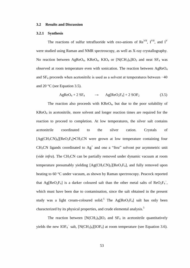
53
3.2 Results and Discussion
3.2.1 Synthesis
The reactions of sulfur tetrafluoride with oxo-anions of ReVII
, IVII
, and IV
were studied using Raman and NMR spectroscopy, as well as X-ray crystallography.
No reaction between AgReO4, KReO4, KIO4 or [N(CH3)4]IO3 and neat SF4 was
observed at room temperature even with sonication. The reaction between AgReO4
and SF4 proceeds when acetonitrile is used as a solvent at temperatures between −40
and 20 °C (see Equation 3.5).
AgReO4 + 2 SF4 → Ag[ReO2F4] + 2 SOF2 (3.5)
The reaction also proceeds with KReO4, but due to the poor solubility of
KReO4 in acetonitrile, more solvent and longer reaction times are required for the
reaction to proceed to completion. At low temperatures, the silver salt contains
acetonitrile coordinated to the silver cation. Crystals of
[Ag(CH3CN)4][ReO2F4]•CH3CN were grown at low temperature containing four
CH3CN ligands coordinated to Ag+ and one a “free” solvent per asymmetric unit
(vide infra). The CH3CN can be partially removed under dynamic vacuum at room
temperature presumably yielding [Ag(CH3CN)2][ReO2F4], and fully removed upon
heating to 60 °C under vacuum, as shown by Raman spectroscopy. Peacock reported
that Ag[ReO2F4] is a darker coloured salt than the other metal salts of ReO2F4−,
which must have been due to contamination, since the salt obtained in the present
study was a light cream-coloured solid.5 The Ag[ReO2F4] salt has only been
characterized by its physical properties, and crude elemental analysis.5
The reaction between [N(CH3)4]IO3 and SF4 in acetonitrile quantitatively
yields the new IOF4− salt, [N(CH3)4][IOF4] at room temperature (see Equation 3.6).

54
hen the orange solution is cooled from room temperature to −30 °C, large plates
crystallize from the reaction mixture.
[N(CH3)4][IO3] + 2 SF4 → [N(CH3)4][IOF4] + 2 SOF2 (3.6)
hen the volatiles were removed at −80 °C, the reaction mixture became
clear and colourless. The rest of the volatiles were removed between −80 and −30 °C
leaving clear colourless plate-like crystals.
No reaction occurred between KIO4 and SF4 in acetonitrile. A slurry of KIO4
in anhydrous HF reacted with SF4 to form a clear colourless solution at 0 °C.
(Equation 3.7) hen the volatiles were removed at −78 °C, a white solid remained
with clear colourless crystals.
KIO4 + 2 SF4 → K[IO2F4] + 2 SOF2 (3.7)
3.2.2 [Ag(CH3CN)4][ReO2F4]•CH3CN, [Ag(CH3CN)x]ReO2F4 (where x = 0, 2)
3.2.2.1 Raman Spectroscopy
The Raman spectra of [Ag(CH3CN)4][ReO2F4]•CH3CN and
[Ag(CH3CN)x]ReO2F4 (where x = 0, 2) are depicted in Figure 3.1. The Raman
frequencies and tentative assignments are listed in Table 3.1. The signals associated
with the acetonitrile moieties were assigned based on previous assignments made by
Reedijk et al.13
The signals associated with ReO2F4− anion were assigned based on
the previous assignments made by Schrobilgen et al.,6 who used computational
techniques to aide in the assignment of the vibrational modes.

55
Figure 3.1 Raman spectra of AgReO2F4 salts with varying amounts of CH3CN.
Asterisks (*) denote bands arising from the FEP sample tube. Daggers (†) denote
bands arising from the CH3CN.
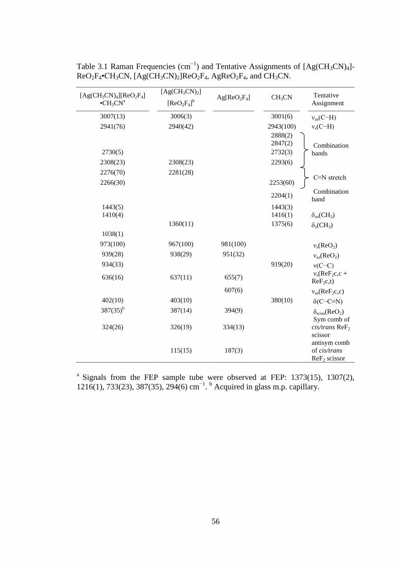
56
Table 3.1 Raman Frequencies (cm1
) and Tentative Assignments of [Ag(CH3CN)4]-
ReO2F4•CH3CN, [Ag(CH3CN)2]ReO2F4, AgReO2F4, and CH3CN.
[Ag(CH3CN)4][ReO2F4]
•CH3CNa
[Ag(CH3CN)2]
[ReO2F4]b
Ag[ReO2F4] CH3CN
Tentative
Assignment
3007(13) 3006(3) 3001(6) νas(C−H)
2941(76) 2940(42) 2943(100) νs(C−H)
2888(2)
2847(2)
Combination
bands 2730(5) 2732(3)
2308(23) 2308(23) 2293(6)
2276(70) 2281(28) C≡N stretch
2266(30) 2253(60)
2204(1)
Combination
band
1443(5)
1410(4)
1443(3)
1416(1)
as(CH3)
1360(11) 1375(6) s(CH3)
1038(1)
973(100) 967(100) 981(100) νs(ReO2)
939(28) 938(29) 951(32) νas(ReO2)
934(33) 919(20) ν(C−C)
636(16) 637(11) 655(7) νs(ReF2c,c +
ReF2c,t)
607(6) νas(ReF2c,c)
402(10) 403(10) 380(10) (C−C≡N)
387(35)b
387(14) 394(9) δsciss(ReO2)
324(26) 326(19) 334(13)
Sym comb of
cis/trans ReF2
scissor
115(15) 187(3)
antisym comb
of cis/trans
ReF2 scissor
a Signals from the FEP sample tube were observed at FEP: 1373(15), 1307(2),
1216(1), 733(23), 387(35), 294(6) cm−1
. b Acquired in glass m.p. capillary.
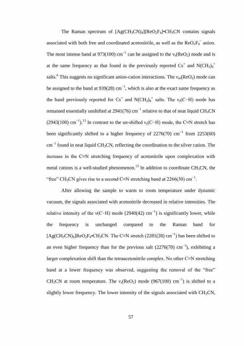
57
The Raman spectrum of [Ag(CH3CN)4][ReO2F4]•CH3CN contains signals
associated with both free and coordinated acetonitrile, as well as the ReO2F4− anion.
The most intense band at 973(100) cm−1
can be assigned to the νs(ReO2) mode and is
at the same frequency as that found in the previously reported Cs+ and N(CH3)4
+
salts.6 This suggests no significant anion-cation interactions. The νas(ReO2) mode can
be assigned to the band at 939(28) cm−1
, which is also at the exact same frequency as
the band previously reported for Cs+ and N(CH3)4
+ salts. The νs(C−H) mode has
remained essentially unshifted at 2941(76) cm−1
relative to that of neat liquid CH3CN
(2943(100) cm−1
).13
In contrast to the un-shifted νs(C−H) mode, the C≡N stretch has
been significantly shifted to a higher frequency of 2276(70) cm−1
from 2253(60)
cm−1
found in neat liquid CH3CN, reflecting the coordination to the silver cation. The
increase in the C≡N stretching frequency of acetonitrile upon complexation with
metal cations is a well-studied phenomenon.13
In addition to coordinate CH3CN, the
“free” CH3CN gives rise to a second C≡N stretching band at 2266(30) cm−1
.
After allowing the sample to warm to room temperature under dynamic
vacuum, the signals associated with acetonitrile decreased in relative intensities. The
relative intensity of the ν(C−H) mode (2940(42) cm−1
) is significantly lower, while
the frequency is unchanged compared to the Raman band for
[Ag(CH3CN)4]ReO2F4•CH3CN. The C≡N stretch (2281(28) cm−1
) has been shifted to
an even higher frequency than for the previous salt (2276(70) cm−1
), exhibiting a
larger complexation shift than the tetraacetonitrile complex. No other C≡N stretching
band at a lower frequency was observed, suggesting the removal of the “free”
CH3CN at room temperature. The νs(ReO2) mode (967(100) cm−1
) is shifted to a
slightly lower frequency. The lower intensity of the signals associated with CH3CN,
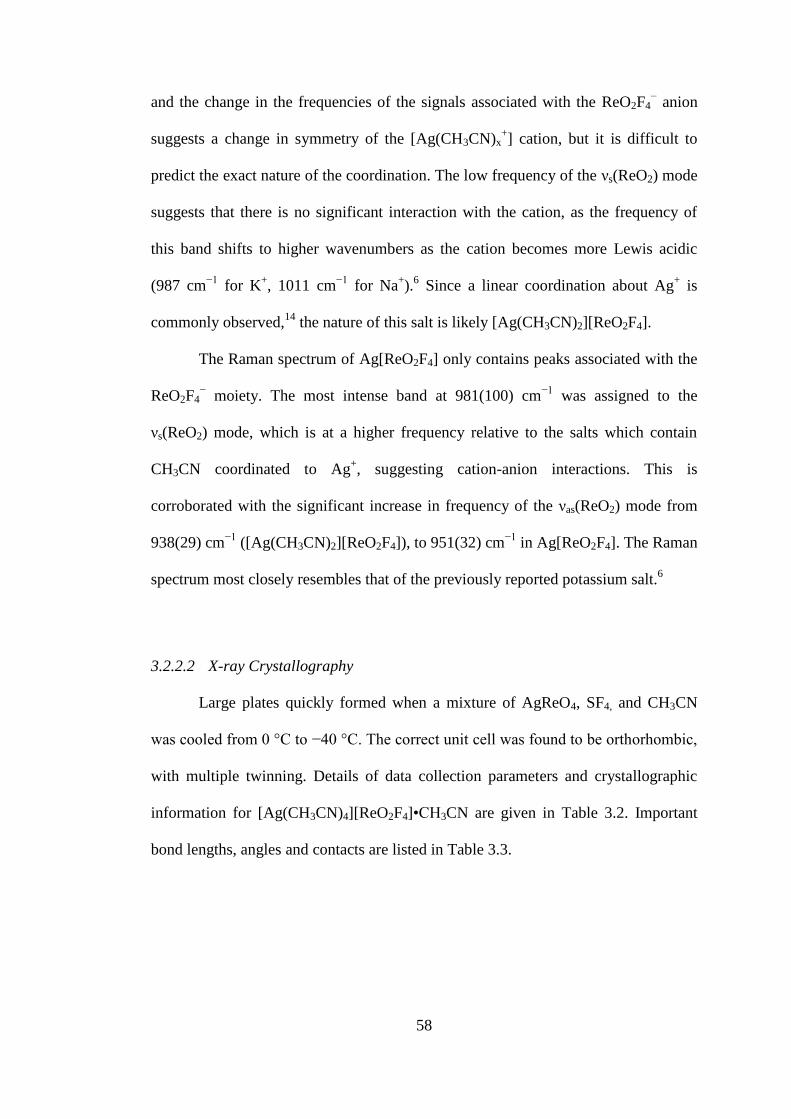
58
and the change in the frequencies of the signals associated with the ReO2F4− anion
suggests a change in symmetry of the [Ag(CH3CN)x+] cation, but it is difficult to
predict the exact nature of the coordination. The low frequency of the νs(ReO2) mode
suggests that there is no significant interaction with the cation, as the frequency of
this band shifts to higher wavenumbers as the cation becomes more Lewis acidic
(987 cm−1
for K+, 1011 cm
−1 for Na
+).
6 Since a linear coordination about Ag
+ is
commonly observed,14
the nature of this salt is likely [Ag(CH3CN)2][ReO2F4].
The Raman spectrum of Ag[ReO2F4] only contains peaks associated with the
ReO2F4− moiety. The most intense band at 981(100) cm
−1 was assigned to the
νs(ReO2) mode, which is at a higher frequency relative to the salts which contain
CH3CN coordinated to Ag+, suggesting cation-anion interactions. This is
corroborated with the significant increase in frequency of the νas(ReO2) mode from
938(29) cm−1
([Ag(CH3CN)2][ReO2F4]), to 951(32) cm−1
in Ag[ReO2F4]. The Raman
spectrum most closely resembles that of the previously reported potassium salt.6
3.2.2.2 X-ray Crystallography
Large plates quickly formed when a mixture of AgReO4, SF4, and CH3CN
was cooled from 0 °C to −40 °C. The correct unit cell was found to be orthorhombic,
with multiple twinning. Details of data collection parameters and crystallographic
information for [Ag(CH3CN)4][ReO2F4]•CH3CN are given in Table 3.2. Important
bond lengths, angles and contacts are listed in Table 3.3.
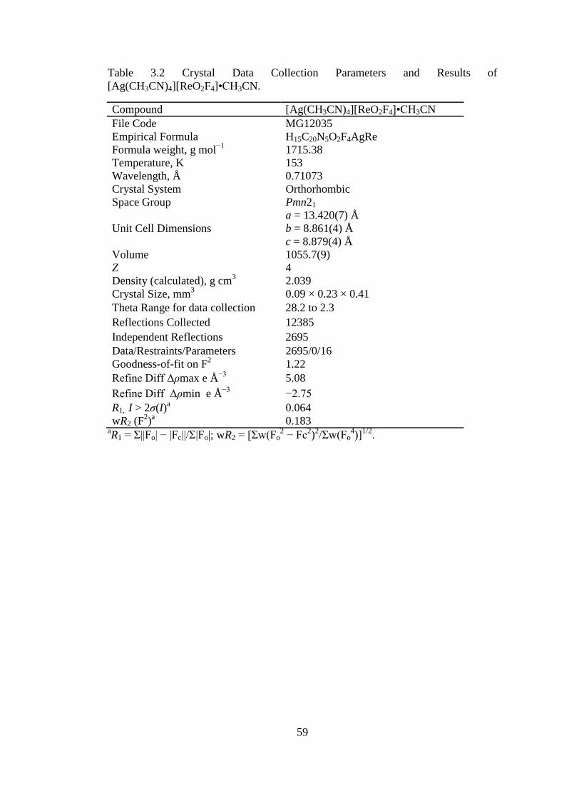
59
Table 3.2 Crystal Data Collection Parameters and Results of
[Ag(CH3CN)4][ReO2F4]•CH3CN.
Compound [Ag(CH3CN)4][ReO2F4]•CH3CN
File Code MG12035
Empirical Formula H15C20N5O2F4AgRe
Formula weight, g mol−1
1715.38
Temperature, K 153
Wavelength, Å 0.71073
Crystal System Orthorhombic
Space Group Pmn21
Unit Cell Dimensions
a = 13.420(7) Å
b = 8.861(4) Å
c = 8.879(4) Å
Volume 1055.7(9)
Z 4
Density (calculated), g cm3 2.039
Crystal Size, mm3 0.09 × 0.23 × 0.41
Theta Range for data collection 28.2 to 2.3
Reflections Collected 12385
Independent Reflections 2695
Data/Restraints/Parameters 2695/0/16
Goodness-of-fit on F2 1.22
Refine Diff Δρmax e Å−3
5.08
Refine Diff Δρmin e Å−3
−2.75
R1, I > 2σ(I)a
0.064
wR2 (F2)a
0.183 aR1 = Σ||Fo| − |Fc||/Σ|Fo|; wR2 = [Σw(Fo
2 − Fc
2)2/Σw(Fo
4)]
1/2.
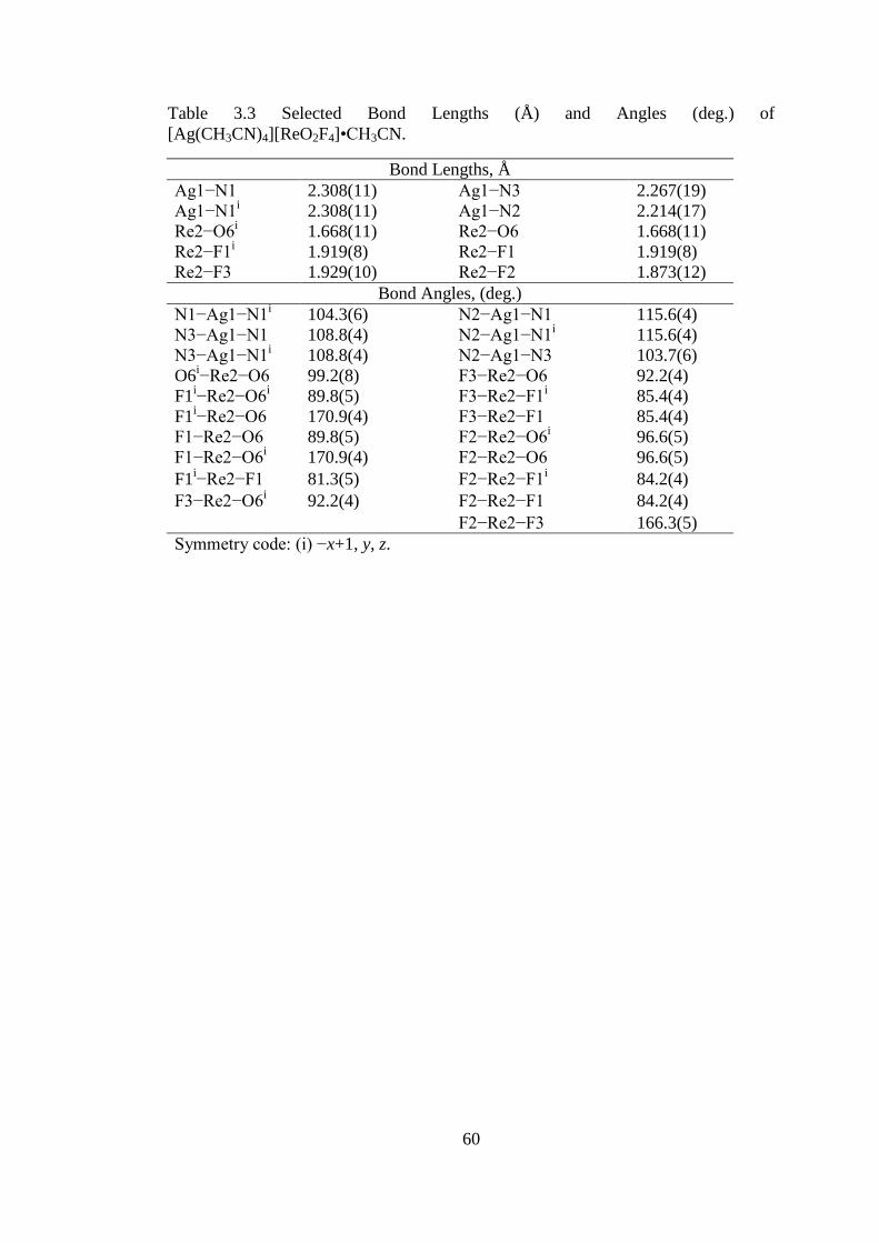
60
Table 3.3 Selected Bond Lengths (Å) and Angles (deg.) of
[Ag(CH3CN)4][ReO2F4]•CH3CN.
Bond Lengths, Å
Ag1−N1 2.308(11) Ag1−N3 2.267(19)
Ag1−N1i 2.308(11) Ag1−N2 2.214(17)
Re2−O6i 1.668(11) Re2−O6 1.668(11)
Re2−F1i 1.919(8) Re2−F1 1.919(8)
Re2−F3 1.929(10) Re2−F2 1.873(12)
Bond Angles, (deg.)
N1−Ag1−N1i 104.3(6) N2−Ag1−N1 115.6(4)
N3−Ag1−N1 108.8(4) N2−Ag1−N1i 115.6(4)
N3−Ag1−N1i 108.8(4) N2−Ag1−N3 103.7(6)
O6i−Re2−O6 99.2(8) F3−Re2−O6 92.2(4)
F1i−Re2−O6
i 89.8(5) F3−Re2−F1
i 85.4(4)
F1i−Re2−O6 170.9(4) F3−Re2−F1 85.4(4)
F1−Re2−O6 89.8(5) F2−Re2−O6i 96.6(5)
F1−Re2−O6i 170.9(4) F2−Re2−O6 96.6(5)
F1i−Re2−F1 81.3(5) F2−Re2−F1
i 84.2(4)
F3−Re2−O6i 92.2(4) F2−Re2−F1 84.2(4)
F2−Re2−F3 166.3(5)
Symmetry code: (i) −x+1, y, z.

61
The structure consists of well separated ReO2F4− anions, which adopt the cis-
conformation, and a silver cation coordinated by four acetonitrile ligands, forming a
tetrahedral geometry around silver (see Figure 3.2).
Figure 3.2 Thermal ellipsoid plot of [Ag(CH3CN)4][ReO2F4]•CH3CN. Thermal
ellipsoids are set to 50% probability.
An additional “free” acetonitrile co-crystallizes in this salt. The cis-ReO2F4− anion
adopts a distorted octahedral geometry, in which the axial fluorines are pushed
towards the equatorial fluorines. The ReF2ax moieties lie along a mirror plane, and
therefore the equatorial Re−O bonds, as well as the Re−Feq bonds, are
crystallographically equivalent. The bond lengths agree well with those of the
previously reported Li+ salt. The Li
+ cation has six Li---F (2.04(3) to 2.108(7) Å)

62
contacts in an octahedral geometry.6 For the [Ag(CH3CN)4][ReO2F4]•CH3CN salt no
significant cation-anion contacts are observed, since acetonitrile molecules separate
the cations from the anions. The limited number of crystal structures which contain
four acetonitriles coordinated to Ag(I) cations, contain counter-anions which are
weakly coordinating, such as BF4−.15
The Re−O bonds (1.668(11) Å) are significantly shorter than the Re−Feq
(1.919(8) Å) and the Re−Fax bonds (1.929(10), 1.873(12) Å). These values agree
with the Li[ReO2F4] salt (Re−Feq = 1.867(8) Å and Re−Fax = 2.002(7) Å), except for
the distortion of one of Re−Fax bonds.6 The cis-dioxo arrangement is favored in
Re(VII) oxide-fluoride species and has been studied in depth by vibrational and 19
F
NMR spectroscopies.6,16
3.2.3 K[IO2F4]
The Raman frequencies and tentative assignments for this known salt are
listed in the experimental chapter. The Raman frequencies and intensities agree very
well with what has previously been reported by Gillespie and Krasznai,17
Boatz et
al.,12
and Christe et al.18
The Raman spectrum contains signals associated with both
the cis and trans-IO2F4− anion. The assignment of the signals for the two isomers are
based on the previous assignments made by Boatz et al. for the N(CH3)4+ and Cs
+
salts, who were able to separate the two stereoisomers.12
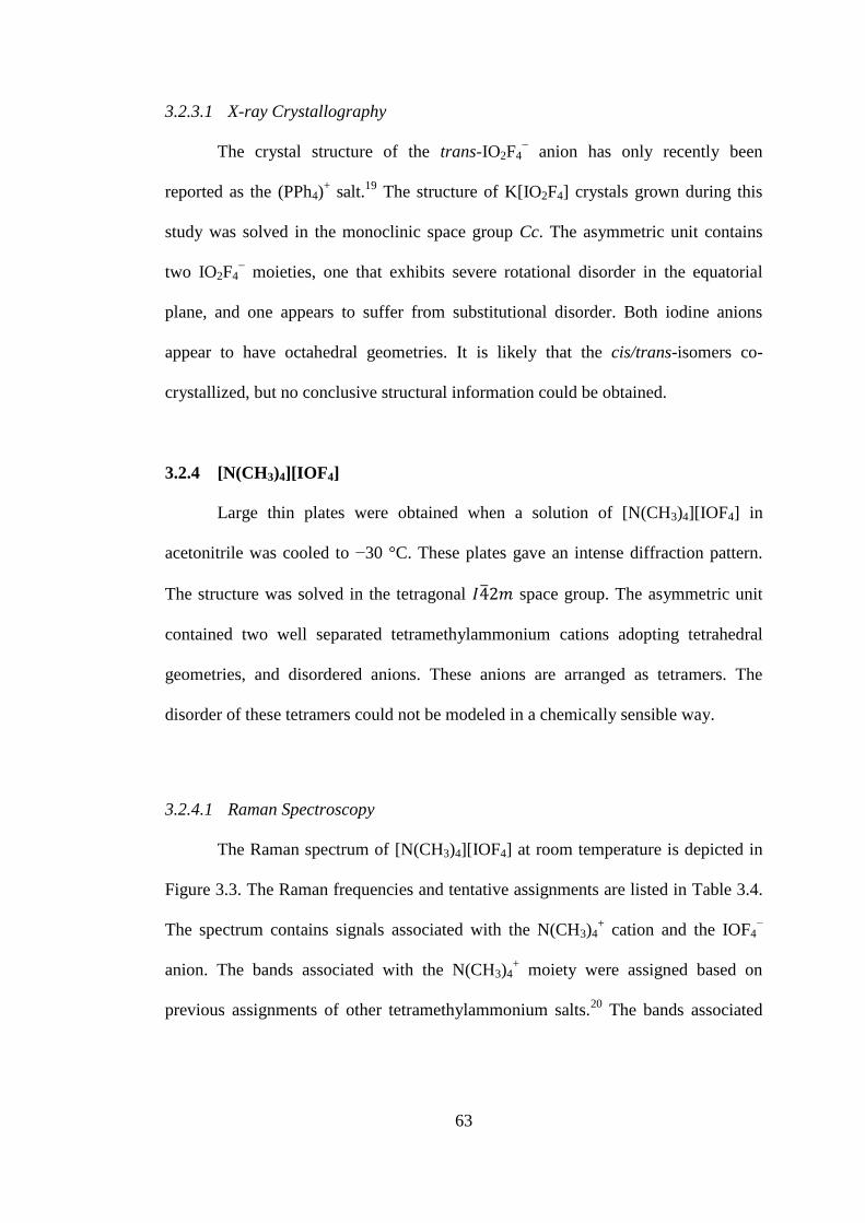
63
3.2.3.1 X-ray Crystallography
The crystal structure of the trans-IO2F4− anion has only recently been
reported as the (PPh4)+ salt.
19 The structure of K[IO2F4] crystals grown during this
study was solved in the monoclinic space group Cc. The asymmetric unit contains
two IO2F4− moieties, one that exhibits severe rotational disorder in the equatorial
plane, and one appears to suffer from substitutional disorder. Both iodine anions
appear to have octahedral geometries. It is likely that the cis/trans-isomers co-
crystallized, but no conclusive structural information could be obtained.
3.2.4 [N(CH3)4][IOF4]
Large thin plates were obtained when a solution of [N(CH3)4][IOF4] in
acetonitrile was cooled to −30 °C. These plates gave an intense diffraction pattern.
The structure was solved in the tetragonal ̅ space group. The asymmetric unit
contained two well separated tetramethylammonium cations adopting tetrahedral
geometries, and disordered anions. These anions are arranged as tetramers. The
disorder of these tetramers could not be modeled in a chemically sensible way.
3.2.4.1 Raman Spectroscopy
The Raman spectrum of [N(CH3)4][IOF4] at room temperature is depicted in
Figure 3.3. The Raman frequencies and tentative assignments are listed in Table 3.4.
The spectrum contains signals associated with the N(CH3)4+ cation and the IOF4
−
anion. The bands associated with the N(CH3)4+ moiety were assigned based on
previous assignments of other tetramethylammonium salts.20
The bands associated

64
with the IOF4− anion were assigned based on the assignments for the previously
reported Cs[IOF4] salt.10
Figure 3.3 Raman spectrum of [N(CH3)4][IOF4]. Asterisks (*) denote bands arising
from the FEP sample tube. Daggers (†) denote bands arising from the [N(CH3)4+]
cation.
The most intense band in the Raman spectrum at 901(100) cm−1
can be
assigned to the ν(I−O) mode, and is in good agreement with that of the Cs[IOF4] salt
(888 cm−1
). The in-phase νs (IF4) mode was assigned to the band at 526(45) cm−1
and
is in good agreement with the Cs[IOF4] salt (533 cm−1
).

65
Table 3.4 Raman Frequencies (cm1
) and Tentative Assignments of [N(CH3)4][IOF4].
[N(CH3)4][IOF4] CsIOF4b
Assignment
3039(25)
2980(11)
2960(23) C−H stretch
2920(9)
2882(5)
2811(6)
1531(1)
1497(2)
1470(33) CH3 deformation
1464(24)
1412(7)
1286(4)
1175(6) C−N stretching modes
1070(2)
948(28) N(CH3)4+
901(100) 888 vs ν(I−O)
756(24) νs(NC4)
526(45) 533 vs νs(IF4) in phase
484(15) 485 s νas(IF4)
449(22) 475 m νs(IF4) out of phase
376(5) s(NC4)
345(28) 365 ms (OF4) wag
263(7) 273 w s(IF4) umbrella
204(8) 214 w s(IF4) in plane
180(3)
143(4) 124 w as(IF4) in plane a Signals from the FEP sample tube were observed at: 1380(3), 1214(1), 733(13),
526(overlap), 385(5), 291(3) cm−1
. b From reference 10.

66
3.3 Summary and Conclusions
The reaction of transition-metal and main-group oxo-anions with SF4
conveniently formed ReVII
, IVII
, and IV oxide fluoride anions. These reactions occur
in acetonitrile or anhydrous HF and give quantitative yields in a single step. The
byproducts and solvents are easily removed under dynamic vacuum at low
temperatures, or in the case of the [Ag(CH3CN)x]+ cation, upon mild heating. The
Ag[ReO2F4] salt was characterized by Raman spectroscopy for the first time.
Although the Ag[ReO2F4] salt had been previously prepared, it had only been
characterized by crude elemental analysis. The new
[Ag(CH3CN)4][ReO2F4]•CH3CN salt was characterized by low-temperature Raman
and X-ray crystallography. The new [N(CH3)4][IOF4] salt was synthesized and
characterized by Raman spectroscopy.

67
References
(1) Dmowski, W. Introduction of Fluorine Using Sulfur Tetrfluoride and Analogs
In Organo-Fluorine Compounds; Baasner, B.; Hagemann, H.; Tatlow, J. C.,
Eds.; Methods of Organic Chemistry, Houben-Weyl, Vol. E10a; Thieme:
Stuttgart, 2000; Ch. 8, pp. 321-431.
(2) Oppegard, A. L.; Smith, W. C.; Muetterties, E. L.; Engelhardt, V. A. J. Am.
Chem. Soc. 1960, 82, 3835-3838.
(3) Smith, W. C.; Engelhardt, V. A. J. Am. Chem. Soc. 1960, 82, 3838-3840.
(4) Gerken, M.; Mercier, H. P. A.; Schrobilgen, G. J. Syntheses and Structures of
the Oxide Fluorides of the Main-Group and Transition Metal Elements In
Advanced Inorganic Fluorides; Nakajima, T.; Zemva, B., Eds.; Tressaud, A.,
Elsevier: Lausanne, 2000, Ch. 5, pp. 117-174.
(5) Peacock, R. D. J. Chem. Soc. 1955, 602-603.
(6) Casteel, W. J.; Dixon, D. A.; LeBlond, N.; Lock, P. E.; Mercier, H. P. A.;
Schrobilgen, G. J. Inorg. Chem. 1999, 38, 2340-2358.
(7) Brisdon, A. K.; Holloway, J. H.; Hope, E. G. J. Fluorine Chem. 1998, 89, 35-
37.
(8) Supeł, J.; Marx, R.; Seppelt, K. Z. Anorg. Allg. Chem. 2005, 631, 2979-2986.
(9) Selig, H.; El-Gad, U. J. Inorg. Nucl. Chem. 1973, 35, 3517-3522.
(10) Milne, J. B.; Moffett, D. M. Inorg. Chem. 1976, 15, 2165-2169.
(11) Ryan, R. R.; Asprey, L. B. Acta Crystallogr. B 1972, 28, 979-981.
(12) Boatz, J. A.; Christe, K. O.; Dixon, D. A.; Fir, B. A.; Gerken, M.; Gnann, R.
Z.; Mercier, H. P. A.; Schrobilgen, G. J. Inorg. Chem. 2003, 42, 5282-5292.

68
(13) Reedijk, J.; Zuur, A. P.; Groeneveld, W. L. Recl. Trav. Chim. Pays-Bas 1967,
86, 1127-1137.
(14) Shoeib, T.; El, A. H.; Siu, K. W. M.; Hopkinson, A. C. J. Phys. Chem. A
2001, 105, 710-719.
(15) Aly, A.; Walfort, B.; Lang, H. Z. Kristallogr. - New Cryst. Struct. 2004, 219,
489-491.
(16) Kuhlmann, W.; Sawodny, W. J. Fluorine Chem. 1977, 9, 341-357.
(17) Gillespie, R. J.; Krasznai, J. P. Inorg. Chem. 1977, 16, 1384-1392.
(18) Christe, K. O.; Wilson, R. D.; Schack, C. J. Inorg. Chem. 1981, 20, 2104-
2114.
(19) Christe, K. O.; Haiges, R. In 21st Winterfluorine Conference St. Petersburg,
Florida, Abstract IL-6, 2013.
(20) Kabisch, G. J. Raman Spectrosc. 1980, 9, 279-285.
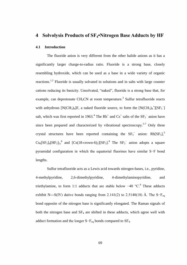
69
4 Solvolysis Products of SF4•Nitrogen Base Adducts by HF
4.1 Introduction
The fluoride anion is very different from the other halide anions as it has a
significantly larger charge-to-radius ratio. Fluoride is a strong base, closely
resembling hydroxide, which can be used as a base in a wide variety of organic
reactions.1,2
Fluoride is usually solvated in solutions and in salts with large counter
cations reducing its basicity. Unsolvated, “naked”, fluoride is a strong base that, for
example, can deprotonate CH3CN at room temperature.3 Sulfur tetrafluoride reacts
with anhydrous [N(CH3)4]F, a naked fluoride source, to form the [N(CH3)4+][SF5
−]
salt, which was first reported in 1963.4 The Rb
+ and Cs
+ salts of the SF5
− anion have
since been prepared and characterized by vibrational spectroscopy.5-7
Only three
crystal structures have been reported containing the SF5− anion: Rb[SF5],
5
Cs6[SF5]4[HF2]2,8 and [Cs(18-crown-6)2][SF5].
8 The SF5
− anion adopts a square
pyramidal configuration in which the equatorial fluorines have similar S−F bond
lengths.
Sulfur tetrafluoride acts as a Lewis acid towards nitrogen-bases, i.e., pyridine,
4-methylpyridine, 2,6-dimethylpyridine, 4-dimethylaminopyridine, and
triethylamine, to form 1:1 adducts that are stable below −40 °C.9 These adducts
exhibit N---S(IV) dative bonds ranging from 2.141(2) to 2.5140(18) Å. The S−Feq
bond opposite of the nitrogen base is significantly elongated. The Raman signals of
both the nitrogen base and SF4 are shifted in these adducts, which agree well with
adduct formation and the longer S−Feq bonds compared to SF4.

70
Both anhydrous hydrogen fluoride (aHF) and SF4 are used as fluorinating
agents in organic chemistry. Due to the difficulties associated with handling aHF, a
mixture of pyridine and HF is often used.10
Mixtures of pyridine with varying
amounts of HF (C5H5N•nHF, where n = 1, 2, 3, 4) have been structurally
characterized by X-ray crystallography.11
The N−H bond distance decreases from
1.34 Å in C5H5N•HF to 0.87 Å in C5H5N•4HF. This trend is accompanied by an
increase of the N(H)---F distance from 2.472 Å for C5H5N•HF to 2.793 Å for
C5H5N•4HF. This can be explained by the decrease in Lewis basicity as the size of
the polyfluoride anion (HnF−
n+1 where n = 1, 2, 3, 4) increases. Sulfur tetrafluoride
almost always contains traces of HF due to the presence of moisture and HF is
sometimes purposely added to the reaction mixture. Several mechanisms have been
proposed for the fluorination of carbonyl and hydroxyl groups by SF4 containing HF
in the reaction mixture (see Introduction). In contrast to the acidic conditions of
fluorination using SF4/HF mixtures, certain carbonyl, and hydroxyl containing
molecules, are fluorinated with SF4 in the presence of bases, such as triethylamine,
pyridine, or KF.12,13
To the best of my knowledge, no mechanism has been reported
on the fluorination of organic carbonyl and hydroxyl groups with SF4 under basic
conditions. Therefore, the study of the SF4-HF-nitrogen-base reaction system may
help in expanding our knowledge about species present in such reactions.
4.2 Results and Discussion
4.2.1 General Synthetic Approach
Initial attempts to recrystallize adducts between SF4 and nitrogen-bases
(pyridine, 4-methylpyridine, and 2,6-dimethylpyridine) from toluene, which was
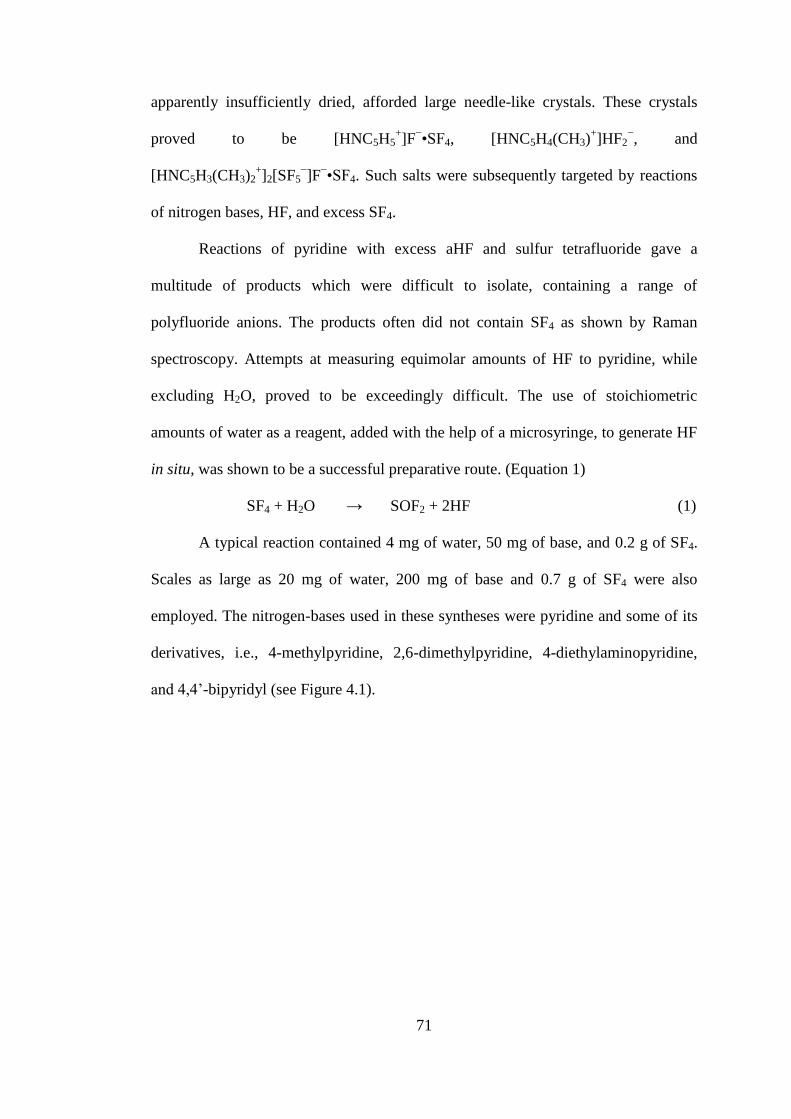
71
apparently insufficiently dried, afforded large needle-like crystals. These crystals
proved to be [HNC5H5+]F
−•SF4, [HNC5H4(CH3)
+]HF2
−, and
[HNC5H3(CH3)2+]2[SF5
−]F
−•SF4. Such salts were subsequently targeted by reactions
of nitrogen bases, HF, and excess SF4.
Reactions of pyridine with excess aHF and sulfur tetrafluoride gave a
multitude of products which were difficult to isolate, containing a range of
polyfluoride anions. The products often did not contain SF4 as shown by Raman
spectroscopy. Attempts at measuring equimolar amounts of HF to pyridine, while
excluding H2O, proved to be exceedingly difficult. The use of stoichiometric
amounts of water as a reagent, added with the help of a microsyringe, to generate HF
in situ, was shown to be a successful preparative route. (Equation 1)
SF4 + H2O → SOF2 + 2HF (1)
A typical reaction contained 4 mg of water, 50 mg of base, and 0.2 g of SF4.
Scales as large as 20 mg of water, 200 mg of base and 0.7 g of SF4 were also
employed. The nitrogen-bases used in these syntheses were pyridine and some of its
derivatives, i.e., 4-methylpyridine, 2,6-dimethylpyridine, 4-diethylaminopyridine,
and 4,4’-bipyridyl (see Figure 4.1).
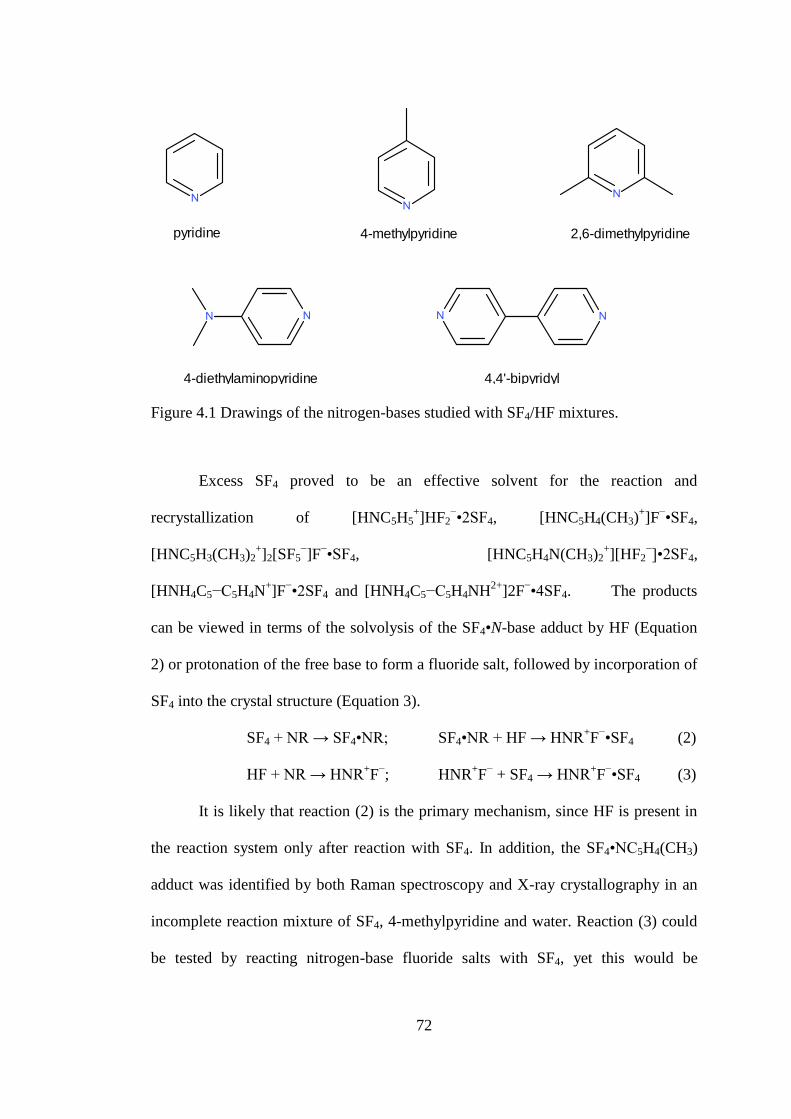
72
pyridine 4-methylpyridine 2,6-dimethylpyridine
4-diethylaminopyridine 4,4'-bipyridyl
Figure 4.1 Drawings of the nitrogen-bases studied with SF4/HF mixtures.
Excess SF4 proved to be an effective solvent for the reaction and
recrystallization of [HNC5H5+]HF2
−•2SF4, [HNC5H4(CH3)
+]F
−•SF4,
[HNC5H3(CH3)2+]2[SF5
−]F
−•SF4, [HNC5H4N(CH3)2
+][HF2
−]•2SF4,
[HNH4C5−C5H4N+]F
−•2SF4 and [HNH4C5−C5H4NH
2+]2F
−•4SF4. The products
can be viewed in terms of the solvolysis of the SF4•N-base adduct by HF (Equation
2) or protonation of the free base to form a fluoride salt, followed by incorporation of
SF4 into the crystal structure (Equation 3).
SF4 + NR → SF4•NR; SF4•NR + HF → HNR+F−•SF4 (2)
HF + NR → HNR+F−; HNR
+F− + SF4 → HNR
+F−•SF4 (3)
It is likely that reaction (2) is the primary mechanism, since HF is present in
the reaction system only after reaction with SF4. In addition, the SF4•NC5H4(CH3)
adduct was identified by both Raman spectroscopy and X-ray crystallography in an
incomplete reaction mixture of SF4, 4-methylpyridine and water. Reaction (3) could
be tested by reacting nitrogen-base fluoride salts with SF4, yet this would be

73
challenging because of the difficulties associated with isolating the 1:1 nitrogen-base
to HF salts, due to the formation of polyfluoride anions.10,11
When dichloromethane
is used as a solvent in conjunction with nitrogen-bases, care must be taken to avoid
the formation of methylenebispyridinium dichloride compounds.14
4.2.2 Pyridine-HF-SF4 System
Large needle-like crystals were obtained by recrystallization of the
SF4•NC5H5 adduct in toluene between −60 and −80 °C. Instead of the anticipated
structure of SF4•NC5H5, the crystal structure of [HNC5H5+]F
−•SF4 was obtained.
Apparently water in the toluene hydrolyzed SF4 producing HF (see Equation 1)
which then solvolyzed the SF4•NC5H5 adduct. Attempts to obtain crystals of
[HNC5H5+]F
−•SF4 were unsuccessful when SF4 was used as a solvent. Instead,
crystals of the [HNC5H5+]HF2
−•2SF4 salt always formed, even when a deficiency of
water was used. When an excess of pyridine was used, in order to ensure the
selective formation of [HNC5H5+]F
−•SF4 and not [HNC5H5
+][HF2
−]•2SF4, a signal
attributable to the SF4•NC5H5 adduct was observed in the Raman spectrum. The
[HNC5H5+][HF2
−]•2SF4 salt is soluble in SF4, whereas it is quite possible the
[HNC5H5+]F
−•SF4 is insoluble. For the [HNC5H5
+][HF2
−]•2SF4 salt, crystals were
grown by slow cooling of the pyridine, water, and excess SF4 mixture from ambient
temperature to −80 °C. Excess SF4 and SOF2 were removed at −90 °C.
4.2.2.1 X−ray Crystal Structures of [HNC5H5+]F
−•SF4 and [HNC5H5
+]HF2
−•2SF4.
Details of data collection parameters and crystallographic information for
[HNC5H5+]F
−•SF4 and [HNC5H5
+]HF2
−•2SF4 are given in Table 4.1. Important bond

74
lengths, angles and contacts for [HNC5H5+]F
−•SF4 and [HNC5H5
+]HF2
−•2SF4 are
given in Table 4.2 and Table 4.3.
Table 4.1 Crystal Data Collection Parameters and Results of [HNC5H5+]F
−•SF4 and
[HNC5H5+]HF2
−•2SF4
Compound [HNC5H5+]F
−•SF4 [HNC5H5
+]HF2
−•2SF4
File Code MG11019 MG12051
Empirical Formula H6C5F5NS C5H7F10NS2
Formula weight, g mol−1
207.17 335.24
Temperature, K 153 153
Crystal System Orthorhombic Monoclinic
Space Group Pbca C2/m
Unit Cell Dimensions a = 13.919 (4) Å
b = 13.681 (4) Å
c = 17.101 (4) Å
a = 16.366 (11) Å
b = 8.794 (6) Å
c = 8.842 (6) Å
β = 116.566 (7)°
μ (mm−1
) 0.43 0.58
Volume Å3 3256.4(15) 1138.1 (13)
Z 16 4
Density (calculated), g cm−3
1.690 1.956
F(000) 1664 664
Crystal Size, mm3 1.38 × 0.36 × 0.31 0.29 × 0.12 × 0.08
Reflections Collected 35850 6509
Independent Reflections 4062 [Rint = 0.025] 1385 [Rint = 0.041]
Data/Restraints/Parameters 4062/0/225 1385/0/91
Goodness-of-fit on F2 1.09 1.03
Refine Diff Δρmax e Å−3
0.23 0.86
Refine Diff Δρmin e Å−3
−0.37 −0.60
R1, I > 2σ(I)a
0.0298 0.0466
wR2 (F2)a
0.0936 0.1089 aR1 = Σ||Fo| − |Fc||/Σ|Fo|; wR2 = [Σw(Fo
2 − Fc
2)2/Σw(Fo
4)]
1/2.

75
Table 4.2 Bond Lengths (Å), Contacts (Å), and Angles (deg.) of [HNC5H5+]F
−•SF4.
Bond Lengths and Contacts, Å
S1−F3 1.5398(9) S2−F7 1.5382(9)
S1−F2 1.5425(9) S2−F6 1.5440(9)
S1−F1 1.6622(11) S2−F5 1.6632(11)
S1−F4 1.6680(11) S2−F8 1.6671(11)
S1---F9 2.6826(9) S2---F9 2.8241(9)
S1---F10 2.7739(9) S2---F10 2.6923(9)
N1(H)---F9 2.4367(13) N2(H)---F10 2.4376(13)
C9(H)---F9 3.290 (2)
Bond Angles, deg.
F3−S1−F2 98.49(5) F7−S2−F6 98.69(6)
F3−S1−F1 87.10(5) F7−S2−F5 87.36(5)
F2−S1−F1 87.48(5) F6−S2−F5 87.46(5)
F3−S1−F4 87.49(6) F7−S2−F8 87.16(5)
F2−S1−F4 87.53(5) F6−S2−F8 87.53(5)
F1−S1−F4 172.03(5) F5−S2−F8 171.93(5)
F3−S1−F9 78.70(4) F7−S2−F10 78.59(5)
F2−S1−F9 176.49(4) F6−S2−F10 177.23(4)
F1−S1−F9 90.25(4) F5−S2−F10 91.84(4)
F4−S1−F9 94.42(4) F8−S2−F10 92.87(4)
F3−S1−F10 176.94(4) N1−F9−S1 105.59(4)
F2−S1−F10 78.46(4) N2−F10−S2 106.97(4)
F1−S1−F10 92.96(4) N2−F10−S1 90.56(4)
F4−S1−F10 92.14(4) S2−F10−S1 161.76(3)
F9---S1---F10 104.35(3)

76
Table 4.3 Bond Lengths (Å), Contacts (Å), and Angles (deg.) of
[HNC5H5+][HF2
−]•2SF4.
Bond Lengths and Contacts, Å
S1−F2 1.537(2) S2−F5ii 1.535(2)
S1−F2i 1.537(2) S2−F5 1.535(2)
S1−F3 1.643(3) S2−F6 1.652(3)
S1−F1 1.648(3) S2−F4 1.670(3)
S1---F7 2.876(3) S2---F7 2.840(3)
N1(H)---F 2.937(5) F7---N1 2.937(5)
F7-(H)-F7iii
2.241(7) N1−N1i 1.345(6)
Bond Angles, deg.
F2−S1−F2i 99.71(17) F5
ii−S2−F5 99.47(18)
F2−S1−F3 86.54(13) F5ii−S2−F6 87.14(13)
F2i−S1−F3 86.54(13) F5−S2−F6 87.14(13)
F2−S1−F1 87.80(13) F5ii−S2−F4 86.98(12)
F2i−S1−F1 87.80(13) F5−S2−F4 86.98(12)
F3−S1−F1 171.21(18) F6−S2−F4 170.90(19)
F5ii−S2−F7 174.02(12) S2−F7−S1 172.33(11)
F5−S2−F7 76.09(12) F7iii−F7---N1 142.73(13)
F6−S2−F7 96.54(11) S2−F7---N1 95.28(13)
F4−S2−F7 88.78(11) S1−F7---N1 87.56(11)
F7iii−F7−S2 96.70(11) N1
i−N1−C2 120.85(18)
F7iii−F7−S1 85.20(14) N1
i−N1−F7 119.06(8)
F2−S1−F7 171.14(13) C2−N1---F7 119.4(2)
F2i−S1−F7 82.65(11) N1−C2−C3 119.7(3)
F3−S1−F7 102.17(12) F7---S1---F7iii
93.8(1)
F1−S1−F7 83.75(12) F7---S2---F7iii
108.0(1)
Symmetry codes: (i) x, −y, z; (ii) x, −y+1, z; (iii) −x+1, y, −z+1.
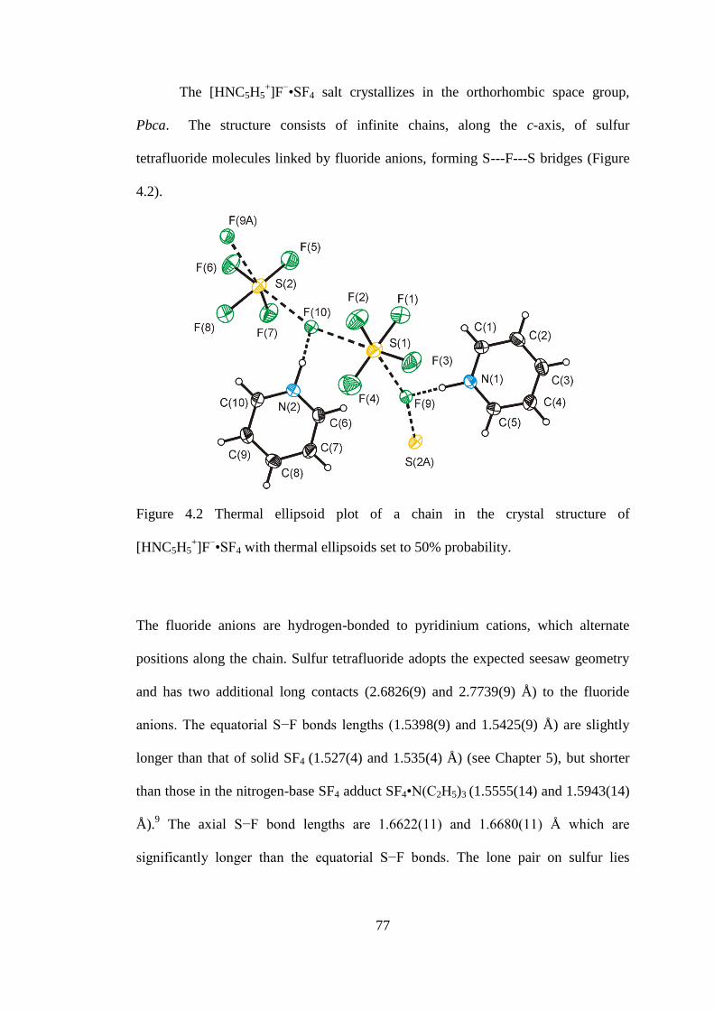
77
The [HNC5H5+]F
−•SF4 salt crystallizes in the orthorhombic space group,
Pbca. The structure consists of infinite chains, along the c-axis, of sulfur
tetrafluoride molecules linked by fluoride anions, forming S---F---S bridges (Figure
4.2).
Figure 4.2 Thermal ellipsoid plot of a chain in the crystal structure of
[HNC5H5+]F
−•SF4 with thermal ellipsoids set to 50% probability.
The fluoride anions are hydrogen-bonded to pyridinium cations, which alternate
positions along the chain. Sulfur tetrafluoride adopts the expected seesaw geometry
and has two additional long contacts (2.6826(9) and 2.7739(9) Å) to the fluoride
anions. The equatorial S−F bonds lengths (1.5398(9) and 1.5425(9) Å) are slightly
longer than that of solid SF4 (1.527(4) and 1.535(4) Å) (see Chapter 5), but shorter
than those in the nitrogen-base SF4 adduct SF4•N(C2H5)3 (1.5555(14) and 1.5943(14)
Å).9 The axial S−F bond lengths are 1.6622(11) and 1.6680(11) Å which are
significantly longer than the equatorial S−F bonds. The lone pair on sulfur lies

78
between the two S---F contacts, resulting in a large F---S---F contact angle of
104.35(3)°. The N1(H)---F9 distance (2.4367(13) Å) in the [HNC5H5+]F
−•SF4 salt
agrees well with that of the C5H5N•HF salt (2.472 Å).11
Infinite chains bridged by
weak fluorine bridges are quite common structural motifs with molecular species
which contain open coordination sites. For example group 17 fluorides,15
[BrF4+][Sb2F11
−],
16 and TeF4 form fluorine-bridges in the solid state.
17
The [HNC5H5+][HF2
−]•2SF4 salt crystallizes in the monoclinic space group
C2/m. The structure consists of a sulfur fluoride double chain composed of
alternating SF4 and HF2− molecules with pyridinium cations hydrogen-bonded to a
bifluoride anion. (Figure 4.3)
Figure 4.3 Thermal ellipsoid plot of the [HNC5H5+][HF2
−]•2SF4 double chain. The
fluorines bound to S(1A), S(2A) and S(1B) are omitted for clarity. Thermal
ellipsoids are set to 50% probability. The pyridinium cations are disordered where
half the time the ring is rotated by 60° and hydrogen bonded to adjacent bifluoride
anions.

79
The pyridinium cation exhibits an orientational disorder where half the time it
is hydrogen-bonded to one bifluoride, and the other half of the time it is shifted by
60° and hydrogen-bonded to the adjacent bifluoride. This disorder is imposed by a
mirror plane, which relates the C1 and N1 atoms with a site occupancy of 50% each.
The equatorial S−F bond lengths (S1−F2 = 1.537(2) Å and S2−F5 = 1.535(2) Å) in
both SF4 molecules are identical since both SF2ax moieties lie in mirror planes, that
bisect the SF2eq angles. The axial S−F bond lengths range from 1.643(3) to 1.670(3)
Å. All of the S−F bond lengths agree within experimental error with that of neat SF4.
Along the b-axis, the pyridine rings, bifluoride and both SF4 molecules pack in a
parallel fashion.
The N(H)---F (2.937(5) Å) and the S---F (2.840(3) to 2.876(3) Å) distances
are much longer in the bifluoride structure than those found in [HNC5H5+]F
−•SF4
((N(H)---F = 2.4367(13) Å and S---F = 2.6826(9) Å). This agrees with the much
weaker basicity of bifluoride compared to that of fluoride. These long contacts reflect
the relative instability of the crystals towards loss of SF4 which was observed when
handling the crystals in the cold trough at −80 °C while selecting crystals. The N(H)-
--F contacts are much longer than those found in pyridinium bifluoride (2.508 Å) and
also 4-methylpyridinium bifluoride (2.533(4) Å) (vide infra), and could be imposed
by the pyridinium ring disorder. The pyridinium disorder has also an effect on the
polarization of the bifluoride anion. Depending which side of the anion the
pyridinium is hydrogen-bonded to, i.e., F1−H---F2---HNC5H5+ and NC5H5H
+---F1---
H−F2, the hydrogen in HF2− will be closer to one or the other fluorine atom. As the
consequence of these two superimposed structures, the hydrogen in the bifluoride
anion is supposedly disordered over two positions and could not be located in the
80
difference map and the thermal ellipsoids of the fluorines are elongated. The F---F
distance in bifluoride is 2.241(7) Å which is shorter than the F---F distance found in
pyridinium bifluoride (2.326 Å), or 4-methylpyridinium bifluoride (2.322(4) Å). The
F---S---F contact angles alternate from 93.8(1) ° (S1), and 108.0(1) ° (S2). The small
angle occurs between two adjacent bifluorides that are hydrogen-bonded to the same
disordered pyridinium cations, while the large angle is observed when the bifluorides
are hydrogen-bonded to two different pyridinium cations.
4.2.2.2 Raman Spectroscopy
Raman spectroscopy on the [HNC5H5+]F
−•SF4 salt was unsuccessful due to the
intense signals of toluene, surrounding the crystallized sample, which dominated the
spectrum. The Raman spectrum of [HNC5H5+][HF2
−]•2SF4 was acquired at −97 °C
(Figure 4.4). The observed vibrational frequencies and their tentative assignments for
[HNC5H5+][HF2
−]•2SF4 can be found in Table 4.4. The assignment of Raman bands
associated with the pyridinium cation is based on that previously reported for
pyridinium salts.18
Comparisons could also be made with the Raman spectrum of the
SF4•NC5H5 adduct, previously assigned with the aid of computational chemistry.

81
Figure 4.4 Raman spectrum of [HNC5H5+][HF2
−]•2SF4. Asterisks (*) denote bands
arising from the FEP sample tube.
The N−H stretching band could not be located in the Raman spectrum of
[HNC5H5+][HF2
−]•2SF4. The N−H stretching band in Raman spectra is known to
vary greatly in intensity, broadness and frequency, depending on the counter-anion.
This is because the nature of the anion determines the type of interaction between the
proton and the nitrogen.19
The most intense peak is found at 1028 cm−1
, which is
attributable to the NC5 ring breathing mode, and is at a higher frequency than that of
neat pyridine (990 cm−1
), the SF4•NC5H5 adduct (1003 cm−1
), and the pyridinium
chloride salt (1009 cm−1
).18
The signals attributable to S−F stretching within SF4 are
only slightly shifted from those of neat SF4, when compared to the shifts of SF4
stretching bands observed for the nitrogen-base-SF4 adducts. This reflects the weak
donor properties of bifluoride compared with the relatively strong donor properties of
the nitrogen bases. Despite the weak interaction of SF4 with bifluoride, the peaks in
the Raman spectrum attributable to SF4 are sharp compared to liquid SF4 at the same
temperature.

82
Table 4.4 Raman Frequencies (cm1
) and Tentative Assignments of
[HNC5H5+][HF2
−]•2SF4.
[HNC5H5+][HF2
−]•2SF4
a,c SF4
d Assignment
3092(19)
3065(7) ν(C–H)
2992(4)
1631(7)
1309(4)
1260(4)
1216(13)b ν(C–C)/ ν(C–N)
1177(2)
1075(4)
1024(100) νring
904(32) SF4 comb. band
880(7) 888(75)/880(99) νs(SF2eq)
841(13) 860sh νas(SF2eq)
649(19) 629(7) νas(SF2ax)
522(21) 536(92)/532(100) νs(SF2ax)
524(54)
449(4) 458(31) τ(SF2)
367(2)
351(3)
243(15) δsc(SF2eq) − δsc(SF2ax) a Signals from the FEP sample tube were observed at: 1383(6), 1216(13) (overlap),
733(13), 595(2), 385(3), 294(3), b Signals overlap with those of FEP,
c Acquired at
−97 °C. d Solid SF4 at −135 °C.

83
4.2.3 4-Methylpyridine-HF-SF4 System
Recrystallization of the SF4•NC5H4(CH3) adduct from toluene resulted in the
formation of large needles. The crystals were the [HNC5H4(CH3)+]HF2
− salt which
likely formed because the presence of trace amounts of water in the toluene that was
used and because of a deficiency of SF4 in this experiment, which reacted with the
water to form SOF2 and HF. Cooling of a 1:2 mixture of water to 4-methylpyridine,
in excess SF4 from room temperature to −20 °C resulted in the formation of large
crystalline blocks. These crystals were shown to be of [HNC5H4(CH3)+]F
−•SF4.
4.2.3.1 X−ray Crystal Structures of [HNC5H4(CH3)+]F
−•SF4 and
[HNC5H4(CH3)+]HF2
−
Details of data collection parameters and crystallographic information for
[HNC5H4(CH3)+]F
−•SF4 and [HNC5H4(CH3)
+]HF2
− are given in Table 4.5. Important
bond lengths, angles and contacts for [HNC5H4(CH3)+]F
−•SF4 and
[HNC5H4(CH3)+]HF2
− are given in Table 4.6 and Table 4.7, respectively.
The compound, [HNC5H4(CH3)+]F
−•SF4, crystallized in the triclinic space
group, ̅ and consisted of 4-methylpyridinium cations hydrogen-bonded to fluoride,
which forms two long contacts to the sulfur atom of SF4 (S1---F1 = 2.632 (6) Å, S1--
-F1A = 2.823(6) Å) forming discrete dimers (see Figure 4.5). As expected, SF4
adopts a seesaw geometry with the S−Feq bonds (S1−F1 = 1.544(4) Å, S1−F2 =
1.543(4) Å) being shorter than the S−Fax bonds (S1−F3 = 1.652(4) Å, S1−F4 = 1.650
(4) Å). The F5---S1---F5A angle of 103.69(3)° agrees well with the contact angle in
[HNC5H5+]F
−•SF4 (104.35(3)°). Two 4-methylpyridinium rings exhibit π-stacking

84
(C3---C5 = 3.352(3) Å) along the c-axis, in which the rings are alternating, rotated by
180°.
Table 4.5 Crystal Data Collection Parameters and Results of [HNC5H4(CH3)+]F
−•SF4
and [HNC5H4(CH3)+][HF2
−].
Compound [HNC5H4(CH3)+]F
−•SF4 [HNC5H4(CH3)
+]HF2
−
File Code MG12072 MG12078
Empirical Formula C6H8F5NS C6H9F2N
Formula weight, g mol−1
221.20 133.14
Temperature, K 153 153
Wavelength, Å 0.71073 0.71073
Crystal System Triclinic P Orthorhombic
Space Group ̅ Pnma
Unit Cell Dimensions a = 7.261 (16) Å
b = 8.419 (18) Å
c = 8.705 (19) Å
α = 61.90 (2)°
β = 82.15 (2)°
γ = 75.28 (2)°
a = 19.22 (4) Å
b = 7.741 (16) Å
c = 4.74 (1) Å
Volume 453.9 (17) 705 (2)
Z 2 4
ρ (calculated), g cm−3
1.618 1.254
Abs. coeff. μ (mm−1
) 0.39 0.11
F(000) 224.0 280
Crystal Size, mm3 0.28 × 0.23 × 0.16 0.35 × 0.16 × 0.09
Reflections Collected 2101 7416
Independent Reflections 2101 [Rint = 0.020] 869 [Rint = 0.040]
Data/Restraints/Parameters 2101/0/119 869/0/53
Goodness-of-fit on F2 1.02 1.02
Δρmax (e Å−3
) 0.31 0.20
Δρmin (e Å−3
) −0.34 −0.14
R1, I > 2σ(I)a
0.0295 0.0366
wR2(F2)a
0.0884 0.1148 aR1 = Σ||Fo| − |Fc||/Σ|Fo|; wR2 = [Σw(Fo
2 − Fc
2)2/Σw(Fo
4)]
1/2.
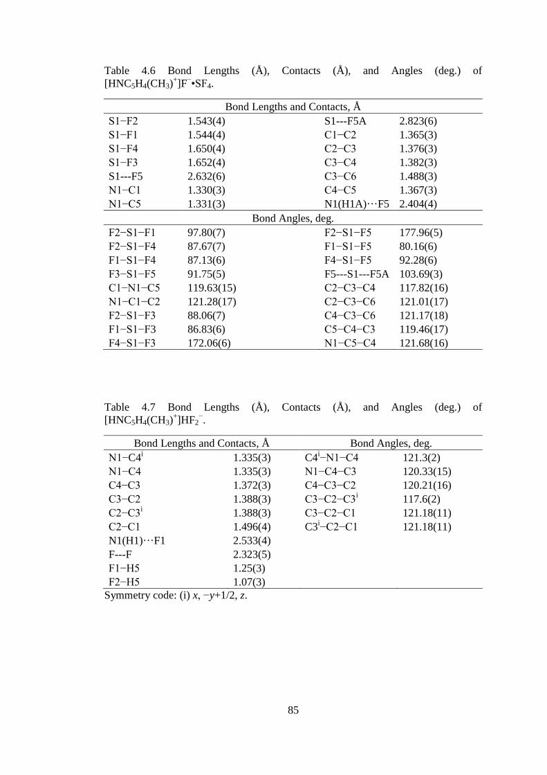
85
Table 4.6 Bond Lengths (Å), Contacts (Å), and Angles (deg.) of
[HNC5H4(CH3)+]F
−•SF4.
Bond Lengths and Contacts, Å
S1−F2 1.543(4) S1---F5A 2.823(6)
S1−F1 1.544(4) C1−C2 1.365(3)
S1−F4 1.650(4) C2−C3 1.376(3)
S1−F3 1.652(4) C3−C4 1.382(3)
S1---F5 2.632(6) C3−C6 1.488(3)
N1−C1 1.330(3) C4−C5 1.367(3)
N1−C5 1.331(3) N1(H1A)···F5 2.404(4)
Bond Angles, deg.
F2−S1−F1 97.80(7) F2−S1−F5 177.96(5)
F2−S1−F4 87.67(7) F1−S1−F5 80.16(6)
F1−S1−F4 87.13(6) F4−S1−F5 92.28(6)
F3−S1−F5 91.75(5) F5---S1---F5A 103.69(3)
C1−N1−C5 119.63(15) C2−C3−C4 117.82(16)
N1−C1−C2 121.28(17) C2−C3−C6 121.01(17)
F2−S1−F3 88.06(7) C4−C3−C6 121.17(18)
F1−S1−F3 86.83(6) C5−C4−C3 119.46(17)
F4−S1−F3 172.06(6) N1−C5−C4 121.68(16)
Table 4.7 Bond Lengths (Å), Contacts (Å), and Angles (deg.) of
[HNC5H4(CH3)+]HF2
−.
Bond Lengths and Contacts, Å Bond Angles, deg.
N1−C4i 1.335(3) C4
i−N1−C4 121.3(2)
N1−C4 1.335(3) N1−C4−C3 120.33(15)
C4−C3 1.372(3) C4−C3−C2 120.21(16)
C3−C2 1.388(3) C3−C2−C3i 117.6(2)
C2−C3i 1.388(3) C3−C2−C1 121.18(11)
C2−C1 1.496(4) C3i−C2−C1 121.18(11)
N1(H1)···F1 2.533(4)
F---F 2.323(5)
F1−H5 1.25(3)
F2−H5 1.07(3)
Symmetry code: (i) x, −y+1/2, z.

86
Figure 4.5 Thermal ellipsoid plot of the dimer present in the crystal structure of
[HNC5H4(CH3)+]F
−•SF4. Thermal ellipsoids are at 50% probability.
The crystal structure is remarkably different from the extended chain structures
observed with the pyridine-HF-SF4 system. In the crystal structure of the
[HNC5H5+]F
−•SF4 salt, a fluoride is present close to the para-position (C9(H)---F9
= 3.290(2) Å) of the pyridine rings. The methyl group in the 4-position of
[HNC5H4(CH3)+]F
−•SF4 prevents the formation of an infinite chain with a packing
similar to that of [HNC5H5+]F
−•SF4. The N1(H)---F5 distance (2.404(4) Å) is
significantly shorter than the N(H)---F distance (2.4379(13) Å) in [HNC5H5+]F
−•SF4.
This is in accord with the weaker Brønsted acidity of 4-methylpyridinium (pKa =
5.98) compared to that of pyridinium (pKa = 5.23).20
In the [HNC5H4(CH3)+]HF2
− salt, the 4-methylpyridinium cation is hydrogen-
bonded to one of the fluorines of bifluoride (see Figure 4.6). The N1(H)---F1
distance (2.533(4) Å) is longer than the majority of the structures containing fluoride
bound to SF4 and substantially longer than the N(H)---F contact length (2.405(4) Å)
of the [HNC5H5+]F
−•SF4 salt. The F---F distance in the bifluoride anion is 2.323(5)
Å, which is the same as the F---F distance of 2.326 Å found in pyridinium
bifluoride.11
The hydrogen atom was located in the difference map and refined. As
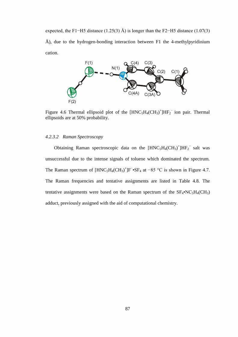
87
expected, the F1−H5 distance (1.25(3) Å) is longer than the F2−H5 distance (1.07(3)
Å), due to the hydrogen-bonding interaction between F1 the 4-methylpyridinium
cation.
Figure 4.6 Thermal ellipsoid plot of the [HNC5H4(CH3)+]HF2
− ion pair. Thermal
ellipsoids are at 50% probability.
4.2.3.2 Raman Spectroscopy
Obtaining Raman spectroscopic data on the [HNC5H4(CH3)+]HF2
− salt was
unsuccessful due to the intense signals of toluene which dominated the spectrum.
The Raman spectrum of [HNC5H4(CH3)+]F
−•SF4 at −85 °C is shown in Figure 4.7.
The Raman frequencies and tentative assignments are listed in Table 4.8. The
tentative assignments were based on the Raman spectrum of the SF4•NC5H4(CH3)
adduct, previously assigned with the aid of computational chemistry.

88
Table 4.8 Raman Frequencies (cm1
) and Tentative Assignments of
[HNC5H4(CH3)+]F
−•SF4.
[HNC5H4(CH3)+]F
−•SF4
a SF4
c Assignment
3097(36) 3082(49)
ν(C–H) 3021(15) 2967(21) 2931(82) 2879(12) ν(CH3) 2736(6) 1632(36)
1595(8) ν(C–C)/ ν(C–N) 1448(9) 1380(45)
b 1336(21) CH3 deformation 1256(11) 1222(26) 1074(32) νs(NC5) 1002(14) 904(32) SF4 comb. band 855(17) 888(75)/880(99) νs(SF2eq) 828(56) 860sh νas (SF2eq)
815(13) out-of-plane(HCC)
798(19) out-of-plane(HCC) 788(19) SF2
770(55) SF2
665(79) in-plane(CCC)/in-plane(CNC) 629(7) νas(SF2ax) 604(8) 562(8) 521(100) 536(92)/532(100) νs(SF2ax) 524(54) δrock(SF2eq) 487(9) 515(72)/508(66) δsc(SF2eq) + δsc(SF2ax) 445(19) 458(31) τ(SF2) 351(31) 294(18)
b ρr(CH3) 258(6) ρr(CH3) 238(21) 243(15) δsc(SF2eq) − δsc(SF2ax)
a Signals from the FEP sample tube were observed at: 1513(7), 1380(45) (overlap),
1303(9), 733(47), 382(16), 294(18) (overlap) b Signals overlap with those of FEP.
c Acquired at −97 °C.
d Solid SF4 at −135 °C.

89
Figure 4.7 Raman spectrum of [HNC5H4(CH3)+]F
−•SF4. Asterisks (*) denote bands
arising from the FEP sample tube.
The methyl group increases the complexity of the Raman spectrum significantly
compared to that of the pyridinium salt. An intense signal at 2931 cm−1
is indicative
of the C−H stretches on a methyl group. The most intense peak (521 cm−1
) can be
assigned to the νs(SF2ax) stretch, which is at a lower frequency than that of neat solid
SF4 (536(92) and 532(100) cm−1
). The band assigned to the νs(SF2eq) mode is also at
significantly lower frequency and intensity (855(17) cm−1
) than that of neat solid SF4
(888(75) and 880(99) cm−1
), and is no longer split.
4.2.4 2,6-Dimethylpyridine-HF-SF4 System
In an attempt to obtain crystals of SF4-2,6-dimethylpyridine adducts, large
plate-like crystals were obtained by recrystallizing the SF4•HNC5H3(CH3)2 adduct in
toluene between −60 and −80 °C. Instead of the anticipated structure of
SF4•HNC5H3(CH3)2, the crystal structure of [HNC5H3(CH3)2+]2[SF5
−]F
−•SF4 was
obtained. Similarly to the crystal structure of [HNC5H5+]F
−•SF4 (vide supra), traces

90
of water in the toluene hydrolyzed SF4 producing HF which then solvolyzed
SF4•NC5H3(CH3)2. Using SF4 as a solvent and introducing stoichiometric
amounts of H2O, crystals formed which had the same unit cell as the
[HNC5H3(CH3)2+]2[SF5
−]F
−•SF4 salt previously obtained. The sample, however,
contained crystals with two different morphologies. A block-type crystal that was
mounted on the diffractometer had different unit cell parameters than the
[HNC5H3(CH3)2+]2[SF5
−]F
−•SF4 salt. This crystal contained three extra molecules of
SF4, which formed layers of SF4, and is discussed in Section 5.2 together with the
solid-state structure of SF4.
4.2.4.1 X-ray Crystal Structure of [HNC5H3(CH3)2+]2[SF5
−]F
−•SF4
Details of data collection parameters and crystallographic information for
([HNC5H3(CH3)2+]2[SF5
−]F
−•SF4) are given in Table 4.9. Important bond lengths,
angles and contacts for [HNC5H3(CH3)2+]2[SF5
−]F
−•SF4 are listed in Table 4.10. The
structure of [HNC5H3(CH3)2+]2[SF5
−]F
−•SF4 consists of two 2,6-dimethylpyridinium
cations hydrogen-bonded to a single fluoride anion, which is coordinated to one SF4
molecule, and a separate SF5− anion (see Figure 4.8).
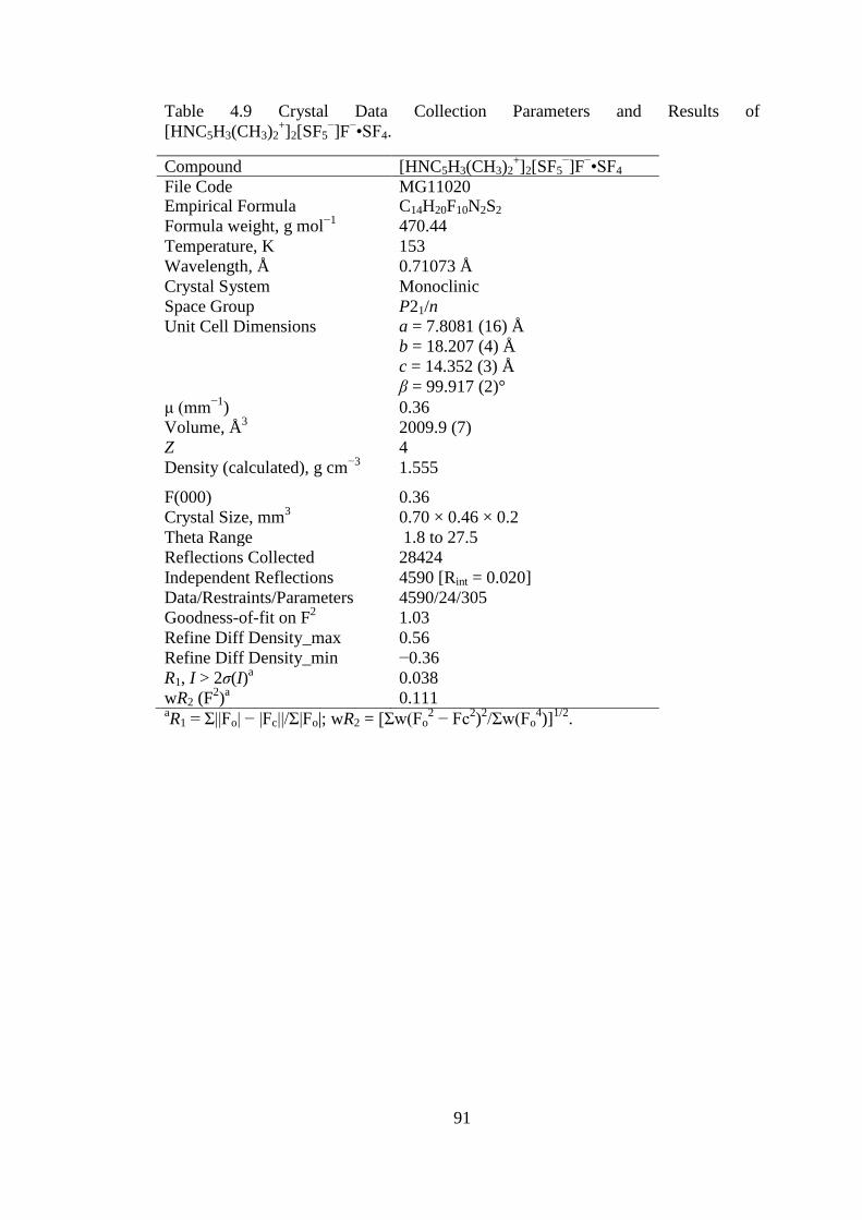
91
Table 4.9 Crystal Data Collection Parameters and Results of
[HNC5H3(CH3)2+]2[SF5
−]F
−•SF4.
Compound [HNC5H3(CH3)2+]2[SF5
−]F
−•SF4
File Code MG11020 Empirical Formula C14H20F10N2S2
Formula weight, g mol−1
470.44
Temperature, K 153
Wavelength, Å 0.71073 Å
Crystal System Monoclinic
Space Group P21/n
Unit Cell Dimensions a = 7.8081 (16) Å
b = 18.207 (4) Å
c = 14.352 (3) Å
β = 99.917 (2)°
μ (mm−1
) 0.36
Volume, Å3 2009.9 (7)
Z 4
Density (calculated), g cm−3
1.555
F(000) 0.36
Crystal Size, mm3 0.70 × 0.46 × 0.2
Theta Range 1.8 to 27.5
Reflections Collected 28424
Independent Reflections 4590 [Rint = 0.020]
Data/Restraints/Parameters 4590/24/305
Goodness-of-fit on F2 1.03
Refine Diff Density_max 0.56
Refine Diff Density_min −0.36
R1, I > 2σ(I)a 0.038
wR2 (F2)a 0.111
aR1 = Σ||Fo| − |Fc||/Σ|Fo|; wR2 = [Σw(Fo
2 − Fc
2)2/Σw(Fo
4)]
1/2.

92
Table 4.10 Bond Lengths (Å), Contacts (Å), and Angles (deg.) of
[HNC5H3(CH3)2+]2[SF5
−]F
−•SF4.
Bond Lengths and Contacts, Å
F1−S1A 1.506(5) S1A−F5A 1.594(17)
F1−S1 1.586(2) S1A−F4A 1.657(7)
S1−F4 1.663(3) S1A−F2A 1.697(8)
S1−F3 1.698(3) S1A−F3A 1.699(7)
S1−F2 1.709(4) S2−F6 1.5415(11)
S1−F5 1.718(5) S2−F8 1.5538(13)
S2−F9 1.6557(12) S2---F10 2.5116(12)
S2−F7 1.6736(12) N2(H2)---F10 2.5308(17)
N1(H1)---F10 2.5396(17)
Bond Angles, deg.
S1A−F1−S1 12.61(14) F4A−S1A−F2A 171.1(5)
F1−S1−F4 84.28(19) F1−S1A−F3A 83.2(3)
F1−S1−F3 87.02(13) F5A−S1A−F3A 172.7(8)
F4−S1−F3 90.67(19) F4A−S1A−F3A 93.7(6)
F1−S1−F2 85.9(2) F2A−S1A−F3A 86.9(6)
F4−S1−F2 170.1(3) F6−S2−F8 97.39(7)
F3−S1−F2 88.03(19) F6−S2−F9 86.60(7)
F1−S1−F5 82.0(2) F8−S2−F9 88.05(7)
F4−S1−F5 91.6(3) F6−S2−F7 86.06(7)
F3−S1−F5 168.5(2) F8−S2−F7 87.65(7)
F2−S1−F5 87.8(3) F9−S2−F7 170.94(7)
F1−S1A−F5A 89.7(7) F6−S2−F10 78.87(5)
F1−S1A−F4A 93.0(3) F8−S2−F10 175.08(6)
F5A−S1A−F4A 85.2(8) F9−S2−F10 88.54(6)
F1−S1A−F2A 78.2(4) F7−S2−F10 95.23(6)
F5A−S1A−F2A 93.1(8)

93
a) b)
Figure 4.8 Thermal ellipsoid plot of [HNC5H3(CH3)2+]2F
−•SF4[SF5
−]; a) the
[HNC5H3(CH3)2+]2F
−•SF4 moiety and b) the disordered SF5
− anion. Thermal
ellipsoids are at 50% probability.
The 2,6-dimethylpyridinium cations exhibit long contacts to F− (N1(H)---F10 =
2.5396(17) Å and N2(H)---F10 = 2.5308(17) Å) with an N1(H)---F10---(H)N2 angle
of 146.57(6)°. The sulfur tetrafluoride adopts the expected seesaw geometry and has
a S---F contact (2.5116(12) Å) with F10. The S2−F8 bond (1.5538(13) Å) in SF4 is
slightly longer than the other equatorial S2−F6 bond (1.5415(11) Å), as it is located
trans of the Lewis basic fluoride. The SF5− anion adopts the expected square
pyramidal structure with similar, but on average slightly longer bond lengths,
compared to the SF5− anion in the previously reported RbSF5 structure.
5 The thermal
ellipsoids in the equatorial plane are elongated, suggesting some rotational motion
around the S−F axis, however the actual disorder was modelled by assigning two
separate SF5− anions which are joined by a fixed pivot point, i.e., the axial fluorine.
The axial S−F bond length (1.560(2) Å) is much shorter than the equatorial S−F
bond lengths (1.730(2) Å). The equatorial F−S−F bond angles range from 87.8(3) to
91.6(3)°.
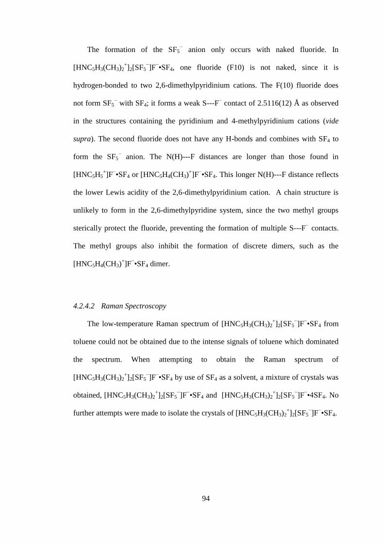
94
The formation of the SF5− anion only occurs with naked fluoride. In
[HNC5H3(CH3)2+]2[SF5
−]F
−•SF4, one fluoride (F10) is not naked, since it is
hydrogen-bonded to two 2,6-dimethylpyridinium cations. The F(10) fluoride does
not form SF5− with SF4; it forms a weak S---F
− contact of 2.5116(12) Å as observed
in the structures containing the pyridinium and 4-methylpyridinium cations (vide
supra). The second fluoride does not have any H-bonds and combines with SF4 to
form the SF5− anion. The N(H)---F distances are longer than those found in
[HNC5H5+]F
−•SF4 or [HNC5H4(CH3)
+]F
−•SF4. This longer N(H)---F distance reflects
the lower Lewis acidity of the 2,6-dimethylpyridinium cation. A chain structure is
unlikely to form in the 2,6-dimethylpyridine system, since the two methyl groups
sterically protect the fluoride, preventing the formation of multiple S---F− contacts.
The methyl groups also inhibit the formation of discrete dimers, such as the
[HNC5H4(CH3)+]F
−•SF4 dimer.
4.2.4.2 Raman Spectroscopy
The low-temperature Raman spectrum of [HNC5H3(CH3)2+]2[SF5
−]F
−•SF4 from
toluene could not be obtained due to the intense signals of toluene which dominated
the spectrum. When attempting to obtain the Raman spectrum of
[HNC5H3(CH3)2+]2[SF5
−]F
−•SF4 by use of SF4 as a solvent, a mixture of crystals was
obtained, [HNC5H3(CH3)2+]2[SF5
−]F
−•SF4 and [HNC5H3(CH3)2
+]2[SF5
−]F
−•4SF4. No
further attempts were made to isolate the crystals of [HNC5H3(CH3)2+]2[SF5
−]F
−•SF4.
95
4.2.5 The 4-Dimethylaminopyridine-HF-SF4 System
The Lewis basicity of 4-dimethylaminopyridine is significantly greater than
that of the other pyridine derivatives. As a result, the conjugate acid, 4-
dimethylaminopyridinium, will be the weakest acid in this series of protonated
pyridinium derivatives. Slow cooling of a 2-to-1 mixture of 4-
dimethylaminopyridine and water with excess SF4, from 3 to −20 °C, resulted in the
formation of large needles, which were shown to be [HNC5H4N(CH3)2+][HF2
−]•2SF4.
In a different experiment, the SF4•NC5H4N(CH3)2 adduct in the presence of excess
SF4 was dissolved in dichloromethane to increase the solubility. Volatiles were
removed from −80 to −60 °C which led to the formation of fine crystalline needles.
These needles were [HNC5H4N(CH3)2+]2[SF5
−]F
−•CH2Cl2 as determined by Raman
spectroscopy and X-ray crystallography. Apparently, traces of water hydrolyzed SF4
forming HF, which protonated the basic nitrogen atoms on 4-dimethylaminopyridine.
4.2.5.1 X−ray Crystal Structures of [HNC5H4N(CH3)2+][HF2
−]•2SF4 and
[HNC5H4N(CH3)2+]2[SF5
−]F
−•CH2Cl2
Details of data collection parameters and crystallographic information for
[HNC5H4N(CH3)2+][HF2
−]•2SF4 and [HNC5H4N(CH3)2
+]2[SF5
−]F
−•CH2Cl2 are given
in Table 4.11. Important bond lengths, angles and contacts for
[HNC5H4N(CH3)2+][HF2
−]•2SF4 and [HNC5H4N(CH3)2
+]2[SF5
−]F
−•CH2Cl2 are given
in Table 4.12 and Table 4.13.

96
Table 4.11 Crystal Data Collection Parameters and Results of
[HNC5H4N(CH3)2+][HF2
−]•2SF4 and [HNC5H4N(CH3)2
+]2[SF5
−]F
−•CH2Cl2.
Compound [HNC5H4N(CH3)2+][HF2
−]•2SF4 [HNC5H4N(CH3)2
+]2[SF5
−]F
−•CH2Cl2
File Code MG12071 MG12074
Empirical Formula C7H12F10N2S2 C15H24Cl2F6N4S
Formula weight, g
mol−1
378.31 477.34
Temperature, K 153 153
Wavelength, Å 0.71073 0.71073
Crystal System Monoclinic Monoclinic
Space Group P21/c P21/n
Unit Cell
Dimensions
a = 8.605 (6) Å
b = 20.371 (15) Å
c = 16.500 (12) Å
β = 90.415 (9)°
a = 7.001 (5) Å
b = 14.351 (10) Å
c = 21.647 (15) Å
β = 96.742 (8)°
Abs. coeff. μ
(mm−1
)
0.47 0.46
Volume Å3
2892 (4) 2160 (3)
Z 8 4
Density
(calculated),
g cm−3
1.738 1.468
F(000) 1520 984
Crystal Size, mm3 0.52 × 0.22 × 0.20 0.37 × 0.09 × 0.08
Reflections
Collected
32789 24526
Independent
Reflections
6703 [Rint = 0.046] 5242 [Rint = 0.045]
Data/Restraints/Par
ameters
6703/0/391 5242/34/297
Goodness-of-fit on
F2
1.02 1.15
Refine Diff Δρmax
e Å−3
0.38 0.64
Refine Diff Δρmin
e Å−3
−0.32 −0.43
R1, I > 2σ(I)a
0.0325 0.0707
wR2 (F2)
a 0.0886 0.1930
aR1 = Σ||Fo| − |Fc||/Σ|Fo|; wR2 = [Σw(Fo
2 − Fc
2)
2/Σw(Fo
4)]
1/2.

97
Table 4.12 Selected Bond Lengths (Å), Contacts (Å), and Angles (deg.) of
[HNC5H4N(CH3)2+][HF2
−]•2SF4
Bond Lengths and Contacts, Å
S1−F14 1.5422(14) S3−F32 1.6497(15)
S1−F13 1.5463(14) S3−F31 1.6726(17)
S1−F11 1.6484(15) S3−F2 2.758(2)
S1−F12 1.6746(16) S3−F4i 2.7668(18)
S1−F1 2.6783(18) N1(H1)---F1 2.638(2)
S1−F3i 2.8703(18) N1A(H1A)---F3 2.632(2)
S2−F23 1.5332(15) F2(H1B)---F1 2.284(2)
S2−F24 1.5414(13) F4(H2B)---F3 2.291(2)
S2−F21 1.6325(15) S4−F44 1.5357(14)
S2−F22 1.6617(16) S4−F43 1.5458(13)
S2−F2 2.7136(18) S4−F42 1.6539(15)
S2−F4 2.799(2) S4−F41 1.6825(16)
S3−F34 1.5414(14) S4−F3 2.6787(19)
S3−F33 1.5434(15) S4−F1 2.8411(17)
Bond Angles, deg.
F11−S1−F12 171.02(8) F41−S4−F3 85.42(6)
F14−S1−F1 168.84(6) F44−S4−F1 77.74(7)
F13−S1−F1 78.26(7) F43−S4−F1 166.18(5)
F11−S1−F1 102.91(6) F42−S4−F1 79.09(6)
F12−S1−F1 81.64(6) F41−S4−F1 106.77(6)
F14−S1−F3i 82.48(8) F3−S4−F1 108.26(6)
F13−S1−F3i 171.01(6) F14−S1−F13 99.25(9)
F11−S1−F3i 84.08(7) F14−S1−F11 87.75(8)
F12−S1−F3i 102.72(7) F13−S1−F11 87.17(8)
F1−S1−F3i 101.69(6) F14−S1−F12 87.36(8)
F23−S2−F24 98.79(8) F13−S1−F12 86.19(8)
F23−S2−F21 87.36(9) F21−S2−F4 87.70(7)
F24−S2−F21 87.23(8) F22−S2−F4 97.97(8)
F23−S2−F22 86.53(9) F2−S2−F4 106.41(6)
F24−S2−F22 86.79(9) F34−S3−F33 99.04(9)
F21−S2−F22 170.71(8) F34−S3−F32 87.34(8)
F23−S2−F2 76.66(7) F33−S3−F32 87.01(8)
F24−S2−F2 174.40(6) F34−S3−F31 86.97(8)
F21−S2−F2 89.28(8) F33−S3−F31 86.93(8)
F22−S2−F2 96.11(8) F32−S3−F31 170.95(8)
F23−S2−F4 174.16(6) F34−S3−F2 77.92(8)
F24−S2−F4 77.84(7) F33−S3−F2 176.83(7)
F44−S4−F43 99.05(9) F32−S3−F2 93.70(7)
F44−S4−F42 88.26(8) F31−S3−F2 91.99(7)
F43−S4−F42 87.41(7) F34−S3−F4i 179.45(6)

98
Table 4.12 continued.
F44−S4−F41 87.51(8) F33−S3−F4i 80.78(8)
F43−S4−F41 86.37(7) F32−S3−F4i 93.17(7)
F42−S4−F41 171.85(7) F31−S3−F4i 92.50(7)
F44−S4−F3 171.82(6) F2−S3−F4i 102.25(7)
F43−S4−F3 76.41(7) S1−F1−S4 115.89(6)
F42−S4−F3 98.25(6) S2−F2−S3 118.61(6)
Symmetry code: (i) x+1, y, z.
Table 4.13 Selected Bond Lengths (Å), Contacts (Å), and Angles (deg.) of
[HNC5H4N(CH3)2+]2[SF5
−]F
−•CH2Cl2
Bond Lengths and Contacts, Å
S1−F5 1.553(5) S1A−F5A 1.452(13)
S1−F2 1.696(3) S1A−F3A 1.690(12)
S1−F3 1.707(4) S1A−F4A 1.700(15)
S1−F1 1.728(5) S1A−F1A 1.719(14)
S1−F4 1.749(5) S1A−F2 1.755(11)
N3(H)---F6 2.511(4) N1(H)---F6 2.517(4)
Bond Angles, deg.
F5−S1−F2 85.5(2) F3−S1−F1 168.0(4)
F5−S1−F3 83.6(3) F5−S1−F4 83.5(3)
F2−S1−F3 90.37(19) F2−S1−F4 169.0(3)
F5−S1−F1 84.5(4) F3−S1−F4 88.5(3)
F2−S1−F1 90.6(2) F1−S1−F4 88.3(3)

99
The structure of [HNC5H4N(CH3)2+][HF2
−]•2SF4 contains a double chain
consisting of bifluoride, each anion coordinating to four SF4 molecules, and 4-
dimethylaminopyridinium cations hydrogen-bonded to fluorine on the same side of
all bifluoride anions. (Figure 4.9)
Figure 4.9 Thermal ellipsoid plot of the [HNC5H4N(CH3)2+][HF2
−]•2SF4 double
chain. Thermal ellipsoids are at 50% probability.
The structural motif is very similar to that observed for the
[HNC5H5+][HF2
−]•2SF4 salt as it contains a double bifluoride-SF4 chain, except that
the protonated nitrogen-base cations are not disordered as the dimethylamino group
prevents rotation of the pyridinium ring while maintaining the overall packing
arrangement. The 4-dimethylaminopyridinium cations are all found on one side of
100
the bifluoride chain, which causes polarization of the bifluoride anions. The thermal
ellipsoids of SF4 and one fluorine atom of bifluoride, which compose the half of the
double chain that have contacts to the 4-dimethylaminopyridinium cations, are
smaller than the thermal ellipsoids of the other half of the chain, which do not have
contacts with the cations. This reflects the stabilizing effect of the hydrogen-bonded
cations on the chain. The S−Feq bond lengths (1.5332(15) to 1.5458(13) Å) are the
same within 3σ with those of neat solid SF4 (1.527(4) and 1.535(4) Å).
The N(H)---F contacts (2.632(2) and 2.638(2) Å) are much longer than those
in all of the structures containing fluoride and pyridinium/pyridinium derivatives, but
are significantly shorter than the N(H)---F contacts (2.937(5) Å) in
[HNC5H5+]HF2
−•2SF4. The N(H)---F distance is significantly longer than the N(H)---
F distances found in other bifluoride salts which do not contain SF4, such as the
[HNC5H5+]HF2
− salt (2.508 Å) and the [HNC5H4(CH3)
+]HF2
− salt (2.534(4) Å),
because the 4-dimethylaminopyridinium cation is a weaker Bronsted acid (pKa =
9.5).20
In this structure, it was possible to locate the proton in the bifluoride anion. As
expected, the fluorides (F1 and F3) that are hydrogen-bonded to the cations have
longer F1−H1B/F3−H2B bonds (1.28(3) and 1.25(3) Å) than the F2−H1B/F4−H2B
bonds (1.01(3) and 1.05(3) Å). The F---F distances in the bifluoride anions are
relatively short (2.284 (2) and 2.291 (2) Å), although it is not as short as the F---F
distance of 2.213(4) Å found in the tetramethylammonium bifluoride salt that
contains symmetric HF2− anions.
21 The S---F contacts (2.758(2) Å) are generally
longer than the S---F contacts found in the other salts, particularly the structures that
do not form chains. The F---S---F bond angles range from 101.69(6) to 108.26(6)°,
and span a smaller range than the angles found in the [HNC5H5+][HF2
−]•2SF4 salt.
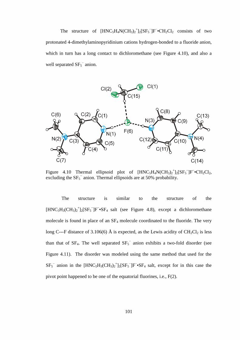
101
The structure of [HNC5H4N(CH3)2+]2[SF5
−]F
−•CH2Cl2 consists of two
protonated 4-dimethylaminopyridinium cations hydrogen-bonded to a fluoride anion,
which in turn has a long contact to dichloromethane (see Figure 4.10), and also a
well separated SF5− anion.
Figure 4.10 Thermal ellipsoid plot of [HNC5H4N(CH3)2+]2[SF5
−]F
−•CH2Cl2,
excluding the SF5− anion. Thermal ellipsoids are at 50% probability.
The structure is similar to the structure of the
[HNC5H3(CH3)2+]2[SF5
−]F
−•SF4 salt (see Figure 4.8), except a dichloromethane
molecule is found in place of an SF4 molecule coordinated to the fluoride. The very
long C---F distance of 3.106(6) Å is expected, as the Lewis acidity of CH2Cl2 is less
than that of SF4. The well separated SF5− anion exhibits a two-fold disorder (see
Figure 4.11). The disorder was modeled using the same method that used for the
SF5− anion in the [HNC5H3(CH3)2
+]2[SF5
−]F
−•SF4 salt, except for in this case the
pivot point happened to be one of the equatorial fluorines, i.e., F(2).
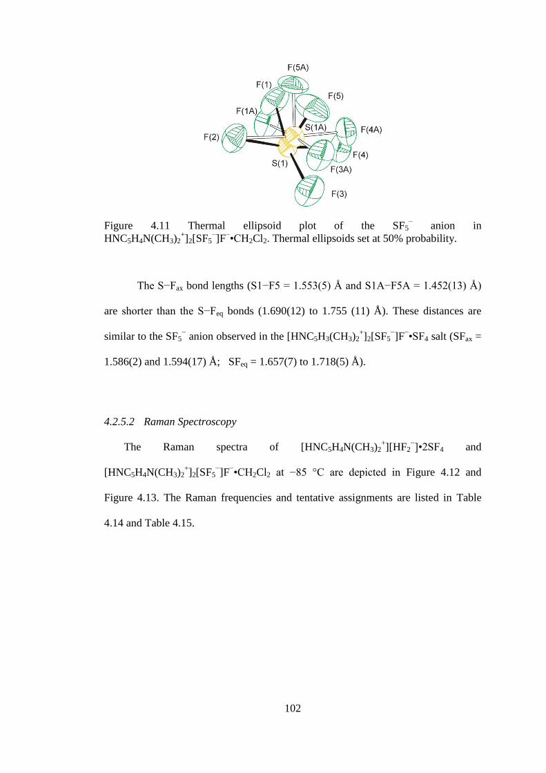
102
Figure 4.11 Thermal ellipsoid plot of the SF5− anion in
HNC5H4N(CH3)2+]2[SF5
−]F
−•CH2Cl2. Thermal ellipsoids set at 50% probability.
The S−Fax bond lengths (S1−F5 = 1.553(5) Å and S1A−F5A = 1.452(13) Å)
are shorter than the S−Feq bonds (1.690(12) to 1.755 (11) Å). These distances are
similar to the SF5− anion observed in the [HNC5H3(CH3)2
+]2[SF5
−]F
−•SF4 salt (SFax =
1.586(2) and 1.594(17) Å; SFeq = 1.657(7) to 1.718(5) Å).
4.2.5.2 Raman Spectroscopy
The Raman spectra of [HNC5H4N(CH3)2+][HF2
−]•2SF4 and
[HNC5H4N(CH3)2+]2[SF5
−]F
−•CH2Cl2 at −85 °C are depicted in Figure 4.12 and
Figure 4.13. The Raman frequencies and tentative assignments are listed in Table
4.14 and Table 4.15.
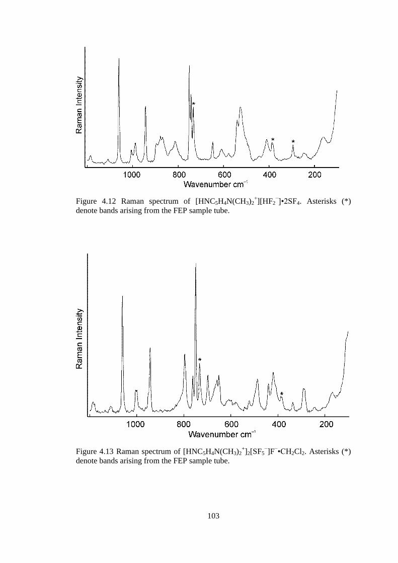
103
Figure 4.12 Raman spectrum of [HNC5H4N(CH3)2+][HF2
−]•2SF4. Asterisks (*)
denote bands arising from the FEP sample tube.
Figure 4.13 Raman spectrum of [HNC5H4N(CH3)2+]2[SF5
−]F
−•CH2Cl2. Asterisks (*)
denote bands arising from the FEP sample tube.

104
Table 4.14 Raman Frequencies (cm1
) and Tentative Assignments of
[HNC5H4N(CH3)2+][HF2
−]•2SF4.
[HNC5H4N(CH3)2+][HF2
−]•2SF4
a SF4 Assignment
3114(21) ν(C–H)
3030(9) ν(C–H)
2941(28) ν(CH3)
2877(10) ν(CH3)
2827(11) ν(CH3)
1643(30)
1566(29) ν (C–C)/ ν(C–N)
1524(13)
1487(7)
1469(11) as(CH3)
1446(30)
1419(9) ν(C–C)/ ν(C–N)
1406(11)
1336(4)
1305(sh)
1250(5) in-plane(HCC)
1212(13)
1185(7) r(CH3)
1108(4)
1060(100) νs(NC5)
1006(13)
988(16)
DMAP in-plane(CCC)/in-
plane(NCC)
943(51) DMAP r(CH3)
897(19) 904(32) SF4 comb.
878(24) 888(75) νs SF2eq
868(23) 880(99) νs SF2eq
813(20) 860sh νas SF2eq
751(86)b
DMAP in-plane(CCC)/in-
plane(NCC)
743(60)
647(18) DMAP
629(7) νas SF2ax
609(6) νs (HF2−)
540(34) 536(92)/532(100) νs SF2ax
524(54) δrock (SF2eq)
526(50) 515(72)/508(66) δsc(SF2eq) + δsc(SF2ax)
458(31) Τ(SF2)
410(19) DMAP
248(6) 243(15) δsc(SF2eq) − δsc(SF2ax)
159(19) r(CH3) a Signals from the FEP sample tube were observed at: 1383(16), 1294(12), 1222(sh), 733(48), 578(4), 387(18),
294(13) b Overlap with FEP signal

105
Table 4.15 Raman Frequencies (cm1
) and Tentative Assignments of
[HNC5H4N(CH3)2+]2[SF5
−]F
−•CH2Cl2.
[HNC5H4N(CH3)2+]2[SF5
−]
F−•CH2Cl2
CH2Cl2 CsSF5−
Assignment
3111(25) ν(C–H)
3056(12) CH2Cl2 ν(CH2)
3025(16) ν(C–H)
2986(18) 2987(74) CH2Cl2 ν(CH2)
2932(32) ν(CH3)
2876(18) ν(CH3)
2827(1) CH2Cl2 comb.
2823(20)
1650(31) ν(C–C)/ ν(C–N)
1612(14)
1565(30)
1524(13)
1490(6) as(CH3)
1459(24)
1446(31)
1423(28) 1419(17) CH2Cl2 (CH2)
1405(11)
1310(8)
1296(13)b
1265(3) CH2Cl2 ω(CH2)
1248(2) in-plane(HCC)
1220(12)b
1212(10)
1156(8) CH2Cl2 τ(CH2)
1186(7)
1112(4)
1061(81) νs(NC5)
1005(16)
943(44) DMAP r(CH3)
896(2) CH2Cl2 (CH2)
796(40) 796(37) SF5− ν (SFax)
762(23) 785(12) SF5−ν (SFax)
750(100)b
DMAP in-
plane(CCC)/in-
plane(NCC)
739(10) CH2Cl2, νas(CCl2)
697(21) 701(100) CH2Cl2, νs(CCl2)
659(18) DMAP
651(20)
609(3) 590 sh/583(7) SF5−, νas(SF4)
542(2)
522(6) 522(27) SF5− νs (SF4) in phase
487(21) 512(7) SF5− s(SF4)out of plane
440(19) SF5−s(SF4) umbrella
420(28) 435(100)/420(12) SF5− (FaxSF4)
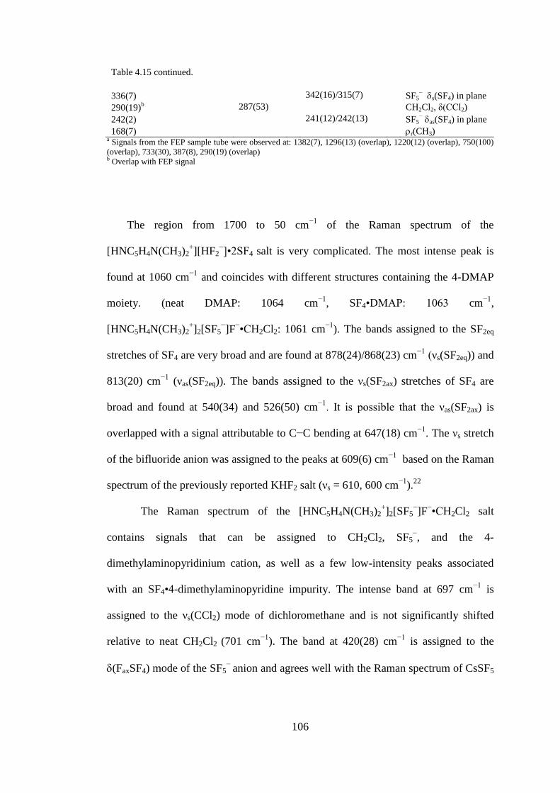
106
Table 4.15 continued.
336(7) 342(16)/315(7) SF5− s(SF4) in plane
290(19)b 287(53) CH2Cl2, δ(CCl2)
242(2) 241(12)/242(13) SF5− as(SF4) in plane
168(7) r(CH3) a Signals from the FEP sample tube were observed at: 1382(7), 1296(13) (overlap), 1220(12) (overlap), 750(100)
(overlap), 733(30), 387(8), 290(19) (overlap) b Overlap with FEP signal
The region from 1700 to 50 cm−1
of the Raman spectrum of the
[HNC5H4N(CH3)2+][HF2
−]•2SF4 salt is very complicated. The most intense peak is
found at 1060 cm−1
and coincides with different structures containing the 4-DMAP
moiety. (neat DMAP: 1064 cm−1
, SF4•DMAP: 1063 cm−1
,
[HNC5H4N(CH3)2+]2[SF5
−]F
−•CH2Cl2: 1061 cm
−1). The bands assigned to the SF2eq
stretches of SF4 are very broad and are found at 878(24)/868(23) cm−1
(νs(SF2eq)) and
813(20) cm−1
(νas(SF2eq)). The bands assigned to the νs(SF2ax) stretches of SF4 are
broad and found at 540(34) and 526(50) cm−1. It is possible that the νas(SF2ax) is
overlapped with a signal attributable to C−C bending at 647(18) cm−1
. The νs stretch
of the bifluoride anion was assigned to the peaks at 609(6) cm−1
based on the Raman
spectrum of the previously reported KHF2 salt (νs = 610, 600 cm−1
).22
The Raman spectrum of the [HNC5H4N(CH3)2+]2[SF5
−]F
−•CH2Cl2 salt
contains signals that can be assigned to CH2Cl2, SF5−, and the 4-
dimethylaminopyridinium cation, as well as a few low-intensity peaks associated
with an SF4•4-dimethylaminopyridine impurity. The intense band at 697 cm−1
is
assigned to the νs(CCl2) mode of dichloromethane and is not significantly shifted
relative to neat CH2Cl2 (701 cm−1
). The band at 420(28) cm−1
is assigned to the
(FaxSF4) mode of the SF5−
anion and agrees well with the Raman spectrum of CsSF5

107
(420(12) cm−1
).6 The peaks assigned to the 4-dimethylaminopyridinium cation
coincide with the peaks in the Raman spectrum of [HNC5H4N(CH3)2+][HF2
−]•2SF4.
The most intense peak assigned to residual SF4•4-dimethylaminopyridine is at
796(40) cm−1
.
4.2.6 The 4,4’-Bipyridyl-HF-SF4 System
Previous attempts at elucidating the structure of the product formed between
4,4’-bipyridyl and SF4 had limited success.23
The solubility of 4,4’-bipyridyl in neat
SF4 is low. It was hypothesized that the solubility of protonated 4,4’-bipyridyl in neat
SF4 could be higher. Slow cooling of a 1-to-2 mixture of H2O to 4,4’-bipyridyl (1:1
HF to 4,4-bipyridyl) in excess SF4 caused the formation of large needles
([HNH4C5−C5H4N+]F
−•2SF4). Slow cooling of a 1-to-1 mixture of H2O to 4,4’-
bipyridyl (2:1 HF to 4,4-bipyridyl) in excess SF4 from room temperature to −80 °C
resulted in the formation of large needles with the composition
[HNH4C5−C5H4NH2+
]2F−•4SF4.
4.2.6.1 X−ray Crystal Structures of [HNH4C5−C5H4N+]F
−•2SF4 and
[HNH4C5−C5H4NH2+
]2F−•4SF4
Details of data collection parameters and crystallographic information for
[HNH4C5−C5H4N+]F
−•2SF4 and [HNH4C5−C5H4NH
2+]2F
−•4SF4 are given in Table
4.16. Important bond lengths, angles and contacts for [HNH4C5−C5H4N+]F
−•2SF4
and [HNH4C5−C5H4NH2+
]2F−•4SF4 are listed in Table 4.17 and Table 4.18
respectively.

108
Table 4.16 Crystal Data Collection Parameters and Results of
[HNH4C5−C5H4N+]F
−•2SF4 and [HNH4C5−C5H4NH
2+]2F
−•4SF4
Compound [HNH4C5−C5H4N+]F
−•2SF4 [HNH4C5−C5H4NH
2+]2F
−•4SF4
File Code MG120176 MG12086
Empirical Formula C10H9F9N2S2 C10H10F18N2S4
Formula weight, g mol−1
392.31 628.44
Temperature, K 153 153
Wavelength, Å 0.71073 0.71073
Crystal System Orthorhombic Tetragonal
Space Group P212121 P42 1c
Unit Cell Dimensions a = 7.339 (7) Å
b = 10.783 (10) Å
c = 18.641 (17) Å
a = 16.530 (13) Å
c = 8.322 (6) Å
Abs. coeff. μ, mm−1
0.46 0.57
Volume 1475 (2) 2274 (3)
Z 4 4
Density (calculated), g cm−1
1.783 1.836
F(000) 784 1240
Crystal Size, mm3 0.31 × 0.15 × 0.11 0.58 × 0.08 × 0.08
Reflections Collected 17011 25142
Independent Reflections 3418 [Rint = 0.054] 2620 [Rint = 0.053]
Data/Restraints/Parameters 3418/0/209 2620/0/155
Goodness-of-fit on F2 1.02 1.05
Refine Diff Δρmax e Å−3
0.41 0.23
Refine Diff Δρmin e Å−3
−0.28 −0.29
R1, I > 2σ(I)a
0.0377 0.0324
wR2(F2)
a 0.1041 0.0882
aR1 = Σ||Fo| − |Fc||/Σ|Fo|; wR2 = [Σw(Fo
2 − Fc
2)
2/Σw(Fo
4)]
1/2.

109
Table 4.17 Selected Bond Lengths (Å), Contacts (Å), and Angles (deg.) of
[HNH4C5−C5H4N+]F
−•2SF4.
Bond Lengths and Contacts, Å
S1−F1 1.521(2) S2−F11 1.510(2)
S1−F2 1.559(2) S2−F12 1.553(2)
S1−F4 1.644(2) S2−F13 1.633(2)
S1−F3 1.650(2) S2−F14 1.651(2)
S1−N1 2.613(3) N2(H)---F5 2.429(3)
F5---S2 2.562(3) S1----F5i 3.005(3)
Bond Angles, deg.
F1−S1−F2 96.06(11) F11−S2−F12 98.75(14)
F1−S1−F4 87.43(15) F11−S2−F13 88.35(15)
F2−S1−F4 88.31(12) F12−S2−F13 87.80(13)
F1−S1−F3 87.88(14) F11−S2−F14 87.68(15)
F2−S1−F3 88.31(12) F12−S2−F14 88.69(15)
F4−S1−F3 173.90(14) F13−S2−F14 174.25(15)
F1−S1−N1 78.09(9) F11−S2−F5 77.98(11)
F2−S1−N1 173.14(9) F12−S2−F5 175.17(10)
F4−S1−N1 87.85(10) F13−S2−F5 88.56(12)
F3−S1−N1 94.99(11) F14−S2−F5 94.69(13)
Symmetry code: (i) −1/2+x, 1.5−y, 1−z
Table 4.18 Selected Bond Lengths (Å), Contacts (Å), and Angles (deg.) of
[HNH4C5−C5H4NH2+
]2F−•4SF4.
Bond Lengths and Contacts, Å
S1−F1 1.512(3) F9----S2i 2.695(3)
S1−F2 1.534(3) S2−F6 1.536(2)
S1−F4 1.642(3) S2−F8 1.547(2)
S1−F3 1.643(3) S2−F7 1.653(2)
S1---F9 2.838(3) S2−F5 1.680(2)
S2---F9 2.658(2) N1(H1)---F9 2.427(3)
Bond Angles, deg.
F1−S1−F2 99.83(16) F8−S2−F7 87.67(12)
F1−S1−F4 88.93(15) F6−S2−F5 87.25(10)
F2−S1−F4 88.36(14) F8−S2−F5 86.93(11)
F1−S1−F3 87.19(14) F7−S2−F5 172.39(11)
F2−S1−F3 88.11(16) F6−S2−F9 174.90(10)
F4−S1−F3 174.23(16) F8−S2−F9 77.42(11)
F1−S1−F9 77.08(12) F7−S2−F9 89.42(9)
F2−S1−F9 174.35(12) F5−S2−F9 94.63(8)
F4−S1−F9 96.26(10) S2−F9−S2i 126.43(8)

110
Table 4.18 continued.
F3−S1−F9 87.03(12) S2−F9−S1 91.12(8)
F6−S2−F8 97.97(13) S2i−F9−S1 112.96(8)
F6−S2−F7 88.19(11) F9---S2---F9 107.11(6)
Symmetry codes: (i) y+1/2, x−1/2, z+1/2; (ii) −x+2, −y+1, z.
The structure of [HNH4C5−C5H4N+]F
−•2SF4 consists of a 4,4’-bipyridyl
molecule with one protonated nitrogen. The protonated nitrogen is hydrogen-bonded
to a fluoride, which forms a contact to SF4. The other nitrogen is directly coordinated
to an SF4 molecule (see Figure 4.14).
Figure 4.14 Thermal ellipsoid plot of [HNH4C5−C5H4N+]F
−•2SF4 Thermal ellipsoids
are at 50% probability.
The torsion angle between the rings in 4,4’-bipyridyl is 14.3(2)°, which
agrees well with the angle in neat 4,4’-bipyridyl of 14.1(8)°.24
This structure contains
both F4S---N and F4S---(F)---HN bonding, and is therefore a link between the
previously characterized SF4-nitrogen-base adducts, and the nitrogen-base-HF-SF4
salts. The S---N contact is 2.614(3) Å which is significantly shorter than the sum of
the van-der-Waals radii (3.35 Å). The SF4 which forms a contact with the nitrogen
also has a weak contact (3.005(3) Å) with the fluoride. This contact, however, does

111
not distort the square pyramidal geometry of the F4S---N moiety. The S---N
(2.614(3) Å) contact is longer than the previous S---N contact in F4S---NC5H5 of
2.5140(18) Å, reflecting the weaker Lewis basicity of the partially protonated 4,4’-
bypyridyl ligand compared to pyridine. The equatorial S1−F2 bond (1.559(2) Å)
opposite of the nitrogen atom is much longer than the other equatorial S1−F1 bond
(1.521(2) Å). This increase in bond length is caused by the trans-effect of the
nitrogen donor. The SFax bond lengths are the same within 3σ (1.644(2) and 1.650(2)
Å). Similar S−F bond lengths are observed in the SF4 molecule which is coordinated
by fluoride (S---F− = 2.562(3) Å). The trans S2−F12 bond (1.553(2) Å) is elongated
compared with the other equatorial S−F bond (1.510(2) Å), due to trans-effect of the
fluoride contact. The bipy rings exhibit π-π stacking, in which the proton alternates
sides (C1---C10 3.522(5) Å, C2---C9 3.603(4) Å).
In the [HNH4C5−C5H4NH2+
]2F−•4SF4 crystal structure, both nitrogen atoms
of 4,4’-bipyridyl are protonated and the NH groups form hydrogen-bonds to fluoride,
which is coordinated to three SF4 molecules. (Figure 4.15) Two of the three SF4
molecules are related by crystallographic symmetry. The asymmetric unit contains
half of the protonated bipyridyl ring bound to fluoride, coordinated to two SF4
molecules. The SF4 and fluoride form an infinite chain, which is different from what
is observed in the previous chained structures in this chapter, i.e., [HNC5H5+]F
−•SF4,
[HNC5H5+][HF2
−]•2SF4, and [HNC5H4N(CH3)2
+][HF2
−]•2SF4.

112
Figure 4.15 Thermal ellipsoid plot of [HNH4C5−C5H4NH2+
]2F−•4SF4 with thermal
ellipsoids set at 50% probability.
The chain contains two unique SF4 molecules. One SF4 has two
comparatively short contacts (2.658(2) and 2.695(3) Å) with two fluorides and forms
a similar chain to [HNC5H5+]F
−•SF4. The other SF4 molecule has a long contact
(2.838(3) Å) with fluoride, and a very long contact (3.156(3) Å) with the equatorial
fluorine of the first SF4 with short S---F contacts. The thermal ellipsoids of the SF4
with long contacts are larger, representing the greater degree of thermal motion in
less coordinated SF4. As expected, both the axial and equatorial S−F bond lengths
are longer in the more strongly coordinated SF4 molecule than in the less coordinated
SF4 molecule. The [HNH4C5−C5H4NH2+
]2F−•4SF4 salt also exhibits π−π stacking (C-
--C = 3.520(5) and 3.547(5) Å) between the aromatic 4,4’-bipyridyl rings, which lies
along the c-axis (see Figure 4.16).

113
Figure 4.16 Thermal ellipsoid plot of [HNH4C5−C5H4NH2+
]2F−•4SF4 packed along
the c-axis. Thermal ellipsoids are set to 50% probability.
Along the c-axis, one can see that the columns of the bipyridyl moieties are
completely surrounded by SF4. The N(H)---F contacts in the partially protonated
4,4’-bipyridyl salt compared to the fully protonated bipyridyl salt are not
significantly different (2.429(3) vs. 2.427(3) Å, respectively).

114
4.2.6.2 Raman Spectroscopy
The Raman spectrum of [HNH4C5−C5H4N+]F
−•2SF4 at −85 °C and
[HNH4C5−C5H4NH2+
]2F−•4SF4 at −97 °C, are shown in Figure 4.17. The Raman
frequencies and tentative assignments are shown in Table 4.19 and in Table 4.20.
The Raman spectrum of both salts contain signals associated with the 4,4’-
bipyridyl moiety as well as signals associated with SF4 moieties. The assignment of
the 4,4’-bipyridyl moiety was aided by the previous assignments reported by Topaçli
and Akyüz.25
As expected, the Raman spectrum of [HNH4C5−C5H4N+]F
−•2SF4
contains a significantly greater number of bands than that of
[HNH4C5−C5H4NH2+
]2F−•4SF4, due to the overall lower symmetry and different
sulfur tetrafluoride crystallographic environments. The frequency of the νs(SF2ax)
(534 cm−1
) mode does not change between the two salts, although its relative
intensity varies greatly. The Raman spectrum of [HNH4C5−C5H4N+]F
−•2SF4 contains
two τ(SF2) signals at 452(11) and 445(8) cm−1
as well as two signals attributable to
the νas(SF2eq) stretches at 856(8) and 843(3) cm−1
. It is difficult to assign a signal to
the two different SF4 considering the S−Feq bond lengths are not significantly
different (N---SF4 S−Feq = 1.559(2) and 1.521(2) Å; F−---SF4 S−Feq = 1.553(2) and
1.510(2) Å). The Raman spectrum of [HNH4C5−C5H4NH2+
]F−•4SF4 contains only
one signal attributable to the τ(SF2) mode, at 446(6) cm−1
. It is therefore likely that
τ(SF2) (N---SF4) = 452(11) cm−1
and τ(SF2) (F−---SF4) = 445(8) cm
−1 for the
[HNH4C5−C5H4N+]F
−•2SF4 salt.

115
Figure 4.17 Raman spectra of [HNH4C5−C5H4N+]F
−•2SF4 (top) and
[HNH4C5−C5H4NH2+
]2F−•4SF4 (bottom). Asterisks (*) denote bands arising from the
FEP sample tube.
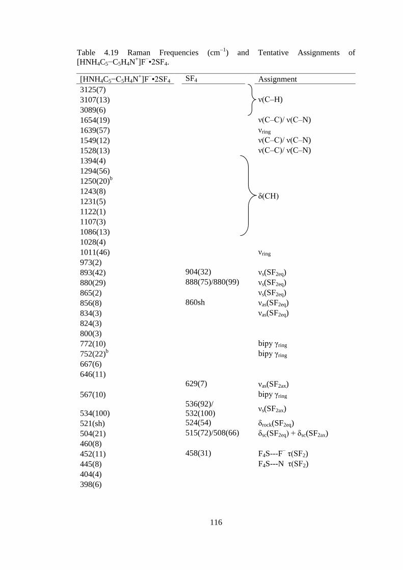
116
Table 4.19 Raman Frequencies (cm1
) and Tentative Assignments of
[HNH4C5−C5H4N+]F
−•2SF4.
[HNH4C5−C5H4N+]F
−•2SF4 SF4 Assignment
3125(7)
3107(13) ν(C–H)
3089(6)
1654(19) ν(C–C)/ ν(C–N)
1639(57) νring
1549(12) ν(C–C)/ ν(C–N)
1528(13) ν(C–C)/ ν(C–N)
1394(4)
1294(56)
1250(20)b
1243(8)
δ(CH) 1231(5)
1122(1)
1107(3)
1086(13)
1028(4)
1011(46) νring
973(2)
893(42) 904(32) νs(SF2eq)
880(29) 888(75)/880(99) νs(SF2eq)
865(2) νs(SF2eq)
856(8) 860sh νas(SF2eq)
834(3) νas(SF2eq)
824(3)
800(3)
772(10) bipy γring
752(22)b bipy γring
667(6)
646(11)
629(7) νas(SF2ax)
567(10) bipy γring
534(100)
536(92)/
532(100)
νs(SF2ax)
521(sh) 524(54) δrock(SF2eq)
504(21) 515(72)/508(66) δsc(SF2eq) + δsc(SF2ax)
460(8)
452(11) 458(31) F4S---F− τ(SF2)
445(8) F4S---N τ(SF2)
404(4)
398(6)
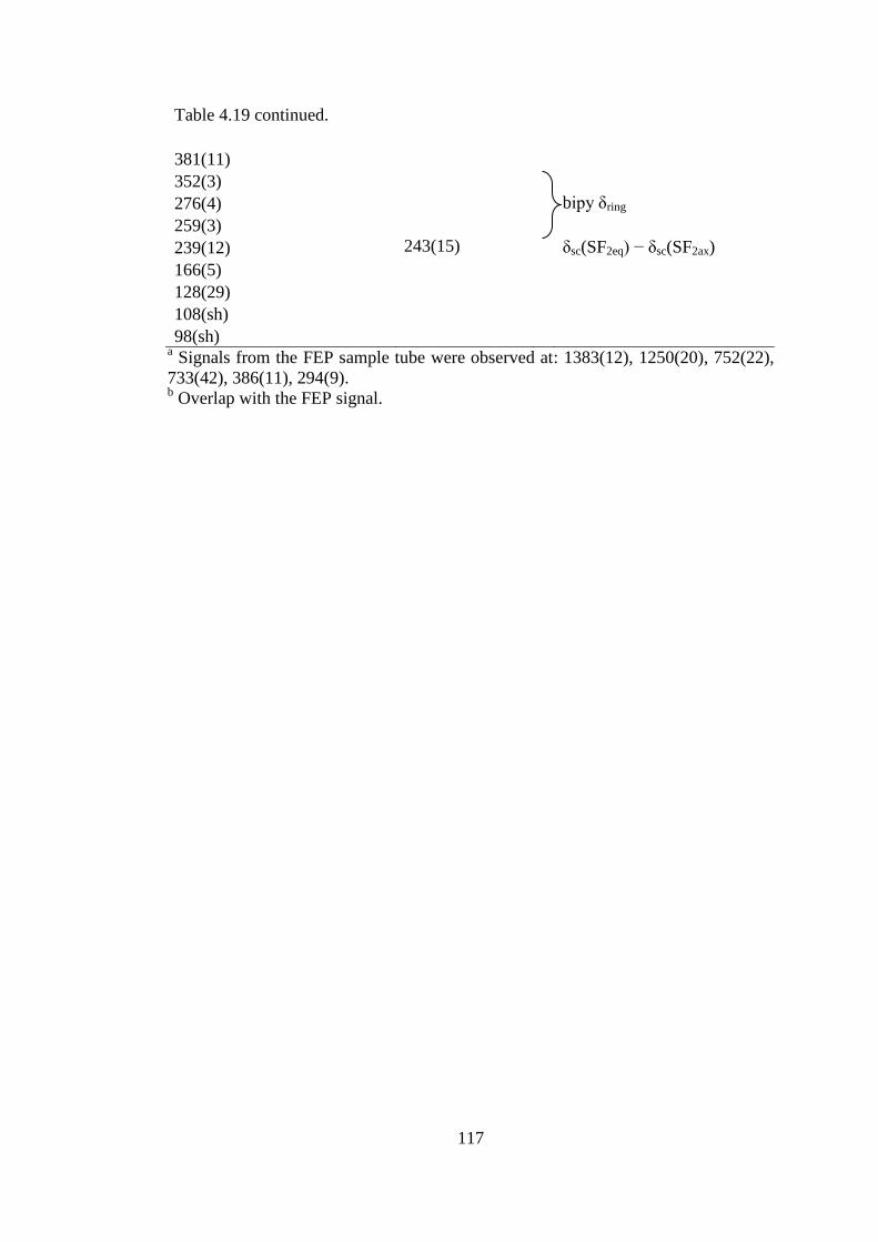
117
Table 4.19 continued.
381(11)
352(3)
276(4) bipy δring
259(3)
239(12) 243(15) δsc(SF2eq) − δsc(SF2ax)
166(5)
128(29)
108(sh)
98(sh) a
Signals from the FEP sample tube were observed at: 1383(12), 1250(20), 752(22),
733(42), 386(11), 294(9). b Overlap with the FEP signal.

118
Table 4.20 Raman Frequencies (cm1
) and Tentative Assignments of
[HNH4C5−C5H4NH2+
]2F−•4SF4.
[HNH4C5−C5H4NH2+
]2F−•4SF4 SF4 (solid) Assignment
3103(12) C−H
1651(45)
1639(46) ν(C–C)/ ν(C–N)
1530(30)
1294(100)b νring
1248(40)
1234(16) δ(CH)
1080(13)
1008(42) δring
995(24) νring
985(24) νring
897(37) 904(32) comb. band
871(3) 888(75) SF4 νs(SF2eq)
862(3) 880(99) SF4 νs(SF2eq)
836(15) 860sh SF4 νas(SF2eq)
751(16)b bipy γring
647(33)
629(7) SF4 νas(SF2ax)
569(10) bipy γring
533(42) 536(92)/532(100) SF4 νs(SF2ax)
521(31) 524(54) SF4 δrock(SF2eq)
515(72)/508(66) SF4 δsc(SF2eq) +
δsc(SF2ax)
446(6) 458(31) SF4 τ(SF2)
282(7) bipy δring
243(15) SF4 δsc(SF2eq) −
δsc(SF2ax) a Signals from the FEP sample tube were observed at: 1384(14), 1294(100) (overlap),
751(16) (overlap), 733(28), 387(7), 294(6) b Overlap with the FEP signal.
4.3 Summary and Conclusion
A large range of pyridinium and substituted pyridinium fluoride salts that
incorporate sulfur tetrafluoride have been synthesized and characterized by X-ray
crystallography and Raman spectroscopy at low temperatures. These structures
exhibit a surprising range of bonding modalities and provide an extensive view of

119
SF4 in the solid state. The structures offer the first look at F4S---F− contacts in
contrast to the known F4S−F− bonds in the SF5
− anion. In general, weak F4S---F
−
contacts, exhibit shorter S−F bonds and larger thermal ellipsoids. These structures
represent actual fluorinating agents that have been used to fluorinate organic
compounds containing carbonyl and hydroxyl groups and are only stable at low
temperatures.
The S---F− contacts range from 2.5116(12) to 2.8241(9) Å and are all
significantly shorter than the sum of the van-der-Waals radii (3.27 Å). The shortest
S---F− contacts occur when one fluoride is coordinated to one SF4 molecule, e.g., S---
F− of [HNC5H3(CH3)2
+]2[SF5
−]F
−•SF4 (2.5116(12) Å) and S---F
− of
[HNH4C5−C5H4N+]F
−•2SF4 (2.562(3) Å). The longest S---F
− contacts occur when
sulfur has contacts with two fluoride anions, e.g., S---F− of [HNC5H5
+]F
−•SF4 =
2.6923(9), 2.8241(9) Å and S---F− of [HNC5H4(CH3)
+]F
−•SF4 = 2.632(6), 2.823(6)
Å. The N(H)---F− distances range from 2.404(4) to 2.5396(17) Å. These hydrogen
bonds, except for the hydrogen bonds in [HNC5H3(CH3)2+]2[SF5
−]F
−•SF4, can be
classified as strong, according to the Steiner.26
The N(H)---F− distances (2.5308(17)
and 2.5396(17) Å are significantly longer in the 2,6-dimethylpyridinium
[HNC5H3(CH3)2+]2F
− moiety due to the steric hindrance of the methyl groups located
at the ortho-positions. These hydrogen bonds can be classified moderate in strength.1
The bifluoride anion formed in three of these reaction systems. The F---F
distances of these bifluoride anions agree well with previously reported F---F
distances. The 4-methylpyridinium bifluoride formed due to the presence of excess
HF, and insufficient SF4. The [HNC5H5+][HF2
−]•2SF4 and
120
[HNC5H4N(CH3)2+][HF2
−]•2SF4 salts are the first examples of SF4-bifluoride
interactions in the solid state.

121
References
(1) Schwesinger, R.; Link, R.; Wenzl, P.; Kossek, S. Chem. Eur. J. 2005, 12,
438-445.
(2) Clark, J. H. Chem. Rev. 1980, 80, 429-452.
(3) Christie, K. O.; Wilson, W. W. J. Fluorine Chem. 1990, 47, 117-120.
(4) Tunder, R.; Siegel, B. J. Inorg. Nucl. Chem. 1963, 25, 1097-1098.
(5) Bittner, J.; Fuchs, J.; Seppelt, K. Z. Anorg. Allg. Chem. 1988, 557, 182-190.
(6) Drullinger, L. F.; Griffths, J. E. Spectrochim. Acta A 1971, 27, 1793-1799.
(7) Christe, K. O.; Curtis, E. C.; Schack, C. J.; Pilipovich, D. Inorg. Chem. 1972,
11, 1679-1682.
(8) Clark, M.; Kellen-Yuen, C.; Robinson, K.; Zhang, H.; Yang, Z.-Y.;
Madappat, K.; Fuller, J.; Atwood, J.; Thrasher, J. Eur. J. Solid State Inorg.
Chem. 1992, 29, 809-833.
(9) Goettel, J. T.; Chaudhary, P.; Hazendonk, P.; Mercier, H. P. A.; Gerken, M.
Chem. Commun. 2012, 48, 9120–9122.
(10) Olah, G. A.; Welch, J. T.; Vankar, Y. D.; Nojima, M.; Kerekes, I.; Olah, J. A.
J. Org. Chem. 1979, 44, 3872-3881.
(11) Boenigk, D.; Mootz, D. J. Am. Chem. Soc. 1988, 110, 2135-2139.
(12) Schaefer, T.; Rowbotham, J. B.; Parr, W. J.; Marat, K.; Janzen, A. F. Can. J.
Chem. 1976, 54, 1322-1328.
(13) Dmowski, W. Pol. J. Chem. 1982, 56, 1369.
(14) Rudine, A. B.; Walter, M. G.; Wamser, C. C. J. Org. Chem. 2010, 75, 4292-
4295.
122
(15) Casteel, W. J.; Dixon, D. A.; LeBlond, N.; Lock, P. E.; Mercier, H. P. A.;
Schrobilgen, G. J. Inorg. Chem. 1999, 38, 2340-2358.
(16) Lind, M. D.; Christe, K. O. Inorg. Chem. 1972, 11, 608-612.
(17) Kniep, R.; Korte, L.; Kryschi, R.; Poll, W. Angew. Chem. Int. Ed. Engl. 1984,
23, 388-389.
(18) Cook, D. Can. J. Chem. 1961, 39, 2009-2024.
(19) Aakeroy C, B.; Seddon, K. R. Z. Naturforsch., B: Chem. Sci. 1993, 48, 1023-
1025.
(20) Andon, R.; Cox, J.; Herington, E. Trans. Faraday Soc. 1954, 50, 918-927.
(21) Wilson, W. W.; Christe, K. O.; Feng, J.-a.; Bau, R. Can. J. Chem. 1989, 67,
1898-1901.
(22) Dawson, P.; Hargreave, M. M.; Wilkinson, G. R. Spectrochimica Acta Part
A: Molecular Spectroscopy 1975, 31, 1055-1063.
(23) Chaudhary, P., M.Sc. Thesis, Lethbridge, Alta.: University of Lethbridge,
Dept. of Chemistry and Biochemistry, 2011.
(24) Boag, N. M.; Coward, K. M.; Jones, A. C.; Pemble, M. E.; Thompson, J. R.
Acta Crystallogr., Sect. C: Cryst. Struct. Commun. 1999, 55, 672-674.
(25) Topaçli, A.; Akyüz, S. Spectrochim. Acta, Part A 1995, 51, 633-641.
(26) Steiner, T. Angew. Chem. Int. Ed. 2002, 41, 48-76.
123
5 Structure of Sulfur Tetrafluoride in the Solid State
5.1 Introduction
Sulfur tetrafluoride is one of the fundamental binary main-group fluorides and,
since its discovery in 1929, its structure and bonding has been subject to many
studies.1,2
The structure of SF4 has been determined in the gas phase by microwave,3
vibrational,4 and nuclear magnetic resonance spectroscopy,
5 as well as electron
diffraction,6 revealing the molecular seesaw geometry (C2v) which is in accordance
with the VSEPR rules. Vibrational spectra of liquid SF4 have also been assigned in
terms of molecular C2v point symmetry.7 Sulfur tetrafluoride in solution is one of
the typical examples for a fluxional trigonal bipyramidal electron-group geometry,
with rapidly exchanging axial and equatorial fluorine environments on the NMR
time-scale at room temperature.8 At low-temperature, the exchange can be slowed
down, allowing the observation of two triplets in the 19
F NMR spectrum for the axial
and equatorial fluorine environments in SF4.
An NMR study of the temperature dependence of the 19
F NMR chemical shifts
and 2J coupling constants suggested the presence of labile fluorine bridging.
9 In the
past, a series of structures in solutions and the solid state have been discussed (see
Figure 5.1).
Structures (I) and (II) were first proposed but later discarded since the
equatorial S−F bonds are more covalent than the axial S−F bonds. This renders the
equatorial fluorines less fluoro-basic than the axial fluorines. The more ionic nature
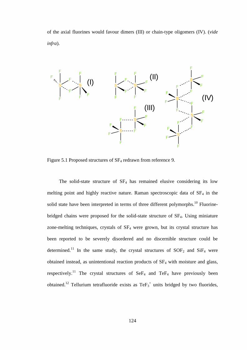
124
of the axial fluorines would favour dimers (III) or chain-type oligomers (IV). (vide
infra).
(I)
(III)
(IV)
(II)
Figure 5.1 Proposed structures of SF4 redrawn from reference 9.
The solid-state structure of SF4 has remained elusive considering its low
melting point and highly reactive nature. Raman spectroscopic data of SF4 in the
solid state have been interpreted in terms of three different polymorphs.10
Fluorine-
bridged chains were proposed for the solid-state structure of SF4. Using miniature
zone-melting techniques, crystals of SF4 were grown, but its crystal structure has
been reported to be severely disordered and no discernible structure could be
determined.11
In the same study, the crystal structures of SOF2 and SiF4 were
obtained instead, as unintentional reaction products of SF4 with moisture and glass,
respectively.11
The crystal structures of SeF4 and TeF4 have previously been
obtained.12
Tellurium tetrafluoride exists as TeF3+ units bridged by two fluorides,
125
whereas SeF4 contains distinct distorted disphenoidal SeF4 units connected by
contacts involving the axial fluorines.
5.2 Results and Discussion
5.2.1 [HNC5H3(CH3)2+]2[SF5
−]F
−•4SF4
The [HNC5H3(CH3)2+]2[SF5
−]F
−•4SF4 salt was synthesized by the reaction of
2,6-dimethylpyridine with half an equivalent of water in the presence of a large
excess of SF4 (see Equation 1).
6 SF4 + H2O + 2 N(C5H3)(CH3)2 → [HNC5H3(CH3)2+]2F
−[SF5
−]•4SF4 + SOF2 (1)
While mounting crystals of [HNC5H3(CH3)2+]2[SF5
−]F
−•SF4 (see Chapter 4),
which have a lozenge-like morphology, a small number of block-shaped crystals
were observed. The majority of these block-shaped crystals were found in the lower
portion of the reaction vessel. The crystal structure of the block-shaped crystals was
found to be related to that of [HNC5H3(CH3)2+]2[SF5
−]F
−•SF4, but included layers of
uncoordinated SF4. The use of a very large excess of SF4, along with cooling to
lower temperatures, exclusively yielded thick needles, which easily broke into block-
shaped crystals of [HNC5H3(CH3)2+]2F
−[SF5
−]•4SF4. The
[HNC5H3(CH3)2+]2F
−[SF5
−]•4SF4 salt is stable up to –90 °C, above which the crystals
decompose. This compound is the only one in which layers of uncoordinated SF4 are
present.

126
5.2.1.1 X-ray crystallography
Details of data collection parameters and crystallographic information for
[HNC5H3(CH3)2+]2F
−[SF5
−]•4SF4 are given in Table 5.1. Important bond lengths,
angles and contacts for [HNC5H3(CH3)2+]2F
−[SF5
−]•4SF4 are listed in Table 5.2.
This salt contains two 2,6-dimethylpyridinium cations that are hydrogen-
bonded to one fluoride anion, an SF5– anion, and four different SF4 molecules.
(Figure 5.2)
One SF4 molecule exhibits an S---F− contact to the fluoride and is located
within a layer of the [HNC5H3(CH3)2+] cations and the F
− and SF5
− anions (see
Figure 5.3). This S---F− contact distance (2.487(2) Å) is shorter than the S---F
−
contact distance (2.5116(12) Å) in the salt which does not contain an SF4 layer, i.e.,
[HNC5H3(CH3)2+]2[SF5
−]F
−•SF4. A second significantly weaker interaction (2.818(2)
Å) between sulfur and a fluorine atom from the SF5− anion expands the coordination
environment about S(1) to six.

127
Table 5.1 Crystal Data Collection Parameters and Results of
[HNC5H3(CH3)2+]2[SF5
−]F
−•4SF4 and SF4.
Compound [HNC5H3(CH3)2+]2[SF5
−]F
−•4SF4 SF4
File Code MG12107 MG12097
Empirical Formula C14H20F22N2S5 F4S
Formula weight, g mol-1 794.62 108.06
Temperature, K 133 100
Wavelength, Å 0.71073 Å 0.71073 Å
Crystal System Orthorhombic Orthorhombic
Space Group P212121 P212121
Unit Cell Dimensions a = 7.4597(10) Å
b = 18.150(2) Å
c = 21.863(3) Å
a = 6.773(4) Å
b = 6.812(4) Å
c = 13.122(8) Å
Abs. coeff. μ mm−1
0.54 0.98
Volume 2960.2(7) 605.5(6)
Z 4 8
Density (calculated), g cm-1
1.783 2.371
F(000) 1584 416
Crystal Size, mm3 0.56 × 0.23 × 0.16 0.17 × 0.15 × 0.14
Reflections Collected 33934 6874
Independent Reflections 6819 [Rint = 0.033] 1387 [Rint = 0.052]
Data/Restraints/Parameters 6819/0/392 1387/0/92
Goodness-of-fit on F2 1.04 1.18
Refine Diff Δρmax e Å−3
0.63 0.85
Refine Diff Δρmin e Å−3
−0.43 −0.67
R1, I > 2σ(I)a
0.0416 0.0501
wR2(F2)
a 0.1166 0.1117
aR1 = Σ||Fo| − |Fc||/Σ|Fo|; wR2 = [Σw(Fo
2 − Fc
2)
2/Σw(Fo
4)]
1/2.

128
Table 5.2 Selected Bond Lengths (Å), Contacts (Å), and Angles (deg.) of
[HNC5H3(CH3)2+]2F
−[SF5
−]•4SF4
Bond Lengths and Contacts, Å
S1−F1 1.5447(18) S1B---F9 2.937(2)
S1−F2 1.549(2) S1B---F4Aiii
3.164(3)
S1−F3 1.6503(18) S1C−F2C 1.502(3)
S1−F4 1.7059(18) S1C−F1C 1.533(2)
S1---F5 2.487(2) S1C−F3C 1.604(3)
S1---F7i 2.818(2) S1C−F4C 1.641(4)
S1A−F1A 1.530(2) S1C---F4iv
2.867(2)
S1A−F2A 1.543(2) S1C---F4Cv 3.114(4)
S1A−F3A 1.658(2) S2−F6 1.564(2)
S1A−F4A 1.668(2) S2−F10 1.664(2)
S1A---F8 2.755(2) S2−F9 1.719(2)
S1A---F3Aii 3.036(3) S2−F7 1.730(2)
S1B−F2B 1.500(4) S2−F8 1.763(2)
S1B−F1B 1.546(3) N1(H1)---F5 2.554(3)
S1B−F3B 1.619(3) N2(H2)---F5 2.553(3)
S1B−F4B 1.640(3)
Bond Angles, deg.
F1−S1−F2 97.43(11) F2B−S1B---F9 75.21(14)
F1−S1−F3 87.09(11) F1B−S1B---F9 172.89(15)
F2−S1−F3 88.27(12) F3B−S1B---F9 86.07(15)
F1−S1−F4 86.05(10) F4B−S1B---F9 100.26(13)
F2−S1−F4 87.32(11) F2B−S1B---F4Aiii
168.7(2)
F3−S1−F4 171.31(11) F1B−S1B---F4Aiii
76.38(17)
F1−S1---F5 79.91(9) F3B−S1B---F4Aiii
102.5(2)
F2−S1---F5 176.53(10) F4B−S1B---F4Aiii
79.92(14)
F3−S1---F5 89.36(9) F9---S1B---F4Aiii
107.83(7)
F4−S1---F5 94.69(9) F2C−S1C−F1C 100.49(18)
F1−S1---F7i 171.55(9) F2C−S1C−F3C 87.1(2)
F2−S1---F7i 81.81(10) F1C−S1C−F3C 90.0(2)
F3−S1---F7i 101.29(10) F2C−S1C−F4C 88.2(2)
F4−S1---F7i 85.50(9) F1C−S1C−F4C 87.69(19)
F5−S1---F7i 101.15(8) F3C−S1C−F4C 174.3(3)
F1A−S1A−F2A 99.76(15) F2C−S1C---F4iv
79.99(13)
F1A−S1A−F3A 87.10(15) F1C−S1C---F4iv
179.35(14)
F2A−S1A−F3A 87.53(13) F3C−S1C---F4iv
90.48(14)
F1A−S1A−F4A 87.31(15) F4C−S1C---F4iv
91.89(14)
F2A−S1A−F4A 87.99(13) F2C−S1C---F4Cv 171.49(17)
F3A−S1A−F4A 172.15(14) F1C−S1C---F4Cv 84.89(15)
F1A−S1A---F8 76.09(11) F3C−S1C---F4Cv 86.32(19)
F2A−S1A---F8 172.92(11) F4C−S1C---F4Cv 98.66(11)

129
Table 5.2 continued.
F3A−S1A---F8 97.89(10) F4iv
---S1C---F4Cv 94.68(8)
F4A−S1A---F8 86.10(10) F6−S2−F10 86.74(13)
F1A−S1A---F3Aii 168.85(12) F6−S2−F9 85.13(13)
F2A−S1A---F3Aii 78.66(11) F10−S2−F9 89.98(13)
F3A−S1A---F3Aii 103.79(8) F6−S2−F7 85.99(15)
F4A−S1A---F3Aii 81.62(11) F10−S2−F7 90.35(13)
F8−S1A---F3Aii 104.29(7) F9−S2−F7 171.08(13)
F2B−S1B−F1B 101.8(2) F6−S2−F8 83.96(12)
F2B−S1B−F3B 88.5(3) F10−S2−F8 170.70(13)
F1B−S1B−F3B 87.41(18) F9−S2−F8 88.89(10)
F2B−S1B−F4B 88.8(2) F7−S2−F8 89.35(11)
F1B−S1B−F4B 86.03(18) S2−F8---S1A 125.71(10)
F3B−S1B−F4B 172.2(2) S2−F9---S1B 134.86(12)
Symmetry codes: (i) x−1, y, z; (ii) x−1/2, −y+1/2, −z+1; (iii) x+1/2, −y+1/2,
−z+1; (iv) x+1, y, z; (v) x+1/2, −y+1/2, −z.
Figure 5.2 Thermal ellipsoid view along the a-axis of the packing of
[HNC5H3(CH3)2+]2F
−[SF5
−]•4SF4. Thermal ellipsoids are set at 50 % probability.

130
Figure 5.3 Thermal ellipsoid plot of the [HNC5H3(CH3)2+]2F
−---SF4 moiety. Thermal
ellipsoids are set at 50 % probability.
The 2,6-dimethylpyridinium cations form hydrogen bonds to the fluoride
with N(H)---F− distances of 2.553(3) and 2.554(3) Å, which are slightly longer than
the distances in [HNC5H3(CH3)2+]2[SF5
−]F
−•SF4 (N1(H)---F10 = 2.5396(17) Å and
N2(H)---F10 = 2.5308(17) Å).
The second fluoride ion in the structure is sufficiently naked to form the SF5−
anion (Figure 5.4). Because three of the four equatorial fluorines of this anion form
F---S contacts, the anion is locked in one position without disorder. As a
consequence of the contacts the anion geometry deviates from an idealized square
pyramid.
Figure 5.4 Thermal ellipsoid plot of the SF5− anion in
[HNC5H3(CH3)2+]2F
−[SF5
−]•4SF4. Thermal ellipsoids are set at 50 % probability.

131
The axial S−F bond length (1.564(2) Å) is much shorter than the equatorial
S−F bond lengths (1.664(2) to 1.763(2) Å). The three equatorial fluorines that have
contacts to adjacent SF4 molecules have significantly longer S−F bonds (1.719(2) to
1.763(2) Å) than the bond to the other equatorial fluorine, which does not form
contacts. The average S−Feq bond length is 1.719 Å, which is in excellent agreement
with the average equatorial bond length reported for Rb[SF5].13
The fluorine of the
longest most ionic bond in SF5− forms the strongest contact (F(8)---S and is trans to
the shortest most covalent equatorial bond, i.e., S2−F10 (1.664(2) Å).
Three SF4 molecules form a layer separating two ionic layers (see S1A-C in
Figure 5.5). The SF4 molecules in the layer show significantly larger thermal
ellipsoids on fluorine, than those on the SF4 coordinated to F–. The coordination
environments about sulfur in all SF4 molecules include two S---F contacts (Figure
5.5). The S---F contacts of the three SF4, which compose the layer, are with axial
fluorines of other SF4 molecules (2.867(2) to 3.164(3) Å) and with equatorial
fluorines of the SF5− anion (2.755(2) and 2.937(2) Å). One of the SF4 molecules in
the layer has contacts only with axial fluorines of other SF4 molecules. The
observation of the layer of “free” SF4 sparked interest in the solid-state structure of
neat SF4 (vide infra).

132
Figure 5.5 Thermal ellipsoid plot of the coordination environment about the SF4
molecules in the X-ray crystal structure of [HNC5H3(CH3)2+]2F
−[SF5
−]•4SF4; thermal
ellipsoids are drawn at the 50% probability level.

133
5.2.1.2 Raman Spectroscopy
The observed vibrational frequencies and their tentative assignments for
[HNC5H3(CH3)2+]2F
−[SF5
−]•4SF4 are listed in Table 5.3. The Raman spectrum of
solid SF4 at −135 °C exhibits significant splitting as previously observed.10
These
splittings can be explained by the presence of two crystallographically different SF4
molecules and/or by vibrational coupling between SF4 molecules in one unit cell.
The Raman spectrum of [HNC5H3(CH3)2+]2F
−[SF5
−]•4SF4 at −100 °C is
depicted in Figure 5.6 and contains the characteristic signals associated with the
HNC5H3(CH3)2+ cation and the SF5
− anion. The latter were assigned based on the
vibrational assignments previously reported for the Cs+, [Cs(18-crown-6)2]
+, and
[N(CH3)4]+ salts.
13-15 The Raman spectrum also shows several bands attributable to
SF4. Interestingly, two sets of bands in the equatorial SF2 stretching region can be
distinguished and tentatively assigned to νs(SF2,eq) of SF4 in the layer (880 cm–1
),
which is close to that of neat SF4 (896, 880 cm−1
), and that of SF4 coordinated by F–
(863 cm−1
). A Raman spectrum of solid [HNC5H3(CH3)2+]2F
−[SF5
−]•4SF4 recorded at
−85 °C contains a broadened signal at 884 cm−1
, which resembles the broad signal
observed in liquid SF4. This observation corroborates the observation of significant
thermal motion within the SF4 layer and suggests the onset of decomposition via
release of SF4.

134
Table 5.3 Experimental Raman frequencies and Tentative Assignments for
[HNC5H3(CH3)2+]2F
−[SF5
−]•4SF4.
[HNC5H3(CH3)2+]2F−[SF5
−]•4SF4a SF4 solid SF5
− in CsSF5b/[Cs(18-crown-6)2]SF5
c
Assignment Assignment Assignment
3111(6)
3082(6) ν(C–H)
3015(6)
2981(13)
2940(66) ν(CH3)
2861(3)
2757(8)
1657(10)
1626(20) ν(C–C)/ ν(C–N)
1556(7)
1439(6)
1420(9)
1393(30) CH3 deform
1385(31) CH3 deform
1312(4)
1293(27) ν(C–C) / ν(C–N)
1286sh
1216(3)
1174(9)
1100(16) νs(NC5)
1089(4)
1015(86)
993(5)
904(32) Overtone or
comb. band
880(63) SF4 (in layer),
νs(SF2eq)
888(75)
880(99) νs(SF2eq)
863(32) SF4···F
–,
νs(SF2eq)
849sh
844(21)
SF4 (in layer),
νas(SF2eq)
860sh νas(SF2eq)
819(19) SF4···F
–,νas
(SF2eq)
809(19)
803sh SF5
–, ν (SFax)
796(37)/785(12) ν (SFax)
790sh

135
Table 5.3 continued.
725(90) δin-plane(CCC)/
δin-plane(CNC)
626(3) SF4, νas(SF2ax)
629(7) νas(SF2ax)
580(16)c
574sh SF5− νas(SF4)
590 sh/583(7) νas(SF4)
561(24) δin-plane(CCC)/
δin-plane(CNC)
543sh δin-plane(CCC)/
δin-plane(NCC)
535(88) SF4 νs(SF2ax) 536(92)
532(100) νs SF2ax
527sh
514sh
SF4, δsc(SF2eq) +
δsc(SF2ax)
SF5− νs(SF4) in
phase
524(54) δsc(SF2eq) +
δsc(SF2ax)
522(27)/ 512(7) νs(SF4) in phase
486(16)
SF4, δrock(SF2eq)
SF5− νs(SF4) out
of phasee
515(72)
508(66) δrock(SF2eq)
435(100)/469(100) SF5
− νs(SF4) out
of phasee
459(8) SF4, τ(SF2)
458(31) τ(SF2)
440 sh SF5
− νs(SF4)
umbrella
469 sh/435(17) δs(SF4) umbrella
428(13) δout-of-plane(CCH)
403(13) SF5−, δ(FaxSF4)
e
435(100)/420(12) δ(FaxSF4) e
332(6) SF5
−, δs(SF4) in
plane
342(16)/315(7) δs(SF4) in plane
297(23)d ρr(CH3)
244sh
238sh
SF4, δsc(SF2eq) –
δsc(SF2ax)
SF5−, δas(SF4)
out of plane
243(15) δsc(SF2eq) –
δsc(SF2ax)
269 sh/267(20) δas(SF4) out of
plane
229(28)
222(27)
SF5−, δas(SF4) in
plane
ρr(CH3)
241(12)/242(13) δas(SF4) in plane
153(2)
126(100) Lattice modes
a Signals from the FEP sample tube were observed at 733(21), 387(4) 381(7), and 293sh cm
–1.
b From K.O. Christe, E.C. Curtis, C. J. Schack, and D. Pilipovich, Inorg. Chem. 1972, 11, 1679-1682.
c From M. Clark, C. J. Kellen-Yuen, K. D. Robinson, H. Zhang, Z.-Y. Yang, K. V. Madappat, J. W.
Fuller, J. L. Atwood, J. S. Thrasher, Eur. J. Solid State Inorg. Chem. 1992, 29, 809-833. d Overlap with the FEP signal.
e Assignment could be reversed.

136
Figure 5.6 Raman spectra of (a) [HNC5H3(CH3)2+]2F
−[SF5
−]•4SF4 in FEP tubing and
(b) of solid SF4 in a Pyrex glass 5-mm NMR tube recorded at –100 °C and –135 °C,
respectively, using 1064-nm excitation. Asterisks (*) denote signals arising from the
FEP sample tube. Bands attributed to the 2,6-dimethylpyridinium cation and to the
SF5− anion are denoted by (†) and (§), respectively.
5.2.2 Solid State Structure of SF4
Raman spectroscopy has been reported on solid SF4 in the past. Using matrix-
isolation techniques, three different phases were observed.10
It may be possible to
obtain different “phases” using low temperature matrix-isolation and annealing

137
techniques, yet we observed no indications of different phases in bulk samples. The
Raman spectrum at −135 °C and 1 cm−1
resolution exhibited splitting and shoulders
which have been previously reported and assigned by Christe et al.15
Slow cooling of neat SF4 results in the formation of a clear solid mass, which
contains striations that suggest a crystalline phase. The suggested unit cell of crystals
grown from neat SF4 was tetragonal P (6.81 × 6.81 × 13.17 Å), which is different
than the previously reported unit cell; cubic F: (6.761(5) Å).11
However attempts at
solving the structure in this unit cell failed. Since the use of a solvent to grow crystals
could provide an ordered structure, SF4 was crystallized from CF2Cl2. Ultimately the
same tetragonal unit cell was obtained for crystals grown from CF2Cl2. The correct
structural solution, however, showed that SF4 crystallized in the orthorhombic
system with twinning and two crystallographically unique ordered SF4 molecules in
the asymmetric unit (see Figure 5.7). Details of data collection parameters and
crystallographic information for SF4 are given in Table 5.1.
Important bond lengths, angles and contacts for SF4 are listed in Table 5.4.
Figure 5.7 Thermal Ellipsoid Plot of the asymmetric unit of SF4. Thermal Ellipsoids
are set to 50% probability.

138
Table 5.4 Bond Lengths (Å), Contacts (Å), and Angles (deg.) of SF4.
Bond Lengths and Contacts, Å
S1−F1 1.527(4) S2−F6 1.474(6)
S1−F2 1.535(4) S2−F5 1.553(4)
S1−F3 1.647(5) S2−F8 1.635(4)
S1−F4 1.676(5) S2−F7 1.671(5)
S1---F7 2.954(5) S2---F4ii 2.975(4)
S1---F8i 3.031(5) S2---F7
iii 3.261(6)
Bond Angles, deg.
F1−S1−F2 101.0(2) F6−S2−F8 86.9(3)
F1−S1−F3 88.3(3) F5−S2−F8 88.6(3)
F2−S1−F3 87.7(3) F6−S2−F7 86.6(3)
F1−S1−F4 87.3(3) F5−S2−F7 87.1(3)
F2−S1−F4 87.3(2) F8−S2−F7 171.6(3)
F3−S1−F4 172.6(3) F6−S2---F4ii 73.8(2)
F1−S1---F7 170.4(2) F5−S2---F4ii 170.1(3)
F2−S1---F7 69.57(18) F8−S2---F4ii 83.6(2)
F3−S1---F7 92.9(2) F7−S2---F4ii 99.8(2)
F4−S1---F7 90.5(2) F6−S2---F7iii
167.3(2)
F1−S1---F8i 68.4(2) F5−S2---F7
iii 71.4(2)
F2−S1---F8i 167.45(19) F8−S2---F7
iii 101.5(3)
F3−S1---F8i 85.4(2) F7−S2---F7
iii 84.01(18)
F4−S1---F8i 98.5(2) F4
ii---S2−F7
iii 116.20(13)
F7−S1---F8i 121.21(15) S2−F7---S1 135.9(2)
F6−S2−F5 99.6(3)
Symmetry codes: (i) −x+5/2, −y, z+1/2; (ii) x−1/2, −y+1/2, −z+2; (iii) x+1/2,
−y+1/2, −z+2.
The structure can best be described as a network with weak intermolecular S-
--F contacts. The shortest S---F contact found in the structure is 2.954(5) Å. These
contacts are exclusively formed by the more ionic axial fluorines to the sulfur atoms
of adjacent SF4 molecules. The geometry of the SF4 molecules agree well with the
seesaw geometry found for the gas phase with two longer, more ionic axial S–F
bonds and two shorter equatorial S–F bonds. None of the equatorial fluorines form
significant intermolecular contacts. This agrees very well with the more covalent
nature of the S−Feq bonds. Because of the location of the lone pair, the F---S---F

139
angles (121.2(2)° and 116.2(1)°) are significantly larger than the Feq---S---Feq angles
(101.0(2)° and 99.6(3)°). The S2−F6 bond (1.474(6) Å) is significantly shorter than
the subsequently shortest S−F bond (1.527(4) Å). This can be explained by an
unfavourable steric interaction between F6 and F8, which has a distance of 2.774(1)
Å, which is within the sum of the van-der-Waals radii (2.94 Å).
The S---F contacts found in solid SF4 (2.945(4) to 3.261(6) Å) are
significantly longer than the S---F− contact (2.487(2) Å) of the fluoride bound SF4
found in the [HNC5H3(CH3)2+]2F
−[SF5
−]•4SF4 structure, but are comparable to the S-
--FeqSF3 contacts found in the layer (2.867(2) to 3.164(3) Å). The S−Feq of solid SF4
bond lengths are not significantly different than the S−Feq bond lengths in the layer.
The structure is very different from that of TeF4, which forms infinite chains
composed of TeF3+ units bridged by fluorides (Figure 5.8).
Figure 5.8 Thermal Ellipsoid Plot of the TeF4 chain. Thermal ellipsoids are set at
50% probability. (Data from reference 12)
The structure is similar to that of SeF4, except that SeF4 only contains one
crystallographically unique molecule and each of the axial fluorines form a contact

140
with an adjacent selenium atom (Figure 5.9). In SF4, on the other hand, one of the
axial fluorines (F3) has no significant contacts.
Figure 5.9 Thermal ellipsoid plot of SeF4, showing contacts to adjacent SeF4
molecules. Thermal ellipsoids are set to 50% probability. (Data from reference 12)
5.3 Summary and Conclusion
The [HNC5H3(CH3)2+]2F
−[SF5
−]
•4SF4 salt was synthesized and studied at low
temperatures. The structure was found to contain layers of “free” SF4, and was
characterized by X-ray crystallography and Raman spectroscopy. For the first time,
the structure of SF4 in the solid state has been elucidated. The structure can best be
described as a network with weak intermolecular S---F contacts formed exclusively
with the axial fluorines that exhibit more ionic character. The structure is different
from TeF4 and previous predictions of chain-type or dimeric structures, which
contains two contacts between each SF4 molecule.9 A similar structural motif is
found in the novel [HNC5H3(CH3)2+]2F
−[SF5
−]
•4SF4 salt which contain SF4 layers.
The latter salt represents the first compound that contains a range of interaction
141
motifs between SF4 and F, i.e., F4SF– (1.564(2) to 1.763(2) Å), F4S···F
– (2.587(2)
Å), F4S···FSF4–(1.755(2) to 2.937(2) Å), F4S···FSF3 (2.867(2) to 3.164(2) Å).

142
References
(1) Fischer, J.; Jaenckner, W. Angew. Chem. Int. Ed. Engl. 1929, 42, 810-811.
(2) Oberhammer, H.; Shlykov, S. A. Dalton Trans. 2010, 39, 2838-2841.
(3) Tolles, W. M.; Gwinn, W. D. J. Chem. Phys. 1962, 36, 1119-1121.
(4) Dodd, R. E.; Woodward, L. A.; Roberts, H. L. Trans. Faraday Soc. 1956, 52,
1052-1061.
(5) Spring, C. A.; True, N. S. J. Am. Chem. Soc. 1983, 105, 7231-7236.
(6) Ewing, V.; Sutton, L. Trans. Faraday Soc. 1963, 59, 1241-1247.
(7) Christe, K. O.; Zhang, X.; Sheehy, J. A.; Bau, R. J. Am. Chem. Soc. 2001,
123, 6338-6348.
(8) Pavone, M.; Barone, V.; Ciofini, I.; Adamo, C. J. Chem. Phys. 2004, 120,
9167-9174.
(9) Gombler, W.; Seel, F. J. Fluorine Chem. 1974, 4, 333-339.
(10) Berney, C. V. J. Mol. Struc. 1972, 12, 87-97.
(11) Mootz, D.; Korte, L. Z. Naturforsch., B: Anorg. Chem., Org. Chem. 1984,
39B, 1295-1299.
(12) Kniep, R.; Korte, L.; Kryschi, R.; Poll, W. Angew. Chem. Int. Ed. Engl. 1984,
23, 388-389.
(13) Bittner, J.; Fuchs, J.; Seppelt, K. Z. Anorg. Allg. Chem. 1988, 557, 182-190.
(14) Drullinger, L. F.; Griffths, J. E. Spectrochim. Acta A 1971, 27, 1793-1799.
(15) Christe, K. O.; Curtis, E. C.; Schack, C. J.; Pilipovich, D. Inorg. Chem. 1972,
11, 1679-1682.

143
6 Sulfur Tetrafluoride Oxygen-Base Adducts
6.1 Introduction
Recently, Lewis acid-base adduct formation was conclusively shown for SF4
and a number of nitrogen bases, i.e., pyridine,1 4-methylpyridine,
1 2,6-
dimethylpyridine,1 4-dimethylaminopyridine,
1 and triethylamine.
2 Based on the
19F
chemical shift of SF4 in THF (OC4H6) and ethyl acetate, Muetterties suggested that
SF4 does not form adducts with these two oxygen bases.3 Azeem, on the other hand,
reported that at low temperatures the changes in (19
F) and the decrease in 2J
(19F−
19F) coupling of SF4 in THF and Et2O solvents suggest the formation of
SF4•OC4H6 and SF4•O(C2H5)2 adducts.4 Two new bands in the infrared spectrum of
matrix-isolated SF4 with acetone were also interpreted in terms of the formation of a
1:1 adduct.5 No conclusive information, however, is available about the Lewis acid-
base interactions between SF4 and oxygen bases.
The heavier chalcogen analogue, TeF4, which is significantly more Lewis
acidic than SF4, reacts with various cyclic and acyclic ethers to form the adducts
TeF4•1,4-dioxane,6 TeF4•(1,2-dimethoxyethane)2,
6 TeF4•Et2O,
6 and TeF4•(THF)2,
7
which have been structurally characterized by X-ray crystallography.
6.2 Results and Discussion
6.2.1 Synthesis and Properties
The reaction of SF4 with a series of oxygen-bases was studied by low-
temperature Raman spectroscopy and X-ray crystallography. The three oxygen-bases

144
which formed isolable adducts with SF4 were a cyclic ether (THF), a diether (1,2-
dimethoxyethane), and a cyclic ketone (cyclopentanone) (see Figure 6.1).
.
tetrahydrofuran (OC4H8)
...
..
..........
1,2-dimethoxyethane [(CH3OCH2)2]
cyclopentanone(O=C5H8)
Figure 6.1 Structures of the oxygen-bases that form Lewis acid-base adducts with
SF4.
Unlike the nitrogen-base adducts, mixtures of SF4 with oxygen-bases do not
appear to be sensitive to the presence of traces of HF and no solvolysis products
analogous to those described in Chapter 4 were observed. The SF4•O-base adducts
dissociate back into the Lewis acids and bases when warmed above −60 °C or placed
under reduced pressure. Mixtures of SF4 and THF in various ratios form clear
colourless liquids, which have lower vapour pressures than neat SF4 or neat THF at
temperatures between −60 to −90 °C. A 1:1 mixture of SF4 and THF freezes at −99
°C, forming a clear colourless crystalline solid whereas a 1:2 mixture of SF4 to THF
freezes at a lower temperature of −106 °C. As shown by Raman spectroscopy and X-
ray crystallography, two distinct adducts were obtained from the two reagent ratios
(see Equation 6.1).
SF4 + nOC4H8 ⇌ SF4•(OC4H8)n (where n = 1, 2) (6.1)
145
A mixture of 1,2-dimethoxyethane in excess SF4 was placed under dynamic
vacuum at −90 °C for several hours. Mass balance measurements indicated that the
mixture obtained after the removal of excess SF4, corresponded to an approximate
1:1 molar ratio of SF4 to 1,2-dimethoxyethane. This resulting mixture froze at −105
°C to form a clear colourless crystalline solid which was characterized by Raman
spectroscopy and X-ray crystallography as the SF4•(CH3OCH2)2 adduct. (Equation
6.2) It remains solid at −83 °C, but with vigorous agitation will revert back to the
liquid state.
SF4 + (CH3OCH2)2 ⇌ SF4•(CH3OCH2)2 (6.2)
Cyclopentanone is miscible with an equivalent amount of SF4 at −50 °C. It
remains liquid until approximately −100 °C, when it starts to crystallize into a solid
mass, which melts at −63 °C (see Equation 6.3). A crystal suitable for X-ray
crystallography was isolated from the solid mass and was shown to contain a 1:2
molar ratio of SF4 vs. cyclopentanone. The nature of the solid was also confirmed by
Raman spectroscopy. No evidence of fluorination of the carbonyl was observed in
the Raman spectrum under these conditions.
SF4 + 2 O=C5H8 ⇌ SF4•(O=C5H8)2 (6.3)
The reaction of SF4 with three other oxygen-bases was studied: diethyl ether,
acetylacetone, and 4-methylcyclohexanone (Figure 6.2).
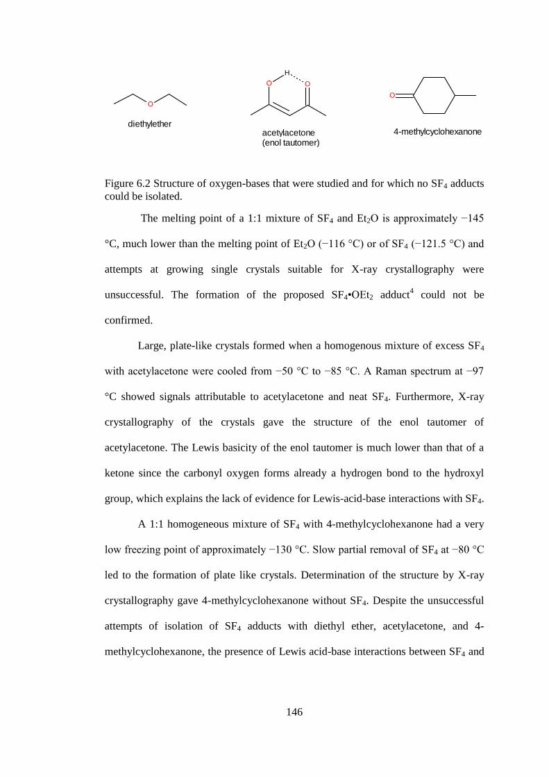
146
diethylether4-methylcyclohexanoneacetylacetone
(enol tautomer)
Figure 6.2 Structure of oxygen-bases that were studied and for which no SF4 adducts
could be isolated.
The melting point of a 1:1 mixture of SF4 and Et2O is approximately −145
°C, much lower than the melting point of Et2O (−116 °C) or of SF4 (−121.5 °C) and
attempts at growing single crystals suitable for X-ray crystallography were
unsuccessful. The formation of the proposed SF4•OEt2 adduct4 could not be
confirmed.
Large, plate-like crystals formed when a homogenous mixture of excess SF4
with acetylacetone were cooled from −50 °C to −85 °C. A Raman spectrum at −97
°C showed signals attributable to acetylacetone and neat SF4. Furthermore, X-ray
crystallography of the crystals gave the structure of the enol tautomer of
acetylacetone. The Lewis basicity of the enol tautomer is much lower than that of a
ketone since the carbonyl oxygen forms already a hydrogen bond to the hydroxyl
group, which explains the lack of evidence for Lewis-acid-base interactions with SF4.
A 1:1 homogeneous mixture of SF4 with 4-methylcyclohexanone had a very
low freezing point of approximately −130 °C. Slow partial removal of SF4 at −80 °C
led to the formation of plate like crystals. Determination of the structure by X-ray
crystallography gave 4-methylcyclohexanone without SF4. Despite the unsuccessful
attempts of isolation of SF4 adducts with diethyl ether, acetylacetone, and 4-
methylcyclohexanone, the presence of Lewis acid-base interactions between SF4 and

147
these oxygen-bases cannot be excluded, but the expected lability and low
dissociation temperatures of the adducts renders the isolation of any adducts difficult.
6.2.2 Crystal Structure of SF4•OC4H6 and SF4•(OC4H6)2
Details of data collection parameters and crystallographic information for
SF4•OC4H6 and SF4•(OC4H6)2 are given in Table 6.1. Important bond lengths, angles
and contacts for SF4•OC4H6 and SF4•(OC4H6)2 are given in Table 6.2 and Table 6.3,
respectively.
Table 6.1 Crystal Data Collection Parameters and Results of SF4•OC4H8,
SF4•(OC4H8)2, SF4•(CH3OCH2)2, and SF4•O=C5H8.
Compound SF4•OC4H8 SF4•(OC4H8)2 SF4•(CH3OCH2)2 SF4•(O=C5H8)2
File Code MG12088 MG13029 MG13024 MG13026
Empirical Formula C4H8F4OS C8H16F4O2S C4H10F4O2S C10H16F4O2S
Formula weight,
g mol−1
180.16 252.27 198.18 276.29
Temperature, K 133 123 128 123
Wavelength, Å 0.71073 0.71073 0.71073 0.71073
Crystal System Monoclinic Triclinic Orthorhombic Monoclinic
Space Group P21/n ̅ Pbcm P21/n
Unit Cell a = 11.225(4) Å
b = 10.798(4) Å
c = 12.435(4) Å
β = 97.074(4)°
a = 11.307 (2) Å
b = 13.664 (4) Å
c = 17.149 (3) Å
α = 107.28 (4)°
β = 98.74 (3)°
γ = 107.83 (3)°
a = 4.6402(12) Å
b = 13.168(3) Å
c = 13.503(3) Å
a = 8.9081(16) Å
b = 16.721(3) Å
c = 9.4878(17) Å
β = 116.320(2)°
Volume, Å3 1495.7(8) 2320.9(9) 825.1(4) 1266.7(4)
Z 8 8 4 4
μ (mm−1) 0.44 0.31 0.42 0.29
Density (calc.),
g cm1
1.600 1.444 1.595 1.449
F(000) 736 1056 408 576
Crystal Size, mm3 0.50 × 0.31 × 0.15 0.22 × 0.19 × 0.10 0.67 × 0.20 × 015 0.27 × 0.16 × 0.12
Reflections Collected 16903 21104 8490 14456
Independent Reflections 3481 10599 991 2906
Data/Restraints/
Parameters 3481/0/182 10599/0/541 991/0/56 2906/0/154
Goodness-of-fit on F2 1.05 0.93 1.13 1.00
Δρmax (e Å−3) 0.75 0.36 0.30 0.30
Δρmin (e Å−3) −0.74 −0.28 −0.32 −0.30
R1, I > 2σ(I) a 0.0473 0.057 0.020 0.034
wR2 (F2) a 0.1193 0.133 0.058 0.085
aR1 = Σ||Fo| − |Fc||/Σ|Fo|; wR2 = [Σw(Fo2 − Fc2)2/Σw(Fo
4)]1/2.

148
Table 6.2 Selected Bond Lengths (Å), Contacts (Å), and Angles (°) of SF4•OC4H6.
Bond Lengths and Contacts, Å
S1−F2 1.5344(17) S2−F6 1.5465(17) S1---O6 2.7766(17)
S1−F1 1.5448(16) S2−F5 1.5468(16) S1---O1 2.8022(19)
S1−F4 1.6430(17) S2−F8 1.6503(19) S2---O6 2.7892(18)
S1−F3 1.6610(18) S2−F7 1.6557(19) S2---O1 2.793(2)
Bond Angles, deg.
F2−S1−F1 98.25(10) F6−S2−F5 98.46(10) C5−O1−C2 108.37(18)
F2−S1−F4 88.15(11) F6−S2−F8 87.18(10) C5−O1−S2 116.03(18)
F1−S1−F4 87.93(10) F5−S2−F8 87.28(10) C2−O1---S2 118.26(15)
F2−S1−F3 88.09(11) F6−S2−F7 87.28(11) C5−O1−S1 110.57(17)
F1−S1−F3 87.68(10) F5−S2−F7 87.33(10) C2−O1−S1 123.64(14)
F4−S1−F3 173.77(11) F8−S2−F7 171.62(11) S2---O1---S1 77.49(5)
F2−S1−O6 79.70(8) F6−S2−O6 79.21(8) S1---O6---S2 77.97(4)
F1−S1−O6 175.99(8) F5−S2−O6 176.75(8)
F4−S1−O6 88.56(7) F8−S2−O6 90.32(8)
F3−S1−O6 95.66(8) F7−S2−O6 94.81(8)
F2−S1−O1 176.04(9) F6−S2−O1 178.47(8)
F1−S1−O1 79.72(8) F5−S2−O1 80.26(9)
F4−S1−O1 88.38(8) F8−S2−O1 91.92(8)
F3−S1−O1 95.20(8) F7−S2−O1 93.49(8)
O6---S1---O1 102.12(6) O6---S2---O1 102.03(5)

149
Table 6.3 Selected Bond Lengths (Å), Contacts (Å), and Angles (°) of SF4•(OC4H6)2.
Bond Lengths and Contacts, Å
S1−F1 1.5275(19) S2−F6 1.5341(18)
S1−F2 1.5350(19) S2−F7 1.5454(18)
S1−F3 1.649(2) S2−F5 1.643(2)
S1−F4 1.658(2) S2−F8 1.653(2)
S1---O2 2.687(2) S2---O4 2.678(2)
S1---O1 2.701(2) S2---O3 2.737(2)
S3−F11 1.5316(19) S4−F14 1.5352(19)
S3−F10 1.5438(19) S4−F13 1.5457(18)
S3−F12 1.641(2) S4−F15 1.626(2)
S3−F9 1.641(2) S4−F16 1.641(2)
S3---O6 2.662(2) S4---O7 2.703(2)
S3---O5 2.792(2) S4---O8 2.731(2)
Bond Angles, deg.
F1−S1−F2 96.68(11) F6−S2−F7 96.50(10)
F1−S1−F3 87.14(12) F6−S2−F5 86.20(11)
F2−S1−F3 88.07(12) F7−S2−F5 87.60(11)
F1−S1−F4 87.42(12) F6−S2−F8 87.93(11)
F2−S1−F4 86.53(11) F7−S2−F8 86.45(11)
F3−S1−F4 171.84(12) F5−S2−F8 171.12(11)
F1−S1---O2 171.09(9) F6−S2---O4 174.42(9)
F2−S1---O2 76.05(9) F7−S2---O4 78.00(9)
F3−S1---O2 97.63(11) F5−S2---O4 94.41(10)
F4−S1---O2 87.00(10) F8−S2---O4 90.79(10)
F1−S1---O1 76.21(9) F6−S2---O3 78.17(8)
F2−S1---O1 170.96(9) F7−S2---O3 173.03(9)
F3−S1---O1 86.03(10) F5−S2---O3 96.45(10)
F4−S1---O1 98.56(10) F8−S2---O3 88.85(10)
O2---S1---O1 111.52(7) O4---S2---O3 107.25(7)
F11−S3−F10 96.73(11) F14−S4−F13 97.07(10)
F11−S3−F12 86.29(13) F14−S4−F15 86.99(13)
F10−S3−F12 87.80(12) F13−S4−F15 88.35(12)
F11−S3−F9 88.37(12) F14−S4−F16 88.42(12)
F10−S3−F9 86.94(11) F13−S4−F16 86.48(11)
F12−S3−F9 172.02(11) F15−S4−F16 172.63(12)
F11−S3---O6 171.15(11) F14−S4---O7 74.95(9)
F10−S3---O6 75.96(9) F13−S4---O7 171.42(9)
F12−S3---O6 98.25(11) F15−S4---O7 94.29(10)
F9−S3---O6 86.28(10) F16−S4---O7 90.09(10)
F11−S3---O5 76.16(9) F14−S4---O8 171.02(9)
F10−S3---O5 168.69(10) F13−S4---O8 75.35(9)
F12−S3---O5 100.33(10) F15−S4---O8 87.95(10)
F9−S3---O5 84.11(9) F16−S4---O8 95.82(10)
O6---S3---O5 110.24(7) O7---S4---O8 112.86(7)
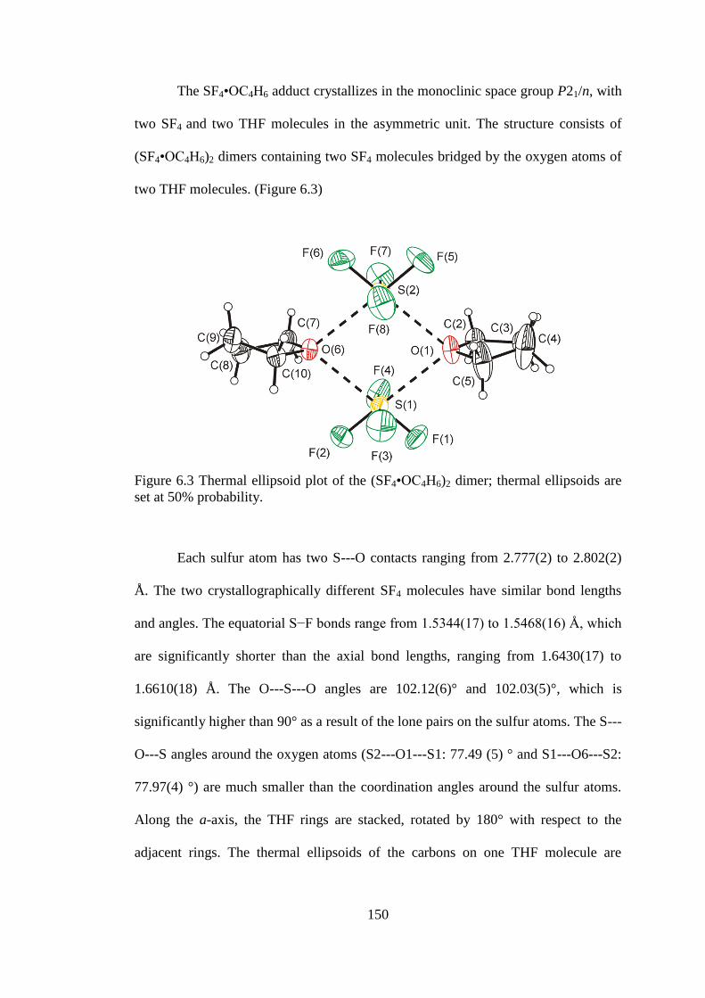
150
The SF4•OC4H6 adduct crystallizes in the monoclinic space group P21/n, with
two SF4 and two THF molecules in the asymmetric unit. The structure consists of
(SF4•OC4H6)2 dimers containing two SF4 molecules bridged by the oxygen atoms of
two THF molecules. (Figure 6.3)
Figure 6.3 Thermal ellipsoid plot of the (SF4•OC4H6)2 dimer; thermal ellipsoids are
set at 50% probability.
Each sulfur atom has two S---O contacts ranging from 2.777(2) to 2.802(2)
Å. The two crystallographically different SF4 molecules have similar bond lengths
and angles. The equatorial S−F bonds range from 1.5344(17) to 1.5468(16) Å, which
are significantly shorter than the axial bond lengths, ranging from 1.6430(17) to
1.6610(18) Å. The O---S---O angles are 102.12(6)° and 102.03(5)°, which is
significantly higher than 90° as a result of the lone pairs on the sulfur atoms. The S---
O---S angles around the oxygen atoms (S2---O1---S1: 77.49 (5) ° and S1---O6---S2:
77.97(4) °) are much smaller than the coordination angles around the sulfur atoms.
Along the a-axis, the THF rings are stacked, rotated by 180° with respect to the
adjacent rings. The thermal ellipsoids of the carbons on one THF molecule are

151
elongated, reflecting a high degree of thermal motion, i.e., puckering of the THF
ring, which is a common occurrence with THF.
The SF4•(OC4H6)2 adduct crystallizes in the triclinic space group ̅. The
asymmetric unit contains 4 molecules of SF4 and 8 molecules of THF. In the
structure, two THF molecules coordinate to one sulfur atom of each SF4 molecule,
and the oxygen atoms are essentially in the same plane as the equatorial fluorines of
SF4 (see Figure 6.4). The structure contains a large range of S---O contacts and O---
S---O angles. The equatorial S−F have lengths between 1.5275(19) and 1.5457(18)
Å, which are significantly shorter than the axial bonds (1.626(2) to 1.658(2) Å). The
S---O contact distances lie between 2.662(2) and 2.792(2) Å, which is a larger S---O
range of distances than found in the SF4•OC4H6 adduct (2.777(2) to 2.802(2) Å). The
O---S---O angles range from 107.25(7) to 112.86(7) Å, which are significantly larger
than the O---S---O angles in the SF4•OC4H6 adduct (102.12(6)° and 102.03(5)°).
The coordination of THF to sulfur is very different from that of N-bases to
SF4. For example, for the SF4•NC5H5 adduct, only one pyridine coordinates SF4,
resulting in a square pyramidal geometry about sulfur.1 The O---S bridged dimer has
a higher symmetry than the F−---S bridged dimer found in [HNC5H4(CH3)
+]F
−•SF4
(see Chapter 4).
To the best of my knowledge, these structures represent the first examples of
THF coordinating to a sulfur atom as well as the (SF4•OC4H6)2 dimer represents a
rare structure in which an organic oxygen-base is coordinated to two non-metals. A
search of the Cambridge Crystal Database for coordination complexes of oxygen to
sulfur gave only one result where dioxane is coordinated to SO3.8 The structure of
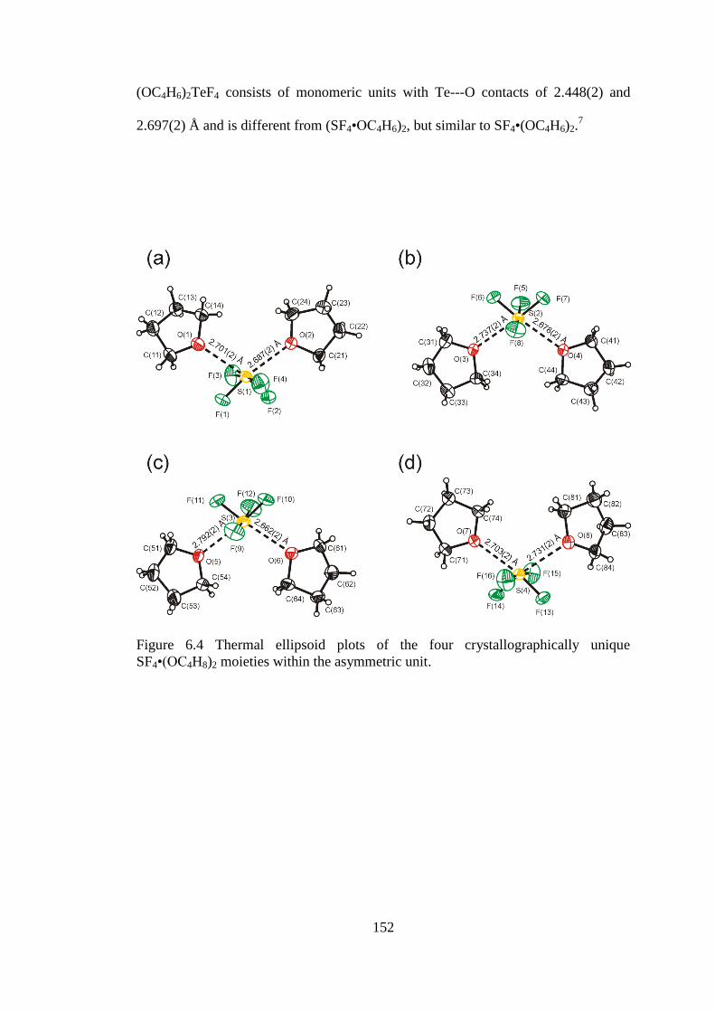
152
(OC4H6)2TeF4 consists of monomeric units with Te---O contacts of 2.448(2) and
2.697(2) Å and is different from (SF4•OC4H6)2, but similar to SF4•(OC4H6)2.7
Figure 6.4 Thermal ellipsoid plots of the four crystallographically unique
SF4•(OC4H8)2 moieties within the asymmetric unit.

153
6.2.3 Raman Spectroscopy of SF4•OC4H6 and SF4•(OC4H6)2
The Raman spectra of solid SF4•OC4H6 and SF4•(OC4H6)2 were recorded at
−107 °C, (Figure 6.5). The Raman frequencies and tentative assignments of
SF4•OC4H6 and SF4•(OC4H6)2 are given in Table 6.4 and Table 6.5, respectively. The
assignment of Raman bands associated with the THF molecule is based on the data
reported by Berthier et al., who used computational chemistry to aid in the
vibrational assignment.9 The band at 848(12) cm
−1 and several shoulders (2280, 822,
and 513 cm−1
) in the Raman spectrum of the SF4•OC4H6 adduct can be attributed to
an impurity of SF4•(OC4H6)2. Most bands attributable to the THF moiety exhibit
shifts relative to those of free THF. For example, for the SF4•OC4H6 adduct, the most
intense band attributable to the THF moiety (νs(COC)) has been shifted to a higher
frequency (923(53) cm−1
) compared to that of neat THF (914(100) cm−1
). The most
intense band in the Raman spectrum was assigned to the νs(SF2eq) mode at 859(100)
cm−1
, which is at a significantly lower frequency than that of neat liquid SF4 (896(65)
cm−1) reflecting the increase in ionic nature of the S−Feq bonds upon donation of
electron density from the Lewis base. The second most intense band appears at
527(84) cm−1
and was assigned to the νs(SF2ax) mode. This stretching mode is only
slightly shifted to lower frequency compared to that of neat SF4 (536(100) cm−1
).
The bands attributable to the equatorial S−F stretching modes (νs(SF2eq)) have been
more significantly shifted than the axial S−F stretching modes since they are located
trans to the oxygen donor atom of THF. As expected, the equatorial SF2 stretching
bands (νs(SF2eq) 859(100) cm−1
and νas(SF2eq) 828(39)) show a less pronounced low-
frequency shift compared to the SFeq stretching bands found in the Raman spectrum

154
of the SF4•N(C2H5)3 adduct (νs 826/816 cm−1
and νas 691 cm−1
),2 since triethylamine
is a much stronger base than THF.
Figure 6.5 Raman spectra of a) SF4•OC4H6 (at −107 °C), b) SF4•(OC4H6)2 (at −107
°C), and c) OC4H6 (room temperature). Asterisks (*) denote bands arising from the
FEP sample tube.

155
Table 6.4 Raman Frequencies (cm1
) and Tentative Assignments of SF4•OC4H6,
OC4H6, and SF4.
SF4•OC4H6a,c
OC4H6d
SF4b
Assignment 2996(sh) 2983(sh) 2987(43) 2962(93) νs(CH2) 2975(sh) 2956(31) 2942(30) 2941(88) 2917(13) 2913(sh) νas(CH2) 2893(56) 2877(64)
2875(98)
2732(1) 2684(1) 2661(5)
2623(1)
2584(2) 2575(2) (CH2) 1492(12)
1485(9) 1489(15) 1462(14) 1450(23) 1449(16) 1372(10) 1365(3) 1346(3) 1334(2) (CH2)wag 1308(9) 1246(19) 1239(16) 1228(12) (CH2)twist 1176(8) 1179(2) 1141(2) 1070(3) 1033(19) 1029(13) rock(CH2) 958(4) 923(53) 914(100) νs(COC)
913(11)
νas(COC) 894(9)
νs(C−C)
880(sh) 880/866 νas(C−C) 859(100) 896(65) νs(SF2eq) 828(39) 857(22) νas(SF2eq) 774(6) 703(5) 663(5)
ring bend
621(4) 578(5) ring bend 527(84) 536(100) νs (SF2ax) 446(8) 461(16) τ(SF2) 381(10) 295(11) 286(4) ring pucker 256(6) 237(12) δsc(SF2eq) – δsc(SF2ax)
a Signals from the FEP sample tube were observed at: 1383(11), 1297(sh), 1216(4),
751(6), 733(40), 386(10), 295(11) cm1
. Signals from the SF4•(OC4H6)2 impurity
were observed at: 2880(sh), 848(12), 822(sh), and 513(sh) cm1
. b The Raman
spectrum was recorded in a ¼-in. FEP tube at −110°C. Signals from the FEP sample
tube were observed at 294(8), 385(12), 733(53), 1216(2), 1306(1), 1382(2) cm–1
.
Bands at 1382(19), 804(9), 772(11) cm−1
were observed for ν(S–O) SOF2, ν(S–F)
SOF2 and ν(S–F) SF6 respectively. c Acquired at −107 °C.
d Acquired at room
temperature.

156
Table 6.5 Raman Frequencies (cm1
) and Tentative Assignments of SF4•(OC4H6)2,
OC4H6, and SF4.
SF4•(OC4H6)2a (OC4H6)2
d SF4
c Assignment
2983(63) 2983(sh)
2962(93)
νs(CH2)
2940(59) 2941(88)
2913(sh) νas(CH2)
2879(70) 2875(98)
2726(8) 2718(12)
2669(4)
2661(5)/
2623(1)
2582(2) 2575(2) (CH2)
1493(16) 1489(15)
1462(16)
1448(32) 1449(16)
1369(8)
1342(4) 1365(3) (CH2)wag
1306(4) 1334(2)
1244(19) 1228(12) (CH2)twist 1176(7) 1179(2)
1056(8) 1070(3)
1033(25) 1029(13) rock(CH2)
959(3)
923(49) 914(100) νs(COC)
894(10) νs(C−C)
847(100) 896(65) νs(SF2eq)
826(41) 857(22) νas(SF2eq)
773(2)
666(3) 703(5)
634(3)
579(5) ring bend
518(91) 536(100) νs(SF2ax)
445(7) 461(16) τ(SF2)
381(9)
294(9)b
286(4) ring Pucker
266(6) 237(12) δsc(SF2eq) – δsc(SF2ax) a Signals from the FEP sample tube were observed at FEP: 1383(8), 751(3), 733(28),
387(9), 294(9) cm–1
. b Overlaps with FEP signals.
c The Raman spectrum was
recorded in a ¼-in. FEP tube at −110°C. Signals from the FEP sample tube were
observed at 294(8), 385(12), 733(53), 1216(2), 1306(1), 1382(2) cm–1
. Bands at
1382(19), 804(9), 772(11) cm−1
were observed for ν(S–O) SOF2, ν(S–F) SOF2 and
ν(S–F) SF6 respectively. d Sample recorded at room temperature in 5-mm glass NMR
tube.

157
The most intense band in the Raman spectrum of SF4•(OC4H6)2 appears at
847(100) cm−1
and was assigned to the νs(SF2eq) mode. The second most intense peak
(518(91) cm−1) was assigned to the νs(SF2ax) mode. These observations agree very
well with the expected trend for the sequence neat SF4, SF4•OC4H6, SF4•(OC4H6)2.
The more electron density is donated to the sulfur atom on SF4, the more ionic and
weaker the S−F bonds are expected to become, resulting in lower stretching
frequencies. The vibrational frequencies of the νs(SF2eq) decrease from 896(65) cm−1
(SF4) to 859(100) cm−1
(SF4•OC4H6), and 847(100) cm−1
(SF4•(OC4H6)2). The
vibrational frequencies attributable to the νas(SF2eq) mode are also significantly
different from neat liquid SF4 (860sh cm−1
) but the difference between SF4•OC4H6
(828(39) cm−1
) and SF4•(OC4H6)2 (826(41)cm−1
) is not significantly different.
6.2.4 Crystal Structure of SF4•(CH3OCH2)2
Details of data collection parameters and crystallographic information for
SF4•(CH3OCH2)2 are given in Table 6.1. Important bond lengths, angles and contacts
for SF4•(CH3OCH2)2 are given in Table 6.6.
The adduct, SF4•(CH3OCH2)2, crystallizes in the orthorhombic space group
Pbcm. The structure of SF4•(CH3OCH2)2 consists of 1,2-dimethoxymethane, in
which one Lewis basic oxygen atom is coordinated to one sulfur atom of SF4 and the
second oxygen is coordinated to a second SF4 molecule. (Figure 6.6) The sulfur atom
in SF4 has two equivalent contacts (2.8692(9) Å) with oxygen atoms of different 1,2-
dimethoxyethane molecules, which increase the coordination environment around
sulfur to 6.

158
Table 6.6 Selected Bond Lengths (Å), Contacts (Å), and Angles (°) of
SF4•(CH3OCH2)2
Bond Lengths and Contacts, Å
S1−F1 1.5474(7) S1---O 2.8692(9)
S1−F1i 1.5474(7) S1---O1
i 2.8692(9)
S1−F2 1.6602(10) C1−O1 1.4203(13)
S1−F3 1.6736(10) O1−C2 1.4275(12)
C2−C2ii 1.498(2)
Bond Angles, deg.
F1−S1−F1i 99.03(5) F1−S1−O1
i 75.69(3)
F1−S1−F2 87.49(4) F1i−S1−O1
i 168.37(3)
F1i−S1−F2 87.49(4) F2−S1−O1
i 81.98(3)
F1−S1−F3 86.94(4) F3−S1−O1i 102.93(3)
F1i−S1−F3 86.94(4) O1---S1---O1
i 107.49(4)
F2−S1−F3 171.41(5) C1−O1−C2 110.98(8)
F1−S1---O1 168.37(3) C1−O1---S1 106.59(6)
F1i−S1---O1 75.69(3) C2−O1−S1 126.25(6)
F2−S1−O1 81.98(3) O1−C2−C2ii 109.98(7)
F3−S1−O1 102.93(3)
Symmetry codes: (i) x, y, −z+1/2; (ii) x, −y+1/2, −z+1.
Figure 6.6 Thermal ellipsoid plot of the SF4•(CH3OCH2)2 adduct; thermal ellipsoids
are set at 50% probability.

159
These contacts result in infinite chains along the c-axis. The axial fluorine
atoms and the sulfur of SF4 lie in a crystallographic mirror plane, and therefore the
equatorial S−F bonds are symmetry-related. As expected, the axial S−F bonds
(S1−F2 = 1.6602(10) Å and S1−F3 = 1.6736(10) Å) are significantly longer than the
equatorial bonds (S1−F1 = 1.5474(7) Å). The difference in the length of the axial
S−F bonds is likely due to packing effects, since both of the axial fluorines form no
significant contacts. The O1---S1---O1i contact angle is 107.49(4)°, which is much
larger than the Feq−S−Feq angle (99.03(5)°), because of the location of the lone pair
on sulfur. The 1,2-dimethoxyethane molecule lies on a C2-axis, thus half of the
molecule is related by symmetry and the 1,2-dimethoxyethane molecule adopts the
stable gauche conformation.10
The view along the c-axis shows the two different
orientations of adjacent SF4-1,2-dimethoxyethane chains (see Figure 6.7).
Figure 6.7 View along the c-axis of the thermal ellipsoid plot of SF4•(CH3OCH2)2.
Thermal ellipsoids set at 50% probability.
160
It was hypothesized that 1,2-dimethoxyethane could act as a bidentate ligand
towards sulfur, as seen towards metal complexes and TeF4.11,12
A bidentate
coordination may be geometrically disfavoured because of the smaller size of sulfur
compared to tellurium. It is interesting to note that TeF4 forms an adduct in which
two 1,2-dimethoxyethane ligands coordinate to Te in a bidentate fashion. The
resulting coordination number of 9 about Te is possible because of its much larger
radius.
6.2.5 Raman Spectroscopy of SF4•(CH3OCH2)2
The Raman spectrum of SF4•(CH3OCH2)2 at −107 °C is shown in Figure 6.8.
The Raman frequencies and tentative assignments are listed in Table 6.7. The Raman
spectrum at −107 °C contains bands associated with the SF4 and 1,2-
dimethoxyethane moieties, and low-intensity signals associated with residual neat
liquid SF4. The assignment of Raman bands associated with the 1,2-dimethoxyethane
is based on the previous assignments by Yoshida and Matsuura using DFT
calculations.13
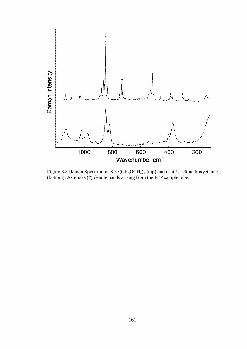
161
Figure 6.8 Raman Spectrum of SF4•(CH3OCH2)2 (top) and neat 1,2-dimethoxyethane
(bottom). Asterisks (*) denote bands arising from the FEP sample tube.

162
Table 6.7 Raman Frequencies (cm1
) and Tentative Assignments of
SF4•(CH3OCH2)2, (CH3OCH2)2, and SF4.
Vibrational Frequencies, cm−1
SF4•(CH3OCH2)2a,e
(CH3OCH2)2d
SF4c Assignments
3000(21) 2984(39)
2960(10) 2945(51)
2934(13)
2916(22) 2922(52)
2903(19) 2890(70) ν(C−H)
2884(9)
2855(14) 2842(74)
2824(24) 2818(100)
2811(sh)
2800(sh)
2732(4) 2719(10)
1479(29) 1472(24) CH2 scis, CH3 asym def.
1460(15) CH3 asym def, CH2 scis.
1454(8) CH3 sym def, CH2 scis.
1447(6) 1451(30)
1418(4) CH2 wag, C–C str, CH3 def.
1306(4)
1289(12) 1286(7) CH2 twist
1250(3) 1251(3) CH2 twist, CH3 rock
1160(3) CH3 rock
1138(10) 1135(7) CH3–O str, C–O str
1096(4) CH2 rock, CH3 rock
1036(8) CH2 rock, CH3–O str, C–O str
1030(7) 1026(7) CH3–O str, C–C str
995(5)
984(5)
877(19) 896(65)
νs(SF2eq) 866(31)
858(24) 849(24) C–O str, CH2 rock, C–C Str
850(100)
835(22) 821(13) 857(22) νas(SF2eq)
773(1)
610(4)
579(3) 539(1) CCO def, (COC) , CH2 rock
529(16)
522(12) 536(100) νs(SF2ax)
512(40)
453(7) 461(16) τ(SF2)
381(6) 398(4)
372(8) 367(12) COC bend, CCO def
308(2) COC bend, CCO def
294(7)b CCO def, COC bend, C–C tor
255(3) 237(12) δsc(SF2eq) – δsc(SF2ax)
123(8) C–C tor, CH3–O a
Signals from the FEP sample tube were observed at: 1383(6), 1214(1), 733(24), 751(3), 294(7),
387(6). b
Signals overlap with those of FEP. c The Raman spectrum was recorded in a ¼–in FEP tube
at −110°C. Signals from the FEP sample tube were observed at 294(8), 385(12), 733(53), 1216(2),
1306(1), 1382(2) cm–1
. Bands at 1382(19), 804(9), 772(11) cm−1
were observed for ν(S–O) SOF2,
ν(S–F) SOF2 and ν(S–F) SF6 respectively. d Sample recorded at room temperature in 5-mm glass
NMR tube.
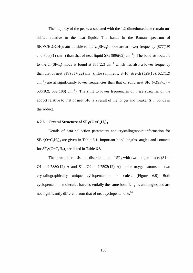
163
The majority of the peaks associated with the 1,2-dimethoxethane remain un-
shifted relative to the neat liquid. The bands in the Raman spectrum of
SF4•(CH3OCH2)2 attributable to the νs(SF2eq) mode are at lower frequency (877(19)
and 866(31) cm−1
) than that of neat liquid SF4 (896(65) cm−1
). The band attributable
to the νas(SF2eq) mode is found at 835(22) cm−1
which has also a lower frequency
than that of neat SF4 (857(22) cm−1). The symmetric S−Fax stretch (529(16), 522(12)
cm−1
) are at significantly lower frequencies than that of solid neat SF4 (νs(SF2ax) =
536(92), 532(100) cm−1
). The shift to lower frequencies of these stretches of the
adduct relative to that of neat SF4 is a result of the longer and weaker S−F bonds in
the adduct.
6.2.6 Crystal Structure of SF4•(O=C5H8)2
Details of data collection parameters and crystallographic information for
SF4•(O=C5H8)2 are given in Table 6.1. Important bond lengths, angles and contacts
for SF4•(O=C5H8)2 are listed in Table 6.8.
The structure consists of discrete units of SF4 with two long contacts (S1---
O1 = 2.7880(12) Å and S1---O2 = 2.7592(12) Å) to the oxygen atoms on two
crystallographically unique cyclopentanone molecules. (Figure 6.9) Both
cyclopentanone molecules have essentially the same bond lengths and angles and are
not significantly different from that of neat cyclopentanone.14

164
Table 6.8 Selected Bond Lengths (Å), Contacts (Å), and Angles (°) of
SF4•(O=C5H8)2
Bond Lengths and Contacts, Å
S1−F1 1.5455(10) O1−C1 1.2151(18) O2−C6 1.2157(19)
S1−F2 1.5478(10) C1−C2 1.507(2) C6−C7 1.509(2)
S1−F3 1.6579(10) C1−C5 1.507(2) C6−C10 1.510(2)
S1−F4 1.6674(10) C2−C3 1.527(2) C8−C7 1.525(2)
S1---O2 2.7592(12) C3−C4 1.528(2) C8−C9 1.532(2)
S1---O1 2.7880(12) C4−C5 1.525(2) C9−C10 1.527(2)
O2−C6 1.2157(19)
Bond Angles, deg.
F1−S1−F2 98.24(6) C1−O1---S1 120.80(10) C6−O2---S1 118.73(10)
F1−S1−F3 87.70(6) O1−C1−C2 125.16(14) O2−C6−C7 125.04(14)
F2−S1−F3 87.24(6) O1−C1−C5 125.92(14) O2−C6−C10 126.08(14)
F1−S1−F4 87.21(6) C2−C1−C5 108.92(13) C7−C6−C10 108.88(13)
F2−S1−F4 87.19(6) C1−C2−C3 104.91(12) C7−C8−C9 103.93(13)
F3−S1−F4 171.85(6) C2−C3−C4 103.98(13) C6−C7−C8 105.23(12)
O2---S1---O1 105.46(4) C5−C4−C3 103.57(13) C10−C9−C8 103.76(13)
C1−C5−C4 104.50(13) C6−C10−C9 104.30(13)
F1−S1---O1 177.00(5) F1−S1---O2 77.41(5)
F2−S1---O1 78.83(5) F2−S1---O2 173.57(5)
F3−S1---O1 91.51(5) F3−S1---O2 87.85(5)
F4−S1---O1 93.25(5) F4−S1---O2 97.24(5)

165
Figure 6.9 Thermal ellipsoid plot of the SF4•(O=C5H8)2 adduct; thermal ellipsoids are
set at 50% probability.
As in neat SF4 and the other SF4•O-base adducts, the S−Feq bond lengths
(1.5455(10) and 1.5478(10) Å) are shorter than the S−Fax bond lengths (1.6579(10)
and 1.6674(10) Å). The lone pair on sulfur resides directly in between both S---O
contacts which form an O---S---O angle of 105.46(4)°. The small size of the carbon
thermal ellipsoids suggests less thermal motion in the carbon ring of cyclopentanone
than that found in the THF ring of the SF4•OC4H6 adduct. The C=O lengths of the
cyclopentanone molecules in the SF4 adduct (1.2151(18) and 1.2157(19) Å) are not
significantly different from those of the neat cyclopentanone (1.2109(15) and
1.2148(15) Å)) reflecting the weakness of the acid-base interaction.14

166
6.2.7 Raman Spectroscopy of SF4•(O=C5H8)2
The Raman spectrum of solid SF4•(O=C5H8)2 recorded at −107 °C is shown in
Figure 6.10. The Raman frequencies and tentative assignments are listed in Table
6.9. The Raman spectrum contains peaks associated with the SF4 and cyclopentanone
moieties. The assignment of Raman bands associated with cyclopentanone are based
on the previously reported assignments by Cataliotti and Paliani.15
A number of the
peaks associated with the cyclopentanone ring are shifted and exhibit extra splittings
presumably because of vibrational coupling of the two O=C5H8 molecules in the
adduct. The signals associated with SF4 are significantly shifted and are much
sharper than that of neat SF4 at the same temperature. For example, the νs(SF2eq)
mode is a single band shifted to 872(88) cm−1
from that of neat liquid SF4 (896(65)
cm−1
).

167
Figure 6.10 Raman spectra of SF4•(O=C5H8)2 (top) and neat cyclopentanone
(O=C5H8) (bottom). Asterisks (*) denote bands arising from the FEP sample tube.

168
Table 6.9 Raman Frequencies (cm1
) and Tentative Assignments of SF4•(O=C5H8)2 (−107 °C), O=C5H8, and SF4.
SF4•(O=C5H8)2a
O=C5H8b
SF4c
Assignments
2978(100)
2969(82)
2969(100)
2957(42)
2941(19)
2918(sh)
2914(58)
ν(C−H)
2906(53)
2901(55)
2902(84)
2890(sh)
2886(56) 2883(95)
2787(3) 2802(7)
2616(3) 2606(3)
1724(16)
1712(34)
1743(18)
1728(18)
ν(CO)
1507(1)
1474(8)
1470(3)
1470(11)
1459(25)
1453(38)
1455(22)
CH2 def.
1403(35) 1410(23)
1319(6) 1309(2)
1286(12) 1278(8) CH2 wag
1275(12) 1268(8) CH2 wag
1242(22)
1232(10)
1231(9)
CH2 twist 1198(4) 1197(2)
1163(18)
1158(sh)
1152(sh) 1153(9) CH2 rock
1030(25)
1021(20)
1023(20)
967(12) Ring mode
961(8) 960(8) Ring mode
922(3) CH2 rock
914(4)
895(89) 892(88) Ring mode
872(88) 896(65) νs(SF2eq)
836(18) Ring mode
831(21) 857(22) νas(SF2eq)
814(29) 810(27) Ring mode
775(2)
703(23) 711(20) Ring mode
639(5)
590(4)
583(4)
581(10)
Ring mode
561(14)
Ring mode
532(41) 538(30)
526(47)
519(36)
536(100)
νs(SF2ax)
482(36) 461(16) τ(SF2)

169
Table 6.9 continued
471(8) 473(15) CO def
450(12) 451(sh) CO def
401(2)
382(3)
355(1)
260(5) 237(12) δsc(SF2eq) δsc(SF2ax)
239(3) 236(2)
139(14)
97(21) a
Signals from the FEP sample tube were observed at: 1384(3), 751(1), 733(18), 598(1), 386(3),
294(4) cm−1
. b
Sample acquired at room temperature in a 5-mm glass NMR tube. c The Raman
spectrum was recorded in a ¼–in FEP tube at −110°C. Signals from the FEP sample tube were
observed at 294(8), 385(12), 733(53), 1216(2), 1306(1), 1382(2) cm–1
. Bands at 1382(19), 804(9),
772(11) cm−1
were observed for ν(S–O) SOF2, ν(S–F) SOF2 and ν(S–F) SF6 respectively.

170
6.3 Summary and Conclusion
For the first time, SF4•oxygen-base adducts have been synthesized, isolated,
and structurally characterized. Adduct formation was observed with the oxygen
bases: THF, 1,2-dimethoxethane, and cyclopentanone at low temperatures. It was
crucial to handle these adducts at temperatures below −60 °C to avoid dissociation
because of the weakness of their Lewis-acid-base interaction. The adducts were
characterized by low-temperature Raman spectroscopy and X-ray crystallography.
Each structure contains sulfur atoms which are coordinated by two Lewis-basic
oxygens, increasing the coordination environment about sulfur in SF4 from 4 to 6.
This observation is in contrast to SF4•N-base adducts in which only one nitrogen
base coordinates to sulfur tetrafluoride to form a square pyramidal geometry about
sulfur.1,2
The S---N contacts lengths (2.141(2) to 2.5140(18) Å, for F4S•4-
NC5H4N(CH3)2 and SF4•NC5H5, respectively)1 in the SF4•N-base adducts are much
shorter than the S---O contact lengths (2.663(3) to 2.8692 (9) Å). The stronger Lewis
acid-base interaction in the SF4•N-base adducts results in donation of electron
density to sulfur and, as a consequence, a lowering of the Lewis acidity of sulfur in
SF4, and in addition, a closer proximity with the nitrogen base. Therefore, both
electronic and steric arguments likely contribute in preventing further coordination of
another nitrogen base.
Whereas sulfur tetrafluoride exclusively formed hexacoordinated adducts with
oxygen-bases, and pentacoordinated adducts with nitrogen-bases, both types of
coordination geometries are observed for fluorides (see Chapter 4). The contact
lengths between the SF4•O-base adducts are on average longer than those in the
SF4•F−(H)N-base adducts. The S---F
− contact lengths and the F
−---S---F
− angles have

171
a much larger range than the S---O contact lengths and the O---S---O bond angles in
the SF4•O-base adducts since the basicity of F− greatly depends on the strength of the
hydrogen bond to the protonated N-base. In SF4•F−(H)N-base adducts which form
chain-type structures or dimers, the sulfur atom has a coordination environment of 6,
the same as the SF4•O-base adducts. In other cases, such as the
[HNC5H3(CH3)2+]2[SF5
−]F
−•SF4 salt, only one significant S---F
− contact (2.5116(12)
Å) with SF4 is present, yielding a square pyramidal geometry about the sulfur atom.
The sulfur atom in this SF4 has an additional contact (2.900(5) Å) with one of the
fluorine atoms on the SF5− anion; however, it does not distort the square pyramidal
geometry to a noticeable extent (see Chapter 4). The extreme case, which is most
dissimilar to the SF4•O-base adducts, is when naked fluoride coordinates to sulfur
tetrafluoride to form the square pyramidal SF5− anion.
This is the first report of the coordination of oxygen-bases to SF4. Particularly,
the characterization of the SF4•ketone adduct (SF4•O=C5H4) is of great significance,
since SF4 can serve as a fluorinating agent towards carbonyl groups. It is, however,
postulated that SF3+•ketone adducts are the intermediates in the fluorination reaction.
These adducts offer the first extensive view of dative O---S(IV) bonds. A
summary of trends in structure and vibrational frequencies of these adducts can be
seen in Table 6.10. All of O---S contacts are within the sum of van-der-Waals radii
(3.32 Å). The longest S---O contacts are found in the SF4•(CH3OCH2)2 adduct
(2.8692(9) Å). Despite the fact that THF is the strongest donor, the 1:1 adduct
SF4•OC4H8 has relatively long contacts since one oxygen donor atom bridges two
Lewis acidic sulfur atoms. As expected, the 2:1 adduct (SF4•OC4H8) has the shortest
contact (2.663(3) Å).

172
Quantification of Lewis basicity is difficult, since it depends on the nature of
the Lewis acid.16
The most extensive list of Lewis basicity values is that for the BF3
affinity scale.16
Although BF3 is a harder acid than SF4, it was found that the trends
in BF3 affinity values are in agreement with the current observations. The higher
frequencies (877(19) and 866(31) cm−1) of the νs(SF2eq) stretch in the
SF4•(CH3OCH2)2 adduct agrees well with the weak donor properties of 1,2-
dimethoxyethane (74.67(19) kJ mol−1
(BF3)) when compared with the stronger donor
properties of THF (90.40(28) kJ mol−1
(BF3)).17
It is possible that cyclopentanone is not basic enough to act as a donor towards
two SF4 molecules, as observed with THF, but the 1:1 adduct (SF4•O=C5H8) cannot
be excluded based on my results. The oxygen is not sterically confined; therefore,
one would expect it would have the geometrical abilities to interact with more than
one SF4, if it were electronically favourable.
Table 6.10 Selected Structural and Vibrational Data in isolated SF4•O-Base Adducts.
Compound SF4•OC4H8 SF4•(OC4H8)2 SF4•(CH3OCH2)2 SF4•(O=C5H8)2
S---O (Å) 2.7892(18)
2.8022(19)
2.662(2)
2.792(2) 2.8692(9)
2.7592(12)
2.7880(12)
O---S---O (°)
102.03(5)
102.12(6)
107.25(7)
112.86(7) 107.49(4)
105.46(4)
S−Feq (Å)
1.5344(17)
1.5448(16)
1.5275(19)
1.5457(18) 1.5474(7)
1.5455(10)
1.5478(10)
S−Fax (Å)
1.6430(17)
1.6610(18)
1.626(2)
1.658(2)
1.6602(10)
1.6736(10)
1.6579(10)
1.6674(10)
νs(SF2eq) (cm−1
) 859(100) 847(100) 877(19), 866(31) 872(88)
Donor Strengtha 90.40(28) 90.40(28) 74.67(19) 77.44(45)
a Donor strength (kJ mol
−1) using the BF3 affinity scale, from 17.

173
References
(1) Goettel, J. T.; Chaudhary, P.; Hazendonk, P.; Mercier, H. P. A.; Gerken, M.
In 95th Canadian Chemistry Conference Calgary, Alberta, Canada 2012,
Abstract #353.
(2) Goettel, J. T.; Chaudhary, P.; Hazendonk, P.; Mercier, H. P. A.; Gerken, M.
Chem. Commun. 2012, 48, 9120–9122.
(3) Muetterties, E. L.; U.S. Patent 2,729,663: 1959.
(4) Azeem, M. Pak. J. Sci. Ind. Res. 1967, 10, 10-12.
(5) Sass, C. S.; Ault, B. S. J. Phys. Chem. 1985, 89, 1002-1006.
(6) Shlykov, S. A.; Giricheva, N. I.; Titov, A. V.; Szwak, M.; Lentz, D.;
Girichev, G. V. Dalton Trans. 2010, 39, 3245-3255.
(7) Lentz, D.; Szwak, M. Angew. Chem. Int. Ed. 2005, 44, 5079-5082.
(8) Richtera, L.; Toužín, J. Chemické listy 2004, 633-633.
(9) Cadioli, B.; Gallinella, E.; Coulombeau, C.; Jobic, H.; Berthier, G. J. Phys.
Chem. 1993, 97, 7844-7856.
(10) Jaffe, R. L.; Smith, G. D.; Yoon, D. Y. J. Phys. Chem. 1993, 97, 12745-
12751.
(11) Belli Dell’Amico, D.; Bradicich, C.; Labella, L.; Marchetti, F. Inorg. Chim.
Acta 2006, 359, 1659-1665.
(12) Shlykov, S. A.; Giricheva, N. I.; Titov, A. V.; Szwak, M.; Lentz, D.;
Girichev, G. V. Dalton Trans. 2010, 39, 3245-3255.
(13) Yoshida, H.; Matsuura, H. J. Phys. Chem. A 1998, 102, 2691-2699.

174
(14) Yufit, D. S.; Howard, J. A. K. Acta Crystallogr., Sect. C: Cryst. Struct.
Commun. 2011, 67, o104-o106.
(15) Cataliotti, R.; Paliani, G. Chem. Phys. Lett. 1973, 20, 280-283.
(16) Laurence, C.; Gal, J. F. Lewis Basicity and Affinity Scales; John Wiley and
Sons: Chichester, 2010.
(17) Maria, P. C.; Gal, J. F. J. Phys. Chem. 1985, 89, 1296-1304.
175
7 Summary and Directions for Future Work
7.1 Conclusions
The chemistry of sulfur tetrafluoride was significantly extended in the present
work. The previously known [ReO2F4−], [IO2F4
−], and [IOF4
−] anions were
synthesized in one-step reactions of SF4 with the oxo-anions ReO4−, IO4
−, and IO3
−,
respectively. These reactions gave excellent yields and were easy to separate from
the by-product, SOF2 and solvents (CH3CN or aHF). These reactions are the first
reported use of SF4 as a selective fluorinating agent towards oxo-anions to form
oxide-fluoride anions.
A large range of compounds were synthesized from mixtures of pyridine and
pyridine derivatives with HF and SF4. These compounds exhibit a wide range of
bonding modalities in the solid state, and provide a detailed view into the interaction
between SF4 and fluoride.
The solid-state structure of SF4 was, for the first time, fully elucidated. The
structure can best be described as a network with weak intermolecular S---F contacts
formed exclusively with the axial fluorines, which are more ionic in nature. A similar
structural motif was observed in the novel [HNC5H3(CH3)2+]2F
−[SF5
−]•4SF4 salt
which contains layers of SF4.
For the first time, adducts between sulfur tetrafluoride and oxygen bases were
isolated and structurally characterized. These adducts exhibit two long S---O contacts
per SF4 molecule, characteristic of the lower Lewis basicity of the oxygen bases
compared to that of the nitrogen bases or fluoride. These compounds offer the first
look at S(IV)---OR2 interactions in the solid state. The SF4•(O=C5H8)2 adduct proves
176
that carbonyl groups interact with SF4, which could be the first step in mechanism of
fluorination of carbonyl groups by SF4.
7.2 Directions for Future Work
The chemistry of sulfur tetrafluoride with other oxo-anions should be explored.
The reaction of SF4 with main-group oxo-anions such as ClOx−, BrOx
−, SO4
2−, PO4
3−,
NO3− and CO3
− could possibly result in clean efficient methods for obtaining oxide-
fluoride species.
The introduction of organic compounds containing carbonyl, hydroxyl and
carboxylic acid substituents to the SF4-HF-nitrogen base mixtures at low-
temperatures is the next step for elucidating the mechanism of fluorination of these
respective groups by SF4 in the presence of nitrogen-bases. For example, addition of
cyclopentanone to [HNC5H4(CH3)+]F
−•SF4 in the presence of excess SF4 could
reveal interesting Lewis acid-base interactions in the solid state at low temperature.
Adducts between other oxygen-bases (acetone, dioxanes, esters) should be
characterized by Raman and X-ray crystallography. Computational chemistry should
be used to confirm the geometries and Raman frequencies of these adducts. Also
molecules containing both nitrogen-bases and oxygen-bases should be used, such as
the reaction of SF4 with caffeine, in light of the possibility of forming two contacts
between sulfur and two different atoms.
Finally, exploring the chemistry of sulfur fluorides as ligands towards
transition-metal complexes should be further pursued, such as the reaction of sulfur
fluorides with tungsten carbonyl complexes. Although no conclusive evidence was
177
obtained for the formation of these species in this study, it is likely that these species
can be isolated in a variety of systems, and their pursuit is worthwhile.