Invitation for Bidder/s to provide structural engineering ... - Dirco
Upload
khangminh22Category
view
2download
0
© 2020 ENERCALC, Inc.
ENERCALC, INC
Structural Engineering Library
Structural Engineering LibraryVersion 6.0
by Michael D. Brooks, S.E., P.E.
A product of
ENERCALC, INC.
All rights reserved. No parts of this work may be reproduced in any form or by any means - graphic, electronic, ormechanical, including photocopying, recording, taping, or information storage and retrieval systems - without thewritten permission of the publisher.
Products that are referred to in this document may be either trademarks and/or registered trademarks of therespective owners. The publisher and the author make no claim to these trademarks.
While every precaution has been taken in the preparation of this document, the publisher and the author assume noresponsibility for errors or omissions, or for damages resulting from the use of information contained in thisdocument or from the use of programs and source code that may accompany it. In no event shall the publisher andthe author be liable for any loss of profit or any other commercial damage caused or alleged to have been causeddirectly or indirectly by this document.
Structural Engineering Library
© 2020 ENERCALC, Inc.
Publisher
ENERCALC Engineering Software
Post Office Box 188Corona del Mar, CA 92625
(949) 645-0151(800) 424-2252
Fax: (949) 645-3881
Sales: [email protected] : [email protected]
Web : www.enercalc.com
Managing Editor
ENERCALC, INC.
Michael D. Brooks, S.E., P.E.
Vesion 6 User's ReferenceMarch 2010
Corona del Mar, CA, USA

Structural Engineering LibraryI
© 2020 ENERCALC, Inc.
Table of ContentsForeword 0
Part I Introduction 1
................................................................................................................................... 31 Welcome
................................................................................................................................... 52 Our History
................................................................................................................................... 73 Warning & Disclaimer
................................................................................................................................... 84 License & Copyright
................................................................................................................................... 95 End of Service Policy
Part II Installation & Activation 10
................................................................................................................................... 121 License Types
................................................................................................................................... 142 Installation Overview
................................................................................................................................... 153 Activation Types
................................................................................................................................... 174 Manual Activation
................................................................................................................................... 195 Moving & Maintaining Your Activation
Part III Software Updates 23
................................................................................................................................... 251 Web Update
................................................................................................................................... 282 Update from Website
Part IV Support & Maintenance 29
................................................................................................................................... 311 Maintenance & Support Plan
................................................................................................................................... 322 Getting Assistance
................................................................................................................................... 343 Viewing Enhancements and Changes to the Software
Part V Getting Started 35
................................................................................................................................... 371 System Overview & Design Philosophy
................................................................................................................................... 382 About Our Documentation
................................................................................................................................... 393 Building Codes Supported
................................................................................................................................... 404 Learning Structural Engineering Library
................................................................................................................................... 415 Introductory Videos
................................................................................................................................... 426 Request for Suggestions
Part VI Program Overview 43
................................................................................................................................... 451 Introduction
................................................................................................................................... 472 Typical Worksession
................................................................................................................................... 483 Program Settings
................................................................................................................................... 554 Files & File Locations
IIContents
II
© 2020 ENERCALC, Inc.
................................................................................................................................... 565 Project Assistant
................................................................................................................................... 586 Databases
................................................................................................................................... 597 Screen Layout
................................................................................................................................... 628 Generating Reports
................................................................................................................................... 649 General Calculation Screen Usage
................................................................................................................................... 6610 3D Renderings
Part VII Main Menu 68
................................................................................................................................... 701 File
................................................................................................................................... 762 Settings
.......................................................................................................................................................... 78Default Values
................................................................................................................................... 793 Databases
.......................................................................................................................................................... 80Steel Section Database
.......................................................................................................................................................... 81Wood Section Database
.......................................................................................................................................................... 82Wood Reference Design Values Database
.......................................................................................................................................................... 83Masonry Database
.......................................................................................................................................................... 84Load Combination Database
................................................................................................................................... 874 Tools
................................................................................................................................... 895 License
................................................................................................................................... 906 Help
Part VIII Project Manager 94
................................................................................................................................... 1011 General Division
.......................................................................................................................................................... 102Building Code Information
.......................................................................................................................................................... 103Project Information
.......................................................................................................................................................... 104Client Information
.......................................................................................................................................................... 105Designer Notes
.......................................................................................................................................................... 106Revision List
................................................................................................................................... 1072 Loads & Forces Division
................................................................................................................................... 1083 Calculation List
.......................................................................................................................................................... 112Divisions
.......................................................................................................................................................... 116Adding, Deleting, Copying
.......................................................................................................................................................... 118Sorting by Division, Type & Material
.......................................................................................................................................................... 122Changing Calculation Order
.......................................................................................................................................................... 126Importing Calculations
................................................................................................................................... 1314 Project Printing
Part IX Sample Session 134
................................................................................................................................... 1361 Starting the Program
................................................................................................................................... 1372 Project Assistant
................................................................................................................................... 1393 Creating a Project File
................................................................................................................................... 1414 Entering Project Information
................................................................................................................................... 1435 Setting up your Title Block
................................................................................................................................... 1456 Adding a Calculation
................................................................................................................................... 1487 Viewing the Calculation Screen
Structural Engineering LibraryIII
© 2020 ENERCALC, Inc.
................................................................................................................................... 1498 Changing the Default Values/Settings
................................................................................................................................... 1509 Entering Data
................................................................................................................................... 16110 Selecting Sections and Materials from Built-in Databases
................................................................................................................................... 16611 Displaying a Sketch
................................................................................................................................... 16712 Displaying Diagrams
................................................................................................................................... 16913 Automatic Member Section Selection
................................................................................................................................... 17214 Printing a Calculation
................................................................................................................................... 17515 Saving a Calculation
................................................................................................................................... 17616 Editing a Division Name and Adding a New Division
................................................................................................................................... 18017 Adding Another Calculation
................................................................................................................................... 18318 Creating a Technical Support Question
................................................................................................................................... 18819 Closing a Project File
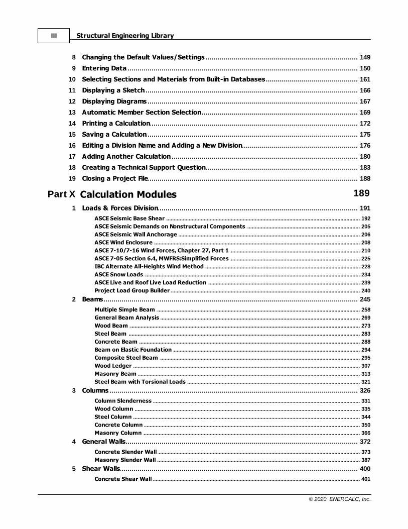
Part X Calculation Modules 189
................................................................................................................................... 1911 Loads & Forces Division
.......................................................................................................................................................... 192ASCE Seismic Base Shear
.......................................................................................................................................................... 205ASCE Seismic Demands on Nonstructural Components
.......................................................................................................................................................... 206ASCE Seismic Wall Anchorage
.......................................................................................................................................................... 208ASCE Wind Enclosure
.......................................................................................................................................................... 210ASCE 7-10/7-16 Wind Forces, Chapter 27, Part 1
.......................................................................................................................................................... 225ASCE 7-05 Section 6.4, MWFRS:Simplified Forces
.......................................................................................................................................................... 228IBC Alternate All-Heights Wind Method
.......................................................................................................................................................... 234ASCE Snow Loads
.......................................................................................................................................................... 239ASCE Live and Roof Live Load Reduction
.......................................................................................................................................................... 240Project Load Group Builder
................................................................................................................................... 2452 Beams
.......................................................................................................................................................... 258Multiple Simple Beam
.......................................................................................................................................................... 269General Beam Analysis
.......................................................................................................................................................... 273Wood Beam
.......................................................................................................................................................... 283Steel Beam
.......................................................................................................................................................... 288Concrete Beam
.......................................................................................................................................................... 294Beam on Elastic Foundation
.......................................................................................................................................................... 295Composite Steel Beam
.......................................................................................................................................................... 307Wood Ledger
.......................................................................................................................................................... 313Masonry Beam
.......................................................................................................................................................... 321Steel Beam with Torsional Loads
................................................................................................................................... 3263 Columns
.......................................................................................................................................................... 331Column Slenderness
.......................................................................................................................................................... 335Wood Column
.......................................................................................................................................................... 344Steel Column
.......................................................................................................................................................... 350Concrete Column
.......................................................................................................................................................... 366Masonry Column
................................................................................................................................... 3724 General Walls
.......................................................................................................................................................... 373Concrete Slender Wall
.......................................................................................................................................................... 387Masonry Slender Wall
................................................................................................................................... 4005 Shear Walls
.......................................................................................................................................................... 401Concrete Shear Wall
IVContents
IV
© 2020 ENERCALC, Inc.
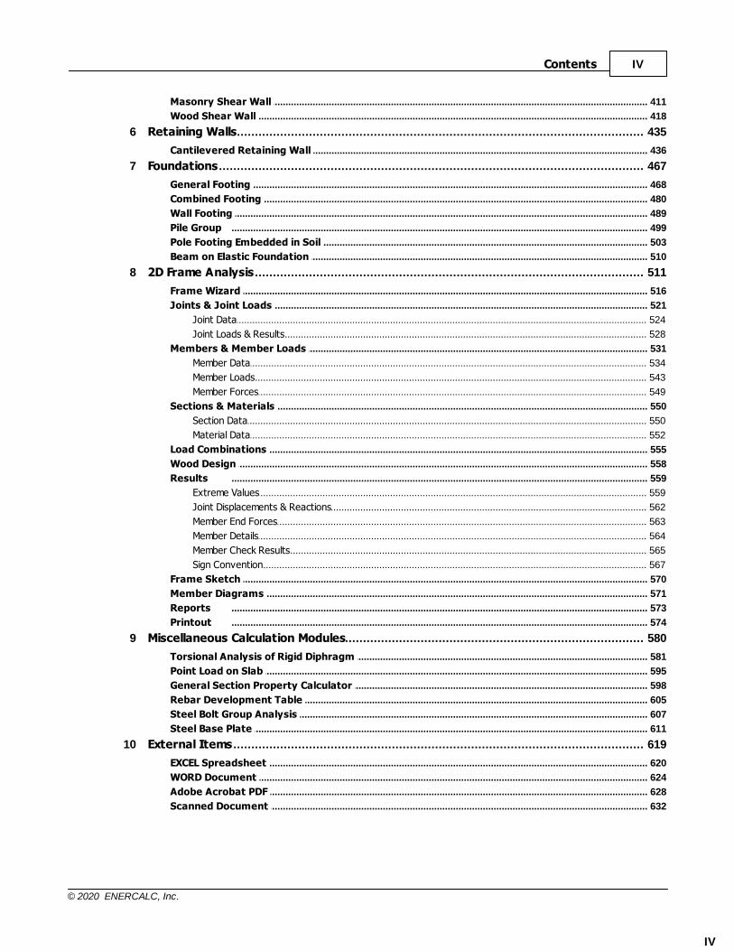
.......................................................................................................................................................... 411Masonry Shear Wall
.......................................................................................................................................................... 418Wood Shear Wall
................................................................................................................................... 4356 Retaining Walls
.......................................................................................................................................................... 436Cantilevered Retaining Wall
................................................................................................................................... 4677 Foundations
.......................................................................................................................................................... 468General Footing
.......................................................................................................................................................... 480Combined Footing
.......................................................................................................................................................... 489Wall Footing
.......................................................................................................................................................... 499Pile Group
.......................................................................................................................................................... 503Pole Footing Embedded in Soil
.......................................................................................................................................................... 510Beam on Elastic Foundation
................................................................................................................................... 5118 2D Frame Analysis
.......................................................................................................................................................... 516Frame Wizard
.......................................................................................................................................................... 521Joints & Joint Loads
......................................................................................................................................................... 524Joint Data
......................................................................................................................................................... 528Joint Loads & Results
.......................................................................................................................................................... 531Members & Member Loads
......................................................................................................................................................... 534Member Data
......................................................................................................................................................... 543Member Loads
......................................................................................................................................................... 549Member Forces
.......................................................................................................................................................... 550Sections & Materials
......................................................................................................................................................... 550Section Data
......................................................................................................................................................... 552Material Data
.......................................................................................................................................................... 555Load Combinations
.......................................................................................................................................................... 558Wood Design
.......................................................................................................................................................... 559Results
......................................................................................................................................................... 559Extreme Values
......................................................................................................................................................... 562Joint Displacements & Reactions
......................................................................................................................................................... 563Member End Forces
......................................................................................................................................................... 564Member Details
......................................................................................................................................................... 565Member Check Results
......................................................................................................................................................... 567Sign Convention
.......................................................................................................................................................... 570Frame Sketch
.......................................................................................................................................................... 571Member Diagrams
.......................................................................................................................................................... 573Reports
.......................................................................................................................................................... 574Printout
................................................................................................................................... 5809 Miscellaneous Calculation Modules
.......................................................................................................................................................... 581Torsional Analysis of Rigid Diphragm
.......................................................................................................................................................... 595Point Load on Slab
.......................................................................................................................................................... 598General Section Property Calculator
.......................................................................................................................................................... 605Rebar Development Table
.......................................................................................................................................................... 607Steel Bolt Group Analysis
.......................................................................................................................................................... 611Steel Base Plate
................................................................................................................................... 61910 External Items
.......................................................................................................................................................... 620EXCEL Spreadsheet
.......................................................................................................................................................... 624WORD Document
.......................................................................................................................................................... 628Adobe Acrobat PDF
.......................................................................................................................................................... 632Scanned Document
Part
I

Introduction 2
© 2020 ENERCALC, Inc.
1 Introduction
Last Revised: 3 February 2020

Structural Engineering Library3
© 2020 ENERCALC, Inc.
1.1 Welcome
Welcome to Structural Engineering Library
You've chosen one of the most respected Structural Engineering software packagesavailable today. In continuous development since 1983, Structural Engineering Library isthe culmination of years of development and refinement from suggestions of engineersworldwide.
Structural Engineering Library is developed with the practicing engineer in mind.Although large complex frames are fun projects, structural engineers spend most of theirtime designing and analyzing the components of structures. Because most of the buildingsworldwide rely on simple beams, columns, foundations, walls, and other small items, thissoftware system will quickly become your best friend. Structural Engineering Libraryremembers the mathematics, building code provisions, and standard materials you needto perform a detailed and economical design.
Because we feel that simple, repetitive engineering problems are far more common thanextensive 3-D frame analysis, this software package is designed specifically for fast,interactive engineering design of building components. We've combined the typical workingmethods of engineers, national building code provisions, and construction materialdatabases with the principles of structural mechanics into each "calcsheet" module. Youwill find that these modules operate very much like an electronic calculation pad.....simplyfill in the data entries and the entire calculation will be instantly updated for your review.
To add even more power and utility to the system, we've added detailed design sketchesand stress diagrams, automatic design and sizing, an online help system, materialdatabases, and elegant calculation printing to Structural Engineering Library.
Structural Engineering Library is designed around a file of calculations called a"Project". This single file with the extension "EC6" can hold one or thousands of individualcalculations. You add, edit, and delete the calculations in your Project File during the in-office design stage. Then, when it's time for submittal to a governing agency, you can printa complete set of calculations.
Because of the ever-expanding number of modules, we invite you to stay in close contact
with our website at www.enercalc.com
. Maintenance releases, up-to-the-minute technicaladvice, revised electronic documentation, and new product information will all be providedthere FIRST.
ENERCALC has put years of work into this package in support of the highly technical anddedicated service Structural Engineers provide to the people of the world. We continue toenhance this product weekly and are committed to developing this product well into thefuture. We extend our thanks for choosing ENERCALC, and look forward to using yoursuggestions to provide you with ever improving tools for your daily work.

Introduction 4
© 2020 ENERCALC, Inc.

Structural Engineering Library5
© 2020 ENERCALC, Inc.
1.2 Our History
ENERCALC Engineering Software (now ENERCALC, INC.) originated as one youngengineer playing with his new T.I. programmable calculator in 1980. In 1981, a set of Lotus1-2-3 spreadsheet templates was developed to automate the repetitive design ofcomponents of tilt-up and small office buildings. The software proved so productive andtime saving that it was decided to market it in the newly founded microcomputer industry.The entire set of 26 spreadsheet "templates" was named Structural Engineering Libraryand shipped on three 360K 5 1/4" diskettes, running on a 4.77 MHz 8086 IBM PC. Typicalcost of this state of the art engineering hardware and software system was $6,000!
As years went by, sales of the product increased. For engineers to purchase a technicalsoftware system based as a pre-programmed spreadsheet "template", it was a testamentboth to the intelligence of the users and to the easy and simple design of the spreadsheetbased software package.
In 1986, Lotus Development introduced a tool for programmers to link programs written in"C" to the very guts of 1-2-3. Called the "Add-In Toolkit", it offered a unique opportunity forENERCALC software designers. A decision was made to rewrite all of the currentengineering spreadsheet "templates" into the "C" language, and link these powerfulprograms to simple 1-2-3 "templates". The Lotus 1-2-3 spreadsheets would become dataentry/output screens driving powerful "C" language compiled processing programs. Thissolved the major problem with a spreadsheet.....lack of iteration capability that was criticalto engineering tasks.
Our first application of this technology was FastFrame 2-D introduced in 1987. FastFrametransformed a simple, off-the-shelf spreadsheet program into a powerful finite-elementanalysis system with full graphics. Prior to founding RISA Technologies, Bruce Batesworked on a "lightning fast" 16 MHz PC to develop the FastFrame solver. That solverwould later become the guts of the first version of RISA 2-D. Users were amazed that thepreviously complex batch processed frame analysis systems were reduced to entering anumber in a spreadsheet and INSTANTLY the entire frame was recalculated. At the 1987Lotus Developers Conference in Boston, MA, the actual software authors of Lotus 1-2-3were stunned to see their "business tool" doing complex analysis for multi story buildings!
With the decline of DOS and Lotus 1-2-3 , ENERCALC rewrote the entire "user interface"portion that provided the calculation screens and printing. Keeping the same "look and feel"to ease the change for users, our programmers wrote our own user interface program, assimple and fast as 1-2-3, complete with support for hundreds of printers. Version 4.4 forDOS was released in August of 1994, and produced a large increase in ENERCALC'suser base. Version 4.4 for DOS has become known as the "Volkswagen of structuralengineering software"... simple, enduring, yet designed to get you almost anywhere.
Structural Engineering Library 5.0 for Windows was introduced in 1996 as acompletely new rewrite of the legacy systems of the previous 15 years. Although much ofthe proven "C" language engineering calculation processes were retained, the rest of thesystem was redesigned and written from scratch for the modern Windows basedcomputer systems. The days of a spreadsheet based program were now gone, and a newsystem designed to be as easy as 1-2-3 was introduced.

Introduction 6
© 2020 ENERCALC, Inc.
In 2007 ENERCALC released Version 6 of Structural Engineering Library. Over thecourse of three decades since ENERCALC began we've enjoyed a large, loyal andconsistently growing base of users. This new version is a complete rewrite....the first ofits kind. New solvers, graphics, reporting, user interface, and database designs preparethis new platform with the future in mind. We look forward to years of enhancementsbased on this new release!
In 2017 ENERCALC released the next generation of Structural Engineering Library. Withthis release, we de-emphasize the "version" number, and rely solely on the build number toidentify the release. The software is now based on new development tools that areavailable to make processes more efficient and to provide a fresh, new look.
Sincerely,
Michael D. Brooks, P.E., S.E.President & FounderENERCALC, INC.

Structural Engineering Library7
© 2020 ENERCALC, Inc.
1.3 Warning & Disclaimer
Although it is our intent that the information contained in this manual and associatedsoftware program is accurate and reliable, it is possible that there may be errors, both ofomission and commission, that we are not aware of at any time. ENERCALC, Inc. canmake no warranties, either express or implied, as to the accuracy of the material in thismanual and software nor its suitability for a specific purpose or application for which it isadvertised.
ENERCALC, Inc., its owners, directors, and employees, can offer no guarantee and willaccept no liability for damages of any kind resulting from the use of the informationcontained or generated by this document and the accompanying computer software.
If you do not agree to be bound by these conditions and the conditions contained in theLicense Agreement contained herein, then you may Internet deactivate the program anduninstall the software within the trial period after the date of your order and request a fullrefund of the License Fee.
8

Introduction 8
© 2020 ENERCALC, Inc.
1.4 License & Copyright
The complete License Agreement can be viewed by using the following link:
License Agreement

Structural Engineering Library9
© 2020 ENERCALC, Inc.
1.5 End of Service Policy
At some point in the future the current version software will undergo a major overhaul ofcapability increase. At this time the prior version reaches its "End of Service" time.
When a version reaches its "End of Service", access to support and maintenance willcease in about 6 months (the time frame will be set by ENERCALC and is at ourdiscretion). The software will continue to operate but technical support, updates, and othersupport related items will cease to be available.
All software products, Structural Engineering Library included, have a practical commerciallifetime. In order to provide the highest quality products and support to our customers,each product is developed utilizing a product life cycle methodology, which includes anEnd-of-Service (EOS) phase.
The ENERCALC product EOS policy is to support the current release plus the previous(one back) release for up to six (6) months by default. After this time, ENERCALC'sproduct development ceases active development and support of that software releasewithin the Maintenance and Support Plan. ENERCALC does not create or make availablemaintenance releases or patches for software that has reached the EOS milestone.
During the EOS phase, ENERCALC will continue to investigate, troubleshoot, andcharacterize issues in an attempt to provide solutions and workarounds using theproduction releases. If a solution cannot be found using software that has reached theEOS milestone, ENERCALC will suggest that the system be upgraded to a more recentsoftware release.
Once the EOS process starts on a product release, a notice will be posted on all relevantpages stating that the product release has entered the EOS process.
Note: This policy is subject to revision.

Part
II

Structural Engineering Library11
© 2020 ENERCALC, Inc.
2 Installation & Activation
General
Structural Engineering Library (SEL) must be installed on each computer where it willbe used.
SEL has a new license security system that activates the software.
This requires a copy & paste of the Product Control Code (PCC) into the activationsection of the program and then using the [Internet Activate] button to obtain activationpermission from our Internet Activation server.
You can install SEL on ANY computer that you may wish to use it on, BUT beforeyou can RUN the program, you must Activate it.
This means you can easily move the activation of the software around between all of yourcomputers. You can just use this Internet based activation and deactivation ability to usethe software wherever you wish.
Important: Anti-Virus software and Firewalls
Our Internet Activation system and Web Update system use the Internet with typical"http over port 80" communications. You may have to tell your anti-virus and firewallsoftware to allow our programs to communicate over the Internet. The important programfile names are EC6.exe and ec6webupdate.exe, and they are typically installed in theProgram Files\ENERCALC_6 folder. You will may also need to give your computerpermission to communicate with enercalc.net. (Note that it does NOT use the www.prefix.)
If you do not perform this task then your activation request may not receive a response.
There are other methods of manually activating the software if you do not have an InternetConnection. Please see the "For Our Users" page at www.enercalc.com/users.html underManual License Activation and also the last section in this guide.
Installation & Activation 12
© 2020 ENERCALC, Inc.
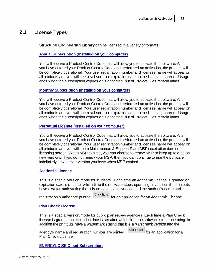
2.1 License Types
Structural Engineering Library can be licensed in a variety of formats:
Annual Subscription (Installed on your computer)
You will receive a Product Control Code that will allow you to activate the software. Afteryou have entered your Product Control Code and performed an activation, the product willbe completely operational. Your user registration number and licensee name will appear onall printouts and you will see a subscription expiration date on the licensing screen. Usageends when the subscription expires or is canceled, but all Project Files remain intact.
Monthly Subscription (Installed on your computer)
You will receive a Product Control Code that will allow you to activate the software. Afteryou have entered your Product Control Code and performed an activation, the product willbe completely operational. Your user registration number and licensee name will appear onall printouts and you will see a subscription expiration date on the licensing screen. Usageends when the subscription expires or is canceled, but all Project Files remain intact.
Perpetual License (Installed on your computer)
You will receive a Product Control Code that will allow you to activate the software. Afteryou have entered your Product Control Code and performed an activation, the product willbe completely operational. Your user registration number and licensee name will appear onall printouts and you will see a Maintenance & Support Plan (MSP) expiration date on thelicensing screen. When MSP expires, you can choose to renew MSP to keep up to date onnew versions. If you do not renew your MSP, then you can continue to use the softwareindefinitely at whatever version you have when MSP expired.
Academic License
This is a special version/mode for students. Each time an Academic license is granted anexpiration date is set after which time the software stops operating. In addition the printoutshave a watermark stating that it is an educational version and the student's name and
registration number are printed. Click here
for an application for an Academic License.
Plan Check License
This is a special version/mode for public plan review agencies. Each time a Plan Checklicense is granted an expiration date is set after which time the software stops operating. Inaddition the printouts have a watermark stating that it is a plan check version and the
agency's name and registration number are printed. Click here
for an application for aPlan Check License.
ENERCALC SE Cloud Subscription

Structural Engineering Library13
© 2020 ENERCALC, Inc.
This subscription offering allows access to our cloud-based applications: STRUCTURE,EARTH, and ENERCALC 3D. STRUCTURE is the cloud format of Structural EngineeringLibrary. EARTH is the cloud format of RetainPro. ENERCALC 3D is our general purpose3D finite element analysis and and design application. No installations are required forENERCALC SE. The applications run through your Internet browser, and data is stored inour secure online storage for universal availability and ease of collaboration.

Installation & Activation 14
© 2020 ENERCALC, Inc.
2.2 Installation Overview
General
For the most current installation information you need to review this document located onour website:
http://www.enercalc.com/pdf/EC_V6_Install_SingleLicense.pdf
Structural Engineering Library (SEL) must be installed on each computer where it will
be used. Click here for a video on installation: Installation
Feel free to install the software on any computer where you may want to run it, but keep inmind that you will need to Activate an installation before it will actually run. More on that inthe Activation section...
When using our installation program you will be asked to paste in your Product ControlCode (PCC) for security. Then simply follow the on-screen prompts to complete theinstallation.

Structural Engineering Library15
© 2020 ENERCALC, Inc.
2.3 Activation Types
When Internet activating SEL, the following activation types will be offered:
Click here for a video on Internet Activation: Internet Activation
The activation types behave as follows:
Indefinite:
This option saves activation info to your computer, so it will result in an installation that willremain activated until it is Internet deactivated by the user, or until another user forciblydeactivates this computer.
This option is useful in situations where the number of users is equal to the number ofavailable seats, such that there is no need to share seats among multiple computers. It isalso useful in situations where a laptop will be taken to a remote location where Internetaccess is uncertain.
Automatic Activation/Deactivation:
This option automatically activates the program when it is launched (if a seat is available),and it automatically deactivates when the user exits the program.
This option is useful in situations where the number of users is greater than the number ofavailable seats, such that there is need to share seats among multiple computers.

Installation & Activation 16
© 2020 ENERCALC, Inc.
Note: To change to a different activation type, such as to change from "Automatic" to"Indefinite", simply Internet Deactivate temporarily. Then Internet Activate once again andyou will be offered the "Select Activation Type" dialog where you can choose the desiredactivation type.
Structural Engineering Library17
© 2020 ENERCALC, Inc.
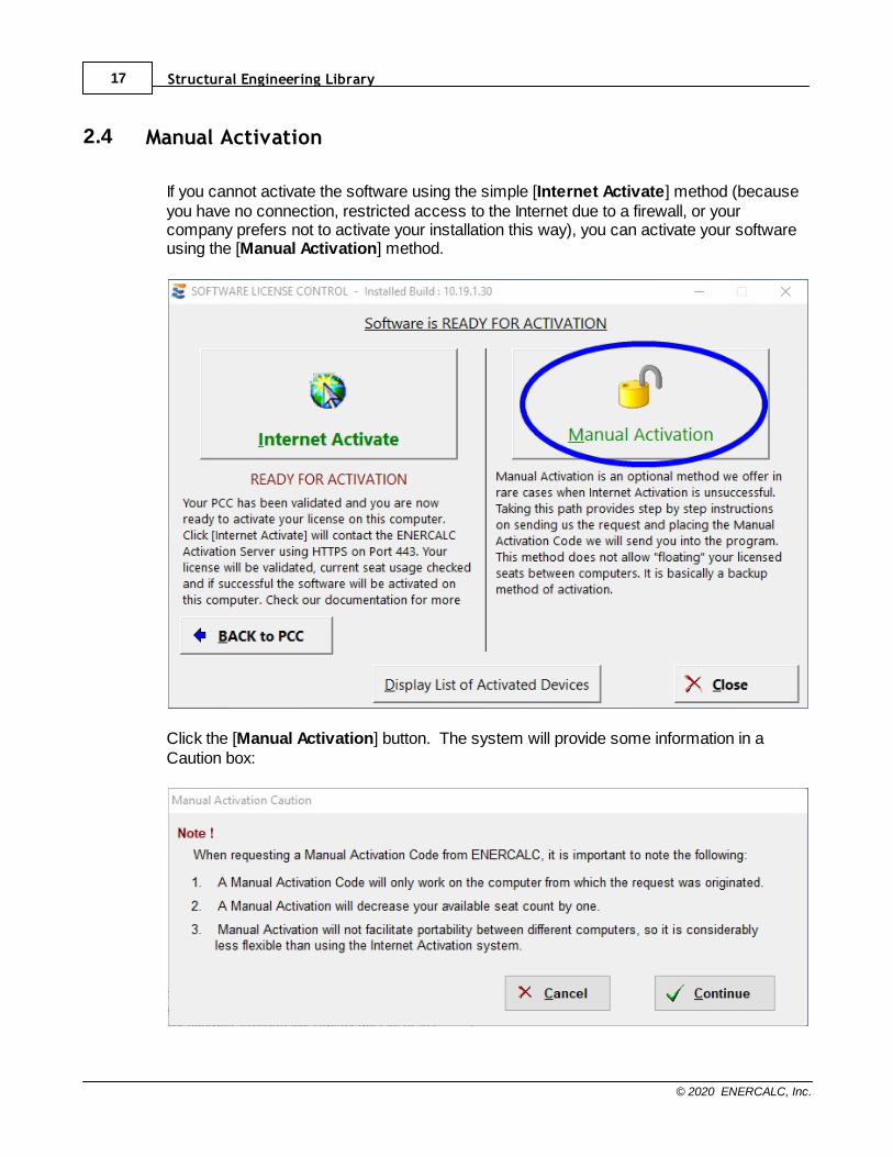
2.4 Manual Activation
If you cannot activate the software using the simple [Internet Activate] method (becauseyou have no connection, restricted access to the Internet due to a firewall, or yourcompany prefers not to activate your installation this way), you can activate your softwareusing the [Manual Activation] method.
Click the [Manual Activation] button. The system will provide some information in aCaution box:
Installation & Activation 18
© 2020 ENERCALC, Inc.
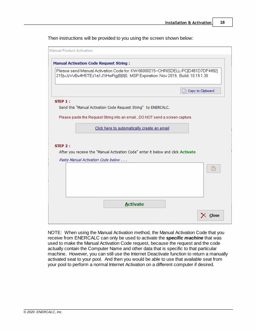
Then instructions will be provided to you using the screen shown below:
NOTE: When using the Manual Activation method, the Manual Activation Code that youreceive from ENERCALC can only be used to activate the specific machine that wasused to make the Manual Activation Code request, because the request and the codeactually contain the Computer Name and other data that is specific to that particularmachine. However, you can still use the Internet Deactivate function to return a manuallyactivated seat to your pool. And then you would be able to use that available seat fromyour pool to perform a normal Internet Activation on a different computer if desired.

Structural Engineering Library19
© 2020 ENERCALC, Inc.
2.5 Moving & Maintaining Your Activation
A Structural Engineering Library license has some number of "seats" associated with it. Each activation uses one of your available seats. When an installation gets deactivated,that seat returns to your pool of available seats.
This section will assist you in moving your activation from one computer to another.
Moving Your Activation
When you originally activated the software, if you used [Internet Activate], then you canuse [Internet Deactivate] to return this activation to our server, so that it can be availableto another computer.
Follow these steps:
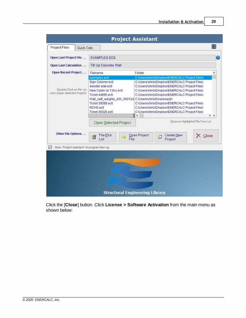
Start Structural Engineering Library. You will probably see the Project Assistant screenas shown below:
Installation & Activation 20
© 2020 ENERCALC, Inc.
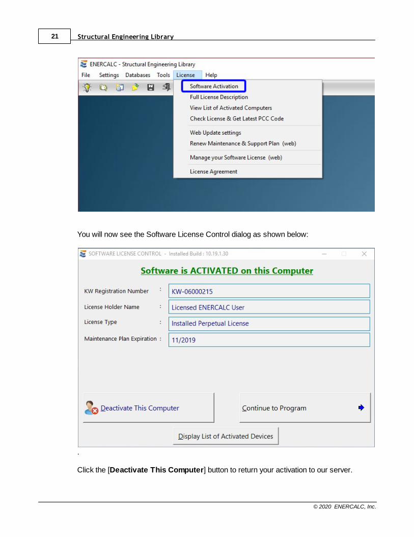
Click the [Close] button. Click License > Software Activation from the main menu asshown below:
Structural Engineering Library21
© 2020 ENERCALC, Inc.
You will now see the Software License Control dialog as shown below:
.
Click the [Deactivate This Computer] button to return your activation to our server.

Installation & Activation 22
© 2020 ENERCALC, Inc.
Note! You must allow the ENERCALC file “EC6.EXE” Internet access through your firewallor anti-virus software. Also, be sure to trust enercalc.net (note no www.).
After a moment, the system will indicate that the installation has been successfullydeactivated by offering an [Internet Activate] button in the Software License Controldialog as shown below:
Your activation has now been returned to our server, and you can go to another computerwhere Structural Engineering Library is installed, and activate it by clicking License>Software Activation > [Internet Activate] from the main menu.
Part
III

Software Updates 24
© 2020 ENERCALC, Inc.
3 Software Updates
Structural Engineering Library25
© 2020 ENERCALC, Inc.
3.1 Web Update
At ENERCALC we are continually improving and enhancing our software. It is fairly simpleto make changes to the software here in our offices, however it can be overwhelming toship thousands of CDs to our user base. To distribute the latest software builds to theentire user base, we depend on a Web Update system. The update is provided in twoways:
Web Update System: This system is built into your Structural Engineering Librarysoftware package. It will check with our server to see if a newer version of the software isavailable and prompt you with an option to install it if available. See What Actually Happensbelow for a description of how it works.
The Web Update system uses Internet protocol HTTP on port 80 to check if a newerversion of the software is available and to transfer those files from our server to yourcomputer as needed. You can configure the program to perform this check automaticallyevery time you start the software, but it can also be performed on an on-demand basis ifdesired.
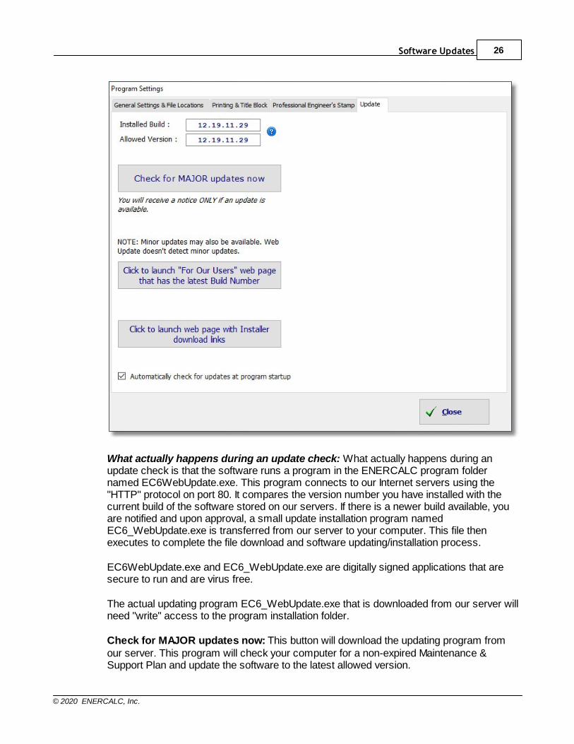
Select Settings > Updates from the main menu to display the web update screen asshown below:
Software Updates 26
© 2020 ENERCALC, Inc.
What actually happens during an update check: What actually happens during anupdate check is that the software runs a program in the ENERCALC program foldernamed EC6WebUpdate.exe. This program connects to our Internet servers using the"HTTP" protocol on port 80. It compares the version number you have installed with thecurrent build of the software stored on our servers. If there is a newer build available, youare notified and upon approval, a small update installation program namedEC6_WebUpdate.exe is transferred from our server to your computer. This file thenexecutes to complete the file download and software updating/installation process.
EC6WebUpdate.exe and EC6_WebUpdate.exe are digitally signed applications that aresecure to run and are virus free.
The actual updating program EC6_WebUpdate.exe that is downloaded from our server willneed "write" access to the program installation folder.
Check for MAJOR updates now: This button will download the updating program fromour server. This program will check your computer for a non-expired Maintenance &Support Plan and update the software to the latest allowed version.

Structural Engineering Library27
© 2020 ENERCALC, Inc.
Note: The "WebUpdate" procedure may send information to ENERCALC, Inc. about yourinstallation and use of the software licensed from ENERCALC, Inc. This may include anyof the following: your ENERCALC assigned User Registration Number, the Installed BuildNumber of your ENERCALC software, Internet IP address of the computer that will receivethe updated files, time usage for the various portions of the software, and potentially otherinformation only related specifically to the use of the software license. Absolutely no files,configurations, settings, or other information not specifically regarding the usage of theENERCALC license will be sent. If you are concerned about this, please contact us forinformation on what is being sent. We have an open policy on providing you withinformation showing what might be included.
TECH NOTE: Some users with multiple installations may prefer to set the status of theautomatic check directly through the registry entry for convenience:
REG_CURRENT_USER\Software\ENERCALC\V6\DoCheckForUpdates
Yes = 1No = -1
Software Updates 28
© 2020 ENERCALC, Inc.
3.2 Update from Website
In addition to the Web Update system that is built into the software, it is also possible toinitiate updates by visiting the "For Our Users" page of www.enercalc.com and using theUPDATE Structural Engineering Library link.
Note:There are times where a more recent build will be available on the website than isoffered/detected by the built-in Web Update system. The reason for this is as follows. Thebuilt-in Web Update system offers those updates that are regarded as "major" or that havea significant impact on a majority of the users. On the other hand, the website will alwaysoffer an update for the absolute latest available build of Structural Engineering Library,regardless of whether it is categorized as a "major" update or not.

Part
IV

Support & Maintenance 30
© 2020 ENERCALC, Inc.
4 Support & Maintenance

Structural Engineering Library31
© 2020 ENERCALC, Inc.
4.1 Maintenance & Support Plan
Our Maintenance & Support Plan (MSP) ensures that you will always have full technicalsupport and access to the latest build of the software during the term of the plan.
While your MSP is current, you will receive every new build, feature enhancement, andimprovement for your licensed software, ensuring you're always using the most currenttechnology.
You will have access to voice/fax/email technical assistance from our staff.
You will also receive discounts on new software releases and additional software licenses.This is the easiest and most economical way for you and your company to keep yoursoftware investment current.
Please see this web page for details on the Maintenance & Support Plan:
http://www.enercalc.com/support_maintenance.html
Support & Maintenance 32
© 2020 ENERCALC, Inc.
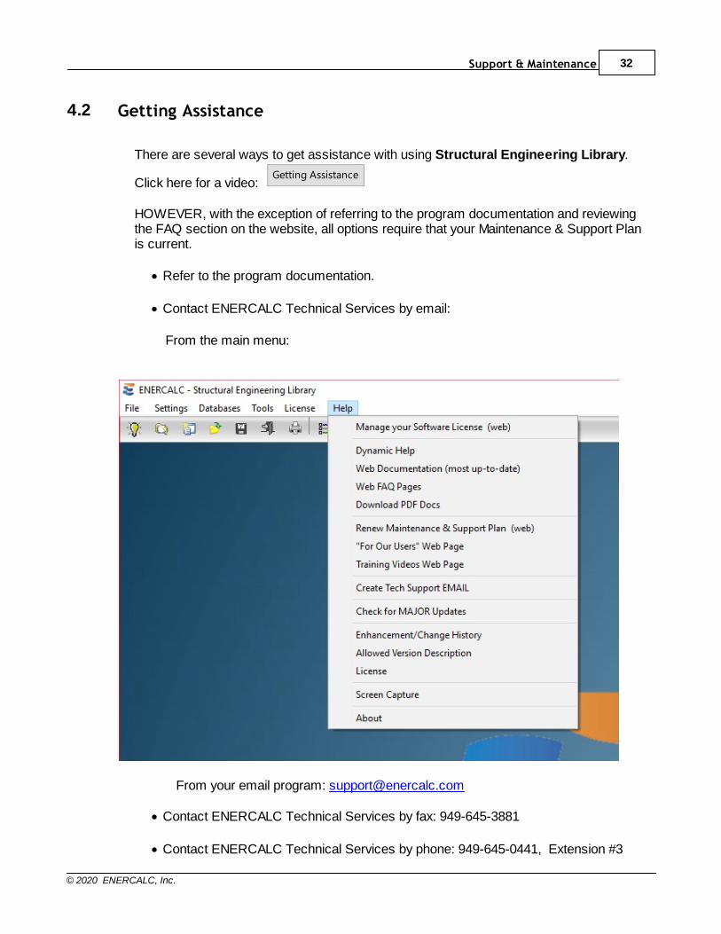
4.2 Getting Assistance
There are several ways to get assistance with using Structural Engineering Library.
Click here for a video: Getting Assistance
HOWEVER, with the exception of referring to the program documentation and reviewingthe FAQ section on the website, all options require that your Maintenance & Support Planis current.
· Refer to the program documentation.
· Contact ENERCALC Technical Services by email:
From the main menu:
From your email program: [email protected]
· Contact ENERCALC Technical Services by fax: 949-645-3881
· Contact ENERCALC Technical Services by phone: 949-645-0441, Extension #3

Structural Engineering Library33
© 2020 ENERCALC, Inc.
· Review the "Frequently Asked Questions" (FAQ) page on our website:
http://www.enercalc.com/support_knowledge.html
Support & Maintenance 34
© 2020 ENERCALC, Inc.
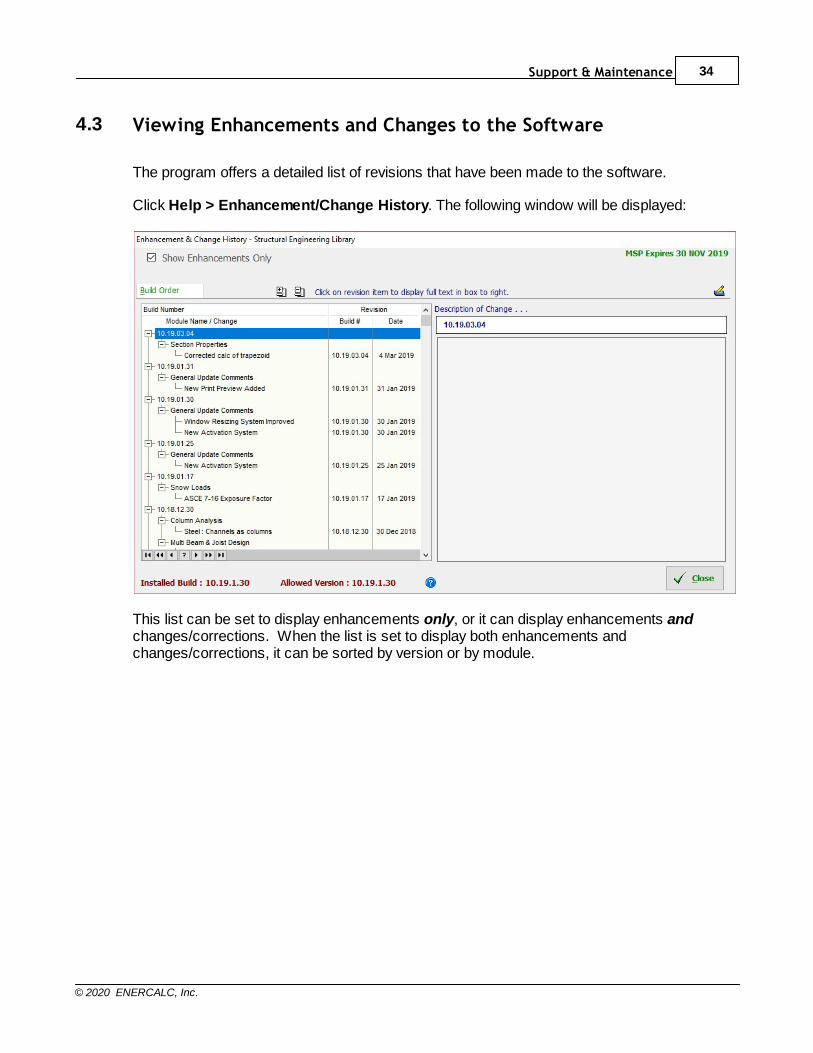
4.3 Viewing Enhancements and Changes to the Software
The program offers a detailed list of revisions that have been made to the software.
Click Help > Enhancement/Change History. The following window will be displayed:
This list can be set to display enhancements only, or it can display enhancements andchanges/corrections. When the list is set to display both enhancements andchanges/corrections, it can be sorted by version or by module.
Part
V

Getting Started 36
© 2020 ENERCALC, Inc.
5 Getting Started
Structural Engineering Library37
© 2020 ENERCALC, Inc.
5.1 System Overview & Design Philosophy
Structural Engineering Library is a collection of modules that provides analysis anddesign functionality for components of buildings.
Walls, columns, beams, footings, diaphragms, frames, and other common elements canbe thoroughly engineered through the use of the modules in this package. If you are atypical engineer whose work consists of a regular flow of small and medium-sizedprojects, this package is designed specifically for you.
As an engineer you will find that each module combines the governing code provisions,mathematical analysis processes, and commonly available construction materials into asimple and effective "calcpad" style fill-in-the-blanks program. You can feel partiallyrelieved that the software will consistently perform all the required checks that may beskipped over when doing repetitive hand calculations....especially when fatigue sets in anda deadline is near! You can enjoy the time to do more exhaustive design studies, come upwith safer and more economical designs, and enjoy clearly documented calculations forreview and archiving.
This software is not a "black box" program. Each calculation is designed to be a "visiblecalcpad" where you can work with the data and immediately view the resultingcalculations. Automatic design is provided in most modules, and is intended primarily toautomate tedious iterative tasks.
You, as an experienced structural engineer or architect, can quickly enter and changemember sizes and other design parameters and view the results. In this way, StructuralEngineering Library maximizes the use of your time and design skills by enabling you toquickly define a concept and then make necessary modifications to refine it into a finaldesign.
Getting Started 38
© 2020 ENERCALC, Inc.
5.2 About Our Documentation
Documentation of your software package is essential for your successful and pleasant useof our products. We try hard to supply you, now and on an ongoing basis, with detailedinformation on all aspects of the software. To support this commitment, we providedocumentation of your software in multiple forms:
· A Windows Help system file named ENERCALC.CHM is installed with yoursoftware. This help system may be accessed by clicking Help > Dynamic Helpfrom the main menu.
· A User's Manual in Adobe Acrobat PDF file format is available for download at any
time from our website http://www.enercalc.com/pdf/SEL60_DOCS.PDF
.
· An Online Help system is available at www.enercalc.com/sel_help
.
Printed Documentation
Printed documentation is not provided with ENERCALC products. This is in keeping withthe nearly universal industry move away from printed documentation.
Updating your Documentation
The most up-to-date documentation for our software products is always available inelectronic form. Whenever the software is updated with the built-in Web Update system,part of the process includes transferring the latest documentation to your computer. Thisensures that the content that you view by clicking Help > Dynamic Help from the mainmenu is current and coordinated.
Structural Engineering Library39
© 2020 ENERCALC, Inc.
5.3 Building Codes Supported
As of May 2019, SEL supports the following codes and design standards:
Design Standards:§ American Concrete Institute publication ACI 318-05/08/11/14§ American Concrete Institute publication ACI 530-05/08/11/13§ American Forest & Paper Association publication NDS 2005/2012/2015/2018 Editions§ American Society of Civil Engineers publication ASCE/SEI 7-05/7-10/7-16§ American Institute of Steel Construction publication AISC 360-05, -10, and -16§ The Masonry Society publication TMS 402/602-16
General Building Codes:§ International Code Council publication International Building Code 2006, 2009, 2012,
2015 and 2018 editions. IBC references the above publications in Chapter 35. Themodifications to each referenced design standard have been incorporated if applicable tothe functionality provided by the individual calculation modules.
§ California Building Standards Commission publication 2007 California Building Code,2010 California Building Code, 2013 California Building Code, 2016 California BuildingCode and 2019 California Building Code. Chapter 19 references ACI 318, Chapter 21references ACI 530/TMS 402/602, Chapter 22 references ANSI/AISC 360-05, Chapter 23references NDS, and Chapter 16 which defines the forces on buildings is essentially thesame as ASCE 7-05/ASCE 7-10/ASCE 7-16.
Getting Started 40
© 2020 ENERCALC, Inc.
5.4 Learning Structural Engineering Library
There are several sources of information that will assist you with learning to useStructural Engineering Library.
· A series of tutorial videos is available at our website:
http://www.enercalc.com/training_videos.html
· This documentation. An Internet version of the help system is available at:
http://www.enercalc.com/sel_help
· Responses to "Frequently Asked Questions" are available at our website:
http://www.enercalc.com/faq_help/
Structural Engineering Library41
© 2020 ENERCALC, Inc.
5.5 Introductory Videos
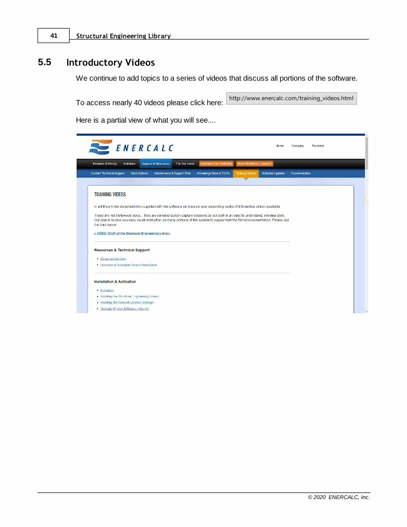
We continue to add topics to a series of videos that discuss all portions of the software.
To access nearly 40 videos please click here: http://www.enercalc.com/training_videos.html
Here is a partial view of what you will see....
Getting Started 42
© 2020 ENERCALC, Inc.
5.6 Request for Suggestions
Although our intentions are to provide you with the best product possible, it is likely thatthere may be areas of this User's Guide and the software itself that could be improved tobetter suit your needs, be made simpler to operate, easier to understand, or supportengineering technologies that have emerged since this publication.
To call these to our attention and to offer suggestions for improvement, we sincerelyrequest that you send us your thoughts. Please address your comments [email protected], or:
Michael D. Brooks, P.E., S.E.PresidentENERCALC, Inc.
Post Office Box 2208Newport Beach, California, USA 92659

Part
VI

Program Overview 44
© 2020 ENERCALC, Inc.
6 Program Overview

Structural Engineering Library45
© 2020 ENERCALC, Inc.
6.1 Introduction
Structural Engineering Library is a collection of modules (also referred to as"calcsheets") that provide functionality for the analysis and design of components ofbuildings. Walls, columns, beams, footings, diaphragms, frames, and other commonelements can be thoroughly engineered through the use of the modules in this package. Ifyou are a typical engineer, whose work consists of a monthly flow of small and medium-sized projects, this package is designed especially for you.
As an engineer, you will find that each module combines the governing code provisions,mathematical analysis processes, and commonly available construction materials into asimple and effective "calcpad" style fill-in-the-blanks program. You can feel partiallyrelieved that the software will consistently perform all the required checks that may beskipped over when doing repetitive hand calculations. You can enjoy the time to do moreexhaustive design studies, come up with safer and more economical designs, and enjoyclearly documented calculations for review and archiving.
This software is not a "black box" program. Each calculation is designed to be a "visiblecalcpad" where you can work with the data and immediately view the resultingcalculations. Automatic design is provided in most modules, and is intended primarily toautomate tedious iterative tasks.
You, as an experienced structural engineer or architect, can quickly enter and changemember sizes and other design parameters and view the results. In this way, StructuralEngineering Library maximizes the use of your time and design skills by enabling you toquickly define a concept and then make necessary modifications to refine it into a finaldesign.
The "Calcpad" Approach
When Structural Engineering Library was designed in 1983, our concept wasrevolutionary.....design it like an engineer's calculation pad. When an engineer prepares acalculation, the finished product is a neat and organized sheet of paper that follows thedesign flow from load tabulation, force and stress calculation, to the final adequacy checkof the structural component that will satisfy the task.
At the time, all other competing programs were aging versions of mainframe programs thathad been modified to run on microcomputers. Many of those programs executed "batch"design, where the user entered all the data, told the computer to run the program, and thenopened a crude file to review the results. ENERCALC was unique in that the input andoutput was mixed on the same screen....easy to see at a glance. But the mostrevolutionary aspect was the tremendous speed it offered to prepare calculations.
This great speed was due to the fact that you could change a number and instantly see allthe updated results on the screen.
Moving forward, the current version of SEL for Windows maintains that same fill-in-the-blanks approach with instant recalculation of results. When using any of the approximately30 calculation modules, all input data and output results are presented on the same screen

Program Overview 46
© 2020 ENERCALC, Inc.
and viewed just by selecting a tab that groups the information. Whenever you change aninput value, the entire module is recalculated and the results are immediatelyvisible. Thanks to efficient programming and fast modern computers, incredibly complexstructural analysis and design is performed in a split second.
This instant updating also happens when you are viewing graphical sketches of designs orstress diagrams.....after any change, the graphics are instantly updated.

Structural Engineering Library47
© 2020 ENERCALC, Inc.
6.2 Typical Worksession
A Typical Worksession
In order of occurrence, here are the steps in using the software:
1. Start the program.
2. The Project Assistant is displayed where you can choose to use the last calculation,the last project, a recent project, or create a new project.
3. A project is selected and you view the Project Manager. Here you can add newcalculations, edit existing calculations, insert non-calculation items into the project(such as Microsoft Word or Excel files, Adobe Acrobat PDF files, or scanned images),and initiate project printing capabilities.
4. Editing or adding a calculation takes you to the calculation sheet for one of themodules.
5. Using the calculation sheet, you enter data on the top set of tabs while reviewingresults and graphics on the bottom set.
6. When the structural calculation is complete, you can print it and/or save it to theproject.
7. You can always return to the Project Manager where you can add/edit/delete/printother items within the current project, or save the current project and open a new one.
Program Overview 48
© 2020 ENERCALC, Inc.
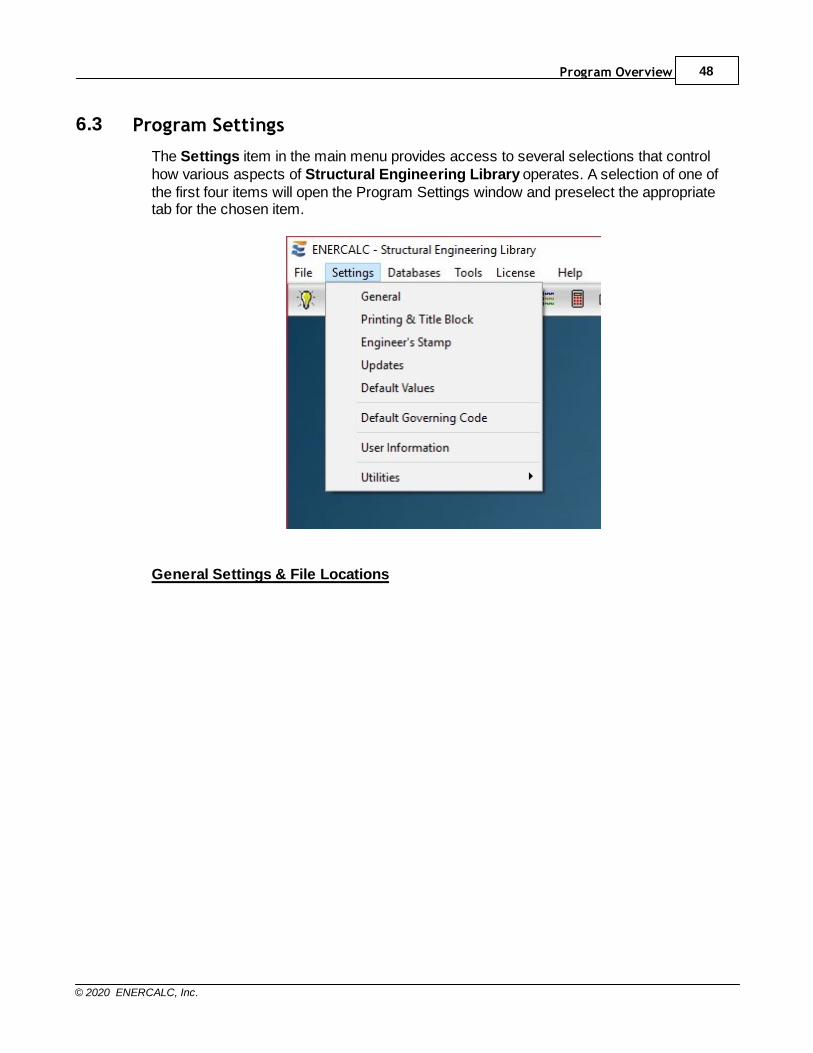
6.3 Program Settings
The Settings item in the main menu provides access to several selections that controlhow various aspects of Structural Engineering Library operates. A selection of one ofthe first four items will open the Program Settings window and preselect the appropriatetab for the chosen item.
General Settings & File Locations
Structural Engineering Library49
© 2020 ENERCALC, Inc.
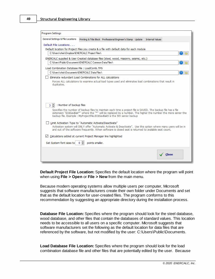
Default Project File Location: Specifies the default location where the program will pointwhen using File > Open or File > New from the main menu.
Because modern operating systems allow multiple users per computer, Microsoftsuggests that software manufacturers create their own folder under Documents and setthat as the default location for user-created files. The program conforms to thisrecommendation by suggesting an appropriate directory during the installation process.
Database File Location: Specifies where the program should look for the steel database,wood database, and other files that contain the databases of standard values. This locationneeds to be accessible to all users on a specific computer. Microsoft suggests thatsoftware manufacturers set the following as the default location for data files that arereferenced by the software, but not modified by the user: C:\Users\Public\Documents.
Load Database File Location: Specifies where the program should look for the loadcombination database file and other files that are potentially edited by the user. Because
Program Overview 50
© 2020 ENERCALC, Inc.
this is a file that can be customized by the user, the default location for this file is the sameas the default location offered for storing Project Files.
Eliminate redundant Load Combinations for ALL calculations: With this box checkedthe software will only run load combinations that are unique. It will automatically eliminateany load combinations that result in a combination that is redundant.
Number of backup files: Specifies the number of backup files to maintain for eachProject File. With this box checked the software will automatically create a backup file withthe .EC6SavBak file extension in the same folder as the original Project File. The backupfiles are created when a Project File is OPENED.
Limit Activation Type to "Automatic Activate/Deactivate": Removes the option tospecify Indefinite activation.
Calculations added at current Project Manager line highlighted: This applies to theway calculations are inserted when using the Project Manager. When this box is checkedand you use the [+Add] button, it adds a new calculation to the project, and the calculationis inserted directly above that position. What you see is that the new calculation takes thatspot in the list, and the highlighted item is moved down. If this box is unchecked and youuse the [+Add] button, the new calculation is inserted BELOW the highlighted item.
Set System font sizes to X points smaller: Provides a way to scale fonts down, for highresolution displays.
Printing & Title Block
Structural Engineering Library51
© 2020 ENERCALC, Inc.
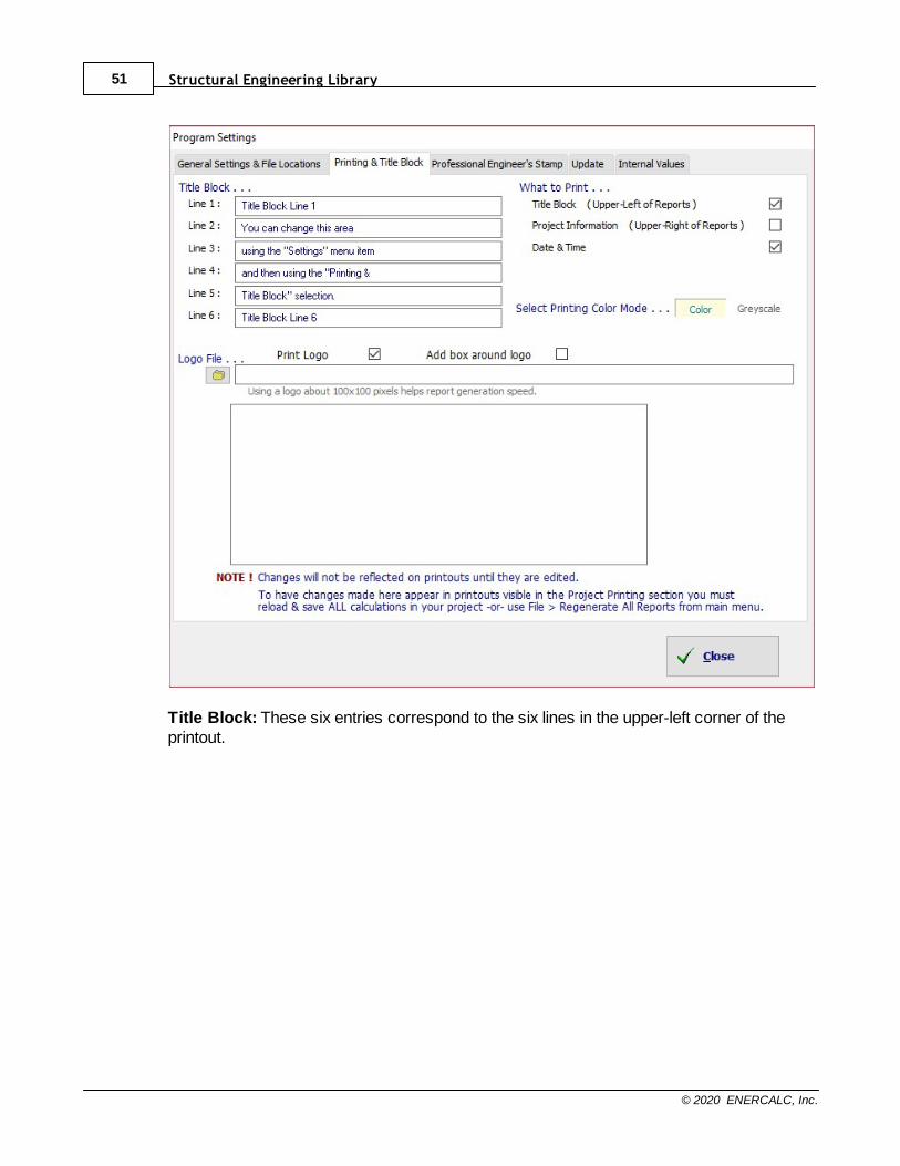
Title Block: These six entries correspond to the six lines in the upper-left corner of theprintout.
Program Overview 52
© 2020 ENERCALC, Inc.
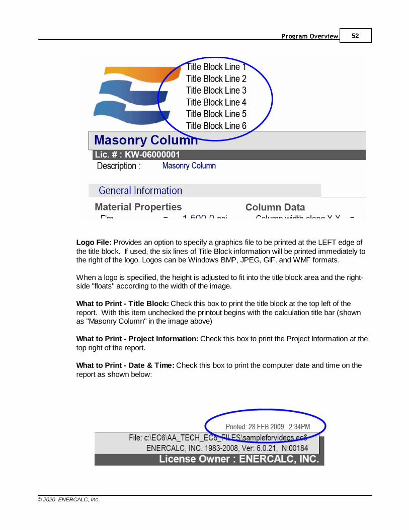
Logo File: Provides an option to specify a graphics file to be printed at the LEFT edge ofthe title block. If used, the six lines of Title Block information will be printed immediately tothe right of the logo. Logos can be Windows BMP, JPEG, GIF, and WMF formats.
When a logo is specified, the height is adjusted to fit into the title block area and the right-side "floats" according to the width of the image.
What to Print - Title Block: Check this box to print the title block at the top left of thereport. With this item unchecked the printout begins with the calculation title bar (shownas "Masonry Column" in the image above)
What to Print - Project Information: Check this box to print the Project Information at thetop right of the report.
What to Print - Date & Time: Check this box to print the computer date and time on thereport as shown below:
Structural Engineering Library53
© 2020 ENERCALC, Inc.
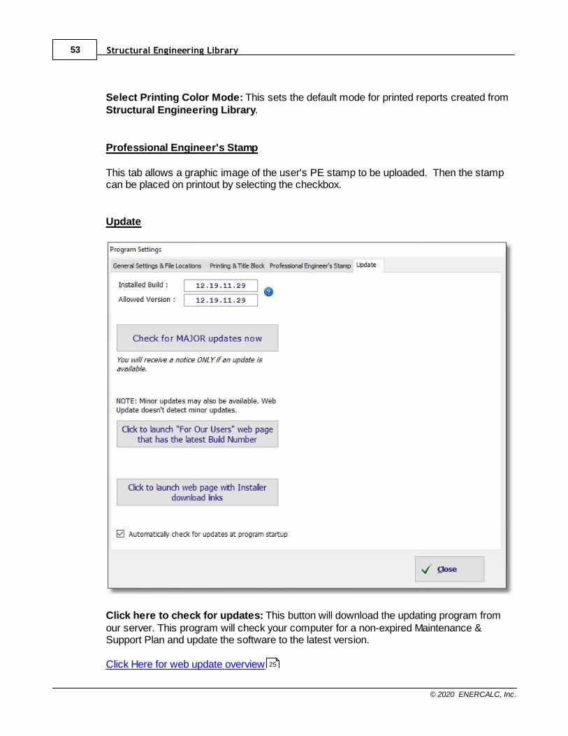
Select Printing Color Mode: This sets the default mode for printed reports created fromStructural Engineering Library.
Professional Engineer's Stamp
This tab allows a graphic image of the user's PE stamp to be uploaded. Then the stampcan be placed on printout by selecting the checkbox.
Update
Click here to check for updates: This button will download the updating program fromour server. This program will check your computer for a non-expired Maintenance &Support Plan and update the software to the latest version.
Click Here for web update overview 25
Program Overview 54
© 2020 ENERCALC, Inc.
Internal Values
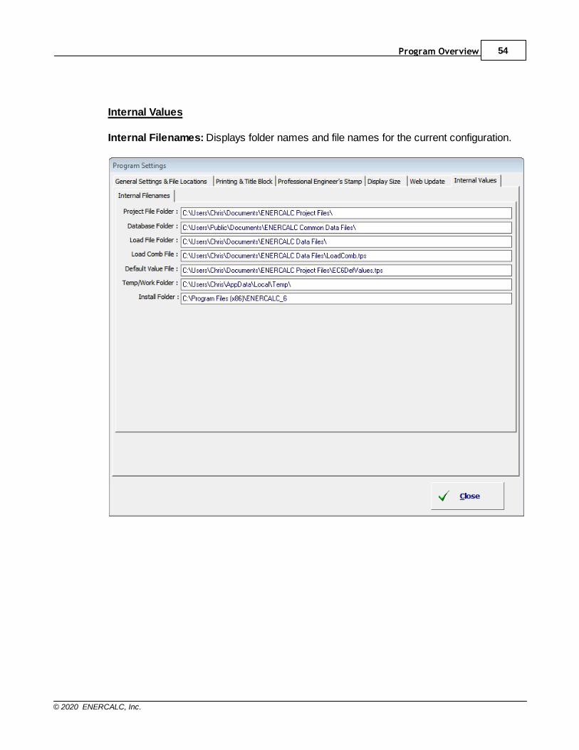
Internal Filenames: Displays folder names and file names for the current configuration.

Structural Engineering Library55
© 2020 ENERCALC, Inc.
6.4 Files & File Locations
Project Files
Structural Engineering Library uses a single file to store the project information and allthe calculations and items that are created as a part of that "Project". This file uses an"EC6" extension.
To backup an ENERCALC Project File simply copy the .EC6 file to the desired backuplocation.
To have the system automatically create a backup file, activate the checkbox labeledAutomatically create backup files on the Settings > General Settings dialog.
As Structural Engineering Library advances in capabilities, the file formats used willchange, but we will always provide conversion programs for previously saved ProjectFiles.
General Comments· Each ENERCALC Project File contains all information on a Project. There are no
other files you will need to keep track of.
· Always remember that the Project Manager is showing you the Divisions andcalculations for the current Project. It is NOT showing you a disk directory structure.
· There is no Save item on the File menu. After you have edited a calculation, you caneither click [Save Only] or [Save & Exit] within the individual modules. Either onewill save the calculation data to the Project File.
Database Files
A number of database files are supplied with Structural Engineering Library. These filescontain AISC section properties, NDS stress grades, wood section properties, seismicacceleration data, USA cities & Zip Codes, and other files. These files are not to be editedor modified in any way by the user.
User-Created Database Files
The user can create User Defined database files to store their own steel sections, woodsections and wood stress databases. These files are created and stored in the samefolder as the other database files. User defined database files are differentiated from thestandard database files that are delivered with the software by inserting the word "_USER"in the filename.
Program Overview 56
© 2020 ENERCALC, Inc.
6.5 Project Assistant
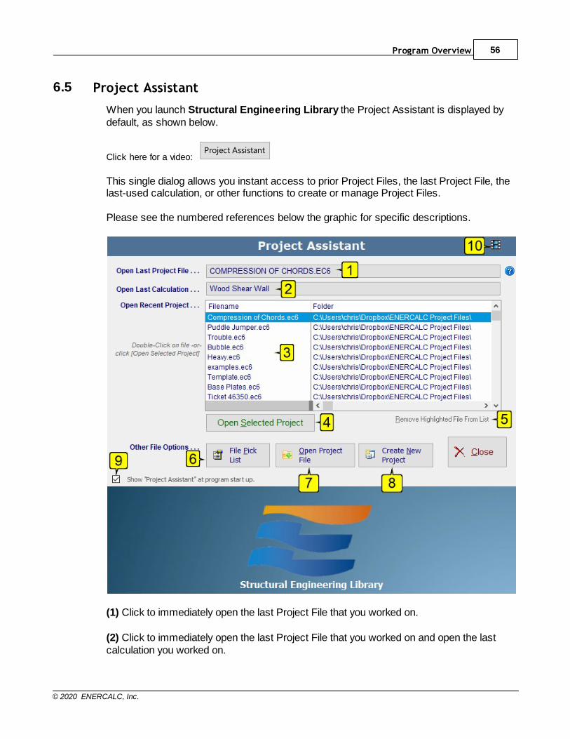
When you launch Structural Engineering Library the Project Assistant is displayed bydefault, as shown below.
Click here for a video: Project Assistant
This single dialog allows you instant access to prior Project Files, the last Project File, thelast-used calculation, or other functions to create or manage Project Files.
Please see the numbered references below the graphic for specific descriptions.
(1) Click to immediately open the last Project File that you worked on.
(2) Click to immediately open the last Project File that you worked on and open the lastcalculation you worked on.

Structural Engineering Library57
© 2020 ENERCALC, Inc.
(3) This list shows the most recent Project Files that you opened on this computer, withthe most recent Project File at the top of the list. Double-click on any item in the list to openthat Project File.
(4) Click to open the highlighted Project File in the list.
(5) Click to remove the highlighted file from the Recent Projects list.
(6) Click to open a Pick List that displays ALL Project Files in the various folders that youhave used in the past. See the section Main Menu > File for a description of the PickList.
(7) Click to open a Windows File Open dialog that allows you to navigate through disks andfolders to locate and open a Project File.
(8) Click to open the Windows File Create dialog that allows you to navigate through disksand folders and create a new ENERCALC Project File.
(9) Uncheck this box if you do not wish to automatically display the Project Assistant atstartup. To again have the Project Assistant automatically displayed at startup, click File >Display Project Assistant and then activate the checkbox to Show Project Assistant atprogram startup.
(10) Link to a help video on the Project Assistant.
70
Program Overview 58
© 2020 ENERCALC, Inc.
6.6 Databases
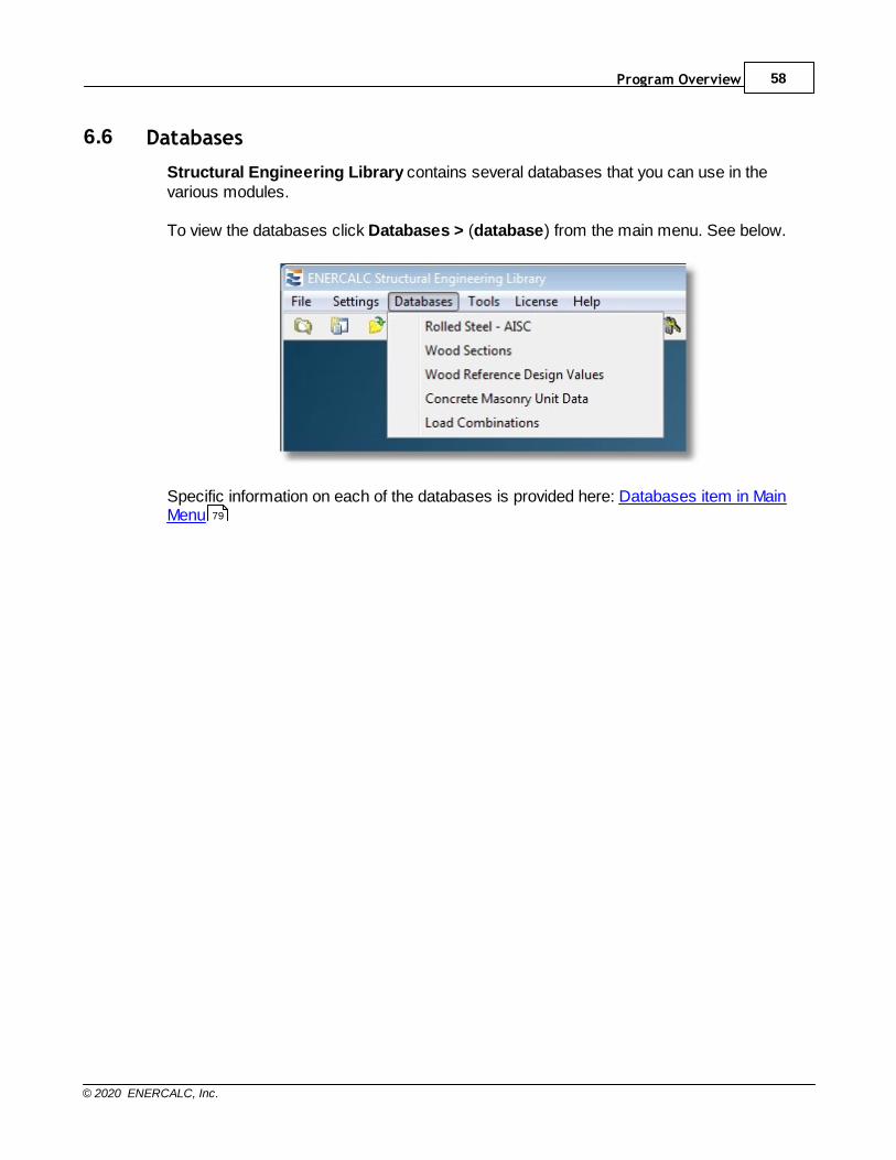
Structural Engineering Library contains several databases that you can use in thevarious modules.
To view the databases click Databases > (database) from the main menu. See below.
Specific information on each of the databases is provided here: Databases item in MainMenu 79
Structural Engineering Library59
© 2020 ENERCALC, Inc.
6.7 Screen Layout
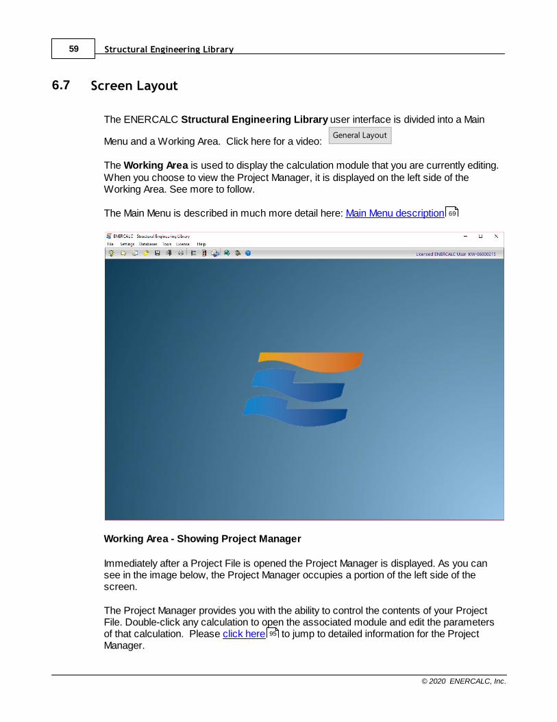
The ENERCALC Structural Engineering Library user interface is divided into a Main
Menu and a Working Area. Click here for a video: General Layout
The Working Area is used to display the calculation module that you are currently editing. When you choose to view the Project Manager, it is displayed on the left side of theWorking Area. See more to follow.
The Main Menu is described in much more detail here: Main Menu description
Working Area - Showing Project Manager
Immediately after a Project File is opened the Project Manager is displayed. As you cansee in the image below, the Project Manager occupies a portion of the left side of thescreen.
The Project Manager provides you with the ability to control the contents of your ProjectFile. Double-click any calculation to open the associated module and edit the parametersof that calculation. Please click here to jump to detailed information for the ProjectManager.
69
95
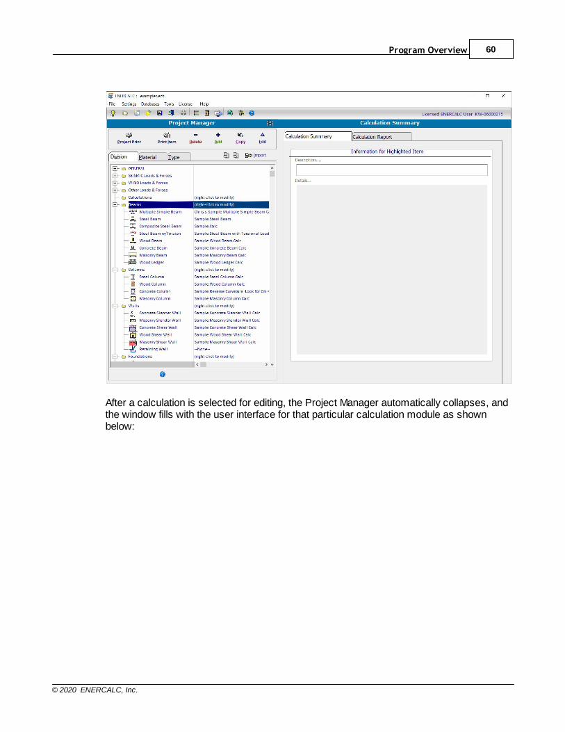
Program Overview 60
© 2020 ENERCALC, Inc.
After a calculation is selected for editing, the Project Manager automatically collapses, andthe window fills with the user interface for that particular calculation module as shownbelow:
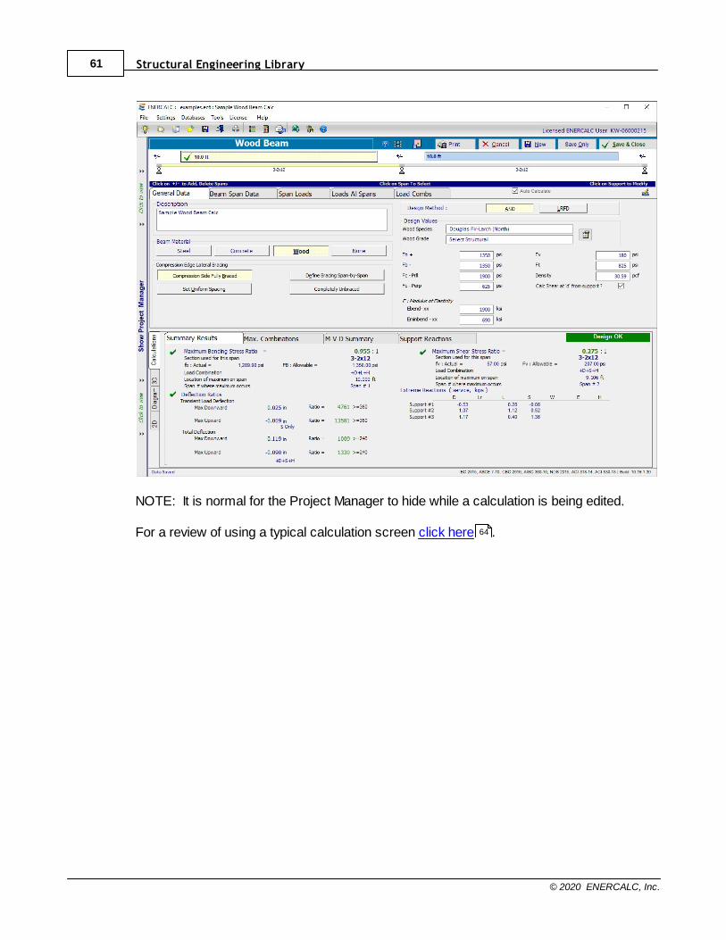
Structural Engineering Library61
© 2020 ENERCALC, Inc.
NOTE: It is normal for the Project Manager to hide while a calculation is being edited.
For a review of using a typical calculation screen click here .64
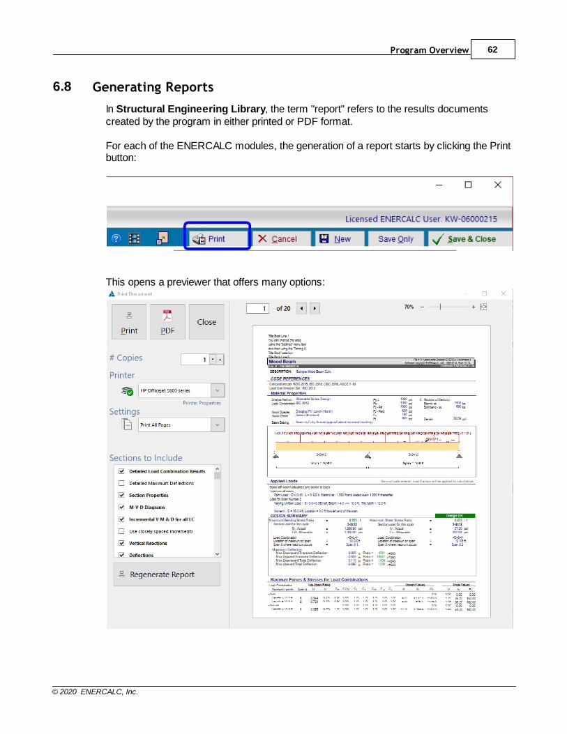
Program Overview 62
© 2020 ENERCALC, Inc.
6.8 Generating Reports
In Structural Engineering Library, the term "report" refers to the results documentscreated by the program in either printed or PDF format.
For each of the ENERCALC modules, the generation of a report starts by clicking the Printbutton:
This opens a previewer that offers many options:
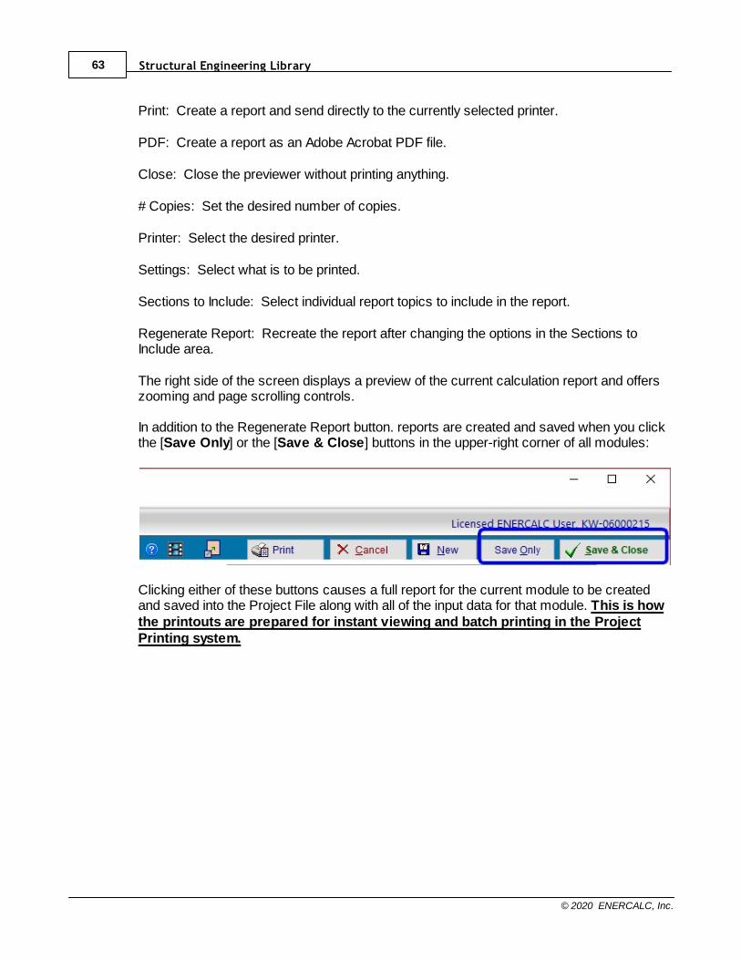
Structural Engineering Library63
© 2020 ENERCALC, Inc.
Print: Create a report and send directly to the currently selected printer.
PDF: Create a report as an Adobe Acrobat PDF file.
Close: Close the previewer without printing anything.
# Copies: Set the desired number of copies.
Printer: Select the desired printer.
Settings: Select what is to be printed.
Sections to Include: Select individual report topics to include in the report.
Regenerate Report: Recreate the report after changing the options in the Sections toInclude area.
The right side of the screen displays a preview of the current calculation report and offerszooming and page scrolling controls. In addition to the Regenerate Report button. reports are created and saved when you clickthe [Save Only] or the [Save & Close] buttons in the upper-right corner of all modules:
Clicking either of these buttons causes a full report for the current module to be createdand saved into the Project File along with all of the input data for that module. This is howthe printouts are prepared for instant viewing and batch printing in the ProjectPrinting system.
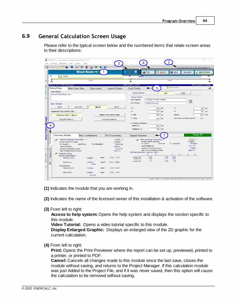
Program Overview 64
© 2020 ENERCALC, Inc.
6.9 General Calculation Screen Usage
Please refer to the typical screen below and the numbered items that relate screen areasto their descriptions:
(1) Indicates the module that you are working in.
(2) Indicates the name of the licensed owner of this installation & activation of the software.
(3) From left to right: Access to help system: Opens the help system and displays the section specific tothis module.Video Tutorial: Opens a video tutorial specific to this module.Display Enlarged Graphic: Displays an enlarged view of the 2D graphic for thecurrent calculation.
(4) From left to right:Print: Opens the Print Previewer where the report can be set up, previewed, printed toa printer, or printed to PDF.Cancel: Cancels all changes made to this module since the last save, closes themodule without saving, and returns to the Project Manager. If this calculation modulewas just Added to the Project File, and if it was never saved, then this option will causethe calculation to be removed without saving.

Structural Engineering Library65
© 2020 ENERCALC, Inc.
New: Uses the current calculation data to create a new calculation item in the ProjectManager.Save Only: Saves the current Project File (to capture all the data entered into thismodule), creates a report (which can be printed at a later time), and keeps the moduleopen for further editing.Save & Close: Saves the current Project File (to capture all the data entered into thismodule), creates a report (which can be printed at a later time), closes the module,and returns to the Project Manager.
(5) Data input tabs: Click these tabs to move to various categories of data input.
(6) Major Result Category Tabs: Select between major categories of result data to view;numerical values, sketches, diagrams or 3D renderings.
(7) Numeric Result Tabs: Click these tabs to view the various components of calculatedresults.
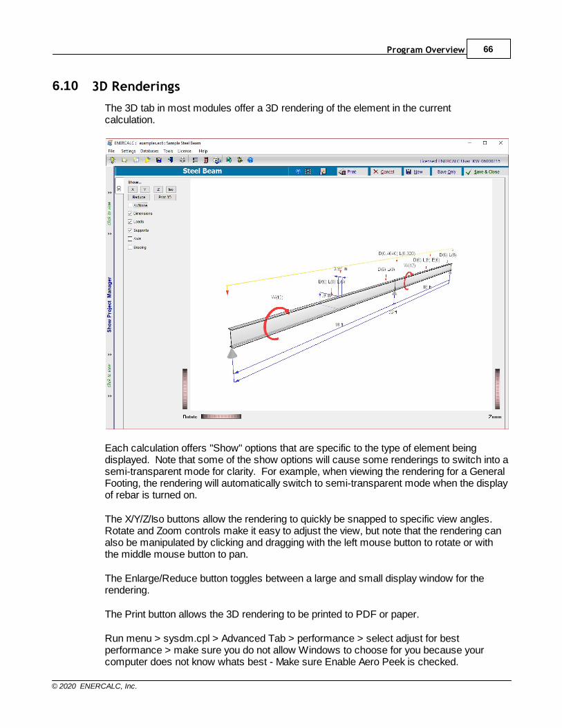
Program Overview 66
© 2020 ENERCALC, Inc.
6.10 3D Renderings
The 3D tab in most modules offer a 3D rendering of the element in the currentcalculation.
Each calculation offers "Show" options that are specific to the type of element beingdisplayed. Note that some of the show options will cause some renderings to switch into asemi-transparent mode for clarity. For example, when viewing the rendering for a GeneralFooting, the rendering will automatically switch to semi-transparent mode when the displayof rebar is turned on.
The X/Y/Z/Iso buttons allow the rendering to quickly be snapped to specific view angles. Rotate and Zoom controls make it easy to adjust the view, but note that the rendering canalso be manipulated by clicking and dragging with the left mouse button to rotate or withthe middle mouse button to pan.
The Enlarge/Reduce button toggles between a large and small display window for therendering.
The Print button allows the 3D rendering to be printed to PDF or paper.
Run menu > sysdm.cpl > Advanced Tab > performance > select adjust for bestperformance > make sure you do not allow Windows to choose for you because yourcomputer does not know whats best - Make sure Enable Aero Peek is checked.

Structural Engineering Library67
© 2020 ENERCALC, Inc.

Part
VII

Structural Engineering Library69
© 2020 ENERCALC, Inc.
7 Main Menu
The main menu of Structural Engineering Library is always displayed.
The menu offers the following selections. Click an item below to jump to that help section
page, or click here for a video: Main Menu and Toolbar
File : To create, load, close and print Project Files.Settings : To establish settings, user information and default valuesDatabases : To view the various databases supplied with the softwareTools : To access utilities provided with the softwareLicense : To directly access the licensing control windowHelp : To access the help system, technical support options, Knowledge
Base with FAQs, Enhancement/Change History and the ENERCALCwebsite.
70
76
79
87
89
90
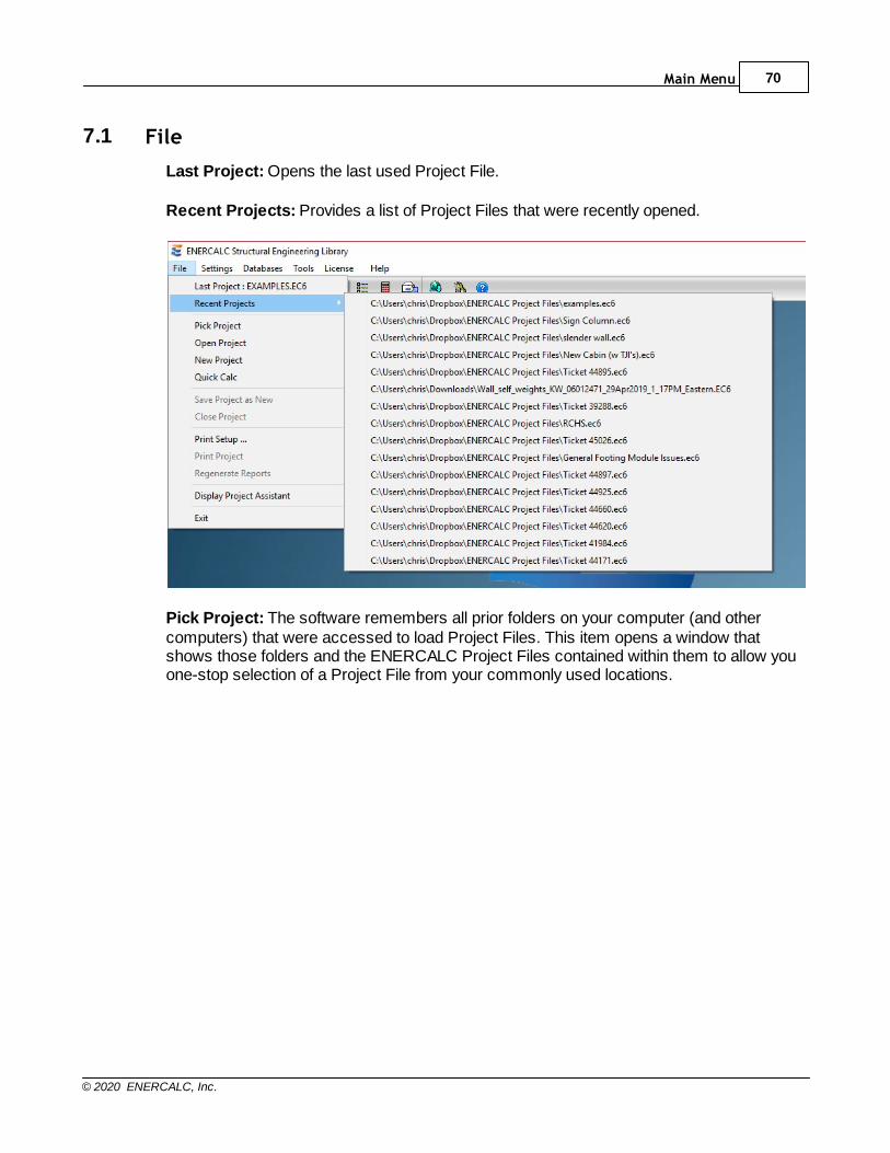
Main Menu 70
© 2020 ENERCALC, Inc.
7.1 File
Last Project: Opens the last used Project File.
Recent Projects: Provides a list of Project Files that were recently opened.
Pick Project: The software remembers all prior folders on your computer (and othercomputers) that were accessed to load Project Files. This item opens a window thatshows those folders and the ENERCALC Project Files contained within them to allow youone-stop selection of a Project File from your commonly used locations.
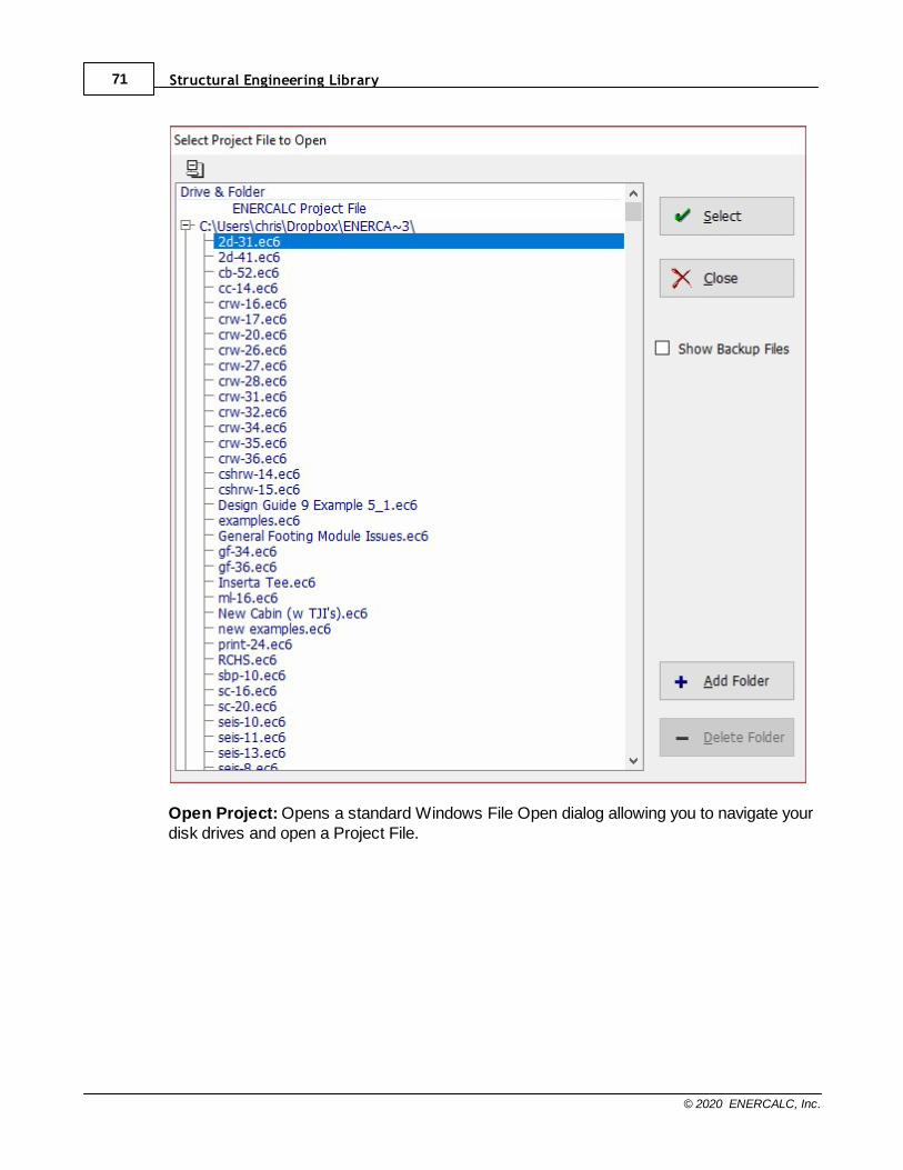
Structural Engineering Library71
© 2020 ENERCALC, Inc.
Open Project: Opens a standard Windows File Open dialog allowing you to navigate yourdisk drives and open a Project File.

Main Menu 72
© 2020 ENERCALC, Inc.
New Project: Opens a standard Windows File Create dialog allowing you to navigate yourdisk drives and specify the name of a Project File to create.
Save Project as New: Allows you to save the currently open Project File as a new fileusing a different name. Opens a standard Windows File Create dialog allowing you tonavigate your disk drives and specify the name of the Project File to create.
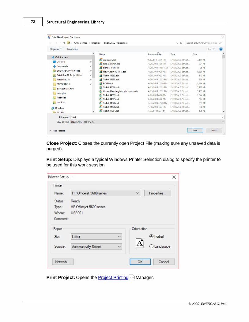
Structural Engineering Library73
© 2020 ENERCALC, Inc.
Close Project: Closes the currently open Project File (making sure any unsaved data ispurged).
Print Setup: Displays a typical Windows Printer Selection dialog to specify the printer tobe used for this work session.
Print Project: Opens the Project Printing Manager.131
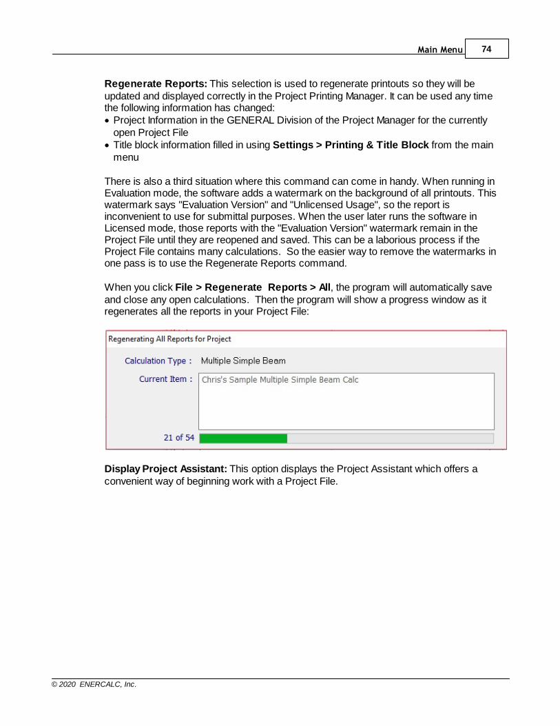
Main Menu 74
© 2020 ENERCALC, Inc.
Regenerate Reports: This selection is used to regenerate printouts so they will beupdated and displayed correctly in the Project Printing Manager. It can be used any timethe following information has changed:· Project Information in the GENERAL Division of the Project Manager for the currently
open Project File· Title block information filled in using Settings > Printing & Title Block from the main
menu
There is also a third situation where this command can come in handy. When running inEvaluation mode, the software adds a watermark on the background of all printouts. Thiswatermark says "Evaluation Version" and "Unlicensed Usage", so the report isinconvenient to use for submittal purposes. When the user later runs the software inLicensed mode, those reports with the "Evaluation Version" watermark remain in theProject File until they are reopened and saved. This can be a laborious process if theProject File contains many calculations. So the easier way to remove the watermarks inone pass is to use the Regenerate Reports command.
When you click File > Regenerate Reports > All, the program will automatically saveand close any open calculations. Then the program will show a progress window as itregenerates all the reports in your Project File:
Display Project Assistant: This option displays the Project Assistant which offers aconvenient way of beginning work with a Project File.
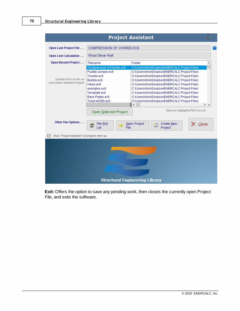
Structural Engineering Library75
© 2020 ENERCALC, Inc.
Exit: Offers the option to save any pending work, then closes the currently open ProjectFile, and exits the software.
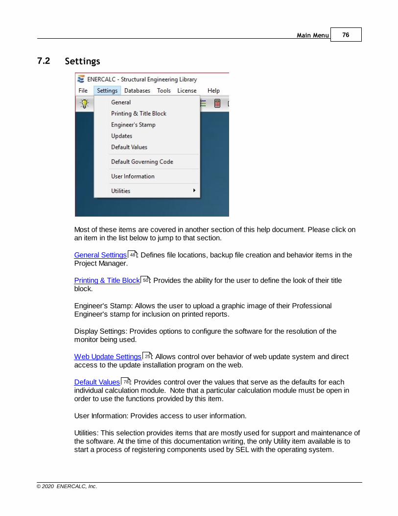
Main Menu 76
© 2020 ENERCALC, Inc.
7.2 Settings
Most of these items are covered in another section of this help document. Please click onan item in the list below to jump to that section.
General Settings : Defines file locations, backup file creation and behavior items in theProject Manager.
Printing & Title Block : Provides the ability for the user to define the look of their titleblock.
Engineer's Stamp: Allows the user to upload a graphic image of their ProfessionalEngineer's stamp for inclusion on printed reports.
Display Settings: Provides options to configure the software for the resolution of themonitor being used.
Web Update Settings : Allows control over behavior of web update system and directaccess to the update installation program on the web.
Default Values : Provides control over the values that serve as the defaults for eachindividual calculation module. Note that a particular calculation module must be open inorder to use the functions provided by this item.
User Information: Provides access to user information.
Utilities: This selection provides items that are mostly used for support and maintenance ofthe software. At the time of this documentation writing, the only Utility item available is tostart a process of registering components used by SEL with the operating system.
48
50
25
78

Structural Engineering Library77
© 2020 ENERCALC, Inc.
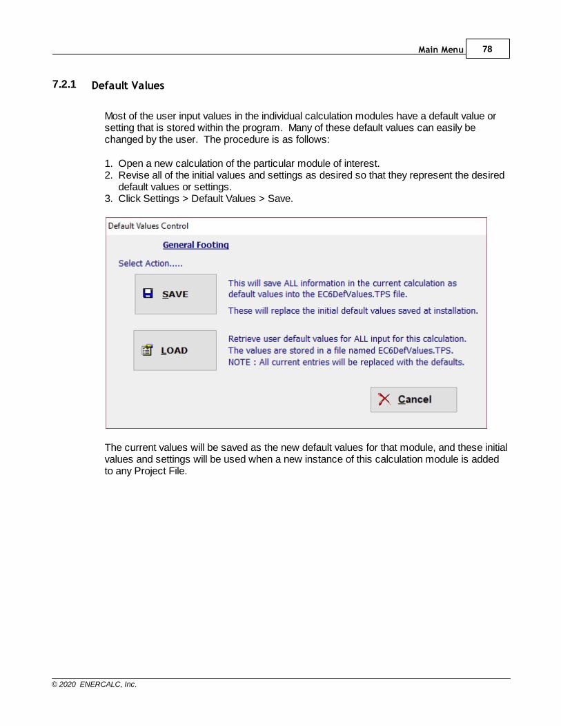
Main Menu 78
© 2020 ENERCALC, Inc.
7.2.1 Default Values
Most of the user input values in the individual calculation modules have a default value orsetting that is stored within the program. Many of these default values can easily bechanged by the user. The procedure is as follows:
1. Open a new calculation of the particular module of interest.2. Revise all of the initial values and settings as desired so that they represent the desired
default values or settings.3. Click Settings > Default Values > Save.
The current values will be saved as the new default values for that module, and these initialvalues and settings will be used when a new instance of this calculation module is addedto any Project File.
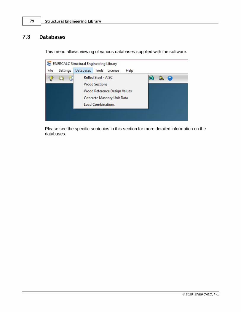
Structural Engineering Library79
© 2020 ENERCALC, Inc.
7.3 Databases
This menu allows viewing of various databases supplied with the software.
Please see the specific subtopics in this section for more detailed information on thedatabases.
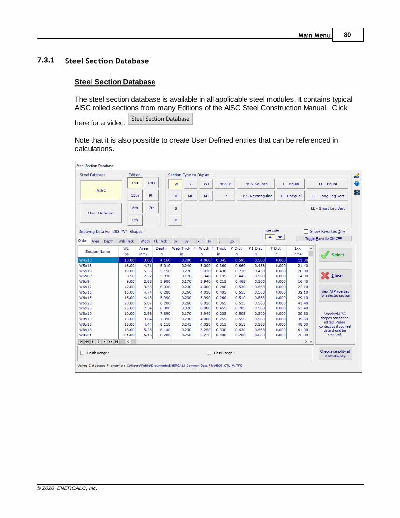
Main Menu 80
© 2020 ENERCALC, Inc.
7.3.1 Steel Section Database
Steel Section Database
The steel section database is available in all applicable steel modules. It contains typicalAISC rolled sections from many Editions of the AISC Steel Construction Manual. Click
here for a video: Steel Section Database
Note that it is also possible to create User Defined entries that can be referenced incalculations.

Structural Engineering Library81
© 2020 ENERCALC, Inc.
7.3.2 Wood Section Database
Wood Section Database
The wood section database contains the section properties for most of the sections listedin the NDS and for many Engineered Wood Products. Click here for a video:
Wood Section Database
The wood section database is available in all applicable wood modules. It contains typicalwood sections available in the United States. These sections are also shown in the 2005NDS. Also included are manufactured sections, however the list of those sections is onlyupdated occasionally. Note that it is also possible to create User Defined entries that canbe referenced in calculations.
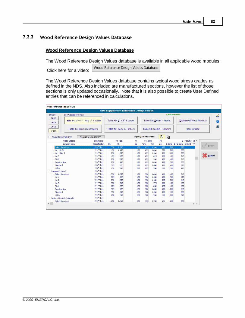
Main Menu 82
© 2020 ENERCALC, Inc.
7.3.3 Wood Reference Design Values Database
Wood Reference Design Values Database
The Wood Reference Design Values database is available in all applicable wood modules.
Click here for a video: Wood Reference Design Values Database
The Wood Reference Design Values database contains typical wood stress grades asdefined in the NDS. Also included are manufactured sections, however the list of thosesections is only updated occasionally. Note that it is also possible to create User Definedentries that can be referenced in calculations.
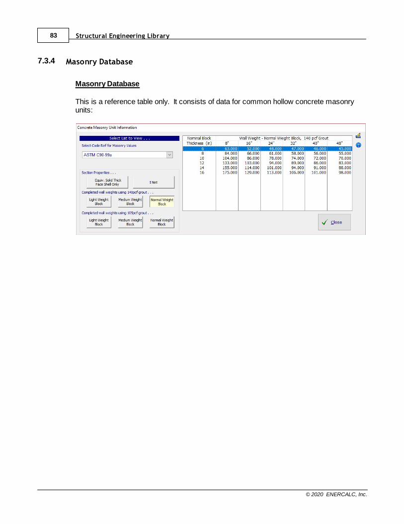
Structural Engineering Library83
© 2020 ENERCALC, Inc.
7.3.4 Masonry Database
Masonry Database
This is a reference table only. It consists of data for common hollow concrete masonryunits:
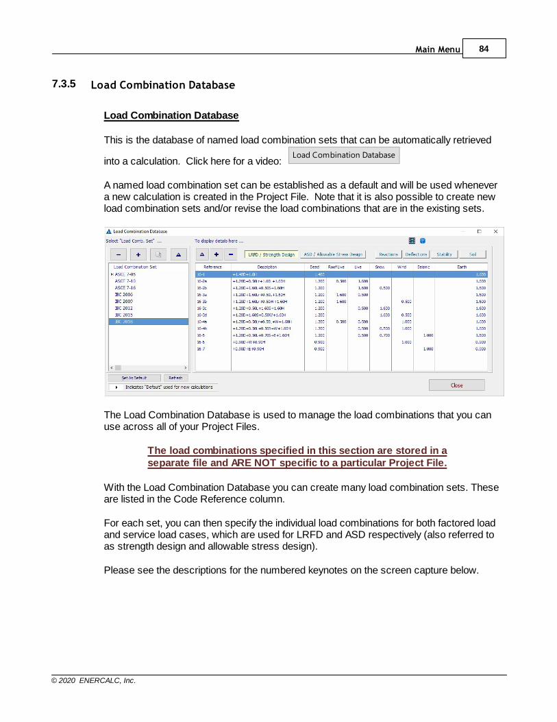
Main Menu 84
© 2020 ENERCALC, Inc.
7.3.5 Load Combination Database
Load Combination Database
This is the database of named load combination sets that can be automatically retrieved
into a calculation. Click here for a video: Load Combination Database
A named load combination set can be established as a default and will be used whenevera new calculation is created in the Project File. Note that it is also possible to create newload combination sets and/or revise the load combinations that are in the existing sets.
The Load Combination Database is used to manage the load combinations that you canuse across all of your Project Files.
The load combinations specified in this section are stored in aseparate file and ARE NOT specific to a particular Project File.
With the Load Combination Database you can create many load combination sets. Theseare listed in the Code Reference column.
For each set, you can then specify the individual load combinations for both factored loadand service load cases, which are used for LRFD and ASD respectively (also referred toas strength design and allowable stress design).
Please see the descriptions for the numbered keynotes on the screen capture below.
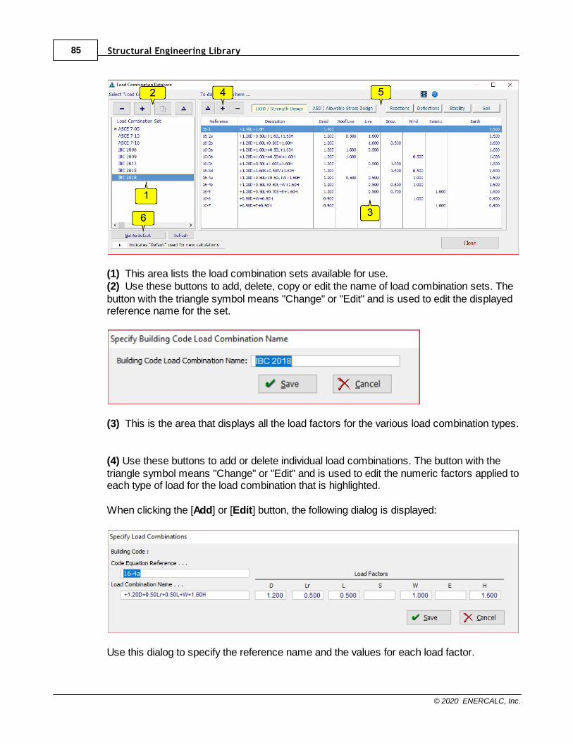
Structural Engineering Library85
© 2020 ENERCALC, Inc.
(1) This area lists the load combination sets available for use.(2) Use these buttons to add, delete, copy or edit the name of load combination sets. Thebutton with the triangle symbol means "Change" or "Edit" and is used to edit the displayedreference name for the set.
(3) This is the area that displays all the load factors for the various load combination types.
(4) Use these buttons to add or delete individual load combinations. The button with thetriangle symbol means "Change" or "Edit" and is used to edit the numeric factors applied toeach type of load for the load combination that is highlighted.
When clicking the [Add] or [Edit] button, the following dialog is displayed:
Use this dialog to specify the reference name and the values for each load factor.

Main Menu 86
© 2020 ENERCALC, Inc.
(5) Click the various buttons to select the category of load combinations to display.
(6) Use the button to make the highlighted load combination set thedefault that will be used in all new ENERCALC calculations.
Using Load Combinations
When creating a NEW calculation in the Project Manager, the default load combination setis automatically loaded into the Load Combination tab in the module.
In the image below you can see that the load combinations have been loaded and aredisplayed on Load Combinations tab in the Masonry Column module.
The design method has been set to LRFD, so the software is displaying FactoredCombinations.
We have clicked the [Select] button to open a list of the available load combination setsfrom the Load Combination database. Selecting one of them from this dropdown list willload those new load combinations into this particular calculation only.
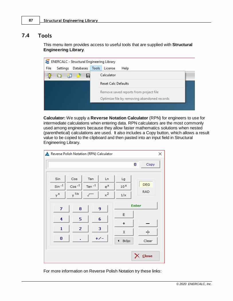
Structural Engineering Library87
© 2020 ENERCALC, Inc.
7.4 Tools
This menu item provides access to useful tools that are supplied with StructuralEngineering Library.
Calculator: We supply a Reverse Notation Calculator (RPN) for engineers to use forintermediate calculations when entering data. RPN calculators are the most commonlyused among engineers because they allow faster mathematics solutions when nested(parenthetical) calculations are used. It also includes a Copy button, which allows a resultvalue to be copied to the clipboard and then pasted into an input field in StructuralEngineering Library.
For more information on Reverse Polish Notation try these links:

Main Menu 88
© 2020 ENERCALC, Inc.
http://en.wikipedia.org/wiki/Reverse_Polish_notation
http://www.hpmuseum.org/rpn.htm
Reset Calc Defaults: This command resets the default values for the current calculationto the hard-coded internal default values. It may be a useful tool in some troubleshootingsituations.
Remove Saved Reports from Project File: This command removes any reports thathave been saved in the current Project File. It can be helpful in terms of reducing file size ifa Project File is to be emailed, but it will require that the reports be regenerated before theycan be printed.
Optimize file by removing abandoned records: This command removes lost records ina Project File which could occur if the program is terminated abnormally (perhaps from apower outage, lockup, network failure, lockup of another program, etc).

Structural Engineering Library89
© 2020 ENERCALC, Inc.
7.5 License
The License item displays the licensing and activation menu.
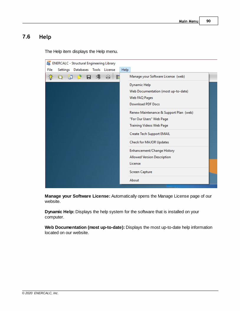
Main Menu 90
© 2020 ENERCALC, Inc.
7.6 Help
The Help item displays the Help menu.
Manage your Software License: Automatically opens the Manage License page of ourwebsite.
Dynamic Help: Displays the help system for the software that is installed on yourcomputer.
Web Documentation (most up-to-date): Displays the most up-to-date help informationlocated on our website.
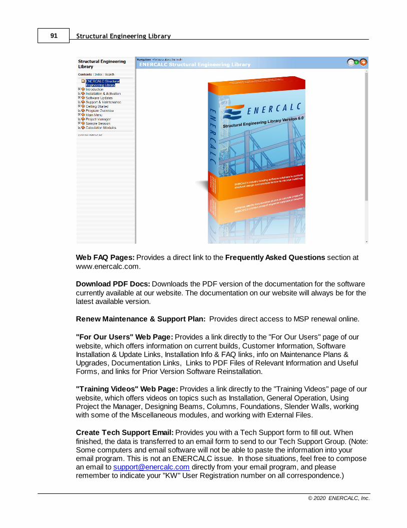
Structural Engineering Library91
© 2020 ENERCALC, Inc.
Web FAQ Pages: Provides a direct link to the Frequently Asked Questions section atwww.enercalc.com.
Download PDF Docs: Downloads the PDF version of the documentation for the softwarecurrently available at our website. The documentation on our website will always be for thelatest available version.
Renew Maintenance & Support Plan: Provides direct access to MSP renewal online.
"For Our Users" Web Page: Provides a link directly to the "For Our Users" page of ourwebsite, which offers information on current builds, Customer Information, SoftwareInstallation & Update Links, Installation Info & FAQ links, info on Maintenance Plans &Upgrades, Documentation Links, Links to PDF Files of Relevant Information and UsefulForms, and links for Prior Version Software Reinstallation.
"Training Videos" Web Page: Provides a link directly to the "Training Videos" page of ourwebsite, which offers videos on topics such as Installation, General Operation, UsingProject the Manager, Designing Beams, Columns, Foundations, Slender Walls, workingwith some of the Miscellaneous modules, and working with External Files.
Create Tech Support Email: Provides you with a Tech Support form to fill out. Whenfinished, the data is transferred to an email form to send to our Tech Support Group. (Note:Some computers and email software will not be able to paste the information into youremail program. This is not an ENERCALC issue. In those situations, feel free to composean email to [email protected] directly from your email program, and pleaseremember to indicate your "KW" User Registration number on all correspondence.)
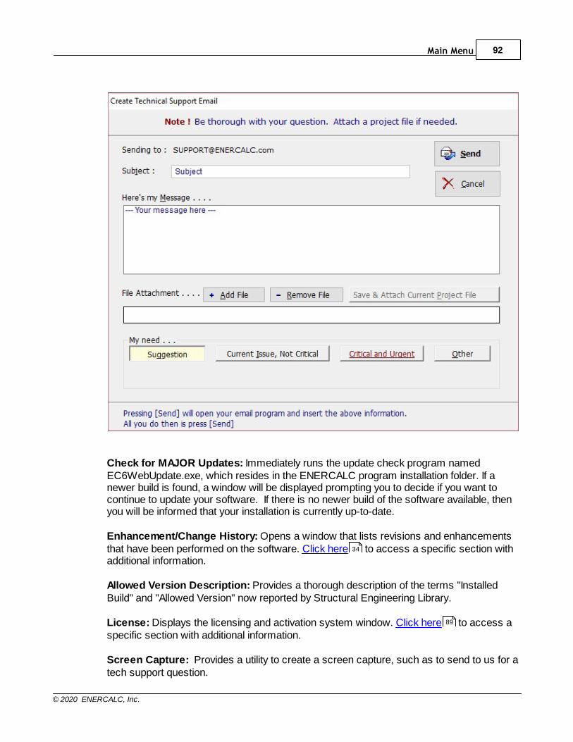
Main Menu 92
© 2020 ENERCALC, Inc.
Check for MAJOR Updates: Immediately runs the update check program namedEC6WebUpdate.exe, which resides in the ENERCALC program installation folder. If anewer build is found, a window will be displayed prompting you to decide if you want tocontinue to update your software. If there is no newer build of the software available, thenyou will be informed that your installation is currently up-to-date.
Enhancement/Change History: Opens a window that lists revisions and enhancementsthat have been performed on the software. Click here to access a specific section withadditional information.
Allowed Version Description: Provides a thorough description of the terms "InstalledBuild" and "Allowed Version" now reported by Structural Engineering Library.
License: Displays the licensing and activation system window. Click here to access aspecific section with additional information.
Screen Capture: Provides a utility to create a screen capture, such as to send to us for atech support question.
34
89
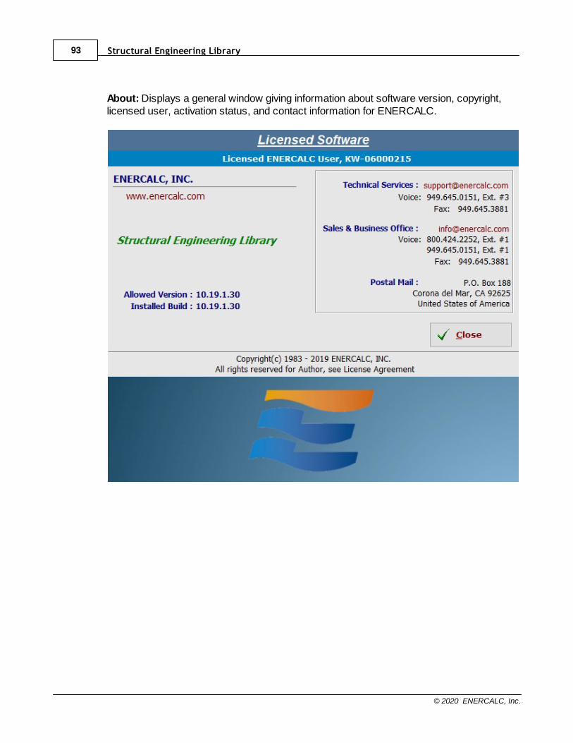
Structural Engineering Library93
© 2020 ENERCALC, Inc.
About: Displays a general window giving information about software version, copyright,licensed user, activation status, and contact information for ENERCALC.

Part
VIII

Structural Engineering Library95
© 2020 ENERCALC, Inc.
8 Project Manager
The Project Manager is displayed on the left side of the ENERCALC screen when a
Project File has been opened. Click here for a video: Project Manager
The Project Manger provides the ability to create and modify a single Project File that cancontain a set of calculations and external items for a specific project. The layout, which willbe ever-improving, is designed to allow an ENERCALC Project File to be a singlecollection point for documents relating to the load development and structural design of abuilding or other structure.
The behavior of the Project Manager has been enhanced by introducing the ability todisplay and hide the Project Manager on-demand. This offers the following advantages:
· Larger area is available for use in the Project Manager when it is displayed.
· More verbose calculation descriptions can be provided with fewer crypticabbreviations.
· Greater selection of "project level" operations buttons can be displayed.
· More efficient organization of GENERAL Division, LOADS & FORCES Division andcustom Divisions within the Project Manager.
· Larger area available for the display of input and results when Project Manager ishidden.
· More verbose descriptions of input variables can now be provided.
· Less on-screen congestion and less need for horizontal scroll bars in results tables.
Components that all Project Files AUTOMATICALLY contain are:
GENERAL Division (Only one can exist in a Project File)A storage location for pieces of information pertaining to areas of the entire project, suchas:
· Project Info, Building Department Contact Info, Designer Notes, Revisions, Client,Designer.
· Future additions
LOADS & FORCES Division (Only one can exist in a Project File)A storage location for pieces of information pertaining to areas of the entire project, suchas:
· General forces for the project including Snow Loads, Wind Loads and Seismic Loads.
· Live load reductions.
· Future additions
Components that any Project File CAN contain are:
Custom Divisions (An unlimited number can exist in a Project File)

Project Manager 96
© 2020 ENERCALC, Inc.
Storage locations (folders) for organizing user-generated calculations and external items.· Can be created, named, copied, organized, expanded, collapsed, and deleted.
· Are typically named in ways that are meaningful to the designer and that suit thespecific project.
· Are generally populated with calculations and external items.
· Provide a convenient way to selectively control project printing operations for logicalsets of calculations.
· Every new Project File is automatically populated with one Division named"Calculations".
Calculations (An unlimited number can exist in a Project File)User-generated calculations that are created using the built-in ENERCALC modules andare stored in the Custom Divisions.· Can be created, moved between Divisions, and deleted.
· Can be copied to serve as the basis for a new calculation with similar input data.
· Can be imported from one Project File to another.
· Can be printed singly or in batch mode using the Project Printing Manager.
External Items (An unlimited number can exist in a Project File)User-generated external files that are created using external programs and then stored inthe Custom Divisions.· Can consist of MS Word documents, MS Excel spreadsheets, Adobe Acrobat PDFs,
and scanned documents/images.· Can be embedded within the Project File for maximum portability, or can be linked to
the Project File to minimize file size. · Can be created, moved between Divisions, and deleted.
Please see the descriptive keynotes on the following screen capture for information onvarious areas of the Project Manager.
Detailed descriptions are contained in the sections of this topic.
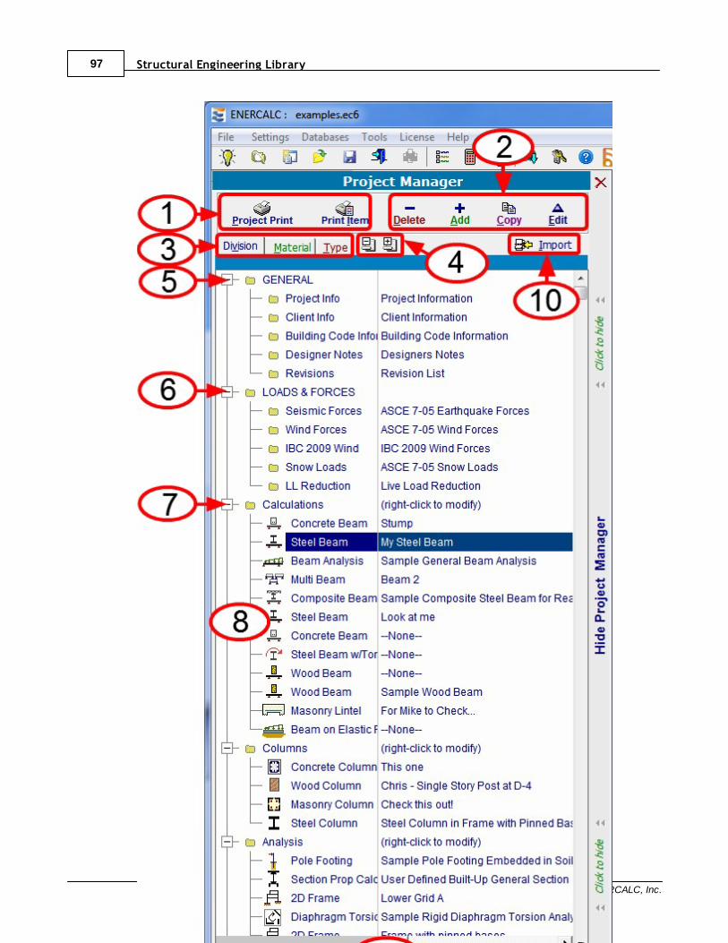
Structural Engineering Library97
© 2020 ENERCALC, Inc.
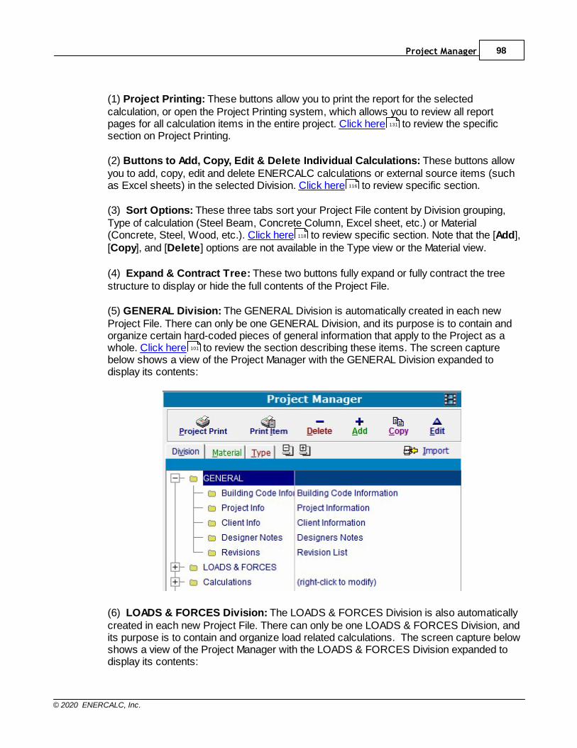
Project Manager 98
© 2020 ENERCALC, Inc.
(1) Project Printing: These buttons allow you to print the report for the selectedcalculation, or open the Project Printing system, which allows you to review all reportpages for all calculation items in the entire project. Click here to review the specificsection on Project Printing.
(2) Buttons to Add, Copy, Edit & Delete Individual Calculations: These buttons allowyou to add, copy, edit and delete ENERCALC calculations or external source items (suchas Excel sheets) in the selected Division. Click here to review specific section.
(3) Sort Options: These three tabs sort your Project File content by Division grouping,Type of calculation (Steel Beam, Concrete Column, Excel sheet, etc.) or Material(Concrete, Steel, Wood, etc.). Click here to review specific section. Note that the [Add],[Copy], and [Delete] options are not available in the Type view or the Material view.
(4) Expand & Contract Tree: These two buttons fully expand or fully contract the treestructure to display or hide the full contents of the Project File.
(5) GENERAL Division: The GENERAL Division is automatically created in each newProject File. There can only be one GENERAL Division, and its purpose is to contain andorganize certain hard-coded pieces of general information that apply to the Project as awhole. Click here to review the section describing these items. The screen capturebelow shows a view of the Project Manager with the GENERAL Division expanded todisplay its contents:
(6) LOADS & FORCES Division: The LOADS & FORCES Division is also automaticallycreated in each new Project File. There can only be one LOADS & FORCES Division, andits purpose is to contain and organize load related calculations. The screen capture belowshows a view of the Project Manager with the LOADS & FORCES Division expanded todisplay its contents:
131
116
118
101
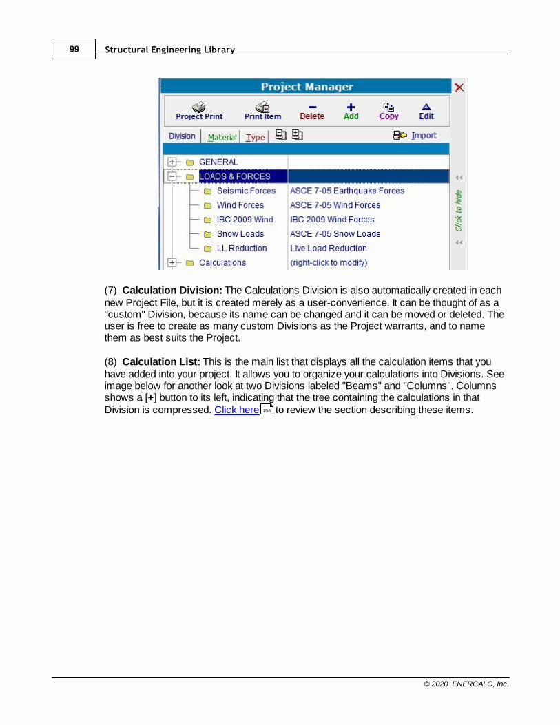
Structural Engineering Library99
© 2020 ENERCALC, Inc.
(7) Calculation Division: The Calculations Division is also automatically created in eachnew Project File, but it is created merely as a user-convenience. It can be thought of as a"custom" Division, because its name can be changed and it can be moved or deleted. Theuser is free to create as many custom Divisions as the Project warrants, and to namethem as best suits the Project.
(8) Calculation List: This is the main list that displays all the calculation items that youhave added into your project. It allows you to organize your calculations into Divisions. Seeimage below for another look at two Divisions labeled "Beams" and "Columns". Columnsshows a [+] button to its left, indicating that the tree containing the calculations in thatDivision is compressed. Click here to review the section describing these items.108
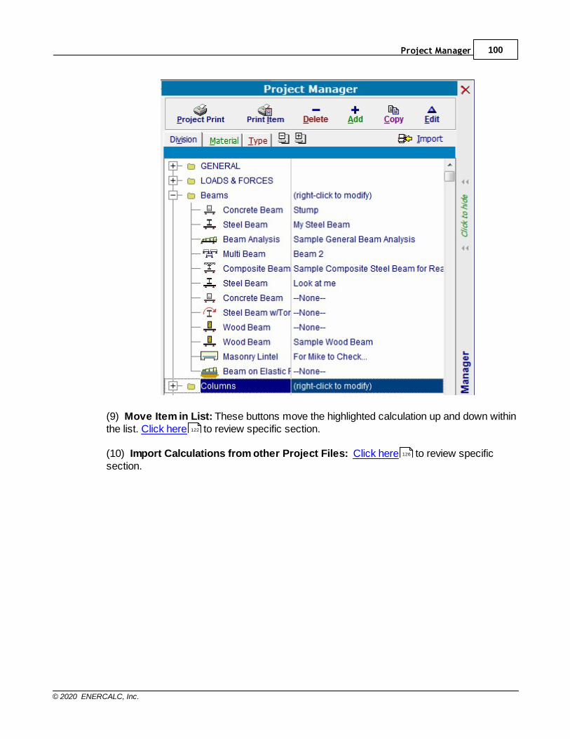
Project Manager 100
© 2020 ENERCALC, Inc.
(9) Move Item in List: These buttons move the highlighted calculation up and down withinthe list. Click here to review specific section.
(10) Import Calculations from other Project Files: Click here to review specificsection.
122
126
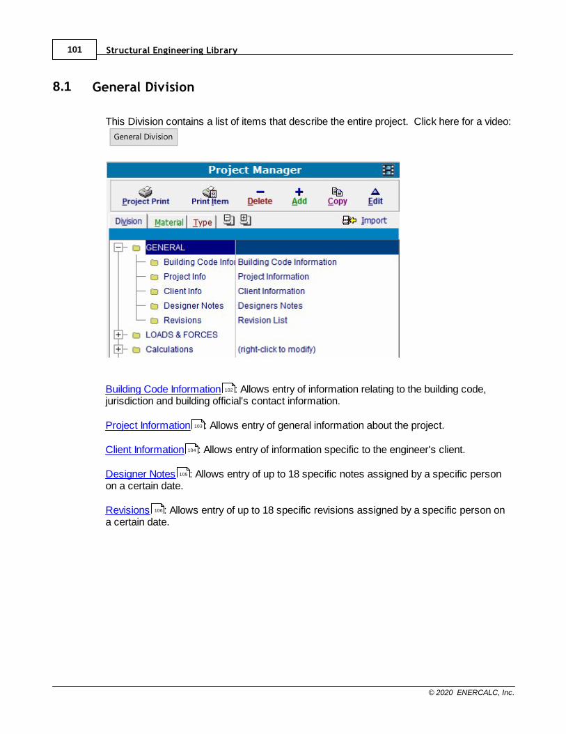
Structural Engineering Library101
© 2020 ENERCALC, Inc.
8.1 General Division
This Division contains a list of items that describe the entire project. Click here for a video:
General Division
Building Code Information : Allows entry of information relating to the building code,jurisdiction and building official's contact information.
Project Information : Allows entry of general information about the project.
Client Information : Allows entry of information specific to the engineer's client.
Designer Notes : Allows entry of up to 18 specific notes assigned by a specific personon a certain date.
Revisions : Allows entry of up to 18 specific revisions assigned by a specific person ona certain date.
102
103
104
105
106
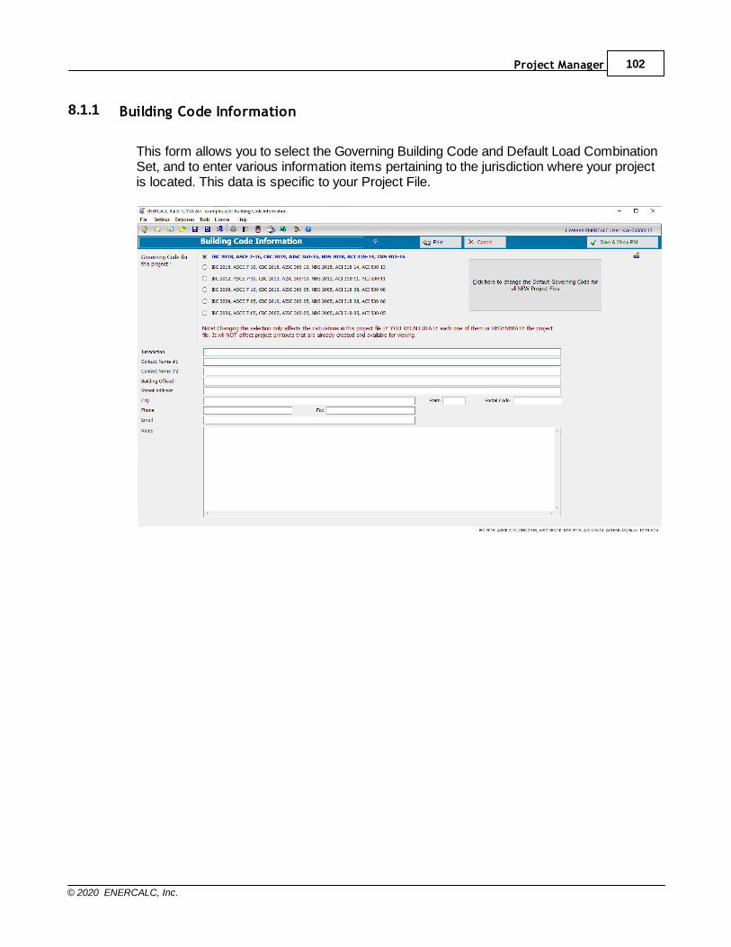
Project Manager 102
© 2020 ENERCALC, Inc.
8.1.1 Building Code Information
This form allows you to select the Governing Building Code and Default Load CombinationSet, and to enter various information items pertaining to the jurisdiction where your projectis located. This data is specific to your Project File.
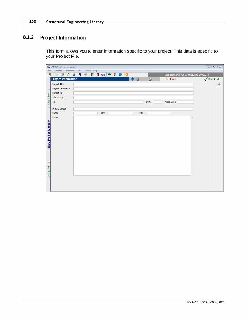
Structural Engineering Library103
© 2020 ENERCALC, Inc.
8.1.2 Project Information
This form allows you to enter information specific to your project. This data is specific toyour Project File.
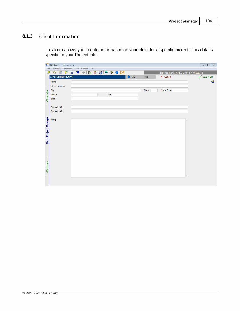
Project Manager 104
© 2020 ENERCALC, Inc.
8.1.3 Client Information
This form allows you to enter information on your client for a specific project. This data isspecific to your Project File.
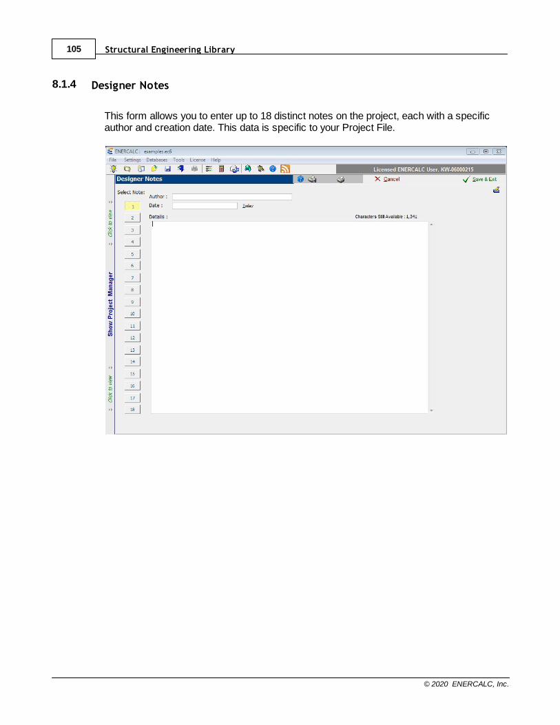
Structural Engineering Library105
© 2020 ENERCALC, Inc.
8.1.4 Designer Notes
This form allows you to enter up to 18 distinct notes on the project, each with a specificauthor and creation date. This data is specific to your Project File.
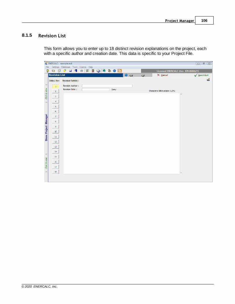
Project Manager 106
© 2020 ENERCALC, Inc.
8.1.5 Revision List
This form allows you to enter up to 18 distinct revision explanations on the project, eachwith a specific author and creation date. This data is specific to your Project File.
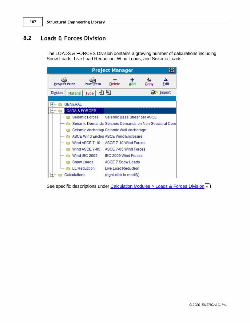
Structural Engineering Library107
© 2020 ENERCALC, Inc.
8.2 Loads & Forces Division
The LOADS & FORCES Division contains a growing number of calculations includingSnow Loads, Live Load Reduction, Wind Loads, and Seismic Loads.
See specific descriptions under Calculation Modules > Loads & Forces Division .107

Project Manager 108
© 2020 ENERCALC, Inc.
8.3 Calculation List
The Calculation List is the main Project Manager view that you will use when building your
calculation sets for projects. Click here for a video: Calculations Division
Most of a normal work session consists of adding and editing calculations in the list.
Please see the notes below as well as the following sections to learn what each buttonprovides and how to manage the list of calculations.

Structural Engineering Library109
© 2020 ENERCALC, Inc.
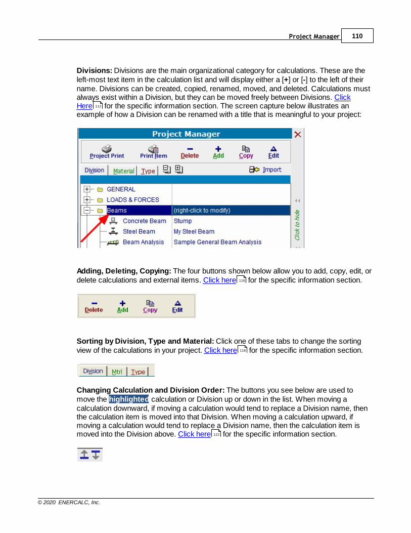
Project Manager 110
© 2020 ENERCALC, Inc.
Divisions: Divisions are the main organizational category for calculations. These are theleft-most text item in the calculation list and will display either a [+] or [-] to the left of theirname. Divisions can be created, copied, renamed, moved, and deleted. Calculations mustalways exist within a Division, but they can be moved freely between Divisions. ClickHere for the specific information section. The screen capture below illustrates anexample of how a Division can be renamed with a title that is meaningful to your project:
Adding, Deleting, Copying: The four buttons shown below allow you to add, copy, edit, ordelete calculations and external items. Click here for the specific information section.
Sorting by Division, Type and Material: Click one of these tabs to change the sortingview of the calculations in your project. Click here for the specific information section.
Changing Calculation and Division Order: The buttons you see below are used tomove the highlighted calculation or Division up or down in the list. When moving acalculation downward, if moving a calculation would tend to replace a Division name, thenthe calculation item is moved into that Division. When moving a calculation upward, ifmoving a calculation would tend to replace a Division name, then the calculation item ismoved into the Division above. Click here for the specific information section.
112
116
118
122

Structural Engineering Library111
© 2020 ENERCALC, Inc.
Importing Calculations: Clicking the [Import] button displays thecalculation import system. Click here for the specific information section.126

Project Manager 112
© 2020 ENERCALC, Inc.
8.3.1 Divisions
Divisions are used to organize calculations. The image below has custom Divisionsnamed Beams, Columns, Analysis, etc.
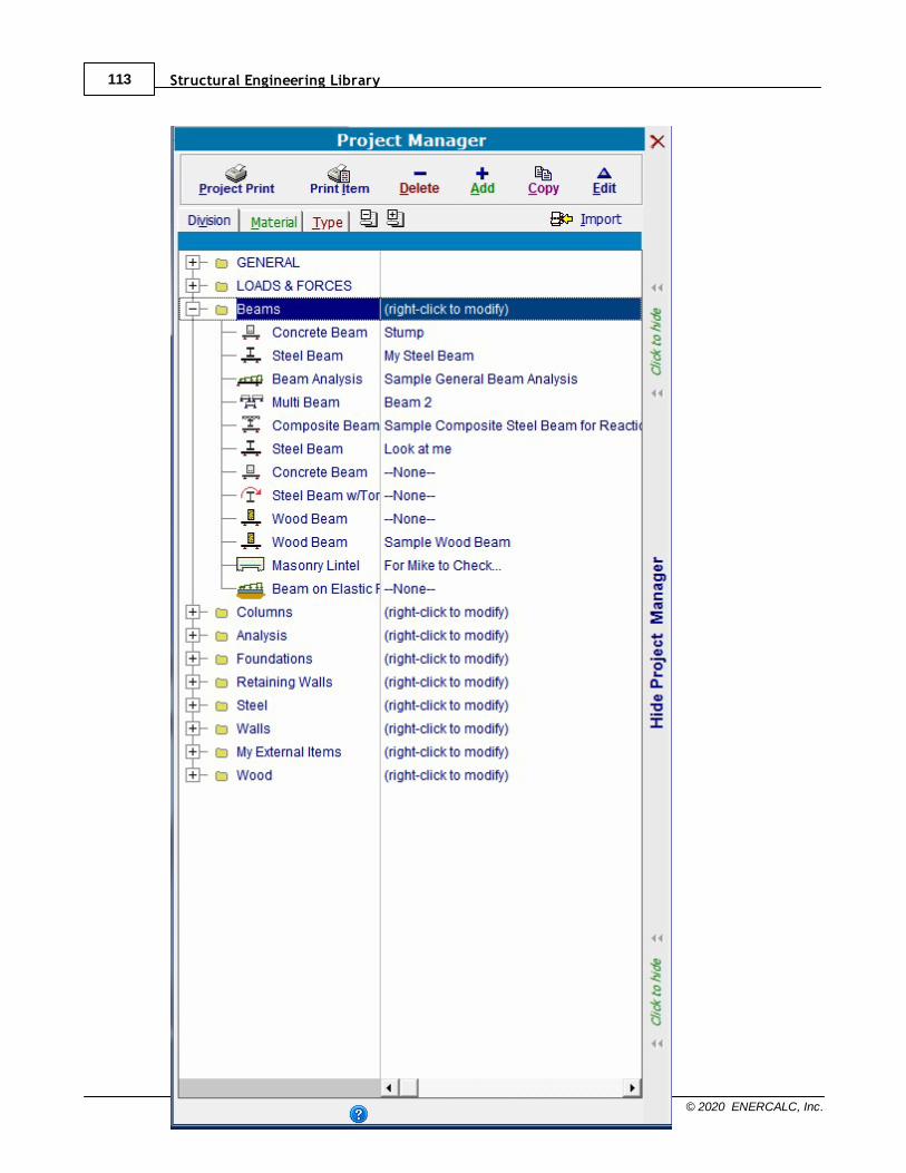
Structural Engineering Library113
© 2020 ENERCALC, Inc.
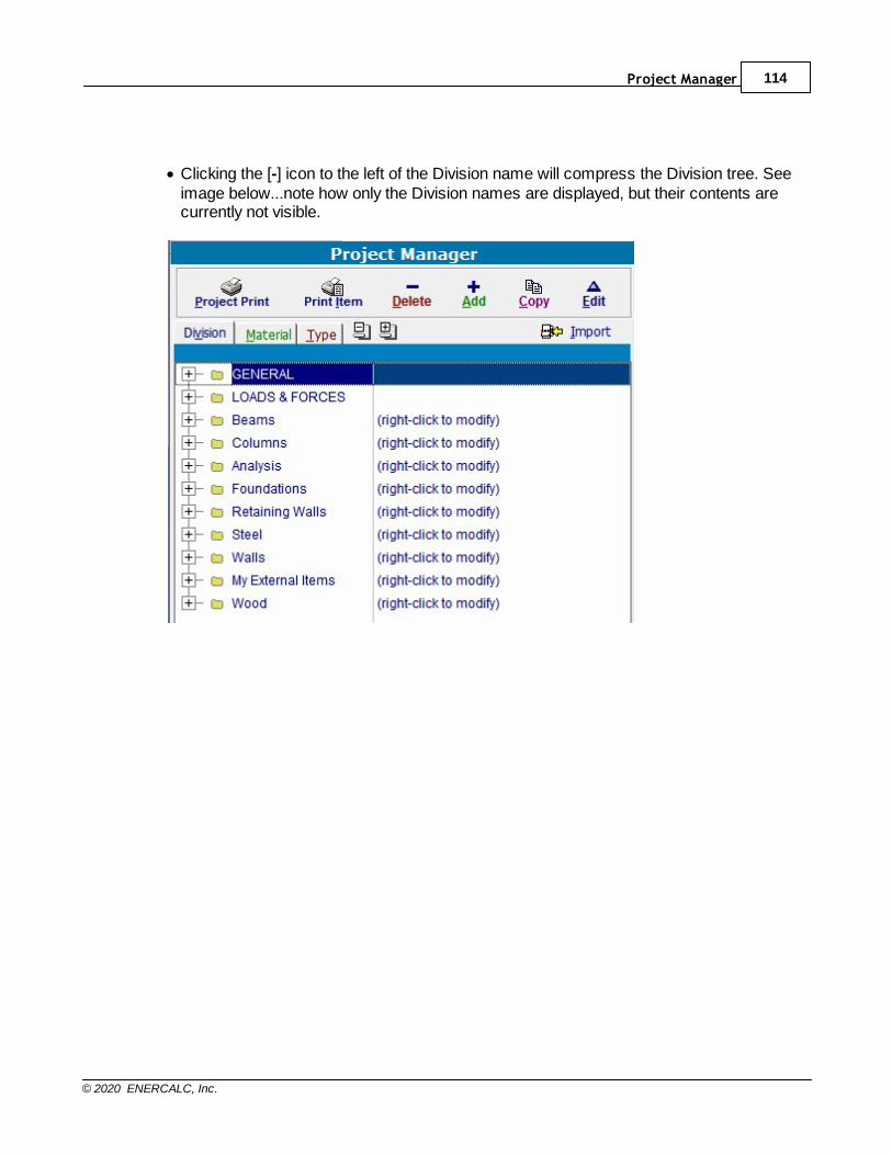
Project Manager 114
© 2020 ENERCALC, Inc.
· Clicking the [-] icon to the left of the Division name will compress the Division tree. Seeimage below...note how only the Division names are displayed, but their contents arecurrently not visible.
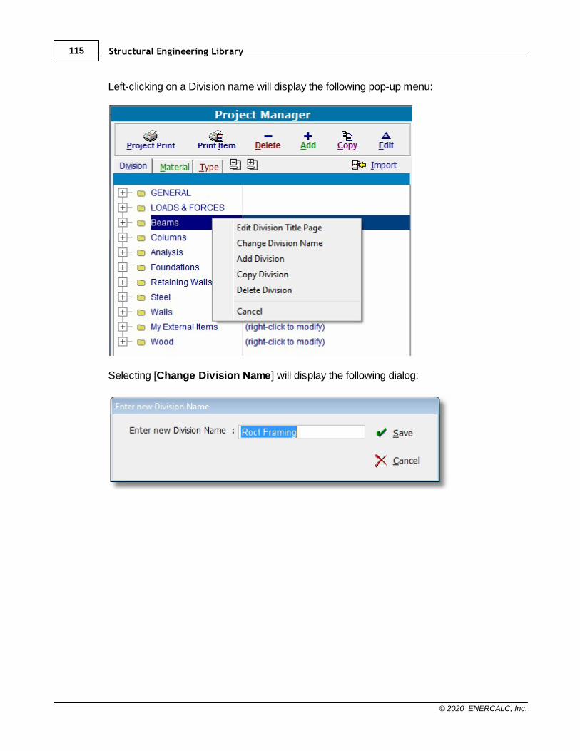
Structural Engineering Library115
© 2020 ENERCALC, Inc.
Left-clicking on a Division name will display the following pop-up menu:
Selecting [Change Division Name] will display the following dialog:
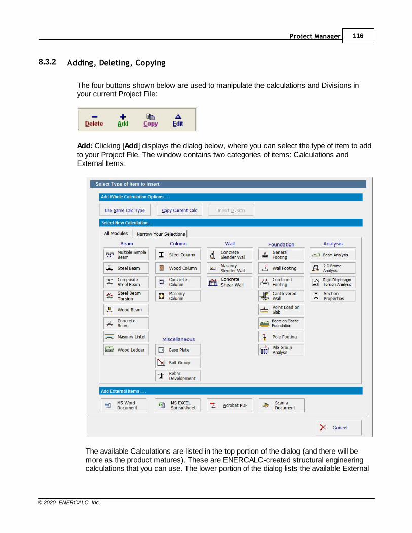
Project Manager 116
© 2020 ENERCALC, Inc.
8.3.2 Adding, Deleting, Copying
The four buttons shown below are used to manipulate the calculations and Divisions inyour current Project File:
Add: Clicking [Add] displays the dialog below, where you can select the type of item to addto your Project File. The window contains two categories of items: Calculations andExternal Items.
The available Calculations are listed in the top portion of the dialog (and there will bemore as the product matures). These are ENERCALC-created structural engineeringcalculations that you can use. The lower portion of the dialog lists the available External

Structural Engineering Library117
© 2020 ENERCALC, Inc.
Items that can be created externally from the ENERCALC software package and theninserted into an ENERCALC Project File. These item types are:
Microsoft WORD Document: You can include a Microsoft Word document as an itemin your Project File. Click here to go to the specific section.
Microsoft EXCEL Spreadsheet: You can include a Microsoft Excel spreadsheet as anitem in your Project File. Click here to go to the specific section.
Adobe Acrobat PDF File: You can include a PDF file as an item in your Project File.Click here to go to the specific section.
Scanned Document: You can set up your scanner and scan documents or images toinclude as an item in your Project File. Click here to go to the specific section.
Copy: For the currently highlighted item in the calculation list, clicking [Copy] creates anew calculation of the same type using all of the information in the current calculation tomake the new calculation. The copy is added to the list and is automatically opened forediting.
Edit: For the currently highlighted item in the calculation list, clicking [Edit] opens thecalculation for editing.
Delete: Deletes the item that is currently highlighted in the calculation list. You areprompted to confirm before the deletion is made.
620
624
628
632

Project Manager 118
© 2020 ENERCALC, Inc.
8.3.3 Sorting by Division, Type & Material
Select the "Division", "Material", or "Type" tab to sort the calculation list based on thesethree primary organizational hierarchies.
Division: Organizes the calculation list by the Divisions you created, and sorts thecalculations within each Division in the order that you established. See below.

Structural Engineering Library119
© 2020 ENERCALC, Inc.
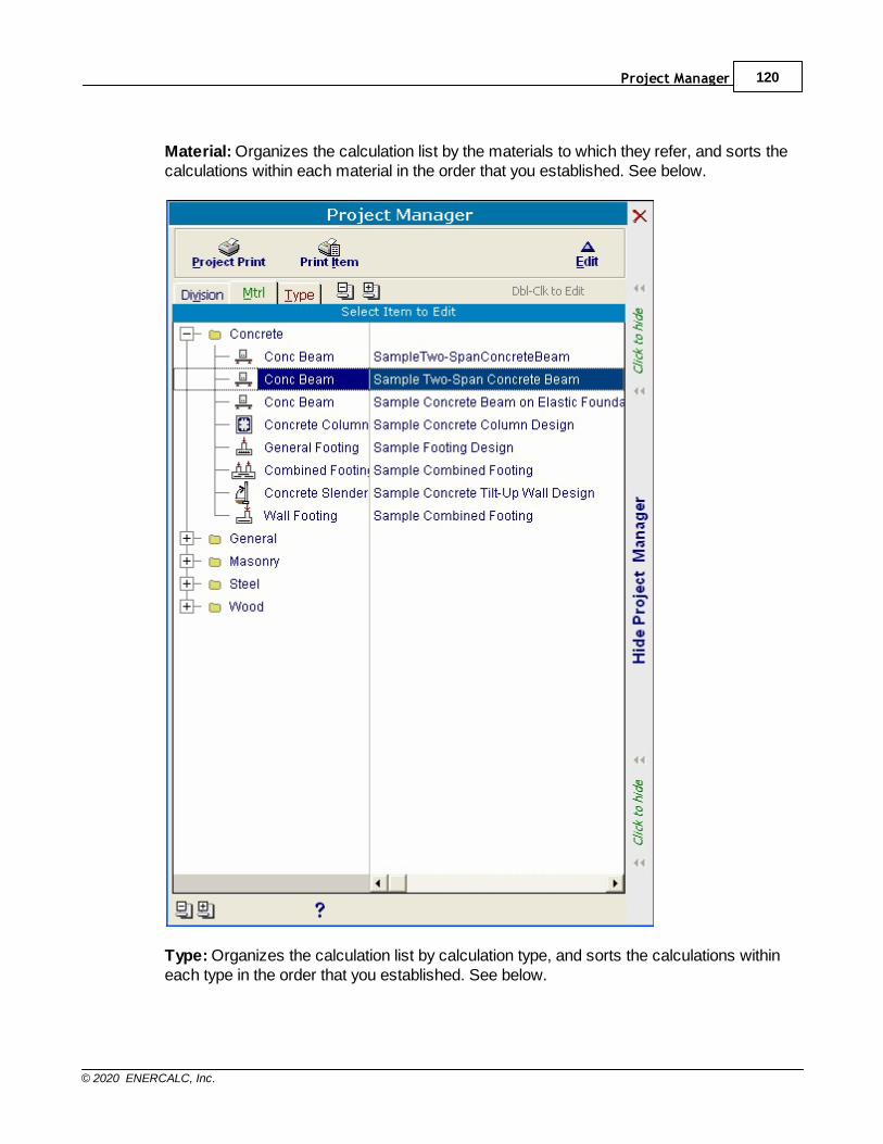
Project Manager 120
© 2020 ENERCALC, Inc.
Material: Organizes the calculation list by the materials to which they refer, and sorts thecalculations within each material in the order that you established. See below.
Type: Organizes the calculation list by calculation type, and sorts the calculations withineach type in the order that you established. See below.
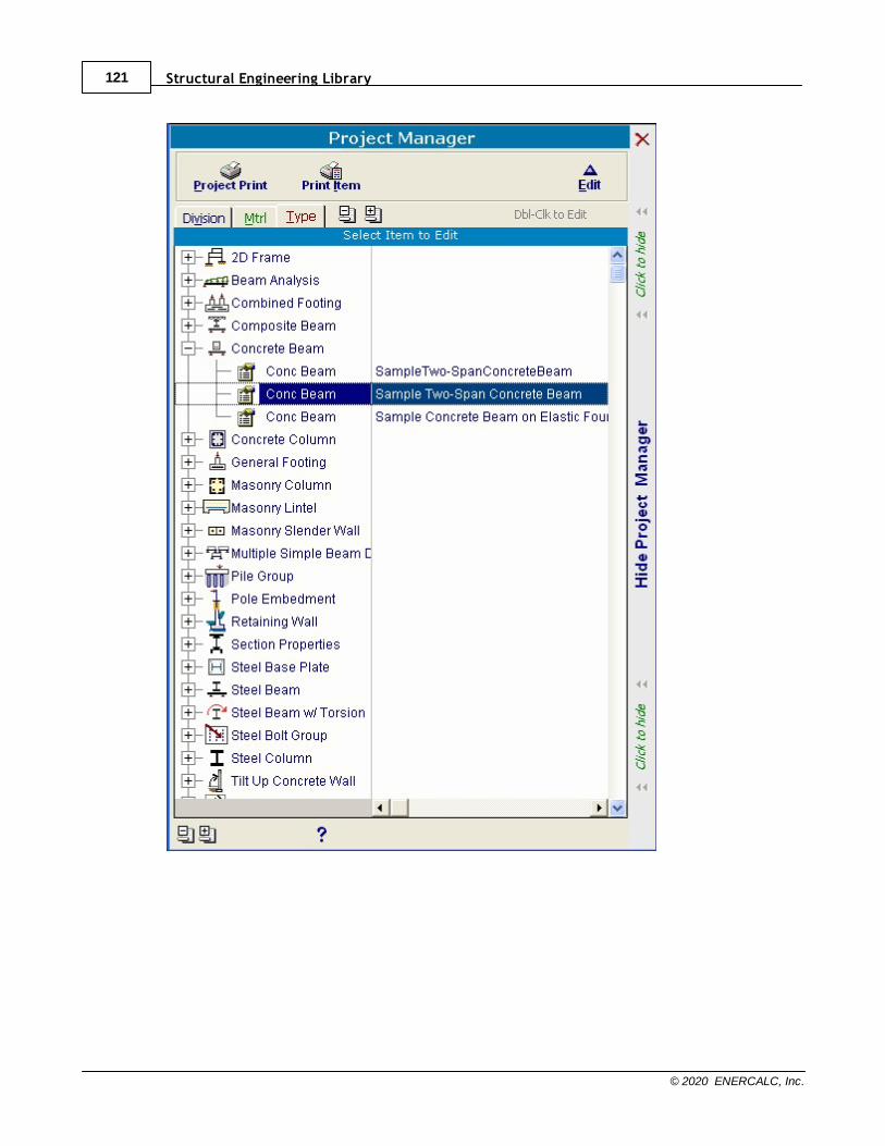
Structural Engineering Library121
© 2020 ENERCALC, Inc.

Project Manager 122
© 2020 ENERCALC, Inc.
8.3.4 Changing Calculation Order
The two buttons shown at the bottom of the calculation list (see image below) are used tomove the currently highlighted calculation or Division up or down in the list.
In the images below, note the button that is used to move the item upward in the list:
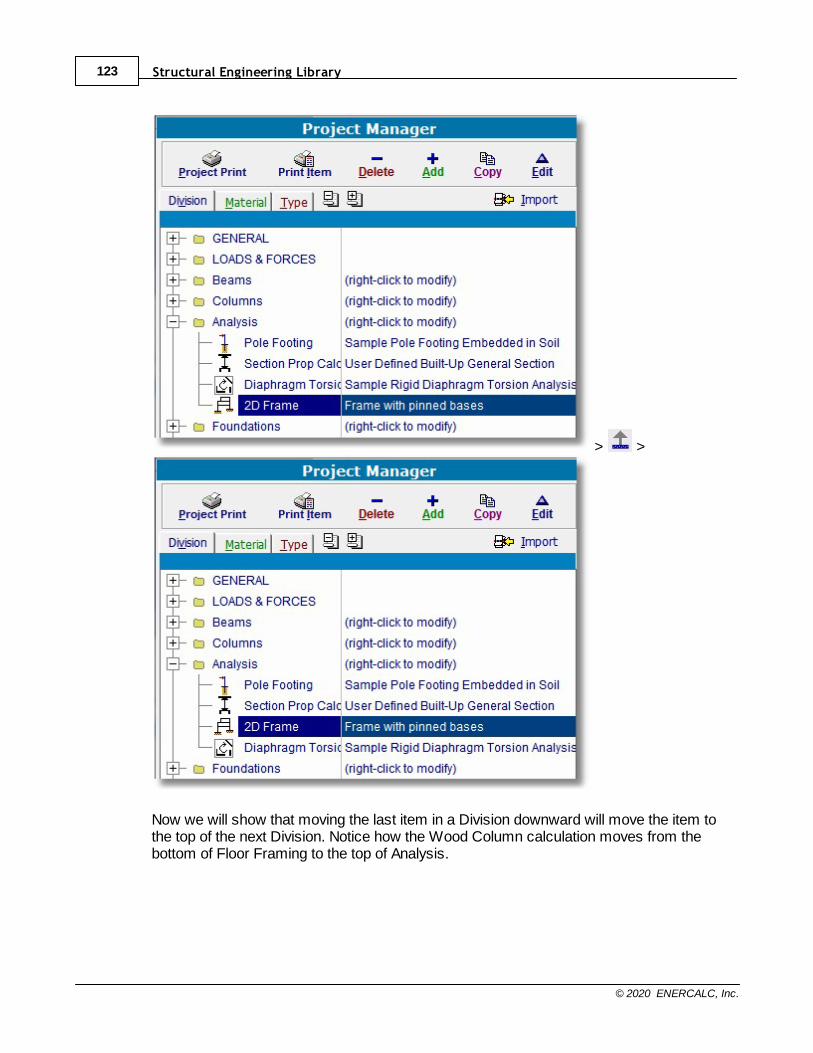
Structural Engineering Library123
© 2020 ENERCALC, Inc.
> >
Now we will show that moving the last item in a Division downward will move the item tothe top of the next Division. Notice how the Wood Column calculation moves from thebottom of Floor Framing to the top of Analysis.
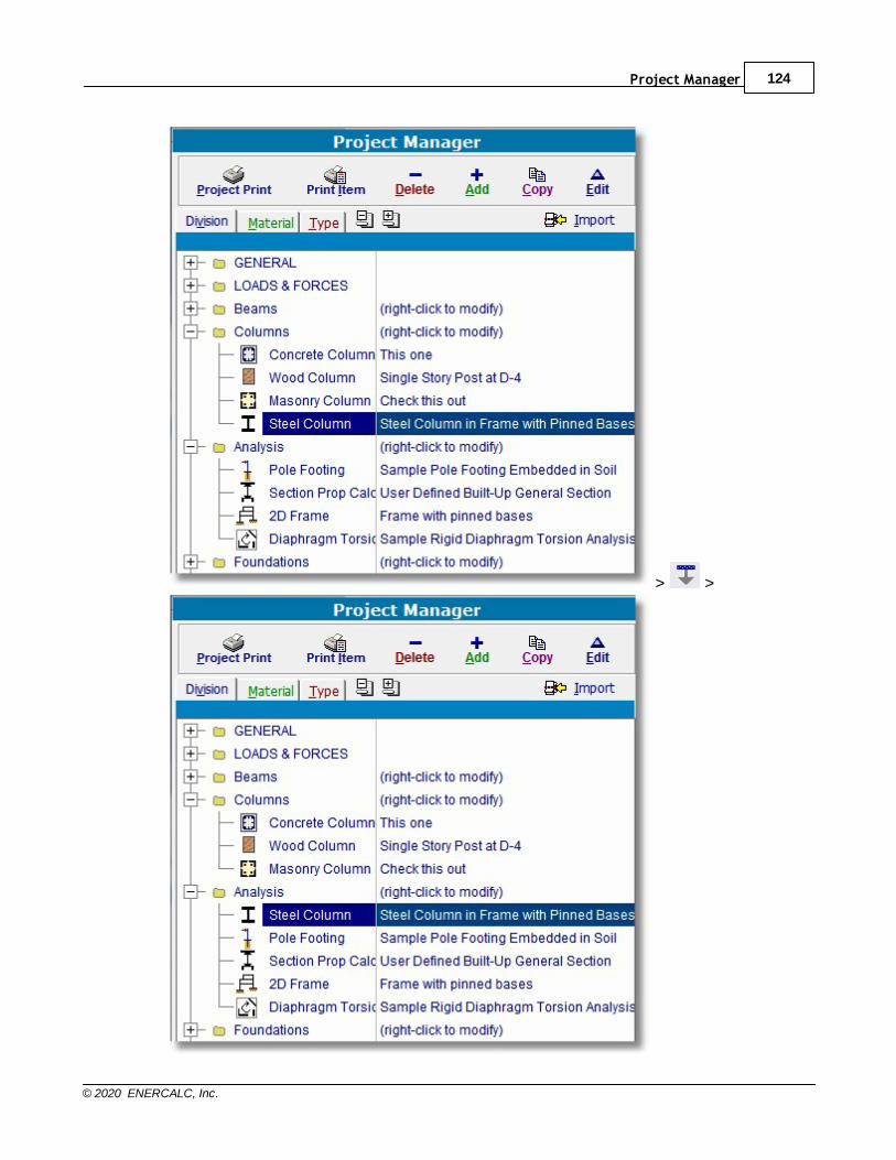
Project Manager 124
© 2020 ENERCALC, Inc.
> >

Structural Engineering Library125
© 2020 ENERCALC, Inc.
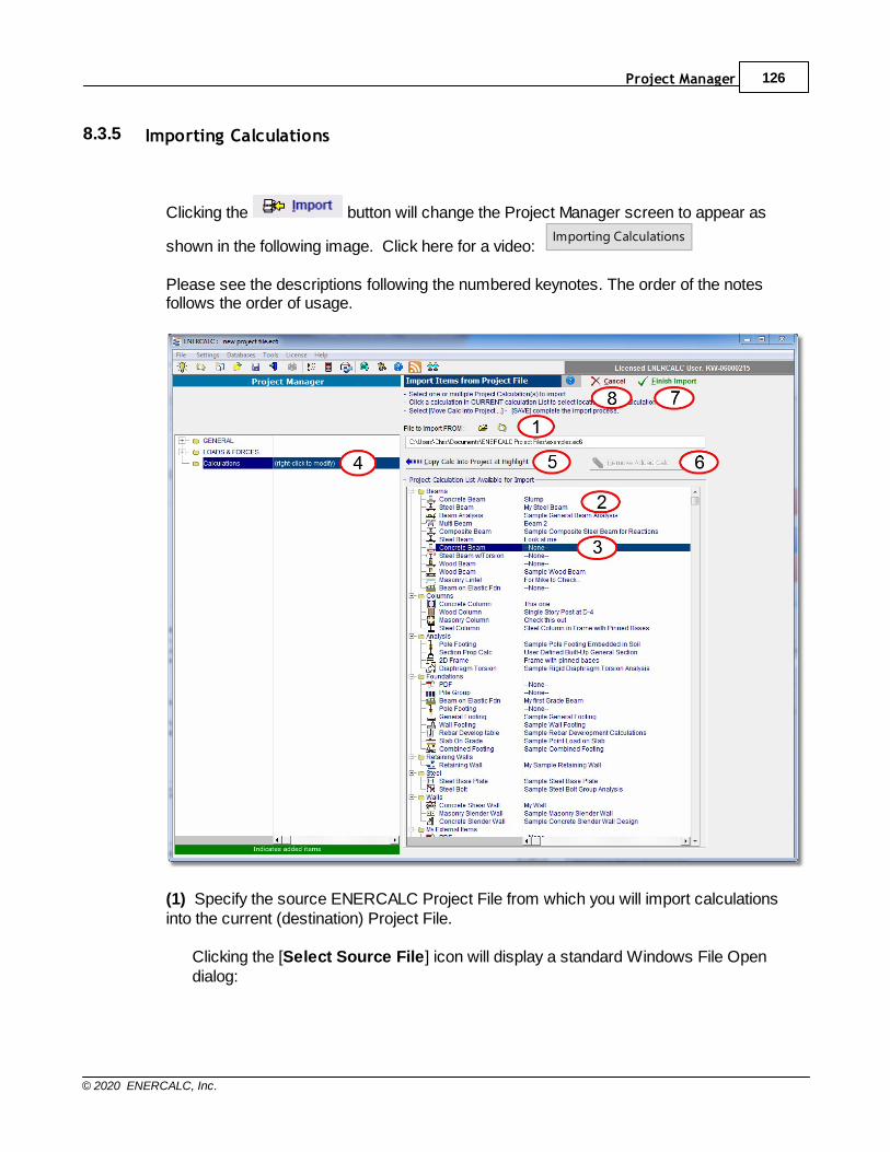
Project Manager 126
© 2020 ENERCALC, Inc.
8.3.5 Importing Calculations
Clicking the button will change the Project Manager screen to appear as
shown in the following image. Click here for a video: Importing Calculations
Please see the descriptions following the numbered keynotes. The order of the notesfollows the order of usage.
(1) Specify the source ENERCALC Project File from which you will import calculationsinto the current (destination) Project File.
Clicking the [Select Source File] icon will display a standard Windows File Opendialog:
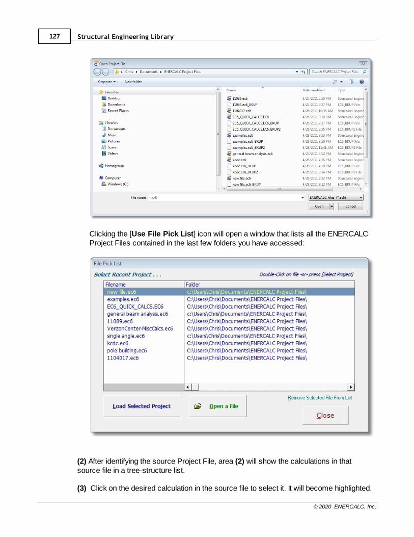
Structural Engineering Library127
© 2020 ENERCALC, Inc.
Clicking the [Use File Pick List] icon will open a window that lists all the ENERCALCProject Files contained in the last few folders you have accessed:
(2) After identifying the source Project File, area (2) will show the calculations in thatsource file in a tree-structure list.
(3) Click on the desired calculation in the source file to select it. It will become highlighted.

Project Manager 128
© 2020 ENERCALC, Inc.
(4) Click in the current (destination) Project File to highlight a line where the calculationshould be imported. (The only restriction is that calculations cannot be imported into theGENERAL Division or the LOADS & FORCES Division, so be sure to select a locationother than those two Divisions or any of their contents.)
(5) Click the [Copy Calc Into Project at Highlight] button.
Notice in the image below the [Concrete Beam] calculation is now highlighted in green inthe current (destination) file to indicate the location where it will be inserted.
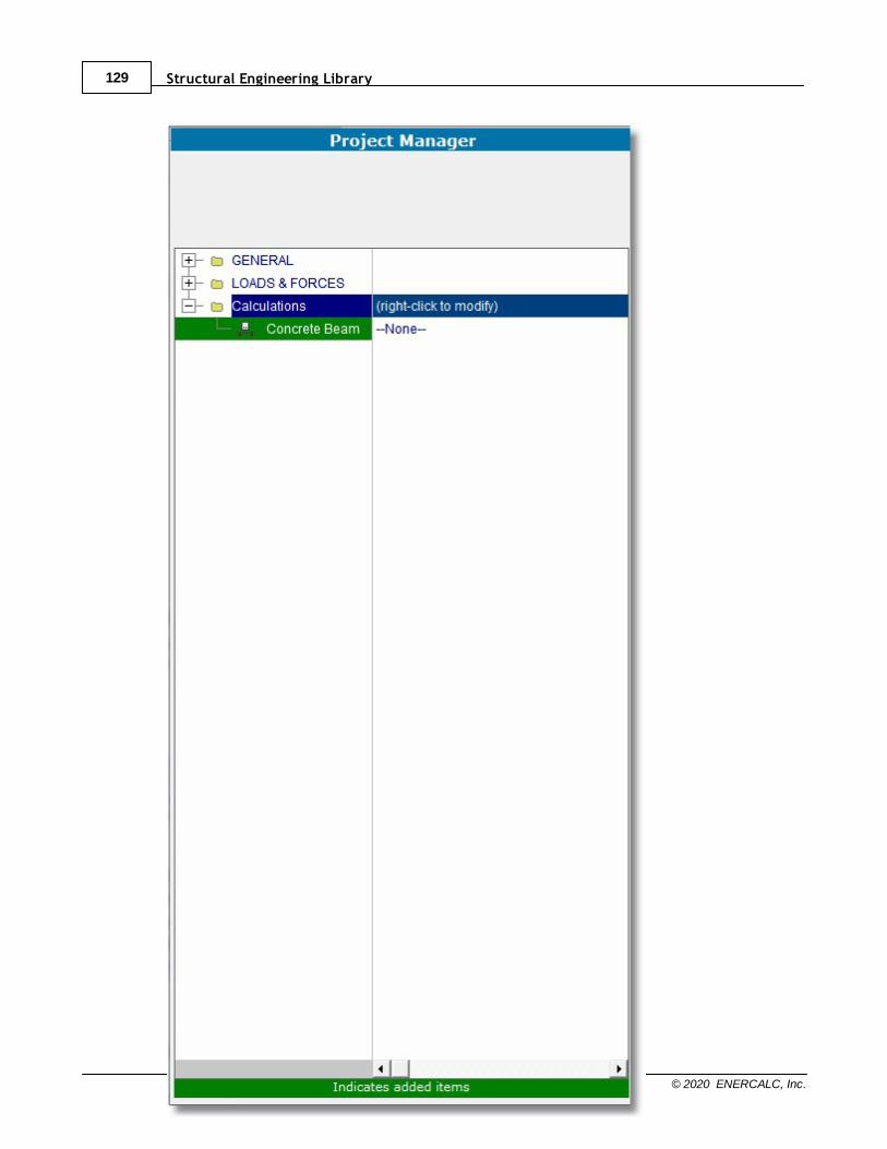
Structural Engineering Library129
© 2020 ENERCALC, Inc.

Project Manager 130
© 2020 ENERCALC, Inc.
Note: If you made a mistake and want to cancel the selection, just highlight the calculationin green on the left and click the [Remove Added Calc] button (6).
(7) To finish the import process click the button.
(8) To completely cancel the import click the button.
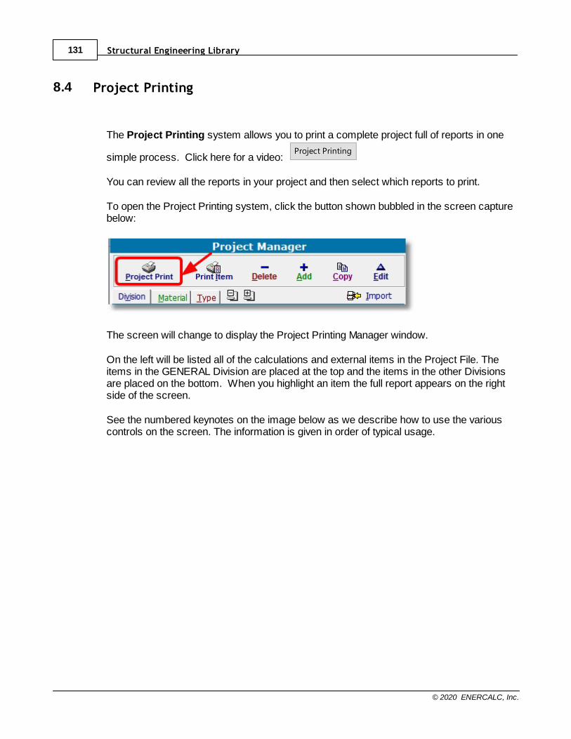
Structural Engineering Library131
© 2020 ENERCALC, Inc.
8.4 Project Printing
The Project Printing system allows you to print a complete project full of reports in one
simple process. Click here for a video: Project Printing
You can review all the reports in your project and then select which reports to print.
To open the Project Printing system, click the button shown bubbled in the screen capturebelow:
The screen will change to display the Project Printing Manager window.
On the left will be listed all of the calculations and external items in the Project File. Theitems in the GENERAL Division are placed at the top and the items in the other Divisionsare placed on the bottom. When you highlight an item the full report appears on the rightside of the screen.
See the numbered keynotes on the image below as we describe how to use the variouscontrols on the screen. The information is given in order of typical usage.
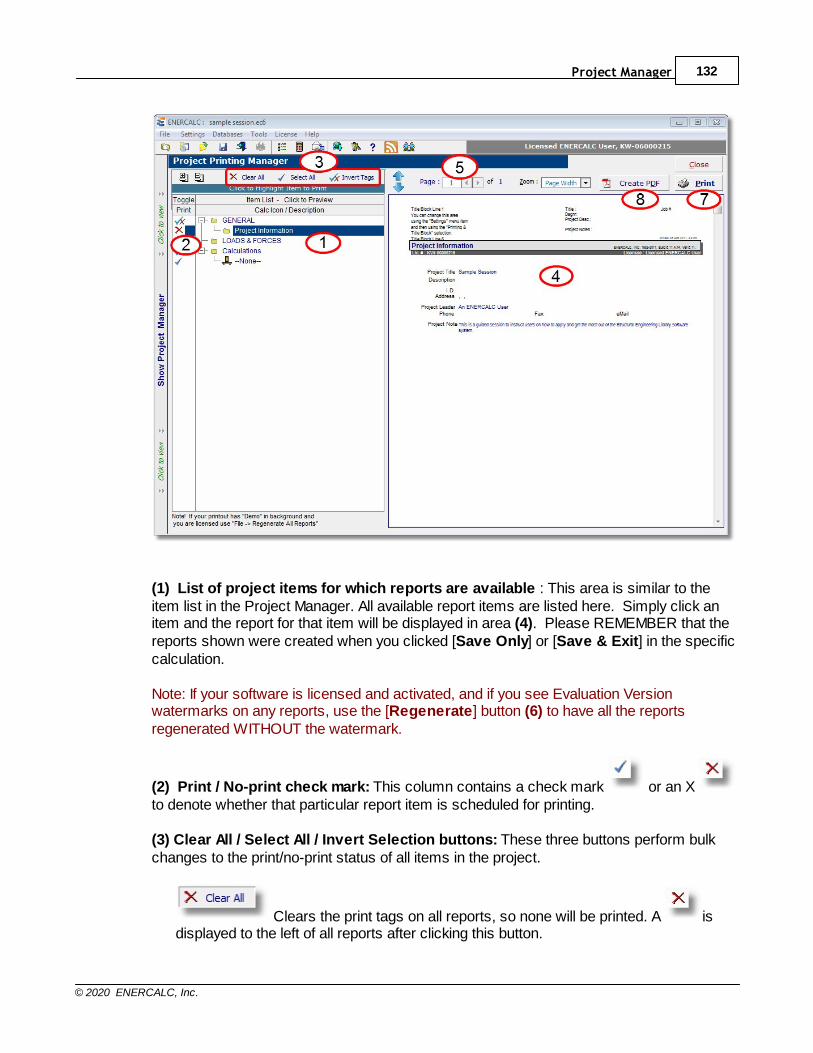
Project Manager 132
© 2020 ENERCALC, Inc.
(1) List of project items for which reports are available : This area is similar to theitem list in the Project Manager. All available report items are listed here. Simply click anitem and the report for that item will be displayed in area (4). Please REMEMBER that thereports shown were created when you clicked [Save Only] or [Save & Exit] in the specificcalculation.
Note: If your software is licensed and activated, and if you see Evaluation Versionwatermarks on any reports, use the [Regenerate] button (6) to have all the reportsregenerated WITHOUT the watermark.
(2) Print / No-print check mark: This column contains a check mark or an X to denote whether that particular report item is scheduled for printing.
(3) Clear All / Select All / Invert Selection buttons: These three buttons perform bulkchanges to the print/no-print status of all items in the project.
Clears the print tags on all reports, so none will be printed. A isdisplayed to the left of all reports after clicking this button.

Structural Engineering Library133
© 2020 ENERCALC, Inc.
Selects the print tags on all reports, so all will be printed. A isdisplayed to the left of all reports after clicking this button.
Inverts the print/no-print tags on all reports.
(4) Report Preview area: The complete preview of the report is shown in this area for thereport item highlighted in the list.
(5) Report page selection: When the highlighted item is a multi-page report, this boxselects the page to view.
(6) (Item removed)
(7) Print selected reports to printer: Displays the Windows standard Print dialog boxand begins printing all selected project items.
(8) Create single PDF file for selected reports: Displays a Windows Open File dialogbox to request a filename for a PDF file and then creates a PDF of all selected projectitems.
Click [Close] to dismiss the Project Printing Manager.

Part
IX

Structural Engineering Library135
© 2020 ENERCALC, Inc.
9 Sample Session
This section will guide you through a session of preparing and printing a calculation. Wewill use the Wood Beam calculation because it contains all the features available inStructural Engineering Library.

Sample Session 136
© 2020 ENERCALC, Inc.
9.1 Starting the Program
First....let's start the program
To start Structural Engineering Library, navigate to the ENERCALC program groupfrom the Start menu.
Click the Windows [Start] button and move upward to highlight the Programs (or AllPrograms) item. Locate the ENERCALC program group and highlight it. You will seeseveral selections. Move the cursor to highlight Structural Library and release the mousebutton. Structural Engineering Library will now open, and you will be viewing the ProjectAssistant as described below.
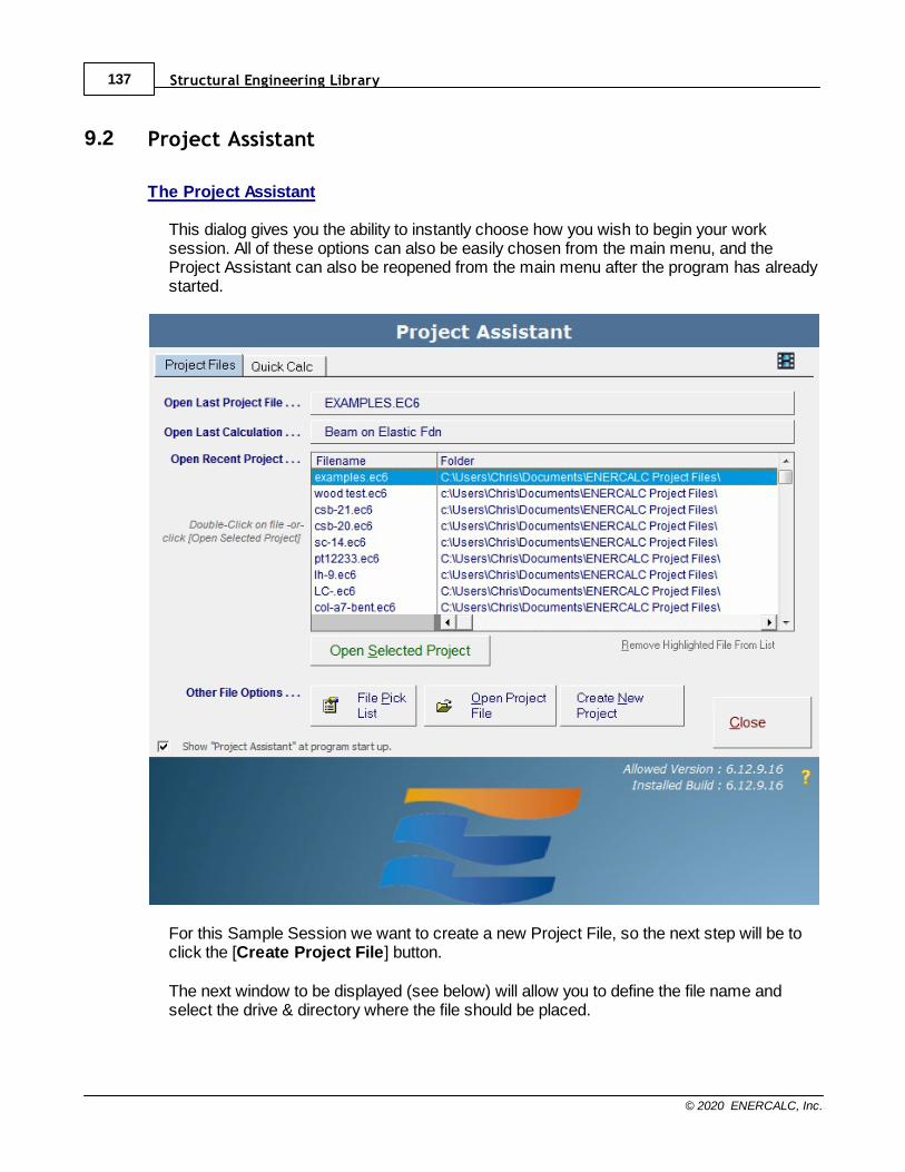
Structural Engineering Library137
© 2020 ENERCALC, Inc.
9.2 Project Assistant
The Project Assistant
This dialog gives you the ability to instantly choose how you wish to begin your worksession. All of these options can also be easily chosen from the main menu, and theProject Assistant can also be reopened from the main menu after the program has alreadystarted.
For this Sample Session we want to create a new Project File, so the next step will be toclick the [Create Project File] button.
The next window to be displayed (see below) will allow you to define the file name andselect the drive & directory where the file should be placed.

Sample Session 138
© 2020 ENERCALC, Inc.
We will use the filename Sample Session and place it in a folder named ENERCALCProject Files that we created specifically to hold Project Files.
Note: You could place the file in other directories, but keep in mind that Microsoftis now recommending specific locations for saving user-generated files with thenewer operating systems, and the default ENERCALC data folder conforms tothese new best-practice recommendations. The important thing to recognize isthat an ENERCALC Project File can hold thousands of calculations, so it is likelythat there will only need to be a single ENERCALC Project File for each designproject in the office.

Structural Engineering Library139
© 2020 ENERCALC, Inc.
9.3 Creating a Project File
Creating a Project File
Here's the Create NEW Project File dialog box with the new filename entered. NO FILEEXTENSION is necessary....the program will append it. When the dialog appears as itdoes below, just click [Save] and the file will be created.
When a new Project File is created, the new Project File is immediately opened anddisplayed in the Project Manager window. You can see in the screen image below that thenew Project File looks rather plain and simple.

Sample Session 140
© 2020 ENERCALC, Inc.
Notice that the ONLY items appearing in the calculation list are the words "GENERAL","LOADS & FORCES" and "Calculations". These items are called Divisions. You can create as many Divisions as you like. Theyserve as a way to organize your calculations into logical groups for your convenience .
All newly created Project Files will contain these three Divisions by default. The"GENERAL" Division and the "LOADS & FORCES" Division cannot be renamed ordeleted, and they serve specific purposes, which we will see shortly. But the"Calculations" Division is just created for convenience. It can be renamed, deleted, copied,etc.
Before we add any calculations to this Project File, the next step will be to enter somegeneral information about the project itself.
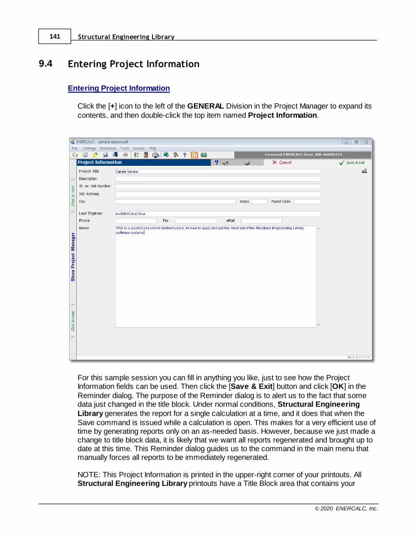
Structural Engineering Library141
© 2020 ENERCALC, Inc.
9.4 Entering Project Information
Entering Project Information
Click the [+] icon to the left of the GENERAL Division in the Project Manager to expand itscontents, and then double-click the top item named Project Information.
For this sample session you can fill in anything you like, just to see how the ProjectInformation fields can be used. Then click the [Save & Exit] button and click [OK] in theReminder dialog. The purpose of the Reminder dialog is to alert us to the fact that somedata just changed in the title block. Under normal conditions, Structural EngineeringLibrary generates the report for a single calculation at a time, and it does that when theSave command is issued while a calculation is open. This makes for a very efficient use oftime by generating reports only on an as-needed basis. However, because we just made achange to title block data, it is likely that we want all reports regenerated and brought up todate at this time. This Reminder dialog guides us to the command in the main menu thatmanually forces all reports to be immediately regenerated. NOTE: This Project Information is printed in the upper-right corner of your printouts. AllStructural Engineering Library printouts have a Title Block area that contains your

Sample Session 142
© 2020 ENERCALC, Inc.
company's information in the upper-left corner and the Project Information in the upper-right corner. The above project information (and the title block information described in thenext section) will look like this on the printouts:
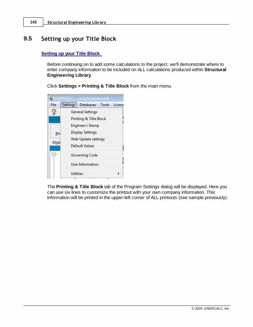
Structural Engineering Library143
© 2020 ENERCALC, Inc.
9.5 Setting up your Title Block
Setting up your Title Block
Before continuing on to add some calculations to the project, we'll demonstrate where toenter company information to be included on ALL calculations produced within StructuralEngineering Library. Click Settings > Printing & Title Block from the main menu.
The Printing & Title Block tab of the Program Settings dialog will be displayed. Here youcan use six lines to customize the printout with your own company information. Thisinformation will be printed in the upper-left corner of ALL printouts (see sample previously).
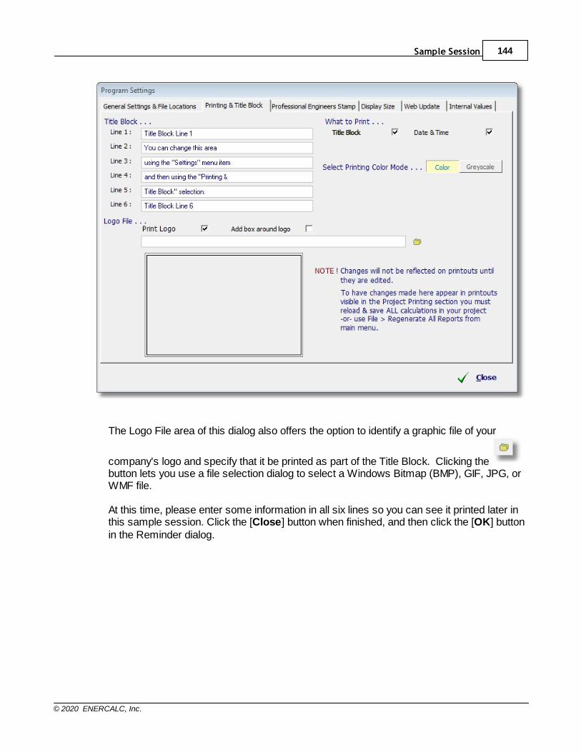
Sample Session 144
© 2020 ENERCALC, Inc.
The Logo File area of this dialog also offers the option to identify a graphic file of your
company's logo and specify that it be printed as part of the Title Block. Clicking the button lets you use a file selection dialog to select a Windows Bitmap (BMP), GIF, JPG, orWMF file. At this time, please enter some information in all six lines so you can see it printed later inthis sample session. Click the [Close] button when finished, and then click the [OK] buttonin the Reminder dialog.
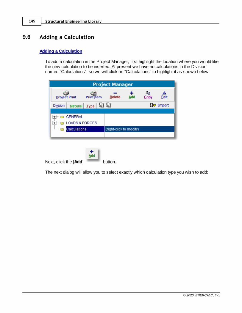
Structural Engineering Library145
© 2020 ENERCALC, Inc.
9.6 Adding a Calculation
Adding a Calculation
To add a calculation in the Project Manager, first highlight the location where you would likethe new calculation to be inserted. At present we have no calculations in the Divisionnamed "Calculations", so we will click on "Calculations" to highlight it as shown below:
Next, click the [Add] button.
The next dialog will allow you to select exactly which calculation type you wish to add:
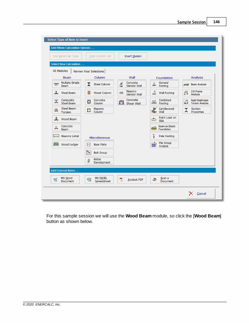
Sample Session 146
© 2020 ENERCALC, Inc.
For this sample session we will use the Wood Beam module, so click the [Wood Beam]button as shown below.
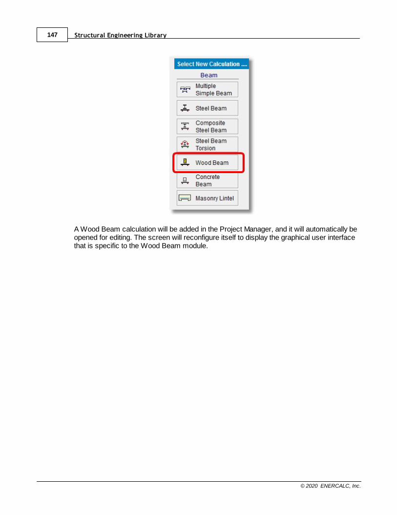
Structural Engineering Library147
© 2020 ENERCALC, Inc.
A Wood Beam calculation will be added in the Project Manager, and it will automatically beopened for editing. The screen will reconfigure itself to display the graphical user interfacethat is specific to the Wood Beam module.
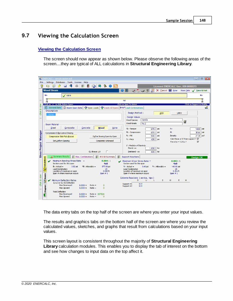
Sample Session 148
© 2020 ENERCALC, Inc.
9.7 Viewing the Calculation Screen
Viewing the Calculation Screen
The screen should now appear as shown below. Please observe the following areas of thescreen....they are typical of ALL calculations in Structural Engineering Library.
The data entry tabs on the top half of the screen are where you enter your input values. The results and graphics tabs on the bottom half of the screen are where you review thecalculated values, sketches, and graphs that result from calculations based on your inputvalues. This screen layout is consistent throughout the majority of Structural EngineeringLibrary calculation modules. This enables you to display the tab of interest on the bottomand see how changes to input data on the top affect it.
Structural Engineering Library149
© 2020 ENERCALC, Inc.
9.8 Changing the Default Values/Settings
Changing the Default Values/Settings
When you first add any calculation to a Project File, that calculation will come in withdefault values/settings for all user input items. If you find that you are almost alwayshaving to change certain items, it may make sense for you to revise those defaults tobetter suit your work. Revising the default values for any module is easy. Just follow thesesteps:
1. Add a new calculation of the module of interest to a Project File. It will come in with theexisting default values/settings.2. Revise the values/settings to suit.3. Click Settings > Default Values > Save.
This will save all of your current settings/values as the new defaults for that particularmodule. From that point onward, any time you add a new calculation of that module type, itwill automatically be populated with the default values/settings that you just established.
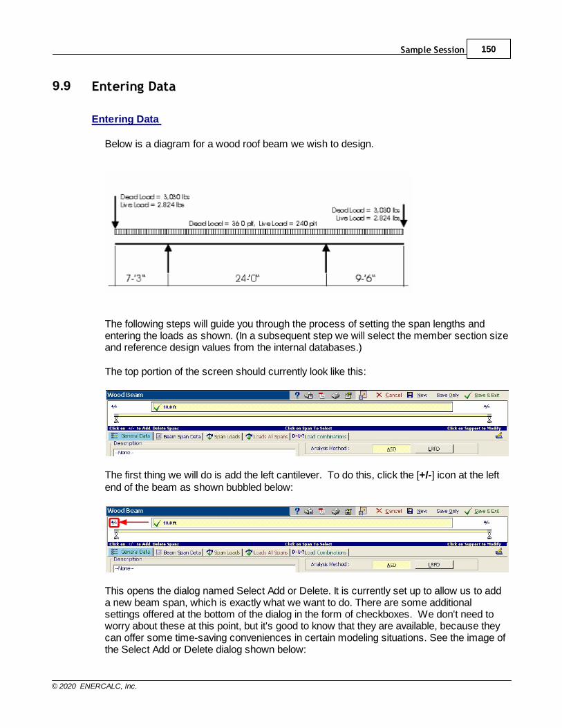
Sample Session 150
© 2020 ENERCALC, Inc.
9.9 Entering Data
Entering Data
Below is a diagram for a wood roof beam we wish to design.
The following steps will guide you through the process of setting the span lengths andentering the loads as shown. (In a subsequent step we will select the member section sizeand reference design values from the internal databases.)
The top portion of the screen should currently look like this:
The first thing we will do is add the left cantilever. To do this, click the [+/-] icon at the leftend of the beam as shown bubbled below:
This opens the dialog named Select Add or Delete. It is currently set up to allow us to adda new beam span, which is exactly what we want to do. There are some additionalsettings offered at the bottom of the dialog in the form of checkboxes. We don't need toworry about these at this point, but it's good to know that they are available, because theycan offer some time-saving conveniences in certain modeling situations. See the image ofthe Select Add or Delete dialog shown below:
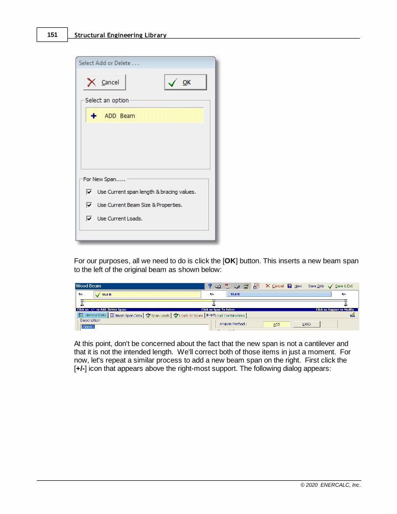
Structural Engineering Library151
© 2020 ENERCALC, Inc.
For our purposes, all we need to do is click the [OK] button. This inserts a new beam spanto the left of the original beam as shown below:
At this point, don't be concerned about the fact that the new span is not a cantilever andthat it is not the intended length. We'll correct both of those items in just a moment. Fornow, let's repeat a similar process to add a new beam span on the right. First click the[+/-] icon that appears above the right-most support. The following dialog appears:
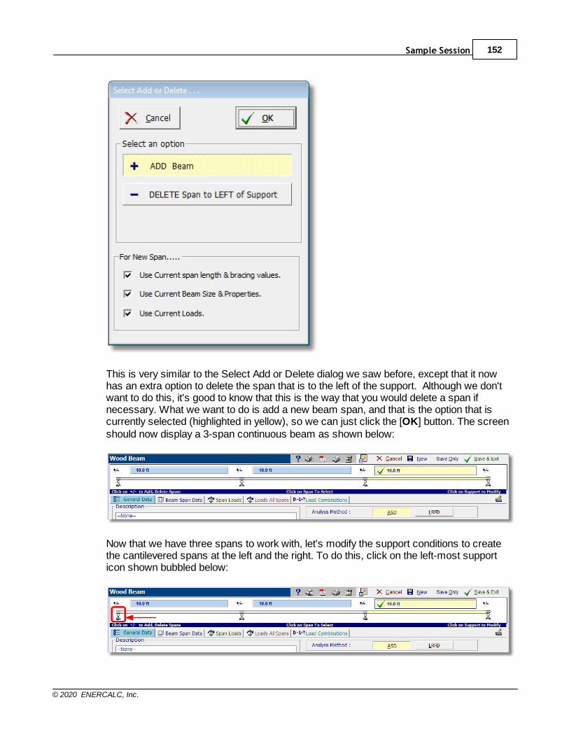
Sample Session 152
© 2020 ENERCALC, Inc.
This is very similar to the Select Add or Delete dialog we saw before, except that it nowhas an extra option to delete the span that is to the left of the support. Although we don'twant to do this, it's good to know that this is the way that you would delete a span ifnecessary. What we want to do is add a new beam span, and that is the option that iscurrently selected (highlighted in yellow), so we can just click the [OK] button. The screenshould now display a 3-span continuous beam as shown below:
Now that we have three spans to work with, let's modify the support conditions to createthe cantilevered spans at the left and the right. To do this, click on the left-most supporticon shown bubbled below:
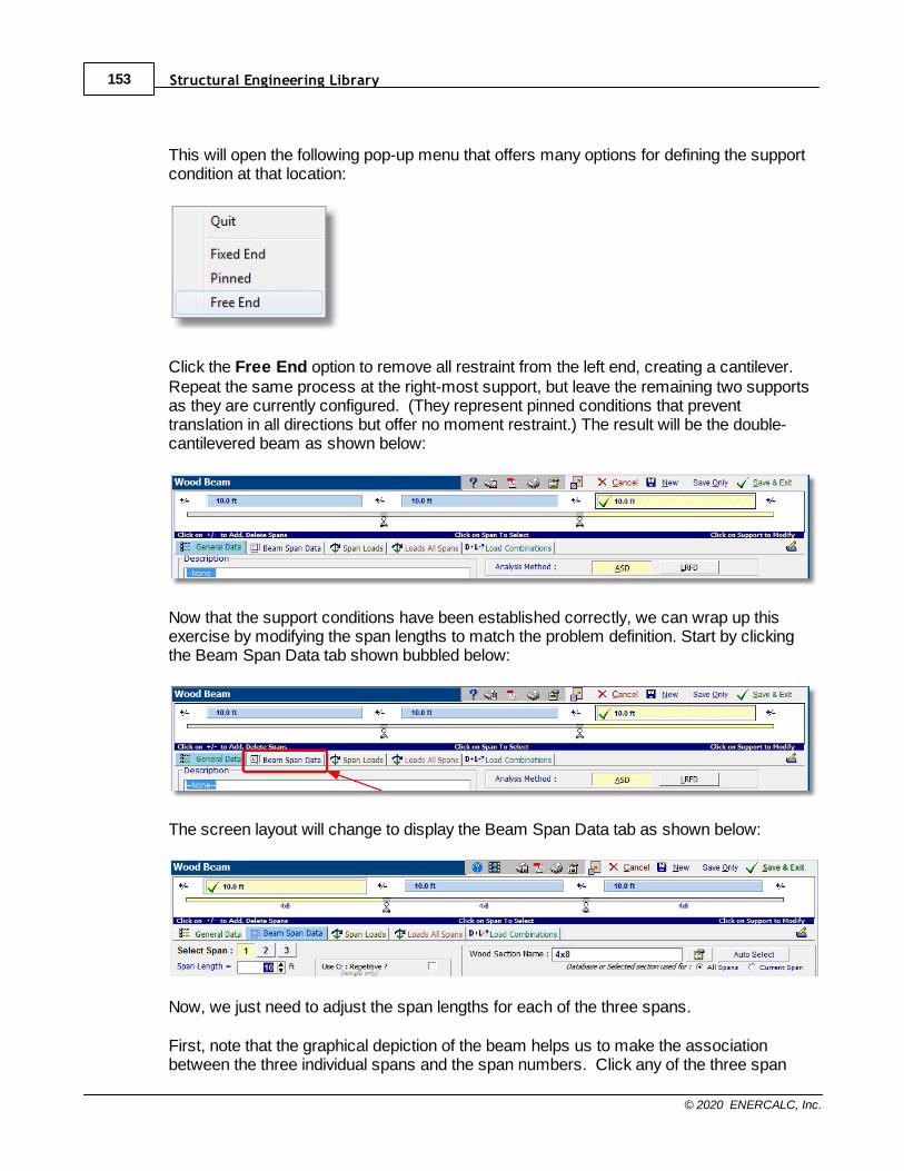
Structural Engineering Library153
© 2020 ENERCALC, Inc.
This will open the following pop-up menu that offers many options for defining the supportcondition at that location:
Click the Free End option to remove all restraint from the left end, creating a cantilever.Repeat the same process at the right-most support, but leave the remaining two supportsas they are currently configured. (They represent pinned conditions that preventtranslation in all directions but offer no moment restraint.) The result will be the double-cantilevered beam as shown below:
Now that the support conditions have been established correctly, we can wrap up thisexercise by modifying the span lengths to match the problem definition. Start by clickingthe Beam Span Data tab shown bubbled below:
The screen layout will change to display the Beam Span Data tab as shown below:
Now, we just need to adjust the span lengths for each of the three spans.
First, note that the graphical depiction of the beam helps us to make the associationbetween the three individual spans and the span numbers. Click any of the three span
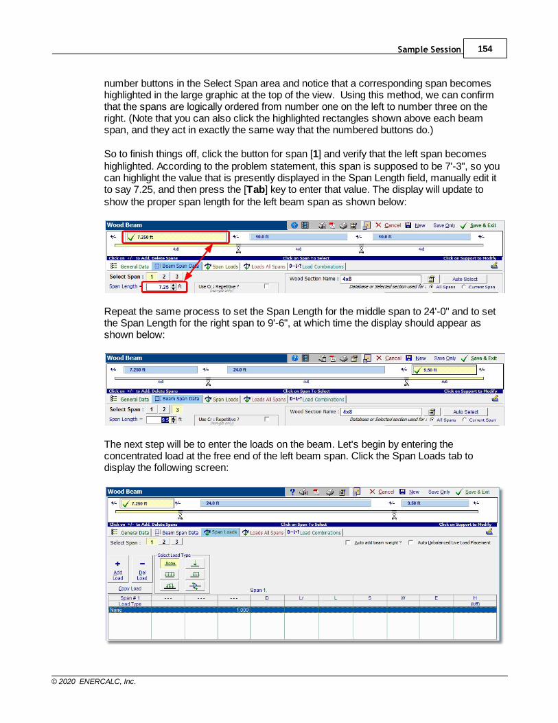
Sample Session 154
© 2020 ENERCALC, Inc.
number buttons in the Select Span area and notice that a corresponding span becomeshighlighted in the large graphic at the top of the view. Using this method, we can confirmthat the spans are logically ordered from number one on the left to number three on theright. (Note that you can also click the highlighted rectangles shown above each beamspan, and they act in exactly the same way that the numbered buttons do.)
So to finish things off, click the button for span [1] and verify that the left span becomeshighlighted. According to the problem statement, this span is supposed to be 7'-3", so youcan highlight the value that is presently displayed in the Span Length field, manually edit itto say 7.25, and then press the [Tab] key to enter that value. The display will update toshow the proper span length for the left beam span as shown below:
Repeat the same process to set the Span Length for the middle span to 24'-0" and to setthe Span Length for the right span to 9'-6", at which time the display should appear asshown below:
The next step will be to enter the loads on the beam. Let's begin by entering theconcentrated load at the free end of the left beam span. Click the Span Loads tab todisplay the following screen:
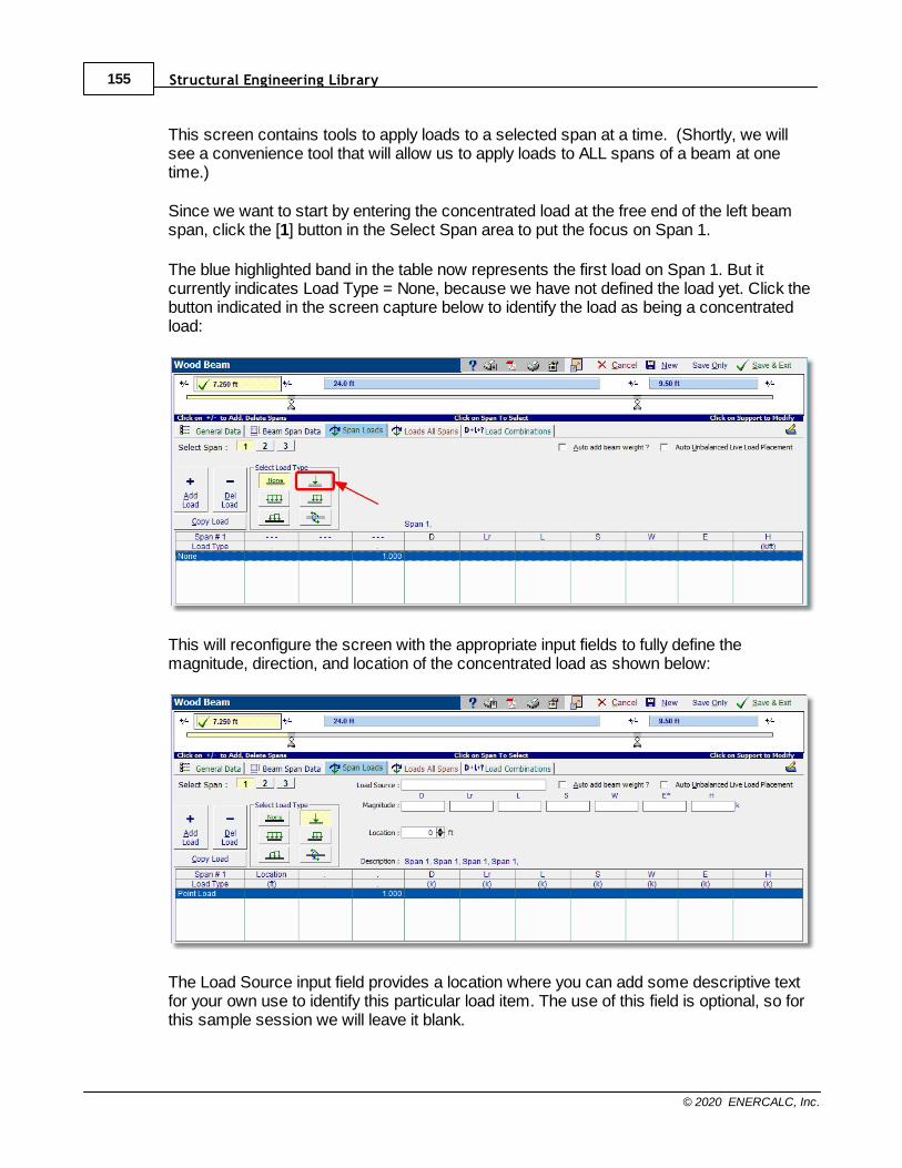
Structural Engineering Library155
© 2020 ENERCALC, Inc.
This screen contains tools to apply loads to a selected span at a time. (Shortly, we willsee a convenience tool that will allow us to apply loads to ALL spans of a beam at onetime.)
Since we want to start by entering the concentrated load at the free end of the left beamspan, click the [1] button in the Select Span area to put the focus on Span 1.
The blue highlighted band in the table now represents the first load on Span 1. But itcurrently indicates Load Type = None, because we have not defined the load yet. Click thebutton indicated in the screen capture below to identify the load as being a concentratedload:
This will reconfigure the screen with the appropriate input fields to fully define themagnitude, direction, and location of the concentrated load as shown below:
The Load Source input field provides a location where you can add some descriptive textfor your own use to identify this particular load item. The use of this field is optional, so forthis sample session we will leave it blank.
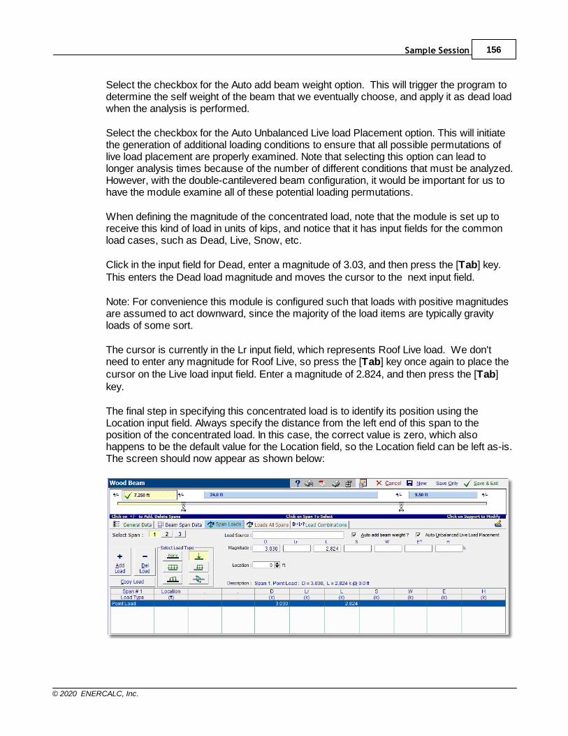
Sample Session 156
© 2020 ENERCALC, Inc.
Select the checkbox for the Auto add beam weight option. This will trigger the program todetermine the self weight of the beam that we eventually choose, and apply it as dead loadwhen the analysis is performed.
Select the checkbox for the Auto Unbalanced Live load Placement option. This will initiatethe generation of additional loading conditions to ensure that all possible permutations oflive load placement are properly examined. Note that selecting this option can lead tolonger analysis times because of the number of different conditions that must be analyzed.However, with the double-cantilevered beam configuration, it would be important for us tohave the module examine all of these potential loading permutations.
When defining the magnitude of the concentrated load, note that the module is set up toreceive this kind of load in units of kips, and notice that it has input fields for the commonload cases, such as Dead, Live, Snow, etc.
Click in the input field for Dead, enter a magnitude of 3.03, and then press the [Tab] key.This enters the Dead load magnitude and moves the cursor to the next input field.
Note: For convenience this module is configured such that loads with positive magnitudesare assumed to act downward, since the majority of the load items are typically gravityloads of some sort.
The cursor is currently in the Lr input field, which represents Roof Live load. We don'tneed to enter any magnitude for Roof Live, so press the [Tab] key once again to place thecursor on the Live load input field. Enter a magnitude of 2.824, and then press the [Tab]key.
The final step in specifying this concentrated load is to identify its position using theLocation input field. Always specify the distance from the left end of this span to theposition of the concentrated load. In this case, the correct value is zero, which alsohappens to be the default value for the Location field, so the Location field can be left as-is.The screen should now appear as shown below:
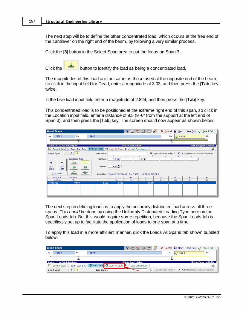
Structural Engineering Library157
© 2020 ENERCALC, Inc.
The next step will be to define the other concentrated load, which occurs at the free end ofthe cantilever on the right end of the beam, by following a very similar process.
Click the [3] button in the Select Span area to put the focus on Span 3.
Click the button to identify the load as being a concentrated load.
The magnitudes of this load are the same as those used at the opposite end of the beam,so click in the input field for Dead, enter a magnitude of 3.03, and then press the [Tab] keytwice.
In the Live load input field enter a magnitude of 2.824, and then press the [Tab] key.
This concentrated load is to be positioned at the extreme right end of this span, so click inthe Location input field, enter a distance of 9.5 (9'-6" from the support at the left end ofSpan 3), and then press the [Tab] key. The screen should now appear as shown below:
The next step in defining loads is to apply the uniformly distributed load across all threespans. This could be done by using the Uniformly Distributed Loading Type here on theSpan Loads tab. But this would require some repetition, because the Span Loads tab isspecifically set up to facilitate the application of loads to one span at a time.
To apply this load in a more efficient manner, click the Loads All Spans tab shown bubbledbelow:
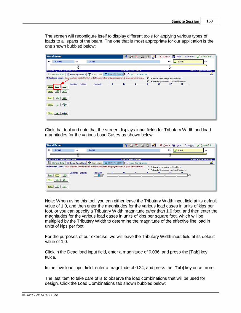
Sample Session 158
© 2020 ENERCALC, Inc.
The screen will reconfigure itself to display different tools for applying various types ofloads to all spans of the beam. The one that is most appropriate for our application is theone shown bubbled below:
Click that tool and note that the screen displays input fields for Tributary Width and loadmagnitudes for the various Load Cases as shown below:
Note: When using this tool, you can either leave the Tributary Width input field at its defaultvalue of 1.0, and then enter the magnitudes for the various load cases in units of kips perfoot, or you can specify a Tributary Width magnitude other than 1.0 foot, and then enter themagnitudes for the various load cases in units of kips per square foot, which will bemultiplied by the Tributary Width to determine the magnitude of the effective line load inunits of kips per foot.
For the purposes of our exercise, we will leave the Tributary Width input field at its defaultvalue of 1.0.
Click in the Dead load input field, enter a magnitude of 0.036, and press the [Tab] keytwice.
In the Live load input field, enter a magnitude of 0.24, and press the [Tab] key once more.
The last item to take care of is to observe the load combinations that will be used fordesign. Click the Load Combinations tab shown bubbled below:
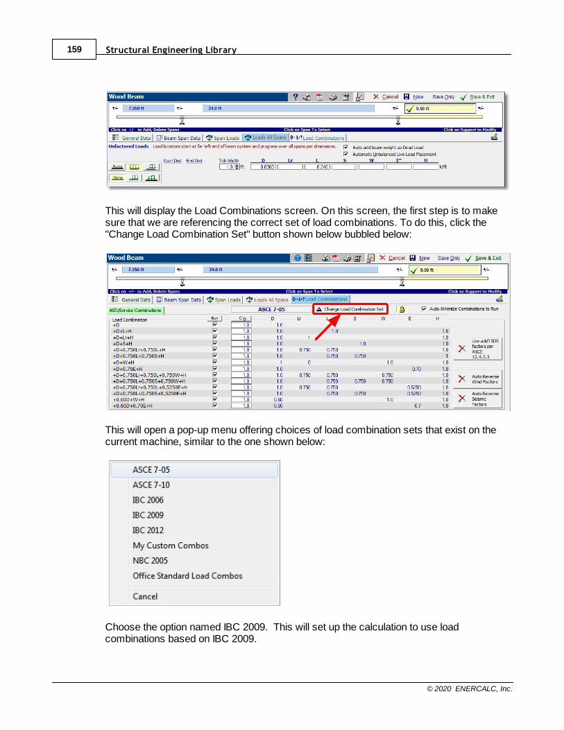
Structural Engineering Library159
© 2020 ENERCALC, Inc.
This will display the Load Combinations screen. On this screen, the first step is to makesure that we are referencing the correct set of load combinations. To do this, click the"Change Load Combination Set" button shown below bubbled below:
This will open a pop-up menu offering choices of load combination sets that exist on thecurrent machine, similar to the one shown below:
Choose the option named IBC 2009. This will set up the calculation to use loadcombinations based on IBC 2009.

Sample Session 160
© 2020 ENERCALC, Inc.
Next, click the button, and confirm by clicking the [Yes] button. This is a veryconvenient option for wood designs, because it automatically sets the C
D value based on
the shortest duration load case within each load combination. Note the various values ofC
D that result.
The final step in this section is to ensure that all of the listed load combinations will be usedin the analysis and design. To do this, click the button. This will open a pop-up menuoffering options for marking and clearing the Run status of all of the load combinations inthe list, as shown below:
Simply click the [Mark All] option, and all of the load combinations in the list will be markedfor use in the analysis and design.
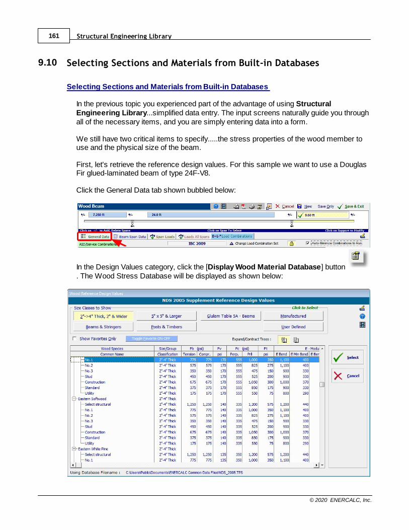
Structural Engineering Library161
© 2020 ENERCALC, Inc.
9.10 Selecting Sections and Materials from Built-in Databases
Selecting Sections and Materials from Built-in Databases
In the previous topic you experienced part of the advantage of using StructuralEngineering Library...simplified data entry. The input screens naturally guide you throughall of the necessary items, and you are simply entering data into a form.
We still have two critical items to specify.....the stress properties of the wood member touse and the physical size of the beam.
First, let's retrieve the reference design values. For this sample we want to use a DouglasFir glued-laminated beam of type 24F-V8.
Click the General Data tab shown bubbled below:
In the Design Values category, click the [Display Wood Material Database] button . The Wood Stress Database will be displayed as shown below:
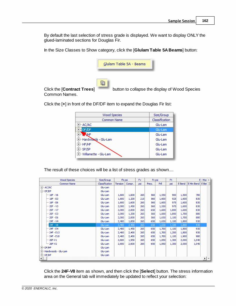
Sample Session 162
© 2020 ENERCALC, Inc.
By default the last selection of stress grade is displayed. We want to display ONLY theglued-laminated sections for Douglas Fir. In the Size Classes to Show category, click the [Glulam Table 5A Beams] button:
Click the [Contract Trees] button to collapse the display of Wood SpeciesCommon Names.
Click the [+] in front of the DF/DF item to expand the Douglas Fir list:
The result of these choices will be a list of stress grades as shown....
Click the 24F-V8 item as shown, and then click the [Select] button. The stress informationarea on the General tab will immediately be updated to reflect your selection:
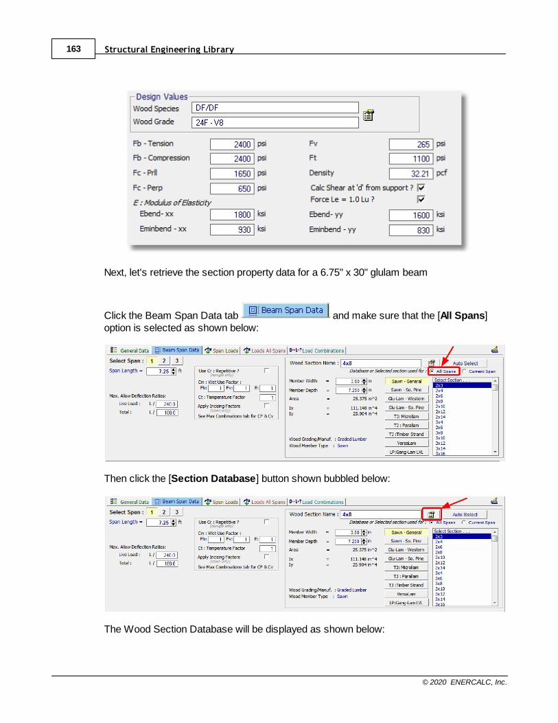
Structural Engineering Library163
© 2020 ENERCALC, Inc.
Next, let's retrieve the section property data for a 6.75" x 30" glulam beam
Click the Beam Span Data tab and make sure that the [All Spans]option is selected as shown below:
Then click the [Section Database] button shown bubbled below:
The Wood Section Database will be displayed as shown below:
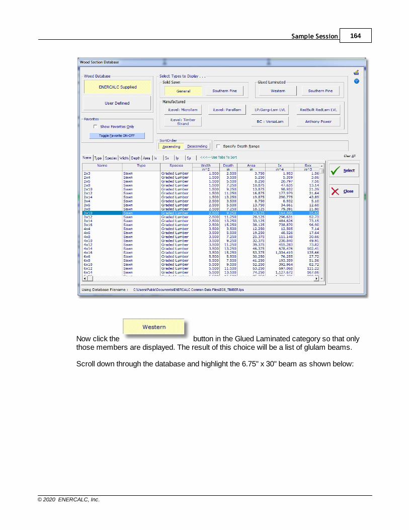
Sample Session 164
© 2020 ENERCALC, Inc.
Now click the button in the Glued Laminated category so that onlythose members are displayed. The result of this choice will be a list of glulam beams.
Scroll down through the database and highlight the 6.75" x 30" beam as shown below:
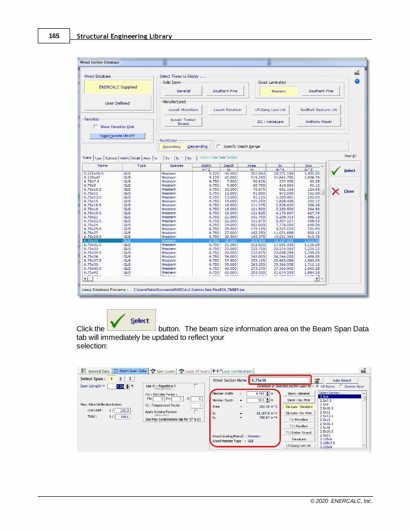
Structural Engineering Library165
© 2020 ENERCALC, Inc.
Click the button. The beam size information area on the Beam Span Datatab will immediately be updated to reflect yourselection:
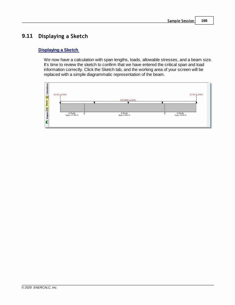
Sample Session 166
© 2020 ENERCALC, Inc.
9.11 Displaying a Sketch
Displaying a Sketch
We now have a calculation with span lengths, loads, allowable stresses, and a beam size.It's time to review the sketch to confirm that we have entered the critical span and loadinformation correctly. Click the Sketch tab, and the working area of your screen will bereplaced with a simple diagrammatic representation of the beam.
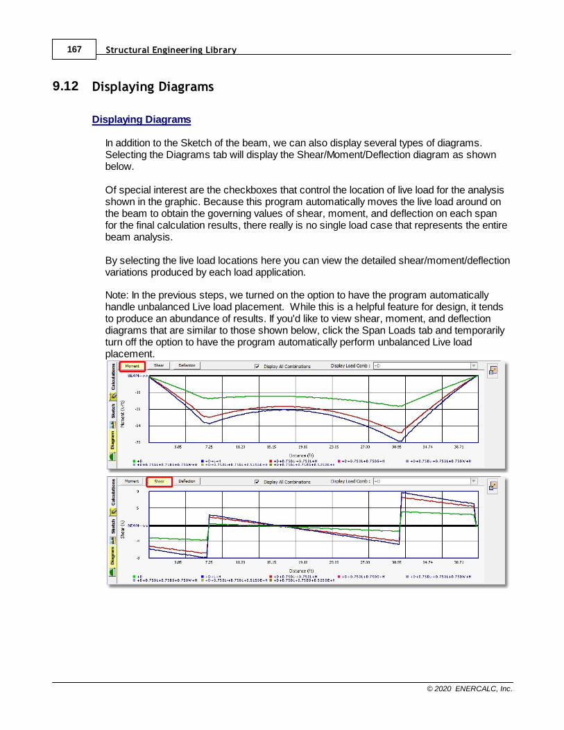
Structural Engineering Library167
© 2020 ENERCALC, Inc.
9.12 Displaying Diagrams
Displaying Diagrams
In addition to the Sketch of the beam, we can also display several types of diagrams.Selecting the Diagrams tab will display the Shear/Moment/Deflection diagram as shownbelow. Of special interest are the checkboxes that control the location of live load for the analysisshown in the graphic. Because this program automatically moves the live load around onthe beam to obtain the governing values of shear, moment, and deflection on each spanfor the final calculation results, there really is no single load case that represents the entirebeam analysis. By selecting the live load locations here you can view the detailed shear/moment/deflectionvariations produced by each load application.
Note: In the previous steps, we turned on the option to have the program automaticallyhandle unbalanced Live load placement. While this is a helpful feature for design, it tendsto produce an abundance of results. If you'd like to view shear, moment, and deflectiondiagrams that are similar to those shown below, click the Span Loads tab and temporarilyturn off the option to have the program automatically perform unbalanced Live loadplacement.
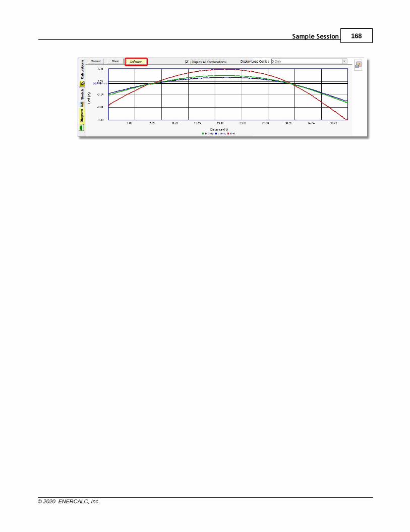
Sample Session 168
© 2020 ENERCALC, Inc.

Structural Engineering Library169
© 2020 ENERCALC, Inc.
9.13 Automatic Member Section Selection
Automatic Member Section Selection
An additional feature of many of Structural Engineering Library calculation modules isautomatic selection of sizes that satisfy your specified design criteria.
Note: If you turned off the option to have the program automatically perform unbalancedLive load placement in the previous topic, please click back to the Span Loads tab now andmake sure the option for Auto Unbalanced Live Load Placement is selected once again.
Click the Calculations tab at the left edge of the screen as shown bubbled below:
When the screen displays the Calculations environment, click the Summary Results tabas shown bubbled below:
Take a look at the stress and deflection ratios bubbled in the screen capture below:
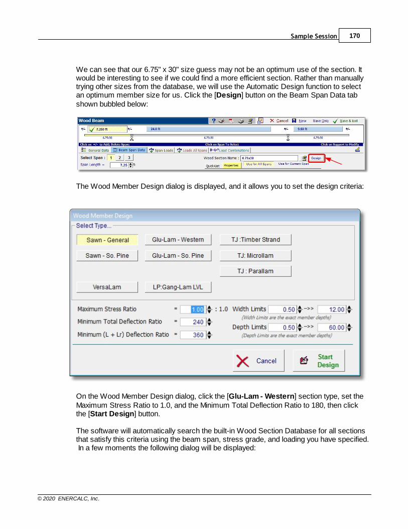
Sample Session 170
© 2020 ENERCALC, Inc.
We can see that our 6.75" x 30" size guess may not be an optimum use of the section. Itwould be interesting to see if we could find a more efficient section. Rather than manuallytrying other sizes from the database, we will use the Automatic Design function to selectan optimum member size for us. Click the [Design] button on the Beam Span Data tabshown bubbled below:
The Wood Member Design dialog is displayed, and it allows you to set the design criteria:
On the Wood Member Design dialog, click the [Glu-Lam - Western] section type, set theMaximum Stress Ratio to 1.0, and the Minimum Total Deflection Ratio to 180, then clickthe [Start Design] button.
The software will automatically search the built-in Wood Section Database for all sectionsthat satisfy this criteria using the beam span, stress grade, and loading you have specified. In a few moments the following dialog will be displayed:

Structural Engineering Library171
© 2020 ENERCALC, Inc.
Notice how the listed members can be sorted in different orders based on: Weight,Bending Ratio, Shear Ration, LL Deflection Ratio,Total Deflection Ratio, Depth, etc. Thisallows you to review the beam sizes that pass your criteria in different ways.
Click on the 5.125 x 27 beam and then click the [Select] button. The final design (withSummary Results tab showing) looks like this:
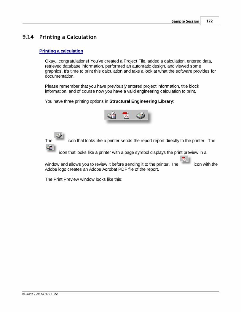
Sample Session 172
© 2020 ENERCALC, Inc.
9.14 Printing a Calculation
Printing a calculation
Okay...congratulations! You've created a Project File, added a calculation, entered data,retrieved database information, performed an automatic design, and viewed somegraphics. It's time to print this calculation and take a look at what the software provides fordocumentation. Please remember that you have previously entered project information, title blockinformation, and of course now you have a valid engineering calculation to print. You have three printing options in Structural Engineering Library:
The icon that looks like a printer sends the report report directly to the printer. The
icon that looks like a printer with a page symbol displays the print preview in a
window and allows you to review it before sending it to the printer. The icon with theAdobe logo creates an Adobe Acrobat PDF file of the report. The Print Preview window looks like this:
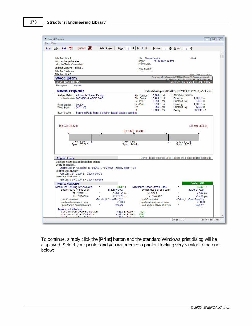
Structural Engineering Library173
© 2020 ENERCALC, Inc.
To continue, simply click the [Print] button and the standard Windows print dialog will bedisplayed. Select your printer and you will receive a printout looking very similar to the onebelow:
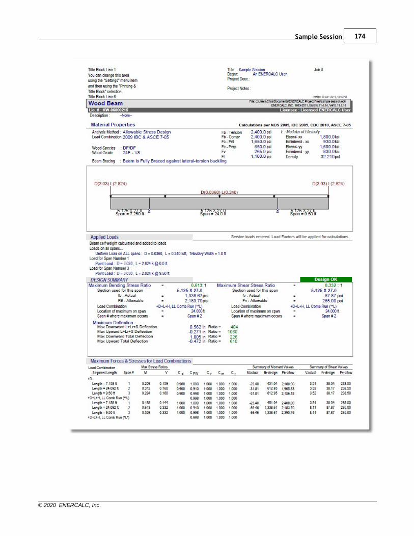
Sample Session 174
© 2020 ENERCALC, Inc.
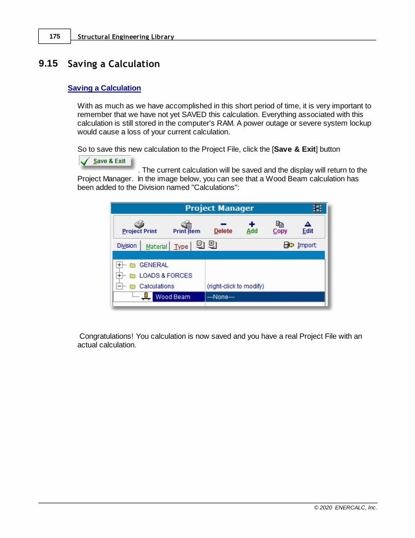
Structural Engineering Library175
© 2020 ENERCALC, Inc.
9.15 Saving a Calculation
Saving a Calculation
With as much as we have accomplished in this short period of time, it is very important toremember that we have not yet SAVED this calculation. Everything associated with thiscalculation is still stored in the computer's RAM. A power outage or severe system lockupwould cause a loss of your current calculation. So to save this new calculation to the Project File, click the [Save & Exit] button
. The current calculation will be saved and the display will return to theProject Manager. In the image below, you can see that a Wood Beam calculation hasbeen added to the Division named "Calculations":
Congratulations! You calculation is now saved and you have a real Project File with anactual calculation.
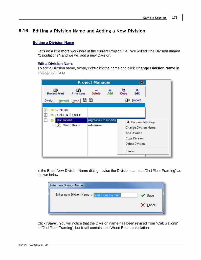
Sample Session 176
© 2020 ENERCALC, Inc.
9.16 Editing a Division Name and Adding a New Division
Editing a Division Name
Let's do a little more work here in the current Project File. We will edit the Division named"Calculations", and we will add a new Division.
Edit a Division NameTo edit a Division name, simply right-click the name and click Change Division Name inthe pop-up menu.
In the Enter New Division Name dialog, revise the Division name to "2nd Floor Framing" asshown below:
Click [Save]. You will notice that the Division name has been revised from "Calculations"to "2nd Floor Framing", but it still contains the Wood Beam calculation.
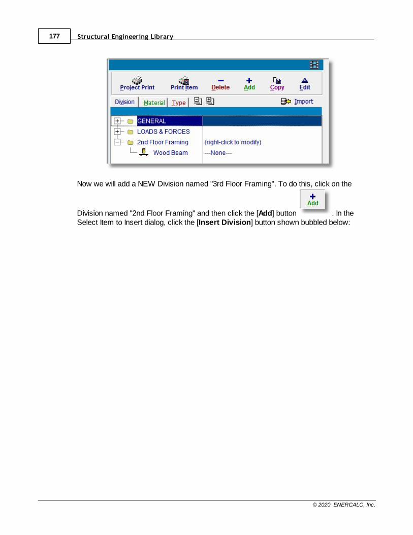
Structural Engineering Library177
© 2020 ENERCALC, Inc.
Now we will add a NEW Division named "3rd Floor Framing". To do this, click on the
Division named "2nd Floor Framing" and then click the [Add] button . In theSelect Item to Insert dialog, click the [Insert Division] button shown bubbled below:
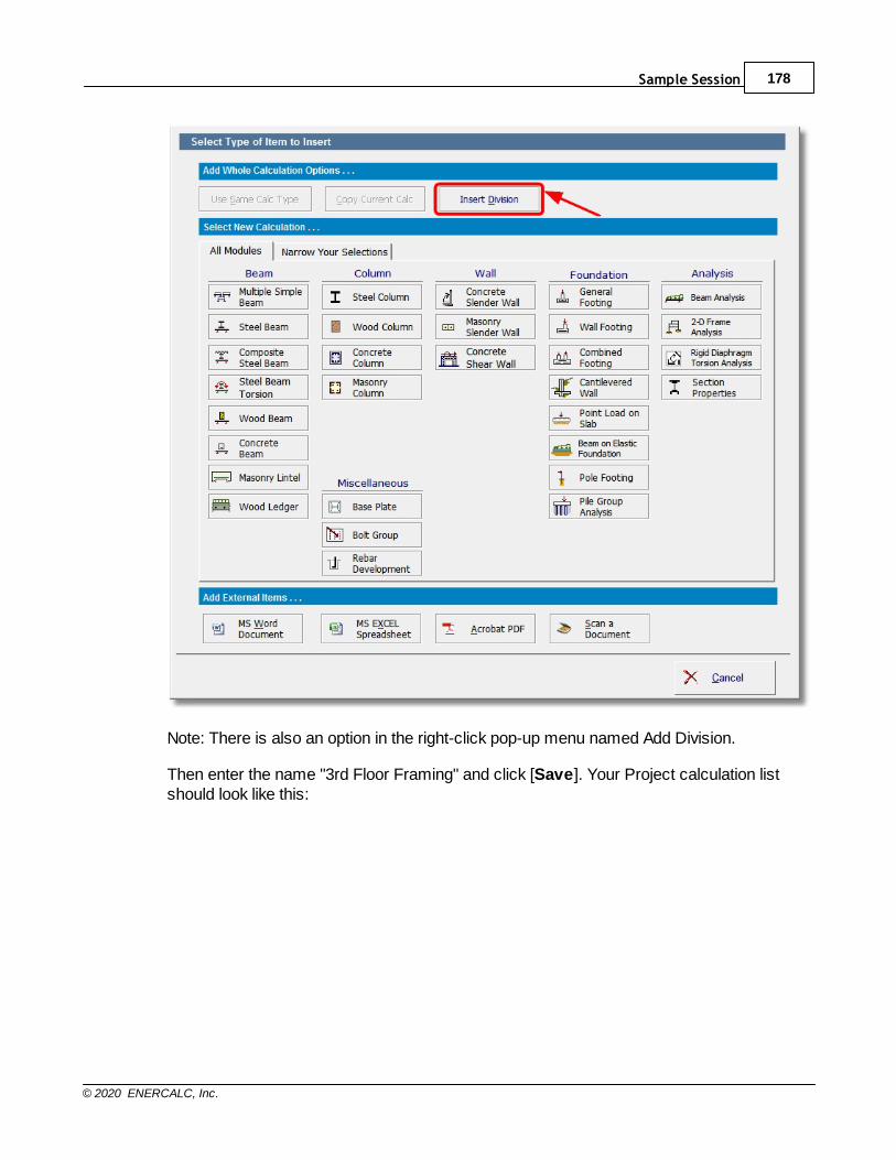
Sample Session 178
© 2020 ENERCALC, Inc.
Note: There is also an option in the right-click pop-up menu named Add Division.
Then enter the name "3rd Floor Framing" and click [Save]. Your Project calculation listshould look like this:
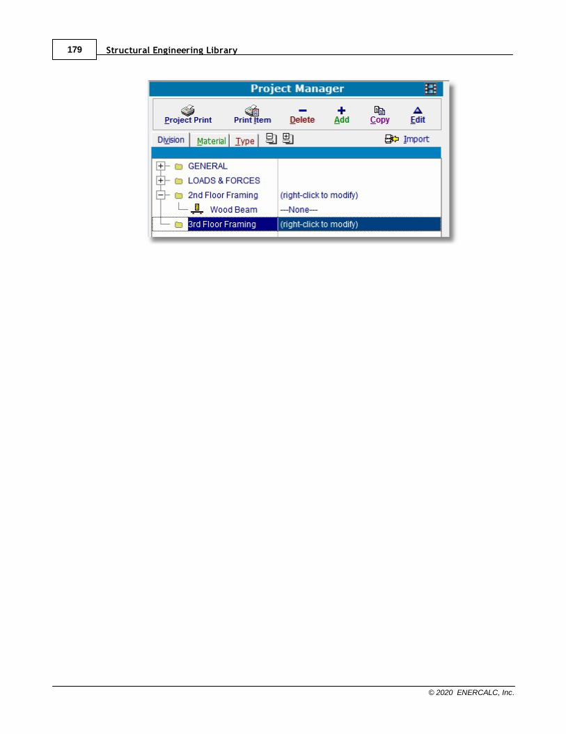
Structural Engineering Library179
© 2020 ENERCALC, Inc.
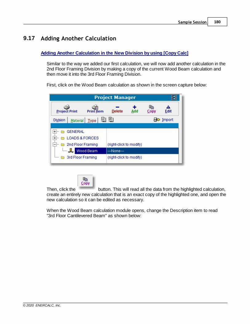
Sample Session 180
© 2020 ENERCALC, Inc.
9.17 Adding Another Calculation
Adding Another Calculation in the New Division by using [Copy Calc]
Similar to the way we added our first calculation, we will now add another calculation in the2nd Floor Framing Division by making a copy of the current Wood Beam calculation andthen move it into the 3rd Floor Framing Division.
First, click on the Wood Beam calculation as shown in the screen capture below:
Then, click the button. This will read all the data from the highlighted calculation,create an entirely new calculation that is an exact copy of the highlighted one, and open thenew calculation so it can be edited as necessary.
When the Wood Beam calculation module opens, change the Description item to read"3rd Floor Cantilevered Beam" as shown below:
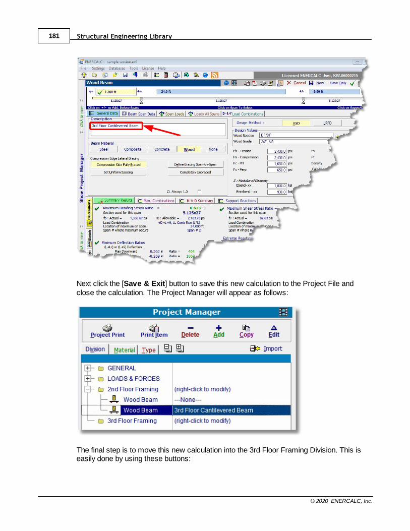
Structural Engineering Library181
© 2020 ENERCALC, Inc.
Next click the [Save & Exit] button to save this new calculation to the Project File andclose the calculation. The Project Manager will appear as follows:
The final step is to move this new calculation into the 3rd Floor Framing Division. This iseasily done by using these buttons:
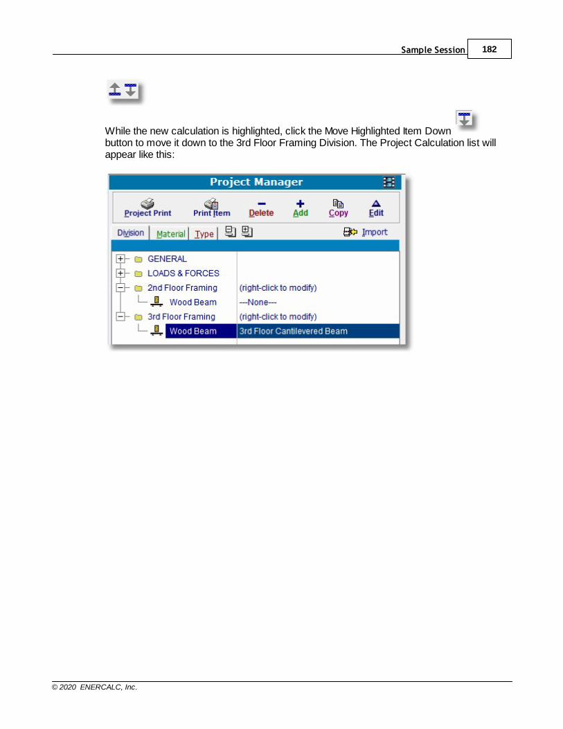
Sample Session 182
© 2020 ENERCALC, Inc.
While the new calculation is highlighted, click the Move Highlighted Item Down button to move it down to the 3rd Floor Framing Division. The Project Calculation list willappear like this:

Structural Engineering Library183
© 2020 ENERCALC, Inc.
9.18 Creating a Technical Support Question
Creating a Technical Support Question
The occasion may arise that you will have a question about the software system. To bestserve you, there are certain pieces of information that are essential. Among these are yourname, the name of your company, your "KW" user registration number, and the buildnumber of the software you are using. To make it easy for you to give us all this AND state your question, StructuralEngineering Library has a built-in technical support form. It allows you to simply type inyour question and either email it directly to our Technical Support Group or print it out to faxto us.
By emailing or faxing us your Technical Support questions, we can easily identify you,determine if you are in need of a maintenance release, and easily read your questions. Inaddition, the email method offers the option of attaching the subject ENERCALC file. To create an email:Click Help > Create Tech Support EMAIL from the main menu. This opens the formshown below, in which you can enter your question and attach your Project File if desired.
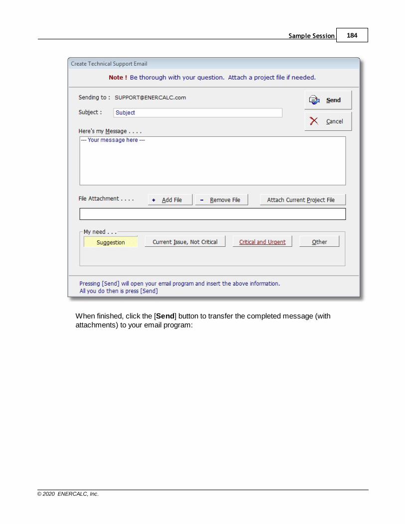
Sample Session 184
© 2020 ENERCALC, Inc.
When finished, click the [Send] button to transfer the completed message (withattachments) to your email program:
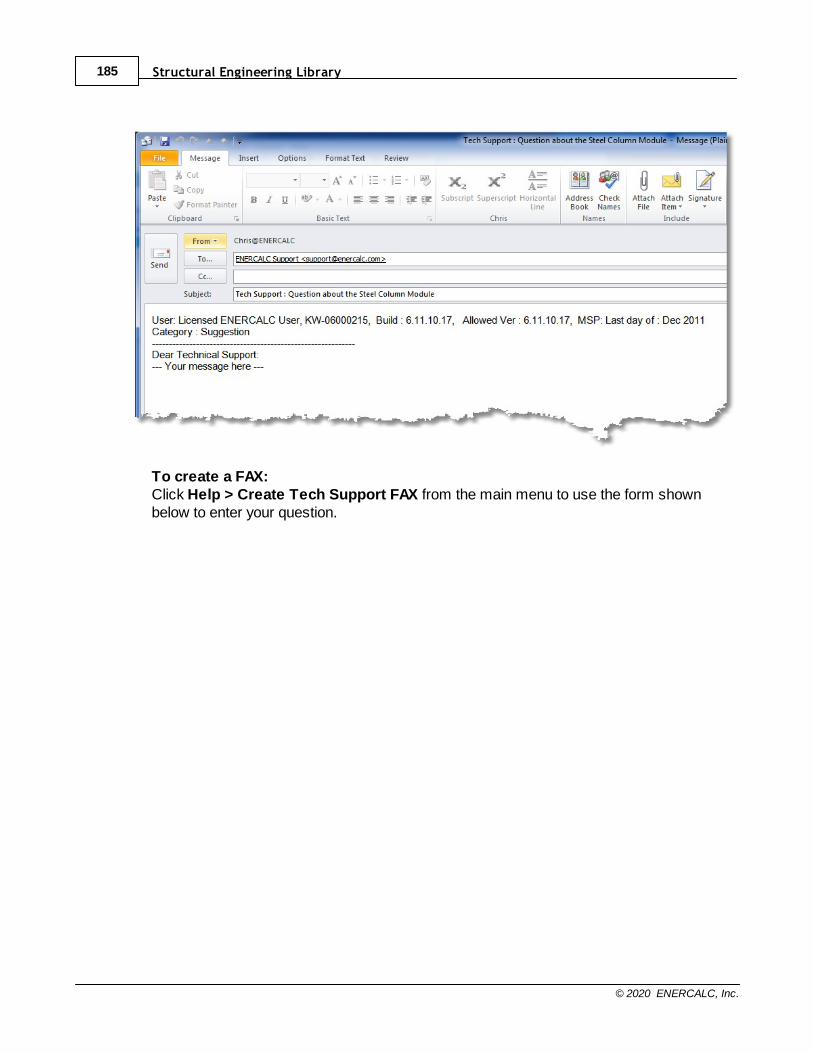
Structural Engineering Library185
© 2020 ENERCALC, Inc.
To create a FAX:Click Help > Create Tech Support FAX from the main menu to use the form shownbelow to enter your question.

Sample Session 186
© 2020 ENERCALC, Inc.
When finished, the completed message can be printed for faxing (or it can be sent directlyfrom your computer-based fax software).
Here's the printed form, ready for transmission:
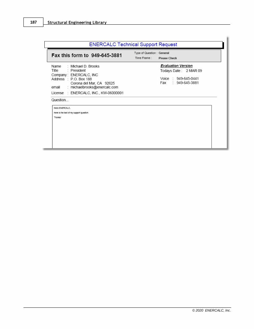
Structural Engineering Library187
© 2020 ENERCALC, Inc.

Sample Session 188
© 2020 ENERCALC, Inc.
9.19 Closing a Project File
Closing a Project File
It is now time to close out our work session. The data is saved in the Project File already,so at this point we can close the current Project File by clicking File > Close Project fromthe main menu:

Part
X

Calculation Modules 190
© 2020 ENERCALC, Inc.
10 Calculation Modules
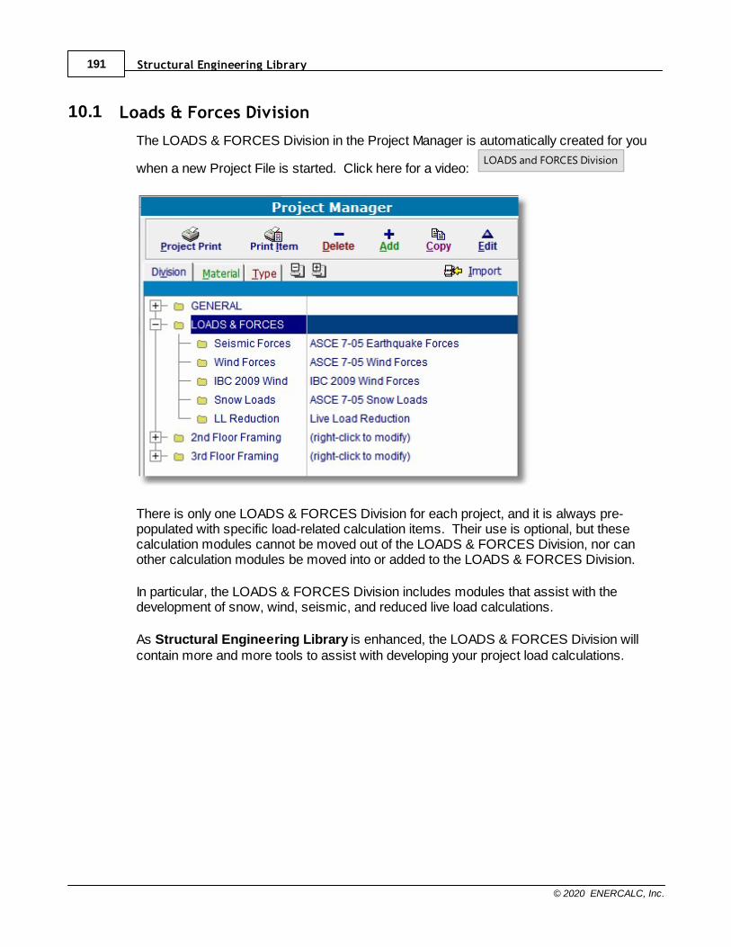
Structural Engineering Library191
© 2020 ENERCALC, Inc.
10.1 Loads & Forces Division
The LOADS & FORCES Division in the Project Manager is automatically created for you
when a new Project File is started. Click here for a video: LOADS and FORCES Division
There is only one LOADS & FORCES Division for each project, and it is always pre-populated with specific load-related calculation items. Their use is optional, but thesecalculation modules cannot be moved out of the LOADS & FORCES Division, nor canother calculation modules be moved into or added to the LOADS & FORCES Division.
In particular, the LOADS & FORCES Division includes modules that assist with thedevelopment of snow, wind, seismic, and reduced live load calculations.
As Structural Engineering Library is enhanced, the LOADS & FORCES Division willcontain more and more tools to assist with developing your project load calculations.
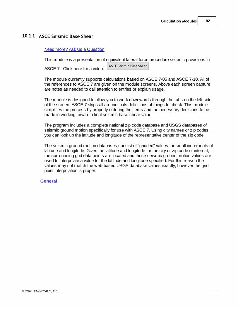
Calculation Modules 192
© 2020 ENERCALC, Inc.
10.1.1 ASCE Seismic Base Shear
Need more? Ask Us a Question
This module is a presentation of equivalent lateral force procedure seismic provisions in
ASCE 7. Click here for a video: ASCE Seismic Base Shear
The module currently supports calculations based on ASCE 7-05 and ASCE 7-10. All ofthe references to ASCE 7 are given on the module screens. Above each screen captureare notes as needed to call attention to entries or explain usage.
The module is designed to allow you to work downwards through the tabs on the left sideof the screen. ASCE 7 skips all around in its definitions of things to check. This modulesimplifies the process by properly ordering the items and the necessary decisions to bemade in working toward a final seismic base shear value.
The program includes a complete national zip code database and USGS databases ofseismic ground motion specifically for use with ASCE 7. Using city names or zip codes,you can look up the latitude and longitude of the representative center of the zip code.
The seismic ground motion databases consist of "gridded" values for small increments oflatitude and longitude. Given the latitude and longitude for the city or zip code of interest,the surrounding grid data points are located and those seismic ground motion values areused to interpolate a value for the latitude and longitude specified. For this reason thevalues may not match the web-based USGS database values exactly, however the gridpoint interpolation is proper.
General
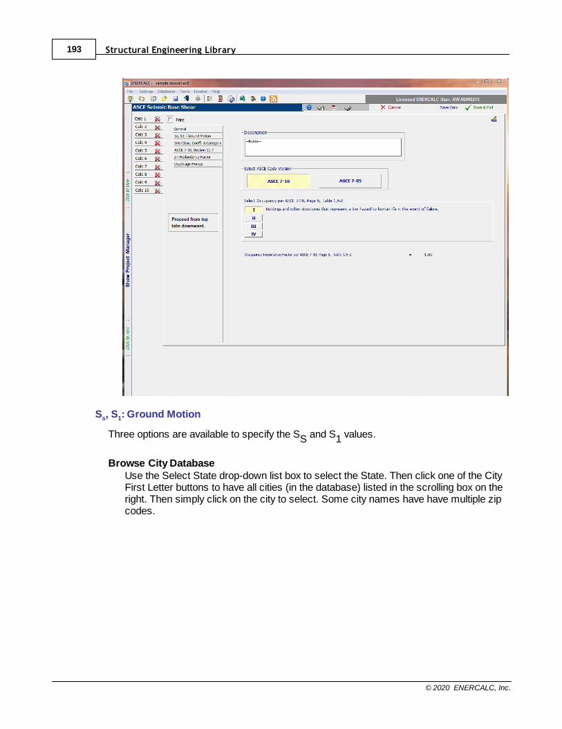
Structural Engineering Library193
© 2020 ENERCALC, Inc.
Ss, S1: Ground Motion
Three options are available to specify the SS and S1 values.
Browse City DatabaseUse the Select State drop-down list box to select the State. Then click one of the CityFirst Letter buttons to have all cities (in the database) listed in the scrolling box on theright. Then simply click on the city to select. Some city names have have multiple zipcodes.
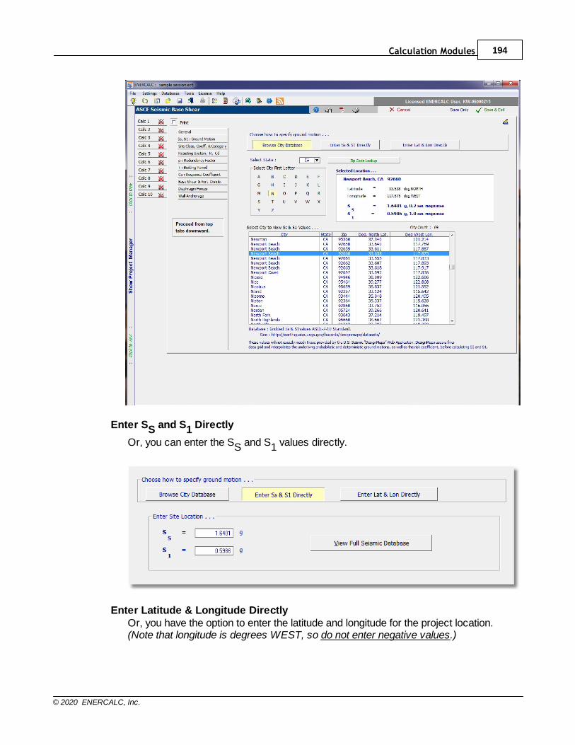
Calculation Modules 194
© 2020 ENERCALC, Inc.
Enter SS and S1 Directly
Or, you can enter the SS and S1 values directly.
Enter Latitude & Longitude DirectlyOr, you have the option to enter the latitude and longitude for the project location.(Note that longitude is degrees WEST, so do not enter negative values.)
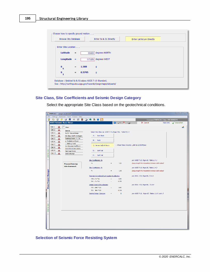
Structural Engineering Library195
© 2020 ENERCALC, Inc.
Site Class, Site Coefficients and Seismic Design Category
Select the appropriate Site Class based on the geotechnical conditions.
Selection of Seismic Force Resisting System
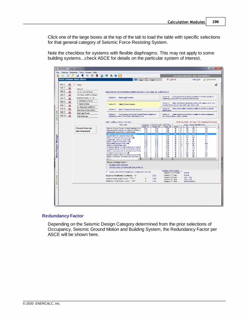
Calculation Modules 196
© 2020 ENERCALC, Inc.
Click one of the large boxes at the top of the tab to load the table with specific selectionsfor that general category of Seismic Force Resisting System.
Note the checkbox for systems with flexible diaphragms. This may not apply to somebuilding systems...check ASCE for details on the particular system of interest.
Redundancy Factor
Depending on the Seismic Design Category determined from the prior selections ofOccupancy, Seismic Ground Motion and Building System, the Redundancy Factor perASCE will be shown here.
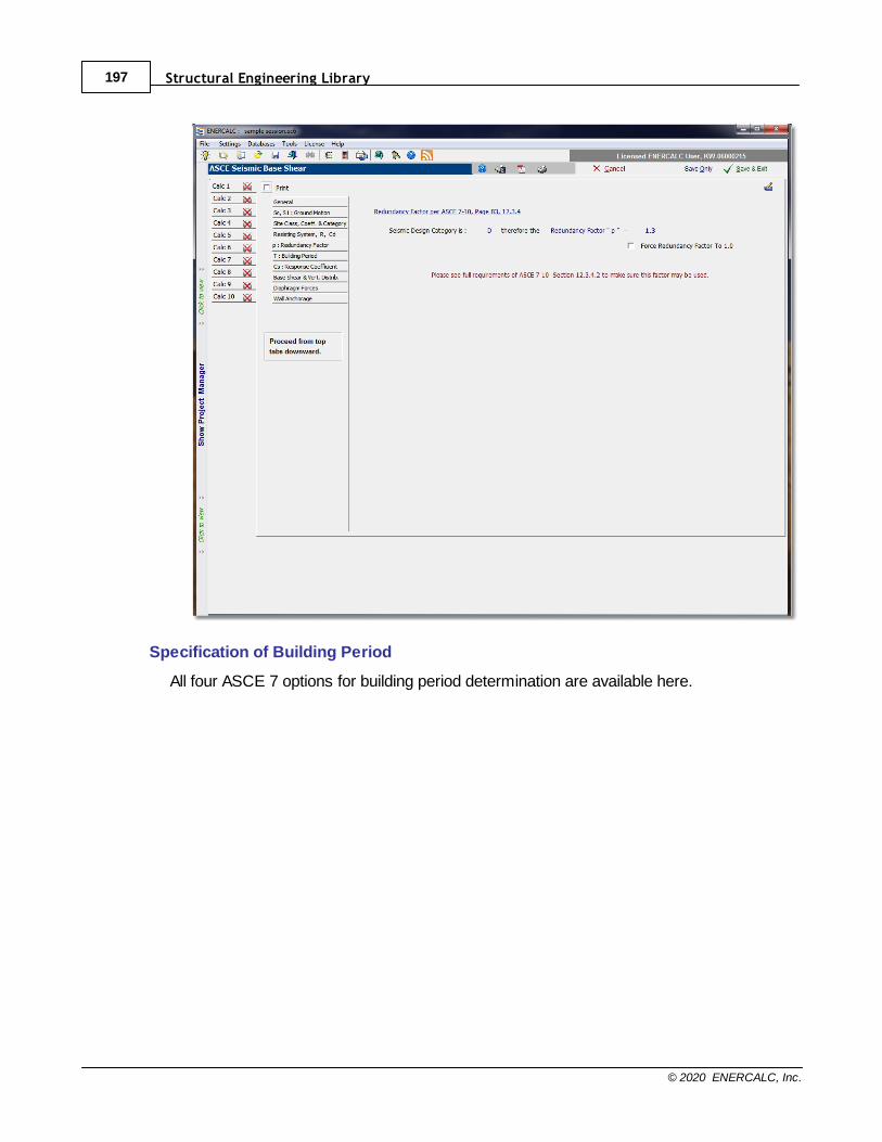
Structural Engineering Library197
© 2020 ENERCALC, Inc.
Specification of Building Period
All four ASCE 7 options for building period determination are available here.
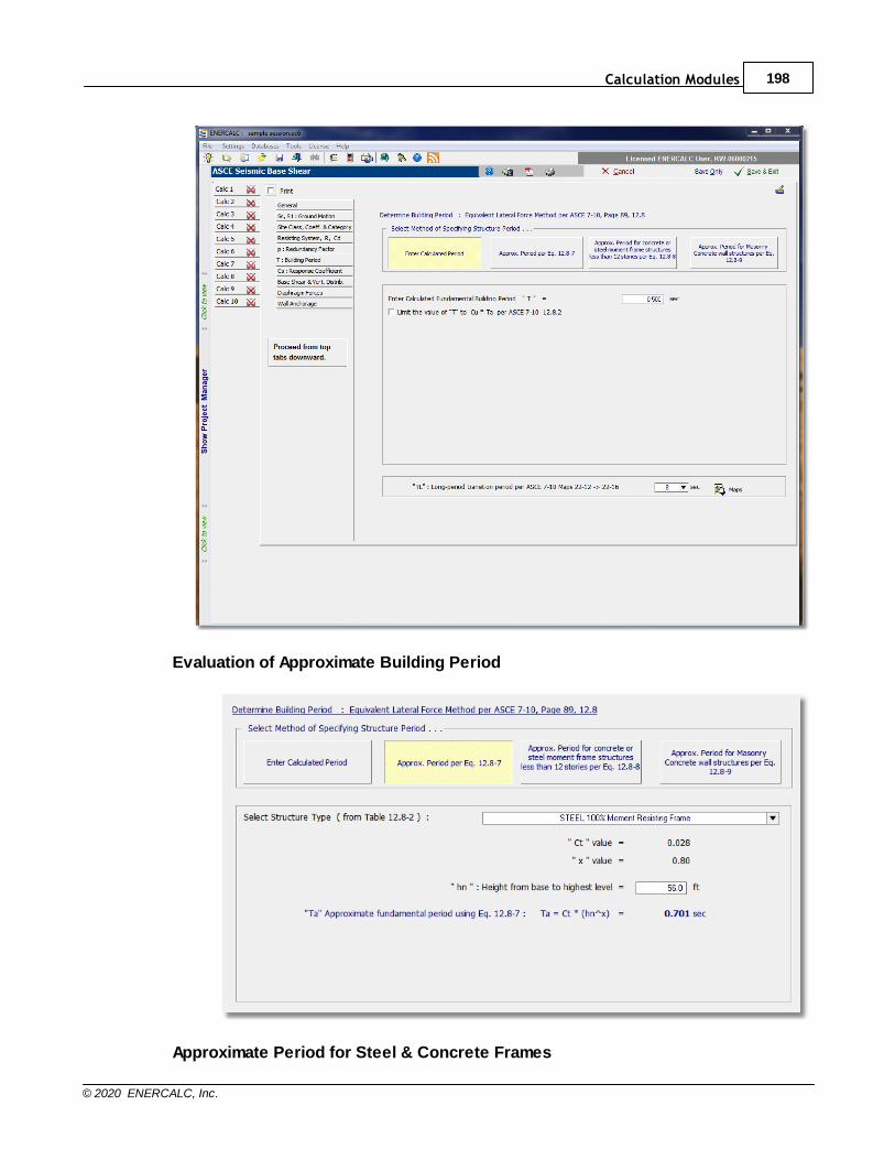
Calculation Modules 198
© 2020 ENERCALC, Inc.
Evaluation of Approximate Building Period
Approximate Period for Steel & Concrete Frames
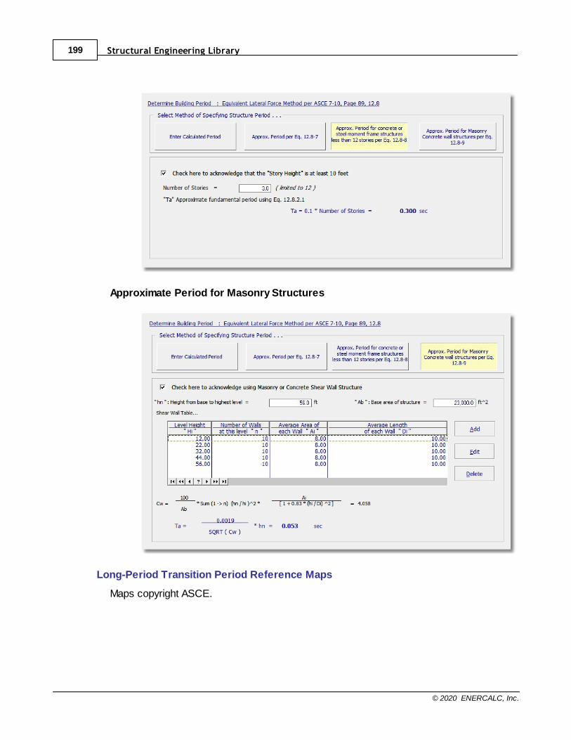
Structural Engineering Library199
© 2020 ENERCALC, Inc.
Approximate Period for Masonry Structures
Long-Period Transition Period Reference Maps
Maps copyright ASCE.
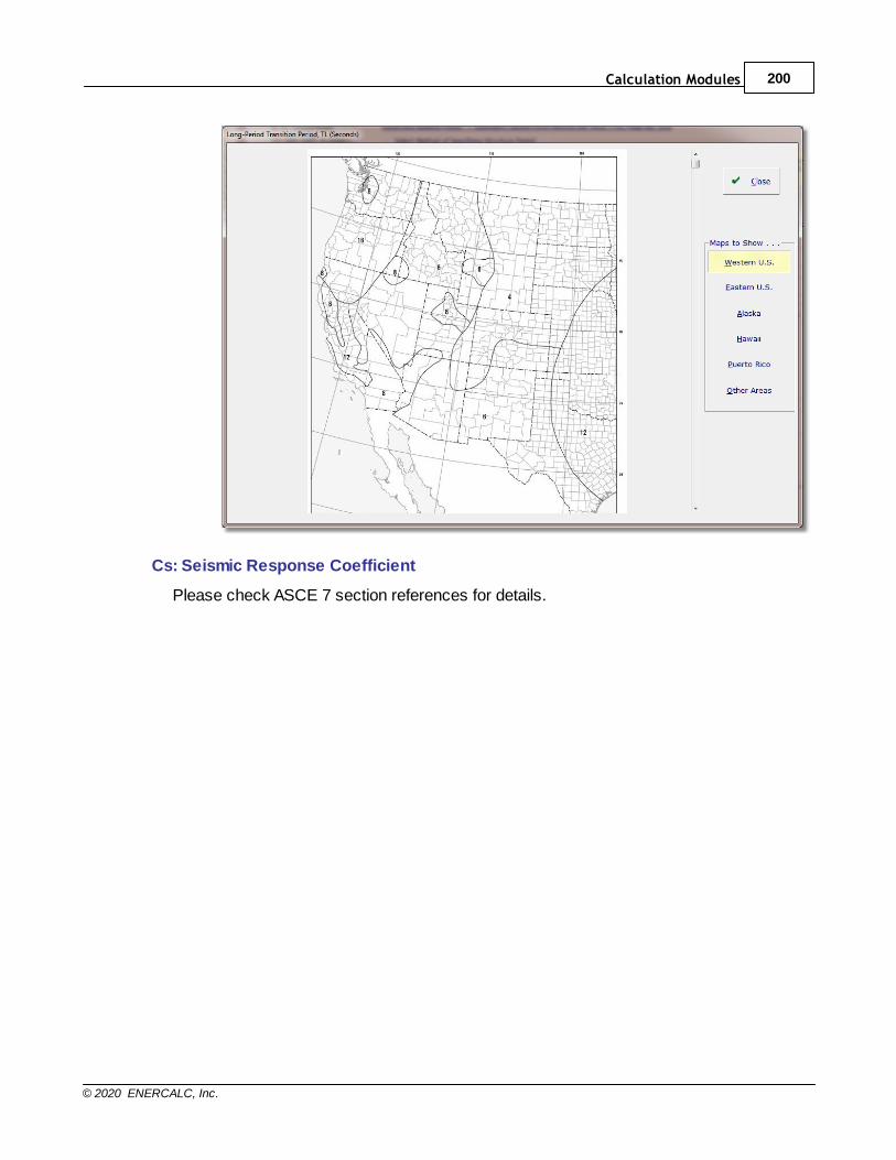
Calculation Modules 200
© 2020 ENERCALC, Inc.
Cs: Seismic Response Coefficient
Please check ASCE 7 section references for details.
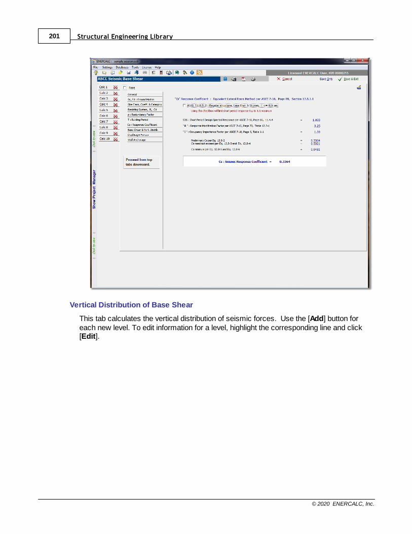
Structural Engineering Library201
© 2020 ENERCALC, Inc.
Vertical Distribution of Base Shear
This tab calculates the vertical distribution of seismic forces. Use the [Add] button foreach new level. To edit information for a level, highlight the corresponding line and click[Edit].
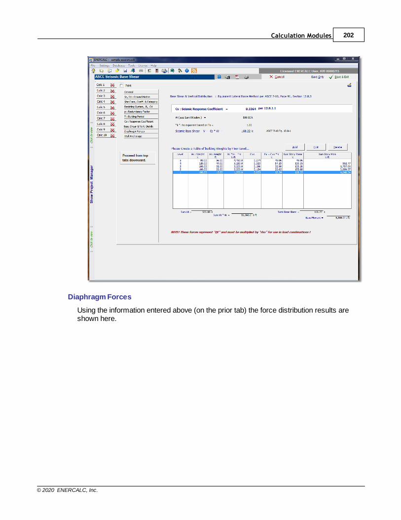
Calculation Modules 202
© 2020 ENERCALC, Inc.
Diaphragm Forces
Using the information entered above (on the prior tab) the force distribution results areshown here.
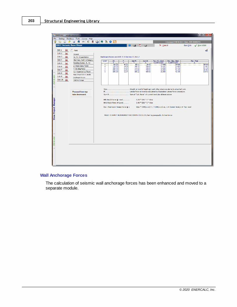
Structural Engineering Library203
© 2020 ENERCALC, Inc.
Wall Anchorage Forces
The calculation of seismic wall anchorage forces has been enhanced and moved to aseparate module.
Calculation Modules 204
© 2020 ENERCALC, Inc.
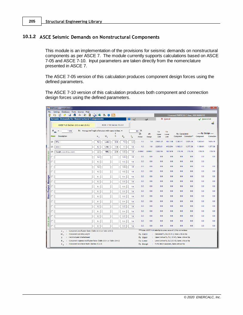
Structural Engineering Library205
© 2020 ENERCALC, Inc.
10.1.2 ASCE Seismic Demands on Nonstructural Components
This module is an implementation of the provisions for seismic demands on nonstructuralcomponents as per ASCE 7. The module currently supports calculations based on ASCE7-05 and ASCE 7-10. Input parameters are taken directly from the nomenclaturepresented in ASCE 7.
The ASCE 7-05 version of this calculation produces component design forces using thedefined parameters.
The ASCE 7-10 version of this calculation produces both component and connectiondesign forces using the defined parameters.
Calculation Modules 206
© 2020 ENERCALC, Inc.
10.1.3 ASCE Seismic Wall Anchorage
This module is an implementation of the provisions for design and anchorage of walls toresist seismic forces as per ASCE 7. The module currently supports calculations basedon ASCE 7-05 and ASCE 7-10. Input parameters are taken directly from the nomenclaturepresented in ASCE 7.
The ASCE 7-05 version of this calculation produces:· Out-of-Plane Force for Structural Wall Design
· Out-of-Plane Force for Concrete and Masonry Structural Wall Anchorage Design (for allSeismic Design Categories where structural walls connect to rigid diaphragms, and forSDC A and B where walls connect to flexible diaphragms)
· Out-of-Plane Force for Concrete and Masonry Structural Wall Anchorage Design (forSeismic Design Categories C through F where walls connect to flexible diaphragms)
The ASCE 7-10 version of this calculation produces:· Out-of-Plane Force for Structural Wall Design
· Out-of-Plane Wall Anchorage Force
The module is configured to allow the definition of up to 20 different wall conditions. Theuser has the option to decide which (if any) of the calculations will be included in a ProjectPrint.

Structural Engineering Library207
© 2020 ENERCALC, Inc.
Calculation Modules 208
© 2020 ENERCALC, Inc.
10.1.4 ASCE Wind Enclosure
This module is an implementation of the provisions for determining the EnclosureClassification for the determination of Wind Loads as per ASCE 7. Click here for a video:
ASCE 7 Wind Enclosure Classification
The module currently supports calculations based on ASCE 7-05 and ASCE 7-10. Inputparameters are taken directly from the nomenclature presented in ASCE 7.
The calculation sheet is set up to permit up to ten different analyses to be documentedwithin a single Project File. This can be useful when a project includes multiple buildings,or in situations where multiple scenarios are being evaluated.
The data collection is presented in such a way as to guide the user through the module ina logical progression.
Values of gross area and area of openings are provided for walls on four sides of thebuilding (arbitrarily designated "North", "South", "East", and "West"). Once these valuesare provided, the module can determine if the structure qualifies as "Open" or not. If thestructure is determined to be "Open", then the module will indicate that result and stopthere. If the structure does not qualify as an "Open" structure, then input fields for RoofGross Area and Roof Opening Area will be displayed, and a set of four tabs will appear inthe bottom half of the screen. Once the Roof areas are populated, the four tabs thoroughlypresent the calculations to determine whether the structure qualifies as "Enclosed" or"Partially Enclosed" when each of the four respective walls receives positive externalpressure.
The results of this determination are useful for project documentation requirements, aswell as in guiding the user to read the appropriate results values from other modules withinStructural Engineering Library.
Note: The provisions of the ASCE Wind Enclosure module are already incorporated intothe ASCE 7-10 Wind Loads module. So it is not necessary to run the standalone versionof this module if the ASCE 7-10 Wind Loads module will be used.
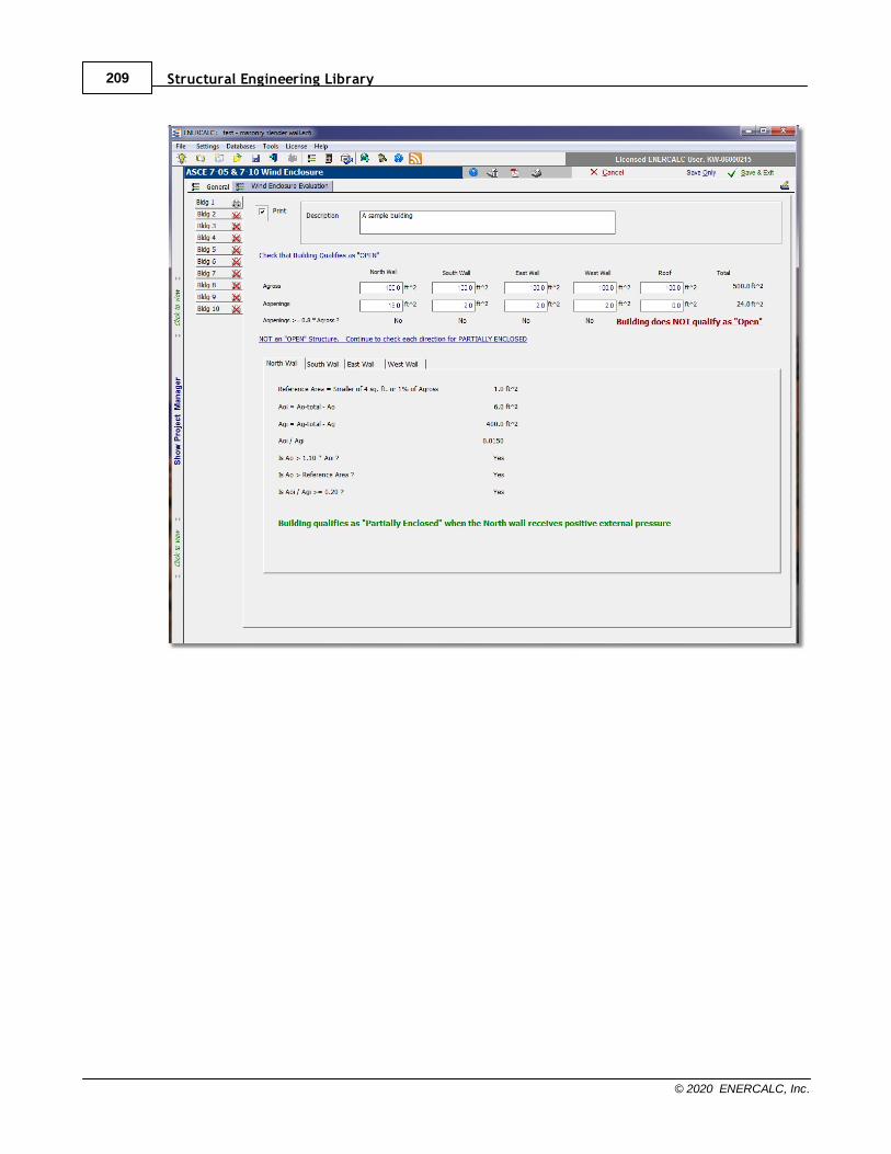
Structural Engineering Library209
© 2020 ENERCALC, Inc.
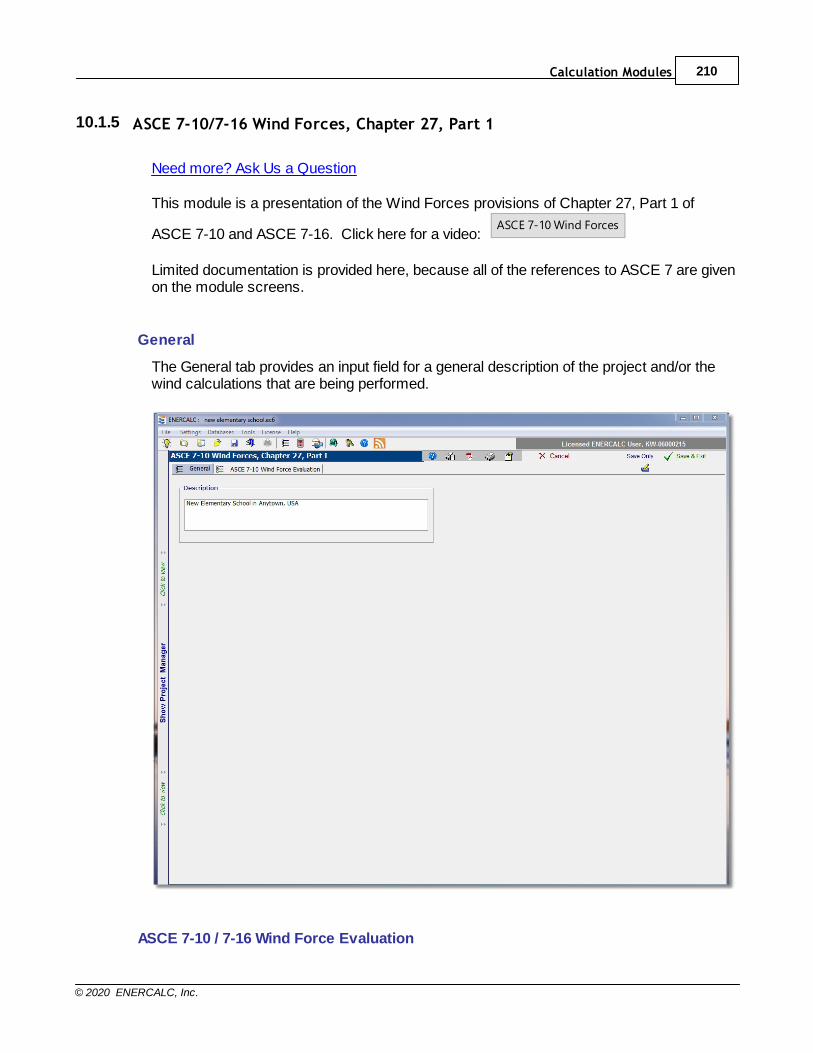
Calculation Modules 210
© 2020 ENERCALC, Inc.
10.1.5 ASCE 7-10/7-16 Wind Forces, Chapter 27, Part 1
Need more? Ask Us a Question
This module is a presentation of the Wind Forces provisions of Chapter 27, Part 1 of
ASCE 7-10 and ASCE 7-16. Click here for a video: ASCE 7-10 Wind Forces
Limited documentation is provided here, because all of the references to ASCE 7 are givenon the module screens.
General
The General tab provides an input field for a general description of the project and/or thewind calculations that are being performed.
ASCE 7-10 / 7-16 Wind Force Evaluation
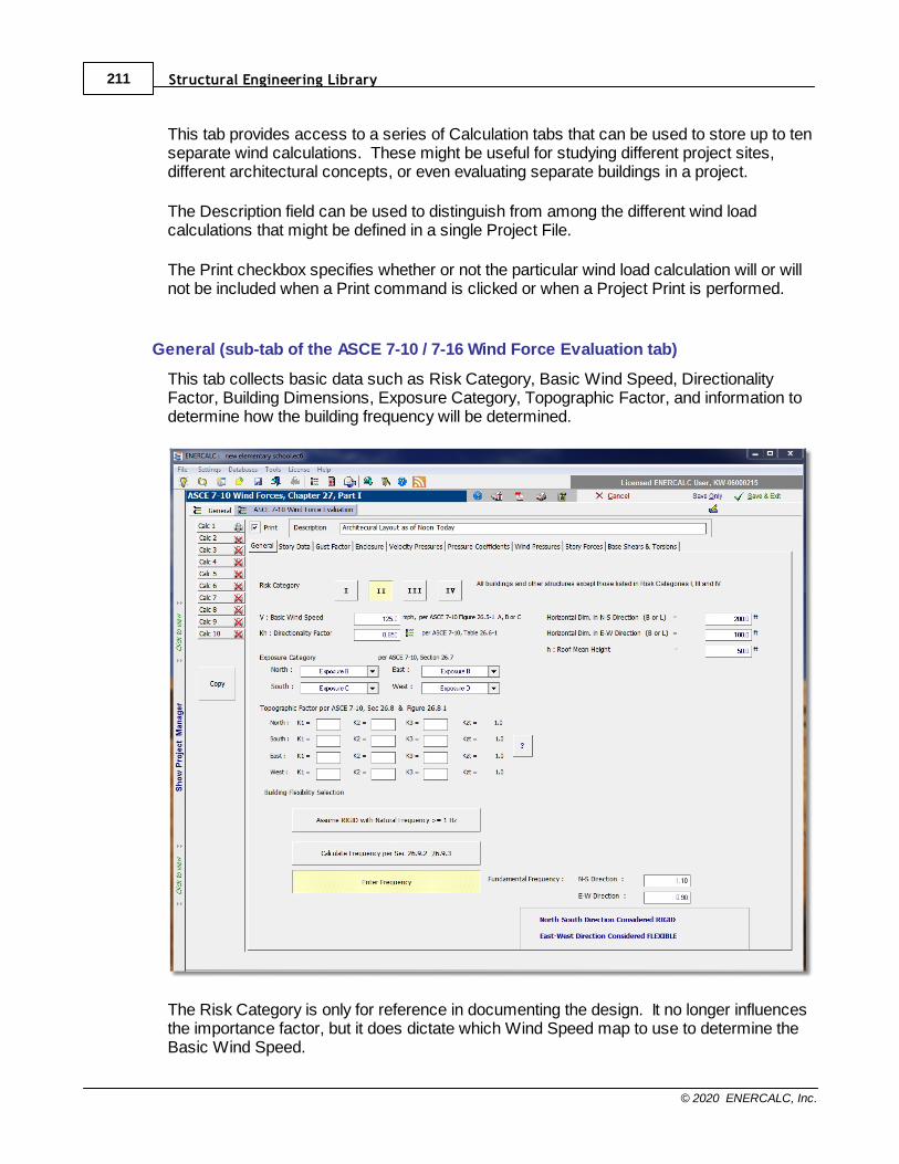
Structural Engineering Library211
© 2020 ENERCALC, Inc.
This tab provides access to a series of Calculation tabs that can be used to store up to tenseparate wind calculations. These might be useful for studying different project sites,different architectural concepts, or even evaluating separate buildings in a project.
The Description field can be used to distinguish from among the different wind loadcalculations that might be defined in a single Project File.
The Print checkbox specifies whether or not the particular wind load calculation will or willnot be included when a Print command is clicked or when a Project Print is performed.
General (sub-tab of the ASCE 7-10 / 7-16 Wind Force Evaluation tab)
This tab collects basic data such as Risk Category, Basic Wind Speed, DirectionalityFactor, Building Dimensions, Exposure Category, Topographic Factor, and information todetermine how the building frequency will be determined.
The Risk Category is only for reference in documenting the design. It no longer influencesthe importance factor, but it does dictate which Wind Speed map to use to determine theBasic Wind Speed.
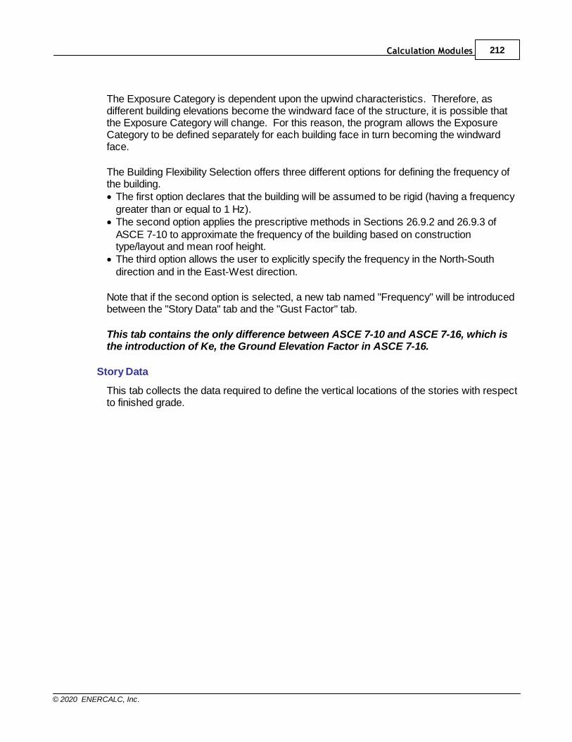
Calculation Modules 212
© 2020 ENERCALC, Inc.
The Exposure Category is dependent upon the upwind characteristics. Therefore, asdifferent building elevations become the windward face of the structure, it is possible thatthe Exposure Category will change. For this reason, the program allows the ExposureCategory to be defined separately for each building face in turn becoming the windwardface.
The Building Flexibility Selection offers three different options for defining the frequency ofthe building.· The first option declares that the building will be assumed to be rigid (having a frequency
greater than or equal to 1 Hz).· The second option applies the prescriptive methods in Sections 26.9.2 and 26.9.3 of
ASCE 7-10 to approximate the frequency of the building based on constructiontype/layout and mean roof height.
· The third option allows the user to explicitly specify the frequency in the North-Southdirection and in the East-West direction.
Note that if the second option is selected, a new tab named "Frequency" will be introducedbetween the "Story Data" tab and the "Gust Factor" tab.
This tab contains the only difference between ASCE 7-10 and ASCE 7-16, which isthe introduction of Ke, the Ground Elevation Factor in ASCE 7-16.
Story Data
This tab collects the data required to define the vertical locations of the stories with respectto finished grade.
Structural Engineering Library213
© 2020 ENERCALC, Inc.
The development of the story data table is controlled by the three buttons: Add Level, EditLevel, and Delete Level, which perform their respective operations on the table of storydata.
Clicking Add or Edit opens the Story Information pop-up dialog as shown above. Twoitems are worthy of note on this dialog. First, the Height to Story is always referenced fromgrade, so it is looking to collect the height from grade to the story of interest, not the storyto story height. Second, the values of e
Rx and e
Ry are only used if a building is determined
(or defined) to be "Flexible" (< 1 Hz) in a particular direction. So if a building turns out to be"Rigid" in one or both directions, then the values of e
Rx and e
Ry are not required in those
directions, and the values can be left at zero or a value can be entered, but the programwill ignore it.
Frequency (Only displayed if the option is selected on the General tab to "CalculateFrequency")
This tab displays the story data that was previously collected, and it requests the BuildingConstruction Type and the values of Li necessary to complete the check to determine ifthe approximate methods of frequency determination are applicable.
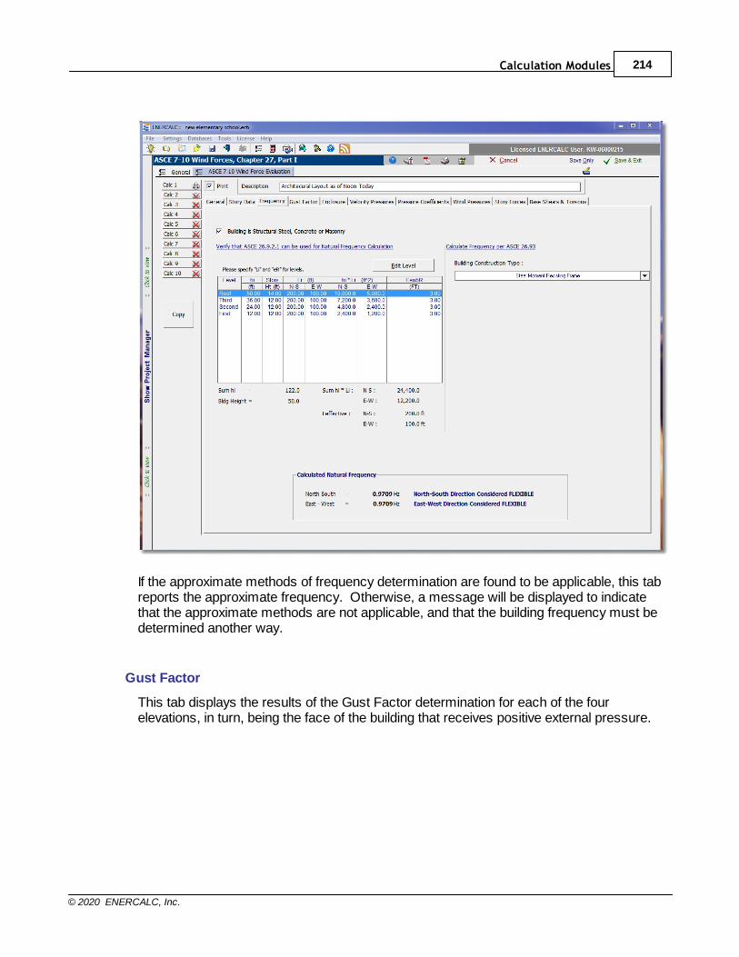
Calculation Modules 214
© 2020 ENERCALC, Inc.
If the approximate methods of frequency determination are found to be applicable, this tabreports the approximate frequency. Otherwise, a message will be displayed to indicatethat the approximate methods are not applicable, and that the building frequency must bedetermined another way.
Gust Factor
This tab displays the results of the Gust Factor determination for each of the fourelevations, in turn, being the face of the building that receives positive external pressure.
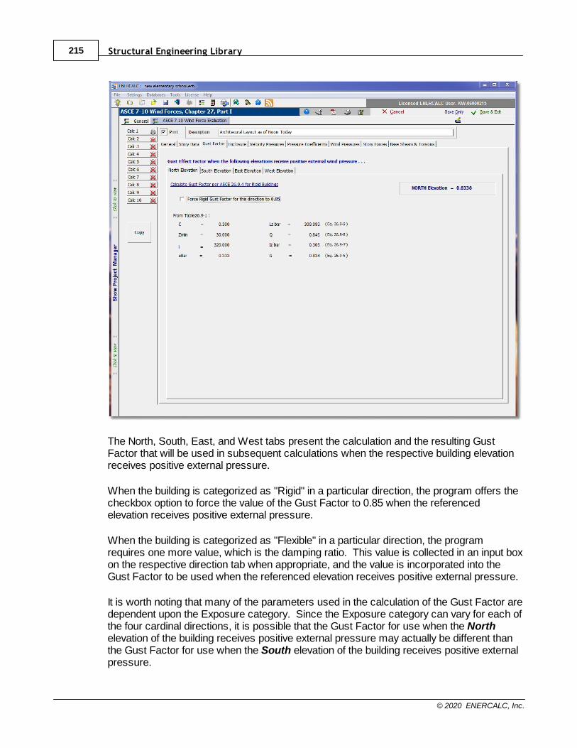
Structural Engineering Library215
© 2020 ENERCALC, Inc.
The North, South, East, and West tabs present the calculation and the resulting GustFactor that will be used in subsequent calculations when the respective building elevationreceives positive external pressure.
When the building is categorized as "Rigid" in a particular direction, the program offers thecheckbox option to force the value of the Gust Factor to 0.85 when the referencedelevation receives positive external pressure.
When the building is categorized as "Flexible" in a particular direction, the programrequires one more value, which is the damping ratio. This value is collected in an input boxon the respective direction tab when appropriate, and the value is incorporated into theGust Factor to be used when the referenced elevation receives positive external pressure.
It is worth noting that many of the parameters used in the calculation of the Gust Factor aredependent upon the Exposure category. Since the Exposure category can vary for each ofthe four cardinal directions, it is possible that the Gust Factor for use when the Northelevation of the building receives positive external pressure may actually be different thanthe Gust Factor for use when the South elevation of the building receives positive externalpressure.
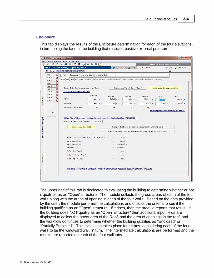
Calculation Modules 216
© 2020 ENERCALC, Inc.
Enclosure
This tab displays the results of the Enclosure determination for each of the four elevations,in turn, being the face of the building that receives positive external pressure.
The upper half of this tab is dedicated to evaluating the building to determine whether or notit qualifies as an "Open" structure. The module collects the gross areas of each of the fourwalls along with the areas of opening in each of the four walls. Based on the data providedby the user, the module performs the calculations and checks the criteria to see if thebuilding qualifies as an "Open" structure. If it does, then the module reports that result. Ifthe building does NOT qualify as an "Open" structure" then additional input fields aredisplayed to collect the gross area of the Roof, and the area of openings in the roof, andthe workflow continues to determine whether the building qualifies as "Enclosed" or"Partially Enclosed". This evaluation takes place four times, considering each of the fourwalls to be the windward wall, in turn. The intermediate calculations are performed and theresults are reported on each of the four wall tabs.
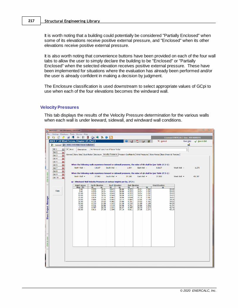
Structural Engineering Library217
© 2020 ENERCALC, Inc.
It is worth noting that a building could potentially be considered "Partially Enclosed" whensome of its elevations receive positive external pressure, and "Enclosed" when its otherelevations receive positive external pressure.
It is also worth noting that convenience buttons have been provided on each of the four walltabs to allow the user to simply declare the building to be "Enclosed" or "PartiallyEnclosed" when the selected elevation receives positive external pressure. These havebeen implemented for situations where the evaluation has already been performed and/orthe user is already confident in making a decision by judgment.
The Enclosure classification is used downstream to select appropriate values of GCpi touse when each of the four elevations becomes the windward wall.
Velocity Pressures
This tab displays the results of the Velocity Pressure determination for the various wallswhen each wall is under leeward, sidewall, and windward wall conditions.
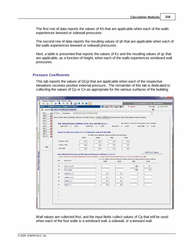
Calculation Modules 218
© 2020 ENERCALC, Inc.
The first row of data reports the values of Kh that are applicable when each of the wallsexperiences leeward or sidewall pressures.
The second row of data reports the resulting values of qh that are applicable when each ofthe walls experiences leeward or sidewall pressures.
Next, a table is presented that reports the values of Kz and the resulting values of qz thatare applicable, as a function of height, when each of the walls experiences windward wallpressures.
Pressure Coefficients
This tab reports the values of GCpi that are applicable when each of the respectiveelevations receives positive external pressure. The remainder of this tab is dedicated tocollecting the values of Cp or Cn as appropriate for the various surfaces of the building.
Wall values are collected first, and the input fields collect values of Cp that will be usedwhen each of the four walls is a windward wall, a sidewall, or a leeward wall.
Structural Engineering Library219
© 2020 ENERCALC, Inc.
At the bottom of the tab is a customizable table that is set up to receive many lines of Cpor Cn values pertinent to the roof. A convenience button is provided to display the figuresthat define the Cp or Cn values for various conditions. A glance at the tables reveals thatthe factors for roofs are frequently dependent upon the wind direction with respect to theridge, and also dependent upon whether pressures are desired for the windward orleeward surfaces of the roof. So some planning will be required to set this table up to yieldthe desired results. To make the downstream results most applicable and easy to read,the program has been set up so that a roof pressure value will only be calculated forsituations where nonzero values of Cp or Cn have been specified. To put this anotherway, referring to the table above, there are no values of Cp defined for the North or Southelevations for the "Perpendicular: Windward" or "Perpendicular: Leeward" conditions. Thisis because the ridge is assumed to run in the North-South direction in the hypotheticalbuilding being considered. As such, it would not make sense to ask the program to reportwindward or leeward roof pressures when the wind acts in the north or south directions. So to avoid overpopulating the output with meaningless results, the blank fields will beinterpreted by the program as an indication that the corresponding calculation is notrequired. We will see the benefit of this when we move to the Wind Pressures tab and seehow concisely these results are reported.
On a related note, it is worth mentioning that the Cp and Cn tables occasionally reportvalues of zero for certain conditions. These are typically provided for interpolationpurposes. But if a situation is ever encountered where a value of zero for Cp or Cn isactually required for design purposes, the user is advised to enter a small nonzero value.
Wind Pressures
This tab reports the values of wind pressures that occur on the various surfaces of thebuilding when the named elevation receives positive external pressure.
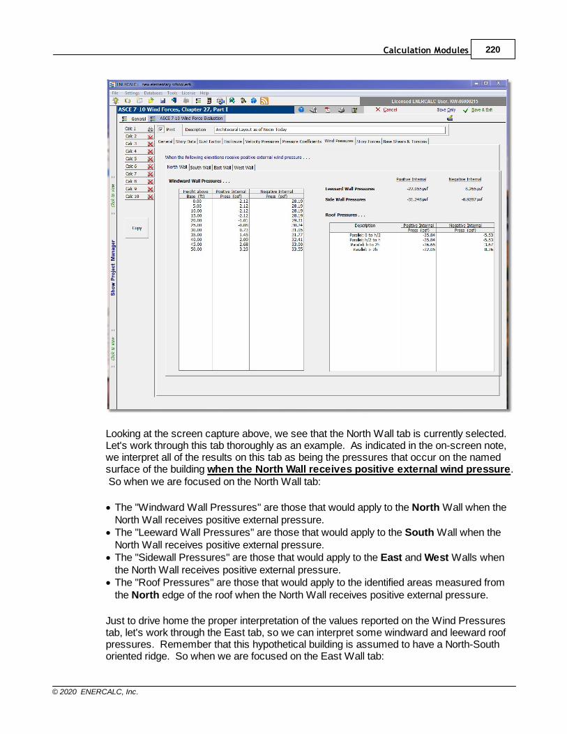
Calculation Modules 220
© 2020 ENERCALC, Inc.
Looking at the screen capture above, we see that the North Wall tab is currently selected. Let's work through this tab thoroughly as an example. As indicated in the on-screen note,we interpret all of the results on this tab as being the pressures that occur on the namedsurface of the building when the North Wall receives positive external wind pressure. So when we are focused on the North Wall tab:
· The "Windward Wall Pressures" are those that would apply to the North Wall when theNorth Wall receives positive external pressure.
· The "Leeward Wall Pressures" are those that would apply to the South Wall when theNorth Wall receives positive external pressure.
· The "Sidewall Pressures" are those that would apply to the East and West Walls whenthe North Wall receives positive external pressure.
· The "Roof Pressures" are those that would apply to the identified areas measured fromthe North edge of the roof when the North Wall receives positive external pressure.
Just to drive home the proper interpretation of the values reported on the Wind Pressurestab, let's work through the East tab, so we can interpret some windward and leeward roofpressures. Remember that this hypothetical building is assumed to have a North-Southoriented ridge. So when we are focused on the East Wall tab:
Structural Engineering Library221
© 2020 ENERCALC, Inc.
· The "Windward Wall Pressures" are those that would apply to the East Wall when theEast Wall receives positive external pressure.
· The "Leeward Wall Pressures" are those that would apply to the West Wall when theEast Wall receives positive external pressure.
· The "Sidewall Pressures" are those that would apply to the North and South Wallswhen the East Wall receives positive external pressure.
· The "Perp: Windward Roof Pressures" are those that would apply to the windward(East) portion of the roof when the East Wall receives positive external pressure.
· The "Perp: Leeward Roof Pressures" are those that would apply to the leeward (West)portion of the roof when the East Wall receives positive external pressure.
Note that all surfaces report pressures based on both the positive and the negative internalpressure conditions, and the algebraic sign convention follows that of ASCE 7, which is tosay that positive values are interpreted to act toward the named surface and negativevalues act away from the named surface. Work this logic through an example such as awindward wall and see that it all makes sense. The negative internal pressure conditionproduces higher total pressures toward the windward wall, than the positive internalpressure condition does, because the negative internal pressure works in the samedirection as the external pressure on a windward wall. Similar logic can be applied to allother surfaces to demonstrate that the mathematics are proper.
Story Forces
This tab reports the values of wind forces tributary to each story in the building.
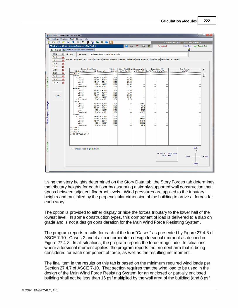
Calculation Modules 222
© 2020 ENERCALC, Inc.
Using the story heights determined on the Story Data tab, the Story Forces tab determinesthe tributary heights for each floor by assuming a simply-supported wall construction thatspans between adjacent floor/roof levels. Wind pressures are applied to the tributaryheights and multiplied by the perpendicular dimension of the building to arrive at forces foreach story.
The option is provided to either display or hide the forces tributary to the lower half of thelowest level. In some construction types, this component of load is delivered to a slab ongrade and is not a design consideration for the Main Wind Force Resisting System.
The program reports results for each of the four "Cases" as presented by Figure 27.4-8 ofASCE 7-10. Cases 2 and 4 also incorporate a design torsional moment as defined inFigure 27.4-8. In all situations, the program reports the force magnitude. In situationswhere a torsional moment applies, the program reports the moment arm that is beingconsidered for each component of force, as well as the resulting net moment.
The final item in the results on this tab is based on the minimum required wind loads perSection 27.4.7 of ASCE 7-10. That section requires that the wind load to be used in thedesign of the Main Wind Force Resisting System for an enclosed or partially enclosedbuilding shall not be less than 16 psf multiplied by the wall area of the building (and 8 psf

Structural Engineering Library223
© 2020 ENERCALC, Inc.
multiplied by the roof area of the building projected onto a vertical plane normal to theassumed wind direction). So in this last item in the results list, the program reports storyforces assuming 16 psf applied to each wall of the building. As of build 6.12.4.24, theprogram does not collect enough information to consider the 8 psf on the projection of theroof area, so this additional load may need to be considered with supplemental handcalculations on buildings with other than flat or low-slope roofs.
Base Shears & Torsions
This tab reports the summation of the wind story forces and torsions for all levels in thebuilding, for all four "Cases" and for the minimum required wind loads per Section 27.4.7.
Although "Base Shears" are not technically a part of the ASCE 7-10 design procedure forwind loads, the summation of all story forces is often of interest to designers for a varietyof reasons. Some designers like to see how the wind "base shear" compares to theseismic base shear. For some designers, the summation of the wind forces is useful inthe checking process to get a confidence level that the calculated pressures arereasonable. Whatever the reason, the values are reported on this tab if they are ofinterest.
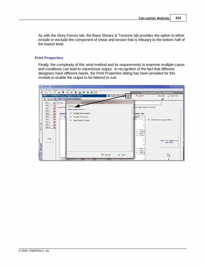
Calculation Modules 224
© 2020 ENERCALC, Inc.
As with the Story Forces tab, the Base Shears & Torsions tab provides the option to eitherinclude or exclude the component of shear and torsion that is tributary to the bottom half ofthe lowest level.
Print Properties
Finally, the complexity of this wind method and its requirements to examine multiple casesand conditions can lead to voluminous output. In recognition of the fact that differentdesigners have different needs, the Print Properties dialog has been provided for thismodule to enable the output to be tailored to suit.
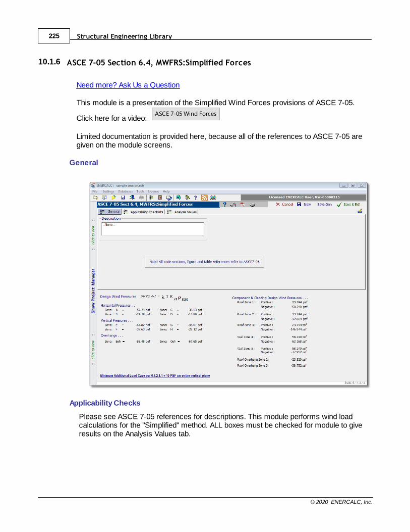
Structural Engineering Library225
© 2020 ENERCALC, Inc.
10.1.6 ASCE 7-05 Section 6.4, MWFRS:Simplified Forces
Need more? Ask Us a Question
This module is a presentation of the Simplified Wind Forces provisions of ASCE 7-05.
Click here for a video: ASCE 7-05 Wind Forces
Limited documentation is provided here, because all of the references to ASCE 7-05 aregiven on the module screens.
General
Applicability Checks
Please see ASCE 7-05 references for descriptions. This module performs wind loadcalculations for the "Simplified" method. ALL boxes must be checked for module to giveresults on the Analysis Values tab.
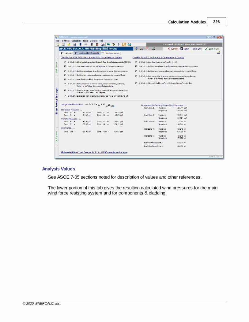
Calculation Modules 226
© 2020 ENERCALC, Inc.
Analysis Values
See ASCE 7-05 sections noted for description of values and other references.
The lower portion of this tab gives the resulting calculated wind pressures for the mainwind force resisting system and for components & cladding.
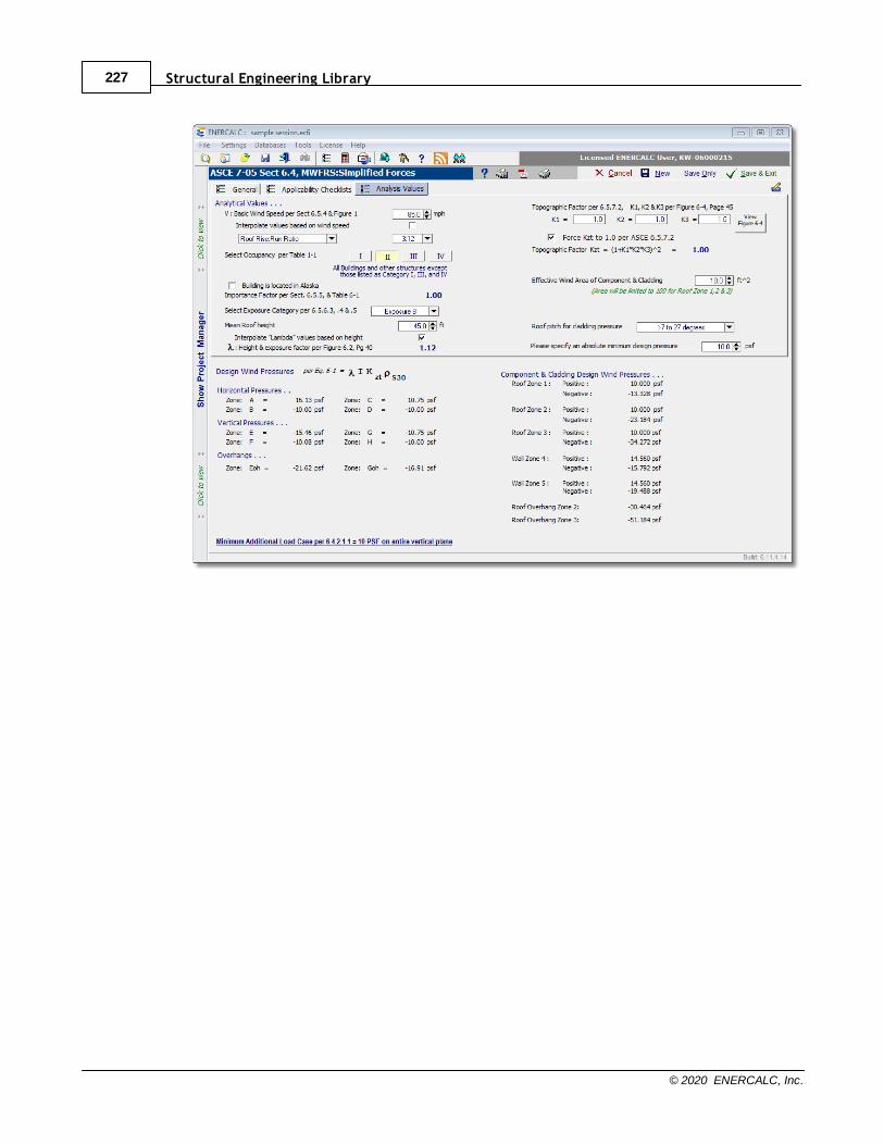
Structural Engineering Library227
© 2020 ENERCALC, Inc.
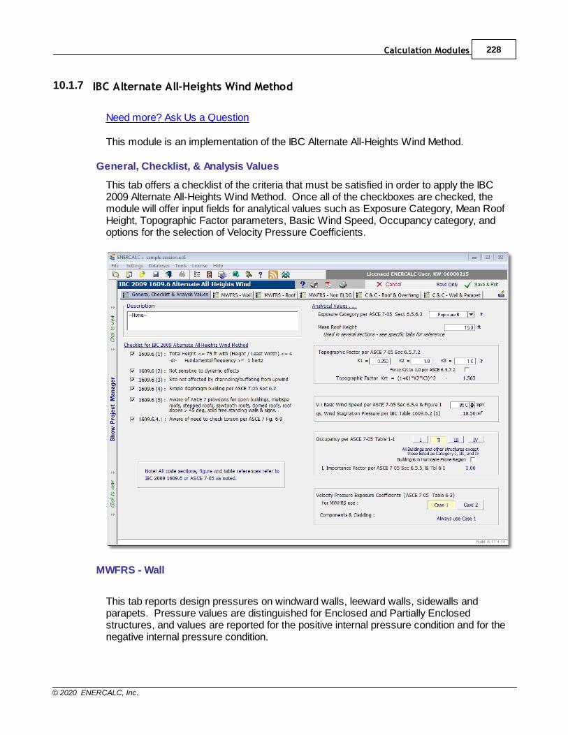
Calculation Modules 228
© 2020 ENERCALC, Inc.
10.1.7 IBC Alternate All-Heights Wind Method
Need more? Ask Us a Question
This module is an implementation of the IBC Alternate All-Heights Wind Method.
General, Checklist, & Analysis Values
This tab offers a checklist of the criteria that must be satisfied in order to apply the IBC2009 Alternate All-Heights Wind Method. Once all of the checkboxes are checked, themodule will offer input fields for analytical values such as Exposure Category, Mean RoofHeight, Topographic Factor parameters, Basic Wind Speed, Occupancy category, andoptions for the selection of Velocity Pressure Coefficients.
MWFRS - Wall
This tab reports design pressures on windward walls, leeward walls, sidewalls andparapets. Pressure values are distinguished for Enclosed and Partially Enclosedstructures, and values are reported for the positive internal pressure condition and for thenegative internal pressure condition.
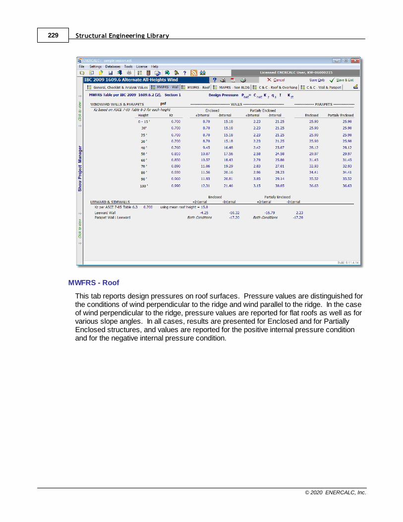
Structural Engineering Library229
© 2020 ENERCALC, Inc.
MWFRS - Roof
This tab reports design pressures on roof surfaces. Pressure values are distinguished forthe conditions of wind perpendicular to the ridge and wind parallel to the ridge. In the caseof wind perpendicular to the ridge, pressure values are reported for flat roofs as well as forvarious slope angles. In all cases, results are presented for Enclosed and for PartiallyEnclosed structures, and values are reported for the positive internal pressure conditionand for the negative internal pressure condition.
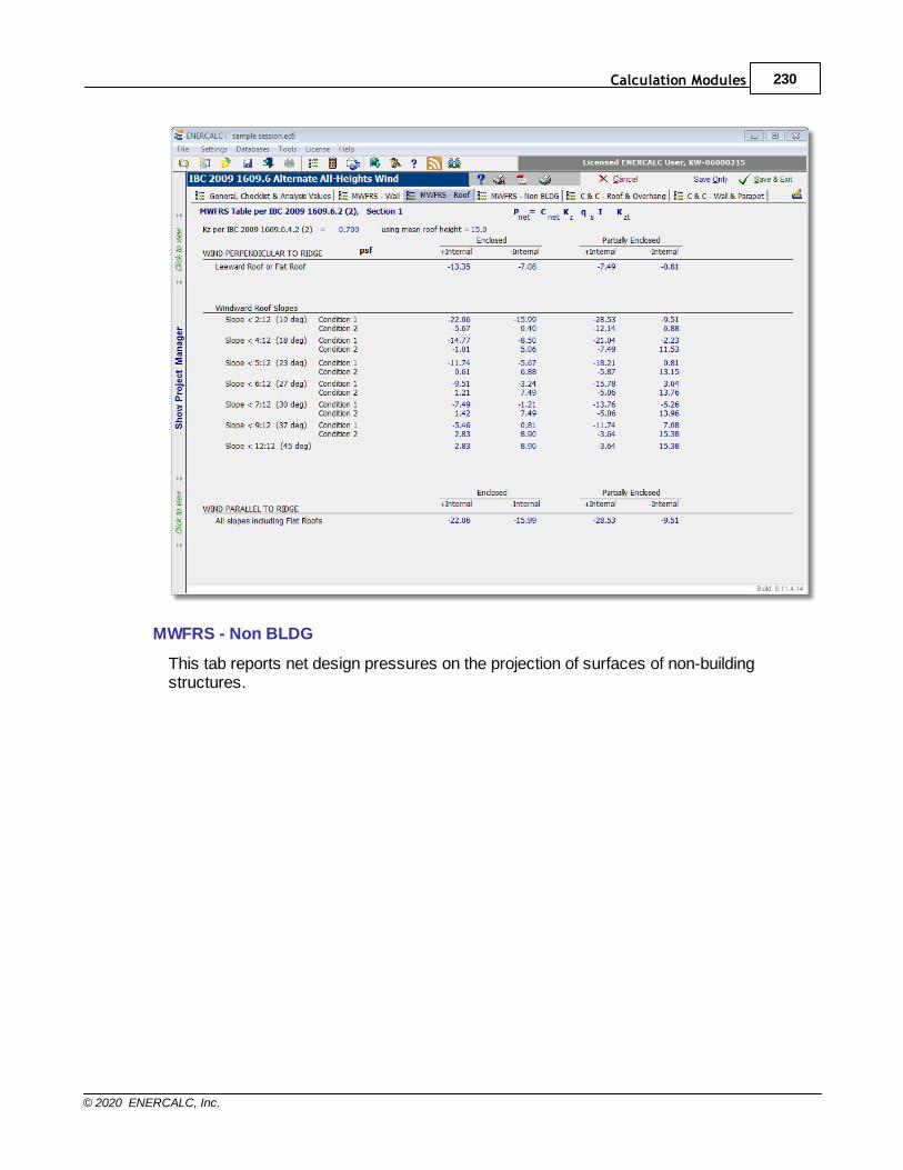
Calculation Modules 230
© 2020 ENERCALC, Inc.
MWFRS - Non BLDG
This tab reports net design pressures on the projection of surfaces of non-buildingstructures.
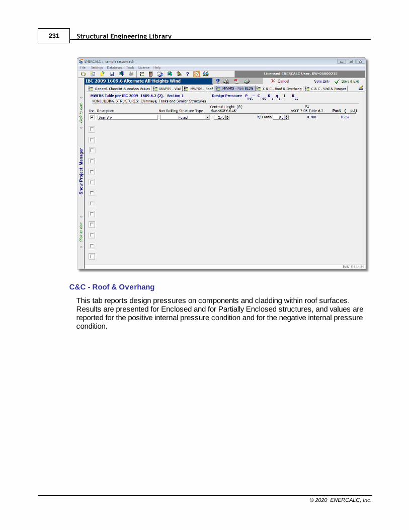
Structural Engineering Library231
© 2020 ENERCALC, Inc.
C&C - Roof & Overhang
This tab reports design pressures on components and cladding within roof surfaces. Results are presented for Enclosed and for Partially Enclosed structures, and values arereported for the positive internal pressure condition and for the negative internal pressurecondition.
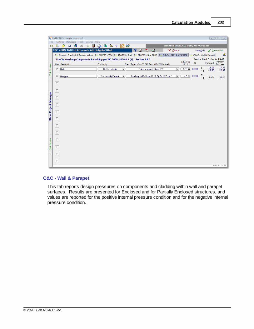
Calculation Modules 232
© 2020 ENERCALC, Inc.
C&C - Wall & Parapet
This tab reports design pressures on components and cladding within wall and parapetsurfaces. Results are presented for Enclosed and for Partially Enclosed structures, andvalues are reported for the positive internal pressure condition and for the negative internalpressure condition.
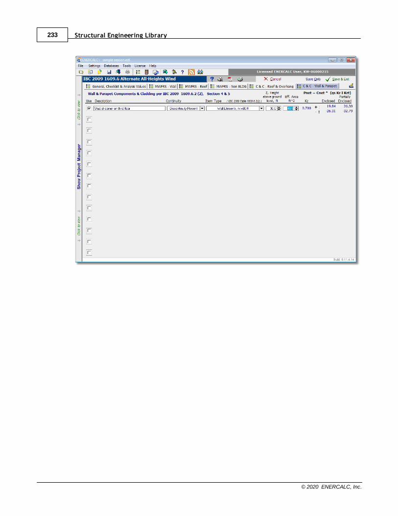
Structural Engineering Library233
© 2020 ENERCALC, Inc.
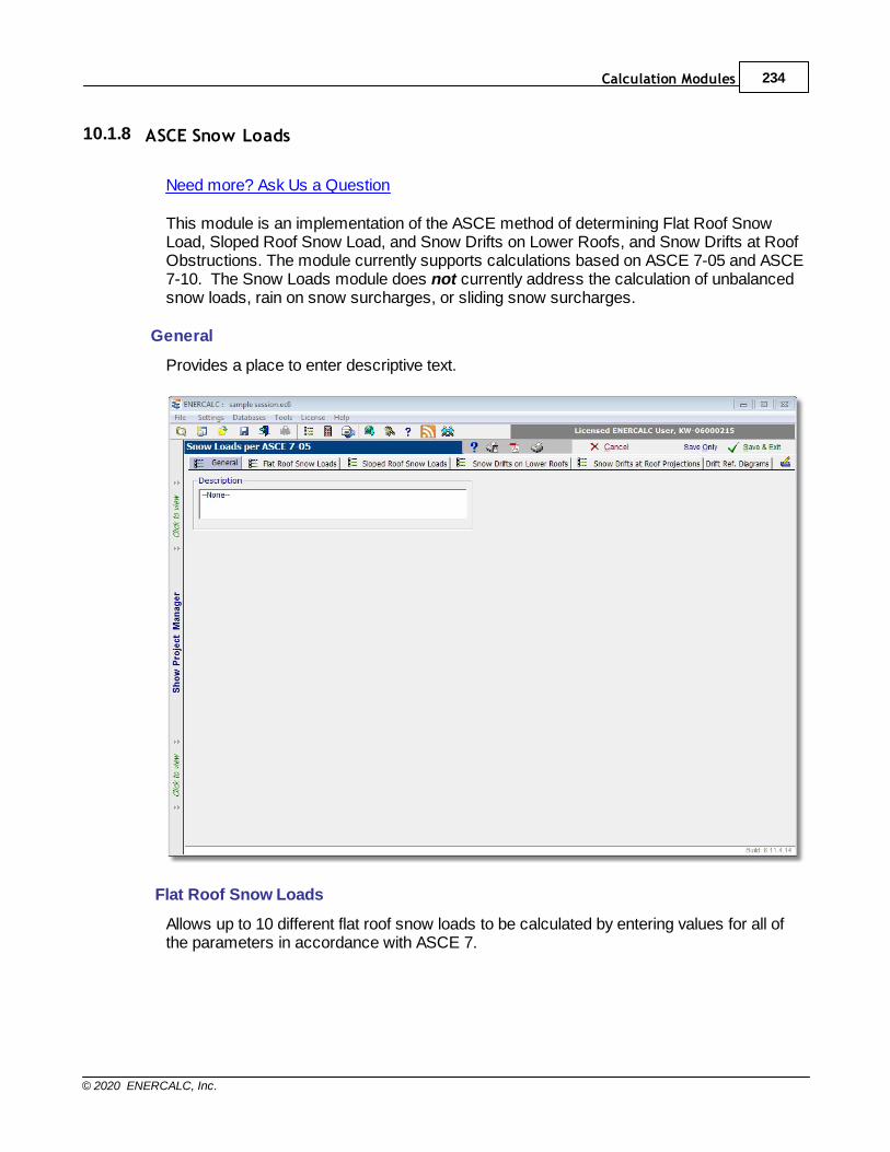
Calculation Modules 234
© 2020 ENERCALC, Inc.
10.1.8 ASCE Snow Loads
Need more? Ask Us a Question
This module is an implementation of the ASCE method of determining Flat Roof SnowLoad, Sloped Roof Snow Load, and Snow Drifts on Lower Roofs, and Snow Drifts at RoofObstructions. The module currently supports calculations based on ASCE 7-05 and ASCE7-10. The Snow Loads module does not currently address the calculation of unbalancedsnow loads, rain on snow surcharges, or sliding snow surcharges.
General
Provides a place to enter descriptive text.
Flat Roof Snow Loads
Allows up to 10 different flat roof snow loads to be calculated by entering values for all ofthe parameters in accordance with ASCE 7.
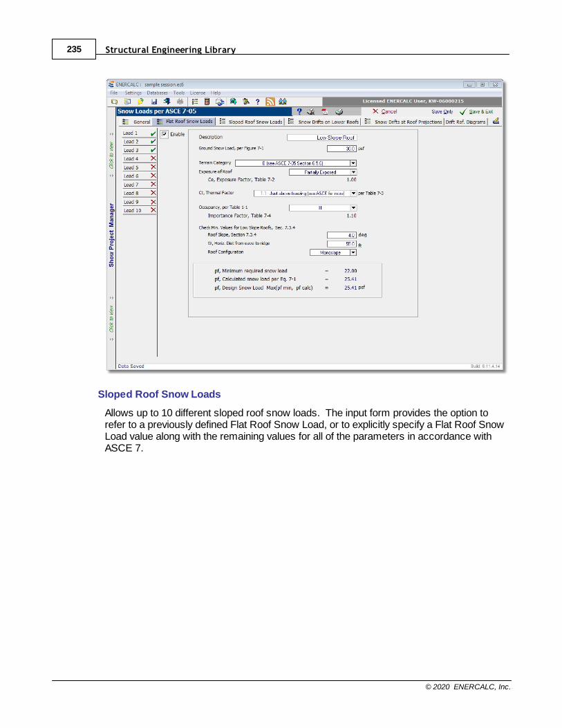
Structural Engineering Library235
© 2020 ENERCALC, Inc.
Sloped Roof Snow Loads
Allows up to 10 different sloped roof snow loads. The input form provides the option torefer to a previously defined Flat Roof Snow Load, or to explicitly specify a Flat Roof SnowLoad value along with the remaining values for all of the parameters in accordance withASCE 7.
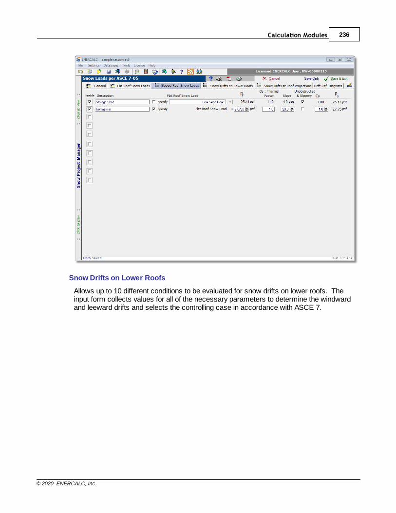
Calculation Modules 236
© 2020 ENERCALC, Inc.
Snow Drifts on Lower Roofs
Allows up to 10 different conditions to be evaluated for snow drifts on lower roofs. Theinput form collects values for all of the necessary parameters to determine the windwardand leeward drifts and selects the controlling case in accordance with ASCE 7.
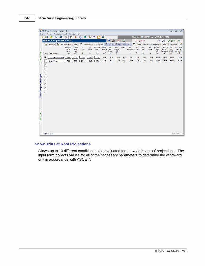
Structural Engineering Library237
© 2020 ENERCALC, Inc.
Snow Drifts at Roof Projections
Allows up to 10 different conditions to be evaluated for snow drifts at roof projections. Theinput form collects values for all of the necessary parameters to determine the windwarddrift in accordance with ASCE 7.
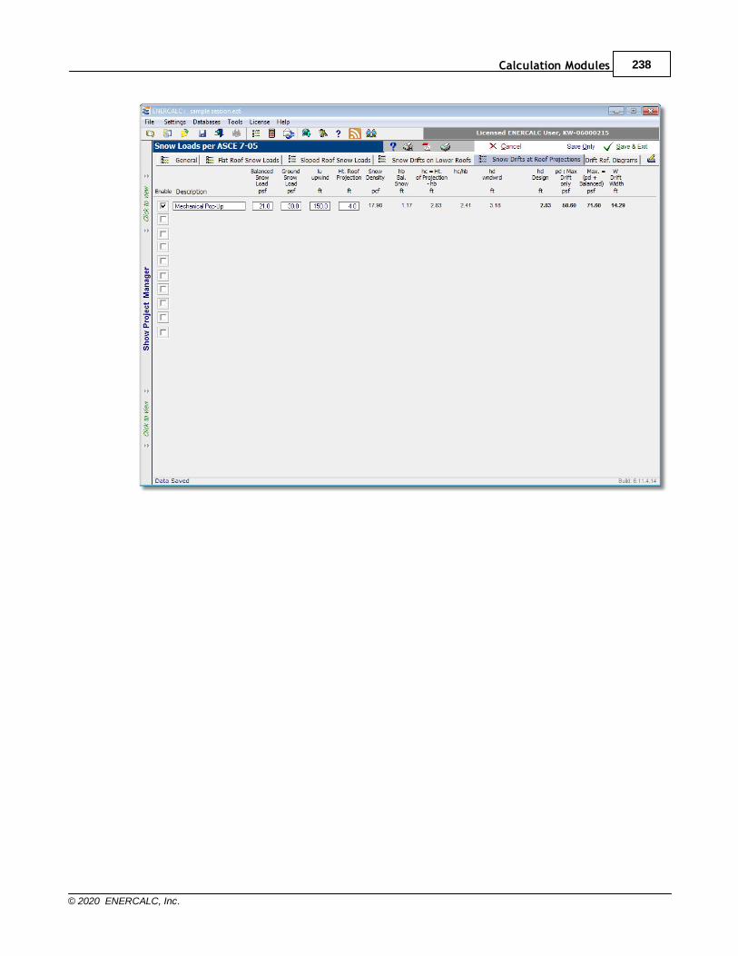
Calculation Modules 238
© 2020 ENERCALC, Inc.
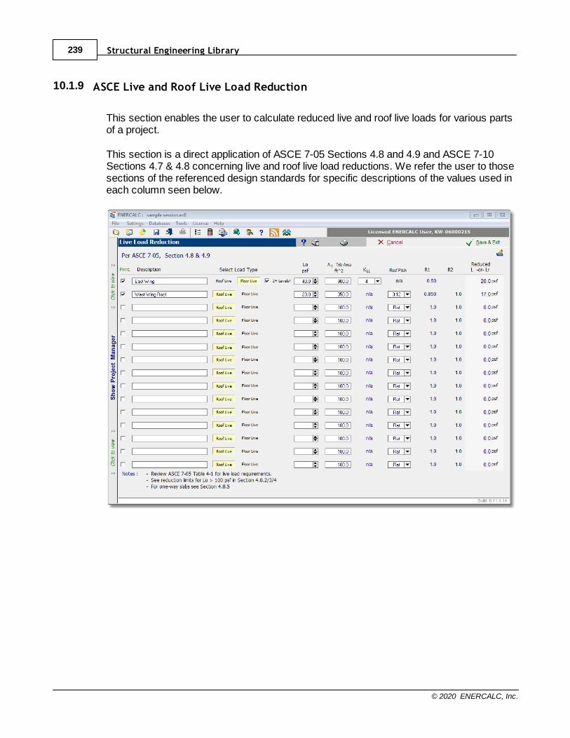
Structural Engineering Library239
© 2020 ENERCALC, Inc.
10.1.9 ASCE Live and Roof Live Load Reduction
This section enables the user to calculate reduced live and roof live loads for various partsof a project.
This section is a direct application of ASCE 7-05 Sections 4.8 and 4.9 and ASCE 7-10Sections 4.7 & 4.8 concerning live and roof live load reductions. We refer the user to thosesections of the referenced design standards for specific descriptions of the values used ineach column seen below.
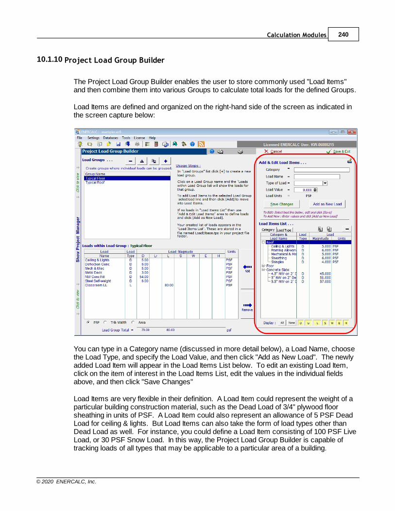
Calculation Modules 240
© 2020 ENERCALC, Inc.
10.1.10 Project Load Group Builder
The Project Load Group Builder enables the user to store commonly used "Load Items"and then combine them into various Groups to calculate total loads for the defined Groups.
Load Items are defined and organized on the right-hand side of the screen as indicated inthe screen capture below:
You can type in a Category name (discussed in more detail below), a Load Name, choosethe Load Type, and specify the Load Value, and then click "Add as New Load". The newlyadded Load Item will appear in the Load Items List below. To edit an existing Load Item,click on the item of interest in the Load Items List, edit the values in the individual fieldsabove, and then click "Save Changes"
Load Items are very flexible in their definition. A Load Item could represent the weight of aparticular building construction material, such as the Dead Load of 3/4" plywood floorsheathing in units of PSF. A Load Item could also represent an allowance of 5 PSF DeadLoad for ceiling & lights. But Load Items can also take the form of load types other thanDead Load as well. For instance, you could define a Load Item consisting of 100 PSF LiveLoad, or 30 PSF Snow Load. In this way, the Project Load Group Builder is capable oftracking loads of all types that may be applicable to a particular area of a building.
Structural Engineering Library241
© 2020 ENERCALC, Inc.
One of the powerful features of the Project Load Group Builder is that it takes the LoadItem data that you enter and it saves that data in a file that is separate and distinct fromyour Project File. (The file is named LoadDbase.tps, and it is saved in the folder that youhave identified as your default Project File location.) In this way, the system continues toaccumulate more and more of your commonly specified materials and loads as you workon different projects. And that ever-growing database of your custom Load Items is alwaysavailable to you on future projects.
In order to bring some organization to the many load items that you may eventuallyaccumulate, the Project Load Group Builder introduces the concept of the "Category". ACategory can contain one or more Load Items. Here again, the way you use Categoriescan be extremely flexible. Some users may prefer to organize their Load Items intoCategories that represent different types of materials or loads. For example, theorganizational hierarchy might take on a form like this where the bullet items representLoad Items within the indicated Category:
Category: Roof Sheathing· 1/2" sheathing
· 5/8" sheathing
· 3/4" sheathing
· 7/8" sheathing
· 1" sheathing
Category: Roof Framing· 2x6@16" o/c
· 2x8@16" o/c
· 2x10@16" o/c
· 2x12@16" o/c
Category: NW Concrete Slab· 4.5" total with 2" deck
· 5.0" total with 2" deck
· 5.5" total with 2" deck
· 6.0" total with 2" deck
· 5.5" total with 3" deck
· 6.0" total with 3" deck
· 6.5" total with 3" deck
Category: LW Concrete Slab· 4.5" total with 2" deck
· 5.0" total with 2" deck
· 5.25" total with 2" deck
· 5.5" total with 2" deck
· 6.0" total with 2" deck
· 5.5" total with 3" deck
· 6.0" total with 3" deck
· 6.25" total with 3" deck
Calculation Modules 242
© 2020 ENERCALC, Inc.
· 6.5" total with 3" deck
Category: Live Load· Classroom
· First Floor Corridor
· Office
· Stack Rooms
Category: Snow Load· 30 PSF
· 32 PSF
· 34 PSF
· 36 PSF
And so on...
But remember, this is just one way that Categories could be used. Here is yet anotheridea:
Category: Typical classroom on structural floor· DL of flooring
· DL of concrete slab on metal deck
· DL of composite metal deck
· DL allowance for structural steel framing
· DL allowance for ceiling & lights
· DL allowance for mechanical & misc.
· LL for classroom occupancy
· LL for partition allowance
Category: Typical corridor on structural floor· DL of flooring
· DL of concrete slab on metal deck
· DL of composite metal deck
· DL allowance for structural steel framing
· DL allowance for ceiling & lights
· DL allowance for mechanical & misc.
· LL for corridor above first floor occupancy
Category: Typical roof structure· DL of asphalt shingles
· DL allowance for second layer of asphalt shingles
· DL of metal roof deck
· DL structural steel framing
· DL allowance for ceiling & lights
· DL allowance for mechanical & misc.
· SL for sloped roof
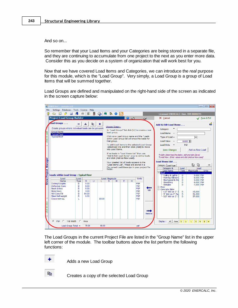
Structural Engineering Library243
© 2020 ENERCALC, Inc.
And so on...
So remember that your Load Items and your Categories are being stored in a separate file,and they are continuing to accumulate from one project to the next as you enter more data. Consider this as you decide on a system of organization that will work best for you.
Now that we have covered Load Items and Categories, we can introduce the real purposefor this module, which is the "Load Group". Very simply, a Load Group is a group of LoadItems that will be summed together.
Load Groups are defined and manipulated on the right-hand side of the screen as indicatedin the screen capture below:
The Load Groups in the current Project File are listed in the "Group Name" list in the upperleft corner of the module. The toolbar buttons above the list perform the followingfunctions:
Adds a new Load Group
Creates a copy of the selected Load Group
Calculation Modules 244
© 2020 ENERCALC, Inc.
Allows the name of the selected Load Group to be edited
Deletes the selected Load Group
When a Load Group is selected in the "Group Name" list, the details of that Load Group aredisplayed in the lower left corner of the screen. (A newly created Load Group will displayno detailed information until some Load Items are added to the Loaf Group.) The displaywill show the Load Items that have been added to the current Load Group including theLoad Item name, the Load Type (Dead Live, Snow, etc.), the magnitude of the load, andthe units.
So we have now covered Load Items and Load Groups. The final detail is...how do we addthese Load Items to Load Groups? The answer lies in the buttons shown below:
Adds the selected Load Item to the current Load Group
Removes the selected Load Item from the current Load Group
Finally, the Print function will automatically include all defined Load Groups and provide anice tabular summary of the Load Items that combine to produce each Load Group.
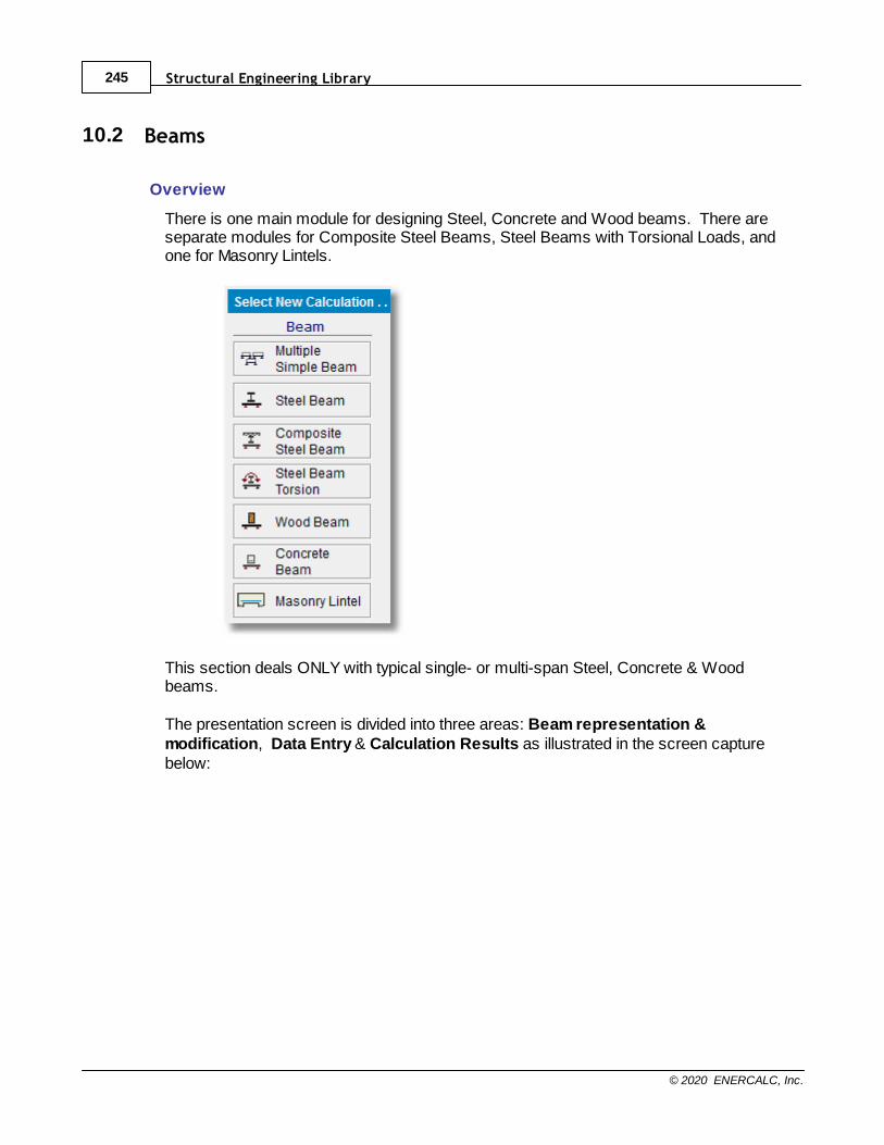
Structural Engineering Library245
© 2020 ENERCALC, Inc.
10.2 Beams
Overview
There is one main module for designing Steel, Concrete and Wood beams. There areseparate modules for Composite Steel Beams, Steel Beams with Torsional Loads, andone for Masonry Lintels.
This section deals ONLY with typical single- or multi-span Steel, Concrete & Woodbeams.
The presentation screen is divided into three areas: Beam representation &modification, Data Entry & Calculation Results as illustrated in the screen capturebelow:
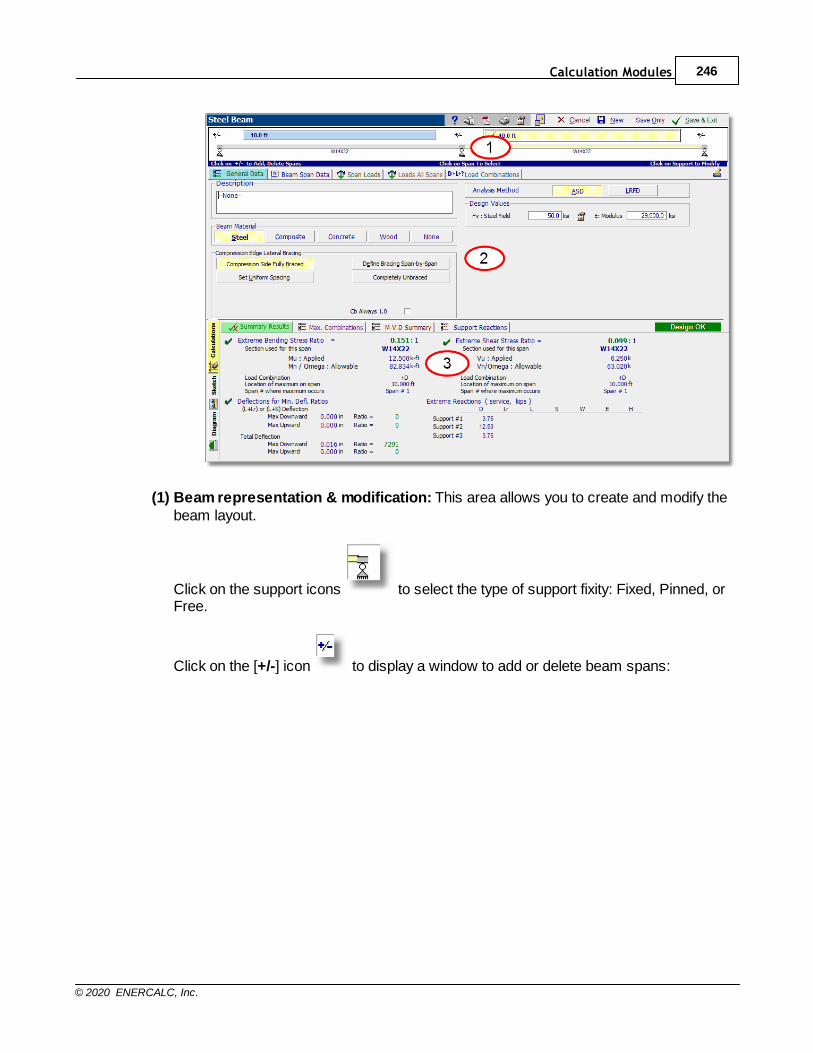
Calculation Modules 246
© 2020 ENERCALC, Inc.
(1) Beam representation & modification: This area allows you to create and modify thebeam layout.
Click on the support icons to select the type of support fixity: Fixed, Pinned, orFree.
Click on the [+/-] icon to display a window to add or delete beam spans:
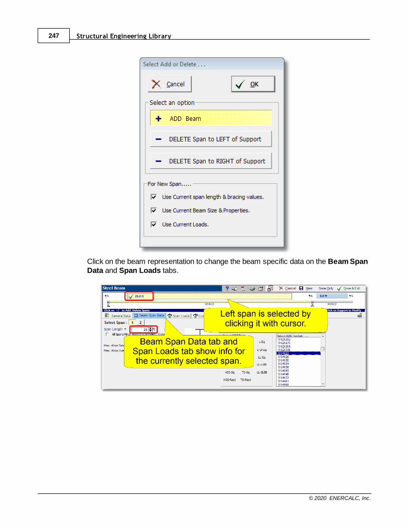
Structural Engineering Library247
© 2020 ENERCALC, Inc.
Click on the beam representation to change the beam specific data on the Beam SpanData and Span Loads tabs.
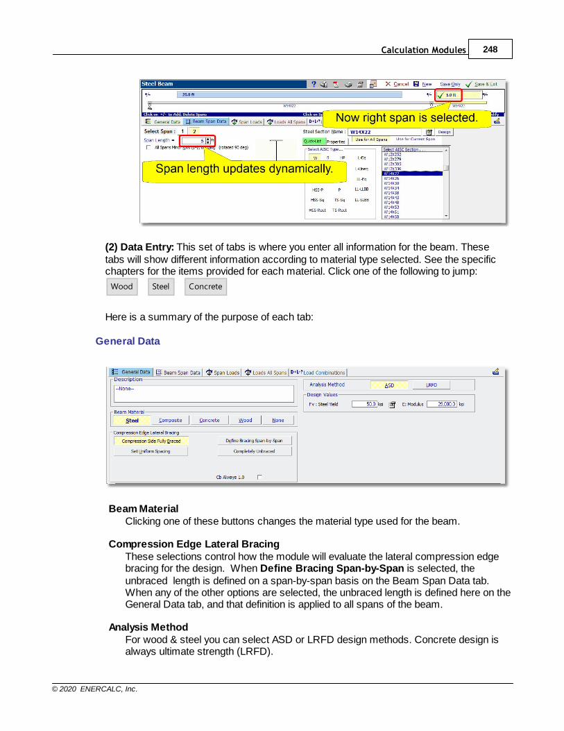
Calculation Modules 248
© 2020 ENERCALC, Inc.
(2) Data Entry: This set of tabs is where you enter all information for the beam. Thesetabs will show different information according to material type selected. See the specificchapters for the items provided for each material. Click one of the following to jump:
Wood
Steel
Concrete
Here is a summary of the purpose of each tab:
General Data
Beam MaterialClicking one of these buttons changes the material type used for the beam.
Compression Edge Lateral BracingThese selections control how the module will evaluate the lateral compression edgebracing for the design. When Define Bracing Span-by-Span is selected, theunbraced length is defined on a span-by-span basis on the Beam Span Data tab. When any of the other options are selected, the unbraced length is defined here on theGeneral Data tab, and that definition is applied to all spans of the beam.
Analysis MethodFor wood & steel you can select ASD or LRFD design methods. Concrete design isalways ultimate strength (LRFD).
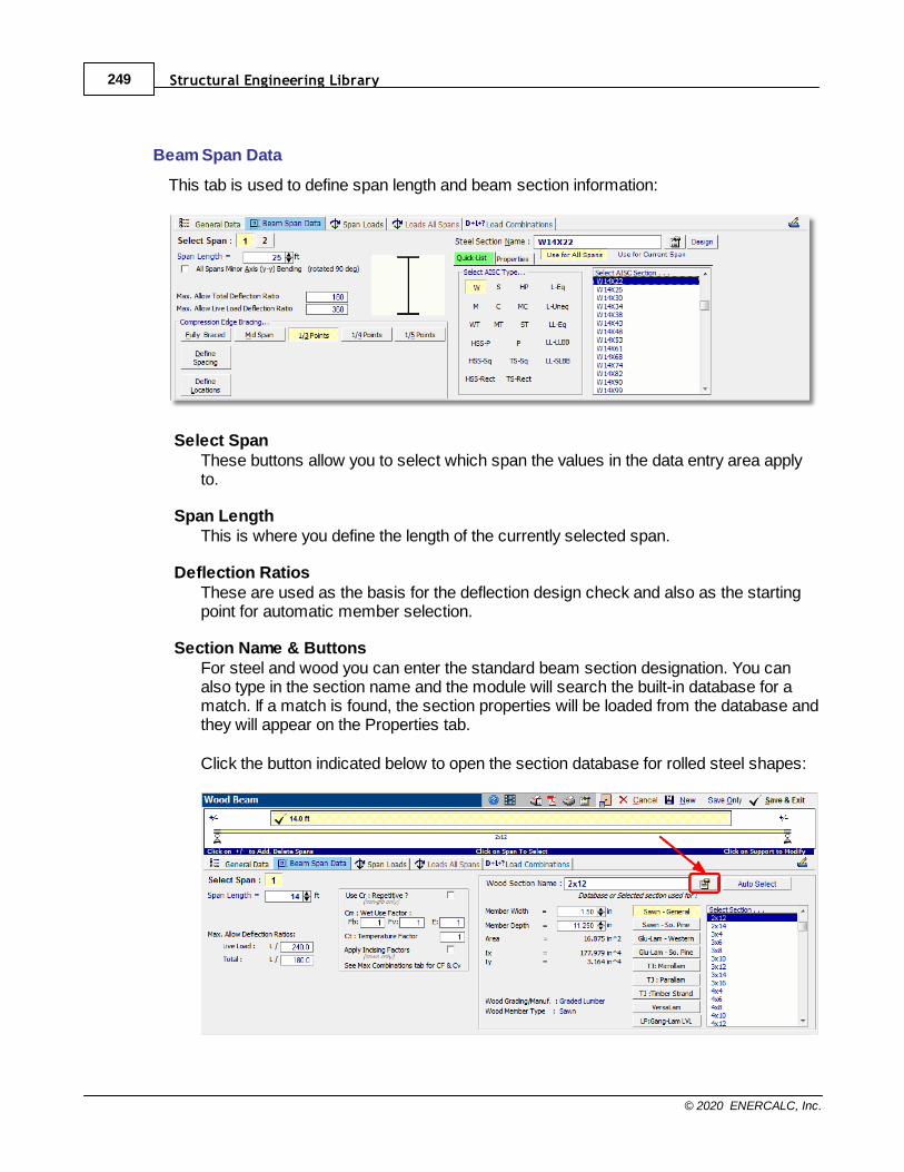
Structural Engineering Library249
© 2020 ENERCALC, Inc.
Beam Span Data
This tab is used to define span length and beam section information:
Select Span These buttons allow you to select which span the values in the data entry area applyto.
Span LengthThis is where you define the length of the currently selected span.
Deflection RatiosThese are used as the basis for the deflection design check and also as the startingpoint for automatic member selection.
Section Name & ButtonsFor steel and wood you can enter the standard beam section designation. You canalso type in the section name and the module will search the built-in database for amatch. If a match is found, the section properties will be loaded from the database andthey will appear on the Properties tab.
Click the button indicated below to open the section database for rolled steel shapes:
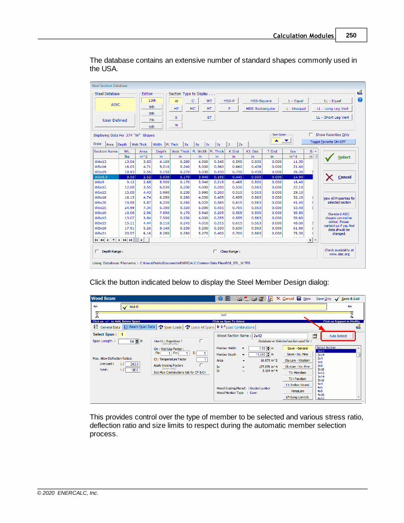
Calculation Modules 250
© 2020 ENERCALC, Inc.
The database contains an extensive number of standard shapes commonly used inthe USA.
Click the button indicated below to display the Steel Member Design dialog:
This provides control over the type of member to be selected and various stress ratio,deflection ratio and size limits to respect during the automatic member selectionprocess.
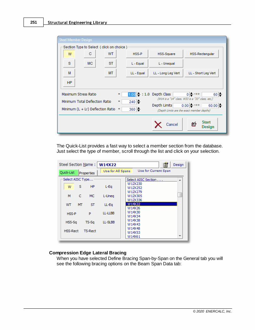
Structural Engineering Library251
© 2020 ENERCALC, Inc.
The Quick-List provides a fast way to select a member section from the database.Just select the type of member, scroll through the list and click on your selection.
Compression Edge Lateral BracingWhen you have selected Define Bracing Span-by-Span on the General tab you willsee the following bracing options on the Beam Span Data tab:
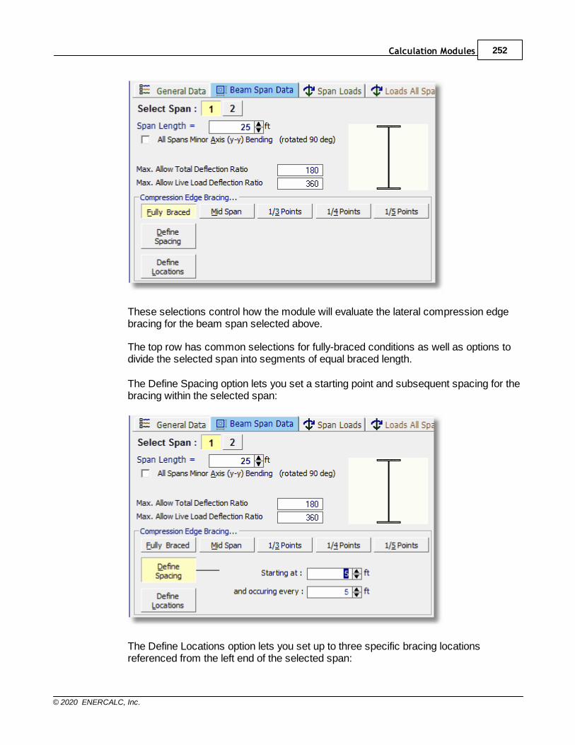
Calculation Modules 252
© 2020 ENERCALC, Inc.
These selections control how the module will evaluate the lateral compression edgebracing for the beam span selected above.
The top row has common selections for fully-braced conditions as well as options todivide the selected span into segments of equal braced length.
The Define Spacing option lets you set a starting point and subsequent spacing for thebracing within the selected span:
The Define Locations option lets you set up to three specific bracing locationsreferenced from the left end of the selected span:
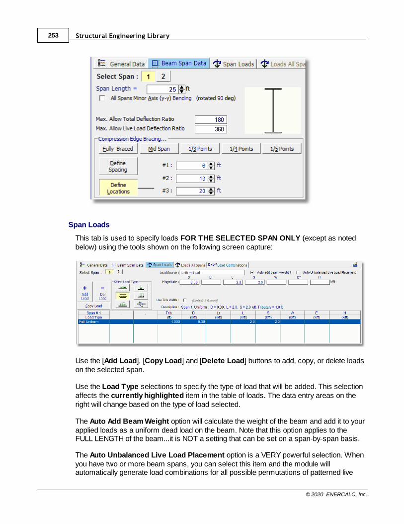
Structural Engineering Library253
© 2020 ENERCALC, Inc.
Span Loads
This tab is used to specify loads FOR THE SELECTED SPAN ONLY (except as notedbelow) using the tools shown on the following screen capture:
Use the [Add Load], [Copy Load] and [Delete Load] buttons to add, copy, or delete loadson the selected span.
Use the Load Type selections to specify the type of load that will be added. This selectionaffects the currently highlighted item in the table of loads. The data entry areas on theright will change based on the type of load selected.
The Auto Add Beam Weight option will calculate the weight of the beam and add it to yourapplied loads as a uniform dead load on the beam. Note that this option applies to theFULL LENGTH of the beam...it is NOT a setting that can be set on a span-by-span basis.
The Auto Unbalanced Live Load Placement option is a VERY powerful selection. Whenyou have two or more beam spans, you can select this item and the module willautomatically generate load combinations for all possible permutations of patterned live
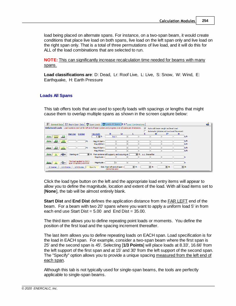
Calculation Modules 254
© 2020 ENERCALC, Inc.
load being placed on alternate spans. For instance, on a two-span beam, it would createconditions that place live load on both spans, live load on the left span only and live load onthe right span only. That is a total of three permutations of live load, and it will do this forALL of the load combinations that are selected to run.
NOTE: This can significantly increase recalculation time needed for beams with manyspans.
Load classifications are: D: Dead, Lr: Roof Live, L: Live, S: Snow, W: Wind, E:Earthquake, H: Earth Pressure
Loads All Spans
This tab offers tools that are used to specify loads with spacings or lengths that mightcause them to overlap multiple spans as shown in the screen capture below:
Click the load type button on the left and the appropriate load entry items will appear toallow you to define the magnitude, location and extent of the load. With all load items set to[None], the tab will be almost entirely blank.
Start Dist and End Dist defines the application distance from the FAR LEFT end of thebeam. For a beam with two 20' spans where you want to apply a uniform load 5' in fromeach end use Start Dist = 5.00 and End Dist = 35.00.
The third item allows you to define repeating point loads or moments. You define theposition of the first load and the spacing increment thereafter.
The last item allows you to define repeating loads on EACH span. Load specification is forthe load in EACH span. For example, consider a two-span beam where the first span is25' and the second span is 45'. Selecting [1/3 Points] will place loads at 8.33', 16.66' fromthe left support of the first span and at 15' and 30' from the left support of the second span.The "Specify" option allows you to provide a unique spacing measured from the left end ofeach span.
Although this tab is not typically used for single-span beams, the tools are perfectlyapplicable to single-span beams.
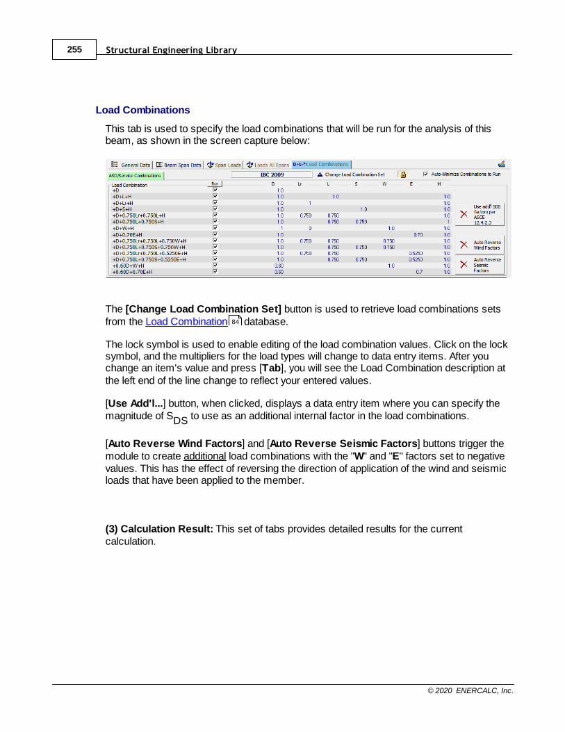
Structural Engineering Library255
© 2020 ENERCALC, Inc.
Load Combinations
This tab is used to specify the load combinations that will be run for the analysis of thisbeam, as shown in the screen capture below:
The [Change Load Combination Set] button is used to retrieve load combinations setsfrom the Load Combination database.
The lock symbol is used to enable editing of the load combination values. Click on the locksymbol, and the multipliers for the load types will change to data entry items. After youchange an item's value and press [Tab], you will see the Load Combination description atthe left end of the line change to reflect your entered values.
[Use Add'l...] button, when clicked, displays a data entry item where you can specify themagnitude of SDS to use as an additional internal factor in the load combinations.
[Auto Reverse Wind Factors] and [Auto Reverse Seismic Factors] buttons trigger themodule to create additional load combinations with the "W" and "E" factors set to negativevalues. This has the effect of reversing the direction of application of the wind and seismicloads that have been applied to the member.
(3) Calculation Result: This set of tabs provides detailed results for the currentcalculation.
84
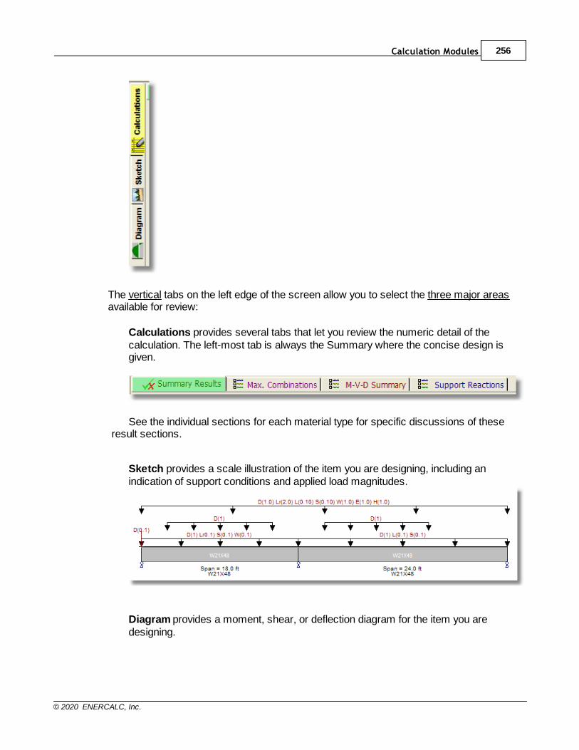
Calculation Modules 256
© 2020 ENERCALC, Inc.
The vertical tabs on the left edge of the screen allow you to select the three major areasavailable for review:
Calculations provides several tabs that let you review the numeric detail of thecalculation. The left-most tab is always the Summary where the concise design isgiven.
See the individual sections for each material type for specific discussions of theseresult sections.
Sketch provides a scale illustration of the item you are designing, including anindication of support conditions and applied load magnitudes.
Diagram provides a moment, shear, or deflection diagram for the item you aredesigning.
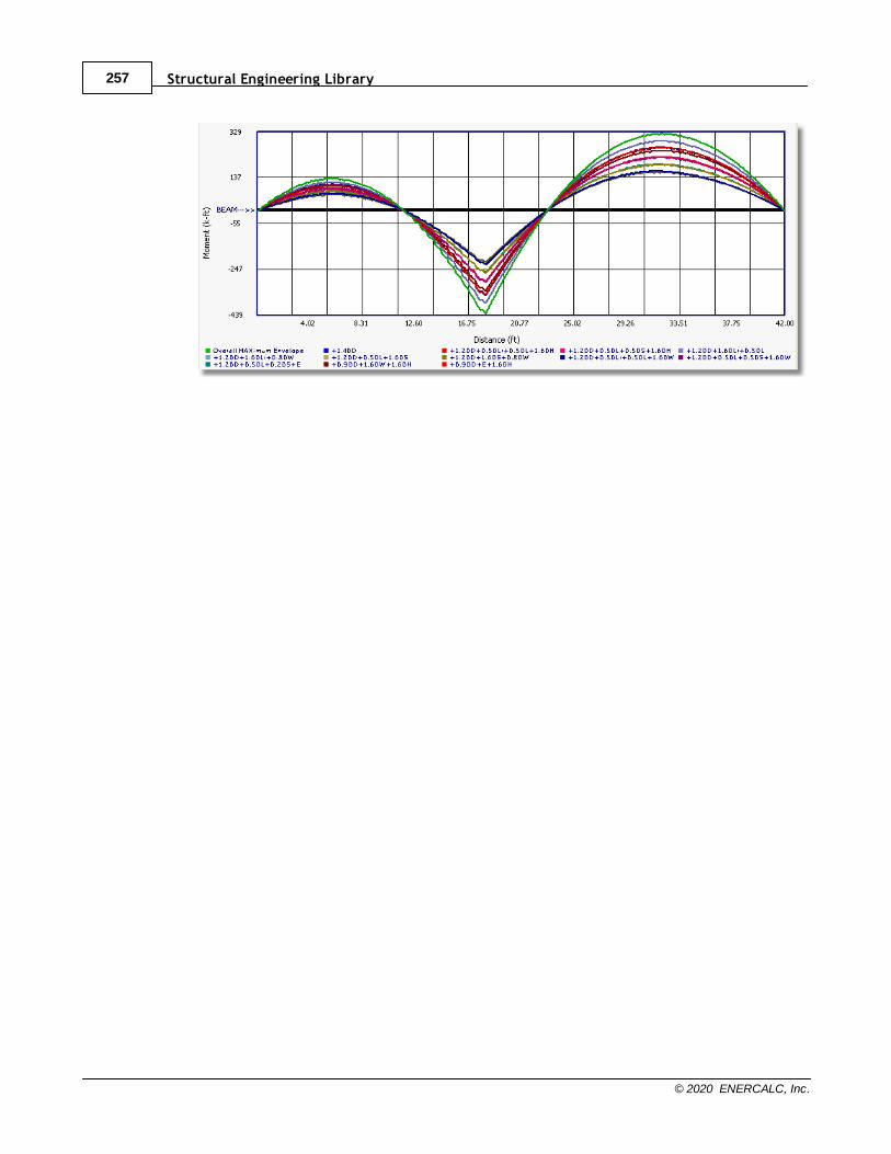
Structural Engineering Library257
© 2020 ENERCALC, Inc.
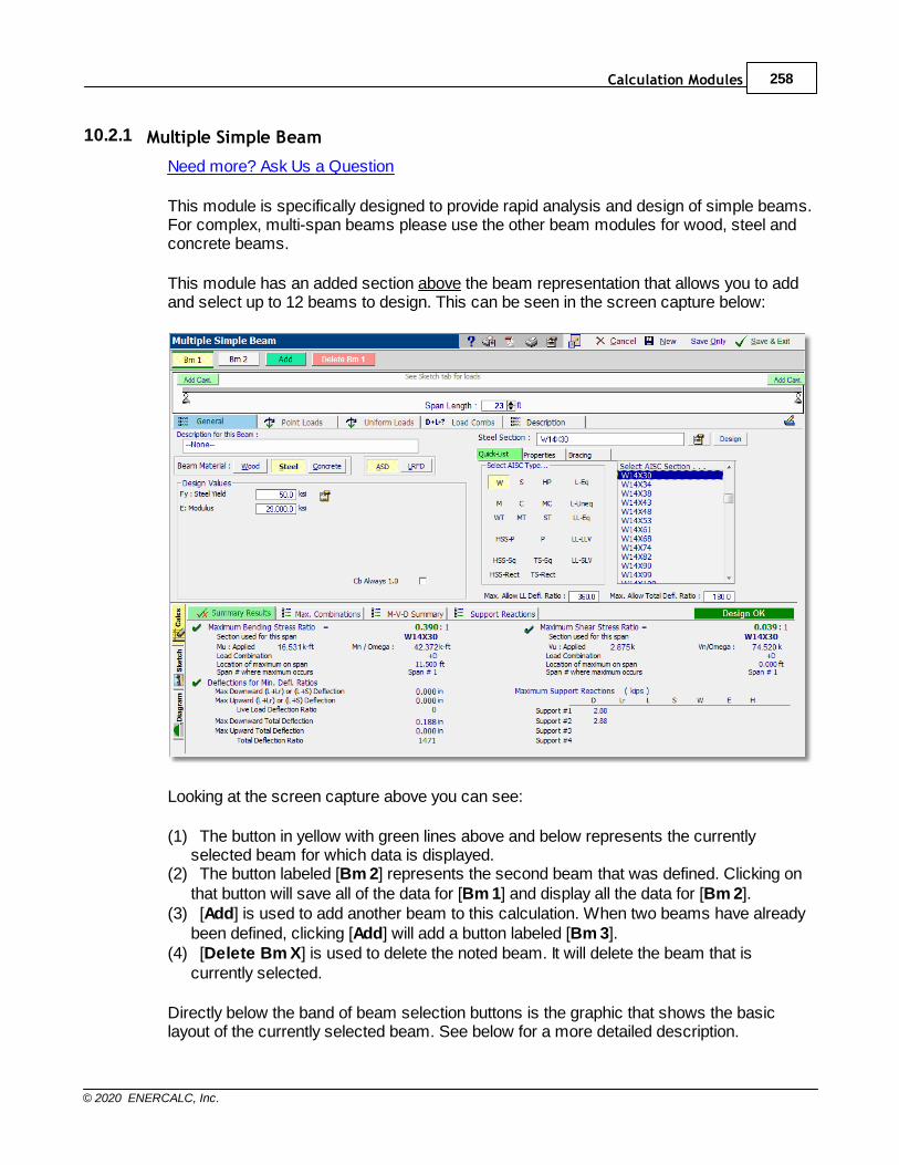
Calculation Modules 258
© 2020 ENERCALC, Inc.
10.2.1 Multiple Simple Beam
Need more? Ask Us a Question
This module is specifically designed to provide rapid analysis and design of simple beams.For complex, multi-span beams please use the other beam modules for wood, steel andconcrete beams.
This module has an added section above the beam representation that allows you to addand select up to 12 beams to design. This can be seen in the screen capture below:
Looking at the screen capture above you can see:
(1) The button in yellow with green lines above and below represents the currentlyselected beam for which data is displayed.
(2) The button labeled [Bm 2] represents the second beam that was defined. Clicking onthat button will save all of the data for [Bm 1] and display all the data for [Bm 2].
(3) [Add] is used to add another beam to this calculation. When two beams have alreadybeen defined, clicking [Add] will add a button labeled [Bm 3].
(4) [Delete Bm X] is used to delete the noted beam. It will delete the beam that iscurrently selected.
Directly below the band of beam selection buttons is the graphic that shows the basiclayout of the currently selected beam. See below for a more detailed description.
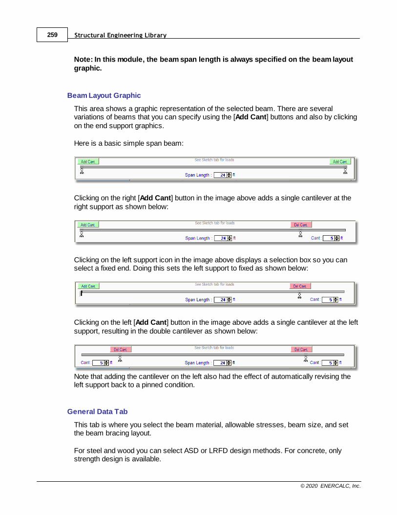
Structural Engineering Library259
© 2020 ENERCALC, Inc.
Note: In this module, the beam span length is always specified on the beam layoutgraphic.
Beam Layout Graphic
This area shows a graphic representation of the selected beam. There are severalvariations of beams that you can specify using the [Add Cant] buttons and also by clickingon the end support graphics.
Here is a basic simple span beam:
Clicking on the right [Add Cant] button in the image above adds a single cantilever at theright support as shown below:
Clicking on the left support icon in the image above displays a selection box so you canselect a fixed end. Doing this sets the left support to fixed as shown below:
Clicking on the left [Add Cant] button in the image above adds a single cantilever at the leftsupport, resulting in the double cantilever as shown below:
Note that adding the cantilever on the left also had the effect of automatically revising theleft support back to a pinned condition.
General Data Tab
This tab is where you select the beam material, allowable stresses, beam size, and setthe beam bracing layout.
For steel and wood you can select ASD or LRFD design methods. For concrete, onlystrength design is available.
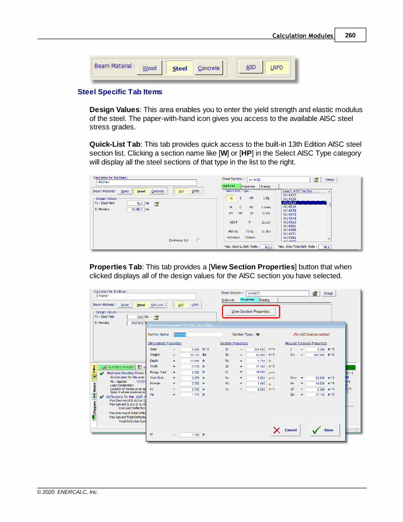
Calculation Modules 260
© 2020 ENERCALC, Inc.
Steel Specific Tab Items
Design Values: This area enables you to enter the yield strength and elastic modulusof the steel. The paper-with-hand icon gives you access to the available AISC steelstress grades.
Quick-List Tab: This tab provides quick access to the built-in 13th Edition AISC steelsection list. Clicking a section name like [W] or [HP] in the Select AISC Type categorywill display all the steel sections of that type in the list to the right.
Properties Tab: This tab provides a [View Section Properties] button that whenclicked displays all of the design values for the AISC section you have selected.
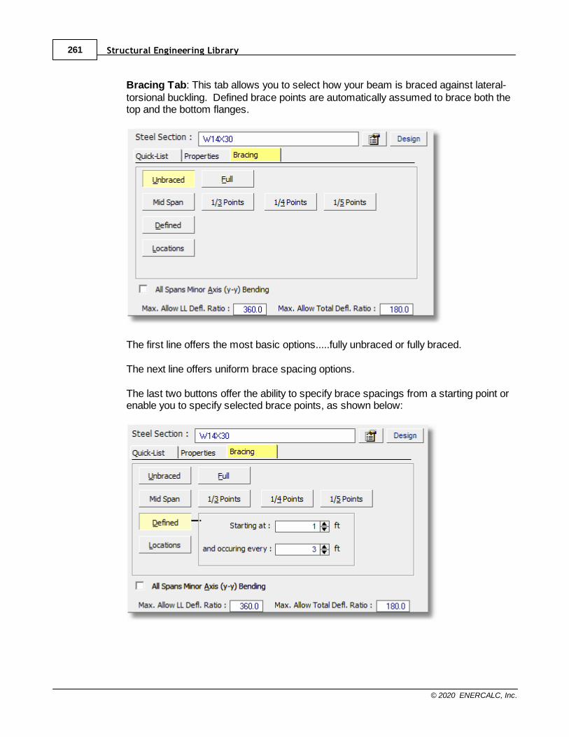
Structural Engineering Library261
© 2020 ENERCALC, Inc.
Bracing Tab: This tab allows you to select how your beam is braced against lateral-torsional buckling. Defined brace points are automatically assumed to brace both thetop and the bottom flanges.
The first line offers the most basic options.....fully unbraced or fully braced.
The next line offers uniform brace spacing options.
The last two buttons offer the ability to specify brace spacings from a starting point orenable you to specify selected brace points, as shown below:
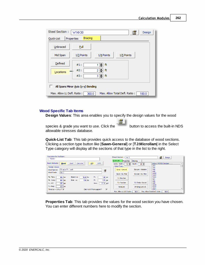
Calculation Modules 262
© 2020 ENERCALC, Inc.
Wood Specific Tab ItemsDesign Values: This area enables you to specify the design values for the wood
species & grade you want to use. Click the button to access the built-in NDSallowable stresses database.
Quick-List Tab: This tab provides quick access to the database of wood sections.Clicking a section type button like [Sawn-General] or [TJ:Microllam] in the SelectType category will display all the sections of that type in the list to the right.
Properties Tab: This tab provides the values for the wood section you have chosen.You can enter different numbers here to modify the section.

Structural Engineering Library263
© 2020 ENERCALC, Inc.
Bracing Tab: See information provided above in the Steel section for a summary ofbracing options.
Concrete Specific Tab Items
Design Values: This area enables you to enter concrete and reinforcing strengths forthe beam. In addition you can specify the stirrup size and Phi values.
Span Data
When a concrete beam is chosen, a new tab named Span Data will be added to theuser interface (see below). This tab is where you specify the beam cross section andreinforcing. This tab will only be shown when the material is set to concrete.
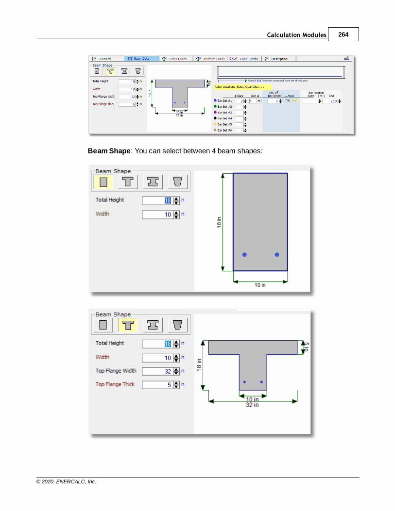
Calculation Modules 264
© 2020 ENERCALC, Inc.
Beam Shape: You can select between 4 beam shapes:
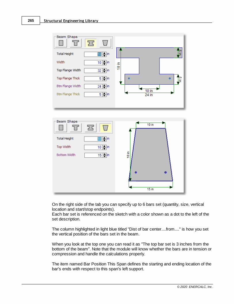
Structural Engineering Library265
© 2020 ENERCALC, Inc.
On the right side of the tab you can specify up to 6 bars set (quantity, size, verticallocation and start/stop endpoints). Each bar set is referenced on the sketch with a color shown as a dot to the left of theset description.
The column highlighted in light blue titled "Dist of bar center....from...." is how you setthe vertical position of the bars set in the beam.
When you look at the top one you can read it as "The top bar set is 3 inches from thebottom of the beam". Note that the module will know whether the bars are in tension orcompression and handle the calculations properly.
The item named Bar Position This Span defines the starting and ending location of thebar's ends with respect to this span's left support.
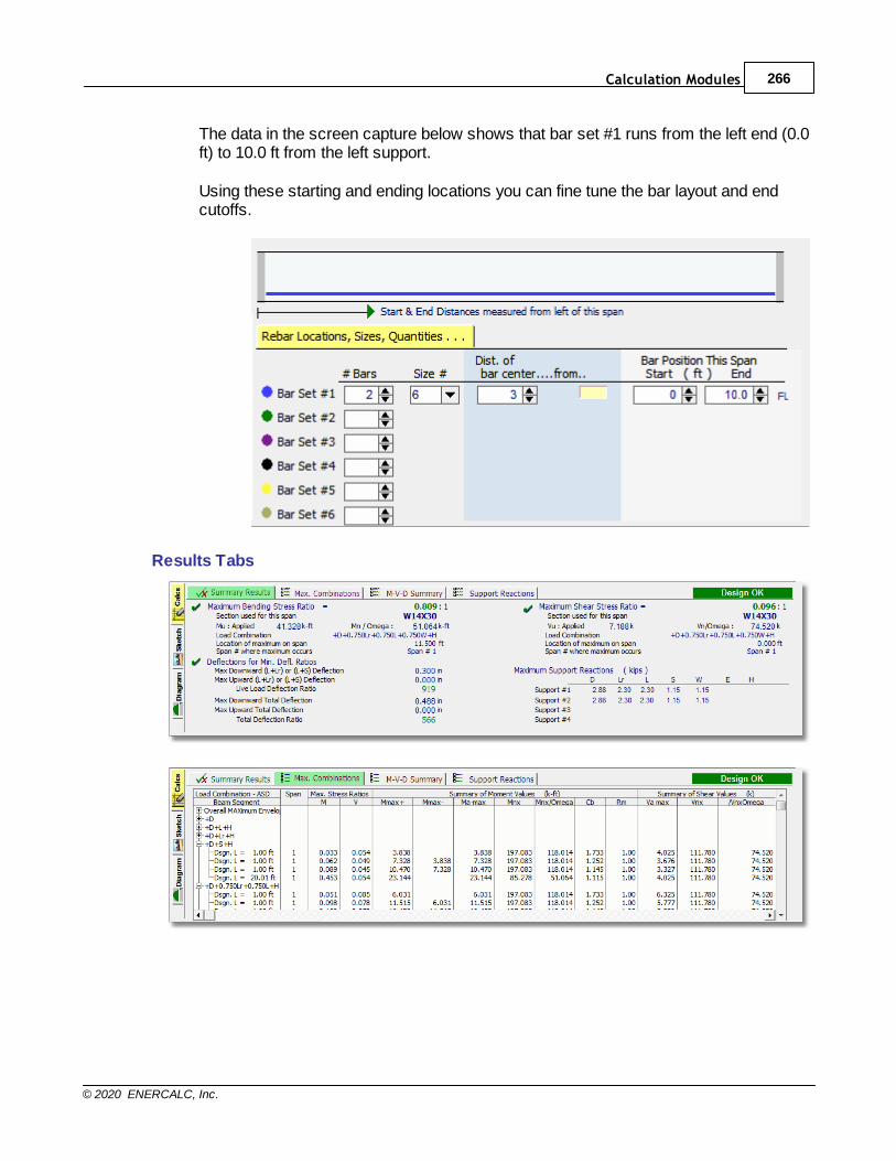
Calculation Modules 266
© 2020 ENERCALC, Inc.
The data in the screen capture below shows that bar set #1 runs from the left end (0.0ft) to 10.0 ft from the left support.
Using these starting and ending locations you can fine tune the bar layout and endcutoffs.
Results Tabs
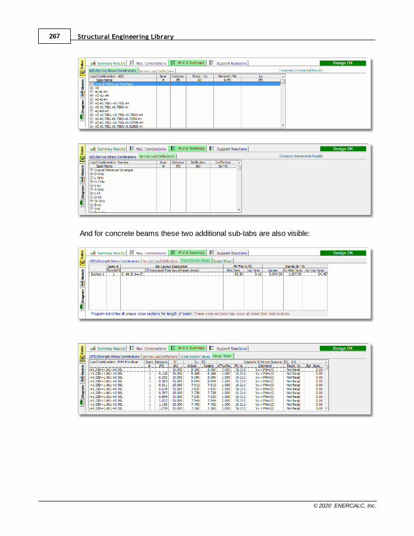
Structural Engineering Library267
© 2020 ENERCALC, Inc.
And for concrete beams these two additional sub-tabs are also visible:
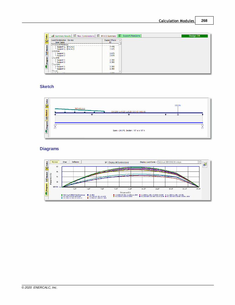
Calculation Modules 268
© 2020 ENERCALC, Inc.
Sketch
Diagrams
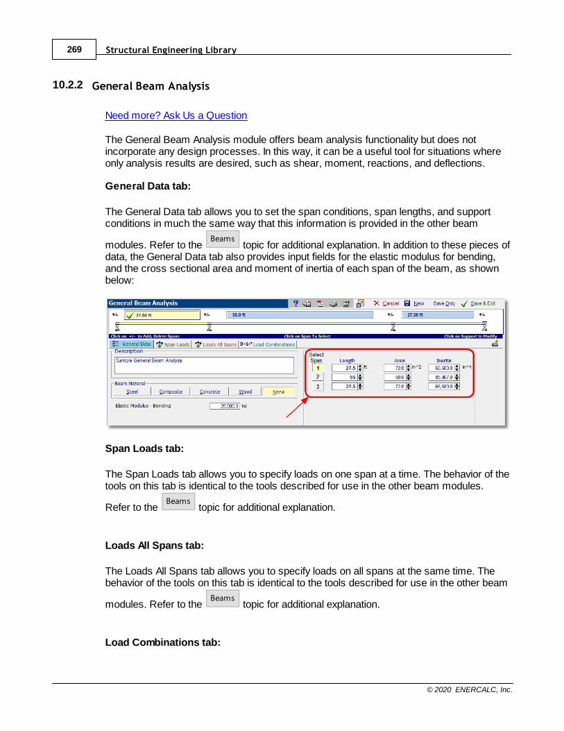
Structural Engineering Library269
© 2020 ENERCALC, Inc.
10.2.2 General Beam Analysis
Need more? Ask Us a Question
The General Beam Analysis module offers beam analysis functionality but does notincorporate any design processes. In this way, it can be a useful tool for situations whereonly analysis results are desired, such as shear, moment, reactions, and deflections.
General Data tab:
The General Data tab allows you to set the span conditions, span lengths, and supportconditions in much the same way that this information is provided in the other beam
modules. Refer to the Beams
topic for additional explanation. In addition to these pieces ofdata, the General Data tab also provides input fields for the elastic modulus for bending,and the cross sectional area and moment of inertia of each span of the beam, as shownbelow:
Span Loads tab:
The Span Loads tab allows you to specify loads on one span at a time. The behavior of thetools on this tab is identical to the tools described for use in the other beam modules.
Refer to the Beams
topic for additional explanation.
Loads All Spans tab:
The Loads All Spans tab allows you to specify loads on all spans at the same time. Thebehavior of the tools on this tab is identical to the tools described for use in the other beam
modules. Refer to the Beams
topic for additional explanation.
Load Combinations tab:
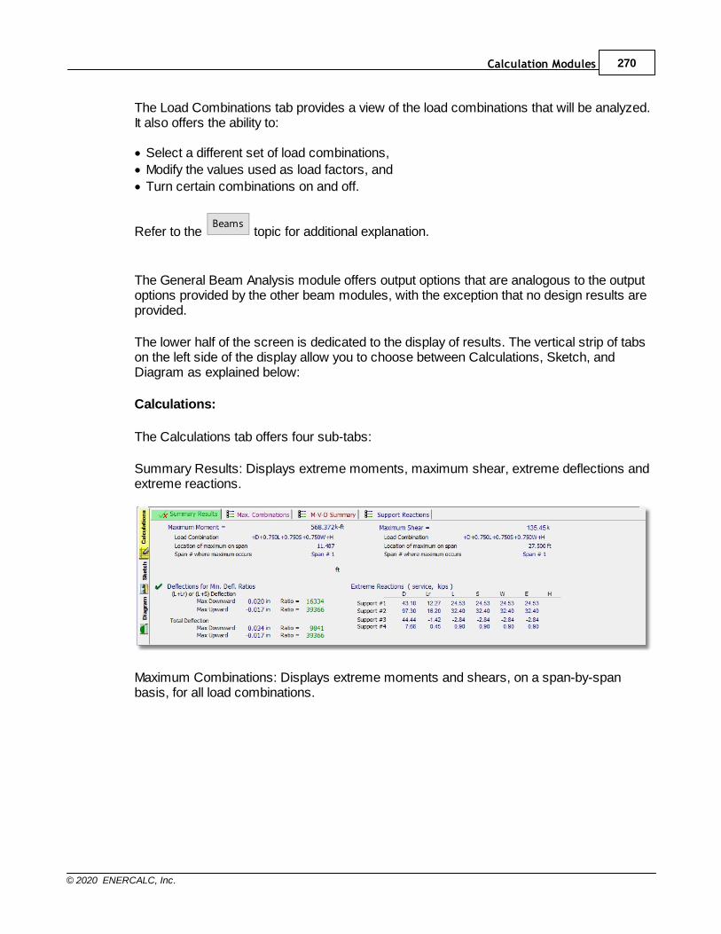
Calculation Modules 270
© 2020 ENERCALC, Inc.
The Load Combinations tab provides a view of the load combinations that will be analyzed.It also offers the ability to:
· Select a different set of load combinations,
· Modify the values used as load factors, and
· Turn certain combinations on and off.
Refer to the Beams
topic for additional explanation.
The General Beam Analysis module offers output options that are analogous to the outputoptions provided by the other beam modules, with the exception that no design results areprovided.
The lower half of the screen is dedicated to the display of results. The vertical strip of tabson the left side of the display allow you to choose between Calculations, Sketch, andDiagram as explained below:
Calculations:
The Calculations tab offers four sub-tabs:
Summary Results: Displays extreme moments, maximum shear, extreme deflections andextreme reactions.
Maximum Combinations: Displays extreme moments and shears, on a span-by-spanbasis, for all load combinations.
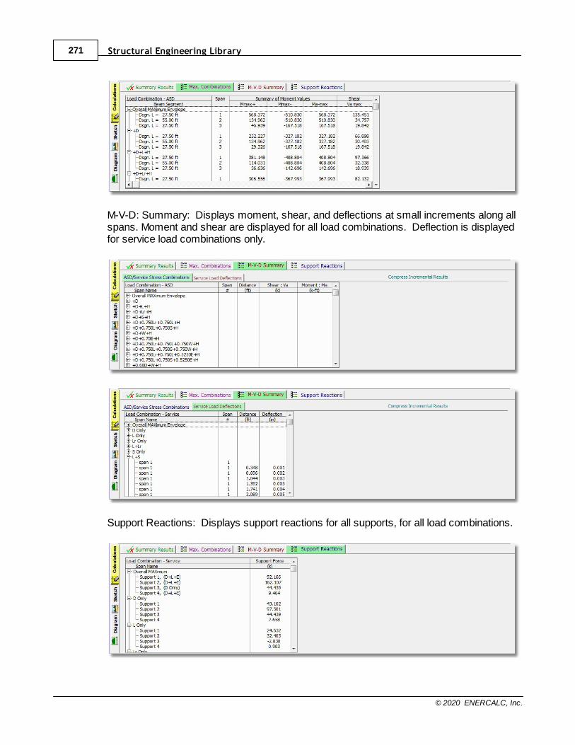
Structural Engineering Library271
© 2020 ENERCALC, Inc.
M-V-D: Summary: Displays moment, shear, and deflections at small increments along allspans. Moment and shear are displayed for all load combinations. Deflection is displayedfor service load combinations only.
Support Reactions: Displays support reactions for all supports, for all load combinations.

Calculation Modules 272
© 2020 ENERCALC, Inc.
Sketch:
Displays a sketch of the beam, indicating span lengths, support conditions, and appliedloads.
Diagram:
Displays a graphic depiction of the beam with superimposed graphs of Moment, Shear, orDeflection for a selected load combination, or for an envelope of all load combinations.

Structural Engineering Library273
© 2020 ENERCALC, Inc.
10.2.3 Wood Beam
Need more? Ask Us a Question
In this section, for each input tab we will review only the items that are unique to the
WOOD material type. Click here for a video: Wood Beam
For general information on the typical data input for all beams see the Beams topic.
This module offers complete design of single and multi-span wood members. Among itscapabilities are:
· Single or multi-span beams.
· End fixity can be pinned, fixed, free or a combination thereof.
· Analysis is according to 2005 NDS.
· ASD or LRFD design methods can be selected. Values of KF and phi are
automatically determined and applied for the LRFD method.· A complete wood section database is provided. This includes sawn, glued-
laminated and selected manufactured sections.· A complete wood species database is provided. All values are per 2005 NDS.
· Unbraced compression edge lengths can be specified in a variety of ways.
· Automatic member selection is provided.
· You can specify values for CM, C
t and C
r. C
F or C
V is automatically provided. In the
case of CF, the value is also based on species stress grade.
General Data
Beam MaterialClicking one of these buttons changes the material type used for the beam.
Design MethodFor wood & steel you can select ASD or LRFD design methods. Concrete designalways uses ultimate strength design (LRFD).
Design Values
245
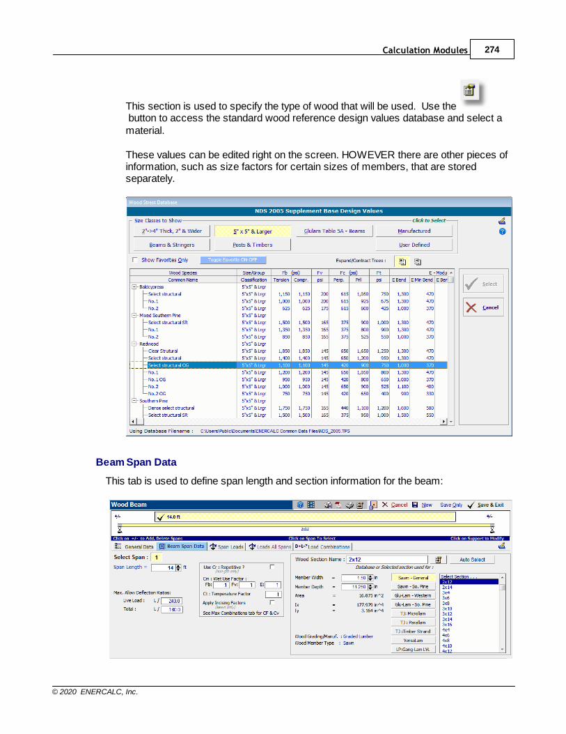
Calculation Modules 274
© 2020 ENERCALC, Inc.
This section is used to specify the type of wood that will be used. Use the button to access the standard wood reference design values database and select amaterial.
These values can be edited right on the screen. HOWEVER there are other pieces ofinformation, such as size factors for certain sizes of members, that are storedseparately.
Beam Span Data
This tab is used to define span length and section information for the beam:
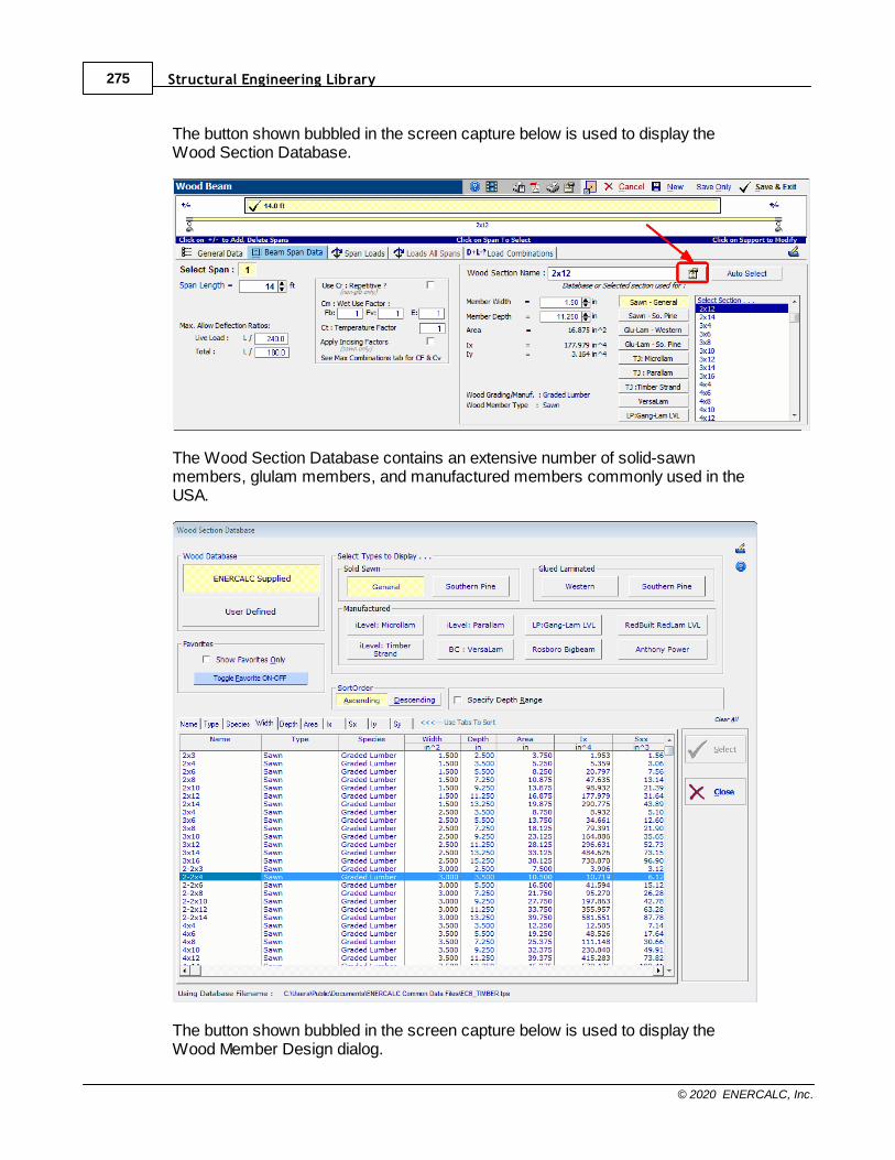
Structural Engineering Library275
© 2020 ENERCALC, Inc.
The button shown bubbled in the screen capture below is used to display theWood Section Database.
The Wood Section Database contains an extensive number of solid-sawnmembers, glulam members, and manufactured members commonly used in theUSA.
The button shown bubbled in the screen capture below is used to display theWood Member Design dialog.
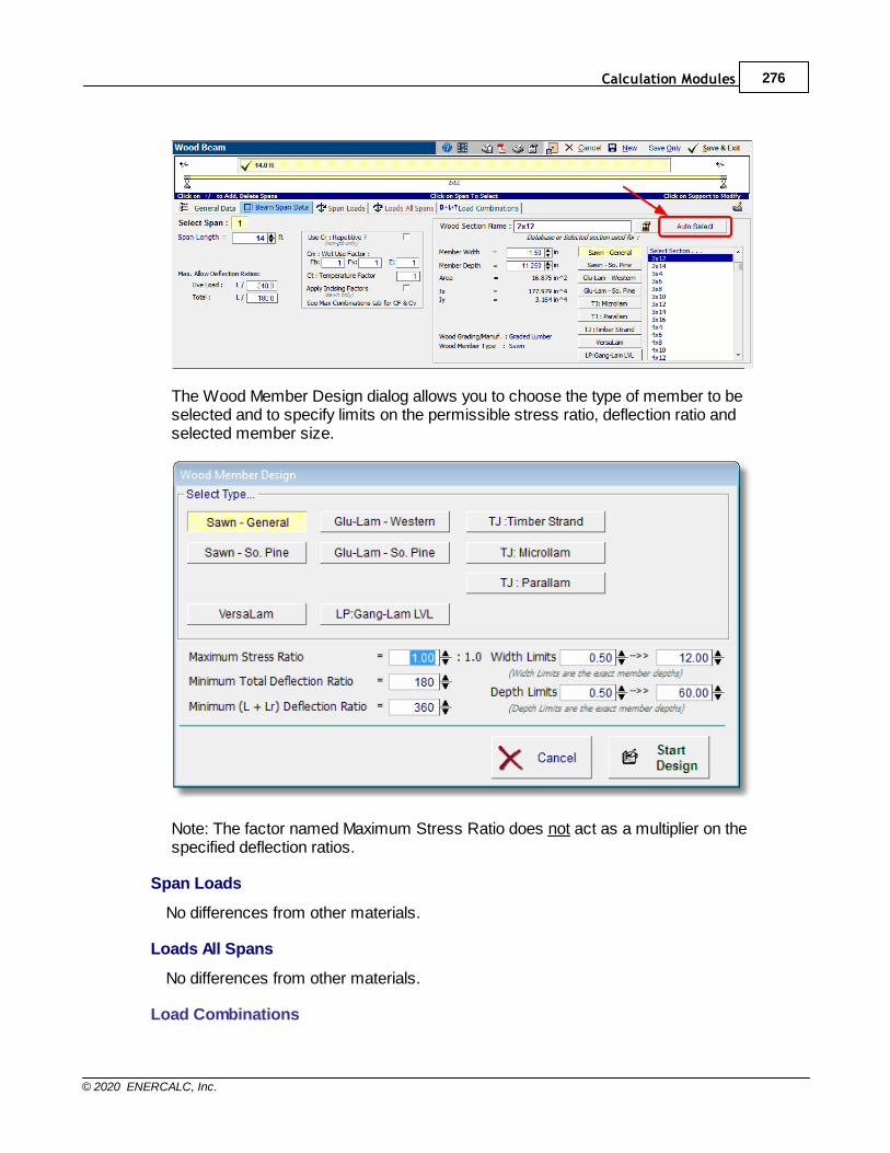
Calculation Modules 276
© 2020 ENERCALC, Inc.
The Wood Member Design dialog allows you to choose the type of member to beselected and to specify limits on the permissible stress ratio, deflection ratio andselected member size.
Note: The factor named Maximum Stress Ratio does not act as a multiplier on thespecified deflection ratios.
Span Loads
No differences from other materials.
Loads All Spans
No differences from other materials.
Load Combinations
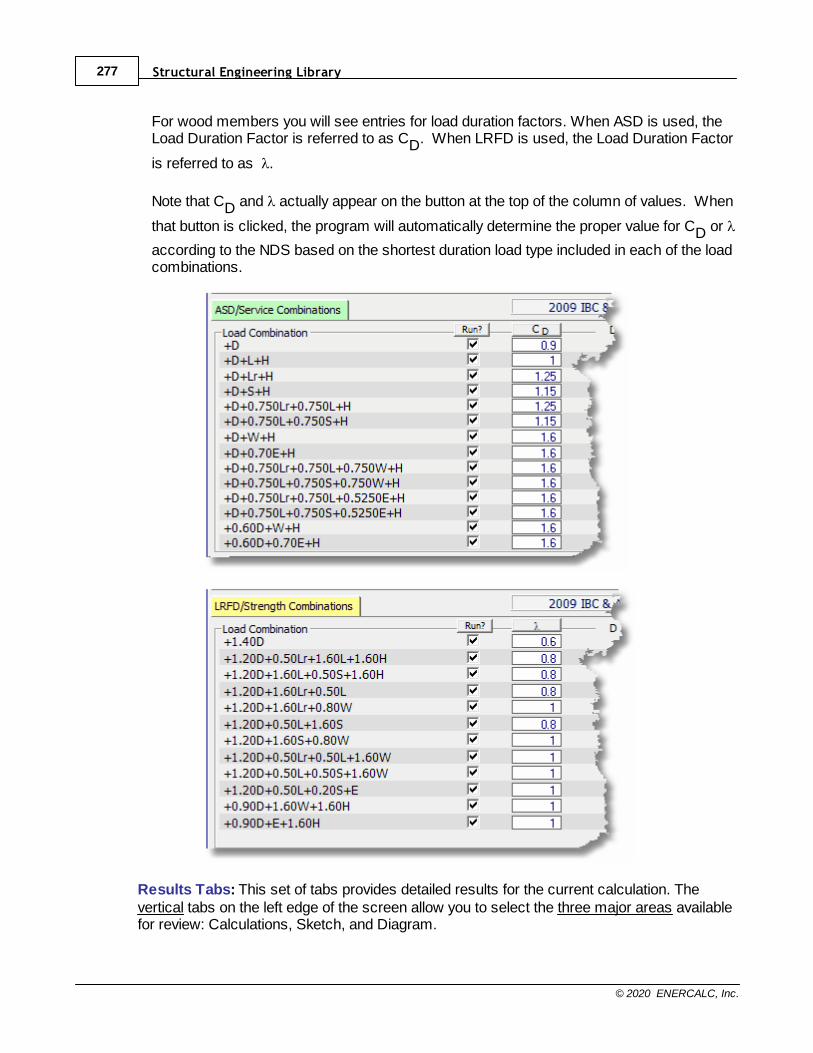
Structural Engineering Library277
© 2020 ENERCALC, Inc.
For wood members you will see entries for load duration factors. When ASD is used, theLoad Duration Factor is referred to as CD. When LRFD is used, the Load Duration Factor
is referred to as l.
Note that CD and l actually appear on the button at the top of the column of values. When
that button is clicked, the program will automatically determine the proper value for CD or l
according to the NDS based on the shortest duration load type included in each of the loadcombinations.
Results Tabs: This set of tabs provides detailed results for the current calculation. Thevertical tabs on the left edge of the screen allow you to select the three major areas availablefor review: Calculations, Sketch, and Diagram.
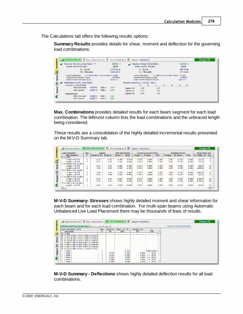
Calculation Modules 278
© 2020 ENERCALC, Inc.
The Calculations tab offers the following results options:
Summary Results provides details for shear, moment and deflection for the governingload combinations.
Max. Combinations provides detailed results for each beam segment for each loadcombination. The leftmost column lists the load combinations and the unbraced lengthbeing considered.
These results are a consolidation of the highly detailed incremental results presentedon the M-V-D Summary tab.
M-V-D Summary- Stresses shows highly detailed moment and shear information foreach beam and for each load combination. For multi-span beams using AutomaticUnbalanced Live Load Placement there may be thousands of lines of results.
M-V-D Summary - Deflections shows highly detailed deflection results for all loadcombinations.
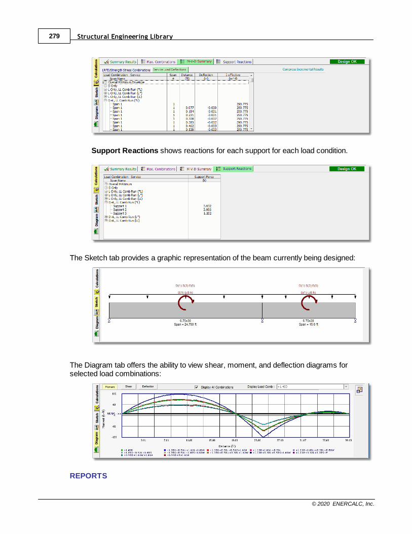
Structural Engineering Library279
© 2020 ENERCALC, Inc.
Support Reactions shows reactions for each support for each load condition.
The Sketch tab provides a graphic representation of the beam currently being designed:
The Diagram tab offers the ability to view shear, moment, and deflection diagrams forselected load combinations:
REPORTS
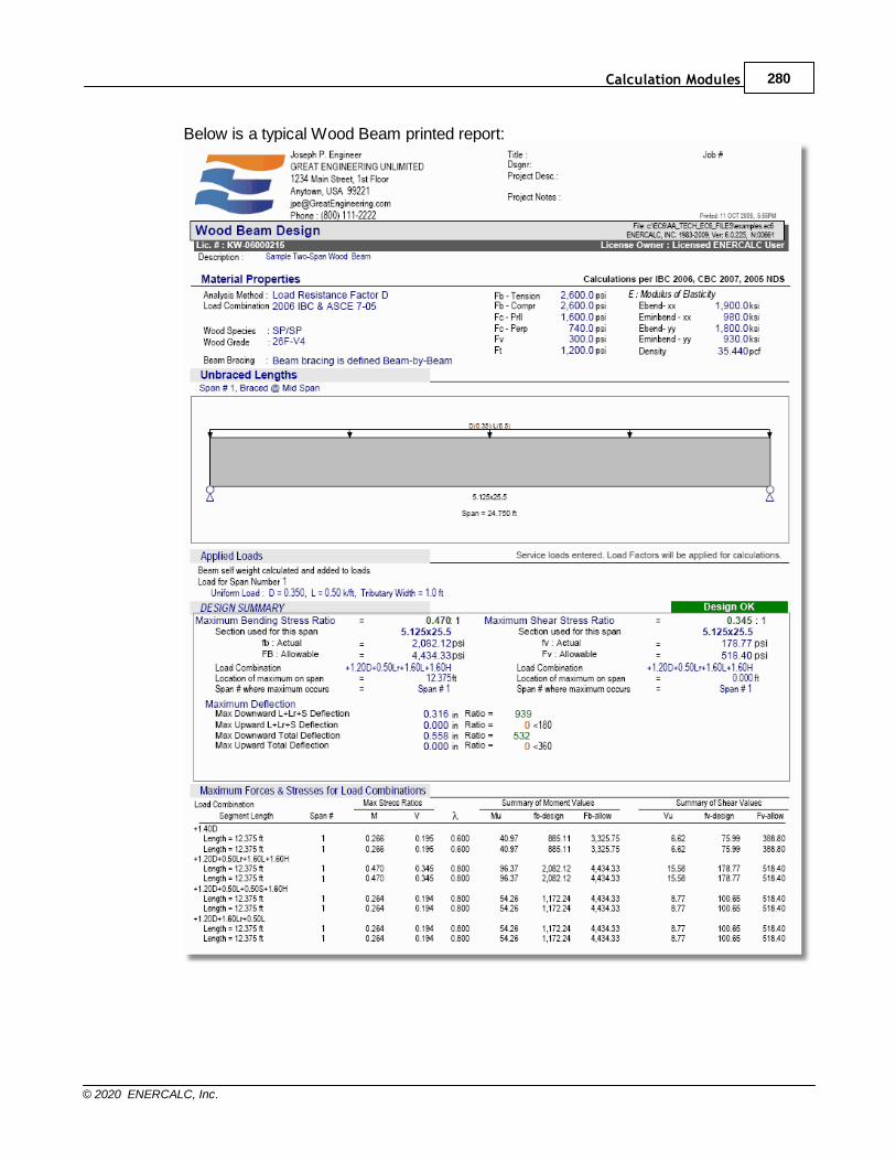
Calculation Modules 280
© 2020 ENERCALC, Inc.
Below is a typical Wood Beam printed report:

Structural Engineering Library281
© 2020 ENERCALC, Inc.
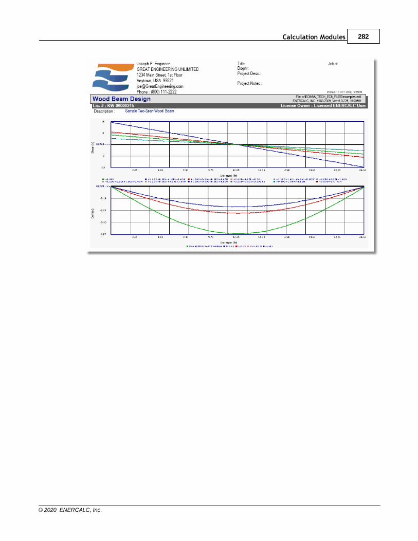
Calculation Modules 282
© 2020 ENERCALC, Inc.
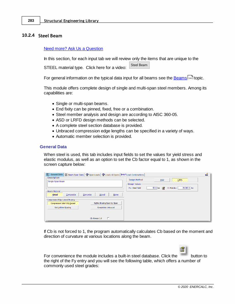
Structural Engineering Library283
© 2020 ENERCALC, Inc.
10.2.4 Steel Beam
Need more? Ask Us a Question
In this section, for each input tab we will review only the items that are unique to the
STEEL material type. Click here for a video: Steel Beam
For general information on the typical data input for all beams see the Beams topic.
This module offers complete design of single and multi-span steel members. Among itscapabilities are:
· Single or multi-span beams.
· End fixity can be pinned, fixed, free or a combination.
· Steel member analysis and design are according to AISC 360-05.
· ASD or LRFD design methods can be selected.
· A complete steel section database is provided.
· Unbraced compression edge lengths can be specified in a variety of ways.
· Automatic member selection is provided.
General Data
When steel is used, this tab includes input fields to set the values for yield stress andelastic modulus, as well as an option to set the Cb factor equal to 1, as shown in thescreen capture below:
If Cb is not forced to 1, the program automatically calculates Cb based on the moment anddirection of curvature at various locations along the beam.
For convenience the module includes a built-in steel database. Click the button tothe right of the Fy entry and you will see the following table, which offers a number ofcommonly used steel grades:
245
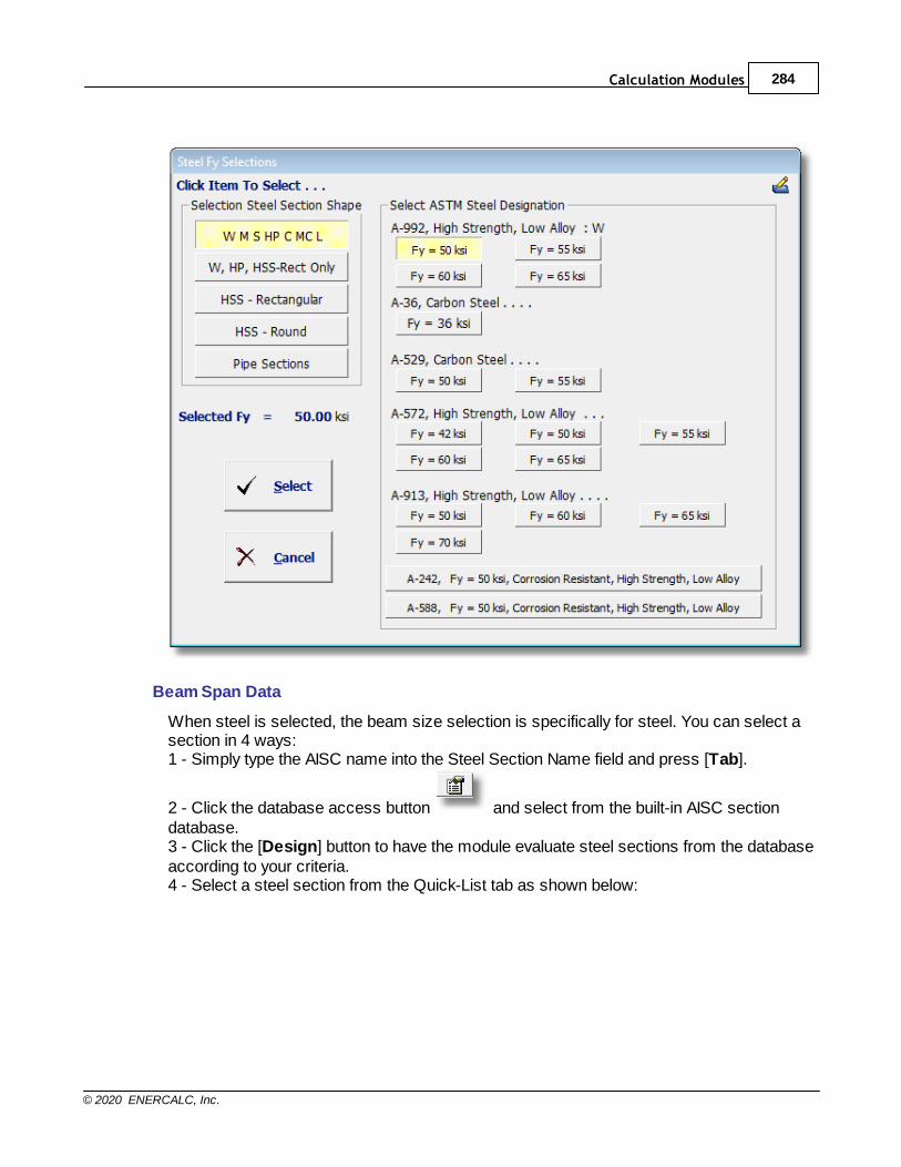
Calculation Modules 284
© 2020 ENERCALC, Inc.
Beam Span Data
When steel is selected, the beam size selection is specifically for steel. You can select asection in 4 ways:1 - Simply type the AISC name into the Steel Section Name field and press [Tab].
2 - Click the database access button and select from the built-in AISC sectiondatabase.3 - Click the [Design] button to have the module evaluate steel sections from the databaseaccording to your criteria.4 - Select a steel section from the Quick-List tab as shown below:
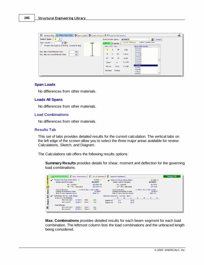
Structural Engineering Library285
© 2020 ENERCALC, Inc.
Span Loads
No differences from other materials.
Loads All Spans
No differences from other materials.
Load Combinations
No differences from other materials.
Results Tab
This set of tabs provides detailed results for the current calculation. The vertical tabs onthe left edge of the screen allow you to select the three major areas available for review:Calculations, Sketch, and Diagram.
The Calculations tab offers the following results options:
Summary Results provides details for shear, moment and deflection for the governingload combinations.
Max. Combinations provides detailed results for each beam segment for each loadcombination. The leftmost column lists the load combinations and the unbraced lengthbeing considered.

Calculation Modules 286
© 2020 ENERCALC, Inc.
These results are a consolidation of the highly detailed incremental results on the M-V-D Summary tab.
M-V-D Summary- Stresses shows highly detailed moment and shear information foreach beam and for each load combination. For multi-span beams using AutomaticUnbalanced Live Load Placement there may be thousands of lines of results.
M-V-D Summary - Deflections shows highly detailed deflection results for all loadcombinations.
Support Reactions shows reactions for each support for each load condition.
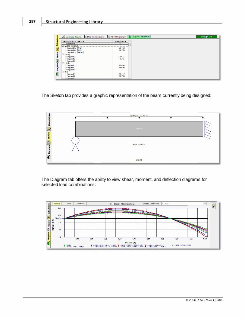
Structural Engineering Library287
© 2020 ENERCALC, Inc.
The Sketch tab provides a graphic representation of the beam currently being designed:
The Diagram tab offers the ability to view shear, moment, and deflection diagrams forselected load combinations:

Calculation Modules 288
© 2020 ENERCALC, Inc.
10.2.5 Concrete Beam
Need more? Ask Us a Question
In this section, for each input tab we will review only the items that are unique to the
CONCRETE material type. Click here for a video: Concrete Beam
General Data
The concrete beam module handles single- and multiple-span beams using ONE crosssection shape. That shape can have up to six groups of reinforcing per span, and thereinforcing can vary on a span-by-span basis.
This module also has a beam on elastic foundation option for single-span beams. In thescreen capture below you can see the two large selection boxes. Selecting Single SpanBeam on Elastic Foundation will remove the ability to select end support conditions, and itwill provide an entry for the Modulus of Subgrade Reaction of the supporting soil.
On the right side of this tab are all the required rebar, concrete strength and elasticmodulus entries, shear stirrup data, strength reduction factors and deflection criteria tocheck.
NOTE: It is important to know how this module operates with regard to beam stiffnessalong the span, and how this affects multi-span beams. This module divides each spaninto a series of segments. The effective moment of inertia for each segment (for each loadcombination) is calculated using the actual unfactored moment on that segment. Thus themodule creates a very accurate variable stiffness model of the beam based on actualmoments. For multiple-span beams, this will affect the relative stiffness of each beamspan. Thus the moment distribution across multiple spans will be properly performed. Thiswill affect factored load moments and shears and service load level deflections andreactions.
Beam Span Data
This tab has some pieces of input that are constant for all spans and some that can varyon a span-by-span basis.
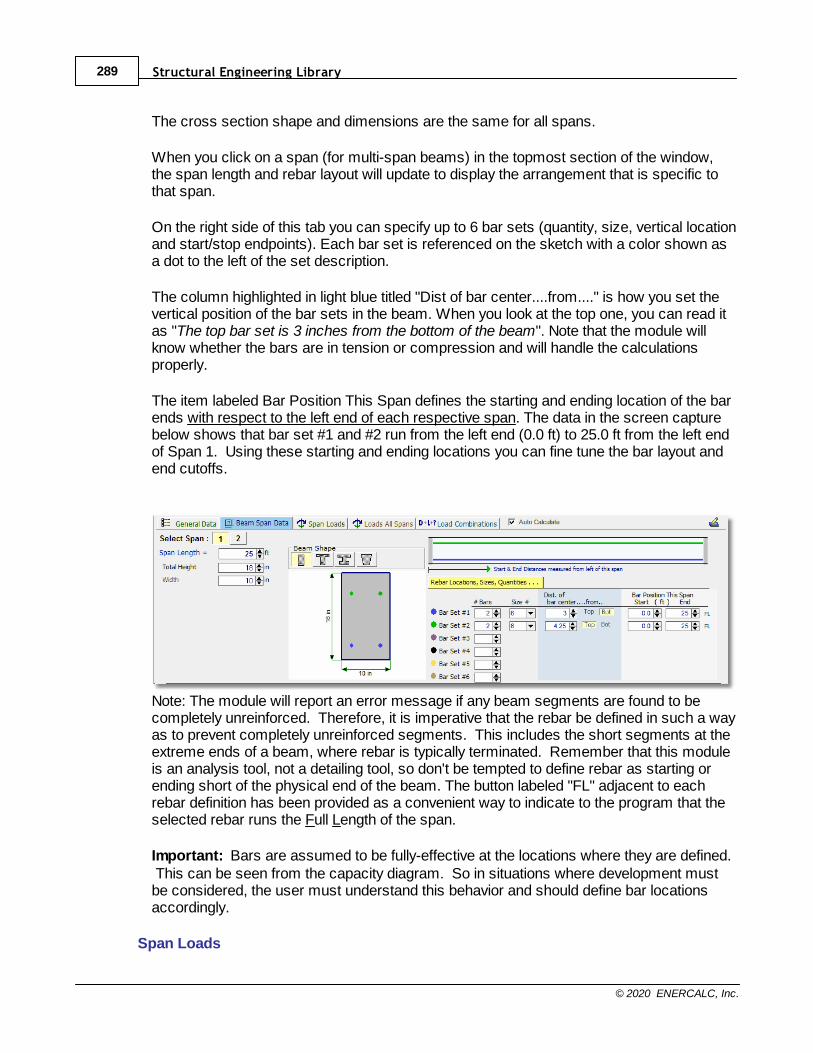
Structural Engineering Library289
© 2020 ENERCALC, Inc.
The cross section shape and dimensions are the same for all spans.
When you click on a span (for multi-span beams) in the topmost section of the window,the span length and rebar layout will update to display the arrangement that is specific tothat span.
On the right side of this tab you can specify up to 6 bar sets (quantity, size, vertical locationand start/stop endpoints). Each bar set is referenced on the sketch with a color shown asa dot to the left of the set description.
The column highlighted in light blue titled "Dist of bar center....from...." is how you set thevertical position of the bar sets in the beam. When you look at the top one, you can read itas "The top bar set is 3 inches from the bottom of the beam". Note that the module willknow whether the bars are in tension or compression and will handle the calculationsproperly.
The item labeled Bar Position This Span defines the starting and ending location of the barends with respect to the left end of each respective span. The data in the screen capturebelow shows that bar set #1 and #2 run from the left end (0.0 ft) to 25.0 ft from the left endof Span 1. Using these starting and ending locations you can fine tune the bar layout andend cutoffs.
Note: The module will report an error message if any beam segments are found to becompletely unreinforced. Therefore, it is imperative that the rebar be defined in such a wayas to prevent completely unreinforced segments. This includes the short segments at theextreme ends of a beam, where rebar is typically terminated. Remember that this moduleis an analysis tool, not a detailing tool, so don't be tempted to define rebar as starting orending short of the physical end of the beam. The button labeled "FL" adjacent to eachrebar definition has been provided as a convenient way to indicate to the program that theselected rebar runs the Full Length of the span.
Important: Bars are assumed to be fully-effective at the locations where they are defined. This can be seen from the capacity diagram. So in situations where development mustbe considered, the user must understand this behavior and should define bar locationsaccordingly.
Span Loads
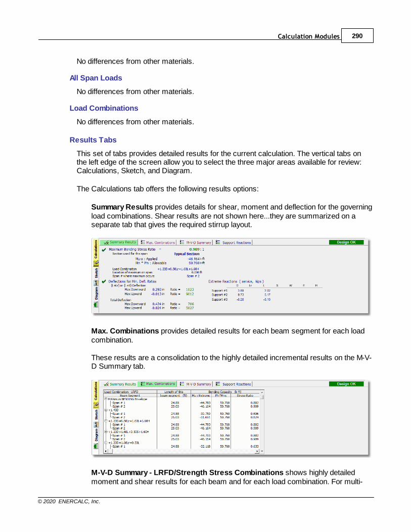
Calculation Modules 290
© 2020 ENERCALC, Inc.
No differences from other materials.
All Span Loads
No differences from other materials.
Load Combinations
No differences from other materials.
Results Tabs
This set of tabs provides detailed results for the current calculation. The vertical tabs onthe left edge of the screen allow you to select the three major areas available for review:Calculations, Sketch, and Diagram.
The Calculations tab offers the following results options:
Summary Results provides details for shear, moment and deflection for the governingload combinations. Shear results are not shown here...they are summarized on aseparate tab that gives the required stirrup layout.
Max. Combinations provides detailed results for each beam segment for each loadcombination.
These results are a consolidation to the highly detailed incremental results on the M-V-D Summary tab.
M-V-D Summary - LRFD/Strength Stress Combinations shows highly detailedmoment and shear results for each beam and for each load combination. For multi-
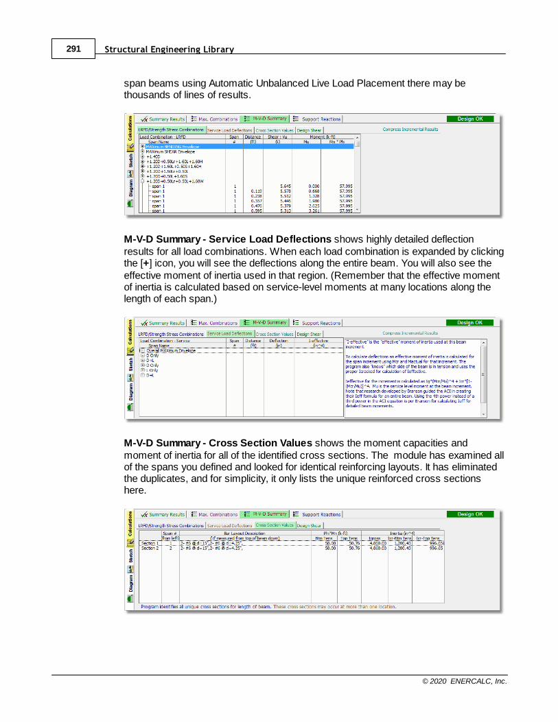
Structural Engineering Library291
© 2020 ENERCALC, Inc.
span beams using Automatic Unbalanced Live Load Placement there may bethousands of lines of results.
M-V-D Summary - Service Load Deflections shows highly detailed deflectionresults for all load combinations. When each load combination is expanded by clickingthe [+] icon, you will see the deflections along the entire beam. You will also see theeffective moment of inertia used in that region. (Remember that the effective momentof inertia is calculated based on service-level moments at many locations along thelength of each span.)
M-V-D Summary - Cross Section Values shows the moment capacities andmoment of inertia for all of the identified cross sections. The module has examined allof the spans you defined and looked for identical reinforcing layouts. It has eliminatedthe duplicates, and for simplicity, it only lists the unique reinforced cross sectionshere.

Calculation Modules 292
© 2020 ENERCALC, Inc.
M-V-D Summary - Design Shear shows the shear stirrup requirements along thespan(s) as required by the governing load combinations that generate the highestshear at each section.
The column labeled Comment indicates the ACI code condition that governs therequirement for shear reinforcing at each design location.
Support Reactions shows reactions for each support for each load condition.
The Sketch tab provides a graphic representation of the beam currently being designed:
The Diagram tab offers the ability to view shear, moment, and deflection diagrams forselected load combinations:
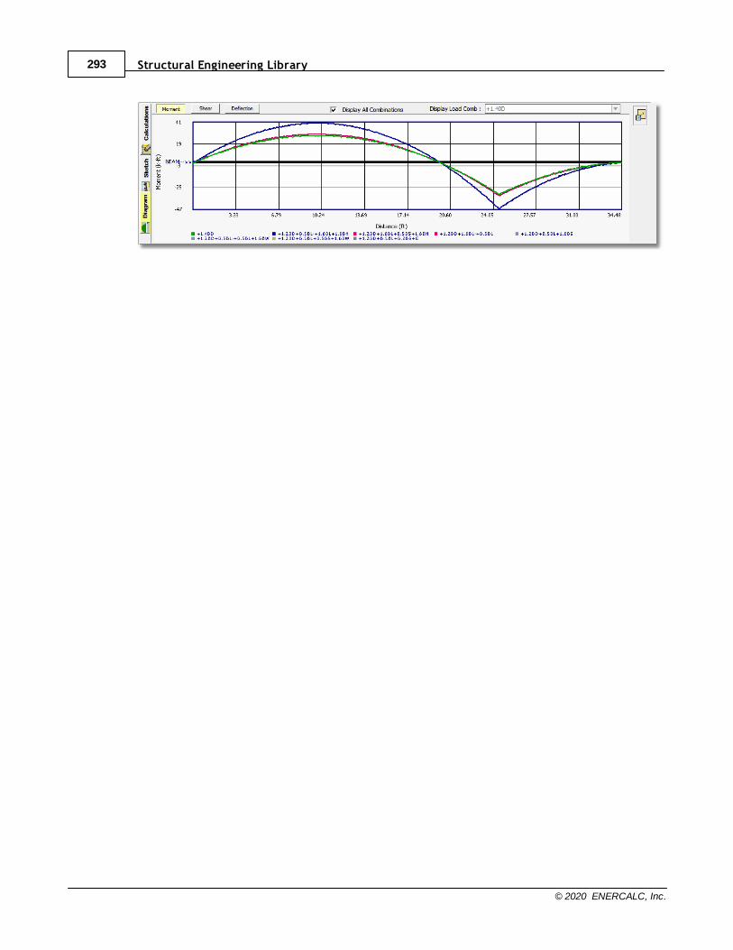
Structural Engineering Library293
© 2020 ENERCALC, Inc.
Calculation Modules 294
© 2020 ENERCALC, Inc.
10.2.6 Beam on Elastic Foundation
Need more? Ask Us a Question
The Beam on Elastic Foundation module is a single-span version of the Concrete Beammodule that provides special support conditions to represent an idealized, compression-only, continuous elastic support.
The significant variation between the Beam on Elastic Foundation module and theConcrete Beam module is the fact that the Beam on Elastic Foundation module collects aSoil Subgrade Modulus for use in modeling the spring support.
Note: This module will stop if it finds any locations where the soil springs tend togo into tension, so be sure to use realistic load combinations. For instance, don'trun +W Only or +Lr Only, without the corresponding dead load that would also beapplied concurrently.
Refer to the Concrete Beam module information in this document for other details.
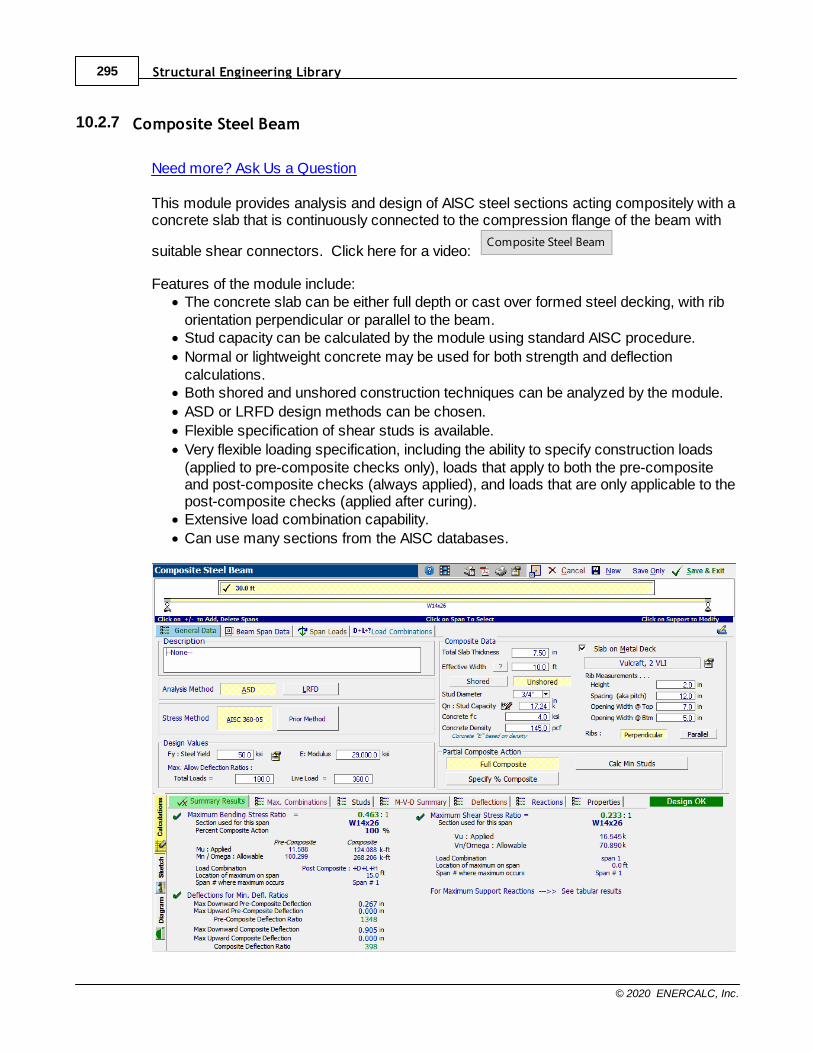
Structural Engineering Library295
© 2020 ENERCALC, Inc.
10.2.7 Composite Steel Beam
Need more? Ask Us a Question
This module provides analysis and design of AISC steel sections acting compositely with aconcrete slab that is continuously connected to the compression flange of the beam with
suitable shear connectors. Click here for a video: Composite Steel Beam
Features of the module include:· The concrete slab can be either full depth or cast over formed steel decking, with rib
orientation perpendicular or parallel to the beam.· Stud capacity can be calculated by the module using standard AISC procedure.
· Normal or lightweight concrete may be used for both strength and deflectioncalculations.
· Both shored and unshored construction techniques can be analyzed by the module.
· ASD or LRFD design methods can be chosen.
· Flexible specification of shear studs is available.
· Very flexible loading specification, including the ability to specify construction loads(applied to pre-composite checks only), loads that apply to both the pre-compositeand post-composite checks (always applied), and loads that are only applicable to thepost-composite checks (applied after curing).
· Extensive load combination capability.
· Can use many sections from the AISC databases.
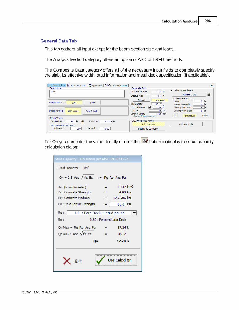
Calculation Modules 296
© 2020 ENERCALC, Inc.
General Data Tab
This tab gathers all input except for the beam section size and loads.
The Analysis Method category offers an option of ASD or LRFD methods.
The Composite Data category offers all of the necessary input fields to completely specifythe slab, its effective width, stud information and metal deck specification (if applicable).
For Qn you can enter the value directly or click the button to display the stud capacitycalculation dialog:
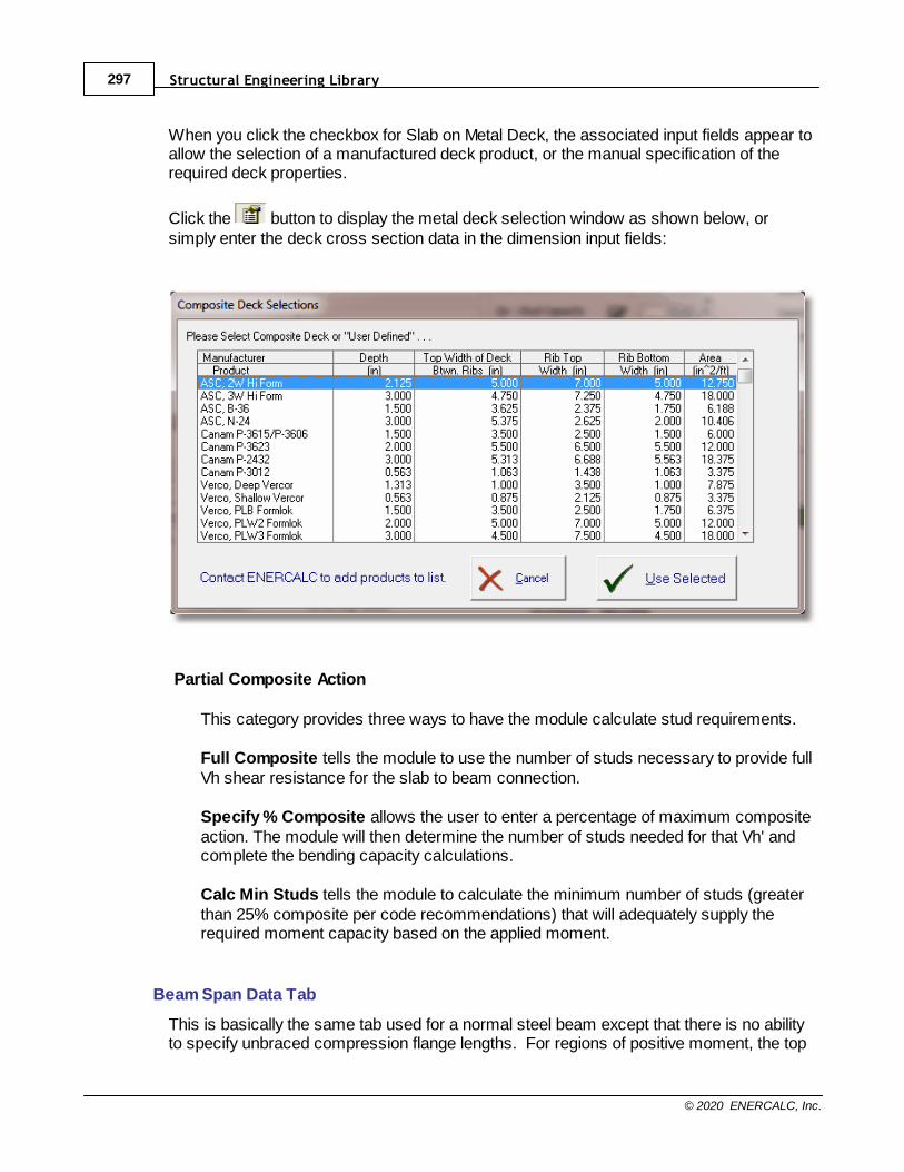
Structural Engineering Library297
© 2020 ENERCALC, Inc.
When you click the checkbox for Slab on Metal Deck, the associated input fields appear toallow the selection of a manufactured deck product, or the manual specification of therequired deck properties.
Click the button to display the metal deck selection window as shown below, orsimply enter the deck cross section data in the dimension input fields:
Partial Composite Action
This category provides three ways to have the module calculate stud requirements.
Full Composite tells the module to use the number of studs necessary to provide fullVh shear resistance for the slab to beam connection.
Specify % Composite allows the user to enter a percentage of maximum compositeaction. The module will then determine the number of studs needed for that Vh' andcomplete the bending capacity calculations.
Calc Min Studs tells the module to calculate the minimum number of studs (greaterthan 25% composite per code recommendations) that will adequately supply therequired moment capacity based on the applied moment.
Beam Span Data Tab
This is basically the same tab used for a normal steel beam except that there is no abilityto specify unbraced compression flange lengths. For regions of positive moment, the top
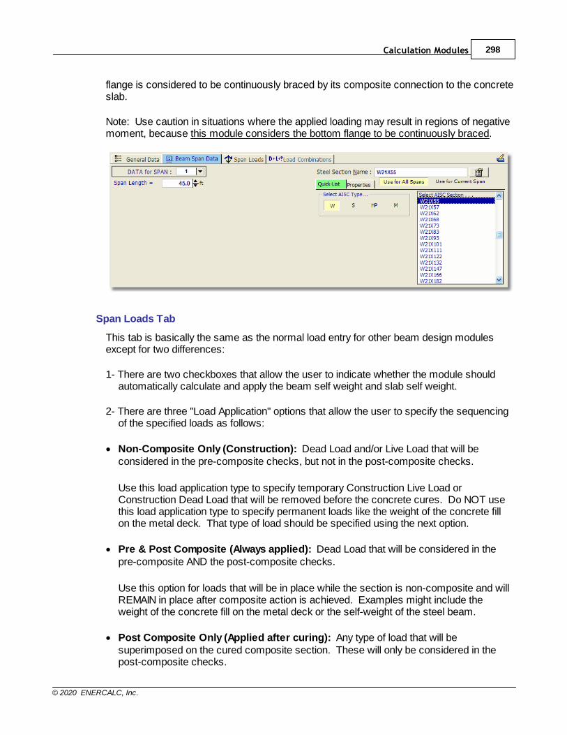
Calculation Modules 298
© 2020 ENERCALC, Inc.
flange is considered to be continuously braced by its composite connection to the concreteslab.
Note: Use caution in situations where the applied loading may result in regions of negativemoment, because this module considers the bottom flange to be continuously braced.
Span Loads Tab
This tab is basically the same as the normal load entry for other beam design modulesexcept for two differences:
1- There are two checkboxes that allow the user to indicate whether the module shouldautomatically calculate and apply the beam self weight and slab self weight.
2- There are three "Load Application" options that allow the user to specify the sequencingof the specified loads as follows:
· Non-Composite Only (Construction): Dead Load and/or Live Load that will beconsidered in the pre-composite checks, but not in the post-composite checks.
Use this load application type to specify temporary Construction Live Load orConstruction Dead Load that will be removed before the concrete cures. Do NOT usethis load application type to specify permanent loads like the weight of the concrete fillon the metal deck. That type of load should be specified using the next option.
· Pre & Post Composite (Always applied): Dead Load that will be considered in thepre-composite AND the post-composite checks.
Use this option for loads that will be in place while the section is non-composite and willREMAIN in place after composite action is achieved. Examples might include theweight of the concrete fill on the metal deck or the self-weight of the steel beam.
· Post Composite Only (Applied after curing): Any type of load that will besuperimposed on the cured composite section. These will only be considered in thepost-composite checks.

Structural Engineering Library299
© 2020 ENERCALC, Inc.
Use this option for loads that will be placed on the structure only after composite actionhas developed. Some examples might include the weight of architectural floor finishesor the weight of permanent mechanical equipment.
Load Combinations Tab
The function of the Load Combinations tab in the Composite Steel Beam module is thesame as in other beam modules.
Results Tabs: This set of tabs provides detailed results for the current calculation. Thevertical tabs on the left edge of the screen allow the user to select the three major areasavailable for review: Calculations, Sketch, and Diagram.
The Calculations tab offers the following results options:
Summary Results tab presents the maximum/governing ratio values from all of the resultspresented on the Max. Combinations tab. The module looks for the maximum bendingstress ratio and presents the components that are calculated to create that ratio.
For the bending stress item the module reports the Construction bending ratio whichconsiders all loads specified to be applied to the beam before curing. The resultingmoment is compared to the capacity of the steel section acting alone (non-compositely).
For the item reported as Governing Values, the module considers all loads specified to beapplied to the composite section. That moment is then compared to the full compositesection moment capacity for the percentage of shear connection specified.
The results indicate the load combination that creates the governing values along with thespan id and location at which the governing ratio was found to occur.
The module calculates the maximum total deflection as the sum of the deflection of thenon-composite steel section resisting all of the loads that are specified as Pre & PostComposite (Always applied) plus the deflection of the composite section resisting all of theloads that are specified as Post Composite Only (Applied after curing).
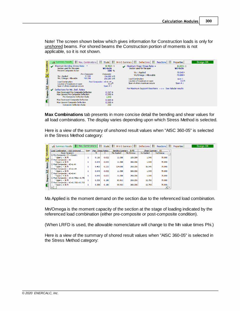
Calculation Modules 300
© 2020 ENERCALC, Inc.
Note! The screen shown below which gives information for Construction loads is only forunshored beams. For shored beams the Construction portion of moments is notapplicable, so it is not shown.
Max Combinations tab presents in more concise detail the bending and shear values forall load combinations. The display varies depending upon which Stress Method is selected.
Here is a view of the summary of unshored result values when "AISC 360-05" is selectedin the Stress Method category:
Ma Applied is the moment demand on the section due to the referenced load combination.
Mn/Omega is the moment capacity of the section at the stage of loading indicated by thereferenced load combination (either pre-composite or post-composite condition).
(When LRFD is used, the allowable nomenclature will change to the Mn value times Phi.)
Here is a view of the summary of shored result values when "AISC 360-05" is selected inthe Stress Method category:
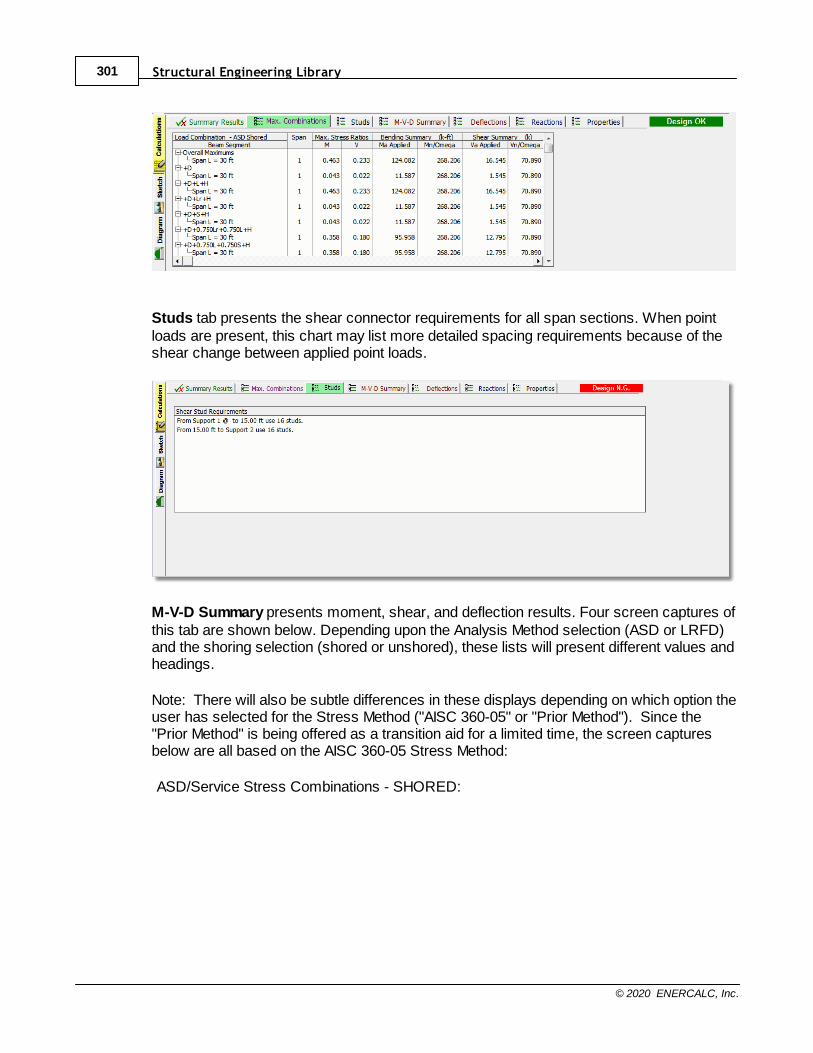
Structural Engineering Library301
© 2020 ENERCALC, Inc.
Studs tab presents the shear connector requirements for all span sections. When pointloads are present, this chart may list more detailed spacing requirements because of theshear change between applied point loads.
M-V-D Summary presents moment, shear, and deflection results. Four screen captures ofthis tab are shown below. Depending upon the Analysis Method selection (ASD or LRFD)and the shoring selection (shored or unshored), these lists will present different values andheadings.
Note: There will also be subtle differences in these displays depending on which option theuser has selected for the Stress Method ("AISC 360-05" or "Prior Method"). Since the"Prior Method" is being offered as a transition aid for a limited time, the screen capturesbelow are all based on the AISC 360-05 Stress Method:
ASD/Service Stress Combinations - SHORED:
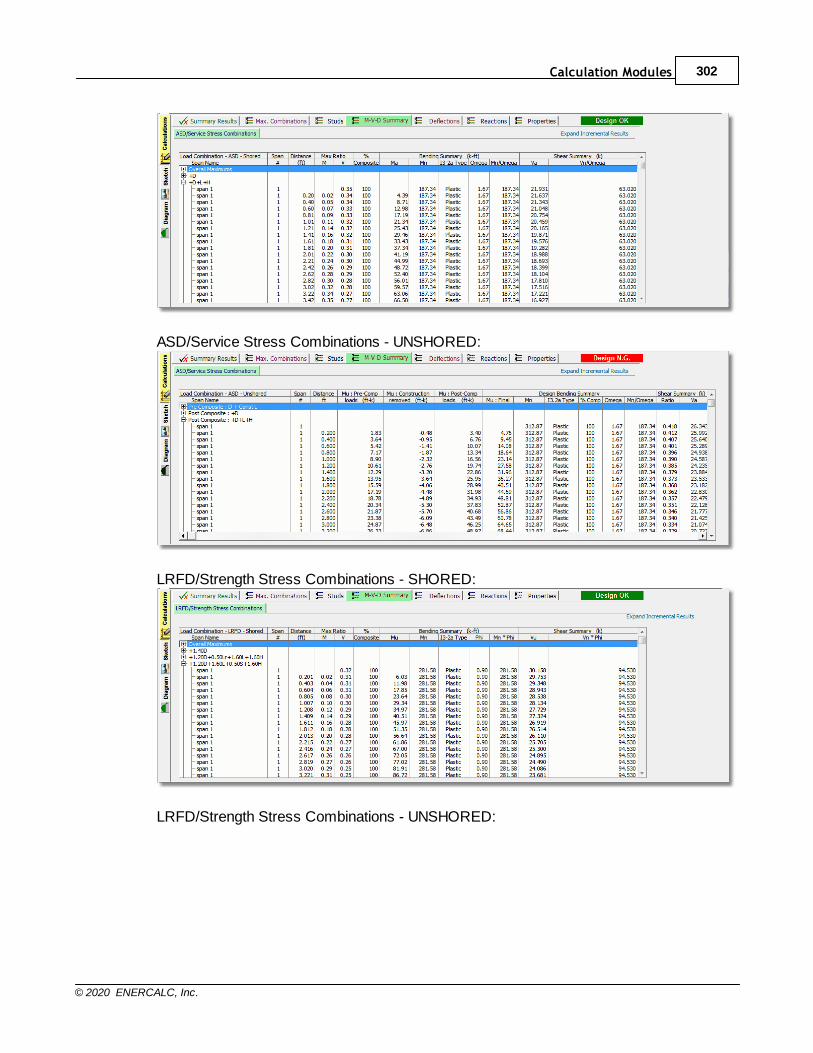
Calculation Modules 302
© 2020 ENERCALC, Inc.
ASD/Service Stress Combinations - UNSHORED:
LRFD/Strength Stress Combinations - SHORED:
LRFD/Strength Stress Combinations - UNSHORED:
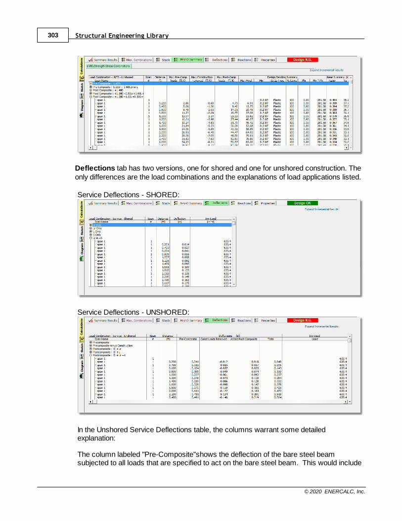
Structural Engineering Library303
© 2020 ENERCALC, Inc.
Deflections tab has two versions, one for shored and one for unshored construction. Theonly differences are the load combinations and the explanations of load applications listed.
Service Deflections - SHORED:
Service Deflections - UNSHORED:
In the Unshored Service Deflections table, the columns warrant some detailedexplanation:
The column labeled "Pre-Composite"shows the deflection of the bare steel beamsubjected to all loads that are specified to act on the bare steel beam. This would include
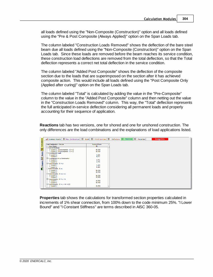
Calculation Modules 304
© 2020 ENERCALC, Inc.
all loads defined using the "Non-Composite (Construction)" option and all loads definedusing the "Pre & Post Composite (Always Applied)" option on the Span Loads tab.
The column labeled "Construction Loads Removed" shows the deflection of the bare steelbeam due all loads defined using the "Non-Composite (Construction)" option on the SpanLoads tab. Since these loads are removed before the beam reaches its service condition,these construction load deflections are removed from the total deflection, so that the Totaldeflection represents a correct net total deflection in the service condition.
The column labeled "Added Post Composite" shows the deflection of the compositesection due to the loads that are superimposed on the section after it has achievedcomposite action. This would include all loads defined using the "Post Composite Only(Applied after curing)" option on the Span Loads tab.
The column labeled "Total" is calculated by adding the value in the "Pre-Composite"column to the value in the "Added Post Composite" column and then netting out the valuein the "Construction Loads Removed" column. This way, the "Total" deflection representsthe full anticipated in-service deflection considering all permanent loads and properlyaccounting for their sequence of application.
Reactions tab has two versions, one for shored and one for unshored construction. Theonly differences are the load combinations and the explanations of load applications listed.
Properties tab shows the calculations for transformed section properties calculated inincrements of 1% shear connection, from 100% down to the code minimum 25%. "I LowerBound" and "I Constant Stiffness" are terms described in AISC 360-05.
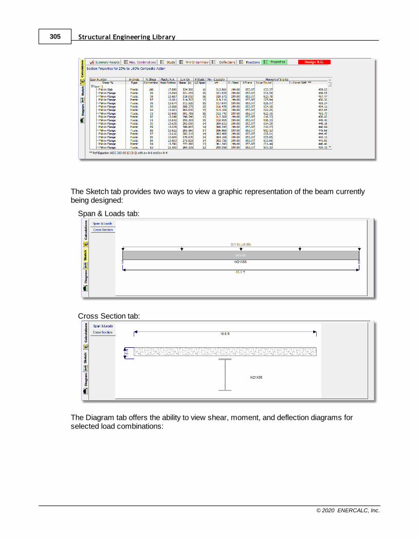
Structural Engineering Library305
© 2020 ENERCALC, Inc.
The Sketch tab provides two ways to view a graphic representation of the beam currentlybeing designed:
Span & Loads tab:
Cross Section tab:
The Diagram tab offers the ability to view shear, moment, and deflection diagrams forselected load combinations:

Calculation Modules 306
© 2020 ENERCALC, Inc.
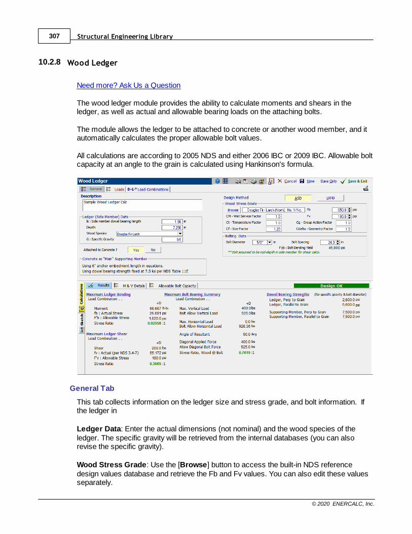
Structural Engineering Library307
© 2020 ENERCALC, Inc.
10.2.8 Wood Ledger
Need more? Ask Us a Question
The wood ledger module provides the ability to calculate moments and shears in theledger, as well as actual and allowable bearing loads on the attaching bolts.
The module allows the ledger to be attached to concrete or another wood member, and itautomatically calculates the proper allowable bolt values.
All calculations are according to 2005 NDS and either 2006 IBC or 2009 IBC. Allowable boltcapacity at an angle to the grain is calculated using Hankinson's formula.
General Tab
This tab collects information on the ledger size and stress grade, and bolt information. Ifthe ledger in
Ledger Data: Enter the actual dimensions (not nominal) and the wood species of theledger. The specific gravity will be retrieved from the internal databases (you can alsorevise the specific gravity).
Wood Stress Grade: Use the [Browse] button to access the built-in NDS referencedesign values database and retrieve the Fb and Fv values. You can also edit these valuesseparately.
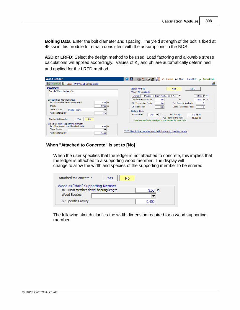
Calculation Modules 308
© 2020 ENERCALC, Inc.
Bolting Data: Enter the bolt diameter and spacing. The yield strength of the bolt is fixed at45 ksi in this module to remain consistent with the assumptions in the NDS.
ASD or LRFD: Select the design method to be used. Load factoring and allowable stresscalculations will applied accordingly. Values of K
F and phi are automatically determined
and applied for the LRFD method.
When "Attached to Concrete" is set to [No]
When the user specifies that the ledger is not attached to concrete, this implies thatthe ledger is attached to a supporting wood member. The display will change to allow the width and species of the supporting member to be entered.
The following sketch clarifies the width dimension required for a wood supportingmember:
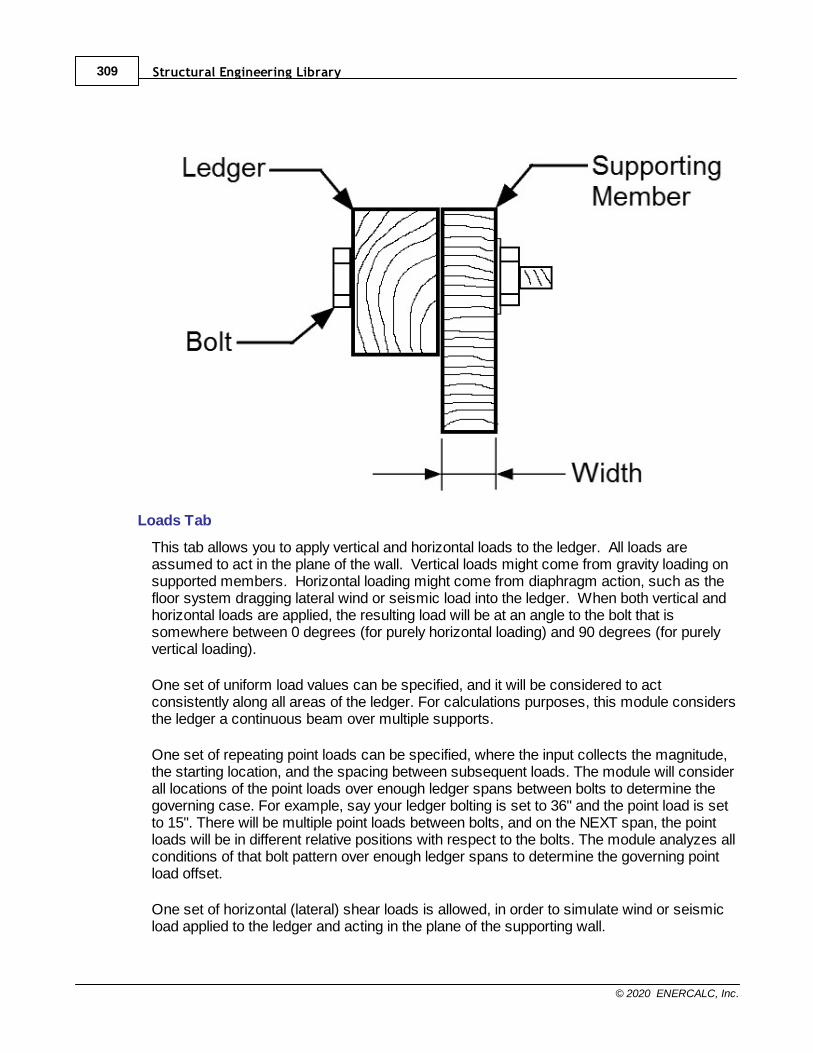
Structural Engineering Library309
© 2020 ENERCALC, Inc.
Loads Tab
This tab allows you to apply vertical and horizontal loads to the ledger. All loads areassumed to act in the plane of the wall. Vertical loads might come from gravity loading onsupported members. Horizontal loading might come from diaphragm action, such as thefloor system dragging lateral wind or seismic load into the ledger. When both vertical andhorizontal loads are applied, the resulting load will be at an angle to the bolt that issomewhere between 0 degrees (for purely horizontal loading) and 90 degrees (for purelyvertical loading).
One set of uniform load values can be specified, and it will be considered to actconsistently along all areas of the ledger. For calculations purposes, this module considersthe ledger a continuous beam over multiple supports.
One set of repeating point loads can be specified, where the input collects the magnitude,the starting location, and the spacing between subsequent loads. The module will considerall locations of the point loads over enough ledger spans between bolts to determine thegoverning case. For example, say your ledger bolting is set to 36" and the point load is setto 15". There will be multiple point loads between bolts, and on the NEXT span, the pointloads will be in different relative positions with respect to the bolts. The module analyzes allconditions of that bolt pattern over enough ledger spans to determine the governing pointload offset.
One set of horizontal (lateral) shear loads is allowed, in order to simulate wind or seismicload applied to the ledger and acting in the plane of the supporting wall.
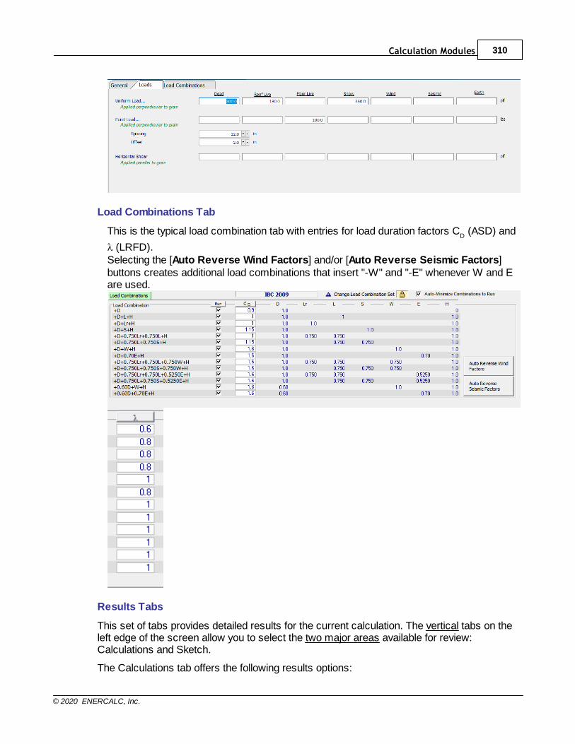
Calculation Modules 310
© 2020 ENERCALC, Inc.
Load Combinations Tab
This is the typical load combination tab with entries for load duration factors CD (ASD) and
l (LRFD).Selecting the [Auto Reverse Wind Factors] and/or [Auto Reverse Seismic Factors]buttons creates additional load combinations that insert "-W" and "-E" whenever W and Eare used.
Results Tabs
This set of tabs provides detailed results for the current calculation. The vertical tabs on theleft edge of the screen allow you to select the two major areas available for review:Calculations and Sketch.
The Calculations tab offers the following results options:
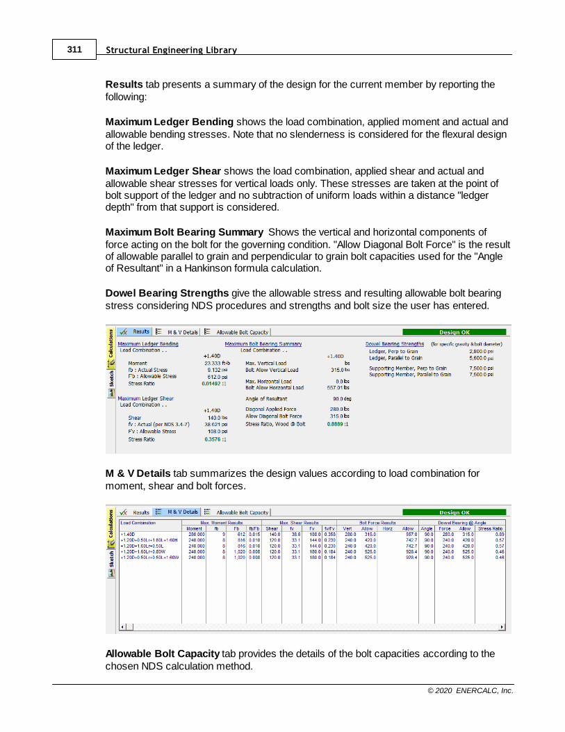
Structural Engineering Library311
© 2020 ENERCALC, Inc.
Results tab presents a summary of the design for the current member by reporting thefollowing:
Maximum Ledger Bending shows the load combination, applied moment and actual andallowable bending stresses. Note that no slenderness is considered for the flexural designof the ledger.
Maximum Ledger Shear shows the load combination, applied shear and actual andallowable shear stresses for vertical loads only. These stresses are taken at the point ofbolt support of the ledger and no subtraction of uniform loads within a distance "ledgerdepth" from that support is considered.
Maximum Bolt Bearing Summary Shows the vertical and horizontal components offorce acting on the bolt for the governing condition. "Allow Diagonal Bolt Force" is the resultof allowable parallel to grain and perpendicular to grain bolt capacities used for the "Angleof Resultant" in a Hankinson formula calculation.
Dowel Bearing Strengths give the allowable stress and resulting allowable bolt bearingstress considering NDS procedures and strengths and bolt size the user has entered.
M & V Details tab summarizes the design values according to load combination formoment, shear and bolt forces.
Allowable Bolt Capacity tab provides the details of the bolt capacities according to thechosen NDS calculation method.
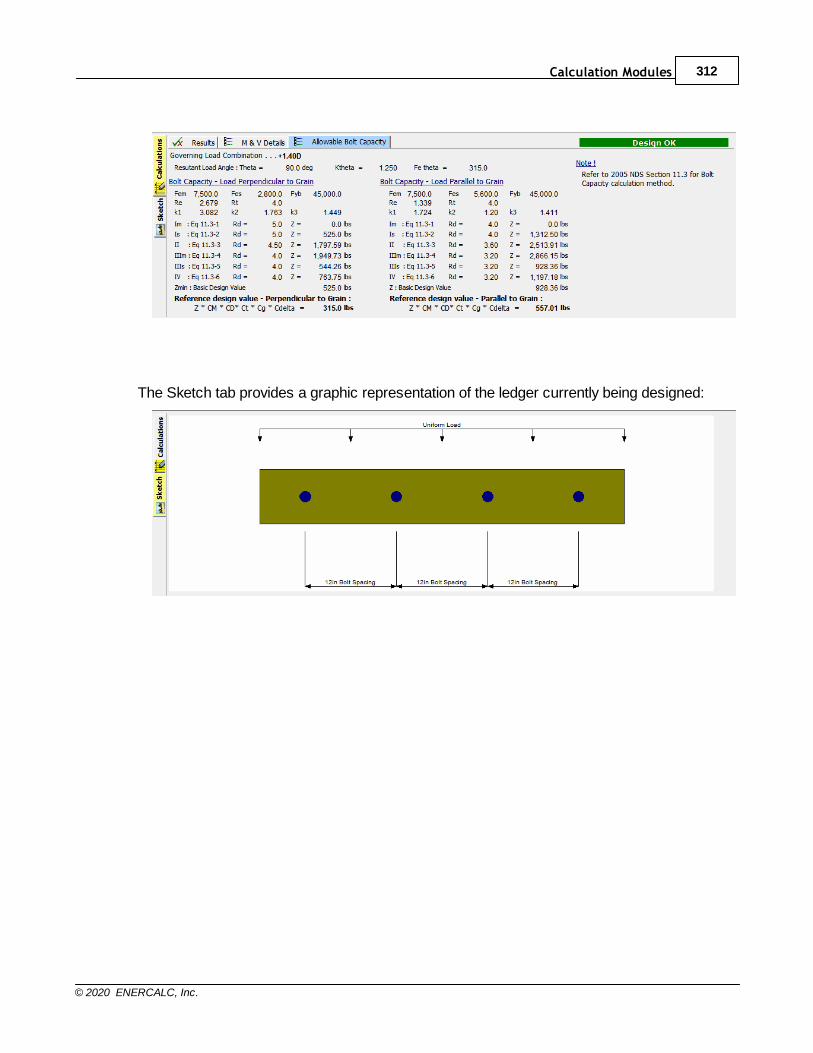
Calculation Modules 312
© 2020 ENERCALC, Inc.
The Sketch tab provides a graphic representation of the ledger currently being designed:
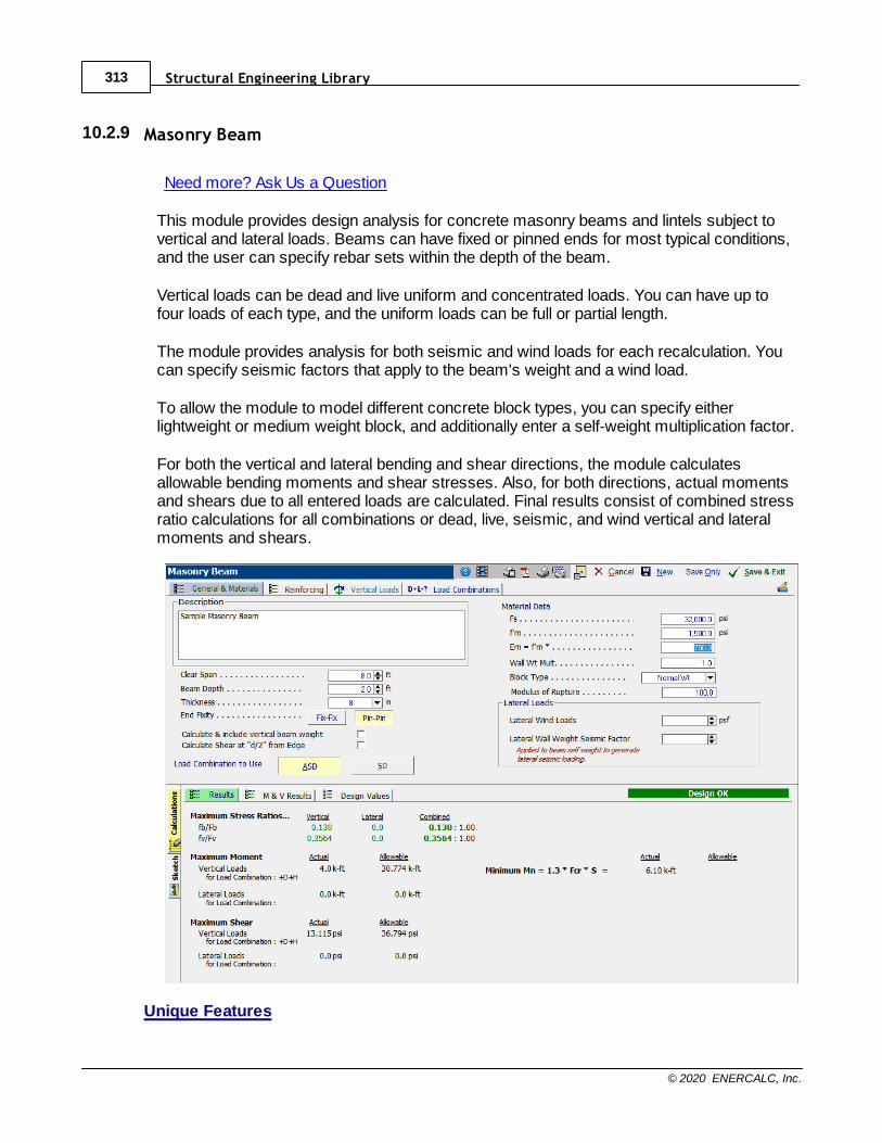
Structural Engineering Library313
© 2020 ENERCALC, Inc.
10.2.9 Masonry Beam
Need more? Ask Us a Question
This module provides design analysis for concrete masonry beams and lintels subject tovertical and lateral loads. Beams can have fixed or pinned ends for most typical conditions,and the user can specify rebar sets within the depth of the beam.
Vertical loads can be dead and live uniform and concentrated loads. You can have up tofour loads of each type, and the uniform loads can be full or partial length.
The module provides analysis for both seismic and wind loads for each recalculation. Youcan specify seismic factors that apply to the beam's weight and a wind load.
To allow the module to model different concrete block types, you can specify eitherlightweight or medium weight block, and additionally enter a self-weight multiplication factor.
For both the vertical and lateral bending and shear directions, the module calculatesallowable bending moments and shear stresses. Also, for both directions, actual momentsand shears due to all entered loads are calculated. Final results consist of combined stressratio calculations for all combinations or dead, live, seismic, and wind vertical and lateralmoments and shears.
Unique Features
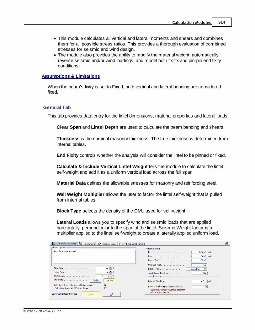
Calculation Modules 314
© 2020 ENERCALC, Inc.
· This module calculates all vertical and lateral moments and shears and combinesthem for all possible stress ratios. This provides a thorough evaluation of combinedstresses for seismic and wind design.
· The module also provides the ability to modify the material weight, automaticallyreverse seismic and/or wind loadings, and model both fix-fix and pin-pin end fixityconditions.
Assumptions & Limitations
When the beam's fixity is set to Fixed, both vertical and lateral bending are consideredfixed.
General Tab
This tab provides data entry for the lintel dimensions, material properties and lateral loads.
Clear Span and Lintel Depth are used to calculate the beam bending and shears.
Thickness is the nominal masonry thickness. The true thickness is determined frominternal tables.
End Fixity controls whether the analysis will consider the lintel to be pinned or fixed.
Calculate & Include Vertical Lintel Weight tells the module to calculate the lintelself-weight and add it as a uniform vertical load across the full span.
Material Data defines the allowable stresses for masonry and reinforcing steel.
Wall Weight Multiplier allows the user to factor the lintel self-weight that is pulledfrom internal tables.
Block Type selects the density of the CMU used for self-weight.
Lateral Loads allows you to specify wind and seismic loads that are appliedhorizontally, perpendicular to the span of the lintel. Seismic Weight factor is amultiplier applied to the lintel self-weight to create a laterally applied uniform load.
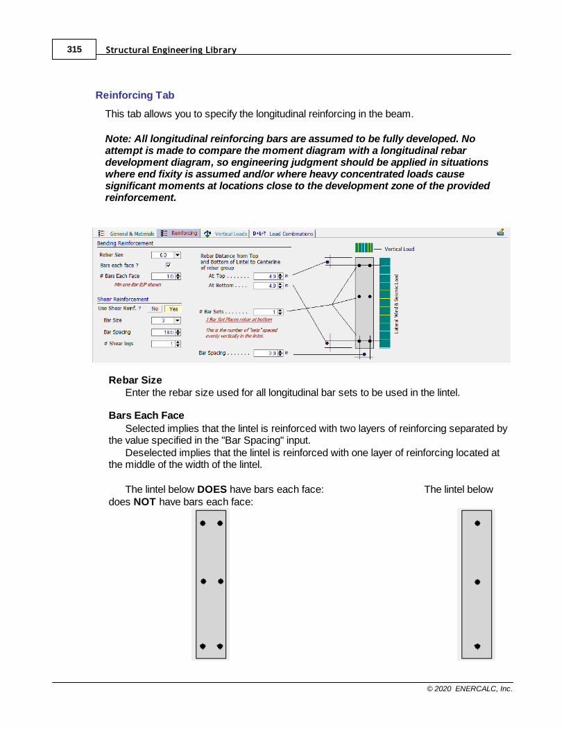
Structural Engineering Library315
© 2020 ENERCALC, Inc.
Reinforcing Tab
This tab allows you to specify the longitudinal reinforcing in the beam.
Note: All longitudinal reinforcing bars are assumed to be fully developed. Noattempt is made to compare the moment diagram with a longitudinal rebardevelopment diagram, so engineering judgment should be applied in situationswhere end fixity is assumed and/or where heavy concentrated loads causesignificant moments at locations close to the development zone of the providedreinforcement.
Rebar Size Enter the rebar size used for all longitudinal bar sets to be used in the lintel.
Bars Each Face
Selected implies that the lintel is reinforced with two layers of reinforcing separated bythe value specified in the "Bar Spacing" input.
Deselected implies that the lintel is reinforced with one layer of reinforcing located atthe middle of the width of the lintel.
The lintel below DOES have bars each face: The lintel belowdoes NOT have bars each face:
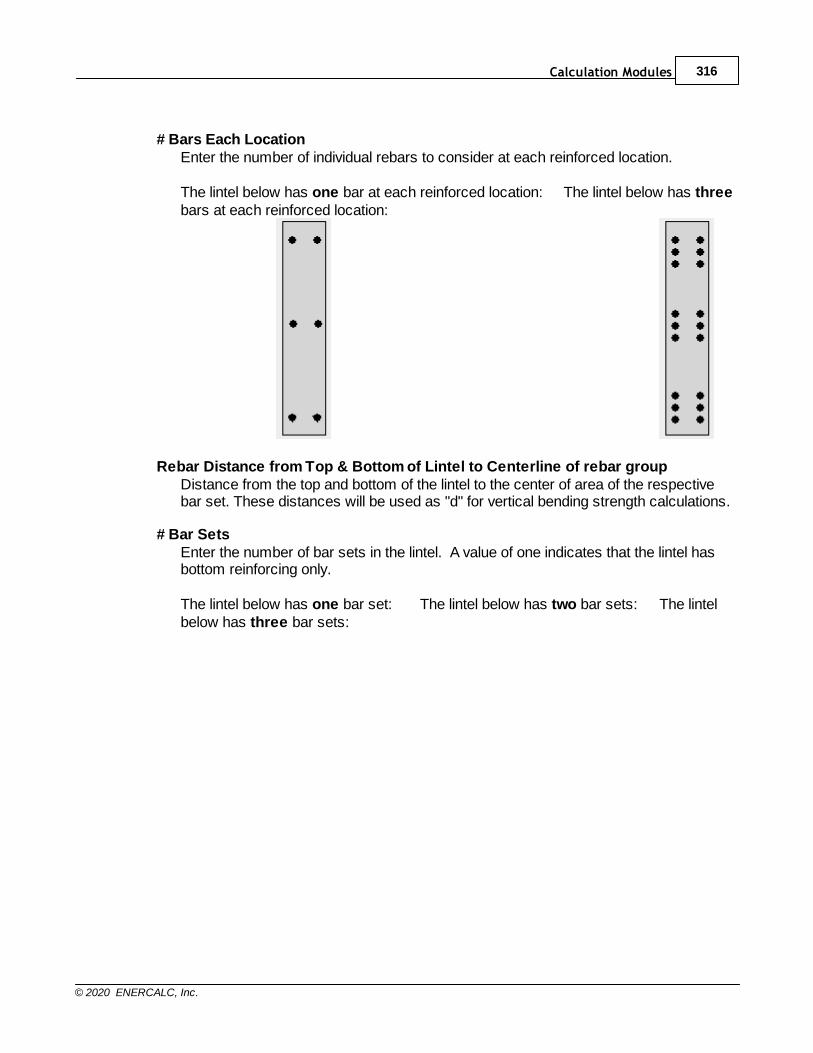
Calculation Modules 316
© 2020 ENERCALC, Inc.
# Bars Each LocationEnter the number of individual rebars to consider at each reinforced location.
The lintel below has one bar at each reinforced location: The lintel below has threebars at each reinforced location:
Rebar Distance from Top & Bottom of Lintel to Centerline of rebar group Distance from the top and bottom of the lintel to the center of area of the respectivebar set. These distances will be used as "d" for vertical bending strength calculations.
# Bar Sets Enter the number of bar sets in the lintel. A value of one indicates that the lintel hasbottom reinforcing only.
The lintel below has one bar set: The lintel below has two bar sets: The lintelbelow has three bar sets:
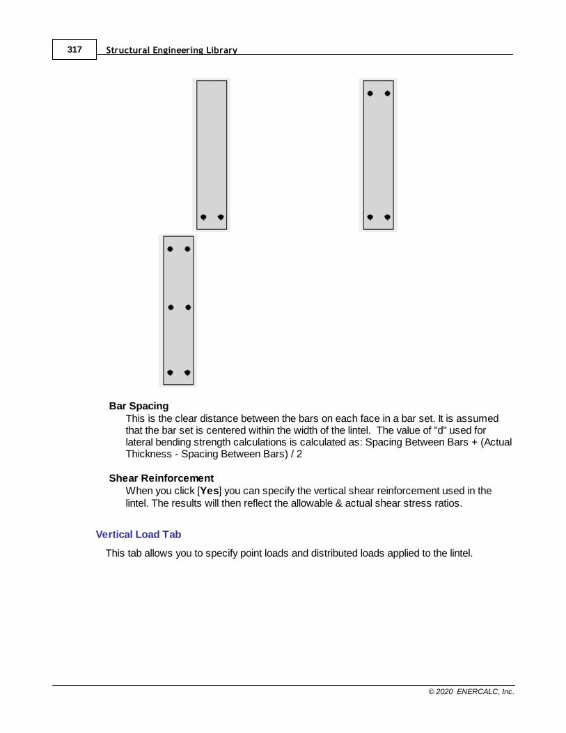
Structural Engineering Library317
© 2020 ENERCALC, Inc.
Bar Spacing This is the clear distance between the bars on each face in a bar set. It is assumedthat the bar set is centered within the width of the lintel. The value of "d" used forlateral bending strength calculations is calculated as: Spacing Between Bars + (ActualThickness - Spacing Between Bars) / 2
Shear ReinforcementWhen you click [Yes] you can specify the vertical shear reinforcement used in thelintel. The results will then reflect the allowable & actual shear stress ratios.
Vertical Load Tab
This tab allows you to specify point loads and distributed loads applied to the lintel.
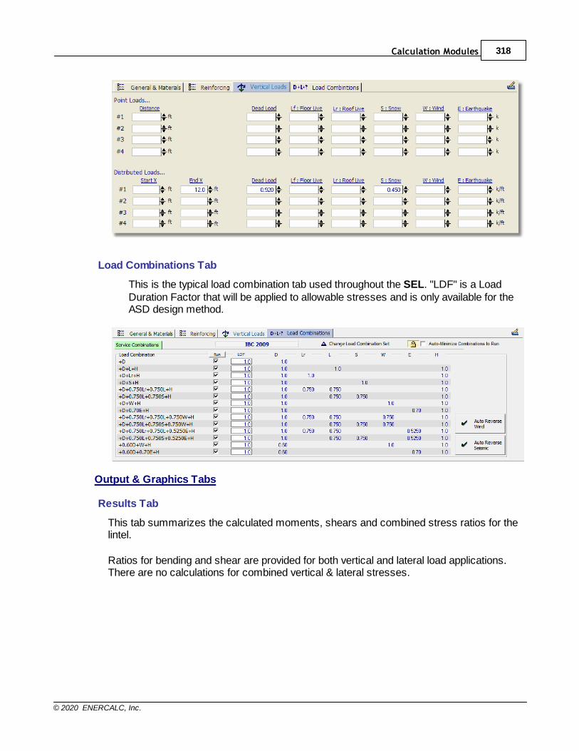
Calculation Modules 318
© 2020 ENERCALC, Inc.
Load Combinations Tab
This is the typical load combination tab used throughout the SEL. "LDF" is a LoadDuration Factor that will be applied to allowable stresses and is only available for theASD design method.
Output & Graphics Tabs
Results Tab
This tab summarizes the calculated moments, shears and combined stress ratios for thelintel.
Ratios for bending and shear are provided for both vertical and lateral load applications.There are no calculations for combined vertical & lateral stresses.
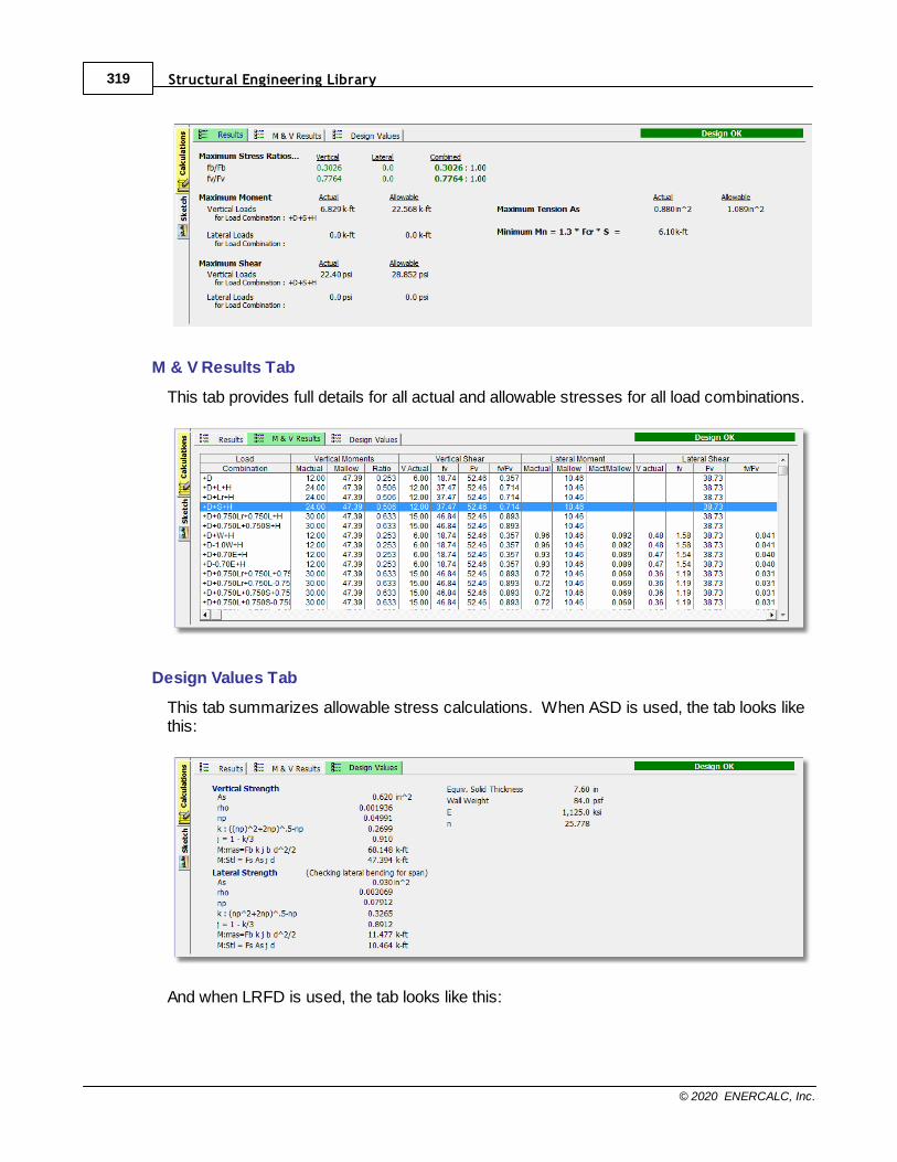
Structural Engineering Library319
© 2020 ENERCALC, Inc.
M & V Results Tab
This tab provides full details for all actual and allowable stresses for all load combinations.
Design Values Tab
This tab summarizes allowable stress calculations. When ASD is used, the tab looks likethis:
And when LRFD is used, the tab looks like this:
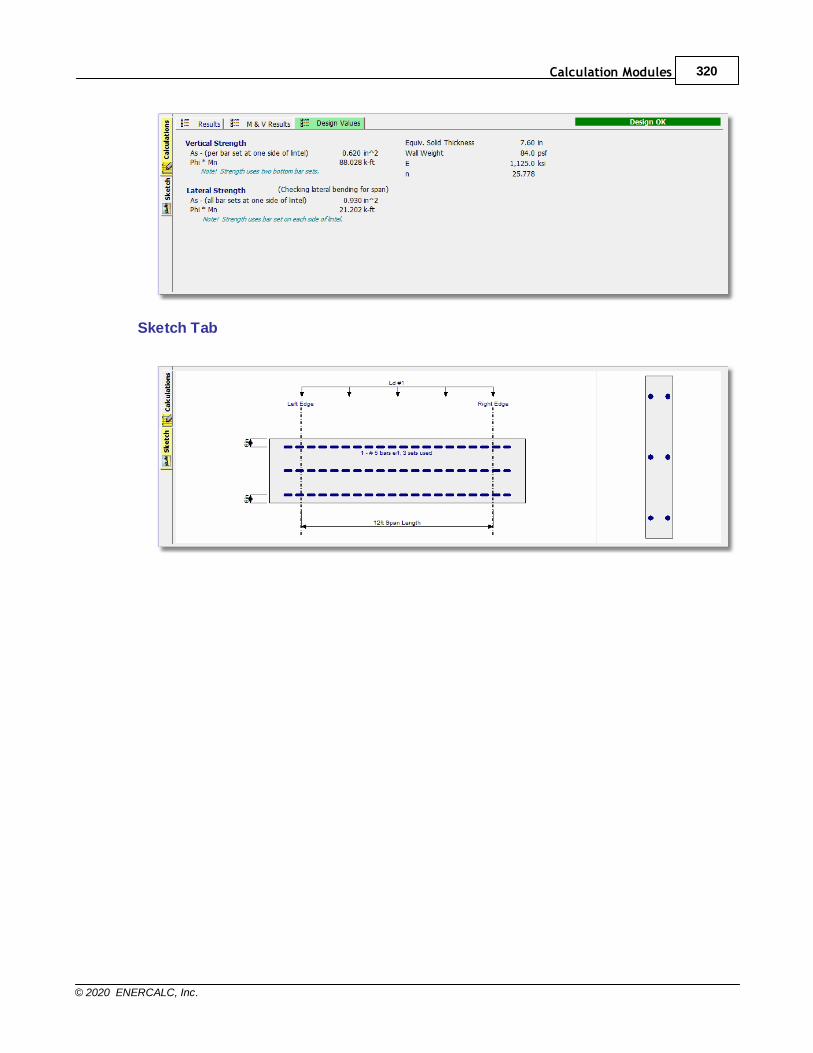
Calculation Modules 320
© 2020 ENERCALC, Inc.
Sketch Tab
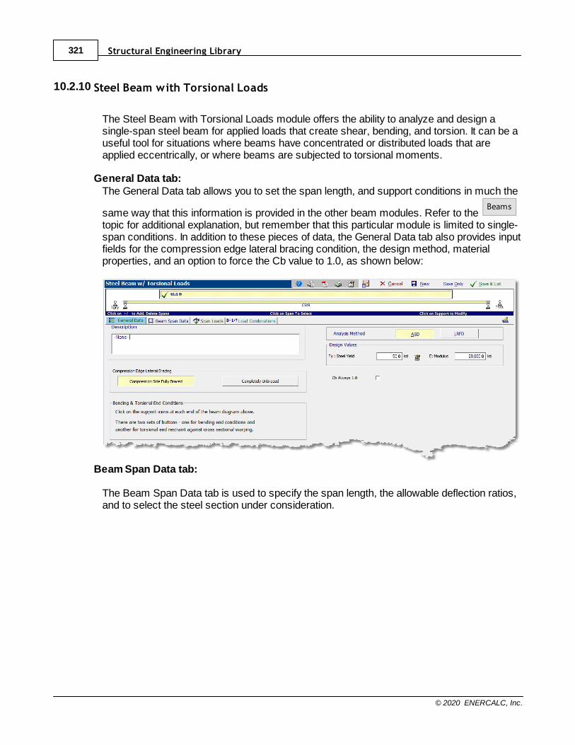
Structural Engineering Library321
© 2020 ENERCALC, Inc.
10.2.10 Steel Beam with Torsional Loads
The Steel Beam with Torsional Loads module offers the ability to analyze and design asingle-span steel beam for applied loads that create shear, bending, and torsion. It can be auseful tool for situations where beams have concentrated or distributed loads that areapplied eccentrically, or where beams are subjected to torsional moments.
General Data tab:The General Data tab allows you to set the span length, and support conditions in much the
same way that this information is provided in the other beam modules. Refer to the Beams
topic for additional explanation, but remember that this particular module is limited to single-span conditions. In addition to these pieces of data, the General Data tab also provides inputfields for the compression edge lateral bracing condition, the design method, materialproperties, and an option to force the Cb value to 1.0, as shown below:
Beam Span Data tab:
The Beam Span Data tab is used to specify the span length, the allowable deflection ratios,and to select the steel section under consideration.
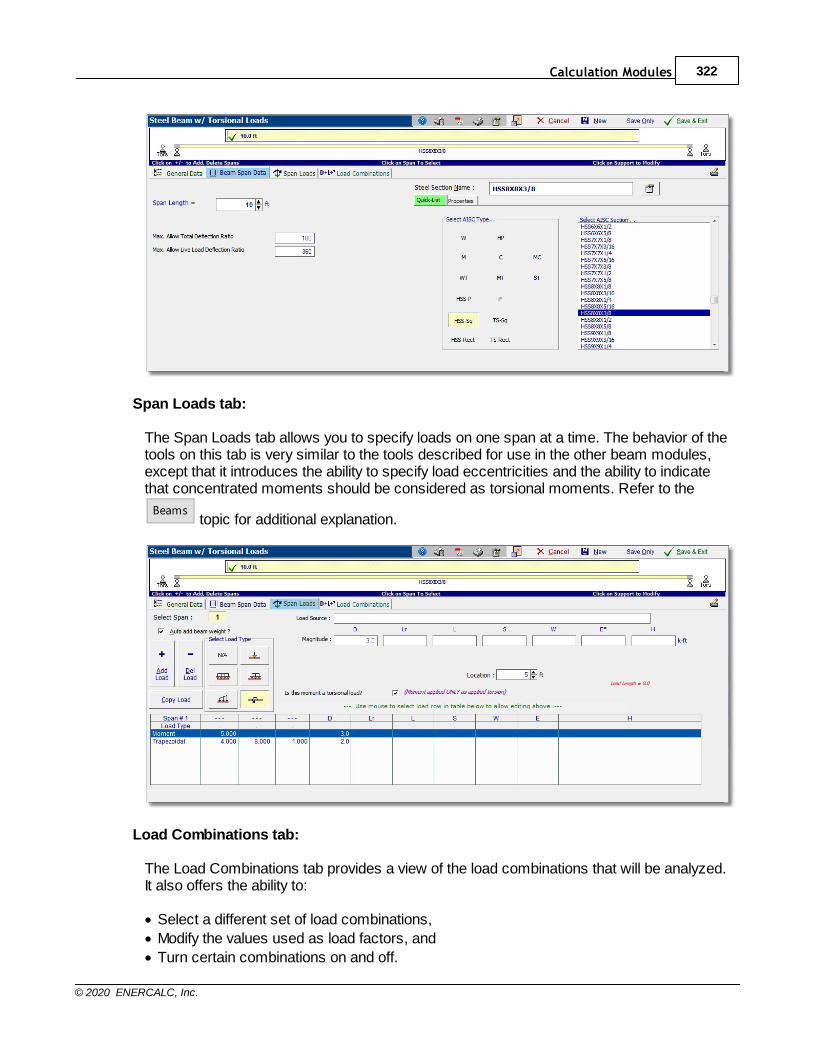
Calculation Modules 322
© 2020 ENERCALC, Inc.
Span Loads tab:
The Span Loads tab allows you to specify loads on one span at a time. The behavior of thetools on this tab is very similar to the tools described for use in the other beam modules,except that it introduces the ability to specify load eccentricities and the ability to indicatethat concentrated moments should be considered as torsional moments. Refer to the
Beams topic for additional explanation.
Load Combinations tab:
The Load Combinations tab provides a view of the load combinations that will be analyzed.It also offers the ability to:
· Select a different set of load combinations,
· Modify the values used as load factors, and
· Turn certain combinations on and off.
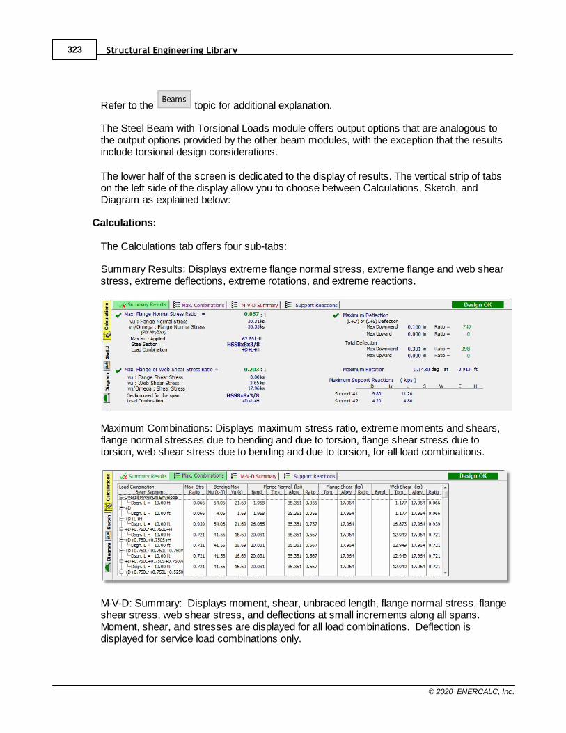
Structural Engineering Library323
© 2020 ENERCALC, Inc.
Refer to the Beams
topic for additional explanation.
The Steel Beam with Torsional Loads module offers output options that are analogous tothe output options provided by the other beam modules, with the exception that the resultsinclude torsional design considerations.
The lower half of the screen is dedicated to the display of results. The vertical strip of tabson the left side of the display allow you to choose between Calculations, Sketch, andDiagram as explained below:
Calculations:
The Calculations tab offers four sub-tabs:
Summary Results: Displays extreme flange normal stress, extreme flange and web shearstress, extreme deflections, extreme rotations, and extreme reactions.
Maximum Combinations: Displays maximum stress ratio, extreme moments and shears,flange normal stresses due to bending and due to torsion, flange shear stress due totorsion, web shear stress due to bending and due to torsion, for all load combinations.
M-V-D: Summary: Displays moment, shear, unbraced length, flange normal stress, flangeshear stress, web shear stress, and deflections at small increments along all spans.Moment, shear, and stresses are displayed for all load combinations. Deflection isdisplayed for service load combinations only.
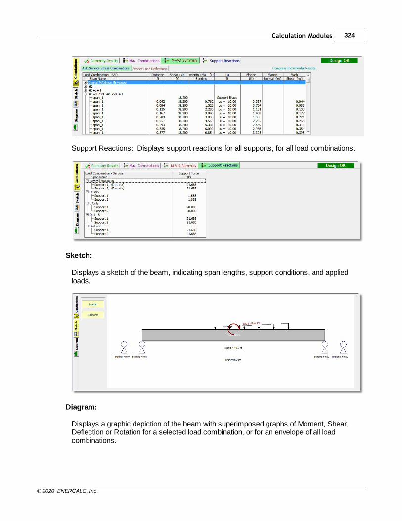
Calculation Modules 324
© 2020 ENERCALC, Inc.
Support Reactions: Displays support reactions for all supports, for all load combinations.
Sketch:
Displays a sketch of the beam, indicating span lengths, support conditions, and appliedloads.
Diagram:
Displays a graphic depiction of the beam with superimposed graphs of Moment, Shear,Deflection or Rotation for a selected load combination, or for an envelope of all loadcombinations.
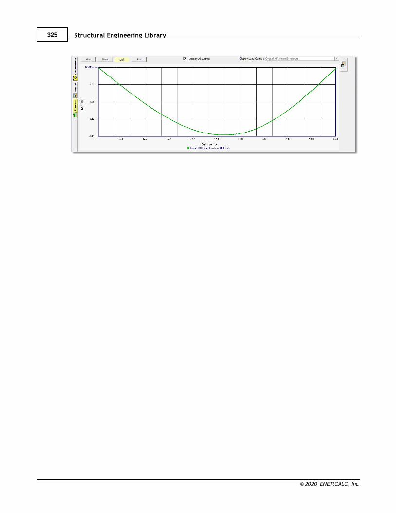
Structural Engineering Library325
© 2020 ENERCALC, Inc.
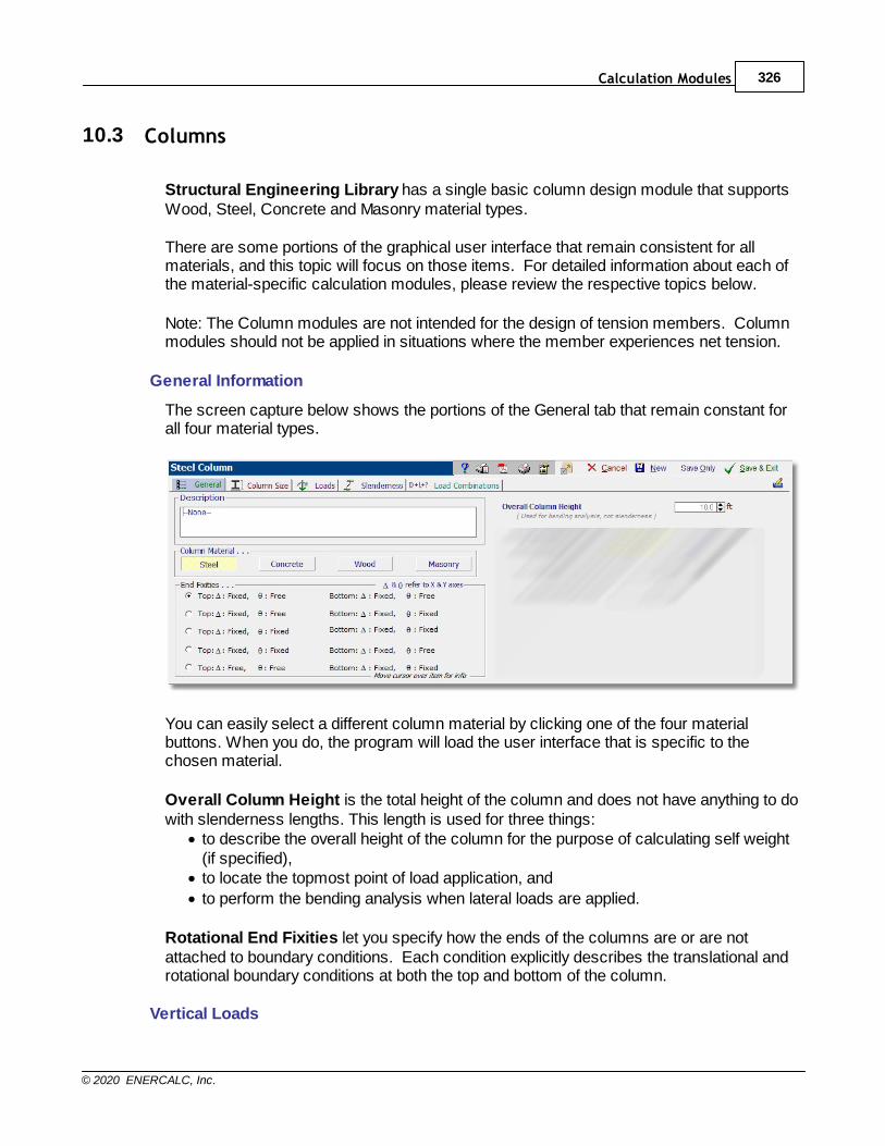
Calculation Modules 326
© 2020 ENERCALC, Inc.
10.3 Columns
Structural Engineering Library has a single basic column design module that supportsWood, Steel, Concrete and Masonry material types.
There are some portions of the graphical user interface that remain consistent for allmaterials, and this topic will focus on those items. For detailed information about each ofthe material-specific calculation modules, please review the respective topics below.
Note: The Column modules are not intended for the design of tension members. Columnmodules should not be applied in situations where the member experiences net tension.
General Information
The screen capture below shows the portions of the General tab that remain constant forall four material types.
You can easily select a different column material by clicking one of the four materialbuttons. When you do, the program will load the user interface that is specific to thechosen material.
Overall Column Height is the total height of the column and does not have anything to dowith slenderness lengths. This length is used for three things:
· to describe the overall height of the column for the purpose of calculating self weight(if specified),
· to locate the topmost point of load application, and
· to perform the bending analysis when lateral loads are applied.
Rotational End Fixities let you specify how the ends of the columns are or are notattached to boundary conditions. Each condition explicitly describes the translational androtational boundary conditions at both the top and bottom of the column.
Vertical Loads
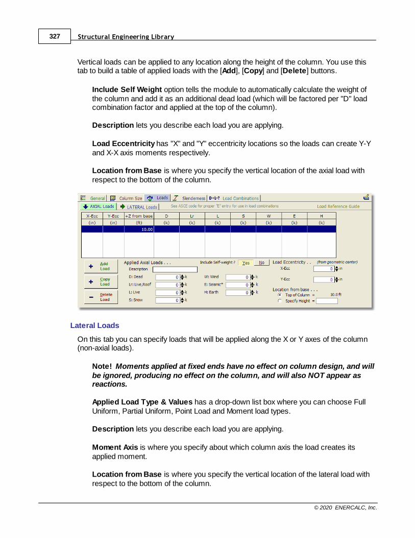
Structural Engineering Library327
© 2020 ENERCALC, Inc.
Vertical loads can be applied to any location along the height of the column. You use thistab to build a table of applied loads with the [Add], [Copy] and [Delete] buttons.
Include Self Weight option tells the module to automatically calculate the weight ofthe column and add it as an additional dead load (which will be factored per "D" loadcombination factor and applied at the top of the column).
Description lets you describe each load you are applying.
Load Eccentricity has "X" and "Y" eccentricity locations so the loads can create Y-Yand X-X axis moments respectively.
Location from Base is where you specify the vertical location of the axial load withrespect to the bottom of the column.
Lateral Loads
On this tab you can specify loads that will be applied along the X or Y axes of the column(non-axial loads).
Note! Moments applied at fixed ends have no effect on column design, and willbe ignored, producing no effect on the column, and will also NOT appear asreactions.
Applied Load Type & Values has a drop-down list box where you can choose FullUniform, Partial Uniform, Point Load and Moment load types.
Description lets you describe each load you are applying.
Moment Axis is where you specify about which column axis the load creates itsapplied moment.
Location from Base is where you specify the vertical location of the lateral load withrespect to the bottom of the column.
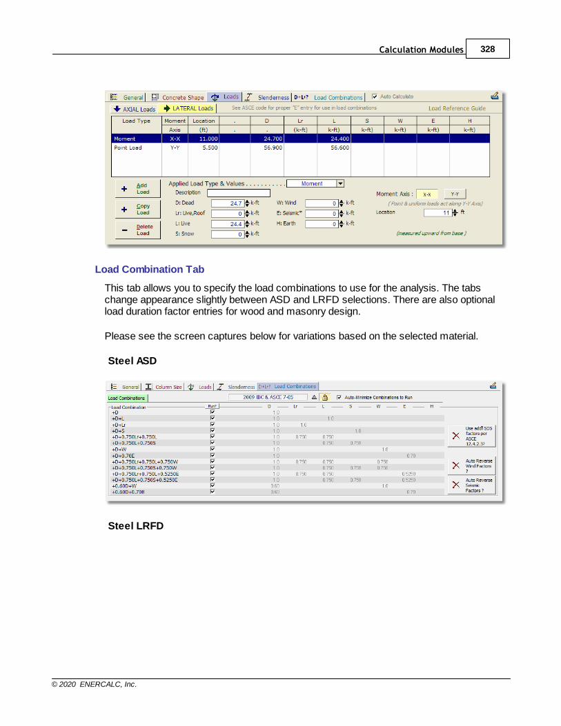
Calculation Modules 328
© 2020 ENERCALC, Inc.
Load Combination Tab
This tab allows you to specify the load combinations to use for the analysis. The tabschange appearance slightly between ASD and LRFD selections. There are also optionalload duration factor entries for wood and masonry design.
Please see the screen captures below for variations based on the selected material.
Steel ASD
Steel LRFD
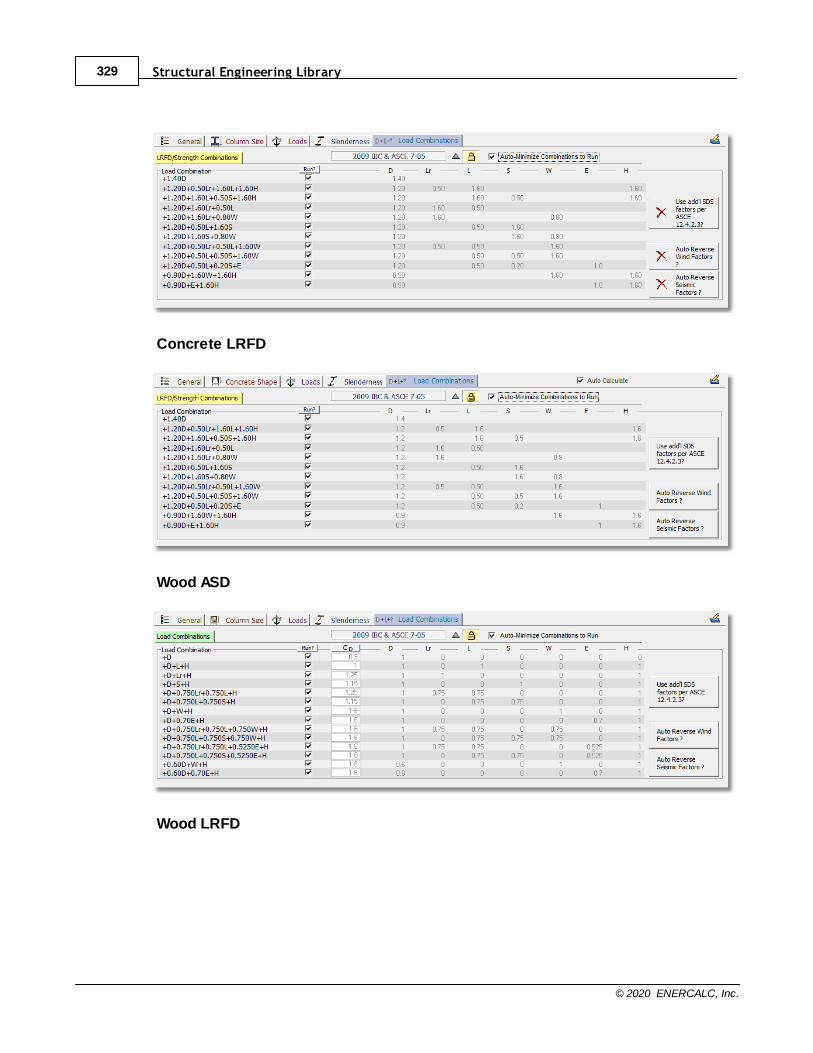
Structural Engineering Library329
© 2020 ENERCALC, Inc.
Concrete LRFD
Wood ASD
Wood LRFD
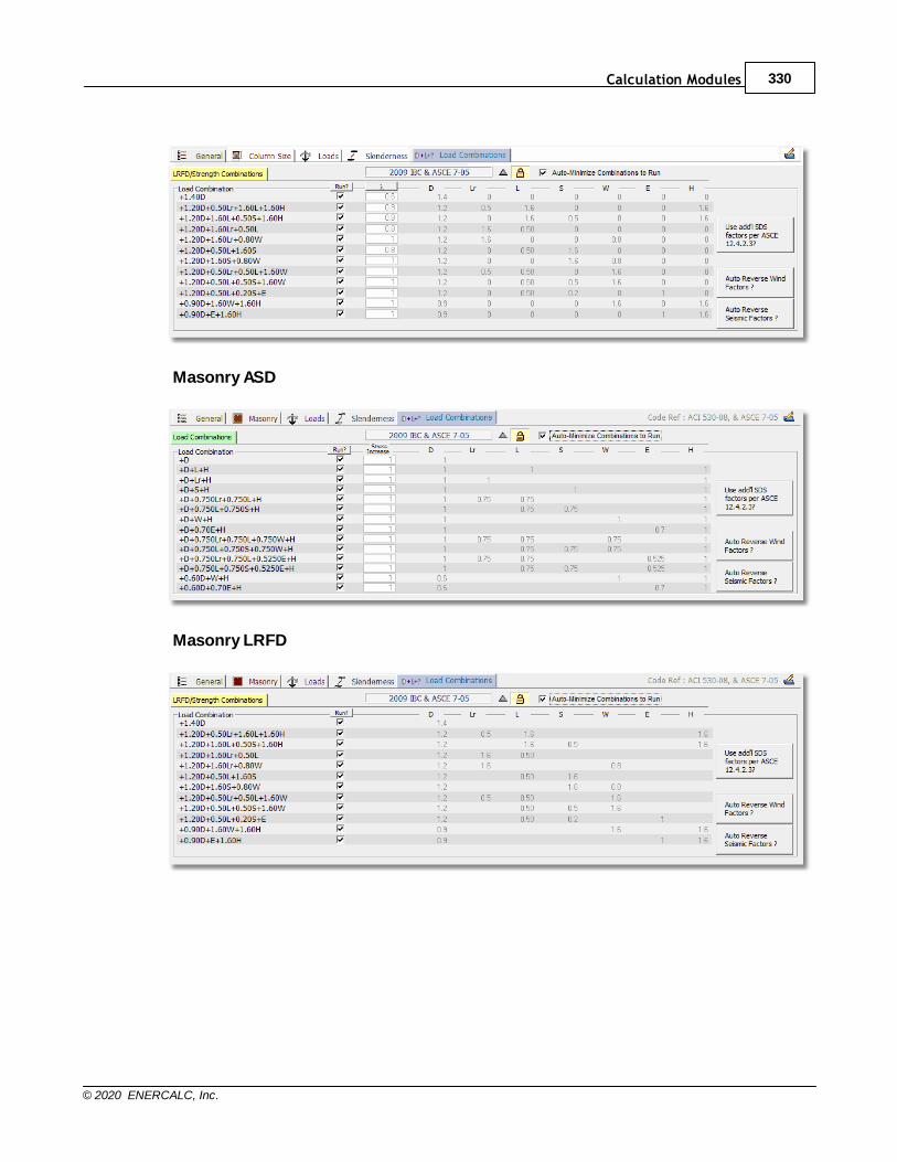
Calculation Modules 330
© 2020 ENERCALC, Inc.
Masonry ASD
Masonry LRFD

Structural Engineering Library331
© 2020 ENERCALC, Inc.
10.3.1 Column Slenderness
Need more? Ask Us a Question
The Slenderness tab allows you to specify the column bracing, which will be considered in
axial capacity calculations. Click here for a video: Column Slenderness
It is important to understand that the settings on the Slenderness tab serve double-duty. When the column has applied bending forces, these slenderness settings also define theunbraced compression edge lengths, and therefore they affect the calculation of allowablebending stresses.
In most of the column modules there are two tabs: "X-X" and "Y-Y Axis ColumnSlenderness". Let's start with the all-important definition of the axis reference forslenderness.
Buckling failure of a column can be thought of as an uncontrolled and excessive deflectionin the direction of a particular axis. When defining slenderness, one of the importantvalues is the distance between points that brace the column against movement (or failure)along a particular axis.
The column modules ask you to specify the distance between points of bracing thatprevent buckling along the column's local X-X or Y-Y axis.
The X-X axis is always parallel to the "width" dimension of the column. The Y-Y axis isalways parallel to the "depth" dimension of the column.
For example, the "X-X" axis of a steel W14 section is parallel to the flanges. The "X-X AxisColumn Slenderness" defines the distance between points that prevent the column frombuckling along its "X-X" axis.
In Structural Engineering Library, slenderness is entered as the distance betweenpoints bracing a member against buckling in the direction of the specified axis.
In the screen capture immediately below, we have selected [Fully braced "X" Axis]. Thismeans that the column is fully braced against buckling along its X-X axis, which is parallelto the width dimension. If this was a steel "W" section, then the column is fully bracedagainst buckling parallel to the flanges.
All materials, column fully bracedThis selection sets the column as fully braced, and no slenderness effects will beevaluated.
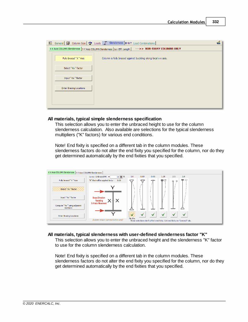
Calculation Modules 332
© 2020 ENERCALC, Inc.
All materials, typical simple slenderness specificationThis selection allows you to enter the unbraced height to use for the columnslenderness calculation. Also available are selections for the typical slendernessmultipliers ("K" factors) for various end conditions.
Note! End fixity is specified on a different tab in the column modules. Theseslenderness factors do not alter the end fixity you specified for the column, nor do theyget determined automatically by the end fixities that you specified.
All materials, typical slenderness with user-defined slenderness factor "K"This selection allows you to enter the unbraced height and the slenderness "K" factorto use for the column slenderness calculation.
Note! End fixity is specified on a different tab in the column modules. Theseslenderness factors do not alter the end fixity you specified for the column, nor do theyget determined automatically by the end fixities that you specified.
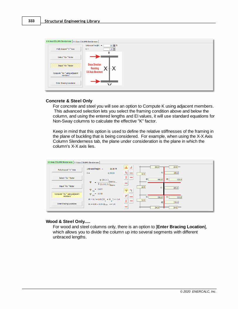
Structural Engineering Library333
© 2020 ENERCALC, Inc.
Concrete & Steel OnlyFor concrete and steel you will see an option to Compute K using adjacent members. This advanced selection lets you select the framing condition above and below thecolumn, and using the entered lengths and EI values, it will use standard equations forNon-Sway columns to calculate the effective "K" factor.
Keep in mind that this option is used to define the relative stiffnesses of the framing inthe plane of buckling that is being considered. For example, when using the X-X AxisColumn Slenderness tab, the plane under consideration is the plane in which thecolumn's X-X axis lies.
Wood & Steel Only.....For wood and steel columns only, there is an option to [Enter Bracing Location],which allows you to divide the column up into several segments with differentunbraced lengths.
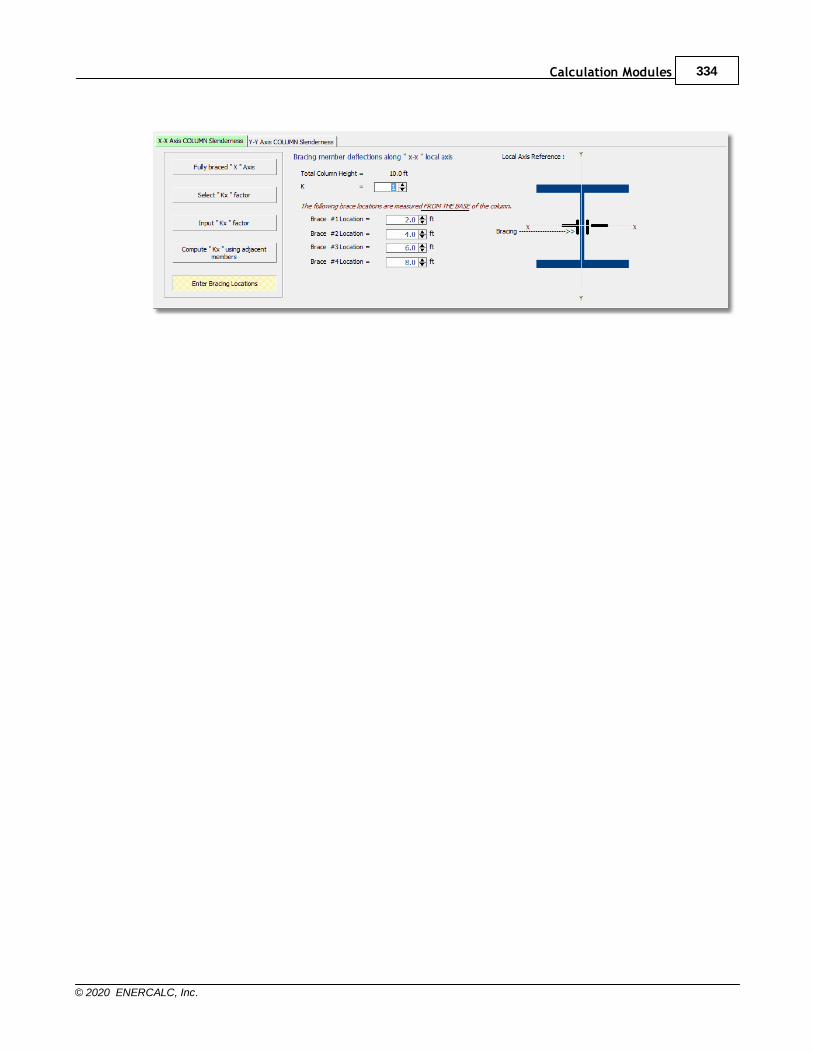
Calculation Modules 334
© 2020 ENERCALC, Inc.
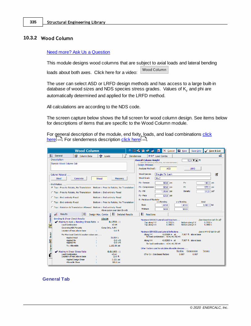
Structural Engineering Library335
© 2020 ENERCALC, Inc.
10.3.2 Wood Column
Need more? Ask Us a Question
This module designs wood columns that are subject to axial loads and lateral bending
loads about both axes. Click here for a video: Wood Column
The user can select ASD or LRFD design methods and has access to a large built-indatabase of wood sizes and NDS species stress grades. Values of K
F and phi are
automatically determined and applied for the LRFD method.
All calculations are according to the NDS code.
The screen capture below shows the full screen for wood column design. See items belowfor descriptions of items that are specific to the Wood Column module.
For general description of the module, end fixity, loads, and load combinations clickhere . For slenderness description click here .
General Tab
326 331
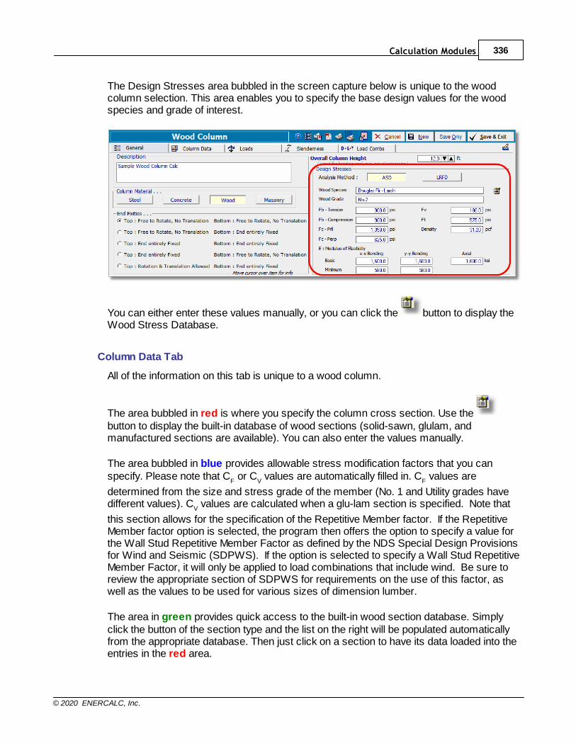
Calculation Modules 336
© 2020 ENERCALC, Inc.
The Design Stresses area bubbled in the screen capture below is unique to the woodcolumn selection. This area enables you to specify the base design values for the woodspecies and grade of interest.
You can either enter these values manually, or you can click the button to display theWood Stress Database.
Column Data Tab
All of the information on this tab is unique to a wood column.
The area bubbled in red is where you specify the column cross section. Use the button to display the built-in database of wood sections (solid-sawn, glulam, andmanufactured sections are available). You can also enter the values manually.
The area bubbled in blue provides allowable stress modification factors that you canspecify. Please note that C
F or C
V values are automatically filled in. C
F values are
determined from the size and stress grade of the member (No. 1 and Utility grades havedifferent values). C
V values are calculated when a glu-lam section is specified. Note that
this section allows for the specification of the Repetitive Member factor. If the RepetitiveMember factor option is selected, the program then offers the option to specify a value forthe Wall Stud Repetitive Member Factor as defined by the NDS Special Design Provisionsfor Wind and Seismic (SDPWS). If the option is selected to specify a Wall Stud RepetitiveMember Factor, it will only be applied to load combinations that include wind. Be sure toreview the appropriate section of SDPWS for requirements on the use of this factor, aswell as the values to be used for various sizes of dimension lumber.
The area in green provides quick access to the built-in wood section database. Simplyclick the button of the section type and the list on the right will be populated automaticallyfrom the appropriate database. Then just click on a section to have its data loaded into theentries in the red area.
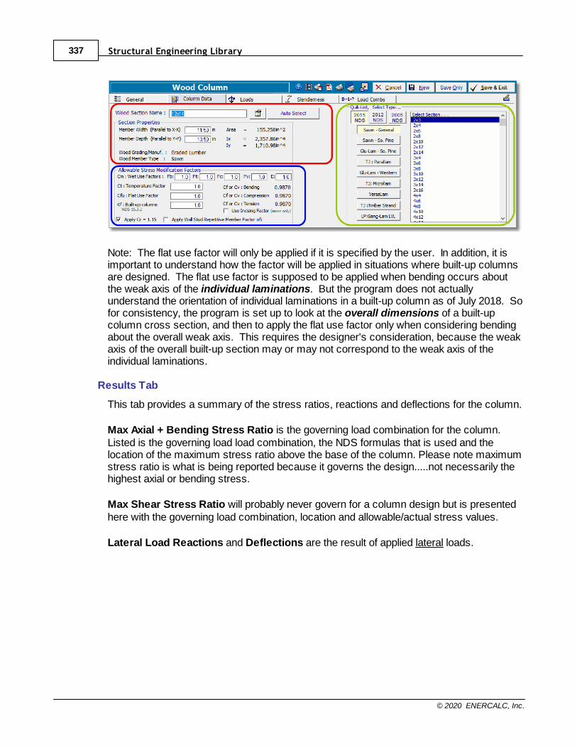
Structural Engineering Library337
© 2020 ENERCALC, Inc.
Note: The flat use factor will only be applied if it is specified by the user. In addition, it isimportant to understand how the factor will be applied in situations where built-up columnsare designed. The flat use factor is supposed to be applied when bending occurs aboutthe weak axis of the individual laminations. But the program does not actuallyunderstand the orientation of individual laminations in a built-up column as of July 2018. Sofor consistency, the program is set up to look at the overall dimensions of a built-upcolumn cross section, and then to apply the flat use factor only when considering bendingabout the overall weak axis. This requires the designer's consideration, because the weakaxis of the overall built-up section may or may not correspond to the weak axis of theindividual laminations.
Results Tab
This tab provides a summary of the stress ratios, reactions and deflections for the column.
Max Axial + Bending Stress Ratio is the governing load combination for the column.Listed is the governing load load combination, the NDS formulas that is used and thelocation of the maximum stress ratio above the base of the column. Please note maximumstress ratio is what is being reported because it governs the design.....not necessarily thehighest axial or bending stress.
Max Shear Stress Ratio will probably never govern for a column design but is presentedhere with the governing load combination, location and allowable/actual stress values.
Lateral Load Reactions and Deflections are the result of applied lateral loads.
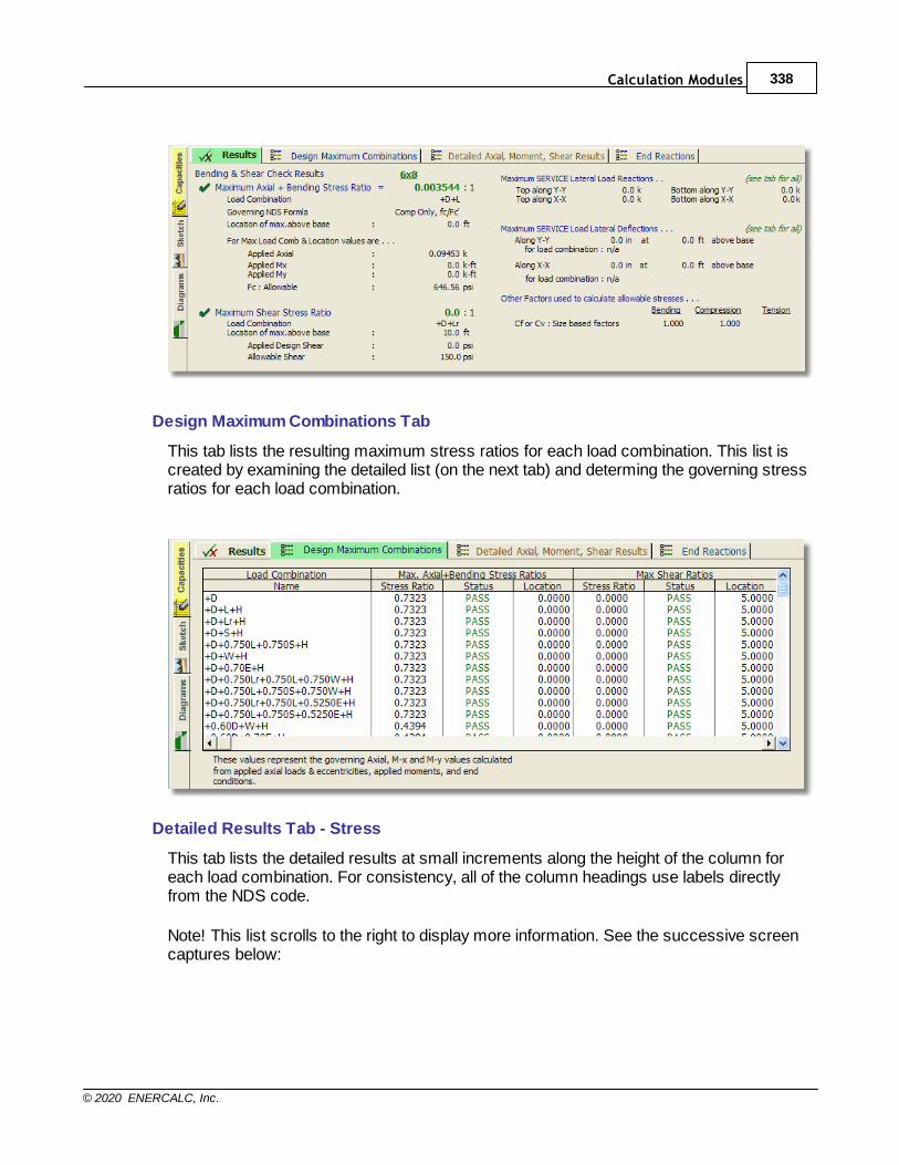
Calculation Modules 338
© 2020 ENERCALC, Inc.
Design Maximum Combinations Tab
This tab lists the resulting maximum stress ratios for each load combination. This list iscreated by examining the detailed list (on the next tab) and determing the governing stressratios for each load combination.
Detailed Results Tab - Stress
This tab lists the detailed results at small increments along the height of the column foreach load combination. For consistency, all of the column headings use labels directlyfrom the NDS code.
Note! This list scrolls to the right to display more information. See the successive screencaptures below:
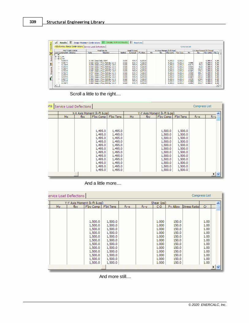
Structural Engineering Library339
© 2020 ENERCALC, Inc.
Scroll a little to the right....
And a little more....
And more still....
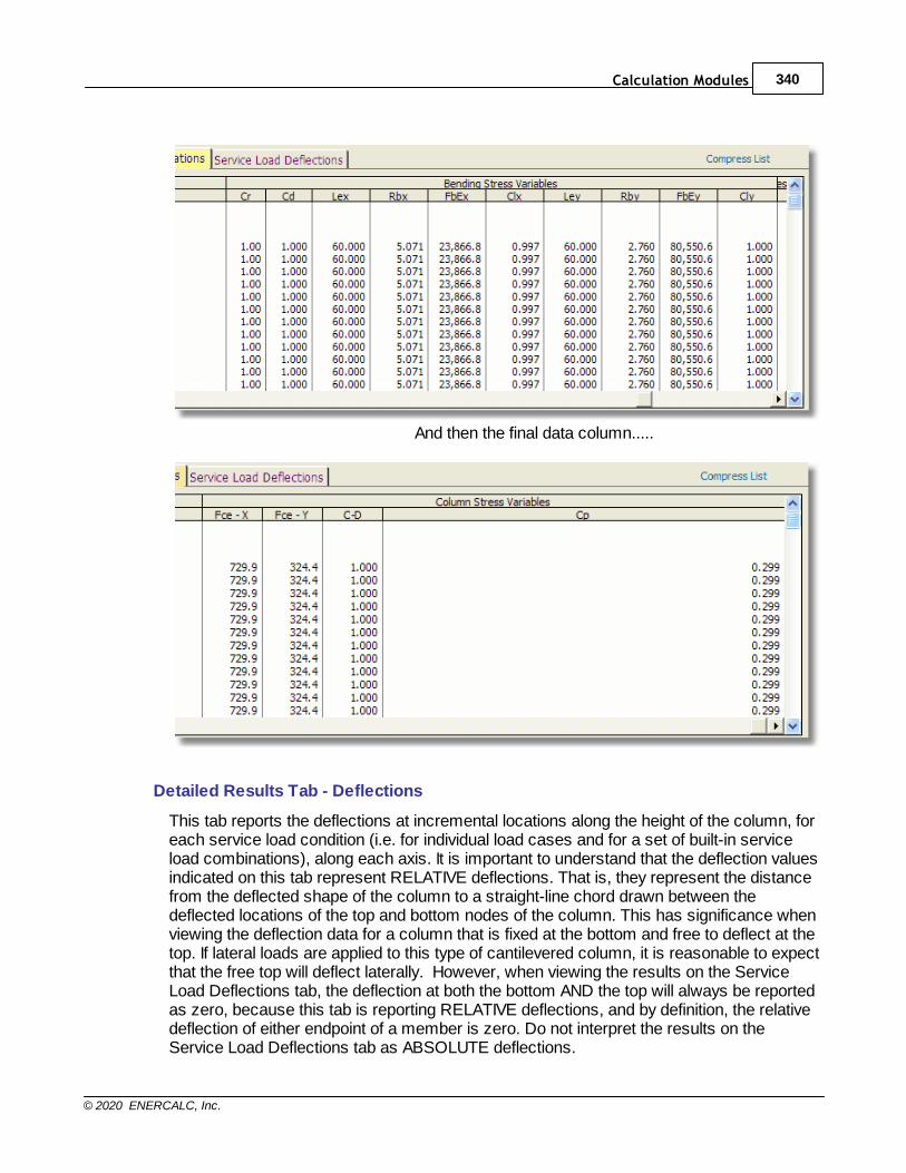
Calculation Modules 340
© 2020 ENERCALC, Inc.
And then the final data column.....
Detailed Results Tab - Deflections
This tab reports the deflections at incremental locations along the height of the column, foreach service load condition (i.e. for individual load cases and for a set of built-in serviceload combinations), along each axis. It is important to understand that the deflection valuesindicated on this tab represent RELATIVE deflections. That is, they represent the distancefrom the deflected shape of the column to a straight-line chord drawn between thedeflected locations of the top and bottom nodes of the column. This has significance whenviewing the deflection data for a column that is fixed at the bottom and free to deflect at thetop. If lateral loads are applied to this type of cantilevered column, it is reasonable to expectthat the free top will deflect laterally. However, when viewing the results on the ServiceLoad Deflections tab, the deflection at both the bottom AND the top will always be reportedas zero, because this tab is reporting RELATIVE deflections, and by definition, the relativedeflection of either endpoint of a member is zero. Do not interpret the results on theService Load Deflections tab as ABSOLUTE deflections.
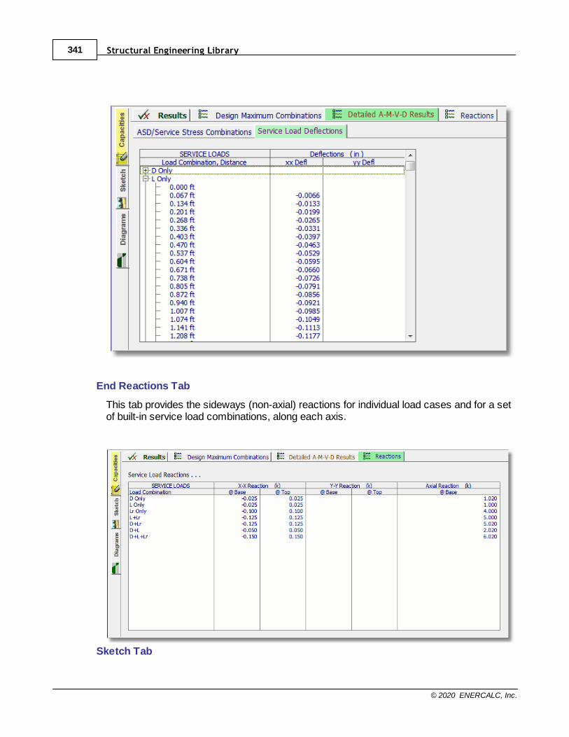
Structural Engineering Library341
© 2020 ENERCALC, Inc.
End Reactions Tab
This tab provides the sideways (non-axial) reactions for individual load cases and for a setof built-in service load combinations, along each axis.
Sketch Tab
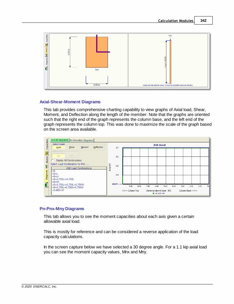
Calculation Modules 342
© 2020 ENERCALC, Inc.
Axial-Shear-Moment Diagrams
This tab provides comprehensive charting capability to view graphs of Axial load, Shear,Moment, and Deflection along the length of the member. Note that the graphs are orientedsuch that the right end of the graph represents the column base, and the left end of thegraph represents the column top. This was done to maximize the scale of the graph basedon the screen area available.
Pn-Pnx-Mny Diagrams
This tab allows you to see the moment capacities about each axis given a certainallowable axial load.
This is mostly for reference and can be considered a reverse application of the loadcapacity calculations.
In the screen capture below we have selected a 30 degree angle. For a 1.1 kip axial loadyou can see the moment capacity values, Mnx and Mny.

Structural Engineering Library343
© 2020 ENERCALC, Inc.
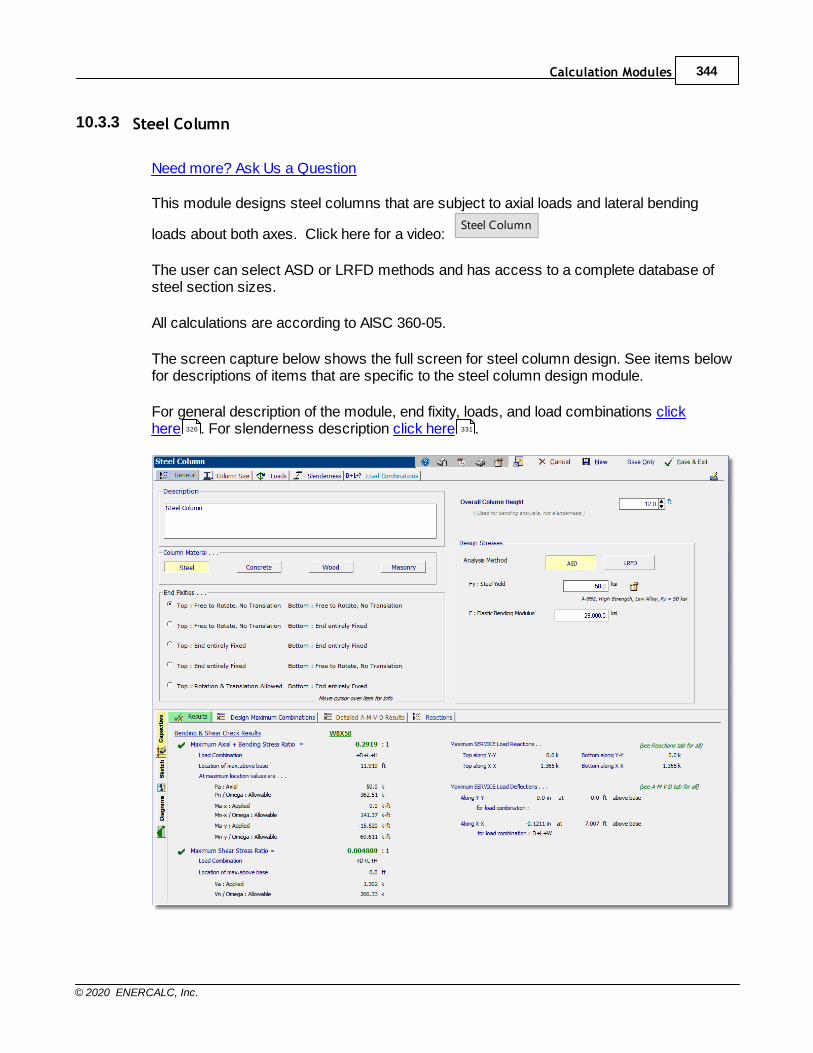
Calculation Modules 344
© 2020 ENERCALC, Inc.
10.3.3 Steel Column
Need more? Ask Us a Question
This module designs steel columns that are subject to axial loads and lateral bending
loads about both axes. Click here for a video: Steel Column
The user can select ASD or LRFD methods and has access to a complete database ofsteel section sizes.
All calculations are according to AISC 360-05.
The screen capture below shows the full screen for steel column design. See items belowfor descriptions of items that are specific to the steel column design module.
For general description of the module, end fixity, loads, and load combinations clickhere . For slenderness description click here .326 331
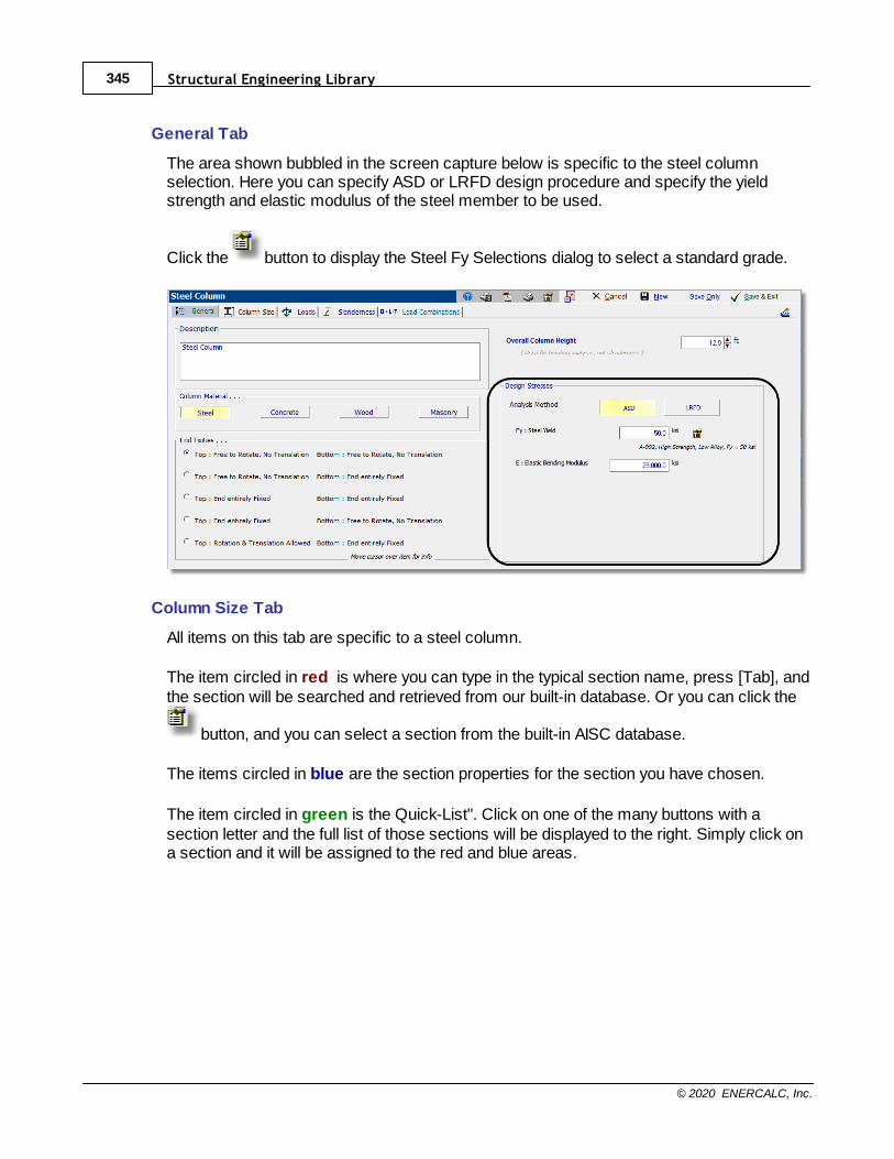
Structural Engineering Library345
© 2020 ENERCALC, Inc.
General Tab
The area shown bubbled in the screen capture below is specific to the steel columnselection. Here you can specify ASD or LRFD design procedure and specify the yieldstrength and elastic modulus of the steel member to be used.
Click the button to display the Steel Fy Selections dialog to select a standard grade.
Column Size Tab
All items on this tab are specific to a steel column.
The item circled in red is where you can type in the typical section name, press [Tab], andthe section will be searched and retrieved from our built-in database. Or you can click the
button, and you can select a section from the built-in AISC database.
The items circled in blue are the section properties for the section you have chosen.
The item circled in green is the Quick-List". Click on one of the many buttons with asection letter and the full list of those sections will be displayed to the right. Simply click ona section and it will be assigned to the red and blue areas.

Calculation Modules 346
© 2020 ENERCALC, Inc.
The button circled in pink will display the Steel Member Design dialog (see below).
This tool checks all of the steel sections for the selected type (W is selected in this case). A section will be judged to pass if the maximum stress ratio entered is not exceededand the depth measurements and depth class are not exceeded.
We use the term "Depth Class" to refer to the nominal dimension of the family to which thesection belongs (ex: W14). It does refer to the actual depth of the section. All sectionsstarting with "W14" are of the "14" depth class.
Results Tab
This tab provides a summary of the stress ratios, reactions and deflections for the column.
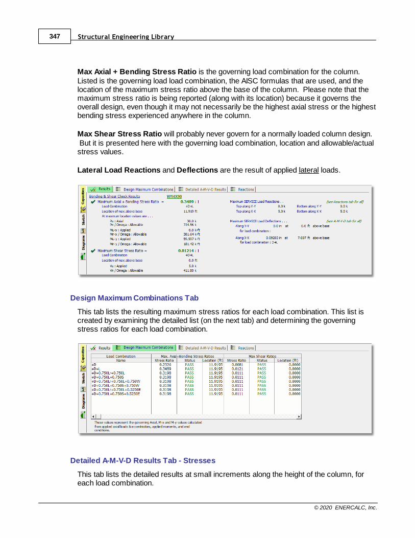
Structural Engineering Library347
© 2020 ENERCALC, Inc.
Max Axial + Bending Stress Ratio is the governing load combination for the column.Listed is the governing load load combination, the AISC formulas that are used, and thelocation of the maximum stress ratio above the base of the column. Please note that themaximum stress ratio is being reported (along with its location) because it governs theoverall design, even though it may not necessarily be the highest axial stress or the highestbending stress experienced anywhere in the column.
Max Shear Stress Ratio will probably never govern for a normally loaded column design. But it is presented here with the governing load combination, location and allowable/actualstress values.
Lateral Load Reactions and Deflections are the result of applied lateral loads.
Design Maximum Combinations Tab
This tab lists the resulting maximum stress ratios for each load combination. This list iscreated by examining the detailed list (on the next tab) and determining the governingstress ratios for each load combination.
Detailed A-M-V-D Results Tab - Stresses
This tab lists the detailed results at small increments along the height of the column, foreach load combination.
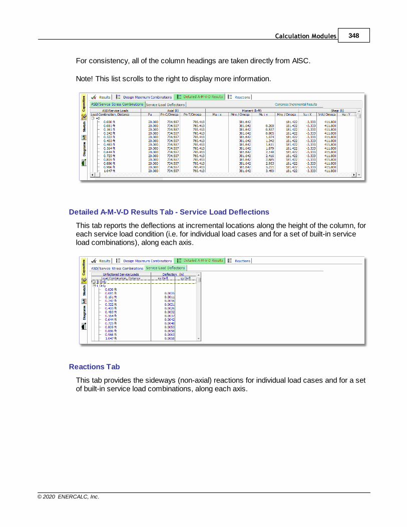
Calculation Modules 348
© 2020 ENERCALC, Inc.
For consistency, all of the column headings are taken directly from AISC.
Note! This list scrolls to the right to display more information.
Detailed A-M-V-D Results Tab - Service Load Deflections
This tab reports the deflections at incremental locations along the height of the column, foreach service load condition (i.e. for individual load cases and for a set of built-in serviceload combinations), along each axis.
Reactions Tab
This tab provides the sideways (non-axial) reactions for individual load cases and for a setof built-in service load combinations, along each axis.
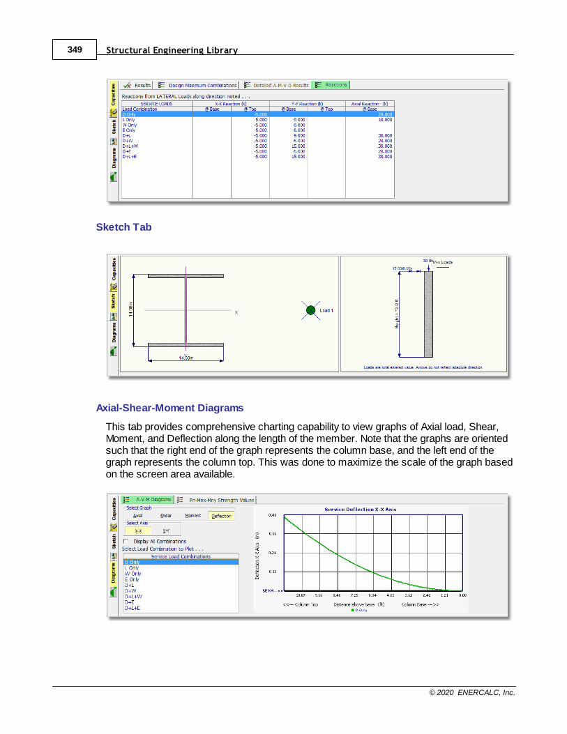
Structural Engineering Library349
© 2020 ENERCALC, Inc.
Sketch Tab
Axial-Shear-Moment Diagrams
This tab provides comprehensive charting capability to view graphs of Axial load, Shear,Moment, and Deflection along the length of the member. Note that the graphs are orientedsuch that the right end of the graph represents the column base, and the left end of thegraph represents the column top. This was done to maximize the scale of the graph basedon the screen area available.
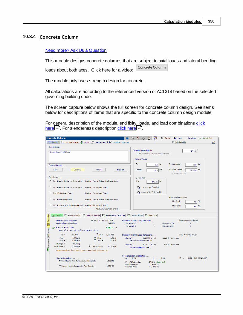
Calculation Modules 350
© 2020 ENERCALC, Inc.
10.3.4 Concrete Column
Need more? Ask Us a Question
This module designs concrete columns that are subject to axial loads and lateral bending
loads about both axes. Click here for a video: Concrete Column
The module only uses strength design for concrete.
All calculations are according to the referenced version of ACI 318 based on the selectedgoverning building code.
The screen capture below shows the full screen for concrete column design. See itemsbelow for descriptions of items that are specific to the concrete column design module.
For general description of the module, end fixity, loads, and load combinations clickhere . For slenderness description click here .326 331
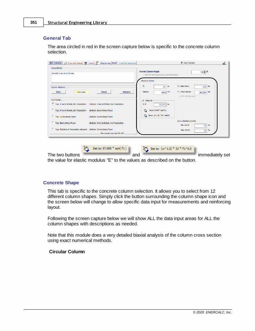
Structural Engineering Library351
© 2020 ENERCALC, Inc.
General Tab
The area circled in red in the screen capture below is specific to the concrete columnselection.
The two buttons and immediately setthe value for elastic modulus "E" to the values as described on the button.
Concrete Shape
This tab is specific to the concrete column selection. It allows you to select from 12different column shapes. Simply click the button surrounding the column shape icon andthe screen below will change to allow specific data input for measurements and reinforcinglayout.
Following the screen capture below we will show ALL the data input areas for ALL thecolumn shapes with descriptions as needed.
Note that this module does a very detailed biaxial analysis of the column cross sectionusing exact numerical methods.
Circular Column
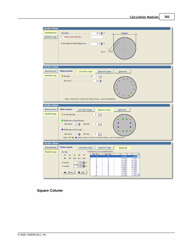
Calculation Modules 352
© 2020 ENERCALC, Inc.
Square Column
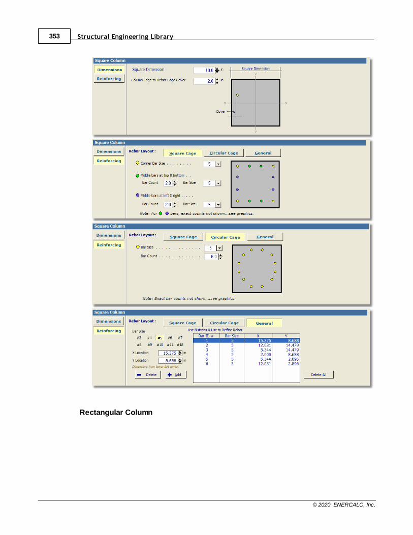
Structural Engineering Library353
© 2020 ENERCALC, Inc.
Rectangular Column
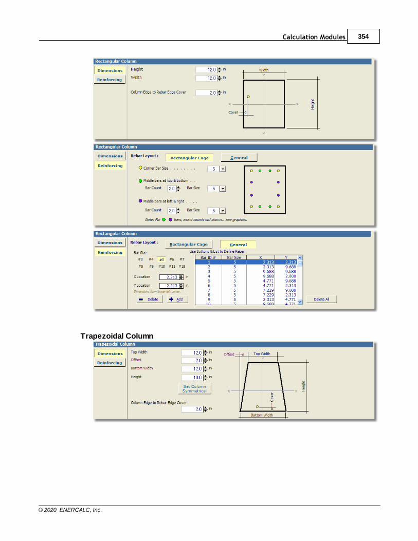
Calculation Modules 354
© 2020 ENERCALC, Inc.
Trapezoidal Column
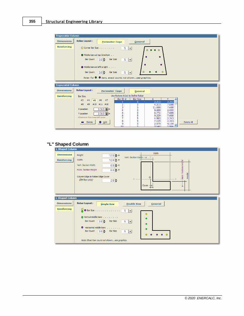
Structural Engineering Library355
© 2020 ENERCALC, Inc.
"L" Shaped Column
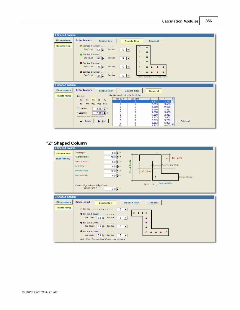
Calculation Modules 356
© 2020 ENERCALC, Inc.
"Z" Shaped Column
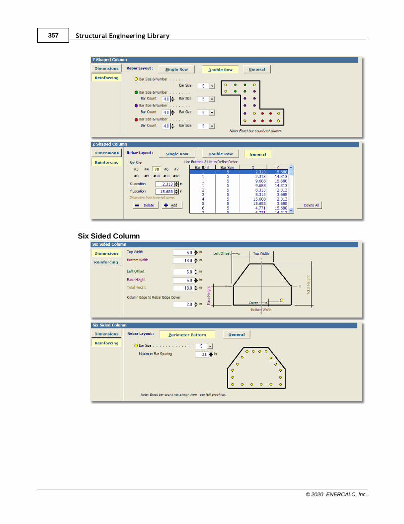
Structural Engineering Library357
© 2020 ENERCALC, Inc.
Six Sided Column
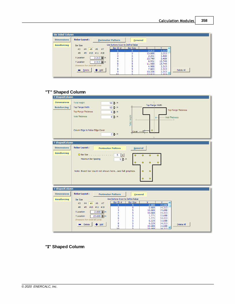
Calculation Modules 358
© 2020 ENERCALC, Inc.
"T" Shaped Column
"I" Shaped Column
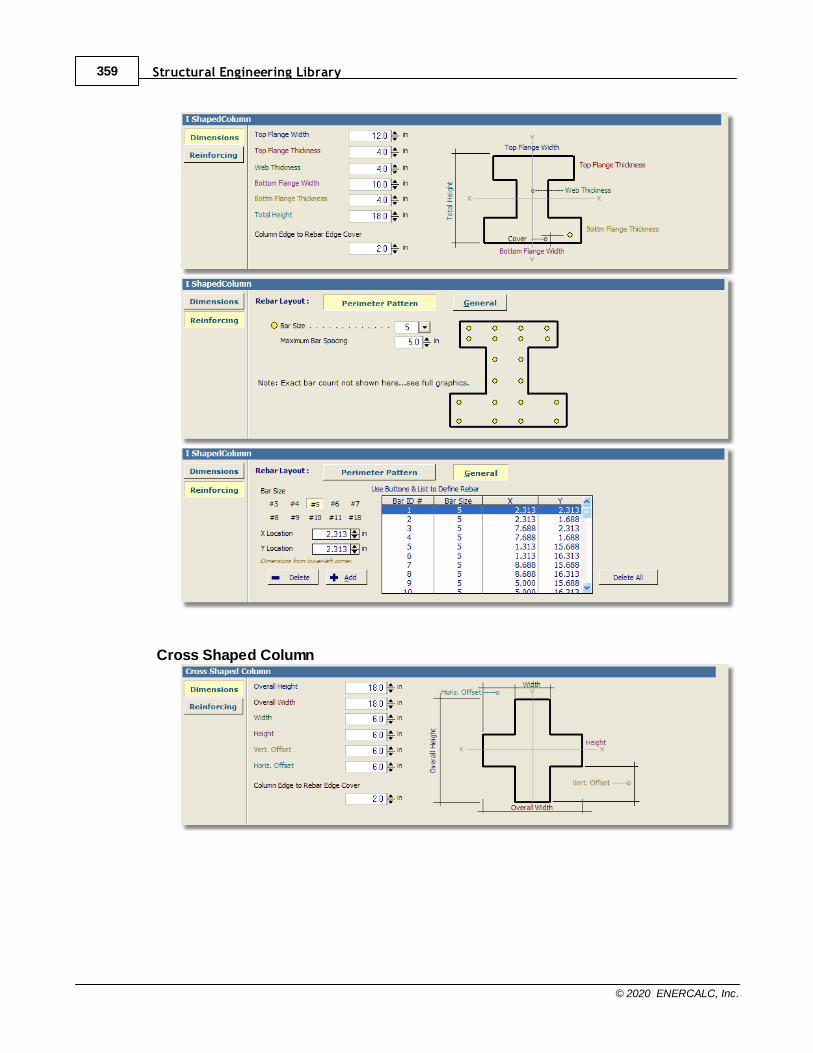
Structural Engineering Library359
© 2020 ENERCALC, Inc.
Cross Shaped Column
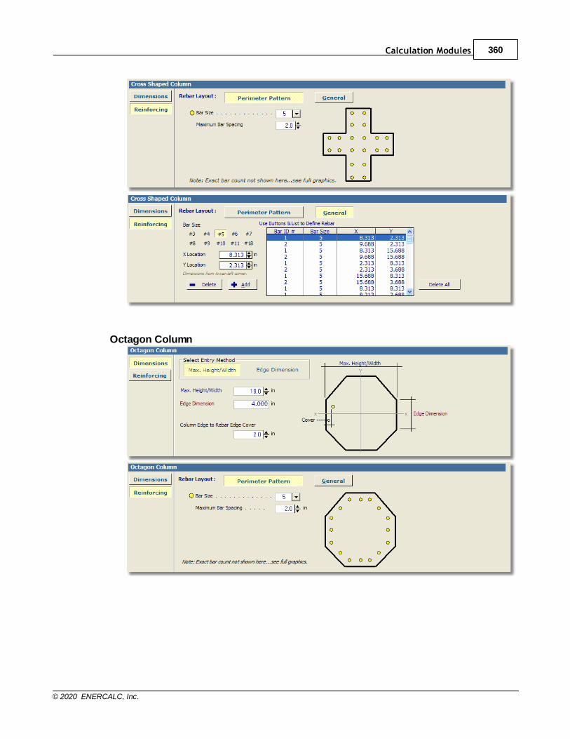
Calculation Modules 360
© 2020 ENERCALC, Inc.
Octagon Column
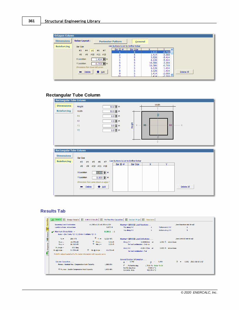
Structural Engineering Library361
© 2020 ENERCALC, Inc.
Rectangular Tube Column
Results Tab
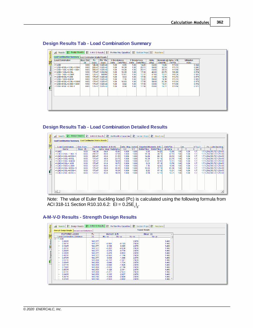
Calculation Modules 362
© 2020 ENERCALC, Inc.
Design Results Tab - Load Combination Summary
Design Results Tab - Load Combination Detailed Results
Note: The value of Euler Buckling load (Pc) is calculated using the following formula fromACI 318-11 Section R10.10.6.2: EI = 0.25E
cIg.
A-M-V-D Results - Strength Design Results
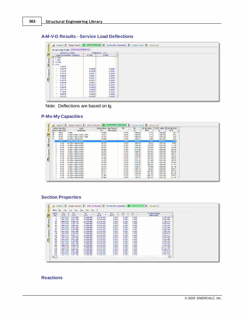
Structural Engineering Library363
© 2020 ENERCALC, Inc.
A-M-V-D Results - Service Load Deflections
Note: Deflections are based on Ig.
P-Mx-My Capacities
Section Properties
Reactions
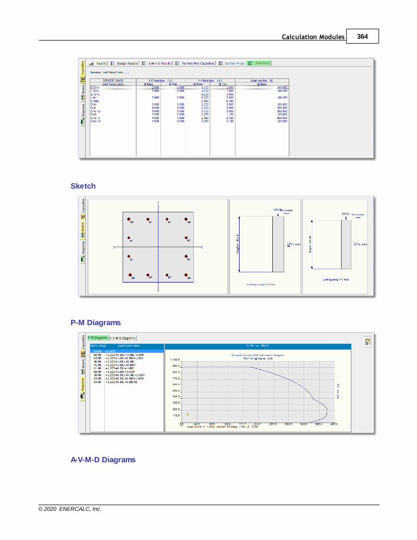
Calculation Modules 364
© 2020 ENERCALC, Inc.
Sketch
P-M Diagrams
A-V-M-D Diagrams
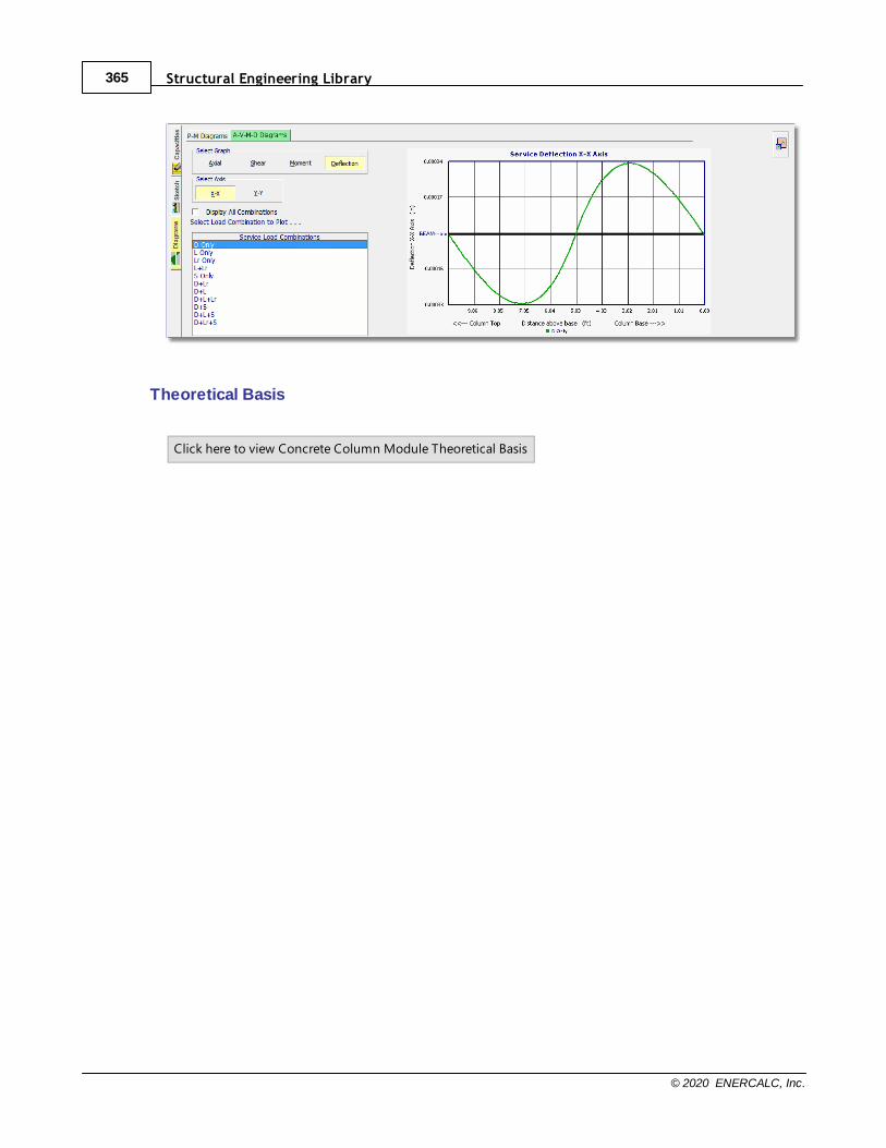
Structural Engineering Library365
© 2020 ENERCALC, Inc.
Theoretical Basis
Click here to view Concrete Column Module Theoretical Basis
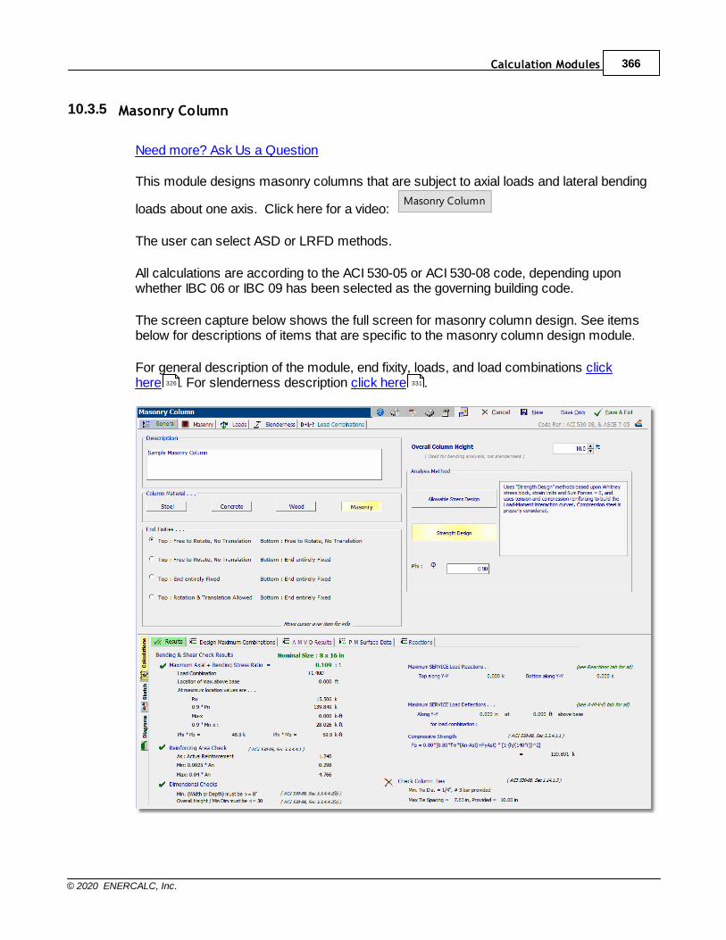
Calculation Modules 366
© 2020 ENERCALC, Inc.
10.3.5 Masonry Column
Need more? Ask Us a Question
This module designs masonry columns that are subject to axial loads and lateral bending
loads about one axis. Click here for a video: Masonry Column
The user can select ASD or LRFD methods.
All calculations are according to the ACI 530-05 or ACI 530-08 code, depending uponwhether IBC 06 or IBC 09 has been selected as the governing building code.
The screen capture below shows the full screen for masonry column design. See itemsbelow for descriptions of items that are specific to the masonry column design module.
For general description of the module, end fixity, loads, and load combinations clickhere . For slenderness description click here .326 331
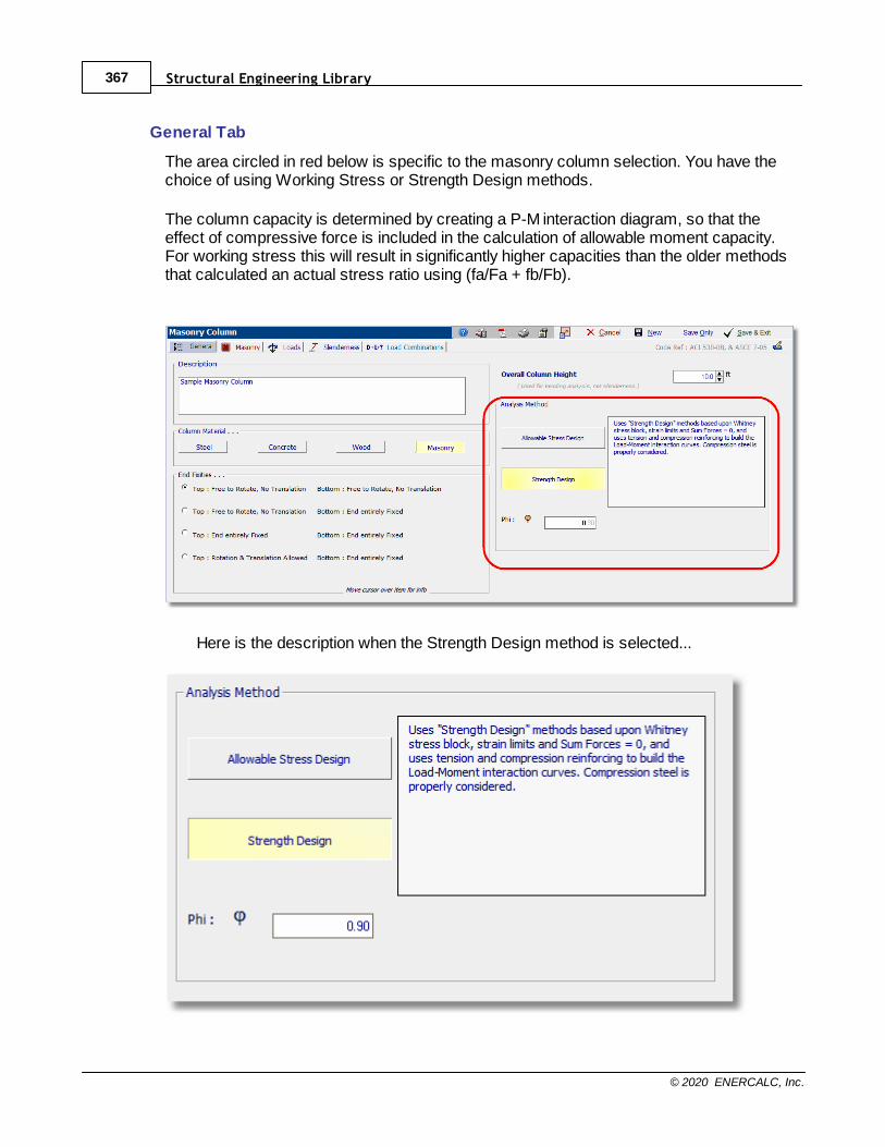
Structural Engineering Library367
© 2020 ENERCALC, Inc.
General Tab
The area circled in red below is specific to the masonry column selection. You have thechoice of using Working Stress or Strength Design methods.
The column capacity is determined by creating a P-M interaction diagram, so that theeffect of compressive force is included in the calculation of allowable moment capacity.For working stress this will result in significantly higher capacities than the older methodsthat calculated an actual stress ratio using (fa/Fa + fb/Fb).
Here is the description when the Strength Design method is selected...
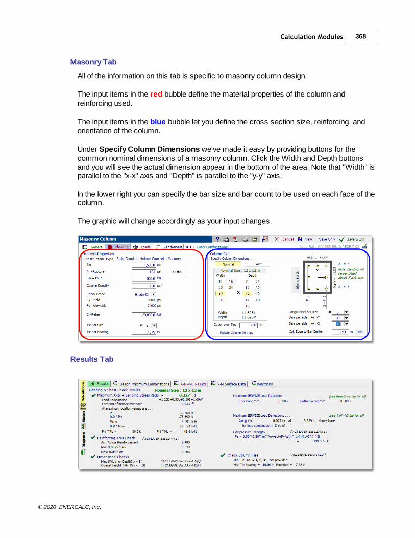
Calculation Modules 368
© 2020 ENERCALC, Inc.
Masonry Tab
All of the information on this tab is specific to masonry column design.
The input items in the red bubble define the material properties of the column andreinforcing used.
The input items in the blue bubble let you define the cross section size, reinforcing, andorientation of the column.
Under Specify Column Dimensions we've made it easy by providing buttons for thecommon nominal dimensions of a masonry column. Click the Width and Depth buttonsand you will see the actual dimension appear in the bottom of the area. Note that "Width" isparallel to the "x-x" axis and "Depth" is parallel to the "y-y" axis.
In the lower right you can specify the bar size and bar count to be used on each face of thecolumn.
The graphic will change accordingly as your input changes.
Results Tab
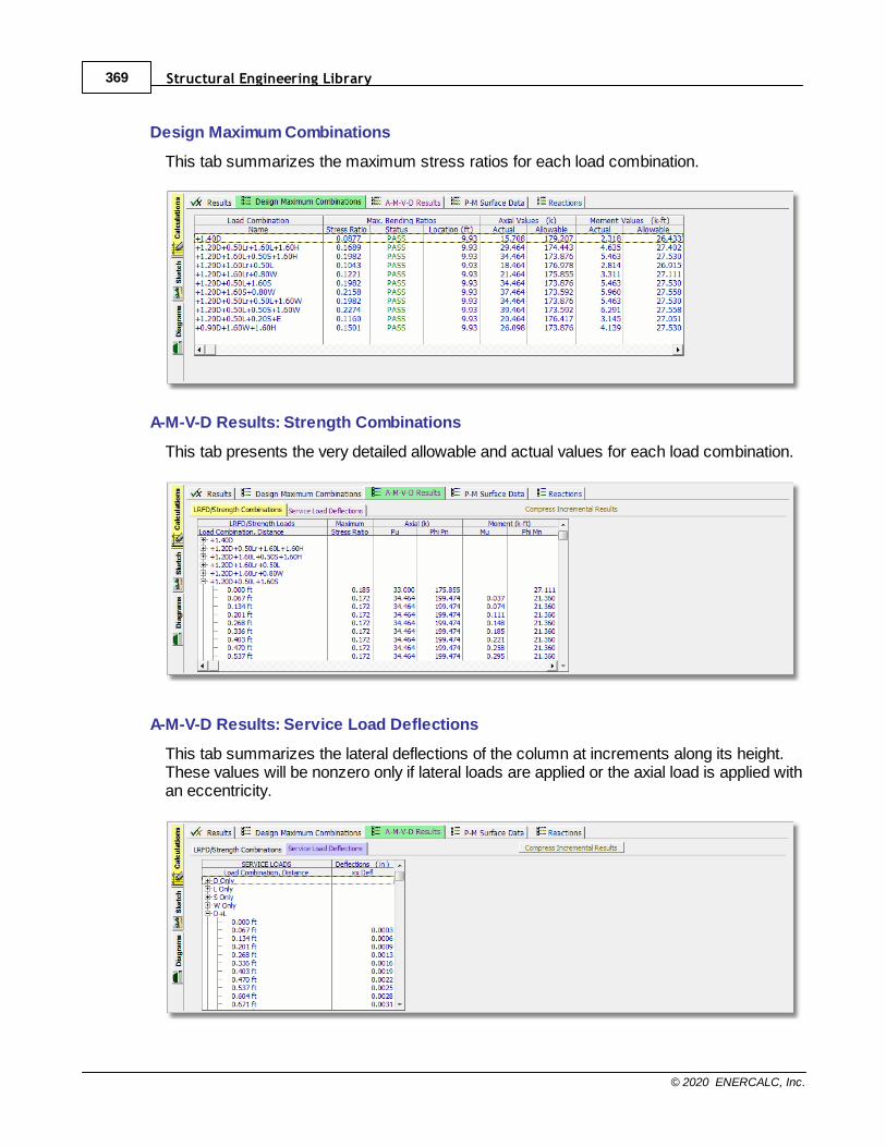
Structural Engineering Library369
© 2020 ENERCALC, Inc.
Design Maximum Combinations
This tab summarizes the maximum stress ratios for each load combination.
A-M-V-D Results: Strength Combinations
This tab presents the very detailed allowable and actual values for each load combination.
A-M-V-D Results: Service Load Deflections
This tab summarizes the lateral deflections of the column at increments along its height.These values will be nonzero only if lateral loads are applied or the axial load is applied withan eccentricity.
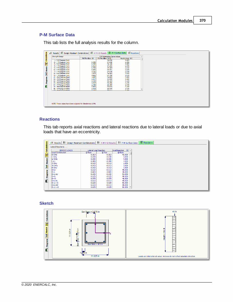
Calculation Modules 370
© 2020 ENERCALC, Inc.
P-M Surface Data
This tab lists the full analysis results for the column.
Reactions
This tab reports axial reactions and lateral reactions due to lateral loads or due to axialloads that have an eccentricity.
Sketch
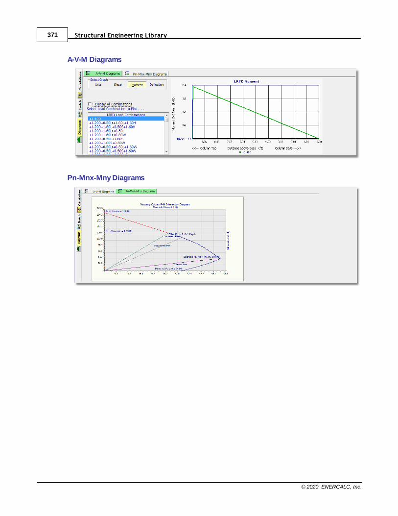
Structural Engineering Library371
© 2020 ENERCALC, Inc.
A-V-M Diagrams
Pn-Mnx-Mny Diagrams

Calculation Modules 372
© 2020 ENERCALC, Inc.
10.4 General Walls
General Introductory Video:
Click Here for Video

Structural Engineering Library373
© 2020 ENERCALC, Inc.
10.4.1 Concrete Slender Wall
Need more? Ask Us a Question
This program provides analysis of concrete wall panels that stand vertically and have
applied vertical and out-of-plane lateral loads. Click here for a video: Concrete Slender Wall
The wall panel is analyzed using strength design procedures. Out-of-plane momentswithin the wall are created by eccentric axial loads, applied lateral loads, lateral self weightloads and moments induced due to the wall weight acting at an eccentricity when itdeflects (P-Delta moments).
The ACI slender wall procedure, introduced in ACI 318-99, was first adopted by the IBC2000 and subsequent code editions. As quoted in ACI 318R-05 Commentary, Section 14.8is based on the corresponding requirements in 1997 UBC and experimental researchpresented in the 1982 "Test Report by SCCACI-SEAOSC". Analytical study of the currentIBC/ACI provisions for concrete wall panels showed the ACI procedure does notcorrespond to a bilinear load-deflection characteristic observed in the SEAOSC tests andsignificantly underestimates the service load deflection. The ENERCALC Concrete Slender Wall program uses basic principles of structuralmechanics to model the wall as a series of beam segments. For each segment the actualmoment is used to calculate member stiffness using the I
ef f ectiv e equations developed by
Peter H. Bischoff. Since these changes to wall stiffness affect the wall deflection profile,the program performs an iterative analysis of calculating moments (including P-Deltaeffects). The results are deflection curves almost exactly matching the SCCACI-SEAOSCtest results. This makes this program far more accurate at calculating wall deflections andP-Delta effects than the simple equations in the ACI code.
Capabilities
This module provides these capabilities:· One or two story slender tilt-up concrete walls
· Iterative process accounts for P-delta
· Optional parapet
· Axial loads with optional eccentricities
· Wind, seismic and user defined lateral loads creating bending on the wall panel
· Variable strip width to model the wall panel
· Temperature differential can be specified across thickness of wall to add curvature
· Rebar location at center of wall or two layers of reinforcing at each side
· Bottom of wall can be fixed or pinned for moment resistance
· Top of wall can be pinned or free
· A reveal can be defined and cross section properties modified for reduced thickness andoptionally add rebar
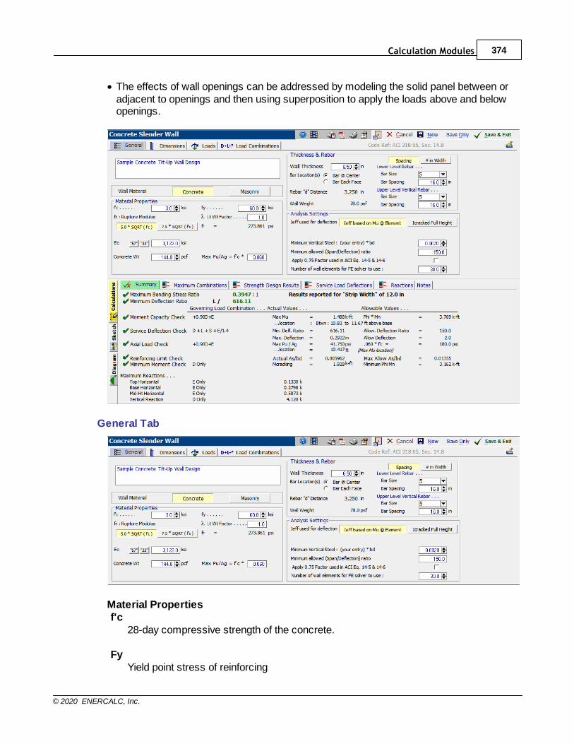
Calculation Modules 374
© 2020 ENERCALC, Inc.
· The effects of wall openings can be addressed by modeling the solid panel between oradjacent to openings and then using superposition to apply the loads above and belowopenings.
General Tab
Material Propertiesf'c
28-day compressive strength of the concrete.
FyYield point stress of reinforcing
Structural Engineering Library375
© 2020 ENERCALC, Inc.
Fr: Rupture ModulusMultiplier used in the expression to define the modulus of rupture for the concrete. 5.0is the original recommended multiplier that was developed as a result of the SEAOSCslender wall tests of the early 1980s. 7.5 is the multiplier provided by ACI 318-05, -08,and -11.
LambdaFactor to account for lightweight concrete.
EcModulus of elasticity of concrete. You can enter the value or click the["57"] button to set Ec = 57000 * sqrt(f'c), or click the
["33"] button to set Ec = 33 * sqrt(f'c) * ConcWeight1.5.
Concrete WtWeight of concrete in pounds per cubic foot.
Max Pu/Ag = f'c * <entry>Enter a multiplier less than 1.0 which will be applied to f'c to determine the maximumallowable factored axial stress.
Thickness & Rebar
Wall ThicknessTotal wall thickness
Bar LocationYou can select bar placement at the center of the wall thickness or at each face.When selecting "Bar Each Face" the module performs calculations considering bothbars.
Rebar "d" DistanceEnter the distance between the outside surface of the wall to the centerline of therebar. For bars each face this measurement can be from either face.
Wall WeightThe internally calculated wall weight considering the concrete weight and wallthickness entered.
Rebar [Spacing] / [# in Width]These two options indicate how you will specify the rebar quantity in your design strip.
[Spacing] will change the entry so that you can enter a spacing in inches for the rebar.
[# in Width] changes the entry so you can enter the number of bars in your designstrip, where the width of the design strip is entered on the Dimensions tab.
Calculation Modules 376
© 2020 ENERCALC, Inc.
Note: When using the "Bars Each Face" option, the "# Bars in Width" specifies thenumber of bars on each face within the design strip width.
Bar SizeEnter the US customary rebar size number.
Analysis Settings
Ieff used for DeflectionThe module offers the option to use I
ef f ectiv e based on the moment in the individual wall
elements or to use Icracked
for the full height of the wall.
Temperature Differential across thicknessThis input is used to describe the temperature change between each face of the wall.A temperature change induces a slight curvature into the wall because the hotter sideexpands, resulting in a slightly higher out-of-plane deflection.
Minimum Vertical Steel: %/100Minimum steel as a percentage of the gross wall area.
Minimum Allowed (Span/Deflection) RatioThis setting establishes the minimum allowable ratio of span length to service loaddeflection. If a lower actual Span/Deflection ratio occurs (meaning greater deflection),a warning message will be displayed.
Apply 0.75 Factor used in ACI Eq. 14-5 & 14-6Please see the code reference for an explanation of this factor. It is typically not usedin this module because it is a calibration factor used to curve fit deflection calculationswith ACI approximate formulas.
Number of wall elements for FE solver to useThis module divides the wall design strip into segments from the base to the top foranalysis purposes. Use this entry to define the number of segments to use.Experience demonstrates that approximately 30 segments gives a good balancebetween the iterative P-Delta analysis reaching convergence and excessivecalculation time.
Dimensions Tab
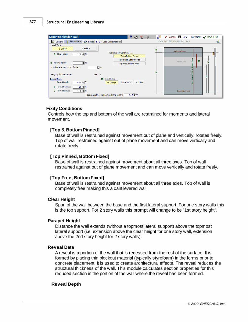
Structural Engineering Library377
© 2020 ENERCALC, Inc.
Fixity ConditionsControls how the top and bottom of the wall are restrained for moments and lateralmovement.
[Top & Bottom Pinned]Base of wall is restrained against movement out of plane and vertically, rotates freely.Top of wall restrained against out of plane movement and can move vertically androtate freely.
[Top Pinned, Bottom Fixed]Base of wall is restrained against movement about all three axes. Top of wallrestrained against out of plane movement and can move vertically and rotate freely.
[Top Free, Bottom Fixed]Base of wall is restrained against movement about all three axes. Top of wall iscompletely free making this a cantilevered wall.
Clear HeightSpan of the wall between the base and the first lateral support. For one story walls thisis the top support. For 2 story walls this prompt will change to be "1st story height".
Parapet HeightDistance the wall extends (without a topmost lateral support) above the topmostlateral support (i.e. extension above the clear height for one story wall, extensionabove the 2nd story height for 2 story walls).
Reveal DataA reveal is a portion of the wall that is recessed from the rest of the surface. It isformed by placing thin blockout material (typically styrofoam) in the forms prior toconcrete placement. It is used to create architectural effects. The reveal reduces thestructural thickness of the wall. This module calculates section properties for thisreduced section in the portion of the wall where the reveal has been formed.
Reveal Depth
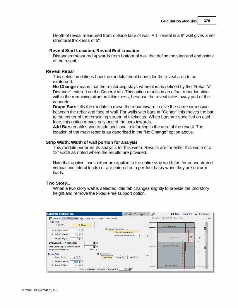
Calculation Modules 378
© 2020 ENERCALC, Inc.
Depth of reveal measured from outside face of wall. A 1" reveal in a 6" wall gives a netstructural thickness of 5".
Reveal Start Location, Reveal End LocationDistances measured upwards from bottom of wall that define the start and end pointsof the reveal.
Reveal RebarThis selection defines how the module should consider the reveal area to bereinforced.No Change means that the reinforcing stays where it is as defined by the "Rebar 'd'Distance" entered on the General tab. This option results in an offset rebar locationwithin the remaining structural thickness, because the reveal takes away part of theconcrete.Drape Bars tells the module to move the rebar inward to give the same dimensionbetween the rebar and face of wall. For walls with bars at "Center" this moves the barto the center of the remaining structural thickness. When bars are specified on eachface, this option moves only one of the bars inwards.Add Bars enables you to add additional reinforcing in the area of the reveal. Thelocation of the main rebar is as described in the "No Change" option above.
Strip Width: Width of wall portion for analysisThis module performs its analysis for this width. Results are for either this width or a12" width as noted where the results are provided.
Note that applied loads either are applied to the entire strip width (as for concentratedvertical and lateral loads) or are entered on a per-foot basis when they are uniformloads.
Two Story...When a two story wall is selected, this tab changes slightly to provide the 2nd storyheight and remove the Fixed-Free support option.
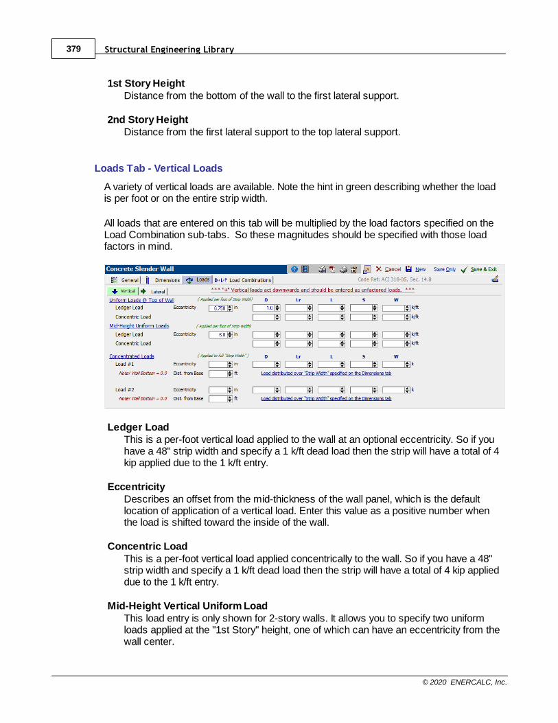
Structural Engineering Library379
© 2020 ENERCALC, Inc.
1st Story HeightDistance from the bottom of the wall to the first lateral support.
2nd Story HeightDistance from the first lateral support to the top lateral support.
Loads Tab - Vertical Loads
A variety of vertical loads are available. Note the hint in green describing whether the loadis per foot or on the entire strip width.
All loads that are entered on this tab will be multiplied by the load factors specified on theLoad Combination sub-tabs. So these magnitudes should be specified with those loadfactors in mind.
Ledger LoadThis is a per-foot vertical load applied to the wall at an optional eccentricity. So if youhave a 48" strip width and specify a 1 k/ft dead load then the strip will have a total of 4kip applied due to the 1 k/ft entry.
EccentricityDescribes an offset from the mid-thickness of the wall panel, which is the defaultlocation of application of a vertical load. Enter this value as a positive number whenthe load is shifted toward the inside of the wall.
Concentric LoadThis is a per-foot vertical load applied concentrically to the wall. So if you have a 48"strip width and specify a 1 k/ft dead load then the strip will have a total of 4 kip applieddue to the 1 k/ft entry.
Mid-Height Vertical Uniform LoadThis load entry is only shown for 2-story walls. It allows you to specify two uniformloads applied at the "1st Story" height, one of which can have an eccentricity from thewall center.

Calculation Modules 380
© 2020 ENERCALC, Inc.
Concentrated LoadsThis is a single concentrated vertical load applied to the wall "strip width" with anoptional eccentricity. Distance from Base is the height at which the load is applied.
Loads Tab - Lateral Loads
Lateral loads are applied perpendicular to the plane of the wall and are almost alwaysseismic or wind. These loads create out of plane deflection of the wall, which the modulewill use to develop P-Delta effects to calculate secondary moments in the wall. Recall thatthis module divides the wall into small segments and calculates the allowable and actualforces and deflections for each small segment. In this way the lateral loads are properlymodeled on what is effectively a beam with variable stiffness due to the state of cracking ineach segment.
All loads that are entered on this tab will be multiplied by the load factors specified on theLoad Combination sub-tabs. So these magnitudes should be specified with those loadfactors in mind.
Full area WIND LoadEnter the wind load that will be applied to the wall in the out-of-plane direction. Thisload will only be applied to one surface of the wall, and as such, the magnitude musttake into consideration both the internal and external pressures.
For the purpose of defining the direction of applied wind pressures, consider thatpressure will only be applied to the exterior surface of the wall. A net pressure thatacts TOWARD the exterior surface of the wall should be entered as a positive value. Anet pressure that acts AWAY FROM the exterior surface of the wall should be enteredas a negative value.
Wall Weight SEISMIC LoadThis section offers three options to specify the seismic load that will be applied to thewall in the out-of-plane direction:
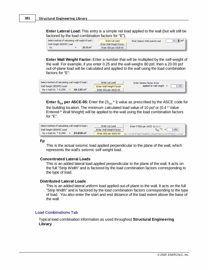
Structural Engineering Library381
© 2020 ENERCALC, Inc.
Enter Lateral Load: This entry is a simple net load applied to the wall (but will still befactored by the load combination factors for "E").
Enter Wall Weight Factor: Enter a number that will be multiplied by the self-weight ofthe wall. For example, if you enter 0.25 and the wall weighs 80 psf, then a 20.00 psfout-of-plane load will be calculated and applied to the wall using the load combinationfactors for "E".
Enter SDS per ASCE-05: Enter the (SDS
* I) value as prescribed by the ASCE code for
the building location. The minimum calculated load value of 10 psf or (0.4 * ValueEntered * Wall Weight) will be applied to the wall using the load combination factorsfor "E".
FpThis is the actual seismic load applied perpendicular to the plane of the wall, whichrepresents the wall's seismic self weight load.
Concentrated Lateral LoadsThis is an added lateral load applied perpendicular to the plane of the wall. It acts onthe full "Strip Width" and is factored by the load combination factors corresponding tothe type of load.
Distributed Lateral LoadsThis is an added lateral uniform load applied out-of-plane to the wall. It acts on the full"Strip Width" and is factored by the load combination factors corresponding to the typeof load. You also enter the start and end distance of the load extent above the base ofthe wall.
Load Combinations Tab
Typical load combination information as used throughout Structural EngineeringLibrary.
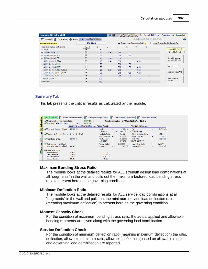
Calculation Modules 382
© 2020 ENERCALC, Inc.
Summary Tab
This tab presents the critical results as calculated by the module.
Maximum Bending Stress RatioThe module looks at the detailed results for ALL strength design load combinations atall "segments" in the wall and pulls out the maximum factored load bending stressratio to present here as the governing condition.
Minimum Deflection RatioThe module looks at the detailed results for ALL service load combinations at all"segments" in the wall and pulls out the minimum service load deflection ratio(meaning maximum deflection) to present here as the governing condition.
Moment Capacity CheckFor the condition of maximum bending stress ratio, the actual applied and allowablebending moments are given along with the governing load combination.
Service Deflection CheckFor the condition of minimum deflection ratio (meaning maximum deflection) the ratio,deflection, allowable minimum ratio, allowable deflection (based on allowable ratio)and governing load combination are reported.

Structural Engineering Library383
© 2020 ENERCALC, Inc.
Axial Load CheckThe module checks the actual axial stress in all segments for all load combinationsand gives the maximum actual stress Pu/Ag. The allowable value is the result of theuser's entry for maximum percentage of f'c to use.
Reinforcing Limit CheckThe module checks all portions of the wall for reinforcing (including differentlyreinforced first and second stories and reveal areas). It reports the maximumreinforcing ratio and compares it with the maximum percentage of balanced sectionanalysis As allowed.
Minimum Moment CheckACI specifies that a wall section in bending shall have a minimum strength Mn that isgreater than the cracking strength Mcr = Sgross * Fr.
Maximum ReactionsThis gives a summary of the maximum reactions (both out-of-plane and vertical) alongwith the load combination that creates them.
Maximum Combinations Tab
This tab provides a summary of the governing values for each load combination for bothfactored load axial & bending and service load deflections.
Factored Load Maximum Moments for Load Combinations: The module looksthrough the result set for each load combination and identifies the location above thebase of the wall at which the maximum condition is found. Note that "Aseff" is theeffective area of steel and is influenced by the axial compression in that segment.
Service Load Maximum Deflections for Load Combinations: The module looksthrough the result set for each load combination and identifies the location above thebase of the wall at which the maximum out-of-plane deflection is found. The value for"Ieff" is specific to the segment at that location and is based on the actual moment andBischoff's equation for calculating effective moment of inertia.

Calculation Modules 384
© 2020 ENERCALC, Inc.
Strength Design Results Tab
This tab provides an extremely detailed summary of the factored axial load, moments,effective steel area and moment of inertia at each wall analysis segment for each loadcombination.
Service Load Deflections Tab
This tab provides an extremely detailed summary of the service axial load, moments,effective moment of inertia and calculated deflection at each wall analysis segment foreach load combination.
Reactions Tab
This tab gives a summary of out-of-plane and vertical base reactions for each service loadcombination.
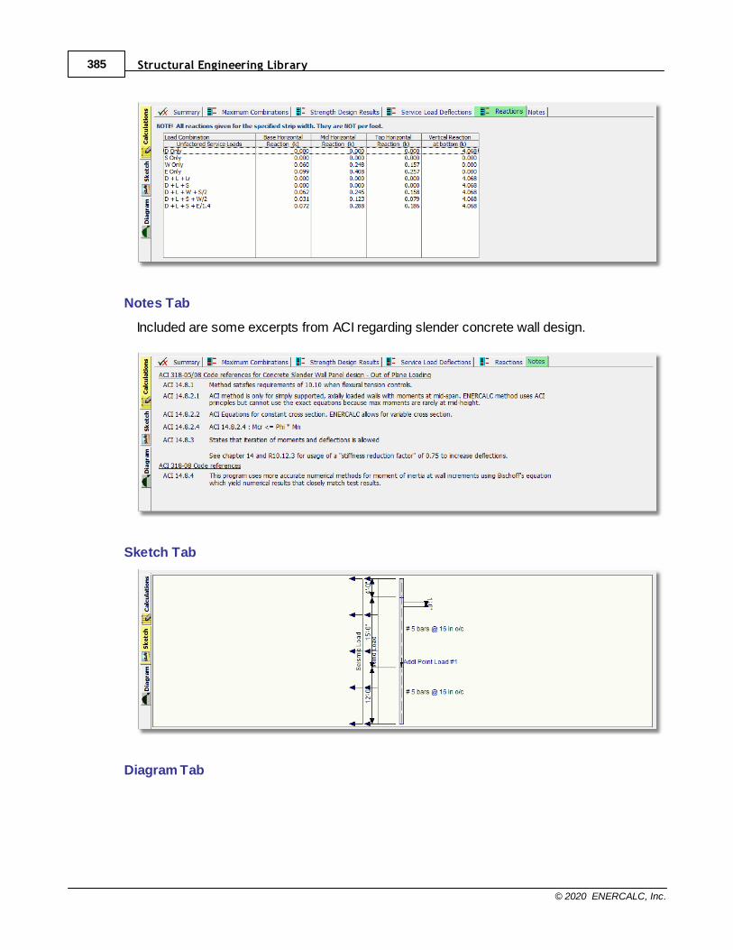
Structural Engineering Library385
© 2020 ENERCALC, Inc.
Notes Tab
Included are some excerpts from ACI regarding slender concrete wall design.
Sketch Tab
Diagram Tab
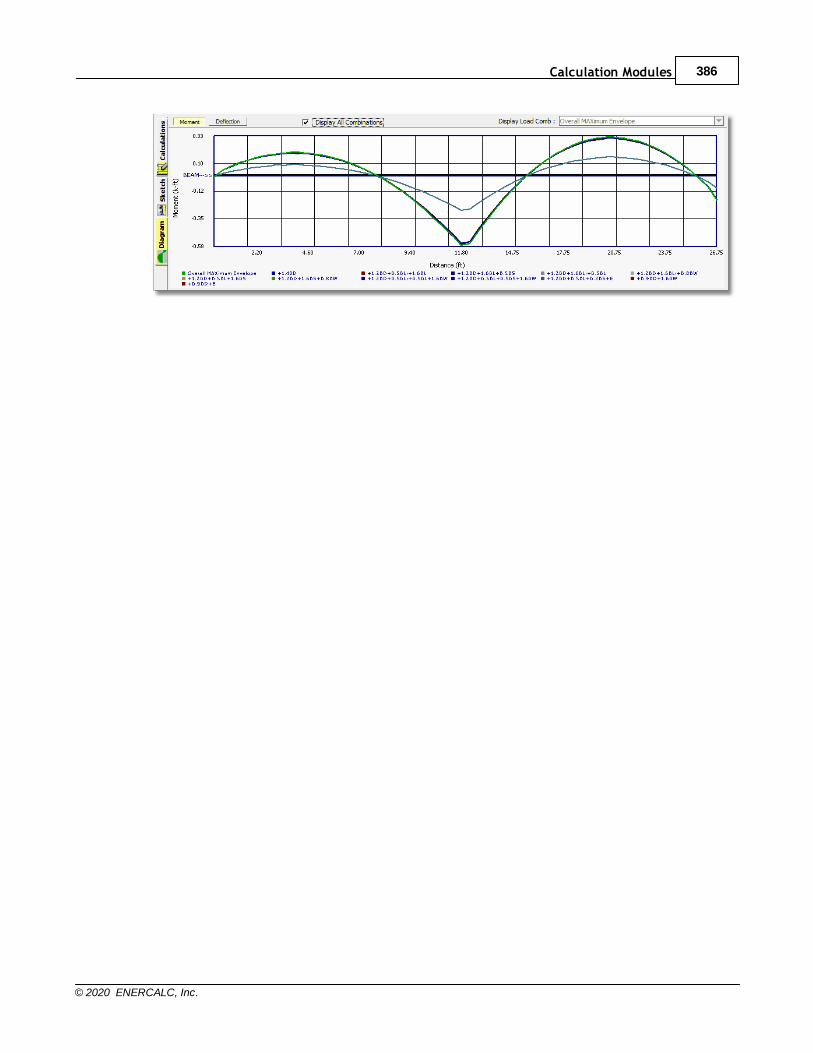
Calculation Modules 386
© 2020 ENERCALC, Inc.
Structural Engineering Library387
© 2020 ENERCALC, Inc.
10.4.2 Masonry Slender Wall
Need more? Ask Us a Question
This module provides design and analysis according to the new provisions for design ofmasonry walls, using the P-Delta deflection considerations now included in the IBC. Click
here for a video: Masonry Slender Wall
This method lifts the restriction on H/t ratios, and performs wall analysis using theprinciples of ultimate strength design. The design method is very similar to that of theConcrete Slender Wall module.
This module uses a variable width strip of wall section to represent a typical section ofwall. The module has the ability to apply a lateral wind load, seismic load, partial lengthuniform lateral load, and a lateral point load to the clear span of the wall section. Thisvariety of loadings should take care of almost every lateral loading case possible.
The user may specify masonry and reinforcing strengths, seismic factor, wind load,vertical and lateral loads, vertical load eccentricities, and wall construction. The moduledetermines the wall capacity, actual deflections considering P-Delta effects, and solves forthe final moments obtained through iteration of the P-Delta effects. Deflection analysis isprovided for both service and factored load cases.
The user reaches a final design by modifying wall thickness, rebar size, and rebar spacinguntil no overstress condition exists and the deflection limits prescribed in the code aresatisfied.
This module uses basic principles of structural mechanics to model the wall as a series ofbeam segments. For each segment the actual moment is used to calculate memberstiffness using the I
ef f ectiv e equations developed by Peter H. Bischoff. Since these changes
to wall stiffness affect the wall deflection profile, the program performs an iterative analysisof calculating moments (including P-Delta effects). The results are deflection curvesalmost exactly matching the SCCACI-SEAOSC test results. This makes this module farmore accurate at calculating wall deflections and P-Delta effects than the simple equationsin the ACI code.
Capabilities
This module provides these capabilities:· One or two story slender masonry walls
· Iterative process accounts for P-delta
· Optional parapet
· Axial loads with optional eccentricities
· Wind, seismic and user defined lateral loads creating bending on the wall panel
· Variable strip width to model the wall panel
· Temperature differential can be specified across thickness of wall to add curvature
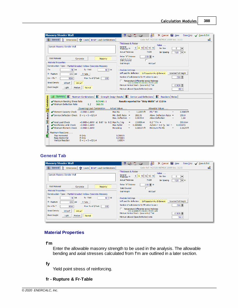
Calculation Modules 388
© 2020 ENERCALC, Inc.
General Tab
Material Properties
f'mEnter the allowable masonry strength to be used in the analysis. The allowablebending and axial stresses calculated from f'm are outlined in a later section.
fyYield point stress of reinforcing.
fr - Rupture & Fr-Table
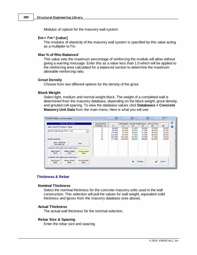
Structural Engineering Library389
© 2020 ENERCALC, Inc.
Modulus of rupture for the masonry wall system.
Em = f'm * [value]The modulus of elasticity of the masonry wall system is specified by this value actingas a multiplier to f'm.
Max % of Rho BalancedThis value sets the maximum percentage of reinforcing the module will allow withoutgiving a warning message. Enter this as a value less than 1.0 which will be applied tothe reinforcing area calculated for a balanced section to determine the maximumallowable reinforcing ratio.
Grout DensityChoose from two different options for the density of the grout.
Block WeightSelect light, medium and normal weight block. The weight of a completed wall isdetermined from the masonry database, depending on the block weight, grout density,and grouted cell spacing. To view the database values click Databases > ConcreteMasonry Unit Data from the main menu. Here is what you will see:
Thickness & Rebar
Nominal ThicknessSelect the nominal thickness for the concrete masonry units used in the wallconstruction. This selection will pull the values for wall weight, equivalent solidthickness and Igross from the masonry database (see above).
Actual ThicknessThe actual wall thickness for the nominal selection.
Rebar Size & SpacingEnter the rebar size and spacing.
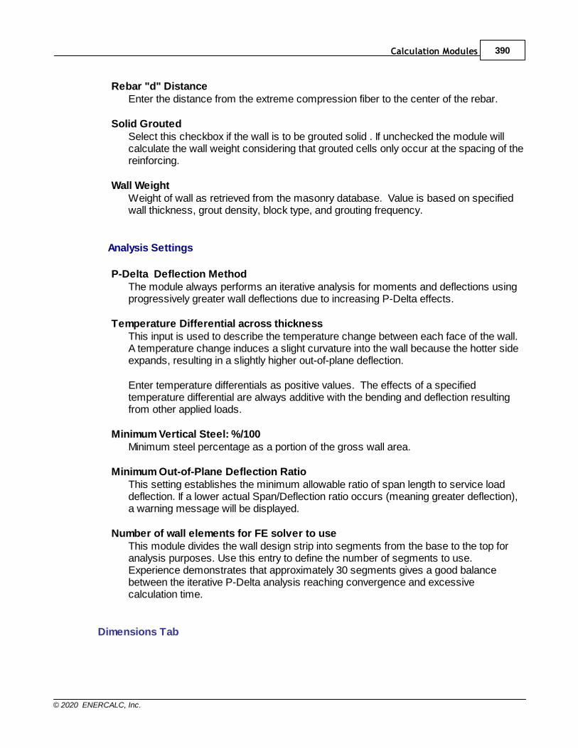
Calculation Modules 390
© 2020 ENERCALC, Inc.
Rebar "d" DistanceEnter the distance from the extreme compression fiber to the center of the rebar.
Solid GroutedSelect this checkbox if the wall is to be grouted solid . If unchecked the module willcalculate the wall weight considering that grouted cells only occur at the spacing of thereinforcing.
Wall WeightWeight of wall as retrieved from the masonry database. Value is based on specifiedwall thickness, grout density, block type, and grouting frequency.
Analysis Settings
P-Delta Deflection MethodThe module always performs an iterative analysis for moments and deflections usingprogressively greater wall deflections due to increasing P-Delta effects.
Temperature Differential across thicknessThis input is used to describe the temperature change between each face of the wall.A temperature change induces a slight curvature into the wall because the hotter sideexpands, resulting in a slightly higher out-of-plane deflection.
Enter temperature differentials as positive values. The effects of a specifiedtemperature differential are always additive with the bending and deflection resultingfrom other applied loads.
Minimum Vertical Steel: %/100Minimum steel percentage as a portion of the gross wall area.
Minimum Out-of-Plane Deflection RatioThis setting establishes the minimum allowable ratio of span length to service loaddeflection. If a lower actual Span/Deflection ratio occurs (meaning greater deflection),a warning message will be displayed.
Number of wall elements for FE solver to useThis module divides the wall design strip into segments from the base to the top foranalysis purposes. Use this entry to define the number of segments to use.Experience demonstrates that approximately 30 segments gives a good balancebetween the iterative P-Delta analysis reaching convergence and excessivecalculation time.
Dimensions Tab

Structural Engineering Library391
© 2020 ENERCALC, Inc.
Fixity ConditionsControls how the top and bottom of the wall are restrained for moments and lateralmovement.
[Top & Bottom Pinned]Base of wall is restrained against movement out of plane and vertically, rotates freely.Top of wall restrained against out of plane movement and can move vertically androtate freely.
[Top Pinned, Bottom Fixed]Base of wall is restrained against movement about all three axes. Top of wallrestrained against out of plane movement and can move vertically and rotate freely.
[Top Free, Bottom Fixed]Base of wall is restrained against movement about all three axes. Top of wall iscompletely free making this a cantilevered wall.
Clear HeightSpan of the wall between the base and the first lateral support. For one story walls thisis the top support. For 2 story walls this is this prompt will change to be "1st storyheight".
Parapet HeightDistance the wall extends (without a topmost lateral support) above the topmostlateral support (clear height for one story wall, 2nd story height for 2 story walls)
Strip Width: Width of wall portion for analysis
This module performs its analysis for this width. Results are for either for this width ora 12" width as noted where the results are provided.
Note that applied loads either are applied to the entire strip width (as for concentratedvertical and lateral loads) or are entered on a per-foot basis when they are uniformloads.
Two Story...
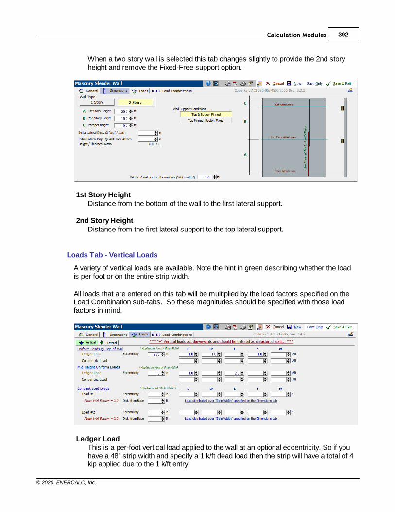
Calculation Modules 392
© 2020 ENERCALC, Inc.
When a two story wall is selected this tab changes slightly to provide the 2nd storyheight and remove the Fixed-Free support option.
1st Story HeightDistance from the bottom of the wall to the first lateral support.
2nd Story HeightDistance from the first lateral support to the top lateral support.
Loads Tab - Vertical Loads
A variety of vertical loads are available. Note the hint in green describing whether the loadis per foot or on the entire strip width.
All loads that are entered on this tab will be multiplied by the load factors specified on theLoad Combination sub-tabs. So these magnitudes should be specified with those loadfactors in mind.
Ledger LoadThis is a per-foot vertical load applied to the wall at an optional eccentricity. So if youhave a 48" strip width and specify a 1 k/ft dead load then the strip will have a total of 4kip applied due to the 1 k/ft entry.

Structural Engineering Library393
© 2020 ENERCALC, Inc.
Concentric LoadThis is a per-foot vertical load applied concentrically to the wall. So if you have a 48"strip width and specify a 1 k/ft dead load then the strip will have a total of 4 kip applieddue to the 1 k/ft entry.
Mid-Height Vertical Uniform LoadThis load entry is only shown for 2-story walls. It allows you to specify two uniformloads applied at the "1st Story" height, one of which can have an eccentricity from thewall center.
Concentrated LoadsThese are single concentrated vertical loads applied to the wall "strip width" with anoptional eccentricity. Distance from Base is the height at which the load is applied.
EccentricityDescribes an offset from the mid-thickness of the wall panel, which is the defaultlocation of application of a vertical load. Enter this value as a positive number whenthe load is shifted toward the inside of the wall.
Loads Tab - Lateral Loads
Lateral loads are applied perpendicular to the plane of the wall and are almost alwaysseismic or wind. These loads create out-of-plane deflection of the wall, which the modulewill use to develop P-Delta effects to calculate secondary moments in the wall. Recall fromother explanations that the module divides the wall into small segments and calculates theallowable and actual forces and deflections for each small segment. In this way the lateralloads are properly modeled on what is a beam with variable stiffness due to the state ofcracking in each segment.
All loads that are entered on this tab will be multiplied by the load factors specified on theLoad Combination sub-tabs. So these magnitudes should be specified with those loadfactors in mind.
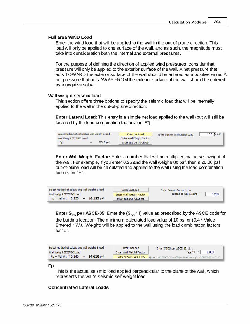
Calculation Modules 394
© 2020 ENERCALC, Inc.
Full area WIND LoadEnter the wind load that will be applied to the wall in the out-of-plane direction. Thisload will only be applied to one surface of the wall, and as such, the magnitude musttake into consideration both the internal and external pressures.
For the purpose of defining the direction of applied wind pressures, consider thatpressure will only be applied to the exterior surface of the wall. A net pressure thatacts TOWARD the exterior surface of the wall should be entered as a positive value. Anet pressure that acts AWAY FROM the exterior surface of the wall should be enteredas a negative value.
Wall weight seismic loadThis section offers three options to specify the seismic load that will be internallyapplied to the wall in the out-of-plane direction:
Enter Lateral Load: This entry is a simple net load applied to the wall (but will still befactored by the load combination factors for "E").
Enter Wall Weight Factor: Enter a number that will be multiplied by the self-weight ofthe wall. For example, if you enter 0.25 and the wall weighs 80 psf, then a 20.00 psfout-of-plane load will be calculated and applied to the wall using the load combinationfactors for "E".
Enter SDS per ASCE-05: Enter the (SDS
* I) value as prescribed by the ASCE code for
the building location. The minimum calculated load value of 10 psf or (0.4 * ValueEntered * Wall Weight) will be applied to the wall using the load combination factorsfor "E".
FpThis is the actual seismic load applied perpendicular to the plane of the wall, whichrepresents the wall's seismic self weight load.
Concentrated Lateral Loads
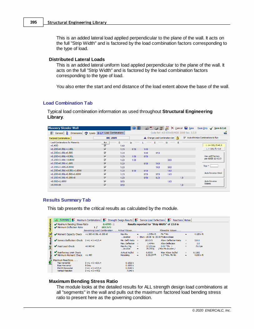
Structural Engineering Library395
© 2020 ENERCALC, Inc.
This is an added lateral load applied perpendicular to the plane of the wall. It acts onthe full "Strip Width" and is factored by the load combination factors corresponding tothe type of load.
Distributed Lateral LoadsThis is an added lateral uniform load applied perpendicular to the plane of the wall. Itacts on the full "Strip Width" and is factored by the load combination factorscorresponding to the type of load.
You also enter the start and end distance of the load extent above the base of the wall.
Load Combination Tab
Typical load combination information as used throughout Structural EngineeringLibrary.
Results Summary Tab
This tab presents the critical results as calculated by the module.
Maximum Bending Stress RatioThe module looks at the detailed results for ALL strength design load combinations atall "segments" in the wall and pulls out the maximum factored load bending stressratio to present here as the governing condition.
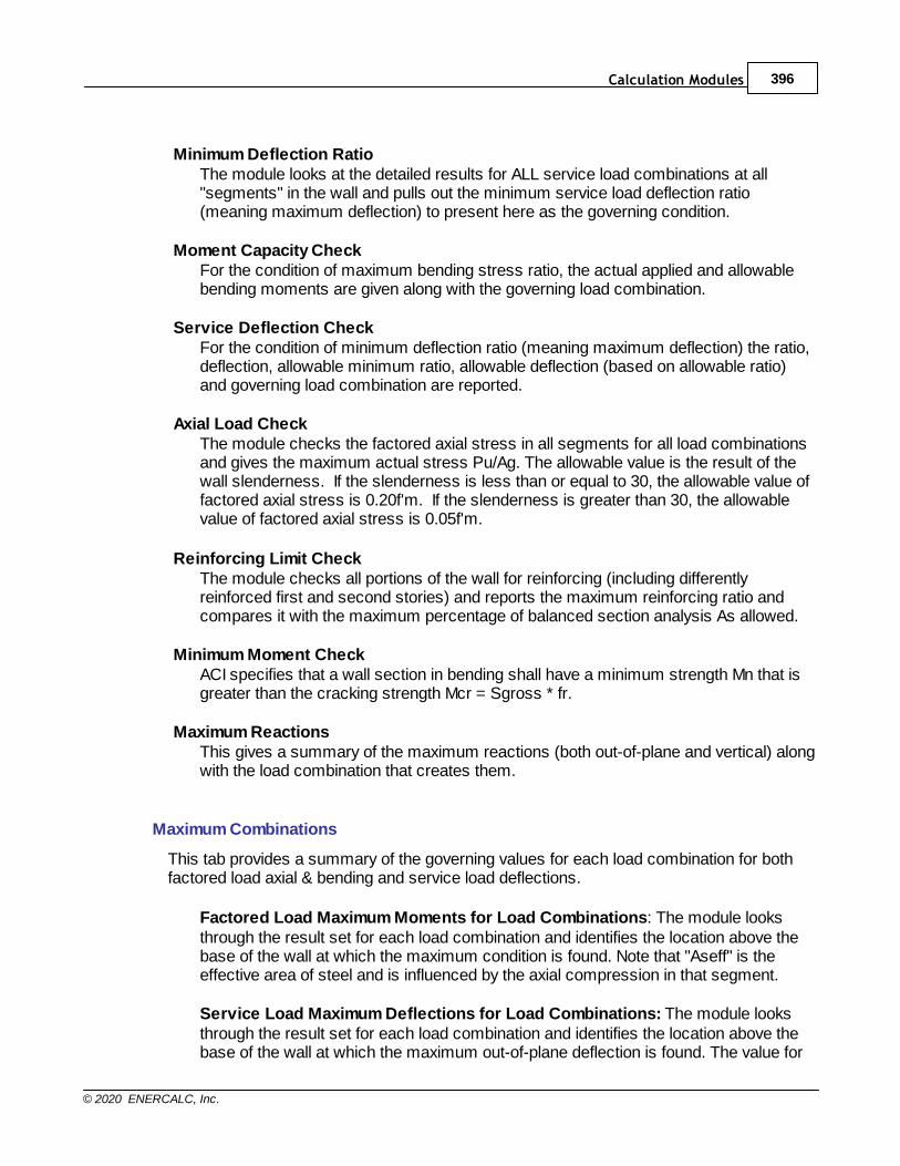
Calculation Modules 396
© 2020 ENERCALC, Inc.
Minimum Deflection RatioThe module looks at the detailed results for ALL service load combinations at all"segments" in the wall and pulls out the minimum service load deflection ratio(meaning maximum deflection) to present here as the governing condition.
Moment Capacity CheckFor the condition of maximum bending stress ratio, the actual applied and allowablebending moments are given along with the governing load combination.
Service Deflection CheckFor the condition of minimum deflection ratio (meaning maximum deflection) the ratio,deflection, allowable minimum ratio, allowable deflection (based on allowable ratio)and governing load combination are reported.
Axial Load CheckThe module checks the factored axial stress in all segments for all load combinationsand gives the maximum actual stress Pu/Ag. The allowable value is the result of thewall slenderness. If the slenderness is less than or equal to 30, the allowable value offactored axial stress is 0.20f'm. If the slenderness is greater than 30, the allowablevalue of factored axial stress is 0.05f'm.
Reinforcing Limit CheckThe module checks all portions of the wall for reinforcing (including differentlyreinforced first and second stories) and reports the maximum reinforcing ratio andcompares it with the maximum percentage of balanced section analysis As allowed.
Minimum Moment CheckACI specifies that a wall section in bending shall have a minimum strength Mn that isgreater than the cracking strength Mcr = Sgross * fr.
Maximum ReactionsThis gives a summary of the maximum reactions (both out-of-plane and vertical) alongwith the load combination that creates them.
Maximum Combinations
This tab provides a summary of the governing values for each load combination for bothfactored load axial & bending and service load deflections.
Factored Load Maximum Moments for Load Combinations: The module looksthrough the result set for each load combination and identifies the location above thebase of the wall at which the maximum condition is found. Note that "Aseff" is theeffective area of steel and is influenced by the axial compression in that segment.
Service Load Maximum Deflections for Load Combinations: The module looksthrough the result set for each load combination and identifies the location above thebase of the wall at which the maximum out-of-plane deflection is found. The value for
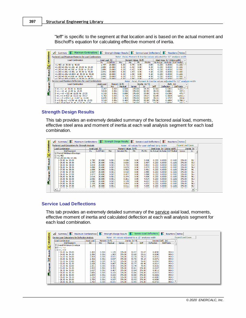
Structural Engineering Library397
© 2020 ENERCALC, Inc.
"Ieff" is specific to the segment at that location and is based on the actual moment andBischoff's equation for calculating effective moment of inertia.
Strength Design Results
This tab provides an extremely detailed summary of the factored axial load, moments,effective steel area and moment of inertia at each wall analysis segment for each loadcombination.
Service Load Deflections
This tab provides an extremely detailed summary of the service axial load, moments,effective moment of inertia and calculated deflection at each wall analysis segment foreach load combination.
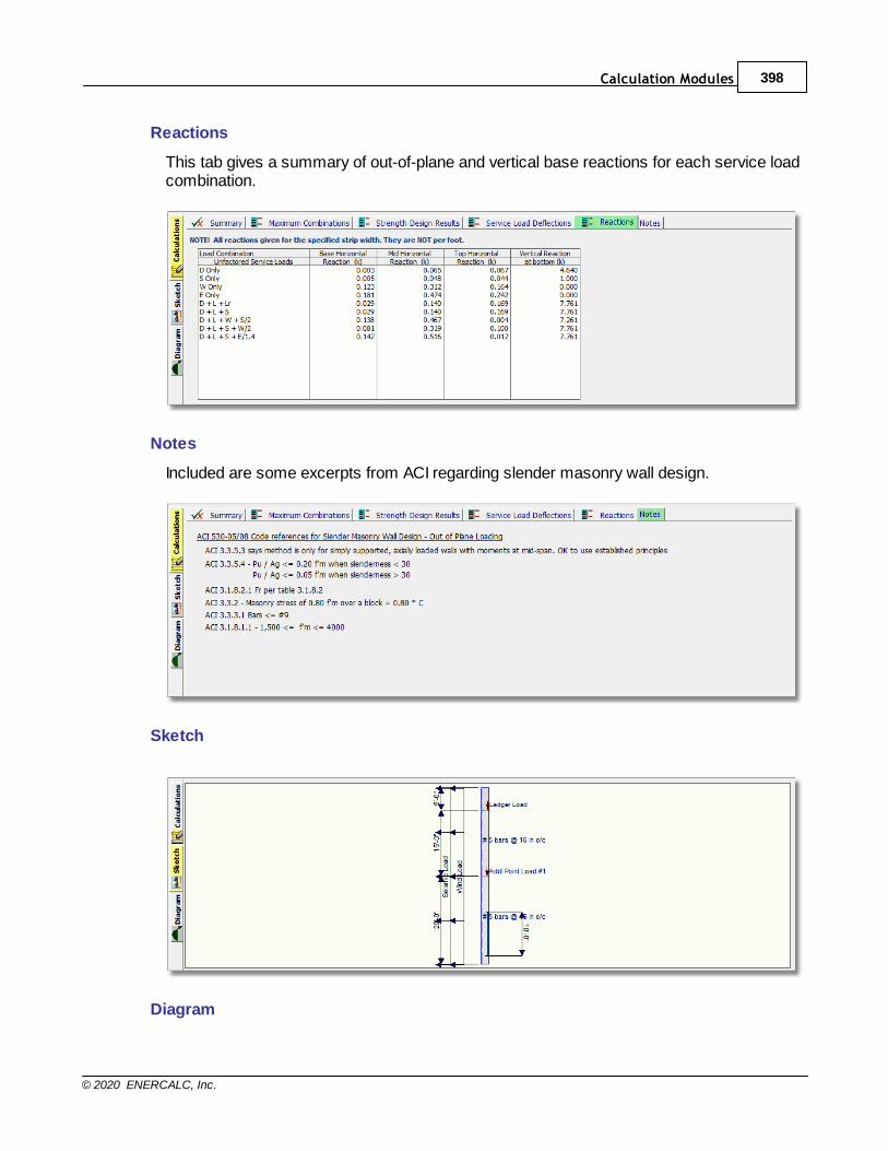
Calculation Modules 398
© 2020 ENERCALC, Inc.
Reactions
This tab gives a summary of out-of-plane and vertical base reactions for each service loadcombination.
Notes
Included are some excerpts from ACI regarding slender masonry wall design.
Sketch
Diagram
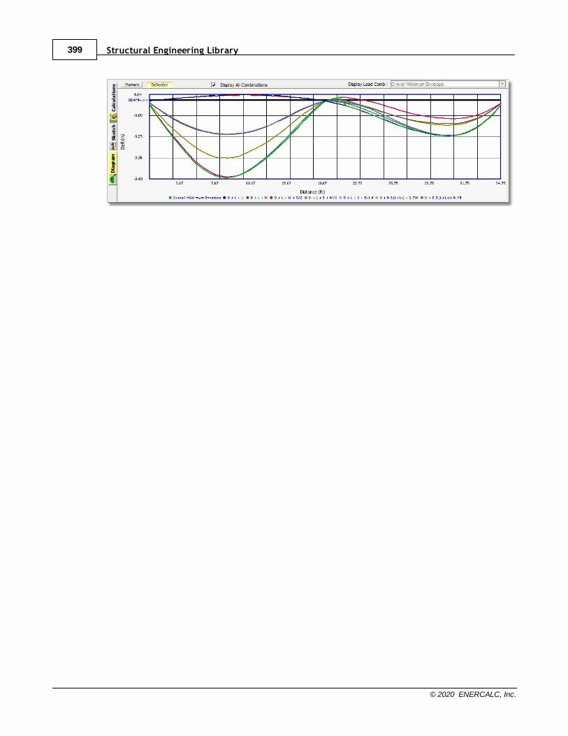
Structural Engineering Library399
© 2020 ENERCALC, Inc.
Calculation Modules 400
© 2020 ENERCALC, Inc.
10.5 Shear Walls
Please select a material chapter.

Structural Engineering Library401
© 2020 ENERCALC, Inc.
10.5.1 Concrete Shear Wall
Need more? Ask Us a Question
This module allows the design of concrete shear walls including multi-story walls with noopenings but with up to five levels of differing length, height and thickness.
General Tab
Height specifies the total height of the wall. On the next tab you can divide that totalheight into up to five different wall portions.
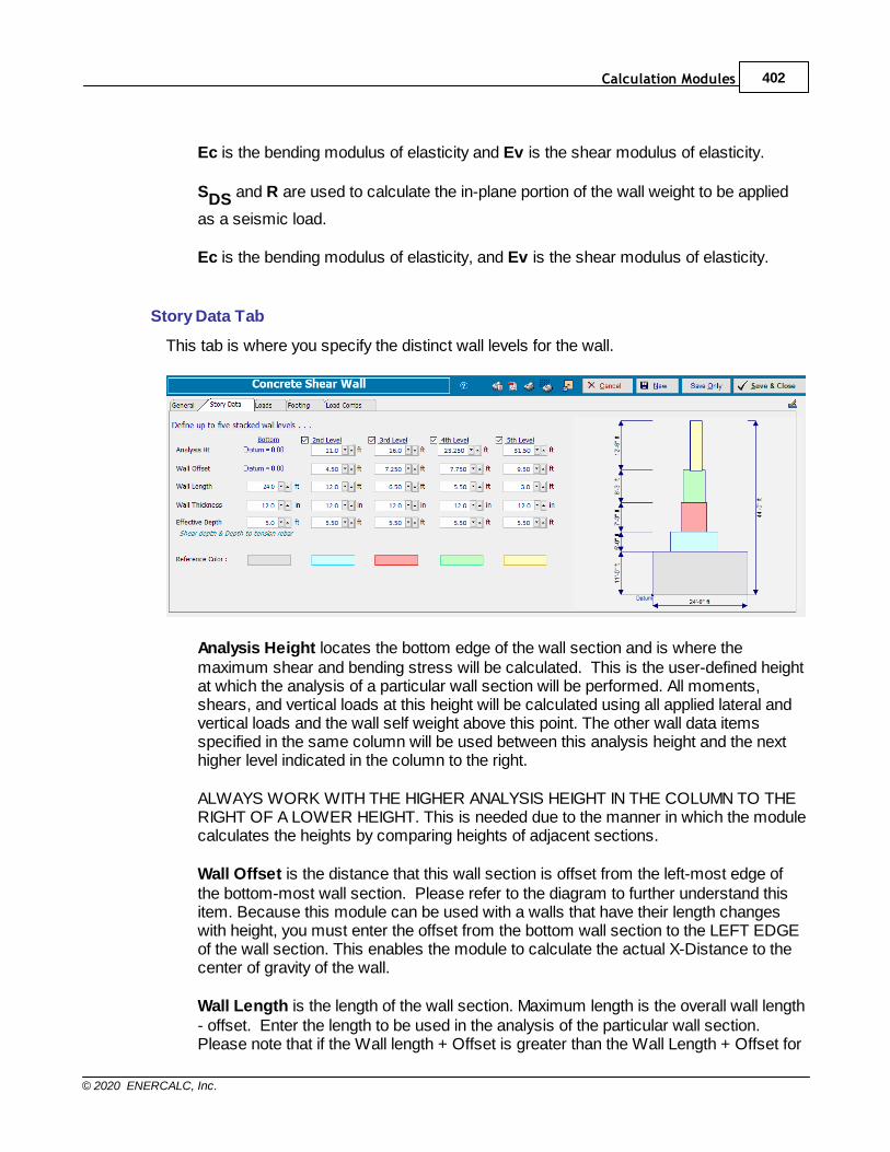
Calculation Modules 402
© 2020 ENERCALC, Inc.
Ec is the bending modulus of elasticity and Ev is the shear modulus of elasticity.
SDS and R are used to calculate the in-plane portion of the wall weight to be applied
as a seismic load.
Ec is the bending modulus of elasticity, and Ev is the shear modulus of elasticity.
Story Data Tab
This tab is where you specify the distinct wall levels for the wall.
Analysis Height locates the bottom edge of the wall section and is where themaximum shear and bending stress will be calculated. This is the user-defined heightat which the analysis of a particular wall section will be performed. All moments,shears, and vertical loads at this height will be calculated using all applied lateral andvertical loads and the wall self weight above this point. The other wall data itemsspecified in the same column will be used between this analysis height and the nexthigher level indicated in the column to the right.
ALWAYS WORK WITH THE HIGHER ANALYSIS HEIGHT IN THE COLUMN TO THERIGHT OF A LOWER HEIGHT. This is needed due to the manner in which the modulecalculates the heights by comparing heights of adjacent sections.
Wall Offset is the distance that this wall section is offset from the left-most edge ofthe bottom-most wall section. Please refer to the diagram to further understand thisitem. Because this module can be used with a walls that have their length changeswith height, you must enter the offset from the bottom wall section to the LEFT EDGEof the wall section. This enables the module to calculate the actual X-Distance to thecenter of gravity of the wall.
Wall Length is the length of the wall section. Maximum length is the overall wall length- offset. Enter the length to be used in the analysis of the particular wall section.Please note that if the Wall length + Offset is greater than the Wall Length + Offset for
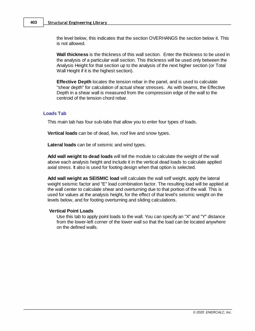
Structural Engineering Library403
© 2020 ENERCALC, Inc.
the level below, this indicates that the section OVERHANGS the section below it. Thisis not allowed.
Wall thickness is the thickness of this wall section. Enter the thickness to be used inthe analysis of a particular wall section. This thickness will be used only between theAnalysis Height for that section up to the analysis of the next higher section (or TotalWall Height if it is the highest section).
Effective Depth locates the tension rebar in the panel, and is used to calculate"shear depth" for calculation of actual shear stresses. As with beams, the EffectiveDepth in a shear wall is measured from the compression edge of the wall to thecentroid of the tension chord rebar.
Loads Tab
This main tab has four sub-tabs that allow you to enter four types of loads.
Vertical loads can be of dead, live, roof live and snow types.
Lateral loads can be of seismic and wind types.
Add wall weight to dead loads will tell the module to calculate the weight of the wallabove each analysis height and include it in the vertical dead loads to calculate appliedaxial stress. It also is used for footing design when that option is selected.
Add wall weight as SEISMIC load will calculate the wall self weight, apply the lateralweight seismic factor and "E" load combination factor. The resulting load will be applied atthe wall center to calculate shear and overturning due to that portion of the wall. This isused for values at the analysis height, for the effect of that level's seismic weight on thelevels below, and for footing overturning and sliding calculations.
Vertical Point LoadsUse this tab to apply point loads to the wall. You can specify an "X" and "Y" distancefrom the lower-left corner of the lower wall so that the load can be located anywhereon the defined walls.
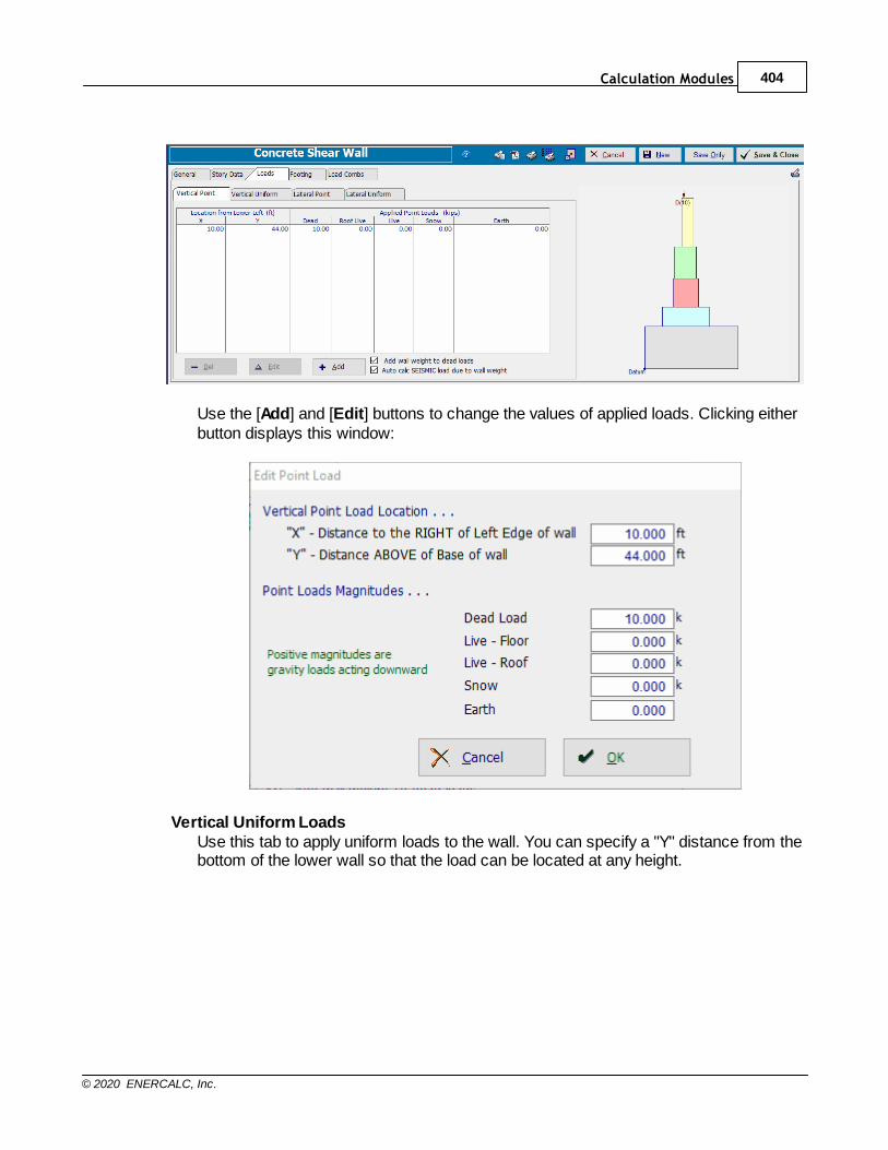
Calculation Modules 404
© 2020 ENERCALC, Inc.
Use the [Add] and [Edit] buttons to change the values of applied loads. Clicking eitherbutton displays this window:
Vertical Uniform LoadsUse this tab to apply uniform loads to the wall. You can specify a "Y" distance from thebottom of the lower wall so that the load can be located at any height.
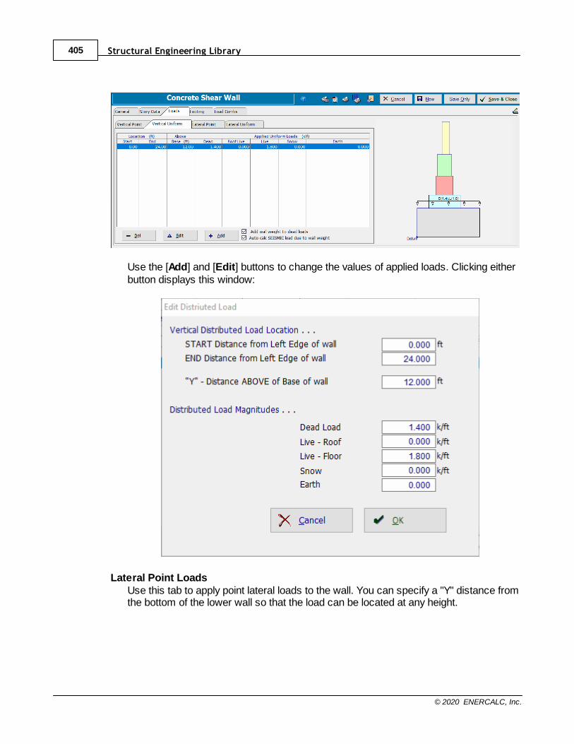
Structural Engineering Library405
© 2020 ENERCALC, Inc.
Use the [Add] and [Edit] buttons to change the values of applied loads. Clicking eitherbutton displays this window:
Lateral Point LoadsUse this tab to apply point lateral loads to the wall. You can specify a "Y" distance fromthe bottom of the lower wall so that the load can be located at any height.
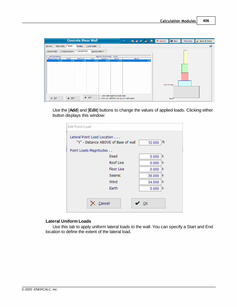
Calculation Modules 406
© 2020 ENERCALC, Inc.
Use the [Add] and [Edit] buttons to change the values of applied loads. Clicking eitherbutton displays this window:
Lateral Uniform Loads
Use this tab to apply uniform lateral loads to the wall. You can specify a Start and Endlocation to define the extent of the lateral load.
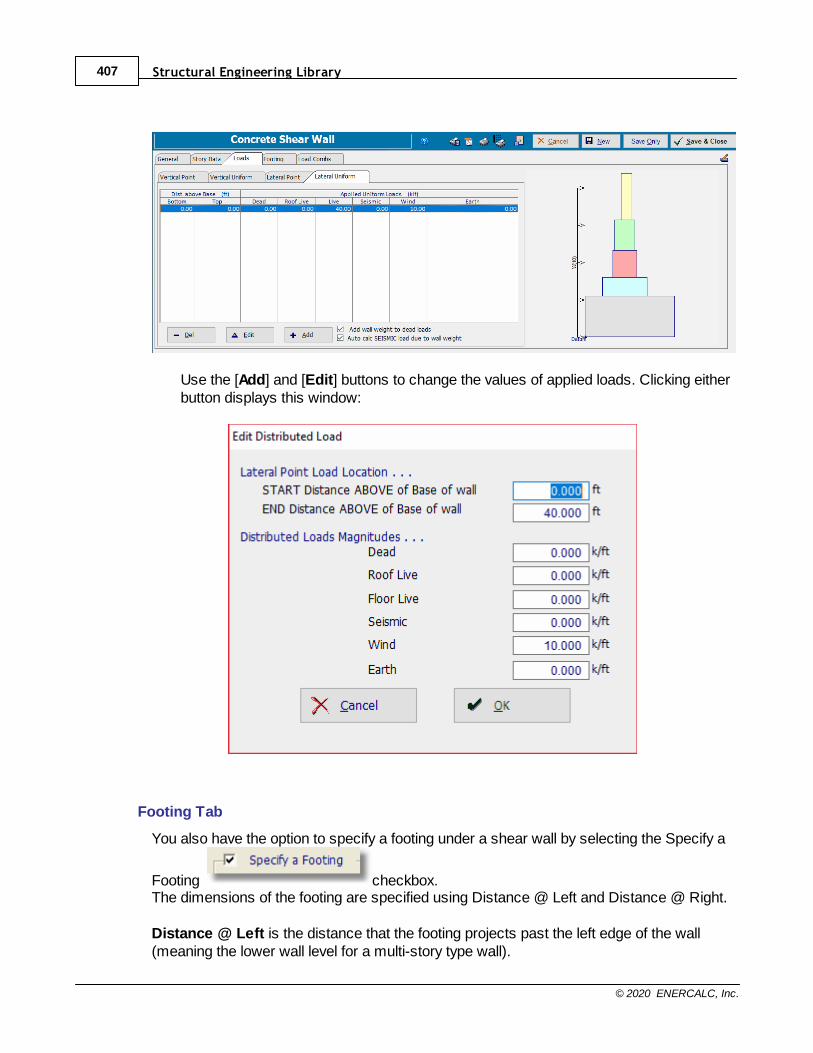
Structural Engineering Library407
© 2020 ENERCALC, Inc.
Use the [Add] and [Edit] buttons to change the values of applied loads. Clicking eitherbutton displays this window:
Footing Tab
You also have the option to specify a footing under a shear wall by selecting the Specify a
Footing checkbox.The dimensions of the footing are specified using Distance @ Left and Distance @ Right.
Distance @ Left is the distance that the footing projects past the left edge of the wall(meaning the lower wall level for a multi-story type wall).
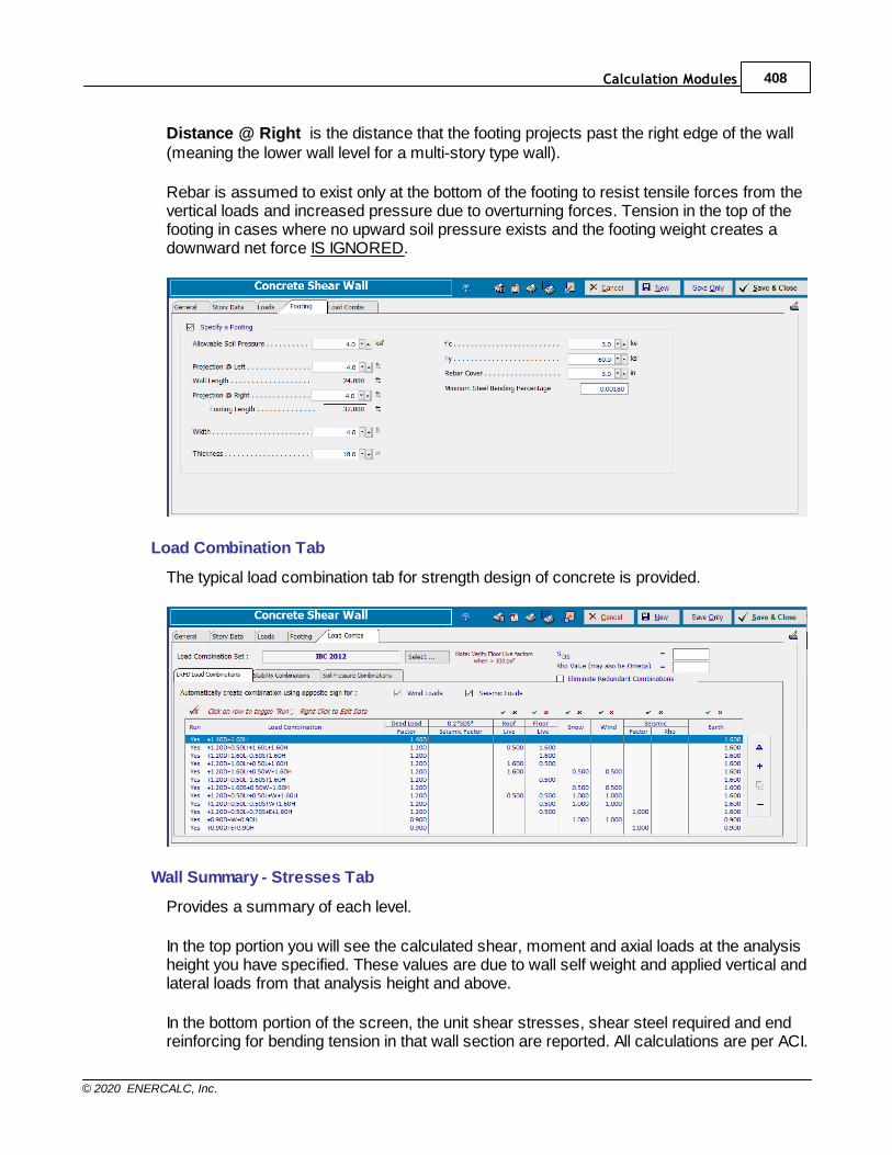
Calculation Modules 408
© 2020 ENERCALC, Inc.
Distance @ Right is the distance that the footing projects past the right edge of the wall(meaning the lower wall level for a multi-story type wall).
Rebar is assumed to exist only at the bottom of the footing to resist tensile forces from thevertical loads and increased pressure due to overturning forces. Tension in the top of thefooting in cases where no upward soil pressure exists and the footing weight creates adownward net force IS IGNORED.
Load Combination Tab
The typical load combination tab for strength design of concrete is provided.
Wall Summary - Stresses Tab
Provides a summary of each level.
In the top portion you will see the calculated shear, moment and axial loads at the analysisheight you have specified. These values are due to wall self weight and applied vertical andlateral loads from that analysis height and above.
In the bottom portion of the screen, the unit shear stresses, shear steel required and endreinforcing for bending tension in that wall section are reported. All calculations are per ACI.
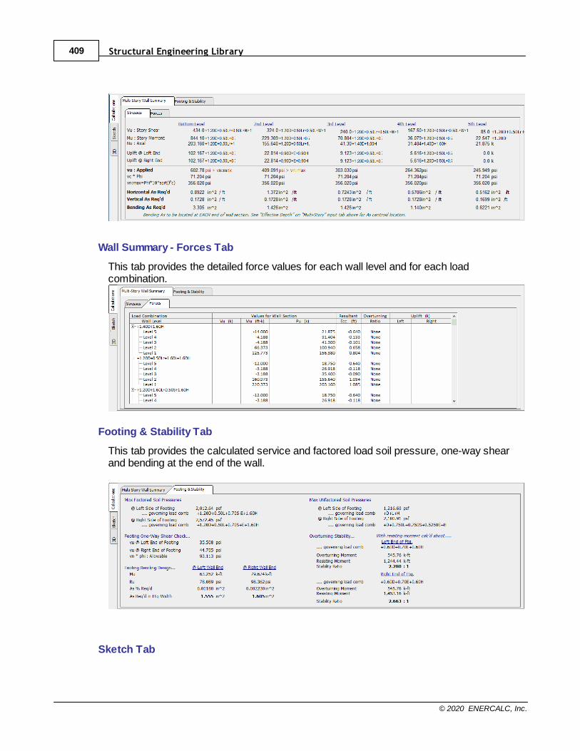
Structural Engineering Library409
© 2020 ENERCALC, Inc.
Wall Summary - Forces Tab
This tab provides the detailed force values for each wall level and for each loadcombination.
Footing & Stability Tab
This tab provides the calculated service and factored load soil pressure, one-way shearand bending at the end of the wall.
Sketch Tab
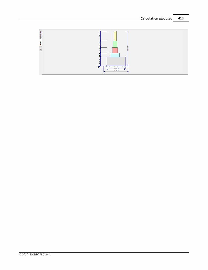
Calculation Modules 410
© 2020 ENERCALC, Inc.
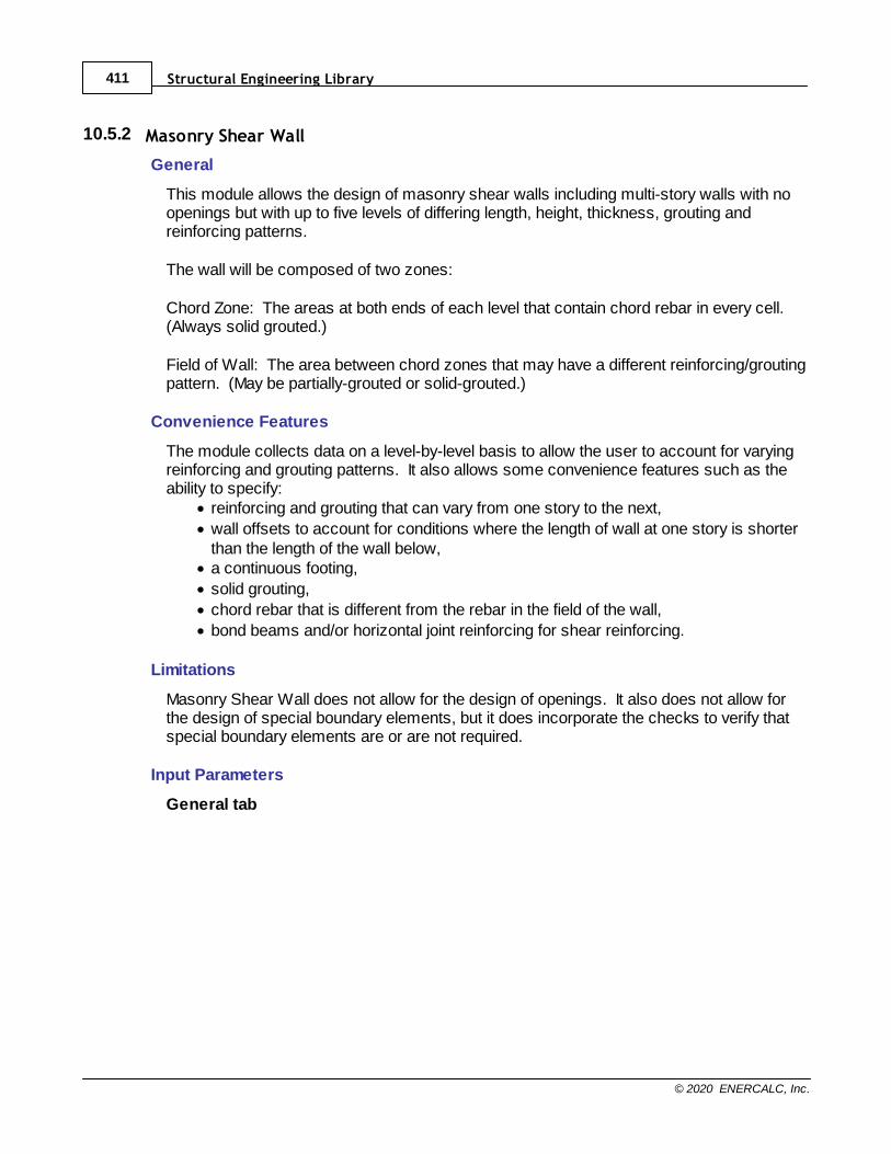
Structural Engineering Library411
© 2020 ENERCALC, Inc.
10.5.2 Masonry Shear Wall
General
This module allows the design of masonry shear walls including multi-story walls with noopenings but with up to five levels of differing length, height, thickness, grouting andreinforcing patterns.
The wall will be composed of two zones:
Chord Zone: The areas at both ends of each level that contain chord rebar in every cell. (Always solid grouted.)
Field of Wall: The area between chord zones that may have a different reinforcing/groutingpattern. (May be partially-grouted or solid-grouted.)
Convenience Features
The module collects data on a level-by-level basis to allow the user to account for varyingreinforcing and grouting patterns. It also allows some convenience features such as theability to specify:
· reinforcing and grouting that can vary from one story to the next,
· wall offsets to account for conditions where the length of wall at one story is shorterthan the length of the wall below,
· a continuous footing,
· solid grouting,
· chord rebar that is different from the rebar in the field of the wall,
· bond beams and/or horizontal joint reinforcing for shear reinforcing.
Limitations
Masonry Shear Wall does not allow for the design of openings. It also does not allow forthe design of special boundary elements, but it does incorporate the checks to verify thatspecial boundary elements are or are not required.
Input Parameters
General tab
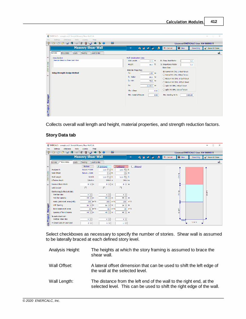
Calculation Modules 412
© 2020 ENERCALC, Inc.
Collects overall wall length and height, material properties, and strength reduction factors.
Story Data tab
Select checkboxes as necessary to specify the number of stories. Shear wall is assumedto be laterally braced at each defined story level.
Analysis Height: The heights at which the story framing is assumed to brace theshear wall.
Wall Offset: A lateral offset dimension that can be used to shift the left edge ofthe wall at the selected level.
Wall Length: The distance from the left end of the wall to the right end, at theselected level. This can be used to shift the right edge of the wall.
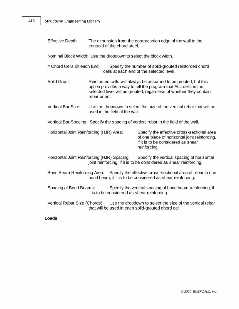
Structural Engineering Library413
© 2020 ENERCALC, Inc.
Effective Depth: The dimension from the compression edge of the wall to thecentroid of the chord steel.
Nominal Block Width: Use the dropdown to select the block width.
# Chord Cells @ each End: Specify the number of solid-grouted reinforced chordcells at each end of the selected level.
Solid Grout: Reinforced cells will always be assumed to be grouted, but thisoption provides a way to tell the program that ALL cells in theselected level will be grouted, regardless of whether they containrebar or not.
Vertical Bar Size: Use the dropdown to select the size of the vertical rebar that will beused in the field of the wall.
Vertical Bar Spacing: Specify the spacing of vertical rebar in the field of the wall.
Horizontal Joint Reinforcing (HJR) Area: Specify the effective cross-sectional areaof one piece of horizontal joint reinforcing,if it is to be considered as shearreinforcing.
Horizontal Joint Reinforcing (HJR) Spacing: Specify the vertical spacing of horizontaljoint reinforcing, if it is to be considered as shear reinforcing.
Bond Beam Reinforcing Area: Specify the effective cross-sectional area of rebar in onebond beam, if it is to be considered as shear reinforcing.
Spacing of Bond Beams: Specify the vertical spacing of bond beam reinforcing, ifit is to be considered as shear reinforcing.
Vertical Rebar Size (Chords): Use the dropdown to select the size of the vertical rebarthat will be used in each solid-grouted chord cell.
Loads
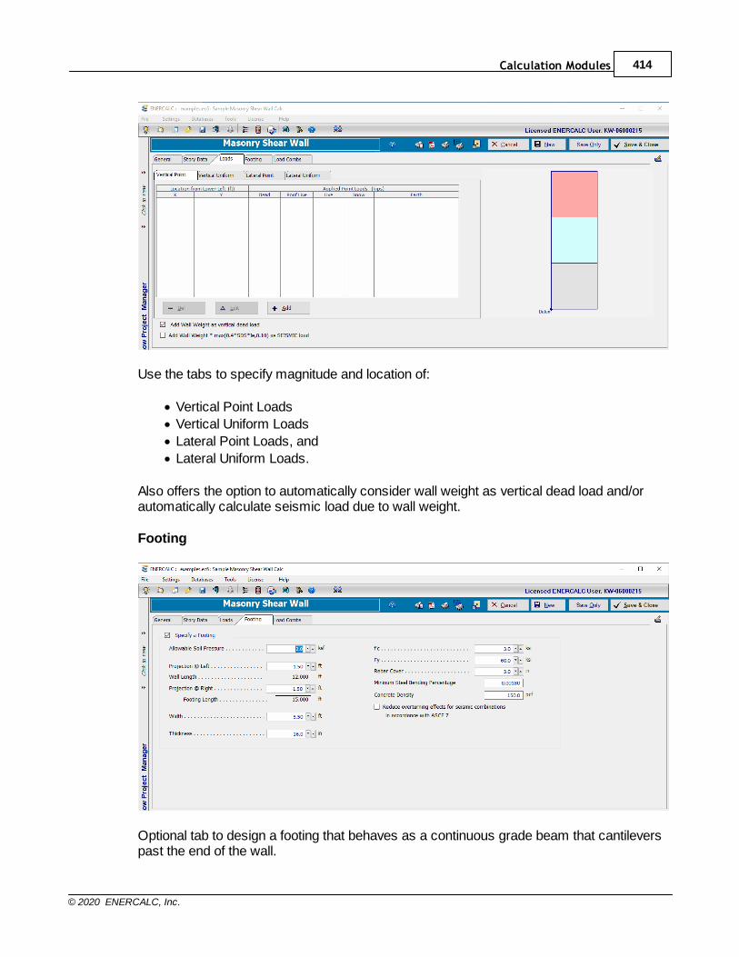
Calculation Modules 414
© 2020 ENERCALC, Inc.
Use the tabs to specify magnitude and location of:
· Vertical Point Loads
· Vertical Uniform Loads
· Lateral Point Loads, and
· Lateral Uniform Loads.
Also offers the option to automatically consider wall weight as vertical dead load and/orautomatically calculate seismic load due to wall weight.
Footing
Optional tab to design a footing that behaves as a continuous grade beam that cantileverspast the end of the wall.
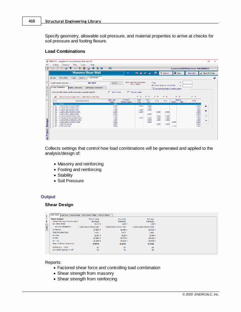
Structural Engineering Library415
© 2020 ENERCALC, Inc.
Specify geometry, allowable soil pressure, and material properties to arrive at checks forsoil pressure and footing flexure.
Load Combinations
Collects settings that control how load combinations will be generated and applied to theanalysis/design of:
· Masonry and reinforcing
· Footing and reinforcing
· Stability
· Soil Pressure
Output
Shear Design
Reports:· Factored shear force and controlling load combination
· Shear strength from masonry
· Shear strength from reinforcing
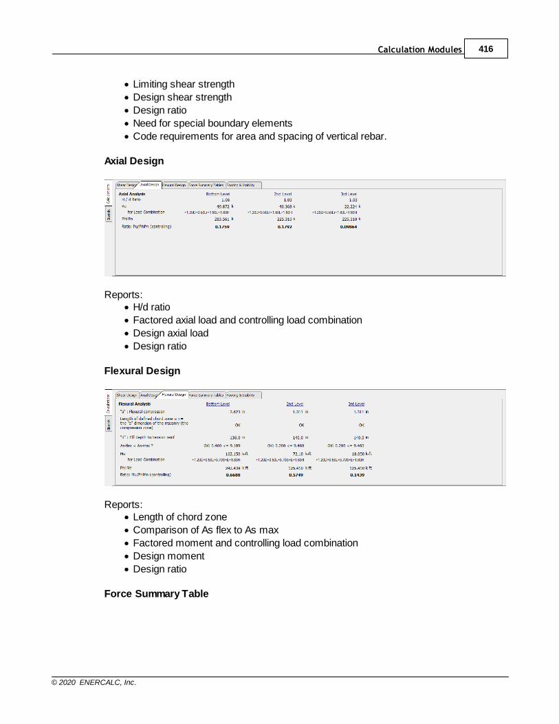
Calculation Modules 416
© 2020 ENERCALC, Inc.
· Limiting shear strength
· Design shear strength
· Design ratio
· Need for special boundary elements
· Code requirements for area and spacing of vertical rebar.
Axial Design
Reports:· H/d ratio
· Factored axial load and controlling load combination
· Design axial load
· Design ratio
Flexural Design
Reports:· Length of chord zone
· Comparison of As flex to As max
· Factored moment and controlling load combination
· Design moment
· Design ratio
Force Summary Table
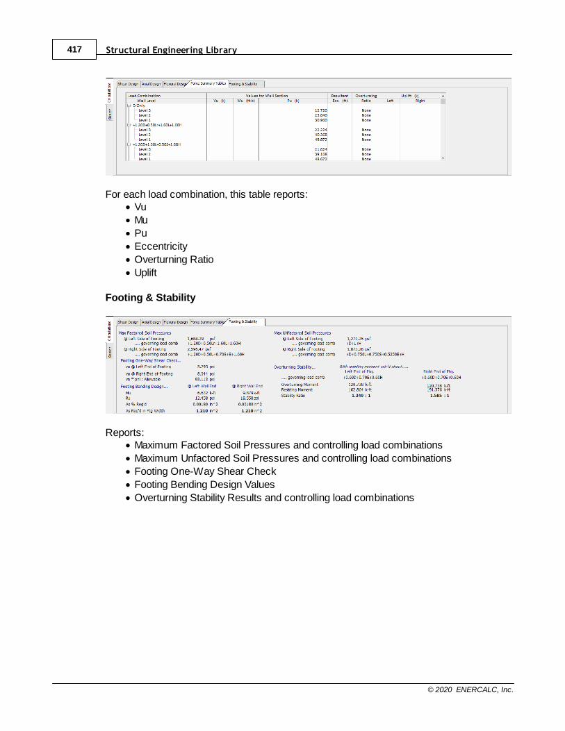
Structural Engineering Library417
© 2020 ENERCALC, Inc.
For each load combination, this table reports:· Vu
· Mu
· Pu
· Eccentricity
· Overturning Ratio
· Uplift
Footing & Stability
Reports:· Maximum Factored Soil Pressures and controlling load combinations
· Maximum Unfactored Soil Pressures and controlling load combinations
· Footing One-Way Shear Check
· Footing Bending Design Values
· Overturning Stability Results and controlling load combinations
Calculation Modules 418
© 2020 ENERCALC, Inc.
10.5.3 Wood Shear Wall
Basis
The NDS Special Design Provisions for Wind & Seismic allows for three approaches towood shear wall design:
1. Force Transfer Shear Walls2. Perforated Shear Walls 3. Individual Full-Height Wall Segment Shear Walls.
Force Transfer Shear Walls and Perforated Shear Walls allow the designer to use morefavorable analysis assumptions, and offers some benefits in terms of construction details. But it comes at a cost of the designer having to perform more calculations and designs tofollow the load path through all of the headers, jambs, sills, etc., and their connections.
At present, the Wood Shear Wall module implements the Individual Full-Height WallSegment Shear Walls method. This is the most straightforward method from the designstandpoint. This method still requires the evaluation of h/b ratios to decide whether toeliminate slender segments or suffer the imposed reduction on the nominal shear capacitybased on the slenderness of each panel in the wall. (Section 4.3.5.1 refers back toSection 4.3.4, which includes this reduction.) But this method does not requireconsideration of the reduction factor (Co) that applies to Perforated Shear Walls.
The implementation within Structural Engineering Library goes a little further by allowingthe user to specify openings. The module then takes the defined openings and considersonly the solid stacked portions of remaining wall as being effective at resisting lateral loads. Section 4.3.3.4 provides the justification for summing the resistance of multiple IndividualFull-Height Wall Segments because, by our definition within the module, all segments willbe “sheathed with the same materials and construction”.
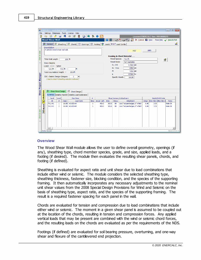
Structural Engineering Library419
© 2020 ENERCALC, Inc.
Overview
The Wood Shear Wall module allows the user to define overall geometry, openings (ifany), sheathing type, chord member species, grade, and size, applied loads, and afooting (if desired). The module then evaluates the resulting shear panels, chords, andfooting (if defined).
Sheathing is evaluated for aspect ratio and unit shear due to load combinations thatinclude either wind or seismic. The module considers the selected sheathing type,sheathing thickness, fastener size, blocking condition, and the species of the supportingframing. It then automatically incorporates any necessary adjustments to the nominalunit shear values from the 2008 Special Design Provisions for Wind and Seismic on thebasis of sheathing type, aspect ratio, and the species of the supporting framing. Theresult is a required fastener spacing for each panel in the wall.
Chords are evaluated for tension and compression due to load combinations that includeeither wind or seismic. The moment in a given shear panel is assumed to be coupled outat the location of the chords, resulting in tension and compression forces. Any appliedvertical loads that may be present are combined with the wind or seismic chord forces,and the resulting loads on the chords are evaluated as per the requirements of the NDS.
Footings (if defined) are evaluated for soil bearing pressure, overturning, and one-wayshear and flexure of the cantilevered end projection.
Calculation Modules 420
© 2020 ENERCALC, Inc.
There are certain items that are not explicitly evaluated by this module, and the usershould be aware of the following exclusions: bending or shear in the top plate, bearing onthe top plate, out of plane design of the wall sheathing or framing, gravity-only loading onthe common studs or chords, bearing on the bottom plate, design of anchoragehardware or connections.
Workflow Process
The general workflow proceeds as follows:
1. The overall height and length of the shear wall are defined on the General tab, alongwith selections such as the Seismic Design Category, the Design Method, and theFraming and Chord Species and Grade.
2. The sheathing type, thickness, fastener size and blocking conditions is selected on theSheathing tab. This tab also allows for the specification of sheathing on the secondside of the framing when necessary.
3. The chord size is specified on a level-by-level basis on the Chords tab. This tab alsoallows for the specification of the bracing assumption to be applied in the compressiondesign of the chords.
4. If openings are present in the wall, they can be defined on the Openings tab. 5. Loads of many types can be defined and applied on the Loads tab.6. If a continuous footing design is desired, the footing geometry and material properties
can be entered on the Footing tab.7. The Load Combinations tab allows for the definition of the load combinations that will
be used for the design. 8. The results for the shear panels, chords, and footing (if designed) can be reviewed in
the Results panel in the lower portion of the screen.
General tab
Description: Enter a freeform description of the current wall design for reference.
Total Wall Length: Enter the overall length of the shear wall in units of feet.
Story Heights: Enter the heights of up to five stories in units of feet. Whenever a valueis entered, the input field for the next story height is displayed in case it is needed. Thetotal accumulated height is automatically reported.
Seismic Design Category: Enter the appropriate Seismic Design Category for the wallbeing designed. This is used to check the selected sheathing type to be sure it ispermissible for use in that SDS according to the Special Design Provisions for Wind andSeismic.
Structural Engineering Library421
© 2020 ENERCALC, Inc.
Design Method: Select ASD or LRFD to dictate which method will be applied whendesigning shear panels and chords. Footing design (when requested) is always by LRFDmethods.
Framing & Chord Material: Use the icon to access the Wood Reference Design Valuesdatabase in order to select the species and grade of wood used for the chords andcommon framing in the wall.
Sheathing tab
Select SDPWS Construction Table: Choose the table from which the sheathing will beselected.
Select Main Sheathing: Select a tabular entry to represent the sheathing type, sheathingthickness, fastener size/penetration, and in some cases the blocking condition.
Nominal Shear Capacities: The program displays the nominal shear capacities for seismicdesign and for wind design directly from the selected table. These are nominal valueswhich still need to be modified for use in design, such as with a phi factor or factor ofsafety and with any applicable adjustments such as for aspect ratio or specific gravity ofthe supporting framing.
Sheathing is Blocked: (Only visible for some tabular selections) Use this checkbox toindicate if the sheathing is blocked or not. This setting has an effect on some of theallowable aspect ratios.
Table 4.3A Footnote 2 is applicable: (Only visible for some tabular selections) Use thischeckbox to indicate if a specific condition exists as described in detail in the referencedfootnote in Table 4.3A of the 2008 Special Design Provisions for Wind and Seismic.
Sheathing on 2nd Side: Use this checkbox to indicate that there is a sheathing of somesort on the other side of the framing.
Use Same as Main Sheathing: A convenience option that automatically sets theSheathing on 2nd Side to be identical to the sheathing on the Main side.
Note: If sheathing is specified on the second side, and if the sheathing comes from thesame Construction Table as the Main Sheathing, then the blocking setting for the 2ndside will automatically be assumed to be the same as the blocking setting for the Mainside.
Chords tab
The Chords tab will automatically display one row of chord definition data for each storythat was defined on the General tab.
Calculation Modules 422
© 2020 ENERCALC, Inc.
Chord Size: Use the drop-down list box to select the size of the sawn lumber member(s)that will be used at the chord locations for the given level. Note that the program willautomatically determine the number of chord members required at each location. So forexample, if the wall was generally going to be constructed of 2x4 framing, then this inputshould be set to "2x4". Once the analysis and design has been completed, the programwill report how many 2x4s should be ganged together to safely resist the imposed chordforces at each location.
CF: Size Factor: Enter the appropriate Size Factor for the chord member size, species,and grade being entered.
Area per Chord: The program reports that cross sectional area of one member of theselected size for reference.
Maximum Chord Stress Ratio: Enter the maximum permissible chord stress ratio. Typically 1.0 using current design methods and load combinations.
Chord Strength Calculation: This setting offers two options for defining the bracing ofchord members when the allowable compression stress is calculated. · The option named "Treat all chords as fully braced about both axes " implies that all
chords are braced against column buckling. The physical model for this option might bea situation where chord members always occur at "L" or "T" shaped intersections, suchthat the sheathing prevents buckling in the plane of the shear wall, and the intersectingwall prevents buckling out of the plane of the shear wall. (These conditions areprobably not common.)
· The option named "Assume all chords unbraced out of plane of wall for story height "
implies that the sheathing prevents buckling in the plane of the shear wall, but nothingprohibits column buckling of the chord member out of the plane of the wall. This is thecondition for the chords at the end of an isolated straight panel of wall where noperpendicular walls intersect the shear wall at the chord locations.
Openings tab
The Openings tab allows openings to be defined in the shear wall.
Add: The Add button opens the Add Opening dialog. The dialog automatically numbersthe openings that are added, and it collects the geometric information necessary to locateand size the opening. The Add Opening dialog also checks the alignment of definedopenings to ensure that all jambs are aligned.
Edit: By selecting an existing opening in the list, the Edit button allows the selectedopening to be revised.
Delete: By selecting an existing opening in the list, the Delete button allows the selectedopening to be removed.

Structural Engineering Library423
© 2020 ENERCALC, Inc.
Renumber: The Renumber button allows existing openings to be renumbered in a logicalorder by working from left to right and then from bottom to top.
The graphic display offers checkboxes to independently display or hide:· Openings
· Shear Panel callouts
· Chord graphics and callouts
· Panel and opening dimensions
· All loads
Note: This module is predicated on the design assumptions of the Individual Full-HeightWall Segment Shear Walls method. This method disregards the shear resistance ofportions of shear walls above and below openings. This leads to two importantconsiderations regarding the use of openings:
1. In multi-story models, any opening in one story must not partially overlap an openingin a different story. Envision vertical lines at the jambs of an opening, and projectthem to the top and bottom of the entire wall. Those jamb reference lines must notcross any other opening. The Add Opening dialog will warn if this condition is beingviolated by having partially-overlapping openings in any story. This may requireenlarging some openings so that they respect the jamb locations of adjacentopenings, or it may require applying the module only to the solid portions of the wallthat remain after the openings have been omitted.
2. The presence of an opening within a given story, creates a panel that is ineffective atresisting shear. The ineffective panel is defined by the width of the opening and itextends for the full height of that story. This means that it is not necessary to modelstacked openings within a given story. In fact, doings so will cause an error.
See the following diagrams for some acceptable and unacceptable opening geometries:
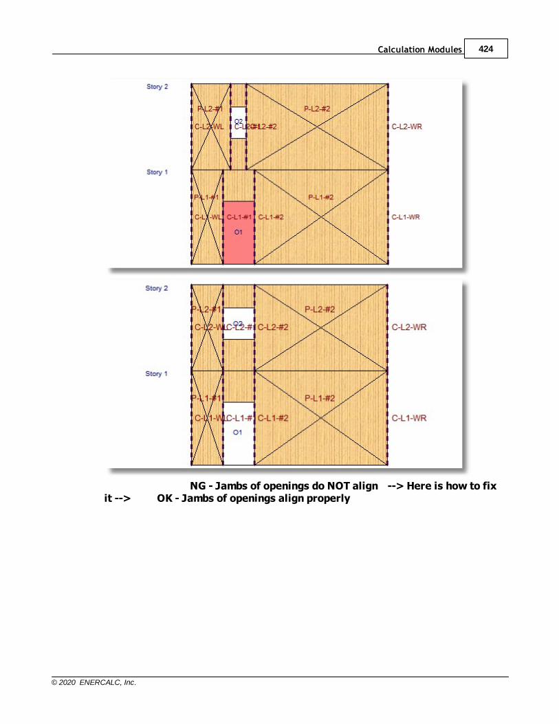
Calculation Modules 424
© 2020 ENERCALC, Inc.
NG - Jambs of openings do NOT align --> Here is how to fixit --> OK - Jambs of openings align properly
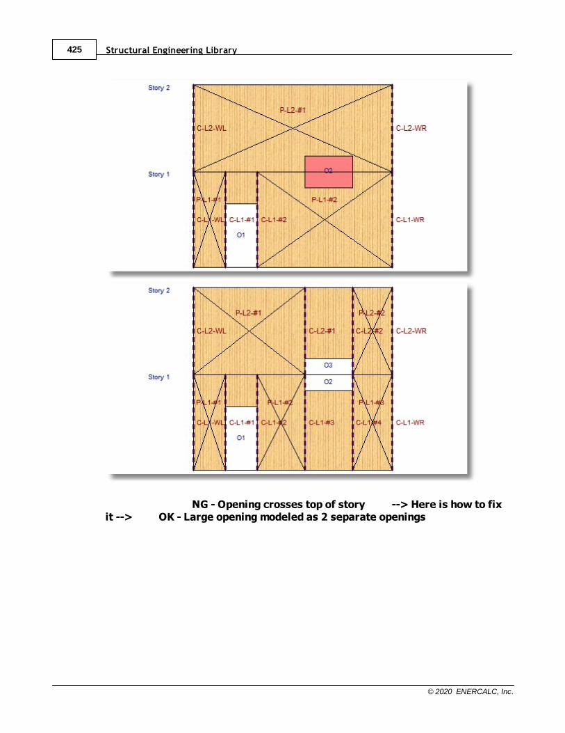
Structural Engineering Library425
© 2020 ENERCALC, Inc.
NG - Opening crosses top of story --> Here is how to fixit --> OK - Large opening modeled as 2 separate openings

Calculation Modules 426
© 2020 ENERCALC, Inc.
NG - Stacked openings within a story --> Here is how to fixit --> OK - One opening accomplishes the task
Note: When using the self-weight functions for Dead Load and for seismic load, theprogram does not deduct any weight for openings. In other words, the programassumes that the unit weight of the window, door, louver, etc. in the opening, isapproximately the same as the unit weight of the wood-framed construction it isreplacing.
Footing tab
Structural Engineering Library427
© 2020 ENERCALC, Inc.
Specify a Footing: If this checkbox is selected, then the input fields for defining a footingare displayed. Note: This checkbox also causes some footing-related input to be shownor hidden as appropriate on the Loads tab.
Allowable Soil Pressure: Specify the allowable soil bearing pressure in units of ksf.
f'c: Specify the compressive stress of concrete in units of ksi.
Fy: Specify the yield stress of rebar in units of ksi.
Rebar Cover: Specify the cover over rebar in units of inches. The program will use thisvalue and an allowance for the rebar size to calculate the effective depth of the concretesection.
Minimum Steel Reinforcing Percentage Based on Thickness: Specify the minimumpermissible ratio of rebar area to gross area of concrete.
Concrete Density: Specify the density of concrete in units of pcf.
Footing Width: Specify the width of the footing in units of ft. This is the dimensionperpendicular to the wall length.
Footing Thickness: Enter the thickness of the footing in units of inches.
Projection @ Left: Enter the projection of the footing beyond the left end of the wall inunits of ft.
Wall Length: The program reports the shear wall length in units of ft for reference.
Projection @ Right: Enter the projection of the footing beyond the right end of the wall inunits of ft.
Footing Length: The program reports the footing length in units of ft for reference.
Loads tab
The Loads tab provides several sub-tabs for the convenient definition of many differenttypes of loads that could potentially act on a shear wall system.
General sub-tab
The Wall Self Weight category offers inputs for the following:
Consider Wall Weight: This category provides options to automatically consider the wallself-weight:· As vertical Dead load - a way to request that the program use the unit weight described
above to calculate a dead load
Calculation Modules 428
© 2020 ENERCALC, Inc.
· As Seismic load - a way to request that the program use the unit weight described
above to calculate a lateral seismic load using the value of Cs described below
Weight: (Only displayed when one of the options above has been selected.) Enter theunit weight of shear wall construction in psf.
Cs: Seismic Response Coefficient: (Only displayed when the "As Seismic load" optionabove has been selected.) Collects the value of Cs by which the unit weight would bemultiplied to determine the seismic load due to the self-weight of the wall if that option isselected.
The Soil over Footing category is only displayed if the "Specify a Footing" option isselected on the Footing tab. This category offers inputs for the following:
Soil depth over footing: Enter the depth of soil above the top of the footing in units ofinches. This value is used to determine loading on concrete footings when one isdesigned. This value will affect the reinforced concrete design, the soil bearing pressure,and the overturning ratio.
Soil density: Enter the density of soil above the top of the footing in units of pcf. Thisvalue is used to determine loading on concrete footings when one is designed. This valuewill affect the reinforced concrete design, the soil bearing pressure, and the overturningratio. If no footing design is requested, this value has no influence on the remainingcalculations.
The Added Overburden Load over Footing category is only displayed if the "Specify aFooting" option is selected on the Footing tab. This category allows the user to specifysuperimposed load on the top of the footing for all of the common load cases. Thisvalue will affect the reinforced concrete design, the soil bearing pressure, and theoverturning ratio. Vertical Point sub-tab
Add: The Add button opens the Add Point Load dialog. The dialog allows vertical pointloads of all load cases to be defined and located with respect to the lower left corner ofthe wall. Note: Positive magnitudes are assumed to act downward.
Edit: By selecting an existing load in the list, the Edit button allows the selected load to berevised.
Delete: By selecting an existing load in the list, the Delete button allows the load openingto be removed.
Vertical Uniform sub-tab
Add: The Add button opens the Add Uniform Load dialog. The dialog allows verticaluniform loads of all load cases to be defined and located with respect to the lower leftcorner of the wall. Note: Uniform loads can be specified as partial-length loads by
Structural Engineering Library429
© 2020 ENERCALC, Inc.
specifying the start and end locations of the load with respect to the left edge of the wall. Positive magnitudes are assumed to act downward.
Edit: By selecting an existing load in the list, the Edit button allows the selected load to berevised.
Delete: By selecting an existing load in the list, the Delete button allows the load openingto be removed.
Lateral Point sub-tab
Add: The Add button opens the Add Point Load dialog. The dialog allows lateral pointloads of all load cases to be defined and located with respect to the lower edge of thewall. Note: Positive magnitudes are assumed to act to the right.
Edit: By selecting an existing load in the list, the Edit button allows the selected load to berevised.
Delete: By selecting an existing load in the list, the Delete button allows the load openingto be removed.
Lateral Uniform sub-tab
Add: The Add button opens the Add Uniform Load dialog. The dialog allows lateraluniform loads of all load cases to be defined and located with respect to the lower edge ofthe wall. Note: Uniform loads can be specified as partial-height loads by specifying thestart and end locations of the load with respect to the bottom edge of the wall. Positivemagnitudes are assumed to act to the right.
Edit: By selecting an existing load in the list, the Edit button allows the selected load to berevised.
Delete: By selecting an existing load in the list, the Delete button allows the load openingto be removed.
The graphic display offers checkboxes to independently display or hide:· Openings
· Shear Panel callouts
· Chord graphics and callouts
· Panel and opening dimensions
· All loads - otherwise only the loads associated with the selected tab are displayed
Load Combinations tab
The Load Combinations tab indicates the currently selected load combination set.
Calculation Modules 430
© 2020 ENERCALC, Inc.
The load combination set can be changed by clicking the Change Load Combination Setbutton.
The padlock icon can be used to unlock the individual load factors so they can be edited. Note: Editing load factors in this way will not alter the load factors that are stored in theselected load combination set. The edits will only affect the currently active calculation.
The Load Combinations tab has two sub-tabs: Service Combinations and FactoredCombinations.
Service Combinations sub-tab
The Service Combinations tab offers the service-level combinations from the selected loadcombination set. These load combinations will be used for wood design when the ASDDesign Method is selected. They will also be used to determine soil bearing pressureswhen the option is selected to design a footing.
A selected checkbox in the "Run" column indicates that the associated load combinationwill be considered. The "Run" button offers quick convenience options for changing theselection status of many load combinations at one time.
The CD column is only visible when the ASD Design Method is selected. It indicates the
value of the Load Duration Factor for each load combination. Click the CD button to
quickly set the values of CD for all load combinations based on the load case with the
shortest duration.
Use additional factors per ASCE 12.4.2.3: Select this button to instruct the module toconsider the additional contribution to the Dead Load due to the vertical component ofseismic load prescribed in ASCE 12.4.2.3.
Auto Reverse Wind: Select this button to instruct the module to also consider thealgebraic negative of the defined Wind loads. (This may be useful for quickly creating aload combinations that reverse the direction of application of applied wind loads bycreating a "sister" load combination that uses the negative version of the wind componentfor each load combo that normally incorporates +W.)
Auto Reverse Seismic: Select this button to instruct the module to also consider thealgebraic negative of the defined Seismic loads. (This may be useful for quickly creatinga load combinations that reverse the direction of application of applied seismic loads bycreating a "sister" load combination that uses the negative version of the seismiccomponent for each load combo that normally incorporates +E.)
Factored Combinations sub-tab
The Factored Combinations tab offers the factored- or ultimate-level combinations fromthe selected load combination set. These load combinations will be used for wood designwhen the LRFD Design Method is selected. They will also be used for reinforced concretedesign when the option is selected to design a footing.
Structural Engineering Library431
© 2020 ENERCALC, Inc.
A selected checkbox in the "Run" column indicates that the associated load combinationwill be considered. The "Run" button offers quick convenience options for changing theselection status of many load combinations at one time.
The Lambda column is only visible when the LRFD Design Method is selected. It indicatesthe value of the Time Effect Factor for each load combination. Click the Lambda buttonto quickly set the values of Lambda for all load combinations based on Table N3.
L <= 100, f1=0.5: Select this option to set appropriate load factors on Live Load whenthe specified Live Load is less than or equal to 100 psf.
L > 100, f1=1.0: Select this option to set appropriate load factors on Live Load when thespecified Live Load is greater than 100 psf.
Use additional factors per ASCE 12.4.2.3: Select this button to instruct the module toconsider the additional contribution to the Dead Load due to the vertical component ofseismic load prescribed in ASCE 12.4.2.3.
Auto Reverse Wind: Select this button to instruct the module to also consider thealgebraic negative of the defined Wind loads. (This may be useful for quickly creating aload combinations that reverse the direction of application of applied wind loads bycreating a "sister" load combination that uses the negative version of the wind componentfor each load combo that normally incorporates +W.)
Auto Reverse Seismic: Select this button to instruct the module to also consider thealgebraic negative of the defined Seismic loads. (This may be useful for quickly creatinga load combinations that reverse the direction of application of applied seismic loads bycreating a "sister" load combination that uses the negative version of the seismiccomponent for each load combo that normally incorporates +E.)
The lower portion of the screen offers the following options for reviewing results:
Shear Panel Design
Summary
On a panel-by-panel, level-by-level basis, the Summary tab presents the followinginformation:
Max Shear: Reports the maximum shear force and the load combination associated withthat maximum shear force.
# of Sides: Indicates the number of sides to which sheathing has been applied. Willeither be 1 or 2.

Calculation Modules 432
© 2020 ENERCALC, Inc.
Shear Summary & Attachment: Reports the actual unit shear, the allowable unit shear,the design status, and the required attachment pattern.
Height/Width Ratio: Reports the actual height-to-width ratio, the allowable height-to-widthratio for Side 1 (Main Sheathing), the allowable height-to-width ratio for Side 2 (2nd SideSheathing), and notes regarding the status of the height-to-width ratio and any necessaryadjustments.
Detail by Panel ID
On a panel-by-panel, load combination-by-load combination basis, the Detail by Panel IDtab presents the following information:
Panel Data: Reports the story in which the panel exists, the distance from the left edgeof the overall wall to the left edge of the panel, the width of the panel, the distance fromthe bottom edge of the overall wall to the bottom edge of the panel, the height of thepanel, and the height-to-width ratio of the panel.
width, and the maximum unit shear.
Capacity Factors: Reports phi for LRFD designs or the reciprocal of the Factor of Safetyfor ASD designs, a capacity adjustment factor due to aspect ratio of the sheathing onthe Main Sheathing side of the wall, a capacity adjustment factor due to aspect ratio ofthe sheathing on the 2nd Side of the wall, and a capacity adjustment factor due to thespecific gravity of the framing.
Adjusted Allowable Shear: Reports the allowable unit shears for all relevant fastenerspacings incorporating any applicable capacity adjustment factors. In situations wheretwo sides of sheathing are being considered, this table will correctly determine thecapacity considering both sides of sheathing by applying the rules of 4.3.3.3 and4.3.3.3.2.
Panel Moment: Reports the moment in the panel.
Chord ID: Reports the identifying labels for the chords at the left and at the right end ofeach panel.
Detail by Load Combination
On a load combination-by-load combination, panel-by-panel basis, the Detail by LoadCombination tab presents the following information:
Structural Engineering Library433
© 2020 ENERCALC, Inc.
Shear Force = shear tributary to each panel
A convenient nomenclature key is presented on this tab as well.
Chord Design
Chord Data
For each chord in the wall, the Chord Data tab presents the following information:
Location: Reports the Level in which the chord occurs and the distance from the leftedge of the overall wall to the chord.
Chord Design: Reports the chord force associated with the controlling design ratio, theload combination responsible for producing the controlling design ratio, then number ofchord members required to resist the applied load, the size of the chord memberindicated by the user, the governing design ratio, the governing design consideration(tension or compression), and the design status.
Chord Compression Stress: Reports the maximum chord compression force, the loadcombination responsible for producing the maximum chord compression force, themaximum compressive stress, and the allowable compressive stress.
Chord Tension Stress: Reports the maximum chord tension force, the load combinationresponsible for producing the maximum chord tension force, the maximum tensile stress,and the allowable tensile stress.
Chord Forces by Chord ID
For each chord in the wall, on a load combination-by-load combination basis the ChordForces by Chord ID tab presents the following information:
Story: The story in which the chord occurs.
ID: The identification label assigned to the chord.
Axial: Reports the load in the chord due to the sum of applied vertical loads, the load inthe chord that can be added or subtracted due to the overturning moment in the panel,the force with the largest (tendency for) tension, and the force with the largest(tendency for) compression.
Chord Location: Reports the distance from the left edge of the overall shear wall to thechord location, the distance from the bottom edge of the overall shear wall to the bottomof the chord, and the distance from the bottom edge of the overall shear wall to the topof the chord.
Calculation Modules 434
© 2020 ENERCALC, Inc.
Footing & Stability
Max Factored Pressures: Reports the maximum factored soil pressures at the left andright sides of the footing, along with the load combination responsible for producing eachof those pressures. Note: Factored soil pressures are reported for reference, as theyare used in the reinforced concrete design calculation for the footing.
Footing One-Way Shear Check: Reports the results of the one-way shear calculation forboth ends of the footing.
Footing Bending Design: Reports the results of the flexural analysis and design includingrecommended reinforcing options to satisfy the required area of steel.
Max Unfactored Soil Pressures: Reports the maximum unfactored soil pressures at theleft and right sides of the footing, along with the load combination responsible forproducing each of those pressures. Unfactored soil pressures are compared to theallowable soil bearing pressure provided by the user.
Overturning Stability: Reports the overturning analysis performed about each end of thefooting including the overturning moment, the resisting moment, the stability ratio, andthe governing load combination.
Sketch
The sketch tab provides a convenient graphical view of the shear wall with options toselectively view or hide the following:· Openings
· Shear Panel callouts
· Chord graphics and callouts
· Panel and opening dimensions
· All loads

Structural Engineering Library435
© 2020 ENERCALC, Inc.
10.6 Retaining Walls
Please select a subtopic.
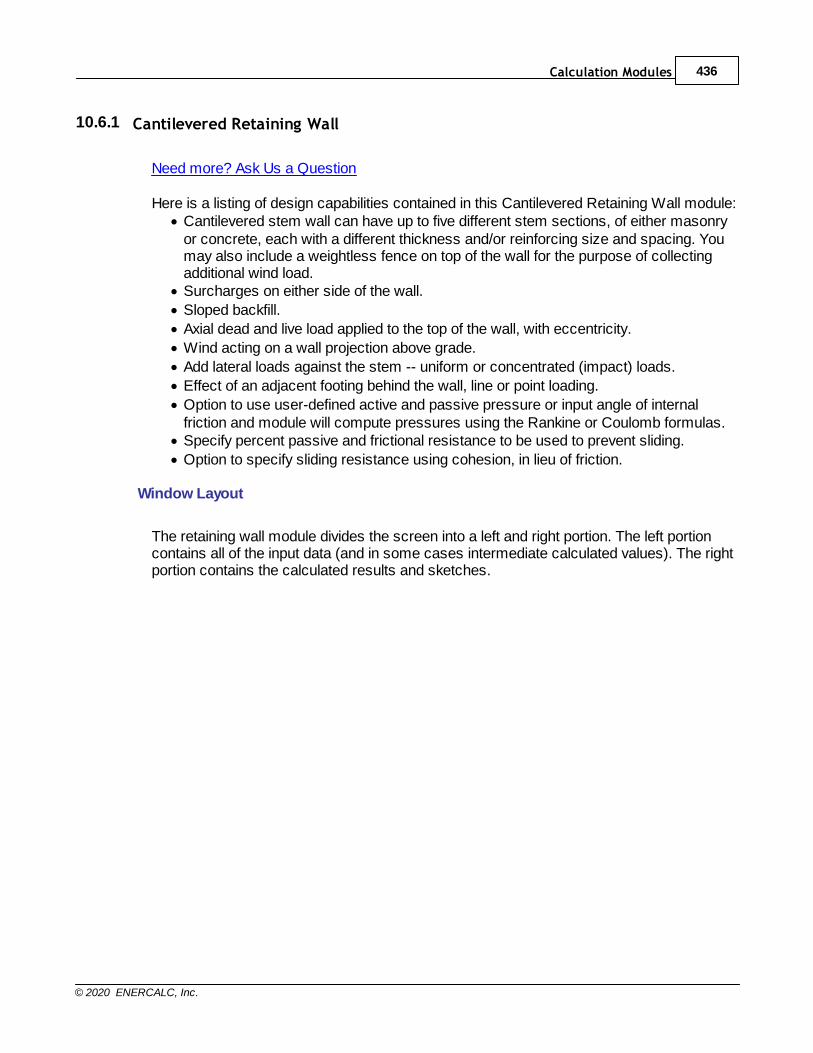
Calculation Modules 436
© 2020 ENERCALC, Inc.
10.6.1 Cantilevered Retaining Wall
Need more? Ask Us a Question
Here is a listing of design capabilities contained in this Cantilevered Retaining Wall module:· Cantilevered stem wall can have up to five different stem sections, of either masonry
or concrete, each with a different thickness and/or reinforcing size and spacing. Youmay also include a weightless fence on top of the wall for the purpose of collectingadditional wind load.
· Surcharges on either side of the wall.
· Sloped backfill.
· Axial dead and live load applied to the top of the wall, with eccentricity.
· Wind acting on a wall projection above grade.
· Add lateral loads against the stem -- uniform or concentrated (impact) loads.
· Effect of an adjacent footing behind the wall, line or point loading.
· Option to use user-defined active and passive pressure or input angle of internalfriction and module will compute pressures using the Rankine or Coulomb formulas.
· Specify percent passive and frictional resistance to be used to prevent sliding.
· Option to specify sliding resistance using cohesion, in lieu of friction.
Window Layout
The retaining wall module divides the screen into a left and right portion. The left portioncontains all of the input data (and in some cases intermediate calculated values). The rightportion contains the calculated results and sketches.
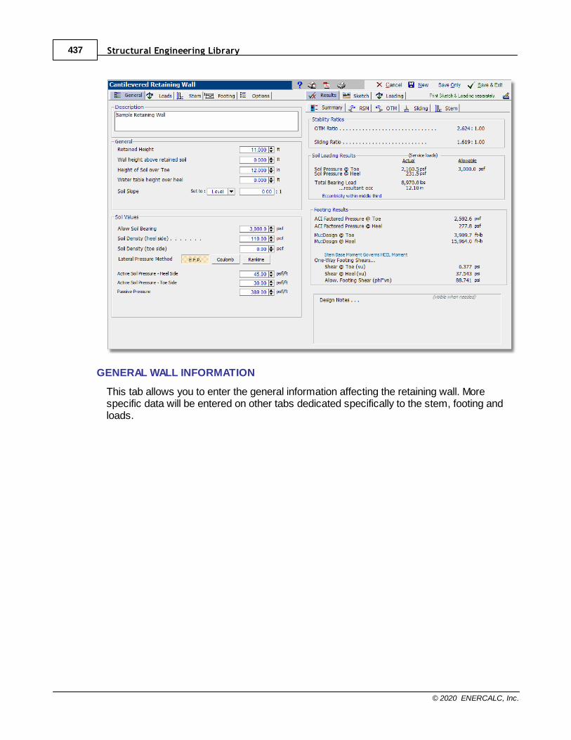
Structural Engineering Library437
© 2020 ENERCALC, Inc.
GENERAL WALL INFORMATION
This tab allows you to enter the general information affecting the retaining wall. Morespecific data will be entered on other tabs dedicated specifically to the stem, footing andloads.
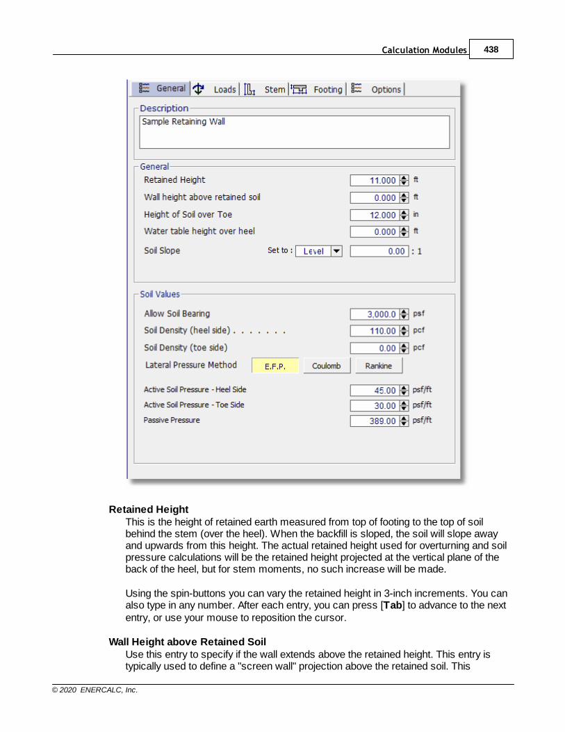
Calculation Modules 438
© 2020 ENERCALC, Inc.
Retained HeightThis is the height of retained earth measured from top of footing to the top of soilbehind the stem (over the heel). When the backfill is sloped, the soil will slope awayand upwards from this height. The actual retained height used for overturning and soilpressure calculations will be the retained height projected at the vertical plane of theback of the heel, but for stem moments, no such increase will be made.
Using the spin-buttons you can vary the retained height in 3-inch increments. You canalso type in any number. After each entry, you can press [Tab] to advance to the nextentry, or use your mouse to reposition the cursor.
Wall Height above Retained SoilUse this entry to specify if the wall extends above the retained height. This entry istypically used to define a "screen wall" projection above the retained soil. This

Structural Engineering Library439
© 2020 ENERCALC, Inc.
extension can be used as a weightless "Fence", or it can be defined as a concrete ormasonry stem section without any soil retained behind it. You can enter wind load onthis projection using the entry labeled "Load @ stem above soil" on the Loads tab.We'll handle the fence when we get to the Stem design screen. The total height of thewall (above the footing) will be equal to the Retained Height plus the Wall Height AboveRetained Soil.
Height of Soil over ToeMeasured from top of footing to top of soil on the toe side, this may vary from a fewinches to a few feet depending upon site conditions. (Note that it is specified ininches.) It is used to calculate passive soil resistance (but its effective depth can bemodified by the "Soil over toe to Neglect" entry in the Sliding Resistance category onthe Footing tab). This depth of soil is also used to calculate the resisting moment, andto reduce the net lateral sliding force. You can negate the latter effects on the Optionsscreen if desired.
Water table height over heelIf a portion of the retained height is below a water table, the active pressure of thesaturated soil will increase below that level. This additional pressure for the saturatedsoil is equal to the pressure of water, plus the submerged weight of the soil (itssaturated weight - 62.4), plus the surcharge of the soil above the water table. Thesubmerged weight of a soil can be approximated as 62% of its dry unit weight.
If you want to design for a water table condition, enter the maximum height from top offooting to water table level. The module will then compute the added pressures forsaturated soil on the heel side of the footing, including buoyancy effect. It will alsocalculate increased moments and shears on the stem, and an increased overturningmoment. Don’t enter a height more than the retained height, nor a liquid other thanwater. If the water table is near the top of the retained height, it may be advisable toenter the saturated soil density and specify the resulting active pressure for the fullretained height.
Soil SlopeYou may enter any backfill slope behind the wall. Use the drop-down list box or typethe slope ratio as Horiz/Vert. The soil must be level or slope upward. Negative backfillslopes (grade sloping downward, away from the wall) are not allowed.
The module will use this slope to:
1. include the weight of a triangular wedge of soil over the heel as vertical load, and 2. compute overturning based upon an assumed vertical plane at the back face of the
footing extending from the bottom of the footing to the ground surface – a steeperslope will result in a higher overturning moment.
When the Rankine or Coulomb method is used, the final calculated pressures doinclude the effect of the slope on those Rankine or Coulomb equations.
The module will not accept a backfill slope steeper than the angle of internal friction.
Allow Soil Bearing
Calculation Modules 440
© 2020 ENERCALC, Inc.
The maximum allowable soil bearing pressure for static conditions. Using the spinbuttons you can increment in 50 psf steps. Typical values vary from 1,000 psf to 4,000psf or more.
Soil Density (heel side)Enter the soil density for all earth (or water if applicable) above the heel of the footing.This weight is used to calculate overturning resistance forces and soil pressuresusing the weight of the soil block over the projecting heel of the footing. Whensurcharges are applied over the soil, the surcharges are transformed to equivalentuniform lateral loads acting on the wall by the ratio force = (Surcharge/ Density)*Lateral Load. Input this value in lbs. per cubic foot. Usual values are 110 pcf to 120pcf. More if saturated soil. Water is usually assumed to be 64 pcf.
Soil Density (toe side)Enter the soil density on the toe side, which may be different than the heel side. Whensurcharges are applied over the soil on the toe side, the surcharge is transformed toequivalent uniform lateral loads acting on the wall by the ratio force = (Surcharge/Density)*Lateral Load. Input this value in lbs. per cubic foot. Typical values are 110 pcfto 120 pcf.
Lateral Pressure MethodHere you can choose between E.F.P. (Equivalent Fluid Pressure), Rankine formula orCoulomb formula. Based on your choice for Lateral Pressure Method, you will beoffered the following input fields to fully define the lateral forces acting on the wall andfooting.
When the EFP Method is selected:
Active Soil Pressure - Heel SideEnter the equivalent fluid pressure (EFP) for the soil being retained that acts tooverturn and slide the wall toward the toe side. This pressure acts on the stem forstem section calculations, and on the total footing+wall+slope height for overturning,sliding, and soil pressure calculations.
Commonly used values, assuming an angle of internal friction of 34°, are 30 pcf for alevel backfill; 35 pcf for a 4:1 slope; 38 pcf for a 3:1 slope; 43 pcf for a 2:1 slope; and55 pcf for a 1.5:1 slope. These values are usually provided by the geotechnicalengineer.
When the retained soil is sloped, a vertical component of the lateral earth pressureover the heel can be applied vertically downward in the plane of the back of the footing.You can choose to apply this force for overturning resistance, sliding resistance,and/or for soil pressure calculations, by checking the boxes on the Options tab.
Active Soil Pressure - Toe SideEnter the active pressure to be used on the toe side of the wall. This active pressureis used along with the "Soil Height over Toe" value (entered on the Sliding tab) tocalculate a stabilizing soil force on the wall. This front side of the wall is assumed to
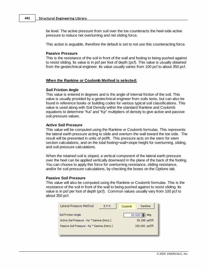
Structural Engineering Library441
© 2020 ENERCALC, Inc.
be level. The active pressure from soil over the toe counteracts the heel-side activepressure to reduce net overturning and net sliding force.
This action is arguable, therefore the default is set to not use this counteracting force.
Passive PressureThis is the resistance of the soil in front of the wall and footing to being pushed againstto resist sliding. Its value is in psf per foot of depth (pcf). This value is usually obtainedfrom the geotechnical engineer. Its value usually varies from 100 pcf to about 350 pcf.
When the Rankine or Coulomb Method is selected:
Soil Friction AngleThis value is entered in degrees and is the angle of internal friction of the soil. Thisvalue is usually provided by a geotechnical engineer from soils tests, but can also befound in reference books or building codes for various typical soil classifications. Thisvalue is used along with Soil Density within the standard Rankine and Coulombequations to determine "Ka" and "Kp" multipliers of density to give active and passivesoil pressure values.
Active Soil PressureThis value will be computed using the Rankine or Coulomb formulas. This representsthe lateral earth pressure acting to slide and overturn the wall toward the toe side. Theresult will be presented in units of psf/ft. This pressure acts on the stem for stemsection calculations, and on the total footing+wall+slope height for overturning, sliding,and soil pressure calculations.
When the retained soil is sloped, a vertical component of the lateral earth pressureover the heel can be applied vertically downward in the plane of the back of the footing.You can choose to apply this force for overturning resistance, sliding resistance,and/or for soil pressure calculations, by checking the boxes on the Options tab.
Passive Soil PressureThis value will also be computed using the Rankine or Coulomb formulas. This is theresistance of the soil in front of the wall to being pushed against to resist sliding. Itsvalue is in psf per foot of depth (pcf). Common values usually vary from 100 pcf toabout 350 pcf.
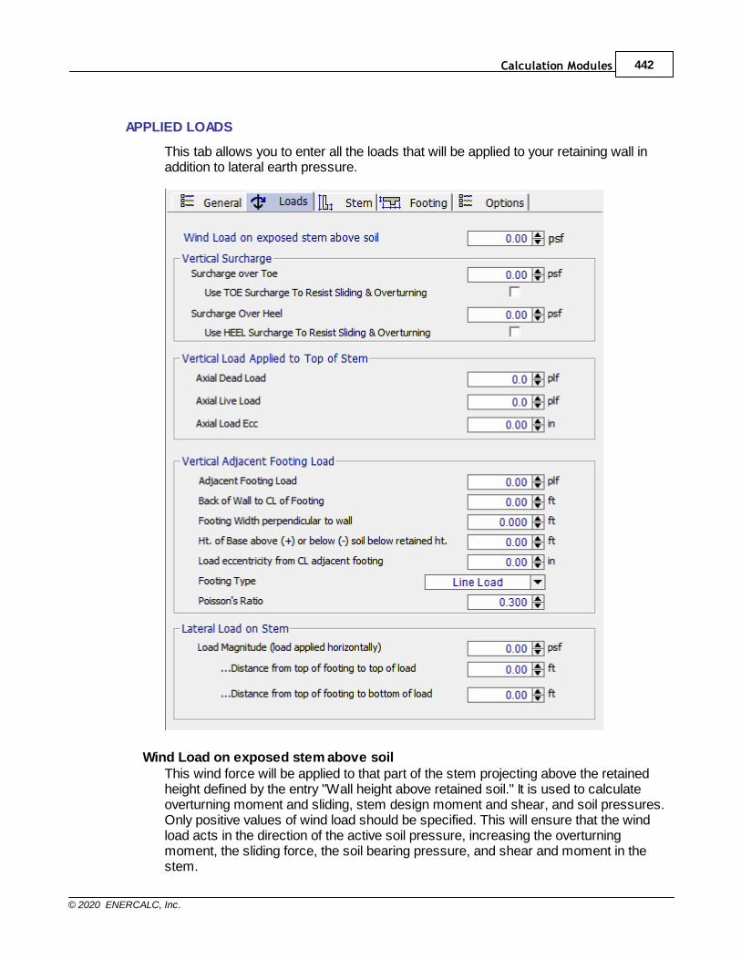
Calculation Modules 442
© 2020 ENERCALC, Inc.
APPLIED LOADS
This tab allows you to enter all the loads that will be applied to your retaining wall inaddition to lateral earth pressure.
Wind Load on exposed stem above soilThis wind force will be applied to that part of the stem projecting above the retainedheight defined by the entry "Wall height above retained soil." It is used to calculateoverturning moment and sliding, stem design moment and shear, and soil pressures.Only positive values of wind load should be specified. This will ensure that the windload acts in the direction of the active soil pressure, increasing the overturningmoment, the sliding force, the soil bearing pressure, and shear and moment in thestem.

Structural Engineering Library443
© 2020 ENERCALC, Inc.
Vertical Surcharge (Surcharges will be factored as Earth Load, H for LRFDdesigns.)Surcharge over Toe
This surcharge is treated as additional soil weight – if the surcharge is 240 psf and thedensity is 120 pcf, then the module uses two feet of additional soil. Similarly, if 50 psfis added for the weight of a slab over the footing, this will be equivalent to 0.41 feet ofsoil (50 / 120). This surcharge will affect sliding resistance and active toe pressure.Keep this in mind if modeling a point load toe surcharge.
Use TOE Surcharge to resist sliding & overturningChecking this box will include the weight of soil overburden on the toe to resistoverturning and add to its weight for frictional resistance.
Surcharge over HeelThis surcharge is considered uniformly applied to the top surface of the soil over theheel. It may be entered whether or not the ground surface is sloped, but it is unlikely asurcharge could apply to a sloped backfill. This surcharge is always taken as a verticalforce. This surcharge is divided by the soil density and multiplied by the ActivePressure to create a uniform lateral load applied to the wall. You can choose to usethis surcharge to resist sliding and overturning by clicking the box on the Options tab.Typical live load surcharges are 100 psf for light traffic and parking, and 250 psf forhighway traffic.
Use HEEL Surcharge to resist sliding & overturningChecking this box will include heel surcharge. If the surcharge includes live load, thenusing it to resist sliding and overturning could be non-conservative. In this situation, itmight be advisable to deselect this checkbox.
Vertical Load Applied to Top of StemThese loads are considered uniform load along the length of the wall. They are appliedto the top of the topmost stem section and affect the design of masonry stems only.The dead and live loads are used to calculate stem design values and factored soilreaction pressures used for footing design. Only the dead load is used to resistoverturning and sliding of the retaining wall.
If a wall is subjected to a high axial load (say more than 3 kips/ft) it could cause areversal of the bending moment in the heel. Under these conditions, it might beadvisable to investigate the design with and without the high axial load, to be sure thatan acceptable design is found for all conditions.
Since slenderness ratios (h/t) for retaining walls are generally small, usually less than10, and axial stresses are low, slenderness effects are checked but usually have asmall effect.
If a point load is applied to the top of a wall, such as a beam reaction, the point load istypically assumed to distribute itself laterally at a rate that is based on engineeringjudgment for the materials under consideration. As a result of this distribution, thepoint load will result in a uniformly distributed load of some relatively low magnitude by
Calculation Modules 444
© 2020 ENERCALC, Inc.
the time it reaches the base of the stem. This module does not have an explicit inputfield for point loads, so they must be represented as uniformly distributed loads. Toproperly account for the lateral distribution that is characteristic of an axial point loadapplied to a wall, the magnitude that is entered to represent the point load shouldconsider this distribution effect. The top of the wall may also need to be checked byappended calculations for the localized effects of the full magnitude of theconcentrated load.
Axial Load EccentricityThis is the eccentricity of the axial load with respect to the centerline of the uppermoststem section. Positive values of eccentricity move the load toward the toe, causingbending moments that are additive to those caused by the lateral soil pressure overthe heel. Negative eccentricities are not accepted.
Vertical Adjacent Footing LoadThis entry gives you the option of placing a footing (line or square) adjacent andparallel to the back face of the wall, and have its effect on the wall included in both thevertical and horizontal forces on the wall and footing. Refer to the General ReferenceDiagram for locations where input measurements should be taken.
For "Line (Strip) Load" the entry is the total load per ft. parallel to the wall (not psf). Ifthe adjacent footing is specified as "Square Footing" (not line load), the load enteredshould be the adjacent footing load divided by its dimension parallel to the wall, givinga pounds per lineal foot value, as for a continuous (line) footing.
A Boussinesq analysis is used to calculate the vertical and lateral pressures acting onthe stem and footing. The module uses equation (11-20a) in Bowles’ FoundationAnalysis and Design, 5th Edition, McGraw-Hill, pages 630. When the Boussinesqanalysis is used, the module may require additional computing time, depending uponthe speed of your computer (hundreds of internal calculations are done after eachentry). To avoid this delay (which occurs any time any entry is changed) we suggestyou use a vertical load of zero until your data entry is nearly finalized. Then enter theactual footing load and modify your final values.
For adjacent truck or highway loading, it may be preferable to use a heel surcharge(uniform) of 250 psf (or more), instead of treating it as an adjacent footing.
It is generally not necessary to use this feature if the adjacent footing load is fartherfrom the stem than the retained height, less the depth of the adjacent footing below theretained height, since at this distance it will not have significant effect on the wall.
Wall to Footing Centerline DistanceThis is the horizontal distance from the center of the adjacent footing to the back faceof the stem (measured at the top of retaining wall footing). The nearest edge of thefooting should be at least a foot away from the wall face – otherwise it is suggested touse an equivalent heel surcharge instead.
Note: If the horizontal distance from the center of the adjacent footing to the back faceof the stem is greater than the vertical distance from the top of the retaining wall
Structural Engineering Library445
© 2020 ENERCALC, Inc.
footing to the bottom of the adjacent footing, then the effect on the retaining wall will beinsignificant.
Footing WidthWidth of the adjacent footing measured perpendicular to the wall. This is necessary tocreate a one-foot long by Width wide area over which the load is applied.
Height of Base Above (+) or Below (-) Retained HeightUse this entry to locate the bottom of the adjacent footing with respect to the RetainedHeight. Entering a negative number places the footing below the Retained Height. Apositive entry would typically only be used when the soil is sloped and the adjacentfooting resides uphill. To insert a negative number, first type the number, then pressthe "-" (minus) sign.
Note: If the Adjacent Footing is another retaining wall at a higher elevation, theBoussinesq analysis may be used for the vertical load applied to the soil from the wall,however the design must also consider the lateral (sliding) loads from that adjacentwall. This load could be applied as Added Lateral Load, however this is at thediscretion of the designer and is not within the scope of the module. Caution is urgedfor this condition. See discussion in the companion book: Basics of Retaining WallDesign. For questionable soil or site conditions a global stability analysis is advised.
EccentricityThis entry is provided in case the soil pressure under the adjacent footing is notuniform. Enter the eccentricity of the resultant force under the adjacent footing fromthe centerline of the adjacent footing. Positive eccentricity shifts the load toward thetoe, resulting in greater pressure at the side of the adjacent footing closest to the stemof the retaining wall. The module will use the vertical load and eccentricity and create atrapezoidal pressure distribution under the adjacent footing for use with theBoussinesq analysis of vertical and lateral pressures.
Footing TypeThis drop-down list box allows you to enter either an isolated footing using the "SquareFooting" selection, or a continuous footing using the "Line Load" selection.
Poisson's RatioSince the resulting pressures are sensitive to Poisson’s Ratio, there is an entryallowing you to select a ratio from 0.30 to 0.55. This value should be provided by thegeotechnical engineer. A value of 0.50 is often assumed.
Lateral Load on StemThis input allows you to specify an additional uniformly distributed lateral load appliedto the stem.
This is for an impact point load, such as due to an impact of a car or similar force.Enter the load as a one-foot high increment, separating the "Height to Bottom" and"Height to Top" by one-half foot (or meter).

Calculation Modules 446
© 2020 ENERCALC, Inc.
Note: This load is not factored. To apply a load factor (such as for an impact load),increase the applied load proportionately (e.g. an impact load of 1000 lbs requiring aload factor of 2.0 would be entered as 2,000 lbs). You may need to do several designsto check load factor combinations.
Keep in mind that when considering a concentrated lateral load, it may be possible toreduce the magnitude to account for the fact that the load distributes horizontally atlevels below the point of application.
Height to TopThis dimension defines the upper extent of the added lateral load measured from thetop of the footing. Do not enter a dimension that exceeds "retained height" plus "Wallheight above retained soil".
Height to BottomThis dimension defines the lower extent (or bottom) of the added lateral loadmeasured from the top of the footing.
STEM DESIGN TAB
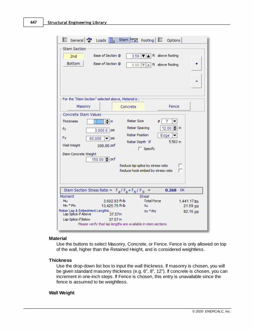
Structural Engineering Library447
© 2020 ENERCALC, Inc.
MaterialUse the buttons to select Masonry, Concrete, or Fence. Fence is only allowed on topof the wall, higher than the Retained Height, and is considered weightless.
ThicknessUse the drop-down list box to input the wall thickness. If masonry is chosen, you willbe given standard masonry thickness (e.g. 6", 8", 12"). If concrete is chosen, you canincrement in one-inch steps. If Fence is chosen, this entry is unavailable since thefence is assumed to be weightless.
Wall Weight
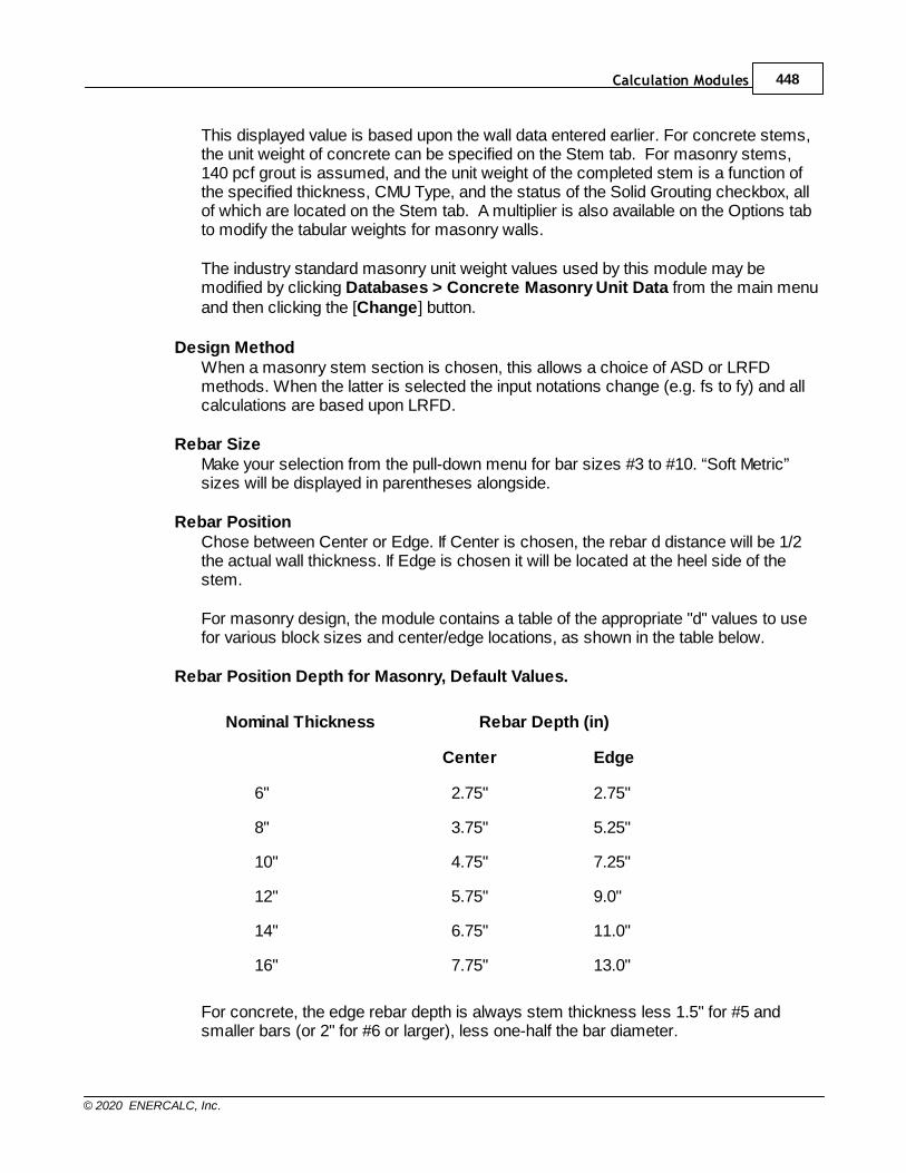
Calculation Modules 448
© 2020 ENERCALC, Inc.
This displayed value is based upon the wall data entered earlier. For concrete stems,the unit weight of concrete can be specified on the Stem tab. For masonry stems,140 pcf grout is assumed, and the unit weight of the completed stem is a function ofthe specified thickness, CMU Type, and the status of the Solid Grouting checkbox, allof which are located on the Stem tab. A multiplier is also available on the Options tabto modify the tabular weights for masonry walls.
The industry standard masonry unit weight values used by this module may bemodified by clicking Databases > Concrete Masonry Unit Data from the main menuand then clicking the [Change] button.
Design MethodWhen a masonry stem section is chosen, this allows a choice of ASD or LRFDmethods. When the latter is selected the input notations change (e.g. fs to fy) and allcalculations are based upon LRFD.
Rebar SizeMake your selection from the pull-down menu for bar sizes #3 to #10. “Soft Metric”sizes will be displayed in parentheses alongside.
Rebar PositionChose between Center or Edge. If Center is chosen, the rebar d distance will be 1/2the actual wall thickness. If Edge is chosen it will be located at the heel side of thestem.
For masonry design, the module contains a table of the appropriate "d" values to usefor various block sizes and center/edge locations, as shown in the table below.
Rebar Position Depth for Masonry, Default Values.
Nominal Thickness Rebar Depth (in)
Center Edge
6" 2.75" 2.75"
8" 3.75" 5.25"
10" 4.75" 7.25"
12" 5.75" 9.0"
14" 6.75" 11.0"
16" 7.75" 13.0"
For concrete, the edge rebar depth is always stem thickness less 1.5" for #5 andsmaller bars (or 2" for #6 or larger), less one-half the bar diameter.
Structural Engineering Library449
© 2020 ENERCALC, Inc.
Specify Position BoxClick this box to change the default "d" value.
FsEnter the allowable steel stress, based on working stress design, which should beused for design of the masonry stem section. The spin button changes this value inincrements, and is not visible when a concrete wall has been specified.
Short Term IncreaseThis factor is applied to masonry ASD design and allowable soil bearing as permittedby IBC 2009, section 1806.1, and ACI 530-08, section 2.1.2.3. This is applicable onlywhen wind and/or seismic is applied.
Solid GroutThis applies to masonry only. If this box is checked, the weight of the wall will bebased upon industry standard solid-grout weight for either lightweight, medium weight,or normal weight block regardless of the specified spacing of reinforcing. If this box isnot checked, the module will calculate the weight based on the assumption that onlycells containing reinforcing are grouted.
This also affects equivalent solid thickness for stem shear calculations, and area foraxial stress calculations (combined with moment for masonry stems).
Modular "n", RatioThis is the multiplier used to calculate the modulus of elasticity of masonry. The ACI530-05 and ACI 530-08 both specify Em = 900*f’m which is the default value. Themultiplier can be modified on the Options tab.
Equivalent Solid ThicknessIf partially grouted (not solid grout), this value is generated from an internal databasethat is accessible by clicking Database > Concrete Masonry Unit Data.
Stem Design HeightsIMPORTANT! The term “Stem Design Height” used in this module is the height abovethe top of the footing (i.e. above the base of the stem). It is the height above the bottomof the stem where you want the module to compute moments and shears.
You can divide the stem into up to five sections (increments of height). Each sectionrepresents either a different material (concrete, masonry, or fence), a change inthickness, or a change in reinforcing size or spacing.
For most walls, only two or three changes in stem sections are used. For example, itwould be logical to create a change of section at the top of the dowels projecting intothe stem from the footing and perhaps another change in section further up the wallwhere a more economical design is desired.
BottomYou must start the stem design here, at the base (height above footing = 0.00), wherethe stem moment and shear are maximum. As you manipulate the bar sizes, spacing,and position (you first, of course, will have selected a wall material and trial thickness)

Calculation Modules 450
© 2020 ENERCALC, Inc.
until the Summary box shows you an acceptable stress ratio (the higher and closer to1.0, the more efficient).
To check the wall at a higher Design Height, such as at least the LAP REQ’D IFABOVE distance, where reinforcing or thickness can be reduced, click the [InsertStem] button and enter the next higher section. Advance the spin button to the desiredheight above the top of the footing or enter it by typing. This will move (and dim) theBottom Section and you can now design this new section.
Continue this way, clicking [Insert Stem] button after each stem section design iscompleted, up to a maximum of five heights. A new Design Height should only beentered when you want to change the material, thickness, or reinforcing, and shouldnever be less than about two foot intervals.
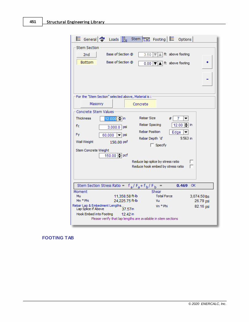
Structural Engineering Library451
© 2020 ENERCALC, Inc.
FOOTING TAB
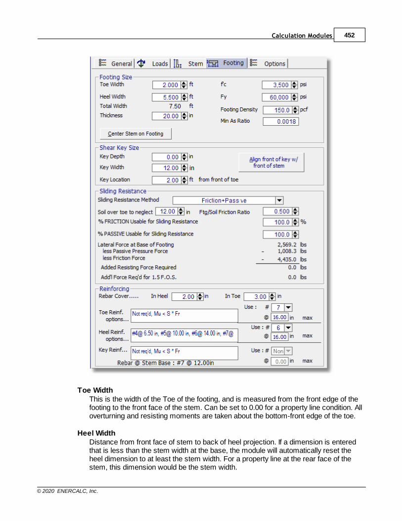
Calculation Modules 452
© 2020 ENERCALC, Inc.
Toe WidthThis is the width of the Toe of the footing, and is measured from the front edge of thefooting to the front face of the stem. Can be set to 0.00 for a property line condition. Alloverturning and resisting moments are taken about the bottom-front edge of the toe.
Heel WidthDistance from front face of stem to back of heel projection. If a dimension is enteredthat is less than the stem width at the base, the module will automatically reset theheel dimension to at least the stem width. For a property line at the rear face of thestem, this dimension would be the stem width.

Structural Engineering Library453
© 2020 ENERCALC, Inc.
Total WidthThe calculated width of the footing, Toe Width + Heel Width.
ThicknessTotal footing thickness, NOT including the key depth (if used). For bending and sheardesign of the footing, the rebar depth "d" is taken as Footing Depth - Rebar Cover - ½"(to account for the rebar radius). If footing thickness is inadequate for shear capacity ared warning indicator will appear.
The footing thickness must be sufficient to allow for rebar development (for hookeddowels) plus rebar cover (adjacent to the soil). If you enter a dimension less thanrequired for stem bar development, a red message will appear at the top of thescreen. If the thickness is inadequate, increase the footing thickness, or change thestem dowels, until this message disappears.
f'cEnter concrete compressive stress for footing.
FyAllowable rebar yield stress to be used for design of footing bending reinforcement.
Footing DensityThis option is necessary since, if there is any buoyancy effect, it will reduce theeffective weight of the footing concrete.
Min "As" RatioEnter the absolute minimum steel percentage to be used to calculate rebar spacingrequirements (commonly 0.0018 Ag for Fy=60,000 psi, but code applicability forfootings is arguable). If the % steel required by stress analysis is less that 200/Fy, theminimum of (200/Fy or 1.333 * bending percentage required) is calculated andcompared with the Minimum As% entered here, and the greater of the two is used tocalculate rebar spacing requirements.
Key DepthDepth of the key below the bottom of footing. The bottom of the key is used as thelower horizontal plane for determining the size of the passive pressure block from thesoil in front of the footing. Adjust this depth so the sliding safety factor is acceptable(typically a value of 1.5 is used).
Key Width Width of the key, measured along the same direction as the footing width. This isusually 12"-14", but generally not less than one-half the key depth so flexural stress inthe key is usually minimal.
Key LocationEnter the distance from the front edge of the toe to the beginning of the key. Do notenter a distance greater than the footing width minus key width.

Calculation Modules 454
© 2020 ENERCALC, Inc.
Sliding Resistance MethodEnter whether sliding resistance will be by friction and passive pressure or bycohesion and passive pressure.
Soil over toe to neglectSince the soil over the toe of the footing may be loose and uncompacted, it may havelittle or no passive resistance. This entry gives you the option of neglecting any or all ofthe Height of Soil Over Toe that you entered in the Criteria tab. You can neglect thesoil over toe plus the footing thickness, if desired.
Ftg/Soil Friction RatioEnter the friction factor here. It is generally provided by the geotechnical engineer andusually varies from 0.25 to 0.45.
% FRICTION Usable for Sliding ResistanceThis may be a stated restriction in the geotechnical report. Enter a value from zero to100%.
% PASSIVE Usable for Sliding ResistanceThis may be a stated restriction in the geotechnical report. Enter a value from zero to100%
Lateral Forces at Base of FootingThis is the total lateral force against the stem and footing which causes the wall toslide and which must be resisted. It is the total active pressure on the heel side lessthe active pressure on the toe side.
less Passive Pressure ForceThis uses the allowable passive pressure in pcf times the available depth (footingthickness plus soil above toe minus height to neglect) and multiplied by the percentusable that you indicated, to compute the total passive resistance. Weight due to toesurcharge, if applicable, will also be added. If a key is used, the available passivepressure depth will be to the bottom of the key.
less Friction ForceThis is the total vertical reaction multiplied by the friction factor and multiplied by thepercent usable that you indicated.
Added resisting force requiredIf this is 0.0 lbs., the forces balance, but there may be no safety factor. Watch theSliding Factor of Safety for an adequate value (usually 1.5). Consider adding a key orrevising the footing dimensions if required.
Additional force required for a 1.5 Factor of SafetyThis is the additional resisting force that would be required in order to achieve a 1.5safety factor. If this value indicates zero, then the sliding factor of safety is alreadygreater than or equal to 1.5.

Structural Engineering Library455
© 2020 ENERCALC, Inc.
Rebar Cover in Heel & ToeThese input fields allow you to specify the clear cover that will be used at the heel andat the toe. When specifying these values, keep in mind that the toe rebar is placedclosest to the bottom of the footing, and the heel rebar is placed closest to the top ofthe footing. When calculating the "d" dimension for bending and shear strengthcalculations, this module will consider the footing thickness and then deduct thespecified clear cover and an additional 1/2" to account for the radius of the rebar.
Toe Reinforcing OptionsThis list gives you choices for reinforcing sizes and spacing for the bottom toe bars.Typically the toe bars are extensions of the stem dowels, which are bent out towardthe toe. Therefore, it may be most efficient to simply verify that the bar size andspacing used for the stem dowels is within the range of the selections offered for toereinforcing options.
NOTE: If “No reinf’ req’d” message appears, it means the flexural capacity of thefooting (modulus of rupture times the section modulus, with 2” deducted from thethickness for crack allowance per code) is adequate to resist the applied moment.However, the designer in some cases may consider it prudent to add reinforcingregardless of the theoretical flexural capacity. For plain concrete per ACI 22.5.1, Fr =phi(5)(f’c)1/2, where phi = 0.55.
Heel Reinforcing OptionsThis list gives you choices for acceptable sizes and spacing of top heel bars. It isdesirable to select a spacing that is modular with the stem dowel bars for ease ofconstruction. Note: The module does not calculate the heel bar development lengthinward from the back face of the stem (where the moment is maximum).
NOTE: If “No reinf’ req’d” message appears, it means the flexural capacity of thefooting (modulus of rupture times the section modulus, with 2” deducted from thethickness for crack allowance per code) is adequate to resist the applied moment.However, the designer in some cases may consider it prudent to add reinforcingregardless of the theoretical flexural capacity.
ALSO NOTE: The heel design moment may be influenced by the setting used for theitem labeled "Neglect Upward Pressure at Heel for Ftg M & V" on the Options tab. Seethe section on the Options tab for additional information.
Key Reinforcing OptionsIf flexural tension is insufficient to resist bending in key, a message will appearindicating reinforcing required. You can vary the width of the key until the messagedisappears. If reinforcing is required options will be shown on the Footing tab.
OPTIONS TAB
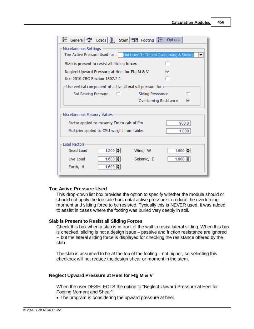
Calculation Modules 456
© 2020 ENERCALC, Inc.
Toe Active Pressure UsedThis drop-down list box provides the option to specify whether the module should orshould not apply the toe side horizontal active pressure to reduce the overturningmoment and sliding force to be resisted. Typically this is NEVER used. It was addedto assist in cases where the footing was buried very deeply in soil.
Slab is Present to Resist all Sliding ForcesCheck this box when a slab is in front of the wall to resist lateral sliding. When this boxis checked, sliding is not a design issue – passive and friction resistance are ignored-- but the lateral sliding force is displayed for checking the resistance offered by theslab.
The slab is assumed to be at the top of the footing – not higher, so selecting thischeckbox will not reduce the design shear or moment in the stem.
Neglect Upward Pressure at Heel for Ftg M & V
When the user DESELECTS the option to “Neglect Upward Pressure at Heel forFooting Moment and Shear”:· The program is considering the upward pressure at heel.
Structural Engineering Library457
© 2020 ENERCALC, Inc.
· The upward pressure tends to reduce the moment caused by the weight of the soiland the self-weight of the heel itself.
· The program is reporting the actual net moment found to exist in the heel.
When the user SELECTS the option to “Neglect Upward Pressure at Heel for FootingMoment and Shear”:· The program is NOT considering the upward pressure at heel.
· The program determines the heel moment caused by the weight of the soil and theself-weight of the heel itself.
· The program then applies the following logic:
- The calculated heel moment is conservative when the upward pressure atheel is neglected.
- The calculated heel moment would act in the same direction as the toemoment.
- The sum of the heel moment and the toe moment can’t be any greater thanthe stem design moment, which is delivering the moment to that joint in the first place.
- So the program conservatively assumes that the heel design moment is thecalculated heel moment but not to exceed the stem design moment.
Use 2010 CBC Section 1807.2.1
Section 1807.2.1 of 2010 CBC and IBC 2009 requires the designer to consider in thesliding analysis the effects of the active pressure extending all the way to the bottom ofa keyway when one is used. Selecting this option will ensure that the analysisproperly considers the full extent of the active pressure on a keyway.
Choices for Use of Vertical Component of Active Pressure
The vertical component of the lateral pressure is applied at a vertical plane at the backof the heel. You can choose whether or not to use this force to resist overturning, toresist sliding, and to reduce soil bearing pressure.
If you choose the option to use this force to resist overturning, then for a level backfill,the module will back-solve the EFP method to find the equivalent internal friction angle,and then apply this vertical component equal to tanß. If either the Rankine or Coulomb
method had been chosen, this vertical component would be tangent of .
If you choose the option to use this force to resist sliding, then the sliding calculationwill incorporate the additional frictional force that can be generated as a result of theadditional vertical force.
If you choose the option named "Soil Bearing Pressure", then the the effect of thisvertical component at the back of the heel will be considered in the calculation of thesoil bearing pressures.

Calculation Modules 458
© 2020 ENERCALC, Inc.
Factor Applied to Masonry f'm for Calculation of EmThe modulus of elasticity for masonry is 900 times f'm per ACI 530-05. This fieldallows you to enter a multiplier of other than 900 if necessary.
Multiplier Applied to CMU Weight from TablesThis entry allows you to increase or decrease the internal default values of CMUweights, as displayed on the Stem tab.
Load FactorsFor each type of load (DL, LL, etc) the default factor will be displayed. You can changethem and set new defaults, but remember to review them for a new design since theymay have been changed.
RESULTS TAB
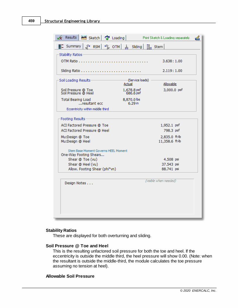
Structural Engineering Library459
© 2020 ENERCALC, Inc.
Stability RatiosThese are displayed for both overturning and sliding.
Soil Pressure @ Toe and HeelThis is the resulting unfactored soil pressure for both the toe and heel. If theeccentricity is outside the middle third, the heel pressure will show 0.00. (Note: whenthe resultant is outside the middle-third, the module calculates the toe pressureassuming no tension at heel).
Allowable Soil Pressure
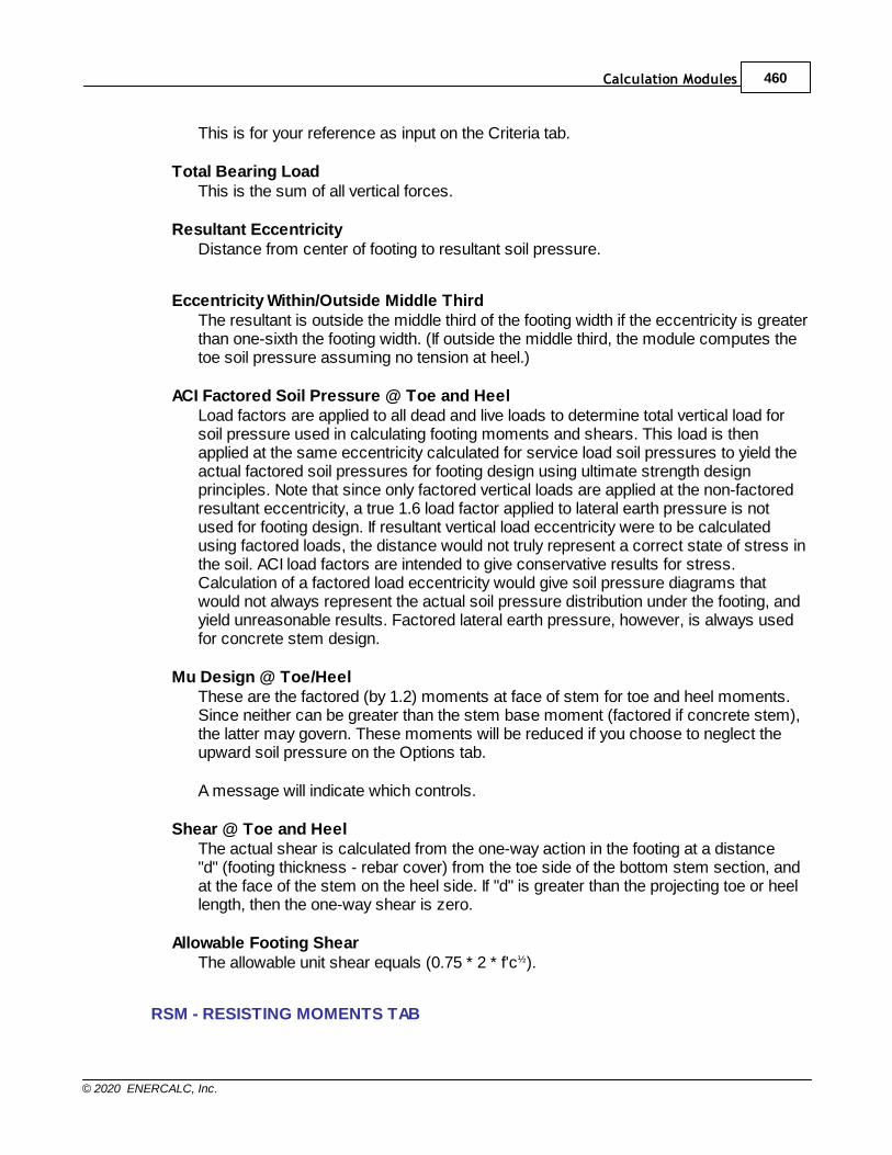
Calculation Modules 460
© 2020 ENERCALC, Inc.
This is for your reference as input on the Criteria tab.
Total Bearing LoadThis is the sum of all vertical forces.
Resultant EccentricityDistance from center of footing to resultant soil pressure.
Eccentricity Within/Outside Middle ThirdThe resultant is outside the middle third of the footing width if the eccentricity is greaterthan one-sixth the footing width. (If outside the middle third, the module computes thetoe soil pressure assuming no tension at heel.)
ACI Factored Soil Pressure @ Toe and HeelLoad factors are applied to all dead and live loads to determine total vertical load forsoil pressure used in calculating footing moments and shears. This load is thenapplied at the same eccentricity calculated for service load soil pressures to yield theactual factored soil pressures for footing design using ultimate strength designprinciples. Note that since only factored vertical loads are applied at the non-factoredresultant eccentricity, a true 1.6 load factor applied to lateral earth pressure is notused for footing design. If resultant vertical load eccentricity were to be calculatedusing factored loads, the distance would not truly represent a correct state of stress inthe soil. ACI load factors are intended to give conservative results for stress.Calculation of a factored load eccentricity would give soil pressure diagrams thatwould not always represent the actual soil pressure distribution under the footing, andyield unreasonable results. Factored lateral earth pressure, however, is always usedfor concrete stem design.
Mu Design @ Toe/HeelThese are the factored (by 1.2) moments at face of stem for toe and heel moments.Since neither can be greater than the stem base moment (factored if concrete stem),the latter may govern. These moments will be reduced if you choose to neglect theupward soil pressure on the Options tab.
A message will indicate which controls.
Shear @ Toe and HeelThe actual shear is calculated from the one-way action in the footing at a distance"d" (footing thickness - rebar cover) from the toe side of the bottom stem section, andat the face of the stem on the heel side. If "d" is greater than the projecting toe or heellength, then the one-way shear is zero.
Allowable Footing ShearThe allowable unit shear equals (0.75 * 2 * f'c½).
RSM - RESISTING MOMENTS TAB
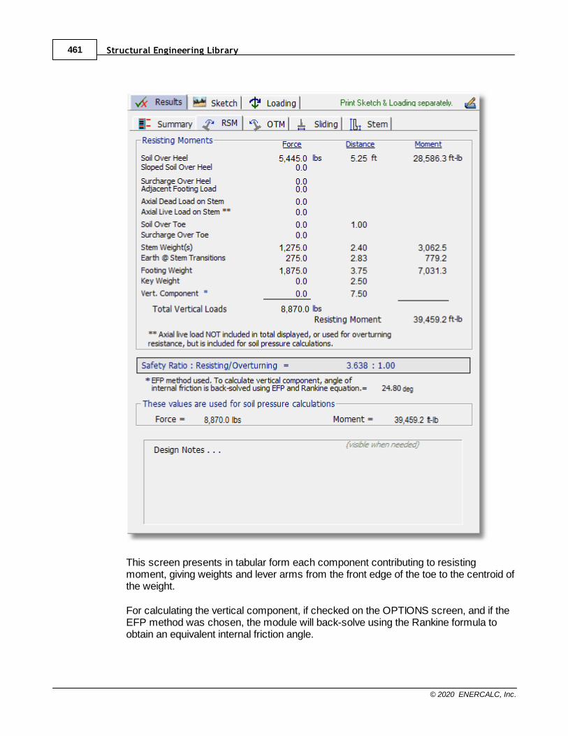
Structural Engineering Library461
© 2020 ENERCALC, Inc.
This screen presents in tabular form each component contributing to resistingmoment, giving weights and lever arms from the front edge of the toe to the centroid ofthe weight.
For calculating the vertical component, if checked on the OPTIONS screen, and if theEFP method was chosen, the module will back-solve using the Rankine formula toobtain an equivalent internal friction angle.
Calculation Modules 462
© 2020 ENERCALC, Inc.
The force and moment displayed at the bottom accounts for deduction of effect ofvertical component, if box on Options tab has been checked.
OTM - OVERTURNING MOMENTS TAB
This screen presents in tabular form each component acting horizontally to overturnthe wall/footing system. The centroid of each force is multiplied by its distance up fromthe bottom of the footing. The Heel Active Pressure includes the effect of surchargesand water table, if applicable, and its Distance is to the centroid of the total lateralforce.
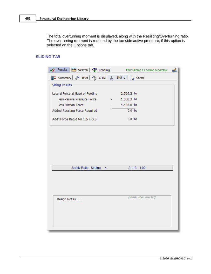
Structural Engineering Library463
© 2020 ENERCALC, Inc.
The total overturning moment is displayed, along with the Resisting/Overturning ratio.The overturning moment is reduced by the toe side active pressure, if this option isselected on the Options tab.
SLIDING TAB
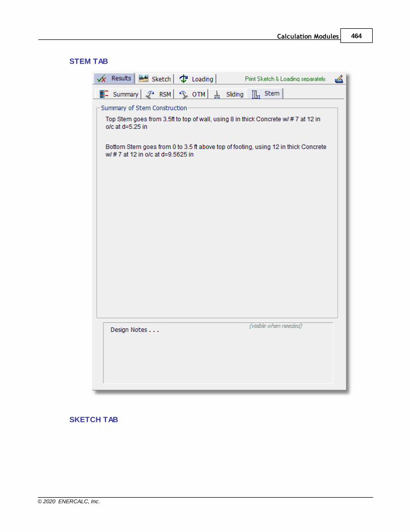
Calculation Modules 464
© 2020 ENERCALC, Inc.
STEM TAB
SKETCH TAB
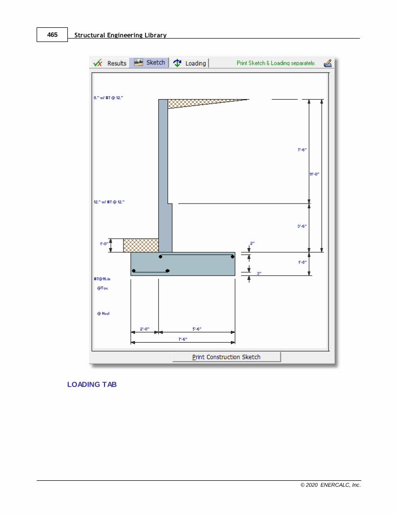
Structural Engineering Library465
© 2020 ENERCALC, Inc.
LOADING TAB

Calculation Modules 466
© 2020 ENERCALC, Inc.

Structural Engineering Library467
© 2020 ENERCALC, Inc.
10.7 Foundations
Please select a subtopic.
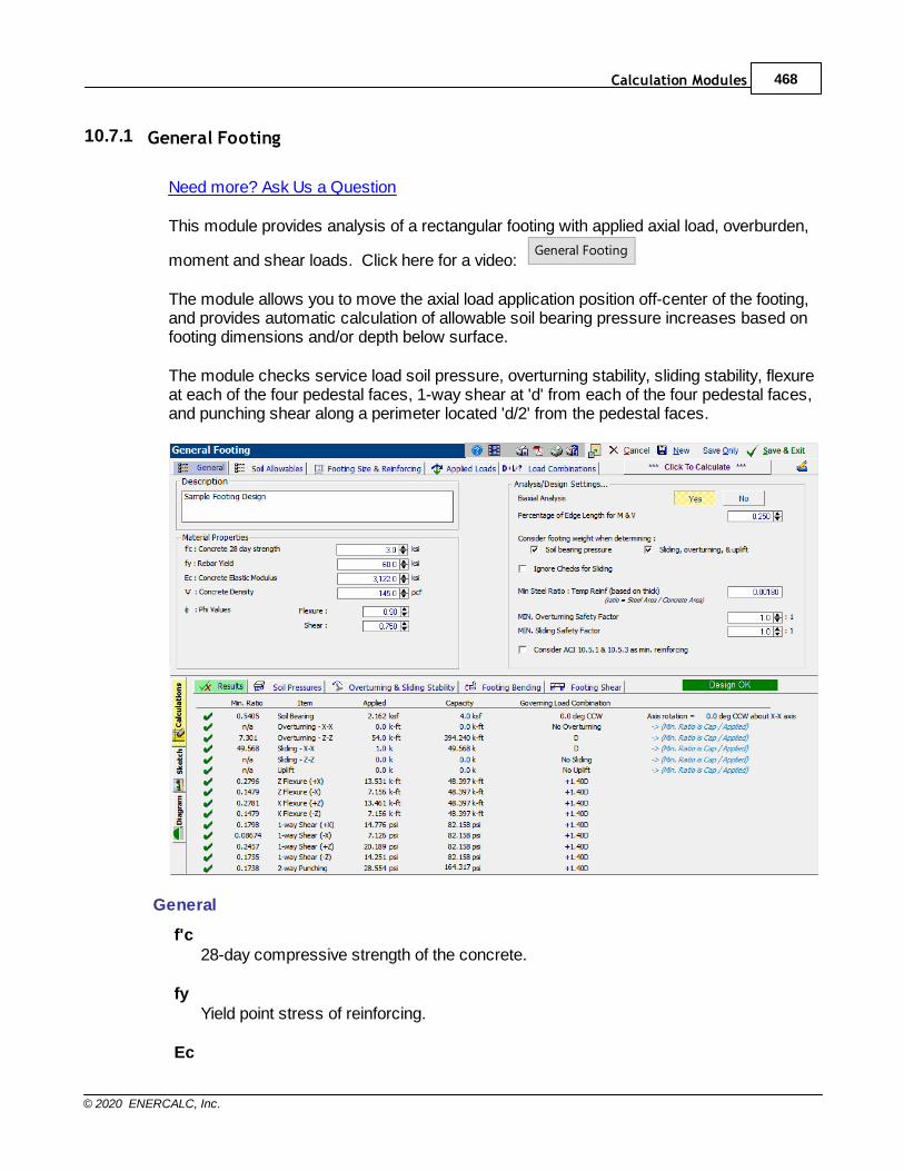
Calculation Modules 468
© 2020 ENERCALC, Inc.
10.7.1 General Footing
Need more? Ask Us a Question
This module provides analysis of a rectangular footing with applied axial load, overburden,
moment and shear loads. Click here for a video: General Footing
The module allows you to move the axial load application position off-center of the footing,and provides automatic calculation of allowable soil bearing pressure increases based onfooting dimensions and/or depth below surface.
The module checks service load soil pressure, overturning stability, sliding stability, flexureat each of the four pedestal faces, 1-way shear at 'd' from each of the four pedestal faces,and punching shear along a perimeter located 'd/2' from the pedestal faces.
General
f'c28-day compressive strength of the concrete.
fyYield point stress of reinforcing.
Ec
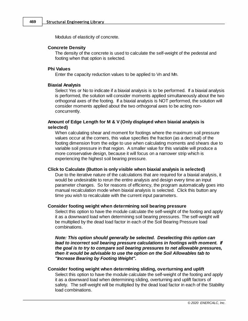
Structural Engineering Library469
© 2020 ENERCALC, Inc.
Modulus of elasticity of concrete.
Concrete DensityThe density of the concrete is used to calculate the self-weight of the pedestal andfooting when that option is selected.
Phi ValuesEnter the capacity reduction values to be applied to Vn and Mn.
Biaxial AnalysisSelect Yes or No to indicate if a biaxial analysis is to be performed. If a biaxial analysisis performed, the solution will consider moments applied simultaneously about the twoorthogonal axes of the footing. If a biaxial analysis is NOT performed, the solution willconsider moments applied about the two orthogonal axes to be acting non-concurrently.
Amount of Edge Length for M & V (Only displayed when biaxial analysis isselected)
When calculating shear and moment for footings where the maximum soil pressurevalues occur at the corners, this value specifies the fraction (as a decimal) of thefooting dimension from the edge to use when calculating moments and shears due tovariable soil pressure in that region. A smaller value for this variable will produce amore conservative design, because it will focus on a narrower strip which isexperiencing the highest soil bearing pressure.
Click to Calculate (Button is only visible when biaxial analysis is selected)Due to the iterative nature of the calculations that are required for a biaxial analysis, itwould be undesirable to rerun the entire analysis and design every time an inputparameter changes. So for reasons of efficiency, the program automatically goes intomanual recalculation mode when biaxial analysis is selected. Click this button anytime you wish to recalculate with the current input parameters.
Consider footing weight when determining soil bearing pressureSelect this option to have the module calculate the self-weight of the footing and applyit as a downward load when determining soil bearing pressures. The self-weight willbe multiplied by the dead load factor in each of the Soil Bearing Pressure loadcombinations.
Note: This option should generally be selected. Deselecting this option canlead to incorrect soil bearing pressure calculations in footings with moment. Ifthe goal is to try to compare soil bearing pressures to net allowable pressures,then it would be advisable to use the option on the Soil Allowables tab to"Increase Bearing by Footing Weight".
Consider footing weight when determining sliding, overturning and upliftSelect this option to have the module calculate the self-weight of the footing and applyit as a downward load when determining sliding, overturning and uplift factors ofsafety. The self-weight will be multiplied by the dead load factor in each of the Stabilityload combinations.
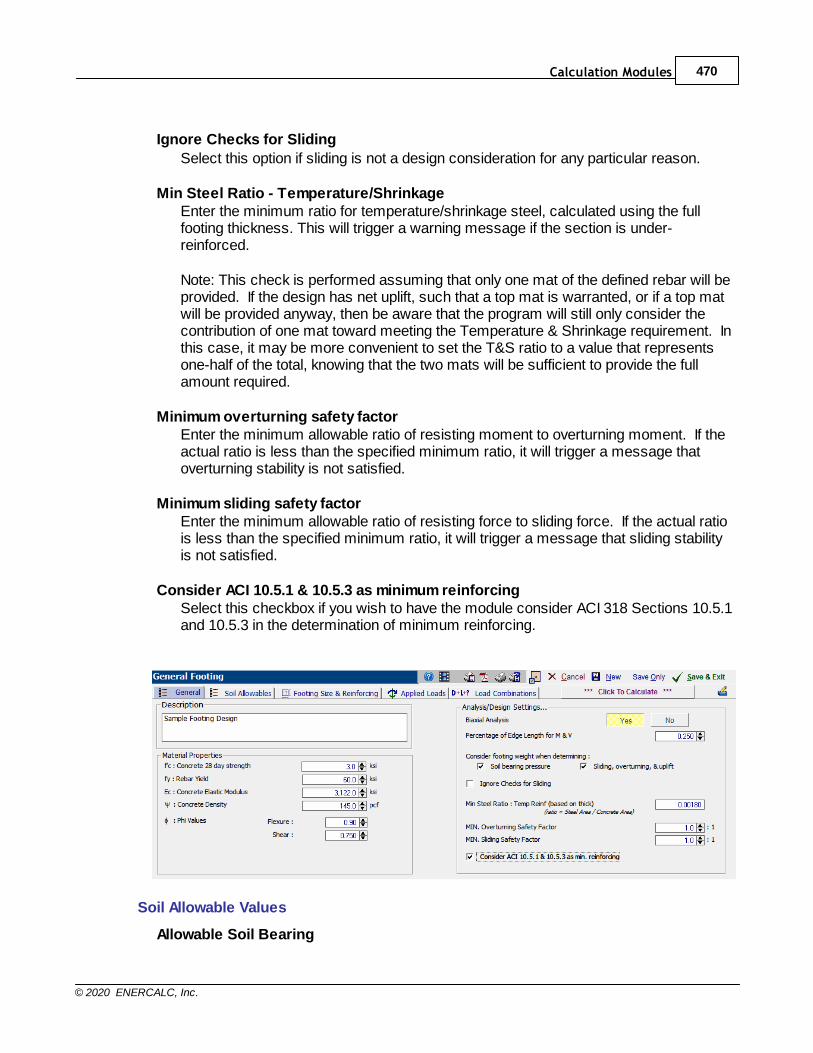
Calculation Modules 470
© 2020 ENERCALC, Inc.
Ignore Checks for Sliding
Select this option if sliding is not a design consideration for any particular reason.
Min Steel Ratio - Temperature/ShrinkageEnter the minimum ratio for temperature/shrinkage steel, calculated using the fullfooting thickness. This will trigger a warning message if the section is under-reinforced.
Note: This check is performed assuming that only one mat of the defined rebar will beprovided. If the design has net uplift, such that a top mat is warranted, or if a top matwill be provided anyway, then be aware that the program will still only consider thecontribution of one mat toward meeting the Temperature & Shrinkage requirement. Inthis case, it may be more convenient to set the T&S ratio to a value that representsone-half of the total, knowing that the two mats will be sufficient to provide the fullamount required.
Minimum overturning safety factorEnter the minimum allowable ratio of resisting moment to overturning moment. If theactual ratio is less than the specified minimum ratio, it will trigger a message thatoverturning stability is not satisfied.
Minimum sliding safety factorEnter the minimum allowable ratio of resisting force to sliding force. If the actual ratiois less than the specified minimum ratio, it will trigger a message that sliding stabilityis not satisfied.
Consider ACI 10.5.1 & 10.5.3 as minimum reinforcingSelect this checkbox if you wish to have the module consider ACI 318 Sections 10.5.1and 10.5.3 in the determination of minimum reinforcing.
Soil Allowable Values
Allowable Soil Bearing
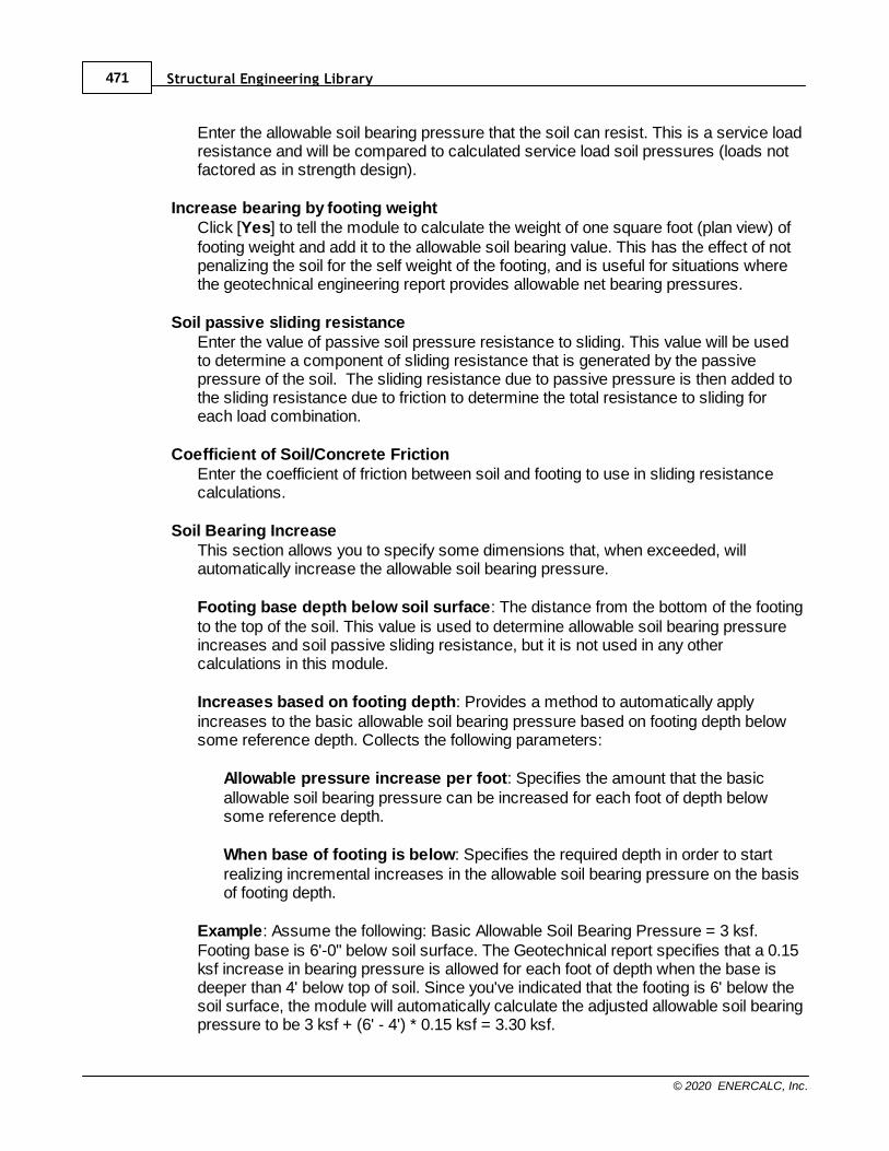
Structural Engineering Library471
© 2020 ENERCALC, Inc.
Enter the allowable soil bearing pressure that the soil can resist. This is a service loadresistance and will be compared to calculated service load soil pressures (loads notfactored as in strength design).
Increase bearing by footing weightClick [Yes] to tell the module to calculate the weight of one square foot (plan view) offooting weight and add it to the allowable soil bearing value. This has the effect of notpenalizing the soil for the self weight of the footing, and is useful for situations wherethe geotechnical engineering report provides allowable net bearing pressures.
Soil passive sliding resistanceEnter the value of passive soil pressure resistance to sliding. This value will be usedto determine a component of sliding resistance that is generated by the passivepressure of the soil. The sliding resistance due to passive pressure is then added tothe sliding resistance due to friction to determine the total resistance to sliding foreach load combination.
Coefficient of Soil/Concrete FrictionEnter the coefficient of friction between soil and footing to use in sliding resistancecalculations.
Soil Bearing IncreaseThis section allows you to specify some dimensions that, when exceeded, willautomatically increase the allowable soil bearing pressure.
Footing base depth below soil surface: The distance from the bottom of the footingto the top of the soil. This value is used to determine allowable soil bearing pressureincreases and soil passive sliding resistance, but it is not used in any othercalculations in this module.
Increases based on footing depth: Provides a method to automatically applyincreases to the basic allowable soil bearing pressure based on footing depth belowsome reference depth. Collects the following parameters:
Allowable pressure increase per foot: Specifies the amount that the basicallowable soil bearing pressure can be increased for each foot of depth belowsome reference depth.
When base of footing is below: Specifies the required depth in order to startrealizing incremental increases in the allowable soil bearing pressure on the basisof footing depth.
Example: Assume the following: Basic Allowable Soil Bearing Pressure = 3 ksf.Footing base is 6'-0" below soil surface. The Geotechnical report specifies that a 0.15ksf increase in bearing pressure is allowed for each foot of depth when the base isdeeper than 4' below top of soil. Since you've indicated that the footing is 6' below thesoil surface, the module will automatically calculate the adjusted allowable soil bearingpressure to be 3 ksf + (6' - 4') * 0.15 ksf = 3.30 ksf.
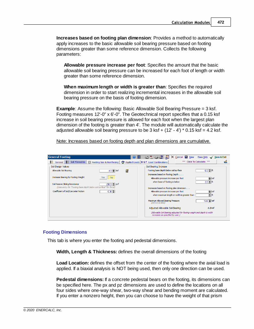
Calculation Modules 472
© 2020 ENERCALC, Inc.
Increases based on footing plan dimension: Provides a method to automaticallyapply increases to the basic allowable soil bearing pressure based on footingdimensions greater than some reference dimension. Collects the followingparameters:
Allowable pressure increase per foot: Specifies the amount that the basicallowable soil bearing pressure can be increased for each foot of length or widthgreater than some reference dimension.
When maximum length or width is greater than: Specifies the requireddimension in order to start realizing incremental increases in the allowable soilbearing pressure on the basis of footing dimension.
Example: Assume the following: Basic Allowable Soil Bearing Pressure = 3 ksf.Footing measures 12'-0" x 6'-0". The Geotechnical report specifies that a 0.15 ksfincrease in soil bearing pressure is allowed for each foot when the largest plandimension of the footing is greater than 4'. The module will automatically calculate theadjusted allowable soil bearing pressure to be 3 ksf + (12' - 4') * 0.15 ksf = 4.2 ksf.
Note: Increases based on footing depth and plan dimensions are cumulative.
Footing Dimensions
This tab is where you enter the footing and pedestal dimensions.
Width, Length & Thickness: defines the overall dimensions of the footing
Load Location: defines the offset from the center of the footing where the axial load isapplied. If a biaxial analysis is NOT being used, then only one direction can be used.
Pedestal dimensions: If a concrete pedestal bears on the footing, its dimensions canbe specified here. The px and pz dimensions are used to define the locations on allfour sides where one-way shear, two-way shear and bending moment are calculated.If you enter a nonzero height, then you can choose to have the weight of that prism
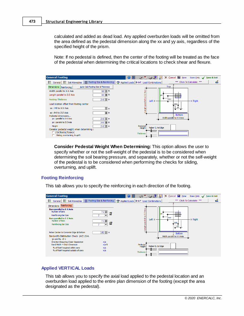
Structural Engineering Library473
© 2020 ENERCALC, Inc.
calculated and added as dead load. Any applied overburden loads will be omitted fromthe area defined as the pedestal dimension along the xx and yy axis, regardless of thespecified height of the prism.
Note: If no pedestal is defined, then the center of the footing will be treated as the faceof the pedestal when determining the critical locations to check shear and flexure.
Consider Pedestal Weight When Determining: This option allows the user tospecify whether or not the self-weight of the pedestal is to be considered whendetermining the soil bearing pressure, and separately, whether or not the self-weightof the pedestal is to be considered when performing the checks for sliding,overturning, and uplift.
Footing Reinforcing
This tab allows you to specify the reinforcing in each direction of the footing.
Applied VERTICAL Loads
This tab allows you to specify the axial load applied to the pedestal location and anoverburden load applied to the entire plan dimension of the footing (except the areadesignated as the pedestal).
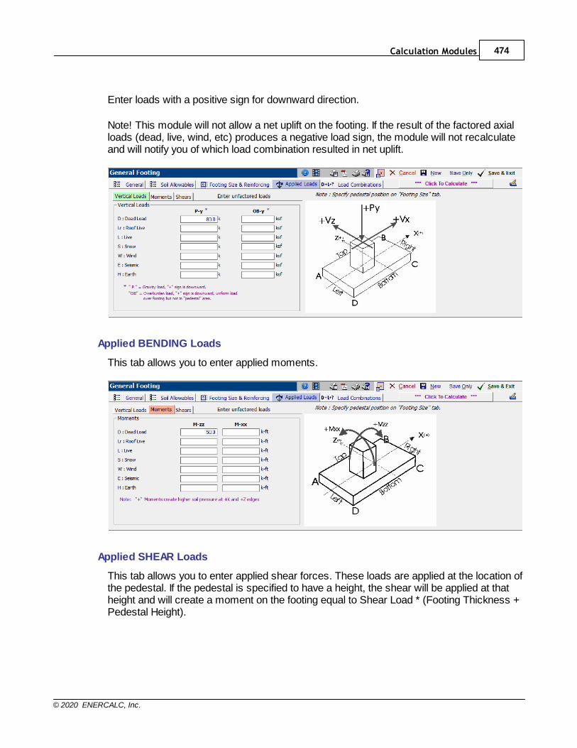
Calculation Modules 474
© 2020 ENERCALC, Inc.
Enter loads with a positive sign for downward direction.
Note! This module will not allow a net uplift on the footing. If the result of the factored axialloads (dead, live, wind, etc) produces a negative load sign, the module will not recalculateand will notify you of which load combination resulted in net uplift.
Applied BENDING Loads
This tab allows you to enter applied moments.
Applied SHEAR Loads
This tab allows you to enter applied shear forces. These loads are applied at the location ofthe pedestal. If the pedestal is specified to have a height, the shear will be applied at thatheight and will create a moment on the footing equal to Shear Load * (Footing Thickness +Pedestal Height).
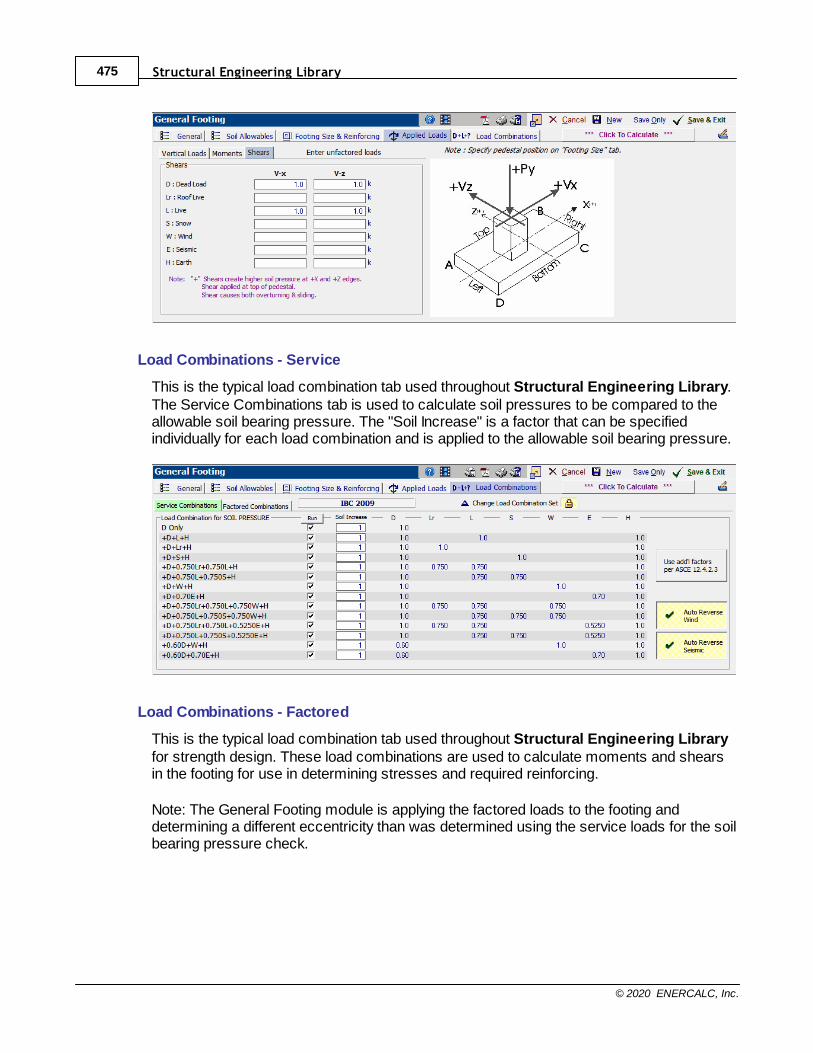
Structural Engineering Library475
© 2020 ENERCALC, Inc.
Load Combinations - Service
This is the typical load combination tab used throughout Structural Engineering Library.The Service Combinations tab is used to calculate soil pressures to be compared to theallowable soil bearing pressure. The "Soil Increase" is a factor that can be specifiedindividually for each load combination and is applied to the allowable soil bearing pressure.
Load Combinations - Factored
This is the typical load combination tab used throughout Structural Engineering Libraryfor strength design. These load combinations are used to calculate moments and shearsin the footing for use in determining stresses and required reinforcing.
Note: The General Footing module is applying the factored loads to the footing anddetermining a different eccentricity than was determined using the service loads for the soilbearing pressure check.
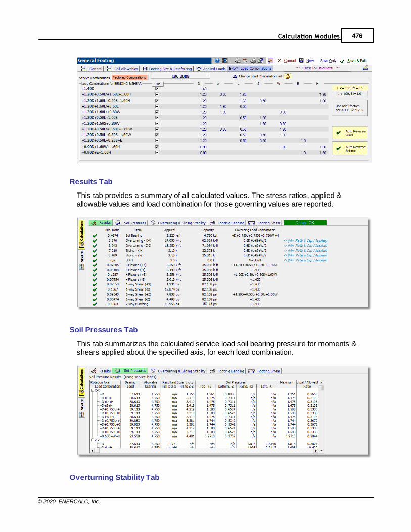
Calculation Modules 476
© 2020 ENERCALC, Inc.
Results Tab
This tab provides a summary of all calculated values. The stress ratios, applied &allowable values and load combination for those governing values are reported.
Soil Pressures Tab
This tab summarizes the calculated service load soil bearing pressure for moments &shears applied about the specified axis, for each load combination.
Overturning Stability Tab
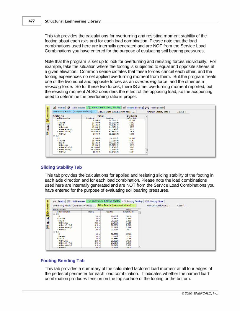
Structural Engineering Library477
© 2020 ENERCALC, Inc.
This tab provides the calculations for overturning and resisting moment stability of thefooting about each axis and for each load combination. Please note that the loadcombinations used here are internally generated and are NOT from the Service LoadCombinations you have entered for the purpose of evaluating soil bearing pressures.
Note that the program is set up to look for overturning and resisting forces individually. Forexample, take the situation where the footing is subjected to equal and opposite shears ata given elevation. Common sense dictates that these forces cancel each other, and thefooting experiences no net applied overturning moment from them. But the program treatsone of the two equal and opposite forces as an overturning force, and the other as aresisting force. So for these two forces, there IS a net overturning moment reported, butthe resisting moment ALSO considers the effect of the opposing load, so the accountingused to determine the overturning ratio is proper.
Sliding Stability Tab
This tab provides the calculations for applied and resisting sliding stability of the footing ineach axis direction and for each load combination. Please note the load combinationsused here are internally generated and are NOT from the Service Load Combinations youhave entered for the purpose of evaluating soil bearing pressures.
Footing Bending Tab
This tab provides a summary of the calculated factored load moment at all four edges ofthe pedestal perimeter for each load combination. It indicates whether the named loadcombination produces tension on the top surface of the footing or the bottom.
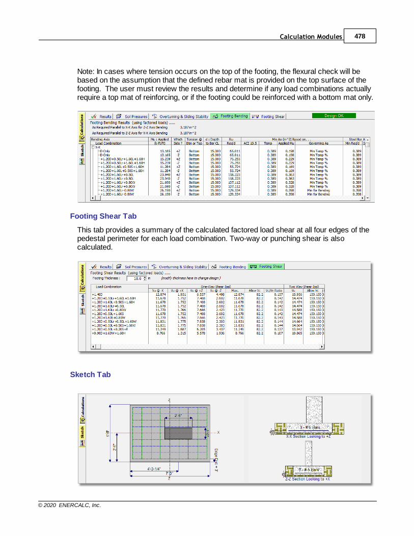
Calculation Modules 478
© 2020 ENERCALC, Inc.
Note: In cases where tension occurs on the top of the footing, the flexural check will bebased on the assumption that the defined rebar mat is provided on the top surface of thefooting. The user must review the results and determine if any load combinations actuallyrequire a top mat of reinforcing, or if the footing could be reinforced with a bottom mat only.
Footing Shear Tab
This tab provides a summary of the calculated factored load shear at all four edges of thepedestal perimeter for each load combination. Two-way or punching shear is alsocalculated.
Sketch Tab

Structural Engineering Library479
© 2020 ENERCALC, Inc.
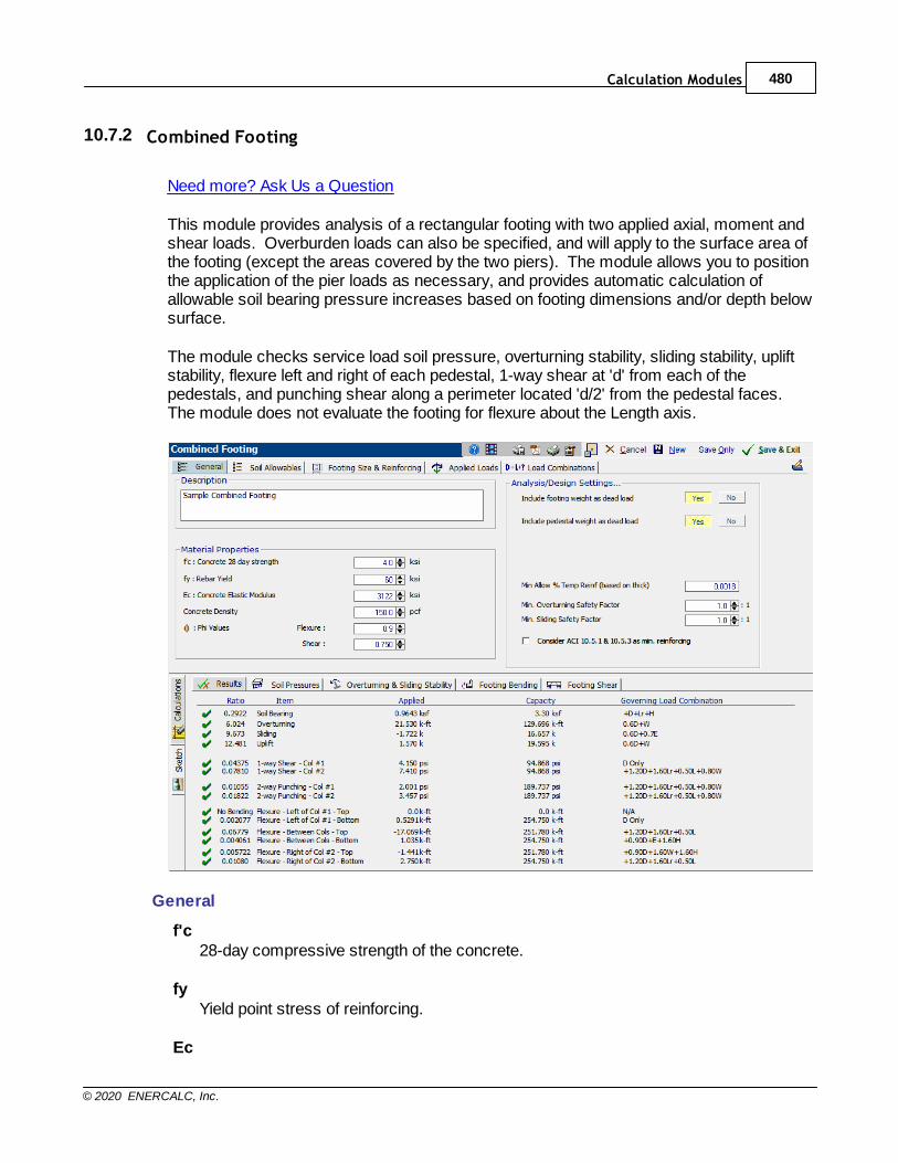
Calculation Modules 480
© 2020 ENERCALC, Inc.
10.7.2 Combined Footing
Need more? Ask Us a Question
This module provides analysis of a rectangular footing with two applied axial, moment andshear loads. Overburden loads can also be specified, and will apply to the surface area ofthe footing (except the areas covered by the two piers). The module allows you to positionthe application of the pier loads as necessary, and provides automatic calculation ofallowable soil bearing pressure increases based on footing dimensions and/or depth belowsurface.
The module checks service load soil pressure, overturning stability, sliding stability, upliftstability, flexure left and right of each pedestal, 1-way shear at 'd' from each of thepedestals, and punching shear along a perimeter located 'd/2' from the pedestal faces. The module does not evaluate the footing for flexure about the Length axis.
General
f'c28-day compressive strength of the concrete.
fyYield point stress of reinforcing.
Ec
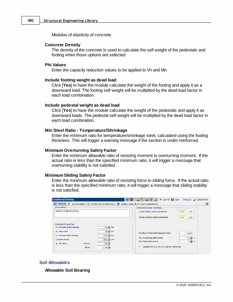
Structural Engineering Library481
© 2020 ENERCALC, Inc.
Modulus of elasticity of concrete.
Concrete DensityThe density of the concrete is used to calculate the self weight of the pedestals andfooting when those options are selected.
Phi ValuesEnter the capacity reduction values to be applied to Vn and Mn.
Include footing weight as dead loadClick [Yes] to have the module calculate the weight of the footing and apply it as adownward load. The footing self weight will be multiplied by the dead load factor ineach load combination.
Include pedestal weight as dead loadClick [Yes] to have the module calculate the weight of the pedestals and apply it asdownward loads. The pedestal self weight will be multiplied by the dead load factor ineach load combination.
Min Steel Ratio - Temperature/ShrinkageEnter the minimum ratio for temperature/shrinkage steel, calculated using the footingthickness. This will trigger a warning message if the section is under-reinforced.
Minimum Overturning Safety FactorEnter the minimum allowable ratio of resisting moment to overturning moment. If theactual ratio is less than the specified minimum ratio, it will trigger a message thatoverturning stability is not satisfied.
Minimum Sliding Safety FactorEnter the minimum allowable ratio of resisting force to sliding force. If the actual ratiois less than the specified minimum ratio, it will trigger a message that sliding stabilityis not satisfied.
Soil Allowables
Allowable Soil Bearing
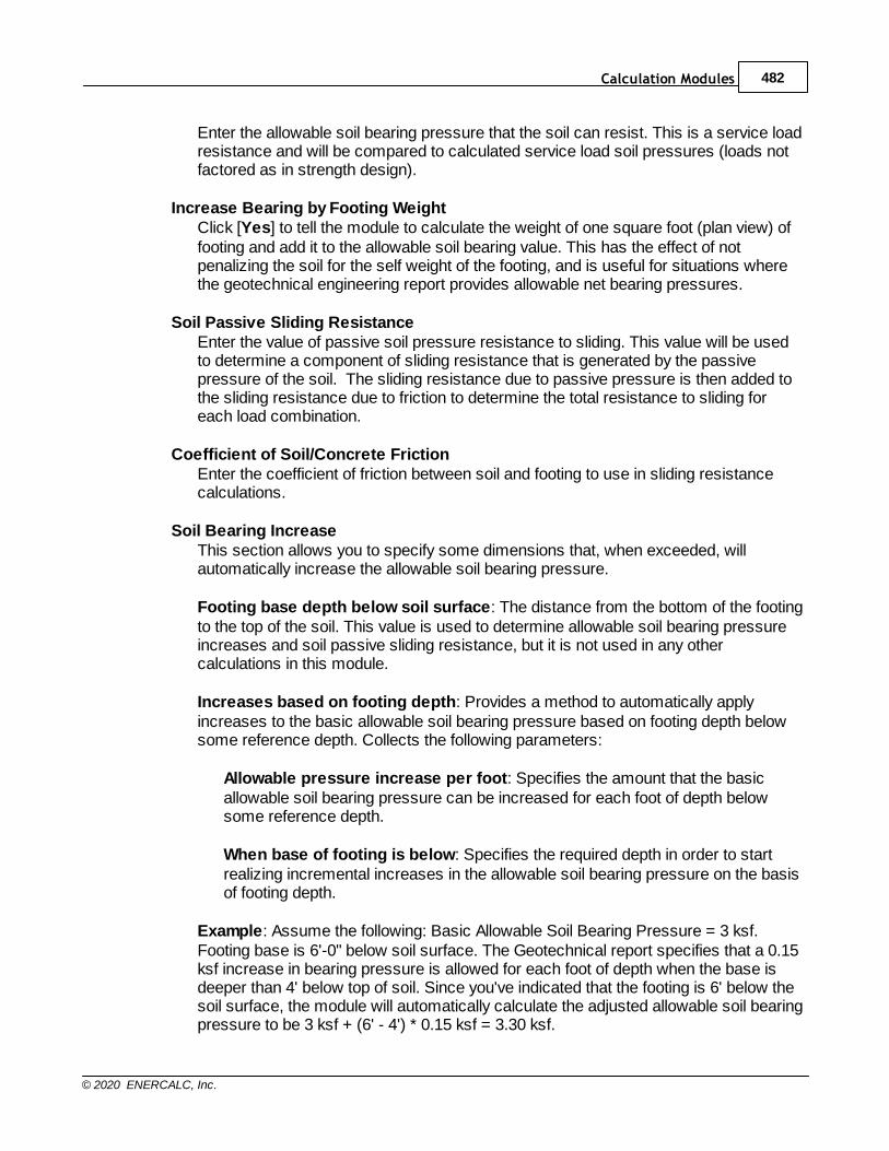
Calculation Modules 482
© 2020 ENERCALC, Inc.
Enter the allowable soil bearing pressure that the soil can resist. This is a service loadresistance and will be compared to calculated service load soil pressures (loads notfactored as in strength design).
Increase Bearing by Footing WeightClick [Yes] to tell the module to calculate the weight of one square foot (plan view) offooting and add it to the allowable soil bearing value. This has the effect of notpenalizing the soil for the self weight of the footing, and is useful for situations wherethe geotechnical engineering report provides allowable net bearing pressures.
Soil Passive Sliding ResistanceEnter the value of passive soil pressure resistance to sliding. This value will be usedto determine a component of sliding resistance that is generated by the passivepressure of the soil. The sliding resistance due to passive pressure is then added tothe sliding resistance due to friction to determine the total resistance to sliding foreach load combination.
Coefficient of Soil/Concrete FrictionEnter the coefficient of friction between soil and footing to use in sliding resistancecalculations.
Soil Bearing IncreaseThis section allows you to specify some dimensions that, when exceeded, willautomatically increase the allowable soil bearing pressure.
Footing base depth below soil surface: The distance from the bottom of the footingto the top of the soil. This value is used to determine allowable soil bearing pressureincreases and soil passive sliding resistance, but it is not used in any othercalculations in this module.
Increases based on footing depth: Provides a method to automatically applyincreases to the basic allowable soil bearing pressure based on footing depth belowsome reference depth. Collects the following parameters:
Allowable pressure increase per foot: Specifies the amount that the basicallowable soil bearing pressure can be increased for each foot of depth belowsome reference depth.
When base of footing is below: Specifies the required depth in order to startrealizing incremental increases in the allowable soil bearing pressure on the basisof footing depth.
Example: Assume the following: Basic Allowable Soil Bearing Pressure = 3 ksf.Footing base is 6'-0" below soil surface. The Geotechnical report specifies that a 0.15ksf increase in bearing pressure is allowed for each foot of depth when the base isdeeper than 4' below top of soil. Since you've indicated that the footing is 6' below thesoil surface, the module will automatically calculate the adjusted allowable soil bearingpressure to be 3 ksf + (6' - 4') * 0.15 ksf = 3.30 ksf.
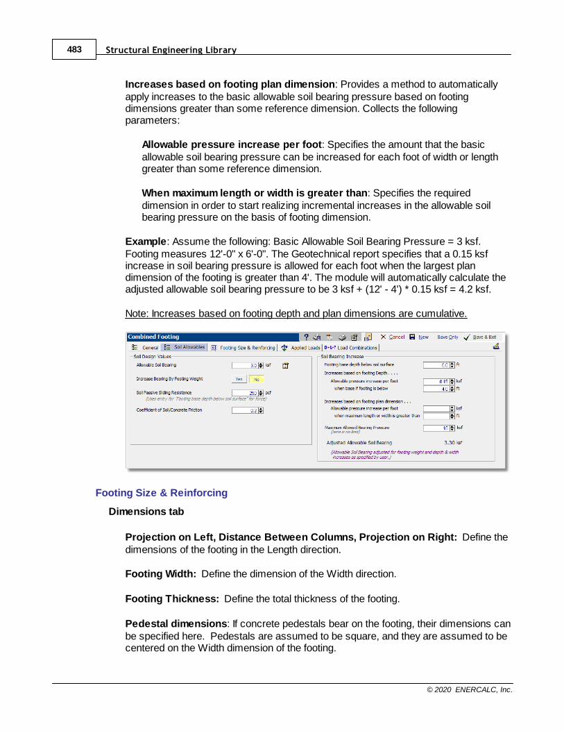
Structural Engineering Library483
© 2020 ENERCALC, Inc.
Increases based on footing plan dimension: Provides a method to automaticallyapply increases to the basic allowable soil bearing pressure based on footingdimensions greater than some reference dimension. Collects the followingparameters:
Allowable pressure increase per foot: Specifies the amount that the basicallowable soil bearing pressure can be increased for each foot of width or lengthgreater than some reference dimension.
When maximum length or width is greater than: Specifies the requireddimension in order to start realizing incremental increases in the allowable soilbearing pressure on the basis of footing dimension.
Example: Assume the following: Basic Allowable Soil Bearing Pressure = 3 ksf.Footing measures 12'-0" x 6'-0". The Geotechnical report specifies that a 0.15 ksfincrease in soil bearing pressure is allowed for each foot when the largest plandimension of the footing is greater than 4'. The module will automatically calculate theadjusted allowable soil bearing pressure to be 3 ksf + (12' - 4') * 0.15 ksf = 4.2 ksf.
Note: Increases based on footing depth and plan dimensions are cumulative.
Footing Size & Reinforcing
Dimensions tab
Projection on Left, Distance Between Columns, Projection on Right: Define thedimensions of the footing in the Length direction.
Footing Width: Define the dimension of the Width direction.
Footing Thickness: Define the total thickness of the footing.
Pedestal dimensions: If concrete pedestals bear on the footing, their dimensions canbe specified here. Pedestals are assumed to be square, and they are assumed to becentered on the Width dimension of the footing.
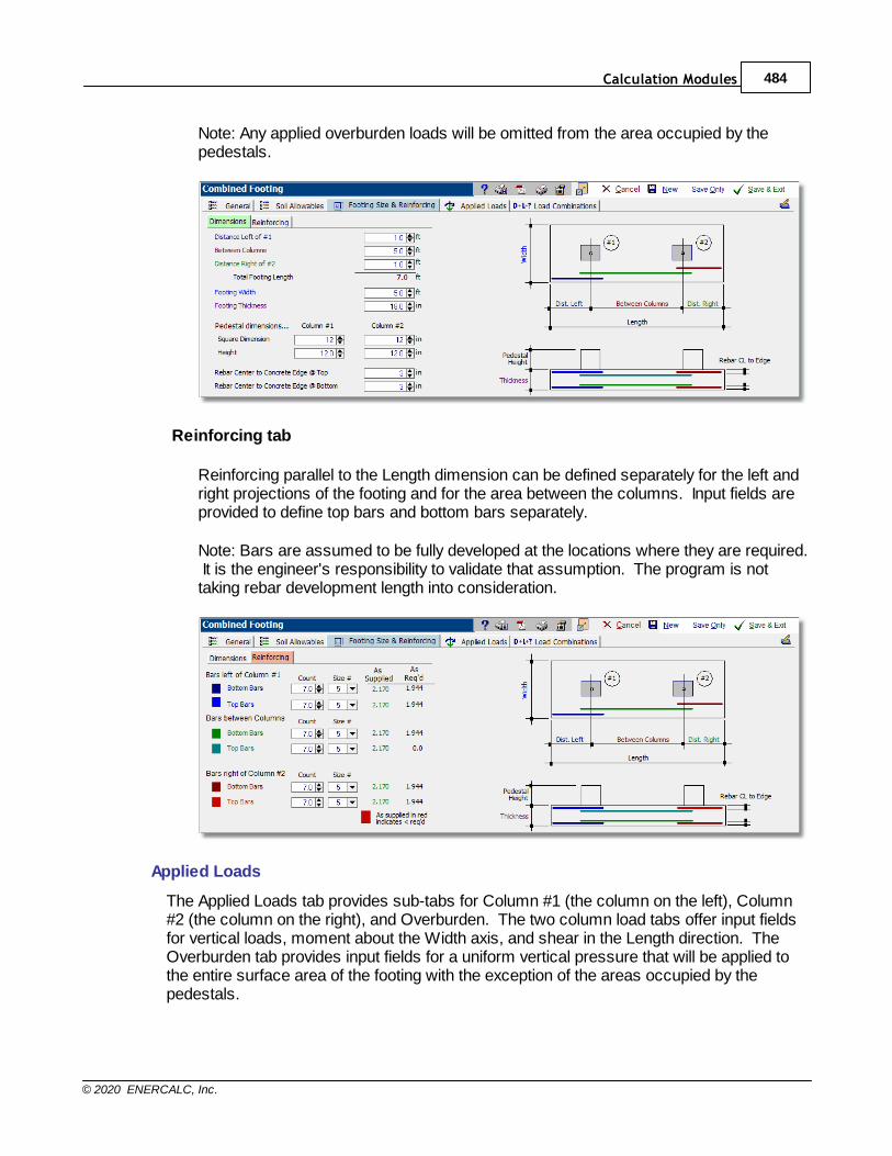
Calculation Modules 484
© 2020 ENERCALC, Inc.
Note: Any applied overburden loads will be omitted from the area occupied by thepedestals.
Reinforcing tab
Reinforcing parallel to the Length dimension can be defined separately for the left andright projections of the footing and for the area between the columns. Input fields areprovided to define top bars and bottom bars separately.
Note: Bars are assumed to be fully developed at the locations where they are required. It is the engineer's responsibility to validate that assumption. The program is nottaking rebar development length into consideration.
Applied Loads
The Applied Loads tab provides sub-tabs for Column #1 (the column on the left), Column#2 (the column on the right), and Overburden. The two column load tabs offer input fieldsfor vertical loads, moment about the Width axis, and shear in the Length direction. TheOverburden tab provides input fields for a uniform vertical pressure that will be applied tothe entire surface area of the footing with the exception of the areas occupied by thepedestals.
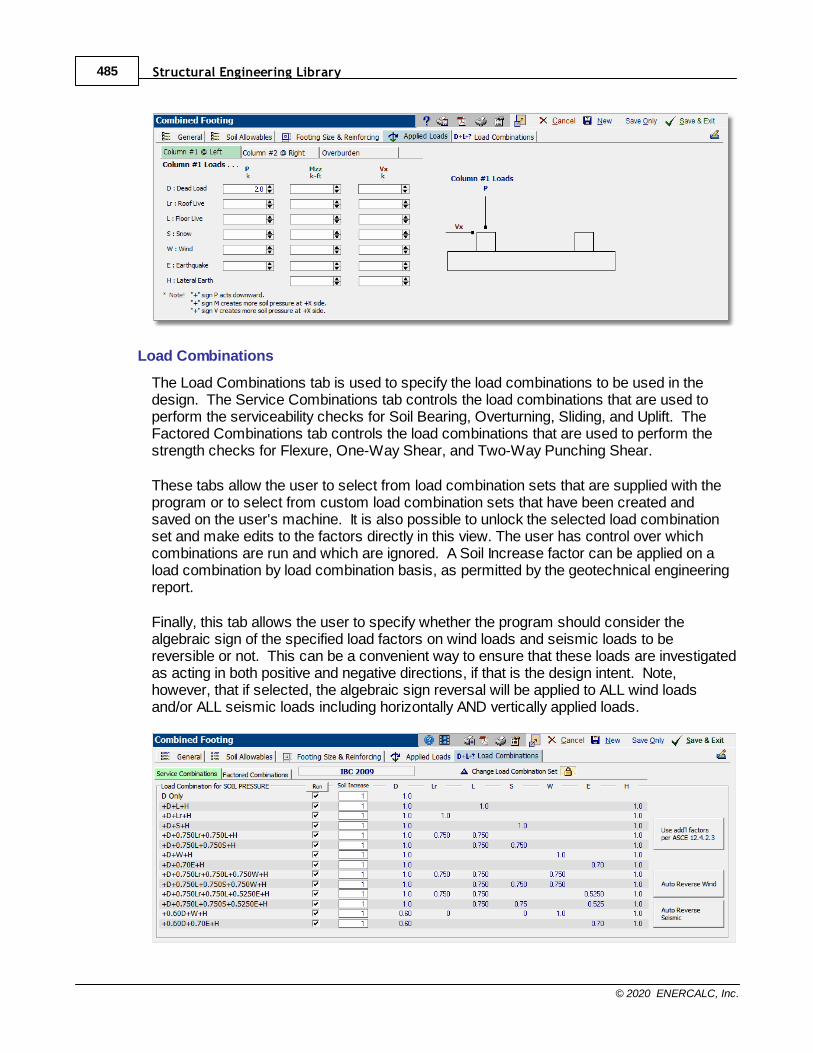
Structural Engineering Library485
© 2020 ENERCALC, Inc.
Load Combinations
The Load Combinations tab is used to specify the load combinations to be used in thedesign. The Service Combinations tab controls the load combinations that are used toperform the serviceability checks for Soil Bearing, Overturning, Sliding, and Uplift. TheFactored Combinations tab controls the load combinations that are used to perform thestrength checks for Flexure, One-Way Shear, and Two-Way Punching Shear.
These tabs allow the user to select from load combination sets that are supplied with theprogram or to select from custom load combination sets that have been created andsaved on the user's machine. It is also possible to unlock the selected load combinationset and make edits to the factors directly in this view. The user has control over whichcombinations are run and which are ignored. A Soil Increase factor can be applied on aload combination by load combination basis, as permitted by the geotechnical engineeringreport.
Finally, this tab allows the user to specify whether the program should consider thealgebraic sign of the specified load factors on wind loads and seismic loads to bereversible or not. This can be a convenient way to ensure that these loads are investigatedas acting in both positive and negative directions, if that is the design intent. Note,however, that if selected, the algebraic sign reversal will be applied to ALL wind loadsand/or ALL seismic loads including horizontally AND vertically applied loads.
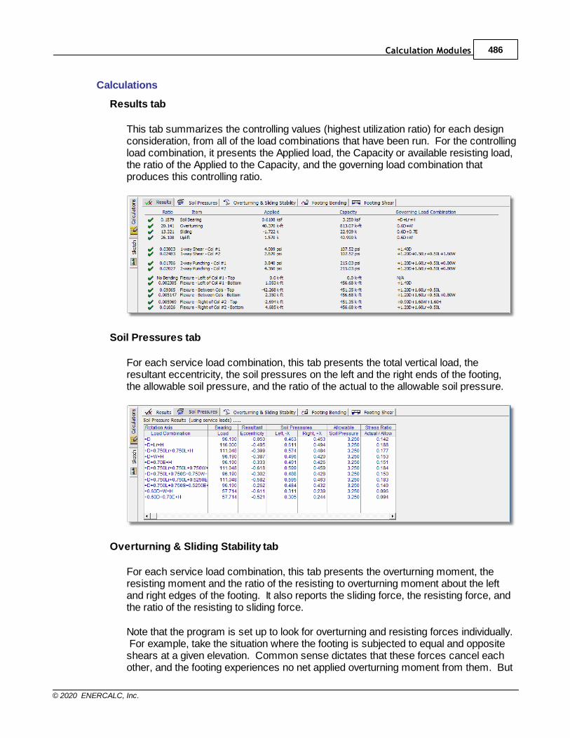
Calculation Modules 486
© 2020 ENERCALC, Inc.
Calculations
Results tab
This tab summarizes the controlling values (highest utilization ratio) for each designconsideration, from all of the load combinations that have been run. For the controllingload combination, it presents the Applied load, the Capacity or available resisting load,the ratio of the Applied to the Capacity, and the governing load combination thatproduces this controlling ratio.
Soil Pressures tab
For each service load combination, this tab presents the total vertical load, theresultant eccentricity, the soil pressures on the left and the right ends of the footing,the allowable soil pressure, and the ratio of the actual to the allowable soil pressure.
Overturning & Sliding Stability tab
For each service load combination, this tab presents the overturning moment, theresisting moment and the ratio of the resisting to overturning moment about the leftand right edges of the footing. It also reports the sliding force, the resisting force, andthe ratio of the resisting to sliding force.
Note that the program is set up to look for overturning and resisting forces individually. For example, take the situation where the footing is subjected to equal and oppositeshears at a given elevation. Common sense dictates that these forces cancel eachother, and the footing experiences no net applied overturning moment from them. But
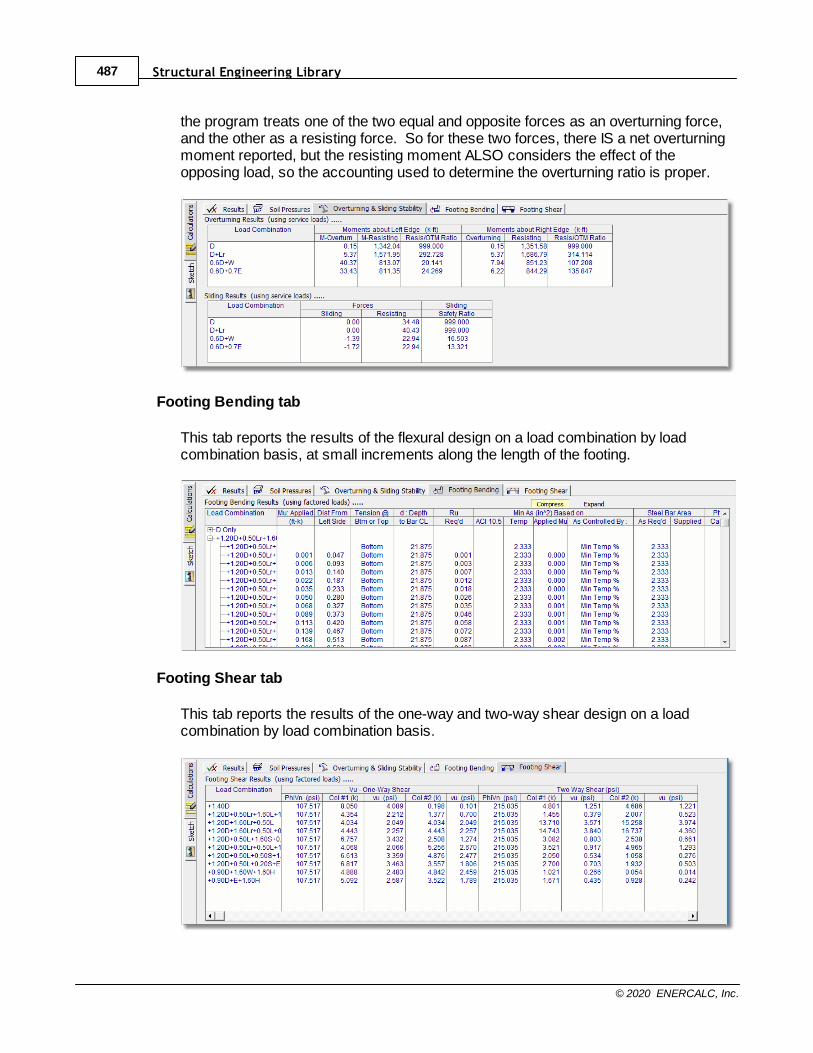
Structural Engineering Library487
© 2020 ENERCALC, Inc.
the program treats one of the two equal and opposite forces as an overturning force,and the other as a resisting force. So for these two forces, there IS a net overturningmoment reported, but the resisting moment ALSO considers the effect of theopposing load, so the accounting used to determine the overturning ratio is proper.
Footing Bending tab
This tab reports the results of the flexural design on a load combination by loadcombination basis, at small increments along the length of the footing.
Footing Shear tab
This tab reports the results of the one-way and two-way shear design on a loadcombination by load combination basis.
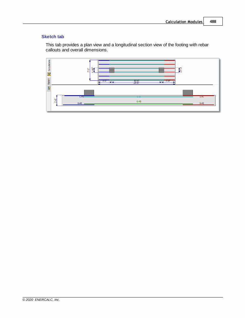
Calculation Modules 488
© 2020 ENERCALC, Inc.
Sketch tab
This tab provides a plan view and a longitudinal section view of the footing with rebarcallouts and overall dimensions.
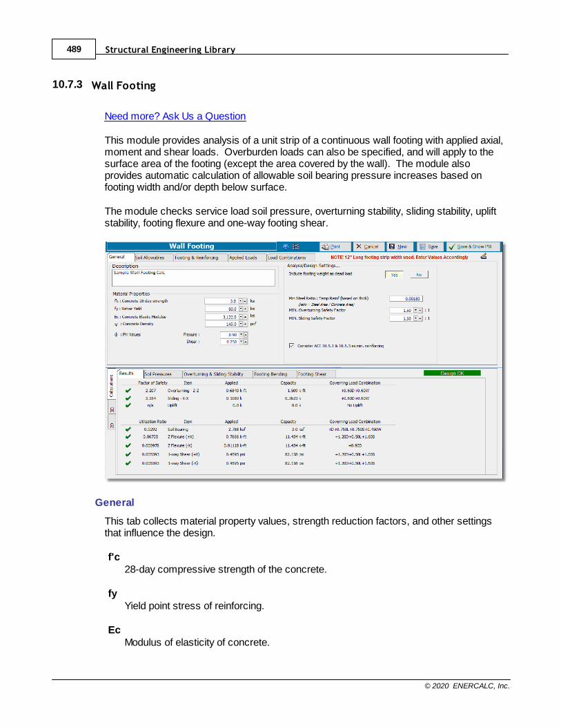
Structural Engineering Library489
© 2020 ENERCALC, Inc.
10.7.3 Wall Footing
Need more? Ask Us a Question
This module provides analysis of a unit strip of a continuous wall footing with applied axial,moment and shear loads. Overburden loads can also be specified, and will apply to thesurface area of the footing (except the area covered by the wall). The module alsoprovides automatic calculation of allowable soil bearing pressure increases based onfooting width and/or depth below surface.
The module checks service load soil pressure, overturning stability, sliding stability, upliftstability, footing flexure and one-way footing shear.
General
This tab collects material property values, strength reduction factors, and other settingsthat influence the design.
f'c28-day compressive strength of the concrete.
fyYield point stress of reinforcing.
EcModulus of elasticity of concrete.
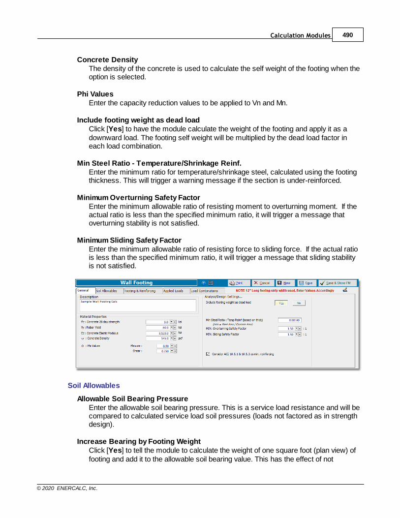
Calculation Modules 490
© 2020 ENERCALC, Inc.
Concrete DensityThe density of the concrete is used to calculate the self weight of the footing when theoption is selected.
Phi ValuesEnter the capacity reduction values to be applied to Vn and Mn.
Include footing weight as dead loadClick [Yes] to have the module calculate the weight of the footing and apply it as adownward load. The footing self weight will be multiplied by the dead load factor ineach load combination.
Min Steel Ratio - Temperature/Shrinkage Reinf.Enter the minimum ratio for temperature/shrinkage steel, calculated using the footingthickness. This will trigger a warning message if the section is under-reinforced.
Minimum Overturning Safety FactorEnter the minimum allowable ratio of resisting moment to overturning moment. If theactual ratio is less than the specified minimum ratio, it will trigger a message thatoverturning stability is not satisfied.
Minimum Sliding Safety FactorEnter the minimum allowable ratio of resisting force to sliding force. If the actual ratiois less than the specified minimum ratio, it will trigger a message that sliding stabilityis not satisfied.
Soil Allowables
Allowable Soil Bearing PressureEnter the allowable soil bearing pressure. This is a service load resistance and will becompared to calculated service load soil pressures (loads not factored as in strengthdesign).
Increase Bearing by Footing WeightClick [Yes] to tell the module to calculate the weight of one square foot (plan view) offooting and add it to the allowable soil bearing value. This has the effect of not
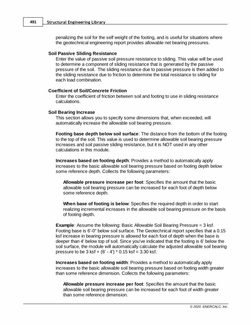
Structural Engineering Library491
© 2020 ENERCALC, Inc.
penalizing the soil for the self weight of the footing, and is useful for situations wherethe geotechnical engineering report provides allowable net bearing pressures.
Soil Passive Sliding ResistanceEnter the value of passive soil pressure resistance to sliding. This value will be usedto determine a component of sliding resistance that is generated by the passivepressure of the soil. The sliding resistance due to passive pressure is then added tothe sliding resistance due to friction to determine the total resistance to sliding foreach load combination.
Coefficient of Soil/Concrete FrictionEnter the coefficient of friction between soil and footing to use in sliding resistancecalculations.
Soil Bearing IncreaseThis section allows you to specify some dimensions that, when exceeded, willautomatically increase the allowable soil bearing pressure.
Footing base depth below soil surface: The distance from the bottom of the footingto the top of the soil. This value is used to determine allowable soil bearing pressureincreases and soil passive sliding resistance, but it is NOT used in any othercalculations in this module.
Increases based on footing depth: Provides a method to automatically applyincreases to the basic allowable soil bearing pressure based on footing depth belowsome reference depth. Collects the following parameters:
Allowable pressure increase per foot: Specifies the amount that the basicallowable soil bearing pressure can be increased for each foot of depth belowsome reference depth.
When base of footing is below: Specifies the required depth in order to startrealizing incremental increases in the allowable soil bearing pressure on the basisof footing depth.
Example: Assume the following: Basic Allowable Soil Bearing Pressure = 3 ksf.Footing base is 6'-0" below soil surface. The Geotechnical report specifies that a 0.15ksf increase in bearing pressure is allowed for each foot of depth when the base isdeeper than 4' below top of soil. Since you've indicated that the footing is 6' below thesoil surface, the module will automatically calculate the adjusted allowable soil bearingpressure to be 3 ksf + (6' - 4') * 0.15 ksf = 3.30 ksf.
Increases based on footing width: Provides a method to automatically applyincreases to the basic allowable soil bearing pressure based on footing width greaterthan some reference dimension. Collects the following parameters:
Allowable pressure increase per foot: Specifies the amount that the basicallowable soil bearing pressure can be increased for each foot of width greaterthan some reference dimension.
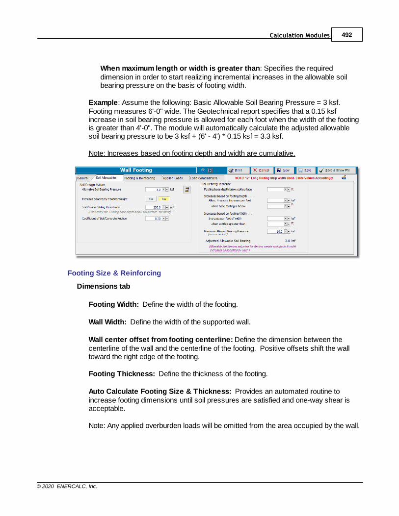
Calculation Modules 492
© 2020 ENERCALC, Inc.
When maximum length or width is greater than: Specifies the requireddimension in order to start realizing incremental increases in the allowable soilbearing pressure on the basis of footing width.
Example: Assume the following: Basic Allowable Soil Bearing Pressure = 3 ksf.Footing measures 6'-0" wide. The Geotechnical report specifies that a 0.15 ksfincrease in soil bearing pressure is allowed for each foot when the width of the footingis greater than 4'-0". The module will automatically calculate the adjusted allowablesoil bearing pressure to be 3 ksf + (6' - 4') * 0.15 ksf = 3.3 ksf.
Note: Increases based on footing depth and width are cumulative.
Footing Size & Reinforcing
Dimensions tab
Footing Width: Define the width of the footing.
Wall Width: Define the width of the supported wall.
Wall center offset from footing centerline: Define the dimension between thecenterline of the wall and the centerline of the footing. Positive offsets shift the walltoward the right edge of the footing.
Footing Thickness: Define the thickness of the footing.
Auto Calculate Footing Size & Thickness: Provides an automated routine toincrease footing dimensions until soil pressures are satisfied and one-way shear isacceptable.
Note: Any applied overburden loads will be omitted from the area occupied by the wall.

Structural Engineering Library493
© 2020 ENERCALC, Inc.
Reinforcing tab
Reinforcing Bar Size: Indicate the rebar size to consider for the bars that runparallel to the footing width.
Rebar Spacing: Provides an option to either specify an explicit value for the rebarspacing, or to specify the number of bars in a 12-inch length.
Rebar Center to Concrete Edge @ Bottom: Specify the clear cover plus 1/2 thediameter of the rebar.
Applied Loads
Vertical Loads tabProvides input fields for vertical loads and overburden pressures. Vertical loads arespecified in units of kips per foot, and they are considered to act at the center of thewidth of the wall. Overburden loads are specified in units of kips per square foot, andthey are considered to act on the top surface area of the footing, excluding the areaoccupied by the wall.
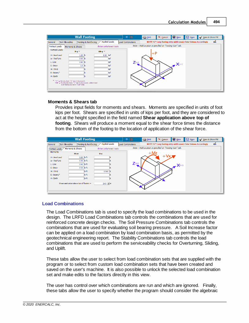
Calculation Modules 494
© 2020 ENERCALC, Inc.
Moments & Shears tabProvides input fields for moments and shears. Moments are specified in units of footkips per foot. Shears are specified in units of kips per foot, and they are considered toact at the height specified in the field named Shear application above top offooting. Shears will produce a moment equal to the shear force times the distancefrom the bottom of the footing to the location of application of the shear force.
Load Combinations
The Load Combinations tab is used to specify the load combinations to be used in thedesign. The LRFD Load Combinations tab controls the combinations that are used forreinforced concrete design checks. The Soil Pressure Combinations tab controls thecombinations that are used for evaluating soil bearing pressure. A Soil Increase factorcan be applied on a load combination by load combination basis, as permitted by thegeotechnical engineering report. The Stability Combinations tab controls the loadcombinations that are used to perform the serviceability checks for Overturning, Sliding,and Uplift.
These tabs allow the user to select from load combination sets that are supplied with theprogram or to select from custom load combination sets that have been created andsaved on the user's machine. It is also possible to unlock the selected load combinationset and make edits to the factors directly in this view.
The user has control over which combinations are run and which are ignored. Finally,these tabs allow the user to specify whether the program should consider the algebraic
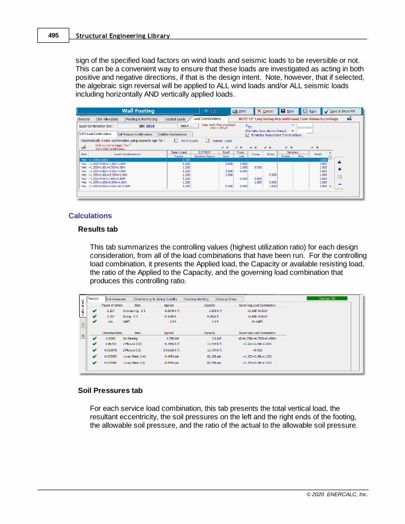
Structural Engineering Library495
© 2020 ENERCALC, Inc.
sign of the specified load factors on wind loads and seismic loads to be reversible or not. This can be a convenient way to ensure that these loads are investigated as acting in bothpositive and negative directions, if that is the design intent. Note, however, that if selected,the algebraic sign reversal will be applied to ALL wind loads and/or ALL seismic loadsincluding horizontally AND vertically applied loads.
Calculations
Results tab
This tab summarizes the controlling values (highest utilization ratio) for each designconsideration, from all of the load combinations that have been run. For the controllingload combination, it presents the Applied load, the Capacity or available resisting load,the ratio of the Applied to the Capacity, and the governing load combination thatproduces this controlling ratio.
Soil Pressures tab
For each service load combination, this tab presents the total vertical load, theresultant eccentricity, the soil pressures on the left and the right ends of the footing,the allowable soil pressure, and the ratio of the actual to the allowable soil pressure.
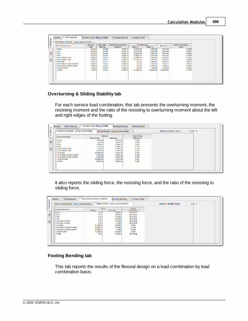
Calculation Modules 496
© 2020 ENERCALC, Inc.
Overturning & Sliding Stability tab
For each service load combination, this tab presents the overturning moment, theresisting moment and the ratio of the resisting to overturning moment about the leftand right edges of the footing.
It also reports the sliding force, the resisting force, and the ratio of the resisting tosliding force.
Footing Bending tab
This tab reports the results of the flexural design on a load combination by loadcombination basis.

Structural Engineering Library497
© 2020 ENERCALC, Inc.
Footing Shear tab
This tab reports the results of the shear design on a load combination by loadcombination basis.
3D tab
This tab presents the 3D rendering of the footing:
2D tab
This tab presents plan and section views of the footing:
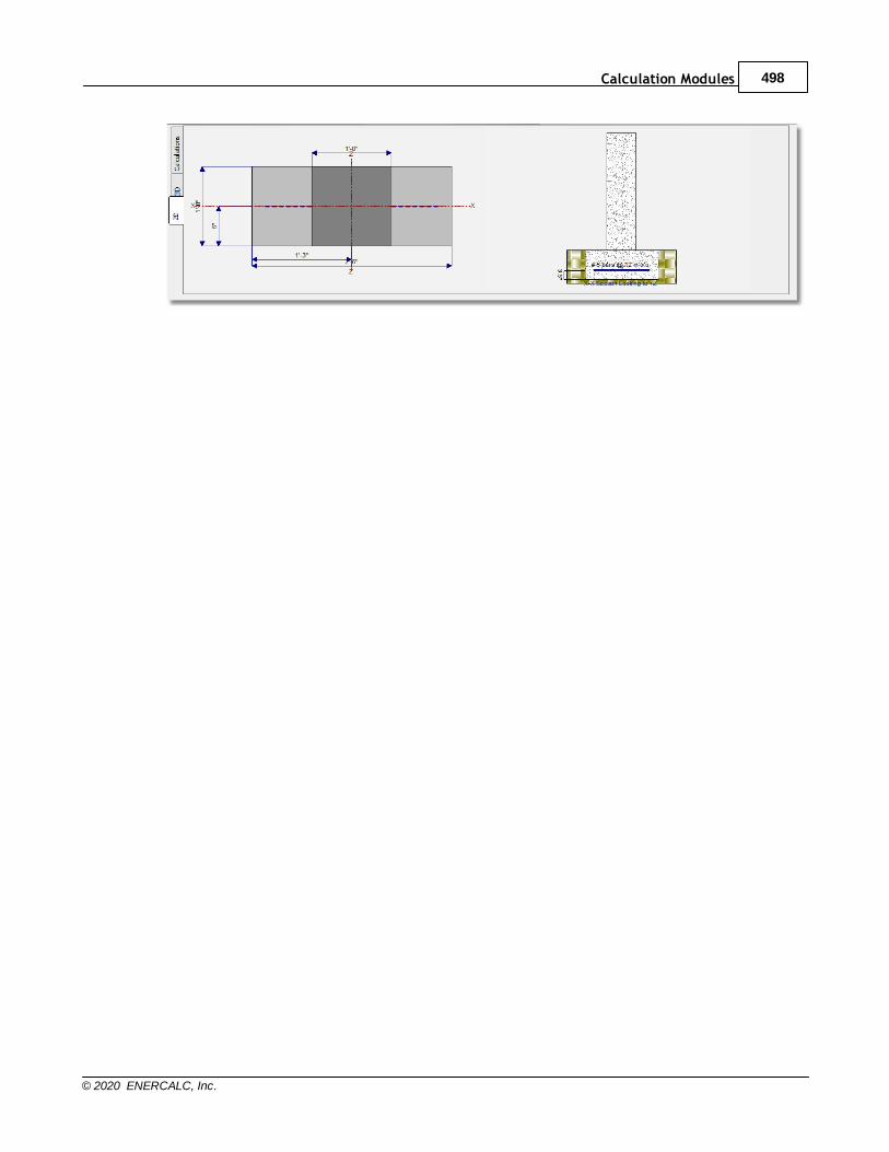
Calculation Modules 498
© 2020 ENERCALC, Inc.

Structural Engineering Library499
© 2020 ENERCALC, Inc.
10.7.4 Pile Group
Need more? Ask Us a Question
This module considers a concentrated load applied to a rigid pile cap and distributes it to agroup of piles. Force distribution is performed assuming a rigid pile cap and that all pileshave equal vertical load resistance.
Distribution of loads to each pile due to the effect of load eccentricity is determined using askew bending analysis. This considers simultaneous action about both X and Y axes.
The module is also an efficient method for determining loads on a pile group in the as-driven arrangement.
General Tab
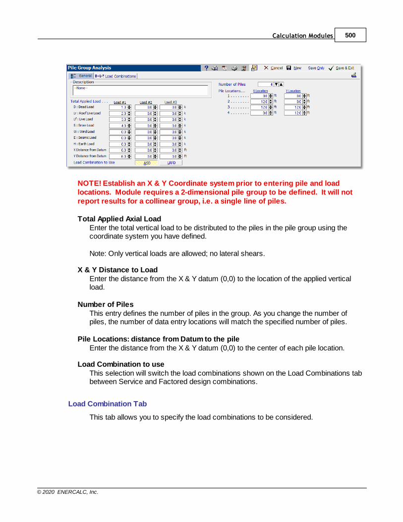
Calculation Modules 500
© 2020 ENERCALC, Inc.
NOTE! Establish an X & Y Coordinate system prior to entering pile and loadlocations. Module requires a 2-dimensional pile group to be defined. It will notreport results for a collinear group, i.e. a single line of piles.
Total Applied Axial LoadEnter the total vertical load to be distributed to the piles in the pile group using thecoordinate system you have defined.
Note: Only vertical loads are allowed; no lateral shears.
X & Y Distance to LoadEnter the distance from the X & Y datum (0,0) to the location of the applied verticalload.
Number of PilesThis entry defines the number of piles in the group. As you change the number ofpiles, the number of data entry locations will match the specified number of piles.
Pile Locations: distance from Datum to the pileEnter the distance from the X & Y datum (0,0) to the center of each pile location.
Load Combination to useThis selection will switch the load combinations shown on the Load Combinations tabbetween Service and Factored design combinations.
Load Combination Tab
This tab allows you to specify the load combinations to be considered.

Structural Engineering Library501
© 2020 ENERCALC, Inc.
Results Tab
This tab summarizes the overall calculated values for the pile group and lists themaximum factored load for each pile and the load combination that produced themaximum load.
Detailed Results Tab
This tab gives the detailed calculations for each pile for each load combination. Itindicates the Direct force as well as the component of axial load that is due to the netmoment applied to the entire group. This latter effect will be observed for any pile thatis located at a distance from the center of gravity of the pile group.
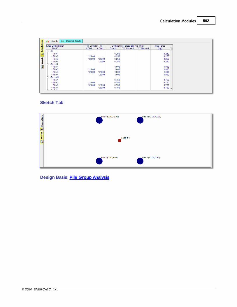
Calculation Modules 502
© 2020 ENERCALC, Inc.
Sketch Tab
Design Basis: Pile Group Analysis
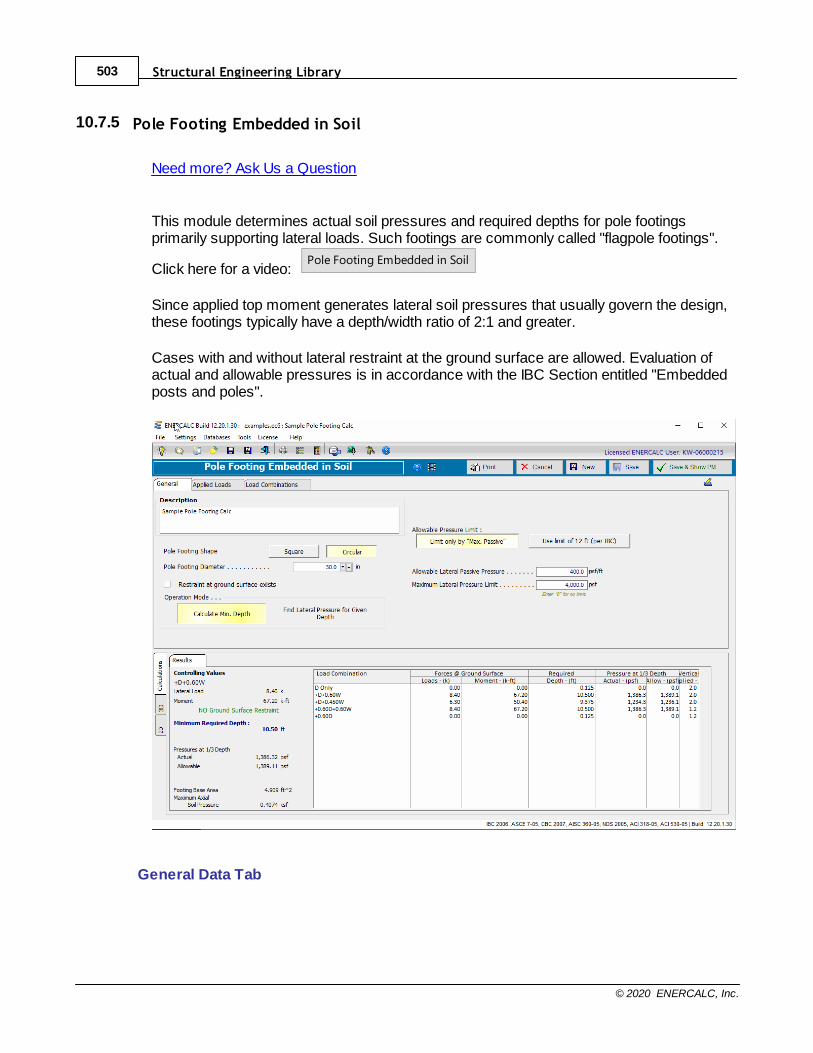
Structural Engineering Library503
© 2020 ENERCALC, Inc.
10.7.5 Pole Footing Embedded in Soil
Need more? Ask Us a Question
This module determines actual soil pressures and required depths for pole footingsprimarily supporting lateral loads. Such footings are commonly called "flagpole footings".
Click here for a video: Pole Footing Embedded in Soil
Since applied top moment generates lateral soil pressures that usually govern the design,these footings typically have a depth/width ratio of 2:1 and greater.
Cases with and without lateral restraint at the ground surface are allowed. Evaluation ofactual and allowable pressures is in accordance with the IBC Section entitled "Embeddedposts and poles".
General Data Tab
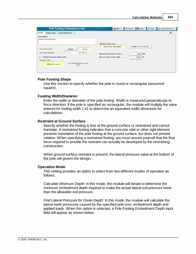
Calculation Modules 504
© 2020 ENERCALC, Inc.
Pole Footing ShapeUse this section to specify whether the pole is round or rectangular (assumedsquare).
Footing Width/DiameterEnter the width or diameter of the pole footing. Width is measured perpendicular toforce direction. If the pole is specified as rectangular, the module will multiply the valueentered for footing width 1.41 to determine an equivalent width dimension forcalculations.
Restraint at Ground SurfaceSpecify whether the footing is free at the ground surface or restrained and cannottranslate. A restrained footing indicates that a concrete slab or other rigid elementprevents translation of the pole footing at the ground surface, but does not preventrotation. When specifying a restrained footing, you must assure yourself that the finalforce required to provide the restraint can actually be developed by the restrainingconstruction.
When ground surface restraint is present, the lateral pressure value at the bottom ofthe pole will govern the design.
Operation ModeThis setting provides an option to select from two different modes of operation asfollows:
Calculate Minimum Depth: In this mode, the module will iterate to determine theminimum embedment depth required to make the actual lateral soil pressure lowerthan the allowable soil pressure.
Find Lateral Pressure for Given Depth: In this mode, the module will calculate thelateral earth pressures caused by the specified pole size, embedment depth andapplied loads. When this option is selected, a Pole Footing Embedment Depth inputfield will appear as shown below:
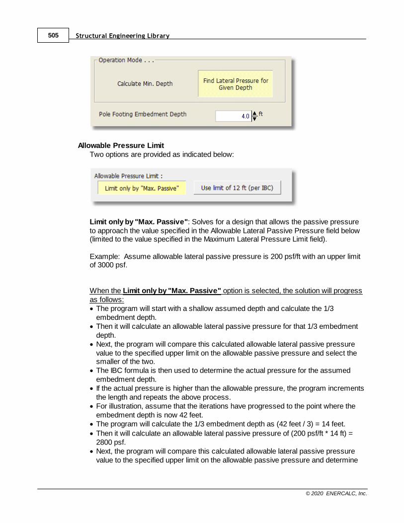
Structural Engineering Library505
© 2020 ENERCALC, Inc.
Allowable Pressure LimitTwo options are provided as indicated below:
Limit only by "Max. Passive": Solves for a design that allows the passive pressureto approach the value specified in the Allowable Lateral Passive Pressure field below(limited to the value specified in the Maximum Lateral Pressure Limit field).
Example: Assume allowable lateral passive pressure is 200 psf/ft with an upper limitof 3000 psf.
When the Limit only by "Max. Passive" option is selected, the solution will progressas follows:· The program will start with a shallow assumed depth and calculate the 1/3
embedment depth.· Then it will calculate an allowable lateral passive pressure for that 1/3 embedment
depth.· Next, the program will compare this calculated allowable lateral passive pressure
value to the specified upper limit on the allowable passive pressure and select thesmaller of the two.
· The IBC formula is then used to determine the actual pressure for the assumedembedment depth.
· If the actual pressure is higher than the allowable pressure, the program incrementsthe length and repeats the above process.
· For illustration, assume that the iterations have progressed to the point where theembedment depth is now 42 feet.
· The program will calculate the 1/3 embedment depth as (42 feet / 3) = 14 feet.
· Then it will calculate an allowable lateral passive pressure of (200 psf/ft * 14 ft) =2800 psf.
· Next, the program will compare this calculated allowable lateral passive pressurevalue to the specified upper limit on the allowable passive pressure and determine

Calculation Modules 506
© 2020 ENERCALC, Inc.
that 2800 psf < 3000 psf, therefore it will use 2800 psf as the Allowable LateralPassive Pressure.
· When the program finds an embedment depth for which the actual pressure islower than the allowable pressure, it rounds the embedment depth up slightly andreports that value.
Use limit of 12 ft (per IBC): Solves for a design that achieves a passive pressurethat does not exceed the Allowable Lateral Passive Pressure, where the AllowableLateral Passive Pressure is calculated based on 1/3 of the embedment depth but notto exceed 12 feet (and limited to the value specified in the Maximum Lateral PressureLimit field).
Example: Assume allowable lateral passive pressure is 200 psf/ft with an upper limitof 3000 psf.
When the Use limit of 12 ft (per IBC) option is selected, the solution will progress asfollows:· The program will start with a shallow assumed depth and calculate the 1/3
embedment depth.· Next, it will compare the 1/3 embedment depth to 12 feet and base the allowable
lateral passive pressure calculation on the smaller of the two.· Next, the program will compare this calculated allowable lateral passive pressure
value to the specified upper limit on the allowable passive pressure and select thesmaller of the two.
· The IBC formula is then used to determine the actual pressure for the assumedembedment depth.
· If the actual pressure is higher than the allowable pressure, the program incrementsthe length and repeats the above process.
· For illustration, assume that the iterations have progressed to the point where theembedment depth is now 42 feet.
· The program will calculate the 1/3 embedment depth as (42 feet / 3) = 14 feet.
· Next, it will compare the 1/3 embedment depth to 12 feet and determine that 14 feet> 12 feet, therefore it will base the allowable lateral passive pressure calculation on12 feet.
· Then it will calculate an allowable lateral passive pressure of (200 psf/ft * 12 ft) =2400 psf.
· Next, the program will compare this calculated allowable lateral passive pressurevalue to the specified upper limit on the allowable passive pressure and determinethat 2400 psf < 3000 psf, therefore it will use 2400 psf as the Allowable LateralPassive Pressure.
· When the program finds an embedment depth for which the actual pressure islower than the allowable pressure, it rounds the embedment depth up slightly andreports that value.
Allowable Lateral Passive PressureThe allowable lateral passive pressure that the soil can withstand. This value isentered as pounds per square foot per foot of embedment depth.
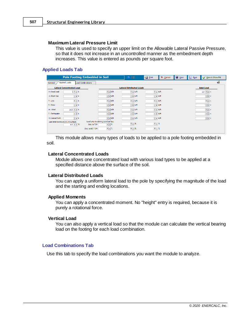
Structural Engineering Library507
© 2020 ENERCALC, Inc.
Maximum Lateral Pressure LimitThis value is used to specify an upper limit on the Allowable Lateral Passive Pressure,so that it does not increase in an uncontrolled manner as the embedment depthincreases. This value is entered as pounds per square foot.
Applied Loads Tab
This module allows many types of loads to be applied to a pole footing embedded insoil.
Lateral Concentrated LoadsModule allows one concentrated load with various load types to be applied at aspecified distance above the surface of the soil.
Lateral Distributed LoadsYou can apply a uniform lateral load to the pole by specifying the magnitude of the loadand the starting and ending locations.
Applied MomentsYou can apply a concentrated moment. No "height" entry is required, because it ispurely a rotational force.
Vertical LoadYou can also apply a vertical load so that the module can calculate the vertical bearingload on the footing for each load combination.
Load Combinations Tab
Use this tab to specify the load combinations you want the module to analyze.
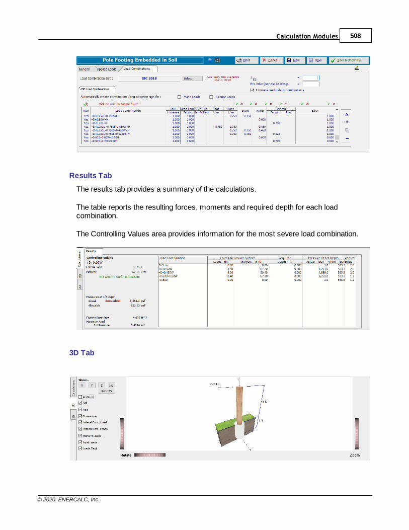
Calculation Modules 508
© 2020 ENERCALC, Inc.
Results Tab
The results tab provides a summary of the calculations.
The table reports the resulting forces, moments and required depth for each loadcombination.
The Controlling Values area provides information for the most severe load combination.
3D Tab
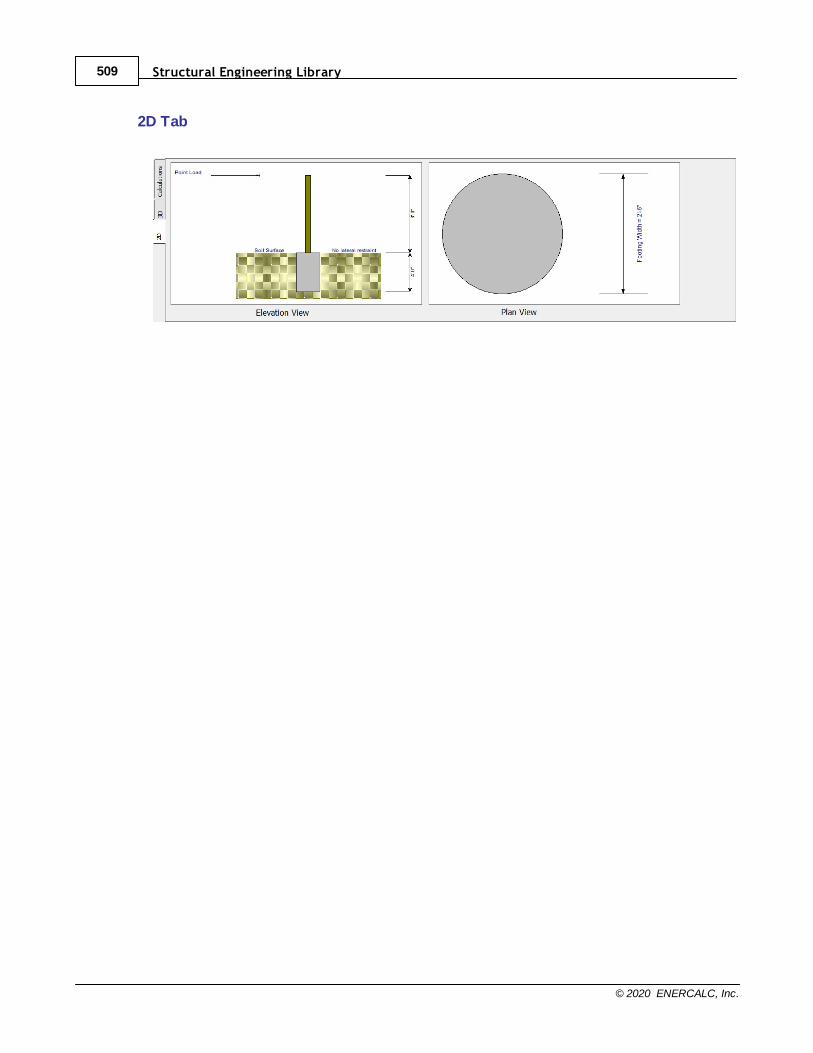
Structural Engineering Library509
© 2020 ENERCALC, Inc.
2D Tab

Calculation Modules 510
© 2020 ENERCALC, Inc.
10.7.6 Beam on Elastic Foundation
See Beam on Elastic Foundation in the Beams section.294

Structural Engineering Library511
© 2020 ENERCALC, Inc.
10.8 2D Frame Analysis
Need more? Ask Us a Question
This module provides force & deflection analysis, steel member stress analysis and woodstress analysis for two dimensional frames. Click here for the first in a series of videos:
2-D Frame Analysis Intro
The frame you create can be general in nature...the module is not limited to trusses orframes with rigid connections. You have the ability to specify the connection between allmembers in terms of axial, shear and bending restraints or releases.
Here are the highlights of this module:
· Use the Frame Wizard to automatically create common trusses and frames.
· Generic joint & member method of specifying the geometry of the frame.
· Completely flexible way to specify how the X, Y & Z degrees of freedom for joints areconnected to the earth and how the members are connected to the joints (three degreesof freedom are available at each end of each member).
· Apply forces and moments directly to joints. You can also specify joint starttemperatures.
· All loads can have dead, live, roof live, snow, wind, seismic and earth types.
· Apply concentrated and distributed loads to beams. These loads can be Global or localin direction and can be applied as forces, moments or temperature changes.
· Members are easily linked to section properties. For stress analysis you can setunbraced length, slenderness factors, Cb & Cm for members.
· Loads and members can be deactivated for quick modeling of alternatives.
· Complete AISC and NDS section databases are available.
· Specify material properties used by sections.
· Specify an extensive set of load combinations.
· Complete graphics of frame with deflected shapes.
· Complete stress & deflection diagrams of members individually.
· Extensive reporting capability and control.
· Module uses beam elements and a very fast matrix solver. With each change of theinput data, the frame can be completely recalculated in an instant. (For convenience withlarge models or when running many load combinations, this module has been enhancedwith the ability to turn the Automatic Recalculation feature off, and to trigger manualrecalculations only when desired.)
Note: This module is intended to be a simple alternative to complex frame programs. Theintent is to provide a simple and fast tool to perform simple indeterminate analysis &member design. No P-Delta effects, exotic elements, or non-linear analysis will ever beadded to this module.
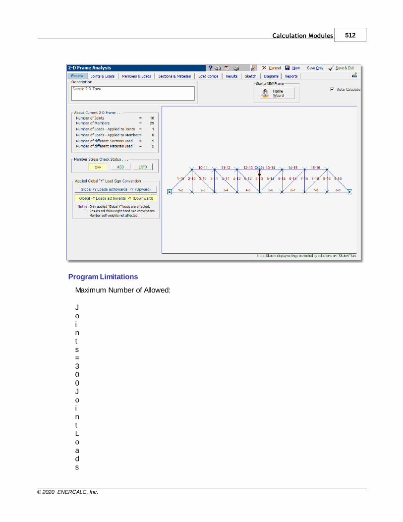
Calculation Modules 512
© 2020 ENERCALC, Inc.
Program Limitations
Maximum Number of Allowed:
Joints=300JointLoads
Structural Engineering Library513
© 2020 ENERCALC, Inc.
=600Beams=600BeamPointLoads= 600BeamDistributedLoa
Calculation Modules 514
© 2020 ENERCALC, Inc.
ds= 600Sections= 100Materials=
50LoadCombinations

Structural Engineering Library515
© 2020 ENERCALC, Inc.
= 100
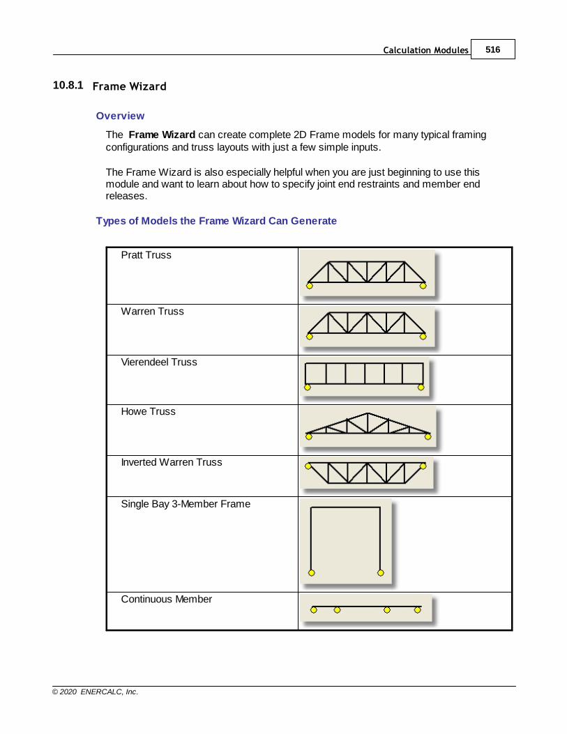
Calculation Modules 516
© 2020 ENERCALC, Inc.
10.8.1 Frame Wizard
Overview
The Frame Wizard can create complete 2D Frame models for many typical framingconfigurations and truss layouts with just a few simple inputs.
The Frame Wizard is also especially helpful when you are just beginning to use thismodule and want to learn about how to specify joint end restraints and member endreleases.
Types of Models the Frame Wizard Can Generate
Pratt Truss
Warren Truss
Vierendeel Truss
Howe Truss
Inverted Warren Truss
Single Bay 3-Member Frame
Continuous Member
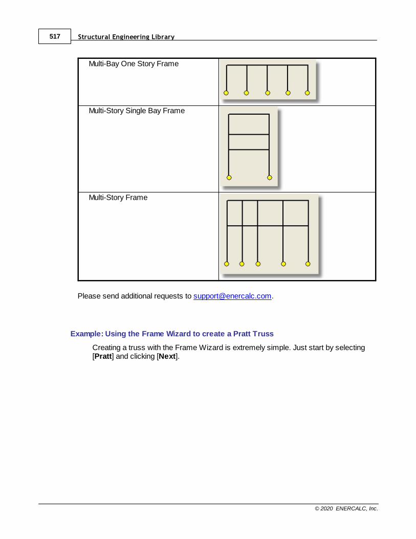
Structural Engineering Library517
© 2020 ENERCALC, Inc.
Multi-Bay One Story Frame
Multi-Story Single Bay Frame
Multi-Story Frame
Please send additional requests to [email protected].
Example: Using the Frame Wizard to create a Pratt Truss
Creating a truss with the Frame Wizard is extremely simple. Just start by selecting[Pratt] and clicking [Next].
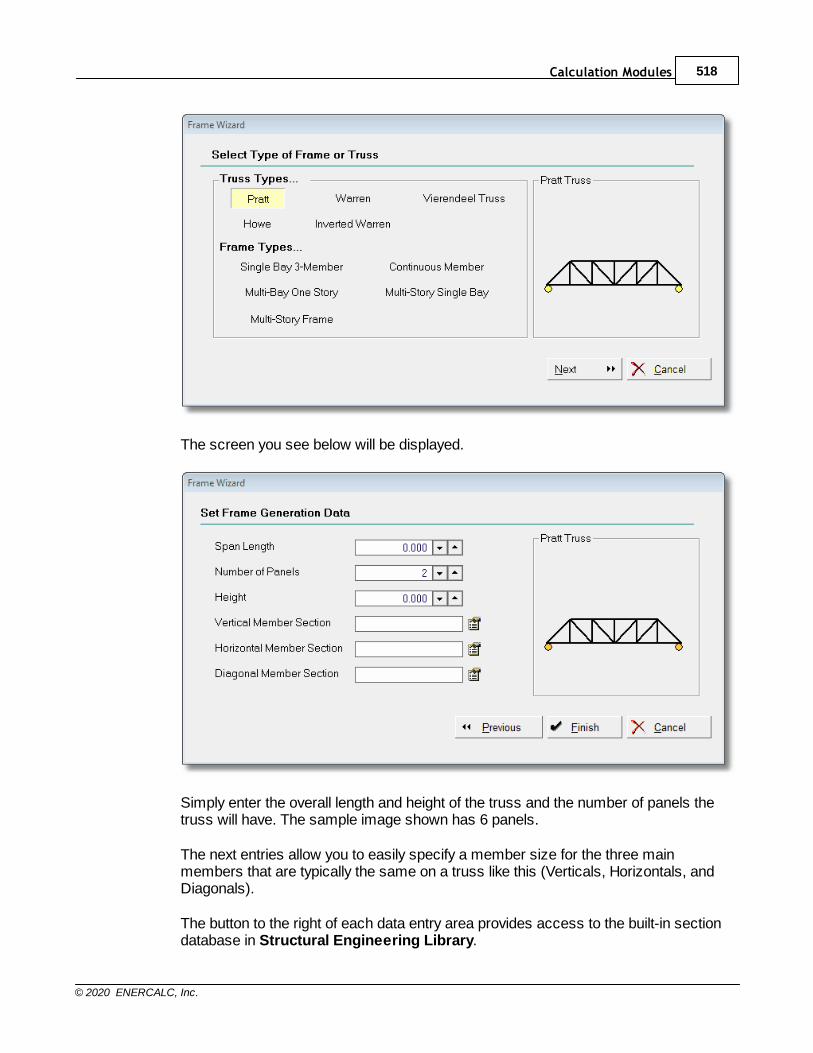
Calculation Modules 518
© 2020 ENERCALC, Inc.
The screen you see below will be displayed.
Simply enter the overall length and height of the truss and the number of panels thetruss will have. The sample image shown has 6 panels.
The next entries allow you to easily specify a member size for the three mainmembers that are typically the same on a truss like this (Verticals, Horizontals, andDiagonals).
The button to the right of each data entry area provides access to the built-in sectiondatabase in Structural Engineering Library.
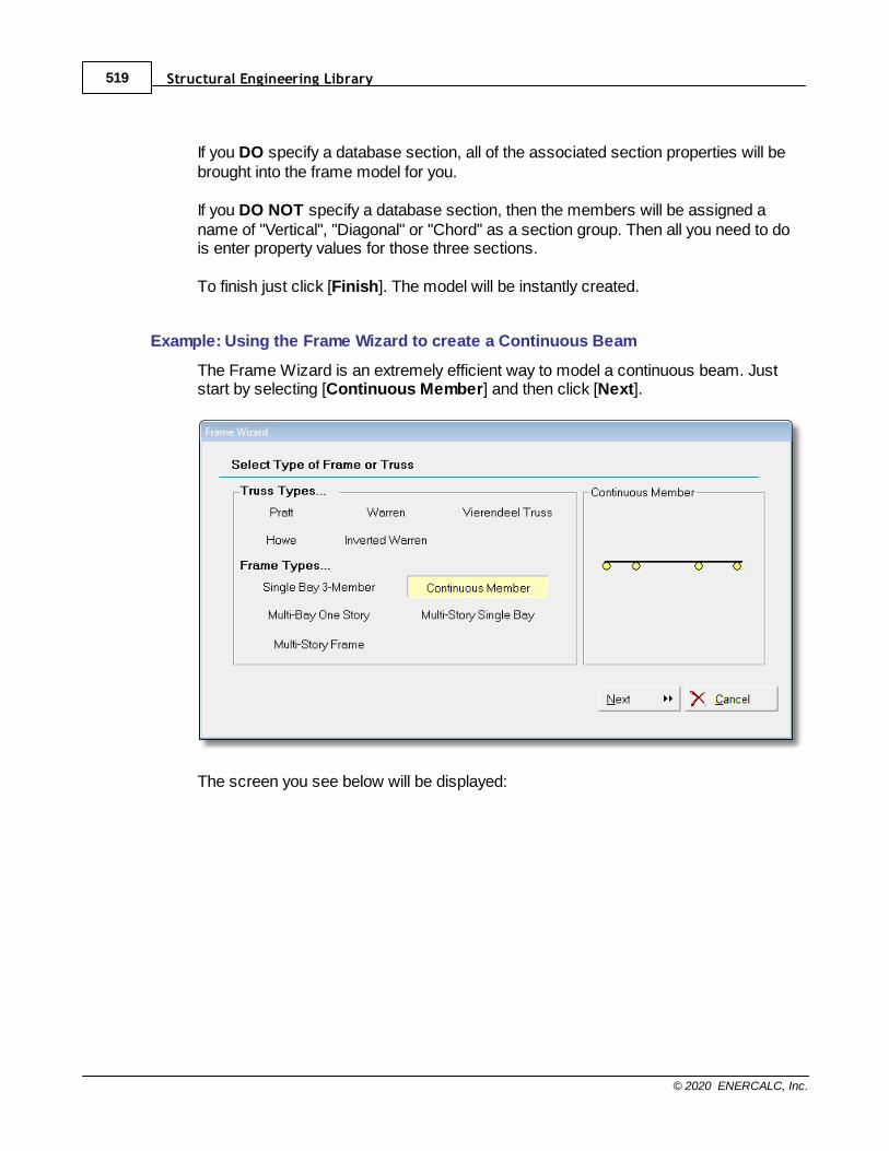
Structural Engineering Library519
© 2020 ENERCALC, Inc.
If you DO specify a database section, all of the associated section properties will bebrought into the frame model for you.
If you DO NOT specify a database section, then the members will be assigned aname of "Vertical", "Diagonal" or "Chord" as a section group. Then all you need to dois enter property values for those three sections.
To finish just click [Finish]. The model will be instantly created.
Example: Using the Frame Wizard to create a Continuous Beam
The Frame Wizard is an extremely efficient way to model a continuous beam. Juststart by selecting [Continuous Member] and then click [Next].
The screen you see below will be displayed:
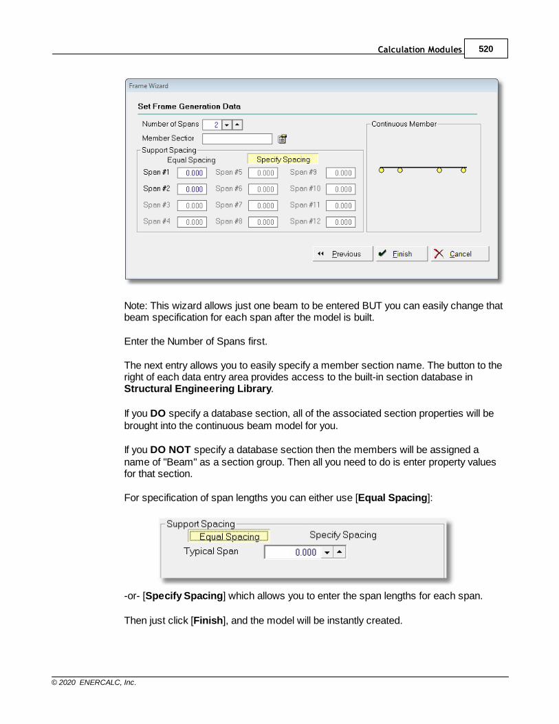
Calculation Modules 520
© 2020 ENERCALC, Inc.
Note: This wizard allows just one beam to be entered BUT you can easily change thatbeam specification for each span after the model is built.
Enter the Number of Spans first.
The next entry allows you to easily specify a member section name. The button to theright of each data entry area provides access to the built-in section database inStructural Engineering Library.
If you DO specify a database section, all of the associated section properties will bebrought into the continuous beam model for you.
If you DO NOT specify a database section then the members will be assigned aname of "Beam" as a section group. Then all you need to do is enter property valuesfor that section.
For specification of span lengths you can either use [Equal Spacing]:
-or- [Specify Spacing] which allows you to enter the span lengths for each span.
Then just click [Finish], and the model will be instantly created.
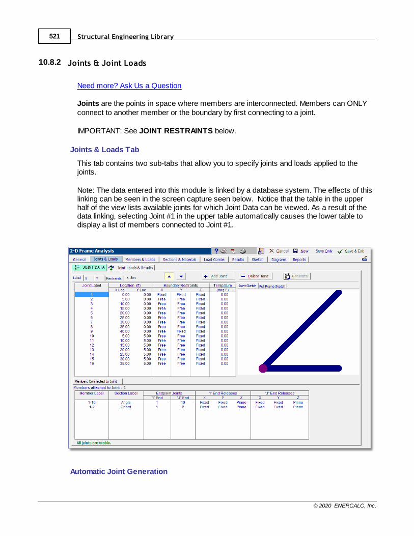
Structural Engineering Library521
© 2020 ENERCALC, Inc.
10.8.2 Joints & Joint Loads
Need more? Ask Us a Question
Joints are the points in space where members are interconnected. Members can ONLYconnect to another member or the boundary by first connecting to a joint.
IMPORTANT: See JOINT RESTRAINTS below.
Joints & Loads Tab
This tab contains two sub-tabs that allow you to specify joints and loads applied to thejoints.
Note: The data entered into this module is linked by a database system. The effects of thislinking can be seen in the screen capture seen below. Notice that the table in the upperhalf of the view lists available joints for which Joint Data can be viewed. As a result of thedata linking, selecting Joint #1 in the upper table automatically causes the lower table todisplay a list of members connected to Joint #1.
Automatic Joint Generation
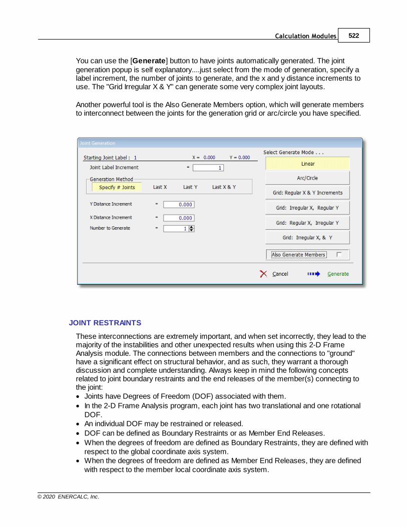
Calculation Modules 522
© 2020 ENERCALC, Inc.
You can use the [Generate] button to have joints automatically generated. The jointgeneration popup is self explanatory....just select from the mode of generation, specify alabel increment, the number of joints to generate, and the x and y distance increments touse. The "Grid Irregular X & Y" can generate some very complex joint layouts.
Another powerful tool is the Also Generate Members option, which will generate membersto interconnect between the joints for the generation grid or arc/circle you have specified.
JOINT RESTRAINTS
These interconnections are extremely important, and when set incorrectly, they lead to themajority of the instabilities and other unexpected results when using this 2-D FrameAnalysis module. The connections between members and the connections to "ground"have a significant effect on structural behavior, and as such, they warrant a thoroughdiscussion and complete understanding. Always keep in mind the following conceptsrelated to joint boundary restraints and the end releases of the member(s) connecting tothe joint:· Joints have Degrees of Freedom (DOF) associated with them.
· In the 2-D Frame Analysis program, each joint has two translational and one rotationalDOF.
· An individual DOF may be restrained or released.
· DOF can be defined as Boundary Restraints or as Member End Releases.
· When the degrees of freedom are defined as Boundary Restraints, they are defined withrespect to the global coordinate axis system.
· When the degrees of freedom are defined as Member End Releases, they are definedwith respect to the member local coordinate axis system.

Structural Engineering Library523
© 2020 ENERCALC, Inc.
The term Degrees of Freedom refers to the capability of a joint to move in the X and Ydirection and to rotate about the Z axis.
An X Restraint prevents a joint from moving in the Global X direction.A Y Restraint prevents a joint from moving in the Global Y direction.A Z Restraint prevents a joint from rotating about the Global Z axis.
Please see the diagram below for a brief primer on joint restraints and member releases.
The dark black items define the joint restraints. Joint restraints attach the joint to theboundary. The boundary is an infinitely stiff support and is most commonly called earth.When a joint is restrained against translation in the X and Y directions and against rotationabout the Z axis, it is held firmly in place. Any forces or moments applied to it will result ina reaction which is the boundary applying a force to the joint to keep it from moving in aparticular direction.
THE MOST IMPORTANT PIECE OF INFORMATION: Each joint must be prevented frommoving in/rotating about each of its three degrees of freedom, either by a joint restraint orby a positive connection to member. If a joint can translate or rotate in an unrestrainedmanner, then it is unstable.
NEXT MOST IMPORTANT PIECE OF INFORMATION: When a joint restraint isspecified, then any connected members that are not released in that particular directionwill not deflect in that direction. If a joint has an "X" restraint and a member framing into thatjoint does not have an "X" release, then the member is actually rigidly connected to theboundary through the joint.
ALSO IMPORTANT: When you are modeling a frame, nearly all joints will be free from theboundary. This means that those joints will need to have their X, Y & Z degrees of freedomrestrained by a connection to one or more members. Because members can only attachto each other through a joint, this is usually handled by virtue of the member having allthree degrees of freedom "fixed" at its ends. BUT FOR TRUSS CONNECTIONS, THISCAN CAUSE PROBLEMS WITH THE "Z" rotational degree of freedom. For truss models(where moments are not applied to nodes), it may be easier to achieve stability for all jointsby declaring all joints as "fixed" against rotation about the Z-axis, and then "pinning" bothends of all members to prevent the transfer of moment from one member to another.
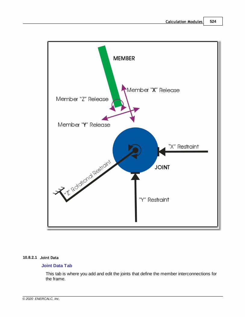
Calculation Modules 524
© 2020 ENERCALC, Inc.
10.8.2.1 Joint Data
Joint Data Tab
This tab is where you add and edit the joints that define the member interconnections forthe frame.
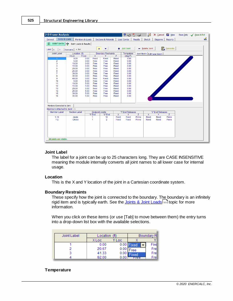
Structural Engineering Library525
© 2020 ENERCALC, Inc.
Joint LabelThe label for a joint can be up to 25 characters long. They are CASE INSENSITIVEmeaning the module internally converts all joint names to all lower case for internalusage.
LocationThis is the X and Y location of the joint in a Cartesian coordinate system.
Boundary RestraintsThese specify how the joint is connected to the boundary. The boundary is an infinitelyrigid item and is typically earth. See the Joints & Joint Loads topic for moreinformation.
When you click on these items (or use [Tab] to move between them) the entry turnsinto a drop-down list box with the available selections.
Temperature
521
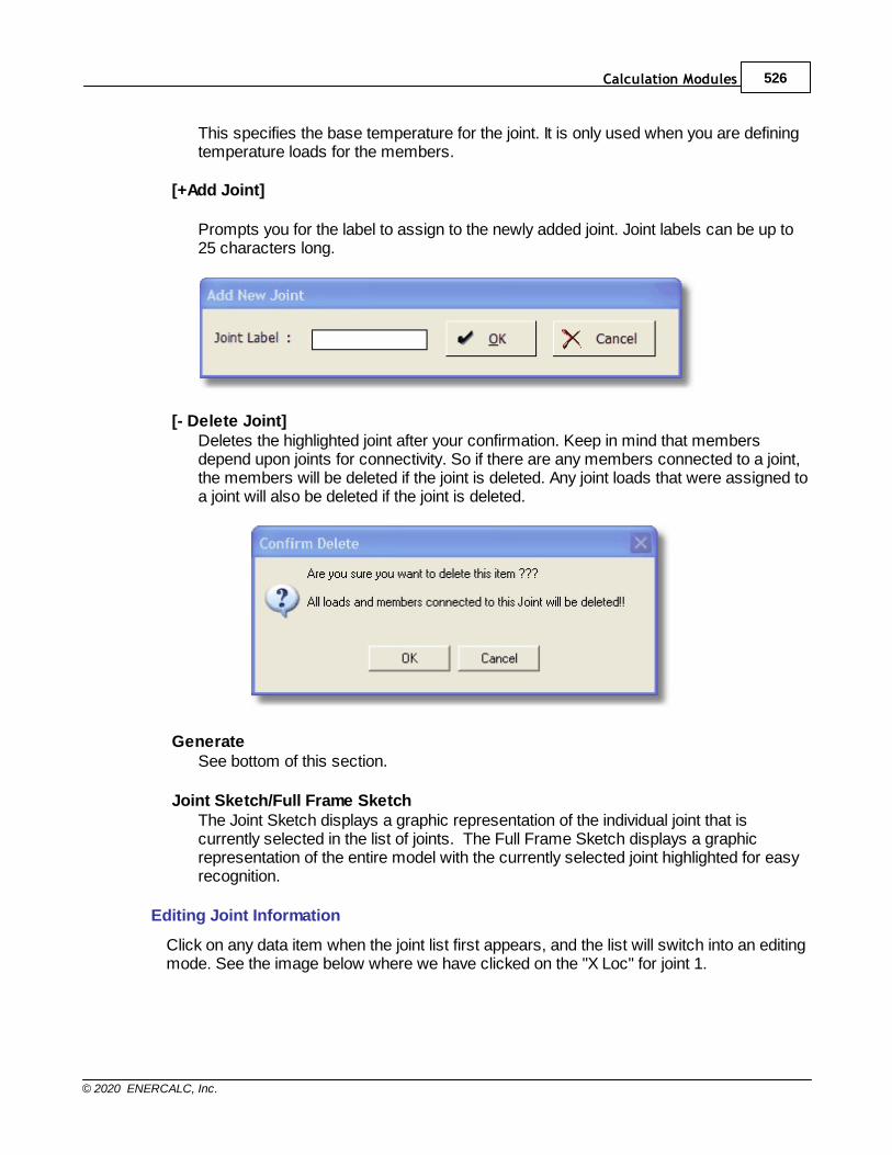
Calculation Modules 526
© 2020 ENERCALC, Inc.
This specifies the base temperature for the joint. It is only used when you are definingtemperature loads for the members.
[+Add Joint]
Prompts you for the label to assign to the newly added joint. Joint labels can be up to25 characters long.
[- Delete Joint]Deletes the highlighted joint after your confirmation. Keep in mind that membersdepend upon joints for connectivity. So if there are any members connected to a joint,the members will be deleted if the joint is deleted. Any joint loads that were assigned toa joint will also be deleted if the joint is deleted.
GenerateSee bottom of this section.
Joint Sketch/Full Frame SketchThe Joint Sketch displays a graphic representation of the individual joint that iscurrently selected in the list of joints. The Full Frame Sketch displays a graphicrepresentation of the entire model with the currently selected joint highlighted for easyrecognition.
Editing Joint Information
Click on any data item when the joint list first appears, and the list will switch into an editingmode. See the image below where we have clicked on the "X Loc" for joint 1.
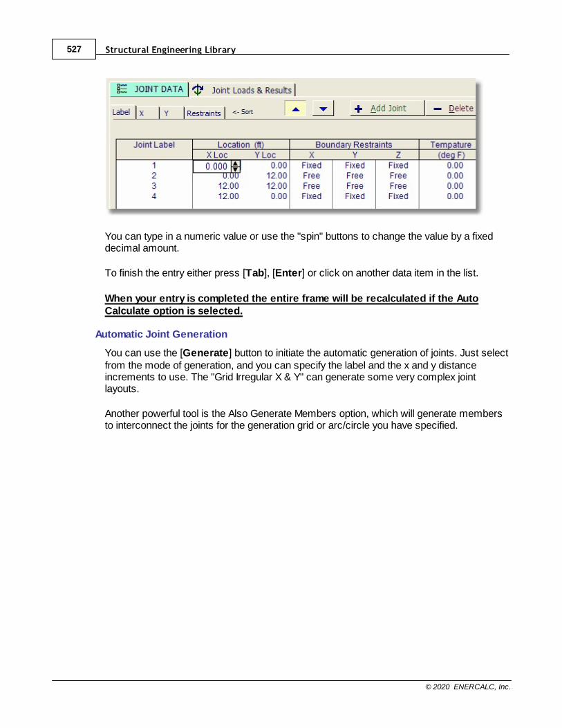
Structural Engineering Library527
© 2020 ENERCALC, Inc.
You can type in a numeric value or use the "spin" buttons to change the value by a fixeddecimal amount.
To finish the entry either press [Tab], [Enter] or click on another data item in the list.
When your entry is completed the entire frame will be recalculated if the AutoCalculate option is selected.
Automatic Joint Generation
You can use the [Generate] button to initiate the automatic generation of joints. Just selectfrom the mode of generation, and you can specify the label and the x and y distanceincrements to use. The "Grid Irregular X & Y" can generate some very complex jointlayouts.
Another powerful tool is the Also Generate Members option, which will generate membersto interconnect the joints for the generation grid or arc/circle you have specified.
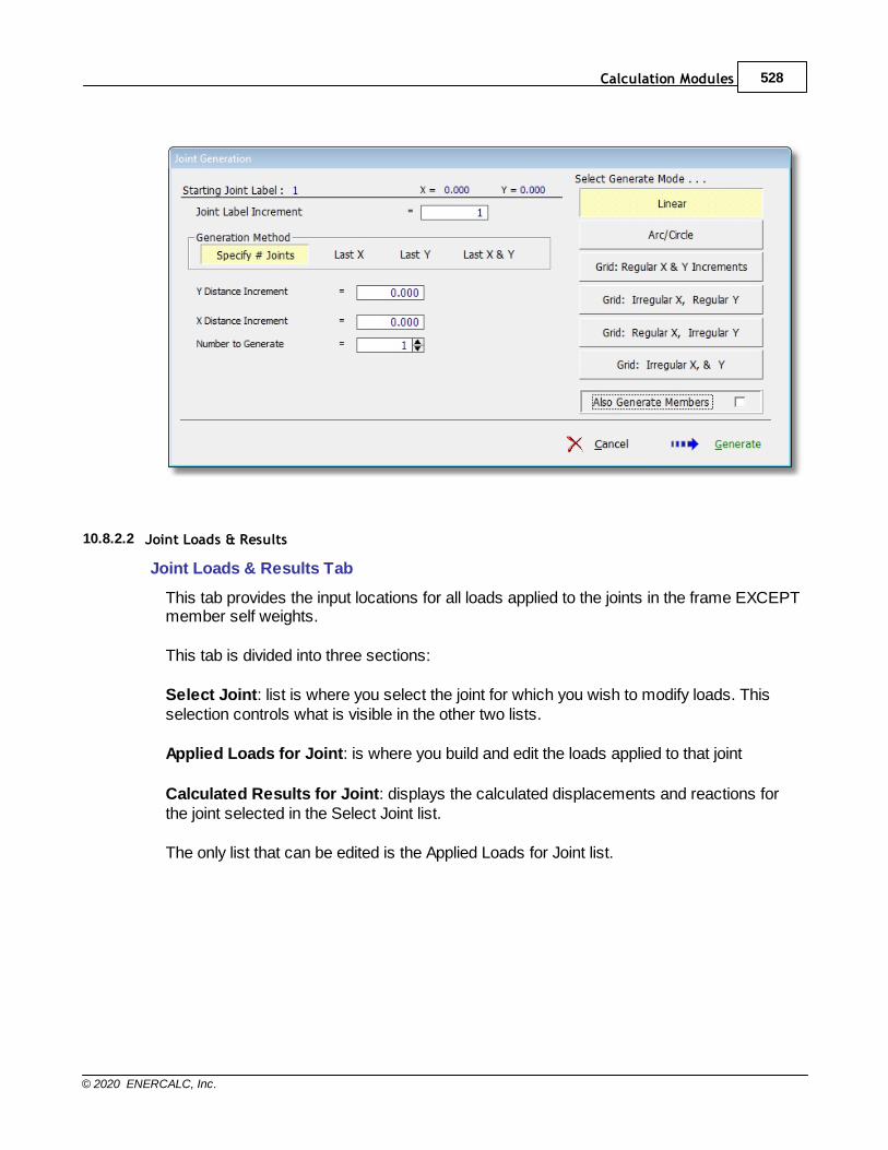
Calculation Modules 528
© 2020 ENERCALC, Inc.
10.8.2.2 Joint Loads & Results
Joint Loads & Results Tab
This tab provides the input locations for all loads applied to the joints in the frame EXCEPTmember self weights.
This tab is divided into three sections:
Select Joint: list is where you select the joint for which you wish to modify loads. Thisselection controls what is visible in the other two lists.
Applied Loads for Joint: is where you build and edit the loads applied to that joint
Calculated Results for Joint: displays the calculated displacements and reactions forthe joint selected in the Select Joint list.
The only list that can be edited is the Applied Loads for Joint list.

Structural Engineering Library529
© 2020 ENERCALC, Inc.
Adding & Deleting Loads
To add a joint load just click the [Add Load] button and a new load entry line will be addedat the bottom of the list for the currently selected joint.To delete a load just click on the load line you wish to delete and click the [Delete Load]button.
Editing Joint Load Information
Click on any data item in the joint load list, and it will switch into an editing mode. See theimage below where we have clicked on the Dead load column in the first line in the list ofloads associated with joint 1.
You can type in a numeric value or use the "spin" buttons to change the value by a fixeddecimal amount.

Calculation Modules 530
© 2020 ENERCALC, Inc.
To finish the entry either press [Tab], [Enter] or click on another data item in the list.
When your entry is completed the entire frame will be recalculated if the AutoCalculate option is selected.
Note: If a load is applied in the same direction that a Joint Restraint is specified, that load willimmediately be "absorbed" by the joint restraint, so it will not have any effect on the frame.
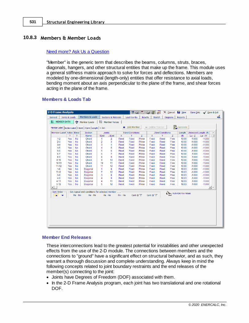
Structural Engineering Library531
© 2020 ENERCALC, Inc.
10.8.3 Members & Member Loads
Need more? Ask Us a Question
"Member" is the generic term that describes the beams, columns, struts, braces,diagonals, hangers, and other structural entities that make up the frame. This module usesa general stiffness matrix approach to solve for forces and deflections. Members aremodeled by one-dimensional (length-only) entities that offer resistance to axial loads,bending moment about an axis perpendicular to the plane of the frame, and shear forcesacting in the plane of the frame.
Members & Loads Tab
Member End Releases
These interconnections lead to the greatest potential for instabilities and other unexpectedeffects from the use of the 2-D module. The connections between members and theconnections to "ground" have a significant effect on structural behavior, and as such, theywarrant a thorough discussion and complete understanding. Always keep in mind thefollowing concepts related to joint boundary restraints and the end releases of themember(s) connecting to the joint:· Joints have Degrees of Freedom (DOF) associated with them.
· In the 2-D Frame Analysis program, each joint has two translational and one rotationalDOF.
Calculation Modules 532
© 2020 ENERCALC, Inc.
· An individual DOF may be restrained or released.
· DOF can be defined as Boundary Restraints or as Member End Releases.
· When the degrees of freedom are defined as Boundary Restraints, they are defined withrespect to the global coordinate axis system.
· When the degrees of freedom are defined as Member End Releases, they are definedwith respect to the member local coordinate axis system.
The term Degrees of Freedom refers to the capability of a joint to move in the X and Ydirection and to rotate about the Z axis.
An X Restraint prevents a joint from moving in the Global X direction.A Y Restraint prevents a joint from moving in the Global Y direction.A Z Restraint prevents a joint from rotating about the Global Z axis.
Please see the diagram below for a brief primer on joint restraints and member releases.
The dark black items define the joint restraints. Joint restraints attach the joint to theboundary. The boundary is an infinitely stiff support and is most commonly called earth.When a joint is restrained against translation in the X and Y directions and against rotationabout the Z axis, it is held firmly in place. Any forces or moments applied to it will result ina reaction which is the boundary applying a force to the joint to keep it from moving in aparticular direction.
THE MOST IMPORTANT PIECE OF INFORMATION: Each joint must be prevented frommoving in/rotating about each of its three degrees of freedom, either by a joint restraint orby a positive connection to member. If a joint can translate or rotate in an unrestrainedmanner, then it is unstable.
NEXT MOST IMPORTANT PIECE OF INFORMATION: When a joint restraint isspecified, then any connected members that are not released in that particular directionwill not deflect in that direction. If a joint has an "X" restraint and a member framing into thatjoint does not have an "X" release, then the member is actually rigidly connected to theboundary through the joint.
ALSO IMPORTANT: When you are modeling a frame, nearly all joints will be free from theboundary. This means that those joints will need to have their X, Y & Z degrees of freedomrestrained by a connection to one or more members. Because members can only attachto each other through a joint, this is usually handled by virtue of the member having allthree degrees of freedom "fixed" at its ends. BUT FOR TRUSS CONNECTIONS, THISCAN CAUSE PROBLEMS WITH THE "Z" rotational degree of freedom. For truss models(where moments are not applied to nodes), it may be easier to achieve stability for all jointsby declaring all joints as "fixed" against rotation about the Z-axis, and then "pinning" bothends of all members to prevent the transfer of moment from one member to another.
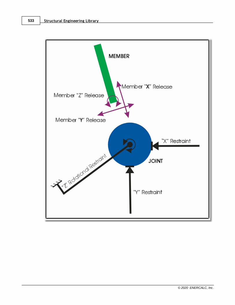
Structural Engineering Library533
© 2020 ENERCALC, Inc.
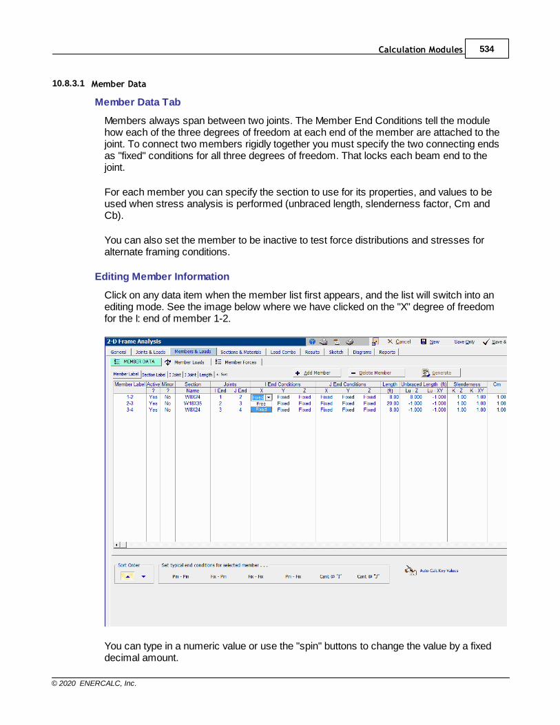
Calculation Modules 534
© 2020 ENERCALC, Inc.
10.8.3.1 Member Data
Member Data Tab
Members always span between two joints. The Member End Conditions tell the modulehow each of the three degrees of freedom at each end of the member are attached to thejoint. To connect two members rigidly together you must specify the two connecting endsas "fixed" conditions for all three degrees of freedom. That locks each beam end to thejoint.
For each member you can specify the section to use for its properties, and values to beused when stress analysis is performed (unbraced length, slenderness factor, Cm andCb).
You can also set the member to be inactive to test force distributions and stresses foralternate framing conditions.
Editing Member Information
Click on any data item when the member list first appears, and the list will switch into anediting mode. See the image below where we have clicked on the "X" degree of freedomfor the I: end of member 1-2.
You can type in a numeric value or use the "spin" buttons to change the value by a fixeddecimal amount.
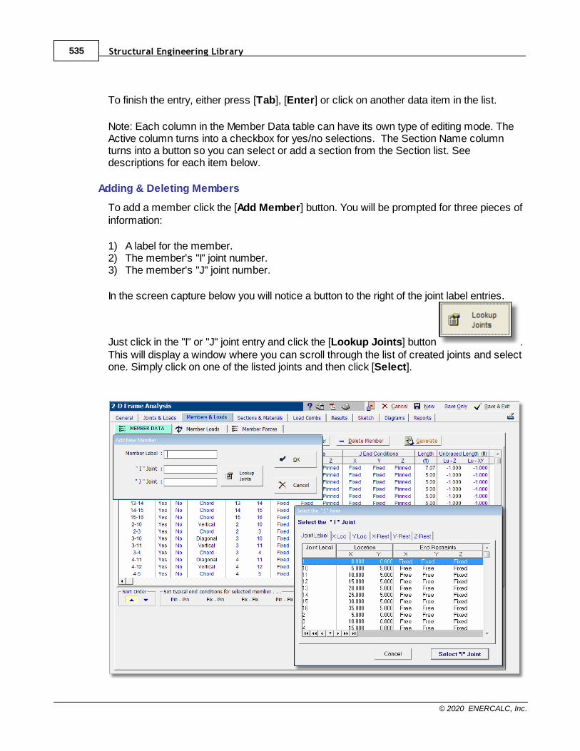
Structural Engineering Library535
© 2020 ENERCALC, Inc.
To finish the entry, either press [Tab], [Enter] or click on another data item in the list.
Note: Each column in the Member Data table can have its own type of editing mode. TheActive column turns into a checkbox for yes/no selections. The Section Name columnturns into a button so you can select or add a section from the Section list. Seedescriptions for each item below.
Adding & Deleting Members
To add a member click the [Add Member] button. You will be prompted for three pieces ofinformation:
1) A label for the member.2) The member's "I" joint number.3) The member's "J" joint number.
In the screen capture below you will notice a button to the right of the joint label entries.
Just click in the "I" or "J" joint entry and click the [Lookup Joints] button .This will display a window where you can scroll through the list of created joints and selectone. Simply click on one of the listed joints and then click [Select].
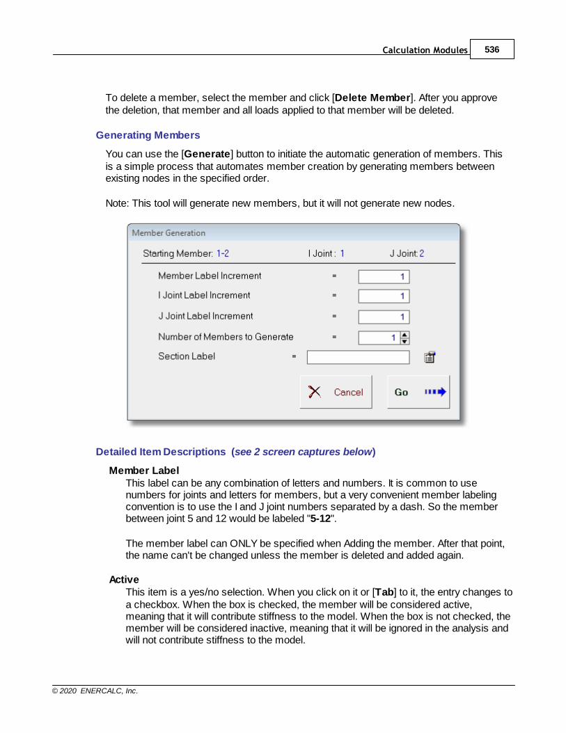
Calculation Modules 536
© 2020 ENERCALC, Inc.
To delete a member, select the member and click [Delete Member]. After you approvethe deletion, that member and all loads applied to that member will be deleted.
Generating Members
You can use the [Generate] button to initiate the automatic generation of members. Thisis a simple process that automates member creation by generating members betweenexisting nodes in the specified order.
Note: This tool will generate new members, but it will not generate new nodes.
Detailed Item Descriptions (see 2 screen captures below)
Member LabelThis label can be any combination of letters and numbers. It is common to usenumbers for joints and letters for members, but a very convenient member labelingconvention is to use the I and J joint numbers separated by a dash. So the memberbetween joint 5 and 12 would be labeled "5-12".
The member label can ONLY be specified when Adding the member. After that point,the name can't be changed unless the member is deleted and added again.
ActiveThis item is a yes/no selection. When you click on it or [Tab] to it, the entry changes toa checkbox. When the box is checked, the member will be considered active,meaning that it will contribute stiffness to the model. When the box is not checked, themember will be considered inactive, meaning that it will be ignored in the analysis andwill not contribute stiffness to the model.
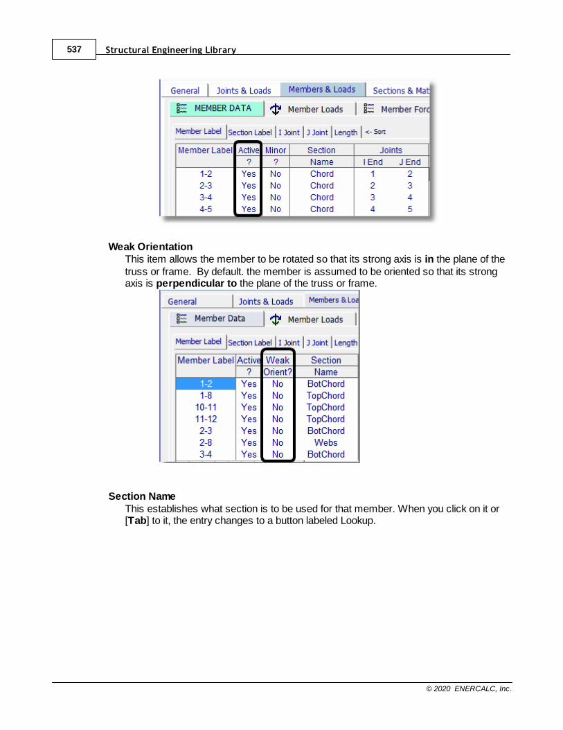
Structural Engineering Library537
© 2020 ENERCALC, Inc.
Weak OrientationThis item allows the member to be rotated so that its strong axis is in the plane of thetruss or frame. By default. the member is assumed to be oriented so that its strongaxis is perpendicular to the plane of the truss or frame.
Section NameThis establishes what section is to be used for that member. When you click on it or[Tab] to it, the entry changes to a button labeled Lookup.
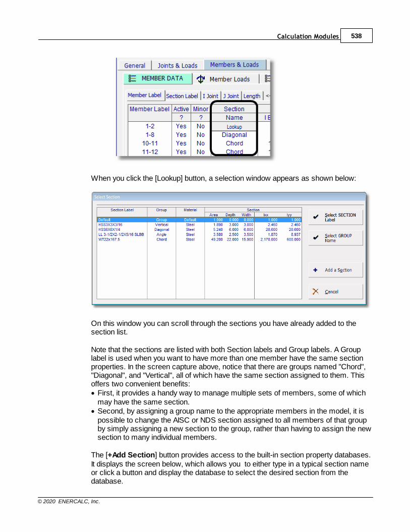
Calculation Modules 538
© 2020 ENERCALC, Inc.
When you click the [Lookup] button, a selection window appears as shown below:
On this window you can scroll through the sections you have already added to thesection list.
Note that the sections are listed with both Section labels and Group labels. A Grouplabel is used when you want to have more than one member have the same sectionproperties. In the screen capture above, notice that there are groups named "Chord","Diagonal", and "Vertical", all of which have the same section assigned to them. Thisoffers two convenient benefits:· First, it provides a handy way to manage multiple sets of members, some of which
may have the same section.· Second, by assigning a group name to the appropriate members in the model, it is
possible to change the AISC or NDS section assigned to all members of that groupby simply assigning a new section to the group, rather than having to assign the newsection to many individual members.
The [+Add Section] button provides access to the built-in section property databases.It displays the screen below, which allows you to either type in a typical section nameor click a button and display the database to select the desired section from thedatabase.
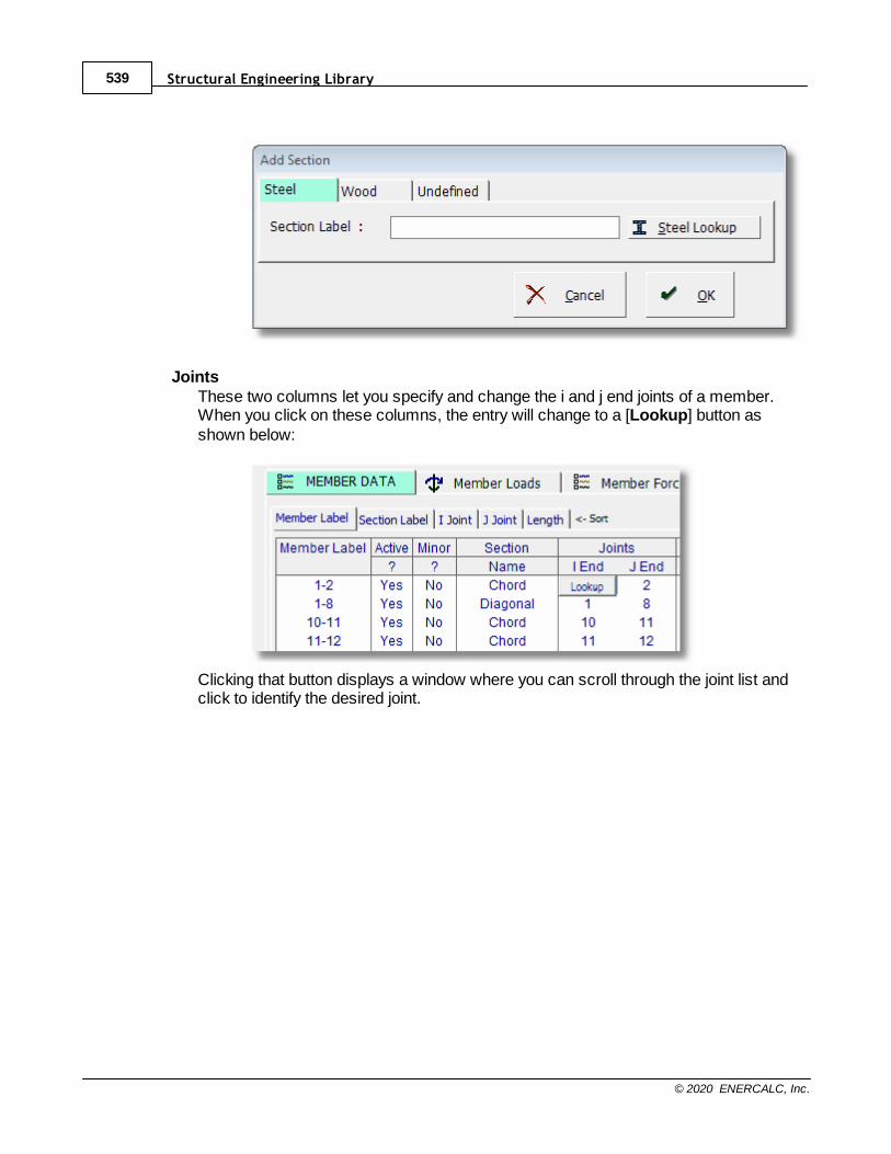
Structural Engineering Library539
© 2020 ENERCALC, Inc.
JointsThese two columns let you specify and change the i and j end joints of a member.When you click on these columns, the entry will change to a [Lookup] button asshown below:
Clicking that button displays a window where you can scroll through the joint list andclick to identify the desired joint.

Calculation Modules 540
© 2020 ENERCALC, Inc.
I & J End ConditionsThese six columns allow you to specify how the ends of the member are attached tothe joints. When you click on or [Tab] to one of these columns, the entry will change toa drop-down list box offering appropriate fixity options:
In order to most efficiently describe the I & J End Conditions, it helps to introduce theconcept of the member local axis system. Each member can be thought of as havingits own x, y, and z coordinate axes that are mutually perpendicular and follow the right-hand rule. The orientation of the member local axes can be determined as follows:
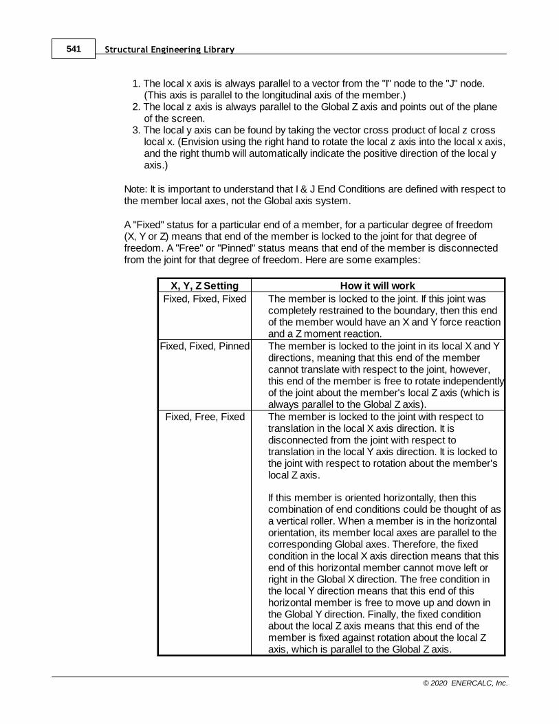
Structural Engineering Library541
© 2020 ENERCALC, Inc.
1. The local x axis is always parallel to a vector from the "I" node to the "J" node.(This axis is parallel to the longitudinal axis of the member.)
2. The local z axis is always parallel to the Global Z axis and points out of the planeof the screen.
3. The local y axis can be found by taking the vector cross product of local z crosslocal x. (Envision using the right hand to rotate the local z axis into the local x axis,and the right thumb will automatically indicate the positive direction of the local yaxis.)
Note: It is important to understand that I & J End Conditions are defined with respect tothe member local axes, not the Global axis system.
A "Fixed" status for a particular end of a member, for a particular degree of freedom(X, Y or Z) means that end of the member is locked to the joint for that degree offreedom. A "Free" or "Pinned" status means that end of the member is disconnectedfrom the joint for that degree of freedom. Here are some examples:
X, Y, Z Setting How it will work
Fixed, Fixed, Fixed The member is locked to the joint. If this joint wascompletely restrained to the boundary, then this endof the member would have an X and Y force reactionand a Z moment reaction.
Fixed, Fixed, Pinned The member is locked to the joint in its local X and Ydirections, meaning that this end of the membercannot translate with respect to the joint, however,this end of the member is free to rotate independentlyof the joint about the member's local Z axis (which isalways parallel to the Global Z axis).
Fixed, Free, Fixed The member is locked to the joint with respect totranslation in the local X axis direction. It isdisconnected from the joint with respect totranslation in the local Y axis direction. It is locked tothe joint with respect to rotation about the member'slocal Z axis.
If this member is oriented horizontally, then thiscombination of end conditions could be thought of asa vertical roller. When a member is in the horizontalorientation, its member local axes are parallel to thecorresponding Global axes. Therefore, the fixedcondition in the local X axis direction means that thisend of this horizontal member cannot move left orright in the Global X direction. The free condition inthe local Y direction means that this end of thishorizontal member is free to move up and down inthe Global Y direction. Finally, the fixed conditionabout the local Z axis means that this end of themember is fixed against rotation about the local Zaxis, which is parallel to the Global Z axis.
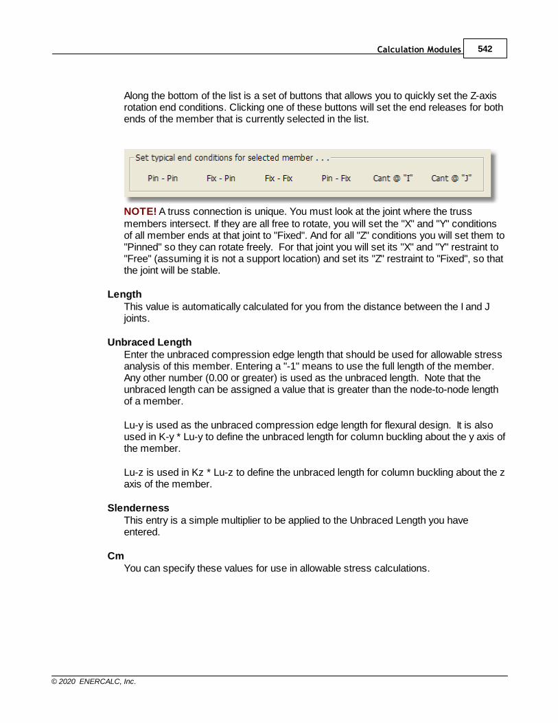
Calculation Modules 542
© 2020 ENERCALC, Inc.
Along the bottom of the list is a set of buttons that allows you to quickly set the Z-axisrotation end conditions. Clicking one of these buttons will set the end releases for bothends of the member that is currently selected in the list.
NOTE! A truss connection is unique. You must look at the joint where the trussmembers intersect. If they are all free to rotate, you will set the "X" and "Y" conditionsof all member ends at that joint to "Fixed". And for all "Z" conditions you will set them to"Pinned" so they can rotate freely. For that joint you will set its "X" and "Y" restraint to"Free" (assuming it is not a support location) and set its "Z" restraint to "Fixed", so thatthe joint will be stable.
LengthThis value is automatically calculated for you from the distance between the I and Jjoints.
Unbraced LengthEnter the unbraced compression edge length that should be used for allowable stressanalysis of this member. Entering a "-1" means to use the full length of the member.Any other number (0.00 or greater) is used as the unbraced length. Note that theunbraced length can be assigned a value that is greater than the node-to-node lengthof a member.
Lu-y is used as the unbraced compression edge length for flexural design. It is alsoused in K-y * Lu-y to define the unbraced length for column buckling about the y axis ofthe member.
Lu-z is used in Kz * Lu-z to define the unbraced length for column buckling about the zaxis of the member.
SlendernessThis entry is a simple multiplier to be applied to the Unbraced Length you haveentered.
CmYou can specify these values for use in allowable stress calculations.
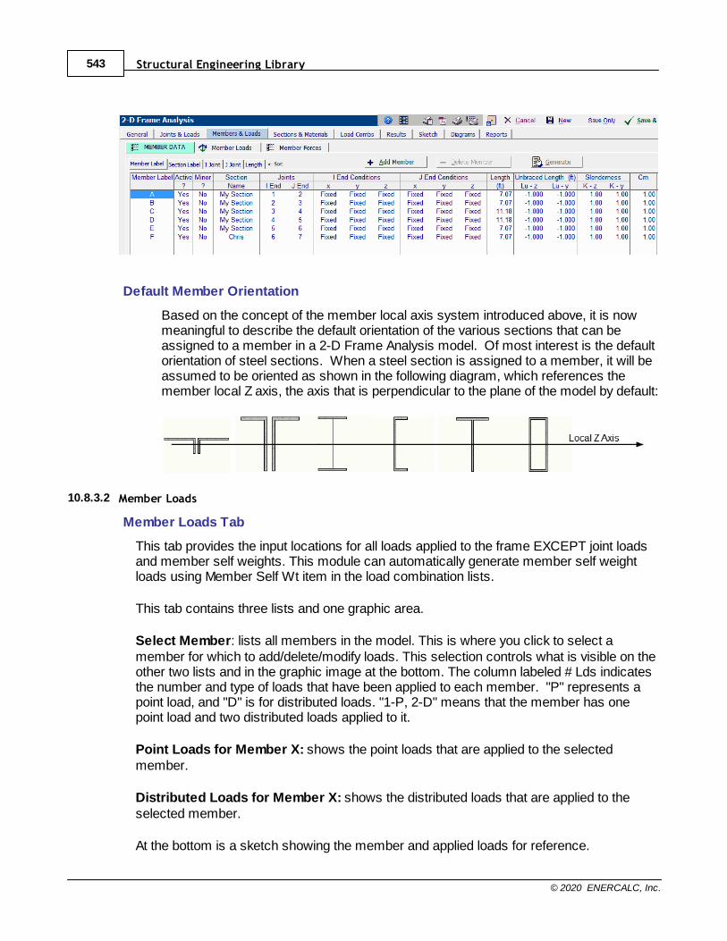
Structural Engineering Library543
© 2020 ENERCALC, Inc.
Default Member Orientation
Based on the concept of the member local axis system introduced above, it is nowmeaningful to describe the default orientation of the various sections that can beassigned to a member in a 2-D Frame Analysis model. Of most interest is the defaultorientation of steel sections. When a steel section is assigned to a member, it will beassumed to be oriented as shown in the following diagram, which references themember local Z axis, the axis that is perpendicular to the plane of the model by default:
10.8.3.2 Member Loads
Member Loads Tab
This tab provides the input locations for all loads applied to the frame EXCEPT joint loadsand member self weights. This module can automatically generate member self weightloads using Member Self Wt item in the load combination lists.
This tab contains three lists and one graphic area.
Select Member: lists all members in the model. This is where you click to select amember for which to add/delete/modify loads. This selection controls what is visible on theother two lists and in the graphic image at the bottom. The column labeled # Lds indicatesthe number and type of loads that have been applied to each member. "P" represents apoint load, and "D" is for distributed loads. "1-P, 2-D" means that the member has onepoint load and two distributed loads applied to it.
Point Loads for Member X: shows the point loads that are applied to the selectedmember.
Distributed Loads for Member X: shows the distributed loads that are applied to theselected member.
At the bottom is a sketch showing the member and applied loads for reference.
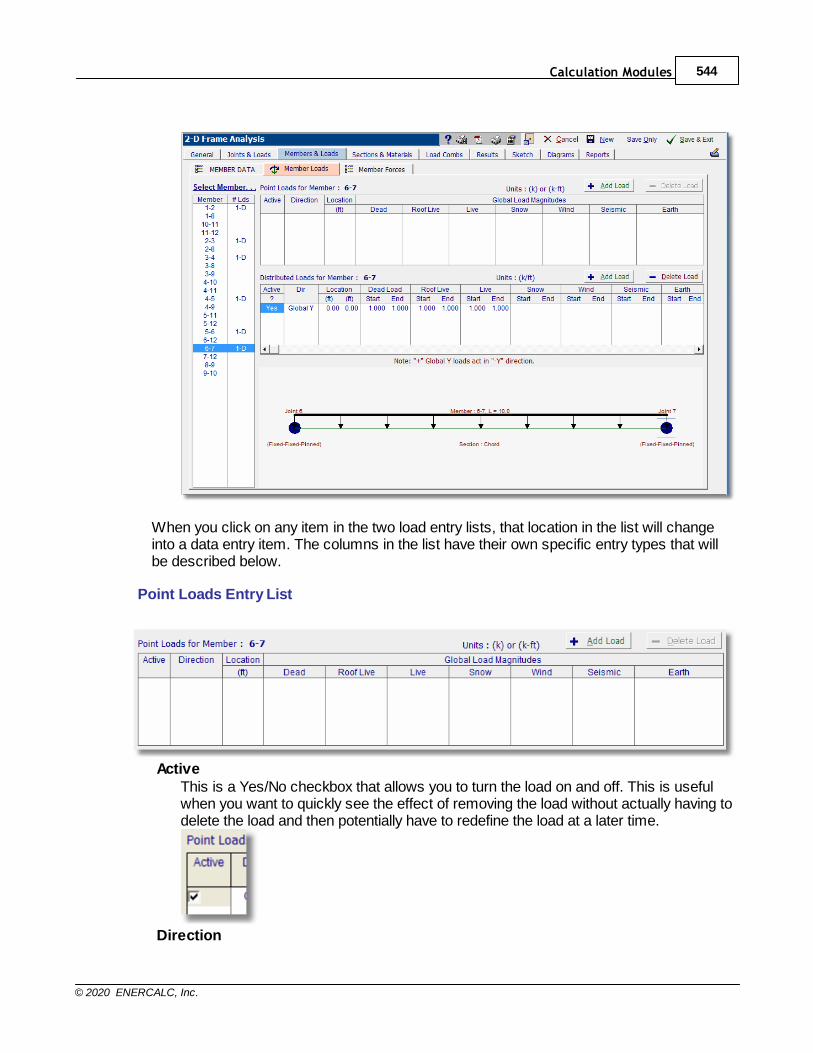
Calculation Modules 544
© 2020 ENERCALC, Inc.
When you click on any item in the two load entry lists, that location in the list will changeinto a data entry item. The columns in the list have their own specific entry types that willbe described below.
Point Loads Entry List
ActiveThis is a Yes/No checkbox that allows you to turn the load on and off. This is usefulwhen you want to quickly see the effect of removing the load without actually having todelete the load and then potentially have to redefine the load at a later time.
Direction
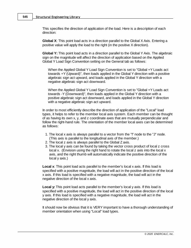
Structural Engineering Library545
© 2020 ENERCALC, Inc.
This specifies the direction of application of the load. Here is a description of eachdirection:
Global X: This point load acts in a direction parallel to the Global X Axis. Entering apositive value will apply the load to the right (in the positive X direction).
Global Y: This point load acts in a direction parallel to the Global Y Axis. The algebraicsign on the magnitude will affect the direction of application based on the AppliedGlobal Y Load Sign Convention setting on the General tab as follows:
When the Applied Global Y Load Sign Convention is set to "Global +Y Loads acttowards +Y (Upward)", then loads applied in the Global Y direction with a positivealgebraic sign act upward, and loads applied in the Global Y direction with anegative algebraic sign act downward.
When the Applied Global Y Load Sign Convention is set to "Global +Y Loads acttowards -Y (Downward)", then loads applied in the Global Y direction with apositive algebraic sign act downward, and loads applied in the Global Y directionwith a negative algebraic sign act upward.
In order to most efficiently describe the direction of application of the "Local" loadtypes, it helps to refer to the member local axis system. Each member can be thoughtof as having its own x, y, and z coordinate axes that are mutually perpendicular andfollow the right-hand rule. The orientation of the member local axes can be determinedas follows:
1. The local x axis is always parallel to a vector from the "I" node to the "J" node.(This axis is parallel to the longitudinal axis of the member.)
2. The local z axis is always parallel to the Global Z axis. 3. The local y axis can be found by taking the vector cross product of local z cross
local x. (Envision using the right hand to rotate the local z axis into the local xaxis, and the right thumb will automatically indicate the positive direction of thelocal y axis.)
Local x: This point load acts parallel to the member's local x axis. If this load isspecified with a positive magnitude, the load will act in the positive direction of the localx axis. If this load is specified with a negative magnitude, the load will act in thenegative direction of the local x axis.
Local y: This point load acts parallel to the member's local y axis. If this load isspecified with a positive magnitude, the load will act in the positive direction of the localy axis. If this load is specified with a negative magnitude, the load will act in thenegative direction of the local y axis.
It should now be obvious that it is VERY important to have a thorough understanding ofmember orientation when using "Local" load types.
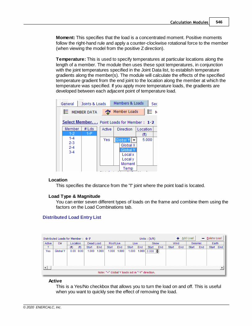
Calculation Modules 546
© 2020 ENERCALC, Inc.
Moment: This specifies that the load is a concentrated moment. Positive momentsfollow the right-hand rule and apply a counter-clockwise rotational force to the member(when viewing the model from the positive Z direction).
Temperature: This is used to specify temperatures at particular locations along thelength of a member. The module then uses these spot temperatures, in conjunctionwith the joint temperatures specified in the Joint Data list, to establish temperaturegradients along the member(s). The module will calculate the effects of the specifiedtemperature gradient from the end joint to the location along the member at which thetemperature was specified. If you apply more temperature loads, the gradients aredeveloped between each adjacent point of temperature load.
LocationThis specifies the distance from the "I" joint where the point load is located.
Load Type & MagnitudeYou can enter seven different types of loads on the frame and combine them using thefactors on the Load Combinations tab.
Distributed Load Entry List
ActiveThis is a Yes/No checkbox that allows you to turn the load on and off. This is usefulwhen you want to quickly see the effect of removing the load.
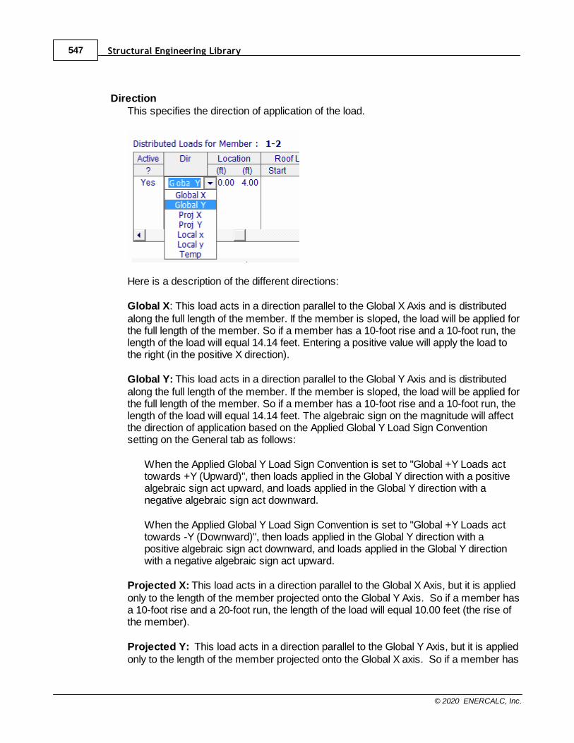
Structural Engineering Library547
© 2020 ENERCALC, Inc.
DirectionThis specifies the direction of application of the load.
Here is a description of the different directions:
Global X: This load acts in a direction parallel to the Global X Axis and is distributedalong the full length of the member. If the member is sloped, the load will be applied forthe full length of the member. So if a member has a 10-foot rise and a 10-foot run, thelength of the load will equal 14.14 feet. Entering a positive value will apply the load tothe right (in the positive X direction).
Global Y: This load acts in a direction parallel to the Global Y Axis and is distributedalong the full length of the member. If the member is sloped, the load will be applied forthe full length of the member. So if a member has a 10-foot rise and a 10-foot run, thelength of the load will equal 14.14 feet. The algebraic sign on the magnitude will affectthe direction of application based on the Applied Global Y Load Sign Conventionsetting on the General tab as follows:
When the Applied Global Y Load Sign Convention is set to "Global +Y Loads acttowards +Y (Upward)", then loads applied in the Global Y direction with a positivealgebraic sign act upward, and loads applied in the Global Y direction with anegative algebraic sign act downward.
When the Applied Global Y Load Sign Convention is set to "Global +Y Loads acttowards -Y (Downward)", then loads applied in the Global Y direction with apositive algebraic sign act downward, and loads applied in the Global Y directionwith a negative algebraic sign act upward.
Projected X: This load acts in a direction parallel to the Global X Axis, but it is appliedonly to the length of the member projected onto the Global Y Axis. So if a member hasa 10-foot rise and a 20-foot run, the length of the load will equal 10.00 feet (the rise ofthe member).
Projected Y: This load acts in a direction parallel to the Global Y Axis, but it is appliedonly to the length of the member projected onto the Global X axis. So if a member has
Calculation Modules 548
© 2020 ENERCALC, Inc.
a 10-foot rise and a 20-foot run, the length of the load will equal 20.00 feet (the run ofthe member).
In order to most efficiently describe the direction of application of the "Local" loadtypes, it helps to refer to the member local axis system. Each member can be thoughtof as having its own x, y, and z coordinate axes that are mutually perpendicular andfollow the right-hand rule. The orientation of the member local axes can be determinedas follows:
1. The local x axis is always parallel to a vector from the "I" node to the "J" node.(This axis is parallel to the longitudinal axis of the member.)
2. The local z axis is always parallel to the Global Z axis.3. The local y axis can be found by taking the vector cross product of local z cross
local x. (Envision using the right hand to rotate the local z axis into the local xaxis, and the right thumb will automatically indicate the positive direction of thelocal y axis.)
Local x: This distributed load acts parallel to the member's local x axis. If this load isspecified with a positive magnitude, the load will act in the positive direction of the localx axis. If this load is specified with a negative magnitude, the load will act in thenegative direction of the local x axis.
Local y: This distributed load acts parallel to the member's local y axis. If this load isspecified with a positive magnitude, the load will act in the positive direction of the localy axis. If this load is specified with a negative magnitude, the load will act in thenegative direction of the local y axis.
It should now be obvious that it is VERY important to have a thorough understanding ofmember orientation when using "Local" load types.
Temperature: This is used to specify temperatures at particular locations along thelength of a member. The module then uses these spot temperatures, in conjunctionwith the joint temperatures specified in the Joint Data list, to establish temperaturegradients along the member(s). The module will calculate the effects of the specifiedtemperature gradient from the end joint to the location along the member at which thetemperature was specified. If you apply more temperature loads, the gradients aredeveloped between each adjacent point of temperature load.
Location - Start, EndThis specifies the distance from the "I" joint to the beginning and end of the load.Leaving BOTH values as zero (0.0) will cause the load to be applied to the full lengthof the member.
Load Type & MagnitudeYou can enter seven different types of loads on the frame and combine them using thevalues on the Load Combinations tab.
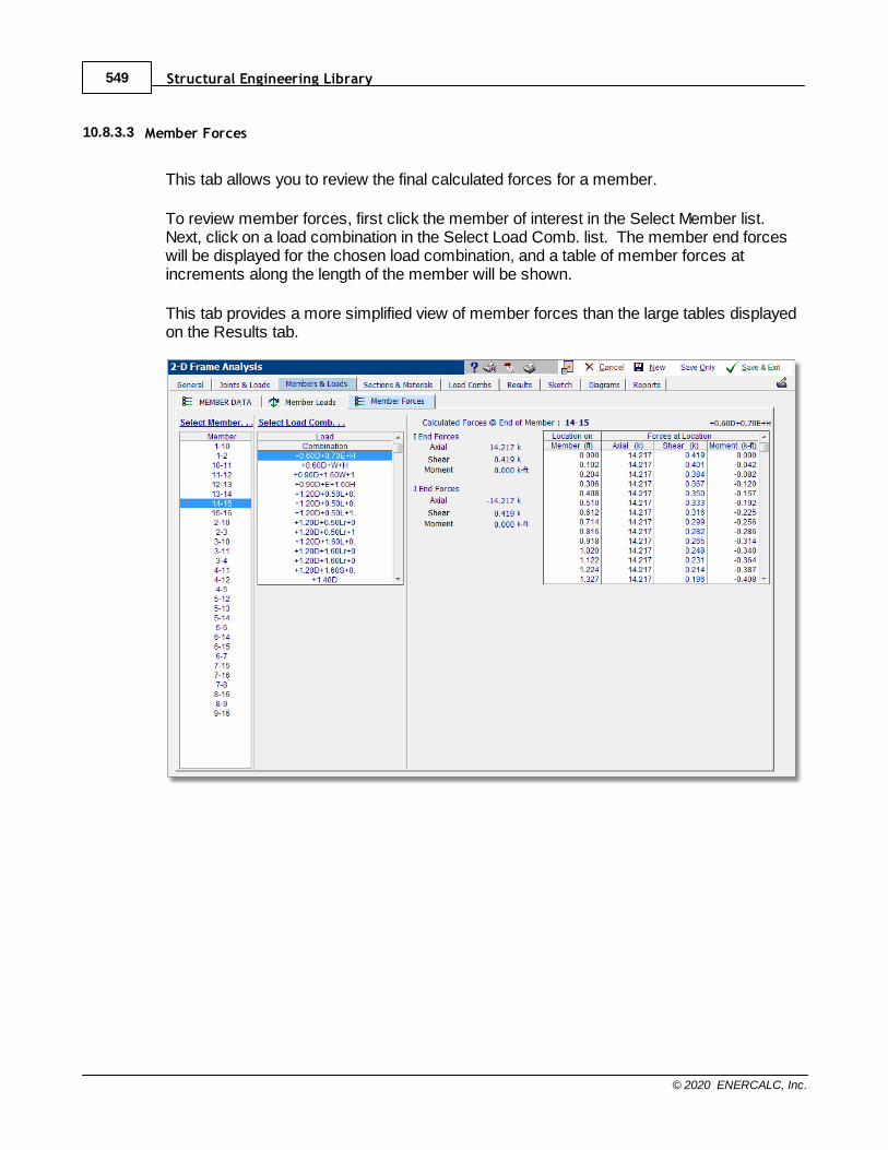
Structural Engineering Library549
© 2020 ENERCALC, Inc.
10.8.3.3 Member Forces
This tab allows you to review the final calculated forces for a member.
To review member forces, first click the member of interest in the Select Member list.Next, click on a load combination in the Select Load Comb. list. The member end forceswill be displayed for the chosen load combination, and a table of member forces atincrements along the length of the member will be shown.
This tab provides a more simplified view of member forces than the large tables displayedon the Results tab.

Calculation Modules 550
© 2020 ENERCALC, Inc.
10.8.4 Sections & Materials
Need more? Ask Us a Question
The two tabs under Sections & Materials provide the ability to define the section propertiesand material properties for the members used in the frame.
10.8.4.1 Section Data
The SECTION DATA tab allows you to specify sections to be used for the frame.
Section Label vs. Group Label
These two ways of labeling a section are very helpful and should be understood.
The Section Label is the actual name of the section, whether it is an AISC section namelike W14x22 or a wood section like 4x10. The Section Label always represents somethingthat can be retrieved from the internal databases.
It can also be the name of a section that you create by entering a name and someproperties.
The Group Label lets you associate a section name with a label that is meaningful to youand that can be used on multiple members. This makes it so you can easily revise the
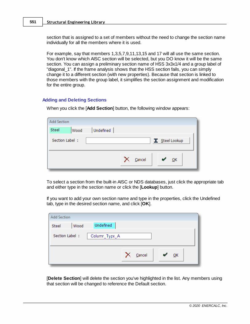
Structural Engineering Library551
© 2020 ENERCALC, Inc.
section that is assigned to a set of members without the need to change the section nameindividually for all the members where it is used.
For example, say that members 1,3,5,7,9,11,13,15 and 17 will all use the same section.You don't know which AISC section will be selected, but you DO know it will be the samesection. You can assign a preliminary section name of HSS 3x3x1/4 and a group label of"diagonal_1". If the frame analysis shows that the HSS section fails, you can simplychange it to a different section (with new properties). Because that section is linked tothose members with the group label, it simplifies the section assignment and modificationfor the entire group.
Adding and Deleting Sections
When you click the [Add Section] button, the following window appears:
To select a section from the built-in AISC or NDS databases, just click the appropriate taband either type in the section name or click the [Lookup] button.
If you want to add your own section name and type in the properties, click the Undefinedtab, type in the desired section name, and click [OK].
[Delete Section] will delete the section you've highlighted in the list. Any members usingthat section will be changed to reference the Default section.
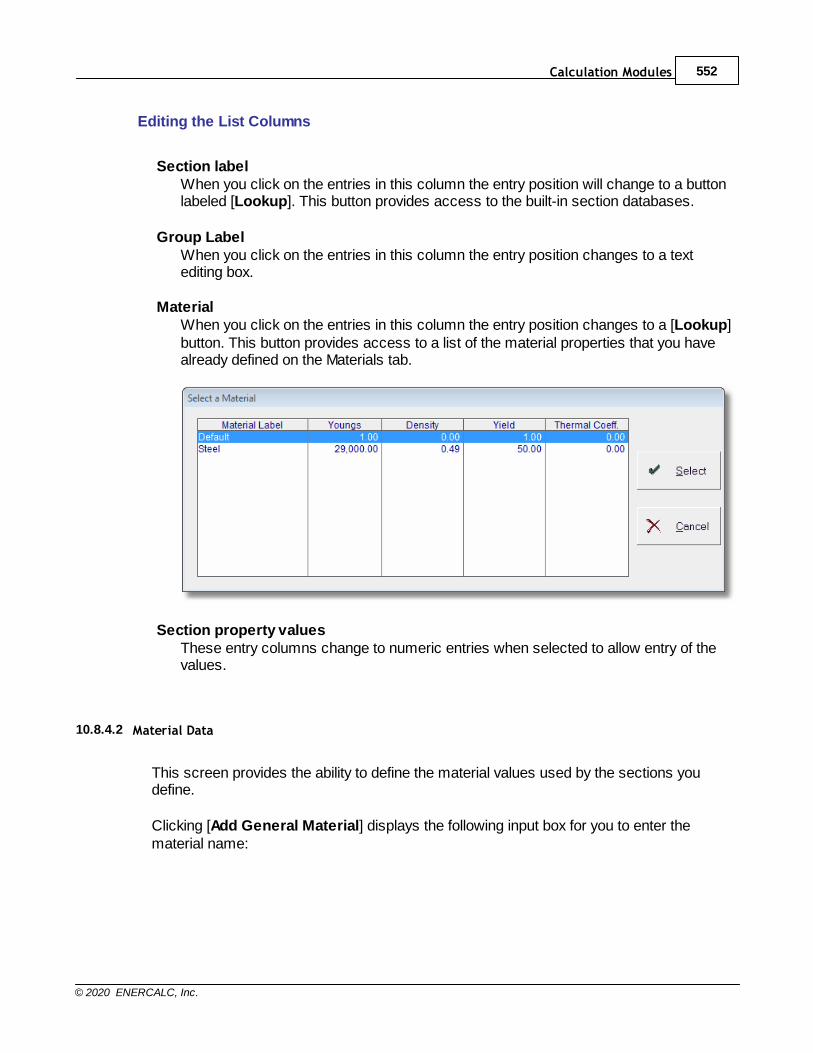
Calculation Modules 552
© 2020 ENERCALC, Inc.
Editing the List Columns
Section labelWhen you click on the entries in this column the entry position will change to a buttonlabeled [Lookup]. This button provides access to the built-in section databases.
Group LabelWhen you click on the entries in this column the entry position changes to a textediting box.
MaterialWhen you click on the entries in this column the entry position changes to a [Lookup]button. This button provides access to a list of the material properties that you havealready defined on the Materials tab.
Section property valuesThese entry columns change to numeric entries when selected to allow entry of thevalues.
10.8.4.2 Material Data
This screen provides the ability to define the material values used by the sections youdefine.
Clicking [Add General Material] displays the following input box for you to enter thematerial name:

Structural Engineering Library553
© 2020 ENERCALC, Inc.
To add a new material, enter the name of the material and then click [OK]. The newmaterial will appear in the Materials list on the Material Data tab.
Clicking [Add Wood Material] displays the Wood Reference Design Values databasewhere you can select a wood species and grade combination:
To select a wood material to use in the current calculation, click on the desired material inthe Wood Reference Design Values database and then click [Select]. The new woodmaterial will appear in the Materials list on the Material Data tab as shown below:
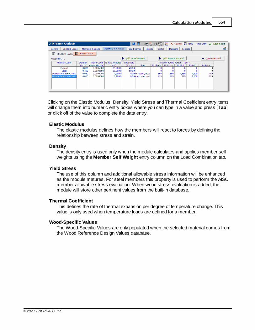
Calculation Modules 554
© 2020 ENERCALC, Inc.
Clicking on the Elastic Modulus, Density, Yield Stress and Thermal Coefficient entry itemswill change them into numeric entry boxes where you can type in a value and press [Tab]or click off of the value to complete the data entry.
Elastic ModulusThe elastic modulus defines how the members will react to forces by defining therelationship between stress and strain.
DensityThe density entry is used only when the module calculates and applies member selfweights using the Member Self Weight entry column on the Load Combination tab.
Yield StressThe use of this column and additional allowable stress information will be enhancedas the module matures. For steel members this property is used to perform the AISCmember allowable stress evaluation. When wood stress evaluation is added, themodule will store other pertinent values from the built-in database.
Thermal CoefficientThis defines the rate of thermal expansion per degree of temperature change. Thisvalue is only used when temperature loads are defined for a member.
Wood-Specific ValuesThe Wood-Specific Values are only populated when the selected material comes fromthe Wood Reference Design Values database.
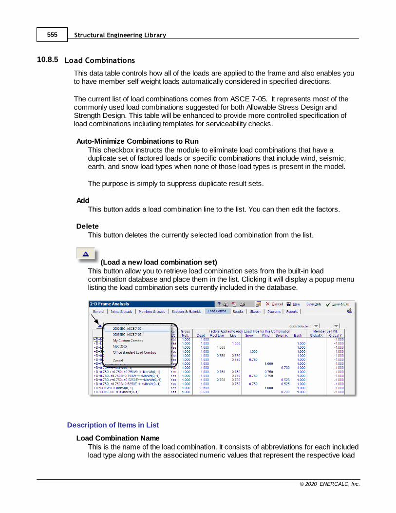
Structural Engineering Library555
© 2020 ENERCALC, Inc.
10.8.5 Load Combinations
This data table controls how all of the loads are applied to the frame and also enables youto have member self weight loads automatically considered in specified directions.
The current list of load combinations comes from ASCE 7-05. It represents most of thecommonly used load combinations suggested for both Allowable Stress Design andStrength Design. This table will be enhanced to provide more controlled specification ofload combinations including templates for serviceability checks.
Auto-Minimize Combinations to RunThis checkbox instructs the module to eliminate load combinations that have aduplicate set of factored loads or specific combinations that include wind, seismic,earth, and snow load types when none of those load types is present in the model.
The purpose is simply to suppress duplicate result sets.
Add This button adds a load combination line to the list. You can then edit the factors.
DeleteThis button deletes the currently selected load combination from the list.
(Load a new load combination set)This button allow you to retrieve load combination sets from the built-in loadcombination database and place them in the list. Clicking it will display a popup menulisting the load combination sets currently included in the database.
Description of Items in List
Load Combination NameThis is the name of the load combination. It consists of abbreviations for each includedload type along with the associated numeric values that represent the respective load
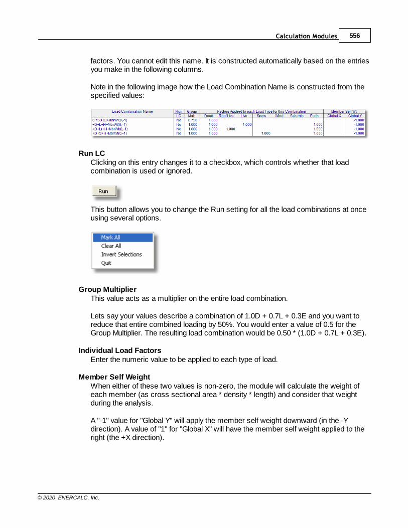
Calculation Modules 556
© 2020 ENERCALC, Inc.
factors. You cannot edit this name. It is constructed automatically based on the entriesyou make in the following columns.
Note in the following image how the Load Combination Name is constructed from thespecified values:
Run LCClicking on this entry changes it to a checkbox, which controls whether that loadcombination is used or ignored.
This button allows you to change the Run setting for all the load combinations at onceusing several options.
Group MultiplierThis value acts as a multiplier on the entire load combination.
Lets say your values describe a combination of 1.0D + 0.7L + 0.3E and you want toreduce that entire combined loading by 50%. You would enter a value of 0.5 for theGroup Multiplier. The resulting load combination would be 0.50 * (1.0D + 0.7L + 0.3E).
Individual Load FactorsEnter the numeric value to be applied to each type of load.
Member Self WeightWhen either of these two values is non-zero, the module will calculate the weight ofeach member (as cross sectional area * density * length) and consider that weightduring the analysis.
A "-1" value for "Global Y" will apply the member self weight downward (in the -Ydirection). A value of "1" for "Global X" will have the member self weight applied to theright (the +X direction).
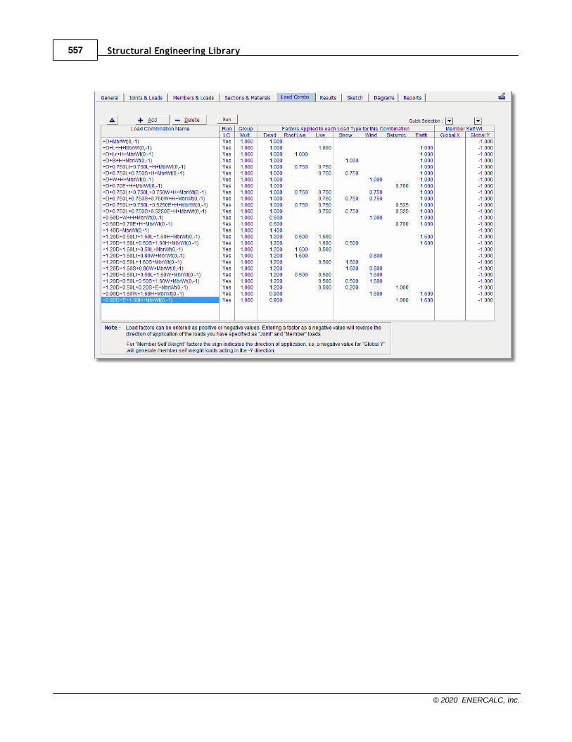
Structural Engineering Library557
© 2020 ENERCALC, Inc.
Calculation Modules 558
© 2020 ENERCALC, Inc.
10.8.6 Wood Design
The 2D Frame module now incorporates wood stress checking according based on ASDor LRFD methods according to NDS methods.
Adjustment Factors for Sawn Lumber
The module only collects CD or Lambda from the user.
The module assumes a value of 1.0 for CM, C
t, C
f u, C
i, C
r and C
T.
The module calculates values for CL, C
F, and C
P.
The bearing area factor Cb never comes into play in the functions performed within
this module.
Adjustment Factors for Glued Laminated Timber
The module only collects CD or Lambda from the user.
The module assumes a value of 1.0 for CM, C
t, C
f u, C
c, C
I, and C
v r.
The module calculates values for CL, C
V, and C
P.
The bearing area factor Cb never comes into play in the functions performed within
this module.
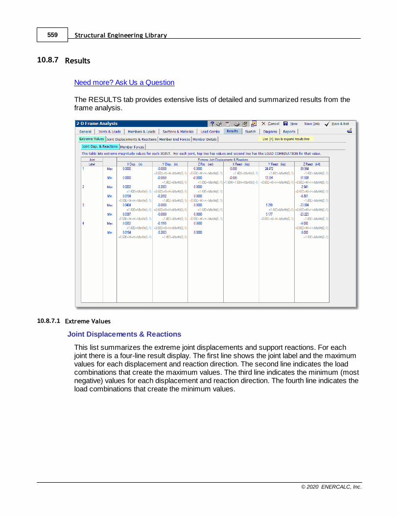
Structural Engineering Library559
© 2020 ENERCALC, Inc.
10.8.7 Results
Need more? Ask Us a Question
The RESULTS tab provides extensive lists of detailed and summarized results from theframe analysis.
10.8.7.1 Extreme Values
Joint Displacements & Reactions
This list summarizes the extreme joint displacements and support reactions. For eachjoint there is a four-line result display. The first line shows the joint label and the maximumvalues for each displacement and reaction direction. The second line indicates the loadcombinations that create the maximum values. The third line indicates the minimum (mostnegative) values for each displacement and reaction direction. The fourth line indicates theload combinations that create the minimum values.
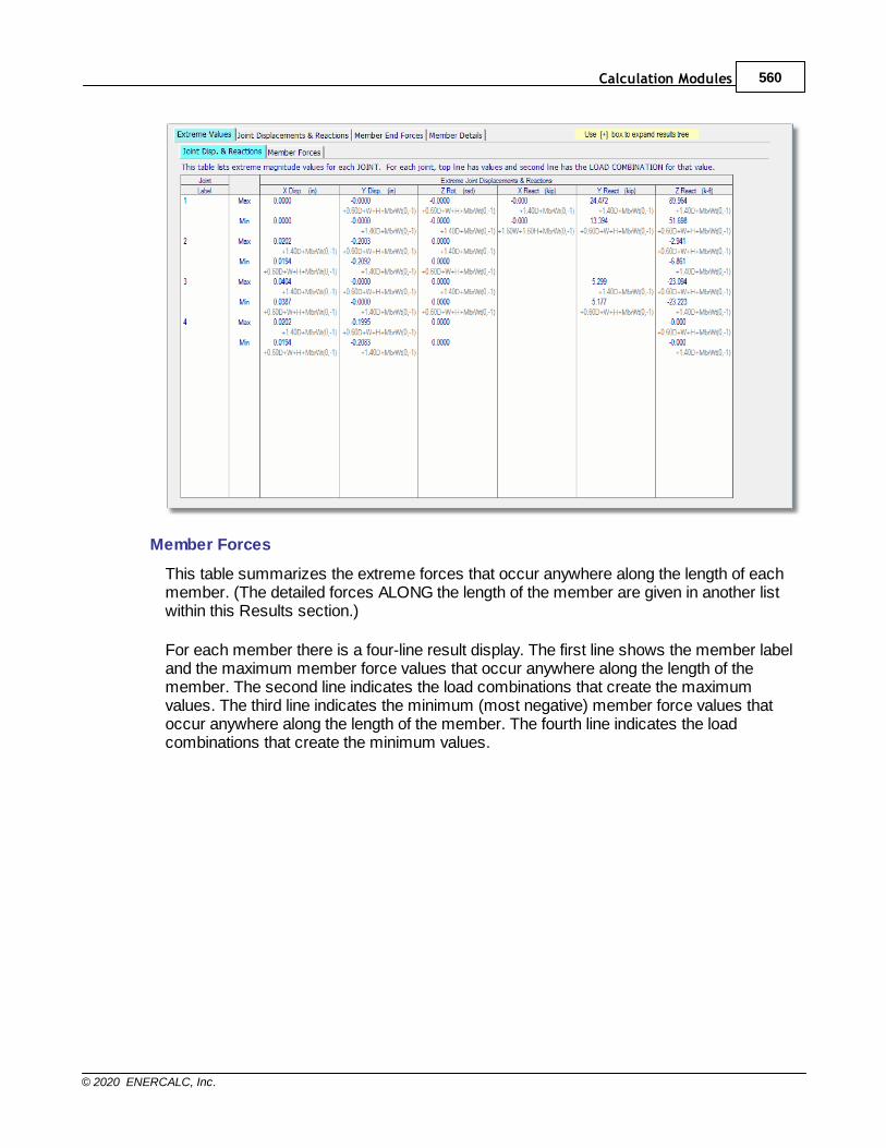
Calculation Modules 560
© 2020 ENERCALC, Inc.
Member Forces
This table summarizes the extreme forces that occur anywhere along the length of eachmember. (The detailed forces ALONG the length of the member are given in another listwithin this Results section.)
For each member there is a four-line result display. The first line shows the member labeland the maximum member force values that occur anywhere along the length of themember. The second line indicates the load combinations that create the maximumvalues. The third line indicates the minimum (most negative) member force values thatoccur anywhere along the length of the member. The fourth line indicates the loadcombinations that create the minimum values.
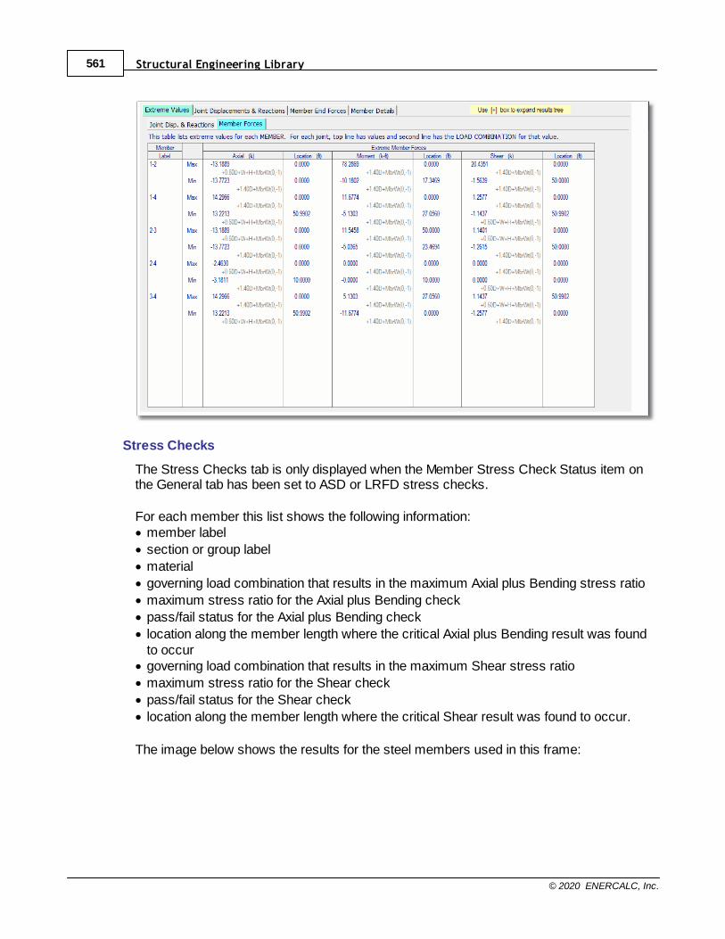
Structural Engineering Library561
© 2020 ENERCALC, Inc.
Stress Checks
The Stress Checks tab is only displayed when the Member Stress Check Status item onthe General tab has been set to ASD or LRFD stress checks.
For each member this list shows the following information:· member label
· section or group label
· material
· governing load combination that results in the maximum Axial plus Bending stress ratio
· maximum stress ratio for the Axial plus Bending check
· pass/fail status for the Axial plus Bending check
· location along the member length where the critical Axial plus Bending result was foundto occur
· governing load combination that results in the maximum Shear stress ratio
· maximum stress ratio for the Shear check
· pass/fail status for the Shear check
· location along the member length where the critical Shear result was found to occur.
The image below shows the results for the steel members used in this frame:
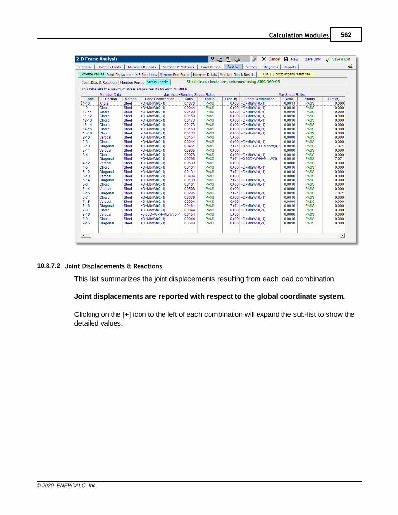
Calculation Modules 562
© 2020 ENERCALC, Inc.
10.8.7.2 Joint Displacements & Reactions
This list summarizes the joint displacements resulting from each load combination.
Joint displacements are reported with respect to the global coordinate system.
Clicking on the [+] icon to the left of each combination will expand the sub-list to show thedetailed values.
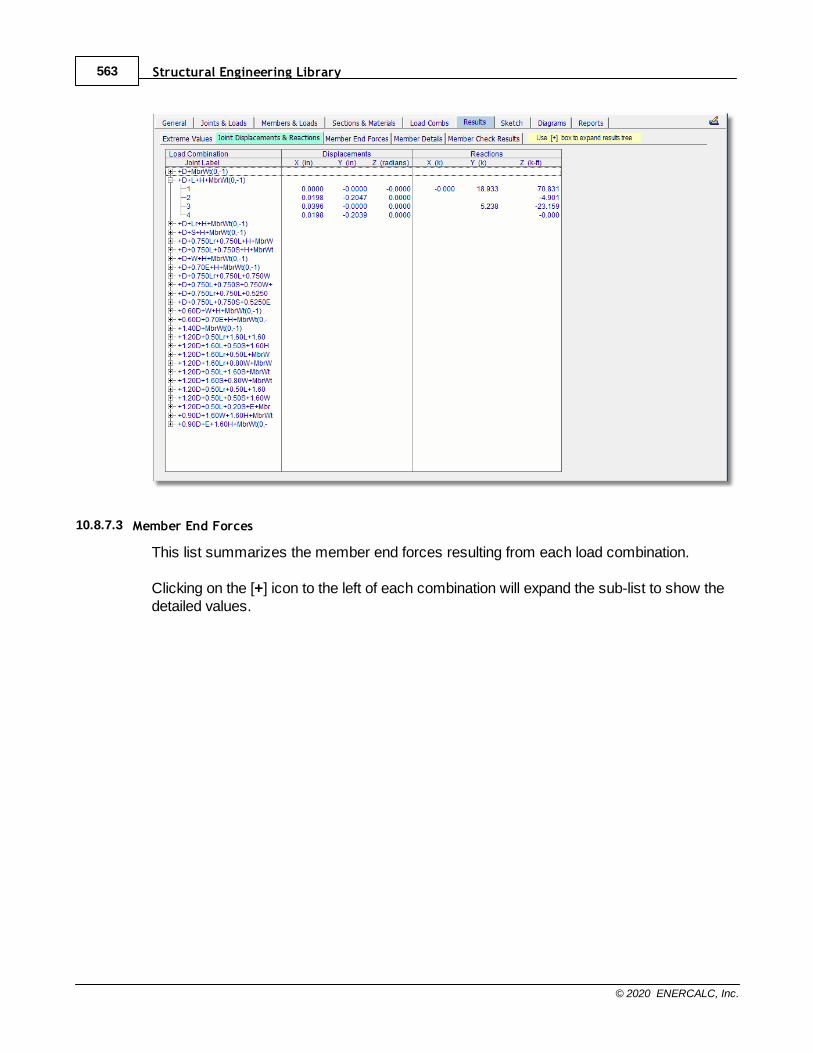
Structural Engineering Library563
© 2020 ENERCALC, Inc.
10.8.7.3 Member End Forces
This list summarizes the member end forces resulting from each load combination.
Clicking on the [+] icon to the left of each combination will expand the sub-list to show thedetailed values.
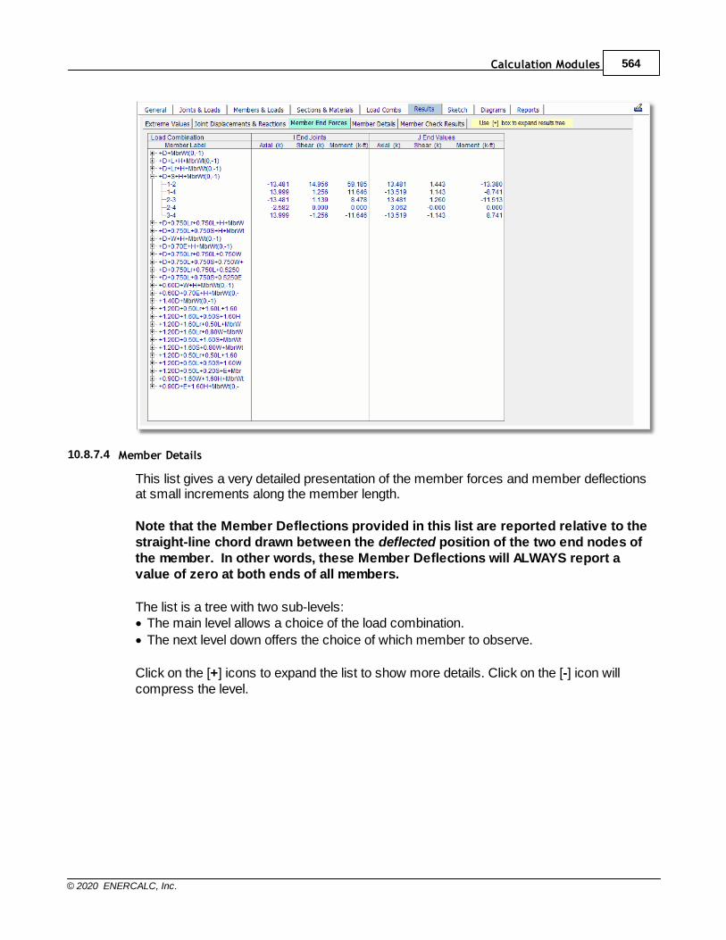
Calculation Modules 564
© 2020 ENERCALC, Inc.
10.8.7.4 Member Details
This list gives a very detailed presentation of the member forces and member deflectionsat small increments along the member length.
Note that the Member Deflections provided in this list are reported relative to thestraight-line chord drawn between the deflected position of the two end nodes ofthe member. In other words, these Member Deflections will ALWAYS report avalue of zero at both ends of all members.
The list is a tree with two sub-levels:· The main level allows a choice of the load combination.
· The next level down offers the choice of which member to observe.
Click on the [+] icons to expand the list to show more details. Click on the [-] icon willcompress the level.
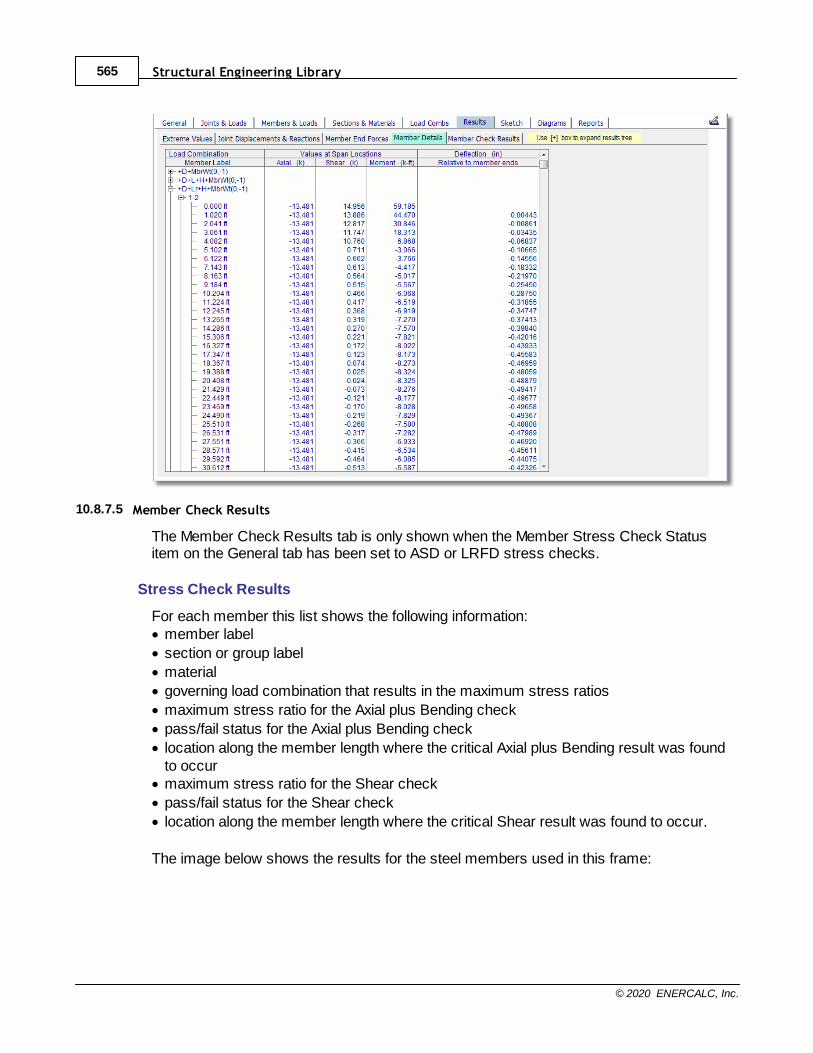
Structural Engineering Library565
© 2020 ENERCALC, Inc.
10.8.7.5 Member Check Results
The Member Check Results tab is only shown when the Member Stress Check Statusitem on the General tab has been set to ASD or LRFD stress checks.
Stress Check Results
For each member this list shows the following information:· member label
· section or group label
· material
· governing load combination that results in the maximum stress ratios
· maximum stress ratio for the Axial plus Bending check
· pass/fail status for the Axial plus Bending check
· location along the member length where the critical Axial plus Bending result was foundto occur
· maximum stress ratio for the Shear check
· pass/fail status for the Shear check
· location along the member length where the critical Shear result was found to occur.
The image below shows the results for the steel members used in this frame:
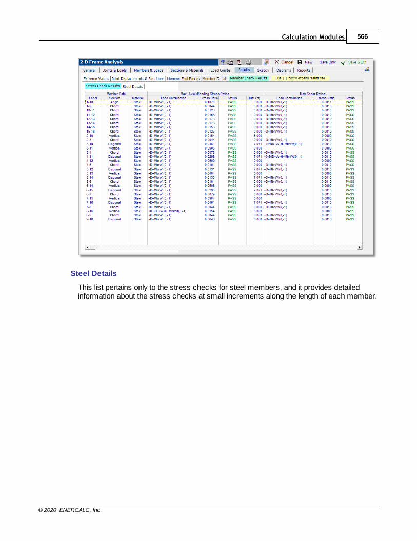
Calculation Modules 566
© 2020 ENERCALC, Inc.
Steel Details
This list pertains only to the stress checks for steel members, and it provides detailedinformation about the stress checks at small increments along the length of each member.

Structural Engineering Library567
© 2020 ENERCALC, Inc.
10.8.7.6 Sign Convention
Coordinate Axis Convention
The right-hand rule states that if you take the vector cross product of X cross Y, the result isin the Z direction. This is what is used to establish the positive Z direction if you know thepositive X and Y directions. It applies to the Global Coordinate Axis system and the memberlocal coordinate axis system in the 2-D Frame Analysis module, in the 2-D Frame Analysismodule.
The Global Coordinate Axis system is oriented such that X points to the right, Y pointsupward, and Z is perpendicular to the screen in the 2-D Frame Analysis module.
The member local coordinate axis system is established as follows. A vector from the I nodeto the J node establishes the member local x axis. The vector cross product of local x crossGlobal Y produces the member local z direction. This works for all member orientationsexcept for vertically oriented members, because it is not possible to take the vector crossproduct of two parallel vectors. So in those cases the module adopts the convention that themember local z axis will be parallel to the Global Z axis. These are just mathematical rulesthat establish that member local z will be perpendicular to the screen (unless you havespecified that the member is working in weak axis bending). The local z axis isperpendicular to the web of a wide flange section. It typically represents the “strong” axis of amember. Finally, we need to establish the orientation of the local y axis. Vector crossproduct rules for a right-hand coordinate system also state that local z cross local xproduces local y. So this pins down the orientation of the local y axis. The local y axis of awide flange member lies in the plane of the web and is mutually perpendicular to the local x
Calculation Modules 568
© 2020 ENERCALC, Inc.
and local z axes. For a horizontally oriented beam member, the local y axis points straightup, parallel to the Global Y axis.
Result Sign Convention
Now for the sign conventions of the various results that are available.
Joint Displacements
Joint Displacements are reported with respect to the Global Coordinate Axis system. Apositive displacement indicates a displacement in the direction of the positive correspondingaxis. A positive rotation indicates a positive rotation about the Global Z axis. (Using thethumb of the right hand, point the thumb in the direction of the positive Global Z axis, and thenatural curl of the right fingers will indicate the direction of a positive rotation.)
Reactions
Reactions are also reported with respect to the Global Coordinate Axis system. A positiveforce reaction indicates a force in the direction of the positive corresponding axis. A positivemoment reaction indicates a positive moment about the Global Z axis. (Using the thumb ofthe right hand, point the thumb in the direction of the positive Global Z axis, and the naturalcurl of the right fingers will indicate the direction of a positive moment.)
Member End Forces
Member End Forces are reported with respect to the member local coordinate axis system. A positive value of axial load at the I end of the member means that the force acts in themember local x direction, so it is pushing into the starting end of the member, so itrepresents a compressive force. Likewise, a negative value of axial load at the J end of themember means that the force acts in the member local -x direction, so it is pushing into theending end of the member, so again this represents a compressive force.
Shears are also reported with respect to the member local coordinate axis system. Apositive value of shear at the I end of the member means that the force acts in the memberlocal y direction. Likewise, a negative value of shear at the J end of the member means thatthe force acts in the member local -y direction.
A positive value of moment at either end of the member means that the moment acts in themember local z direction. (Using the thumb of the right hand, point the thumb in the directionof the positive Global Z axis, and the natural curl of the right fingers will indicate the directionof a positive moment.)
Member Forces at Sections

Structural Engineering Library569
© 2020 ENERCALC, Inc.
The physical sense of the member forces at sections can best be established by relating tothe physical sense of the member end forces at the starting end of the member as describedabove.
Deflections (Relative to member ends)
The deflections relative to member ends are measured parallel to the member local y axisand are referenced from the straight-line chord connecting the undeflected end nodelocations. Positive values represent deflections in the positive local y axis direction from thatstraight-line chord.
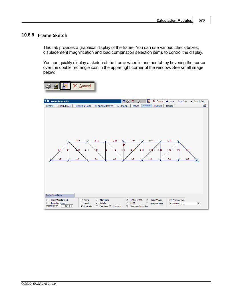
Calculation Modules 570
© 2020 ENERCALC, Inc.
10.8.8 Frame Sketch
This tab provides a graphical display of the frame. You can use various check boxes,displacement magnification and load combination selection items to control the display.
You can quickly display a sketch of the frame when in another tab by hovering the cursorover the double rectangle icon in the upper right corner of the window. See small imagebelow:
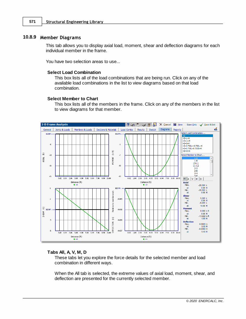
Structural Engineering Library571
© 2020 ENERCALC, Inc.
10.8.9 Member Diagrams
This tab allows you to display axial load, moment, shear and deflection diagrams for eachindividual member in the frame.
You have two selection areas to use...
Select Load CombinationThis box lists all of the load combinations that are being run. Click on any of theavailable load combinations in the list to view diagrams based on that loadcombination.
Select Member to ChartThis box lists all of the members in the frame. Click on any of the members in the listto view diagrams for that member.
Tabs All, A, V, M, DThese tabs let you explore the force details for the selected member and loadcombination in different ways.
When the All tab is selected, the extreme values of axial load, moment, shear, anddeflection are presented for the currently selected member.
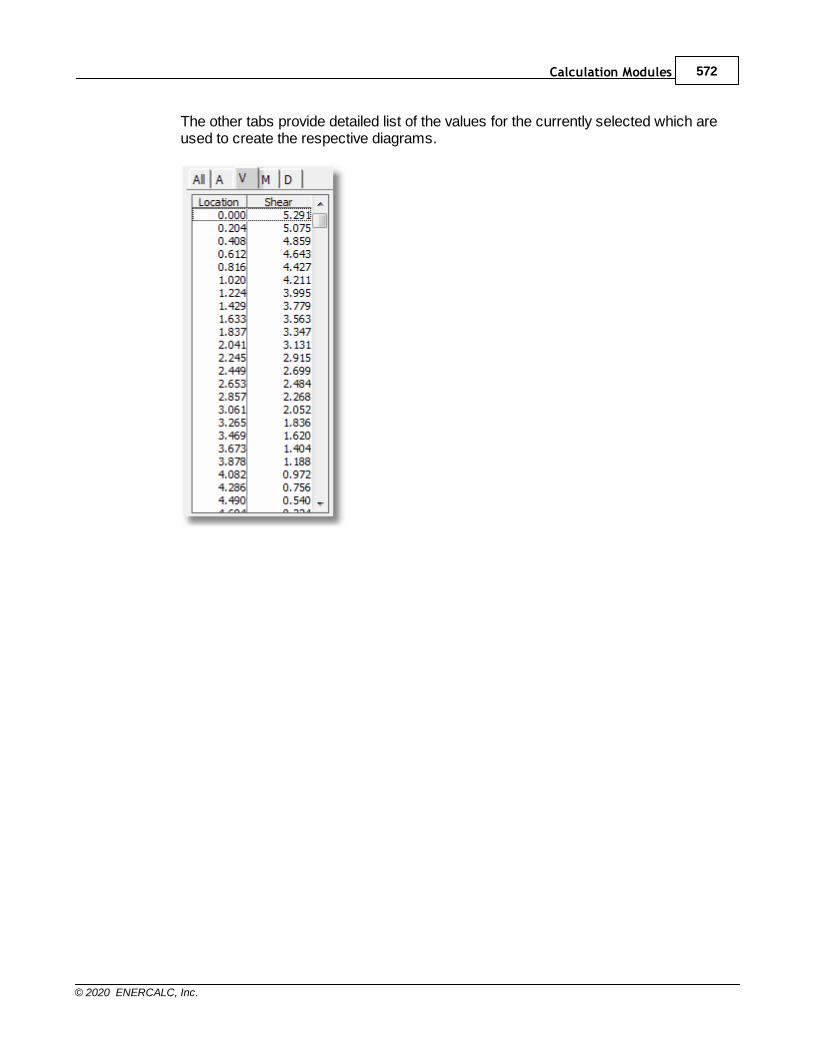
Calculation Modules 572
© 2020 ENERCALC, Inc.
The other tabs provide detailed list of the values for the currently selected which areused to create the respective diagrams.
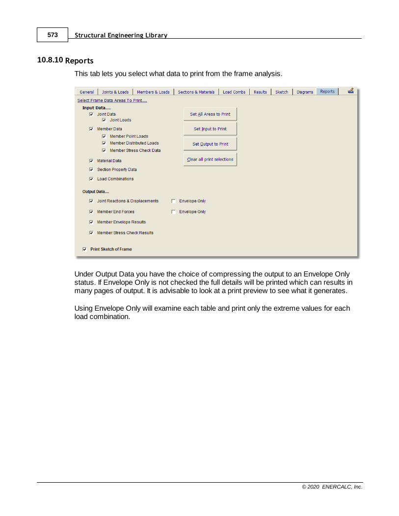
Structural Engineering Library573
© 2020 ENERCALC, Inc.
10.8.10 Reports
This tab lets you select what data to print from the frame analysis.
Under Output Data you have the choice of compressing the output to an Envelope Onlystatus. If Envelope Only is not checked the full details will be printed which can results inmany pages of output. It is advisable to look at a print preview to see what it generates.
Using Envelope Only will examine each table and print only the extreme values for eachload combination.
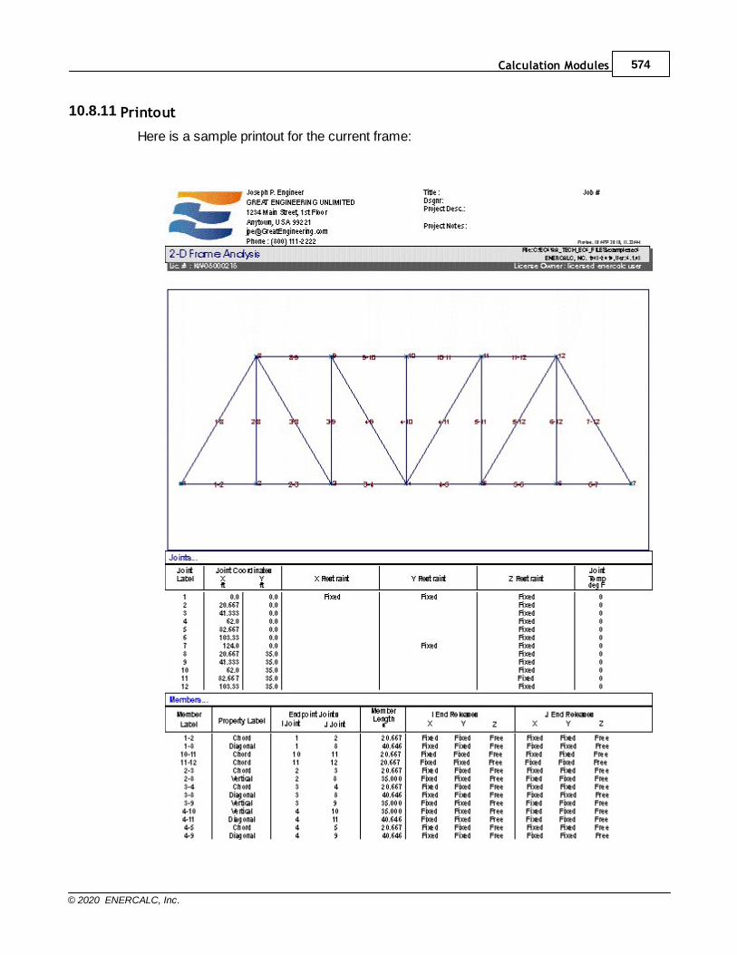
Calculation Modules 574
© 2020 ENERCALC, Inc.
10.8.11 Printout
Here is a sample printout for the current frame:
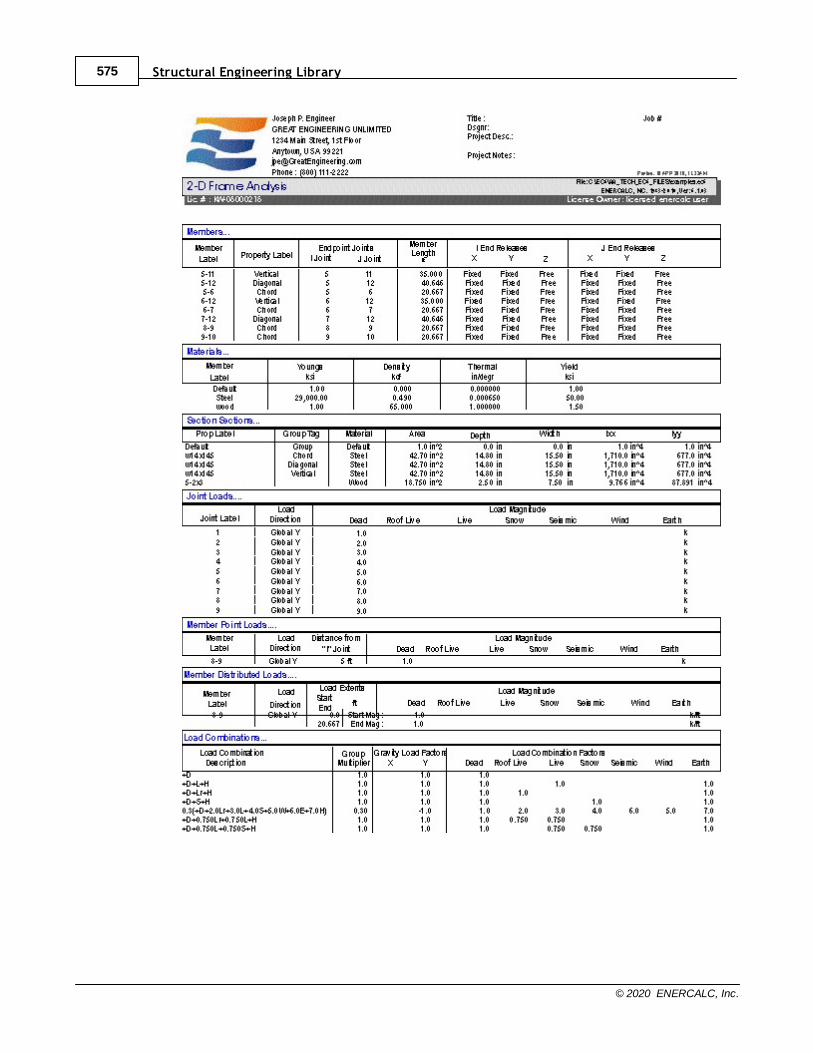
Structural Engineering Library575
© 2020 ENERCALC, Inc.

Calculation Modules 576
© 2020 ENERCALC, Inc.
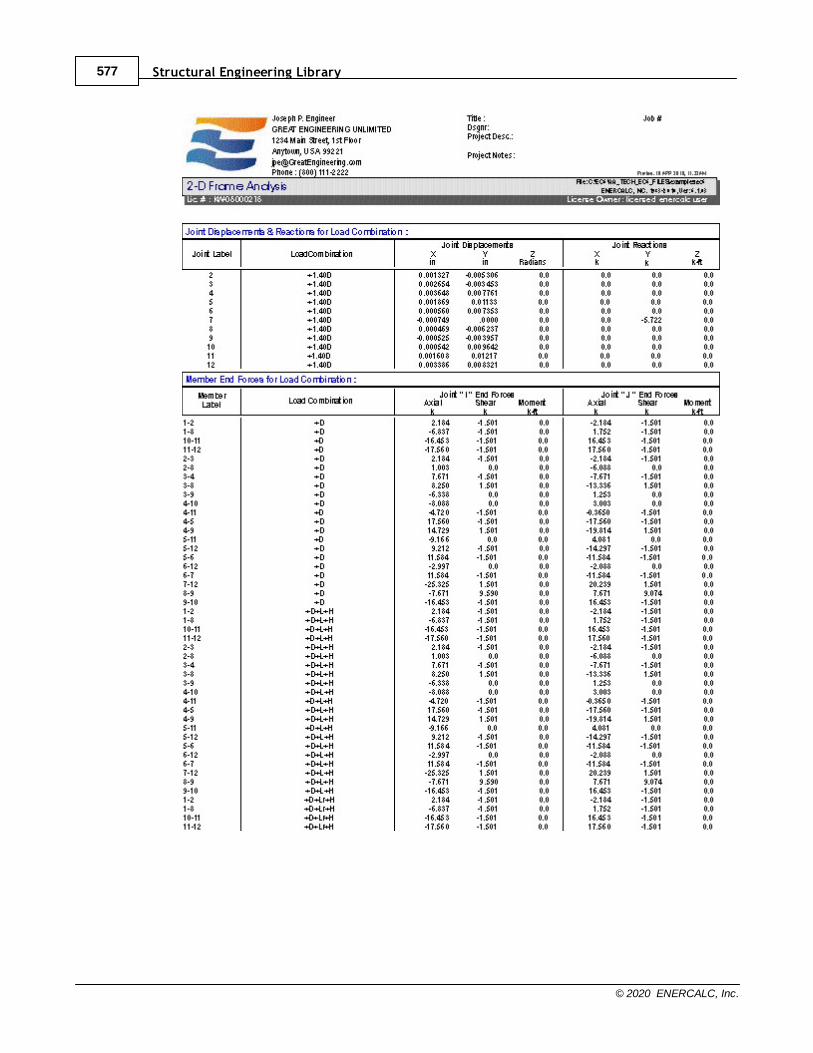
Structural Engineering Library577
© 2020 ENERCALC, Inc.
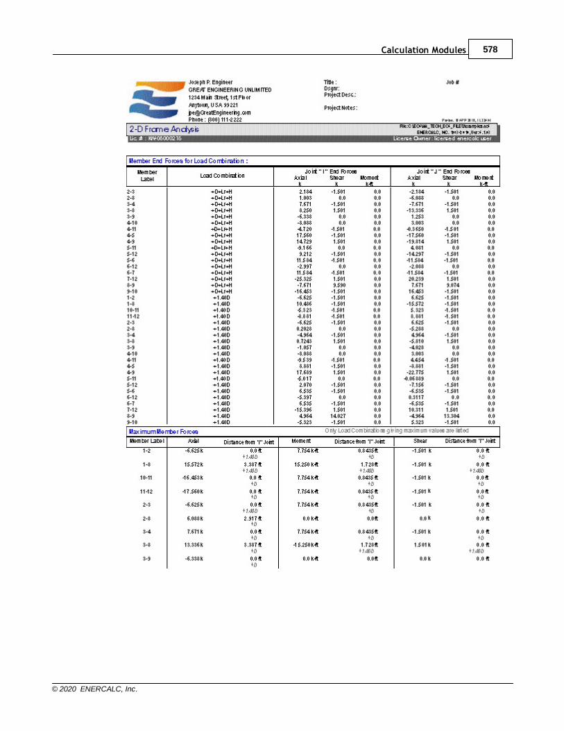
Calculation Modules 578
© 2020 ENERCALC, Inc.
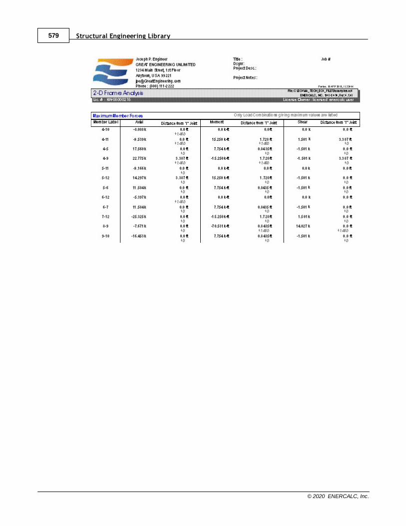
Structural Engineering Library579
© 2020 ENERCALC, Inc.

Calculation Modules 580
© 2020 ENERCALC, Inc.
10.9 Miscellaneous Calculation Modules
Structural Engineering Library581
© 2020 ENERCALC, Inc.
10.9.1 Torsional Analysis of Rigid Diphragm
Need more? Ask Us a Question
This module provides horizontal force distribution analysis for a rigid diaphragm laterallysupported by up to 160 resisting elements (walls, columns or generic resisting elements).
Click here for a video: Torsional Analysis of Rigid Diaphragm
The lateral shear force is applied to the rigid diaphragm, and that force is distributed to allelements after the rotational stiffness analysis has been completed.
All lateral forces are distributed to each element on the basis of relative rigidities andresisting element locations. Lateral shear forces, direct torsional forces, and accidentaleccentricity torsional forces are considered after determining the location of the center ofrigidity.
The module provides analysis for one level only. For structures where elements aresymmetrically placed on many levels, a calculation may be performed for each level andresults added to determine shears and overturning moments for each element. Whendetermining center of mass (where the lateral force is applied) on successively lowerlevels when elements are NOT all aligned vertically, a new center of mass position shouldbe calculated based upon element forces acting from the diaphragm from the level aboveand combined with the force at that level.
A very unique capability of this module is to have the applied lateral load applied at angularincrements for a full 360 degree rotation. The prior version of this module in our Version 5.8software only applied the lateral load at 90 degree increments. Because seismic or windloads can occur at any angle, we provide the ability for the user to define the angles atwhich the lateral load is applied to the rigid diaphragm for distribution to the resistingelements.
When the lateral force is rotated around the specified number of angular increments, theuser has two options for specifying the magnitude of the force to consider at each angularorientation. One option is to specify the magnitude of the applied lateral force and anoptional orthogonal force magnitude that will be considered to act concurrently. When thisoption is selected, the program uses the same magnitude for the resultant lateral force atall angular increments, and that magnitude is calculated as the SRSS of the applied lateralforce and the orthogonal force. The second option is to specify the magnitude of theapplied lateral force when the force points in the X direction and the magnitude of theapplied lateral force when the force points in the Y direction. When this option is selected,the program considers the lateral force to vary in an elliptical manner as the angularorientation of the force changes. When the force is considered to act at the zero-degreeorientation, the magnitude will be exactly equal to the specified lateral force in the Xdirection. As the angular orientation changes, the lateral force will vary in that ellipticalmanner. When the force is considered to act at the 90-degree orientation, the lateral forcewill be exactly equal to the specified force in the Y direction, and so on.

Calculation Modules 582
© 2020 ENERCALC, Inc.
Another unique feature is the handling of the accidental eccentricity. The code specifiesthat an accidental eccentricity must be considered, as it will have an effect on the totaltorsional moment applied to the diaphragm. The minimum eccentricity is typically specifiedas 5% of the building dimension measured perpendicular to the direction of loadapplication. To thoroughly address the eccentricity requirements, this module creates anellipse measuring 5% (or the specified value) of the building dimension on each axis,around which the lateral load is applied.
Technical note: Prior to build 6.15.7.24, this module neglected the shear due to thetorsional component of load if it was of the opposite algebraic sign to the direct shearcomponent, because considering that component would reduce the total shear on theparticular element being considered. However, build 6.15.7.24 introduced a user option tochange this behavior. It appears in the form of a checkbox labeled "Neglect torsionalshear component when it reduces total shear in element". If this option is selected, theprogram will operate in the way that it used to prior to build 6.15.7.24. If this option isDEselected, the program will always consider the shears due to torsion (inherent andaccidental), even if they are of opposite algebraic sign to the direct shears and thereforetend to reduce the total shears in an element.
So to recap.....the applied lateral load is applied at the angular increments you specify for afull 360 degrees, and this is performed for the number of angular locations you specifyaround the minimum eccentricity ellipse. This means if you use 15 degree angularincrements for load direction and 15 degree increments for accidental eccentricity, thenthe lateral load is actually applied (360/15+1) * (360/15+1) = 625 times in various locationsand directions. This can provide a very accurate calculation of applied torsions and directshears to all resisting elements connected to a rigid diaphragm.
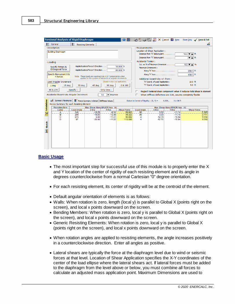
Structural Engineering Library583
© 2020 ENERCALC, Inc.
Basic Usage
· The most important step for successful use of this module is to properly enter the Xand Y location of the center of rigidity of each resisting element and its angle indegrees counterclockwise from a normal Cartesian "0" degree orientation.
· For each resisting element, its center of rigidity will be at the centroid of the element.
· Default angular orientation of elements is as follows:
· Walls: When rotation is zero, length (local y) is parallel to Global X (points right on thescreen), and local x points downward on the screen.
· Bending Members: When rotation is zero, local y is parallel to Global X (points right onthe screen), and local x points downward on the screen.
· Generic Resisting Elements: When rotation is zero, local y is parallel to Global X(points right on the screen), and local x points downward on the screen.
· When rotation angles are applied to resisting elements, the angle increases positivelyin a counterclockwise direction. Enter all angles as positive.
· Lateral shears are typically the force at the diaphragm level due to wind or seismicforces at that level. Location of Shear Application specifies the X-Y coordinates of thecenter of the load ellipse where the lateral shears act. If lateral forces must be addedto the diaphragm from the level above or below, you must combine all forces tocalculate an adjusted mass application point. Maximum Dimensions are used to
Calculation Modules 584
© 2020 ENERCALC, Inc.
calculate the minimum additional eccentricity that will be added to and subtractedfrom the inherent eccentricity to calculate governing forces for each resistingelement.
· When defining walls as resisting elements, the thickness, length, and height arerequired for each wall providing lateral support to the diaphragm. These values areused with the elastic modulus to establish the relative stiffness of each wall. For otherresisting elements you can enter the section information or just enter the resistingelement deflection under the same load for all elements.
· The Elastic Modulus does not have to be an exact value if all of the elements are ofidentical construction. In this situation, it may be simpler to just use a value of 1.
· X & Y Distances for each resisting element define the location of the center ofstiffness of each element in plan view. This location will be used when combining allstiffnesses and calculating the overall center of rigidity for all elements acting as asystem.
· Enter the fixity condition that best describes the element's top and bottom restraintagainst rotation about the longitudinal and transverse axes. Fix-Pin would beappropriate for an inverted pendulum condition (where walls or columns cantilever upfrom a fixed base condition, but are free to rotate at their tops). Fix-Pin would also beappropriate for a moment frame structure with pinned column bases (a structure thatbehaves like a table). Fix-Fix would be appropriate for conditions where both the topsand the bottoms of the columns and/or walls are fixed against rotation about theirlongitudinal and transverse axes. This setting results in double curvature in thevertical lateral force resisting elements.
Unique Features
This module uses a numerical approach to determine center of rigidity location and todistribute lateral forces to each resisting element. Because resisting elements may belocated at any angle, a rigorous stiffness analysis is performed, calculating each element'sstiffness about both axes and combining the stiffnesses of all the elements to determine acenter of rigidity location.
Coordinate System
Please note that a strict X-Y coordinate system should be used to ensure that the analysisis properly carried out. When setting up a model, remember that Global X increases to theright and Global Y increases up the screen.
General Input Tab
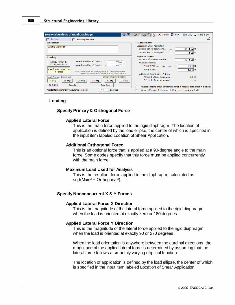
Structural Engineering Library585
© 2020 ENERCALC, Inc.
Loading
Specify Primary & Orthogonal Force
Applied Lateral ForceThis is the main force applied to the rigid diaphragm. The location ofapplication is defined by the load ellipse, the center of which is specified inthe input item labeled Location of Shear Application.
Additional Orthogonal ForceThis is an optional force that is applied at a 90-degree angle to the mainforce. Some codes specify that this force must be applied concurrentlywith the main force.
Maximum Load Used for AnalysisThis is the resultant force applied to the diaphragm, calculated assqrt(Main2 + Orthogonal2).
Specify Nonconcurrent X & Y Forces
Applied Lateral Force X DirectionThis is the magnitude of the lateral force applied to the rigid diaphragmwhen the load is oriented at exactly zero or 180 degrees.
Applied Lateral Force Y DirectionThis is the magnitude of the lateral force applied to the rigid diaphragmwhen the load is oriented at exactly 90 or 270 degrees.
When the load orientation is anywhere between the cardinal directions, themagnitude of the applied lateral force is determined by assuming that thelateral force follows a smoothly varying elliptical function.
The location of application is defined by the load ellipse, the center of whichis specified in the input item labeled Location of Shear Application.
Calculation Modules 586
© 2020 ENERCALC, Inc.
Load Angular IncrementThis module allows the force to be applied to the rigid diaphragm in almost allangular directions.
According to the entry for angular increment, the module will apply the load to thediaphragm at multiple angular increments. For example, if you select "15 deg", themodule will apply the lateral load at 0, 15, 30 degrees, etc. When the Load AngularIncrement is set to smaller values, it will result in slightly longer calculation times, butit wall also allow the module to "zero in" more accurately on the actual maximumshear forces in all of the resisting elements.
Note that there is also an option named "Specify". This allows you to specify anangular increment for the direction of load.
Accidental Eccentricity Angular IncrementMost building codes require the consideration of an "accidental eccentricity". This isa prescribed additional amount of moment arm that must be compounded with theinherent eccentricity that already exists in the system; i.e. the distance between thecenter of rigidity and the center of mass for seismic loads or the distance betweenthe center of rigidity and the center of exposure for wind loads. This additionaleccentricity accounts for the variability of the exact location of the center of rigidity innormal as-built conditions.
Normally an "X direction" and a "Y direction" accidental eccentricity would bedetermined as a function (typically 5%) of the overall building dimensionperpendicular to each direction. Then, the X directed force would be applied at twolocations: · center of mass PLUS "Y direction" eccentricity, and
· center of mass MINUS "Y direction" eccentricity.
And the Y directed force would be applied at two locations:· center of mass PLUS "X direction" eccentricity, and
· center of mass MINUS "X direction" eccentricity.
However, in this module the "X direction" and "Y direction" eccentricities are used tospecify the dimensions of an ellipse that encircles the center of mass. This ellipsecreates a continuous path that smoothly incorporates the "X direction" and "Ydirection" eccentricities. In this way, it defines all possible locations where the loadshould be applied to account for all possible accidental eccentricity locations.
The entry for Accidental Eccentricity Angular Increment specifies the angularincrement that will be used to subdivide the ellipse into a number of locations wherethe force will be applied to the diaphragm.
Summary of Angular Increment & Accidental Eccentricity Angular IncrementThe module applies the lateral load at the "Load Angular Increments" at each locationof "Accidental Eccentricity Angular Increment" to generate an extensive set of resultsfrom which the maximum force values for each resisting element may be inspected.
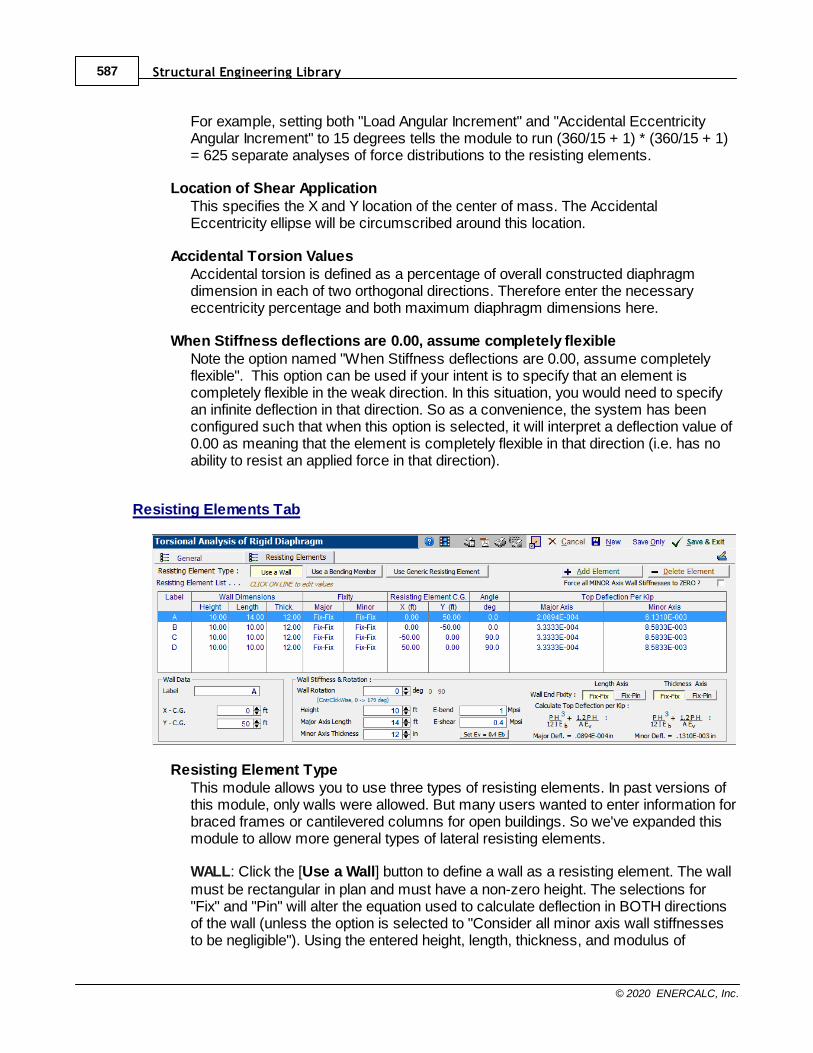
Structural Engineering Library587
© 2020 ENERCALC, Inc.
For example, setting both "Load Angular Increment" and "Accidental EccentricityAngular Increment" to 15 degrees tells the module to run (360/15 + 1) * (360/15 + 1)= 625 separate analyses of force distributions to the resisting elements.
Location of Shear ApplicationThis specifies the X and Y location of the center of mass. The AccidentalEccentricity ellipse will be circumscribed around this location.
Accidental Torsion ValuesAccidental torsion is defined as a percentage of overall constructed diaphragmdimension in each of two orthogonal directions. Therefore enter the necessaryeccentricity percentage and both maximum diaphragm dimensions here.
When Stiffness deflections are 0.00, assume completely flexibleNote the option named "When Stiffness deflections are 0.00, assume completelyflexible". This option can be used if your intent is to specify that an element iscompletely flexible in the weak direction. In this situation, you would need to specifyan infinite deflection in that direction. So as a convenience, the system has beenconfigured such that when this option is selected, it will interpret a deflection value of0.00 as meaning that the element is completely flexible in that direction (i.e. has noability to resist an applied force in that direction).
Resisting Elements Tab
Resisting Element TypeThis module allows you to use three types of resisting elements. In past versions ofthis module, only walls were allowed. But many users wanted to enter information forbraced frames or cantilevered columns for open buildings. So we've expanded thismodule to allow more general types of lateral resisting elements.
WALL: Click the [Use a Wall] button to define a wall as a resisting element. The wallmust be rectangular in plan and must have a non-zero height. The selections for"Fix" and "Pin" will alter the equation used to calculate deflection in BOTH directionsof the wall (unless the option is selected to "Consider all minor axis wall stiffnessesto be negligible"). Using the entered height, length, thickness, and modulus of
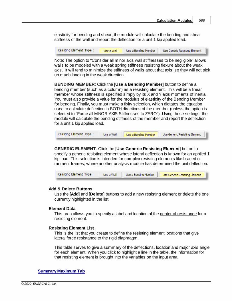
Calculation Modules 588
© 2020 ENERCALC, Inc.
elasticity for bending and shear, the module will calculate the bending and shearstiffness of the wall and report the deflection for a unit 1 kip applied load.
Note: The option to "Consider all minor axis wall stiffnesses to be negligible" allowswalls to be modeled with a weak spring stiffness resisting flexure about the weakaxis. It will tend to minimize the stiffness of walls about that axis, so they will not pickup much loading in the weak direction.
BENDING MEMBER: Click the [Use a Bending Member] button to define abending member (such as a column) as a resisting element. This will be a linearmember whose stiffness is specified simply by its X and Y axis moments of inertia.You must also provide a value for the modulus of elasticity of the Bending Memberfor bending. Finally, you must make a fixity selection, which dictates the equationused to calculate deflection in BOTH directions of the member (unless the option isselected to "Force all MINOR AXIS Stiffnesses to ZERO"). Using these settings, themodule will calculate the bending stiffness of the member and report the deflectionfor a unit 1 kip applied load.
GENERIC ELEMENT: Click the [Use Generic Resisting Element] button tospecify a generic resisting element whose lateral deflection is known for an applied 1kip load. This selection is intended for complex resisting elements like braced ormoment frames, where another analysis module has determined the unit deflection.
Add & Delete ButtonsUse the [Add] and [Delete] buttons to add a new resisting element or delete the onecurrently highlighted in the list.
Element DataThis area allows you to specify a label and location of the center of resistance for aresisting element.
Resisting Element ListThis is the list that you create to define the resisting element locations that givelateral force resistance to the rigid diaphragm.
This table serves to give a summary of the deflections, location and major axis anglefor each element. When you click to highlight a line in the table, the information forthat resisting element is brought into the variables on the input area.
Summary Maximum Tab
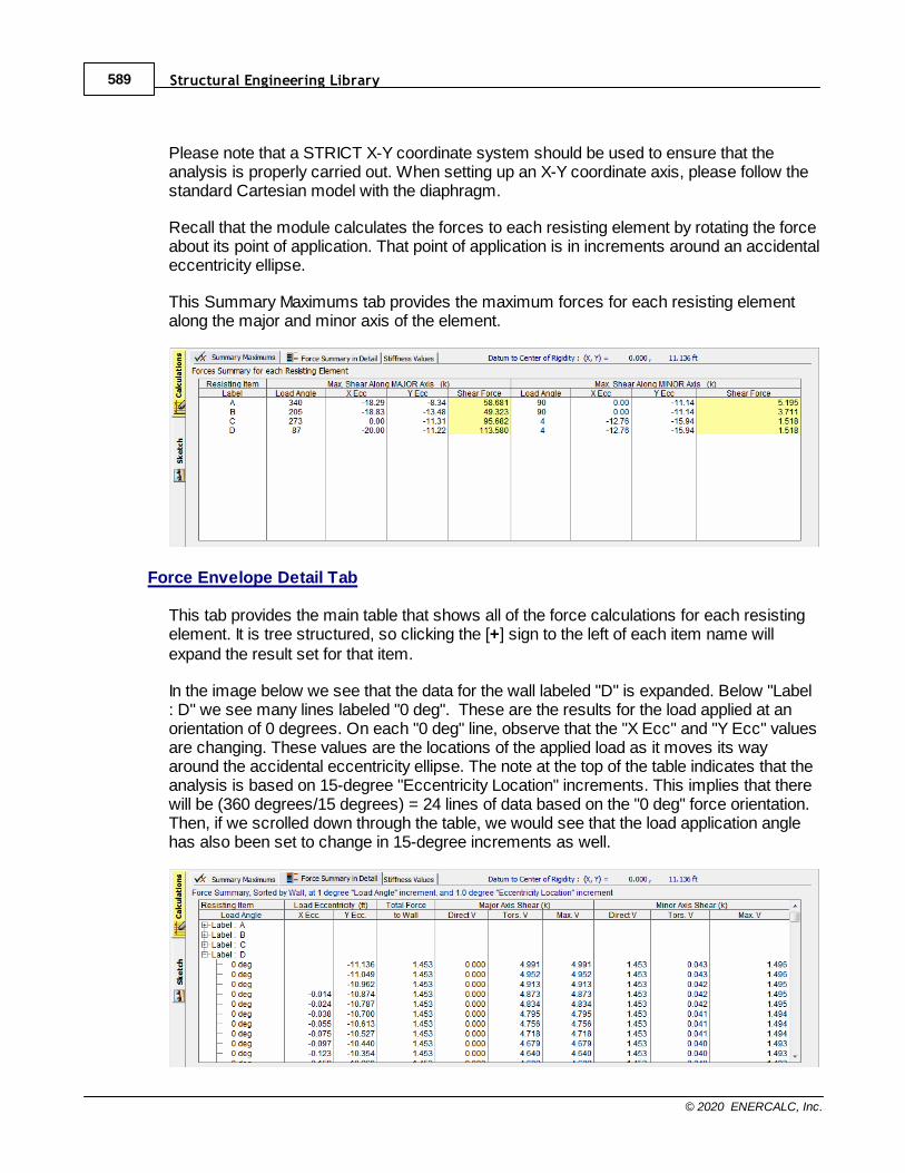
Structural Engineering Library589
© 2020 ENERCALC, Inc.
Please note that a STRICT X-Y coordinate system should be used to ensure that theanalysis is properly carried out. When setting up an X-Y coordinate axis, please follow thestandard Cartesian model with the diaphragm.
Recall that the module calculates the forces to each resisting element by rotating the forceabout its point of application. That point of application is in increments around an accidentaleccentricity ellipse.
This Summary Maximums tab provides the maximum forces for each resisting elementalong the major and minor axis of the element.
Force Envelope Detail Tab
This tab provides the main table that shows all of the force calculations for each resistingelement. It is tree structured, so clicking the [+] sign to the left of each item name willexpand the result set for that item.
In the image below we see that the data for the wall labeled "D" is expanded. Below "Label: D" we see many lines labeled "0 deg". These are the results for the load applied at anorientation of 0 degrees. On each "0 deg" line, observe that the "X Ecc" and "Y Ecc" valuesare changing. These values are the locations of the applied load as it moves its wayaround the accidental eccentricity ellipse. The note at the top of the table indicates that theanalysis is based on 15-degree "Eccentricity Location" increments. This implies that therewill be (360 degrees/15 degrees) = 24 lines of data based on the "0 deg" force orientation.Then, if we scrolled down through the table, we would see that the load application anglehas also been set to change in 15-degree increments as well.
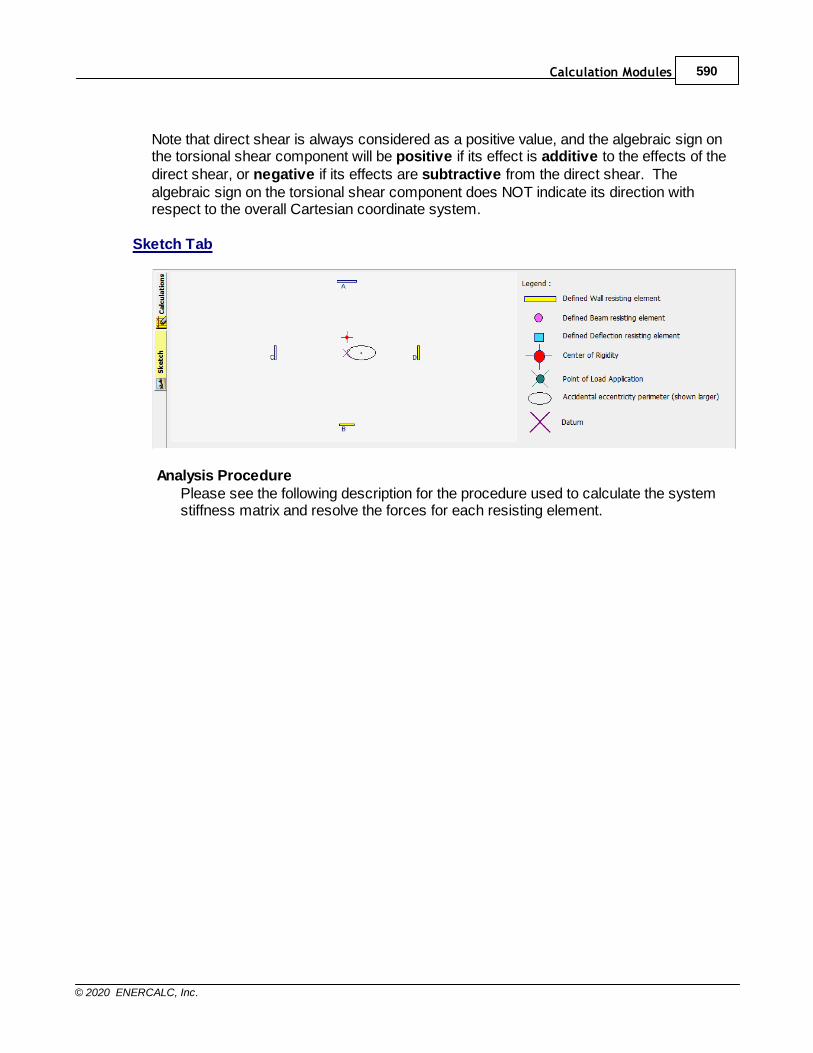
Calculation Modules 590
© 2020 ENERCALC, Inc.
Note that direct shear is always considered as a positive value, and the algebraic sign onthe torsional shear component will be positive if its effect is additive to the effects of thedirect shear, or negative if its effects are subtractive from the direct shear. Thealgebraic sign on the torsional shear component does NOT indicate its direction withrespect to the overall Cartesian coordinate system.
Sketch Tab
Analysis ProcedurePlease see the following description for the procedure used to calculate the systemstiffness matrix and resolve the forces for each resisting element.
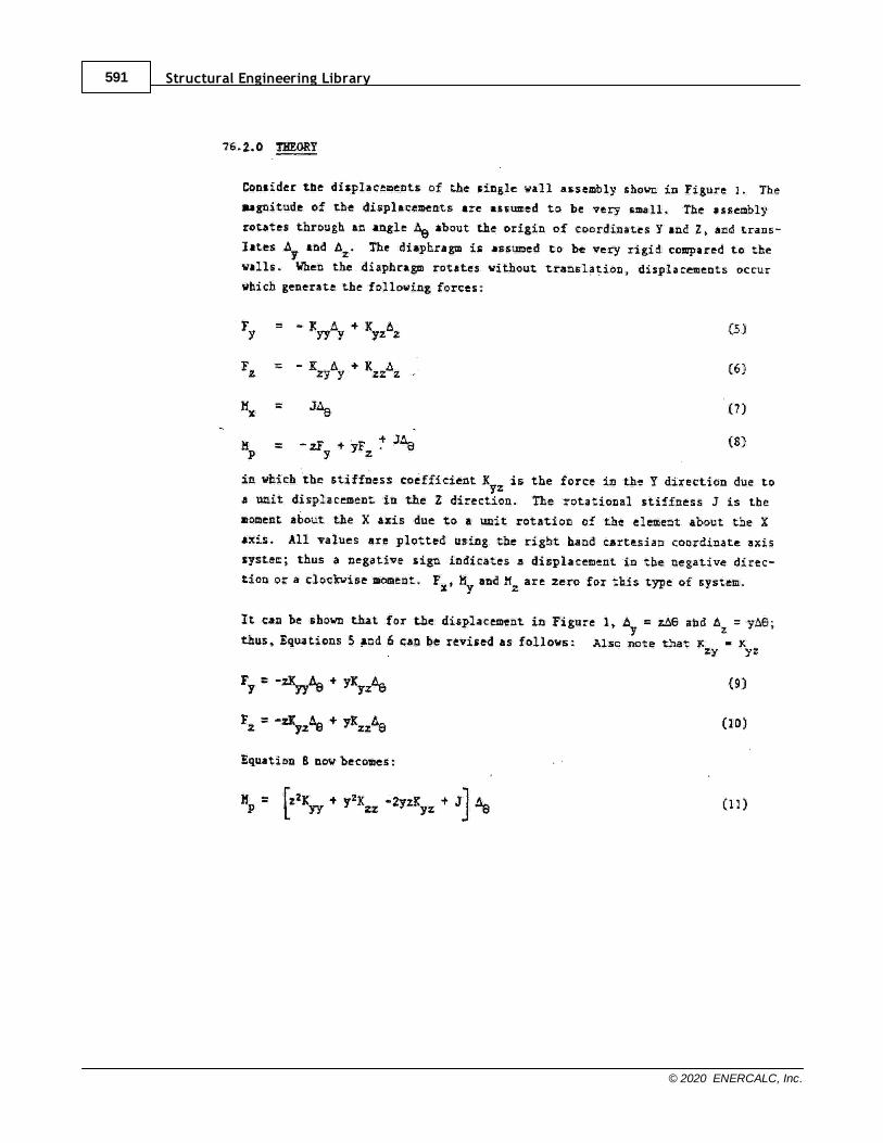
Structural Engineering Library591
© 2020 ENERCALC, Inc.
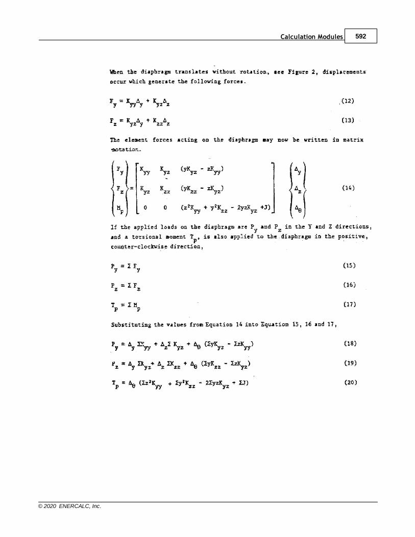
Calculation Modules 592
© 2020 ENERCALC, Inc.
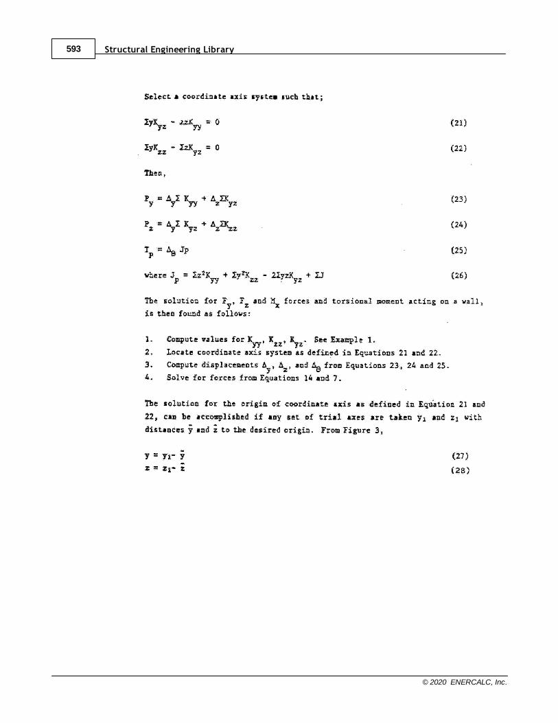
Structural Engineering Library593
© 2020 ENERCALC, Inc.
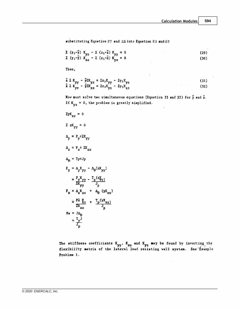
Calculation Modules 594
© 2020 ENERCALC, Inc.
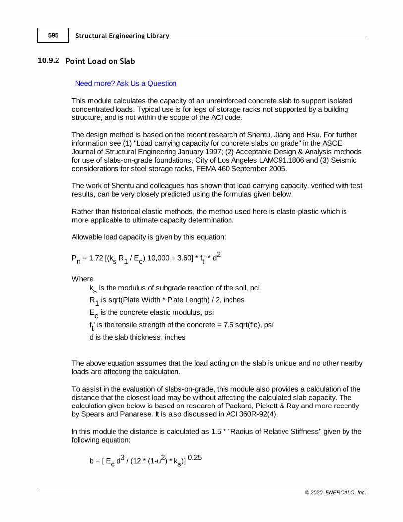
Structural Engineering Library595
© 2020 ENERCALC, Inc.
10.9.2 Point Load on Slab
Need more? Ask Us a Question
This module calculates the capacity of an unreinforced concrete slab to support isolatedconcentrated loads. Typical use is for legs of storage racks not supported by a buildingstructure, and is not within the scope of the ACI code.
The design method is based on the recent research of Shentu, Jiang and Hsu. For furtherinformation see (1) "Load carrying capacity for concrete slabs on grade" in the ASCEJournal of Structural Engineering January 1997; (2) Acceptable Design & Analysis methodsfor use of slabs-on-grade foundations, City of Los Angeles LAMC91.1806 and (3) Seismicconsiderations for steel storage racks, FEMA 460 September 2005.
The work of Shentu and colleagues has shown that load carrying capacity, verified with testresults, can be very closely predicted using the formulas given below.
Rather than historical elastic methods, the method used here is elasto-plastic which ismore applicable to ultimate capacity determination.
Allowable load capacity is given by this equation:
Pn = 1.72 [(ks R1 / Ec) 10,000 + 3.60] * ft' * d2
Whereks is the modulus of subgrade reaction of the soil, pci
R1 is sqrt(Plate Width * Plate Length) / 2, inches
Ec is the concrete elastic modulus, psi
ft' is the tensile strength of the concrete = 7.5 sqrt(f'c), psi
d is the slab thickness, inches
The above equation assumes that the load acting on the slab is unique and no other nearbyloads are affecting the calculation.
To assist in the evaluation of slabs-on-grade, this module also provides a calculation of thedistance that the closest load may be without affecting the calculated slab capacity. Thecalculation given below is based on research of Packard, Pickett & Ray and more recentlyby Spears and Panarese. It is also discussed in ACI 360R-92(4).
In this module the distance is calculated as 1.5 * "Radius of Relative Stiffness" given by thefollowing equation:
b = [ Ec d3 / (12 * (1-u2) * ks)] 0.25
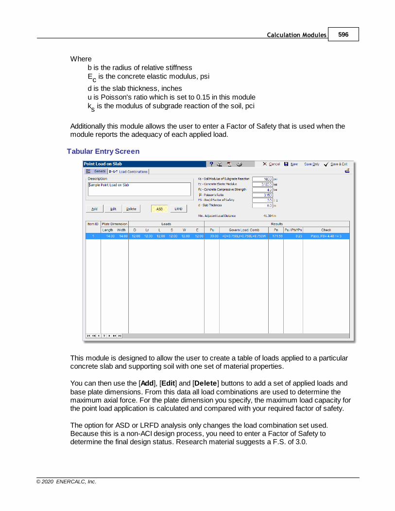
Calculation Modules 596
© 2020 ENERCALC, Inc.
Whereb is the radius of relative stiffnessEc is the concrete elastic modulus, psi
d is the slab thickness, inchesu is Poisson's ratio which is set to 0.15 in this moduleks is the modulus of subgrade reaction of the soil, pci
Additionally this module allows the user to enter a Factor of Safety that is used when themodule reports the adequacy of each applied load.
Tabular Entry Screen
This module is designed to allow the user to create a table of loads applied to a particularconcrete slab and supporting soil with one set of material properties.
You can then use the [Add], [Edit] and [Delete] buttons to add a set of applied loads andbase plate dimensions. From this data all load combinations are used to determine themaximum axial force. For the plate dimension you specify, the maximum load capacity forthe point load application is calculated and compared with your required factor of safety.
The option for ASD or LRFD analysis only changes the load combination set used.Because this is a non-ACI design process, you need to enter a Factor of Safety todetermine the final design status. Research material suggests a F.S. of 3.0.
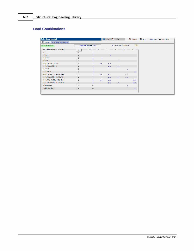
Structural Engineering Library597
© 2020 ENERCALC, Inc.
Load Combinations
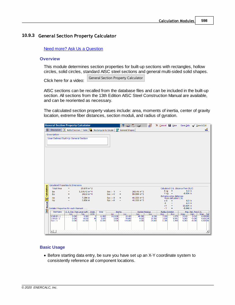
Calculation Modules 598
© 2020 ENERCALC, Inc.
10.9.3 General Section Property Calculator
Need more? Ask Us a Question
Overview
This module determines section properties for built-up sections with rectangles, hollowcircles, solid circles, standard AISC steel sections and general multi-sided solid shapes.
Click here for a video: General Section Property Calculator
AISC sections can be recalled from the database files and can be included in the built-upsection. All sections from the 13th Edition AISC Steel Construction Manual are available,and can be reoriented as necessary.
The calculated section property values include: area, moments of inertia, center of gravitylocation, extreme fiber distances, section moduli, and radius of gyration.
Basic Usage
· Before starting data entry, be sure you have set up an X-Y coordinate system toconsistently reference all component locations.

Structural Engineering Library599
© 2020 ENERCALC, Inc.
· For each rectangular shape, enter the height, width, and center of area measured fromthe datum.
· Hollow circular sections are entered by specifying the outside radius and thickness. Solidcircular sections are entered by specifying the outside radius and setting the thickness tozero.
· For AISC sections, you can use the Xcg and Ycg input fields to locate the section'scentroid position with respect to the datum. The module knows the centroid location ofAISC members with respect to their own extreme fiber locations. However, you need toenter the location of the member's centroid in relation to the other members in the built-up section. Be careful, as this can be tricky when entering channels, angles, and teesections that are rotated.
· A unique feature allows the user to specify that AISC sections can be rotated in 90-degree increments, and steel angle sections can also be mirrored about their Y axis.
Assumptions & Limitations
The module operates on a simple calculation procedure:
· Calculate the moment of inertia of each shape,
· Calculate the neutral axis of the group of shapes, and
· Calculate the moment of inertia of the group using I + A*D2 equations.
More complex analysis such as polar moment of inertia, plastic moduli, and bucklingconstants are beyond the scope of the module at this time but continuing development willadd these items in future updates.
Rolled Section / Table tab
This tab enables you to specify up to 10 sections from the AISC 13th Edition database touse in a built-up member.
The square buttons across the top of the tab are used to represent the componentsections that comprise your built-up shape. When a section has been specified for a
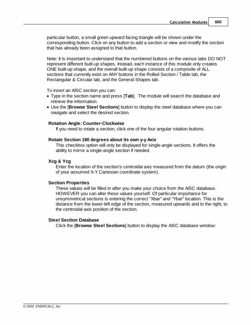
Calculation Modules 600
© 2020 ENERCALC, Inc.
particular button, a small green upward facing triangle will be shown under thecorresponding button. Click on any button to add a section or view and modify the sectionthat has already been assigned to that button.
Note: It is important to understand that the numbered buttons on the various tabs DO NOTrepresent different built-up shapes. Instead, each instance of this module only createsONE built-up shape, and the overall built-up shape consists of a composite of ALLsections that currently exist on ANY buttons in the Rolled Section / Table tab, theRectangular & Circular tab, and the General Shapes tab.
To insert an AISC section you can:· Type in the section name and press [Tab]. The module will search the database and
retrieve the information.· Use the [Browse Steel Sections] button to display the steel database where you can
navigate and select the desired section.
Rotation Angle: Counter-ClockwiseIf you need to rotate a section, click one of the four angular rotation buttons.
Rotate Section 180 degrees about its own y-y AxisThis checkbox option will only be displayed for single-angle sections. It offers theability to mirror a single-angle section if needed.
Xcg & YcgEnter the location of the section's centroidal axis measured from the datum (the originof your assumed X-Y Cartesian coordinate system).
Section PropertiesThese values will be filled in after you make your choice from the AISC database.HOWEVER you can alter these values yourself. Of particular importance forunsymmetrical sections is entering the correct "Xbar" and "Ybar" location. This is thedistance from the lower-left edge of the section, measured upwards and to the right, tothe centroidal axis position of the section.
Steel Section DatabaseClick the [Browse Steel Sections] button to display the AISC database window:
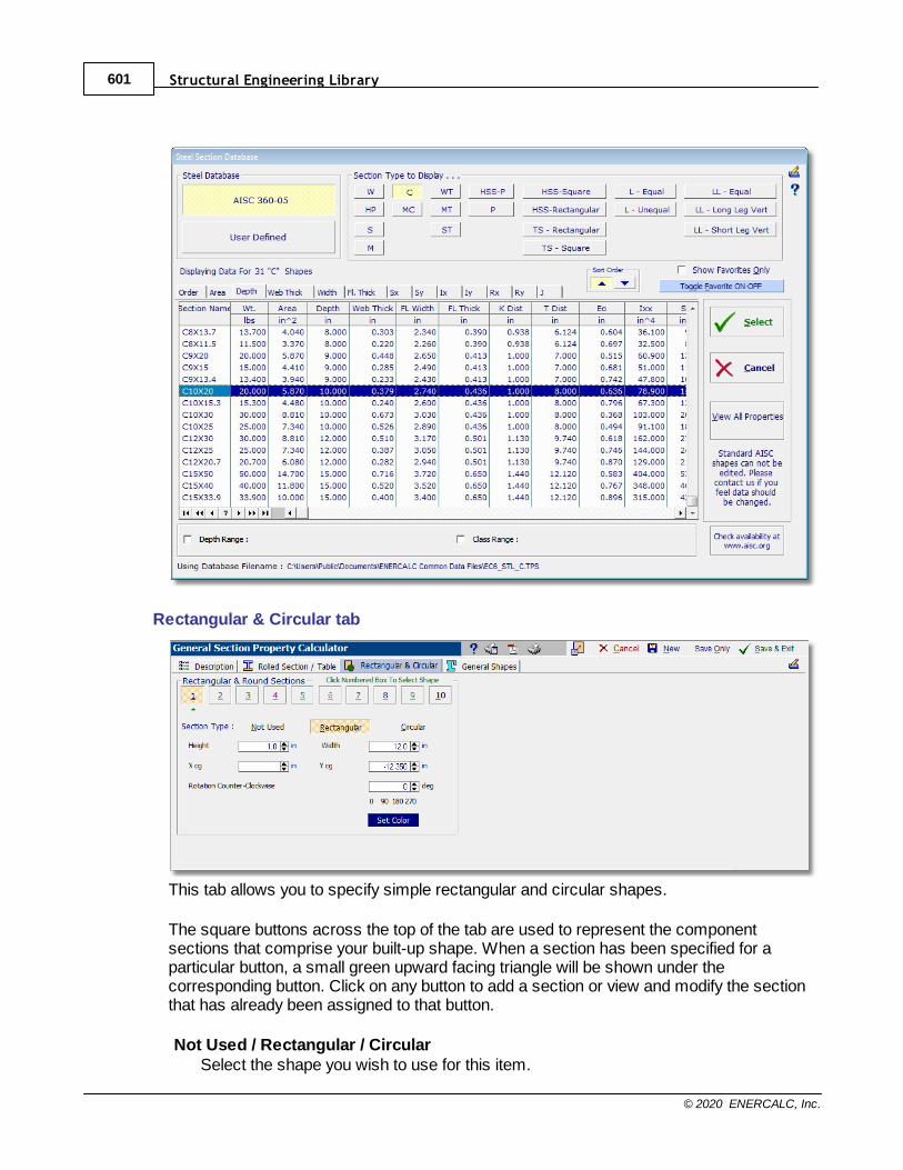
Structural Engineering Library601
© 2020 ENERCALC, Inc.
Rectangular & Circular tab
This tab allows you to specify simple rectangular and circular shapes.
The square buttons across the top of the tab are used to represent the componentsections that comprise your built-up shape. When a section has been specified for aparticular button, a small green upward facing triangle will be shown under thecorresponding button. Click on any button to add a section or view and modify the sectionthat has already been assigned to that button.
Not Used / Rectangular / CircularSelect the shape you wish to use for this item.

Calculation Modules 602
© 2020 ENERCALC, Inc.
Rectangular Data EntryWhen a rectangular shape is chosen the data entry consists of height and width.
Circular Data EntryWhen a circular shape is selected the data entry consists of Outside Radius and WallThickness (not inside radius). To model a solid circular section, enter the appropriateOutside Radius and set the Wall Thickness to zero.
Xcg & YcgEnter the location of the section's centroidal axis measured from the datum (the originof your assumed X-Y Cartesian coordinate system).
General Shapes tab
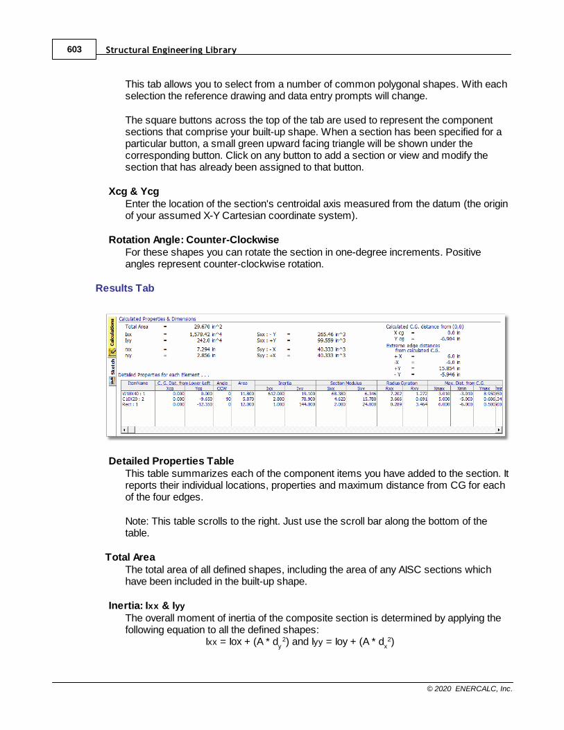
Structural Engineering Library603
© 2020 ENERCALC, Inc.
This tab allows you to select from a number of common polygonal shapes. With eachselection the reference drawing and data entry prompts will change.
The square buttons across the top of the tab are used to represent the componentsections that comprise your built-up shape. When a section has been specified for aparticular button, a small green upward facing triangle will be shown under thecorresponding button. Click on any button to add a section or view and modify thesection that has already been assigned to that button.
Xcg & YcgEnter the location of the section's centroidal axis measured from the datum (the originof your assumed X-Y Cartesian coordinate system).
Rotation Angle: Counter-ClockwiseFor these shapes you can rotate the section in one-degree increments. Positiveangles represent counter-clockwise rotation.
Results Tab
Detailed Properties TableThis table summarizes each of the component items you have added to the section. Itreports their individual locations, properties and maximum distance from CG for eachof the four edges.
Note: This table scrolls to the right. Just use the scroll bar along the bottom of thetable.
Total AreaThe total area of all defined shapes, including the area of any AISC sections whichhave been included in the built-up shape.
Inertia: Ixx & Iyy
The overall moment of inertia of the composite section is determined by applying thefollowing equation to all the defined shapes: Ixx = Iox + (A * d
y2) and Iyy = Ioy + (A * d
x2)
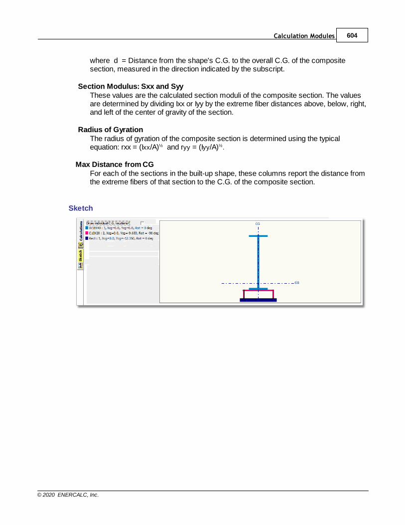
Calculation Modules 604
© 2020 ENERCALC, Inc.
where d = Distance from the shape's C.G. to the overall C.G. of the compositesection, measured in the direction indicated by the subscript.
Section Modulus: Sxx and SyyThese values are the calculated section moduli of the composite section. The valuesare determined by dividing Ixx or Iyy by the extreme fiber distances above, below, right,and left of the center of gravity of the section.
Radius of GyrationThe radius of gyration of the composite section is determined using the typicalequation: rxx = (Ixx/A)½ and ryy = (Iyy/A)½.
Max Distance from CGFor each of the sections in the built-up shape, these columns report the distance fromthe extreme fibers of that section to the C.G. of the composite section.
Sketch
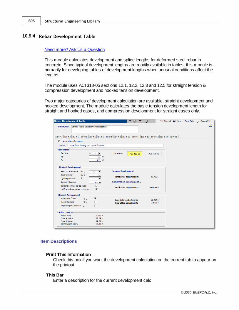
Structural Engineering Library605
© 2020 ENERCALC, Inc.
10.9.4 Rebar Development Table
Need more? Ask Us a Question
This module calculates development and splice lengths for deformed steel rebar inconcrete. Since typical development lengths are readily available in tables, this module isprimarily for developing tables of development lengths when unusual conditions affect thelengths.
The module uses ACI 318-05 sections 12.1, 12.2, 12.3 and 12.5 for straight tension &compression development and hooked tension development.
Two major categories of development calculation are available; straight development andhooked development. The module calculates the basic tension development length forstraight and hooked cases, and compression development for straight cases only.
Item Descriptions
Print This InformationCheck this box if you want the development calculation on the current tab to appear onthe printout.
This BarEnter a description for the current development calc.

Calculation Modules 606
© 2020 ENERCALC, Inc.
Bar DetailsEnter the basic stress info for this bar. You can also select to perform the calculationaccording to ACI 318-91.
Straight DevelopmentThis section performs tension & compression bar development according to ACIsection 12.2 and 12.3. Please refer to the ACI code for the proper definitions of theseentries.
Hooked DevelopmentThis section performs tension hooked rebar development according to ACI section12.5. Please refer to the ACI code for the proper definitions of these entries.
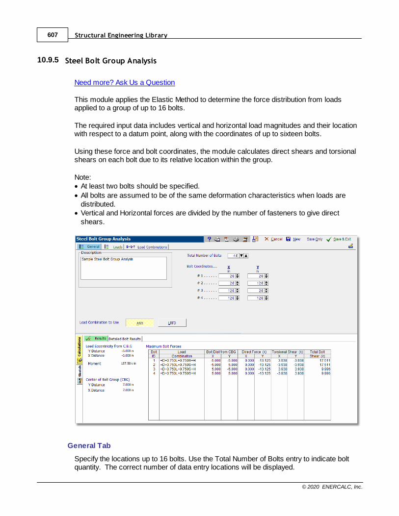
Structural Engineering Library607
© 2020 ENERCALC, Inc.
10.9.5 Steel Bolt Group Analysis
Need more? Ask Us a Question
This module applies the Elastic Method to determine the force distribution from loadsapplied to a group of up to 16 bolts.
The required input data includes vertical and horizontal load magnitudes and their locationwith respect to a datum point, along with the coordinates of up to sixteen bolts.
Using these force and bolt coordinates, the module calculates direct shears and torsionalshears on each bolt due to its relative location within the group.
Note:· At least two bolts should be specified.
· All bolts are assumed to be of the same deformation characteristics when loads aredistributed.
· Vertical and Horizontal forces are divided by the number of fasteners to give directshears.
General Tab
Specify the locations up to 16 bolts. Use the Total Number of Bolts entry to indicate boltquantity. The correct number of data entry locations will be displayed.
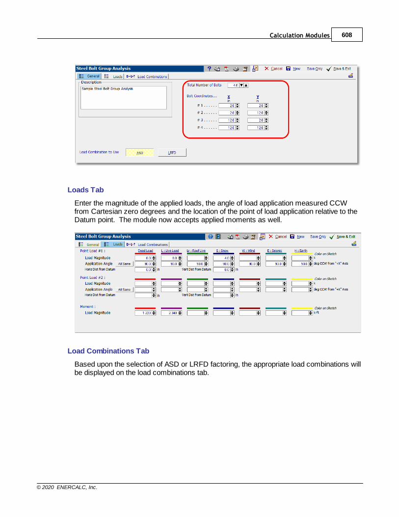
Calculation Modules 608
© 2020 ENERCALC, Inc.
Loads Tab
Enter the magnitude of the applied loads, the angle of load application measured CCWfrom Cartesian zero degrees and the location of the point of load application relative to theDatum point. The module now accepts applied moments as well.
Load Combinations Tab
Based upon the selection of ASD or LRFD factoring, the appropriate load combinations willbe displayed on the load combinations tab.
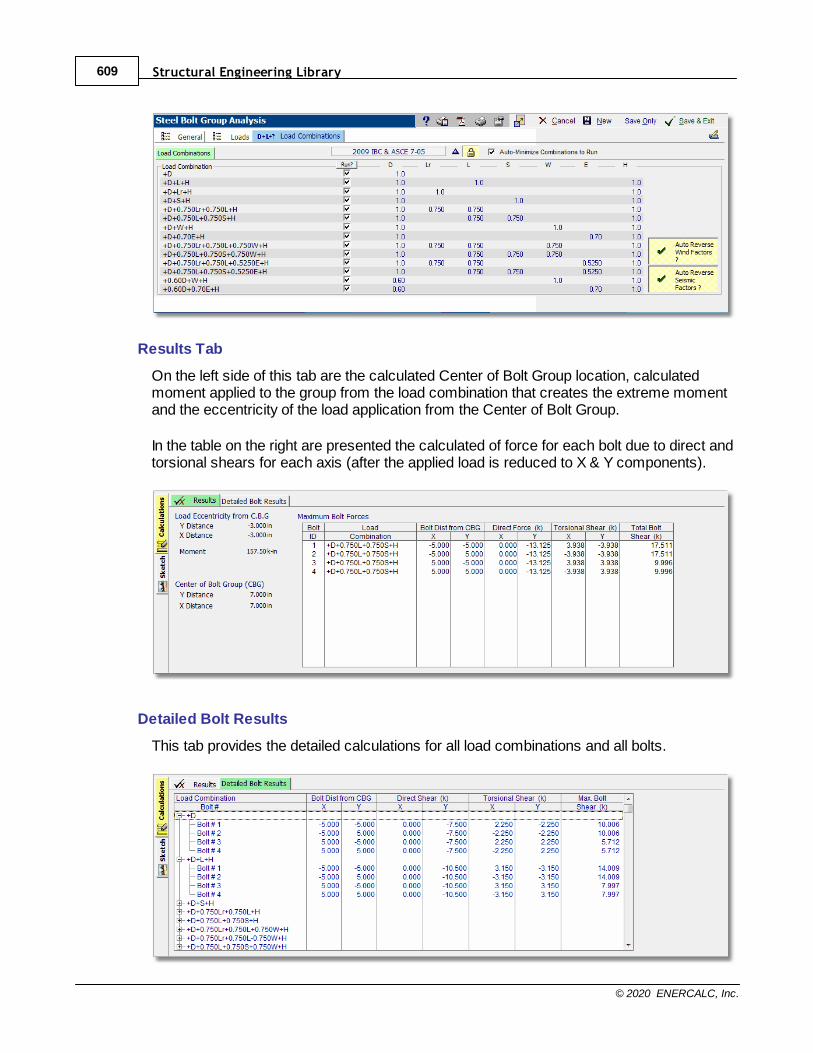
Structural Engineering Library609
© 2020 ENERCALC, Inc.
Results Tab
On the left side of this tab are the calculated Center of Bolt Group location, calculatedmoment applied to the group from the load combination that creates the extreme momentand the eccentricity of the load application from the Center of Bolt Group.
In the table on the right are presented the calculated of force for each bolt due to direct andtorsional shears for each axis (after the applied load is reduced to X & Y components).
Detailed Bolt Results
This tab provides the detailed calculations for all load combinations and all bolts.
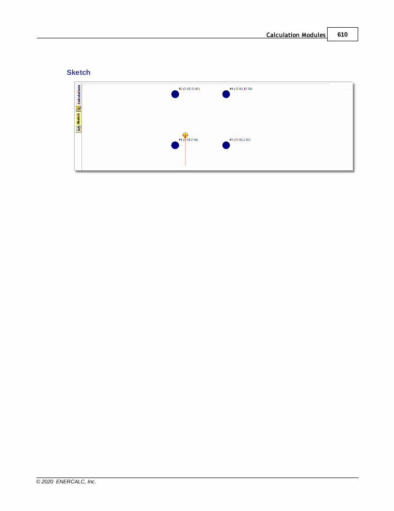
Calculation Modules 610
© 2020 ENERCALC, Inc.
Sketch
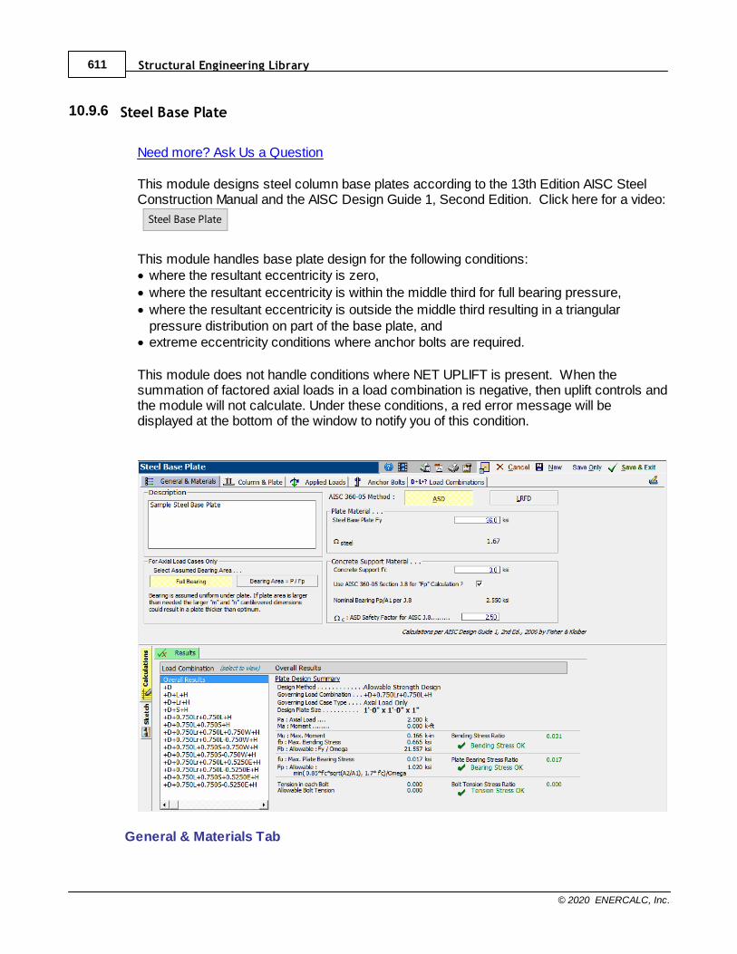
Structural Engineering Library611
© 2020 ENERCALC, Inc.
10.9.6 Steel Base Plate
Need more? Ask Us a Question
This module designs steel column base plates according to the 13th Edition AISC SteelConstruction Manual and the AISC Design Guide 1, Second Edition. Click here for a video:
Steel Base Plate
This module handles base plate design for the following conditions:· where the resultant eccentricity is zero,
· where the resultant eccentricity is within the middle third for full bearing pressure,
· where the resultant eccentricity is outside the middle third resulting in a triangularpressure distribution on part of the base plate, and
· extreme eccentricity conditions where anchor bolts are required.
This module does not handle conditions where NET UPLIFT is present. When thesummation of factored axial loads in a load combination is negative, then uplift controls andthe module will not calculate. Under these conditions, a red error message will bedisplayed at the bottom of the window to notify you of this condition.
General & Materials Tab
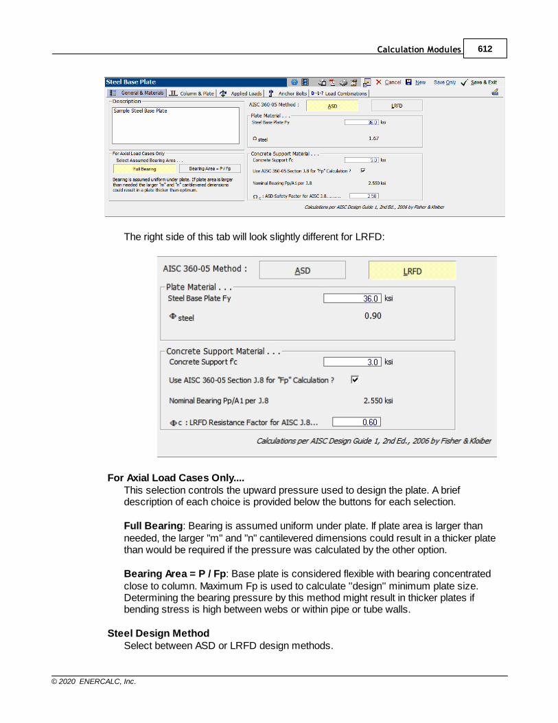
Calculation Modules 612
© 2020 ENERCALC, Inc.
The right side of this tab will look slightly different for LRFD:
For Axial Load Cases Only....This selection controls the upward pressure used to design the plate. A briefdescription of each choice is provided below the buttons for each selection.
Full Bearing: Bearing is assumed uniform under plate. If plate area is larger thanneeded, the larger "m" and "n" cantilevered dimensions could result in a thicker platethan would be required if the pressure was calculated by the other option.
Bearing Area = P / Fp: Base plate is considered flexible with bearing concentratedclose to column. Maximum Fp is used to calculate ''design'' minimum plate size.Determining the bearing pressure by this method might result in thicker plates ifbending stress is high between webs or within pipe or tube walls.
Steel Design MethodSelect between ASD or LRFD design methods.
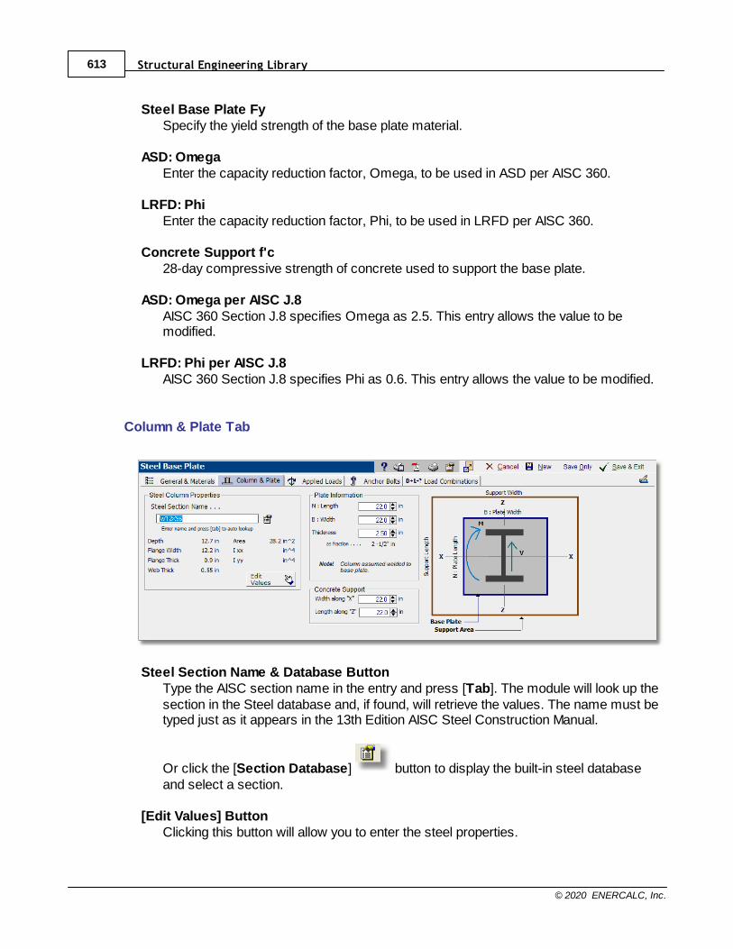
Structural Engineering Library613
© 2020 ENERCALC, Inc.
Steel Base Plate FySpecify the yield strength of the base plate material.
ASD: OmegaEnter the capacity reduction factor, Omega, to be used in ASD per AISC 360.
LRFD: PhiEnter the capacity reduction factor, Phi, to be used in LRFD per AISC 360.
Concrete Support f'c28-day compressive strength of concrete used to support the base plate.
ASD: Omega per AISC J.8AISC 360 Section J.8 specifies Omega as 2.5. This entry allows the value to bemodified.
LRFD: Phi per AISC J.8AISC 360 Section J.8 specifies Phi as 0.6. This entry allows the value to be modified.
Column & Plate Tab
Steel Section Name & Database ButtonType the AISC section name in the entry and press [Tab]. The module will look up thesection in the Steel database and, if found, will retrieve the values. The name must betyped just as it appears in the 13th Edition AISC Steel Construction Manual.
Or click the [Section Database] button to display the built-in steel databaseand select a section.
[Edit Values] ButtonClicking this button will allow you to enter the steel properties.

Calculation Modules 614
© 2020 ENERCALC, Inc.
Plate Information
Enter the length, width and thickness of the base plate. Use the buttons to quicklychange the values...the results are instantly recalculated.
Concrete SupportEnter the support dimensions that will be used to calculate the allowable bearingpressure increase, A1 * sqrt(A2/A1).
Applied Loads Tab
Py - Axial LoadThis column of entries specifies the axial load applied to the base plate. Note thatpositive values represent downward loads.
Vz - ShearThis column of entries specifies the shear applied parallel to the plate and to beresisted by the anchor bolts.
Mx - MomentThis column of entries specifies the moment that the column applies to the plate.
Anchor Bolts Tab
Items on this tab specify the strength and location of the anchor bolts that will resist shearand tension.
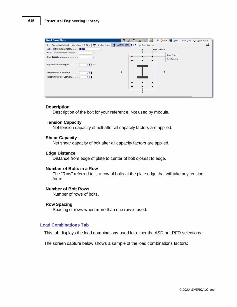
Structural Engineering Library615
© 2020 ENERCALC, Inc.
DescriptionDescription of the bolt for your reference. Not used by module.
Tension CapacityNet tension capacity of bolt after all capacity factors are applied.
Shear CapacityNet shear capacity of bolt after all capacity factors are applied.
Edge DistanceDistance from edge of plate to center of bolt closest to edge.
Number of Bolts in a RowThe "Row" referred to is a row of bolts at the plate edge that will take any tensionforce.
Number of Bolt RowsNumber of rows of bolts.
Row SpacingSpacing of rows when more than one row is used.
Load Combinations Tab
This tab displays the load combinations used for either the ASD or LRFD selections.
The screen capture below shows a sample of the load combinations factors:
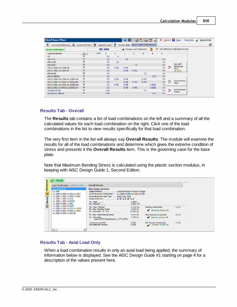
Calculation Modules 616
© 2020 ENERCALC, Inc.
Results Tab - Overall
The Results tab contains a list of load combinations on the left and a summary of all thecalculated values for each load combination on the right. Click one of the loadcombinations in the list to view results specifically for that load combination.
The very first item in the list will always say Overall Results. The module will examine theresults for all of the load combinations and determine which gives the extreme condition ofstress and presents it the Overall Results item. This is the governing case for the baseplate.
Note that Maximum Bending Stress is calculated using the plastic section modulus, inkeeping with AISC Design Guide 1, Second Edition.
Results Tab - Axial Load Only
When a load combination results in only an axial load being applied, the summary ofinformation below is displayed. See the AISC Design Guide #1 starting on page 4 for adescription of the values present here.
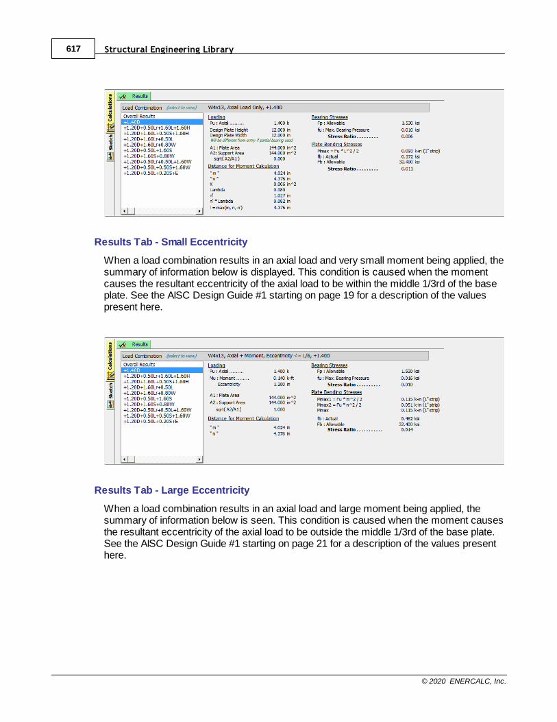
Structural Engineering Library617
© 2020 ENERCALC, Inc.
Results Tab - Small Eccentricity
When a load combination results in an axial load and very small moment being applied, thesummary of information below is displayed. This condition is caused when the momentcauses the resultant eccentricity of the axial load to be within the middle 1/3rd of the baseplate. See the AISC Design Guide #1 starting on page 19 for a description of the valuespresent here.
Results Tab - Large Eccentricity
When a load combination results in an axial load and large moment being applied, thesummary of information below is seen. This condition is caused when the moment causesthe resultant eccentricity of the axial load to be outside the middle 1/3rd of the base plate.See the AISC Design Guide #1 starting on page 21 for a description of the values presenthere.
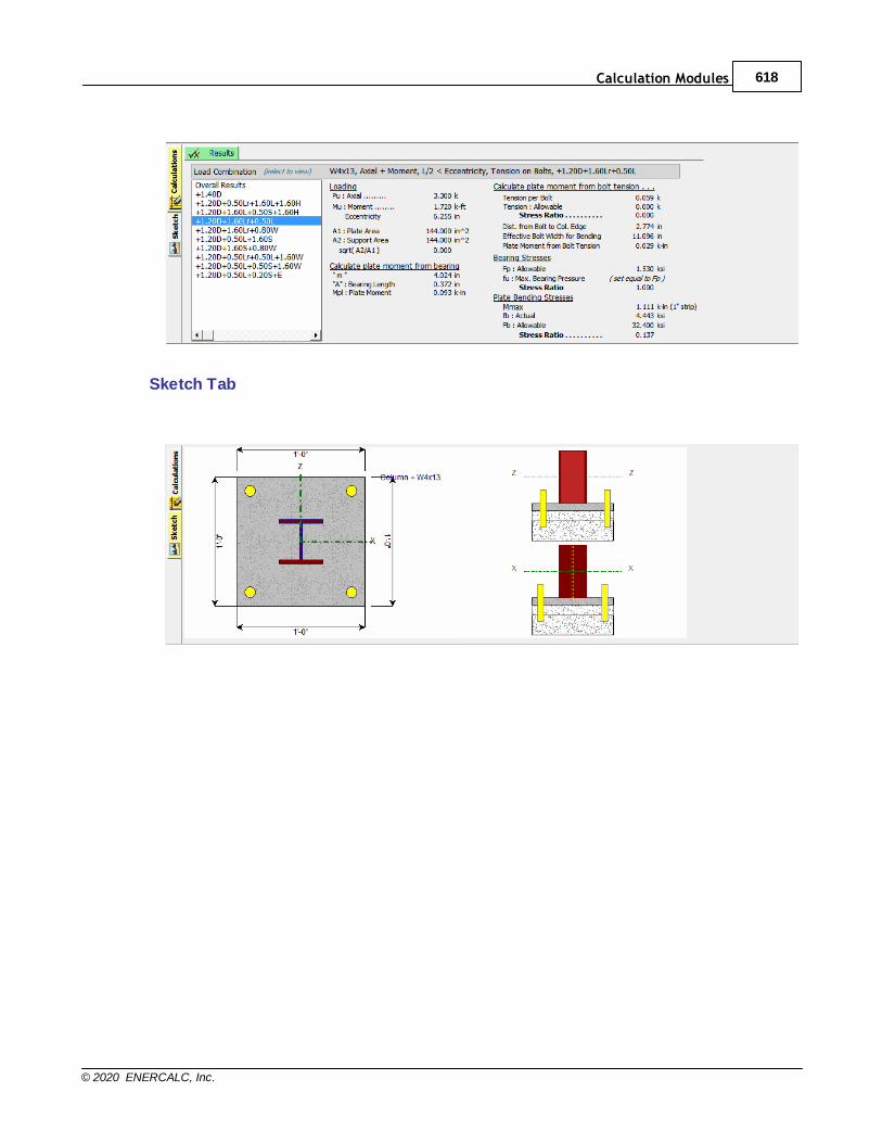
Calculation Modules 618
© 2020 ENERCALC, Inc.
Sketch Tab
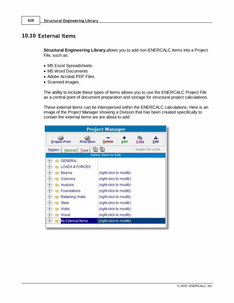
Structural Engineering Library619
© 2020 ENERCALC, Inc.
10.10 External Items
Structural Engineering Library allows you to add non-ENERCALC items into a ProjectFile, such as:
· MS Excel Spreadsheets
· MS Word Documents
· Adobe Acrobat PDF Files
· Scanned Images
The ability to include these types of items allows you to use the ENERCALC Project Fileas a central point of document preparation and storage for structural project calculations.
These external items can be interspersed within the ENERCALC calculations. Here is animage of the Project Manager showing a Division that has been created specifically tocontain the external items we are about to add:
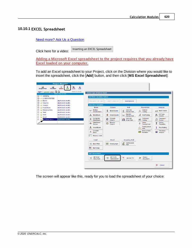
Calculation Modules 620
© 2020 ENERCALC, Inc.
10.10.1 EXCEL Spreadsheet
Need more? Ask Us a Question
Click here for a video: Inserting an EXCEL Spreadsheet
Adding a Microsoft Excel spreadsheet to the project requires that you already haveExcel loaded on your computer.
To add an Excel spreadsheet to your Project, click on the Division where you would like toinsert the spreadsheet, click the [Add] button, and then click [MS Excel Spreadsheet]:
The screen will appear like this, ready for you to load the spreadsheet of your choice:

Structural Engineering Library621
© 2020 ENERCALC, Inc.
(1) Use the [Open/Retrieve] button to load the desired Excel spreadsheet.
(2) Use the [Print Document] button to print this item using the Excel printing functionality.
(3) Use the [Clear Document] button to remove the currently loaded Excel spreadsheetfrom the Project File.
(4) Use the [SaveAs] button to save the currently loaded Excel spreadsheet to a newfilename.
(5) The Storage Method buttons are used to specify how the Excel spreadsheet will bestored for use within ENERCALC.
· [Embed] saves a copy of the item in the Project File. (Easiest for portability, results inlarger Project File size, changes to original item will not be visible.)
· [Link] saves a link to the item in Project File. (Changes to original item will be visible,keeps Project File size small, not easily portable.)
(6) This area is used to define the name of the Excel spreadsheet when it is storedexternally from the Project File.
(7) Enter a description of this item as needed. It will be displayed in the Descriptionscolumn of the Project Manager for reference.
(8) This is the area where the Excel spreadsheet is loaded, as shown below:
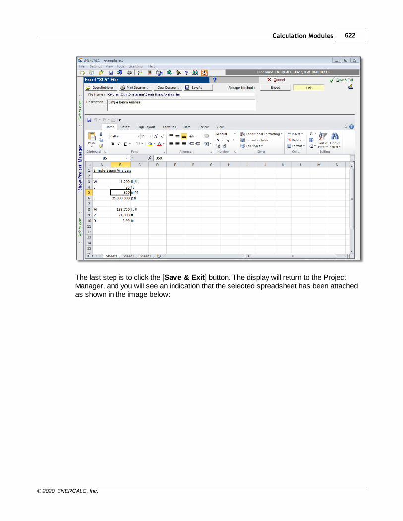
Calculation Modules 622
© 2020 ENERCALC, Inc.
The last step is to click the [Save & Exit] button. The display will return to the ProjectManager, and you will see an indication that the selected spreadsheet has been attachedas shown in the image below:
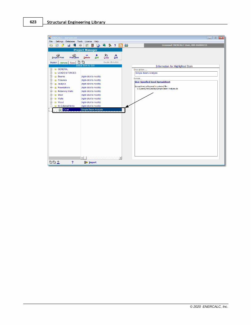
Structural Engineering Library623
© 2020 ENERCALC, Inc.
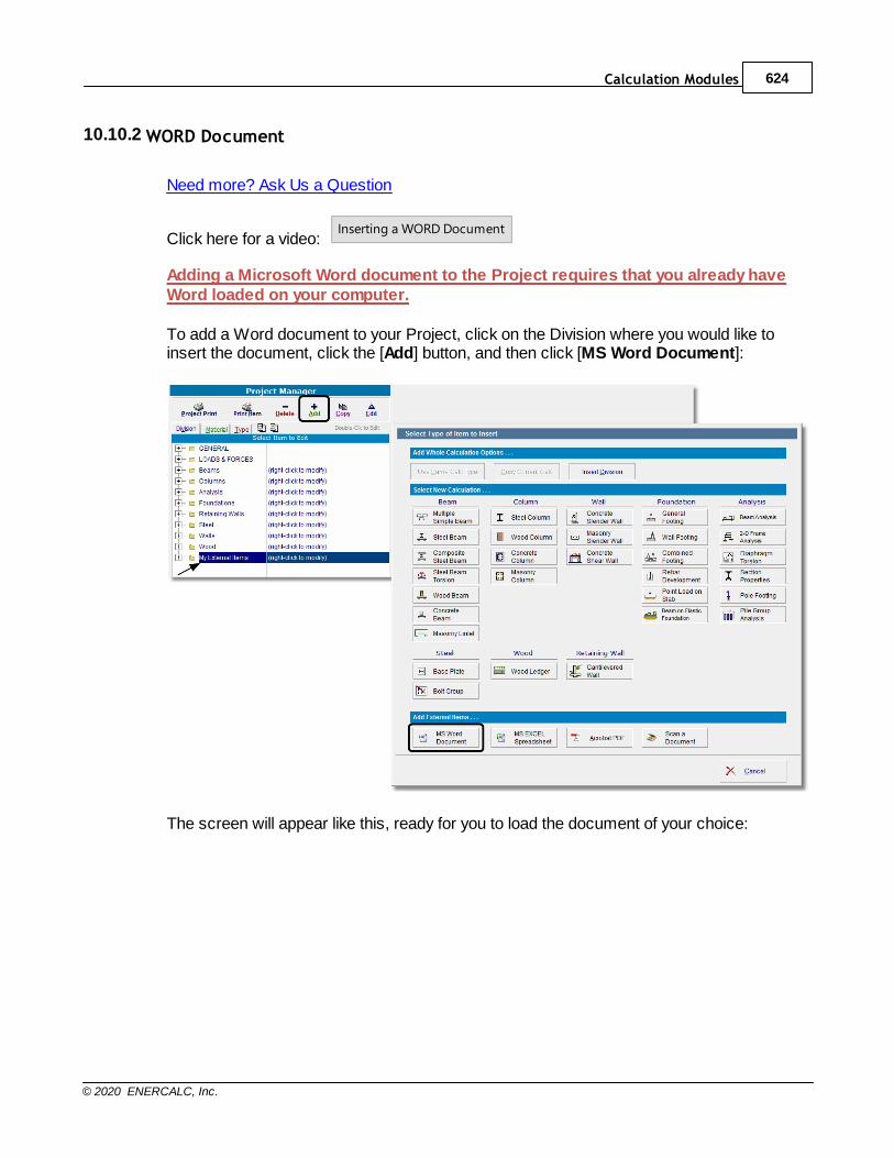
Calculation Modules 624
© 2020 ENERCALC, Inc.
10.10.2 WORD Document
Need more? Ask Us a Question
Click here for a video: Inserting a WORD Document
Adding a Microsoft Word document to the Project requires that you already haveWord loaded on your computer.
To add a Word document to your Project, click on the Division where you would like toinsert the document, click the [Add] button, and then click [MS Word Document]:
The screen will appear like this, ready for you to load the document of your choice:
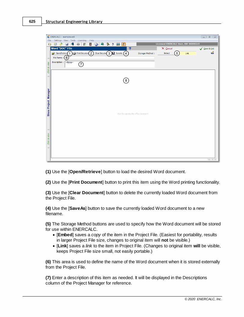
Structural Engineering Library625
© 2020 ENERCALC, Inc.
(1) Use the [Open/Retrieve] button to load the desired Word document.
(2) Use the [Print Document] button to print this item using the Word printing functionality.
(3) Use the [Clear Document] button to delete the currently loaded Word document fromthe Project File.
(4) Use the [SaveAs] button to save the currently loaded Word document to a newfilename.
(5) The Storage Method buttons are used to specify how the Word document will be storedfor use within ENERCALC.
· [Embed] saves a copy of the item in the Project File. (Easiest for portability, resultsin larger Project File size, changes to original item will not be visible.)
· [Link] saves a link to the item in Project File. (Changes to original item will be visible,keeps Project File size small, not easily portable.)
(6) This area is used to define the name of the Word document when it is stored externallyfrom the Project File.
(7) Enter a description of this item as needed. It will be displayed in the Descriptionscolumn of the Project Manager for reference.
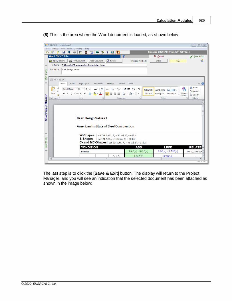
Calculation Modules 626
© 2020 ENERCALC, Inc.
(8) This is the area where the Word document is loaded, as shown below:
The last step is to click the [Save & Exit] button. The display will return to the ProjectManager, and you will see an indication that the selected document has been attached asshown in the image below:

Structural Engineering Library627
© 2020 ENERCALC, Inc.
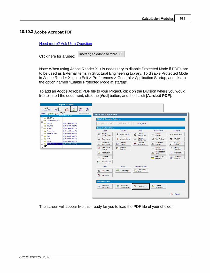
Calculation Modules 628
© 2020 ENERCALC, Inc.
10.10.3 Adobe Acrobat PDF
Need more? Ask Us a Question
Click here for a video: Inserting an Adobe Acrobat PDF
Note: When using Adobe Reader X, it is necessary to disable Protected Mode if PDFs areto be used as External Items in Structural Engineering Library. To disable Protected Modein Adobe Reader X, go to Edit > Preferences > General > Application Startup, and disablethe option named “Enable Protected Mode at startup”.
To add an Adobe Acrobat PDF file to your Project, click on the Division where you wouldlike to insert the document, click the [Add] button, and then click [Acrobat PDF]:
The screen will appear like this, ready for you to load the PDF file of your choice:
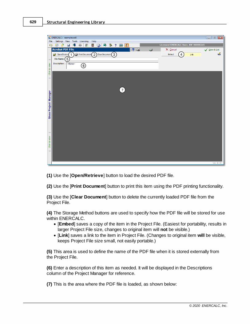
Structural Engineering Library629
© 2020 ENERCALC, Inc.
(1) Use the [Open/Retrieve] button to load the desired PDF file.
(2) Use the [Print Document] button to print this item using the PDF printing functionality.
(3) Use the [Clear Document] button to delete the currently loaded PDF file from theProject File.
(4) The Storage Method buttons are used to specify how the PDF file will be stored for usewithin ENERCALC.
· [Embed] saves a copy of the item in the Project File. (Easiest for portability, results inlarger Project File size, changes to original item will not be visible.)
· [Link] saves a link to the item in Project File. (Changes to original item will be visible,keeps Project File size small, not easily portable.)
(5) This area is used to define the name of the PDF file when it is stored externally fromthe Project File.
(6) Enter a description of this item as needed. It will be displayed in the Descriptionscolumn of the Project Manager for reference.
(7) This is the area where the PDF file is loaded, as shown below:
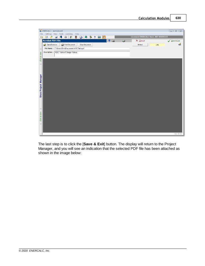
Calculation Modules 630
© 2020 ENERCALC, Inc.
The last step is to click the [Save & Exit] button. The display will return to the ProjectManager, and you will see an indication that the selected PDF file has been attached asshown in the image below:
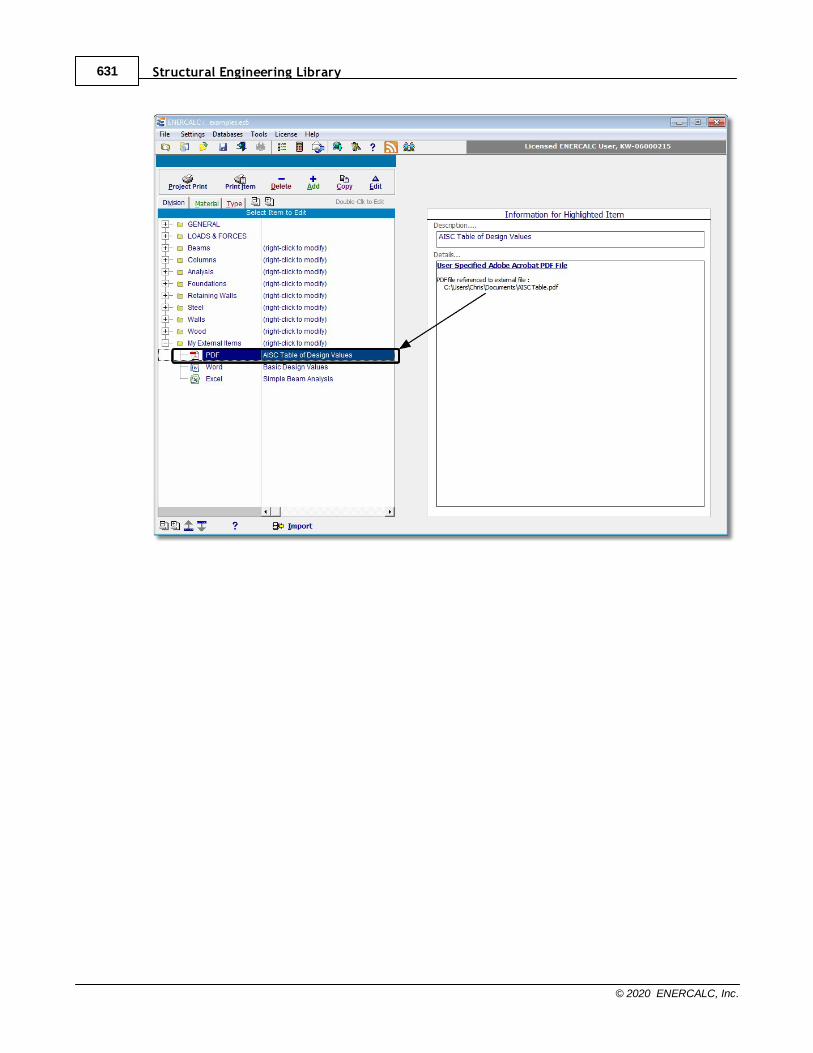
Structural Engineering Library631
© 2020 ENERCALC, Inc.
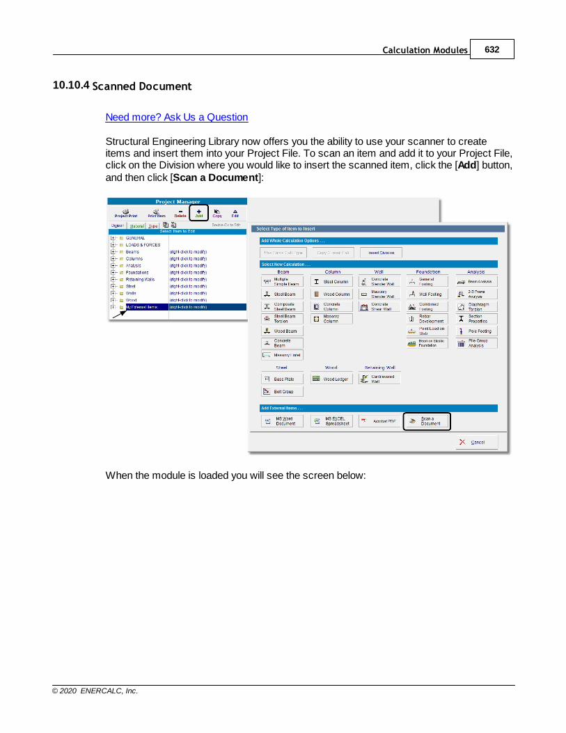
Calculation Modules 632
© 2020 ENERCALC, Inc.
10.10.4 Scanned Document
Need more? Ask Us a Question
Structural Engineering Library now offers you the ability to use your scanner to createitems and insert them into your Project File. To scan an item and add it to your Project File,click on the Division where you would like to insert the scanned item, click the [Add] button,and then click [Scan a Document]:
When the module is loaded you will see the screen below:
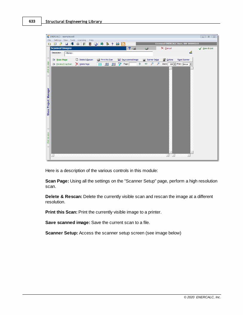
Structural Engineering Library633
© 2020 ENERCALC, Inc.
Here is a description of the various controls in this module:
Scan Page: Using all the settings on the "Scanner Setup" page, perform a high resolutionscan.
Delete & Rescan: Delete the currently visible scan and rescan the image at a differentresolution.
Print this Scan: Print the currently visible image to a printer.
Save scanned image: Save the current scan to a file.
Scanner Setup: Access the scanner setup screen (see image below)
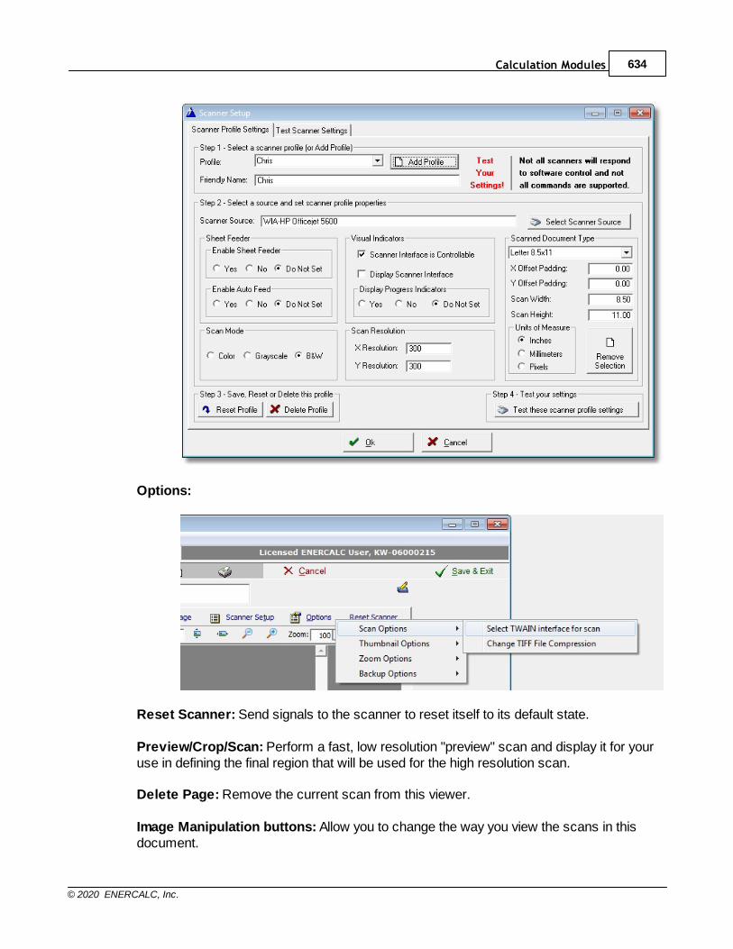
Calculation Modules 634
© 2020 ENERCALC, Inc.
Options:
Reset Scanner: Send signals to the scanner to reset itself to its default state.
Preview/Crop/Scan: Perform a fast, low resolution "preview" scan and display it for youruse in defining the final region that will be used for the high resolution scan.
Delete Page: Remove the current scan from this viewer.
Image Manipulation buttons: Allow you to change the way you view the scans in thisdocument.
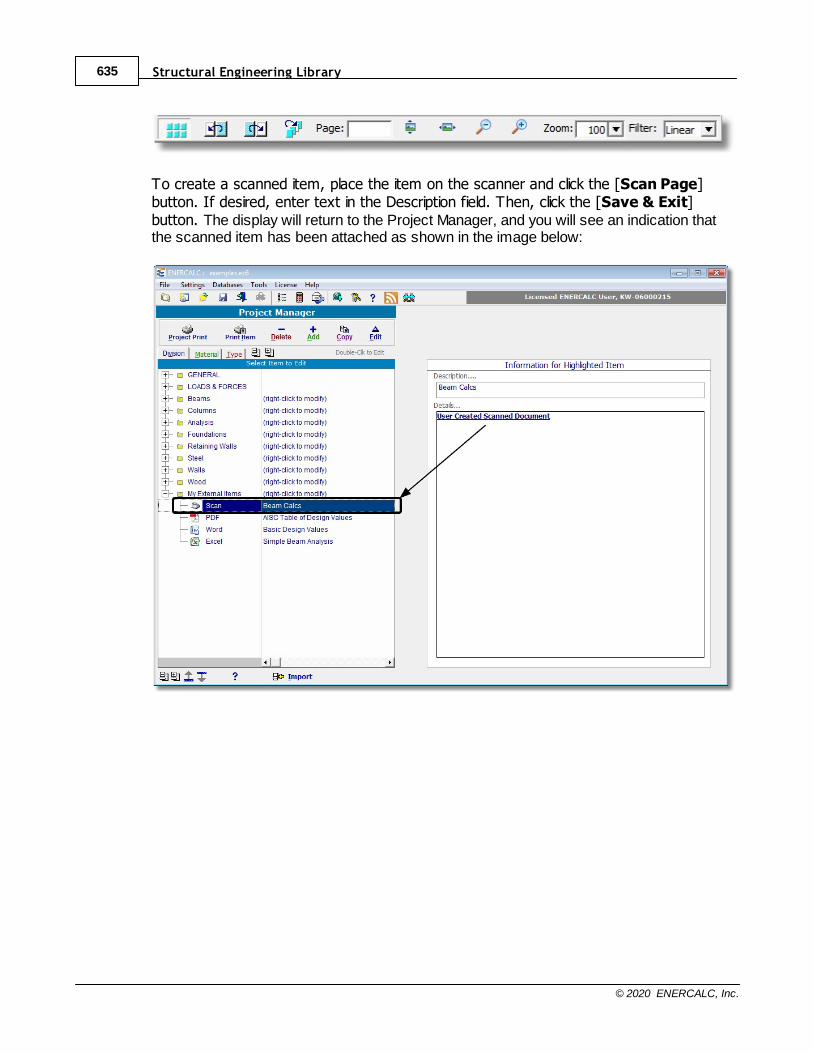
Structural Engineering Library635
© 2020 ENERCALC, Inc.
To create a scanned item, place the item on the scanner and click the [Scan Page]button. If desired, enter text in the Description field. Then, click the [Save & Exit]button. The display will return to the Project Manager, and you will see an indication thatthe scanned item has been attached as shown in the image below:
Copyright © 2022 FDOKUMEN