Regressive and transgressive sequences in a raised Holocene gravelly beach, southwestern Crete

Structural controls on the stratigraphic architectureof net-transgressive shallow-marine strata in asalt-influenced rift basin:Middle-to-Upper JurassicEgersund Basin,Norwegian North SeaA. S. Mannie C. A. - L. Jackson and G. J. Hampson
Basins Research Group (BRG), Department of Earth Science & Engineering, Imperial College, London, UK
ABSTRACT
In this study, we integrate 3D seismic reflection, wireline log, biostratigraphic and core data from
the Egersund Basin, Norwegian North Sea to determine the impact of syn-depositional salt move-
ment and associated growth faulting on the sedimentology and stratigraphic architecture of the Mid-
dle-to-Upper Jurassic, net-transgressive, syn-rift succession. Borehole data indicate that Middle-to-
Upper Jurassic strata consist of low-energy, wave-dominated offshore and shoreface deposits and
coal-bearing coastal-plain deposits. These deposits are arranged in four parasequences that are ag-
gradationally to retrogradationally stacked to form a net-transgressive succession that is up to 150-m
thick, at least 20 km in depositional strike (SW-NE) extent, and >70 km in depositional dip (NW-
SE) extent. In this rift-margin location, changes in thickness but not facies are noted across active
salt structures. Abrupt facies changes, from shoreface sandstones to offshore mudstones, only occur
across large displacement, basement-involved normal faults. Comparisons to other tectonically active
salt-influenced basins suggest that facies changes across syn-depositional salt structures are observed
only where expansion indices are >2. Subsidence between salt walls resulted in local preservation ofcoastal-plain deposits that cap shoreface parasequences, which were locally removed by transgressive
erosion in adjacent areas of lower subsidence. The depositional dip that characterizes the Egersund
Basin is unusual and likely resulted from its marginal location within the evolving North Sea rift and
an extra-basinal sediment supply from the Norwegian mainland.
INTRODUCTION
Depositional models for salt-influenced rift basins indi-
cate that the growth of salt-cored structures is a first-
order control on basin physiography, accommodation
development and the resultant stratigraphic architecture
of shallow-marine syn-rift deposits. For example, syn-rift
deposits in these settings may become thinner and be
composed of progressively shallower water facies onto the
flanks of syn-depositional, salt-cored structural highs
(Davison et al., 1996; Stewart & Clark, 1999; Alves et al.,2003; Aschoff & Giles, 2005; Kieft et al., 2010). In some
cases, segmentation of a basin by salt structures and salt-
related normal faults can result in the formation of at-sea-
bed relief, local amplification of tidal currents, and depo-
sition of syn-rift successions that contain a strong tidal
signature (e.g. Mellere & Steel, 1996; Carr et al., 2003;Jackson et al., 2005; Kieft et al., 2010). Outcrop examples
that highlight these complex tectono-stratigraphic rela-
tionships between salt-related structures and coeval
shallow-marine depositional systems are rare (Alves et al.,2003; Aschoff & Giles, 2005; Giles & Rowan, 2012; Ban-
ham & Mountney, 2013), and subsurface examples have
tended to focus exclusively on either the structural orstratigraphic aspects of salt-influenced rift basin develop-
ment and have not, therefore, provided a comprehensive
account of how the two are linked (Stewart & Clark, 1999;
Davies et al., 2000). We therefore lack detailed case stud-
ies focused on the influence of salt tectonics on the sedi-
mentology and stratigraphic architecture of shallow-
marine syn-rift deposits in salt-influenced rift basins, and
our understanding of how these systems evolve is there-
fore relatively limited when compared to their deep-mar-
ine counterparts (e.g. Jackson et al., 2010). As a result ofthis paucity of studies, there are a number of unanswered
questions related to this topic; for example, does syn-
depositional deformation in salt-influenced rifts always
result in abrupt lateral changes in the thickness and facies
of shallow-marine syn-rift strata? What are the relative
roles of regional tectonics, eustasy and relatively short
length-scale salt-related deformation on the overall stack-
ing pattern of transgressive strata? How does location
within the rift (i.e. rift-margin vs. rift centre), and associ-
ated variations in sediment supply and accumulation rate,
Correspondence: Aruna S. Mannie, Basins Research Group(BRG), Department of Earth Science & Engineering, ImperialCollege, Prince Consort Road, London SW7 2BP, UK. E-mail:[email protected]
© 2014 The AuthorsBasin Research © 2014 John Wiley & Sons Ltd, European Association of Geoscientists & Engineers and International Association of Sedimentologists 1
Basin Research (2014) 26, 1–26, doi: 10.1111/bre.12058
EAGE

impact the stratigraphic architecture of shallow-marine
syn-rift strata in salt-influenced rifts?
In this study, we use seismic reflection and well data
from the Egersund Basin, Norwegian North Sea to: (1)
characterize the main structural styles within a salt-
influenced rift basin; (2) describe the sedimentology and
stratigraphic architecture of a Middle-to-Upper Juras-
sic, net-transgressive, coastal-plain-to-shallow-marine
syn-rift succession (Bryne, Sandnes and Egersund for-
mations); and (3) investigate the combined role that
rift-related normal faulting and salt tectonics had on the
thickness of and facies distribution within, a shallow-
marine syn-rift succession.
LOCATION ANDTECTONO-STRATIGRAPHIC EVOLUTIONOF THEEGERSUNDBASIN
The study area is located in the Egersund Basin, which
lies in the Central North Sea, to the east of the UK Cen-
tral Graben and ca. 115 km offshore SW Norway
(Fig. 1a). The Egersund Basin is bound to the west by the
Sele High, the Stavanger Platform to the NE, the Fle-
kkefjord High to the south and the Lista Nose to the SE
(Fig. 1b) (Sørensen et al., 1992). The tectono-strati-
graphic evolution of the Egersund Basin is described
below in order to provide a regional context for the struc-
tures that influenced deposition during the Middle-to-
Upper Jurassic rift period.
Permian
Late Carboniferous-to-Permian transtension led to the
formation of the North Permian Basin, and resulted in
the initial opening of the Egersund Basin and �AstaGraben (Sørensen et al., 1992). The oldest sediments
encountered in the Egersund Basin are composed of
nonmarine clastics that belong to the Early Permian
Rotliegend Group (e.g. wells 17/12-2 and 10/5-1;
Fig. 1b). A marine transgression during the Late
Permian caused flooding of the basin and resulted in
deposition of the evaporite-dominated Zechstein Super-
group (Glennie et al., 2003). On structural highs, such
0.0
1.0
2.0
3.0
4.0
5.0
6.0
Two-
way
tim
e in
sec
onds
SW NE
Western Platform Central Graben Norwegian - Danish Basin Stavanger Platform
Forties-MontroseHigh Jaeren High Egersund Basin (area of interest)
(a)
(b)
(c)
580N
50E
40E
LISTA NOSE
18/11-1
9/2-1
8/12-1
9/2-6s
STAVANGERPLATFORM
9/4-19/4-3
9/2-4s
9/3-19/2-8s
9/2-5
9/2-3
9/4-4
9/2-7s
9/2-9s
18/10-1
17/12-1R
17/12-3
17/12-2
10/8-1
9/8-1
10/7-1
8/9-1
KeyBasement-involved normal faults
Structural high
EGERSUNDBASIN
ÅSTA
GRABE
N
LING
GRABEN
FLEKKEFJORDHIGH
CALEDONIAN FRONT
FISKEBANKBASIN
10/5-1
Basement thrust
Fig. 2
10 km
Fig. 8B
SELEHIGH
N
Wells with biostratigraphic data
Wells with coredata
3D seismicsurvey outline
2D seismic lines
Fig. 8A
9/4-2
9/2-2
0o
5o E
UK
NORWAY
DENMARK
GERMANY
EastShetlandPlatform Be
rgen
Hig
h
Vest
land
-Uts
ira H
igh
Danish Embayment
Ringkobing-Fyn High
FladenGround
Spur
Dutch BankBasin
Witch Ground Graben
Inner MorayFirth
HalibutHorst
Forties-Montrose
High
JaerenHigh
Sout
h Vi
king
Gra
nen
West Central Graben
ForthApproaches
Basin Central Graben
Mid North Sea High
100 km
Basement Highs
Stavanger Platform
Bery
l Em
baym
entN
a d r oH
mr of ta lP
Ling
Dep
ress
ion
Sørvestlandet
High
Cod
Terrace
StordBasin
International Boundary
55oN
Fig. 1C
Egersund Basin
Western Platform
East Central Graben
Area of study
SeleHigh
ÅstaGra
ben
ListaNose
Horn G
raben
NETHERLANDS
High
FortiesHigh
Pre-ZechsteinZechsteinTriassicJurassicCretaceousPaleocene
Faults
KEY
Eocene-Present
Zechstein absent
salt anticline
Triassic rafts
Jurassic
by halokineitcmovement
thick-skinnedsub-salt normal
faults
thin-skinnedsupra-salt
crestal graben
by inversion
salt diapir
thin-skinnedsupra-salt
crestal graben
25 km
Fig. 1. (a) Simplified map illustrating the structural setting of the central North Sea. Only structural domains related to Mesozoic
rifting are shown for clarity. Modified from Glennie (1998). The location of the geoseismic cross-section shown in (c) is indicated. (b)
Structure map depicting main structural elements of the Egersund Basin, distribution of wells and location of geoseismic sections
(Figs 2 and 8). Structure taken at top-Rotliengend level from Sørensen et al. (1992). (c) Simplified geoseismic section across the
Central Graben illustrating the main geographical basins, structural features and their spatial relationships (after Zanella & Coward,
2003).
© 2014 The AuthorsBasin Research © 2014 John Wiley & Sons Ltd, European Association of Geoscientists & Engineers and International Association of Sedimentologists2
A.S. Mannie et al.

as the footwalls of thick-skinned normal faults, the
Zechstein Supergroup is relatively thin or absent and
is dominated by carbonates and clastics that are not
associated with large salt structures (e.g. wells 17/12-2
and 10/5-1; Fig. 1b) (Jackson & Lewis, 2013). In con-
trast, in basinal areas, the Zechstein Supergroup is rel-
atively thick and dominated by halite and anhydrite,
and is associated with large salt walls and stocks (e.g.
wells 9/2-4s, 9/2-8s and 9/2-2; Fig. 1b). Post-deposi-
tional mobilization of the Zechstein Supergroup con-
trolled the overall structural style and physiography of
the Egersund Basin during the Middle Jurassic-to-
Early Cretaceous rift event and, therefore, deposition
of the Middle-to-Upper Jurassic syn-rift succession
considered herein.
Triassic
Non-marine clastics of the Smith Bank and Skagerrak for-
mations, which are together up to 2000-m thick in the
Egersund Basin (well 17/12-1R), were deposited
throughout the North Permian Basin during the Triassic
(Fig. 2a) (Vollset & Dor�e, 1984; Goldsmith et al., 2003;McKie & Williams, 2009). Rifting during the Triassic
reactivated some of the Permo-Triassic thick-skinned
faults, and this resulted in flow of the Zechstein Super-
group evaporites and the growth of salt structures
(Fig. 1c). In the centre of the basin, where the Zechstein
Supergroup was halite-rich and relatively mobile, a series
of salt walls, anticlines and stocks formed, which were
flanked by Triassic rafts (Fig. 1c).
Jurassic
A marine transgression during the Early Jurassic led to
the deposition of shallow-marine sandstones of the Gas-
sum Formation and shallow-marine mudstones of the
Fjerritslev Formation, both of which are only locally
preserved as a result of Middle Jurassic uplift of the Mid-
North Sea Dome (e.g. Rattey & Hayward, 1993; Under-
hill & Partington, 1993). In the Egersund Basin, much of
the Early Jurassic is represented by the ‘intra-Aalenian’ or
‘mid-Cimmerian’ unconformity (Fig. 2) (Ziegler, 1990;
Underhill & Partington, 1993; Fraser et al., 2003). Subsi-dence of the Mid-North Sea Dome during the early part
of the Middle Jurassic resulted in flooding of the Egers-
und Basin and deposition of a net-transgressive, Middle-
to-Upper Jurassic succession that is 200–700-m thick.
The lower part of this succession comprises fluvial-to-
coastal-plain deposits of the Bryne Formation, which
unconformably overlie Triassic strata across the
intra-Aalenian unconformity (Fig. 2b). Regional bio-
stratigraphic data suggest that the poorly dated Bryne
Formation (Aalenian-to-Bathonian?) is unconformably
overlain by shallow-marine deposits of the Sandnes
Formation (Callovian-to-Oxfordian) (Fig. 2a) (Vollset &
Dor�e, 1984); the corresponding Middle Callovian uncon-
formity is however difficult to identify in our dataset. The
NW SE+ve –ve
100 ms
1 km
Thin-skinned normal faults
Basement-involved thick-skinned normal faults
Key for seismic section
(c)
Syst
emci ssar uJ
Seri
es
Stage
Upp
erM
iddl
eLo
wer
Volgian
Kimmeridgian
Oxfordian
Callovian
Bathonian
Bajocian
Toarcian
Pliensbachian
Sinemurian
Hettangian
Egersund Basin
Sauda Fm.
Tau Fm.
Egersund Fm.
Sandnes Fm.
FjerritslevFm.
Gassum Fm.
Bryne Fm.
?
Aalenian
ci ssairTnai
mr ePLo
wer
Upp
er
Zechstein Supergroup
Rotliegend Group
Mid
dle
Low
erU
pper
Skagerrak Fm.
Smith Bank Fm.
Mechanically weak décollement
and subsidence
Main phase ofextension and
halokinesis; formationof Triassic
rafts
Main phase of uplift of Mid-North Sea Dome;
erosion of LowerJurassic/Triassic stratigraphy
subsidence of Mid-North Sea Dome.
Marine transgression and re-established connection between Arctic & Thethys
oceans. Rifting, halokinesis and formation of crestal graben
transition from non-marine to marine depositional
environment
Main tectonic events in theEgersund Basin
Sub-detachment“basement”
Intra-Aalenianunconformity
–150 280
Sea levelchange
(m)
(a) (b)
nai nel aA
nai noht aB/ nai coj a Bnai voll aC
nai dr of xO
nai gdir em
mi K
J20?
J40
J50
J60
enyr B
Sandnes
Egersund
Tau
GeneticUnitsFormations
MappedSesimic
Horizons
cissairTnai
mr eP
Tr10
Tr00
Top J50
Top J20?
Top Triassic(IAU)
Top Zechstein
Top Rotliegend
145.0
152.0
157.0
171.0
251.0
ca. 210.0
ca. 165.0
Top J40
Age(Ma)
175.6
inta-J40A
Intra-Aalenian unconformity
Fig. 2. (a) Regional stratigraphic column modified from Vollset & Dor�e (1984), illustrating Permian to Triassic stratigraphy of the
Egersund Basin and global sea-level changes relative to present day, Hardenbol et al. (1998). (b) Details of the Triassic to early Upper
Jurassic stages. The “J” and “T” nomenclature for the genetic units corresponds to that established by Partington et al. (1993).(c) Seismic reflection events mapped in this study and their interpreted stratigraphic positions are indicated. The ages of stratal
surfaces such as the top of the Tr10, J20, J40 and J50 units are constrained by biostratigraphic data.
© 2014 The AuthorsBasin Research © 2014 John Wiley & Sons Ltd, European Association of Geoscientists & Engineers and International Association of Sedimentologists 3
Salt-influenced, shallow-marine deposition

close proximity of the Egersund Basin to the Norwegian
mainland during the Middle Jurassic meant that the main
sediment supply to fluvial and shallow-marine, syn-rift
depositional systems was likely from the basin margin.
An eustatic sea-level rise, augmented by rift-related
extension, resulted in a continued relative sea-level rise
during the latest Jurassic (Kimmeridgian and Volgian),
and deposition of the open marine, mudstone-dominated
Egersund, Tau and Sauda formations (Fig. 2a) (e.g. Voll-
set & Dor�e, 1984; Sørensen et al., 1992). This study
focuses on the impact that Middle Jurassic-to-Early Cre-
taceous, rift-related extension and salt tectonics had on
the sedimentology and stratigraphic architecture of the
Bryne, Sandnes and Egersund formations, which equate
to the J20- J50 units of Partington et al. (1993).
Cretaceous
Rifting ceased during the Early Cretaceous, although an
ongoing rise in eustatic sea-level resulted in continued
deepening of the Egersund Basin and deposition of a
very fine-grained, open marine succession (Cromer
Knoll Group; Vollset & Dor�e, 1984). During the Late
Cretaceous, a global sea-level highstand resulted in
widespread deposition of very fine-grained carbonates of
the Shetland Group (e.g. Vollset & Dor�e, 1984; Søren-sen et al., 1992). Basin inversion in the Late Cretaceous,
triggered by the far-field effects of the Alpine Orogeny,
resulted in minor reverse reactivation of basement-
involved normal faults, and squeezing and amplification
of salt diapirs (Fig. 1c) (Sørensen et al., 1992; Jacksonet al., 2013). Thin-skinned normal faults in the centre
of the Egersund Basin, which are localized above salt
walls, do not appear to have been reverse reactivated
during this period of inversion.
DATASET
This study utilizes both 2D and 3D seismic reflection sur-
veys (Fig. 1b). The 3D seismic reflection survey, which
was acquired in 2005, comprises prestack, time-migrated
data that covers 3600 km2 and has an inline and crossline
spacing of 25 m. Inlines are oriented NW-SE and cross-
lines are oriented NE-SW. The vertical axis is measured
in milliseconds two-way time (ms TWT) and the data
have a record length of 6600 ms TWT. The vertical reso-
lution within the Middle-to-Upper Jurassic interval of
interest is ca. 25 m (based on a dominant seismic fre-
quency of 40 Hz and an interval velocity of 4000 m s�1).
The seismic data are displayed with SEG reverse polarity;
a downward increase in acoustic impedance is represented
by a negative or blue reflection, and a downward decrease
in acoustic impedance is represented by a positive or red
reflection (Fig. 2b) (Brown, 1999). The regional, time-
migrated, 2D seismic lines are from multiple surveys that
were acquired from 1997 to 2006. We use these 2D data
to tie wells that lie outside the 3D seismic survey area.
Seismic lines displayed in this paper are from the 3D seis-
mic survey.
The following five regional, age-constrained, strati-
graphic surfaces were identified and mapped on seismic in
the Permian-to-Jurassic interval (Fig. 2b):
(i)top Rotliegend Group (258 Ma)
(ii)top Zechstein Supergroup (251 Ma)
(iii)top Triassic (ca. 210 Ma)
(iv)top J20 (165 Ma; i.e. near top Bathonian)
(v)top J50 (144 Ma; i.e. near top Oxfordian).
These surfaces define major changes in lithology, and
they are therefore characterized by marked changes in
density and velocity that manifest on seismic data as
regionally mappable seismic reflections (Fig. 3). In the
central part of the Egersund Basin, the J40 unit, which
consists of the Sandnes Formation, is well developed and
above the tuning thickness of the seismic data (Figs 2b
and 3). In this area, two additional J40 reflection events,
which help illustrate some of the subtle stratal geometries
present in the unit, were mapped (i.e. top J40 and intra-
J40A; Fig. 2b and c).
Twenty-five wells penetrate the Middle-to-Upper
Jurassic succession and they all have a standard suite of
wireline-log data (Table 1). Twenty of the wells have
time-depth curves; these allowed chronostratigraphic,
sedimentological and stratigraphic observations from
boreholes to be tied to the seismic data and two-way
travel time measurements derived from seismic data to
be converted to thickness and/or depth. Fourteen wells
are cored and these provide a total of 524 m of core in
the Middle-to-Upper Jurassic succession; 435 m in the
Sandnes Formation and 89 m in the Bryne Formation.
Nine wells contain detailed biostratigraphic picks that
can be correlated with the regional North Sea biostrati-
graphic scheme of Partington et al. (1993) (Fig. 1b and
Table 1).
METHODOLOGY
This integrated study utilizes a combination of geological
and geophysical methods that include: (1) sedimentologi-
cal logging at 1:100 scale to characterize sedimentary
facies in core; (2) petrofacies characterization and inter-
pretation of core facies; (3) stratigraphic correlation of
age-constrained surfaces and stratigraphic packages
between wells; (4) tying of well data to seismic through
construction of synthetic seismograms, and interpretation
of seismic data to define the seismic-stratigraphic frame-
work; (5) construction of isochrons of key stratigraphic
intervals to determine the location and magnitude of
structural controls on thickness and facies variations; and
(6) generation and interpretation of seismic attribute
volumes, such as coherency, to identify faults and salt
structures.
© 2014 The AuthorsBasin Research © 2014 John Wiley & Sons Ltd, European Association of Geoscientists & Engineers and International Association of Sedimentologists4
A.S. Mannie et al.

STRUCTUREOF THE EGERSUNDBASIN
Time-structure maps were generated for mapped seismic
horizons, and isochron maps were constructed for the
intervening seismic-stratigraphic units. Together, these
maps allowed identification of the key structural features
within the basin and the control they had on the thickness
of the Middle-to-Upper Jurassic succession. Below, we
describe the following three key types of structures
identified in the Egersund Basin: (1) thick-skinned, base-
ment-involved normal faults; we herein define ‘basement-
involved’ as faults that offset subsalt strata (i.e. Rotliegend
Group and older); (2) salt structures related to flow of the
Zechstein Supergroup; and (3) thin-skinned, cover-
restricted normal faults, which detach downward unto the
salt and do not therefore deform basement (Fig. 4).
Thick-skinned, basement-involvednormalfaults
The top Rotliegend Group time-structure map indicates
that the Egersund Basin trends NW-SE and is bounded
Top Triassic
GR0 150
DT45145
RC–ve +ve
AI–ve +ve
SyntheticSeismogram
OriginalSeismic Data
TVDSS(m)
Top J50
Top J40Top J20
SeismicHorizon
2200
2300
2400
RHOB1.50 2.95
17/12-1R
Top J20
9/2-2GR
0 150DT
45145RC
–ve+veAI
–ve +veSynthetic
SeismogramOriginal
Seismic Data
Top J50
3200
3300
3400
3500
SeismicHorizon
Top J40
intra-J40A
RHOB1.50 2.95
3100
Top Triassic
TVDSS(m)
Fig. 3. Synthetic seismograms illustrating the tie between well and seismic data for the Middle Jurassic to Triassic stratigraphy in
wells 17/12-1R and 9/2-2, respectively from the marginal and central parts of the Egersund Basin (Fig. 1b). Both wells are displayed
at the same scale and with seismic horizons interpreted. In well 17/12-1R, the Sandnes Formation is below tuning thickness, whereas
in well 9/2-2 it is 107-m thick and can be sub-divided by the top J40 and intra-J40A reflections, which are mapped locally. GR,
Gamma Ray (API units); RHOB, Density (g cm�3); DT, Sonic (ls ft�1); RC, Reflection Coefficient; AI, Acoustic Impedance.
© 2014 The AuthorsBasin Research © 2014 John Wiley & Sons Ltd, European Association of Geoscientists & Engineers and International Association of Sedimentologists 5
Salt-influenced, shallow-marine deposition

by the Stavanger Platform and Lista Nose to the N-NE
and by the Sele High to the NW (Fig. 4a). The Stavanger
Platform is separated from the Egersund Basin by the
Stavanger Fault Zone; this is a NW-SE-striking, SW-
dipping fault system that has up to 1.5 km of throw and
which only locally breaches the salt to the north where the
salt is thin (Lewis et al., 2013). The Lista Nose is a N-S-
striking, ca. 13-km wide horst, which is bound by N-S-
striking faults that decrease in displacement northwards
and which offset the salt. The eastern margin of the Sele
High is defined by a NE-SW-striking, SE-dipping, Sele
High Fault System, which has up to 1.5 km of displace-
ment, but which does not offset the salt. In the centre of
the Egersund Basin, NW-SE- and WNW-ESE-striking
normal faults are developed; these faults have relatively
low displacements (<500 m) and are typically overlain by
salt diapirs (outset map in Fig. 4a and d) (see below).
Thick-skinned faults in the Egersund Basin likely formed
in response to crustal extension during the Permian, Tri-
assic and Jurassic-Cretaceous rift events (Sørenson et al.,1992; Jackson et al., 2013; Lewis et al., 2013).
Salt structures
Seismic mapping of the top Zechstein Supergroup
allowed the following five main types of salt structure to
be identified: (1) salt walls; (2) salt stocks; (3) salt rollers;
(4) salt pillows; and (5) salt anticlines (sensu Hudec &
Jackson, 2007) (Fig. 4b). In the centre of the Egersund
Basin, salt walls are located above the NW-SE- and
WNW-ESE-striking, sub salt-restricted normal faults
(Fig. 4b). Salt stocks are locally developed along these
walls, and they are sub-circular in plan view, up to 5 km
in diameter, and have a relief of up to 4.5 km (i.e. the
Delta, Omega, Epsilon and Chi diapirs; Fig. 4b). The
main salt walls are up to 4-km wide, up to 50-km long and
have considerably lower relief than the stocks (i.e. up to
1 km; i.e. the Beta and Alpha salt walls; Fig. 4b). Where
sub salt-restricted normal faults change strike from
WNW-ESE to NW-SE, a ca. 8-km wide zone of salt roll-
ers is developed, which occur in the footwalls of thin-
skinned normal faults (i.e. the Lambda Roller Zone;
Fig. 4b). The Stavanger Salt Pillow is a sub-circular, 2.5-
km diameter, 700-m relief salt structure that is located in
the footwall of the Stavanger Fault Zone (Fig. 4b). The
Xi Salt Anticline is a broadly N-trending, 5-km wide,
500-m amplitude, salt-cored anticline located ca. 10 km
to the east of the Sele High Fault System (Fig. 4b).
Thin-skinned, basement-detachednormalfaults
Two main types of thin-skinned, basement-detached nor-
mal faults are identified in the Egersund Basin. The first
Table 1. Listing of well data availability and quality
Well list Composite log Cores Biostratigraphic data GR RHOB DT NPHI RES T-D
8/9-1 U ✗ U U U U U U U8/12-1 U U (B) U U U U U U U9/8-1 U U (S) (p) ✗ U U U ✗ U U
9/2-1 U U (S) ✗ U U U U U U9/2-2 U U (B, S) ✗ U U U U U U9/2-3 U U (S) ✗ U U U U U U9/2-4s U U (S) ✗ U U ✗ U U U
9/2-5 U U (S) U U U ✗ U U ✗
9/2-6s U U (S) ✗ U U U U U ✗
9/2-7s U U (S) ✗ U U U U U ✗
9/2-8s U U (S) ✗ U U ✗ U U U9/2-9s U U (S) (p) ✗ U U ✗ U U ✗
9/3-1 U U (S) U U U U U U U
9/4-1 U ✗ U U U U ✗ U ✗
9/4-2 U ✗ ✗ U ✗ U ✗ U ✗
9/4-3 U ✗ U U U U ✗ U U9/4-4 U ✗ U U U U U U U
10/5-1 U ✗ U (p) U U U U U U10/7-1 U U (S) ✗ U U U U U U10/8-1 U ✗ ✗ U U U ✗ U U
17/12-1R U ✗ ✗ U U U ✗ U U17/12-2 U ✗ ✗ U U U U U U17/12-3 U ✗ ✗ U U U U U U
18/10-1 U U (B) ✗ U U U U U U18/11-1 U ✗ U (p) U U U ✗ U U
Wireline-log curves include: GR =Gamma Ray; RHOB=Density; DT = Sonic; NPHI =Neutron; RES = Resistivity; T –D = Time-Depth.
U = data available; ✗ = data not available; (p) = poor data quality; B = Bryne; S = Sandnes.
© 2014 The AuthorsBasin Research © 2014 John Wiley & Sons Ltd, European Association of Geoscientists & Engineers and International Association of Sedimentologists6
A.S. Mannie et al.

type are developed above the Alpha and Beta salt walls,
have up to 300 m of throw, and typically occur in oppo-
sitely dipping pairs that define 1–2 km-wide graben
(Fig. 4c and d). These relatively planar faults offset Tri-
assic-to-Jurassic strata, and tip-out downwards into the
Zechstein Supergroup. The second type of faults is
located away from the main salt walls in areas of relatively
thin salt. They form 1–2-km wide symmetrical graben
and tip-out downwards into the Triassic succession
(Fig. 4c) (Tvedt et al., in press).Supra-salt faults can form by one or a combination of
three principal mechanism, at distinct times in the evolu-
tion of a salt structure: (i) by subterranean salt dissolution,which is accommodated by the formation of inward-dip-
ping normal faults (Ge & Jackson, 1998) – faults of this
origin typically form after the main period of growth of
the structure; (ii) by active diapirism, which results in fold-ing (arching) and extension of the overburden – these
faults typically form relatively late in the growth history
of the structure (Schultz-Ela et al., 1993; Jackson et al.,1994; Hudec & Jackson, 2007; Yin & Groshong, 2007);
and (iii) thin-skinned regional extension, which triggers,
rather than is triggered by, salt diapirism – these faults
typically form before the related salt structure (Vendeville
& Jackson, 1992a,b; Jackson et al., 1994; Stewart & Clark,
1999; Davison et al., 2000; Stewart, 2007).Considering these mechanisms in terms of the tectono-
stratigraphic setting and evolution of the Egersund Basin,
we suggest that salt dissolution may have triggered supra-
wall extensional faulting, although the presence of a Tri-
assic roof above many of the salt structures, even where
supra-salt faults are present, argues that this was not the
main mechanism. The observation that a relatively thin,
Triassic-to-Jurassic interval is locally arched above some
high-relief parts of the salt walls (Fig. 5d) suggests that
active diapirism may locally have been important for the
DepthTWT(ms)
–1730
– 4150
N
NW-SE Stavanger Fault Zone
SeleHigh
Lista Nose
Outstep map
10 km
salt weld
smallersalt walls
Omega diapir
Xi saltanticline
salt walland diapir
salt weld
Deltadiapir
Betasalt wall
Lambdaroller zone
Gammasalt wall
Alpha salt wall
Epsilondiapir
N
DepthTWT(ms)
–250
–390010 km
LambdaRoller Zone
StavangerFault Zone
Thin-skinned normal faults
away from mainsalt structures
SeleHigh
Alpha Salt Wall
Lista Nose
EgersundBasin
0.5
0
N
10 km
9/2-1
9/2-2
9/2-1
9/2 -2 9/2 -1
100 ms1.3 km
Top J50
Top J20
Top Triassic
Top Zechstein
Top Rotliegend
Thin-skinned normal faultThick-skinned normal fault
intra-J40
KEY
BetaSalt Wall
Thin-skinned normal faults
Fig. 4E
Fig. 4D
0
10 km
(b)
(c) (d)
(e)Fig. 4D
syn-depositionalfault
N
ThicknessTWT(ms)
Chidiapir
120
NW-SE normal faults
WNW-ESE normal faults
N
3 km
(a)
Stavangersalt pillowStavanger
Platform
9/2-2
Fig. 4. (a) Top Rotliegend Group structure map illustrating main basin-bounding topographical highs and thick-skinned normal
fault orientations. Outset dip map highlights the WNW-ESE and NW-SE normal-fault orientations in the Egersund Basin. (b) Top
Zechstein structure illustrating the geometries and distribution of: salt walls, salt diapirs, salt anticlines, salt pillows and salt roller
zones. (c) Top J20 coherency map highlighting main structural features such as the Stavanger Fault Zone, Lista Nose, Sele High, salt
walls and thin-skinned normal faults. (d) Asymmetrical crestal graben above salt walls. See Fig. 4c for location. (e) Intra-J40A to top
J20 (Middle Jurassic; Fig. 2b) isochron map showing thickness variations within graben and adjacent footwalls. See Fig. 4c for
location.
© 2014 The AuthorsBasin Research © 2014 John Wiley & Sons Ltd, European Association of Geoscientists & Engineers and International Association of Sedimentologists 7
Salt-influenced, shallow-marine deposition

formation of supra-salt normal faults. Along-strike from
these locations, where the walls have considerably less
relief, many of the supra-salt faults occur in areas that do
not display folding of Triassic and Jurassic strata across
the underlying structures. We suggest that, in these loca-
tions, the supra-salt faults formed due to post-Triassic
regional extension, which caused the salt walls to widen
and collapse (Vendeville & Jackson, 1992a; Jackson et al.,1994) (Fig. 4d).
SEISMIC-SCALEGEOMETRYANDDISTRIBUTIONOF THEMIDDLE-TO-UPPER JURASSIC SYN-RIFTSUCCESSION
3D seismic reflection data indicate that the Middle-to-
Upper Jurassic syn-rift succession, which comprises the
Bryne and Sandnes formations, display prominent
changes in thickness adjacent to some of the structure
described above. For example, an isochron map of the
J20-J50 interval (Fig. 5a) and borehole data from well
9/3-1 and 9/2-1 (Fig. 5b) indicate that this unit thick-
ens from the footwall to the hangingwall of the thick-
skinned, basement-involved, Stavanger Fault Zone
(Table 2; Fig. 5a). A similar change in thickness across
the Sele High Fault System and the fault bounding the
western margin of the Lista Nose is observed on seismic
data (Fig. 5a). In the footwall of the Stavanger Fault
System, the J20-J50 interval is folded above but does
not display seismic-scale thickness variations across the
Stavanger Salt Pillow, implying that this structure
developed after the main period of Late Jurassic-to-
Early Cretaceous rifting (Fig. 5b) (see also Jackson
et al., 2013).In the axis of the Egersund Basin, thickness varia-
tions are commonly observed along the major salt walls
(Alpha, Beta and Gamma) and the salt anticline (Xi)
(Fig. 5a). For example, borehole and seismic data indi-
cate that J20-J50 succession thins by ca. 45% from the
flank (well 17/12-3) to the crest (well 17/12-1R) of the
Xi Salt Anticline (Table 2; Fig. 5c). Similar thickness
variations are observed between wells 9/2-4s and 9/2-
6s, which are located on the crest and flank, respec-
tively, of the Alpha salt wall (Table 2; Fig. 5d). In this
example, stratigraphic thinning indicated by borehole
data is associated with stratal convergence of the J50
unit onto the underlying J20 unit, which is folded
9/3-1
9/2-1
17/12-1R17/12-3
9/2-4s
9/2-6s
thickness variation
along Alphasalt wall
thickness variationalong Beta
salt wall
Sele High
Stavanger Platform
Lista Nose
ThicknessTWT(ms)
0
300 10 km
N
17/12-3GR RHOB DT
17/12-1RGR RHOB DT
100 ms500 m
9/2-1GR RHOB DT
9/3-1GR RHOB DT
250 ms
1 km
9/2-6sGR RHOB DT
9/2-4sGR RHOB
100
m
Thin-skinned normal faultsBasement-involved thick-skinned normal faults
KeyJ50 unitJ40 unitJ20 unit
93218
13
40175
16
45172
31153
932
72741
673
6969
55211
17/12-1R17/12-39/2-6s 9/2-4s
9/3 -19/2 -1
Top J50Top J40Top J20Top TriassicTop ZechsteinTop Rotliegend 72 well
thickness
(a) (b)
(c) (d)
Fig. 5C
Fig. 5DFig. 5B
500 m
200 ms
Xi anticline
Fig. 5. (a) Middle-to-Upper Jurassic (J20-J50) isochron map. (b) Well data and seismic cross-section illustrating thickness changes
from the footwall of the Stavanger Fault Zone to the Egersund Basin. (c) Well data and seismic cross-section illustrating thickness
changes from the flank to the crest of the Xi Anticline. (d) Well data and seismic cross-section illustrating thickness changes from the
crest to the flank of the Alpha Salt Wall. See Fig. 5a for line locations.
© 2014 The AuthorsBasin Research © 2014 John Wiley & Sons Ltd, European Association of Geoscientists & Engineers and International Association of Sedimentologists8
A.S. Mannie et al.

across the underlying salt wall. Thickening of the J20-
J50 unit into the supra-salt wall graben are also
observed on seismic data, although we use borehole data
on both sides of the bounding faults to directly con-
strain the exact amount of stratal thickening in the spe-
cific interval of interest (Fig. 4d and e). These
observations clearly indicate that some of the main salt-
related folds and faults were growing during the Mid-
dle-to-Late Jurassic, and that they were therefore con-
trolling the physiography and accommodation
development within the Egersund Basin at this time.
Having established that many of the thick- and thin-
skinned normal faults, and salt-related structures were
active during the Middle-to-Upper Jurassic, we then
explore the stratigraphic response to the evolving rift
structural style. We began by undertaking a detailed
sedimentological analysis of the syn-rift succession,
which then allows us to erect a sequence-stratigraphic
framework. Within this framework, we can then analyse
the sub-seismic variability in thickness and facies, and
the detailed stratigraphic response to the structural
development of this salt-influenced rift basin.
FACIESANALYSIS OFMIDDLE-TO-UPPER JURASSIC SYN-RIFT DEPOSITS
We identify 12 facies in the Bryne and Sandnes forma-
tions (J20-J40 units), based on lithology, grain size,
degree of sorting, nature of bedding contacts, primary
sedimentary structures, bioturbation intensity (using
‘bioturbation index’ of Taylor & Goldring, 1993) and
trace fossil assemblages (Table 3). These facies are
grouped into the following five facies associations: (FA1)
offshore; (FA2) offshore transition; (FA3) lower shore-
face; (FA4) upper shoreface; and (FA5) coastal plain
(Table 3). The facies association nomenclature is
adopted from the bioturbated shoreface model of Gow-
land (1996), which places mean fair-weather wave base
(FWWB) at the base of the lower shoreface facies associ-
ation, and mean storm-wave base (SWB) at the base of
the proximal offshore transition facies association. The
Bryne Formation of the J20 unit contains only the
coastal-plain facies association (FA5), whereas the J40
unit of the Sandnes Formation contains intervals of all
five facies associations (FA1-FA5).
Facies association1 (FA1):Offshore faciesassociation
Description
This facies association is present in the upper part of the
Sandnes Formation (e.g. Fig. 6a), and passes gradation-
ally upward into open marine mudstones of the Egersund
Formation. FA1 consists of structureless, unbioturbated,
calcite-cemented mudstone (facies 1.1; Table 3). It is only
cored in well 9/2-6s, where it abruptly overlies lower
shoreface deposits (FA3; Fig. 6a). Biostratigraphic data
from well 9/2-5 (Fig. 1b) suggest that FA1 was deposited
in a fully marine, offshore environment.
Interpretation
The very fine-grained character of FA1 suggests deposi-
tion by suspension fall-out. Lack of stratification and bio-
turbation is attributed to overprinting by calcite
cementation. Because of its vertical and lateral association
with shallow-marine deposits (FA2-FA4), in conjunction
with biostratigraphic data from well 9/2-5 (Fig. 1b) and
its lateral continuity in wells in the distal part of the basin
(e.g. 18/10-1), we interpret that FA1 documents offshore
deposition on a marine shelf or ramp.
Facies association 2 (FA2):Offshoretransition facies association
Description
This facies association is present in the Sandnes Forma-
tion and occurs in association with the lower and upper
shoreface facies associations (FA3 and FA4). FA2 com-
prises bioturbated silty mudstone (facies 2.1) and biotur-
bated siltstone (facies 2.2; Table 3). Facies 2.1 is friable
and poorly preserved, making it difficult to identify sedi-
mentary structures and quantify bioturbation intensity.
Facies 2.2 is highly bioturbated (BI = 5) by a diverse trace
fossil assemblage (Planolites, Anconichnus, Terebellina,Rosselia, Teichichnus; Fig. 6b). Rare, thin (<10 cm)
Table 2. Examples of thickness variations in the J20, J40 and J50 units of the Middle-to-Upper Jurassic Bryne and Sandnes
formations
Well name Location
Unit thickness (m)
J20-J50 thickness variation (%)J20 J40 J50
9/3-1 Footwall Stavanger fault 112 55 69 60
9/2-1 Egersund Basin 376 147 72
17/12-1R Crest Xi salt anticline 104 16 75 45
17/12-3 Flank Xi salt anticline 239 31 81
9/2-4s Crest Alpha salt wall Limited penetration 113 53 25
9/2-6s Flank Alpha salt wall 154 72
© 2014 The AuthorsBasin Research © 2014 John Wiley & Sons Ltd, European Association of Geoscientists & Engineers and International Association of Sedimentologists 9
Salt-influenced, shallow-marine deposition

Table
3.Summaryoffacies
andfacies
associationoftheJ20-J40stratigraphicintervalintheBryneandSandnes
form
ations
Facles/FaclesAssociation
Lithofaclesnomenclature
Lithologicaldescriptions
Bioturbation
Depositionalenvironment
FA1offshoreshelf
1.1
Structurelesscalcareous
mudstone
Calcareous,structureless,calcite-
cementedmudstone
BI=0
Shelf
FA2offshoretranslation
2.1
Bioturbated
siltymudstone
Veryfriable,silty,bioturbated
mudstone
BI>3?
Offshoretransition
zone
2.2
Bioturbated
siltstone
Bioturbated,carbonaceous
siltstone,withthin
(<10-cm
scale)hummocky
cross-
stratification
BI=5(Pl,An,Tr,Ros,Tri,Te)
Offshoretransition
zone
FA3lowershoreface
3.1
Hummockycross-stratified
and
bioturbated,sandstone
Veryfine-
tofine-grained,well-
sorted,carbonaceoussandstone.
Sandstones
arehighly
bioturbated
whichareseprated
byhummocky
cross-stratified
bedsets(3–34-m
thick)
BI=1–6(Pl,Ch,Th,Au,An,Te,
Ros,Op,Cy,Pa,Sk)
Low
ershoreface
3.2
Very-fine-
tofine-grained,
massive
sandstone
Veryfine-
tofine-grained,well-
sorted,massive
sandstonewith
rare
occurrencesofplanar,low-
angleandhigh-anglecross-
beddingdefined
by
carbonaceousgrains
BI=0–3(Au,Op,rare
Th,Sk,Pl,
Ros,An,Cy)
Low
ershoreface
FA4upper
shoreface
4.1
Medium-grained,cross-
stratified,bioturbated
sandstone
Medium-grained,well-to-
moderatelysorted
sandstone
withplanarlamination,
symmetricalripplesandtrough
cross-bedding.Lam
inationmay
bedefined
bycarbonaceous
drapes
orcoarse
quartzsand
grains
BI=0–3(O
p,Au,Sk,An,rare
Th,Ros,Cy)
Uppershoreface
4.2
Fining-upward,bioturbated
sandstone
Upward-fining,erosionally
based,poorly-sorted
sandstone
withabaselsurfacelined
by
coarse
quartzsandor
carbonaceousgrains
BI=0–3(Au,Pl,Sk,Op,Th)
Uppershoreface(tidal
channel?)
(Continued)
© 2014 The AuthorsBasin Research © 2014 John Wiley & Sons Ltd, European Association of Geoscientists & Engineers and International Association of Sedimentologists10
A.S. Mannie et al.

Table3(Continued)
Facles/FaclesAssociation
Lithofaclesnomenclature
Lithologicaldescriptions
Bioturbation
Depositionalenvironment
FA5coastalplain
5.1
Rooted
sandstone
Fine-to-m
edium-grained,thin
(<2m),moderatelysorted,
carbonaceoussandstonewith
root
penetrations
BI=1
Root-penetratedforeshore
andcoastalplain
5.2
Coal
Coalwhichgrades
inpartsto
a
carbonaceoussiltstone
BI=0
Mire
5.3
Interbedded,cross-stratified
sandstone
Coarse-to
fine-grained,well-to
poorlysorted,erosionallybased,
carbonaceoussandstone.Lack
bioturbationandcontain
asym
metricalripples,planar-
lowanglelamination,tabular
andtrough
cross-bedding
BI=0
Distributary
channel
5.4
Bioturbated,organic-rich
siltstones
Organic-rich,carbonaceous
siltstonewithfine-grained
sandstonelaminations,ripples
andsynaeresiscracks
BI=0–3Pl,rare
Ros,Pa,Ph,Cy
Lagoon
5.5
Barrenorganic-richsilty
mudstone
Black,fissile,organic-richsilty
mudstone
BI=0
Anoxiclagoon
orlake
Bioturbationfabricisdescribed
usingtheBioturbationIndex
(BI)schem
eof
Taylor&Goldring(1993).Te,Teichichnus;Sk,Skolithos;An,Anconichnus;Pa,Palaeophycus;Op,Ophimorpha;Ros,Rosellia;Pl,Planolites;Tr,
Terebellina;Tri,Trichinous;Th,Thalassinoides;Au,Aulichnites;CyCylindrichnus;Ch,Chondrites;Ph,Phycosiphon.
© 2014 The AuthorsBasin Research © 2014 John Wiley & Sons Ltd, European Association of Geoscientists & Engineers and International Association of Sedimentologists 11
Salt-influenced, shallow-marine deposition

intervals of hummocky cross-stratified siltstone are
observed. FA2 underlies and overlies lower shoreface
deposits (FA3; e.g. Fig. 6b).
Interpretation
The fine-grain size and abundant bioturbation that
characterizes facies 2.1 and 2.2 suggests overall low rates
of deposition, predominantly by suspension settling in a
low-energy environment. Rare hummocky cross-stratified
beds indicate infrequent, episodic deposition by storm-
generated oscillatory or combined flows below FWWB
(Dott & Bourgeois, 1982). The diverse trace fossil assem-
blage is typical of the Cruziana ichnofacies, which
indicates a low-energy offshore-to-lower shoreface envi-
ronment of deposition (MacEachern & Bann, 2008). In
shallow-marine deposits of the Late Jurassic Fulmar
Formation in the UK Central Graben, Terebellina andAnconichus characterize offshore transition and distal
lower shoreface deposits (Gowland, 1996; Martin &
Pollard, 1996). The finer grain size of facies 2.1 is inter-
preted to reflect a more distal depositional environment
than facies 2.2.
Facies association 3 (FA3): lower shorefacefacies association
Description
This is the most common facies association encountered
in the cored wells, and thick (9–34 m) successions occur
in the Sandnes Formation. FA3 is vertically and laterally
associated with the offshore transition, upper shoreface
and coastal-plain facies associations (FA2, FA4 and FA5,
respectively) and is restricted to the centre and eastern
part of the Egersund Basin. FA3 is typically characterized
by highly bioturbated, hummocky cross-stratified sand-
stones, which occur in successions with overall coarsen-
ing-upward or uniform grain size trends (facies 3.1;
Table 3). Successions can be subdivided into bedsets
(Campbell, 1967) that are defined by: (1) highly bioturbat-
ed (BI = 5–6) intervals, which are separated by packages
of hummocky cross-stratified beds, in which there is little
or no bioturbation (BI = 0–1); or (2) by moderately bio-
turbated (BI < 3), hummocky cross-stratified intervals.
Bedsets are 3–34-m in thickness, but are typically 10–20-m thick (Fig. 6b). Trace fossil assemblages are relatively
Granules/coarsequartz grains
LITHOLOGIES
sulphur
C carbonaceous
High angle lamination
Carbonaceous wavy lamination
Trough cross-lamination
Low angle lamination
Hummockycross-stratification
Planar lamination
SEDIMENTARY STRUCTURES
Aulichnites
Bioturbation
TRACE FOSSILS
Carbonaceous bioturbation
Shellfragments
Belemnite
BODY FOSSILS
KEY
STRATIGRAPHY FA facies association
FS flooding surface
Roots
CLY
SLT SAND
VF F M C
4794
4795
4799
4798
4797
4796
4800
4801
4802
4793
Gamma RayAPI
0 120
Density g cm–3
Neutron v/v1.95 2.95
0.5 0 Lith
olog
y
B. I.
2 4
C
C
C
FA 1
:
Faci
es 3
.2
FS4
FA 3
: low
er s
hore
face
Dep
th (M
D)
m
sandstone
shale
coal
calcareous
missingcore
CLY
SLT
SANDVF F M C
Gamma RayAPI
0 120
Neutron v/v1.95 2.95
0.5 0 Lith
olog
y
2 4
Faci
es 5
.4
FA 5
: co
asta
l pla
in
Dep
th (M
D)
m
2717
2716
2718
2719
2720
2721
2722
2723
2724
2725
2726
2727
2728
FA 4
: up
per
shor
efac
e
Faci
es 4
.2
CLY
SLT SAND
VF F M C
Gamma RayAPI
0 120
Neutron v/v1.95 2.95
0.5 0 Lith
olog
y
B. I
.
2 4Dep
th (M
D)
m
3277
3276
3282
3281
3280
3279
3278
3283
3287
3286
3285
3284
C
Faci
es 3
.1Fa
cies
4.1
FA 4
: upp
er s
hore
face
FA 5
: C
oast
al
Plai
nFA
3: l
ower
sho
refa
ce
FS3
Flaser
Lenticular
CLY
SLT SAND
VF F M C
Gamma RayAPI
0 120 Lith
olog
y
B. I
.
Faci
es 3
.1
Dep
th (M
D)
m
3176
3185
3195
3205
3215
3225
3235
3245
3255
3265
3275
3285
FA 3
: low
er s
hore
face
Faci
es 3
.2
FA 3
: low
er s
hore
face
FS3
Neutron v/v
1.95 2.95
0.5 0
C
C
C
C
C
C
C
C
C
C
Faci
es 3
.1FA
3: l
ower
s
hore
face
FS2
Faci
es 4
.2Fa
cies
4.1
FA 4
: upp
er s
hore
face
Faci
es 3
.2Fa
cies
2.2
FA 3
: low
er
shor
efac
e
Faci
es 3
.1
appearstructureless
?
(a) (b) (c)
(d)
C
C
C
C
Faci
es 5
.1Fa
cies
5.4
Faci
es 5
.1Fa
cies
5.2
FS1
Physociphon
2 4
FA
Faci
es
B. I
.
Grain size &sedimentary
structures
Grain size &sedimentary
structures
Grain size &sedimentary
structures
Grain size &sedimentary
structures
oil s
tain
edoi
l sta
ined
oil s
tain
edoi
l sta
ined
Faci
es 1
.1
Sequ
ence
Stra
tigra
phy
Uni
t DU
nit
C
Faci
es 5
.2
FA
Faci
es
Sequ
ence
Stra
tigra
phy
Uni
t A
Uni
t B
FAFaci
es
Sequ
ence
Stra
tigra
phy
Uni
t CU
nit B
Uni
t D
FAFaci
es
Sequ
ence
Stra
tigra
phy
Uni
t DU
nit E
9/2-6s 9/2-1 9/2-3
8/12-1
Density g cm–3 Density g cm–3
Density g cm–3
oil s
tain
ed
Fig. 6. Representative core and wireline logs through facies associations (FA) and vertical facies successions: (a) FA3 to FA1 in the
uppermost J40 unit, well 9/2-6s; (b) FA2, FA3 and FA4 in the J40 unit, well 9/2-1; (c) FA3, FA4 and FA5 in the J40 unit, well 9/2-
3; and (d) FA4 and FA5 in the J20 unit and lowermost J40 unit, well 8/12-1. Note different vertical scales are used in parts (a–d). B.I.,Bioturbation Index of Taylor & Goldring (1993).
© 2014 The AuthorsBasin Research © 2014 John Wiley & Sons Ltd, European Association of Geoscientists & Engineers and International Association of Sedimentologists12
A.S. Mannie et al.

diverse (Planolites, Chondrites, Thalassinoides, Aulichnites,Anconichnus, Rosselia, Teichichnus, Ophiomorpha, Cylind-richnus, Palaeophycus, Skolithos). Facies 3.2 comprises
predominantly massive, well-sorted sandstones contain-
ing rare planar lamination, low-angle cross-lamination
and high-angle cross-bedding, which may be defined by
carbonaceous drapes. Heavy oil staining in some cores
hampers recognition of sedimentary and biogenic struc-
tures in FA3 (Fig. 6a–c).
Interpretation
The presence of hummocky cross-stratified beds (facies
3.1) is indicative of deposition during storm events
(Dott & Bourgeois, 1982). The tops of these beds were
then bioturbated during quiescent conditions below
FWWB before the next storm event. The trace fossil
assemblage represents a mixture of the Skolithos and
Cruziana ichnofacies, which is typical of lower shoreface
deposits (MacEachern & Bann, 2008). Thus, facies 3.1
is interpreted to document deposition above mean SWB
in a lower shoreface environment (sensu Gowland,
1996). The massive appearance of sandstones in facies
3.2 most likely reflects a relatively uniform grain size.
The different styles of lamination likely reflect varying
hydrodynamic conditions; for example, high-angle
cross-bedding indicates dune migration under lower
flow regime conditions, whereas planar lamination may
indicate upper flow regime conditions (Harms et al.,1975). The very-fine grained, well-sorted character of
the sandstones implies extensive reworking and win-
nowing, consistent with deposition above fair-weather
wave base.
Facies association 4 (FA4): upper shorefacefaciesassociation
Description
FA4 is present in the Sandnes Formation and, in a similar
manner to FA3, is restricted to the centre and eastern part
of the Egersund Basin. In the centre of the Egersund
Basin it is commonly overlain by coastal-plain or lower
shoreface deposits (FA5 and FA3, respectively; Fig. 6c).
On the Flekkefjord and Lista highs, FA4 is overlain by
offshore marine mudstones of the Egersund Formation,
and on the Stavanger Platform it is by offshore transition
deposits (FA2). Units of FA4 consist of either well-to-
moderately sorted, medium-grained sandstones that lack
a vertical grain size trend (facies 4.1), or an overall
upward-fining, poorly-sorted sandstones that is underlain
by an erosional, coarse quartz sand grain-mantled surface
(facies 4.2; Fig. 6b and Table 3). Primary sedimentary
structures include planar lamination, symmetrical ripples
and trough cross-bedding. In some instances, laminations
are defined by carbonaceous drapes or stringers of coarse
quartz sand grains (Fig. 8c). Bioturbation is typically
absent to moderate (BI = 0–3), and the trace fossil assem-
blage is characterized by Aulichinites, Planolites, Skolithosand Ophimorpha, with rare Thalassinoides, Rosselia and
Cylindrichnus.
Interpretation
Variability in sorting likely reflects the degree of sedi-
ment reworking, with the well-sorted, subrounded sand
grains (facies 4.1) being intensively reworked by fair-
weather waves, and moderately-to-poorly sorted,
subangular grains (facies 4.2) being sourced from nearby
fluvial input points. The lack of fine-grained sediments
in FA4 suggests deposition under the continuous action
of relatively strong currents. Intercalation of symmetri-
cal ripples, trough cross-bedded, planar and low-angle
parallel stratified beds indicated deposition by oscillatory
waves and unidirectional currents under fluctuating
hydrodynamic energy conditions (Harms et al., 1975).
The sharp, erosional base and upward-fining character
of facies 4.2 indicate deposition under conditions of
gradually decreasing energy, which may record channel
migration and eventual abandonment. Carbonaceous
drapes within this facies may reflect periods of reduced
velocity related to the action of tides (e.g. Nio & Yang,
1991) or low fluvial discharge. The relatively low inten-
sity and diversity of bioturbation is indicative of a
mobile substrate or high-energy setting, and is typical of
the Skolithos ichnofacies that characterizes middle shore-
face-to-foreshore deposits (sensu MacEachern & Bann,
2008). In summary, the sedimentological and ichnologi-
cal characteristics described above are similar to those
reported from upper shoreface deposits of several Juras-
sic units in the central and northern North Sea (e.g. the
Fulmar Formation, UK Central Graben; the Etive For-
mation, Horda Platform; the Ula Formation, Norwegian
Central Graben; see Gowland, 1996; Fraser et al., 2003;Bullimore & Helland-Hansen, 2009; Jackson et al.,2010).
Facies association 5 (FA5):Coastal-plainfacies association
Description
This facies association is present throughout the study
area in the Bryne Formation, but is only locally pre-
served in the centre of the Egersund Basin in the Sand-
nes Formation (wells 9/2-4s, 9/2-6s, 9/2-3, 9/2-5, 9/2-
9s; Fig. 1b). In the Sandnes Formation, FA5 is com-
monly overlain by lower shoreface deposits (FA3) across
a sharp or erosional surface, and underlain by upper
shoreface deposits (FA4; e.g. Fig. 6c). FA5 is composed
of five facies that are stacked vertically into heterolithic
successions of variable thickness (Table 3). Thin
(<2 m), carbonaceous and root-penetrated sandstones
(facies 5.1) underlie coals and carbonaceous siltstone
(facies 5.2). Erosionally based, well- to poorly-sorted,
coarse- to fine-grained, carbonaceous sandstones occur
© 2014 The AuthorsBasin Research © 2014 John Wiley & Sons Ltd, European Association of Geoscientists & Engineers and International Association of Sedimentologists 13
Salt-influenced, shallow-marine deposition
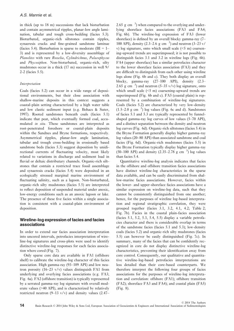
in thick (up to 18 m) successions that lack bioturbation
and contain asymmetrical ripples, planar-low angle lami-
nation, tabular and tough cross-bedding (facies 5.3).
Bioturbated, organic-rich siltstones contain ripples,
synaeresis cracks and fine-grained sandstone laminae
(facies 5.4). Bioturbation is sparse to moderate (BI = 1–3) and is represented by a low-diversity assemblage of
Planolites with rare Rosselia, Cylindrichnus, Palaeophycusand Phycosiphon. Non-bioturbated, organic-rich, silty
mudstones occur in a thick (17 m) succession in well 9/
2-2 (facies 5.5).
Interpretation
Coals (facies 5.2) can occur in a wide range of deposi-
tional environments, but their close association with
shallow-marine deposits in this context suggests a
coastal-plain setting characterized by a high water table
and low clastic sediment input (e.g. Bohacs & Suter,
1997). Rooted sandstones beneath coals (facies 5.1)
indicate that peat, which eventually formed coal, accu-
mulated in situ. These sandstones are interpreted as
root-penetrated foreshore or coastal-plain deposits
within the Sandnes and Bryne formations, respectively.
Asymmetrical ripples, planar-low angle lamination,
tabular and trough cross-bedding in erosionally based
sandstone beds (facies 5.3) suggest deposition by unidi-
rectional currents of fluctuating velocity, most likely
related to variations in discharge and sediment load in
fluvial or deltaic distributary channels. Organic-rich silt-
stones that contain a restricted trace fossil assemblage
and synaeresis cracks (facies 5.4) were deposited in an
ecologically stressed marginal marine environment of
fluctuating salinity, such as a lagoon. Non-bioturbated,
organic-rich silty mudstones (facies 5.5) are interpreted
to reflect deposition of suspended material under anoxic,
low-energy conditions such as an anoxic lagoon or lake.
The presence of these five facies within a single associa-
tion is consistent with a coastal-plain environment of
deposition.
Wireline-logexpressionof faciesand faciesassociations
In order to extend our facies association interpretation
into uncored intervals, petrofacies interpretation of wire-
line-log signatures and cross-plots were used to identify
distinctive wireline-log responses for each facies associa-
tion where cored (Fig. 7).
Only sparse core data are available in FA1 (offshore
shelf) to calibrate the wireline-log character of this facies
association. High gamma-ray (93–109 API) and low neu-
tron porosity (16–23 v/v) values distinguish FA1 from
underlying and overlying facies associations (e.g. FA3;
Fig. 6a). FA2 (offshore transition) is typically represented
by a serrated gamma-ray log signature with overall mod-
erate values (>40 API), and is characterized by relatively
restricted neutron (9–13 v/v) and density values (2.47–
2.65 g cm�3) when compared to the overlying and under-
lying shoreface facies associations (FA3 and FA4;
Fig. 6b). The wireline-log expression of FA3 (lower
shoreface) is defined by an overall blocky gamma-ray (7–100 API), density (2.3–2.6 g cm�3) and neutron (3–23 v/v) log signature, onto which small scale (<5 m) coarsen-
ing-upward trends are superimposed; it is not possible to
distinguish facies 3.1 and 3.2 in wireline logs (Fig. 6b).
FA4 (upper shoreface) has a similar petrofacies character
to the lower shoreface facies association (FA3) and they
are difficult to distinguish from each other using wireline
logs alone (Fig. 6b and c). They both display an overall
blocky, gamma-ray (27–100 API), density (2.3–2.65 g cm�3) and neutron (5–35 v/v) log signature, onto
which small scale (<5 m) coarsening-upward trends are
superimposed (Fig. 6b and c). FA5 (coastal plain) is rep-
resented by a combination of wireline-log signatures.
Coals (facies 5.2) are characterized by very low-density
(1.5–2.0 g cm�3) log values (Fig. 6c and d). Sandstones
of facies 5.1 and 5.3 are typically represented by funnel-
shaped gamma-ray log curves of low values (5–70 API),
and a distinct separation between the density and neutron
log curves (Fig. 6d). Organic-rich siltstones (facies 5.4) in
the Bryne Formation generally display higher gamma-ray
log values (20–80 API) than associated sandstone and coal
facies (Fig. 6d). Organic-rich mudstones (facies 5.5) in
the Bryne Formation typically display higher gamma-ray
(50–100 API) and density (2.35–2.78 g cm�3) log values
than facies 5.4.
Quantitative wireline-log analysis indicates that facies
in the offshore and offshore transition facies associations
have distinct wireline-log characteristics in the sparse
data available, and can be easily discriminated from shal-
low-marine facies associations. However, facies within
the lower- and upper-shoreface facies associations have a
similar expression on wireline-log data, such that they
cannot be consistently distinguished from one another;
hence, for the purposes of wireline log-based interpreta-
tion and regional stratigraphic correlation, they were
grouped together (facies 3.1, 3.2, 4.1, 4.2; Table 2;
Fig. 7b). Facies in the coastal plain-facies association
(facies 5.1, 5.2, 5.3, 5.4, 5.5) display a variable petrofa-
cies character and there is considerable overlap in terms
of the sandstone facies (facies 5.1 and 5.3); low-density
coals (facies 5.2) and organic-rich silty mudstones (facies
5.5) can however be easily distinguished (Fig. 7c). In
summary, many of the facies that can be confidently rec-
ognized in core do not display distinctive wireline-log
characteristics, preventing their identification away from
core control. Consequently, our qualitative and quantita-
tive wireline-log-based petrofacies interpretations are
less detailed than their core-based counterparts. We
therefore interpret the following four groups of facies
associations for the purposes of wireline-log interpreta-
tion and correlation: offshore (FA1); offshore transition
(FA2); shoreface FA3 and FA4); and coastal plain (FA5)
(Fig. 8).
© 2014 The AuthorsBasin Research © 2014 John Wiley & Sons Ltd, European Association of Geoscientists & Engineers and International Association of Sedimentologists14
A.S. Mannie et al.

DT/(µs/ft)
Facies Association 1 & 2: (offshore and offshore transition)
Facies Association 3 & 4: (lower and upper shoreface)
Facies Association 5: (coastal plain)
GR
(API
)
0
120
140 40
DT/(µs/ft)
GR
(API
)
0
120
140 40
DT/(µs/ft)
GR
(API
)
0
120
140 40
RHO
B (g
/cc)
NPHI (v/v)1.5
2.9
0 50
RHO
B (g
/cc)
NPHI (v/v)1.5
2.9
0 50
RHO
B (g
/cc)
NPHI (v/v)1.5
2.9
0 50
Facies 5.1
Facies 5.2
Facies 5.3 Facies 5.4 Facies 5.5
Facies 1.1
Facies 2.1
Facies 2.2
Facies 1.1
Facies 2.1
Facies 2.2
Facies 3.1
Facies 3.2
Facies 4.1
Facies 4.2
Facies 3.1
Facies 3.2
Facies 4.1
Facies 4.2
Facies 5.1
Facies 5.2
Facies 5.3
Facies 5.4
Facies 5.5
Facies 5.1: Rooted sandstone; Facies 5.2: Coal; Facies 5.3: Interbedded cross-stratified sandstone; Facies 5.4: Bioturbated organic-rich siltstones; Facies 5.5: Barren, organic-rich silty shale
Facies 1.1: Structureless calcareous mudstone; Facies 2.1: Bioturbated silty mudstone; Facies 2.2: Highly bioturbated siltstone;
Depths 1800-3200 m SS
Facies 3.1: Hummocky cross-stratified and bioturbated sandstone; Facies 3.2: Very fine to fine grained massive sandstone; Facies 4.1: Medium grained, cross-stratified, bioturbated sandstone; Facies 4.2: Fining upward bioturbated sandstone;
Depths 3150-3250 m SS
Depths 2400-3130 m SS
(a)
(b)
(c)
Fig. 7. Wireline-log cross-plots of, in left-hand column, Gamma Ray (GR) vs. Sonic (DT) data and, in right-hand column, Density
(RHOB) vs. Neutron Porosity (NPHI) data. These cross-plots illustrate the quantitative log character of the facies associations of the
Bryne and Sandnes formations: (a) offshore and offshore transition facies associations (FA1, FA2); (b) lower and upper shoreface facies
associations (FA3, FA4); and (c) coastal-plain facies association (FA5).
© 2014 The AuthorsBasin Research © 2014 John Wiley & Sons Ltd, European Association of Geoscientists & Engineers and International Association of Sedimentologists 15
Salt-influenced, shallow-marine deposition

NPHI0.5 0
Unit B
Unit C
FS1
FS2
Unit A
FS3
Unit D
FS5
Flooding surfaces (FS)/Stratigraphic
Sequences
Egersund
Sand
nes
Bryne
Formation
Triassic
16.2 km 27.8 km 9.0 km 1.8 km 50.2 kmNW SE
Egersund Basin Lista Nose
FS4
Sele High
14.8 km
Unit E
(a)
Top J50
Top J20
Top Triassic (IAU)
Top Zechstein
Top Rotliegend
Shoreface
Coastal plain3: Lower shoreface
4: Upper shoreface
5: Coastal plain
CORED INTERVALSFACIES ASSOCIATION
FACIES ASSOCIATION GROUPSIN WIRELINE-LOGS
SEISMIC LINE INTERPRETATION
Thin-skinned normal fault
Thick-skinned normal fault
FS4 (core and wireline-log data)
J50
J40/FS5
J20/FS1
SURFACES
intra-J40A (seismic data)
KEY
(biostratigraphy)
FS3 (core and wireline-log data)
FS2 (core and wireline-log data)
(biostratigraphy/core and wireline-log data)
17/12-1RGR
0 200RHOB
1.95 2.95DT
45145GR
0 200RHOB
1.95 2.95DT
45145
18/10-1GR
0 200RHOB
1.95 2.95DT
45145NPHI
0.5 0
9/2-2GR
0 200RHOB
1.95 2.95DT
45145NPHI
0.5 0
9/2-1GR
0 200RHOB
1.95 2.95DT
45145NPHI
0.5 0
9/2-4sGR
0 200RHOB
1.95 2.95NPHI
0.5 0
10/7-1GR
0 200RHOB
1.95 2.95DT
45145NPHI
0.5 0
20 m
(biostratigraphy/and wireline-log data)
17/12-2
17/12-1R 18/10-1 9/2-2 9/2-4S9/2-1 10/7-117/12-2
ListaNose
Epsilonsalt
diapir
Xi salt anticline
SeleHigh
5 km200 ms
0NPHI
0.5
9/2-4s 9/2-3Flooding
surfaces (FS)/Stratigraphic
Sequences
Unit B
Unit C
FS1
FS2
FS3
Unit D
FS5Unit E
FS4
Egersund
Sand
nes
Bryne
Formation
Unit A
15.0 km 11.3 km 0.8 km 10.6 km 17.8 km 42.9 kmNE SW
Stavanger Platform Egersund Basin(b)
GR0 200
RHOB1.95 2.95
DT45145
9/3-1
0NPHI
0.5
GR0 200
RHOB1.95 2.95
0NPHI
0.5
GR0 200
RHOB1.95 2.95
DT45145
9/2-5
0NPHI
0.5
GR0 200
RHOB1.95 2.95
9/4-4
0NPHI
0.5
GR0 200
RHOB1.95 2.95
DT45145
9/4-1
0NPHI
0.5
GR0 200
RHOB1.95 2.95
DT45145
8/12-1
0NPHI
0.5
GR0 200
RHOB1.95 2.95
DT45145
20 m
9/3-1 9/2-4s 9/2-3 9/2-5
2 km200 ms
© 2014 The AuthorsBasin Research © 2014 John Wiley & Sons Ltd, European Association of Geoscientists & Engineers and International Association of Sedimentologists16
A.S. Mannie et al.

SEQUENCE-STRATIGRAPHICFRAMEWORKOF THEMIDDLE-TO-UPPER JURASSIC SYN-RIFTSUCCESSION
Stratigraphic analysis of the Middle-to-Upper Jurassic
succession, constrained by the detailed facies association
framework established above, allows identification of
three, relatively low-frequency (ca. 5 Myr) sequences
that correspond to the North Sea basin-wide, J20?, J40
and J50 chronostratigraphic intervals of Partington et al.(1993) (Fig. 2b). The poorly dated J20? sequence (Bryne
Formation) consists of coastal-plain deposits (FA5), and
the overlying J40-to-J50 interval (Sandnes and Egersund
formations) records an overall landward migration of the
shoreline over a period of ca. 21 Myr (Fig. 2b). Based
on facies and facies association stacking patterns, four
upward-coarsening units are recognized within the J40-
to-J50 succession, and they are bound by relatively high-
frequency (ca. 1 Myr) flooding surfaces (surfaces FS1-
FS5 bounding stratal units B–E; Fig. 8). At the resolu-
tion and distribution of available data, units B–E do not
appear to contain erosional unconformities and basin-
ward facies shifts, such that there is no evidence for
base-level fall or sequence boundary formation in the
J40-to-J50 succession (sensu Van Wagoner et al., 1988).Instead, each unit corresponds to a single regressive suc-
cession or parasequence (sensu Van Wagoner et al.,1988). The J40-to-J50 interval therefore represents a ret-
rogradational parasequence set (sensu Van Wagoner
et al., 1988).
DISTRIBUTION ANDTHICKNESS OFSYN-RIFT SEQUENCES;THEROLEOFSYN-DEPOSITIONALTECTONICS
In this section, the sub-seismic sequence-stratigraphic
framework and gross facies distributions in the J40-to-
J50 succession, and their relationship with the rift- and
salt-related structures described above, are illustrated
using two regional stratigraphic correlations. The first
transect is oriented NW-SE, broadly parallel to regional
depositional dip, and crosses the Sele High through the
Egersund Basin in the NW (i.e. palaeoseaward), and the
Lista Nose in the SE (i.e. palaeolandward) (Figs. 1a and
8a). The second transect is oriented NE-SW, broadly
parallel to regional depositional strike, from the Stavan-
ger Platform in the NE, through the axis of the Egers-
und Basin in the SW (Figs 1b and 8b). To synthesize
our key observations we have constructed a series of pal-
aeogeographic maps for the four main stratigraphic units
(B–E) in the Sandnes Formation, based on the facies
association distribution at the point of maximum regres-
sion immediately below the capping flooding surface
(Fig. 9). To highlight the role that pre-, syn- or post-
depositional subsidence had on the original depositional
or subsequent preserved thickness of the studied strati-
graphic unit, the thickness of the J40 unit are displayed
on the palaeogeographic maps (Fig. 9). Seismic data res-
olution is insufficient and well data are spaced such that
it is not possible to determine if the constituent units of
J40 (to lowermost J50) change in thickness adjacent to
the salt structures and thin-skinned normal faults
described above; however, they all lie within a package
that either: (1) thickens towards faults bounding supra-
salt graben; or (2) thins towards salt-cored structural
highs, implying that these structures were active at the
time they were deposited.
Unit A
Description
The base of unit A, which corresponds to the Bryne For-
mation, is defined by the mid-Cimmerian or Intra-Aale-
nian unconformity. Core data indicate that Unit A is
composed exclusively of coastal-plain deposits (Figs 2b
and 8b). Unit A is overlain by a major flooding surface
that marks a regional transgression and the onset of shal-
low-marine deposition in the Egersund Basin (J20/FS1;
Fig. 8). Seismic and borehole data indicate that Unit A is
broadly tabular and at least 150 m thick across much of
the Egersund Basin, and thins abruptly (to 50 m) onto the
Lista Nose across the W-dipping fault that defines its
western margin (Fig. 8a). Locally, however, in the axis of
the Egersund Basin, seismic data indicate that Unit A is
wedge-shaped and clearly thickens towards faults that
bound the supra-salt wall graben (Fig. 4d and 5b), and
that the same unit thins across the salt anticline in the
NW of the basin (Fig. 5c).
Interpretation
Coastal-plain sediments (FA5) in Unit A were derived
either from the NW and from erosion of the Mid-North
Sea Dome during the initial stages of deflation and sub-
sidence of this structure, or from the NE and from ero-
sion of mainland Norway; provenance data from Unit A
would be required to test these two hypotheses. Accom-
modation during the Aalenian-to-Bajocian was likely
Fig. 8. Well-log correlation panels and seismic cross-sections illustrating: (a) transect oriented NW (palaeoseaward) to SE (palaeo-
landward), from the Sele High through the Egersund Basin to the Lista Nose, and (b) transect oriented along the basin axis from the
Stavanger Platform (NE) through the Egersund Basin (SW). See Fig. 1b for line locations. Well-log depths are in TVDSS (m); GR,
Gamma Ray (API); NPHI, neutron (v/v); RHOB, density (g cm�3) Well-log correlation panels use the top-J20 flooding surface as a
horizontal datum.
© 2014 The AuthorsBasin Research © 2014 John Wiley & Sons Ltd, European Association of Geoscientists & Engineers and International Association of Sedimentologists 17
Salt-influenced, shallow-marine deposition

generated by a combination of regional subsidence of the
Mid-North Sea Dome and relatively local subsidence
caused by the initiation of thick-skinned rift-related nor-
mal faulting along the margins of the Egersund Basin. In
support of the latter interpretation is the observation
that Unit A thins onto topographical highs such as the
Lista Nose, which are bound by thick-skinned normal
faults, and thinning of the unit across the Xi salt anti-
cline, which is genetically linked to and was triggered by
the initiation of slip on, the basin-bounding, Sele High
Fault System (Tvedt et al., in press). Supra-salt wall
graben was also active at this time as indicated by the
wedge-shaped geometry of Unit A adjacent to the
bounding thin-skinned normal faults.
Unit B
Description
Unit B is bound below and above by FS1 and FS2,
respectively (Fig. 8). In the south-east and central part of
the Egersund Basin, Unit B consists of a 0–20-m thick
package of shoreface sandstones, which pass downdip to
the NW and pinchout into a significantly thinner (<5 m)
package of offshore shelf mudstones and siltstone (e.g.
wells 18/10-1 and 17/12-1R; Fig. 8a). A fine-grained
succession is also developed on the Sele High, although,
present-day, the Sele High Fault System has ca. 1.5 km
of displacement (Fig. 4a). In the SE part of the basin,
Unit B displays a relatively constant thickness across
strike (ca. 20 m; Fig. 8b), and it is generally thinner (e.g.
10 m, well 10/7-1) but still composed entirely of shore-
face sandstones on adjacent topographical highs (e.g.
Stavanger Platform, Lista Nose, Flekkefjord High;
Fig. 8).
Interpretation
Unit B heralds the onset of shallow-marine sedimentation
in the Egersund Basin, triggered by a regional rise in rela-
tive sea-level and flooding of the basin, which was likely
eustatically driven (Hardenbol et al., 1998), but locally
augmented by minor rift-related normal faulting and sub-
sidence. We interpret that a very wide (up to 70-km along
depositional strike), broadly SW-NE-trending shoreface
facies belt was established in the Egersund Basin at this
time, and that this passed downdip to the NW into off-
shore shelf deposits (Fig. 9a). An important observation
is that this shoreface belt extended outside of the main de-
pocentre and onto the flanking fault-bound highs imply-
ing that, at this time, these structures were associated
Key
58oN
5oE4oE
LISTA NOSE
18/11-1
9/2-29/2-1
8/12-1
9/2-6s
N
STAVANGERPLATFORM
9/4-2
9/4-19/4-3
9/2-4s 9/3-1
9/2-59/2-3
9/4-4
9/2-7s9/2-9s
18/10-1
17/12-1R
17/12-3
17/12-2
10/8-1
9/8-1
10/7-1
8/9-1
EGERSUNDBASIN
FLEKKEFJORDHIGH
FISKEBANKBASIN
10/5-1
30 km
SELEHIGH
Unit B,Below FS2
58oN
5oE4oE
LISTA NOSE
18/11-1
9/2-29/2-1
8/12-1
9/2-6s
N
STAVANGERPLATFORM
9/4-2
9/4-19/4-3
9/2-4s 9/3-1
9/2-59/2-3
9/4-4
9/2-7s9/2-9s
18/10-1
17/12-1R
17/12-3
17/12-2
10/8-1
9/8-1
10/7-1
8/9-1
EGERSUNDBASIN
FLEKKEFJORDHIGH
FISKEBANKBASIN
10/5-1
30 km
SELEHIGH
Unit D,Below FS4
58oN
5oE4oE
LISTA NOSE
18/11-1
9/2-29/2-1
8/12-1
9/2-6s
N
STAVANGERPLATFORM
9/4-2
9/4-19/4-3
9/2-4s 9/3-1
9/2-59/2-3
9/4-4
9/2-7s9/2-9s
18/10-1
17/12-1R
17/12-3
17/12-2
10/8-1
9/8-1
10/7-1
8/9-1
EGERSUNDBASIN
FLEKKEFJORDHIGH
FISKEBANKBASIN
10/5-1
30 km
SELEHIGH
Unit E,Below FS5
58oN
5oE4oE
LISTA NOSE
18/11-1
9/2-29/2-1
8/12-1
9/2-6s
N
STAVANGERPLATFORM
9/4-2
9/4-19/4-3
9/2-4s 9/3-1
9/2-59/2-3
9/4-4
9/2-7s9/2-9s
18/10-1
17/12-1R
17/12-3
17/12-2
10/8-1
9/8-1
10/7-1
8/9-1
EGERSUNDBASIN
FLEKKEFJORDHIGH
FISKEBANKBASIN
10/5-1
30 km
SELEHIGH
Unit C,Below FS3
maximum extent of shoreface deposits based on coreand well data
localisedshoreline
maximum extent of shoreface deposits based on coreand well data
maximum extent of coastal-plaindeposits based on coreand well data
maximum extent of shoreface deposits based on coreand well data
thick-skinnednormal faults
salt structureson 3D seismic
STRUCTURE
J40 UNIT WELL THICKNESS (m)
< 2021-5051-125> 125
FACIES ASSOCIATION GROUPS
Shoreface
Coastal plain
localisedshoreline
(a) (b)
(c) (d)
Fig. 9. Palaeogeographic maps with basin-bounding, thick-skinned normal faults, salt structures and J40 unit well thickness illustrat-
ing the distribution of facies associations at maximum regression during the four stratigraphic sequences (b–e) shown in Fig. 8: (a)facies distribution below FS2; (b) facies distribution below FS3; (c) facies distribution below FS4; (d) facies distribution below FS5.
© 2014 The AuthorsBasin Research © 2014 John Wiley & Sons Ltd, European Association of Geoscientists & Engineers and International Association of Sedimentologists18
A.S. Mannie et al.
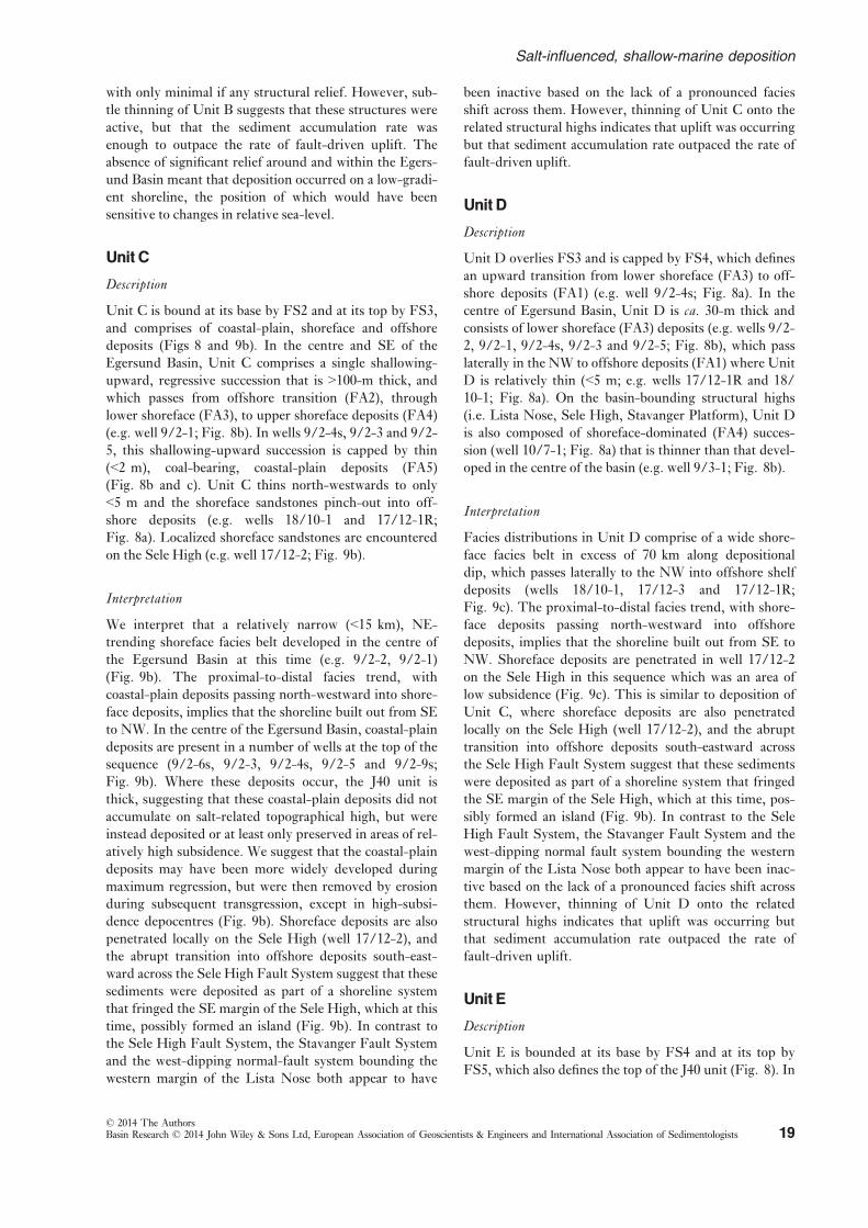
with only minimal if any structural relief. However, sub-
tle thinning of Unit B suggests that these structures were
active, but that the sediment accumulation rate was
enough to outpace the rate of fault-driven uplift. The
absence of significant relief around and within the Egers-
und Basin meant that deposition occurred on a low-gradi-
ent shoreline, the position of which would have been
sensitive to changes in relative sea-level.
Unit C
Description
Unit C is bound at its base by FS2 and at its top by FS3,
and comprises of coastal-plain, shoreface and offshore
deposits (Figs 8 and 9b). In the centre and SE of the
Egersund Basin, Unit C comprises a single shallowing-
upward, regressive succession that is >100-m thick, and
which passes from offshore transition (FA2), through
lower shoreface (FA3), to upper shoreface deposits (FA4)
(e.g. well 9/2-1; Fig. 8b). In wells 9/2-4s, 9/2-3 and 9/2-
5, this shallowing-upward succession is capped by thin
(<2 m), coal-bearing, coastal-plain deposits (FA5)
(Fig. 8b and c). Unit C thins north-westwards to only
<5 m and the shoreface sandstones pinch-out into off-
shore deposits (e.g. wells 18/10-1 and 17/12-1R;
Fig. 8a). Localized shoreface sandstones are encountered
on the Sele High (e.g. well 17/12-2; Fig. 9b).
Interpretation
We interpret that a relatively narrow (<15 km), NE-
trending shoreface facies belt developed in the centre of
the Egersund Basin at this time (e.g. 9/2-2, 9/2-1)
(Fig. 9b). The proximal-to-distal facies trend, with
coastal-plain deposits passing north-westward into shore-
face deposits, implies that the shoreline built out from SE
to NW. In the centre of the Egersund Basin, coastal-plain
deposits are present in a number of wells at the top of the
sequence (9/2-6s, 9/2-3, 9/2-4s, 9/2-5 and 9/2-9s;
Fig. 9b). Where these deposits occur, the J40 unit is
thick, suggesting that these coastal-plain deposits did not
accumulate on salt-related topographical high, but were
instead deposited or at least only preserved in areas of rel-
atively high subsidence. We suggest that the coastal-plain
deposits may have been more widely developed during
maximum regression, but were then removed by erosion
during subsequent transgression, except in high-subsi-
dence depocentres (Fig. 9b). Shoreface deposits are also
penetrated locally on the Sele High (well 17/12-2), and
the abrupt transition into offshore deposits south-east-
ward across the Sele High Fault System suggest that these
sediments were deposited as part of a shoreline system
that fringed the SE margin of the Sele High, which at this
time, possibly formed an island (Fig. 9b). In contrast to
the Sele High Fault System, the Stavanger Fault System
and the west-dipping normal-fault system bounding the
western margin of the Lista Nose both appear to have
been inactive based on the lack of a pronounced facies
shift across them. However, thinning of Unit C onto the
related structural highs indicates that uplift was occurring
but that sediment accumulation rate outpaced the rate of
fault-driven uplift.
Unit D
Description
Unit D overlies FS3 and is capped by FS4, which defines
an upward transition from lower shoreface (FA3) to off-
shore deposits (FA1) (e.g. well 9/2-4s; Fig. 8a). In the
centre of Egersund Basin, Unit D is ca. 30-m thick and
consists of lower shoreface (FA3) deposits (e.g. wells 9/2-
2, 9/2-1, 9/2-4s, 9/2-3 and 9/2-5; Fig. 8b), which pass
laterally in the NW to offshore deposits (FA1) where Unit
D is relatively thin (<5 m; e.g. wells 17/12-1R and 18/
10-1; Fig. 8a). On the basin-bounding structural highs
(i.e. Lista Nose, Sele High, Stavanger Platform), Unit D
is also composed of shoreface-dominated (FA4) succes-
sion (well 10/7-1; Fig. 8a) that is thinner than that devel-
oped in the centre of the basin (e.g. well 9/3-1; Fig. 8b).
Interpretation
Facies distributions in Unit D comprise of a wide shore-
face facies belt in excess of 70 km along depositional
dip, which passes laterally to the NW into offshore shelf
deposits (wells 18/10-1, 17/12-3 and 17/12-1R;
Fig. 9c). The proximal-to-distal facies trend, with shore-
face deposits passing north-westward into offshore
deposits, implies that the shoreline built out from SE to
NW. Shoreface deposits are penetrated in well 17/12-2
on the Sele High in this sequence which was an area of
low subsidence (Fig. 9c). This is similar to deposition of
Unit C, where shoreface deposits are also penetrated
locally on the Sele High (well 17/12-2), and the abrupt
transition into offshore deposits south-eastward across
the Sele High Fault System suggest that these sediments
were deposited as part of a shoreline system that fringed
the SE margin of the Sele High, which at this time, pos-
sibly formed an island (Fig. 9b). In contrast to the Sele
High Fault System, the Stavanger Fault System and the
west-dipping normal fault system bounding the western
margin of the Lista Nose both appear to have been inac-
tive based on the lack of a pronounced facies shift across
them. However, thinning of Unit D onto the related
structural highs indicates that uplift was occurring but
that sediment accumulation rate outpaced the rate of
fault-driven uplift.
Unit E
Description
Unit E is bounded at its base by FS4 and at its top by
FS5, which also defines the top of the J40 unit (Fig. 8). In
© 2014 The AuthorsBasin Research © 2014 John Wiley & Sons Ltd, European Association of Geoscientists & Engineers and International Association of Sedimentologists 19
Salt-influenced, shallow-marine deposition

the Egersund Basin, this sequence is up to 10-m thick and
consists of upward-fining offshore deposits (FA1),
whereas on the Stavanger Platform, it comprises offshore
transition (FA2) deposits (well 9/3-1; Fig. 8b). Biostrati-
graphic data indicate that Unit E is absent on the Fle-
kkefjord High (wells 9/4-1 and 8/12-1; Fig. 8b).
Interpretation
Unit E marks the onset of relatively distal, fully marine
conditions across the Egersund Basin and flooding of the
adjacent structural highs, which is likely linked to the
major eustatically driven, tectonically augmented trans-
gression that characterized the latest Jurassic-to-earliest
Cretaceous across much of the northern North Sea
(Figs 8 and 9d).
DISCUSSION
Regional controls onsyn-rift stratigraphicarchitecture in salt-influenced rifts
Thermal deflation and subsidence of the Mid-North Sea
Dome, coupled with a rise in eustatic sea-level, were
responsible for creating regional accommodation during
the Middle-to-Late Jurassic and for controlling the over-
all net-transgressive stratigraphic architecture of the stud-
ied succession (Underhill & Partington, 1993; Hampson
et al., 2009). Overall thinning and pinchout of shoreface
deposits towards the WNW-NW, and the overall NNE-
SSW trend of the shoreline in successive depositional
sequences, strongly suggest that sediment supply was
either: (i) delivered directly to the Egersund Basin from
the Stavanger Platform to the E; or (ii) fed along-strike
into the basin by longshore currents. Despite the Middle-
to-Late Jurassic, rift-margin setting of the Egersund
Basin, sediment supply to the basin was relatively low and
was eventually outpaced by a rise in relative sea-level,
thereby resulting in the net-transgressive stratigraphic
architecture. There were times, however, when sediment
supply and regional subsidence were broadly in balance,
such that a thick (>150 m), aggradational package of
shoreface deposits were deposited in the basin axis. Fur-
thermore, the wide shoreface facies belts (Fig. 9a and c)
suggest a relatively low shoreline gradient, which would
have resulted in the shoreline being extremely sensitive to
small eustatic changes (Fig. 9b). However, the strongly
aggradational motif of the studied succession suggests
that such eustatic changes did not occur or, if they did,
they were minor.
Local controls onsyn-rift stratigraphicarchitecture in salt-influenced rifts
The growth of thick-skinned, basin-bounding fault sys-
tems, salt structures and thin-skinned, salt-related normal
faults and folds locally overprinted the more regional con-
trols on subsidence, accommodation and stratigraphic
architecture described above. In the axis of the Egersund
Basin, the large (>70 km) dip extent of shallow-marine
shoreface deposits is suggestive of relatively low deposi-
tional gradients; in this respect, the Egersund Basin acted
a relatively stable, gently subsiding structural block,
despite the overall rift basin setting. However, seismic
and borehole data indicate marked changes in thickness
do occur on relatively short length scales (<5 km), espe-
cially towards the crests of salt structures and across thin-
skinned, salt-related normal faults. These changes in
thickness are not however associated with a change in
facies, which suggests that sediment aggradation rates
outpaced structurally induced changes in relief and
accommodation (cf. Doglioni et al., 1998). As a result,
syn-depositional intra-basinal normal faults and salt
structures were not expressed at the depositional surface
and they did not therefore influence the relative roles of
physical processes (e.g. waves and tides) occurring within
the basin. These structures were however critical in terms
of creating additional accommodation and thus preserving
locally thickened successions of syn-rift strata.
The only example of structurally induced facies parti-
tioning occurs in the eastern part of the Egersund Basin
in association with the basin-bounding Sele High Fault
System. During the onset of rifting in the Middle Juras-
sic, offshore deposits extended across the Sele High,
implying that the Sele High Fault System was either not
active, or was active but not associated with significant
relief (Fig. 9a); a similar interpretation can be made for
the Stavanger Fault System and the structure bounding
the western margin of the Lista Nose. An abrupt change
in water depth, which we attribute to an increase in slip
rate of and the relief associated with the Sele High Fault
System, resulted in the development of a fringing shore-
line in the immediate footwall of the fault, whereas dee-
per water conditions and mudstone deposition persisted
in its hangingwall (Fig. 9b and c). This abrupt facies
transition reflects steeper, fault-related bathymetric gra-
dients during the rift-climax, at a time when fault throw
rates were high, differential accommodation generation
was greatest, and tectonic subsidence locally outpaced
sediment supply (cf. Prosser, 1993; Gawthorpe & Lee-
der, 2000).
Controlson the stratigraphic development ofnet-transgressive shallow-marine systems
In order to place the Middle-to-Upper Jurassic strata of
the Egersund Basin in a wider context, a comparison was
made with net-transgressive, tectonically influenced shal-
low-marine strata in a number of other salt-influenced
and salt-free sedimentary basins (Table 4). Although we
have focused on salt-influenced rifts, we extend our com-
parison to rifts that lack salt and passive margin settings.
In this way, we can further highlight the key role that
intra-basin salt tectonics can have on basin physiography,
accommodation development and syn-rift stratigraphic
architecture. To structure this comparison, we focus on
© 2014 The AuthorsBasin Research © 2014 John Wiley & Sons Ltd, European Association of Geoscientists & Engineers and International Association of Sedimentologists20
A.S. Mannie et al.

several key parameters: (1) sediment provenance; (2)
structural styles active during deposition; (3, 4) thickness
and net-to-gross ratio of the net-transgressive strata from
the crest to the flank of salt structures, and from the foot-
wall to hanging wall of normal faults; (5) expansion index
across active structures (Thorsen, 1963; Cartwright &
Dewhurst, 1998; Bouroullec et al., 2004; Jackson & Rote-
vatn, 2013); (6) sediment accumulation rate; (7) deposi-
tional process regime; (8) dip extent of the shallow-
marine sandstones in areas of active structures; and (9)
orientation of shorelines relative to the structural grain of
the basin (Table 4). For consistency, a net-transgressive
shallow-marine succession is defined at its base by an
abrupt deepening of facies above coastal-plain deposits
and at its top by a flooding surface into fine-grained, off-
shore deposits that document deposition below normal
storm-wave base.
Our analysis indicates that Middle-to-Upper Jurassic
strata in the Egersund Basin share many similarities to the
other basin types. In salt-influenced basins, an increase in
thickness is noted from the crest to the flank of salt struc-
tures (Table 4) (e.g. Alves et al., 2003; Aschoff & Giles,
2005; Kieft et al., 2010) and in salt-free rift basins, syn-
rift strata thicken from the footwall to hangingwall of
active normal faults (Table 4) (e.g. Maxwell et al., 1999;Davies et al., 2000; Kuhn et al., 2003; Jackson et al.,2005; Zecchin et al., 2006). Such increase in thickness is
typically accompanied by a decrease in sandstone content
(i.e. net-to-gross; Table 4). For example, where strati-
graphic units thin towards the crest of salt structures, the
net-to-gross increases (Table 4) (e.g. Alves et al., 2003;Aschoff & Giles, 2005; Kieft et al., 2010). Furthermore,
where expansion index values are >2.0 facies changes are
noted. A good example of this relationship occurs in the
Bombarral-Alcobaca sub-basin western Portugal, where
shallow-marine carbonates restricted to the crests of salt
pillows pass downdip into mudstone-dominated, turbi-
dite-bearing successions in the flanking minibasins (Alves
et al., 2003). Similarly, in the Hugin Formation, South
Viking Graben, northern North Sea, wave- and tide-
influenced, shallow-marine deposits located at the crests
of salt-cored structural highs pass downdip into offshore
mudstones in adjacent minibasins (Kieft et al., 2010). Incontrast, where expansion index values are <2.0, sand-stone content remains relatively unaffected by thickness
variations across active structures, facies variations are
absent, and aggradational successions are developed,
implying that relatively low rates of subsidence did not
result in across-fault changes in water depth and therefore
depositional environment (Table 4) (e.g. Maxwell et al.,1999; Kuhn et al., 2003). In some cases, syn-rift strata in
the hangingwall display a strong tidal influence, implying
that the depocentre-bounding structure was associated
with a subaerial or shallow-marine scarp, which locally
constrained and augmented tidal energy (Mellere & Steel,
1996; Maxwell et al., 1999; Jackson et al., 2005; Zecchinet al., 2006).
The sediment provenance in most of the basins illus-
trated in Table 4 is extra-basinal, with the exception of
the Upper Jurassic, shallow-marine sandstones of the
Fulmar Formation in the UK Central Graben (Kuhn
et al., 2003). The dip extent of the in the Fulmar Forma-
tion, which are genetically related to but slightly younger
than the Sandnes Formation, is limited (up to 1.5 km)
due to local sourcing from a relatively small, intra-basinal
fault scarp (Table 4) (Kuhn et al., 2003). In salt-influ-
enced basins, the depositional dip extent of the shallow-
marine sandstones is <40 km (Alves et al., 2003; Aschoff& Giles, 2005; Kieft et al., 2010), whereas in active rifts,
it is <10 km (Maxwell et al., 1999; Davies et al., 2000;Zecchin et al., 2006) and in passive foreland basins, it is
<20 km (Olsen et al., 1999) (Table 4). We suggest that
the anomalously large dip extent (up to 70 km) of net-
transgressive shallow-marine sandstones in the Egersund
Basin is related to the low depositional gradient in the axis
of the basin and its close proximity to a sediment source
(i.e. the Stavanger Platform and mainland Norway). In
general, the orientation of the shoreline relative to the
trend of syn-depositional structures does not seem to
influence the depositional dip extent of the shallow-mar-
ine sandstones.
Net-transgressive sandstones developed along the wes-
tern margin of the Western Cretaceous Interior Seaway,
United States, which lay within a thermally subsiding
foreland basin and was thus tectonically passive for much
of its evolution (e.g. Liu et al., 2011), were wave-domi-
nated and display little evidence for the influence of tides.
Shallow-marine sandstones were sourced from the basin
margin cordillera and have a depositional dip extent of
9–20 km (Table 4) (Olsen et al., 1999). These values aresimilar to those for net-transgressive shallow-marine
sandstones in salt-influenced basins and salt-free rift
basins, implying that the depositional dip extent of such
deposits is not simply related to basin type, but rather
reflects local or sub-regional substrate gradient, and the
location of the basin with respect to a large, typically
extra-basinal sediment source (Table 4).
CONCLUSIONS
An integrated dataset of seismic, wireline-log, biostrati-
graphic and core data has been analysed in order to under-
stand the influence of structural controls on depositional
thickness and gross facies distributions of a net-transgres-
sive succession in a salt-influenced, rift basin. Mapping of
key seismic horizons provides the framework to character-
ize the main structural styles of the basin. When inte-
grated with facies analysis of cores and wireline logs,
biostratigraphically constrained correlation and seismic
attribute analysis, seismic mapping enables the role of
structures on subsidence, stratigraphic thickness and
depositional patterns to be elucidated. The key findings of
this study are:
© 2014 The AuthorsBasin Research © 2014 John Wiley & Sons Ltd, European Association of Geoscientists & Engineers and International Association of Sedimentologists 21
Salt-influenced, shallow-marine deposition

● Thick-skinned, basement-involved normal faults, salt
structures and thin-skinned, basement-detached nor-
mal faults are identified as the main structural controls
influencing deposition of the Middle-to-Upper Juras-
sic Bryne, Sandnes and Egersund formations of the
J20-J50 unit in the Egersund Basin. Similar to that
observed in other salt-influenced basins, these struc-
tures influenced depositional thickness by creating
accommodation space on the flanks of salt diapirs,
walls and pillows, in the hangingwall of normal faults,
and in crestal graben above salt structures.
● Sedimentological descriptions of core and wireline-
log data have identified five facies associations in the
J20-J40 unit of the Bryne and Sandnes formations: (1)
offshore; (2) offshore transition; (3) lower shoreface;
(4) upper shoreface; and (5) coastal plain. Vertical
facies successions define upward-shallowing, low-
energy, wave-dominated offshore and shoreface
Table 4. Parameters describing the influence of salt structures and normal faulting on net-trangressive, shallow-marine stratigraphy
Basin name Basin type
Stratigraphic
unit
Age
(duration/Myr)
Sediment
provenance
Structural
styles
during
deposition
*Thickness
(m)
Egersund Basin,
North Sea,
Norway
Salt-influenced
active rift
Sandnes
Formation
Callovian-
Oxfordian (5.0)
Extra-basinal Xi salt anticline 16|31
Alpha salt wall 112|155
Bombarral-
Alcobaca sub-
basin, West
Iberia
Salt-influenced
active rift
Alcobaca
Formation
(A2-A3 unit)
Oxfordian-
Kimmeridgian
(2.6)
Extra-basinal Bolhos-Vimerio
salt pillow
275|650
Montejunto salt
pillow
120|560
South Viking
Graben, North
Sea, Norway
Salt-influenced
active rift
Hugin
Formation
Callovian (3.5) Extra-basinal Salt-cored high 50|75
La Popa Basin,
Mexico
Salt-influenced
active rift
Delgado
Sandstone
Member
Maastrichtian (3.9) Extra-basinal El Gordo diapir 10|30
El Papalote
diapir
10|40
Central Graben,
North Sea, UK
Salt-influenced
active rift
Fulmar
Formation
Kimmeridgian (1.0) Intra-basinal Fulmar Field
normal fault
150|250
East Shetland
Basin, North
Sea, Norway
Active rift Tarbert
Formation
Bajocain-Bathonian
(4.0)
Extra-basinal Statfjord East
normal fault
0|70
Beryl
Embayment-
North Sea,
United Kingdom
Active rift Beryl Formation Bathonian (3.0) Extra-basinal B2 normal fault 75|120
45|56
Crotone Basin,
southern Italy
Active rift Zinga (Unit 2
and 3)
Pilocene (1.5) Extra-basinal Zinga normal
fault
55|185
Montagna-Piana
normal fault
55|333
Gulf of Suez Rift,
Egypt
Active rift Nukhul
Formation
Miocene (1.4) Extra-basinal East Tanka
normal fault
0|45
Cretaceous
Interior Seaway,
NewMexico
Foreland Hosta Tongue
SAndstone
Santonian (0.5) Extra-basinal Passive <50
Cretaceous
Interior Seaway,
SW Colorado
Foreland Cliff house
formation
Campanian (2.0) Extra-basinal Passive 200
(4 individual
sandstone
tongues
50–55 m)
*Represent thickness of stratigraphic unit from the crest|flank of salt structures or from the footwall|hangingwall of normal faults.
†Percentage of stratigraphic unit that is sandstone or carbonate on the crest|flank of salt structures or in the footwall|hangingwall of normal faults.
‡Expansion Index = (thickness of stratigraphic unit on the flank of salt structures or in the hanging wall of normal faults)/(thickness of stratigraphic
§Accumulation Rate (m Myr�1) = (maximum thickness of stratigraphic unit)/(duration of deposition).
¶In a net-transgressive succession shallow marine is defined at the base by an abrupt deepening of facies across a flooding surface and at the top by
a flooding surface into offshore transition or shelf deposits.
© 2014 The AuthorsBasin Research © 2014 John Wiley & Sons Ltd, European Association of Geoscientists & Engineers and International Association of Sedimentologists22
A.S. Mannie et al.

deposits, capped by coal-bearing coastal-plain succes-
sions bounded by five key flooding surfaces (FS1-
FS5) that sub-divide the J20-to-J40 unit into five
stratigraphic units (A–E). Wave-dominated, shallow-
marine depositional processes are common in net-
transgressive salt-influenced basins.
● Though these five stratigraphic units (A–E) are
marked by stratal thickness changes across salt struc-
tures and most normal faults, facies variability is
limited where calculated expansion index values are
<2.0. This suggests that sediment supply outpaced
accommodation generation across actively growing
structures throughout much of the study area during
deposition of these stratigraphic sequences. In other
salt-influenced basins, facies changes due to bathy-
metric or topographical expression of salt structures
are only observed where expansion index values are
in salt-influenced and active rift basins
†Net:
gross
(%)
‡Expansion
index
§Accumulation
rate (m/Myr)
Depositional
process
¶Depositional
dip extent of
shallow marine
sandstone (km)
Shoreline
orientation
relative to
structural
grain References
90|80 1.9 6 Wave-dominated
shallow marine with
minor tidal influence
70 Transverse
95|90 1.4 30
65|5 2.4 250 Current and wave-
dominated shallow
marine reefal
carbonates; turbidities
40 Transverse Alves et al. (2003)
30|10 4.7 215
100|20 3.0 21 Wave and tide-
dominated shallow
marine
>15 Axial Kieft et al. (2010)
100|25 3.0 10 Wave-dominated
shallow marine
20 Transverse Aschoff & Giles (2005);
Lawton et al. (2001)100|50 4.0
100|100 1.7 250 Wave-dominated
shallow marine
1.5 Axial Kuhn et al. (2003)
0|80 - 17 Wave-dominated
shallow marine; fluvial
7 Transverse Davies et al. (2000)
100|95 1.6 40 Tide-dominated
shallow marine
10 Transverse Maxwell et al. (1999);Karasek et al. (2003)98|98 1.2 18
3.4 123 Wave-dominated and
tidal influenced
shallow marine;
lagoonal
3–5 Axial Zecchin et al. (2004);Zecchin et al. (2006)
6.0 222
0|80 - 32 Tidally influenced
shallow marine
3 Transverse Jackson et al. (2005)
- - 100 Wave-dominated
shallow marine with
tidal influence
9–11 - Sixsmith et al. (2008)
- - 100 Wave-dominated
shallow marine
10–20 - Olsen et al. (1999)
unit on the crest of salt structures or in the footwall of normal faults).
© 2014 The AuthorsBasin Research © 2014 John Wiley & Sons Ltd, European Association of Geoscientists & Engineers and International Association of Sedimentologists 23
Salt-influenced, shallow-marine deposition

>2.0 and record a shallowing of facies from the flank
to crest of salt structures.
● Abrupt lateral facies change linked to differential
tectonic subsidence only occurs across a basement-
involved normal fault in stratigraphic Units C and
D, where shoreface deposits on the slowly subsiding
Sele High pass into offshore deposits in the more
rapidly subsiding Egersund Basin. This lateral
change indicates that accommodation generation
locally outpaced sediment supply in the fault hang-
ingwall.
● Thin, coal-bearing coastal-plain deposits that cap
Unit C (just below FS3) are preserved only in depo-
centres associated with high rates of normal-fault-
hangingwall and/or salt-withdrawal subsidence. Sim-
ilar coastal-plain deposits may have been present in
adjacent areas of low subsidence, but were removed
by subsequent transgressive erosion.
● The close proximity of the Egersund Basin to the
heavily eroded structural high of the Stavanger Plat-
form and a low shoreline gradient can account for the
anomalously large depositional dip extent (up to
70 km) of the Middle-to-Upper Jurassic net-trans-
gressive shallow-marine sandstones. In other salt-
influenced basins, extra-basinally sourced, net-trans-
gressive shallow-marine sandstones have depositional
dip extents of <40 km. In contrast, corresponding dip
extent in rift-basins where salt is absent are <10 km.
● In this basin reservoir, distribution is more wide-
spread than originally predicted as compared to other
tectonically active salt-influenced basins. No unex-
pected lateral facies changes are observed during the
growth of salt structures and internal facies heteroge-
neity are absent, reducing the risk of reservoir quality
in the basin.
The results of this study highlight the complexity of
proposing a distinct depositional model for salt-influ-
enced rift basins. Basin physiography, rate of accommo-
dation creation and sediment flux are the main factors
controlling depositional thickness and processes, net:gross
variability, depositional dip extent and the resulting
stratigraphic architecture of the basin.
ACKNOWLEDGEMENTS
We would like to thank PGS for providing access to the
seismic data and for granting permission to publish the
results of this study. We also thank Mike Charnock for
biostratigraphic data and related discussions, and the
Norwegian Petroleum Directorate for providing access to
the core data. Centrica Energi Norge and the Common-
wealth Commission are gratefully acknowledged for fund-
ing and support of this work. Stuart Archer, Helen Lever
and David Hodgson are thanked for their critical reviews
which improved the manuscript. Journal editor Jeffrey
Nunn is also thanked for his insightful suggestions.
REFERENCESALVES, T.M., MANUPPELLA, G., GAWTHORPE, R.L., HUNT,
D.W. & MONTEIRO, J.H. (2003) The depositional evolution
of diapir- and fault-bounded rift basins: examples from
the Lusitanian Basin of West Iberia. Sed. Geol., 162, 273–303.
ASCHOFF, J.L. & GILES, K.A. (2005) Salt diapir-influenced, shal-
low-marine sediment dispersal patterns: insights from out-
crop analogs. Am. Assoc. Pet. Geol. Bull., 89, 447–469.BANHAM, S.G. & MOUNTNEY, N.P. (2013) Evolution of fluvial
systems in salt-walled mini-basins: a review and new insights.
Sed. Geol., 296, 142–166.BOHACS, K. & SUTER, K. (1997) Sequence stratigraphic distribu-
tion of coaly rocks: fundamental controls and paralic exam-
ples. Am. Assoc. Pet. Geol. Bull., 81, 1612–1639.BOUROULLEC, R., CARTWRIGHT, J.A., JOHNSON, H.D., LANSIG-
U, C.A., QUEMENER, J.-M. & SAVANIER, D., eds. (2004)
Syndepositional faulting in the Gres d’ Annot Formation,
SE France: high-resolution kinematic analysis and strati-
graphic response to growth faulting. In: Deep-Water Sedi-mentation in the Alpine Basin of SE France: New Perspectiveon the Gres d’ Annot and Related Systems (Ed. by P. Joseph
& S.A. Lomas) Geol. Soc. London Spec. Publ., 122, 241–265.
BROWN, A.R. (1999) Interpretation of Three-Dimensional
Seismic Data. Am. Assoc. Pet. Geol. Mem., 42, 530–533.BULLIMORE, S.A. & HELLAND-HANSEN, W. (2009) Trajectory
analysis of the lower Brent Group (Jurassic), Northern North
Sea: contrasting depositional patterns during the advance of a
major deltaic system. Basin Res., 21, 559–572.CAMPBELL, C.V. (1967) Lamina, laminaset, bed and bedset. Sedi-mentology, 8, 7–26.
CARR, I.D., GAWTHORPE, R.L., JACKSON, C.A.L. & SHARP, I.R.
(2003) Sedimentology and sequence stratigraphy of early syn-
rift tidal sediments: the Nukhul Formation, Suez Rift, Egypt.
J. Sediment. Res., 73, 407–420.CARTWRIGHT, J.A. & DEWHURST, D. (1998) Layer-bound
compaction faults in fine-grained sediments. Bull. Geol. Soc.Am., 110, 1242–1257.
DAVIES, S.J., DAWERS, N.H., MCLEOD, A.E. & UNDERHILL, J.R.
(2000) The structural and sedimentological evolution of early
syn-rift successions: the Middle Jurassic Tarbert Formation,
North Sea. Basin Res., 12, 343–365.DAVISON, I., BOSENGE, D., ALSOP, G.I. & MOHAMMED, H.A.L.-
A. (1996) Deformation and sedimentation around active Mio-
cene salt diapirs on the Tihama, northwest Yemen. In: SaltTectonics (Ed. by G.I. Alsop, D.J. Blundell & I. Davison).
Geol. Soc. London Spec. Publ., 100, 23–39.DAVISON, I., ALSOP, I., BIRCH, P., ELDERS, C., EVANS, N., NICH-
OLSON, H., RORISON, P., WADE, D., WOODWARD, J. & YOUNG,
M. (2000) Geometry and late-stage structural evolution of
Central Graben salt diapirs, North Sea. Mar. Pet. Geol., 17,499–522.
DOGLIONI, C., AGOSTINO, N.D. & MARIOTTI, G. (1998) Normal
faulting vs regional subsidence and sedimentation rate. Mar.Pet. Geol., 15, 737–750.
DOTT, R.H. & BOURGEOIS, J. (1982) Hummocky stratification:
significance of its variable bedding sequences. Geol. Soc. Am.Bull., 93, 663–680.
FRASER, S.I., ROBINSON, A.M., JOHNSON, H.D., UNDERHILL,
J.R., KADOLSKY, D.G.A., CONNELL, R., JOHANNESSEN, P. &
© 2014 The AuthorsBasin Research © 2014 John Wiley & Sons Ltd, European Association of Geoscientists & Engineers and International Association of Sedimentologists24
A.S. Mannie et al.
RAVN�AS, R. (2003) Upper Jurassica. In: The Millennium Atlas:Petroleum Geology of the Central and Northern North Sea (Ed.by D. Evans, C. Graham, A. Armour & P. Bathurst), pp.
157–189. The Geological Society, London.
GAWTHORPE, R.L. & LEEDER, M.R. (2000) Tectono-sedimentary
evolution of active extensional basins. Basin Res., 12, 195–218.
GE, H. & JACKSON, M.P.A. (1998) Physical modelling of struc-
tures formed by salt withdrawal: implications for deformation
caused by salt dissolution. Am. Assoc. Pet. Geol. Bull., 82,228–250.
GILES, K.A. & ROWAN, M.G. (2012) Concepts in halokinetic-
sequence deformation and stratigraphy. In: Salt Tectonics,Sediments and Prospectivity (Ed. by G.I. Alsop), Geol. Soc.London Spec. Publ., 363, 7–31.
GLENNIE, K.W. (1998) Petroleum Geology of the North Sea: BasicConcepts and Recent Advances. 4th edn.. pp. 294–349. TheGeological Society, London.
GLENNIE, K.W., HIGHAM, J. & STEMMERIK, L. (2003) Permian.
In: The Millennium Atlas: Petroleum Geology of the Central andNorthern North Sea (Ed. by D. Evans, C. Graham, A. Armour
& P. Bathurst), pp. 212–258. The Geological Society,
London.
GOLDSMITH, P.J., HUDSON, G. & VAN VEEN, P. (2003) Triassica.In: The Millennium Atlas: Petroleum Geology of the Central andNorthern North Sea (Ed. by D. Evans, C. Graham, A. Armour
& P. Bathurst), pp. 260–314. The Geological Society,
London.
GOWLAND, S. (1996) Facies characteristics and depositional
model of highly bioturbated shallow marine siliciclastic strata:
an example from the Fulmar Formation (Upper Jurassic),
UK Central Graben. In: Geology of the Humber Group: Cen-tral Graben and Moray Firth, UKCS (Ed. by A. Hurst, H.D.
Johnson, S.D. Burley, A. Canham & D.S. Mackertich) Geol.Soc. London Spec. Publ., 114, 185–214.
HAMPSON, G.J., SIXSMITH, P.J., KIEFT, R.L., JACKSON, C.A.-L.
& JOHNSON, H.D. (2009) Quantitative analysis of net-trans-
gressive shoreline trajectories and stratigraphic architectures:
mid-to-late Jurassic of the North Sea Rift Basin. Basin Res.,21, 528–558.
HARDENBOL, J., THIERRY, J., FARLEY, M.B., DE GRACIANSKY,
P.C. & VAIL, P. (1998) Mesozoic and Cenozoic sequence
chronostratigraphic framework of European basins. In: Meso-zoic and Cenozoic Sequence Stratigraphy of European Basins(Ed. by P.C. Graciansky) SEPM Spec. Publ., 60, 3–13.
HARMS, J.C., SOUTHARD, J.B., SPEARING, D.R. & WALKER, R.G.
(1975) Depositional environments as interpreted from pri-
mary sedimentary structures and stratification sequences. Soc.Econ. Paleont. Miner., Short Course, 2, 161.
HUDEC, M.R. & JACKSON, M.P.A. (2007) Terra infirma: under-
standing salt tectonics. Earth-Sci. Rev., 82, 1–28.JACKSON, C.A.-L. & LEWIS, M.M. (2013) Physiography of the
NE margin of the Permian Salt Basin: new insights from 3D
seismic reflection data. J. Geol. Soc. London, 170, 857–860.JACKSON, C.A.-L. & ROTEVATN, A. (2013) 3D seismic analysis of
the structure and evolution of a salt-influenced normal fault
zone: a test of competing fault growth models. J. Struct. Geol.,54, 215–234.
JACKSON, M.P.A., VENDEVILLE, B.C. & ELA-SCHULTZ, D.D.
(1994) Structural dynamics of salt systems. Annu. Rev. EarthPlanet. Sci., 22, 93–117.
JACKSON, C.A.-L., GAWTHORPE, R.L. & SHARP, I.R. (2005) Nor-
mal faulting as a control on the stratigraphic development of
shallow marine syn-rift sequences: the Nukhul and lower
Rudeis Formations, Hammam Faraun fault block, Suez Rift,
Egypt. Sedimentology, 52, 313–338.JACKSON, C.A.-L., KANE, K.E. & LARSEN, E. (2010) Structural
evolution of minibasins on the Utsira High, Northern North
Sea; implications for Jurassic sediment dispersal and reservoir
distribution. Petroleum Geoscience, 16, 105–120.JACKSON, C.A.-L., CHUA, S.-T., BELL, R.E. & MAGEE, C. (2013)
Structural style and early stage growth of inversion struc-
tures: 3D seismic insights from the Egersund Basin, offshore
Norway. J. Struct. Geol., 46, 167–185.KARASEK, R.M., VAUGHAN, R.L. & MASUDA, T.T. (2003) The
Beryl Field, Block 9/13, UK North Sea. In: United KingdomOil and Gas Fields, Commemorative Volume (Ed. by J.G.
Gluyas & H.M. Hichens), pp. 153–166. The Geological
Society, London.
KIEFT, R.L., JACKSON, C.A.-L., HAMPSON, G.J. & LARSEN, E.
(2010) Sedimentology and sequence stratigraphy of the Hugin
Formation, Quadrant 15, Norwegian sector, South Viking
Graben. In: Petroleum Geology: From Mature Basins to NewFrontiers, Proceedings of the 7th Petroleum Geology Conference(Ed. by B.A. Vining & S.C. Pickering), pp. 157–176. TheGeological Society, London.
KUHN, O., SMITH, S.W., VAN NOORT, K. & LOISEAU, B. (2003)
The Fulmar Field, Blocks 30/16, 30/11b, UK North Sea. In:
United Kingdom Oil and Gas fields, Commemorative MillenniumVolume (Ed. by J.G. Gluyas & H.M. Hichens), Memoir 20,
pp. 263–585. The Geological Society, London.
LAWTON, T.F., VEGA, F.J., GILES, K.A. & ROSALES-DOMI-
NIQUEZ, C. (2001) Stratigraphy and origin of the La Popa
Basin, Nuevo Leon and Coahuila, Mexico. In: The WesternGulf of Mexico Basin: Tectonics, Sedimentary Basins andPetroleum Systems (Ed. by C. Bartolini, R.T. Buffler & A.
Cantu-Chapa) Am. Assoc. Pet. Geol. Mem., 75, 219–240.LEWIS, M.M., JACKSON, C.A.-L. & GAWTHORPE, R.L. (2013)
Salt-influenced normal fault growth and forced folding: the
Stavanger Fault System, North Sea. J. Struct. Geol., 54, 156–173.
LIU, S., NUMMEDAL, D. & LIU, L. (2011) Migration of dynamic
subsidence across the Late Cretaceous United States Western
Interior Basin in response to Farallon plate subduction.
Geology, 39, 555–558.MACEACHERN, J.A. & BANN, K.L. (2008) The role of ichnology
in refining shallow marine facies models. In: Recent Advancesin Models of Siliciclastic Shallow-Marine Stratigraphy (Ed. by
G.J. Hampson, R.J. Steel, P.M. Burgess & R.W. Dalrymple)
Soc. Sediment. Geol., Spec. Publ., 90, 73–116.MARTIN, M.A. & POLLARD, J.E. (1996) The role of trace fossil
(ichnofabric) analysis in the development of depositional
models for the Upper Jurassic Fulmar Formation of the Kitti-
wake Field (Quadrant 21 UKCS). In: Geology of the HumberGroup: Central Graben and Moray Firth, UKCS (Ed. by
A. Hurst, H.D. Johnson, S.D. Burley, A. Canham & D.S.
Mackertich) Geol. Soc. London Spec. Publ., 114, 163–183.MAXWELL, G., HARTLEY, A. & CRANE, J. (1999) High-resolution
zonation within a tide-dominated deltaic reservoir: the
Middle Jurassic Beryl Formation, Beryl Field, UKCS. In:
Petroleum Geology of Northwest Europe: Proceedings of the 5thConference (Ed. by A.J. Fleet, S.A.R. Boldy), pp. 1187–1198.Geological Society, London.
MCKIE, T. & WILLIAMS, B. (2009) Triassic palaeogeography and
fluvial dispersal across the northwest Europe Basins. Geol. J.,44, 711–741.
© 2014 The AuthorsBasin Research © 2014 John Wiley & Sons Ltd, European Association of Geoscientists & Engineers and International Association of Sedimentologists 25
Salt-influenced, shallow-marine deposition

MELLERE, D. & STEEL, R.J. (1996) Tidal sedimentation in Inner
Hebrides half grabens, Scotland: the Mid-Jurassic Bearreraig
Sandstone Formation. Geol. Soc. London Spec. Publ., 117, 49–79.
NIO, S.-D. & YANG, C. (1991) Diagnostic attributes of clastic
tidal deposits: a review. Can. Soc. Pet. Geol. Mem., 16, 3–27.OLSEN, T.R., MELLERE, D. & OLSEN, T. (1999) Facies architec-
ture and geometry of landward-stepping shoreface tongues:
the Upper Cretaceous Cliff House Sandstone (Mancos
Canyon, south-west Colorado). Sedimentology, 46, 603–626.PARTINGTON, M.A., COPESTAKE, P., MITCHENER, B.C. & UNDER-
HILL, J.R. (1993) Biostratigraphic calibration of genetic strati-
graphic sequences in the Jurassic-lowermost Cretaceous
(Hettangian to Ryazanian) of the North Sea and adjacent
areas. In: Petroleum Geology of Northwest Europe: Proceedingsof the 4th Conference (Ed. by J.R. Parker), pp. 371–386.Geological Society, London.
PROSSER, S. (1993) Rift-related linked depositional systems and
their seismic expression. In: Tectonics and Seismic SequenceStratigraphy (Ed. by G.D. Williams & A. Dobb) Geol. Soc.London Spec. Publ., 71, 35–66.
RATTEY, R.P. & HAYWARD, A.B. (1993) Sequence stratigraphy of
a failed rift system: the Middle Jurassic to Early Cretaceous
basin evolution of the Central and Northern North Sea. In:
Petroleum Geology of Northwest Europe: Proceedings of the 4thConference (Ed. by J.R. Parker), pp. 215–249. Geological Soci-
ety, London.
SCHULTZ-ELA, D., JACKSON, M.P.A. & VENDEVILLE, B.C.A.
(1993) Mechanics of active salt diapirism. Tectonophysics, 228,275–312.
SIXSMITH, P.J., HAMPSON, G.J., GUPTA, S., JOHNSON, H.D. &
FOFANA, J.J. (2008) Facies architecture of a transgressive sand-
stone reservoir analogue: the Cretaceous Hosta Sandstone,
NewMexico.USA. Am. Assoc. Pet. Geol. Bull., 92, 513–547.SØRENSEN, S., MORIZOT, H. & SKOTTHEIM, S. (1992) A tectono-
stratigraphic analysis of the southeast Norwegian North Sea
Basin. In: Norwegian Petroleum Society: Structural and Tec-tonic Modelling and its Application to Petroleum Geology (Ed.
by R.M. Larsen, H. Brekke, B. T Larsen & E. Talleraas), pp.
19–42. Proceedings of the Norwegian Petroleum Society
Workshop, Elsevier, Amsterdam.
STEWART, S.A. (2007) Salt tectonics in the North Sea Basin: a
structural style template for seismic interpreters. In: Deforma-tion of the Continental Crust: The Legacy of Mike Coward (Ed.by A.C.A. Ries, R.W.H. Butler & R.H. Graham) Geol. Soc.London Spec. Publ., 272, 361–396.
STEWART, S.A. & CLARK, J.A. (1999) Impact of salt on the struc-
ture of the Central North Sea hydrocarbon fairways. In:
Petroleum Geology of Northwest Europe: Proceedings of the 5thConference (Ed. by A.J. Fleet, S.A.R. Boldy), pp. 179–200.Geological Society, London.
TAYLOR, A.M. & GOLDRING, R. (1993) Description and analysis
of bioturbation and ichnofabrica. J. Geol. Soc. London, 150,141–148.
THORSEN, C.E. (1963) Age of growth faulting in southeast
Louisiana. Gulf Coast Assoc. Geol. Soc. Trans., 13, 103–110.
TVEDT, A.B.M., ROTEVATN, A., JACKSON, C.A.-L., FOSSEN,
H. & GAWTHORPE, R.L. (2013) Growth of normal faults in
multilayer sequences; a 3D seismic case study from the
Egersund Basin, Norwegian North Sea. J. Struct. Geol.,55, 1–20.
UNDERHILL, J.R. & PARTINGTON, M.A. (1993) Jurassic ther-
mal doming and deflation in the North Sea: implications of
the sequence stratigraphic evidence. In: Petroleum Geologyof Northwest Europe: Proceedings of the 4th Conference (Ed.
by J.R. Parker), pp. 337–345. The Geological Society,
London.
VAN WAGONER, J.C., POSAMENTIER, H.W., MITCHUM, R.M.,
VAIL, P.R., SARG, J.F., LOUTIT, T.S. & HARDENBOL, J. (1988)
An overview of sequence stratigraphy and key definitions. In:
Sea Level Changes: An Integrated Approach (Ed. by C.K.
Wilgus, B.S. Hastings, C.G.St.C. Kendall, H.W. Posamen-
tier, C.A. Ross & J.C. Van Wagoner) Soc. Sediment. Geol.,Spec. Publ., 42, 39–45.
VENDEVILLE, B.C. & JACKSON, M.P.A. (1992a) The rise of
diapirs during thin-skinned extension. Mar. Pet. Geol., 9,331–353.
VENDEVILLE, B.C. & JACKSON, M.P.A. (1992b) The fall of
diapirs during thin-skinned extension. Mar. Pet. Geol., 9,354–371.
VOLLSET, J. & DOR�E, A.G. (1984) A revised Triassic and
Jurassic lithostratigraphic nomenclature for the Norwegian
North Sea. Norwegian Petroleum Directorate, Bull., 3, 1–51.YIN, H. & GROSHONG, R.H. (2007) A three-dimensional kine-
matic model for the deformation above an active diapir. Am.Assoc. Pet. Geol. Bull., 91, 343–366.
ZANELLA, E. & COWARD, M.P. (2003) Structural framework.
In: The Millennium Atlas: Petroleum Geology of the Centraland Northern North Sea (Ed. by D. Evans, C. Graham, A.
Armour & P. Bathurst), pp. 45–59. The Geological Society,
London.
ZECCHIN, M., MASSARI, F., MELLERE, D. & PROSSER, G. (2004)
Anatomy and evolution of a Mediterranean-type fault
bounded basin: the lower Pliocene of the northern Crotone
Basin (Southern Italy). Basin Res., 16, 117–143.ZECCHIN, M., MELLERE, D. & RODA, C. (2006) Sequence stratig-
raphy and architectural variability in growth fault-bounded
basin fills: a review of Plio-Pliestocene stratal units of the
Crotone Basin, southern Italy. J. Geol. Soc. London, 163, 471–486.
ZIEGLER, P.A. (1990) Geological Atlas of Western and CentralEurope, pp. 1–239. Shell International Petroleum Maatschap-
pij B.V., Netherlands.
Manuscript received 14 April 2012; In revised form 23October 2013; Manuscript accepted 08 January 2014.
© 2014 The AuthorsBasin Research © 2014 John Wiley & Sons Ltd, European Association of Geoscientists & Engineers and International Association of Sedimentologists26
A.S. Mannie et al.
Copyright © 2022 FDOKUMEN