STRUCTURAL CALCULATIONS Jamestown S'Kallam ...
85
1201 First Avenue South, Suite 310 | Seattle, Washington 98134 | 206-402-5156 | www.lundopsahl.com STRUCTURAL CALCULATIONS 19-161-01 Jamestown S’Kallam Healing Campus – MAT Facility 526 S 9 th Ave Sequim, WA 98382 for Rice Fergus Miller January 10, 2020 21502 L U N D M A R J O R I E A . R P R E E N G L A O N S S E I I N O F E N O T G N I A W F S H T E S A T O E G I N E R E N A L T R U C U R S T 01/10/2020
-
Upload
khangminh22 -
Category
Documents
-
view
2 -
download
0
Transcript of STRUCTURAL CALCULATIONS Jamestown S'Kallam ...

1 2 0 1 F i r s t A v e n u e S o u t h , S u i t e 3 1 0 | S e a t t l e , W a s h i n g t o n 9 8 1 3 4 | 2 0 6 - 4 0 2 - 5 1 5 6 | w w w . l u n d o p s a h l . c o m
STRUCTURAL CALCULATIONS 19-161-01
Jamestown S’Kallam Healing Campus – MAT
Facility 526 S 9th Ave
Sequim, WA 98382
for
Rice Fergus Miller
January 10, 2020
21502
LUND
MA
RJORIE A.
RPR E
ENGLAONSSE
IIN
OF E
NOTGNI
AWF SH
TE
SAT
O
E
GINE
R
ENALT
RUC
U R
ST
01/10/2020

1 2 0 1 F i r s t A v e n u e S o u t h , S u i t e 3 1 0 | S e a t t l e , W a sh i n g t o n 9 8 1 3 4 | 2 0 6 - 4 0 2 - 5 1 5 6 | w w w . l u n d o p s a h l . c o m
Jamestown S’Kallam Healing Campus – MAT Facility
Permit Submittal
Table of Contents
SECTION PAGE
Design Criteria
3
Roof Framing
Design
17
Column and
Wall Design
Foundation
Design
Lateral Design
51
61
65
C O P Y R I G H T :
The calculations, sketches and notations contained herein are not a part of the Contract Documents and any seal upon these
documents only represents that they were prepared under the supervision of Lund Opsahl LLC. These calculations, sketches and
notations are only an instrument for the sole use of Lund Opsahl LLC and are not to be used by any other party. If copies are provided
to Building Regulation Agencies they are for the purpose of showing general criteria used for design.
Copyright © 2016 Lund Opsahl LLC, All Rights Reserved

1 2 0 1 F i r s t A v e n u e S o u t h , S u i t e 3 1 0 | S e a t t l e , W a s h i n g t o n 9 8 1 3 4 | 2 0 6 - 4 0 2 - 5 1 5 6 | w w w . l u n d o p s a h l . c o m
Design Criteria
3

I
I
su¡ie.tl
DSAHt
Client
Desioner
www.lundopsahl.com I Tel: 206.402.5156
Paqe No.
Project No.
Dâte
oL i oPêN WêÊ Ìtrvtt (È !¡'o.C/ q,eçLgËfr*
o,è1 , I
â.e ?sç
tÊ/tc' '?Lv wcxuo¡' CSoeßÇ¿r*, , t?,g" \
] I.ç FSF
qu Î.þteLN\roñ{q" .'óraç.flVr¡l
ÀIê¿HAN rcAL' ? q¿.rnrc.q,_
a,ãP6Ê
3 osPèlJ pêo ee.E-r:] N('
flHoroVoLT,+tc ptueg.GLu uu¡,r ÊGa'I.,\
u.
.+
LL aI Rq) ç Lt = ¿o"o eSF
ãu 6L aã.oçsF
4

Hazards by Location
Search Information
Address: US 101 & 8th Ave Sequim, WA 98382
Coordinates: 48.0730005, -123.09714250000002
Elevation: 205 ft
Timestamp: 2019-12-13T15:46:58.003Z
Hazard Type: Seismic
Reference Document: ASCE7-10
Risk Category: II
Site Class: D
Basic Parameters
Name Value Description
SS 1.311 MCER ground motion (period=0.2s)
S1 0.54 MCER ground motion (period=1.0s)
SMS 1.311 Site-modified spectral acceleration value
SM1 0.81 Site-modified spectral acceleration value
SDS 0.874 Numeric seismic design value at 0.2s SA
SD1 0.54 Numeric seismic design value at 1.0s SA
Additional Information
Name Value Description
SDC D Seismic design category
Fa 1 Site amplification factor at 0.2s
Fv 1.5 Site amplification factor at 1.0s
CRS 0.98 Coefficient of risk (0.2s)
CR1 0.934 Coefficient of risk (1.0s)
PGA 0.5 MCEG peak ground acceleration
FPGA 1 Site amplification factor at PGA
PGAM 0.5 Site modified peak ground acceleration
TL 16 Long-period transition period (s)
SsRT 1.311 Probabilistic risk-targeted ground motion (0.2s)
SsUH 1.338 Factored uniform-hazard spectral acceleration (2% probability of
exceedance in 50 years)
SsD 1.5 Factored deterministic acceleration value (0.2s)
S1RT 0.54 Probabilistic risk-targeted ground motion (1.0s)
S1UH 0.579 Factored uniform-hazard spectral acceleration (2% probability of
exceedance in 50 years)
S1D 0.6 Factored deterministic acceleration value (1.0s)
PGAd 0.5 Factored deterministic acceleration value (PGA)
The results indicated here DO NOT reflect any state or local amendments to the values or any delineation lines made during the building code adoption process. Users should confirm any
output obtained from this tool with the local Authority Having Jurisdiction before proceeding with design.
Disclaimer
Hazard loads are provided by the U.S. Geological Survey Seismic Design Web Services.
While the information presented on this website is believed to be correct, ATC and its sponsors and contributors assume no responsibility or liability for its accuracy. The material presented
in the report should not be used or relied upon for any specific application without competent examination and verification of its accuracy, suitability and applicability by engineers or other
licensed professionals. ATC does not intend that the use of this information replace the sound judgment of such competent professionals, having experience and knowledge in the field of
practice, nor to substitute for the standard of care required of such professionals in interpreting and applying the results of the report provided by this website. Users of the information from
this website assume all liability arising from such use. Use of the output of this website does not imply approval by the governing building code bodies responsible for building code approval
and interpretation for the building site described by latitude/longitude location in the report.
Map data ©2019 GoogleReport a map error
5

Seismic Loading Analysis - Base Shear 2015 IBC (Ch. 16) & ASCE 7-10 (Ch. 11, 12, & 22), References per ASCE 7-10, UNO
Site Specific Criteria:
Risk Category II [IBC Tab. 1604.5] Fa 1.00 [IBC Tab. 1613.3.3(1)]
Site Class C [ASCE 7 Ch. 20] Fv 1.30 [IBC Tab. 1613.3.3(2)]
Design Category D [Table 11.6-1 and 2] SMS 1.320 (g) [IBC Eqn. 16-37]
Ss 1.320 (g) SM1 0.707 (g) [IBC Eqn. 16-38]
S1 0.544 (g) SDS 0.880 (g) [IBC Eqn. 16-39]
Ie 1.00 [Tab. 1.5-2] SD1 0.471 (g) [IBC Eqn. 16-40]
Equivalent Lateral Force Procedure - X Direction
[Sec. 12.8]
Loading
Lateral System
[Tab. 12.2-1]
Ct 0.02 [Tab. 12.8-2] Cs 0.135 [Eqn. 12.8-2] Cvx Fx Vx Fpx
x 0.75 [Tab. 12.8-2] 0.345 [Eqn. 12.8-3] [Eqn. 12.8-12] [Eqn. 12.8-11] [Eqn. 12.8-13] [Eqn. 12.10-1,-2,-3]
hn 23.000 (ft) [Sec. 12.8.2.1] [Eqn. 12.8-4] (kip) (ft) (kip-ft) (kip) (kip) (kip)
hlimit 65 (ft) [Tab. 12.2-1] 0.039 [Eqn. 12.8-5] R 496 20.00 9915.8 1.000 67.1 67.1 87.3
Ta 0.210 (sec) [Eqn. 12.8-7] [Eqn. 12.8-6] 0.0 0.000 0.0 0.0 0.0
Cu 1.4 [Tab. 12.8-1] 0.0 0.000 0.0 0.0 0.0
TMODAL - (sec) [Sec. 12.8.2] Cs,design 0.135 0.0 0.000 0.0 0.0 0.0
T 0.210 (sec) [Sec. 12.8.2] 0.0 0.000 0.0 0.0 0.0
TL 6.00 (sec) [Fig. 22-12] k 1 [Sec. 12.8.3] 0.0 0.000 0.0 0.0 0.0
0.0 0.000 0.0 0.0 0.0
R 6.5 [Tab. 12.2-1] W 496 (kip) [Sec. 12.8.1] 0.0 0.000 0.0 0.0 0.0
Ω0 3 [Tab. 12.2-1] V 67 (kip) [Eqn. 12.8-1] 0.0 0.000 0.0 0.0 0.0
Cd 4 [Tab. 12.2-1] Sum 496 9916 1.000 67.1 87.3
[IBC Fig. 1613.3.1(1)] or
[USGS Seismic Hazard
Data]
15. Light-framed (wood) walls sheathed with wood structural panels rated for shear resistance
A. BEARING WALL SYSTEMS
X Direction
Cs, max
Cs, min
Levelwx hx wxhx
k
Vertical Distribution of Forces
6

Seismic Loading Analysis - Base Shear 2015 IBC (Ch. 16) & ASCE 7-10 (Ch. 11, 12, & 22), References per ASCE 7-10, UNO
Site Specific Criteria:
Risk Category II [IBC Tab. 1604.5] Fa 1.00 [IBC Tab. 1613.3.3(1)]
Site Class C [ASCE 7 Ch. 20] Fv 1.30 [IBC Tab. 1613.3.3(2)]
Design Category D [Table 11.6-1 and 2] SMS 1.320 (g) [IBC Eqn. 16-37]
Ss 1.320 (g) SM1 0.707 (g) [IBC Eqn. 16-38]
S1 0.544 (g) SDS 0.880 (g) [IBC Eqn. 16-39]
Ie 1.00 [Tab. 1.5-2] SD1 0.471 (g) [IBC Eqn. 16-40]
[IBC Fig. 1613.3.1(1)] or
[USGS Seismic Hazard
Data]
Equivalent Lateral Force Procedure - Y Direction
[Sec. 12.8]
Loading
Lateral System
[Tab. 12.2-1]
Ct 0.02 [Tab. 12.8-2] Cs 0.135 [Eqn. 12.8-2] Cvx Fx Vx Fpx
x 0.75 [Tab. 12.8-2] 0.345 [Eqn. 12.8-3] [Eqn. 12.8-12] [Eqn. 12.8-11] [Eqn. 12.8-13] [Eqn. 12.10-1,-2,-3]
hn 23.000 (ft) [Sec. 12.8.2.1] [Eqn. 12.8-4] (kip) (ft) (kip-ft) (kip) (kip) (kip)
hlimit 65 (ft) [Tab. 12.2-1] 0.039 [Eqn. 12.8-5] R 495.8 20.00 9915.8 1.000 67.1 67.1 87.3
Ta 0.210 (sec) [Eqn. 12.8-7] [Eqn. 12.8-6] 0.0 0.000 0.0 0.0 0.0
Cu 1.4 [Tab. 12.8-1] 0.0 0.000 0.0 0.0 0.0
TMODAL - (sec) [Sec. 12.8.2] Cs,design 0.135 0.0 0.000 0.0 0.0 0.0
T 0.210 (sec) [Sec. 12.8.2] 0.0 0.000 0.0 0.0 0.0
TL 6.00 (sec) [Fig. 22-12] k 1 [Sec. 12.8.3] 0.0 0.000 0.0 0.0 0.0
0.0 0.000 0.0 0.0 0.0
R 6.5 [Tab. 12.2-1] W 496 (kip) [Sec. 12.8.1] 0.0 0.000 0.0 0.0 0.0
Ω0 3 [Tab. 12.2-1] V 67 (kip) [Eqn. 12.8-1] 0.0 0.000 0.0 0.0 0.0
Cd 4 [Tab. 12.2-1] Sum 496 9916 1.000 67.1 87.3
wx hx wxhxk
A. BEARING WALL SYSTEMS
Cs, max
Cs, min
15. Light-framed (wood) walls sheathed with wood structural panels rated for shear resistance
Y Direction
Vertical Distribution of Forces
Level
7

Clallam County, Washington
Wind, Snow and Seismic Zones for Clallam
County
Area Wind Speed Exposure
Average Snow
Load (≤600'
elev) *
Seismic
Design
Category
ASCE 7-10 IBC
2015GROUND
Port Angeles 130 MPH C/(D**) 25 PSF D2
Diamond Point 130 MPH C/(D**) 25 PSF D2
Sequim 130 MPH C/(D**) 25 PSF D2
Beaver 140 MPH C 30 PSF D2
Pillar Point 140 MPH C/(D**) 25 PSF D2
Clallam
Bay/Sekiu140 MPH C/(D**) 25 PSF D2
Neah Bay 150 MPH C/(D**) 30 PSF D1
La Push 150 MPH C/(D**) 25 PSF D2
Forks 140 MPH C 30 PSF D2
Lake
Dawn/Foothills130 MPH C * D2
Soil bearing pressure: 1500# p.s.f.
Frost depth: 12" min.
* For elevations greater than 600 ft above sea level, snow load = elev x 0.04.
Example: 800 ft elevation = (800 x 0.04 = 32 psf snow load).
Roof snow load shall not be reduced below 30 psf in Beaver, Forks or Neah Bay and not
below 25 psf for the remainder of Clallam County.
** All areas within 600 feet of the marine shoreline are exposure "D", and/or a body of water
5000 feet (.95 of a mile) long, are exposure D.
Contact Us
Copyright © 2008-2019 Clallam County. • 223 East 4th St., Port Angeles, WA 98362 • 360-417-2000
Permits and Licenses http://www.clallam.net/Permits/windsnow.html
1 of 1 12/13/2019, 7:59 AM
8

Wind Loading Analysis - MWFRS (Directional Procedure)
ASCE 7-10, Chapter 27 - Enclosed an d Partially Enclosed Buildings of All Heights
Building and Site Information
Wind Direction Normal to building ridge
V 130 mph [Fig. 26.5-1A-C]
Bldg. Class. II [Tab. 1.4-1]
Exp. Cat. B [Sec. 26.7]
hr 22.75 ft
he 14.50 ft
Width 98.33 ft
Length 217.00 ft
Roof Type Monoslope
Kzt 1.00 [Sec. 26.8, Tab. 26.8-1]
Kd 0.85 [Tab. 26.6-1]
Enclosed? Y [Sec. 26.2, Fig. 6-5]
Hurricane Region? N
β 0.050
Ct 0.0350
Resulting Parameters and Coefficients:
θ 4.80 deg
h 14.50 ft
Cp, windward wall 0.80 WW wall [Fig. 27.4-1]
Cp, leeward wall -0.50 LW wall [Fig. 27.4-1]
Cp, side walls -0.70 Side walls [Fig. 27.4-1]
Cₚ -0.90 Roof (Z #1) [Fig. 27.4-1] L = 98.33 ft.
-0.18 B = 217 ft.
Cₚ -0.90 Roof (Z #2) [Fig. 27.4-1]
-0.18
Cₚ -0.50 Roof (Z #3) [Fig. 27.4-1]
-0.18
Cₚ -0.30 Roof (Z #4) [Fig. 27.4-1]
-0.18
+(GCpi) 0.18 [Tab. 26.11-1]
-(GCpi) -0.18 [Tab. 26.11-1]
α 7.00 [Tab. 26.9-1]
zg 1200 ft [Tab. 26.9-1]
Kh 0.57 [Tab. 27.3-1]
qh 21.13 psf [Eq. 27.3-1]
Ratio h/L 0.147
f 3.845 Hz
(f >= 1, Rigid structure)
θ o
L
B
hr
he
h
Plan
Elevation
L
Wind
Width
Length
4 of 21 1/10/2020 8:37 AM
9

Design Net External Wind Pressures
[Sec. 27.4]
Normal to Ridge Wind Load Tabulation for MWFRS - Buildings of Any Height
z Kz qz Cp p = Net Design Press. (psf)
Surface (ft) (psf) [w/ +(GCpi)] [w/ -(GCpi)]
Windward Wall 0 0.57 21.13 0.80 9.94 17.55
0 15.00 0.57 21.13 0.80 9.94 17.55
0 20.00 0.62 22.95 0.80 11.12 18.73
For z = hr: 22.75 0.65 23.81 0.80 11.68 19.29
0 0.00 0.00 0.00 0.00 0.00 0.00
0 0.00 0.00 0.00 0.00 0.00 0.00
0 0.00 0.00 0.00 0.00 0.00 0.00
0 0.00 0.00 0.00 0.00 0.00 0.00
0 0.00 0.00 0.00 0.00 0.00 0.00
0 0.00 0.00 0.00 0.00 0.00 0.00
0 0.00 0.00 0.00 0.00 0.00 0.00
0 0.00 0.00 0.00 0.00 0.00 0.00
0 0.00 0.00 0.00 0.00 0.00 0.00
0 0.00 0.00 0.00 0.00 0.00 0.00
0 0.00 0.00 0.00 0.00 0.00 0.00
0 0.00 0.00 0.00 0.00 0.00 0.00
0 0.00 0.00 0.00 0.00 0.00 0.00
0 0.00 0.00 0.00 0.00 0.00 0.00
0 0.00 0.00 0.00 0.00 0.00 0.00
0 0.00 0.00 0.00 0.00 0.00 0.00
0 0.00 0.00 0.00 0.00 0.00 0.00
0 0.00 0.00 0.00 0.00 0.00 0.00
0 0.00 0.00 0.00 0.00 0.00 0.00
0 0.00 0.00 0.00 0.00 0.00 0.00
0 0.00 0.00 0.00 0.00 0.00 0.00
0 0.00 0.00 0.00 0.00 0.00 0.00
For z = he: 14.50 0.57 21.13 0.80 9.94 17.55
For z = h: 14.50 0.57 21.13 0.80 9.94 17.55
Leeward Wall All -0.50 -12.39 -4.79
Side Walls All -0.70 -15.83 -8.22
Roof (zone #1) cond. 1 - - - -0.90 -19.27 -11.66
Roof (zone #1) cond. 2 - - - -0.18 -6.90 0.71
Roof (zone #2) cond. 1 - - - -0.90 -19.27 -11.66
Roof (zone #2) cond. 2 - - - -0.18 -6.90 0.71
Roof (zone #3) cond. 1 - - - -0.50 -12.39 -4.79
Roof (zone #3) cond. 2 - - - -0.18 -6.90 0.71
Roof (zone #4) cond. 1 - - - -0.30 -8.96 -1.35
Roof (zone #4) cond. 2 - - - -0.18 -6.90 0.71
Footnotes:
1(+) and (-) signs signify wind pressures acting toward & away from respective surfaces.
2Per Code Section 27.1.5, the minimum wind load for MWFRS shall not be less than 16 psf.
3Roof zone #1 is applied for horizontal distance of 0 to h/2 from windward edge.
4Roof zone #2 is applied for horizontal distance of h/2 to h from windward edge.
5Roof zone #3 is applied for horizontal distance of h to 2*h from windward edge.
6Roof zone #4 is applied for horizontal distance of > 2*h from windward edge.
6 of 21 1/10/2020 8:37 AM
10

Wind Loading Analysis - MWFRS (Directional Procedure)
ASCE 7-10, Chapter 27 - Enclosed an d Partially Enclosed Buildings of All Heights
Building and Site Information
Wind Direction Parallel to building ridge
V 130 mph [Fig. 26.5-1A-C]
Bldg. Class. II [Tab. 1.4-1]
Exp. Cat. B [Sec. 26.7]
hr 22.75 ft
he 14.50 ft
Width 98.33 ft
Length 217.00 ft
Roof Type Monoslope
Kzt 1.00 [Sec. 26.8, Tab. 26.8-1]
Kd 0.85 [Tab. 26.6-1]
Enclosed? Y [Sec. 26.2, Fig. 6-5]
Hurricane Region? N
β 0.050
Ct 0.0350
Resulting Parameters and Coefficients:
θ 4.80 deg
h 14.50 ft
Cp, windward wall 0.80 WW wall [Fig. 27.4-1]
Cp, leeward wall -0.29 LW wall [Fig. 27.4-1]
Cp, side walls -0.70 Side walls [Fig. 27.4-1]
Cₚ -0.90 Roof (Z #1) [Fig. 27.4-1] L = 217 ft.
-0.18 B = 98.33 ft.
Cₚ -0.90 Roof (Z #2) [Fig. 27.4-1]
-0.18
Cₚ -0.50 Roof (Z #3) [Fig. 27.4-1]
-0.18
Cₚ -0.30 Roof (Z #4) [Fig. 27.4-1]
-0.18
+(GCpi) 0.18 [Tab. 26.11-1]
-(GCpi) -0.18 [Tab. 26.11-1]
α 7.00 [Tab. 26.9-1]
zg 1200 ft [Tab. 26.9-1]
Kh 0.57 [Tab. 27.3-1]
qh 21.13 psf [Eq. 27.3-1]
Ratio h/L 0.067
f 3.845 Hz
(f >= 1, Rigid structure)
L
B
hr
he
h
Plan
Elevation
L
Wind
Length
Width
7 of 21 1/10/2020 8:37 AM
11

Design Net External Wind Pressures
[Sec. 27.4]
Parallel to Ridge Wind Load Tabulation for MWFRS - Buildings of Any Height
z Kz qz Cp p = Net Design Press. (psf)
Surface (ft) (psf) [w/ +(GCpi)] [w/ -(GCpi)]
Windward Wall 0 0.57 21.13 0.80 10.50 18.11
0 15.00 0.57 21.13 0.80 10.50 18.11
0 20.00 0.62 22.95 0.80 11.72 19.33
For z = hr: 22.75 0.65 23.81 0.80 12.31 19.92
0 0.00 0.00 0.00 0.00 0.00 0.00
0 0.00 0.00 0.00 0.00 0.00 0.00
0 0.00 0.00 0.00 0.00 0.00 0.00
0 0.00 0.00 0.00 0.00 0.00 0.00
0 0.00 0.00 0.00 0.00 0.00 0.00
0 0.00 0.00 0.00 0.00 0.00 0.00
0 0.00 0.00 0.00 0.00 0.00 0.00
0 0.00 0.00 0.00 0.00 0.00 0.00
0 0.00 0.00 0.00 0.00 0.00 0.00
0 0.00 0.00 0.00 0.00 0.00 0.00
0 0.00 0.00 0.00 0.00 0.00 0.00
0 0.00 0.00 0.00 0.00 0.00 0.00
0 0.00 0.00 0.00 0.00 0.00 0.00
0 0.00 0.00 0.00 0.00 0.00 0.00
0 0.00 0.00 0.00 0.00 0.00 0.00
0 0.00 0.00 0.00 0.00 0.00 0.00
0 0.00 0.00 0.00 0.00 0.00 0.00
0 0.00 0.00 0.00 0.00 0.00 0.00
0 0.00 0.00 0.00 0.00 0.00 0.00
0 0.00 0.00 0.00 0.00 0.00 0.00
0 0.00 0.00 0.00 0.00 0.00 0.00
0 0.00 0.00 0.00 0.00 0.00 0.00
For z = he: 14.50 0.57 21.13 0.80 10.50 18.11
For z = h: 14.50 0.57 21.13 0.80 10.50 18.11
Leeward Wall All -0.29 -8.98 -1.37
Side Walls All -0.70 -16.32 -8.71
Roof (zone #1) cond. 1 - - - -0.90 -19.90 -12.29
Roof (zone #1) cond. 2 - - - -0.18 -7.02 0.59
Roof (zone #2) cond. 1 - - - -0.90 -19.90 -12.29
Roof (zone #2) cond. 2 - - - -0.18 -7.02 0.59
Roof (zone #3) cond. 1 - - - -0.50 -12.74 -5.14
Roof (zone #3) cond. 2 - - - -0.18 -7.02 0.59
Roof (zone #4) cond. 1 - - - -0.30 -9.17 -1.56
Roof (zone #4) cond. 2 - - - -0.18 -7.02 0.59
Footnotes:
1 (+) and (-) signs signify wind pressures acting toward & away from respective surfaces.
2 Per Code Section 27.1.5, the minimum wind load for MWFRS shall not be less than 16 psf.
3 Roof zone #1 is applied for horizontal distance of 0 to h/2 from windward edge.
4 Roof zone #2 is applied for horizontal distance of h/2 to h from windward edge.
5 Roof zone #3 is applied for horizontal distance of h to 2*h from windward edge.
6 Roof zone #4 is applied for horizontal distance of > 2*h from windward edge.
9 of 21 1/10/2020 8:37 AM
12

"ASCE710W.xls" Program
Version 1.0
Wind Loading Analysis - Wall Components & Cladding
ASCE 7-10, Chapter 30 - Part 1 (Low-Rise Buildings) and Part 3 (Buildings with h > 60')
Building and Site Information
V 130 mph [Fig. 26.5-1A-C]
Bldg. Class. II [Tab. 1.4-1]
Exp. Cat. B [Sec. 26.7]
hr 22.75 ft
he 14.50 ft
Width 98.33 ft
Length 217.00 ft
Roof Type Monoslope
Kzt 1.00 [Sec. 26.8, Tab. 26.8-1]
Kd 0.85 [Tab. 26.6-1]
Enclosed? Y [Sec. 26.2, Fig. 6-5]
Resulting Parameters and Coefficients:
θ 4.80 deg
h 14.50 ft
Ae = 10 ft2 Ae = 500 ft2
+GCp 0.90 0.63 Zone 4 [Fig. 30.4-1]
+GCp 0.90 0.63 Zone 5 [Fig. 30.4-1]
-GCp -0.99 -0.72 Zone 4 [Fig. 30.4-1]
-GCp -1.26 -0.72 Zone 5 [Fig. 30.4-1]
+(GCpi) 0.18 [Tab. 26.11-1]
-(GCpi) -0.18 [Tab. 26.11-1]
α 7.00 [Tab. 26.9-1]
zg 1200 ft [Tab. 26.9-1]
Kh 0.70 [Tab. 27.3-1]
qh 25.76 psf [Eq. 30.3-1]
θ ohr
heh
Elevation
Width
Width
Plan
Length
10 of 3 1/10/2020 8:37 AM
13

"ASCE710W.xls" Program
Version 1.0
Design Net External Wind Pressures (Sect. 30.4 & 30.6):
[Sec. 30.4 and 30.6]
Wind Load Tabulation for Wall Components & Cladding
Ae z p = Net Design Pressures (psf)
Component (ft2) (ft) Zone 4 (+) Zone 4 (-) Zone 5 (+) Zone 5 (-)
10 22.75 28 -30 28 -37
20 22.75 27 -29 27 -35
30 22.75 26 -28 26 -33
40 22.75 25 -28 25 -32
50 22.75 25 -27 25 -31
75 22.75 24 -27 24 -30
100 22.75 24 -26 24 -29
200 22.75 22 -25 22 -26
500 22.75 21 -23 21 -23
Ex: 1st Flr Stud 25 10.00 26.2 -28.5 26.2 -33.8
Ex: Eave Nail 8 8.25 27.8 -30.1 27.8 -37.1
Footnotes:
1 (+) and (-) signs signify wind pressures acting toward & away from respective surfaces.
2 Width of Zone 5 (end zones), 'a' = 5.80 ft.
3 Per Code Section 30.2.2, the minimum wind load for C&C shall not be less than 16 psf.
Rep
rese
nta
tive
Are
as
for
Gen
era
l U
se [
eva
luate
d a
t z
= h
]
11 of 3 1/10/2020 8:37 AM
14

"ASCE710W.xls" Program
Version 1.0
Wind Loading Analysis - Roof Components & Cladding
ASCE 7-10, Chapter 30 - Part 1 (Low-Rise Buildings) and Part 3 (Buildings with h > 60')
Building and Site Information
V 130 mph [Fig. 26.5-1A-C]
Bldg. Class. II [Tab. 1.4-1]
Exp. Cat. B [Sec. 26.7]
hr 22.75 ft
he 14.50 ft
Width 98.33 ft
Length 217.00 ft
Roof Type Monoslope
Kzt 1.00 [Sec. 26.8, Tab. 26.8-1]
Kd 0.85 [Tab. 26.6-1]
Enclosed? N [Sec. 26.2, Fig. 6-5]
Overhangs? N
Resulting Parameters and Coefficients:
θ 4.80 deg
h 14.50 ft
Ae = 10 ft2 Ae = 100 ft2 Ae = 500 ft2 Monoslope Roof > 3 degrees!
+GCp 0.30 0.20 0.20 Zone 1, 2, 3 [Fig. 30.4-2A, 30.4-2B, and 30.4-2C]
-GCp -1.00 -0.90 -0.90 Zone 1 [Fig. 30.4-2A, 30.4-2B, and 30.4-2C]
-GCp -1.80 -1.10 -1.10 Zone 2 [Fig. 30.4-2A, 30.4-2B, and 30.4-2C]
-GCp -2.80 -1.10 -1.10 Zone 3 [Fig. 30.4-2A, 30.4-2B, and 30.4-2C]
+(GCpi) 0.55 [Tab. 26.11-1]
-(GCpi) -0.55 [Tab. 26.11-1]
α 7.00 [Tab. 26.9-1]
zg 1200 ft [Tab. 26.9-1]
Kh 0.70 [Tab. 27.3-1]
qh 25.76 psf [Eq. 30.3-1]
θ ohr
heh
Elevation
Width
Width
Plan
Length
12 of 21 1/10/2020 8:37 AM
15

"ASCE710W.xls" Program
Version 1.0
Design Net External Wind Pressures (Sect. 30.4 & 30.6):
[Sec. 30.4 and 30.6]
Wind Load Tabulation for Roof Components & Cladding
Ae z
Component (ft2) (ft) Zone 1,2,3 (+) Zone 1 (-) Zone 2 (-) Zone 3 (-)
10 22.75 22 -40 -61 -86
20 22.75 21 -39 -55 -73
30 22.75 21 -39 -52 -65
40 22.75 20 -38 -50 -60
50 22.75 20 -38 -48 -56
75 22.75 20 -38 -45 -48
100 22.75 19 -37 -43 -43
200 22.75 19 -37 -43 -43
500 22.75 19 -37 -43 -43
Ex: Ridge Beam 80 8.50 19.6 -37.6 -44.3 -46.8
Ex: Edge Nail 10 8.25 21.9 -39.9 -60.5 -86.3
Footnotes:
1 (+) and (-) signs signify wind pressures acting toward & away from respective surfaces.
2 Width of Zone 2 (edge), 'a' = 5.80 ft.
3 Width of Zone 3 (corner), 'a' = 5.80 ft.
4 For monoslope roofs with q <= 3 degrees, use Fig. 30.4-2A for 'GC p ' values with 'q h '.
5For buildings with h > 60' and q > 10 degrees, use Fig. 30.6-1 for 'GC pi ' values with 'q h '.
6 For all buildings with overhangs, use Fig. 30.4-2B for 'GC p ' values per Sect. 30.10.
7If a parapet >= 3' in height is provided around perimeter of roof with q <= 10 degrees,
Zone 3 shall be treated as Zone 2.
8 Per Code Section 30.2.2, the minimum wind load for C&C shall not be less than 16 psf.
p = Net Design Pressures (psf)
Rep
rese
nta
tive
Are
as
for
Gen
era
l U
se
[
eva
luate
d a
t z
= h
]
13 of 21 1/10/2020 8:37 AM
16

1 2 0 1 F i r s t A v e n u e S o u t h , S u i t e 3 1 0 | S e a t t l e , W a s h i n g t o n 9 8 1 3 4 | 2 0 6 - 4 0 2 - 5 1 5 6 | w w w . l u n d o p s a h l . c o m
Roof Framing Design
17

Pro¡ect Sheet
Subject
ND Cl¡ent
Paqe No.
Proiect No.
Des¡oner Dâte
www.lundopsahl.com I Tel: 206.402.5156
OGTêr,¡,r.xNG t^rfN,0{ót{€^,¿.
F rz.0 rvn 6 p f\øArp ÊHe€-í
úÊ6 WL = eô6 (t-luf) ÊoÊ, w t\pu€ het€*(f oF wñL.b*
W tt !Nr)
0lr t
hÀ^'rr.o -- (åopsc) cee.?f) = qççLslFr\\&Lç fRe LeÀ! vr¡ru &o To ffooÊ à ftÁrue-F¿'Fcrrlr¡,¡O*f¡e¡¡
FF w O' (,qçsts/Êr\ C a rr') -- {?t', "trl
a!_6.rNCê sêIqMsC- CFp. 67,1n\' ¡t ê߀,rì{'€( / Ðq,rêò.J
ÊulLÐE¡¡Gr Ft¡cCe"çSr.¡.fC LOHp -
I I I
18

Project Sheet
Sub¡ect Pâôe No.
NDSAHt
Cl¡ent Proiect No.
Des¡qner Date
fß\¡È\ 0€ÀfGv
gÊ<3.lJet
vê'E,
www.lundopsahl.com I Tel: 206.402.5156
Aqt 'çt"
I
ÞL = [?Q<ê
SL - AçPSF
Splcet*n * tso h
LÊÞg?EC-
ø, Ç,
&6" D
t\ | '11l t
tt- e l? eSÊ
6u =â{?st\argx:ÐG 3 6!rro'c 'usTr¡È
wêß
) o:31
Ail I
Ð'-stt
19
ENERCALCUSE (2) 2X6 @ 32" O.C.

Type: Joist Between GrProject: ProjectLocation:
Folder: Roof
Date: 1/10/20 9:06 AM
RedSpec™ by RedBuilt™ Designer:
v7.1.10 Comment:
26" Red-L™ @ 32" o.c.This product meets or exceeds the set design controls for the application and loads listed
This truss design is feasible. The finished design shall be produced by RedBuilt Engineering. All open-web trusses are custom
designed to carry the specific design loads for each project. Actual truss capacity when fabricated is limited to that required to
resist the specific loads. Do not use this analysis to verify the capacity of existing trusses.
DEFLECTIONS (in) % Design Allow. Design Allow. Pass/FailSpan Live 43% 0.413 0.967 L / 843 L / 360 PASS
Span Total 48% 0.694 1.450 L / 502 L / 240 PASS
SUPPORTS Support 1 Support 2Live Reaction (lb) (DOL%) 985 (115) 987 (115)
Dead Reaction (lb) 670 671Total Reaction (lb) (DOL%) 1656 (115) 1658 (115)
Bearing Top Chord Top ChordSupport Wall Beam
Bearing Clip 6" No-Notch Clip
6" No-Notch Clip
Approx. Clip Height 1.5" 1.5"Approx. Clip Width 7.1875" 7.1875"
Assumed Bearing Width 3.5" 3.5"
SPANS AND LOADSDimensions represent horizontal clear span. Member Slope: 2/12
29'- 0.0"
APPLICATION LOADSType Units DOL Live Dead Partition Tributary Member TypeUniform psf Snow(115%) 25 17 0 32" Snow Roof Joist
NOTES• Building code and design methodology: 2009 IBC ASD (US).• No repetitive member increase applied in design.• Beveled plate required at left support.• Beveled plate required at right support.• Truss design includes consideration for partial span application live load.• Continuous lateral support required at top edge. Lateral support at bottom edge shall be per RedBuilt recommendations.• Pricing Load (plf) = 112• Pricing Index (plf) = 112
S:\2019\19-161-01 Jamestown S'Kallam Healing Campus MAT Clinic\Engineer\Calcs\DD\19-161-01.red
The products noted are intended for interior, untreated, non-corrosive applications with normal temperatures and dry conditions of use, and must be installed in accordance with local building code requirements and RedBuilt™ recommendations. The loads, spans, and spacing have been provided by others and must be approved for the specific application by the design professional for the project. Unless otherwise noted, this output has not been reviewed by a RedBuilt™ associate. PRODUCT SUBSTITUTION VOIDS THIS ANALYSIS.
RedBuilt™, RedSpec™, Red-I™, Red-I45™, Red-I45L™, Red-I58™, Red-I65™, Red-I90™, Red-I90H™, Red-I90HS™, Red-L™, Red-W™, Red-S™, Red-M™, Red-H™, RedLam™, FloorChoice™ are trademarks of RedBuilt LLC, Boise ID, USA. Copyright © 2010-2019 RedBuilt LLC. All rights reserved.
1/10/2020 9:06:22 AM Project : Roof : Joist Between Gr Page 1 of 1
20

Wood Beam ENERCALC, INC. 1983-2013, Build:6.13.8.31, Ver:6.13.8.31Licensee : LUND OPSAHL LLCLic. # : KW-06004202
File = S:\2019\19-161-01 Jamestown S'Kallam Healing Campus MAT Clinic\Engineer\Calcs\DD\19-161-01.ec6
Description : --None--
Title Block Line 1You can change this areausing the "Settings" menu itemand then using the "Printing &Title Block" selection.Title Block Line 6
Project Title:Engineer: Project ID:
Printed: 10 JAN 2020, 9:11AM
Project Descr:
CODE REFERENCESCalculations per NDS 2005, IBC 2006, CBC 2007, ASCE 7-05Load Combination Set : ASCE 7-10Material Properties
Beam Bracing : Completely Unbraced
Allowable Stress Design
Douglas Fir - LarchNo.1
1,000.01,000.01,500.0
625.0
1,700.0620.0
180.0675.0 32.210
Analysis Method :
Eminbend - xx ksiWood Species :Wood Grade :
Fb - Tensionpsipsi
Fv psi
Fb - Compr
Ft psi
Fc - Prll psipsiFc - Perp
E : Modulus of ElasticityEbend- xx ksi
Density pcf
Load Combination :ASCE 7-10
2-2x6
Span = 11.330 ft
2-2x6
Span = 5.0 ft
D(0.04539) Lr(0.05340) S(0.06675)
.Applied Loads Service loads entered. Load Factors will be applied for calculations.Loads on all spans...
Uniform Load on ALL spans : D = 0.0170, Lr = 0.020, S = 0.0250 ksf, Tributary Width = 2.670 ft.DESIGN SUMMARY Design OK
Maximum Bending Stress Ratio 0.751: 1
Load Combination +D+S+H
Span # where maximum occurs Span # 1Location of maximum on span 11.330ft
64.48 psi=
=
FB : Allowable 1,480.34psi Fv : Allowable
2-2x6Section used for this span
Span # where maximum occursLocation of maximum on span
Span # 1=
Load Combination +D+S+H=
=
=
207.00 psi==
Section used for this span 2-2x6fb : Actual
Maximum Shear Stress Ratio 0.312 : 1
10.887 ft==
1,112.13psi fv : Actual
Maximum Deflection
8338286
Ratio = 3362
Max Downward L+Lr+S Deflection 0.191 in 711Ratio =Max Upward L+Lr+S Deflection -0.014 in Ratio =Max Downward Total Deflection 0.474 in Ratio =Max Upward Total Deflection -0.036 in
.Maximum Forces & Stresses for Load Combinations
Span #Moment ValuesLoad Combination
C i C LC CCC F/V mr tdShear ValuesMax Stress Ratios
M CV fbM fvF'b V F'vSegment Length+D+H 0.00 0.00 0.00 0.00
0.99 Length = 11.330 ft 1 0.388 0.161 0.90 1.30 1.00 1.00 1.00 0.57 450.15 1161.35 0.29 162.00 1.00 26.10 1.00 Length = 5.0 ft 2 0.386 0.161 0.90 1.30 1.00 1.00 1.00 0.57 450.15 1166.44 0.21 162.00 1.00 26.10 1.00+D+L+H 1.30 1.00 1.00 1.00 0.00 0.00 0.00 1.00 0.00 0.99 Length = 11.330 ft 1 0.349 0.145 1.00 1.30 1.00 1.00 1.00 0.57 450.15 1289.16 0.29 180.00 1.00 26.10 1.00 Length = 5.0 ft 2 0.347 0.145 1.00 1.30 1.00 1.00 1.00 0.57 450.15 1295.58 0.21 180.00 1.00 26.10 1.00+D+Lr+H 1.30 1.00 1.00 1.00 0.00 0.00 0.00 1.00 0.00 0.99 Length = 11.330 ft 1 0.610 0.252 1.25 1.30 1.00 1.00 1.00 1.23 979.74 1607.42 0.62 225.00 1.00 56.81 1.00 Length = 5.0 ft 2 0.606 0.252 1.25 1.30 1.00 1.00 1.00 1.23 979.74 1617.99 0.45 225.00 1.00 56.81 1.00+D+S+H 1.30 1.00 1.00 1.00 0.00 0.00 0.00 1.00 0.00 0.99 Length = 11.330 ft 1 0.751 0.312 1.15 1.30 1.00 1.00 1.00 1.40 1,112.13 1480.34 0.71 207.00 1.00 64.48
21

Wood Beam ENERCALC, INC. 1983-2013, Build:6.13.8.31, Ver:6.13.8.31Licensee : LUND OPSAHL LLCLic. # : KW-06004202
File = S:\2019\19-161-01 Jamestown S'Kallam Healing Campus MAT Clinic\Engineer\Calcs\DD\19-161-01.ec6
Description : --None--
Title Block Line 1You can change this areausing the "Settings" menu itemand then using the "Printing &Title Block" selection.Title Block Line 6
Project Title:Engineer: Project ID:
Printed: 10 JAN 2020, 9:11AM
Project Descr:
Span #Moment ValuesLoad Combination
C i C LC CCC F/V mr tdShear ValuesMax Stress Ratios
M CV fbM fvF'b V F'vSegment Length 1.00 Length = 5.0 ft 2 0.747 0.312 1.15 1.30 1.00 1.00 1.00 1.40 1,112.13 1489.10 0.51 207.00 1.00 64.48 1.00+D+0.750Lr+0.750L+H 1.30 1.00 1.00 1.00 0.00 0.00 0.00 1.00 0.00 0.99 Length = 11.330 ft 1 0.527 0.218 1.25 1.30 1.00 1.00 1.00 1.07 847.34 1607.42 0.54 225.00 1.00 49.13 1.00 Length = 5.0 ft 2 0.524 0.218 1.25 1.30 1.00 1.00 1.00 1.07 847.34 1617.99 0.39 225.00 1.00 49.13 1.00+D+0.750L+0.750S+H 1.30 1.00 1.00 1.00 0.00 0.00 0.00 1.00 0.00 0.99 Length = 11.330 ft 1 0.639 0.265 1.15 1.30 1.00 1.00 1.00 1.19 946.64 1480.34 0.60 207.00 1.00 54.89 1.00 Length = 5.0 ft 2 0.636 0.265 1.15 1.30 1.00 1.00 1.00 1.19 946.64 1489.10 0.43 207.00 1.00 54.89 1.00+D+0.60W+H 1.30 1.00 1.00 1.00 0.00 0.00 0.00 1.00 0.00 0.99 Length = 11.330 ft 1 0.220 0.091 1.60 1.30 1.00 1.00 1.00 0.57 450.15 2049.58 0.29 288.00 1.00 26.10 0.99 Length = 5.0 ft 2 0.218 0.091 1.60 1.30 1.00 1.00 1.00 0.57 450.15 2068.26 0.21 288.00 1.00 26.10 0.99+D+0.70E+H 1.30 1.00 1.00 1.00 0.00 0.00 0.00 1.00 0.00 0.99 Length = 11.330 ft 1 0.220 0.091 1.60 1.30 1.00 1.00 1.00 0.57 450.15 2049.58 0.29 288.00 1.00 26.10 0.99 Length = 5.0 ft 2 0.218 0.091 1.60 1.30 1.00 1.00 1.00 0.57 450.15 2068.26 0.21 288.00 1.00 26.10 0.99+D+0.750Lr+0.750L+0.450W+H 1.30 1.00 1.00 1.00 0.00 0.00 0.00 1.00 0.00 0.99 Length = 11.330 ft 1 0.413 0.171 1.60 1.30 1.00 1.00 1.00 1.07 847.34 2049.58 0.54 288.00 1.00 49.13 0.99 Length = 5.0 ft 2 0.410 0.171 1.60 1.30 1.00 1.00 1.00 1.07 847.34 2068.26 0.39 288.00 1.00 49.13 0.99+D+0.750L+0.750S+0.450W+H 1.30 1.00 1.00 1.00 0.00 0.00 0.00 1.00 0.00 0.99 Length = 11.330 ft 1 0.462 0.191 1.60 1.30 1.00 1.00 1.00 1.19 946.64 2049.58 0.60 288.00 1.00 54.89 0.99 Length = 5.0 ft 2 0.458 0.191 1.60 1.30 1.00 1.00 1.00 1.19 946.64 2068.26 0.43 288.00 1.00 54.89 0.99+D+0.750L+0.750S+0.5250E+H 1.30 1.00 1.00 1.00 0.00 0.00 0.00 1.00 0.00 0.99 Length = 11.330 ft 1 0.462 0.191 1.60 1.30 1.00 1.00 1.00 1.19 946.64 2049.58 0.60 288.00 1.00 54.89 0.99 Length = 5.0 ft 2 0.458 0.191 1.60 1.30 1.00 1.00 1.00 1.19 946.64 2068.26 0.43 288.00 1.00 54.89 0.99+0.60D+0.60W+0.60H 1.30 1.00 1.00 1.00 0.00 0.00 0.00 1.00 0.00 0.99 Length = 11.330 ft 1 0.132 0.054 1.60 1.30 1.00 1.00 1.00 0.34 270.09 2049.58 0.17 288.00 1.00 15.66 0.99 Length = 5.0 ft 2 0.131 0.054 1.60 1.30 1.00 1.00 1.00 0.34 270.09 2068.26 0.12 288.00 1.00 15.66 0.99+0.60D+0.70E+0.60H 1.30 1.00 1.00 1.00 0.00 0.00 0.00 1.00 0.00 0.99 Length = 11.330 ft 1 0.132 0.054 1.60 1.30 1.00 1.00 1.00 0.34 270.09 2049.58 0.17 288.00 1.00 15.66 0.99 Length = 5.0 ft 2 0.131 0.054 1.60 1.30 1.00 1.00 1.00 0.34 270.09 2068.26 0.12 288.00 1.00 15.66
.Location in SpanLoad CombinationMax. "-" Defl Location in SpanLoad Combination Span Max. "+" Defl
Overall Maximum Deflections - Unfactored Loads
D+Lr+S 1 0.4741 5.127 0.0000 0.000D+Lr+SD+Lr+S 2 0.0440 5.000 -0.0357 1.453
.Load Combination Support 1 Support 2 Support 3Vertical Reactions - Unfactored Support notation : Far left is #1 Values in KIPS
Overall MAXimum 0.755 1.948D Only 0.207 0.534Lr Only 0.244 0.628S Only 0.304 0.786Lr+S 0.548 1.414D+Lr 0.451 1.163D+S 0.512 1.320D+Lr+S 0.755 1.948
22

Pro¡ect Sheet
Subiect Paqe No.
DSÃ,Ht
Cl¡ent
Des¡gner
www.lundopsahl.com I Tel: 206.402.5156
Pro.ject No.
Date
9GaÍ'Ar æ Eñ I Êa\)\H
z'-q'l I I
1' -qn qr-6v
Ou r\?çî¡ÊãL r!ÇÇÇP
VÊ\Fè Ê.Nêßc-htc,,
ugè Cr,\-axøg 3e" a.è.
23

Wood Beam ENERCALC, INC. 1983-2013, Build:6.13.8.31, Ver:6.13.8.31Licensee : LUND OPSAHL LLCLic. # : KW-06004202
File = S:\2019\19-161-01 Jamestown S'Kallam Healing Campus MAT Clinic\Engineer\Calcs\DD\19-161-01.ec6
Description : Joist Design at North and South Canopy
Title Block Line 1You can change this areausing the "Settings" menu itemand then using the "Printing &Title Block" selection.Title Block Line 6
Project Title:Engineer: Project ID:
Printed: 10 JAN 2020, 10:05AM
Project Descr:
CODE REFERENCESCalculations per NDS 2005, IBC 2006, CBC 2007, ASCE 7-05Load Combination Set : ASCE 7-02Material Properties
Beam Bracing : Completely Unbraced Repetitive Member Stress Increase
Allowable Stress Design
Douglas Fir - LarchNo.2
900.0900.0
1,350.0625.0
1,600.0580.0
180.0575.0 32.210
Analysis Method :
Eminbend - xx ksiWood Species :Wood Grade :
Fb - Tensionpsipsi
Fv psi
Fb - Compr
Ft psi
Fc - Prll psipsiFc - Perp
E : Modulus of ElasticityEbend- xx ksi
Density pcf
Load Combination :ASCE 7-02
2-2x6
Span = 7.750 ft
2-2x6
Span = 4.50 ft
D(0.04539) Lr(0.05340) S(0.06675)
.Applied Loads Service loads entered. Load Factors will be applied for calculations.Loads on all spans...
Uniform Load on ALL spans : D = 0.0170, Lr = 0.020, S = 0.0250 ksf, Tributary Width = 2.670 ft.DESIGN SUMMARY Design OK
Maximum Bending Stress Ratio 0.586: 1
Load Combination +D+S+H
Span # where maximum occurs Span # 1Location of maximum on span 7.750ft
48.41 psi=
=
FB : Allowable 1,536.31psi Fv : Allowable
2-2x6Section used for this span
Span # where maximum occursLocation of maximum on span
Span # 1=
Load Combination +D+S+H=
=
=
207.00 psi==
Section used for this span 2-2x6fb : Actual
Maximum Shear Stress Ratio 0.234 : 1
7.317 ft==
900.83psi fv : Actual
Maximum Deflection
21828308
Ratio = 8801
Max Downward L+Lr+S Deflection 0.141 in 764Ratio =Max Upward L+Lr+S Deflection -0.004 in Ratio =Max Downward Total Deflection 0.350 in Ratio =Max Upward Total Deflection -0.011 in
.Maximum Forces & Stresses for Load Combinations
Span #Moment ValuesLoad Combination
C i C LC CCC F/V mr tdShear ValuesMax Stress Ratios
M CV fbM fvF'b V F'vSegment LengthD Only 0.00 0.00 0.00 0.00
0.99 Length = 7.750 ft 1 0.303 0.121 0.90 1.30 1.15 1.00 1.00 0.46 364.62 1204.38 0.22 162.00 1.00 19.59 1.00 Length = 4.50 ft 2 0.302 0.121 0.90 1.30 1.15 1.00 1.00 0.46 364.62 1207.28 0.18 162.00 1.00 19.59 1.00+D+L+H 1.30 1.15 1.00 1.00 0.00 0.00 0.00 1.00 0.00 0.99 Length = 7.750 ft 1 0.273 0.109 1.00 1.30 1.15 1.00 1.00 0.46 364.62 1337.30 0.22 180.00 1.00 19.59 1.00 Length = 4.50 ft 2 0.272 0.109 1.00 1.30 1.15 1.00 1.00 0.46 364.62 1340.95 0.18 180.00 1.00 19.59 1.00+D+Lr+H 1.30 1.15 1.00 1.00 0.00 0.00 0.00 1.00 0.00 0.99 Length = 7.750 ft 1 0.476 0.190 1.25 1.30 1.15 1.00 1.00 1.00 793.59 1668.71 0.47 225.00 1.00 42.65 1.00 Length = 4.50 ft 2 0.474 0.190 1.25 1.30 1.15 1.00 1.00 1.00 793.59 1674.65 0.40 225.00 1.00 42.65 1.00+D+S+H 1.30 1.15 1.00 1.00 0.00 0.00 0.00 1.00 0.00 0.99 Length = 7.750 ft 1 0.586 0.234 1.15 1.30 1.15 1.00 1.00 1.14 900.83 1536.31 0.53 207.00 1.00 48.41
24

Wood Beam ENERCALC, INC. 1983-2013, Build:6.13.8.31, Ver:6.13.8.31Licensee : LUND OPSAHL LLCLic. # : KW-06004202
File = S:\2019\19-161-01 Jamestown S'Kallam Healing Campus MAT Clinic\Engineer\Calcs\DD\19-161-01.ec6
Description : Joist Design at North and South Canopy
Title Block Line 1You can change this areausing the "Settings" menu itemand then using the "Printing &Title Block" selection.Title Block Line 6
Project Title:Engineer: Project ID:
Printed: 10 JAN 2020, 10:05AM
Project Descr:
Span #Moment ValuesLoad Combination
C i C LC CCC F/V mr tdShear ValuesMax Stress Ratios
M CV fbM fvF'b V F'vSegment Length 1.00 Length = 4.50 ft 2 0.584 0.234 1.15 1.30 1.15 1.00 1.00 1.14 900.83 1541.25 0.45 207.00 1.00 48.41 1.00+D+0.750Lr+0.750L+H 1.30 1.15 1.00 1.00 0.00 0.00 0.00 1.00 0.00 0.99 Length = 7.750 ft 1 0.411 0.164 1.25 1.30 1.15 1.00 1.00 0.87 686.34 1668.71 0.41 225.00 1.00 36.88 1.00 Length = 4.50 ft 2 0.410 0.164 1.25 1.30 1.15 1.00 1.00 0.87 686.34 1674.65 0.35 225.00 1.00 36.88 1.00+D+0.750L+0.750S+H 1.30 1.15 1.00 1.00 0.00 0.00 0.00 1.00 0.00 0.99 Length = 7.750 ft 1 0.499 0.199 1.15 1.30 1.15 1.00 1.00 0.97 766.78 1536.31 0.45 207.00 1.00 41.21 1.00 Length = 4.50 ft 2 0.498 0.199 1.15 1.30 1.15 1.00 1.00 0.97 766.78 1541.25 0.39 207.00 1.00 41.21 1.00+D+W+H 1.30 1.15 1.00 1.00 0.00 0.00 0.00 1.00 0.00 0.99 Length = 7.750 ft 1 0.171 0.068 1.60 1.30 1.15 1.00 1.00 0.46 364.62 2130.37 0.22 288.00 1.00 19.59 0.99 Length = 4.50 ft 2 0.170 0.068 1.60 1.30 1.15 1.00 1.00 0.46 364.62 2140.71 0.18 288.00 1.00 19.59 0.99+D+0.70E+H 1.30 1.15 1.00 1.00 0.00 0.00 0.00 1.00 0.00 0.99 Length = 7.750 ft 1 0.171 0.068 1.60 1.30 1.15 1.00 1.00 0.46 364.62 2130.37 0.22 288.00 1.00 19.59 0.99 Length = 4.50 ft 2 0.170 0.068 1.60 1.30 1.15 1.00 1.00 0.46 364.62 2140.71 0.18 288.00 1.00 19.59 0.99+D+0.750Lr+0.750L+0.750W+H 1.30 1.15 1.00 1.00 0.00 0.00 0.00 1.00 0.00 0.99 Length = 7.750 ft 1 0.322 0.128 1.60 1.30 1.15 1.00 1.00 0.87 686.34 2130.37 0.41 288.00 1.00 36.88 0.99 Length = 4.50 ft 2 0.321 0.128 1.60 1.30 1.15 1.00 1.00 0.87 686.34 2140.71 0.35 288.00 1.00 36.88 0.99+D+0.750Lr+0.750L+0.5250E+H 1.30 1.15 1.00 1.00 0.00 0.00 0.00 1.00 0.00 0.99 Length = 7.750 ft 1 0.322 0.128 1.60 1.30 1.15 1.00 1.00 0.87 686.34 2130.37 0.41 288.00 1.00 36.88 0.99 Length = 4.50 ft 2 0.321 0.128 1.60 1.30 1.15 1.00 1.00 0.87 686.34 2140.71 0.35 288.00 1.00 36.88 0.99+D+0.750L+0.750S+0.750W+H 1.30 1.15 1.00 1.00 0.00 0.00 0.00 1.00 0.00 0.99 Length = 7.750 ft 1 0.360 0.143 1.60 1.30 1.15 1.00 1.00 0.97 766.78 2130.37 0.45 288.00 1.00 41.21 0.99 Length = 4.50 ft 2 0.358 0.143 1.60 1.30 1.15 1.00 1.00 0.97 766.78 2140.71 0.39 288.00 1.00 41.21 0.99+D+0.750L+0.750S+0.5250E+H 1.30 1.15 1.00 1.00 0.00 0.00 0.00 1.00 0.00 0.99 Length = 7.750 ft 1 0.360 0.143 1.60 1.30 1.15 1.00 1.00 0.97 766.78 2130.37 0.45 288.00 1.00 41.21 0.99 Length = 4.50 ft 2 0.358 0.143 1.60 1.30 1.15 1.00 1.00 0.97 766.78 2140.71 0.39 288.00 1.00 41.21 0.99+0.60D+W+H 1.30 1.15 1.00 1.00 0.00 0.00 0.00 1.00 0.00 0.99 Length = 7.750 ft 1 0.103 0.041 1.60 1.30 1.15 1.00 1.00 0.28 218.77 2130.37 0.13 288.00 1.00 11.76 0.99 Length = 4.50 ft 2 0.102 0.041 1.60 1.30 1.15 1.00 1.00 0.28 218.77 2140.71 0.11 288.00 1.00 11.76 0.99+0.60D+0.70E+H 1.30 1.15 1.00 1.00 0.00 0.00 0.00 1.00 0.00 0.99 Length = 7.750 ft 1 0.103 0.041 1.60 1.30 1.15 1.00 1.00 0.28 218.77 2130.37 0.13 288.00 1.00 11.76 0.99 Length = 4.50 ft 2 0.102 0.041 1.60 1.30 1.15 1.00 1.00 0.28 218.77 2140.71 0.11 288.00 1.00 11.76
.Location in SpanLoad CombinationMax. "-" Defl Location in SpanLoad Combination Span Max. "+" Defl
Overall Maximum Deflections - Unfactored Loads
D+Lr+SD+Lr+S 1 0.0472 2.814 -0.0106 6.927D+Lr+S 2 0.3503 4.500 0.0000 6.927
.Load Combination Support 1 Support 2 Support 3Vertical Reactions - Unfactored Support notation : Far left is #1 Values in KIPS
Overall MAXimum 0.425 1.603D Only 0.117 0.439Lr Only 0.137 0.517S Only 0.171 0.646Lr+S 0.309 1.163D+Lr 0.254 0.956D+S 0.288 1.086D+Lr+S 0.425 1.603
25

Proiect Sheet
Subject Page No.
ND Cl¡ent Project No.
Designer Date
www.lundopsahl.com I Tel: 206.402.5156
êLtl lilt^ ÈèAl^ ê ¿Rèß1 I t€r9
t¡otu,L
a6t -o,'
sr_ - t? P1Ê
6t- : ââeiç' ' Þrtte¡,.ê F'te¡r' el*es't6
/- aÊ¡tlrrßlÆfêrKlôwrÊR3 {t,f€, t ûe, r &ã.rÊq. I
FLo¡n êNQßC:ALC- ,
\)Se 6t/t x ê,iþe etè
etÐLAlvA' )betA ¡¿1 @ C¡OÊS € LoPÉ w ' tôC Cc{,t l¿ip Sc:ÞÞêÊr
1, "rt ¿ÞLu¡^ÀJ
arr-t" [.1 '-qlr
PL : tr pSÉ
Êr_ , å6pSF
Ìty6 waolh = g<,es'I ga' = g5l,ra$/
F rdo¡"t e}J6¿g6-Lê¡
ú_sè F Y6 xes¡â GLg
IITT
26

Wood Beam ENERCALC, INC. 1983-2013, Build:6.13.8.31, Ver:6.13.8.31Licensee : LUND OPSAHL LLCLic. # : KW-06004202
File = S:\2019\19-161-01 Jamestown S'Kallam Healing Campus MAT Clinic\Engineer\Calcs\DD\19-161-01.ec6
Description : Glulam Beam @ Cross Slope
Title Block Line 1You can change this areausing the "Settings" menu itemand then using the "Printing &Title Block" selection.Title Block Line 6
Project Title:Engineer: Project ID:
Printed: 10 JAN 2020, 9:14AM
Project Descr:
CODE REFERENCESCalculations per NDS 2005, IBC 2006, CBC 2007, ASCE 7-05Load Combination Set : ASCE 7-02Material Properties
Beam Bracing : Beam is Fully Braced against lateral-torsion buckling
Allowable Stress Design
DF/DF24F - V4
2,400.01,850.01,650.0
650.0
1,800.0930.0
265.01,100.0 32.210
Analysis Method :
Eminbend - xx ksiWood Species :Wood Grade :
Fb - Tensionpsipsi
Fv psi
Fb - Compr
Ft psi
Fc - Prll psipsiFc - Perp
E : Modulus of Elasticity
1,600.0ksi830.0ksi
Ebend- yyEminbend - yy
Ebend- xx ksi
Density pcf
Load Combination :ASCE 7-02
5.125x25.5Span = 26.0 ft
D(0.427125) Lr(0.5025) S(0.628125)
.Applied Loads Service loads entered. Load Factors will be applied for calculations.Uniform Load : D = 0.0170, Lr = 0.020, S = 0.0250 ksf, Tributary Width = 25.125 ft
.DESIGN SUMMARY Design OKMaximum Bending Stress Ratio 0.769: 1
Load Combination +D+S+H
Span # where maximum occurs Span # 1Location of maximum on span 13.000ft
132.17 psi=
=
FB : Allowable 2,505.52psi Fv : Allowable
5.125x25.5Section used for this span
Span # where maximum occursLocation of maximum on span
Span # 1=
Load Combination +D+S+H=
=
=
304.75 psi==
Section used for this span 5.125x25.5fb : Actual
Maximum Shear Stress Ratio 0.434 : 1
23.912 ft==
1,926.51psi fv : Actual
Maximum Deflection
0 <360246
Ratio = 0 <240
Max Downward L+Lr+S Deflection 0.510 in 612Ratio =Max Upward L+Lr+S Deflection 0.000 in Ratio =Max Downward Total Deflection 1.264 in Ratio =Max Upward Total Deflection 0.000 in
.Maximum Forces & Stresses for Load Combinations
Span #Moment ValuesLoad Combination
C i C LC CCC F/V mr tdShear ValuesMax Stress Ratios
M CV fbM fvF'b V F'vSegment LengthD Only 0.00 0.00 0.00 0.00
1.00 Length = 26.0 ft 1 0.398 0.224 0.90 0.91 1.00 1.00 1.00 36.09 779.78 1960.84 4.66 238.50 1.00 53.50 1.00+D+L+H 0.91 1.00 1.00 1.00 0.00 0.00 0.00 1.00 0.00 1.00 Length = 26.0 ft 1 0.358 0.202 1.00 0.91 1.00 1.00 1.00 36.09 779.78 2178.71 4.66 265.00 1.00 53.50 1.00+D+Lr+H 0.91 1.00 1.00 1.00 0.00 0.00 0.00 1.00 0.00 1.00 Length = 26.0 ft 1 0.623 0.352 1.25 0.91 1.00 1.00 1.00 78.55 1,697.16 2723.39 10.14 331.25 1.00 116.44 1.00+D+S+H 0.91 1.00 1.00 1.00 0.00 0.00 0.00 1.00 0.00 1.00 Length = 26.0 ft 1 0.769 0.434 1.15 0.91 1.00 1.00 1.00 89.17 1,926.51 2505.52 11.52 304.75 1.00 132.17 1.00+D+0.750Lr+0.750L+H 0.91 1.00 1.00 1.00 0.00 0.00 0.00 1.00 0.00 1.00 Length = 26.0 ft 1 0.539 0.304 1.25 0.91 1.00 1.00 1.00 67.94 1,467.81 2723.39 8.77 331.25 1.00 100.70 1.00+D+0.750L+0.750S+H 0.91 1.00 1.00 1.00 0.00 0.00 0.00 1.00 0.00 1.00 Length = 26.0 ft 1 0.654 0.369 1.15 0.91 1.00 1.00 1.00 75.90 1,639.82 2505.52 9.80 304.75 1.00 112.50
27

Wood Beam ENERCALC, INC. 1983-2013, Build:6.13.8.31, Ver:6.13.8.31Licensee : LUND OPSAHL LLCLic. # : KW-06004202
File = S:\2019\19-161-01 Jamestown S'Kallam Healing Campus MAT Clinic\Engineer\Calcs\DD\19-161-01.ec6
Description : Glulam Beam @ Cross Slope
Title Block Line 1You can change this areausing the "Settings" menu itemand then using the "Printing &Title Block" selection.Title Block Line 6
Project Title:Engineer: Project ID:
Printed: 10 JAN 2020, 9:14AM
Project Descr:
Span #Moment ValuesLoad Combination
C i C LC CCC F/V mr tdShear ValuesMax Stress Ratios
M CV fbM fvF'b V F'vSegment Length 1.00+D+W+H 0.91 1.00 1.00 1.00 0.00 0.00 0.00 1.00 0.00 1.00 Length = 26.0 ft 1 0.224 0.126 1.60 0.91 1.00 1.00 1.00 36.09 779.78 3485.94 4.66 424.00 1.00 53.50 1.00+D+0.70E+H 0.91 1.00 1.00 1.00 0.00 0.00 0.00 1.00 0.00 1.00 Length = 26.0 ft 1 0.224 0.126 1.60 0.91 1.00 1.00 1.00 36.09 779.78 3485.94 4.66 424.00 1.00 53.50 1.00+D+0.750Lr+0.750L+0.750W+H 0.91 1.00 1.00 1.00 0.00 0.00 0.00 1.00 0.00 1.00 Length = 26.0 ft 1 0.421 0.238 1.60 0.91 1.00 1.00 1.00 67.94 1,467.81 3485.94 8.77 424.00 1.00 100.70 1.00+D+0.750Lr+0.750L+0.5250E+H 0.91 1.00 1.00 1.00 0.00 0.00 0.00 1.00 0.00 1.00 Length = 26.0 ft 1 0.421 0.238 1.60 0.91 1.00 1.00 1.00 67.94 1,467.81 3485.94 8.77 424.00 1.00 100.70 1.00+D+0.750L+0.750S+0.750W+H 0.91 1.00 1.00 1.00 0.00 0.00 0.00 1.00 0.00 1.00 Length = 26.0 ft 1 0.470 0.265 1.60 0.91 1.00 1.00 1.00 75.90 1,639.82 3485.94 9.80 424.00 1.00 112.50 1.00+D+0.750L+0.750S+0.5250E+H 0.91 1.00 1.00 1.00 0.00 0.00 0.00 1.00 0.00 1.00 Length = 26.0 ft 1 0.470 0.265 1.60 0.91 1.00 1.00 1.00 75.90 1,639.82 3485.94 9.80 424.00 1.00 112.50 1.00+0.60D+W+H 0.91 1.00 1.00 1.00 0.00 0.00 0.00 1.00 0.00 1.00 Length = 26.0 ft 1 0.134 0.076 1.60 0.91 1.00 1.00 1.00 21.66 467.87 3485.94 2.80 424.00 1.00 32.10 1.00+0.60D+0.70E+H 0.91 1.00 1.00 1.00 0.00 0.00 0.00 1.00 0.00 1.00 Length = 26.0 ft 1 0.134 0.076 1.60 0.91 1.00 1.00 1.00 21.66 467.87 3485.94 2.80 424.00 1.00 32.10
.Location in SpanLoad CombinationMax. "-" Defl Location in SpanLoad Combination Span Max. "+" Defl
Overall Maximum Deflections - Unfactored Loads
D+Lr+S 1 1.2639 13.095 0.0000 0.000.
Load Combination Support 1 Support 2Vertical Reactions - Unfactored Support notation : Far left is #1 Values in KIPS
Overall MAXimum 20.251 20.251D Only 5.553 5.553Lr Only 6.533 6.533S Only 8.166 8.166Lr+S 14.698 14.698D+Lr 12.085 12.085D+S 13.718 13.718D+Lr+S 20.251 20.251
28

Wood Beam ENERCALC, INC. 1983-2013, Build:6.13.8.31, Ver:6.13.8.31Licensee : LUND OPSAHL LLCLic. # : KW-06004202
File = S:\2019\19-161-01 Jamestown S'Kallam Healing Campus MAT Clinic\Engineer\Calcs\DD\19-161-01.ec6
Description : Glulam Beam @ Cross Slope with Log Column Support
Title Block Line 1You can change this areausing the "Settings" menu itemand then using the "Printing &Title Block" selection.Title Block Line 6
Project Title:Engineer: Project ID:
Printed: 10 JAN 2020, 9:17AM
Project Descr:
CODE REFERENCESCalculations per NDS 2005, IBC 2006, CBC 2007, ASCE 7-05Load Combination Set : ASCE 7-10Material Properties
Beam Bracing : Beam is Fully Braced against lateral-torsion buckling
Allowable Stress Design
DF/DF24F - V4
2,400.01,850.01,650.0
650.0
1,800.0930.0
265.01,100.0 32.210
Analysis Method :
Eminbend - xx ksiWood Species :Wood Grade :
Fb - Tensionpsipsi
Fv psi
Fb - Compr
Ft psi
Fc - Prll psipsiFc - Perp
E : Modulus of Elasticity
1,600.0ksi830.0ksi
Ebend- yyEminbend - yy
Ebend- xx ksi
Density pcf
Load Combination :ASCE 7-10
5.125x25.5Span = 24.670 ft
5.125x25.5Span = 17.330 ft
D(0.427125) Lr(0.5025) S(0.628125) D(0.427125) Lr(0.5025) S(0.628125)
.Applied Loads Service loads entered. Load Factors will be applied for calculations.Load for Span Number 1
Uniform Load : D = 0.0170, Lr = 0.020, S = 0.0250 ksf, Tributary Width = 25.125 ftLoad for Span Number 2
Uniform Load : D = 0.0170, Lr = 0.020, S = 0.0250 ksf, Tributary Width = 25.125 ft.DESIGN SUMMARY Design OK
Maximum Bending Stress Ratio 0.707: 1
Load Combination +D+S+H
Span # where maximum occurs Span # 1Location of maximum on span 24.670ft
153.90 psi=
=
FB : Allowable 1,941.51psi Fv : Allowable
5.125x25.5Section used for this span
Span # where maximum occursLocation of maximum on span
Span # 1=
Load Combination +D+S+H=
=
=
304.75 psi==
Section used for this span 5.125x25.5fb : Actual
Maximum Shear Stress Ratio 0.505 : 1
22.603 ft==
1,371.94psi fv : Actual
Maximum Deflection
13638539
Ratio = 5499
Max Downward L+Lr+S Deflection 0.221 in 1336Ratio =Max Upward L+Lr+S Deflection -0.015 in Ratio =Max Downward Total Deflection 0.549 in Ratio =Max Upward Total Deflection -0.038 in
.Maximum Forces & Stresses for Load Combinations
Span #Moment ValuesLoad Combination
C i C LC CCC F/V mr tdShear ValuesMax Stress Ratios
M CV fbM fvF'b V F'vSegment Length+D+H 0.00 0.00 0.00 0.00
1.00 Length = 24.670 ft 1 0.365 0.261 0.90 0.91 1.00 1.00 1.00 25.70 555.31 1519.44 5.43 238.50 1.00 62.29 1.00 Length = 17.330 ft 2 0.353 0.261 0.90 0.95 1.00 1.00 1.00 25.70 555.31 1574.06 4.32 238.50 1.00 62.29 1.00+D+L+H 0.95 1.00 1.00 1.00 0.00 0.00 0.00 1.00 0.00 1.00 Length = 24.670 ft 1 0.329 0.235 1.00 0.91 1.00 1.00 1.00 25.70 555.31 1688.27 5.43 265.00 1.00 62.29 1.00 Length = 17.330 ft 2 0.318 0.235 1.00 0.95 1.00 1.00 1.00 25.70 555.31 1748.95 4.32 265.00 1.00 62.29 1.00+D+Lr+H 0.95 1.00 1.00 1.00 0.00 0.00 0.00 1.00 0.00 1.00 Length = 24.670 ft 1 0.573 0.409 1.25 0.91 1.00 1.00 1.00 55.94 1,208.62 2110.33 11.81 331.25 1.00 135.58 1.00 Length = 17.330 ft 2 0.553 0.409 1.25 0.95 1.00 1.00 1.00 55.94 1,208.62 2186.19 9.39 331.25 1.00 135.58
29

Wood Beam ENERCALC, INC. 1983-2013, Build:6.13.8.31, Ver:6.13.8.31Licensee : LUND OPSAHL LLCLic. # : KW-06004202
File = S:\2019\19-161-01 Jamestown S'Kallam Healing Campus MAT Clinic\Engineer\Calcs\DD\19-161-01.ec6
Description : Glulam Beam @ Cross Slope with Log Column Support
Title Block Line 1You can change this areausing the "Settings" menu itemand then using the "Printing &Title Block" selection.Title Block Line 6
Project Title:Engineer: Project ID:
Printed: 10 JAN 2020, 9:17AM
Project Descr:
Span #Moment ValuesLoad Combination
C i C LC CCC F/V mr tdShear ValuesMax Stress Ratios
M CV fbM fvF'b V F'vSegment Length 1.00+D+S+H 0.95 1.00 1.00 1.00 0.00 0.00 0.00 1.00 0.00 1.00 Length = 24.670 ft 1 0.707 0.505 1.15 0.91 1.00 1.00 1.00 63.50 1,371.94 1941.51 13.41 304.75 1.00 153.90 1.00 Length = 17.330 ft 2 0.682 0.505 1.15 0.95 1.00 1.00 1.00 63.50 1,371.94 2011.29 10.66 304.75 1.00 153.90 1.00+D+0.750Lr+0.750L+H 0.95 1.00 1.00 1.00 0.00 0.00 0.00 1.00 0.00 1.00 Length = 24.670 ft 1 0.495 0.354 1.25 0.91 1.00 1.00 1.00 48.38 1,045.29 2110.33 10.22 331.25 1.00 117.26 1.00 Length = 17.330 ft 2 0.478 0.354 1.25 0.95 1.00 1.00 1.00 48.38 1,045.29 2186.19 8.12 331.25 1.00 117.26 1.00+D+0.750L+0.750S+H 0.95 1.00 1.00 1.00 0.00 0.00 0.00 1.00 0.00 1.00 Length = 24.670 ft 1 0.601 0.430 1.15 0.91 1.00 1.00 1.00 54.05 1,167.78 1941.51 11.41 304.75 1.00 131.00 1.00 Length = 17.330 ft 2 0.581 0.430 1.15 0.95 1.00 1.00 1.00 54.05 1,167.78 2011.29 9.08 304.75 1.00 131.00 1.00+D+0.60W+H 0.95 1.00 1.00 1.00 0.00 0.00 0.00 1.00 0.00 1.00 Length = 24.670 ft 1 0.206 0.147 1.60 0.91 1.00 1.00 1.00 25.70 555.31 2701.23 5.43 424.00 1.00 62.29 1.00 Length = 17.330 ft 2 0.198 0.147 1.60 0.95 1.00 1.00 1.00 25.70 555.31 2798.32 4.32 424.00 1.00 62.29 1.00+D+0.70E+H 0.95 1.00 1.00 1.00 0.00 0.00 0.00 1.00 0.00 1.00 Length = 24.670 ft 1 0.206 0.147 1.60 0.91 1.00 1.00 1.00 25.70 555.31 2701.23 5.43 424.00 1.00 62.29 1.00 Length = 17.330 ft 2 0.198 0.147 1.60 0.95 1.00 1.00 1.00 25.70 555.31 2798.32 4.32 424.00 1.00 62.29 1.00+D+0.750Lr+0.750L+0.450W+H 0.95 1.00 1.00 1.00 0.00 0.00 0.00 1.00 0.00 1.00 Length = 24.670 ft 1 0.387 0.277 1.60 0.91 1.00 1.00 1.00 48.38 1,045.29 2701.23 10.22 424.00 1.00 117.26 1.00 Length = 17.330 ft 2 0.374 0.277 1.60 0.95 1.00 1.00 1.00 48.38 1,045.29 2798.32 8.12 424.00 1.00 117.26 1.00+D+0.750L+0.750S+0.450W+H 0.95 1.00 1.00 1.00 0.00 0.00 0.00 1.00 0.00 1.00 Length = 24.670 ft 1 0.432 0.309 1.60 0.91 1.00 1.00 1.00 54.05 1,167.78 2701.23 11.41 424.00 1.00 131.00 1.00 Length = 17.330 ft 2 0.417 0.309 1.60 0.95 1.00 1.00 1.00 54.05 1,167.78 2798.32 9.08 424.00 1.00 131.00 1.00+D+0.750L+0.750S+0.5250E+H 0.95 1.00 1.00 1.00 0.00 0.00 0.00 1.00 0.00 1.00 Length = 24.670 ft 1 0.432 0.309 1.60 0.91 1.00 1.00 1.00 54.05 1,167.78 2701.23 11.41 424.00 1.00 131.00 1.00 Length = 17.330 ft 2 0.417 0.309 1.60 0.95 1.00 1.00 1.00 54.05 1,167.78 2798.32 9.08 424.00 1.00 131.00 1.00+0.60D+0.60W+0.60H 0.95 1.00 1.00 1.00 0.00 0.00 0.00 1.00 0.00 1.00 Length = 24.670 ft 1 0.123 0.088 1.60 0.91 1.00 1.00 1.00 15.42 333.19 2701.23 3.26 424.00 1.00 37.38 1.00 Length = 17.330 ft 2 0.119 0.088 1.60 0.95 1.00 1.00 1.00 15.42 333.19 2798.32 2.59 424.00 1.00 37.38 1.00+0.60D+0.70E+0.60H 0.95 1.00 1.00 1.00 0.00 0.00 0.00 1.00 0.00 1.00 Length = 24.670 ft 1 0.123 0.088 1.60 0.91 1.00 1.00 1.00 15.42 333.19 2701.23 3.26 424.00 1.00 37.38 1.00 Length = 17.330 ft 2 0.119 0.088 1.60 0.95 1.00 1.00 1.00 15.42 333.19 2798.32 2.59 424.00 1.00 37.38
.Location in SpanLoad CombinationMax. "-" Defl Location in SpanLoad Combination Span Max. "+" Defl
Overall Maximum Deflections - Unfactored Loads
D+Lr+S 1 0.5492 11.164 0.0000 0.000D+Lr+SD+Lr+S 2 0.0268 12.489 -0.0378 3.098
.Load Combination Support 1 Support 2 Support 3Vertical Reactions - Unfactored Support notation : Far left is #1 Values in KIPS
Overall MAXimum 15.415 8.089 41.922D Only 4.227 2.218 11.495Lr Only 4.973 2.609 13.523S Only 6.216 3.262 16.904Lr+S 11.188 5.871 30.427D+Lr 9.199 4.827 25.018D+S 10.443 5.480 28.398D+Lr+S 15.415 8.089 41.922
30

ect Sheet
Sub¡ect Paqe No.
ND Client Project No.
Desioner Date
www.lundopsahl.com I Tel: 206.402.5156
FoÊ gu"¡rl¡^ Ê€54¡^s @ e*sç¡ g È sI
\e'-o /'
O L =tr e6ç-
€L >xq-P6fìfKlK ¡vIoìrr\ = e3,l5.
â
, ).?ç'ê-1+
u6E)ùè Ør¡eßc*t{-r
u Êe âvç >< to?ìLvø
IteA€4. Aßqvê wa.Êb^/ ¿'r eYrê*r.(--
6I.6tt
pr- = \" PSF
êL = e6 PSF
TRl6 WroTH - ê-ljj '* ê,â5, = fq,ç |
?.UtBt¡G êu e¿g¡\çg
! J
lt trK tÞ ÞF $3 HêÈ9eÊ
31

Wood Beam ENERCALC, INC. 1983-2013, Build:6.13.8.31, Ver:6.13.8.31Licensee : LUND OPSAHL LLCLic. # : KW-06004202
File = S:\2019\19-161-01 Jamestown S'Kallam Healing Campus MAT Clinic\Engineer\Calcs\DD\19-161-01.ec6
Description : Exterior Glulam Beam Design at Grid B & J
Title Block Line 1You can change this areausing the "Settings" menu itemand then using the "Printing &Title Block" selection.Title Block Line 6
Project Title:Engineer: Project ID:
Printed: 10 JAN 2020, 9:19AM
Project Descr:
CODE REFERENCESCalculations per NDS 2005, IBC 2006, CBC 2007, ASCE 7-05Load Combination Set : ASCE 7-10Material Properties
Beam Bracing : Beam bracing is defined as a set spacing over all spans
Allowable Stress Design
DF/DF24F - V4
2,400.01,850.01,650.0
650.0
1,800.0930.0
265.01,100.0 32.210
Analysis Method :
Eminbend - xx ksiWood Species :Wood Grade :
Fb - Tensionpsipsi
Fv psi
Fb - Compr
Ft psi
Fc - Prll psipsiFc - Perp
E : Modulus of Elasticity
1,600.0ksi830.0ksi
Ebend- yyEminbend - yy
Ebend- xx ksi
Density pcf
Load Combination :ASCE 7-10
Unbraced LengthsFirst Brace starts at ft from Left-Most supportRegular spacing of lateral supports on length of beam = 2.670 ft
5.125x10.5
Span = 12.0 ft
D(0.2635) Lr(0.31) S(0.3875)
.Applied Loads Service loads entered. Load Factors will be applied for calculations.Beam self weight calculated and added to loads
Uniform Load : D = 0.0170, Lr = 0.020, S = 0.0250 ksf, Tributary Width = 15.50 ft.DESIGN SUMMARY Design OK
Maximum Bending Stress Ratio 0.552: 1
Load Combination +D+S+H
Span # where maximum occurs Span # 1Location of maximum on span 6.000ft
95.51 psi=
=
FB : Allowable 2,756.55psi Fv : Allowable
5.125x10.5Section used for this span
Span # where maximum occursLocation of maximum on span
Span # 1=
Load Combination +D+S+H=
=
=
304.75 psi==
Section used for this span 5.125x10.5fb : Actual
Maximum Shear Stress Ratio 0.313 : 1
0.000 ft==
1,520.79psi fv : Actual
Maximum Deflection
0 <360280
Ratio = 0 <180
Max Downward L+Lr+S Deflection 0.204 in 704Ratio =Max Upward L+Lr+S Deflection 0.000 in Ratio =Max Downward Total Deflection 0.513 in Ratio =Max Upward Total Deflection 0.000 in
.Maximum Forces & Stresses for Load Combinations
Span #Moment ValuesLoad Combination
C i C LC CCC F/V mr tdShear ValuesMax Stress Ratios
M CV fbM fvF'b V F'vSegment Length+D+H 0.00 0.00 0.00 0.00
1.00 Length = 2.628 ft 1 0.200 0.166 0.90 1.00 1.00 1.00 1.00 3.39 432.35 2157.93 1.42 238.50 1.00 39.69 1.00 Length = 2.672 ft 1 0.289 0.166 0.90 1.00 1.00 1.00 1.00 4.89 623.37 2157.90 0.93 238.50 1.00 39.69 1.00 Length = 2.672 ft 1 0.293 0.166 0.90 1.00 1.00 1.00 1.00 4.96 631.99 2157.90 0.54 238.50 1.00 39.69 1.00 Length = 2.672 ft 1 0.261 0.166 0.90 1.00 1.00 1.00 1.00 4.42 563.81 2157.90 1.28 238.50 1.00 39.69 1.00 Length = 1.358 ft 1 0.117 0.166 0.90 1.00 1.00 1.00 1.00 1.99 253.65 2158.94 1.42 238.50 1.00 39.69 1.00+D+L+H 1.00 1.00 1.00 1.00 0.00 0.00 0.00 1.00 0.00
32

Wood Beam ENERCALC, INC. 1983-2013, Build:6.13.8.31, Ver:6.13.8.31Licensee : LUND OPSAHL LLCLic. # : KW-06004202
File = S:\2019\19-161-01 Jamestown S'Kallam Healing Campus MAT Clinic\Engineer\Calcs\DD\19-161-01.ec6
Description : Exterior Glulam Beam Design at Grid B & J
Title Block Line 1You can change this areausing the "Settings" menu itemand then using the "Printing &Title Block" selection.Title Block Line 6
Project Title:Engineer: Project ID:
Printed: 10 JAN 2020, 9:19AM
Project Descr:
Span #Moment ValuesLoad Combination
C i C LC CCC F/V mr tdShear ValuesMax Stress Ratios
M CV fbM fvF'b V F'vSegment Length 1.00 Length = 2.628 ft 1 0.180 0.150 1.00 1.00 1.00 1.00 1.00 3.39 432.35 2397.44 1.42 265.00 1.00 39.69 1.00 Length = 2.672 ft 1 0.260 0.150 1.00 1.00 1.00 1.00 1.00 4.89 623.37 2397.40 0.93 265.00 1.00 39.69 1.00 Length = 2.672 ft 1 0.264 0.150 1.00 1.00 1.00 1.00 1.00 4.96 631.99 2397.40 0.54 265.00 1.00 39.69 1.00 Length = 2.672 ft 1 0.235 0.150 1.00 1.00 1.00 1.00 1.00 4.42 563.81 2397.40 1.28 265.00 1.00 39.69 1.00 Length = 1.358 ft 1 0.106 0.150 1.00 1.00 1.00 1.00 1.00 1.99 253.65 2398.69 1.42 265.00 1.00 39.69 1.00+D+Lr+H 1.00 1.00 1.00 1.00 0.00 0.00 0.00 1.00 0.00 1.00 Length = 2.628 ft 1 0.307 0.255 1.25 1.00 1.00 1.00 1.00 7.21 918.78 2995.99 3.03 331.25 1.00 84.35 1.00 Length = 2.672 ft 1 0.442 0.255 1.25 1.00 1.00 1.00 1.00 10.40 1,324.71 2995.92 1.97 331.25 1.00 84.35 1.00 Length = 2.672 ft 1 0.448 0.255 1.25 1.00 1.00 1.00 1.00 10.54 1,343.03 2995.92 1.15 331.25 1.00 84.35 1.00 Length = 2.672 ft 1 0.400 0.255 1.25 1.00 1.00 1.00 1.00 9.40 1,198.13 2995.92 2.72 331.25 1.00 84.35 1.00 Length = 1.358 ft 1 0.180 0.255 1.25 1.00 1.00 1.00 1.00 4.23 539.03 2997.95 3.03 331.25 1.00 84.35 1.00+D+S+H 1.00 1.00 1.00 1.00 0.00 0.00 0.00 1.00 0.00 1.00 Length = 2.628 ft 1 0.377 0.313 1.15 1.00 1.00 1.00 1.00 8.16 1,040.38 2756.61 3.43 304.75 1.00 95.51 1.00 Length = 2.672 ft 1 0.544 0.313 1.15 1.00 1.00 1.00 1.00 11.77 1,500.05 2756.55 2.24 304.75 1.00 95.51 1.00 Length = 2.672 ft 1 0.552 0.313 1.15 1.00 1.00 1.00 1.00 11.93 1,520.79 2756.55 1.31 304.75 1.00 95.51 1.00 Length = 2.672 ft 1 0.492 0.313 1.15 1.00 1.00 1.00 1.00 10.65 1,356.71 2756.55 3.08 304.75 1.00 95.51 1.00 Length = 1.358 ft 1 0.221 0.313 1.15 1.00 1.00 1.00 1.00 4.79 610.38 2758.27 3.43 304.75 1.00 95.51 1.00+D+0.750Lr+0.750L+H 1.00 1.00 1.00 1.00 0.00 0.00 0.00 1.00 0.00 1.00 Length = 2.628 ft 1 0.266 0.221 1.25 1.00 1.00 1.00 1.00 6.26 797.17 2995.99 2.63 331.25 1.00 73.18 1.00 Length = 2.672 ft 1 0.384 0.221 1.25 1.00 1.00 1.00 1.00 9.02 1,149.38 2995.92 1.71 331.25 1.00 73.18 1.00 Length = 2.672 ft 1 0.389 0.221 1.25 1.00 1.00 1.00 1.00 9.14 1,165.27 2995.92 1.00 331.25 1.00 73.18 1.00 Length = 2.672 ft 1 0.347 0.221 1.25 1.00 1.00 1.00 1.00 8.16 1,039.55 2995.92 2.36 331.25 1.00 73.18 1.00 Length = 1.358 ft 1 0.156 0.221 1.25 1.00 1.00 1.00 1.00 3.67 467.69 2997.95 2.63 331.25 1.00 73.18 1.00+D+0.750L+0.750S+H 1.00 1.00 1.00 1.00 0.00 0.00 0.00 1.00 0.00 1.00 Length = 2.628 ft 1 0.322 0.268 1.15 1.00 1.00 1.00 1.00 6.97 888.38 2756.61 2.93 304.75 1.00 81.56 1.00 Length = 2.672 ft 1 0.465 0.268 1.15 1.00 1.00 1.00 1.00 10.05 1,280.88 2756.55 1.91 304.75 1.00 81.56 1.00 Length = 2.672 ft 1 0.471 0.268 1.15 1.00 1.00 1.00 1.00 10.19 1,298.59 2756.55 1.12 304.75 1.00 81.56 1.00 Length = 2.672 ft 1 0.420 0.268 1.15 1.00 1.00 1.00 1.00 9.09 1,158.49 2756.55 2.63 304.75 1.00 81.56 1.00 Length = 1.358 ft 1 0.189 0.268 1.15 1.00 1.00 1.00 1.00 4.09 521.19 2758.27 2.93 304.75 1.00 81.56 1.00+D+0.60W+H 1.00 1.00 1.00 1.00 0.00 0.00 0.00 1.00 0.00 1.00 Length = 2.628 ft 1 0.113 0.094 1.60 1.00 1.00 1.00 1.00 3.39 432.35 3833.38 1.42 424.00 1.00 39.69 1.00 Length = 2.672 ft 1 0.163 0.094 1.60 1.00 1.00 1.00 1.00 4.89 623.37 3833.27 0.93 424.00 1.00 39.69 1.00 Length = 2.672 ft 1 0.165 0.094 1.60 1.00 1.00 1.00 1.00 4.96 631.99 3833.27 0.54 424.00 1.00 39.69 1.00 Length = 2.672 ft 1 0.147 0.094 1.60 1.00 1.00 1.00 1.00 4.42 563.81 3833.27 1.28 424.00 1.00 39.69 1.00 Length = 1.358 ft 1 0.066 0.094 1.60 1.00 1.00 1.00 1.00 1.99 253.65 3836.63 1.42 424.00 1.00 39.69 1.00+D+0.70E+H 1.00 1.00 1.00 1.00 0.00 0.00 0.00 1.00 0.00 1.00 Length = 2.628 ft 1 0.113 0.094 1.60 1.00 1.00 1.00 1.00 3.39 432.35 3833.38 1.42 424.00 1.00 39.69 1.00 Length = 2.672 ft 1 0.163 0.094 1.60 1.00 1.00 1.00 1.00 4.89 623.37 3833.27 0.93 424.00 1.00 39.69 1.00 Length = 2.672 ft 1 0.165 0.094 1.60 1.00 1.00 1.00 1.00 4.96 631.99 3833.27 0.54 424.00 1.00 39.69 1.00 Length = 2.672 ft 1 0.147 0.094 1.60 1.00 1.00 1.00 1.00 4.42 563.81 3833.27 1.28 424.00 1.00 39.69 1.00 Length = 1.358 ft 1 0.066 0.094 1.60 1.00 1.00 1.00 1.00 1.99 253.65 3836.63 1.42 424.00 1.00 39.69 1.00+D+0.750Lr+0.750L+0.450W+H 1.00 1.00 1.00 1.00 0.00 0.00 0.00 1.00 0.00 1.00 Length = 2.628 ft 1 0.208 0.173 1.60 1.00 1.00 1.00 1.00 6.26 797.17 3833.38 2.63 424.00 1.00 73.18 1.00 Length = 2.672 ft 1 0.300 0.173 1.60 1.00 1.00 1.00 1.00 9.02 1,149.38 3833.27 1.71 424.00 1.00 73.18 1.00 Length = 2.672 ft 1 0.304 0.173 1.60 1.00 1.00 1.00 1.00 9.14 1,165.27 3833.27 1.00 424.00 1.00 73.18 1.00 Length = 2.672 ft 1 0.271 0.173 1.60 1.00 1.00 1.00 1.00 8.16 1,039.55 3833.27 2.36 424.00 1.00 73.18 1.00 Length = 1.358 ft 1 0.122 0.173 1.60 1.00 1.00 1.00 1.00 3.67 467.69 3836.63 2.63 424.00 1.00 73.18 1.00+D+0.750L+0.750S+0.450W+H 1.00 1.00 1.00 1.00 0.00 0.00 0.00 1.00 0.00 1.00 Length = 2.628 ft 1 0.232 0.192 1.60 1.00 1.00 1.00 1.00 6.97 888.38 3833.38 2.93 424.00 1.00 81.56 1.00 Length = 2.672 ft 1 0.334 0.192 1.60 1.00 1.00 1.00 1.00 10.05 1,280.88 3833.27 1.91 424.00 1.00 81.56 1.00 Length = 2.672 ft 1 0.339 0.192 1.60 1.00 1.00 1.00 1.00 10.19 1,298.59 3833.27 1.12 424.00 1.00 81.56 1.00 Length = 2.672 ft 1 0.302 0.192 1.60 1.00 1.00 1.00 1.00 9.09 1,158.49 3833.27 2.63 424.00 1.00 81.56 1.00 Length = 1.358 ft 1 0.136 0.192 1.60 1.00 1.00 1.00 1.00 4.09 521.19 3836.63 2.93 424.00 1.00 81.56 1.00+D+0.750L+0.750S+0.5250E+H 1.00 1.00 1.00 1.00 0.00 0.00 0.00 1.00 0.00 1.00 Length = 2.628 ft 1 0.232 0.192 1.60 1.00 1.00 1.00 1.00 6.97 888.38 3833.38 2.93 424.00 1.00 81.56 1.00 Length = 2.672 ft 1 0.334 0.192 1.60 1.00 1.00 1.00 1.00 10.05 1,280.88 3833.27 1.91 424.00 1.00 81.56 1.00 Length = 2.672 ft 1 0.339 0.192 1.60 1.00 1.00 1.00 1.00 10.19 1,298.59 3833.27 1.12 424.00 1.00 81.56 1.00 Length = 2.672 ft 1 0.302 0.192 1.60 1.00 1.00 1.00 1.00 9.09 1,158.49 3833.27 2.63 424.00 1.00 81.56 1.00 Length = 1.358 ft 1 0.136 0.192 1.60 1.00 1.00 1.00 1.00 4.09 521.19 3836.63 2.93 424.00 1.00 81.56 1.00+0.60D+0.60W+0.60H 1.00 1.00 1.00 1.00 0.00 0.00 0.00 1.00 0.00
33

Wood Beam ENERCALC, INC. 1983-2013, Build:6.13.8.31, Ver:6.13.8.31Licensee : LUND OPSAHL LLCLic. # : KW-06004202
File = S:\2019\19-161-01 Jamestown S'Kallam Healing Campus MAT Clinic\Engineer\Calcs\DD\19-161-01.ec6
Description : Exterior Glulam Beam Design at Grid B & J
Title Block Line 1You can change this areausing the "Settings" menu itemand then using the "Printing &Title Block" selection.Title Block Line 6
Project Title:Engineer: Project ID:
Printed: 10 JAN 2020, 9:19AM
Project Descr:
Span #Moment ValuesLoad Combination
C i C LC CCC F/V mr tdShear ValuesMax Stress Ratios
M CV fbM fvF'b V F'vSegment Length 1.00 Length = 2.628 ft 1 0.068 0.056 1.60 1.00 1.00 1.00 1.00 2.04 259.41 3833.38 0.85 424.00 1.00 23.82 1.00 Length = 2.672 ft 1 0.098 0.056 1.60 1.00 1.00 1.00 1.00 2.94 374.02 3833.27 0.56 424.00 1.00 23.82 1.00 Length = 2.672 ft 1 0.099 0.056 1.60 1.00 1.00 1.00 1.00 2.98 379.20 3833.27 0.33 424.00 1.00 23.82 1.00 Length = 2.672 ft 1 0.088 0.056 1.60 1.00 1.00 1.00 1.00 2.65 338.28 3833.27 0.77 424.00 1.00 23.82 1.00 Length = 1.358 ft 1 0.040 0.056 1.60 1.00 1.00 1.00 1.00 1.19 152.19 3836.63 0.85 424.00 1.00 23.82 1.00+0.60D+0.70E+0.60H 1.00 1.00 1.00 1.00 0.00 0.00 0.00 1.00 0.00 1.00 Length = 2.628 ft 1 0.068 0.056 1.60 1.00 1.00 1.00 1.00 2.04 259.41 3833.38 0.85 424.00 1.00 23.82 1.00 Length = 2.672 ft 1 0.098 0.056 1.60 1.00 1.00 1.00 1.00 2.94 374.02 3833.27 0.56 424.00 1.00 23.82 1.00 Length = 2.672 ft 1 0.099 0.056 1.60 1.00 1.00 1.00 1.00 2.98 379.20 3833.27 0.33 424.00 1.00 23.82 1.00 Length = 2.672 ft 1 0.088 0.056 1.60 1.00 1.00 1.00 1.00 2.65 338.28 3833.27 0.77 424.00 1.00 23.82 1.00 Length = 1.358 ft 1 0.040 0.056 1.60 1.00 1.00 1.00 1.00 1.19 152.19 3836.63 0.85 424.00 1.00 23.82
.Location in SpanLoad CombinationMax. "-" Defl Location in SpanLoad Combination Span Max. "+" Defl
Overall Maximum Deflections - Unfactored Loads
D+Lr+S 1 0.5131 6.044 0.0000 0.000.
Load Combination Support 1 Support 2Vertical Reactions - Unfactored Support notation : Far left is #1 Values in KIPS
Overall MAXimum 5.838 5.838D Only 1.653 1.653Lr Only 1.860 1.860S Only 2.325 2.325Lr+S 4.185 4.185D+Lr 3.513 3.513D+S 3.978 3.978D+Lr+S 5.838 5.838
34

Wood Beam ENERCALC, INC. 1983-2013, Build:6.13.8.31, Ver:6.13.8.31Licensee : LUND OPSAHL LLCLic. # : KW-06004202
File = S:\2019\19-161-01 Jamestown S'Kallam Healing Campus MAT Clinic\Engineer\Calcs\DD\19-161-01.ec6
Description : Exterior Header Above Window
Title Block Line 1You can change this areausing the "Settings" menu itemand then using the "Printing &Title Block" selection.Title Block Line 6
Project Title:Engineer: Project ID:
Printed: 10 JAN 2020, 9:21AM
Project Descr:
CODE REFERENCESCalculations per NDS 2005, IBC 2006, CBC 2007, ASCE 7-05Load Combination Set : ASCE 7-10Material Properties
Beam Bracing : Beam bracing is defined as a set spacing over all spans
Allowable Stress Design
Douglas Fir - LarchNo.2
900.0900.0
1,350.0625.0
1,600.0580.0
180.0575.0 32.210
Analysis Method :
Eminbend - xx ksiWood Species :Wood Grade :
Fb - Tensionpsipsi
Fv psi
Fb - Compr
Ft psi
Fc - Prll psipsiFc - Perp
E : Modulus of ElasticityEbend- xx ksi
Density pcf
Load Combination :ASCE 7-10
Unbraced LengthsFirst Brace starts at ft from Left-Most supportRegular spacing of lateral supports on length of beam = 2.670 ft
4x10
Span = 6.0 ft
D(0.3315) Lr(0.39) S(0.4875)
.Applied Loads Service loads entered. Load Factors will be applied for calculations.Beam self weight calculated and added to loads
Uniform Load : D = 0.0170, Lr = 0.020, S = 0.0250 ksf, Tributary Width = 19.50 ft.DESIGN SUMMARY Design OK
Maximum Bending Stress Ratio 0.721: 1
Load Combination +D+S+H
Span # where maximum occurs Span # 1Location of maximum on span 3.000ft
85.50 psi=
=
FB : Allowable 1,239.21psi Fv : Allowable
4x10Section used for this span
Span # where maximum occursLocation of maximum on span
Span # 1=
Load Combination +D+S+H=
=
=
207.00 psi==
Section used for this span 4x10fb : Actual
Maximum Shear Stress Ratio 0.413 : 1
0.000 ft==
893.92psi fv : Actual
Maximum Deflection
0 <360745
Ratio = 0 <180
Max Downward L+Lr+S Deflection 0.039 in 1859Ratio =Max Upward L+Lr+S Deflection 0.000 in Ratio =Max Downward Total Deflection 0.097 in Ratio =Max Upward Total Deflection 0.000 in
.Maximum Forces & Stresses for Load Combinations
Span #Moment ValuesLoad Combination
C i C LC CCC F/V mr tdShear ValuesMax Stress Ratios
M CV fbM fvF'b V F'vSegment Length+D+H 0.00 0.00 0.00 0.00
1.00 Length = 2.650 ft 1 0.373 0.216 0.90 1.20 1.00 1.00 1.00 1.50 361.49 970.32 0.76 162.00 1.00 35.06 1.00 Length = 2.672 ft 1 0.378 0.216 0.90 1.20 1.00 1.00 1.00 1.52 366.49 970.31 0.76 162.00 1.00 35.06 1.00 Length = 0.6788 ft 1 0.151 0.216 0.90 1.20 1.00 1.00 1.00 0.61 147.09 971.58 0.76 162.00 1.00 35.06 1.00+D+L+H 1.20 1.00 1.00 1.00 0.00 0.00 0.00 1.00 0.00 1.00 Length = 2.650 ft 1 0.335 0.195 1.00 1.20 1.00 1.00 1.00 1.50 361.49 1077.92 0.76 180.00 1.00 35.06 1.00 Length = 2.672 ft 1 0.340 0.195 1.00 1.20 1.00 1.00 1.00 1.52 366.49 1077.90 0.76 180.00 1.00 35.06
35

Wood Beam ENERCALC, INC. 1983-2013, Build:6.13.8.31, Ver:6.13.8.31Licensee : LUND OPSAHL LLCLic. # : KW-06004202
File = S:\2019\19-161-01 Jamestown S'Kallam Healing Campus MAT Clinic\Engineer\Calcs\DD\19-161-01.ec6
Description : Exterior Header Above Window
Title Block Line 1You can change this areausing the "Settings" menu itemand then using the "Printing &Title Block" selection.Title Block Line 6
Project Title:Engineer: Project ID:
Printed: 10 JAN 2020, 9:21AM
Project Descr:
Span #Moment ValuesLoad Combination
C i C LC CCC F/V mr tdShear ValuesMax Stress Ratios
M CV fbM fvF'b V F'vSegment Length 1.00 Length = 0.6788 ft 1 0.136 0.195 1.00 1.20 1.00 1.00 1.00 0.61 147.09 1079.48 0.76 180.00 1.00 35.06 1.00+D+Lr+H 1.20 1.00 1.00 1.00 0.00 0.00 0.00 1.00 0.00 1.00 Length = 2.650 ft 1 0.577 0.335 1.25 1.20 1.00 1.00 1.00 3.23 777.68 1346.72 1.63 225.00 1.00 75.41 1.00 Length = 2.672 ft 1 0.585 0.335 1.25 1.20 1.00 1.00 1.00 3.28 788.44 1346.69 1.63 225.00 1.00 75.41 1.00 Length = 0.6788 ft 1 0.235 0.335 1.25 1.20 1.00 1.00 1.00 1.32 316.44 1349.19 1.63 225.00 1.00 75.41 1.00+D+S+H 1.20 1.00 1.00 1.00 0.00 0.00 0.00 1.00 0.00 1.00 Length = 2.650 ft 1 0.712 0.413 1.15 1.20 1.00 1.00 1.00 3.67 881.73 1239.23 1.85 207.00 1.00 85.50 1.00 Length = 2.672 ft 1 0.721 0.413 1.15 1.20 1.00 1.00 1.00 3.72 893.92 1239.21 1.85 207.00 1.00 85.50 1.00 Length = 0.6788 ft 1 0.289 0.413 1.15 1.20 1.00 1.00 1.00 1.49 358.78 1241.31 1.85 207.00 1.00 85.50 1.00+D+0.750Lr+0.750L+H 1.20 1.00 1.00 1.00 0.00 0.00 0.00 1.00 0.00 1.00 Length = 2.650 ft 1 0.500 0.290 1.25 1.20 1.00 1.00 1.00 2.80 673.64 1346.72 1.41 225.00 1.00 65.32 1.00 Length = 2.672 ft 1 0.507 0.290 1.25 1.20 1.00 1.00 1.00 2.84 682.95 1346.69 1.41 225.00 1.00 65.32 1.00 Length = 0.6788 ft 1 0.203 0.290 1.25 1.20 1.00 1.00 1.00 1.14 274.10 1349.19 1.41 225.00 1.00 65.32 1.00+D+0.750L+0.750S+H 1.20 1.00 1.00 1.00 0.00 0.00 0.00 1.00 0.00 1.00 Length = 2.650 ft 1 0.607 0.352 1.15 1.20 1.00 1.00 1.00 3.13 751.67 1239.23 1.57 207.00 1.00 72.89 1.00 Length = 2.672 ft 1 0.615 0.352 1.15 1.20 1.00 1.00 1.00 3.17 762.07 1239.21 1.57 207.00 1.00 72.89 1.00 Length = 0.6788 ft 1 0.246 0.352 1.15 1.20 1.00 1.00 1.00 1.27 305.86 1241.31 1.57 207.00 1.00 72.89 1.00+D+0.60W+H 1.20 1.00 1.00 1.00 0.00 0.00 0.00 1.00 0.00 1.00 Length = 2.650 ft 1 0.210 0.122 1.60 1.20 1.00 1.00 1.00 1.50 361.49 1722.56 0.76 288.00 1.00 35.06 1.00 Length = 2.672 ft 1 0.213 0.122 1.60 1.20 1.00 1.00 1.00 1.52 366.49 1722.51 0.76 288.00 1.00 35.06 1.00 Length = 0.6788 ft 1 0.085 0.122 1.60 1.20 1.00 1.00 1.00 0.61 147.09 1726.66 0.76 288.00 1.00 35.06 1.00+D+0.70E+H 1.20 1.00 1.00 1.00 0.00 0.00 0.00 1.00 0.00 1.00 Length = 2.650 ft 1 0.210 0.122 1.60 1.20 1.00 1.00 1.00 1.50 361.49 1722.56 0.76 288.00 1.00 35.06 1.00 Length = 2.672 ft 1 0.213 0.122 1.60 1.20 1.00 1.00 1.00 1.52 366.49 1722.51 0.76 288.00 1.00 35.06 1.00 Length = 0.6788 ft 1 0.085 0.122 1.60 1.20 1.00 1.00 1.00 0.61 147.09 1726.66 0.76 288.00 1.00 35.06 1.00+D+0.750Lr+0.750L+0.450W+H 1.20 1.00 1.00 1.00 0.00 0.00 0.00 1.00 0.00 1.00 Length = 2.650 ft 1 0.391 0.227 1.60 1.20 1.00 1.00 1.00 2.80 673.64 1722.56 1.41 288.00 1.00 65.32 1.00 Length = 2.672 ft 1 0.396 0.227 1.60 1.20 1.00 1.00 1.00 2.84 682.95 1722.51 1.41 288.00 1.00 65.32 1.00 Length = 0.6788 ft 1 0.159 0.227 1.60 1.20 1.00 1.00 1.00 1.14 274.10 1726.66 1.41 288.00 1.00 65.32 1.00+D+0.750L+0.750S+0.450W+H 1.20 1.00 1.00 1.00 0.00 0.00 0.00 1.00 0.00 1.00 Length = 2.650 ft 1 0.436 0.253 1.60 1.20 1.00 1.00 1.00 3.13 751.67 1722.56 1.57 288.00 1.00 72.89 1.00 Length = 2.672 ft 1 0.442 0.253 1.60 1.20 1.00 1.00 1.00 3.17 762.07 1722.51 1.57 288.00 1.00 72.89 1.00 Length = 0.6788 ft 1 0.177 0.253 1.60 1.20 1.00 1.00 1.00 1.27 305.86 1726.66 1.57 288.00 1.00 72.89 1.00+D+0.750L+0.750S+0.5250E+H 1.20 1.00 1.00 1.00 0.00 0.00 0.00 1.00 0.00 1.00 Length = 2.650 ft 1 0.436 0.253 1.60 1.20 1.00 1.00 1.00 3.13 751.67 1722.56 1.57 288.00 1.00 72.89 1.00 Length = 2.672 ft 1 0.442 0.253 1.60 1.20 1.00 1.00 1.00 3.17 762.07 1722.51 1.57 288.00 1.00 72.89 1.00 Length = 0.6788 ft 1 0.177 0.253 1.60 1.20 1.00 1.00 1.00 1.27 305.86 1726.66 1.57 288.00 1.00 72.89 1.00+0.60D+0.60W+0.60H 1.20 1.00 1.00 1.00 0.00 0.00 0.00 1.00 0.00 1.00 Length = 2.650 ft 1 0.126 0.073 1.60 1.20 1.00 1.00 1.00 0.90 216.89 1722.56 0.45 288.00 1.00 21.03 1.00 Length = 2.672 ft 1 0.128 0.073 1.60 1.20 1.00 1.00 1.00 0.91 219.89 1722.51 0.45 288.00 1.00 21.03 1.00 Length = 0.6788 ft 1 0.051 0.073 1.60 1.20 1.00 1.00 1.00 0.37 88.26 1726.66 0.45 288.00 1.00 21.03 1.00+0.60D+0.70E+0.60H 1.20 1.00 1.00 1.00 0.00 0.00 0.00 1.00 0.00 1.00 Length = 2.650 ft 1 0.126 0.073 1.60 1.20 1.00 1.00 1.00 0.90 216.89 1722.56 0.45 288.00 1.00 21.03 1.00 Length = 2.672 ft 1 0.128 0.073 1.60 1.20 1.00 1.00 1.00 0.91 219.89 1722.51 0.45 288.00 1.00 21.03 1.00 Length = 0.6788 ft 1 0.051 0.073 1.60 1.20 1.00 1.00 1.00 0.37 88.26 1726.66 0.45 288.00 1.00 21.03
.Location in SpanLoad CombinationMax. "-" Defl Location in SpanLoad Combination Span Max. "+" Defl
Overall Maximum Deflections - Unfactored Loads
D+Lr+S 1 0.0966 3.022 0.0000 0.000.
Load Combination Support 1 Support 2Vertical Reactions - Unfactored Support notation : Far left is #1 Values in KIPS
Overall MAXimum 3.649 3.649D Only 1.016 1.016Lr Only 1.170 1.170S Only 1.463 1.463Lr+S 2.633 2.633D+Lr 2.186 2.186D+S 2.479 2.479D+Lr+S 3.649 3.649
36

Project Sheet
Subject
NDSÃ,'HL
Client
Des¡gner
www.lundopsahl.com I Tel: 206.402.5156
Page No.
Proiect No.
Date
/1
€'*rou
J,,!,,
W*¡¡...
lÀ&,DØe
Q8'-1"
1ßtÊ r¡tgÊÎr@vôw
(è0Ê
.îr.3È w\fiRe |\:rêR nøoÊ
ry.'.' l,t\l
rq' {t,?}': 1,66î'
$t uu¡qrl,te \tÐllt¿ i,êrit4 rt,å1, v 6l
u.ho,
t$t rùU¡,A¡L n
C rlf?6$) f_ø, \ t to¿u¡¡.
(86Ê8c) {ø') * l6a4kr
f.r6FÊ6) tS,tt'¡ - 6Q *1er
t/GI\,6 gpe¿c*re
vÊê, drt x &.ì&'er-g
t-
IIII-trrr!r-I-
37

Wood Beam ENERCALC, INC. 1983-2013, Build:6.13.8.31, Ver:6.13.8.31Licensee : LUND OPSAHL LLCLic. # : KW-06004202
File = S:\2019\19-161-01 Jamestown S'Kallam Healing Campus MAT Clinic\Engineer\Calcs\DD\19-161-01.ec6
Description : Glulam Beam Below Roof Transition
Title Block Line 1You can change this areausing the "Settings" menu itemand then using the "Printing &Title Block" selection.Title Block Line 6
Project Title:Engineer: Project ID:
Printed: 10 JAN 2020, 9:30AM
Project Descr:
CODE REFERENCESCalculations per NDS 2005, IBC 2006, CBC 2007, ASCE 7-05Load Combination Set : ASCE 7-10Material Properties
Beam Bracing : Beam is Fully Braced against lateral-torsion buckling
Allowable Stress Design
DF/DF24F - V4
240018501650
650
1800930
2651100 32.21
Analysis Method :
Eminbend - xx ksiWood Species :Wood Grade :
Fb - Tensionpsipsi
Fv psi
Fb - Compr
Ft psi
Fc - Prll psipsiFc - Perp
E : Modulus of Elasticity
1600ksi830ksi
Ebend- yyEminbend - yy
Ebend- xx ksi
Density pcf
Load Combination :ASCE 7-10
5.125x22.5Span = 28.330 ft
D(0.102) Lr(0.12) S(0.15)D(0.059,0)
.Applied Loads Service loads entered. Load Factors will be applied for calculations.Beam self weight calculated and added to loads
Uniform Load : D = 0.1020, Lr = 0.120, S = 0.150 , Tributary Width = 1.0 ftVarying Uniform Load : D(S,E) = 0.0590->0.0 k/ft, Extent = 0.0 -->> 28.330 ft, Trib Width = 1.0 ft
.DESIGN SUMMARY Design OKMaximum Bending Stress Ratio 0.340: 1
Load Combination +D+S+H
Span # where maximum occurs Span # 1Location of maximum on span 13.958ft
50.33 psi=
=
FB : Allowable 2,515.40psi Fv : Allowable
5.125x22.5Section used for this span
Span # where maximum occursLocation of maximum on span
Span # 1=
Load Combination +D+S+H=
=
=
304.75 psi==
Section used for this span 5.125x22.5fb : Actual
Maximum Shear Stress Ratio 0.165 : 1
0.000 ft==
855.74psi fv : Actual
Maximum Deflection
0 <360477
Ratio = 0 <240
Max Downward L+Lr+S Deflection 0.250 in 1361Ratio =Max Upward L+Lr+S Deflection 0.000 in Ratio =Max Downward Total Deflection 0.711 in Ratio =Max Upward Total Deflection 0.000 in
.Maximum Forces & Stresses for Load Combinations
Span #Moment ValuesLoad Combination
C i C LC CCC F/V mr tdShear ValuesMax Stress Ratios
M CV fbM fvF'b V F'vSegment Length+D+H 0.00 0.00 0.00 0.00
1.00 Length = 28.330 ft 1 0.223 0.110 0.90 0.91 1.00 1.00 1.00 15.80 438.34 1968.57 2.02 238.50 1.00 26.32 1.00+D+L+H 0.91 1.00 1.00 1.00 0.00 0.00 0.00 1.00 0.00 1.00 Length = 28.330 ft 1 0.200 0.099 1.00 0.91 1.00 1.00 1.00 15.80 438.34 2187.30 2.02 265.00 1.00 26.32 1.00+D+Lr+H 0.91 1.00 1.00 1.00 0.00 0.00 0.00 1.00 0.00 1.00 Length = 28.330 ft 1 0.282 0.137 1.25 0.91 1.00 1.00 1.00 27.83 772.23 2734.13 3.50 331.25 1.00 45.53 1.00+D+S+H 0.91 1.00 1.00 1.00 0.00 0.00 0.00 1.00 0.00 1.00 Length = 28.330 ft 1 0.340 0.165 1.15 0.91 1.00 1.00 1.00 30.84 855.74 2515.40 3.87 304.75 1.00 50.33 1.00+D+0.750Lr+0.750L+H 0.91 1.00 1.00 1.00 0.00 0.00 0.00 1.00 0.00 1.00 Length = 28.330 ft 1 0.252 0.123 1.25 0.91 1.00 1.00 1.00 24.82 688.75 2734.13 3.13 331.25 1.00 40.72
38

Wood Beam ENERCALC, INC. 1983-2013, Build:6.13.8.31, Ver:6.13.8.31Licensee : LUND OPSAHL LLCLic. # : KW-06004202
File = S:\2019\19-161-01 Jamestown S'Kallam Healing Campus MAT Clinic\Engineer\Calcs\DD\19-161-01.ec6
Description : Glulam Beam Below Roof Transition
Title Block Line 1You can change this areausing the "Settings" menu itemand then using the "Printing &Title Block" selection.Title Block Line 6
Project Title:Engineer: Project ID:
Printed: 10 JAN 2020, 9:30AM
Project Descr:
Span #Moment ValuesLoad Combination
C i C LC CCC F/V mr tdShear ValuesMax Stress Ratios
M CV fbM fvF'b V F'vSegment Length 1.00+D+0.750L+0.750S+H 0.91 1.00 1.00 1.00 0.00 0.00 0.00 1.00 0.00 1.00 Length = 28.330 ft 1 0.299 0.145 1.15 0.91 1.00 1.00 1.00 27.08 751.36 2515.40 3.41 304.75 1.00 44.33 1.00+D+0.60W+H 0.91 1.00 1.00 1.00 0.00 0.00 0.00 1.00 0.00 1.00 Length = 28.330 ft 1 0.125 0.062 1.60 0.91 1.00 1.00 1.00 15.80 438.34 3499.68 2.02 424.00 1.00 26.32 1.00+D+0.70E+H 0.91 1.00 1.00 1.00 0.00 0.00 0.00 1.00 0.00 1.00 Length = 28.330 ft 1 0.125 0.062 1.60 0.91 1.00 1.00 1.00 15.80 438.34 3499.68 2.02 424.00 1.00 26.32 1.00+D+0.750Lr+0.750L+0.450W+H 0.91 1.00 1.00 1.00 0.00 0.00 0.00 1.00 0.00 1.00 Length = 28.330 ft 1 0.197 0.096 1.60 0.91 1.00 1.00 1.00 24.82 688.75 3499.68 3.13 424.00 1.00 40.72 1.00+D+0.750L+0.750S+0.450W+H 0.91 1.00 1.00 1.00 0.00 0.00 0.00 1.00 0.00 1.00 Length = 28.330 ft 1 0.215 0.105 1.60 0.91 1.00 1.00 1.00 27.08 751.36 3499.68 3.41 424.00 1.00 44.33 1.00+D+0.750L+0.750S+0.5250E+H 0.91 1.00 1.00 1.00 0.00 0.00 0.00 1.00 0.00 1.00 Length = 28.330 ft 1 0.215 0.105 1.60 0.91 1.00 1.00 1.00 27.08 751.36 3499.68 3.41 424.00 1.00 44.33 1.00+0.60D+0.60W+0.60H 0.91 1.00 1.00 1.00 0.00 0.00 0.00 1.00 0.00 1.00 Length = 28.330 ft 1 0.075 0.037 1.60 0.91 1.00 1.00 1.00 9.48 263.00 3499.68 1.21 424.00 1.00 15.79 1.00+0.60D+0.70E+0.60H 0.91 1.00 1.00 1.00 0.00 0.00 0.00 1.00 0.00 1.00 Length = 28.330 ft 1 0.075 0.037 1.60 0.91 1.00 1.00 1.00 9.48 263.00 3499.68 1.21 424.00 1.00 15.79
.Location in SpanLoad CombinationMax. "-" Defl Location in SpanLoad Combination Span Max. "+" Defl
Overall Maximum Deflections - Unfactored Loads
D+Lr+S 1 0.7114 14.165 0.0000 0.000.
Load Combination Support 1 Support 2Vertical Reactions - Unfactored Support notation : Far left is #1 Values in KIPS
Overall MAXimum 6.192 5.913D Only 2.367 2.089Lr Only 1.700 1.700S Only 2.125 2.125Lr+S 3.825 3.825D+Lr 4.067 3.789D+S 4.492 4.214D+Lr+S 6.192 5.913
39

Project Sheet
Su bject Page No.
NDSA,Ht
Cl i ent Prôiê.1 No.
Desiqner Date
Çúff-û.lc¡Ê ¿-urlu¡"^. tê ê*t¡¡Cf,f
Ê:rfeg¡o¿ &uu:¡-¡¡"a @ ÊW eA|*rcrçY \pËu\- eerÞ\t?cit* gèê"¡eÀJAú.C-tX É.eC*t¡e,grÈ úEe- sF rcÊ¿t ¡1e\ GL.% ! AXA @ r l-êrl 1t ,,-
Urol
6tdt âtl -ee,1
ÞLr = ( q,fzo"Ó/fi.\
www.lundopsahl.com I Tel: 206.402.5156
{¡*(,5
t.û'ôr' I tJôl'
=. r 7ffi$ (qre e- lt'/Ô.c- PGf. N({c¡t \ll ,s+rì
0ua
ôL
r tTPsç
!È âçPSç
Tßt,b wÇÞTÞ\ .z ê.S) + jÊ| = \A€ÊfA,
l¡åÞ, -- t "PSFI
(râ,fFT\ = gg u"rS r
ú¿¡ pr, - (r"PSçl Cn.TFr\ > Q,rêr,e¡r.
fÐi * (âcP \ t\q,SÇt) = AlðtË/ÊT
\rõ5ì-¡è- ésp4.c-Pu4-
\rse [os/h Xat G¿A
t I I J J IJla'-r>"
40

Wood Beam ENERCALC, INC. 1983-2013, Build:6.13.8.31, Ver:6.13.8.31Licensee : LUND OPSAHL LLCLic. # : KW-06004202
File = S:\2019\19-161-01 Jamestown S'Kallam Healing Campus MAT Clinic\Engineer\Calcs\DD\19-161-01.ec6
Description : Exterior Glulam @ Canopy
Title Block Line 1You can change this areausing the "Settings" menu itemand then using the "Printing &Title Block" selection.Title Block Line 6
Project Title:Engineer: Project ID:
Printed: 10 JAN 2020, 9:36AM
Project Descr:
CODE REFERENCESCalculations per NDS 2005, IBC 2006, CBC 2007, ASCE 7-05Load Combination Set : ASCE 7-10Material Properties
Beam Bracing : Beam bracing is defined as a set spacing over all spans
Allowable Stress Design
DF/DF24F - V4
2,400.01,850.01,650.0
650.0
1,800.0930.0
265.01,100.0 32.210
Analysis Method :
Eminbend - xx ksiWood Species :Wood Grade :
Fb - Tensionpsipsi
Fv psi
Fb - Compr
Ft psi
Fc - Prll psipsiFc - Perp
E : Modulus of Elasticity
1,600.0ksi830.0ksi
Ebend- yyEminbend - yy
Ebend- xx ksi
Density pcf
Load Combination :ASCE 7-10
Unbraced LengthsFirst Brace starts at ft from Left-Most supportRegular spacing of lateral supports on length of beam = 2.330 ft
10.75x21Span = 5.0 ft 10.75x21Span = 28.0 ft 10.75x21Span = 18.0 ft 10.75x21Span = 18.0 ft
D(0.088) Lr(0.02) S(0.025)D(0.088)D(0.213) S(0.313)
D(0.213) S(0.313) D(0.213) S(0.313)
.Applied Loads Service loads entered. Load Factors will be applied for calculations.Load for Span Number 1
Uniform Load : D = 0.0880, Lr = 0.020, S = 0.0250 , Tributary Width = 1.0 ftLoad for Span Number 2
Uniform Load : D = 0.0880 k/ft, Extent = 0.0 -->> 12.0 ft, Tributary Width = 1.0 ftUniform Load : D = 0.2130, S = 0.3130 k/ft, Extent = 12.0 -->> 28.0 ft, Tributary Width = 1.0 ft
Load for Span Number 3Uniform Load : D = 0.2130, S = 0.3130 , Tributary Width = 1.0 ft
Load for Span Number 4Uniform Load : D = 0.2130, S = 0.3130 , Tributary Width = 1.0 ft
.DESIGN SUMMARY Design OKMaximum Bending Stress Ratio 0.232: 1
Load Combination +D+S+H
Span # where maximum occurs Span # 2Location of maximum on span 28.000ft
42.74 psi=
=
FB : Allowable 1,815.10psi Fv : Allowable
10.75x21Section used for this span
Span # where maximum occursLocation of maximum on span
Span # 2=
Load Combination +D+S+H=
=
=
304.75 psi==
Section used for this span 10.75x21fb : Actual
Maximum Shear Stress Ratio 0.140 : 1
26.582 ft==
421.55psi fv : Actual
Maximum Deflection
25801997
Ratio = 1338
Max Downward L+Lr+S Deflection 0.089 in 3765Ratio =Max Upward L+Lr+S Deflection -0.047 in Ratio =Max Downward Total Deflection 0.168 in Ratio =Max Upward Total Deflection -0.090 in
.Maximum Forces & Stresses for Load Combinations
41

Wood Beam ENERCALC, INC. 1983-2013, Build:6.13.8.31, Ver:6.13.8.31Licensee : LUND OPSAHL LLCLic. # : KW-06004202
File = S:\2019\19-161-01 Jamestown S'Kallam Healing Campus MAT Clinic\Engineer\Calcs\DD\19-161-01.ec6
Description : Exterior Glulam @ Canopy
Title Block Line 1You can change this areausing the "Settings" menu itemand then using the "Printing &Title Block" selection.Title Block Line 6
Project Title:Engineer: Project ID:
Printed: 10 JAN 2020, 9:36AM
Project Descr:
Span #Moment ValuesLoad Combination
C i C LC CCC F/V mr tdShear ValuesMax Stress Ratios
M CV fbM fvF'b V F'vSegment Length 1.00 Length = 2.481 ft 2 0.021 0.014 1.60 0.85 1.00 1.00 1.00 4.60 69.90 3276.14 0.88 424.00 1.00 5.86 1.00 Length = 2.127 ft 2 0.013 0.018 1.60 0.85 1.00 1.00 1.00 2.81 42.63 3276.14 1.15 424.00 1.00 7.67 1.00 Length = 2.481 ft 2 0.016 0.023 1.60 0.85 1.00 1.00 1.00 2.61 39.71 2525.36 1.47 424.00 1.00 9.77 1.00 Length = 2.127 ft 2 0.036 0.026 1.60 0.85 1.00 1.00 1.00 6.03 91.62 2525.36 1.65 424.00 1.00 10.98 1.00 Length = 0.7089 ft 2 0.044 0.026 1.60 0.85 1.00 1.00 1.00 7.30 110.87 2525.36 1.65 424.00 1.00 10.98 1.00 Length = 1.823 ft 3 0.042 0.026 1.60 0.89 1.00 1.00 1.00 7.30 110.87 2639.44 1.17 424.00 1.00 10.98 1.00 Length = 2.278 ft 3 0.029 0.026 1.60 0.89 1.00 1.00 1.00 5.02 76.18 2639.44 1.14 424.00 1.00 10.98 1.00 Length = 2.506 ft 3 0.016 0.026 1.60 0.89 1.00 1.00 1.00 2.76 41.88 2639.44 0.85 424.00 1.00 10.98 1.00 Length = 2.278 ft 3 0.006 0.026 1.60 0.89 1.00 1.00 1.00 1.04 15.80 2639.44 0.53 424.00 1.00 10.98 1.00 Length = 2.278 ft 3 0.001 0.026 1.60 0.89 1.00 1.00 1.00 0.18 2.66 2639.44 0.23 424.00 1.00 10.98 1.00 Length = 2.278 ft 3 0.003 0.026 1.60 0.89 1.00 1.00 1.00 0.44 6.62 2639.44 0.35 424.00 1.00 10.98 1.00 Length = 2.278 ft 3 0.009 0.026 1.60 0.89 1.00 1.00 1.00 1.56 23.72 2639.44 0.64 424.00 1.00 10.98 1.00 Length = 2.278 ft 3 0.019 0.026 1.60 0.89 1.00 1.00 1.00 3.35 50.89 2639.44 1.13 424.00 1.00 10.98 1.00 Length = 0.2278 ft 4 0.019 0.026 1.60 0.89 1.00 1.00 1.00 3.35 50.89 2639.44 1.13 424.00 1.00 10.98 1.00 Length = 2.278 ft 4 0.018 0.026 1.60 0.89 1.00 1.00 1.00 3.05 46.32 2639.44 1.13 424.00 1.00 10.98 1.00 Length = 2.278 ft 4 0.007 0.026 1.60 0.89 1.00 1.00 1.00 1.58 24.00 3424.13 1.02 424.00 1.00 10.98 1.00 Length = 2.278 ft 4 0.013 0.026 1.60 0.89 1.00 1.00 1.00 2.90 44.05 3424.13 0.72 424.00 1.00 10.98 1.00 Length = 2.506 ft 4 0.016 0.026 1.60 0.89 1.00 1.00 1.00 3.59 54.46 3424.13 0.43 424.00 1.00 10.98 1.00 Length = 2.278 ft 4 0.016 0.026 1.60 0.89 1.00 1.00 1.00 3.64 55.22 3424.13 0.18 424.00 1.00 10.98 1.00 Length = 2.278 ft 4 0.016 0.026 1.60 0.89 1.00 1.00 1.00 3.51 53.34 3424.13 0.47 424.00 1.00 10.98 1.00 Length = 2.278 ft 4 0.012 0.026 1.60 0.89 1.00 1.00 1.00 2.78 42.15 3424.13 0.76 424.00 1.00 10.98 1.00 Length = 1.595 ft 4 0.006 0.026 1.60 0.89 1.00 1.00 1.00 1.38 20.88 3424.13 0.76 424.00 1.00 10.98
.Location in SpanLoad CombinationMax. "-" Defl Location in SpanLoad Combination Span Max. "+" Defl
Overall Maximum Deflections - Unfactored Loads
D+S 1 0.0000 0.000 -0.0896 0.000D+S 2 0.1682 13.823 0.0000 0.000
D+S 3 0.0000 13.823 -0.0199 5.241D+S 4 0.0506 9.797 0.0000 5.241
.Load Combination Support 1 Support 2 Support 3 Support 4 Support 5Vertical Reactions - Unfactored Support notation : Far left is #1 Values in KIPS
Overall MAXimum 3.936 12.657 2.970 9.529D Only 1.607 5.338 1.848 3.779Lr Only -0.001 -0.017 0.112 0.007S Only 2.329 7.318 1.010 5.743Lr+S 2.328 7.301 1.122 5.750D+Lr 1.606 5.321 1.960 3.785D+S 3.936 12.657 2.858 9.522D+Lr+S 3.935 12.639 2.970 9.529
42

Proiect Sheêt
Su bject
NDSÃ,HL
Client
Des¡gner
www.lundopsahl.com I Tel: 206. 402.5156
Paqe No.
Project No.
Date
oçèRl\ÈLe 9ÀQæTTO ú €ö r\tó"
Oæçê¡J beaMl 'FoÊ. C}€ean\er-ê ÞArQl¿Tços tóçtro4t, Þtl/tæT oæL6çÌEÐ
fÒ \/4t. FG;ç'GttT' <eÇ '¡JÀtd- çt eãS'Jt'1.€rO ?Õ ÈË TÞ 1t{èRctTÎo¡vtâÊTt\ç*ROC)ç \,¡\lLgv\ !\ \6çlr,
Aðî,ut¡c" Wr\u- {Cu = toÊeÊ
N*A,-. *{toeSF)L\bçTl = lG,c>te/çt
r-\o = (rrp66l CA,ørçT) - 4"tS/Cr
U)Ê Ë- Lgççcl C? Cp-¡çç) = 6? uô/çr
¡Þg + lrJ \
ââ'-c?
uèe ë,irerre,r*uL-
use 6t/t XA\ CtLÈ
Éoc, êNQ cJ3[.] Ne¿Trêrc/ ,¡tsúrvxe wAl,¡- æe ccLì ê Þ¡e €?Ée.æ êÊÀt^.
Ê. -¡ (raouÊ/çr) Cad) + ¿qçr-e/er"\ ( 8b') , C 6T'?e.)LAa')T.--
ô 'd
? 4q6tL6
\r* eL €c-eâ ¿Añ ( Rn = rS${+çLÈl @
43

Wood Beam ENERCALC, INC. 1983-2013, Build:6.13.8.31, Ver:6.13.8.31Licensee : LUND OPSAHL LLCLic. # : KW-06004202
File = S:\2019\19-161-01 Jamestown S'Kallam Healing Campus MAT Clinic\Engineer\Calcs\DD\19-161-01.ec6
Description : Operable Partition Support Beam
Title Block Line 1You can change this areausing the "Settings" menu itemand then using the "Printing &Title Block" selection.Title Block Line 6
Project Title:Engineer: Project ID:
Printed: 10 JAN 2020, 9:38AM
Project Descr:
CODE REFERENCESCalculations per NDS 2005, IBC 2006, CBC 2007, ASCE 7-05Load Combination Set : ASCE 7-02Material Properties
Beam Bracing : Beam is Fully Braced against lateral-torsion buckling
Allowable Stress Design
DF/DF24F - V4
2,400.01,850.01,650.0
650.0
1,800.0930.0
265.01,100.0 32.210
Analysis Method :
Eminbend - xx ksiWood Species :Wood Grade :
Fb - Tensionpsipsi
Fv psi
Fb - Compr
Ft psi
Fc - Prll psipsiFc - Perp
E : Modulus of Elasticity
1,600.0ksi830.0ksi
Ebend- yyEminbend - yy
Ebend- xx ksi
Density pcf
Load Combination :ASCE 7-02
5.125x21Span = 23.0 ft
D(0.205) S(0.067)
.Applied Loads Service loads entered. Load Factors will be applied for calculations.Uniform Load : D = 0.2050, S = 0.0670 , Tributary Width = 1.0 ft
.DESIGN SUMMARY Design OKMaximum Bending Stress Ratio 0.255: 1
Load Combination +D+S+H
Span # where maximum occurs Span # 1Location of maximum on span 11.500ft
37.23 psi=
=
FB : Allowable 2,248.83psi Fv : Allowable
5.125x21Section used for this span
Span # where maximum occursLocation of maximum on span
Span # 1=
Load Combination +D+S+H=
=
=
265.00 psi==
Section used for this span 5.125x21fb : Actual
Maximum Shear Stress Ratio 0.140 : 1
0.000 ft==
572.97psi fv : Actual
Maximum Deflection
0 <3601140
Ratio = 0 <180
Max Downward L+Lr+S Deflection 0.060 in 4630Ratio =Max Upward L+Lr+S Deflection 0.000 in Ratio =Max Downward Total Deflection 0.242 in Ratio =Max Upward Total Deflection 0.000 in
.Maximum Forces & Stresses for Load Combinations
Span #Moment ValuesLoad Combination
C i C LC CCC F/V mr tdShear ValuesMax Stress Ratios
M CV fbM fvF'b V F'vSegment LengthD Only 0.00 0.00 0.00 0.00
1.00 Length = 23.0 ft 1 0.192 0.106 1.00 0.94 1.00 1.00 1.00 13.56 431.84 2248.83 2.01 265.00 1.00 28.06 1.00+D+L+H 0.94 1.00 1.00 1.00 0.00 0.00 0.00 1.00 0.00 1.00 Length = 23.0 ft 1 0.192 0.106 1.00 0.94 1.00 1.00 1.00 13.56 431.84 2248.83 2.01 265.00 1.00 28.06 1.00+D+Lr+H 0.94 1.00 1.00 1.00 0.00 0.00 0.00 1.00 0.00 1.00 Length = 23.0 ft 1 0.192 0.106 1.00 0.94 1.00 1.00 1.00 13.56 431.84 2248.83 2.01 265.00 1.00 28.06 1.00+D+S+H 0.94 1.00 1.00 1.00 0.00 0.00 0.00 1.00 0.00 1.00 Length = 23.0 ft 1 0.255 0.140 1.00 0.94 1.00 1.00 1.00 17.99 572.97 2248.83 2.67 265.00 1.00 37.23 1.00+D+0.750Lr+0.750L+H 0.94 1.00 1.00 1.00 0.00 0.00 0.00 1.00 0.00 1.00 Length = 23.0 ft 1 0.192 0.106 1.00 0.94 1.00 1.00 1.00 13.56 431.84 2248.83 2.01 265.00 1.00 28.06 1.00+D+0.750L+0.750S+H 0.94 1.00 1.00 1.00 0.00 0.00 0.00 1.00 0.00 1.00 Length = 23.0 ft 1 0.239 0.132 1.00 0.94 1.00 1.00 1.00 16.88 537.69 2248.83 2.51 265.00 1.00 34.94
44

Wood Beam ENERCALC, INC. 1983-2013, Build:6.13.8.31, Ver:6.13.8.31Licensee : LUND OPSAHL LLCLic. # : KW-06004202
File = S:\2019\19-161-01 Jamestown S'Kallam Healing Campus MAT Clinic\Engineer\Calcs\DD\19-161-01.ec6
Description : Operable Partition Support Beam
Title Block Line 1You can change this areausing the "Settings" menu itemand then using the "Printing &Title Block" selection.Title Block Line 6
Project Title:Engineer: Project ID:
Printed: 10 JAN 2020, 9:38AM
Project Descr:
Span #Moment ValuesLoad Combination
C i C LC CCC F/V mr tdShear ValuesMax Stress Ratios
M CV fbM fvF'b V F'vSegment Length 1.00+D+W+H 0.94 1.00 1.00 1.00 0.00 0.00 0.00 1.00 0.00 1.00 Length = 23.0 ft 1 0.192 0.106 1.00 0.94 1.00 1.00 1.00 13.56 431.84 2248.83 2.01 265.00 1.00 28.06 1.00+D+0.70E+H 0.94 1.00 1.00 1.00 0.00 0.00 0.00 1.00 0.00 1.00 Length = 23.0 ft 1 0.192 0.106 1.00 0.94 1.00 1.00 1.00 13.56 431.84 2248.83 2.01 265.00 1.00 28.06 1.00+D+0.750Lr+0.750L+0.750W+H 0.94 1.00 1.00 1.00 0.00 0.00 0.00 1.00 0.00 1.00 Length = 23.0 ft 1 0.192 0.106 1.00 0.94 1.00 1.00 1.00 13.56 431.84 2248.83 2.01 265.00 1.00 28.06 1.00+D+0.750Lr+0.750L+0.5250E+H 0.94 1.00 1.00 1.00 0.00 0.00 0.00 1.00 0.00 1.00 Length = 23.0 ft 1 0.192 0.106 1.00 0.94 1.00 1.00 1.00 13.56 431.84 2248.83 2.01 265.00 1.00 28.06 1.00+D+0.750L+0.750S+0.750W+H 0.94 1.00 1.00 1.00 0.00 0.00 0.00 1.00 0.00 1.00 Length = 23.0 ft 1 0.239 0.132 1.00 0.94 1.00 1.00 1.00 16.88 537.69 2248.83 2.51 265.00 1.00 34.94 1.00+D+0.750L+0.750S+0.5250E+H 0.94 1.00 1.00 1.00 0.00 0.00 0.00 1.00 0.00 1.00 Length = 23.0 ft 1 0.239 0.132 1.00 0.94 1.00 1.00 1.00 16.88 537.69 2248.83 2.51 265.00 1.00 34.94 1.00+0.60D+W+H 0.94 1.00 1.00 1.00 0.00 0.00 0.00 1.00 0.00 1.00 Length = 23.0 ft 1 0.115 0.064 1.00 0.94 1.00 1.00 1.00 8.13 259.10 2248.83 1.21 265.00 1.00 16.84 1.00+0.60D+0.70E+H 0.94 1.00 1.00 1.00 0.00 0.00 0.00 1.00 0.00 1.00 Length = 23.0 ft 1 0.115 0.064 1.00 0.94 1.00 1.00 1.00 8.13 259.10 2248.83 1.21 265.00 1.00 16.84
.Location in SpanLoad CombinationMax. "-" Defl Location in SpanLoad Combination Span Max. "+" Defl
Overall Maximum Deflections - Unfactored Loads
D+S 1 0.2420 11.584 0.0000 0.000.
Load Combination Support 1 Support 2Vertical Reactions - Unfactored Support notation : Far left is #1 Values in KIPS
Overall MAXimum 3.128 3.128D Only 2.358 2.358S Only 0.771 0.771D+S 3.128 3.128
45

Pro¡ect
Subiect Paoe No.
NDSA,'HL
Client
Desioner
www.lundopsahl.com I Tel: 206.402.5156
Proiect No.
Date
O<)u ( \-ev<*- tlgrtê).)
lt I _ol(
oI
þÉþGêgå¡l^ roÉ!)
(,1 &Tè€êrs
Ð
(y
?e+?5
ePèè bÊ4u,5
c'-t" g'-t" g''E" B /-è'/[c+Ê1ôut ßt6èet
+--
ctt'o
---
rl
lrrlft
Èõtn
a,'-t" 1''btn
46

Proj ect Sheet
Subject
NDSÃ,.HL
Client
Des¡oner
www.lundopsahl.com I Tel: 206.402.5156
Page No.
Project No.
Date
eÞèê fÀsAr,\ cHeêK I lo , grrese) þJ (g'6t'+r') ? ?gLtgo(
) CgJ¡r-}at I = lQ t-ãa
1ô - c'FôPss) (+
1¡.lg|Jg €Ëêr¡.c*r¡-\}Êe ßl- eY¿ eç *e*
ClU.( fèEegGR '. ,vtkx KeÀaT EoJ 6 ê our RC€êßGs Csronerre*c.t*.c1
Ro = leoLb
ßt =.egcL6
be¡¡¡G e}'¡êqLs{^C-l
( 8ì-e:r- pç{*&
llÀr \rñ,rçf ߀AC$6h.\ 4il6 "
8..r? . -c>.âQ¡( * -c). Qap =-(¡,ãrtf
flÊo{ate c,s¡.¡¡¡GcsIo}) {e' (Ê:.sS-¡\)eLrçl CÀ:Þl
b\Þ\S sF
47

RäÐ-ã-" ANry RËþ"$I'" TRUSS üËTATL5
L7 Top ff":ord ß*aring (anti{er¡erNr:-ltlntch Clip
Main span
Bottom chord
bracing may
be required
V." max. overhang per 2x_ bearing plate
3%" min. with Red-L" trusses;
5%" min. with Red-W" trusses
o Values are limited by the published backspan capacity (plf).
¡ Members evaluated for 300 lb. point load.
Canti Iever
3" minimum
Bottom chord splice kitavailable for installingover beams
L8 ffio{t*:ræ f!'¡ord ßearing (a¡'¡tiåeve¡'U"e!ip
Main span Ca ntilever
Metal cross bracing isrequired for installation(see page 30); additionalblocking is required totransfer diaphragm forces
1" minimum, at centerlineof wall preferred
3%" minimum
Bottom chord
bracing maybe required
Contact your RedBuilt technicd, representotive if cantilever exceeds lEof main span
19 T'op Chond Fxtension'¡
table
Contøct yout RedBuilt technicol representotive if cantilever exceeds ltof main spon
20 Do¡"¡ble Top Chord Fxtens[on
2x_ extensioninstalled by
RedBuilt'"L
See
tableSee
Design criteria for details L9 and 20:
F" = 175 psi
F¡ = 2,100 psi
E = 1.8 x 10⁶ psi
Deflection:. 2Ll360 at LL for floors
(live load = 0.80 x total load)
. 2Ll240 at TL for roofs
o Values ¿re limited by the published backspan capacity (plf).
r lulembers evaluated for 300 lb. point load.
L€ngtht
Allowable Uniform load Ca¡acitv lolf)Red.L" Trusscs Red-W" lrusses
Floor(100%l
Snow
Roof(115v")
Non.SnowRoof
lt25%l
Floor(r00%)
SnowRoof
(1157.)
ilon-5nowRonf
(t25y,l
10" 315 4?5 460 455 500 515
12', 375 425 460 455 500 515
t4" 455 500 515
16' 390 465 470
18" 215 330 330
IenghL
Allowable Uniform load Caoacitv l¡lflRed-L" Trusses Red.W" Trusses
Floor(t00%)
9now
Roof
{115,6)
I'lon.Snour
Roof(125%l
Floor(100%)
tnowRoof
(u5%l
Non-SnowRoof
(t25y,l
18' 375 4?5 460 455 500 515
20' ?95 355 355 400 480 480
22' ??0 265 265 300 360 360
170 205 205 230 280 280
26" 135 160 160 180 220 220
28' 145 t75 175
30- 120 145 145
32" 100 115 115
2L * qubö e 2x - Qut"r agger
Framinganchor Blocking Field install with 16d
(3%") nails at 8" o.c.
into each outrigger2x_ cap plate
Double 2x-outrigger
See table Do not use single2x- outriggers
The following minimum criteria were used to develop the values:
2x4 and 2x6:F" = 175 psi
Fo = 2,100 psi
E = 1.8 x 10⁶ psi
2x8:F" = 175 psi
F6 = lQQ p5i{t)
E = 1.6 x 10⁶ psi
0utrigger deflection:. 2L1360 at LL for floors
(live load = 0.80 x total load). 2L1240 at TL for roofs
,n,, o. 0utrigger defl ection = ffio Values are limited by the published backspan capacity (plf)
¡ lfembers evalu¿ted for 300 lb. point load.
0utriggerlength
t
Allowable [Jniform Load Ca¡acitv lolflDouble 2rl 0utris¡er Double 2r6 0utripøer Double 2r8 0utriøøer
Floor(1oo%l
SnowRoof
(115%)
Non-Snot.lRoof
lt?sv,lFloor
(1007")
SnowRoof
(r15%)
Non-SnowRoof
(125WFloor
Goo%)
Snow
Roof(115%)
l{on.SnowRoof
(1257.)
zry 315 425 460 315 425 460 315 425 460
30" 345 395 430 315 425 460 375 425 460
36' 240 2t5 300 315 425 460 315 425 460
Á2 t5 200 210 315 4?5 460 315 425 460
48" 115 140 140 330 380 4'J.5 295 340 370
5¿' 260 300 325 235 270 290
60" 210 245 265 190 2?0 L11
66" fi5 200 2r0 155 180 195
72" 135 160 160 130 150 165
7S' 105 125 r25 110 130 140
84" 85 100 100 95 110 120
90" 10 80 80 85 95 105
9096" 55 70 70 15 85
(1) Multiply by C'=1.2
15 48

Wood Beam ENERCALC, INC. 1983-2013, Build:6.13.8.31, Ver:6.13.8.31Licensee : LUND OPSAHL LLCLic. # : KW-06004202
File = S:\2019\19-161-01 Jamestown S'Kallam Healing Campus MAT Clinic\Engineer\Calcs\DD\19-161-01.ec6
Description : Outrigger
Title Block Line 1You can change this areausing the "Settings" menu itemand then using the "Printing &Title Block" selection.Title Block Line 6
Project Title:Engineer: Project ID:
Printed: 10 JAN 2020, 9:50AM
Project Descr:
CODE REFERENCESCalculations per NDS 2005, IBC 2006, CBC 2007, ASCE 7-05Load Combination Set : ASCE 7-02Material Properties
Beam Bracing : Completely Unbraced
Allowable Stress Design
Douglas Fir - LarchNo.1
1,000.01,000.01,500.0
625.0
1,700.0620.0
180.0675.0 32.210
Analysis Method :
Eminbend - xx ksiWood Species :Wood Grade :
Fb - Tensionpsipsi
Fv psi
Fb - Compr
Ft psi
Fc - Prll psipsiFc - Perp
E : Modulus of ElasticityEbend- xx ksi
Density pcf
Load Combination :ASCE 7-02
2-2x6
Span = 2.670 ft
2-2x6
Span = 3.0 ft
D(0.18) S(0.26)D(0.04539) S(0.06675)
.Applied Loads Service loads entered. Load Factors will be applied for calculations.Loads on all spans...
Uniform Load on ALL spans : D = 0.0170, S = 0.0250 ksf, Tributary Width = 2.670 ftLoad for Span Number 2
Point Load : D = 0.180, S = 0.260 k @ 3.0 ft.DESIGN SUMMARY Design OK
Maximum Bending Stress Ratio 0.971: 1
Load Combination +D+S+H
Span # where maximum occurs Span # 2Location of maximum on span 0.000ft
71.17 psi=
=
FB : Allowable 1,491.56psi Fv : Allowable
2-2x6Section used for this span
Span # where maximum occursLocation of maximum on span
Span # 1=
Load Combination +D+S+H=
=
=
207.00 psi==
Section used for this span 2-2x6fb : Actual
Maximum Shear Stress Ratio 0.344 : 1
2.223 ft==
1,447.64psi fv : Actual
Maximum Deflection
2884304
Ratio = 1707
Max Downward L+Lr+S Deflection 0.140 in 514Ratio =Max Upward L+Lr+S Deflection -0.011 in Ratio =Max Downward Total Deflection 0.237 in Ratio =Max Upward Total Deflection -0.019 in
.Maximum Forces & Stresses for Load Combinations
Span #Moment ValuesLoad Combination
C i C LC CCC F/V mr tdShear ValuesMax Stress Ratios
M CV fbM fvF'b V F'vSegment LengthD Only 0.00 0.00 0.00 0.00
1.00 Length = 2.670 ft 1 0.505 0.179 0.90 1.30 1.00 1.00 1.00 0.74 590.48 1168.15 0.32 162.00 1.00 29.00 1.00 Length = 3.0 ft 2 0.506 0.179 0.90 1.30 1.00 1.00 1.00 0.74 590.48 1167.91 0.30 162.00 1.00 29.00 1.00+D+L+H 1.30 1.00 1.00 1.00 0.00 0.00 0.00 1.00 0.00 1.00 Length = 2.670 ft 1 0.455 0.161 1.00 1.30 1.00 1.00 1.00 0.74 590.48 1297.71 0.32 180.00 1.00 29.00 1.00 Length = 3.0 ft 2 0.455 0.161 1.00 1.30 1.00 1.00 1.00 0.74 590.48 1297.41 0.30 180.00 1.00 29.00 1.00+D+Lr+H 1.30 1.00 1.00 1.00 0.00 0.00 0.00 1.00 0.00 1.00 Length = 2.670 ft 1 0.364 0.129 1.25 1.30 1.00 1.00 1.00 0.74 590.48 1621.39 0.32 225.00 1.00 29.00 1.00 Length = 3.0 ft 2 0.364 0.129 1.25 1.30 1.00 1.00 1.00 0.74 590.48 1620.92 0.30 225.00 1.00 29.00
49

Wood Beam ENERCALC, INC. 1983-2013, Build:6.13.8.31, Ver:6.13.8.31Licensee : LUND OPSAHL LLCLic. # : KW-06004202
File = S:\2019\19-161-01 Jamestown S'Kallam Healing Campus MAT Clinic\Engineer\Calcs\DD\19-161-01.ec6
Description : Outrigger
Title Block Line 1You can change this areausing the "Settings" menu itemand then using the "Printing &Title Block" selection.Title Block Line 6
Project Title:Engineer: Project ID:
Printed: 10 JAN 2020, 9:50AM
Project Descr:
Span #Moment ValuesLoad Combination
C i C LC CCC F/V mr tdShear ValuesMax Stress Ratios
M CV fbM fvF'b V F'vSegment Length 1.00+D+S+H 1.30 1.00 1.00 1.00 0.00 0.00 0.00 1.00 0.00 1.00 Length = 2.670 ft 1 0.970 0.344 1.15 1.30 1.00 1.00 1.00 1.82 1,447.64 1491.95 0.78 207.00 1.00 71.17 1.00 Length = 3.0 ft 2 0.971 0.344 1.15 1.30 1.00 1.00 1.00 1.82 1,447.64 1491.56 0.73 207.00 1.00 71.17 1.00+D+0.750Lr+0.750L+H 1.30 1.00 1.00 1.00 0.00 0.00 0.00 1.00 0.00 1.00 Length = 2.670 ft 1 0.364 0.129 1.25 1.30 1.00 1.00 1.00 0.74 590.48 1621.39 0.32 225.00 1.00 29.00 1.00 Length = 3.0 ft 2 0.364 0.129 1.25 1.30 1.00 1.00 1.00 0.74 590.48 1620.92 0.30 225.00 1.00 29.00 1.00+D+0.750L+0.750S+H 1.30 1.00 1.00 1.00 0.00 0.00 0.00 1.00 0.00 1.00 Length = 2.670 ft 1 0.827 0.293 1.15 1.30 1.00 1.00 1.00 1.55 1,233.35 1491.95 0.67 207.00 1.00 60.63 1.00 Length = 3.0 ft 2 0.827 0.293 1.15 1.30 1.00 1.00 1.00 1.55 1,233.35 1491.56 0.62 207.00 1.00 60.63 1.00+D+W+H 1.30 1.00 1.00 1.00 0.00 0.00 0.00 1.00 0.00 1.00 Length = 2.670 ft 1 0.285 0.101 1.60 1.30 1.00 1.00 1.00 0.74 590.48 2074.01 0.32 288.00 1.00 29.00 1.00 Length = 3.0 ft 2 0.285 0.101 1.60 1.30 1.00 1.00 1.00 0.74 590.48 2073.23 0.30 288.00 1.00 29.00 1.00+D+0.70E+H 1.30 1.00 1.00 1.00 0.00 0.00 0.00 1.00 0.00 1.00 Length = 2.670 ft 1 0.285 0.101 1.60 1.30 1.00 1.00 1.00 0.74 590.48 2074.01 0.32 288.00 1.00 29.00 1.00 Length = 3.0 ft 2 0.285 0.101 1.60 1.30 1.00 1.00 1.00 0.74 590.48 2073.23 0.30 288.00 1.00 29.00 1.00+D+0.750Lr+0.750L+0.750W+H 1.30 1.00 1.00 1.00 0.00 0.00 0.00 1.00 0.00 1.00 Length = 2.670 ft 1 0.285 0.101 1.60 1.30 1.00 1.00 1.00 0.74 590.48 2074.01 0.32 288.00 1.00 29.00 1.00 Length = 3.0 ft 2 0.285 0.101 1.60 1.30 1.00 1.00 1.00 0.74 590.48 2073.23 0.30 288.00 1.00 29.00 1.00+D+0.750Lr+0.750L+0.5250E+H 1.30 1.00 1.00 1.00 0.00 0.00 0.00 1.00 0.00 1.00 Length = 2.670 ft 1 0.285 0.101 1.60 1.30 1.00 1.00 1.00 0.74 590.48 2074.01 0.32 288.00 1.00 29.00 1.00 Length = 3.0 ft 2 0.285 0.101 1.60 1.30 1.00 1.00 1.00 0.74 590.48 2073.23 0.30 288.00 1.00 29.00 1.00+D+0.750L+0.750S+0.750W+H 1.30 1.00 1.00 1.00 0.00 0.00 0.00 1.00 0.00 1.00 Length = 2.670 ft 1 0.595 0.211 1.60 1.30 1.00 1.00 1.00 1.55 1,233.35 2074.01 0.67 288.00 1.00 60.63 1.00 Length = 3.0 ft 2 0.595 0.211 1.60 1.30 1.00 1.00 1.00 1.55 1,233.35 2073.23 0.62 288.00 1.00 60.63 1.00+D+0.750L+0.750S+0.5250E+H 1.30 1.00 1.00 1.00 0.00 0.00 0.00 1.00 0.00 1.00 Length = 2.670 ft 1 0.595 0.211 1.60 1.30 1.00 1.00 1.00 1.55 1,233.35 2074.01 0.67 288.00 1.00 60.63 1.00 Length = 3.0 ft 2 0.595 0.211 1.60 1.30 1.00 1.00 1.00 1.55 1,233.35 2073.23 0.62 288.00 1.00 60.63 1.00+0.60D+W+H 1.30 1.00 1.00 1.00 0.00 0.00 0.00 1.00 0.00 1.00 Length = 2.670 ft 1 0.171 0.060 1.60 1.30 1.00 1.00 1.00 0.45 354.29 2074.01 0.19 288.00 1.00 17.40 1.00 Length = 3.0 ft 2 0.171 0.060 1.60 1.30 1.00 1.00 1.00 0.45 354.29 2073.23 0.18 288.00 1.00 17.40 1.00+0.60D+0.70E+H 1.30 1.00 1.00 1.00 0.00 0.00 0.00 1.00 0.00 1.00 Length = 2.670 ft 1 0.171 0.060 1.60 1.30 1.00 1.00 1.00 0.45 354.29 2074.01 0.19 288.00 1.00 17.40 1.00 Length = 3.0 ft 2 0.171 0.060 1.60 1.30 1.00 1.00 1.00 0.45 354.29 2073.23 0.18 288.00 1.00 17.40
.Location in SpanLoad CombinationMax. "-" Defl Location in SpanLoad Combination Span Max. "+" Defl
Overall Maximum Deflections - Unfactored Loads
D+S 1 0.0000 0.000 -0.0188 1.566D+S 2 0.2365 3.000 0.0000 1.566
.Load Combination Support 1 Support 2 Support 3Vertical Reactions - Unfactored Support notation : Far left is #1 Values in KIPS
Overall MAXimum -0.534 1.610D Only -0.218 0.656S Only -0.316 0.954D+S -0.534 1.610
50

1 2 0 1 F i r s t A v e n u e S o u t h , S u i t e 3 1 0 | S e a t t l e , W a s h i n g t o n 9 8 1 3 4 | 2 0 6 - 4 0 2 - 5 1 5 6 | w w w . l u n d o p s a h l . c o m
Column and Wall Design
51

Project Sh eet
Subiecl Paqe No.
DSÃ,HL
Client
Desiqner
www.lundopsahl.com I Tel: 206.402.5'156
Proiect No.
Date
æUJt N Pêqr6È
V se Cl-sr¡¡.ut Cou¡¡r¡trt VO ãuçç6s¡ ÊèÈ\l^S , MÀxll^uncer-ol^us Ìs L(9C-ATTGQ 6A1ñ eÊêßÊ9 ? Auo¡¡e vâ\L,.gy6F
Le\ses)(.oc.Ê.
1
)Ii
f- l-:'I
þ-sJI t''' ,,1 |
*'-j-:-l (o€I|(1*
(
L
Þu¡ hPÊÇ
tu = eçPsF
? eo,l<' {¡' a?' e ç.l.etr W ÈG .61 f îØ ,Aaot^/ u-,
6.
lPrs AaeÀ = 6¡-6çTe6.
Po = cv?PsF) c6ó6€re)? q6aaLg
Ps= Casese) tsøe+r?) =.l,qtîotôU t$Jè 694¿Pvc-,
V6 1'/a C.cur-¡¡tn cot-r,:nx) CrOFuã\
Q-¡æZ e.:zLtrL\t^ Cour¡x¿tñgrþ-f) B\
è }\:re+.co+ Cx*ol.¡G G.F.rÞ ÞrèÀqÎ. êÊ
L : l.ân{/+ rr.l.rç./ = ß,&Çt W 2 aî,a</.+^/ f' :î?,ï,,^?-
TRråAr1êf\ ' ('\3,ùS') Ce),\',ì ¡ ql?FÎeF a ,aa,6'? /
Pp= Crrpsp) [l¡16-1*) * ?osqr-b
Pr " fx¡ptcl (tucto) = toqefr-g
^J1fL¡¿e es4..câ¡lçc-l
U \e. 611" rl,/a- Ççs,* ( r sf tLß\
52

Wood Column ENERCALC, INC. 1983-2013, Build:6.13.8.31, Ver:6.13.8.31Licensee : LUND OPSAHL LLCLic. # : KW-06004202
File = S:\2019\19-161-01 Jamestown S'Kallam Healing Campus MAT Clinic\Engineer\Calcs\DD\19-161-01.ec6
Description : Typical Glulam Column
Title Block Line 1You can change this areausing the "Settings" menu itemand then using the "Printing &Title Block" selection.Title Block Line 6
Project Title:Engineer: Project ID:
Printed: 10 JAN 2020, 9:52AM
Project Descr:
.Code ReferencesCalculations per 2005 NDS, IBC 2006, CBC 2007, ASCE 7-05Load Combinations Used : ASCE 7-10General Information
Wood Section Name 5.125x7.5Analysis Method :
18.330Overall Column Height ft
Allowable Stress Design
( Used for non-slender calculations ) Allow Stress Modification Factors
End Fixities Top & Bottom Pinned
Wood Species GluLam Column, Species: DFWood Grade 1.9 E2, >= 3 LaminationsFb - Tension 1,250.0
1,250.0 psi1,200.0
560.0
230.0900.0
psi Fv psiFb - Compr Ft psiFc - Prll psi
psiDensity pcf
Fc - PerpE : Modulus of Elasticity . . .
1,800.0930.0
1,800.0930.0
Cfu : Flat Use Factor 1.0
Cf or Cv for Tension 1.0
Use Cr : Repetitive ?Kf : Built-up columns 1.0
(non-glb only)NDS 15.3.2
Exact Width 5.125 inExact Depth 7.50 in
Area 38.438 in^2Ix 180.176 in^4Iy 84.132 in^4
Wood Grading/Manuf. WesternWood Member Type GLB
Ct : Temperature Factor 1.0
Cf or Cv for Compression 1.0
1,800.0Axial
Cm : Wet Use Factor 1.0
Cf or Cv for Bending 1.0
x-x Bending y-y Bendingksi No
MinimumBasic
Y-Y (depth) axis :X-X (width) axis :
Unbraced Length for X-X Axis buckling = 18.330 ft, K = 1.0Fully braced against buckling along X-X Axis
Brace condition for deflection (buckling) along columns :
.Service loads entered. Load Factors will be applied for calculations.Applied LoadsColumn self weight included : 0.0 lbs * Dead Load FactorAXIAL LOADS . . . Axial Load at 18.330 ft, D = 9.622, Lr = 11.320, S = 14.150 k
.DESIGN SUMMARY
PASS
PASS
Max. Axial+Bending Stress Ratio = 0.7877
Location of max.above base 0.0 ft
Applied Axial 23.772 kApplied Mx 0.0 k-ft
Load Combination +D+S+H
Load Combination +0.60D+0.70E+0.60H
Bending & Shear Check Results
Maximum Shear Stress Ratio =
Applied Design Shear 0.0 psi368.0Allowable Shear
1.000 1.000
psi
0.0 : 1 Bending Compression TensionCf or Cv : Size based factors
Location of max.above base 18.330 ft
: 1
At maximum location values are . . .
Applied My 0.0 k-ft
Maximum SERVICE Lateral Load Reactions . .Top along Y-Y 0.0 k Bottom along Y-Y 0.0 kTop along X-X 0.0 k Bottom along X-X 0.0 kGoverning NDS Forumla Comp Only, fc/Fc'
Maximum SERVICE Load Lateral Deflections . . .Along Y-Y 0.0 in at 0.0 ft above base
for load combination : n/aAlong X-X 0.0 in at 0.0 ft above base
Fc : Allowable 785.14 psiOther Factors used to calculate allowable stresses . . .
for load combination : n/a
.
Maximum Axial + Bending Stress Ratios Maximum Shear RatiosDCLoad Combination Stress Ratio Location Stress Ratio Status LocationStatus
Load Combination Results
+D+H 0.900 PASS PASS0.0 0.0 18.330 ftft0.3413+D+L+H 1.000 PASS PASS0.0 0.0 18.330 ftft0.330+D+Lr+H 1.250 PASS PASS0.0 0.0 18.330 ftft0.6827+D+S+H 1.150 PASS PASS0.0 0.0 18.330 ftft0.7877+D+0.750Lr+0.750L+H 1.250 PASS PASS0.0 0.0 18.330 ftft0.5905+D+0.750L+0.750S+H 1.150 PASS PASS0.0 0.0 18.330 ftft0.6705+D+0.60W+H 1.600 PASS PASS0.0 0.0 18.330 ftft0.3029+D+0.70E+H 1.600 PASS PASS0.0 0.0 18.330 ftft0.3029+D+0.750Lr+0.750L+0.450W+H 1.600 PASS PASS0.0 0.0 18.330 ftft0.5702+D+0.750L+0.750S+0.450W+H 1.600 PASS PASS0.0 0.0 18.330 ftft0.6371+D+0.750L+0.750S+0.5250E+H 1.600 PASS PASS0.0 0.0 18.330 ftft0.6371+0.60D+0.60W+0.60H 1.600 PASS PASS0.0 0.0 18.330 ftft0.1818
53

Wood Column ENERCALC, INC. 1983-2013, Build:6.13.8.31, Ver:6.13.8.31Licensee : LUND OPSAHL LLCLic. # : KW-06004202
File = S:\2019\19-161-01 Jamestown S'Kallam Healing Campus MAT Clinic\Engineer\Calcs\DD\19-161-01.ec6
Description : Typical Glulam Column
Title Block Line 1You can change this areausing the "Settings" menu itemand then using the "Printing &Title Block" selection.Title Block Line 6
Project Title:Engineer: Project ID:
Printed: 10 JAN 2020, 9:52AM
Project Descr:
Maximum Axial + Bending Stress Ratios Maximum Shear RatiosDCLoad Combination Stress Ratio Location Stress Ratio Status LocationStatus
Load Combination Results
+0.60D+0.70E+0.60H 1.600 PASS PASS0.0 0.0 18.330 ftft0.1818.Note: Only non-zero reactions are listed.
Load CombinationX-X Axis Reaction Y-Y Axis Reaction Axial Reaction
@ Base @ Top @ Base @ Base @ Top
Maximum Reactions - Unfactored
kD Only k 9.622 kkLr Only k 11.320 kkS Only k 14.150 kkD+Lr k 20.942 kkD+S k 23.772 kkD+Lr+S k 35.092 k
.Maximum Deflections for Load Combinations - Unfactored LoadsMax. X-X Deflection Max. Y-Y Deflection DistanceLoad Combination Distance
D Only 0.0000 0.000 0.000 ftft inin 0.000Lr Only 0.0000 0.000 0.000 ftft inin 0.000S Only 0.0000 0.000 0.000 ftft inin 0.000D+Lr 0.0000 0.000 0.000 ftft inin 0.000D+S 0.0000 0.000 0.000 ftft inin 0.000D+Lr+S 0.0000 0.000 0.000 ftft inin 0.000
.Sketches
7.50
in
5.125 in
Y
XX
5.125x7.5
Hei
ght =
18.
330
ft35.092k
Loads are total entered value. Arrows do not reflect absolute direction.
54

Proiect Sheet
Sub¡ect Paqe No.
NDs^ã,.Ht
Client
Designer
www.lundopsahl.com I Tel: 206.402.5156
Project No.
Date
61\10 wntr. OGltEGÑ
Ar e,es"O AP
{ tl¡w:l¡Ê
TßAê wBçrr$ ¿ ry +q,r¡gt = ¡e,Ç6 '
Po = (l?PsFl( tq,5E') a Aãã uh/çr
Pt = ¿pgnç) Cn.çE') = qqo tû/er\rse, 31uÞS e. 16, o.c .
? * (aêÊ '+ qqo slrt)(r,r.,l ? q Ë€rê
$¡¡,r¡o= lf6PtFlf L,&l\= *o¡ç/e(
Pbf¡rC¡ . âeÈe*eqËe'esr \ e*l oÊ nc¡.a
fn * êateuÊ >
<1JÊê eXÈ 0F Ëi' tÊ- la"cb.. .
P
Èr ì\:tgh gooî.. I Af row Roopr
:ítíCT
¡/f
\Jr¡JOr
t5?1+
\9I
\Àdq$$\sP $f
¡r
T
/
Ar F\'ê\ t¿t¡èe
rß.sô wrerr\ - -Þ5!,¡.:rgÈ/ = lr.qe'a-
?on (ne6Ê)Cìr.q,qt) = 1¡¡ALÊ/çrfs-- cacPsÊlcil-1e/l = &ht tè/er
| -- CaostâutYp.\(\.st')= GèGL$4\J3è 'lz" tl¿rt ã o.
55

Project Sheet
Subject
DSA,Ht
Cl¡ent
Des¡q ner
www.lundopsahl.com I Tel: 206. 402.5156
Page No.
Proiect No.
Date
Ê*{ uou.l Loo ¡\Tf(38 wae\t\ v9-r5þ.¡Sr ç 1\,t?ç /
a? yo e CnPsÊ)ftr.t'zd) : Qoâ ÀlVrr
fr ' Cnç rte) (ul ,t r('J = 3"4r t ß /e*
p ã. (rar uB/er )Cr,lB') 3 d6qto '
\2sS.Nk 3çÊeAA 3\eè-r Ilo = l êâoug
9XC oe *a.r
uçG eÊ(- 0F *he AìvO
56

Post Design
Member Size 2x6
Species Doug Fir Larch Grade No. 2 (2"-4")
Crit Load Dur. Wind/Seismic # studs 1
Incised Wood? No le 12.0 ft
Sheathed? Yes Ke 1.0 NDS appendix G
Pressure 15 psf Stud spacing 16.0 in
Repetative Member? Yes
bind 1.50 in A 8.25 in2le/d 26.2 le/d ratio OK
b 1.50 in d 5.50 in S 7.56 in3
Fb 900 psi NDS Supplement Table 4A E 1600000 psi NDS Supplement Table 4A
Fc 1350 psi NDS Supplement Table 4A Emin 580000 psi NDS Supplement Table 4A
Ft 575 psi NDS Supplement Table 4A
CD 1.60 NDS '15 2.3.2 CM 1.00 NDS Supplement Table 4A
CFc 1.10 NDS Supplement Table 4A Ct 1.00 NDS '15 2.3.3
CFb 1.30 NDS Supplement Table 4A Ci 1.00 NDS '15 4.3.8
Cr 1.15
Kf 1.00 NDS '15 15.3.2 c 0.8 sawn lumber NDS '15 15.3.2
FcE 696 psi NDS '15 3.7.1 Fc* 2376 psi NDS '15 3.7.1
CP 0.27 NDS '15 15.3.2 Fc' 647 psi NDS '15 4.3.1
fc 398 psi
fb 571 psi Fb' 2153 psi NDS '15 4.3.1
1.00
Pallow 5,338 lb (Buckling)
Pallow 3,286 lb (Axial-Bending Interation)
Check Sill Plate Crushing
Plate Species: Doug Fir Larch
Fc,perp 625 psi NDS Supplement Table 4A
Cb 1.00 NDS '15 3.10.4
Fc,perp` 625 NDS Supplement Table 4A
Pallow 5,156 lb
Pallow = 3,286 lbs
Project Project Sheet
Subject Subject Page No.
Client Client Project No.
Designer Designer Date
www.lundopsahl.com | Tel: 206.402.5156
57

Post Design
Member Size 2x6
Species Doug Fir Larch Grade No. 2 (2"-4")
Crit Load Dur. Wind/Seismic # studs 1
Incised Wood? No le 14.5 ft
Sheathed? Yes Ke 1.0 NDS appendix G
Pressure 15 psf Stud spacing 16.0 in
Repetative Member? Yes
bind 1.50 in A 8.25 in2le/d 31.6 le/d ratio OK
b 1.50 in d 5.50 in S 7.56 in3
Fb 900 psi NDS Supplement Table 4A E 1600000 psi NDS Supplement Table 4A
Fc 1350 psi NDS Supplement Table 4A Emin 580000 psi NDS Supplement Table 4A
Ft 575 psi NDS Supplement Table 4A
CD 1.60 NDS '15 2.3.2 CM 1.00 NDS Supplement Table 4A
CFc 1.10 NDS Supplement Table 4A Ct 1.00 NDS '15 2.3.3
CFb 1.30 NDS Supplement Table 4A Ci 1.00 NDS '15 4.3.8
Cr 1.15
Kf 1.00 NDS '15 15.3.2 c 0.8 sawn lumber NDS '15 15.3.2
FcE 476 psi NDS '15 3.7.1 Fc* 2376 psi NDS '15 3.7.1
CP 0.19 NDS '15 15.3.2 Fc' 455 psi NDS '15 4.3.1
fc 229 psi
fb 834 psi Fb' 2153 psi NDS '15 4.3.1
1.00
Pallow 3,752 lb (Buckling)
Pallow 1,890 lb (Axial-Bending Interation)
Check Sill Plate Crushing
Plate Species: Doug Fir Larch
Fc,perp 625 psi NDS Supplement Table 4A
Cb 1.00 NDS '15 3.10.4
Fc,perp` 625 NDS Supplement Table 4A
Pallow 5,156 lb
Pallow = 1,890 lbs
Project Project Sheet
Subject Subject Page No.
Client Client Project No.
Designer Designer Date
www.lundopsahl.com | Tel: 206.402.5156
58

Wood Column ENERCALC, INC. 1983-2013, Build:6.13.8.31, Ver:6.13.8.31Licensee : LUND OPSAHL LLCLic. # : KW-06004202
File = S:\2019\19-161-01 Jamestown S'Kallam Healing Campus MAT Clinic\Engineer\Calcs\DD\19-161-01.ec6
Description : --None--
Title Block Line 1You can change this areausing the "Settings" menu itemand then using the "Printing &Title Block" selection.Title Block Line 6
Project Title:Engineer: Project ID:
Printed: 10 JAN 2020, 10:00AM
Project Descr:
.Code ReferencesCalculations per 2005 NDS, IBC 2006, CBC 2007, ASCE 7-05Load Combinations Used : ASCE 7-02General Information
Wood Section Name 1.5x5.5Analysis Method :
23.750Overall Column Height ft
Allowable Stress Design
( Used for non-slender calculations ) Allow Stress Modification Factors
End Fixities Top & Bottom Pinned
Wood Species iLevel Truss JoistWood Grade MicroLam LVL 1.9 EFb - Tension 2,600.0
2,600.0 psi2,510.0
750.0
285.01,555.032.210
psi Fv psiFb - Compr Ft psiFc - Prll psi
psiDensity pcf
Fc - PerpE : Modulus of Elasticity . . .
1,900.0965.71
1,900.0965.71
Cfu : Flat Use Factor 1.0
Cf or Cv for Tension 1.0
Use Cr : Repetitive ?Kf : Built-up columns 1.0
(non-glb only)NDS 15.3.2
Exact Width 1.50 inExact Depth 5.50 in
Area 8.250 in^2Ix 20.797 in^4Iy 1.547 in^4
Wood Grading/Manuf. Trus-JoistWood Member Type TimberStrand
Ct : Temperature Factor 1.0
Cf or Cv for Compression 1.0
1,900.0Axial
Cm : Wet Use Factor 1.0
Cf or Cv for Bending 1.0
x-x Bending y-y Bendingksi No
MinimumBasic
Y-Y (depth) axis :X-X (width) axis :
Fully braced against buckling along Y-Y AxisFully braced against buckling along X-X Axis
Brace condition for deflection (buckling) along columns :
.Service loads entered. Load Factors will be applied for calculations.Applied LoadsColumn self weight included : 43.827 lbs * Dead Load FactorAXIAL LOADS . . . Axial Load at 23.750 ft, D = 0.2030, S = 0.2980 kBENDING LOADS . . . Lat. Uniform Load creating Mx-x, W = 0.020 k/ft
.DESIGN SUMMARY
PASS
PASS
Max. Axial+Bending Stress Ratio = 0.8607
Location of max.above base 11.795 ft
Applied Axial 0.2468 kApplied Mx 1.410 k-ft
Load Combination +D+W+H
Load Combination +D+W+H
Bending & Shear Check Results
Maximum Shear Stress Ratio =
Applied Design Shear 43.182 psi285.0Allowable Shear
1.000 1.000
psi
0.1010 : 1 Bending Compression TensionCf or Cv : Size based factors
Location of max.above base 23.750 ft
: 1
At maximum location values are . . .
Applied My 0.0 k-ft
Maximum SERVICE Lateral Load Reactions . .Top along Y-Y 0.2375 k Bottom along Y-Y 0.2375 kTop along X-X 0.0 k Bottom along X-X 0.0 kGoverning NDS Forumla Comp + Mxx, NDS Eq. 3.9-3
Maximum SERVICE Load Lateral Deflections . . .Along Y-Y 3.662 in at 11.955 ft above base
for load combination : W OnlyAlong X-X 0.0 in at 0.0 ft above base
Fc : Allowable 2,510.0 psiOther Factors used to calculate allowable stresses . . .
for load combination : n/a
.
Maximum Axial + Bending Stress Ratios Maximum Shear RatiosDCLoad Combination Stress Ratio Location Stress Ratio Status LocationStatus
Load Combination Results
D Only 1.000 PASS PASS0.0 0.0 23.750 ftft0.01192+D+L+H 1.000 PASS PASS0.0 0.0 23.750 ftft0.01192+D+Lr+H 1.000 PASS PASS0.0 0.0 23.750 ftft0.01192+D+S+H 1.000 PASS PASS0.0 0.0 23.750 ftft0.02631+D+0.750Lr+0.750L+H 1.000 PASS PASS0.0 0.0 23.750 ftft0.01192+D+0.750L+0.750S+H 1.000 PASS PASS0.0 0.0 23.750 ftft0.02271+D+W+H 1.000 PASS PASS11.795 0.1010 23.750 ftft0.8607+D+0.70E+H 1.000 PASS PASS0.0 0.0 23.750 ftft0.01192+D+0.750Lr+0.750L+0.750W+H 1.000 PASS PASS11.795 0.07576 23.750 ftft0.6456
59

Wood Column ENERCALC, INC. 1983-2013, Build:6.13.8.31, Ver:6.13.8.31Licensee : LUND OPSAHL LLCLic. # : KW-06004202
File = S:\2019\19-161-01 Jamestown S'Kallam Healing Campus MAT Clinic\Engineer\Calcs\DD\19-161-01.ec6
Description : --None--
Title Block Line 1You can change this areausing the "Settings" menu itemand then using the "Printing &Title Block" selection.Title Block Line 6
Project Title:Engineer: Project ID:
Printed: 10 JAN 2020, 10:00AM
Project Descr:
Maximum Axial + Bending Stress Ratios Maximum Shear RatiosDCLoad Combination Stress Ratio Location Stress Ratio Status LocationStatus
Load Combination Results
+D+0.750Lr+0.750L+0.5250E+H 1.000 PASS PASS0.0 0.0 23.750 ftft0.01192+D+0.750L+0.750S+0.750W+H 1.000 PASS PASS11.795 0.07576 23.750 ftft0.6459+D+0.750L+0.750S+0.5250E+H 1.000 PASS PASS0.0 0.0 23.750 ftft0.02271+0.60D+W+H 1.000 PASS PASS11.795 0.1010 23.750 ftft0.8606+0.60D+0.70E+H 1.000 PASS PASS0.0 0.0 23.750 ftft0.007152
.Note: Only non-zero reactions are listed.
Load CombinationX-X Axis Reaction Y-Y Axis Reaction Axial Reaction
@ Base @ Top @ Base @ Base @ Top
Maximum Reactions - Unfactored
kD Only k 0.247 kkS Only k 0.298 kkW Only 0.238 k k 0.238kD+S k 0.545 kkD+W 0.238 k 0.247 k 0.238
.Maximum Deflections for Load Combinations - Unfactored LoadsMax. X-X Deflection Max. Y-Y Deflection DistanceLoad Combination Distance
D Only 0.0000 0.000 0.000 ftft inin 0.000S Only 0.0000 0.000 0.000 ftft inin 0.000W Only 0.0000 3.662 11.955 ftft inin 0.000D+S 0.0000 0.000 0.000 ftft inin 0.000D+W 0.0000 3.662 11.955 ftft inin 0.000
.Sketches
5.50
in
1.50 in
Y
XX
1.5x5.5
Hei
ght =
23.
750
ft0.5010k
0.02klf
M-x Loads
Loads are total entered value. Arrows do not reflect absolute direction.
60

1 2 0 1 F i r s t A v e n u e S o u t h , S u i t e 3 1 0 | S e a t t l e , W a s h i n g t o n 9 8 1 3 4 | 2 0 6 - 4 0 2 - 5 1 5 6 | w w w . l u n d o p s a h l . c o m
Foundation Design
61

Project Sheet
5u bject
DSAHL
Cl¡ent
Desig n er
www.lundopsahl.com I Tel: 206. 402.5156
Page No.
Project No.
Date
:f<>of sUG=--g-e6Ec'É
Ê(oM Gêoqecn ßè?ê{.-T
u,tF¡ * t6soçgf
lôÉ ÕLc Fr e
trsoÀ^ pQ.evr.a,us cÀucv LAçiTcpF)
l¡s a or6$aus
P¡ rlt{ I fÞLfå
Pp
{
cc'|lc. f'!Ç:
Atts = P o+Ps' ¿'f,
1.,*
{+êaar-e r lq tçee-ñìâao.rçsç
q,€ FTa
j
q ,hr#-
É
v \ e. ¡1. ).or < t¿l -ël' f \'-0tlJö fouê É16 Cf\çte* tt"FTaì
{rn*x=(W : lq ßâ ?sÞ
ôtrLcr.¡ LÞr Ce ßGsllF. f¿êc\/ûr
1* " \'b{uv r \.6 ClqtèeSF). q31tF6ç at -ot'
ÀÀr¡ s QuLB -F( eãrtpsç) ¡or"Sao.
" trscuS r Ll,.16.ËgFr FI
{ o rÊh-êé - ?." n G ,êq" C.rnY Ëî ÈAß)
Aqa.co,n ry5- ¿q."?6qF) _ o,rÈ1r'ç.-t (t.en*) -' +r
1t,
üåe &S e- re.ruo.c . ,. 6' +ç}
62

Project Sheet
Subject
NDSA,Ht
Client
www.lundopsahl.com I Tel: 206. 402.5156
No.
Dãte
Page No.
'Wþr* ¿-tr.sep rc,sc"igÉ€sÊL,
Þ€ebp Ês\Írs.(r çri'È F()l¿ vi ÈLLt€,ÀvrlT LèArÇñI.fs.,tê.êTË+J Foq \¿\LL ê\!Lsç FlGr se, Ar4rJb €'ÉI.p gpëßt-c-È FC?rL tJ NJ 91 w=,aTK
¿éHnRæL¡trÀ¡..
S wc+t¡s
TRsg w.Éa'Ì l'\ t Cþ,5t + pt,eç /a1?,sÊla
r¡2p = ¿n 93S) ¿e?, sg') ¡ \ toèca/çrt)s o CesPsç\ (?>,3f\ - 6çAtA/Cf
1KY b'-'' r^.,1 x ìr-ø"o F-rG,4t
fe
È (6Ês Lè/pr + ut ø¿ *ß¿,\
G"cooPsÈ ) Crcr\ = C,\(a Ff ¿ þ "B/'g/r
ugè B,.Or' y,¡ çtl*b{râ {oN4 FJG
63

Project Sheet
Subject
NDSÃ,Ht
Cl¡ent
Designer
www.lundopsahl.com I Tel: 206.402.5156
Page No.
Project No.
Date
DC(S-etÊ r.oÕî-r3G* fô ey Êi étr
Al Ge:ro I
-.å-
trP.Õl^ pa.ev cù*C-
?rrou = a¡ãê\Èêr
På qæLÊ/çr
Po : CâBs6&r\ + Crop€çì( n' \ oqç"*/o
P z er \È uÈ/Êtr
Cl\Lct¡\-ñrrc5' ¡¡':¿-aÏv\ o€ F(>Þ\Î'|JG, Rec\ T€*. Ur¡¡¡r FT eÊ FÊ
9,t o g 3c>crPÉF
WPeor =ølåS !Ê/er!.'-
e æÈ PtF+ o-14ã
4r 'tF .¡\
ffuÈê a'-onwsse FìG,
64

1 2 0 1 F i r s t A v e n u e S o u t h , S u i t e 3 1 0 | S e a t t l e , W a s h i n g t o n 9 8 1 3 4 | 2 0 6 - 4 0 2 - 5 1 5 6 | w w w . l u n d o p s a h l . c o m
Lateral Design
65

Project Sheet
Subject Page No.
Client Project No.
SÃ,.HL- Desi q ner
www.lundopsahl.com I Tel: 206.4025156
Date
N oR\ Hêru¡ bRrrcr¡ee È¡ctJElt
\al
-
l?,
-,t
12ts-(¿>
i[,rel
-,{
o où?'*'l '(
te ç/*7 t q'¡l -gtt 1Çt-gt/{
C9
rq,ç '*ÿ
UJe!
16t
ert*À Nl^
HfèR{eûÊe¡rLV
I t
l(eot
CAl.Cut-AÎe É€E$,\^¡C, Fcf,"CG e, ÉÞßÎkr se{ÐÉ B? c¡s ËÊü.\E-
Nrgrt oê ñôRjrq ¿¿t)É Tc'ïen.&Çï_oêç Ê\r(êrì
c,HccK \¡/ÀLL S Ìr¡ NGr\ Ê()u.s¡r.SF = 6eaøç"r{
eaESbFTa(6'1,\Kl ? lb,Bß Cuurl
= lt,?r( (èso)
trþ= lt,1Ë cr, è?R n ler Cltgtêçr
WALL \ ,, Fp r {o ,e1e.</crl C æç:1 ? g,\É (rr{tl ì
t¡¡\uu 1l Éç, (o,u?å*reçla ';";*zç,qe) * \,tx c*tel
nJALrr '. FF = {o,ort *lcrl( Þq,€d.\ . aã,tK CÀlÐ 1
W luu \ ,, trp -- ¿ þ, o)3!Ét) ¿ %3'\ ? l, eß ( rsç\
66

Project
Subject
Sheet
Paqe No.
NDSAHt
Cl¡ent
Desiqn er
www.lundopsahl.com I Tel: 206.402.5156
Project No.
Date
Ê$è^$ C-Fr¡.êçruñçrÞÉq fen wÀlE A^
!wr'.'. t Iq,ç I
Hw¡iu = lø'
+ r g.!a ¿' Q,l -? l.rt¡ Êèsç¡q,*¡çr¡\¡
t' Fe q tôsLrl åqt €/c r
-
=Lwr¡u tq,ç Fr
U bô åt¡rG ( Vn , êrorÈ/çfì
'HÞLÞw*Fotrqge.¡ f:L, Ê (q,¡n\f rs'\..-å{ la,g'ì
* a,qêKL
U6g rAÞþ-\ C .f"a E qãAeLÈ\
FotÈ a€:Ês eF w*Uu\
þÞuu Lw¡.u- ìv.¡r. % FP r ,l{cLÞqwp l.\öLgow ÈWALt-
ôHa¡ -?.
C f..,= 3,oü¿ì
€)Hsu -\(heq,ç
(Ð HÞe-\CT.. t q,f3k)
o l{ptr-8,r r 3,etk )
l?,5 l6' 0,ol t 0toor loot/'Cvn = 3ro'ç¡6wb
lç4eK
l4,Sl Ò'8a 4toË â\5*l' €wê
_(_lrr:?rou?ç1äqË¡(
þ,ç' l(ot 4,11 ?toÑ e3or/' 3,69K5N6
Cvn =ero"Z*l
ta' lbt 1,93 laôè* €3È1,6\Jò
(.vr, = I ro,?f l, Þ\K
67

Proiect Sheet
Subiect Paqe No.
DSA,Ht
Cl¡ent
Desiqner
www.lundopsahl.com I Tel: 206.402.5156
Proiect No.
Þate
l/Jp . (,lrooocga Oooo.*a(ta.ç t+aq.srç
rß, tì1,ç,ìeÒô rtlFT
VSe S\ÀL CVn = ê\C>\çVçr.\
Bltor\TeôT LGr¡gîþt wÀuu rq 1g, .on_rc,
bìsI
:llll¡t¡l
II
4
¡ ti¡--+ - H {ruoF
nb,Èi,- \tocÊ
IlocrLsÉtÐ
Épa r
Þp, 3
crter) È sqecL$60,tçT
6qçrLÂ (rtsr\çQtÞtsLßte'lFî
T =C - C.àtaèLu\ f aa.s'l l/aro3Lå\f rôt\ ,,r 6?ôp¡16lgt
68

Project Sheet
Subject Page No.
NDSAHL
Cl¡ent
Des¡qner
www.lundopsahl.com I Tel: 206.402.5156
Project No.
Date
Nôw ÞêGAô N w/dráJËt
Àtottg' èl(8Ð A '. tp =
?N 'rH6 ê*GT \A'ett ç,f.ßêÂl*¡At
S.qK
Lrr¡* "ll*rr.- --
[=
n¡+18'.1ç'+¡¿t* '4zl\11.3'tFÅ i,gS=\ãBrÊ/ÊtLvruv ttt '
\JÈe €r¡¡O (V¡-'ôrotD,br\
l.'\OLÞôWUFOa¿l' :ì .Í rÇ * É!! E( 1S\ (rB,as') c l,6â.t( éÂûn \L le/
hl'o*rg ollvç 1 ô*,co D 6*ehn wrr$Ls \¿'LL TNEè L.,As FRo¡rtvoK\Ì\êû\l PoetsorJ ôF ÈuÊLÞBÈ d s.r.r..s*ru fic¿ræ¡-
ôF rògtusrr*g_
Fßt¿la No¡.LîEr.r, FoÊ:flroÞ (ø-' aooe)
FF - |t")\a = 6.1í-
Freo¡a 3 outr¡gú¡.,J Éc¡êffor¿ ( ÉE@l'\ rãcrsF
ñ = !}gH-c'tq (þt,v<\ = qo,el< Cu.+)aaESGFIà
: 35,Ar< C/\ÊDl
u¿Pz w50.TFl.
o O,@1R/F r
fue-rnnn þ z o.6c1vl ," (u,ççr,/n\ = lr.oK
69

Project Sheet
Sub¡ect Paqe No.
NDSA,HL
Client
Designer
www.lundopsahl.com I Tel: 206. 402.5156
Project No.
Date
AIT usr^¡ d¿oÕF
l.l rt ,Fft@¡É. (t
\/, V)fI
o
t, o,ì¡t
.å,ccel( .?,7r,( e'ct*
€r¡rCe rlH=S
Fpx = Vr
ìLS o\¡g S\òsy bOEùsNê
Ø,o1yL/FT
C&t c¡.¡u*¡e FoRc-e rn DÎ:AÌilßk&^
cÐ*:¿çSr ? rtco r-Ê/ef(zs,sst\
t'o¡* ,rí
gbat t¡tJ6Le¿f¿p tt'ò(É. $lrÞ.Q-.
Vh' StoLÈ/rr
-
-rL'51guÊ 16¡
-
C.o? clLol* OK
úsè vâ/""¿ \bèG- Þ,L '
êALc\rux¡e e oLLçCtr& ro4e & a\Fre,ûsê¡3 \r¡rr.¡-g
wÀu- \ tVo*t " thbLà/çr
nl*\". = (â,îîrcra,eør¿)-ì'q,ç¿
--t
= e\Kurc/Çl
a-. ã-Gt ¡'¡erBþ¡Þ*ÈtrrALÈlFf
çRcrÀ/¡Pg 31¡¡pÊøUuttâ?
l '-\ l'
hl'€r+'
tn3 ds
6 'ç/r
t (eâ aLÊ
70

Project Sheet
Su bject Page No.
DSA,Ht
Cl¡ent
Designer
www.lundopsahl.com I Tel: 206.402.5156
Project No.
Date
W¡,1.{- e', Voer ' (0 ,?fßâa.oók-\Þ$'Ê¡*t
,lrà9/
wALu a (î,'lår *a.cctl g,rsg,rÊ/çr, ì(r/
to*t9 f,r'tçt
?{rrk,ugÚça cs \\ 3aq*9
llsr
É ¡rv,¡
Dfi&.tre¡û,
lrq,6r te,t aø' ,¡g$llj, ,&to'1tt "
r-
t
tee t(
5'.rH
CA.{-cu LÀÎê. ASo CH,CC¡a çlqÀe.nelèl.^.
vo¡*, rE*! ? ècruË/çç
Y. = 0'fî tÐler
ôËN¿ê Vq¡r ¿ Yn
?.'F¿?À
-
gÈLCu Lr\Tê Csu-eg\oç. F€ßCÊ'5
71

Proiect Sheet
Su biect Paqe No.
NDSÃ,HL
Client
Des¡gner
www.lundopsahl.com I Tel: 206. 402.5X56
Project No.
Date
Vp=x = Þqtê/FtVwRu- =
bqcôLgqr* r lQbrs'þf-
4t,â{/ W'| _teã,?s' t3 lr,f
ãt{tàrþ
tRrÈêl
gø*{ ,{øì4 6têLß óff¿F
- l¡oi .tS
La\ - a* e Ìop cþ\oaÞ
à Lg Qøt6
(în * È\ÊtS\¿A¡J Coul_ê c,t LÕAÐ
Vpe* ; ?e.. tÊlçr
t'w*u, *.-ä=g = \ra's/er6a S,
, .l e,1à /, lÈ/ à2 Jt I
r-
aqrtêr
1tkr6lçal
lÊÌÞB LA
ïç,arÊlStTLß
À/Ax ¿SLLêCTôR, €o|(C-e ãr$ô?Lß(e") e)(6 roP,pLl\re tg Aûê6*ç*1e fc¿t_ ¡_o+eS
72

PIE!!t Sheet
Page No.
NDSAHL
Client
Des¡gner
www.lundopsahl.com I Tel: 206. 402.5156
Project No.
Date
gl-o lt ru'o d \ t¡f-or ôf tÞr-cr " þ'd it*{f
b, -7,'
gl
0r.dl S1è€-L Polrfîc) ê,uPec)
ôt !Érèc-þeÞf
ç
As e {*.1'ì(ro') : ¿oq,Ê,, tFßc¡¡n' u':q\¡ç r' èÉrQ *Fßaa.çq,*eg.r.
Wu r et,tsc (ú.:r )i o esÇ cas)
l gr* wt'crî r\ã lo, Ç '
lÀ)n$,o = Crufsel ¿ro,f,r)= [Øtsrslrt
Pp *Fsù
{
þ€
ft\u*r. r't1g$. (tøtubie.\ (â5?*ß
s; T,3Q4\s€r
:,13,-9! {.8 É'
)-t
gæ tr41 g X6 rVk ( ry : .Ç5 ,gv-*s - Asks*€reó-,tsJ
1!- 9-!9g!-2íqqe9 =
a L o,r bE k/ft) (Æu\ ( zm-*11?K\ c eqêoo K \lt ) (.5o,ø¡rrJ
þAe On pêP rJ LTEoJ FofL ÞV - wsÉt¡
l\T
QrWcc-*t
o.z Cr.¡,ã/¡ : Qtt#a' 6b) Cä,)c.Ol.^ß}lrÊ Lo\.tFJ(-
= ¡ tr,b, //
73
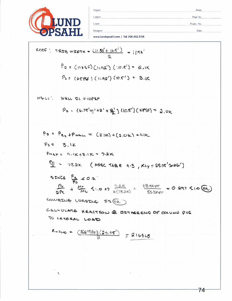
Project Sheet
Subject Paoe No.
NDSAHt
Client
Designer
www.lundopsahl.com I Tel: 206.402.5156
Project No.
Date
ÊÒÕç 'rqtß w*oîK .. C¡rll¿ raS!. - l!1.àlOL
Pn - (rr n rÊ) frr,re') (,ro ,frJ - A.,r(
Ps= 1-cçpgp)Crr.qg/)Cro,er¡ = B,LK
WÀrUu'. W\Lu QU "; rçgÊF
Po " {'a,rr\r+er+g!1 tmC}(pftel* },uK
PO t PAo +PR¡\r¡. : (.*,trcì +(a.o{c\ *¿tÅ}L
Ps = A,\'¿0* \" : ¿t.t K t?,ì ìC = ?,eK-
-9..-¡L 16.â.8- ( Ascc qge q.g , Éry = âS,16'+.e.''^J
Tg\Jæ P"-9o
.¿ o ,a,*
å + ä, (\'., c?
eÆ^^qç\)g' LÞNÞSNQ' rçÈ
?ler.¿?t,trrç\
e).1" 'W,
6s,3K+r - @.ân¡ Çre @)
c-NuuuuAnê þê&cT!ôlJ @ gg.rtç-c"ê}.Ig oF æeur¡rl gric1o u¡ sê.t-þç l-eÀÞ
Rv,S¡¡e = t6s aìI ,?ç' 7 eLbôc6
74

Project Sheet
Subiect Paqe No.
NDtCl¡ent
Desiqner
www.lundopsahl.com I Tel: 206.4025156
Proiect No.
Date
ÊGArvr AÊov¿ êU Csrt+. r V¡Atr .
I'
-cf (6r Vo 4,, lg, -b,, t o/ -J" ¡o,-3,, Vr '6/t
Trtaa wÉer\( tt, å3l+ \e.,f / lr : ù\,1e'åÞr.n?sç$ t- zeÇfSl-
USe 576x larl
r¡eGx¡ C-gur..l
\rqe USS -Tô guP?o6 <1ôße€ß6,.rr ÊG¡wee¡¡- t\\\ pctì
+t99r t '
+- $iur-r.o
Iol-Gv
þo= (ropsp\ (4à t'+ $)' t,5cÞ/ç*
u¿wlNo = ( røe<Ç) C ã *a'ç*). t6€LÊ/Fr
I l
t, \\¡ç êx¡ stcnrc / x
75

SheetProject
Subiect Paqe No.
NDSÃ,.HL
Cliênt Proiect No.
Desìqner
www.lundopsahl.com I Tel: 206.402.5156
\Jow, ÐeE,çet/ ßlÀ(,AûwNLus, \) \rf¡Îèk (Loæl¡ !*!ë" co¡ -/ aq'-g l(
3b
o
6
Fp = 6o?tt4t-5
- 3Saqq Lß
t!p. * ÉA-
U.tpi
(Vuf /Qfte-\ßa¡,¡a cr*Lf oc¡Fr6>¡¡)
(¡sp \
3çaq err À Lt 64 ø/çr'A.i1 t
À./€r¿à<G'.*VrkLt-¡è{Gr\Ç
ì^¿Àtr.M A¿(
L
ri\wttL h/¡ fr â\,\çÈe ISLDt¡\rt¡
tro{Le-u -1.
-?irøu -a
IraÌô(Ð
(9CÐ
@
CÐ
o
Vfuu-\
H'fl
0
H,yðo -\Ft
Date
i
dI
6"l "l (Ð
@ ô .f
T t t u
¡oar, fui.sl v tel# tlo*/t 6wbCvn r3tol9É, E4@Lß
LO/ \?,f ' l,lç lâooÈ rao*/ èw6I
fl ¡ôôtß
1ê., tq' l.ìq ?1tú* aw*/t 6ub ¿{? !tstg
SLJU\ g-"?-t;LSt\,'?çt 11,bt r,Qf 4qrc* ôaçt/'
z8"lÐ/tç t* l"\ '7oo<glq' 2t,41 4,â3
Q\,?çl \t.b(l 0,1f
4ttgË
bt6* Ioøþ1,tgwb
,teo\%q
,\,SI l?,3q t Lro6'\^, \" ¿{ {
6'1àóuÊ.4ltlË ltoÈ1tq,1/ n.3\l l.d brcÊ a \1rl Çv¡6 3?6ELf{
a&o a1t 0(ß 4zþt I z¿ø*/, t\¡rG2 ¿r¡S4
@ q',sQr 't'q I Þâtl
lqoÊ tra$/, €wT sfa.r Hact 4
76
H,yðo -\H,yðo -\

SheetClE!!1
Paqe No.
NDSÃ,HL
lqEgct
Client
Desiq ner
www.lundopsahl.com I Tel: 206.402.5156
Date
n,s I 1\,$ / t9,33 /
ô @ @;frt
TT/ \arrar=\rj}
tsl
t?, t f/ ìaf
- @í!D
(Þd ?rt rt,$l rt,Q{
@o
trJp * ft - 3aaqqtl-13\'
- bq ruP/rf
WhLL l-v¡ru H/o Fp v ãrÉrßYJ*üLI.IOLÞÔN I)
Por¿el-\ouoowN
liwxr,-
o ttvts*
o Þ\!u -
@ lwo -
(Ð t-lou-
@þtÛt, *
@HÊu '
@tJu .
ô+{t¡u *
t\Êc-o@
þ{ ttJ-
@ \,
Iû 6 âl.c"r/ (,8"( a I ì3'lf løq#/,6wÇ 363ârg
ã1.5' àeot' CI,6ø 6ßxtr+ laxu¡ãwG ãÊêt L$
It.3J' &t.ør [, e.t Sott+ Vuq+t,3vb at Êå L¡
.Agt t(,?l/ ô, ?f bql)+ì Tr.art,lwG qtatilß
t3' t(,6/ 1, LlÇ ï.10øÞ 3æët,6h/Þ qlrßtq
41tgt_&?f/11 , ßnç/ l,où\ &¡6ao{ %rt, sv/ 1o
ler t1É û,lø ï lqq tt ?"@ufsw6
-r1ß¿Ë
zw fotb+l L.E
?crç6t' qgá//8,\/ 4Ø,çt O,11
fç' 'at.ø7 t,ç t I tr?o* 1#/,á;w1. cùå ett6
¿Ctn t!3t.5'T lct,ç' l,Oø \ ãr1È 18Ét A?ilG
L9,K þñl lsutil c8+* / 6vtb tt L{i t:"t Fu"
77
4
4
4
5
5
2
2
2
2

Project Sheet
Subi ect Paqe No.
DtClient
Desig ner
www.lundopsahl.com I Tel: 206. 4O2.5156
Project No.
Date
oùr-rQ Nss-ox\
c¡ e e* F ovpo Àlfolù Fo( ov eE[uRNE)ùG \ lt-xorrrgForL6 ÇçOxt åWe*¿wALL . \^,aßçê ¿â$e je opp€-q6s{F-t¡r ¡He h, - S ÊÍ߀cTroÐ \Àrr\&- I
Ép ,.-àFfwArt- a\.qlLwLLL -t?.?çr
.r
ll.(¿,'lr.l-l
\t-an ¡ to!o
tusolr.rç çOaCe = Fe -. 'lãtèLB CASÞ
ôT/,,\ <
ôa e cr( o v ê.¿ \ur¿ ¡¡r¡J ô
)r,r * Õ-tlv1 c gtorAuñ fr
Õ&r,e.ur"ç1¿; É4,grq- ç ttur¿e€.=
Fos*- o cê')ir,+nl|t5o Êr-rJ ¡;.?,,?1 ¿1 I r r/ ì F þ-4rþø tg
flrr¡xr,. s t'b t tOPS{ ) {*1,.t'J 1r6',?ç/.\ = ..t1æLn
l0 noc¡Ê ? ö,b ( t"põF) ( *l (nz5'¡ : ?zr ¡g
&n- p*, (å) (0n,rr'r+ pnooc) ( å ) i(raqtrrej ['{s \ + t ( rrøets+nz{$ \t}*ç')
tøt^Ll-
lr>? ãâor.-g*FT + lbôçå rB-FTt G I tX tl a- rBfT
78

Project Sheet
Subject
ND Cl¡ent
Page No.
Project No.
Desioner Date
www.lundopsahl.com I Tel: 206.402.5156
ôA¿-
l\{ø
tlq l'72 t,ârfãS<;-zø
C¡tLcuLlrlê êerc'rNe' fßêÊ<eRc
,Fo \ootÂ3tß t l.?¿C)LÈ+ ts?t4Lg= 4âr??Lß
atqOlâ + r5ìêêx - ttQ t?â :¡€?
¡¡ e {,ê1 '
¿> å-* =. ry-\.11''=?'qtçrã!ì.JCe e: Ð= 0,61Sf
Uâe v {n l=
\
3-e-3CÞ -cì L
qì 9( rc rçerÐ= 0411pSÊ < i,.¡¡&æçs\
- 33eßqt-rË¡BI r,tQ,)3'
79

Project Sheet
Subiect Paqe No.
NDSA,HL
Cl¡ent
Desig ner
www.lundopsahl.com I Tel: 206.402.5156
Pro.ject No.
Date
a
¡ Tr
{.*uc,.:uutg. eåã u:ç
t Il''ö (
}#t--(/tl-J
1,"
1t^
1o= l,þ Lat\nptr) = 4t?eptçP €STGÞ P€A FI
M^ = (' ?'!l rt+{ r'l'o¡a - LqB s
-
k-FrFT
I j,'j" i
o+ot lrÀr¡. \,q3 s F "*"qè = ó,ôÈ on7C,
4(rgo.3*!
9Sß .lù ¿t e nlc,C . r* ) (\\ - ¡iF¿r rær¡è _
r¡( Nñ \ .¡ eR\ e s\ €Gu È \ I e¡{(àq1 N\ 0 ße þege
ÀSssq .=. Ò .oo.rs6 C rl.\ ¿tt',)-*. Ò , a¡ C8 /f f
80

Project Sheet
Subject
NDSÃ,HL
Client
Desi q ner
www.lundopsahl.com I Tel: 206. 402.5156
Page No.
Proiect No.
Date
,r_q
t1,s ' 36 s' ç t qþlo,- aa4
oe
Is'
Ð-1,t/ (^,
\ (o,7Jwp= 61t,yFr
r\ ô$6Lgçr'
¿ sô$E
6S6i '\\oâ6 Lè
rq 3a-
AT ÜR.XÞP
"
VwÀ = 6665Lß =4ò \b/çr
,/*,*. .*,H * !Þôtàlcr
þþ%rn
æ'såt
aâouE
6161\g
ì1 '-g l?('-zt' t16t rã' '|
tÇt qa lf'rS/ lf?f/a
a ù'À,1\tq
81

ProjectSheet
NDSA,HL
9!.E9it
Cl¡ent
Des¡q ner
www.lundopsahl.com I Tel: 205 .402.5156
Paqe No.
Project No.
Date
q\q,ULF
Ai vALGYt'
VÊtÀ L . 6SåçL6 = ?ô"6/E.
?t'tt? {156î{6{ irceGLS
t/orro B l\0S6(Ê = 6tl-$/pr
?fltl{w¡r. : g6l t-â/çT
II6?.as /
å\rtÊf
Êrr9f¡
'uT
j1àLÊ9q?
u\lætc>
¿\393rÀ 3'ìllu$ Ittø's
Y =tlgt-s
Atr6e¡ge,. 'i VPt¡' l\oS6LS # 6trB/efâr? j
V",Àr-L' l,t0â616{--.¡6'?.9fft
lbQ'ê/P¡
ì \ Stlr
î,
tr t!ð/p¡
b676Lb 82

Project Sheet
5ubject Paqe No.
Cl i ent No.
Datet Desiq ner
www.lundopsahl.com I Tel: 206.402.5156
ú¡le¿ru UîP ee. Ê6qrç çt&Ët1ÊÂC,|Àlqr t4 ar. lôt' ,d1 ú
sJ-
s.e
xIi!
¡€e

Project Sheet
Subiect Paqe No.
ND Cl ient Project No.
Des¡g ner Date
www.lundopsahl.com I Tel: 206.402.5156
Ñrßrtl vJ eß\ (paNè¿- c*rsotoy r^¡ÉrJ- co pTÉcå- E etT eJ
Ø,Uu¡¡.* ¡llu(\Ê'tl- t c¡
6 (¡.ê r,or',*
Ptovl0e î1ß Ar i*t ¡li'\ ßuoc
C-k¿.oLk$c '.e6a þ\4C- @Ce
Ép = Ô1l* (ffi.-) * åo-zr-tur¡ CAIsJ
z Õ,")(^qtqLßl ' 191tue
QÊTe¿^ÀlNê f51RÈ9?lÐG. ì LcÉC'Tt.t GÊ 6Locr<cr¡c*
usc, & \ra êTRAP (rnTSuaoLQ >ìiuayoác:¡rl6\
D¿*P¡rR¿rgr.n ìtt r.2NtsLôcK6O wl tÇ/tattre.a'!+rlNc
ì ,*.d @- è" u.c. Éf¿oø 'rAg-e q,er oF êÞPh/E/
lR.ov ¡pG61
¿ trJS((+,c.êL
YÁ.L Þ.Éß/o.e.o
o*uB|=i-
LE¡.JG.Í H Oç ÊUOCêNê TÐ Þ€VELôP FÔTLCQ ßACK 3Pì'Ô ÞI 'ùFttfeê(lr¡¡
?9}lrse cB Lþ/pr
41QÊr\
L t ?'
84

Project Sheet
Subiect Paqe No.
NDSÃ,.HL
Ëp
C lient Proiect No.
Des¡qner Date
www.lundopsahl.com I Tel: 206.402.5156
f;.l ftte '..5o(Lrk\ à. eo,.rr* ev¡.gcxE.Þìù / V Se. 9u1{a¡4¿gç TC¡ Þß.Aêtc'Þo þAcr( €N{c? Ρ-ue MÀËLÈ alÈe\Êtsê}^. uÊè l{Ò\-Þèw tJ \oBYdÐ.¡ G, LoNg trqOrnn Cu\g.{.è6G¡$- s., L}'\è to {¡ fù è R çR \¡ÈÊ, C:r¡cßo ,
or¡<rS:gèê\ c:añR<4Êlr-
1à1,''t-*,*oççct¡ âf
wALL
Fn¿u ?eev, êú\.r-(-,
F¡ --ao<tu6 e*an
rrtEtJG. L?rl c¡u<p:cgf,'e{s
> âc*.r.u ß4.
= lOtt t t-È
tJ€¡€: tO âa rtor.oowÑ
85