Structural analysis of Wendelstein 7-X magnet weight supports
7
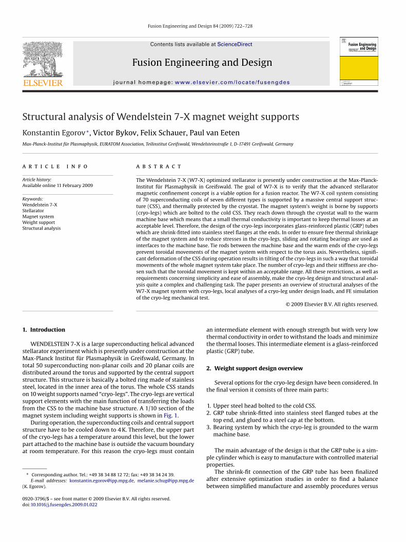
Fusion Engineering and Design 84 (2009) 722–728 Contents lists available at ScienceDirect Fusion Engineering and Design journal homepage: www.elsevier.com/locate/fusengdes Structural analysis of Wendelstein 7-X magnet weight supports Konstantin Egorov ∗ , Victor Bykov, Felix Schauer, Paul van Eeten Max-Planck-Institut für Plasmaphysik, EURATOM Association, Teilinstitut Greifswald, Wendelsteinstraße 1, D-17491 Greifswald, Germany article info Article history: Available online 11 February 2009 Keywords: Wendelstein 7-X Stellarator Magnet system Weight support Structural analysis abstract The Wendelstein 7-X (W7-X) optimized stellarator is presently under construction at the Max-Planck- Institut für Plasmaphysik in Greifswald. The goal of W7-X is to verify that the advanced stellarator magnetic confinement concept is a viable option for a fusion reactor. The W7-X coil system consisting of 70 superconducting coils of seven different types is supported by a massive central support struc- ture (CSS), and thermally protected by the cryostat. The magnet system’s weight is borne by supports (cryo-legs) which are bolted to the cold CSS. They reach down through the cryostat wall to the warm machine base which means that a small thermal conductivity is important to keep thermal losses at an acceptable level. Therefore, the design of the cryo-legs incorporates glass-reinforced plastic (GRP) tubes which are shrink-fitted into stainless steel flanges at the ends. In order to ensure free thermal shrinkage of the magnet system and to reduce stresses in the cryo-legs, sliding and rotating bearings are used as interfaces to the machine base. Tie rods between the machine base and the warm ends of the cryo-legs prevent toroidal movements of the magnet system with respect to the torus axis. Nevertheless, signifi- cant deformation of the CSS during operation results in tilting of the cryo-legs in such a way that toroidal movements of the whole magnet system take place. The number of cryo-legs and their stiffness are cho- sen such that the toroidal movement is kept within an acceptable range. All these restrictions, as well as requirements concerning simplicity and ease of assembly, make the cryo-leg design and structural anal- ysis quite a complex and challenging task. The paper presents an overview of structural analyses of the W7-X magnet system with cryo-legs, local analyses of a cryo-leg under design loads, and FE simulation of the cryo-leg mechanical test. © 2009 Elsevier B.V. All rights reserved. 1. Introduction WENDELSTEIN 7-X is a large superconducting helical advanced stellarator experiment which is presently under construction at the Max-Planck Institut für Plasmaphysik in Greifswald, Germany. In total 50 superconducting non-planar coils and 20 planar coils are distributed around the torus and supported by the central support structure. This structure is basically a bolted ring made of stainless steel, located in the inner area of the torus. The whole CSS stands on 10 weight supports named “cryo-legs”. The cryo-legs are vertical support elements with the main function of transferring the loads from the CSS to the machine base structure. A 1/10 section of the magnet system including weight supports is shown in Fig. 1. During operation, the superconducting coils and central support structure have to be cooled down to 4K. Therefore, the upper part of the cryo-legs has a temperature around this level, but the lower part attached to the machine base is outside the vacuum boundary at room temperature. For this reason the cryo-legs must contain ∗ Corresponding author. Tel.: +49 38 34 88 12 72; fax: +49 38 34 24 39. E-mail addresses: [email protected], [email protected] (K. Egorov). an intermediate element with enough strength but with very low thermal conductivity in order to withstand the loads and minimize the thermal looses. This intermediate element is a glass-reinforced plastic (GRP) tube. 2. Weight support design overview Several options for the cryo-leg design have been considered. In the final version it consists of three main parts: 1. Upper steel head bolted to the cold CSS. 2. GRP tube shrink-fitted into stainless steel flanged tubes at the top end, and glued to a steel cap at the bottom. 3. Bearing system by which the cryo-leg is grounded to the warm machine base. The main advantage of the design is that the GRP tube is a sim- ple cylinder which is easy to manufacture with controlled material properties. The shrink-fit connection of the GRP tube has been finalized after extensive optimization studies in order to find a balance between simplified manufacture and assembly procedures versus 0920-3796/$ – see front matter © 2009 Elsevier B.V. All rights reserved. doi:10.1016/j.fusengdes.2009.01.022
-
Upload
independent -
Category
Documents
-
view
0 -
download
0
Transcript of Structural analysis of Wendelstein 7-X magnet weight supports
S
KM
a
AA
KWSMWS
1
sMtdssosfm
sopa
(
0d
Fusion Engineering and Design 84 (2009) 722–728
Contents lists available at ScienceDirect
Fusion Engineering and Design
journa l homepage: www.e lsev ier .com/ locate / fusengdes
tructural analysis of Wendelstein 7-X magnet weight supports
onstantin Egorov ∗, Victor Bykov, Felix Schauer, Paul van Eetenax-Planck-Institut für Plasmaphysik, EURATOM Association, Teilinstitut Greifswald, Wendelsteinstraße 1, D-17491 Greifswald, Germany
r t i c l e i n f o
rticle history:vailable online 11 February 2009
eywords:endelstein 7-X
tellaratoragnet systemeight support
tructural analysis
a b s t r a c t
The Wendelstein 7-X (W7-X) optimized stellarator is presently under construction at the Max-Planck-Institut für Plasmaphysik in Greifswald. The goal of W7-X is to verify that the advanced stellaratormagnetic confinement concept is a viable option for a fusion reactor. The W7-X coil system consistingof 70 superconducting coils of seven different types is supported by a massive central support struc-ture (CSS), and thermally protected by the cryostat. The magnet system’s weight is borne by supports(cryo-legs) which are bolted to the cold CSS. They reach down through the cryostat wall to the warmmachine base which means that a small thermal conductivity is important to keep thermal losses at anacceptable level. Therefore, the design of the cryo-legs incorporates glass-reinforced plastic (GRP) tubeswhich are shrink-fitted into stainless steel flanges at the ends. In order to ensure free thermal shrinkageof the magnet system and to reduce stresses in the cryo-legs, sliding and rotating bearings are used asinterfaces to the machine base. Tie rods between the machine base and the warm ends of the cryo-legsprevent toroidal movements of the magnet system with respect to the torus axis. Nevertheless, signifi-cant deformation of the CSS during operation results in tilting of the cryo-legs in such a way that toroidal
movements of the whole magnet system take place. The number of cryo-legs and their stiffness are cho-sen such that the toroidal movement is kept within an acceptable range. All these restrictions, as well asrequirements concerning simplicity and ease of assembly, make the cryo-leg design and structural anal-ysis quite a complex and challenging task. The paper presents an overview of structural analyses of theW7-X magnet system with cryo-legs, local analyses of a cryo-leg under design loads, and FE simulational tes
of the cryo-leg mechanic. Introduction
WENDELSTEIN 7-X is a large superconducting helical advancedtellarator experiment which is presently under construction at theax-Planck Institut für Plasmaphysik in Greifswald, Germany. In
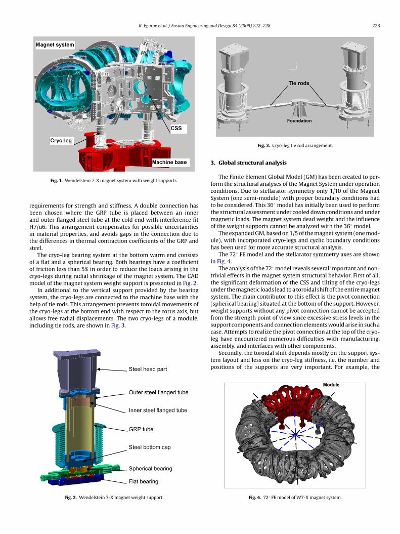
otal 50 superconducting non-planar coils and 20 planar coils areistributed around the torus and supported by the central supporttructure. This structure is basically a bolted ring made of stainlessteel, located in the inner area of the torus. The whole CSS standsn 10 weight supports named “cryo-legs”. The cryo-legs are verticalupport elements with the main function of transferring the loadsrom the CSS to the machine base structure. A 1/10 section of the
agnet system including weight supports is shown in Fig. 1.During operation, the superconducting coils and central support
tructure have to be cooled down to 4 K. Therefore, the upper partf the cryo-legs has a temperature around this level, but the lowerart attached to the machine base is outside the vacuum boundaryt room temperature. For this reason the cryo-legs must contain
∗ Corresponding author. Tel.: +49 38 34 88 12 72; fax: +49 38 34 24 39.E-mail addresses: [email protected], [email protected]
K. Egorov).
920-3796/$ – see front matter © 2009 Elsevier B.V. All rights reserved.oi:10.1016/j.fusengdes.2009.01.022
t.© 2009 Elsevier B.V. All rights reserved.
an intermediate element with enough strength but with very lowthermal conductivity in order to withstand the loads and minimizethe thermal looses. This intermediate element is a glass-reinforcedplastic (GRP) tube.
2. Weight support design overview
Several options for the cryo-leg design have been considered. Inthe final version it consists of three main parts:
1. Upper steel head bolted to the cold CSS.2. GRP tube shrink-fitted into stainless steel flanged tubes at the
top end, and glued to a steel cap at the bottom.3. Bearing system by which the cryo-leg is grounded to the warm
machine base.
The main advantage of the design is that the GRP tube is a sim-
ple cylinder which is easy to manufacture with controlled materialproperties.The shrink-fit connection of the GRP tube has been finalizedafter extensive optimization studies in order to find a balancebetween simplified manufacture and assembly procedures versus
K. Egorov et al. / Fusion Engineering and Design 84 (2009) 722–728 723
rbaHits
oocm
shtai
Fig. 1. Wendelstein 7-X magnet system with weight supports.
equirements for strength and stiffness. A double connection haseen chosen where the GRP tube is placed between an innernd outer flanged steel tube at the cold end with interference fit7/u6. This arrangement compensates for possible uncertainties
n material properties, and avoids gaps in the connection due tohe differences in thermal contraction coefficients of the GRP andteel.
The cryo-leg bearing system at the bottom warm end consistsf a flat and a spherical bearing. Both bearings have a coefficientf friction less than 5% in order to reduce the loads arising in theryo-legs during radial shrinkage of the magnet system. The CADodel of the magnet system weight support is presented in Fig. 2.In additional to the vertical support provided by the bearing
ystem, the cryo-legs are connected to the machine base with theelp of tie rods. This arrangement prevents toroidal movements ofhe cryo-legs at the bottom end with respect to the torus axis, but
llows free radial displacements. The two cryo-legs of a module,ncluding tie rods, are shown in Fig. 3.Fig. 2. Wendelstein 7-X magnet weight support.
Fig. 3. Cryo-leg tie rod arrangement.
3. Global structural analysis
The Finite Element Global Model (GM) has been created to per-form the structural analyses of the Magnet System under operationconditions. Due to stellarator symmetry only 1/10 of the MagnetSystem (one semi-module) with proper boundary conditions hadto be considered. This 36◦ model has initially been used to performthe structural assessment under cooled down conditions and undermagnetic loads. The magnet system dead weight and the influenceof the weight supports cannot be analyzed with the 36◦ model.
The expanded GM, based on 1/5 of the magnet system (one mod-ule), with incorporated cryo-legs and cyclic boundary conditionshas been used for more accurate structural analysis.
The 72◦ FE model and the stellarator symmetry axes are shownin Fig. 4.
The analysis of the 72◦ model reveals several important and non-trivial effects in the magnet system structural behavior. First of all,the significant deformation of the CSS and tilting of the cryo-legsunder the magnetic loads lead to a toroidal shift of the entire magnetsystem. The main contributor to this effect is the pivot connection(spherical bearing) situated at the bottom of the support. However,weight supports without any pivot connection cannot be acceptedfrom the strength point of view since excessive stress levels in thesupport components and connection elements would arise in such acase. Attempts to realize the pivot connection at the top of the cryo-leg have encountered numerous difficulties with manufacturing,
assembly, and interfaces with other components.Secondly, the toroidal shift depends mostly on the support sys-tem layout and less on the cryo-leg stiffness, i.e. the number andpositions of the supports are very important. For example, the
Fig. 4. 72◦ FE model of W7-X magnet system.
724 K. Egorov et al. / Fusion Engineering and Design 84 (2009) 722–728
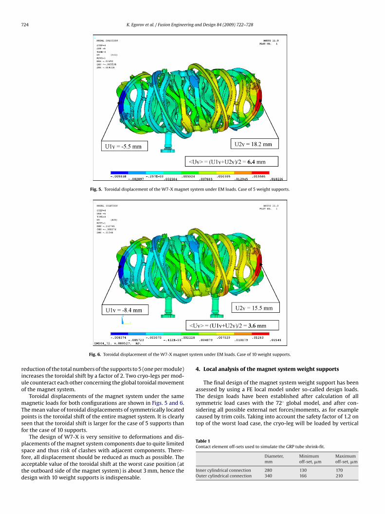
Fig. 5. Toroidal displacement of the W7-X magnet system under EM loads. Case of 5 weight supports.
et syst
riuo
mTpsf
psfatd
symmetric load cases with the 72◦ global model, and after con-sidering all possible external net forces/moments, as for examplecaused by trim coils. Taking into account the safety factor of 1.2 ontop of the worst load case, the cryo-leg will be loaded by vertical
Table 1Contact element off-sets used to simulate the GRP tube shrink-fit.
Fig. 6. Toroidal displacement of the W7-X magn
eduction of the total numbers of the supports to 5 (one per module)ncreases the toroidal shift by a factor of 2. Two cryo-legs per mod-le counteract each other concerning the global toroidal movementf the magnet system.
Toroidal displacements of the magnet system under the sameagnetic loads for both configurations are shown in Figs. 5 and 6.
he mean value of toroidal displacements of symmetrically locatedoints is the toroidal shift of the entire magnet system. It is clearlyeen that the toroidal shift is larger for the case of 5 supports thanor the case of 10 supports.
The design of W7-X is very sensitive to deformations and dis-lacements of the magnet system components due to quite limited
pace and thus risk of clashes with adjacent components. There-ore, all displacement should be reduced as much as possible. Thecceptable value of the toroidal shift at the worst case position (athe outboard side of the magnet system) is about 3 mm, hence theesign with 10 weight supports is indispensable.em under EM loads. Case of 10 weight supports.
4. Local analysis of the magnet system weight supports
The final design of the magnet system weight support has beenassessed by using a FE local model under so-called design loads.The design loads have been established after calculation of all
Diameter,mm
Minimumoff-set, �m
Maximumoff-set, �m
Inner cylindrical connection 280 130 170Outer cylindrical connection 340 166 210
K. Egorov et al. / Fusion Engineering and Design 84 (2009) 722–728 725
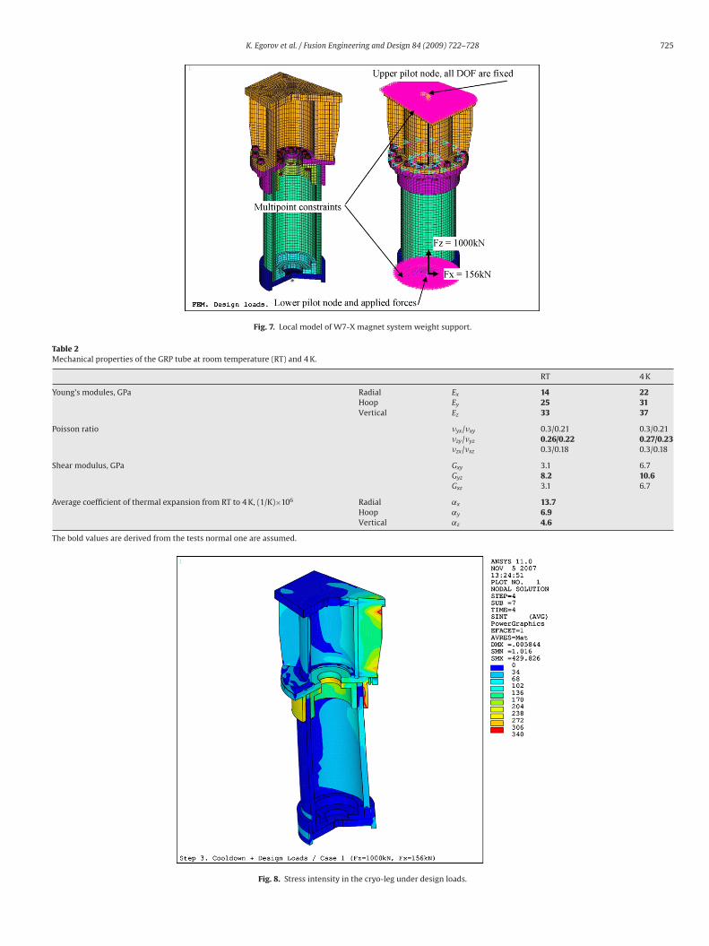
Fig. 7. Local model of W7-X magnet system weight support.
Table 2Mechanical properties of the GRP tube at room temperature (RT) and 4 K.
RT 4 K
Young’s modules, GPa Radial Ex 14 22Hoop Ey 25 31Vertical Ez 33 37
Poisson ratio �yx/�xy 0.3/0.21 0.3/0.21�zy/�yz 0.26/0.22 0.27/0.23�zx/�xz 0.3/0.18 0.3/0.18
Shear modulus, GPa Gxy 3.1 6.7Gyz 8.2 10.6Gxz 3.1 6.7
Average coefficient of thermal expansion from RT to 4 K, (1/K)×106 Radial ˛x 13.7Hoop ˛y 6.9Vertical ˛z 4.6
The bold values are derived from the tests normal one are assumed.
Fig. 8. Stress intensity in the cryo-leg under design loads.
726 K. Egorov et al. / Fusion Engineering and Design 84 (2009) 722–728
ca
twtbo
td
mtb
tgw
mp
itwc
hoTp
n
TS
MMMMMM
Table 4Ultimate strength of the UD lamina at room temperature (RT) and 4 K.
RT 4 K
Longitudinal tensile strength, MPa RII+ 1546
Longitudinal compressive strength, MPa RII− 1389
Transverse tensile strength, MPa R⊥+ 34 51Transverse compressive strength, MPa R⊥− 143 214In-plane shear strength in, MPa RII⊥ 64 96
Fig. 10. Arrangement of the GRP tube test in IMA.
Fig. 9. Points for GRP stress components calculation.
ompressive forces of 1000 kN and lateral forces of 156 kN, appliedt the ambient temperature bottom end.
The local model represents the part of weight support abovehe spherical bearing. The GRP tube shrink-fit has been simulatedith the help of contact elements located at the interface between
he GRP and the steel tubes. Initial contact surface off-sets haveeen applied in accordance to the shrink-fit specification. Requiredff-sets are given in Table 1.
The flanged steel tubes are connected to each other and attachedo the steel head part through the bolted flange. The bolts are intro-uced in the model and tightened using pre-stress elements.
The Multipoint Constraint technique has been used to fix theodel at the upper flange, and the design loads were applied at
he bottom. The local FE model of the weight support with appliedoundary conditions is shown in Fig. 7.
Three load steps have been analyzed: (1) shrink-fit of the GRPube in the steel parts and flange bolt pre-stress; (2) temperatureradient along the length of the weight support due to cool downithin the cryostat; (3) design loads.
Anisotropy of the GRP tube has been taken into account in theodel by the use of orthotropic material properties. The mechanical
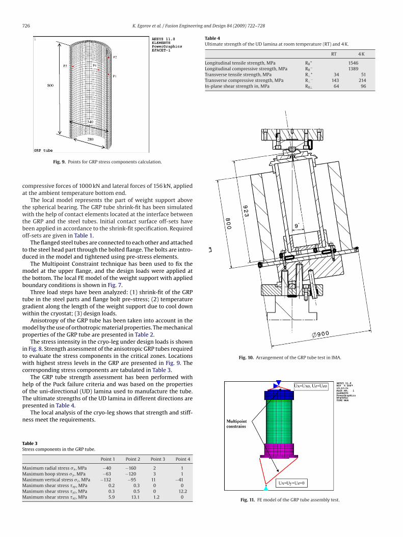
roperties of the GRP tube are presented in Table 2.The stress intensity in the cryo-leg under design loads is shown
n Fig. 8. Strength assessment of the anisotropic GRP tubes requiredo evaluate the stress components in the critical zones. Locationsith highest stress levels in the GRP are presented in Fig. 9. The
orresponding stress components are tabulated in Table 3.The GRP tube strength assessment has been performed with
elp of the Puck failure criteria and was based on the propertiesf the uni-directional (UD) lamina used to manufacture the tube.he ultimate strengths of the UD lamina in different directions areresented in Table 4.
The local analysis of the cryo-leg shows that strength and stiff-ess meet the requirements.
able 3tress components in the GRP tube.
Point 1 Point 2 Point 3 Point 4
aximum radial stress �x , MPa −40 −160 2 1aximum hoop stress �y , MPa −63 −120 3 1aximum vertical stress �z , MPa −132 −95 11 −41aximum shear stress �xy , MPa 0.2 0.3 0 0aximum shear stress �yz , MPa 0.3 0.5 0 12.2aximum shear stress �xz , MPa 5.9 13.1 1.2 0
Fig. 11. FE model of the GRP tube assembly test.
ering a
5
rtnbc
K. Egorov et al. / Fusion Engine
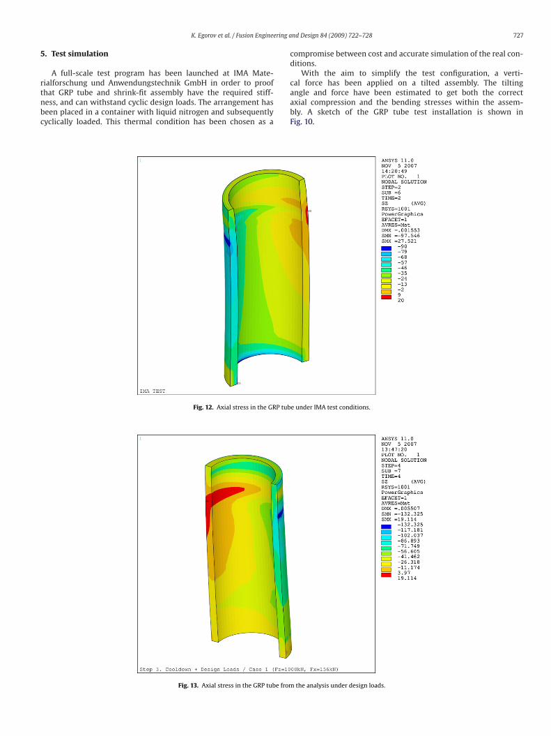
. Test simulation
A full-scale test program has been launched at IMA Mate-ialforschung und Anwendungstechnik GmbH in order to proof
hat GRP tube and shrink-fit assembly have the required stiff-ess, and can withstand cyclic design loads. The arrangement haseen placed in a container with liquid nitrogen and subsequentlyyclically loaded. This thermal condition has been chosen as aFig. 12. Axial stress in the GRP tub
Fig. 13. Axial stress in the GRP tube from
nd Design 84 (2009) 722–728 727
compromise between cost and accurate simulation of the real con-ditions.
With the aim to simplify the test configuration, a verti-cal force has been applied on a tilted assembly. The tilting
angle and force have been estimated to get both the correctaxial compression and the bending stresses within the assem-bly. A sketch of the GRP tube test installation is shown inFig. 10.e under IMA test conditions.
the analysis under design loads.
7 ering a
ttbt
28 K. Egorov et al. / Fusion Engine
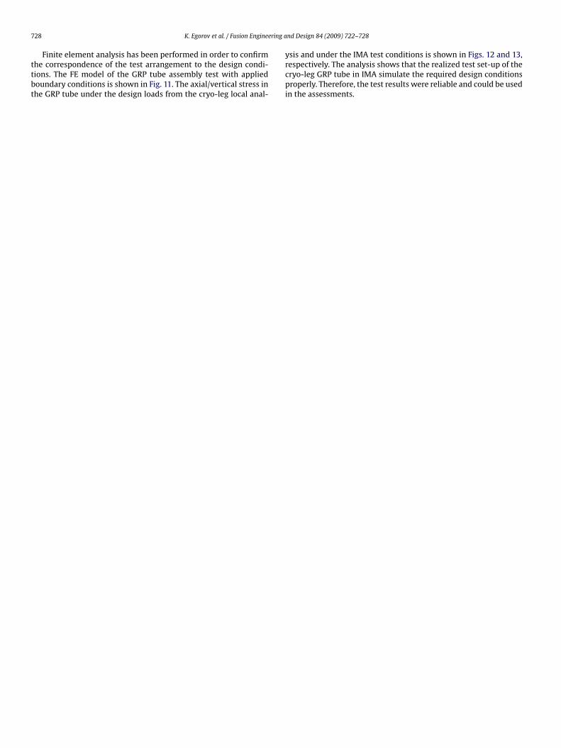
Finite element analysis has been performed in order to confirmhe correspondence of the test arrangement to the design condi-ions. The FE model of the GRP tube assembly test with appliedoundary conditions is shown in Fig. 11. The axial/vertical stress inhe GRP tube under the design loads from the cryo-leg local anal-
nd Design 84 (2009) 722–728
ysis and under the IMA test conditions is shown in Figs. 12 and 13,respectively. The analysis shows that the realized test set-up of thecryo-leg GRP tube in IMA simulate the required design conditionsproperly. Therefore, the test results were reliable and could be usedin the assessments.