Strength of Materials
480
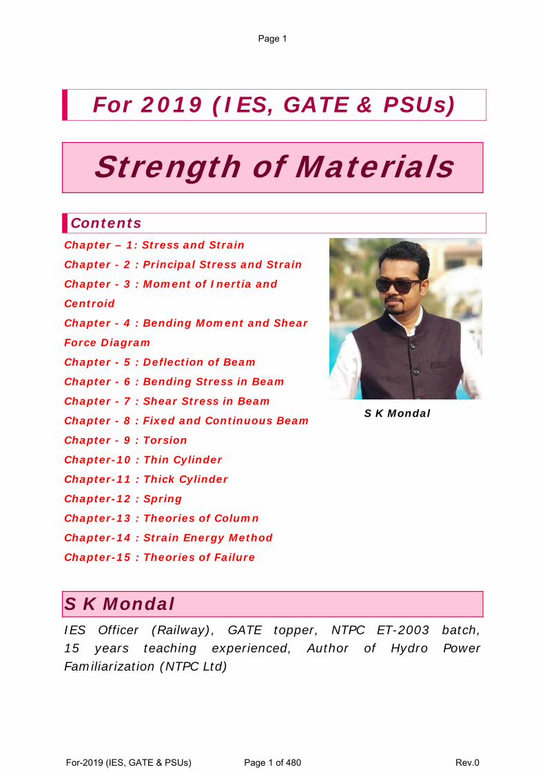
For 2019 (IES, GATE & PSUs) Strength of Materials Contents Chapter – 1: Stress and Strain Chapter - 2 : Principal Stress and Strain Chapter - 3 : Moment of Inertia and Centroid Chapter - 4 : Bending Moment and Shear Force Diagram Chapter - 5 : Deflection of Beam Chapter - 6 : Bending Stress in Beam Chapter - 7 : Shear Stress in Beam Chapter - 8 : Fixed and Continuous Beam Chapter - 9 : Torsion Chapter-10 : Thin Cylinder Chapter-11 : Thick Cylinder Chapter-12 : Spring Chapter-13 : Theories of Column Chapter-14 : Strain Energy Method Chapter-15 : Theories of Failure S K Mondal S K Mondal IES Officer (Railway), GATE topper, NTPC ET-2003 batch, 15 years teaching experienced, Author of Hydro Power Familiarization (NTPC Ltd) Page 1 For-2019 (IES, GATE & PSUs) Page 1 of 480 Rev.0
-
Upload
khangminh22 -
Category
Documents
-
view
0 -
download
0
Transcript of Strength of Materials
For 2019 (IES, GATE & PSUs)
Strength of Materials
Contents Chapter – 1: Stress and Strain
Chapter - 2 : Principal Stress and Strain
Chapter - 3 : Moment of Inertia and
Centroid
Chapter - 4 : Bending Moment and Shear
Force Diagram
Chapter - 5 : Deflection of Beam
Chapter - 6 : Bending Stress in Beam
Chapter - 7 : Shear Stress in Beam
Chapter - 8 : Fixed and Continuous Beam
Chapter - 9 : Torsion
Chapter-10 : Thin Cylinder
Chapter-11 : Thick Cylinder
Chapter-12 : Spring
Chapter-13 : Theories of Column
Chapter-14 : Strain Energy Method
Chapter-15 : Theories of Failure
S K Mondal
S K Mondal IES Officer (Railway), GATE topper, NTPC ET-2003 batch, 15 years teaching experienced, Author of Hydro Power Familiarization (NTPC Ltd)
Page 1
For-2019 (IES, GATE & PSUs) Page 1 of 480 Rev.0
Note “Asked Objective Questions” is the total collection of questions from:-
27 yrs IES (2018-1992) [Engineering Service Examination]
27 yrs. GATE (2018-1992) [Mechanical Engineering]
16 yrs. GATE (2018-2003) [Civil Engineering]
and 14 yrs. IAS (Prelim.) [Civil Service Preliminary]
Copyright © 2007 S K Mondal
Every effort has been made to see that there are no errors (typographical or otherwise) in the
material presented. However, it is still possible that there are a few errors (serious or
otherwise). I would be thankful to the readers if they are brought to my attention at the
following e-mail address: [email protected]
S K Mondal
Page 2
For-2019 (IES, GATE & PSUs) Page 2 of 480 Rev.0
1. Stress and Strain Theory at a Glance (for IES, GATE, PSU)
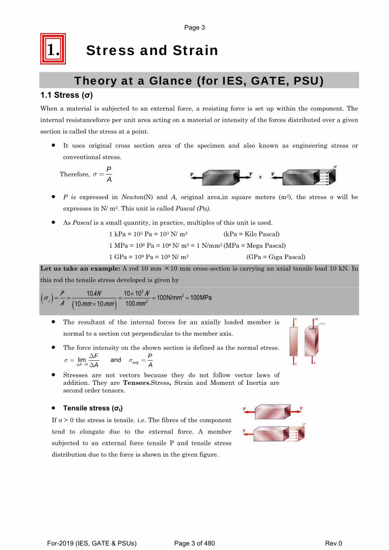
1.1 Stress (σ) When a material is subjected to an external force, a resisting force is set up within the component. The
internal resistanceforce per unit area acting on a material or intensity of the forces distributed over a given
section is called the stress at a point.
• It uses original cross section area of the specimen and also known as engineering stress or
conventional stress.
Therefore, PA
σ =
• P is expressed in Newton(N) and A, original area,in square meters (m2), the stress σ will be
expresses in N/ m2. This unit is called Pascal (Pa).
• As Pascal is a small quantity, in practice, multiples of this unit is used.
1 kPa = 103 Pa = 103 N/ m2 (kPa = Kilo Pascal)
1 MPa = 106 Pa = 106 N/ m2 = 1 N/mm2 (MPa = Mega Pascal) 1 GPa = 109 Pa = 109 N/ m2 (GPa = Giga Pascal)
Let us take an example: A rod 10 mm ×10 mm cross-section is carrying an axial tensile load 10 kN. In
this rod the tensile stress developed is given by
σ t( ) = PA= 10kN
10mm ×10mm( )= 10×103 N
100mm 2=100N/mm2 =100MPa
• The resultant of the internal forces for an axially loaded member is
normal to a section cut perpendicular to the member axis.
• The force intensity on the shown section is defined as the normal stress.
0lim and avgA
F PA A
σ σΔ →
Δ= =
Δ
• Stresses are not vectors because they do not follow vector laws of addition. They are Tensors.Stress, Strain and Moment of Inertia are second order tensors.
• Tensile stress (σt) If σ > 0 the stress is tensile. i.e. The fibres of the component
tend to elongate due to the external force. A member subjected to an external force tensile P and tensile stress
distribution due to the force is shown in the given figure.
Page 3
For-2019 (IES, GATE & PSUs) Page 3 of 480 Rev.0
Chapter-1 Stress and Strain S K Mondal’s
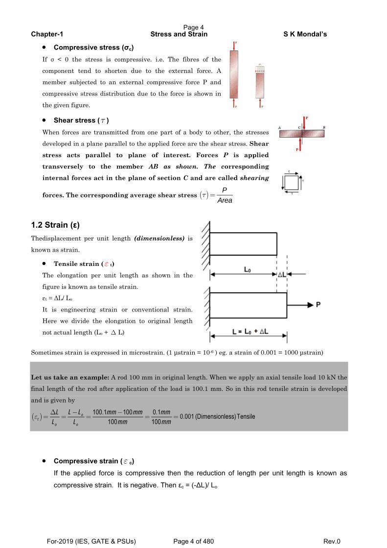
• Compressive stress (σc) If σ < 0 the stress is compressive. i.e. The fibres of the
component tend to shorten due to the external force. A
member subjected to an external compressive force P and
compressive stress distribution due to the force is shown in
the given figure.
• Shear stress (τ ) When forces are transmitted from one part of a body to other, the stresses
developed in a plane parallel to the applied force are the shear stress. Shear
stress acts parallel to plane of interest. Forces P is applied
transversely to the member AB as shown. The corresponding
internal forces act in the plane of section C and are called shearing
forces. The corresponding average shear stress ( ) PArea
τ =
1.2 Strain (ε) Thedisplacement per unit length (dimensionless) is
known as strain.
• Tensile strain (ε t)
The elongation per unit length as shown in the
figure is known as tensile strain.
εt = ΔL/ Lo
It is engineering strain or conventional strain. Here we divide the elongation to original length
not actual length (Lo + Δ L)
Sometimes strain is expressed in microstrain. (1 μstrain = 10-6 ) eg. a strain of 0.001 = 1000 μstrain)
Let us take an example: A rod 100 mm in original length. When we apply an axial tensile load 10 kN the final length of the rod after application of the load is 100.1 mm. So in this rod tensile strain is developed
and is given by
( ) 100.1 100 0.1 0.001 (Dimensionless)Tensile100 100
ot
o o
L LL mm mm mmL L mm mm
ε−Δ −
= = = = =
• Compressive strain (ε c) If the applied force is compressive then the reduction of length per unit length is known as
compressive strain. It is negative. Then εc = (-∆L)/ Lo
Page 4
For-2019 (IES, GATE & PSUs) Page 4 of 480 Rev.0
Chapter-1 Stress and Strain S K Mondal’s
Let us take an example: A rod 100 mm in original length. When we apply an axial compressive load 10
kN the final length of the rod after application of the load is 99 mm. So in this rod a compressive strain is
developed and is given by
( ) 99 100 1 0.01 (Dimensionless)compressive100 100
oc
o o
L LL mm mm mmL L mm mm
ε−Δ − −
= = = = =−
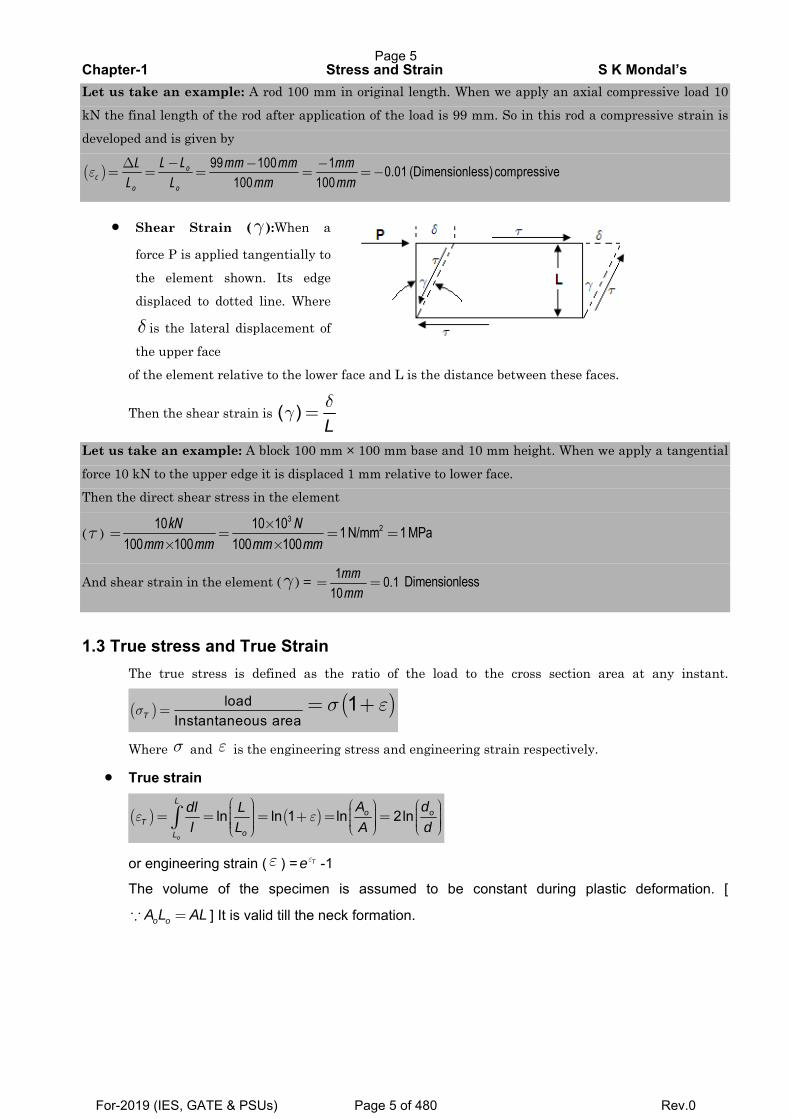
• Shear Strain (γ ):When a
force P is applied tangentially to
the element shown. Its edge
displaced to dotted line. Where
δ is the lateral displacement of
the upper face of the element relative to the lower face and L is the distance between these faces.
Then the shear strain is ( )Lδ
γ =
Let us take an example: A block 100 mm × 100 mm base and 10 mm height. When we apply a tangential
force 10 kN to the upper edge it is displaced 1 mm relative to lower face. Then the direct shear stress in the element
(τ ) 3
210 10 10 1 N/mm 1 MPa100 100 100 100
kN Nmm mm mm mm
×= = = =
× ×
And shear strain in the element (γ ) = 1 0.110
mmmm
= = Dimensionless
1.3 True stress and True Strain
The true stress is defined as the ratio of the load to the cross section area at any instant.
( ) loadInstantaneous areaTσ = ( )1σ ε= +
Where σ and ε is the engineering stress and engineering strain respectively.
• True strain
( ) ( )ln ln 1 ln 2lno
Lo o
ToL
A ddl Ll L A d
ε ε⎛ ⎞ ⎛ ⎞ ⎛ ⎞⎟⎜ ⎟ ⎟⎜ ⎜⎟= = = + = =⎟ ⎟⎜ ⎜ ⎜⎟ ⎟ ⎟⎜ ⎟ ⎟⎜ ⎜⎟⎜ ⎝ ⎠ ⎝ ⎠⎝ ⎠∫
or engineering strain (ε ) = Teε -1
The volume of the specimen is assumed to be constant during plastic deformation. [
o oA L AL=∵ ] It is valid till the neck formation.
Page 5
For-2019 (IES, GATE & PSUs) Page 5 of 480 Rev.0
Chapter-1 Stress and Strain S K Mondal’s
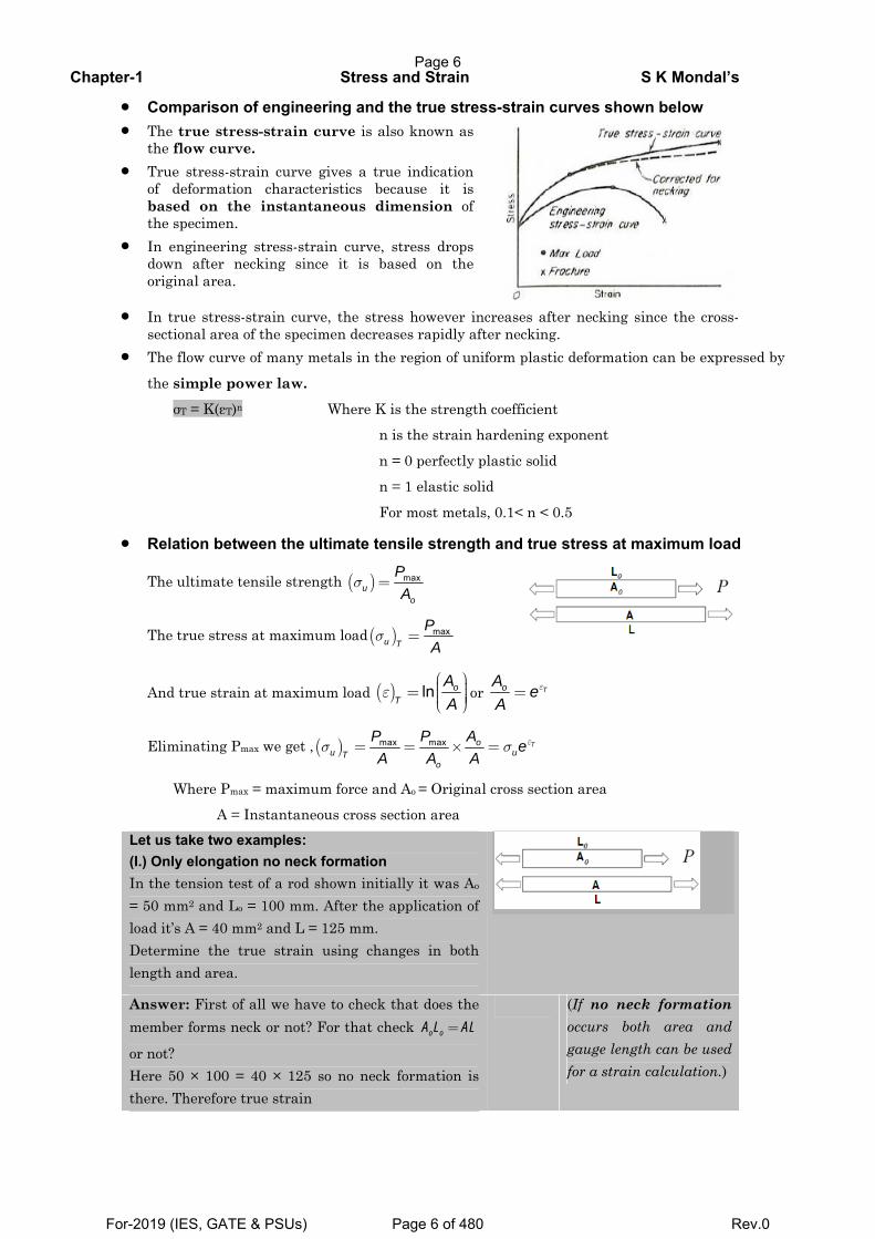
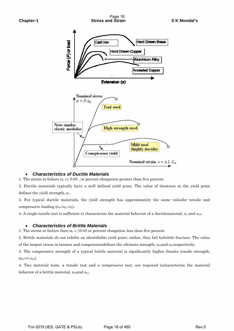
• Comparison of engineering and the true stress-strain curves shown below • The true stress-strain curve is also known as
the flow curve. • True stress-strain curve gives a true indication
of deformation characteristics because it is based on the instantaneous dimension of the specimen.
• In engineering stress-strain curve, stress drops down after necking since it is based on the original area.
• In true stress-strain curve, the stress however increases after necking since the cross-
sectional area of the specimen decreases rapidly after necking. • The flow curve of many metals in the region of uniform plastic deformation can be expressed by
the simple power law.
σT = K(εT)n Where K is the strength coefficient n is the strain hardening exponent
n = 0 perfectly plastic solid
n = 1 elastic solid
For most metals, 0.1< n < 0.5
• Relation between the ultimate tensile strength and true stress at maximum load
The ultimate tensile strength ( ) maxu
o
PA
σ =
The true stress at maximum load( ) maxu T
PA
σ =
And true strain at maximum load ( ) ln oT
AA
ε⎛ ⎞⎟⎜= ⎟⎜ ⎟⎟⎜⎝ ⎠
or ToAe
Aε=
Eliminating Pmax we get ,( ) max max Tou uT
o
P P A eA A A
εσ σ= = × =
Where Pmax = maximum force and Ao = Original cross section area
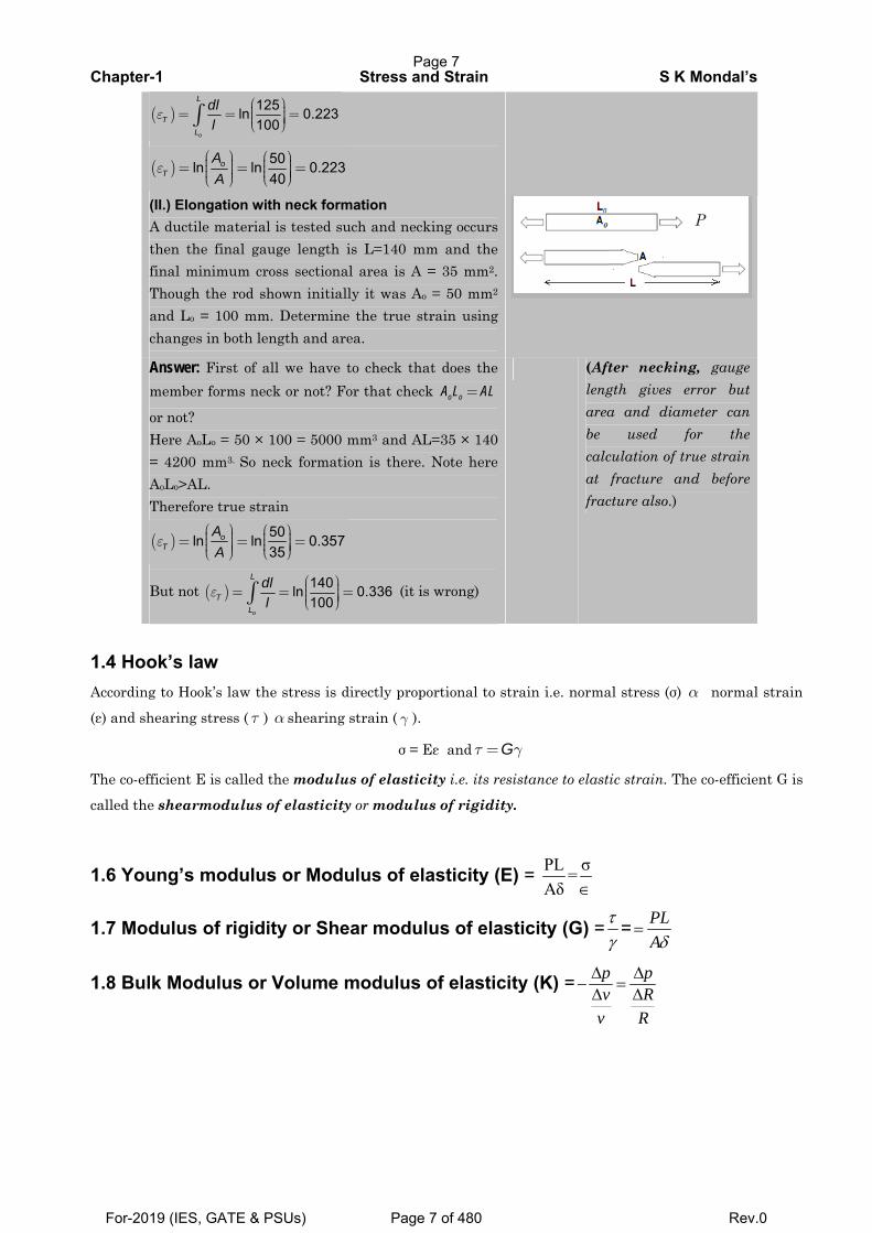
A = Instantaneous cross section area Let us take two examples: (I.) Only elongation no neck formation In the tension test of a rod shown initially it was Ao = 50 mm2 and Lo = 100 mm. After the application of load it’s A = 40 mm2 and L = 125 mm. Determine the true strain using changes in both length and area.
Answer: First of all we have to check that does the member forms neck or not? For that check =o oA L AL
or not? Here 50 × 100 = 40 × 125 so no neck formation is there. Therefore true strain
(If no neck formation occurs both area and gauge length can be used for a strain calculation.)
Page 6
For-2019 (IES, GATE & PSUs) Page 6 of 480 Rev.0
Chapter-1 Stress and Strain S K Mondal’s
( ) 125ln 0.223100
o
L
TL
dll
ε⎛ ⎞⎟⎜= = =⎟⎜ ⎟⎟⎜⎝ ⎠∫
( ) 50ln ln 0.22340
oT
AA
ε⎛ ⎞ ⎛ ⎞⎟ ⎟⎜ ⎜= = =⎟ ⎟⎜ ⎜⎟ ⎟⎟⎜⎜ ⎟ ⎝ ⎠⎝ ⎠
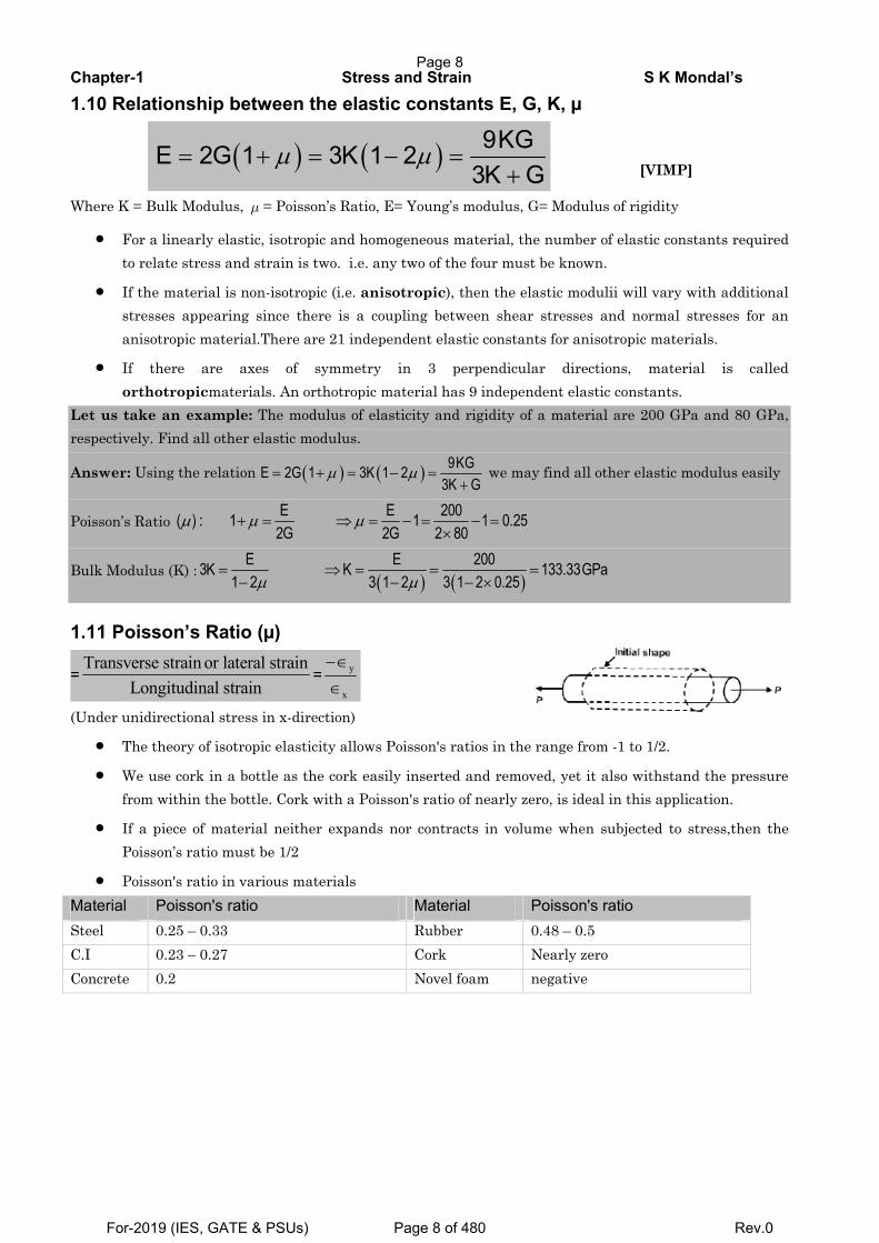
(II.) Elongation with neck formation A ductile material is tested such and necking occurs then the final gauge length is L=140 mm and the final minimum cross sectional area is A = 35 mm2. Though the rod shown initially it was Ao = 50 mm2 and Lo = 100 mm. Determine the true strain using changes in both length and area.
Answer: First of all we have to check that does the member forms neck or not? For that check =o oA L AL
or not? Here AoLo = 50 × 100 = 5000 mm3 and AL=35 × 140 = 4200 mm3. So neck formation is there. Note here AoLo>AL. Therefore true strain
( ) 50ln ln 0.35735
oT
AA
ε⎛ ⎞ ⎛ ⎞⎟ ⎟⎜ ⎜= = =⎟ ⎟⎜ ⎜⎟ ⎟⎟⎜⎜ ⎟ ⎝ ⎠⎝ ⎠
But not ( ) 140ln 0.336100
o
L
TL
dll
ε⎛ ⎞⎟⎜= = =⎟⎜ ⎟⎟⎜⎝ ⎠∫ (it is wrong)
(After necking, gauge length gives error but area and diameter can be used for the calculation of true strain at fracture and before fracture also.)
1.4 Hook’s law
According to Hook’s law the stress is directly proportional to strain i.e. normal stress (σ) α normal strain
(ε) and shearing stress ( τ ) α shearing strain ( γ ).
σ = Eε and Gτ γ=
The co-efficient E is called the modulus of elasticity i.e. its resistance to elastic strain. The co-efficient G is
called the shearmodulus of elasticity or modulus of rigidity.
1.6 Young’s modulus or Modulus of elasticity (E) = PL σ=Aδ ∈
1.7 Modulus of rigidity or Shear modulus of elasticity (G) = τγ
= PLAδ
=
1.8 Bulk Modulus or Volume modulus of elasticity (K) = p pv R
v R
Δ Δ− =Δ Δ
Page 7
For-2019 (IES, GATE & PSUs) Page 7 of 480 Rev.0
Chapter-1 Stress and Strain S K Mondal’s
1.10 Relationship between the elastic constants E, G, K, µ
( ) ( ) 9KGE 2G 1 3K 1 23K G
μ μ= + = − =+ [VIMP]
Where K = Bulk Modulus, μ = Poisson’s Ratio, E= Young’s modulus, G= Modulus of rigidity
• For a linearly elastic, isotropic and homogeneous material, the number of elastic constants required to relate stress and strain is two. i.e. any two of the four must be known.
• If the material is non-isotropic (i.e. anisotropic), then the elastic modulii will vary with additional stresses appearing since there is a coupling between shear stresses and normal stresses for an anisotropic material.There are 21 independent elastic constants for anisotropic materials.
• If there are axes of symmetry in 3 perpendicular directions, material is called orthotropicmaterials. An orthotropic material has 9 independent elastic constants.
Let us take an example: The modulus of elasticity and rigidity of a material are 200 GPa and 80 GPa, respectively. Find all other elastic modulus.
Answer: Using the relation ( ) ( )μ μ= + = − =+
9KGE 2G 1 3K 1 23K G
we may find all other elastic modulus easily
Poisson’s Ratio μ μ μ+ = ⇒ = − = − =×
E E 200( ) : 1 1 1 0.252G 2G 2 80
Bulk Modulus (K) :( ) ( )μ μ
= ⇒ = = =− − − ×E E 2003K K 133.33GPa
1 2 3 1 2 3 1 2 0.25
1.11 Poisson’s Ratio (µ)
=Transverse strain or lateral strain
Longitudinal strain= y
x
−∈
∈
(Under unidirectional stress in x-direction)
• The theory of isotropic elasticity allows Poisson's ratios in the range from -1 to 1/2.
• We use cork in a bottle as the cork easily inserted and removed, yet it also withstand the pressure from within the bottle. Cork with a Poisson's ratio of nearly zero, is ideal in this application.
• If a piece of material neither expands nor contracts in volume when subjected to stress,then the Poisson’s ratio must be 1/2
• Poisson's ratio in various materials Material Poisson's ratio Material Poisson's ratio Steel 0.25 – 0.33 Rubber 0.48 – 0.5 C.I 0.23 – 0.27 Cork Nearly zero Concrete 0.2 Novel foam negative
Page 8
For-2019 (IES, GATE & PSUs) Page 8 of 480 Rev.0
Chapter-1 Stress and Strain S K Mondal’s
1.12 For bi-axial stretching of sheet
11 o
1
22
2
ln L length
ln L -Final length
f
o
ff
o
LOriginal
L
LL
⎛ ⎞∈ = −⎜ ⎟
⎝ ⎠⎛ ⎞
∈ = ⎜ ⎟⎝ ⎠
Final thickness (tf) = 1 2
thickness(t )oInitiale e∈ ∈×
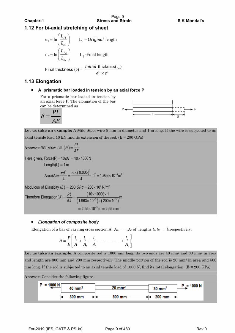
1.13 Elongation • A prismatic bar loaded in tension by an axial force P
For a prismatic bar loaded in tension by an axial force P. The elongation of the bar can be determined as
δ =PLAE
Let us take an example: A Mild Steel wire 5 mm in diameter and 1 m long. If the wire is subjected to an
axial tensile load 10 kN find its extension of the rod. (E = 200 GPa)
Answer: ( )δ =We know that PLAE
( )ππ −
= = ×=
×= = = ×
222 5 2
Here given, Force(P) 10 10 1000NLength(L) 1 m
0.005Area(A) m 1.963 10 m
4 4
kN
d
( )( ) ( )
δ−
−
= = ×
× ×= =
× × ×
= × =
9 2
5 9
3
Modulous of Elasticity ( ) 200 200 10 N/m10 1000 1
Therefore Elongation( ) m1.963 10 200 10
2.55 10 m 2.55 mm
E GPaPLAE
• Elongation of composite body Elongation of a bar of varying cross section A1, A2,----------,An of lengths l1, l2,--------lnrespectively.
31 2 n
1 2 3
δ⎡ ⎤
= + + − − − − − − − +⎢ ⎥⎣ ⎦n
ll l lPE A A A A
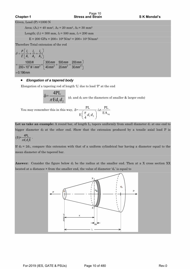
Let us take an example: A composite rod is 1000 mm long, its two ends are 40 mm2 and 30 mm2 in area
and length are 300 mm and 200 mm respectively. The middle portion of the rod is 20 mm2 in area and 500
mm long. If the rod is subjected to an axial tensile load of 1000 N, find its total elongation. (E = 200 GPa).
Answer: Consider the following figure
Page 9
For-2019 (IES, GATE & PSUs) Page 9 of 480 Rev.0
Chapter-1 Stress and Strain S K Mondal’s
Given, Load (P) =1000 N
Area; (A1) = 40 mm2, A2 = 20 mm2, A3 = 30 mm2
Length; (l1) = 300 mm, l2 = 500 mm, l3 = 200 mm E = 200 GPa = 200× 109 N/m2 = 200× 103 N/mm2
Therefore Total extension of the rod
δ⎡ ⎤
= + +⎢ ⎥⎣ ⎦
⎡ ⎤= × + +⎢ ⎥× ⎣ ⎦=
31 2
1 2 3
3 2 2 2 21000 300 500 200
200 10 / 40 20 300.196mm
ll lPE A A A
N mm mm mmN mm mm mm mm
• Elongation of a tapered body Elongation of a tapering rod of length ‘L’ due to load ‘P’ at the end
1 2
4PLδ=Edπ d (d1 and d2 are the diameters of smaller & larger ends)
You may remember this in this way,
1 2
PL PLδ= . .EAE
4π⎛ ⎞⎜ ⎟⎝ ⎠
eq
i ed d
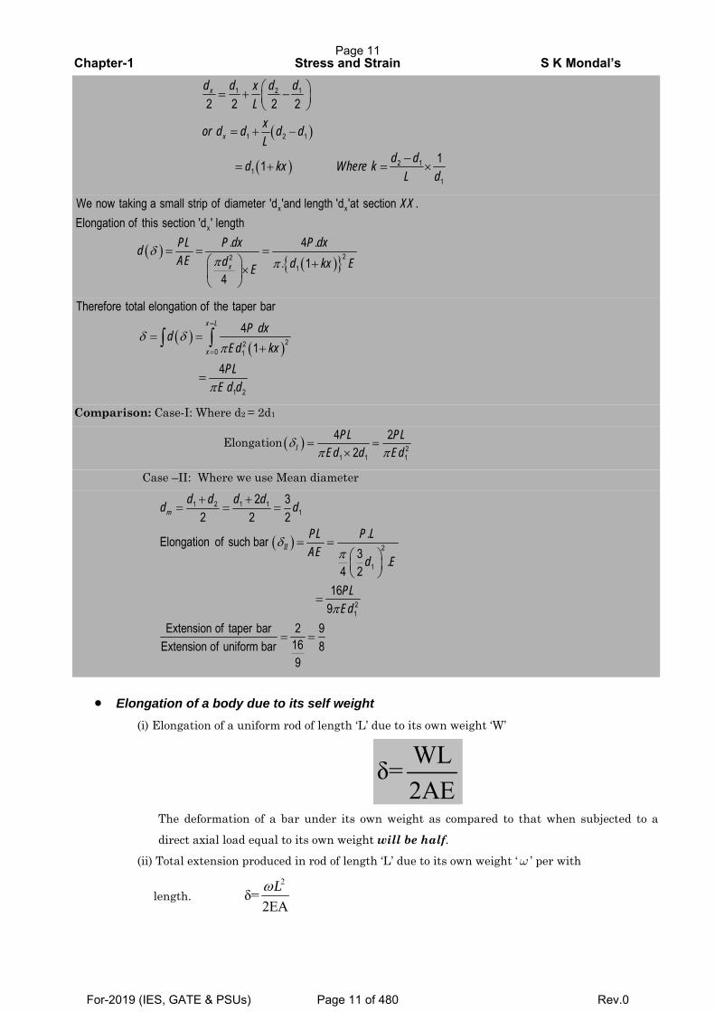
Let us take an example: A round bar, of length L, tapers uniformly from small diameter d1 at one end to
bigger diameter d2 at the other end. Show that the extension produced by a tensile axial load P is
( )1 2
4PLδ =Eπd d
.
If d2 = 2d1, compare this extension with that of a uniform cylindrical bar having a diameter equal to the
mean diameter of the tapered bar.
Answer: Consider the figure below d1 be the radius at the smaller end. Then at a X cross section XX
located at a distance × from the smaller end, the value of diameter ‘dx’ is equal to
Page 10
For-2019 (IES, GATE & PSUs) Page 10 of 480 Rev.0
Chapter-1 Stress and Strain S K Mondal’s
( )
( )
⎛ ⎞= + −⎜ ⎟⎝ ⎠
= + −
−= + = ×
1 2 1
1 2 1
2 11
1
2 2 2 2
11
x
x
d d d dxL
xor d d d dL
d dd kx Where kL d
( )( ){ }
δπ π
= = =⎛ ⎞ +×⎜ ⎟⎝ ⎠
x x
x
221
We now taking a small strip of diameter 'd 'and length 'd 'at section .Elongation of this section 'd ' length
. 4 .. 1
4x
XX
PL P dx P dxdAE d d kx EE
( )( )
δ δπ
π
=
=
= =+
=
∫ ∫ 220 1
1 2
Therefore total elongation of the taper bar4
14
x L
x
P dxdEd kxPL
E d d
Comparison: Case-I: Where d2 = 2d1
Elongation ( )δπ π
= =× 2
1 1 1
4 22I
PL PLEd d Ed
Case –II: Where we use Mean diameter
( )δπ
π
+ += = =
= =⎛ ⎞⎜ ⎟⎝ ⎠
=
= =
1 2 1 11
2
1
21
2 32 2 2
.Elongation of such bar3 .
4 216
9Extension of taper bar 2 9
16Extension of uniform bar 89
m
II
d d d dd d
PL P LAE
d E
PLEd
• Elongation of a body due to its self weight
(i) Elongation of a uniform rod of length ‘L’ due to its own weight ‘W’
WLδ=2AE
The deformation of a bar under its own weight as compared to that when subjected to a
direct axial load equal to its own weight will be half.
(ii) Total extension produced in rod of length ‘L’ due to its own weight ‘ω ’ per with
length. 2
δ=2EAωL
Page 11
For-2019 (IES, GATE & PSUs) Page 11 of 480 Rev.0
Chapter-1 Stress and Strain S K Mondal’s
(iii) Elongation of a conical bar due to its self weight
2
max
δ=6E 2ρ
=gL WL
A E
1.14 Structural members or machines must be designed such that the working stresses are less than the
ultimate strength of the material.
( )
11
Working stress n=1.5 to 2factor of safety
n 2 to 3
Proof stress
yw
ult
pp
n
n
n
σσ
σ
σσ
⎫= ⎪
⎪⎬⎪= = ⎪⎭
= =
1.15 Factor of Safety: (n) = y p ult
w
or orσ σ σσ
1.16 Thermal or Temperature stress and strain
• When a material undergoes a change in temperature, it either elongates or contracts depending
upon whether temperature is increased or decreased of the material.
• If the elongation or contraction is not restricted, i. e. free then the material does not experience
any stress despite the fact that it undergoes a strain.
• The strain due to temperature change is called thermal strain and is expressed as,
( )Tε α= Δ
• Where α is co-efficient of thermal expansion, a material property, and ΔT is the change in
temperature.
• The free expansion or contraction of materials, when restrained induces stress in the material
and it is referred to as thermal stress.
( )σ α= Δt E T Where, E = Modulus of elasticity
• Thermal stress produces the same effect in the material similar to that of mechanical stress. A
compressive stress will produce in the material with increase in temperature and the stress
developed is tensile stress with decrease in temperature.
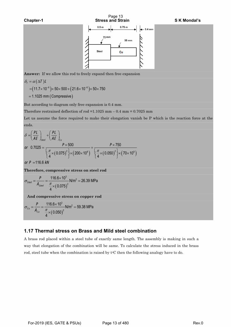
Let us take an example: A rod consists of two parts that are made of steel and copper as shown in figure
below. The elastic modulus and coefficient of thermal expansion for steel are 200 GPa and 11.7 × 10⁻⁶ per °C
respectively and for copper 70 GPa and 21.6 × 10⁻⁶ per °C respectively. If the temperature of the rod is
raised by 50°C, determine the forces and stresses acting on the rod.
Page 12
For-2019 (IES, GATE & PSUs) Page 12 of 480 Rev.0
Chapter-1 Stress and Strain S K Mondal’s
Answer: If we allow this rod to freely expand then free expansion
( )( ) ( )
( )
δ α− −
= Δ
= × × × + × × ×
=
6 611.7 10 50 500 21.6 10 50 750
1.1025 mm Compressive
T T L
But according to diagram only free expansion is 0.4 mm.
Therefore restrained deflection of rod =1.1025 mm – 0.4 mm = 0.7025 mm
Let us assume the force required to make their elongation vanish be P which is the reaction force at the
ends.
( ) ( ) ( ) ( )
δ
π π
⎛ ⎞ ⎛ ⎞= +⎜ ⎟ ⎜ ⎟⎝ ⎠ ⎝ ⎠
× ×= +⎧ ⎫ ⎧ ⎫× × × × × ×⎨ ⎬ ⎨ ⎬⎩ ⎭ ⎩ ⎭
=
2 29 9
500 7500.70250.075 200 10 0.050 70 10
4 4116.6
Steel Cu
PL PLAE AE
P Por
or P kN
Therefore, compressive stress on steel rod
( )σ
π×
= = =×
32
2
116.6 10 N/m 26.39 MPa0.075
4
SteelSteel
PA
And compressive stress on copper rod
( )σ
π×
= = =×
32
2
116.6 10 N/m 59.38 MPa0.050
4
CuCu
PA
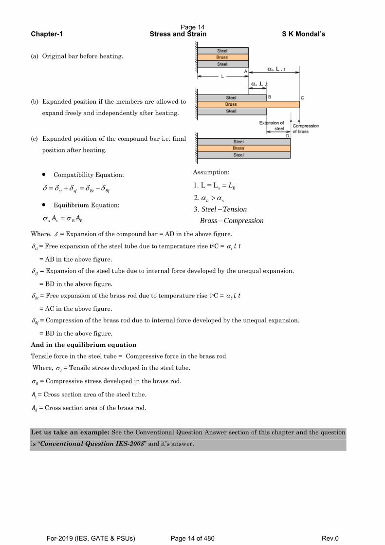
1.17 Thermal stress on Brass and Mild steel combination A brass rod placed within a steel tube of exactly same length. The assembly is making in such a
way that elongation of the combination will be same. To calculate the stress induced in the brass rod, steel tube when the combination is raised by toC then the following analogy have to do.
Page 13
For-2019 (IES, GATE & PSUs) Page 13 of 480 Rev.0
Chapter-1 Stress and Strain S K Mondal’s
(a) Original bar before heating.
(b) Expanded position if the members are allowed to
expand freely and independently after heating.
(c) Expanded position of the compound bar i.e. final
position after heating.
• Compatibility Equation:
δ δ δ δ δ= + = −st sf Bt Bf
• Equilibrium Equation:
σ σ=s s B BA A
Assumption:
s1. L = L
2.3.α α
=
>−−
B
b s
L
Steel TensionBrass Compression
Where, δ = Expansion of the compound bar = AD in the above figure.
stδ = Free expansion of the steel tube due to temperature rise toC = s L tα
= AB in the above figure.
sfδ = Expansion of the steel tube due to internal force developed by the unequal expansion.
= BD in the above figure.
Btδ = Free expansion of the brass rod due to temperature rise toC = b L tα
= AC in the above figure.
Bfδ = Compression of the brass rod due to internal force developed by the unequal expansion.
= BD in the above figure.
And in the equilibrium equation
Tensile force in the steel tube = Compressive force in the brass rod
Where, sσ = Tensile stress developed in the steel tube.
Bσ = Compressive stress developed in the brass rod.
sA = Cross section area of the steel tube.
BA = Cross section area of the brass rod.
Let us take an example: See the Conventional Question Answer section of this chapter and the question
is “Conventional Question IES-2008” and it’s answer.
Page 14
For-2019 (IES, GATE & PSUs) Page 14 of 480 Rev.0
Chapter-1 Stress and Strain S K Mondal’s
1.18 Maximum stress and elongation due to rotation
(i) 2 2
max 8Lρωσ = and ( )
2 3
12LLE
ρωδ =
(ii) 2 2
max 2Lρωσ = and ( )
2 3
3LL
Eρωδ =
For remember: You will get (ii) by multiplying by 4 of (i)
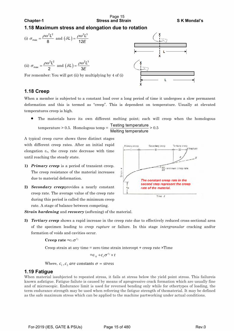
1.18 Creep When a member is subjected to a constant load over a long period of time it undergoes a slow permanent deformation and this is termed as “creep”. This is dependent on temperature. Usually at elevated temperatures creep is high.
• The materials have its own different melting point; each will creep when the homologous
temperature > 0.5. Homologous temp = Testing temperatureMelting temperature
> 0.5
A typical creep curve shows three distinct stages with different creep rates. After an initial rapid elongation εo, the creep rate decrease with time until reaching the steady state.
1) Primary creep is a period of transient creep. The creep resistance of the material increases due to material deformation.
2) Secondary creepprovides a nearly constant creep rate. The average value of the creep rate during this period is called the minimum creep rate. A stage of balance between competing.
Strain hardening and recovery (softening) of the material.
3) Tertiary creep shows a rapid increase in the creep rate due to effectively reduced cross-sectional area of the specimen leading to creep rupture or failure. In this stage intergranular cracking and/or formation of voids and cavities occur.
Creep rate =c1 2cσ
Creep strain at any time = zero time strain intercept + creep rate ×Time
= 20 1
cc tσ∈ + ×
Where, 1 2, constantsc c are stressσ =
1.19 Fatigue When material issubjected to repeated stress, it fails at stress below the yield point stress. This failureis known asfatigue. Fatigue failute is caused by means of aprogressive crack formation which are usually fine and of microscopic. Endurance limit is used for reversed bending only while for othertypes of loading, the term endurance strength may be used when referring the fatigue strength of thematerial. It may be defined as the safe maximum stress which can be applied to the machine partworking under actual conditions.
Page 15
For-2019 (IES, GATE & PSUs) Page 15 of 480 Rev.0
Chapter-1 Stress and Strain S K Mondal’s
1.20 Stress produced by a load P in falling from height ’h’
σ σ⎫⎡ ⎤⎪= + +⎢ ⎥⎬
∈⎢ ⎥⎪⎣ ⎦⎭∈
21 1
being stress & strain produced by static load P & L=length of bar.
dhL
21 1P AEhA PL⎡ ⎤
= + +⎢ ⎥⎣ ⎦
If a load P is applied suddenly to a bar then the stress & strain induced will be double than those obtained by an equal load applied gradually.
1.21 Loads shared by the materials of a compound bar made of bars x & y due to load W,
.
.
x xx
x x y y
y yy
x x y y
A EP WA E A E
A EP W
A E A E
=+
=+
1.22Elongation of a compound bar, x x y y
PLA E A E
δ =+
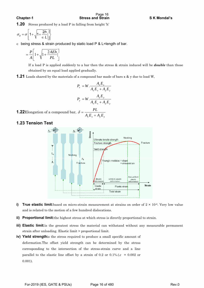
1.23 Tension Test
i) True elastic limit:based on micro-strain measurement at strains on order of 2 × 10⁻⁶. Very low value and is related to the motion of a few hundred dislocations.
ii) Proportional limit:the highest stress at which stress is directly proportional to strain.
iii) Elastic limit:is the greatest stress the material can withstand without any measurable permanent strain after unloading. Elastic limit > proportional limit.
iv) Yield strengthis the stress required to produce a small specific amount of
deformation.The offset yield strength can be determined by the stress
corresponding to the intersection of the stress-strain curve and a line
parallel to the elastic line offset by a strain of 0.2 or 0.1%.( ε = 0.002 or
0.001).
Page 16
For-2019 (IES, GATE & PSUs) Page 16 of 480 Rev.0
Chapter-1 Stress and Strain S K Mondal’s
• The offset yield stress is referred to proof stress either at 0.1 or 0.5% strain used for design and
specification purposes to avoid the practical difficulties of measuring the elastic limit or
proportional limit.
v) Tensile strength or ultimate tensile strength (UTS) uσ is the maximum load Pmax divided by the
original cross-sectional area Ao of the specimen.
vi) % Elongation, f o
o
L LL−
= ,is chiefly influenced by uniform elongation, which is dependent on the strain-
hardening capacity of the material.
vii) Reduction of Area: o f
o
A Aq
A−
=
• Reduction of area is more a measure of the deformation required to produce failure and its chief
contribution results from the necking process.
• Because of the complicated state of stress state in the neck, values of reduction of area are
dependent on specimen geometry, and deformation behaviour, and they should not be taken as
true material properties.
• RA is the most structure-sensitive ductility parameter and is useful in detecting quality
changes in the materials.
viii) Modulus of Elasticity or Young’s Modulus
• It is slope of elastic line upto proportional limit.
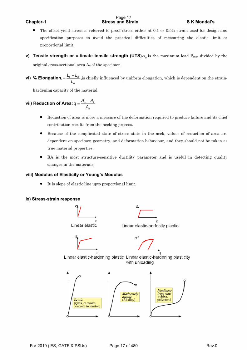
ix) Stress-strain response
Page 17
For-2019 (IES, GATE & PSUs) Page 17 of 480 Rev.0
Chapter-1 Stress and Strain S K Mondal’s
• Characteristics of Ductile Materials
1. The strain at failure is, ε≥ 0.05 , or percent elongation greater than five percent.
2. Ductile materials typically have a well defined yield point. The value of thestress at the yield point
defines the yield strength, σy.
3. For typical ductile materials, the yield strength has approximately the same valuefor tensile and
compressive loading (σyt≈σyc≈σy).
4. A single tensile test is sufficient to characterize the material behavior of a ductilematerial, σy and σult.
• Characteristics of Brittle Materials
1. The strain at failure ilure is, ε ≤0.05 or percent elongation less than five percent.
2. Brittle materials do not exhibit an identifiable yield point; rather, they fail bybrittle fracture. The value
of the largest stress in tension and compressiondefines the ultimate strength, σutand σucrespectively.
3. The compressive strength of a typical brittle material is significantly higher thanits tensile strength,
(σuc>> σut).
4. Two material tests, a tensile test and a compressive test, are required tocharacterize the material
behavior of a brittle material, σutand σuc.
Page 18
For-2019 (IES, GATE & PSUs) Page 18 of 480 Rev.0
Chapter-1 Stress and Strain S K Mondal’s
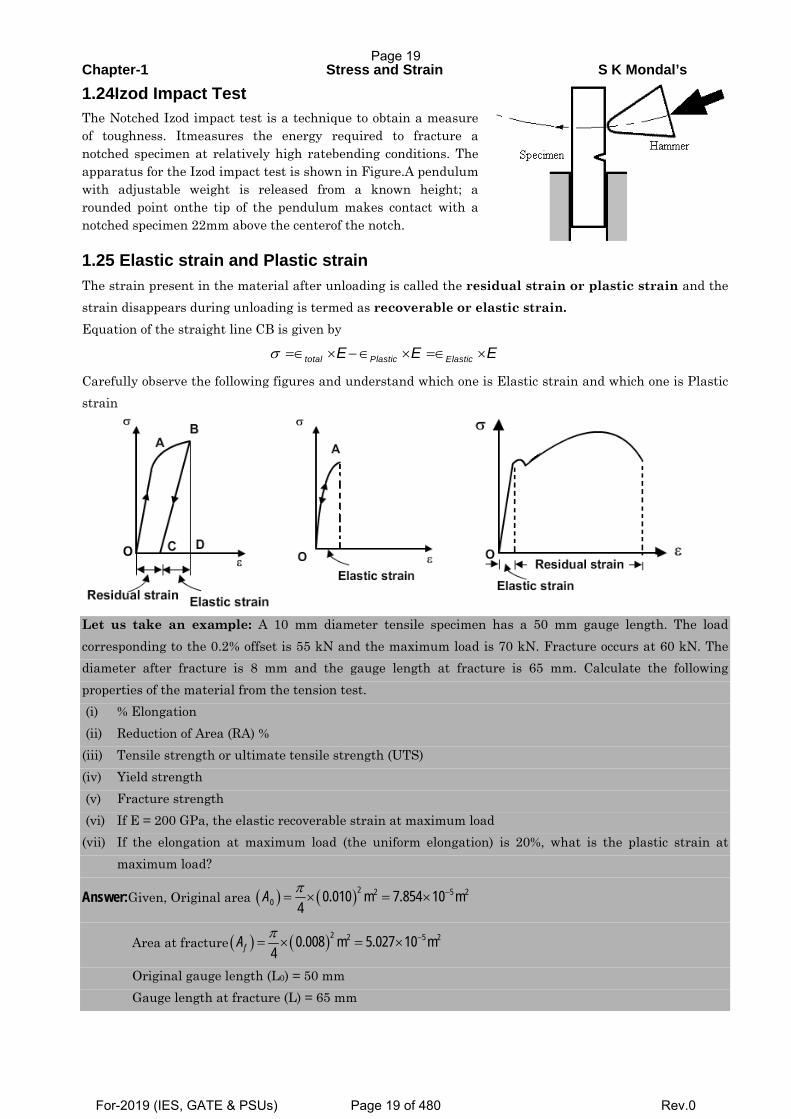
1.24Izod Impact Test The Notched Izod impact test is a technique to obtain a measure of toughness. Itmeasures the energy required to fracture a notched specimen at relatively high ratebending conditions. The apparatus for the Izod impact test is shown in Figure.A pendulum with adjustable weight is released from a known height; a rounded point onthe tip of the pendulum makes contact with a notched specimen 22mm above the centerof the notch. 1.25 Elastic strain and Plastic strain
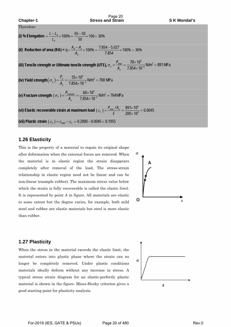
The strain present in the material after unloading is called the residual strain or plastic strain and the strain disappears during unloading is termed as recoverable or elastic strain. Equation of the straight line CB is given by
σ =∈ × −∈ × =∈ ×total Plastic ElasticE E E
Carefully observe the following figures and understand which one is Elastic strain and which one is Plastic strain
Let us take an example: A 10 mm diameter tensile specimen has a 50 mm gauge length. The load corresponding to the 0.2% offset is 55 kN and the maximum load is 70 kN. Fracture occurs at 60 kN. The diameter after fracture is 8 mm and the gauge length at fracture is 65 mm. Calculate the following properties of the material from the tension test. (i) % Elongation (ii) Reduction of Area (RA) % (iii) Tensile strength or ultimate tensile strength (UTS) (iv) Yield strength (v) Fracture strength (vi) If E = 200 GPa, the elastic recoverable strain at maximum load (vii) If the elongation at maximum load (the uniform elongation) is 20%, what is the plastic strain at
maximum load?
Answer:Given, Original area ( ) ( )π −= × = ×2 2 5 20 0.010 m 7.854 10 m
4A
Area at fracture ( ) ( )π −= × = ×2 2 5 20.008 m 5.027 10 m4fA
Original gauge length (L0) = 50 mm Gauge length at fracture (L) = 65 mm
Page 19
For-2019 (IES, GATE & PSUs) Page 19 of 480 Rev.0
Chapter-1 Stress and Strain S K Mondal’s
Therefore
(i) % Elongation − −= × = × =0
0
65 50100% 100 30%50
L LL
(ii) Reduction of area (RA) = q − −= × = × =0
0
7.854 5.027100% 100% 36%7.854
fA AA
(iii) Tensile strength or Ultimate tensile strength (UTS),σ −
×= = =
×
32
570 10 N/m 891MPa
7.854 10max
uo
PA
(iv) Yield strength ( )σ −
×= = =
×
32
555 10 N/m 700 MPa
7.854 10y
yo
PA
(v) Fracture strength ( )σ −
×= = =
×
32
560 10 N/m 764MPa
7.854 10Fracture
Fo
PA
(vi) Elastic recoverable strain at maximum load ( )ε ×= = =
×
6max
9/ 891 10 0.0045
200 10o
EP A
E
(vii) Plastic strain ( )ε ε ε= − = − =0.2000 0.0045 0.1955P total E
1.26 Elasticity This is the property of a material to regain its original shape
after deformation when the external forces are removed. When the material is in elastic region the strain disappears
completely after removal of the load, The stress-strain
relationship in elastic region need not be linear and can be
non-linear (example rubber). The maximum stress value below which the strain is fully recoverable is called the elastic limit.
It is represented by point A in figure. All materials are elastic
to some extent but the degree varies, for example, both mild steel and rubber are elastic materials but steel is more elastic
than rubber.
1.27 Plasticity When the stress in the material exceeds the elastic limit, the
material enters into plastic phase where the strain can no
longer be completely removed. Under plastic conditions
materials ideally deform without any increase in stress. A
typical stress strain diagram for an elastic-perfectly plastic
material is shown in the figure. Mises-Henky criterion gives a
good starting point for plasticity analysis.
Page 20
For-2019 (IES, GATE & PSUs) Page 20 of 480 Rev.0
Chapter-1 Stress and Strain S K Mondal’s
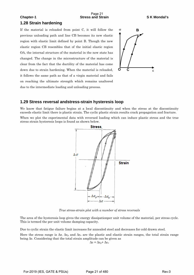
1.28 Strain hardening If the material is reloaded from point C, it will follow the
previous unloading path and line CB becomes its new elastic region with elastic limit defined by point B. Though the new
elastic region CB resembles that of the initial elastic region
OA, the internal structure of the material in the new state has
changed. The change in the microstructure of the material is clear from the fact that the ductility of the material has come
down due to strain hardening. When the material is reloaded,
it follows the same path as that of a virgin material and fails
on reaching the ultimate strength which remains unaltered
due to the intermediate loading and unloading process.
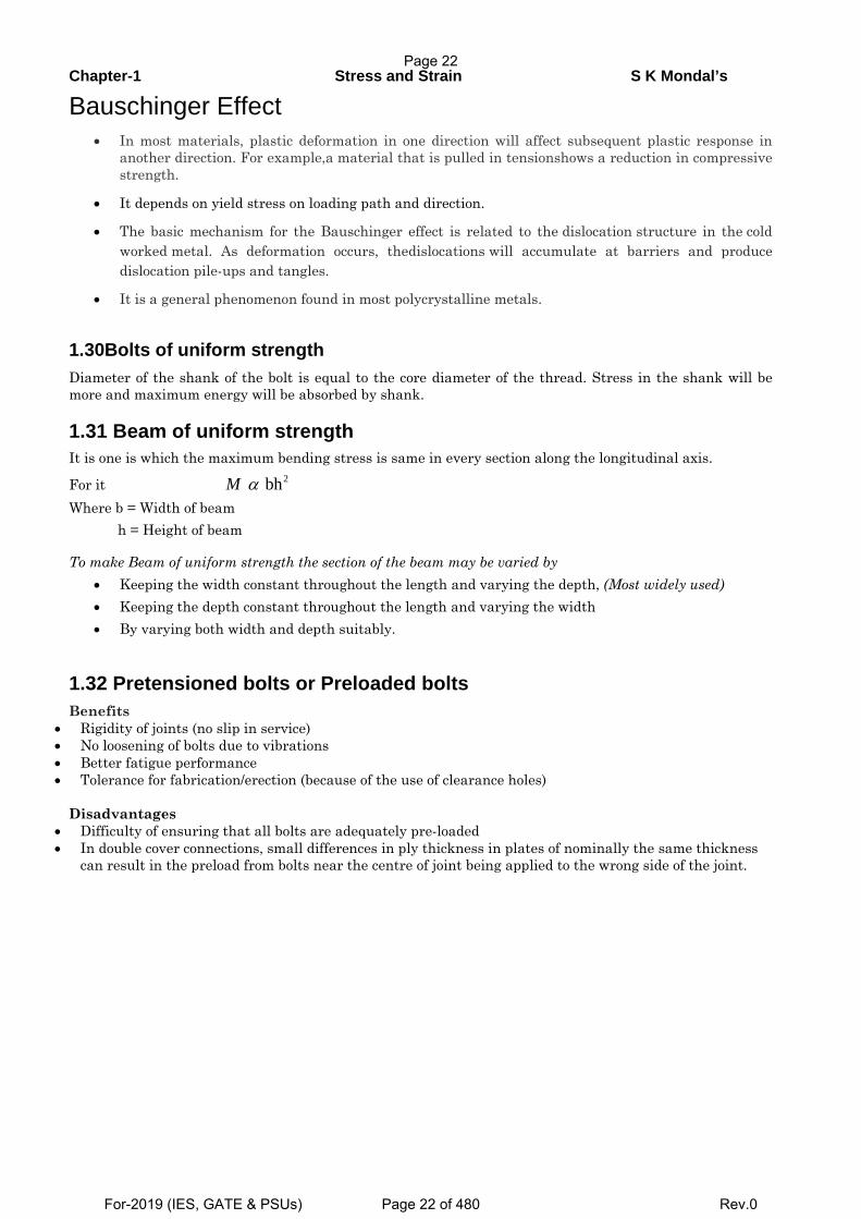
1.29 Stress reversal andstress-strain hysteresis loop
We know that fatigue failure begins at a local discontinuity and when the stress at the discontinuity exceeds elastic limit there is plastic strain. The cyclic plastic strain results crack propagation and fracture.
When we plot the experimental data with reversed loading which can induce plastic stress and the true stress strain hysteresis loops is found as shown below.
True stress-strain plot with a number of stress reversals
The area of the hysteresis loop gives the energy dissipationper unit volume of the material, per stress cycle. This is termed the per unit volume damping capacity. Due to cyclic strain the elastic limit increases for annealed steel and decreases for cold drawn steel.
Here the stress range is Δσ. Δεp and Δεe are the plastic and elastic strain ranges, the total strain range being Δε. Considering that the total strain amplitude can be given as
Δε = Δεp+ Δεe
Page 21
For-2019 (IES, GATE & PSUs) Page 21 of 480 Rev.0
Chapter-1 Stress and Strain S K Mondal’s
Bauschinger Effect • In most materials, plastic deformation in one direction will affect subsequent plastic response in
another direction. For example,a material that is pulled in tensionshows a reduction in compressive strength.
• It depends on yield stress on loading path and direction.
• The basic mechanism for the Bauschinger effect is related to the dislocation structure in the cold worked metal. As deformation occurs, thedislocations will accumulate at barriers and produce dislocation pile-ups and tangles.
• It is a general phenomenon found in most polycrystalline metals.
1.30Bolts of uniform strength Diameter of the shank of the bolt is equal to the core diameter of the thread. Stress in the shank will be more and maximum energy will be absorbed by shank. 1.31 Beam of uniform strength It is one is which the maximum bending stress is same in every section along the longitudinal axis.
For it Where b = Width of beam h = Height of beam
To make Beam of uniform strength the section of the beam may be varied by • Keeping the width constant throughout the length and varying the depth, (Most widely used) • Keeping the depth constant throughout the length and varying the width • By varying both width and depth suitably.
1.32 Pretensioned bolts or Preloaded bolts Benefits
• Rigidity of joints (no slip in service) • No loosening of bolts due to vibrations • Better fatigue performance • Tolerance for fabrication/erection (because of the use of clearance holes)
Disadvantages
• Difficulty of ensuring that all bolts are adequately pre-loaded • In double cover connections, small differences in ply thickness in plates of nominally the same thickness
can result in the preload from bolts near the centre of joint being applied to the wrong side of the joint.
2 bhM α
Page 22
For-2019 (IES, GATE & PSUs) Page 22 of 480 Rev.0
Chapter-1 Stress and Strain S K Mondal’s
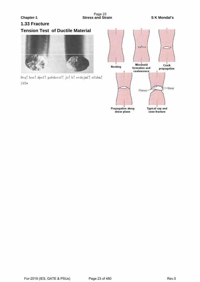
1.33 Fracture Tension Test of Ductile Material
Dvq! boe! dpof! gsbduvsf! jo! b! evdujmf! nfubm!
)NT*
Page 23
For-2019 (IES, GATE & PSUs) Page 23 of 480 Rev.0
Chapter-1 Stress and Strain S K Mondal’s
OBJECTIVE QUESTIONS (GATE, IES, IAS)
Previous 25-Years GATE Questions
Stress in a bar GATE-1. Two identical circular rods of same diameter and same length are subjected to same
magnitude of axial tensile force. One of the rods is made out of mild steel having the
modulus of elasticity of 206 GPa. The other rod is made out of cast iron having the
modulus of elasticity of 100 GPa. Assume both the materials to be homogeneous and
isotropic and the axial force causes the same amount of uniform stress in both the
rods. The stresses developed are within the proportional limit of the respective
materials. Which of the following observations is correct? [GATE-2003]
(a) Both rods elongate by the same amount
(b) Mild steel rod elongates more than the cast iron rod
(c) Cast iron rod elongates more than the mild steel rod
(d) As the stresses are equal strains are also equal in both the rods
GATE-1(i).A rod of length L having uniform cross-sectional area A is subjected to a tensile force
P as shown in the figure below If the Young's modulus of the material varies linearly
from E1, to E2along the length of the rod, the normal stress developed at the section-
SS is [GATE-2013]
(𝑎)𝑃
𝐴(𝑏)
𝑃(𝐸1 − 𝐸2)
𝐴(𝐸1 + 𝐸2)(𝑐)
𝑃𝐸2
𝐴𝐸1
(𝑑)𝑃𝐸1
𝐴𝐸2
GATE-2. A steel bar of 40 mm × 40 mm square cross-section is subjected to an axial
compressive load of 200 kN. If the length of the bar is 2 m and E = 200 GPa, the
elongation of the bar will be: [GATE-2006]
(a)1.25 mm (b)2.70 mm (c)4.05 mm (d) 5.40 mm
GATE-2a. A 300 mm long copper wire of uniform cross-section is pulled in tension so that a
maximum tensile stress of 270 MPa is developed within the wire. The entire
deformation of the wire remains linearly elastic. The elastic modulus of copper is 100
GPa. The resultant elongation (in mm) is ________.[PI: GATE-2006]
Page 24
For-2019 (IES, GATE & PSUs) Page 24 of 480 Rev.0
Chapter-1 Stress and Strain S K Mondal’s
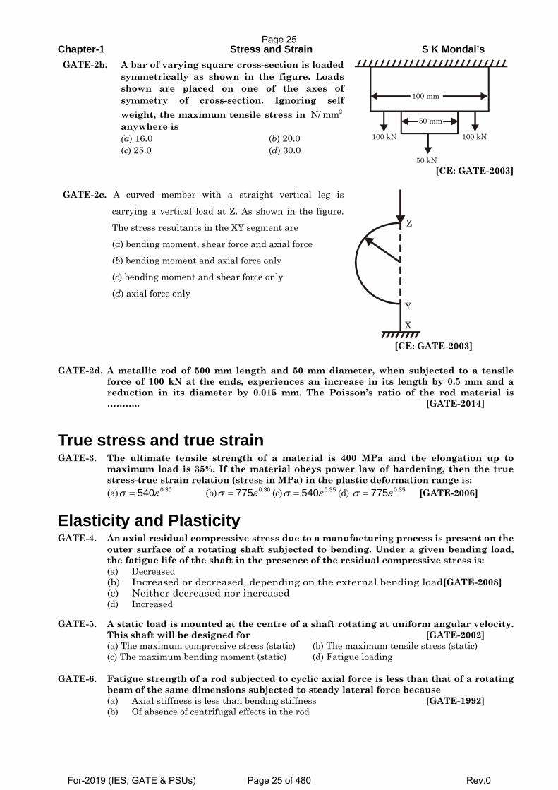
GATE-2b. A bar of varying square cross-section is loaded symmetrically as shown in the figure. Loads shown are placed on one of the axes of symmetry of cross-section. Ignoring self weight, the maximum tensile stress in 2N/ mm anywhere is (a) 16.0 (b) 20.0 (c) 25.0 (d) 30.0
100 mm
100 kN
50 mm
100 kN
50 kN [CE: GATE-2003]
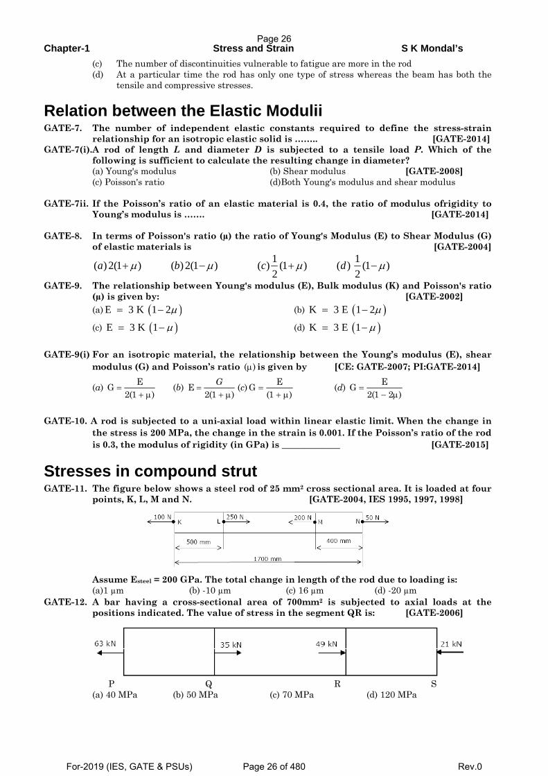
GATE-2c. A curved member with a straight vertical leg is
carrying a vertical load at Z. As shown in the figure. The stress resultants in the XY segment are
(a) bending moment, shear force and axial force
(b) bending moment and axial force only
(c) bending moment and shear force only
(d) axial force only
Z
Y
X
[CE: GATE-2003] GATE-2d. A metallic rod of 500 mm length and 50 mm diameter, when subjected to a tensile
force of 100 kN at the ends, experiences an increase in its length by 0.5 mm and a reduction in its diameter by 0.015 mm. The Poisson’s ratio of the rod material is ……….. [GATE-2014]
True stress and true strain GATE-3. The ultimate tensile strength of a material is 400 MPa and the elongation up to
maximum load is 35%. If the material obeys power law of hardening, then the true stress-true strain relation (stress in MPa) in the plastic deformation range is:
(a) 0.30540σ ε= (b) 0.30775σ ε= (c) 0.35540σ ε= (d) 0.35775σ ε= [GATE-2006]
Elasticity and Plasticity GATE-4. An axial residual compressive stress due to a manufacturing process is present on the
outer surface of a rotating shaft subjected to bending. Under a given bending load, the fatigue life of the shaft in the presence of the residual compressive stress is:
(a) Decreased (b) Increased or decreased, depending on the external bending load[GATE-2008] (c) Neither decreased nor increased (d) Increased
GATE-5. A static load is mounted at the centre of a shaft rotating at uniform angular velocity. This shaft will be designed for [GATE-2002]
(a) The maximum compressive stress (static) (b) The maximum tensile stress (static) (c) The maximum bending moment (static) (d) Fatigue loading GATE-6. Fatigue strength of a rod subjected to cyclic axial force is less than that of a rotating
beam of the same dimensions subjected to steady lateral force because (a) Axial stiffness is less than bending stiffness [GATE-1992] (b) Of absence of centrifugal effects in the rod
Page 25
For-2019 (IES, GATE & PSUs) Page 25 of 480 Rev.0
Chapter-1 Stress and Strain S K Mondal’s
(c) The number of discontinuities vulnerable to fatigue are more in the rod (d) At a particular time the rod has only one type of stress whereas the beam has both the
tensile and compressive stresses.
Relation between the Elastic Modulii GATE-7. The number of independent elastic constants required to define the stress-strain
relationship for an isotropic elastic solid is …….. [GATE-2014] GATE-7(i).A rod of length L and diameter D is subjected to a tensile load P. Which of the
following is sufficient to calculate the resulting change in diameter? (a) Young's modulus (b) Shear modulus [GATE-2008] (c) Poisson's ratio (d)Both Young's modulus and shear modulus GATE-7ii. If the Poisson’s ratio of an elastic material is 0.4, the ratio of modulus ofrigidity to
Young’s modulus is ……. [GATE-2014] GATE-8. In terms of Poisson's ratio (µ) the ratio of Young's Modulus (E) to Shear Modulus (G)
of elastic materials is [GATE-2004]
1 1( ) 2(1 ) ( ) 2(1 ) ( ) (1 ) ( ) (1 )2 2
a b c dμ μ μ μ+ − + −
GATE-9. The relationship between Young's modulus (E), Bulk modulus (K) and Poisson's ratio (µ) is given by: [GATE-2002]
(a) ( )E 3 K 1 2μ= − (b) ( )K 3 E 1 2μ= −
(c) ( )E 3 K 1 μ= − (d) ( )K 3 E 1 μ= − GATE-9(i) For an isotropic material, the relationship between the Young’s modulus (E), shear
modulus (G) and Poisson’s ratio ( )μ is given by [CE: GATE-2007; PI:GATE-2014]
(a) EG2(1 )
=+ μ
(b) E2(1 )
G=
+ μ (c) EG
(1 )=
+ μ (d) EG
2(1 2 )=
− μ GATE-10. A rod is subjected to a uni-axial load within linear elastic limit. When the change in
the stress is 200 MPa, the change in the strain is 0.001. If the Poisson’s ratio of the rod is 0.3, the modulus of rigidity (in GPa) is _____________ [GATE-2015]
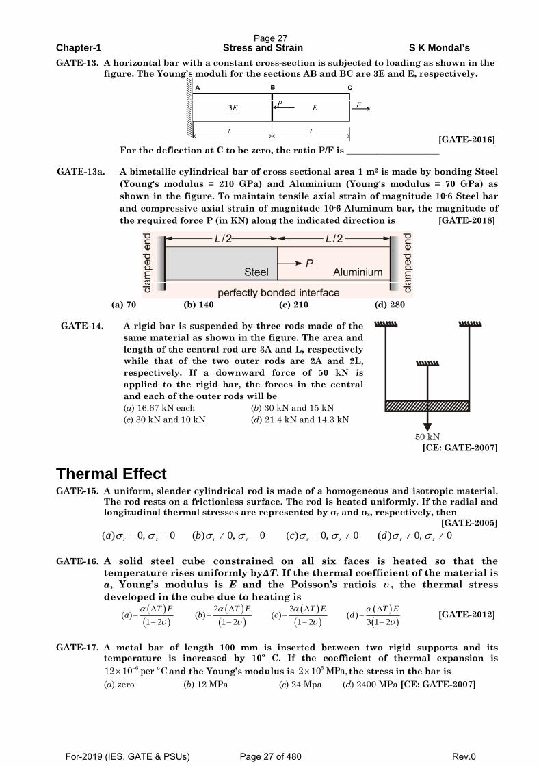
Stresses in compound strut GATE-11. The figure below shows a steel rod of 25 mm2 cross sectional area. It is loaded at four
points, K, L, M and N. [GATE-2004, IES 1995, 1997, 1998]
Assume Esteel = 200 GPa. The total change in length of the rod due to loading is: (a)1 µm (b) -10 µm (c) 16 µm (d) -20 µm GATE-12. A bar having a cross-sectional area of 700mm2 is subjected to axial loads at the
positions indicated. The value of stress in the segment QR is: [GATE-2006]
P Q R S (a) 40 MPa (b) 50 MPa (c) 70 MPa (d) 120 MPa
Page 26
For-2019 (IES, GATE & PSUs) Page 26 of 480 Rev.0
Chapter-1 Stress and Strain S K Mondal’s
GATE-13. A horizontal bar with a constant cross-section is subjected to loading as shown in the figure. The Young’s moduli for the sections AB and BC are 3E and E, respectively.
[GATE-2016] For the deflection at C to be zero, the ratio P/F is _____________________
GATE-13a. A bimetallic cylindrical bar of cross sectional area 1 m2 is made by bonding Steel
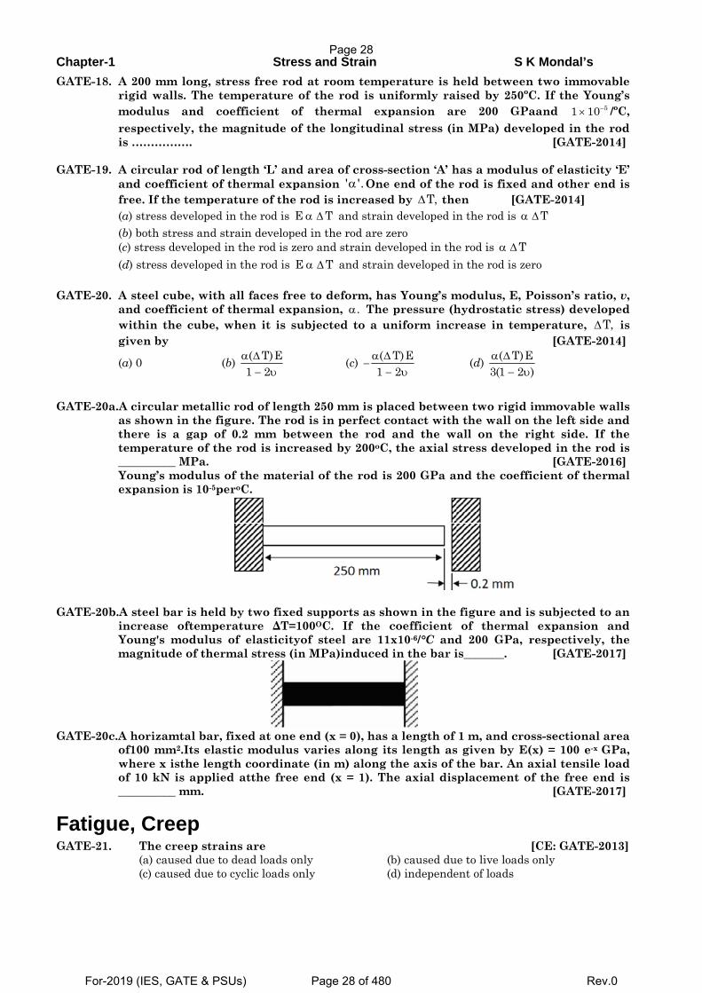
(Young's modulus = 210 GPa) and Aluminium (Young's modulus = 70 GPa) as shown in the figure. To maintain tensile axial strain of magnitude 10-6 Steel bar and compressive axial strain of magnitude 10-6 Aluminum bar, the magnitude of the required force P (in KN) along the indicated direction is [GATE-2018]
(a) 70 (b) 140 (c) 210 (d) 280 GATE-14. A rigid bar is suspended by three rods made of the
same material as shown in the figure. The area and length of the central rod are 3A and L, respectively while that of the two outer rods are 2A and 2L, respectively. If a downward force of 50 kN is applied to the rigid bar, the forces in the central and each of the outer rods will be (a) 16.67 kN each (b) 30 kN and 15 kN (c) 30 kN and 10 kN (d) 21.4 kN and 14.3 kN 50 kN
[CE: GATE-2007]
Thermal Effect GATE-15. A uniform, slender cylindrical rod is made of a homogeneous and isotropic material.
The rod rests on a frictionless surface. The rod is heated uniformly. If the radial and longitudinal thermal stresses are represented by σr and σz, respectively, then
[GATE-2005] ( ) 0, 0 ( ) 0, 0 ( ) 0, 0 ( ) 0, 0r z r z r z r za b c dσ σ σ σ σ σ σ σ= = ≠ = = ≠ ≠ ≠
GATE-16. A solid steel cube constrained on all six faces is heated so that the
temperature rises uniformly byΔT. If the thermal coefficient of the material is α, Young’s modulus is E and the Poisson’s ratiois υ , the thermal stress developed in the cube due to heating is
( )( )
( )( )
( )( )
( )( )
2 3( ) ( ) ( ) ( )
1 2 1 2 1 2 3 1 2T E T E T E T E
a b c dα α α α
υ υ υ υΔ Δ Δ Δ
− − − −− − − −
[GATE-2012]
GATE-17. A metal bar of length 100 mm is inserted between two rigid supports and its
temperature is increased by 10º C. If the coefficient of thermal expansion is 612 10 per ºC−× and the Young’s modulus is 52 10 MPa,× the stress in the bar is
(a) zero (b) 12 MPa (c) 24 Mpa (d) 2400 MPa [CE: GATE-2007]
Page 27
For-2019 (IES, GATE & PSUs) Page 27 of 480 Rev.0
Chapter-1 Stress and Strain S K Mondal’s
GATE-18. A 200 mm long, stress free rod at room temperature is held between two immovable rigid walls. The temperature of the rod is uniformly raised by 250ºC. If the Young’s modulus and coefficient of thermal expansion are 200 GPaand 51 10−× /ºC, respectively, the magnitude of the longitudinal stress (in MPa) developed in the rod is ……………. [GATE-2014]
GATE-19. A circular rod of length ‘L’ and area of cross-section ‘A’ has a modulus of elasticity ‘E’
and coefficient of thermal expansion ' '.α One end of the rod is fixed and other end is free. If the temperature of the rod is increased by T,Δ then [GATE-2014]
(a) stress developed in the rod is E Tα Δ and strain developed in the rod is Tα Δ (b) both stress and strain developed in the rod are zero (c) stress developed in the rod is zero and strain developed in the rod is Tα Δ (d) stress developed in the rod is E Tα Δ and strain developed in the rod is zero GATE-20. A steel cube, with all faces free to deform, has Young’s modulus, E, Poisson’s ratio, v,
and coefficient of thermal expansion, .α The pressure (hydrostatic stress) developed within the cube, when it is subjected to a uniform increase in temperature, T,Δ is given by [GATE-2014]
(a) 0 (b) ( T)E1 2α Δ
− υ (c) ( T)E
1 2α Δ
−− υ
(d) ( T)E3(1 2 )α Δ
− υ GATE-20a.A circular metallic rod of length 250 mm is placed between two rigid immovable walls
as shown in the figure. The rod is in perfect contact with the wall on the left side and there is a gap of 0.2 mm between the rod and the wall on the right side. If the temperature of the rod is increased by 200oC, the axial stress developed in the rod is __________ MPa. [GATE-2016] Young’s modulus of the material of the rod is 200 GPa and the coefficient of thermal expansion is 10-5peroC.
GATE-20b.A steel bar is held by two fixed supports as shown in the figure and is subjected to an
increase oftemperature ΔT=100OC. If the coefficient of thermal expansion and Young's modulus of elasticityof steel are 11x10-6/°C and 200 GPa, respectively, the magnitude of thermal stress (in MPa)induced in the bar is_______. [GATE-2017]
GATE-20c.A horizamtal bar, fixed at one end (x = 0), has a length of 1 m, and cross-sectional area
of100 mm2.Its elastic modulus varies along its length as given by E(x) = 100 e-x GPa, where x isthe length coordinate (in m) along the axis of the bar. An axial tensile load of 10 kN is applied atthe free end (x = 1). The axial displacement of the free end is __________ mm. [GATE-2017]
Fatigue, Creep GATE-21. The creep strains are [CE: GATE-2013] (a) caused due to dead loads only (b) caused due to live loads only
(c) caused due to cyclic loads only (d) independent of loads
Page 28
For-2019 (IES, GATE & PSUs) Page 28 of 480 Rev.0
Chapter-1 Stress and Strain S K Mondal’s
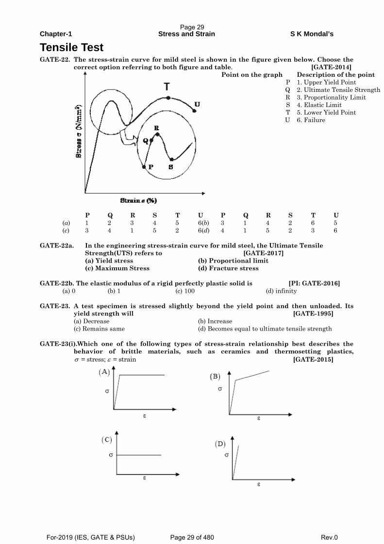
Tensile Test GATE-22. The stress-strain curve for mild steel is shown in the figure given below. Choose the
correct option referring to both figure and table. [GATE-2014]
Point on the graph Description of the point P 1. Upper Yield Point Q 2. Ultimate Tensile Strength R 3. Proportionality Limit S 4. Elastic Limit T U
5. Lower Yield Point 6. Failure
P Q R S T U P Q R S T U (a) 1 2 3 4 5 6(b) 3 1 4 2 6 5 (c) 3 4 1 5 2 6(d) 4 1 5 2 3 6
GATE-22a. In the engineering stress-strain curve for mild steel, the Ultimate Tensile
Strength(UTS) refers to [GATE-2017] (a) Yield stress (b) Proportional limit (c) Maximum Stress (d) Fracture stress
GATE-22b. The elastic modulus of a rigid perfectly plastic solid is [PI: GATE-2016]
(a) 0 (b) 1 (c) 100 (d) infinity GATE-23. A test specimen is stressed slightly beyond the yield point and then unloaded. Its
yield strength will [GATE-1995] (a) Decrease (b) Increase (c) Remains same (d) Becomes equal to ultimate tensile strength GATE-23(i).Which one of the following types of stress-strain relationship best describes the
behavior of brittle materials, such as ceramics and thermosetting plastics, = stress; = strainσ ε [GATE-2015]
Page 29
For-2019 (IES, GATE & PSUs) Page 29 of 480 Rev.0
Chapter-1 Stress and Strain S K Mondal’s
GATE-23a. In a linearly hardening plastic material, the true stress beyond initial yielding
(a) increases linearly with the true strain [GATE-2018]
(b) decreases linearly with the true strain
(c) first increases linearly and then decreases linearly with the true strain
(d) remain constant
GATE-24. The flow stress (in MPa) of a material is given by 0.1500σ ε= where ε is true strain. The Young’s modulus of elasticity of the material is 200 GPa. A block of thickness 100 mm made of this material is compressed to 95 mm thickness and then the load is removed. The final dimension of the block (in mm) is _________[GATE-2015]
GATE-25. The strain hardening exponent n of stainless steel SS304 with distinct yield and UTS
values undergoing plastic deformation is [GATE-2015] (a) n < 0 (b) n =0 (c) 0 < n < 1 (d) n = 1
GATE-26. Under repeated loading a material has the stress-strain curve shown in figure, which of the following statements is true?
(a) The smaller the shaded area, the better the material damping
(b) The larger the shaded area, the better the material damping
(c) Material damping is an independent material property and does not depend on this curve
(d) None of these
[GATE-1999]
GATE-27. Pre-tensioning of a bolted joint is used to [GATE-2018]
(a) strain harden the bolt head
(b) decrease stiffness of the bolted joint
(c) increase stiffness of the bolted joint
(d) prevent yielding of the thread root
Previous 25-Years IES Questions
Stress in a bar due to self-weight IES-1. A solid uniform metal bar of diameter D and length L is hanging vertically from its
upper end. The elongation of the bar due to self weight is: [IES-2005] (a) Proportional to L and inversely proportional to D2 (b) Proportional to L2 and inversely proportional to D2 (c) Proportional of L but independent of D (d) Proportional of L2 but independent of D IES-2. The deformation of a bar under its own weight as compared to that when subjected
to a direct axial load equal to its own weight will be: [IES-1998] (a) The same (b) One-fourth (c) Half (d) Double
Page 30
For-2019 (IES, GATE & PSUs) Page 30 of 480 Rev.0
Chapter-
IES-3.
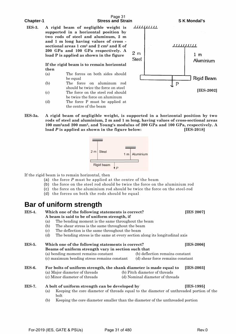
IES-3a.
If the rigi
Bar oIES-4. IES-5. IES-6. IES-7.
-1 A rigid supportetwo rodsand 1 msectional200 GPaload P is If the rigthen (a)
(b)
(c)
(d)
A rigid rods of s100 mm2aload P is
id beam is t(a) the fo(b) the fo(c) the fo(d) the fo
of unifoWhich onA beam i(a) The(b) The(c) The(d) The
Which onBeams of(a) bendin(c) maxim
For bolts(a) Major (c) Minor
A bolt of (a) Kee
bolt(b) Kee
beam of ed in a hos of steel
m long havl areas 1 cm
a and 100 s applied as
gid beam is
The forcebe equal The forcshould beThe force be twice tThe forcethe centre
beam of nsteel and aand 200 mm
s applied a
to remain hoorce P musorce on the orce on the orces on bo
orm strne of the fois said to bee bending moe shear strese deflection ie bending str
ne of the fof uniform sng moment r
mum bending
s of uniform diameter of diameter of
f uniform steping the cort eping the cor
Strenegligible
orizontal pand alum
ving valuesm2 and 2 cmGPa resp
s shown in
s to remain
es on both s
ce on alu twice the fo on the stee
the force on ae P must bee of the beam
negligible luminium, m2, and Yo
as shown in
orizontal, thst be applie steel rod s aluminiumoth the rod
rength ollowing stae of uniformoment is thess is the samis the same tress is the sa
ollowing stastrength varemains cong stress rem
m strengthf threads f threads
trength canre diameter
re diameter
ess and St weight iposition by
minum, 2 ms of cross m2 and E o
pectively. A the figure
n horizonta
sides should
minum rodorce on steelel rod shouldaluminum e applied am
weight, is 2 m and 1 oung's modn the figur
hen ed at the cehould be tw
m rod shouldds should b
atements im strengthe same throu
me throughouthroughout ame at every
atements iary in sectistant ains constan
h, the shank (b (d
n be develor of threads
smaller than
rains y
m -
of A
al
d
d l d
at
supporte m long, ha
dulus of 20e below:
entre of thewice the ford be twice te equal
s correct? h, if ughout the but the beam the beam y section alo
s correct? ion such th
(b) dent (d) sh
k diameter b) Pitch diamd) Nominal d
oped by equal to the
n the diame
d in a horaving value0 GPa and
e beam rce on the athe force on
beam
ong its longi
hat eflection remhear force rem
is made eqmeter of thrediameter of t
e diameter o
eter of the un
S K
rizontal poes of cross-
d 100 GPa, [I
aluminium n the steel-r
[I
tudinal axis
[I
mains constamains const
qual to [Ieads threads
[Iof unthread
nthreaded p
Mondal’s
[IES-2
osition by-sectional arespective
IES-2018]
rod rod
IES 2007]
s
IES-2006]
ant tant
IES-2003]
IES-1995] ded portion o
portion
2002]
y two areas ely. A
of the
Page 31
For-2019 (IES, GATE & PSUs) Page 31 of 480 Rev.0
Chapter-1 Stress and Strain S K Mondal’s
(c) Keeping the nominal diameter of threads equal the diameter of unthreaded portion of the
bolt
(d) One end fixed and the other end free
IES-7a. In a bolt of uniform strength:
(a) Nominal diameter of thread is equal to the diameter of shank of the bolt
(b) Nominal diameter of thread is larger than the diameter of shank of the bolt
(c) Nominal diameter of thread is less than the diameter of shank of the bolt
(d) Core diameter of threads is equal to the diameter of shank of the bolt.
[IES-2011]
Elongation of a Taper Rod IES-8. Two tapering bars of the same material are subjected to a tensile load P. The lengths
of both the bars are the same. The larger diameter of each of the bars is D. The
diameter of the bar A at its smaller end is D/2 and that of the bar B is D/3. What is the
ratio of elongation of the bar A to that of the bar B? [IES-2006]
(a) 3 : 2 (b) 2: 3 (c) 4 : 9 (d) 1: 3
IES-9. A bar of length L tapers uniformly from diameter 1.1 D at one end to 0.9 D at the
other end. The elongation due to axial pull is computed using mean diameter D. What
is the approximate error in computed elongation? [IES-2004]
(a) 10% (b) 5% (c) 1% (d) 0.5%
IES-10. The stretch in a steel rod of circular section, having a length 'l' subjected to a tensile
load' P' and tapering uniformly from a diameter d1 at one end to a diameter d2 at the
other end, is given [IES-1995]
(a)
1 24
Pl
Ed d (b)
1 2
.pl
Ed d
(c)
1 2
.
4
pl
Ed d
(d)
1 2
4 pl
Ed d
IES-11. A tapering bar (diameters of end sections being d1 andd2 a bar of uniform cross-
section ’d’ have the same length and are subjected the same axial pull. Both the bars
will have the same extension if’d’ is equal to [IES-1998]
1 2 1 2 1 21 2a b c d
2 2 2
d d d d d dd d
IES-11(i). A rod of length l tapers uniformly from a diameter D at one end to a diameter d at the
other. The Young’s modulus of the material is E. The extension caused by an axial
load P is [IES-2012]
(𝑎)4𝑃𝑙
𝜋(𝐷2 − 𝑑2)𝐸(𝑏)
4𝑃𝑙
𝜋(𝐷2 + 𝑑2)𝐸(𝑐)
4𝑃𝑙
𝜋𝐷𝑑𝐸(𝑑)
2𝑃𝑙
𝜋𝐷𝑑𝐸
IES-11ii. A rod of length L tapers uniformly from a diameter D at one end to a diameter D/2 at
the other end and is subjected to an axial load P. A second rod of length L and
uniform diameter D is subjected to same axial load P. Both the rods are of same
material with Young’s modulus of elasticity E. The ratio of extension of the first rod
to that of the second rod [IES-2014]
(a) 4 (b) 3 (c) 2 (d) 1
Poisson’s ratio IES-12. In the case of an engineering material under unidirectional stress in the x-direction,
the Poisson's ratio is equal to (symbols have the usual meanings)
[IAS 1994, IES-2000]
(a)
x
y
(b)
x
y
(c)
x
y
(d)
x
y
Page 32
For-2019 (IES, GATE & PSUs) Page 32 of 480 Rev.0
Chapter-1 Stress and Strain S K Mondal’s
IES-13. Which one of the following is correct in respect of Poisson's ratio (v) limits for an isotropic elastic solid? [IES-2004]
(a) ν−∞≤ ≤∞ (b) 1/ 4 1/ 3ν≤ ≤ (c) 1 1/ 2ν− ≤ ≤ (d) 1/ 2 1/ 2ν− ≤ ≤ IES-14. Match List-I (Elastic properties of an isotropic elastic material) with List-II (Nature
of strain produced) and select the correct answer using the codes given below the Lists: [IES-1997]
List-I List-II A. Young's modulus 1. Shear strain B. Modulus of rigidity 2. Normal strain C. Bulk modulus 3. Transverse strain D. Poisson's ratio 4. Volumetric strain Codes: A B C D A B C D (a) 1 2 3 4 (b) 2 1 3 4 (c) 2 1 4 3 (d) 1 2 4 3 IES-15. If the value of Poisson's ratio is zero, then it means that [IES-1994] (a) The material is rigid. (b) The material is perfectly plastic. (c) There is no longitudinal strain in the material (d) The longitudinal strain in the material is infinite. IES-16. Which of the following is true (µ= Poisson's ratio) [IES-1992] (a) 0 1/ 2μ< < (b) 1 0μ< < (c)1 1μ< < − (d) μ∞ < << −∞
Elasticity and Plasticity IES-17. If the area of cross-section of a wire is circular and if the radius of this circle
decreases to half its original value due to the stretch of the wire by a load, then the modulus of elasticity of the wire be: [IES-1993]
(a) One-fourth of its original value (b) Halved (c) Doubled (d) Unaffected IES-18. The relationship between the Lame’s constant ‘λ’, Young’s modulus ‘E’ and the
Poisson’s ratio ‘μ’ [IES-1997]
( ) ( )( ) ( )( ) ( ) ( ) ( )a ( ) c d
1 1 2 1 2 1 1 1μ μ μ μλ λ λ λ
μ μ μ μ μ μ= = = =
+ − + − + −E E E Eb
IES-19. Which of the following pairs are correctly matched? [IES-1994] 1. Resilience…………… Resistance to deformation. 2. Malleability …………..Shape change. 3. Creep ........................ Progressive deformation. 4. Plasticity .... ………….Permanent deformation. Select the correct answer using the codes given below: Codes: (a) 2, 3 and 4 (b) 1, 2 and 3 (c) 1, 2 and 4 (d) 1, 3 and 4 IES-19a Match List – I with List - II and select the correct answer using the code given below
thelists: [IES-2011] List –I List –II
A. Elasticity 1. Deform non-elastically without fracture B. Malleability 2. Undergo plastic deformation under tensile load C. Ductility 3. Undergo plastic deformation under compressive load D. Plasticity 4. Return to its original shape on unloading Codes A B C D A B C D (a) 1 2 3 4 (b) 4 2 3 1 (c) 1 3 2 4 (d) 4 3 2 1
Page 33
For-2019 (IES, GATE & PSUs) Page 33 of 480 Rev.0
Chapter-1 Stress and Strain S K Mondal’s
IES-19b. Assertion (A): Plastic deformation is a function of applied stress, temperature and strain rate. [IES-2010] Reason (R): Plastic deformation is accompanied by change in both the internal and external state of the material. (a) Both A and R are individually true and R is the correct explanation of A (b) Both A and R are individually true but R is NOT the correct explanation of A (c) A is true but R is false (d) A is false but R is true
Creep and fatigue IES-20. What is the phenomenon of progressive extension of the material i.e., strain
increasing with the time at a constant load, called? [IES 2007] (a) Plasticity (b) Yielding (b) Creeping (d) Breaking IES-21. The correct sequence of creep deformation in a creep curve in order of their
elongation is: [IES-2001] (a) Steady state, transient, accelerated (b) Transient, steady state, accelerated (c) Transient, accelerated, steady state (d) Accelerated, steady state, transient IES-22. The highest stress that a material can withstand for a specified length of time
without excessive deformation is called [IES-1997] (a) Fatigue strength (b) Endurance strength (c) Creep strength (d) Creep rupture strength IES-22a. A transmission shaft subjected to bending loads must be designed on the basis of (a) Maximum normal stress theory [IES-1996] (b) Maximum shear stress theory (c) Maximum normal stress and maximum shear stress theories (d) Fatigue strength IES-22b. Endurance limit is of primary concern in the design of a/an [IES-2016]
1. rotating shaft 2. industrial structure 3. column 4. machine base Which of the above is/are correct? (a) 1 only (b) 2 only (c) 3 and 4 only (d) 1, 2, 3 and 4
IES-23. Which one of the following features improves the fatigue strength of a metallic
material? [IES-2000] (a) Increasing the temperature (b) Scratching the surface (c) Overstressing (d) Under stressing IES-24. Consider the following statements: [IES-1993] For increasing the fatigue strength of welded joints it is necessary to employ 1. Grinding 2. Coating 3. Hammer peening Of the above statements (a) 1 and 2 are correct (b) 2 and 3 are correct (c) 1 and 3 are correct (d) 1, 2 and 3 are correct
Relation between the Elastic Modulii IES-25. For a linearly elastic, isotropic and homogeneous material, the number of elastic
constants required to relate stress and strain is:[IAS 1994; IES-1998, CE:GATE-2010] (a) Two (b) Three (c) Four (d) Six IES-26. E, G, K and μ represent the elastic modulus, shear modulus, bulk modulus and
Poisson's ratio respectively of a linearly elastic, isotropic and homogeneous material. To express the stress-strain relations completely for this material, at least[IES-2006]
(a) E, G and μ must be known (b) E, K and μ must be known (c) Any two of the four must be known (d) All the four must be known
Page 34
For-2019 (IES, GATE & PSUs) Page 34 of 480 Rev.0
Chapter-1 Stress and Strain S K Mondal’s
IES-26a. An isotropic elastic material is characterized by [IES-2016] (a) two independent moduli of elasticity along two mutually perpendicular directions (b) two independent moduli of elasticity along two mutually perpendicular directions andPoisson’s ratio (c) a modulus of elasticity, a modulus of rigidity and Poisson’s ratio (d) any two out of a modulus of elasticity, a modulus of rigidity and Poisson’s ratio
IES-27. The number of elastic constants for a completely anisotropic elastic material which
follows Hooke's law is: [IES-1999] (a) 3 (b) 4 (c) 21 (d) 25 IES-28. What are the materials which show direction dependent properties, called? (a) Homogeneous materials (b) Viscoelastic materials[IES 2007, IES-2011] (c) Isotropic materials (d) Anisotropic materials IES-28a. Measured mechanical properties of material are same in a particular direction at
each point. This property of the material is known as [IES-2016] (a) isotropy (b) homogeneity (c) orthotropy (d) anisotropy
IES-29. An orthotropic material, under plane stress condition will have: [IES-2006] (a) 15 independent elastic constants (b) 4 independent elastic constants (c) 5 independent elastic constants (d) 9 independent elastic constants IES-30. Match List-I (Properties) with List-II (Units) and select the correct answer using the
codes given below the lists: [IES-2001] List I List II A. Dynamic viscosity 1. Pa B. Kinematic viscosity 2. m2/s C. Torsional stiffness 3. Ns/m2
D. Modulus of rigidity 4. N/m Codes: A B C D A B C D (a) 3 2 4 1 (b) 5 2 4 3 (b) 3 4 2 3 (d) 5 4 2 1 IES-31. Young's modulus of elasticity and Poisson's ratio of a material are 1.25 ×10⁵ MPa and
0.34 respectively. The modulus of rigidity of the material is: [IAS 1994, IES-1995, 2001, 2002, 2007] (a) 0.4025 ×10⁵ Mpa (b) 0.4664 ×10⁵ Mpa (c) 0.8375 ×10⁵ MPa (d) 0.9469 ×10⁵ MPa IES-31(i). Consider the following statements: Modulus of rigidity and bulk modulus of a material are found to be 60 GPa and 140
GPa respectively. Then [IES-2013] 1. Elasticity modulus is nearly 200 GPa 2. Poisson’s ratio is nearly 0.3 3. Elasticity modulus is nearly 158 GPa 4. Poisson’s ratio is nearly 0.25 Which of these statements are correct? (a) 1 and 3 (b) 2 and 4 (c) 1 and 4 (d) 2 and 3 IES-31(ii). The modulus of rigidity and the bulk modulus of a material are found as 70 GPa and
150 GPa respectively. Then [IES-2014] 1. elasticity modulus is 200 GPa 2. Poisson’s ratio is 0.22 3. elasticity modulus is 182 GPa 4. Poisson’s ratio is 0.3 Which of the above statements are correct? (a) 1 and 2 (b) 1 and 4 (c) 2 and 3 (d) 3 and 4
Page 35
For-2019 (IES, GATE & PSUs) Page 35 of 480 Rev.0
Chapter-1 Stress and Strain S K Mondal’s
IES-31(iii).For a material following Hooke’s law the values of elastic and shear moduli are 3x10⁵
MPa and 1.2x10⁵ MPa respectively. The value for bulk modulus [IES-2015] (a) 1.5x10⁵MPa (b) 2x10⁵MPa (c) 2.5x10⁵MPa (d) 3x10⁵MPa
IES-32. In a homogenous, isotropic elastic material, the modulus of elasticity E in terms of G
and K is equal to [IAS-1995, IES - 1992]
(a)3
9G K
KG+
(b) 39G K
KG+
(c)9
3KG
G K+ (d)
93
KGK G+
IES-33. What is the relationship between the linear elastic properties Young's modulus (E),
rigidity modulus (G) and bulk modulus (K)? [IES-2008]
1 9 3 3 9 1 9 3 1 9 1 3(a) (b) (c) (d)E K G E K G E K G E K G= + = + = + = +
IES-34. What is the relationship between the liner elastic properties Young’s modulus (E),
rigidity modulus (G) and bulk modulus (K)? [IES-2009]
(a) 9
KGEK G
=+
(b) 9KGEK G
=+
(c)9
3KGE
K G=
+ (d)
93
KGEK G
=+
IES-35. If E, G and K denote Young's modulus, Modulus of rigidity and Bulk Modulus,
respectively, for an elastic material, then which one of the following can be possibly true? [IES-2005]
(a) G = 2K (b) G = E (c) K = E (d) G = K = E IES-36. If a material had a modulus of elasticity of 2.1 × 10⁶ kgf/cm2 and a modulus of rigidity
of 0.8 × 10⁶ kgf/cm2 then the approximate value of the Poisson's ratio of the material would be: [IES-1993]
(a) 0.26 (b) 0.31 (c) 0.47 (d) 0.5 IES-37. The modulus of elasticity for a material is 200 GN/m2 and Poisson's ratio is 0.25. What is the modulus of rigidity? [IES-2004] (a) 80 GN/m2 (b) 125 GN/m2 (c) 250 GN/m2 (d) 320 GN/m2
IES-37a. The modulus of rigidity of an elastic material isfound to be 38.5% of the value of its Young’smodulus. The poisson’s ratio μof the materialis nearly:[IES-2017 (Prelims)]
(a) 0.28 (b) 0.30 (c) 0.33 (d) 0.35 IES-38. Consider the following statements: [IES-2009] 1. Two-dimensional stresses applied to a thin plate in itsown plane represent the
planestress condition. 2. Under plane stress condition, the strain in the direction perpendicular to the
plane is zero. 3. Normal and shear stresses may occur simultaneously on aplane. Which of the above statements is /are correct? (a)1 only (b)1 and 2 (c)2 and 3 (d)1 and 3 IES-38(i). A 16 mm diameter bar elongates by 0.04% under a tensile force of 16 kN. The average
decrease in diameter is found to be 0.01% Then: [IES-2013] 1. E = 210 GPa and G = 77 GPa 2. E = 199 GPa and v = 0.25 3. E = 199 GPa and v = 0.30 4. E = 199 GPa and G = 80 GPa Which of these values are correct? (a) 3 and 4 (b) 2 and 4 (c) 1 and 3 (d) 1 and 4
Page 36
For-2019 (IES, GATE & PSUs) Page 36 of 480 Rev.0
Chapter-1 Stress and Strain S K Mondal’s
IES-38a. A bar produces a lateral strain of magnitude 60 x 10-5mm when subjected to a tensile
stress of magnitude 300 MPa along the axial direction. What is the elastic modulus of
the material if the poisson’s ratio is 0.3? [IES-2017 (Prelims)]
(a) 200 GPa (b) 150 GPa (c) 125 GPa (d) 100 GPa
Stresses in compound strut IES-39. Eight bolts are to be selected for fixing the cover plate of a cylinder subjected to a
maximum load of 980·175 kN. If the design stress for the bolt material is 315 N/mm2,
what is the diameter of each bolt? [IES-2008]
(a) 10 mm (b) 22 mm (c) 30 mm (d) 36 mm
IES-39a. A tension member of square cross-section of side 10 mm and Young’s modulus E is
replaced by another member of square cross-section of same length but Young’s
modulus E/2. The side of the new square cross-section, required to maintain the same
elongation under the same load, is nearly [IES-2014]
(a) 14 mm (b) 17 mm (c) 8 mm (d) 5 mm
IES-39b. Two steel rods of identical length and material properties are subjected to equal
axialloads. The first rod is solid with diameter d and the second is a hollow one with
externaldiameter D and interned diameter 50% of D. If the two rods experience equal
extensions,the ratio of 𝒅
𝑫 [IES-2016]
(𝑎) 3
4 (b)
√3
2 (c)
1
2 (d)
1
4
IES-40. For a composite consisting of a bar enclosed inside a tube of another material when
compressed under a load 'w' as a whole through rigid collars at the end of the bar.
The equation of compatibility is given by (suffixes 1 and 2) refer to bar and tube
respectively [IES-1998]
1 2 1 21 2 1 2
1 1 2 2 1 2 2 1
( ) ( ) . ( ) ( )W W W W
a W W W b W W Const c dA E A E A E A E
IES-40(i). A copper rod of 2 cm diameter is completely encased in a steel tube of inner diameter
2 cm and outer diameter 4 cm. Under an axial load, the stress in the steel tube is 100
N/mm2. If ES = 2 EC , then stress in the copper rod is [IES-2015]
(a) 50N/mm2 (b)33.33 N/mm2 (c) 100 N/mm2 (d) 300 N/mm2
IES-41. When a composite unit consisting of a steel rod surrounded by a cast iron tube is
subjected to an axial load. [IES-2000]
Assertion (A): The ratio of normal stresses induced in both the materials is equal to
the ratio of Young's moduli of respective materials.
Reason (R): The composite unit of these two materials is firmly fastened together at
the ends to ensure equal deformation in both the materials.
(a) Both A and R are individually true and R is the correct explanation of A
(b) Both A and R are individually true but R is notthe correct explanation of A
(c) A is true but R is false
(d) A is false but R is true
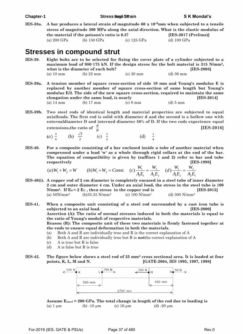
IES-42. The figure below shows a steel rod of 25 mm2 cross sectional area. It is loaded at four
points, K, L, M and N. [GATE-2004, IES 1995, 1997, 1998]
Assume Esteel = 200 GPa. The total change in length of the rod due to loading is
(a) 1 µm (b) -10 µm (c) 16 µm (d) -20 µm
Page 37
For-2019 (IES, GATE & PSUs) Page 37 of 480 Rev.0
Chapter-1 Stress and Strain S K Mondal’s
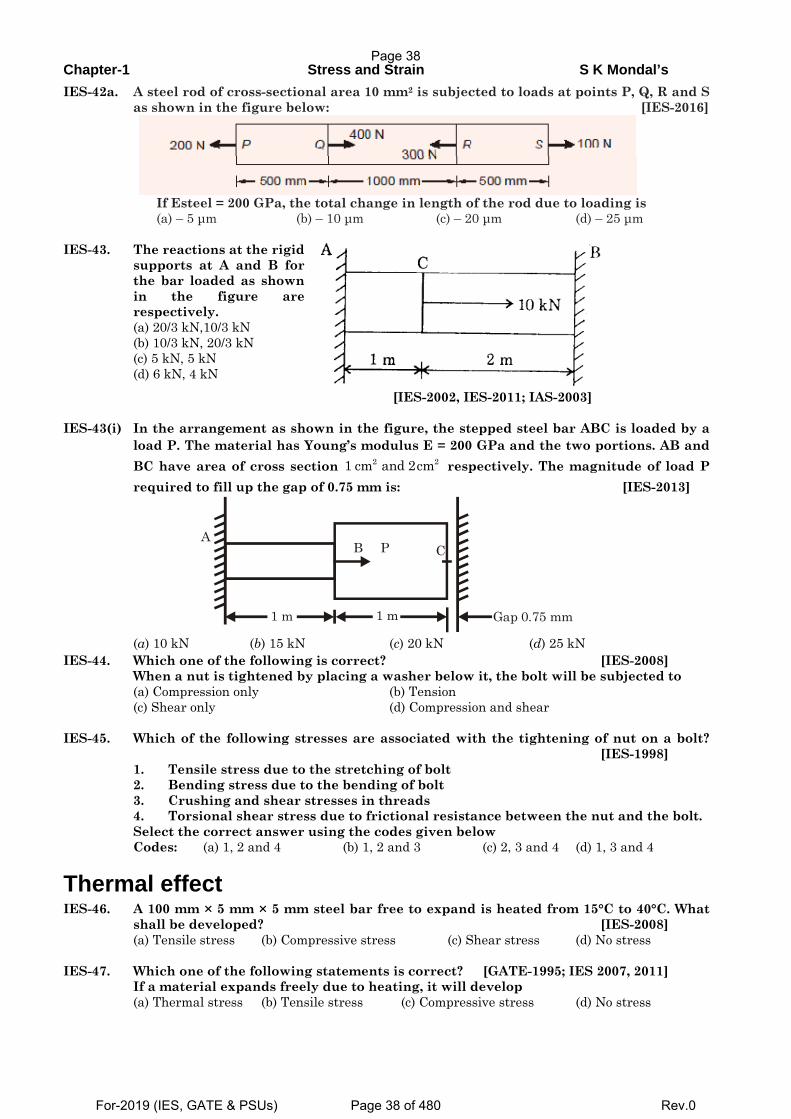
IES-42a. A steel rod of cross-sectional area 10 mm2 is subjected to loads at points P, Q, R and S as shown in the figure below: [IES-2016]
If Esteel = 200 GPa, the total change in length of the rod due to loading is
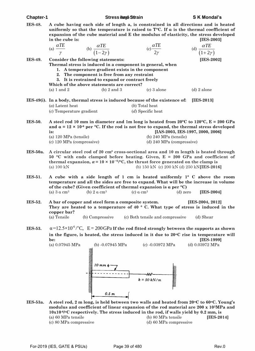
(a) – 5 μm (b) – 10 μm (c) – 20 μm (d) – 25 μm IES-43. The reactions at the rigid
supports at A and B for the bar loaded as shown in the figure are respectively.
(a) 20/3 kN,10/3 kN (b) 10/3 kN, 20/3 kN (c) 5 kN, 5 kN (d) 6 kN, 4 kN
[IES-2002, IES-2011; IAS-2003] IES-43(i) In the arrangement as shown in the figure, the stepped steel bar ABC is loaded by a
load P. The material has Young’s modulus E = 200 GPa and the two portions. AB and BC have area of cross section 2 21 cm and 2cm respectively. The magnitude of load P required to fill up the gap of 0.75 mm is: [IES-2013]
Gap 0.75 mm 1 m 1 m
B P C A
(a) 10 kN (b) 15 kN (c) 20 kN (d) 25 kN IES-44. Which one of the following is correct? [IES-2008] When a nut is tightened by placing a washer below it, the bolt will be subjected to (a) Compression only (b) Tension (c) Shear only (d) Compression and shear IES-45. Which of the following stresses are associated with the tightening of nut on a bolt?
[IES-1998] 1. Tensile stress due to the stretching of bolt 2. Bending stress due to the bending of bolt 3. Crushing and shear stresses in threads 4. Torsional shear stress due to frictional resistance between the nut and the bolt. Select the correct answer using the codes given below Codes: (a) 1, 2 and 4 (b) 1, 2 and 3 (c) 2, 3 and 4 (d) 1, 3 and 4
Thermal effect IES-46. A 100 mm × 5 mm × 5 mm steel bar free to expand is heated from 15°C to 40°C. What
shall be developed? [IES-2008] (a) Tensile stress (b) Compressive stress (c) Shear stress (d) No stress IES-47. Which one of the following statements is correct? [GATE-1995; IES 2007, 2011] If a material expands freely due to heating, it will develop (a) Thermal stress (b) Tensile stress (c) Compressive stress (d) No stress
Page 38
For-2019 (IES, GATE & PSUs) Page 38 of 480 Rev.0
Chapter-1 Stress and Strain S K Mondal’s
IES-48. A cube having each side of length a, is constrained in all directions and is heated
uniformly so that the temperature is raised to T°C. If α is the thermal coefficient of
expansion of the cube material and E the modulus of elasticity, the stress developed
in the cube is: [IES-2003]
(a) TE
(b)
1 2
TE
(c)
2
TE
(d)
1 2
TE
IES-49. Consider the following statements: [IES-2002]
Thermal stress is induced in a component in general, when
1. A temperature gradient exists in the component
2. The component is free from any restraint
3. It is restrained to expand or contract freely
Which of the above statements are correct?
(a) 1 and 2 (b) 2 and 3 (c) 3 alone (d) 2 alone
IES-49(i). In a body, thermal stress is induced because of the existence of: [IES-2013]
(a) Latent heat (b) Total heat
(c) Temperature gradient (d) Specific heat
IES-50. A steel rod 10 mm in diameter and 1m long is heated from 20°C to 120°C, E = 200 GPa
and α = 12 × 10-6 per °C. If the rod is not free to expand, the thermal stress developed
is: [IAS-2003, IES-1997, 2000, 2006]
(a) 120 MPa (tensile) (b) 240 MPa (tensile)
(c) 120 MPa (compressive) (d) 240 MPa (compressive)
IES-50a. A circular steel rod of 20 cm² cross-sectional area and 10 m length is heated through
50 °C with ends clamped before heating. Given, E = 200 GPa and coefficient of
thermal expansion, 𝜶 = 10 × 𝟏𝟎−𝟔/°C, the thrust force generated on the clamp is
(a) 100 kN (b) 150 kN (c) 200 kN (d) 250 kN[IES-2016]
IES-51. A cube with a side length of 1 cm is heated uniformly 1° C above the room
temperature and all the sides are free to expand. What will be the increase in volume
of the cube? (Given coefficient of thermal expansion is α per °C)
(a) 3 α cm3 (b) 2 α cm3 (c) α cm3 (d) zero [IES-2004]
IES-52. A bar of copper and steel form a composite system. [IES-2004, 2012]
They are heated to a temperature of 40 ° C. What type of stress is induced in the
copper bar?
(a) Tensile (b) Compressive (c) Both tensile and compressive (d) Shear
IES-53. -6 oα=12.5×10 / C, E = 200GPa If the rod fitted strongly between the supports as shown
in the figure, is heated, the stress induced in it due to 20oC rise in temperature will
be: [IES-1999]
(a) 0.07945 MPa (b) -0.07945 MPa (c) -0.03972 MPa (d) 0.03972 MPa
IES-53a. A steel rod, 2 m long, is held between two walls and heated from 20oC to 60oC. Young’s
modulus and coefficient of linear expansion of the rod material are 200 x 103MPa and
10x10-6/oC respectively. The stress induced in the rod, if walls yield by 0.2 mm, is
(a) 60 MPa tensile (b) 80 MPa tensile [IES-2014]
(c) 80 MPa compressive (d) 60 MPa compressive
Page 39
For-2019 (IES, GATE & PSUs) Page 39 of 480 Rev.0
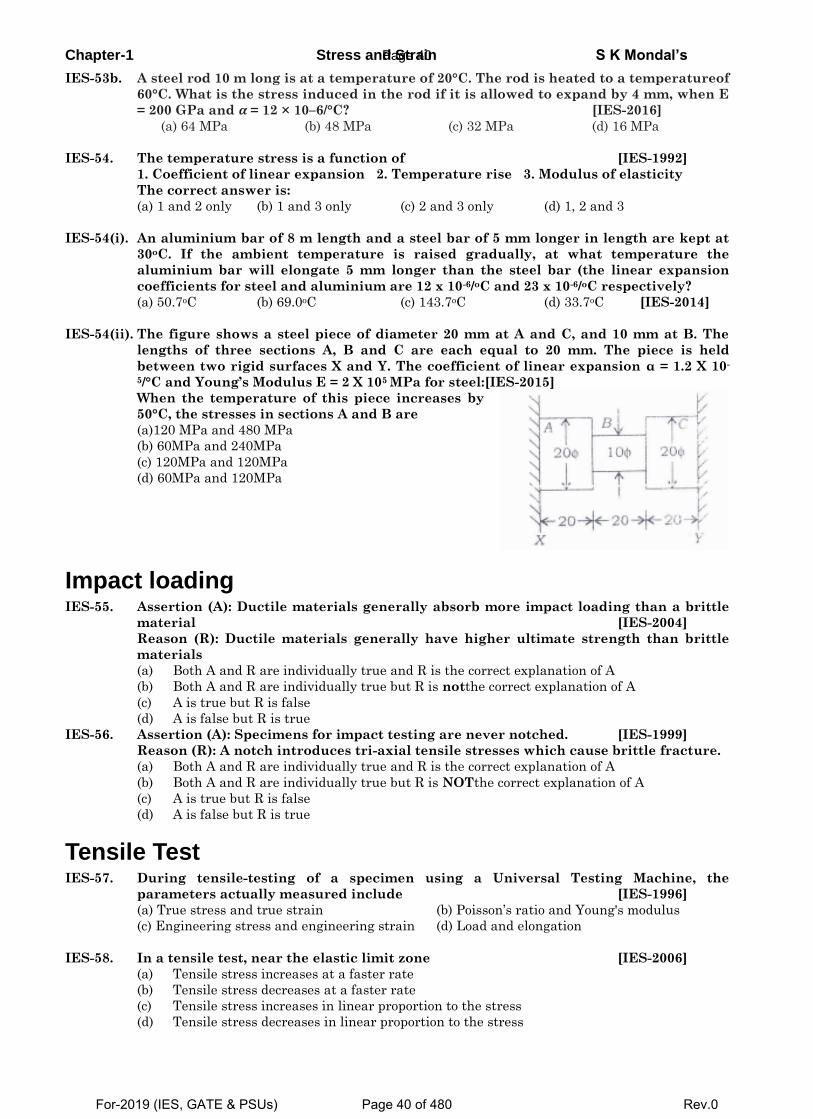
Chapter-1 Stress and Strain S K Mondal’s
IES-53b. A steel rod 10 m long is at a temperature of 20°C. The rod is heated to a temperatureof
60°C. What is the stress induced in the rod if it is allowed to expand by 4 mm, when E
= 200 GPa and 𝜶 = 12 × 10–6/°C? [IES-2016]
(a) 64 MPa (b) 48 MPa (c) 32 MPa (d) 16 MPa
IES-54. The temperature stress is a function of [IES-1992]
1. Coefficient of linear expansion 2. Temperature rise 3. Modulus of elasticity
The correct answer is:
(a) 1 and 2 only (b) 1 and 3 only (c) 2 and 3 only (d) 1, 2 and 3
IES-54(i). An aluminium bar of 8 m length and a steel bar of 5 mm longer in length are kept at
30oC. If the ambient temperature is raised gradually, at what temperature the
aluminium bar will elongate 5 mm longer than the steel bar (the linear expansion
coefficients for steel and aluminium are 12 x 10-6/oC and 23 x 10-6/oC respectively?
(a) 50.7oC (b) 69.0oC (c) 143.7oC (d) 33.7oC [IES-2014]
IES-54(ii). The figure shows a steel piece of diameter 20 mm at A and C, and 10 mm at B. The
lengths of three sections A, B and C are each equal to 20 mm. The piece is held
between two rigid surfaces X and Y. The coefficient of linear expansion α = 1.2 X 10-
5/°C and Young’s Modulus E = 2 X 10⁵ MPa for steel:[IES-2015]
When the temperature of this piece increases by
50°C, the stresses in sections A and B are
(a)120 MPa and 480 MPa
(b) 60MPa and 240MPa
(c) 120MPa and 120MPa
(d) 60MPa and 120MPa
Impact loading IES-55. Assertion (A): Ductile materials generally absorb more impact loading than a brittle
material [IES-2004]
Reason (R): Ductile materials generally have higher ultimate strength than brittle
materials
(a) Both A and R are individually true and R is the correct explanation of A
(b) Both A and R are individually true but R is notthe correct explanation of A
(c) A is true but R is false
(d) A is false but R is true
IES-56. Assertion (A): Specimens for impact testing are never notched. [IES-1999]
Reason (R): A notch introduces tri-axial tensile stresses which cause brittle fracture.
(a) Both A and R are individually true and R is the correct explanation of A
(b) Both A and R are individually true but R is NOTthe correct explanation of A
(c) A is true but R is false
(d) A is false but R is true
Tensile Test IES-57. During tensile-testing of a specimen using a Universal Testing Machine, the
parameters actually measured include [IES-1996]
(a) True stress and true strain (b) Poisson’s ratio and Young's modulus
(c) Engineering stress and engineering strain (d) Load and elongation
IES-58. In a tensile test, near the elastic limit zone [IES-2006]
(a) Tensile stress increases at a faster rate
(b) Tensile stress decreases at a faster rate
(c) Tensile stress increases in linear proportion to the stress
(d) Tensile stress decreases in linear proportion to the stress
Page 40
For-2019 (IES, GATE & PSUs) Page 40 of 480 Rev.0
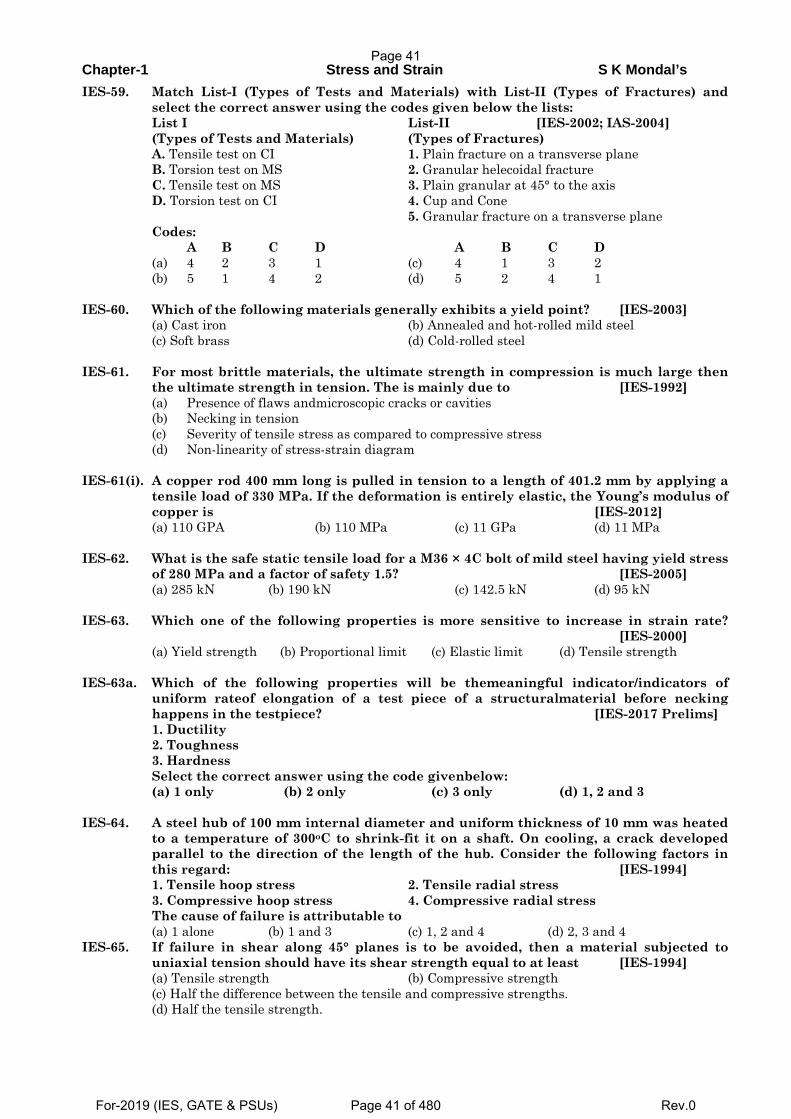
Chapter-1 Stress and Strain S K Mondal’s
IES-59. Match List-I (Types of Tests and Materials) with List-II (Types of Fractures) and select the correct answer using the codes given below the lists:
List I List-II [IES-2002; IAS-2004] (Types of Tests and Materials) (Types of Fractures) A. Tensile test on CI 1. Plain fracture on a transverse plane B. Torsion test on MS 2. Granular helecoidal fracture C. Tensile test on MS 3. Plain granular at 45° to the axis D. Torsion test on CI 4. Cup and Cone 5. Granular fracture on a transverse plane Codes: A B C D A B C D (a) 4 2 3 1 (c) 4 1 3 2 (b) 5 1 4 2 (d) 5 2 4 1 IES-60. Which of the following materials generally exhibits a yield point? [IES-2003] (a) Cast iron (b) Annealed and hot-rolled mild steel (c) Soft brass (d) Cold-rolled steel IES-61. For most brittle materials, the ultimate strength in compression is much large then
the ultimate strength in tension. The is mainly due to [IES-1992] (a) Presence of flaws andmicroscopic cracks or cavities (b) Necking in tension (c) Severity of tensile stress as compared to compressive stress (d) Non-linearity of stress-strain diagram IES-61(i). A copper rod 400 mm long is pulled in tension to a length of 401.2 mm by applying a
tensile load of 330 MPa. If the deformation is entirely elastic, the Young’s modulus of copper is [IES-2012] (a) 110 GPA (b) 110 MPa (c) 11 GPa (d) 11 MPa
IES-62. What is the safe static tensile load for a M36 × 4C bolt of mild steel having yield stress
of 280 MPa and a factor of safety 1.5? [IES-2005] (a) 285 kN (b) 190 kN (c) 142.5 kN (d) 95 kN IES-63. Which one of the following properties is more sensitive to increase in strain rate?
[IES-2000] (a) Yield strength (b) Proportional limit (c) Elastic limit (d) Tensile strength IES-63a. Which of the following properties will be themeaningful indicator/indicators of
uniform rateof elongation of a test piece of a structuralmaterial before necking happens in the testpiece? [IES-2017 Prelims]
1. Ductility 2. Toughness 3. Hardness Select the correct answer using the code givenbelow: (a) 1 only (b) 2 only (c) 3 only (d) 1, 2 and 3 IES-64. A steel hub of 100 mm internal diameter and uniform thickness of 10 mm was heated
to a temperature of 300oC to shrink-fit it on a shaft. On cooling, a crack developed parallel to the direction of the length of the hub. Consider the following factors in this regard: [IES-1994]
1. Tensile hoop stress 2. Tensile radial stress 3. Compressive hoop stress 4. Compressive radial stress The cause of failure is attributable to (a) 1 alone (b) 1 and 3 (c) 1, 2 and 4 (d) 2, 3 and 4 IES-65. If failure in shear along 45° planes is to be avoided, then a material subjected to
uniaxial tension should have its shear strength equal to at least [IES-1994] (a) Tensile strength (b) Compressive strength (c) Half the difference between the tensile and compressive strengths. (d) Half the tensile strength.
Page 41
For-2019 (IES, GATE & PSUs) Page 41 of 480 Rev.0
Chapter-1 Stress and Strain S K Mondal’s
IES-66. Select the proper sequence [IES-1992] 1. Proportional Limit 2. Elastic limit 3. Yielding 4. Failure (a) 2, 3, 1, 4 (b) 2, 1, 3, 4 (c) 1, 3, 2, 4 (d) 1, 2, 3, 4 IES-67. Elastic limit of cast iron as compared to its ultimate breaking strength is
(a) Half (b) Double [IES-2012] (c) Approximately (d) None of the above
IES-68. Statement (I): Steel reinforcing bars are used in reinforced cement concrete.
Statement (II): Concrete is weak in compression. [IES-2012] (a) Both Statement (I) and Statement (II) are individually true and Statement (II) is the correct explanation of Statement (I) (b) Both Statement (I) and Statement (II) are individually true but Statement (II) is not the correct explanation of Statement (I) (c) Statement (I) is true but Statement (II) is false (d) Statement (I) is false but Statement (II) is true
IES-69. Statement (I): Cast iron is good in compression.
Statement (II): It is extensively used in members of truss. [IES-2014] (a)Both statement (I) and (II) are individually correct and statement (II) is the correct explanation of statement (I) (b)Both statement (I) and (II) are individually correct and statement (II) is not the correct explanation of statement (I) (c)Statement (I) is true but statement (II) is false. (d)Statement (I) is false but statement (II) is true.
IES-70. Statement (I): The Bauschinger effect is observed in tension test of mild steel
specimen due to loss of mechanical energy during local yielding. Statement (II): The Bauschinger effect is a function of section modulus of specimen under test. [IES-2015] (a) Both statement (I) and (II) are individually correct and statement (II) is the correct explanation of statement (I) (b) Both statement (I) and (II) are individually correct and statement (II) is not the correct explanation of statement (I) (c) Statement (I) is true but statement (II) is false. (d) Statement (I) is false but statement (II) is true.
IES-71. A 10 mm diameter bar of mild steel of elasticmodulus 200x109 Pa is subjected to a
tensileload of 50000 N, taking it just beyond its yieldpoint. The elastic recovery of strain that wouldoccur upon removal of tensile load will be [IES-2017 Prelims]
(a) 1.38 x 10⁻³ (b) 2.68 x 10⁻³ (c) 3.18 x 10⁻³ (d) 4.62 x10⁻³
Previous 25-Years IAS Questions
Stress in a bar due to self-weight IAS-1. A heavy uniform rod of length 'L' and material density 'δ' is hung vertically with its
top end rigidly fixed. How is the total elongation of the bar under its own weight expressed? [IAS-2007]
(a) 22 L g
Eδ
(b) 2L g
Eδ
(c)2
2L g
Eδ (d)
2
2L gE
δ
IAS-2. A rod of length 'l' and cross-section area ‘A’ rotates about an axis passing through one
end of the rod. The extension produced in the rod due to centrifugal forces is (w is the weight of the rod per unit length and ω is the angular velocity of rotation of the rod). [IAS 1994]
Page 42
For-2019 (IES, GATE & PSUs) Page 42 of 480 Rev.0
Chapter-1 Stress and Strain S K Mondal’s
(a) gEwl 2ω (b)
gEwl
3
32ω (c)gEwl32ω (d) 32
3wlgE
ω
Elongation of a Taper Rod IAS-3. A rod of length, "ι " tapers uniformly from a diameter ''D1' to a diameter ''D2' and
carries an axial tensile load of "P". The extension of the rod is (E represents the modulus of elasticity of the material of the rod) [IAS-1996]
(a) 1 2
4 1π
PED D
1 2
4 1( )π
PEbD D
(c)1 2
14
EPD Dπ
(d) 1 2
14
PED Dπ
Poisson’s ratio IAS-4. In the case of an engineering material under unidirectional stress in the x-direction,
the Poisson's ratio is equal to (symbols have the usual meanings) [IAS 1994, IES-2000]
(a) x
y
εε
(b) x
y
σε
(c)x
y
σσ
(d) x
y
εσ
IAS-5. Assertion (A): Poisson's ratio of a material is a measure of its ductility. Reason (R): For every linear strain in the direction of force, Poisson's ratio of the
material gives the lateral strain in directions perpendicular to the direction of force. [IAS-1999]
(a) Both A and R are individually true and R is the correct explanation of A (b) Both A and R are individually true but R is notthe correct explanation of A (c) A is true but R is false (d) A is false but R is true IAS-6. Assertion (A): Poisson's ratio is a measure of the lateral strain in all direction
perpendicular to and in terms of the linear strain. [IAS-1997] Reason (R): The nature of lateral strain in a uni-axially loaded bar is opposite to that
of the linear strain. (a) Both A and R are individually true and R is the correct explanation of A (b) Both A and R are individually true but R is notthe correct explanation of A (c) A is true but R is false (d) A is false but R is true
Elasticity and Plasticity IAS-7. A weight falls on a plunger fitted in a container filled with oil thereby producing a
pressure of 1.5 N/mm2 in the oil. The Bulk Modulus of oil is 2800 N/mm2. Given this situation, the volumetric compressive strain produced in the oil will be:[IAS-1997]
(a) 400 × 10-6 (b) 800 × 106 (c) 268 × 106 (d) 535 × 10-6
Relation between the Elastic Modulii IAS-8. For a linearly elastic, isotropic and homogeneous material, the number of elastic
constants required to relate stress and strain is: [IAS 1994; IES-1998] (a) Two (b) Three (c) Four (d) Six IAS-9. The independent elastic constants for a homogenous and isotropic material are (a) E, G, K, v (b) E, G, K (c) E, G, v (d) E, G [IAS-1995] IAS-10. The unit of elastic modulus is the same as those of [IAS 1994] (a)Stress, shear modulus and pressure (b) Strain, shear modulus and force (c) Shear modulus, stress and force (d) Stress, strain and pressure. IAS-11. Young's modulus of elasticity and Poisson's ratio of a material are 1.25 × 10⁵ MPa and
0.34 respectively. The modulus of rigidity of the material is:
Page 43
For-2019 (IES, GATE & PSUs) Page 43 of 480 Rev.0
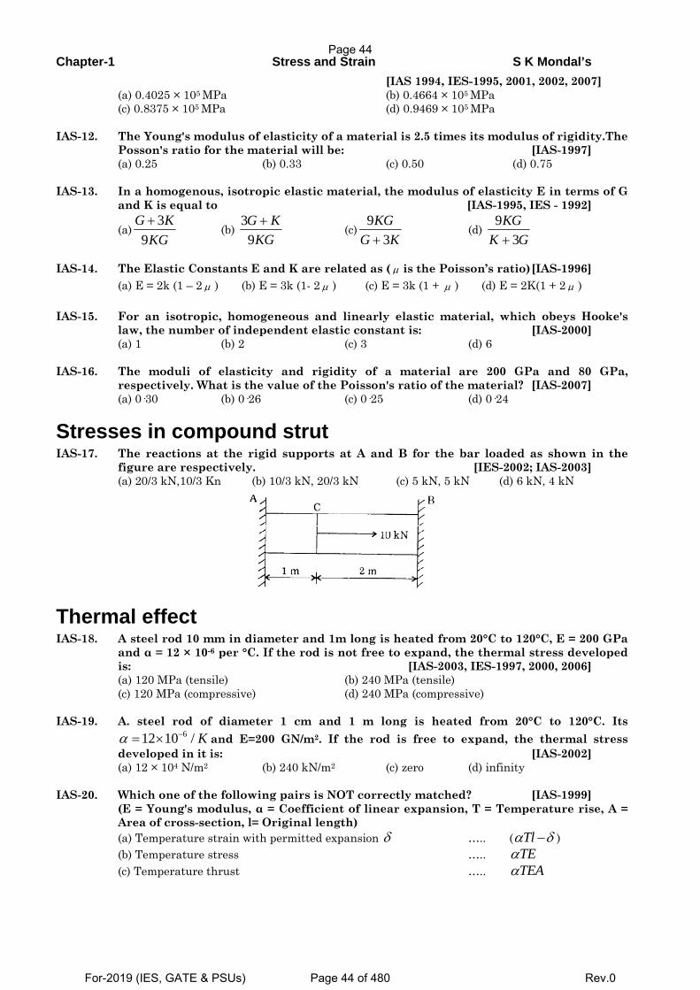
Chapter-1 Stress and Strain S K Mondal’s
[IAS 1994, IES-1995, 2001, 2002, 2007] (a) 0.4025 × 10⁵ MPa (b) 0.4664 × 10⁵ MPa (c) 0.8375 × 10⁵ MPa (d) 0.9469 × 10⁵ MPa IAS-12. The Young's modulus of elasticity of a material is 2.5 times its modulus of rigidity.The
Posson's ratio for the material will be: [IAS-1997] (a) 0.25 (b) 0.33 (c) 0.50 (d) 0.75 IAS-13. In a homogenous, isotropic elastic material, the modulus of elasticity E in terms of G
and K is equal to [IAS-1995, IES - 1992]
(a)3
9G K
KG+
(b) 39G K
KG+
(c)9
3KG
G K+ (d)
93
KGK G+
IAS-14. The Elastic Constants E and K are related as ( μ is the Poisson’s ratio) [IAS-1996] (a) E = 2k (1 – 2 μ ) (b) E = 3k (1- 2 μ ) (c) E = 3k (1 + μ ) (d) E = 2K(1 + 2 μ ) IAS-15. For an isotropic, homogeneous and linearly elastic material, which obeys Hooke's
law, the number of independent elastic constant is: [IAS-2000] (a) 1 (b) 2 (c) 3 (d) 6 IAS-16. The moduli of elasticity and rigidity of a material are 200 GPa and 80 GPa,
respectively. What is the value of the Poisson's ratio of the material? [IAS-2007] (a) 0·30 (b) 0·26 (c) 0·25 (d) 0·24
Stresses in compound strut IAS-17. The reactions at the rigid supports at A and B for the bar loaded as shown in the
figure are respectively. [IES-2002; IAS-2003] (a) 20/3 kN,10/3 Kn (b) 10/3 kN, 20/3 kN (c) 5 kN, 5 kN (d) 6 kN, 4 kN
Thermal effect IAS-18. A steel rod 10 mm in diameter and 1m long is heated from 20°C to 120°C, E = 200 GPa
and α = 12 × 10-6 per °C. If the rod is not free to expand, the thermal stress developed is: [IAS-2003, IES-1997, 2000, 2006]
(a) 120 MPa (tensile) (b) 240 MPa (tensile) (c) 120 MPa (compressive) (d) 240 MPa (compressive) IAS-19. A. steel rod of diameter 1 cm and 1 m long is heated from 20°C to 120°C. Its
612 10 / Kα −= × and E=200 GN/m2. If the rod is free to expand, the thermal stress developed in it is: [IAS-2002]
(a) 12 × 104 N/m2 (b) 240 kN/m2 (c) zero (d) infinity IAS-20. Which one of the following pairs is NOT correctly matched? [IAS-1999] (E = Young's modulus, α = Coefficient of linear expansion, T = Temperature rise, A =
Area of cross-section, l= Original length) (a) Temperature strain with permitted expansion δ ….. ( Tlα δ− ) (b) Temperature stress ….. TEα (c) Temperature thrust ….. TEAα
Page 44
For-2019 (IES, GATE & PSUs) Page 44 of 480 Rev.0
Chapter-1 Stress and Strain S K Mondal’s
(d) Temperature stress with permitted expansion δ ….. ( )E Tl
lα δ−
Impact loading IAS-21. Match List I with List II and select the correct answer using the codes given below
the lists: [IAS-1995] List I (Property) List II (Testing Machine) A. Tensile strength 1. Rotating Bending Machine B. Impact strength 2. Three-Point Loading Machine C. Bending strength 3. Universal Testing Machine D. Fatigue strength 4. Izod Testing Machine Codes: A B C D A B C D (a) 4 3 2 1 (b) 3 2 1 4 (c) 2 1 4 3 (d) 3 4 2 1
Tensile Test IAS-22. A mild steel specimen is tested in tension up to fracture in a Universal Testing
Machine. Which of the following mechanical properties of the material can be evaluated from such a test? [IAS-2007]
1. Modulus of elasticity 2. Yield stress 3. Ductility 4. Tensile strength 5. Modulus of rigidity Select the correct answer using the code given below: (a)1, 3, 5 and 6 (b) 2, 3, 4 and 6 (c) 1, 2, 5 and 6 (d) 1, 2, 3 and 4 IAS-23. In a simple tension test, Hooke's law is valid upto the [IAS-1998] (a) Elastic limit (b) Limit of proportionality (c) Ultimate stress (d)Breaking point IAS-24. Lueder' lines on steel specimen under simple tension test is a direct indication of
yielding of material due to slip along the plane [IAS-1997] (a) Of maximum principal stress (b) Off maximum shear (c) Of loading (d) Perpendicular to the direction of loading IAS-25. The percentage elongation of a material as obtained from static tension test depends
upon the [IAS-1998] (a) Diameter of the test specimen (b) Gauge length of the specimen (c) Nature of end-grips of the testing machine (d) Geometry of the test specimen IAS-26. Match List-I (Types of Tests and Materials) with List-II (Types of Fractures) and
select the correct answer using the codes given below the lists: List I List-II [IES-2002; IAS-2004] (Types of Tests and Materials) (Types of Fractures) A. Tensile test on CI 1. Plain fracture on a transverse plane B. Torsion test on MS 2. Granular helecoidal fracture C. Tensile test on MS 3. Plain granular at 45° to the axis D. Torsion test on CI 4. Cup and Cone 5. Granular fracture on a transverse plane Codes: A B C D A B C D (a) 4 2 3 1 (c) 4 1 3 2 (b) 5 1 4 2 (d) 5 2 4 1 IAS-27. Assertion (A): For a ductile material stress-strain curve is a straight line up to the
yield point. [IAS-2003] Reason (R): The material follows Hooke's law up to the point of proportionality. (a) Both A and R are individually true and R is the correct explanation of A (b) Both A and R are individually true but R is notthe correct explanation of A (c) A is true but R is false (d) A is false but R is true
Page 45
For-2019 (IES, GATE & PSUs) Page 45 of 480 Rev.0
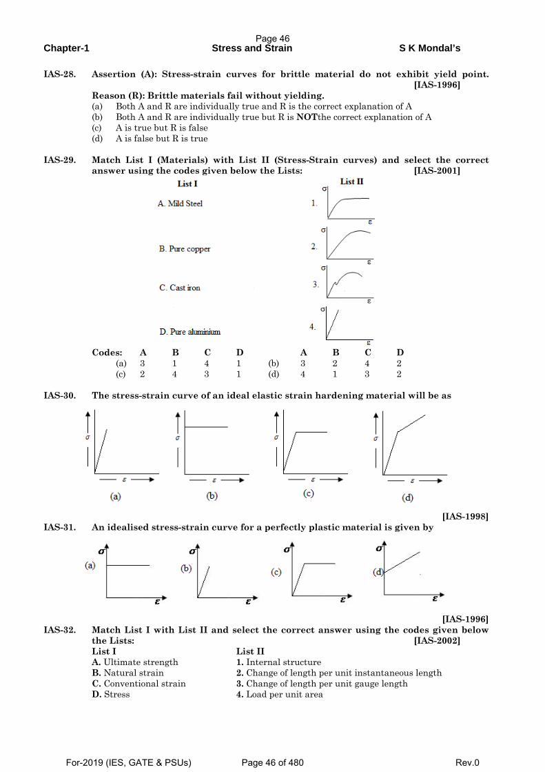
Chapter-1 Stress and Strain S K Mondal’s
IAS-28. Assertion (A): Stress-strain curves for brittle material do not exhibit yield point.
[IAS-1996] Reason (R): Brittle materials fail without yielding. (a) Both A and R are individually true and R is the correct explanation of A (b) Both A and R are individually true but R is NOTthe correct explanation of A (c) A is true but R is false (d) A is false but R is true IAS-29. Match List I (Materials) with List II (Stress-Strain curves) and select the correct
answer using the codes given below the Lists: [IAS-2001]
Codes: A B C D A B C D (a) 3 1 4 1 (b) 3 2 4 2 (c) 2 4 3 1 (d) 4 1 3 2 IAS-30. The stress-strain curve of an ideal elastic strain hardening material will be as
[IAS-1998]
IAS-31. An idealised stress-strain curve for a perfectly plastic material is given by
[IAS-1996]
IAS-32. Match List I with List II and select the correct answer using the codes given below the Lists: [IAS-2002]
List I List II A. Ultimate strength 1. Internal structure B. Natural strain 2. Change of length per unit instantaneous length C. Conventional strain 3. Change of length per unit gauge length D. Stress 4. Load per unit area
Page 46
For-2019 (IES, GATE & PSUs) Page 46 of 480 Rev.0
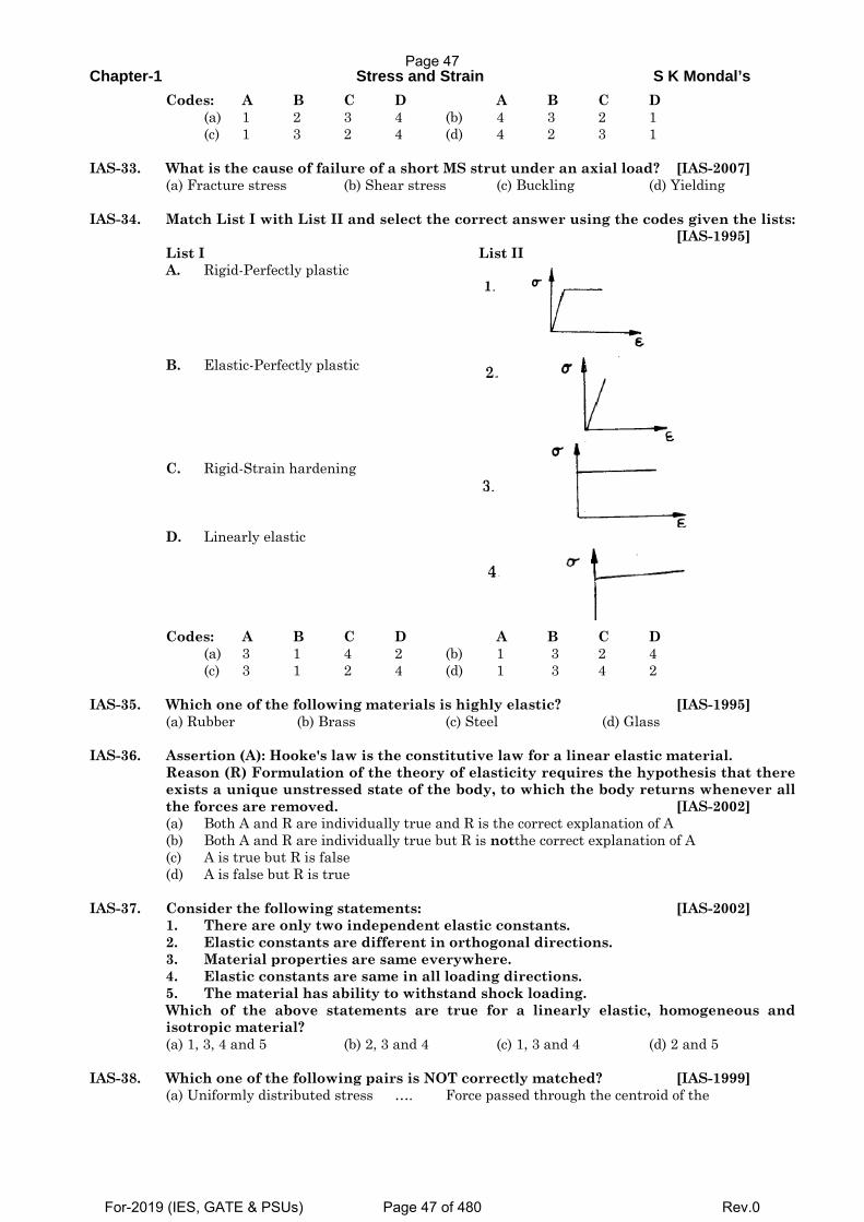
Chapter-1 Stress and Strain S K Mondal’s
Codes: A B C D A B C D (a) 1 2 3 4 (b) 4 3 2 1 (c) 1 3 2 4 (d) 4 2 3 1 IAS-33. What is the cause of failure of a short MS strut under an axial load? [IAS-2007] (a) Fracture stress (b) Shear stress (c) Buckling (d) Yielding IAS-34. Match List I with List II and select the correct answer using the codes given the lists:
[IAS-1995] List I List II A. Rigid-Perfectly plastic
B. Elastic-Perfectly plastic
C. Rigid-Strain hardening
D. Linearly elastic
Codes: A B C D A B C D (a) 3 1 4 2 (b) 1 3 2 4 (c) 3 1 2 4 (d) 1 3 4 2 IAS-35. Which one of the following materials is highly elastic? [IAS-1995] (a) Rubber (b) Brass (c) Steel (d) Glass IAS-36. Assertion (A): Hooke's law is the constitutive law for a linear elastic material. Reason (R) Formulation of the theory of elasticity requires the hypothesis that there
exists a unique unstressed state of the body, to which the body returns whenever all the forces are removed. [IAS-2002]
(a) Both A and R are individually true and R is the correct explanation of A (b) Both A and R are individually true but R is notthe correct explanation of A (c) A is true but R is false (d) A is false but R is true IAS-37. Consider the following statements: [IAS-2002] 1. There are only two independent elastic constants. 2. Elastic constants are different in orthogonal directions. 3. Material properties are same everywhere. 4. Elastic constants are same in all loading directions. 5. The material has ability to withstand shock loading. Which of the above statements are true for a linearly elastic, homogeneous and
isotropic material? (a) 1, 3, 4 and 5 (b) 2, 3 and 4 (c) 1, 3 and 4 (d) 2 and 5 IAS-38. Which one of the following pairs is NOT correctly matched? [IAS-1999] (a) Uniformly distributed stress …. Force passed through the centroid of the
Page 47
For-2019 (IES, GATE & PSUs) Page 47 of 480 Rev.0
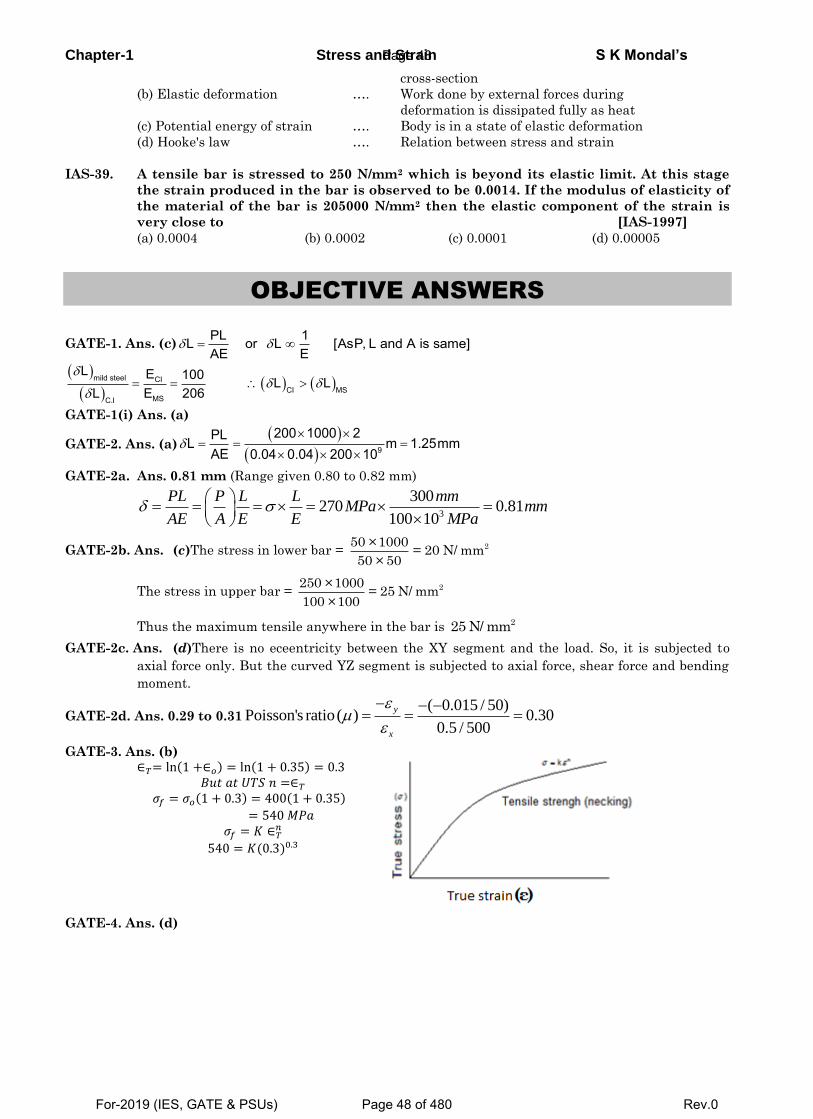
Chapter-1 Stress and Strain S K Mondal’s
cross-section
(b) Elastic deformation …. Work done by external forces during
deformation is dissipated fully as heat
(c) Potential energy of strain …. Body is in a state of elastic deformation
(d) Hooke's law …. Relation between stress and strain
IAS-39. A tensile bar is stressed to 250 N/mm2 which is beyond its elastic limit. At this stage
the strain produced in the bar is observed to be 0.0014. If the modulus of elasticity of
the material of the bar is 205000 N/mm2 then the elastic component of the strain is
very close to [IAS-1997]
(a) 0.0004 (b) 0.0002 (c) 0.0001 (d) 0.00005
OBJECTIVE ANSWERS
GATE-1. Ans. (c)PL 1L or L [AsP, L and A is same]AE E
mild steel CI
CI MSMSC.I
L E 100 L LL E 206
GATE-1(i) Ans. (a)
GATE-2. Ans. (a)
9
200 1000 2PLL m 1.25mmAE 0.04 0.04 200 10
GATE-2a. Ans. 0.81 mm (Range given 0.80 to 0.82 mm)
3
300270 0.81
100 10
PL P L L mmMPa mm
AE A E E MPa
GATE-2b. Ans. (c)The stress in lower bar = 250 ×1000= 20 N/ mm
50 × 50
The stress in upper bar = 2250 ×1000= 25 N/ mm
100 ×100
Thus the maximum tensile anywhere in the bar is 225 N/ mm
GATE-2c. Ans. (d)There is no eceentricity between the XY segment and the load. So, it is subjected to
axial force only. But the curved YZ segment is subjected to axial force, shear force and bending
moment.
GATE-2d. Ans. 0.29 to 0.31( 0.015 / 50)
Poisson's ratio( ) 0.300.5 / 500
y
x
GATE-3. Ans. (b) ∈𝑇= ln(1 +∈𝑜) = ln(1 + 0.35) = 0.3
𝐵𝑢𝑡 𝑎𝑡 𝑈𝑇𝑆 𝑛 =∈𝑇
𝜎𝑓 = 𝜎𝑜(1 + 0.3) = 400(1 + 0.35)
= 540 𝑀𝑃𝑎
𝜎𝑓 = 𝐾 ∈𝑇𝑛
540 = 𝐾(0.3)0.3
GATE-4. Ans. (d)
Page 48
For-2019 (IES, GATE & PSUs) Page 48 of 480 Rev.0
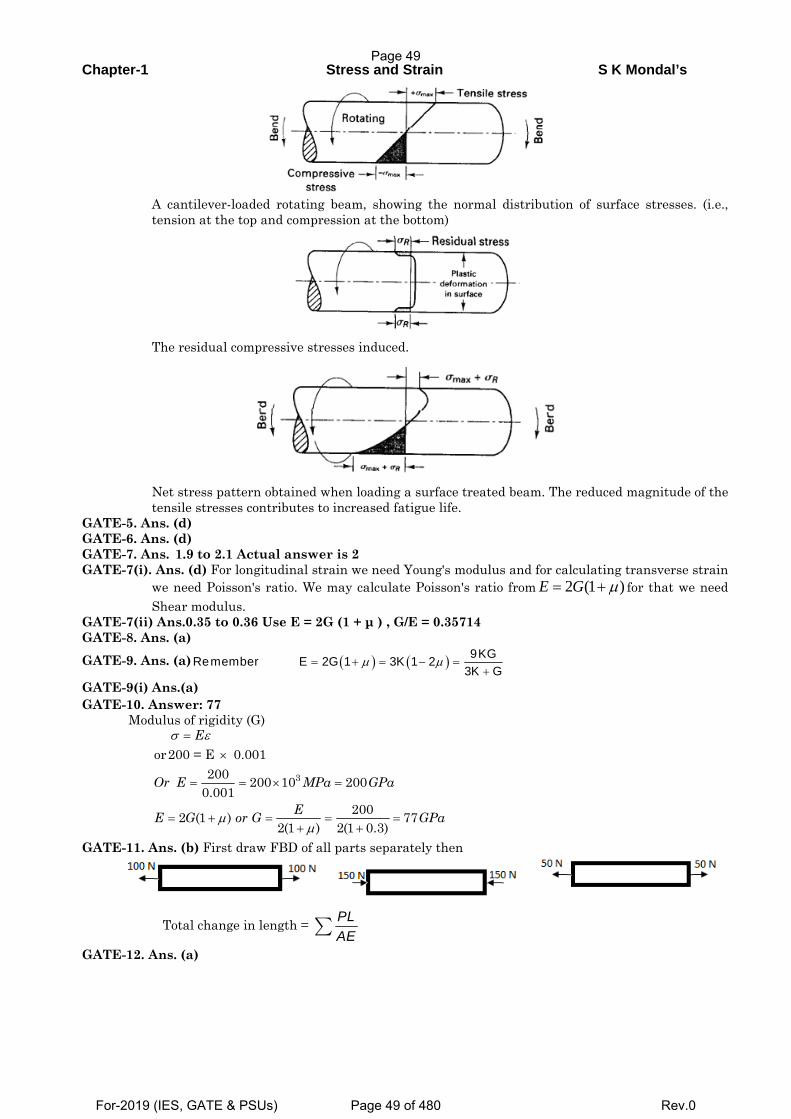
Chapter-1 Stress and Strain S K Mondal’s
A cantilever-loaded rotating beam, showing the normal distribution of surface stresses. (i.e.,
tension at the top and compression at the bottom)
The residual compressive stresses induced.
Net stress pattern obtained when loading a surface treated beam. The reduced magnitude of the tensile stresses contributes to increased fatigue life.
GATE-5. Ans. (d) GATE-6. Ans. (d) GATE-7. Ans. 1.9 to 2.1 Actual answer is 2 GATE-7(i). Ans. (d) For longitudinal strain we need Young's modulus and for calculating transverse strain
we need Poisson's ratio. We may calculate Poisson's ratio from )1(2 μ+= GE for that we need Shear modulus.
GATE-7(ii) Ans.0.35 to 0.36 Use E = 2G (1 + μ ) , G/E = 0.35714 GATE-8. Ans. (a) GATE-9. Ans. (a) ( ) ( ) 9KGRemember E 2G 1 3K 1 2
3K Gμ μ= + = − =
+
GATE-9(i) Ans.(a) GATE-10. Answer: 77
Modulus of rigidity (G)
3
or200 = E 0.001200 200 10 200
0.0012002 (1 ) 77
2(1 ) 2(1 0.3)
E
Or E MPa GPa
EE G or G GPa
σ ε
μμ
=×
= = × =
= + = = =+ +
GATE-11. Ans. (b) First draw FBD of all parts separately then
Total change in length = PLAE∑
GATE-12. Ans. (a)
Page 49
For-2019 (IES, GATE & PSUs) Page 49 of 480 Rev.0
Chapter-1 Stress and Strain S K Mondal’s
F.B.D QR
P 28000 MPa 40MPaA 700
σ = = =
GATE-13. Ans. 4.0 (Range given 3.9 to 4.1)
( )
( .) ( ) 4.03EAB BC
P F L FL PComp Tensile Or Or
A AE Fδ δ
−= = =
×
GATE-13a. Ans. (d)
6
6 9
6
6 9
10 ( )
10 1 210 10 210
10 ( )
10 1 70 102101000
280
stst
AlAl
R TensileAE
R N kNP Rand CompressiveAE
P kN
P kN
ε
ε
−
−
−
−
= =
= × × × =−
= =
× × ×− =
=
GATE-14. Ans. (c)If the force in each of outer rods is 0P and force in the central rod is P ,c then + =02P P 50c …(i) Also, the elongation of central rod and outer rods is same.
∴ =0 0 C C
0 C
P L P LA E A E
⇒ × ×=0 CP 2L P L
2 A 3 A
⇒ =C 0P 3P …(ii) Solving (i) and (ii) we get = =C 0P 30kN and P 10kN GATE-15.Ans.(a) Thermal stress will develop only when you prevent the material to contrast/elongate. As
here it is free no thermal stress will develop. GATE-16. Ans. (a) ( )33 3
3
1a T aV pV K a
α+ −Δ= =
( )
3
3 1 2
pOr TE
α
υ
=
−
Page 50
For-2019 (IES, GATE & PSUs) Page 50 of 480 Rev.0
Chapter-1 Stress and Strain S K Mondal’s
( )( )
( )( )
( ) . .1 2 1 2
T E T EOr p or stress p i e compressive
α ασ
υ υΔ Δ
= = − = −− −
Same question was asked in IES-2003 please refer question no. IES-48 in this chapter. GATE-17. Ans. (c) Temperature stress = −α = × × × × =6 5TE 12 10 10 2 10 24 MPa
GATE-18.Ans. 499 to 501 ( ) ( )5 9 61 10 250 200 10 500 10 500tE Pa MPaσ α −= Δ = × × × × = × = GATE-19.Ans.(c) GATE-20.Ans. (a) GATE-20a.Ans. 240 MPa (Compressive) Range given (239.9 MPa to 240.1 MPa)
5 3 30.210 200 200 10 200 10250
PL LL T or L TAE EEor TEL
σα δ α δ
δσ α −
Δ − = Δ − =
= Δ − = × × × − × ×
GATE-20b. Ans. 220 Range (218 to 222)
GATE-20c. Ans. Range (1.70 to 1.72)
GATE-21. Ans. (a) Creep is due to constant load but depends on time. GATE-22.Ans. (c) GATE-22a. Ans. (c)
GATE-22b. Ans. (d) , In the plastic zone 0 ,ThereforeE = InfiniteE σ εε
Δ= Δ =Δ
GATE-23. Ans. (b)
GATE-23a. Ans. (a)
GATE-23(i). Ans. (d) GATE-24. Ans. 95.19
σ
σ
=
= × =
× × ×× =
Δ ΔΔ =
0.1
69
100True strain = ln 0.512995
500 (0.5129) 371.51Upto elastic limits using Hooke's Law
371.51 10 100E = 200 10
0.18575 (considering this for elastic recovery)This is elastic componen
l orl l
l mmt and after release of the compressive load this
amount of recovery takes place. This will be added to 95mm. Therefore, final dimension = 95.18575mm
GATE-25.Ans. (c) GATE-26. Ans. (b) GATE-27. Ans.(c) Pretension increase stiffness of system.
Page 51
For-2019 (IES, GATE & PSUs) Page 51 of 480 Rev.0
Chapter-1 Stress and Strain S K Mondal’s
IES
IES-1. Ans. (d) π ρ
δ δπ
× × × ×= = ∞
× ×
2
22
D L g LWL 4 or L2AE D2 E
4
IES-2. Ans. (c) IES-3. Ans. (b) IES-3a.Ans. (c) After application of load rigid beam will remain horizontal, therefore elongation of steel and aluminium will be same. IES-4. Ans. (d) IES-5. Ans. (c) IES-6. Ans. (c) IES-7. Ans. (a) IES-7a. Ans. (d)
IES-8. Ans. (b) Elongation of a taper rod ( )1 2
PLld d E
4
δπ
=
( )( )
( )( )
2A B
2B A
l d D / 3 2orl d D / 2 3
δδ
⎛ ⎞= = =⎜ ⎟⎝ ⎠
IES-9. Ans. (c) ( )act
1 2
PL PLActual elongation of the bar ld d E 1.1D 0.9D E
4 4
δπ π
= =⎛ ⎞ ⎛ ⎞× ×⎜ ⎟ ⎜ ⎟⎝ ⎠ ⎝ ⎠
( )
( ) ( ) ( )( )
=×
− ⎛ ⎞∴ = × = − × =⎜ ⎟×⎝ ⎠
2Cal
2act cal
cal
PLCalculated elongation of the bar lD E4
l l DError % 100 1 100% 1%l 1.1D 0.9D
δπ
δ δδ
IES-10. Ans. (d) ( )act
1 2
PLActual elongation of the bar ld d E
4
δπ
=⎛ ⎞⎜ ⎟⎝ ⎠
IES-11. Ans. (b) IES-11(i). Ans. (c) IES-11(ii). Ans(c)
Extension of tapered rod =1 2
4PlED Dπ
Extension of uniform diameter rod=PlAE
Ratio = 1 2
2
4
2
/ 4
PlED DPl
D E
π
π
=
×
IES-12. Ans. (a) IES-13. Ans. (c) Theoretically 1 1/ 2 but practically 0 1/ 2μ μ− < < < < IES-14. Ans. (c) IES-15. Ans. (a) If Poisson's ratio is zero, then material is rigid. IES-16. Ans. (a) IES-17. Ans. (d) Note: Modulus of elasticity is the property of material. It will remain same. IES-18. Ans. (a) IES-19. Ans. (a) Strain energy stored by a body within elastic limit is known as resilience. IES-19a. Ans. (d) IES-19b. Ans. (b) Plastic deformation
• Following the elastic deformation, material undergoesplastic deformation. • Also characterized by relation between stress and strain atconstant strain rate and temperature.
Page 52
For-2019 (IES, GATE & PSUs) Page 52 of 480 Rev.0
Chapter-1 Stress and Strain S K Mondal’s
Microscopically…it involves breaking atomic bonds,moving atoms, then restoration of bonds.
Stress-Strain relation here is complex because of atomicplane movement, dislocation movement,
and the obstaclesthey encounter.
Crystalline solids deform by processes – slip and twinningin particular directions.
Amorphous solids deform by viscous flow mechanismwithout any directionality.
Equations relating stress and strain are called constitutiveequations.
A true stress-strain curve is called flow curve as it gives thestress required to cause the material to
flow plastically tocertain strain.
IES-20. Ans. (c)
IES-21. Ans. (b)
IES-22. Ans. (c)
IES-22a. Ans. (d) Shaft means torsion and added bending load produce a reversed state of stress.
IES-22b.Ans. (a)Endurance limit is the design criteria for cyclic loading.
IES-23. Ans. (d)
IES-24. Ans. (c) A polished surface by grinding can take more number of cycles than a part with rough
surface. In Hammer peening residual compressive stress lower the peak tensile stress
IES-25. Ans. (a)
IES-26. Ans. (c)
IES-26a.Ans. (d)Isotropic material is characterized by two independent elastic constant.
IES-27. Ans. (c)
IES-28. Ans. (d)
IES-28a.Ans. (b)
IES-29. Ans. (d)
IES-30. Ans. (a)
IES-31. Ans.(b) )1(2 GE or 1.25x105 = 2G(1+0.34) or G = 0.4664 × 10⁵ MPa
IES-31(i). Ans. (d)
IES-31(ii). Ans(d) G =70GPa, K = 150GPa We know,
3 (1 2 ) 3 150(1 2 ) 2 (1 ) 2 70(1 )E K G
On solving the above equations we get, 0.3& 182E GPa
IES-31(iii). Ans. (b)
IES-32. Ans. (c)
IES-33. Ans. (d) 9KGE 2G 1 3K 1 2
3K G
IES-34. Ans. (d) 9KGE 2G 1 3K 1 2
3K G
IES-35. Ans.(c) 9KGE 2G 1 3K 1 2
3K G
1the value of must be between 0 to 0.5 so E never equal to G but if then3
E k so ans. is c
IES-36. Ans. (b) Use 2 1E G
IES-37. Ans. (a)
2E 200E 2G 1 or G 80GN / m2 1 2 1 0.25
IES-37a. Ans. (b)
IES-38. Ans. (d) Under plane stress condition, the strain in the direction perpendicular to the plane is not
zero. It has been found experimentally that when a body is stressed within elastic limit, the
lateral strain bears a constant ratio to the linear strain.
IES-38(i). Ans. (b)
IES-38a. Ans. (b) Axial strain (𝜺𝒙) =𝑳𝒂𝒕𝒆𝒓𝒂𝒍 𝑺𝒕𝒓𝒂𝒊𝒏
𝑷𝒐𝒊𝒔𝒔𝒐𝒏′𝒔 𝑹𝒂𝒕𝒊𝒐=
𝟔𝟎×𝟏𝟎−𝟓
𝟎.𝟑= 𝟐𝟎𝟎 × 𝟏𝟎−𝟓
𝑬 =𝝈𝒙
𝜺𝒙=
𝟑𝟎𝟎 × 𝟏𝟎𝟔
𝟐𝟎𝟎 × 𝟏𝟎−𝟓= 𝟏𝟓𝟎 𝐺𝑃𝑎
IES-39. Ans. (b) 2d P 980175Total load P 8 or d 22.25mm
4 2 2 315
IES-39a. Ans. (a)
Page 53
For-2019 (IES, GATE & PSUs) Page 53 of 480 Rev.0
Chapter-1 Stress and Strain S K Mondal’s
2
2 2
know; = ; ; ; ;2
2 2 10/ 2
2 10 2 10 14
newold new old new old new old
old old new new
old new
newnew old
old
new new
EPLwe P P L L E
AE
PL PLor A E A E
AE AE
AEA A
E A
a a mm
IES-39b.Ans. (b)𝑃𝐿
𝐴𝑆𝐸 =
𝑃𝐿
𝐴𝐻𝐸 or 𝐴𝑆 = 𝐴𝐻 or𝑑2 = 𝐷2 − (
𝐷
2 )2 or
𝑑
𝐷 =
√3
2
IES-40.Ans. (c) Compatibility equation insists that the change in length of the bar must be compatible
with the boundary conditions. Here (a) is also correct but it is equilibrium equation.
IES-40(i) Ans. (a) Elongation will be same for this composite body
2100
50 /2
c s c s cc
c c s s c s c c
P L P LN mm
A E A E E E E E
IES-41. Ans. (a)
IES-42. Ans. (b) First draw FBD of all parts separately then
Total change in length = PL
AEå
IES-42a.Ans. (d)1
10 ×10−6×200 ×10⁹ [ (200 × 0.5) + ( -200 × 1) + ( 100 × 0.5 ) ]= - 25×10⁻⁶ m
IES-43. Ans. (a) Elongation in AC = length reduction in CB
A BR 1 R 2AE AE
And RA + RB = 10
IES-43(i) Ans. (b)
IES-44. Ans. (b)
IES-45. Ans. (d)
IES-46. Ans. (d) If we resist to expand then only stress will develop.
IES-47. Ans. (d)
IES-48. Ans. (b) ( ) ( )33 3
3
1p a T aV
V K a
s a= + -D= =
( )
3
3 1 2
pOr T
Ea
g
=
-
IES-49. Ans. (c)
IES-49(i). Ans. (c)
IES-50. Ans. (d) 6 3E t 12 10 200 10 120 20 240MPa
It will be compressive as elongation restricted.
IES-50a.Ans. (c)L 𝛼 ∙ ∆𝑇 = 𝑃𝐿
𝐴𝐸 or P = 𝛼 ∙ ∆𝑇 ∙ 𝐴𝐸 = 10× 10−6 × 50 × 20 × 10−4 × 200 × 109N = 200kN
IES-51. Ans. (a) co-efficient of volume expansion 3 co efficient of linear expansion
IES-52. Ans. (b)
IES-53. Ans. (b) Let compression of the spring = x m
Therefore spring force = kx kN
Expansion of the rod due to temperature rise = L t
Reduction in the length due to compression force = kx L
AE
Now kx L
L t xAE
Page 54
For-2019 (IES, GATE & PSUs) Page 54 of 480 Rev.0
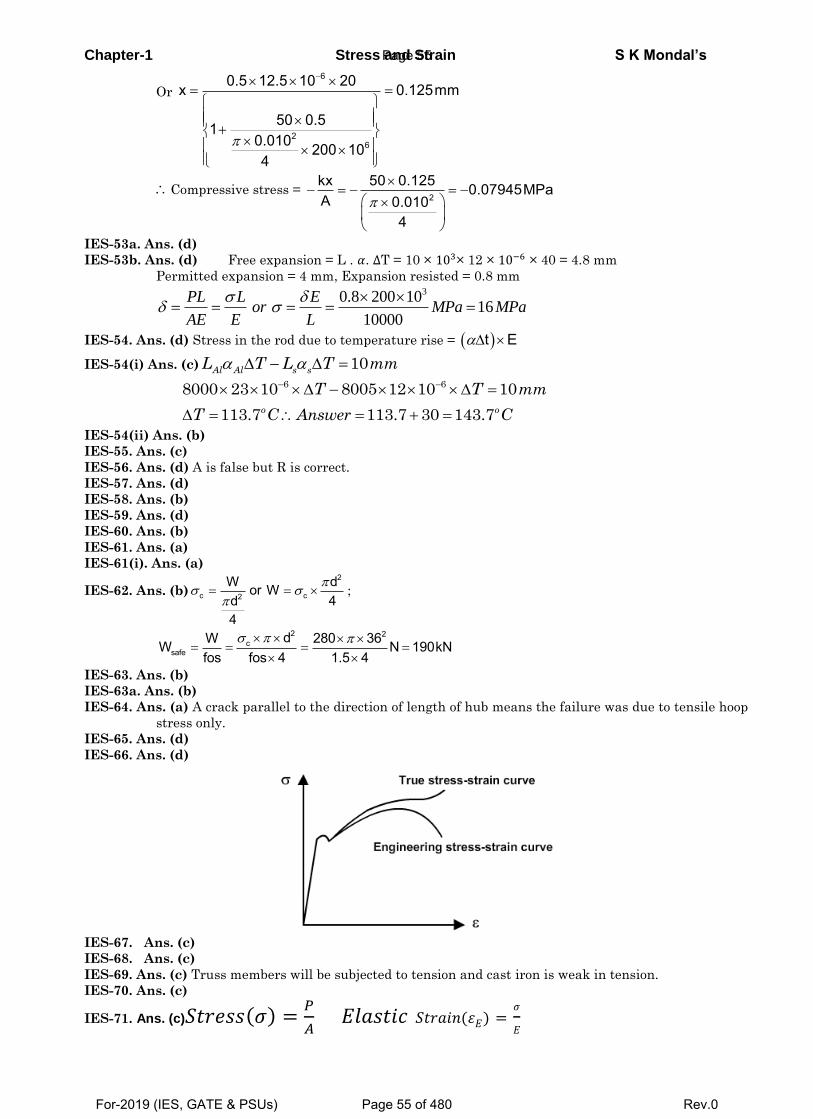
Chapter-1 Stress and Strain S K Mondal’s
Or
6
26
0.5 12.5 10 20x 0.125mm
50 0.510.010 200 104
Compressive stress = 2
kx 50 0.125 0.07945MPaA 0.010
4
IES-53a. Ans. (d)
IES-53b. Ans. (d) Free expansion = L . 𝛼. ∆T = 10 × 103× 12 × 10−6 × 40 = 4.8 mm
Permitted expansion = 4 mm, Expansion resisted = 0.8 mm 30.8 200 10
1610000
PL L Eor MPa MPa
AE E L
IES-54. Ans. (d) Stress in the rod due to temperature rise = t E
IES-54(i) Ans. (c) 10Al Al s s
L T L T mm
6 68000 23 10 8005 12 10 10
113.7 113.7 30 143.7o o
T T mm
T C Answer C
IES-54(ii) Ans. (b)
IES-55. Ans. (c)
IES-56. Ans. (d) A is false but R is correct.
IES-57. Ans. (d)
IES-58. Ans. (b)
IES-59. Ans. (d)
IES-60. Ans. (b)
IES-61. Ans. (a)
IES-61(i). Ans. (a)
IES-62. Ans. (b)2
c c2
W dor W4d
4
;
2 2c
safedW 280 36W N 190kN
fos fos 4 1.5 4
IES-63. Ans. (b)
IES-63a. Ans. (b)
IES-64. Ans. (a) A crack parallel to the direction of length of hub means the failure was due to tensile hoop
stress only.
IES-65. Ans. (d)
IES-66. Ans. (d)
IES-67. Ans. (c)
IES-68. Ans. (c)
IES-69. Ans. (c) Truss members will be subjected to tension and cast iron is weak in tension.
IES-70. Ans. (c)
IES-71. Ans. (c)𝑆𝑡𝑟𝑒𝑠𝑠(𝜎) =𝑃
𝐴 𝐸𝑙𝑎𝑠𝑡𝑖𝑐 𝑆𝑡𝑟𝑎𝑖𝑛(𝜀𝐸) =
𝜎
𝐸
Page 55
For-2019 (IES, GATE & PSUs) Page 55 of 480 Rev.0
Chapter-1 Stress and Strain S K Mondal’s
IAS
IAS-1. Ans. (d) Elongation due to self weight = 2
2 2 2
ALg LWL L g
AE AE E
IAS-2. Ans. (b)
IAS-3. Ans. (a)The extension of the taper rod =
1 2
Pl
D D .E4
IAS-4. Ans. (a)
IAS-5. ans. (d)
IAS-6. Ans. (b)
IAS-7. Ans. (d) Bulk modulus of elasticity (K) = 6v
v
P P 1.5or 535 10K 2800
IAS-8. Ans. (a)
IAS-9. Ans. (d)
IAS-10. Ans. (a)
IAS-11. Ans.(b) )1(2 GE or 1.25x105 = 2G(1+0.34) or G = 0.4664 × 10⁵ MPa
IAS-12. Ans. (a) E E 2.5E 2G 1 1 1 1 0.25
2G 2G 2
IAS-13. Ans. (c)
IAS-14. Ans. (b) E = 2G (1 + ) = 3k (1- 2 )
IAS-15. Ans. (b) E, G, K and µ represent the elastic modulus, shear modulus, bulk modulus and poisons
ratio respectively of a ‘linearly elastic, isotropic and homogeneous material.’ To express the
stress – strain relations completely for this material; at least any two of the four must be
known. 9
2 1 3 1 33
KGE G K
K G
IAS-16. Ans. (c) E = 2G (1+ ) or =200
1 1 0.252 2 80
E
G
IAS-17. Ans. (a) Elongation in AC = length reduction in CB
A BR 1 R 2AE AE
And RA + RB = 10
IAS-18. Ans. (d) 6 3E t 12 10 200 10 120 20 240MPa
It will be compressive as elongation restricted.
IAS-19. Ans. (c) Thermal stress will develop only if expansion is restricted.
IAS-20. Ans. (a) Dimensional analysis gives (a) is wrong
IAS-21. Ans. (d)
IAS-22. Ans. (d)
IAS-23. Ans. (b)
IAS-24. Ans. (b)
IAS-25. Ans. (b)
IAS-26. Ans. (d)
IAS-27. Ans. (d)
IAS-28. Ans. (a) Up to elastic limit.
IAS-29. Ans. (b)
IAS-30. Ans. (d)
IAS-31. Ans. (a)
IAS-32. Ans. (a)
IAS-33. Ans. (d) In compression tests of ductile materials fractures is seldom obtained. Compression is
accompanied by lateral expansion and a compressed cylinder ultimately assumes the shape of a
flat disc.
IAS-34. Ans. (a)
Page 56
For-2019 (IES, GATE & PSUs) Page 56 of 480 Rev.0
Chapter-1 Stress and Strain S K Mondal’s
IAS-35. Ans. (c)Steel is the highly elastic material because it is deformed least on loading, and regains its
original from on removal of the load.
IAS-36. Ans. (a)
IAS-37. Ans. (a)
IAS-38. Ans. (b)
IAS-39. Ans. (b)
Page 57
For-2019 (IES, GATE & PSUs) Page 57 of 480 Rev.0
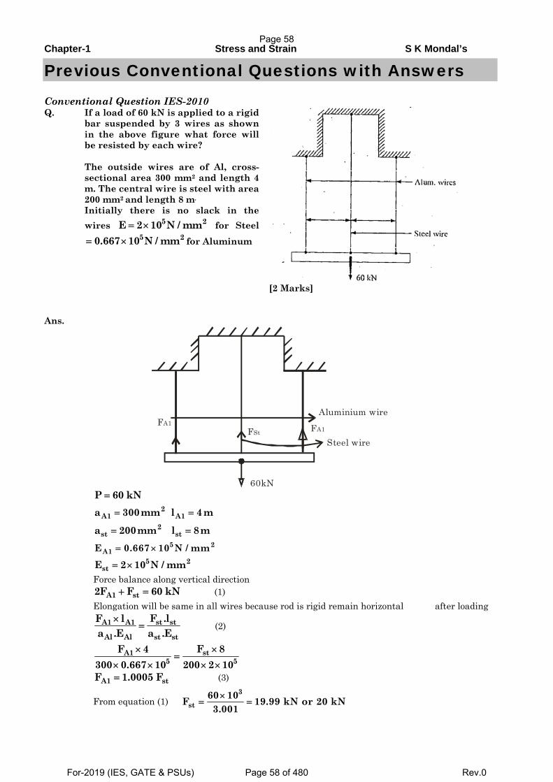
Chapter-1 Stress and Strain S K Mondal’s
Previous Conventional Questions with Answers
Conventional Question IES-2010 Q. If a load of 60 kN is applied to a rigid
bar suspended by 3 wires as shown in the above figure what force will be resisted by each wire? The outside wires are of Al, cross- sectional area 300 mm2 and length 4 m. The central wire is steel with area 200 mm2 and length 8 m.
Initially there is no slack in the wires 5 2E 2 10 N / mm= × for Steel
5 20.667 10 N / mm= × for Aluminum
[2 Marks]
Ans.
FA1FSt
Aluminium wire
Steel wireFA1
60kN P 60 kN=
2A1 A1a 300mm l 4m= =
2st sta 200mm l 8m= =
5 2A1E 0.667 10 N / mm= ×
5 2stE 2 10 N / mm= ×
Force balance along vertical direction A1 st2F F 60 kN+ = (1) Elongation will be same in all wires because rod is rigid remain horizontal after loading
st stA1 A1
Al Al st st
F .lF la .E a .E
×= (2)
stA15 5
F 8F 4300 0.667 10 200 2 10
××=
× × × ×
A1 stF 1.0005 F= (3)
From equation (1) 3
st60 10F 19.99 kN or 20 kN3.001×
= =
Page 58
For-2019 (IES, GATE & PSUs) Page 58 of 480 Rev.0
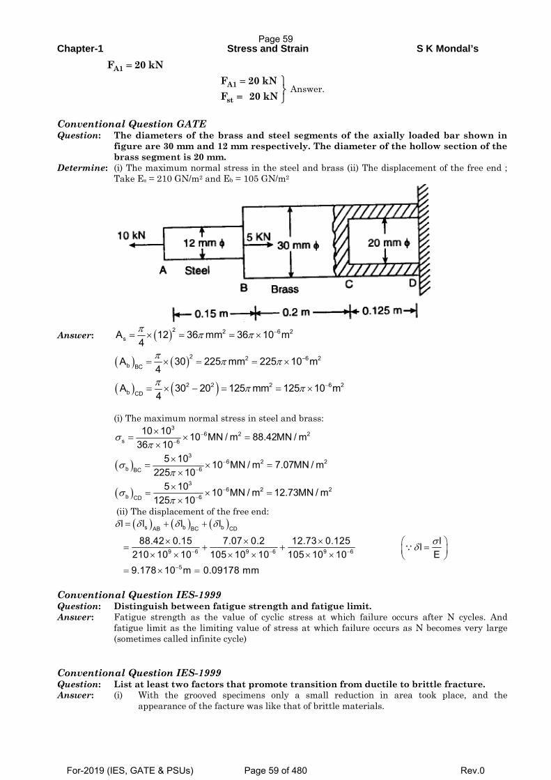
Chapter-1 Stress and Strain S K Mondal’s
A1F 20 kN=
A1
st
F 20 kNF 20 kN
= ⎫⎬= ⎭
Answer.
Conventional Question GATE Question: The diameters of the brass and steel segments of the axially loaded bar shown in
figure are 30 mm and 12 mm respectively. The diameter of the hollow section of the brass segment is 20 mm.
Determine: (i) The maximum normal stress in the steel and brass (ii) The displacement of the free end ; Take Es = 210 GN/m2 and Eb = 105 GN/m2
Answer: ( )2 2 6 2sA 12 36 mm 36 10 m
4π π π −= × = = ×
( ) ( )2 2 6 2b BC
A 30 225 mm 225 10 m4π π π −= × = = ×
( ) ( )2 2 2 6 2b CD
A 30 20 125 mm 125 10 m4π π π −= × − = = ×
(i) The maximum normal stress in steel and brass:
( )
( )
36 2 2
s 6
36 2 2
b 6BC
36 2 2
b 6CD
10 10 10 MN / m 88.42MN / m36 10
5 10 10 MN / m 7.07MN / m225 10
5 10 10 MN / m 12.73MN / m125 10
σπ
σπ
σπ
−−
−−
−−
×= × =
××
= × =×
×= × =
×
(ii) The displacement of the free end:
( ) ( ) ( )s b bAB BC CD
9 6 9 6 9 6
5
l l l l
88.42 0.15 7.07 0.2 12.73 0.125 llE210 10 10 105 10 10 105 10 10
9.178 10 m 0.09178 mm
δ δ δ δ
σδ− − −
−
= + +
× × × ⎛ ⎞= + + =⎜ ⎟× × × × × × ⎝ ⎠= × =
∵
Conventional Question IES-1999 Question: Distinguish between fatigue strength and fatigue limit. Answer: Fatigue strength as the value of cyclic stress at which failure occurs after N cycles. And
fatigue limit as the limiting value of stress at which failure occurs as N becomes very large (sometimes called infinite cycle)
Conventional Question IES-1999 Question: List at least two factors that promote transition from ductile to brittle fracture. Answer: (i) With the grooved specimens only a small reduction in area took place, and the
appearance of the facture was like that of brittle materials.
Page 59
For-2019 (IES, GATE & PSUs) Page 59 of 480 Rev.0
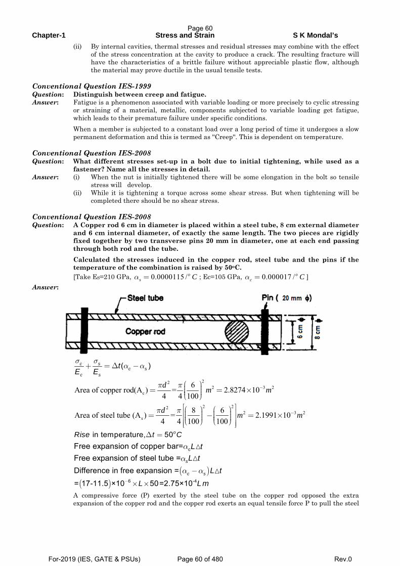
Chapter-1 Stress and Strain S K Mondal’s
(ii) By internal cavities, thermal stresses and residual stresses may combine with the effect of the stress concentration at the cavity to produce a crack. The resulting fracture will have the characteristics of a brittle failure without appreciable plastic flow, although the material may prove ductile in the usual tensile tests.
Conventional Question IES-1999 Question: Distinguish between creep and fatigue. Answer: Fatigue is a phenomenon associated with variable loading or more precisely to cyclic stressing
or straining of a material, metallic, components subjected to variable loading get fatigue, which leads to their premature failure under specific conditions.
When a member is subjected to a constant load over a long period of time it undergoes a slow permanent deformation and this is termed as ''Creep''. This is dependent on temperature.
Conventional Question IES-2008 Question: What different stresses set-up in a bolt due to initial tightening, while used as a
fastener? Name all the stresses in detail. Answer: (i) When the nut is initially tightened there will be some elongation in the bolt so tensile
stress will develop. (ii) While it is tightening a torque across some shear stress. But when tightening will be
completed there should be no shear stress. Conventional Question IES-2008 Question: A Copper rod 6 cm in diameter is placed within a steel tube, 8 cm external diameter
and 6 cm internal diameter, of exactly the same length. The two pieces are rigidly fixed together by two transverse pins 20 mm in diameter, one at each end passing through both rod and the tube.
Calculated the stresses induced in the copper rod, steel tube and the pins if the temperature of the combination is raised by 50oC.
[Take ES=210 GPa, 0.0000115 /os Cα = ; Ec=105 GPa, 0.000017 /o
c Cα = ] Answer:
( )σ σα α+ =Δ −c s
c sc s
tE E
22
2 3 2c
6Area of copper rod(A ) = 2.8274 104 4 100
π π −⎛ ⎞⎟⎜= = ×⎟⎜ ⎟⎜⎝ ⎠d m m
2 22
2 3 28 6Area of steel tube (A ) = 2.1991 104 4 100 100
π π −⎡ ⎤⎛ ⎞ ⎛ ⎞⎢ ⎥⎟ ⎟⎜ ⎜= − = ×⎟ ⎟⎜ ⎜⎢ ⎥⎟ ⎟⎜ ⎜⎝ ⎠ ⎝ ⎠⎢ ⎥⎣ ⎦
sd m m
in temperature, 50Δ = oRise t C
cFree expansion of copper bar= L tα
Free expansion of steel tube = sL tα
( )Difference in free expansion = c s L tα α−
( ) 6 -4= 17-11.5 ×10 50=2.75×10L L m− × × A compressive force (P) exerted by the steel tube on the copper rod opposed the extra
expansion of the copper rod and the copper rod exerts an equal tensile force P to pull the steel
Page 60
For-2019 (IES, GATE & PSUs) Page 60 of 480 Rev.0
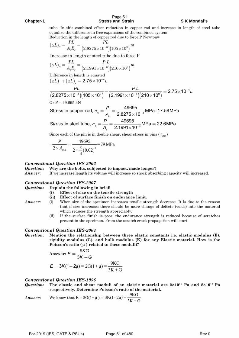
Chapter-1 Stress and Strain S K Mondal’s
tube. In this combined effect reduction in copper rod and increase in length of steel tube equalize the difference in free expansions of the combined system.
Reduction in the length of copper rod due to force P Newton=
( ) ( )( )3 9 m2.8275 10 105 10C
c c
PL PLLA E −
= =× ×
Increase in length of steel tube due to force P
( )( )( )3 9
.2.1991 10 210 10S
s s
PL P LL mA E −
= =× ×
Difference in length is equated ( ) ( ) 42.75 10
c sL L L−+ = ×
( )( ) ( )( )
43 9 3 9
. 2.75 102.8275 10 105 10 2.1991 10 210 10
PL P L L−− −
+ = ×× × × ×
Or P = 49.695 kN
c 349695Stress in copper rod, MPa=17.58MPa
2.8275 10c
PA
σ −= =×
349695 in steel tube, MPa 22.6MPa
2.1991 10ss
PStressA
σ −= = =×
Since each of the pin is in double shear, shear stress in pins ( pinτ )
=( )2
49695 =79 MPa2 2 0.02
4π
=× ×pin
PA
Conventional Question IES-2002 Question: Why are the bolts, subjected to impact, made longer? Answer: If we increase length its volume will increase so shock absorbing capacity will increased. Conventional Question IES-2007 Question: Explain the following in brief: (i) Effect of size on the tensile strength (ii) Effect of surface finish on endurance limit. Answer: (i) When size of the specimen increases tensile strength decrease. It is due to the reason
that if size increases there should be more change of defects (voids) into the material which reduces the strength appreciably.
(ii) If the surface finish is poor, the endurance strength is reduced because of scratches present in the specimen. From the scratch crack propagation will start.
Conventional Question IES-2004 Question: Mention the relationship between three elastic constants i.e. elastic modulus (E),
rigidity modulus (G), and bulk modulus (K) for any Elastic material. How is the Poisson's ratio (μ ) related to these modulli?
Answer: 93
KGEK G
=+
9KGµ) = 2G(1+ µ) =
3K + G3 (1 2E K= −
Conventional Question IES-1996 Question: The elastic and shear moduli of an elastic material are 2×10¹¹ Pa and 8×10¹⁰ Pa
respectively. Determine Poisson's ratio of the material.
Answer: We know that E = 2G(1+µ ) = 9KG3K(1- 2µ) =
3K + G
Page 61
For-2019 (IES, GATE & PSUs) Page 61 of 480 Rev.0
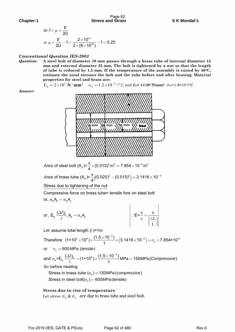
Chapter-1 Stress and Strain S K Mondal’s
or µ
µ
11
10
or,12
2 101 1 0.252 2 (8 10 )
EG
EG
=
+ =
×− = − =
× ×
Conventional Question IES-2003 Question: A steel bolt of diameter 10 mm passes through a brass tube of internal diameter 15
mm and external diameter 25 mm. The bolt is tightened by a nut so that the length of tube is reduced by 1.5 mm. If the temperature of the assembly is raised by 40oC, estimate the axial stresses the bolt and the tube before and after heating. Material properties for steel and brass are:
5 5SE 2 10 / 1.2 10 /α −= × = × o
S C2N mm and Eb= 1×10⁵ N/mm2 αb=1.9×10⁻⁵/oC Answer:
π
π
2 2 5 2s
2 2 4b
of steel bolt (A )= (0.010) 7.854 104
of brass tube (A )= (0.025) (0.015) 3.1416 104
Area m m
Area
−
−
× = ×
⎡ ⎤− = ×⎢ ⎥⎣ ⎦
Sσ σ
σ σσL
L
b
b. b
Stress due to tightening of the nut
Compressive force on brass tube= tensile fore on steel boltor,
( ), E . E=
b s
bs s
A A
lor A A
=
⎡ ⎤⎢ ⎥⎢ ⎥Δ⎢ ⎥= =
⎛ ⎞⎢ ⎥∈ ⎟⎜⎢ ⎥⎟⎜ ⎟⎜⎢ ⎥⎝ ⎠⎣ ⎦
∵
( )
35 6 4 -5
35
b.
assume total length ( )=1m(1.5 10 )Therefore (1×10 10 ) 3.1416 10 7.854×10
1600 ( )
( ) (1.5 10 )and =E (1×10 ) 150 ( )1
s
s
bb
Let
or MPa tensilel
MPa MPa Compressive
σ
σ
σ
−−
−
×× × × × = ×
=
Δ ×= × =
σσ
b
s
before heating Stress in brass tube ( ) 150 ( ) Stress in steel bolt( ) 600 (tensile)
SoMPa compressive
MPa=
=
Stress due to rise of temperature Let stress ' '
bσ & σ s due to brass tube and steel bolt.are
Page 62
For-2019 (IES, GATE & PSUs) Page 62 of 480 Rev.0
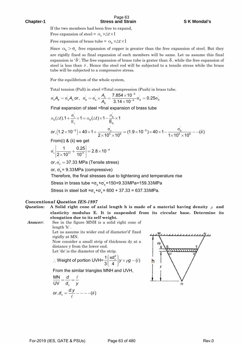
Chapter-1 Stress and Strain S K Mondal’s
If the two members had been free to expand, Free expansion of steel = s 1tα × ×
Free expansion of brass tube = 1α × ×b t
Since b s σα > free expansion of copper is greater than the free expansion of steel. But they are rigidly fixed so final expansion of each members will be same. Let us assume this final expansion is 'δ ', The free expansion of brass tube is grater than δ , while the free expansion of steel is less than δ . Hence the steel rod will be subjected to a tensile stress while the brass tube will be subjected to a compressive stress.
For the equilibrium of the whole system, Total tension (Pull) in steel =Total compression (Push) in brass tube.
'bσ σ σ σ σ σ
5' ' ' ' '
b s 4
7.854 10, 0.253.14 10
sb s s S S
b
AA A or
A
−
−
×= = × = =
×
( )
's
s
σE
σ σ
'b
sb
' '5 5
5 6 5 6
Final expansion of steel =final expansion of brass tube
( ).1 1 ( ) 1 1E
, 1.2 10 40 1 (1.9 10 ) 40 1 ( )2 10 10 1 10 10
b
s b
t t
or ii
σα α
− −
+ × = × − ×
× × × + = × × × − −−× × × ×
'sσ
σ
411 11
'
'b
From(i) & (ii) we get
1 0.25 2.8 102 10 10
, 37.33 MPa (Tensile stress)
or, σ = 9.33MPa (compressive)sor
−⎡ ⎤⎢ ⎥+ = ×⎢ ⎥×⎣ ⎦
=
'b b
's s
Therefore, the final stresses due to tightening and temperature rise Stress in brass tube =σ +σ =150+9.33MPa=159.33MPa
Stress in steel bolt =σ +σ = 600 + 37.33 = 637.33MPa.
Conventional Question IES-1997 Question: A Solid right cone of axial length h is made of a material having density ρ and
elasticity modulus E. It is suspended from its circular base. Determine its elongation due to its self weight.
Answer: See in the figure MNH is a solid right cone of length 'h' .
Let us assume its wider end of diameter’d’ fixed rigidly at MN.
Now consider a small strip of thickness dy at a distance y from the lower end.
Let 'ds' is the diameter of the strip.
π 21Weight of portion UVH= ( )
3 4sd
y g iρ⎛ ⎞⎟⎜ ⎟∴ × −⎜ ⎟⎜ ⎟⎜⎝ ⎠
From the similar triangles MNH and UVH,MNUV
., ( )
s
s
dd y
d yor d ii
= =
= −−−−
Page 63
For-2019 (IES, GATE & PSUs) Page 63 of 480 Rev.0
Chapter-1 Stress and Strain S K Mondal’s
π 2
force at UV Weight of UVHStress at section UV =sec area at UV
4scross tion d
∴ =⎛ ⎞− ⎟⎜ ⎟⎜ ⎟⎜ ⎟⎜⎝ ⎠
π
π
2
2
1 . . . 13 4 =3
4
s
s
d y gy g
d
ρρ=
⎛ ⎞⎟⎜ ⎟⎜ ⎟⎜ ⎟⎜⎝ ⎠
h 2
0
1 .3, extension in dy=
13Total extension of the bar =
6
y g dySo
E
y gdy ghE E
ρ
ρ ρ
⎛ ⎞⎟⎜ ⎟⎜ ⎟⎜⎝ ⎠
∴ =∫
δ δd
From stress-strain relation ship.E= ,or dEδ
= =∈
Conventional Question IES-2004 Question: Which one of the three shafts listed hare has the highest ultimate tensile strength?
Which is the approximate carbon content in each steel? (i) Mild Steel (ii) cast iron (iii) spring steel Answer: Among three steel given, spring steel has the highest ultimate tensile strength. Approximate carbon content in (i) Mild steel is (0.3% to 0.8%) (ii) Cost iron (2% to 4%) (iii) Spring steel (0.4% to 1.1%) Conventional Question IES-2003 Question: If a rod of brittle material is subjected to pure torsion, show with help of a sketch,
the plane along which it will fail and state the reason for its failure. Answer: Brittle materials fail in tension. In a torsion test the maximum tensile test Occurs at 45°to the
axis of the shaft. So failure will occurs along a 45o to the axis of the shaft. So failure will occurs along a 45° helix
XX
So failures will occurs according to 45°plane. Conventional Question IAS-1995 Question: The steel bolt shown in Figure has a thread pitch of 1.6 mm. If the nut is initially
tightened up by hand so as to cause no stress in the copper spacing tube, calculate the stresses induced in the tube and in the bolt if a spanner is then used to turn the nut through 90°.Take Ec and Es as 100 GPa and 209 GPa respectively.
Answer: Given: p = 1.6 mm, Ec= 100 GPa ; Es = 209 CPa.
Page 64
For-2019 (IES, GATE & PSUs) Page 64 of 480 Rev.0
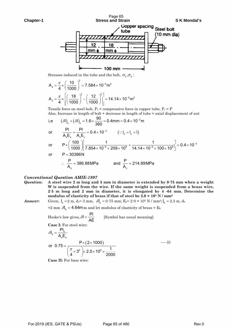
Chapter-1 Stress and Strain S K Mondal’s
Stresses induced in the tube and the bolt, c s, :σ σ
25 2
s
2 25 2
s
10A 7.584 10 m4 1000
18 12A 14.14 10 m4 1000 1000
π
π
−
−
⎛ ⎞= × = ×⎜ ⎟⎝ ⎠⎡ ⎤⎛ ⎞ ⎛ ⎞= × − = ×⎢ ⎥⎜ ⎟ ⎜ ⎟⎝ ⎠ ⎝ ⎠⎢ ⎥⎣ ⎦
Tensile force on steel bolt, Ps = compressive force in copper tube, Pc = P Also, Increase in length of bolt + decrease in length of tube = axial displacement of nut
( ) ( )
( )
3s c
3s c
s s c c
35 9 5 9
s c
90i,e l l 1.6 0.4mm 0.4 10 m360
Pl Plor 0.4 10 l l lA E A E
100 1 1or P 0.4 101000 7.854 10 209 10 14.14 10 100 10
or P 30386NP P386.88MPa and 214.89MPaA A
δ δ −
−
−− −
+ = × = = ×
+ = × = =
⎛ ⎞ ⎡ ⎤× + = ×⎜ ⎟ ⎢ ⎥× × × × × ×⎝ ⎠ ⎣ ⎦=
∴ = =
∵
Conventional Question AMIE-1997 Question: A steel wire 2 m long and 3 mm in diameter is extended by 0·75 mm when a weight
W is suspended from the wire. If the same weight is suspended from a brass wire, 2·5 m long and 2 mm in diameter, it is elongated by 4 -64 mm. Determine the modulus of elasticity of brass if that of steel be 2.0 × 10⁵ N / mm2
Answer: Given, sl =2 m, ds= 3 mm, slδ = 0·75 mm; Es= 2·0 × 105 N / mm2; bl = 2.5 m, db
=2 mm bl 4.64mδ = m and let modulus of elasticity of brass = Eb
Hooke's law gives,PllAE
δ = [Symbol has usual meaning]
Case I: For steel wire:
( )
ss
s s
2 5
Pll
A EP 2 1000
or 0.7513 2.0 10
4 2000
δ
π
=
× ×=⎛ ⎞× × × ×⎜ ⎟⎝ ⎠
---- (i)
Case II: For bass wire:
Page 65
For-2019 (IES, GATE & PSUs) Page 65 of 480 Rev.0
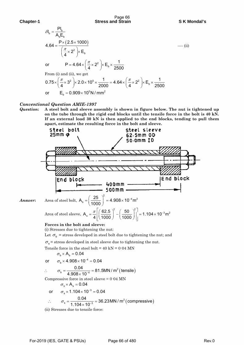
Chapter-1 Stress and Strain S K Mondal’s
( )
bb
b b
2b
2b
PllA E
P 2.5 10004.64
2 E4
1or P 4.64 2 E4 2500
δ
π
π
=
× ×=
⎛ ⎞× ×⎜ ⎟⎝ ⎠
⎛ ⎞= × × × ×⎜ ⎟⎝ ⎠
---- (ii)
From (i) and (ii), we get
2 5 2
b
5 2b
1 10.75 3 2.0 10 4.64 2 E4 2000 4 2500
or E 0.909 10 N / mm
π π⎛ ⎞ ⎛ ⎞× × × × × = × × × ×⎜ ⎟ ⎜ ⎟⎝ ⎠ ⎝ ⎠
= ×
Conventional Question AMIE-1997 Question: A steel bolt and sleeve assembly is shown in figure below. The nut is tightened up
on the tube through the rigid end blocks until the tensile force in the bolt is 40 kN. If an external load 30 kN is then applied to the end blocks, tending to pull them apart, estimate the resulting force in the bolt and sleeve.
Answer: Area of steel bolt, 2
4 2b
25A 4.908 10 m1000
−⎛ ⎞= = ×⎜ ⎟⎝ ⎠
Area of steel sleeve, 2 2
3 2s
62.5 50A 1.104 10 m4 1000 1000π −⎡ ⎤⎛ ⎞ ⎛ ⎞= − = ×⎢ ⎥⎜ ⎟ ⎜ ⎟⎝ ⎠ ⎝ ⎠⎢ ⎥⎣ ⎦
Forces in the bolt and sleeve: (i) Stresses due to tightening the nut: Let bσ = stress developed in steel bolt due to tightening the nut; and sσ = stress developed in steel sleeve due to tightening the nut. Tensile force in the steel bolt = 40 kN = 0·04 MN
( )
b b4
b
2b 4
A 0.04
or 4.908 10 0.040.04 81.5MN / m tensile
4.908 10
σ
σ
σ
−
−
× =
× × =
∴ = =×
Compressive force in steel sleeve = 0·04 MN
( )
s s3
s
2s 3
A 0.04
or 1.104 10 0.040.04 36.23MN / m compressive
1.104 10
σ
σ
σ
−
−
× =
× × =
∴ = =×
(ii) Stresses due to tensile force:
Page 66
For-2019 (IES, GATE & PSUs) Page 66 of 480 Rev.0
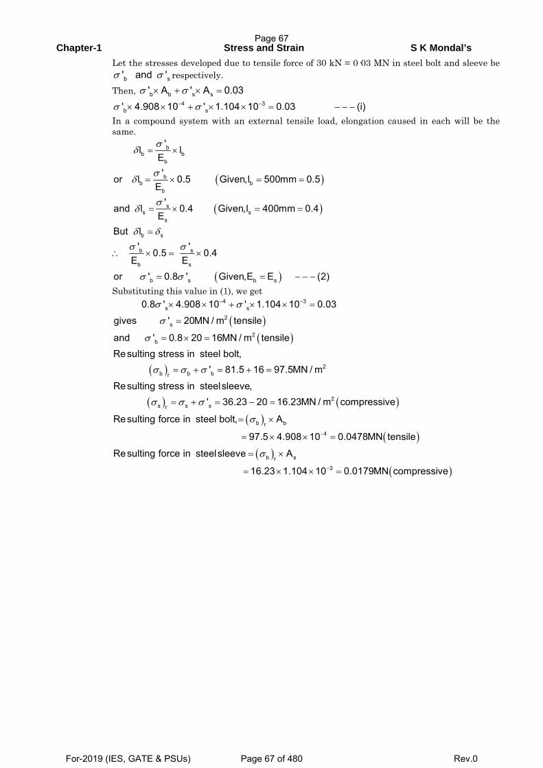
Chapter-1 Stress and Strain S K Mondal’s
Let the stresses developed due to tensile force of 30 kN = 0·03 MN in steel bolt and sleeve be b s' and 'σ σ respectively.
Then, b b s s' A ' A 0.03σ σ× + × =
4 3b s' 4.908 10 ' 1.104 10 0.03 (i)σ σ− −× × + × × = − − −
In a compound system with an external tensile load, elongation caused in each will be the same.
( )
( )
( )
bb b
b
bb b
b
ss s
s
b s
b s
b s
b s b s
'l lE'or l 0.5 Given,l 500mm 0.5
E'and l 0.4 Given,l 400mm 0.4
EBut l
' '0.5 0.4E E
or ' 0.8 ' Given,E E (2)
σδ
σδ
σδ
δ δσ σ
σ σ
= ×
= × = =
= × = =
=
∴ × = ×
= = − − −
Substituting this value in (1), we get
( )( )
( )
( )
4 3s s
2s
2b
2b b br
s s sr
0.8 ' 4.908 10 ' 1.104 10 0.03
gives ' 20MN / m tensile
and ' 0.8 20 16MN / m tensileResulting stress in steel bolt,
' 81.5 16 97.5MN / m
Resulting stress in steelsleeve,' 36.23 20 16.23MN /
σ σ
σ
σ
σ σ σ
σ σ σ
− −× × + × × =
=
= × =
= + = + =
= + = − = ( )( )
( )( )
( )
2
b br4
b sr3
m compressive
Resulting force in steel bolt, A
97.5 4.908 10 0.0478MN tensile
Resulting force in steelsleeve A
16.23 1.104 10 0.0179MN compressive
σ
σ
−
−
= ×
= × × =
= ×
= × × =
Page 67
For-2019 (IES, GATE & PSUs) Page 67 of 480 Rev.0
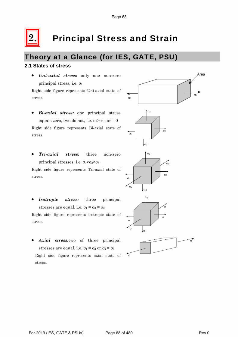
2. Principal Stress and Strain
Theory at a Glance (for IES, GATE, PSU) 2.1 States of stress
• Uni-axial stress: only one non-zero
principal stress, i.e. σ1 Right side figure represents Uni-axial state of
stress.
• Bi-axial stress: one principal stress
equals zero, two do not, i.e. σ1>σ3 ; σ2 = 0 Right side figure represents Bi-axial state of
stress.
• Tri-axial stress: three non-zero
principal stresses, i.e. σ1>σ2>σ3 Right side figure represents Tri-axial state of
stress.
• Isotropic stress: three principal
stresses are equal, i.e. σ1 = σ2 = σ3 Right side figure represents isotropic state of
stress.
• Axial stress:two of three principal
stresses are equal, i.e. σ1 = σ2 or σ2 = σ3 Right side figure represents axial state of
stress.
Page 68
For-2019 (IES, GATE & PSUs) Page 68 of 480 Rev.0
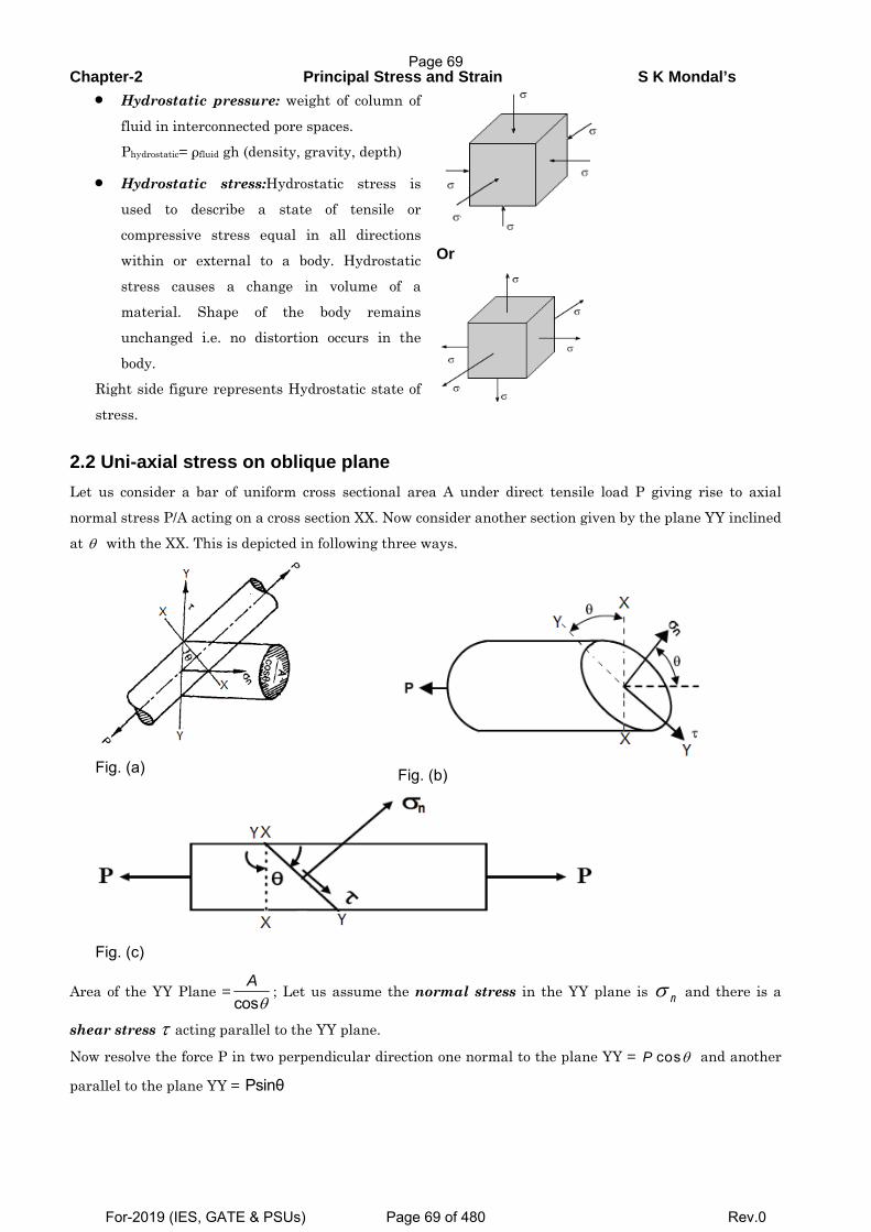
Chapter-2 Principal Stress and Strain S K Mondal’s • Hydrostatic pressure: weight of column of
fluid in interconnected pore spaces.
Phydrostatic= ρfluid gh (density, gravity, depth)
• Hydrostatic stress:Hydrostatic stress is
used to describe a state of tensile or
compressive stress equal in all directions
within or external to a body. Hydrostatic
stress causes a change in volume of a
material. Shape of the body remains
unchanged i.e. no distortion occurs in the
body. Right side figure represents Hydrostatic state of
stress.
Or
2.2 Uni-axial stress on oblique plane Let us consider a bar of uniform cross sectional area A under direct tensile load P giving rise to axial
normal stress P/A acting on a cross section XX. Now consider another section given by the plane YY inclined
at θ with the XX. This is depicted in following three ways.
Fig. (a)
Fig. (b)
Fig. (c)
Area of the YY Plane =θcos
A; Let us assume the normal stress in the YY plane is σ n and there is a
shear stress τ acting parallel to the YY plane.
Now resolve the force P in two perpendicular direction one normal to the plane YY = θcosP and another
parallel to the plane YY = Psinθ
Page 69
For-2019 (IES, GATE & PSUs) Page 69 of 480 Rev.0
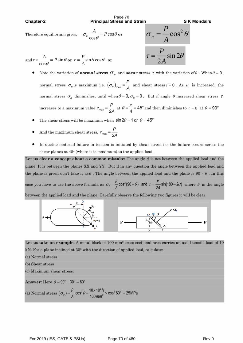
Chapter-2 Principal Stress and Strain S K Mondal’s
Therefore equilibrium gives, coscos
σ θθ=n
A P or 2cosn
PA
σ θ=
and sincos
τ θθ
× =A P or sin cosτ θ θ=
PA
or sin 2
2PA
τ θ=
• Note the variation of normal stress σ n and shear stress τ with the variation ofθ . When 0θ = ,
normal stress nσ is maximum i.e. ( )maxnPA
σ = and shear stress 0τ = . As θ is increased, the
normal stress nσ diminishes, until when 0, 0nθ σ= = . But if angle θ increased shear stress τ
increases to a maximum value max 2PA
τ = at 454
oπθ = = and then diminishes to 0τ = at 90oθ =
• The shear stress will be maximum when θ θ= =sin2 1 45oor
• And the maximum shear stress, max 2PA
τ =
• In ductile material failure in tension is initiated by shear stress i.e. the failure occurs across the
shear planes at 45o (where it is maximum) to the applied load.
Let us clear a concept about a common mistake: The angle θ is not between the applied load and the
plane. It is between the planes XX and YY. But if in any question the angle between the applied load and
the plane is given don’t take it asθ . The angle between the applied load and the plane is 90 - θ . In this
case you have to use the above formula as σ θ τ θ= − = −2cos (90 ) and sin(180 2 )2n
P PA A
where θ is the angle
between the applied load and the plane. Carefully observe the following two figures it will be clear.
Let us take an example: A metal block of 100 mm2 cross sectional area carries an axial tensile load of 10
kN. For a plane inclined at 300 with the direction of applied load, calculate:
(a) Normal stress (b) Shear stress
(c) Maximum shear stress.
Answer: Here θ = − =90 30 60o o o
(a) Normal stress ( )σ θ ×= = × =
32 2
210 10cos cos 60 25MPa100
on
P NA mm
Page 70
For-2019 (IES, GATE & PSUs) Page 70 of 480 Rev.0
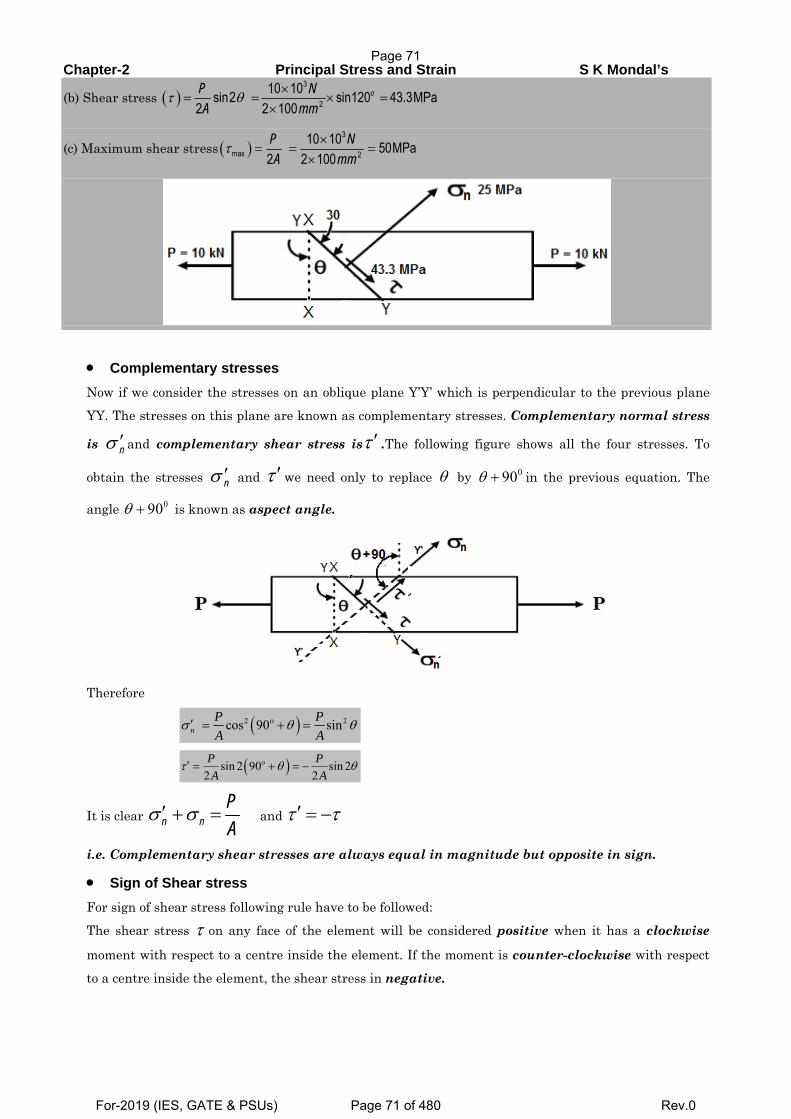
Chapter-2 Principal Stress and Strain S K Mondal’s
(b) Shear stress ( )τ θ ×= = × =
×
3
210 10sin2 sin120 43.3MPa
2 2 100oP N
A mm
(c) Maximum shear stress ( )τ ×= = =
×
3
max 210 10 50MPa
2 2 100P NA mm
• Complementary stresses Now if we consider the stresses on an oblique plane Y’Y’ which is perpendicular to the previous plane
YY. The stresses on this plane are known as complementary stresses. Complementary normal stress
is σ ′n and complementary shear stress isτ ′ .The following figure shows all the four stresses. To
obtain the stresses σ ′n and τ ′we need only to replace θ by 090θ + in the previous equation. The
angle 090θ + is known as aspect angle.
Therefore
( )2 2cos 90 sinon
P PA A
σ θ θ′ = + =
( )sin 2 90 sin 22 2
′ = + = −τ θ θoP PA A
It is clear σ σ′ + =n nPA
and τ τ′ = −
i.e. Complementary shear stresses are always equal in magnitude but opposite in sign.
• Sign of Shear stress For sign of shear stress following rule have to be followed:
The shear stress τ on any face of the element will be considered positive when it has a clockwise
moment with respect to a centre inside the element. If the moment is counter-clockwise with respect
to a centre inside the element, the shear stress in negative.
Page 71
For-2019 (IES, GATE & PSUs) Page 71 of 480 Rev.0
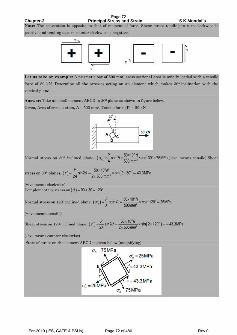
Chapter-2 Principal Stress and Strain S K Mondal’s Note: The convention is opposite to that of moment of force. Shear stress tending to turn clockwise is
positive and tending to turn counter clockwise is negative.
Let us take an example: A prismatic bar of 500 mm2 cross sectional area is axially loaded with a tensile force of 50 kN. Determine all the stresses acting on an element which makes 300 inclination with the
vertical plane.
Answer: Take an small element ABCD in 300 plane as shown in figure below,
Given, Area of cross-section, A = 500 mm2, Tensile force (P) = 50 kN
Normal stress on 30° inclined plane, ( )3
2 2n 2
P 50×10 Nσ = cos θ = ×cos 30 =75MPaA 500 mm
o (+ive means tensile).Shear
stress on 30° planes, ( ) ( )τ θ ×= = × × =
×
3
250 10sin2 sin 2 30 43.3MPa
2 2 500oP N
A mm
(+ive means clockwise) Complementary stress on ( )θ = + =90 30 120o
Normal stress on 1200 inclined plane, ( )σ θ ×′ = = × =3
2 22
50 10cos cos 120 25MPa500
on
P NA mm
(+ ive means tensile)
Shear stress on 1200 nclined plane, ( ) ( )τ θ ×′ = = × × = −×
3
250 10sin2 sin 2 120 43.3MPa
2 2 500oP N
A mm
(- ive means counter clockwise) State of stress on the element ABCD is given below (magnifying)
Page 72
For-2019 (IES, GATE & PSUs) Page 72 of 480 Rev.0
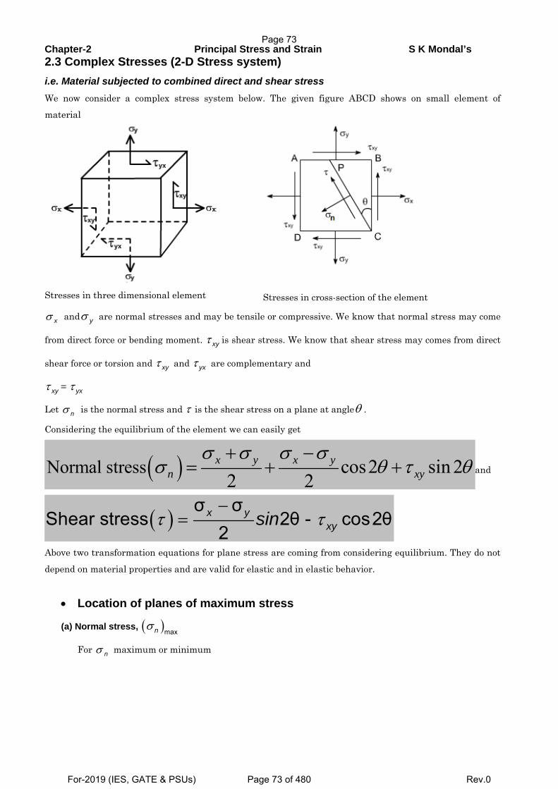
Chapter-2 Principal Stress and Strain S K Mondal’s 2.3 Complex Stresses (2-D Stress system) i.e. Material subjected to combined direct and shear stress We now consider a complex stress system below. The given figure ABCD shows on small element of
material
Stresses in three dimensional element
Stresses in cross-section of the element
xσ and yσ are normal stresses and may be tensile or compressive. We know that normal stress may come
from direct force or bending moment. xyτ is shear stress. We know that shear stress may comes from direct
shear force or torsion and xyτ and yxτ are complementary and
xyτ = yxτ
Let nσ is the normal stress and τ is the shear stress on a plane at angleθ .
Considering the equilibrium of the element we can easily get
( )Normal stress cos2 sin 22 2
x y x yn xy
σ σ σ σσ θ τ θ
+ −= + + and
( )σ σ
Shear stress 2θ - cos2θ2
x yxysinτ τ
−=
Above two transformation equations for plane stress are coming from considering equilibrium. They do not
depend on material properties and are valid for elastic and in elastic behavior.
• Location of planes of maximum stress
(a) Normal stress, ( )maxnσ
For nσ maximum or minimum
Page 73
For-2019 (IES, GATE & PSUs) Page 73 of 480 Rev.0
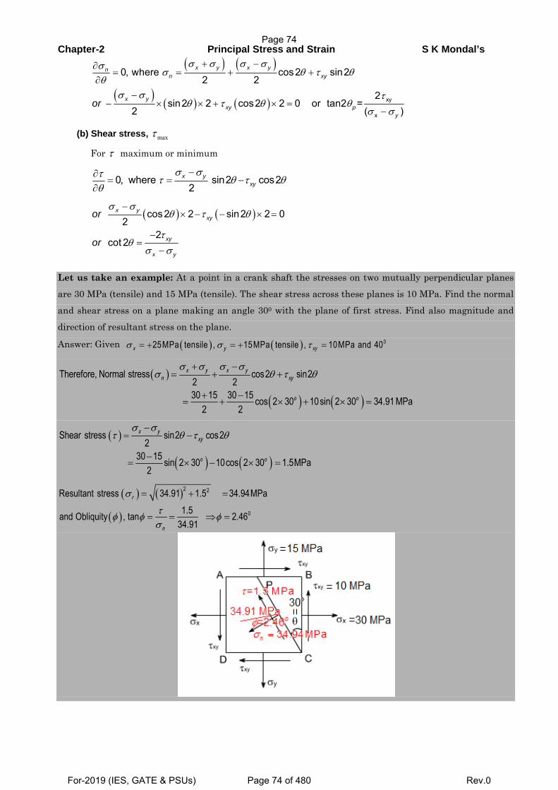
Chapter-2 Principal Stress and Strain S K Mondal’s ( ) ( )
( ) ( ) ( ) xy
x
0, where cos2 sin22 2
2sin2 2 cos2 2 0 or tan2 =
2 ( )
x y x ynn xy
x yxy p
y
or
σ σ σ σσσ θ τ θ
θσ σ τ
θ τ θ θσ σ
+ −∂= = + +
∂−
− × × + × =−
(b) Shear stress, maxτ
For τ maximum or minimum
0, where sin2 cos22
x yxy
σ στ τ θ τ θθ
−∂= = −
∂
( ) ( )σ σ
θ τ θ
τθ
σ σ
−× − − × =
−=
−
cos2 2 sin2 2 02
2cot 2
x yxy
xy
x y
or
or
Let us take an example: At a point in a crank shaft the stresses on two mutually perpendicular planes
are 30 MPa (tensile) and 15 MPa (tensile). The shear stress across these planes is 10 MPa. Find the normal
and shear stress on a plane making an angle 300 with the plane of first stress. Find also magnitude and
direction of resultant stress on the plane.
Answer: Given ( ) ( )σ σ τ= + = + = 025MPa tensile , 15MPa tensile , 10MPa and 40x y xy
( )
( ) ( )
σ σ σ σσ θ τ θ
+ −= + +
+ −= + × + × =
Therefore, Normal stress cos2 sin22 230 15 30 15 cos 2 30 10sin 2 30 34.91 MPa
2 2
x y x yn xy
o o
( )
( ) ( )
σ στ θ τ θ
−= −
−= × − × =
Shear stress sin2 cos22
30 15 sin 2 30 10cos 2 30 1.5MPa2
x yxy
o o
( ) ( )
( )
σ
τφ φ φσ
= + =
= = ⇒ =
2 2
0
Resultant stress 34.91 1.5 34.94MPa1.5and Obliquity , tan 2.46
34.91
r
n
Page 74
For-2019 (IES, GATE & PSUs) Page 74 of 480 Rev.0
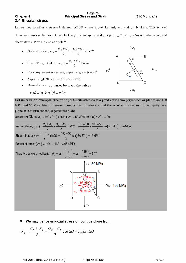
Chapter-2 Principal Stress and Strain S K Mondal’s 2.4 Bi-axial stress Let us now consider a stressed element ABCD where τ xy =0, i.e. only σ x and σ y is there. This type of
stress is known as bi-axial stress. In the previous equation if you put τ xy =0 we get Normal stress, nσ and
shear stress, τ on a plane at angleθ .
• Normal stress , n 22 2
x y x y cosσ σ σ σ
σ θ+ −
= +
• Shear/Tangential stress, sin 22
x yσ στ θ
−=
• For complementary stress, aspect angle = 090θ +
• Aspect angle ‘θ ’ varies from 0 to /2π
• Normal stress varies between the valuesnσ
y( 0) & ( / 2)xσ θ σ θ π= =
Let us take an example: The principal tensile stresses at a point across two perpendicular planes are 100
MPa and 50 MPa. Find the normal and tangential stresses and the resultant stress and its obliquity on a
plane at 200 with the major principal plane
Answer: Given ( ) ( )σ σ θ= = = 0100MPa tensile , 50MPa tensile 20x y and
( ) ( )σ σ σ σσ θ
+ − + −= + = + × =
100 50 100 50Normal stress, cos2 cos 2 20 94MPa2 2 2 2
x y x y on
( ) ( )( )
σ στ θ
σ
− −= = × =
= + =
0
2 2
100 50Shear stress, sin2 sin 2 20 16MPa2 2
Resultant stress 94 16 95.4MPa
x y
r
( ) τφσ
− −⎛ ⎞ ⎛ ⎞= = =⎜ ⎟ ⎜ ⎟⎝ ⎠⎝ ⎠
1 1 016Therefore angle of obliquity, tan tan 9.794n
• We may derive uni-axial stress on oblique plane from
cos2 sin 22 2
x y x yn xy
σ σ σ σσ θ τ θ
+ −= + +
Page 75
For-2019 (IES, GATE & PSUs) Page 75 of 480 Rev.0
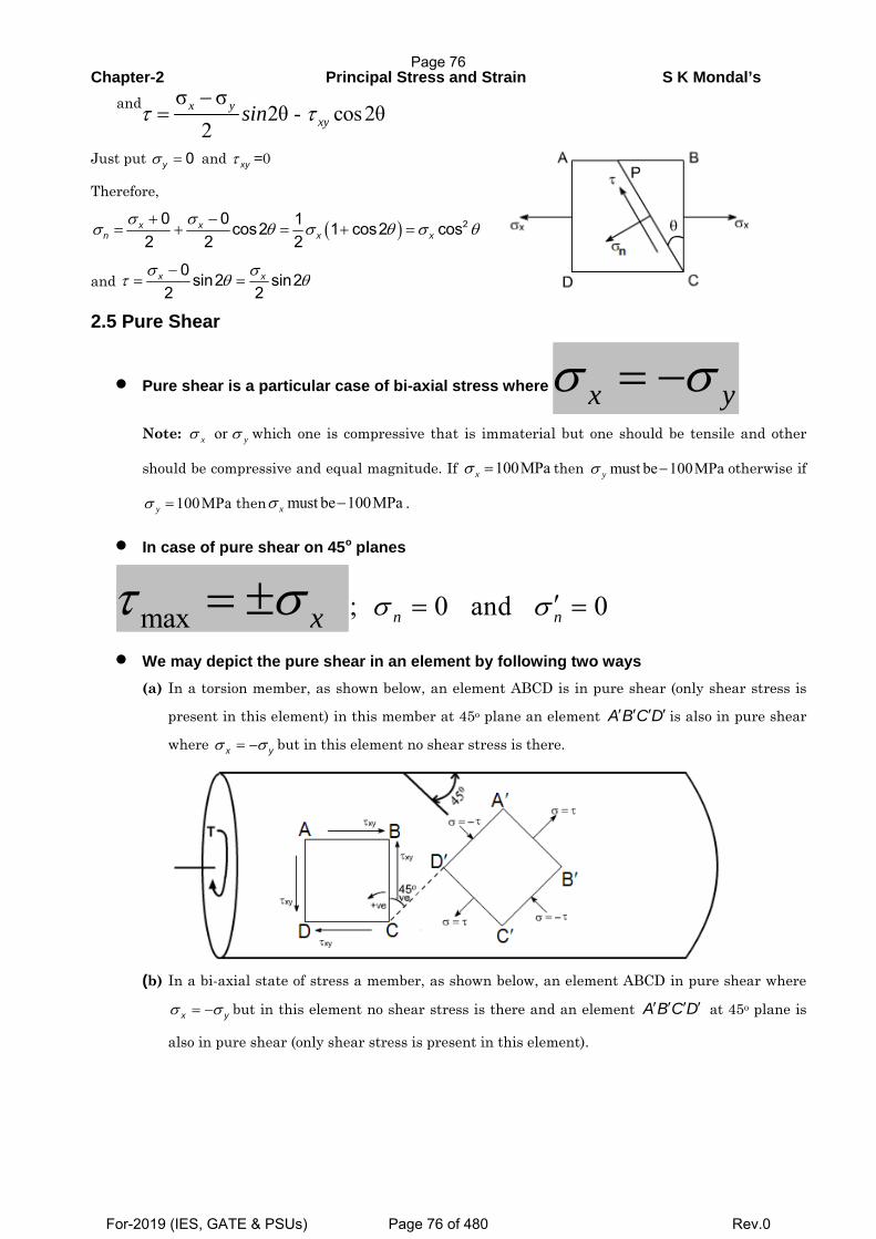
Chapter-2 Principal Stress and Strain S K Mondal’s and σ σ
2θ - cos2θ2
x yxysinτ τ
−=
Just put σ = 0y and τ xy =0
Therefore,
( )σ σσ θ σ θ σ θ
+ −= + = + = 20 0 1cos2 1 cos2 cos
2 2 2x x
n x x
and σ σ
τ θ θ−
= =0 sin2 sin2
2 2x x
2.5 Pure Shear
• Pure shear is a particular case of bi-axial stress where x yσ σ= −
Note: orx yσ σ which one is compressive that is immaterial but one should be tensile and other
should be compressive and equal magnitude. If 100MPaxσ = then must be 100MPayσ − otherwise if
100MPayσ = then must be 100MPaxσ − .
• In case of pure shear on 45o planes
max xτ σ= ± ; 0 and 0n nσ σ ′= =
• We may depict the pure shear in an element by following two ways (a) In a torsion member, as shown below, an element ABCD is in pure shear (only shear stress is
present in this element) in this member at 45o plane an element ′ ′ ′ ′A B C D is also in pure shear
where σ σ= −x y but in this element no shear stress is there.
(b) In a bi-axial state of stress a member, as shown below, an element ABCD in pure shear where
σ σ= −x y but in this element no shear stress is there and an element ′ ′ ′ ′A B C D at 45o plane is
also in pure shear (only shear stress is present in this element).
Page 76
For-2019 (IES, GATE & PSUs) Page 76 of 480 Rev.0
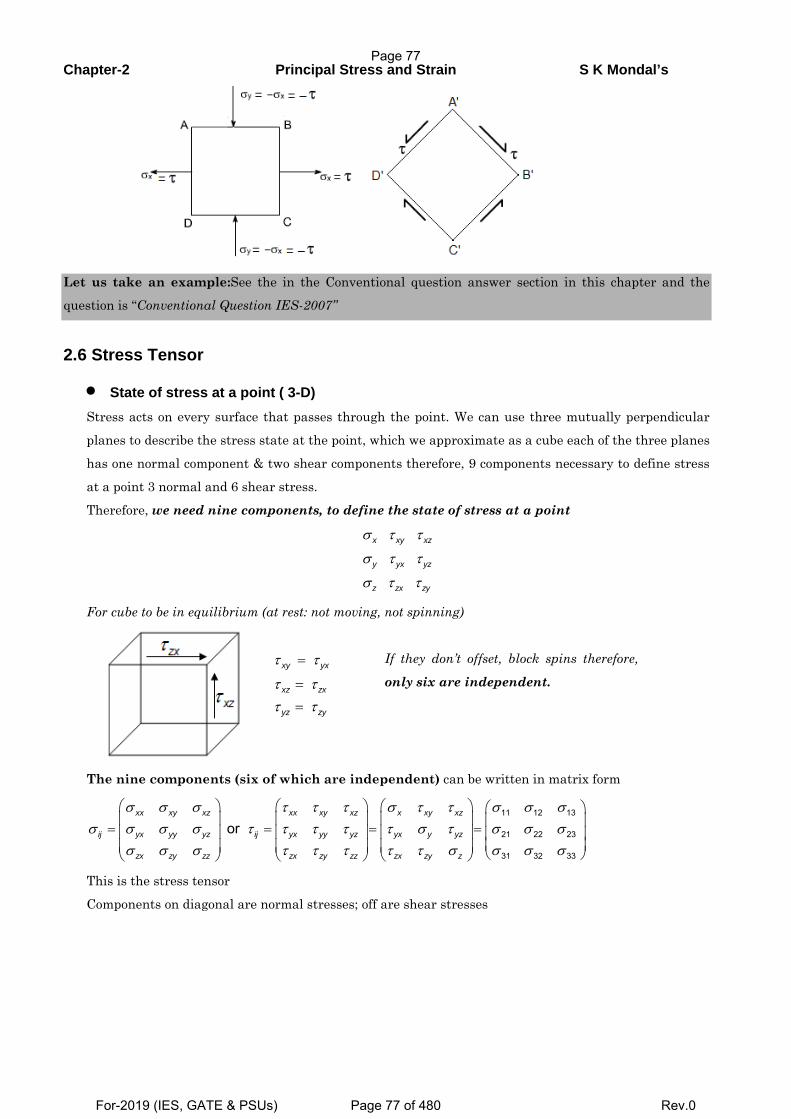
Chapter-2 Principal Stress and Strain S K Mondal’s
Let us take an example:See the in the Conventional question answer section in this chapter and the question is “Conventional Question IES-2007”
2.6 Stress Tensor
• State of stress at a point ( 3-D) Stress acts on every surface that passes through the point. We can use three mutually perpendicular
planes to describe the stress state at the point, which we approximate as a cube each of the three planes
has one normal component & two shear components therefore, 9 components necessary to define stress
at a point 3 normal and 6 shear stress.
Therefore, we need nine components, to define the state of stress at a point
σ τ τ
σ τ τ
σ τ τ
x xy xz
y yx yz
z zx zy
For cube to be in equilibrium (at rest: not moving, not spinning)
τ τ
τ ττ τ
=
=
=
xy yx
xz zx
yz zy
If they don’t offset, block spins therefore,
only six are independent.
The nine components (six of which are independent) can be written in matrix form
11 12 13
21 22 23
31 32 33
orxx xy xz xx xy xz x xy xz
ij yx yy yz ij yx yy yz yx y yz
zx zy zz zx zy zz zx zy z
σ σ σ τ τ τ σ τ τ σ σ σσ σ σ σ τ τ τ τ τ σ τ σ σ σ
σ σ σ τ τ τ τ τ σ σ σ σ
⎛ ⎞ ⎛ ⎞ ⎛ ⎞ ⎛ ⎞⎜ ⎟ ⎜ ⎟ ⎜ ⎟ ⎜ ⎟= = = =⎜ ⎟ ⎜ ⎟ ⎜ ⎟ ⎜ ⎟
⎜ ⎟⎜ ⎟ ⎜ ⎟ ⎜ ⎟ ⎝ ⎠⎝ ⎠ ⎝ ⎠ ⎝ ⎠
This is the stress tensor
Components on diagonal are normal stresses; off are shear stresses
Page 77
For-2019 (IES, GATE & PSUs) Page 77 of 480 Rev.0
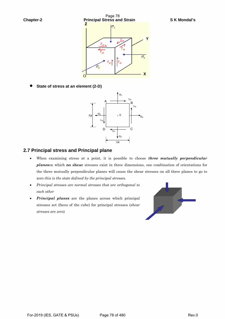
Chapter-2 Principal Stress and Strain S K Mondal’s
• State of stress at an element (2-D)
2.7 Principal stress and Principal plane • When examining stress at a point, it is possible to choose three mutually perpendicular
planeson which no shear stresses exist in three dimensions, one combination of orientations for the three mutually perpendicular planes will cause the shear stresses on all three planes to go to
zero this is the state defined by the principal stresses.
• Principal stresses are normal stresses that are orthogonal to
each other
• Principal planes are the planes across which principal
stresses act (faces of the cube) for principal stresses (shear
stresses are zero)
Page 78
For-2019 (IES, GATE & PSUs) Page 78 of 480 Rev.0
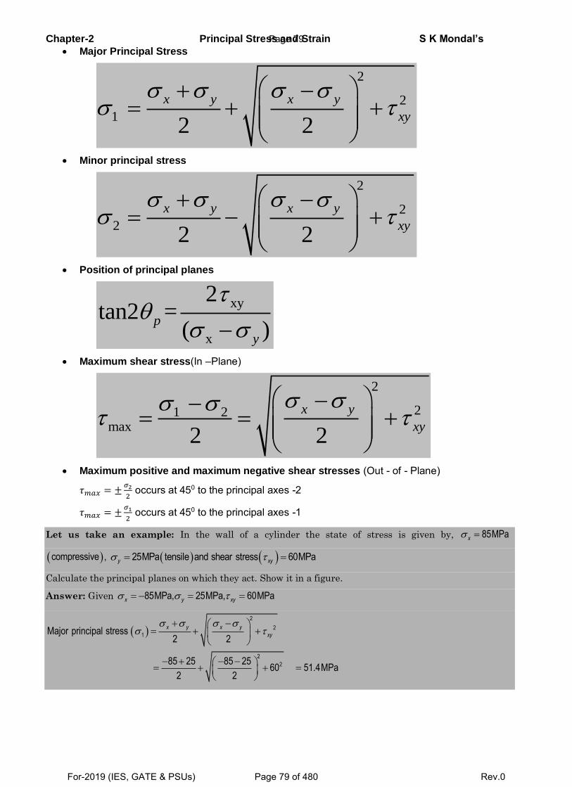
Chapter-2 Principal Stress and Strain S K Mondal’s
Major Principal Stress
2
2
12 2
x y x y
xy
Minor principal stress
2
2
22 2
x y x y
xy
Position of principal planes
xy
x
2tan2 =
( )p
y
Maximum shear stress(In –Plane)
2
21 2max
2 2
x y
xy
Maximum positive and maximum negative shear stresses (Out - of - Plane)
𝜏𝑚𝑎𝑥 = ±𝜎2
2 occurs at 450 to the principal axes -2
𝜏𝑚𝑎𝑥 = ±𝜎1
2 occurs at 450 to the principal axes -1
Let us take an example: In the wall of a cylinder the state of stress is given by, 85MPa x
compressive , 25MPa tensile and shear stress 60MPay xy
Calculate the principal planes on which they act. Show it in a figure.
Answer: Given 85MPa, 25MPa, 60MPax y xy
2
2
1
2
2
Major principal stress2 2
85 25 85 2560 51.4MPa
2 2
x y x y
xy
Page 79
For-2019 (IES, GATE & PSUs) Page 79 of 480 Rev.0
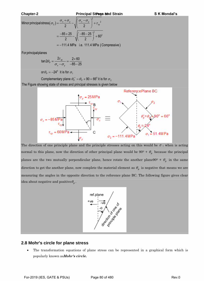
Chapter-2 Principal Stress and Strain S K Mondal’s
2
2
2
2
2
Minor principalstress2 2
85 25 85 2560
2 2
111.4 MPa i.e. 111.4 MPa Compressive
x y x y
xy
For principalplanes
2 2 60tan2
85 25
xy
P
x y
0
1
0
2
or 24 it is for
Complementary plane 90 66 it is for
The Figure showing state of stress and principal stresses is given below
P
P P
The direction of one principle plane and the principle stresses acting on this would be 1 when is acting
normal to this plane, now the direction of other principal plane would be 900 + p because the principal
planes are the two mutually perpendicular plane, hence rotate the another plane900 + p in the same
direction to get the another plane, now complete the material element as p is negative that means we are
measuring the angles in the opposite direction to the reference plane BC. The following figure gives clear
idea about negative and positive p .
2.8 Mohr's circle for plane stress
The transformation equations of plane stress can be represented in a graphical form which is
popularly known asMohr's circle.
Page 80
For-2019 (IES, GATE & PSUs) Page 80 of 480 Rev.0
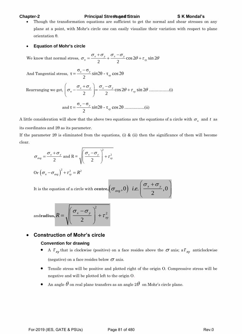
Chapter-2 Principal Stress and Strain S K Mondal’s Though the transformation equations are sufficient to get the normal and shear stresses on any
plane at a point, with Mohr's circle one can easily visualize their variation with respect to plane
orientation θ.
Equation of Mohr's circle
We know that normal stress, cos 2 sin 22 2
x y x y
n xy
And Tangential stress, σ σ
τ 2θ - τ cos 2θ2
x y
xysin
Rearranging we get, cos 2 sin 22 2
x y x y
n xy ……………(i)
andσ σ
τ 2θ - τ cos 2θ2
x y
xysin
……………(ii)
A little consideration will show that the above two equations are the equations of a circle with n and t as
its coordinates and 2θ as its parameter.
If the parameter 2θ is eliminated from the equations, (i) & (ii) then the significance of them will become
clear.
2
x y
avgand R =
2
2
2
x y
xy
Or 2
2 2 n avg xy R
It is the equation of a circle with centre, ,0 . . ,02
x y
avg i e
andradius,
2
2
2
x y
xyR
Construction of Mohr’s circle
Convention for drawing
A xy that is clockwise (positive) on a face resides above the axis; a xy anticlockwise
(negative) on a face resides below axis.
Tensile stress will be positive and plotted right of the origin O. Compressive stress will be
negative and will be plotted left to the origin O.
An angle on real plane transfers as an angle 2 on Mohr’s circle plane.
Page 81
For-2019 (IES, GATE & PSUs) Page 81 of 480 Rev.0
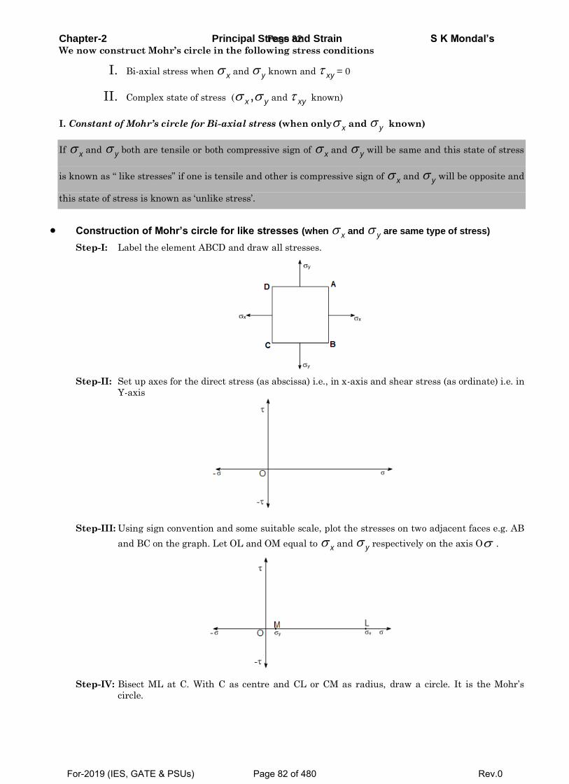
Chapter-2 Principal Stress and Strain S K Mondal’s We now construct Mohr’s circle in the following stress conditions
I. Bi-axial stress when x and y known and xy = 0
II. Complex state of stress ( ,x y and xy known)
I. Constant of Mohr’s circle for Bi-axial stress (when only x and y known)
If x and y both are tensile or both compressive sign of x and y will be same and this state of stress
is known as “ like stresses” if one is tensile and other is compressive sign of x and y will be opposite and
this state of stress is known as ‘unlike stress’.
Construction of Mohr’s circle for like stresses (when x and y are same type of stress)
Step-I: Label the element ABCD and draw all stresses.
Step-II: Set up axes for the direct stress (as abscissa) i.e., in x-axis and shear stress (as ordinate) i.e. in
Y-axis
Step-III: Using sign convention and some suitable scale, plot the stresses on two adjacent faces e.g. AB
and BC on the graph. Let OL and OM equal to x and y respectively on the axis O .
Step-IV: Bisect ML at C. With C as centre and CL or CM as radius, draw a circle. It is the Mohr’s
circle.
Page 82
For-2019 (IES, GATE & PSUs) Page 82 of 480 Rev.0
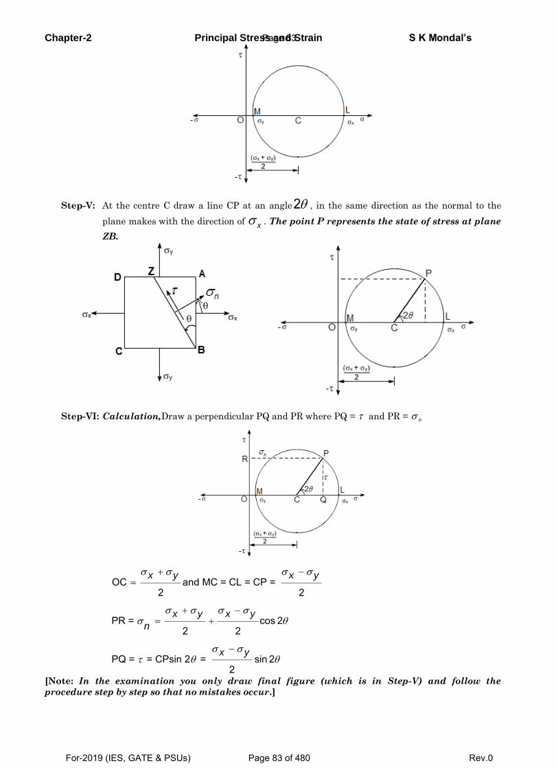
Chapter-2 Principal Stress and Strain S K Mondal’s
Step-V: At the centre C draw a line CP at an angle2 , in the same direction as the normal to the
plane makes with the direction of x . The point P represents the state of stress at plane
ZB.
Step-VI: Calculation,Draw a perpendicular PQ and PR where PQ = and PR = n
OC and MC = CL = CP = 2 2
PR = cos 22 2
PQ = = CPsin 2 = sin 22
x y x y
x y x y
x y
n
[Note: In the examination you only draw final figure (which is in Step-V) and follow the
procedure step by step so that no mistakes occur.]
Page 83
For-2019 (IES, GATE & PSUs) Page 83 of 480 Rev.0
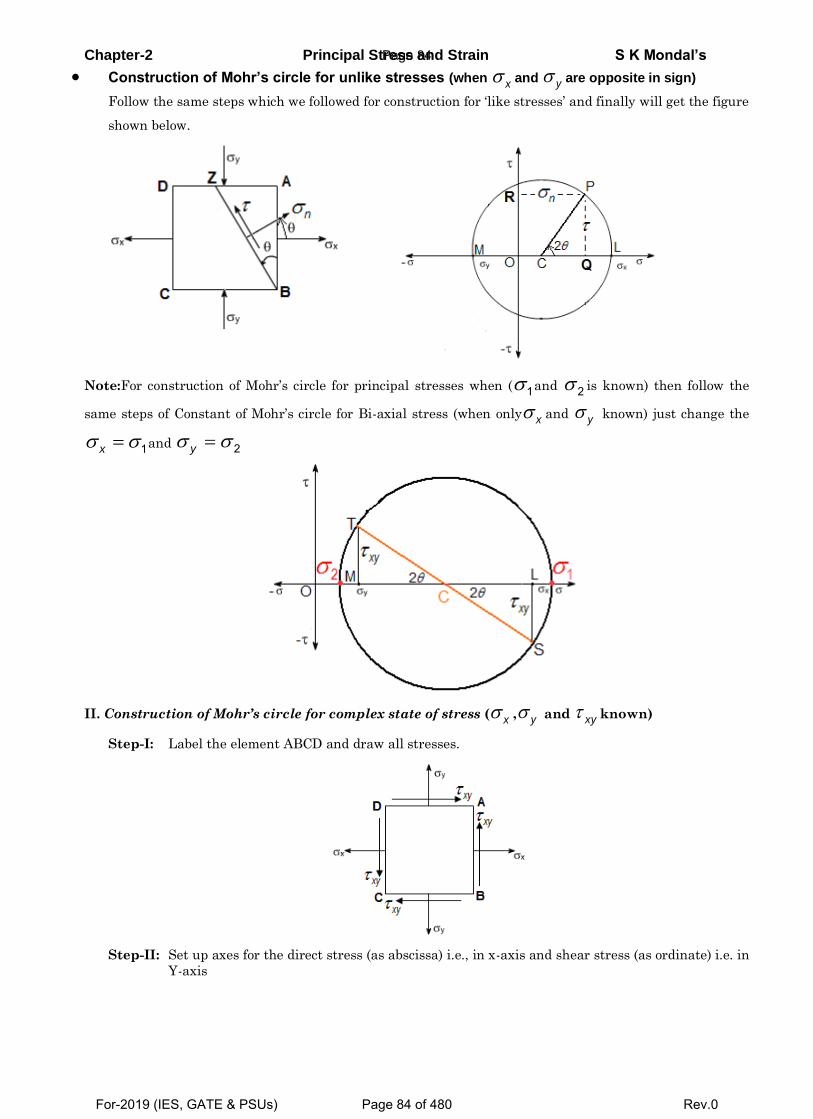
Chapter-2 Principal Stress and Strain S K Mondal’s
Construction of Mohr’s circle for unlike stresses (when x and y are opposite in sign)
Follow the same steps which we followed for construction for ‘like stresses’ and finally will get the figure
shown below.
Note:For construction of Mohr’s circle for principal stresses when ( 1 and 2 is known) then follow the
same steps of Constant of Mohr’s circle for Bi-axial stress (when only x and y known) just change the
1x and 2y
II. Construction of Mohr’s circle for complex state of stress ( x , y and xy known)
Step-I: Label the element ABCD and draw all stresses.
Step-II: Set up axes for the direct stress (as abscissa) i.e., in x-axis and shear stress (as ordinate) i.e. in
Y-axis
Page 84
For-2019 (IES, GATE & PSUs) Page 84 of 480 Rev.0
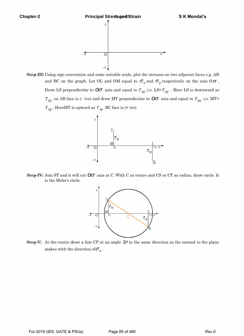
Chapter-2 Principal Stress and Strain S K Mondal’s
Step-III: Using sign convention and some suitable scale, plot the stresses on two adjacent faces e.g. AB
and BC on the graph. Let OL and OM equal to x and y respectively on the axis O .
Draw LS perpendicular to o axis and equal to xy .i.e. LS= xy . Here LS is downward as
xy on AB face is (– ive) and draw MT perpendicular to o axis and equal to xy i.e. MT=
xy . HereMT is upward as xy BC face is (+ ive).
Step-IV: Join ST and it will cut o axis at C. With C as centre and CS or CT as radius, draw circle. It
is the Mohr’s circle.
Step-V: At the centre draw a line CP at an angle 2 in the same direction as the normal to the plane
makes with the direction of x .
Page 85
For-2019 (IES, GATE & PSUs) Page 85 of 480 Rev.0
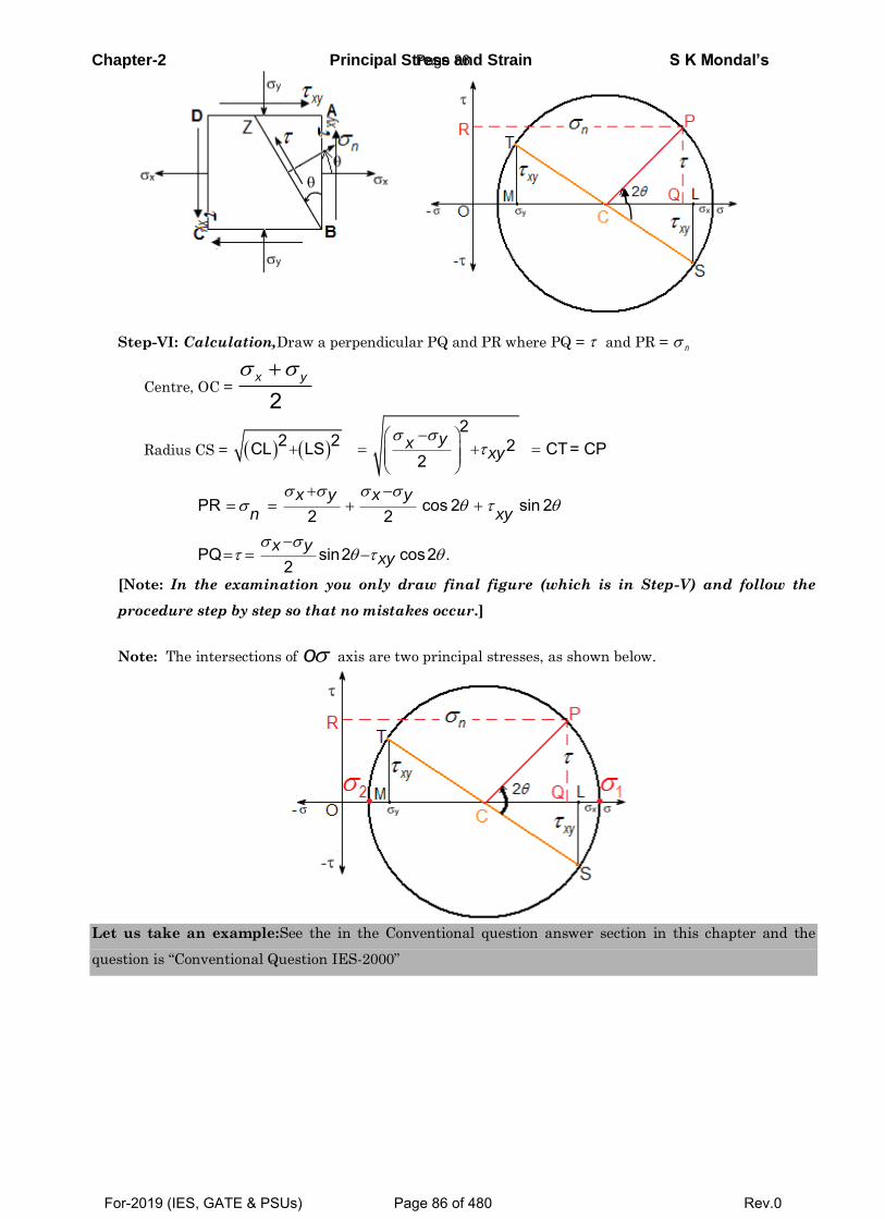
Chapter-2 Principal Stress and Strain S K Mondal’s
Step-VI: Calculation,Draw a perpendicular PQ and PR where PQ = and PR = n
Centre, OC = 2
x y
Radius CS = 2
2 2 2CL LS CT= CP2
yxxy
PR cos 2 sin 22 2
PQ sin2 cos2 .2
x y x y
n xy
x yxy
[Note: In the examination you only draw final figure (which is in Step-V) and follow the
procedure step by step so that no mistakes occur.]
Note: The intersections of o axis are two principal stresses, as shown below.
Let us take an example:See the in the Conventional question answer section in this chapter and the
question is “Conventional Question IES-2000”
Page 86
For-2019 (IES, GATE & PSUs) Page 86 of 480 Rev.0
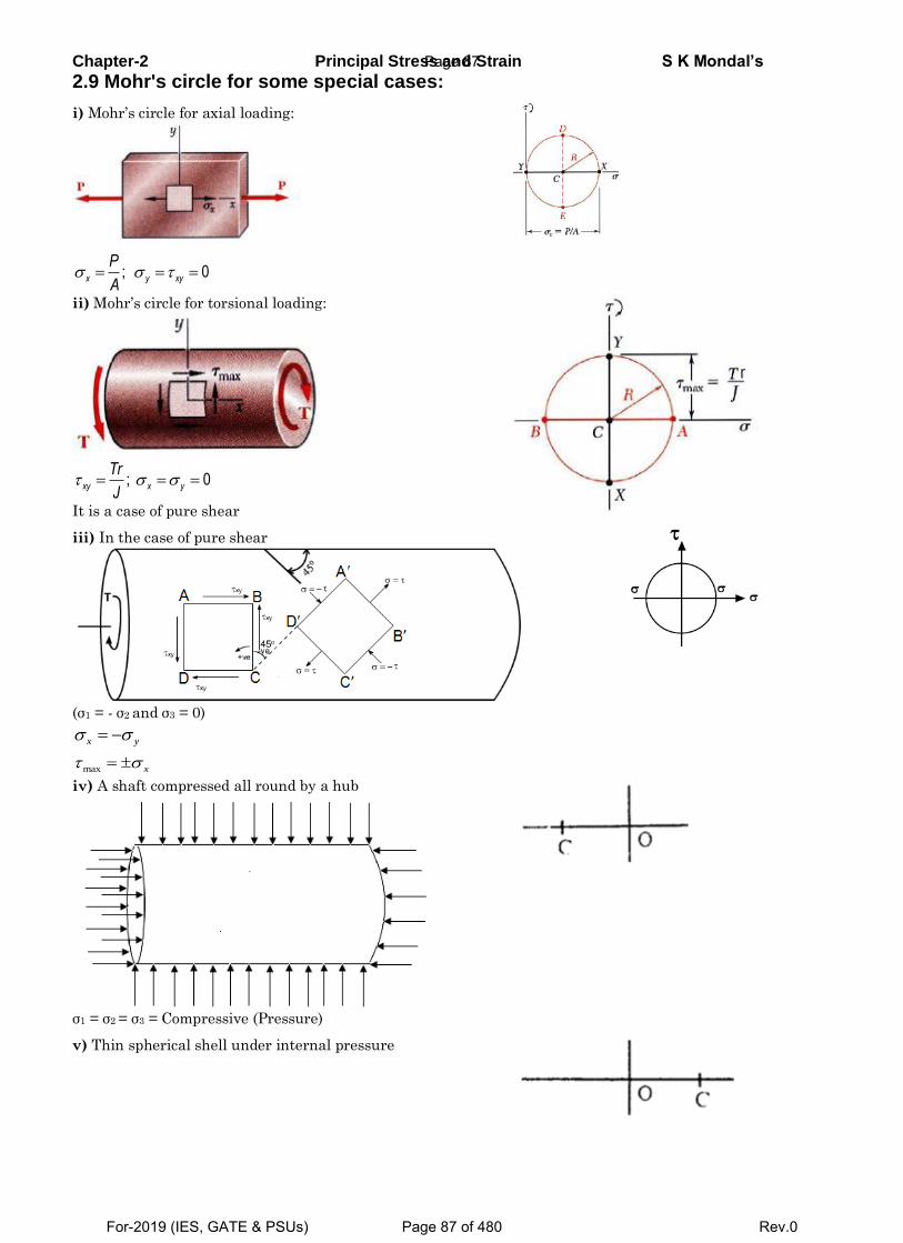
Chapter-2 Principal Stress and Strain S K Mondal’s
2.9 Mohr's circle for some special cases:
i) Mohr’s circle for axial loading:
; 0x y xy
P
A
ii) Mohr’s circle for torsional loading:
; 0xy x y
Tr
J
It is a case of pure shear iii) In the case of pure shear
(σ1 = - σ2 and σ3 = 0)
x y
max x
iv) A shaft compressed all round by a hub
σ1 = σ2 = σ3 = Compressive (Pressure)
v) Thin spherical shell under internal pressure
Page 87
For-2019 (IES, GATE & PSUs) Page 87 of 480 Rev.0
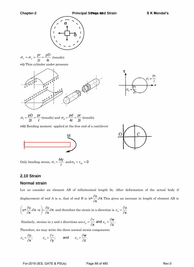
Chapter-2 Principal Stress and Strain S K Mondal’s
1 22 4
pr pD
t t (tensile)
vi) Thin cylinder under pressure
1 2pD pr
t t(tensile) and 2 4 2
pd pr
t t(tensile)
vii) Bending moment applied at the free end of a cantilever
Only bending stress, 1My
I and 2 0xy
2.10 Strain
Normal strain
Let us consider an element AB of infinitesimal length δx. After deformation of the actual body if
displacement of end A is u, that of end B is uu+ . x.x
This gives an increase in length of element AB is
u uu+ . x -u xx x
and therefore the strain in x-direction is x
ux
Similarly, strains in y and z directions are ywand .
x zz
Therefore, we may write the three normal strain components
x yu w; ; andx y zz
.
Page 88
For-2019 (IES, GATE & PSUs) Page 88 of 480 Rev.0
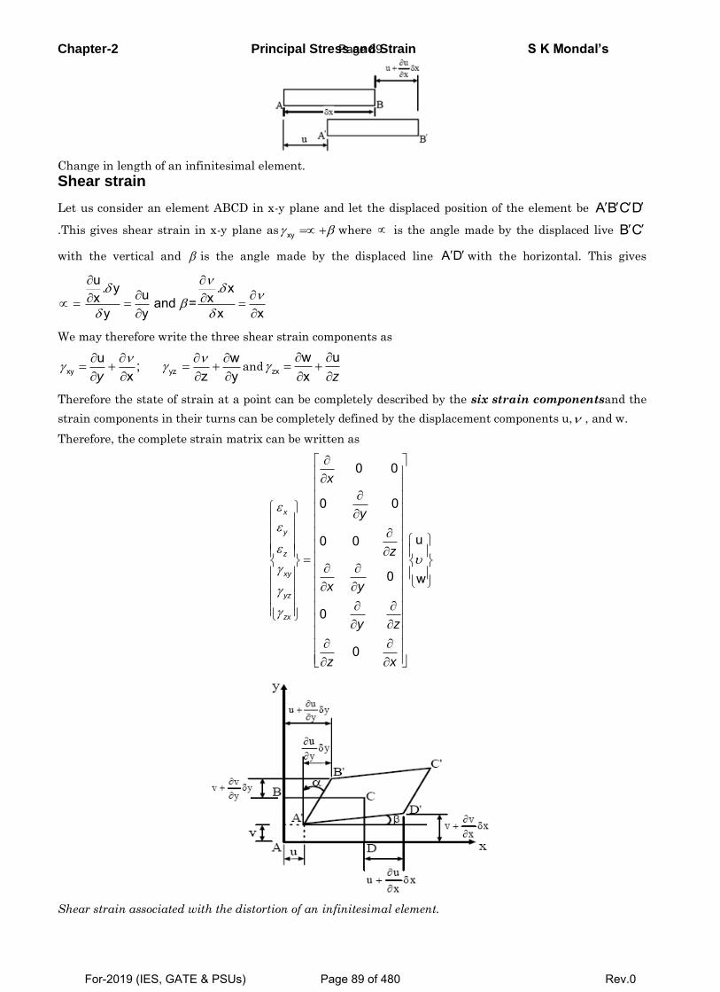
Chapter-2 Principal Stress and Strain S K Mondal’s
Change in length of an infinitesimal element.
Shear strain
Let us consider an element ABCD in x-y plane and let the displaced position of the element be A B C D
.This gives shear strain in x-y plane as xy where is the angle made by the displaced live B C
with the vertical and is the angle made by the displaced line A D with the horizontal. This gives
u. y . xux xand =y y x x
We may therefore write the three shear strain components as
xy yzu w;
x z yy
and zxw ux z
Therefore the state of strain at a point can be completely described by the six strain componentsand the
strain components in their turns can be completely defined by the displacement components u, , and w.
Therefore, the complete strain matrix can be written as
0 0
0 0
u0 0
0 w
0
0
x
y
z
xy
yz
zx
x
y
z
x y
y z
z x
Shear strain associated with the distortion of an infinitesimal element.
Page 89
For-2019 (IES, GATE & PSUs) Page 89 of 480 Rev.0
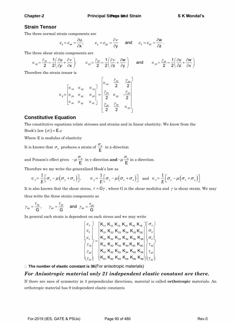
Chapter-2 Principal Stress and Strain S K Mondal’s
Strain Tensor
The three normal strain components are
x xx yu w; and x y zyy z zz
.
The three shear strain components are
1 u 1 w 1 w; and
2 2 x 2 2 z y 2 2 zxy yz zx
xy yz zx
u
y x
Therefore the strain tensor is
2 2
2 2
2 2
xy xzxx
xx xy xz
yx yz
ij yx yy yz yy
zx zy zzzyzx
zz
Constitutive Equation
The constitutive equations relate stresses and strains and in linear elasticity. We know from the
Hook’s law E.
Where E is modulus of elasticity
It is known that x produces a strain of E
x in x-direction
and Poisson’s effect gives E
x in y-direction andE
x in z-direction.
Therefore we my write the generalized Hook’s law as
1
x x y z
E,
1 y y z x
E and
1 z z x y
E
It is also known that the shear stress, G , where G is the shear modulus and is shear strain. We may
thus write the three strain components as
xy yz zxxy yz zx, and
G G G
In general each strain is dependent on each stress and we may write
11 12 13 14 15 16
21 22 23 24 25 26
31 32 33 34 35 36
41 42 43 44 45 46
51 52 53 54 55 56
61 62 63 64 65 66
K K K K K KK K K K K KK K K K K KK K K K K KK K K K K KK K K K K K
x x
y y
z z
xy xy
yz yz
zx zx
The number of elastic constant is 36(For anisotropic materials)
For Anisotropic material only 21 independent elastic constant are there.
If there are axes of symmetry in 3 perpendicular directions, material is called orthotropic materials. An
orthotropic material has 9 independent elastic constants
Page 90
For-2019 (IES, GATE & PSUs) Page 90 of 480 Rev.0
Chapter-2 Principal Stress and Strain S K Mondal’s For isotropic material
11 22 33
44 55 66
12 13 21 23 31 32
1K K KE1K K K
K K K K K KE
G
Rest of all elements in K matrix are zero.
For isotropic material only two independent elastic constant is there say E and G.
1-D Stress
Let us take an example: A rod of cross sectional area Ao is
loaded by a tensile force P.
It’s stresses , 0, 0Ax y z
o
Pand
1-D state of stress or Uni-axial state of stress
0 0 0 0 0 0
0 0 0 or 0 0 0 0 0 00 0 0 0 0 0 0 0 0
xx xx x
ij ij
Therefore strain components are
xx
E
;
xy x
E
; and
xz x
E
Strain
0 00 0 0 0
0 0 0 0 0 00 0 0 0
0 0
x
x y
xij x y
x yx
E p
qE
q
E
2-D Stress ( 0)z
(i)
1x x y
E
1y y x
E
z x yE
[Where, , ,x y z are strain component in X, Y, and Z axis respectively]
Page 91
For-2019 (IES, GATE & PSUs) Page 91 of 480 Rev.0
Chapter-2 Principal Stress and Strain S K Mondal’s
(ii) 21
x x y
E
21
y y x
E
3-D Stress & Strain
(i) 1
x x y zE
1
y y z xE
1
z z x yE
(ii)
1
1 1 2x x y z
E
11 1 2
11 1 2
y y z x
z z x y
E
E
Let us take an example: At a point in a loaded member, a state of plane stress exists and the strains are
6 6 6x xy270 10 ; 90 10 and 360 10 .y If the elastic constants E, and G are 200
GPa, 0.25 and 80 GPa respectively.
Determine the normal stress x and y and the shear stress xy
at the point.
Answer: We know that
.
x x
1
E
1
E
G
y
y y x
xy
xy
96 6
x x y2 2
E 200 10This gives 270 10 0.25 90 10 Pa
1 1 0.25
52.8 MPa (i.e. tensile)
Page 92
For-2019 (IES, GATE & PSUs) Page 92 of 480 Rev.0
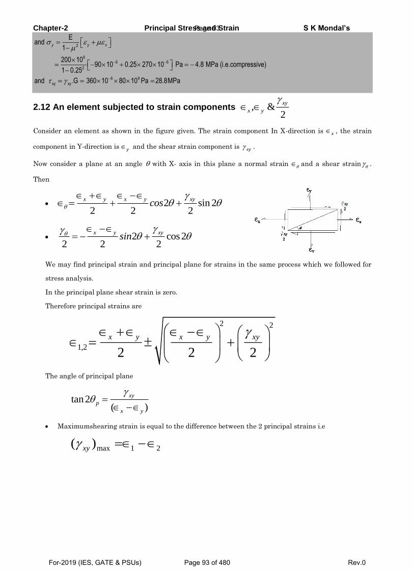
Chapter-2 Principal Stress and Strain S K Mondal’s
x2
96 6
2
6 9
xy xy
Eand
1
200 1090 10 0.25 270 10 Pa 4.8 MPa (i.e.compressive)
1 0.25
and .G 360 10 80 10 Pa 28.8MPa
y y
2.12 An element subjected to strain components , &2
xy
x y
Consider an element as shown in the figure given. The strain component In X-direction is x , the strain
component in Y-direction is y and the shear strain component is
xy .
Now consider a plane at an angle with X- axis in this plane a normal strain and a shear strain .
Then
2 sin 22 2 2
x y x y xycos
2 cos22 2 2
x y xysin
We may find principal strain and principal plane for strains in the same process which we followed for
stress analysis.
In the principal plane shear strain is zero.
Therefore principal strains are
2 2
1,22 2 2
x y x y xy
The angle of principal plane
tan2( )
xy
p
x y
Maximumshearing strain is equal to the difference between the 2 principal strains i.e
max 1 2( )xy
Page 93
For-2019 (IES, GATE & PSUs) Page 93 of 480 Rev.0
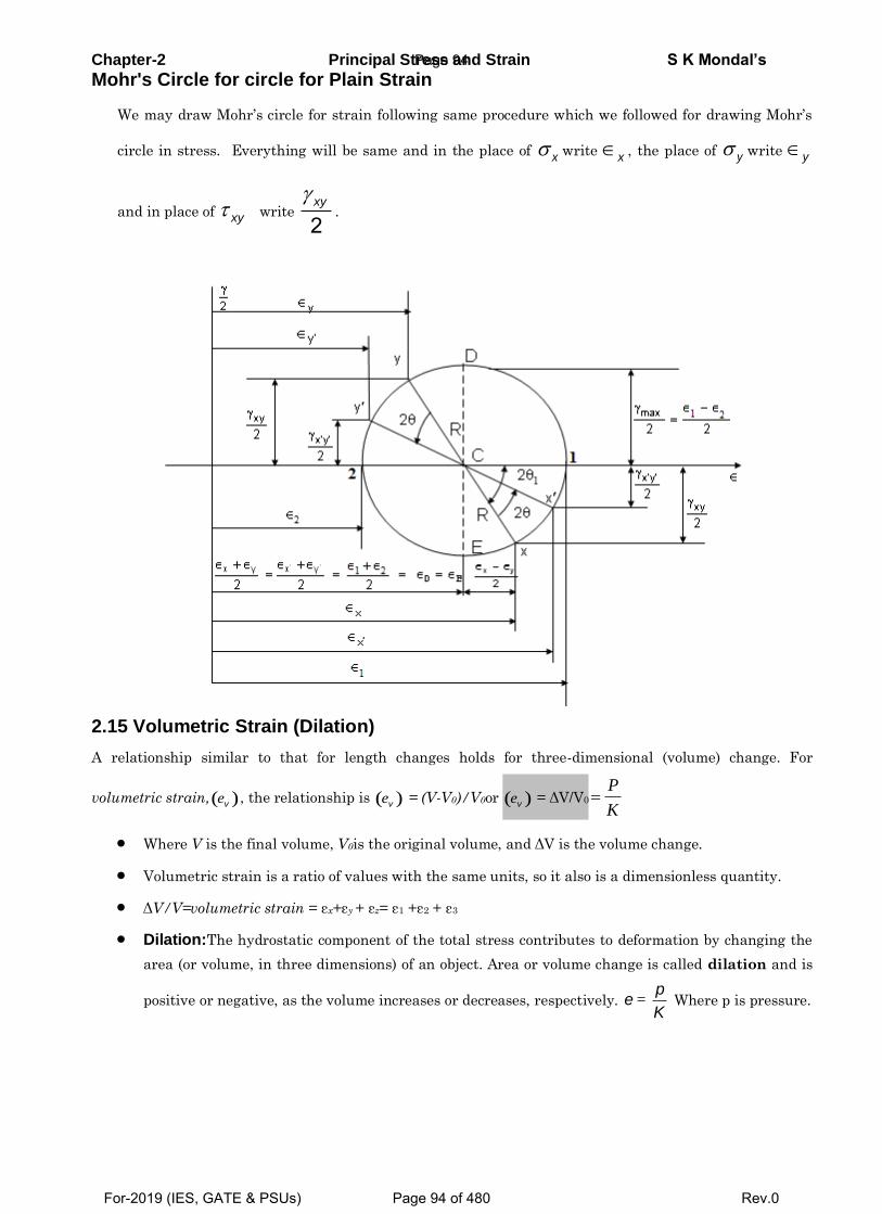
Chapter-2 Principal Stress and Strain S K Mondal’s
Mohr's Circle for circle for Plain Strain
We may draw Mohr’s circle for strain following same procedure which we followed for drawing Mohr’s
circle in stress. Everything will be same and in the place of x write x , the place of y write y
and in place of xy write 2xy
.
2.15 Volumetric Strain (Dilation)
A relationship similar to that for length changes holds for three-dimensional (volume) change. For
volumetric strain,( )ve , the relationship is ( )ve = (V-V0)/V0or ( )ve = ΔV/V0
P
K
Where V is the final volume, V0is the original volume, and ΔV is the volume change.
Volumetric strain is a ratio of values with the same units, so it also is a dimensionless quantity.
ΔV/V=volumetric strain = εx+εy + εz= ε1 +ε2 + ε3
Dilation:The hydrostatic component of the total stress contributes to deformation by changing the
area (or volume, in three dimensions) of an object. Area or volume change is called dilation and is
positive or negative, as the volume increases or decreases, respectively. p
eK
= Where p is pressure.
Page 94
For-2019 (IES, GATE & PSUs) Page 94 of 480 Rev.0
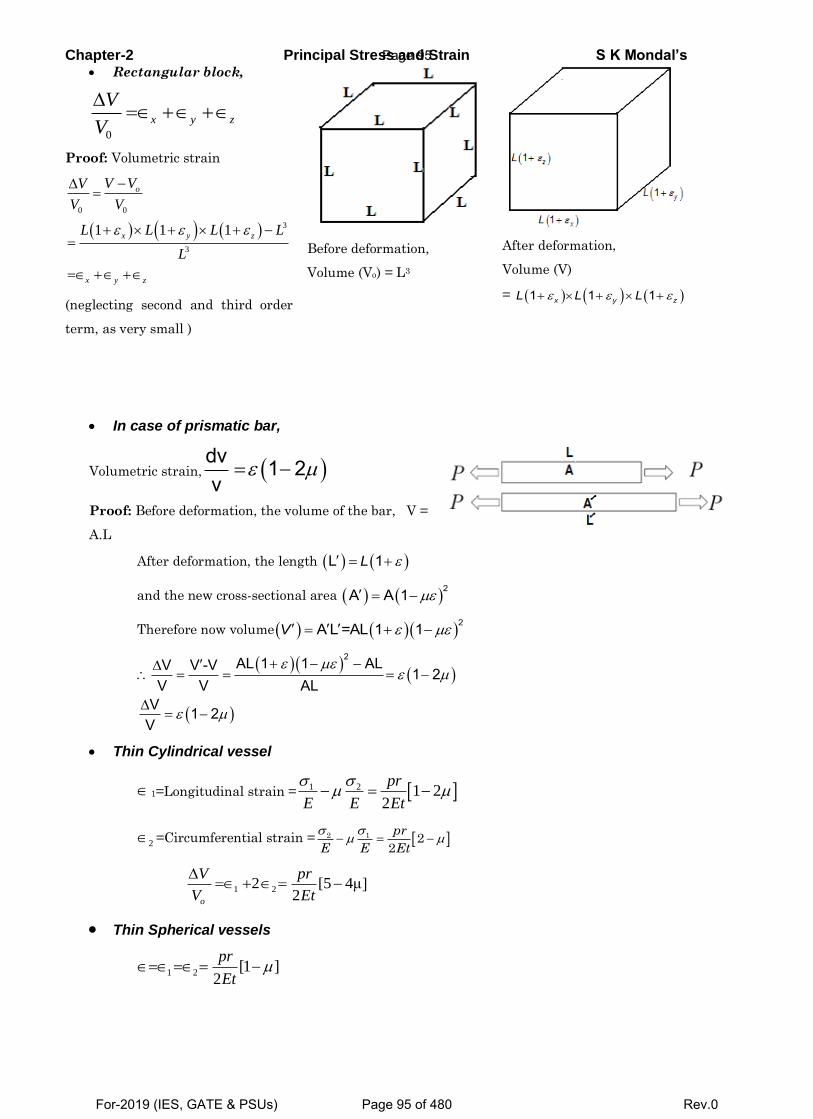
Chapter-2 Principal Stress and Strain S K Mondal’s Rectangular block,
0
x y z
V
V
Proof: Volumetric strain
0 0
3
3
1 1 1
o
x y z
x y z
V VV
V V
L L L L
L
(neglecting second and third order
term, as very small )
Before deformation,
Volume (Vo) = L3
After deformation,
Volume (V)
= 1 1 1x y zL L L
In case of prismatic bar,
Volumetric strain, dv 1 2v
Proof: Before deformation, the volume of the bar, V =
A.L
After deformation, the length L 1L
and the new cross-sectional area 2A A 1
Therefore now volume 2A L =AL 1 1V
2AL 1 1 ALV V -V 1 2V V AL
V 1 2V
Thin Cylindrical vessel
1=Longitudinal strain = 1 2 1 22
pr
E E Et
2 =Circumferential strain = 2 1 22
pr
E E Et
1 22 [5 4μ]
2o
V pr
V Et
Thin Spherical vessels
1 2 [1 ]2
pr
Et
Page 95
For-2019 (IES, GATE & PSUs) Page 95 of 480 Rev.0
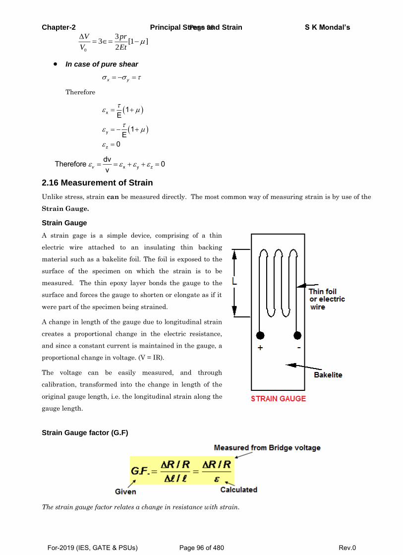
Chapter-2 Principal Stress and Strain S K Mondal’s
0
33 [1 ]
2
V pr
V Et
In case of pure shear
x y
Therefore
x
y
z
1E
1E
0
x y zdvTherefore 0vv
2.16 Measurement of Strain
Unlike stress, strain can be measured directly. The most common way of measuring strain is by use of the
Strain Gauge.
Strain Gauge
A strain gage is a simple device, comprising of a thin
electric wire attached to an insulating thin backing
material such as a bakelite foil. The foil is exposed to the
surface of the specimen on which the strain is to be
measured. The thin epoxy layer bonds the gauge to the
surface and forces the gauge to shorten or elongate as if it
were part of the specimen being strained.
A change in length of the gauge due to longitudinal strain
creates a proportional change in the electric resistance,
and since a constant current is maintained in the gauge, a
proportional change in voltage. (V = IR).
The voltage can be easily measured, and through
calibration, transformed into the change in length of the
original gauge length, i.e. the longitudinal strain along the
gauge length.
Strain Gauge factor (G.F)
The strain gauge factor relates a change in resistance with strain.
Page 96
For-2019 (IES, GATE & PSUs) Page 96 of 480 Rev.0
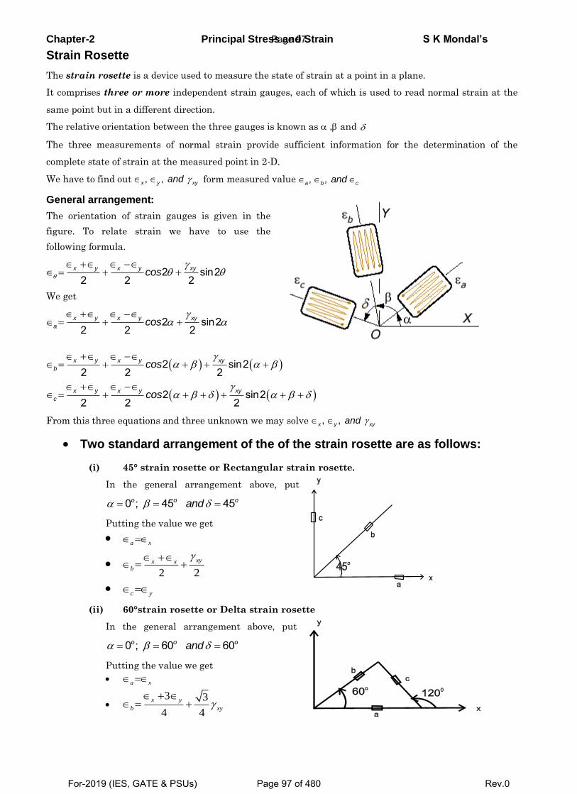
Chapter-2 Principal Stress and Strain S K Mondal’s
Strain Rosette
The strain rosette is a device used to measure the state of strain at a point in a plane.
It comprises three or more independent strain gauges, each of which is used to read normal strain at the
same point but in a different direction.
The relative orientation between the three gauges is known as , and
The three measurements of normal strain provide sufficient information for the determination of the
complete state of strain at the measured point in 2-D.
We have to find out , ,x y xyand form measured value , ,a b cand
General arrangement:
The orientation of strain gauges is given in the
figure. To relate strain we have to use the
following formula.
2 sin22 2 2
x y x y xycos
We get
2 sin22 2 2
x y x y xy
a cos
2 sin22 2 2
x y x y xy
b cos
2 sin22 2 2
x y x y xy
c cos
From this three equations and three unknown we may solve , ,x y xyand
Two standard arrangement of the of the strain rosette are as follows:
(i) 45° strain rosette or Rectangular strain rosette.
In the general arrangement above, put
0 ; 45 45o o oand
Putting the value we get
a x
2 2
xyx xb
c y
(ii) 60°strain rosette or Delta strain rosette
In the general arrangement above, put
0 ; 60 60o o oand
Putting the value we get
a x
3 3
4 4
x y
b xy
Page 97
For-2019 (IES, GATE & PSUs) Page 97 of 480 Rev.0
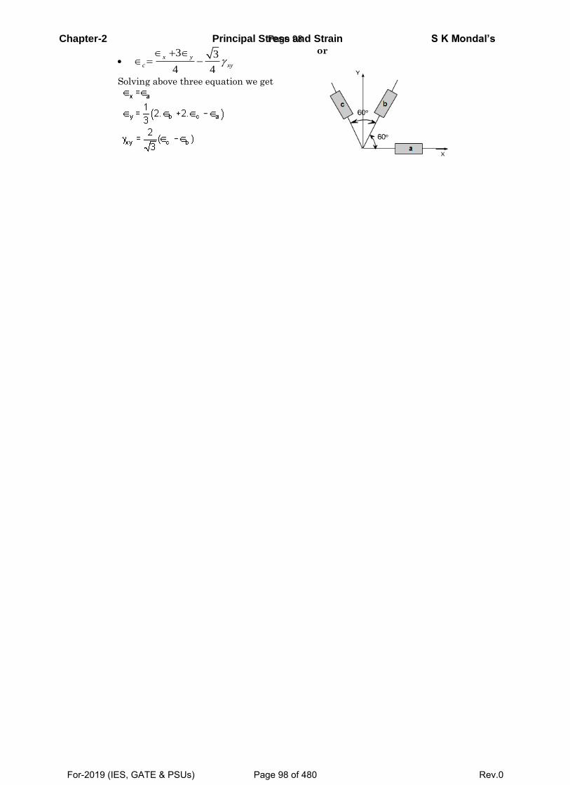
Chapter-2 Principal Stress and Strain S K Mondal’s
3 3
4 4
x y
c xy
Solving above three equation we get
or
Page 98
For-2019 (IES, GATE & PSUs) Page 98 of 480 Rev.0
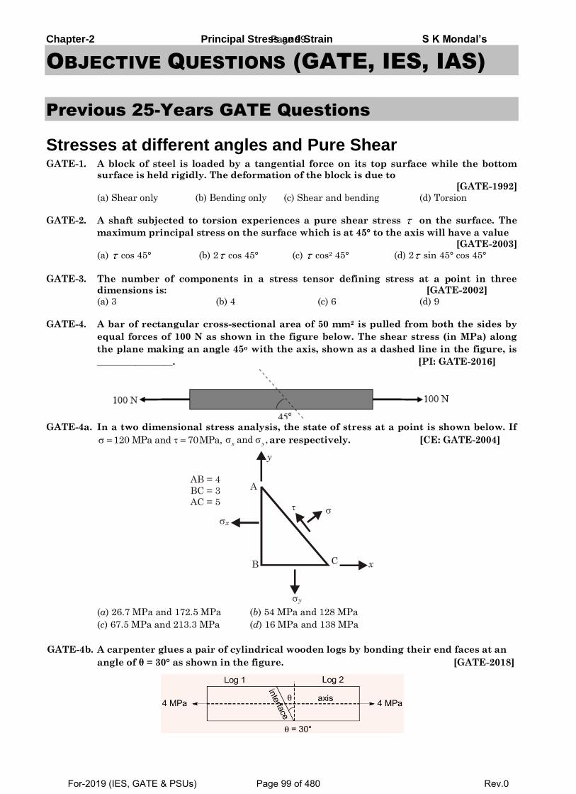
Chapter-2 Principal Stress and Strain S K Mondal’s
OBJECTIVE QUESTIONS (GATE, IES, IAS)
Previous 25-Years GATE Questions
Stresses at different angles and Pure Shear GATE-1. A block of steel is loaded by a tangential force on its top surface while the bottom
surface is held rigidly. The deformation of the block is due to
[GATE-1992]
(a) Shear only (b) Bending only (c) Shear and bending (d) Torsion
GATE-2. A shaft subjected to torsion experiences a pure shear stress on the surface. The
maximum principal stress on the surface which is at 45° to the axis will have a value
[GATE-2003]
(a) cos 45° (b) 2 cos 45° (c) cos2 45° (d) 2 sin 45° cos 45°
GATE-3. The number of components in a stress tensor defining stress at a point in three
dimensions is: [GATE-2002]
(a) 3 (b) 4 (c) 6 (d) 9
GATE-4. A bar of rectangular cross-sectional area of 50 mm2 is pulled from both the sides by
equal forces of 100 N as shown in the figure below. The shear stress (in MPa) along
the plane making an angle 45o with the axis, shown as a dashed line in the figure, is
________________. [PI: GATE-2016]
GATE-4a. In a two dimensional stress analysis, the state of stress at a point is shown below. If
120 MPa and 70MPa, and ,x y
are respectively. [CE: GATE-2004]
A
B C x
y
x
y
AB = 4
BC = 3
AC = 5
(a) 26.7 MPa and 172.5 MPa (b) 54 MPa and 128 MPa
(c) 67.5 MPa and 213.3 MPa (d) 16 MPa and 138 MPa
GATE-4b. A carpenter glues a pair of cylindrical wooden logs by bonding their end faces at an
angle of θ = 30° as shown in the figure. [GATE-2018]
Page 99
For-2019 (IES, GATE & PSUs) Page 99 of 480 Rev.0
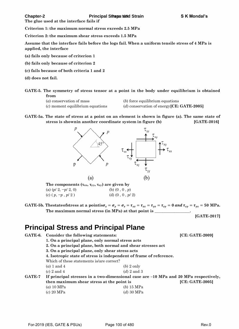
Chapter-2 Principal Stress and Strain S K Mondal’s The glue used at the interface fails if
Criterion 1: the maximum normal stress exceeds 2.5 MPa
Criterion 2: the maximum shear stress exceeds 1.5 MPa
Assume that the interface fails before the logs fail. When a uniform tensile stress of 4 MPa is
applied, the interface
(a) fails only because of criterion 1
(b) fails only because of criterion 2
(c) fails because of both criteria 1 and 2
(d) does not fail.
GATE-5. The symmetry of stress tensor at a point in the body under equilibrium is obtained
from
(a) conservation of mass (b) force equilibrium equations
(c) moment equilibrium equations (d) conservation of energy[CE: GATE-2005]
GATE-5a. The state of stress at a point on an element is shown in figure (a). The same state of
stress is shownin another coordinate system in figure (b) [GATE-2016]
The components (τxx, τyy, τxy) are given by
(a) (𝑝/ 2, −𝑝/ 2, 0) (b) (0 , 0 , 𝑝)
(c) ( 𝑝, −𝑝 , 𝑝/ 2 ) (d) (0 , 0 , 𝑝/ 2)
GATE-5b. Thestateofstress at a pointis𝝈𝒙 = 𝝈𝒚 = 𝝈𝒛 = 𝝉𝒙𝒛 = 𝝉𝒛𝒙 = 𝝉𝒚𝒛 = 𝝉𝒛𝒚 = 𝟎 𝒂𝒏𝒅 𝝉𝒙𝒚 = 𝝉𝒚𝒙 = 𝟓𝟎 MPa.
The maximum normal stress (in MPa) at that point is __________________.
[GATE-2017]
Principal Stress and Principal Plane GATE-6. Consider the following statements: [CE: GATE-2009]
1. On a principal plane, only normal stress acts
2. On a principal plane, both normal and shear stresses act
3. On a principal plane, only shear stress acts
4. Isotropic state of stress is independent of frame of reference.
Which of these statements is/are correct?
(a) 1 and 4 (b) 2 only
(c) 2 and 4 (d) 2 and 3
GATE-7 If principal stresses in a two-dimensional case are –10 MPa and 20 MPa respectively,
then maximum shear stress at the point is [CE: GATE-2005]
(a) 10 MPa (b) 15 MPa
(c) 20 MPa (d) 30 MPa
Page 100
For-2019 (IES, GATE & PSUs) Page 100 of 480 Rev.0
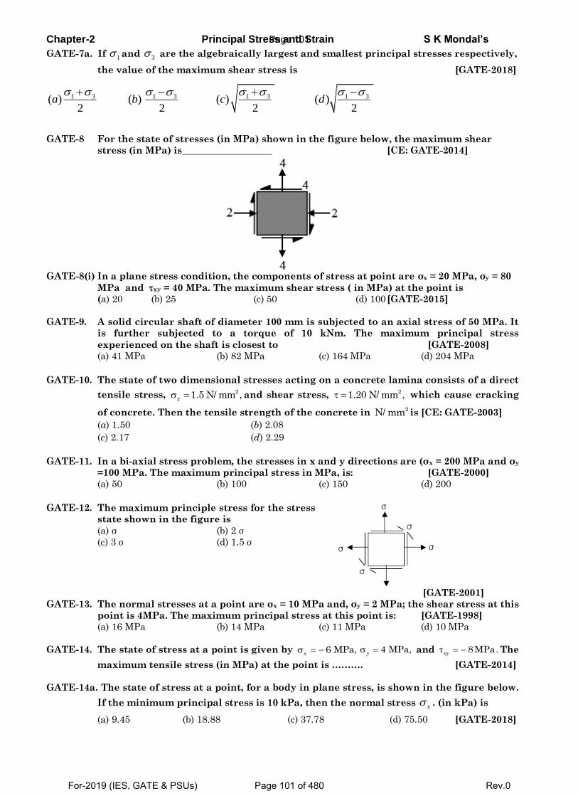
Chapter-2 Principal Stress and Strain S K Mondal’s
GATE-7a. If 1 and 3 are the algebraically largest and smallest principal stresses respectively,
the value of the maximum shear stress is [GATE-2018]
1 3 1 3 1 3 1 3( ) ( ) ( ) ( )2 2 2 2
a b c d
GATE-8 For the state of stresses (in MPa) shown in the figure below, the maximum shear
stress (in MPa) is___________________ [CE: GATE-2014]
GATE-8(i) In a plane stress condition, the components of stress at point are σx = 20 MPa, σy = 80
MPa and xy = 40 MPa. The maximum shear stress ( in MPa) at the point is
(a) 20 (b) 25 (c) 50 (d) 100 [GATE-2015]
GATE-9. A solid circular shaft of diameter 100 mm is subjected to an axial stress of 50 MPa. It
is further subjected to a torque of 10 kNm. The maximum principal stress
experienced on the shaft is closest to [GATE-2008]
(a) 41 MPa (b) 82 MPa (c) 164 MPa (d) 204 MPa
GATE-10. The state of two dimensional stresses acting on a concrete lamina consists of a direct
tensile stress, 21.5 N/ mm ,x
and shear stress, 21.20 N/ mm , which cause cracking
of concrete. Then the tensile strength of the concrete in 2N/ mm is [CE: GATE-2003]
(a) 1.50 (b) 2.08
(c) 2.17 (d) 2.29
GATE-11. In a bi-axial stress problem, the stresses in x and y directions are (σx = 200 MPa and σy
=100 MPa. The maximum principal stress in MPa, is: [GATE-2000]
(a) 50 (b) 100 (c) 150 (d) 200
GATE-12. The maximum principle stress for the stress
state shown in the figure is
(a) σ (b) 2 σ
(c) 3 σ (d) 1.5 σ
[GATE-2001]
GATE-13. The normal stresses at a point are σx = 10 MPa and, σy = 2 MPa; the shear stress at this
point is 4MPa. The maximum principal stress at this point is: [GATE-1998]
(a) 16 MPa (b) 14 MPa (c) 11 MPa (d) 10 MPa
GATE-14. The state of stress at a point is given by 6 MPa,x
4 MPa,y
and 8MPa.xy The
maximum tensile stress (in MPa) at the point is ………. [GATE-2014]
GATE-14a. The state of stress at a point, for a body in plane stress, is shown in the figure below.
If the minimum principal stress is 10 kPa, then the normal stress s . (in kPa) is
(a) 9.45 (b) 18.88 (c) 37.78 (d) 75.50 [GATE-2018]
Page 101
For-2019 (IES, GATE & PSUs) Page 101 of 480 Rev.0
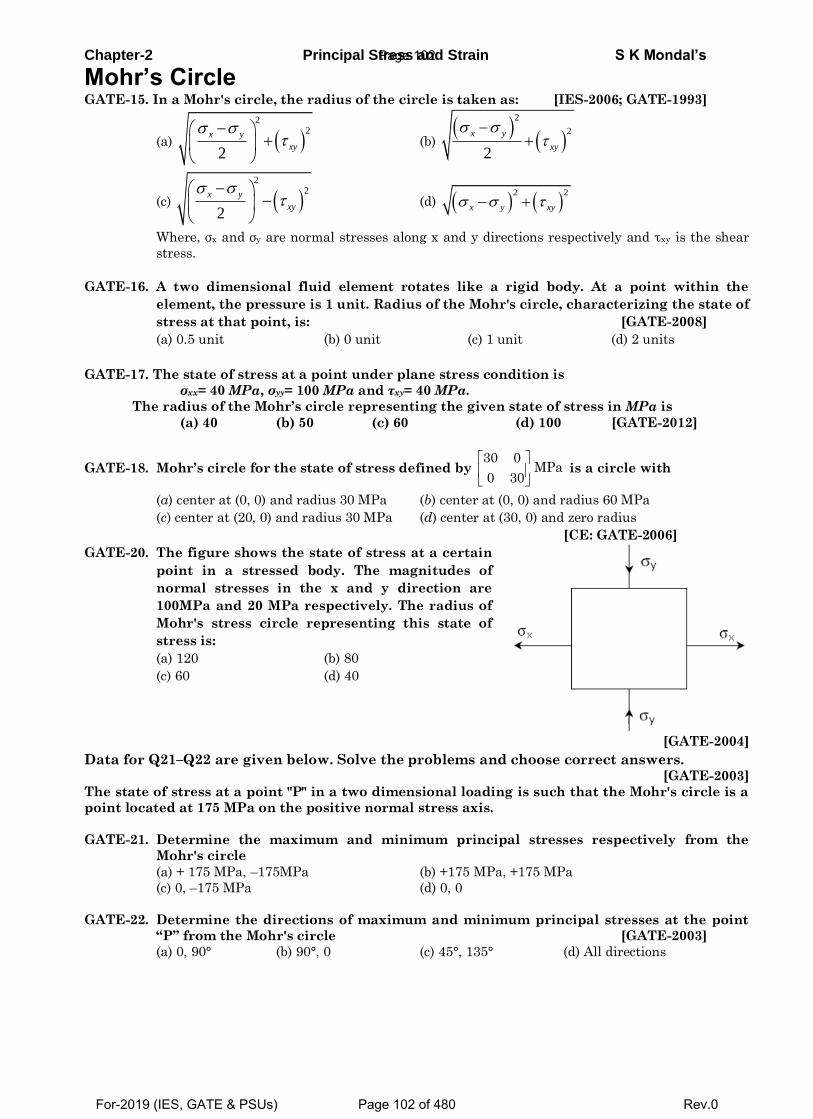
Chapter-2 Principal Stress and Strain S K Mondal’s
Mohr’s Circle GATE-15. In a Mohr's circle, the radius of the circle is taken as: [IES-2006; GATE-1993]
(a) 2
2
2
x y
xy
(b)
2
2
2
x y
xy
(c) 2
2
2
x y
xy
(d)
2 2
x y xy
Where, σx and σy are normal stresses along x and y directions respectively and τxy is the shear
stress.
GATE-16. A two dimensional fluid element rotates like a rigid body. At a point within the
element, the pressure is 1 unit. Radius of the Mohr's circle, characterizing the state of
stress at that point, is: [GATE-2008]
(a) 0.5 unit (b) 0 unit (c) 1 unit (d) 2 units
GATE-17. The state of stress at a point under plane stress condition is
σxx= 40 MPa, σyy= 100 MPa and τxy= 40 MPa.
The radius of the Mohr’s circle representing the given state of stress in MPa is
(a) 40 (b) 50 (c) 60 (d) 100 [GATE-2012]
GATE-18. Mohr’s circle for the state of stress defined by 30 0
MPa0 30
is a circle with
(a) center at (0, 0) and radius 30 MPa (b) center at (0, 0) and radius 60 MPa
(c) center at (20, 0) and radius 30 MPa (d) center at (30, 0) and zero radius
[CE: GATE-2006]
GATE-20. The figure shows the state of stress at a certain
point in a stressed body. The magnitudes of
normal stresses in the x and y direction are
100MPa and 20 MPa respectively. The radius of
Mohr's stress circle representing this state of
stress is:
(a) 120 (b) 80
(c) 60 (d) 40
[GATE-2004]
Data for Q21–Q22 are given below. Solve the problems and choose correct answers. [GATE-2003]
The state of stress at a point "P" in a two dimensional loading is such that the Mohr's circle is a
point located at 175 MPa on the positive normal stress axis.
GATE-21. Determine the maximum and minimum principal stresses respectively from the
Mohr's circle
(a) + 175 MPa, –175MPa (b) +175 MPa, +175 MPa
(c) 0, –175 MPa (d) 0, 0
GATE-22. Determine the directions of maximum and minimum principal stresses at the point
“P” from the Mohr's circle [GATE-2003]
(a) 0, 90° (b) 90°, 0 (c) 45°, 135° (d) All directions
Page 102
For-2019 (IES, GATE & PSUs) Page 102 of 480 Rev.0
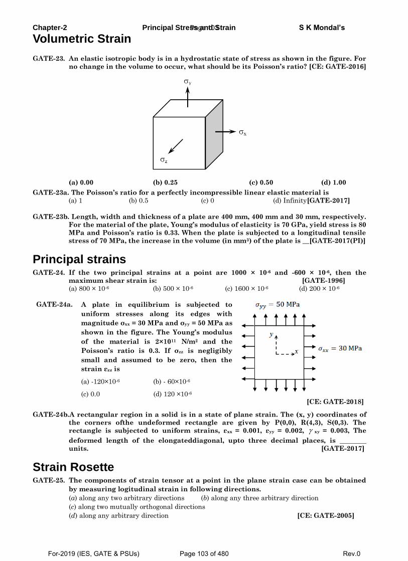
Chapter-2 Principal Stress and Strain S K Mondal’s
Volumetric Strain
GATE-23. An elastic isotropic body is in a hydrostatic state of stress as shown in the figure. For
no change in the volume to occur, what should be its Poisson’s ratio? [CE: GATE-2016]
(a) 0.00 (b) 0.25 (c) 0.50 (d) 1.00
GATE-23a. The Poisson’s ratio for a perfectly incompressible linear elastic material is
(a) 1 (b) 0.5 (c) 0 (d) Infinity[GATE-2017]
GATE-23b. Length, width and thickness of a plate are 400 mm, 400 mm and 30 mm, respectively.
For the material of the plate, Young’s modulus of elasticity is 70 GPa, yield stress is 80
MPa and Poisson’s ratio is 0.33. When the plate is subjected to a longitudinal tensile
stress of 70 MPa, the increase in the volume (in mm3) of the plate is __[GATE-2017(PI)]
Principal strains GATE-24. If the two principal strains at a point are 1000 × 10-6 and -600 × 10-6, then the
maximum shear strain is: [GATE-1996]
(a) 800 × 10-6 (b) 500 × 10-6 (c) 1600 × 10-6 (d) 200 × 10-6
GATE-24a. A plate in equilibrium is subjected to
uniform stresses along its edges with
magnitude σxx = 30 MPa and σyy = 50 MPa as
shown in the figure. The Young’s modulus
of the material is 2×10¹¹ N/m2 and the
Poisson’s ratio is 0.3. If σzz is negligibly
small and assumed to be zero, then the
strain εzz is
(a) -120×10-6 (b) - 60×10-6
(c) 0.0 (d) 120 ×10-6
[CE: GATE-2018]
GATE-24b.A rectangular region in a solid is in a state of plane strain. The (x, y) coordinates of
the corners ofthe undeformed rectangle are given by P(0,0), R(4,3), S(0,3). The
rectangle is subjected to uniform strains, εxx = 0.001, εyy = 0.002, xy = 0.003, The
deformed length of the elongateddiagonal, upto three decimal places, is ________
units. [GATE-2017]
Strain Rosette GATE-25. The components of strain tensor at a point in the plane strain case can be obtained
by measuring logitudinal strain in following directions.
(a) along any two arbitrary directions (b) along any three arbitrary direction
(c) along two mutually orthogonal directions
(d) along any arbitrary direction [CE: GATE-2005]
Page 103
For-2019 (IES, GATE & PSUs) Page 103 of 480 Rev.0
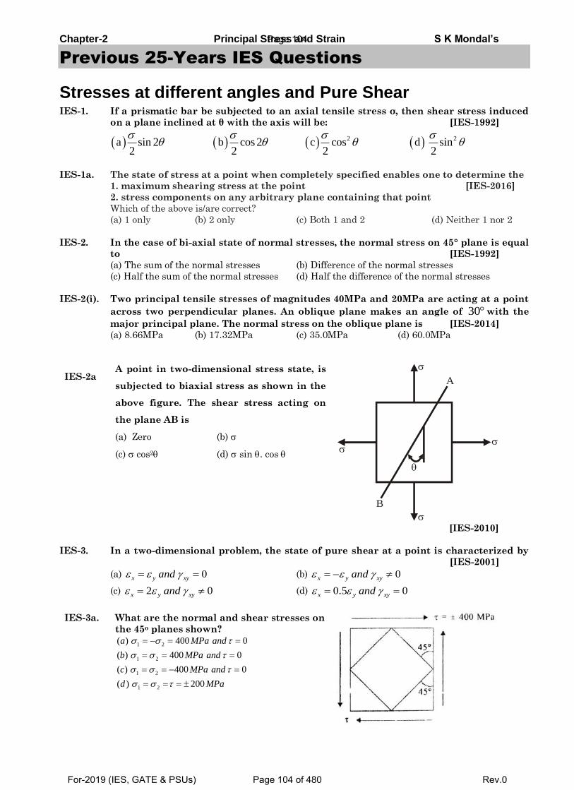
Chapter-2 Principal Stress and Strain S K Mondal’s
Previous 25-Years IES Questions
Stresses at different angles and Pure Shear IES-1. If a prismatic bar be subjected to an axial tensile stress σ, then shear stress induced
on a plane inclined at θ with the axis will be: [IES-1992]
2 2a sin 2 b cos 2 c cos d sin 2 2 2 2
IES-1a. The state of stress at a point when completely specified enables one to determine the
1. maximum shearing stress at the point [IES-2016]
2. stress components on any arbitrary plane containing that point
Which of the above is/are correct?
(a) 1 only (b) 2 only (c) Both 1 and 2 (d) Neither 1 nor 2
IES-2. In the case of bi-axial state of normal stresses, the normal stress on 45° plane is equal
to [IES-1992]
(a) The sum of the normal stresses (b) Difference of the normal stresses
(c) Half the sum of the normal stresses (d) Half the difference of the normal stresses
IES-2(i). Two principal tensile stresses of magnitudes 40MPa and 20MPa are acting at a point
across two perpendicular planes. An oblique plane makes an angle of 30with the
major principal plane. The normal stress on the oblique plane is [IES-2014]
(a) 8.66MPa (b) 17.32MPa (c) 35.0MPa (d) 60.0MPa
IES-2a A point in two-dimensional stress state, is
subjected to biaxial stress as shown in the
above figure. The shear stress acting on
the plane AB is
(a) Zero (b)
(c) cos2 (d) sin . cos
B
A
[IES-2010]
IES-3. In a two-dimensional problem, the state of pure shear at a point is characterized by
[IES-2001]
(a) 0x y xyand (b) 0x y xyand
(c) 2 0x y xyand (d) 0.5 0x y xyand
IES-3a. What are the normal and shear stresses on
the 45o planes shown?
1 2
1 2
1 2
1 2
( ) 400 0
( ) 400 0
( ) 400 0
( ) 200
a MPa and
b MPa and
c MPa and
d MPa
Page 104
For-2019 (IES, GATE & PSUs) Page 104 of 480 Rev.0
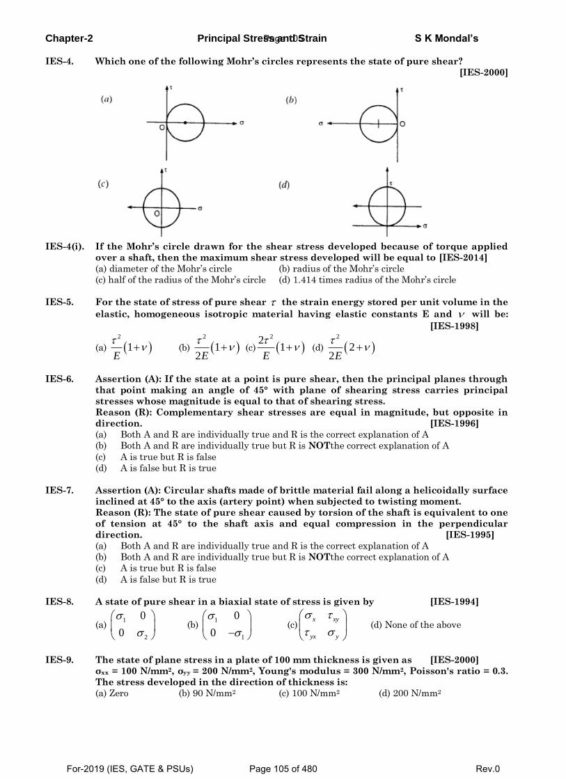
Chapter-2 Principal Stress and Strain S K Mondal’s
IES-4. Which one of the following Mohr’s circles represents the state of pure shear?
[IES-2000]
IES-4(i). If the Mohr’s circle drawn for the shear stress developed because of torque applied
over a shaft, then the maximum shear stress developed will be equal to [IES-2014]
(a) diameter of the Mohr’s circle (b) radius of the Mohr’s circle
(c) half of the radius of the Mohr’s circle (d) 1.414 times radius of the Mohr’s circle
IES-5. For the state of stress of pure shear the strain energy stored per unit volume in the
elastic, homogeneous isotropic material having elastic constants E and will be:
[IES-1998]
(a) 2
1E
(b)
2
12E
(c)
221
E
(d)
2
22E
IES-6. Assertion (A): If the state at a point is pure shear, then the principal planes through
that point making an angle of 45° with plane of shearing stress carries principal
stresses whose magnitude is equal to that of shearing stress.
Reason (R): Complementary shear stresses are equal in magnitude, but opposite in
direction. [IES-1996]
(a) Both A and R are individually true and R is the correct explanation of A
(b) Both A and R are individually true but R is NOTthe correct explanation of A
(c) A is true but R is false
(d) A is false but R is true
IES-7. Assertion (A): Circular shafts made of brittle material fail along a helicoidally surface
inclined at 45° to the axis (artery point) when subjected to twisting moment.
Reason (R): The state of pure shear caused by torsion of the shaft is equivalent to one
of tension at 45° to the shaft axis and equal compression in the perpendicular
direction. [IES-1995]
(a) Both A and R are individually true and R is the correct explanation of A
(b) Both A and R are individually true but R is NOTthe correct explanation of A
(c) A is true but R is false
(d) A is false but R is true
IES-8. A state of pure shear in a biaxial state of stress is given by [IES-1994]
(a) 1
2
0
0
(b) 1
1
0
0
(c)
x xy
yx y
(d) None of the above
IES-9. The state of plane stress in a plate of 100 mm thickness is given as [IES-2000]
σxx = 100 N/mm2, σyy = 200 N/mm2, Young's modulus = 300 N/mm2, Poisson's ratio = 0.3.
The stress developed in the direction of thickness is:
(a) Zero (b) 90 N/mm2 (c) 100 N/mm2 (d) 200 N/mm2
Page 105
For-2019 (IES, GATE & PSUs) Page 105 of 480 Rev.0
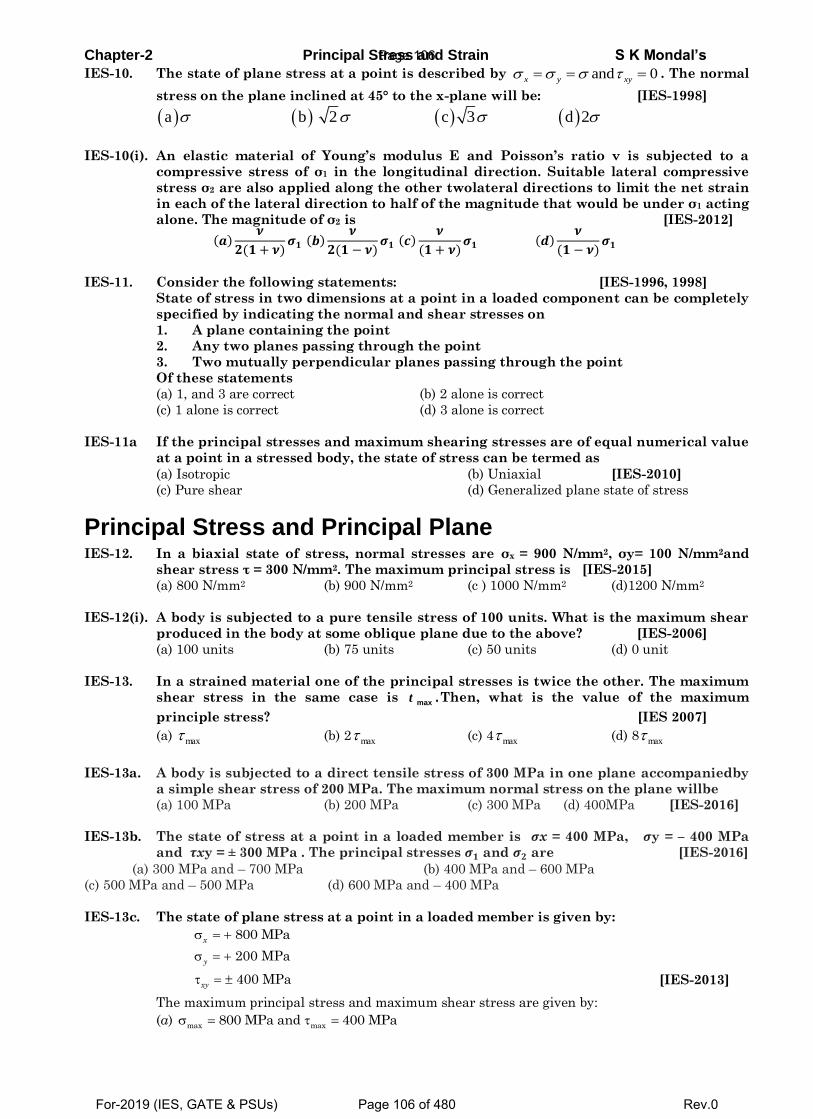
Chapter-2 Principal Stress and Strain S K Mondal’s
IES-10. The state of plane stress at a point is described by and 0x y xy . The normal
stress on the plane inclined at 45° to the x-plane will be: [IES-1998]
a b 2 c 3 d 2
IES-10(i). An elastic material of Young’s modulus E and Poisson’s ratio ν is subjected to a
compressive stress of σ1 in the longitudinal direction. Suitable lateral compressive
stress σ2 are also applied along the other twolateral directions to limit the net strain
in each of the lateral direction to half of the magnitude that would be under σ1 acting
alone. The magnitude of σ2 is [IES-2012]
(𝒂)𝝂
𝟐(𝟏 + 𝝂)𝝈𝟏 (𝒃)
𝝂
𝟐(𝟏 − 𝝂)𝝈𝟏 (𝒄)
𝝂
(𝟏 + 𝝂)𝝈𝟏 (𝒅)
𝝂
(𝟏 − 𝝂)𝝈𝟏
IES-11. Consider the following statements: [IES-1996, 1998]
State of stress in two dimensions at a point in a loaded component can be completely
specified by indicating the normal and shear stresses on
1. A plane containing the point
2. Any two planes passing through the point
3. Two mutually perpendicular planes passing through the point
Of these statements
(a) 1, and 3 are correct (b) 2 alone is correct
(c) 1 alone is correct (d) 3 alone is correct
IES-11a If the principal stresses and maximum shearing stresses are of equal numerical value
at a point in a stressed body, the state of stress can be termed as
(a) Isotropic (b) Uniaxial [IES-2010]
(c) Pure shear (d) Generalized plane state of stress
Principal Stress and Principal Plane IES-12. In a biaxial state of stress, normal stresses are σx = 900 N/mm2, σy= 100 N/mm2and
shear stress τ = 300 N/mm2. The maximum principal stress is [IES-2015]
(a) 800 N/mm2 (b) 900 N/mm2 (c ) 1000 N/mm2 (d)1200 N/mm2
IES-12(i). A body is subjected to a pure tensile stress of 100 units. What is the maximum shear
produced in the body at some oblique plane due to the above? [IES-2006]
(a) 100 units (b) 75 units (c) 50 units (d) 0 unit
IES-13. In a strained material one of the principal stresses is twice the other. The maximum
shear stress in the same case is max .t Then, what is the value of the maximum
principle stress? [IES 2007]
(a) max (b) 2 max (c) 4 max (d) 8 max
IES-13a. A body is subjected to a direct tensile stress of 300 MPa in one plane accompaniedby
a simple shear stress of 200 MPa. The maximum normal stress on the plane willbe
(a) 100 MPa (b) 200 MPa (c) 300 MPa (d) 400MPa [IES-2016]
IES-13b. The state of stress at a point in a loaded member is 𝝈x = 400 MPa, 𝝈y = – 400 MPa
and 𝝉xy = ± 300 MPa . The principal stresses 𝝈𝟏 and 𝝈𝟐 are [IES-2016]
(a) 300 MPa and – 700 MPa (b) 400 MPa and – 600 MPa
(c) 500 MPa and – 500 MPa (d) 600 MPa and – 400 MPa
IES-13c. The state of plane stress at a point in a loaded member is given by:
800 MPax
200 MPay
400 MPaxy [IES-2013]
The maximum principal stress and maximum shear stress are given by:
(a) max max
800 MPa and 400 MPa
Page 106
For-2019 (IES, GATE & PSUs) Page 106 of 480 Rev.0
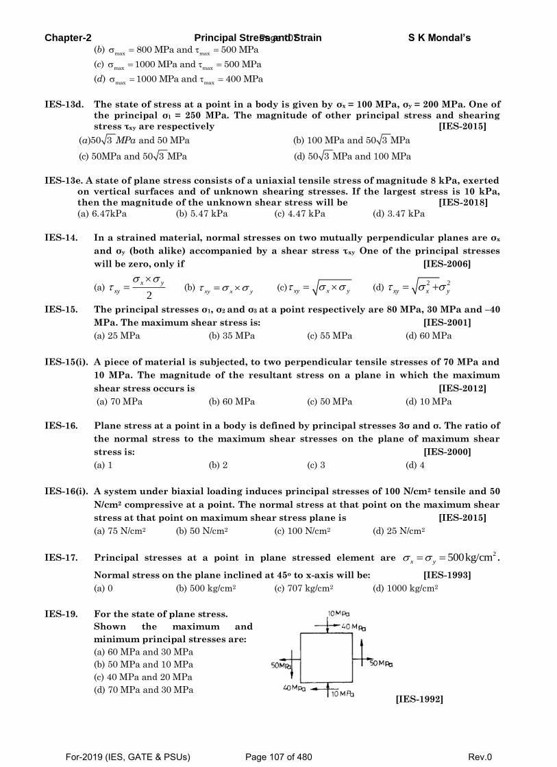
Chapter-2 Principal Stress and Strain S K Mondal’s (b)
max max800 MPa and 500 MPa
(c) max max
1000 MPa and 500 MPa
(d) max max
1000 MPa and 400 MPa
IES-13d. The state of stress at a point in a body is given by σx = 100 MPa, σy = 200 MPa. One of
the principal σ1 = 250 MPa. The magnitude of other principal stress and shearing
stress τxy are respectively [IES-2015]
( )50 3 and 50 MPa (b) 100 MPa and 50 3 MPa
(c) 50MPa and 50 3 MPa (d) 50 3 MPa and 100 MPa
a MPa
IES-13e. A state of plane stress consists of a uniaxial tensile stress of magnitude 8 kPa, exerted
on vertical surfaces and of unknown shearing stresses. If the largest stress is 10 kPa,
then the magnitude of the unknown shear stress will be [IES-2018]
(a) 6.47kPa (b) 5.47 kPa (c) 4.47 kPa (d) 3.47 kPa
IES-14. In a strained material, normal stresses on two mutually perpendicular planes are σx
and σy (both alike) accompanied by a shear stress τxy One of the principal stresses
will be zero, only if [IES-2006]
(a) 2
x y
xy
(b)
xy x y (c) xy x y (d) 2 2
xy x y
IES-15. The principal stresses σ1, σ2 and σ3 at a point respectively are 80 MPa, 30 MPa and –40
MPa. The maximum shear stress is: [IES-2001]
(a) 25 MPa (b) 35 MPa (c) 55 MPa (d) 60 MPa
IES-15(i). A piece of material is subjected, to two perpendicular tensile stresses of 70 MPa and
10 MPa. The magnitude of the resultant stress on a plane in which the maximum
shear stress occurs is [IES-2012]
(a) 70 MPa (b) 60 MPa (c) 50 MPa (d) 10 MPa
IES-16. Plane stress at a point in a body is defined by principal stresses 3σ and σ. The ratio of
the normal stress to the maximum shear stresses on the plane of maximum shear
stress is: [IES-2000]
(a) 1 (b) 2 (c) 3 (d) 4
IES-16(i). A system under biaxial loading induces principal stresses of 100 N/cm2 tensile and 50
N/cm2 compressive at a point. The normal stress at that point on the maximum shear
stress at that point on maximum shear stress plane is [IES-2015]
(a) 75 N/cm2 (b) 50 N/cm2 (c) 100 N/cm2 (d) 25 N/cm2
IES-17. Principal stresses at a point in plane stressed element are 2500kg/cmx y .
Normal stress on the plane inclined at 45o to x-axis will be: [IES-1993]
(a) 0 (b) 500 kg/cm2 (c) 707 kg/cm2 (d) 1000 kg/cm2
IES-19. For the state of plane stress.
Shown the maximum and
minimum principal stresses are:
(a) 60 MPa and 30 MPa
(b) 50 MPa and 10 MPa
(c) 40 MPa and 20 MPa
(d) 70 MPa and 30 MPa
[IES-1992]
Page 107
For-2019 (IES, GATE & PSUs) Page 107 of 480 Rev.0
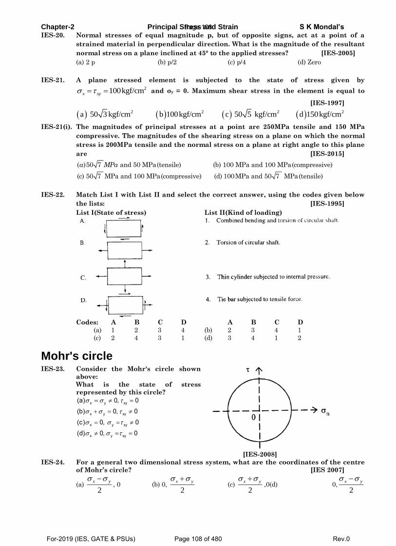
Chapter-2 Principal Stress and Strain S K Mondal’s IES-20. Normal stresses of equal magnitude p, but of opposite signs, act at a point of a
strained material in perpendicular direction. What is the magnitude of the resultant
normal stress on a plane inclined at 45° to the applied stresses? [IES-2005]
(a) 2 p (b) p/2 (c) p/4 (d) Zero
IES-21. A plane stressed element is subjected to the state of stress given by 2100kgf/cmx xy and σy = 0. Maximum shear stress in the element is equal to
[IES-1997]
2 2 2 2a 50 3 kgf/cm b 1 00kgf/cm c 50 5 kgf/cm d 1 50kgf/cm
IES-21(i). The magnitudes of principal stresses at a point are 250MPa tensile and 150 MPa
compressive. The magnitudes of the shearing stress on a plane on which the normal
stress is 200MPa tensile and the normal stress on a plane at right angle to this plane
are [IES-2015]
( )50 7 and 50 MPa(tensile) (b) 100 MPa and 100 MPa(compressive)
(c) 50 7 MPa and 100 MPa(compressive) (d) 100MPa and 50 7 MPa(tensile)
a MPa
IES-22. Match List I with List II and select the correct answer, using the codes given below
the lists: [IES-1995]
List I(State of stress) List II(Kind of loading)
Codes: A B C D A B C D
(a) 1 2 3 4 (b) 2 3 4 1
(c) 2 4 3 1 (d) 3 4 1 2
Mohr's circle IES-23. Consider the Mohr's circle shown
above:
What is the state of stress
represented by this circle?
x y xy
x y xy
x y xy
x y xy
(a) 0, 0
(b) 0, 0
(c) 0, 0
(d) 0, 0
[IES-2008]
IES-24. For a general two dimensional stress system, what are the coordinates of the centre
of Mohr’s circle? [IES 2007]
(a) 2
yx , 0 (b) 0,
2
yx (c)
2
yx ,0(d) 0,
2
yx
Page 108
For-2019 (IES, GATE & PSUs) Page 108 of 480 Rev.0
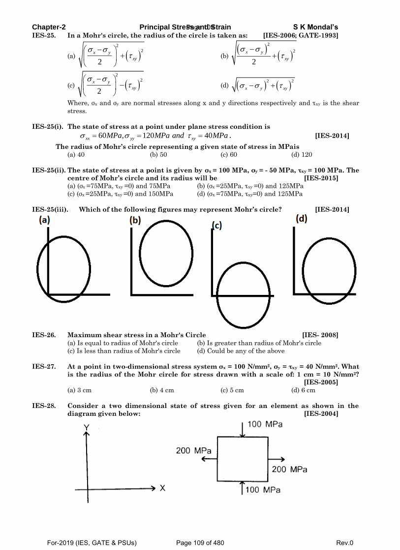
Chapter-2 Principal Stress and Strain S K Mondal’s IES-25. In a Mohr's circle, the radius of the circle is taken as: [IES-2006; GATE-1993]
(a) 2
2
2
x y
xy
(b)
2
2
2
x y
xy
(c) 2
2
2
x y
xy
(d)
2 2
x y xy
Where, σx and σy are normal stresses along x and y directions respectively and τxy is the shear
stress.
IES-25(i). The state of stress at a point under plane stress condition is
60 , 120 40xx yy xyMPa MPa and MPa . [IES-2014]
The radius of Mohr’s circle representing a given state of stress in MPais
(a) 40 (b) 50 (c) 60 (d) 120
IES-25(ii). The state of stress at a point is given by σx = 100 MPa, σy = - 50 MPa, τxy = 100 MPa. The
centre of Mohr’s circle and its radius will be [IES-2015]
(a) (σx =75MPa, τxy =0) and 75MPa (b) (σx =25MPa, τxy =0) and 125MPa
(c) (σx =25MPa, τxy =0) and 150MPa (d) (σx =75MPa, τxy=0) and 125MPa
IES-25(iii). Which of the following figures may represent Mohr’s circle? [IES-2014]
IES-26. Maximum shear stress in a Mohr's Circle [IES- 2008]
(a) Is equal to radius of Mohr's circle (b) Is greater than radius of Mohr's circle
(c) Is less than radius of Mohr's circle (d) Could be any of the above
IES-27. At a point in two-dimensional stress system σx = 100 N/mm2, σy = τxy = 40 N/mm2. What
is the radius of the Mohr circle for stress drawn with a scale of: 1 cm = 10 N/mm2?
[IES-2005]
(a) 3 cm (b) 4 cm (c) 5 cm (d) 6 cm
IES-28. Consider a two dimensional state of stress given for an element as shown in the
diagram given below: [IES-2004]
Page 109
For-2019 (IES, GATE & PSUs) Page 109 of 480 Rev.0
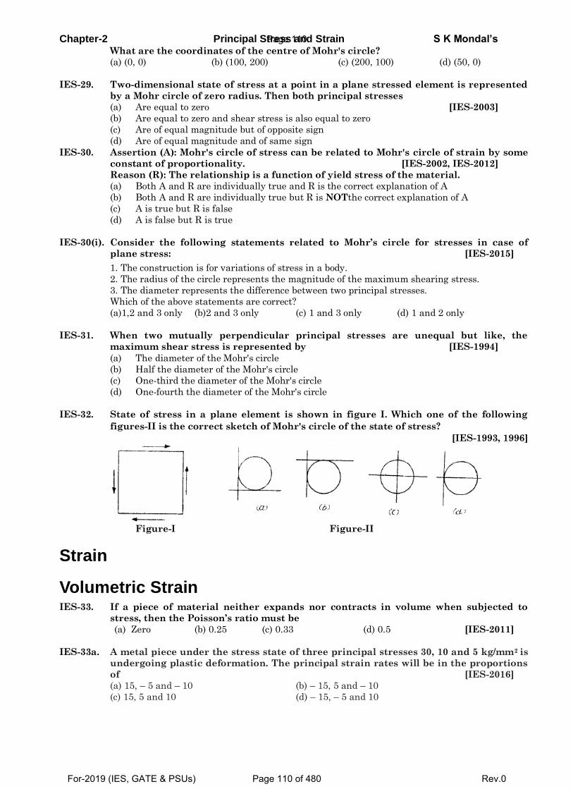
Chapter-2 Principal Stress and Strain S K Mondal’s What are the coordinates of the centre of Mohr's circle?
(a) (0, 0) (b) (100, 200) (c) (200, 100) (d) (50, 0)
IES-29. Two-dimensional state of stress at a point in a plane stressed element is represented
by a Mohr circle of zero radius. Then both principal stresses
(a) Are equal to zero [IES-2003]
(b) Are equal to zero and shear stress is also equal to zero
(c) Are of equal magnitude but of opposite sign
(d) Are of equal magnitude and of same sign
IES-30. Assertion (A): Mohr's circle of stress can be related to Mohr's circle of strain by some
constant of proportionality. [IES-2002, IES-2012]
Reason (R): The relationship is a function of yield stress of the material.
(a) Both A and R are individually true and R is the correct explanation of A
(b) Both A and R are individually true but R is NOTthe correct explanation of A
(c) A is true but R is false
(d) A is false but R is true
IES-30(i). Consider the following statements related to Mohr’s circle for stresses in case of
plane stress: [IES-2015]
1. The construction is for variations of stress in a body.
2. The radius of the circle represents the magnitude of the maximum shearing stress.
3. The diameter represents the difference between two principal stresses.
Which of the above statements are correct?
(a)1,2 and 3 only (b)2 and 3 only (c) 1 and 3 only (d) 1 and 2 only
IES-31. When two mutually perpendicular principal stresses are unequal but like, the
maximum shear stress is represented by [IES-1994]
(a) The diameter of the Mohr's circle
(b) Half the diameter of the Mohr's circle
(c) One-third the diameter of the Mohr's circle
(d) One-fourth the diameter of the Mohr's circle
IES-32. State of stress in a plane element is shown in figure I. Which one of the following
figures-II is the correct sketch of Mohr's circle of the state of stress?
[IES-1993, 1996]
Figure-I Figure-II
Strain
Volumetric Strain IES-33. If a piece of material neither expands nor contracts in volume when subjected to
stress, then the Poisson’s ratio must be
(a) Zero (b) 0.25 (c) 0.33 (d) 0.5 [IES-2011]
IES-33a. A metal piece under the stress state of three principal stresses 30, 10 and 5 kg/mm2 is
undergoing plastic deformation. The principal strain rates will be in the proportions
of [IES-2016]
(a) 15, – 5 and – 10 (b) – 15, 5 and – 10
(c) 15, 5 and 10 (d) – 15, – 5 and 10
Page 110
For-2019 (IES, GATE & PSUs) Page 110 of 480 Rev.0
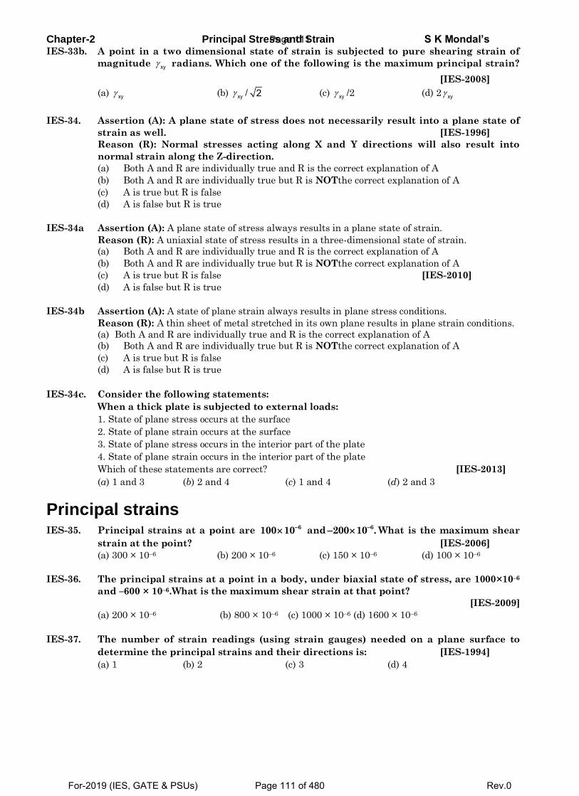
Chapter-2 Principal Stress and Strain S K Mondal’s IES-33b. A point in a two dimensional state of strain is subjected to pure shearing strain of
magnitude xy radians. Which one of the following is the maximum principal strain?
[IES-2008]
(a) xy (b) xy / 2 (c) xy /2 (d) 2 xy
IES-34. Assertion (A): A plane state of stress does not necessarily result into a plane state of
strain as well. [IES-1996]
Reason (R): Normal stresses acting along X and Y directions will also result into
normal strain along the Z-direction.
(a) Both A and R are individually true and R is the correct explanation of A
(b) Both A and R are individually true but R is NOTthe correct explanation of A
(c) A is true but R is false
(d) A is false but R is true
IES-34a Assertion (A): A plane state of stress always results in a plane state of strain.
Reason (R): A uniaxial state of stress results in a three-dimensional state of strain.
(a) Both A and R are individually true and R is the correct explanation of A
(b) Both A and R are individually true but R is NOTthe correct explanation of A
(c) A is true but R is false [IES-2010]
(d) A is false but R is true
IES-34b Assertion (A): A state of plane strain always results in plane stress conditions.
Reason (R): A thin sheet of metal stretched in its own plane results in plane strain conditions.
(a) Both A and R are individually true and R is the correct explanation of A
(b) Both A and R are individually true but R is NOTthe correct explanation of A
(c) A is true but R is false
(d) A is false but R is true
IES-34c. Consider the following statements:
When a thick plate is subjected to external loads:
1. State of plane stress occurs at the surface
2. State of plane strain occurs at the surface
3. State of plane stress occurs in the interior part of the plate
4. State of plane strain occurs in the interior part of the plate
Which of these statements are correct? [IES-2013]
(a) 1 and 3 (b) 2 and 4 (c) 1 and 4 (d) 2 and 3
Principal strains IES-35. Principal strains at a point are 6100 10 and 6200 10 . What is the maximum shear
strain at the point? [IES-2006]
(a) 300 × 10–6 (b) 200 × 10–6 (c) 150 × 10–6 (d) 100 × 10–6
IES-36. The principal strains at a point in a body, under biaxial state of stress, are 1000×10–6
and –600 × 10–6.What is the maximum shear strain at that point?
[IES-2009]
(a) 200 × 10–6 (b) 800 × 10–6 (c) 1000 × 10–6 (d) 1600 × 10–6
IES-37. The number of strain readings (using strain gauges) needed on a plane surface to
determine the principal strains and their directions is: [IES-1994]
(a) 1 (b) 2 (c) 3 (d) 4
Page 111
For-2019 (IES, GATE & PSUs) Page 111 of 480 Rev.0
Chapter-2 Principal Stress and Strain S K Mondal’s
Principal strain induced by principal stress IES-38. The principal stresses at a point in two dimensional stress system are 1 and 2 and
corresponding principal strains are 1 and 2 . If E and denote Young's modulus and
Poisson's ratio, respectively, then which one of the following is correct?
[IES-2008]
1 1 1 1 22
1 1 2 1 1 22
E(a) E (b)1
E(c) (d) E1
IES-38(i). At a point in a body, ε1 = 0.004 and ε2 = -0.00012. If E = 2x10⁵ MPa and µ = 0.3, the
smallest normal stress and the largest shearing stress are [IES-2015]
(a) 40MPa and 40MPa (b) 0MPa and 40MPa
(c) 80MPa and 0MPa (d)0MPa and 80MPa
IES-38(ii). Two strain gauges fixed along the principal directions on a plane surface of a steel
member recorded strain values of 0.0013 tensile and 0.0013 compressive respectively.
Given that the value of E = 2x10⁵ MPa and µ = 0.3, the largest normal and shearing
stress at this point are [IES-2015]
(a)200MPa and 200MPa (b)400MPa and 200MPa
(c)260MPa and 260MPa (d)260MPa and 520MPa
IES-39. Assertion (A): Mohr's construction is possible for stresses, strains and area moment of
inertia. [IES-2009]
Reason (R): Mohr's circle represents the transformation of second-order tensor.
(a) Both A and R are individually true and R is the correct explanation of A.
(b) Both A and R are individually true but R is NOT the correct explanation of A.
(c) A is true but R is false.
(d) A is false but R is true.
IES-40. A rectangular strain rosette, shown
infigure, gives following reading in a
strain measurement task,
100010-680010-6
and60010-6
The direction of the major principal
strainwith respect to gauge 1is
(a) 0o (b) 15o
(c) 30o (d) 45o
[IES-2011]
Previous 25-Years IAS Questions
Stresses at different angles and Pure Shear IAS-1. On a plane, resultant stress is inclined at an angle of 45o to the plane. If the normal
stress is 100 N /mm2, the shear stress on the plane is: [IAS-2003]
(a) 71.5 N/mm2 (b) 100 N/mm2 (c) 86.6 N/mm2 (d) 120.8 N/mm2
Page 112
For-2019 (IES, GATE & PSUs) Page 112 of 480 Rev.0
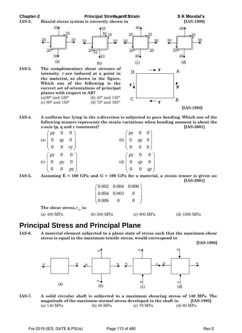
Chapter-2 Principal Stress and Strain S K Mondal’s IAS-2. Biaxial stress system is correctly shown in [IAS-1999]
IAS-3. The complementary shear stresses of
intensity are induced at a point in
the material, as shown in the figure.
Which one of the following is the
correct set of orientations of principal
planes with respect to AB?
(a)30° and 120° (b) 45° and 135°
(c) 60° and 150° (d) 75° and 165° [IAS-1998]
IAS-4. A uniform bar lying in the x-direction is subjected to pure bending. Which one of the
following tensors represents the strain variations when bending moment is about the
z-axis (p, q and r constants)? [IAS-2001]
(a)
0 0
0 0
0 0
py
qy
ry
(b)
0 0
0 0
0 0 0
py
qy
(c)
0 0
0 0
0 0
py
py
py
(d)
0 0
0 0
0 0
py
qy
qy
IAS-5. Assuming E = 160 GPa and G = 100 GPa for a material, a strain tensor is given as:
[IAS-2001]
0.002 0.004 0.006
0.004 0.003 0
0.006 0 0
The shear stress,xy is:
(a) 400 MPa (b) 500 MPa (c) 800 MPa (d) 1000 MPa
Principal Stress and Principal Plane IAS-6. A material element subjected to a plane state of stress such that the maximum shear
stress is equal to the maximum tensile stress, would correspond to
[IAS-1998]
IAS-7. A solid circular shaft is subjected to a maximum shearing stress of 140 MPs. The
magnitude of the maximum normal stress developed in the shaft is: [IAS-1995]
(a) 140 MPa (b) 80 MPa (c) 70 MPa (d) 60 MPa
Page 113
For-2019 (IES, GATE & PSUs) Page 113 of 480 Rev.0
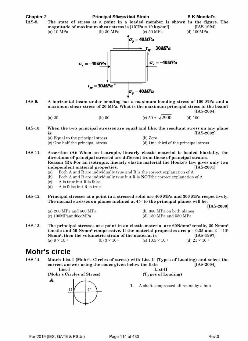
Chapter-2 Principal Stress and Strain S K Mondal’s IAS-8. The state of stress at a point in a loaded member is shown in the figure. The
magnitude of maximum shear stress is [1MPa = 10 kg/cm2] [IAS 1994]
(a) 10 MPa (b) 30 MPa (c) 50 MPa (d) 100MPa
IAS-9. A horizontal beam under bending has a maximum bending stress of 100 MPa and a
maximum shear stress of 20 MPa. What is the maximum principal stress in the beam?
[IAS-2004]
(a) 20 (b) 50 (c) 50 + 2900 (d) 100
IAS-10. When the two principal stresses are equal and like: the resultant stress on any plane
is: [IAS-2002]
(a) Equal to the principal stress (b) Zero
(c) One half the principal stress (d) One third of the principal stress
IAS-11. Assertion (A): When an isotropic, linearly elastic material is loaded biaxially, the
directions of principal stressed are different from those of principal strains.
Reason (R): For an isotropic, linearly elastic material the Hooke's law gives only two
independent material properties. [IAS-2001]
(a) Both A and R are individually true and R is the correct explanation of A
(b) Both A and R are individually true but R is NOTthe correct explanation of A
(c) A is true but R is false
(d) A is false but R is true
IAS-12. Principal stresses at a point in a stressed solid are 400 MPa and 300 MPa respectively.
The normal stresses on planes inclined at 45° to the principal planes will be:
[IAS-2000]
(a) 200 MPa and 500 MPa (b) 350 MPa on both planes
(c) 100MPaand6ooMPa (d) 150 MPa and 550 MPa
IAS-13. The principal stresses at a point in an elastic material are 60N/mm2 tensile, 20 N/mm2
tensile and 50 N/mm2 compressive. If the material properties are: µ = 0.35 and E = 105
N/mm2, then the volumetric strain of the material is: [IAS-1997]
(a) 9 × 10⁻⁵ (b) 3 × 10⁻⁴ (c) 10.5 × 10⁻⁵ (d) 21 × 10–5
Mohr's circle IAS-14. Match List-I (Mohr's Circles of stress) with List-II (Types of Loading) and select the
correct answer using the codes given below the lists: [IAS-2004]
List-I List-II
(Mohr's Circles of Stress) (Types of Loading)
1. A shaft compressed all round by a hub
Page 114
For-2019 (IES, GATE & PSUs) Page 114 of 480 Rev.0
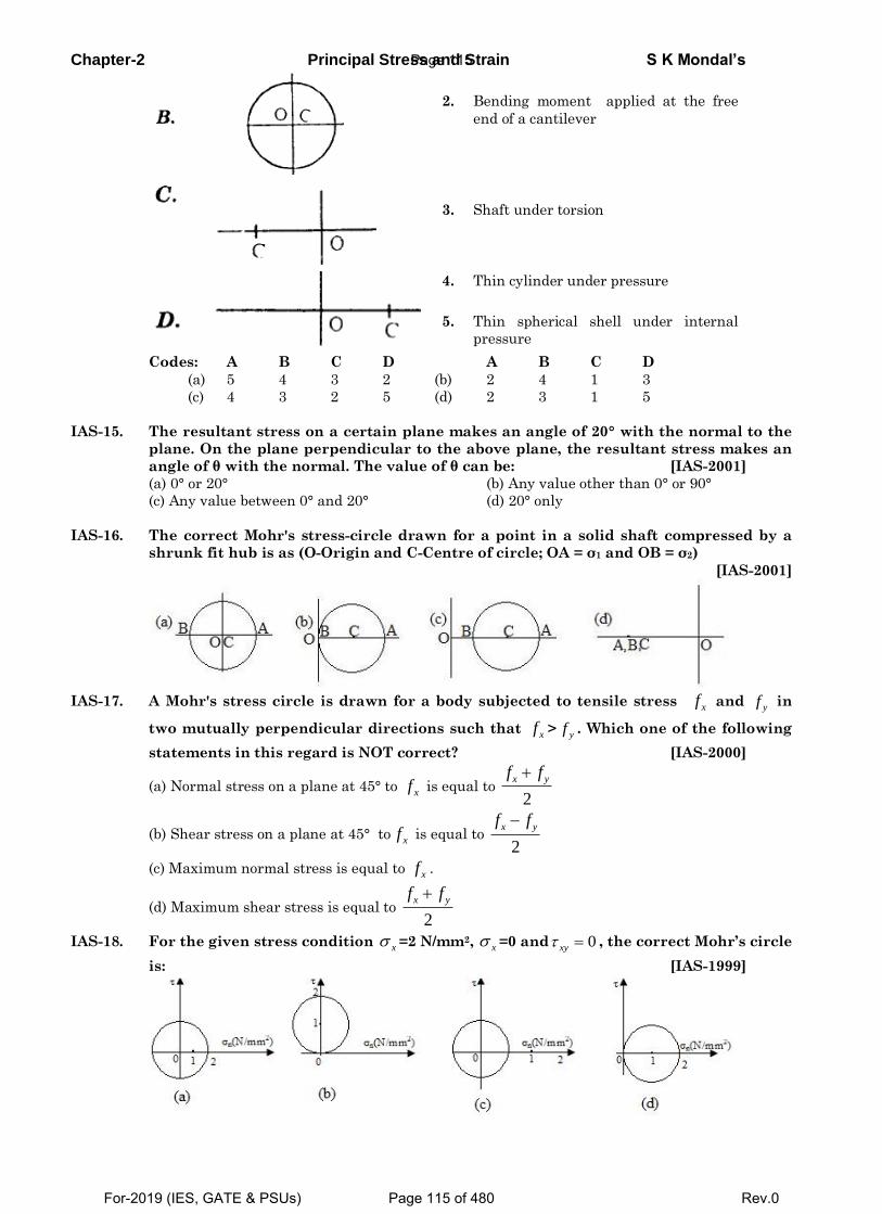
Chapter-2 Principal Stress and Strain S K Mondal’s
2. Bending moment applied at the free
end of a cantilever
3. Shaft under torsion
4. Thin cylinder under pressure
5. Thin spherical shell under internal
pressure
Codes: A B C D A B C D
(a) 5 4 3 2 (b) 2 4 1 3
(c) 4 3 2 5 (d) 2 3 1 5
IAS-15. The resultant stress on a certain plane makes an angle of 20° with the normal to the
plane. On the plane perpendicular to the above plane, the resultant stress makes an
angle of θ with the normal. The value of θ can be: [IAS-2001]
(a) 0° or 20° (b) Any value other than 0° or 90°
(c) Any value between 0° and 20° (d) 20° only
IAS-16. The correct Mohr's stress-circle drawn for a point in a solid shaft compressed by a
shrunk fit hub is as (O-Origin and C-Centre of circle; OA = σ1 and OB = σ2)
[IAS-2001]
IAS-17. A Mohr's stress circle is drawn for a body subjected to tensile stress xf and
yf in
two mutually perpendicular directions such that xf >yf . Which one of the following
statements in this regard is NOT correct? [IAS-2000]
(a) Normal stress on a plane at 45° to xf is equal to 2
x yf f
(b) Shear stress on a plane at 45° to xf is equal to 2
x yf f
(c) Maximum normal stress is equal to xf .
(d) Maximum shear stress is equal to 2
x yf f
IAS-18. For the given stress condition x =2 N/mm2, x =0 and 0xy , the correct Mohr’s circle
is: [IAS-1999]
Page 115
For-2019 (IES, GATE & PSUs) Page 115 of 480 Rev.0
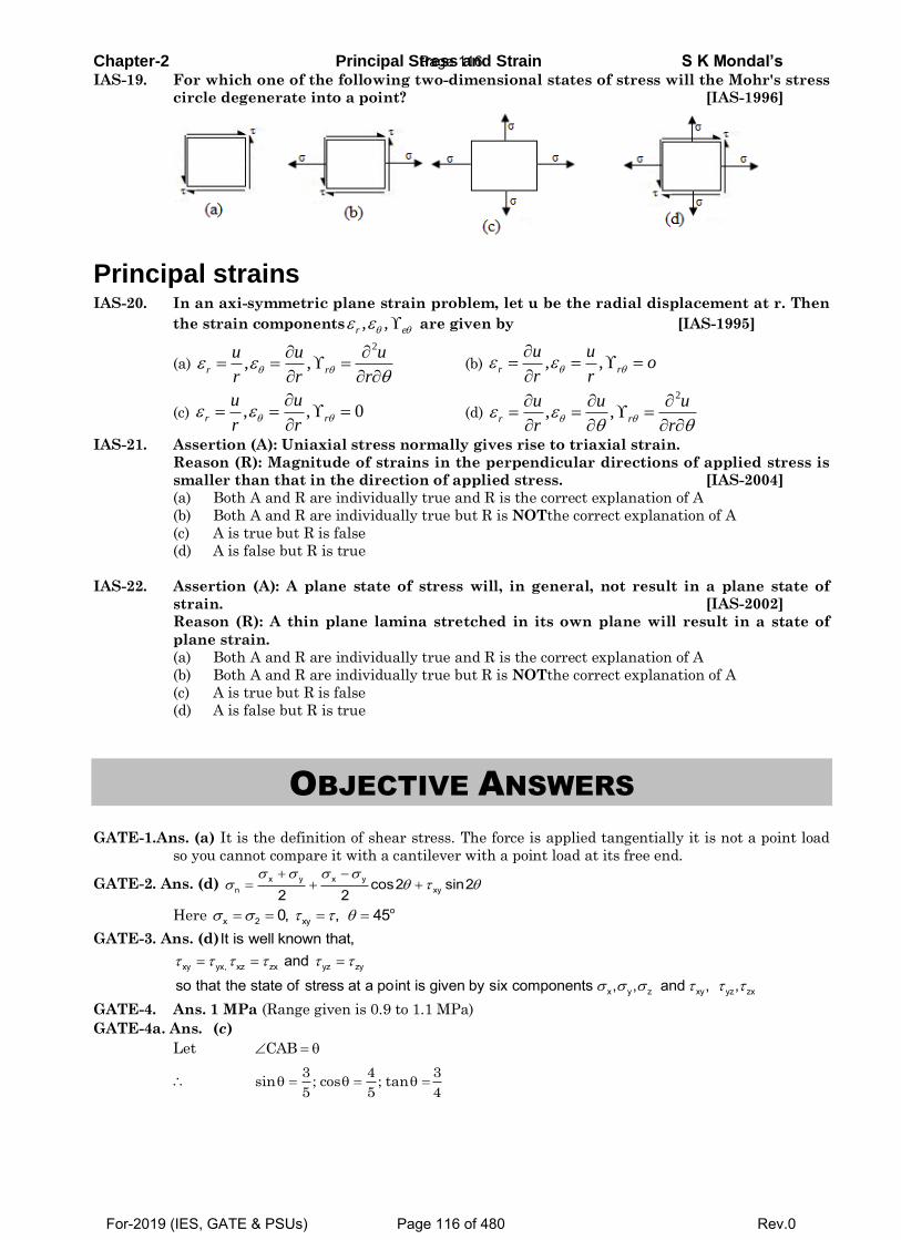
Chapter-2 Principal Stress and Strain S K Mondal’s IAS-19. For which one of the following two-dimensional states of stress will the Mohr's stress
circle degenerate into a point? [IAS-1996]
Principal strains IAS-20. In an axi-symmetric plane strain problem, let u be the radial displacement at r. Then
the strain components , ,r e are given by [IAS-1995]
(a)
2
, ,r r
u u u
r r r
(b) , ,r r
u uo
r r
(c) , , 0r r
u u
r r
(d)
2
, ,r r
u u u
r r
IAS-21. Assertion (A): Uniaxial stress normally gives rise to triaxial strain.
Reason (R): Magnitude of strains in the perpendicular directions of applied stress is
smaller than that in the direction of applied stress. [IAS-2004]
(a) Both A and R are individually true and R is the correct explanation of A
(b) Both A and R are individually true but R is NOTthe correct explanation of A
(c) A is true but R is false
(d) A is false but R is true
IAS-22. Assertion (A): A plane state of stress will, in general, not result in a plane state of
strain. [IAS-2002]
Reason (R): A thin plane lamina stretched in its own plane will result in a state of
plane strain.
(a) Both A and R are individually true and R is the correct explanation of A
(b) Both A and R are individually true but R is NOTthe correct explanation of A
(c) A is true but R is false
(d) A is false but R is true
OBJECTIVE ANSWERS
GATE-1.Ans. (a) It is the definition of shear stress. The force is applied tangentially it is not a point load
so you cannot compare it with a cantilever with a point load at its free end.
GATE-2. Ans. (d) x y x yn xycos2 sin2
2 2
Here ox 2 xy0, , 45
GATE-3. Ans. (d)It is well known that,
xy yx, xz zx yz zy
x y z xy yz zx
and
so that the state of stress at a point is given by six components , , and , ,
GATE-4. Ans. 1 MPa (Range given is 0.9 to 1.1 MPa)
GATE-4a. Ans. (c)
Let CAB
3 4 3
sin ; cos ; tan5 5 4
Page 116
For-2019 (IES, GATE & PSUs) Page 116 of 480 Rev.0
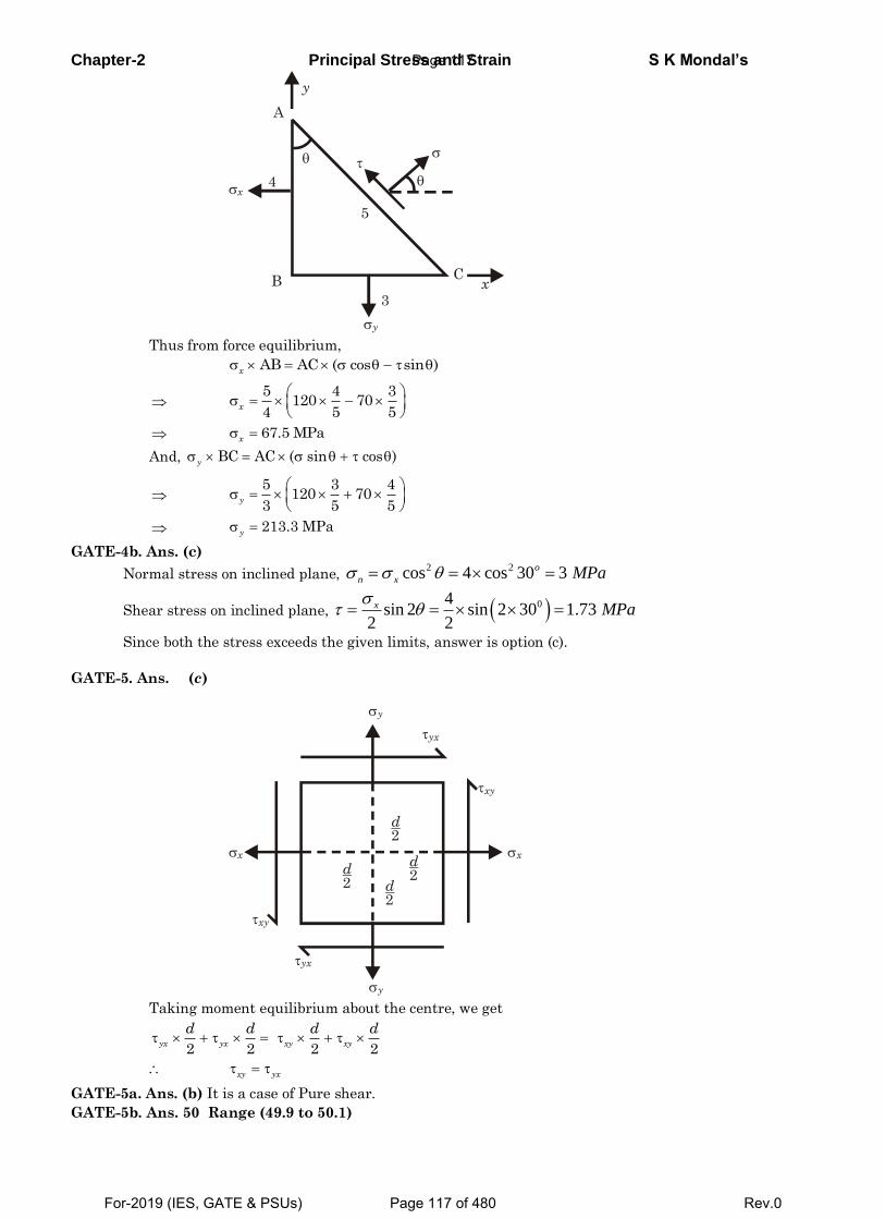
Chapter-2 Principal Stress and Strain S K Mondal’s
A
B C
x
y
x
y
3
5
4
Thus from force equilibrium,
AB AC ( cos sin )x
5 4 3120 70
4 5 5x
67.5 MPax
And, BC AC ( sin cos )y
5 3 4120 70
3 5 5y
213.3 MPay
GATE-4b. Ans. (c)
Normal stress on inclined plane, 2 2cos 4 cos 30 3o
n x MPa
Shear stress on inclined plane, 04sin 2 sin 2 30 1.73
2 2
x MPa
Since both the stress exceeds the given limits, answer is option (c).
GATE-5. Ans. (c)
d2
d2
d2
d2
y
y
x x
yx
yx
xy
xy
Taking moment equilibrium about the centre, we get
2 2 2 2
yx yx xy xy
d d d d
xy yx
GATE-5a. Ans. (b) It is a case of Pure shear.
GATE-5b. Ans. 50 Range (49.9 to 50.1)
Page 117
For-2019 (IES, GATE & PSUs) Page 117 of 480 Rev.0
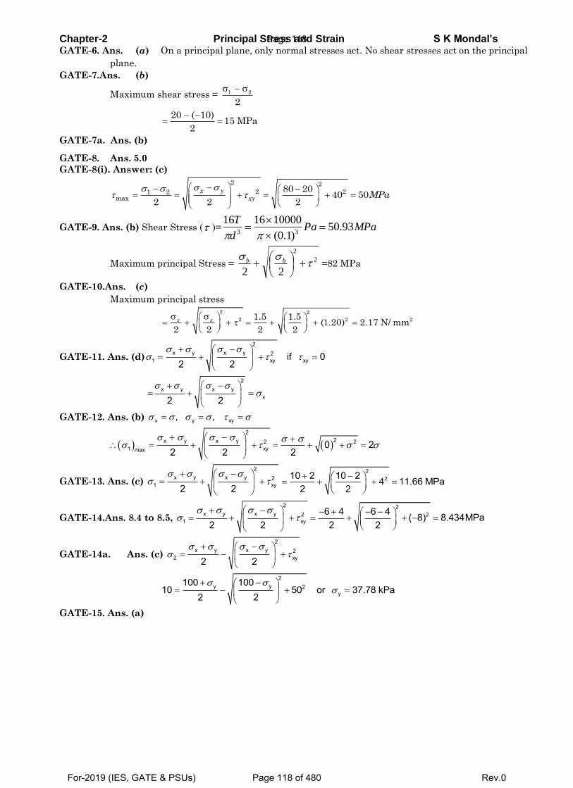
Chapter-2 Principal Stress and Strain S K Mondal’s GATE-6. Ans. (a) On a principal plane, only normal stresses act. No shear stresses act on the principal
plane.
GATE-7.Ans. (b)
Maximum shear stress =
1 2
2
20 ( 10)
15 MPa2
GATE-7a. Ans. (b)
GATE-8. Ans. 5.0
GATE-8(i). Answer: (c)
2 22 21 2
max
80 2040 50
2 2 2
x yxy MPa
GATE-9. Ans. (b) Shear Stress ( )= MPaPad
T93.50
)1.0(
10000161633
Maximum principal Stress = 2
2
22
bb =82 MPa
GATE-10.Ans. (c)
Maximum principal stress
2 2
2 2 21.5 1.5(1.20) 2.17 N/ mm
2 2 2 2
x x
GATE-11. Ans. (d)
2x y x y 2
1 xy xyif 02 2
2x y x y
x2 2
GATE-12. Ans. (b) x y xy, ,
2
2x y x y 2 21 xymax
0 22 2 2
GATE-13. Ans. (c)
2x y x y 2
1 xy2 2
2210 2 10 2 4 11.66 MPa
2 2
GATE-14.Ans. 8.4 to 8.5,
2 2x y x y 2 2
1 xy6 4 6 4 ( 8) 8.434MPa
2 2 2 2
GATE-14a. Ans. (c)
2x y x y 2
2 xy2 2
2y y 2
y
100 10010 50 or 37.78 kPa
2 2
GATE-15. Ans. (a)
Page 118
For-2019 (IES, GATE & PSUs) Page 118 of 480 Rev.0
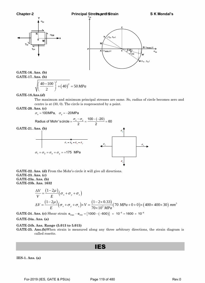
Chapter-2 Principal Stress and Strain S K Mondal’s
GATE-16. Ans. (b)
GATE-17. Ans. (b)
2
240 10040 50
2MPa
GATE-18.Ans.(d)
The maximum and minimum principal stresses are same. So, radius of circle becomes zero and
centre is at (30, 0). The circle is respresented by a point.
GATE-20. Ans. (c)
x y
x y
100MPa, 20MPa
100 20Radius of Mohr 'scircle 60
2 2
GATE-21. Ans. (b)
1 2 x y 175 MPa
GATE-22. Ans. (d) From the Mohr’s circle it will give all directions.
GATE-23. Ans. (c)
GATE-23a. Ans. (b) GATE-23b. Ans. 1632
3
3
1 2
1 2 1 2 0.3370 0 0 400 400 30
70 10
x y z
x y z
V
V E
V V MPa mmE MPa
GATE-24. Ans. (c) Shear strain 6 6max mine e 1000 600 10 1600 10
GATE-24a. Ans. (a)
GATE-24b. Ans. Range (5.013 to 5.015)
GATE-25. Ans.(b)When strain is measured along any three arbitrary directions, the strain diagram is
called rosette.
IES
IES-1. Ans. (a)
Page 119
For-2019 (IES, GATE & PSUs) Page 119 of 480 Rev.0
Chapter-2 Principal Stress and Strain S K Mondal’s IES-1a. Ans. (c)
Normal stress cos2 sin 22 2
x y x y
n xy
σ σ
Shear stress 2θ - cos2θ2
x y
xysin
IES-2. Ans. (c) x y x yn xycos2 sin2
2 2
x yoxy nAt 45 and 0;
2
IES-2(i). Ans(c) 40 , 20x yMPa MPa .
cos 2 30 10cos60 352 2
x y x yMPa
IES-2a Ans. (a)
σ σShear stress 2θ - cos2θ
2x y
xysin
Hereσ σ, σ σ 0x y xyand
IES-3. Ans. (b)
IES-3a. Ans. (a)
IES-4. Ans. (c)
IES-4(i). Ans. (b)
IES-5. Ans. (a) 1 2 3, , 0
22 21 1U 2 V V2E E
IES-6. Ans. (b)
IES-7. Ans. (a) Both A and R are true and R is correct explanation for A.
IES-8. Ans. (b) 1 2 3, , 0
IES-9. Ans. (a)
IES-10. Ans. (a) x y x yn xycos2 sin2
2 2
IES-10(i). Ans. (b)
IES-11. Ans. (d)
IES-11a Ans. (c)
IES-12. Ans. (c)
IES-12(i). Ans. (c) 1 2max
100 0 50 units.2 2
IES-13. Ans. (c) 2
21max
, 21 2 or
2
2max
or max2 2 or 21 2 = max4
IES-13a.Ans. (d)
2
2
1
300 300200 400
2 2MPa
IES-13b.Ans. (c)
2
2
1,2
400 400 400 400300 500
2 2MPa
IES-13c. Ans. (c)
IES-13d. Ans. (c)
IES-13e. Ans. (c)
Page 120
For-2019 (IES, GATE & PSUs) Page 120 of 480 Rev.0
Chapter-2 Principal Stress and Strain S K Mondal’s
σ1 =σ x +0
2+
σ x −02
⎛
⎝⎜
⎞
⎠⎟
2
+τ 2
10 = 8 + 02
+ 8−02
⎛
⎝⎜
⎞
⎠⎟
2
+τ 2
τ = 4.47 kPa
IES-14. Ans. (c) 2
x y x y 21,2 xy2 2
σ σ σ σσ τ
+ −⎛ ⎞= + +⎜ ⎟
⎝ ⎠
2x y x y 2
2 xy
2 2x y x y 2
xy xy x y
if 02 2
or or2 2
σ σ σ σσ τ
σ σ σ στ τ σ σ
+ −⎛ ⎞= ⇒ = +⎜ ⎟
⎝ ⎠
+ −⎛ ⎞ ⎛ ⎞= + = ×⎜ ⎟ ⎜ ⎟
⎝ ⎠ ⎝ ⎠
IES-15. Ans. (d) 1 2max
80 ( 40) 602 2
σ στ
− − −= = = MPa
IES-15(i). Ans. (c)
IES-16. Ans. (b) xy
x y
2tan2 0
τθ θ
σ σ= ⇒ =
−
1 2max
32 2
σ σ σ στ σ− −
= = =
Major principal stress on the plane of maximum shear = 13 2
2σ σσ σ+
= =
IES-16(i).Ans. (d) Shear stress is maximum at 45o plane.
cos22 2
100 ( 50) cos2 45 252 2
x y x yn
x y on MPa
σ σ σ σσ θ
σ σσ
+ −= +
−+ −= + × =
IES-17. Ans. (b)When stresses are alike, then normal stress σn on plane inclined at angle 45° is 2 2
2 2 21 1 1 1cos sin 500 500kg/cm2 22 2n y x y xσ σ θ σ θ σ σ⎛ ⎞ ⎛ ⎞ ⎡ ⎤= + = + = + =⎜ ⎟ ⎜ ⎟ ⎢ ⎥⎣ ⎦⎝ ⎠ ⎝ ⎠
IES-19. Ans. (d)2
x y x y 21,2 xy2 2
σ σ σ σσ τ
+ −⎛ ⎞= + +⎜ ⎟
⎝ ⎠
2
21,2
50 ( 10) 50 10 402 2
σ + − +⎛ ⎞= + +⎜ ⎟⎝ ⎠
max min70 and 30σ σ= = −
IES-20. Ans. (d) x y x yx cos2
2 2σ σ σ σ
σ θ+ −
= +
nP P P P cos2 45 0
2 2σ − +
= + × =
IES-21. Ans. (c) ( )2
21,2
0 0 50 50 52 2
σ σσ τ+ +⎛ ⎞= ± + =⎜ ⎟⎝ ⎠
∓x xxy
Page 121
For-2019 (IES, GATE & PSUs) Page 121 of 480 Rev.0
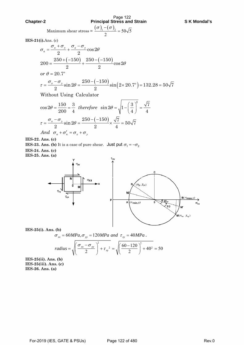
Chapter-2 Principal Stress and Strain S K Mondal’s
Maximum shear stress = ( ) ( )1 2 50 5
2σ σ−
=
IES-21(i).Ans. (c)
( ) ( )
( ) ( )
( )
2
cos22 2
250 150 250 150200 cos2
2 220.7
250 150sin2 sin 2 20.7 132.28 50 7
2 2Without Using Calculator
150 3 3 7cos2 sin2 1200 4 4 4
250 150 7sin2 50 72 2 4
x y x yn
o
x y o
x y
or
therefore
σ σ σ σσ θ
θ
θσ σ
τ θ
θ θ
σ στ θ
+ −= +
+ − − −= +
=
− − −= = × = =
⎛ ⎞= = = − =⎜ ⎟⎝ ⎠
− − −= = × =
n n x yAnd σ σ σ σ′+ = + IES-22. Ans. (c) IES-23. Ans. (b) It is a case of pure shear. 1 2Just put σ σ= − IES-24. Ans. (c) IES-25. Ans. (a)
IES-25(i). Ans. (b)
60 , 120 40xx yy xyMPa MPa and MPaσ σ τ= = = . 2 2
2 260 120 40 502 2xx yy
xyradiusσ σ
τ−⎛ ⎞ −⎛ ⎞= + = + =⎜ ⎟ ⎜ ⎟
⎝ ⎠⎝ ⎠ IES-25(ii). Ans. (b) IES-25(iii). Ans. (c) IES-26. Ans. (a)
Page 122
For-2019 (IES, GATE & PSUs) Page 122 of 480 Rev.0
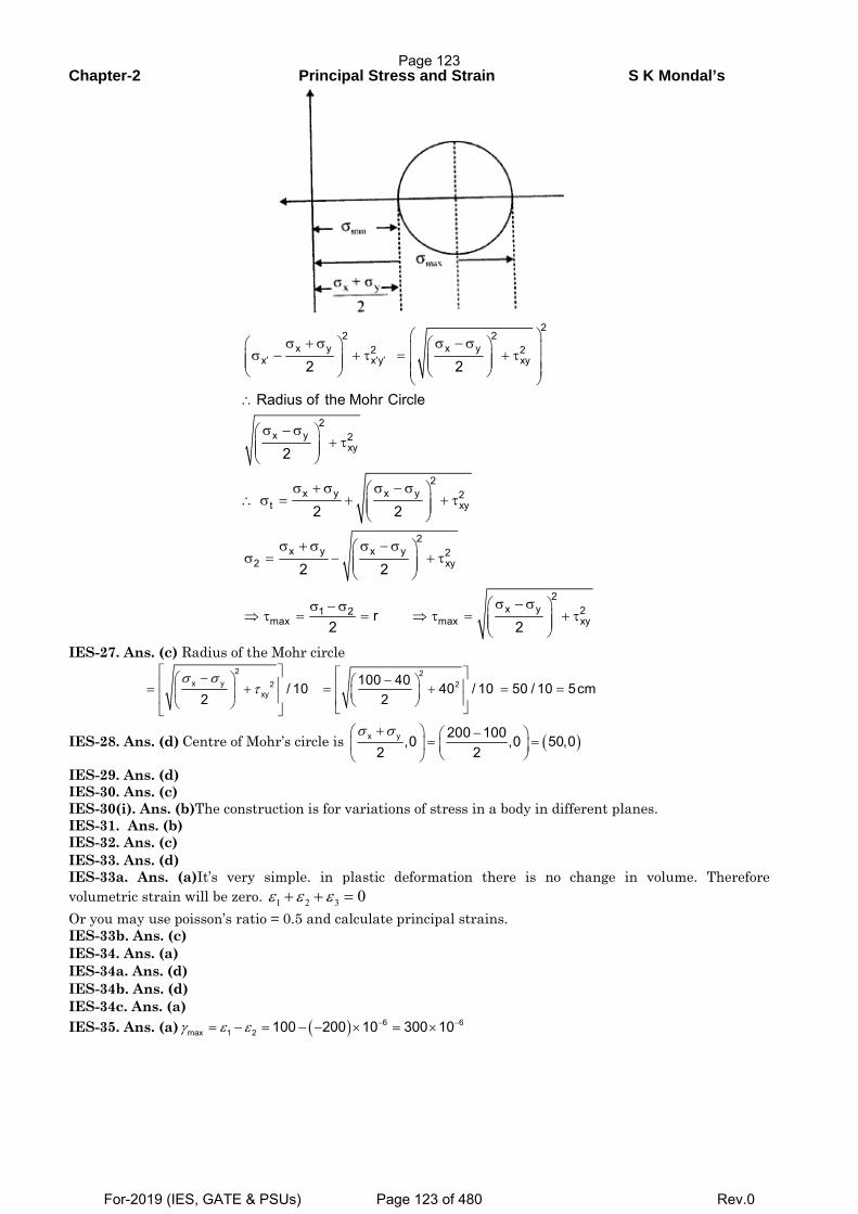
Chapter-2 Principal Stress and Strain S K Mondal’s
2
2 2x y x y2 2
x x y xy
2x y 2
xy
2x y x y 2
t xy
2x y x y 2
2 xy
x y1 2max max
2 2
Radius of the Mohr Circle
2
2 2
2 2
r 2 2
′ ′ ′
⎛ ⎞σ + σ σ − σ⎛ ⎞ ⎛ ⎞⎜ ⎟σ − + τ = + τ⎜ ⎟ ⎜ ⎟⎜ ⎟ ⎜ ⎟⎜ ⎟⎜ ⎟⎝ ⎠ ⎝ ⎠⎝ ⎠∴
σ − σ⎛ ⎞+ τ⎜ ⎟⎜ ⎟
⎝ ⎠
σ + σ σ − σ⎛ ⎞∴ σ = + + τ⎜ ⎟⎜ ⎟
⎝ ⎠
σ + σ σ − σ⎛ ⎞σ = − + τ⎜ ⎟⎜ ⎟
⎝ ⎠
σ − σ⎛ ⎞σ − σ⇒ τ = = ⇒ τ = ⎜⎜
⎝
22xy+ τ⎟⎟
⎠
IES-27. Ans. (c) Radius of the Mohr circle
2 2
x y 2 2xy
100 40/ 10 40 / 10 50 / 10 5cm2 2
σ στ
⎡ ⎤ ⎡ ⎤−⎛ ⎞ −⎛ ⎞⎢ ⎥ ⎢ ⎥= + = + = =⎜ ⎟ ⎜ ⎟⎢ ⎥ ⎢ ⎥⎝ ⎠⎝ ⎠ ⎣ ⎦⎣ ⎦
IES-28. Ans. (d) Centre of Mohr’s circle is ( )x y 200 100,0 ,0 50,02 2
σ σ+⎛ ⎞ −⎛ ⎞= =⎜ ⎟ ⎜ ⎟⎝ ⎠⎝ ⎠
IES-29. Ans. (d) IES-30. Ans. (c) IES-30(i). Ans. (b)The construction is for variations of stress in a body in different planes. IES-31. Ans. (b) IES-32. Ans. (c) IES-33. Ans. (d) IES-33a. Ans. (a)It’s very simple. in plastic deformation there is no change in volume. Therefore volumetric strain will be zero. 1 2 3 0ε ε ε+ + = Or you may use poisson’s ratio = 0.5 and calculate principal strains. IES-33b. Ans. (c) IES-34. Ans. (a) IES-34a. Ans. (d) IES-34b. Ans. (d) IES-34c. Ans. (a) IES-35. Ans. (a) ( ) 6 6
max 1 2 100 200 10 300 10γ ε ε − −= − = − − × = ×
Page 123
For-2019 (IES, GATE & PSUs) Page 123 of 480 Rev.0
Chapter-2 Principal Stress and Strain S K Mondal’s
( ) 1 2
max
xy 1 2 1 2max
don' t confuse withMaximumShear stress2
in strain and that is the difference.2 2 2
σ στ
γ ε ε σ στ
−=
− −= =
IES-36. Ans. (d)
( )− − −∈ −∈ φ= ⇒ φ = ∈ −∈ = × − − × = ×x y xy 6 6 6
xy x y 1000 10 600 10 1600 102 2
IES-37. Ans. (c) Three strain gauges are needed on a plane surface to determine the principal strains and their directions.
IES-38. Ans. (b) 1 2 2 11 2and
E E E Eσ σ σ σ
ε μ ε μ= − = − From these two equation eliminate 2σ .
IES-38(i). Ans. (b) IES-38(ii).Ans. (a) IES-39. Ans. (a) IES-40. Ans. (a)
IAS
IAS-1. Ans. (b) 2nWeknow cos and sin cosσ σ θ τ σ θ θ= =
2100 cos 45 or 200
200sin45cos45 100σ σ
τ= =
= =
IAS-2. Ans. (c)
IAS-3. Ans. (b) It is a case of pure shear so principal planes will be along the diagonal. IAS-4. Ans. (d)Stress in x direction =σx
Therefore x x x, ,x y zE E Eσ σ σε ε μ ε μ= = − = −
IAS-5. Ans. (c)
and 2
ε ε εγ
ε ε ε ε
ε ε ε
⎡ ⎤⎢ ⎥
=⎢ ⎥⎢ ⎥⎣ ⎦
xx xy xzxy
yx yy yz xy
zx zy zz
( )3100 10 0.004 2 MPa 800MPaτ γ= = × × × =xy xyG
IAS-6. Ans. (d) 1 2 1 1max 1
( )2 2
σ σ σ στ σ
− − −= = =
IAS-7. Ans. (a) 1 2max 2
σ στ
−= Maximum normal stress will developed if 1 2σ σ σ= − =
IAS-8. Ans. (c) 22
max 2 xyyx τ
σστ +⎟⎟
⎠
⎞⎜⎜⎝
⎛ −= = 2
2
302
4040+⎟
⎠⎞
⎜⎝⎛ −−
= 50 MPa
Page 124
For-2019 (IES, GATE & PSUs) Page 124 of 480 Rev.0
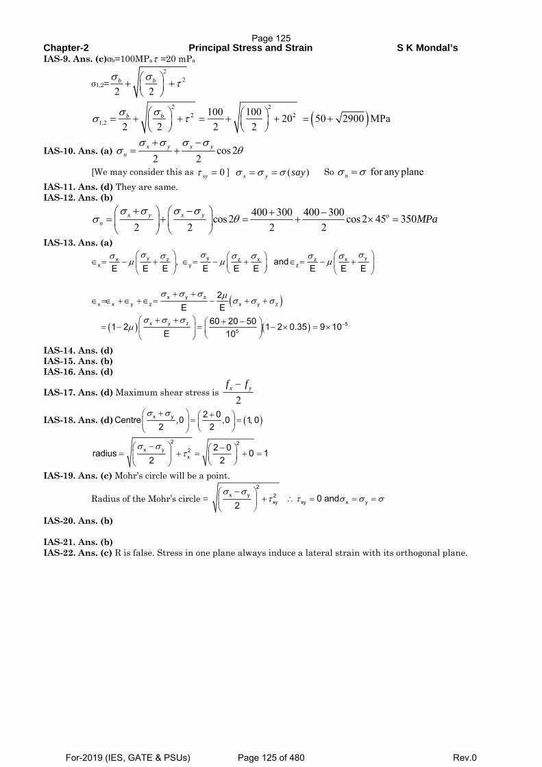
Chapter-2 Principal Stress and Strain S K Mondal’s IAS-9. Ans. (c)σb=100MPaτ =20 mPa
σ1,2=2
2
2 2b bσ σ τ⎛ ⎞+ +⎜ ⎟
⎝ ⎠
( )2 2
2 21,2
100 100 20 50 2900 MPa2 2 2 2σ σσ τ⎛ ⎞ ⎛ ⎞= + + = + + = +⎜ ⎟⎜ ⎟
⎝ ⎠⎝ ⎠b b
IAS-10. Ans. (a) cos 22 2
x y x yn
σ σ σ σσ θ
+ −= +
[We may consider this as 0xyτ = ] ( )x y sayσ σ σ= = So for any planenσ σ= IAS-11. Ans. (d) They are same. IAS-12. Ans. (b)
400 300 400 300cos 2 cos 2 45 350
2 2 2 2x y x y o
n MPaσ σ σ σ
σ θ+ −⎛ ⎞ ⎛ ⎞ + −
= + = + × =⎜ ⎟ ⎜ ⎟⎝ ⎠ ⎝ ⎠
IAS-13. Ans. (a)
σ σ σσ σ σ σ σ σ
μ μ μ⎛ ⎞ ⎛ ⎞⎛ ⎞∈ = − + ∈ = − + ∈ = − +⎜ ⎟ ⎜ ⎟⎜ ⎟
⎝ ⎠⎝ ⎠ ⎝ ⎠
y y yx z z x z xx y z, and
E E E E E E E E E
( )
( ) ( )
σ σ σ μ σ σ σ
σ σ σμ −
+ +∈ =∈ +∈ +∈ = − + +
+ +⎛ ⎞ + −⎛ ⎞= − = − × = ×⎜ ⎟ ⎜ ⎟⎝ ⎠⎝ ⎠
x y zv x y z x y z
x y z 55
2E E
60 20 501 2 1 2 0.35 9 10E 10
IAS-14. Ans. (d) IAS-15. Ans. (b)
IAS-16. Ans. (d)
IAS-17. Ans. (d) Maximum shear stress is 2
x yf f−
IAS-18. Ans. (d) ( )x y 2 0Centre ,0 ,0 1, 02 2
σ σ+⎛ ⎞ +⎛ ⎞= =⎜ ⎟ ⎜ ⎟⎝ ⎠⎝ ⎠
2 2
x y 2x
2 0radius 0 12 2
σ στ
−⎛ ⎞ −⎛ ⎞= + = + =⎜ ⎟ ⎜ ⎟⎝ ⎠⎝ ⎠
IAS-19. Ans. (c) Mohr’s circle will be a point.
Radius of the Mohr’s circle = 2
x y 2xy xy x y0 and
2σ σ
τ τ σ σ σ−⎛ ⎞
+ ∴ = = =⎜ ⎟⎝ ⎠
IAS-20. Ans. (b) IAS-21. Ans. (b) IAS-22. Ans. (c) R is false. Stress in one plane always induce a lateral strain with its orthogonal plane.
Page 125
For-2019 (IES, GATE & PSUs) Page 125 of 480 Rev.0
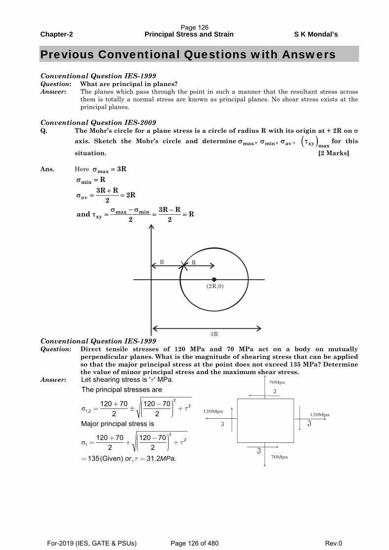
Chapter-2 Principal Stress and Strain S K Mondal’s
Previous Conventional Questions with Answers
Conventional Question IES-1999 Question: What are principal in planes? Answer: The planes which pass through the point in such a manner that the resultant stress across
them is totally a normal stress are known as principal planes. No shear stress exists at the principal planes.
Conventional Question IES-2009 Q. The Mohr’s circle for a plane stress is a circle of radius R with its origin at + 2R on σ
axis. Sketch the Mohr’s circle and determine , for this
situation. [2 Marks] Ans. Here
Conventional Question IES-1999 Question: Direct tensile stresses of 120 MPa and 70 MPa act on a body on mutually
perpendicular planes. What is the magnitude of shearing stress that can be applied so that the major principal stress at the point does not exceed 135 MPa? Determine the value of minor principal stress and the maximum shear stress.
Answer: Let shearing stress is ' ' MPa.τ
σ
22
1,2
The principal stresses are
120 70 120 702 2
τ⎛ ⎞+ − ⎟⎜= ± +⎟⎜ ⎟⎜⎝ ⎠
σ2
21
Major principal stress is
120 70 120 702 2
135(Given) , 31.2 .or MPa
τ
τ
⎛ ⎞+ − ⎟⎜= + +⎟⎜ ⎟⎜⎝ ⎠
= =
max ,σ min ,σ avσ ( )xy maxτ
max 3Rσ =
min
v
max minxy
R3R R 2R
23R Rand R
2 2
σ
σ =
+σ = =
σ − σ −τ = = =
R
(2R,0)
R
3R
Page 126
For-2019 (IES, GATE & PSUs) Page 126 of 480 Rev.0
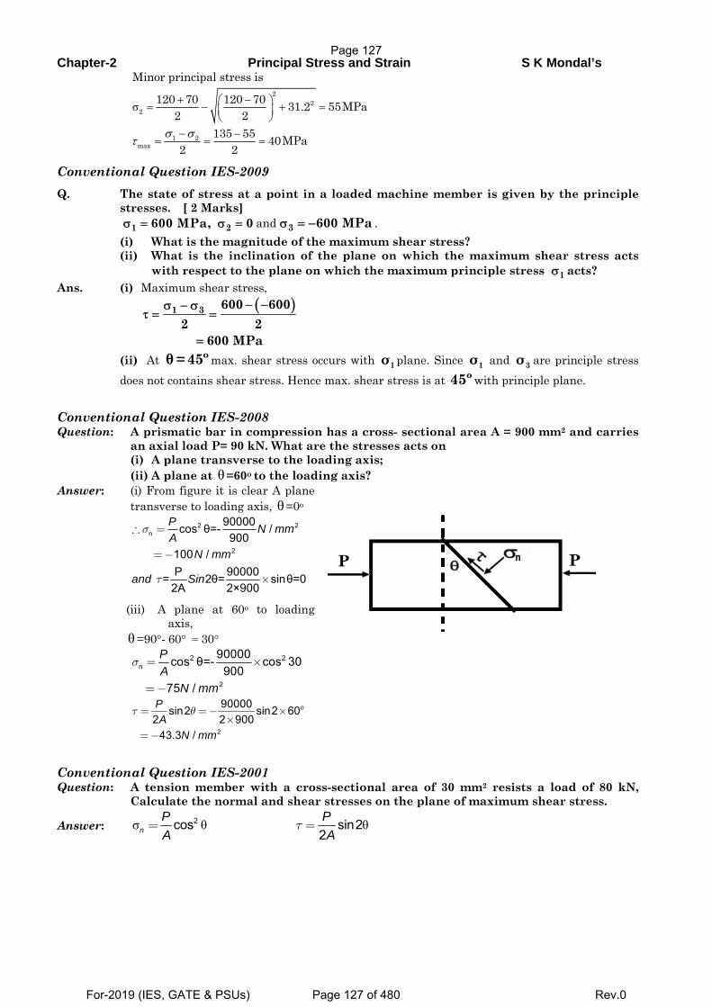
Chapter-2 Principal Stress and Strain S K Mondal’s
σ2
22
1 2max
Minor principal stress is
120 70 120 70 31.2 55MPa2 2
135 55 40MPa2 2
+ −⎛ ⎞= − + =⎜ ⎟⎝ ⎠
− −= = =σ σ
τ
Conventional Question IES-2009
Q. The state of stress at a point in a loaded machine member is given by the principle stresses. [ 2 Marks]
and . (i) What is the magnitude of the maximum shear stress? (ii) What is the inclination of the plane on which the maximum shear stress acts
with respect to the plane on which the maximum principle stress acts? Ans. (i) Maximum shear stress,
(ii) At θ= 45º max. shear stress occurs with 1σ plane. Since 1σ and 3σ are principle stress does not contains shear stress. Hence max. shear stress is at 45º with principle plane.
Conventional Question IES-2008 Question: A prismatic bar in compression has a cross- sectional area A = 900 mm2 and carries
an axial load P= 90 kN. What are the stresses acts on (i) A plane transverse to the loading axis; (ii) A plane at θ=60o to the loading axis? Answer: (i) From figure it is clear A plane
transverse to loading axis, θ=0o
2 2n
2
90000cos θ=- /900
100 /P 90000 = 2θ= sinθ=0
2A 2×900
P N mmA
N mm
and Sin
σ
τ
∴ =
=−
×
(iii) A plane at 60o to loading axis,
θ=90°- 60° = 30°
2 2
n
2
90000cos θ=- cos 30900
75 /
PA
N mm
σ = ×
=−
2
90000sin2 sin2 602 2 900
43.3 /
oPA
N mm
τ θ= =− ××
=−
Conventional Question IES-2001 Question: A tension member with a cross-sectional area of 30 mm2 resists a load of 80 kN,
Calculate the normal and shear stresses on the plane of maximum shear stress.
Answer: σ θ θ2cos sin22n
P PA A
τ= =
1 600 MPa,σ = 2 0σ = 3 600 MPaσ = −
1σ
( )1 3 600 6002 2
600 MPa
− −σ − στ = =
=
Page 127
For-2019 (IES, GATE & PSUs) Page 127 of 480 Rev.0
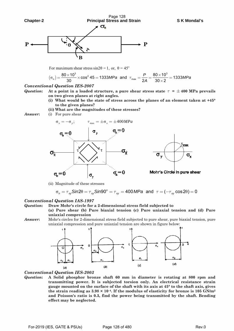
Chapter-2 Principal Stress and Strain S K Mondal’s
( )
oFor maximum shear stress sin2θ = 1, or, θ = 45
σ33
2max
80 1080 10 cos 45 1333 and 133330 2 30 2n
PMPa MPaA
τ××
= × = = = =×
Conventional Question IES-2007 Question: At a point in a loaded structure, a pure shear stress state τ = ± 400 MPa prevails
on two given planes at right angles. (i) What would be the state of stress across the planes of an element taken at +45°
to the given planes? (ii) What are the magnitudes of these stresses? Answer: (i) For pure shear
maxσ σ ; σ 400τ=− = ± = ±x y x MPa
(ii) Magnitude of these stresses
σ θ θ2 90 400 and ( cos2 ) 0on xy xy xy xySin Sin MPaτ τ τ τ τ= = = = = − =
Conventional Question IAS-1997 Question: Draw Mohr's circle for a 2-dimensional stress field subjected to (a) Pure shear (b) Pure biaxial tension (c) Pure uniaxial tension and (d) Pure
uniaxial compression Answer: Mohr's circles for 2-dimensional stress field subjected to pure shear, pure biaxial tension, pure
uniaxial compression and pure uniaxial tension are shown in figure below:
Conventional Question IES-2003 Question: A Solid phosphor bronze shaft 60 mm in diameter is rotating at 800 rpm and
transmitting power. It is subjected torsion only. An electrical resistance strain gauge mounted on the surface of the shaft with its axis at 45° to the shaft axis, gives the strain reading as 3.98 × 10⁻⁴. If the modulus of elasticity for bronze is 105 GN/m2
and Poisson's ratio is 0.3, find the power being transmitted by the shaft. Bending effect may be neglected.
Page 128
For-2019 (IES, GATE & PSUs) Page 128 of 480 Rev.0
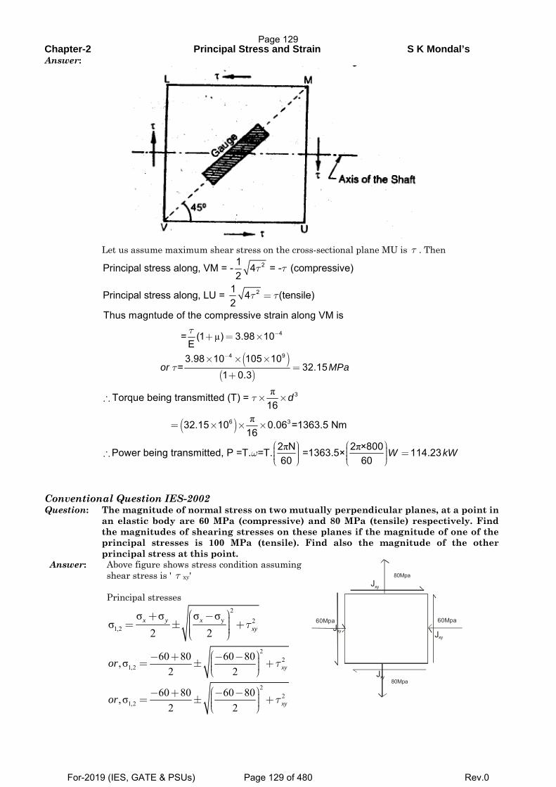
Chapter-2 Principal Stress and Strain S K Mondal’s Answer:
Let us assume maximum shear stress on the cross-sectional plane MU is τ . Then
2
2
1Principal stress along, VM = - 4 = - (compressive)2
1Principal stress along, LU = 4 (tensile)2
τ τ
τ τ=
( )( )
µ 4
4 9
Thus magntude of the compressive strain along VM is
= (1 ) 3.98 10E
3.98 10 105 10= 32.15
1 0.3or MPa
τ
τ
−
−
+ = ×
× × ×=
+
( )
π
π
3
6 3
Torque being transmitted (T) = 16
32.15 10 0.06 =1363.5 Nm16
dτ∴ × ×
= × × ×
π π2 N 2 ×800Power being transmitted, P =T. =T. =1363.5× 114.2360 60
W kWω⎛ ⎞ ⎛ ⎞⎟ ⎟⎜ ⎜∴ =⎟ ⎟⎜ ⎜⎟ ⎟⎜ ⎜⎝ ⎠ ⎝ ⎠
Conventional Question IES-2002 Question: The magnitude of normal stress on two mutually perpendicular planes, at a point in
an elastic body are 60 MPa (compressive) and 80 MPa (tensile) respectively. Find the magnitudes of shearing stresses on these planes if the magnitude of one of the principal stresses is 100 MPa (tensile). Find also the magnitude of the other principal stress at this point.
Answer: Above figure shows stress condition assuming shear stress is ' τ xy'
Principal stresses
2
y 21,2
σ σ σ σσ
2 2τ
⎛ ⎞+ − ⎟⎜ ⎟= ± +⎜ ⎟⎜ ⎟⎜⎝ ⎠x y x
xy
2
21,2
60 80 60 80,σ2 2
τ⎛ ⎞− + − − ⎟⎜= ± +⎟⎜ ⎟⎜⎝ ⎠ xyor
2
21,2
60 80 60 80,σ2 2
τ⎛ ⎞− + − − ⎟⎜= ± +⎟⎜ ⎟⎜⎝ ⎠ xyor
80Mpa
80Mpa
60Mpa60Mpa
Jxy
Jxy
Jxy
Jxy
Page 129
For-2019 (IES, GATE & PSUs) Page 129 of 480 Rev.0
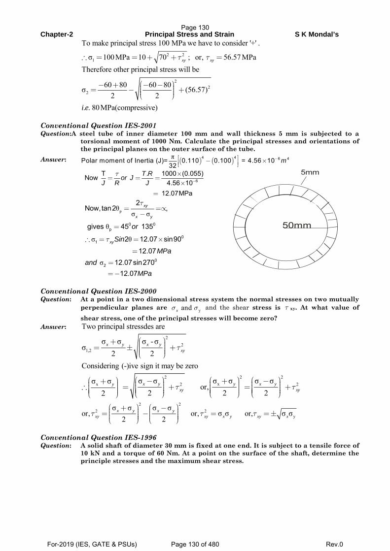
Chapter-2 Principal Stress and Strain S K Mondal’s
2 21
To make principal stress 100 MPa we have to consider '+' .
σ 100MPa 10 70 ; or, 56.57 MPaτ τ∴ = = + + =xy xy
2
22
Therefore other principal stress will be
60 80 60 80σ (56.57)2 2
. . 80MPa(compressive)i e
⎛ ⎞− + − − ⎟⎜= − +⎟⎜ ⎟⎜⎝ ⎠
Conventional Question IES-2001 Question:A steel tube of inner diameter 100 mm and wall thickness 5 mm is subjected to a
torsional moment of 1000 Nm. Calculate the principal stresses and orientations of the principal planes on the outer surface of the tube.
Answer: ( ) ( )π 4 4 6 4Polar moment of Inertia (J)= 0.110 0.100 = 4.56 1032
m−⎡ ⎤− ×⎢ ⎥⎣ ⎦
6
T . 1000 (0.055)Now 4.56 10
12.07MPa
T Ror JJ R J
τ−
×= = =
×
=
pθ σ σ
θ
σ θ
σ
0 0p
01
02
2Now,tan2 ,
gives 45 135
2 12.07 sin90
12.07 12.07sin270
12.07
xy
x y
xy
or
Sin
MPaand
MPa
τ
τ
= =∝−
=
∴ = = ×
=
=
=−
50mm
5mm
Conventional Question IES-2000 Question: At a point in a two dimensional stress system the normal stresses on two mutually
perpendicular planes are yand σ σx and the shear stress is τ xy. At what value of shear stress, one of the principal stresses will become zero?
Answer: Two principal stressdes are
2
21,2
σ σ σ -σσ
2 2τ
⎛ ⎞+ ⎟⎜ ⎟= ± +⎜ ⎟⎜ ⎟⎜⎝ ⎠x y x y
xy
Considering (-)ive sign it may be zero
2 2 2
xx 2 2σ σ σ σ σ σσ σor,
2 2 22τ τ
⎛ ⎞ ⎛ ⎞ ⎛ ⎞⎛ ⎞ − + −+ ⎟ ⎟ ⎟⎟ ⎜ ⎜ ⎜⎜ ⎟ ⎟ ⎟∴ = + = +⎟ ⎜ ⎜ ⎜⎜ ⎟ ⎟ ⎟⎟ ⎜ ⎜ ⎜⎜ ⎟ ⎟ ⎟⎟ ⎜ ⎜ ⎜⎜ ⎝ ⎠ ⎝ ⎠ ⎝ ⎠⎝ ⎠x y y x yy
xy xy
2 2
2 2y
σ σ σ σor, or, σ σ or, σ σ
2 2τ τ τ
⎛ ⎞ ⎛ ⎞+ −⎟ ⎟⎜ ⎜= ⎟ − ⎟ = =±⎜ ⎜⎟ ⎟⎜ ⎜⎟ ⎟⎝ ⎠ ⎝ ⎠x y x y
xy xy x y xy x
Conventional Question IES-1996 Question: A solid shaft of diameter 30 mm is fixed at one end. It is subject to a tensile force of
10 kN and a torque of 60 Nm. At a point on the surface of the shaft, determine the principle stresses and the maximum shear stress.
Page 130
For-2019 (IES, GATE & PSUs) Page 130 of 480 Rev.0
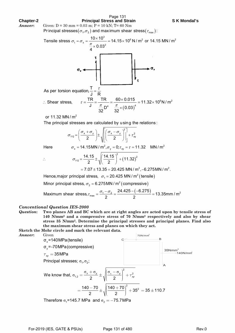
Chapter-2 Principal Stress and Strain S K Mondal’s Answer: Given: D = 30 mm = 0.03 m; P = 10 kN; T= 60 Nm
( ) ( )1 2 max
36 2 2
t x2
Pr incipal stresses , and max imum shear stress :
10 10Tensile stress 14.15 10 N / m or 14.15 MN / m0.03
4
σ σ τ
σ σπ
×= = = ×
×
TAs per torsion equation,J R
τ=
( )6 2
44
2
TR TR 60 0.015Shear stress, 11.32 10 N / mJ D 0.03
32 32or 11.32 MN / m
τπ π
×∴ = = = = ×
×
( )
2x y x y 2
1 2 xy
2 2x y xy
22
1 2
2
The principal stresses are calculated by using the relations :
,2 2
Here 14.15MN / m , 0; 11.32 MN / m
14.15 14.15, 11.322 2
7.07 13.35 20.425 MN / m , 6.275M
σ σ σ σσ τ
σ σ τ τ
σ
⎡ ⎤+ −⎛ ⎞ ⎛ ⎞⎢ ⎥= ± +⎜ ⎟ ⎜ ⎟⎢ ⎥⎝ ⎠ ⎝ ⎠⎣ ⎦
= = = =
⎛ ⎞∴ = ± +⎜ ⎟⎝ ⎠
= ± = −
( )( )
( )
2
21
22
21 2max
N / m .Hence,major principal stress, 20.425 MN / m tensile
Minor principal stress, 6.275MN / m compressive
24.425 6.275Maximum shear stress, 13.35mm / m
2 2
σ
σ
σ στ
=
=
− −−= = =
Conventional Question IES-2000 Question: Two planes AB and BC which are at right angles are acted upon by tensile stress of
140 N/mm2 and a compressive stress of 70 N/mm2 respectively and also by shear stress 35 N/mm2. Determine the principal stresses and principal planes. Find also the maximum shear stress and planes on which they act.
Sketch the Mohr circle and mark the relevant data. Answer: Given
x
y
σ =140MPa(tensile)σ =-70MPa(compressive)
35MPaxyτ =
σ σ1 2Principal stresses; , ;
70N/mm2
35Nmm2
A
C B
140N/mm2
xσ σ σ σσ
σ σ
22
1,2
22
1 2
We know that, 2 2
140 70 140 70 35 35 110.72 2
Therefore =145.7 MPa and 75.7MPa
x y yxyτ
⎛ ⎞+ − ⎟⎜ ⎟= ± +⎜ ⎟⎜ ⎟⎜⎝ ⎠
⎛ ⎞− + ⎟⎜= ± + = ±⎟⎜ ⎟⎜⎝ ⎠
=−
Page 131
For-2019 (IES, GATE & PSUs) Page 131 of 480 Rev.0
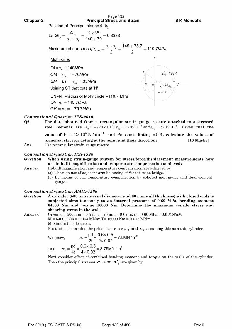
Chapter-2 Principal Stress and Strain S K Mondal’s
y
θ θ
θσ σ
σ - σ
1 2
1 2max
Position of Principal planes ,2 2 35tan2 0.3333
140 70
145 75.7Maximum shear stress, 110.72 2
xyp
x
MPa
τ
τ
×= = =
− +
+= = =
Mohr cirle:
σσ
xOL= 14070
35Joining ST that cuts at 'N'
y
xy
MPaOM MPa
SM LT MPaτ
=
= =−
= = =
σσ
1
2
SN=NT=radius of Mohr circle =110.7 MPaOV= 145.7
75.7MPa
OV MPa=
= =−
T
VL
2 =198.4θpS
UM O 2θ=78.4
σ 140=
Y
N
Conventional Question IES-2010 Q6. The data obtained from a rectangular strain gauge rosette attached to a stressed
steel member are 6 6 60 45 90220 10 , 120 10 220 10andε ε ε− − −= − × = × = × . Given that the
value of E = and Poisson’s Ratio , calculate the values of principal stresses acting at the point and their directions. [10 Marks]
Ans. Use rectangular strain gauge rosette Conventional Question IES-1998 Question: When using strain-gauge system for stress/force/displacement measurements how
are in-built magnification and temperature compensation achieved? Answer: In-built magnification and temperature compensation are achieved by (a) Through use of adjacent arm balancing of Wheat-stone bridge. (b) By means of self temperature compensation by selected melt-gauge and dual element-
gauge. Conventional Question AMIE-1998 Question: A cylinder (500 mm internal diameter and 20 mm wall thickness) with closed ends is
subjected simultaneously to an internal pressure of 0-60 MPa, bending moment 64000 Nm and torque 16000 Nm. Determine the maximum tensile stress and shearing stress in the wall.
Answer: Given: d = 500 mm = 0·5 m; t = 20 mm = 0·02 m; p = 0·60 MPa = 0.6 MN/m2; M = 64000 Nm = 0·064 MNm; T= 16000 Nm = 0·016 MNm. Maximum tensile stress: First let us determine the principle stresses 1 2andσ σ assuming this as a thin cylinder.
We know, 21
pd 0.6 0.5 7.5MN / m2t 2 0.02
σ ×= = =
×
22
pd 0.6 0.5and 3.75MN / m4t 4 0.02
σ ×= = =
×
Next consider effect of combined bending moment and torque on the walls of the cylinder. Then the principal stresses 1 2' and 'σ σ are given by
5 22 10 N / mm× 0.3μ =
Page 132
For-2019 (IES, GATE & PSUs) Page 132 of 480 Rev.0
Chapter-2 Principal Stress and Strain S K Mondal’s
( )
( )
2 21 3
2 22 3
2 2 21 3
2 2 22 3
max
I IImax
II 2 2
16' M M Td
16and ' M M Td16' 0.064 0.064 0.016 5.29MN / m0.516and ' 0.064 0.064 0.016 0.08MN / m0.5
Maximum shearing stress, :
We Know,2
' 3.75
σπ
σπ
σπ
σπ
τσ σ
τ
σ σ σ
⎡ ⎤= + +⎣ ⎦
⎡ ⎤= − +⎣ ⎦
⎡ ⎤∴ = + + =⎣ ⎦×
⎡ ⎤= − + = −⎣ ⎦×
−=
= + = − ( )2
2max
0.08 3.67MN / m tensile12.79 3.67 4.56MN / m
2τ
=
−∴ = =
Page 133
For-2019 (IES, GATE & PSUs) Page 133 of 480 Rev.0
3. Moment of Inertia and Centroid
Theory at a Glance (for IES, GATE, PSU) 3.1 Centre of gravity
The centre of gravity of a body defined as the point through which the whole weight of a body may be
assumed to act.
3.2 Centroid or Centre of area
The centroid or centre of area is defined as the point where the whole area of the figure is assumed to be
concentrated.
3.3 Moment of Inertia (MOI)
About any point the product of the force and the perpendicular distance between them is known as
moment of a force or first moment of force.
This first moment is again multiplied by the perpendicular distance between them to obtain second
moment of force.
In the same way if we consider the area of the figure it is called second moment of area or area
moment of inertia and if we consider the mass of a body it is called second moment of mass or mass
moment of Inertia.
Mass moment of inertia is the measure of resistance of the body to rotation and forms the basis
of dynamics of rigid bodies.
Area moment of Inertia is the measure of resistance to bending and forms the basis of strength
of materials.
3.4 Mass moment of Inertia (MOI)
2
i ii
I m r
Notice that the moment of inertia ‘I’ depends on the distribution of mass in the system.
The furthest the mass is from the rotation axis, the bigger the moment of inertia.
For a given object, the moment of inertia depends on where we choose the rotation axis.
In rotational dynamics, the moment of inertia ‘I’ appears in the same way that mass m does in
linear dynamics.
Page 134
For-2019 (IES, GATE & PSUs) Page 134 of 480 Rev.0
Chapter-3 Moment of Inertia and Centroid Solid disc or cylinder of mass M and radius R, about perpendicular axis through its centre,
21
2I MR
Solid sphere of mass M and radius R, about an axis through its centre, I = 2/5 M R2
Thin rod of mass M and length L, about a perpendicular axis through
its centre.
21
12I ML
Thin rod of mass M and length L, about a perpendicular axis through its
end.
21
3I ML
3.5 Area Moment of Inertia (MOI) or Second moment of area
To find the centroid of an area by the first moment of the area
about an axis was determined ( ∫ x dA )
Integral of the second moment of area is called moment of
inertia (∫ x2dA)
Consider the area ( A )
By definition, the moment of inertia of the differential area
about the x and y axes are dIxx and dIyy
dIxx = y2dAIxx = ∫ y2 dA
dIyy = x2dAIyy = ∫ x2dA
3.6 Parallel axis theorem for an area
The rotational inertia about any axis is the sum of
second moment of inertia about a parallel axis
through the C.G and total area of the body times
square of the distance between the axes.
INN = ICG + Ah2
Page 135
For-2019 (IES, GATE & PSUs) Page 135 of 480 Rev.0
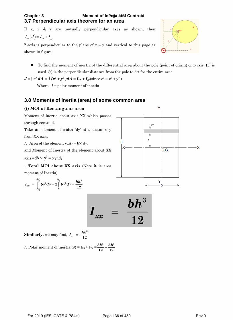
Chapter-3 Moment of Inertia and Centroid
3.7 Perpendicular axis theorem for an area
If x, y & z are mutually perpendicular axes as shown, then
zz xx yyI J I I
Z-axis is perpendicular to the plane of x – y and vertical to this page as
shown in figure.
To find the moment of inertia of the differential area about the pole (point of origin) or z-axis, (r) is
used. (r) is the perpendicular distance from the pole to dA for the entire area
J = ∫ r2 dA = ∫ (x2 + y2 )dA = Ixx + Iyy(since r2 = x2 + y2 )
Where, J = polar moment of inertia
3.8 Moments of Inertia (area) of some common area
(i) MOI of Rectangular area
Moment of inertia about axis XX which passes
through centroid.
Take an element of width ‘dy’ at a distance y
from XX axis.
Area of the element (dA) = b dy.
and Moment of Inertia of the element about XX
axis2 2dA y b.y .dy
Total MOI about XX axis (Note it is area
moment of Inertia)
32 22 2
02
212
h h
xx
h
bhI by dy by dy
3
12
xx
bhI
Similarly, we may find, 3
12
yy
hbI
Polar moment of inertia (J) = Ixx + Iyy =3 3
12 12
bh hb
Page 136
For-2019 (IES, GATE & PSUs) Page 136 of 480 Rev.0
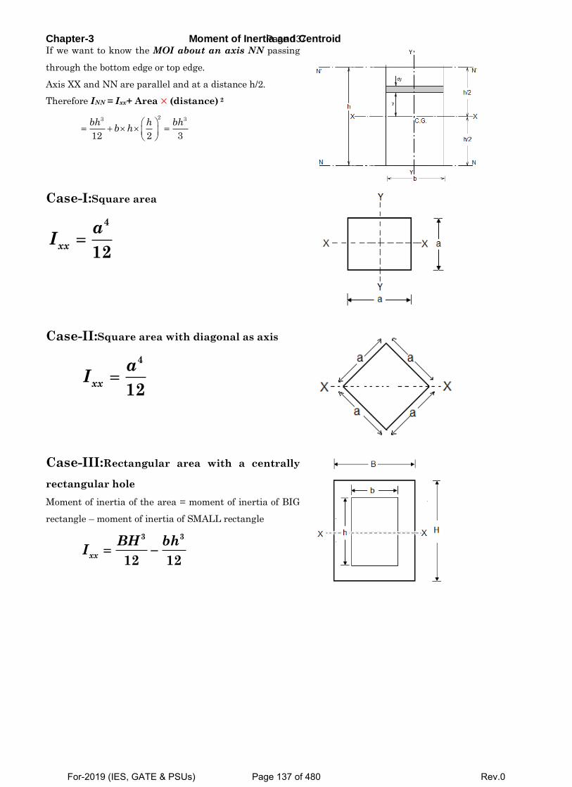
Chapter-3 Moment of Inertia and Centroid If we want to know the MOI about an axis NN passing
through the bottom edge or top edge.
Axis XX and NN are parallel and at a distance h/2.
Therefore INN = Ixx+ Area (distance) 2
23 3
12 2 3
bh h bhb h
Case-I:Square area
4
12xx
aI
Case-II:Square area with diagonal as axis
4
12xx
aI
Case-III:Rectangular area with a centrally
rectangular hole
Moment of inertia of the area = moment of inertia of BIG
rectangle – moment of inertia of SMALL rectangle
3 3
12 12xx
BH bhI
Page 137
For-2019 (IES, GATE & PSUs) Page 137 of 480 Rev.0
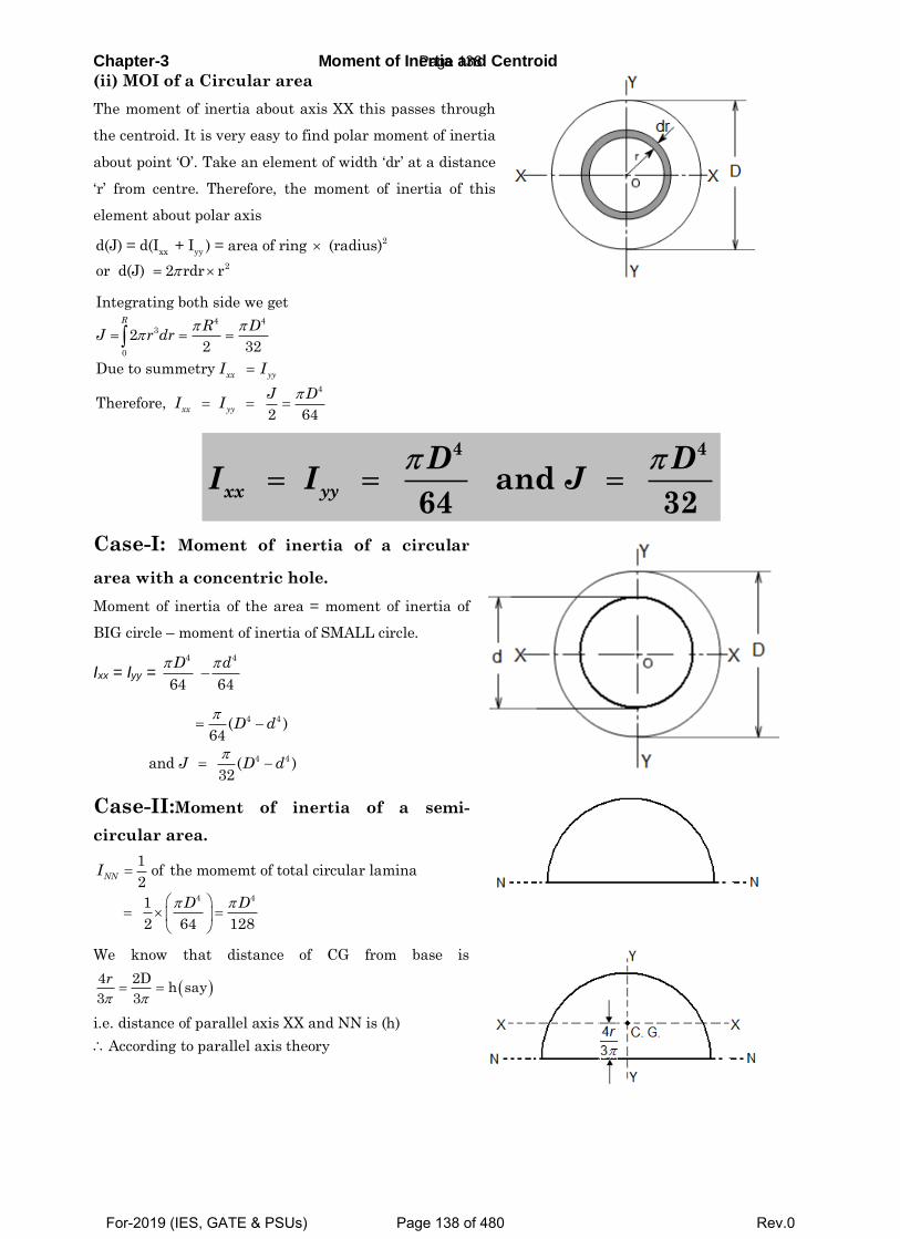
Chapter-3 Moment of Inertia and Centroid
(ii) MOI of a Circular area
The moment of inertia about axis XX this passes through
the centroid. It is very easy to find polar moment of inertia
about point ‘O’. Take an element of width ‘dr’ at a distance
‘r’ from centre. Therefore, the moment of inertia of this
element about polar axis
2
xx yy
2
d(J) = d(I + I ) = area of ring (radius)
or d(J) 2 rdr r
4 43
0
4
Integrating both side we get
22 32
Due to summetry
Therefore, 2 64
R
xx yy
xx yy
R DJ r dr
I I
J DI I
4 4
and 64 32
xx yy
D DI I J
Case-I: Moment of inertia of a circular
area with a concentric hole.
Moment of inertia of the area = moment of inertia of
BIG circle – moment of inertia of SMALL circle.
Ixx = Iyy = 4
64
D –
4
64
d
4 4
4 4
( )64
and ( )32
D d
J D d
Case-II:Moment of inertia of a semi-
circular area.
4 4
1of the momemt of total circular lamina
2
1 2 64 128
NNI
D D
We know that distance of CG from base is
4 2D
h say3 3
r
i.e. distance of parallel axis XX and NN is (h)
According to parallel axis theory
Page 138
For-2019 (IES, GATE & PSUs) Page 138 of 480 Rev.0
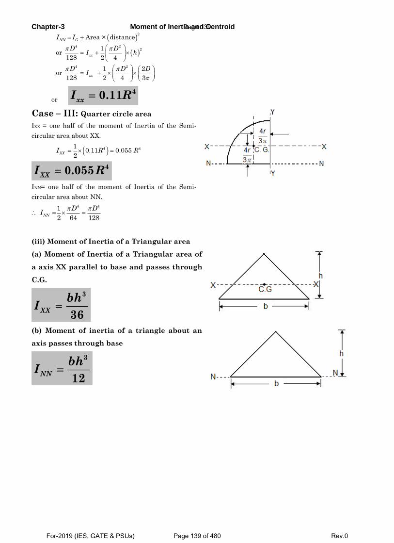
Chapter-3 Moment of Inertia and Centroid
2
4 22
4 2
Area × distance
1or
128 2 4
1 2or
128 2 4 3
NN G
xx
xx
I I
D DI h
D D DI
or
40.11xxI R
Case – III: Quarter circle area
IXX = one half of the moment of Inertia of the Semi-
circular area about XX.
4 410.11 0.055
2XX
I R R
40.055XXI R
INN= one half of the moment of Inertia of the Semi-
circular area about NN.
4 41
2 64 128NN
D DI
(iii) Moment of Inertia of a Triangular area
(a) Moment of Inertia of a Triangular area of
a axis XX parallel to base and passes through
C.G.
3
36XX
bhI
(b) Moment of inertia of a triangle about an
axis passes through base
3
12NN
bhI
Page 139
For-2019 (IES, GATE & PSUs) Page 139 of 480 Rev.0
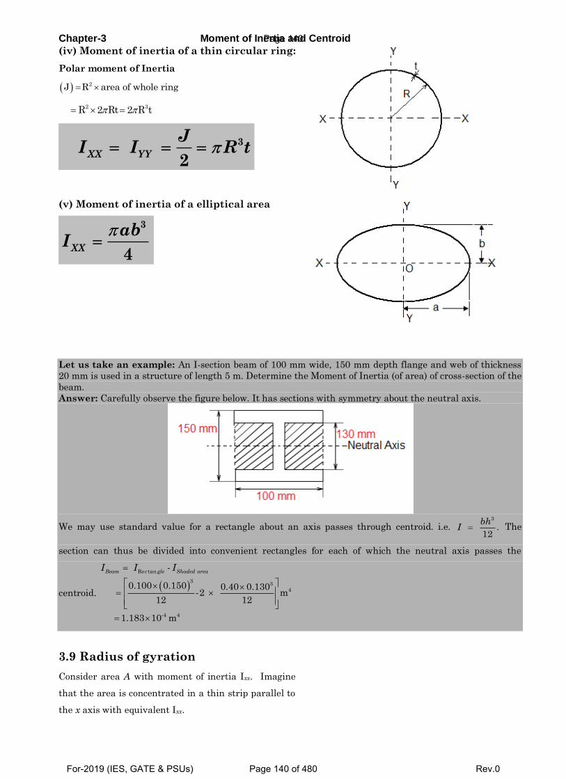
Chapter-3 Moment of Inertia and Centroid
(iv) Moment of inertia of a thin circular ring:
Polar moment of Inertia
2J R area of whole ring
2 3R 2 Rt 2 R t
3 2
XX YY
JI I R t
(v) Moment of inertia of a elliptical area
3
4XX
abI
Let us take an example: An I-section beam of 100 mm wide, 150 mm depth flange and web of thickness
20 mm is used in a structure of length 5 m. Determine the Moment of Inertia (of area) of cross-section of the
beam.
Answer: Carefully observe the figure below. It has sections with symmetry about the neutral axis.
We may use standard value for a rectangle about an axis passes through centroid. i.e. 3
.12
bhI The
section can thus be divided into convenient rectangles for each of which the neutral axis passes the
centroid.
Re tan
33
4
-4 4
-
0.100 0.150 0.40 0.130-2 m
12 12
1.183 10 m
Beam c gle Shaded areaI I I
3.9 Radius of gyration
Consider area A with moment of inertia Ixx. Imagine
that the area is concentrated in a thin strip parallel to
the x axis with equivalent Ixx.
Page 140
For-2019 (IES, GATE & PSUs) Page 140 of 480 Rev.0
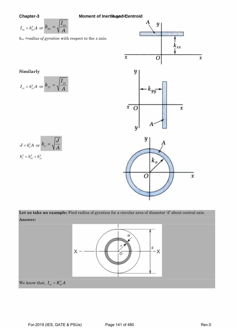
Chapter-3 Moment of Inertia and Centroid
2
xx xxI k A or
xx
xx
Ik
A
kxx =radius of gyration with respect to the x axis.
Similarly
2
yy yyI k A or
yy
yy
Ik
A
2
oJ k A or o
Jk
A
2 2 2
o xx yyk k k
Let us take an example: Find radius of gyration for a circular area of diameter ‘d’ about central axis.
Answer:
We know that, 2
xx xxI K A
Page 141
For-2019 (IES, GATE & PSUs) Page 141 of 480 Rev.0
Chapter-3 Moment of Inertia and Centroid
or
4
2
64
4
4
XX
XX
dI d
KA d
Page 142
For-2019 (IES, GATE & PSUs) Page 142 of 480 Rev.0
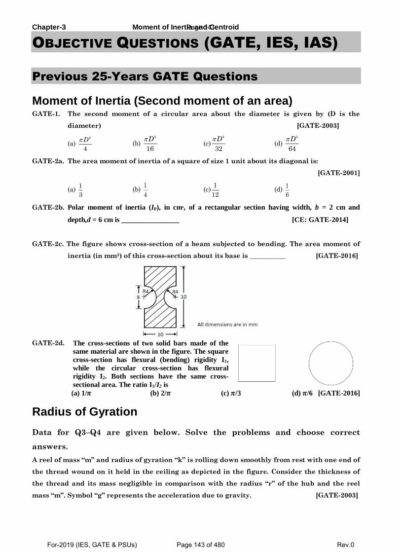
Chapter-3 Moment of Inertia and Centroid
OBJECTIVE QUESTIONS (GATE, IES, IAS)
Previous 25-Years GATE Questions
Moment of Inertia (Second moment of an area) GATE-1. The second moment of a circular area about the diameter is given by (D is the
diameter) [GATE-2003]
(a) 4
4
D (b)
4
16
D (c)
4
32
D (d)
4
64
D
GATE-2a. The area moment of inertia of a square of size 1 unit about its diagonal is:
[GATE-2001]
(a) 1
3 (b)
1
4 (c)
1
12 (d)
1
6
GATE-2b. Polar moment of inertia (Ip), in cm4, of a rectangular section having width, b = 2 cm and
depth,d = 6 cm is ________________ [CE: GATE-2014]
GATE-2c. The figure shows cross-section of a beam subjected to bending. The area moment of
inertia (in mm3) of this cross-section about its base is ___________ [GATE-2016]
GATE-2d. The cross-sections of two solid bars made of the
same material are shown in the figure. The square
cross-section has flexural (bending) rigidity I1,
while the circular cross-section has flexural
rigidity I2. Both sections have the same cross-
sectional area. The ratio I1/I2 is (a) 1/𝜋 (b) 2/𝜋 (c) 𝜋/3 (d) 𝜋/6 [GATE-2016]
Radius of Gyration
Data for Q3–Q4 are given below. Solve the problems and choose correct
answers.
A reel of mass “m” and radius of gyration “k” is rolling down smoothly from rest with one end of
the thread wound on it held in the ceiling as depicted in the figure. Consider the thickness of
the thread and its mass negligible in comparison with the radius “r” of the hub and the reel
mass “m”. Symbol “g” represents the acceleration due to gravity. [GATE-2003]
Page 143
For-2019 (IES, GATE & PSUs) Page 143 of 480 Rev.0
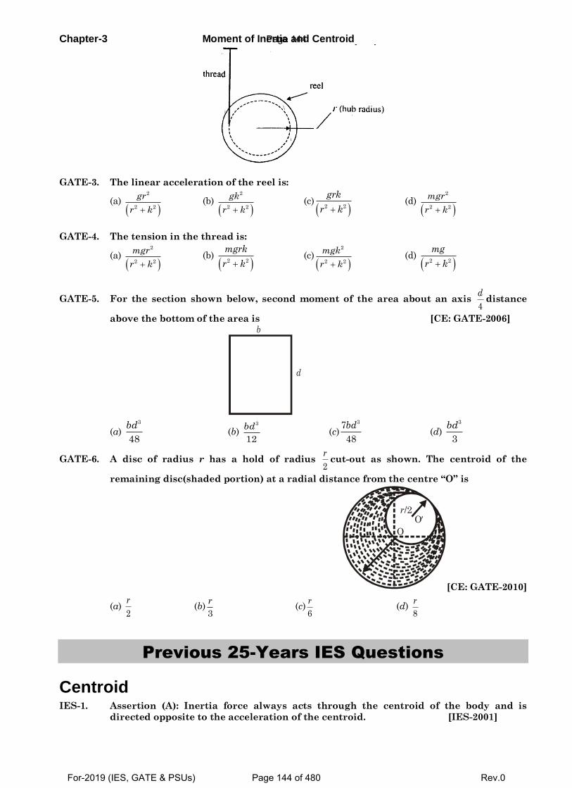
Chapter-3 Moment of Inertia and Centroid
GATE-3. The linear acceleration of the reel is:
(a)
2
2 2
gr
r k (b)
2
2 2
gk
r k (c)
2 2
grk
r k (d)
2
2 2
mgr
r k
GATE-4. The tension in the thread is:
(a)
2
2 2
mgr
r k (b)
2 2
mgrk
r k (c)
2
2 2
mgk
r k (d)
2 2
mg
r k
GATE-5. For the section shown below, second moment of the area about an axis 4
ddistance
above the bottom of the area is [CE: GATE-2006]
b
d
(a) 3
48
bd (b)
3
12
bd (c)
37
48
bd (d)
3
3
bd
GATE-6. A disc of radius r has a hold of radius 2
rcut-out as shown. The centroid of the
remaining disc(shaded portion) at a radial distance from the centre “O” is
O
Or/2
[CE: GATE-2010]
(a) 2
r (b)
3
r (c)
6
r (d)
8
r
Previous 25-Years IES Questions
Centroid IES-1. Assertion (A): Inertia force always acts through the centroid of the body and is
directed opposite to the acceleration of the centroid. [IES-2001]
Page 144
For-2019 (IES, GATE & PSUs) Page 144 of 480 Rev.0
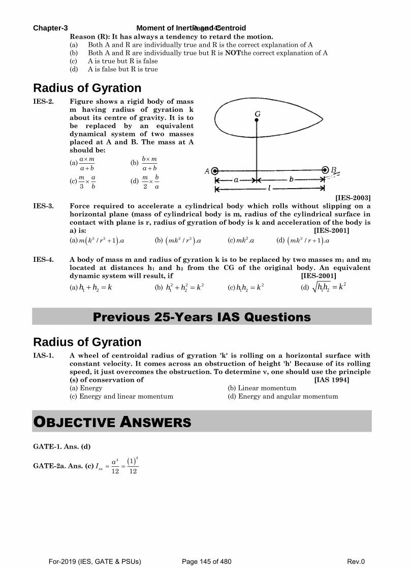
Chapter-3 Moment of Inertia and Centroid Reason (R): It has always a tendency to retard the motion.
(a) Both A and R are individually true and R is the correct explanation of A
(b) Both A and R are individually true but R is NOTthe correct explanation of A
(c) A is true but R is false
(d) A is false but R is true
Radius of Gyration IES-2. Figure shows a rigid body of mass
m having radius of gyration k
about its centre of gravity. It is to
be replaced by an equivalent
dynamical system of two masses
placed at A and B. The mass at A
should be:
(a)a m
a b
(b)
b m
a b
(c)3
m a
b (d)
2
m b
a
[IES-2003]
IES-3. Force required to accelerate a cylindrical body which rolls without slipping on a
horizontal plane (mass of cylindrical body is m, radius of the cylindrical surface in
contact with plane is r, radius of gyration of body is k and acceleration of the body is
a) is: [IES-2001]
(a) 2 2/ 1 .m k r a (b) 2 2/ .mk r a (c) 2.mk a (d) 2 / 1 .mk r a
IES-4. A body of mass m and radius of gyration k is to be replaced by two masses m1 and m2
located at distances h1 and h2 from the CG of the original body. An equivalent
dynamic system will result, if [IES-2001]
(a) 1 2h h k (b) 2 2 2
1 2h h k (c)2
1 2h h k (d) 2
1 2h h k
Previous 25-Years IAS Questions
Radius of Gyration IAS-1. A wheel of centroidal radius of gyration 'k' is rolling on a horizontal surface with
constant velocity. It comes across an obstruction of height 'h' Because of its rolling
speed, it just overcomes the obstruction. To determine v, one should use the principle
(s) of conservation of [IAS 1994]
(a) Energy (b) Linear momentum
(c) Energy and linear momentum (d) Energy and angular momentum
OBJECTIVE ANSWERS
GATE-1. Ans. (d)
GATE-2a. Ans. (c)
44 1
12 12xx
aI
Page 145
For-2019 (IES, GATE & PSUs) Page 145 of 480 Rev.0
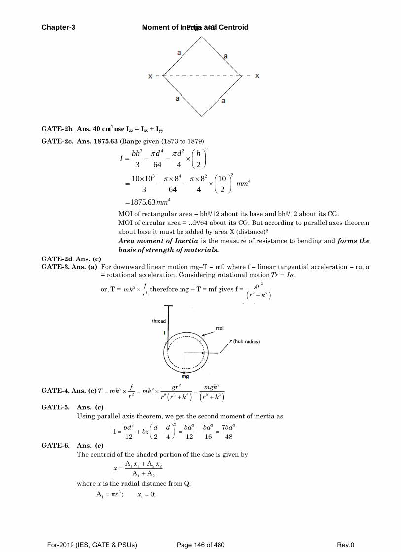
Chapter-3 Moment of Inertia and Centroid
GATE-2b. Ans. 40 cm4
use Izz = Ixx + Iyy
GATE-2c. Ans. 1875.63 (Range given (1873 to 1879)
23 4 2
23 4 24
4
3 64 4 2
10 10 8 8 10
3 64 4 2
1875.63
bh d d hI
mm
mm
MOI of rectangular area = bh3/12 about its base and bh3/12 about its CG.
MOI of circular area = d4/64 about its CG. But according to parallel axes theorem
about base it must be added by area X (distance)2
Area moment of Inertia is the measure of resistance to bending and forms the
basis of strength of materials.
GATE-2d. Ans. (c)
GATE-3. Ans. (a) For downward linear motion mg–T = mf, where f = linear tangential acceleration = rα, α
= rotational acceleration. Considering rotational motion .Tr I
or, T = 2
2
fmk
r therefore mg – T = mf gives f =
2
2 2
gr
r k
GATE-4. Ans. (c)
2 22 2
2 2 2 2 2 2
f gr mgkT mk mk
r r r k r k
GATE-5. Ans. (c)
Using parallel axis theorem, we get the second moment of inertia as
23 3 3 37I
12 2 4 12 16 48
bd d d bd bd bdbx
GATE-6. Ans. (c)
The centroid of the shaded portion of the disc is given by
1 1 2 2
1 2
A A
A A
x xx
where x is the radial distance from Q.
2
1A ;r
10;x
Page 146
For-2019 (IES, GATE & PSUs) Page 146 of 480 Rev.0
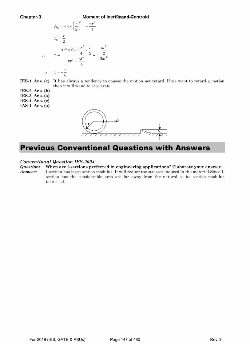
Chapter-3 Moment of Inertia and Centroid
2 2
2A
2 4
r r
2
2
rx
2 22
2 22
04 2 2
3
4
r r rr
xr r
r
6
rx
IES-1. Ans. (c) It has always a tendency to oppose the motion not retard. If we want to retard a motion
then it will wand to accelerate.
IES-2. Ans. (b)
IES-3. Ans. (a)
IES-4. Ans. (c)
IAS-1. Ans. (a)
Previous Conventional Questions with Answers
Conventional Question IES-2004 Question: When are I-sections preferred in engineering applications? Elaborate your answer.
Answer: I-section has large section modulus. It will reduce the stresses induced in the material.Since I-
section has the considerable area are far away from the natural so its section modulus
increased.
Page 147
For-2019 (IES, GATE & PSUs) Page 147 of 480 Rev.0
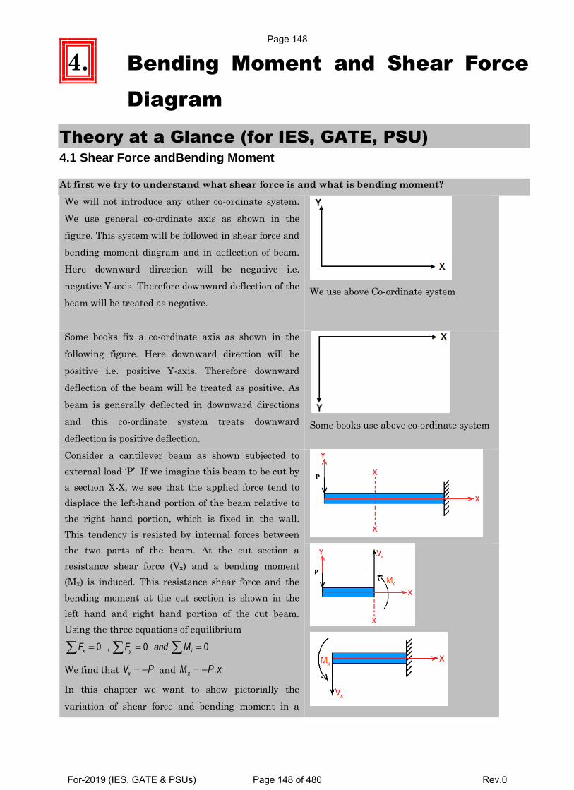
4. Bending Moment and Shear Force
Diagram
Theory at a Glance (for IES, GATE, PSU) 4.1 Shear Force andBending Moment
At first we try to understand what shear force is and what is bending moment?
We will not introduce any other co-ordinate system.
We use general co-ordinate axis as shown in the
figure. This system will be followed in shear force and
bending moment diagram and in deflection of beam.
Here downward direction will be negative i.e.
negative Y-axis. Therefore downward deflection of the
beam will be treated as negative.
We use above Co-ordinate system
Some books fix a co-ordinate axis as shown in the
following figure. Here downward direction will be
positive i.e. positive Y-axis. Therefore downward
deflection of the beam will be treated as positive. As
beam is generally deflected in downward directions
and this co-ordinate system treats downward
deflection is positive deflection.
Some books use above co-ordinate system
Consider a cantilever beam as shown subjected to
external load ‘P’. If we imagine this beam to be cut by
a section X-X, we see that the applied force tend to
displace the left-hand portion of the beam relative to
the right hand portion, which is fixed in the wall.
This tendency is resisted by internal forces between
the two parts of the beam. At the cut section a
resistance shear force (Vx) and a bending moment
(Mx) is induced. This resistance shear force and the
bending moment at the cut section is shown in the
left hand and right hand portion of the cut beam.
Using the three equations of equilibrium
0 , 0 0x y iF F and M
We find that xV P and .xM P x
In this chapter we want to show pictorially the
variation of shear force and bending moment in a
Page 148
For-2019 (IES, GATE & PSUs) Page 148 of 480 Rev.0
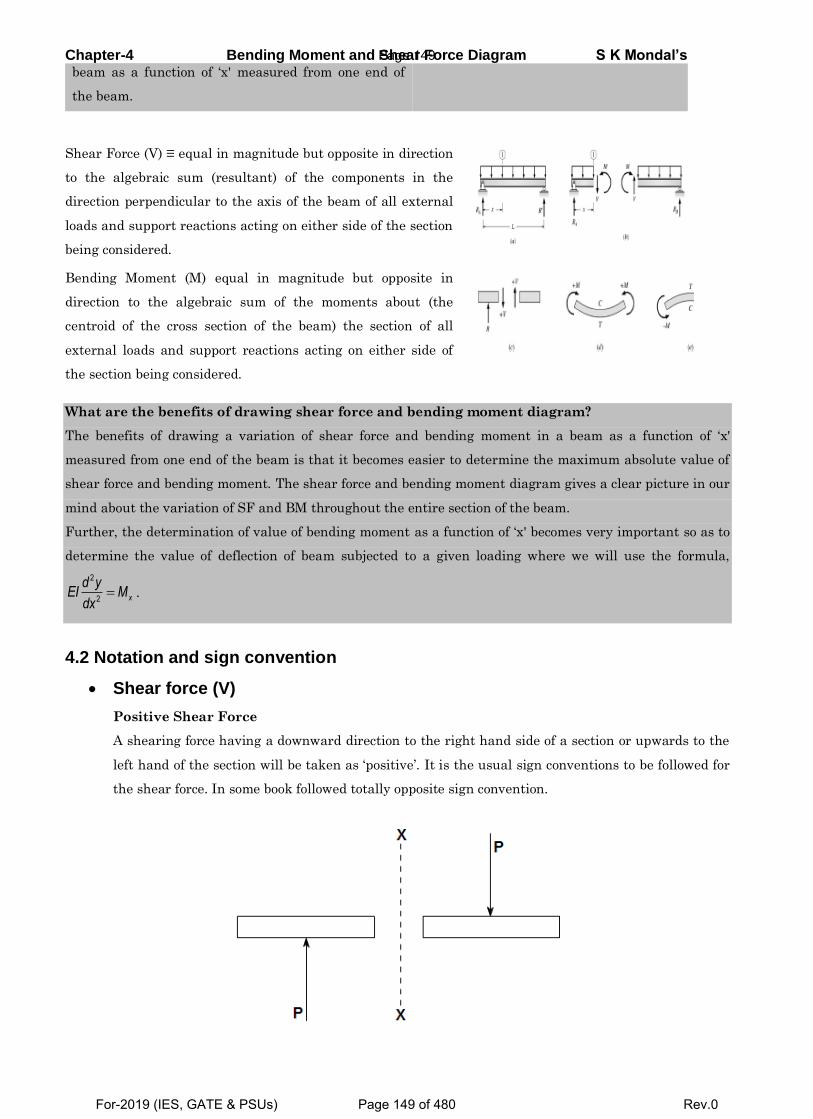
Chapter-4 Bending Moment and Shear Force Diagram S K Mondal’s beam as a function of ‘x' measured from one end of
the beam.
Shear Force (V) ≡ equal in magnitude but opposite in direction
to the algebraic sum (resultant) of the components in the
direction perpendicular to the axis of the beam of all external
loads and support reactions acting on either side of the section
being considered.
Bending Moment (M) equal in magnitude but opposite in
direction to the algebraic sum of the moments about (the
centroid of the cross section of the beam) the section of all
external loads and support reactions acting on either side of
the section being considered.
What are the benefits of drawing shear force and bending moment diagram?
The benefits of drawing a variation of shear force and bending moment in a beam as a function of ‘x'
measured from one end of the beam is that it becomes easier to determine the maximum absolute value of
shear force and bending moment. The shear force and bending moment diagram gives a clear picture in our
mind about the variation of SF and BM throughout the entire section of the beam.
Further, the determination of value of bending moment as a function of ‘x' becomes very important so as to
determine the value of deflection of beam subjected to a given loading where we will use the formula,
2
2 x
d yEI M
dx .
4.2 Notation and sign convention
Shear force (V)
Positive Shear Force
A shearing force having a downward direction to the right hand side of a section or upwards to the
left hand of the section will be taken as ‘positive’. It is the usual sign conventions to be followed for
the shear force. In some book followed totally opposite sign convention.
Page 149
For-2019 (IES, GATE & PSUs) Page 149 of 480 Rev.0
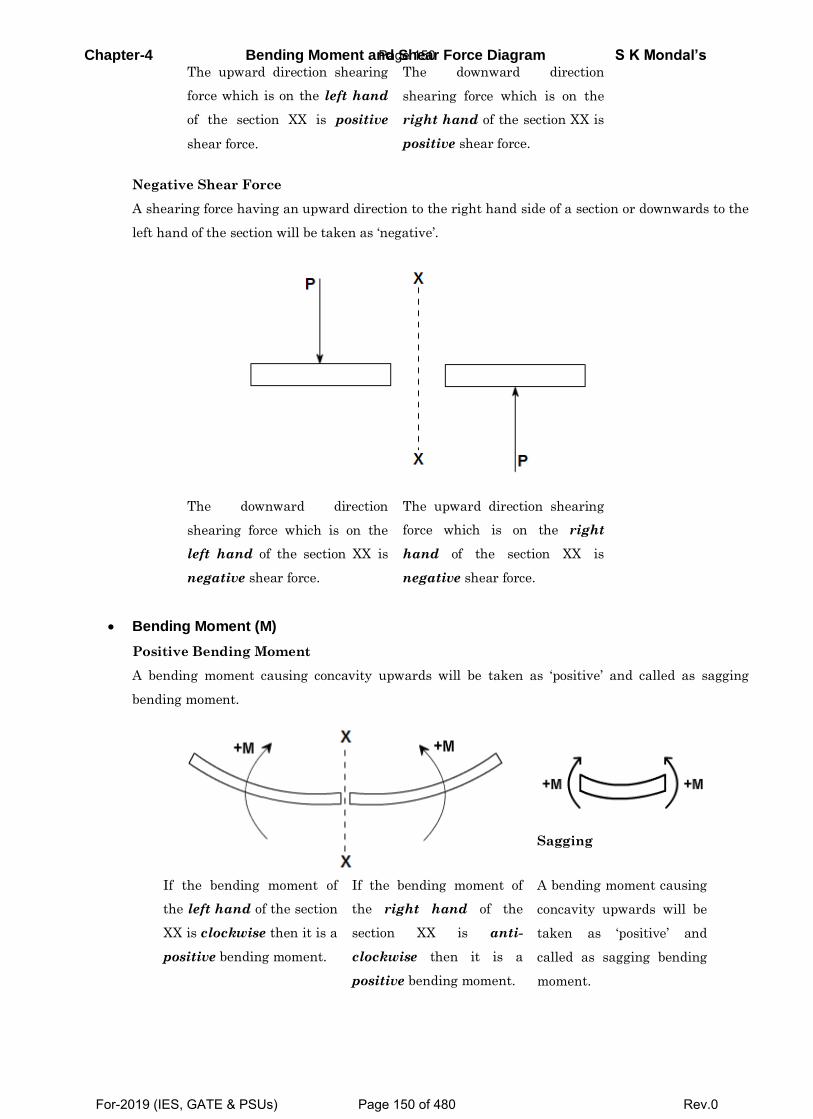
Chapter-4 Bending Moment and Shear Force Diagram S K Mondal’s The upward direction shearing
force which is on the left hand
of the section XX is positive
shear force.
The downward direction
shearing force which is on the
right hand of the section XX is
positive shear force.
Negative Shear Force
A shearing force having an upward direction to the right hand side of a section or downwards to the
left hand of the section will be taken as ‘negative’.
The downward direction
shearing force which is on the
left hand of the section XX is
negative shear force.
The upward direction shearing
force which is on the right
hand of the section XX is
negative shear force.
Bending Moment (M)
Positive Bending Moment
A bending moment causing concavity upwards will be taken as ‘positive’ and called as sagging
bending moment.
Sagging
If the bending moment of
the left hand of the section
XX is clockwise then it is a
positive bending moment.
If the bending moment of
the right hand of the
section XX is anti-
clockwise then it is a
positive bending moment.
A bending moment causing
concavity upwards will be
taken as ‘positive’ and
called as sagging bending
moment.
Page 150
For-2019 (IES, GATE & PSUs) Page 150 of 480 Rev.0
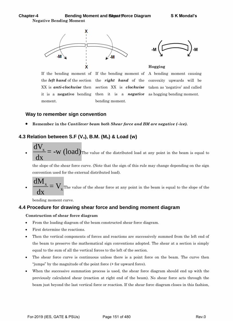
Chapter-4 Bending Moment and Shear Force Diagram S K Mondal’s Negative Bending Moment
Hogging
If the bending moment of
the left hand of the section
XX is anti-clockwise then
it is a negative bending
moment.
If the bending moment of
the right hand of the
section XX is clockwise
then it is a negative
bending moment.
A bending moment causing
convexity upwards will be
taken as ‘negative’ and called
as hogging bending moment.
Way to remember sign convention
Remember in the Cantilever beam both Shear force and BM are negative (–ive).
4.3 Relation between S.F (Vx), B.M. (Mx) & Load (w)
xdV
= -w (load)dx
The value of the distributed load at any point in the beam is equal to
the slope of the shear force curve. (Note that the sign of this rule may change depending on the sign
convention used for the external distributed load).
x
x
dM= V
dxThe value of the shear force at any point in the beam is equal to the slope of the
bending moment curve.
4.4 Procedure for drawing shear force and bending moment diagram
Construction of shear force diagram
From the loading diagram of the beam constructed shear force diagram.
First determine the reactions.
Then the vertical components of forces and reactions are successively summed from the left end of
the beam to preserve the mathematical sign conventions adopted. The shear at a section is simply
equal to the sum of all the vertical forces to the left of the section.
The shear force curve is continuous unless there is a point force on the beam. The curve then
“jumps” by the magnitude of the point force (+ for upward force).
When the successive summation process is used, the shear force diagram should end up with the
previously calculated shear (reaction at right end of the beam). No shear force acts through the
beam just beyond the last vertical force or reaction. If the shear force diagram closes in this fashion,
Page 151
For-2019 (IES, GATE & PSUs) Page 151 of 480 Rev.0
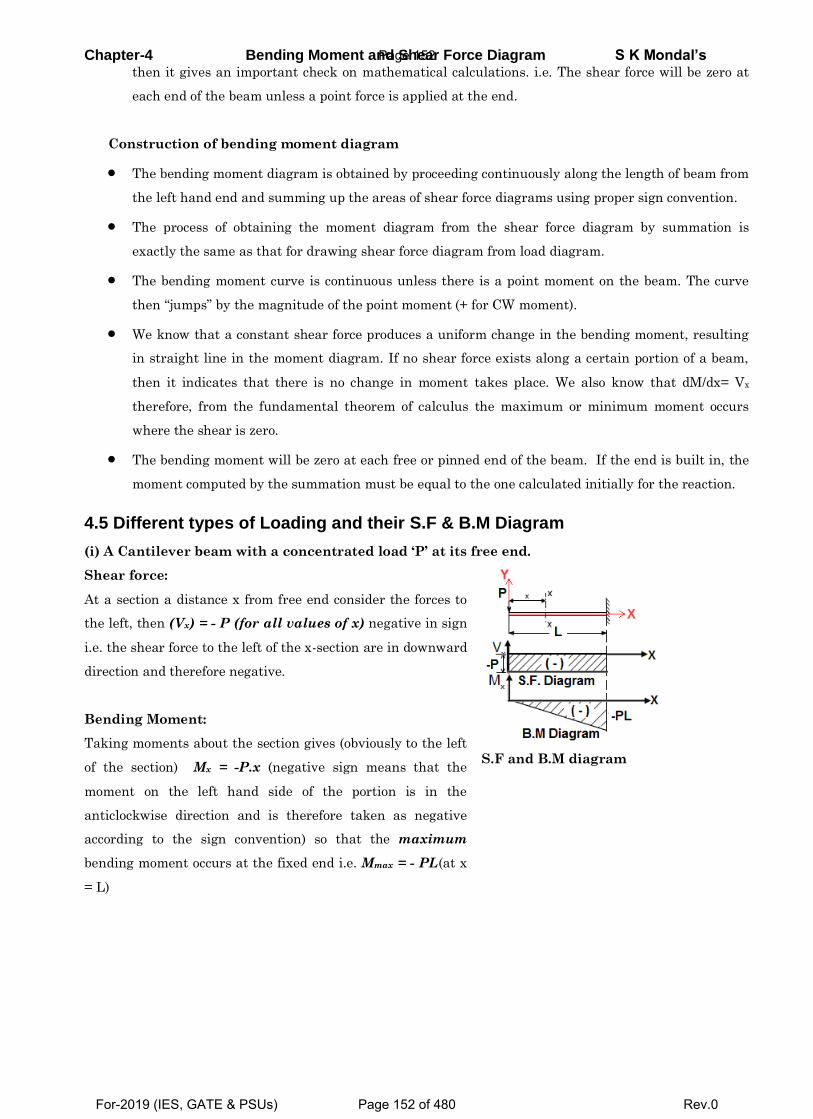
Chapter-4 Bending Moment and Shear Force Diagram S K Mondal’s then it gives an important check on mathematical calculations. i.e. The shear force will be zero at
each end of the beam unless a point force is applied at the end.
Construction of bending moment diagram
The bending moment diagram is obtained by proceeding continuously along the length of beam from
the left hand end and summing up the areas of shear force diagrams using proper sign convention.
The process of obtaining the moment diagram from the shear force diagram by summation is
exactly the same as that for drawing shear force diagram from load diagram.
The bending moment curve is continuous unless there is a point moment on the beam. The curve
then “jumps” by the magnitude of the point moment (+ for CW moment).
We know that a constant shear force produces a uniform change in the bending moment, resulting
in straight line in the moment diagram. If no shear force exists along a certain portion of a beam,
then it indicates that there is no change in moment takes place. We also know that dM/dx= Vx
therefore, from the fundamental theorem of calculus the maximum or minimum moment occurs
where the shear is zero.
The bending moment will be zero at each free or pinned end of the beam. If the end is built in, the
moment computed by the summation must be equal to the one calculated initially for the reaction.
4.5 Different types of Loading and their S.F & B.M Diagram
(i) A Cantilever beam with a concentrated load ‘P’ at its free end.
Shear force:
At a section a distance x from free end consider the forces to
the left, then (Vx) = - P (for all values of x) negative in sign
i.e. the shear force to the left of the x-section are in downward
direction and therefore negative.
Bending Moment:
Taking moments about the section gives (obviously to the left
of the section) Mx = -P.x (negative sign means that the
moment on the left hand side of the portion is in the
anticlockwise direction and is therefore taken as negative
according to the sign convention) so that the maximum
bending moment occurs at the fixed end i.e. Mmax = - PL(at x
= L)
S.F and B.M diagram
Page 152
For-2019 (IES, GATE & PSUs) Page 152 of 480 Rev.0
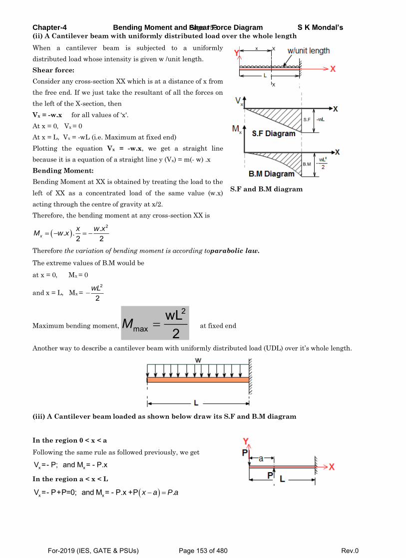
Chapter-4 Bending Moment and Shear Force Diagram S K Mondal’s (ii) A Cantilever beam with uniformly distributed load over the whole length
When a cantilever beam is subjected to a uniformly
distributed load whose intensity is given w /unit length.
Shear force:
Consider any cross-section XX which is at a distance of x from
the free end. If we just take the resultant of all the forces on
the left of the X-section, then
Vx = -w.x for all values of ‘x'.
At x = 0, Vx = 0
At x = L, Vx = -wL (i.e. Maximum at fixed end)
Plotting the equation Vx = -w.x, we get a straight line
because it is a equation of a straight line y (Vx) = m(- w) .x
Bending Moment:
Bending Moment at XX is obtained by treating the load to the
left of XX as a concentrated load of the same value (w.x)
acting through the centre of gravity at x/2.
S.F and B.M diagram
Therefore, the bending moment at any cross-section XX is
2.. .
2 2x
x w xM w x
Therefore the variation of bending moment is according toparabolic law.
The extreme values of B.M would be
at x = 0, Mx = 0
and x = L, Mx = 2
2wL
Maximum bending moment, 2
maxwL2
M at fixed end
Another way to describe a cantilever beam with uniformly distributed load (UDL) over it’s whole length.
(iii) A Cantilever beam loaded as shown below draw its S.F and B.M diagram
In the region 0 < x < a
Following the same rule as followed previously, we get
x xV =- P; and M = - P.x
In the region a < x < L
x xV =- P+P=0; and M = - P.x +P .x a P a
Page 153
For-2019 (IES, GATE & PSUs) Page 153 of 480 Rev.0
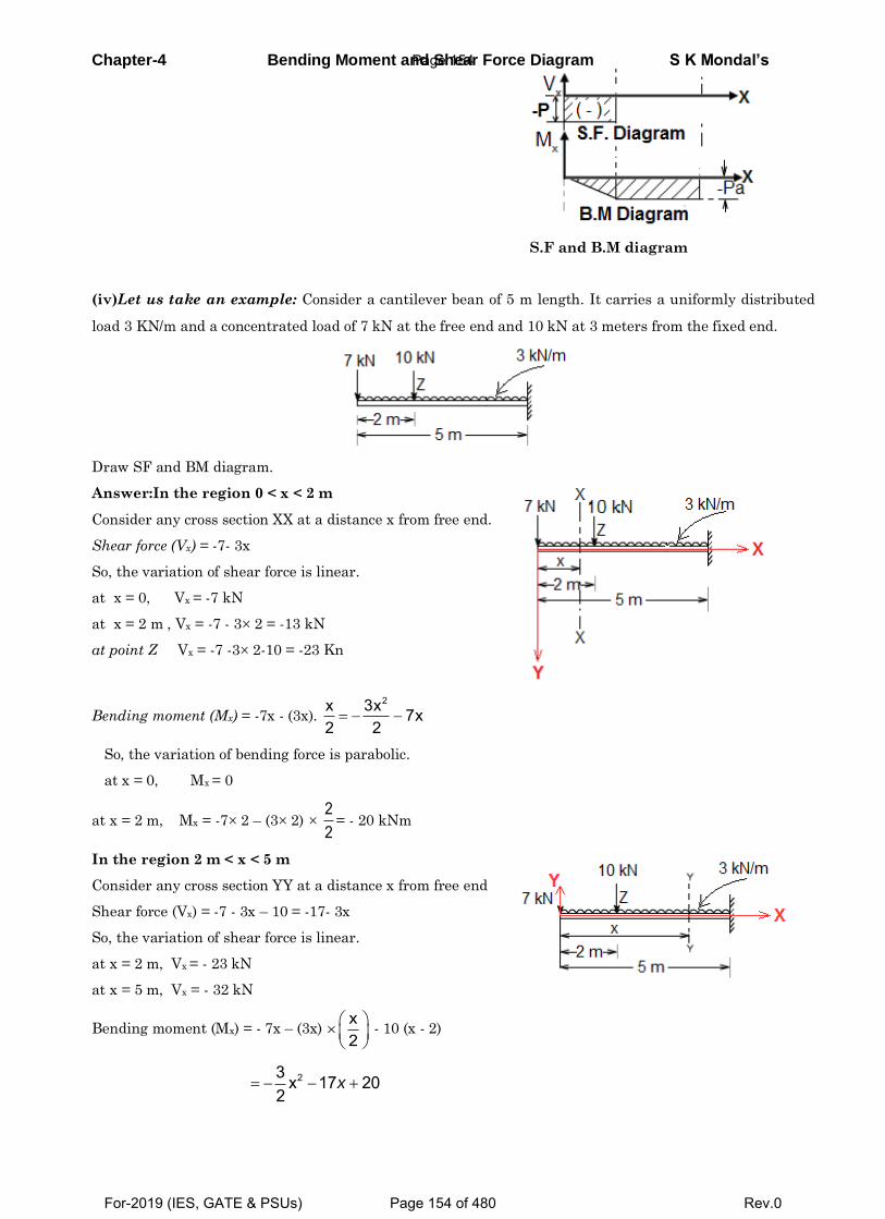
Chapter-4 Bending Moment and Shear Force Diagram S K Mondal’s
S.F and B.M diagram
(iv)Let us take an example: Consider a cantilever bean of 5 m length. It carries a uniformly distributed
load 3 KN/m and a concentrated load of 7 kN at the free end and 10 kN at 3 meters from the fixed end.
Draw SF and BM diagram.
Answer:In the region 0 < x < 2 m
Consider any cross section XX at a distance x from free end.
Shear force (Vx) = -7- 3x
So, the variation of shear force is linear.
at x = 0, Vx = -7 kN
at x = 2 m , Vx = -7 - 3 2 = -13 kN
at point Z Vx = -7 -3 2-10 = -23 Kn
Bending moment (Mx) = -7x - (3x). 2x 3x 7x
2 2
So, the variation of bending force is parabolic.
at x = 0, Mx = 0
at x = 2 m, Mx = -7 2 – (3 2) 22
= - 20 kNm
In the region 2 m < x < 5 m
Consider any cross section YY at a distance x from free end
Shear force (Vx) = -7 - 3x – 10 = -17- 3x
So, the variation of shear force is linear.
at x = 2 m, Vx = - 23 kN
at x = 5 m, Vx = - 32 kN
Bending moment (Mx) = - 7x – (3x) x2
- 10 (x - 2)
23 x 17 20
2x
Page 154
For-2019 (IES, GATE & PSUs) Page 154 of 480 Rev.0
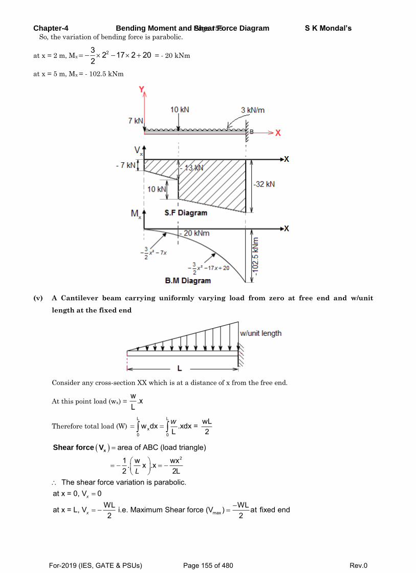
Chapter-4 Bending Moment and Shear Force Diagram S K Mondal’s So, the variation of bending force is parabolic.
at x = 2 m, Mx23 2 17 2 20
2 = - 20 kNm
at x = 5 m, Mx = - 102.5 kNm
(v) A Cantilever beam carrying uniformly varying load from zero at free end and w/unit
length at the fixed end
Consider any cross-section XX which is at a distance of x from the free end.
At this point load (wx) = w .xL
Therefore total load (W)
L L
x0 0
wLw dx .xdx = L 2w
2
max
area of ABC (load triangle)
1 w wx . x .x2 2L
The shear force variation is parabolic.at x = 0, V 0
WL WLat x = L, V i.e. Maximum Shear force (V ) at fi2 2
x
x
L
xShear force V
xed end
Page 155
For-2019 (IES, GATE & PSUs) Page 155 of 480 Rev.0
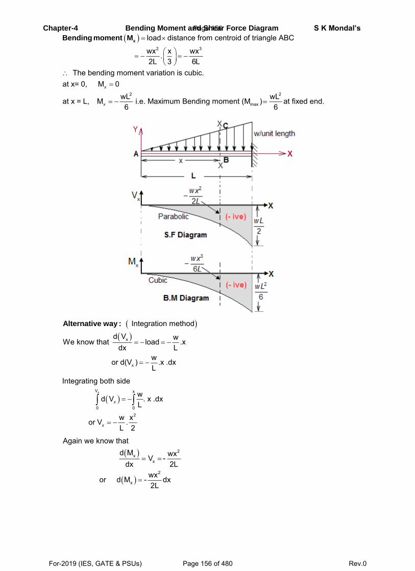
Chapter-4 Bending Moment and Shear Force Diagram S K Mondal’s
2 3
2 2
max
load distance from centroid of triangle ABC
wx x wx.2L 3 6L
The bending moment variation is cubic.at x= 0, M 0
wL wLat x = L, M i.e. Maximum Bending moment (M ) at fix6 6
x
x
xBending moment M
ed end.
x
Integration method
d V wWe know that load .xdx L
wor d(V ) .x .dxLx
Alternative way :
V x
0 02
Integrating both side
wd V . x .dxL
w xor V .L 2
x
x
x
2x
x
2
x
Again we know thatd M wx V -
dx 2Lwxor d M - dx2L
Page 156
For-2019 (IES, GATE & PSUs) Page 156 of 480 Rev.0
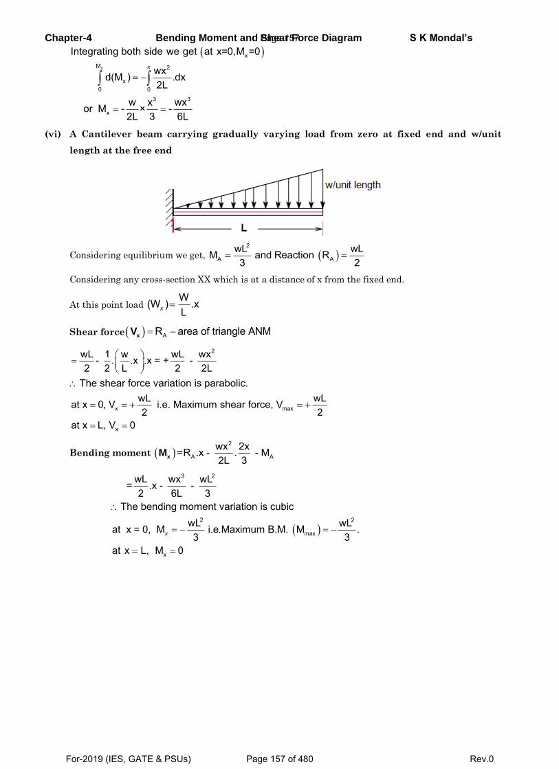
Chapter-4 Bending Moment and Shear Force Diagram S K Mondal’s
x
M 2
x0 0
3 3
x
Integrating both side we get at x=0,M =0
wxd(M ) .dx2L
w x wxor M - × -2L 3 6L
x x
(vi) A Cantilever beam carrying gradually varying load from zero at fixed end and w/unit
length at the free end
Considering equilibrium we get, 2
A AwL wLM and Reaction R3 2
Considering any cross-section XX which is at a distance of x from the fixed end.
At this point load W(W ) .xLx
Shear force AR area of triangle ANMxV
2
x max
x
wL 1 w wL wx- . .x .x = + - 2 2 L 2 2L
The shear force variation is parabolic.wL wLat x 0, V i.e. Maximum shear force, V2 2
at x L, V 0
Bending moment 2
A Awx 2x=R .x - . - M2L 3xM
3 2
2 2
max
x
wL wx wL= .x - - 2 6L 3
The bending moment variation is cubicwL wLat x = 0, M i.e.Maximum B.M. M .3 3
at x L, M 0
x
Page 157
For-2019 (IES, GATE & PSUs) Page 157 of 480 Rev.0
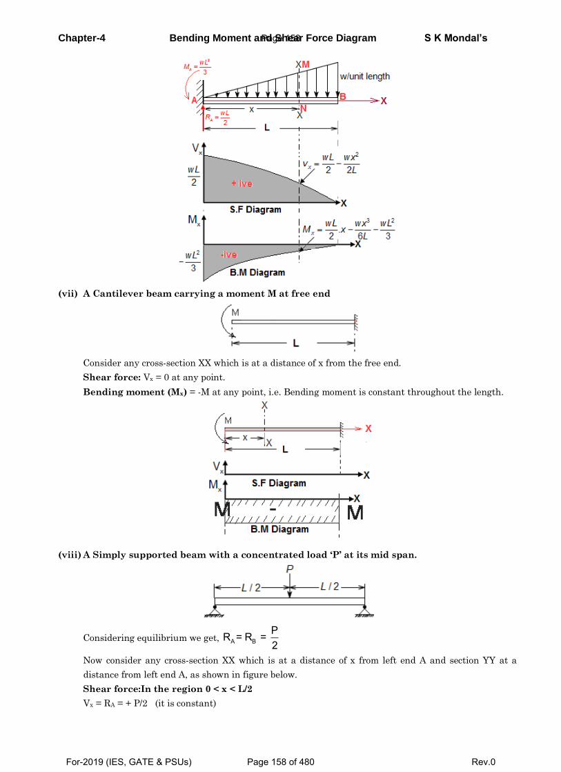
Chapter-4 Bending Moment and Shear Force Diagram S K Mondal’s
(vii) A Cantilever beam carrying a moment M at free end
Consider any cross-section XX which is at a distance of x from the free end.
Shear force: Vx = 0 at any point.
Bending moment (Mx) = -M at any point, i.e. Bending moment is constant throughout the length.
(viii) A Simply supported beam with a concentrated load ‘P’ at its mid span.
Considering equilibrium we get, A BPR = R = 2
Now consider any cross-section XX which is at a distance of x from left end A and section YY at a
distance from left end A, as shown in figure below.
Shear force:In the region 0 < x < L/2
Vx = RA = + P/2 (it is constant)
Page 158
For-2019 (IES, GATE & PSUs) Page 158 of 480 Rev.0
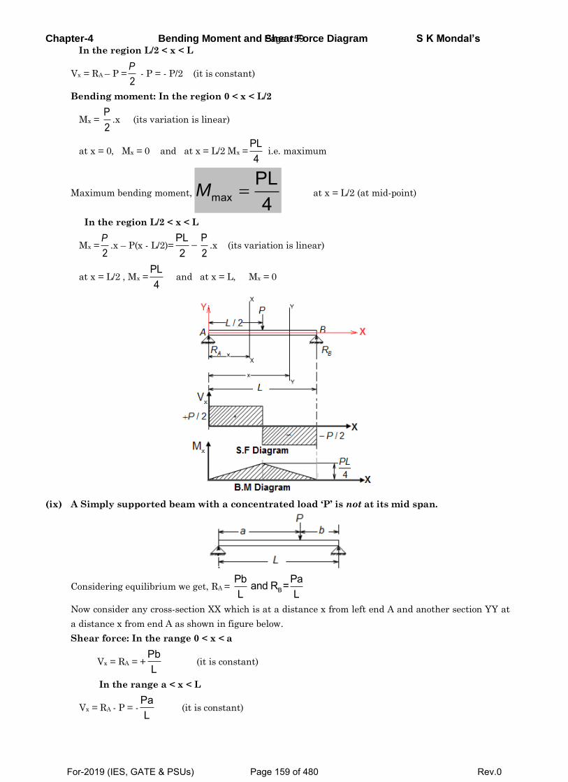
Chapter-4 Bending Moment and Shear Force Diagram S K Mondal’s In the region L/2 < x < L
Vx = RA – P =2P
- P = - P/2 (it is constant)
Bending moment: In the region 0 < x < L/2
Mx = P2
.x (its variation is linear)
at x = 0, Mx = 0 and at x = L/2 Mx =PL4
i.e. maximum
Maximum bending moment, maxPL4
M at x = L/2 (at mid-point)
In the region L/2 < x < L
Mx =2P
.x – P(x - L/2)=PL2
P2
.x (its variation is linear)
at x = L/2 , Mx =PL4
and at x = L, Mx = 0
(ix) A Simply supported beam with a concentrated load ‘P’ is not at its mid span.
Considering equilibrium we get, RA = BPb Paand R =L L
Now consider any cross-section XX which is at a distance x from left end A and another section YY at
a distance x from end A as shown in figure below.
Shear force: In the range 0 < x < a
Vx = RA = +PbL
(it is constant)
In the range a < x < L
Vx = RA - P = -PaL
(it is constant)
Page 159
For-2019 (IES, GATE & PSUs) Page 159 of 480 Rev.0
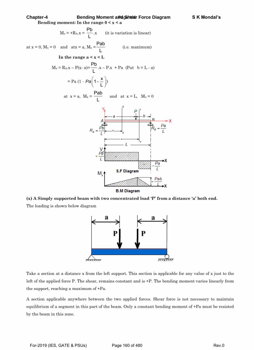
Chapter-4 Bending Moment and Shear Force Diagram S K Mondal’s Bending moment: In the range 0 < x < a
Mx = +RA.x = PbL
.x (it is variation is linear)
at x = 0, Mx = 0 and atx = a, Mx =Pab
L (i.e. maximum)
In the range a < x < L
Mx = RA.x – P(x- a)=PbL
.x – P.x + Pa (Put b = L - a)
= Pa (1 - x1L
Pa
)
at x = a, Mx = Pab
L and at x = L, Mx = 0
(x) A Simply supported beam with two concentrated load ‘P’ from a distance ‘a’ both end.
The loading is shown below diagram
Take a section at a distance x from the left support. This section is applicable for any value of x just to the
left of the applied force P. The shear, remains constant and is +P. The bending moment varies linearly from
the support, reaching a maximum of +Pa.
A section applicable anywhere between the two applied forces. Shear force is not necessary to maintain
equilibrium of a segment in this part of the beam. Only a constant bending moment of +Pa must be resisted
by the beam in this zone.
Page 160
For-2019 (IES, GATE & PSUs) Page 160 of 480 Rev.0

Chapter-4 Bending Moment and Shear Force Diagram S K Mondal’s Such a state of bending or flexure is called pure bending.
Shear and bending-moment diagrams for this loading condition are shown below.
(xi) A Simply supported beam with a uniformly distributed load (UDL) through out its length
We will solve this problem by following two alternative ways.
(a) By Method of Section
Considering equilibrium we get RA = RB = wL2
Now Consider any cross-section XX which is at a distance x from left end A.
Then the section view
Page 161
For-2019 (IES, GATE & PSUs) Page 161 of 480 Rev.0
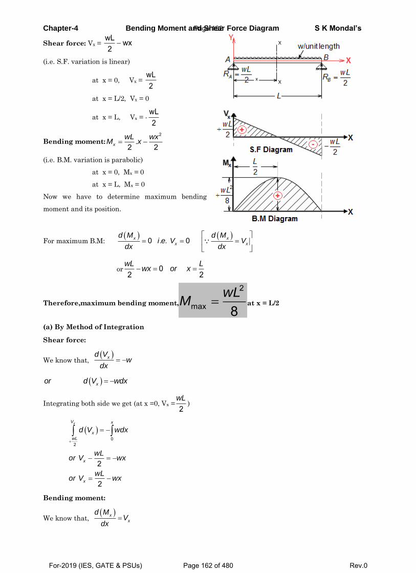
Chapter-4 Bending Moment and Shear Force Diagram S K Mondal’s
Shear force: Vx = wL wx2
(i.e. S.F. variation is linear)
at x = 0, Vx = wL2
at x = L/2, Vx = 0
at x = L, Vx = -wL2
Bending moment:2
.2 2x
wL wxM x
(i.e. B.M. variation is parabolic)
at x = 0, Mx = 0
at x = L, Mx = 0
Now we have to determine maximum bending
moment and its position.
For maximum B.M:
0 . . 0x x
x x
d M d Mi e V V
dx dx
or 02 2
wL Lwx or x
Therefore,maximum bending moment, 2
max 8wL
M at x = L/2
(a) By Method of Integration
Shear force:
We know that, xd V
wdx
xor d V wdx
Integrating both side we get (at x =0, Vx =2
wL)
0
2
2
2
xV x
x
wL
x
x
d V wdx
wLor V wx
wLor V wx
Bending moment:
We know that, x
x
d MV
dx
Page 162
For-2019 (IES, GATE & PSUs) Page 162 of 480 Rev.0
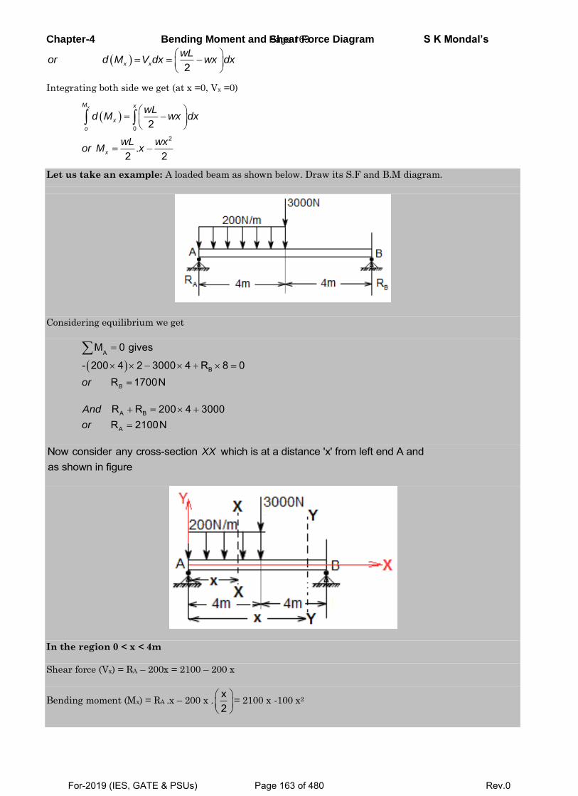
Chapter-4 Bending Moment and Shear Force Diagram S K Mondal’s
2x x
wLor d M V dx wx dx
Integrating both side we get (at x =0, Vx =0)
0
2
2
.2 2
xM x
x
o
x
wLd M wx dx
wL wxor M x
Let us take an example: A loaded beam as shown below. Draw its S.F and B.M diagram.
Considering equilibrium we get
A
B
M 0 gives
- 200 4 2 3000 4 R 8 0R 1700NBor
A B
A
R R 200 4 3000R 2100N
And
or
Now consider any cross-section which is at a distance 'x' from left end A andas shown in figure
XX
In the region 0 < x < 4m
Shear force (Vx) = RA – 200x = 2100 – 200 x
Bending moment (Mx) = RA .x – 200 x .x2
= 2100 x -100 x2
Page 163
For-2019 (IES, GATE & PSUs) Page 163 of 480 Rev.0
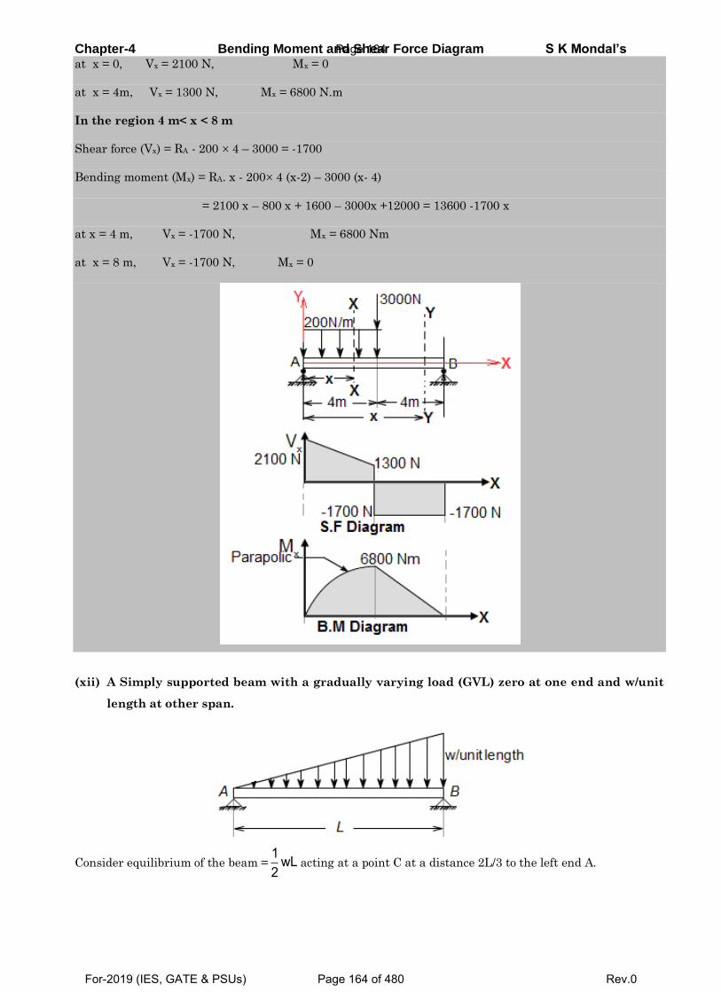
Chapter-4 Bending Moment and Shear Force Diagram S K Mondal’s at x = 0, Vx = 2100 N, Mx = 0
at x = 4m, Vx = 1300 N, Mx = 6800 N.m
In the region 4 m< x < 8 m
Shear force (Vx) = RA - 200 4 – 3000 = -1700
Bending moment (Mx) = RA. x - 200 4 (x-2) – 3000 (x- 4)
= 2100 x – 800 x + 1600 – 3000x +12000 = 13600 -1700 x
at x = 4 m, Vx = -1700 N, Mx = 6800 Nm
at x = 8 m, Vx = -1700 N, Mx = 0
(xii) A Simply supported beam with a gradually varying load (GVL) zero at one end and w/unit
length at other span.
Consider equilibrium of the beam =1 wL2
acting at a point C at a distance 2L/3 to the left end A.
Page 164
For-2019 (IES, GATE & PSUs) Page 164 of 480 Rev.0
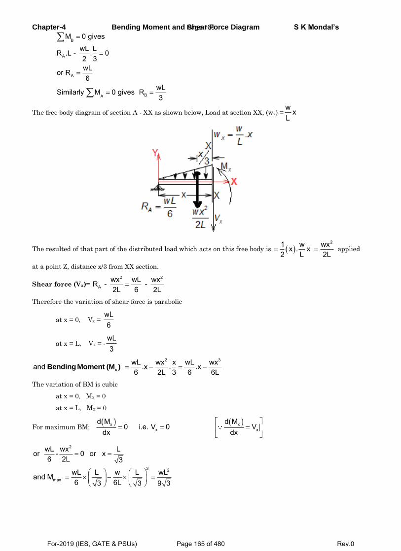
Chapter-4 Bending Moment and Shear Force Diagram S K Mondal’s
B
A
A
BA
M 0 gives
wL LR .L - . 02 3wLor R6
wLSimilarly M 0 gives R3
The free body diagram of section A - XX as shown below, Load at section XX, (wx) =w xL
The resulted of that part of the distributed load which acts on this free body is 21 w wxx . x
2 L 2L applied
at a point Z, distance x/3 from XX section.
Shear force (Vx)= 2 2
Awx wL wxR - - 2L 6 2L
Therefore the variation of shear force is parabolic
at x = 0, Vx = wL6
at x = L, Vx = -wL3
2 3wL wx x wL wxand .x . .x
6 2L 3 6 6LxBending Moment (M )
The variation of BM is cubic
at x = 0, Mx = 0
at x = L, Mx = 0
For maximum BM; x x
x x
d M d M0 i.e. V 0 V
dx dx
2
3 2
max
wL wx Lor - 0 or x6 2L 3
wL L w L wLand M6 6L3 3 9 3
Page 165
For-2019 (IES, GATE & PSUs) Page 165 of 480 Rev.0
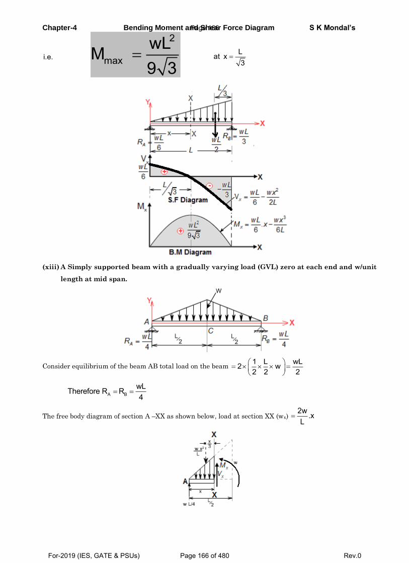
Chapter-4 Bending Moment and Shear Force Diagram S K Mondal’s
i.e. 2
maxwLM9 3
Lat x3
(xiii) A Simply supported beam with a gradually varying load (GVL) zero at each end and w/unit
length at mid span.
Consider equilibrium of the beam AB total load on the beam 1 L wL2 w2 2 2
A BwLTherefore R R4
The free body diagram of section A –XX as shown below, load at section XX (wx) 2w .xL
Page 166
For-2019 (IES, GATE & PSUs) Page 166 of 480 Rev.0
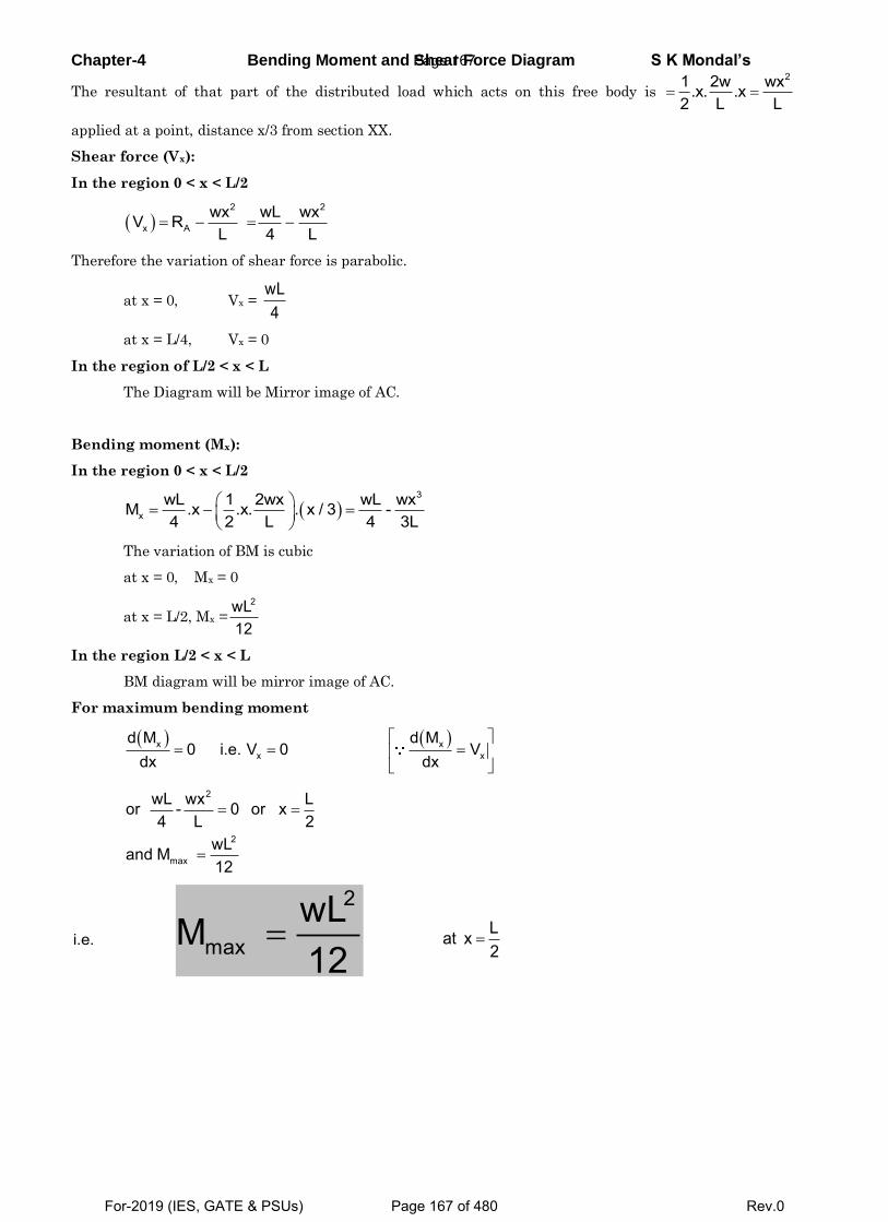
Chapter-4 Bending Moment and Shear Force Diagram S K Mondal’s
The resultant of that part of the distributed load which acts on this free body is 21 2w wx.x. .x
2 L L
applied at a point, distance x/3 from section XX.
Shear force (Vx):
In the region 0 < x < L/2
2 2
x Awx wL wxV RL 4 L
Therefore the variation of shear force is parabolic.
at x = 0, Vx = wL4
at x = L/4, Vx = 0
In the region of L/2 < x < L
The Diagram will be Mirror image of AC.
Bending moment (Mx):
In the region 0 < x < L/2
3
xwL 1 2wx wL wxM .x .x. . x / 3 -4 2 L 4 3L
The variation of BM is cubic
at x = 0, Mx = 0
at x = L/2, Mx =2wL
12
In the region L/2 < x < L
BM diagram will be mirror image of AC.
For maximum bending moment
x xx x
d M d M0 i.e. V 0 V
dx dx
2
2
max
wL wx Lor - 0 or x4 L 2
wLand M12
i.e. 2
maxwLM12
Lat x2
Page 167
For-2019 (IES, GATE & PSUs) Page 167 of 480 Rev.0
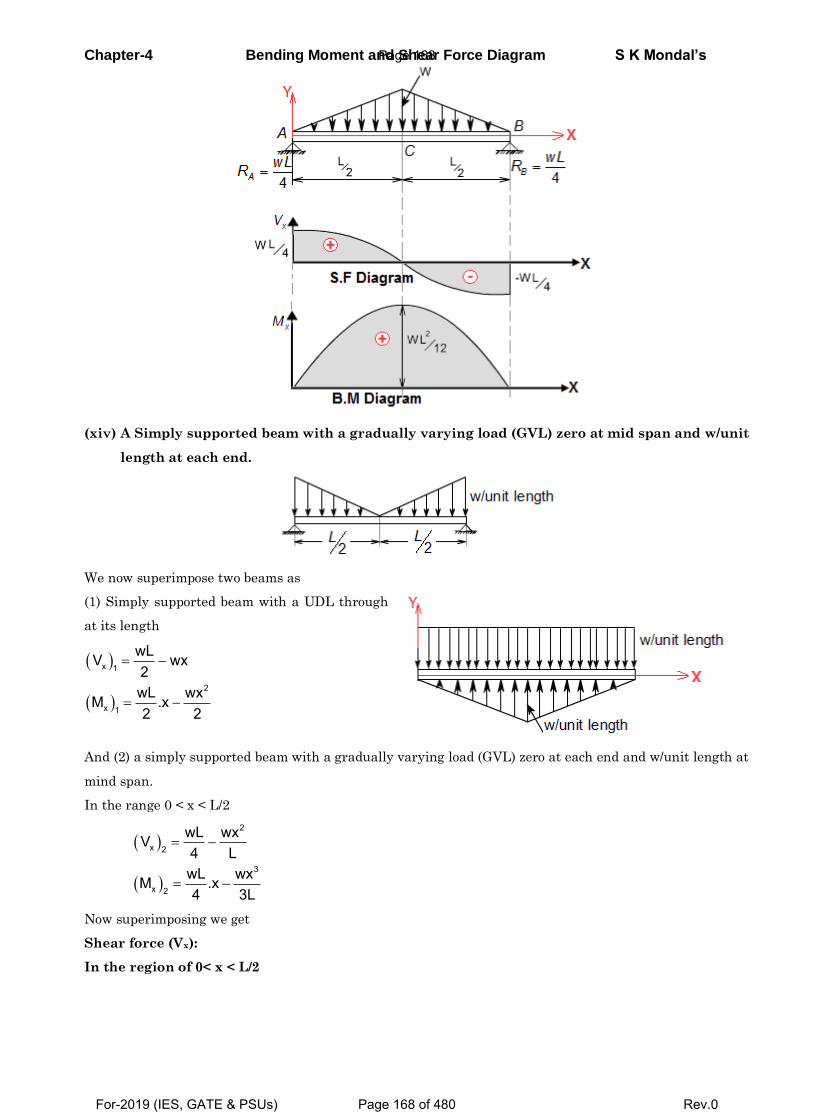
Chapter-4 Bending Moment and Shear Force Diagram S K Mondal’s
(xiv) A Simply supported beam with a gradually varying load (GVL) zero at mid span and w/unit
length at each end.
We now superimpose two beams as
(1) Simply supported beam with a UDL through
at its length
x 1
2
x 1
wLV wx2wL wxM .x2 2
And (2) a simply supported beam with a gradually varying load (GVL) zero at each end and w/unit length at
mind span.
In the range 0 < x < L/2
2
x 2
3
x 2
wL wxV4 LwL wxM .x4 3L
Now superimposing we get
Shear force (Vx):
In the region of 0< x < L/2
Page 168
For-2019 (IES, GATE & PSUs) Page 168 of 480 Rev.0
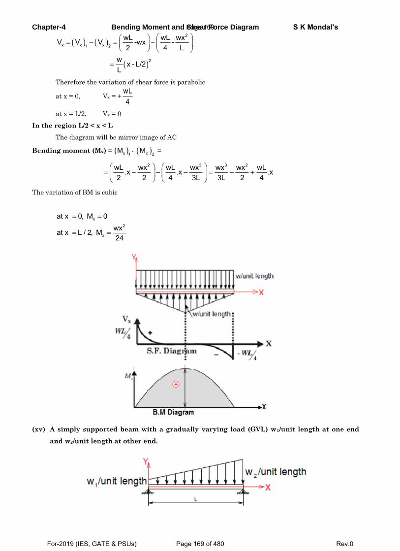
Chapter-4 Bending Moment and Shear Force Diagram S K Mondal’s
2
x x x1 2
2
wL wL wxV V V -wx -2 4 L
w x - L/2L
Therefore the variation of shear force is parabolic
at x = 0, Vx = +wL4
at x = L/2, Vx = 0
In the region L/2 < x < L
The diagram will be mirror image of AC
Bending moment (Mx) = x 1M - x 2
M =
2 3 3 2wL wx wL wx wx wx wL.x .x .x2 2 4 3L 3L 2 4
The variation of BM is cubic
x
2
x
at x 0, M 0wxat x L / 2, M24
(xv) A simply supported beam with a gradually varying load (GVL) w1/unit length at one end
and w2/unit length at other end.
Page 169
For-2019 (IES, GATE & PSUs) Page 169 of 480 Rev.0
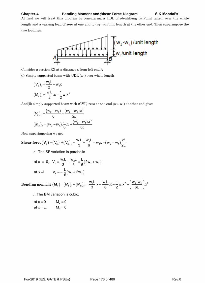
Chapter-4 Bending Moment and Shear Force Diagram S K Mondal’s At first we will treat this problem by considering a UDL of identifying (w1)/unit length over the whole
length and a varying load of zero at one end to (w2- w1)/unit length at the other end. Then superimpose the
two loadings.
Consider a section XX at a distance x from left end A
(i) Simply supported beam with UDL (w1) over whole length
1x 11
21x 11
w LV w x2
w L 1M .x w x2 2
And(ii) simply supported beam with (GVL) zero at one end (w2- w1) at other end gives
22 1 2 1
2
32 1
2 12
6 2
. .6 6
x
x
w w w w xV
L
w w xLM w w x
L
Now superimposing we get
Shear force 2
1 2x x 1 2 11 2
w L w L xV + V + w x w w3 6 2LxV
The SF variation is parabolic
1 2x 1 2
x 1 2
w L w L Lat x 0, V 2w w3 6 6Lat x L, V w 2w6
Bending moment
2 31 1 2 1x x 11 2
w L w L w -w1M M .x .x w x .x3 6 2 6LxM
The BM variation is cubic.
x
x
at x 0, M 0at x L, M 0
Page 170
For-2019 (IES, GATE & PSUs) Page 170 of 480 Rev.0
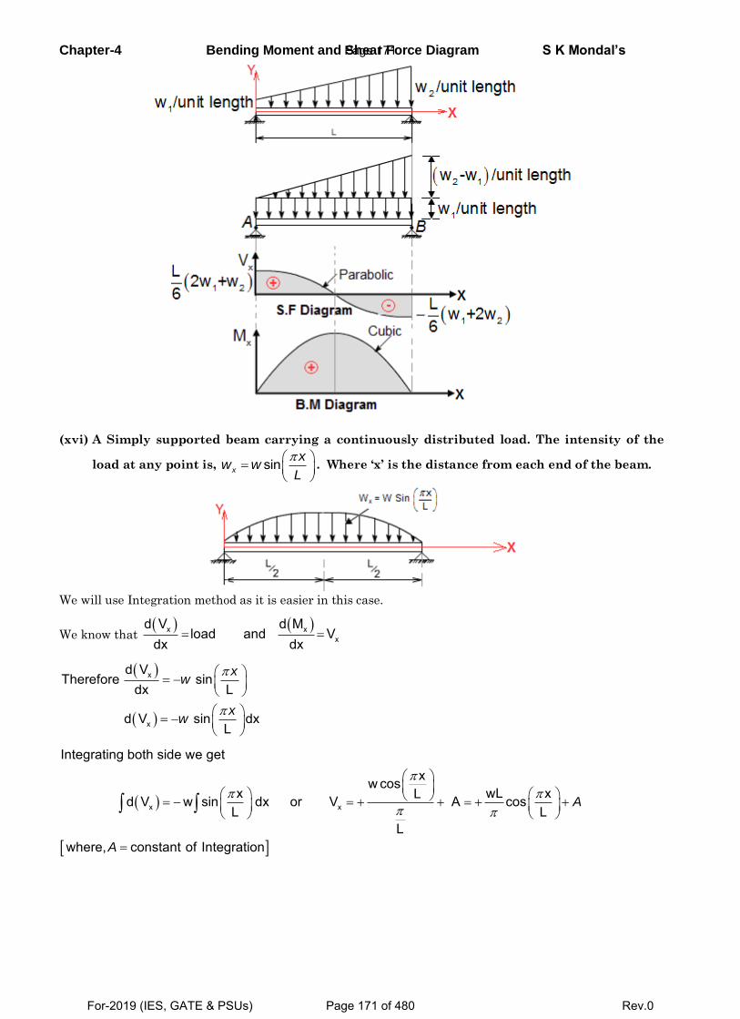
Chapter-4 Bending Moment and Shear Force Diagram S K Mondal’s
(xvi) A Simply supported beam carrying a continuously distributed load. The intensity of the
load at any point is,
sinx
xw w
L. Where ‘x’ is the distance from each end of the beam.
We will use Integration method as it is easier in this case.
We know that x x
x
d V d Mload and V
dx dx
x
x
d VTherefore sin
dx L
d V sin dxL
xw
xw
x x
Integrating both side we getxw cos
x wL xLd V w sin dx or V A cosL L
Lwhere, constant of Integration
A
A
Page 171
For-2019 (IES, GATE & PSUs) Page 171 of 480 Rev.0
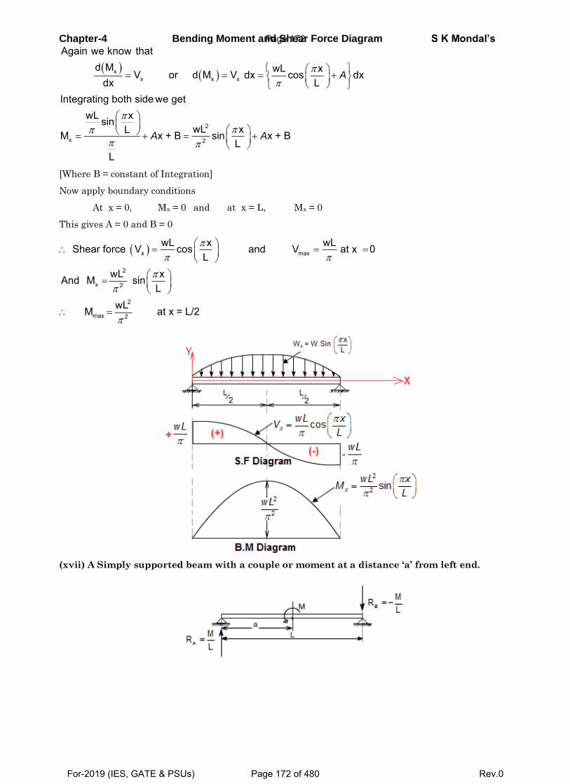
Chapter-4 Bending Moment and Shear Force Diagram S K Mondal’s
xx x x
2
x 2
Again we know thatd M wL xV or d M V dx cos dx
dx LIntegrating both side we get
wL xsinwL xLM x + B sin x + B
LL
A
A A
[Where B = constant of Integration]
Now apply boundary conditions
At x = 0, Mx = 0 and at x = L, Mx = 0
This gives A = 0 and B = 0
x max
2
x 2
2
max 2
wL x wL Shear force V cos and V at x 0L
wL xAnd M sinL
wLM at x = L/2
(xvii) A Simply supported beam with a couple or moment at a distance ‘a’ from left end.
Page 172
For-2019 (IES, GATE & PSUs) Page 172 of 480 Rev.0
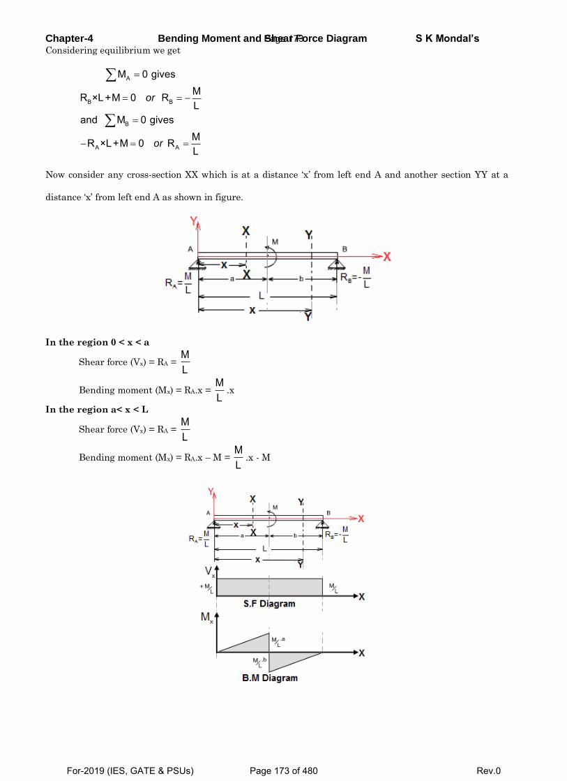
Chapter-4 Bending Moment and Shear Force Diagram S K Mondal’s Considering equilibrium we get
A
B B
B
A A
M 0 givesMR ×L+M 0 RL
and M 0 givesMR ×L+M 0 RL
or
or
Now consider any cross-section XX which is at a distance ‘x’ from left end A and another section YY at a
distance ‘x’ from left end A as shown in figure.
In the region 0 < x < a
Shear force (Vx) = RA = ML
Bending moment (Mx) = RA.x = ML
.x
In the region a< x < L
Shear force (Vx) = RA = ML
Bending moment (Mx) = RA.x – M = ML
.x - M
Page 173
For-2019 (IES, GATE & PSUs) Page 173 of 480 Rev.0
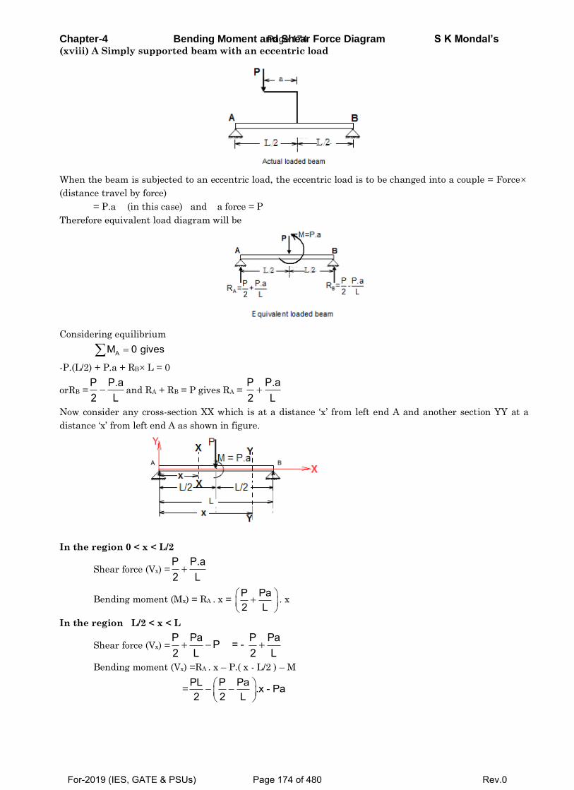
Chapter-4 Bending Moment and Shear Force Diagram S K Mondal’s (xviii) A Simply supported beam with an eccentric load
When the beam is subjected to an eccentric load, the eccentric load is to be changed into a couple = Force
(distance travel by force)
= P.a (in this case) and a force = P
Therefore equivalent load diagram will be
Considering equilibrium
AM 0 gives
-P.(L/2) + P.a + RB L = 0
orRB =P P.a2 L and RA + RB = P gives RA =
P P.a2 L
Now consider any cross-section XX which is at a distance ‘x’ from left end A and another section YY at a
distance ‘x’ from left end A as shown in figure.
In the region 0 < x < L/2
Shear force (Vx) =P P.a2 L
Bending moment (Mx) = RA . x = P Pa2 L
. x
In the region L/2 < x < L
Shear force (Vx) =P Pa P PaP = -2 L 2 L
Bending moment (Vx) =RA . x – P.( x - L/2 ) – M
=PL P Pa .x - Pa2 2 L
Page 174
For-2019 (IES, GATE & PSUs) Page 174 of 480 Rev.0
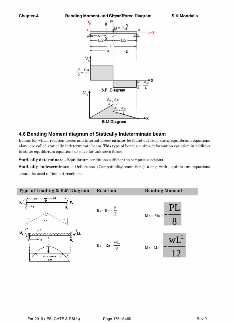
Chapter-4 Bending Moment and Shear Force Diagram S K Mondal’s
4.6 Bending Moment diagram of Statically Indeterminate beam
Beams for which reaction forces and internal forces cannot be found out from static equilibrium equations
alone are called statically indeterminate beam. This type of beam requires deformation equation in addition
to static equilibrium equations to solve for unknown forces.
Statically determinate - Equilibrium conditions sufficient to compute reactions.
Statically indeterminate - Deflections (Compatibility conditions) along with equilibrium equations
should be used to find out reactions.
Type of Loading & B.M Diagram Reaction Bending Moment
RA= RB = P
2
MA = MB =
PL-
8
RA = RB =wL
2
MA= MB =
2wL-
12
Page 175
For-2019 (IES, GATE & PSUs) Page 175 of 480 Rev.0
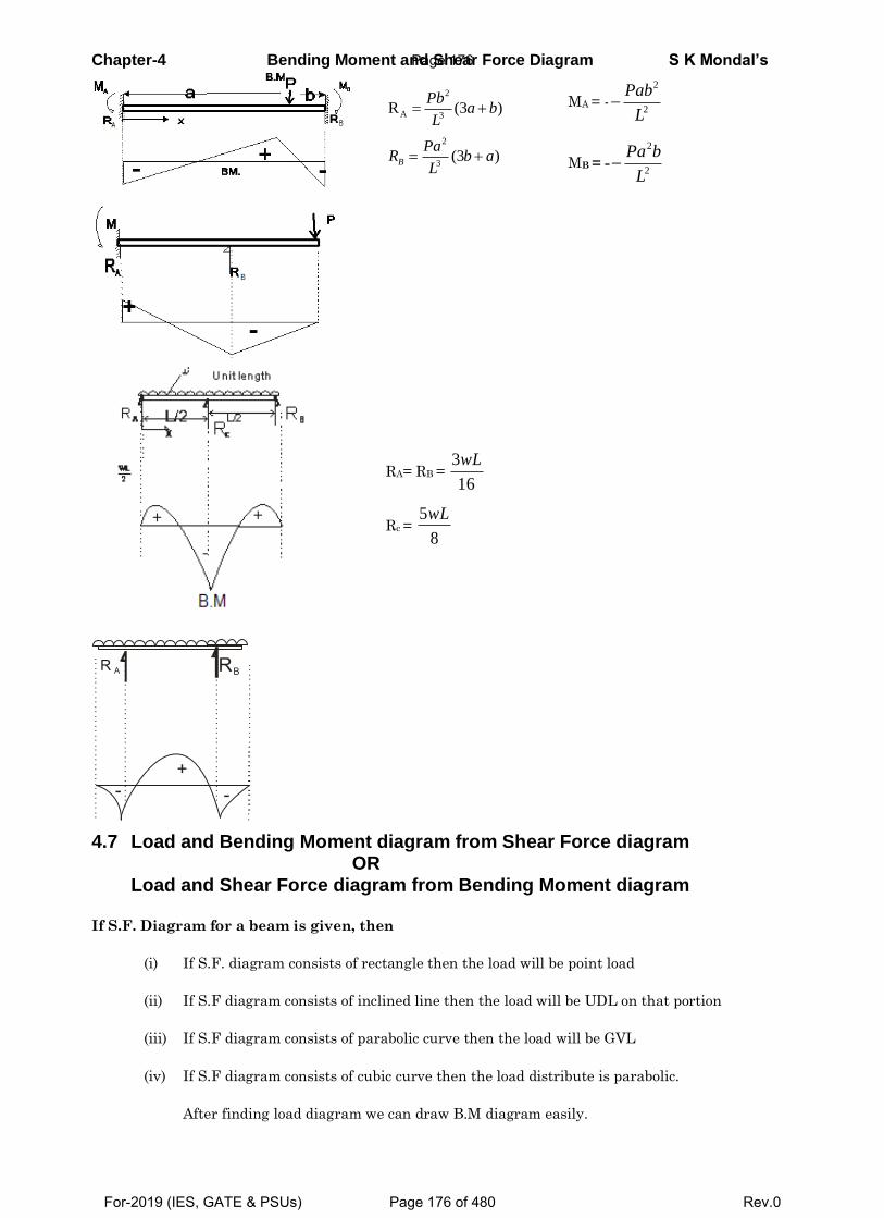
Chapter-4 Bending Moment and Shear Force Diagram S K Mondal’s
2
A 3
2
3
R (3 )
(3 )B
Pba b
L
PaR b a
L
MA = -
2
2
Pab
L
MB = -
2
2
Pa b
L
RA= RB = 3
16
wL
Rc = 5
8
wL
R A RB
+--
4.7 Load and Bending Moment diagram from Shear Force diagram OR Load and Shear Force diagram from Bending Moment diagram
If S.F. Diagram for a beam is given, then
(i) If S.F. diagram consists of rectangle then the load will be point load
(ii) If S.F diagram consists of inclined line then the load will be UDL on that portion
(iii) If S.F diagram consists of parabolic curve then the load will be GVL
(iv) If S.F diagram consists of cubic curve then the load distribute is parabolic.
After finding load diagram we can draw B.M diagram easily.
Page 176
For-2019 (IES, GATE & PSUs) Page 176 of 480 Rev.0
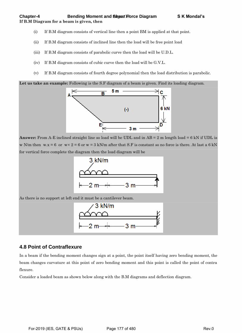
Chapter-4 Bending Moment and Shear Force Diagram S K Mondal’s If B.M Diagram for a beam is given, then
(i) If B.M diagram consists of vertical line then a point BM is applied at that point.
(ii) If B.M diagram consists of inclined line then the load will be free point load
(iii) If B.M diagram consists of parabolic curve then the load will be U.D.L.
(iv) If B.M diagram consists of cubic curve then the load will be G.V.L.
(v) If B.M diagram consists of fourth degree polynomial then the load distribution is parabolic.
Let us take an example: Following is the S.F diagram of a beam is given. Find its loading diagram.
Answer: From A-E inclined straight line so load will be UDL and in AB = 2 m length load = 6 kN if UDL is
w N/m then w.x = 6 or w 2 = 6 or w = 3 kN/m after that S.F is constant so no force is there. At last a 6 kN
for vertical force complete the diagram then the load diagram will be
As there is no support at left end it must be a cantilever beam.
4.8 Point of Contraflexure
In a beam if the bending moment changes sign at a point, the point itself having zero bending moment, the
beam changes curvature at this point of zero bending moment and this point is called the point of contra
flexure.
Consider a loaded beam as shown below along with the B.M diagrams and deflection diagram.
Page 177
For-2019 (IES, GATE & PSUs) Page 177 of 480 Rev.0
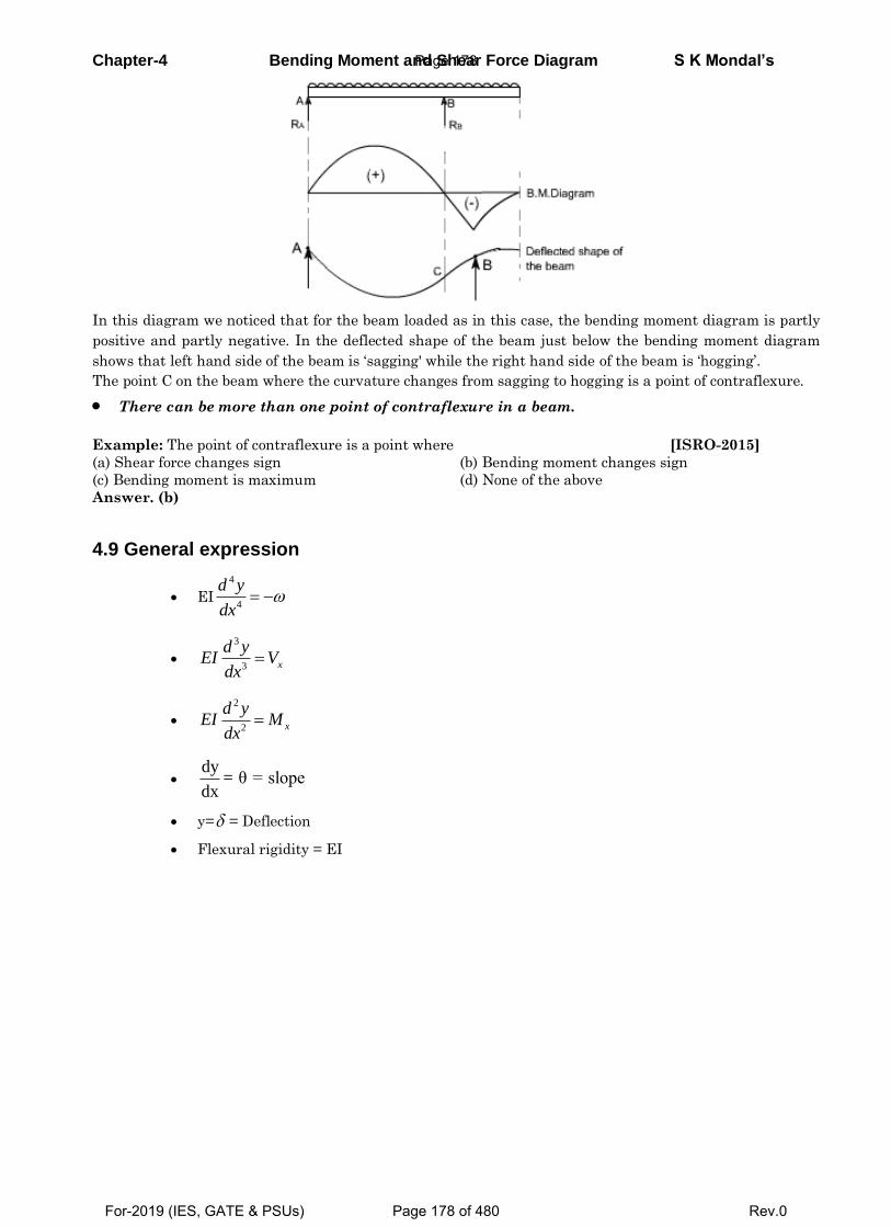
Chapter-4 Bending Moment and Shear Force Diagram S K Mondal’s
In this diagram we noticed that for the beam loaded as in this case, the bending moment diagram is partly
positive and partly negative. In the deflected shape of the beam just below the bending moment diagram
shows that left hand side of the beam is ‘sagging' while the right hand side of the beam is ‘hogging’.
The point C on the beam where the curvature changes from sagging to hogging is a point of contraflexure.
There can be more than one point of contraflexure in a beam.
Example: The point of contraflexure is a point where [ISRO-2015]
(a) Shear force changes sign (b) Bending moment changes sign
(c) Bending moment is maximum (d) None of the above
Answer. (b)
4.9 General expression
EI
4
4
d y
dx
3
3 x
d yEI V
dx
2
2 x
d yEI M
dx
dy
= θ = slopedx
y= = Deflection
Flexural rigidity = EI
Page 178
For-2019 (IES, GATE & PSUs) Page 178 of 480 Rev.0
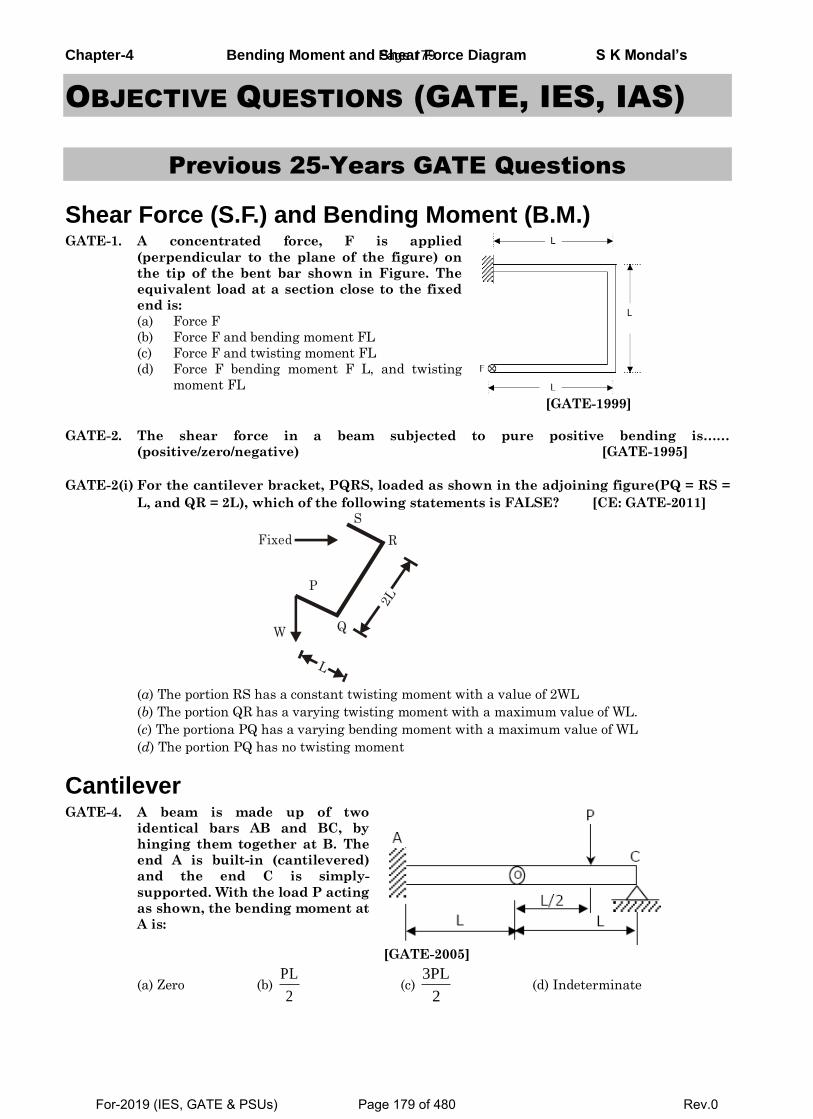
Chapter-4 Bending Moment and Shear Force Diagram S K Mondal’s
OBJECTIVE QUESTIONS (GATE, IES, IAS)
Previous 25-Years GATE Questions
Shear Force (S.F.) and Bending Moment (B.M.) GATE-1. A concentrated force, F is applied
(perpendicular to the plane of the figure) on
the tip of the bent bar shown in Figure. The
equivalent load at a section close to the fixed
end is:
(a) Force F
(b) Force F and bending moment FL
(c) Force F and twisting moment FL
(d) Force F bending moment F L, and twisting
moment FL [GATE-1999]
GATE-2. The shear force in a beam subjected to pure positive bending is……
(positive/zero/negative) [GATE-1995]
GATE-2(i) For the cantilever bracket, PQRS, loaded as shown in the adjoining figure(PQ = RS =
L, and QR = 2L), which of the following statements is FALSE? [CE: GATE-2011]
R
S
P
Fixed
W
L
Q
2L
(a) The portion RS has a constant twisting moment with a value of 2WL
(b) The portion QR has a varying twisting moment with a maximum value of WL.
(c) The portiona PQ has a varying bending moment with a maximum value of WL
(d) The portion PQ has no twisting moment
Cantilever GATE-4. A beam is made up of two
identical bars AB and BC, by
hinging them together at B. The
end A is built-in (cantilevered)
and the end C is simply-
supported. With the load P acting
as shown, the bending moment at
A is:
[GATE-2005]
(a) Zero (b) PL
2 (c)
3PL
2 (d) Indeterminate
Page 179
For-2019 (IES, GATE & PSUs) Page 179 of 480 Rev.0
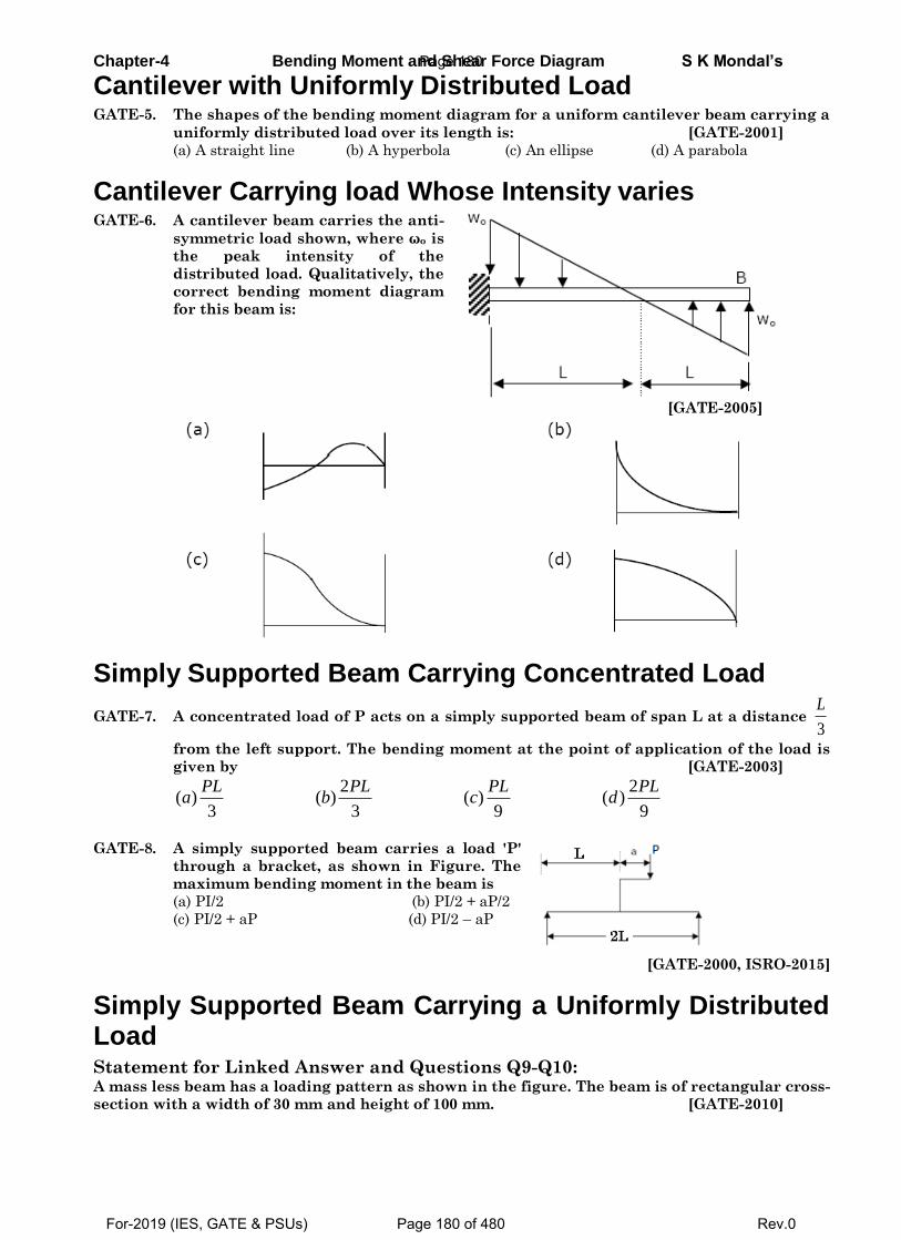
Chapter-4 Bending Moment and Shear Force Diagram S K Mondal’s
Cantilever with Uniformly Distributed Load GATE-5. The shapes of the bending moment diagram for a uniform cantilever beam carrying a
uniformly distributed load over its length is: [GATE-2001]
(a) A straight line (b) A hyperbola (c) An ellipse (d) A parabola
Cantilever Carrying load Whose Intensity varies GATE-6. A cantilever beam carries the anti-
symmetric load shown, where ωo is
the peak intensity of the
distributed load. Qualitatively, the
correct bending moment diagram
for this beam is:
[GATE-2005]
Simply Supported Beam Carrying Concentrated Load
GATE-7. A concentrated load of P acts on a simply supported beam of span L at a distance 3
L
from the left support. The bending moment at the point of application of the load is
given by [GATE-2003]
2 2
( ) ( ) ( ) ( )3 3 9 9
PL PL PL PLa b c d
GATE-8. A simply supported beam carries a load 'P'
through a bracket, as shown in Figure. The
maximum bending moment in the beam is
(a) PI/2 (b) PI/2 + aP/2
(c) PI/2 + aP (d) PI/2 – aP
[GATE-2000, ISRO-2015]
Simply Supported Beam Carrying a Uniformly Distributed Load Statement for Linked Answer and Questions Q9-Q10: A mass less beam has a loading pattern as shown in the figure. The beam is of rectangular cross-
section with a width of 30 mm and height of 100 mm. [GATE-2010]
Page 180
For-2019 (IES, GATE & PSUs) Page 180 of 480 Rev.0
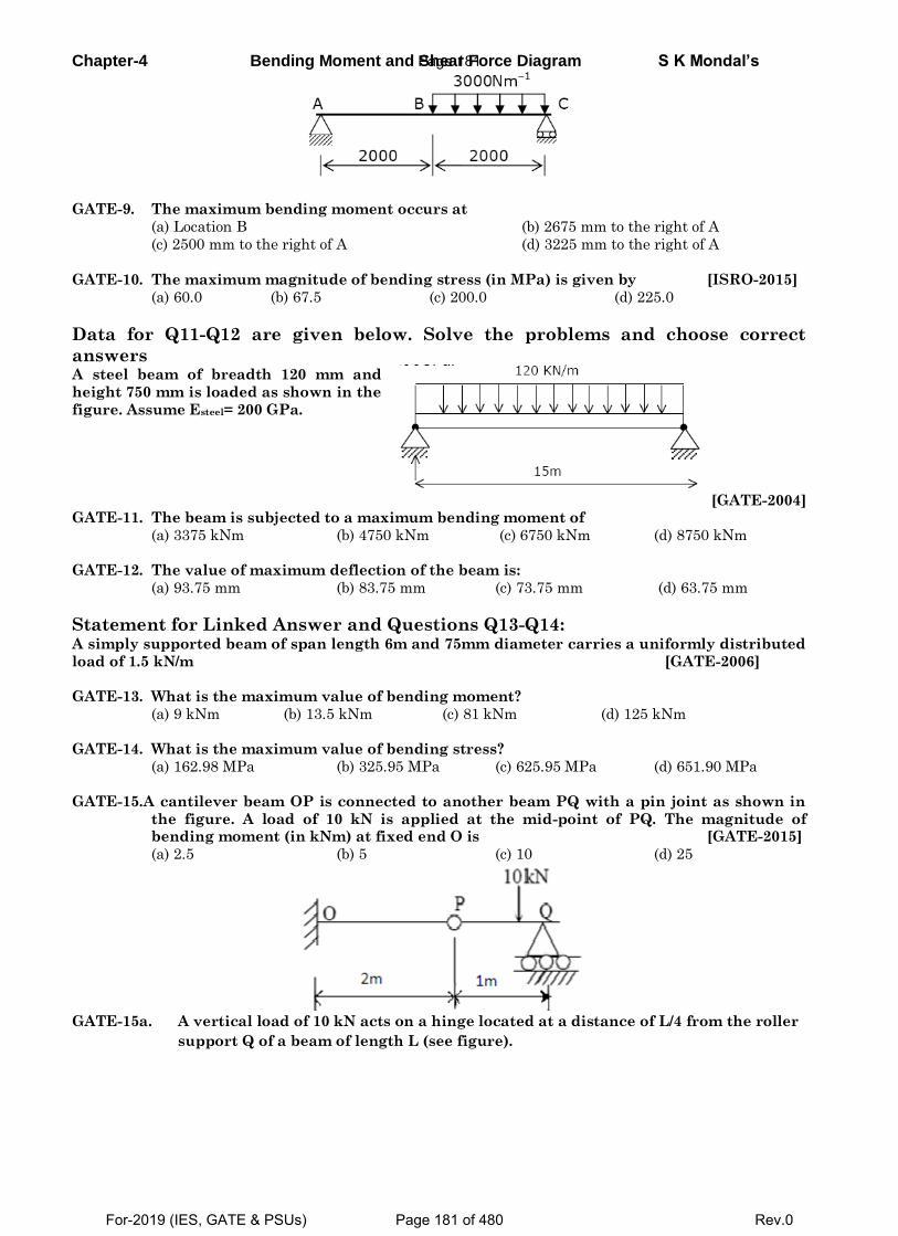
Chapter-4 Bending Moment and Shear Force Diagram S K Mondal’s
GATE-9. The maximum bending moment occurs at
(a) Location B (b) 2675 mm to the right of A
(c) 2500 mm to the right of A (d) 3225 mm to the right of A
GATE-10. The maximum magnitude of bending stress (in MPa) is given by [ISRO-2015]
(a) 60.0 (b) 67.5 (c) 200.0 (d) 225.0
Data for Q11-Q12 are given below. Solve the problems and choose correct
answers A steel beam of breadth 120 mm and
height 750 mm is loaded as shown in the
figure. Assume Esteel= 200 GPa.
[GATE-2004]
GATE-11. The beam is subjected to a maximum bending moment of
(a) 3375 kNm (b) 4750 kNm (c) 6750 kNm (d) 8750 kNm
GATE-12. The value of maximum deflection of the beam is:
(a) 93.75 mm (b) 83.75 mm (c) 73.75 mm (d) 63.75 mm
Statement for Linked Answer and Questions Q13-Q14: A simply supported beam of span length 6m and 75mm diameter carries a uniformly distributed
load of 1.5 kN/m [GATE-2006]
GATE-13. What is the maximum value of bending moment?
(a) 9 kNm (b) 13.5 kNm (c) 81 kNm (d) 125 kNm
GATE-14. What is the maximum value of bending stress?
(a) 162.98 MPa (b) 325.95 MPa (c) 625.95 MPa (d) 651.90 MPa
GATE-15.A cantilever beam OP is connected to another beam PQ with a pin joint as shown in
the figure. A load of 10 kN is applied at the mid-point of PQ. The magnitude of bending moment (in kNm) at fixed end O is [GATE-2015]
(a) 2.5 (b) 5 (c) 10 (d) 25
GATE-15a. A vertical load of 10 kN acts on a hinge located at a distance of L/4 from the roller
support Q of a beam of length L (see figure).
Page 181
For-2019 (IES, GATE & PSUs) Page 181 of 480 Rev.0
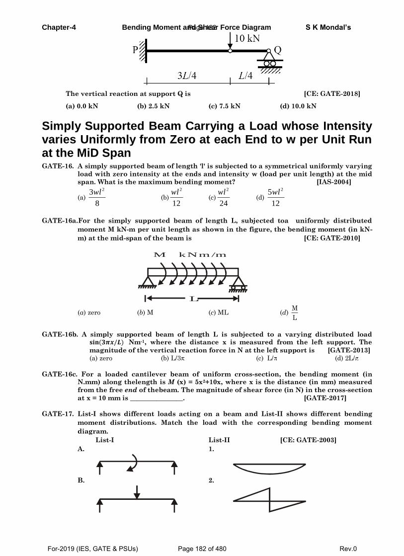
Chapter-4 Bending Moment and Shear Force Diagram S K Mondal’s
The vertical reaction at support Q is [CE: GATE-2018]
(a) 0.0 kN (b) 2.5 kN (c) 7.5 kN (d) 10.0 kN
Simply Supported Beam Carrying a Load whose Intensity varies Uniformly from Zero at each End to w per Unit Run at the MiD Span GATE-16. A simply supported beam of length 'l' is subjected to a symmetrical uniformly varying
load with zero intensity at the ends and intensity w (load per unit length) at the mid
span. What is the maximum bending moment? [IAS-2004]
(a)
23
8
wl (b)
2
12
wl (c)
2
24
wl (d)
25
12
wl
GATE-16a.For the simply supported beam of length L, subjected toa uniformly distributed
moment M kN-m per unit length as shown in the figure, the bending moment (in kN-
m) at the mid-span of the beam is [CE: GATE-2010]
L
M kNm/m
(a) zero (b) M (c) ML (d) M
L
GATE-16b. A simply supported beam of length L is subjected to a varying distributed load 𝐬𝐢𝐧(𝟑𝝅𝒙/𝑳) Nm-1, where the distance x is measured from the left support. The
magnitude of the vertical reaction force in N at the left support is [GATE-2013]
(a) zero (b) L/3 (c) L/ (d) 2L/
GATE-16c. For a loaded cantilever beam of uniform cross-section, the bending moment (in N.mm) along thelength is M (x) = 5x2+10x, where x is the distance (in mm) measured
from the free end of thebeam. The magnitude of shear force (in N) in the cross-section
at x = 10 mm is ________________. [GATE-2017]
GATE-17. List-I shows different loads acting on a beam and List-II shows different bending
moment distributions. Match the load with the corresponding bending moment
diagram.
List-I List-II [CE: GATE-2003]
A. 1.
B. 2.
Page 182
For-2019 (IES, GATE & PSUs) Page 182 of 480 Rev.0
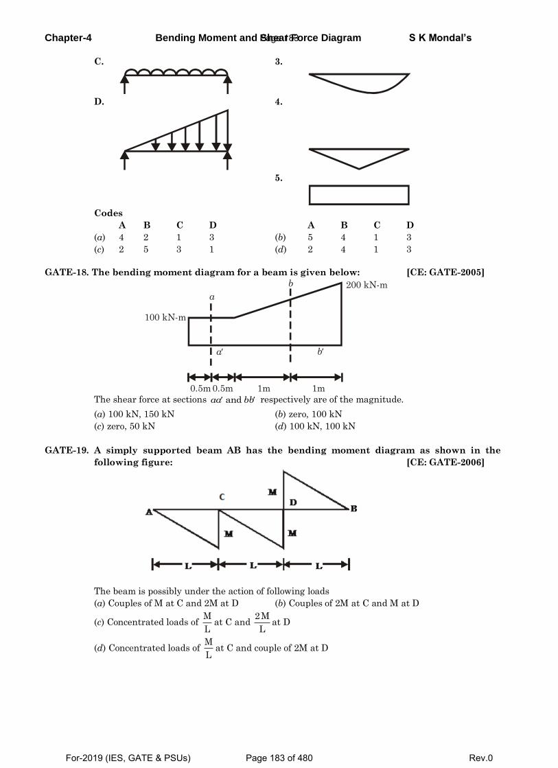
Chapter-4 Bending Moment and Shear Force Diagram S K Mondal’s
C. 3.
D. 4.
5.
Codes
A B C D A B C D
(a) 4 2 1 3 (b) 5 4 1 3
(c) 2 5 3 1 (d) 2 4 1 3
GATE-18. The bending moment diagram for a beam is given below: [CE: GATE-2005]
100 kN-m
200 kN-m
a
b
ba
0.5m 0.5m 1m 1m The shear force at sections andaa bb respectively are of the magnitude.
(a) 100 kN, 150 kN (b) zero, 100 kN
(c) zero, 50 kN (d) 100 kN, 100 kN
GATE-19. A simply supported beam AB has the bending moment diagram as shown in the
following figure: [CE: GATE-2006]
The beam is possibly under the action of following loads
(a) Couples of M at C and 2M at D (b) Couples of 2M at C and M at D
(c) Concentrated loads of M
Lat C and
2M
Lat D
(d) Concentrated loads of M
Lat C and couple of 2M at D
Page 183
For-2019 (IES, GATE & PSUs) Page 183 of 480 Rev.0
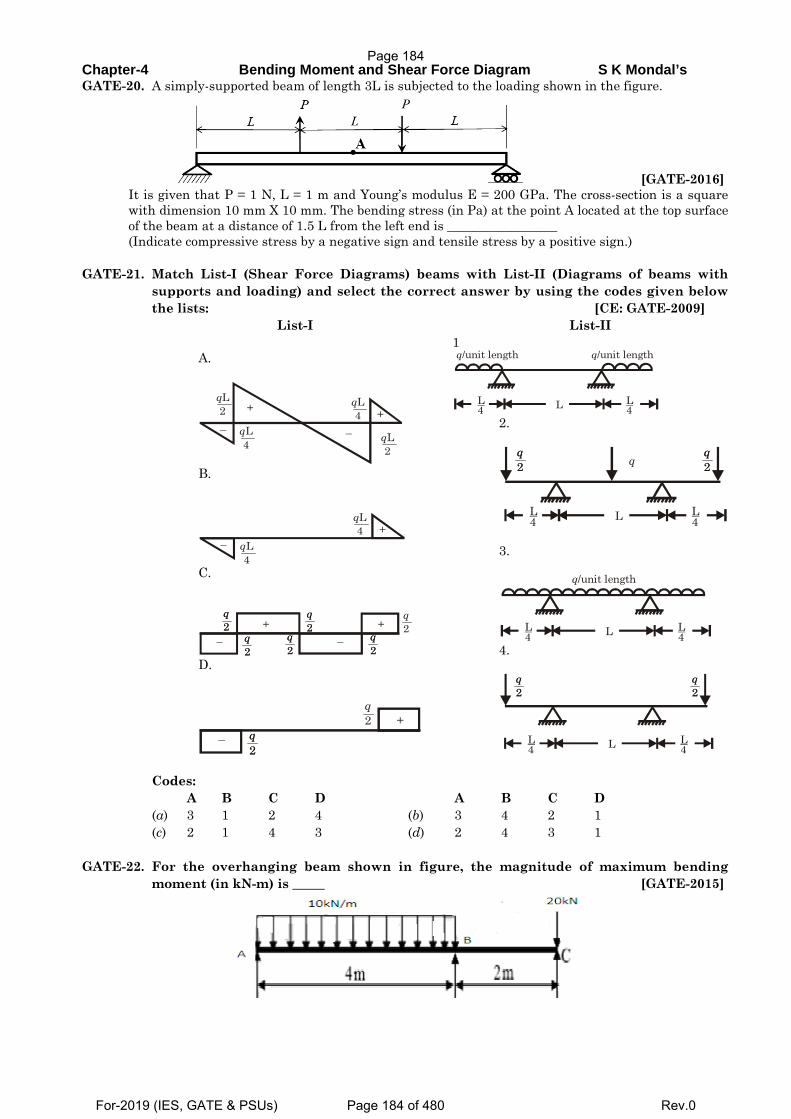
Chapter-4 Bending Moment and Shear Force Diagram S K Mondal’s GATE-20. A simply-supported beam of length 3L is subjected to the loading shown in the figure.
[GATE-2016] It is given that P = 1 N, L = 1 m and Young’s modulus E = 200 GPa. The cross-section is a square with dimension 10 mm X 10 mm. The bending stress (in Pa) at the point A located at the top surface of the beam at a distance of 1.5 L from the left end is _________________ (Indicate compressive stress by a negative sign and tensile stress by a positive sign.)
GATE-21. Match List-I (Shear Force Diagrams) beams with List-II (Diagrams of beams with
supports and loading) and select the correct answer by using the codes given below the lists: [CE: GATE-2009]
List-I List-II A.
qL4
qL4 +
–
+
– qL2
qL2
B.
qL4
qL4 +
–
C.
q2
q2
q2
q2
q2 +
–+
–
q2q2
q2q2
q2q2
D.
q2
q2q2
+–
1
L4
L4L
q/unit length q/unit length
2.
L4
q2
L4L
q2
q2q2 q
3.
L4
L4L
q/unit length
4.
L4
q2
L4L
q2
q2q2
Codes: A B C D A B C D (a) 3 1 2 4 (b) 3 4 2 1 (c) 2 1 4 3 (d) 2 4 3 1 GATE-22. For the overhanging beam shown in figure, the magnitude of maximum bending
moment (in kN-m) is _____ [GATE-2015]
Page 184
For-2019 (IES, GATE & PSUs) Page 184 of 480 Rev.0
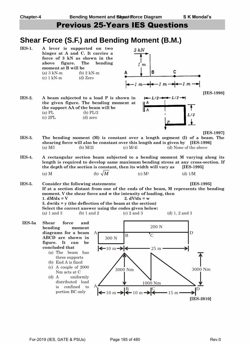
Chapter-4 Bending Moment and Shear Force Diagram S K Mondal’s
Previous 25-Years IES Questions
Shear Force (S.F.) and Bending Moment (B.M.) IES-1. A lever is supported on two
hinges at A and C. It carries a
force of 3 kN as shown in the
above figure. The bending
moment at B will be
(a) 3 kN-m (b) 2 kN-m
(c) 1 kN-m (d) Zero
[IES-1998]
IES-2. A beam subjected to a load P is shown in
the given figure. The bending moment at
the support AA of the beam will be
(a) PL (b) PL/2
(c) 2PL (d) zero
[IES-1997]
IES-3. The bending moment (M) is constant over a length segment (I) of a beam. The
shearing force will also be constant over this length and is given by [IES-1996]
(a) M/l (b) M/2l (c) M/4l (d) None of the above
IES-4. A rectangular section beam subjected to a bending moment M varying along its
length is required to develop same maximum bending stress at any cross-section. If the depth of the section is constant, then its width will vary as [IES-1995]
(a) M (b) M (c) M2 (d) 1/M
IES-5. Consider the following statements: [IES-1995]
If at a section distant from one of the ends of the beam, M represents the bending
moment. V the shear force and w the intensity of loading, then 1. dM/dx = V 2. dV/dx = w
3. dw/dx = y (the deflection of the beam at the section)
Select the correct answer using the codes given below: (a) 1 and 3 (b) 1 and 2 (c) 2 and 3 (d) 1, 2 and 3
IES-5a Shear force and
bending moment
diagrams for a beam
ABCD are shown in
figure. It can be
concluded that
(a) The beam has
three supports
(b) End A is fixed
(c) A couple of 2000
Nm acts at C
(d) A uniformly
distributed load
is confined to
portion BC only
300 N
200 N
10 m 25 m
A DB C
3000 Nm
10 m 10 m 15 m
1000 Nm
3000 Nm
AB C D
[IES-2010]
Page 185
For-2019 (IES, GATE & PSUs) Page 185 of 480 Rev.0
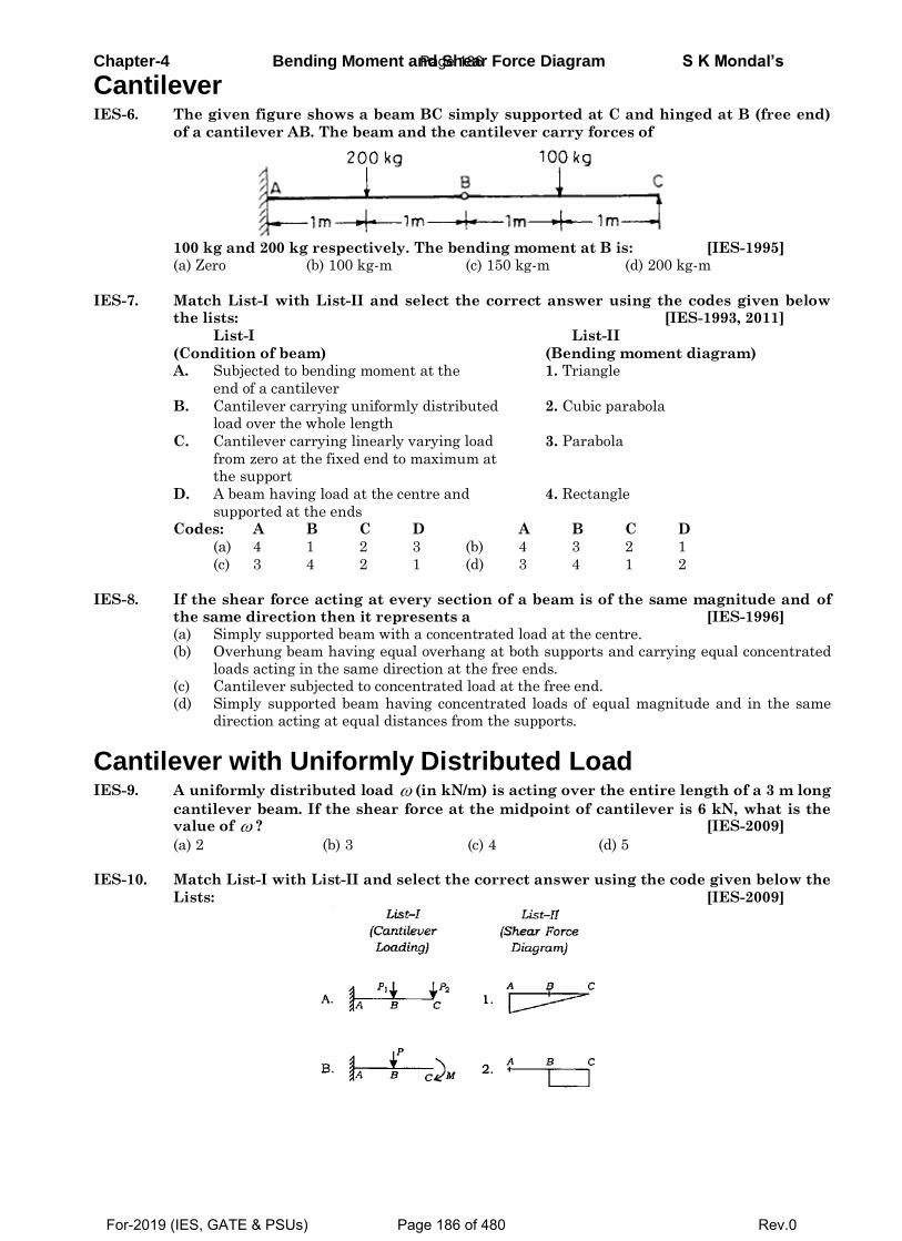
Chapter-4 Bending Moment and Shear Force Diagram S K Mondal’s
Cantilever IES-6. The given figure shows a beam BC simply supported at C and hinged at B (free end)
of a cantilever AB. The beam and the cantilever carry forces of
100 kg and 200 kg respectively. The bending moment at B is: [IES-1995] (a) Zero (b) 100 kg-m (c) 150 kg-m (d) 200 kg-m
IES-7. Match List-I with List-II and select the correct answer using the codes given below the lists: [IES-1993, 2011]
List-I List-II
(Condition of beam) (Bending moment diagram) A. Subjected to bending moment at the 1. Triangle
end of a cantilever
B. Cantilever carrying uniformly distributed 2. Cubic parabola load over the whole length
C. Cantilever carrying linearly varying load 3. Parabola
from zero at the fixed end to maximum at the support
D. A beam having load at the centre and 4. Rectangle
supported at the ends Codes: A B C D A B C D
(a) 4 1 2 3 (b) 4 3 2 1
(c) 3 4 2 1 (d) 3 4 1 2
IES-8. If the shear force acting at every section of a beam is of the same magnitude and of
the same direction then it represents a [IES-1996] (a) Simply supported beam with a concentrated load at the centre. (b) Overhung beam having equal overhang at both supports and carrying equal concentrated
loads acting in the same direction at the free ends. (c) Cantilever subjected to concentrated load at the free end. (d) Simply supported beam having concentrated loads of equal magnitude and in the same
direction acting at equal distances from the supports.
Cantilever with Uniformly Distributed Load IES-9. A uniformly distributed load (in kN/m) is acting over the entire length of a 3 m long
cantilever beam. If the shear force at the midpoint of cantilever is 6 kN, what is the value of ? [IES-2009]
(a) 2 (b) 3 (c) 4 (d) 5 IES-10. Match List-I with List-II and select the correct answer using the code given below the
Lists: [IES-2009]
Page 186
For-2019 (IES, GATE & PSUs) Page 186 of 480 Rev.0
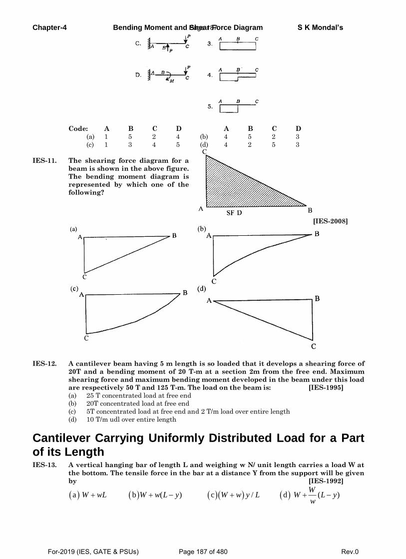
Chapter-4 Bending Moment and Shear Force Diagram S K Mondal’s
Code: A B C D A B C D
(a) 1 5 2 4 (b) 4 5 2 3
(c) 1 3 4 5 (d) 4 2 5 3
IES-11. The shearing force diagram for a
beam is shown in the above figure.
The bending moment diagram is
represented by which one of the
following?
[IES-2008]
IES-12. A cantilever beam having 5 m length is so loaded that it develops a shearing force of
20T and a bending moment of 20 T-m at a section 2m from the free end. Maximum
shearing force and maximum bending moment developed in the beam under this load
are respectively 50 T and 125 T-m. The load on the beam is: [IES-1995]
(a) 25 T concentrated load at free end
(b) 20T concentrated load at free end
(c) 5T concentrated load at free end and 2 T/m load over entire length
(d) 10 T/m udl over entire length
Cantilever Carrying Uniformly Distributed Load for a Part of its Length IES-13. A vertical hanging bar of length L and weighing w N/ unit length carries a load W at
the bottom. The tensile force in the bar at a distance Y from the support will be given
by [IES-1992]
a b ( ) c / d ( ) W
W wL W w L y W w y L W L yw
Page 187
For-2019 (IES, GATE & PSUs) Page 187 of 480 Rev.0
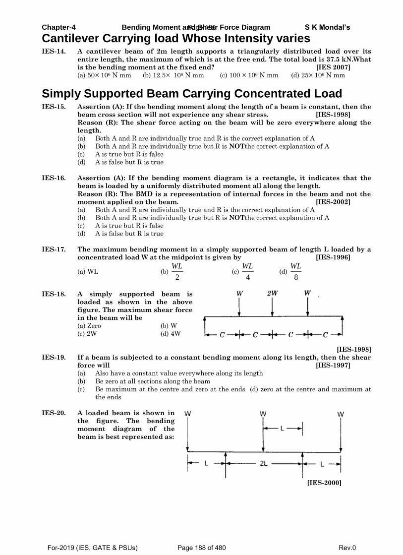
Chapter-4 Bending Moment and Shear Force Diagram S K Mondal’s
Cantilever Carrying load Whose Intensity varies IES-14. A cantilever beam of 2m length supports a triangularly distributed load over its
entire length, the maximum of which is at the free end. The total load is 37.5 kN.What
is the bending moment at the fixed end? [IES 2007]
(a) 50106 N mm (b) 12.5 106 N mm (c) 100 106 N mm (d) 25 106 N mm
Simply Supported Beam Carrying Concentrated Load IES-15. Assertion (A): If the bending moment along the length of a beam is constant, then the
beam cross section will not experience any shear stress. [IES-1998]
Reason (R): The shear force acting on the beam will be zero everywhere along the
length.
(a) Both A and R are individually true and R is the correct explanation of A
(b) Both A and R are individually true but R is NOTthe correct explanation of A
(c) A is true but R is false
(d) A is false but R is true
IES-16. Assertion (A): If the bending moment diagram is a rectangle, it indicates that the
beam is loaded by a uniformly distributed moment all along the length.
Reason (R): The BMD is a representation of internal forces in the beam and not the
moment applied on the beam. [IES-2002]
(a) Both A and R are individually true and R is the correct explanation of A
(b) Both A and R are individually true but R is NOTthe correct explanation of A
(c) A is true but R is false
(d) A is false but R is true
IES-17. The maximum bending moment in a simply supported beam of length L loaded by a
concentrated load W at the midpoint is given by [IES-1996]
(a) WL (b) 2
WL (c)
4
WL (d)
8
WL
IES-18. A simply supported beam is
loaded as shown in the above
figure. The maximum shear force
in the beam will be
(a) Zero (b) W
(c) 2W (d) 4W
[IES-1998]
IES-19. If a beam is subjected to a constant bending moment along its length, then the shear
force will [IES-1997]
(a) Also have a constant value everywhere along its length
(b) Be zero at all sections along the beam
(c) Be maximum at the centre and zero at the ends (d) zero at the centre and maximum at
the ends
IES-20. A loaded beam is shown in
the figure. The bending
moment diagram of the
beam is best represented as:
[IES-2000]
Page 188
For-2019 (IES, GATE & PSUs) Page 188 of 480 Rev.0
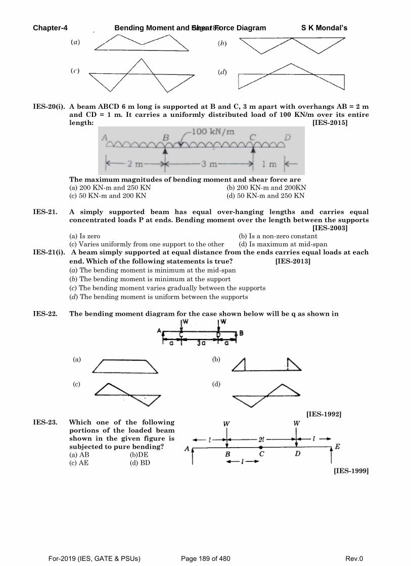
Chapter-4 Bending Moment and Shear Force Diagram S K Mondal’s
IES-20(i). A beam ABCD 6 m long is supported at B and C, 3 m apart with overhangs AB = 2 m
and CD = 1 m. It carries a uniformly distributed load of 100 KN/m over its entire
length: [IES-2015]
The maximum magnitudes of bending moment and shear force are
(a) 200 KN-m and 250 KN (b) 200 KN-m and 200KN
(c) 50 KN-m and 200 KN (d) 50 KN-m and 250 KN
IES-21. A simply supported beam has equal over-hanging lengths and carries equal
concentrated loads P at ends. Bending moment over the length between the supports
[IES-2003]
(a) Is zero (b) Is a non-zero constant
(c) Varies uniformly from one support to the other (d) Is maximum at mid-span
IES-21(i). A beam simply supported at equal distance from the ends carries equal loads at each
end. Which of the following statements is true? [IES-2013]
(a) The bending moment is minimum at the mid-span
(b) The bending moment is minimum at the support
(c) The bending moment varies gradually between the supports
(d) The bending moment is uniform between the supports
IES-22. The bending moment diagram for the case shown below will be q as shown in
(a)
(b)
(c)
(d)
[IES-1992]
IES-23. Which one of the following
portions of the loaded beam
shown in the given figure is
subjected to pure bending?
(a) AB (b)DE
(c) AE (d) BD [IES-1999]
Page 189
For-2019 (IES, GATE & PSUs) Page 189 of 480 Rev.0
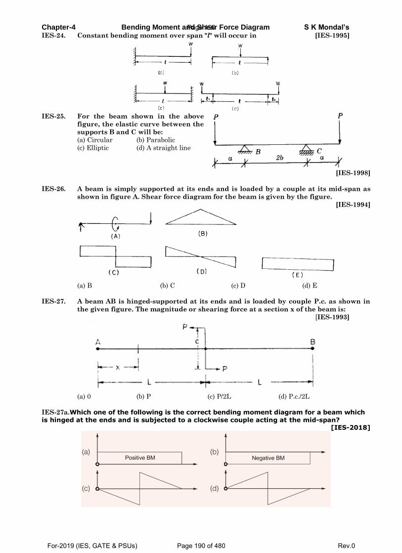
Chapter-4 Bending Moment and Shear Force Diagram S K Mondal’s IES-24. Constant bending moment over span "l" will occur in [IES-1995]
IES-25. For the beam shown in the above
figure, the elastic curve between the
supports B and C will be:
(a) Circular (b) Parabolic
(c) Elliptic (d) A straight line
[IES-1998]
IES-26. A beam is simply supported at its ends and is loaded by a couple at its mid-span as
shown in figure A. Shear force diagram for the beam is given by the figure.
[IES-1994]
(a) B (b) C (c) D (d) E
IES-27. A beam AB is hinged-supported at its ends and is loaded by couple P.c. as shown in
the given figure. The magnitude or shearing force at a section x of the beam is:
[IES-1993]
(a) 0 (b) P (c) P/2L (d) P.c./2L
IES-27a.Which one of the following is the correct bending moment diagram for a beam which
is hinged at the ends and is subjected to a clockwise couple acting at the mid-span? [IES-2018]
Page 190
For-2019 (IES, GATE & PSUs) Page 190 of 480 Rev.0
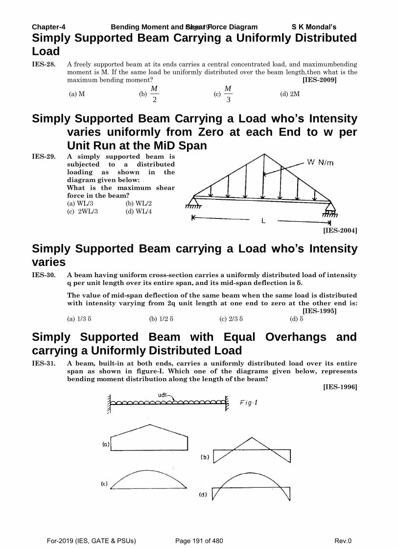
Chapter-4 Bending Moment and Shear Force Diagram S K Mondal’s
Simply Supported Beam Carrying a Uniformly Distributed Load IES-28. A freely supported beam at its ends carries a central concentrated load, and maximumbending
moment is M. If the same load be uniformly distributed over the beam length,then what is the
maximum bending moment? [IES-2009]
(a) M (b) 2
M (c)
3
M (d) 2M
Simply Supported Beam Carrying a Load who’s Intensity varies uniformly from Zero at each End to w per Unit Run at the MiD Span
IES-29. A simply supported beam is
subjected to a distributed
loading as shown in the
diagram given below:
What is the maximum shear
force in the beam?
(a) WL/3 (b) WL/2
(c) 2WL/3 (d) WL/4
[IES-2004]
Simply Supported Beam carrying a Load who’s Intensity varies IES-30. A beam having uniform cross-section carries a uniformly distributed load of intensity
q per unit length over its entire span, and its mid-span deflection is δ.
The value of mid-span deflection of the same beam when the same load is distributed
with intensity varying from 2q unit length at one end to zero at the other end is:
[IES-1995]
(a) 1/3 δ (b) 1/2 δ (c) 2/3 δ (d) δ
Simply Supported Beam with Equal Overhangs and carrying a Uniformly Distributed Load IES-31. A beam, built-in at both ends, carries a uniformly distributed load over its entire
span as shown in figure-I. Which one of the diagrams given below, represents
bending moment distribution along the length of the beam?
[IES-1996]
Page 191
For-2019 (IES, GATE & PSUs) Page 191 of 480 Rev.0
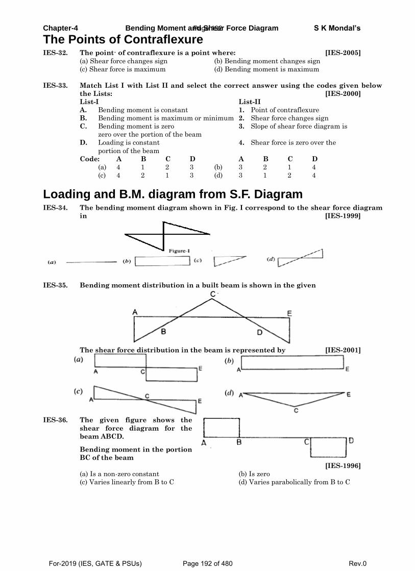
Chapter-4 Bending Moment and Shear Force Diagram S K Mondal’s
The Points of Contraflexure IES-32. The point· of contraflexure is a point where: [IES-2005]
(a) Shear force changes sign (b) Bending moment changes sign
(c) Shear force is maximum (d) Bending moment is maximum
IES-33. Match List I with List II and select the correct answer using the codes given below
the Lists: [IES-2000]
List-I List-II
A. Bending moment is constant 1. Point of contraflexure
B. Bending moment is maximum or minimum 2. Shear force changes sign
C. Bending moment is zero 3. Slope of shear force diagram is
zero over the portion of the beam
D. Loading is constant 4. Shear force is zero over the
portion of the beam
Code: A B C D A B C D
(a) 4 1 2 3 (b) 3 2 1 4
(c) 4 2 1 3 (d) 3 1 2 4
Loading and B.M. diagram from S.F. Diagram IES-34. The bending moment diagram shown in Fig. I correspond to the shear force diagram
in [IES-1999]
IES-35. Bending moment distribution in a built beam is shown in the given
The shear force distribution in the beam is represented by [IES-2001]
IES-36. The given figure shows the
shear force diagram for the
beam ABCD.
Bending moment in the portion
BC of the beam
[IES-1996]
(a) Is a non-zero constant (b) Is zero
(c) Varies linearly from B to C (d) Varies parabolically from B to C
Page 192
For-2019 (IES, GATE & PSUs) Page 192 of 480 Rev.0
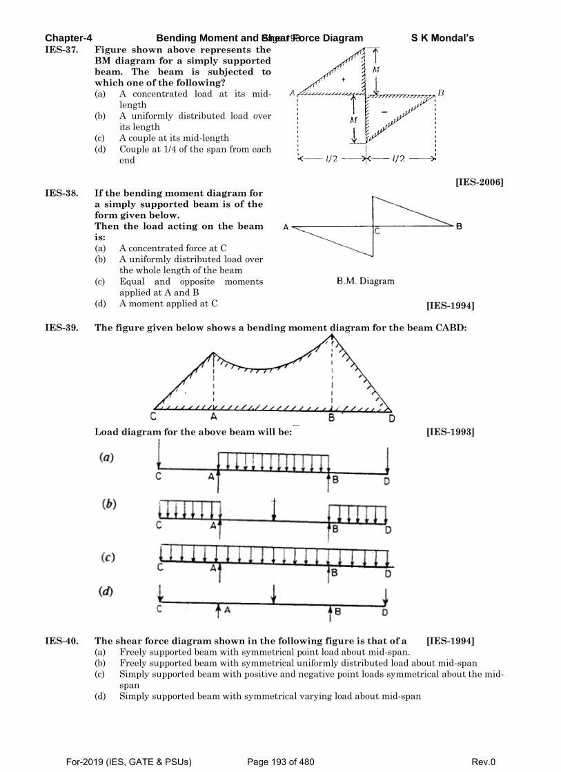
Chapter-4 Bending Moment and Shear Force Diagram S K Mondal’s IES-37. Figure shown above represents the
BM diagram for a simply supported
beam. The beam is subjected to
which one of the following?
(a) A concentrated load at its mid-
length
(b) A uniformly distributed load over
its length
(c) A couple at its mid-length
(d) Couple at 1/4 of the span from each
end
[IES-2006]
IES-38. If the bending moment diagram for
a simply supported beam is of the
form given below.
Then the load acting on the beam
is:
(a) A concentrated force at C
(b) A uniformly distributed load over
the whole length of the beam
(c) Equal and opposite moments
applied at A and B
(d) A moment applied at C
[IES-1994]
IES-39. The figure given below shows a bending moment diagram for the beam CABD:
Load diagram for the above beam will be: [IES-1993]
IES-40. The shear force diagram shown in the following figure is that of a [IES-1994]
(a) Freely supported beam with symmetrical point load about mid-span.
(b) Freely supported beam with symmetrical uniformly distributed load about mid-span
(c) Simply supported beam with positive and negative point loads symmetrical about the mid-
span
(d) Simply supported beam with symmetrical varying load about mid-span
Page 193
For-2019 (IES, GATE & PSUs) Page 193 of 480 Rev.0
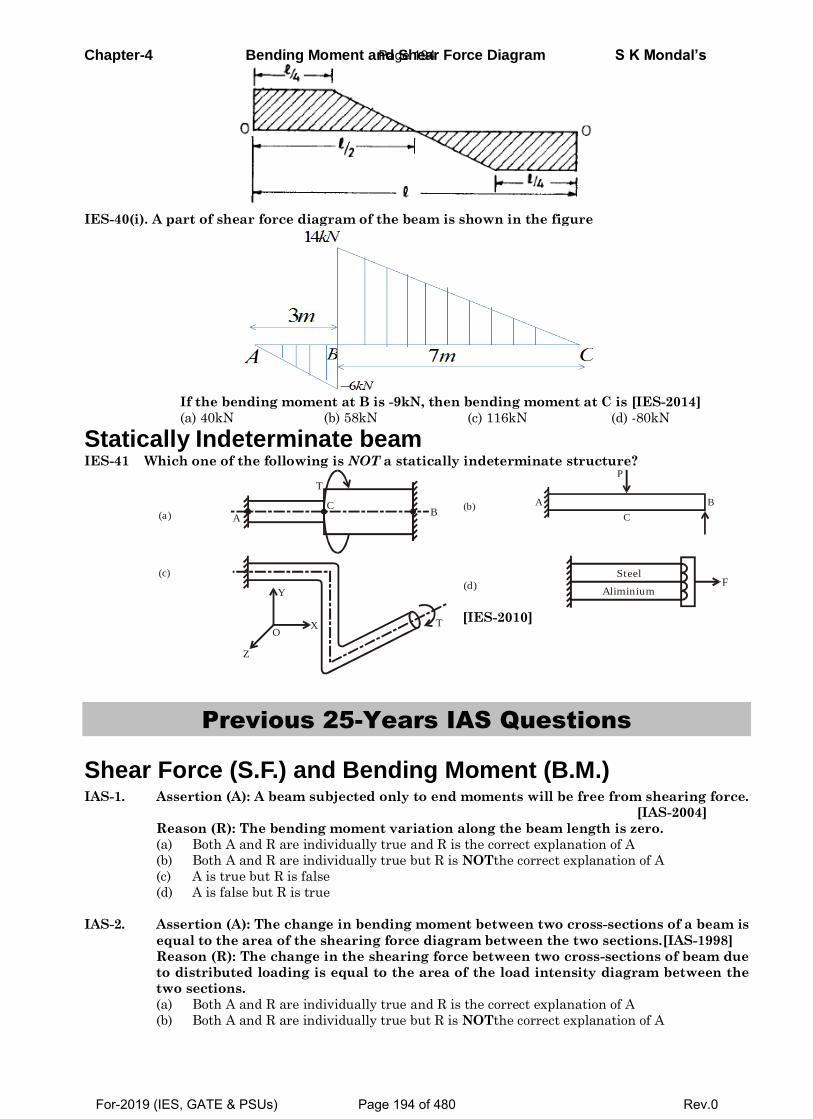
Chapter-4 Bending Moment and Shear Force Diagram S K Mondal’s
IES-40(i). A part of shear force diagram of the beam is shown in the figure
If the bending moment at B is -9kN, then bending moment at C is [IES-2014]
(a) 40kN (b) 58kN (c) 116kN (d) -80kN
Statically Indeterminate beam IES-41 Which one of the following is NOT a statically indeterminate structure?
A
CB
T
(a)
P
BA
C(b)
TX
Y
Z
O
(c)
Steel
AliminiumF(d)
[IES-2010]
Previous 25-Years IAS Questions
Shear Force (S.F.) and Bending Moment (B.M.) IAS-1. Assertion (A): A beam subjected only to end moments will be free from shearing force.
[IAS-2004]
Reason (R): The bending moment variation along the beam length is zero.
(a) Both A and R are individually true and R is the correct explanation of A
(b) Both A and R are individually true but R is NOTthe correct explanation of A
(c) A is true but R is false
(d) A is false but R is true
IAS-2. Assertion (A): The change in bending moment between two cross-sections of a beam is
equal to the area of the shearing force diagram between the two sections.[IAS-1998]
Reason (R): The change in the shearing force between two cross-sections of beam due
to distributed loading is equal to the area of the load intensity diagram between the
two sections.
(a) Both A and R are individually true and R is the correct explanation of A
(b) Both A and R are individually true but R is NOTthe correct explanation of A
Page 194
For-2019 (IES, GATE & PSUs) Page 194 of 480 Rev.0
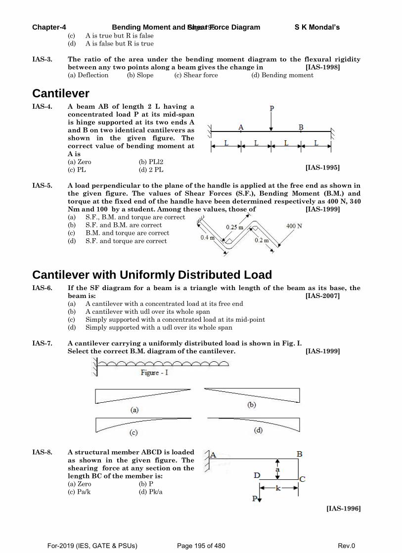
Chapter-4 Bending Moment and Shear Force Diagram S K Mondal’s (c) A is true but R is false
(d) A is false but R is true
IAS-3. The ratio of the area under the bending moment diagram to the flexural rigidity
between any two points along a beam gives the change in [IAS-1998]
(a) Deflection (b) Slope (c) Shear force (d) Bending moment
Cantilever IAS-4. A beam AB of length 2 L having a
concentrated load P at its mid-span
is hinge supported at its two ends A
and B on two identical cantilevers as
shown in the given figure. The
correct value of bending moment at
A is
(a) Zero (b) PLl2
(c) PL (d) 2 PL
[IAS-1995]
IAS-5. A load perpendicular to the plane of the handle is applied at the free end as shown in
the given figure. The values of Shear Forces (S.F.), Bending Moment (B.M.) and
torque at the fixed end of the handle have been determined respectively as 400 N, 340
Nm and 100 by a student. Among these values, those of [IAS-1999]
(a) S.F., B.M. and torque are correct
(b) S.F. and B.M. are correct
(c) B.M. and torque are correct
(d) S.F. and torque are correct
Cantilever with Uniformly Distributed Load IAS-6. If the SF diagram for a beam is a triangle with length of the beam as its base, the
beam is: [IAS-2007]
(a) A cantilever with a concentrated load at its free end
(b) A cantilever with udl over its whole span
(c) Simply supported with a concentrated load at its mid-point
(d) Simply supported with a udl over its whole span
IAS-7. A cantilever carrying a uniformly distributed load is shown in Fig. I.
Select the correct B.M. diagram of the cantilever. [IAS-1999]
IAS-8. A structural member ABCD is loaded
as shown in the given figure. The
shearing force at any section on the
length BC of the member is:
(a) Zero (b) P
(c) Pa/k (d) Pk/a
[IAS-1996]
Page 195
For-2019 (IES, GATE & PSUs) Page 195 of 480 Rev.0
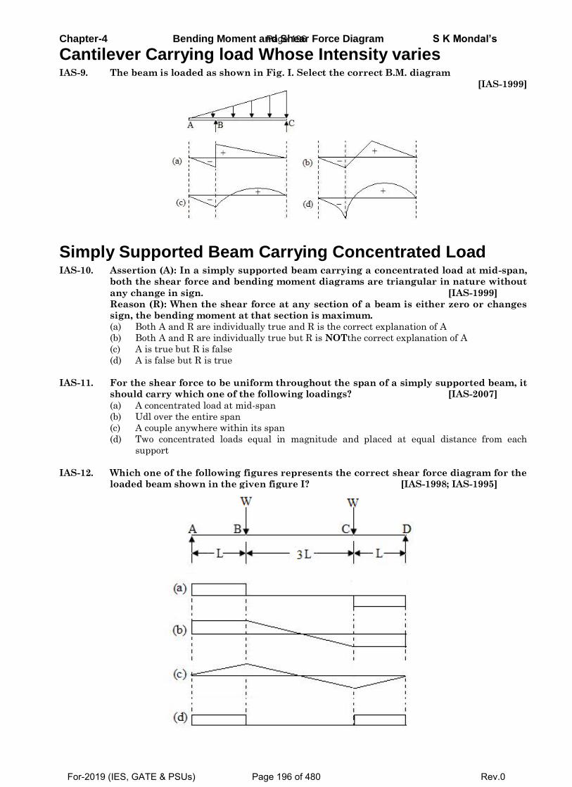
Chapter-4 Bending Moment and Shear Force Diagram S K Mondal’s
Cantilever Carrying load Whose Intensity varies IAS-9. The beam is loaded as shown in Fig. I. Select the correct B.M. diagram
[IAS-1999]
Simply Supported Beam Carrying Concentrated Load IAS-10. Assertion (A): In a simply supported beam carrying a concentrated load at mid-span,
both the shear force and bending moment diagrams are triangular in nature without
any change in sign. [IAS-1999]
Reason (R): When the shear force at any section of a beam is either zero or changes
sign, the bending moment at that section is maximum.
(a) Both A and R are individually true and R is the correct explanation of A
(b) Both A and R are individually true but R is NOTthe correct explanation of A
(c) A is true but R is false
(d) A is false but R is true
IAS-11. For the shear force to be uniform throughout the span of a simply supported beam, it
should carry which one of the following loadings? [IAS-2007]
(a) A concentrated load at mid-span
(b) Udl over the entire span
(c) A couple anywhere within its span
(d) Two concentrated loads equal in magnitude and placed at equal distance from each
support
IAS-12. Which one of the following figures represents the correct shear force diagram for the
loaded beam shown in the given figure I? [IAS-1998; IAS-1995]
Page 196
For-2019 (IES, GATE & PSUs) Page 196 of 480 Rev.0
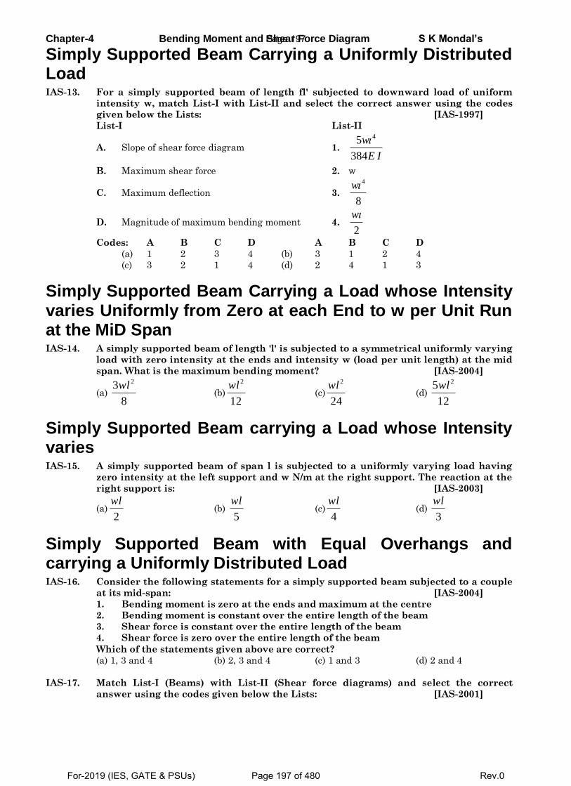
Chapter-4 Bending Moment and Shear Force Diagram S K Mondal’s
Simply Supported Beam Carrying a Uniformly Distributed Load IAS-13. For a simply supported beam of length fl' subjected to downward load of uniform
intensity w, match List-I with List-II and select the correct answer using the codes
given below the Lists: [IAS-1997]
List-I List-II
A. Slope of shear force diagram 1.
45
384
w
E I
B. Maximum shear force 2. w
C. Maximum deflection 3.
4
8
w
D. Magnitude of maximum bending moment 4. 2
w
Codes: A B C D A B C D
(a) 1 2 3 4 (b) 3 1 2 4
(c) 3 2 1 4 (d) 2 4 1 3
Simply Supported Beam Carrying a Load whose Intensity varies Uniformly from Zero at each End to w per Unit Run at the MiD Span IAS-14. A simply supported beam of length 'l' is subjected to a symmetrical uniformly varying
load with zero intensity at the ends and intensity w (load per unit length) at the mid
span. What is the maximum bending moment? [IAS-2004]
(a)
23
8
wl (b)
2
12
wl (c)
2
24
wl (d)
25
12
wl
Simply Supported Beam carrying a Load whose Intensity varies IAS-15. A simply supported beam of span l is subjected to a uniformly varying load having
zero intensity at the left support and w N/m at the right support. The reaction at the
right support is: [IAS-2003]
(a)2
wl (b)
5
wl (c)
4
wl (d)
3
wl
Simply Supported Beam with Equal Overhangs and carrying a Uniformly Distributed Load IAS-16. Consider the following statements for a simply supported beam subjected to a couple
at its mid-span: [IAS-2004]
1. Bending moment is zero at the ends and maximum at the centre
2. Bending moment is constant over the entire length of the beam
3. Shear force is constant over the entire length of the beam
4. Shear force is zero over the entire length of the beam
Which of the statements given above are correct?
(a) 1, 3 and 4 (b) 2, 3 and 4 (c) 1 and 3 (d) 2 and 4
IAS-17. Match List-I (Beams) with List-II (Shear force diagrams) and select the correct
answer using the codes given below the Lists: [IAS-2001]
Page 197
For-2019 (IES, GATE & PSUs) Page 197 of 480 Rev.0
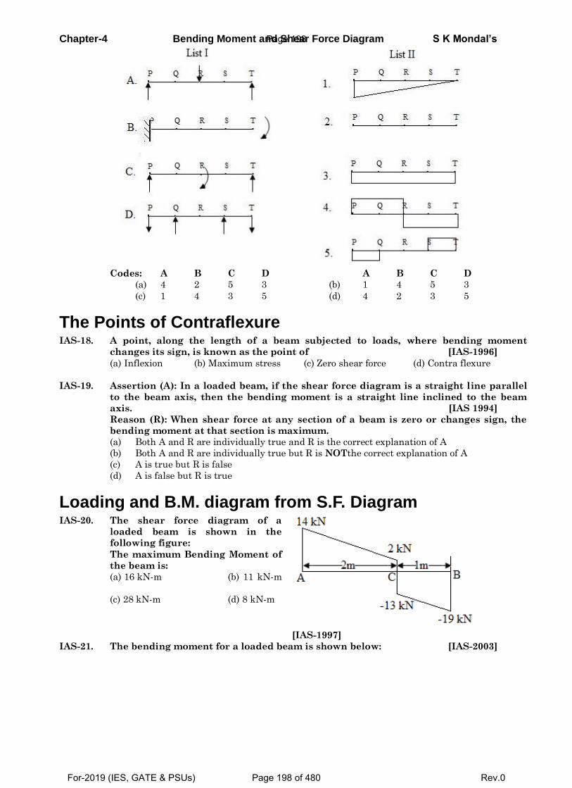
Chapter-4 Bending Moment and Shear Force Diagram S K Mondal’s
Codes: A B C D A B C D
(a) 4 2 5 3 (b) 1 4 5 3
(c) 1 4 3 5 (d) 4 2 3 5
The Points of Contraflexure IAS-18. A point, along the length of a beam subjected to loads, where bending moment
changes its sign, is known as the point of [IAS-1996]
(a) Inflexion (b) Maximum stress (c) Zero shear force (d) Contra flexure
IAS-19. Assertion (A): In a loaded beam, if the shear force diagram is a straight line parallel
to the beam axis, then the bending moment is a straight line inclined to the beam
axis. [IAS 1994]
Reason (R): When shear force at any section of a beam is zero or changes sign, the
bending moment at that section is maximum.
(a) Both A and R are individually true and R is the correct explanation of A
(b) Both A and R are individually true but R is NOTthe correct explanation of A
(c) A is true but R is false
(d) A is false but R is true
Loading and B.M. diagram from S.F. Diagram IAS-20. The shear force diagram of a
loaded beam is shown in the
following figure:
The maximum Bending Moment of
the beam is:
(a) 16 kN-m (b) 11 kN-m
(c) 28 kN-m (d) 8 kN-m
[IAS-1997]
IAS-21. The bending moment for a loaded beam is shown below: [IAS-2003]
Page 198
For-2019 (IES, GATE & PSUs) Page 198 of 480 Rev.0
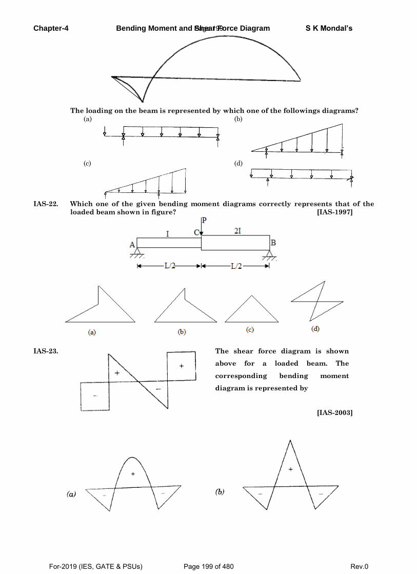
Chapter-4 Bending Moment and Shear Force Diagram S K Mondal’s
The loading on the beam is represented by which one of the followings diagrams?
(a)
(b)
(c)
(d)
IAS-22. Which one of the given bending moment diagrams correctly represents that of the
loaded beam shown in figure? [IAS-1997]
IAS-23.
The shear force diagram is shown
above for a loaded beam. The
corresponding bending moment
diagram is represented by
[IAS-2003]
Page 199
For-2019 (IES, GATE & PSUs) Page 199 of 480 Rev.0
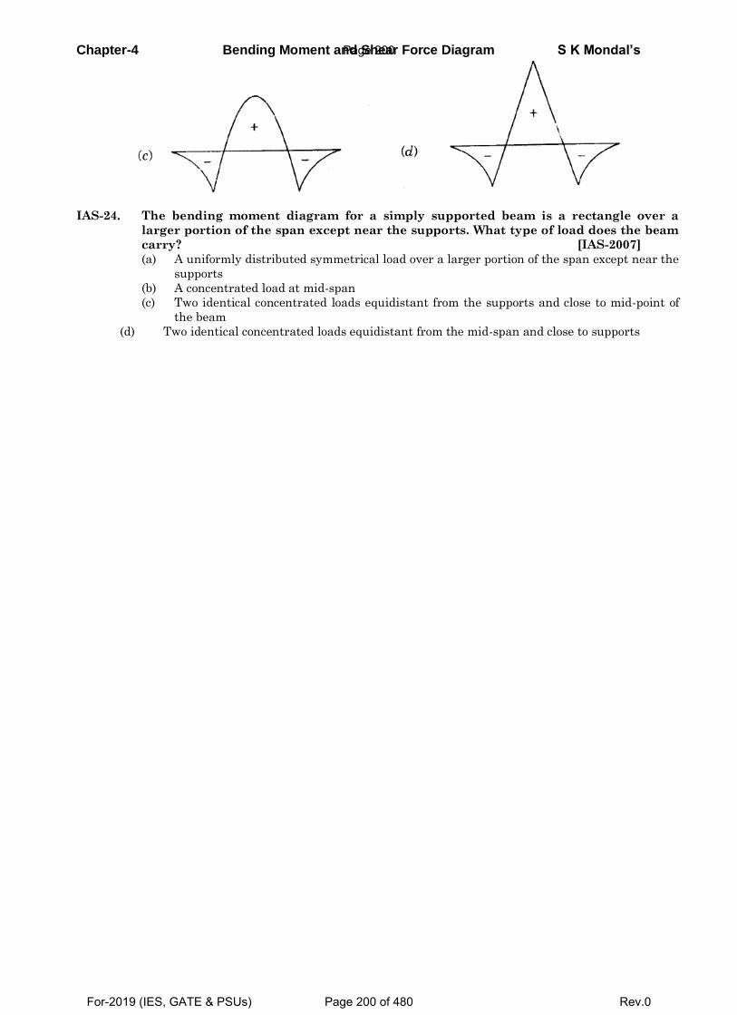
Chapter-4 Bending Moment and Shear Force Diagram S K Mondal’s
IAS-24. The bending moment diagram for a simply supported beam is a rectangle over a
larger portion of the span except near the supports. What type of load does the beam
carry? [IAS-2007]
(a) A uniformly distributed symmetrical load over a larger portion of the span except near the
supports
(b) A concentrated load at mid-span
(c) Two identical concentrated loads equidistant from the supports and close to mid-point of
the beam
(d) Two identical concentrated loads equidistant from the mid-span and close to supports
Page 200
For-2019 (IES, GATE & PSUs) Page 200 of 480 Rev.0
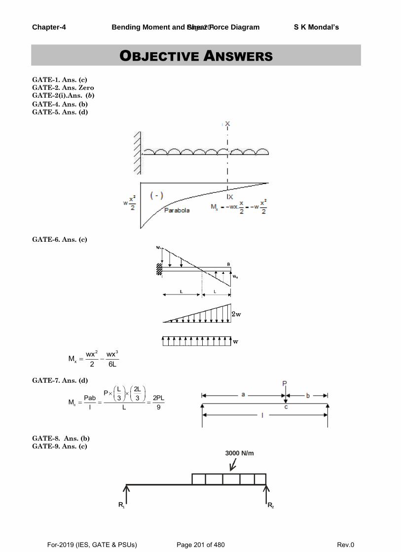
Chapter-4 Bending Moment and Shear Force Diagram S K Mondal’s
OBJECTIVE ANSWERS
GATE-1. Ans. (c)
GATE-2. Ans. Zero GATE-2(i).Ans. (b)
GATE-4. Ans. (b)
GATE-5. Ans. (d)
GATE-6. Ans. (c)
2 3
xwx wxM
2 6L
GATE-7. Ans. (d)
c
L 2LPPab 2PL3 3M
l L 9
GATE-8. Ans. (b)
GATE-9. Ans. (c)
R1 R2
3000 N/m
Page 201
For-2019 (IES, GATE & PSUs) Page 201 of 480 Rev.0
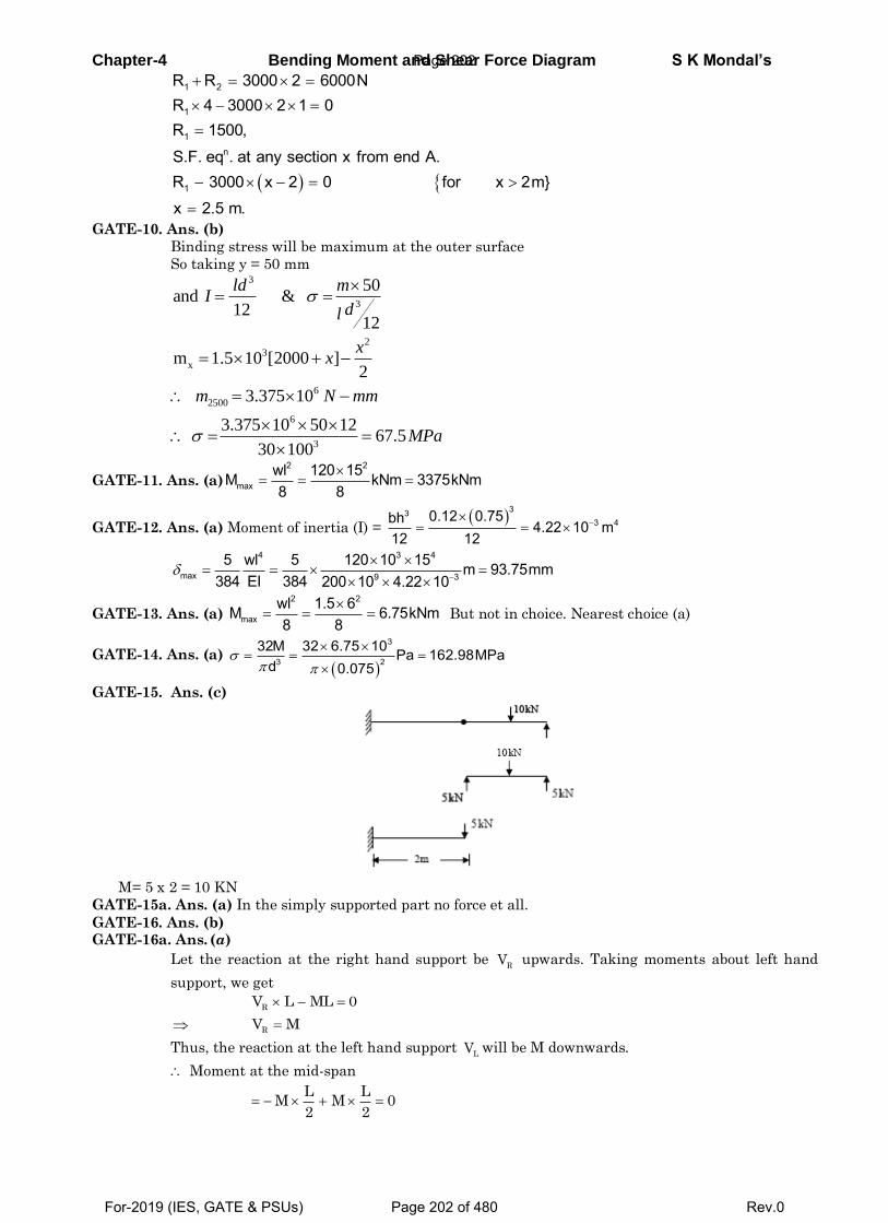
Chapter-4 Bending Moment and Shear Force Diagram S K Mondal’s
1 2
1
1n
1
R R 3000 2 6000NR 4 3000 2 1 0R 1500,
S.F. eq . at any section x from end A.R 3000 x 2 0 for x 2m}x 2.5 m.
GATE-10. Ans. (b)
Binding stress will be maximum at the outer surface
So taking y = 50 mm
3
3
23
x
6
2500
6
3
50and &
1212
m 1.5 10 [2000 ]2
3.375 10
3.375 10 50 1267.5
30 100
ld mI
dl
xx
m N mm
MPa
GATE-11. Ans. (a)2 2
maxwl 120 15M kNm 3375kNm8 8
GATE-12. Ans. (a) Moment of inertia (I) =
333 40.12 0.75bh 4.22 10 m
12 12
4 3 4
max 9 3
5 wl 5 120 10 15 m 93.75mm384 EI 384 200 10 4.22 10
GATE-13. Ans. (a) 2 2
maxwl 1.5 6M 6.75kNm8 8
But not in choice. Nearest choice (a)
GATE-14. Ans. (a)
3
3 2
32M 32 6.75 10 Pa 162.98MPad 0.075
GATE-15. Ans. (c)
M= 5 x 2 = 10 KN
GATE-15a. Ans. (a) In the simply supported part no force et all.
GATE-16. Ans. (b) GATE-16a. Ans. (a)
Let the reaction at the right hand support be R
V upwards. Taking moments about left hand
support, we get
R
V L ML 0
R
V M
Thus, the reaction at the left hand support L
V will be M downwards.
Moment at the mid-span
L L
M M 02 2
Page 202
For-2019 (IES, GATE & PSUs) Page 202 of 480 Rev.0
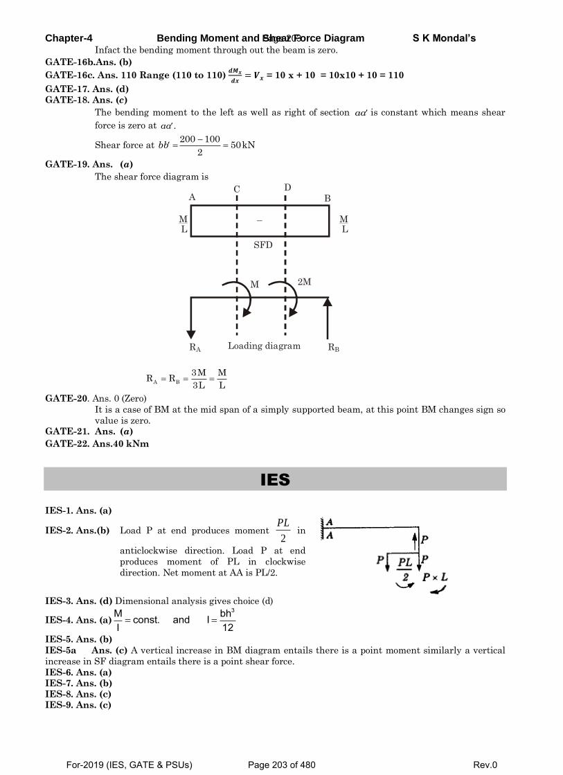
Chapter-4 Bending Moment and Shear Force Diagram S K Mondal’s Infact the bending moment through out the beam is zero.
GATE-16b.Ans. (b)
GATE-16c. Ans. 110 Range (110 to 110) 𝒅𝑴𝒙
𝒅𝒙= 𝑽𝒙 = 10 x + 10 = 10x10 + 10 = 110
GATE-17. Ans. (d)
GATE-18. Ans. (c)
The bending moment to the left as well as right of section aa is constant which means shear
force is zero at .aa
Shear force at
200 100
50kN2
bb
GATE-19. Ans. (a)
The shear force diagram is
R A R B
2M M
Loading diagram
A B C D
ML
ML
SFD
–
A B
3M MR R
3L L GATE-20. Ans. 0 (Zero)
It is a case of BM at the mid span of a simply supported beam, at this point BM changes sign so
value is zero. GATE-21. Ans. (a)
GATE-22. Ans.40 kNm
IES
IES-1. Ans. (a)
IES-2. Ans.(b) Load P at end produces moment 2
PL in
anticlockwise direction. Load P at end
produces moment of PL in clockwise
direction. Net moment at AA is PL/2.
IES-3. Ans. (d) Dimensional analysis gives choice (d)
IES-4. Ans. (a) 3M bhconst. and I
I 12
IES-5. Ans. (b)
IES-5a Ans. (c) A vertical increase in BM diagram entails there is a point moment similarly a vertical
increase in SF diagram entails there is a point shear force.
IES-6. Ans. (a) IES-7. Ans. (b) IES-8. Ans. (c) IES-9. Ans. (c)
Page 203
For-2019 (IES, GATE & PSUs) Page 203 of 480 Rev.0
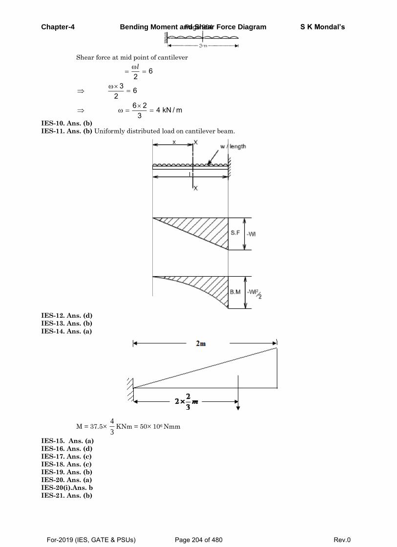
Chapter-4 Bending Moment and Shear Force Diagram S K Mondal’s
Shear force at mid point of cantilever
62
3 62
6 2 4 kN / m3
l
IES-10. Ans. (b)
IES-11. Ans. (b) Uniformly distributed load on cantilever beam.
IES-12. Ans. (d)
IES-13. Ans. (b)
IES-14. Ans. (a)
M = 37.53
4KNm = 50 106 Nmm
IES-15. Ans. (a)
IES-16. Ans. (d)
IES-17. Ans. (c)
IES-18. Ans. (c)
IES-19. Ans. (b)
IES-20. Ans. (a)
IES-20(i).Ans. b
IES-21. Ans. (b)
Page 204
For-2019 (IES, GATE & PSUs) Page 204 of 480 Rev.0
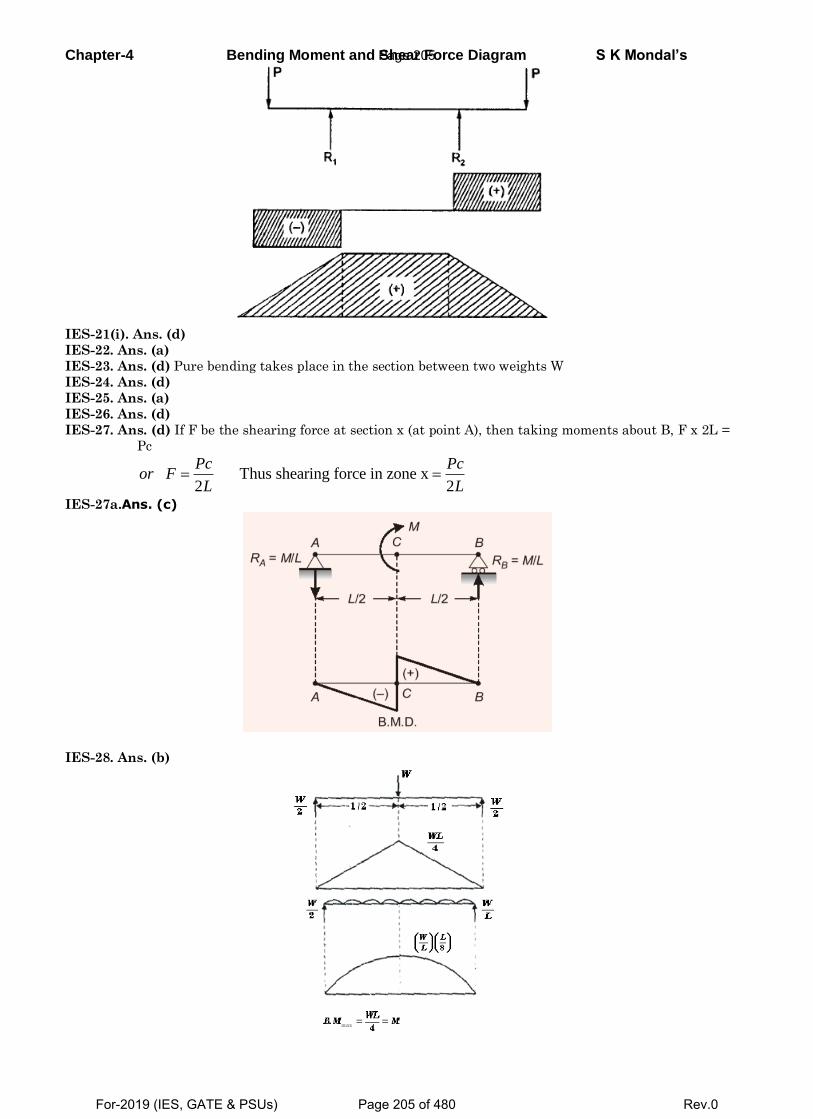
Chapter-4 Bending Moment and Shear Force Diagram S K Mondal’s
IES-21(i). Ans. (d)
IES-22. Ans. (a)
IES-23. Ans. (d) Pure bending takes place in the section between two weights W
IES-24. Ans. (d)
IES-25. Ans. (a)
IES-26. Ans. (d)
IES-27. Ans. (d) If F be the shearing force at section x (at point A), then taking moments about B, F x 2L =
Pc
Thus shearing force in zone x2 2
Pc Pcor F
L L
IES-27a.Ans. (c)
IES-28. Ans. (b)
Page 205
For-2019 (IES, GATE & PSUs) Page 205 of 480 Rev.0
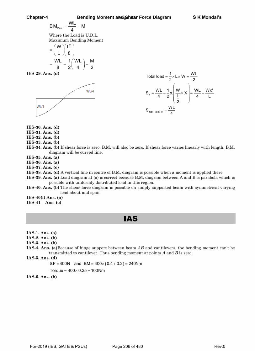
Chapter-4 Bending Moment and Shear Force Diagram S K Mondal’s
MaxWLB.M M4
Where the Load is U.D.L.
Maximum Bending Moment
2W LL 8
WL 1 WL M8 2 4 2
IES-29. Ans. (d)
2
x
max at x 0
1 WLTotal load L W2 2
WL 1 W WL WxS x. XL4 2 4 L2
WLS4
IES-30. Ans. (d)
IES-31. Ans. (d)
IES-32. Ans. (b)
IES-33. Ans. (b)
IES-34. Ans. (b) If shear force is zero, B.M. will also be zero. If shear force varies linearly with length, B.M.
diagram will be curved line.
IES-35. Ans. (a)
IES-36. Ans. (a)
IES-37. Ans. (c)
IES-38. Ans. (d) A vertical line in centre of B.M. diagram is possible when a moment is applied there.
IES-39. Ans. (a) Load diagram at (a) is correct because B.M. diagram between A and B is parabola which is
possible with uniformly distributed load in this region.
IES-40. Ans. (b) The shear force diagram is possible on simply supported beam with symmetrical varying
load about mid span.
IES-40(i) Ans. (a)
IES-41 Ans. (c)
IAS
IAS-1. Ans. (a)
IAS-2. Ans. (b)
IAS-3. Ans. (b)
IAS-4. Ans. (a)Because of hinge support between beam AB and cantilevers, the bending moment can't be
transmitted to cantilever. Thus bending moment at points A and B is zero.
IAS-5. Ans. (d)
S.F 400N and BM 400 0.4 0.2 240Nm
Torque 400 0.25 100Nm
IAS-6. Ans. (b)
Page 206
For-2019 (IES, GATE & PSUs) Page 206 of 480 Rev.0
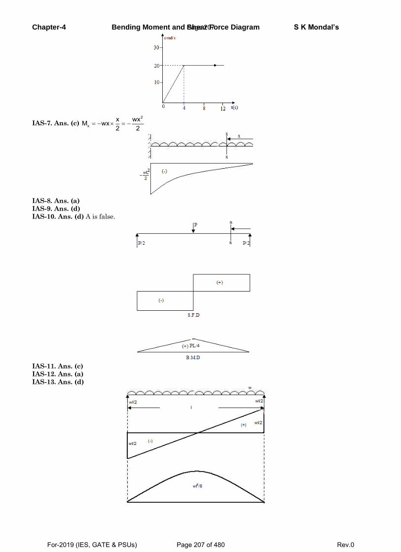
Chapter-4 Bending Moment and Shear Force Diagram S K Mondal’s
IAS-7. Ans. (c) 2
xx wxM wx2 2
IAS-8. Ans. (a)
IAS-9. Ans. (d)
IAS-10. Ans. (d) A is false.
IAS-11. Ans. (c)
IAS-12. Ans. (a)
IAS-13. Ans. (d)
Page 207
For-2019 (IES, GATE & PSUs) Page 207 of 480 Rev.0
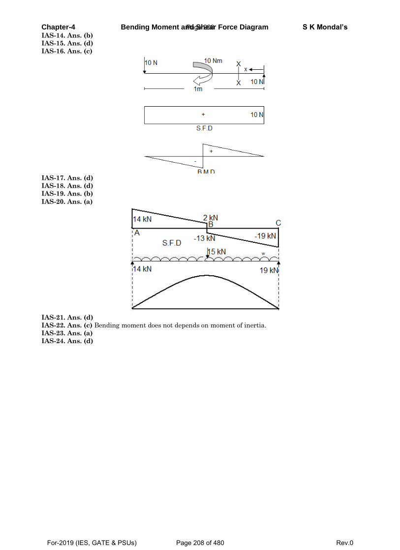
Chapter-4 Bending Moment and Shear Force Diagram S K Mondal’s IAS-14. Ans. (b)
IAS-15. Ans. (d)
IAS-16. Ans. (c)
IAS-17. Ans. (d)
IAS-18. Ans. (d)
IAS-19. Ans. (b)
IAS-20. Ans. (a)
IAS-21. Ans. (d)
IAS-22. Ans. (c) Bending moment does not depends on moment of inertia.
IAS-23. Ans. (a)
IAS-24. Ans. (d)
Page 208
For-2019 (IES, GATE & PSUs) Page 208 of 480 Rev.0
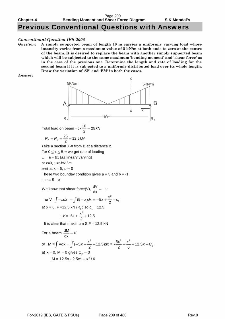
Chapter-4 Bending Moment and Shear Force Diagram S K Mondal’s
Previous Conventional Questions with Answers
Conventional Question IES-2005 Question: A simply supported beam of length 10 m carries a uniformly varying load whose
intensity varies from a maximum value of 5 kN/m at both ends to zero at the centre of the beam. It is desired to replace the beam with another simply supported beam which will be subjected to the same maximum 'bending moment’ and ‘shear force' as in the case of the previous one. Determine the length and rate of loading for the second beam if it is subjected to a uniformly distributed load over its whole length. Draw the variation of 'SF' and 'BM' in both the cases.
Answer:
10mR A R B
5KN/m 5KN/mX
X
B
10Total load on beam =5× 252
25 12.52
a section X-X from B at a distance x.For 0 x 5 we get rate of loading
[ lineary varying]at x=0, =5 /
at x = 5, 0These two bounday con
A B
kN
R R kN
Takem
a bx askN m
and
ωω
ω
=
∴ = = =
≤ ≤= +
=
dition gives a = 5 and b = -1 5 xω∴ = −
2
1
B 12
dVWe know that shear force(V), dx
or V = = (5 ) 52
x = 0, F =12.5 kN (R ) so c 12.5
x = -5x + 12.52
It is clear that maximum S.F = 12.5 kN
xdx x dx x c
at
V
ω
ω
=−
− − − =− + +
=
∴ +
∫ ∫
2 2 3
2
22 3
dMFor a beam dx
5x, M = Vdx ( 5 12.5) = - 12.52 2 6
x = 0, M = 0 gives C 0
M = 12.5x - 2.5x / 6
V
x xor x dx x C
at
x
=
= − + + + + +
=
+
∫ ∫
Page 209
For-2019 (IES, GATE & PSUs) Page 209 of 480 Rev.0
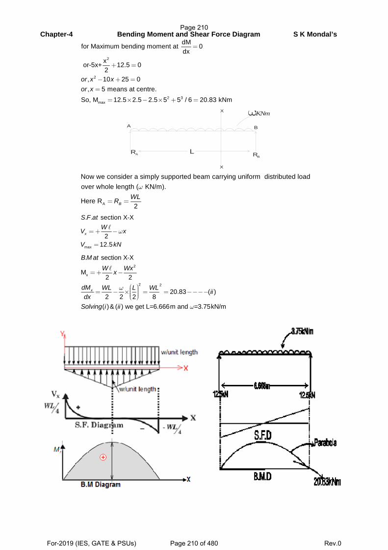
Chapter-4 Bending Moment and Shear Force Diagram S K Mondal’s
2
2
2 3max
dMfor Maximum bending moment at 0dx
x or-5x+ 12.5 02
, 10 25 0, 5 means at centre.
So, M 12.5 2.5 2.5 5 5 / 6 20.83 kNm
or x xor x
=
+ =
− + ==
= × − × + =
A B
RA RBL
X
X
ωKNm
A
Now we consider a simply supported beam carrying uniform distributed load over whole length ( KN/m).
Here R2B
WLR
ω
= =
max
. . section X-X
212.5
x
S F atWV x
V kN
ω=+ −
=
2
x
2 2
. section X-X
M2 2
20.83 ( )2 2 2 8
( )& ( ) we get L=6.666m and =3.75kN/m
x
B M atW Wxx
dM WL L WL iidx
Solving i ii
ω
ω
=+ −
⎛ ⎞⎟⎜= − × = = −−−−⎟⎜ ⎟⎜⎝ ⎠
Page 210
For-2019 (IES, GATE & PSUs) Page 210 of 480 Rev.0
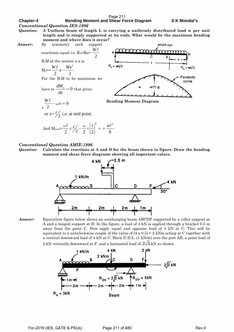
Chapter-4 Bending Moment and Shear Force Diagram S K Mondal’s Conventional Question IES-1996 Question: A Uniform beam of length L is carrying a uniformly distributed load w per unit
length and is simply supported at its ends. What would be the maximum bending moment and where does it occur?
Answer: By symmetry each support
reactionis equal i.e. RA=RB= 2
W
B.M at the section x-x is
Mx=+2
2 2W Wxx−
For the B.M to be maximum we
have to 0xdMdx
= that gives.
+0
2or x= i.e. at mid point.2
W xω− =
Bending Moment Diagram
And Mmax=2 2
22 2 2 8wω ω ⎡ ⎤
⎢ ⎥× − × =+⎢ ⎥⎣ ⎦
Conventional Question AMIE-1996 Question: Calculate the reactions at A and D for the beam shown in figure. Draw the bending
moment and shear force diagrams showing all important values.
Answer: Equivalent figure below shows an overhanging beam ABCDF supported by a roller support at
A and a hinged support at D. In the figure, a load of 4 kN is applied through a bracket 0.5 m away from the point C. Now apply equal and opposite load of 4 kN at C. This will be equivalent to a anticlockwise couple of the value of (4 x 0.5) = 2 kNm acting at C together with a vertical downward load of 4 kN at C. Show U.D.L. (1 kN/m) over the port AB, a point load of 2 kN vertically downward at F, and a horizontal load of 2 3 kN as shown.
Page 211
For-2019 (IES, GATE & PSUs) Page 211 of 480 Rev.0
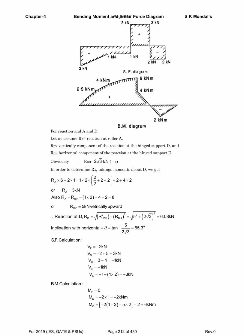
Chapter-4 Bending Moment and Shear Force Diagram S K Mondal’s
For reaction and A and D.
Let ue assume RA= reaction at roller A.
RDV vertically component of the reaction at the hinged support D, and
RDH horizontal component of the reaction at the hinged support D.
Obviously RDH= 2 3 kN ()
In order to determine RA, takings moments about D, we get
A
A
A DV
2R 6 2 1 1 2 2 2 2 4 22
or R 3kNAlso R R 1 2 4 2 8
DV
222 2D DV DH
1 0
or R 5kNvetricallyupward
Reaction at D, R R R 5 2 3 6.08kN
5Inclination with horizontal tan 55.32 3
F
D
C
B
A
S.F.Calculation :V 2kNV 2 5 3kNV 3 4 1kNV 1kNV 1 1 2 3kN
F
D
C
B.M.Calculation :M 0M 2 1 2kNm
M 2 1 2 5 2 2 6kNm
Page 212
For-2019 (IES, GATE & PSUs) Page 212 of 480 Rev.0
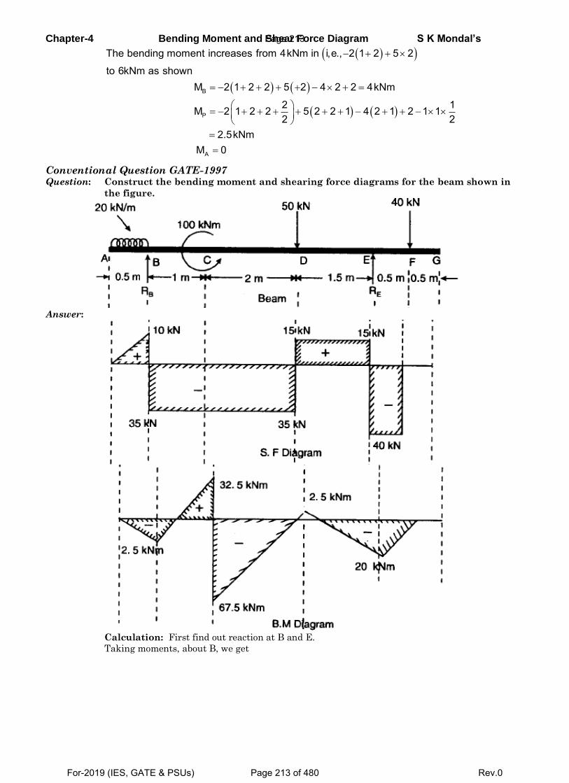
Chapter-4 Bending Moment and Shear Force Diagram S K Mondal’s
B
P
A
The bending moment increases from 4kNm in i,e., 2 1 2 5 2
to 6kNm as shownM 2 1 2 2 5 2 4 2 2 4kNm
2 1M 2 1 2 2 5 2 2 1 4 2 1 2 1 12 2
2.5kNmM 0
Conventional Question GATE-1997 Question: Construct the bending moment and shearing force diagrams for the beam shown in
the figure.
Answer:
Calculation: First find out reaction at B and E.
Taking moments, about B, we get
Page 213
For-2019 (IES, GATE & PSUs) Page 213 of 480 Rev.0
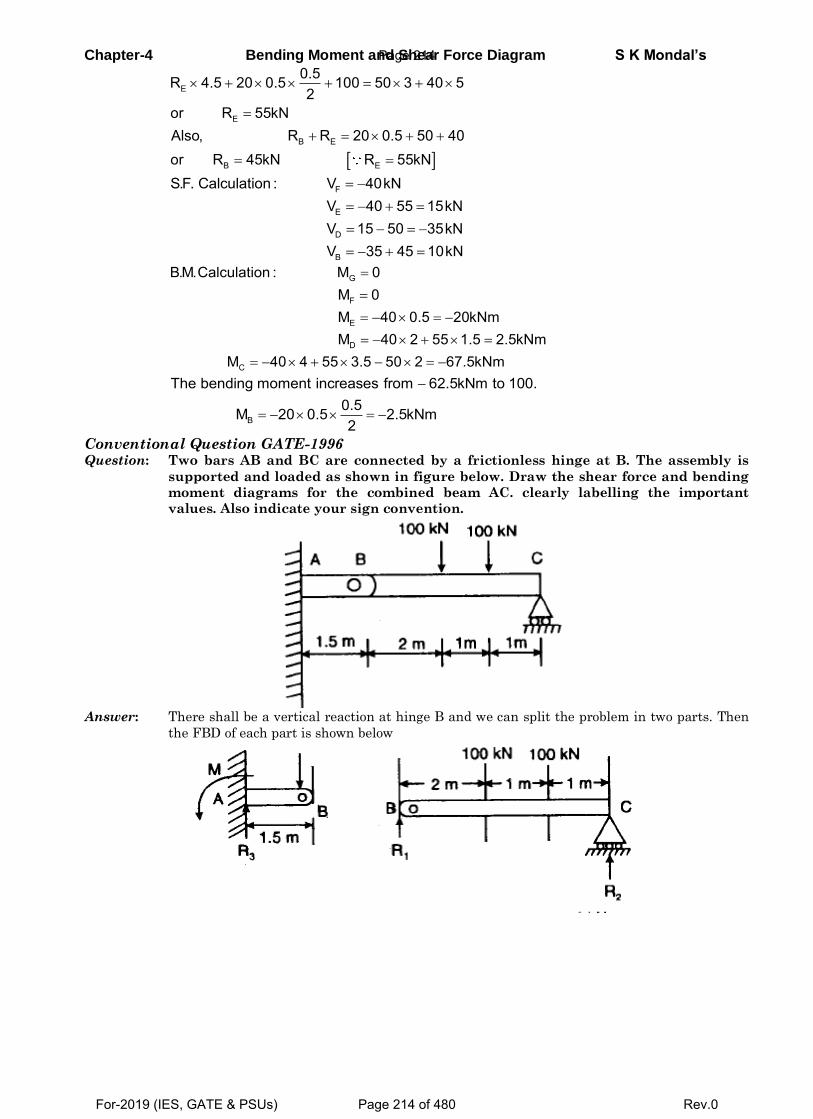
Chapter-4 Bending Moment and Shear Force Diagram S K Mondal’s
E
E
B E
B E
0.5R 4.5 20 0.5 100 50 3 40 52
or R 55kNAlso, R R 20 0.5 50 40or R 45kN R 55kN
F
E
D
B
S.F. Calculation : V 40kNV 40 55 15kNV 15 50 35kNV 35 45 10kN
G
F
E
D
C
B.M.Calculation : M 0M 0M 40 0.5 20kNmM 40 2 55 1.5 2.5kNm
M 40 4 55 3.5 50 2 67.5kNm
B
The bending moment increases from 62.5kNm to 100.0.5M 20 0.5 2.5kNm2
Conventional Question GATE-1996 Question: Two bars AB and BC are connected by a frictionless hinge at B. The assembly is
supported and loaded as shown in figure below. Draw the shear force and bending
moment diagrams for the combined beam AC. clearly labelling the important
values. Also indicate your sign convention.
Answer: There shall be a vertical reaction at hinge B and we can split the problem in two parts. Then
the FBD of each part is shown below
Page 214
For-2019 (IES, GATE & PSUs) Page 214 of 480 Rev.0
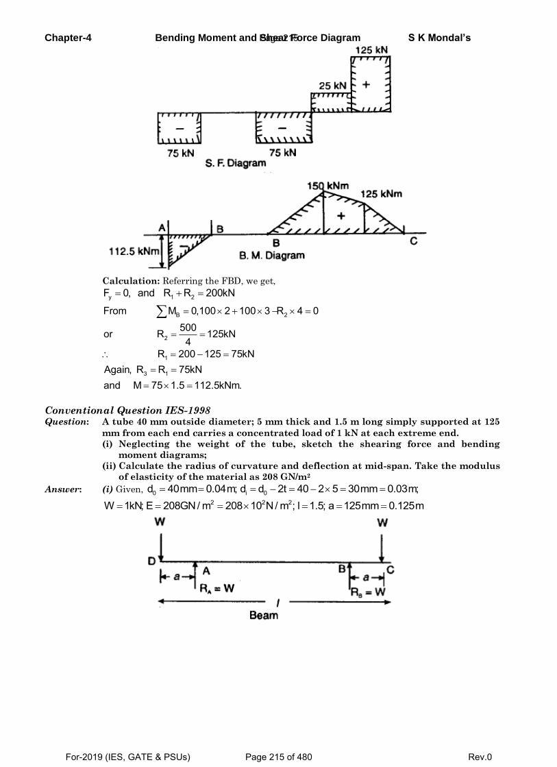
Chapter-4 Bending Moment and Shear Force Diagram S K Mondal’s
Calculation: Referring the FBD, we get,
y 1 2F 0, and R R 200kN
B 2
2
From M 0,100 2 100 3 R 4 0500or R 125kN
4
1
3 1
R 200 125 75kNAgain, R R 75kNand M 75 1.5 112.5kNm.
Conventional Question IES-1998 Question: A tube 40 mm outside diameter; 5 mm thick and 1.5 m long simply supported at 125
mm from each end carries a concentrated load of 1 kN at each extreme end.
(i) Neglecting the weight of the tube, sketch the shearing force and bending
moment diagrams;
(ii) Calculate the radius of curvature and deflection at mid-span. Take the modulus
of elasticity of the material as 208 GN/m2
Answer: (i) Given, 0 i 0d 40mm 0.04m; d d 2t 40 2 5 30mm 0.03m;
2 2 2W 1kN; E 208GN/ m 208 10 N/ m ; l 1.5; a 125mm 0.125m
Page 215
For-2019 (IES, GATE & PSUs) Page 215 of 480 Rev.0
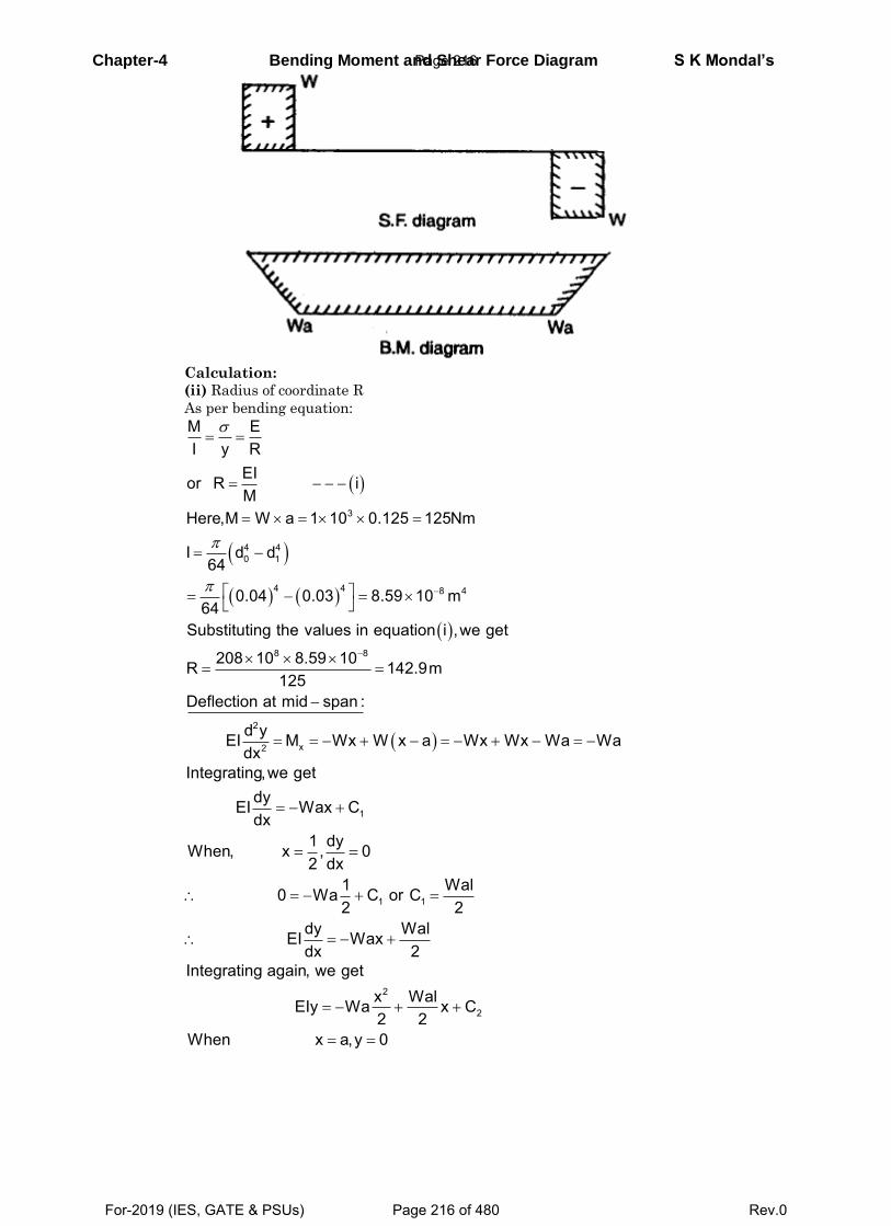
Chapter-4 Bending Moment and Shear Force Diagram S K Mondal’s
Calculation:
(ii) Radius of coordinate R
As per bending equation:
3
4 40 1
4 4 8 4
M EI y R
EIor R iM
Here,M W a 1 10 0.125 125Nm
I d d64
0.04 0.03 8.59 10 m64
8 8
2
x2
Substituting the values in equation i ,we get
208 10 8.59 10R 142.9m125
Deflection at mid span :
d yEI M Wx W x a Wx Wx Wa Wadx
1
1 1
Integrating,we getdyEI Wax Cdx
1 dyWhen, x , 02 dx
1 Wal0 Wa C or C2 2
dy WalEI Waxdx 2
2
2
Integrating again, we getx WalEIy Wa x C2 2
When x a,y 0
Page 216
For-2019 (IES, GATE & PSUs) Page 216 of 480 Rev.0
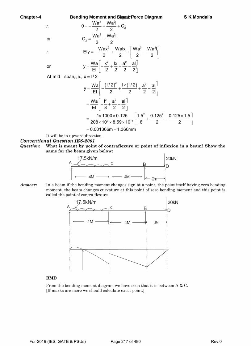
Chapter-4 Bending Moment and Shear Force Diagram S K Mondal’s
3 2
2
3 2
2
Wa Wa l0 C2 2
Wa Wa lor C2 2
2 3 2
2 2
Wax Walx Wa Wa lEIy2 2 2 2
Wa x lx a alor yEI 2 2 2 2
2 2
2 2
2 2
9 8
At mid span,i,e., x l / 2
l / 2 l l / 2Wa a alyEI 2 2 2 2
Wa l a alEI 8 2 2
1 1000 0.125 1.5 0.125 0.125 1.58 2 2208 10 8.59 10
0.001366m 1.366mm
It will be in upward direction
Conventional Question IES-2001 Question: What is meant by point of contraflexure or point of inflexion in a beam? Show the
same for the beam given below:
4M 4M 2m
A C B D
20kN17.5kN/m
Answer: In a beam if the bending moment changes sign at a point, the point itself having zero bending
moment, the beam changes curvature at this point of zero bending moment and this point is
called the point of contra flexure.
4M 4M 2M
A C B D
20kN17.5kN/m
BMD
From the bending moment diagram we have seen that it is between A & C.
[If marks are more we should calculate exact point.]
Page 217
For-2019 (IES, GATE & PSUs) Page 217 of 480 Rev.0
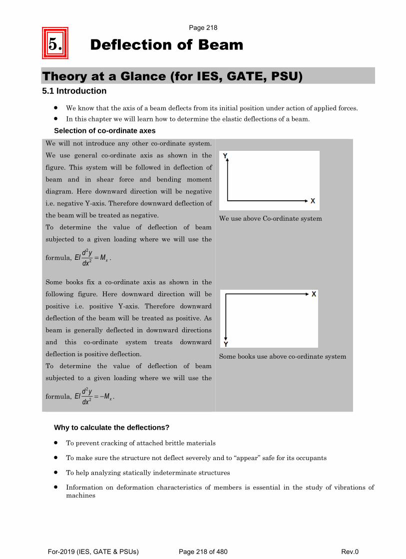
5. Deflection of Beam
Theory at a Glance (for IES, GATE, PSU) 5.1 Introduction
We know that the axis of a beam deflects from its initial position under action of applied forces.
In this chapter we will learn how to determine the elastic deflections of a beam.
Selection of co-ordinate axes
We will not introduce any other co-ordinate system.
We use general co-ordinate axis as shown in the
figure. This system will be followed in deflection of
beam and in shear force and bending moment
diagram. Here downward direction will be negative
i.e. negative Y-axis. Therefore downward deflection of
the beam will be treated as negative.
To determine the value of deflection of beam
subjected to a given loading where we will use the
formula, 2
2 x
d yEI M
dx.
We use above Co-ordinate system
Some books fix a co-ordinate axis as shown in the
following figure. Here downward direction will be
positive i.e. positive Y-axis. Therefore downward
deflection of the beam will be treated as positive. As
beam is generally deflected in downward directions
and this co-ordinate system treats downward
deflection is positive deflection.
To determine the value of deflection of beam
subjected to a given loading where we will use the
formula, 2
2 x
d yEI M
dx.
Some books use above co-ordinate system
Why to calculate the deflections?
To prevent cracking of attached brittle materials
To make sure the structure not deflect severely and to “appear” safe for its occupants
To help analyzing statically indeterminate structures
Information on deformation characteristics of members is essential in the study of vibrations of
machines
Page 218
For-2019 (IES, GATE & PSUs) Page 218 of 480 Rev.0
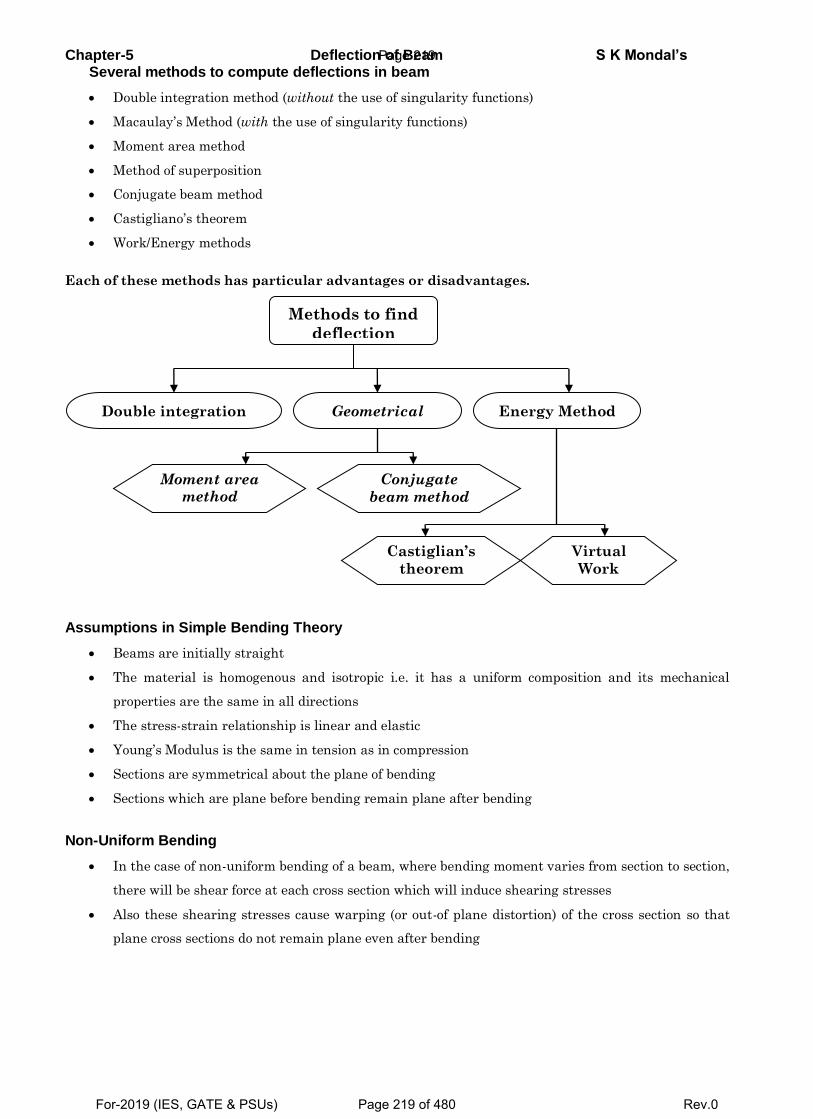
Chapter-5 Deflection of Beam S K Mondal’s Several methods to compute deflections in beam
Double integration method (without the use of singularity functions)
Macaulay’s Method (with the use of singularity functions)
Moment area method
Method of superposition
Conjugate beam method
Castigliano’s theorem
Work/Energy methods
Each of these methods has particular advantages or disadvantages.
Assumptions in Simple Bending Theory
Beams are initially straight
The material is homogenous and isotropic i.e. it has a uniform composition and its mechanical
properties are the same in all directions
The stress-strain relationship is linear and elastic
Young’s Modulus is the same in tension as in compression
Sections are symmetrical about the plane of bending
Sections which are plane before bending remain plane after bending
Non-Uniform Bending
In the case of non-uniform bending of a beam, where bending moment varies from section to section,
there will be shear force at each cross section which will induce shearing stresses
Also these shearing stresses cause warping (or out-of plane distortion) of the cross section so that
plane cross sections do not remain plane even after bending
Methods to find
deflection
Double integration
method
Geometrical Method
Energy Method
Moment area
method
Conjugate
beam method
Castiglian’s
theorem
Work/
Energy
metho
ds
Virtual
Work
Method
Page 219
For-2019 (IES, GATE & PSUs) Page 219 of 480 Rev.0
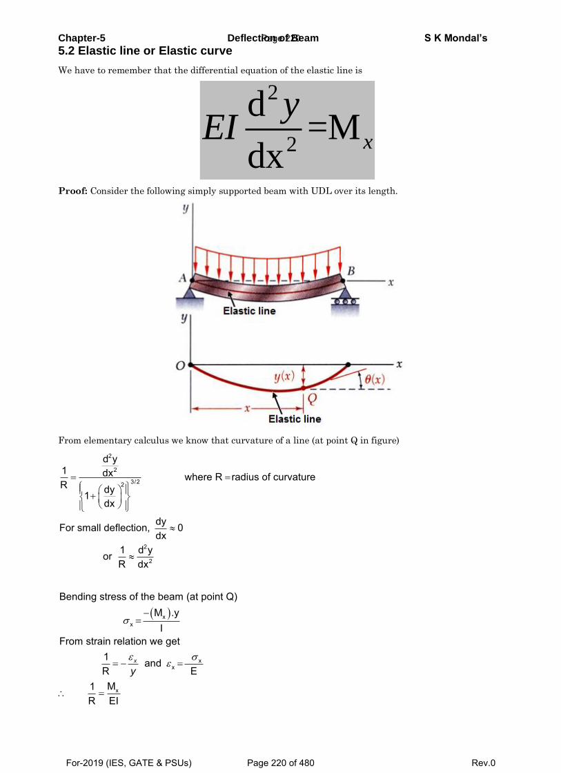
Chapter-5 Deflection of Beam S K Mondal’s
5.2 Elastic line or Elastic curve
We have to remember that the differential equation of the elastic line is
2
2
d=M
dxx
yEI
Proof: Consider the following simply supported beam with UDL over its length.
From elementary calculus we know that curvature of a line (at point Q in figure)
2
2
3/22
2
2
d y1 dx where R radius of curvatureR dy1
dx
dyFor small deflection, 0dx
1 d yorR dx
xx
xx
x
Bending stress of the beam (at point Q)M .y
I
From strain relation we get 1 and
R EM1
R EI
x
y
Page 220
For-2019 (IES, GATE & PSUs) Page 220 of 480 Rev.0
Chapter-5 Deflection of Beam S K Mondal’s
2x
2
2
x2
Md yThereforeEIdx
d yor EI Mdx
5.3 General expression
From the equation 2
2 x
d yEI M
dx we may easily find out the following relations.
4
4
d yEI
dx Shear force density (Load)
3
3 x
d yEI V
dx Shear force
2
2 x
d yEI M
dx Bending moment
dy
= θ = slopedx
y = = Deflection, Displacement Flexural rigidity = EI
5.4 Double integration method (without the use of singularity functions)
Vx= dx
Mx = xV dx
2
2 x
d yEI M
dx
1
xSlope M dxEI
Deflection dx
4-step procedure to solve deflection of beam problems by double integration method
Step 1: Write down boundary conditions (Slope boundary conditions and displacement boundary
conditions), analyze the problem to be solved
Step 2: Write governing equations for,
2
2 x
d yEI M
dx
Step 3: Solve governing equations by integration, results in expression with unknown integration constants
Step 4: Apply boundary conditions (determine integration constants)
Page 221
For-2019 (IES, GATE & PSUs) Page 221 of 480 Rev.0
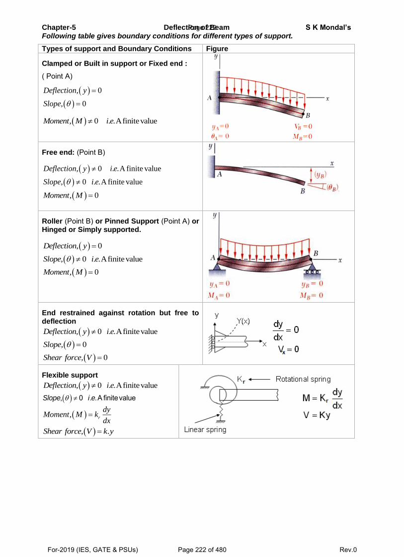
Chapter-5 Deflection of Beam S K Mondal’s
Following table gives boundary conditions for different types of support.
Types of support and Boundary Conditions Figure
Clamped or Built in support or Fixed end :
( Point A)
, 0
, 0
Deflection y
Slope
, 0 . .AfinitevalueMoment M i e
Free end: (Point B)
, 0 . .A finite value
, 0 . .A finite value
Deflection y i e
Slope i e
, 0Moment M
Roller (Point B) or Pinned Support (Point A) or Hinged or Simply supported.
, 0Deflection y
, 0 . .Afinitevalue Slope i e
, 0Moment M
End restrained against rotation but free to deflection
, 0 . .AfinitevalueDeflection y i e
, 0 Slope
, 0Shear force V
Flexible support
, 0 . .AfinitevalueDeflection y i e
, 0 . .A finitevalueSlope i e
, r
dyMoment M k
dx
, .Shear force V k y
Page 222
For-2019 (IES, GATE & PSUs) Page 222 of 480 Rev.0
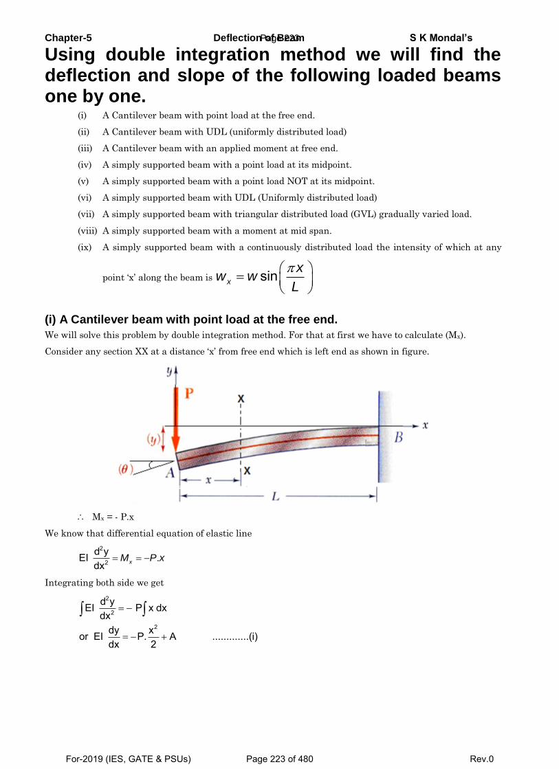
Chapter-5 Deflection of Beam S K Mondal’s
Using double integration method we will find the deflection and slope of the following loaded beams one by one.
(i) A Cantilever beam with point load at the free end.
(ii) A Cantilever beam with UDL (uniformly distributed load)
(iii) A Cantilever beam with an applied moment at free end.
(iv) A simply supported beam with a point load at its midpoint.
(v) A simply supported beam with a point load NOT at its midpoint.
(vi) A simply supported beam with UDL (Uniformly distributed load)
(vii) A simply supported beam with triangular distributed load (GVL) gradually varied load.
(viii) A simply supported beam with a moment at mid span.
(ix) A simply supported beam with a continuously distributed load the intensity of which at any
point ‘x’ along the beam is sinx
xw w
L
(i) A Cantilever beam with point load at the free end.
We will solve this problem by double integration method. For that at first we have to calculate (Mx).
Consider any section XX at a distance ‘x’ from free end which is left end as shown in figure.
Mx = - P.x
We know that differential equation of elastic line
2
2
d yEI .dx xM P x
Integrating both side we get
2
2
2
d yEI P x dxdx
dy xor EI P. A .............(i) dx 2
Page 223
For-2019 (IES, GATE & PSUs) Page 223 of 480 Rev.0
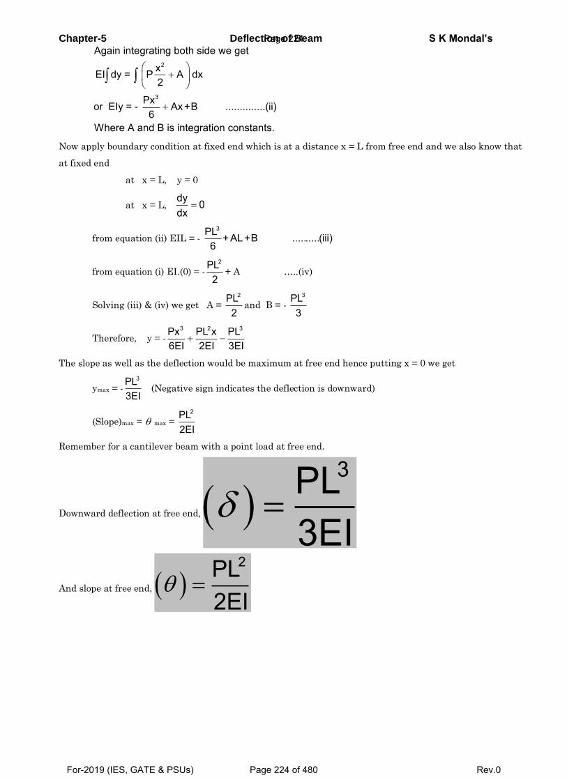
Chapter-5 Deflection of Beam S K Mondal’s
2
3
Again integrating both side we get
xEI dy = P A dx2
Pxor EIy = - Ax+B ..............(ii)6
Where A and B is integration constants.
Now apply boundary condition at fixed end which is at a distance x = L from free end and we also know that
at fixed end
at x = L, y = 0
at x = L, dy 0dx
from equation (ii) EIL = -
3PL +AL+B ..........(iii)6
from equation (i) EI.(0) = -
2PL2
+ A …..(iv)
Solving (iii) & (iv) we get A =
2PL2
and B = -
3PL3
Therefore, y = -
3 2 3Px PL x PL6EI 2EI 3EI
The slope as well as the deflection would be maximum at free end hence putting x = 0 we get
ymax = -
3PL3EI
(Negative sign indicates the deflection is downward)
(Slope)max = max =
2PL2EI
Remember for a cantilever beam with a point load at free end.
Downward deflection at free end, 3PL
3EI
And slope at free end, 2PL
2EI
Page 224
For-2019 (IES, GATE & PSUs) Page 224 of 480 Rev.0
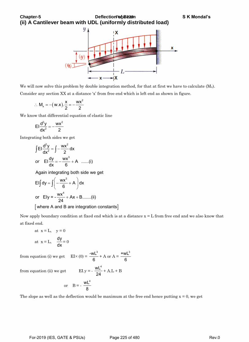
Chapter-5 Deflection of Beam S K Mondal’s
(ii) A Cantilever beam with UDL (uniformly distributed load)
We will now solve this problem by double integration method, for that at first we have to calculate (Mx).
Consider any section XX at a distance ‘x’ from free end which is left end as shown in figure.
2
xx wxM w.x .2 2
We know that differential equation of elastic line
2 2
2
d y wxEIdx 2
Integrating both sides we get
2 2
2
3
d y wxEI dx2dx
dy wxEI A ......(i)dx 6
or
3
4
Again integrating both side we get
wxEI dy A dx6
wxor EIy = - Ax B.......(ii) 24
where A and B are integration constants
Now apply boundary condition at fixed end which is at a distance x = L from free end and we also know that
at fixed end.
at x = L, y = 0
at x = L, dydx
= 0
from equation (i) we get EI (0) =
3-wL6
+ A or A =
3+wL6
from equation (ii) we get EI.y = -
4wL24
+ A.L + B
or B = -
4wL8
The slope as well as the deflection would be maximum at the free end hence putting x = 0, we get
Page 225
For-2019 (IES, GATE & PSUs) Page 225 of 480 Rev.0
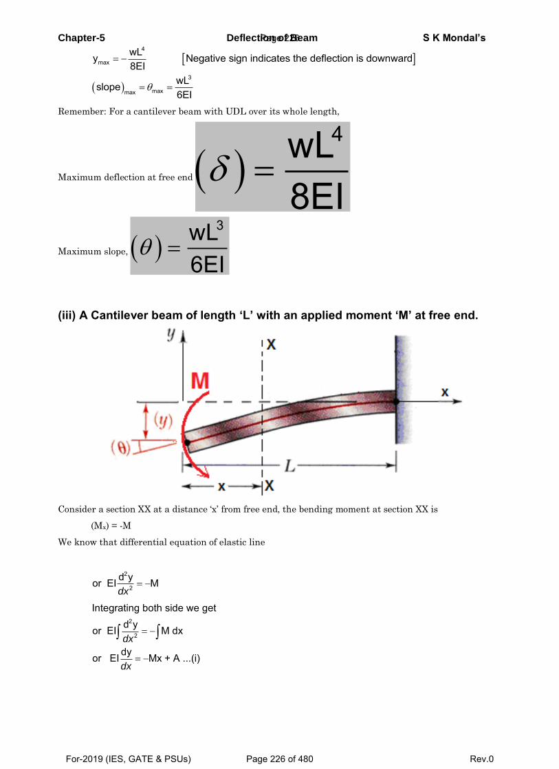
Chapter-5 Deflection of Beam S K Mondal’s
4
max
3
maxmax
wLy Negative sign indicates the deflection is downward8EI
wLslope6EI
Remember: For a cantilever beam with UDL over its whole length,
Maximum deflection at free end 4wL
8EI
Maximum slope, 3wL
6EI
(iii) A Cantilever beam of length ‘L’ with an applied moment ‘M’ at free end.
Consider a section XX at a distance ‘x’ from free end, the bending moment at section XX is
(Mx) = -M
We know that differential equation of elastic line
2
2
d yor EI M dx
2
2
Integrating both side we getd yor EI M dx
dyor EI Mx + A ...(i)
dx
dx
Page 226
For-2019 (IES, GATE & PSUs) Page 226 of 480 Rev.0
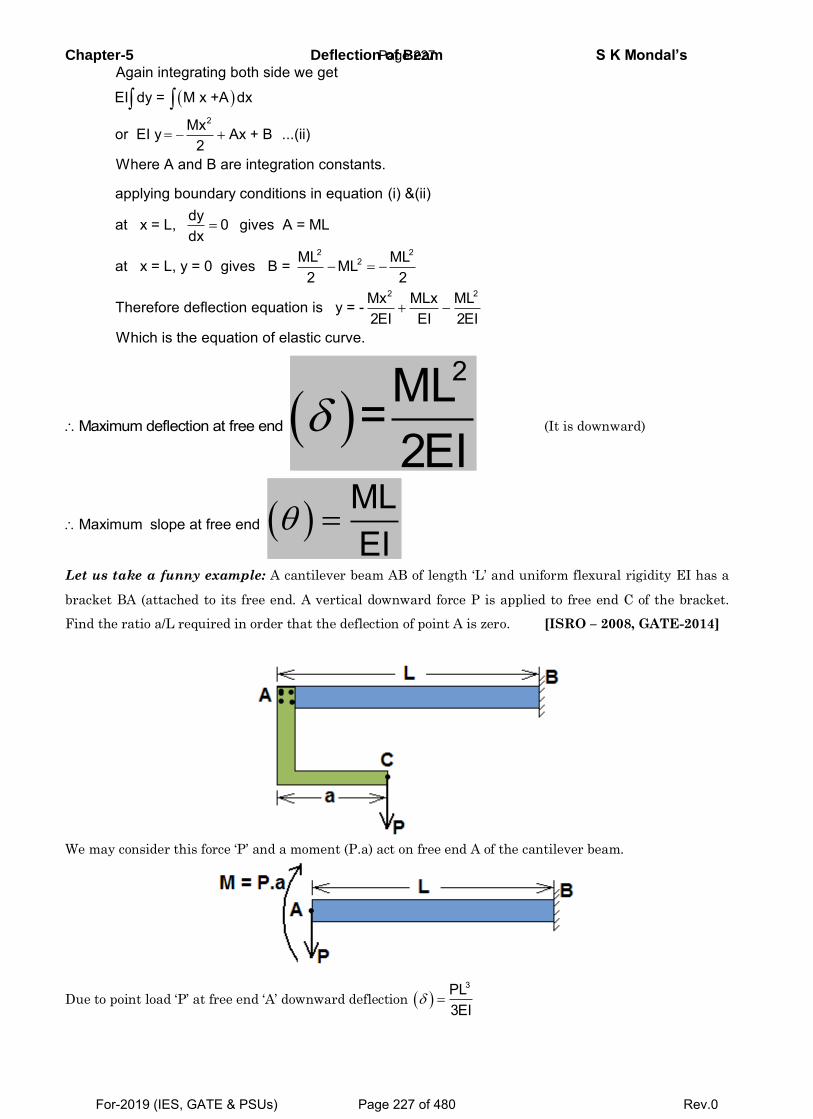
Chapter-5 Deflection of Beam S K Mondal’s
2
Again integrating both side we get
EI dy = M x +A dx
Mxor EI y Ax + B ...(ii) 2
Where A and B are integration constants.
2 22
2 2
applying boundary conditions in equation (i) &(ii) dyat x = L, 0 gives A = MLdx
ML MLat x = L, y = 0 gives B = ML2 2
Mx MLx MLTherefore deflection equation is y = -2EI EI 2EI
Which is the
equation of elastic curve.
Maximum deflection at free end 2ML=
2EI (It is downward)
Maximum slope at free end MLEI
Let us take a funny example: A cantilever beam AB of length ‘L’ and uniform flexural rigidity EI has a
bracket BA (attached to its free end. A vertical downward force P is applied to free end C of the bracket.
Find the ratio a/L required in order that the deflection of point A is zero. [ISRO – 2008, GATE-2014]
We may consider this force ‘P’ and a moment (P.a) act on free end A of the cantilever beam.
Due to point load ‘P’ at free end ‘A’ downward deflection 3PL
3EI
Page 227
For-2019 (IES, GATE & PSUs) Page 227 of 480 Rev.0
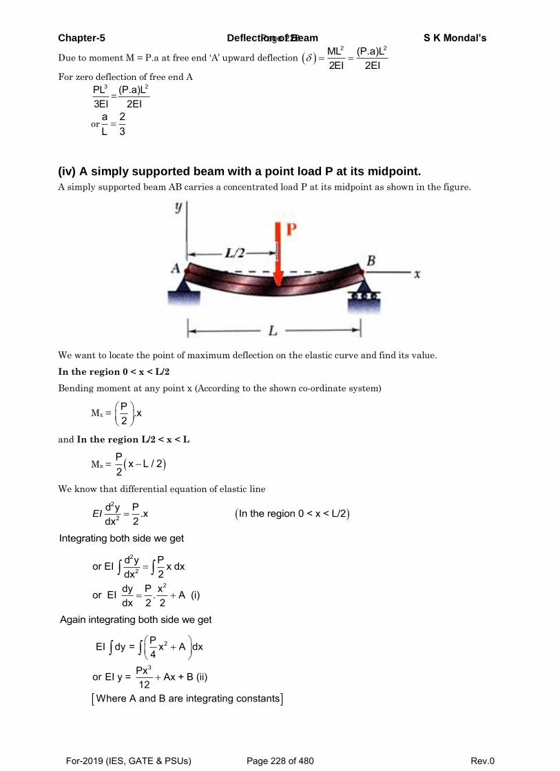
Chapter-5 Deflection of Beam S K Mondal’s
Due to moment M = P.a at free end ‘A’ upward deflection 2 2ML (P.a)L
2EI 2EI
For zero deflection of free end A 3PL
3EI=
2(P.a)L2EI
ora 2L 3
(iv) A simply supported beam with a point load P at its midpoint.
A simply supported beam AB carries a concentrated load P at its midpoint as shown in the figure.
We want to locate the point of maximum deflection on the elastic curve and find its value.
In the region 0 < x < L/2
Bending moment at any point x (According to the shown co-ordinate system)
Mx = P .x2
and In the region L/2 < x < L
Mx = P x L / 22
We know that differential equation of elastic line
2
2
d y P .x In the region 0 < x < L/22dx
EI
Integrating both side we get
2
2
2
d y Por EI x dx 2dx
dy P xor EI . A (i) dx 2 2
Again integrating both side we get
2
3
P EI dy = x A dx4
Pxor EI y = Ax + B (ii) 12
Where A and B are integrating constants
Page 228
For-2019 (IES, GATE & PSUs) Page 228 of 480 Rev.0
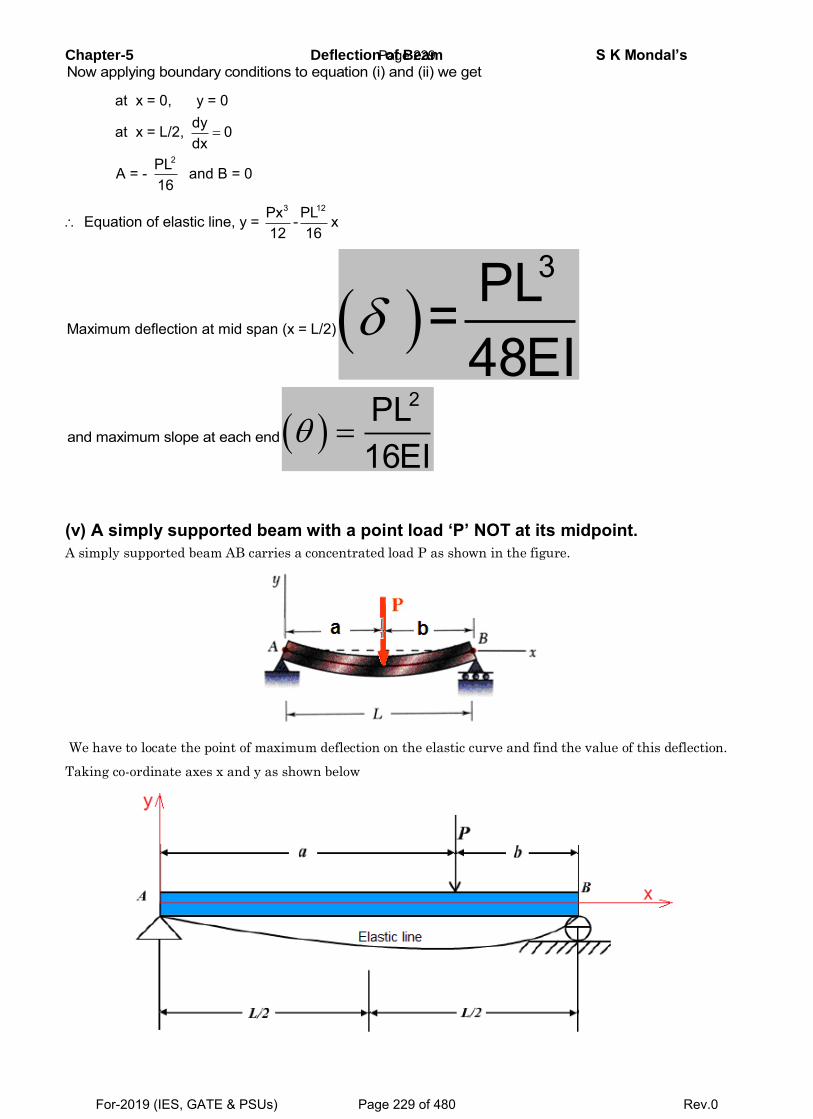
Chapter-5 Deflection of Beam S K Mondal’s Now applying boundary conditions to equation (i) and (ii) we get
2
at x = 0, y = 0dyat x = L/2, 0dx
PLA = - and B = 016
3 12Px PL Equation of elastic line, y = - x12 16
Maximum deflection at mid span (x = L/2) 3PL=
48EI
and maximum slope at each end 2PL
16EI
(v) A simply supported beam with a point load ‘P’ NOT at its midpoint.
A simply supported beam AB carries a concentrated load P as shown in the figure.
We have to locate the point of maximum deflection on the elastic curve and find the value of this deflection.
Taking co-ordinate axes x and y as shown below
Page 229
For-2019 (IES, GATE & PSUs) Page 229 of 480 Rev.0
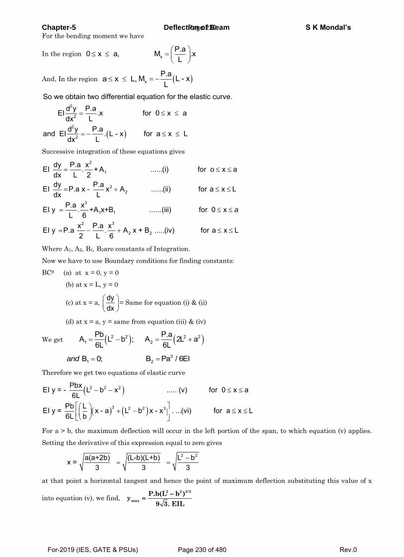
Chapter-5 Deflection of Beam S K Mondal’s For the bending moment we have
In the region xP.a0 x a, M .xL
And, In the region a x L, xP.aM L - xL
2
2
2
2
So we obtain two differential equation for the elastic curve.d y P.aEI .x for 0 x a
Ldxd y P.aand EI . L - x for a x L
Ldx
Successive integration of these equations gives
2
1
22
3
1 1
2 3
2 2
dy P.a xEI . + A ......(i) for o x adx L 2dy P.aEI P.a x - x A ......(ii) for a x Ldx L
P.a xEI y . +A x+B ......(iii) for 0 xL 6
x P.a xEI y P.a . A x + B .....(iv) for a x L2 L 6
a
Where A1, A2, B1, B2are constants of Integration.
Now we have to use Boundary conditions for finding constants:
BCS (a) at x = 0, y = 0
(b) at x = L, y = 0
(c) at x = a, dydx
= Same for equation (i) & (ii)
(d) at x = a, y = same from equation (iii) & (iv)
We get 2 2 2 21 2
Pb P.aA L b ; A 2L a6L 6L
31 2B 0; B Pa / 6EIand
Therefore we get two equations of elastic curve
2 2 2
3 2 2 3
PbxEI y = - L b x ..... (v) for 0 x a6L
Pb LEI y = x - a L b x - x . ...(vi) for a x L6L b
For a > b, the maximum deflection will occur in the left portion of the span, to which equation (v) applies.
Setting the derivative of this expression equal to zero gives
2 2a(a+2b) (L-b)(L+b) L bx = 3 3 3
at that point a horizontal tangent and hence the point of maximum deflection substituting this value of x
into equation (v), we find, 2 2 3/2
max
P.b(L b )y
9 3. EIL
Page 230
For-2019 (IES, GATE & PSUs) Page 230 of 480 Rev.0
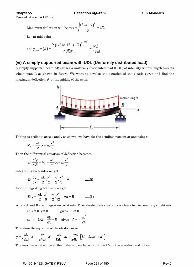
Chapter-5 Deflection of Beam S K Mondal’s Case –I: if a = b = L/2 then
Maximum deflection will be at x =
22L L/2L/2
3
i.e. at mid point
and
3/2223
max
P. L/2 L L/2 PLy48EI9 3 EIL
(vi) A simply supported beam with UDL (Uniformly distributed load)
A simply supported beam AB carries a uniformly distributed load (UDL) of intensity w/unit length over its
whole span L as shown in figure. We want to develop the equation of the elastic curve and find the
maximum deflection at the middle of the span.
Taking co-ordinate axes x and y as shown, we have for the bending moment at any point x
2
xwL xM .x - w.2 2
Then the differential equation of deflection becomes
2 2
x2
d y wL xEI M .x - w.2 2dx
Integrating both sides we get
2 3dy wL x xEI . . A .....(i)dx 2 2 2 3
w
Again Integrating both side we get
3 4wL x xEI y . . Ax + B .....(ii)2 6 2 12
w
Where A and B are integration constants. To evaluate these constants we have to use boundary conditions.
at x = 0, y = 0 gives B = 0
at x = L/2, 0dy
dx gives
3
24wL
A
Therefore the equation of the elastic curve
33 4 3 2 3wL wL wxy . . .x = 2 . x
12EI 24EI 12EI 24EI w
x x L L x
The maximum deflection at the mid-span, we have to put x = L/2 in the equation and obtain
Page 231
For-2019 (IES, GATE & PSUs) Page 231 of 480 Rev.0
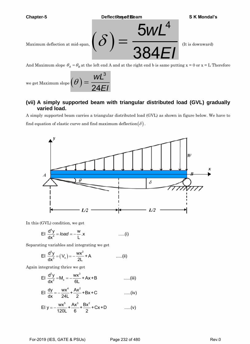
Chapter-5 Deflection of Beam S K Mondal’s
Maximum deflection at mid-span, 45
384wL
EI (It is downward)
And Maximum slope A B at the left end A and at the right end b is same putting x = 0 or x = L Therefore
we get Maximum slope 3
24wL
EI
(vii) A simply supported beam with triangular distributed load (GVL) gradually varied load.
A simply supported beam carries a triangular distributed load (GVL) as shown in figure below. We have to
find equation of elastic curve and find maximum deflection .
In this (GVL) condition, we get
4
4
d y wEI .x .....(i)Ldx
load
Separating variables and integrating we get
3 2
x3
d y wxEI V +A .....(ii) 2Ldx
Again integrating thrice we get
2 3
x2
d y wxEI M +Ax+B .....(iii)6Ldx
4 2dy wx AxEI + +Bx+C .....(iv)dx 24L 2
5 3 2wx Ax BxEI y + + +Cx+D .....(v)120L 6 2
Page 232
For-2019 (IES, GATE & PSUs) Page 232 of 480 Rev.0
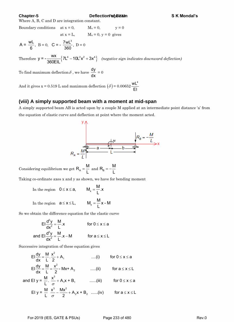
Chapter-5 Deflection of Beam S K Mondal’s Where A, B, C and D are integration constant.
Boundary conditions at x = 0, Mx = 0, y = 0
at x = L, Mx = 0, y = 0 gives
wLA = ,6
B = 0, 37wLC = - ,
360 D = 0
Therefore 4 2 2 4wxy = - 7L 10L x 3x360EIL
(negative sign indicates downward deflection)
To find maximum deflection , we have dydx
= 0
And it gives x = 0.519 L and maximum deflection = 0.00652
4wLEI
(viii) A simply supported beam with a moment at mid-span
A simply supported beam AB is acted upon by a couple M applied at an intermediate point distance ‘a’ from
the equation of elastic curve and deflection at point where the moment acted.
Considering equilibrium we get AMRL
and BMRL
Taking co-ordinate axes x and y as shown, we have for bending moment
In the region xM0 x a, M .xL
In the region xMa x L, M x - ML
So we obtain the difference equation for the elastic curve
2
2
2
2
d y MEI .x for 0 x aLdx
d y Mand EI .x M for a x LLdx
Successive integration of these equation gives
2
1
2
2
3
1 1
3 2
2 2
dy M xEI . A ....(i) for 0 x adx L 2dy M xEI - Mx+ A .....(ii) for a x Ldx L 2
M xand EI y = . A x + B ......(iii) for 0 x aLM x Mx EI y = A x + B ......(iv) for a x L L 2
Page 233
For-2019 (IES, GATE & PSUs) Page 233 of 480 Rev.0
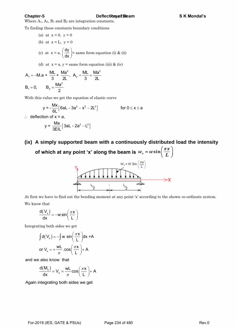
Chapter-5 Deflection of Beam S K Mondal’s Where A1, A2, B1 and B2 are integration constants.
To finding these constants boundary conditions
(a) at x = 0, y = 0
(b) at x = L, y = 0
(c) at x = a, dydx
= same form equation (i) & (ii)
(d) at x = a, y = same form equation (iii) & (iv)
2 2
1 2
2
1 2
ML Ma ML MaA M.a + + , A3 2L 3 2L
MaB 0, B2
With this value we get the equation of elastic curve
2 2 2
2 2
Mxy = - 6aL - 3a x 2L for 0 x a6L
deflection of x = a,Ma y = 3aL - 2a L
3EIL
(ix) A simply supported beam with a continuously distributed load the intensity
of which at any point ‘x’ along the beam is sinx
xw w
L
At first we have to find out the bending moment at any point ‘x’ according to the shown co-ordinate system.
We know that
xd V xw sindx L
Integrating both sides we get
x
x
xd V w sin dx +AL
wL xor V .cos AL
and we also know that
xx
d M wL xV cos Adx L
Again integrating both sides we get
Page 234
For-2019 (IES, GATE & PSUs) Page 234 of 480 Rev.0
Chapter-5 Deflection of Beam S K Mondal’s
x
2
x 2
wL xd M cos A dxL
wL xor M sin Ax +BL
Where A and B are integration constants, to find out the values of A and B. We have to use boundary
conditions
at x = 0, Mx = 0
and at x = L, Mx = 0
From these we get A = B = 0. Therefore
2
x 2
wL xM sinL
So the differential equation of elastic curve
2 2
x2 2
d y wL xEI M sinLdx
Successive integration gives
3
3
4
4
dy wL xEI cos C .......(i)dx L
wL xEIy sin Cx D .....(ii)L
Where C and D are integration constants, to find out C and D we have to use boundary conditions
at x = 0, y = 0
at x = L, y = 0
and that give C = D = 0
Therefore slope equation
3
3
dy wL xEI cosdx L
and Equation of elastic curve
4
4
wL xy sinLEI
(-ive sign indicates deflection is downward)
Deflection will be maximum if xsin
L
is maximum
xsinL
= 1 or x = L/2
and Maximum downward deflection =
4
4
WLEI
(downward).
5.5 Macaulay's Method (Use of singularity function)
When the beam is subjected to point loads (but several loads) this is very convenient method for
determining the deflection of the beam.
In this method we will write single moment equation in such a way that it becomes continuous for
entire length of the beam in spite of the discontinuity of loading.
After integrating this equation we will find the integration constants which are valid for entire
length of the beam. This method is known as method of singularity constant.
Page 235
For-2019 (IES, GATE & PSUs) Page 235 of 480 Rev.0
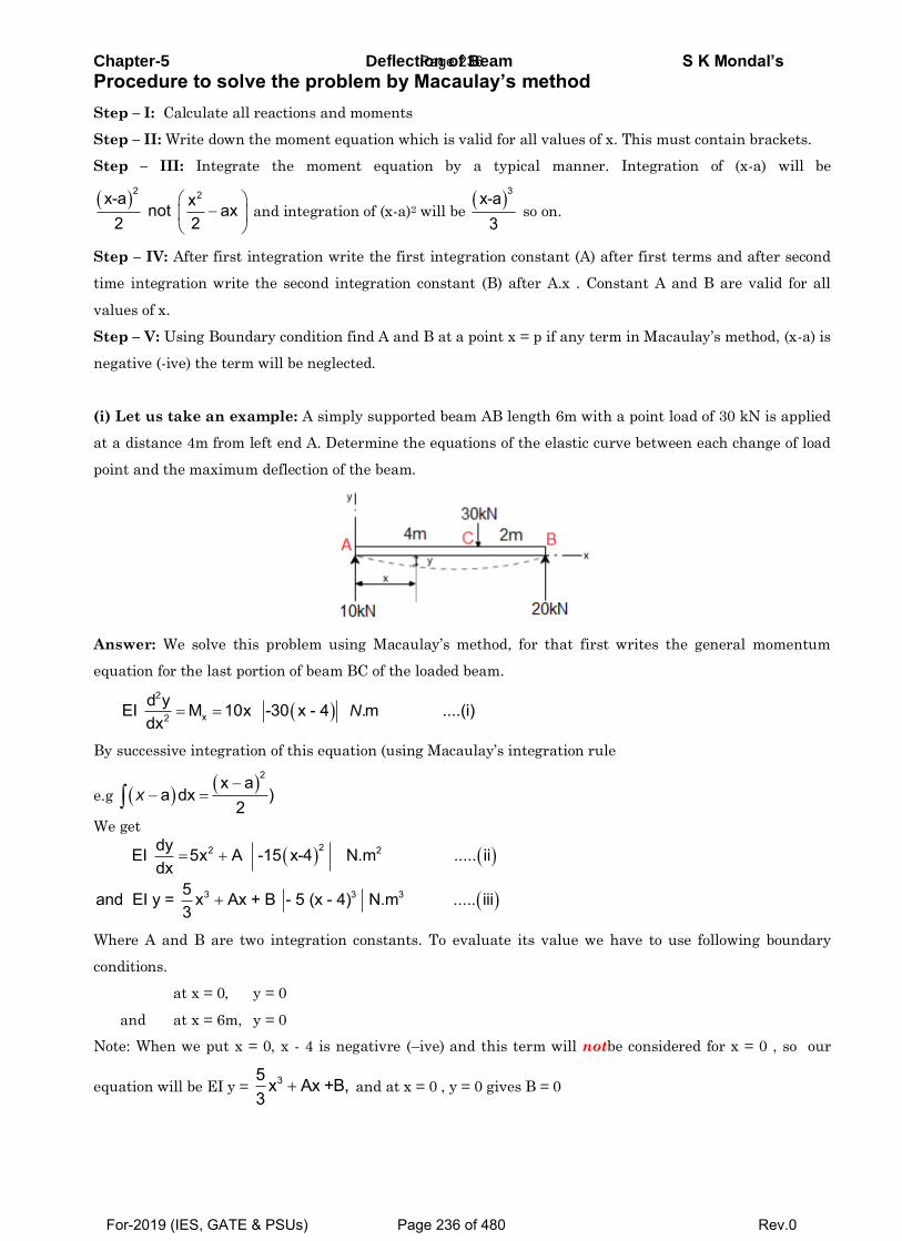
Chapter-5 Deflection of Beam S K Mondal’s
Procedure to solve the problem by Macaulay’s method
Step – I: Calculate all reactions and moments
Step – II: Write down the moment equation which is valid for all values of x. This must contain brackets.
Step – III: Integrate the moment equation by a typical manner. Integration of (x-a) will be
2 2x-a x not ax
2 2
and integration of (x-a)2 will be
3x-a3
so on.
Step – IV: After first integration write the first integration constant (A) after first terms and after second
time integration write the second integration constant (B) after A.x . Constant A and B are valid for all
values of x.
Step – V: Using Boundary condition find A and B at a point x = p if any term in Macaulay’s method, (x-a) is
negative (-ive) the term will be neglected.
(i) Let us take an example: A simply supported beam AB length 6m with a point load of 30 kN is applied
at a distance 4m from left end A. Determine the equations of the elastic curve between each change of load
point and the maximum deflection of the beam.
Answer: We solve this problem using Macaulay’s method, for that first writes the general momentum
equation for the last portion of beam BC of the loaded beam.
2
x2
d yEI M 10x -30 x - 4 .m ....(i)dx
N
By successive integration of this equation (using Macaulay’s integration rule
e.g
2x aa dx )
2x
We get
22 2
3 3 3
dyEI 5x A -15 x-4 N.m ..... iidx
5and EI y = x Ax + B - 5 (x - 4) N.m ..... iii3
Where A and B are two integration constants. To evaluate its value we have to use following boundary
conditions.
at x = 0, y = 0
and at x = 6m, y = 0
Note: When we put x = 0, x - 4 is negativre (–ive) and this term will notbe considered for x = 0 , so our
equation will be EI y = 35 x Ax +B,
3 and at x = 0 , y = 0 gives B = 0
Page 236
For-2019 (IES, GATE & PSUs) Page 236 of 480 Rev.0
Chapter-5 Deflection of Beam S K Mondal’s But when we put x = 6, x-4 is positive (+ive) and this term will be considered for x = 6, y = 0 so our equation
will be EI y = 35 x
3+ Ax + 0 – 5 (x – 4)3
This gives
EI .(0) = 3 35.6 A.6 0 5(6 4)
3
or A = - 53
So our slope and deflection equation will be
22
33
dyEI 5x - 53 - 15 x - 4dx
5 and EI y x - 53x + 0 - 5 x - 43
Now we have two equations for entire section of the beam and we have to understand how we use these
equations. Here if x < 4 then x – 4 is negative so this term will be deleted. That so why in the region
o x 4m we will neglect (x – 4) term and ourslope and deflection equation will be
2dyEI 5x -53
dx
and 35EI y x - 53x
3
But in the region 4 x 6mm , (x – 4) is positive so we include this term and our slope and deflection
equation will be
22dyEI 5x - 53 - 15 x - 4
dx
335EI y x - 53x - 5 x - 4
3
Now we have to find out maximum deflection, but we don’t know at what value of ‘x’ it will be maximum.
For this assuming the value of ‘x’ will be in the region 0 x 4m .
Deflection (y) will be maximum for that dydx
= 0 or 25x - 53 = 0 or x = 3.25 m as our calculated x is in the
region 0 x 4m ; at x = 3.25 m deflection will be maximum
or EI ymax = 53 3.253 – 53 3.25
or ymax = - 115EI
(-ive sign indicates downward deflection)
But if you have any doubt that Maximum deflection may be in the range of 4 x 6m , use EIy = 5x2 – 53x
– 5 (x – 4)3 and find out x. The value of x will be absurd that indicates the maximum deflection will not
occur in the region 4 x 6m .
Deflection (y) will be maximum for that dydx
= 0
or 225x -53 - 15 x - 4 = 0
or 10x2 -120x + 293 = 0
Page 237
For-2019 (IES, GATE & PSUs) Page 237 of 480 Rev.0
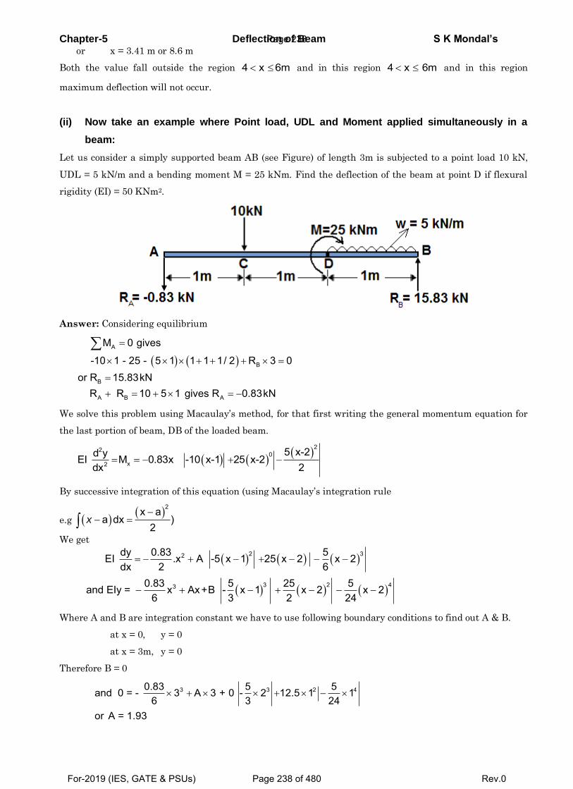
Chapter-5 Deflection of Beam S K Mondal’s or x = 3.41 m or 8.6 m
Both the value fall outside the region 4 x 6m and in this region 4 x 6m and in this region
maximum deflection will not occur.
(ii) Now take an example where Point load, UDL and Moment applied simultaneously in a
beam:
Let us consider a simply supported beam AB (see Figure) of length 3m is subjected to a point load 10 kN,
UDL = 5 kN/m and a bending moment M = 25 kNm. Find the deflection of the beam at point D if flexural
rigidity (EI) = 50 KNm2.
Answer: Considering equilibrium
A
B
B
A B A
M 0 gives
-10 1 - 25 - 5 1 1 1 1/ 2 R 3 0or R 15.83kN
R R 10 5 1 gives R 0.83kN
We solve this problem using Macaulay’s method, for that first writing the general momentum equation for
the last portion of beam, DB of the loaded beam.
220
x2
5 x-2d yEI M 0.83x -10 x-1 25 x-2dx 2
By successive integration of this equation (using Macaulay’s integration rule
e.g
2x aa dx )
2x
We get
2 32
3 2 43
dy 0.83 5EI .x A -5 x 1 25 x 2 x 2dx 2 6
0.83 5 25 5and EIy = x Ax+B - x 1 x 2 x 26 3 2 24
Where A and B are integration constant we have to use following boundary conditions to find out A & B.
at x = 0, y = 0
at x = 3m, y = 0
Therefore B = 0
3 3 2 40.83 5 5and 0 = - 3 A 3 + 0 - 2 12.5 1 16 3 24
or A = 1.93
Page 238
For-2019 (IES, GATE & PSUs) Page 238 of 480 Rev.0
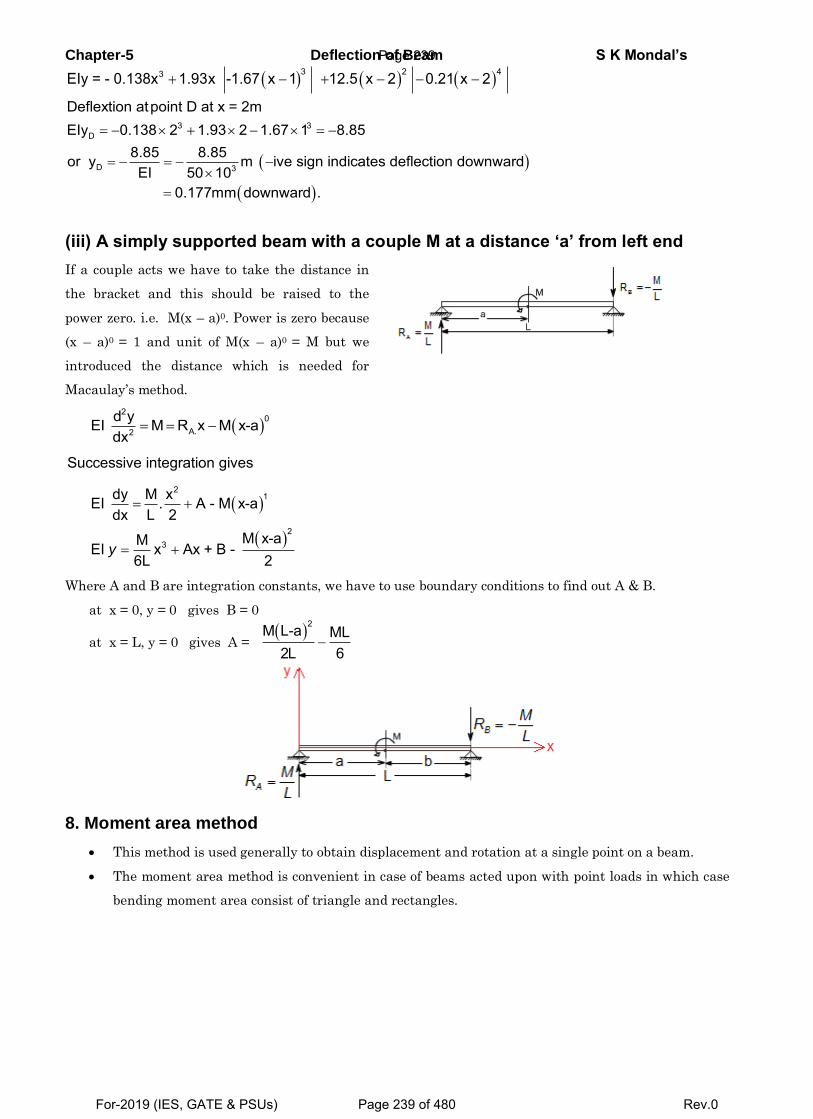
Chapter-5 Deflection of Beam S K Mondal’s
3 2 43EIy = - 0.138x 1.93x -1.67 x 1 12.5 x 2 0.21 x 2
3 3D
D 3
Deflextion atpoint D at x = 2mEIy 0.138 2 1.93 2 1.67 1 8.85
8.85 8.85or y m ive sign indicates deflection downwardEI 50 10
0.177mm downward .
(iii) A simply supported beam with a couple M at a distance ‘a’ from left end
If a couple acts we have to take the distance in
the bracket and this should be raised to the
power zero. i.e. M(x – a)0. Power is zero because
(x – a)0 = 1 and unit of M(x – a)0 = M but we
introduced the distance which is needed for
Macaulay’s method.
2
0A.2
d yEI M R x M x-adx
Successive integration gives
21
23
dy M xEI . A - M x-adx L 2
M x-aMEI x Ax + B - 6L 2
y
Where A and B are integration constants, we have to use boundary conditions to find out A & B.
at x = 0, y = 0 gives B = 0
at x = L, y = 0 gives A =
2M L-a ML 2L 6
8. Moment area method
This method is used generally to obtain displacement and rotation at a single point on a beam.
The moment area method is convenient in case of beams acted upon with point loads in which case
bending moment area consist of triangle and rectangles.
Page 239
For-2019 (IES, GATE & PSUs) Page 239 of 480 Rev.0
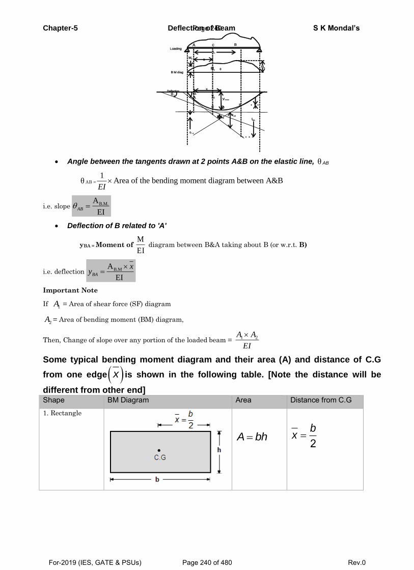
Chapter-5 Deflection of Beam S K Mondal’s
Angle between the tangents drawn at 2 points A&B on the elastic line, θ AB
θ AB =
1Area of the bending moment diagram between A&B
EI
i.e. slope B.M.A
EI AB
Deflection of B related to 'A'
yBA = Moment of M
EI diagram between B&A taking about B (or w.r.t. B)
i.e. deflection B.MA
EI
BA
xy
Important Note
If 1A = Area of shear force (SF) diagram
2A = Area of bending moment (BM) diagram,
Then, Change of slope over any portion of the loaded beam = 1 2A A
EI
Some typical bending moment diagram and their area (A) and distance of C.G
from one edge x is shown in the following table. [Note the distance will be
different from other end] Shape BM Diagram Area Distance from C.G
1. Rectangle
A bh
2b
x
Page 240
For-2019 (IES, GATE & PSUs) Page 240 of 480 Rev.0
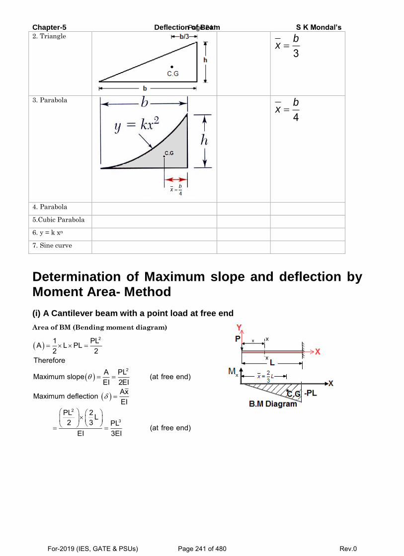
Chapter-5 Deflection of Beam S K Mondal’s
2. Triangle
3b
x
3. Parabola
4b
x
4. Parabola
5.Cubic Parabola
6. y = k xn
7. Sine curve
Determination of Maximum slope and deflection by Moment Area- Method
(i) A Cantilever beam with a point load at free end
Area of BM (Bending moment diagram)
2
2
2
3
1 PLA L PL2 2
ThereforeA PLMaximum slope (at free end)EI 2EI
AxMaximum deflection EI
PL 2 L2 3 PL (at free end)
EI 3EI
Page 241
For-2019 (IES, GATE & PSUs) Page 241 of 480 Rev.0
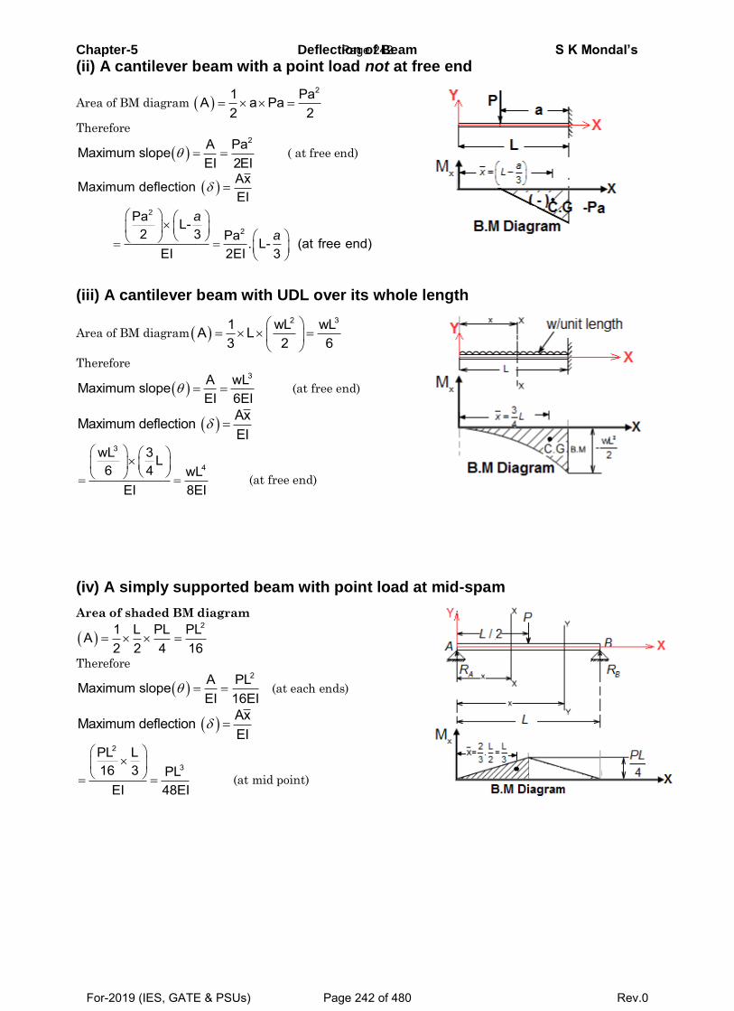
Chapter-5 Deflection of Beam S K Mondal’s
(ii) A cantilever beam with a point load not at free end
Area of BM diagram 21 PaA a Pa
2 2
Therefore
2A PaMaximum slope
EI 2EI ( at free end)
2
2
AxMaximum deflection EI
Pa L-2 3 Pa . L- (at free end)
EI 2EI 3
a
a
(iii) A cantilever beam with UDL over its whole length
Area of BM diagram
2 31 wL wLA L3 2 6
Therefore
3A wLMaximum slope
EI 6EI (at free end)
AxMaximum deflection EI
3
4
wL 3 L6 4 wL
EI 8EI
(at free end)
(iv) A simply supported beam with point load at mid-spam
Area of shaded BM diagram
21 L PL PLA
2 2 4 16
Therefore
2A PLMaximum slope
EI 16EI (at each ends)
AxMaximum deflection EI
2
3
PL L16 3 PL
EI 48EI
(at mid point)
Page 242
For-2019 (IES, GATE & PSUs) Page 242 of 480 Rev.0
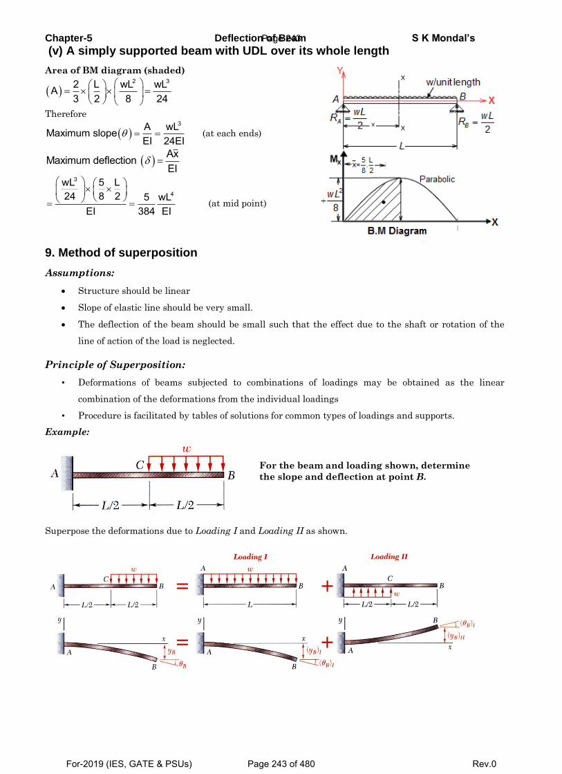
Chapter-5 Deflection of Beam S K Mondal’s
(v) A simply supported beam with UDL over its whole length
Area of BM diagram (shaded)
2 32 L wL wLA
3 2 8 24
Therefore
3A wLMaximum slope
EI 24EI (at each ends)
AxMaximum deflection EI
3
4
wL 5 L24 8 2 5 wL
EI 384 EI
(at mid point)
9. Method of superposition
Assumptions:
Structure should be linear
Slope of elastic line should be very small.
The deflection of the beam should be small such that the effect due to the shaft or rotation of the
line of action of the load is neglected.
Principle of Superposition:
• Deformations of beams subjected to combinations of loadings may be obtained as the linear
combination of the deformations from the individual loadings
• Procedure is facilitated by tables of solutions for common types of loadings and supports.
Example:
Superpose the deformations due to Loading I and Loading II as shown.
For the beam and loading shown, determine
the slope and deflection at point B.
Page 243
For-2019 (IES, GATE & PSUs) Page 243 of 480 Rev.0
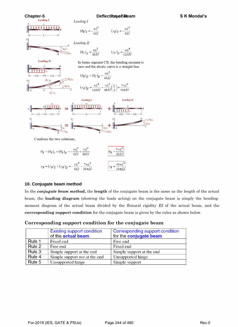
Chapter-5 Deflection of Beam S K Mondal’s
10. Conjugate beam method
In the conjugate beam method, the length of the conjugate beam is the same as the length of the actual
beam, the loading diagram (showing the loads acting) on the conjugate beam is simply the bending-
moment diagram of the actual beam divided by the flexural rigidity EI of the actual beam, and the
corresponding support condition for the conjugate beam is given by the rules as shown below.
Corresponding support condition for the conjugate beam
Page 244
For-2019 (IES, GATE & PSUs) Page 244 of 480 Rev.0
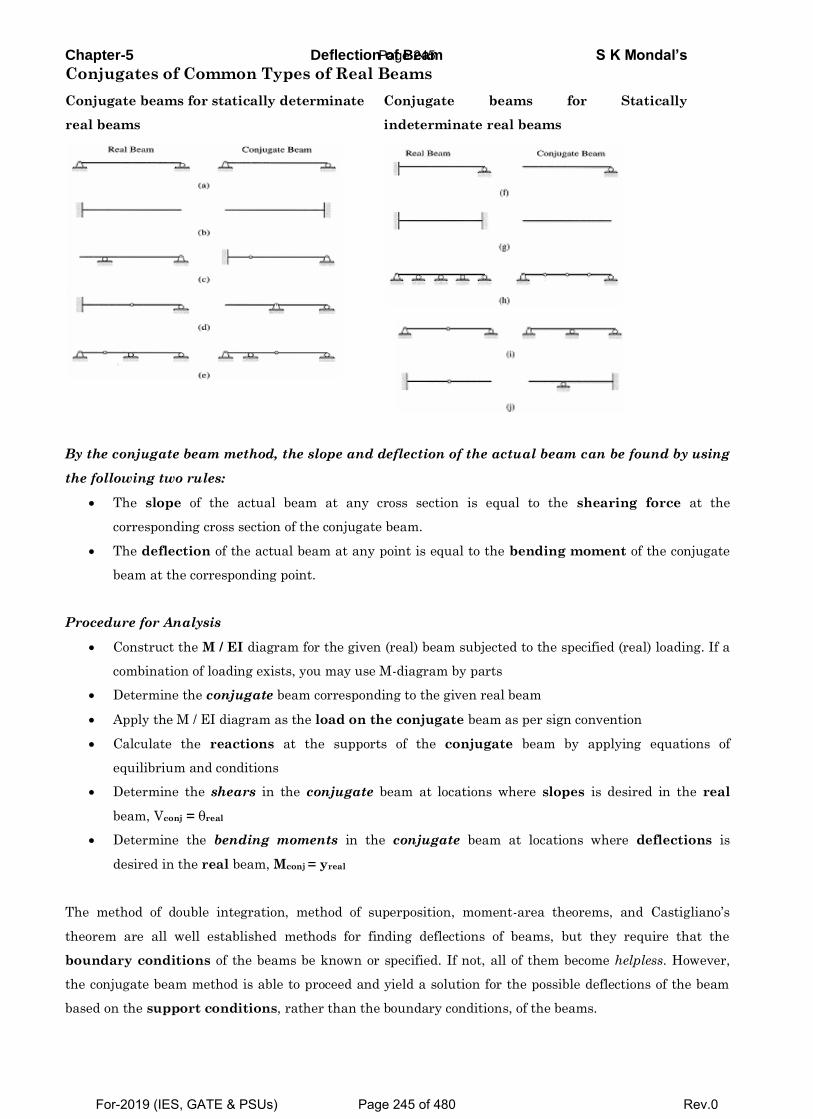
Chapter-5 Deflection of Beam S K Mondal’s
Conjugates of Common Types of Real Beams
Conjugate beams for statically determinate
real beams
Conjugate beams for Statically
indeterminate real beams
By the conjugate beam method, the slope and deflection of the actual beam can be found by using
the following two rules:
The slope of the actual beam at any cross section is equal to the shearing force at the
corresponding cross section of the conjugate beam.
The deflection of the actual beam at any point is equal to the bending moment of the conjugate
beam at the corresponding point.
Procedure for Analysis
Construct the M / EI diagram for the given (real) beam subjected to the specified (real) loading. If a
combination of loading exists, you may use M-diagram by parts
Determine the conjugate beam corresponding to the given real beam
Apply the M / EI diagram as the load on the conjugate beam as per sign convention
Calculate the reactions at the supports of the conjugate beam by applying equations of
equilibrium and conditions
Determine the shears in the conjugate beam at locations where slopes is desired in the real
beam, Vconj = θreal
Determine the bending moments in the conjugate beam at locations where deflections is
desired in the real beam, Mconj = yreal
The method of double integration, method of superposition, moment-area theorems, and Castigliano’s
theorem are all well established methods for finding deflections of beams, but they require that the
boundary conditions of the beams be known or specified. If not, all of them become helpless. However,
the conjugate beam method is able to proceed and yield a solution for the possible deflections of the beam
based on the support conditions, rather than the boundary conditions, of the beams.
Page 245
For-2019 (IES, GATE & PSUs) Page 245 of 480 Rev.0
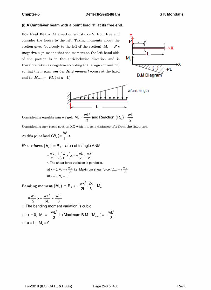
Chapter-5 Deflection of Beam S K Mondal’s
(i) A Cantilever beam with a point load ‘P’ at its free end.
For Real Beam: At a section a distance ‘x’ from free end
consider the forces to the left. Taking moments about the
section gives (obviously to the left of the section) Mx = -P.x
(negative sign means that the moment on the left hand side
of the portion is in the anticlockwise direction and is
therefore taken as negative according to the sign convention)
so that the maximum bending moment occurs at the fixed
end i.e. Mmax = - PL ( at x = L)
Considering equilibrium we get, 2
A AwL wLM and Reaction R3 2
Considering any cross-section XX which is at a distance of x from the fixed end.
At this point load W(W ) .xLx
Shear force AR area of triangle ANMxV
2
x max
x
wL 1 w wL wx- . .x .x = + - 2 2 L 2 2L
The shear force variation is parabolic.wL wLat x 0, V i.e. Maximum shear force, V2 2
at x L, V 0
Bending moment 2
A Awx 2x= R .x - . - M2L 3xM
3 2
2 2
max
x
wL wx wL= .x - - 2 6L 3
The bending moment variation is cubicwL wLat x = 0, M i.e.Maximum B.M. M .3 3
at x L, M 0
x
Page 246
For-2019 (IES, GATE & PSUs) Page 246 of 480 Rev.0

Chapter-5 Deflection of Beam S K Mondal’s
OBJECTIVE QUESTIONS (GATE, IES, IAS)
Previous 25-Years GATE Questions
Beam Deflection
GATE-1. A lean elastic beam of given flexural
rigidity, EI, is loaded by a single force F
as shown in figure. How many boundary
conditions are necessary to determine
the deflected centre line of the beam?
(a) 5 (b) 4
(c) 3 (d) 2
[GATE-1999]
GATE-1(i).Two identical cantilever beams are supported as shown, with their free ends in
contact through a rigid roller. After the load P is applied, the free ends will have
[GATE-2005]
(a) Equal deflections but not equal slopes
(b) Equal slopes but not equal deflections
(c) Equal slopes as well as equal deflections
(d) Neither equal slopes nor equal deflections
GATE-1(ii). The ‘plane section remains plane’ assumption in bending theory implies:
(a) strain profile is linear [CE: GATE-2013]
(b) stress profile is linear
(c) both strain and stress profiles are linear
(d) shear deformations are neglected
Double Integration Method
GATE-1(iii). A cantilever beam of length L, with uniform cross-section and flexural rigidity, EI, is loaded uniformly by a vertical load, w per unit length. The maximum vertical
deflection of the beam is given by [GATE-2014]
(a) 4L
8EI
w (b)
4L
16EI
w (c)
4L
4 EI
w (d)
4L
24 EI
w
GATE-1(iv). A cantilever beam having square cross-section of side a is subjected to an end
load. If a is increased by 19%, the tip deflection decreases approximately by
(a) 19% (b) 29% (c) 41% (d) 50% [GATE-2016]
GATE-1(v)The following statement are related to bending of beams [CE: GATE-2012]
I. The slope of the bending moment diagram is equal to the shear force.
Page 247
For-2019 (IES, GATE & PSUs) Page 247 of 480 Rev.0
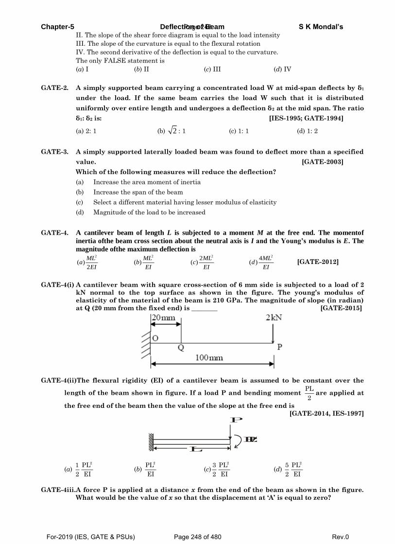
Chapter-5 Deflection of Beam S K Mondal’s II. The slope of the shear force diagram is equal to the load intensity
III. The slope of the curvature is equal to the flexural rotation
IV. The second derivative of the deflection is equal to the curvature.
The only FALSE statement is
(a) I (b) II (c) III (d) IV
GATE-2. A simply supported beam carrying a concentrated load W at mid-span deflects by δ1
under the load. If the same beam carries the load W such that it is distributed
uniformly over entire length and undergoes a deflection δ2 at the mid span. The ratio
δ1: δ2 is: [IES-1995; GATE-1994]
(a) 2: 1 (b) 2 : 1 (c) 1: 1 (d) 1: 2
GATE-3. A simply supported laterally loaded beam was found to deflect more than a specified
value. [GATE-2003]
Which of the following measures will reduce the deflection?
(a) Increase the area moment of inertia
(b) Increase the span of the beam
(c) Select a different material having lesser modulus of elasticity
(d) Magnitude of the load to be increased
GATE-4. A cantilever beam of length L is subjected to a moment M at the free end. The momentof
inertia ofthe beam cross section about the neutral axis is I and the Young’s modulus is E. The
magnitude ofthe maximum deflection is
2 2 2 22 4
( ) ( ) ( ) ( )2
ML ML ML MLa b c d
EI EI EI EI [GATE-2012]
GATE-4(i) A cantilever beam with square cross-section of 6 mm side is subjected to a load of 2
kN normal to the top surface as shown in the figure. The young’s modulus of
elasticity of the material of the beam is 210 GPa. The magnitude of slope (in radian)
at Q (20 mm from the fixed end) is ________ [GATE-2015]
GATE-4(ii)The flexural rigidity (EI) of a cantilever beam is assumed to be constant over the
length of the beam shown in figure. If a load P and bending moment PL
2are applied at
the free end of the beam then the value of the slope at the free end is
[GATE-2014, IES-1997]
L
PL/2
P
(a) 21 PL
2 EI (b)
2PL
EI (c)
23 PL
2 EI (d)
25 PL
2 EI
GATE-4iii. A force P is applied at a distance x from the end of the beam as shown in the figure.
What would be the value of x so that the displacement at ‘A’ is equal to zero?
Page 248
For-2019 (IES, GATE & PSUs) Page 248 of 480 Rev.0
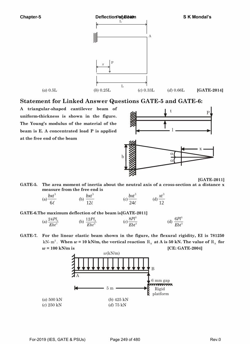
Chapter-5 Deflection of Beam S K Mondal’s L
P x
L
A
(a) 0.5L (b) 0.25L (c) 0.33L (d) 0.66L [GATE-2014]
Statement for Linked Answer Questions GATE-5 and GATE-6:
A triangular-shaped cantilever beam of
uniform-thickness is shown in the figure.
The Young’s modulus of the material of the
beam is E. A concentrated load P is applied
at the free end of the beam
t
l
P
x
b
[GATE-2011]
GATE-5. The area moment of inertia about the neutral axis of a cross-section at a distance x
measure from the free end is
(a)
3
6
bxt (b)
3
12
bxt (c)
3
24
bxt (d)
3
12
xt
GATE-6.The maximum deflection of the beam is[GATE-2011]
(a) 3
3
24Pl
Ebt (b) 3
3
12Pl
Ebt (c)
3
3
8Pl
Ebt (d)
3
3
6Pl
Ebt
GATE-7. For the linear elastic beam shown in the figure, the flexural rigidity, EI is 781250 2kN-m . When w = 10 kN/m, the vertical reaction
AR at A is 50 kN. The value of
AR for
w = 100 kN/m is [CE: GATE-2004]
w(kN/m)
B
A 6 mm gap
Rigid
platform
5 m
(a) 500 kN (b) 425 kN
(c) 250 kN (d) 75 kN
Page 249
For-2019 (IES, GATE & PSUs) Page 249 of 480 Rev.0
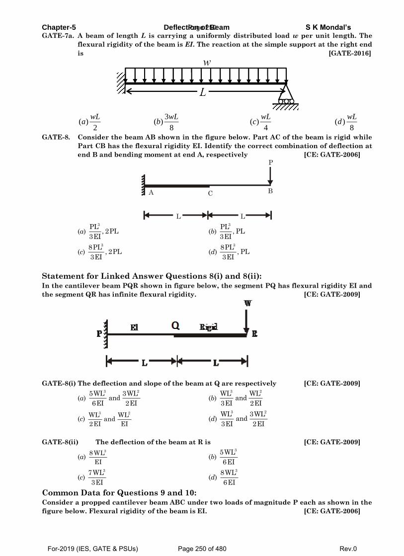
Chapter-5 Deflection of Beam S K Mondal’s GATE-7a. A beam of length L is carrying a uniformly distributed load w per unit length. The
flexural rigidity of the beam is EI. The reaction at the simple support at the right end
is [GATE-2016]
3
( ) ( ) ( ) ( )2 8 4 8
wL wL wL wLa b c d
GATE-8. Consider the beam AB shown in the figure below. Part AC of the beam is rigid while
Part CB has the flexural rigidity EI. Identify the correct combination of deflection at
end B and bending moment at end A, respectively [CE: GATE-2006]
A C B
L
P
L
(a) 3PL
, 2PL3EI
(b) 3PL
, PL3EI
(c) 38PL
, 2PL3EI
(d) 38PL
, PL3EI
Statement for Linked Answer Questions 8(i) and 8(ii): In the cantilever beam PQR shown in figure below, the segment PQ has flexural rigidity EI and
the segment QR has infinite flexural rigidity. [CE: GATE-2009]
GATE-8(i) The deflection and slope of the beam at Q are respectively [CE: GATE-2009]
(a) 3 25WL 3WL
and6EI 2EI
(b) 3 2WL WL
and3EI 2EI
(c) 3 2WL WL
and2EI EI
(d) 3 2WL 3WL
and3EI 2EI
GATE-8(ii) The deflection of the beam at R is [CE: GATE-2009]
(a) 38 WL
EI (b)
35WL
6EI
(c) 37WL
3EI (d)
38WL
6EI
Common Data for Questions 9 and 10: Consider a propped cantilever beam ABC under two loads of magnitude P each as shown in the
figure below. Flexural rigidity of the beam is EI. [CE: GATE-2006]
Page 250
For-2019 (IES, GATE & PSUs) Page 250 of 480 Rev.0
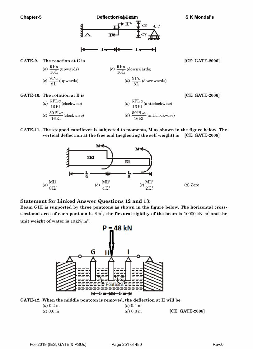
Chapter-5 Deflection of Beam S K Mondal’s
L
A
L
P
B P
C a
a
GATE-9. The reaction at C is [CE: GATE-2006]
(a) 9P
(upwards)16L
a (b)
9P(downwards)
16L
a
(c) 9P
(upwards)8L
a (d)
9P(downwards)
8L
a
GATE-10. The rotation at B is [CE: GATE-2006]
(a) 5PL
(clockwise)16EI
a (b)
5PL(anticlockwise)
16EI
a
(c) 59PL
(clockwise)16EI
a (d)
59PL(anticlockwise)
16EI
a
GATE-11. The stepped cantilever is subjected to moments, M as shown in the figure below. The
vertical deflection at the free end (neglecting the self weight) is [CE: GATE-2008]
(a)2ML
8El (b)
2ML
4El (c)
2ML
2El (d) Zero
Statement for Linked Answer Questions 12 and 13:
Beam GHI is supported by three pontoons as shown in the figure below. The horizontal cross-
sectional area of each pontoon is 28m , the flexural rigidity of the beam is 210000 kN-m and the
unit weight of water is 310kN/ m .
GATE-12. When the middle pontoon is removed, the deflection at H will be
(a) 0.2 m (b) 0.4 m
(c) 0.6 m (d) 0.8 m [CE: GATE-2008]
Page 251
For-2019 (IES, GATE & PSUs) Page 251 of 480 Rev.0
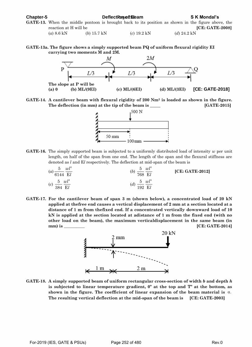
Chapter-5 Deflection of Beam S K Mondal’s GATE-13. When the middle pontoon is brought back to its position as shown in the figure above, the
reaction at H will be [CE: GATE-2008]
(a) 8.6 kN (b) 15.7 kN (c) 19.2 kN (d) 24.2 kN
GATE-13a. The figure shows a simply supported beam PQ of uniform flexural rigidity EI
carrying two moments M and 2M.
The slope at P will be
(a) 0 (b) ML/(9EI) (c) ML/(6EI) (d) ML/(3EI) [CE: GATE-2018]
GATE-14. A cantilever beam with flexural rigidity of 200 Nm2 is loaded as shown in the figure.
The deflection (in mm) at the tip of the beam is _____ [GATE-2015]
GATE-16. The simply supported beam is subjected to a uniformly distributed load of intensity w per unit
length, on half of the span from one end. The length of the span and the flexural stiffness are
denoted as l and El respectively. The deflection at mid-span of the beam is
(a)45
6144 E
wl
l (b)
45
768 E
wl
l [CE: GATE-2012]
(c) 45
384 E
wl
l (d)
45
192 E
wl
l
GATE-17. For the cantilever beam of span 3 m (shown below), a concentrated load of 20 kN
applied at thefree end causes a vertical displacement of 2 mm at a section located at a
distance of 1 m from thefixed end. If a concentrated vertically downward load of 10
kN is applied at the section located at adistance of 1 m from the fixed end (with no
other load on the beam), the maximum verticaldisplacement in the same beam (in
mm) is __________ [CE: GATE-2014]
GATE-18. A simply supported beam of uniform rectangular cross-section of width b and depth h
is subjected to linear temperature gradient, 0º at the top and Tº at the bottom, as
shown in the figure. The coefficient of linear expansion of the beam material is
The resulting vertical deflection at the mid-span of the beam is [CE: GATE-2003]
.
Page 252
For-2019 (IES, GATE & PSUs) Page 252 of 480 Rev.0
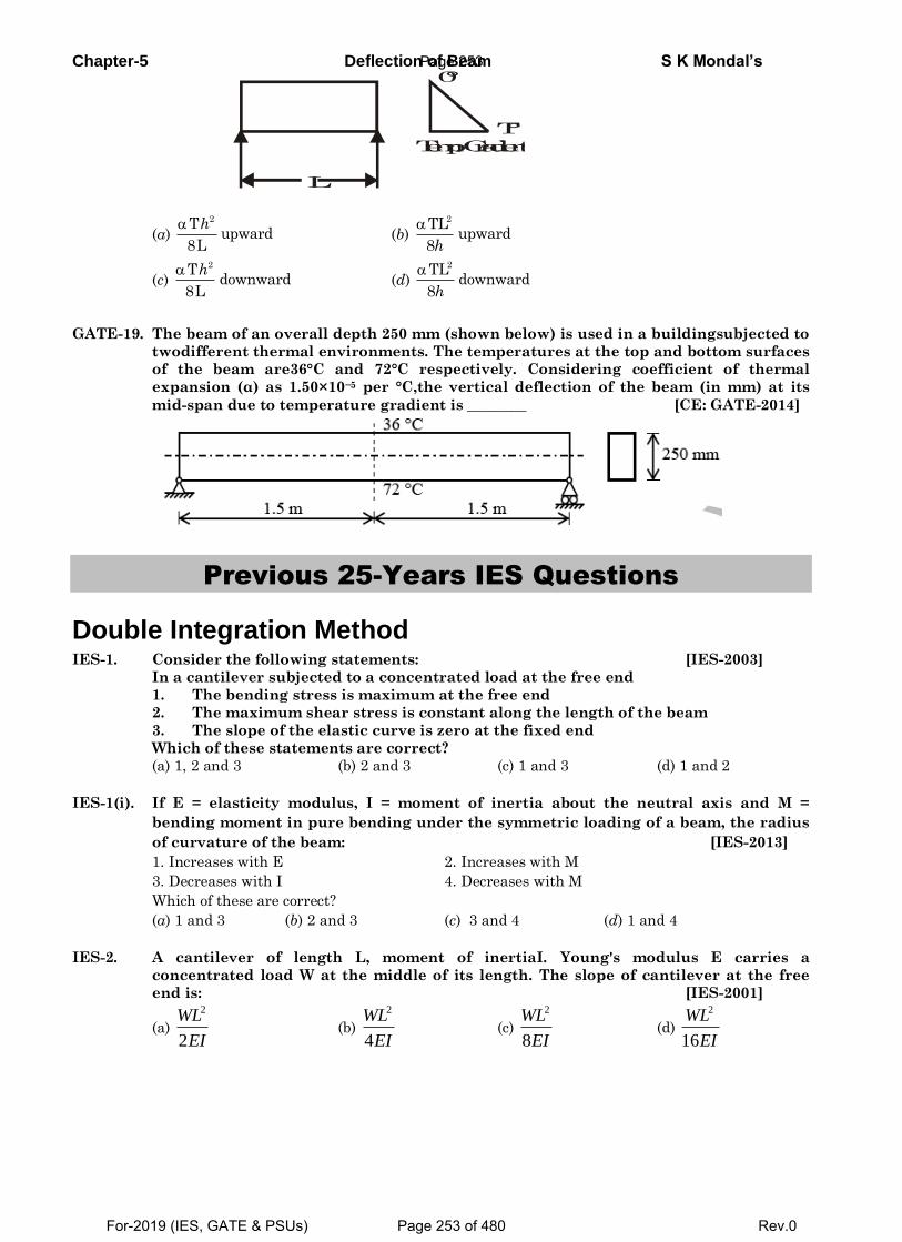
Chapter-5 Deflection of Beam S K Mondal’s
(a) (b)
(c) (d)
GATE-19. The beam of an overall depth 250 mm (shown below) is used in a buildingsubjected to
twodifferent thermal environments. The temperatures at the top and bottom surfaces
of the beam are36°C and 72°C respectively. Considering coefficient of thermal
expansion (α) as 1.50×10⁻⁵ per °C,the vertical deflection of the beam (in mm) at its
mid-span due to temperature gradient is ________ [CE: GATE-2014]
Previous 25-Years IES Questions
Double Integration Method IES-1. Consider the following statements: [IES-2003]
In a cantilever subjected to a concentrated load at the free end
1. The bending stress is maximum at the free end
2. The maximum shear stress is constant along the length of the beam
3. The slope of the elastic curve is zero at the fixed end
Which of these statements are correct?
(a) 1, 2 and 3 (b) 2 and 3 (c) 1 and 3 (d) 1 and 2
IES-1(i). If E = elasticity modulus, I = moment of inertia about the neutral axis and M =
bending moment in pure bending under the symmetric loading of a beam, the radius
of curvature of the beam: [IES-2013]
1. Increases with E 2. Increases with M
3. Decreases with I 4. Decreases with M
Which of these are correct?
(a) 1 and 3 (b) 2 and 3 (c) 3 and 4 (d) 1 and 4
IES-2. A cantilever of length L, moment of inertiaI. Young's modulus E carries a
concentrated load W at the middle of its length. The slope of cantilever at the free
end is: [IES-2001]
(a)
2
2
WL
EI (b)
2
4
WL
EI (c)
2
8
WL
EI (d)
2
16
WL
EI
L
0°
T°
Temp. Gradient
2Tupward
8L
h 2TLupward
8h
2Tdownward
8L
h 2TLdownward
8h
Page 253
For-2019 (IES, GATE & PSUs) Page 253 of 480 Rev.0
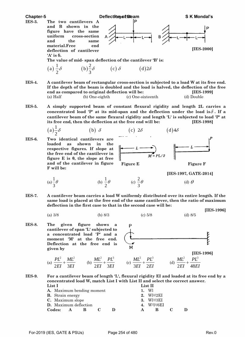
Chapter-5 Deflection of Beam S K Mondal’s IES-3. The two cantilevers A
and B shown in the
figure have the same
uniform cross-section
and the same
material.Free end
deflection of cantilever
'A' is δ.
[IES-2000]
The value of mid- span deflection of the cantilever ‘B’ is:
1 2
a b c d 2 2 3
IES-4. A cantilever beam of rectangular cross-section is subjected to a load W at its free end.
If the depth of the beam is doubled and the load is halved, the deflection of the free
end as compared to original deflection will be: [IES-1999]
(a) Half (b) One-eighth (c) One-sixteenth (d) Double
IES-5. A simply supported beam of constant flexural rigidity and length 2L carries a
concentrated load 'P' at its mid-span and the deflection under the load is . If a
cantilever beam of the same flexural rigidity and length 'L' is subjected to load 'P' at
its free end, then the deflection at the free end will be: [IES-1998]
1
a b c 2 d 4 2
IES-6. Two identical cantilevers are
loaded as shown in the
respective figures. If slope at
the free end of the cantilever in
figure E is θ, the slope at free
and of the cantilever in figure
F will be:
Figure E Figure F
[IES-1997, GATE-2014]
(a)1
3 (b)
1
2 (c)
2
3 (d)
IES-7. A cantilever beam carries a load W uniformly distributed over its entire length. If the
same load is placed at the free end of the same cantilever, then the ratio of maximum
deflection in the first case to that in the second case will be:
[IES-1996]
(a) 3/8 (b) 8/3 (c) 5/8 (d) 8/5
IES-8. The given figure shows a
cantilever of span 'L' subjected to
a concentrated load 'P' and a
moment 'M' at the free end.
Deflection at the free end is
given by [IES-1996]
(a)
2 2
2 3
PL ML
EI EI (b)
2 3
2 3
ML PL
EI EI (c)
2 3
3 2
ML PL
EI EI (d)
2 3
2 48
ML PL
EI EI
IES-9. For a cantilever beam of length 'L', flexural rigidity EI and loaded at its free end by a
concentrated load W, match List I with List II and select the correct answer.
List I List II
A. Maximum bending moment 1. Wl
B. Strain energy 2. Wl2/2EI
C. Maximum slope 3. Wl3/3EI
D. Maximum deflection 4. W2l2/6EI
Codes: A B C D A B C D
Page 254
For-2019 (IES, GATE & PSUs) Page 254 of 480 Rev.0
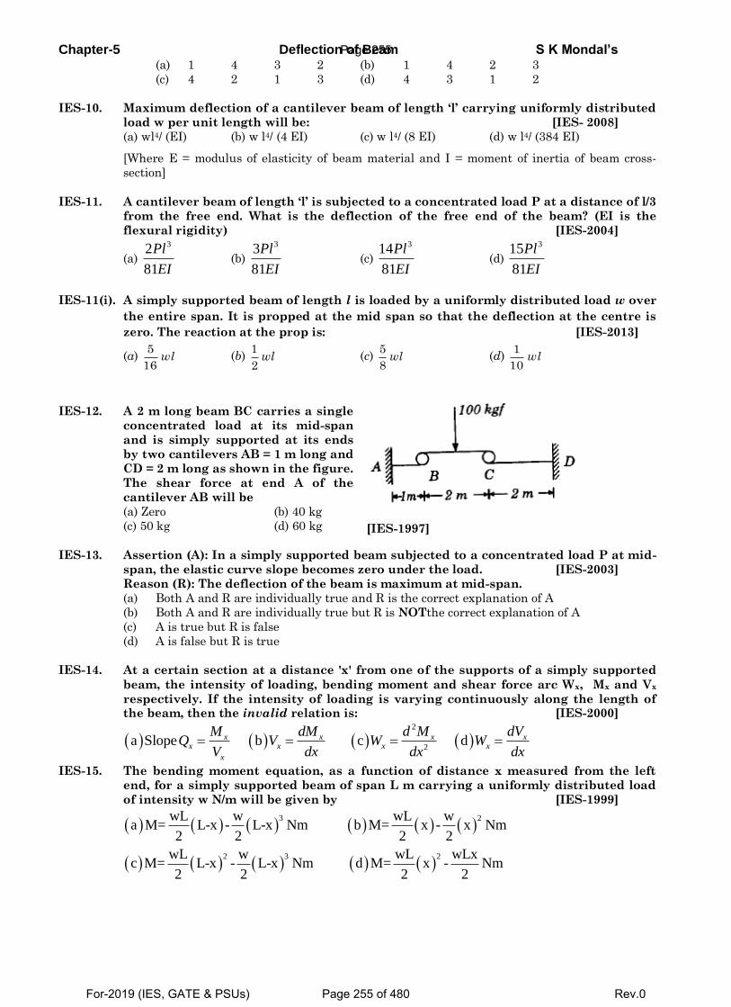
Chapter-5 Deflection of Beam S K Mondal’s (a) 1 4 3 2 (b) 1 4 2 3
(c) 4 2 1 3 (d) 4 3 1 2
IES-10. Maximum deflection of a cantilever beam of length ‘l’ carrying uniformly distributed
load w per unit length will be: [IES- 2008]
(a) wl4/ (EI) (b) w l4/ (4 EI) (c) w l4/ (8 EI) (d) w l4/ (384 EI)
[Where E = modulus of elasticity of beam material and I = moment of inertia of beam cross-
section]
IES-11. A cantilever beam of length ‘l’ is subjected to a concentrated load P at a distance of l/3
from the free end. What is the deflection of the free end of the beam? (EI is the
flexural rigidity) [IES-2004]
(a)
32
81
Pl
EI (b)
33
81
Pl
EI (c)
314
81
Pl
EI (d)
315
81
Pl
EI
IES-11(i). A simply supported beam of length l is loaded by a uniformly distributed load w over
the entire span. It is propped at the mid span so that the deflection at the centre is
zero. The reaction at the prop is: [IES-2013]
(a) 5
16wl (b)
1
2wl (c)
5
8wl (d)
1
10wl
IES-12. A 2 m long beam BC carries a single
concentrated load at its mid-span
and is simply supported at its ends
by two cantilevers AB = 1 m long and
CD = 2 m long as shown in the figure.
The shear force at end A of the
cantilever AB will be
(a) Zero (b) 40 kg
(c) 50 kg (d) 60 kg
[IES-1997]
IES-13. Assertion (A): In a simply supported beam subjected to a concentrated load P at mid-
span, the elastic curve slope becomes zero under the load. [IES-2003]
Reason (R): The deflection of the beam is maximum at mid-span.
(a) Both A and R are individually true and R is the correct explanation of A
(b) Both A and R are individually true but R is NOTthe correct explanation of A
(c) A is true but R is false
(d) A is false but R is true
IES-14. At a certain section at a distance 'x' from one of the supports of a simply supported
beam, the intensity of loading, bending moment and shear force arc Wx, Mx and Vx
respectively. If the intensity of loading is varying continuously along the length of the beam, then the invalid relation is: [IES-2000]
2
2a Slope b c dx x x x
x x x x
x
M dM d M dVQ V W W
V dx dx dx
IES-15. The bending moment equation, as a function of distance x measured from the left
end, for a simply supported beam of span L m carrying a uniformly distributed load
of intensity w N/m will be given by [IES-1999]
3 2
2 3 2
wL w wL wa M= L-x - L-x Nm b M= x - x Nm
2 2 2 2
wL w wL wLxc M= L-x - L-x Nm d M= x - Nm
2 2 2 2
Page 255
For-2019 (IES, GATE & PSUs) Page 255 of 480 Rev.0
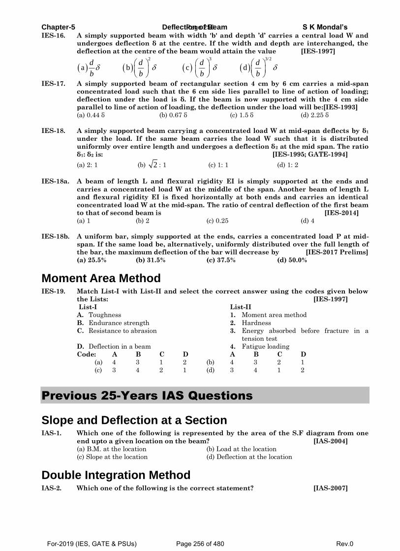
Chapter-5 Deflection of Beam S K Mondal’s IES-16. A simply supported beam with width 'b' and depth ’d’ carries a central load W and
undergoes deflection δ at the centre. If the width and depth are interchanged, the
deflection at the centre of the beam would attain the value [IES-1997]
2 3 3/2
a b c d d d d d
b b b b
IES-17. A simply supported beam of rectangular section 4 cm by 6 cm carries a mid-span
concentrated load such that the 6 cm side lies parallel to line of action of loading;
deflection under the load is δ. If the beam is now supported with the 4 cm side
parallel to line of action of loading, the deflection under the load will be:[IES-1993]
(a) 0.44 δ (b) 0.67 δ (c) 1.5 δ (d) 2.25 δ
IES-18. A simply supported beam carrying a concentrated load W at mid-span deflects by δ1
under the load. If the same beam carries the load W such that it is distributed
uniformly over entire length and undergoes a deflection δ2 at the mid span. The ratio
δ1: δ2 is: [IES-1995; GATE-1994]
(a) 2: 1 (b) 2 : 1 (c) 1: 1 (d) 1: 2
IES-18a. A beam of length L and flexural rigidity EI is simply supported at the ends and
carries a concentrated load W at the middle of the span. Another beam of length L
and flexural rigidity EI is fixed horizontally at both ends and carries an identical
concentrated load W at the mid-span. The ratio of central deflection of the first beam
to that of second beam is [IES-2014]
(a) 1 (b) 2 (c) 0.25 (d) 4
IES-18b. A uniform bar, simply supported at the ends, carries a concentrated load P at mid-
span. If the same load be, alternatively, uniformly distributed over the full length of
the bar, the maximum deflection of the bar will decrease by [IES-2017 Prelims]
(a) 25.5% (b) 31.5% (c) 37.5% (d) 50.0%
Moment Area Method IES-19. Match List-I with List-II and select the correct answer using the codes given below
the Lists: [IES-1997]
List-I List-II
A. Toughness 1. Moment area method
B. Endurance strength 2. Hardness
C. Resistance to abrasion 3. Energy absorbed before fracture in a
tension test
D. Deflection in a beam 4. Fatigue loading
Code: A B C D A B C D
(a) 4 3 1 2 (b) 4 3 2 1
(c) 3 4 2 1 (d) 3 4 1 2
Previous 25-Years IAS Questions
Slope and Deflection at a Section IAS-1. Which one of the following is represented by the area of the S.F diagram from one
end upto a given location on the beam? [IAS-2004]
(a) B.M. at the location (b) Load at the location
(c) Slope at the location (d) Deflection at the location
Double Integration Method IAS-2. Which one of the following is the correct statement? [IAS-2007]
Page 256
For-2019 (IES, GATE & PSUs) Page 256 of 480 Rev.0
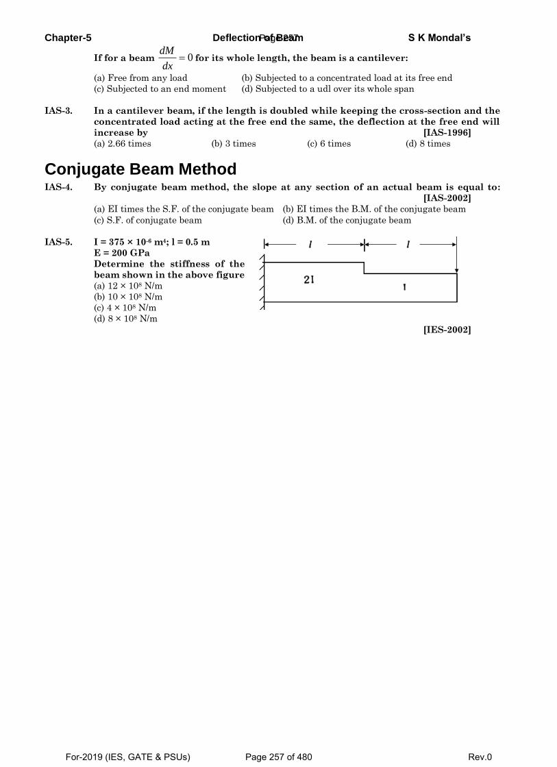
Chapter-5 Deflection of Beam S K Mondal’s
If for a beam 0dM
dx for its whole length, the beam is a cantilever:
(a) Free from any load (b) Subjected to a concentrated load at its free end
(c) Subjected to an end moment (d) Subjected to a udl over its whole span
IAS-3. In a cantilever beam, if the length is doubled while keeping the cross-section and the
concentrated load acting at the free end the same, the deflection at the free end will
increase by [IAS-1996]
(a) 2.66 times (b) 3 times (c) 6 times (d) 8 times
Conjugate Beam Method IAS-4. By conjugate beam method, the slope at any section of an actual beam is equal to:
[IAS-2002]
(a) EI times the S.F. of the conjugate beam (b) EI times the B.M. of the conjugate beam
(c) S.F. of conjugate beam (d) B.M. of the conjugate beam
IAS-5. I = 375 × 10-6 m4; l = 0.5 m
E = 200 GPa
Determine the stiffness of the
beam shown in the above figure
(a) 12 × 108 N/m
(b) 10 × 108 N/m
(c) 4 × 10⁸ N/m
(d) 8 × 10⁸ N/m
[IES-2002]
Page 257
For-2019 (IES, GATE & PSUs) Page 257 of 480 Rev.0
Chapter-5 Deflection of Beam S K Mondal’s
OBJECTIVE ANSWERS
GATE-1.Ans.(d)2
2
d yEI Mdx
.Since it is second order differential equation so we need two boundary
conditions to solve it.
GATE-1(i). Ans. (a) As it is rigid roller, deflection must be same, because after deflection they also will
be in contact. But slope unequal.
GATE-1(ii). Ans. (a)
GATE-1(iii). Ans. (a)
GATE-1(iv). Ans. (d) 3 4 3
4 4
4 4 4
2 1 1
1 2 1
4
1 2
1
4 1I
3 12
1
1.19 1.19
1% Decrease 100% 1 100% 50.13%
1.19
PL a PLor
EI Ea a
a a
a a
GATE-1(v). Ans. (c)
We know that
Also
GATE-2. Ans. (d)
3
1Wl48EI
and
43
2
W5 l5Wll
384EI 384EI
Therefore δ1: δ2 = 8 : 5
GATE-3. Ans. (a) Maximum deflection (δ) = 3Wl
48EI
To reduce, δ, increase the area moment of Inertia.
GATE-4. Ans. (a)
GATE-4(i) Ans. 0.158 Use double integration method.
GATE-4(ii)Ans. (b)
GATE-4(iii)Ans. (c) Refer theory of this book, “Let us take an funny example” ISRO-2008
Wds
dx
MS
X
d
d
2
2EI . M
d y
dx
2
2
M
EI
d y
dx
M E
I Ry
M 1
EI R
2
2
1
R
d y
dx
Page 258
For-2019 (IES, GATE & PSUs) Page 258 of 480 Rev.0
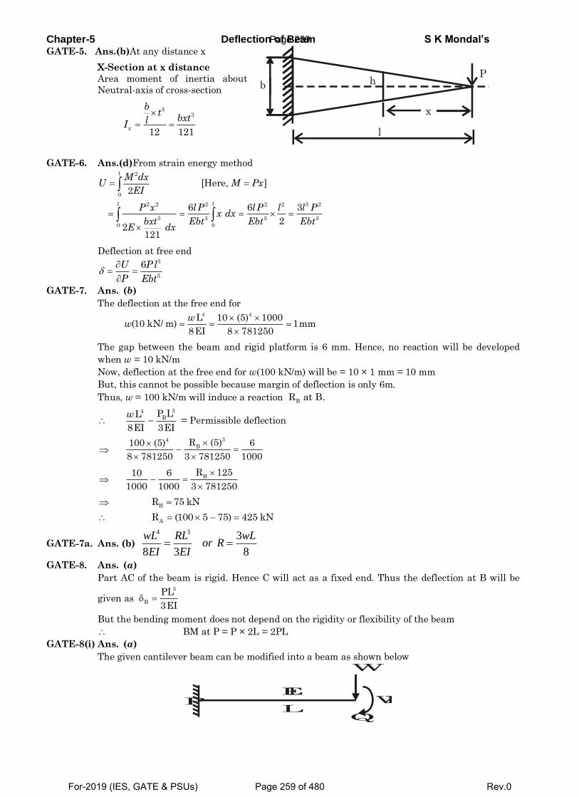
Chapter-5 Deflection of Beam S K Mondal’s GATE-5. Ans.(b)At any distance x
X-Section at x distance
Area moment of inertia about
Neutral-axis of cross-section
33
12 121x
bt
bxtlI
GATE-6. Ans.(d)From strain energy method
1 2
0
1 12 2 2 2 2 3 2
3 3 3 3
0 0
[Here, ]2
6 6 3
22
121
M dxU M Px
EI
P x l P l P l l Px dx
bxt Ebt Ebt EbtE dx
Deflection at free end
3
3
6U Pl
P Ebt
GATE-7. Ans. (b)
The deflection at the free end for
The gap between the beam and rigid platform is 6 mm. Hence, no reaction will be developed
when w = 10 kN/m
Now, deflection at the free end for w(100 kN/m) will be = 10 × 1 mm = 10 mm
But, this cannot be possible because margin of deflection is only 6m.
Thus, w = 100 kN/m will induce a reaction
= Permissible deflection
GATE-7a. Ans. (b)
4 3 3
8 3 8
wL RL wLor R
EI EI
GATE-8. Ans. (a)
Part AC of the beam is rigid. Hence C will act as a fixed end. Thus the deflection at B will be
given as
But the bending moment does not depend on the rigidity or flexibility of the beam
BM at P = P × 2L = 2PL
GATE-8(i) Ans. (a)
The given cantilever beam can be modified into a beam as shown below
b
x
l
Ph
4 4L 10 (5) 1000(10 kN/ m) 1mm
8EI 8 781250
ww
BR at B.
34
BP LL
8EI 3EI
w
34
BR (5)100 (5) 6
8 781250 3 781250 1000
BR 12510 6
1000 1000 3 781250
B
R 75 kN
A
R (100 5 75) 425 kN
3
B
PL
3EI
P L
El WL
W
Q
Page 259
For-2019 (IES, GATE & PSUs) Page 259 of 480 Rev.0
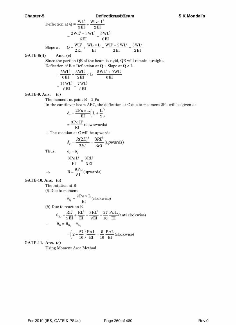
Chapter-5 Deflection of Beam S K Mondal’s
Deflection at Q =
Slope at
GATE-8(ii) Ans. (c)
Since the portion QR of the beam is rigid, QR will remain straight.
Deflection of R = Deflection at Q + Slope at Q × L
GATE-9. Ans. (c)
The moment at point B = 2 Pa
In the cantilever beam ABC, the deflection at C due to meoment 2Pa will be given as
(downwards)
The reaction at C will be upwards
3 3(2 ) 8( )
3 3c
R L RLupwards
EI EI
Thus,
GATE-10. Ans. (a)
The rotation at B
(i) Due to moment
(ii) Due to reaction R
GATE-11. Ans. (c)
Using Moment Area Method
3 2WL WL L
3EI 2EI
3 3 32WL 3WL 5WL
6EI 6EI
2 2 2 2WL WL × L WL 2WL 3WLQ
2EI EI 2EI 2EI
3 2 3 35WL 3WL 5WL 9WLL
6EI 2EI 6EI
3 314WL 7WL
6EI 3EI
2P L LL
EI 2c
a
23P L
EI
a
c c
2 33P L 8RL
EI 3EI
a
9P
R (upwards)8L
a
1B
2P L(clockwise)
EI
a
2
2 2 2
B
RL RL 3RL 27 P L(anti clockwise)
2EI EI 2EI 16 EI
a
1 2B B B
27 P L 5 P L2 (clockwise)
16 EI 16 EI
a a
Page 260
For-2019 (IES, GATE & PSUs) Page 260 of 480 Rev.0
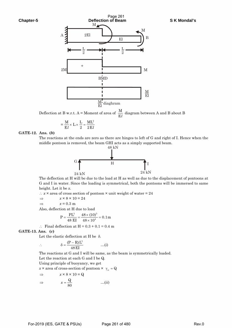
Chapter-5 Deflection of Beam S K Mondal’s
Deflection at B w.r.t. A = Moment of area of diagram between A and B about B
GATE-12. Ans. (b) The reactions at the ends are zero as there are hinges to left of G and right of I. Hence when the
middle pontoon is removed, the beam GHI acts as a simply supported beam.
The deflection at H will be due to the load at H as well as due to the displacement of pontoons at
G and I in water. Since the loading is symmetrical, both the pontoons will be immersed to same height. Let it be x.
x × area of cross section of pontoon × unit weight of water = 24 x × 8 × 10 = 24 x = 0.3 m Also, deflection at H due to load
Final deflection at H = 0.3 + 0.1 = 0.4 m GATE-13. Ans. (c) Let the elastic deflection at H be
…(i)
The reactions at G and I will be same, as the beam is symmetrically loaded. Let the reaction at each G and I be Q. Using principle of buoyancy, we get x × area of cross-section of pontoon × x × 8 × 10 = Q
…(ii)
L 2
L 2
M M
El2El B A
2M
MEl diaghram
MEl
BMD
M +
MEl
2M L ML= LE 2 2El l
× × =
G H I
24 kN
48 kN
24 kN
∴⇒⇒
×= = =
×
3 3
4PL 48 (10)P 0.1m
48 EI 48 10∴
δ.
∴−
δ =3(P R)L
48EI
γ = Qw
⇒
⇒ =Q80
x
Page 261
For-2019 (IES, GATE & PSUs) Page 261 of 480 Rev.0
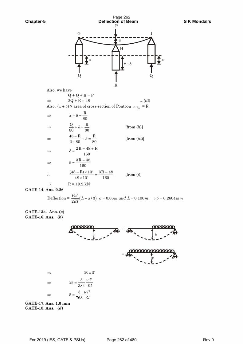
Chapter-5 Deflection of Beam S K Mondal’s
Also, we have Q + Q + R = P 2Q + R = 48 …(iii) Also, × area of cross-section of Pontoon = R
[from (ii)]
[from (iii)]
[from (i)]
R = 19.2 kN GATE-14. Ans. 0.26
( )2
Deflection = / 3 0.05 0.100 0.26042Pa L a a m and L m mmEI
δ− = = ⇒ =
GATE-13a. Ans. (c) GATE-16. Ans. (b)
GATE-17. Ans. 1.0 mm GATE-18. Ans. (d)
P
H
δ
x xx + δ
Q
R
Q
G I
⇒+ δ( )x × γw
⇒ + δ =R80
x
⇒ + δ =Q R80 80
⇒−
+ δ =×
48 R R2 80 80
⇒− +
δ =2R 48 R
160
⇒−
δ =3R 48
160
∴− × −
=×
3
4(48 R) 10 3R 48
16048 10⇒
δ+
δ
δ′=
⇒ 2δ = δ′
⇒452
384 Ewl
lδ =
⇒45
768 Ewl
lδ =
Page 262
For-2019 (IES, GATE & PSUs) Page 262 of 480 Rev.0
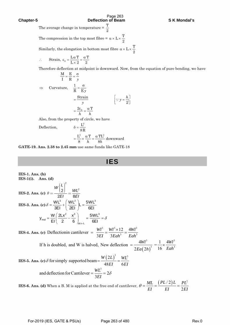
Chapter-5 Deflection of Beam S K Mondal’s
The average change in temperature =
The compression in the top most fibre =
Similarly, the elongation in bottom most fibre
Strain,
Therefore deflection at midpoint is downward. Now, from the equation of pure bending, we have
Curvature,
Also, from the property of circle, we have
Deflection,
GATE-19. Ans. 2.38 to 2.45 mm use same funda like GATE-18
IES IES-1. Ans. (b) IES-1(i). Ans. (d)
IES-2. Ans. (c)
2
222 8
LWWL
EI EIθ
⎛ ⎞⎟⎜ ⎟⎜ ⎟⎜⎝ ⎠= =
IES-3. Ans. (c)3 2 3WL WL 5WLL
3EI 2EI 6EIδ
⎛ ⎞= + =⎜ ⎟
⎝ ⎠
2 3 3
midat x L
W 2Lx x 5WLyEI 2 6 6EI
δ=
⎛ ⎞= − = =⎜ ⎟
⎝ ⎠
IES-4. Ans. (c) 3 3 3
3 3
12 4Deflectionin cantilever 3 3
×= = =
Wl Wl WlEI Eah Eah
( )
3 3
3 3
4 1 4If h is doubled, and W is halved, New deflection =162 2
= ×Wl Wl
EahEa h
IES-5. Ans. (c)( )3 32
for simply supported beam48 6
δ = =W L WL
EI EI
3
and deflection for Cantilever 23
δ= =WL
EI
IES-6. Ans. (d) When a B. M is applied at the free end of cantilever, ( ) 2/ 2
2PL LML PL
EI EI EIθ = = =
T2
α × ×TL2
α × ×TL2
∴α α
ε = =×0
L T TL 2 2
M EI R y
σ= =
⇒1R E y
σ=
=Strain
y⎡ ⎤=⎢ ⎥⎣ ⎦∵
2hy
ε α= =02 T
h h
δ =2L
8Rα α
= × =2 2L T TL downward
8 8h h
Page 263
For-2019 (IES, GATE & PSUs) Page 263 of 480 Rev.0
Chapter-5 Deflection of Beam S K Mondal’s
When a cantilever is subjected to a single concentrated load at free end, then 2
2PLEI
θ =
IES-7. Ans. (a)3 3 3
8 3 8Wl WlEI EI
÷ =
IES-8. Ans. (b) IES-9. Ans. (b) IES-10. Ans. (c) IES-11. Ans. (c)
( )
δ
⎛ ⎞ ⎛ ⎞ ⎛ ⎞× × × +⎜ ⎟ ⎜ ⎟ ⎜ ⎟⎝ ⎠ ⎝ ⎠ ⎝ ⎠= =
= × × =
⎛ ⎞⎜ ⎟⎧ ⎫ ⎧ ⎫⎝ ⎠= − = −⎨ ⎬ ⎨ ⎬
⎩ ⎭ ⎩ ⎭−
= × ×
=
A
3 3
2
2
max
3
3
Moment Area method gives us1 2Pl 2l l 4 l
Area 2 3 3 3 9xEI EI
Pl 2 7 14 PlEI 9 9 81 EI
2lWWa l a l 2l / 33Alternatively YEI 2 6 EI 2 6
9 2Wl 4EI 9 18
14 Wl81 EI
IES-11(i). Ans. (c) IES-12. Ans. (c) Reaction force on B and C is same 100/2 = 50 kg. And we know that shear force is same
throughout its length and equal to load at free end. IES-13. Ans. (a) IES-14. Ans. (a) IES-15. Ans. (b)
IES-16.Ans. (b) Deflection at center 3 3
3
Wl Wl48EI bd48E
12
δ = =⎛ ⎞⎜ ⎟⎝ ⎠
3 3 3 2 2
2 23 3In second case,deflection
4848 48
12 12
δ δ′= = = = =′ ⎛ ⎞ ⎛ ⎞
⎜ ⎟ ⎜ ⎟⎝ ⎠ ⎝ ⎠
Wl Wl Wl d dEI b bdb bdE E
IES-17. Ans. (d) Use above explanation
IES-18. Ans.(d) 3
1Wl48EI
δ = = and
43
2
W5 l5Wll
384EI 384EIδ
⎛ ⎞⎜ ⎟⎝ ⎠= = Therefore δ1: δ2 = 8: 5
IES-18a. Ans.(d)
Deflection of simply supported beam with concentrated load at the mid span =3
48Pl
EI
Deflection of beam fixed horizontally at both ends with concentrated load at the mid span=3
192Pl
EI
Ratio of central deflections=
3
348 4
192
PlEI
PlEI
=
IES-18b. Ans. (c) IES-19. Ans. (c)
Page 264
For-2019 (IES, GATE & PSUs) Page 264 of 480 Rev.0
Chapter-5 Deflection of Beam S K Mondal’s
IAS IAS-1. Ans. (a) IAS-2. Ans. (c) udl or point load both vary with x. But
if we apply Bending Moment (M) = const.
and 0dMdx
=
IAS-3. Ans. (d)
33
3 2 2
1 1
LPL L 83EI L
δδ δ
δ⎛ ⎞
= ∴ ∞ ∴ = =⎜ ⎟⎝ ⎠
IAS-4. Ans. (c) IAS-5. Ans. (c) Stiffness means required load for unit deformation.BMD of the given beam
Loading diagram of conjugate beam
The deflection at the free end of the actual beam = BM of the at fixed point of conjugate beam
31 2 1 2 3
2 3 2 2 2 2 3 2ML L WL L WL L WLy L L L L LEI EI EI EI
⎛ ⎞ ⎛ ⎞ ⎛ ⎞ ⎛ ⎞ ⎛ ⎞⎟ ⎟ ⎟ ⎟ ⎟⎜ ⎜ ⎜ ⎜ ⎜= × × × + × × + + × × × + =⎟ ⎟ ⎟ ⎟ ⎟⎜ ⎜ ⎜ ⎜ ⎜⎟ ⎟ ⎟ ⎟ ⎟⎜ ⎜ ⎜ ⎜ ⎜⎝ ⎠ ⎝ ⎠ ⎝ ⎠ ⎝ ⎠ ⎝ ⎠
Or stiffness = ( ) ( )
( )
9 610
3 3
2 200 10 375 102 4 10 /3 3 0.5
W EI N my L
−× × × ×= = = ×
×
Previous Conventional Questions with Answers
Conventional Question GATE-1999 Question: Consider the signboard mounting shown in figure below. The wind load acting
perpendicular to the plane of the figure is F = 100 N. We wish to limit the deflection, due to bending, at point A of the hollow cylindrical pole of outer diameter 150 mm to 5 mm. Find the wall thickness for the pole. [Assume E = 2.0 X 10¹¹ N/m2]
Page 265
For-2019 (IES, GATE & PSUs) Page 265 of 480 Rev.0
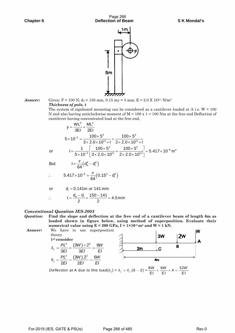
Chapter-5 Deflection of Beam S K Mondal’s
Answer: Given: F = 100 N; d0 = 150 mm, 0.15 my = 5 mm; E = 2.0 X 1O11 N/m2 Thickness of pole, t The system of signboard mounting can be considered as a cantilever loaded at A i.e. W = 100
N and also having anticlockwise moment of M = 100 x 1 = 100 Nm at the free end.Deflection of cantilever having concentrated load at the free end,
3 2
3 33
11 11
3 36 4
3 11 11
WL MLy3EI 2EI
100 5 100 55 103 2.0 10 I 2 2.0 10 I
1 100 5 100 5or I 5.417 10 m5 10 3 2.0 10 2 2.0 10
−
−−
= +
× ×× = +
× × × × × ×⎡ ⎤× ×
= + = ×⎢ ⎥× × × × ×⎣ ⎦
( )
( )
4 40 i
6 4 4i
But I d d64
5.417 10 0.15 d64
π
π−
= −
∴ × = −
i
0 i
or d 0.141m or 141 mmd d 150 141t 4.5mm
2 2
=
− −∴ = = =
Conventional Question IES-2003 Question: Find the slope and deflection at the free end of a cantilever beam of length 6m as
loaded shown in figure below, using method of superposition. Evaluate their numerical value using E = 200 GPa, I = 1×10⁻⁴ m4 and W = 1 kN.
Answer: We have to use superposition theory.
1st consider
δ
θ
33
2 2
(3 ) 2 83 3
(3 ).2 62 2
c
c
WPL WEI EI EI
PL W WEI EI EI
×= = =
= = =
δ δ1 c8W 6 32 at A due to this load( ) = .(6 2) = 4EIc
W WDeflectionEI EI
θ+ − + × =
Page 266
For-2019 (IES, GATE & PSUs) Page 266 of 480 Rev.0
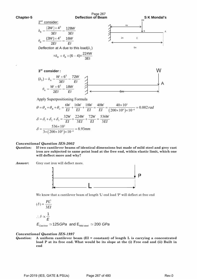
Chapter-5 Deflection of Beam S K Mondal’s
( )
2
δ
δ
δ
nd
3
B
2
2 consider:2 4 128
3 3(2 ) 4 16
2 at A due to this load( )
224W = (6 4)=3EI
B
B B
W WEI EI
W WEI EI
Deflection
θ
θ
×= =
×= =
+ × −
.
δ δ3
3
2
A
6 72( )3
6 18 2
rd3 consider :
AW W
EI EIW W
EI EIθ
×= = =
×= =
( )
( )
3
9 4
1 2 3
3
9 4
Apply Superpositioning Formula6 16 18 40 40 10 0.002
200 10 1032 224 72 536
3 3536 10 8.93
3 200 10 10
A B CW W W W radEI EI EI EI
W W W WEI EI EI EI
mm
θ θ θ θ
δ δ δ δ
δ
−
−
×= + + = + + = = =
× ×
= + + = + + =
×= =
× × ×
Conventional Question IES-2002 Question: If two cantilever beams of identical dimensions but made of mild steel and grey cast
iron are subjected to same point load at the free end, within elastic limit, which one will deflect more and why?
Answer: Grey cost iron will deflect more.
We know that a cantilever beam of length 'L' end load 'P' will deflect at free end
(δ ) = 3
3PLEI
Mild steel
1
125 and E 200 Cast Iron
EE GPa GPa
δ∴ ∝
Conventional Question IES-1997 Question: A uniform cantilever beam (EI = constant) of length L is carrying a concentrated
load P at its free end. What would be its slope at the (i) Free end and (ii) Built in end
Page 267
For-2019 (IES, GATE & PSUs) Page 267 of 480 Rev.0
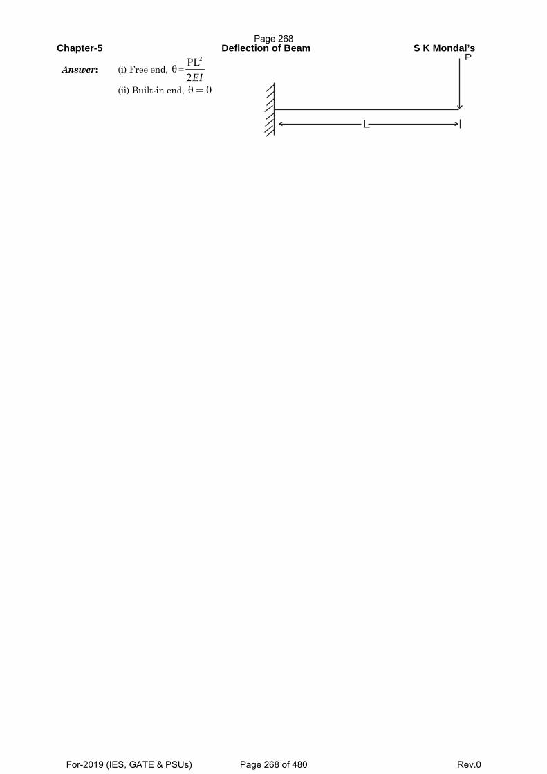
Chapter-5 Deflection of Beam S K Mondal’s
Answer: (i) Free end, θ=2PL
2EI
(ii) Built-in end, θ 0=
L
P
Page 268
For-2019 (IES, GATE & PSUs) Page 268 of 480 Rev.0
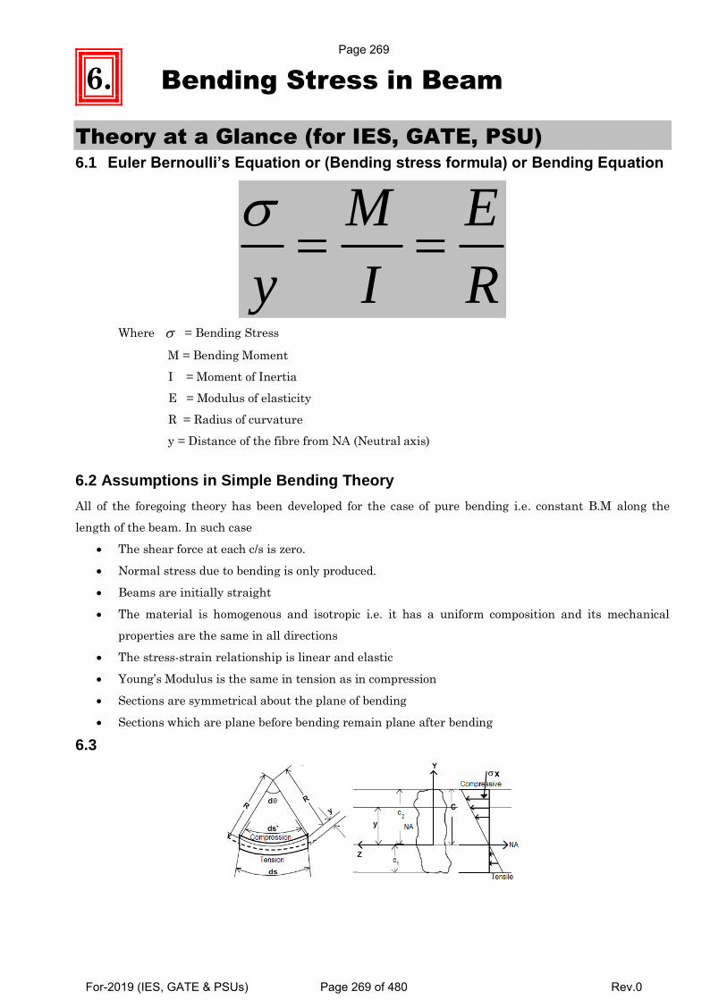
6. Bending Stress in Beam
Theory at a Glance (for IES, GATE, PSU) 6.1 Euler Bernoulli’s Equation or (Bending stress formula) or Bending Equation
M E
y I R
Where = Bending Stress
M = Bending Moment
I = Moment of Inertia
E = Modulus of elasticity
R = Radius of curvature
y = Distance of the fibre from NA (Neutral axis)
6.2 Assumptions in Simple Bending Theory
All of the foregoing theory has been developed for the case of pure bending i.e. constant B.M along the
length of the beam. In such case
The shear force at each c/s is zero.
Normal stress due to bending is only produced.
Beams are initially straight
The material is homogenous and isotropic i.e. it has a uniform composition and its mechanical
properties are the same in all directions
The stress-strain relationship is linear and elastic
Young’s Modulus is the same in tension as in compression
Sections are symmetrical about the plane of bending
Sections which are plane before bending remain plane after bending
6.3
Page 269
For-2019 (IES, GATE & PSUs) Page 269 of 480 Rev.0
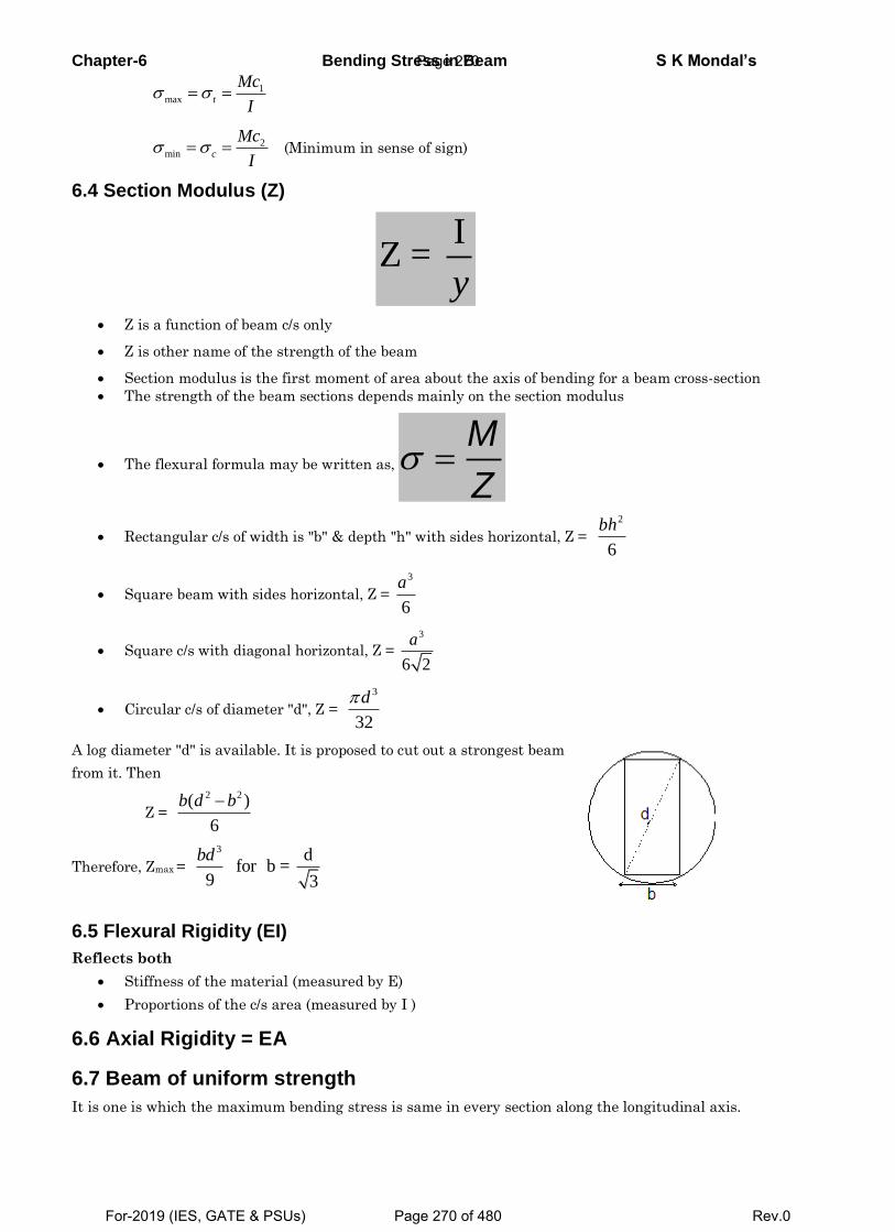
Chapter-6 Bending Stress in Beam S K Mondal’s
1max t
Mc
I
2min c
Mc
I (Minimum in sense of sign)
6.4 Section Modulus (Z)
IZ =
y
Z is a function of beam c/s only
Z is other name of the strength of the beam
Section modulus is the first moment of area about the axis of bending for a beam cross-section
The strength of the beam sections depends mainly on the section modulus
The flexural formula may be written as, M
Z
Rectangular c/s of width is "b" & depth "h" with sides horizontal, Z =
2
6
bh
Square beam with sides horizontal, Z =
3
6
a
Square c/s with diagonal horizontal, Z =
3
6 2
a
Circular c/s of diameter "d", Z =
3
32
d
A log diameter "d" is available. It is proposed to cut out a strongest beam
from it. Then
Z =
2 2( )
6
b d b
Therefore, Zmax =
3 dfor b =
9 3
bd
6.5 Flexural Rigidity (EI)
Reflects both
Stiffness of the material (measured by E)
Proportions of the c/s area (measured by I )
6.6 Axial Rigidity = EA
6.7 Beam of uniform strength
It is one is which the maximum bending stress is same in every section along the longitudinal axis.
Page 270
For-2019 (IES, GATE & PSUs) Page 270 of 480 Rev.0
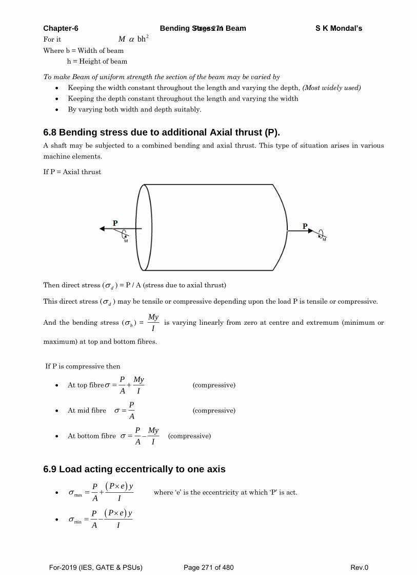
Chapter-6 Bending Stress in Beam S K Mondal’s
For it 2 bhM
Where b = Width of beam
h = Height of beam
To make Beam of uniform strength the section of the beam may be varied by
Keeping the width constant throughout the length and varying the depth, (Most widely used)
Keeping the depth constant throughout the length and varying the width
By varying both width and depth suitably.
6.8 Bending stress due to additional Axial thrust (P).
A shaft may be subjected to a combined bending and axial thrust. This type of situation arises in various
machine elements.
If P = Axial thrust
Then direct stress (
d ) = P / A (stress due to axial thrust)
This direct stress (d ) may be tensile or compressive depending upon the load P is tensile or compressive.
And the bending stress (b ) =
My
I is varying linearly from zero at centre and extremum (minimum or
maximum) at top and bottom fibres.
If P is compressive then
At top fibreP My
A I (compressive)
At mid fibre P
A (compressive)
At bottom fibre P
A –
My
I (compressive)
6.9 Load acting eccentrically to one axis
max
P e yP
A I where ‘e’ is the eccentricity at which ‘P’ is act.
min
P e yP
A I
Page 271
For-2019 (IES, GATE & PSUs) Page 271 of 480 Rev.0
Chapter-6 Bending Stress in Beam S K Mondal’s
Condition for No tension in any section
For no tension in any section, the eccentricity must not exceed 22k
d
[Where d = depth of the section; k = radius of gyration of c/s]
For rectangular section (b x h) , 6h
e i.e load will be 23h
e of the middle section.
For circular section of diameter ‘d’ , 8d
e i.e. diameter of the kernel, 24d
e
For hollow circular section of diameter ‘d’ , 2 2
8D d
eD
i.e. diameter of the kernel,
2 2
2 .4
D de
D
Page 272
For-2019 (IES, GATE & PSUs) Page 272 of 480 Rev.0
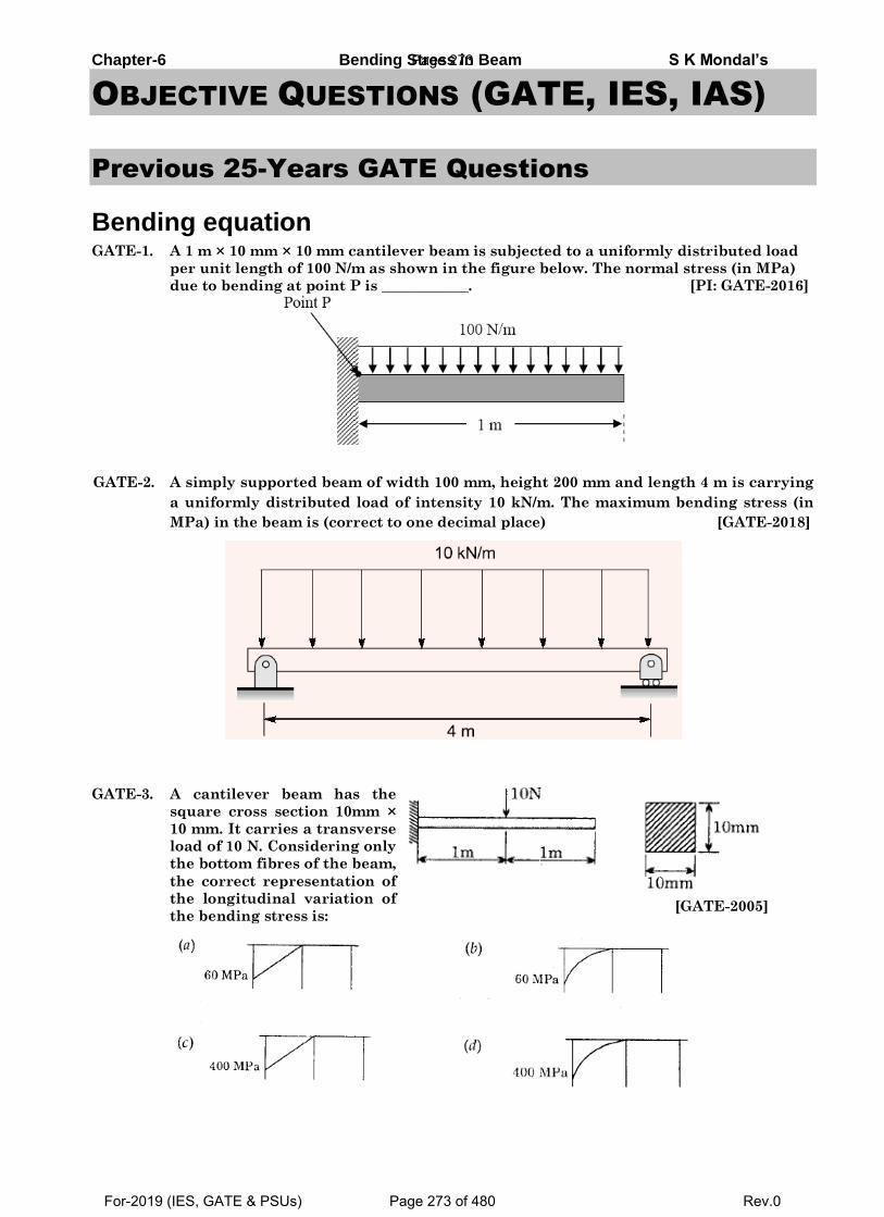
Chapter-6 Bending Stress in Beam S K Mondal’s
OBJECTIVE QUESTIONS (GATE, IES, IAS)
Previous 25-Years GATE Questions
Bending equation GATE-1. A 1 m × 10 mm × 10 mm cantilever beam is subjected to a uniformly distributed load
per unit length of 100 N/m as shown in the figure below. The normal stress (in MPa)
due to bending at point P is ____________. [PI: GATE-2016]
GATE-2. A simply supported beam of width 100 mm, height 200 mm and length 4 m is carrying
a uniformly distributed load of intensity 10 kN/m. The maximum bending stress (in
MPa) in the beam is (correct to one decimal place) [GATE-2018]
GATE-3. A cantilever beam has the
square cross section 10mm ×
10 mm. It carries a transverse
load of 10 N. Considering only
the bottom fibres of the beam,
the correct representation of
the longitudinal variation of
the bending stress is:
[GATE-2005]
Page 273
For-2019 (IES, GATE & PSUs) Page 273 of 480 Rev.0
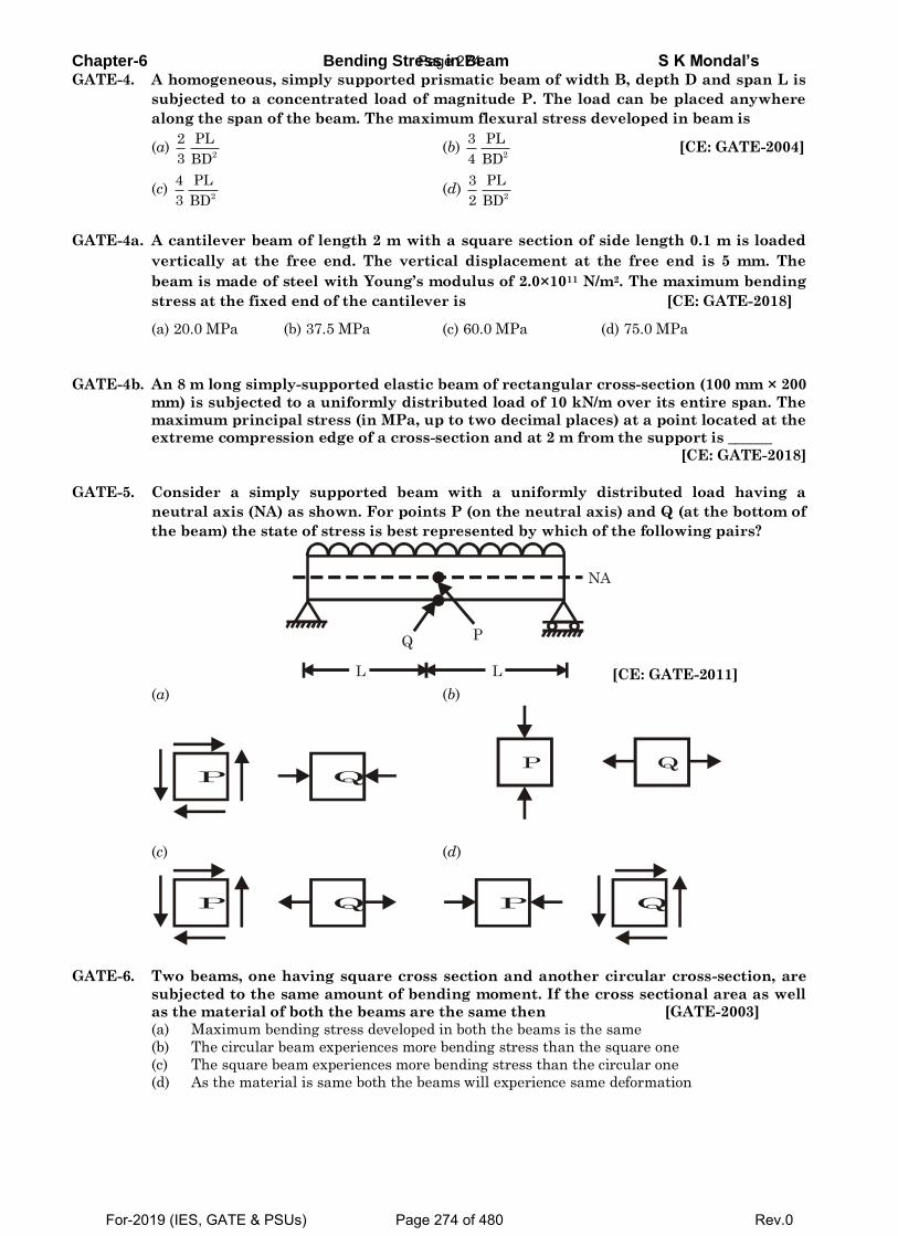
Chapter-6 Bending Stress in Beam S K Mondal’s GATE-4. A homogeneous, simply supported prismatic beam of width B, depth D and span L is
subjected to a concentrated load of magnitude P. The load can be placed anywhere
along the span of the beam. The maximum flexural stress developed in beam is
(a) 2
2 PL
3 BD (b)
2
3 PL
4 BD [CE: GATE-2004]
(c) 2
4 PL
3 BD (d)
2
3 PL
2 BD
GATE-4a. A cantilever beam of length 2 m with a square section of side length 0.1 m is loaded
vertically at the free end. The vertical displacement at the free end is 5 mm. The
beam is made of steel with Young’s modulus of 2.0×10¹¹ N/m2. The maximum bending
stress at the fixed end of the cantilever is [CE: GATE-2018]
(a) 20.0 MPa (b) 37.5 MPa (c) 60.0 MPa (d) 75.0 MPa
GATE-4b. An 8 m long simply-supported elastic beam of rectangular cross-section (100 mm × 200
mm) is subjected to a uniformly distributed load of 10 kN/m over its entire span. The
maximum principal stress (in MPa, up to two decimal places) at a point located at the
extreme compression edge of a cross-section and at 2 m from the support is ______
[CE: GATE-2018]
GATE-5. Consider a simply supported beam with a uniformly distributed load having a
neutral axis (NA) as shown. For points P (on the neutral axis) and Q (at the bottom of
the beam) the state of stress is best represented by which of the following pairs?
Q P
NA
L L [CE: GATE-2011]
(a) (b)
P Q
P Q
(c) (d)
P Q
P Q
GATE-6. Two beams, one having square cross section and another circular cross-section, are
subjected to the same amount of bending moment. If the cross sectional area as well
as the material of both the beams are the same then [GATE-2003]
(a) Maximum bending stress developed in both the beams is the same
(b) The circular beam experiences more bending stress than the square one
(c) The square beam experiences more bending stress than the circular one
(d) As the material is same both the beams will experience same deformation
Page 274
For-2019 (IES, GATE & PSUs) Page 274 of 480 Rev.0
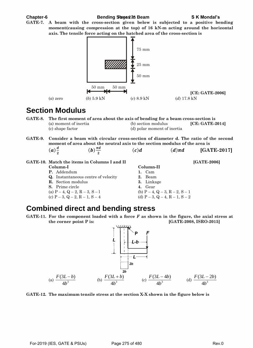
Chapter-6 Bending Stress in Beam S K Mondal’s GATE-7. A beam with the cross-section given below is subjected to a positive bending
moment(causing compression at the top) of 16 kN-m acting around the horizontal
axis. The tensile force acting on the hatched area of the cross-section is
50 mm 50 mm
50 mm
25 mm
75 mm
[CE: GATE-2006]
(a) zero (b) 5.9 kN (c) 8.9 kN (d) 17.8 kN
Section Modulus GATE-8. The first moment of area about the axis of bending for a beam cross-section is
(a) moment of inertia (b) section modulus [CE: GATE-2014]
(c) shape factor (d) polar moment of inertia
GATE-9. Consider a beam with circular cross-section of diameter d. The ratio of the second
moment of area about the neutral axis to the section modulus of the area is
(𝒂)𝒅
𝟐 (𝒃)
𝝅𝒅
𝟐 (𝒄)𝒅 (𝒅)𝝅𝒅 [GATE-2017]
GATE-10. Match the items in Columns I and II [GATE-2006]
Column-I Column-II
P. Addendum 1. Cam
Q. Instantaneous centre of velocity 2. Beam
R. Section modulus 3. Linkage
S. Prime circle 4. Gear
(a) P – 4, Q – 2, R – 3, S – l (b) P – 4, Q – 3, R – 2, S – 1
(c) P – 3, Q – 2, R – 1, S – 4 (d) P – 3, Q – 4, R – 1, S – 2
Combined direct and bending stress GATE-11. For the component loaded with a force F as shown in the figure, the axial stress at
the corner point P is: [GATE-2008, ISRO-2015]
(a) 34
)3(
b
bLF (b)
34
)3(
b
bLF (c)
34
)43(
b
bLF (d)
34
)23(
b
bLF
GATE-12. The maximum tensile stress at the section X-X shown in the figure below is
Page 275
For-2019 (IES, GATE & PSUs) Page 275 of 480 Rev.0
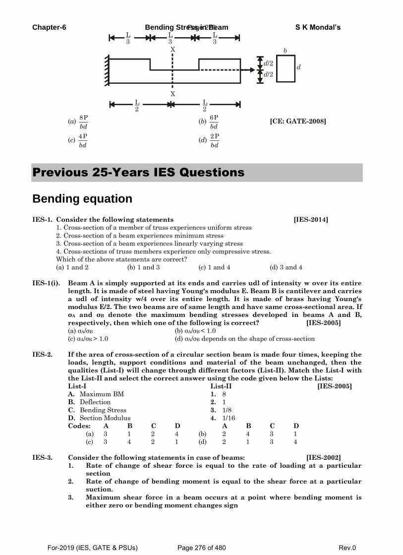
Chapter-6 Bending Stress in Beam S K Mondal’s
L 2
L 2
L 3
L 3
L 3
X
X
d/2
d/2
b
d
(a) 8P
bd (b)
6P
bd [CE: GATE-2008]
(c) 4P
bd (d)
2P
bd
Previous 25-Years IES Questions
Bending equation
IES-1. Consider the following statements [IES-2014]
1. Cross-section of a member of truss experiences uniform stress
2. Cross-section of a beam experiences minimum stress
3. Cross-section of a beam experiences linearly varying stress
4. Cross-sections of truss members experience only compressive stress.
Which of the above statements are correct?
(a) 1 and 2 (b) 1 and 3 (c) 1 and 4 (d) 3 and 4
IES-1(i). Beam A is simply supported at its ends and carries udl of intensity w over its entire
length. It is made of steel having Young's modulus E. Beam B is cantilever and carries
a udl of intensity w/4 over its entire length. It is made of brass having Young's
modulus E/2. The two beams are of same length and have same cross-sectional area. If
σA and σB denote the maximum bending stresses developed in beams A and B,
respectively, then which one of the following is correct? [IES-2005]
(a) σA/σB (b) σA/σB < 1.0
(c) σA/σB > 1.0 (d) σA/σB depends on the shape of cross-section
IES-2. If the area of cross-section of a circular section beam is made four times, keeping the
loads, length, support conditions and material of the beam unchanged, then the
qualities (List-I) will change through different factors (List-II). Match the List-I with
the List-II and select the correct answer using the code given below the Lists:
List-I List-II [IES-2005]
A. Maximum BM 1. 8
B. Deflection 2. 1
C. Bending Stress 3. 1/8
D. Section Modulus 4. 1/16
Codes: A B C D A B C D
(a) 3 1 2 4 (b) 2 4 3 1
(c) 3 4 2 1 (d) 2 1 3 4
IES-3. Consider the following statements in case of beams: [IES-2002]
1. Rate of change of shear force is equal to the rate of loading at a particular
section
2. Rate of change of bending moment is equal to the shear force at a particular
suction.
3. Maximum shear force in a beam occurs at a point where bending moment is
either zero or bending moment changes sign
Page 276
For-2019 (IES, GATE & PSUs) Page 276 of 480 Rev.0
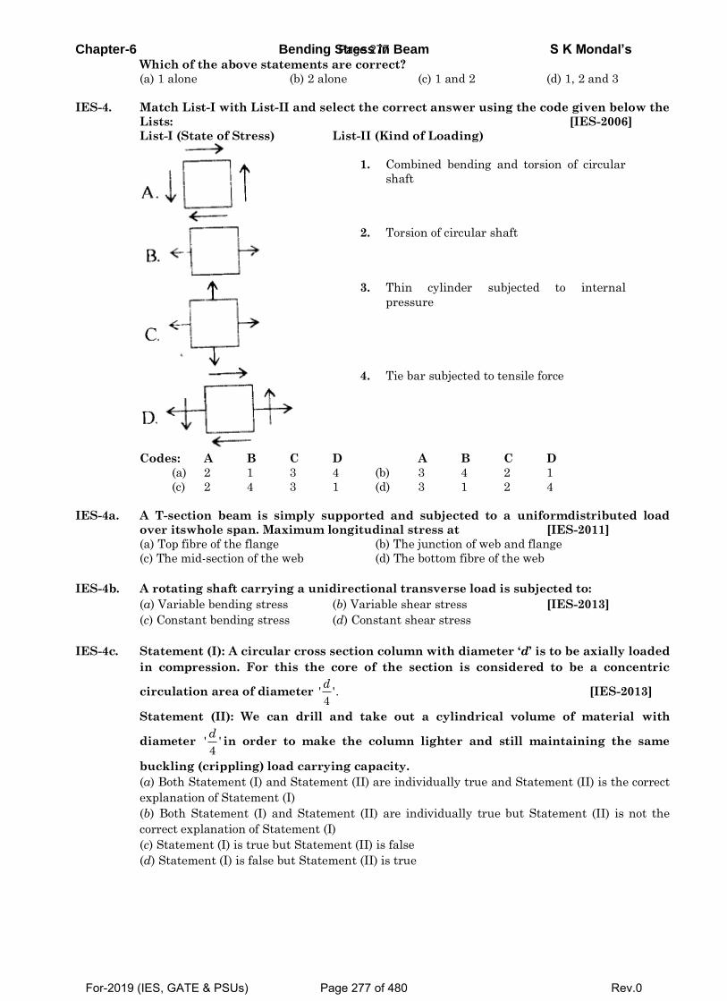
Chapter-6 Bending Stress in Beam S K Mondal’s Which of the above statements are correct?
(a) 1 alone (b) 2 alone (c) 1 and 2 (d) 1, 2 and 3
IES-4. Match List-I with List-II and select the correct answer using the code given below the
Lists: [IES-2006]
List-I (State of Stress) List-II (Kind of Loading)
1. Combined bending and torsion of circular
shaft
2. Torsion of circular shaft
3. Thin cylinder subjected to internal
pressure
4. Tie bar subjected to tensile force
Codes: A B C D A B C D
(a) 2 1 3 4 (b) 3 4 2 1
(c) 2 4 3 1 (d) 3 1 2 4
IES-4a. A T-section beam is simply supported and subjected to a uniformdistributed load
over itswhole span. Maximum longitudinal stress at [IES-2011]
(a) Top fibre of the flange (b) The junction of web and flange
(c) The mid-section of the web (d) The bottom fibre of the web
IES-4b. A rotating shaft carrying a unidirectional transverse load is subjected to:
(a) Variable bending stress (b) Variable shear stress [IES-2013]
(c) Constant bending stress (d) Constant shear stress
IES-4c. Statement (I): A circular cross section column with diameter ‘d’ is to be axially loaded
in compression. For this the core of the section is considered to be a concentric
circulation area of diameter ' '.4
d [IES-2013]
Statement (II): We can drill and take out a cylindrical volume of material with
diameter ' '4
din order to make the column lighter and still maintaining the same
buckling (crippling) load carrying capacity.
(a) Both Statement (I) and Statement (II) are individually true and Statement (II) is the correct
explanation of Statement (I)
(b) Both Statement (I) and Statement (II) are individually true but Statement (II) is not the
correct explanation of Statement (I)
(c) Statement (I) is true but Statement (II) is false
(d) Statement (I) is false but Statement (II) is true
Page 277
For-2019 (IES, GATE & PSUs) Page 277 of 480 Rev.0
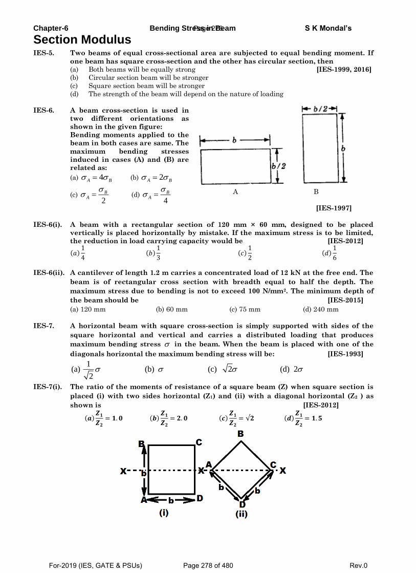
Chapter-6 Bending Stress in Beam S K Mondal’s
Section Modulus IES-5. Two beams of equal cross-sectional area are subjected to equal bending moment. If
one beam has square cross-section and the other has circular section, then
(a) Both beams will be equally strong [IES-1999, 2016]
(b) Circular section beam will be stronger
(c) Square section beam will be stronger
(d) The strength of the beam will depend on the nature of loading
IES-6. A beam cross-section is used in
two different orientations as
shown in the given figure:
Bending moments applied to the
beam in both cases are same. The
maximum bending stresses
induced in cases (A) and (B) are
related as:
(a) 4A B (b) 2A B
(c) 2
BA
(d)
4
BA
A B
[IES-1997]
IES-6(i). A beam with a rectangular section of 120 mm × 60 mm, designed to be placed
vertically is placed horizontally by mistake. If the maximum stress is to be limited,
the reduction in load carrying capacity would be [IES-2012]
(𝑎)1
4 (𝑏)
1
3 (𝑐)
1
2 (𝑑)
1
6
IES-6(ii). A cantilever of length 1.2 m carries a concentrated load of 12 kN at the free end. The
beam is of rectangular cross section with breadth equal to half the depth. The
maximum stress due to bending is not to exceed 100 N/mm2. The minimum depth of
the beam should be [IES-2015]
(a) 120 mm (b) 60 mm (c) 75 mm (d) 240 mm
IES-7. A horizontal beam with square cross-section is simply supported with sides of the
square horizontal and vertical and carries a distributed loading that produces
maximum bending stress in the beam. When the beam is placed with one of the
diagonals horizontal the maximum bending stress will be: [IES-1993]
1
(a) (b) (c) 2 (d) 22
IES-7(i). The ratio of the moments of resistance of a square beam (Z) when square section is
placed (i) with two sides horizontal (Z1) and (ii) with a diagonal horizontal (Z2 ) as
shown is [IES-2012]
(𝒂)𝒁𝟏
𝒁𝟐
= 𝟏. 𝟎 (𝒃)𝒁𝟏
𝒁𝟐
= 𝟐. 𝟎 (𝒄)𝒁𝟏
𝒁𝟐
= √𝟐 (𝒅)𝒁𝟏
𝒁𝟐
= 𝟏. 𝟓
Page 278
For-2019 (IES, GATE & PSUs) Page 278 of 480 Rev.0
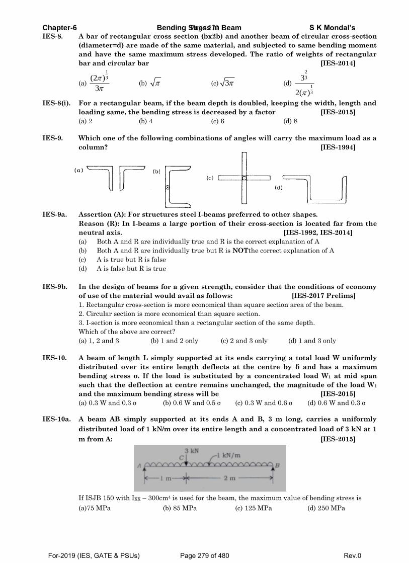
Chapter-6 Bending Stress in Beam S K Mondal’s IES-8. A bar of rectangular cross section (bx2b) and another beam of circular cross-section
(diameter=d) are made of the same material, and subjected to same bending moment
and have the same maximum stress developed. The ratio of weights of rectangular
bar and circular bar [IES-2014]
(a)
1
3(2 )
3
(b) (c) 3 (d)
2
3
1
3
3
2( )
IES-8(i). For a rectangular beam, if the beam depth is doubled, keeping the width, length and
loading same, the bending stress is decreased by a factor [IES-2015]
(a) 2 (b) 4 (c) 6 (d) 8
IES-9. Which one of the following combinations of angles will carry the maximum load as a
column? [IES-1994]
IES-9a. Assertion (A): For structures steel I-beams preferred to other shapes.
Reason (R): In I-beams a large portion of their cross-section is located far from the
neutral axis. [IES-1992, IES-2014]
(a) Both A and R are individually true and R is the correct explanation of A
(b) Both A and R are individually true but R is NOTthe correct explanation of A
(c) A is true but R is false
(d) A is false but R is true
IES-9b. In the design of beams for a given strength, consider that the conditions of economy
of use of the material would avail as follows: [IES-2017 Prelims]
1. Rectangular cross-section is more economical than square section area of the beam.
2. Circular section is more economical than square section.
3. I-section is more economical than a rectangular section of the same depth.
Which of the above are correct?
(a) 1, 2 and 3 (b) 1 and 2 only (c) 2 and 3 only (d) 1 and 3 only
IES-10. A beam of length L simply supported at its ends carrying a total load W uniformly
distributed over its entire length deflects at the centre by δ and has a maximum
bending stress σ. If the load is substituted by a concentrated load W1 at mid span
such that the deflection at centre remains unchanged, the magnitude of the load W1
and the maximum bending stress will be [IES-2015]
(a) 0.3 W and 0.3 σ (b) 0.6 W and 0.5 σ (c) 0.3 W and 0.6 σ (d) 0.6 W and 0.3 σ
IES-10a. A beam AB simply supported at its ends A and B, 3 m long, carries a uniformly
distributed load of 1 kN/m over its entire length and a concentrated load of 3 kN at 1
m from A: [IES-2015]
If ISJB 150 with IXX – 300cm4 is used for the beam, the maximum value of bending stress is
(a)75 MPa (b) 85 MPa (c) 125 MPa (d) 250 MPa
Page 279
For-2019 (IES, GATE & PSUs) Page 279 of 480 Rev.0
Chapter-6 Bending Stress in Beam S K Mondal’s IES-10b. A beam of rectangular section (12 cm wide × 20 cm deep) is simply supported over a
span of 12 m. It is acted upon by a concentrated load of 80 kN at the midspan. The
maximum bending stress induced is: [IES-2017 Prelims]
(a) 400 MPa (b) 300 MPa (c) 200 MPa (d) 100 MPa
Combined direct and bending stress IES-11. Assertion (A): A column subjected to eccentric load will have its stress at centroid
independent of the eccentricity. [IES-1994]
Reason (R): Eccentric loads in columns produce torsion.
(a) Both A and R are individually true and R is the correct explanation of A
(b) Both A and R are individually true but R is NOTthe correct explanation of A
(c) A is true but R is false
(d) A is false but R is true
IES-11(i). For the configuration of loading shown in the given figure, the stress in fibre AB is
given by: [IES-1995]
(a) P/A (tensile) (b) . .5
xx
P P e
A I
(Compressive)
(c) . .5
xx
P P e
A I
(Compressive) (d) P/A (Compressive)
IES-12. A column of square section 40 mm × 40
mm, fixed to the ground carries an
eccentric load P of 1600 N as shown in
the figure.
If the stress developed along the edge
CD is –1.2 N/mm2, the stress along the
edge AB will be:
(a) –1.2 N/mm2
(b) +1 N/mm2
(c) +0.8 N/mm2
(d) –0.8 N/mm2
[IES-1999]
Page 280
For-2019 (IES, GATE & PSUs) Page 280 of 480 Rev.0
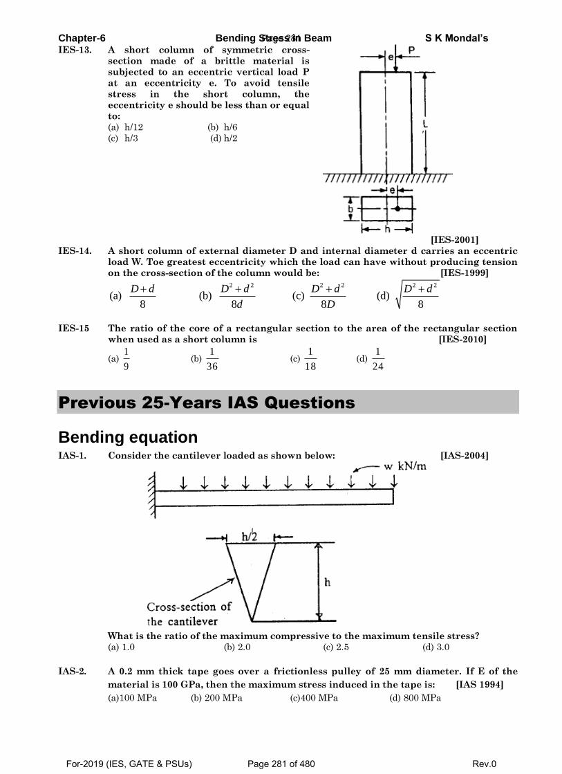
Chapter-6 Bending Stress in Beam S K Mondal’s IES-13. A short column of symmetric cross-
section made of a brittle material is
subjected to an eccentric vertical load P
at an eccentricity e. To avoid tensile
stress in the short column, the
eccentricity e should be less than or equal
to:
(a) h/12 (b) h/6
(c) h/3 (d) h/2
[IES-2001]
IES-14. A short column of external diameter D and internal diameter d carries an eccentric
load W. Toe greatest eccentricity which the load can have without producing tension
on the cross-section of the column would be: [IES-1999]
2 2 2 2 2 2
(a) (b) (c) (d)8 8 8 8
D d D d D d D d
d D
IES-15 The ratio of the core of a rectangular section to the area of the rectangular section
when used as a short column is [IES-2010]
(a) 1
9 (b)
1
36 (c)
1
18 (d)
1
24
Previous 25-Years IAS Questions
Bending equation IAS-1. Consider the cantilever loaded as shown below: [IAS-2004]
What is the ratio of the maximum compressive to the maximum tensile stress?
(a) 1.0 (b) 2.0 (c) 2.5 (d) 3.0
IAS-2. A 0.2 mm thick tape goes over a frictionless pulley of 25 mm diameter. If E of the
material is 100 GPa, then the maximum stress induced in the tape is: [IAS 1994]
(a)100 MPa (b) 200 MPa (c)400 MPa (d) 800 MPa
Page 281
For-2019 (IES, GATE & PSUs) Page 281 of 480 Rev.0
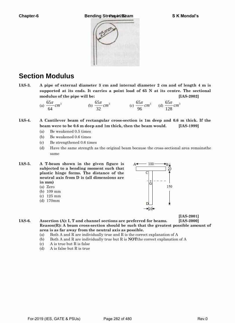
Chapter-6 Bending Stress in Beam S K Mondal’s
Section Modulus
IAS-3. A pipe of external diameter 3 cm and internal diameter 2 cm and of length 4 m is
supported at its ends. It carries a point load of 65 N at its centre. The sectional
modulus of the pipe will be: [IAS-2002]
(a) 365
64cm
(b)
365
32cm
(c)
365
96cm
(d)
365
128cm
IAS-4. A Cantilever beam of rectangular cross-section is 1m deep and 0.6 m thick. If the
beam were to be 0.6 m deep and 1m thick, then the beam would. [IAS-1999]
(a) Be weakened 0.5 times
(b) Be weakened 0.6 times
(c) Be strengthened 0.6 times
(d) Have the same strength as the original beam because the cross-sectional area remainsthe
same
IAS-5. A T-beam shown in the given figure is
subjected to a bending moment such that
plastic hinge forms. The distance of the
neutral axis from D is (all dimensions are
in mm)
(a) Zero
(b) 109 mm
(c) 125 mm
(d) 170mm
[IAS-2001]
IAS-6. Assertion (A): I, T and channel sections are preferred for beams. [IAS-2000]
Reason(R): A beam cross-section should be such that the greatest possible amount of
area is as far away from the neutral axis as possible.
(a) Both A and R are individually true and R is the correct explanation of A
(b) Both A and R are individually true but R is NOTthe correct explanation of A
(c) A is true but R is false
(d) A is false but R is true
Page 282
For-2019 (IES, GATE & PSUs) Page 282 of 480 Rev.0
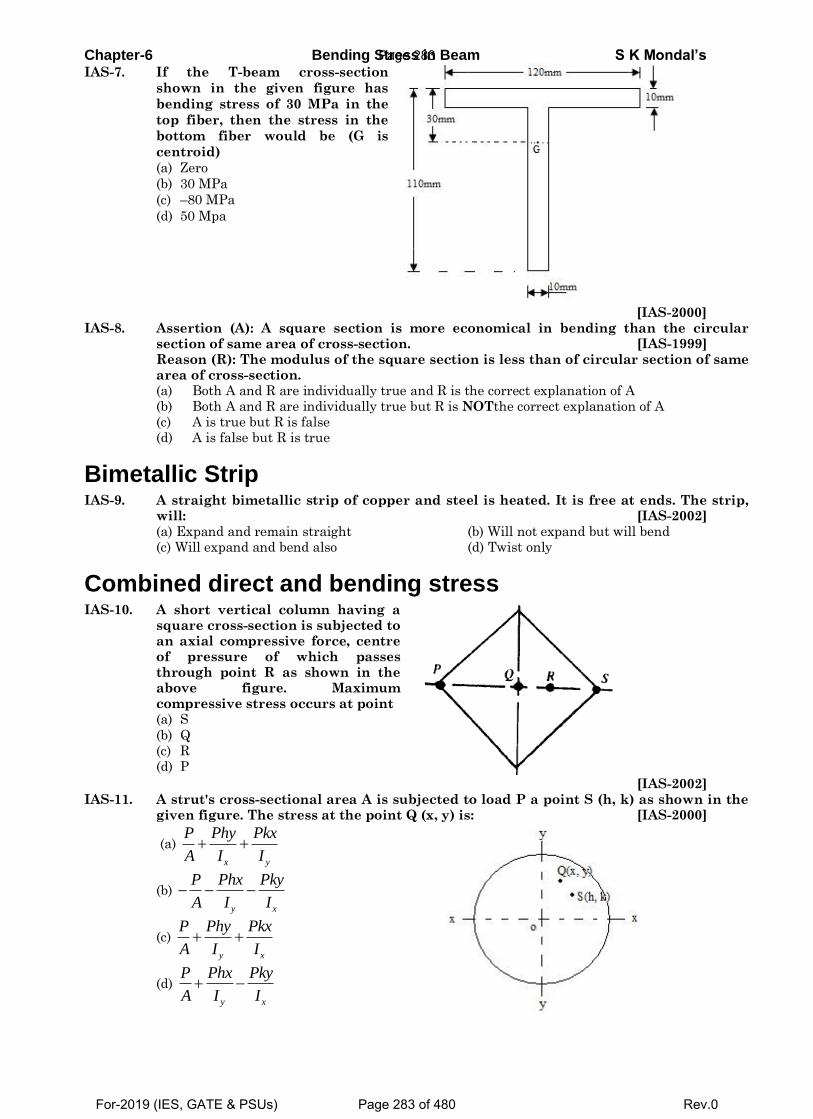
Chapter-6 Bending Stress in Beam S K Mondal’s IAS-7. If the T-beam cross-section
shown in the given figure has
bending stress of 30 MPa in the
top fiber, then the stress in the
bottom fiber would be (G is
centroid)
(a) Zero
(b) 30 MPa
(c) –80 MPa
(d) 50 Mpa
[IAS-2000]
IAS-8. Assertion (A): A square section is more economical in bending than the circular section of same area of cross-section. [IAS-1999]
Reason (R): The modulus of the square section is less than of circular section of same area of cross-section.
(a) Both A and R are individually true and R is the correct explanation of A
(b) Both A and R are individually true but R is NOTthe correct explanation of A (c) A is true but R is false (d) A is false but R is true
Bimetallic Strip IAS-9. A straight bimetallic strip of copper and steel is heated. It is free at ends. The strip,
will: [IAS-2002] (a) Expand and remain straight (b) Will not expand but will bend (c) Will expand and bend also (d) Twist only
Combined direct and bending stress IAS-10. A short vertical column having a
square cross-section is subjected to an axial compressive force, centre of pressure of which passes through point R as shown in the above figure. Maximum compressive stress occurs at point
(a) S
(b) Q (c) R
(d) P
[IAS-2002]
IAS-11. A strut's cross-sectional area A is subjected to load P a point S (h, k) as shown in the given figure. The stress at the point Q (x, y) is: [IAS-2000]
(a)
x y
P Phy Pkx
A I I
(b)
y x
P Phx Pky
A I I
(c)
y x
P Phy Pkx
A I I
(d)
y x
P Phx Pky
A I I
Page 283
For-2019 (IES, GATE & PSUs) Page 283 of 480 Rev.0
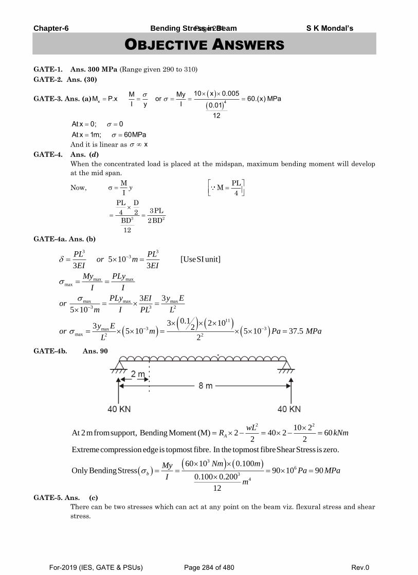
Chapter-6 Bending Stress in Beam S K Mondal’s
OBJECTIVE ANSWERS
GATE-1. Ans. 300 MPa (Range given 290 to 310)
GATE-2. Ans. (30)
GATE-3. Ans. (a)
x 4
10 x 0.005M MyM P.x or 60.(x) MPaI y I 0.01
12
At x 0; 0At x 1m; 60MPa
And it is linear as x
GATE-4. Ans. (d)
When the concentrated load is placed at the midspan, maximum bending moment will develop
at the mid span.
Now,
GATE-4a. Ans. (b)
3 33
max maxmax
max max max
3 3 2
11
3 3maxmax 2 2
5 10 [UseSI unit]3 3
33
5 10
0.13 2 103 25 10 5 10 37.5
2
PL PLor m
EI EI
My PLy
I I
PLy y EEIor
m I PL L
y Eor m Pa MPa
L
GATE-4b. Ans. 90
2 2
3
6
34
10 2At 2mfromsupport, Bending Moment (M) 2 40 2 60
2 2
Extremecompression edgeis topmost fibre. In the topmost fibreShearStress is zero.
60 10 0.100Only BendingStress 90 10 90
0.100 0.200
12
A
b
wLR kNm
Nm mMyPa M
Im
Pa
GATE-5. Ans. (c)
There can be two stresses which can act at any point on the beam viz. flexural stress and shear
stress.
M
Iy
PLM
4
3 2
PL D3PL4 2
BD 2BD
12
Page 284
For-2019 (IES, GATE & PSUs) Page 284 of 480 Rev.0
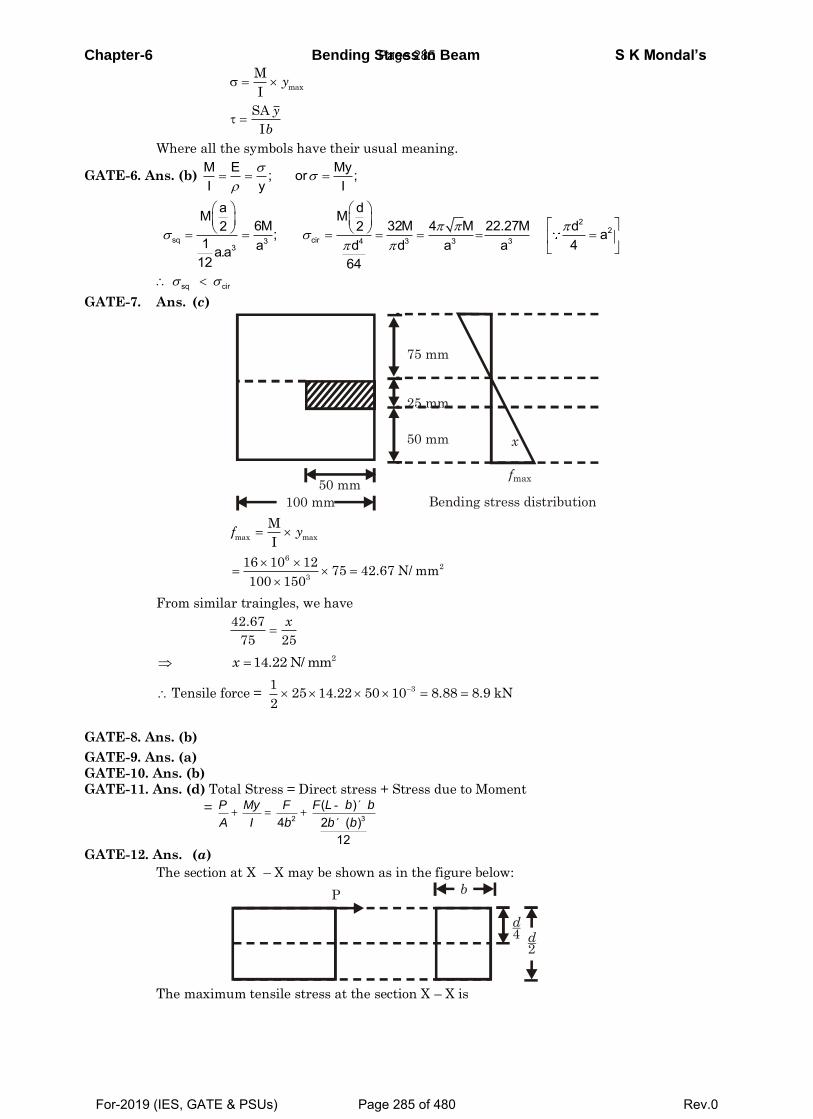
Chapter-6 Bending Stress in Beam S K Mondal’s
Where all the symbols have their usual meaning.
GATE-6. Ans. (b) M E My; or ;I y I
2
2sq cir3 4 3 3 3
3
a dM M6M 32M 4 M 22.27M d2 2; a
1 4a d d a aa.a12 64
sq cir
GATE-7. Ans. (c)
From similar traingles, we have
Tensile force =
GATE-8. Ans. (b)
GATE-9. Ans. (a)
GATE-10. Ans. (b)
GATE-11. Ans. (d) Total Stress = Direct stress + Stress due to Moment
= 2 3
( )4 2 ( )
12
P My F F L b b
A I b b b
- ´+ = +
´
GATE-12. Ans. (a)
The section at X – X may be shown as in the figure below:
The maximum tensile stress at the section X – X is
max
M
Iy
SA
I
y
b
100 mm
50 mm
50 mm
25 mm
75 mm
x
Bending stress distribution
fmax
max max
M
If y
62
3
16 10 1275 42.67 N/ mm
100 150
42.67
75 25
x
214.22 N/ mmx
31
25 14.22 50 10 8.88 8.9 kN2
d2
d4
P b
Page 285
For-2019 (IES, GATE & PSUs) Page 285 of 480 Rev.0
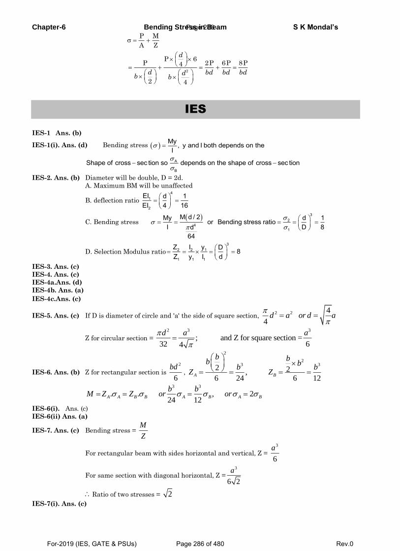
Chapter-6 Bending Stress in Beam S K Mondal’s
IES
IES-1 Ans. (b)
IES-1(i). Ans. (d) Bending stress My , y and I both depends on theI
A
B
Shape of cross sec tion so depends on the shape of cross sec tion
IES-2. Ans. (b) Diameter will be double, D = 2d.
A. Maximum BM will be unaffected
B. deflection ratio
41
2
EI d 1EI 4 16
C. Bending stress 3
24
1
M d / 2My d 1or Bending stress ratioI D 8d
64
D. Selection Modulus ratio
32 2 1
1 1 1
Z I y D 8Z y I d
IES-3. Ans. (c)
IES-4. Ans. (c)
IES-4a.Ans. (d)
IES-4b. Ans. (a)
IES-4c.Ans. (c)
IES-5. Ans. (c) If D is diameter of circle and 'a' the side of square section, 2 2 4
4d a or d a
Z for circular section =
2 3 3
; and Z for square section =32 64
d a a
IES-6. Ans. (b) Z for rectangular section is
2
6
bd,
2
23 3
2 2,6 24 6 12
A B
b bb bb b
Z Z
3 3
. . , 224 12
A A B B A B A B
b bM Z Z or or
IES-6(i). Ans. (c)
IES-6(ii) Ans. (a)
IES-7. Ans. (c) Bending stress = M
Z
For rectangular beam with sides horizontal and vertical, Z =
3
6
a
For same section with diagonal horizontal, Z =
3
6 2
a
Ratio of two stresses = 2 IES-7(i). Ans. (c)
P M
A Z
2
P 6P 2P 6P 8P4
2 4
d
d bd bd bddb b
Page 286
For-2019 (IES, GATE & PSUs) Page 286 of 480 Rev.0
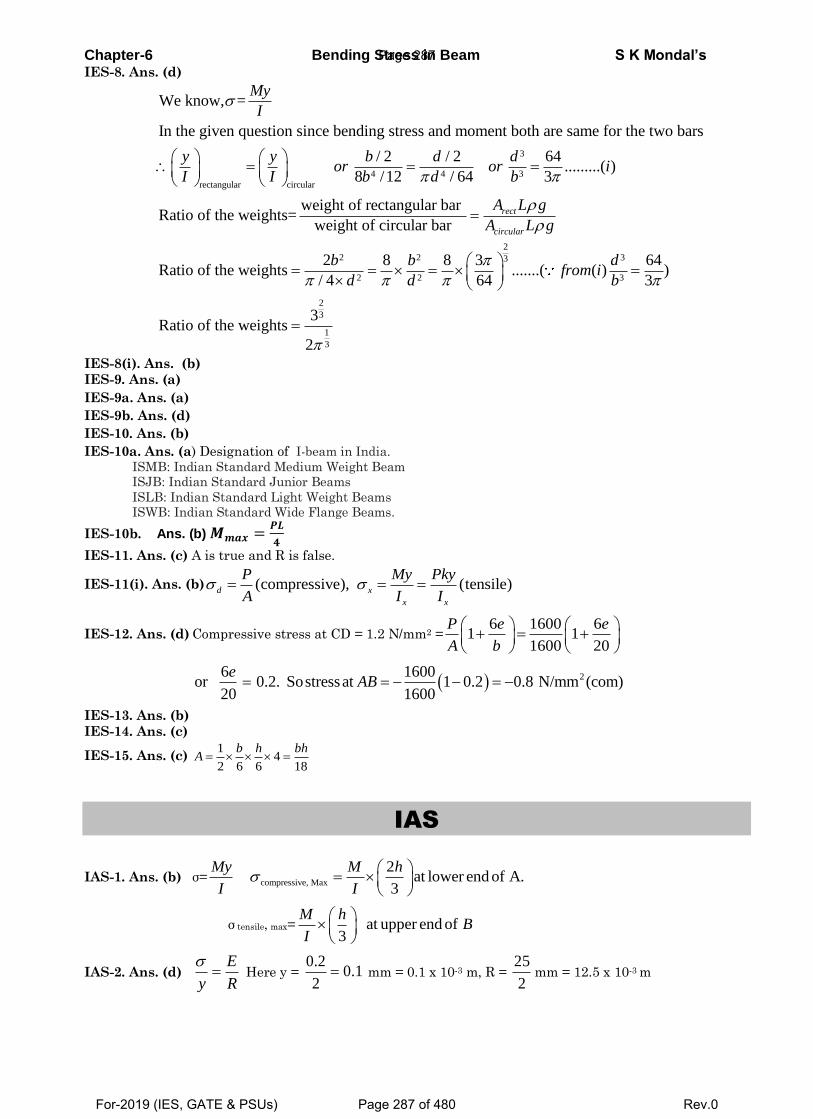
Chapter-6 Bending Stress in Beam S K Mondal’s IES-8. Ans. (d)
3
4 4 3
rectangular circular
We know, =
In the given question since bending stress and moment both are same for the two bars
/ 2 / 2 64.........( )
8 /12 / 64 3
Ratio of the weights=
My
I
y y b d dor or i
I I b d b
2
2 2 33
2 2 3
2
3
1
3
weight of rectangular bar
weight of circular bar
2 8 8 3 64Ratio of the weights .......( ( ) )
/ 4 64 3
3Ratio of the weights
2
rect
circular
A L g
A L g
b b dfrom i
d d b
IES-8(i). Ans. (b)
IES-9. Ans. (a)
IES-9a. Ans. (a)
IES-9b. Ans. (d)
IES-10. Ans. (b)
IES-10a. Ans. (a) Designation of I-beam in India.
ISMB: Indian Standard Medium Weight Beam
ISJB: Indian Standard Junior Beams
ISLB: Indian Standard Light Weight Beams
ISWB: Indian Standard Wide Flange Beams.
IES-10b. Ans. (b) 𝑴𝒎𝒂𝒙 =𝑷𝑳
𝟒
IES-11. Ans. (c) A is true and R is false.
IES-11(i). Ans. (b) (compressive), (tensile) d x
x x
P My Pky
A I I
IES-12. Ans. (d) Compressive stress at CD = 1.2 N/mm2 =6 1600 6
1 11600 20
P e e
A b
26 1600or 0.2. Sostressat 1 0.2 0.8 N/mm (com)
20 1600
eAB
IES-13. Ans. (b)
IES-14. Ans. (c)
IES-15. Ans. (c) 1
42 6 6 18
b h bhA
IAS
IAS-1. Ans. (b) σ= compressive, Max
2at lower end of A.
3
My M h
I I
σ tensile, max= at upper end of3
M hB
I
IAS-2. Ans. (d) R
E
y
Here y = 1.0
2
2.0 mm = 0.1 x 10⁻³ m, R =
2
25mm = 12.5 x 10⁻³ m
Page 287
For-2019 (IES, GATE & PSUs) Page 287 of 480 Rev.0
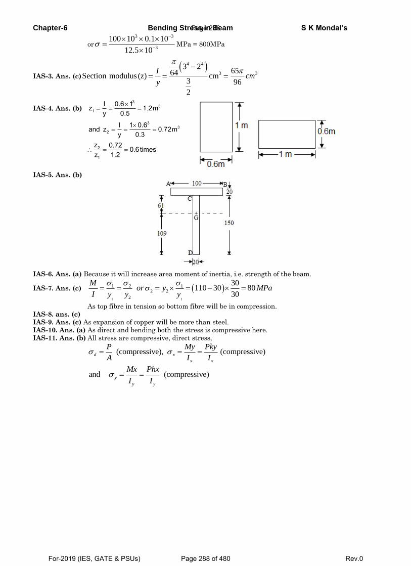
Chapter-6 Bending Stress in Beam S K Mondal’s
or3
33
105.12
101.010100
MPa = 800MPa
IAS-3. Ans. (c)
4 4
3
3 264Section modulus (z) cm
3
2
I
y
365
96cm
IAS-4. Ans. (b)
3
31
I 0.6 1z 1.2my 0.5
3
32
I 1 0.6and z 0.72my 0.3
2
1
z 0.72 0.6timesz 1.2
IAS-5. Ans. (b)
IAS-6. Ans. (a) Because it will increase area moment of inertia, i.e. strength of the beam.
IAS-7. Ans. (c) 1 1
1 2 12 2
2
30110 30 80
30
Mor y MPa
I y y y
As top fibre in tension so bottom fibre will be in compression. IAS-8. ans. (c) IAS-9. Ans. (c) As expansion of copper will be more than steel. IAS-10. Ans. (a) As direct and bending both the stress is compressive here. IAS-11. Ans. (b) All stress are compressive, direct stress,
(compressive), (compressive) d x
x x
P My Pky
A I I
and (compressive) y
y y
Mx Phx
I I
Page 288
For-2019 (IES, GATE & PSUs) Page 288 of 480 Rev.0
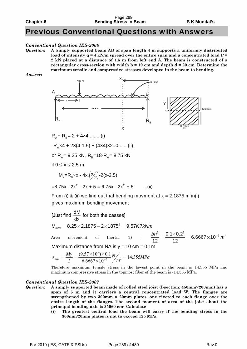
Chapter-6 Bending Stress in Beam S K Mondal’s
Previous Conventional Questions with Answers
Conventional Question IES-2008 Question: A Simply supported beam AB of span length 4 m supports a uniformly distributed
load of intensity q = 4 kN/m spread over the entire span and a concentrated load P = 2 kN placed at a distance of 1.5 m from left end A. The beam is constructed of a rectangular cross-section with width b = 10 cm and depth d = 20 cm. Determine the maximum tensile and compressive stresses developed in the beam to bending.
Answer:
A BR + R = 2 + 4×4.........(i)
A-R ×4 + 2×(4-1.5) + (4×4)×2=0.......(ii)
A B Aor R = 9.25 kN, R =18-R = 8.75 kN
if 0 x 2.5 m≤ ≤
( )x Bx M =R ×x - 4x. -2(x-2.5)2
2 2=8.75x - 2x - 2x + 5 = 6.75x - 2x + 5 ...(ii)
From (i) & (ii) we find out that bending movment at x = 2.1875 m in(i)gives maximum bending movement
2
max
dM[Just find for both the casses]dx
M 8.25 2.1875 2 1875 9.57 7K kNm= × − × =
Area movement of Inertia (I) = 3 3
5 40.1 0.2 6.6667 1012 12bh m−×
= = ×
Maximum distance from NA is y = 10 cm = 0.1m
3
2max 5
(9.57 10 ) 0.1 14.3556.6667 10
σ −
× ×= = =
×My N MPamI
Therefore maximum tensile stress in the lowest point in the beam is 14.355 MPa and maximum compressive stress in the topmost fiber of the beam is -14.355 MPa.
Conventional Question IES-2007 Question: A simply supported beam made of rolled steel joist (I-section: 450mm×200mm) has a
span of 5 m and it carriers a central concentrated load W. The flanges are strengthened by two 300mm × 20mm plates, one riveted to each flange over the entire length of the flanges. The second moment of area of the joist about the principal bending axis is 35060 cm4. Calculate
(i) The greatest central load the beam will carry if the bending stress in the 300mm/20mm plates is not to exceed 125 MPa.
AB
RA R
B
X
1.5
4m
2KN4kN/M
X
C/s
B=10cm
NA
Page 289
For-2019 (IES, GATE & PSUs) Page 289 of 480 Rev.0
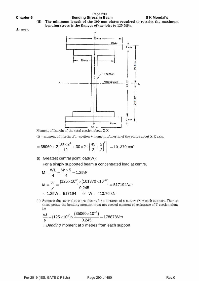
Chapter-6 Bending Stress in Beam S K Mondal’s (ii) The minimum length of the 300 mm plates required to restrict the maximum
bending stress is the flanges of the joist to 125 MPa. Answer:
Moment of Inertia of the total section about X-X
(I) = moment of inertia of I –section + moment of inertia of the plates about X-X axis.
2330 2 45 235060 2 30 2
12 2 2
⎡ ⎤⎛ ⎞×⎢ ⎥⎟⎜= + + × × + ⎟⎜⎢ ⎥⎟⎜⎝ ⎠⎢ ⎥⎣ ⎦ 4101370 cm=
( ) ( )σ6 8
(i) Greatest central point load(W):For a simply supported beam a concentrated load at centre.
WL 5M = 1.254 4
125 10 101370 10. 5171940.245
1.25W = 517194 or W = 413.76 kN
W W
IM Nmy
−
×= =
× × ×= = =
∴
(ii) Suppose the cover plates are absent for a distance of x-meters from each support. Then at these points the bending moment must not exceed moment of resistance of ‘I’ section alone i.e
( ) ( )σ8
635060 10. 125 10 178878
0.245I Nm
y
−×= × × =
moment at x metres from each support Bending∴
Page 290
For-2019 (IES, GATE & PSUs) Page 290 of 480 Rev.0
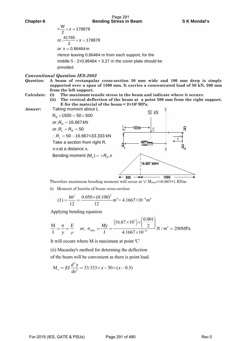
Chapter-6 Bending Stress in Beam S K Mondal’s
W= 178878241760, 178878
2 0.86464
leaving 0.86464 m from each support, for themiddle 5 - 2×0.86464 = 3.27 m the cover plate should beprovided.
x
or x
or x mHence
× =
× =
=
Conventional Question IES-2002 Question: A beam of rectangular cross-section 50 mm wide and 100 mm deep is simply
supported over a span of 1500 mm. It carries a concentrated load of 50 kN, 500 mm from the left support.
Calculate: (i) The maximum tensile stress in the beam and indicate where it occurs: (ii) The vertical deflection of the beam at a point 500 mm from the right support.
E for the material of the beam = 2×10⁵ MPa. Answer: Taking moment about L
RR 1500 50 500, 16.667, 50
50 16.667=33.333 kN
R
L R
L
or R kNor R R
R
× = ×
=
+ =
∴ = −
Take a section from right R, x-x at a distance x.
xBending moment (M ) .RR x=+
Therefore maximum bending moment will occur at 'c' Mmax=16.667×1 KNm (i) Moment of Inertia of beam cross-section
33
4 6 40.050 (0.100)( ) = 4.1667×10¹² 12
−×= =
bhI m m
( )3
2max 6
Applying bending equation0.00116.67 10
M σ 2or, σ / 200MPaI 4.1667 10
E My N my Iρ −
⎛ ⎞⎟⎜× × ⎟⎜ ⎟⎜⎝ ⎠= = = = =
×
It will occure where M is maximum at point 'C'
2
x 2
(ii) Macaulay's method for determing the deflectionof the beam will be convenient as there is point load.
M 33.333 50 ( 0.5)= = × − × −d yEI x xdx
Page 291
For-2019 (IES, GATE & PSUs) Page 291 of 480 Rev.0
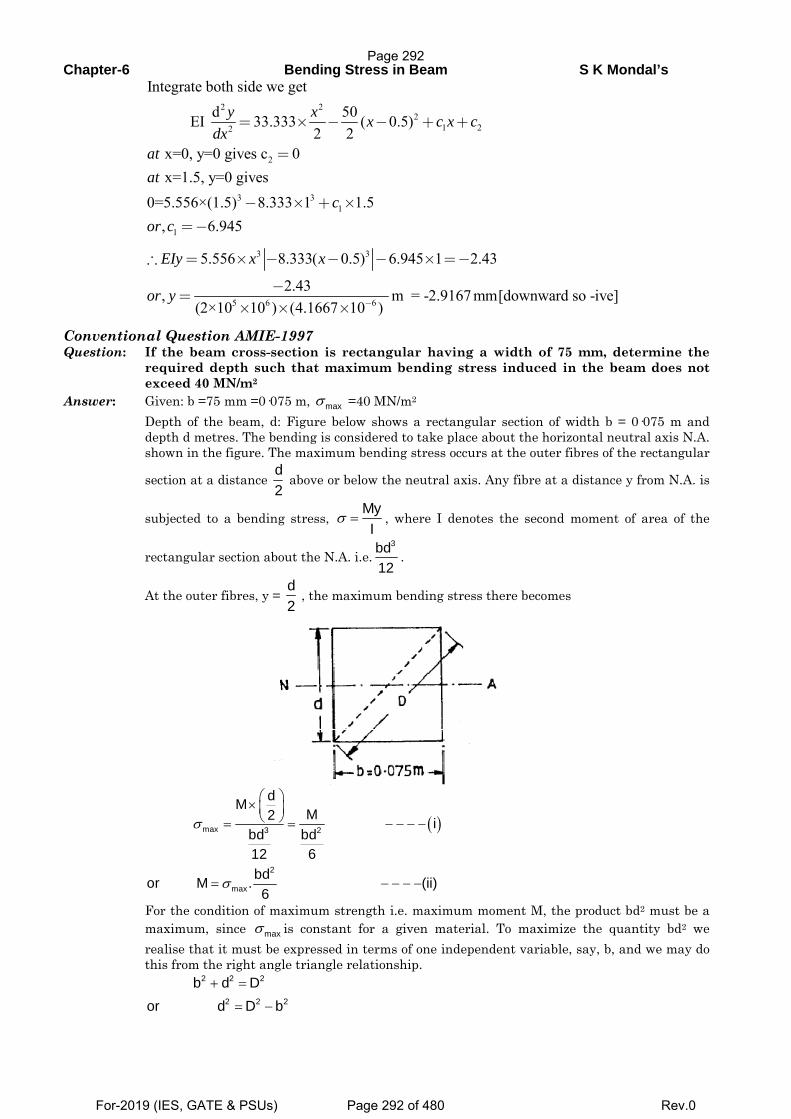
Chapter-6 Bending Stress in Beam S K Mondal’s
2 22
1 22
2
3 31
1
Integrate both side we getd 50 EI 33.333 ( 0.5)
2 2 x=0, y=0 gives c 0 x=1.5, y=0 gives
0=5.556×(1.5) 8.333 1 1.5, 6.945
= × − − + +
=
− × + ×
=−
y x x c x cdx
atat
cor c
3 3
5 6 6
5.556 8.333( 0.5) 6.945 1 2.43
2.43, m = -2.9167 mm[downward so -ive](2×10 10 ) (4.1667 10 )
EIy x x
or y −
∴ = × − − − × =−
−=
× × ×
Conventional Question AMIE-1997 Question: If the beam cross-section is rectangular having a width of 75 mm, determine the
required depth such that maximum bending stress induced in the beam does not exceed 40 MN/m2
Answer: Given: b =75 mm =0·075 m, maxσ =40 MN/m2
Depth of the beam, d: Figure below shows a rectangular section of width b = 0·075 m and depth d metres. The bending is considered to take place about the horizontal neutral axis N.A. shown in the figure. The maximum bending stress occurs at the outer fibres of the rectangular
section at a distance d2
above or below the neutral axis. Any fibre at a distance y from N.A. is
subjected to a bending stress, MyI
σ = , where I denotes the second moment of area of the
rectangular section about the N.A. i.e.3bd
12.
At the outer fibres, y = d2
, the maximum bending stress there becomes
( )max 3 2
2
max
dMM2 i
bd bd12 6bdor M . (ii)6
σ
σ
⎛ ⎞× ⎜ ⎟⎝ ⎠= = − − − −
= − − − −
For the condition of maximum strength i.e. maximum moment M, the product bd2 must be a maximum, since maxσ is constant for a given material. To maximize the quantity bd2 we realise that it must be expressed in terms of one independent variable, say, b, and we may do this from the right angle triangle relationship.
2 2 2
2 2 2
b d Dor d D b
+ =
= −
Page 292
For-2019 (IES, GATE & PSUs) Page 292 of 480 Rev.0
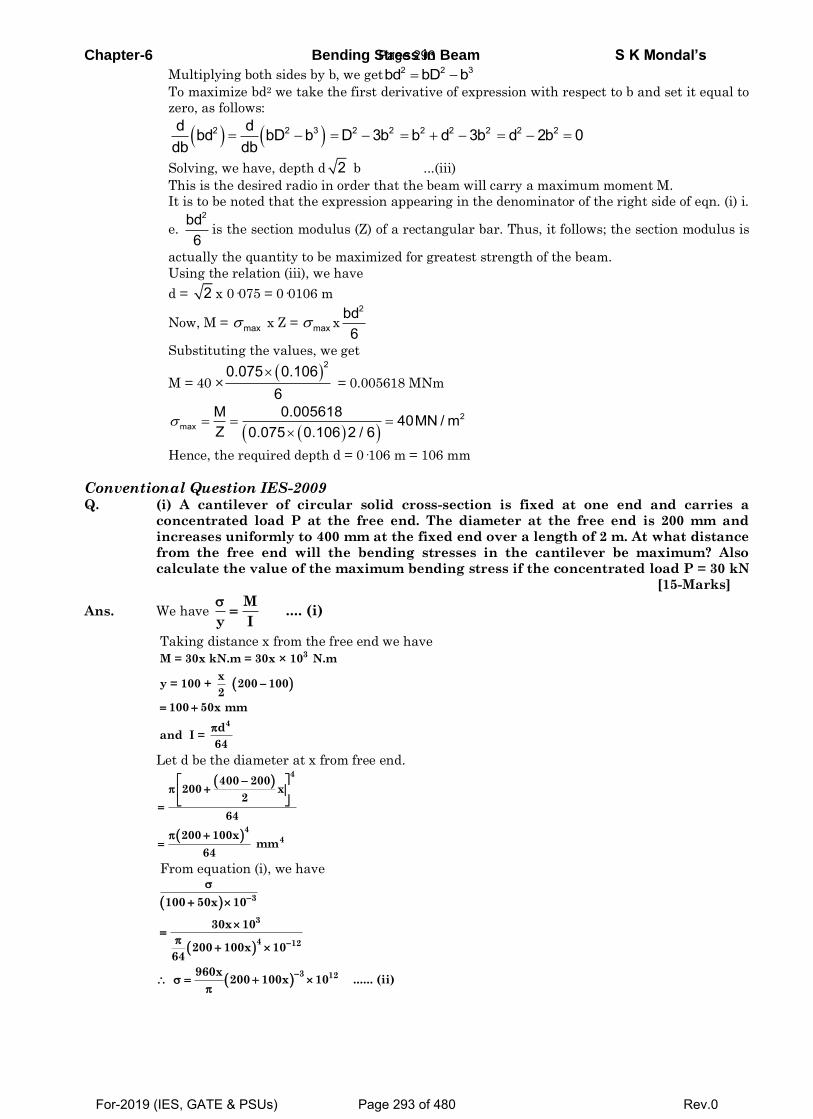
Chapter-6 Bending Stress in Beam S K Mondal’s
Multiplying both sides by b, we get 2 2 3bd bD b
To maximize bd2 we take the first derivative of expression with respect to b and set it equal to
zero, as follows:
2 2 3 2 2 2 2 2 2 2d dbd bD b D 3b b d 3b d 2b 0db db
Solving, we have, depth d 2 b ...(iii)
This is the desired radio in order that the beam will carry a maximum moment M.
It is to be noted that the expression appearing in the denominator of the right side of eqn. (i) i.
e. 2bd
6is the section modulus (Z) of a rectangular bar. Thus, it follows; the section modulus is
actually the quantity to be maximized for greatest strength of the beam.
Using the relation (iii), we have
d = 2 x 0·075 = 0·0106 m
Now, M = max x Z = max x
2bd6
Substituting the values, we get
M = 40 ×
20.075 0.1066
= 0.005618 MNm
2max
M 0.005618 40MN / mZ 0.075 0.106 2 / 6
Hence, the required depth d = 0·106 m = 106 mm
Conventional Question IES-2009 Q. (i) A cantilever of circular solid cross-section is fixed at one end and carries a
concentrated load P at the free end. The diameter at the free end is 200 mm and
increases uniformly to 400 mm at the fixed end over a length of 2 m. At what distance
from the free end will the bending stresses in the cantilever be maximum? Also
calculate the value of the maximum bending stress if the concentrated load P = 30 kN
[15-Marks]
Ans. We have
Taking distance x from the free end we have
Let d be the diameter at x from free end.
From equation (i), we have
M .... (i)
y I
3
4
M = 30x kN.m = 30x × 10 N.m
xy = 100 + 200 100
2
100 50x mm
dand I =
64
4
4
4
400 200200 x
2
64
200 100x mm
64
3
3
4 12
3 12
100 50x 10
30x 10
200 100x 1064
960x 200 100x 10 ...... (ii)
Page 293
For-2019 (IES, GATE & PSUs) Page 293 of 480 Rev.0
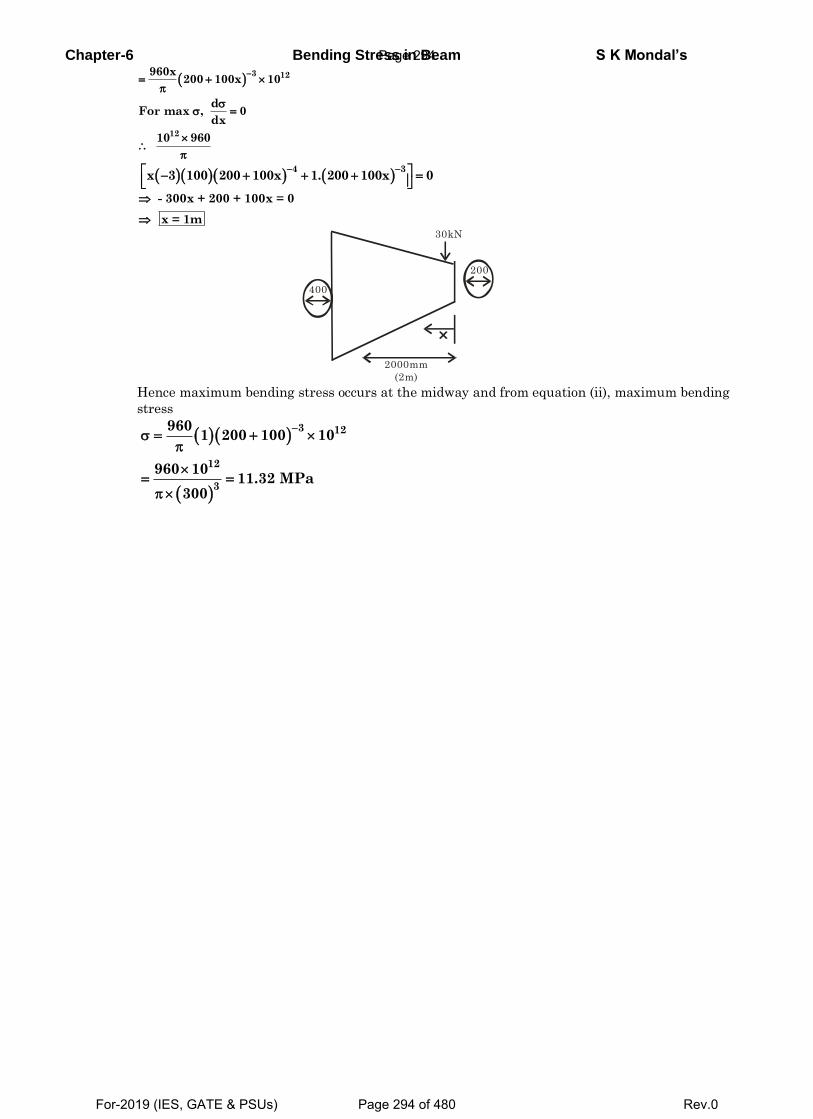
Chapter-6 Bending Stress in Beam S K Mondal’s
Hence maximum bending stress occurs at the midway and from equation (ii), maximum bending
stress
3 12960x
200 100x 10
dFor max , 0
dx
1210 960
4 3
x 3 100 200 100x 1. 200 100x 0
- 300x + 200 + 100x = 0
x = 1m
30kN
2000mm
(2m)
200
400
3 12
12
3
9601 200 100 10
960 1011.32 MPa
300
Page 294
For-2019 (IES, GATE & PSUs) Page 294 of 480 Rev.0
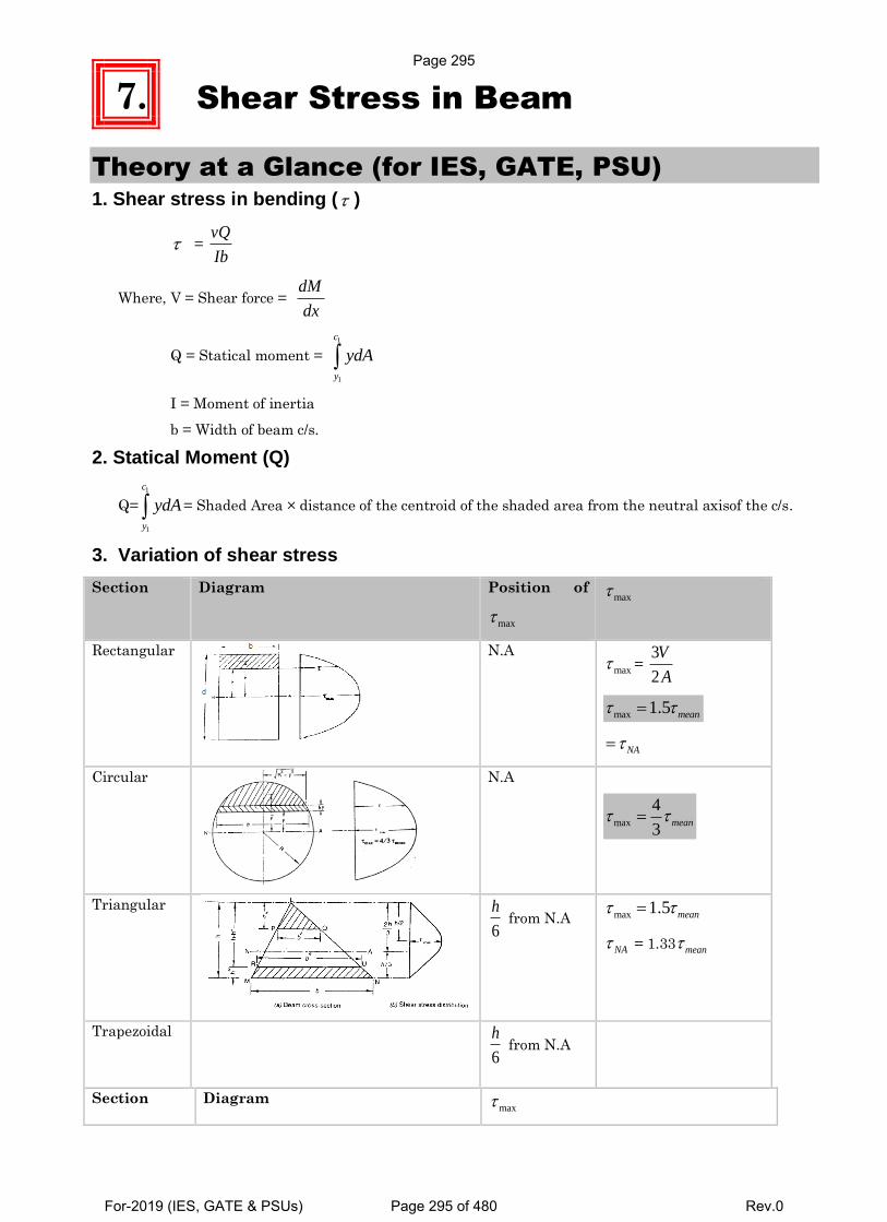
7. Shear Stress in Beam
Theory at a Glance (for IES, GATE, PSU) 1. Shear stress in bending ( )
= vQ
Ib
Where, V = Shear force = dM
dx
Q = Statical moment =
1
1
c
y
ydA
I = Moment of inertia
b = Width of beam c/s.
2. Statical Moment (Q)
Q=
1
1
c
y
ydA = Shaded Area × distance of the centroid of the shaded area from the neutral axisof the c/s.
3. Variation of shear stress Section Diagram Position of
max
max
Rectangular
N.A
max =
3
2
V
A
max 1.5 mean
NA
Circular
N.A
max
4
3 mean
Triangular
6
h from N.A max 1.5 mean
NA = 1.33mean
Trapezoidal
6
h from N.A
Section Diagram max
Page 295
For-2019 (IES, GATE & PSUs) Page 295 of 480 Rev.0
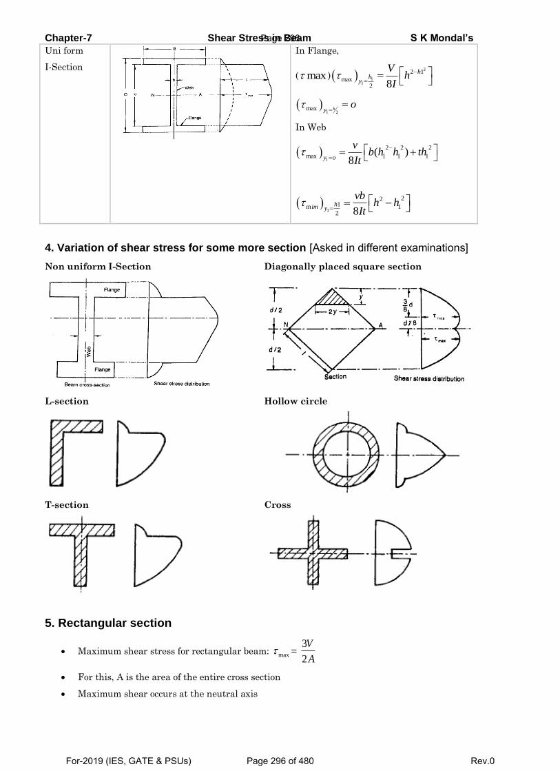
Chapter-7 Shear Stress in Beam S K Mondal’s
Uni form
I-Section
In Flange,
( max ) 2
11
2 1
max2 8
hh
y
Vh
I
1 2
max hyo
In Web
1
2 2 2
max 1 1 1( )8y o
vb h h th
It
1
221m 1
2 8him y
vbh h
It
4. Variation of shear stress for some more section [Asked in different examinations] Non uniform I-Section
Diagonally placed square section
L-section
Hollow circle
T-section
Cross
5. Rectangular section
Maximum shear stress for rectangular beam: max = 3
2
V
A
For this, A is the area of the entire cross section
Maximum shear occurs at the neutral axis
Page 296
For-2019 (IES, GATE & PSUs) Page 296 of 480 Rev.0
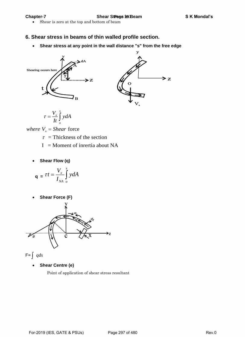
Chapter-7 Shear Stress in Beam S K Mondal’s Shear is zero at the top and bottom of beam
6. Shear stress in beams of thin walled profile section.
Shear stress at any point in the wall distance "s" from the free edge
force
= Thickness of the section
I = Moment of inrertia about NA
s
x
o
x
VydA
It
where V Shear
Shear Flow (q)
q =
s
x
NA o
Vt ydA
I
Shear Force (F)
F= qds
Shear Centre (e)
Point of application of shear stress resultant
Page 297
For-2019 (IES, GATE & PSUs) Page 297 of 480 Rev.0
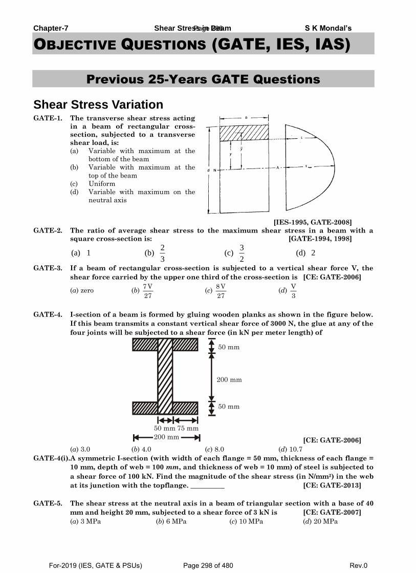
Chapter-7 Shear Stress in Beam S K Mondal’s
OBJECTIVE QUESTIONS (GATE, IES, IAS)
Previous 25-Years GATE Questions
Shear Stress Variation GATE-1. The transverse shear stress acting
in a beam of rectangular cross-
section, subjected to a transverse
shear load, is:
(a) Variable with maximum at the
bottom of the beam
(b) Variable with maximum at the
top of the beam
(c) Uniform
(d) Variable with maximum on the
neutral axis
[IES-1995, GATE-2008]
GATE-2. The ratio of average shear stress to the maximum shear stress in a beam with a
square cross-section is: [GATE-1994, 1998]
2 3
(a) 1 (b) (c) (d) 23 2
GATE-3. If a beam of rectangular cross-section is subjected to a vertical shear force V, the
shear force carried by the upper one third of the cross-section is [CE: GATE-2006]
(a) zero (b) 7 V
27 (c)
8 V
27 (d)
V
3
GATE-4. I-section of a beam is formed by gluing wooden planks as shown in the figure below.
If this beam transmits a constant vertical shear force of 3000 N, the glue at any of the
four joints will be subjected to a shear force (in kN per meter length) of
50 mm 75 mm
200 mm
50 mm
200 mm
50 mm
[CE: GATE-2006]
(a) 3.0 (b) 4.0 (c) 8.0 (d) 10.7
GATE-4(i).A symmetric I-section (with width of each flange = 50 mm, thickness of each flange =
10 mm, depth of web = 100 mm, and thickness of web = 10 mm) of steel is subjected to
a shear force of 100 kN. Find the magnitude of the shear stress (in N/mm2) in the web
at its junction with the topflange. __________ [CE: GATE-2013]
GATE-5. The shear stress at the neutral axis in a beam of triangular section with a base of 40
mm and height 20 mm, subjected to a shear force of 3 kN is [CE: GATE-2007]
(a) 3 MPa (b) 6 MPa (c) 10 MPa (d) 20 MPa
Page 298
For-2019 (IES, GATE & PSUs) Page 298 of 480 Rev.0
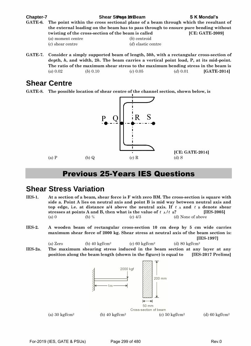
Chapter-7 Shear Stress in Beam S K Mondal’s GATE-6. The point within the cross sectional plane of a beam through which the resultant of
the external loading on the beam has to pass through to ensure pure bending without
twisting of the cross-section of the beam is called [CE: GATE-2009]
(a) moment centre (b) centroid
(c) shear centre (d) elastic centre
GATE-7. Consider a simply supported beam of length, 50h, with a rectangular cross-section of
depth, h, and width, 2h. The beam carries a vertical point load, P, at its mid-point.
The ratio of the maximum shear stress to the maximum bending stress in the beam is
(a) 0.02 (b) 0.10 (c) 0.05 (d) 0.01 [GATE-2014]
Shear Centre GATE-8. The possible location of shear centre of the channel section, shown below, is
[CE: GATE-2014]
(a) P (b) Q (c) R (d) S
Previous 25-Years IES Questions
Shear Stress Variation IES-1. At a section of a beam, shear force is F with zero BM. The cross-section is square with
side a. Point A lies on neutral axis and point B is mid way between neutral axis and
top edge, i.e. at distance a/4 above the neutral axis. If t A and t B denote shear
stresses at points A and B, then what is the value of t A / t B? [IES-2005]
(a) 0 (b) ¾ (c) 4/3 (d) None of above
IES-2. A wooden beam of rectangular cross-section 10 cm deep by 5 cm wide carries
maximum shear force of 2000 kg. Shear stress at neutral axis of the beam section is:
[IES-1997]
(a) Zero (b) 40 kgf/cm2 (c) 60 kgf/cm2 (d) 80 kgf/cm2
IES-2a. The maximum shearing stress induced in the beam section at any layer at any
position along the beam length (shown in the figure) is equal to [IES-2017 Prelims]
(a) 30 kgf/cm2 (b) 40 kgf/cm2 (c) 50 kgf/cm2 (d) 60 kgf/cm2
Page 299
For-2019 (IES, GATE & PSUs) Page 299 of 480 Rev.0
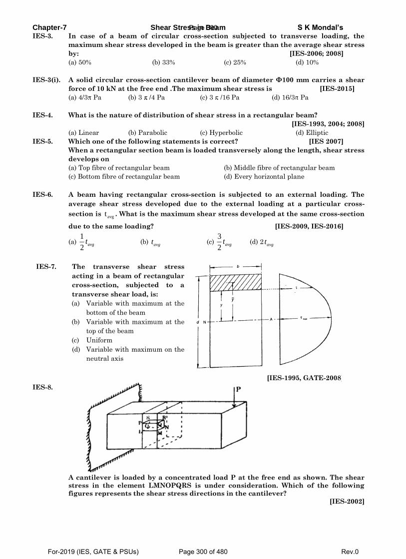
Chapter-7 Shear Stress in Beam S K Mondal’s IES-3. In case of a beam of circular cross-section subjected to transverse loading, the
maximum shear stress developed in the beam is greater than the average shear stress
by: [IES-2006; 2008]
(a) 50% (b) 33% (c) 25% (d) 10%
IES-3(i). A solid circular cross-section cantilever beam of diameter Φ100 mm carries a shear
force of 10 kN at the free end .The maximum shear stress is [IES-2015]
(a) 4/3 Pa (b) 3 /4 Pa (c) 3 /16 Pa (d) 16/3 Pa
IES-4. What is the nature of distribution of shear stress in a rectangular beam?
[IES-1993, 2004; 2008]
(a) Linear (b) Parabolic (c) Hyperbolic (d) Elliptic
IES-5. Which one of the following statements is correct? [IES 2007]
When a rectangular section beam is loaded transversely along the length, shear stress
develops on
(a) Top fibre of rectangular beam (b) Middle fibre of rectangular beam
(c) Bottom fibre of rectangular beam (d) Every horizontal plane
IES-6. A beam having rectangular cross-section is subjected to an external loading. The
average shear stress developed due to the external loading at a particular cross-
section is avgt . What is the maximum shear stress developed at the same cross-section
due to the same loading? [IES-2009, IES-2016]
(a) 1
2avgt (b)
avgt (c) 3
2avgt (d) 2
avgt
IES-7. The transverse shear stress
acting in a beam of rectangular
cross-section, subjected to a
transverse shear load, is:
(a) Variable with maximum at the
bottom of the beam
(b) Variable with maximum at the
top of the beam
(c) Uniform
(d) Variable with maximum on the
neutral axis
[IES-1995, GATE-2008]
IES-8.
A cantilever is loaded by a concentrated load P at the free end as shown. The shear
stress in the element LMNOPQRS is under consideration. Which of the following
figures represents the shear stress directions in the cantilever?
[IES-2002]
Page 300
For-2019 (IES, GATE & PSUs) Page 300 of 480 Rev.0
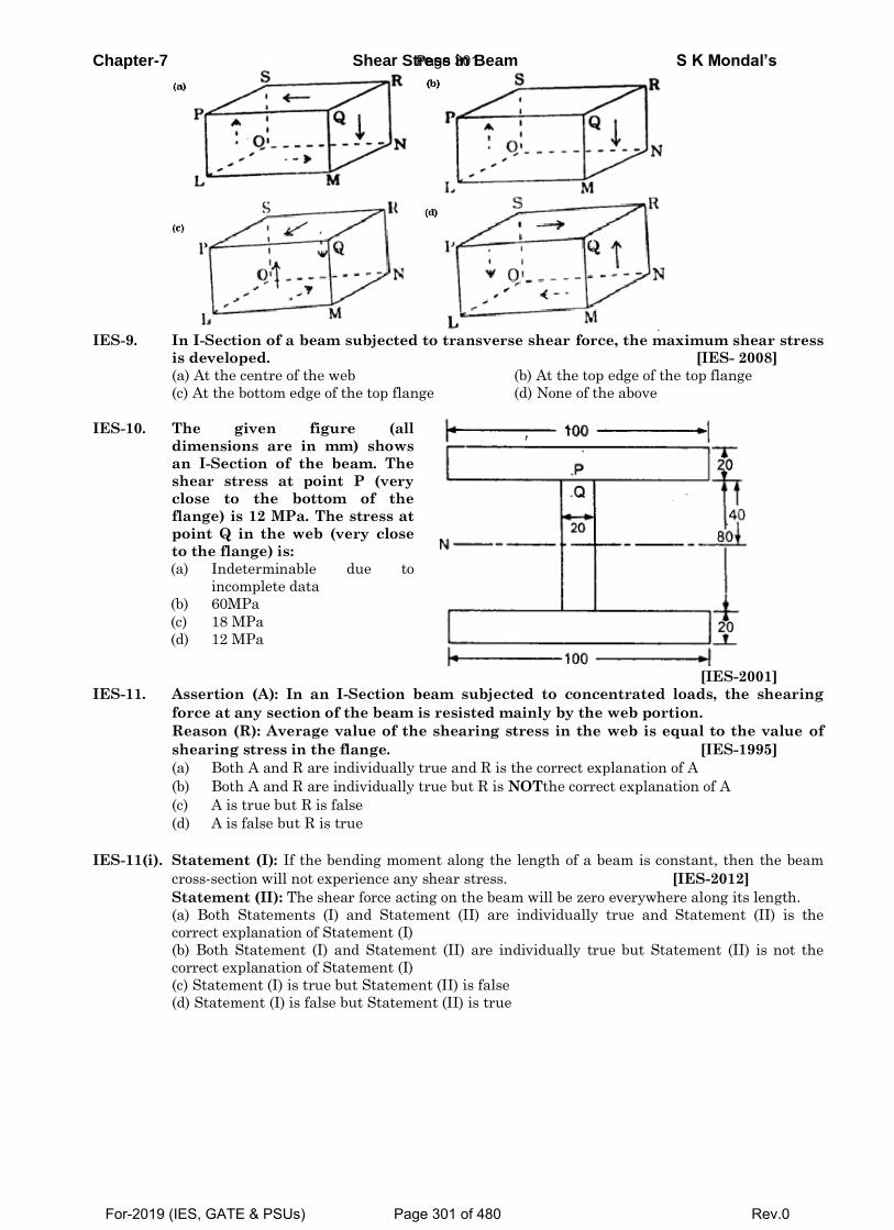
Chapter-7 Shear Stress in Beam S K Mondal’s
IES-9. In I-Section of a beam subjected to transverse shear force, the maximum shear stress
is developed. [IES- 2008]
(a) At the centre of the web (b) At the top edge of the top flange
(c) At the bottom edge of the top flange (d) None of the above
IES-10. The given figure (all
dimensions are in mm) shows
an I-Section of the beam. The
shear stress at point P (very
close to the bottom of the
flange) is 12 MPa. The stress at
point Q in the web (very close
to the flange) is:
(a) Indeterminable due to
incomplete data
(b) 60MPa
(c) 18 MPa
(d) 12 MPa
[IES-2001]
IES-11. Assertion (A): In an I-Section beam subjected to concentrated loads, the shearing
force at any section of the beam is resisted mainly by the web portion.
Reason (R): Average value of the shearing stress in the web is equal to the value of
shearing stress in the flange. [IES-1995]
(a) Both A and R are individually true and R is the correct explanation of A
(b) Both A and R are individually true but R is NOTthe correct explanation of A
(c) A is true but R is false
(d) A is false but R is true
IES-11(i). Statement (I): If the bending moment along the length of a beam is constant, then the beam
cross-section will not experience any shear stress. [IES-2012]
Statement (II): The shear force acting on the beam will be zero everywhere along its length.
(a) Both Statements (I) and Statement (II) are individually true and Statement (II) is the
correct explanation of Statement (I)
(b) Both Statement (I) and Statement (II) are individually true but Statement (II) is not the
correct explanation of Statement (I)
(c) Statement (I) is true but Statement (II) is false
(d) Statement (I) is false but Statement (II) is true
Page 301
For-2019 (IES, GATE & PSUs) Page 301 of 480 Rev.0
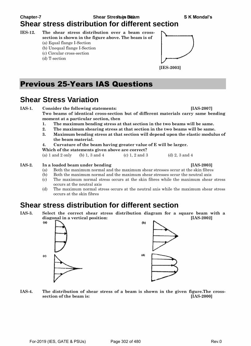
Chapter-7 Shear Stress in Beam S K Mondal’s
Shear stress distribution for different section IES-12. The shear stress distribution over a beam cross-
section is shown in the figure above. The beam is of
(a) Equal flange I-Section
(b) Unequal flange I-Section
(c) Circular cross-section
(d) T-section
[IES-2003]
Previous 25-Years IAS Questions
Shear Stress Variation IAS-1. Consider the following statements: [IAS-2007]
Two beams of identical cross-section but of different materials carry same bending
moment at a particular section, then
1. The maximum bending stress at that section in the two beams will be same.
2. The maximum shearing stress at that section in the two beams will be same.
3. Maximum bending stress at that section will depend upon the elastic modulus of
the beam material.
4. Curvature of the beam having greater value of E will be larger.
Which of the statements given above are correct?
(a) 1 and 2 only (b) 1, 3 and 4 (c) 1, 2 and 3 (d) 2, 3 and 4
IAS-2. In a loaded beam under bending [IAS-2003] (a) Both the maximum normal and the maximum shear stresses occur at the skin fibres (b) Both the maximum normal and the maximum shear stresses occur the neutral axis (c) The maximum normal stress occurs at the skin fibres while the maximum shear stress
occurs at the neutral axis (d) The maximum normal stress occurs at the neutral axis while the maximum shear stress
occurs at the skin fibres
Shear stress distribution for different section IAS-3. Select the correct shear stress distribution diagram for a square beam with a
diagonal in a vertical position: [IAS-2002]
IAS-4. The distribution of shear stress of a beam is shown in the given figure.The cross-
section of the beam is: [IAS-2000]
Page 302
For-2019 (IES, GATE & PSUs) Page 302 of 480 Rev.0
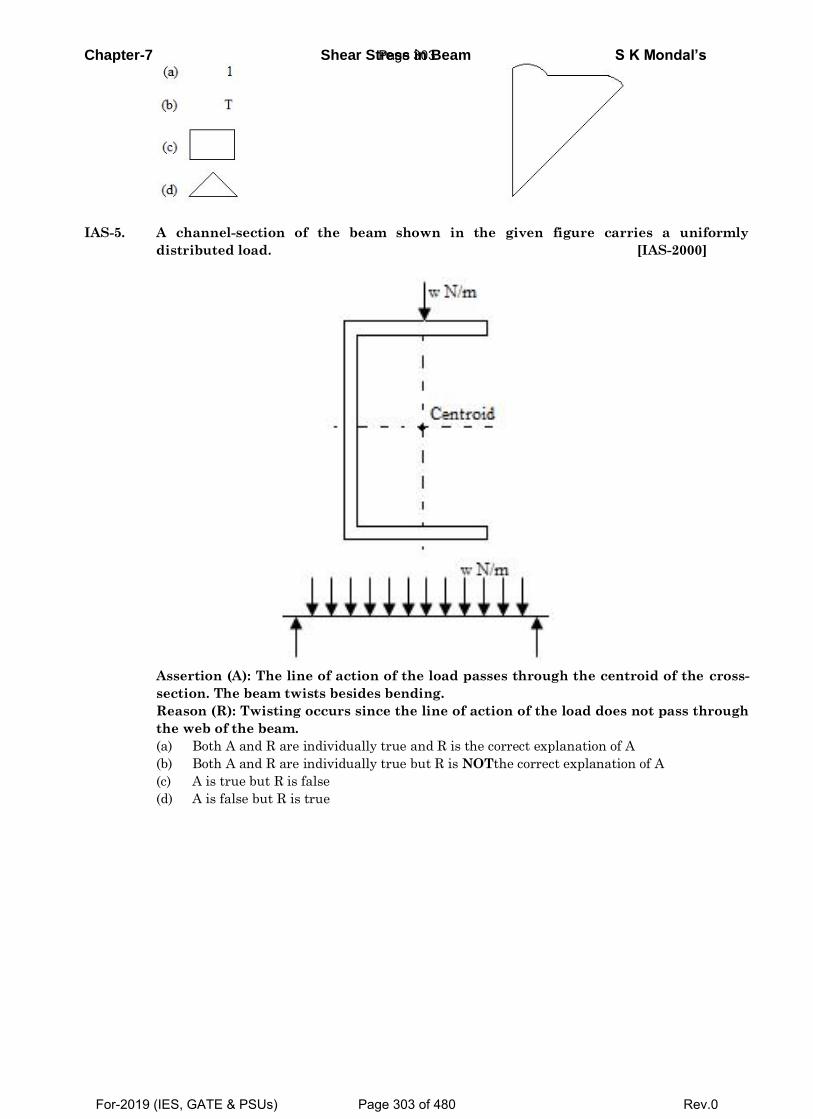
Chapter-7 Shear Stress in Beam S K Mondal’s
IAS-5. A channel-section of the beam shown in the given figure carries a uniformly
distributed load. [IAS-2000]
Assertion (A): The line of action of the load passes through the centroid of the cross-
section. The beam twists besides bending.
Reason (R): Twisting occurs since the line of action of the load does not pass through
the web of the beam.
(a) Both A and R are individually true and R is the correct explanation of A
(b) Both A and R are individually true but R is NOTthe correct explanation of A
(c) A is true but R is false
(d) A is false but R is true
Page 303
For-2019 (IES, GATE & PSUs) Page 303 of 480 Rev.0
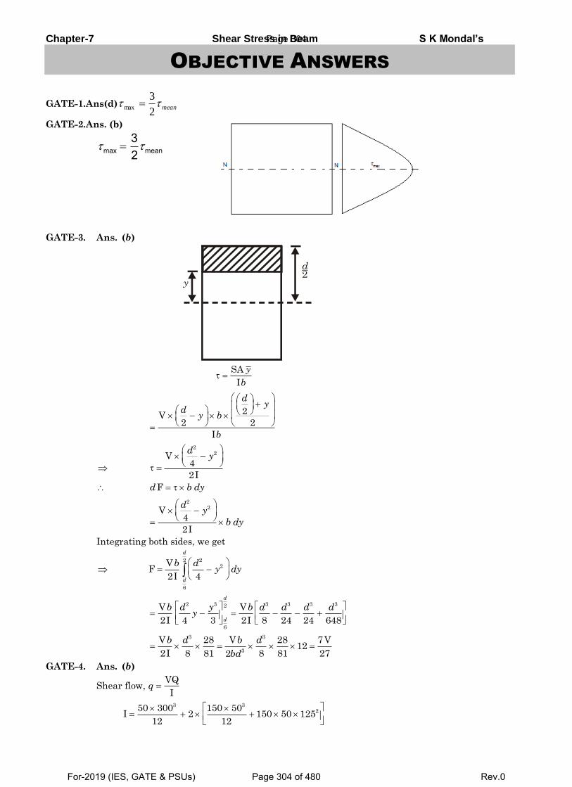
Chapter-7 Shear Stress in Beam S K Mondal’s
OBJECTIVE ANSWERS
GATE-1.Ans(d)
GATE-2.Ans. (b)
GATE-3. Ans. (b)
Integrating both sides, we get
GATE-4. Ans. (b)
Shear flow,
mean2
3max
max mean32
d2
y
SA
I
y
b
2V2 2
I
dy
dy b
b
22V
4
2I
dy
Fd b dy
22V
4
2I
dy
b dy
222
6
VF
2I 4
d
d
b dy dy
2 3 3 3 3 32
6
V V
2I 4 3 2I 8 24 24 648
d
d
b d y b d d d dy
3 3
3
V 28 V 28 7V12
2I 8 81 8 81 272
b d b d
bd
VQ
Iq
3 3250 300 150 50
I 2 150 50 12512 12
Page 304
For-2019 (IES, GATE & PSUs) Page 304 of 480 Rev.0
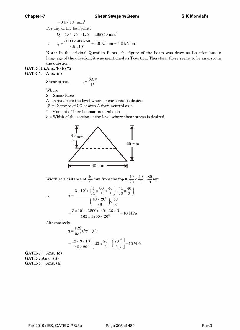
Chapter-7 Shear Stress in Beam S K Mondal’s
For any of the four joints,
Q = 50 × 75 × 125 =
Note: In the original Question Paper, the figure of the beam was draw as I-section but in
language of the question, it was mentioned as T-section. Therefore, there seems to be an error in
the question.
GATE-4(i).Ans. 70 to 72
GATE-5. Ans. (c)
Shear stress,
Where
S = Shear force
A = Area above the level where shear stress is desired
= Distance of CG of area A from neutral axis
I = Moment of Inertia about neutral axis
b = Width of the section at the level where shear stress is desired.
Width at a distance of mm from the top =
Alternatively,
GATE-6. Ans. (c)
GATE-7.Ans. (d)
GATE-8. Ans. (a)
8 43.5 10 mm
3468750 mm
8
3000 4687504.0 N/ mm 4.0 kN/ m
3.5 10q
SA
I
y
b
y
40 mm
403
mm
20 mm
40
3
40 40 80mm
20 3 3
3
3
1 80 40 1 403 10
2 3 3 3 3
40 20 80
36 3
3
3
3 10 3200 40 36 310 MPa
162 3200 20
2
3
12S( )q hy y
bh
23
3
12 3 10 20 2020 10MPa
3 340 20
Page 305
For-2019 (IES, GATE & PSUs) Page 305 of 480 Rev.0
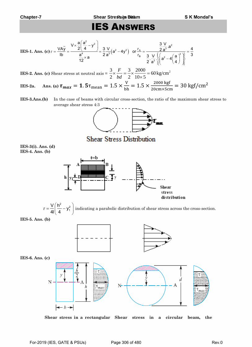
Chapter-7 Shear Stress in Beam S K Mondal’s
IES ANSWERS
IES-1. Ans. (c)
IES-2. Ans. (c) Shear stress at neutral axis =
IES-2a. Ans. (a) 𝝉𝒎𝒂𝒙 = 𝟏. 𝟓τmean = 1.5 ×V
bh= 1.5 ×
2000 kgf
20cm×5cm= 30 kgf/cm2
IES-3.Ans.(b) In the case of beams with circular cross-section, the ratio of the maximum shear stress to
average shear stress 4:3
IES-3(i). Ans. (d)
IES-4. Ans. (b)
indicating a parabolic distribution of shear stress across the cross-section.
IES-5. Ans. (b)
IES-6. Ans. (c)
Shear stress in a rectangular Shear stress in a circular beam, the
22 2
32 2 A
4 3 2B 2
3
a a 3 VV y .a2 4VAy 3 V 42 aa 4y orIb 2 3a a 3 V aa . . a 412 2 4a
23 3 200060kg/cm
2 2 10 5
F
bd
221
V h y4I 4
Page 306
For-2019 (IES, GATE & PSUs) Page 306 of 480 Rev.0
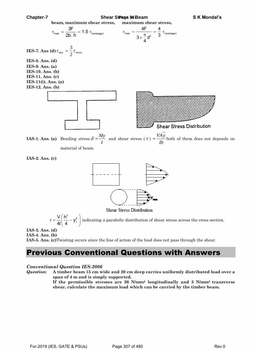
Chapter-7 Shear Stress in Beam S K Mondal’s beam, maximum shear stress,
maximum shear stress,
IES-7. Ans (d)
IES-8. Ans. (d)
IES-9. Ans. (a)
IES-10. Ans. (b)
IES-11. Ans. (c)
IES-11(i). Ans. (a)
IES-12. Ans. (b)
IAS-1. Ans. (a) Bending stress = and shear stress ( ) = both of them does not depends on
material of beam.
IAS-2. Ans. (c)
indicating a parabolic distribution of shear stress across the cross-section.
IAS-3. Ans. (d) IAS-4. Ans. (b)
IAS-5. Ans. (c)Twisting occurs since the line of action of the load does not pass through the shear.
Previous Conventional Questions with Answers
Conventional Question IES-2006 Question: A timber beam 15 cm wide and 20 cm deep carries uniformly distributed load over a
span of 4 m and is simply supported.
If the permissible stresses are 30 N/mm2 longitudinally and 3 N/mm2 transverse
shear, calculate the maximum load which can be carried by the timber beam.
max (average)3F 1.5
2b. h
max (average)2
4F 433 d
4
mean2
3max
My
I
VAy
Ib
221
V h y4I 4
Page 307
For-2019 (IES, GATE & PSUs) Page 307 of 480 Rev.0
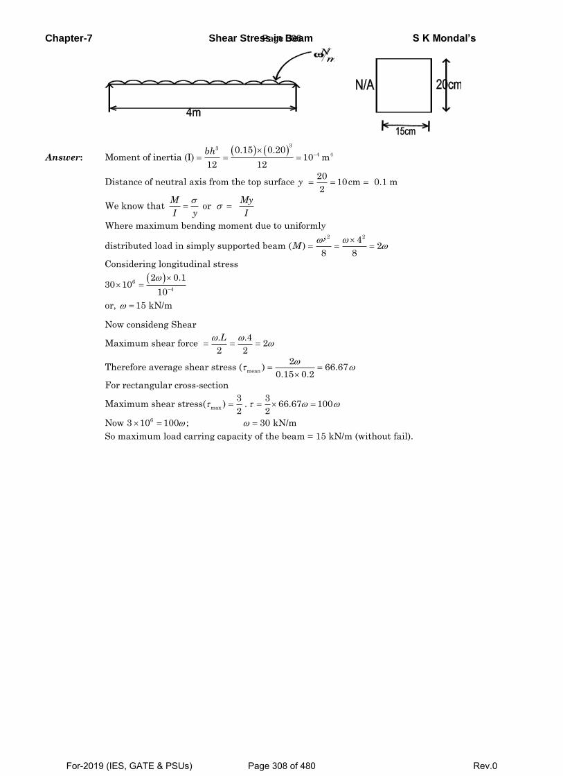
Chapter-7 Shear Stress in Beam S K Mondal’s
Answer:
33
4 40.15 0.20
Moment of inertia (I) 10 m12 12
bh
2 2
20Distance of neutral axis from the top surface 10cm 0.1 m
2
We know that or
Where maximum bending moment due to uniformly
4distributed load in simply supported beam ( ) 2
8 8
Cons
y
M My
I y I
M
6
4
idering longitudinal stress
2 0.130 10
10
or, 15 kN/m
mean
max
6
Now consideng Shear
. .4Maximum shear force 2
2 2
2Therefore average shear stress ( ) 66.67
0.15 0.2
For rectangular cross-section
3 3Maximum shear stress( ) . 66.67 100
2 2
Now 3 10 100 ;
L
30 kN/m
So maximum load carring capacity of the beam = 15 kN/m (without fail).
Page 308
For-2019 (IES, GATE & PSUs) Page 308 of 480 Rev.0
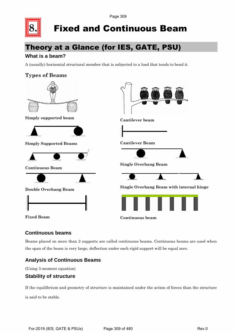
8. Fixed and Continuous Beam
Theory at a Glance (for IES, GATE, PSU) What is a beam?
A (usually) horizontal structural member that is subjected to a load that tends to bend it.
Types of Beams
Simply supported beam
Cantilever beam
Simply Supported Beams
Cantilever Beam
Continuous Beam
Single Overhang Beam
Double Overhang Beam
Single Overhang Beam with internal hinge
Fixed Beam
Continuous beam
Continuous beams
Beams placed on more than 2 supports are called continuous beams. Continuous beams are used when
the span of the beam is very large, deflection under each rigid support will be equal zero.
Analysis of Continuous Beams
(Using 3-moment equation)
Stability of structure
If the equilibrium and geometry of structure is maintained under the action of forces than the structure
is said to be stable.
Page 309
For-2019 (IES, GATE & PSUs) Page 309 of 480 Rev.0
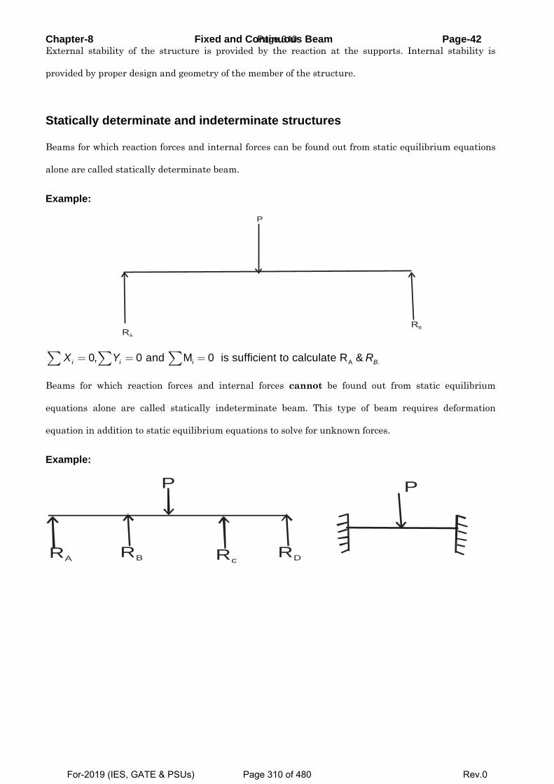
Chapter-8 Fixed and Continuous Beam Page-42 External stability of the structure is provided by the reaction at the supports. Internal stability is
provided by proper design and geometry of the member of the structure.
Statically determinate and indeterminate structures
Beams for which reaction forces and internal forces can be found out from static equilibrium equations
alone are called statically determinate beam.
Example:
i A .0, 0 and M 0 is sufficient to calculate R &i i BX Y R= = =∑ ∑ ∑
Beams for which reaction forces and internal forces cannot be found out from static equilibrium
equations alone are called statically indeterminate beam. This type of beam requires deformation
equation in addition to static equilibrium equations to solve for unknown forces.
Example:
RA RB RcRD
P P
RA
RB
P
Page 310
For-2019 (IES, GATE & PSUs) Page 310 of 480 Rev.0
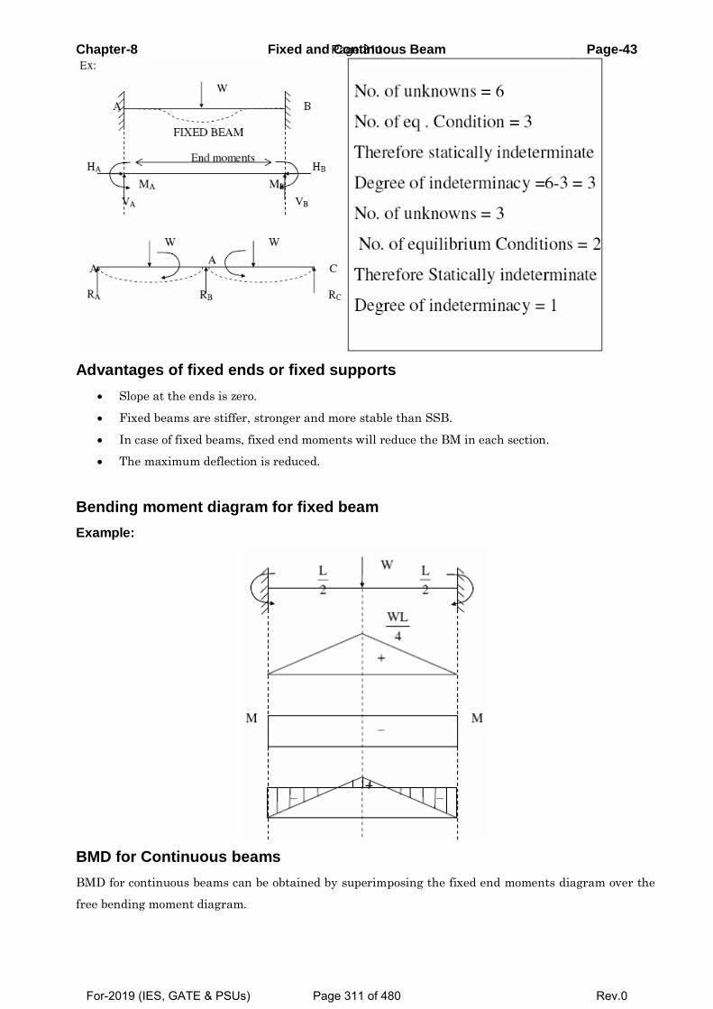
Chapter-8 Fixed and Continuous Beam Page-43
Advantages of fixed ends or fixed supports
Slope at the ends is zero.
Fixed beams are stiffer, stronger and more stable than SSB.
In case of fixed beams, fixed end moments will reduce the BM in each section.
The maximum deflection is reduced.
Bending moment diagram for fixed beam Example:
BMD for Continuous beams
BMD for continuous beams can be obtained by superimposing the fixed end moments diagram over the
free bending moment diagram.
Page 311
For-2019 (IES, GATE & PSUs) Page 311 of 480 Rev.0
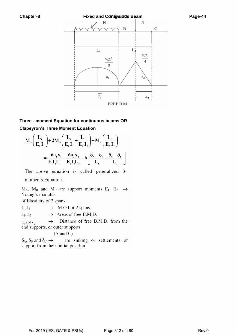
Chapter-8 Fixed and Continuous Beam Page-44
Three - moment Equation for continuous beams OR
Clapeyron’s Three Moment Equation
Page 312
For-2019 (IES, GATE & PSUs) Page 312 of 480 Rev.0
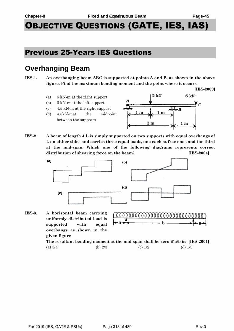
Chapter-8 Fixed and Continuous Beam Page-45
OBJECTIVE QUESTIONS (GATE, IES, IAS)
Previous 25-Years IES Questions
Overhanging Beam
IES-1. An overhanging beam ABC is supported at points A and B, as shown in the above
figure. Find the maximum bending moment and the point where it occurs.
[IES-2009]
(a) 6 kN-m at the right support
(b) 6 kN-m at the left support
(c) 4.5 kN-m at the right support
(d) 4.5kN-mat the midpoint
between the supports
IES-2. A beam of length 4 L is simply supported on two supports with equal overhangs of
L on either sides and carries three equal loads, one each at free ends and the third
at the mid-span. Which one of the following diagrams represents correct
distribution of shearing force on the beam? [IES-2004]
IES-3. A horizontal beam carrying
uniformly distributed load is
supported with equal
overhangs as shown in the
given figure
The resultant bending moment at the mid-span shall be zero if a/b is: [IES-2001]
(a) 3/4 (b) 2/3 (c) 1/2 (d) 1/3
Page 313
For-2019 (IES, GATE & PSUs) Page 313 of 480 Rev.0
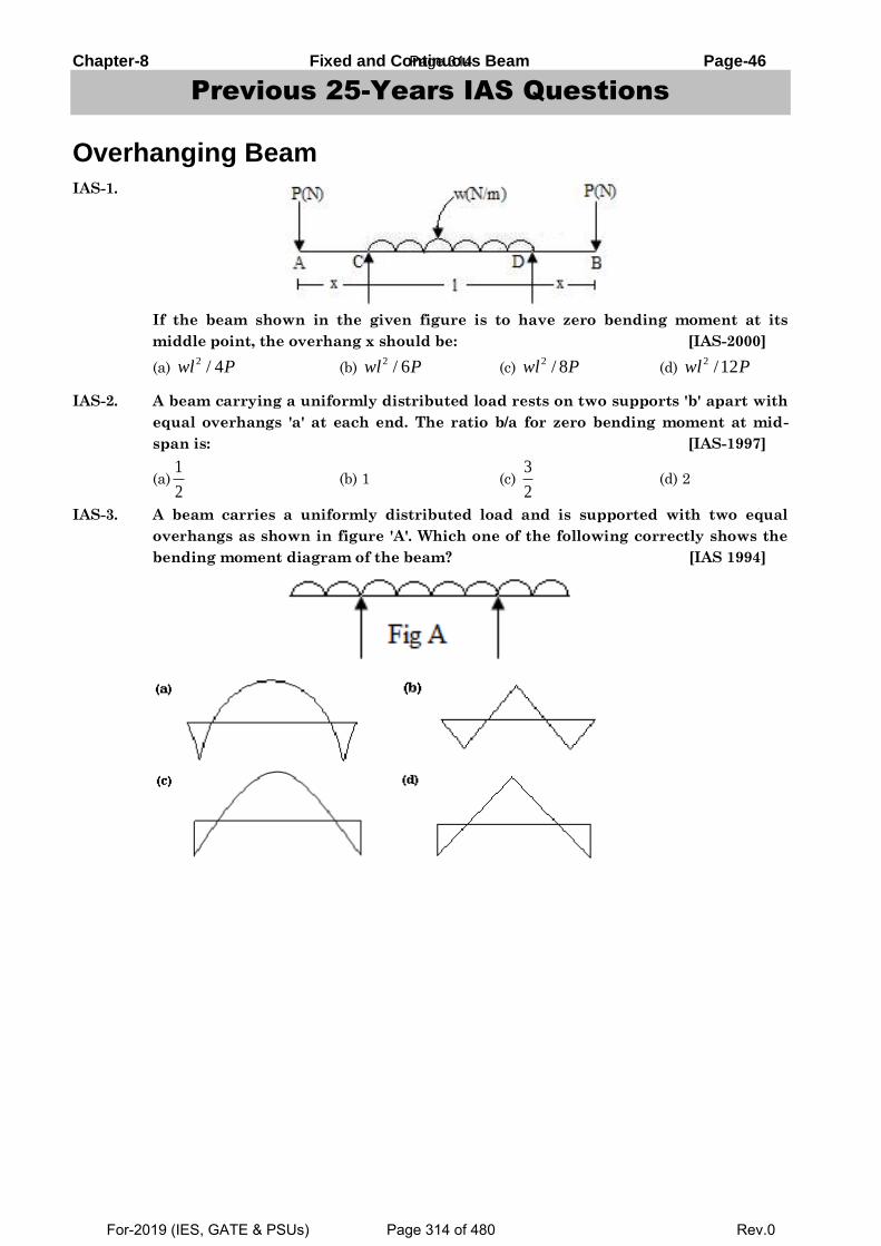
Chapter-8 Fixed and Continuous Beam Page-46
Previous 25-Years IAS Questions
Overhanging Beam
IAS-1.
If the beam shown in the given figure is to have zero bending moment at its
middle point, the overhang x should be: [IAS-2000]
(a) 2 / 4wl P (b)
2 / 6wl P (c) 2 / 8wl P (d)
2 /12wl P
IAS-2. A beam carrying a uniformly distributed load rests on two supports 'b' apart with
equal overhangs 'a' at each end. The ratio b/a for zero bending moment at mid-
span is: [IAS-1997]
(a)1
2 (b) 1 (c)
3
2 (d) 2
IAS-3. A beam carries a uniformly distributed load and is supported with two equal
overhangs as shown in figure 'A'. Which one of the following correctly shows the
bending moment diagram of the beam? [IAS 1994]
Page 314
For-2019 (IES, GATE & PSUs) Page 314 of 480 Rev.0
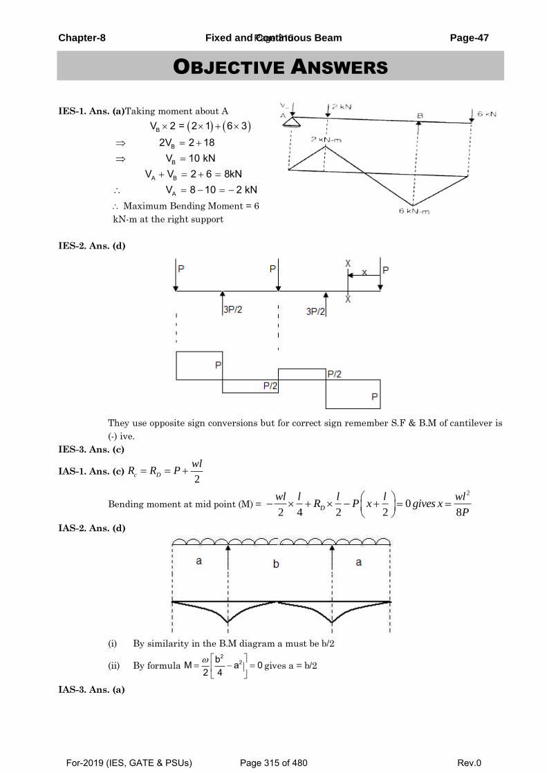
Chapter-8 Fixed and Continuous Beam Page-47
OBJECTIVE ANSWERS
IES-1. Ans. (a)Taking moment about A
Maximum Bending Moment = 6
kN-m at the right support
IES-2. Ans. (d)
They use opposite sign conversions but for correct sign remember S.F & B.M of cantilever is
(-) ive.
IES-3. Ans. (c)
IAS-1. Ans. (c)
Bending moment at mid point (M) =
IAS-2. Ans. (d)
(i) By similarity in the B.M diagram a must be b/2
(ii) By formula gives a = b/2
IAS-3. Ans. (a)
B
B
B
A B
A
V 2 = 2 1 6 32V 2 18
V 10 kNV V 2 6 8kN
V 8 10 2 kN
2c D
wlR R P
2
02 4 2 2 8
D
wl l l l wlR P x gives x
P
22bM a 0
2 4
Page 315
For-2019 (IES, GATE & PSUs) Page 315 of 480 Rev.0
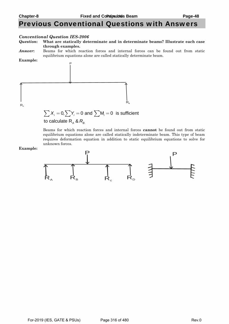
Chapter-8 Fixed and Continuous Beam Page-48
Previous Conventional Questions with Answers
Conventional Question IES-2006 Question: What are statically determinate and in determinate beams? Illustrate each case
through examples. Answer: Beams for which reaction forces and internal forces can be found out from static
equilibrium equations alone are called statically determinate beam. Example:
i
A .
0, 0 and M 0 is sufficient
to calculate R &i i
B
X Y
R
= = =∑ ∑ ∑
Beams for which reaction forces and internal forces cannot be found out from static equilibrium equations alone are called statically indeterminate beam. This type of beam requires deformation equation in addition to static equilibrium equations to solve for unknown forces.
Example:
RA RB RcRD
P P
RA
RB
P
Page 316
For-2019 (IES, GATE & PSUs) Page 316 of 480 Rev.0
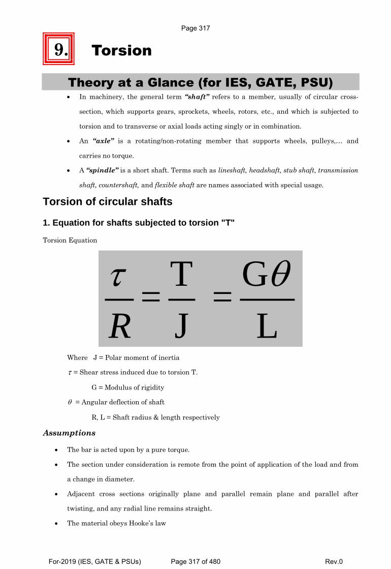
9. Torsion
Theory at a Glance (for IES, GATE, PSU) In machinery, the general term “shaft” refers to a member, usually of circular cross-
section, which supports gears, sprockets, wheels, rotors, etc., and which is subjected to
torsion and to transverse or axial loads acting singly or in combination.
An “axle” is a rotating/non-rotating member that supports wheels, pulleys,… and
carries no torque.
A “spindle” is a short shaft. Terms such as lineshaft, headshaft, stub shaft, transmission
shaft, countershaft, and flexible shaft are names associated with special usage.
Torsion of circular shafts
1. Equation for shafts subjected to torsion "T"
Torsion Equation
T G= =
J L
R
Where J = Polar moment of inertia
= Shear stress induced due to torsion T.
G = Modulus of rigidity
= Angular deflection of shaft
R, L = Shaft radius & length respectively
Assumptions
The bar is acted upon by a pure torque.
The section under consideration is remote from the point of application of the load and from
a change in diameter.
Adjacent cross sections originally plane and parallel remain plane and parallel after
twisting, and any radial line remains straight.
The material obeys Hooke’s law
Page 317
For-2019 (IES, GATE & PSUs) Page 317 of 480 Rev.0
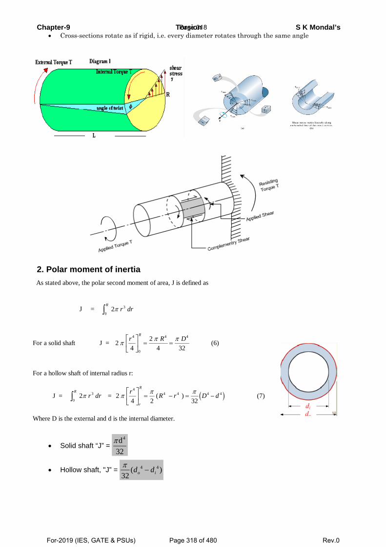
Chapter-9 Torsion S K Mondal’s • Cross-sections rotate as if rigid, i.e. every diameter rotates through the same angle
2. Polar moment of inertia
• Solid shaft “J” = 4d
32π
• Hollow shaft, "J” = 4 4( )32π
−o id d
As stated above, the polar second moment of area, J is defined as J = 2 3
0π r dr
Rz
For a solid shaft J = 24
24 32
4
0
4 4
π π πr R DRL
NMOQP
= = (6)
For a hollow shaft of internal radius r:
J = 2 3
0π r dr
Rz = 24 2 32
44 4 4 4π π πr R r D d
r
RLNMOQP
= − = −( ) c h (7)
Where D is the external and d is the internal diameter.
Page 318
For-2019 (IES, GATE & PSUs) Page 318 of 480 Rev.0
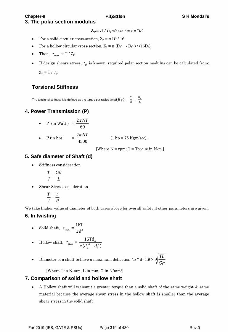
Chapter-9 Torsion S K Mondal’s
3. The polar section modulus
Zp= J / c, where c = r = D/2
For a solid circular cross-section, Zp = π D3 / 16
For a hollow circular cross-section, Zp = π (Do4 - Di4 ) / (16Do)
Then, max = T / Zp
If design shears stress, d is known, required polar section modulus can be calculated from:
Zp = T / d
Torsional Stiffness
The tensional stiffness k is defined as the torque per radius twist(𝐾𝑇) =𝑇
𝜃=
𝐺𝐽
𝐿
4. Power Transmission (P)
P (in Watt ) = 2
60
NT
P (in hp) = 2
4500
NT (1 hp = 75 Kgm/sec).
[Where N = rpm; T = Torque in N-m.]
5. Safe diameter of Shaft (d)
Stiffness consideration
T G
J L
Shear Stress consideration
T
J R
We take higher value of diameter of both cases above for overall safety if other parameters are given.
6. In twisting
Solid shaft, max = 3
16T
d
Hollow shaft, max = o
4 4
16Td
( ) o id d
Diameter of a shaft to have a maximum deflection " " d=4.9 × 4
TL
G
[Where T in N-mm, L in mm, G in N/mm2]
7. Comparison of solid and hollow shaft
A Hollow shaft will transmit a greater torque than a solid shaft of the same weight & same
material because the average shear stress in the hollow shaft is smaller than the average
shear stress in the solid shaft
Page 319
For-2019 (IES, GATE & PSUs) Page 319 of 480 Rev.0
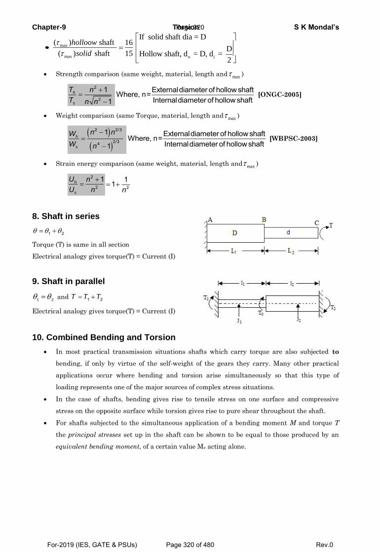
Chapter-9 Torsion S K Mondal’s
max
max
( ) shaft 16
( ) shaft 15
holloow
solido i
If solid shaft dia = D
DHollow shaft, d = D, d =
2
Strength comparison (same weight, material, length and max )
2
2
11
h
s
T n
T n n
Externaldiameter of hollow shaftWhere, n=Internaldiameter of hollow shaft
[ONGC-2005]
Weight comparison (same Torque, material, length and max )
2 2/3
2/34
1
1h
s
n nW
W n
Externaldiameter of hollow shaftWhere, n=Internaldiameter of hollow shaft
[WBPSC-2003]
Strain energy comparison (same weight, material, length and max )
2
2
1h
s
U n
U n
2
11n
8. Shaft in series
1 2
Torque (T) is same in all section
Electrical analogy gives torque(T) = Current (I)
9. Shaft in parallel
1 2 and 1 2T T T
Electrical analogy gives torque(T) = Current (I)
10. Combined Bending and Torsion
In most practical transmission situations shafts which carry torque are also subjected to
bending, if only by virtue of the self-weight of the gears they carry. Many other practical
applications occur where bending and torsion arise simultaneously so that this type of
loading represents one of the major sources of complex stress situations.
In the case of shafts, bending gives rise to tensile stress on one surface and compressive
stress on the opposite surface while torsion gives rise to pure shear throughout the shaft.
For shafts subjected to the simultaneous application of a bending moment M and torque T
the principal stresses set up in the shaft can be shown to be equal to those produced by an
equivalent bending moment, of a certain value Me acting alone.
Page 320
For-2019 (IES, GATE & PSUs) Page 320 of 480 Rev.0
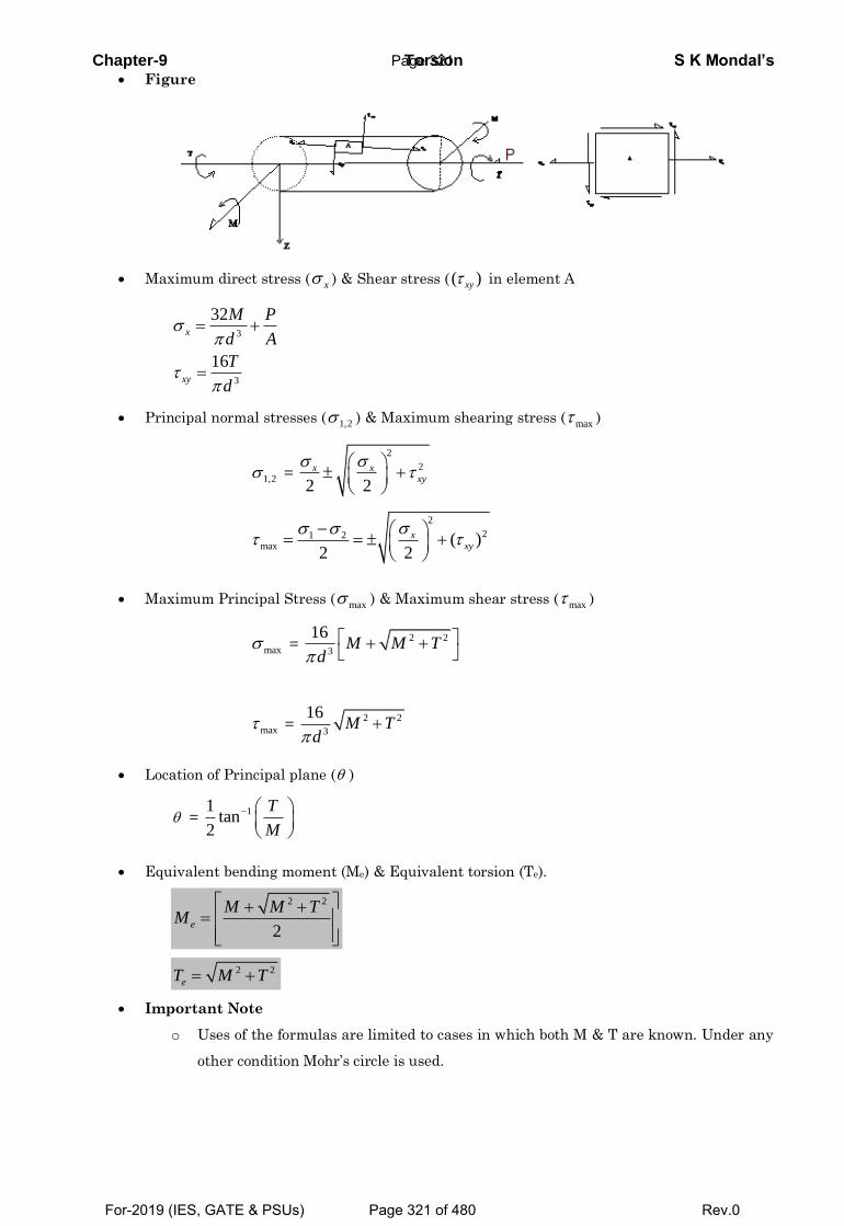
Chapter-9 Torsion S K Mondal’s Figure
Maximum direct stress ( x ) & Shear stress ( ( )xy in element A
3
3
32
16
x
xy
M P
d A
T
d
Principal normal stresses ( 1,2 ) & Maximum shearing stress ( max )
1,2 =
2
2
2 2
x xxy
2
21 2max ( )
2 2
xxy
Maximum Principal Stress ( max ) & Maximum shear stress ( max )
max = 2 2
3
16
M M T
d
max = 2 2
3
16
M T
d
Location of Principal plane ( )
= 11
tan2
T
M
Equivalent bending moment (Me) & Equivalent torsion (Te).
2 2
2
e
M M TM
2 2 eT M T
Important Note
o Uses of the formulas are limited to cases in which both M & T are known. Under any
other condition Mohr’s circle is used.
Page 321
For-2019 (IES, GATE & PSUs) Page 321 of 480 Rev.0
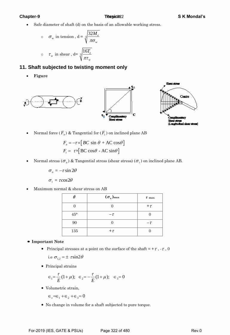
Chapter-9 Torsion S K Mondal’s
Safe diameter of shaft (d) on the basis of an allowable working stress.
o w in tension , d = 332 e
w
M
o w in shear , d= 316 e
w
T
11. Shaft subjected to twisting moment only
Figure
Normal force ( nF ) & Tangential for ( tF ) on inclined plane AB
sin + AC cos
× BC cos - AC sin
n
t
F BC
F
Normal stress ( n ) & Tangential stress (shear stress) ( t ) on inclined plane AB.
n = sin 2
t = 2 cos
Maximum normal & shear stress on AB
(n )max max
0 0 +
45° – 0
90 0 –
135 + 0
Important Note
Principal stresses at a point on the surface of the shaft = + , - , 0
i.e 1,2 sin2
Principal strains
1 2 3(1 ); (1 ); 0
E E
Volumetric strain,
1 2 3 0 v
No change in volume for a shaft subjected to pure torque.
Page 322
For-2019 (IES, GATE & PSUs) Page 322 of 480 Rev.0
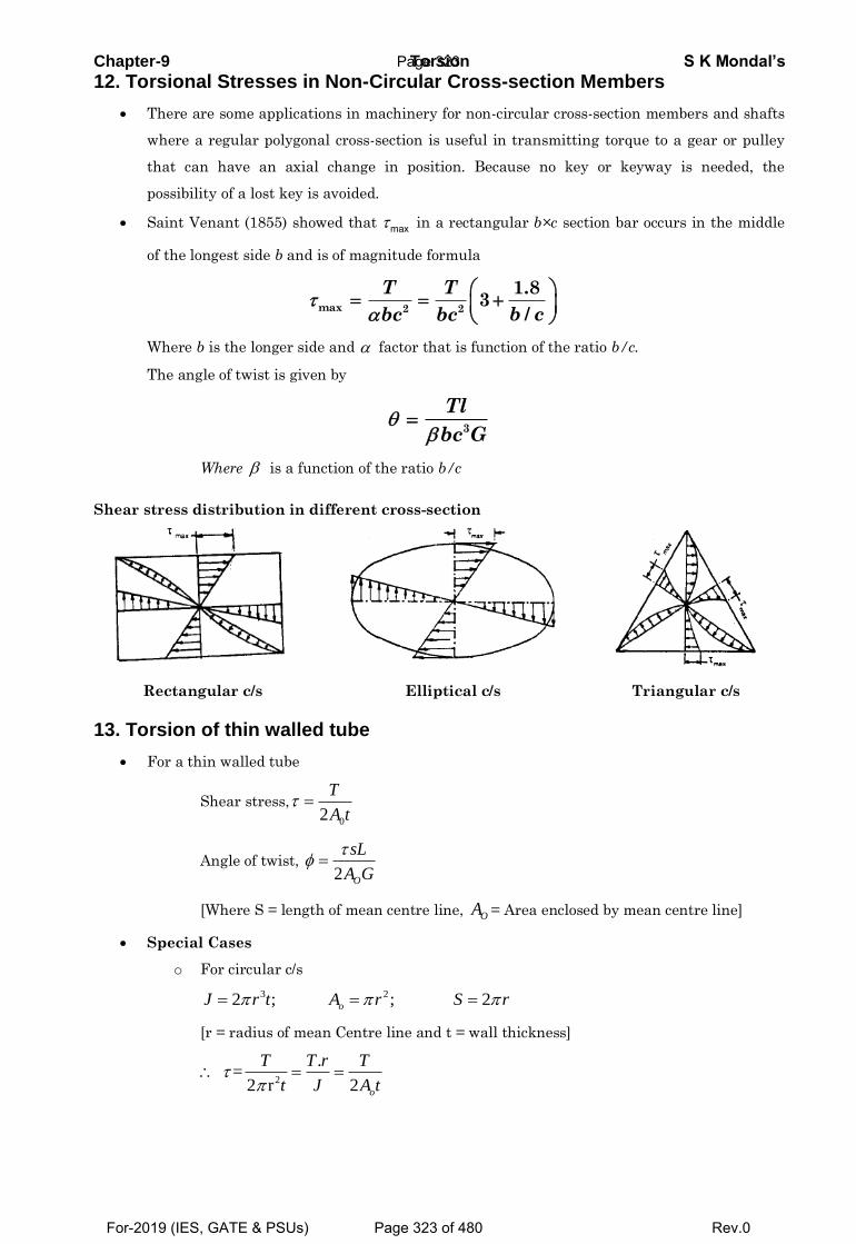
Chapter-9 Torsion S K Mondal’s
12. Torsional Stresses in Non-Circular Cross-section Members
There are some applications in machinery for non-circular cross-section members and shafts
where a regular polygonal cross-section is useful in transmitting torque to a gear or pulley
that can have an axial change in position. Because no key or keyway is needed, the
possibility of a lost key is avoided.
Saint Venant (1855) showed that max in a rectangular b×c section bar occurs in the middle
of the longest side b and is of magnitude formula
max 2 2
1.83
/
T T
b cbc bc
Where b is the longer side and factor that is function of the ratio b/c.
The angle of twist is given by
3
Tl
bc G
Where is a function of the ratio b/c
Shear stress distribution in different cross-section
Rectangular c/s Elliptical c/s Triangular c/s
13. Torsion of thin walled tube
For a thin walled tube
Shear stress,
02
T
A t
Angle of twist, 2 O
sL
A G
[Where S = length of mean centre line, OA = Area enclosed by mean centre line]
Special Cases
o For circular c/s
3 22 ; ; 2 oJ r t A r S r
[r = radius of mean Centre line and t = wall thickness]
2
. =
2 r 2
o
T T r T
t J A t
Page 323
For-2019 (IES, GATE & PSUs) Page 323 of 480 Rev.0
Chapter-9 Torsion S K Mondal’s
32
o
TL L TL
GJ A JG r tG
o For square c/s of length of each side ‘b’ and thickness ‘t’
2
0
=4b
A b
S
o For elliptical c/s ‘a’ and ‘b’ are the half axis lengths.
0
3 ( )
2
A ab
S a b ab
Page 324
For-2019 (IES, GATE & PSUs) Page 324 of 480 Rev.0
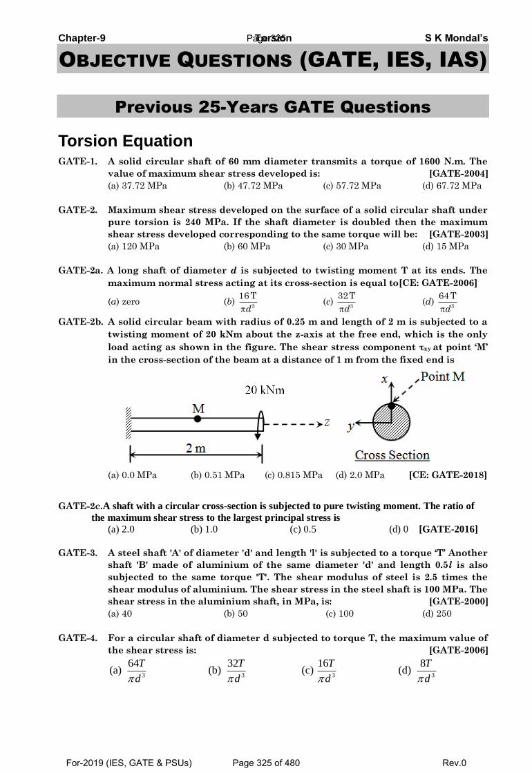
Chapter-9 Torsion S K Mondal’s
OBJECTIVE QUESTIONS (GATE, IES, IAS)
Previous 25-Years GATE Questions
Torsion Equation GATE-1. A solid circular shaft of 60 mm diameter transmits a torque of 1600 N.m. The
value of maximum shear stress developed is: [GATE-2004]
(a) 37.72 MPa (b) 47.72 MPa (c) 57.72 MPa (d) 67.72 MPa
GATE-2. Maximum shear stress developed on the surface of a solid circular shaft under
pure torsion is 240 MPa. If the shaft diameter is doubled then the maximum
shear stress developed corresponding to the same torque will be: [GATE-2003]
(a) 120 MPa (b) 60 MPa (c) 30 MPa (d) 15 MPa
GATE-2a. A long shaft of diameter d is subjected to twisting moment T at its ends. The
maximum normal stress acting at its cross-section is equal to[CE: GATE-2006]
(a) zero (b) 3
16 T
d (c)
3
32T
d (d)
3
64 T
d GATE-2b. A solid circular beam with radius of 0.25 m and length of 2 m is subjected to a
twisting moment of 20 kNm about the z-axis at the free end, which is the only
load acting as shown in the figure. The shear stress component τxy at point ‘M’
in the cross-section of the beam at a distance of 1 m from the fixed end is
(a) 0.0 MPa (b) 0.51 MPa (c) 0.815 MPa (d) 2.0 MPa [CE: GATE-2018]
GATE-2c.A shaft with a circular cross-section is subjected to pure twisting moment. The ratio of
the maximum shear stress to the largest principal stress is
(a) 2.0 (b) 1.0 (c) 0.5 (d) 0 [GATE-2016]
GATE-3. A steel shaft 'A' of diameter 'd' and length 'l' is subjected to a torque ‘T’ Another
shaft 'B' made of aluminium of the same diameter 'd' and length 0.5l is also
subjected to the same torque 'T'. The shear modulus of steel is 2.5 times the
shear modulus of aluminium. The shear stress in the steel shaft is 100 MPa. The
shear stress in the aluminium shaft, in MPa, is: [GATE-2000]
(a) 40 (b) 50 (c) 100 (d) 250
GATE-4. For a circular shaft of diameter d subjected to torque T, the maximum value of
the shear stress is: [GATE-2006]
3 3 3 3
64 32 16 8(a) (b) (c) (d)
T T T T
d d d d
Page 325
For-2019 (IES, GATE & PSUs) Page 325 of 480 Rev.0
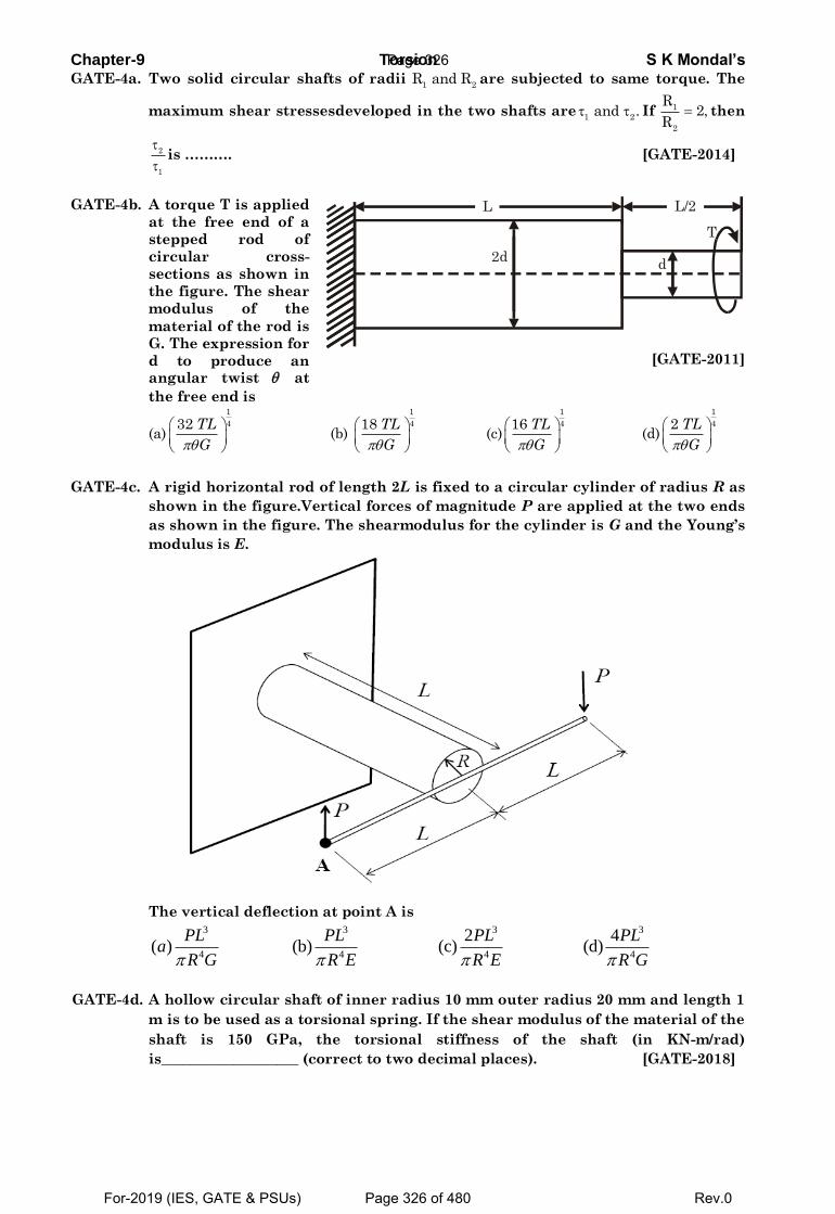
Chapter-9 Torsion S K Mondal’s GATE-4a. Two solid circular shafts of radii
1 2R and R are subjected to same torque. The
maximum shear stressesdeveloped in the two shafts are1 2
and . If 1
2
R2,
R then
2
1
is ………. [GATE-2014]
GATE-4b. A torque T is applied
at the free end of a
stepped rod of
circular cross-
sections as shown in
the figure. The shear
modulus of the
material of the rod is
G. The expression for
d to produce an angular twist at
the free end is
d2d
L L/2
T
[GATE-2011]
(a)
1
432 TL
G
(b)
1
418 TL
G
(c)
1
416 TL
G
(d)
1
42 TL
G
GATE-4c. A rigid horizontal rod of length 2L is fixed to a circular cylinder of radius R as
shown in the figure.Vertical forces of magnitude P are applied at the two ends
as shown in the figure. The shearmodulus for the cylinder is G and the Young’s
modulus is E.
The vertical deflection at point A is
3 3 3 3
4 4 4 4
2 4( ) (b) (c) (d)
PL PL PL PLa
R G R E R E R G
GATE-4d. A hollow circular shaft of inner radius 10 mm outer radius 20 mm and length 1
m is to be used as a torsional spring. If the shear modulus of the material of the
shaft is 150 GPa, the torsional stiffness of the shaft (in KN-m/rad)
is___________________ (correct to two decimal places). [GATE-2018]
Page 326
For-2019 (IES, GATE & PSUs) Page 326 of 480 Rev.0
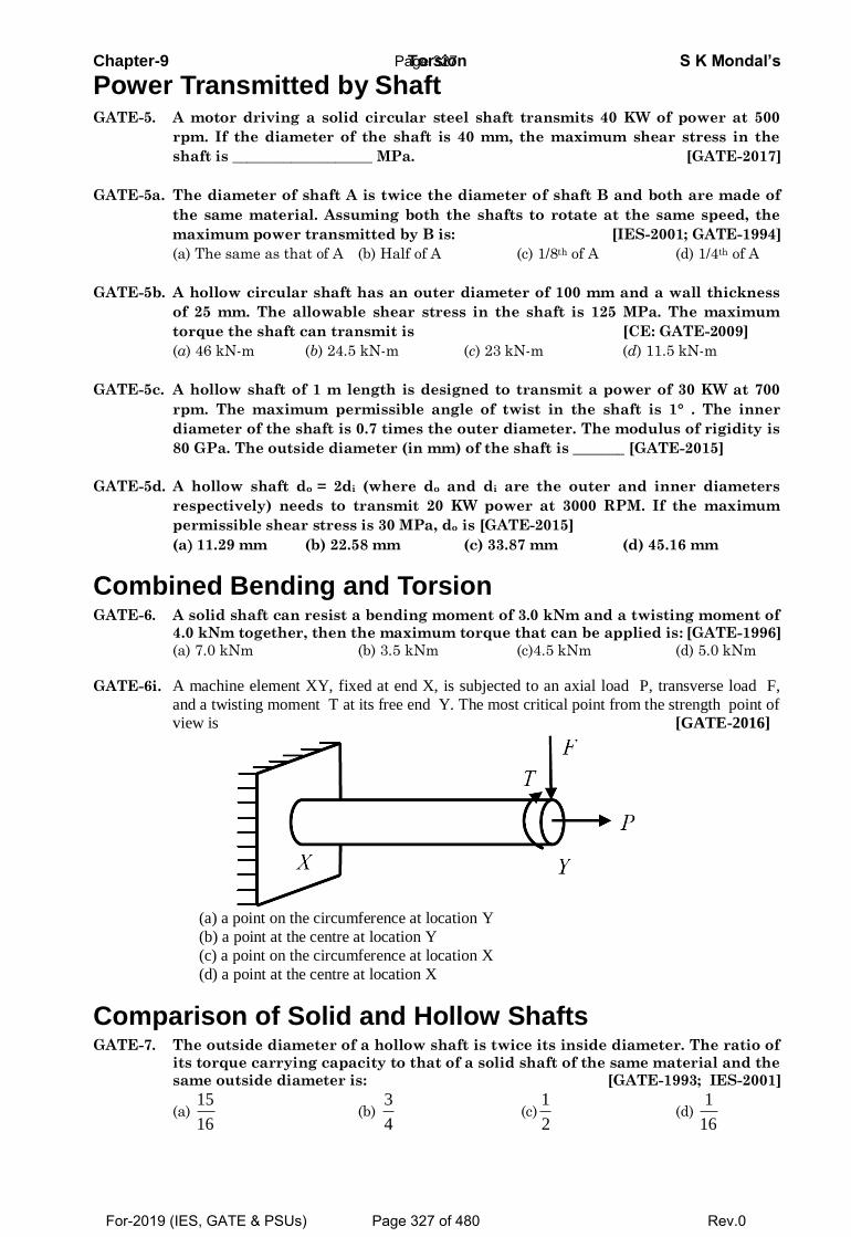
Chapter-9 Torsion S K Mondal’s
Power Transmitted by Shaft GATE-5. A motor driving a solid circular steel shaft transmits 40 KW of power at 500
rpm. If the diameter of the shaft is 40 mm, the maximum shear stress in the
shaft is ___________________ MPa. [GATE-2017]
GATE-5a. The diameter of shaft A is twice the diameter of shaft B and both are made of
the same material. Assuming both the shafts to rotate at the same speed, the
maximum power transmitted by B is: [IES-2001; GATE-1994]
(a) The same as that of A (b) Half of A (c) 1/8th of A (d) 1/4th of A
GATE-5b. A hollow circular shaft has an outer diameter of 100 mm and a wall thickness
of 25 mm. The allowable shear stress in the shaft is 125 MPa. The maximum
torque the shaft can transmit is [CE: GATE-2009]
(a) 46 kN-m (b) 24.5 kN-m (c) 23 kN-m (d) 11.5 kN-m
GATE-5c. A hollow shaft of 1 m length is designed to transmit a power of 30 KW at 700
rpm. The maximum permissible angle of twist in the shaft is 1° . The inner
diameter of the shaft is 0.7 times the outer diameter. The modulus of rigidity is
80 GPa. The outside diameter (in mm) of the shaft is _______ [GATE-2015]
GATE-5d. A hollow shaft do = 2di (where do and di are the outer and inner diameters
respectively) needs to transmit 20 KW power at 3000 RPM. If the maximum
permissible shear stress is 30 MPa, do is [GATE-2015]
(a 11.29 mm (b) 22.58 mm (c) 33.87 mm (d) 45.16 mm
Combined Bending and Torsion GATE-6. A solid shaft can resist a bending moment of 3.0 kNm and a twisting moment of
4.0 kNm together, then the maximum torque that can be applied is: [GATE-1996]
(a) 7.0 kNm (b) 3.5 kNm (c)4.5 kNm (d) 5.0 kNm
GATE-6i. A machine element XY, fixed at end X, is subjected to an axial load P, transverse load F,
and a twisting moment T at its free end Y. The most critical point from the strength point of view is [GATE-2016]
(a) a point on the circumference at location Y
(b) a point at the centre at location Y
(c) a point on the circumference at location X
(d) a point at the centre at location X
Comparison of Solid and Hollow Shafts GATE-7. The outside diameter of a hollow shaft is twice its inside diameter. The ratio of
its torque carrying capacity to that of a solid shaft of the same material and the
same outside diameter is: [GATE-1993; IES-2001]
(a) 15
16 (b)
3
4 (c)
1
2 (d)
1
16
Page 327
For-2019 (IES, GATE & PSUs) Page 327 of 480 Rev.0
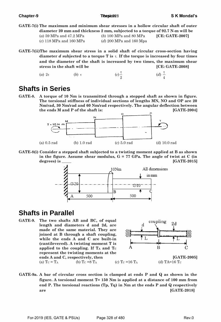
Chapter-9 Torsion S K Mondal’s
GATE-7(i) The maximum and minimum shear stresses in a hollow circular shaft of outer
diameter 20 mm and thickness 2 mm, subjected to a torque of 92.7 N-m will be
(a) 59 MPa and 47.2 MPa (b) 100 MPa and 80 MPa [CE: GATE-2007]
(c) 118 MPa and 160 MPa (d) 200 MPa and 160 Mpa
GATE-7(ii)The maximum shear stress in a solid shaft of circular cross-section having
diameter d subjected to a torque T is . If the torque is increased by four times
and the diameter of the shaft is increased by two times, the maximum shear
stress in the shaft will be [CE: GATE-2008]
(a) 2 (b) (c)2
(d)
4
Shafts in Series GATE-8. A torque of 10 Nm is transmitted through a stepped shaft as shown in figure.
The torsional stiffness of individual sections of lengths MN, NO and OP are 20
Nm/rad, 30 Nm/rad and 60 Nm/rad respectively. The angular deflection between
the ends M and P of the shaft is: [GATE-2004]
(a) 0.5 rad (b) 1.0 rad (c) 5.0 rad (d) 10.0 rad
GATE-8(i) Consider a stepped shaft subjected to a twisting moment applied at B as shown
in the figure. Assume shear modulus, G = 77 GPa. The angle of twist at C (in
degrees) is _____ [GATE-2015]
Shafts in Parallel GATE-9. The two shafts AB and BC, of equal
length and diameters d and 2d, are
made of the same material. They are
joined at B through a shaft coupling,
while the ends A and C are built-in
(cantilevered). A twisting moment T is
applied to the coupling. If TA and TC
represent the twisting moments at the
ends A and C, respectively, then
[GATE-2005]
(a) TC = TA (b) TC =8 TA (c) TC =16 TA (d) TA=16 TC
GATE-9a. A bar of circular cross section is clamped at ends P and Q as shown in the
figure. A torsional moment T= 150 Nm is applied at a distance of 100 mm from
end P. The torsional reactions (Tp, Tq) in Nm at the ends P and Q respectively
are [GATE-2018]
Page 328
For-2019 (IES, GATE & PSUs) Page 328 of 480 Rev.0
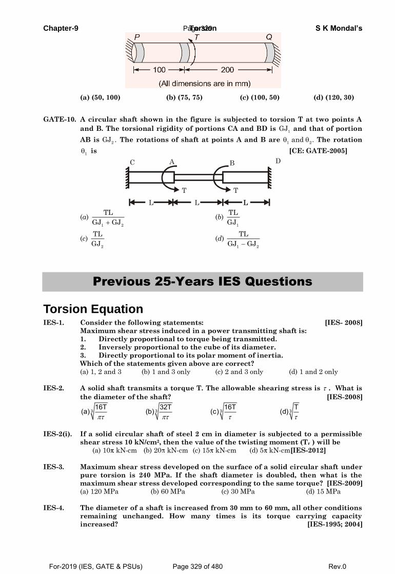
Chapter-9 Torsion S K Mondal’s
(a) (50, 100) (b) (75, 75) (c) (100, 50) (d) (120, 30)
GATE-10. A circular shaft shown in the figure is subjected to torsion T at two points A
and B. The torsional rigidity of portions CA and BD is 1
GJ and that of portion
AB is 2
GJ . The rotations of shaft at points A and B are 1 2
and . The rotation
1 is [CE: GATE-2005]
L
A B C D
L L L
T T
(a) 1 2
TL
GJ GJ (b)
1
TL
GJ
(c) 2
TL
GJ (d)
1 2
TL
GJ GJ
Previous 25-Years IES Questions
Torsion Equation IES-1. Consider the following statements: [IES- 2008]
Maximum shear stress induced in a power transmitting shaft is:
1. Directly proportional to torque being transmitted.
2. Inversely proportional to the cube of its diameter.
3. Directly proportional to its polar moment of inertia.
Which of the statements given above are correct?
(a) 1, 2 and 3 (b) 1 and 3 only (c) 2 and 3 only (d) 1 and 2 only
IES-2. A solid shaft transmits a torque T. The allowable shearing stress is . What is
the diameter of the shaft? [IES-2008]
3 3 3 316T 32T 16T T(a) (b) (c) (d)
IES-2(i). If a solid circular shaft of steel 2 cm in diameter is subjected to a permissible
shear stress 10 kN/cm2, then the value of the twisting moment (Tr ) will be
(a) 10 kN-cm (b) 20 kN-cm (c) 15 kN-cm (d) 5 kN-cm[IES-2012]
IES-3. Maximum shear stress developed on the surface of a solid circular shaft under
pure torsion is 240 MPa. If the shaft diameter is doubled, then what is the
maximum shear stress developed corresponding to the same torque? [IES-2009]
(a) 120 MPa (b) 60 MPa (c) 30 MPa (d) 15 MPa
IES-4. The diameter of a shaft is increased from 30 mm to 60 mm, all other conditions
remaining unchanged. How many times is its torque carrying capacity
increased? [IES-1995; 2004]
Page 329
For-2019 (IES, GATE & PSUs) Page 329 of 480 Rev.0
Chapter-9 Torsion S K Mondal’s (a) 2 times (b) 4 times (c) 8 times (d) 16 times
IES-4(i). Two shafts A and B are of same material and A is twice the diameter of B. The
torque that can be transmitted by A is [IES-2015,2016]
(a) 2 times that of B (b) 8 times that of B
(c) 4 times that of B (d) 6 times that of B
IES-5. A circular shaft subjected to twisting moment results in maximum shear stress
of 60 MPa. Then the maximum compressive stress in the material is: [IES-2003]
(a) 30 MPa (b) 60 MPa (c) 90 MPa (d) 120 MPa
IES-5(i). The boring bar of a boring machine is 25 mm in diameter. During operation,
the bar gets twisted though 0.01 radians and is subjected to a shear stress of 42
N/mm2. The length of the bar is (Taking G = 0.84 × 10⁵ N/mm2) [IES-2012]
(a) 500 mm (b) 250 mm (c) 625 mm (d) 375 mm
IES-5(ii). The magnitude of stress induced in a shaft due to applied torque varies
(a) From maximum at the centre to zero at the circumference
(b) From zero at the centre to maximum at the circumference [IES-2012]
(c) From maximum at the centre to minimum but not zero at the circumference
(d) From minimum but not zero at the centre, to maximum at the circumference
IES-6. Angle of twist of a shaft of diameter ‘d’ is inversely proportional to [IES-2000]
(a) d (b) d2 (c) d3 (d) d4
IES-6a A solid steel shaft of diameter d and length l is subjected to twisting
moment T. Anothershaft B of brass having same diameter d, but length l/2 is
also subjected to the samemoment. If shear modulus of steel is two times
that of brass, the ratio of the angular twistof steel to that of brass shaft is:
(a) 1:2 (b) 1:1 (c) 2:1 (d) 4:1 [IES-2011]
IES-7. A solid circular shaft is subjected to pure torsion. The ratio of maximum shear
to maximum normal stress at any point would be: [IES-1999]
(a) 1 : 1 (b) 1: 2 (c) 2: 1 (d) 2: 3
IES-8. Assertion (A): In a composite shaft having two concentric shafts of different
materials, the torque shared by each shaft is directly proportional to its polar
moment of inertia. [IES-1999]
Reason (R): In a composite shaft having concentric shafts of different
materials, the angle of twist for each shaft depends upon its polar moment of
inertia.
(a) Both A and R areindividually true and R is the correct explanation of A
(b) Both A and R are individually true but R is NOTthe correct explanation of A
(c) A is true but R is false
(d) A is false but R is true
IES-9. A shaft is subjected to torsion as shown. [IES-2002]
Which of the following figures represents the shear stress on the element
LMNOPQRS?
Page 330
For-2019 (IES, GATE & PSUs) Page 330 of 480 Rev.0
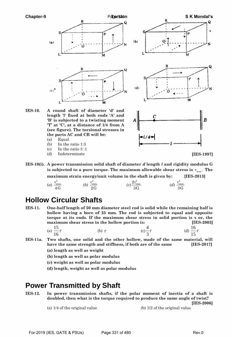
Chapter-9 Torsion S K Mondal’s
IES-10. A round shaft of diameter 'd' and
length 'l' fixed at both ends 'A' and
'B' is subjected to a twisting moment
'T’ at 'C', at a distance of 1/4 from A
(see figure). The torsional stresses in
the parts AC and CB will be:
(a) Equal
(b) In the ratio 1:3
(c) In the ratio 3 :1
(d) Indeterminate
[IES-1997]
IES-10(i). A power transmission solid shaft of diameter d length l and rigidity modulus G
is subjected to a pure torque. The maximum allowable shear stress is max
. The
maximum strain energy/unit volume in the shaft is given by: [IES-2013]
(a) 2
max
4G
(b)
2
max
2G
(c)
2
max2
3G
(d)
2
max
3G
Hollow Circular Shafts IES-11. One-half length of 50 mm diameter steel rod is solid while the remaining half is
hollow having a bore of 25 mm. The rod is subjected to equal and opposite
torque at its ends. If the maximum shear stress in solid portion is τ or, the
maximum shear stress in the hollow portion is: [IES-2003]
(a) 15
16 (b) (c)
4
3 (d)
16
15
IES-11a. Two shafts, one solid and the other hollow, made of the same material, will
have the same strength and stiffness, if both are of the same [IES-2017]
(a) length as well as weight
(b) length as well as polar modulus
(c) weight as well as polar modulus
(d) length, weight as well as polar modulus
Power Transmitted by Shaft IES-12. In power transmission shafts, if the polar moment of inertia of a shaft is
doubled, then what is the torque required to produce the same angle of twist?
[IES-2006]
(a) 1/4 of the original value (b) 1/2 of the original value
Page 331
For-2019 (IES, GATE & PSUs) Page 331 of 480 Rev.0
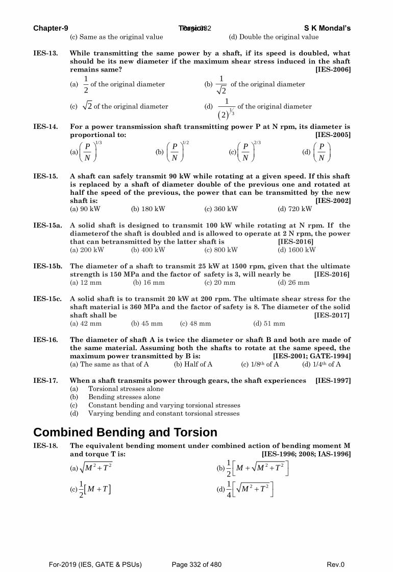
Chapter-9 Torsion S K Mondal’s (c) Same as the original value (d) Double the original value
IES-13. While transmitting the same power by a shaft, if its speed is doubled, what
should be its new diameter if the maximum shear stress induced in the shaft
remains same? [IES-2006]
(a) 1
2of the original diameter (b)
1
2 of the original diameter
(c) 2 of the original diameter (d)
1
3
1
2of the original diameter
IES-14. For a power transmission shaft transmitting power P at N rpm, its diameter is
proportional to: [IES-2005]
(a)
1/3P
N
(b)
1/2P
N
(c)
2/3P
N
(d) P
N
IES-15. A shaft can safely transmit 90 kW while rotating at a given speed. If this shaft
is replaced by a shaft of diameter double of the previous one and rotated at
half the speed of the previous, the power that can be transmitted by the new
shaft is: [IES-2002]
(a) 90 kW (b) 180 kW (c) 360 kW (d) 720 kW
IES-15a. A solid shaft is designed to transmit 100 kW while rotating at N rpm. If the
diameterof the shaft is doubled and is allowed to operate at 2 N rpm, the power
that can betransmitted by the latter shaft is [IES-2016]
(a) 200 kW (b) 400 kW (c) 800 kW (d) 1600 kW
IES-15b. The diameter of a shaft to transmit 25 kW at 1500 rpm, given that the ultimate
strength is 150 MPa and the factor of safety is 3, will nearly be [IES-2016]
(a) 12 mm (b) 16 mm (c) 20 mm (d) 26 mm
IES-15c. A solid shaft is to transmit 20 kW at 200 rpm. The ultimate shear stress for the
shaft material is 360 MPa and the factor of safety is 8. The diameter of the solid
shaft shall be [IES-2017]
(a) 42 mm (b) 45 mm (c) 48 mm (d) 51 mm
IES-16. The diameter of shaft A is twice the diameter or shaft B and both are made of
the same material. Assuming both the shafts to rotate at the same speed, the
maximum power transmitted by B is: [IES-2001; GATE-1994]
(a) The same as that of A (b) Half of A (c) 1/8th of A (d) 1/4th of A
IES-17. When a shaft transmits power through gears, the shaft experiences [IES-1997]
(a) Torsional stresses alone
(b) Bending stresses alone
(c) Constant bending and varying torsional stresses
(d) Varying bending and constant torsional stresses
Combined Bending and Torsion IES-18. The equivalent bending moment under combined action of bending moment M
and torque T is: [IES-1996; 2008; IAS-1996]
(a)2 2M T (b)
2 21
2M M T
(c) 1
2M T (d)
2 21
4M T
Page 332
For-2019 (IES, GATE & PSUs) Page 332 of 480 Rev.0
Chapter-9 Torsion S K Mondal’s IES-19. A solid circular shaft is subjected to a bending moment M and twistingmoment
T. What is the equivalent twisting moment Te which will produce the same
maximum shear stress as the above combination? [IES-1992; 2007]
(a) M2 + T2 (b) M + T (c) 2 2M T (d) M – T
IES-20. A shaft is subjected to fluctuating loads for which the normal torque (T) and
bending moment (M) are 1000 N-m and 500 N-m respectively. If the combined
shock and fatigue factor for bending is 1.5 and combined shock and fatigue
factor for torsion is 2, then the equivalent twisting moment for the shaft is:
[IES-1994]
(a) 2000N-m (b) 2050N-m (c) 2100N-m (d) 2136 N-m
IES-21. A member is subjected to the combined action of bending moment 400 Nm and
torque 300 Nm. What respectively are the equivalent bending moment and
equivalent torque? [IES-1994; 2004]
(a) 450 Nm and 500 Nm (b) 900 Nm and 350 Nm
(c) 900 Nm and 500 Nm (d) 400 Nm and 500 Nm
IES-21a. A solid shaft is subjected to bending moment of 3.46 kN -m and a
torsional moment of 11.5 kN-m. For this case, the equivalent bending
moment and twisting moment are [IES-2018] [IES-2018]
(a) 7.73 kN-m and 12.0 kN-m (b) 14.96 kN-m and 12.0 kN-m
(c) 7.73 kN-m and 8.04 kN-m (d) 14.96 kN-m and 8.04 kN-m
IES-21(i). A shaft of diameter 8 cm is subjected to bending moment of 3000Nm and
twisting moment of 4000 Nm.The maximum normal stress induced in the shaft
250 500 157.5 315
a b c d
[IES-2014]
IES-22. A shaft was initially subjected to bending moment and then was subjected to
torsion. If the magnitude of bending moment is found to be the same as that of
the torque, then the ratio of maximum bending stress to shear stress would be:
[IES-1993]
(a) 0.25 (b) 0.50 (c) 2.0 (d) 4.0
IES-23. A shaft is subjected to simultaneous action of a torque T, bending moment M
and an axial thrust F. Which one of the following statements is correct for this
situation? [IES-2004]
(a) One extreme end of the vertical diametral fibre is subjected to maximum
compressive stress only
(b) The opposite extreme end of the vertical diametral fibre is subjected to
tensile/compressive stress only
(c) Every point on the surface of the shaft is subjected to maximum shear stress only
(d) Axial longitudinal fibre of the shaft is subjected to compressive stress only
Page 333
For-2019 (IES, GATE & PSUs) Page 333 of 480 Rev.0
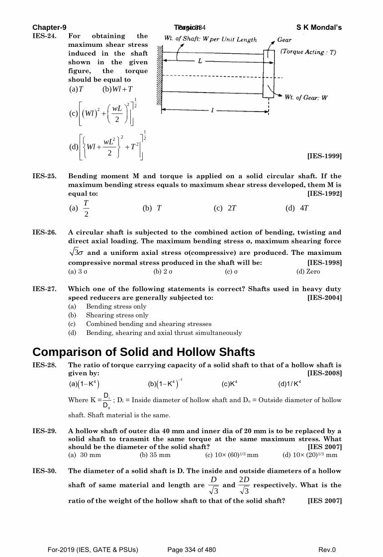
Chapter-9 Torsion S K Mondal’s IES-24. For obtaining the
maximum shear stress
induced in the shaft
shown in the given
figure, the torque
should be equal to
12 2
2
12 22
2
(a) (b)
(c)2
(d)2
T Wl T
wLWl
wLWl T
[IES-1999]
IES-25. Bending moment M and torque is applied on a solid circular shaft. If the
maximum bending stress equals to maximum shear stress developed, them M is
equal to: [IES-1992]
(a) (b) (c) 2 (d) 42
TT T T
IES-26. A circular shaft is subjected to the combined action of bending, twisting and
direct axial loading. The maximum bending stress σ, maximum shearing force
3 and a uniform axial stress σ(compressive) are produced. The maximum
compressive normal stress produced in the shaft will be: [IES-1998]
(a) 3 σ (b) 2 σ (c) σ (d) Zero
IES-27. Which one of the following statements is correct? Shafts used in heavy duty
speed reducers are generally subjected to: [IES-2004]
(a) Bending stress only
(b) Shearing stress only
(c) Combined bending and shearing stresses
(d) Bending, shearing and axial thrust simultaneously
Comparison of Solid and Hollow Shafts IES-28. The ratio of torque carrying capacity of a solid shaft to that of a hollow shaft is
given by: [IES-2008]
14 4 4 4(a) 1 K (b) 1 K (c)K (d)1/ K
Where K = i
o
DD
; Di = Inside diameter of hollow shaft and Do = Outside diameter of hollow
shaft. Shaft material is the same.
IES-29. A hollow shaft of outer dia 40 mm and inner dia of 20 mm is to be replaced by a
solid shaft to transmit the same torque at the same maximum stress. What
should be the diameter of the solid shaft? [IES 2007]
(a) 30 mm (b) 35 mm (c) 10 (60)1/3 mm (d) 10 (20)1/3 mm
IES-30. The diameter of a solid shaft is D. The inside and outside diameters of a hollow
shaft of same material and length are 3
D and
3
2D respectively. What is the
ratio of the weight of the hollow shaft to that of the solid shaft? [IES 2007]
Page 334
For-2019 (IES, GATE & PSUs) Page 334 of 480 Rev.0
Chapter-9 Torsion S K Mondal’s
(a) 1:1 (b) 1: 3 (c) 1:2 (d) 1:3
IES-31. What is the maximum torque transmitted by a hollow shaft of external radius R
and internal radius r? [IES-2006]
(a) 3 3
16sR r f
(b) 4 4
2sR r f
R
(c) 4 4
8sR r f
R
(d)
4 4
32s
R rf
R
( sf = maximum shear stress in the shaft material)
IES-32. A hollow shaft of the same cross-sectional area and material as that of a solid
shaft transmits: [IES-2005]
(a) Same torque (b) Lesser torque
(c) More torque (d) Cannot be predicted without more data
IES-33. The outside diameter of a hollow shaft is twice its inside diameter. The ratio of
its torque carrying capacity to that of a solid shaft of the same material and the
same outside diameter is: [GATE-1993; IES-2001]
(a) 15
16 (b)
3
4 (c)
1
2 (d)
1
16
IES-34. Two hollow shafts of the same material have the same length and outside
diameter. Shaft 1 has internal diameter equal to one-third of the outer
diameter and shaft 2 has internal diameter equal to half of the outer diameter.
If both the shafts are subjected to the same torque, the ratio of their twists
1 2/ will be equal to: [IES-1998]
(a) 16/81 (b) 8/27 (c) 19/27 (d) 243/256
IES-35. Maximum shear stress in a solid shaft of diameter D and length L twisted
through an angle θ is τ. A hollow shaft of same material and length having
outside and inside diameters of D and D/2 respectively is also twisted through
the same angle of twist θ. The value of maximum shear stress in the hollow
shaft will be: [IES-1994; 1997]
16 8 4
a b c d 15 7 3
IES-36. A solid shaft of diameter 'D' carries a twisting moment that develops maximum
shear stress τ. If the shaft is replaced by a hollow one of outside diameter 'D'
and inside diameter D/2, then the maximum shear stress will be: [IES-1994]
(a) 1.067 τ (b) 1.143 τ (c) 1.333 τ (d) 2 τ
IES-37. A solid shaft of diameter 100 mm, length 1000 mm is subjected to a twisting
moment 'T’ The maximum shear stress developed in the shaft is 60 N/mm2. A hole of 50 mm diameter is now drilled throughout the length of the shaft. To develop a maximum shear stress of 60 N/mm2 in the hollow shaft, the torque 'T’ must be reduced by: [IES-1998, 2012]
(a) T/4 (b) T/8 (c) T/12 (d)T/16 IES-38. Assertion (A): A hollow shaft will transmit a greater torque than a solid shaft of
the same weight and same material. [IES-1994] Reason (R): The average shear stress in the hollow shaft is smaller than the
average shear stress in the solid shaft.
(a) Both A and R areindividually true and R is the correct explanation of A (b) Both A and R are individually true but R is NOTthe correct explanation of A (c) A is true but R is false
(d) A is false but R is true
Page 335
For-2019 (IES, GATE & PSUs) Page 335 of 480 Rev.0
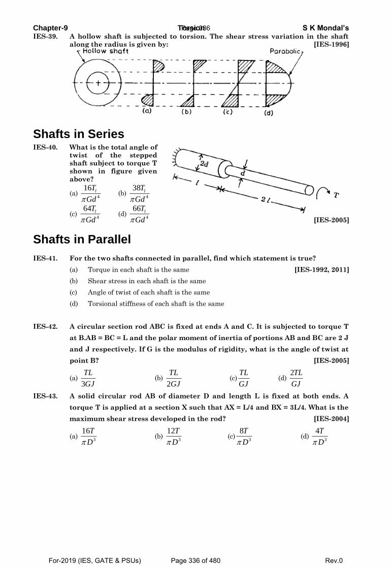
Chapter-9 Torsion S K Mondal’s IES-39. A hollow shaft is subjected to torsion. The shear stress variation in the shaft
along the radius is given by: [IES-1996]
Shafts in Series IES-40. What is the total angle of
twist of the stepped shaft subject to torque T shown in figure given
above?
(a) 4
16 lT
Gd (b)
4
38 lT
Gd
(c) 4
64 lT
Gd (d)
4
66 lT
Gd
[IES-2005]
Shafts in Parallel
IES-41. For the two shafts connected in parallel, find which statement is true?
(a) Torque in each shaft is the same [IES-1992, 2011]
(b) Shear stress in each shaft is the same
(c) Angle of twist of each shaft is the same
(d) Torsional stiffness of each shaft is the same
IES-42. A circular section rod ABC is fixed at ends A and C. It is subjected to torque T
at B.AB = BC = L and the polar moment of inertia of portions AB and BC are 2 J
and J respectively. If G is the modulus of rigidity, what is the angle of twist at
point B? [IES-2005]
(a) 3
TL
GJ (b)
2
TL
GJ (c)
TL
GJ (d)
2TL
GJ
IES-43. A solid circular rod AB of diameter D and length L is fixed at both ends. A
torque T is applied at a section X such that AX = L/4 and BX = 3L/4. What is the
maximum shear stress developed in the rod? [IES-2004]
(a) 3
16T
D (b)
3
12T
D (c)
3
8T
D (d)
3
4T
D
Page 336
For-2019 (IES, GATE & PSUs) Page 336 of 480 Rev.0
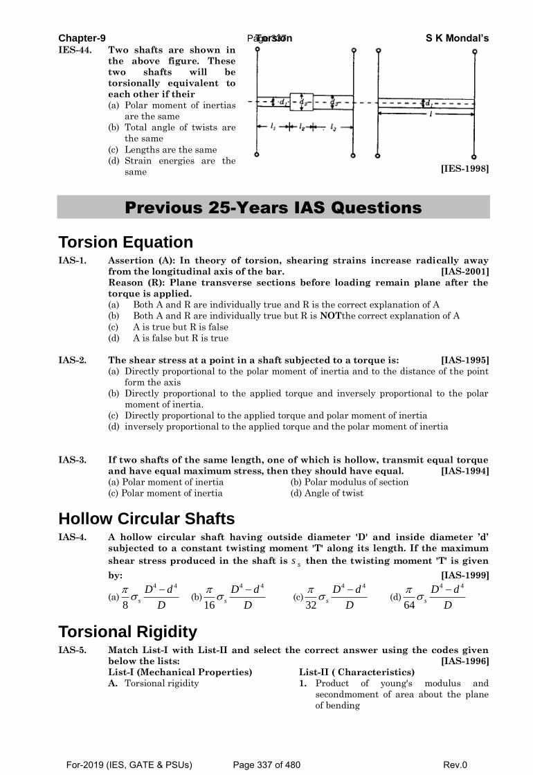
Chapter-9 Torsion S K Mondal’s IES-44. Two shafts are shown in
the above figure. These
two shafts will be
torsionally equivalent to
each other if their
(a) Polar moment of inertias
are the same
(b) Total angle of twists are
the same
(c) Lengths are the same
(d) Strain energies are the
same
[IES-1998]
Previous 25-Years IAS Questions
Torsion Equation IAS-1. Assertion (A): In theory of torsion, shearing strains increase radically away
from the longitudinal axis of the bar. [IAS-2001]
Reason (R): Plane transverse sections before loading remain plane after the
torque is applied.
(a) Both A and R are individually true and R is the correct explanation of A
(b) Both A and R are individually true but R is NOTthe correct explanation of A
(c) A is true but R is false
(d) A is false but R is true
IAS-2. The shear stress at a point in a shaft subjected to a torque is: [IAS-1995]
(a) Directly proportional to the polar moment of inertia and to the distance of the point
form the axis
(b) Directly proportional to the applied torque and inversely proportional to the polar
moment of inertia.
(c) Directly proportional to the applied torque and polar moment of inertia
(d) inversely proportional to the applied torque and the polar moment of inertia
IAS-3. If two shafts of the same length, one of which is hollow, transmit equal torque
and have equal maximum stress, then they should have equal. [IAS-1994]
(a) Polar moment of inertia (b) Polar modulus of section
(c) Polar moment of inertia (d) Angle of twist
Hollow Circular Shafts IAS-4. A hollow circular shaft having outside diameter 'D' and inside diameter ’d’
subjected to a constant twisting moment 'T' along its length. If the maximum
shear stress produced in the shaft is ss then the twisting moment 'T' is given
by: [IAS-1999]
(a)
4 4
8s
D d
D
(b)
4 4
16s
D d
D
(c)
4 4
32s
D d
D
(d)
4 4
64s
D d
D
Torsional Rigidity IAS-5. Match List-I with List-II and select the correct answer using the codes given
below the lists: [IAS-1996]
List-I (Mechanical Properties) List-II ( Characteristics)
A. Torsional rigidity 1. Product of young's modulus and
secondmoment of area about the plane
of bending
Page 337
For-2019 (IES, GATE & PSUs) Page 337 of 480 Rev.0
Chapter-9 Torsion S K Mondal’s B. Modulus of resilience 2. Strain energy per unit volume
C. Bauschinger effect 3. Torque unit angle of twist
D. Flexural rigidity 4. Loss of mechanical energy due to local
yielding
Codes: A B C D A B C D
(a) 1 3 4 2 (b) 3 2 4 1
(c) 2 4 1 3 (d) 3 1 4 2
IAS-6. Assertion (A):Angle of twist per unit length of a uniform diameter shaft
depends upon its torsional rigidity. [IAS-2004]
Reason (R):The shafts are subjected to torque only.
(a) Both A and R are individually true and R is the correct explanation of A
(b) Both A and R are individually true but R is NOTthe correct explanation of A
(c) A is true but R is false
(d) A is false but R is true
Combined Bending and Torsion IAS-7. A shaft is subjected to a bending moment M = 400 N.m alld torque T = 300 N.m
The equivalent bending moment is: [IAS-2002]
(a) 900 N.m (b) 700 N.m (c) 500 N.m (d) 450 N.m
Comparison of Solid and Hollow Shafts IAS-8. A hollow shaft of length L is fixed at its both ends. It is subjected to torque T at
a distance of 3
L from one end. What is the reaction torque at the other end of
the shaft? [IAS-2007]
(a) 2
3
T (b)
2
T (c)
3
T (d)
4
T
IAS-9. A solid shaft of diameter d is replaced by a hollow shaft of the same material
and length. The outside diameter of hollow shaft 2
3
d while the inside diameter
is 3
d. What is the ratio of the torsional stiffness of the hollow shaft to that of
the solid shaft? [IAS-2007]
(a) 2
3 (b)
3
5 (c)
5
3 (d) 2
IAS-10. Two steel shafts, one solid of diameter D and the other hollow of outside
diameter D and inside diameter D/2, are twisted to the same angle of twist per
unit length. The ratio of maximum shear stress in solid shaft to that in the
hollow shaft is: [IAS-1998]
(a) 4
9 (b)
8
7 (c)
16
15 (d)
Shafts in Series IAS-11. Two shafts having the same length and material are joined in series. If the
ratio of the diameter of the first shaft to that of the second shaft is 2, then the
ratio of the angle of twist of the first shaft to that of the second shaft is:
[IAS-1995; 2003]
(a) 16 (b) 8 (c) 4 (d) 2
Page 338
For-2019 (IES, GATE & PSUs) Page 338 of 480 Rev.0
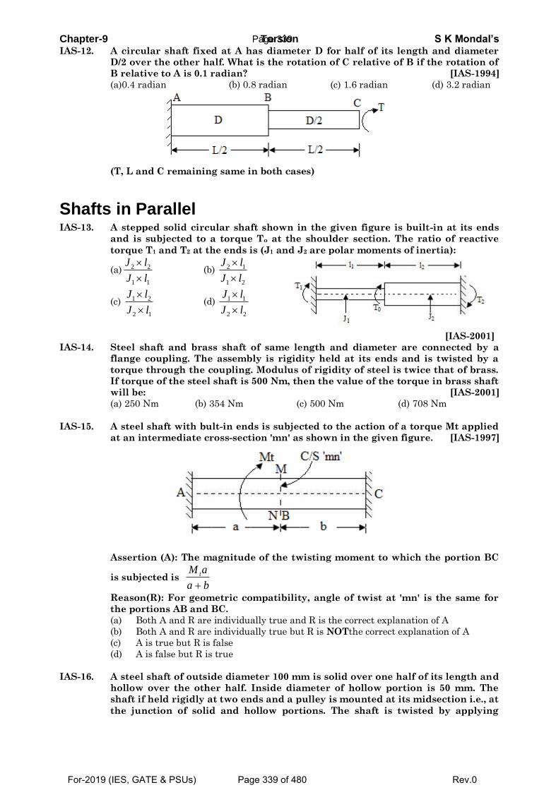
Chapter-9 Torsion S K Mondal’s IAS-12. A circular shaft fixed at A has diameter D for half of its length and diameter
D/2 over the other half. What is the rotation of C relative of B if the rotation of
B relative to A is 0.1 radian? [IAS-1994]
(a)0.4 radian (b) 0.8 radian (c) 1.6 radian (d) 3.2 radian
(T, L and C remaining same in both cases)
Shafts in Parallel IAS-13. A stepped solid circular shaft shown in the given figure is built-in at its ends
and is subjected to a torque To at the shoulder section. The ratio of reactive
torque T1 and T2 at the ends is (J1 and J2 are polar moments of inertia):
(a) 2 2
1 1
J l
J l
(b) 2 1
1 2
J l
J l
(c) 1 2
2 1
J l
J l
(d) 1 1
2 2
J l
J l
[IAS-2001]
IAS-14. Steel shaft and brass shaft of same length and diameter are connected by a
flange coupling. The assembly is rigidity held at its ends and is twisted by a
torque through the coupling. Modulus of rigidity of steel is twice that of brass.
If torque of the steel shaft is 500 Nm, then the value of the torque in brass shaft
will be: [IAS-2001]
(a) 250 Nm (b) 354 Nm (c) 500 Nm (d) 708 Nm
IAS-15. A steel shaft with bult-in ends is subjected to the action of a torque Mt applied
at an intermediate cross-section 'mn' as shown in the given figure. [IAS-1997]
Assertion (A): The magnitude of the twisting moment to which the portion BC
is subjected is
tM a
a b
Reason(R): For geometric compatibility, angle of twist at 'mn' is the same for
the portions AB and BC.
(a) Both A and R are individually true and R is the correct explanation of A
(b) Both A and R are individually true but R is NOTthe correct explanation of A
(c) A is true but R is false
(d) A is false but R is true
IAS-16. A steel shaft of outside diameter 100 mm is solid over one half of its length and
hollow over the other half. Inside diameter of hollow portion is 50 mm. The
shaft if held rigidly at two ends and a pulley is mounted at its midsection i.e., at
the junction of solid and hollow portions. The shaft is twisted by applying
Page 339
For-2019 (IES, GATE & PSUs) Page 339 of 480 Rev.0
Chapter-9 Torsion S K Mondal’s torque on the pulley. If the torque carried by the solid portion of the shaft is
16000kg-m, then the torque carried by the hollow portion of the shaft will be:
[IAS-1997]
(a) 16000 kg-m (b) 15000 kg-m (c) 14000 kg-m (d) 12000 kg-m
Page 340
For-2019 (IES, GATE & PSUs) Page 340 of 480 Rev.0
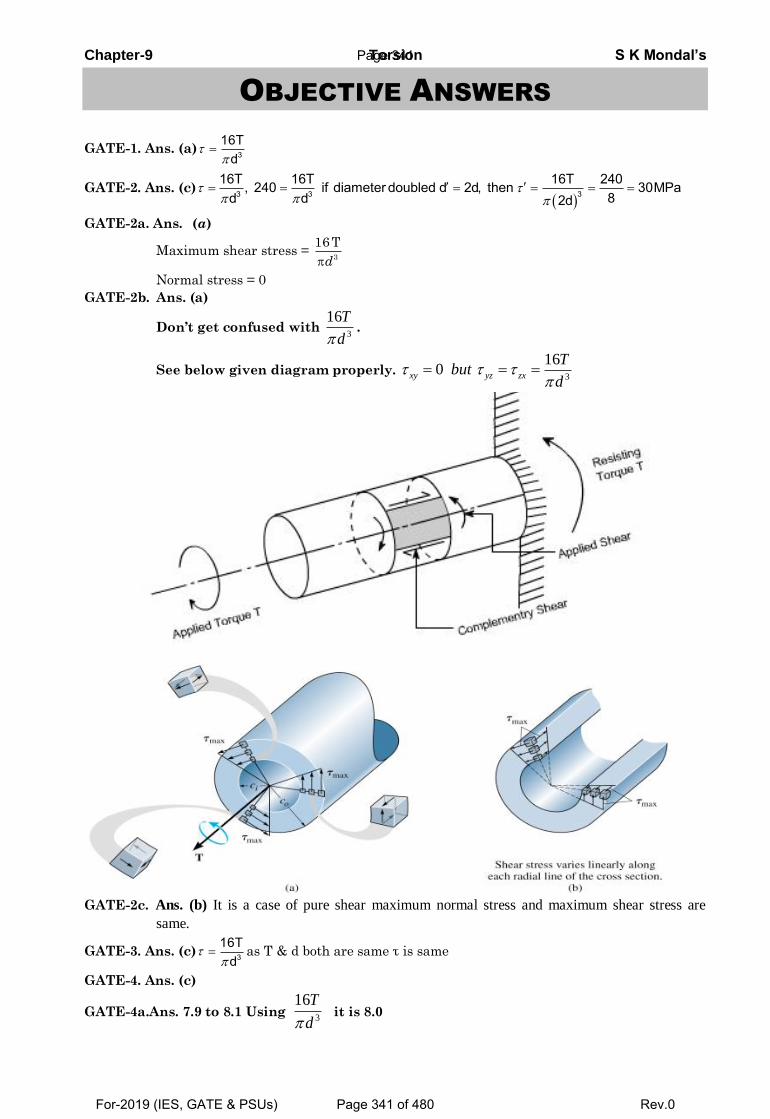
Chapter-9 Torsion S K Mondal’s
OBJECTIVE ANSWERS
GATE-1. Ans. (a) 3
16Td
GATE-2. Ans. (c)
3 3 3
16T 16T 16T 240, 240 if diameter doubled d 2d, then 30MPa8d d 2d
GATE-2a. Ans. (a)
Maximum shear stress = 3
16 T
d
Normal stress = 0
GATE-2b. Ans. (a)
Don’t get confused with 3
16T
d.
See below given diagram properly. 3
160xy yz zx
Tbut
d
GATE-2c. Ans. (b) It is a case of pure shear maximum normal stress and maximum shear stress are
same.
GATE-3. Ans. (c) 3
16Td
as T & d both are same τ is same
GATE-4. Ans. (c)
GATE-4a.Ans. 7.9 to 8.1 Using3
16T
dit is 8.0
Page 341
For-2019 (IES, GATE & PSUs) Page 341 of 480 Rev.0
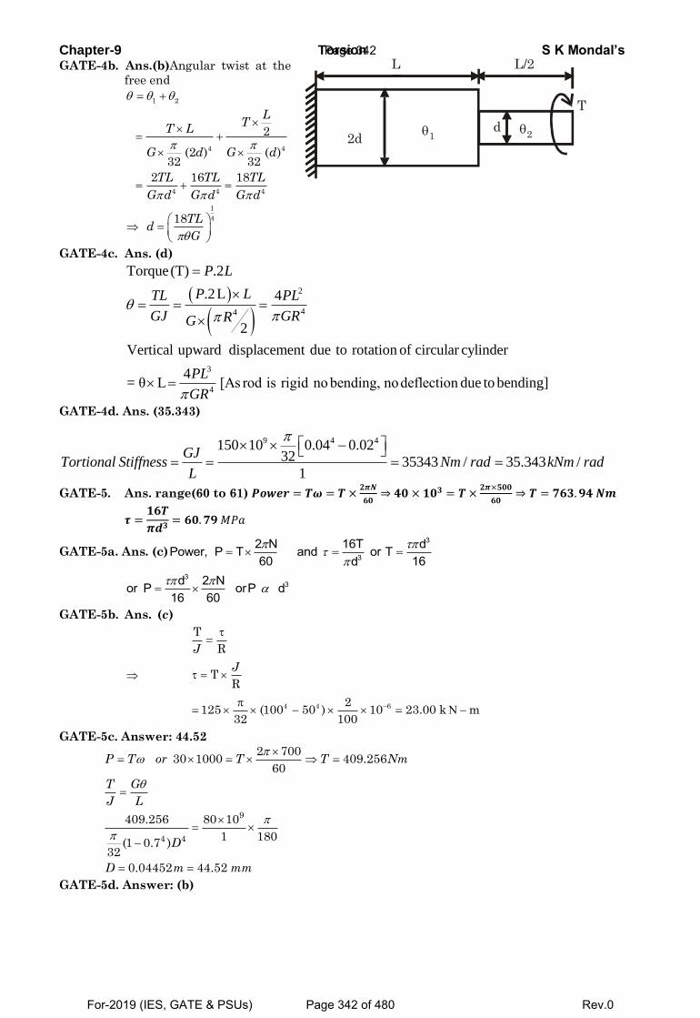
Chapter-9 Torsion S K Mondal’s GATE-4b. Ans.(b)Angular twist at the
free end
1 2
4 4
4 4 4
1
4
2
(2 ) ( )32 32
2 16 18
18
LT
T L
G d G d
TL TL TL
G d G d G d
TLd
G
GATE-4c. Ans. (d)
2
44
3
4
Torque(T) .2
.2L 4
2
Vertical upward displacement due to rotation of circular cylinder
4= θ L [As rod is rigid no bending, nodeflection due to bending]
P L
P LTL PL
GJ GRRG
PL
GR
GATE-4d. Ans. (35.343)
9 4 4150 10 0.04 0.0232 35343 / 35.343 /
1
GJTortional Stiffness Nm rad kNm rad
L
GATE-5. Ans. range(60 to 61) 𝑷𝒐𝒘𝒆𝒓 = 𝑻𝝎 = 𝑻 ×𝟐𝝅𝑵
𝟔𝟎⇒ 𝟒𝟎 × 𝟏𝟎𝟑 = 𝑻 ×
𝟐𝝅×𝟓𝟎𝟎
𝟔𝟎⇒ 𝑻 = 𝟕𝟔𝟑. 𝟗𝟒 𝑵𝒎
𝝉 =𝟏𝟔𝑻
𝝅𝒅𝟑= 𝟔𝟎. 𝟕𝟗 𝑀𝑃𝑎
GATE-5a. Ans. (c)3
3
2 N 16T dPower, P T and or T60 16d
3
3d 2 Nor P orP d16 60
GATE-5b. Ans. (c)
T
RJ
TR
J
4 4 62
125 (100 50 ) 10 23.00 k m32 100
GATE-5c. Answer: 44.52
9
4 4
2 70030 1000 409.256
60
409.256 80 10
1 180(1 0.7 )
32
0.04452 44.52
P T or T T Nm
T G
J L
D
D m mm
GATE-5d. Answer: (b)
d2d
L L/2
T
12
Page 342
For-2019 (IES, GATE & PSUs) Page 342 of 480 Rev.0
Chapter-9 Torsion S K Mondal’s
3
6
4 4
2 300020 10 63.662
60
63.662 30 10
/ 2( )
32
11.295 2 22.59
oo i
i o i
P T or T T Nm
T
r J dd d
d mm or d d mm
GATE-6. Ans. (d) Equivalent torque 2 2 2 2eT M T 3 4 5kNm
GATE-6i. Ans. (c)
GATE-7. Ans. (a) T G Jor T if is const. T JJ L R R
44
h h
4
DD32 2T J 15
T J 16D32
GATE-7(i) Ans. (b)
T
R J
Here,
4 4 4J (20 16 )mm ;32
1
20R 10 mm;
2
T = 92.7 N-m;
2
16R 8 mm
2
3
1
14 4
TR 92.7 10 1099.96 MPa 100 MPa
J(20 16 )
32
and 3
2
24 4
TR 92.7 10 879.96 MPa 80 MPa
J(20 16 )
32
GATE-7(ii)Ans. (c)
We know that
T
R J
1 1 1 2
2 2 2 1
R T
R T
J
J
4
1 1 1 1
2 1 1 1
R T 2R
2R 4T R
1
2
1 116
2 4
12
2
2
2
GATE-8. Ans. (b)TLWe know that or T k. [let k tortional stiffness]GJ
NO OPMNMN NO OP
MN NO OP
T TT 10 10 10 1.0 radk k k 20 30 60
GATE-8(i) Ans. 0.236
Angle of twist at (c) = Angle of twist at (B)
Page 343
For-2019 (IES, GATE & PSUs) Page 343 of 480 Rev.0
Chapter-9 Torsion S K Mondal’s
9 4
10 0.5 320.004134 0.236
77 10 0.02
Tlrad rad
GJ
GATE-9.Ans.(c)
C C C CA A AAB BC A4 4
A A C C
T L T TT L Tor or or T
G J G J 16d 2d32 32
GATE-9a. Ans. (c)
2
( ) 2
2100 50
3 3
P Q PR QR
QPP P
p Q
T T T and
T LT Lor T T T
GJ GJ
T TT Nm and T Nm
GATE-10. Ans. (b)
The symmetry of the shaft shows that there is no torsion on section AB.
Rotation, 1
1
TL
GJ
IES-10(i). Ans. (a)
IES
IES-1. Ans. (d) 3
T r 16TJ d
IES-2. Ans. (a)
IES-2(i). Ans. (d)
IES-3. Ans. (c)Maximum shear stress = 3
16Td
= 240 MPa =
Maximum shear stress developed when diameter is doubled
3 3
16 1 16T 240 30MPa8 d 8 82d
IES-4. Ans. (c)3
3
16T dor T for same material const.16d
3 33 2 2
1 1
T d 60T d or 8T d 30
IES-4(i).Ans. (b) 3
16T
d
IES-5. Ans. (b)
IES-5(i). Ans. (b)
IES-5(ii). Ans. (b)
IES-6. Ans. (d)
IES-6a Ans. (b)
IES-7. Ans. (a)
IES-8. Ans. (c)
IES-9. Ans. (d)
IES-10. Ans. (c) T G GR 1orJ R L L L
Page 344
For-2019 (IES, GATE & PSUs) Page 344 of 480 Rev.0
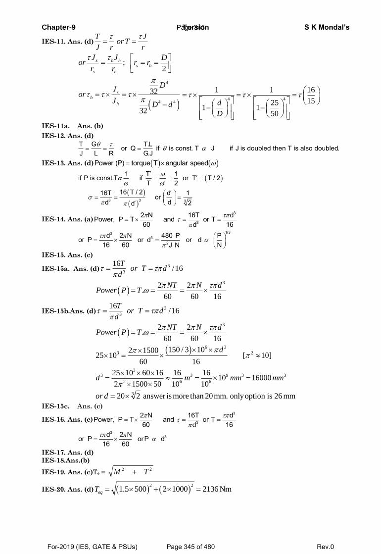
Chapter-9 Torsion S K Mondal’s
IES-11. Ans. (d)
T J
orTJ r r
;2
s h hs h
s h
J J Dor r r
r r
4
4 4
32
32
sh
h
DJ
orJ
D d4 4
1 1 16
15251 1
50
d
D
IES-11a. Ans. (b)
IES-12. Ans. (d)
T G T.Lor Q if is const. T J if J is doubled then T is also doubled.J L R G.J
IES-13. Ans. (d) Power (P) torque T angular speed
3 3 3
1 T 1if P is const.T if or T T / 2T 2
16 T / 216T d 1ordd 2d
IES-14. Ans. (a)3
3
2 N 16T dPower, P T and or T60 16d
1/333
2
d 2 N 480 P Por P or d or d16 60 NJ N
IES-15. Ans. (c)
IES-15a. Ans. (d)3
3
16/16
Tor T d
d
32 2.
60 60 16
NT N dPower P T
IES-15b.Ans. (d)3
3
16/16
Tor T d
d
3
6 3
3 2
33 3 9 3 3
2 6 6
3
2 2.
60 60 16
150 / 3 102 150025 10 [ 10]
60 16
25 10 60 16 16 1610 16000
2 1500 50 10 10
20 2 answer is more than 20mm. onlyoption is 26 mm
NT N dPower P T
d
d m mm mm
or d
IES-15c. Ans. (c)
IES-16. Ans. (c)3
3
2 N 16T dPower, P T and or T60 16d
3
3d 2 Nor P orP d16 60
IES-17. Ans. (d)
IES-18.Ans.(b)
IES-19. Ans. (c)Te = 22 TM
IES-20. Ans. (d) 2 2
1.5 500 2 1000 2136 Nm eqT
Page 345
For-2019 (IES, GATE & PSUs) Page 345 of 480 Rev.0
Chapter-9 Torsion S K Mondal’s
IES-21. Ans. (a) 2 2 2 2
eM M T 400 400 300Equivalent Bending Moment M 450N.m
2 2
2 2 2 2eEquivalent torque T M T 400 300 500N.m
IES-21a. Ans. (a)
Equivalent Bending Moment
𝑀𝑒 =[𝑀 + √𝑀2 + 𝑇2]
2=
[3.46 + √3.462 + 11.52]
2= 7.7346 𝑘𝑁𝑚
Equivalent Torque
𝑇𝑒 = √𝑀2 + 𝑇2 = √3.462 + 11.52 = 12.009 𝑘𝑁𝑚
IES-21(i) Ans. (a)
2 2 2 23 3 6
3000 ; 4000
16 16 2503000 3000 4000
8 10
M Nm T Nm
M M Td
IES-22. Ans. (c)Use equivalent bending moment formula,
1st case: Equivalent bending moment (Me) = M
2nd case: Equivalent bending moment (Me) =
2 20 0
2 2
T T
IES-23. Ans. (d)
IES-24. Ans. (d) Bending Moment, M =
2
2
wLWl
IES-25. Ans. (a) 3
32 Md
and 3
16Td
IES-26. Ans. (a)Maximum normal stress = bending stress σ + axial stress (σ) = 2 σ
We have to take maximum bending stress σ is (compressive)
The maximum compressive normal stress =
2
2
2 2
b bxy
2
22 23 3
2 2
IES-27. Ans. (c)
IES-28. Ans. (b) should be same for both hollow and solid shaft
144s s o sh i
4 44 4 4 h h oo io o i
14s
h
T T D TT D1
T T DD DD D D32 32
T1 k
T
IES-29. Ans. (c)Section modules will be same
H
H
JR
-= s
s
JR
or
4 4(40 20 )32
40
2
= 32
2
4
d
d
or, d3 = (10)360 or d = 103 60 mm
IES-30.Ans.(a)
S
H
W
W = 1
4
33
4
4
2
22
gLD
gLDD
Page 346
For-2019 (IES, GATE & PSUs) Page 346 of 480 Rev.0
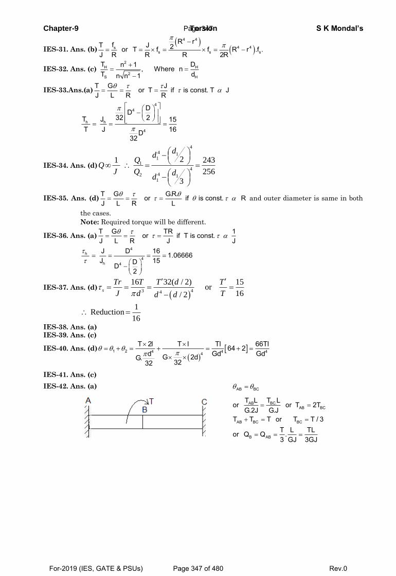
Chapter-9 Torsion S K Mondal’s
IES-31. Ans. (b)
4 4
4 4ss s s
R rfT J 2or T f f R r .f .J R R R 2R
IES-32. Ans. (c) 2
H H
2S H
T Dn 1 , Where nT dn n 1
IES-33.Ans.(a)T G Jor T if is const. T JJ L R R
44
h h
4
DD32 2T J 15
T J 16D32
IES-34. Ans. (d)
44 1
11
442 1
1
21 243
256
3
dd
J Q dd
IES-35. Ans. (d)T G G.R.or if is const. RJ L R L
and outer diameter is same in both
the cases.
Note: Required torque will be different.
IES-36. Ans. (a)T G TR 1or if T is const.J L R J J
4
h4
h 4
J D 16 1.06666J 15DD
2
IES-37. Ans. (d)
43 4
16 32( / 2) 15or
16/ 2s
Tr T T d T
J d Td d
1
Reduction16
IES-38. Ans. (a) IES-39. Ans. (c)
IES-40. Ans. (d)
1 2 4 4 44
T 2l T l Tl 66Tl64 2d Gd GdG 2dG. 3232
IES-41. Ans. (c)
IES-42. Ans. (a)
AB BC
BC.ABAB BC
AB BC BC
B AB
T LT Lor or T 2T
G.2J G.JT T T or T T / 3
T L TLor Q Q .3 GJ 3GJ
Page 347
For-2019 (IES, GATE & PSUs) Page 347 of 480 Rev.0
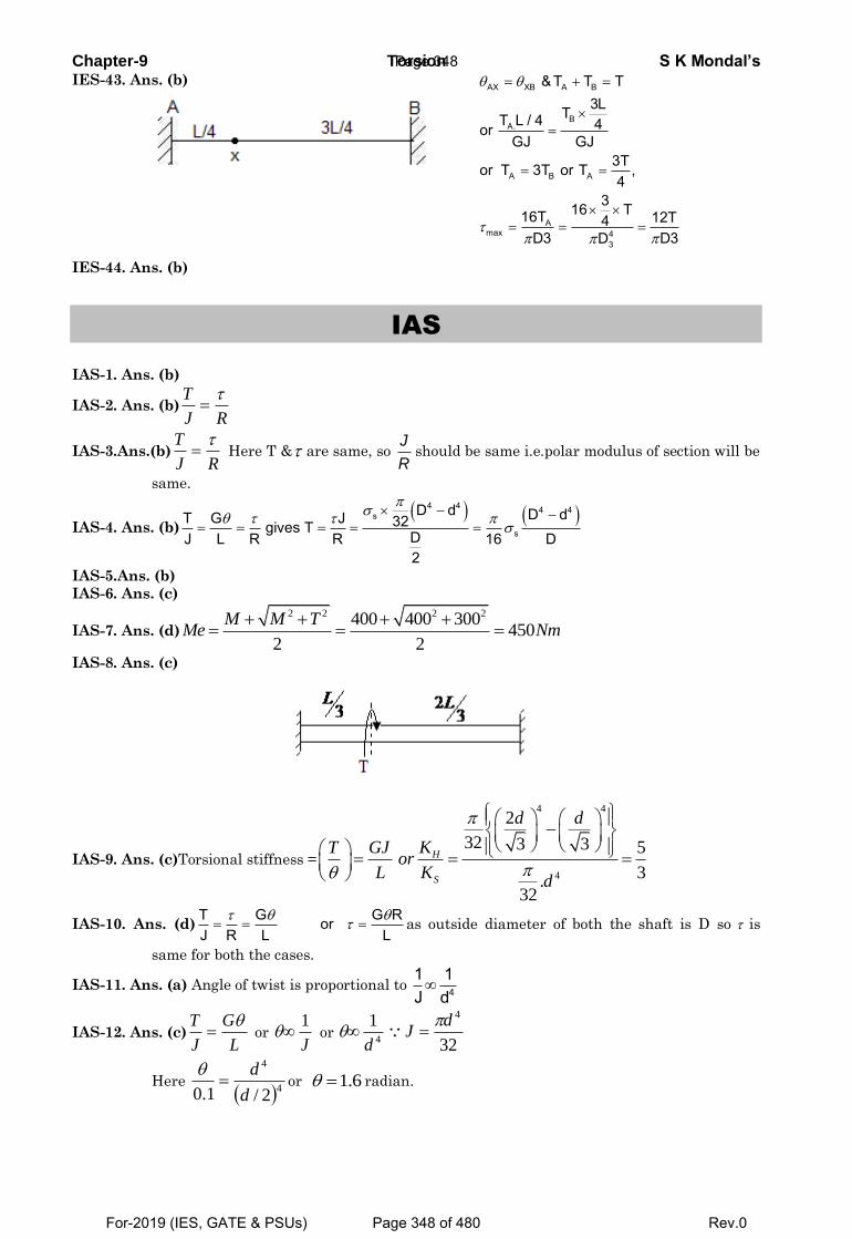
Chapter-9 Torsion S K Mondal’s IES-43. Ans. (b)
AX XB A B
BA.
A B A
Amax 4
3
& T T T3LTT L / 4 4or
GJ GJ3Tor T 3T or T ,4
316 T16T 12T4D3 D3D
IES-44. Ans. (b)
IAS
IAS-1. Ans. (b)
IAS-2. Ans. (b)RJ
T
IAS-3.Ans.(b)RJ
T Here T & are same, so
J
Rshould be same i.e.polar modulus of section will be
same.
IAS-4. Ans. (b)
4 4 4 4s
s
D d D dT G J 32gives TDJ L R R 16 D2
IAS-5.Ans. (b)
IAS-6. Ans. (c)
IAS-7. Ans. (d)
2 2 2 2400 400 300450
2 2
M M TMe Nm
IAS-8. Ans. (c)
IAS-9. Ans. (c)Torsional stiffness =
4 4
4
2
32 3 3 5
3.
32
H
S
d d
KT GJor
L Kd
IAS-10. Ans. (d)T G G RorJ R L L
as outside diameter of both the shaft is D so is
same for both the cases.
IAS-11. Ans. (a) Angle of twist is proportional to 4
1 1J d
IAS-12. Ans. (c)L
G
J
T or
J
1 or
4
1
d
32
4dJ
Here 4
4
2/1.0 d
d
or 6.1 radian.
Page 348
For-2019 (IES, GATE & PSUs) Page 348 of 480 Rev.0
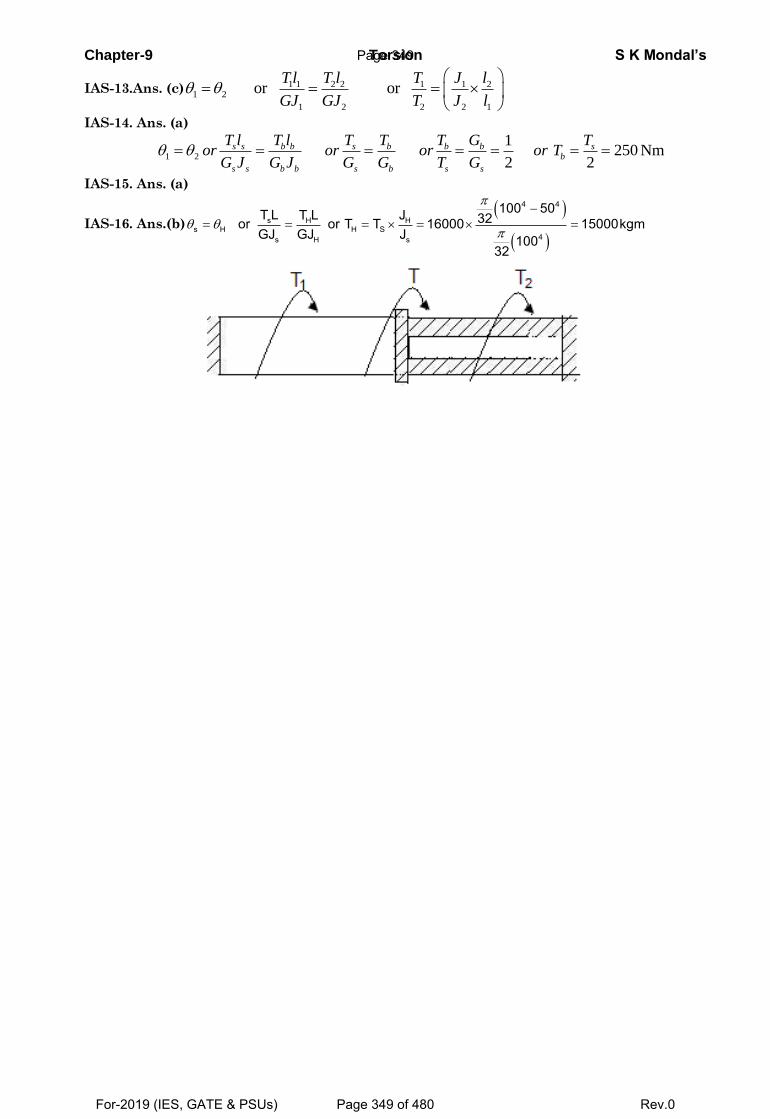
Chapter-9 Torsion S K Mondal’s
IAS-13.Ans. (c) 1 1 2 2 1 1 21 2
1 2 2 2 1
or orTl T l T J l
GJ GJ T J l
IAS-14. Ans. (a)
1 2
1250 Nm
2 2
s s b b s b b b sb
s s b b s b s s
T l T l T T T G Tor or or or T
G J G J G G T G
IAS-15. Ans. (a)
IAS-16. Ans.(b)
4 4
s H Hs H H S
4s H s
100 50T L T L J 32or or T T 16000 15000kgmGJ GJ J 100
32
Page 349
For-2019 (IES, GATE & PSUs) Page 349 of 480 Rev.0
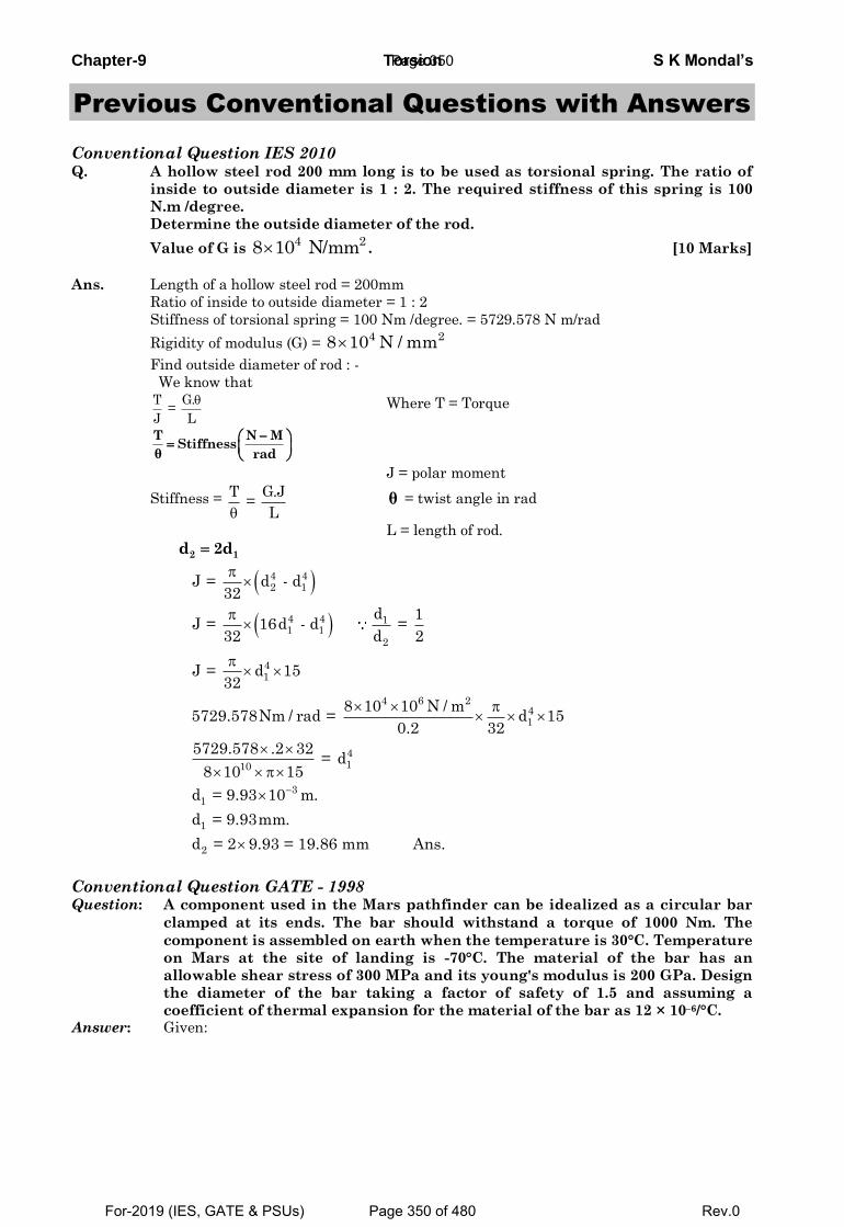
Chapter-9 Torsion S K Mondal’s
Previous Conventional Questions with Answers
Conventional Question IES 2010 Q. A hollow steel rod 200 mm long is to be used as torsional spring. The ratio of
inside to outside diameter is 1 : 2. The required stiffness of this spring is 100
N.m /degree.
Determine the outside diameter of the rod.
Value of G is 4 28 10 N/mm . [10 Marks]
Ans. Length of a hollow steel rod = 200mm
Ratio of inside to outside diameter = 1 : 2
Stiffness of torsional spring = 100 Nm /degree. = 5729.578 N m/rad
Rigidity of modulus (G) = 4 28 10 N / mm
Find outside diameter of rod : -
We know that
T G. =
J L
Where T = Torque
T N MStiffness
θ rad
J = polar moment
Stiffness = T G.J =
L θ = twist angle in rad
L = length of rod.
2 1d 2d
4 42 1
4 4 11 1
2
41
4 6 241
4110
31
1
2
J = d - d32
d 1J = 16d - d =
32 d 2
J = d 1532
8 10 10 N / m5729.578Nm / rad = d 15
0.2 32
5729.578 .2 32 = d
8 10 15
d = 9.93 10 m.
d = 9.93mm.
d = 2 9.93 = 19.86 mm Ans.
Conventional Question GATE - 1998 Question: A component used in the Mars pathfinder can be idealized as a circular bar
clamped at its ends. The bar should withstand a torque of 1000 Nm. The
component is assembled on earth when the temperature is 30°C. Temperature
on Mars at the site of landing is -70°C. The material of the bar has an
allowable shear stress of 300 MPa and its young's modulus is 200 GPa. Design
the diameter of the bar taking a factor of safety of 1.5 and assuming a
coefficient of thermal expansion for the material of the bar as 12 × 10–6/°C. Answer: Given:
Page 350
For-2019 (IES, GATE & PSUs) Page 350 of 480 Rev.0
Chapter-9 Torsion S K Mondal’s
( )
0 0max E m allowable
6 0
6 4
T 1000Nm; t 30 C; t 70 C; 300MPa
E 200GPa; F.O.S. 1.5; 12 10 / CDiameter of the bar,D :Change in length, L L t,where L original length,m.Change in lengthat Mars L 12 10 30 70 12 10 L meters
τ
α
δ
−
− −
= = = − =
= = = ×
= ∝ Δ =
⎡ ⎤= × × × − − = ×⎣ ⎦
2
44
9 4 8a
22a
max 3
max
Change in length 12 10 LLinear strain 12 10original length L
axial stress E linear strain 200 10 12 10 2.4 10 N / mFrom max imum shear stress equation,we have
16TD 2
where,
σ
στπ
τ
−−
−
×= = = ×
= = × = × × × = ×
⎡ ⎤⎛ ⎞⎛ ⎞= +⎢ ⎥⎜ ⎟ ⎜ ⎟⎝ ⎠ ⎝ ⎠⎢ ⎥⎣ ⎦
( )
allowable
2216 8
3
83
1/3
8
300 200MPaF.O.S 1.5
Substituting the values, we get
16 10004 10 1.2 10D
16 1000or 1.6 10D
16 1000or D 0.03169 m 31.69 mm1.6 10
τ
π
π
π
= = =
×⎛ ⎞× = + ×⎜ ⎟⎝ ⎠
×= ×
×⎛ ⎞= = =⎜ ⎟× ×⎝ ⎠
Conventional Question IES-2009 Q. In a torsion test, the specimen is a hollow shaft with 50 mm external and 30 mm
internal diameter. An applied torque of 1.6 kN-m is found to produce an angular twist of 0.4º measured on a length of 0.2 m of the shaft. The Young’s modulus of elasticity obtained from a tensile test has been found to be 200 GPa. Find the values of
(i) Modulus of rigidity. (ii) Poisson’s ratio. [10-Marks] Ans. We have
T G ......... (i)J r L
τ θ= =
Where J = polar moment of inertia
( )( )
4 4
4 4 12
7
3
J = D d32
50 30 10325.338 10
T 1.6 kN m 1.6 10 N-m= 0.4º
l = 0.2 m
−
−
π−
π= − ×
= ×
= − = ×θ
9 2E = 200 × 10 N/m
T GFrom equation (i) J L
θ=
3
7
3
7
G 0.41.6 10 1800.25.338 10
1.6 0.2 10 180 G = 0.4 5.338 10
85.92 GPa
−
−
π⎡ ⎤× ×⎢ ⎥× ⎣ ⎦=×
× × ×⇒
× π × ×=
Page 351
For-2019 (IES, GATE & PSUs) Page 351 of 480 Rev.0
Chapter-9 Torsion S K Mondal’s We also have
Conventional Question IAS - 1996 Question: A solid circular uniformly tapered shaft of length I, with a small angle
oftaper is subjected to a torque T. The diameter at the two ends of the shaft are D and 1.2 D. Determine the error introduced of its angular twist for a given length is determined on the uniform mean diameter of the shaft.
Answer: For shaft of tapering's section, we have
2 2 2 21 1 2 2 1 1 2 2
3 3 3 31 2 1 2
R R R R D D D D2TL 32TL3G R R 3G D D
θπ π⎡ ⎤ ⎡ ⎤+ + + +
= =⎢ ⎥ ⎢ ⎥⎣ ⎦ ⎣ ⎦
( ) ( )
( ) ( )[ ]
2 2
1 23 34
4
1.2 1.2 1 132TL D D and D 1.2D3G D 1.2 1
32TL 2.10653G D
π
π
⎡ ⎤+ × += = =⎢ ⎥
×⎢ ⎥⎣ ⎦
= ×
∵
avg
1.2D DNow, D 1.1D2+
= =
( )( ) ( )
2
6 4 44
3 1.1D32TL 32TL 3 32TL' 2.0493G 3G 3G D1.1D 1.2 .D
θπ π π
⎡ ⎤∴ = × = × = ×⎢ ⎥
⎢ ⎥⎣ ⎦
' 2.1065 2.049Error 0.0273 or 2.73%2.1065
θ θθ− −
= = =
Conventional Question ESE-2008 Question: A hollow shaft and a solid shaft construction of the same material have the
same length and the same outside radius. The inside radius of the hollow shaft is 0.6 times of the outside radius. Both the shafts are subjected to the same torque.
(i) What is the ratio of maximum shear stress in the hollow shaft to that of solid shaft?
(ii) What is the ratio of angle of twist in the hollow shaft to that of solid shaft?
Solution: Using T Gθ= =J R L
τ
Given, Inside radius (r) 0.6 and T
Out side (R)= = =h sT T
(i) τ =( )
h4 4
. . gives ; For hollow shaft ( )
2
τπ
=−
T R T RJ R r
and for solid shaft (τ s)= 4
.
.2πT R
R
Therefore 4
44 4 4
1 1 1.151 0.6
1
ττ
= = = =− −⎛ ⎞⎟⎜− ⎟⎜ ⎟⎜⎝ ⎠
n
s
RR r r
R
( )E = 2 G (1 + v) 200 = 2 × 85.92 1 v 1 + v = 1.164 v = 0.164
∴ +
⇒⇒
Page 352
For-2019 (IES, GATE & PSUs) Page 352 of 480 Rev.0
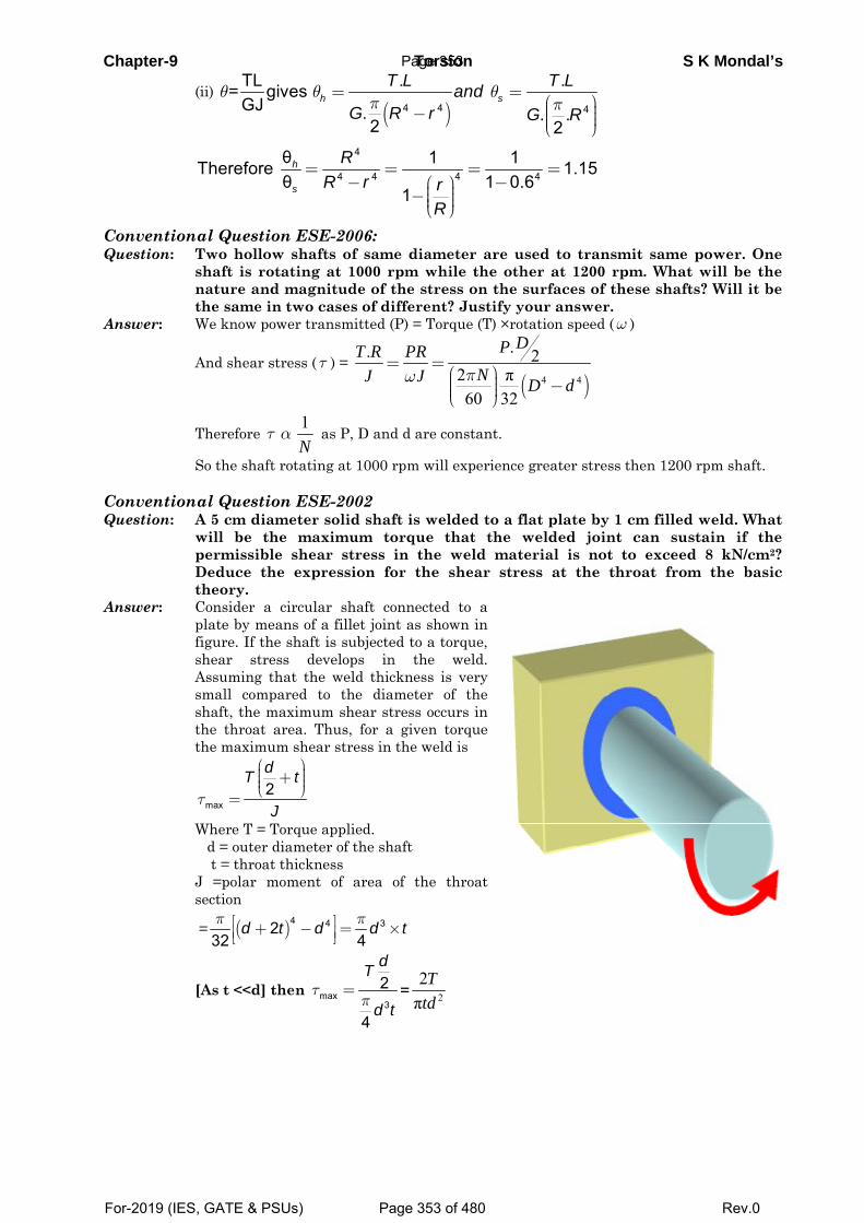
Chapter-9 Torsion S K Mondal’s
(ii) ( )4 4 4
TL . .= gives GJ . . .
2 2
θ θ θπ π
= =⎛ ⎞⎟⎜− ⎟⎜ ⎟⎜⎝ ⎠
h sT L T Land
G R r G R
4
44 4 4
θ 1 1Therefore 1.15θ 1 0.6
1= = = =
− −⎛ ⎞⎟⎜− ⎟⎜ ⎟⎜⎝ ⎠
h
s
RR r r
R
Conventional Question ESE-2006: Question: Two hollow shafts of same diameter are used to transmit same power. One
shaft is rotating at 1000 rpm while the other at 1200 rpm. What will be the nature and magnitude of the stress on the surfaces of these shafts? Will it be the same in two cases of different? Justify your answer.
Answer: We know power transmitted (P) = Torque (T) ×rotation speed (ω )
And shear stress (τ ) = ( )4 4
.. 22 π60 32πω
= =⎛ ⎞⎟⎜ −⎟⎜ ⎟⎜⎝ ⎠
DPT R PRNJ J D d
Therefore τ α1N
as P, D and d are constant.
So the shaft rotating at 1000 rpm will experience greater stress then 1200 rpm shaft. Conventional Question ESE-2002 Question: A 5 cm diameter solid shaft is welded to a flat plate by 1 cm filled weld. What
will be the maximum torque that the welded joint can sustain if the permissible shear stress in the weld material is not to exceed 8 kN/cm2? Deduce the expression for the shear stress at the throat from the basic theory.
Answer: Consider a circular shaft connected to a plate by means of a fillet joint as shown in figure. If the shaft is subjected to a torque, shear stress develops in the weld. Assuming that the weld thickness is very small compared to the diameter of the shaft, the maximum shear stress occurs in the throat area. Thus, for a given torque the maximum shear stress in the weld is
max2dT t
Jτ
⎛ ⎞⎟⎜ + ⎟⎜ ⎟⎜⎝ ⎠=
Where T = Torque applied. d = outer diameter of the shaft t = throat thickness J =polar moment of area of the throat
section
= ( )4 4 3232 4
d t d d tπ π⎡ ⎤+ − = ×⎢ ⎥⎣ ⎦
[As t <<d] then max3
2
4
dT
d tτ
π= = 2
2π
Ttd
Page 353
For-2019 (IES, GATE & PSUs) Page 353 of 480 Rev.0
Chapter-9 Torsion S K Mondal’s
( )
π π
2 6 2max 4 2
2 2 6max
Given d = 5 cm = 0.05 m & t = 1cm = 0.1 m
80008 / 80 80 10 /10
0.05 0.01 80 10 3.1422 2
NkN cm MPa N m
m
d tT kNm
t
t
-= = = = ´
´ ´ ´ ´\ = = =
Conventional Question ESE-2000
Question: The ratio of inside to outside diameter of a hollow shaft is 0.6. If there is a
solid shaft with same torsional strength, what is the ratio of the outside
diameter of hollow shaft to the diameter of the equivalent solid shaft.
Answer: Let D = external diameter of hollow shaft
So d = 0.6D internal diameter of hollow shaft
And Ds=diameter of solid shaft
From torsion equation
( )
π
π
32
πDπD
4 4
4
334
34
{ (0.6 ) }32, for hollow shaft
/ 2
J T= for solidshaftR
2
{1 (0.6) }16 16
1, 1.0721 (0.6)
s
s
s
s
T
J R
D DJ
or TR D
Dand J
D
Dor
D
t
tt
t
t t
=
-
= = ´
= ´
- =
= =-
Conventional Question ESE-2001
Question: A cantilever tube of length 120 mm is subjected to an axial tension P = 9.0 kN,
A torsional moment T = 72.0 Nm and a pending Load F = 1.75 kN at the free
end. The material is aluminum alloy with an yield strength 276 MPa. Find the
thickness of the tube limiting the outside diameter to 50 mm so as to ensure a
factor of safety of 4.
Answer: 3 π
πR3
Polar moment of inertia (J) =24D t
t =
π π π
σπ π
σ
3 2 2
1
2
T.R 2 2 72 18335 or, =2 (0.050)2
49000 9000 57296Direct stress ( )
(0.050)
2Maximum bending stress ( ) [ 2 ]
1750
T TD TD T
J R J J tD t D t t
P
A dt t t
dMMy MdJ I
I I J
tt
´= = = = = =
´ ´´
= = = =
= = = =
´=
π
σ σ σ
3
b 1 2
0.120 0.050 4 106952(0.050)
164248Total longitudinal stress ( )
tt
t
´ ´=
´
\ = + =
Page 354
For-2019 (IES, GATE & PSUs) Page 354 of 480 Rev.0
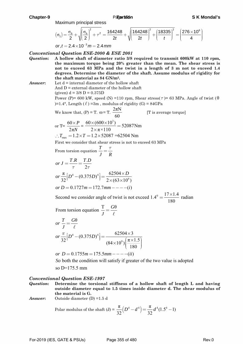
Chapter-9 Torsion S K Mondal’s
( ) σ σσ
2 2 2 62b
1
3
Maximum principal stress
164248 164248 18335 276 102 2 2 2 4
, 2.4 10 2.4
b
t t t
or t m mm
τ
−
⎛ ⎞⎛ ⎞ ⎛ ⎞ ⎛ ⎞ × ⎟⎜⎟ ⎟ ⎟⎜ ⎜ ⎜ ⎟= + + = + + =⎟ ⎟ ⎟ ⎜⎜ ⎜ ⎜ ⎟⎟ ⎟ ⎟ ⎜⎟ ⎜ ⎜⎜ ⎟⎜⎝ ⎠ ⎝ ⎠⎝ ⎠ ⎝ ⎠
= × =
Conventional Question ESE-2000 & ESE 2001 Question: A hollow shaft of diameter ratio 3/8 required to transmit 600kW at 110 rpm,
the maximum torque being 20% greater than the mean. The shear stress is not to exceed 63 MPa and the twist in a length of 3 m not to exceed 1.4 degrees. Determine the diameter of the shaft. Assume modulus of rigidity for the shaft material as 84 GN/m2.
Answer: Let d = internal diameter of the hollow shaft And D = external diameter of the hollow shaft (given) d = 3/8 D = 0.375D Power (P)= 600 kW, speed (N) =110 rpm, Shear stress(τ )= 63 MPa. Angle of twist (θ
)=1.4°, Length ( ) =3m , modulus of rigidity (G) = 84GPa
We know that, (P) = T. ω= T. 2πN60
[T is average torque]
or T= 602π
PN×
= 360 (600 10 ) 52087Nm
2 π×110× ×
=×
max 1.2 1.2 52087 =62504 Nm∴ = × = ×T T First we consider that shear stress is not to exceed 63 MPa
From torsion equation τ
=TJ R
4 46
. .2
π 62504(0.375 )32 2 (63 10 )
0.1727 172.7 ( )
τ τ= =
×⎡ ⎤− =⎢ ⎥⎣ ⎦ × ×= = −−−−
T R T Dor J
Dor D D
or D m mm i
0 17 1.4Second we consider angle of twist is not exceed 1.4 radian180×
=
4 4
9
T θFrom torsion equation
θ
62504 3(0.375 )π 1.532 (84 10 )180
0.1755 175.5 ( )
π
=
=
×⎡ ⎤− =⎢ ⎥⎣ ⎦ ⎛ ⎞× ⎟⎜× ⎟⎜ ⎟⎜⎝ ⎠
= = −−−−
GJ
T GorJ
or D D
or D m mm ii
both the condition will satisfy if greater of the two value is adopted
so D=175.5 mmSo
Conventional Question ESE-1997 Question: Determine the torsional stiffness of a hollow shaft of length L and having
outside diameter equal to 1.5 times inside diameter d. The shear modulus of the material is G.
Answer: Outside diameter (D) =1.5 d
Polar modulus of the shaft (J) = ( )4 4 4 4π π (1.5 1)32 32
D d d− = −
Page 355
For-2019 (IES, GATE & PSUs) Page 355 of 480 Rev.0
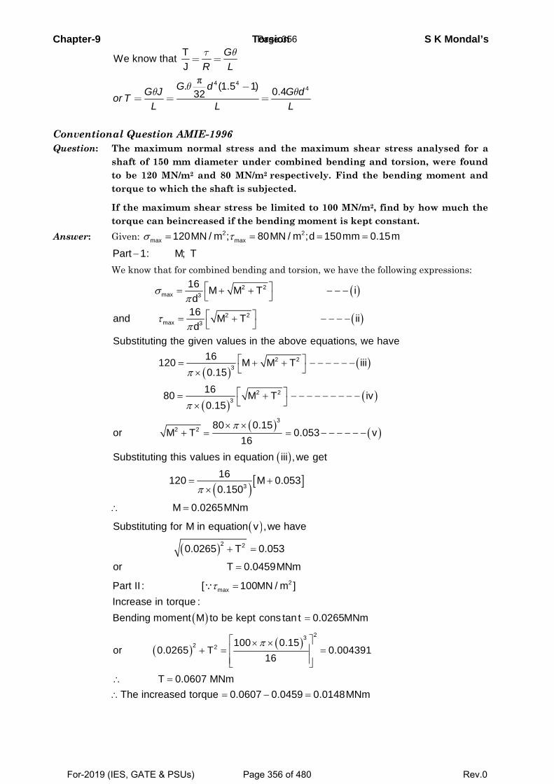
Chapter-9 Torsion S K Mondal’s
π 4 44
TWe know that J
. (1.5 1) 0.432
GR L
G dG J G dor TL L L
τ θ
θθ θ
= =
−= = =
Conventional Question AMIE-1996 Question: The maximum normal stress and the maximum shear stress analysed for a
shaft of 150 mm diameter under combined bending and torsion, were found to be 120 MN/m2 and 80 MN/m2 respectively. Find the bending moment and torque to which the shaft is subjected.
If the maximum shear stress be limited to 100 MN/m2, find by how much the torque can beincreased if the bending moment is kept constant.
Answer: Given: 2 2max max120MN / m ; 80MN / m ;d 150mm 0.15mσ τ= = = =
Part 1: M; T− We know that for combined bending and torsion, we have the following expressions:
( )
( )
2 2max 3
2 2max 3
16 M M T id
16and M T iid
σπ
τπ
⎡ ⎤= + + − − −⎣ ⎦
⎡ ⎤= + − − − −⎣ ⎦
( )
( )
( )( )
( ) ( )
2 23
2 23
32 2
Substituting the given values in the above equations, we have16120 M M T iii0.151680 M T iv0.15
80 0.15or M T 0.053 v
16
π
π
π
⎡ ⎤= + + − − − − − −⎣ ⎦×
⎡ ⎤= + − − − − − − − − −⎣ ⎦×
× ×+ = = − − − − − −
( )
( ) [ ]3
Substituting this values in equation iii ,we get16120 M 0.0530.150
M 0.0265MNm
π= +
×
∴ =
( )
( )2 2
Substituting for M in equation v ,we have
0.0265 T 0.053
or T 0.0459MNm
+ =
=
( )
2maxPart II : [ 100MN / m ]
Increase in torque :Bending moment M to be kept cons tan t 0.0265MNm
τ =
=
∵
( ) ( )23
2 2 100 0.15or 0.0265 T 0.004391
16π⎡ ⎤× ×
⎢ ⎥+ = =⎢ ⎥⎣ ⎦
T 0.0607 MNm
The increased torque 0.0607 0.0459 0.0148MNm∴ =∴ = − =
Page 356
For-2019 (IES, GATE & PSUs) Page 356 of 480 Rev.0
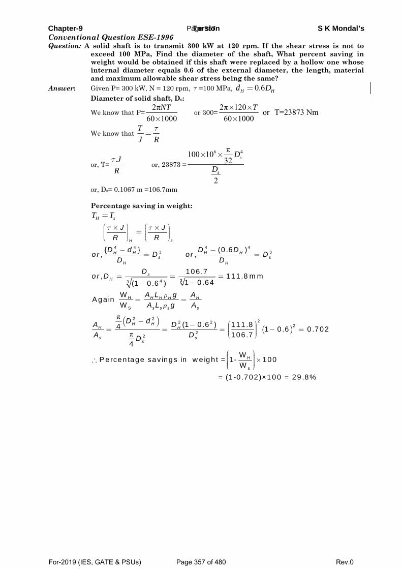
Chapter-9 Torsion S K Mondal’s Conventional Question ESE-1996 Question: A solid shaft is to transmit 300 kW at 120 rpm. If the shear stress is not to
exceed 100 MPa, Find the diameter of the shaft, What percent saving in weight would be obtained if this shaft were replaced by a hollow one whose internal diameter equals 0.6 of the external diameter, the length, material and maximum allowable shear stress being the same?
Answer: Given P= 300 kW, N = 120 rpm, τ =100 MPa, 0.6H Hd D= Diameter of solid shaft, Ds:
We know that P=2π
60 1000NT
× or 300=
2π 120 or T=23873 Nm60 1000× ××
T
We know that τ
=TJ R
or, T=.τ JR
or, 23873 =
6 4π100 1032
2
× × s
s
D
D
or, Ds= 0.1067 m =106.7mm Percentage saving in weight: H sT T=
( )π
π
4 4 4 43 3
343
H
S
2 2 22 2
22
{ } (0 .6 ), ,
106 .7, 111 .8 m m1 0.64(1 0 .6 )
WA ga in W
(1 0 .6 ) 111 .84 1106 .7
4
H s
H H H Hs s
H H
sH
H H H H
s s s s
H HH H
s ss
J JR R
D d D Dor D or DD D
Dor D
A L g AA L g A
D dA DA DD
τ τ
ρρ
⎛ ⎞ ⎛ ⎞× ×⎟ ⎟⎜ ⎜=⎟ ⎟⎜ ⎜⎟ ⎟⎜ ⎜⎝ ⎠ ⎝ ⎠
− −= =
= = =−−
= =
− ⎛ ⎞− ⎟⎜= = = −⎟⎜ ⎟⎜⎝ ⎠( )2
H
s
0 .6 0 .702
WP ercen tage sav ings in w e igh t = 1 - 100W
= (1 -0 .702)×100 = 29 .8%
=
⎛ ⎞⎟⎜ ⎟∴ ×⎜ ⎟⎜ ⎟⎜⎝ ⎠
Page 357
For-2019 (IES, GATE & PSUs) Page 357 of 480 Rev.0
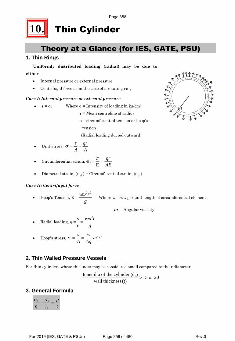
10. Thin Cylinder
Theory at a Glance (for IES, GATE, PSU) 1. Thin Rings
Uniformly distributed loading (radial) may be due to
either
Internal pressure or external pressure
Centrifugal force as in the case of a rotating ring
Case-I: Internal pressure or external pressure
s = qr Where q = Intensity of loading in kg/cm2
r = Mean centreline of radius
s = circumferential tension or hoop’s
tension
(Radial loading ducted outward)
Unit stress, s qr
A A
Circumferential strain, E
c
qr
AE
Diametral strain, (d) = Circumferential strain, (c
)
Case-II: Centrifugal force
Hoop's Tension,
2 2
w rs
g Where w = wt. per unit length of circumferential element
= Angular velocity
Radial loading, q =
2
w rs
r g
Hoop's stress, 2 2.
s wr
A Ag
2. Thin Walled Pressure Vessels
For thin cylinders whose thickness may be considered small compared to their diameter.
iInner dia of the cylinder (d )15 or 20
wall thickness (t)
3. General Formula
1 2
1 2
p
r r t
Page 358
For-2019 (IES, GATE & PSUs) Page 358 of 480 Rev.0
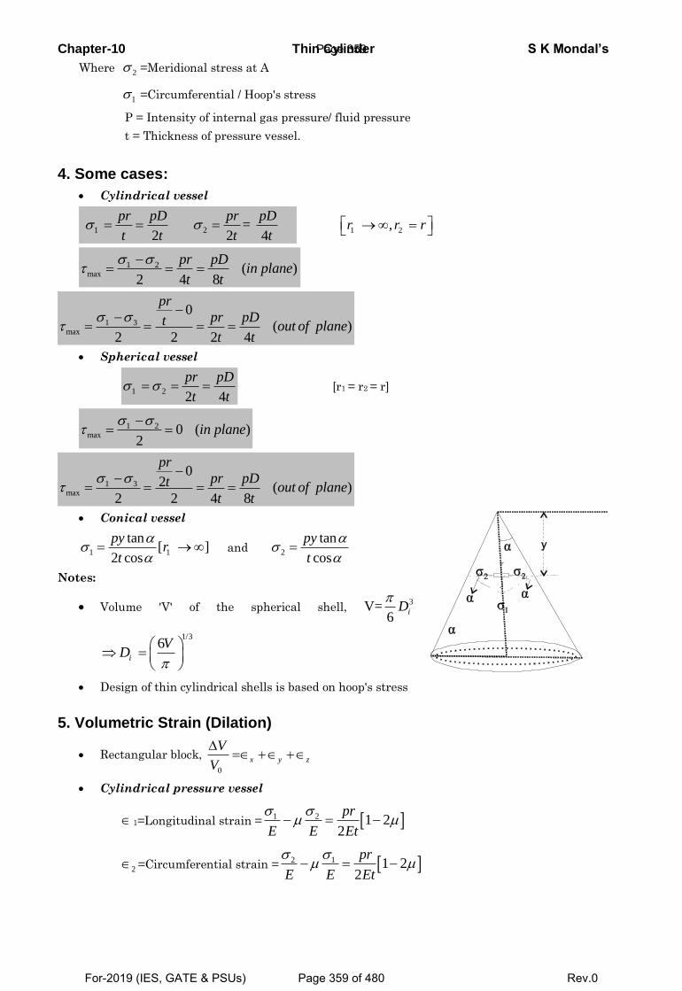
Chapter-10 Thin Cylinder S K Mondal’s
Where 2 =Meridional stress at A
1 =Circumferential / Hoop's stress
P = Intensity of internal gas pressure/ fluid pressure
t = Thickness of pressure vessel.
4. Some cases:
Cylindrical vessel
1 2 = 2 2 4
pr pD pr pD
t t t t
1 2 ,r r r
1 2
max ( )2 4 8
pr pDin plane
t t
1 3max
0
( )2 2 2 4
pr
pr pDt out of planet t
Spherical vessel
1 22 4
pr pD
t t [r1 = r2 = r]
1 2max 0 ( )
2in plane
1 3max
02 ( )
2 2 4 8
pr
pr pDt out of planet t
Conical vessel
1 1
tan[ ]
2 cos
pyr
t
and 2
tan
cos
py
t
Notes:
Volume 'V' of the spherical shell, 3V=
6
iD
1/36
i
VD
Design of thin cylindrical shells is based on hoop's stress
5. Volumetric Strain (Dilation)
Rectangular block,
0
x y z
V
V
Cylindrical pressure vessel
1=Longitudinal strain = 1 2 1 22
pr
E E Et
2 =Circumferential strain = 2 1 1 22
pr
E E Et
Page 359
For-2019 (IES, GATE & PSUs) Page 359 of 480 Rev.0
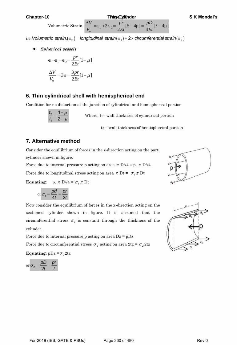
Chapter-10 Thin Cylinder S K Mondal’s
Volumetric Strain, 1 22 [5 4μ] [5 4μ]
2 4
o
V pr pD
V Et Et
i.e. 1 2, 2vVolumetric strain longitudinal strain circumferential strain
Spherical vessels
1 2 [1 ]2
pr
Et
0
33 [1 ]
2
V pr
V Et
6. Thin cylindrical shell with hemispherical end
Condition for no distortion at the junction of cylindrical and hemispherical portion
2
1
12
t
t
Where, t1= wall thickness of cylindrical portion
t2 = wall thickness of hemispherical portion
7. Alternative method
Consider the equilibrium of forces in the z-direction acting on the part
cylinder shown in figure.
Force due to internal pressure p acting on area D2/4 = p. D2/4
Force due to longitudinal stress acting on area Dt = 1 Dt
Equating: p. D2/4 = 1 Dt
or 1 4 2pd pr
t t
Now consider the equilibrium of forces in the x-direction acting on the
sectioned cylinder shown in figure. It is assumed that the
circumferential stress 2 is constant through the thickness of the
cylinder.
Force due to internal pressure p acting on area Dz = pDz
Force due to circumferential stress 2 acting on area 2tz = 2 2tz
Equating: pDz = 2 2tz
or 2 2pD pr
t t
Page 360
For-2019 (IES, GATE & PSUs) Page 360 of 480 Rev.0
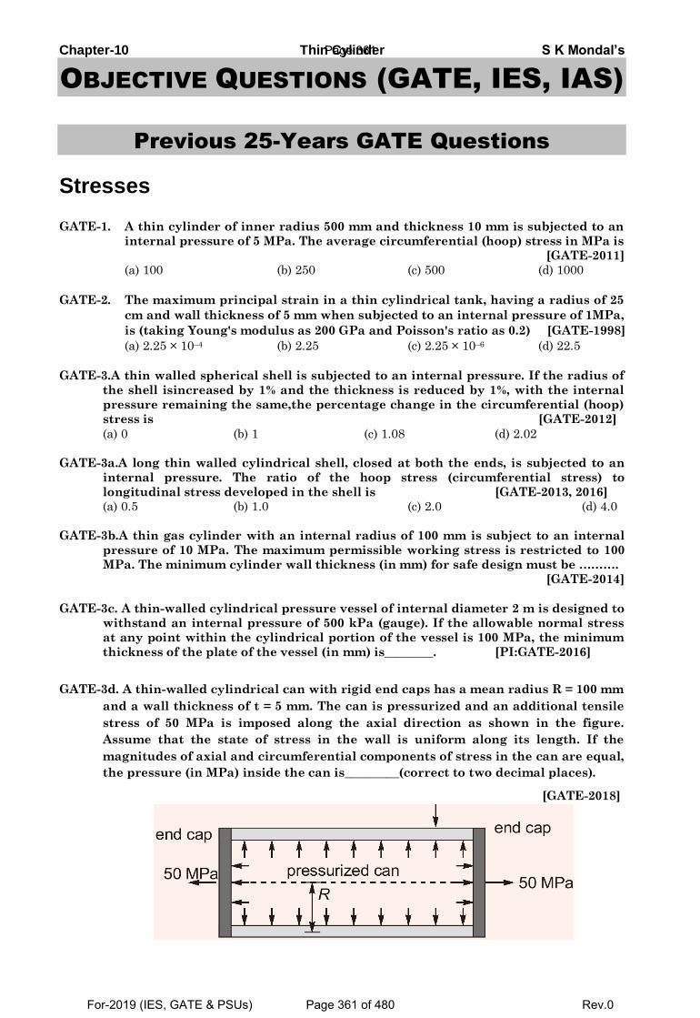
Chapter-10 Thin Cylinder S K Mondal’s
OBJECTIVE QUESTIONS (GATE, IES, IAS)
Previous 25-Years GATE Questions
Stresses
GATE-1. A thin cylinder of inner radius 500 mm and thickness 10 mm is subjected to an
internal pressure of 5 MPa. The average circumferential (hoop) stress in MPa is
[GATE-2011]
(a) 100 (b) 250 (c) 500 (d) 1000
GATE-2. The maximum principal strain in a thin cylindrical tank, having a radius of 25
cm and wall thickness of 5 mm when subjected to an internal pressure of 1MPa,
is (taking Young's modulus as 200 GPa and Poisson's ratio as 0.2) [GATE-1998]
(a) 2.25 × 10⁻⁴ (b) 2.25 (c) 2.25 × 10⁻⁶ (d) 22.5
GATE-3.A thin walled spherical shell is subjected to an internal pressure. If the radius of
the shell isincreased by 1% and the thickness is reduced by 1%, with the internal
pressure remaining the same,the percentage change in the circumferential (hoop)
stress is [GATE-2012]
(a) 0 (b) 1 (c) 1.08 (d) 2.02
GATE-3a.A long thin walled cylindrical shell, closed at both the ends, is subjected to an
internal pressure. The ratio of the hoop stress (circumferential stress) to
longitudinal stress developed in the shell is [GATE-2013, 2016]
(a) 0.5 (b) 1.0 (c) 2.0 (d) 4.0
GATE-3b.A thin gas cylinder with an internal radius of 100 mm is subject to an internal
pressure of 10 MPa. The maximum permissible working stress is restricted to 100
MPa. The minimum cylinder wall thickness (in mm) for safe design must be ……….
[GATE-2014]
GATE-3c. A thin-walled cylindrical pressure vessel of internal diameter 2 m is designed to
withstand an internal pressure of 500 kPa (gauge). If the allowable normal stress
at any point within the cylindrical portion of the vessel is 100 MPa, the minimum
thickness of the plate of the vessel (in mm) is________. [PI:GATE-2016]
GATE-3d. A thin-walled cylindrical can with rigid end caps has a mean radius R = 100 mm
and a wall thickness of t = 5 mm. The can is pressurized and an additional tensile
stress of 50 MPa is imposed along the axial direction as shown in the figure.
Assume that the state of stress in the wall is uniform along its length. If the
magnitudes of axial and circumferential components of stress in the can are equal,
the pressure (in MPa) inside the can is_________(correct to two decimal places).
[GATE-2018]
Page 361
For-2019 (IES, GATE & PSUs) Page 361 of 480 Rev.0
Chapter-10 Thin Cylinder S K Mondal’s GATE-3e. A spherical pressure vessel (made of mild steel) of internal diameter 500
mm and thickness 10 mm is subjected to an internal gauge pressure of 4000
kPa. If the yield stress of mild steel is 200 MPa, the factor of safety (up to
one decimal place) is ______ [GATE(PI)-2018]
Maximum shear stress GATE-4. A thin walled cylindrical vessel of wall thickness, t and diameter d is fitted
with gas to a gauge pressure of p. The maximum shear stress on the vessel wall
will then be: [GATE-1999]
(a) (b) (c) (d) 2 4 8
pd pd pd pd
t t t t
GATE-4(i) A cylindrical tank with closed ends is filled with compressed air at a pressure
of 500 kPa. The inner radius of the tank is 2m, and it has wall thickness of 10
mm. The magnitude of maximum in-plane shear stress (in MPa) is _[GATE-2015]
GATE-4ii A gas is stored in a cylindrical tank of inner radius 7 m and wall thickness 50
mm. The gage pressure of the gas is 2 MPa. The maximum shear stress (in MPa)
in the wall is [GATE-2015]
(a) 35 (b) 70 (c) 140 (d) 280
Statement for Linked Answers and Questions 5 and 6 A cylindrical container of radius R = 1 m, wall
thickness 1 mm is filled with water up to a depth
of 2 m and suspended along its upper rim. The
density of water is 1000 kg/m3 and acceleration
due to gravity is 10 m/s2. The self-weight of the
cylinder is negligible. The formula for hoop
stress in a thin-walled cylinder can be used at all
points along the height of the cylindrical
container.
[GATE-2008]
GATE-5. The axial and circumferential stress ( ), ca experienced by the cylinder wall
at mid-depth (1 m as shown) are
(a) (10,10) MPa (b) (5,10) MPa (c) (10,5) MPa (d) (5,5)MPa
GATE-6. If the Young's modulus and Poisson's ratio of the container material are 100
GPa and 0.3, respectively, the axial strain in the cylinder wall at mid-depth is:
(a) 2 × 10⁻⁵ (b) 6 × 10⁻⁵ (c) 7 × 10⁻⁵ (d) 1.2 × 10⁻⁵
GATE-7. A thin walled cylindrical pressure vessel having a radius of 0.5 m and wall
thickness of 25 mm is subjected to an internal pressure of 700 kPa. The hoop
stress developed is [CE: GATE-2009]
(a) 14 MPa (b) 1.4 MPa (c) 0.14 MPa (d) 0.014 MPa
GATE-8.A thin plate of uniform thickness is subject to pressure as shown in the figure
below
xy
z
y
Page 362
For-2019 (IES, GATE & PSUs) Page 362 of 480 Rev.0
Chapter-10 Thin Cylinder S K Mondal’s Under the assumption of plane stress, which one of the following is correct?
(a) Normal stress is zero in the z-direction [GATE-2014]
(b) Normal stress is tensile in the z-direction
(c) Normal stress is compressive in the z-direction
(d) Normal stress varies in the z-direction
GATE-9. A thin-walled long cylindrical tank of inside radius r is subjected
simultaneously to internal gas pressure p and axial compressive force F at its
ends. In order to produce ‘pure shear’ state of stress in the wall of the cylinder,
F should be equal to
(a) 2p r (b) 22p r [CE: GATE-2006]
(c) 23p r (d) 24p r
Previous 25-Years IES Questions
Circumferential or hoop stress IES-1. Match List-I with List-II and select the correct answer: [IES-2002]
List-I List-II
(2-D Stress system loading) (Ratio of principal stresses)
A. Thin cylinder under internal pressure 1. 3.0
B. Thin sphere under internal pressure 2. 1.0
C. Shaft subjected to torsion 3. –1.0
4. 2.0
Codes: A B C A B C
(a) 4 2 3 (b) 1 3 2
(c) 4 3 2 (d) 1 2 3
IES-2. A thin cylinder of radius r and thickness t when subjected to an internal
hydrostatic pressure P causes a radial displacement u, then the tangential
strain caused is: [IES-2002]
(a) du
dr (b)
1.du
r dr (c)
u
r (d)
2u
r
IES-3. A thin cylindrical shell is subjected to internal pressure p. The Poisson's ratio
of the material of the shell is 0.3. Due to internal pressure, the shell is subjected
to circumferential strain and axial strain. The ratio of circumferential strain to
axial strain is: [IES-2001]
(a) 0.425 (b) 2.25 (c) 0.225 (d) 4.25
IES-4. A thin cylindrical shell of diameter d, length ‘l’ and thickness t is subjected to
an internal pressure p. What is the ratio of longitudinal strain to hoop strain in
terms of Poisson's ratio (1/m)? [IES-2004, ISRO-2015]
(a) 2
2 1
m
m
(b)
2
2 1
m
m
(c)
2 1
2
m
m
(d)
2 2
1
m
m
IES-5. When a thin cylinder of diameter 'd' and thickness 't' is pressurized with an
internal pressure of 'p', (1/m = is the Poisson's ratio and E is the modulus of
elasticity), then [IES-1998]
Page 363
For-2019 (IES, GATE & PSUs) Page 363 of 480 Rev.0
Chapter-10 Thin Cylinder S K Mondal’s
(a) The circumferential strain will be equal to 1 1
2 2
pd
tE m
(b) The longitudinal strain will be equal to 1
12 2
pd
tE m
(c) The longitudinal stress will be equal to2
pd
t
(d) The ratio of the longitudinal strain to circumferential strain will be equal to
2
2 1
m
m
IES-6. A thin cylinder contains fluid at a pressure of 500 N/m2, the internal diameter
of the shell is 0.6 m and the tensile stress in the material is to be limited to 9000
N/m2. The shell must have a minimum wall thickness of nearly [IES-2000]
(a) 9 mm (b) 11 mm (c) 17 mm (d) 21 mm
IES-7. A thin cylinder with closed
lids is subjected to internal
pressure and supported at
the ends as shown in figure.
The state of stress at point
X is as represented in
[IES-1999]
IES-8. A thin cylinder with both ends closed is subjected to internal pressure p. The
longitudinal stress at the surface has been calculated as σo. Maximum shear
stress at the surface will be equal to: [IES-1999]
a 2 b 1.5 c d 0.5o o o o
IES-8(i). If a thin walled cylinder with closed hemispherical ends with thickness 12mm
and inside diameter 1250mm is to withstand a pressure of 1.5MPa, then
maximum shear stress induced is [2014] [IES-2014]
(a) 19.5MPa (b) 39.05MPa (c) 78.12MPa (d) 90.5MPa
IES-9. A metal pipe of 1m diameter contains a fluid having a pressure of 10 kgf/cm2. lf
the permissible tensile stress in the metal is 200 kgf/cm2, then the thickness of
the metal required for making the pipe would be: [IES-1993]
(a) 5mm (b) 10 mm (c) 20 mm (d) 25 mm
IES-10. Circumferential stress in a cylindrical steel boiler shell under internal
pressure is 80 MPa. Young's modulus of elasticity and Poisson's ratio are
respectively 2 × 10⁵ MPa and 0.28. The magnitude of circumferential strain in
the boiler shell will be: [IES-1999]
(a) 3.44 × 10⁻⁴ (b) 3.84 × 10⁻⁴ (c) 4 × 10⁻⁴ (d) 4.56 ×10 –4
IES-11. A penstock pipe of 10m diameter carries water under a pressure head of 100 m.
If the wall thickness is 9 mm, what is the tensile stress in the pipe wall in MPa?
[IES-2009]
(a) 2725 (b) 545·0 (c) 272·5 (d) 1090
Page 364
For-2019 (IES, GATE & PSUs) Page 364 of 480 Rev.0
Chapter-10 Thin Cylinder S K Mondal’s IES-12. A water main of 1 m diameter contains water at a pressure head of 100 metres.
The permissible tensile stress in the material of the water main is 25 MPa.
What is the minimum thickness of the water main? (Take g = 10 m/2s ).
[IES-2009]
(a) 10 mm (b)20mm (c) 50 mm (d) 60 mm
IES-12(i). A seamless pipe of diameter d m is to carry fluid under a pressure of p kN/cm2.
The necessary thickness t of metal in cm, if the maximum stress is not to
exceed σ kN/cm2, is [IES-2012]
(𝑎) 𝑡 ≥𝑝𝑑
2𝜎𝑐𝑚 (𝑏) 𝑡 ≥
100𝑝𝑑
2𝜎𝑐𝑚 (𝑐) 𝑡 ≤
𝑝𝑑
2𝜎𝑐𝑚 (𝑑) 𝑡 ≤
100𝑝𝑑
2𝜎𝑐𝑚
Longitudinal stress IES-13. Hoop stress and longitudinal stress in a boiler shell under internal pressure
are 100 MN/m2 and 50 MN/m2 respectively. Young's modulus of elasticity and
Poisson's ratio of the shell material are 200 GN/m2 and 0.3 respectively. The
hoop strain in boiler shell is: [IES-1995]
(a) 0.425310 (b) 0.5
310 (c) 0.585 310 (d) 0.75
310
Volumetric strain IES-15. Circumferential and longitudinal strains in a cylindrical boiler under internal
steam pressure are 1 and 2 respectively. Change in volume of the boiler
cylinder per unit volume will be: [IES-1993; IAS 2003]
2 2
1 2 1 2 1 2 1 2(a) 2 (b) (c) 2 (d)
IES-15a. In case of a thin cylindrical shell, subjected to an internal fluid pressure, the
volumetricstrain is equal to [IES-2018]
(a) circumferential strain plus longitudinal strain
(b) circumferential strain plus twice the longitudinal strain
(c) twice the circumferential strain plus longitudinal strain
(d) twice the circumferential strain plus twice the longitudinal strain
IES-16. The volumetric strain in case of a thin cylindrical shell of diameter d, thickness
t, subjected to internal pressure p is: [IES-2003; IAS 1997]
(a) . 3 22
pd
tE (b) . 4 3
3
pd
tE (c) . 5 4
4
pd
tE (d) . 4 5
4
pd
tE
(Where E = Modulus of elasticity, μ = Poisson's ratio for the shell material)
Spherical Vessel IES-17. For the same internal diameter, wall thickness, material and internal pressure,
the ratio of maximum stress, induced in a thin cylindrical and in a thin
spherical pressure vessel will be: [IES-2001]
(a) 2 (b) 1/2 (c) 4 (d) ¼
IES-17a. What is the safe working pressure for a spherical pressure vessel 1.5 m internal
diameter and 1.5 cm wall thickness, if the maximum allowable tensile stress is
45 MPa?
(a) 0.9 MPa (b) 3.6 MPa (c) 2.7 MPa (d) 1.8 MPa [IES-2013]
IES-17b. A thin cylindrical pressure vessel and a thinspherical pressure vessel have the
same meanradius, same wall thickness and are subjectedto same internal
Page 365
For-2019 (IES, GATE & PSUs) Page 365 of 480 Rev.0
Chapter-10 Thin Cylinder S K Mondal’s pressure. The hoop stressesset up in these vessels cylinder in relation tosphere
will be in the ratio [IES-2017 Prelims]
(a) 1 : 2 (b) 1: 1 (c) 2 : 1 (d) 4 : 1
IES-18. From design point of view, spherical pressure vessels are preferred over
cylindrical pressure vessels because they [IES-1997]
(a) Are cost effective in fabrication
(b) Have uniform higher circumferential stress
(c) Uniform lower circumferential stress
(d) Have a larger volume for the same quantity of material used
Previous 25-Years IAS Questions
Circumferential or hoop stress IAS-1. The ratio of circumferential stress to longitudinal stress in a thin cylinder
subjected to internal hydrostatic pressure is: [IAS 1994]
(a) 1/2 (b) 1 (c) 2 (d) 4
IAS-2. A thin walled water pipe carries water under a pressure of 2 N/mm2 and
discharges water into a tank. Diameter of the pipe is 25 mm and thickness is
2·5 mm. What is the longitudinal stress induced in the pipe? [IAS-2007]
(a) 0 (b) 2 N/mm2 (c) 5 N/mm2 (d) 10 N/mm2
IAS-3. A thin cylindrical shell of mean diameter 750 mm and wall thickness 10 mm has
its ends rigidly closed by flat steel plates. The shell is subjected to internal
fluid pressure of 10 N/mm2 and an axial external pressure P1. If the
longitudinal stress in the shell is to be zero, what should be the approximate
value of P1? [IAS-2007]
(a) 8 N/mm2 (b) 9 N/mm2 (c) 10 N/mm2 (d) 12 N/mm2
IAS-4. Assertion (A): A thin cylindrical shell is subjected to internal fluid pressure
that induces a 2-D stress state in the material along the longitudinal and
circumferential directions. [IAS-2000]
Reason(R): The circumferential stress in the thin cylindrical shell is two times
the magnitude of longitudinal stress.
(a) Both A and R are individually true and R is the correct explanation of A
(b) Both A and R are individually true but R is NOTthe correct explanation of A
(c) A is true but R is false
(d) A is false but R is true
IAS-5. Match List-I (Terms used in thin cylinder stress analysis) with List-II
(Mathematical expressions) and select the correct answer using the codes
given below the lists: [IAS-1998]
List-I List-II
A. Hoop stress 1. pd/4t
B. Maximum shear stress 2. pd/2t
C. Longitudinal stress 3. pd/2σ
D. Cylinder thickness 4. pd/8t
Codes: A B C D A B C D
(a) 2 3 1 4 (b) 2 3 4 1
(c) 2 4 3 1 (d) 2 4 1 3
Page 366
For-2019 (IES, GATE & PSUs) Page 366 of 480 Rev.0
Chapter-10 Thin Cylinder S K Mondal’s
Longitudinal stress IAS-6. Assertion (A): For a thin cylinder under internal pressure, At least three strain
gauges is needed to know the stress state completely at any point on the shell.
Reason (R): If the principal stresses directions are not know, the minimum
number of strain gauges needed is three in a biaxial field. [IAS-2001]
(a) Both A and R are individually true and R is the correct explanation of A
(b) Both A and R are individually true but R is NOTthe correct explanation of A
(c) A is true but R is false
(d) A is false but R is true
Maximum shear stress IAS-7. The maximum shear stress is induced in a thin-walled cylindrical shell having
an internal diameter 'D' and thickness’t’ when subject to an internal pressure
'p' is equal to: [IAS-1996]
(a) pD/t (b) pD/2t (c) pD/4t (d) pD/8t
Volumetric strain
IAS-8. Circumferential and longitudinal strains in a cylindrical boiler under internal
steam pressure are 1 and 2 respectively. Change in volume of the boiler
cylinder per unit volume will be: [IES-1993; IAS 2003]
2 2
1 2 1 2 1 2 1 2(a) 2 (b) (c) 2 (d)
IAS-9. The volumetric strain in case of a thin cylindrical shell of diameter d, thickness
t, subjected to internal pressure p is: [IES-2003; IAS 1997]
(a) . 3 22
pd
tE (b) . 4 3
3
pd
tE (c) . 5 4
4
pd
tE (d) . 4 5
4
pd
tE
(Where E = Modulus of elasticity, μ = Poisson's ratio for the shell material)
IAS-10. A thin cylinder of diameter ‘d’ and thickness 't' is subjected to an internal
pressure 'p' the change in diameter is (where E is the modulus of elasticity and
μ is the Poisson's ratio) [IAS-1998]
(a)
2
(2 )4
pd
tE (b)
2
(1 )2
pd
tE (c)
2
(2 )pd
tE (d)
2
(2 )4
pd
tE
IAS-11. The percentage change in volume of a thin cylinder under internal pressure
having hoop stress = 200 MPa, E = 200 GPa and Poisson's ratio = 0·25 is:
[IAS-2002]
(a) 0.40 (b) 0·30 (c) 0·25 (d) 0·20
IAS-12. A round bar of length l, elastic modulus E and Poisson's ratio μ is subjected to
an axial pull 'P'. What would be the change in volume of the bar? [IAS-2007]
(a) (1 2 )
Pl
E (b)
(1 2 )Pl
E
(c)
Pl
E
(d)
Pl
E
IAS-13. If a block of material of length 25 cm. breadth 10 cm and height 5 cm undergoes
a volumetric strain of 1/5000, then change in volume will be: [IAS-2000]
(a) 0.50 cm3 (b) 0.25 cm3 (c) 0.20 cm3 (d) 0.75 cm3
Page 367
For-2019 (IES, GATE & PSUs) Page 367 of 480 Rev.0
Chapter-10 Thin Cylinder S K Mondal’s
OBJECTIVE ANSWERS
GATE-1. Ans.(b)Inner radius (r) = 500 mm
Thickness (t) = 10 mm
Internal pressure (p) = 5 MPa
Hoop stress, 65 10 500
25010
c
prPa Mpa
t
GATE-2.Ans. (a)Circumferential or Hoop stress cpr 1 250 50MPat 5
Longitudinal stress lpr 25MPa2t
6 6
4c lc 9 9
50 10 25 10e 0.2 2.25 10E E 200 10 200 10
GATE-3.Ans. (d)
GATE-3a.Ans. (c)
GATE-3b. Ans. 9.8 to 10.6
1
10 100Maximumprincipalstress 100
10
pr
t t
or t mm
GATE-3c. Ans. 5 mm (Range given 4.5 to 5.5 )
0.5 1000
5100
pr pr MPa mmOr t mm
t MPa
GATE-3d. Ans. 5
,
, 502
,
502
5
c
l
c l
prCircumferential stress
t
prAxial Stress MPa
t
Now
pr prMPa
t t
or p MPa
For correct calculation inner radius will be used. GATE-3e. Ans. 4
For mild steel (ductile material) best theory of failure Von-Mises theory
2
2 2
1 2 1 2 1 2
2
2 2
2
5004000 4 ,
2 2 2
2 200 2 104
4 250
y
y
y y
y
pras
fos t
orfos
pr dor or p kPa MPa r mm
fos t fos
tor fos
pr
GATE-4. Ans. (c)
cc l
pd pd pd, , Maximum shear stress2t 4t 2 4t
Page 368
For-2019 (IES, GATE & PSUs) Page 368 of 480 Rev.0
Chapter-10 Thin Cylinder S K Mondal’s GATE-4(i). Ans. 25
max
500 2Maximum in plane shear stress 25
4 4 10
prMPa
t
GATE-4(ii) Ans. (c)
σ1 = pr/t = (2 x 7)/0.05 = 280 MPa
σ2 = pr/2t = (2 x 7)/(2 x 0.05) = 140 MPa
σ3=0
max minmax
280 0Maximum shear stress 140MPa
2 2
GATE-5. Ans. (a)Pressure (P) = h g = 1100010 = 10 kPa
Axial Stress ( a ) LRgRta
22
or
3
1000 10 1 110MPa
1 10a
gRL
t
Circumferential Stress( c )=
3
10 110MPa
1 10
PR
t
GATE-6. Ans. (c)5
33107
10100
103.0
10100
10
EE
caa
GATE-7. Ans. (a)
Hoop stress = 2
pd
t
36
3
700 10 2 0.514 10 14 MPa
2 25 10
GATE-8.Ans. (a)
GATE-9.Ans.(c)
IES
IES-1. Ans. (a)
IES-2. Ans. (c)
IES-3. Ans. (d)Circumferential strain, c lc
pre 2E E 2Et
Longitudinal strain, cll
pre 1 2E E 2Et
IES-4. Ans. (b) lPrlongitudinal stress2t
c
cl
l
c lc
Prhoop stresst
1 1 1m 2E m E 2 m
11 2m 112mE m E
IES-5. Ans. (d) Ratio of longitudinal strain to circumferential strain
=
1 12
2
1 1 2 12
l c l l
c l l l
mm m
m
m m
Circumferential strain, c lc
pre 2E E 2Et
Page 369
For-2019 (IES, GATE & PSUs) Page 369 of 480 Rev.0
Chapter-10 Thin Cylinder S K Mondal’s
Longitudinal strain, ( )cll
pre 1 2E E 2Et
σσμ μ= − = −
IES-6. Ans. (c) IES-7.Ans.(a) Point 'X' is subjected to circumferential and longitudinal stress, i.e. tension on all
faces, but there is no shear stress because vessel is supported freely outside. IES-8. Ans. (d)
2Longitudinal stress hoop stress 2 Max. shear stress
2 2o o o
o oand σ σ σσ σ −= = = =
IES-8(i). Ans. (b)
IES-9. Ans. (d)10 100 1000Hoop stress 200 2.5
2 2 400pd or or t cm
t t×
= = = =×
IES-10. Ans. (a)Circumferential strain = ( )1 21E
σ μσ−
[ ]
1 2
6 45 6
Since circumferential stress 80 MPa and longitudinal stress 40 MPa1Circumferential strain 80 0.28 40 10 3.44 x10
2 10 10
σ σ
−
= =
∴ = − × × =× ×
IES-11. Ans. (b) Tensile stress in the pipe wall= Circumferential stress in pipe wall= Pd2t
2
6 2 23
Where, P gH 980000N / m980000 10Tensile stress 544.44 10 N / m 544.44MN / m 544.44MPa2 9 10−
= ρ =×
∴ = = × = =× ×
IES-12. Ans. (b)Pressure in the main 6 2gh 1000 10 1000 = 10 N / mm 1000 KPa= ρ = × × =
( ) ( )c
6
6c
PdHoop stress2t
10 1Pd 1t m 20 mm2 502 25 10
= σ =
∴ = = = =σ × ×
IES-12(i). Ans. (b)
IES-13. Ans. (a) ( ) [ ] 31 1Hoopstrain = 100 0.3 50 0.425 10200 1000h lE
σ μσ −− = − × = ××
IES-14. Ans. (a) IES-15. Ans. (c) Volumetric stream = 2 × circumferential strain + longitudinal strain (Where E = Modulus of elasticity, μ = Poisson's ratio for the shell material) IES-15a. Ans. (c)
V = πD 2
4× L
logV = log π4
⎛
⎝⎜
⎞
⎠⎟+ log D 2 + log L
εv =dVV
= 2 dDD
+ dLL
εv = 2εCircumferential +εLongitudinal
IES-16. Ans. (c) Remember it. IES-17. Ans. (a) IES-17a.Ans. (d) IES-17b.Ans. (c) IES-18. Ans. (c)
Page 370
For-2019 (IES, GATE & PSUs) Page 370 of 480 Rev.0
Chapter-10 Thin Cylinder S K Mondal’s
IAS
IAS-1. Ans. (c)
IAS-2. Ans. (a)
IAS-3. Ans. (c)Tensile longitudinal stress due to internal fluid pressure ( 1) t =
275010
4
750 10
tensile. Compressive longitudinal stress due to external pressure p1 ( l)c=
2
1
750
4
750 10
P
compressive. For zero longitudinal stress ( l) t = ( l)c.
IAS-4. Ans. (b)For thin cell Pr Pr
2c l
t t
IAS-5. Ans. (d)
IAS-6. Ans.(d)For thin cylinder, variation of radial strain is zero. So only circumferential and
longitudinal strain has to measurer so only two strain gauges are needed.
IAS-7. Ans. (d) c lc l max
PD PD PDHoop stress( ) and Longitudinalstress( )2t 4t 2 8t
IAS-8. Ans. (c) Volumetric stream = 2 x circumferential strain + longitudinal strain.
IAS-9. Ans. (c)Remember it.
IAS-10. Ans. (a)
IAS-11. Ans. (d) 6PrHoop stress 200 10t aP
t
6
9
PrVolumetric strain ( ) 5 4 5 4
2 2
200 10 25 4 0.25
2 200 10 1000
tve
Et E
IAS-12. Ans. (b)
, 0 and 0
or ,
x y z
x xx y
P
A
E E
and
or 1 2 1 2
. 1 2
xz
xv x y z
v v
E
P
E AE
PlV V Al
E
IAS-13. Ans. (b) Volumechange(δV)
Volumetricstrain( )Initial volume(V)
v
31or ( ) 25 10 5 0.25
5000 vV V cm
Page 371
For-2019 (IES, GATE & PSUs) Page 371 of 480 Rev.0
Chapter-10 Thin Cylinder S K Mondal’s
Previous Conventional Questions with Answers
Conventional Question GATE-1996
Question: A thin cylinder of 100 mm internal diameter and 5 mm thickness is subjected
to an internal pressure of 10 MPa and a torque of 2000 Nm. Calculate the
magnitudes of the principal stresses.
Answer: Given: d = 100 mm = 0.1 m; t = 5 mm = 0.005 m; D = d + 2t = 0.1 + 2 x 0.005 =
0.11 m p = 10 MPa, 10 x 106N/m2; T= 2000 Nm.
Longitudinal stress,
66 2
l xpd 10 10 0.1 50 10 N / m 50MPa4t 4 0.005
Circumferential stress, c ypd2t
610 10 0.1 100MPa2 0.005
To find the shear stress, using Torsional equation,
xy
4 4 4 4
T ,we haveJ R
2000 0.05 0.005TR T R 24.14MPaJ D d 0.11 0.1
32 32
Principal stresses are:
22x y x y
1 2 xy
22
1
2
,2 2
50 100 50 100 24.142 2
75 34.75 109.75 and 40.25MPaMajor principal stress 109.75MPa;
minor principal stress 40.25MPa;
Conventional Question IES-2008
Question: A thin cylindrical pressure vessel of inside radius ‘r’ and thickness of metal ‘t’
is subject to an internal fluid pressure p. What are the values of
(i) Maximum normal stress?
(ii) Maximum shear stress?
Answer: Circumferential (Hoop) stress( )cs = ( )max.p r
ts
Longitudinal stress( )s l =.
2=
p r
t
Therefore (ii) Maximum shear stress, ( t max) =.r ( )
2 4c p
inPlanet
s s-=l
and Maximum shear stress, ( t max) =.r ( )
2 2c p
Out of Planet
s=
Conventional Question IES-1996
Page 372
For-2019 (IES, GATE & PSUs) Page 372 of 480 Rev.0
Chapter-10 Thin Cylinder S K Mondal’s Question: A thin cylindrical vessel of internal diameter d and thickness t is closed at
both ends is subjected to an internal pressure P. How much would be the
hoop and longitudinal stress in the material?
Answer: For thin cylinder we know that
Hoop or circumferential stress ( )σ2
c
Pd
t=
And longitudinal stress( )σl =4
Pd
t
Therefore σ 2σc = l
Conventional Question IES-2009
Q. A cylindrical shell has the following dimensions:
Length = 3 m
Inside diameter = 1 m
Thickness of metal = 10 mm
Internal pressure = 1.5 MPa
Calculate the change in dimensions of the shell and the maximum intensity of
shear stress induced. Take E = 200 GPa and Poisson’s ratio ν =0.3 [15-Marks]
Ans. We can consider this as a thin cylinder.
Hoop stresses,
68
1 3
1.5 10 10.75 10
2 10 10
Longitudinal stresses,
66
3
1.5 10 137.5 10 37.5 MPa
4 10 10
1 1 2
63
3 9
1 PdHoop strain v 2 v
E 4tE
1.5 10 12 0.3 0.31875 10
4 10 10 200 10
3
cChange in diameter, d = d = 1 × 0.31875 × 10 m = 0.31875 mm
65
2 9
5 4
pd 37.5 10Logitudinal strain, 1 2v 1 2 0.3 7.5 10
4tE 200 10
Changeinlength, l 7.5 10 3 2.25 10 m 0.225mm
6
max 3
6
max 3
1.5 10 1Maximumshear stress, 18.75 ( )
8 8 10 10
1.5 10 137.5 ( )
4 4 10 10
pdMPa in Plane
t
pdMPa Outof Plane
t
Conventional Question IES-1998
Question: A thin cylinder with closed ends has an internal diameter of 50 mm and a
wall thickness of 2.5 mm. It is subjected to an axial pull of 10 kN and a torque
of 500 Nm while under an internal pressure of 6 MN/m2
(i) Determine the principal stresses in the tube and the maximum shear
stress.
(ii) Represent the stress configuration on a square element taken in the load
direction with direction and magnitude indicated; (schematic).
Answer: Given: d = 50 mm = 0.05 m D = d + 2t = 50 + 2 x 2.5 = 55 mm = 0.055 m;
75 MPa
2
pd
4t
Page 373
For-2019 (IES, GATE & PSUs) Page 373 of 480 Rev.0
Chapter-10 Thin Cylinder S K Mondal’s Axial pull, P = 10 kN; T= 500 Nm; p = 6MPa
(i) Principal stresses ( 1 2, ) in the tube and the maximum shear stress ( maxt )
6 3
x 3 3
6
y 3
pd P 6 10 0.05 10 10 55.5MPa4t dt 4 2.5 10 0.05 2.5 10pd 6 10 0.05 60MPa2t 2 2.5 10
Principal stresses are
x y x y 21 2 xy
4 44 4 7 4
, 12 2
TUseTorsional equation, iJ R
Polar moment of Inertia J D d 0.055 0.05 2.848 10 m32 32
Substituting the values in i ,we get
7
7
5000.055 / 22.848 10
500 0.055 / 2or 48.28MPa
2.848 10
Now, substituting the various values in eqn. (i), we have
21 2
1 2
1max
55.5 60 55.5 60, 48.282 2
106.08MPa, 9.42MPaPrincipal stresses are : 106.08MPa; 9.42MPa
106.08Maximum shear stress, 53.04MPa(Out of Plane)2 2
ii Stress configuration on a square element
Page 374
For-2019 (IES, GATE & PSUs) Page 374 of 480 Rev.0
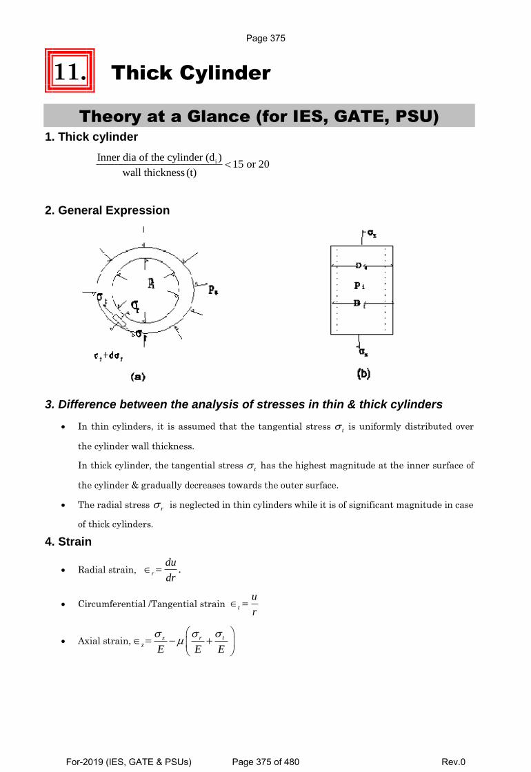
11. Thick Cylinder
Theory at a Glance (for IES, GATE, PSU) 1. Thick cylinder
iInner dia of the cylinder (d )15 or 20
wall thickness (t)
2. General Expression
3. Difference between the analysis of stresses in thin & thick cylinders
In thin cylinders, it is assumed that the tangential stress t is uniformly distributed over
the cylinder wall thickness.
In thick cylinder, the tangential stress t has the highest magnitude at the inner surface of
the cylinder & gradually decreases towards the outer surface.
The radial stress r is neglected in thin cylinders while it is of significant magnitude in case
of thick cylinders.
4. Strain
Radial strain, .r
du
dr
Circumferential /Tangential strain t
u
r
Axial strain, tz rz
E E E
Page 375
For-2019 (IES, GATE & PSUs) Page 375 of 480 Rev.0
Chapter-11 Thick Cylinder S K Mondal’s
5. Stress
Axial stress,
2
2 2
0
i iz
i
p r
r r
Radial stress, 2r
BA
r
Circumferential /Tangential stress, 2t
BA
r
[Note: Radial stress always compressive so its magnitude always –ive. But in some books they
assume that compressive radial stress is positive and they use, 2
r
BA
r]
6. Boundary Conditions
At ir r , r ip
At or r r op
7.2 2
2 2
i i o o
o i
p r p rA
r r and
2 2
2 2( )
( )
i oi o
o i
r rB p p
r r
8. Cylinders with internal pressure (pi) i.e. 0op
2
2 2
0
i iz
i
p r
r r
2 2
0
2 2 2
0
1
i ir
i
p r r
r r r [ -ive means compressive stress]
2 2
0
2 2 2
0
1
i it
i
p r r
r r r
(a) At the inner surface of the cylinder
r
2 2
t 2 2
2
max 2 2
( )
( )
( )( )
( ) .
i
i
i o i
o i
oi
o i
i r r
ii p
p r riii
r r
riv p
r r
(b) At the outer surface of the cylinder
2
i
2 2
( ) r = r
( ) 0
2p r( ) =
o
r
it
o i
i
ii
iiir r
Page 376
For-2019 (IES, GATE & PSUs) Page 376 of 480 Rev.0
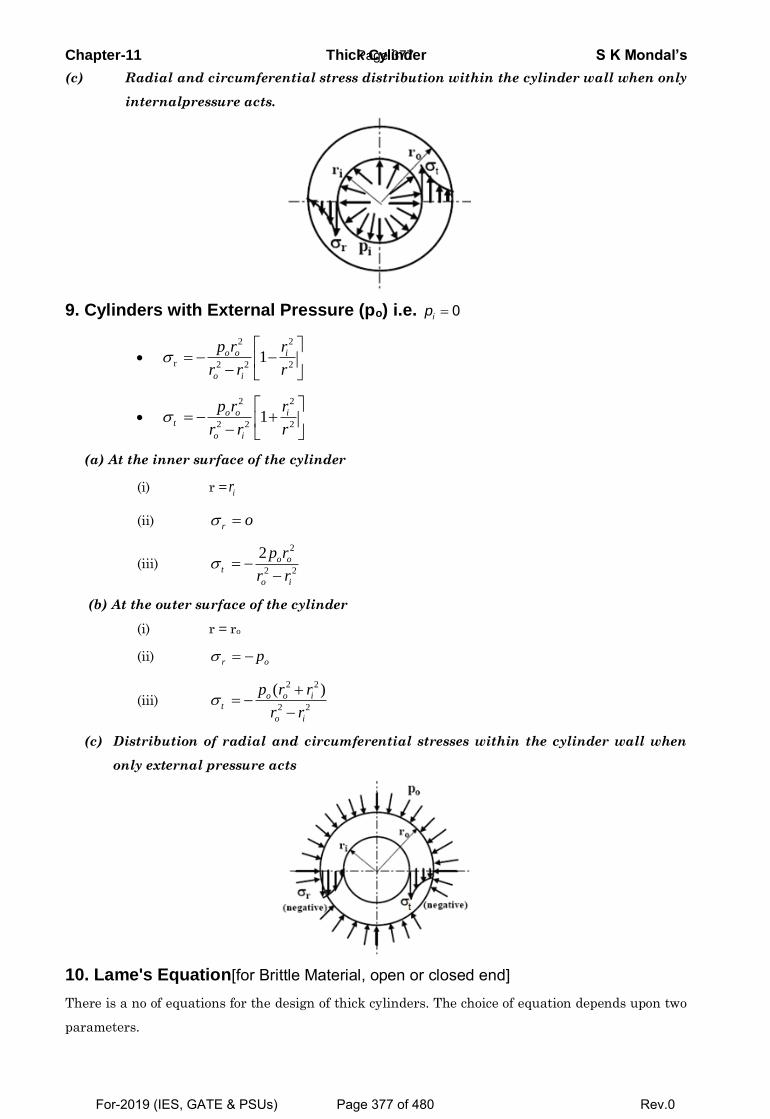
Chapter-11 Thick Cylinder S K Mondal’s
(c) Radial and circumferential stress distribution within the cylinder wall when only
internalpressure acts.
9. Cylinders with External Pressure (po) i.e. 0ip
2 2
r 2 2 21o o i
o i
p r r
r r r
2 2
2 2 21o o i
t
o i
p r r
r r r
(a) At the inner surface of the cylinder
(i) r = ir
(ii) r o
(iii)
2
2 2
2
o ot
o i
p r
r r
(b) At the outer surface of the cylinder
(i) r = ro
(ii) r op
(iii)
2 2
2 2
( )
o o it
o i
p r r
r r
(c) Distribution of radial and circumferential stresses within the cylinder wall when
only external pressure acts
10. Lame's Equation[for Brittle Material, open or closed end]
There is a no of equations for the design of thick cylinders. The choice of equation depends upon two
parameters.
Page 377
For-2019 (IES, GATE & PSUs) Page 377 of 480 Rev.0
Chapter-11 Thick Cylinder S K Mondal’s
Cylinder Material (Whether brittle or ductile)
Condition of Cylinder ends (open or closed)
When the material of the cylinder is brittle, such as cast iron or cast steel, Lame's Equation is used to
determine the wall thickness. Condition of cylinder ends may open or closed.
It is based on maximum principal stress theory of failure.
There principal stresses at the inner surface of the cylinder are as follows: (i) (ii) & (iii)
2 2
0t 2 2
0
2
z 2 2
( )
( )( )
( )
r i
i i
i
i i
o i
i p
p r rii
r r
p riii
r r
t z r
t is the criterion of design o
i
t i
t i
r p
r p
For o ir r t
t 1
t ii
t i
pr
p( ' )Lame s Equation
t
ult
fos
11. Clavarino's Equation[for cylinders with closed end & made of ductile material]
When the material of a cylinder is ductile, such as mild steel or alloy steel, maximum strain theory
of failure is used (St. Venant's theory) is used.
Three principal stresses at the inner surface of the cylinder are as follows (i) (ii) & (iii)
r
2 2
2 2
2
2 2
( )
( )( )
( )
( )( )
i
i o it
o i
i iz
o i
i p
p r rii
r r
p riii
r r
1
t t r z
E
/
yld
t
fos
E E
Or yld
( ). Where =fos
t r z
is the criterion of design
Page 378
For-2019 (IES, GATE & PSUs) Page 378 of 480 Rev.0
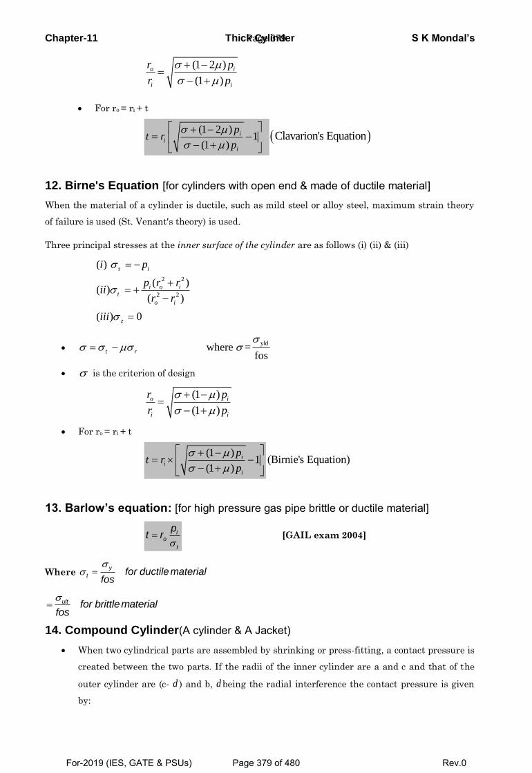
Chapter-11 Thick Cylinder S K Mondal’s
(1 2 )
(1 )
o i
i i
r p
r p
For ro = ri + t
(1 2 )
1 (1 )
ii
i
pt r
p Clavarion's Equation
12. Birne's Equation [for cylinders with open end & made of ductile material]
When the material of a cylinder is ductile, such as mild steel or alloy steel, maximum strain theory
of failure is used (St. Venant's theory) is used.
Three principal stresses at the inner surface of the cylinder are as follows (i) (ii) & (iii)
r
2 2
2 2
( )
( )( )
( )
( ) 0
i
i o it
o i
z
i p
p r rii
r r
iii
yld where =
fos
t r
is the criterion of design
(1 )
(1 )
o i
i i
r p
r p
For ro = ri + t
(1 )
1(1 )
ii
i
pt r
p(Birnie's Equation)
13. Barlow’s equation: [for high pressure gas pipe brittle or ductile material]
io
t
pt r
[GAIL exam 2004]
Where y
t for ductile materialfos
ult for brittlematerialfos
14. Compound Cylinder(A cylinder & A Jacket)
When two cylindrical parts are assembled by shrinking or press-fitting, a contact pressure is
created between the two parts. If the radii of the inner cylinder are a and c and that of the
outer cylinder are (c- d ) and b, d being the radial interference the contact pressure is given
by:
Page 379
For-2019 (IES, GATE & PSUs) Page 379 of 480 Rev.0
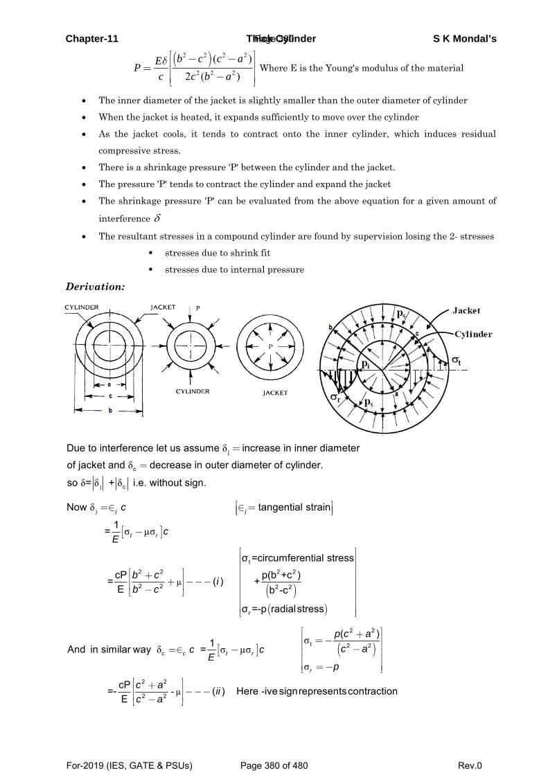
Chapter-11 Thick Cylinder S K Mondal’s
( )2 2 2 2
2 2 2
( )2 ( )
b c c aEPc c b aδ ⎡ ⎤− −⎢ ⎥= ⎢ ⎥−⎢ ⎥⎣ ⎦
Where E is the Young's modulus of the material
• The inner diameter of the jacket is slightly smaller than the outer diameter of cylinder
• When the jacket is heated, it expands sufficiently to move over the cylinder
• As the jacket cools, it tends to contract onto the inner cylinder, which induces residual
compressive stress.
• There is a shrinkage pressure 'P' between the cylinder and the jacket.
• The pressure 'P' tends to contract the cylinder and expand the jacket
• The shrinkage pressure 'P' can be evaluated from the above equation for a given amount of
interference δ
• The resultant stresses in a compound cylinder are found by supervision losing the 2- stresses
stresses due to shrink fit
stresses due to internal pressure
Derivation:
j
δ
δ
δ δ δ
j
c
c
Due to interference let us assume increase in inner diameter
of jacket and decrease in outer diameter of cylinder.
so = + i.e. without sign.
=
=
[ ]
( )( )
j
µ
δ
σ µσ
t2 2 2 2
2 2 2 2
r
Now tangential strain
1 =
σ =circumferential stress
cP p(b +c ) = ( ) +E b -c
σ =-p radialstress
j j
t r
c
cE
b c ib c
⎡ ⎤=∈ ∈ =⎢ ⎥⎣ ⎦
−
⎡ ⎤⎢ ⎥⎢ ⎥
⎡ ⎤ ⎢ ⎥+⎢ ⎥ ⎢ ⎥+ −−−⎢ ⎥ ⎢ ⎥−⎣ ⎦ ⎢ ⎥⎢ ⎥⎢ ⎥⎣ ⎦
[ ] ( )
µ
σδ σ µσ
σ
-
2 2
t 2 2
2 2
2 2
( )1And in similar way =
cP =- ( ) Here -ive signrepresentscontraction E
c c t r
r
p c ac ac c
Ep
c a iic a
⎡ ⎤+⎢ ⎥=−⎢ ⎥−=∈ − ⎢ ⎥⎢ ⎥
=−⎢ ⎥⎣ ⎦⎡ ⎤+⎢ ⎥ −−−⎢ ⎥−⎣ ⎦
Page 380
For-2019 (IES, GATE & PSUs) Page 380 of 480 Rev.0
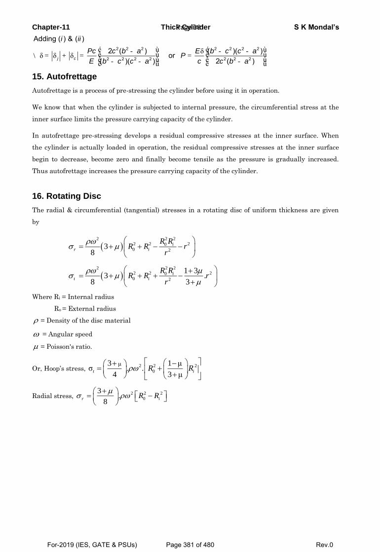
Chapter-11 Thick Cylinder S K Mondal’s
δδ δ δ
2 2 2 2 2 2 2
2 2 2 2 2 2 2
Adding ( ) & ( )
2 ( ) ( )( ) or( )( ) 2 ( )j c
i ii
Pc c b a E b c c aP
E cb c c a c b a
é ù é ù- - -ê ú ê ú\ = + = =ê ú ê ú- - -ë û ë û
15. Autofrettage
Autofrettage is a process of pre-stressing the cylinder before using it in operation.
We know that when the cylinder is subjected to internal pressure, the circumferential stress at the
inner surface limits the pressure carrying capacity of the cylinder.
In autofrettage pre-stressing develops a residual compressive stresses at the inner surface. When
the cylinder is actually loaded in operation, the residual compressive stresses at the inner surface
begin to decrease, become zero and finally become tensile as the pressure is gradually increased.
Thus autofrettage increases the pressure carrying capacity of the cylinder.
16. Rotating Disc
The radial & circumferential (tangential) stresses in a rotating disc of uniform thickness are given
by
2 22
2 2 200 2
38
ir i
R RR R r
r
2 22
2 2 200 2
1 33 .
8 3
it i
R RR R r
r
Where Ri = Internal radius
Ro = External radius
= Density of the disc material
= Angular speed
= Poisson's ratio.
Or, Hoop’s stress, 2 2 2
0
μ3 1 μσ . .
4 3 μ
t iR R
Radial stress, 2 2 2
0
3.
8
r iR R
Page 381
For-2019 (IES, GATE & PSUs) Page 381 of 480 Rev.0
Chapter-11 Thick Cylinder S K Mondal’s
OBJECTIVE QUESTIONS (GATE, IES, IAS)
Previous 25-Years GATE Questions
Lame's theory GATE-1. A thick cylinder is subjected to an internal pressure of 60 MPa. If the hoop
stress on the outer surface is 150 MPa, then the hoop stress on the internal
surface is: [GATE-1996; IES-2001]
(a) 105 MPa (b) 180 MPa (c) 210 MPa (d) 135 MPa
Previous 25-Years IES Questions
Thick cylinder IES-1. If a thick cylindrical shell is subjected to internal pressure, then hoop stress,
radial stress and longitudinal stress at a point in the thickness will be:
(a) Tensile, compressive and compressive respectively [IES-1999]
(b) All compressive
(c) All tensile
(d) Tensile, compressive and tensile respectively
IES-2. Where does the maximum hoop stress in a thick cylinder under external
pressure occur? [IES-2008]
(a) At the outer surface (b) At the inner surface
(c) At the mid-thickness (d) At the 2/3rd outer radius
IES-3. In a thick cylinder pressurized from inside, the hoop stress is maximum at
(a) The centre of the wall thickness (b) The outer radius [IES-1998]
(c) The inner radius (d) Both the inner and the outer radii
IES-3a. Consider the following statements for a thick-walled cylinder, subjected to an
internal pressure: [IES-2016]
1. Hoop stress is maximum at the inside radius.
2. Hoop stress is zero at the outside radius.
3. Shear stress is maximum at the inside radius.
4. Radial stress is uniform throughout the thickness of the wall.
Which of the above statements are correct?
(a) 1 and 4 (b) 1 and 3 (c) 2 and 3 (d) 2 and 4
IES-4. Consider the following statements:
1. In case of a thin spherical shell of diameter d and thickness t, subjected to internal
pressure p, the principal stresses at any point equal 𝑝𝑑
4𝑡. [IES-2018]
2. In case of thin cylinders, the hoop stress is determined assuming it to be uniform across the thickness of the cylinder.
3. In thick cylinders, the hoop stress is not uniform across the thickness but it varies from a maximum value at the inner circumference to a minimum value at the outer circumference.
Which of the above statements are correct? (a) 1 and 2 only (b) 1 and 3 only
Page 382
For-2019 (IES, GATE & PSUs) Page 382 of 480 Rev.0
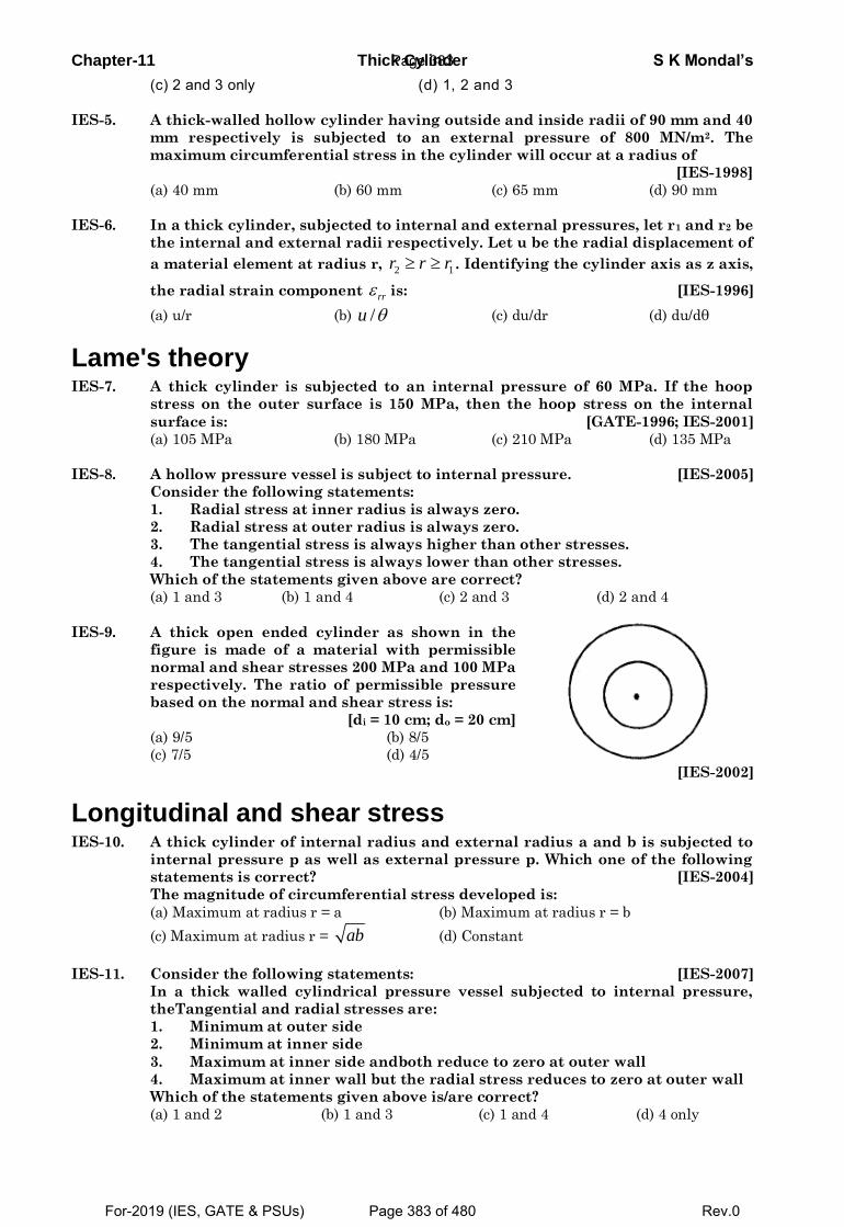
Chapter-11 Thick Cylinder S K Mondal’s
(c) 2 and 3 only (d) 1, 2 and 3
IES-5. A thick-walled hollow cylinder having outside and inside radii of 90 mm and 40
mm respectively is subjected to an external pressure of 800 MN/m2. The
maximum circumferential stress in the cylinder will occur at a radius of
[IES-1998]
(a) 40 mm (b) 60 mm (c) 65 mm (d) 90 mm
IES-6. In a thick cylinder, subjected to internal and external pressures, let r1 and r2 be
the internal and external radii respectively. Let u be the radial displacement of
a material element at radius r, 2 1r r r . Identifying the cylinder axis as z axis,
the radial strain component rr is: [IES-1996]
(a) u/r (b) /u (c) du/dr (d) du/dθ
Lame's theory IES-7. A thick cylinder is subjected to an internal pressure of 60 MPa. If the hoop
stress on the outer surface is 150 MPa, then the hoop stress on the internal
surface is: [GATE-1996; IES-2001]
(a) 105 MPa (b) 180 MPa (c) 210 MPa (d) 135 MPa
IES-8. A hollow pressure vessel is subject to internal pressure. [IES-2005]
Consider the following statements:
1. Radial stress at inner radius is always zero.
2. Radial stress at outer radius is always zero.
3. The tangential stress is always higher than other stresses.
4. The tangential stress is always lower than other stresses.
Which of the statements given above are correct?
(a) 1 and 3 (b) 1 and 4 (c) 2 and 3 (d) 2 and 4
IES-9. A thick open ended cylinder as shown in the
figure is made of a material with permissible
normal and shear stresses 200 MPa and 100 MPa
respectively. The ratio of permissible pressure
based on the normal and shear stress is:
[di = 10 cm; do = 20 cm]
(a) 9/5 (b) 8/5
(c) 7/5 (d) 4/5
[IES-2002]
Longitudinal and shear stress IES-10. A thick cylinder of internal radius and external radius a and b is subjected to
internal pressure p as well as external pressure p. Which one of the following
statements is correct? [IES-2004]
The magnitude of circumferential stress developed is:
(a) Maximum at radius r = a (b) Maximum at radius r = b
(c) Maximum at radius r = ab (d) Constant
IES-11. Consider the following statements: [IES-2007]
In a thick walled cylindrical pressure vessel subjected to internal pressure,
theTangential and radial stresses are:
1. Minimum at outer side
2. Minimum at inner side
3. Maximum at inner side andboth reduce to zero at outer wall
4. Maximum at inner wall but the radial stress reduces to zero at outer wall
Which of the statements given above is/are correct?
(a) 1 and 2 (b) 1 and 3 (c) 1 and 4 (d) 4 only
Page 383
For-2019 (IES, GATE & PSUs) Page 383 of 480 Rev.0
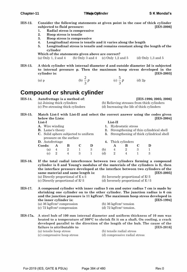
Chapter-11 Thick Cylinder S K Mondal’s
IES-12. Consider the following statements at given point in the case of thick cylinder
subjected to fluid pressure: [IES-2006]
1. Radial stress is compressive
2. Hoop stress is tensile
3. Hoop stress is compressive
4. Longitudinal stress is tensile and it varies along the length
5. Longitudinal stress is tensile and remains constant along the length of the
cylinder
Which of the statements given above are correct?
(a) Only 1, 2 and 4 (b) Only 3 and 4 (c) Only 1,2 and 5 (d) Only 1,3 and 5
IES-13. A thick cylinder with internal diameter d and outside diameter 2d is subjected
to internal pressure p. Then the maximum hoop stress developed in the
cylinder is: [IES-2003]
(a) p (b) 2
3p (c)
5
3p (d) 2p
Compound or shrunk cylinder IES-14. Autofrettage is a method of: [IES-1996; 2005; 2006]
(a) Joining thick cylinders (b) Relieving stresses from thick cylinders
(c) Pre-stressing thick cylinders (d) Increasing the life of thick cylinders
IES-15. Match List-I with List-II and select the correct answer using the codes given
below the Lists: [IES-2004]
List-I List-II
A. Wire winding 1. Hydrostatic stress
B. Lame's theory 2. Strengthening of thin cylindrical shell
C. Solid sphere subjected to uniform 3. Strengthening of thick cylindrical shell
pressure on the surface
D. Autofrettage 4. Thick cylinders
Coeds: A B C D A B C D
(a) 4 2 1 3 (b) 4 2 3 1
(c) 2 4 3 1 (d) 2 4 1 3
IES-16. If the total radial interference between two cylinders forming a compound
cylinder is δ and Young's modulus of the materials of the cylinders is E, then
the interface pressure developed at the interface between two cylinders of the
same material and same length is: [IES-2005]
(a) Directly proportional of E x δ (b) Inversely proportional of E/ δ
(c) Directly proportional of E/ δ (d) Inversely proportional of E / δ
IES-17. A compound cylinder with inner radius 5 cm and outer radius 7 cm is made by
shrinking one cylinder on to the other cylinder. The junction radius is 6 cm
and the junction pressure is 11 kgf/cm2. The maximum hoop stress developed in
the inner cylinder is: [IES-1994]
(a) 36 kgf/cm2 compression (b) 36 kgf/cm2 tension
(c) 72 kgf/cm2 compression (d) 72 kgf/cm2 tension.
IES-17a. A steel hub of 100 mm internal diameter and uniform thickness of 10 mm was
heated to a temperature of 300°C to shrink fit it on a shaft. On cooling, a crack
developed parallel to the direction of the length of the hub. The cause of the
failure is attributable to [IES-2016]
(a) tensile hoop stress (b) tensile radial stress
(c) compressive hoop stress (d) compressive radial stress
Page 384
For-2019 (IES, GATE & PSUs) Page 384 of 480 Rev.0
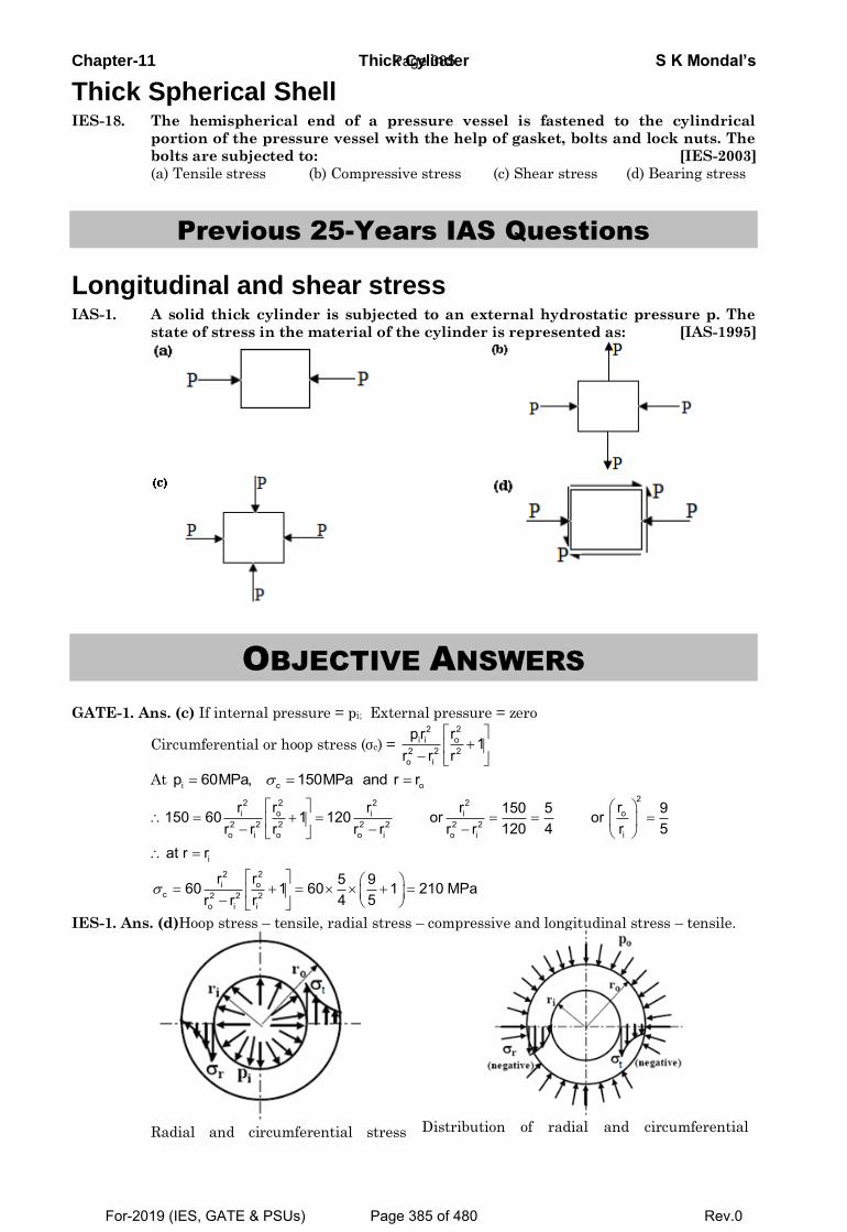
Chapter-11 Thick Cylinder S K Mondal’s
Thick Spherical Shell IES-18. The hemispherical end of a pressure vessel is fastened to the cylindrical
portion of the pressure vessel with the help of gasket, bolts and lock nuts. The
bolts are subjected to: [IES-2003]
(a) Tensile stress (b) Compressive stress (c) Shear stress (d) Bearing stress
Previous 25-Years IAS Questions
Longitudinal and shear stress IAS-1. A solid thick cylinder is subjected to an external hydrostatic pressure p. The
state of stress in the material of the cylinder is represented as: [IAS-1995]
OBJECTIVE ANSWERS
GATE-1. Ans. (c) If internal pressure = pi; External pressure = zero
Circumferential or hoop stress (σc) =
22oi i
2 2 2o i
rp r1
r r r
At i c op 60MPa, 150MPa and r r
222 2 2o oi i i
2 2 2 2 2 2 2io i o o i o i
i
22oi
c 2 2 2o i i
r rr r r 150 5 9150 60 1 120 or or120 4 r 5r r r r r r r
at r r
rr 5 960 1 60 1 210 MPa4 5r r r
IES-1. Ans. (d)Hoop stress – tensile, radial stress – compressive and longitudinal stress – tensile.
Radial and circumferential stress
Distribution of radial and circumferential
Page 385
For-2019 (IES, GATE & PSUs) Page 385 of 480 Rev.0
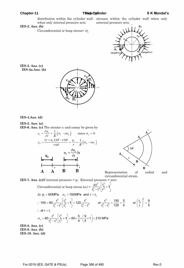
Chapter-11 Thick Cylinder S K Mondal’s
distribution within the cylinder wall
when only internal pressure acts.
stresses within the cylinder wall when only
external pressure acts.
IES-2. Ans. (b)
Circumferential or hoop stress= t
IES-3. Ans. (c)
IES-3a.Ans. (b)
IES-4.Ans. (d)
IES-5. Ans. (a)
IES-6. Ans. (c) The strains εr and εθmay be given by
1since 0
1
r
r r z
r r
r
uv
r E
r u r uv
r r E
Representation of radial and
circumferential strain.
IES-7. Ans. (c)If internal pressure = pi; External pressure = zero
Circumferential or hoop stress (σc) =
22oi i
2 2 2o i
rp r1
r r r
At i c op 60MPa, 150MPa and r r
222 2 2o oi i i
2 2 2 2 2 2 2io i o o i o i
i
22oi
c 2 2 2o i i
r rr r r 150 5 9150 60 1 120 or or120 4 r 5r r r r r r r
at r r
rr 5 960 1 60 1 210 MPa4 5r r r
IES-8. Ans. (c)
IES-9. Ans. (b)
IES-10. Ans. (d)
Page 386
For-2019 (IES, GATE & PSUs) Page 386 of 480 Rev.0
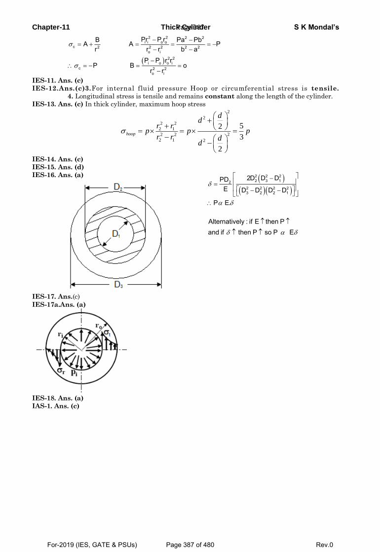
Chapter-11 Thick Cylinder S K Mondal’s
2 2 2 2i i o o
c 2 2 2 2 2o i
2 2i o o i
c 2 2o i
Pr P rB Pa PbA A Pr r r b a
P P r rP B o
r r
IES-11. Ans. (c)
IES-12.Ans.(c)3.For internal fluid pressure Hoop or circumferential stress is tensile.
4. Longitudinal stress is tensile and remains constant along the length of the cylinder.
IES-13. Ans. (c) In thick cylinder, maximum hoop stress 2
2
2 2
2 1
22 2
2 1 2
52
3
2
hoop
dd
r rp p p
r r dd
IES-14. Ans. (c)
IES-15. Ans. (d)
IES-16. Ans. (a)
2 2 22 3 12
2 2 2 23 2 2 1
2D D DPDE D D D D
P E.
Alternatively : if E then Pand if then P so P E
IES-17. Ans.(c)
IES-17a.Ans. (a)
IES-18. Ans. (a)
IAS-1. Ans. (c)
Page 387
For-2019 (IES, GATE & PSUs) Page 387 of 480 Rev.0
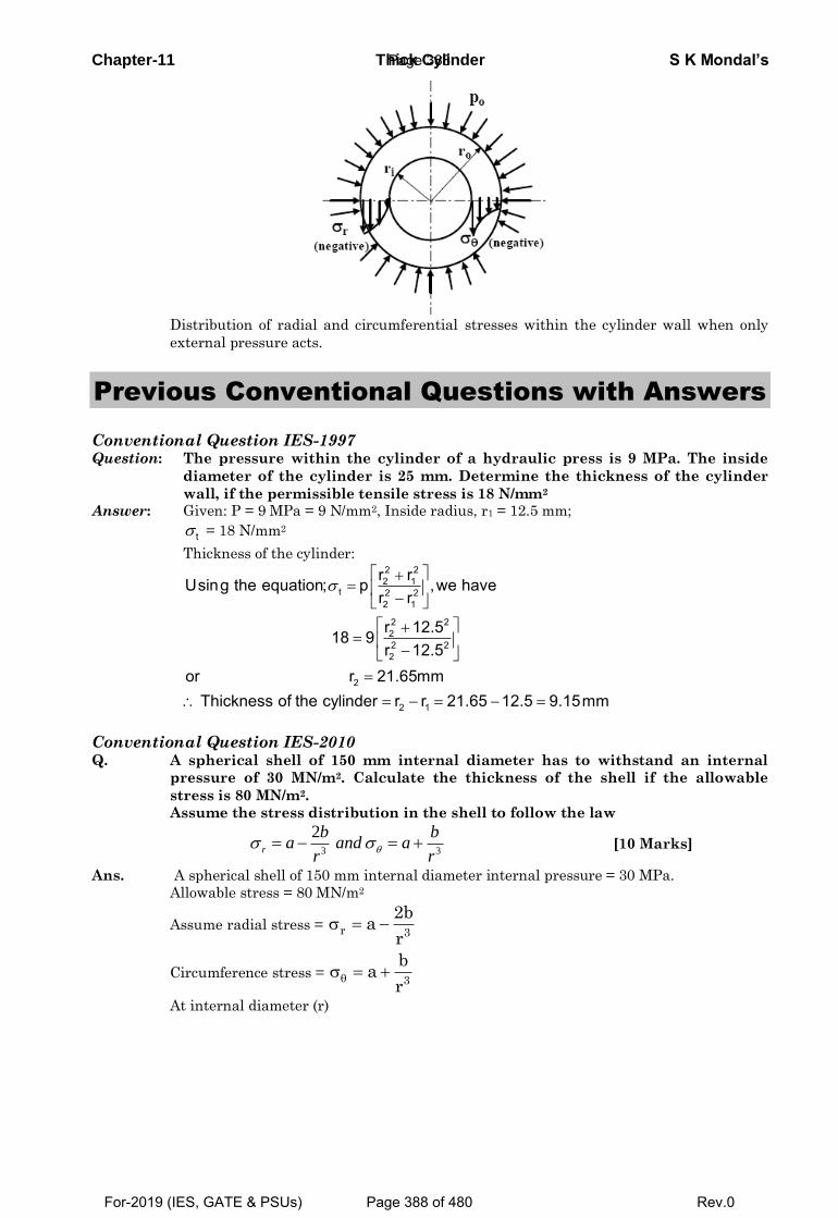
Chapter-11 Thick Cylinder S K Mondal’s
Distribution of radial and circumferential stresses within the cylinder wall when only
external pressure acts.
Previous Conventional Questions with Answers
Conventional Question IES-1997 Question: The pressure within the cylinder of a hydraulic press is 9 MPa. The inside
diameter of the cylinder is 25 mm. Determine the thickness of the cylinder
wall, if the permissible tensile stress is 18 N/mm2
Answer: Given: P = 9 MPa = 9 N/mm2, Inside radius, r1 = 12.5 mm;
t = 18 N/mm2
Thickness of the cylinder:
2 22 1
t 2 22 1
2 222 22
2
2 1
r rUsing the equation; p ,we haver r
r 12.518 9r 12.5
or r 21.65mmThickness of the cylinder r r 21.65 12.5 9.15mm
Conventional Question IES-2010
Q. A spherical shell of 150 mm internal diameter has to withstand an internal
pressure of 30 MN/m2. Calculate the thickness of the shell if the allowable
stress is 80 MN/m2.
Assume the stress distribution in the shell to follow the law
3 3
2r
b ba and a
r r [10 Marks]
Ans. A spherical shell of 150 mm internal diameter internal pressure = 30 MPa.
Allowable stress = 80 MN/m2
Assume radial stress =
Circumference stress =
At internal diameter (r)
r 3
2ba
r
3
ba
r
Page 388
For-2019 (IES, GATE & PSUs) Page 388 of 480 Rev.0
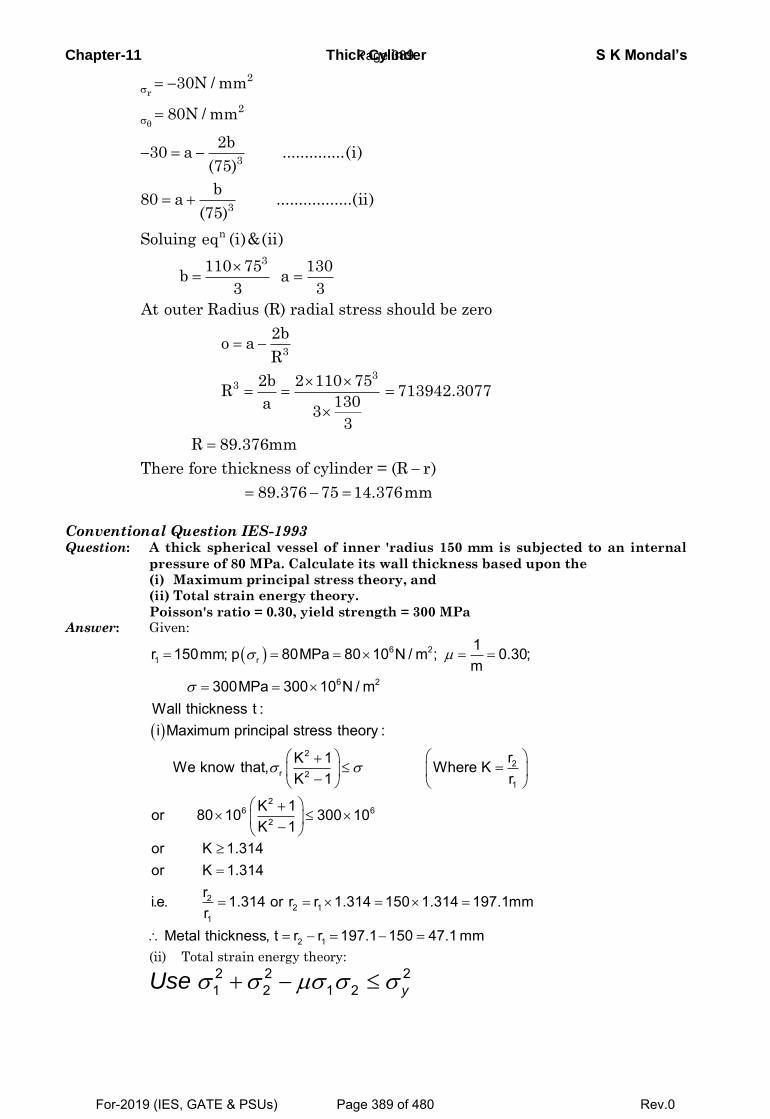
Chapter-11 Thick Cylinder S K Mondal’s
r
2
2
3
3
n
3
3
33
30N / mm
80N / mm
2b30 a ..............(i)
(75)
b80 a .................(ii)
(75)
Soluing eq (i)&(ii)
110 75 130b a
3 3
At outer Radius (R) radial stress should be zero
2bo a
R
2b 2 110 75R 713
130a3
3
942.3077
R 89.376mm
There fore thickness of cylinder = (R r)
89.376 75 14.376mm
Conventional Question IES-1993 Question: A thick spherical vessel of inner 'radius 150 mm is subjected to an internal
pressure of 80 MPa. Calculate its wall thickness based upon the
(i) Maximum principal stress theory, and
(ii) Total strain energy theory.
Poisson's ratio = 0.30, yield strength = 300 MPa Answer: Given:
6 21 r
6 2
1r 150mm; p 80MPa 80 10 N / m ; 0.30;m
300MPa 300 10 N / mWall thickness t :
2
2r 2
1
26 6
2
i Maximum principal stress theory :
rK 1We know that, Where KrK 1
K 1or 80 10 300 10K 1
22 1
1
2 1
or K 1.314or K 1.314
ri.e. 1.314 or r r 1.314 150 1.314 197.1mmr
Metal thickness, t r r 197.1 150 47.1 mm
(ii) Total strain energy theory:
2 2 21 2 1 2 yUse
Page 389
For-2019 (IES, GATE & PSUs) Page 389 of 480 Rev.0
Chapter-11 Thick Cylinder S K Mondal’s
( ) ( )( )
( ) ( ) ( ) ( )( )
( ) ( )
2 4r2
22
26 426
22
22 2 2 4
22
1
2 1
2 K 1 1
K 1
2 80 10 K 1 03 1 0.3300 10
K 1
or 300 K 1 2 80 1.3K 0.7
gives K 1.86 or 0.59It is clear thatK 1
K 1.364ror 1.364 or r 150 1.364 204.6 mmrt r r 204.6 150 54.6 mm
σ μ μσ
⎡ ⎤+ + −⎣ ⎦≥−
⎡ ⎤× × + + −⎣ ⎦∴ × ≥−
− = × +
=>
∴ =
= = × =
∴ = − = − =
Conventional Question ESE-2002 Question: What is the difference in the analysis of think tubes compared to that for thin
tubes? State the basic equations describing stress distribution in a thick tube.
Answer: The difference in the analysis of stresses in thin and thick cylinder: (i) In thin cylinder, it is assumed that the tangential stress is uniformly distributed
over the cylinder wall thickness. In thick cylinder, the tangential stress has highest magnitude at the inner surface of the cylinder and gradually decreases towards the outer surface.
(ii) The radial stress is neglected in thin cylinders, while it is of significant magnitude in case of thick cylinders.
Basic equation for describing stress distribution in thick tube is Lame's equation.
2 2 and r tB BA Ar r
σ σ= − = +
Conventional Question ESE-2006 Question: What is autofrettage? How does it help in increasing the pressure carrying capacity of a thick
cylinder? Answer: Autofrettage is a process of pre-stressing the cylinder before using it in operation.
We know that when the cylinder is subjected to internal pressure, the circumferential stress at the inner surface limits the pressure carrying capacity of the cylinder.
In autofrettage pre-stressing develops a residual compressive stresses at the inner surface. When the cylinder is actually loaded in operation, the residual compressive stresses at the inner surface begin to decrease, become zero and finally become tensile as the pressure is gradually increased. Thus autofrettage increases the pressure carrying capacity of the cylinder.
Conventional Question ESE-2001 Question: When two cylindrical parts are assembled by shrinking or press-fitting, a
contact pressure is created between the two parts. If the radii of the inner cylinder are a and c and that of the outer cylinder are (c- δ ) and b, δbeing the radial interference the contact pressure is given by:
( )2 2 2 2
2 2 2
( )2 ( )
b c c aEPc c b aδ ⎡ ⎤− −⎢ ⎥= ⎢ ⎥−⎢ ⎥⎣ ⎦
Page 390
For-2019 (IES, GATE & PSUs) Page 390 of 480 Rev.0
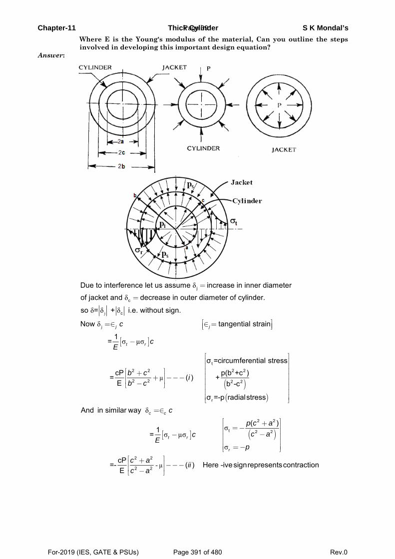
Chapter-11 Thick Cylinder S K Mondal’s
Where E is the Young's modulus of the material, Can you outline the steps involved in developing this important design equation?
Answer:
j
δ
δ
δ δ δ
j
c
c
Due to interference let us assume increase in inner diameter
of jacket and decrease in outer diameter of cylinder.
so = + i.e. without sign.
=
=
[ ]
( )( )
j
µ
δ
σ µσ
t2 2 2 2
2 2 2 2
r
Now tangential strain
1 =
σ =circumferential stress
cP p(b +c ) = ( ) +E b -c
σ =-p radialstress
j j
t r
c
cE
b c ib c
⎡ ⎤=∈ ∈ =⎢ ⎥⎣ ⎦
−
⎡ ⎤⎢ ⎥⎢ ⎥
⎡ ⎤ ⎢ ⎥+⎢ ⎥ ⎢ ⎥+ −−−⎢ ⎥ ⎢ ⎥−⎣ ⎦ ⎢ ⎥⎢ ⎥⎢ ⎥⎣ ⎦
[ ] ( )
µ
δ
σσ µσ
σ
-
2 2
t 2 2
2 2
2 2
And in similar way
( )1 =
cP =- ( ) Here -ivesignrepresentscontraction E
c c
t r
r
c
p c ac ac
Ep
c a iic a
=∈
⎡ ⎤+⎢ ⎥=−⎢ ⎥−− ⎢ ⎥⎢ ⎥
=−⎢ ⎥⎣ ⎦⎡ ⎤+⎢ ⎥ −−−⎢ ⎥−⎣ ⎦
Page 391
For-2019 (IES, GATE & PSUs) Page 391 of 480 Rev.0
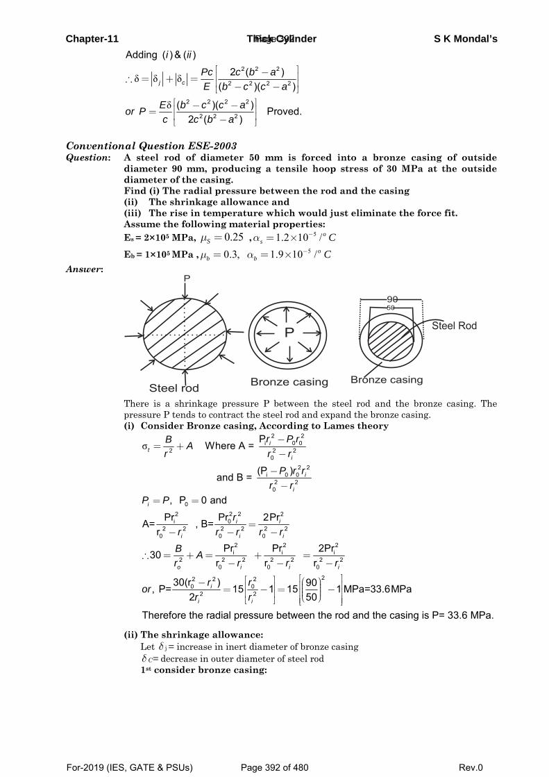
Chapter-11 Thick Cylinder S K Mondal’s
δ δ δ
δ
2 2 2
2 2 2 2
2 2 2 2
2 2 2
Adding ( ) & ( )
2 ( )( )( )
( )( ) Proved.2 ( )
j c
i ii
Pc c b aE b c c a
E b c c aor Pc c b a
⎡ ⎤−⎢ ⎥∴ = + = ⎢ ⎥− −⎣ ⎦⎡ ⎤− −⎢ ⎥= ⎢ ⎥−⎣ ⎦
Conventional Question ESE-2003 Question: A steel rod of diameter 50 mm is forced into a bronze casing of outside
diameter 90 mm, producing a tensile hoop stress of 30 MPa at the outside diameter of the casing.
Find (i) The radial pressure between the rod and the casing (ii) The shrinkage allowance and (iii) The rise in temperature which would just eliminate the force fit. Assume the following material properties: Es = 2×10⁵ MPa, 0.25 Sμ = , 51.2 10 /o
s Cα −= ×
Eb = 1×10⁵ MPa , 50.3, 1.9 10 /ob b Cμ α −= = ×
Answer:
There is a shrinkage pressure P between the steel rod and the bronze casing. The
pressure P tends to contract the steel rod and expand the bronze casing. (i) Consider Bronze casing, According to Lames theory
σ
2 2i 0 0
2 2 20
2 2i 0 0
2 20
P Where A =
(P ) and B =
it
i
i
i
r P rB Ar r r
P r rr r
−= +
−
−−
0
2 22 20i
2 2 2 2 2 20 0 0
, P 0 and
PrPr 2PrA= , B=r
i
i i
i i i
P P
rr r r r r
= =
=− − −
2 2 2i i i
2 2 2 2 2 2 20 0 0
22 2 20 0
2 2
Pr Pr 2Pr30 r r r
30(r ) 90, P= 15 1 15 1 MPa=33.6MPa502
Therefore the radial pressure between the rod and the casing is P=
o i i i
i
i i
B Ar r r r
r ror
r r
∴ = + = + =− − −
⎡ ⎤⎡ ⎤ ⎛ ⎞− ⎢ ⎥⎟⎜⎢ ⎥= − = −⎟⎜⎢ ⎥⎟⎢ ⎥ ⎜⎝ ⎠⎢ ⎥⎣ ⎦ ⎣ ⎦ 33.6 MPa.
(ii) The shrinkage allowance: Let δ j = increase in inert diameter of bronze casing δ C= decrease in outer diameter of steel rod 1st consider bronze casing:
Page 392
For-2019 (IES, GATE & PSUs) Page 392 of 480 Rev.0
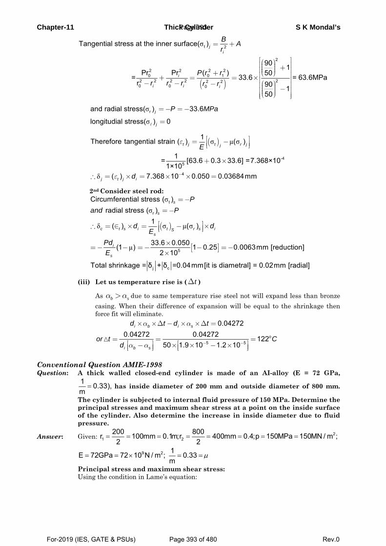
Chapter-11 Thick Cylinder S K Mondal’s
( )
σ t 2
2
2 2 220 0 1
2 2 2 2 22 20 0 0
Tangential stress at the inner surface( )
90 1Pr ( )Pr 50 = 33.6 = 63.6MPa
r 90 150
ji
i
i i i
B Ar
P r rr r r r r
= +
⎡ ⎤⎛ ⎞⎢ ⎥⎟⎜ +⎟⎜⎢ ⎥⎟⎜⎝ ⎠+ ⎢ ⎥+ = = ×⎢ ⎥− − ⎛ ⎞− ⎢ ⎥⎟⎜ −⎟⎜⎢ ⎥⎟⎜⎝ ⎠⎢ ⎥⎣ ⎦
σ
σrand radial stress( ) 33.6
longitudial stress( ) 0j
j
P MPa=− =−
=
( )σ µ σ
δ
-45
4
1Therefore tangential strain ( ) ( )
1 = [63.6 0.3 33.6] =7.368×101×10
( ) 7.368 10 0.050 0.03684mm
t j t r jj
j t j i
E
d
ε
ε −
⎡ ⎤= −⎢ ⎥⎣ ⎦
+ ×
∴ = × = × × =
2nd Consider steel rod:
( )
[ ]
σσ
δ σ µ σ
µ
t
r
5
j c
Circumferential stress ( ) radial stress ( )
1( ) ( )
33.6 0.050(1 ) 1 0.25 0.0063mm [reduction]2 10
Total shrinkage = δ + δ =0.04mm[it is diametral] = 0.0
s
s
c t s i t r s iSs
i
s
Pand P
d dE
PdE
=−
=−
⎡ ⎤∴ = ∈ × = − ×⎢ ⎥⎣ ⎦
×=− − =− − =−
×
2mm [radial]
(iii) Let us temperature rise is ( tΔ )
As b sα α> due to same temperature rise steel not will expand less than bronze casing. When their difference of expansion will be equal to the shrinkage then force fit will eliminate.
5 5
0.042720.04272 0.04272 122
50 1.9 10 1.2 10
i b i s
o
i b s
d t d t
or t Cd
α α
α α − −
× ×Δ − × ×Δ =
= = =⎡ ⎤ ⎡ ⎤− × × − ×⎢ ⎥ ⎢ ⎥⎣ ⎦ ⎣ ⎦
Conventional Question AMIE-1998 Question: A thick walled closed-end cylinder is made of an AI-alloy (E = 72 GPa,
1 0.33),m
= has inside diameter of 200 mm and outside diameter of 800 mm.
The cylinder is subjected to internal fluid pressure of 150 MPa. Determine the principal stresses and maximum shear stress at a point on the inside surface of the cylinder. Also determine the increase in inside diameter due to fluid pressure.
Answer: Given: 21 2
200 800r 100mm 0.1m;r 400mm 0.4;p 150MPa 150MN / m ;2 2
= = = = = = = =
9 2 1E 72GPa 72 10 N / m ; 0.33m
μ= = × = =
Principal stress and maximum shear stress: Using the condition in Lame’s equation:
Page 393
For-2019 (IES, GATE & PSUs) Page 393 of 480 Rev.0
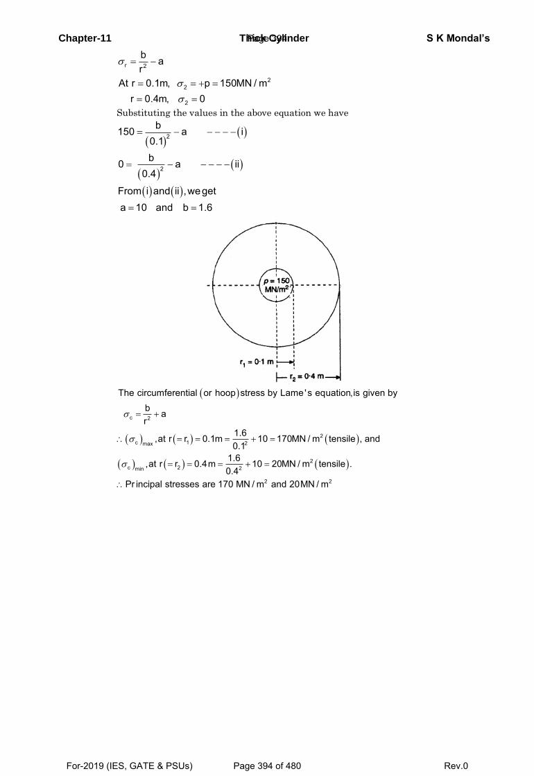
Chapter-11 Thick Cylinder S K Mondal’s
r 2
22
2
b ar
At r 0.1m, p 150MN / mr 0.4m, 0
Substituting the values in the above equation we have
2
2
b150 a i0.1b0 a ii
0.4
From i and ii ,wegeta 10 and b 1.6
c 2
2c 1 2max
2c 2 2min
2 2
The circumferential or hoop stress by Lame's equation,is given byb ar
1.6,at r r 0.1m 10 170MN / m tensile , and0.1
1.6,at r r 0.4m 10 20MN / m tensile .0.4
Pr incipal stresses are 170 MN / m and 20MN / m
Page 394
For-2019 (IES, GATE & PSUs) Page 394 of 480 Rev.0
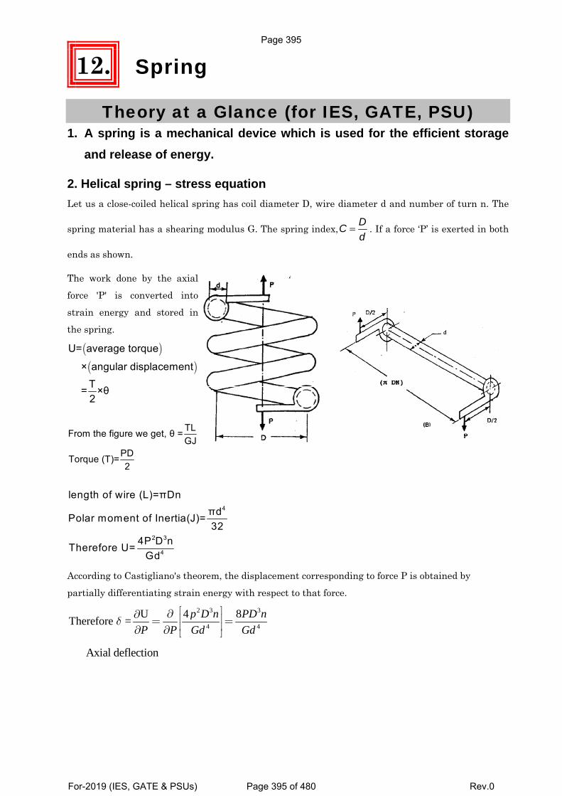
12. Spring
Theory at a Glance (for IES, GATE, PSU) 1. A spring is a mechanical device which is used for the efficient storage
and release of energy.
2. Helical spring – stress equation Let us a close-coiled helical spring has coil diameter D, wire diameter d and number of turn n. The
spring material has a shearing modulus G. The spring index,DCd
= . If a force ‘P’ is exerted in both
ends as shown.
The work done by the axial
force 'P' is converted into
strain energy and stored in
the spring.
( )( )
U= average torque
× angular displacementT = ×θ2
TLFrom the figure we get, θ =GJ
PDTorque (T)=2
4
2 3
4
length of wire (L)=πDnπdPolar moment of Inertia(J)=32
4P D nTherefore U= Gd
According to Castigliano's theorem, the displacement corresponding to force P is obtained by
partially differentiating strain energy with respect to that force. 2 3 3
4 4
4 8UTherefore = p D n PD nP P Gd Gd
δ⎡ ⎤∂∂ ⎢ ⎥= =⎢ ⎥∂ ∂ ⎣ ⎦
Axial deflection
Page 395
For-2019 (IES, GATE & PSUs) Page 395 of 480 Rev.0
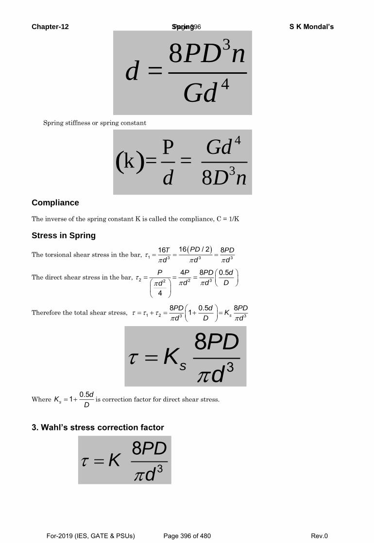
Chapter-12 Spring S K Mondal’s
3
4
8 =
PD n
Gdd
Spring stiffness or spring constant
( )4
3
Pk =
8
Gd
D nd=
Compliance
The inverse of the spring constant K is called the compliance, C = 1/K
Stress in Spring
The torsional shear stress in the bar,
1 3 3 3
16 / 216 8PDT PD
d d d
The direct shear stress in the bar, 2 2 32
4 8 0.5
4
P P PD d
Dd dd
Therefore the total shear stress, 1 2 3 3
8 0.5 81 s
PD d PDK
Dd d
3
8s
PDK
d
Where 0.51s
dK
D is correction factor for direct shear stress.
3. Wahl’s stress correction factor
3
8PDK
d
Page 396
For-2019 (IES, GATE & PSUs) Page 396 of 480 Rev.0
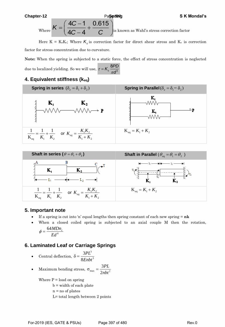
Chapter-12 Spring S K Mondal’s
Where
4 1 0.6154 4
CK
C C
is known as Wahl’s stress correction factor
Here K = KsKc; Where sK is correction factor for direct shear stress and Kc is correction
factor for stress concentration due to curvature.
Note: When the spring is subjected to a static force, the effect of stress concentration is neglected
due to localized yielding. So we will use, 3
8s
PDK
d
4. Equivalent stiffness (keq)
Spring in series 1 2(δ δ δ )e Spring in Parallel 1 2(δ δ = δ )e
eq 1 2
1 1 1 K K K
or 1 2
1 2
eq
K KK
K K eq 1 2 K K K
Shaft in series ( 1 2 ) Shaft in Parallel ( 1 2 eq )
eq 1 2
1 1 1 K K K
or 1 2
1 2
eq
K KK
K K eq 1 2 K K K
5. Important note
If a spring is cut into ‘n’ equal lengths then spring constant of each new spring = nk
When a closed coiled spring is subjected to an axial couple M then the rotation,
4
64 cMDn
Ed
6. Laminated Leaf or Carriage Springs
Central deflection,
3
3
3δ
8
PL
Enbt
Maximum bending stress, max 2
3σ
2
PL
nbt
Where P = load on spring
b = width of each plate
n = no of plates
L= total length between 2 points
Page 397
For-2019 (IES, GATE & PSUs) Page 397 of 480 Rev.0
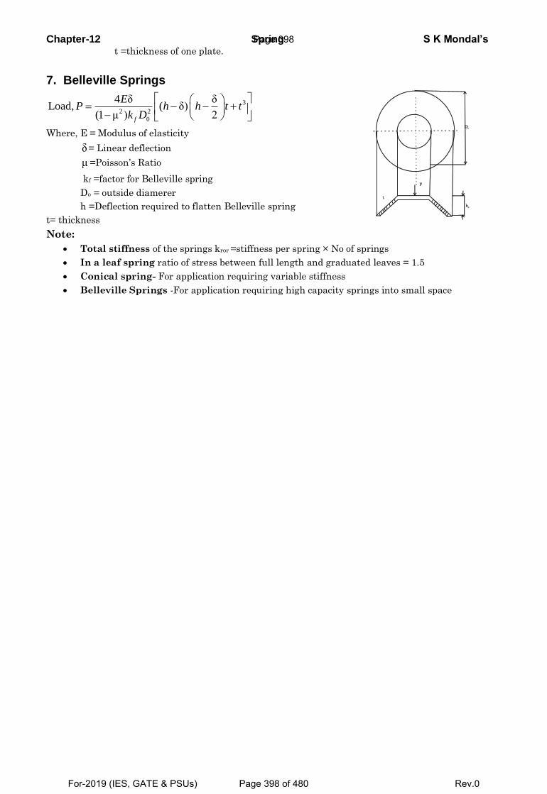
Chapter-12 Spring S K Mondal’s t =thickness of one plate.
7. Belleville Springs
3
2 2
0
4 δ δLoad, ( δ)
(1 μ ) 2
f
EP h h t t
k D
Where, E = Modulus of elasticity
δ = Linear deflection
μ =Poisson’s Ratio
kf =factor for Belleville spring
Do = outside diamerer
h =Deflection required to flatten Belleville spring
t= thickness
Note:
Total stiffness of the springs kror =stiffness per spring × No of springs
In a leaf spring ratio of stress between full length and graduated leaves = 1.5
Conical spring- For application requiring variable stiffness
Belleville Springs -For application requiring high capacity springs into small space
Page 398
For-2019 (IES, GATE & PSUs) Page 398 of 480 Rev.0
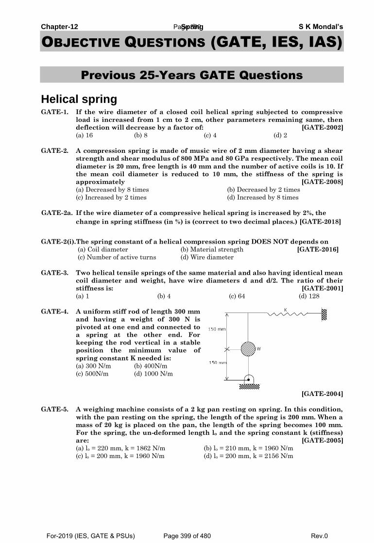
Chapter-12 Spring S K Mondal’s
OBJECTIVE QUESTIONS (GATE, IES, IAS)
Previous 25-Years GATE Questions
Helical spring GATE-1. If the wire diameter of a closed coil helical spring subjected to compressive
load is increased from 1 cm to 2 cm, other parameters remaining same, then
deflection will decrease by a factor of: [GATE-2002]
(a) 16 (b) 8 (c) 4 (d) 2
GATE-2. A compression spring is made of music wire of 2 mm diameter having a shear
strength and shear modulus of 800 MPa and 80 GPa respectively. The mean coil
diameter is 20 mm, free length is 40 mm and the number of active coils is 10. If
the mean coil diameter is reduced to 10 mm, the stiffness of the spring is
approximately [GATE-2008]
(a) Decreased by 8 times (b) Decreased by 2 times
(c) Increased by 2 times (d) Increased by 8 times
GATE-2a. If the wire diameter of a compressive helical spring is increased by 2%, the
change in spring stiffness (in %) is (correct to two decimal places.) [GATE-2018]
GATE-2(i).The spring constant of a helical compression spring DOES NOT depends on
(a) Coil diameter (b) Material strength [GATE-2016]
(c) Number of active turns (d) Wire diameter
GATE-3. Two helical tensile springs of the same material and also having identical mean
coil diameter and weight, have wire diameters d and d/2. The ratio of their
stiffness is: [GATE-2001]
(a) 1 (b) 4 (c) 64 (d) 128
GATE-4. A uniform stiff rod of length 300 mm
and having a weight of 300 N is
pivoted at one end and connected to
a spring at the other end. For
keeping the rod vertical in a stable
position the minimum value of
spring constant K needed is:
(a) 300 N/m (b) 400N/m
(c) 500N/m (d) 1000 N/m
[GATE-2004]
GATE-5. A weighing machine consists of a 2 kg pan resting on spring. In this condition,
with the pan resting on the spring, the length of the spring is 200 mm. When a
mass of 20 kg is placed on the pan, the length of the spring becomes 100 mm.
For the spring, the un-deformed length lo and the spring constant k (stiffness)
are: [GATE-2005]
(a) lo = 220 mm, k = 1862 N/m (b) lo = 210 mm, k = 1960 N/m
(c) lo = 200 mm, k = 1960 N/m (d) lo = 200 mm, k = 2156 N/m
Page 399
For-2019 (IES, GATE & PSUs) Page 399 of 480 Rev.0
Chapter-12 Spring S K Mondal’s
Springs in Series GATE-6. The deflection of a spring with 20 active turns under a load of 1000 N is 10 mm.
The spring is made into two pieces each of 10 active coils and placed in parallel
under the same load. The deflection of this system is: [GATE-1995]
(a) 20 mm (b) 10 mm (c) 5 mm (d) 2.5 mm
GATE-7. A helical compression spring made of a wire of circular cross-section is
subjected to a compressive load. The maximum shear stress induced in the
cross-section of the wire is 24 MPa. For the same compressive load, if both the
wire diameter and the mean coil diameter are doubled, the maximum shear
stress (in MPa) induced in the cross-section of the wire is ___________.
[GATE-2017]
Previous 25-Years IES Questions
Helical spring IES-1. A helical coil spring with wire diameter ’d’ and coil diameter 'D' is subjected to
external load. A constant ratio of d and D has to be maintained, such that the
extension of spring is independent of d and D. What is this ratio? [IES-2008]
4/3 4/3
3 4 3 43 3
D d(a)D / d (b)d / D (c) (d)d D
IES-1(i). If both the mean coil diameter and wire diameter of a helical compression or
tension spring be doubled, then the deflection of the spring close coiled under
same applied load will [IES-2012]
(a) be doubled (b) be halved
(c) increase four times (d) get reduced to one – fourth
IES-2. Assertion (A): Concentric cylindrical helical springs are used to have greater
spring force in a limited space. [IES-2006]
Reason (R): Concentric helical springs are wound in opposite directions to
prevent locking of coils under heavy dynamic loading.
(a) Both A and R are individually true and R is the correct explanation of A
(b) Both A and R are individually true but R is NOTthe correct explanation of A
(c) A is true but R is false
(d) A is false but R is true
IES-3. Assertion (A): Two concentric helical springs used to provide greater spring
force are wound in opposite directions. [IES-1995; IAS-2004]
Reason (R): The winding in opposite directions in the case of helical springs
prevents buckling.
(a) Both A and R are individually true and R is the correct explanation of A
(b) Both A and R are individually true but R is NOTthe correct explanation of A
(c) A is true but R is false
(d) A is false but R is true
IES-4. Which one of the following statements is correct? [IES-1996; 2007; IAS-1997]
If a helical spring is halved in length, its spring stiffness
(a) Remains same (b) Halves (c) Doubles (d) Triples
IES-4(i). A helical compression spring of stiffness k is cut into two pieces, each having
equal number of turns and kept side by side under compression. The
equivalent spring stiffness of this new arrangement is equal to [IES-2015, 2016]
(a) 4k (b) 2k (c) k (d) 0.5k
Page 400
For-2019 (IES, GATE & PSUs) Page 400 of 480 Rev.0
Chapter-12 Spring S K Mondal’s IES-4(ii). A closely coiled spring of 20 cm mean diameter is having 25 coils of 2 cm
diameter. Modulus of rigidity of the material is 210 N/ cm . Stiffness of spring is:
(a) 50 N/cm (b) 250 N/cm (c) 100 N/cm (d) 500 N/cm [IES-2013]
IES-5. A body having weight of 1000 N is dropped from a height of 10 cm over a close-
coiled helical spring of stiffness 200 N/cm. The resulting deflection of spring is
nearly [IES-2001]
(a) 5 cm (b) 16 cm (c) 35 cm (d) 100 cm
IES-5(i). A closed coil helical spring having 10 active turns is made of 8 mm diameter
steel wire. The mean coil diameter is 10 cm. If G = 80 GPa for the material of
the spring, the extension of the spring under the tensile load of 200 N will be
(a) 40 mm (b) 45 mm (c) 49 mm (d) 53 mm [IES-2014]
IES-6. A close-coiled helical spring is made of 5 mm diameter wire coiled to 50 mm
mean diameter. Maximum shear stress in the spring under the action of an
axial force is 20 N/mm2. The maximum shear stress in a spring made of 3 mm
diameter wire coiled to 30 mm mean diameter, under the action of the same
force will be nearly [IES-2001]
(a) 20 N/mm2 (b) 33.3 N/mm2 (c) 55.6 N/mm2 (d) 92.6 N/mm2
IES-6a. A closely-coiled helical spring is made of 10 mm diameter steel wire, with the
coil consisting of 10 turns with a mean diameter 120 mm. The spring carries an
axial pull of 200 N. What is the value of shear stress induced in the spring
neglecting the effect of stress concentration and of deflection in the spring,
when the modulus of rigidity is 80 kN/mm2? [IES-2016]
(a) 63.5 N/mm2 and 34.6 mm (b) 54.2 N/mm2 and 34.6 mm
(c) 63.5 N/mm2 and 42.6 mm (d) 54.2 N/mm2 and 42.6 mm
IES-7. A closely-coiled helical spring is acted upon by an axial force. The maximum
shear stress developed in the spring is t . Half of the length of the spring is cut
off and the remaining spring is acted upon by the same axial force. The
maximum shear stress in the spring the new condition will be: [IES-1995]
(a) ½ t (b) t (c) 2 t (d) 4 t
IES-8. The maximum shear stress occurs on the outermost fibers of a circular shaft
under torsion. In a close coiled helical spring, the maximum shear stress
occurs on the [IES-1999]
(a) Outermost fibres (b) Fibres at mean diameter (c) Innermost fibres (d) End coils
IES-9. A helical spring has N turns of coil of diameter D, and a second spring, made of
same wire diameter and of same material, has N/2 turns of coil of diameter 2D. If the stiffness of the first spring is k, then the stiffness of the second spring will be: [IES-1999]
(a) k/4 (b) k/2 (c) 2k (d) 4k IES-10. A closed-coil helical spring is subjected to a torque about its axis. The spring
wire would experience a [IES-1996; 1998] (a) Bending stress (b) Direct tensile stress of uniform intensity at its cross-section (c) Direct shear stress (d) Torsional shearing stress
IES-11. Given that: [IES-1996] d = diameter of spring, R = mean radius of coils,n = number of coils and G
=modulus of rigidity, the stiffness of the close-coiled helical spring subject to an axial load W is equal to
(a)
4
364
Gd
R n (b)
3
364
Gd
R n (c)
4
332
Gd
R n (d)
4
264
Gd
R n
Page 401
For-2019 (IES, GATE & PSUs) Page 401 of 480 Rev.0
Chapter-12 Spring S K Mondal’s IES-12. A closely coiled helical spring of 20 cm mean diameter is having 25 coils of 2 cm
diameter rod. The modulus of rigidity of the material if 107 N/cm2. What is the stiffness for the spring in N/cm? [IES-2004]
(a) 50 (b) 100 (c) 250 (d) 500 IES-13. Which one of the following expresses the stress factor K used for design of
closed coiled helical spring? [IES-2008]
4C 4 4C 1 0.615 4C 4 0.615 4C 1(a) (b) (c) (d)4C 1 4C 4 C 4C 1 C 4C 4
Where C = spring index IES-14. In the calculation of induced shear stress in helical springs, the Wahl's
correction factor is used to take care of [IES-1995; 1997] (a) Combined effect of transverse shear stress and bending stresses in the wire. (b) Combined effect of bending stress and curvature of the wire. (c) Combined effect of transverse shear stress and curvature of the wire. (d) Combined effect of torsional shear stress and transverse shear stress in the wire. IES-15. While calculating the stress induced in a closed coil helical spring, Wahl's
factor must be considered to account for [IES-2002] (a) The curvature and stress concentration effect (b) Shock loading
(c) Poor service conditions (d) Fatigue loading IES-16. Cracks in helical springs used in Railway carriages usually start on the inner
side of the coil because of the fact that [IES-1994] (a) It is subjected to the higher stress than the outer side. (b) It is subjected to a higher cyclic loading than the outer side. (c) It is more stretched than the outer side during the manufacturing process. (d) It has a lower curvature than the outer side. IES-17. Two helical springs of the same material and of equal circular cross-section
and length and number of turns, but having radii 20 mm and 40 mm, kept concentrically (smaller radius spring within the larger radius spring), are compressed between two parallel planes with a load P. The inner spring will carry a load equal to [IES-1994]
(a) P/2 (b) 2P/3 (c) P/9 (d) 8P/9 IES-18. A length of 10 mm diameter steel wire is coiled to a close coiled helical spring
having 8 coils of 75 mm mean diameter, and the spring has a stiffness K. If the same length of wire is coiled to 10 coils of 60 mm mean diameter, then the spring stiffness will be: [IES-1993]
(a) K (b) 1.25 K (c) 1.56 K (d) 1.95 K
IES-18a. Two equal lengths of steel wires of the same diameter are made into two
springs S1 andS2 of mean diameters 75 mm and 60 mm respectively. The
stiffness ratio of S1 to S2 is [IES-2011] 2 3 2 3
60 60 75 75( ) ( ) ( ) ( )
75 75 60 60a b c d
IES-19. A spring with 25 active coils cannot be accommodated within a given space.
Hence 5 coils of the spring are cut. What is the stiffness of the new spring? (a) Same as the original spring(b) 1.25 times the original spring [IES-2004, 2012] (c) 0.8 times the original spring(d) 0.5 times the original spring IES-20. Wire diameter, mean coil diameter and number of turns of a closely-coiled steel
spring are d, D and N respectively and stiffness of the spring is K. A second spring is made of same steel but with wire diameter, mean coil diameter and number of turns 2d, 2D and 2N respectively. The stiffness of the new spring is:
[IES-1998; 2001] (a) K (b) 2K (c) 4K (d) 8K
Page 402
For-2019 (IES, GATE & PSUs) Page 402 of 480 Rev.0
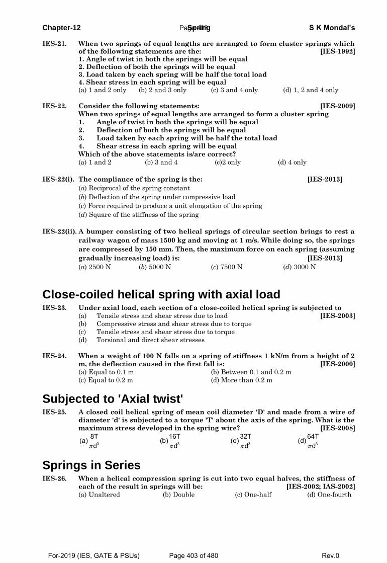
Chapter-12 Spring S K Mondal’s IES-21. When two springs of equal lengths are arranged to form cluster springs which
of the following statements are the: [IES-1992] 1. Angle of twist in both the springs will be equal 2. Deflection of both the springs will be equal 3. Load taken by each spring will be half the total load 4. Shear stress in each spring will be equal (a) 1 and 2 only (b) 2 and 3 only (c) 3 and 4 only (d) 1, 2 and 4 only
IES-22. Consider the following statements: [IES-2009]
When two springs of equal lengths are arranged to form a cluster spring
1. Angle of twist in both the springs will be equal
2. Deflection of both the springs will be equal
3. Load taken by each spring will be half the total load
4. Shear stress in each spring will be equal
Which of the above statements is/are correct?
(a) 1 and 2 (b) 3 and 4 (c)2 only (d) 4 only
IES-22(i). The compliance of the spring is the: [IES-2013]
(a) Reciprocal of the spring constant
(b) Deflection of the spring under compressive load
(c) Force required to produce a unit elongation of the spring
(d) Square of the stiffness of the spring
IES-22(ii). A bumper consisting of two helical springs of circular section brings to rest a
railway wagon of mass 1500 kg and moving at 1 m/s. While doing so, the springs
are compressed by 150 mm. Then, the maximum force on each spring (assuming
gradually increasing load) is: [IES-2013]
(a) 2500 N (b) 5000 N (c) 7500 N (d) 3000 N
Close-coiled helical spring with axial load IES-23. Under axial load, each section of a close-coiled helical spring is subjected to
(a) Tensile stress and shear stress due to load [IES-2003]
(b) Compressive stress and shear stress due to torque
(c) Tensile stress and shear stress due to torque
(d) Torsional and direct shear stresses
IES-24. When a weight of 100 N falls on a spring of stiffness 1 kN/m from a height of 2
m, the deflection caused in the first fall is: [IES-2000]
(a) Equal to 0.1 m (b) Between 0.1 and 0.2 m
(c) Equal to 0.2 m (d) More than 0.2 m
Subjected to 'Axial twist' IES-25. A closed coil helical spring of mean coil diameter 'D' and made from a wire of
diameter 'd' is subjected to a torque 'T' about the axis of the spring. What is the
maximum stress developed in the spring wire? [IES-2008]
3 3 3 3
8T 16T 32T 64T(a) (b) (c) (d)d d d d
Springs in Series IES-26. When a helical compression spring is cut into two equal halves, the stiffness of
each of the result in springs will be: [IES-2002; IAS-2002]
(a) Unaltered (b) Double (c) One-half (d) One-fourth
Page 403
For-2019 (IES, GATE & PSUs) Page 403 of 480 Rev.0
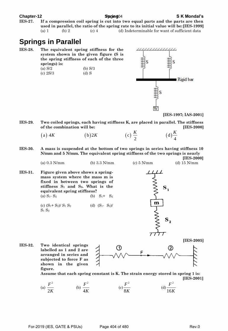
Chapter-12 Spring S K Mondal’s IES-27. If a compression coil spring is cut into two equal parts and the parts are then
used in parallel, the ratio of the spring rate to its initial value will be: [IES-1999]
(a) 1 (b) 2 (c) 4 (d) Indeterminable for want of sufficient data
Springs in Parallel IES-28. The equivalent spring stiffness for the
system shown in the given figure (S is
the spring stiffness of each of the three
springs) is:
(a) S/2 (b) S/3
(c) 2S/3 (d) S
[IES-1997; IAS-2001]
IES-29. Two coiled springs, each having stiffness K, are placed in parallel. The stiffness
of the combination will be: [IES-2000]
a 4 b 2 c d 2 4
K KK K
IES-30. A mass is suspended at the bottom of two springs in series having stiffness 10
N/mm and 5 N/mm. The equivalent spring stiffness of the two springs is nearly
[IES-2000]
(a) 0.3 N/mm (b) 3.3 N/mm (c) 5 N/mm (d) 15 N/mm
IES-31. Figure given above shows a spring-
mass system where the mass m is
fixed in between two springs of
stiffness S1 and S2. What is the
equivalent spring stiffness?
(a) S1- S2 (b) S1+ S2
(c) (S1+ S2)/ S1 S2 (d) (S1- S2)/
S1 S2
[IES-2005]
IES-32. Two identical springs
labelled as 1 and 2 are
arranged in series and
subjected to force F as
shown in the given
figure.
Assume that each spring constant is K. The strain energy stored in spring 1 is:
[IES-2001]
(a)
2
2
F
K (b)
2
4
F
K (c)
2
8
F
K (d)
2
16
F
K
Page 404
For-2019 (IES, GATE & PSUs) Page 404 of 480 Rev.0
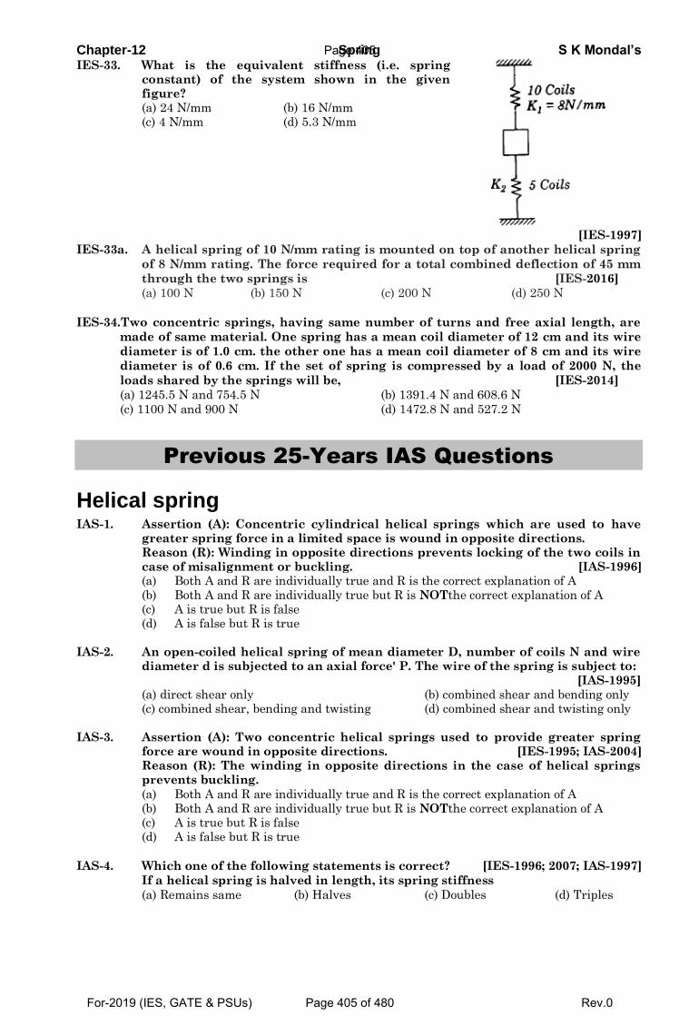
Chapter-12 Spring S K Mondal’s IES-33. What is the equivalent stiffness (i.e. spring
constant) of the system shown in the given figure?
(a) 24 N/mm (b) 16 N/mm (c) 4 N/mm (d) 5.3 N/mm
[IES-1997]
IES-33a. A helical spring of 10 N/mm rating is mounted on top of another helical spring
of 8 N/mm rating. The force required for a total combined deflection of 45 mm
through the two springs is [IES-2016]
(a) 100 N (b) 150 N (c) 200 N (d) 250 N
IES-34.Two concentric springs, having same number of turns and free axial length, are
made of same material. One spring has a mean coil diameter of 12 cm and its wire
diameter is of 1.0 cm. the other one has a mean coil diameter of 8 cm and its wire
diameter is of 0.6 cm. If the set of spring is compressed by a load of 2000 N, the
loads shared by the springs will be, [IES-2014]
(a) 1245.5 N and 754.5 N (b) 1391.4 N and 608.6 N
(c) 1100 N and 900 N (d) 1472.8 N and 527.2 N
Previous 25-Years IAS Questions
Helical spring IAS-1. Assertion (A): Concentric cylindrical helical springs which are used to have
greater spring force in a limited space is wound in opposite directions. Reason (R): Winding in opposite directions prevents locking of the two coils in
case of misalignment or buckling. [IAS-1996] (a) Both A and R are individually true and R is the correct explanation of A (b) Both A and R are individually true but R is NOTthe correct explanation of A (c) A is true but R is false (d) A is false but R is true IAS-2. An open-coiled helical spring of mean diameter D, number of coils N and wire
diameter d is subjected to an axial force' P. The wire of the spring is subject to: [IAS-1995]
(a) direct shear only (b) combined shear and bending only (c) combined shear, bending and twisting (d) combined shear and twisting only IAS-3. Assertion (A): Two concentric helical springs used to provide greater spring
force are wound in opposite directions. [IES-1995; IAS-2004] Reason (R): The winding in opposite directions in the case of helical springs
prevents buckling.
(a) Both A and R are individually true and R is the correct explanation of A (b) Both A and R are individually true but R is NOTthe correct explanation of A (c) A is true but R is false (d) A is false but R is true
IAS-4. Which one of the following statements is correct? [IES-1996; 2007; IAS-1997]
If a helical spring is halved in length, its spring stiffness
(a) Remains same (b) Halves (c) Doubles (d) Triples
Page 405
For-2019 (IES, GATE & PSUs) Page 405 of 480 Rev.0
Chapter-12 Spring S K Mondal’s IAS-5. A closed coil helical spring has 15 coils. If five coils of this spring are removed
by cutting, the stiffness of the modified spring will: [IAS-2004]
(a) Increase to 2.5 times (b) Increase to 1.5 times
(c) Reduce to 0.66 times (d) Remain unaffected
IAS-6. A close-coiled helical spring has wire diameter 10 mm and spring index 5. If the
spring contains 10 turns, then the length of the spring wire would be: [IAS-2000]
(a) 100 mm (b) 157 mm (c) 500 mm (d) 1570 mm
IAS-7. Consider the following types of stresses: [IAS-1996]
1. torsional shear 2. Transverse direct shear 3. Bending stress
The stresses, that are produced in the wire of a close-coiled helical spring
subjected to an axial load, would include
(a) 1 and 3 (b) 1 and 2 (c) 2 and 3 (d) 1, 2 and 3
IAS-8. Two close-coiled springs are subjected to the same axial force. If the second
spring has four times the coil diameter, double the wire diameter and double
the number of coils of the first spring, then the ratio of deflection of the second
spring to that of the first will be: [IAS-1998]
(a) 8 (b) 2 (c)1
2 (d) 1/16
IAS-9. A block of weight 2 N falls from a height of 1m on the top of a spring· If the
spring gets compressed by 0.1 m to bring the weight momentarily to rest, then
the spring constant would be: [IAS-2000]
(a) 50 N/m (b) 100 N/m (c) 200N/m (d) 400N/m
IAS-10. The springs of a chest expander are 60 cm long when unstretched. Their
stiffness is 10 N/mm. The work done in stretching them to 100 cm is: [IAS-1996]
(a) 600 Nm (b) 800 Nm (c) 1000 Nm (d) 1600 Nm
IAS-11. A spring of stiffness 'k' is extended from a displacement x1 to a displacement x2
the work done by the spring is: [IAS-1999]
(a) 2 2
1 2
1 1
2 2k x k x (b)
2
1 2
1( )
2k x x (c)
2
1 2
1( )
2k x x (d)
2
1 2
2
x xk
IAS-12. A spring of stiffness 1000 N/m is stretched initially by 10 cm from the
undeformed position. The work required to stretch it by another 10 cm is:
[IAS-1995]
(a) 5 Nm (b) 7 Nm (c) 10 Nm (d) 15 Nm.
Springs in Series IAS-13. When a helical compression spring is cut into two equal halves, the stiffness of
each of the result in springs will be: [IES-2002; IAS-2002]
(a) Unaltered (b) Double (c) One-half (d) One-fourth
IAS-14. The length of the chest-expander spring when it is un-stretched, is 0.6 m and its
stiffness is 10 N/mm. The work done in stretching it to 1m will be: [IAS-2001]
(a) 800 J (b) 1600 J (c) 3200 J (d) 6400 J
Page 406
For-2019 (IES, GATE & PSUs) Page 406 of 480 Rev.0
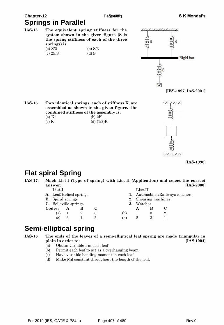
Chapter-12 Spring S K Mondal’s
Springs in Parallel IAS-15. The equivalent spring stiffness for the
system shown in the given figure (S is
the spring stiffness of each of the three
springs) is:
(a) S/2 (b) S/3
(c) 2S/3 (d) S
[IES-1997; IAS-2001]
IAS-16. Two identical springs, each of stiffness K, are
assembled as shown in the given figure. The
combined stiffness of the assembly is:
(a) K2 (b) 2K
(c) K (d) (1/2)K
[IAS-1998]
Flat spiral Spring IAS-17. Mach List-I (Type of spring) with List-II (Application) and select the correct
answer: [IAS-2000]
List-I List-II
A. Leaf/Helical springs 1. Automobiles/Railways coachers
B. Spiral springs 2. Shearing machines
C. Belleville springs 3. Watches
Codes: A B C A B C
(a) 1 2 3 (b) 1 3 2
(c) 3 1 2 (d) 2 3 1
Semi-elliptical spring IAS-18. The ends of the leaves of a semi-elliptical leaf spring are made triangular in
plain in order to: [IAS 1994]
(a) Obtain variable I in each leaf
(b) Permit each leaf to act as a overhanging beam
(c) Have variable bending moment in each leaf
(d) Make Mil constant throughout the length of the leaf.
Page 407
For-2019 (IES, GATE & PSUs) Page 407 of 480 Rev.0
Chapter-12 Spring S K Mondal’s
OBJECTIVE ANSWERS
GATE-1. Ans. (a)
3
4
8PD NG.d
GATE-2. Ans. (d)Spring constant (K) =ND
dGP3
4
8
.
or K
3
1
D
810
2033
2
1
1
2
D
D
K
K
GATE-2a. Ans. (8.243) Stiffness of helical spring
4
3
4 4
2 2 2 1
1 1 1 1
2 1
1
8
1.02
% 100% 8.243%
Gdk
D n
k d k dor
k d k d
k kincreasein stiffness
k
GATE-2(i). Ans. (b) Spring Constant (k) =
4
38
Gd
D n
G is modulus of Rigidity. It is not strength of material. It is elastic constant.
GATE-3. Ans. (c) Spring constant (K) =ND
dGP3
4
8
.
Therefore
4dkn
GATE-4. Ans. (c)Inclined it to a very low angle, d
For equilibrium taking moment about ‘hinge’
l W 300W d k ld l 0 or k 500N / m2 2l 2 0.3
GATE-5. Ans. (b) Initial length = lo m and stiffness = k N/m
o
o
2 g k l 0.2
2 g 20 g k l 0.1
Just solve the above equations.
GATE-6. Ans. (d) When a spring is cut into two, no. of coils gets halved.
Stiffness of each half gets doubled.
When these are connected in parallel, stiffness = 2k + 2k = 4k
Therefore deflection will be ¼ times. = 2.5 mm
GATE-7. Ans. 6
Page 408
For-2019 (IES, GATE & PSUs) Page 408 of 480 Rev.0
Chapter-12 Spring S K Mondal’s
IES
IES-1. Ans. (a)3
4
8PD NGd
2 2 3
4
3
4
D 1T F ; U T2 2
FD TLΤ = ;
2 GJL DN
1 FD L 4F D NU2 2 GJ GdU 8FD NF Gd
IES-1(i). Ans. (b)
𝛿 =8𝑃𝐷3𝑁
𝐺𝑑4
IES-2. Ans. (b)
IES-3. Ans. (c) It is for preventing locking not for buckling.
IES-4. Ans. (c) 4
3
Gd 1Stiffness of sprin k so k andnwiil behalfn8D n
IES-4(i). Ans. (a)
IES-4(ii). Ans. (c)
IES-5. Ans. (b)21mg(h x) kx
2
IES-5(i) Ans. (c) D=10cm,d=8mm,n=10 3 3 6
4 9 4 12
8 8 200 10 10 1048.82 49
80 10 8 10
PD nmm
Gd
IES-6. Ans. (c) s 3
8PDUse kd
IES-6a. Ans. (a)
IES-7. Ans. (b) s 3
8PDUse kd
it is independent of number of turn
IES-8. Ans. (c)
IES-9. Ans. (a)
4 4
233
Stiffness (k) ; econd spring,stiffness (k ) =64 4
64 22
Gd Gd kS
NR NR
IES-10. Ans. (a) IES-11. Ans. (a)
IES-12. Ans. (b)
7 2 4 44
3 3 3
10 N / cm 2 cmGdStiffness of sprin k 100N / cm8D n 8 20 cm 25
IES-13. Ans. (b) IES-14. Ans. (c) IES-15. Ans. (a) IES-16. Ans. (a)
IES-17. Ans. (d)
33
3
20 1 8;
40 8 8 8 9
o i i io i i
i o
W R W WW So W P or W P
W R
IES-18. Ans. (c)
4
3Stiffnessof spring (k) Where G and d issame
64
Gd
R n
Page 409
For-2019 (IES, GATE & PSUs) Page 409 of 480 Rev.0
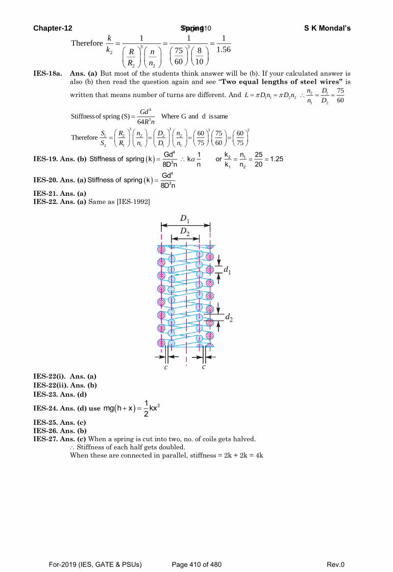
Chapter-12 Spring S K Mondal’s
3 3
2
2 2
1 1 1Therefore
1.5675 8
60 10
k
k R n
R n
IES-18a. Ans. (a) But most of the students think answer will be (b). If your calculated answer is
also (b) then read the question again and see “Two equal lengths of steel wires” is
written that means number of turns are different. And 2 1
1 1 2 2
1 2
75
60
n DL D n D n
n D
4
3Stiffnessof spring (S) Where G and d issame
64
Gd
R n
3 3 3 2
1 2 2 2 2
2 1 1 1 1
60 75 60Therefore
75 60 75
S R n D n
S R n D n
IES-19. Ans. (b) 4
3
GdStiffness of spring k8D n
2 1
1 2
k n1 25k or 1.25n k n 20
IES-20. Ans. (a) 4
3
GdStiffness of spring k8D n
IES-21. Ans. (a)
IES-22. Ans. (a) Same as [IES-1992]
IES-22(i). Ans. (a)
IES-22(ii). Ans. (b)
IES-23. Ans. (d)
IES-24. Ans. (d) use 21mg h x kx2
IES-25. Ans. (c)
IES-26. Ans. (b)
IES-27. Ans. (c) When a spring is cut into two, no. of coils gets halved.
Stiffness of each half gets doubled.
When these are connected in parallel, stiffness = 2k + 2k = 4k
Page 410
For-2019 (IES, GATE & PSUs) Page 410 of 480 Rev.0
Chapter-12 Spring S K Mondal’s
IES-28. Ans. (c) 1 1 1 2
2 3e
e
or S SS S S
IES-29. Ans. (b) 1 2W k k k
IES-30. Ans. (b)1 1 1 10
10 5 3 e
e
or SS
IES-31. Ans. (b)
IES-32. Ans. (c)The strain energy stored per spring =
2
21 1. / 2 / 2
2 2eq
eq
Fk x k
k
and here total
force ‘F’ is supported by both the spring 1 and 2 therefore keq = k + k =2k IES-33. Ans. (a) Stiffness K1 of 10 coils spring = 8 N/mm Stiffness K2 of 5 coils spring = 16 N/mm Though it looks like in series but they are in parallel combination. They are not subjected
to same force. Equivalent stiffness (k) = k1 + k2 = 24 N/mm
IES-33a. Ans. (c)
1
𝑘𝑒𝑞 =
1
𝑘1+
1
𝑘2 or 𝑘𝑒𝑞=
10×8
10+8 = 4.94 N/mm Now 𝛿=
𝐹
𝑘𝑒𝑞 or F = 200 N
IES-34. Ans. (b)
IAS
IAS-1. Ans. (a) IAS-2. Ans. (d) IAS-3. Ans. (c) It is for preventing locking not for buckling.
IAS-4. Ans. (c) 4
3
Gd 1Stiffness of sprin k so k andnwiil behalfn8D n
Page 411
For-2019 (IES, GATE & PSUs) Page 411 of 480 Rev.0
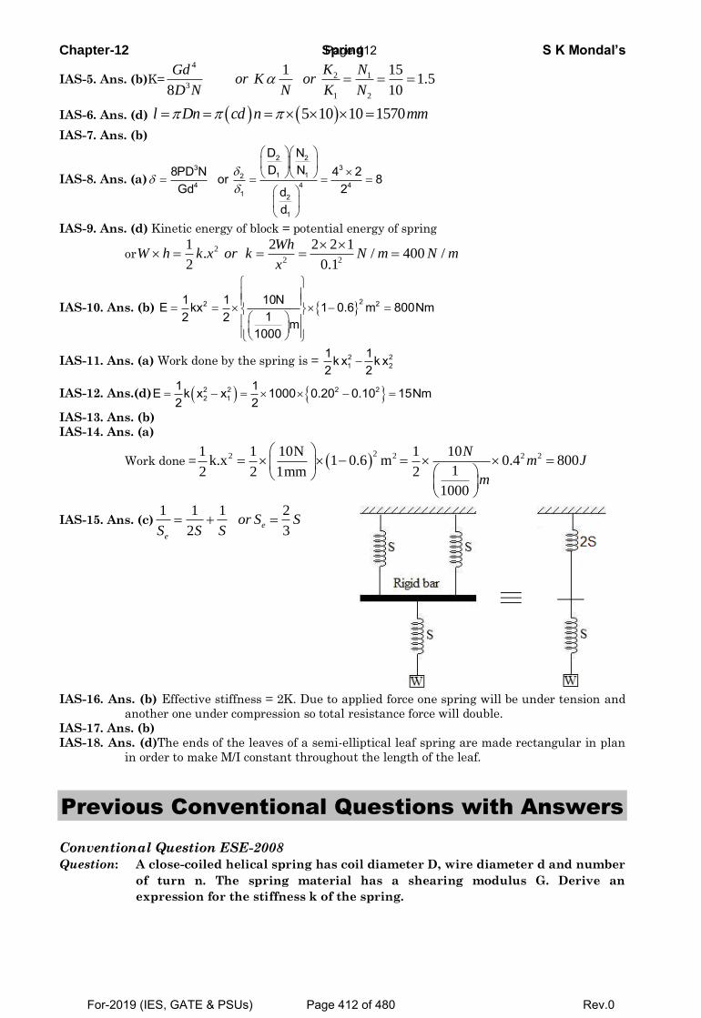
Chapter-12 Spring S K Mondal’s
IAS-5. Ans. (b)K=
4
2 1
3
1 2
1 151.5
8 10
K NGdor K or
D N N K N
IAS-6. Ans. (d) 5 10 10 1570l Dn cd n mm
IAS-7. Ans. (b)
IAS-8. Ans. (a)
2 23 3
1 124 4 4
1 2
1
D ND N8PD N 4 2or 8
Gd 2dd
IAS-9. Ans. (d) Kinetic energy of block = potential energy of spring
or2
2 2
1 2 2 2 1. / 400 /
2 0.1
WhW h k x or k N m N m
x
IAS-10. Ans. (b) 22 21 1 10NE kx 1 0.6 m 800Nm
12 2 m1000
IAS-11. Ans. (a) Work done by the spring is = 2 21 2
1 1k x k x2 2
IAS-12. Ans.(d) 2 2 2 22 1
1 1E k x x 1000 0.20 0.10 15Nm2 2
IAS-13. Ans. (b)
IAS-14. Ans. (a)
Work done = 22 2 2 21 1 10N 1 10
k.x 1 0.6 m 0.4 80012 2 1mm 2
1000
Nm J
m
IAS-15. Ans. (c)1 1 1 2
2 3e
e
or S SS S S
IAS-16. Ans. (b) Effective stiffness = 2K. Due to applied force one spring will be under tension and
another one under compression so total resistance force will double.
IAS-17. Ans. (b)
IAS-18. Ans. (d)The ends of the leaves of a semi-elliptical leaf spring are made rectangular in plan
in order to make M/I constant throughout the length of the leaf.
Previous Conventional Questions with Answers
Conventional Question ESE-2008
Question: A close-coiled helical spring has coil diameter D, wire diameter d and number
of turn n. The spring material has a shearing modulus G. Derive an
expression for the stiffness k of the spring.
Page 412
For-2019 (IES, GATE & PSUs) Page 412 of 480 Rev.0
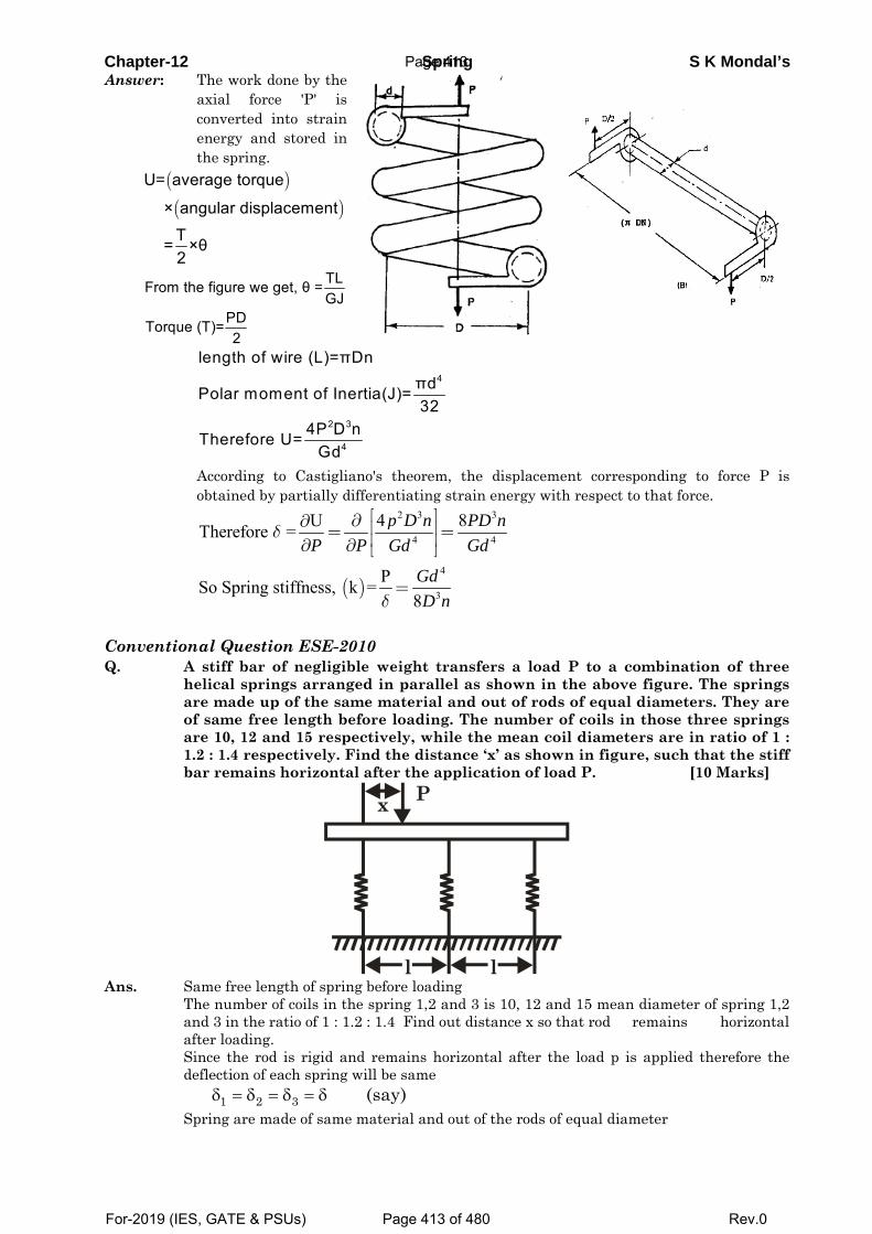
Chapter-12 Spring S K Mondal’s Answer: The work done by the
axial force 'P' is converted into strain energy and stored in the spring.
( )( )
U= average torque
× angular displacementT = ×θ2
TLFrom the figure we get, θ =GJ
PDTorque (T)=2
4
2 3
4
length of wire (L)=πDnπdPolar moment of Inertia(J)=32
4P D nTherefore U= Gd
According to Castigliano's theorem, the displacement corresponding to force P is obtained by partially differentiating strain energy with respect to that force.
( )
2 3 3
4 4
4
3
4 8UTherefore =
PSo Spring stiffness, k =8
p D n PD nP P Gd Gd
GdD n
δ
δ
⎡ ⎤∂∂ ⎢ ⎥= =⎢ ⎥∂ ∂ ⎣ ⎦
=
Conventional Question ESE-2010 Q. A stiff bar of negligible weight transfers a load P to a combination of three
helical springs arranged in parallel as shown in the above figure. The springs are made up of the same material and out of rods of equal diameters. They are of same free length before loading. The number of coils in those three springs are 10, 12 and 15 respectively, while the mean coil diameters are in ratio of 1 : 1.2 : 1.4 respectively. Find the distance ‘x’ as shown in figure, such that the stiff bar remains horizontal after the application of load P. [10 Marks]
l l
x P
Ans. Same free length of spring before loading
The number of coils in the spring 1,2 and 3 is 10, 12 and 15 mean diameter of spring 1,2 and 3 in the ratio of 1 : 1.2 : 1.4 Find out distance x so that rod remains horizontal after loading.
Since the rod is rigid and remains horizontal after the load p is applied therefore the deflection of each spring will be same
1 2 3 (say)δ = δ = δ = δ Spring are made of same material and out of the rods of equal diameter
Page 413
For-2019 (IES, GATE & PSUs) Page 413 of 480 Rev.0
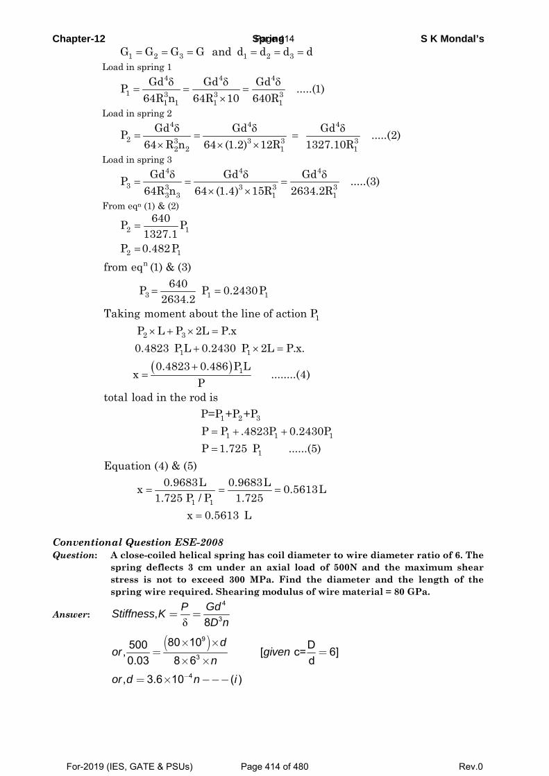
Chapter-12 Spring S K Mondal’s = = = = = =1 2 3 1 2 3G G G G and d d d d Load in spring 1
δ δ δ
= = =×
4 4 4
1 3 3 31 1 1 1
Gd Gd GdP .....(1)64R n 64R 10 640R
Load in spring 2
δ δ δ
= = =× × ×
4 4 4
2 3 3 3 32 2 1 1
Gd Gd GdP .....(2)64 R n 64 (1.2) 12R 1327.10R
Load in spring 3
δ δ δ
= = =× ×
4 4 4
3 3 3 3 33 3 1 1
Gd Gd GdP .....(3)64R n 64 (1.4) 15R 2634.2R
From eqn (1) & (2)
2 1
2 1
640P P1327.1
P 0.482P
=
=
( )
= =
× + × =
+ × =
+=
= + +
n
3 1 1
1
2 3
1 1
1
1 2 3
1 1
from eq (1) & (3)640P P 0.2430P
2634.2Taking moment about the line of action P
P L P 2L P.x0.4823 P L 0.2430 P 2L P.x.
0.4823 0.486 P Lx ........(4)
Ptotal load in the rod is
P=P +P +PP P .4823P 0.24=
= = =
=
1
1
1 1
30PP 1.725 P ......(5)
Equation (4) & (5)0.9683L 0.9683Lx 0.5613L
1.725 P / P 1.725x 0.5613 L
Conventional Question ESE-2008 Question: A close-coiled helical spring has coil diameter to wire diameter ratio of 6. The
spring deflects 3 cm under an axial load of 500N and the maximum shear stress is not to exceed 300 MPa. Find the diameter and the length of the spring wire required. Shearing modulus of wire material = 80 GPa.
Answer: δ
4
3,8GdPStiffness KD n
= =
( )9
3
4
80 10500 D, [ c= 6]0.03 8 6 d
, 3.6 10 ( )
dor given
n
or d n i−
× ×= =
× ×
= × −−−
Page 414
For-2019 (IES, GATE & PSUs) Page 414 of 480 Rev.0
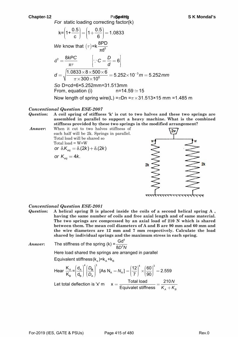
Chapter-12 Spring S K Mondal’s
static loading correcting factor(k)
0.5 0.5 k= 1+ 1 1.0833c 6
For⎛ ⎞ ⎛ ⎞⎟ ⎟⎜ ⎜= + =⎟ ⎟⎜ ⎜⎟ ⎟⎜ ⎜⎝ ⎠ ⎝ ⎠
( )
π
dπ
3
2
8PD know that =kd
8 6
We
kPC DCd
τ
τ⎡ ⎤⎢ ⎥= = =⎢ ⎥⎣ ⎦∵
3
6
1.0833 8 500 6 5.252 10 5.252300 10
D=cd=6×5.252mm=31.513mm
d m mm
Soπ
−× × ×= = × =
× ×
π π×
From, equation (i) n=14.59 15Now length of spring wire(L) = Dn = 31.513×15 mm =1.485 m
Conventional Question ESE-2007 Question: A coil spring of stiffness 'k' is cut to two halves and these two springs are
assembled in parallel to support a heavy machine. What is the combined stiffness provided by these two springs in the modified arrangement?
Answer: When it cut to two halves stiffness of each half will be 2k. Springs in parallel. Total load will be shared so
Total load = W+W
δ δ δ. .(2 ) .(2 )
4 .eq
eq
or K k k
or K k
= +
=
Conventional Question ESE-2001 Question: A helical spring B is placed inside the coils of a second helical spring A ,
having the same number of coils and free axial length and of same material. The two springs are compressed by an axial load of 210 N which is shared between them. The mean coil diameters of A and B are 90 mm and 60 mm and the wire diameters are 12 mm and 7 mm respectively. Calculate the load shared by individual springs and the maximum stress in each spring.
Answer: 4
3
GdThe stiffness of the spring (k) =8D N
⎛ ⎞ ⎛ ⎞ ⎛ ⎞ ⎛ ⎞⎟ ⎟⎜ ⎜ ⎟ ⎟⎜ ⎜⎟ ⎟ = = × =⎜ ⎜ ⎟ ⎟⎜ ⎜⎟ ⎟ ⎟ ⎟⎜ ⎜ ⎜ ⎜⎟ ⎟⎜ ⎜ ⎝ ⎠ ⎝ ⎠⎝ ⎠ ⎝ ⎠
e A B4 3 4 3
A AA
B B A
Here load shared the springs are arranged in parallelEquivalent stiffness(k )=k +k
K d 12 60Hear = [As N ] 2.559K d 7 90N
D ND
B
= =+
Total load 210Let total deflection is 'x' m xEquivalet stiffness A B
NK K
Page 415
For-2019 (IES, GATE & PSUs) Page 415 of 480 Rev.0
Chapter-12 Spring S K Mondal’s
( )
A
210 210Load shared by spring 'A'(F ) =151N
111
2.559
Load shared by spring 'A'(F ) 210 151 59 N
= ´ = =æ ö æ ö
÷ ÷ç ç +÷ ÷+ç ç ÷÷ çç è ø÷çè ø
= ´ = - =
A
B
A
B B
K xk
k
K x
3
0.5 8For static load: = 1+
C πt
æ ö÷ç ÷ç ÷çè ø
PD
d
( )( )
3max
0.5 8 151 0.0901 21.362MPa
90 π 0.012
12
t
ì üï ïï ïï ïï ï ´ ´ï ï= + =í ýæ öï ï ´÷ï ïç ÷ï ïç ÷çï ïè øï ïî þ
A
( )( )
3max
0.5 8 59 0.0601 27.816 MPa
60 π 0.007
7
t
æ ö÷ç ÷ç ÷ç ´ ´÷ç ÷= + =ç ÷ç ÷æ öç ÷ ´÷ç ÷ç ÷ç ÷ç ÷ç ÷ç è øè ø
B
Conventional Question AMIE-1997 Question: A close-coiled spring has mean diameter of 75 mm and spring constant of 90
kN/m. It has 8 coils. What is the suitable diameter of the spring wire if
maximum shear stress is not to exceed 250 MN/m2? Modulus of rigidity of the
spring wire material is 80 GN/m2. What is the maximum axial load the spring
can carry?
Answer: Given D 75mm; k 80kN / m; n 8
2 2 9 2250MN/ m ; G 80GN/ m 80 10 N/ m
Diameter of the spring wire, d:
We know,
3
6 3
3
T d whereT P R16
P 0.0375 250 10 d i16
Also P kor P 80 10 ii
Using the relation:
3314
4 9 4 4
3 144
8P 0.075 88PD n P 33.75 10Gd 80 10 d d
Substituting for in equation(ii),we getPP 80 10 33.75 10 or d 0.0128m or 12.8mmd
Maximum axial load the spring can carry P:
From equation (i), we get
36P 0.0375 250 10 0.0128 ; P 2745.2N 2.7452kN
16
Page 416
For-2019 (IES, GATE & PSUs) Page 416 of 480 Rev.0
13. Theories of Column
Theory at a Glance (for IES, GATE, PSU) 1. Introduction
Strut: A member of structure which carries an axial compressive load.
Column: If the strut is vertical it is known as column.
A long, slender column becomes unstable when its axial compressive load reaches a value
called the critical buckling load.
If a beam element is under a compressive load and its length is an order of magnitude larger
than either of its other dimensions such a beam is called a columns.
Due to its size its axial displacement is going to be very small compared to its lateral
deflection called buckling.
Buckling does not vary linearly with load it occurs suddenly and is therefore dangerous
Slenderness Ratio: The ratio between the length and least radius of gyration.
Elastic Buckling: Buckling with no permanent deformation.
Euler buckling is only valid for long, slender objects in the elastic region.
For short columns, a different set of equations must be used.
2. Which is the critical load?
At this value the structure is in equilibrium regardless of the magnitude of the angle
(provided it stays small)
Critical load is the only load for which the structure will be in equilibrium in the disturbed
position
At this value, restoring effect of the moment in the spring matches the buckling effect of the
axial load represents the boundary between the stable and unstable conditions.
If the axial load is less than Pcr the effect of the moment in the spring dominates and the
structure returns to the vertical position after a small disturbance – stable condition.
If the axial load is larger than Pcr the effect of the axial force predominates and the structure
buckles – unstable condition.
Because of the large deflection caused by buckling, the least moment of inertia I can be
expressed as, I = Ak2
Where: A is the cross sectional area and r is the radius of gyration of the cross sectional area,
i.e. kmin = minI
A
Page 417
For-2019 (IES, GATE & PSUs) Page 417 of 480 Rev.0
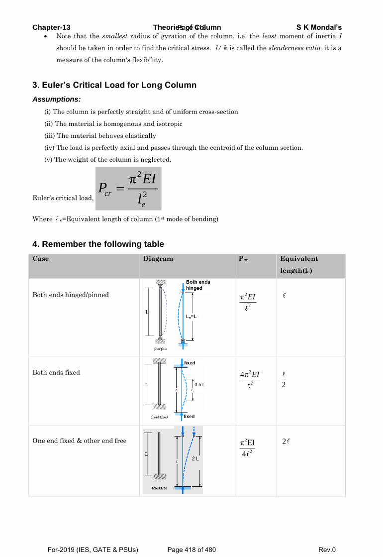
Chapter-13 Theories of Column S K Mondal’s Note that the smallest radius of gyration of the column, i.e. the least moment of inertia I
should be taken in order to find the critical stress. l/ k is called the slenderness ratio, it is a
measure of the column's flexibility.
3. Euler’s Critical Load for Long Column
Assumptions:
(i) The column is perfectly straight and of uniform cross-section
(ii) The material is homogenous and isotropic
(iii) The material behaves elastically
(iv) The load is perfectly axial and passes through the centroid of the column section.
(v) The weight of the column is neglected.
Euler’s critical load,
2
2
πcr
e
EIP
l
Where e=Equivalent length of column (1st mode of bending)
4. Remember the following table
Case Diagram Pcr Equivalent
length(le)
Both ends hinged/pinned
Both ends fixed
One end fixed & other end free
2
2
π EI
2
2
4π EI
2
2
2
π EI
4
2
Page 418
For-2019 (IES, GATE & PSUs) Page 418 of 480 Rev.0
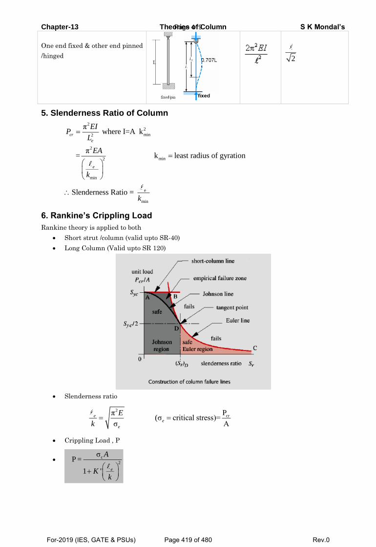
Chapter-13 Theories of Column S K Mondal’s
One end fixed & other end pinned
/hinged
5. Slenderness Ratio of Column
22
min2
2
min2
min
e
min
π where I=A k
π = k least radius of gyration
Slenderness Ratio =
cr
e
e
EIP
L
EA
k
k
6. Rankine’s Crippling Load
Rankine theory is applied to both
Short strut /column (valid upto SR-40)
Long Column (Valid upto SR 120)
Slenderness ratio
2
crPπ(σ critical stress)=
σ A e
e
e
E
k
Crippling Load , P
c
2
σ P =
1 '
e
A
Kk
2
Page 419
For-2019 (IES, GATE & PSUs) Page 419 of 480 Rev.0
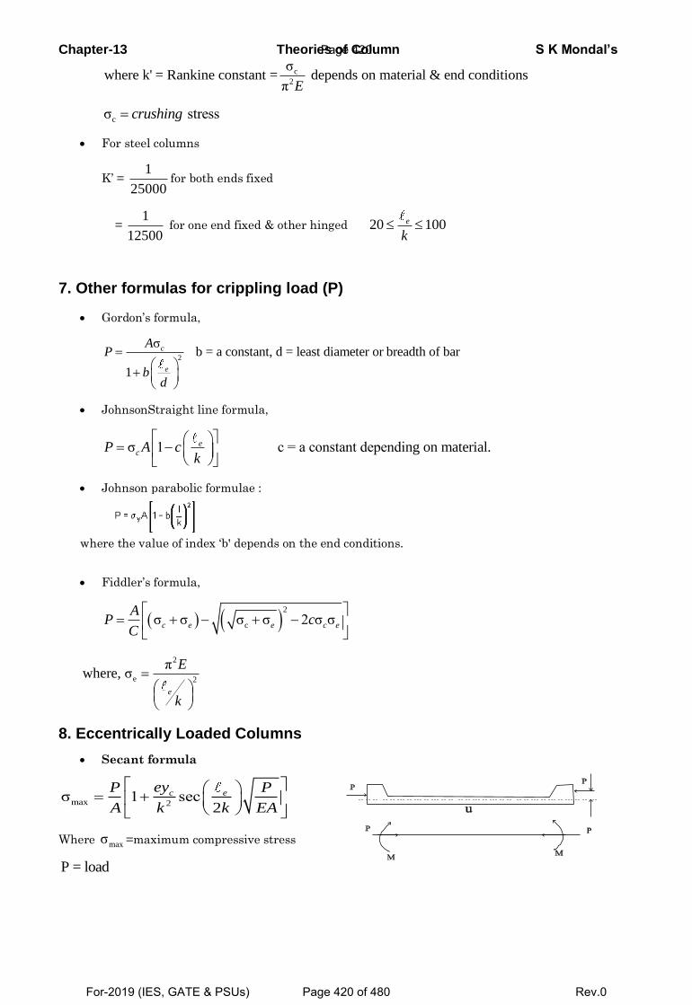
Chapter-13 Theories of Column S K Mondal’s
c
2
σwhere k' = Rankine constant = depends on material & end conditions
π E
cσ stress crushing
For steel columns
K’ = 1
25000for both ends fixed
= 1
12500 for one end fixed & other hinged 20 100 e
k
7. Other formulas for crippling load (P)
Gordon’s formula,
2
σ b = a constant, d = least diameter or breadth of bar
1
c
e
AP
bd
JohnsonStraight line formula,
σ 1 c = a constant depending on material.
ecP A c
k
Johnson parabolic formulae :
where the value of index ‘b' depends on the end conditions.
Fiddler’s formula,
2
cσ σ σ σ 2 σ σ
c e e c e
AP c
C
2
e 2
πwhere, σ
e
E
k
8. Eccentrically Loaded Columns
Secant formula
max 2σ 1 sec
2
c eeyP P
A k k EA
Where maxσ =maximum compressive stress
P = load
Page 420
For-2019 (IES, GATE & PSUs) Page 420 of 480 Rev.0
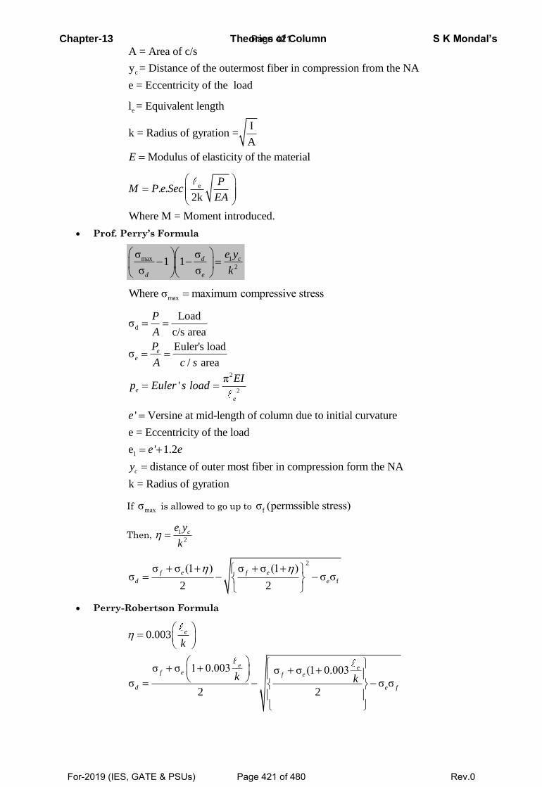
Chapter-13 Theories of Column S K Mondal’s
c
A = Area of c/s
y = Distance of the outermost fiber in compression from the NA
e = Eccentricity of the load
el = Equivalent length
Ik = Radius of gyration =
A
Modulus of elasticity of the materialE
e. .2k
Where M = Moment introduced.
PM P e Sec
EA
Prof. Perry’s Formula
max 1
2
σ σ1 1
σ σ
d c
d e
e y
k
maxWhere σ maximum compressive stress
d
2
2
Loadσ
c/s area
Euler's loadσ
/ area
π'
ee
e
e
P
A
P
A c s
EIp Euler s load
1
' Versine at mid-length of column due to initial curvature
e = Eccentricity of the load
e ' 1.2
distance of outer most fiber in compression form the NA
k = Radius of gyration
c
e
e e
y
If maxσ is allowed to go up to fσ (permssible stress)
Then, 1
2 ce y
k
2
f
σ σ (1 ) σ σ (1 )σ σ σ
2 2
f e f e
d e
Perry-Robertson Formula
0.003
σ σ 1 0.003 σ σ (1 0.003
σ σ σ2 2
e
e ef e f e
d e f
k
k k
Page 421
For-2019 (IES, GATE & PSUs) Page 421 of 480 Rev.0
Chapter-13 Theories of Column S K Mondal’s
9. ISI’s Formula for Columns and Struts
For e
k=0 to 160
'
σ
1 0.2sec4
y
c
e c
fosP
fos p
k E
Where, Pc = Permissible axial compressive stress
Pc’ = A value obtained from above Secant formula
y = Guaranteed minimum yield stress = 2600 kg/cm2 for mild steel
fos = factor of safety = 1.68
el
k Slenderness ratio
E = Modulus of elasticity = 6 22.045 10 /kg cm for mild steel
For 160el
k
Page 422
For-2019 (IES, GATE & PSUs) Page 422 of 480 Rev.0
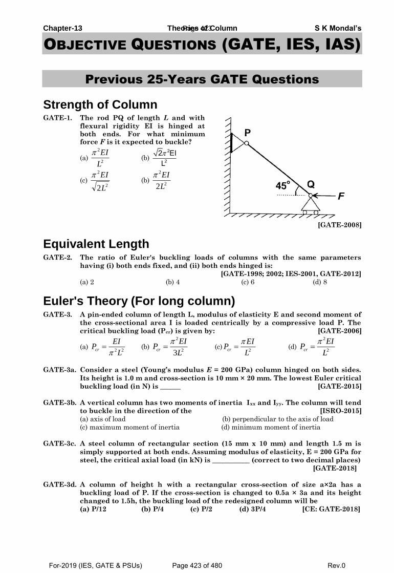
Chapter-13 Theories of Column S K Mondal’s
OBJECTIVE QUESTIONS (GATE, IES, IAS)
Previous 25-Years GATE Questions
Strength of Column GATE-1. The rod PQ of length L and with
flexural rigidity EI is hinged at both ends. For what minimum force F is it expected to buckle?
(a) 2
2
L
EI (b)
2
22 EIL
(c) 2
2
2L
EI (b)
2
2
2L
EI
[GATE-2008]
Equivalent Length GATE-2. The ratio of Euler's buckling loads of columns with the same parameters
having (i) both ends fixed, and (ii) both ends hinged is:
[GATE-1998; 2002; IES-2001, GATE-2012]
(a) 2 (b) 4 (c) 6 (d) 8
Euler's Theory (For long column) GATE-3. A pin-ended column of length L, modulus of elasticity E and second moment of
the cross-sectional area I is loaded centrically by a compressive load P. The
critical buckling load (Pcr) is given by: [GATE-2006]
(a) 2 2cr
EIP
L (b)
2
23cr
EIP
L
(c)
2cr
EIP
L
(d)
2
2cr
EIP
L
GATE-3a. Consider a steel (Young’s modulus E = 200 GPa) column hinged on both sides.
Its height is 1.0 m and cross-section is 10 mm × 20 mm. The lowest Euler critical
buckling load (in N) is ______ [GATE-2015]
GATE-3b. A vertical column has two moments of inertia Ixx and Iyy. The column will tend
to buckle in the direction of the [ISRO-2015]
(a) axis of load (b) perpendicular to the axis of load
(c) maximum moment of inertia (d) minimum moment of inertia
GATE-3c. A steel column of rectangular section (15 mm x 10 mm) and length 1.5 m is
simply supported at both ends. Assuming modulus of elasticity, E = 200 GPa for
steel, the critical axial load (in kN) is ___________ (correct to two decimal places)
[GATE-2018]
GATE-3d. A column of height h with a rectangular cross-section of size a×2a has a
buckling load of P. If the cross-section is changed to 0.5a × 3a and its height
changed to 1.5h, the buckling load of the redesigned column will be
(a) P/12 (b) P/4 (c) P/2 (d) 3P/4 [CE: GATE-2018]
Page 423
For-2019 (IES, GATE & PSUs) Page 423 of 480 Rev.0
Chapter-13 Theories of Column S K Mondal’s GATE-4. The minimum axial compressive load, P required to initiate buckling for a
pinned-pinned slender column with bending stiffness EI and length L is
2 2 2 2
2 2 2 2
3 4( ) ( ) ( ) ( )
4 4
EI EI EI EIa P b P c P d P
L L L L
[GATE-2018]
GATE-4a. What is the expression for the crippling load for a column of length ‘l’ with one
end fixed and other end free? [IES-2006; GATE-1994]
(a)
2
2
2 EIP
l
(b)
2
24
EIP
l
(c)
2
2
4 EIP
l
(d)
2
2
EIP
l
GATE-5. The piston rod of diameter 20 mm and length 700 mm in a hydraulic cylinder is
subjected to a compressive force of 10 KN due to the internal pressure. The end
conditions for the rod may be assumed as guided at the piston end and hinged
at the other end. The Young’s modulus is 200 GPa. The factor of safety for the
piston rod is
(a) 0.68 (b) 2.75 (c) 5.62 (d) 11.0 [GATE-2007]
GATE-5a. A square cross-section wooden column of length 3140 mm is pinned at both
ends. For the wood, Young’s modulus of elasticity is 12 GPa and allowable
compressive stress is 12 MPa. The column needs to support an axial
compressive load of 200 kN. Using a factor of safety of 2.0 in the computation of
Euler’s buckling load, the minimum cross-sectional area (in mm2) of the column
is ______ [GATE-2018(PI)]
GATE-6. A steel column, pinned at both ends, has a buckling load of 200 kN. If the
column is restrained against lateral movement at its mid-height, its buckling
load will be [CE: GATE-2007]
(a) 200 kN (b) 283 kN (c) 400 kN (d) 800 kN
GATE-7. Two steel columns P (length L and yield strength fy = 250 MPa) and Q (length 2L
and yield strength fy = 500 MPa) have the same cross-sections and end-
conditions. The ratio of buckling load of column P to that of column Q is:
(a) 0.5 (b) 1.0 (c) 2.0 (d) 4.0 [CE: GATE-2014]
GATE-8. A long structural column (length = L) with both ends hinged is acted upon by
an axial compressive load P. The differential equation governing the bending
of column is given by:
2
2EI P
d yy
dx [CE: GATE-2003]
where y is the structural lateral deflection and EI is the flexural rigidity. The
first critical load on column responsible for its buckling is given by
(a) 2
2
EI
L
(b)
2
2
2 EI
L
(c) 2
2
2 EI
L
(d)
2
2
4 EI
L
GATE-9. If the following equation establishes equilibrium in slightly bent position, the
mid-span deflection of a member shown in the figure is [CE: GATE-2014] 2
20
d y Py
dx EI
Page 424
For-2019 (IES, GATE & PSUs) Page 424 of 480 Rev.0
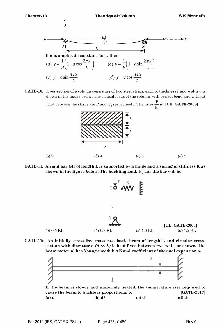
Chapter-13 Theories of Column S K Mondal’s
If a is amplitude constant for y, then
1 2 1 2( ) 1 cos ( ) 1 sin
( ) sin ( ) cos
x xa y a b y a
P L P L
n x n xc y a d y a
L L
GATE-10. Cross-section of a column consisting of two steel strips, each of thickness t and width b is
shown in the figure below. The critical loads of the column with perfect bond and without
bond between the strips are P and 0
P respectively. The ratio 0
P
Pis [CE: GATE-2008]
t
b
t
(a) 2 (b) 4 (c) 6 (d) 8
GATE-11. A rigid bar GH of length L is supported by a hinge and a spring of stiffness K as
shown in the figure below. The buckling load, P ,cr
for the bar will be
L
H
K P
G
[CE: GATE-2008]
(a) 0.5 KL (b) 0.8 KL (c) 1.0 KL (d) 1.2 KL
GATE-11a. An initially stress-free massless elastic beam of length L and circular cross-
section with diameter d (d << L) is held fixed between two walls as shown. The
beam material has Young's modulus E and coefficient of thermal expansion α.
If the beam is slowly and uniformly heated, the temperature rise required to
cause the beam to buckle is proportional to [GATE-2017]
(a) d (b) d2 (c) d3 (d) d4
Page 425
For-2019 (IES, GATE & PSUs) Page 425 of 480 Rev.0
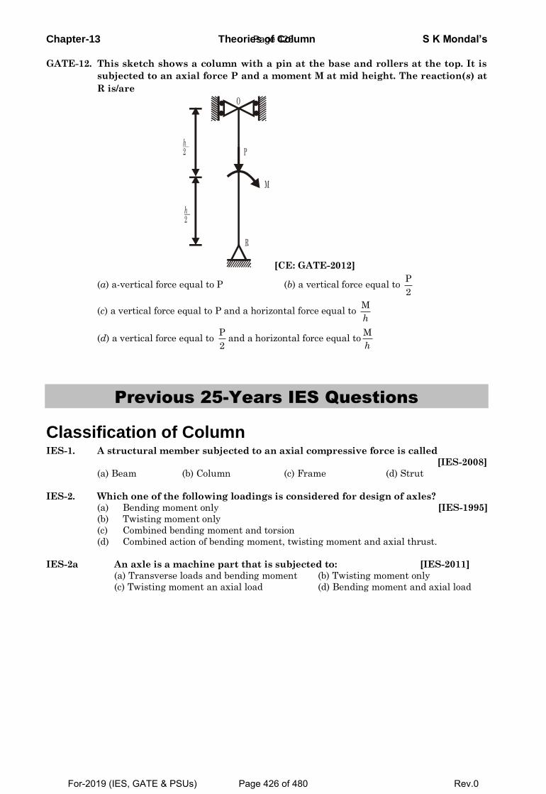
Chapter-13 Theories of Column S K Mondal’s
GATE-12. This sketch shows a column with a pin at the base and rollers at the top. It is
subjected to an axial force P and a moment M at mid height. The reaction(s) at
R is/are
O
P
M
R
h2
h2
[CE: GATE-2012]
(a) a-vertical force equal to P (b) a vertical force equal to P
2
(c) a vertical force equal to P and a horizontal force equal to M
h
(d) a vertical force equal to P
2and a horizontal force equal to
M
h
Previous 25-Years IES Questions
Classification of Column IES-1. A structural member subjected to an axial compressive force is called
[IES-2008]
(a) Beam (b) Column (c) Frame (d) Strut
IES-2. Which one of the following loadings is considered for design of axles?
(a) Bending moment only [IES-1995]
(b) Twisting moment only
(c) Combined bending moment and torsion
(d) Combined action of bending moment, twisting moment and axial thrust.
IES-2a An axle is a machine part that is subjected to: [IES-2011]
(a) Transverse loads and bending moment (b) Twisting moment only
(c) Twisting moment an axial load (d) Bending moment and axial load
Page 426
For-2019 (IES, GATE & PSUs) Page 426 of 480 Rev.0
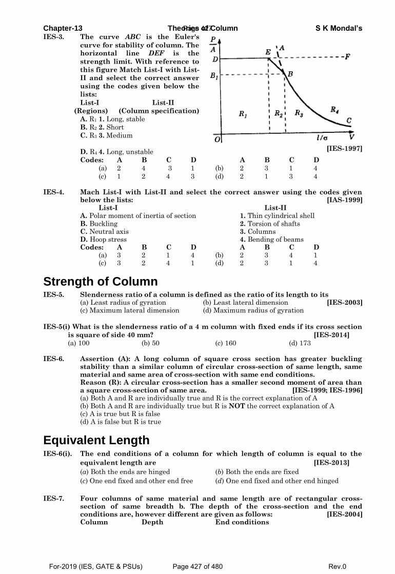
Chapter-13 Theories of Column S K Mondal’s IES-3. The curve ABC is the Euler's
curve for stability of column. The horizontal line DEF is the
strength limit. With reference to
this figure Match List-I with List-
II and select the correct answer
using the codes given below the
lists:
List-I List-II
(Regions) (Column specification)
A. R1 1. Long, stable
B. R2 2. Short
C. R3 3. Medium
D. R4 4. Long, unstable
[IES-1997]
Codes: A B C D A B C D
(a) 2 4 3 1 (b) 2 3 1 4
(c) 1 2 4 3 (d) 2 1 3 4 IES-4. Mach List-I with List-II and select the correct answer using the codes given
below the lists: [IAS-1999] List-I List-II A. Polar moment of inertia of section 1. Thin cylindrical shell B. Buckling 2. Torsion of shafts C. Neutral axis 3. Columns D. Hoop stress 4. Bending of beams Codes: A B C D A B C D (a) 3 2 1 4 (b) 2 3 4 1 (c) 3 2 4 1 (d) 2 3 1 4
Strength of Column IES-5. Slenderness ratio of a column is defined as the ratio of its length to its (a) Least radius of gyration (b) Least lateral dimension [IES-2003] (c) Maximum lateral dimension (d) Maximum radius of gyration
IES-5(i) What is the slenderness ratio of a 4 m column with fixed ends if its cross section
is square of side 40 mm? [IES-2014]
(a) 100 (b) 50 (c) 160 (d) 173 IES-6. Assertion (A): A long column of square cross section has greater buckling
stability than a similar column of circular cross-section of same length, same material and same area of cross-section with same end conditions.
Reason (R): A circular cross-section has a smaller second moment of area than a square cross-section of same area. [IES-1999; IES-1996]
(a) Both A and R are individually true and R is the correct explanation of A (b) Both A and R are individually true but R is NOT the correct explanation of A (c) A is true but R is false (d) A is false but R is true
Equivalent Length IES-6(i). The end conditions of a column for which length of column is equal to the
equivalent length are [IES-2013]
(a) Both the ends are hinged (b) Both the ends are fixed
(c) One end fixed and other end free (d) One end fixed and other end hinged
IES-7. Four columns of same material and same length are of rectangular cross-section of same breadth b. The depth of the cross-section and the end conditions are, however different are given as follows: [IES-2004]
Column Depth End conditions
Page 427
For-2019 (IES, GATE & PSUs) Page 427 of 480 Rev.0
Chapter-13 Theories of Column S K Mondal’s 1 0.6 b Fixed-Fixed 2 0.8 b Fixed-hinged 3 1.0 b Hinged-Hinged 4 2.6 b Fixed-Free Which of the above columns Euler buckling load maximum? (a) Column 1 (b) Column 2 (c) Column 3 (d) Column 4 IES-8. Match List-I (End conditions of columns) with List-II (Equivalent length in
terms of length of hinged-hinged column) and select the correct answer using the codes given below the Lists: [IES-2000]
List-I List-II A. Both ends hinged 1. L
B. One end fixed and other end free 2. L/ 2
C. One end fixed and the other pin-pointed 3. 2L D. Both ends fixed 4. L/2 Code: A B C D A B C D (a) 1 3 4 2 (b) 1 3 2 4 (c) 3 1 2 4 (d) 3 1 4 2
IES-9. The ratio of Euler's buckling loads of columns with the same parameters
having (i) both ends fixed, and (ii) both ends hinged is:
[GATE-1998; 2002; IES-2001]
(a) 2 (b) 4 (c) 6 (d) 8
Euler's Theory (For long column) IES-10. What is the expression for the crippling load for a column of length ‘l’ with one
end fixed and other end free? [IES-2006; GATE-1994]
(a)
2
2
2 EIP
l
(b)
2
24
EIP
l
(c)
2
2
4 EIP
l
(d)
2
2
EIP
l
IES-10(i). The buckling load for a column hinged at both ends is 10 kN. If the ends are
fixed, the buckling load changes to [IES-2012]
(a) 40 kN (b) 2.5 kN (c) 5 kN (d) 20 kN
IES-10(ii). For the case of a slender column of length L and flexural rigidity EI built in at
its base and free at the top, the Euler’s critical buckling load is [IES-2012]
(𝑎)4𝜋2𝐸𝐼
𝐿2 (𝑏)
2𝜋2𝐸𝐼
𝐿2 (𝑐)
𝜋2𝐸𝐼
𝐿2 (𝑑)
𝜋2𝐸𝐼
4𝐿2
IES-11. A 4 m long solid round bar is used as a column having one end fixed and the
other end free. If Euler’s critical load on this column is found as 10 kN and E =
210 GPa for the material of the bar, the diameter of the bar [IES-2014]
(a) 50 mm (b) 40 mm (c) 60 mm (d) 45 mm
IES-11(i). Euler's formula gives 5 to 10% error in crippling load as compared to
experimental results in practice because: [IES-1998]
(a) Effect of direct stress is neglected
(b) Pin joints are not free from friction
(c) The assumptions made in using the formula are not met in practice
(d) The material does not behave in an ideal elastic way in tension and compression
IES-12. Euler's formula can be used for obtaining crippling load for a M.S. column with
hinged ends.
Which one of the following conditions for the slenderness ratio l
k is to be
satisfied? [IES-2000]
(a) 5 8l
k (b) 9 18
l
k (c)19 40
l
k (d) 80
l
k
Page 428
For-2019 (IES, GATE & PSUs) Page 428 of 480 Rev.0
Chapter-13 Theories of Column S K Mondal’s
IES-13. If one end of a hinged column is made fixed and the other free, how much is the
critical load compared to the original value? [IES-2008]
(a) ¼ (b) ½ (c) Twice (d) Four times
IES-14. If one end of a hinged column is made fixed and the other free, how much is the
critical load compared to the original value? [IES-2008]
(a) ¼ (b) ½ (c) Twice (d) Four times
IES-14a. A long column hinged at both the ends has certain critical Euler’s buckling
load-carrying capacity. If the same column be fixed at both the ends (in place
of hinged ends), the load-carrying capacity then increases to [IES-2016]
(a) 4 times (b) 3 times (c) 2 times (d) Nil
IES-15. Match List-I with List-II and select the correct answer using the code given
below the Lists: [IES-1995; 2007; IAS-1997]
List-I(Long Column) List-II(Critical Load)
A. Both ends hinged 1. 2EI/4l2
B. One end fixed, and other end free 2. 4 2EI/ l2
C. Both ends fixed 3. 2 2EI/ l2 D. One end fixed, and other end hinged 4. 2EI/ l2
Code: A B C D A B C D
(a) 2 1 4 3 (b) 4 1 2 3
(c) 2 3 4 1 (d) 4 3 2 1
IES-16. The ratio of the compressive critical load for a long column fixed at both the
ends and a column with one end fixed and the other end free is: [IES-1997]
(a) 1 : 2 (b) 1: 4 (c) 1: 8 (d) 1: 16
IES-17. The buckling load will be maximum for a column, if [IES-1993]
(a) One end of the column is clamped and the other end is free
(b) Both ends of the column are clamped
(c) Both ends of the column are hinged
(d) One end of the column is hinged and the other end is free
IES-18. If diameter of a long column is reduced by 20%, the percentage of reduction in
Euler buckling load is: [IES-2001, 2012]
(a) 4 (b) 36 (c) 49 (d) 59
IES-19. A long slender bar having uniform rectangular cross-section 'B x H' is acted
upon by an axial compressive force. The sides B and H are parallel to x- and y-
axes respectively. The ends of the bar are fixed such that they behave as pin-
jointed when the bar buckles in a plane normal to x-axis, and they behave as
built-in when the bar buckles in a plane normal to y-axis. If load capacity in
either mode of buckling is same, then the value of H/B will be: [IES-2000]
(a) 2 (b) 4 (c) 8 (d) 16
IES-20. The Euler's crippling load for a 2m long slender steel rod of uniform cross-
section hinged at both the ends is 1 kN. The Euler's crippling load for 1 m long
steel rod of the same cross-section and hinged at both ends will be: [IES-1998]
(a) 0.25 kN (b) 0.5 kN (c) 2 kN (d) 4 kN
IES-20(i). Determine the ratio of the buckling strength of a solid steel column to that of a
hollow column of the same material having the same area of cross section. The
internal diameter of the hollow column is half of the external diameter. Both
column are of identical length and are pinned or hinged at the ends: [IES-2013]
(a) P 2
P 5
s
h
(b) P 3
P 5
s
h
(c)P 4
P 5
s
h
(d) P
1P
s
h
Page 429
For-2019 (IES, GATE & PSUs) Page 429 of 480 Rev.0
Chapter-13 Theories of Column S K Mondal’s
IES-21. If σc and E denote the crushing stress and Young's modulus for the material of
a column, then the Euler formula can be applied for determination of cripping
load of a column made of this material only, if its slenderness ratio is:
(a) More than / cE (b) Less than / cE [IES-2005]
(c) More than 2
c
E
(d) Less than 2
c
E
IES-22. Four vertical columns of same material, height and weight have the same end
conditions. Which cross-section will carry the maximum load? [IES-2009]
(a) Solid circular section (b) Thin hollow circular section
(c) Solid square section (d) I-section
Rankine's Hypothesis for Struts/Columns IES-23. Rankine Gordon formula for buckling is valid for [IES-1994]
(a) Long column (b) Short column
(c) Short and long column (d) Very long column
Prof. Perry's formula IES-24. Match List-I with List-II and select the correct answer using the code given
below the lists: [IES-2008]
List-I (Formula/theorem/ method) List-II (Deals with topic)
A. Clapeyron's theorem 1. Deflection of beam
B. Maculay's method 2. Eccentrically loaded column
C. Perry's formula 3. Riveted joints
4. Continuous beam
Code: A B C A B C
(a) 3 2 1 (b) 4 1 2
(c) 4 1 3 (d) 2 4 3
Previous 25-Years IAS Questions
Classification of Column IAS-1. Mach List-I with List-II and select the correct answer using the codes given
below the lists: [IAS-1999]
List-I List-II
A. Polar moment of inertia of section 1. Thin cylindrical shell
B. Buckling 2. Torsion of shafts
C. Neutral axis 3. Columns
D. Hoop stress 4. Bending of beams
Codes: A B C D A B C D
(a) 3 2 1 4 (b) 2 3 4 1
(c) 3 2 4 1 (d) 2 3 1 4
Strength of Column IAS-2. Assertion (A): A long column of square cross-section has greater buckling
stability than that of a column of circular cross-section of same length, same
material, same end conditions and same area of cross-section. [IAS-1998]
Reason (R): The second moment of area of a column of circular cross-section is
smaller than that of a column of square cross section having the same area.
(a) Both A and R are individually true and R is the correct explanation of A
(b) Both A and R are individually true but R is NOTthe correct explanation of A
Page 430
For-2019 (IES, GATE & PSUs) Page 430 of 480 Rev.0
Chapter-13 Theories of Column S K Mondal’s (c) A is true but R is false
(d) A is false but R is true
IAS-3. Which one of the following pairs is not correctly matched? [IAS-2003]
(a) Slenderness ratio : The ratio of length of the column to the least radius of gyration
(b) Buckling factor : The ratio of maximum load to the permissible axial loadon the
column
(c) Short column : A column for which slenderness ratio < 32
(d) Strut : A member of a structure in any position and carrying an axial
compressive load
Equivalent Length IAS-4. A column of length 'ℓ' is fixed at its both ends. The equivalent length of the
column is: [IAS-1995]
(a) 2 l (b) 0.5 l (c) 2 l (d) l
IAS-5. Which one of the following statements is correct? [IAS-2000]
(a) Euler's formula holds good only for short columns
(b) A short column is one which has the ratio of its length to least radius of gyration
greater than 100
(c) A column with both ends fixed has minimum equivalent or effective length
(d) The equivalent length of a column with one end fixed and other end hinged is half
of its actual length
Euler's Theory (For long column)
IAS-6. For which one of the following columns, Euler buckling load =
2
2
4 EI
l
?
(a) Column with both hinged ends [IAS-1999; 2004]
(b) Column with one end fixed and other end free
(c) Column with both ends fixed
(d) Column with one end fixed and other hinged
IAS-7. Assertion (A): Buckling of long columns causes plastic deformation. [IAS-2001]
Reason (R): In a buckled column, the stresses do not exceed the yield stress.
(a) Both A and R are individually true and R is the correct explanation of A
(b) Both A and R are individually true but R is NOT the correct explanation of A
(c) A is true but R is false
(d) A is false but R is true
IAS-8. Match List-I with List-II and select the correct answer using the code given
below the Lists: [IES-1995; 2007; IAS-1997]
List-I(Long Column) List-II(Critical Load)
A. Both ends hinged 1. 2EI/4l2
B. One end fixed, and other end free 2. 4 2EI/ l2
C. Both ends fixed 3. 2 2EI/ l 2
D. One end fixed, and other end hinged 4. 2EI/ l 2
Code: A B C D A B C D
(a) 2 1 4 3 (b) 4 1 2 3
(c) 2 3 4 1 (d) 4 3 2 1
Page 431
For-2019 (IES, GATE & PSUs) Page 431 of 480 Rev.0
Chapter-13 Theories of Column S K Mondal’s
OBJECTIVE ANSWERS
GATE-1.Ans. (b)Axial component of the forceFPQ = F Sin 450
We know for both end fixed column buckling load (P) =2
2
L
EI
and 0Fsin45 = P or F =
2
2
2 EI
L
p
GATE-2. Ans. (b)Euler’s buckling loads of columns
2
2
2
2
4 EI1 both ends fixedl
EI2 both ends hingedl
GATE-3. Ans. (d)
GATE-3a. Ans. 3289.96
2 2 9 3
2
200 10 0.02 0.01Euler's critical load = 3289.96
12
EIN
l
GATE-3b. Ans. (d) Area MOI means resistance to bending. GATE-3c. Ans. (1.097)
32 3
2
min
2 2
15 10200 10
12 1096.62 1.0971500
EIBuckling Load N kN
L
GATE-3d. Ans. (a)
2
min min
2 2
3
22
12 min 2
32
min1 2
2
3 0.5
1122 1.5 12
12
12
cr cr
eq eq
eqcr
eq
cr
EI IP or P
L L
a aLP I h
ora aP I L h
Por P
GATE-4. Ans. (b)
GATE-4a. Ans. (b)
GATE-5. Ans. (c)
Assuming guided end to be fixed and other end given as hinged.
The Euler Critical load
2
4 4 4
2
2 3
2
2, 20 7853.9
64
2 200 10 7853.963.27
700
63.276.32
10
cr
cr
EIP I mm mm
L
P KN
FOS
GATE-5a. Ans. 20000
Page 432
For-2019 (IES, GATE & PSUs) Page 432 of 480 Rev.0
Chapter-13 Theories of Column S K Mondal’s
2
2
42 3
23
2
12 1012
3140200 102
, 20000
crallowable
EIP LPfos fos
a
area a
GATE-7. Ans. (d) Use formula 2
2
EI
LIt is independent of yield strength.
GATE-8. Ans. (a)
The critical load,
2 2
2
EIP
Lc
n
For first critical load, n = 1
1
2
2
EIP
Lc
GATE-9. Ans. (c)
GATE-6. Ans. (c)
Hoop stress,
pr
t
Longitudinal stress,
F
2 2z
pr
t rt
Now, for pure shear state, z should be compressive and is equal to
.
z
F
2 2
pr pr
t t rt
3 F
2 2
pr
t rt
2F 3 pr
GATE-10. Ans. (b)
We know that critical load for a column is proportional to moment of inertia irrespective
of end conditions of the column i.e.
P Icr
When the steel strips are perfectly bonded, then
3 3(2 ) 8
P12 12
pb
b t bt
When the steel strips are not bonded, then
3 32
I 212 12
wb
bt bt
3
3
0
8P 12
P 2
12
bt
bt
0
P4
P
GATE-11. Ans. (c)
Let the deflection in the spring be and force in the spring be F.
Taking moments about G, we get
P F Lcr [But F = K ]
Page 433
For-2019 (IES, GATE & PSUs) Page 433 of 480 Rev.0
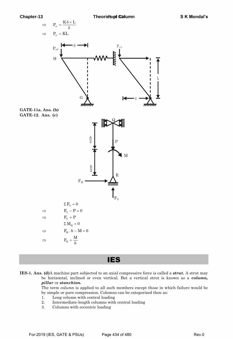
Chapter-13 Theories of Column S K Mondal’s
K LP
cr
P KLcr
G
H
Pcr
P c r
L
GATE-11a. Ans. (b)
GATE-12. Ans. (c)
Q
P
M
R
h2
h2
FH
FV
YF 0
V
F P 0
V
F P
QM 0
H
F . M 0h
H
MF
h
IES
IES-1. Ans. (d)A machine part subjected to an axial compressive force is called a strut. A strut may
be horizontal, inclined or even vertical. But a vertical strut is known as a column,
pillar or stanchion.
The term column is applied to all such members except those in which failure would be
by simple or pure compression. Columns can be categorized then as:
1. Long column with central loading
2. Intermediate-length columns with central loading
3. Columns with eccentric loading
Page 434
For-2019 (IES, GATE & PSUs) Page 434 of 480 Rev.0
Chapter-13 Theories of Column S K Mondal’s 4. Struts or short columns with eccentric loading
IES-2. Ans. (a) Axle is a non-rotating member used for supporting rotating wheels etc. and do not
transmit any torque. Axle must resist forces applied laterally or transversely to their
axes. Such members are called beams.
IES-2a Ans. (a)Axle is a non-rotating member used for supporting rotating wheels etc. and
do not transmit any torque. Axle must resist forces applied laterally or transversely
to their axes. Such members are called beams.
IES-3. Ans. (b) IES-4. Ans. (b) IES-5. Ans. (a)
IES-5(i). Ans. (d) IES-6. Ans. (a)
IES-6(i). Ans. (a)
IES-7. Ans. (b) IES-8. Ans. (b)
IES-9. Ans. (b)Euler’s buckling loads of columns
2
2
2
2
4 EI1 both ends fixedl
EI2 both ends hingedl
IES-10. Ans. (b)
IES-10(i). Ans. (a)
IES-10(ii). Ans. (d)
IES-11. Ans. (a)
For one end fixed and other end free; 2 2 9 4
32 2
210 10 ( / 64)10 10 50
4 4 4cr
EI dP or or d mm
l
IES-11(i). Ans. (c)
IES-12. Ans. (d)
IES-13. Ans. (a)Critical Load for both ends hinged = 2EI/ l 2
And Critical Load for one end fixed, and other end free = 2EI/4l2
IES-14. Ans. (a)Original load = 2
2EI
I
When one end of hinged column is fixed and other free. New Le = 2L
New load =
2 2
2 2EI EI 1 Original value
44L2L
IES-14a. Ans. (a)
IES-15. Ans. (b)
IES-16. Ans. (d) Critical Load for one end fixed, and other end free is 2EI/4l2 and both ends fixed
is 4 2EI/ l2
IES-17. Ans. (b)Buckling load of a column will be maximum when both ends are fixed
IES-18. Ans. (d)
2
2
EIP
L
4P I or P d or 4 4 4
4
d dp p 0.8d1 0.59p dd
IES-19. Ans. (a)
2
2
xx
EIP
L and
2
2
4 yy
EIP
L as xx yyP P then
3 3BH HB HI 4I or 4 or 212 12 B
IES-20. Ans. (d)For column with both ends hinged, P =
2
2
EI
l
. If ‘l’ is halved, P will be 4 times.
IES-20(i). Ans. (b)
IES-21. Ans. (a)For long column PEuler < Pcrushing
or
22 2 2 2
c c c2 2ce e
EI EAK le E leA or A or or E /k kl l
IES-22. Ans. (b)
IES-23. Ans. (c)
IES-24. Ans. (b)
Page 435
For-2019 (IES, GATE & PSUs) Page 435 of 480 Rev.0
Chapter-13 Theories of Column S K Mondal’s
IAS
IAS-1. Ans. (b)
IAS-2. Ans. (a)
IAS-3. Ans. (b) Buckling factor:The ratio of equivalent length of the column to the least radius of
gyration.
IAS-4. Ans. (b)
IAS-5. Ans. (c) A column with both ends fixed has minimum equivalent effective length (l/2)
IAS-6. Ans. (c)
IAS-7. Ans. (d)And Critical Load for one end fixed, and other end free = 2EI/4l2
IAS-8. Ans. (b)
Previous Conventional Questions with Answers
Conventional Question ESE-2001, ESE 2000 Question: Differentiate between strut and column. What is the general expression used
for determining of their critical load? Answer: Strut: A member of structure which carries an axial compressive load. Column: If the strut is vertical it is known as column.
For strut failure due to compression or force
s =c
Compressive
Area
If c ycs s> it fails.
Euler's formula for column( )2
2
π=
lC
e
EIP
Conventional Question ESE-2009 Q. Two long columns are made of identical lengths ‘l’ and flexural rigidities ‘EI’.
Column 1 is hinged at both ends whereas for column 2 one end is fixed and the
other end is free.
(i) Write the expression for Euler’s buckling load for column 1.
(ii) What is the ratio of Euler’s buckling load of column 1 to that column 2? [ 2 Marks]
Ans. (i)
2 2
1 22 2
EI EIP ; P right
L 4L
eForcolumnl,bothendhinged l L
(ii)
Conventional Question ESE-2010 Q. The piston rod of diameter 20 mm and length 700 mm in a hydraulic cylinder is
subjected to a compressive force of 10 kN due to internal pressure. The piston end
of the rod is guided along the cylinder and the other end of the rod is hinged at the
cross-head. The modulus of elasticity for piston rod material is 200 GPa. Estimate
the factor of safety taken for the piston rod design. [2 Marks]
Ans.
20mm PP
1
2
P4
P
Page 436
For-2019 (IES, GATE & PSUs) Page 436 of 480 Rev.0
Chapter-13 Theories of Column S K Mondal’s PσA
= ; PLδAE
= ; e 2= ;
2
e 2e
EIP π= (considering one end of the column is fixed and
other end is hinged) Pe = Euler Crippling load Compressive load, c cP σ Area= × = 10 kN
Euler’s load, ( ) ( )2 9 4
e 2
2 200 10 0.020 / 64P
(0.7)π × × × π ×
= = 63.278 kN
F.S = Euler 's loadCompressiveload
F.S =63.278 6.3
10=
Conventional Question ESE-1999 Question: State the limitation of Euler's formula for calculating critical load on
columns Answer: Assumptions: (i) The column is perfectly straight and of uniform cross-section (ii) The material is homogenous and isotropic (iii) The material behaves elastically (iv) The load is perfectly axial and passes through the centroid of the column section. (v) The weight of the column is neglected. Conventional Question ESE-2007 Question: What is the value of Euler's buckling load for an axially loaded pin-ended
(hinged at both ends) strut of length 'l' and flexural rigidity 'EI'? What would be order of Euler's buckling load carrying capacity of a similar strut but fixed at both ends in terms of the load carrying capacity of the earlier one?
Answer: From Euler's buckling load formula,
π2
C 2Critical load (P )e
EI=
Equivalent length ( ) for both end hinged = for both end fixed.2e =
π2
c 2So for both end hinged (P )behEI
=
( )π π2 2
c 2 2
4and for both fixed (P )
2bef
EI EI= =
Conventional Question ESE-1996 Question: Euler's critical load for a column with both ends hinged is found as 40 kN.
What would be the change in the critical load if both ends are fixed? Answer: We know that Euler's critical laod,
PEuler=2
2
π
e
EI [Where E = modulus of elasticity, I = least moment of inertia
equivalent lengthe = ] For both end hinged ( e) = And For both end fixed ( e) = /2
2π
π π
. . . 2
2 2
Euler . . . 2 2
( ) =40kN(Given)
and (P ) = 4 4 40 160( / 2)
Euler b e h
b e F
EIP
EI EI kN
∴ =
= × = × =
Page 437
For-2019 (IES, GATE & PSUs) Page 437 of 480 Rev.0
Chapter-13 Theories of Column S K Mondal’s Conventional Question ESE-1999 Question: A hollow cast iron column of 300 mm external diameter and 220 mm internal
diameter is used as a column 4 m long with both ends hinged. Determine the safe compressive load the column can carry without buckling using Euler's formula and Rankine's formula
E = 0.7×10⁵ N/mm2, FOS = 4, Rankine constant (a) = 1/1600 Crushing Stress (σc ) =567 N/mm2
Answer: Given outer diameter of column (D) = 300 mm = 0.3 m. Inner diameter of the column (d) = 220 mm = 0.22 m. Length of the column ( ) = 4 m End conditions is both ends hinged. Therefore equivalent length ( e ) = = 4 m.
Yield crushing stress (σc ) = 567 MPa = 567×106 N/m2 Rankine constant (a) = 1/ 1600 and E = 0.7×10⁵ N/mm2 = 70 x 109 N/m2
( )
π π
π
π4π π
4 4 4 4 4 4
4 42 22 2
2 2
2 2 2 2 2
Moment of Inertia(I) ( ) 0.3 0.22 2.826 1064 64
0.3 0.2264 0.09316 16( )
Area(A) ( ) (0.3 0.22 ) 0.032674 4
D d m
D dI D d mA D d
D d m
−⎡ ⎤= − = − = ×⎢ ⎥⎣ ⎦
− ++= = = =
−
= − = − =
2π π
Euler2 9 4
2 2
(i) Euler's buckling load, P
(70 10 ) (2.826 10 ) 12.2MN4
P 12.2Safe load = 3.05fos 4
Eulere
Euler
EIP
MN
−× × × ×= = =
∴ = =
( )σ
Rankine
6
Rankine 2 2
Rankine
(ii)Rankine's buckling load, P
567×10 0.03267. P = = 8.59 MN1 41+1 .
1600 0.093P 8.59 load = 2.148
fos 4
c
e
A
ak
Safe MN
×=
⎛ ⎞ ⎛ ⎞⎟ ⎟⎜ ⎜×+ ⎟ ⎟⎜ ⎜⎟ ⎟⎜⎟⎜ ⎝ ⎠⎝ ⎠
∴ = =
Conventional Question ESE-2008 Question: A both ends hinged cast iron hollow cylindrical column 3 m in length has a
critical buckling load of P kN. When the column is fixed at both the ends, its critical buckling load raise by 300 kN more. If ratio of external diameter to internal diameter is 1.25 and E = 100 GPa determine the external diameter of column.
Answer: 2
2ce
EIPI
π=
2
2
For both end hinged columnEIP= ( )
Liπ
−−−
Page 438
For-2019 (IES, GATE & PSUs) Page 438 of 480 Rev.0
Chapter-13 Theories of Column S K Mondal’s
Conventional Question AMIE-1996 Question: A piston rod of steam engine 80 cm long in subjected to a maximum load of 60
kN. Determine the diameter of the rod using Rankine's formula with permissible compressive stress of 100 N/mm2. Take constant in Rankine's
formula as 1
7500for hinged ends. The rod may be assumed partially fixed
with length coefficient of 0·6. Answer: Given: 3 2
cl 80 cm 800mm ;P 60kN 60 10 N, 100N / mm ;σ= = = = × =
1a for hinged ends; length coefficient 0.6
7500= =
To find diameter of the rod, d: Use Rankine’s formula
c2
e
APl1 ak
σ=
⎛ ⎞+ ⎜ ⎟⎝ ⎠
eHere l 0.6l 0.6 800 480 mm [ length coefficient 0.6]= = × = =∵
4
2
dI d64kA 4d
4
π
π= = =
2
32
100 d460 10
1 48017500 d / 4
π⎛ ⎞× ⎜ ⎟⎝ ⎠∴ × =⎡ ⎤+ ⎢ ⎥⎣ ⎦
Solving the above equation we get the value of ‘d’ Note: Unit of d comes out from the equation will be mm as we put the equivalent
length in mm. =or d 33.23mm
( )2 2
2 2
For both end fixed column4P+300= ( )
2
EI EI iiLL
π π= −−−
(ii) by (i) we getP+300 4 or P=100kN
P
Dividing
=
( )
( )
24 4
2
3 24 4 5
2 9
Moment of inertia of a hollow cylinder c/s is
64100 10 364 1.8577 10
100 10
PLI D dE
orD d
ππ
π π−
= − =
×− = = ×
× ×
44 5
D D 1.25 or d =d 1.25-5
1 D 1 1.8577 101.25
D=0.0749 m = 74.9 mm
given
or
or
−
=
⎡ ⎤⎛ ⎞⎢ ⎥⎟⎜− = ×⎟⎜⎢ ⎥⎟⎜⎝ ⎠⎢ ⎥⎣ ⎦
Page 439
For-2019 (IES, GATE & PSUs) Page 439 of 480 Rev.0
Chapter-13 Theories of Column S K Mondal’s Conventional Question ESE-2005 Question: A hollow cylinder CI column, 3 m long its internal and external diameters as
80 mm and 100 mm respectively. Calculate the safe load using Rankine formula: if
(i) Both ends are hinged and (ii) Both ends are fixed. Take crushing strength of material as 600 2/N mm , Rankine constant 1/1600
and factor of safety = 3.
Answer: π 4 4 4 6 4Moment of Inertia (I)= (0.1 0.08 ) 2.898 10
64m m−− = ×
( )π
σ
2 2 3 2
6
3
2
Area( ) 0.1 0.08 2.8274 104
I 2.898 10Radius of gyration (k) = 0.032A 2.8274 10
.= ; [ = equivalent length]1
cRankine e
e
A m
m
APa
k
−
−
−
= − = ×
×= =
×
⎛ ⎞⎟⎜+ ⎟⎜ ⎟⎜⎝ ⎠
( ) ( )600 6 3
2
Rankine
10 2.8274 10(i) = ; [ = l = 3 m for both end hinged]
1 311600 0.032
=261.026kNP 26126Safe load (P)= 87.09FOS 3
e
kN
−× × ×
⎛ ⎞ ⎛ ⎞⎟ ⎟⎜ ⎜+ ×⎟ ⎟⎜ ⎜⎟ ⎟⎜ ⎜⎝ ⎠ ⎝ ⎠
= =
( )e
6 3
2
(ii) For both end fixed, 1.52600 10 (2.8274 10 )
714.81 1.51
1600 0.032
Rankine
m
P kN−
= =
× × ×= =
⎛ ⎞⎟⎜+ × ⎟⎜ ⎟⎜⎝ ⎠
RankineP 714.8 load (P)= 238.27FOS 3
Safe kN= =
Conventional Question AMIE-1997 Question: A slender column is built-in at one end and an eccentric load is applied at the
free end. Working from the first principles find the expression for the maximum length of column such that the deflection of the free end does not exceed the eccentricity of loading.
Page 440
For-2019 (IES, GATE & PSUs) Page 440 of 480 Rev.0
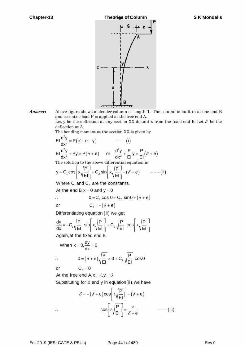
Chapter-
Answer:
-13
Above fand ecceLet y bedeflectioThe ben
=
+
2
2
2
2
d yEIdxd yEIdx
The solu
1y C c
WhereAt the
or
=
∴
Differen
dy Cdx
= −
Again,
Whe
or
∴
At theSubstit
∴
figure showsentric load Pe the deflecton at A. nding momen
(
(
δ
δ
= + −
+ = +
P e
Py P
ution to the
1 2
Pcos xEI
C and Cend B,x 0
0
C
⎡ ⎤+⎢ ⎥
⎢ ⎥⎣ ⎦
=
1
ntiating equ
PC sinEI
⎡⎢⎢⎣
(
2
at the fixeddyn x 0,dx
0
C 0
δ
= =
= +
=
(
free end A,uting for x
δ δ= −
Theo
s a slender cP is applied tion at any
nt at the sec
)
)
−
+
y
e or
above differ
( )
2
1
1
C sin x
are the con0 and y 0
C cos 0
C eδ
⎡+ ⎢
⎢⎣
=
= +
= − +
( )
2
uation ii w
Px CEI
⎡ ⎤+⎥
⎥⎣ ⎦
)
d end B,
0
Pe 0EI
=
+ ×
)
,x ,yand y in eq
e cos
cos
δ
δ
= =
⎡+ ⎢
⎣⎡⎢⎣
ories of Co
column of le at the free esection XX d
ction XX is g
( )− − − −
+ =2
2
i
d y P yEIdx
rential equa
(
)2
P eEI
ns tan ts.
C sin0
δ⎤+ +⎥
⎥⎦
+ +
2
we get
P cosEI
⎡⎢⎢⎣
2PC cEI
+
( )
(
uation ii ,w
PEI
P eEI e
δ
δ
⎤=⎥
⎦⎤=⎥ +⎦
lumn
ength ‘I’. Thend A. distant x fro
given by
( )δ= +P eEI
tion is
)
( )
e
eδ
− − −
+
PxEI
⎤⎥⎥⎦
cos0
)
we have
e
e
+
−
e column is
om the fixed
( )ii−
( )iii− − −
S K
built in at
d end B. Let
Mondal’s
one end B
t δ be the
Page 441
For-2019 (IES, GATE & PSUs) Page 441 of 480 Rev.0
C
CQ
An
CQ
Chapter-13
ConventionQuestion:
nswer: Lb
o
o
∴
CyIA
ConventionQuestion:
It is mentieccentricitySubstitutin
cos
PE
⎡⎢⎣
∴
∴
nal QuestiA long strapplied aeccentricimaximum
Where,tan
Let at a distbeam is y
2
2
2
2
22
2
d yEIdx
d y PorEdx
d yor kdx
∴ =
+
+
C.F of this diy = A cos kx It is clear at And at x =
....e A∴ =
2 cos
co
e A
y e
=
∴ =
Where be
the deflec
tan
dy edx
or kx
∴ =−
=
nal QuestiThe link ocircular cof the linkand elastcan carry
ioned in they. It means tng this value
1
P eEI
P 1cosEI 2
3
δ
π
−
⎤=⎥ +⎦
⎛= ⎜⎝
=
ion ESE-2rut AB of l
at the endsity at the
m bending m
n(kx)= 2
si−
ance 'x' from
2
.
0
0
P y
P yEI
y
−
=
⎡⎢= ⎢⎢⎣∵
ifferential e + B sin kx, W x = 0, y = e , y= 2e
..............( )i
s sin
2oss
k B k
ekx
+
⎡ −⎢+⎢⎣
ending mom
tion will be
sin
2 cossin
ek kx k
kk
+
−=
ion ESE-1of a mechacross-sectiok are hingic modulus
y. Use John
Theoriee problem ththat δ = e e in equatione 1
e 2
12 3
EIP
π
=+
⎞ =⎟⎠
2005 length ' ' is eccentric end B twmoment occos and n
kk
m end A defl
Pk giEI
=∵
quation Where A & B
cos ssin
k or
e kk
⎤− ⎥⎥⎦
ment is maxi
maximum s
2 cos.sin
e ekk
⎡ −⎢⎢⎣
996 anism is suon with diaged. It is ms = 200 kN
non's equati
es of Columhat the defle
n (iii), we ha
is of uniforcally on thwice than curs at a d
Pk=EI
lection of th
iven⎤⎥⎥⎥⎦
B constant.
2s
in
eB
kx
⎡ −⎢=⎢⎣
mum,
so 0
s cos
dydx
k kx
=
⎤⎥ =⎥⎦
ubjected toameter 9 m
made of steeN/mm2. Calcion.
mnection of the
ave
rm sectionhe same sidthat at thistance x fr
e
cosine k
k⎤⎥⎥⎦
0=
axial commm and lenel having yculate the
e free end d
n throughode of the c
he end A. from the en
mpressive fongth 200 mmyield stren critical lo
S K Mooes not exce
ut. A thruscentre line Show tha
nd A,
orce. It hasm. The twogth = 400 N
oad that th
ondal’s eed the
st P is e with at the
s solid o ends N/mm2
he link
Page 442
For-2019 (IES, GATE & PSUs) Page 442 of 480 Rev.0
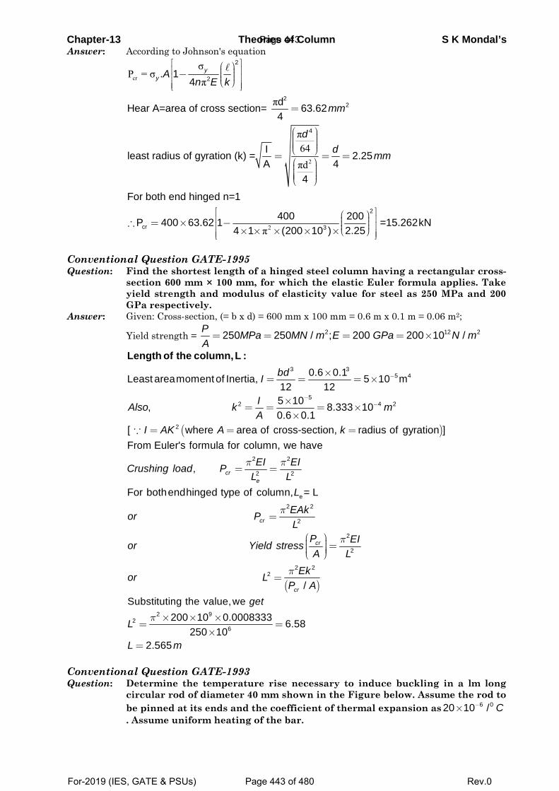
Chapter-13 Theories of Column S K Mondal’s Answer: According to Johnson's equation
cr
2
σP = σ
π
π
π64πd
2
2
22
4
cr
. 14
dHear A=area of cross section= 63.624
Ileast radius of gyration (k) = 2.25A 4
4
For both end hinged n=1
40P 400 63.62 1
yy A
kn E
mm
dd mm
⎡ ⎤⎛ ⎞⎢ ⎥⎟⎜− ⎟⎜⎢ ⎥⎟⎜⎝ ⎠⎢ ⎥⎣ ⎦
=
⎛ ⎞⎟⎜ ⎟⎜ ⎟⎜ ⎟⎜⎝ ⎠= = =
⎛ ⎞⎟⎜ ⎟⎜ ⎟⎜ ⎟⎜⎝ ⎠
∴ = × − 2π
2
3
0 200 =15.262kN2.254 1 (200 10 )
⎡ ⎤⎛ ⎞⎢ ⎥⎟⎜ ⎟⎜⎢ ⎥⎟⎜⎝ ⎠× × × × ×⎢ ⎥⎣ ⎦
Conventional Question GATE-1995 Question: Find the shortest length of a hinged steel column having a rectangular cross-
section 600 mm × 100 mm, for which the elastic Euler formula applies. Take yield strength and modulus of elasticity value for steel as 250 MPa and 200 GPa respectively.
Answer: Given: Cross-section, (= b x d) = 600 mm x 100 mm = 0.6 m x 0.1 m = 0.06 m2;
Yield strength = 2 12 2250 250 / ; 200 200 10 /P MPa MN m E GPa N mA
= = = = ×
3 35 40.6 0.1Least areamoment of Inertia, 5 10 m
12 12bdI −×
= = = ×
Length of the column, L :
( )
52 4 2
2
5 10, 8.333 100.6 0.1
[ where area of cross-section, radius of gyration ]
IAlso k mA
I AK A k
−−×
= = = ××
= = =∵
2 2
2 2
From Euler's formula for column, we have
, cre
EI EICrushing load PL Lπ π
= =
( )
e2 2
2
2
2
2 22
For bothendhinged type of column, = L
/
cr
cr
cr
L
EAkor PL
P EIor Yield stressA L
Ekor LP A
π
π
π
=
⎛ ⎞⎟⎜ =⎟⎜ ⎟⎟⎜⎝ ⎠
=
Substituting the value,we get
2 92
6
200 10 0.0008333 6.58250 10
2.565
L
L m
π × × ×= =
×=
Conventional Question GATE-1993 Question: Determine the temperature rise necessary to induce buckling in a lm long
circular rod of diameter 40 mm shown in the Figure below. Assume the rod to be pinned at its ends and the coefficient of thermal expansion as 6 020 10 / C−×. Assume uniform heating of the bar.
Page 443
For-2019 (IES, GATE & PSUs) Page 443 of 480 Rev.0
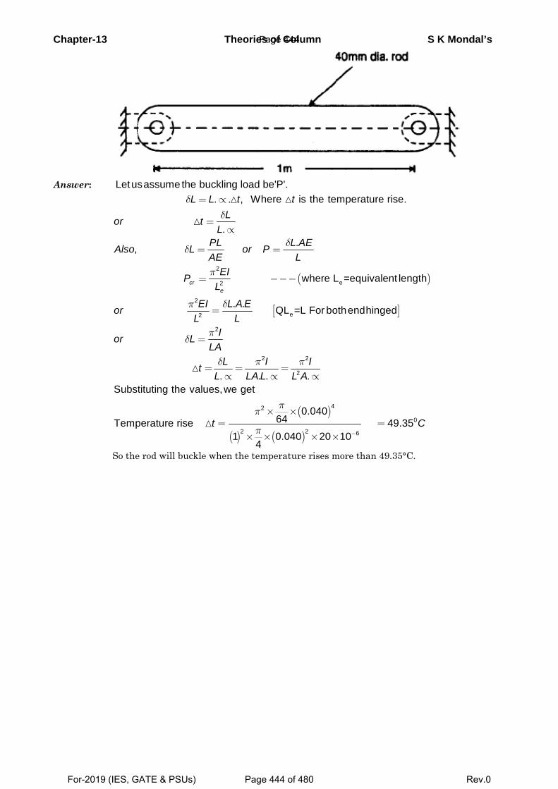
Chapter-13 Theories of Column S K Mondal’s
Answer: Letusassume the buckling load be'P'.
( )
[ ]
2
e2
2
e2
. . , Where is the temperature rise.
..,
where L =equivalent length
. . QL =L For bothendhinged
cre
L L t tLor t
LPL L AEAlso L or PAE L
EIPL
EI L A EorLL
δδ
δδ
π
π δ
= ∝
=∝
= =
= −−−
=
( )
( ) ( )
2
2 2
2
42
0
2 2 6
. . . .Substituting the values,we get
0.04064Temperature rise 49.35
1 0.040 20 104
Ior LLA
L I ItL LA L L A
t C
πδ
δ π π
ππ
π −
=
= = =∝ ∝ ∝
× ×= =
× × × ×
So the rod will buckle when the temperature rises more than 49.35°C.
Page 444
For-2019 (IES, GATE & PSUs) Page 444 of 480 Rev.0
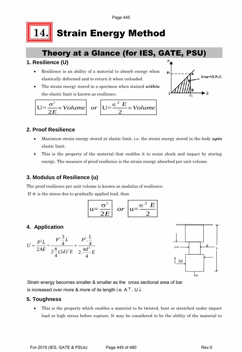
14. Strain Energy Method
Theory at a Glance (for IES, GATE, PSU) 1. Resilience (U)
Resilience is an ability of a material to absorb energy when
elastically deformed and to return it when unloaded.
The strain energy stored in a specimen when stained within
the elastic limit is known as resilience.
2σU= U=
2 2
2 EVolume or Volume
E
2. Proof Resilience
Maximum strain energy stored at elastic limit. i.e. the strain energy stored in the body upto
elastic limit.
This is the property of the material that enables it to resist shock and impact by storing
energy. The measure of proof resilience is the strain energy absorbed per unit volume.
3. Modulus of Resilience (u)
The proof resilience per unit volume is known as modulus of resilience.
If σ is the stress due to gradually applied load, then
2σu= u=
2 2
2 Eor
E
4. Application
2 22
22
3P .
4 4=π π2
2 (2 ) 2.4 4
LL P
P LU
dAEd E E
Strain energy becomes smaller & smaller as the cross sectional area of baris increased over more & more of its length i.e. A , U
5. Toughness
This is the property which enables a material to be twisted, bent or stretched under impact
load or high stress before rupture. It may be considered to be the ability of the material to
Page 445
For-2019 (IES, GATE & PSUs) Page 445 of 480 Rev.0
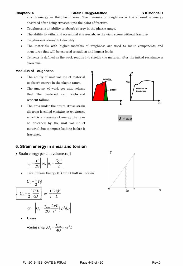
Chapter-14 Strain Energy Method S K Mondal’s absorb energy in the plastic zone. The measure of toughness is the amount of energy
absorbed after being stressed upto the point of fracture.
Toughness is an ability to absorb energy in the plastic range.
The ability to withstand occasional stresses above the yield stress without fracture.
Toughness = strength + ductility
The materials with higher modulus of toughness are used to make components and
structures that will be exposed to sudden and impact loads.
Tenacity is defined as the work required to stretch the material after the initial resistance is
overcome.
Modulus of Toughness
The ability of unit volume of material
to absorb energy in the plastic range.
The amount of work per unit volume
that the material can withstand
without failure.
The area under the entire stress strain
diagram is called modulus of toughness,
which is a measure of energy that can
be absorbed by the unit volume of
material due to impact loading before it
fractures.
UT= σuεf
6. Strain energy in shear and torsion
s
2 2
s
Strain energy per unit volume,(u )
τ or, u
2 2
s
Gu
G
Total Strain Energy (U) for a Shaft in Torsion
2 2
1
2
1 1 GJ
2 2
s
s
U T
T LU or
GJ L
22max
2
τ 2or
2
s
LU d
G r
Cases
22maxτ
,4
sSolid shaft U r LG
Page 446
For-2019 (IES, GATE & PSUs) Page 446 of 480 Rev.0
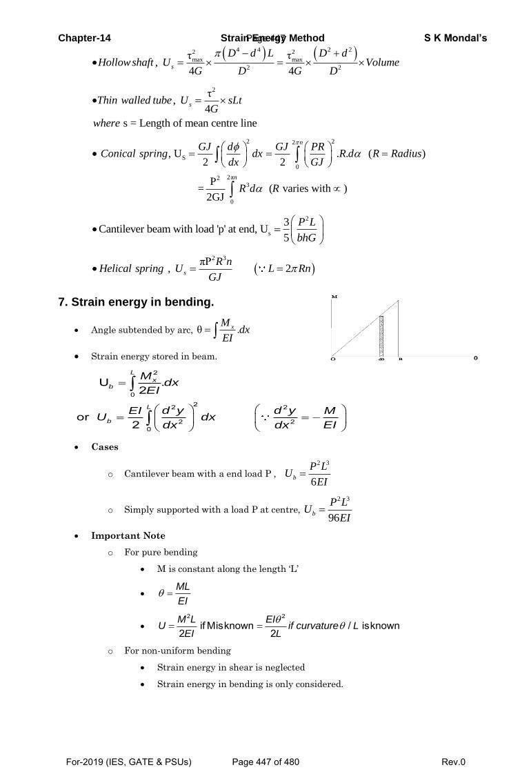
Chapter-14 Strain Energy Method S K Mondal’s
4 4 2 22 2
max max
2 2
τ τ,
4 4s
D d L D dHollowshaft U Volume
G D G D
2τ,
4
s = Length of mean centre line
sThin walled tube U sLtG
where
2 22
S
0
2π23
0
, U . . ( )2 2
P = ( varies with )
2GJ
n
n
GJ d GJ PRConical spring dx R d R Radius
dx GJ
R d R
2
s
3Cantilever beam with load 'p' at end, U
5
P L
bhG
2 3πP
, 2 s
R nHelical spring U L Rn
GJ
7. Strain energy in bending.
Angle subtended by arc, θ . xM
dxEI
Strain energy stored in beam.
2
022 2
2 20
U .2
or 2
L
xb
L
b
Mdx
EI
d y d yEI MU dx
EIdx dx
Cases
o Cantilever beam with a end load P ,
2 3
6b
P LU
EI
o Simply supported with a load P at centre,
2 3
96b
P LU
EI
Important Note
o For pure bending
M is constant along the length ‘L’
ML
EI
2 2
if Misknown / isknown2 2M L EI
U if curvature LEI L
o For non-uniform bending
Strain energy in shear is neglected
Strain energy in bending is only considered.
Page 447
For-2019 (IES, GATE & PSUs) Page 447 of 480 Rev.0
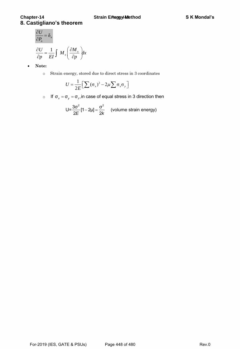
Chapter-14 Strain Energy Method S K Mondal’s
8. Castigliano’s theorem
δ
n
n
U
P
1
x
x
MUM dx
p EI p
Note:
o Strain energy, stored due to direct stress in 3 coordinates
21
(σ ) 2 σ σ2
x x yUE
o If σ σ σ ,in case of equal stress in 3 direction thenx y z
2 23σ σU= [1 2μ] (volume strain energy)2 2E k
Page 448
For-2019 (IES, GATE & PSUs) Page 448 of 480 Rev.0
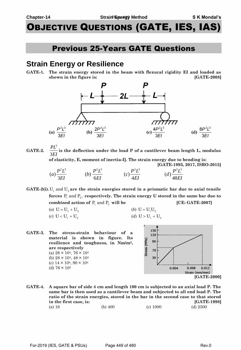
Chapter-14 Strain Energy Method S K Mondal’s
OBJECTIVE QUESTIONS (GATE, IES, IAS)
Previous 25-Years GATE Questions
Strain Energy or Resilience GATE-1. The strain energy stored in the beam with flexural rigidity EI and loaded as
shown in the figure is: [GATE-2008]
(a)
2 3
3P L
EI (b)
2 323P L
EI (c)
2 343P L
EI (d)
2 383P L
EI
GATE-2.
3
3
PL
EIis the deflection under the load P of a cantilever beam length L, modulus
of elasticity, E, moment of inertia-I]. The strain energy due to bending is:
[GATE-1993, 2017, ISRO-2015]
2 3 2 3 2 3 2 3
( ) ( ) ( ) ( )3 6 4 48
P L P L P L P La b c d
EI EI EI EI
GATE-2(i).1 2
U and U are the strain energies stored in a prismatic bar due to axial tensile
forces 1 2
P and P , respectively. The strain energy U stored in the same bar due to
combined action of 1 2
P and P will be [CE: GATE-2007]
(a) 1 2
U U U (b) 1 2
U U U
(c) 1 2
U U U (d) 1 2
U U U
GATE-3. The stress-strain behaviour of a
material is shown in figure. Its
resilience and toughness, in Nm/m3,
are respectively
(a) 28 × 104, 76 × 104
(b) 28 × 104, 48 × 104
(c) 14 × 104, 90 × 104
(d) 76 × 104
[GATE-2000]
GATE-4. A square bar of side 4 cm and length 100 cm is subjected to an axial load P. The
same bar is then used as a cantilever beam and subjected to all end load P. The
ratio of the strain energies, stored in the bar in the second case to that stored
in the first case, is: [GATE-1998]
(a) 16 (b) 400 (c) 1000 (d) 2500
Page 449
For-2019 (IES, GATE & PSUs) Page 449 of 480 Rev.0
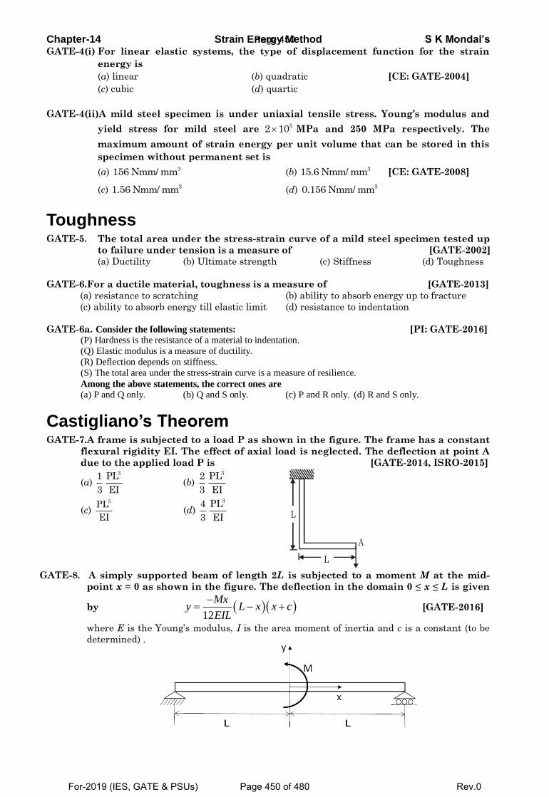
Chapter-14 Strain Energy Method S K Mondal’s GATE-4(i) For linear elastic systems, the type of displacement function for the strain
energy is
(a) linear (b) quadratic [CE: GATE-2004]
(c) cubic (d) quartic
GATE-4(ii)A mild steel specimen is under uniaxial tensile stress. Young’s modulus and
yield stress for mild steel are 52 10 MPa and 250 MPa respectively. The
maximum amount of strain energy per unit volume that can be stored in this
specimen without permanent set is
(a) 3156 Nmm/ mm (b) 315.6 Nmm/ mm [CE: GATE-2008]
(c) 31.56 Nmm/ mm (d) 30.156 Nmm/ mm
Toughness GATE-5. The total area under the stress-strain curve of a mild steel specimen tested up
to failure under tension is a measure of [GATE-2002]
(a) Ductility (b) Ultimate strength (c) Stiffness (d) Toughness
GATE-6.For a ductile material, toughness is a measure of [GATE-2013]
(a) resistance to scratching (b) ability to absorb energy up to fracture
(c) ability to absorb energy till elastic limit (d) resistance to indentation
GATE-6a. Consider the following statements: [PI: GATE-2016] (P) Hardness is the resistance of a material to indentation.
(Q) Elastic modulus is a measure of ductility.
(R) Deflection depends on stiffness.
(S) The total area under the stress-strain curve is a measure of resilience.
Among the above statements, the correct ones are
(a) P and Q only. (b) Q and S only. (c) P and R only. (d) R and S only.
Castigliano’s Theorem GATE-7.A frame is subjected to a load P as shown in the figure. The frame has a constant
flexural rigidity EI. The effect of axial load is neglected. The deflection at point A
due to the applied load P is [GATE-2014, ISRO-2015]
(a) 31 PL
3 EI (b)
32 PL
3 EI
(c) 3PL
EI (d)
34 PL
3 EI
L
A
L
GATE-8. A simply supported beam of length 2L is subjected to a moment M at the mid-
point x = 0 as shown in the figure. The deflection in the domain 0 ≤ x ≤ L is given
by 12
Mxy L x x c
EIL
[GATE-2016]
where E is the Young’s modulus, I is the area moment of inertia and c is a constant (to be
determined) .
Page 450
For-2019 (IES, GATE & PSUs) Page 450 of 480 Rev.0
Chapter-14 Strain Energy Method S K Mondal’s The slope at the center x = 0 is
(a) 𝑀𝐿/(2𝐸𝐼) (b) 𝑀𝐿/(3𝐸𝐼) (c) 𝑀𝐿/(6𝐸𝐼) (d) 𝑀𝐿/(12𝐸𝐼)
Previous 25-Years IES Questions
Strain Energy or Resilience IES-1. What is the strain energy stored in a body of volume V with stress due to
gradually applied load? [IES-2006]
(a) E
V
(b)
2E
V
(c)
2V
E
(d)
2
2
V
E
Where, E = Modulus of elasticity
IES-1a. The capacity of a material to absorb energy when deformed elastically and
then to have this energy recovered upon unloading is called [IES-2016]
(a) endurance (b) resilience (c) toughness (d) ductility
IES-1b. A circular bar L m long and d m in diameter is subjected to tensile force of F
kN. Then the strain energy, U will be (where, E is the modulus of elasticity in
kN/m2 ) [IES-2012]
(𝑎)4𝐹2
𝜋𝑑2∙
𝐿
𝐸(𝑏)
𝐹2
𝜋𝑑2∙
𝐿
𝐸(𝑐)
2𝐹2
𝜋𝑑2∙
𝐿
𝐸(𝑑)
3𝐹2
𝜋𝑑2∙
𝐿
𝐸
IES-1c. Statement (I): Ductile materials generally absorb more impact energy than the
brittle materials.
Statement (II): Ductile materials generally have higher ultimate strength than
brittle materials. [IES-2012]
(a) Both Statement (I) and Statement (II) are individually true and Statement (II) is the
correct explanation of Statement (I)
(b) Both Statement (I) and Statement (II) are individually true but Statement (II) is not
the correct explanation of Statement (I)
(c) Statement (I) is true but Statement (II) is false
(d) Statement (I) is false but Statement (II) is true
IES-2. A bar having length L and uniform cross-section with area A is subjected to
both tensile force P and torque T. If G is the shear modulus and E is the
Young's modulus, the internal strain energy stored in the bar is: [IES-2003]
(a)
2 2
2
T L P L
GJ AE (b)
2 2
2
T L P L
GJ AE (c)
2 2
2 2
T L P L
GJ AE (d)
2 2T L P L
GJ AE
IES-3. Strain energy stored in a body of volume V subjected to uniform stress s is:
[IES-2002]
(a) s E / V (b) sE2/ V (c) sV2/E (d) s2V/2E
IES-4. A bar of length L and of uniform cross-sectional area A and second moment of
area ‘I’ is subjected to a pull P. If Young's modulus of elasticity of the bar
material is E, the expression for strain energy stored in the bar will be:
[IES-1999]
2 2 2 2P L PL PL P L(a) (b) (c) (d)
2AE 2EI AE AE IES-4a. The strain energy per unit volume of a round bar under uniaxial tension with
axial stress and modulus of elasticity E is [IES-2016]
2 2 2 2
( ) (b) (c) (d)2 3 4
aE E E E
Page 451
For-2019 (IES, GATE & PSUs) Page 451 of 480 Rev.0
Chapter-14 Strain Energy Method S K Mondal’s IES-5. Which one of the following gives the correct expression for strain energy
stored in a beam of length L and of uniform cross-section having moment of
inertia ‘I’ and subjected to constant bending moment M? [IES-1997]
2 2
a b c d 2 2
ML ML M L M L
EI EI EI EI
IES-6. A steel specimen 150 2mm in cross-section stretches by 0·05 mm over a 50 mm
gauge length under an axial load of 30 kN. What is the strain energy stored in
the specimen? (Take E = 200 GPa) [IES-2009]
(a) 0.75 N-m (b) 1.00 N-m (c) 1.50 N-m (d) 3.00 N-m
IES-7. What is the expression for the strain energy due to bending of a cantilever
beam (length L. modulus of elasticity E and moment of inertia I)? [IES-2009]
(a)
2 3
3
P L
EI(b)
2 3
6
P L
EI (c)
2 3
4
P L
EI (d)
2 3
48
P L
EI
IES-7(i). A cantilever beam, 2m in length, is subjected to a uniformly distributed load of
5kN/m. If E=200GPa and I=1000 4cm , the strain energy stored in the beam will be
(a) 7Nm (b) 12Nm (c) 8Nm (d) 10Nm [IES-2014]
IES-8. The property by which an amount of energy is absorbed by a material without
plastic deformation, is called: [IES-2000]
(a) Toughness (b) Impact strength (c) Ductility (d) Resilience
IES-8a Resilience of material becomes important when it is subjected to :
(a) Fatigue (b) Thermal stresses
(c) Shock loading (d) Pure static loading [IES-2011]
IES-8b. Which one of the following statements is correct?
(a) The strain produced per unit volume is called resilience.
(b) The maximum strain produced per unit volume is called proof resilience.
(c) The least strain energy stored in a unit volume is called proof resilience.
(d) The greatest strain energy stores in a unit volume of a material without
permanent deformation is called proof resilience. [IES-2017 Prelims]
IES-9. 30 C 8 steel has its yield strength of 400 N/mm2 and modulus of elasticity of 2 ×
105 MPa. Assuming the material to obey Hooke's law up to yielding, what is its
proof resilience? [IES-2006]
(a) 0·8 N/mm2 (b) 0.4 N/mm2 (c) 0·6 N/mm2 (d) 0·7 N/mm2
IES9a Match List I with List II and select the correct answer using the code given
below the lists: [IES-2010] List I List II
A. Point of inflection 1. Strain energy
B. Shearing strain 2. Equation of bending
C. Section modulus 3. Equation of torsion
D. Modulus of resilience 4. Bending moment diagram
Code: A B C D A B C D
(a) 1 3 2 4 (b) 4 3 2 1
(c) 1 2 3 4 (d) 4 2 3 1
Toughness IES-10. Toughness for mild steel under uni-axial tensile loading is given by the shaded
portion of the stress-strain diagram as shown in [IES-2003]
Page 452
For-2019 (IES, GATE & PSUs) Page 452 of 480 Rev.0
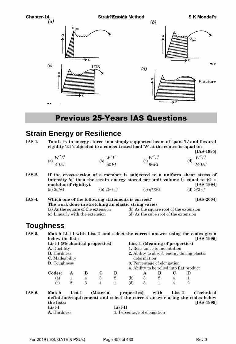
Chapter-14 Strain Energy Method S K Mondal’s
Previous 25-Years IAS Questions
Strain Energy or Resilience IAS-1. Total strain energy stored in a simply supported beam of span, 'L' and flexural
rigidity 'EI 'subjected to a concentrated load 'W' at the centre is equal to:
[IAS-1995]
(a)
2 3
40
W L
EI (b)
2 3
60
W L
EI (c)
2 3
96
W L
EI (d)
2 3
240
W L
EI
IAS-2. If the cross-section of a member is subjected to a uniform shear stress of
intensity 'q' then the strain energy stored per unit volume is equal to (G =
modulus of rigidity). [IAS-1994]
(a) 2q2/G (b) 2G / q2 (c) q2 /2G (d) G/2 q2
IAS-4. Which one of the following statements is correct? [IAS-2004]
The work done in stretching an elastic string varies
(a) As the square of the extension (b) As the square root of the extension
(c) Linearly with the extension (d) As the cube root of the extension
Toughness IAS-5. Match List-I with List-II and select the correct answer using the codes given
below the lists: [IAS-1996]
List-I (Mechanical properties) List-II (Meaning of properties)
A. Ductility 1. Resistance to indentation
B. Hardness 2. Ability to absorb energy during plastic
C. Malleability deformation
D. Toughness 3. Percentage of elongation
4. Ability to be rolled into flat product
Codes: A B C D A B C D
(a) 1 4 3 2 (b) 3 2 4 1
(c) 2 3 4 1 (d) 3 1 4 2
IAS-6. Match List-I (Material properties) with List-II (Technical
definition/requirement) and select the correct answer using the codes below
the lists: [IAS-1999]
List-I List-II
A. Hardness 1. Percentage of elongation
Page 453
For-2019 (IES, GATE & PSUs) Page 453 of 480 Rev.0
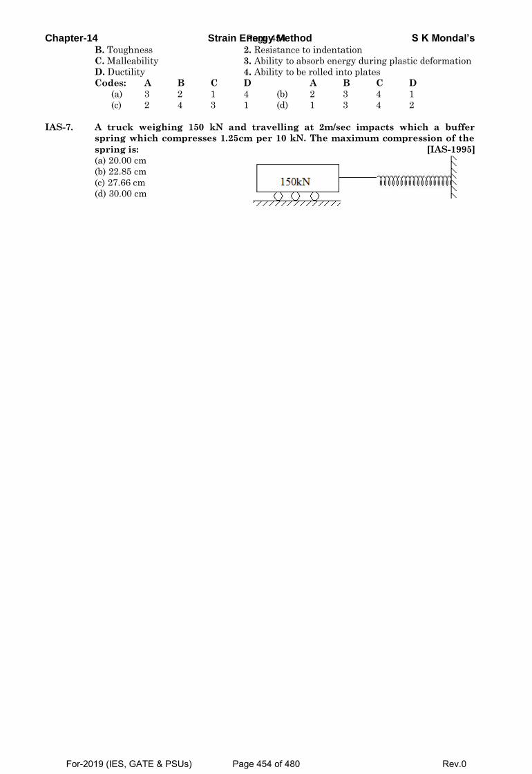
Chapter-14 Strain Energy Method S K Mondal’s B. Toughness 2. Resistance to indentation
C. Malleability 3. Ability to absorb energy during plastic deformation
D. Ductility 4. Ability to be rolled into plates
Codes: A B C D A B C D
(a) 3 2 1 4 (b) 2 3 4 1
(c) 2 4 3 1 (d) 1 3 4 2
IAS-7. A truck weighing 150 kN and travelling at 2m/sec impacts which a buffer
spring which compresses 1.25cm per 10 kN. The maximum compression of the
spring is: [IAS-1995]
(a) 20.00 cm
(b) 22.85 cm
(c) 27.66 cm
(d) 30.00 cm
Page 454
For-2019 (IES, GATE & PSUs) Page 454 of 480 Rev.0
Chapter-14 Strain Energy Method S K Mondal’s
OBJECTIVE ANSWERS
GATE-1.Ans. (C)4 3 42 2 2 2
0 0 32 2 2 2
L L L L
L L
M dx M dx M dx M dxEI EI EI EI
= + +∫ ∫ ∫ ∫
3 42 2 2 2
0 0 3
32 2 2 3
0
2 By symmetry2 2 2 2
( ) ( ) 422 2 3
L L L L
L L
L L
L
M dx M dx M dx M dxEI EI EI EI
Px dx PL dx P LEI EI EI
⎡ ⎤⎢ ⎥= + =⎢ ⎥⎢ ⎥⎣ ⎦
= + =
∫ ∫ ∫ ∫
∫ ∫
GATE-2. Ans. (b)We may do it taking average
Strain energy = Average force x displacement = 3
2 3⎛ ⎞× =⎜ ⎟⎝ ⎠
P PLEI
2 3
6P L
EI
Alternative method: In a funny way you may use Castigliano’s theorem, UP
δ∂
=∂
. Then
UP
δ∂
=∂
3
3PLEI
= or 3
3PLU U PEI
= ∂ = ∂∫ ∫ Partially integrating with respect to P we get
2 3P LU6EI
=
GATE-2(i). Ans. (d)
We know that Strain Energy, =2P LU
2 AE
It is obvious from the above equation that strain energy is proportional to the square of load applied. We know that sum of squares of two numbers is less than the square of their sum. Thus > +1 2U U U .
GATE-3. Ans. (c) Resilience = area under this curve up to 0.004 strain
= 6 41 0.004 70 10 14 102× × × = × Nm/m3
Toughness = area under this curve up to 0.012 strain
= ( ) ( ) ( )4 6 6114 10 70 10 0.012 0.004 0.012 0.004 120 70 102
× + × × − + × − × − × Nm/m3
490 10= × Nm/m3
GATE-4. Ans. (d)
⎛ ⎞⎜ ⎟⎝ ⎠= =
2
2
1
W ALW LAU
2E 2AE
= = =⎛ ⎞⎜ ⎟⎝ ⎠
⎛ ⎞= = × =⎜ ⎟⎝ ⎠
2 3 2 3 2 3
2 44
222
21
W L W L 2W LU16EI Ea6E a
12
U 4L 100or 4 2500U 4a
GATE-4(i) Ans. (b)
Strain Energy = × σ × ε = ε21 1 E2 2
GATE-4(ii)Ans. (d) The strain energy per unit volume may be given as
σ
= × = × = −×
2 23
51 1 (250) 0.156 N mm/ mm2 E 2 2 10
yu
GATE-5.Ans. (d)
Page 455
For-2019 (IES, GATE & PSUs) Page 455 of 480 Rev.0
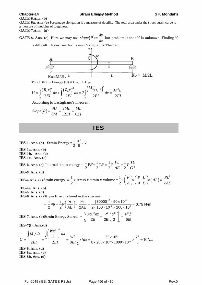
Chapter-14 Strain Energy Method S K Mondal’s GATE-6.Ans. (b) GATE-6a. Ans.(c) Percentage elongation is a measure of ductility. The total area under the stress-strain curve is a measure of modulus of toughness. GATE-7.Ans. (d)
GATE-8. Ans. (c) Here we may use ( ) dyslopedx
θ = but problem is that ‘c’ is unknown. Finding ‘c’
is difficult. Easiest method is use Castigliano’s Theorem.
Total Strain Energy (U) = UAC + UBC
( ) ( ) ( )
( )
22 2 2
0 0 0
.222 2 2 12
According to Castigliano's Theorem212 6
L L La b
M xR x R x M LLU dx dx dxEI EI EI EI
U ML MLSlopeM EI EI
θ
= + = =
∂= = =∂
∫ ∫ ∫
IES
IES-1. Ans. (d) Strain Energy =21 . V
2 Eσ
×
IES-1a. Ans. (b) IES-1b. Ans. (c) IES-1c. Ans. (c)
IES-2. Ans. (c) 1 1 1 1Internal strain energy = P + P +2 2 2 2
PL TLT TAE GJ
δ θ =
IES-3. Ans. (d)
IES-4.Ans. (a) ( )21 1Strain energy x stress x strain x volume = .
2 2 2P P L PLALA A E AE
⎛ ⎞ ⎛ ⎞= × × × =⎜ ⎟ ⎜ ⎟⎝ ⎠ ⎝ ⎠
IES-4a. Ans. (b) IES-5. Ans. (d) IES-6. Ans. (a)Strain Energy stored in the specimen
( ) −
−
× ×⎛ ⎞= δ = = = =⎜ ⎟ × × × ×⎝ ⎠
2 32
6 9
30000 50 101 1 PL P LP P 0.75 N-m2 2 AE 2AE 2 150 10 200 10
IES-7. Ans. (b)Strain Energy Stored ⎛ ⎞
= = =⎜ ⎟⎝ ⎠
∫LL 2 2 3 2 3
0 0
(Px) dx P x P L2E 2EI 3 6EI
IES-7(i). Ans.(d) 22
222 6 5
0 0 49 8
0
2 25 10 2 102 2 8 8 200 10 1000 10 5
L L
xWxM dx dx
WU x dx NmEI EI EI −
⎛ ⎞⎜ ⎟ ×⎝ ⎠= = = = × =
× × × ×
∫ ∫∫
IES-8. Ans. (d) IES-8a. Ans. (c) IES-8b. Ans. (d)
Page 456
For-2019 (IES, GATE & PSUs) Page 456 of 480 Rev.0
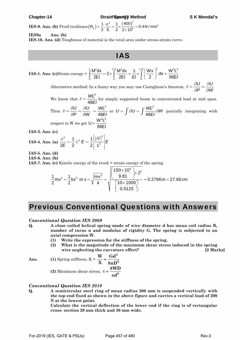
Chapter-14 Strain Energy Method S K Mondal’s
IES-9. Ans. (b) Proof resilience ( ) ( )222
p 5
4001 1R . 0.4N / mm2 E 2 2 10
σ= = × =
× IES9a Ans. (b) IES-10. Ans. (d) Toughness of material is the total area under stress-strain curve.
IAS
IAS-1. Ans. (c)Strain energy = 2L L/2 L/22 2 2 3
0 0 0
M dx M dx 1 Wx W L2 dx2EI 2EI EI 2 96EI
⎛ ⎞= × = × =⎜ ⎟⎝ ⎠∫ ∫ ∫
Alternative method: In a funny way you may use Castigliano’s theorem, U UP W
δ∂ ∂
= =∂ ∂
We know that 3
48WL
EIδ = for simply supported beam in concentrated load at mid span.
Then U UP W
δ∂ ∂
= =∂ ∂
3
48WL
EI= or
3
48WLU U W
EI= ∂ = ∂∫ ∫ partially integrating with
respect to W we get 2 3W LU
96EI=
IAS-2. Ans. (c)
IAS-4. Ans. (a) ( )22
22
1 12 2 2
lE E
E Lδσ ⎡ ⎤
⎢ ⎥= ∈ = ⎢ ⎥⎢ ⎥⎣ ⎦
IAS-5. Ans. (d) IAS-6. Ans. (b) IAS-7. Ans. (c) Kinetic energy of the truck = strain energy of the spring
32
22 2
150 10 29.811 1 mvmv kx or x 0.2766m 27.66cm10 10002 2 k
0.0125
⎛ ⎞××⎜ ⎟
⎝ ⎠= = = = =×⎡ ⎤
⎢ ⎥⎣ ⎦
Previous Conventional Questions with Answers
Conventional Question IES 2009 Q. A close coiled helical spring made of wire diameter d has mean coil radius R,
number of turns n and modulus of rigidity G. The spring is subjected to an axial compression W.
(1) Write the expression for the stiffness of the spring. (2) What is the magnitude of the maximum shear stress induced in the spring
wire neglecting the curvature effect? [2 Marks]
Ans. (1) Spring stiffness, K =
(2) Maximum shear stress,
Conventional Question IES 2010 Q. A semicircular steel ring of mean radius 300 mm is suspended vertically with
the top end fixed as shown in the above figure and carries a vertical load of 200 N at the lowest point. Calculate the vertical deflection of the lower end if the ring is of rectangular cross- section 20 mm thick and 30 mm wide.
4
3W GdX 8nD
=
38WD
dτ =
π
Page 457
For-2019 (IES, GATE & PSUs) Page 457 of 480 Rev.0
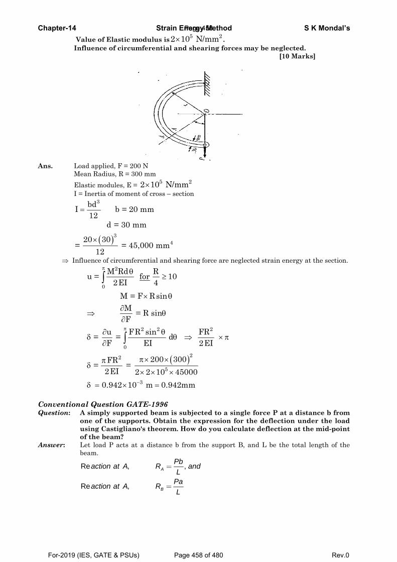
Chapter-14 Strain Energy Method S K Mondal’s Value of Elastic modulus is 5 22 10 N/mm× . Influence of circumferential and shearing forces may be neglected. [10 Marks]
Ans. Load applied, F = 200 N Mean Radius, R = 300 mm Elastic modules, E = 5 22 10 N/mm× I = Inertia of moment of cross – section
3bdI b = 20 mm
12=
( )3 4
d = 30 mm
20 30= = 45,000 mm
12×
⇒ Influence of circumferential and shearing force are neglected strain energy at the section.
( )
π
π
−
θ≥
× θ∂
⇒ θ∂
∂ θδ θ ⇒ ×π
∂
π× ×πδ
× × ×
δ = × =
∫
∫
2
0
2 2 2
022
5
3
M Rd Ru = for 102EI 4
M = F RsinM = R sinF
u FR sin FR = = d F EI 2EI
200 300FR = = 2EI 2 2 10 45000
0.942 10 m 0.942mm
Conventional Question GATE-1996 Question: A simply supported beam is subjected to a single force P at a distance b from
one of the supports. Obtain the expression for the deflection under the load using Castigliano's theorem. How do you calculate deflection at the mid-point of the beam?
Answer: Let load P acts at a distance b from the support B, and L be the total length of the beam.
Re , ,
Re ,
A
B
Pbaction at A R andL
Paaction at A RL
=
=
Page 458
For-2019 (IES, GATE & PSUs) Page 458 of 480 Rev.0
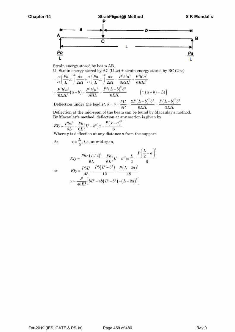
Chapter-14 Strain Energy Method S K Mondal’s
Strain energy stored by beam AB, U=Strain energy stored by AC (U AC) + strain energy stored by BC (UBC)
( ) ( ) ( )
( ) ( )
2 2 2 2 3 2 2 3
2 20 0
22 22 2 2 2 2 2
2
2 22 2
. .2 2 6 6
)6 66
2Deflection under the load ,
6 3
a bPb dx Pa dx P b a P b ax xL EI L EI EIL EIL
P L b bP b a P b aa b a b LEIL EILEIL
P L b b P L b bUP yP EIL EIL
δ
⎛ ⎞ ⎛ ⎞= + = +⎜ ⎟ ⎜ ⎟⎝ ⎠ ⎝ ⎠
−⎡ ⎤= + = = + =⎣ ⎦
− −∂= = = =
∂
∫ ∫
∵
Deflection at the mid-span of the beam can be found by Macaulay's method. By Macaulay's method, deflection at any section is given by
( ) ( )
( ) ( )( ) ( )
( )
332 2
3
32 2
32 22
2 2 2
6 6 6Where y is deflection at any distance x from the support.
At , , . at mid-span,2
/ 2 26 6 2 6
2or,
48 12 48
448
P x aPbx PbEIy L b xL L
Lx i e
LP aPb L Pb LEIy L bL L
Pb L b P L aPbLEIy
Py bL b L b LEI
−= − − −
=
⎛ ⎞−⎜ ⎟× ⎝ ⎠= − − × −
− −= − −
= − − − −( )32a⎡ ⎤⎣ ⎦
Page 459
For-2019 (IES, GATE & PSUs) Page 459 of 480 Rev.0
15. Theories of Failure
Theory at a Glance (for IES, GATE, PSU) 1. Introduction
• Failure: Every material has certain strength, expressed in terms of stress or strain, beyond
which it fractures or fails to carry the load.
• Failure Criterion: A criterion used to hypothesize the failure.
• Failure Theory: A Theory behind a failure criterion.
Why Need Failure Theories?
• To design structural components and calculate margin of safety.
• To guide in materials development.
• To determine weak and strong directions.
Failure Mode
• Yielding: a process of global permanent plastic deformation. Change in the geometry of the
object.
• Low stiffness: excessive elastic deflection.
• Fracture: a process in which cracks grow to the extent that the component breaks apart.
• Buckling: the loss of stable equilibrium. Compressive loading can lead to bucking in
columns.
• Creep: a high-temperature effect. Load carrying capacity drops.
Failure Modes: Excessive elastic deformation
Yielding Fracture
1. Stretch, twist, or bending
2. Buckling 3. Vibration
• Plastic deformation at room temperature
• Creep at elevated temperatures
• Yield stress is the important design factor
• Sudden fracture of brittle materials
• Fatigue (progressive fracture)
• Stress rupture at elevated temperatures
• Ultimate stress is the important design factor
2. Maximum Principal Stress Theory (W. Rankin’s Theory- 1850) – Brittle Material The maximum principal stress criterion:
Page 460
For-2019 (IES, GATE & PSUs) Page 460 of 480 Rev.0
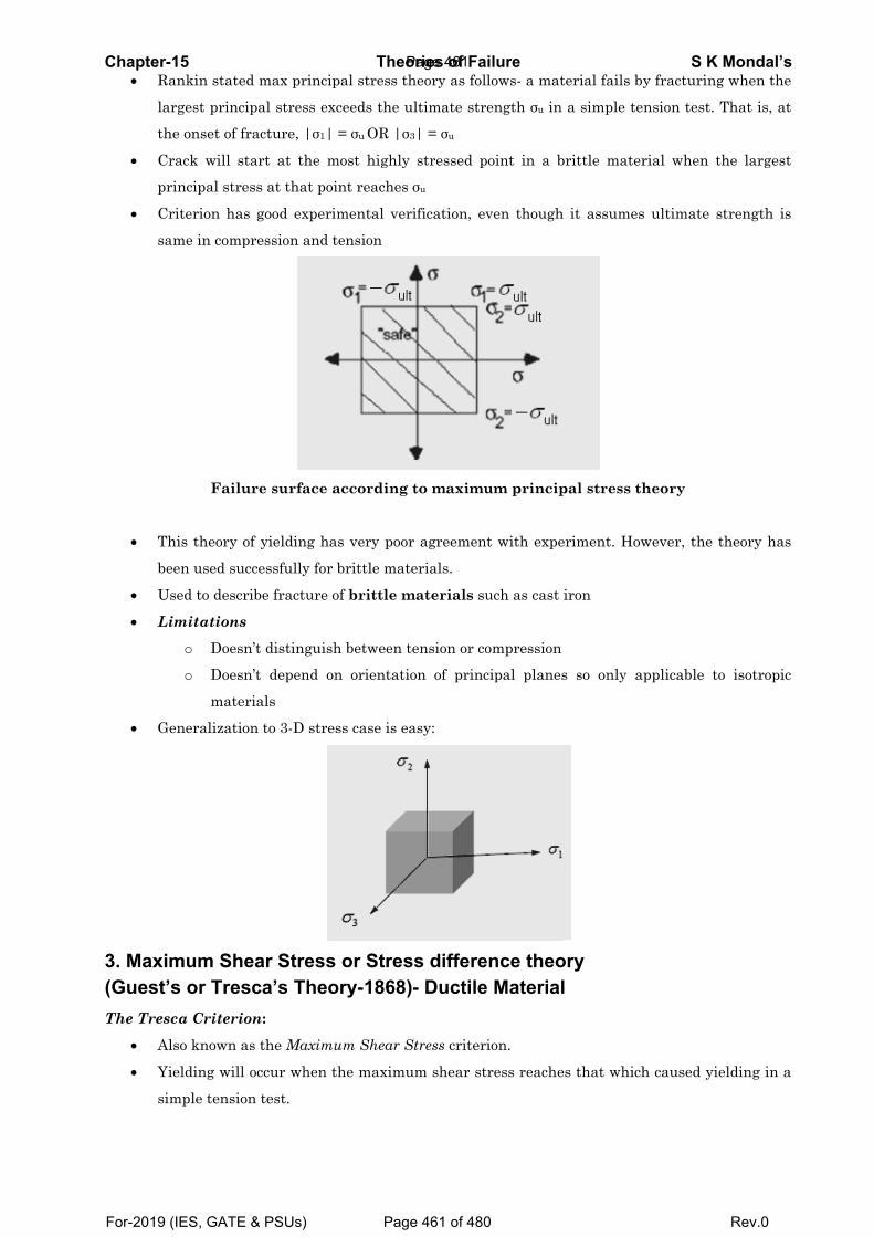
Chapter-• Ra
la
th
• Cr
pr
• Cr
sa
• Th
be
• U
• Li
• G
3. Maxi(Guest’The Tres
• Al
• Yi
si
-15 ankin stated
argest princi
he onset of fr
rack will st
rincipal stre
riterion has
ame in comp
Failu
his theory o
een used suc
sed to descr
imitations
o Doesn
o Doesn
mater
eneralizatio
mum Shes or Tres
sca Criterio
lso known a
ielding will
mple tension
d max princ
ipal stress e
racture, |σ1
tart at the
ess at that po
s good exper
pression and
ure surface
of yielding h
ccessfully for
ribe fracture
n’t distinguis
n’t depend o
rials
on to 3-D str
ear Stresssca’s Theon:
s the Maxim
occur when
n test.
Theoipal stress t
xceeds the u
| = σu OR |σ
most highly
oint reaches
rimental ver
d tension
according
has very poo
r brittle mat
of brittle m
sh between
on orientati
ess case is e
s or Stresory-1868
mum Shear S
the maximu
ories of Fatheory as fol
ultimate str
σ3| = σu
y stressed p
s σu
rification, e
g to maximu
or agreemen
terials.
materials su
tension or co
ion of princ
easy:
ss differe)- Ductile
Stress criter
um shear st
ailurellows- a mat
rength σu in
point in a b
ven though
um princip
nt with expe
uch as cast i
ompression
cipal planes
ence theoe Material
rion.
tress reache
terial fails by
a simple te
rittle mater
it assumes
pal stress th
riment. How
iron
s so only ap
ory
s that which
S K y fracturing
nsion test. T
rial when th
s ultimate s
heory
wever, the t
pplicable to
h caused yie
Mondal’s g when the
That is, at
he largest
trength is
theory has
o isotropic
elding in a
Page 461
For-2019 (IES, GATE & PSUs) Page 461 of 480 Rev.0
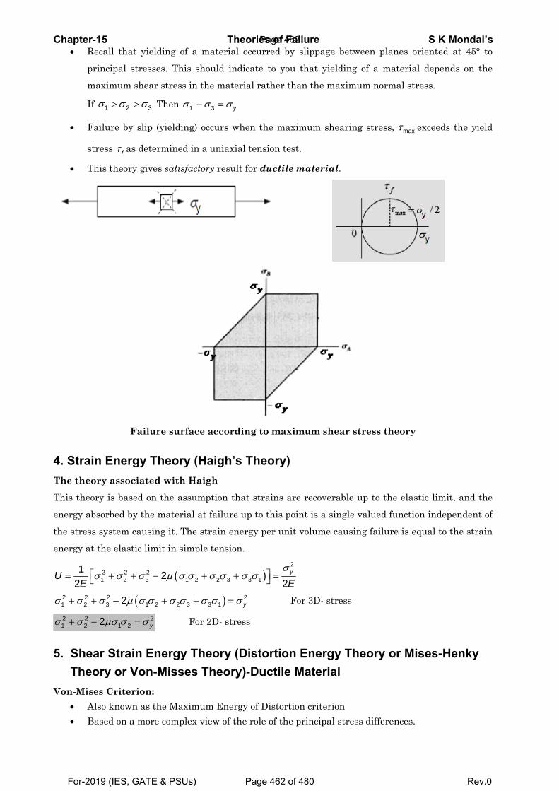
C
4T
T
e
th
e
U
σ
σ
5
V
Chapter-15 • Reca
princ
maxi
If 1σ
• Failu
stres
• This
4. Strain EThe theory
This theory i
nergy absor
he stress sy
nergy at the
21
12
UE
σ⎡= ⎣
2 2 21 2 3σ σ σ+ +
2 21 2 2σ σ μ+ −
5. Shear STheory
Von-Mises C• Also • Base
ll that yield
cipal stresse
imum shear
2 3σ σ> > T
ure by slip (
s fτ as deter
theory gives
Failur
Energy Th associated
is based on
rbed by the m
stem causin
e elastic limi
2 22 3σ σ+ + −
(23 1 22μ σ σ−
21 2 yμσ σ σ=
Strain Eny or Von-MCriterion: known as thd on a more
ding of a m
es. This sho
stress in th
Then 1σ σ−
(yielding) oc
rmined in a
s satisfactory
re surface a
heory (Had with Haig
the assump
material at f
ng it. The str
it in simple
( 1 22μ σ σ σ+
2 3 3σ σ σ+ +
For 2
nergy TheMisses T
he Maximum complex vie
Theoriematerial occu
ould indicate
e material r
3 yσ σ=
ccurs when t
uniaxial ten
ry result for
according t
aigh’s Thgh
ption that st
failure up to
rain energy
tension.
2 3 3 1σ σ σ σ+
) 23 1 yσ σ=
2D- stress
eory (Distheory)-Du
m Energy of ew of the rol
es of Failuurred by slip
e to you tha
rather than t
the maximu
nsion test.
ductile ma
to maximu
eory)
trains are re
o this point
per unit vol
)2
1 2y
Eσ
⎤ =⎦
For 3
tortion Enuctile Ma
Distortion cle of the prin
reppage betwe
at yielding
the maximu
um shearing
aterial.
um shear st
ecoverable u
is a single v
lume causin
3D- stress
nergy Theaterial
criterion ncipal stress
een planes
of a materi
um normal s
g stress, maτ
tress theory
up to the ela
valued funct
ng failure is
eory or M
s differences
S K Mooriented at
al depends
tress.
x exceeds th
y
astic limit, a
ion indepen
equal to the
Mises-Hen
s.
ondal’s 45° to
on the
he yield
and the
ndent of
e strain
nky
Page 462
For-2019 (IES, GATE & PSUs) Page 462 of 480 Rev.0
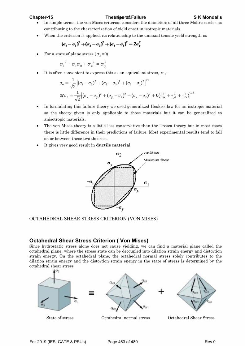
Chapter-• In
co• W
• Fo
• It
• Insoan
• Ththon
• It
OCTAHE
OctaheSince hydoctahedrastrain endilation soctahedra
S
-15 n simple termontributing t
When the crit
or a state of
21σ −
is often con
eσ =
eorσ
n formulatino the theorynisotropic mhe von Misehere is little n or between gives very g
EDRAL SH
dral Sheadrostatic stral plane, whnergy. On thstrain energal shear stre
State of stre
ms, the von to the charaterion is app
f plane stres
1 2 2σ σ σ− +
nvenient to e
1 21 (2
σ σ⎡ −⎢⎣
1 (2 xσ⎡= −⎢⎣
ng this failury given is
materials. es theory is difference in these two tgood result i
HEAR STRE
ar Stress ress alone d
here the strehe octahedry and the dss
ss
TheoMises critercterization o
plied, its rela
s ( 3σ =0)
2 22 yσ=
express this
22 2) (σ σ+ −
2) (y yσ σ− +
re theory weonly applic
a little lessin their predtheories. in ductile m
ESS CRITE
Criteriondoes not caess state canral plane, tdistortion st
Octahe
ories of Farion considerof yield onseationship to
as an equiv
23 3) (σ σ+ −
2) (z xσ σ− +
e used genecable to tho
s conservativdictions of fa
material.
ERION (VO
n ( Von Muse yielding
n be decouplhe octahedr
train energy
edral norma
ailurers the diameet in isotropi the uniaxia
alent stress1/22
1)σ ⎤⎥⎦
2) 6x zσ− +
ralized Hooose materia
ve than the ailure. Most
ON MISES)
ises) g, we can fled into dilaral normal y in the stat
l stress
eters of all tic materials
al tensile yie
, σ e:
2 26( xy yzτ τ+ +
ke's law for ls but it ca
Tresca theot experiment
find a mateation strain
stress solelte of stress
Octahe
S K three Mohr’s. ld strength
1/22 )zxτ ⎤+ ⎥⎦
an isotropican be gene
ory but in mtal results te
erial plane cenergy and ly contributis determin
edral Shear
Mondal’s s circles as
is:
c material ralized to
most cases end to fall
called the distortion tes to the ned by the
Stress
Page 463
For-2019 (IES, GATE & PSUs) Page 463 of 480 Rev.0
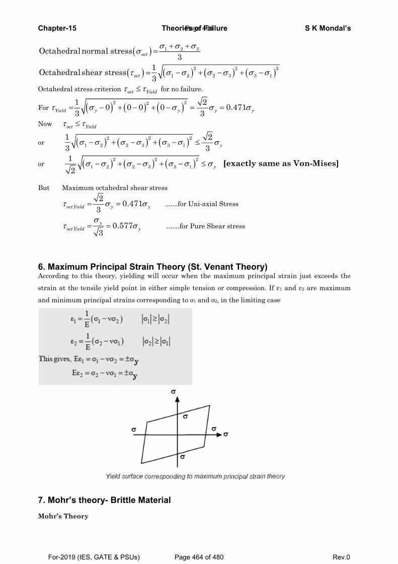
C
O
O
O
F
N
o
o
B
6A
s
a
7
M
Chapter-15
Octahedra
Octahedra
Octahedral s
For 13Yieldτ =
Now octτ ≤
r (13
r 12
But Maxi
octYiτ
octYiτ
6. MaximuAccording to
train at the
and minimum
7. Mohr’s
Mohr’s Theo
alnormal s
al shear str
stress criteri
( )1 03 yσ −
Yieldτ≤
( )21 2σ σ− +
( )21 2σ σ−
imum octahe2
3ield yσ=
03y
ieldσ
= =
um Princio this theory
e tensile yiel
m principal
theory- B
ory
(stress octσ
( )ress octτ =
ion oct Yτ τ≤
( )2 20 0+ −
( )22 3σ σ+ −
(22 3σ σ+ −
edral shear
0.471 yσ=
0.577 yσ
ipal Straiy, yielding w
ld point in e
strains corr
Brittle Ma
Theorie
) 1 2
3σ σ+
=
( 113
σ σ= −
Yield for no fa
( )20 yσ+ −
(23 1σ σ+ −
) (23 3σ σ+ −
stress
y .......for
.......fo
n Theorywill occur w
either simpl
esponding to
aterial
es of Failu 3σ+
) (22 2σ σ+ −
ailure.
2 23 yσ= =
)2 23 yσ≤
)21 yσ σ≤
r Uni-axial S
r Pure Shea
y (St. Venawhen the ma
le tension o
o σ1 and σ2, i
re
) (23 3σ σ− +
0.471 yσ=
y
[exactly
Stress
ar stress
ant Theoaximum prin
r compressi
in the limiti
)21σ−
same as
ry) ncipal strain
on. If ε1 and
ing case
S K Mo
Von-Mise
n just excee
d ε2 are ma
ondal’s
es]
eds the
ximum
Page 464
For-2019 (IES, GATE & PSUs) Page 464 of 480 Rev.0
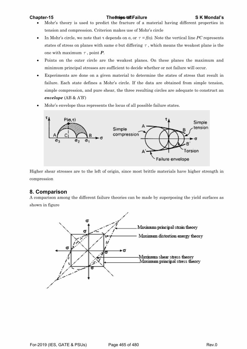
Chapter-• M
te
• In
st
on
• Po
m
• Ex
fa
si
en
• M
Higher sh
compressi
8. ComA compar
shown in
-15 Mohr’s theory
ension and co
n Mohr’s circ
tates of stres
ne with max
oints on th
minimum prin
xperiments
ailure. Each
mple compr
nvelope (AB
Mohr’s envelo
hear stresse
ion
parison rison among
figure
y is used to
ompression.
cle, we note
ss on planes
ximum τ , po
e outer circ
ncipal stress
are done on
state defin
ression, and
B & A’B’)
ope thus rep
s are to the
the differen
Theoo predict th
. Criterion m
that τ depen
s with same
oint P.
cle are the
ses are suffi
n a given m
nes a Mohr’
pure shear,
presents the
e left of orig
nt failure th
ories of Fahe fracture o
makes use of
nds on σ, or
σ but differi
weakest pl
icient to deci
material to d
s circle. If
, the three r
locus of all p
in, since mo
heories can b
ailureof a materia
f Mohr’s circ
τ = f(σ). No
ing τ , which
lanes. On t
ide whether
determine th
the data ar
resulting cir
possible fail
ost brittle m
be made by
al having d
cle
ote the vertic
h means the
these plane
r or not failu
he states of
re obtained
cles are ade
lure states.
materials ha
superposing
S K different pro
cal line PC r
e weakest pl
s the maxi
ure will occur
f stress that
from simpl
equate to con
ave higher st
g the yield s
Mondal’s operties in
represents
lane is the
mum and
r.
t result in
le tension,
nstruct an
trength in
urfaces as
Page 465
For-2019 (IES, GATE & PSUs) Page 465 of 480 Rev.0
Chapter-15 Theories of Failure S K Mondal’s
OBJECTIVE QUESTIONS (GATE, IES, IAS)
Previous 25-Years GATE Questions
Maximum Shear stress or Stress Difference Theory GATE-1. Match 4 correct pairs between list I and List II for the questions [GATE-1994] List-I List-II (a) Hooke's law 1. Planetary motion (b) St. Venant's law 2. Conservation Energy (c) Kepler's laws 3. Elasticity (d) Tresca's criterion 4. Plasticity (e) Coulomb's laws 5. Fracture (f) Griffith's law 6. Inertia GATE-2. Which theory of failure will you use for aluminium components under steady
loading? [GATE-1999] (a) Principal stress theory (b) Principal strain theory (c) Strain energy theory (d) Maximum shear stress theory GATE-2a. An axially loaded bar is subjected to a normal stress of 173 MPa. The shear
stress in the bar is [CE: GATE-2007] (a) 75 MPa (b) 86.5 MPa (c) 100 MPa (d) 122.3 MPa GATE-2b. A machine element is subjected to the following bi-axial state of stress; σx = 80
MPa; σy = 20 MPa τxy = 40 MPa. If the shear strength of the material is 100 MPa, the factor of safety as per Tresca’s maximum shear stress theory is [GATE-2015] (a) 1.0 (b) 2.0 (c) 2.5 (d) 3.3
GATE-2c. The principal stresses at a point in a critical section of a machine component
are σ1 = 60 MPa, σ2 = 5 MPa and σ3 = - 40 MPa. For the material of the component, the tensile yield strength is σy = 200 MPa. According to the maximum shear stress theory, the factor of safety is____________. [GATE-2017]
(a) 1.67 (b) 2.00 (c) 3.6 (d) 4.00 GATE-2d. The Mohr's circle of plane stress
for a point in a body is shown. The design is to be done on the basis of the maximum shear stress theory for yielding. Then, yielding will just begin if the designer chooses a ductile material whose yield strength is:
(a) 45 MPa (b) 50 MPa (c) 90 MPa (d) 100 MPa
[GATE-2005]
Shear Strain Energy Theory (Distortion energy theory) GATE-3. According to Von-Mises' distortion energy theory, the distortion energy under
three dimensional stress state is represented by [GATE-2006]
Page 466
For-2019 (IES, GATE & PSUs) Page 466 of 480 Rev.0
Chapter-15 Theories of Failure S K Mondal’s
GATE-4. A small element at the critical section of a component is in a bi-axial state of
stress with the two principal stresses being 360 MPa and 140 MPa. The maximum working stress according to Distortion Energy Theory is:
[GATE-1997] (a) 220 MPa (b) 110 MPa (c) 314 MPa (d) 330 MPa GATE-4a. In a metal forming operation when the material has just started yielding, the
principal stresses are σ1 = +180 MPa, σ2 = -100 MPa, σ3 = 0. Following von Mises' criterion, the yield stress is ________________ MPa. [GATE-2017]
GATE-4b. A shaft is subjected to pure torsional moment. The maximum shear stress
developed in the shaft is 100 MPa. The yield and ultimate strengths of the shaft material in tension are 300 MPa and 450 MPa, respectively. The factor of safety using maximum distortion energy (von-Mises)theory is ……….. [GATE-2014]
GATE-5. The homogeneous state of stress for a metal part undergoing plastic deformation
is 10 5 05 20 00 0 10
T⎛ ⎞⎜ ⎟= ⎜ ⎟⎜ ⎟−⎝ ⎠
where the stress component values are in MPa. Using von Mises yield criterion, the value of estimated shear yield stress, in MPa is (a) 9.50 (b) 16.07 (c) 28.52 (d) 49.41 [GATE-2012]
GATE-5(i) The uni-axial yield stress of a material is 300 MPa. According to Von Mises
criterion, the shear yield stress (in MPa) of the material is _____ [GATE-2015] GATE-6. Match the following criteria of material failure, under biaxial stresses 1σ and
2σ and yield stress ,yσ with their corresponding graphic representations: [GATE-2011]
P. Maximum-normal-stress criterion L.
Q. Minimum-distortion-energy criterion M.
σ2σy
–σy
–σy
σyσ1
Page 467
For-2019 (IES, GATE & PSUs) Page 467 of 480 Rev.0
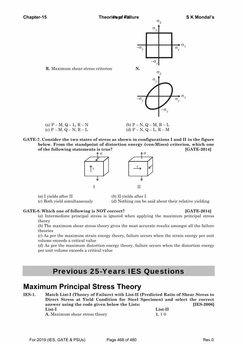
Chapter-15 Theories of Failure S K Mondal’s
R. Maximum shear-stress criterion N.
(a) P – M, Q – L, R – N (b) P – N, Q – M, R – L (c) P – M, Q – N, R – L (d) P – N, Q – L, R – M GATE-7. Consider the two states of stress as shown in configurations I and II in the figure
below. From the standpoint of distortion energy (von-Mises) criterion, which one of the following statements is true? [GATE-2014]
τ
σ
I
τ
σ
II
(a) I yields after II (b) II yields after I (c) Both yield simultaneously (d) Nothing can be said about their relative yielding
GATE-8. Which one of following is NOT correct? [GATE-2014]
(a) Intermediate principal stress is ignored when applying the maximum principal stress theory (b) The maximum shear stress theory gives the most accurate results amongst all the failure theories (c) As per the maximum strain energy theory, failure occurs when the strain energy per unit volume exceeds a critical value (d) As per the maximum distortion energy theory, failure occurs when the distortion energy per unit volume exceeds a critical value
Previous 25-Years IES Questions
Maximum Principal Stress Theory IES-1. Match List-I (Theory of Failure) with List-II (Predicted Ratio of Shear Stress to
Direct Stress at Yield Condition for Steel Specimen) and select the correct answer using the code given below the Lists: [IES-2006]
List-I List-II A. Maximum shear stress theory 1. 1·0
σ2σy
–σy
–σy
σyσ1
σ2σy
–σy
–σy
σyσ1
Page 468
For-2019 (IES, GATE & PSUs) Page 468 of 480 Rev.0
Chapter- IES-2.
IES-3.
IES-4. IES-5. IES-5a
MaximIES-6.
IES-6(i).
IES-7.
-15 B. MaximC. MaximD. MaximCodes: (a) (c) From a ta factor the perm(a) 50 N/m
A circultwisting theory, ttheory, t
( ) 1a 5
Which of(a) Maxim(c) Maxim
Design o(a) Guest'
AssertioncompressiReason (strength. (a) Both A(b) Both A(c) A is tru(d) A is fa
mum SIf the pr
1σ and σfollowingthe maxi
( 1( )2
aσ −
Which onor Tresca
Accordinmoment same sha
(a) T/2
mum distortimum principamum principa
A B1 2 1 3
tension tesof safety o
missible strmm2
ar solid sh moment othe direct
the shear st
(
f the followmum principmum strain e
of shafts ma's theory (b
n (A): A cive load. (R): Shear s A and R are A and R are ue but R is f
alse but R is
Shear sincipal str
2σ is grea
g would beimum shea
)2
2ypσσ
= ±
ne of the foa criterion
ng to the m in a circuaft as per th
Theoonenergy thal stress theal strain the C 4 4 st, the yieldf 2 and appess in the s
(b) 57.7 N
haft is subof 300 kNm stress is tress is τ . T
( ) 3b 9
wing is applal stress the
energy theor
ade of brittb) Rankine’s
cast iron sp
trength of ca
individuallyindividuallyfalse true
stress oresses correater than σe the corre
ar stress cri
( )p b σ
ollowing fign?
maximum sular shaft he maximu
(b) T
ories of Faheory eory eory
D 3 (b2 (d
d strength plying maxsteel shaft
N/mm2
bjected to m. On the σ and acc
The ratio σ
(
lied to briteory (bry (d
tle materia theory (c
pecimen sha
ast iron in c
y true and Ry true but R
or Streesponding
2σ and bot
ect criterioiterion?
1
2 2ypσσ
= ±
gures repre
shear stresis 'T'. The
um princip
ailure A
b) 4 d) 4 of steel is
ximum prinsubjected t
(c) 86.6
a bendingbasis of thcording toσ/ τ is:
) 9c 5
ttle materiab) Maximumd) Maximum
als is basedc) St. Venant
all fail due
compression
R is the corre is NOT the
ss Diff to a two-dth are ten
on for failu
2( )2
c σ
esents the
s theory ofe permissibal stress th
(c) 2
2. 0·577 3. 0·62 4. 0·50 B C3 1 2 1
found to bncipal stresto torque w. N/mm2
g moment he maximuo the max
( )1 d 6
als? m principal stm shear stres
on t's theory (d)
to shear w
is more tha
ect explanati correct expl
ferencedimensionansile, then
ure by yie
2ypσ
= ±
maximum
f failure, pble twistinheory of fai
[IE2T
S K
C D 2 3 e 200 N/mmss theory owill be: [I
(d) 100
of 400 kNum principimum shea
[I1 6
[ISRtrain theoryss theory
[I) Von Mises
when subje[IES-
an half its co
ion of A lanation of A
e Theoal state of s which on
lding, acco[I
1( )d σ =
shear stre[I
permissibleng momentilure will bES-1998: IS
(d) 2T
Mondal’s
m2. Using of failure, IES-2000] N/mm2
Nm and a pal stress ar stress IES-2000]
RO-2015] y
IES-1993] theory
ected to a -2010] mpressive
A
ry stress are ne of the
ording to IES-1993]
2 ypσ= ±
ss theory IES-1999]
twisting will the
be: RO-2008]
T
Page 469
For-2019 (IES, GATE & PSUs) Page 469 of 480 Rev.0
Chapter-15 Theories of Failure S K Mondal’s IES-8. Permissible bending moment in a circular shaft under pure bending is M
according to maximum principal stress theory of failure. According to maximum shear stress theory of failure, the permissible bending moment in the same shaft is: [IES-1995]
(a) 1/2 M (b) M (c) 2 M (d) 2M IES-9. A rod having cross-sectional area 100 x 10- 6 m2 is subjected to a tensile load.
Based on the Tresca failure criterion, if the uniaxial yield stress of the material is 200 MPa, the failure load is: [IES-2001]
(a) 10 kN (b) 20 kN (c) 100 kN (d) 200 kN IES-10. A cold roller steel shaft is designed on the basis of maximum shear stress
theory. The principal stresses induced at its critical section are 60 MPa and - 60 MPa respectively. If the yield stress for the shaft material is 360 MPa, the factor of safety of the design is: [IES-2002]
(a) 2 (b) 3 (c) 4 (d) 6 IES-11. A shaft is subjected to a maximum bending stress of 80 N/mm2 and maximum
shearing stress equal to 30 N/mm2 at a particular section. If the yield point in tension of the material is 280 N/mm2, and the maximum shear stress theory of failure is used, then the factor of safety obtained will be: [IES-1994]
(a) 2.5 (b) 2.8 (c) 3.0 (d) 3.5 IES-12. For a two-dimensional state stress ( 1 2 1 2, 0, 0σ σ σ σ> > < ) the designed values
are most conservative if which one of the following failure theories were used? [IES-1998]
(a) Maximum principal strain theory (b) Maximum distortion energy theory (c) Maximum shear stress theory (d) Maximum principal stress theory
Shear Strain Energy Theory (Distortion energy theory) IES-13. Who postulated the maximum distortion energy theory? [IES-2008] (a) Tresca (b) Rankine (c) St. Venant (d) Mises-Henky IES-14. Who postulated the maximum distortion energy theory? [IES-2008] (a) Tresca (b) Rankine (c) St. Venant (d) Mises-Henky IES-15. The maximum distortion energy theory of failure is suitable to predict the
failure of which one of the following types of materials? [IES-2004] (a) Brittle materials (b) Ductile materials (c) Plastics (d) Composite materials IES-16. If σy is the yield strength of a particular material, then the distortion energy
theory is expressed as [IES-1994] (a) ( ) ( ) ( )2 2 2 2
1 2 2 3 3 1 2 yσ σ σ σ σ σ σ− + − + − =
(b) ( )2 2 2 21 2 3 1 2 2 3 3 12 ( ) yσ σ σ μ σ σ σ σ σ σ σ− + − + + =
(c) ( ) ( ) ( )2 2 2 21 2 2 3 3 1 3 yσ σ σ σ σ σ σ− + − + − =
(d) ( )( ) ( )2 21 2 31 2 2 1 yμ σ σ σ μ σ− + + = +
IES-17. If a shaft made from ductile material is subjected to combined bending and
twisting moments, calculations based on which one of the following failure theories would give the most conservative value? [IES-1996]
(a) Maximum principal stress theory (b) Maximum shear stress theory. (d Maximum strain energy theory (d)Maximum distortion energy theory.
Page 470
For-2019 (IES, GATE & PSUs) Page 470 of 480 Rev.0
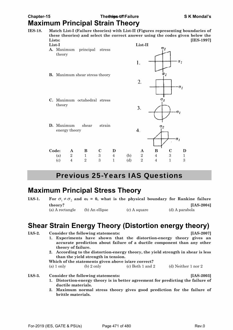
Chapter-15 Theories of Failure S K Mondal’s
Maximum Principal Strain Theory IES-18. Match List-I (Failure theories) with List-II (Figures representing boundaries of
these theories) and select the correct answer using the codes given below the Lists: [IES-1997]
List-I List-II A. Maximum principal stress
theory
B. Maximum shear stress theory
C. Maximum octahedral stress
theory
D. Maximum shear strain
energy theory
Code: A B C D A B C D (a) 2 1 3 4 (b) 2 4 3 1 (c) 4 2 3 1 (d) 2 4 1 3
Previous 25-Years IAS Questions
Maximum Principal Stress Theory IAS-1. For 1 2σ σ≠ and σ3 = 0, what is the physical boundary for Rankine failure
theory? [IAS-2004] (a) A rectangle (b) An ellipse (c) A square (d) A parabola
Shear Strain Energy Theory (Distortion energy theory) IAS-2. Consider the following statements: [IAS-2007]
1. Experiments have shown that the distortion-energy theory gives an accurate prediction about failure of a ductile component than any other theory of failure.
2. According to the distortion-energy theory, the yield strength in shear is less than the yield strength in tension.
Which of the statements given above is/are correct? (a) 1 only (b) 2 only (c) Both 1 and 2 (d) Neither 1 nor 2 IAS-3. Consider the following statements: [IAS-2003]
1. Distortion-energy theory is in better agreement for predicting the failure of ductile materials.
2. Maximum normal stress theory gives good prediction for the failure of brittle materials.
Page 471
For-2019 (IES, GATE & PSUs) Page 471 of 480 Rev.0
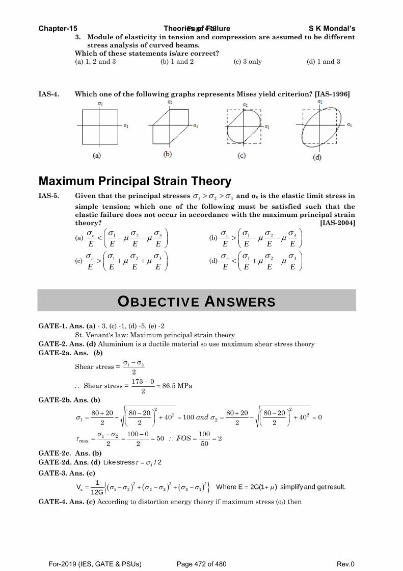
Chapter-15 Theories of Failure S K Mondal’s 3. Module of elasticity in tension and compression are assumed to be different
stress analysis of curved beams. Which of these statements is/are correct? (a) 1, 2 and 3 (b) 1 and 2 (c) 3 only (d) 1 and 3 IAS-4. Which one of the following graphs represents Mises yield criterion? [IAS-1996]
Maximum Principal Strain Theory IAS-5. Given that the principal stresses 1 2 3σ σ σ> > and σe is the elastic limit stress in
simple tension; which one of the following must be satisfied such that the elastic failure does not occur in accordance with the maximum principal strain theory? [IAS-2004]
(a) 31 2e
E E E Eσ σσ σμ μ⎛ ⎞< − −⎜ ⎟
⎝ ⎠ (b) 31 2e
E E E Eσ σσ σμ μ⎛ ⎞> − −⎜ ⎟
⎝ ⎠
(c) 31 2e
E E E Eσ σσ σμ μ⎛ ⎞> + +⎜ ⎟
⎝ ⎠ (d) 31 2e
E E E Eσ σσ σμ μ⎛ ⎞< + −⎜ ⎟
⎝ ⎠
OBJECTIVE ANSWERS
GATE-1. Ans. (a) - 3, (c) -1, (d) -5, (e) -2 St. Venant's law: Maximum principal strain theory GATE-2. Ans. (d) Aluminium is a ductile material so use maximum shear stress theory GATE-2a. Ans. (b)
Shear stress = σ − σ1 2
2
∴ Shear stress = −=
173 0 86.5 MPa2
GATE-2b. Ans. (b)
2 22 2
1 2
1 2max
80 20 80 20 80 20 80 2040 100 40 02 2 2 2
100 0 10050 22 2 50
and
FOS
σ σ
σ στ
+ − + −⎛ ⎞ ⎛ ⎞= + + = = − + =⎜ ⎟ ⎜ ⎟⎝ ⎠ ⎝ ⎠
− −= = = ∴ = =
GATE-2c. Ans. (b) GATE-2d. Ans. (d) τ σ= 1Likestress / 2 GATE-3. Ans. (c)
( ) ( ) ( ){ }2 2 2s 1 2 2 3 3 1
1V Where E 2G(1 ) simplifyand get result.12G
σ σ σ σ σ σ μ= − + − + − = +
GATE-4. Ans. (c) According to distortion energy theory if maximum stress (σt) then
Page 472
For-2019 (IES, GATE & PSUs) Page 472 of 480 Rev.0
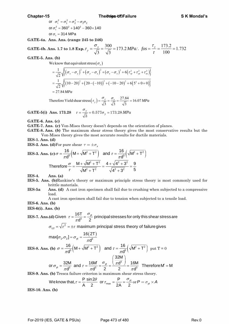
Chapter-15 Theories of Failure S K Mondal’s
2 2 2t 1 2 1 2
2 2 2t
t
or
or 360 140 360 140or 314 MPa
σ σ σ σ σ
σσ
= + −
= + − ×
= GATE-4a. Ans. Ans. (range 245 to 246)
GATE-4b. Ans. 1.7 to 1.8 Exp.300 173.2173.2 1.732
1003 3y y
y MPa fosσ τ
ττ
= = = ∴ = = =
GATE-5. Ans. (b)
( )
( ) ( ) ( ) ( ){ }( ) ( )( ) ( ) ( ){ }
( )
2 2 2 2 2 2
22 2 2
We know that equivalent stress
1 62
1 10 20 20 10 10 20 6 5 0 02
27.84
27.84Therefore Yield shear stress 16.073 3 3
e
x y y z z x xy yz zx
y ey
MPa
MPa
σ
σ σ σ σ σ σ τ τ τ
σ στ
= − + − + − + + +
= − + − − + − − + + +
=
= = = =
GATE-5(i) Ans. 173.28 0.577 173.283y
y MPaσ
τ σ= = =
GATE-6. Ans. (c) GATE-7. Ans. (c) Von-Mises theory doesn’t depends on the orientation of planes. GATE-8. Ans. (b) The maximum shear stress theory gives the most conservative results but the
Von-Mises theory gives the most accurate results for ductile materials. IES-1. Ans. (d) IES-2. Ans. (d)For pure shear xτ σ=±
IES-3. Ans. (c) ( ) ( )2 2 2 23 3
16 16M M T and M Td d
σ τπ π
= + + = +
2 2 2 2
2 2 2 2
M M T 4 4 3 9Therefore5M T 4 3
στ
+ + + += = =
+ +
IES-4. Ans. (a) IES-5. Ans. (b)Rankine's theory or maximum principle stress theory is most commonly used for
brittle materials. IES-5a Ans. (d) A cast iron specimen shall fail due to crushing when subjected to a compressive
load. A cast iron specimen shall fail due to tension when subjected to a tensile load. IES-6. Ans. (b) IES-6(i). Ans. (b)
IES-7. Ans.(d) yt3
16TGiven principalstresses for only thisshear stressare2dσ
τπ
= =
( )σ τ τ
σ σ σπ
= = ±
= =
21,2
1 2 yt 3
maximum principal stress theory of failuregives
16 2Tmax[ , ]
d
IES-8. Ans. (b) ( ) ( )2 2 2 23 3
16 16M M T and M Td d
σ τπ π
= + + = + put T = 0
3
ytyt 3 3 3
32M32M 16M 16Mdor and ThereforeM M
2 2d d dσ πσ τ
π π π
⎛ ⎞⎜ ⎟′ ⎝ ⎠ ′= = = = = =
IES-9. Ans. (b) Tresca failure criterion is maximum shear stress theory.
ytmax
P sin2 PWeknow that, orA 2 2A 2
σθτ τ= = = or ytP Aσ= ×
IES-10. Ans. (b)
Page 473
For-2019 (IES, GATE & PSUs) Page 473 of 480 Rev.0
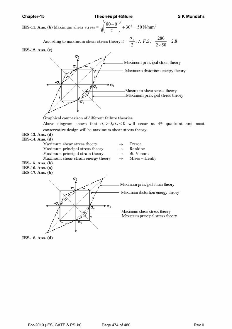
Chapter-15 Theories of Failure S K Mondal’s
IES-11. Ans. (b) Maximum shear stress = 2
2 280 0 30 50 N/mm2−⎛ ⎞ + =⎜ ⎟
⎝ ⎠
According to maximum shear stress theory,280; . . 2.8
2 2 50y F S
στ = ∴ = =
×
IES-12. Ans. (c)
Graphical comparison of different failure theories Above diagram shows that 1 20, 0σ σ> < will occur at 4th quadrant and most
conservative design will be maximum shear stress theory. IES-13. Ans. (d) IES-14. Ans. (d) Maximum shear stress theory → Tresca Maximum principal stress theory → Rankine Maximum principal strain theory → St. Venant Maximum shear strain energy theory → Mises – Henky IES-15. Ans. (b) IES-16. Ans. (a) IES-17. Ans. (b)
IES-18. Ans. (d)
Page 474
For-2019 (IES, GATE & PSUs) Page 474 of 480 Rev.0
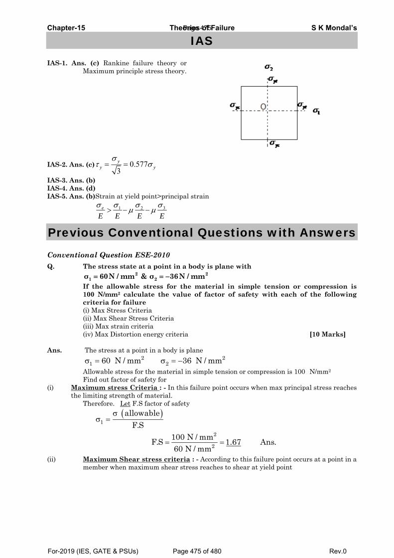
Chapter-15 Theories of Failure S K Mondal’s
IAS IAS-1. Ans. (c) Rankine failure theory or
Maximum principle stress theory.
IAS-2. Ans. (c) 0.5773y
y y
στ σ= =
IAS-3. Ans. (b) IAS-4. Ans. (d) IAS-5. Ans. (b)Strain at yield point>principal strain
31 2e
E E E Eσ σσ σμ μ> − −
Previous Conventional Questions with Answers
Conventional Question ESE-2010 Q. The stress state at a point in a body is plane with 2 2
1 2σ 60N / mm & σ 36N / mm= = − If the allowable stress for the material in simple tension or compression is 100 N/mm2 calculate the value of factor of safety with each of the following criteria for failure (i) Max Stress Criteria (ii) Max Shear Stress Criteria (iii) Max strain criteria (iv) Max Distortion energy criteria [10 Marks] Ans. The stress at a point in a body is plane Allowable stress for the material in simple tension or compression is 100 N/mm2 Find out factor of safety for (i) Maximum stress Criteria : - In this failure point occurs when max principal stress reaches
the limiting strength of material. Therefore. Let F.S factor of safety
( )1
2
2
allowableF.S
100 N / mmF.S 1.67 Ans.60 N / mm
σσ =
= =
(ii) Maximum Shear stress criteria : - According to this failure point occurs at a point in a member when maximum shear stress reaches to shear at yield point
2 21 260 N / mm 36 N / mmσ = σ = −
Page 475
For-2019 (IES, GATE & PSUs) Page 475 of 480 Rev.0
Chapter-15 Theories of Failure S K Mondal’s
σγ = σ =
σ − σ +γ = = = =
=×
= = =×
=
yt 2max yt
21 2max
100 N / mm2 F.S
60 36 96 48 N / mm2 2 2
100482 F.S
100 100F.S 1.0422 48 96
F.S 1.042 Ans.
(iv) Maximum Distortion energy criteria ! – In this failure point occurs at a point in a member when distortion strain energy per unit volume in a bi – axial system reaches the limiting distortion strain energy at the of yield
( )
2yt2 2
1 2 1 2
222
F.S
10060 36 60 36F.S
F.S 1.19
σ⎛ ⎞σ + σ − σ ×σ = ⎜ ⎟
⎝ ⎠
⎛ ⎞+ −× × − = ⎜ ⎟⎝ ⎠
=
Conventional Question ESE-2006 Question: A mild steel shaft of 50 mm diameter is subjected to a beading moment of 1.5
kNm and torque T. If the yield point of steel in tension is 210 MPa, find the maximum value of the torque without causing yielding of the shaft material according to
(i) Maximum principal stress theory (ii) Maximum shear stress theory.
Answer: σπb 3
32We know that, Maximum bending stress ( ) Md
=
π 3
16and Maximum shear stress ( ) Td
τ =
σ σσ
π
22 2 2
1,2 3
Principal stresses are given by:
162 2
b b M M Td
τ⎛ ⎞ ⎡ ⎤⎟⎜= ± + = ± +⎟⎜ ⎢ ⎥⎟⎟⎜ ⎣ ⎦⎝ ⎠
( )2 2 6
3
( ) According to Maximum principal stress theory
Maximum principal stress=Maximum stress at elastic limit
16 210 10
y
i
or M M Td
σ
π⎡ ⎤+ + = ×⎢ ⎥⎣ ⎦
( )2 2 6
3
16or 1500 1500 210 100.050
T = 3332 Nm = 3.332 kNm
T
or
π⎡ ⎤+ + = ×⎢ ⎥⎣ ⎦
Page 476
For-2019 (IES, GATE & PSUs) Page 476 of 480 Rev.0
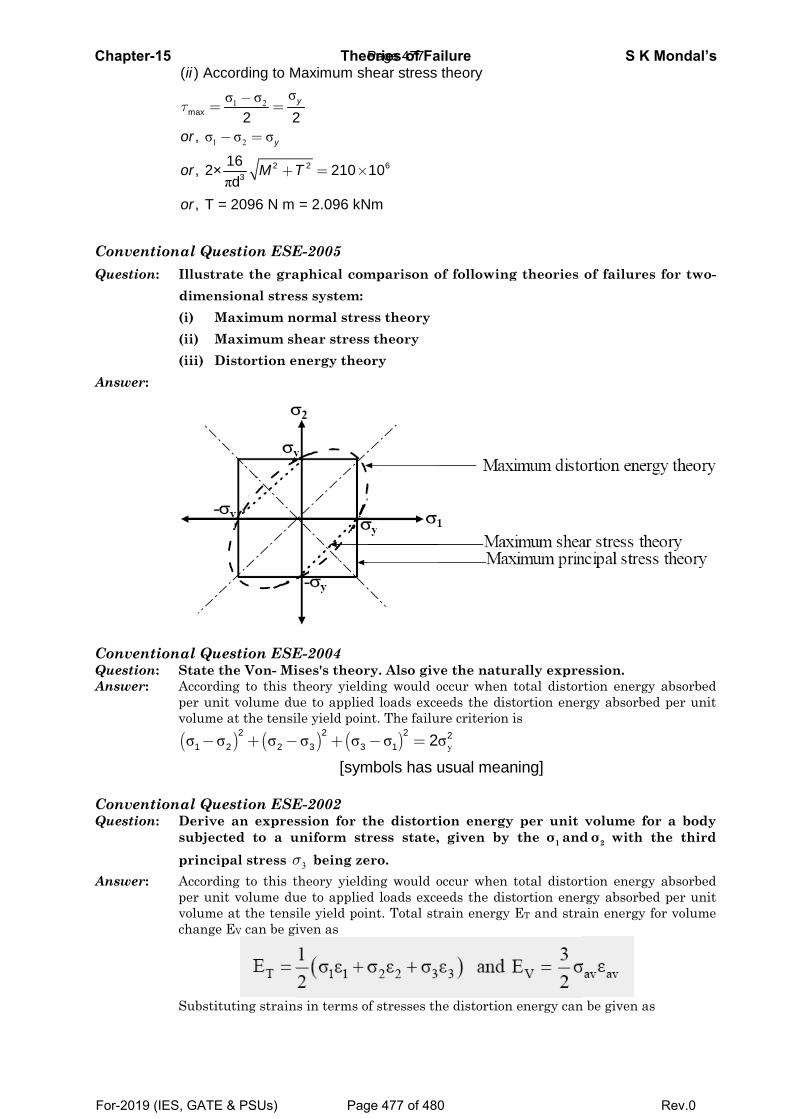
Chapter-
ConventQuestion
Answer:
ConventQuestionAnswer:
ConventQuestion
Answer:
-15
1σ
π
max
( ) Acc
,
, 2×
, T =
ii
or
or
or
τ =
−
tional Quen: Illustra
dimens(i) M(ii) M(iii) D
tional Quen: State th Accordin
per unitvolume
(σ σ1
−
tional Quen: Derive
subjectprincip
Accordinper unitvolume change
Substitu
1 2
2
σσ σ
σ σ
π2
3
cording to M
2 2
16d
= 2096 N m
y
M T
−=
− =
+
estion ESEate the grasional stres
Maximum nMaximum sh
istortion e
estion ESEhe Von- Ming to this tt volume du at the tensi
) (σ22 2
+ −
estion ESE an exprested to a upal stress σng to this tt volume du at the tensiEV can be gi
uting strain
Theo
2
Maximum sh
2
210
= 2.096 kN
y
T = ×
E-2005 aphical comss system: ormal strehear stress
energy theo
E-2004 ises's theortheory yieldue to appliedile yield poin
) (σ σ23 3
[sym
− +
E-2002 ssion for t
uniform str
3σ being zetheory yieldue to appliedile yield poiiven as
s in terms o
ories of Fa
6
hear stress
10
Nm
mparison o
ss theory s theory ory
ry. Also giving would od loads excent. The failu
)σ σ21 2
mbols has u
− =
he distortiress state, ero. ing would od loads excent. Total str
of stresses th
ailuretheory
of following
ve the naturoccur when eeds the dis
ure criterion
yσ2
usual mean
ion energy given by
occur when eeds the disrain energy
he distortion
g theories
rally expretotal distortortion ener is
ning]
y per unit the 1σ and
total distortortion ener ET and stra
n energy can
S K
of failures
ession. rtion energyrgy absorbed
volume fo2d σ with t
rtion energyrgy absorbedain energy f
n be given as
Mondal’s
s for two-
y absorbed d per unit
or a body the third
y absorbed d per unit for volume
s
Page 477
For-2019 (IES, GATE & PSUs) Page 477 of 480 Rev.0
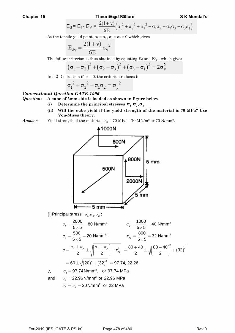
C
CQ
A
Chapter-15
ConventionQuestion:
Answer:
At the tens
The failure
In a 2-D sit
nal Questi
A cube of (i) Dete(ii) Will
Von-Yield stren
( )
1
i Principa
x
z
σ
σ
σ
σ
=
=
∴
2
3
and σ
σ
sile yield poi
e criterion is
tuation if σ3
ion GATE- 5mm side ermine the the cube y-Mises theongth of the m
(
1al stress2000 85 5500 25 5
2
60 20
97.74N/
x y
σ
σ σ
= =×
= =×
+= ±
= ±
=
22.96N/
20Nzσ
=
= =
Theorie
int, σ1 = σy , σ
s thus obtain
= 0, the crit
-1996 is loaded a principal syield if theory. material etσ =
) ( )
1 2 3
2
2
2 2
2
, , :
80 N/mm ;
20 N/mm ;
2
0 32
/mm , or 9
x y
σ σ
σ σ⎛ ⎞−⎜± ⎜⎜⎜⎝ ⎠
+
2
2
mm or 22
N/mm or 2
es of Failu
σ2 = σ3 = 0 w
ned by equat
terion reduc
as shown instresses 1σe yield stre
= 70 MPa =
2 8
97.74, 22
9
y
xy
xy
σ
τ
τ⎞⎟⎟+ =⎟⎟⎠
=
7.74 MPa
.96 MPa
22 MPa
re
which gives
ting Ed and
ces to
n figure bel1 2 3,σ ,σ . ength of th
70 MN/m2 o
1000 45 58005 5
0 402
2.26
y
= =×
= =×
⎛+ ⎜± ⎜⎜⎝
Edy , which
low.
he material
or 70 N/mm2
2
2
2
40 N/mm
32 N/mm
80 402
⎛ ⎞− ⎟ +⎟⎟⎝ ⎠
S K Mo
gives
l is 70 MPa
2.
( )232+
ondal’s
a? Use
Page 478
For-2019 (IES, GATE & PSUs) Page 478 of 480 Rev.0
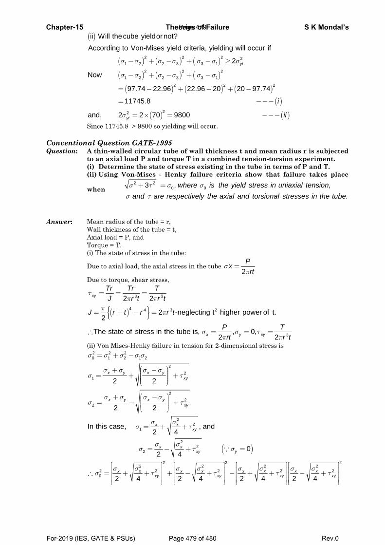
Chapter-15 Theories of Failure S K Mondal’s
( )
( ) ( ) ( )
( ) ( ) ( )
( ) ( ) ( )( )
( ) ( )
2 2 2 21 2 2 3 3 1
2 2 21 2 2 3 3 1
2 2 2
22
ii Will thecube yieldor not?According to Von-Mises yield criteria, yielding will occur if
2
Now
97.74 22.96 22.96 20 20 97.74
11745.8
and, 2 2 70 9800
yt
yt
i
ii
σ σ σ σ σ σ σ
σ σ σ σ σ σ
σ
− + − + − ≥
− + − + −
= − + − + −
= −−−
= × = −−−
Since 11745.8 > 9800 so yielding will occur. Conventional Question GATE-1995 Question: A thin-walled circular tube of wall thickness t and mean radius r is subjected
to an axial load P and torque T in a combined tension-torsion experiment. (i) Determine the state of stress existing in the tube in terms of P and T. (ii) Using Von-Mises - Henky failure criteria show that failure takes place
when2 2
0 03 , ,.
where is the yield stress in uniaxial tensionand are respectively the axial and torsional stresses in the tubeσ τ σ σ
σ τ
+ =
Answer: Mean radius of the tube = r, Wall thickness of the tube = t, Axial load = P, and Torque = T. (i) The state of stress in the tube:
Due to axial load, the axial stress in the tube 2Px
rtσ
π=
Due to torque, shear stress,
( ){ }3 3
4 4 3 2
3
2 2
2 -neglecting t higher power of t.2
The state of stress in the tube is, , 0,2 2
xy
x y xy
Tr Tr TJ r t r t
J r t r r t
P Trt r t
τπ π
ππ
σ σ τπ π
= = =
= + − =
∴ = = =
(ii) Von Mises-Henky failure in tension for 2-dimensional stress is
2 2 20 1 2 1 2
22
1
22
2
2 2
2 2
x y x yxy
x y x yxy
σ σ σ σ σ
σ σ σ σσ τ
σ σ σ σσ τ
= + −
⎛ ⎞+ − ⎟⎜ ⎟= + +⎜ ⎟⎜ ⎟⎜⎝ ⎠
⎛ ⎞+ − ⎟⎜ ⎟= − +⎜ ⎟⎜ ⎟⎜⎝ ⎠
( )
22
1
22
2
2 2 22 2 2 2
2 2 2 2 20
In this case, , and2 4
02 4
2 4 2 4 2 4 2 4
x xxy
x xxy y
x x x x x x x xxy xy xy xy
σ σσ τ
σ σσ τ σ
σ σ σ σ σ σ σ σσ τ τ τ τ
= + +
= − + =
⎡ ⎤ ⎡ ⎤ ⎡ ⎤ ⎡ ⎤⎢ ⎥ ⎢ ⎥ ⎢ ⎥ ⎢ ⎥∴ = + + + − + − + + − +⎢ ⎥ ⎢ ⎥ ⎢ ⎥ ⎢ ⎥⎢ ⎥ ⎢ ⎥ ⎢ ⎥ ⎢ ⎥⎣ ⎦ ⎣ ⎦ ⎣ ⎦ ⎣ ⎦
∵
Page 479
For-2019 (IES, GATE & PSUs) Page 479 of 480 Rev.0
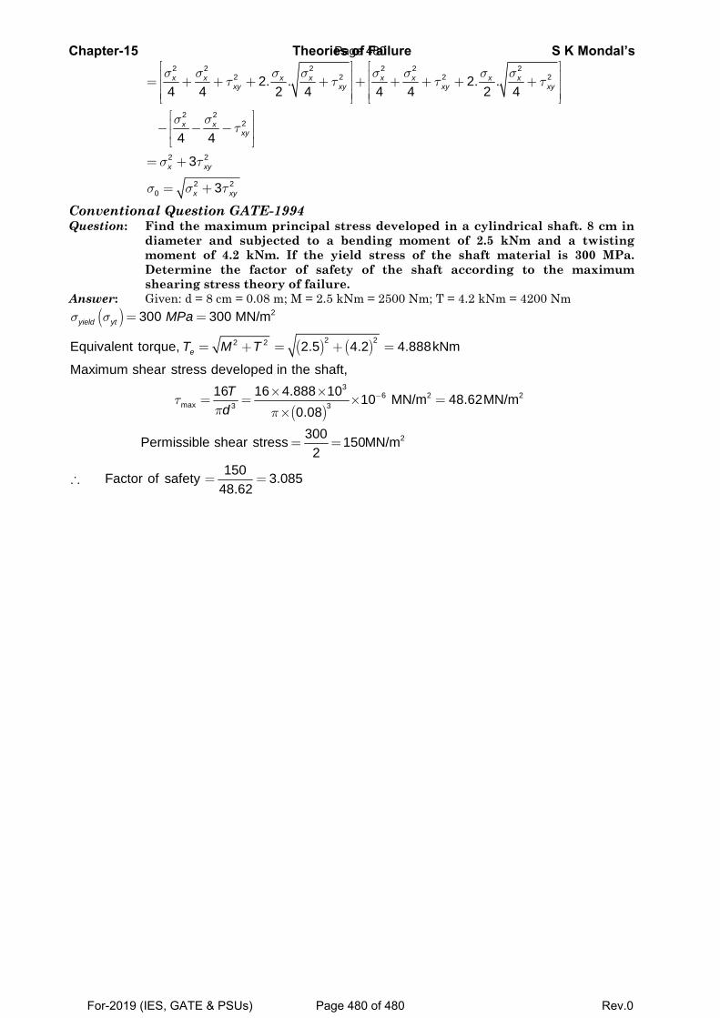
Chapter-15 Theories of Failure S K Mondal’s
2 2 2 2 2 22 2 2 2
2 22
2 2
2 20
2. . 2. .4 4 2 4 4 4 2 4
4 4
3
3
x x x x x x x xxy xy xy xy
x xxy
x xy
x xy
σ σ σ σ σ σ σ στ τ τ τ
σ στ
σ τ
σ σ τ
⎡ ⎤ ⎡ ⎤⎢ ⎥ ⎢ ⎥= + + + + + + + + +⎢ ⎥ ⎢ ⎥⎢ ⎥ ⎢ ⎥⎣ ⎦ ⎣ ⎦⎡ ⎤⎢ ⎥− − −⎢ ⎥⎣ ⎦
= +
= +
Conventional Question GATE-1994 Question: Find the maximum principal stress developed in a cylindrical shaft. 8 cm in
diameter and subjected to a bending moment of 2.5 kNm and a twisting moment of 4.2 kNm. If the yield stress of the shaft material is 300 MPa. Determine the factor of safety of the shaft according to the maximum shearing stress theory of failure.
Answer: Given: d = 8 cm = 0.08 m; M = 2.5 kNm = 2500 Nm; T = 4.2 kNm = 4200 Nm ( )
( ) ( )
( )
2
2 22 2
36 2 2
max 3 3
300 300 MN/m
Equivalent torque, 2.5 4.2 4.888kNm
Maximum shear stress developed in the shaft,16 16 4.888 10 10 MN/m 48.62MN/m
0.08
yield yt
e
MPa
T M T
Td
σ σ
τπ π
−
= =
= + = + =
× ×= = × =
×
2300Permissible shear stress 150MN/m2
150Factor of safety 3.08548.62
= =
∴ = =
Page 480
For-2019 (IES, GATE & PSUs) Page 480 of 480 Rev.0