Strength Characteristics of Secura Hollow Groutable Cable Bolts
10
University of Wollongong Research Online Coal Operators' Conference Faculty of Engineering and Information Sciences 2015 Strength Characteristics of Secura Hollow Groutable Cable Bolts Naj Aziz University of Wollongong, [email protected] Robert Hawker Orica Australia Ali Mirzaghorbanali University of Wollongong, [email protected] Jan Nemcik University of Wollongong, [email protected] Xuwei Li University of Wollongong See next page for additional authors Research Online is the open access institutional repository for the University of Wollongong. For further information contact the UOW Library: [email protected] Publication Details Naj Aziz, Robert Hawker, Ali Mirza, Jan Nemcik, Xuwei Li and Haleh Rasekh, Strength Characteristics of Secura Hollow Groutable Cable Bolts, 15th Coal Operators' Conference, University of Wollongong, e Australasian Institute of Mining and Metallurgy and Mine Managers Association of Australia, 2015, 160-167.
-
Upload
khangminh22 -
Category
Documents
-
view
0 -
download
0
Transcript of Strength Characteristics of Secura Hollow Groutable Cable Bolts

University of WollongongResearch Online
Coal Operators' Conference Faculty of Engineering and Information Sciences
2015
Strength Characteristics of Secura HollowGroutable Cable BoltsNaj AzizUniversity of Wollongong, [email protected]
Robert HawkerOrica Australia
Ali MirzaghorbanaliUniversity of Wollongong, [email protected]
Jan NemcikUniversity of Wollongong, [email protected]
Xuwei LiUniversity of Wollongong
See next page for additional authors
Research Online is the open access institutional repository for the University of Wollongong. For further information contact the UOW Library:[email protected]
Publication DetailsNaj Aziz, Robert Hawker, Ali Mirza, Jan Nemcik, Xuwei Li and Haleh Rasekh, Strength Characteristics of Secura Hollow GroutableCable Bolts, 15th Coal Operators' Conference, University of Wollongong, The Australasian Institute of Mining and Metallurgy andMine Managers Association of Australia, 2015, 160-167.

AuthorsNaj Aziz, Robert Hawker, Ali Mirzaghorbanali, Jan Nemcik, Xuwei Li, and Haleh Rasekh
This conference paper is available at Research Online: http://ro.uow.edu.au/coal/560
2015 Coal Operators’ Conference The University of Wollongong
160 11 – 13 February 2015
STRENGTH CHARACTERISTICS OF SECURA HOLLOW
GROUTABLE CABLE BOLTS
Naj Aziz1, Robert Hawker2, Ali Mirza1, Jan Nemcik1, Xuwei Li1 and Haleh Rasekh1
ABSTRACT: The strength properties of Secura Hollow Groutable Cable-bolts (HGC) were examined for tensile and shear failures. The 30 mm diameter, nine strand, cable bolt consisted of a mixture of five 7.5 mm plain and four 7.0 mm indented strands wrapped around a central 14 mm steel grouting hole to make a round cable with lay length of 500 mm with bulbs at 500mm centres of diameter 35mm. The tensile strength of the cable was tested in accordance with the British Standard (BS7861-part 2:2009) using the double embedment pull test. The shear strength of the cable bolt was tested by both the BS7861 single and UOW double shear methods. The single shear double test used a guillotine shear frame of double embodiment tendon/grout assembly in a steel tube, while the double shear method enabled shear testing of the cable bolt in concrete to simulate rock. It was found that the tensile strength of the cable was in the order of 680 kN, the shear load by single shear test, based on the average of three tests, was around 448 kN. The shear failure load of the cable bolt from double shear testing based on two tests averaged around 786 kN which is significantly higher than achieved from the single shear test. Thus the shear value, obtained from the double shear method was between 13 and 18 % greater than the single shear test method. The use of the guillotine shear frame for the single shear method was considered an unrealistic method of evaluating the shear characteristics of the cable bolts in rock.
INTRODUCTION
Australia uses a variety of cable bolts as a secondary system of support for strata reinforcement. The use of cable bolts initially began in metalliferous mines in mid-1960 and was later introduced to underground coal mines by the early 1970’s. Initially, cable bolts were of a conventional 7 single wire strand round cable and soon other cable types of different strand configurations followed. Presently, there are a variety of cable bolts which vary in size, structural formation, and strength to suit different ground stratification and conditions.
In general, installed cable bolts in situ are subjected to complex ground forces, which range from axial loading, to shearing and unwinding leading to the loss of encapsulation. The variation of the various loading force categories is dependent of the changes in ground conditions. Accordingly, methods used to evaluate the cable bolt strength characteristics should embrace various factors that influence the competency of the cable bolt in providing the necessary reactions to the prevailing ground forces. Thus, the forces applied on the cable bolt for strength evaluation tests must simulate the ground forces that the cable element is subjected to in situ.
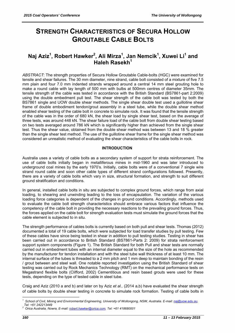
The strength performance of cables bolts is currently based on both pull and shear tests. Thomas (2012) documented a total of 19 cable bolts, which were subjected for load transfer studies by pull testing. Few of these cables have since being tested in shear in addition to pull testing studies. Testing in shear has been carried out in accordance to British Standard (BS7861-Parts 2: 2009) for strata reinforcement support system components (Figure 1). The British Standard for both Pull and shear tests are normally carried out in embedment tubes with an internal diameter equal to the size of the hole as recommended by the manufacturer for tendon installation and with the steel tube wall thickness of at least 10 mm. The internal surface of the tubes is threaded to a 2 mm pitch and 1 mm deep to maintain bonding of the resin / grout between and steel wall. One notable reported investigation using the British Standard of shear testing was carried out by Rock Mechanics Technology (RMT) on the mechanical performance tests on Megastrand flexible bolts (Clifford, 2002) Cementitious and resin based grouts were used for these tests, depending on the type of tested cable in steel tube.
Craig and Aziz (2010 a and b) and later on by Aziz et al., (2014 a,b) have evaluated the shear strength of cable bolts by double shear testing in concrete to simulate rock formation. Testing of cable bolts in
1 School of Civil, Mining and Environmental Engineering, University of Wollongong, NSW, Australia. E-mail: [email protected], Tel: +61 242213449 2 Orica Australia, Nowra, E-mail: [email protected], Tel: +61 418680001
2015 C
11 –13
concrethe sh
In this capabparticuembedreportestreng
Securasoon tfour inis 7.5 on smstrandhowevtype wTable strengcorrescable
The te(BS78groute
Coal Operato
3 February 20
ete was conseared cable
Figure
paper a newility and perf
ular the perfodment tube ed by Graig
gth performan
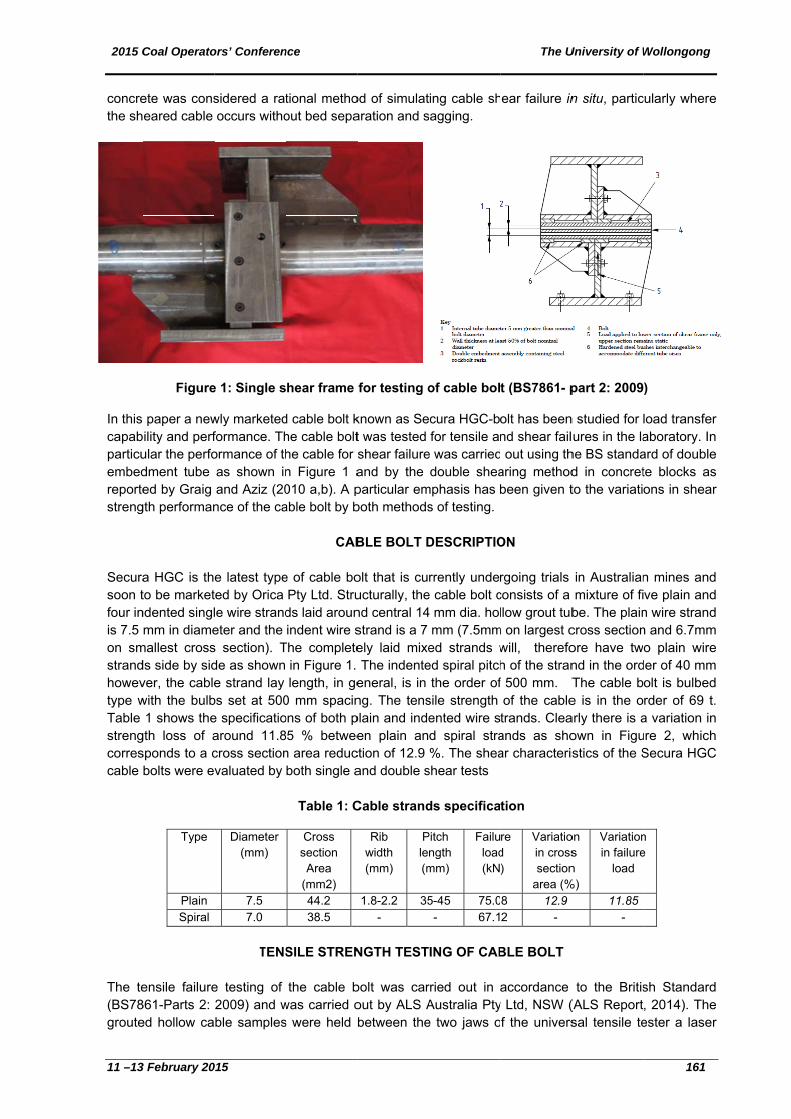
a HGC is thto be marketndented singlmm in diame
mallest crossds side by sidver, the cablewith the bulb1 shows the
gth loss of asponds to a cbolts were e
Type
Plain Spiral
ensile failure861-Parts 2: ed hollow ca
ors’ Conferen
015
sidered a ratoccurs witho
e 1: Single s
wly marketedformance. Thormance of thas shown inand Aziz (20
nce of the ca
e latest typeted by Orica le wire strandeter and the s section). Tde as shown e strand lay
bs set at 500e specificatioaround 11.8cross sectionvaluated by
Diameter (mm)
7.5 7.0
TENS
e testing of 2009) and wble samples
nce
tional methoout bed sepa
hear frame
d cable bolt khe cable bolthe cable for sn Figure 1 a010 a,b). A pable bolt by b
CAB
e of cable boPty Ltd. Struds laid arounindent wire s
The completein Figure 1. length, in ge
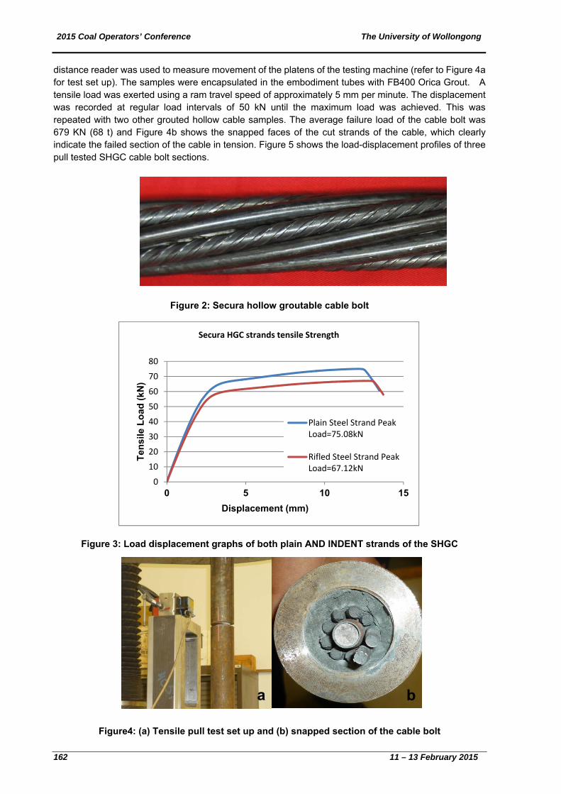
0 mm spacinons of both p5 % betwee
n area reducboth single a
Table 1: C
Cross section Area
(mm2) 44.2 38.5
SILE STREN
the cable bwas carried os were held b
od of simulataration and s
for testing o
known as Set was tested shear failureand by the particular emboth methods
BLE BOLT D
olt that is cuucturally, thend central 14strand is a 7 ely laid mixeThe indente
eneral, is in ng. The tensplain and indeen plain an
ction of 12.9 and double s
Cable strand
Rib width (mm)
Ple(m
1.8-2.2 35-
NGTH TEST
bolt was carout by ALS Abetween the
ing cable shsagging.
of cable bol
cura HGC-bfor tensile an
e was carrieddouble shea
mphasis has s of testing.
DESCRIPTIO
rrently undee cable bolt c4 mm dia. hol
mm (7.5mmed strands wed spiral pitchthe order of
sile strength ented wire sd spiral stra%. The shea
shear tests
ds specifica
Pitch ngth mm)
Failuload(kN
5-45 75.0- 67.1
ING OF CAB
rried out in Australia Ptye two jaws o
The U
ear failure in
t (BS7861- p
olt has beennd shear fail out using th
aring methodbeen given t
ON
rgoing trials consists of a llow grout tub
m on largest cwill, therefoh of the stranf 500 mm. Tof the cabletrands. Cleaands as shoar characteris
tion
re d )
Variatioin crosssection
area (%8 12.9 2 -
BLE BOLT
accordance y Ltd, NSW (f the univers
University of W
n situ, partic
part 2: 2009
n studied for ures in the la
he BS standad in concretto the variati
in Australianmixture of fibe. The plaincross sectionore have twnd in the ordThe cable be is in the oarly there is aown in Figustics of the S
on s n
%)
Variationin failure
load
11.85 -
to the Britis(ALS Reportsal tensile te
Wollongong
161
cularly where
)
load transferaboratory. Inard of doublete blocks asons in shear
n mines andve plain andn wire strandn and 6.7mmo plain wire
der of 40 mmolt is bulbedrder of 69 t.a variation inure 2, whichSecura HGC
n e
sh Standard, 2014). Theester a laser
e
r n e s r
d d d
m e
m d .
n h C
d e r
2015 Coal Operators’ Conference The University of Wollongong
162 11 – 13 February 2015
distance reader was used to measure movement of the platens of the testing machine (refer to Figure 4a for test set up). The samples were encapsulated in the embodiment tubes with FB400 Orica Grout. A tensile load was exerted using a ram travel speed of approximately 5 mm per minute. The displacement was recorded at regular load intervals of 50 kN until the maximum load was achieved. This was repeated with two other grouted hollow cable samples. The average failure load of the cable bolt was 679 KN (68 t) and Figure 4b shows the snapped faces of the cut strands of the cable, which clearly indicate the failed section of the cable in tension. Figure 5 shows the load-displacement profiles of three pull tested SHGC cable bolt sections.
Figure 2: Secura hollow groutable cable bolt
Figure 3: Load displacement graphs of both plain AND INDENT strands of the SHGC
Figure4: (a) Tensile pull test set up and (b) snapped section of the cable bolt
0
10
20
30
40
50
60
70
80
0 5 10 15
Ten
sile
Lo
ad (
kN)
Displacement (mm)
Secura HGC strands tensile Strength
Plain Steel Strand PeakLoad=75.08kN
Rifled Steel Strand PeakLoad=67.12kN
a b

2015 C
11 –13
Fi
Single
Three cable two plaplatenthe jigwas arecordwith tw
Figur
Coal Operato
3 February 20
gure 5: Loa
e shear test
more samplsamples weatens of the s of the testi was exerted
applied to theded at regulawo other grou
re 6: Shear t
10
20
30
40
50
60
70
Load
(kN
)
ors’ Conferen
015
ad displacem
es grouted inre positioneduniversal tenng machine d using a rae sample anar load intervuted hollow c
test and a vi
0
00
00
00
00
00
00
00
0
nce
ment profiles
n the double d into the spnsile tester a (refer to Figum travel spend the initialvals of 50 kNcable sample
ew of the sha
2
Pull test of
Displac
s of three p
SHEAR T
embedmentpecifically de laser distanure 6a for teseed of approxl displacemeN until the mes.
heared samand the stee
4
Secura HG
cement (mm
aa
ull tested Se
TESTING
t tubes were signed sheace reader wa
st set up). A sximately 2.5 ent was thenmaximum loa
mple. Note thel tube
6
C
m)
The U
ecura HGC c
tested for shar testing jig as used to mshear load vimm per min
n measured.ad was achie
he interactio
8 1
University of W
cable bolt s
hear. The groand placed
measure movia a compresnute. A prelo. The displaeved. This w
on between t
10 1
test 1
test 2
test 3
Wollongong
163
sections
outed hollowbetween theement of the
ssion load onoad of 10 kNcement was
was repeated
the strands
12
b
w e e n N s d
2015 Coal Operators’ Conference The University of Wollongong
164 11 – 13 February 2015
Figure 7: Load-displacement graphs of single shear tests
Double shear testing
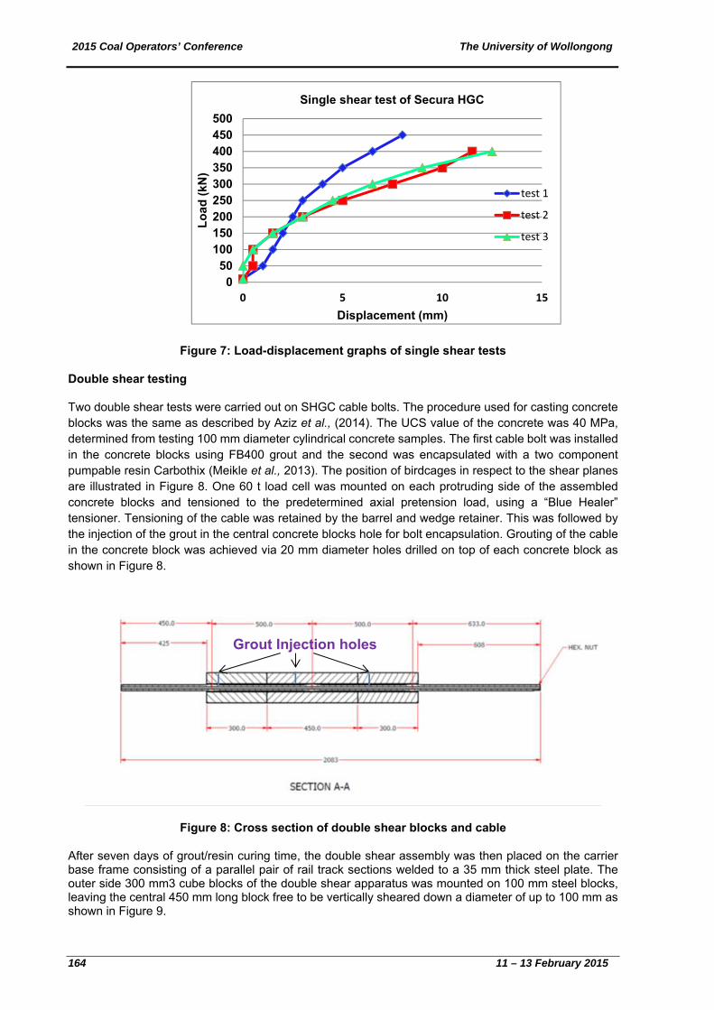
Two double shear tests were carried out on SHGC cable bolts. The procedure used for casting concrete blocks was the same as described by Aziz et al., (2014). The UCS value of the concrete was 40 MPa, determined from testing 100 mm diameter cylindrical concrete samples. The first cable bolt was installed in the concrete blocks using FB400 grout and the second was encapsulated with a two component pumpable resin Carbothix (Meikle et al., 2013). The position of birdcages in respect to the shear planes are illustrated in Figure 8. One 60 t load cell was mounted on each protruding side of the assembled concrete blocks and tensioned to the predetermined axial pretension load, using a “Blue Healer” tensioner. Tensioning of the cable was retained by the barrel and wedge retainer. This was followed by the injection of the grout in the central concrete blocks hole for bolt encapsulation. Grouting of the cable in the concrete block was achieved via 20 mm diameter holes drilled on top of each concrete block as shown in Figure 8.
Figure 8: Cross section of double shear blocks and cable
After seven days of grout/resin curing time, the double shear assembly was then placed on the carrier base frame consisting of a parallel pair of rail track sections welded to a 35 mm thick steel plate. The outer side 300 mm3 cube blocks of the double shear apparatus was mounted on 100 mm steel blocks, leaving the central 450 mm long block free to be vertically sheared down a diameter of up to 100 mm as shown in Figure 9.
050
100150200250300350400450500
0 5 10 15
Lo
ad (
kN)
Displacement (mm)
Single shear test of Secura HGC
test 1
test 2
test 3
Grout Injection holes
2015 Coal Operators’ Conference The University of Wollongong
11 –13 February 2015 165
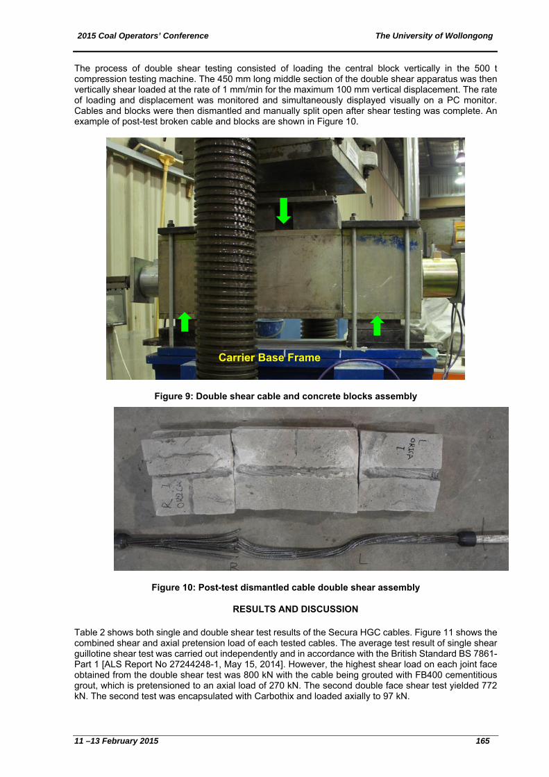
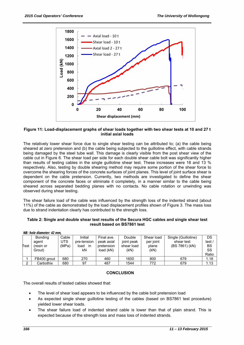
The process of double shear testing consisted of loading the central block vertically in the 500 t compression testing machine. The 450 mm long middle section of the double shear apparatus was then vertically shear loaded at the rate of 1 mm/min for the maximum 100 mm vertical displacement. The rate of loading and displacement was monitored and simultaneously displayed visually on a PC monitor. Cables and blocks were then dismantled and manually split open after shear testing was complete. An example of post-test broken cable and blocks are shown in Figure 10.
Figure 9: Double shear cable and concrete blocks assembly
Figure 10: Post-test dismantled cable double shear assembly
RESULTS AND DISCUSSION
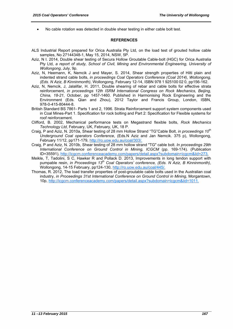
Table 2 shows both single and double shear test results of the Secura HGC cables. Figure 11 shows the combined shear and axial pretension load of each tested cables. The average test result of single shear guillotine shear test was carried out independently and in accordance with the British Standard BS 7861- Part 1 [ALS Report No 27244248-1, May 15, 2014]. However, the highest shear load on each joint face obtained from the double shear test was 800 kN with the cable being grouted with FB400 cementitious grout, which is pretensioned to an axial load of 270 kN. The second double face shear test yielded 772 kN. The second test was encapsulated with Carbothix and loaded axially to 97 kN.
Carrier Base Frame
2015 Coal Operators’ Conference The University of Wollongong
166 11 – 13 February 2015
Figure 11: Load-displacement graphs of shear loads together with two shear tests at 10 and 27 t initial axial loads
The relatively lower shear force due to single shear testing can be attributed to; (a) the cable being sheared at zero pretension and (b) the cable being subjected to the guillotine effect, with cable strands being damaged by the steel tube wall. This damage is clearly visible from the post shear view of the cable cut in Figure 6. The shear load per side for each double shear cable bolt was significantly higher than results of testing cables in the single guillotine shear test. These increases were 18 and 13 % respectively. Also, testing by double shearing method may require some portion of the shear force to overcome the shearing forces of the concrete surfaces of joint planes. This level of joint surface shear is dependent on the cable pretension. Currently, two methods are investigated to define the shear component of the concrete faces or eliminate it completely, in a manner similar to the cable being sheared across separated bedding planes with no contacts. No cable rotation or unwinding was observed during shear testing.
The shear failure load of the cable was influenced by the strength loss of the indented strand (about 11%) of the cable as demonstrated by the load displacement profiles shown of Figure 3. The mass loss due to strand indentation clearly has contributed to the strength loss.
Table 2: Single and double shear test results of the Secura HGC cables and single shear test result based on BS7861 test
NB: hole diameter: 42 mm,
CONCLUSION
The overall results of tested cables showed that:
The level of shear load appears to be influenced by the cable bolt pretension load As expected single shear guillotine testing of the cables (based on BS7861 test procedure)
yielded lower shear loads. The shear failure load of indented strand cable is lower than that of plain strand. This is
expected because of the strength loss and mass loss of indented strands.
0
200
400
600
800
1000
1200
1400
1600
1800
0 20 40 60 80 100
Lo
ad (
kN)
Shear displacement (mm)
Axial load ‐ 10 t
Shear load ‐ 10 t
Axial load 2 ‐ 27 t
Shear load ‐ 27 t
Test
Bonding agent (resin or Grout)
Cable UTS (MPa)
Initial pre-tension
load in kN
Final ave. peak axial pretension load (kN)
Double joint peak shear load
(kN)
Shear load per joint plane (kN)
Single (Guillotine) shear test
(BS 7861) (kN)
DS test / BS SS
Ratio 1 FB400 grout 680 270 460 1600 800 679 1.18 2 Carbothix 680 97 487 1544 772 679 1.13
2015 Coal Operators’ Conference The University of Wollongong
11 –13 February 2015 167
No cable rotation was detected in double shear testing in either cable bolt test.
REFERENCES
ALS Industrial Report prepared for Orica Australia Pty Ltd, on the load test of grouted hollow cable
samples, No 27144348-1, May 15, 2014, NSW, 5P. Aziz, N I. 2014, Double shear testing of Secura Hollow Groutable Cable-bolt (HGC) for Orica Australia
Pty Ltd, a report of study, School of Civil, Mining and Environmental Engineering, University of Wollongong, July, 9p.
Aziz, N, Heemann, K, Nemcik J and Mayer, S. 2014, Shear strength properties of Hilti plain and indented strand cable bolts, in proceedings Coal Operators Conference (Coal 2014), Wollongong, (Eds. N Aziz, B Kinninmonth), Wollongong, February 12-14, ISBN 978 1 925100 02 0, pp156-162.
Aziz, N, Nemcik, J, Jalalifar, H. 2011, Double shearing of rebar and cable bolts for effective strata reinforcement, in proceedings 12th ISRM International Congress on Rock Mechanics, Beijing, China, 18-21, October, pp 1457-1460. Published in Harmonising Rock Engineering and the Environment (Eds. Qian and Zhou), 2012 Taylor and Francis Group, London, ISBN, 978-0-415-80444-8.
British Standard BS 7861- Parts 1 and 2, 1996. Strata Reinforcement support system components used in Coal Mines-Part 1. Specification for rock bolting and Part 2: Specification for Flexible systems for roof reinforcement.
Clifford, B. 2002, Mechanical performance tests on Megastrand flexible bolts, Rock Mechanics Technology Ltd, February, UK, February, UK, 18 P.
Craig, P and Aziz, N. 2010a, Shear testing of 28 mm Hollow Strand “TG”Cable Bolt, in proceedings 10th Underground Coal operators Conference, (Eds.N Aziz and Jan Nemcik. 375 p), Wollongong, February 11/12, pp171-179, http://ro.uow.edu.au/coal/303/.
Craig, P and Aziz, N. 2010b, Shear testing of 28 mm hollow strand "TG" cable bolt. In proceedings 29th International Conference on Ground Control in Mining, ICGCM (pp. 169-174). (Publication ID=35591), http://icgcm.conferenceacademy.com/papers/detail.aspx?subdomain=icgcm&iid=273.
Meikle, T, Tadolini, S C, Hawker R and Pollack D. 2013, Improvements in long tendon support with pumpable resin, in Proceedings 13th Coal Operators’ conference, (Eds. N Aziz, B Kinninmonth), Wollongong, 14-15 February, pp124-130, http://ro.uow.edu.au/coal/445/.
Thomas, R. 2012, The load transfer properties of post-groutable cable bolts used in the Australian coal industry, in Proceedings 31st International Conference on Ground Control in Mining, Morgantown, 10p, http://icgcm.conferenceacademy.com/papers/detail.aspx?subdomain=icgcm&iid=1011.