Stochastic ratcheting of two-dimensional colloids: Directed current and dynamical transitions
Journal of Constructional Steel Research 67 (2011) 1872–1883
Contents lists available at ScienceDirect
Journal of Constructional Steel Research
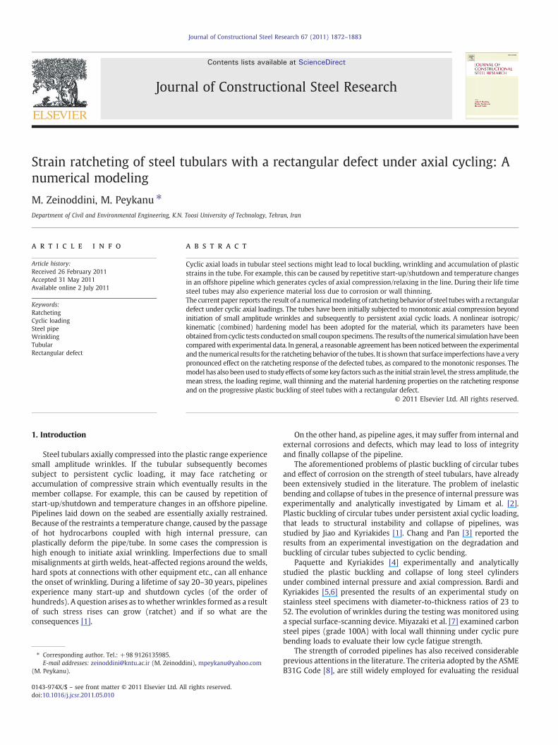
Strain ratcheting of steel tubulars with a rectangular defect under axial cycling: Anumerical modeling
M. Zeinoddini, M. Peykanu ⁎Department of Civil and Environmental Engineering, K.N. Toosi University of Technology, Tehran, Iran
⁎ Corresponding author. Tel.: +98 9126135985.E-mail addresses: [email protected] (M. Zeinodd
(M. Peykanu).
0143-974X/$ – see front matter © 2011 Elsevier Ltd. Adoi:10.1016/j.jcsr.2011.05.010
a b s t r a c t
a r t i c l e i n f oArticle history:Received 26 February 2011Accepted 31 May 2011Available online 2 July 2011
Keywords:RatchetingCyclic loadingSteel pipeWrinklingTubularRectangular defect
Cyclic axial loads in tubular steel sections might lead to local buckling, wrinkling and accumulation of plasticstrains in the tube. For example, this can be caused by repetitive start-up/shutdown and temperature changesin an offshore pipeline which generates cycles of axial compression/relaxing in the line. During their life timesteel tubes may also experience material loss due to corrosion or wall thinning.The current paper reports the result of a numericalmodeling of ratchetingbehavior of steel tubeswith a rectangulardefect under cyclic axial loadings. The tubes have been initially subjected to monotonic axial compression beyondinitiation of small amplitude wrinkles and subsequently to persistent axial cyclic loads. A nonlinear isotropic/kinematic (combined) hardening model has been adopted for the material, which its parameters have beenobtained fromcyclic tests conductedon small coupon specimens. The results of the numerical simulationhave beencomparedwith experimental data. In general, a reasonable agreement has been noticed between the experimentaland the numerical results for the ratcheting behavior of the tubes. It is shown that surface imperfections have a verypronounced effect on the ratcheting response of the defected tubes, as compared to themonotonic responses. Themodel has also beenused to study effects of somekey factors such as the initial strain level, the stress amplitude, themean stress, the loading regime, wall thinning and the material hardening properties on the ratcheting responseand on the progressive plastic buckling of steel tubes with a rectangular defect.
ini), [email protected]
ll rights reserved.
© 2011 Elsevier Ltd. All rights reserved.
1. Introduction
Steel tubulars axially compressed into the plastic range experiencesmall amplitude wrinkles. If the tubular subsequently becomessubject to persistent cyclic loading, it may face ratcheting oraccumulation of compressive strain which eventually results in themember collapse. For example, this can be caused by repetition ofstart-up/shutdown and temperature changes in an offshore pipeline.Pipelines laid down on the seabed are essentially axially restrained.Because of the restraints a temperature change, caused by the passageof hot hydrocarbons coupled with high internal pressure, canplastically deform the pipe/tube. In some cases the compression ishigh enough to initiate axial wrinkling. Imperfections due to smallmisalignments at girth welds, heat-affected regions around the welds,hard spots at connections with other equipment etc., can all enhancethe onset of wrinkling. During a lifetime of say 20–30 years, pipelinesexperience many start-up and shutdown cycles (of the order ofhundreds). A question arises as towhetherwrinkles formed as a resultof such stress rises can grow (ratchet) and if so what are theconsequences [1].
On the other hand, as pipeline ages, it may suffer from internal andexternal corrosions and defects, which may lead to loss of integrityand finally collapse of the pipeline.
The aforementioned problems of plastic buckling of circular tubesand effect of corrosion on the strength of steel tubulars, have alreadybeen extensively studied in the literature. The problem of inelasticbending and collapse of tubes in the presence of internal pressure wasexperimentally and analytically investigated by Limam et al. [2].Plastic buckling of circular tubes under persistent axial cyclic loading,that leads to structural instability and collapse of pipelines, wasstudied by Jiao and Kyriakides [1]. Chang and Pan [3] reported theresults from an experimental investigation on the degradation andbuckling of circular tubes subjected to cyclic bending.
Paquette and Kyriakides [4] experimentally and analyticallystudied the plastic buckling and collapse of long steel cylindersunder combined internal pressure and axial compression. Bardi andKyriakides [5,6] presented the results of an experimental study onstainless steel specimens with diameter-to-thickness ratios of 23 to52. The evolution of wrinkles during the testing was monitored usinga special surface-scanning device. Miyazaki et al. [7] examined carbonsteel pipes (grade 100A) with local wall thinning under cyclic purebending loads to evaluate their low cycle fatigue strength.
The strength of corroded pipelines has also received considerableprevious attentions in the literature. The criteria adopted by the ASMEB31G Code [8], are still widely employed for evaluating the residual
1873M. Zeinoddini, M. Peykanu / Journal of Constructional Steel Research 67 (2011) 1872–1883
strength of corroded pipelines. More recently, DNV-RP-F101 [9]provided recommended practices for assessing the strength ofcorroded pipelines under combined internal pressure and longitudi-nal compressive stress. Based on large and small scale experimentaltest results and numerical simulations, some semi-empirical formulaewere proposed. These take into account single, interacting andcomplex shaped defects. The axial loads and internal/externalpressures considered in these codes are of a monotonic nature andcyclic load effects have not been taken into consideration.
Netto [10,11] studied the effect of narrow and long corrosiondefects on the collapse pressure of offshore pipelines. Results fromsmall-scale experiments and nonlinear finite element analyses werereported in these studies. Netto et al. [12] Sakakibara et al. [13]studied the effect of internal corrosion or erosion defects on thecollapse of pipelines under external pressure. Xue [14] presented anon-linear finite-element analysis for the steady-state buckle prop-agation phenomenon in subsea corroded pipelines subjected toexternal hydrostatic pressures. Xue and Fatt [15] tried to derive aclosed form analytical solutions for this problem.
The subject of ratcheting, wrinkling and collapse of corroded ordefected steel tubes under cyclic axial loadings, however, has notreceived due attention previously. The present paper deals with theratcheting of corroded pipelines subjected to axial cyclic loadings. Anumerical approach has been chosen for this study. The corrosionshape in the steel tube is simplified as a rectangular defect on the tubewall. It reports some results from the finite elements analysis andexperimental studied on the subject.
2. Methods
In the current study, an advanced finite element program [16] hasbeen used to simulate the ratcheting response of carbon steel tubes.
Fig. 1. Machined specimen.
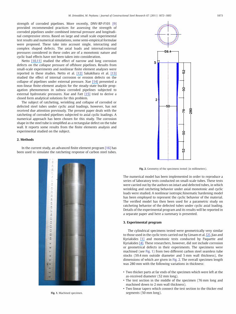
Fig. 2. Geometry of the specimens tested (in millimeters).
The numerical model has been implemented in order to reproduce aseries of laboratory tests conducted on small-scale tubes. These testswere carried out by the authors on intact and defected tubes, in whichwrinkling and ratcheting behavior under axial monotonic and cyclicloads were studied. A nonlinear isotropic/kinematic hardening modelhas been employed to represent the cyclic behavior of the material.The verified model has then been used for a parametric study onratcheting behavior of the defected tubes under cyclic axial loading.Details of the experimental program and its results will be reported ina separate paper and here a summary is presented.
3. Experimental program
The cylindrical specimens tested were geometrically very similarto those used in the cyclic tests carried out by Limam et al. [2], Jiao andKyriakides [1] and monotonic tests conducted by Paquette andKyriakides [4]. These researchers, however, did not include corrosionor geometrical defects in their experiments. The specimens weremachined (see Fig. 1) from two different carbon steel seamless tubestocks (59.4 mm outside diameter and 5 mm wall thickness), thedimensions of which are given in Fig. 2. The overall specimen lengthwas 280 mm with the following variations in thickness:
• Two thicker parts at far ends of the specimen which were left at theas-received diameter (52 mm long).
• The test section in the middle of the specimen (76 mm long andmachined down to 2 mm wall thickness).
• Two linear tapers which connect the test section to the thicker endsegments (50 mm long).
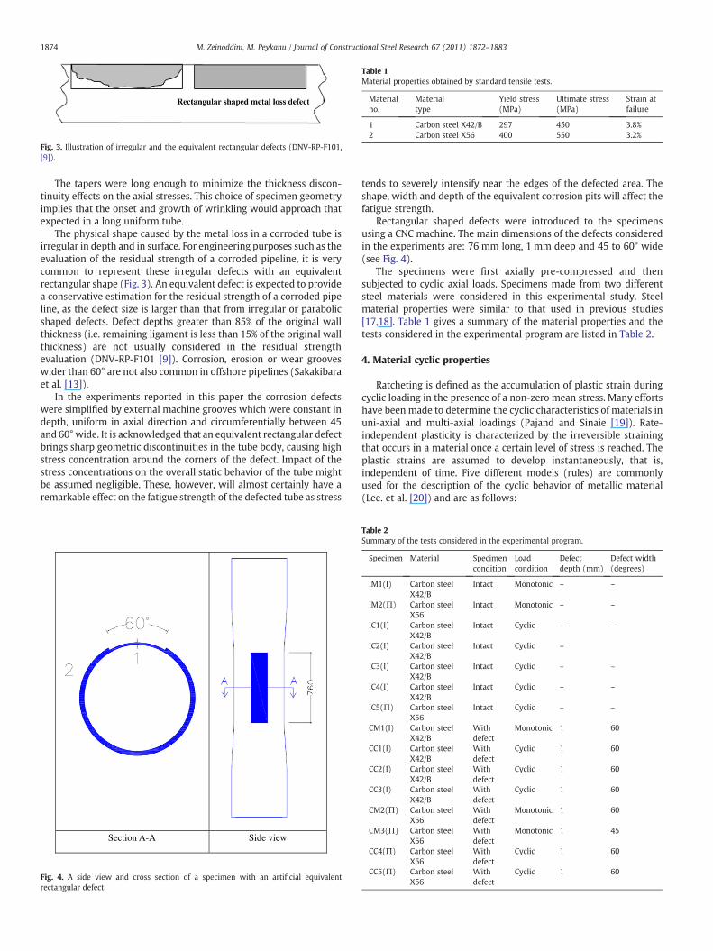
Fig. 3. Illustration of irregular and the equivalent rectangular defects (DNV-RP-F101,[9]).
Table 1Material properties obtained by standard tensile tests.
Materialno.
Materialtype
Yield stress(MPa)
Ultimate stress(MPa)
Strain atfailure
1 Carbon steel X42/B 297 450 3.8%2 Carbon steel X56 400 550 3.2%
1874 M. Zeinoddini, M. Peykanu / Journal of Constructional Steel Research 67 (2011) 1872–1883
The tapers were long enough to minimize the thickness discon-tinuity effects on the axial stresses. This choice of specimen geometryimplies that the onset and growth of wrinkling would approach thatexpected in a long uniform tube.
The physical shape caused by the metal loss in a corroded tube isirregular in depth and in surface. For engineering purposes such as theevaluation of the residual strength of a corroded pipeline, it is verycommon to represent these irregular defects with an equivalentrectangular shape (Fig. 3). An equivalent defect is expected to providea conservative estimation for the residual strength of a corroded pipeline, as the defect size is larger than that from irregular or parabolicshaped defects. Defect depths greater than 85% of the original wallthickness (i.e. remaining ligament is less than 15% of the original wallthickness) are not usually considered in the residual strengthevaluation (DNV-RP-F101 [9]). Corrosion, erosion or wear grooveswider than 60° are not also common in offshore pipelines (Sakakibaraet al. [13]).
In the experiments reported in this paper the corrosion defectswere simplified by external machine grooves which were constant indepth, uniform in axial direction and circumferentially between 45and 60° wide. It is acknowledged that an equivalent rectangular defectbrings sharp geometric discontinuities in the tube body, causing highstress concentration around the corners of the defect. Impact of thestress concentrations on the overall static behavior of the tube mightbe assumed negligible. These, however, will almost certainly have aremarkable effect on the fatigue strength of the defected tube as stress
Section A-A Side view
Fig. 4. A side view and cross section of a specimen with an artificial equivalentrectangular defect.
tends to severely intensify near the edges of the defected area. Theshape, width and depth of the equivalent corrosion pits will affect thefatigue strength.
Rectangular shaped defects were introduced to the specimensusing a CNC machine. The main dimensions of the defects consideredin the experiments are: 76 mm long, 1 mm deep and 45 to 60° wide(see Fig. 4).
The specimens were first axially pre-compressed and thensubjected to cyclic axial loads. Specimens made from two differentsteel materials were considered in this experimental study. Steelmaterial properties were similar to that used in previous studies[17,18]. Table 1 gives a summary of the material properties and thetests considered in the experimental program are listed in Table 2.
4. Material cyclic properties
Ratcheting is defined as the accumulation of plastic strain duringcyclic loading in the presence of a non-zero mean stress. Many effortshave been made to determine the cyclic characteristics of materials inuni-axial and multi-axial loadings (Pajand and Sinaie [19]). Rate-independent plasticity is characterized by the irreversible strainingthat occurs in a material once a certain level of stress is reached. Theplastic strains are assumed to develop instantaneously, that is,independent of time. Five different models (rules) are commonlyused for the description of the cyclic behavior of metallic material(Lee. et al. [20]) and are as follows:
Table 2Summary of the tests considered in the experimental program.
Specimen Material Specimencondition
Loadcondition
Defectdepth (mm)
Defect width(degrees)
IM1(I) Carbon steelX42/B
Intact Monotonic – –
IM2(П) Carbon steelX56
Intact Monotonic – –
IC1(I) Carbon steelX42/B
Intact Cyclic – –
IC2(I) Carbon steelX42/B
Intact Cyclic –
IC3(I) Carbon steelX42/B
Intact Cyclic – –
IC4(I) Carbon steelX42/B
Intact Cyclic – –
IC5(П) Carbon steelX56
Intact Cyclic – –
CM1(I) Carbon steelX42/B
Withdefect
Monotonic 1 60
CC1(I) Carbon steelX42/B
Withdefect
Cyclic 1 60
CC2(I) Carbon steelX42/B
Withdefect
Cyclic 1 60
CC3(I) Carbon steelX42/B
Withdefect
Cyclic 1 60
CM2(П) Carbon steelX56
Withdefect
Monotonic 1 60
CM3(П) Carbon steelX56
Withdefect
Monotonic 1 45
CC4(П) Carbon steelX56
Withdefect
Cyclic 1 60
CC5(П) Carbon steelX56
Withdefect
Cyclic 1 60
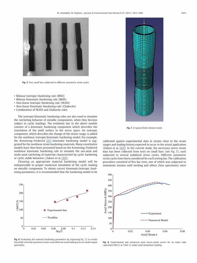
Fig. 5. Four small bars subjected to different symmetric strain cycles.
Fig. 7. A typical finite element mesh.
1875M. Zeinoddini, M. Peykanu / Journal of Constructional Steel Research 67 (2011) 1872–1883
• Bilinear Isotropic Hardening rule (BISO)• Bilinear Kinematic Hardening rule (BKIN)• Non-linear Isotropic Hardening rule (NLISO)• Non-linear Kinematic Hardening rule (Chaboche)• Combination of NLISO and Chaboche rules
The isotropic/kinematic hardening rules are also used to simulatethe ratcheting behavior of metallic components, when they becomesubject to cyclic loadings. The evolution law in the above modelsconsists of a kinematic hardening component which describes thetranslation of the yield surface in the stress space. An isotropiccomponent, which describes the change of the elastic range, is addedfor the nonlinear isotropic/kinematic hardening model. For example,the Armstrong–Frederick [21] kinematic hardening model is sug-gested for the nonlinear strain hardeningmaterials. Many constitutivemodels have then been presented based on the Armstrong–Fredericknonlinear kinematic hardening rule to simulate the uni-axial andmulti-axial ratcheting of materials characterized by cyclic hardeningor cyclic stable behaviors (Zakavi et al. [22]).
Choosing an appropriate material hardening model will beindispensable to proper numerical simulation of the cyclic loadingon metallic component. To obtain correct kinematic/isotropic hard-ening parameters, it is recommended that the hardening model to be
0
50
100
150
200
250
0 0.02 0.04 0.06 0.08 0.1 0.12 0.14
(Δσ/
2)-k
ΔεP/2
Experimental data
Trendline
Fig. 6. Evaluating the material hardening parameters by regressing Eq. (2) to resultsfrom fully reversed symmetric strain-controlled uni-axial loading tests on small couponspecimens.
calibrated against experimental data in strains close to the strainranges and loading history expected to occur in the actual application(Zakavi et al. [22]). In the current study, the necessary stress–straindata has been collected from tests on small bars (see Fig. 5), eachsubjected to several stabilized stress cycles. Different symmetricstrain cycles have been considered for each testing bar. The calibrationprocedure consisted of five bar tests, one of which was subjected tomonotonic tension until necking and others (four specimens) were
0
50
100
150
200
250
300
350
400
450
500
0 0.02 0.04 0.06 0.08
Axi
al S
tres
s σ
(MPa
)
Experiment
Numerical Model
Fig. 8. Experimental and numerical axial stress–strain curves for an intact tube(specimen IM1(I) in Table 2) under axial monotonic loading.
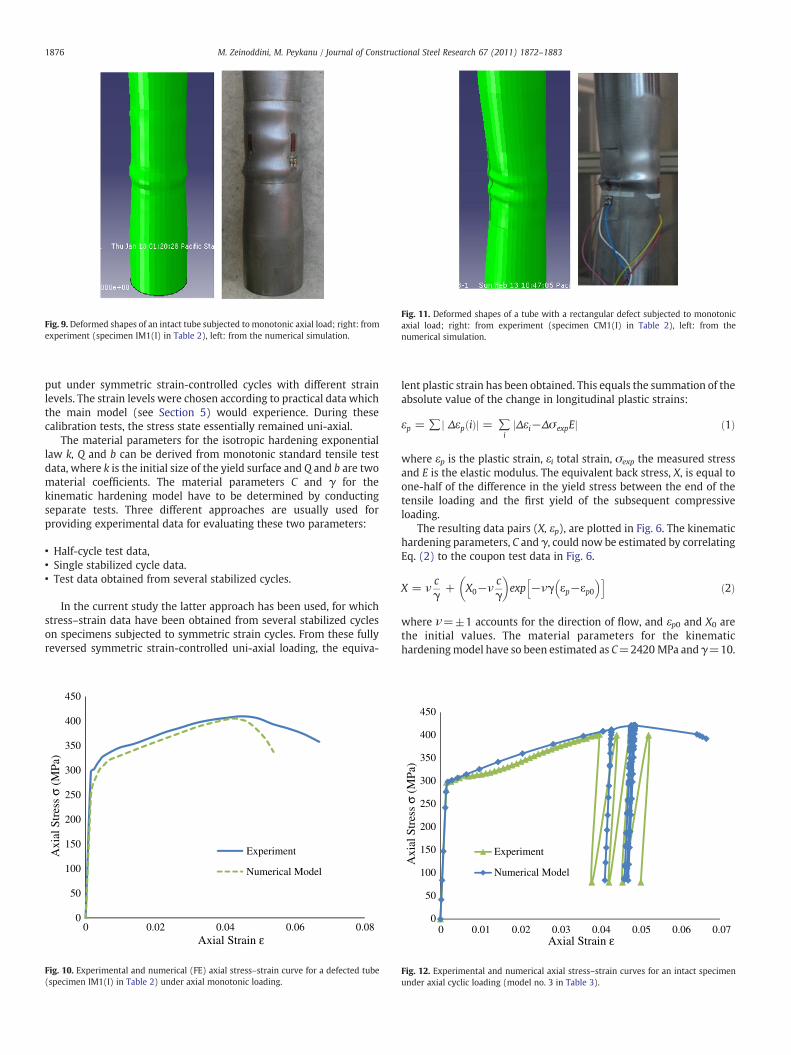
Fig. 9. Deformed shapes of an intact tube subjected to monotonic axial load; right: fromexperiment (specimen IM1(I) in Table 2), left: from the numerical simulation.
Fig. 11. Deformed shapes of a tube with a rectangular defect subjected to monotonicaxial load; right: from experiment (specimen CM1(I) in Table 2), left: from thenumerical simulation.
1876 M. Zeinoddini, M. Peykanu / Journal of Constructional Steel Research 67 (2011) 1872–1883
put under symmetric strain-controlled cycles with different strainlevels. The strain levels were chosen according to practical data whichthe main model (see Section 5) would experience. During thesecalibration tests, the stress state essentially remained uni-axial.
The material parameters for the isotropic hardening exponentiallaw k, Q and b can be derived from monotonic standard tensile testdata, where k is the initial size of the yield surface and Q and b are twomaterial coefficients. The material parameters C and γ for thekinematic hardening model have to be determined by conductingseparate tests. Three different approaches are usually used forproviding experimental data for evaluating these two parameters:
• Half-cycle test data,• Single stabilized cycle data.• Test data obtained from several stabilized cycles.
In the current study the latter approach has been used, for whichstress–strain data have been obtained from several stabilized cycleson specimens subjected to symmetric strain cycles. From these fullyreversed symmetric strain-controlled uni-axial loading, the equiva-
0
50
100
150
200
250
300
350
400
450
Experiment
Numerical Model
0 0.02 0.04 0.06 0.08
Axi
al S
tres
s σ
(MPa
)
Fig. 10. Experimental and numerical (FE) axial stress–strain curve for a defected tube(specimen IM1(I) in Table 2) under axial monotonic loading.
lent plastic strain has been obtained. This equals the summation of theabsolute value of the change in longitudinal plastic strains:
εp = ∑j Δεp ið Þj = ∑ijΔεi−Δσ expEj ð1Þ
where εp is the plastic strain, εi total strain, σexp the measured stressand E is the elastic modulus. The equivalent back stress, X, is equal toone-half of the difference in the yield stress between the end of thetensile loading and the first yield of the subsequent compressiveloading.
The resulting data pairs (X, εp), are plotted in Fig. 6. The kinematichardening parameters, C and γ, could now be estimated by correlatingEq. (2) to the coupon test data in Fig. 6.
X = νcγ
+ X0−νcγ
� �exp −νγ εp−εp0
� �h ið2Þ
where ν=±1 accounts for the direction of flow, and εp0 and X0 arethe initial values. The material parameters for the kinematichardeningmodel have so been estimated as C=2420 MPa and γ=10.
0
50
100
150
200
250
300
350
400
450
0 0.01 0.02 0.03 0.04 0.05 0.06 0.07
Experiment
Numerical Model
Axi
al S
tres
s σ
(MPa
)
Fig. 12. Experimental and numerical axial stress–strain curves for an intact specimenunder axial cyclic loading (model no. 3 in Table 3).
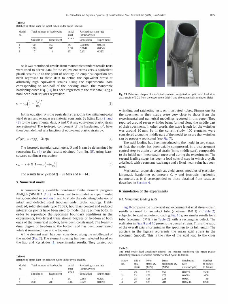
Table 3Ratcheting strain data for intact tubes under cyclic loading.
Modelno.
Total number of load cycles Initialaxialstrain
Ratcheting strain rate(strain/cycle)
Simulation Experiment Simulation Experiment
1 150 150 2% 0.0034% 0.004%2 100 100 0. 3% 0.004% 0.004%3 7 4 4% 0.1% 0.32%
Fig. 13. Deformed shapes of a defected specimen subjected to cyclic axial load at anaxial strain of 5.2% from the experiment (right) and the numerical simulation (left).
1877M. Zeinoddini, M. Peykanu / Journal of Constructional Steel Research 67 (2011) 1872–1883
As it wasmentioned, results frommonotonic standard tensile testswere used to derive data for the equivalent stress versus equivalentplastic strains up to the point of necking. An empirical equation hasbeen regressed to these data to define the equivalent stress atarbitrarily high equivalent strains. Using the experimental datacorresponding to one-half of the necking strain, the monotonichardening curve (Eq. (3)) has been regressed to the test data using anonlinear least-squares regression:
σ = σy 1 +εpm
� �n
ð3Þ
In this equation, σ is the equivalent stress, σy is the initial uni-axialyield stress, andm and n are material constants. By fitting Eqs. (2) and(3) to the experimental data, σ and X at any equivalent plastic strainare estimated. The isotropic component of the hardening, σ0, havethen been defined as a function of equivalent plastic strain by:
σ0 εpð Þ = σ εpð Þ−X εpð Þ ð4Þ
The isotropic material parameters, Q and b, can be determined byregressing Eq. (4) to the results obtained from Eq. (5), using least-squares nonlinear regression.
σ0 = k + Q 1−exp −bεp� �h i
ð5Þ
The results have yielded Q=95 MPa and b=14.8
5. Numerical model
A commercially available non-linear finite element programABAQUS (SIMULIA, [16]) has been used to simulate the experimentaltests, described in Section 3, and to study the ratcheting behavior ofintact and defected steel tubulars under cyclic loadings. Eight-nodded, solid elements type C3D8R, hourglass control and reducedintegration points have been used to model the specimen body. Inorder to reproduce the specimen boundary conditions in theexperiments, two lateral translational degrees of freedom at bothends of the numerical models, have been constrained. The longitu-dinal degree of freedom at the bottom end has been constrainedwhile it remained free at the top end.
A fine element mesh has been considered along the middle part ofthe model (Fig. 7). The element spacing has been selected based onthe Jiao and Kyriakides [1] experimental results. They carried out
Table 4Ratcheting strain data for defected tubes under cyclic loading.
Modelno.
Total number of load cycles Initialaxialstrain
Ratcheting strain rate(strain/cycle)
Simulation Experiment Simulation Experiment
1 7 4 2% 0.15% 0.22%2 200 200 0.3% 0.02% 0.025%
wrinkling and ratcheting tests on intact steel tubes. Dimensions forthe specimen in their study were very close to those from theexperimental and numerical modelings reported in this paper. Theyreported around seven wrinkles being formed along the middle partof their specimens. In other words, the wave length for the wrinkleswas around 10 mm. So in the current study, 100 elements wereconsidered along the middle part of the model to insure that wrinklescan be properly replicated (see Fig. 7).
The axial loading has been introduced to the model in two stages.At first, the model has been axially compressed, in a displacementcontrol step, to attain an axial strain (in its middle part), comparableto the initial non-linear strain measured during the experiments. Thesecond loading stage has been a load control step in which a cyclicaxial load, with a constant load range and a fixedmean value has beenused.
Mechanical properties such as, yield stress, modulus of elasticity,kinematic hardening parameters C, γ and isotropic hardeningparameters k, b, Q corresponded to those obtained from tests, asdescribed in Section 4.
6. Simulation of the experiments
6.1. Monotonic loading tests
Fig. 8 compares the numerical and experimental axial stress–strainresults obtained for an intact tube (specimen IM1(I) in Table 2)subjected to axial monotonic loading. Fig. 10 gives similar results for atube (specimen CM1(I) in Table 2) with a rectangular defect. Theordinates in Figs. 8 and 10 present the overall strains. This is the ratioof the overall axial shortening in the specimen to its full length. Theabscissa in the figures represents the mean axial stress in thespecimen (model). This is the ratio of the axial load to the cross
Table 5The axial cyclic load amplitude effects: the loading condition; the mean plasticratcheting strain rate and the number of load cycles to failure.
Modelno.
Initialaxialstrain
Meanstress σm
(MPa)
Stressamplitude σa
(MPa)
Ratchetingrate(strain/cycle)
Numberof cyclesto failure
1 2% 175 157 0.001% 35002 2% 175 175 0.009% 4003 2% 125 225 0.02% 1804 2% 125 204 0.0024% 1270
0.00
0.01
0.01
0.02
0.02
0.03
0.03
0.04
0 10 20 30
Axi
al R
atch
etin
g St
rain
Number of Cycles N
Model No.2(in Table 5)Model No.1(in Table 5)
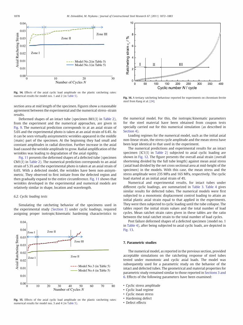
Fig. 14. Effects of the axial cyclic load amplitude on the plastic ratcheting rates:numerical results for model nos. 1 and 2 (in Table 5).
Fig. 16. A tertiary ratcheting behaviour reported for experiments on chromium ferritesteel from Kang et al. [24].
1878 M. Zeinoddini, M. Peykanu / Journal of Constructional Steel Research 67 (2011) 1872–1883
section area at mid length of the specimen. Figures show a reasonableagreement between the experimental and the numerical stress–strainresults.
Deformed shapes of an intact tube (specimen IM1(I) in Table 2),from the experiment and the numerical approaches, are given inFig. 9. The numerical prediction corresponds to at an axial strain of5.6% and the experimental photo is taken at an axial strain of 6.4%. Asit can be seen virtually axisymmetric wrinkles appeared in the middle(main) part of the specimen. At the beginning they had small andconstant amplitudes in radial direction. Further increase in the axialload caused thewrinkle amplitude to grow. Radial amplification of thewrinkles was leading to degradation of the axial rigidity.
Fig. 11 presents the deformed shapes of a defected tube (specimenCM1(I) in Table 2). The numerical prediction corresponds to an axialstrain of 5.3% and the experimental photo is taken at an axial strain of6.6%. With a defected model, the wrinkles have been non-axisym-metric. They observed to first initiate from the defected region andthen gradually expand to the entire circumference. Fig. 11 shows thatwrinkles developed in the experimental and numerical models arerelatively similar in shape, location and wavelength.
6.2. Cyclic loading tests
Simulating the ratcheting behavior of the specimens used inthe experimental study (Section 3) under cyclic loadings, requiredassigning proper isotropic/kinematic hardening characteristics to
0.00
0.01
0.01
0.02
0.02
0.03
0.03
0.04
0.04
0 10 20 30 40 50 60 70 80
Model No.3 (in Table 5)Model No.4 (in Table 5)
Zone II
Zone II
Zone III
Zone
Zone
Number of Cycles N
Axi
al R
atch
etin
g St
rain
Fig. 15. Effects of the axial cyclic load amplitude on the plastic ratcheting rates:numerical results for model nos. 3 and 4 (in Table 5).
the numerical model. For this, the isotropic/kinematic parametersfor the steel material have been obtained from coupon testsspecially carried out for this numerical simulation (as described inSection 4).
Loading regimes for the numerical model, such as the initial axialnon-linear strain, the stress cycle amplitude and the mean stress havebeen kept identical to that used in the experiment.
The numerical predictions and experimental results for an intactspecimen (IC1(I) in Table 2) subjected to axial cyclic loading areshown in Fig. 12. The figure presents the overall axial strain (overallshortening divided by the full tube length) against mean axial stress(axial load divided by the net cross sectional area at mid-height of thespecimen) in the models. With this case, the mean stress and thestress amplitude were 235 MPa and 165 MPa, respectively. The cyclicload started at an initial axial strain of 4%.
Numerical and experimental results, for intact tubes underdifferent cyclic loadings, are summarized in Table 3. Table 4 givessimilar results for defected tubes. The numerical models were firstsubjected to a monotonic displacement control loading to attain aninitial plastic axial strain equal to that applied in the experiments.They were then subjected to cyclic loading until the tube collapse. Thetables report the initial strain values and the total number of loadcycles. Mean ratchet strain rates given in these tables are the ratiobetween the total ratchet strain to the total number of load cycles.
Post failure deformed shapes of a defected specimen (model no. 1in Table 4), after being subjected to axial cyclic loads, are depicted inFig. 13.
7. Parametric studies
The numerical model, as reported in the previous section, providedacceptable simulations on the ratcheting response of steel tubestested under monotonic and cyclic axial loads. The model wassubsequently used for a parametric study on the behavior of theintact and defected tubes. The geometrical and material properties forparametric study remained similar to those reported in Sections 3 and6. Effects of the following parameters have been examined:
• Cyclic stress amplitude• Cyclic load regime• Cyclic mean stress• Hardening defect• Defect effects
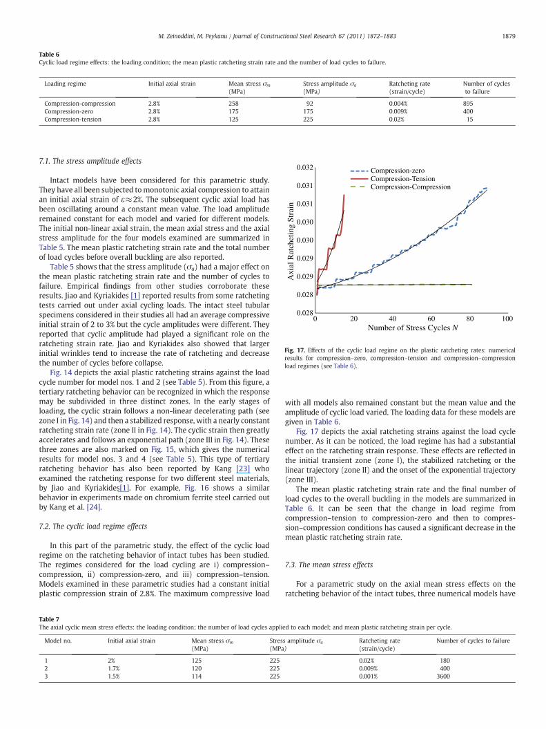
Table 6Cyclic load regime effects: the loading condition; the mean plastic ratcheting strain rate and the number of load cycles to failure.
Loading regime Initial axial strain Mean stress σm
(MPa)Stress amplitude σa
(MPa)Ratcheting rate(strain/cycle)
Number of cyclesto failure
Compression-compression 2.8% 258 92 0.004% 895Compression-zero 2.8% 175 175 0.009% 400Compression-tension 2.8% 125 225 0.02% 15
0.028
0.028
0.029
0.029
0.030
0.030
0.031
0.031
0.032
0 20 40 60 80 100
Axi
al R
atch
etin
g St
rain
Compression-zeroCompression-TensionCompression-Compression
Number of Stress Cycles N
Fig. 17. Effects of the cyclic load regime on the plastic ratcheting rates: numericalresults for compression–zero, compression–tension and compression–compressionload regimes (see Table 6).
1879M. Zeinoddini, M. Peykanu / Journal of Constructional Steel Research 67 (2011) 1872–1883
7.1. The stress amplitude effects
Intact models have been considered for this parametric study.They have all been subjected tomonotonic axial compression to attainan initial axial strain of ε≈2%. The subsequent cyclic axial load hasbeen oscillating around a constant mean value. The load amplituderemained constant for each model and varied for different models.The initial non-linear axial strain, the mean axial stress and the axialstress amplitude for the four models examined are summarized inTable 5. The mean plastic ratcheting strain rate and the total numberof load cycles before overall buckling are also reported.
Table 5 shows that the stress amplitude (σa) had a major effect onthe mean plastic ratcheting strain rate and the number of cycles tofailure. Empirical findings from other studies corroborate theseresults. Jiao and Kyriakides [1] reported results from some ratchetingtests carried out under axial cycling loads. The intact steel tubularspecimens considered in their studies all had an average compressiveinitial strain of 2 to 3% but the cycle amplitudes were different. Theyreported that cyclic amplitude had played a significant role on theratcheting strain rate. Jiao and Kyriakides also showed that largerinitial wrinkles tend to increase the rate of ratcheting and decreasethe number of cycles before collapse.
Fig. 14 depicts the axial plastic ratcheting strains against the loadcycle number for model nos. 1 and 2 (see Table 5). From this figure, atertiary ratcheting behavior can be recognized in which the responsemay be subdivided in three distinct zones. In the early stages ofloading, the cyclic strain follows a non-linear decelerating path (seezone I in Fig. 14) and then a stabilized response, with a nearly constantratcheting strain rate (zone II in Fig. 14). The cyclic strain then greatlyaccelerates and follows an exponential path (zone III in Fig. 14). Thesethree zones are also marked on Fig. 15, which gives the numericalresults for model nos. 3 and 4 (see Table 5). This type of tertiaryratcheting behavior has also been reported by Kang [23] whoexamined the ratcheting response for two different steel materials,by Jiao and Kyriakides[1]. For example, Fig. 16 shows a similarbehavior in experiments made on chromium ferrite steel carried outby Kang et al. [24].
7.2. The cyclic load regime effects
In this part of the parametric study, the effect of the cyclic loadregime on the ratcheting behavior of intact tubes has been studied.The regimes considered for the load cycling are i) compression–compression, ii) compression-zero, and iii) compression–tension.Models examined in these parametric studies had a constant initialplastic compression strain of 2.8%. The maximum compressive load
Table 7The axial cyclic mean stress effects: the loading condition; the number of load cycles applie
Model no. Initial axial strain Mean stress σm
(MPa)Stres(MPa
1 2% 125 2252 1.7% 120 2253 1.5% 114 225
with all models also remained constant but the mean value and theamplitude of cyclic load varied. The loading data for these models aregiven in Table 6.
Fig. 17 depicts the axial ratcheting strains against the load cyclenumber. As it can be noticed, the load regime has had a substantialeffect on the ratcheting strain response. These effects are reflected inthe initial transient zone (zone I), the stabilized ratcheting or thelinear trajectory (zone II) and the onset of the exponential trajectory(zone III).
The mean plastic ratcheting strain rate and the final number ofload cycles to the overall buckling in the models are summarized inTable 6. It can be seen that the change in load regime fromcompression–tension to compression-zero and then to compres-sion–compression conditions has caused a significant decrease in themean plastic ratcheting strain rate.
7.3. The mean stress effects
For a parametric study on the axial mean stress effects on theratcheting behavior of the intact tubes, three numerical models have
d to each model; and mean plastic ratcheting strain per cycle.
s amplitude σa
)Ratcheting rate(strain/cycle)
Number of cycles to failure
0.02% 1800.009% 4000.001% 3600

0
50
100
150
200
250
300
350
400
450
500
0 0.01 0.02 0.03 0.04 0.05 0.06 0.07
Axi
al S
tres
s (M
Pa)
Axial Strain
Experiment
Simulation: with a Nonlinear Kinematic/Isotropic Hardening Rule
Simulation: with a Nonlinear Kinematic Hardening Rule
Fig. 18. Experimental and numerical axial stress–strain curves for an intact specimenunder axial monotonic loading.
0.0200
0.0250
0.0300
0.0350
0.0400
0.0450
0 20 40 60 80 100
Axi
al R
atch
tein
g St
rain
Number of Stress Cycles N
Simulation: with a Nonlinear Kinematic/Isotropic Hardening Rule
Simulation: with a Nonlinear Kinematic Hardening Rule
Fig. 19. Sensitivity of the ratcheting simulations to the material hardening rule.
1880 M. Zeinoddini, M. Peykanu / Journal of Constructional Steel Research 67 (2011) 1872–1883
been considered. The amplitude for the cyclic load remained constantbut the mean stress varied. A compression–compression loadingregime was considered. Table 7 gives a summary of the results. It canbe seen that the mean plastic ratcheting strain rate has considerablyincreased by the mean stress increase.
An experimental study was carried out by Kang et al. [24] on thestrain cyclic characteristics and ratcheting of 316L stainless steelintact tubes subjected to uni-axial and multi-axial cyclic loadings. Thestrain ratcheting responses, reportedly, showed substantial depen-dency on the values of mean stress, stress amplitude and theirhistories.
7.4. Hardening rule
To evaluate the sensitivity of the numerical models to the materialhardening rule, two different numerical models have been consid-ered. One model incorporates a non-linear isotropic/kinematichardening rule and the second employs a non-linear kinematichardening rule. The material hardening parameters were obtainedfrom small coupon tests described in Section 4. The tubes in bothmodels have been assumed to be intact. They have been studied underincremental monotonic as well as cyclic axial loadings
Fig. 18 shows the stress–strain results from numerical simulationof tubes subjected to monotonic axial loading, with the correspondingexperimental data. As can be seen, the numerical model whichemployed a non-linear isotropic/kinematic hardening rule has moreaccurately reproduced the experimental stress–strain results, ascompared to the model which utilized a non-linear kinematichardening rule.
Table 8Impacts from different material hardening parameters on the ratcheting response of an int
Model no. Initial axial strain Mean stress σm
(MPa)Stress amplitude σa
(MPa)
1 (Main model) 2% 100 300234567
Fig. 19 shows the results from simulating an intact steel tubesubjected to asymmetrical axial cyclic stressing within plasticdeformation regimes. It depicts the axial ratcheting strains againstthe cycling numbers, from numerical models which incorporateddifferent material hardening rules. The mean stress σm and the stressamplitude σa have been 100 and 300 MPa, respectively. The tube hashad an initial axial strain of 2% and been examined under acompression–tension load regime.
Fig. 19 indicates that the results have been very sensitive to thehardening rules. The models have predicted substantially differentratcheting responses. The mean axial ratcheting strain rate is around0.0028%/cycle for the model which incorporated a non-linearisotropic/kinematic hardening. It is around 0.005%/cycle for themodel which employed a non-linear kinematic hardening.
A parametric study has also been performed to evaluate theimpacts from different material hardening parameters on theratcheting response. In total, seven models of intact tubes have beenconsidered. Model no. 1 incorporates a non-linear isotropic/kinematichardening rule utilizing those material parameters obtained fromcyclic tests on small coupon specimens (see Section 4). With modelnos. 2 to 7, the material parameters C and γ for the kinematichardening as well as Q and b for the isotropic hardening have beenvaried around 10%with respect to those in model no. 1. Table 8 gives asummary of the results. The table also presents the total number ofload cycles to the overall buckling for each model.
Table 8 shows that with an increase of around 10% in C value, thenumber of cycles to failure has changed from 10 (model no. 1) to 40(model no. 3). With a reduction of around 10% in γ value, the numberof cycles to failure has changed from 10 (model no. 1) to 19 (model no.2). So, the ratcheting response appears to have been very sensitive to
act tube.
C (MPa) γ Q (MPa) b Number of cycles to failure
2442 10 95 14.8 102442 9 95 14.8 192662 10 95 14.8 402442 10 85 14.8 92442 10 104 14.8 142442 10 95 13.32 92442 10 95 16.28 13
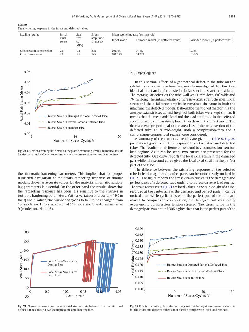
Table 9The ratcheting response in the intact and defected tubes.
Loading regime Initialaxialstrain
Meanstressσm
(MPa)
Stressamplitudeσa (MPa)
Mean ratcheting rate (strain/cycle)
Intact model Corroded model (in deffected zones) Corroded model (in perfect zones)
Compression-compression 2% 125 225 0.004% 0.11% 0.02%Compression-zero 2% 175 175 0.0014% 0.022% 0.009%
0.00
0.01
0.02
0.03
0.04
0.05
0.06
20100
Axi
al R
atch
tein
g St
rain
Ratchet Strain in Damaged Part of a Defected Tube
Ratchet Strain in Perfect Part of a Defected Tube
Ratchet Strain in an Intact Tube
Number of Stress Cycles N
Fig. 20. Effects of a rectangular defect on the plastic ratcheting strains: numerical resultsfor the intact and defected tubes under a cyclic compression–tension load regime.
1881M. Zeinoddini, M. Peykanu / Journal of Constructional Steel Research 67 (2011) 1872–1883
the kinematic hardening parameters. This implies that for propernumerical simulation of the strain ratcheting response of tubularmodels, choosing accurate values for the material kinematic harden-ing parameters is essential. On the other hand the results show thatthe ratcheting response has been less sensitive to the changes inisotropic hardening parameters. With a variation of around ±10% inthe Q and b values, the number of cycles to failure has changed from10 (model no. 1) to amaximumof 14 (model no. 5) and aminimum of9 (model nos. 4 and 6).
-50
0
50
100
150
200
250
300
0 0.01 0.02 0.03 0.04 0.05
Axi
al S
tres
s (M
Pa)
Axial Strain
Local Stress-Strain in the Damage Part
Local Stress-Strain in the Perfect Part
Fig. 21. Numerical results for the local axial stress–strain behaviour in the intact anddefected tubes under a cyclic compression–zero load regimes.
7.5. Defect effects
In this section, effects of a geometrical defect in the tube on theratcheting response have been numerically investigated. For this, twoidentical intact and defected steel tubular specimens were considered.The rectangular defect on the tube wall was 1 mm deep, 60° wide and76mmlong. The initial inelastic compressive axial strain, themeanaxialstress and the axial stress amplitude remained the same in both theintact and the defectedmodels. It should bementioned that for this, theaverage axial stresses at mid-height of both tubes were kept similar. Itmeans that the mean axial load and the load amplitude in the defectedspecimenwere comparatively lower than those in the intactmodel. Thedecrease was proportional to the area loss in the cross section of thedefected tube at its mid-height. Both a compression-zero and acompression–tension load regime were considered.
A summary of the numerical results are given in Table 9. Fig. 20presents a typical ratcheting response from the intact and defectedtubes. The results in this figure correspond to a compression–tensionload regime. As it can be seen, two curves are presented for thedefected tube. One curve reports the local axial strain in the damagedpart while, the second curve gives the local axial strain in the perfectpart of the tube.
The difference between the ratcheting responses of the defectedtube in its damaged and perfect parts can be more clearly noticed inFig. 21. The figure reports the stress–strain curves in the damaged andperfect parts of a defected tube under a compression-zero load regime.The strains/stresses in Fig. 21 are local values in themid-height of a tube,recorded at the center axis of the damaged and perfect parts. It can benoticed that, while cyclic stresses in the perfect part of the tube aremoved to compression–compression, the damaged part was locallyexperiencing compression–tension stresses. The stress range in thedamaged partwas around 30%higher than that in the perfect part of the
0.000
0.005
0.010
0.015
0.020
0.025
0.030
0.035
0.040
0.045
0.050
0 10 20 30
Axi
al R
atch
tein
g St
rain
Ratchet Strain in Damaged Part of a Defected Tube
Ratchet Strain in Perfect Part of a Defected Tube
Ratchet Strain in an Intact Tube
Number of Stress Cycles N
Fig. 22. Effects of a rectangular defect on the plastic ratcheting strains: numerical resultsfor the intact and defected tubes under a cyclic compression–zero load regimes.
1882 M. Zeinoddini, M. Peykanu / Journal of Constructional Steel Research 67 (2011) 1872–1883
tube. This can be one reason for the high ratcheting strain rates obtainedin the damaged part of the tubes (Table 9).
Fig. 20 and Table 9 show that the ratcheting strain rates in thedefected tube have significantly increased, in comparison to that inthe intact tube. Fig. 20 demonstrates that the ratcheting strains andstrain rates in the damaged parts of the defected tube have beennoticeably magnified as compared to the corresponding values in theperfect parts of this tube.
Unlike intact tubes, the wrinkling in the defected tubes has beennoticed to be non-axisymmetric. It first was shaped in the damagedpart of the tube. This localized deformation then circumferentiallymoved towards the perfect areas and gradually extended to theentire perimeter. As the load cycling number increased, a secondwrinkle was formed once again in the damaged part, in anotherlocation along the tube. It then extended circumferentially towardsthe perfect areas to encircle the tube. This type of non-axisymmetricwrinkling has also had some effects on the tube ratcheting response.Fig. 20 shows that when the ratcheting strains in the damaged partreach the onset of the exponential trajectory (zone III), the ratchetingstrains in the perfect part still remain in the linear trajectory (zone II).Fig. 21 demonstrates that the plastic strains in the damaged partshave been higher and ratchet faster than their corresponding valuesin the perfect part of the tube. Therefore, the possibility of theinitiation and development of wrinkling in the damaged area ishigher than in the perfect area.
Fig. 22 shows the ratcheting response of a defected tube under anaxial cyclic loading with a compression–zero load regimes. Results fora corresponding intact tube are also given in the figure. Fig. 22 alsoconfirms the above mentioned interpretations about the wrinklingand ratcheting behaviors of the defected steel tubes.
As it was already mentioned, no attention was previously paid tothe axial ratcheting of corroded steel tubes under cyclic loading. Forthat reason it was not possible to compare the results from the currentstudy to other published literature.
8. Conclusions
Strain ratcheting behavior of the intact and defected steel tubeshas been investigated. A finite element numerical modeling approachhas been considered. It takes into account the combined nonlinearisotropic/kinematic hardening characteristics of the material. Stress–strain data for the material hardening rules have been obtained fromseveral symmetric stabilized stress cycle tests on small couponspecimens. The numerical model has been implemented in order toreproduce a series of laboratory tests already carried out by theauthors on small scale intact and defected steel tubes. Theexperimental and numerical results showed a reasonable degree ofagreement. The numerical model has then been used to investigatethe effects of the mean stress, stress amplitude, loading regime,hardening parameters and geometrical defects on the ratchetingresponse of steel tubes. It has been noticed that:
a) The ratcheting strain rate was governed by (i) the initial non-linear strain in the tube, (ii) the stress amplitude and (iii) themean stress, respectively. This was in agreement with theempirical findings from previous researchers who addressed theaxial ratcheting behavior of intact steel tubes.
b) A non-linear isotropic/kinematic hardening rule provided moreaccurate ratcheting predictions, as compared to those from akinematic hardening rule.
c) The strains in the defected tubes were ratcheting at significantlyhigher rates, in comparison to those in the intact tubes. They morerapidly turned exponential.
d) Indefected tubes the localwrinklingfirst initiated from thedamagedpart. This local buckling then gradually proceeded to the entirecircumference. The ratcheting strains in the defected area were very
rapidly turning exponential, while the ratcheting strains in theperfect zone still remained in the linear trajectory.
e) In defected tubes the strain ratcheting behavior in the damagedpart was distinctively different from the ratcheting behavior in theperfect zones. The ratcheting strains and strain rates in thedamaged part of the tube were considerably higher than thecorresponding values in the perfect zones.
Themain contributions of the current study can be summarized as:
1. It addressed the axial ratcheting response of steel pipes havinggeometrical defects, a subject which has not received due attentionpreviously.
2. It employed a numerical model for simulating the experimentaltesting. The model was well able to reproduce the experimentalresults with a reasonable accuracy.
3. It examined in details the effects from the material hardening ruleson the simulation results. It demonstrated that selecting anappropriate and empirically founded hardening rule is a keyprerequisite for accurate prediction of the ratcheting response ofsteel tubes.
4. It showed that surface corrosion imperfections had a verypronounced effect on the ratcheting response of the defectedtubes, as compared to their monotonic response.
5. The wrinkles in the defected tubes were non-axisymmetric andinitiated from the damaged part of the tube.
6. In a corroded tube the local ratcheting response in the damagedand perfect parts of the tube were vividly different.
References
[1] Jiao R, Kyriakides S. Ratcheting, wrinkling and collapse of tubes under axialcycling. Int J Solids Struct 2009;46:2856–70.
[2] Limam A, Lee LH, Corona E, Kyriakides S. Inelastic wrinkling and collapse of tubesunder combined bending and internal pressure. Int J Mech Sci 2010;52:637–47.
[3] Chang KH, Pan WF. Buckling life estimation of circular tubes under cyclic bending.Int J Solids Struct 2008;46:254–70.
[4] Paquette JA, Kyriakides S. Plastic buckling of tubes under axial compression andinternal pressure. Int J Mech Sci 2006;48:855–67.
[5] Bardi FC, Kyriakides S. Plastic buckling of circular tubes under axial compression—
part I: experiments. Int J Mech Sci 2006;48:830–41.[6] Bardi FC, Kyriakides S. Plastic buckling of circular tubes under axial compression—
part II: analysis. Experiments. Int J Mech Sci 2006;48(842):854.[7] Miyazaki K, Nebu A, Ishiwata M, Hasegawa K. Fracture strength and behavior of
carbon steel pipes with local wall thinning subjected to cyclic bending load. J NuclEng Des 2001;214:127–36.
[8] ASME B31G. Manual for determining the remaining strength of corrodedpipelines. A supplement to ANSI/ASME B31 code for pressure piping; 1991.
[9] DNV Offshore Standard. DNV-RP-F101, “corroded pipeline”, Det Norske Veritas;2009.
[10] Netto TA. A simple procedure for the prediction of the collapse pressure ofpipelines with narrow and long corrosion defects — correlation with newexperimental data. J Appl Ocean Res 2010;32:132–4.
[11] Netto TA. On the effect of narrow and long corrosion defects on the collapsepressure of pipelines. J Appl Ocean Res 2009;31:75–81.
[12] Netto TA, Ferraz US, Botto A. On the effect of corrosion defects on the collapsepressure of pipelines. Int J Solids Struct 2007;44:7597–614.
[13] Sakakibara N, Corona E, Kyriakides S. Collapse of partially corroded or worn pipeunder external pressure. Int J Mech Sci 2008;50:1586–97.
[14] Xue J. A non-linear finite-element analysis of buckle propagation in subseacorroded pipelines. J Finite Elem Anal Des 2006;42:1211–9.
[15] Xue J, Hoo Fat M. Symmetric and anti-symmetric buckle propagation modes insubsea corroded pipelines. J Mar Struct 2005;18:43–61.
[16] SIMULIA. ABAQUS analysis and theory manuals. SIMULIA, the Dassault Systèmes,Realistic Simulation, Providence, RI, USA; 2007.
[17] Zeinoddini M, Parke GAR. Dynamic shakedown and degradation of elasticreactions in laterally impacted steel tubes. Int J Damage Mech 2011;20:400–22.
[18] Zeinoddini M, Parke GAR, Harding JE. Interface forces in laterally impacted steeltubes. Int J Exp Mech 2008;48:265–80.
[19] Pajand M, Sinaie S. On the calibration of the Chaboche hardening model and amodified hardening rule for uni-axial ratcheting prediction. Int J Mech Sci2009;46:3009–17.
[20] Lee JH, Kim SK, Lee JB, Yang YS, Yoo MJ. A numerical simulation model of cyclichardening behaviour of AC4C-T6 for LNG cargo pump using finite elementanalysis. J Loss Prev Process Ind 2007;22:889–96.
[21] Armstrong PJ, Frederick CO. A mathematical representation of the multiaxialBauschinger effect. CEGB Report RD/B/N 731, Central Electricity Generating

1883M. Zeinoddini, M. Peykanu / Journal of Constructional Steel Research 67 (2011) 1872–1883
Board. The report is reproduced as a paper: 2007. Mater High Temperatures1966;24(1):1–26.
[22] Zakavi SJ, Zehsaz M, Eslami MR. The ratcheting behavior of pressurized plainpipework subjected to cyclic bending moment with the combined hardeningmodel. J Nucl Eng Des 2010;240:726–37.
[23] Kang G. Ratcheting: recent progresses in phenomenon observation, constitutivemodeling and application. Int J Fatigue 2007;30:1448–72.
[24] Kang G, Kan Q, Zhang J. Experimental study on the uni-axial cyclic deformationof 25CDV4.11 steel. J Masret Sci Technol 2004;21.
Copyright © 2022 FDOKUMEN