Stereo Acoustic Echo Cancellation Employing Frequency-Domain Preprocessing and Adaptive Filter
10
614 IEEE TRANSACTIONS ON AUDIO, SPEECH, AND LANGUAGE PROCESSING, VOL. 19, NO. 3, MARCH 2011 Stereo Acoustic Echo Cancellation Employing Frequency-Domain Preprocessing and Adaptive Filter Sheng Wu, Xiaojun Qiu, and Ming Wu Abstract—This paper proposes a windowing frequency domain adaptive filter and an upsampling block transform preprocessing to solve the stereo acoustic echo cancellation problem. The pro- posed adaptive filter uses windowing functions with smooth cutoff property to reduce the spectral leakage during filter updating, so the utilization of the independent noise introduced by prepro- cessing in stereo acoustic echo cancellation can be increased. The proposed preprocessing is operated in short blocks with low pro- cessing delay, and it uses frequency-domain upsampling to meet the minimal block length requirement given by the band limit of simultaneous masking. Therefore, the simultaneous masking can be well utilized to improve the audio quality. The acoustic echo cancellation simulations and the audio quality evaluation show that, the proposed windowing frequency domain adaptive filter performs better than the conventional frequency domain adaptive filter in both mono and stereo cases, and the upsampling block transform preprocessing provides better audio quality and stereo acoustic echo cancellation performance than the half-wave preprocessing at the same noise level. Index Terms—Auditory masking, frequency-domain adaptive filter, multichannel, preprocessing, stereo acoustic echo cancella- tion. I. INTRODUCTION A COUSTIC echo cancellers (AECs) are often employed to remove undesired echoes for full-duplex telecommunica- tion, and for spatial sound reproduction such as stereo audio, the stereo acoustic echo cancellation (SAEC) problem should to be solved [1]. Unlike the mono-channel AEC that is a single-input single-output (SISO) system modeling problem, the SAEC is a multi-input single-output (MISO) system modeling problem [2], [3]. In a typical SAEC system, two channels of far-end sig- nals and are broadcast by two loudspeakers in the near-end, where “ ” is the sample index. The echo signals as well as the environment noises are picked up by two near-end microphones. Take one return part of the SAEC shown in Fig. 1 as an example. The echo paths from two loudspeakers to the Manuscript received August 16, 2009; revised November 26, 2009; accepted May 25, 2010. Date of publication June 14, 2010; date of current version De- cember 03, 2010. This work was supported by the National Science Founda- tion of China (NSFC) under Project 10804049. The associate editor coordi- nating the review of this manuscript and approving it for publication was Dr. Sharon Gannot. S. Wu was with the Key Laboratory of Modern Acoustics, Institute of Acous- tics, Nanjing University, Nanjing 210093, China. He is now with Spreadtrum Communications, Inc., Shanghai 201203, China (e-mail: [email protected]. cn). X. Qiu is with the Key Laboratory of Modern Acoustics, Institute of Acous- tics, Nanjing University, Nanjing 210093, China (e-mail: [email protected]). M. Wu is with Institute of Acoustics, Chinese Academy of Sciences, Beijing 100190, China (e-mail: [email protected]). Digital Object Identifier 10.1109/TASL.2010.2052804 Fig. 1. One return part of the SAEC. Fig. 2. Illustration of the stereo AEC with preprocessing. near-end microphone are described by two -point FIR filters and , where subscripts “ ” and “ ” represent channels 1 and 2. The near-end microphone picks up the echo signal , and two adaptive filters (ADFs) and are updated to minimize the difference between and the filter output by approximating the two echo paths, where “ ” is the iteration index. The SAEC has four echo paths, so its computational com- plexity increases dramatically. Furthermore, the high linear cor- relation of the stereo signals in SAEC causes the non-unique- ness problem, which makes the SAEC converge slowly, and makes the SAEC unstable when the far-end acoustic environ- ment changes. The theoretical discussion of the non-uniqueness problem has been carried out in [2] and [3], and several stereo ADFs have been discussed in [4]–[8]. To solve the non-unique- ness problem, the stereo ADFs should be optimized sufficiently to make full use of the independent components in the stereo signal, and the correlation of the stereo signal should be reduced [9]–[12]. The de-correlation is often achieved by preprocessing methods such as adding independent noise to the far-end stereo signal [9], [13]–[16]. The SAEC with preprocessing is illus- trated in Fig. 2, where and are the preprocessed reference signals. There are two basic types of preprocessing: memoryless transform preprocessing and block transform preprocessing. 1558-7916/$26.00 © 2010 IEEE
-
Upload
independent -
Category
Documents
-
view
4 -
download
0
Transcript of Stereo Acoustic Echo Cancellation Employing Frequency-Domain Preprocessing and Adaptive Filter

614 IEEE TRANSACTIONS ON AUDIO, SPEECH, AND LANGUAGE PROCESSING, VOL. 19, NO. 3, MARCH 2011
Stereo Acoustic Echo Cancellation EmployingFrequency-Domain Preprocessing and Adaptive Filter
Sheng Wu, Xiaojun Qiu, and Ming Wu
Abstract—This paper proposes a windowing frequency domainadaptive filter and an upsampling block transform preprocessingto solve the stereo acoustic echo cancellation problem. The pro-posed adaptive filter uses windowing functions with smooth cutoffproperty to reduce the spectral leakage during filter updating,so the utilization of the independent noise introduced by prepro-cessing in stereo acoustic echo cancellation can be increased. Theproposed preprocessing is operated in short blocks with low pro-cessing delay, and it uses frequency-domain upsampling to meetthe minimal block length requirement given by the band limitof simultaneous masking. Therefore, the simultaneous maskingcan be well utilized to improve the audio quality. The acousticecho cancellation simulations and the audio quality evaluationshow that, the proposed windowing frequency domain adaptivefilter performs better than the conventional frequency domainadaptive filter in both mono and stereo cases, and the upsamplingblock transform preprocessing provides better audio quality andstereo acoustic echo cancellation performance than the half-wavepreprocessing at the same noise level.
Index Terms—Auditory masking, frequency-domain adaptivefilter, multichannel, preprocessing, stereo acoustic echo cancella-tion.
I. INTRODUCTION
A COUSTIC echo cancellers (AECs) are often employed toremove undesired echoes for full-duplex telecommunica-
tion, and for spatial sound reproduction such as stereo audio, thestereo acoustic echo cancellation (SAEC) problem should to besolved [1]. Unlike the mono-channel AEC that is a single-inputsingle-output (SISO) system modeling problem, the SAEC isa multi-input single-output (MISO) system modeling problem[2], [3]. In a typical SAEC system, two channels of far-end sig-nals and are broadcast by two loudspeakers in thenear-end, where “ ” is the sample index. The echo signals aswell as the environment noises are picked up by two near-endmicrophones. Take one return part of the SAEC shown in Fig. 1as an example. The echo paths from two loudspeakers to the
Manuscript received August 16, 2009; revised November 26, 2009; acceptedMay 25, 2010. Date of publication June 14, 2010; date of current version De-cember 03, 2010. This work was supported by the National Science Founda-tion of China (NSFC) under Project 10804049. The associate editor coordi-nating the review of this manuscript and approving it for publication was Dr.Sharon Gannot.
S. Wu was with the Key Laboratory of Modern Acoustics, Institute of Acous-tics, Nanjing University, Nanjing 210093, China. He is now with SpreadtrumCommunications, Inc., Shanghai 201203, China (e-mail: [email protected]).
X. Qiu is with the Key Laboratory of Modern Acoustics, Institute of Acous-tics, Nanjing University, Nanjing 210093, China (e-mail: [email protected]).
M. Wu is with Institute of Acoustics, Chinese Academy of Sciences, Beijing100190, China (e-mail: [email protected]).
Digital Object Identifier 10.1109/TASL.2010.2052804
Fig. 1. One return part of the SAEC.
Fig. 2. Illustration of the stereo AEC with preprocessing.
near-end microphone are described by two -point FIR filtersand , where subscripts “ ” and “ ” represent channels 1
and 2. The near-end microphone picks up the echo signal ,and two adaptive filters (ADFs) and are updated tominimize the difference between and the filter outputby approximating the two echo paths, where “ ” is the iterationindex.
The SAEC has four echo paths, so its computational com-plexity increases dramatically. Furthermore, the high linear cor-relation of the stereo signals in SAEC causes the non-unique-ness problem, which makes the SAEC converge slowly, andmakes the SAEC unstable when the far-end acoustic environ-ment changes. The theoretical discussion of the non-uniquenessproblem has been carried out in [2] and [3], and several stereoADFs have been discussed in [4]–[8]. To solve the non-unique-ness problem, the stereo ADFs should be optimized sufficientlyto make full use of the independent components in the stereosignal, and the correlation of the stereo signal should be reduced[9]–[12]. The de-correlation is often achieved by preprocessingmethods such as adding independent noise to the far-end stereosignal [9], [13]–[16]. The SAEC with preprocessing is illus-trated in Fig. 2, where and are the preprocessedreference signals.
There are two basic types of preprocessing: memorylesstransform preprocessing and block transform preprocessing.
1558-7916/$26.00 © 2010 IEEE

WU et al.: SAEC EMPLOYING FREQUENCY-DOMAIN PREPROCESSING AND ADAPTIVE FILTER 615
The memoryless transform preprocessing produces the prepro-cessed reference signal by
(1)
where is an arbitrary function, and the parameter controlsthe amount of the added nonlinear distortion. Morgan et al. dis-cussed six kinds of nonlinear functions of this preprocessing,and found that the half-wave is most ap-plicable for SAEC [17]. Compared to the memoryless transformpreprocessing, the block transform preprocessing can obtain ad-ditional signal properties from the block wise analysis. So theblock transform preprocessing can provide better performanceat the cost of higher block delay. The random phase prepro-cessing based on block transform has also been proposed anddiscussed in [18]–[20].
Unfortunately, the preprocessing methods mentioned abovedegrade the audio quality inevitably. A hybrid structure hasbeen introduced to constrain the memoryless transform prepro-cessing in the low frequency part. Consequently, the harmonicdistortion of the preprocessing is reduced and the audio qualityis improved [21], [22]. For the block transform preprocessing,longer block length can achieve better audio quality, but re-sulting in an undesired long processing delay.
To solve the problems mentioned above, a stereo windowingfrequency domain adaptive filter and an upsampling blocktransform preprocessing are proposed in this paper to achievebetter audio quality and to increase the performance for SAEC.The adaptive filter uses windowing functions with smoothcutoff property to reduce the spectral leakage during filterupdating, so the utilization of the independent noise introducedby preprocessing in SAEC can be increased. The preprocessingis operated in short blocks with low processing delay, and ituses frequency-domain upsampling to meet the minimal blocklength required by the band limit of simultaneous masking, sothe simultaneous masking can be utilized to improve the audioquality.
Throughout this paper, the following vectors and matrixes aredefined to describe the algorithm: and are the identityand zero matrix, respectively, is the 1 unit vector,is the 1 zero vector, and the Fourier and inverse Fourier trans-form matrix are FFT and IFFT respectively,where is the identity matrix with unspecified order.
II. STEREO WINDOWING FREQUENCY-DOMAIN
ADAPTIVE FILTER
The frequency domain adaptive filter (FDAF) uses fastconvolution to accomplish block filtering and filter up-dating with high computational efficiency. However, theFDAF suffers from spectral leakage, so the windowingfrequency domain adaptive filter (WDAF) is adapted andextended to the SAEC case [23]. Define the frequency do-main filter weight as and
, the reference and desiredvectors as ,
, and, respectively.
By using and , the WDAFcalculates the -point filtering error as follows:
(2)
where . It is noted that, (2) utilizes the imaginarypart of the FFT to reduce computation load.
Applying the windowing functionto and , and
to , the windowedfrequency domain vectors are obtained as
(3)
So the modified windowing filter updating equations are
(4)where is the step size, and are updating terms,
is an estimation of the input energy obtained by,
is a forgetting factor, and is a constraint matrix
(5)
The block diagram of the stereo WDAF is shown in Fig. 3,where it can be found that the stereo WDAF requires ten FFTs,two more than that of the stereo FDAF. In fact, the FDAF isa special case of the WDAF with and
.
III. SPECTRAL ANALYSIS OF THE STEREO WDAF FOR SAEC
The filter updating progress of the WDAF can be consideredas a filter error learning model illustrated in Fig. 4, whereexcites both the echo path and the filter to produceand , respectively, and is obtained by . Ap-plying the windowing functions and to and , thefilter error of the WDAF is obtained from thewindowed frequency domain vectors and .
In the stereo case, the filter error learning model of the WDAFhas two echo paths and , two filters and , twofilter errors and , and twoinputs and together with their windowed frequencydomain vectors and . Define the following fourinfinite sequences
else
else
else
else(6)

616 IEEE TRANSACTIONS ON AUDIO, SPEECH, AND LANGUAGE PROCESSING, VOL. 19, NO. 3, MARCH 2011
Fig. 3. Block diagram of the stereo WDAF.
Fig. 4. Filter error learning model of the WDAF.
and their discrete time Fourier transforms (DTFTs) as ,, , and . Let and be the
DTFT of and . According to the convolution the-orem, the th DFT coefficient of , , andcan be written as
(7)
where , . Substitute (7) to(4) with , the th coefficientof can be expressed as shown in (8) at the bottom of thepage.
Equation (8) indicates that is the estimation of. Take two simple but typical reference signals as an
example, assume and have components only atand
(9)
where represents the correlative component in each channel,and are the independent noises. In order to preserve
high audio quality, let the energy of and be muchsmaller than that of . From (8) and (9), the following can be
(8)
WU et al.: SAEC EMPLOYING FREQUENCY-DOMAIN PREPROCESSING AND ADAPTIVE FILTER 617
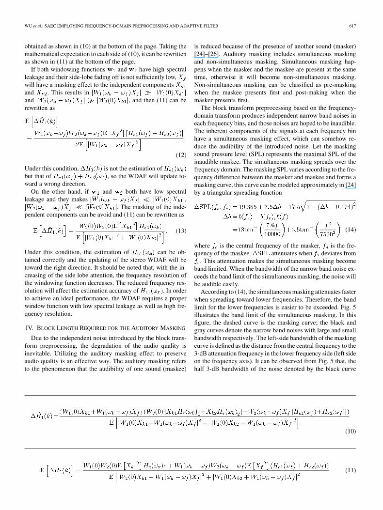
obtained as shown in (10) at the bottom of the page. Taking themathematical expectation to each side of (10), it can be rewrittenas shown in (11) at the bottom of the page.
If both windowing functions and have high spectralleakage and their side-lobe fading off is not sufficiently low,will have a masking effect to the independent componentsand . This results inand , and then (11) can berewritten as
(12)
Under this condition, is not the estimation ofbut that of , so the WDAF will update to-ward a wrong direction.
On the other hand, if and both have low spectralleakage and they makes ,
. The masking of the inde-pendent components can be avoid and (11) can be rewritten as
(13)
Under this condition, the estimation of can be ob-tained correctly and the updating of the stereo WDAF will betoward the right direction. It should be noted that, with the in-creasing of the side lobe attention, the frequency resolution ofthe windowing function decreases. The reduced frequency res-olution will affect the estimation accuracy of . In orderto achieve an ideal performance, the WDAF requires a properwindow function with low spectral leakage as well as high fre-quency resolution.
IV. BLOCK LENGTH REQUIRED FOR THE AUDITORY MASKING
Due to the independent noise introduced by the block trans-form preprocessing, the degradation of the audio quality isinevitable. Utilizing the auditory masking effect to preserveaudio quality is an effective way. The auditory masking refersto the phenomenon that the audibility of one sound (maskee)
is reduced because of the presence of another sound (masker)[24]–[26]. Auditory masking includes simultaneous maskingand non-simultaneous masking. Simultaneous masking hap-pens when the masker and the maskee are present at the sametime, otherwise it will become non-simultaneous masking.Non-simultaneous masking can be classified as pre-maskingwhen the maskee presents first and post-making when themasker presents first.
The block transform preprocessing based on the frequency-domain transform produces independent narrow band noises ineach frequency bins, and those noises are hoped to be inaudible.The inherent components of the signals at each frequency binhave a simultaneous masking effect, which can somehow re-duce the audibility of the introduced noise. Let the maskingsound pressure level (SPL) represents the maximal SPL of theinaudible maskee. The simultaneous masking spreads over thefrequency domain. The masking SPL varies according to the fre-quency difference between the masker and maskee and forms amasking curve, this curve can be modeled approximately in [24]by a triangular spreading function
(14)
where is the central frequency of the masker, is the fre-quency of the maskee. attenuates when deviates from
. This attenuation makes the simultaneous masking becomeband limited. When the bandwidth of the narrow band noise ex-ceeds the band limit of the simultaneous masking, the noise willbe audible easily.
According to (14), the simultaneous masking attenuates fasterwhen spreading toward lower frequencies. Therefore, the bandlimit for the lower frequencies is easier to be exceeded. Fig. 5illustrates the band limit of the simultaneous masking. In thisfigure, the dashed curve is the masking curve; the black andgray curves denote the narrow band noises with large and smallbandwidth respectively. The left-side bandwidth of the maskingcurve is defined as the distance from the central frequency to the3-dB attenuation frequency in the lower frequency side (left sideon the frequency axis). It can be observed from Fig. 5 that, thehalf 3-dB bandwidth of the noise denoted by the black curve
(10)
(11)

618 IEEE TRANSACTIONS ON AUDIO, SPEECH, AND LANGUAGE PROCESSING, VOL. 19, NO. 3, MARCH 2011
Fig. 5. Band limit of the simultaneous masking.
Fig. 6. Left-side bandwidth of the mask curve at different central frequency.
exceeds the left-side bandwidth as well as the masking curve.In order to reduce the probability of exceeding masking curve,the half 3 dB bandwidth of the noise should be restricted belowthe left-side bandwidth of the masking curve, just as the graycurve denoted in Fig. 5.
The left-side bandwidth of different frequency calculated by(14) is shown in Fig. 6. It can be seen that this bandwidth rangesfrom 60 to 100 Hz while the central frequency is lower than1 kHz. Take 60 Hz as the lower limit, the left-side bandwidthshould be restricted below 120 Hz. Using the frequency-domaintransform preprocessing to produce independent noise, the 3-dBbandwidth of the produced independent noise is determined bythe synthesis window in the frequency-domain transform. Let
be the sampling rate and be the length of the window,the rectangle window has the smallest 3-dB bandwidth whichis about [27]. The length of the rectangle windowshould be larger than , corresponding to the dura-tion of 14.6 ms. For the block transform preprocessing, longerblock length can achieve better audio quality, but results in anundesired long processing delay.
V. UPSAMPLING BLOCK TRANSFORM PREPROCESSING
The band limit of the auditory masking determines the lowerlimit of the processing block length. The analysis in Section IVshows that the duration of the smallest block length is 14.6 ms.In order to reduce the processing delay, a frequency-domainupsampling structure can be used in the block transform pre-processing. In this structure, the signals are analyzed in a short
window and upsampled in frequency domain before the inversetransform. The signals are reconstructed in the long window.Upsampling in frequency domain can increase the length of thesynthesis window equivalently.
Based on the frequency-domain upsampling structure, a lowdelay upsampling block transform preprocessing is designedand shown in Fig. 7. Moreover, the overlapping process is usedto remove the block wise discontinuity, and the non-simulta-neous masking effect is also considered [24]–[26]. When thepost-masking happens, more independent noise can be intro-duced with little audio quality distortion.
Take the first channel as an example, in the upsamplingblock transform preprocessing, the far-end signalis concentrated into a -point (50% overlapped) block
in each iteration, sothe process delay is points. The preprocessing includes sixsteps:Step 1) Apply FFT in the short analysis window
(15)
Step 2) Carry out spectrum process
(16)
where is a -point random vector withvalues from [0.5, 1].
Step 3) Carry out channel equalization
(17)
where is the upsampling ratio and controls theamount of distortion.
Step 4) Upsampling
upsample times (18)
where upsampling is operated by interpolatingzeros.
Step 5) Apply IFFT
(19)
Step 6) Carry out overlapping process
no post-maskingpost-masking
leftshift points (20)
In this step, the post-masking is checked by comparing theblock energy. If the previous block has smaller energy, the post-masking is negative, otherwise post-masking appears. and
are -point slow and fast rising windows, andare -point slow and fast fading off windows. Their shapes

WU et al.: SAEC EMPLOYING FREQUENCY-DOMAIN PREPROCESSING AND ADAPTIVE FILTER 619
Fig. 7. Block diagram of the upsampling block transform preprocessing.
are illustrated in Fig. 7. , , , and satisfyand , where , and
can be obtained by
(21)fades to zero at the ( )th point, where and are
positive parameters used to control the fading off rate. The finalpreprocessed output is obtained by
(22)
For the sample rate of 16 kHz, the rectangle synthesiswindow should be longer than samples.With the upsampling ratio , the block delay of theupsampling block transform process only need to be largerthan 29. The computational complexity of the upsamplingblock preprocessing is . Consider a SAECsystem using -point WDAF, the computational complexity is
. If the filtered output is produced in timedomain delaylessly, the computational complexity increasesto . With the configuration of ,
and , the computational complexity of theupsampling block preprocessing only accounts for 38% of theSAEC, and 6.9% of the delayless SAEC.
VI. SIMULATIONS
In order to show the properties of the proposed stereo WDAFand the upsampling block transform preprocessing (calledthe block preprocessing for short in this section), the stereoaudio quality evaluation and the AEC simulations are carriedout. In the first simulation, objective audio quality evaluation
is arranged for the block preprocessing and half-wave pre-processing. The second simulation includes mono AEC andSAEC simulations. The mono AEC simulation investigates theWDAF and FDAF, and the SAEC simulation investigates theperformance of the stereo WDAF and FDAF with and withoutpreprocessing. There are two preprocessing methods involvedin the SAEC simulation, the half-wave preprocessing and theblock preprocessing. Moreover, the subjective audio quality ofthese two preprocessing methods is evaluated and their abilitiesto improve SAEC performance are compared.
Throughout the simulations, the block preprocessing appliesthe Tukey window to the input signal, the fast fading off window
uses and , the slow fading off windowuses and , the upsampling rate , and
the block length is for 16-kHz sampling rate. Under thisconfiguration, the block preprocessing gives 2-ms processingdelay. The half-wave preprocessing uses forthe left channel and for the right channel.The audio distortion is compared based on signal-to-noise ratio(SNR), which is given by
SNRtotal energy of the orignal signal
total energy of the introduced noise(23)
Both the objective and subjective methods are used in theaudio quality evaluation. The objective evaluation tool is theperceptual evaluation of audio quality (PEAQ) which followsthe ITU-R BS.1387 [28], [29]. The PEAQ gives two measuresincluding the noise to mask ratio (NMR) and the objective dif-ference grade (ODG). The NMR (in dB scale) represents the av-erage distance from the introduced noise to the masking curve.The ODG is an overall measure ranged in . If theintroduced noises are masked well by auditory masking, the
620 IEEE TRANSACTIONS ON AUDIO, SPEECH, AND LANGUAGE PROCESSING, VOL. 19, NO. 3, MARCH 2011
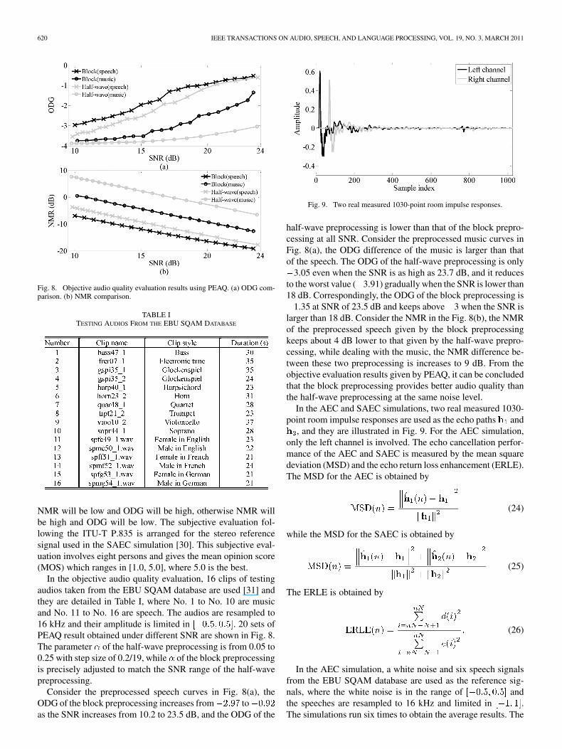
Fig. 8. Objective audio quality evaluation results using PEAQ. (a) ODG com-parison. (b) NMR comparison.
TABLE ITESTING AUDIOS FROM THE EBU SQAM DATABASE
NMR will be low and ODG will be high, otherwise NMR willbe high and ODG will be low. The subjective evaluation fol-lowing the ITU-T P.835 is arranged for the stereo referencesignal used in the SAEC simulation [30]. This subjective eval-uation involves eight persons and gives the mean opinion score(MOS) which ranges in [1.0, 5.0], where 5.0 is the best.
In the objective audio quality evaluation, 16 clips of testingaudios taken from the EBU SQAM database are used [31] andthey are detailed in Table I, where No. 1 to No. 10 are musicand No. 11 to No. 16 are speech. The audios are resampled to16 kHz and their amplitude is limited in . 20 sets ofPEAQ result obtained under different SNR are shown in Fig. 8.The parameter of the half-wave preprocessing is from 0.05 to0.25 with step size of 0.2/19, while of the block preprocessingis precisely adjusted to match the SNR range of the half-wavepreprocessing.
Consider the preprocessed speech curves in Fig. 8(a), theODG of the block preprocessing increases from toas the SNR increases from 10.2 to 23.5 dB, and the ODG of the
Fig. 9. Two real measured 1030-point room impulse responses.
half-wave preprocessing is lower than that of the block prepro-cessing at all SNR. Consider the preprocessed music curves inFig. 8(a), the ODG difference of the music is larger than thatof the speech. The ODG of the half-wave preprocessing is only
3.05 even when the SNR is as high as 23.7 dB, and it reducesto the worst value ( 3.91) gradually when the SNR is lower than18 dB. Correspondingly, the ODG of the block preprocessing is
1.35 at SNR of 23.5 dB and keeps above 3 when the SNR islarger than 18 dB. Consider the NMR in the Fig. 8(b), the NMRof the preprocessed speech given by the block preprocessingkeeps about 4 dB lower to that given by the half-wave prepro-cessing, while dealing with the music, the NMR difference be-tween these two preprocessing is increases to 9 dB. From theobjective evaluation results given by PEAQ, it can be concludedthat the block preprocessing provides better audio quality thanthe half-wave preprocessing at the same noise level.
In the AEC and SAEC simulations, two real measured 1030-point room impulse responses are used as the echo paths and
, and they are illustrated in Fig. 9. For the AEC simulation,only the left channel is involved. The echo cancellation perfor-mance of the AEC and SAEC is measured by the mean squaredeviation (MSD) and the echo return loss enhancement (ERLE).The MSD for the AEC is obtained by
(24)
while the MSD for the SAEC is obtained by
(25)
The ERLE is obtained by
(26)
In the AEC simulation, a white noise and six speech signalsfrom the EBU SQAM database are used as the reference sig-nals, where the white noise is in the range of andthe speeches are resampled to 16 kHz and limited in .The simulations run six times to obtain the average results. The

WU et al.: SAEC EMPLOYING FREQUENCY-DOMAIN PREPROCESSING AND ADAPTIVE FILTER 621
Fig. 10. AEC performance of the WDAF and FDAF.
filter length of the WDAF and FDAF are both 1024, their for-getting factors are 0.1 and they both use the step size whichcan achieve the fastest convergence speed. The WDAF uses theTukey window and the Hanning window. The Tukey windowhas higher side lobe attention than the rectangle window and itsfrequency resolution is slightly decreased, the Hanning windowhas higher side lobe attention than the Tukey window, but withdecreased frequency resolution.
Fig. 10 shows the results of the AEC simulation. The FDAFreaches steady state at about 3.5 s when dealing with the whitenoise, but when dealing with the speech signal, the performanceof the FDAF degrades significantly that the MSD only reaches
39 dB after 12 s. With the reduced spectral leakage, the WDAFusing the Tukey window shows significant improvements that,its speech convergence speed is very close to that of the whitenoise, and its MSD reaches steady state at about 3.5 s and 4.5s when dealing with the white noise and speech signal, respec-tively. The WDAF using the Hanning window gives similar re-sults. However, due to the low frequency resolution of the Han-ning window, the convergence speed is reduced, and the MSDcannot reach steady state at 8 s even dealing with the whitenoise.
In the SAEC simulations, the reference signal is stereo speechwith the sampling rate of 16 kHz and limited in . In thisspeech, the speaker changes twice at 4.1 s and 8.6 s, respec-tively, and an white noise ranged in is added tothe desired signal as an external interference. Three SAECconfigurations without the preprocessing and four SAEC con-figurations with the preprocessing are compared in the SAECsimulations.
The SAEC performances of the three configurations withoutthe preprocessing are shown in Fig. 11. The three configura-tions include the stereo FDAF, the stereo WDAF using the Han-ning window and Tukey window. It can be seen that the stereoFDAF has a poor SAEC performance without preprocessing.The MSD of the stereo FDAF descents slowly and still higherthan 10 dB after 15 s. The ERLE of the stereo FDAF has asimilar ascending speed to that of the stereo WDAF using theHanning window, but after the first speaker change at 4.1 s, theERLE reduces suddenly and keeps a low level for a long time.The stereo WDAF using the Hanning window performs betterthan the FDAF. Its MSD reaches 18 dB after 15 s, but its ERLEstill cannot arise sustainably after the speaker change. The stereo
Fig. 11. SAEC performance of the stereo WDAF and FDAF without prepro-cessing.
TABLE IIFOUR CONFIGURATIONS AND THE AUDIO QUALITY EVALUATION RESULTS
WDAF using the Tukey window gives the best performance. ItsMSD reaches 25 dB after 15 s and its ERLE arises sustainablyafter speaker change. These simulations show that, because theTukey window has a sufficient low side lobe attention and suf-ficient high-frequency resolution, the stereo WDAF using theTukey window has an improved performance in the SAEC en-vironment.
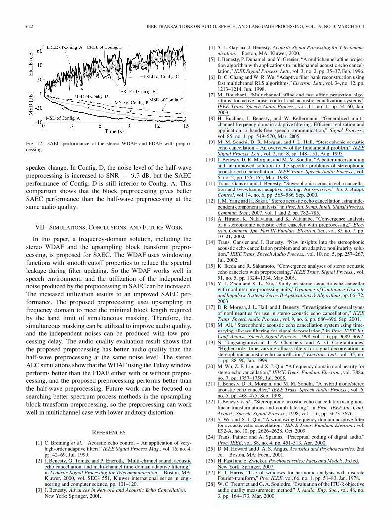
The four SAEC configurations with the preprocessing are de-tailed in Table II. Configs. A and B use the block preprocessing,but use stereo WDAF and FDAF respectively, Configs. C andD use the stereo WDAF and the half-wave preprocessing, whileConfig. D introduces more distortion than Config. C. The stereoWDAF uses the Tukey window. The audio quality evaluation re-sults of the preprocessing are also illustrated in Table II. It canbe seen that the block preprocessing with SNR dB givesthe best audio quality, where the NMR is 17.11 dB and theMOS is 4.75. With the same SNR, the NMR of the half-wavepreprocessing is 14.9 dB and the MOS is 4.63. The half-wavepreprocessing with SNR dB gives an obvious degradedquality, the NMR is only 6.02 dB and the MOS is reduced to3.88.
Fig. 12 gives the SAEC performance of the configurationswith preprocessing. It can be found that Config. A has the bestaudio quality and performs the best. The MSD of Config. Areaches -38 dB after 15 s and the ERLE arises fast and stablyafter speaker change. The performance of Config. B is inferiorto Config. A. Config. B converges slowly and its MSD reaches-35 dB after 15 s. It can be concluded that the stereo WDAFincreases the utilization of the introduced noise equivalently.At the same noise level of SNR dB, the half-wavepreprocessing used in Config. C gives a similar audio qualityto the block preprocessing, but Config. C has the poorest per-formance. The MSD of Config. C decreases slowly and reachesonly -30 dB at 15 s, and the ERLE decreases sharply after
622 IEEE TRANSACTIONS ON AUDIO, SPEECH, AND LANGUAGE PROCESSING, VOL. 19, NO. 3, MARCH 2011
Fig. 12. SAEC performance of the stereo WDAF and FDAF with prepro-cessing.
speaker change. In Config. D, the noise level of the half-wavepreprocessing is increased to SNR dB, but the SAECperformance of Config. D is still inferior to Config. A. Thiscomparison shows that the block preprocessing gives betterSAEC performance than the half-wave preprocessing at thesame audio quality.
VII. SIMULATIONS, CONCLUSIONS, AND FUTURE WORK
In this paper, a frequency-domain solution, including thestereo WDAF and the upsampling block transform prepro-cessing, is proposed for SAEC. The WDAF uses windowingfunctions with smooth cutoff properties to reduce the spectralleakage during filter updating. So the WDAF works well inspeech environment, and the utilization of the independentnoise produced by the preprocessing in SAEC can be increased.The increased utilization results to an improved SAEC per-formance. The proposed preprocessing uses upsampling infrequency domain to meet the minimal block length requiredby the band limit of simultaneous masking. Therefore, thesimultaneous masking can be utilized to improve audio quality,and the independent noises can be produced with low pro-cessing delay. The audio quality evaluation result shows thatthe proposed preprocessing has better audio quality than thehalf-wave preprocessing at the same noise level. The stereoAEC simulations show that the WDAF using the Tukey windowperforms better than the FDAF either with or without prepro-cessing, and the proposed preprocessing performs better thanthe half-wave preprocessing. Future work can be focused onsearching better spectrum process methods in the upsamplingblock transform preprocessing, so the preprocessing can workwell in multichannel case with lower auditory distortion.
REFERENCES
[1] C. Breining et al., “Acoustic echo control – An application of very-high-order adaptive filters,” IEEE Signal Process. Mag., vol. 16, no. 4,pp. 42–69, Jul. 1999.
[2] J. Benesty, G. Tomas, and P. Eneroth, “Multi-channel sound, acousticecho cancellation, and multi-channel time-domain adaptive filtering,”in Acoustic Signal Processing for Telecommunication. Boston, MA:Kluwer, 2000, vol. SECS 551, Kluwer international series in engi-neering and computer science, pp. 101–120.
[3] J. Benesty, Advances in Network and Acoustic Echo Cancellation.New York: Springer, 2001.
[4] S. L. Gay and J. Benesty, Acoustic Signal Processing for Telecommu-nication. Boston, MA: Kluwer, 2000.
[5] J. Benesty, P. Duhamel, and Y. Grenier, “A multichannel affine projec-tion algorithm with applications to multichannel acoustic echo cancel-lation,” IEEE Signal Process. Lett., vol. 3, no. 2, pp. 35–37, Feb. 1996.
[6] D. C. Chang and W. R. Wu, “Adaptive filter bank reconstruction usingfast multichannel RLS algorithms,” Electron. Lett., vol. 34, no. 12, pp.1213–1214, Jun. 1998.
[7] M. Bouchard, “Multichannel affine and fast affine projection algo-rithms for active noise control and acoustic equalization systems,”IEEE Trans. Speech Audio Process., vol. 11, no. 1, pp. 54–60, Jan.2003.
[8] H. Buchner, J. Benesty, and W. Kellermann, “Generalized multi-channel frequency-domain adaptive filtering: Efficient realization andapplication to hands-free speech communication,” Signal Process.,vol. 85, no. 3, pp. 549–570, Mar. 2005.
[9] M. M. Sondhi, D. R. Morgan, and J. L. Hall, “Stereophonic acousticecho cancellation – An overview of the fundamental problem,” IEEESignal Process. Lett., vol. 2, no. 8, pp. 148–151, Aug. 1995.
[10] J. Benesty, D. R. Morgan, and M. M. Sondhi, “A better understandingand an improved solution to the specific problems of stereophonicacoustic echo cancellation,” IEEE Trans. Speech Audio Process., vol.6, no. 2, pp. 156–165, Mar. 1998.
[11] Trans. Gansler and J. Benesty, “Stereophonic acoustic echo cancella-tion and two-channel adaptive filtering: An overview,” Int. J. Adapt.Control, vol. 14, no. 6, pp. 565–586, Sep. 2000.
[12] J. M. Yang and H. Sakai, “Stereo acoustic echo cancellation using inde-pendent component analysis,” in Proc. Int. Symp. Intell. Signal Process.Commun. Syst., 2007, vol. 1 and 2, pp. 782–785.
[13] A. Hirano, K. Nakayama, and K. Watanabe, “Convergence analysisof a stereophonic acoustic echo canceler with preprocessing,” Elec-tron. Commun. Jpn. Part III-Fundam. Electron. Sci., vol. 85, no. 7, pp.10–21, 2002.
[14] Trans. Gansler and J. Benesty, “New insights into the stereophonicacoustic echo cancellation problem and an adaptive nonlinearity solu-tion,” IEEE Trans. Speech Audio Process., vol. 10, no. 5, pp. 257–267,Jul. 2002.
[15] K. Ikeda and R. Sakamoto, “Convergence analyses of stereo acousticecho cancelers with preprocessing,” IEEE Trans. Signal Process., vol.51, no. 5, pp. 1324–1334, May 2003.
[16] Y. J. Zhou and S. L. Xie, “Study on stereo acoustic echo cancellerwith nonlinear pre-processing units,” Dynamics of Continuous Discreteand Impulsive Systems-Series B-Applications & Algorithms, pp. 66–72,2003.
[17] D. R. Morgan, J. L. Hall, and J. Benesty, “Investigation of several typesof nonlinearities for use in stereo acoustic echo cancellation,” IEEETrans. Speech Audio Process., vol. 9, no. 6, pp. 686–696, Sep. 2001.
[18] M. Ali, “Stereophonic acoustic echo cancellation system using time-varying all-pass filtering for signal decorrelation,” in Proc. IEEE Int.Conf. Acoust., Speech, Signal Process., 1998, vol. 1–6, pp. 3689–3692.
[19] N. Tangsangiumvisai, J. A. Chambers, and A. G. Constantinides,“Higher-order time-varying allpass filters for signal decorrelation instereophonic acoustic echo cancellation,” Electron. Lett., vol. 35, no.1, pp. 88–90, Jan. 1999.
[20] M. Wu, Z. B. Lin, and X. J. Qiu, “A frequency domain nonlinearity forstereo echo cancellation,” IEICE Trans. Fundam. Electron., vol. E88a,no. 7, pp. 1757–1759, Jul. 2005.
[21] J. Benesty, D. R. Morgan, and M. M. Sondhi, “A hybrid mono/stereoacoustic echo canceller,” IEEE Trans. Speech Audio Process., vol. 6,no. 5, pp. 468–475, Sep. 1998.
[22] J. Benesty et al., “Stereophonic acoustic echo cancellation using non-linear transformations and comb filtering,” in Proc. IEEE Int. Conf.Acoust., Speech, Signal Process., 1998, vol. 1–6, pp. 3673–3676.
[23] S. Wu and X. J. Qiu, “A windowing frequency domain adaptive filterfor acoustic echo cancellation,” IEICE Trans. Fundam. Electron., vol.E92-A, no. 10, pp. 2626–2628, Oct. 2009.
[24] Trans. Painter and A. Spanias, “Perceptual coding of digital audio,”Proc. IEEE, vol. 88, no. 4, pp. 451–513, Apr. 2000.
[25] D. M. Howard and J. A. S. Angus, Acoustics and Psychoacoustics, 2nded. Boston, MA: Focal, 2001.
[26] H. Fastl and E. Zwicker, Psychoacoustics: Facts and Models, 3rd ed.New York: Springer, 2007.
[27] F. J. Harris, “Use of windows for harmonic-analysis with discreteFourier-transform,” Proc IEEE, vol. 66, no. 1, pp. 51–83, Jan. 1978.
[28] W. C. Treurniet and G. A. Soulodre, “Evaluation of the ITU-R objectiveaudio quality measurement method,” J. Audio. Eng. Soc., vol. 48, no.3, pp. 164–173, Mar. 2000.

WU et al.: SAEC EMPLOYING FREQUENCY-DOMAIN PREPROCESSING AND ADAPTIVE FILTER 623
[29] “Method for objective measurements of perceived audio quality,” 2001,ITU-R Rec. BS.1387-1.
[30] “Subjective test methodology for evaluating speech communicationsystems that include noise suppression algorithm,” 2003, ITU-T Rec.P.835.
[31] “Sound quality assessment material recordings for subjective tests,”Eur. Broadcasting Union, 2004, Rev. Tech. 3253-E.
Sheng Wu graduated with a degree in electronicsfrom Nanjing University, Nanjing, China, in 2004and received the Ph.D. degree from Nanjing Uni-versity in 2009 with a dissertation on acoustic echocancellation.
He has been with the Spreadtrum Communica-tions, Inc., Shanghai, China, as a Research Associatesince 2010. His main research areas include acousticecho cancellation, perceptual audio coding, audiopre/post-processing, and electro-acoustics measure-ment.
Xiaojun Qiu graduated with a degree in electronicsfrom Peking University, Beijing, China, in 1989 andreceived the Ph.D. degree from Nanjing University,Nanjing, China, in 1995 with a dissertation on activenoise control.
He was with the University of Adelaide, Adelaide,Australia, as a Research Fellow from 1997 to 2002.He has been with the Institute of Acoustics, NanjingUniversity, as a Professor in acoustics and signal pro-cessing since 2002. His main research areas includenoise and vibration control, room acoustics, electroa-
coustics, and audio signal processing. He has authored and coauthored morethan 100 technique papers on audio acoustics and audio signal processing.
Prof. Qiu is member of Audio Engineering Society and International Instituteof Acoustics and Vibration.
Ming Wu graduated with a degree in electronics fromNanjing University, Nanjing, China, in 2002 and re-ceived the Ph.D. degree from Nanjing University in2007 with a dissertation on active noise control.
He was with the Institute of Acoustics, NanjingUniversity, as a Postdoctoral Researcher from 2007to 2008. He has been with the Institute of Acous-tics, Chinese Academy of Sciences, Beijing, as anAssociate Research Fellow since 2008. His mainresearch areas include noise and vibration control,electro-acoustics, and audio signal processing.