Flexible calibration technique for fringe-projection-based three-dimensional imaging
Upload
independentCategory
view
1download
0
Steerable spatial phase shifting applied to single-imageclosed-fringe interferograms
Juan Antonio Quiroga,1,* Manuel Servin,2 Julio Cesar Estrada,2
and Jose Antonio Gomez-Pedrero1
1Departamento de Optica, Universidad Complutense de Madrid, Ciudad Universitaria S/N, 28040 Madrid, Spain2Centro de Investigaciones en Optica A.C., Leon, Guanajuato 20036, Mexico
*Corresponding author: [email protected]
Received 22 December 2008; revised 19 March 2009; accepted 19 March 2009;posted 23 March 2009 (Doc. ID 105624); published 16 April 2009
It is well known that spatial phase shifting interferometry (SPSI) may be used to demodulate two-dimensional (2D) spatial-carrier interferograms. In these cases the application of SPSI is straightforwardbecause the modulating phase is a monotonic increasing function of space. However, this is not true whenwe apply SPSI to demodulate a single-image interferogram containing closed fringes. This is becauseusing these algorithms, one would obtain a wrongly demodulated monotonic phase all over the 2D space.We present a technique to overcome this drawback and to allow any SPSI algorithm to be used as asingle-image fringe pattern demodulator containing closed fringes. We make use of the 2D spatial orien-tation direction of the fringes to steer (orient) the one-dimensional SPSI algorithm in order to correctlydemodulate the nonmonotonic 2D phase all over the interferogram. © 2009 Optical Society of America
OCIS codes: 050.5080, 100.5070, 120.5050, 120.3180.
1. Introduction
In optical metrology, the use of single-image interfer-ogram techniques is of great interest in applicationswhere the use of temporal methods is difficult be-cause of the fast nature of the measured phenomena.In this case, the Fourier transform method can beapplied to each single-image interferogram [1].Although the Fourier transform method has manyadvantages, it has two main drawbacks. First, thetechnique assumes open-fringe interferograms forwhich the phase is a monotonically increasing func-tion of space and therefore cannot be applied to thegeneral case of single-image closed-fringe interfero-grams. Second, the processing of interferograms withnonrectangular areas of interest generates errors atthe borders, which in turn must be corrected.In direct space, the spatial phase shifting inter-
ferometry (SPSI) methods are a good alternative tothe Fourier transform method. However, as with
the Fourier method, they cannot be applied to thecase of single-image closed-fringe patterns with non-monotonic two-dimensional (2D) modulating phases.To demodulate single-image closed-fringe interfero-grams in direct space, we can apply regularizationtechniques [2–4], although they lack the simplicityand processing speed of spatial phase shifting meth-ods. These regularization techniques were the firstsingle-image closed-fringe demodulation methods;however, they have some disadvantages. These pro-blems are mainly the regularization parameter tun-ing process, the nonlinear character of the phasedemodulation, the intensive computing to minimizethe local cost function, and the simultaneous compu-tation of phase and spatial frequencies. In this direc-tion, Marroquin et al. [4] were the first to drawattention to the usefulness of decoupling the direc-tion and the spatial frequency computation for thephase demodulation from a single interferogram.This insight was also implicit in the fringe-followingregularized phase tracking based methods [2].
The importance of the direction information wasexplicitly shown by Larkin et al. [5] when they
0003-6935/09/122401-09$15.00/0© 2009 Optical Society of America
20 April 2009 / Vol. 48, No. 12 / APPLIED OPTICS 2401

demonstrated how the interferogram direction angle[6] can be applied to the Fourier analysis of single-image closed-fringe interferograms. This techniquecomputes the phase of a single pattern by first apply-ing a frequency filter (the vortex) and then correctingthe obtained phase using the direction angle. Also,this method can be used with carrier fringe (open-fringe) interferograms in which only the orientationangle is necessary [7]. Onodera et al. [8] presented a2D Hilbert transform based on direct space discreti-zation of the vortex filter where, again, the directionis the key to process 2D closed-fringe interferograms.In this work, we demonstrate how the orientation-
direction information can be used to generalize anyone-dimensional (1D) SPSI method to the generalcase of demodulating single-image closed-fringe in-terferograms with nonmonotonic 2D phase all overthe area of interest. The proposed technique sharesthe simplicity and speed of the spatial SPSI methods,making possible the extension of any SPSI method tothe demodulation of closed-fringe single-image inter-ferograms. Working in direct space, it can naturallyprocess irregular areas of interest with minimizedborder effects. In this way the proposed method isa direct space alternative to the Fourier methodfor single-image closed-fringe interferograms.
2. Steerable Spatial Phase Shifting
A. One-Dimensional Spatial Phase Shifting Interferometryand the Sign Problem
When thinking about the use of SPSI methods, thesimplest case is a monochromatic 1D interferometricsignal given by
sðxÞ ¼ bðxÞ þmðxÞ cosðϕ0 þ ω0xÞ; ð1Þwhere b and m are the background and modulationsignals, ω0 is a constant spatial frequency, and ϕ0 isthe modulating phase in which we are interested. Inthis case, the modulating phase is a lineally increas-ing function of the space, and therefore it can be de-modulated using synchronous SPSI methods. Allsynchronous SPSI techniques can be described bya quadrature filter gðxÞ, tuned at ω0, with a frequencyresponse GðωÞ ¼ FT½gðxÞ� that fulfills
Gð0Þ ¼ 0; Gðω0Þ ¼ 0; Gð−ω0Þ ≠ 0: ð2ÞDue to the Hermitian symmetry of the Fourier
transform of a real signal and the fact that the signalis monotonic, the negative (or positive) frequenciesare superfluous. Equation (2) represents the basicidea behind any quadrature filter; by eliminatingthe negative frequencies of the signal spectrum, itis possible to obtain a complex representation fromwhich certain attributes of the signal become moreaccessible, for example, the phase, to facilitate thederivation of demodulation techniques. If we applythe generic filter described by Eq. (2) to the mono-chromatic fringe pattern of Eq. (1), we generate acomplex phasor given by
AðxÞ ¼ sðxÞ � gðxÞ ¼ mðxÞGð−ω0Þe−iðϕ0þω0xÞ; ð3Þ
from which it is possible to compute the modulatingphase by an arctangent calculation.
A typical example of a synchronous SPSI method isthe three-step synchronous technique [9], which canbe described by the complex filter
gðxÞ ¼ ½2δðxÞ − δðx − 1Þ − δðxþ 1Þ�ð1 − cosω0Þþ i½δðx − 1Þ − δðxþ 1Þ� sinω0; ð4Þ
with frequency response
GðωÞ ¼ 4 sin�ω − ω0
2
�sinω: ð5Þ
We can go one step forward in signal complexityand consider a more general type of interferogramgiven by
sðxÞ ¼ bðxÞ þmðxÞ cos½ϕðxÞ þ ω0x�; ð6Þ
for which the phase is no longer constant but fulfillsjdϕ=dxj ≪ jω0j, that is to say, the total phase is notlinear, but monotonically increasing in space, with lo-cal spatial frequency ωðxÞ ¼ d½ϕðxÞ þ ω0x�=dx > 0. Inthis case, we say that sðxÞ is a quasi-monochromaticinterferogram. To demodulate this signal, we can nolonger use synchronous techniques. Instead, weshould use a detuning insensitive SPSI methodtuned at ω0, with a frequency response satisfying
Gð0Þ ¼ 0; Gðω ≈ ω0Þ ¼ 0; Gðω ≈ −ω0Þ ≠ 0: ð7Þ
Again, as the phase is monotonic with ω > 0, thepositive spatial frequencies are superfluous andcan be filtered. In this case, the returned complexphasor is
AðxÞ ¼ sðxÞ � gðωÞ ¼ mðxÞGðωÞe−iðϕðxÞþω0xÞ
for ω ≈ ω0: ð8Þ
Again, we can demodulate the interferogram phasefrom the phasor given by Eq. (8) by an arctangent op-eration. A typical example of a detuning insensitivemethod is the five-step Hariharan method [10]. Thisfilter is tuned at ω0 ¼ π=2 rad=pixel and can be de-scribed by the next filter,
gðxÞ ¼ ½2δðxÞ − δðx − 2Þ − δðxþ 2Þ�þ 2i½δðx − 1Þ − δðxþ 1Þ�; ð9Þ
with frequency response
GðωÞ ¼ −2 sinωðsinω − 1Þ: ð10Þ
This filter fulfills Eq. (7) around ω0 ¼ π=2, fromwhich it has its detuning insensitive behavior.
2402 APPLIED OPTICS / Vol. 48, No. 12 / 20 April 2009
Finally, the more general case of a 1D interfero-metric signal is
sðxÞ ¼ bðxÞ þmðxÞ cos½ϕðxÞ�: ð11Þ
In this case, the instantaneous spatial frequency,ωðxÞ ¼ dϕ=dx, is only limited by the sampling theo-rem, 0 ≤ jωj ≤ π. Therefore the interferogram phaseis no longer monotonic and can behave arbitrarily.To demodulate this signal, we need a filter that sup-presses all the positive spatial frequencies as well asthe DC term. This would be a filter with a responsegiven by
Gðω > 0Þ ¼ 0; Gðω ≤ 0Þ ≠ 0: ð12Þ
In this case, the complex phasor returned is
AðxÞ ¼ mðxÞGðωÞe−iϕðxÞ: ð13Þ
A good example for a filter of this type is the asyn-chronous five-step method [11]. In this case, theinterferogram is assumed to be locally mono-chromatic with discrete samples given bysk ¼ bþm cos½ϕþ ðk − 2Þω�, k ¼ 1;…; 5, and thephase can be obtained as
tanϕ ¼ signðs2 − s4Þffiffiffiffiffiffiffiffiffiffiffiffiffiffiffiffiffiffiffiffiffiffiffiffiffiffiffiffiffiffiffiffiffiffiffiffiffiffiffiffiffiffiffiffiffiffiffi4ðs2 − s4Þ2 − ðs1 − s5Þ2
p2s3 − ðs1 þ s5Þ
: ð14Þ
This SPSI method is not linear; therefore the fre-quency response cannot be computed by a Fouriertransform. However, for nonlinear methods, the fre-quency response can be calculated as the amplitudeoutput of a signal given by tðxÞ ¼ cosωx. In the caseof the five-step asynchronous SPSI, the frequencyresponse is
GðωÞ ¼ 4 sin2ðωÞ; ω > 0: ð15Þ
From the former discussion, in general any 1DSPSI filter will have the form
gðsÞ ¼ f ðsÞ þ ih1ðsÞ; ð16Þ
where f ðsÞ is an even, real high-pass filter that sup-presses the background term f ðbþm cosωxÞ ¼−mFðωÞ cosωx and h1ðsÞ an odd real filter that trans-forms the cosine in a sine, that is, a general Hilbertoperator with h1ðbþm cosωxÞ ¼ −mH1ðωÞ sinωx.The filter spectrum is
GðωÞ ¼ FðωÞ þ iH1ðωÞ: ð17Þ
Additionally, as the general SPSI method g ofEq. (16) is a quadrature filter, it is required thatjFðωÞj ¼ jH1ðωÞj for a given range of spatial frequen-cies. For example, if jFðωÞj ¼ jH1ðωÞj for a single spa-tial frequency ω0, we speak of synchronous methods,and if jFðωÞj ¼ jH1ðωÞj for 0 ≤ ω ≤ π, we say that the
method is asynchronous. Therefore, given the sym-metries of f and h1 and the relation between theirspectra, G is a real filter that nulls a range of spatialfrequencies.
For example, in the case of the asynchronous five-step method described above,
h1ðsÞ ¼ signðs2 − s4Þffiffiffiffiffiffiffiffiffiffiffiffiffiffiffiffiffiffiffiffiffiffiffiffiffiffiffiffiffiffiffiffiffiffiffiffiffiffiffiffiffiffiffiffiffiffiffi4ðs2 − s4Þ2 − ðs1 − s5Þ2
q
¼ 4m sin2 ω sinϕ;f ðsÞ ¼ 2s3 − ðs1 þ s5Þ ¼ 4m sin2 ω cosϕ; ð18Þ
with jFðωÞj ¼ jH1ðωÞj ¼ 4m sin2 ω, ω > 0.Summarizing, all SPSI methods, linear or not, gen-
erate a complex phasor from which the phase can beextracted by an arctangent calculation. The range offrequencies for which the phasor are well calculateddepends on the type of SPSI method. Moreover, theelection depends on the frequency contents of theinterferogram.
However, in the general case of a nonmonotonicphase, it is important not to forget an important de-tail: all the SPSI methods assume that the modulat-ing phase is monotonic, which means that all thespatial frequencies have the same sign. As a result,the recovered phase is also monotonic. In the case ofa nonmonotonic phase, all SPSI methods will demo-dulate a wrong monotonic phase, losing in this waythe phase sign.
Analytically, we can obtain this result using thegeneral quadrature transform. This operator canbe expressed as a generalized Hilbert filter multi-plied by the fringe direction angle. From [12], thegeneral expression for the Hilbert transform in theN-dimensional case is
hNðsÞ ¼∇sj∇ϕj ¼ −m sinϕ ω
jωj ¼ −m sinϕ · n; ð19Þ
where ω ¼ ð∂ϕ=∂x1;…; ∂ϕ=∂xNÞ is theN-dimensionalspatial frequency vector, and n ¼ ω=jωj is the fringedirection vector [6]. In the 1D case the general ex-pression (19) reduces to
h1ðsÞ ¼ds=dxdϕ=dx ¼ −m sinϕ ω
jωj¼ −m sinϕ · signðωÞ: ð20Þ
From Eq. (19), we see that the general expressionfor the Hilbert transform is a nonlinear operator.Also, Eq. (19) states that to obtain the quadratureterm of a interferogram, it is always necessary to cor-rect the Hilbert transform by the direction vector n,
qNðsÞ ¼ hNðsÞ · n ¼ −m sinϕ; ð21Þ
where qNðsÞ is the N-dimensional quadrature signalcorresponding to m cosϕ. In the 1D case we have
20 April 2009 / Vol. 48, No. 12 / APPLIED OPTICS 2403
q1ðsÞ ¼ h1ðsÞ · signðωÞ ¼ −m sinϕ: ð22Þ
Therefore all Hilbert transform implementationshave to deal with the spatial frequency sign. Inthe frequency domain, the Hilbert transform canbe efficiently implemented by anN-dimensional Reistransform [5,12] that has a uniform frequencyresponse with jHðωÞj ¼ 1. However, in the space do-main with a limited number of samples, we have onlyapproximations to this behavior.From this discussion, in the case of a 1D nonmono-
tonic signal, the complex phasor returned by anySPSI method must be corrected by the spatial fre-quency sign in order to compute correctly the phase.Therefore from Eq. (20), the complex phasor that weobtain for any SPSI filter is
AðxÞ ¼ mðxÞGðωÞ½cosϕþ i signðωÞ sinϕ�: ð23Þ
B. Two-Dimensional Steerable Spatial Phase Shifting
In the former section, we have shown the importanceof the spatial frequency sign in the demodulation of a1D signal using any SPSI method. In the case of a 2Dclosed-fringe interferogram, the role of the spatialfrequency sign is assumed by the fringe direction an-gle. From the general expression of the Hilbert trans-form given by Eq. (19), the components of the Hilberttransform in the case of a general 2D interferogramgiven by
sðx; yÞ ¼ bðx; yÞ þmðx; yÞ cos½ϕðx; yÞ� ð24Þ
are
h2x½sðx; yÞ� ¼ds=dxj∇ϕj ¼ −m sinϕ ωx
jωj¼ −m sinϕ cos β;
h2y½sðx; yÞ� ¼ds=dyj∇ϕj ¼ −m sinϕ ωy
jωj¼ −m sinϕ sin β; ð25Þ
where β is the fringe direction angle, defined as theangle subtended by the fringe direction vector withthe x axis [6]. From Eq. (25), if we apply any SPSIfilter g along the x coordinate to a 2D interferogram,we obtain a phasor given by
Axðx; yÞ ¼ mðx; yÞGðωxÞ½cosϕþ i cos β sinϕ�: ð26Þ
Therefore the recovered quadrature term ismodulated by cos β, and if ωx ≈ 0 (cos β ≈ 0), thenthe recovered phase is zero independently of ϕ.The same problem appears if we apply the sameSPSI method in the y direction. In this case thephasor signal is
Ayðx; yÞ ¼ mðx; yÞGðωyÞ½cosϕþ i sin β sinϕ�; ð27Þ
and the quadrature term is modulated by sin β.Therefore, for ωy ≈ 0 (sin β ≈ 0), the recovered phaseis zero independently of ϕ.
A closed-fringe interferogram has a nonmonotonicphase with positive and negative 2D spatial frequen-cies in x and y. If we apply a 1D SPSI method, even inthe case that we do correct for the direction angle, wehave a wrongly demodulated phase.
The solution for this problem is to compute the 2Dquadrature term incorporating the direction infor-mation, “steering” in this way the 1D SPSI filteralong the fringe direction. Then, if gðsÞ ¼f ðsÞ þ ihðsÞ is a 1D SPSI filter, the quadrature termis obtained using Eq. (21) as
q2ðsÞ ¼ ½h2xðsÞ;h2yðsÞ� · n¼ h2xðsÞ cos β þ h2yðsÞ sin β¼ −m½GðωxÞ þGðωyÞ� sinϕ; ð28Þ
where h2x and h2y correspond to the same Hilbert fil-ter applied in the x and y directions, respectively.From Eq. (28), the general formula to “steer” any1D SPSI method is
tanϕ ¼ h2xðsÞ cos β þ h2yðsÞ sin βf xðsÞ þ f yðsÞ
; ð29Þ
and the frequency response of the methodis GðωÞ ¼ GðωxÞ þGðωyÞ.
For example, if we assume that locally our interfer-ogram is monochromatic, we can always express it as
sðk; lÞ ¼ bþm cos½ϕþ ðk − 2Þωx þ ðl − 2Þωy�;k; l ¼ 1;…; 5; ð30Þ
and we can apply the five-step asynchronous method[11] along rows
h2xðsÞ ¼ signðs2;l − s4;lÞffiffiffiffiffiffiffiffiffiffiffiffiffiffiffiffiffiffiffiffiffiffiffiffiffiffiffiffiffiffiffiffiffiffiffiffiffiffiffiffiffiffiffiffiffiffiffiffiffiffiffiffiffiffiffi4ðs2;l − s4;lÞ2 − ðs1;l − s5;lÞ2
q
¼ 4m sin2ωx cos β sinϕ;f xðsÞ ¼ 2s3;l − ðs1;l þ s5;lÞ ¼ 4m sin2 ωx cosϕ; ð31Þ
and along columns
h2yðsÞ ¼ signðsk;2 − sk;4Þffiffiffiffiffiffiffiffiffiffiffiffiffiffiffiffiffiffiffiffiffiffiffiffiffiffiffiffiffiffiffiffiffiffiffiffiffiffiffiffiffiffiffiffiffiffiffiffiffiffiffiffiffiffiffiffiffiffi4ðsk;2 − sk;4Þ2 − ðsk;1 − sk;5Þ2
q
¼ 4m sin2ωx sin β sinϕ;f yðsÞ ¼ 2sk;3 − ðsk;1 þ sk;5Þ ¼ 4m sin2ωy cosϕ: ð32Þ
Finally, the phase is computed using Eq. (29). Forthis 2D SPSI method the frequency responseis GðωÞ ¼ 4mðsin2 ωx þ sin2 ωyÞ.
Another example is the five-step Hariharanmethod [10] that was designed for ωx;ωy ≈
π=2 rad=sample. In this case, the SPSI filter is givenby Eq. (9) along rows
2404 APPLIED OPTICS / Vol. 48, No. 12 / 20 April 2009
h2xðsÞ ¼ 2ðs2;l − s4;lÞ ¼ 4m sin2ωx cos β sinϕ;f xðsÞ ¼ 2s3;l − ðs1;l þ s5;lÞ ¼ 4m sin2ωx cosϕ; ð33Þ
and along columns
h2yðsÞ ¼ 2ðsk;2 − sk;4Þ ¼ 4m sin2ωy sin β sinϕ;f yðsÞ ¼ 2sk;3 − ðsk;1 þ sk;5Þ ¼ 4m sin2 ωy cosϕ: ð34Þ
Again, the phase is computed using Eq. (29). For thismethod, outside the range ωx;ωy ≈ π=2 the recoveredphase presents periodic detuning errors, and the fre-quency response is GðωÞ ¼ 4mðsin2 ωx þ sin2 ωyÞ,ωx;ωy ≈ π=2. It is not surprising that the frequencyresponse coincides with that of the five-step non-linear asynchronous method of Eqs. (31) and (32).In fact, for ω ≈ π=2 ðs1 − s5 ≈ 0Þ, the asynchronousmethod becomes the linear Hariharan technique.Although we have centered our discussion on the
use of 1D SPSI methods, the presented techniquecan be generalized to any 1D phase demodulationtechnique as, for example, the 1D wavelet transform[13], the windowed Fourier transform [14], or the 1Dphase lock loop [15].Finally, we must mention the effect of using the or-
ientation angle instead of the fringe direction forclosed-fringe interferograms. The orientation anglecan be computed directly from the irradiance [7];however, in the case of closed fringes, it cannot de-scribe the complete set of fringe directions. This isbecause the orientation is defined modulo π (fromthe local irradiance, we do not know if a fringe isdirected “left” or “right”); then if θ is the orientationangle,
θ ¼ β � Kπ; ð35Þ
where K is an integer such that 0 ≤ θ ≤ π. FromEq. (35),
cos θ ¼ ð−1ÞK cos β; sin θ ¼ ð−1ÞK sin β: ð36Þ
For open-fringe interferograms,K ¼ 0, and the use oforientation and direction is equivalent; however, inthe case of closed-fringe patterns Kðx; yÞ ¼ f0; 1g, ifwe apply the steering Eq. (29) with the orientationinstead of the direction, we get
tanϕθ ¼ ð−1ÞKðx;yÞ tanϕ; ð37Þ
where tanϕθ is the 2D phase recovered by using theorientation. Therefore from Eq. (37) for a closed-fringe interferogram when the direction is biggerthan π or less than 0, a sign change appears in therecovered phase. From the point of view of the spatialfrequencies, to have access only to the orientation isequivalent to ignoring the sign of the ωy component ofthe spatial frequency. As a result, the returned phasewill always be monotonic in the y direction withωy > 0 all over 2D space.
3. Experimental Results
In the examples presented in this section, the orien-tation angle is calculated using the method describedin [7], and the direction angle is computed using thetechnique of Villa et al. [6].
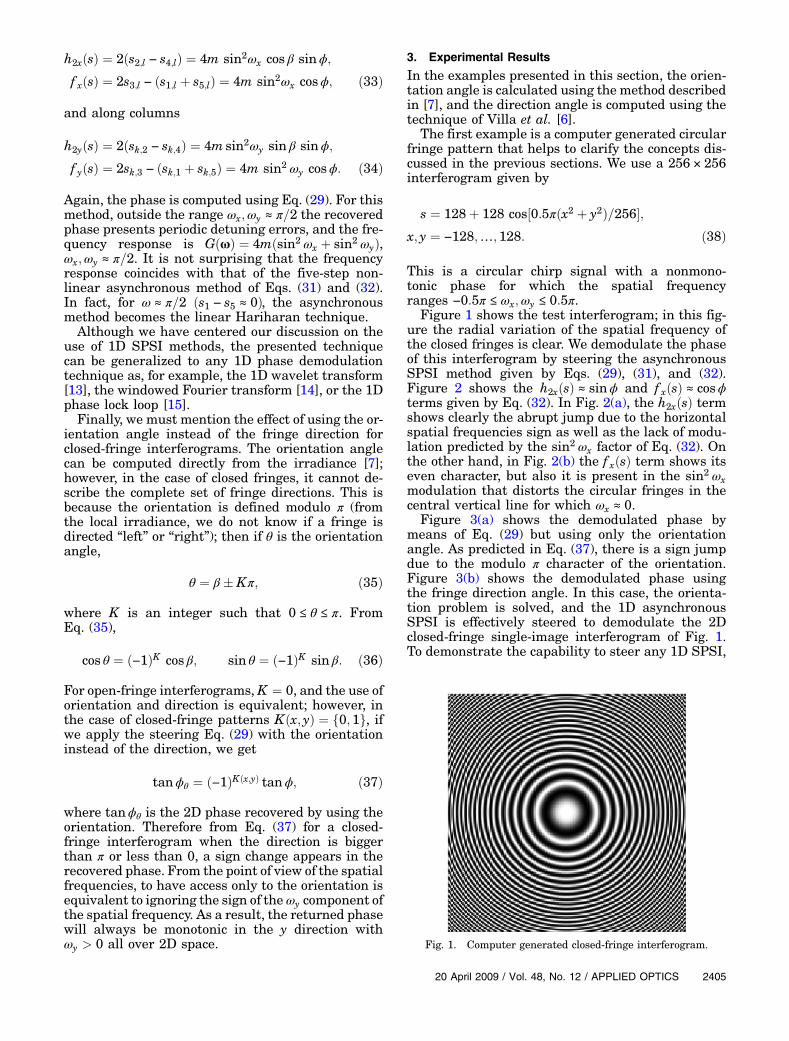
The first example is a computer generated circularfringe pattern that helps to clarify the concepts dis-cussed in the previous sections. We use a 256 × 256interferogram given by
s ¼ 128þ 128 cos½0:5πðx2 þ y2Þ=256�;x; y ¼ −128;…; 128: ð38Þ
This is a circular chirp signal with a nonmono-tonic phase for which the spatial frequencyranges −0:5π ≤ ωx;ωy ≤ 0:5π.
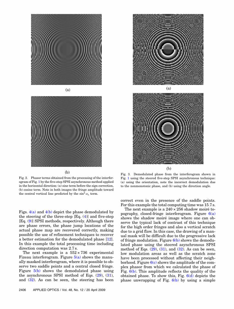
Figure 1 shows the test interferogram; in this fig-ure the radial variation of the spatial frequency ofthe closed fringes is clear. We demodulate the phaseof this interferogram by steering the asynchronousSPSI method given by Eqs. (29), (31), and (32).Figure 2 shows the h2xðsÞ ≈ sinϕ and f xðsÞ ≈ cosϕterms given by Eq. (32). In Fig. 2(a), the h2xðsÞ termshows clearly the abrupt jump due to the horizontalspatial frequencies sign as well as the lack of modu-lation predicted by the sin2 ωx factor of Eq. (32). Onthe other hand, in Fig. 2(b) the f xðsÞ term shows itseven character, but also it is present in the sin2 ωxmodulation that distorts the circular fringes in thecentral vertical line for which ωx ≈ 0.
Figure 3(a) shows the demodulated phase bymeans of Eq. (29) but using only the orientationangle. As predicted in Eq. (37), there is a sign jumpdue to the modulo π character of the orientation.Figure 3(b) shows the demodulated phase usingthe fringe direction angle. In this case, the orienta-tion problem is solved, and the 1D asynchronousSPSI is effectively steered to demodulate the 2Dclosed-fringe single-image interferogram of Fig. 1.To demonstrate the capability to steer any 1D SPSI,
Fig. 1. Computer generated closed-fringe interferogram.
20 April 2009 / Vol. 48, No. 12 / APPLIED OPTICS 2405
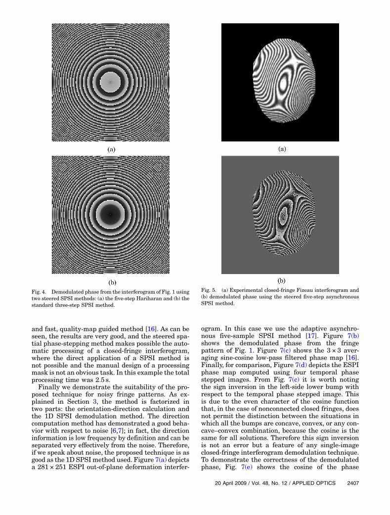
Figs. 4(a) and 4(b) depict the phase demodulated bythe steering of the three-step [Eq. (4)] and five-step[Eq. (9)] SPSI methods, respectively. Although thereare phase errors, the phase jump locations of theactual phase map are recovered correctly, makingpossible the use of refinement techniques to recovera better estimation for the demodulated phase [12].In this example the total processing time includingdirection computation was 2:7 s.The next example is a 552 × 736 experimental
Fizeau interferogram. Figure 5(a) shows the manu-ally masked interferogram, where it is possible to ob-serve two saddle points and a central closed fringe.Figure 5(b) shows the demodulated phase usingthe asynchronous SPSI method of Eqs. (29), (31),and (32). As can be seen, the steering has been
correct even in the presence of the saddle points.For this example the total computing time was 15:7 s.
The next example is a 240 × 256 shadow moiré to-pography, closed-fringe interferogram. Figure 6(a)shows the shadow moiré image where one can ob-serve the typical lack of contrast of this techniquefor the high order fringes and also a vertical scratchdue to a grid flaw. In this case, the drawing of a man-ual mask will be difficult due to the progressive lackof fringe modulation. Figure 6(b) shows the demodu-lated phase using the steered asynchronous SPSImethod of Eqs. (29), (31), and (32). As can be seen,low modulation areas as well as the scratch zonehave been processed without affecting their neigh-borhood. Figure 6(c) shows the amplitude of the com-plex phasor from which we calculated the phase ofFig. 6(b). This amplitude reflects the quality of theobtained phase. To show this, Fig. 6(d) depicts thephase unwrapping of Fig. 6(b) by using a simple
Fig. 2. Phasor terms obtained from the processing of the interfer-ogram of Fig. 1 by the five-step SPSI asynchronousmethod appliedin the horizontal direction: (a) sine term before the sign correction,(b) cosine term. Note in both images the fringe amplitude towardthe central vertical line predicted by the sin2 ωx term.
Fig. 3. Demodulated phase from the interferogram shown inFig. 1 using the steered five-step SPSI asynchronous technique:(a) using the orientation, note the incorrect demodulation dueto the nonmonotonic phase, and (b) using the direction angle.
2406 APPLIED OPTICS / Vol. 48, No. 12 / 20 April 2009
and fast, quality-map guided method [16]. As can beseen, the results are very good, and the steered spa-tial phase-stepping method makes possible the auto-matic processing of a closed-fringe interferogram,where the direct application of a SPSI method isnot possible and the manual design of a processingmask is not an obvious task. In this example the totalprocessing time was 2:5 s.Finally we demonstrate the suitability of the pro-
posed technique for noisy fringe patterns. As ex-plained in Section 3, the method is factorized intwo parts: the orientation-direction calculation andthe 1D SPSI demodulation method. The directioncomputation method has demonstrated a good beha-vior with respect to noise [6,7]; in fact, the directioninformation is low frequency by definition and can beseparated very effectively from the noise. Therefore,if we speak about noise, the proposed technique is asgood as the 1D SPSImethod used. Figure 7(a) depictsa 281 × 251 ESPI out-of-plane deformation interfer-
ogram. In this case we use the adaptive asynchro-nous five-sample SPSI method [17]. Figure 7(b)shows the demodulated phase from the fringepattern of Fig. 1. Figure 7(c) shows the 3 × 3 aver-aging sine-cosine low-pass filtered phase map [16].Finally, for comparison, Figure 7(d) depicts the ESPIphase map computed using four temporal phasestepped images. From Fig. 7(c) it is worth notingthe sign inversion in the left-side lower bump withrespect to the temporal phase stepped image. Thisis due to the even character of the cosine functionthat, in the case of nonconnected closed fringes, doesnot permit the distinction between the situations inwhich all the bumps are concave, convex, or any con-cave–convex combination, because the cosine is thesame for all solutions. Therefore this sign inversionis not an error but a feature of any single-imageclosed-fringe interferogram demodulation technique.To demonstrate the correctness of the demodulatedphase, Fig. 7(e) shows the cosine of the phase
Fig. 4. Demodulated phase from the interferogram of Fig. 1 usingtwo steered SPSI methods: (a) the five-step Hariharan and (b) thestandard three-step SPSI method.
Fig. 5. (a) Experimental closed-fringe Fizeau interferogram and(b) demodulated phase using the steered five-step asynchronousSPSI method.
20 April 2009 / Vol. 48, No. 12 / APPLIED OPTICS 2407
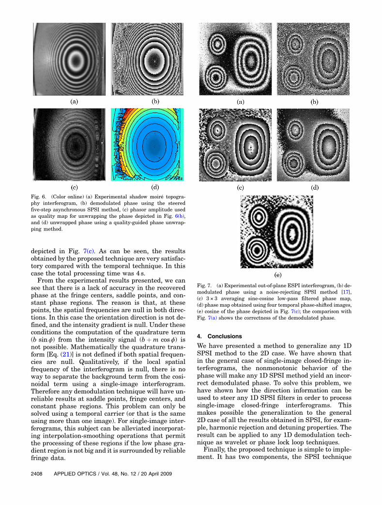
depicted in Fig. 7(c). As can be seen, the resultsobtained by the proposed technique are very satisfac-tory compared with the temporal technique. In thiscase the total processing time was 4 s.From the experimental results presented, we can
see that there is a lack of accuracy in the recoveredphase at the fringe centers, saddle points, and con-stant phase regions. The reason is that, at thesepoints, the spatial frequencies are null in both direc-tions. In this case the orientation direction is not de-fined, and the intensity gradient is null. Under theseconditions the computation of the quadrature term(b sinϕ) from the intensity signal (bþm cosϕ) isnot possible. Mathematically the quadrature trans-form [Eq. (21)] is not defined if both spatial frequen-cies are null. Qualitatively, if the local spatialfrequency of the interferogram is null, there is noway to separate the background term from the cosi-noidal term using a single-image interferogram.Therefore any demodulation technique will have un-reliable results at saddle points, fringe centers, andconstant phase regions. This problem can only besolved using a temporal carrier (or that is the sameusing more than one image). For single-image inter-ferograms, this subject can be alleviated incorporat-ing interpolation-smoothing operations that permitthe processing of these regions if the low phase gra-dient region is not big and it is surrounded by reliablefringe data.
4. Conclusions
We have presented a method to generalize any 1DSPSI method to the 2D case. We have shown thatin the general case of single-image closed-fringe in-terferograms, the nonmonotonic behavior of thephase will make any 1D SPSI method yield an incor-rect demodulated phase. To solve this problem, wehave shown how the direction information can beused to steer any 1D SPSI filters in order to processsingle-image closed-fringe interferograms. Thismakes possible the generalization to the general2D case of all the results obtained in SPSI, for exam-ple, harmonic rejection and detuning properties. Theresult can be applied to any 1D demodulation tech-nique as wavelet or phase lock loop techniques.
Finally, the proposed technique is simple to imple-ment. It has two components, the SPSI technique
Fig. 6. (Color online) (a) Experimental shadow moiré topogra-phy interferogram, (b) demodulated phase using the steeredfive-step asynchronous SPSI method, (c) phasor amplitude usedas quality map for unwrapping the phase depicted in Fig. 6(b),and (d) unwrapped phase using a quality-guided phase unwrap-ping method.
Fig. 7. (a) Experimental out-of-plane ESPI interferogram, (b) de-modulated phase using a noise-rejecting SPSI method [17],(c) 3 × 3 averaging sine-cosine low-pass filtered phase map,(d) phase map obtained using four temporal phase-shifted images,(e) cosine of the phase depicted in Fig. 7(c); the comparison withFig. 7(a) shows the correctness of the demodulated phase.
2408 APPLIED OPTICS / Vol. 48, No. 12 / 20 April 2009

and the orientation-direction computation. The 1DSPSI techniques used can be as simple as the linearmethods discussed in this work or as elaborate as a1D spatial wavelet transform. The orientation calcu-lation is a straightforward arctangent operationusing the intensity gradient [7], and the directioncomputation method is based on a path-followingtechnique with a linear local computation [6]. There-fore, unless a complicated demodulator is used, the2D generalization of any 1D SPSI method can bedone using exclusively linear operations and path-following techniques.
We thank the Ministerio de Ciencia y Tecnología ofSpain for the financial support of this work given byproject DPI2005-03891. Also M. Servin and J. C.Estrada acknowledge the financial support of theMexican Consejo Nacional de Ciencia y Tecnologia(CONACYT).
References1. M. Takeda and K. Mutoh, “Fourier transform profilometry for
the automatic measurement of 3-D object shapes,” Appl. Opt.22, 3977–3982 (1983).
2. M. Servin, J. L. Marroquin, and F. Cuevas, “Fringe-followerregularized phase tracker for demodulation of closed-fringe interferograms,” J. Opt. Soc. Am. A 18, 689–695(2001).
3. J. L. Marroquin, M. Rivera, S. Botello, R. Rodriguez-Vera, andM. Servin, “Regularization methods for processing fringe-pattern images,” Appl. Opt. 38, 788–794 (1999).
4. J. L. Marroquin, R. Rodriguez-Vera, and M. Servin, “Localphase from local orientation by solution of a sequence of linearsystems,” J. Opt. Soc. Am. A 15, 1536–44 (1998).
5. K. Larkin, D. J. Bone, and M. A. Oldfield, “Natural demodula-tion of two-dimensional fringe patterns. I. General back-ground of the spiral phase quadrature transform,” J. Opt.Soc. Am. A 18, 1862–1870 (2001).
6. J. Villa, I. De la Rosa, G. Miramontes, and J. A. Quiroga,“Phase recovery from a single fringe pattern using an orienta-tional vector-field-regularized estimator,” J. Opt. Soc. Am. A22, 2766–2773 (2005).
7. X. Yang, Q. Yu, and S. Fu, “An algorithm for estimating bothfringe orientation and fringe density,” Opt. Commun. 274,286–292 (2007).
8. R. Onodera, Y. Yamamoto, and Y. Ishii, “Signal processing ofinterferogram using a two-dimensional discrete Hilbert trans-form,” inProceedings of Fringe 2005, Fifth International Work-shop on Automatic Processing of Fringe Patterns,W. Osten, ed. (European Space Agency, 2005), pp. 82–89.
9. C. J. Morgan, “Least-squares estimation in phase-measure-ment interferometry,” Opt. Lett. 7, 368–370 (1982).
10. P. Hariharan, B. F. Oreb, and T. Eiju, “Digital phase-shiftinginterferometry: a simple error-compensating phase calcula-tion algorithm,” Appl. Opt. 26, 2504–2506 (1987).
11. J. A. Gomez Pedrero, J. A. Quiroga, and M. Servín, “Asynchro-nous phase demodulation algorithm for temporal evaluationof fringe patterns with spatial carrier,” J. Mod. Opt. 51, 97–109 (2004).
12. M. Servin, J. A. Quiroga, and J. L. Marroquín, “A general n-dimensional quadrature transform and its applications to in-terferogram demodulation,” J. Opt. Soc. Am. A 20, 925–934 (2003).
13. J. Zhong and J. Weng “Spatial carrier-fringe pattern analysisby means of wavelet transform: wavelet transform profilom-etry,” Appl. Opt. 43, 4993–4998 (2004).
14. Q. Kemao, “Two-dimensional windowed Fourier transform forfringe pattern analysis: principles, applications and imple-mentations,” Opt. Lasers Eng. 45, 304–317 (2007).
15. M. Servin, R. Rodriguez-Vera, and D. Malacara, “Noisy fringepattern demodulation by an iterative phase locked loop,” Opt.Lasers Eng. 23, 355–365 (1995).
16. B. Strobel, “Processing of interferometric phase maps ascomplex-valued phasor images,” Appl. Opt. 35, 2192–2198(1996).
17. J. A. Gómez-Pedrero, J. A. Quiroga, and M. Servin, “Adaptiveasynchronous algorithm for fringe pattern demodulation,”Appl. Opt. 47, 3954–3961 (2008).
20 April 2009 / Vol. 48, No. 12 / APPLIED OPTICS 2409
Copyright © 2022 FDOKUMEN