Steel Design Handbook (Gorenc, Tiyuw & Sam)
425
STEEL DESIGNERS ’ GORENC TINYOU SYAM HANDBOOK BRANKO RON ARUN STEEL DESIGNERS ’ 7 EDITION
-
Upload
independent -
Category
Documents
-
view
0 -
download
0
Transcript of Steel Design Handbook (Gorenc, Tiyuw & Sam)

STEEL DESIGNERS’
GORENC TINYOU SYAM
HANDBOOK
BRANKO RON ARUN This seventh, thoroughly updated edition of Steel Designers’ Handbook will be an invaluable tool to all practising structural engineers, as well as engineering students. It introduces the main concepts relating to design in steel and replaces the sixth edition, published in 1996. This edition has been prepared in response to the new structural Design Actions Standard, AS/ANZ 1170, as well as feedback from users. It is based on Australian Standard (AS) 4100: 1998 and provides added background to that Standard.
The book makes extensive use of worked numerical examples to demonstrate the methods of calculating the capacities of structural elements. These examples have been extensively revised from the previous edition, with further examples added. The worked examples are cross-referenced to the relevant clauses in AS 4100: 1998.
Between them, the authors have close to 100 years’ experience of solving engineering problems. All three have practised in all phases of the design and specifi cations of steel structures ranging from commercial to institutional structures; while two, Arun Syam and Branko Gorenc, have served on numerous Standard Australia committees related to steel construction.
U N S W P R E S S
STEEL DESIGNERS ’
GORENC TINYOU SYAM
UNSWP R E S S
HAND BOOK
7E D I T I ON
77E D I T I O N
steeldesigncover.indd 1 17/6/05 3:34:35 PM

STEELD E S I G N E R S ’
HANDBOOK
BRANKO E GORENC is a Fellow of The Institution ofEngineers, Australia, and holds a degree in CivilEngineering from the University of Zagreb, Croatia. He hasbeen practising in the field of structural steel design for fourdecades, gaining considerable expertise in the areas ofconceptual framing design and analysis, member andconnection design. He has designed and led the team ofdesigners in a range of notable structures for bulk storage,sports facilities, wide-bodied aircraft hangars and steel-framed buildings for commerce and industry.
RON TINYOU holds the Degree of Bachelor inEngineering from the University of Sydney. He is a memberof The Institution of Engineers, Australia. Ron has practisedmainly in structural engineering over a wide range ofindustrial and hydraulic structures. Subsequently he wasappointed Senior Head Teacher at the Sydney Institute ofTechnology teaching structural engineering and as a lecturerat the University of Technology, Sydney, specialising in steelstructures.
ARUN A SYAM holds Bachelor and Masters degrees inengineering from the University of Sydney, is a CorporateMember of The Institution of Engineers, Australia and has aCertificate in Arc Welding. Following his studies he wasemployed as a Structural Design Engineer with severalengineering firms and has held all senior technical positionswith the Australian Institute of Steel Construction (nowAustralian Steel Institute). He has significant involvementwith steel design and fabrication, Standards Australia,national steel issues, industry publications/software, weldercertification and lecturing on steelwork around the world.Arun has authored and edited numerous well-knownsteelwork publications and is currently the ExecutiveManager—Applications Engineering & Marketing ofSmorgon Steel Tube Mills.
7EDITION
1106 SDHB 00-04 Final 8/6/05 12:03 PM Page i

1106 SDHB 00-04 Final 8/6/05 12:03 PM Page ii

STEELD E S I G N E R S ’
HANDBOOK
7EDITION
UNSWPRESS
BRANKO GORENC, RON TINYOU & ARUN SYAM
1106 SDHB 00-04 Final 8/6/05 12:03 PM Page iii

A UNSW Press book
Published byUniversity of New South Wales Press LtdUniversity of New South WalesSydney NSW 2052AUSTRALIA
www.unswpress.com.au
©B.E. Gorenc, R. Tinyou and A.A. Syam 2005First published 1970Second edition 1973Third edition 1976Fourth edition 1981Fifth edition 1984, reprinted with minor revisions 1989Sixth edition 1996, reprinted 2001, 2004Seventh edition 2005
This book is copyright. Apart from any fair dealing for the purpose of private study, research, criticism or review, as permitted under the Copyright Act, no part may be reproduced by any process without written permission. Inquiries should be addressed to the publisher.
National Library of AustraliaCataloguing-in-Publication entry:
Gorenc, B. E. (Branko Edward).Steel designers’ handbook.
7th ed.Includes index.ISBN 0 86840 573 6.
1. Steel, Structural. 2. Structural design. I. Tinyou, R.(Ronald). II. Syam, Arun. III. Title.
624.1821
Design, typesetting and diagrams DiZign Pty LtdPrinter BPACover photographs Credits on page 413.
DisclaimerAll reasonable care was taken to ensure the accuracy and correct interpretation of the provisions of the relevantstandards and the material presented in this publication. To the extent permitted by law, the authors, editors andpublishers of this publication:
(a) will not be held liable in any way, and
(b) expressly disclaim any liability or responsibility
for any loss, damage, costs or expenses incurred in connection with this publication by any person, whether thatperson is the purchaser of this publication or not. Without limitations this includes loss, damage, costs and expensesincurred if any person wholly or partially relies on any part of this publication, and loss, damage, costs and expensesincurred as a result of negligence of the authors, editors and publishers.
WarningThis publication is not intended to be used without reference to, or a working knowledge of, the appropriatecurrent Australian and Australian/New Zealand Standards, and should not be used by persons without thoroughprofessional training in the specialised fields covered herein or persons under supervisors lacking this training.
1106 SDHB 00-04 Final 8/6/05 12:03 PM Page iv

Preface ix
chapter 1 Introduction 11.1 Developments in steel structures 11.2 Engineering design process 21.3 Standards and codes of practice 41.4 General structural design principles 51.5 Limit states design method 51.6 Combination of actions 81.7 Strength limit state 91.8 Serviceability limit state 101.9 Other limit states 111.10 Other features of AS 4100 111.11 Criteria for economical design and detailing 111.12 Design aids 131.13 Glossary of limit states design terms 131.14 Further reading 14
chapter 2 Material & Design Requirements 152.1 Steel products 152.2 Physical properties of steel 162.3 Steel types and grades 192.4 Scope of material and design codes 242.5 Material properties and characteristics in AS 4100 242.6 Strength limit state capacity reduction factor φ 252.7 Brittle fracture 262.8 Further reading 28
chapter 3 Design Actions 293.1 General 293.2 Permanent actions 293.3 Imposed actions 323.4 Wind actions 333.5 Earthquake actions 353.6 Other actions 363.7 Notional horizontal forces 37
Contents
1106 SDHB 00-04 Final 8/6/05 12:03 PM Page v

3.8 Temperature actions 373.9 Silo loads 383.10 Crane and hoist loads 383.11 Design action combinations 383.12 Further reading 38
chapter 4 Structural Analysis 394.1 Calculation of design action effects 394.2 Forms of structure vs analysis method 404.3 Calculation of second-order effects 434.4 Moment amplification method in detail 454.5 Elastic flexural buckling load of a member 504.6 Calculation of factor for unequal end moments cm 534.7 Examples 554.8 Summary 624.9 Further reading 63
chapter 5 Beams & Girders 645.1 Types of members subject to bending 645.2 Flexural member behaviour 665.3 Bending moment capacity 665.4 Beam segments and restraints 685.5 Detailed design procedure 745.6 Monosymmetrical I-section beams 845.7 Biaxial bending and bending with axial force 855.8 Web shear capacity and web stiffeners 865.9 Composite steel and concrete systems 985.10 Design for serviceability 995.11 Design for economy 995.12 Examples 1005.13 Further reading 129
chapter 6 Compression & Beam-Column Members 1316.1 Types of compression members 1316.2 Members loaded only axially 1326.3 Design of beam-columns 1436.4 Struts in triangulated structures 1506.5 Battened and laced struts 1516.6 Composite steel and concrete columns 1546.7 Restraining systems for columns and beam-columns 1556.8 Economy in the design 1566.9 Examples 1596.10 Further reading 175
vi S T E E L D E S I G N E R S ’ H A N D B O O Kvi S T E E L D E S I G N E R S ’ H A N D B O O K
1106 SDHB 00-04 Final 8/6/05 12:03 PM Page vi

chapter 7 Tension Members 1767.1 Types of tension members 1767.2 Types of construction 1777.3 Evaluation of load effects 1787.4 Verification of member capacity 1797.5 End connection fasteners and detailing 1837.6 Steel rods 1867.7 Steel wire ropes 1867.8 Examples 1897.9 Further reading 193
chapter 8 Connections 1948.1 Connection and detail design 1948.2 Bolted connections 1978.3 Design and verification of bolted connections 2088.4 Connected plate elements 2158.5 Welded connections 2178.6 Types of welded joints 2298.7 Structural design of simple welds 2338.8 Analysis of weld groups 2368.9 Design of connections as a whole 2398.10 Miscellaneous connections 2438.11 Examples 2508.12 Further reading 263
chapter 9 Plastic Design 2649.1 Basic concepts 2649.2 Plastic analysis 2659.3 Member design 2679.4 Beams 2709.5 Beam-columns 2719.6 Deflections 2749.7 Portal frame analysis 2759.8 Examples 2769.9 Further reading 278
chapter 10 Structural Framing 27910.1 Introduction 27910.2 Mill-type buildings 28110.3 Roof trusses 28310.4 Portal frames 28910.5 Steel frames for low-rise buildings 29410.6 Purlins and girts 297
C O N T E N T S vii
1106 SDHB 00-04 Final 8/6/05 12:03 PM Page vii

10.7 Floor systems for industrial buildings 30010.8 Crane runway girders 30210.9 Deflection limits 30410.10 Fire resistance 30610.11 Fatigue 30710.12 Corrosion protection 31810.13 Further reading 320
Appendix A Bibliography 322A.1 Contents 322A.2 Standard and codes 322A.3 References 325A.4 Computer software 330A.5 Steel manufacturer/supplier websites 331A.6 Steel industry association websites 331
Appendix B Elastic Design Method 332B.1 Contents 332B.2 Introduction 332B.3 Elastic section properties 333B.4 Biaxial and triaxial stresses 337B.5 Stresses in connection elements 339B.6 Unsymmetrical bending 339B.7 Beams subject to torsion 340B.8 Further reading 350
Appendix C Design Aids 352C.1 Contents 352C.2 Beam formulae: Moments, shear forces & deflections 353C.3 Section properties & AS 4100 design section capacities 362C.4 Miscellaneous cross-section parameters 382C.5 Information on other construction materials 384C.6 General formulae—miscellaneous 387C.7 Conversion factors 389
Notation 394
Index 406
viii S T E E L D E S I G N E R S ’ H A N D B O O Kviii S T E E L D E S I G N E R S ’ H A N D B O O K
1106 SDHB 00-04 Final 8/6/05 12:03 PM Page viii

The seventh, thoroughly updated edition of the Steel Designers’ Handbook was preparedin response to the 1998 revision of the Australian Steel Structures Standard (AS 4100)and the latest release of the Loading Codes (previously AS 1170 and now renamed asStructural Design Actions—i.e. AS/NZS 1170). The magnitude of revisions and newterminology was such that the first three chapters of the text had to be rewritten. Anadditional impetus for wide-reaching revisions of the text was the three substantialamendments to AS 4100 and changes in related Standards (e.g. welding, bolting,galvanizing, etc.). Finally, the updated literature on the subject and readers’ feedbackhighlighted other areas for clarification or improvement.
The design of steel structures by the limit states design method may be seen to be asomewhat complex subject, and a correct interpretation and application of codeprovisions is required for successful outcomes. This Handbook is not intended to be aself-standing ‘parallel’ steel design code. The authors recommend that readers take thistext as a directory and guide, and subsequently refer to AS 4100, its Commentary andrelated Standards, for a full appreciation of current structural steel design requirements.This text is intended to cover enough material to enable design of everyday structuralframes, members and connections. An expanded list of related Standards and anextensively re-worked bibliography is included in Appendix A. Combined with thereferences listed in the Standards, this should provide a rich background to various designmethods and solutions.
Some rearrangement of material in the sixth edition has been necessary for convenience.The elastic design method in Appendix B now contains the elastic torsion design methodsthat were previously found in Chapter 5 (though there is also some consideration ofplastic/limit states torsion design). The material on brittle fracture was expanded andplaced in Chapter 2 and the fatigue section has been expanded and placed in Chapter 10.Appendix B now covers basic working stress design theory and torsion design.
A lot of effort has been expended in preparing additional numerical examples andrevising others. Examples are now cross-referenced to clauses in AS 4100, otherStandards, design aids and related material for easier interpretation.
During the writing of this edition of the Handbook, the Building Code of Australianoted that the pre-existing AS 1170 series of Loading Standards were running in parallelwith the newer AS/NZS 1170 series of Structural Design Actions (for a transitionperiod). The effect of this has meant the following for the Handbook:• There are slightly differing load factors, suggested deflection limits (AS 1170 used
Appendix B of AS 4100) and notional horizontal forces which are subsequently notedin the relevant parts of the text with additional comment. The load factor calculationsutilised in the Handbook are those listed in AS/NZS 1170
• There is an interplay of the terms ‘load’ and ‘action’, and both terms are usedinterchangeably
• AS 1170 (i.e. AS 4100) notation for design action effects and design capacities are usedin lieu of AS/NZS 1170 notation.
Preface
1106 SDHB 00-04 Final 8/6/05 12:03 PM Page ix

Some other notable changes and additions to the Handbook include:• A section on ‘Further reading’ placed at the end of each Chapter which lists additional
references should extra detailed or background information be required• An expanded and comprehensive list of steel design and related Standards• An expanded, comprehensive and updated bibliography • A new method of referencing items listed in the bibliography (i.e. by Author(s)/
Publishers name then [year]—e.g. Gorenc & Tinyou [1984])• Significant use/reference to other key design aids and publications (e.g. Australian Steel
Institute Design Capacity Tables, etc.) for quick design calculations• Tips, shortcuts and design/fabrication economics presented where possible• Useful links and references to other Standards, websites, manufacturers and suppliers
in the steel construction and related industries (no other similar hard-boundpublication provides this consolidated information)
• Items of conflict listed between Standards and practice• An all-encompassing summary of the Australian (and some parts of the New Zealand)
steel design, specification, fabrication, etc., scene (including fire, fatigue, fabrication,etc. issues)—something not offered by other similar publications.
The following points should also be noted when using the Handbook:• As is normal practice, and in line with the typical precision of data used in structural
design, all calculations and worked examples are generally done to three (3) significantfigures—hence there may be some very minor numerical rounding when comparingcalculated or listed values with those in other references.
• Linear interpolation of tables may generally be undertaken.• The worked examples are for illustrative purposes and consequently some may depart
from actual detail practice (e.g. bolt threads excluded from the shear plane, use of non-standard steel grades, etc.).
• Due to the revision of the 1998 edition of AS 4100 from its 1990 predecessor, thegeneral notation used for the ‘length’ terms has changed from L to l. In most instances,the Handbook refers to l, however, due to other references, both types of ‘length’notation are used interchangeably.
• Section, Figure and Table numbers in the Handbook are referenced with a number inthe text whereas Section, Figure and Table numbers in other references (e.g. AS 4100)are duly noted with the specific reference.
• Most variables for an equation or term are defined near the respective equation/term.However, due to space limitations, in some instances undefined variables are not listed(as they may be self-evident), though the reader may find the substantial ‘Notation’section at the back of the Handbook useful should variables require defining.
Based on feedback over many years, the authors believe the seventh edition should be ofvaluable assistance to engineering students and practising engineers alike. However, inthe interests of ongoing improvement, and as noted in the previous editions, commentsand suggestions from readers are always welcome.
Lastly, the authors also gratefully acknowledge the support, assistance and patienceprovided by their families as well as Russell Watkins, Simeon Ong, Smorgon Steel TubeMills and University of New South Wales Press in the development of this edition of theHandbook. Arun Syam dedicates his involvement to his ever-supportive father, BijonSyam, who passed away during the final stages of the Handbook’s production.
B.E. Gorenc, R. Tinyou and A.A. Syam
x S T E E L D E S I G N E R S ’ H A N D B O O K
1106 SDHB 00-04 Final 8/6/05 12:03 PM Page x

1.1 Developments in steel structuresEarly steel structures in bridges, industrial buildings, sports stadia and exhibitionbuildings were fully exposed. At the time no special consideration had been given toaesthetics. The form of a structure was driven by its function. Riveted connections hada certain appeal without any further treatment. As the use of steel spread intocommercial, institutional and residential buildings with their traditional masonryfacades, the steel structure as such was no longer a principal modelling element andbecame utilitarian, merely a framework of beams and columns.
The role of steel started to change with the trend towards lighter envelopes, largerspans, and the growing number of sports and civic facilities in which structural steel hadan undisputed advantage. Outstanding lightweight structures have been constructed inthe past four decades. Structural framing exposed to full view has taken many forms,including space frames, barrel vaults, cable stayed and cable net roofs. The trendcontinues unabated with increasing boldness and innovation by designers.
The high visibility of structural framing has brought about a need for moreaesthetically pleasing connections, where the architect might outline a family ofconnection types. In this instance, standardisation on a project-to-project basis ispreferred to universally applied standard connections. Structural designers and draftershave been under pressure to re-examine their connection design. Pin joints often replacebolted connections, simply to avoid association with industrial-type joints. Increasingly,3D computer modelling and scale models are used for better visualisation. Well-designedconnections need not be more expensive because fabrication tools have become moreversatile. Even so, it is necessary to keep costs down through simplicity of detailing andthe maximum possible repetition.
In many other situations, structural steelwork is also used in ‘non-visible’ (e.g. behindfinishes), industrial and resource applications. In these instances general standardisationof connections across all projects is worthwhile. This makes structural framing moreattractive in terms of costs, reduced fabrication and erection effort, without anyreduction in quality and engineering efficiency.
c h a p t e r 1
Introduction
1106 SDHB 00-04 Final 8/6/05 12:03 PM Page 1
Therefore, constructing in steel provides the designer with a panoply of solutions fromwhich to innovate. In Australia and throughout the world there are fine examples ofstructural steel being used in many outstanding commercial buildings as well as inreticulated domes and barrel vaults, space truss roofs, cable nets and other lightweightstructures. A way for the designer to partake in this exciting development is to visit agood library of architecture and engineering technology or to contact resource centreswithin the relevant industry associations (e.g. Australian Steel Institute, HERA in NewZealand).
To be successful in the current creative environment, structural steel designers need toshed many of the old precepts and acquire new skills. One essential element is a basicunderstanding of the behaviour of structural steel and the use of a design or modellingmethodology that adequately reflects this behaviour while emphasising efficiency andeconomy. Such a methodology is embodied in the limit states design philosophyincorporated in key design Standards, such as AS 4100 (Steel Structures) and NZS 3404(Steel Structures Standard). The mastery of such methods is an ongoing task, whichconstantly expands as one delves deeper into the subject.
1.2 Engineering design processThe structural engineer’s (‘designer’) involvement with a project starts with the designbrief, setting out the basic project criteria. The designer’s core task is to conceive thestructure in accordance with the design brief, relevant Standards, statutory requirementsand other constraints. Finally, the designer must verify that the structure will performadequately during its design life.
It has been said that the purpose of structural design is to build a building or a bridge.In this context the designer will inevitably become involved in the project managementof the overall design and construction process. From a structural engineering perspective,the overall design and construction process can be categorised sequentially as follows.
(a) Investigation phase:• site inspection• geotechnical investigation• study of functional layout• research of requirements of the statutory authorities• determination of loads arising from building function and environment• study of similar building designs.
(b) Conceptual design phase:• generation of structural form and layout• selecting materials of construction• constructability studies• budget costing of the structural options• evaluation of options and final selection.
(c) Preliminary design phase:• estimation of design actions and combinations of actions
2 S T E E L D E S I G N E R S ’ H A N D B O O K
1106 SDHB 00-04 Final 8/6/05 12:03 PM Page 2

• identification of all solution constraints• generation of several framing systems• preliminary analysis of structural framework• preliminary sizing of members and connections• preliminary cost estimate• quality assessment of the design solution• client’s review of the preliminary design• reworking of the design in line with the review.
(d) Final design phase:• refining the load estimates• final structural analysis• determination of member types and sizes• detail design of connections• study of the sequence of construction• quality review of the final design (QA)• cost estimate• client’s review of the design and costing• modification of the design to meet client’s requirements.
(e) Documentation phase:• preparation of drawings for tendering• writing the specifications• preparing bills of quantities• final structural cost estimate• preparing a technical description of the structure• quality review of the tender documentation (QA)• client’s approval of the tender documentation• calling tenders.
(f ) Tendering phase:• preparing the construction issue of drawings• assisting the client with queries during tendering• assisting in tender evaluation and award of contract.
(g) Construction phase, when included in the design commission (optional):• approval of contractor’s shop drawings• carrying out periodical inspections• reviewing/issuing of test certificates and inspection• final inspection and certification of the structure• final report.
The process of development and selection of the structural framing scheme can beassisted by studying solutions and cost data of similar existing structures. To arrive at newand imaginative solutions, the designer will often study other existing building structuresand then generate new solutions for the particular project being designed.
Much has been written on design philosophy, innovation and project management, andreaders should consult the literature on the subject. This Handbook’s main emphasis is on
I N T R O D U C T I O N 3
1106 SDHB 00-04 Final 8/6/05 12:03 PM Page 3

determination of action (i.e. load) effects and the design of frames, members andconnection details for low-rise steel structures. The theory of structural mechanics does notform part of the Handbook’s scope and the reader should consult other texts on the topic.
1.3 Standards and codes of practiceThe designer has only limited freedom in determining nominal imposed loads, settingload factors and serviceability limits. This information is normally sourced from theappropriate statutory or regulatory authority e.g. Building Code of Australia (BCA[2003]), which is gazetted into State legislation and may in turn refer to relevant ‘deemedto comply’ Standards (AS 4100 etc.).
Design Standards have a regulatory aspect, and set down the minimum criteria ofstructural adequacy. This can be viewed as the public safety aspect of the Standards.Additionally, Standards provide acceptable methods of determining actions (e.g. forces),methods of carrying out structural analyses, and sizing of members and connections.This gives the design community a means of achieving uniformity and the ability to carryout effective quality-assurance procedures. Standards also cover the materials andworkmanship requirements of the structure (quality, testing and tolerances), which alsoimpact on the design provisions. The degree of safety required is a matter of statutorypolicy of the relevant building authorities and is closely related to public attitudes aboutthe risk of failure.
A list of some of the relevant Standards and their ‘fitness’ aspects is given in Table 1.1.
Table 1.1 List of relevant steelwork Standards
Standard Fitness aspect—design
(a) AS Loading Standards
AS 1170, Part 1 Dead and live loads and load combinations
AS 1170, Part 2 Wind loads
AS 1170, Part 3 Snow loads
AS 1170, Part 4 Earthquake loads
(b) AS/NZS structural design actions intended to replace AS 1170 referred to in:
AS/NZS 1170, Part 0 General principles
AS/NZS 1170, Part 1 Permanent, imposed and other actions
AS/NZS 1170, Part 2 Wind actions
AS/NZS 1170, Part 3 Snow loads
(c) Other standards:
AS 2327 Composite construction
AS 4100 Steel Structures. Includes resistance factors, materials, methods ofanalysis, strength of members and connections, deflection control,fatigue, durability, fire resistance.
AS/NZS 4600 Cold-formed steel structures
Note: At the time of writing this handbook, both the (a) AS 1170 and (b) AS/NZS 1170 series of ‘loading’Standards are referred to in the Building Code of Australia (BCA [2003]–January 2003 amendment).
continued
4 S T E E L D E S I G N E R S ’ H A N D B O O K
1106 SDHB 00-04 Final 8/6/05 12:03 PM Page 4

Table 1.1 List of relevant steelwork Standards (continued)
Standard Fitness aspect—design/material quality
AS 1111 ISO metric hexagon bolts (Commercial bolts)
AS 1163 Structural steel hollow sections
AS/NZS 1252 High-strength bolts, nuts and washers
AS/NZS 1554, Parts 1–5 Welding code
AS/NZS 3678 Hot-rolled plates
AS/NZS 3679, Part 1 Hot-rolled bars and sections
AS/NZS 3679, Part 2 Welded I sections
A more exhaustive listing of Australian and other standards of direct interest to thesteel designer is given in Appendix A.
This edition of the Handbook is generally intended to be used with AS 4100:1998Steel Structures, which is in limit states format. Commentary is also given on relatedloading/action Standards.
1.4 General structural design principlesFor the purposes of this text, the term ‘structure’ includes structural members,connections, fasteners and frames that act together in resisting imposed actions (loads,pressures, displacements, strains, etc.). The essential objective of structural design is todefine a structure capable of remaining fit for the intended use throughout its design lifewithout the need for costly maintenance. To be fit for its intended use the structure mustremain stable, safe and serviceable under all actions and/or combinations of actions thatcan reasonably be expected during its service life, or more precisely its intendeddesign life.
Often the use or function of a structure will change. When this occurs it is the duty ofthe owner of the building to arrange for the structure to be checked for adequacy underthe new imposed actions and/or structural alterations.
Besides the essential objectives of adequate strength and stability, the designer mustconsider the various requirements of adequacy in the design of the structure. Ofparticular importance is serviceability: that is, its ability to fulfil the function for whichthat structure was intended. These additional criteria of adequacy include deflectionlimits, sway limits as well as vibration criteria.
1.5 Limit states design methodThe ‘limit state of a structure’ is a term that describes the state of a loaded structure onthe verge of becoming unfit for use. This may occur as a result of failure of one or moremembers, overturning instability, excessive deformations, or the structure in any wayceasing to fulfil the purpose for which it was intended. In practice it is rarely possible todetermine the exact point at which a limit state would occur. In a research laboratory thechance of determining the limit state would be very good. The designer can deal only
I N T R O D U C T I O N 5
1106 SDHB 00-04 Final 8/6/05 12:03 PM Page 5

with the notion of nominal limit states, as determined by the application of the relevantlimit states Standards.
The first step in verifying the limit state capacity of a structure is to determine the mostadverse combination of actions that may occur in the lifetime of the structure. The usualway of determining the actions is to comply with the requirements of the relevantloading Standard (e.g. AS 1170.X or AS/NZS 1170.X) and/or other relevantspecifications. In special situations the designer could arrange for astatistical/probabilistic analysis of actions to be carried out by an accredited researchorganisation. This would entail determining actions and their combinations, such thatthe structure will have an acceptably low risk of failure or unserviceability. An exampleof such a special situation might be a large, complex roof structure for which the windactions are not given in the wind loading code.
In addition to loads, the structure may be subjected to such actions as strains due todifferential temperature, shrinkage strains from reinforced concrete elements ifincorporated, weld shrinkage strains, and deformations induced by differentialsettlement of foundations.
With actions determined, the next stage in the design procedure is to determine theinternal action effects in the structure. In the vocabulary of the limit states designmethod, the term ‘design action effect’ means internal forces determined by analysis:axial forces, bending moments or shears. It is up to the designer to select the mostappropriate method of structural analysis (see Chapter 4).
With regard to the strength limit state, the following inequality must be satisfied:
(Design action effect) (Design capacity or resistance)
or, symbolically,
Ed φR
where the design action effect, Ed, represents an internal action (axial force, shear force,bending moment) which is obtained by analysis using factored combinations of actionsG, Q and W. In other words, the design action effect Ed is a function of the applieddesign actions and the structural framing characteristics (geometry, stiffness, linkage).
In calculating design action effects, actions are factored and combined in accordancewith the loading code. Action combination factors vary with the type of action,combination of actions and the relevant limit state, with the typical values rangingbetween 0.4 and 1.5 as detailed in Section 1.6 below.
The capacity reduction factors, φ, are intended to take account of variability instrength of material and constructional uncertainties. Different capacity reductionfactors are used with different structural element types. Typical values are between 0.60and 0.90 for the strength limit state.
The statistical/probabilistic relationship between action effects and capacity areillustrated in Figure 1.1. The interplay between the design action effect and designcapacity is illustrated by the separation (or gap) between the probability curves for designaction effects and design capacity.
6 S T E E L D E S I G N E R S ’ H A N D B O O K
1106 SDHB 00-04 Final 8/6/05 12:03 PM Page 6
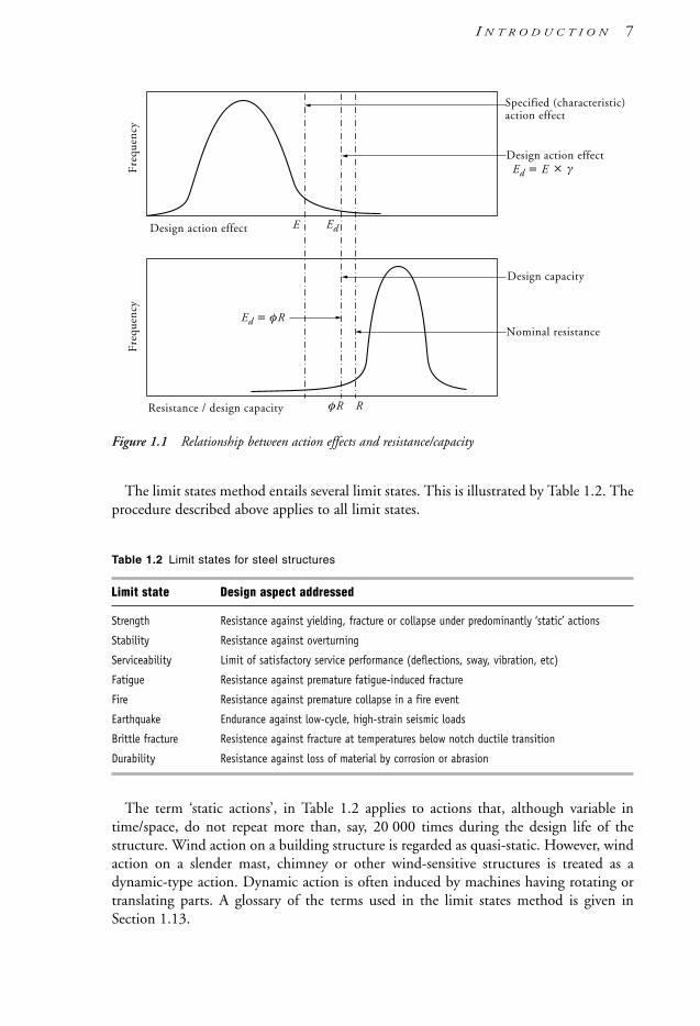
Figure 1.1 Relationship between action effects and resistance/capacity
The limit states method entails several limit states. This is illustrated by Table 1.2. Theprocedure described above applies to all limit states.
Table 1.2 Limit states for steel structures
Limit state Design aspect addressed
Strength Resistance against yielding, fracture or collapse under predominantly ‘static’ actions
Stability Resistance against overturning
Serviceability Limit of satisfactory service performance (deflections, sway, vibration, etc)
Fatigue Resistance against premature fatigue-induced fracture
Fire Resistance against premature collapse in a fire event
Earthquake Endurance against low-cycle, high-strain seismic loads
Brittle fracture Resistence against fracture at temperatures below notch ductile transition
Durability Resistance against loss of material by corrosion or abrasion
The term ‘static actions’, in Table 1.2 applies to actions that, although variable intime/space, do not repeat more than, say, 20 000 times during the design life of thestructure. Wind action on a building structure is regarded as quasi-static. However, windaction on a slender mast, chimney or other wind-sensitive structures is treated as adynamic-type action. Dynamic action is often induced by machines having rotating ortranslating parts. A glossary of the terms used in the limit states method is given inSection 1.13.
Specified (characteristic)action effect
Design action effect
Design capacity
Nominal resistance
Fre
quen
cyF
requ
ency
Design action effect
Resistance / design capacity φR R
Ed = E
Ed = φR
E Ed
× γ
I N T R O D U C T I O N 7
1106 SDHB 00-04 Final 8/6/05 12:03 PM Page 7

1.6 Combination of actionsAs noted in Section 1.5, in order to determine the relevant design action effects (e.g. themaximum moment on a beam), the critical design actions (e.g. externally imposed loads)must initially be assessed.
When acting in a singular manner, design actions such as permanent (G ), imposed (Q)and wind (W ) loads are generally variable in magnitude. The variability is morepronounced for the Q and W loads, and they will consequently have a higher load factor(as noted in Section 1.5).
Realistically, design actions generally do not act in a singular manner but incombination with each other. This combination of actions brings on another dimensionof variability. The variability is allowed for in a combination of actions (i.e. loadcombination) with different and/or additional factors being applied to the relevantindividual nominal action. A case in point is, say, peak wind and earthquake actions,which may have high load factors when acting individually but, as such events are rare incombination, the combination factors would be very low—if considered at all. In manyinstances, a combination of actions is considered specifically in AS/NZS 1170, Part 0which supersedes AS 1170 Part 1. Table 1.3 illustrates some examples of action factorsand their general combinations.
Table 1.3 Examples of some typical action factors and combinations (AS/NZS 1170.0provisions)
Combination no. Action combination factors for strength limit state
1 1.35G
2 1.2G + 1.5Q
3 1.2G + 1.5clQ
4 1.2G + ccQ + Wu
Other See AS/NZS 1170.0
whereG = permanent (dead) actionsQ = imposed (live) actionsWu = wind actions (ultimate)cl = load factor for determining quasi-permanent values of long-term actions (varies between 0.4 and 1.0)cc = combination factor for imposed actions (varies between 0.4 and 1.2).
Readers of previous editions of this Handbook and those knowledgeable of changespublished by Standards Australia in 2002 will note that there has been a change interminology due to the significant revision of the AS/NZS 1170 suite of ‘loading’Standards. Such changes have seen the general term ‘load’ replaced by ‘action’, ‘dead’ by‘permanent’, ‘live’ by ‘imposed’, to name a few. Specific changes to load factors are alsonoted—e.g. the change in the load factor for dead loads acting either singly or incombination.
Further aspects of design actions and their combinations are considered in Chapter 3.
8 S T E E L D E S I G N E R S ’ H A N D B O O K
1106 SDHB 00-04 Final 8/6/05 12:03 PM Page 8

1.7 Strength limit stateThe object of design for strength is to ensure that the structure as a whole, including allof its members and connections, have design capacities in excess of their respective designaction effects. The basic strength design criterion is that the structure must be designedso that its probability of failure in service is as near to zero as practicable. In AS/NZS1170.0 this is taken as five percentile values in a probability distribution curve. It shouldbe noted that zero probability of failure is an ideal that could not be achieved in real life.Engineering design aims to reduce the failure probability to a figure less than thatgenerally regarded as acceptable to the public at large (often about 1 in 100 000 per year,per structure).
The basic inequality for Strength Limit State design is:
(Design action effect) φ (Nominal capacity)For example:
(Design bending moment) φ (Nominal bending capacity)
(Design axial compression force) φ (Nominal compression capacity)
The main features of Strength Limit State design are as follows:
1. The structure is deemed to be of adequate strength if it can be shown that it can resistthe least favourable design action combination without exceeding the limit state ofstrength.
2. Load factors are applied to the specified actions sometimes termed ‘characteristic’actions. The load factors range from 0.40 to 1.50 for the strength limit state (referChapter 3).
3. The design action effects (bending moments, axial, and shear forces) are computedfrom ‘factored’ loads and their combinations.
4. The computed member and section capacities (ultimate resistances) are factoreddown using capacity reduction factors.
5. The capacity reduction factors for steel structures range from 0.6 to 0.9, dependingon the type of the member or connection and the nature of forces.
Table 1.4 gives the values of the capacity reduction factor φ.
Table 1.4 Values of capacity reduction factor φ
Element φ
Steel member as a whole 0.90Connection component (excluding bolts, pins or welds) 0.90Bolted or pin connection 0.80Ply in bearing 0.90Complete penetration butt weld 0.90 (0.60)Longitudinal fillet weld in RHS, t <3 mm 0.70Other welds 0.80 (0.60)
Note: Figures in brackets apply to category GP welds.
I N T R O D U C T I O N 9
1106 SDHB 00-04 Final 8/6/05 12:03 PM Page 9

1.8 Serviceability limit stateThe term ‘serviceability’ applies to the fitness of the structure to serve the purpose forwhich it has been designed. The actions used in verifying the serviceability limit state arecombined using load factors of 1.0 (e.g. 1.0 G + 1.0 csQ). Some of the serviceabilitylimit states include:• deflections, sways and slopes• vibration affecting human comfort or mechanical plant performance• loss of material due to corrosion or abrasion• bolt slip limit state.
Deflections, sway and slopes need to be limited to maintain the proper functioning ofthe building and to avoid public concern about its appearance, safety or comfort.AS 4100 gives only the most essential limits on deflections, leaving it to the designer toinvestigate whether the serviceability requirements are satisfied (Clause 3.5.3).Appendix B of AS 4100 gives a short list of vertical deflection limits, reproduced belowin Table 1.5(a) and (b).
Table 1.5(a) Deflection limit factor Cd in ∆ L/Cd (from AS 4100)
Beam type Loading Coefficient Cd
Beams CantileversBeams supporting masonry
(i) No pre-camber G1 + Q 1000 500
(ii) With pre-camber G1 + Q 500 250
All beams G + C 250 125
Notes: (G1 + Q) means loads applied by the wall or partition and subsequently applied imposed loads.(G + C ) means the least favourable combination of loads.∆ = beam/cantilever deflection.L = span.
Table 1.5(b) Limits of horizontal deflections
Description of building Limit
Clad in metal sheeting, no internal partitions, no gantry cranes H/150
Masonry walls supported by structure H/240
Note: For buildings with gantry cranes, the sway and deflection limits of AS 1418.18 apply. H = column height. Theabove horizontal deflection limits are applicable to the eaves level of adjacent frames in industrial buildings.
A comprehensive tabulation of deflection and sway limits for building elements(structural and non-structural) can be found in AS/NZS 1170.0.
10 S T E E L D E S I G N E R S ’ H A N D B O O K
1106 SDHB 00-04 Final 8/6/05 12:03 PM Page 10

1.9 Other limit states
1.9.1 Stability limit state
This limit state safeguards against loss of equilibrium of the structure or its parts due tosliding, uplift or overturning. This is covered in detail in AS/NZS 1170.0.
1.9.2 Fatigue limit state
Design against premature failure from fatigue damage is required where the number andseverity of fluctuating loads is above the threshold of fatigue damage.
1.9.3 Fire limit state
The behaviour of the structure in the event of fire is an important design consideration.AS 4100 sets the principles of fire engineering for the common building element typesand covers bare steel and most passive fire protection systems, except concreteencasement and filling.
1.9.4 Earthquake limit state
A separate section has been included in AS 4100 to cover special provisions for structuressubject to earthquake forces. In particular, the Standard specifies the design featuresnecessary to achieve ductile behaviour. Further useful guidance can also be found inAS 1170.4 and NZS 3404.
1.9.5 Brittle fracture
Although the risk of this type of failure is low, design against brittle fracture under certainconditions must be considered. Section 10 of AS 4100 and Section 2.7 of this Handbookgive guidance on design against brittle fracture.
1.10 Other features of AS 4100The requirements for high-strength bolting are included in AS 4100. Design of weldedjoints is also fully specified in AS 4100 leaving only the clauses on workmanship,materials, qualification procedures and weld defect tolerances in the welding StandardAS/NZS 1554. AS 4100 also incorporates requirements for Fabrication, Erection,Modification of Existing Structures and Testing of Structures.
1.11 Criteria for economical design and detailingThe owner’s ‘bias’ towards minimal initial cost for the structure, as well as low ongoingmaintenance cost, must be tempered by the edicts of public safety, utility and durability.The designer is constrained to work within the industry norms and limits imposed bythe statutory regulations and requirements of design and material Standards.
I N T R O D U C T I O N 11
1106 SDHB 00-04 Final 8/6/05 12:03 PM Page 11

The choice of an appropriate structural system is based on experience. While it ispossible to carry out optimisation analyses to arrive at the least-weight structural framing,it is rarely possible to arrive, purely by analysis, at the most appropriate solution for aparticular design situation.
In the design of a steel structure the achievement of a minimum weight has alwaysbeen one of the means of achieving economy. Designing for minimum weight shouldproduce the minimum cost in material but it does not necessarily guarantee the lowesttotal cost, because it does not take into account the cost of labour and other cost sources.A more comprehensive method of achieving economical design is the optimum costanalysis. Additionally, costs associated with coating systems (e.g. for corrosion or fireprotection) can dramatically increase the first cost of structural steelwork. The minimumweight design does have its virtues in structures that are sensitive to self-load, e.g. long-span roofs. The dead weight of such a roof structure needs to be minimised, as itcontributes the significant part in the load equation.
Design for optimum cost, while not covered by AS 4100, is part of good engineeringdesign. The term ‘optimal cost’ applies to the total cost of materials, labour forfabricating the structural elements (members, details, end connections), coating anderection. Erection cost is an important consideration, and advice should be sought froma suitably experienced contractor whenever novel frame solutions are being considered.
A rational approach to assessing the costing of steelwork has been developed (Watsonet al. [1996]). This costing method does not assess total fabricated steelwork costs on a‘smeared’ $/tonne basis but develops accurate costs from various relevant parameters,which include material supply ($/m), fabrication ($/hour), application of coatings($/sq.m) and erection ($/lift). Though quite detailed, the rational costing methodrequires current pricing information (which may also vary on a regional basis), andwould seem more suitable for larger projects. To use the method for every small tomedium-sized project may not be justifiable on time and fees considerations.
An alternative course of action would be to use the rational costing method on aninitial basis to determine the relative economics of joints and other systems and to utilisethese outcomes over many projects—much like the practice of standardising connectionswithin a design office. The method is also very useful for quantifying costs in variationassessments. Watson et al. [1996] should be consulted for a detailed understanding of therational costing method.
Since design costs are part of the total project cost, economy of design effort is alsoimportant. There are several ways in which the design process can be reduced in cost, andthese are the use of computers for analysis and documentation, use of shorthand methodsfor sizing the members and connections, and use of standard job specifications. As thedesign process is almost always a step-by-step process, it is helpful if the initial steps arecarried out using approximate analyses and shorthand routines whilst reserving the fulltreatment for the final design phase.
As always, specifications and drawings are the documents most directly responsible forachieving the planned result, and should be prepared with the utmost care. AS 4100 addsa few requirements on the contents of these documents. Clause 1.6 of AS 4100 stipulatesthe additional data to be shown on drawings and/or in specifications. Theserequirements should be studied, as their implementation may not be easy.
12 S T E E L D E S I G N E R S ’ H A N D B O O K
1106 SDHB 00-04 Final 8/6/05 12:03 PM Page 12

1.12 Design aidsVarious design aids and computer software packages are available for rapid sizing andassessing the suitability of steel members, connections and other components. Additionalpublications that provide connection design models, background information andworked examples for all facets of the loading and design Standards are also available—e.g. AISC [1997,1999a,b], Bennetts et al. [1987,1990], Bradford et al. [1997], Hancock[1998], Hogan and Thomas [1994], Hogan and Syam [1997], SSTM [2003b], Syam[1992], Syam and Chapman [1996], Thomas et al. [1992] and Trahair et al. [1993c,d].A useful summary of the more readily available design aids is given by Kneen [2001]. Anexcellent reference on the background to AS 4100 is provided by Trahair and Bradford[1998], with Woolcock et al. [1999] providing some very good practical guidance on thedesign of portal framed buildings.
1.13 Glossary of limit states design termsAction A new term to represent external loads and other imposed effects. The word
‘load’ is used interchangeably with ‘action’ in this Handbook—see ‘Nominal action’.
Action combination factor The factor applied to specified nominal actions within acombined actions equation.
Capacity A term to describe structural resistance—see ‘Nominal capacity’.
Capacity reduction factor, φ The factor applied to the nominal computed member orconnection capacity to safeguard against variations of material strength, behaviour anddimensions.
Design action (load) The product of (nominal action) × (load/combination factor).
Design action effect (load effect) Internal action such as axial load, bending moment orshear in a member, arising from the application of external actions. Design actioneffects are calculated from the design actions and appropriate analysis.
Design capacity The capacity obtained by multiplying the nominal capacity by thecapacity reduction factor.
Load (action) factor The factor applied to a specified action to safeguard against loadvariations.
Nominal action Defined as the following acting on a structure: direct action (e.g.concentrated/distributed forces and moments) or indirect action (e.g. imposed orconstrained structural deformations).
Nominal capacity The capacity of a member, section or connection at the strength limitstate, e.g. axial load at the onset of yielding in a stub column.
Specified action The action of the intensity specified in a loading Standard.
I N T R O D U C T I O N 13
1106 SDHB 00-04 Final 8/6/05 12:03 PM Page 13

14 S T E E L D E S I G N E R S ’ H A N D B O O K
1.14 Further reading• Steel and the architect’s perspective: Ogg [1987], though slightly dated this is an
excellent high quality publication on the topic.• Use of Design Capacity Tables (DCTs): Syam & Hogan [1993].• Minimum requirements for information on structural engineering drawings: Clause
1.6 of AS 4100, and; Syam [1995].• Information pertaining to steel detail (workshop) drawings: AISC [2001].• Information technology in the Australian steel industry: Burns [1999].
1106 SDHB 00-04 Final 8/6/05 12:03 PM Page 14

2.1 Steel productsThe main elements in steel building construction consist of steel plates, standard sectionsand compound sections. An infinite variety of structural forms can be derived from thesesimple elements. Plates and standard sections are regarded as the fundamental elements(see Figure 2.1): that is, compound sections can be made from plates and sections. Thedesigner has the freedom to compose special sections subject to dictates of economy.Some commonly used compound sections are shown in Figures 5.1 and 6.13.
(a) Hot-rolled plates and I-sections
PLT = Plate UB = Universal Beam UC = Universal ColumnWB = Welded Beam (from HR Plate) WC = Welded Column (from HR Plate) TFB = Taper Flange Beamweld = fillet/deep penetration weld r = fillet radius from manufacturing process
(b) Hot-rolled channels, angles and bar
PFC = Parallel Flange Channel EA = Equal Angle UA = Unequal AngleFL = Flat (or Flat Bar) SQ = Square (or Square bar) RND = Round (or Round Bar)r = fillet radius from manufacturing process
(c) Cold-formed structural hollow sections
CHS = Circular Hollow Section RHS = Rectangular Hollow Section SHS = Square Hollow Sectionr = corner radius
Figure 2.1 Fundamental structural steel elements: standard sections and plate
CHS RHS SHS
r r
PFC EA UA FL SQ RND
r
r r
PLT UB UC WB WC TFB
weldweldrr
r
c h a p t e r 2 Material & DesignRequirements
1106 SDHB 00-04 Final 8/6/05 12:03 PM Page 15

For reasons of economy, unless there are other specific criteria to be observed (e.g.minimum mass, headroom restrictions, etc.), the designer’s best strategy is to choosestandard sections in preference to compound sections. Typically, the more readilyavailable standard sections are the following:
Hot-rolled sections: (Onesteel [2003]):• universal beams (UB)• universal columns (UC)• parallel/taper flange channels (PFC/TFC)• taper flange beams (TFB)• equal/unequal angles (EA/UA)• flat bar (with rolled edges).
Standard welded products—three-plate girders (Onesteel [2003]):• welded beams (WB)• welded columns (WC).
Structural steel hollow sections—cold-formed (SSTM [2003a]):• circular hollow sections (CHS)• square hollow sections (SHS)• rectangular hollow sections (RHS).
Plate product information and technical data can be found in BHP Steel [2002]—seeNote 3 in Section A.3.
The above product classification is not exhaustive. Generally, a division is madebetween hot-rolled and open cold-formed products for the design and fabrication of steelstructures. This Handbook’s scope is primarily to consider the provisions of AS 4100Steel Structures (which could be regarded as a hot-rolled product design code). The scopeof AS 4100 applies to members and connections consisting of hot-rolled plates andsections, though it does also consider cold-formed hollow section members that weretraditionally manufactured by hot-forming operations. The inclusion of cold-formedhollow sections within a design Standard as AS 4100 is due to the fact that such sectionsbehave in a similar manner to hot-rolled open sections—specifically, member bucklingmodes. Further restrictions to the scope of AS 4100 are discussed in Section 2.4.
The design and fabrication of cold-formed steel structures is treated in AS/NZS 4600and its related material standards. The treatment of AS/NZS 4600 and other aspects of(open-type) cold-formed steel structures is outside the scope of this Handbook, thoughsome mention is made of the material aspects of this form of construction. The reader isdirected to the AS/NZS 4600 Commentary and Hancock [1998] for an authoritativetreatment of this subject.
2.2 Physical properties of steelPlotting the stress versus strain diagram from data obtained during tensile tests permitsa better appreciation of the characteristic properties of various steel types. Figure 2.2depicts the typical stress–strain diagrams for mild steel and low-alloy steel.
16 S T E E L D E S I G N E R S ’ H A N D B O O K
1106 SDHB 00-04 Final 8/6/05 12:03 PM Page 16

Figure 2.2 Typical stress–strain diagrams for steel Grades 250, 350 and 400(a) Complete diagram(b) Enlarged portion of the diagram (a) in region A–B
The following definitions are provided to explain the various terms.
Elastic limit The greatest stress that the test piece can sustain without permanent set.
Elastic range That portion of the stress–strain diagram in which Hookes’ law ofproportionality holds valid.
Permanent set The strain remaining in the test piece after unloading to zero stress; alsotermed plastic strain, plastic elongation or permanent elongation.
Plastic range That portion of the stress–strain curve over which the stress remainsapproximately constant for a certain range of strains.
Proof stress See definition in yield stress.
Proportional limit The greatest stress which the tensile piece can sustain withoutdeviating from Hookes’ law of proportionality.
Reduction in area The difference between the cross-sectional areas at rupture and thatat the beginning of the test, expressed as a percentage of the latter.
Strain Any forced change in the dimensions of a body; usually unit strain is meant: thatis, change in dimension per unit length.
Strain hardening range The portion of the stress–strain curve immediately after theplastic range.
Stress–strain diagram The curve obtained by plotting unit stress as ordinate againstcorresponding unit strain as abscissa (using the initial cross-sectional area).
Ultimate elongation Maximum elongation of a test piece at rupture expressed as apercentage increase of the original gauge length.
Ultimate tensile strength (denoted as fu or UTS) The maximum stress that a tensile piececan sustain, calculated as a quotient of the ultimate force on the original area.
Yield point The lowest stress at which the strains are detected to grow without a furtherincrease of stress.
Grade250
AA B BA
0
100
200
300
400
500
600
0.1 0.2 0.3
Grade350
Plasticrange
Strainhardening
range
Grade400
0 0.002 0.004
100
200
300
400
500
600
0.2%
350
250
Strain Strain
(a) (b)
Stre
ss (
MP
a)
M A T E R I A L & D E S I G N R E Q U I R E M E N T S 17
1106 SDHB 00-04 Final 8/6/05 12:03 PM Page 17

Yield stress (denoted as fy ) The stress corresponding to the yield point. For steels withouta clearly defined yield point, the yield stress is related to a point on the stress–strain curveat which, after unloading to zero, the permanent set is equal to a strain of 0.002 (i.e.elongation of 0.2%) (see Figure 2.2(b))—the term ‘proof stress’ applies to this case.
Young’s modulus of elasticity (denoted as E ) The slope of the initial linear elastic portionof the stress–strain curve. E varies in the range of 190 000 to 210 000 MPa, and fordesign purposes is approximated as 200 000 MPa in AS 4100.
The yield stress, fy, is regarded as one of the most important parameters in design. Itvaries with chemical composition, method of manufacture and amount of working, andthough this value is determined from uniaxial tension tests it is also used to determinemaximum ‘stresses’ for flexure, transverse shear, uniaxial compression, bearing etc., orcombinations of these design action effects.
Table 2.1 lists the physical properties that are practically constant (at ambientconditions) for all the steels considered in this Handbook. These properties apply atroom temperature. At elevated temperatures the properties are subject to variation, asindicated in Table 2.2. As can be seen at temperatures above 200°C the steel propertiesstart being markedly lower than at room temperature, and the coefficient of thermalexpansion starts rising significantly. This is of particular importance for structuresrequired to operate at elevated temperatures (some industrial structures) and structuressubjected to fire.
Table 2.1 Physical properties of steel for design to AS 4100
Property Value
Young’s modulus of elasticity, E 200 000 MPaShear modulus, G 80 000 MPaCoefficient of thermal expansion, αT at 20°C 11.7 10–6 per °CPoisson’s ratio, ν 0.25Density, ρ 7850 kg/m3
Table 2.2 Properties of steel at elevated temperatures (degrees Celsius) for design
Temperature °C 20 100 200 300 400 500
Reduction factor for E 1.0 0.97 0.93 0.87 0.78 0.65Reduction factor for fy 1.0 1.0 1.0 0.84 0.70 0.55Multiplier for the coefficient
of thermal expansion, αT 1.0 1.03 1.09 1.15 1.21 1.29
Other mechanical properties of interest to the designer of special structures are:
Fatigue strength The stress range of a steel specimen subjected to a cyclic reversal ofstresses of constant magnitude, which will cause failure at a certain specified number ofcycles (usually 1 million cycles). The method of assessment for fatigue loading of the AS 1163, AS 1594, AS 3678 and AS 3769 steels is given in Section 11 of AS 4100.
Creep strength Long-term exposure to temperatures above 300°C can severely reducethe strength of steel because of the effect of creep. For example, Grade 250 mild steel
18 S T E E L D E S I G N E R S ’ H A N D B O O K
1106 SDHB 00-04 Final 8/6/05 12:03 PM Page 18

exposed to 400°C for a period of 10 000 hours can fracture by creep at a stress equal toone-half of the UTS specified at room temperature. Steels for high-temperatureapplications have been specially developed, and advice from the steel makers should besought in each case.
Bend radius The minimum radius to which a plate can be bent at room temperaturewithout cracking. This is important for both plates and sections that undergo formingby presses, though plates are more critical, as they generally possess a higher bend radiusto ‘section’ depth ratio. AS/NZS 3678 presents information on minimum bend radii forplates, which is dependent on the direction of rolling. Riviezzi [1984] presents bendradius limitations for sections, which are dependent on whether the bend radius is in themajor or minor principal bending axis plane.
Hardness For special applications, where abrasion resistance or indentation resistance isa design factor. Special steels are available for this particular design application.
Impact properties at specified temperature Fracture toughness is an energy term thatdescribes the ductile/brittle behaviour of steels at various service temperatures. Due tothe presence of cracks or other types of discontinuities in regions of high local stress,brittle fracture may be possible when the steel has a low fracture toughness. In thisinstance these cracks may no longer allow the steel to behave in a ductile manner andsubsequently propagate at high speed to cause (catastrophic) brittle failure.
Steels generally possess a characteristic temperature property, the transitiontemperature; above it the steel is predominantly (notch) ductile and below it the steel ispredominantly brittle. Low fracture toughness and subsequent brittle fracture may thenarise if the service temperature of a steel is below its transition temperature. Thetoughness of a particular steel is dependent on its grade, manufacture and thickness.
Impact property is also an important parameter for cold-formed hollow sections.Specific impact properties are important to guard against brittle behaviour when suchsections are subject to dynamic or impact loads. This parameter becomes more importantfor thicker wall (i.e. >6 mm) cold-formed hollow sections.
Steels can be supplied with minimal absorbed energy (i.e. fracture toughness)requirements for test pieces at temperatures of 0°C and –15°C. These grades are referredto as notch-ductile and generally have the L0 and L15 subgrade designation. Section 10of AS 4100 offers guidance on designing against brittle fracture.
2.3 Steel types and gradesSteel is an extremely versatile material available in a very wide range of properties andchemical compositions to suit every field of technology. Not all steels produced by steelmakers are suitable for structural applications where the following properties are ofparamount importance.
2.3.1 Weldability
Weldability is a relative term; all steels can be welded with due care, but steels forstructural purposes should be able to be welded with relative ease and withoutcomplicated procedures. Structural steels must be tolerant to small imperfections inwelding—at least up to certain specified limits.
M A T E R I A L & D E S I G N R E Q U I R E M E N T S 19
1106 SDHB 00-04 Final 8/6/05 12:03 PM Page 19

2.3.2 Ductility
Ductility is an essential property, as the whole concept of structural steel design is basedon ductile behaviour of all parts of the structure. For steel, there is a fundamentalrelationship between the elongation of a tensile test piece at fracture and the degree ofductility, but the designer should not rely too heavily on this; it is all too easy to reducethe ductility in the real structure by improper detailing and poor workmanship. Themajority of fractures in service have occurred in the immediate vicinity of joints andabrupt changes in ductility brought about by a triaxial stress condition in these areas.
2.3.3 Low cost-to-strength ratio
The high strength of steel is naturally important when considering the range of strengthsavailable. The ratio of cost to strength may be of real interest in the selection of a steeltype for a particular structure. Many high-strength steels offer an economical solution fortensile and flexural members, although, understandably, availability has a direct bearingon the cost of these items. AISC [1997] provides some general cost indices for thevarying strengths of steel grades.
2.3.4 Availability of sections and plates
The availability of some steels in hot-rolled sections (universal, channels, etc.) in veryhigh-strength grades is not as good as for the mild steel grades, although it is advisableto make enquiries about the availability of the higher-strength grades. Large quantitiescan always be produced, but it takes more time to place them on the steel maker’s rollingprogram. The same is applicable for plates, though a much larger variety of this productis available. Conversely, higher-strength grade hollow sections (i.e. AS 1163 GradeC450L0 for RHS/SHS and AS 1163 Grade C350L0 for CHS) are more readily available.BHP Steel [2002], Onesteel [2003] and SSTM [2003a] provide further information onthe availability of various manufactured steel sections and plates.
Structural steels may be grouped as follows:
(a) Carbon and carbon/manganese steels (typically 230–350 MPa yield stress)These steels derive their strength from alloying with carbon and manganese. They aregenerally known as structural steels and are produced in relatively high tonnages.Because of their widespread use, they are readily available in all standard sections andplates. These steels are generally supplied in the fully killed (fully deoxidised)condition. AS/NZS 3678 and AS/NZS 3679 cover the material specifications,chemistry, mechanical properties, methods of manufacture, tolerances on dimensionsand supply requirements. For general structural purposes, the most applicable gradesare Grade 300 for hot-rolled sections (Onesteel 300PLUS specification) and Grade250 or 350 for structural plates. Where slightly enhanced strength is required, Grade350 can be supplied for hot-rolled sections. Steel plates of enhanced notch ductilityand tensile strength are manufactured to AS 1548 (steel plates for boilers and unfiredpressure vessels).
20 S T E E L D E S I G N E R S ’ H A N D B O O K
1106 SDHB 00-04 Final 8/6/05 12:03 PM Page 20

(b) High yield strength, low-alloy steels (typically 320–450 MPa yield stress)These steels are similar to those in (a) above, except for the addition of smallquantities of alloying elements useful in producing a fine-grain steel. Because thegrain-refining elements seldom exceed 0.15%, these steels are known as low-alloysteels. Generally these steels are fully killed. Grade 400 is used for production ofwelded sections (WB and WC). Grade 350 structural plates are available. Cold-formed hollow sections are generally available in this steel type—see (d) below.
(c) Low-alloy weathering steels (typically 350 MPa yield stress)By their chemical nature these steels are similar to those in (b) above, except for afurther addition of chromium, nickel and copper (up to 2.1%, total) for a greatlyenhanced resistance to atmospheric corrosion. These alloying elements cause the steelsurface to weather to a uniform patina, after which no further corrosion takes place.This allows the use of unpainted steelwork in regions away from marine environmentand heavy pollution. These steels are not commonly produced and are only available,in plate form, direct from the steel mill.
(d) Structural steel hollow sections (typically 250–450 MPa yield stress)The material specifications for hollow sections are covered in AS 1163. In line withcurrent overseas practice this Standard considers only hollow sections manufacturedby cold-forming operations (hence the ‘C’ prefix before the grade designation, e.g.C250, C350 and C450). Hollow sections for structural purposes produced inAustralia are manufactured only by cold-forming and electric resistance welding(ERW). Consequently, stress relieving after the forming and welding operation (atambient temperatures) is now no longer required. The current range of C250, C350and C450 grades of steel for hollow sections are readily available to meet the notch-ductile L0 (e.g. C450L0) requirements of AS 1163. The L0 rating is typicallyavailable from Australian tube manufacturers and should be generally specified (see‘Impact properties…’ in Section 2.2). RHS/SHS are generally available in GradeC450L0 and CHS in Grade C350L0.
(e) Heat-treated carbon/manganese steels (typically 500–600 MPa yield stress)These steels are manufactured from feed derived from rolled steels, somewhat similarto those listed in (a) and (b) above but having enhanced levels of micro-alloys. Thesteel is then subjected to a combination of heating and cooling (quenching andtempering). This changes the microstructure of the steel to raise its strength, hardnessand toughness. In Australia these steels are manufactured only in plate form andcomply with AS 3597.
(f ) Heat-treated alloy steels (typically 500–690 MPa yield stress)These steels are the most advanced (and most costly) constructional steels of weldablequality currently available. Except for significant increases of carbon and manganesecontent, the overall chemistry such as Cr, Ni and Mo and method of manufacture aresimilar to those in (e) above. Plate products of this type of steel comply with AS 3597,and are manufactured in Australia by Bisalloy Steel.
The steels listed in (e) and (f ) are used for structural purposes when the saving of massis of prime importance—for example, in long-span beams and bridges, high-rise building
M A T E R I A L & D E S I G N R E Q U I R E M E N T S 21
1106 SDHB 00-04 Final 8/6/05 12:03 PM Page 21

columns and vehicle building. There is an increased use of these types of steel in theconstruction industry, though at present there is no Australian design Standard. Thecurrent practice is to design to the AISC (USA) code for such steels.
The above grouping of steels has been arranged in order of increasing yield stress andincreasing unit cost of raw product. Except for hollow sections, the expertise required forwelding also increases roughly in the same order.
Other steels complying with relevant Standards (e.g. AS 1397, AS 1548, AS/NZS 1594, AS/NZS 1595) are available for steel flat products. These include steelsfor cold-formed structural steel (other than tubular), tank and boiler applications; theyare mentioned here as their application is outside the scope of this Handbook.
The following (rationalised) product-based Australian Standards cover the steelsnormally used in building construction:
• AS 1163 Structural steel hollow sectionsCold-formed Grade C250/C350 circular hollow sections (CHS) and GradeC350/C450 rectangular and square hollow sections (RHS and SHS) suitable forwelding are considered in this Standard. These sections are manufactured by cold-forming and subsequent electric resistance welding (ERW) operations. See Table 2.3for additional strength details.
• AS 3597 Structural and pressure vessel steel: Quenched and tempered plateThis Standard covers the production, material, supply and other technicalrequirements of 500, 600 and 620–690 MPa (depending on thickness) quenched andtempered plate. See Table 2.4 for additional strength details.
• AS/NZS 3678 Structural steel: Hot-rolled plates, floor plates and slabsThis is an ‘omnibus’ Standard covering the specification of steels of plate productsgrouped in (a) and (b) above—that is, Grades 200, 250, 300, 350, 400 and 450.Subgrades L0 and L15 cover steels of enhanced notch ductility; a minimum CharpyV-notch value of 27 J is obtainable at temperatures above 0°C for subgrade L0 and–15°C for L15. The Standard also covers the material specification for weather-resisting steels. See Table 2.3 for additional strength details.
• AS/NZS 3679, Part 1 Structural steel: Hot-rolled structural steel bars and sectionsThis is another ‘omnibus’ Standard covering the specification of steels of hot-rolledsections (universal sections, taper flange beams, angles, parallel/taper flange channelsand flat bars) for structural and engineering purposes in ordinary weldable grades.Grades include the commonly specified Grades 250 and 300 as well as 350 and thesubgrades of L0 and L15 as in AS/NZS 3678. See Table 2.3 for additional strengthdetails. Before October 1994, sections of Grade 250 were produced by BHP (as it wasknown at the time) as the base grade.
• AS/NZS 3679, Part 2 Structural steel: Welded I sectionsThis Standard provides the production, material, supply and other technicalrequirements for welded I-type steel sections for structural and engineering purposes inordinary weldable and weather-resistant weldable grades. Steel grades include Grade300 and 400 steel and the subgrades of L0 and L15, as noted in AS/NZS 3678. Flange-to-web connections are made by deep-penetration fillet welds using the submerged-arcwelding (SAW) process. This Standard covers the range of standard welded products
22 S T E E L D E S I G N E R S ’ H A N D B O O K
1106 SDHB 00-04 Final 8/6/05 12:03 PM Page 22

released in 1990 to extend the range of universal sections. See Table 2.3 for additionalstrength details.
The mechanical properties of structural steels are given in Table 2.3. As can be seen fromthe table, the yield stress of all steel grades varies slightly from the base figure. This isunavoidable, as the steel receives various amounts of hot and cold working during theproduct rolling process. In general, the thinner the plate, the higher the yield strength.
Table 2.3 Specification and strengths of typical structural steel products noted in AS 4100.
Yield Tensile Standard/Product Steel grade Thickness (mm) stress (MPa) Strength
(MPa)
AS 1163 C450, C450L0 All 450 500Hollow sections C350, C350L0 All 350 430
C250, C250L0 All 250 320AS/NZS 3678 450, 450L15 20 450 520Hot-rolled 21 to 32 420 500plate and floorplate 33 to 50 400 500
400, 400L15 12 400 48013 to 20 380 48021 to 80 360 480
350, 350L15 12 360 45013 to 20 350 45021 to 80 340 45081 to 150 330 450
WR350, WR350L0 50 340 450300, 300L15 8 320 430
9 to 12 310 43013 to 20 300 43021 to 150 280 430
250, 250L15 8 280 4109 to 12 260 41013 to 50 250 410
AS/NZS 3679.1 400, 400L0, 400L15 17 400 520Hot-rolled steel 17 380 520bars and sections 350, 350L0, 350L15 11 360 480
12 to 40 340 48040 330 480
300, 300L0, 300L15 11 320 44011 to 17 300 440
17 280 440250, 250L0, 250L15 11 260 410
11 to 40 250 41040 230 410
Note: (1) For full listing of steel strengths refer to Section 2 of AS 4100. (2) Welded I-sections complying with AS/NZS 3679.2 are manufactured from steel plates complying with
AS/NZS 3678. (3) The 300PLUS range of hot rolled sections (Onesteel [2003]) comply with the above strength requirements
for AS/NZS 3679.1 Grade 300.
M A T E R I A L & D E S I G N R E Q U I R E M E N T S 23
1106 SDHB 00-04 Final 8/6/05 12:03 PM Page 23

Table 2.4 Mechanical properties of quenched & tempered plates (Bisalloy [1998]) to AS 3597
Property / thickness Specification / grade
Bisalloy 60 Bisalloy 70 Bisalloy 80
fy* fu fy
* fu fy* fu
Minimum yield strength,MPa, for thickness of:
5 500 590–730 600 690–830 650 750–900
6 500 590–730 — — 690 790–930
8 to 25 500 590–730 — — 690 790–930
26 to 32 500 590–730 — — 690 790–930
33 to 65 — — — — 690 790–930
70 to 100 — — — — 620 720–900
Note: fy* is 0.2% proof stress.
2.4 Scope of material and design codesThe scope of AS 4100 precludes the use of:• steel elements less than 3 mm thick. One exception is that hollow sections complying
with AS 1163 are included irrespective of thickness;• steel elements with design yield stresses exceeding 450 MPa;• cold-formed members (other than hollow sections complying with AS 1163), which
should be designed to AS/NZS 4600;• composite steel– concrete members (these are to be designed to AS 2327, which, at the
time of this Handbook’s publication, considers only simply supported beams).
Structural steels within the scope of AS 4100 are those complying with the requirementsof AS 1163, AS/NZS 1594, AS/NZS 3678 and AS/NZS 3679. Clause 2.2.3 of AS 4100permits the use of ‘unidentified’ steels under some restrictions, which include limiting thedesign yield stress, fy , to 170 MPa and the design tensile strength, fu , to 300 MPa.
2.5 Material properties and characteristics in AS 4100The nominal strengths of the steels considered within AS 4100 are the same as thoselisted in Table 2.3. AS 4100 does stipulate the design yield stress and design ultimatetensile strengths of steels, which are dependent on the method of forming and theamount of work done on the steel. Table 2.1 of AS 4100 provides the design yield stress( fy ) and design tensile strength ( fu ) of relevant steels for design to AS 4100. It should benoted that apart from the cold-formed hollow sections and some AS 1594 steels, fy isdependent on both grade and thickness, while fu is dependent only on grade (andnot thickness).
In some parts of AS 4100 the designer must determine the ‘residual stress’ category ofthe member or member element (e.g. in Tables 5.2 and 6.2.4 of AS 4100) to assess its
24 S T E E L D E S I G N E R S ’ H A N D B O O K
1106 SDHB 00-04 Final 8/6/05 12:03 PM Page 24

local buckling behaviour. As with the evaluation of fy , the amount of ‘residual stress’ isdependent on the method of manufacture and amount of work done in formingoperations. As a guide to designers, the following ‘residual stress’ categories can beassumed for the above-mentioned tables in AS 4100:
• hot-rolled sections complying with AS/NZS 3679.1: Category HR• welded sections complying with AS/NZS 3679.2: Category HW• hollow sections complying with AS 1163: Category CF
The following should be noted: • The HW residual stress has been assumed for the AS/NZS 3679.2 sections due to the
nature of the welding operation involved (deep-penetration fillet welds) andsubsequent straightening of flanges.
• The residual stress categories HR, HW and CF reduce to SR designation if stressrelieving is undertaken after member fabrication.
• It is often difficult in the design office to determine the exact magnitude of residualstresses for the section being considered, and the above categorisation method issufficient.
2.6 Strength limit state capacity reduction factor φA feature of the strength limit state design method adopted by AS 4100 is the use of two‘safety factors’: the ‘load’ factor γi and the capacity reduction factor φ. The load factor γi
is determined from the Structural Design Actions Standard AS/NZS 1170 for aparticular loading combination and considers the uncertainties in the magnitude,distribution and duration of loads as well as the uncertainties in the structural analysis.
The capacity reduction factor φ is considered within Table 3.4 of AS 4100 andaccounts for the variability in the strength and defects of steel elements and connections.Further information on capacity reduction factors can be found in Sections 1.5 and 1.7of this Handbook. Table 2.5 summarises these capacity reduction factors.
Table 2.5 Capacity reduction factors for strength limit state design to AS 4100
Type of component Capacity reduction factor φ
Beam, column, tie: 0.9Connection plates: 0.9Bolts and pins: 0.8
Welds:Complete penetration butt welds: 0.6 for GP category welds
0.9 for SP category weldsAll other welds: 0.6 for GP category welds
0.8 for SP category welds0.7 for SP category welds to RHS sections, t < 3 mm
Note: Weld categories GP (general purpose) and SP (structural purpose) reflect the degree of quality control andare described in AS/NZS 1554.
M A T E R I A L & D E S I G N R E Q U I R E M E N T S 25
1106 SDHB 00-04 Final 8/6/05 12:03 PM Page 25

2.7 Brittle fracture
2.7.1 Introduction
Unlike fatigue, the brittle fracture failure mode is a one-off event. The first time thecritical loading event occurs in an element containing a critical flaw, the element is liableto fracture. In contrast, the fatigue cracking accumulates, cycle after cycle. The fourconditions that can lead to brittle facture are:• loading at a temperature below the transition temperature of the steel• relatively high tensile stress, axial or bending• presence of cracks, notches or triaxial stress states that lower the ductility of the detail• use of steels having impaired ductility at the lowest service temperature.
The danger of brittle fracture is increased when the ductility of steel is reduced by:• suppression of yield deformations, as may be caused by triaxial stressing• the use of relatively thick plates or sections• impact loading, i.e. high strain rate• cold bending, such that a strain greater than 1% is induced as a result of fabrication or
field straightening• detailing that results in severe stress concentrations (notches).
Methods of design against brittle fracture include such measures as:• choosing a steel that is not susceptible to brittle fracture at the minimum service
temperature for which the structure is exposed• lowering the maximum operating stresses• using details that do not suppress the ductility of steel and contain no notches• post-welding heat treatment (normalising of welds).• consulting a metallurgical engineer to advise on appropriate actions.
2.7.2 The transition temperature
The ductility of steel is normally tested at room temperature, say 20°C. At lowertemperatures the ductility of steel diminishes. The temperature at which the reductionof ductility becomes significant depends on the ductility of the steel, normally measuredby impact energy absorbed in the Charpy test. Impact energy of 27 joules at 20°C wouldnormally be required for the hot-rolled plates and sections. For cold-formed hollowsections the requirement is 27 joules at 0°C.
A practical method of determining the suitability of steel for a particular servicetemperature is given in Section 10 of AS 4100. The method requires an evaluation of theminimum service temperature, plate element thickness and steel type, which is roughlydependent on the notch ductility. Table 10.4.1 of AS 4100 is reproduced in Table 2.6 forthe commonly available steel types in Australia. It is advisable to consult the steelmanufacturer on the selection of a suitable steel grade.
The service temperatures for various locations in Australia are those determined byLODMAT isotherms, deemed to be the ‘lowest one-day mean ambient temperature’.There are only two regions in Australia where the temperature falls to or slightly belowzero (based on LODMAT), namely parts of the southern and central Great Dividing
26 S T E E L D E S I G N E R S ’ H A N D B O O K
1106 SDHB 00-04 Final 8/6/05 12:03 PM Page 26

Range. In New Zealand there are extensive areas where sub-zero service temperaturesoccur (refer to NZS 3404). The selection of steel with appropriate notch toughnessbecomes more important at lower service temperatures. It should be noted thatLODMAT gives average 24-hour temperatures but hourly minima can be some 5 degreeslower. The Commentary to AS 4100 notes that this may be allowed for by subtracting5°C off the structure’s permissible service temperature and ensuring that this is above theregion’s LODMAT isotherm value.
Table 2.6 Steel types required for various service temperatures as noted in AS 4100
Steel type Permissible service temperature for thickness ranges, mm
See Note 6 7–12 13–20 21–32 33–70 >70
1 –20 –10 0 0 0 +5
2 –30 –20 –10 –10 0 0
3 & 6 –40 –30 –20 –15 –15 –10
4 –10 0 0 0 0 +5
5 –30 –20 –10 0 0 0
7A –10 0 0 0 0 –
7B –30 –20 –10 0 0 –
7C –40 –30 –20 –15 –15 –
Note: Steel types are listed below.
Steel types vs steel specifications
Specification and Steel grades
Steel type AS 1163 AS/NZS 3678 AS/NZS 3679.1
1 C250 200, 250, 300 250, 300
2 C250L0 — 250L0, 300L0
3 — 250L15, 300L15 250L15, 300L15
4 C350 350, WR350 350, 400
5 C350L0 WR350L0 350L0, 400L0
6 — 350L15, 400L15 350L15, 400L15
7A C450 450 —
7B C450L0 — —
7C — 450L15 —
Note: AS/NZS 3679.2 steels are categorised in the AS/NZS 3678 group.
As can be read from Table 2.6, a plate stressed in tension and thicker than 70 mm insteel type 1 and 4 is adequate only for a design service temperature of +5°C or higher.This is important for open-air structures and bridges, particularly in colder climates. Theremedy is to use a steel with improved notch ductile properties, say type 2 or higher.
Fabrication of structures in low-temperature zones must be carried out with care.Straining beyond the strain of 1% due to cold forming or straightening could producean effect equivalent to lowering the service temperature by 20°C or more.
M A T E R I A L & D E S I G N R E Q U I R E M E N T S 27
1106 SDHB 00-04 Final 8/6/05 12:03 PM Page 27

28 S T E E L D E S I G N E R S ’ H A N D B O O K
2.7.3 Hydrogen cracking
In the presence of water vapour coming in contact with the surface of the molten metalduring welding, any hydrogen is freed and gets absorbed into the weld metal. Steel has agreat affinity for hydrogen, and if hydrogen is prevented from exiting during cooling, itpromotes the formation of Martensite. Owing to the great hardness of the Martensite theweld metal loses ductility, and this can result in cracking in service. Generally, the thickerthe plates to be joined, the more care is needed to prevent the hydrogen embrittlementof the welds.
The remedy is to prevent hydrogen from becoming entrapped, first by reducing theweld-cooling rate so that the hydrogen is given more time to escape from the molten pooland the heat-affected zone. Preheating the steel prior to welding is beneficial. Using a lowheat input during welding is also a common practice. The second line of defence isshielding the weld pool area from the entry of hydrogen by using inert gas shielding or‘low-hydrogen’ electrodes.
It is sometimes advisable to carry out qualification of welding procedures by testing asa part of the welding procedures approvals. There is a need for frequent and reliableinspection during the welding of components, especially those fabricated from thickerplates (>40 mm). Welding inspection should ascertain that the weld defect tolerancesare not exceeded and should also include hardness tests of the weld metal and the heat-affected zone. In critical welds there should not be any areas of excessive hardness (seeAS/NZS 1554 and WTIA [2004] for further guidance).
2.8 Further reading• Background to the metallurgical aspects of steel: Lay [1982a].• Background to the evolution of steel material Standards: Kotwal [1999a,b].• Standards and material characteristics for cold-formed open sections: Hancock [1998].• Availability of steel products: Keays [1999].• Relative costing between steel materials and products: Watson, et al. [1996].• Steel castings: AS 2074.• Websites for steel material manufacturers/suppliers: See Appendix A.5.• Websites for steel industry associations: See Appendix A.6.
1106 SDHB 00-04 Final 8/6/05 12:03 PM Page 28

3.1 GeneralDesign actions are divided into permanent and imposed actions. The next category arethe environment-generated actions such as wind, waves, vibrations, earthquake andactions caused by volumetric changes (e.g. temperature and concrete shrinkage). Designactions are set in the AS 1170 or AS/NZS 1170 series of Standards on the basis of eitherstatistical/probabilistic analyses or calibration studies of currently available data.
The terms ‘loads’ and ‘actions’ are used in this text as follows: ‘loads’ are used in thetraditional sense, and ‘actions’ denote indirect effects such as temperature, weldshrinkage, concrete shrinkage and inertial effects.
There are situations where the designer must determine the design actions for anumber of reasons:• the building owner’s intended special use of the structure• mechanical equipment and its vibrations.
In such instances the designer has to determine the 95 percentile value of the actions.This may require tests and statistical analyses.
To obtain the design action effects (shears, moments etc.), the nominal (characteristic)actions have to be multiplied by ‘load factors’ to be followed by a structural analysis (seeChapter 4). The action combination rules of AS/NZS 1170.0 are discussed in Section 1.6,with the most common combinations of permanent, imposed and wind actions noted inTable 1.3. Other load combinations can be found in AS/NZS 1170.0.
3.2 Permanent actionsPermanent actions or ‘dead loads’ are actions whose variability does not change in thestructure’s life. AS/NZS 1170.1 specifies the structural design actions due to permanentloads. The main actions are calculated from the self-weight of the:• structure• permanently fixed non-structural elements• partitions, fixed and movable• fixed mechanical, air conditioning and other plant.
c h a p t e r 3
Design Actions
1106 SDHB 00-04 Final 8/6/05 12:03 PM Page 29

30 S T E E L D E S I G N E R S ’ H A N D B O O K
AS/NZS 1170.1 provides for partition walls and the effect of non-structural items that arecapable of being removed. The loads due to self-weight of the structure and loads due tonon-structural elements should often be reviewed during the design process. Load changesoccur constantly as members of the design team look for optimum solutions in theirdisciplines. Unit weight and densities of common materials and bulk solids are given inAS/NZS 1170.1 with selected extracts provided in Tables 3.1 to 3.4 in this Handbook.
Caution should also be exercised with allowances for the mass of connections andfixtures, which can be as high as 10% of the member mass in rigid frames. The allowancefor bolts, gussets, stiffeners and other details should preferably be kept below 10% insimple construction. The added mass of these ‘small’ items could have a significant effecton longer-span structures and a careful review of the dead loads should thus beundertaken at the end of the preliminary design.
Dimensional errors in construction can also result in the variation of dead loads.Similarly, building alterations can result in changes to the permanent and imposed loads.It is important that dead loads be reassessed after significant design changes and followedby a fresh structural analysis.
Table 3.1 Typical unit weights of materials used in building construction
Material Unit weight Material Unit weightkN/m2 kN/m3 kN/m2 kN/m3
Brick masonry, per 100 mm Plaster render, per 10 mm thickness
Engineering, structural 1.90 Cement 0.23
Calcium silicate 1.80 Lime 0.19
Gypsum 0.17
Ceilings/walls/partitions
Fibrous plaster, per 10 mm 0.09 Roofing, corrugated steel sheet
Gypsum plaster, per 10 mm 0.10 Galvanized, 1.00 mm thick 0.12
Fibre-cement sheet, per 10 mm 0.18 Galvanized, 0.80 mm thick 0.10
Galvanized, 0.60 mm thick 0.08
Concrete block masonry, per 100 mm Galvanized, 0.50 mm thick 0.05
Solid blocks 2.40
Hollow blocks, unfilled 1.31 Roofing, non-metallic
Terracotta roof tiles 0.57
Concrete, reinforced using: Profiled concrete tiles 0.53
Blue stone aggregate (dense) 24.0
Laterite stone aggregate 22.0 Stone masonry, per 100 mm
For each 1% one-way reinforcement, add +0.60 Marble, granite 2.70
For each 1% two-way reinforcement, add +1.20 Sandstone 2.30
Floor finishes per 10 mm thickness
Magnesium oxychloride—heavy 0.21
Terrazzo paving 0.27
Ceramic tiles 0.21
Note: See Appendix A of AS/NZS 1170.1 for further information.
1106 SDHB 00-04 Final 8/6/05 12:03 PM Page 30
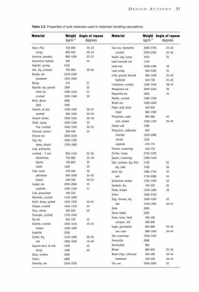
Table 3.2 Properties of bulk materials used in materials handling calculations
Material Weight Angle of repose Material Weight Angle of reposekg/m 3 degrees kg/m 3 degrees
Alum, fine 720–800 30–45lumpy 800–950 30–45
Alumina, powdery 800–1200 22–33Aluminium hydrate 290 34Asphalt, paving 2160Ash, dry, compact 700–800 30–40Baryte, ore 2220–2400
powdered 1920–2040Barley 670 27Bauxite. dry, ground 1090 35
mine run 1280–1440 31crushed 1200–1360 30
Brick, dense 2000light 1600
Cement, at rest 1300–1600 30–33aerated 960–1200 20–30
Cement clinker 1200–1520 30–40Chalk, lumpy 1200–1360 35
fine, crushed 1040–1200 30–35Charcoal, porous 290–400 35Chrome ore 2000–2240Clay, dry 1000–1100
damp, plastic 1750–1900Coal, anthracite,crushed, 3 mm 960–1140 25–30
bituminous 720–800 35–40lignite 700–850 35waste 1400 35
Coke, loose 370–560 30petroleum 600–1000 35–40breeze 400–560 30–45
Copper ore 2000–2800 35sulphate 1200–1360 31
Cork, granulated 190–240Dolomite, crushed 1440–1600Earth, damp, packed 1630–1930 40–45Felspar, crushed 1440–1750 34Flour, wheat 560–640 40Fluorspar, crushed 1750–1920Fly ash 640–720 42Granite, crushed 1360–1440 35–40
broken 1500–1600Graphite 2300Gravel, dry 1440–1600 30–38
wet 1800–1900 10–38Gypsum dust, at rest 1490 42
lumps 1600 40Glass, window 2600Gneiss 2800Ilmenite, ore 2240–2550
Iron ore, haematite 2600–3700 35–40
crushed 2200–2500 35–40
Kaolin clay, lumps 1010 35
Lead arsenate ore 1150
Lead ores 3200–4300 30
Lead oxides 960–2400 35
Lime, ground, burned 960–1400 35–40
hydrated 640–700 35–40
Limestone, crushed 1360–1440 38–45
Manganese ore 2000–2240 39
Magnetite ore 4000 35
Marble, crushed 1280–1500
Nickel ore 1280–2400
Paper, pulp stock 640–960
sheet 800–1500
Phosphate, super 800–880 45
rock, broken 1200–1350 25–39
Potash salt 1280
Potassium, carbonate 820
chloride 1920–2080
nitrate 1220
sulphate 670–770
Pumice, screenings 640–720
Pyrites, lumps 2150–2320
Quartz, screenings 1280–1440
Salt, common, dry, fine 1120 25
dry, cake 1360 36
Sand, dry 1580–1750 35
wet 1750–2080 45
Sandstone, broken 1350–1450 40
Sawdust, dry 150–220 36
Shale, broken 1450–1600 39
Sinter 1600–2150
Slag, furnace, dry 1020–1300 25
wet 1450–1600 40–45
Slate 2800
Stone rubble 2200
Snow, loose, fresh 200–400
compact, old 600–800
Sugar, granulated 800–880 25–30
raw, cane 880–1040 36–40
Talc screenings 1250–1450
Terracotta 2080
Vermiculite 800
Wheat 800–850 25–30
Wood chips, softwood 200–480 40–45
hardwood 450–500 40–45
Zinc ore 2600–2900 35
D E S I G N A C T I O N S 31
1106 SDHB 00-04 Final 8/6/05 12:03 PM Page 31
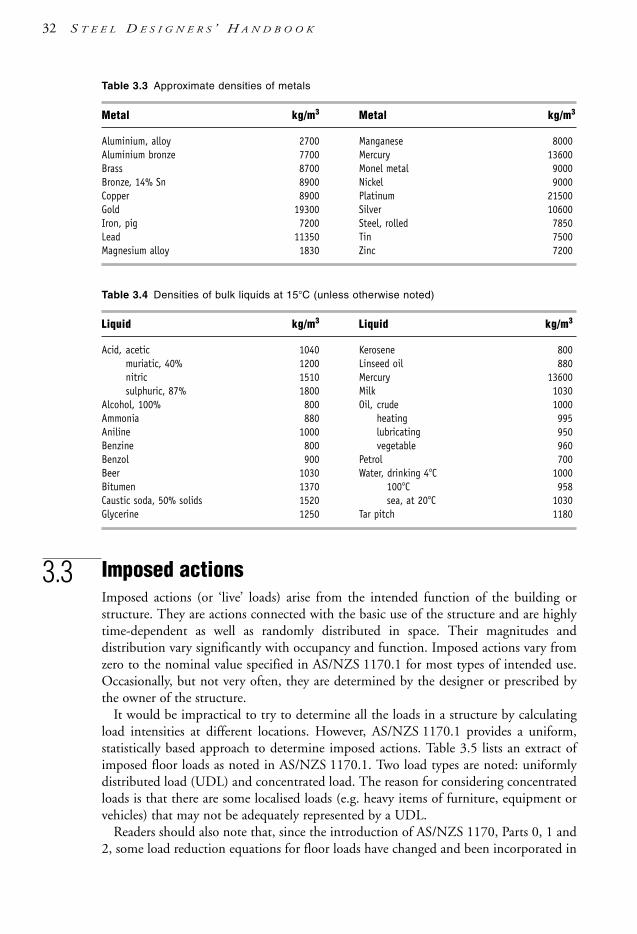
32 S T E E L D E S I G N E R S ’ H A N D B O O K
Table 3.3 Approximate densities of metals
Metal kg/m3 Metal kg/m3
Aluminium, alloy 2700 Manganese 8000Aluminium bronze 7700 Mercury 13600Brass 8700 Monel metal 9000Bronze, 14% Sn 8900 Nickel 9000Copper 8900 Platinum 21500Gold 19300 Silver 10600Iron, pig 7200 Steel, rolled 7850Lead 11350 Tin 7500Magnesium alloy 1830 Zinc 7200
Table 3.4 Densities of bulk liquids at 15°C (unless otherwise noted)
Liquid kg/m3 Liquid kg/m3
Acid, acetic 1040 Kerosene 800muriatic, 40% 1200 Linseed oil 880nitric 1510 Mercury 13600sulphuric, 87% 1800 Milk 1030
Alcohol, 100% 800 Oil, crude 1000Ammonia 880 heating 995Aniline 1000 lubricating 950Benzine 800 vegetable 960Benzol 900 Petrol 700Beer 1030 Water, drinking 4°C 1000Bitumen 1370 100°C 958Caustic soda, 50% solids 1520 sea, at 20°C 1030Glycerine 1250 Tar pitch 1180
3.3 Imposed actionsImposed actions (or ‘live’ loads) arise from the intended function of the building orstructure. They are actions connected with the basic use of the structure and are highlytime-dependent as well as randomly distributed in space. Their magnitudes anddistribution vary significantly with occupancy and function. Imposed actions vary fromzero to the nominal value specified in AS/NZS 1170.1 for most types of intended use.Occasionally, but not very often, they are determined by the designer or prescribed bythe owner of the structure.
It would be impractical to try to determine all the loads in a structure by calculatingload intensities at different locations. However, AS/NZS 1170.1 provides a uniform,statistically based approach to determine imposed actions. Table 3.5 lists an extract ofimposed floor loads as noted in AS/NZS 1170.1. Two load types are noted: uniformlydistributed load (UDL) and concentrated load. The reason for considering concentratedloads is that there are some localised loads (e.g. heavy items of furniture, equipment orvehicles) that may not be adequately represented by a UDL.
Readers should also note that, since the introduction of AS/NZS 1170, Parts 0, 1 and2, some load reduction equations for floor loads have changed and been incorporated in
1106 SDHB 00-04 Final 8/6/05 12:03 PM Page 32

a factor for reduction of imposed floor loads due to area (ca)—see Clauses 3.4.1 and3.4.2 of AS/NZS 1170.1. Overall, it is argued, the effect is the same. Additionally, therehas been some change in the philosophy of loading and magnitude of load to reflect theNew Zealand and ISO (International Organization for Standardization) principles.Reference should be made to the Supplementary Commentary of AS/NZS 1170.1 forfurther information on the changes and use of the Standard.
Table 3.5 Typical values of imposed floor and roof loads
Specific uses UDL Concentrated loadkN/m2 kN
Self-contained dwellings 1.5 1.8
Balconies and accessible roof areas
in self-contained dwellings 2.0 1.8
Offices for general use, classrooms (with tables) 3.0 2.7
Work rooms, light industrial (no storage) 3.0 3.5
Public assembly areas with fixed seats 4.0 2.7
Terraces and plazas 4.0 4.5
Assembly areas without fixed seating 5.0 3.6
Parking garages restricted to cars 2.5 13
Structural elements and cladding of roofs 0.12+1.8/A 1.4
Min 0.25
Roof trusses, joists, hangers - 1.4
Note: (1) For further information and detailed tabulation of specific imposed action requirements see AS/NZS 1170.1. (2) A = plan projection of roof area supported by member, in sq.m.
3.4 Wind actionsWind load intensities and load determination are specified in AS/NSZ 1170.2.
The site wind speed is given by:
Vsit, β = VRMd (Mz,cat MsMt)
where VR = 3 second gust speed applicable to the region and for an annual probabilityof exceedance, 1/R (500 return period for normal structures)—see Table 3.6
Md = 1.0 or smaller wind direction multiplier
Mz,cat = multiplier for building height and terrain category—see Table 3.7
Ms = shielding multiplier—upwind buildings effect
Mt = topographical multiplier—effect of ramping, ridges
The reference annual probability of exceedance is linked to the risk of failure levels(importance levels) as specified in AS/NZS 1170.0. The design wind forces aredetermined from the following expression:
D E S I G N A C T I O N S 33
1106 SDHB 00-04 Final 8/6/05 12:03 PM Page 33

F = 0.5ρair (Vdes,θ )2 Cfig Cdyn Aref
with ρair = 1.2 kg/m3 (density of air), then
F = 0.0006(Vdes,θ)2 Cfig Cdyn Aref
where F is the design wind force in kN
Vdes,θ = maximum value of Vsit, β (see above)= design wind speed
Cfig = aerodynamic shape factor—internal and external pressures
Cdyn = dynamic response factor, use 1.0 unless the structure is windsensitive
Aref = reference area, at height upon which the wind pressure acts,in sq.m.
Table 3.6 Regional wind speed (VR) for annual probability of exceedance of 1 in 500 (V500) fornormal structures
Region Wind velocity Citiesfor V500 in Australia in New Zealand
A1 to A7 45 m/s Brisbane, Hobart, Auckland, Dunedin,
Perth, Sydney, Adelaide, Christchurch,
Canberra, Melbourne Westport, Wanganui
B 57 m/s Norfolk Is., Brisbane
C 66 m/s Cairns, Townsville
Darwin, Pt Hedland
D 80 m/s Carnarvon, Onslow
W 51 m/s Wellington
Note: Refer to AS/NZS 1170.2 for other locations and probability levels.
Table 3.7 Terrain category and height multiplier Mz,cat for ultimate limit state design (notserviceability) in regions A1 to A7, W and B.
Height Terrain categorym 1 2 3 4
5 1.05 0.91 0.83 0.75
10 1.12 1.0 0.83 0.75
15 1.16 1.05 0.89 0.75
20 1.19 1.08 0.94 0.75
30 1.22 1.12 1.00 0.80
50 1.25 1.18 1.07 0.90
100 1.29 1.24 1.16 1.03
34 S T E E L D E S I G N E R S ’ H A N D B O O K
1106 SDHB 00-04 Final 8/6/05 12:03 PM Page 34

3.5 Earthquake actionsIntuitively, the structural response to wind actions is somewhat immediate to theapplication of the actions—that is, a typical building structure responds directly to thepressure forces imposed on its surfaces. In contrast, earthquake actions arise from thestructure’s response to base (foundation) movements. That is, the building structure doesnot respond to forces imparted directly to it—it responds to translational movements atthe base. This means that inertial forces come into play which, coupled with effects fromthe distribution of the structure’s mass and stiffness, may not be synchronised with thebase movement (in terms of time and intensity). Though different in the nature ofloading, earthquake loads on structures can be modelled in design by using quasi-staticloads, much like the design for wind loads.
At the time of this Handbook, there is no joint Australian and New Zealandearthquake loading (action) Standard. From an Australian perspective, load evaluationand other requirements (e.g. detailing, ductility of framing) for earthquakes are coveredin AS 1170.4. Section 13 of AS 4100 sets out some additional minimum design anddetailing requirements.
The method of determining ultimate limit state earthquake forces from AS 1170.4requires the following parameters to be evaluated:• Acceleration coefficient (a)—dependent on geographic location and expressed as a
proportion of the gravity constant (g). It is a measure of the relative seismicity of aregion and relates the effective peak ground acceleration, which approximatelycorresponds to a 500-year return period. Typical values of a range between 0.03 to0.22 in Australia.
• Site factor (S)—dependent on site-verified geotechnical data, it considers foundationmaterial conditions and stiffness, and varies between 0.67 (rock) and 2.0 (silts and softclays) in Australia.
• Structure classification—Types I, II or III, which reflects the importance of a buildingin terms of post-disaster functions. Type III buildings are required for post-earthquakeroles or structures for hazardous operations. Type II buildings include those whichcontain many people, and Type I buildings consider general structures and thosebuildings not placed in the other categories.
• Earthquake design category of the building—categories A, B, C, D or E and evaluatedfrom Structure classification, a and S.
• Whether the structural configuration is considered regular or irregular in both itshorizontal and vertical planes. Irregularities may arise from geometric, stiffness andmass asymmetries and discontinuities.
The type of earthquake design category and the structural regularity/irregularitydetermines the type of analysis (static or dynamic) required. If static analysis is undertaken,the base shear force (V) imparted by the earthquake on the structure is given by:
V = Gg with CS <2.5aCSIRf
D E S I G N A C T I O N S 35
1106 SDHB 00-04 Final 8/6/05 12:03 PM Page 35

where
C = earthquake design coefficient and is a function of accelerationand the structural period of vibration (T )
= 1.25aT – 0.667
a = acceleration coefficient as noted above
T = the structure period (in seconds), which may be evaluated by asimple method or rigorous structural analysis
S = site factor as noted above
I = importance factor of the structure and is dependent on structureclassification. It can be 1.25 (for critically important structures)and 1.0 (generally all others)
Rf = structural response factor and considers the structure’s energy-absorbing capabilities and can range between 4 to 8 for structuralsteel
Gg = the gravity load on the structure, which includes the permanentloads plus a portion of the imposed loads that can be reasonablyexpected during an earthquake event
After the evaluation of V, the individual floor loads are distributed up the structure withrespect to height and vertical mass distribution. In lieu of static analysis, a dynamicanalysis is undertaken for irregular steel buildings in Earthquake Design Categories Dand E. Additional considerations for structures subject to earthquakes include torsionaleffects at each storey, overturning stability effects and drift (overall) deflections.
Further useful references, which detail the background and use of AS 1170.4 and theseismic provisions of AS 4100, include the Commentaries to both Standards, Woodside[1994], Hutchinson et al. [1994] and McBean [1997].
3.6 Other actionsAs specified in AS/NZS 1170.0, various other actions must be considered in the designof buildings and other structures. Where relevant, such actions include:• snow and ice loads (as noted in AS/NZS 1170.3)• retaining wall/earth pressures• liquid pressures• ground water effects• rainwater ponding on roofs• dynamic actions of installed machinery, plant, equipment and crane loads• vehicle and vehicle impact loads• temperature effects (changes and gradients)• construction loads• silo and containment vessel loads• differential settlement of foundations• volumetric changes (e.g. shrinkage, creep)
36 S T E E L D E S I G N E R S ’ H A N D B O O K
1106 SDHB 00-04 Final 8/6/05 12:03 PM Page 36

• axial shortening from imposed actions• special structure requirements and responses.
Due to space constraints, these highly specialised actions are not considered in thisHandbook, and are covered in the relevant supporting publications of the topic. Thesuite of AS/NZS 1170 and AS 1170 standards and their supplementary commentariesshed further light on these other actions, and may provide a starting point for seekingfurther information.
3.7 Notional horizontal forcesWithin the General Design Requirements (Section 3) of AS 4100, Clause 3.2.4 requiresdesigners to consider notional horizontal forces for (only) multi-storey buildings. Thehorizontal force is equal to 0.002 (0.2%) times the design vertical loads for eachparticular floor level and is considered to act in conjunction with the vertical loads. Therationale for this provision is to allow for the minimum horizontal actions arising fromthe ‘out-of-plumb’ tolerance limits for erected columns in such structures (i.e. 1/500from Clause 15.3.3 of AS 4100). It should be noted that these ‘notional’ horizontalforces are for action combinations involving vertical permanent and imposed loads only,and need not be used in combination with the following:• other imposed horizontal/lateral actions (e.g. wind, earthquake actions)• 2.5% restraint forces used for the design of beam and column restraints• any of the limit states except for strength and serviceability.
At the time of writing this Handbook, Clause 6.2.2 of AS 1170 specifies a minimumlateral resistance of buildings of 0.2% of the sum of vertical actions, and that is similarto the notional force provision in AS 4100. However, in AS/NZS 1170.0, the notionalforce termed ‘minimum lateral resistance’ in Clause 6.2.2 is increased to 2.5% of thevertical sum of (G + ccQ ) for each level. Thus, the AS/NZS 1170.0 requirement wouldseem to be more onerous for multi-storey buildings and may need to be harmonised withAS 4100. Clause 6.2.3 of AS/NZS 1170.0 also specifies that all parts of the structuresshould be interconnected, and members used for that purpose should have connectionscapable of resisting a force equal to 5% of the relevant sum of (G + ccQ ) over thetributary area relying on the connection.
3.8 Temperature actionsAny change of temperature results in deformation of the structure. Uniform temperaturevariation produces internal action effects only where the structure is constrained atsupport points. Temperature gradients (i.e. non-uniform temperature distribution) resultin internal action effects in addition to deformations (bowing). The main factors toconsider are the ambient temperature range, solar radiation, internal heating or cooling,and snow cover.
AS/NZS 1170.0, Supplement 1, Appendix CZ lists the extreme temperatures inAustralia.
D E S I G N A C T I O N S 37
1106 SDHB 00-04 Final 8/6/05 12:03 PM Page 37

38 S T E E L D E S I G N E R S ’ H A N D B O O K
The action combination factor for temperature actions is taken as 1.25. The thermalcoefficient of carbon/manganese steels, αT, is 11.7 × 10⁻⁶ per degree Celsius.
3.9 Silo loadsMaterial properties, loads and flow load factors for bulk storage structures are given inAS 3774, together with the methods of calculating the load effects for the design of thecontainer walls and the support structure.
3.10 Crane and hoist loadsLoads and dynamic factors for the design of crane structures are specified in AS 1418.1.Methods of calculating load effects for crane runway girders and monorails are coveredby AS 1418.18.
3.11 Design action combinationsThe combinations of design actions are considered in Section 4 of AS/NZS 1170.0 andin Sections 1.6 and 3.1 of this Handbook.
3.12 Further reading• All the commentaries to the AS/NZS 1170 series of Standards, and the commentaries
to AS 1170.3 (Snow loads) and AS 1170.4 (Earthquake loads).• Specific load/action requirements may be required for platforms, walkways, stairways
and ladders—see AS 1657.• Special loads/actions (e.g. construction loads) may be required for composite steel-
concrete systems during construction (e.g. placement of fresh concrete) before thecomposite structural system is effected (i.e. concrete is cured)—AS 2327.1.
• Loads encountered during the erection of steelwork—see AS 3828.• For floor vibrations—see Murray [1990].• The detailed and rigorous aspects of bridge loading and design is considered in
AS 5100.
1106 SDHB 00-04 Final 8/6/05 12:03 PM Page 38

4.1 Calculation of design action effectsThe objective of structural analysis is to determine internal forces and moments, ordesign action effects. The input into structural analysis consists of frame geometry,member and connection properties, and design actions. Design actions are factored loads(e.g. permanent, imposed, wind, etc.) applied to the structure (see Chapter 3). Theanalysis output includes design action effects (M*, N*, V* ) and deformations.
It should be noted that at the time of publication there is a slight mismatch betweenthe notation in AS 4100 and AS/NZS 1170. Consequently, the notation used in thisHandbook follows the convention noted below:• AS 4100 notation for design capacities and design action effects using a superscript
asterisk, e.g. M* stands for design bending moment• AS/NZS 1170 notation is used for general actions.
Methods of structural analysis range from simple to complex, depending on thestructural form. The designer must decide which method will be adequate for the task,having in mind the degree of accuracy required. The time required to assemble data forrigorous analysis is a consideration, hence simple methods are usually employed inpreliminary design.
It is a requirement of AS 4100 that second-order effects be considered—that is, theinteraction between loads and deformations. In other words, the effects of framedeformations and member curvature must be taken into account either as a part of theframe analysis or separately. Prior to conversion to the limit state design, a ‘first-order’analysis was all that was required for most structures, though ‘second-order’ effects wereapproximately considered in combined actions. In first-order analysis the deformationsof the structure are calculated during the process of solution, but the deformations areassumed to be independent of the design action effects. In reality the deformations of thestructure and the design action effects are coupled, and the method of analysis thatreflects this is termed ‘second-order’ analysis.
The second-order effects due to changes in geometry during the analysis are oftensmall enough to be neglected, but can be significant in special types of structures such as
c h a p t e r 4
Structural Analysis
1106 SDHB 00-04 Final 8/6/05 12:03 PM Page 39
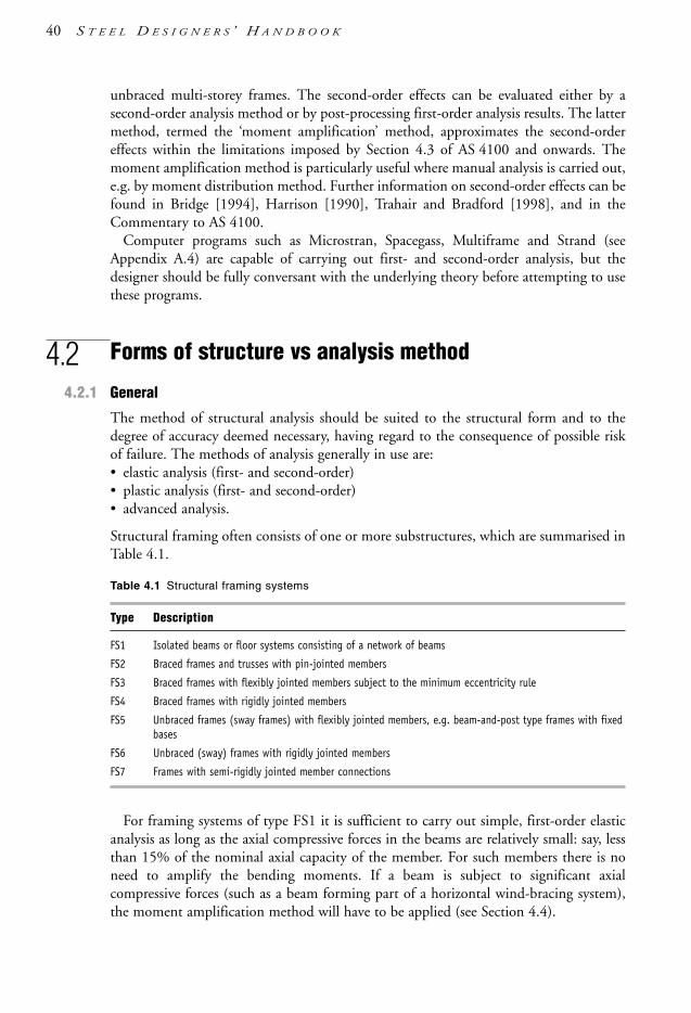
unbraced multi-storey frames. The second-order effects can be evaluated either by asecond-order analysis method or by post-processing first-order analysis results. The lattermethod, termed the ‘moment amplification’ method, approximates the second-ordereffects within the limitations imposed by Section 4.3 of AS 4100 and onwards. Themoment amplification method is particularly useful where manual analysis is carried out,e.g. by moment distribution method. Further information on second-order effects can befound in Bridge [1994], Harrison [1990], Trahair and Bradford [1998], and in theCommentary to AS 4100.
Computer programs such as Microstran, Spacegass, Multiframe and Strand (seeAppendix A.4) are capable of carrying out first- and second-order analysis, but thedesigner should be fully conversant with the underlying theory before attempting to usethese programs.
4.2 Forms of structure vs analysis method
4.2.1 General
The method of structural analysis should be suited to the structural form and to thedegree of accuracy deemed necessary, having regard to the consequence of possible riskof failure. The methods of analysis generally in use are:• elastic analysis (first- and second-order)• plastic analysis (first- and second-order)• advanced analysis.
Structural framing often consists of one or more substructures, which are summarised inTable 4.1.
Table 4.1 Structural framing systems
Type Description
FS1 Isolated beams or floor systems consisting of a network of beams
FS2 Braced frames and trusses with pin-jointed members
FS3 Braced frames with flexibly jointed members subject to the minimum eccentricity rule
FS4 Braced frames with rigidly jointed members
FS5 Unbraced frames (sway frames) with flexibly jointed members, e.g. beam-and-post type frames with fixedbases
FS6 Unbraced (sway) frames with rigidly jointed members
FS7 Frames with semi-rigidly jointed member connections
For framing systems of type FS1 it is sufficient to carry out simple, first-order elasticanalysis as long as the axial compressive forces in the beams are relatively small: say, lessthan 15% of the nominal axial capacity of the member. For such members there is noneed to amplify the bending moments. If a beam is subject to significant axialcompressive forces (such as a beam forming part of a horizontal wind-bracing system),the moment amplification method will have to be applied (see Section 4.4).
40 S T E E L D E S I G N E R S ’ H A N D B O O K
1106 SDHB 00-04 Final 8/6/05 12:03 PM Page 40

Framing system FS2 with rotationally free connections using actual pin connectionscan also be analysed by simple, first-order analysis subject to the same limitations as forsystem FS1. Should transverse loads be applied to a column or between nodes on a trussmember, moment amplification is likely to apply.
The difference between framing systems FS3 and FS2 is that flexible connectionstransfer small bending moments to the columns, and AS 4100 requires a specificminimum eccentricity to be applied in calculating the column end bending moments.The most appropriate method of analysis is first-order elastic analysis followed by amoment amplification procedure for columns. The beams will normally require nomoment amplification unless significant axial compression is induced in them, e.g.beams forming part of the bracing system.
The first-order elastic analysis for framing systems FS1 to FS3 can be quite simple andhand analysis is sufficient in most cases. Such structures can be broken up into individualmembers for rapid design. A check should be made to ascertain that the connectionsoffer only a minimal rotation resistance. Standard flexible end plates and web cleats areequally suitable.
Figure 4.1 Bending moment imposed on columns due to eccentricity
emin 100
R
emin 100 mm
emin 100 ec
mm
mm
*R*
R*
R*
column centreline
S T R U C T U R A L A N A L Y S I S 41
1106 SDHB 00-04 Final 8/6/05 12:03 PM Page 41

With framing systems FS4 to FS7, columns attract significant bending moments andtherefore the appropriate procedure is to carry out either a second-order analysis or thefirst-order analysis followed by moment amplification for all members subject to bendingand compressive axial force.
It is a requirement of AS 4100 (Clause 4.3.4) that columns carrying simply supportedbeams (types FS1 and FS2) be designed for a moment arising from the eccentricapplication of the beam reaction:
ec = d2 + dr
where d2 is the distance from the column centre line to the column face adjacent to thebeam connection and dr is taken as the greater of 100 mm or the distance to the centreof bearing, which can be approximated to be equal to one-half of the bracket length inthe direction of the beam. Where a beam rests on a column cap plate, the eccentricity ec
is taken as being equal to the distance from the centre line of the column to the columnface (see Figure 4.1).
4.2.2 Subdivision into substructures
It is often possible to simplify the analysis by subdividing the total structure into smallersubstructures, which are easier to analyse. The subdivision should follow the planes ofweak interaction between the substructures.
The best insight into the working of the framing system can be gained by consideringthe third dimension. Many framing systems are arranged in the form of parallel frameswith weak interaction between the parallel frames, which makes it possible to deal witheach frame separately. For example, a single-storey warehouse building can be subdividedinto portal frames loaded in their plane and infill members (braces, purlins, girts) at rightangles to the portal frames.
Where the floor system is relatively rigid in its plane, the frames are forced to deflectlaterally by the same amounts but otherwise carry the vertical loads independently. Anexample of such frame is the multi-storey building frame with a concrete floor over thesteel beams. Here the structural model can be simplified for computational purposes byarranging the frames in a single plane with hinged links between them.
Some frames are designed to interact three-dimensionally and should therefore beanalysed as one entity. Typical of these are space grid roofs, latticed towers and two-waybuilding frames.
Rigidly joined substructures with no bracing elements rely entirely on the framerigidity to remain stable. Connections must be designed to be able to transmit all theactions with minimum distortion of the joints. Such frames are usually initially analysedby an elastic or plastic first-order analysis, followed by an assessment of second-ordereffects to verify their stability against frame buckling.
42 S T E E L D E S I G N E R S ’ H A N D B O O K
1106 SDHB 00-04 Final 8/6/05 12:03 PM Page 42

4.3 Calculation of second-order effects
4.3.1 General
AS 4100 requires that the design action effects due to the displacement of the frame anddeformations of the members’ action be determined by a second-order analysis or amethod that closely approximates the results of a second-order analysis.
All frames undergo some sway deformations under load. Sway deformations of bracedframes are often too small to be considered. Unbraced frames rely on the rigidity of theconnections, and their sway deformations cannot be neglected. The sway may be causedby lateral or asymmetrical vertical forces but most often by inadequate stability undersignificant axial forces in the columns.
In performing a simple elastic analysis, the computational process ends with thedetermination of bending moments, axial and shear forces. Displacements of nodes aredetermined in the final steps of the analysis, but there is no feedback to include theeffects of the changed frame geometry in successive steps of the analysis. Such a methodof elastic analysis is known as first-order analysis.
Figure 4.2 shows bending moments and deformations of a single-storey rigid framesubject to vertical and lateral loads. As can be seen, the tops of columns undergo lateraldisplacement, ∆. Hence they are no longer vertical and straight. Applied vertical forcesP1 and P2 act on slanted columns and thus tend to displace the nodes further right, withthe consequence that the bending moments M1 and M2 will increase. This second-ordereffect is also known as the P-∆ (P-large delta) effect. Additionally, the axial compressiveforces in the deformed beam-column members also produce bending moments in thecolumns, equal to P-δ (that is the P-small delta effect).
It should be noted that the P-∆ effect is primarily due to the relative lateral movementof the member ends from sway frame action. However, the second-order moments fromP-δ effects is due to the interaction of individual member curvature (from bendingmoments) with the axial compression forces present. In this instance there need not beany relative transverse displacement between the member ends (i.e. a braced member) forthe second-order moment to occur.
Strictly speaking, member/frame second-order effects can be noticed in the followingaction effects:• bending moments: from the interaction of axial compression, member curvature from
flexure and sway deflections• bending moments: from flexural straining (additional curvature deformations)• axial loads: from axial straining (i.e. shortening or lengthening)• bending moments and axial loads: from shear straining effects.
The last three second-order effects are not significant for typical steelwork applicationsand are not specifically considered in the body of AS 4100. If required, commonlyavailable structural analysis programs provide non-linear options to consider thesesecond-order effects (see Appendix A.4). Shear straining effects are somewhat rare andcan arise from very stubby members with relatively high shear loads. Hence, from anAS 4100 perspective and practically speaking, the only second-order effects to be
S T R U C T U R A L A N A L Y S I S 43
1106 SDHB 00-04 Final 8/6/05 12:03 PM Page 43

44 S T E E L D E S I G N E R S ’ H A N D B O O K
considered are changes to bending moments from the interaction of axial compression,member curvature and sway deflections.
a 1st-order deflectionsb 2nd-order deflections: ∆2 ∆1c 1st-order momentsd 2nd-order moments: M2 M1
Figure 4.2 Moment amplification on a single-storey rigid frame
When a rational second-order elastic analysis is carried out, the design action effectsM*, V*, N* are obtained directly from the analysis. The analysis tracks the magnitudes ofall displacements as it proceeds to the evaluation of design action effects until alldisplacements converge. If convergence is not achieved, the structure is regarded as beingunstable. No further amplification of bending moments needs to be applied.
There are two strategies for avoiding excessive design effort: one is to use a simplifiedprocedure such as the moment amplification method, and the other is to employ acomputer program (e.g. ‘Spacegass’, ‘Microstran’, ‘Multiframe’—see Appendix A.4)suited to the task. Modelling of the structure for a second-order analysis should be carriedout with great care, as the structure must be fully modelled, including the secondary(restraint) members.
AS 4100 allows, as a lower-tier option, replacing the second-order analysis with asimpler manual procedure. Termed the ‘moment amplification method’ (as described inClause 4.4 of AS 4100) it can be used for simple structures which can result in an overallsaving in time while keeping the process easy to visualise and understand. Section 4.4describes the method in detail. For further reading on the subject, the reader is directedto Trahair [1992a,b,c,1993a] and Trahair & Bradford [1998].
4.3.2 Escape routes
As discussed earlier, flexural members are normally subject to negligible axial forces andare therefore not subject to second-order effects. Similarly, tension members are notsubject to second-order effects. Triangulated frames in which member forces arepredominantly axial and no transverse forces are applied between the nodes of thecompression chord can also be designed on the basis of first-order analysis alone. This isfurther elaborated in Sections 4.4.
P1
V
P21
2
M2
M1
A B
cd
ab
1106 SDHB 00-04 Final 8/6/05 12:03 PM Page 44

S T R U C T U R A L A N A L Y S I S 45
4.4 Moment amplification method in detail
4.4.1 Basis of the method
As an example, the moment amplification method consists of the following steps:
(a) elastic first-order analysis(b) calculation of the moment amplification factors(c) checking that the moment amplification factor δ (or ∆ if applicable) does not exceed
the value of 1.4(d) evaluation of design moments in all members subject to the axial compression force,
i.e.:
M* M δ
An amplification factor greater than 1.4 would indicate that the frame was too flexibleand probably would not pass the serviceability check. The options left to the designer insuch a case are either to redesign the frame or to try to use an advanced method ofanalysis and so, one hopes, verify the design.
Any member in the frame subject to axial tension or relatively small axial compressiveforce (e.g. beams and ties) is assumed to have a moment amplification factor of 1.0.
4.4.2 Moment amplification procedure
A distinction should be made between braced and unbraced (sway) members and frames.In AS 4100 terminology, braced members are those which undergo no sway under load,i.e. no relative transverse displacement between the ends of the members. For example,the members in rectangular frames can be categorised as follows:• braced frame — columns and beams are braced members• sway frame — columns are sway members and beams are braced unless axial
compression is significant.
4.4.2.1 Braced members and framesThe procedure for calculating the moment amplification factor is as follows:
(a) Determine elastic flexural buckling load Nomb for each braced compressive member:
Nomb =
The effective length factor ke is equal to 1.0 for pin-ended columns and varies from 0.7to 1.0 for other end conditions, as explained in Section 4.5.
(b) Calculate the factor for unequal moments, cm. For a constant moment along themember, cm=1.0, and this is always conservative. For other moment distributions thevalue of cm lies between 0.2 and 1.0. The method of calculating cm is given in Section4.6.
(c) Calculate the moment amplification factor for a braced member, δb, from:
δb = 1.0
cm
1 – NN
om
*
b
π2EI(ke l )
2
1106 SDHB 00-04 Final 8/6/05 12:03 PM Page 45

where N* is the design axial compressive force for the member being considered.
(d) Check that δb does not exceed 1.4. Otherwise the frame is probably very sensitive toP-δ effects, and a second-order analysis is then necessary unless the frame stiffness isenhanced.
(e) Multiply bending moments from the first-order analysis by δb to obtain the designbending moments:
M* = Mm δb
where Mm is the maximum bending moment in the member being considered. Thiscalculation is carried out on a member-by-member basis. See Table 4.2 on the use of theabove approximate method for specific structural forms and loading distributions.
4.4.2.2 Sway members and framesMoment amplification factors for ‘sway’ members δs in regular, rectangular sway framesare calculated as follows:
δs =
where c3 =
∆s is the translational displacement of the top relative to the bottom in storey height (hs)from a first-order analysis, ΣN* is the sum of all design axial forces in the storey underconsideration and ΣV* is the sum of column shears in the storey under consideration.See structural form and loading no. 8 in Table 4.2 for a description of these parameters.The above procedure provides a generally conservative approach and is termed the storeyshear-displacement moment amplification method.
Alternatively, δs can be calculated from elastic buckling load factor methods such that:
δs = =
whereλms = elastic buckling load factor for the storey under consideration
= for rectangular frames with regular loading andnegligible axial forces in the beams
Noms = elastic buckling load factor (Nom) for a sway member (seeSection 4.5)
l = member length = storey height
N * = member design axial force with tension taken as negative andthe summation includes all columns within a storey
ΣN
loms
ΣNl
*
1
1
1
c
1
1
1
ms
(∆s ΣN* )(hs ΣV* )
1(1 – c3)
46 S T E E L D E S I G N E R S ’ H A N D B O O K
1106 SDHB 00-04 Final 8/6/05 12:03 PM Page 46

S T R U C T U R A L A N A L Y S I S 47
λc = elastic buckling load factor determined from a rational bucklinganalysis of the whole frame
= the lowest of all the λms values for a multi-storey rectangularsway frame
If λms or λc is greater than 3.5, then δs will exceed 1.4, which means that a rationalsecond-order analysis is required or the frame stiffness needs to be enhanced. For manysituations, and when possible, the storey shear-displacement moment amplificationmethod is used when first-order deflections are known. When these deflections areunknown, the λms method is used, but there is the requirement of regular loading on theframe with negligible axial forces in the beams. The λc method requires a rationalbuckling method analysis program that may not be commonly available.
In conjunction with the evaluation of δs there is also a requirement to calculate δb (seeSection 4.4.2.1) for the sway member, i.e.:
δb = 1.0
The overall moment amplification factor for a sway member/frame (δm) can now beevaluated:
If δb > δs then δm= δb, otherwise δm= δs .
A value of δm >1.4 indicates that the frame may be very sway sensitive and the abovesimplified method may have no validity with second-order analysis being necessary.
The final stage is to multiply bending moments from the first-order analysis by δm toobtain the design bending moments:
M* = Mm δm
This calculation is carried out on a member-by-member basis. See Table 4.2 on the useof the above approximate method for specific structural forms and loading distributions.
4.4.3 Limitations and short cuts
Excluded from the approximate methods in Section 4.4.2 are non-rectangular framessuch as pitched portal frames (having a pitch in excess of 15 degrees). Also excluded areframes where beams are subject to relatively high axial compressive loads, highlyirregularly distributed loads or complex geometry. These frames must be analysed by asecond-order or rational frame buckling analysis, as outlined in AS 4100.
The above methods can be applied successfully to a majority of rectangular frames aslong as the following limitations apply:• live loads are relatively regularly distributed through all bays• frames are of sufficient rigidity, i.e. the moment amplification factors are less than 1.4• for members within a frame, the member is not subject to actions from an adjacent
member which is a critically loaded compression member and consequently theadjacent member will increase the moments of the member under consideration.
It should also be noted that some references (e.g. AS 4100 Commentary) suggest thatsecond-order effects of less than 10% may be neglected.
cm
1 NN
om
*
b
1106 SDHB 00-04 Final 8/6/05 12:03 PM Page 47

48 S T E E L D E S I G N E R S ’ H A N D B O O K
Portal frames with sloping rafters may be treated as rectangular frames, provided thatthe pitch of the rafters does not exceed 15 degrees. Columns of such frames are usuallylightly loaded in compression and can be expected to have an amplification factorbetween 1.0. and 1.15.
Braced rectangular frames will normally fall into the ‘unity amplification’ category iftheir columns are bent in double curvature (βm>0, cm<0.6), see Section 4.6.
Trusses and other triangulated frames of light to medium construction would normallyneed no second-order analysis, as the bending moments in members are normally quitesmall. Where members in the web are relatively stocky in the plane of the truss, say l/r<60, the moment amplification factor should be computed.
In general, it is worth noting that the aspects likely to increase the value of the momentamplification factor are the following:• a high ratio of design compressive axial load to the elastic flexural buckling load of the
member• bending moments producing single curvature bending combined with relatively high
axial compression load.
Table 4.2 gives some examples of members and framing systems with suggested methodsof analysis.
Table 4.2 Suggested methods of analysis and use of moment amplification factors
Case 1st or 2nd order Moment amplification Structural form and (Braced or sway) factor loading
1 1 δb = 1.0
Braced
2 1 δb = 1.0 (Tension forces)Braced
3 1 δb = 1.0 (No compressive force)Braced
4 1 δb = 1.0Braced
M*
UDL or concentrated loads
N*N*cm
1 – NN
om
*
b
M*
UDL or concentrated loads
M2* M1
*
N*N*
M2* M1
*
N*N*cm
1 – NN
om
*
b
1106 SDHB 00-04 Final 8/6/05 12:03 PM Page 48
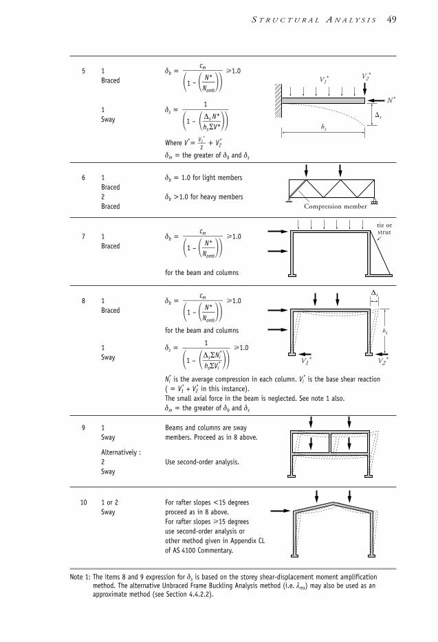
S T R U C T U R A L A N A L Y S I S 49
5 1 δb = 1.0Braced
1 δs =Sway
Where V*= V21*
+ V2*
δm = the greater of δb and δs
6 1 δb = 1.0 for light membersBraced2 δb >1.0 for heavy membersBraced
7 1 δb = 1.0Braced
for the beam and columns
8 1 δb = 1.0Braced
for the beam and columns
1 δs = 1.0Sway
Ni* is the average compression in each column. Vi
* is the base shear reaction ( = V1
* + V2* in this instance).
The small axial force in the beam is neglected. See note 1 also. δm = the greater of δb and δs
9 1 Beams and columns are sway Sway members. Proceed as in 8 above.
Alternatively :2 Use second-order analysis.Sway
10 1 or 2 For rafter slopes <15 degrees Sway proceed as in 8 above.
For rafter slopes 15 degrees use second-order analysis or other method given in Appendix CLof AS 4100 Commentary.
Note 1: The items 8 and 9 expression for δs is based on the storey shear-displacement moment amplificationmethod. The alternative Unbraced Frame Buckling Analysis method (i.e. λms) may also be used as anapproximate method (see Section 4.4.2.2).
1
1 – ∆hs
s
ΣΣVN
i*i*
V1* V2
*
hs
∆scm
1 – NN
om
*
b
tie orstrutcm
1 – NN
om
*
b
Compression member
1
1 – h∆s
s
ΣNV**
N *
V2* V1
*
hs
s
cm
1 – NN
om
*
b
1106 SDHB 00-04 Final 8/6/05 12:03 PM Page 49

4.5 Elastic flexural buckling load of a member4.5.1 General
In the previous sections frequent reference is made to the elastic flexural buckling load ofa member, Nom:
Nom =
where I is the second moment area in the relevant buckling mode, ke is a factor used ineffective length calculations and l is the ‘system’ length of the member—that is, thelength between the centres of the intersecting members or footings.
The value of the effective length factor, ke, depends on the stiffness of the rotationaland translational restraints at the member ends. The effective length (le) of a column-typemember is readily calculated as:
le = ke l
For a braced member, ke has a value between 0.7 and 1.0 (see Figure 4.6.3.2 of AS 4100).A sway member will have a ke larger than 1.0 and has no defined upper limit. Generally, theend restraint condition of a compression member can be divided into two categories: thosewith idealised end restraints, and those which are part of a frame with rigid connections.
4.5.2 Members with idealised end connections
Clause 4.6.3.2 of AS 4100 lists the applicable effective length factor (ke) for thecombination of idealised connection types at the end of a compression member (e.g.pinned or encased/fixed in rotation and braced or sway in lateral translation). This issummarised in Figure 4.3.
Case
Characteristic
Rotational end restraintTop PIN FIX PIN NIL FIXBottom PIN FIX FIX FIX FIX
Translational restraintTop R R R NIL NILBottom R R R R R
ke l
le 1.0 0.7 0.85 2.2 1.2
Legend: PIN pinned; FIX fixed; R restrained.
Figure 4.3 Effective length factor for members with idealised end constraints
l
π2EI(ke l )2
50 S T E E L D E S I G N E R S ’ H A N D B O O K
1106 SDHB 00-04 Final 8/6/05 12:03 PM Page 50

4.5.3 Members in frames
Many end connections of compression members to other steelwork elements cannot becategorised as ideal, as they may fit somewhere between the fixed and pinned type ofconnection. This is particularly the case for members in frames, as noted in Figure 4.4,where the connection type will influence the buckled shape of the individual membersand the overall frame.
(a) Flexible (b) Rigid (c) Semi-rigid
Figure 4.4 Influence of member connection fixity on buckled member and frame shape
Where a compression member is a part of a rectangular frame with regular loading andnegligible axial forces in the beams, the method given in Clauses 4.6.3.3 and 4.6.3.4 ofAS 4100 should be used. The method consists of evaluating the restraint stiffness, γ1 andγ2 , at each column end, that is:
γ = SS
b
c
where Sc and Sb are the flexural stiffnesses of the columns and beams respectively,meeting at the node being considered, giving the combined stiffnesses:
Sc = ΣIlcc
Sb = ΣIlbb βe
where Ic and Ib are respectively the column and beam second moment of area for thein-plane buckling mode, lc and lb are column and beam lengths respectively and βe is amodifying factor that varies with the end restraint of the beam end opposite the columnconnection being considered. Table 4.3 lists the values of βe as noted in Clause 4.6.3.4of AS 4100.
l2
l1
S T R U C T U R A L A N A L Y S I S 51
1106 SDHB 00-04 Final 8/6/05 12:03 PM Page 51

Table 4.3 Modifying factor, βe, for connection conditions at the far beam end
Far end fixity Modifying factor, βe, for member type being restrained by beam
Braced Sway
Pinned 1.5 0.5
Rigidly connected to the column 1.0 1.0
Rotationally fixed 2.0 0.67
For columns with end restraints to footings, Clause 4.6.3.4 of AS 4100 also stipulatesthe following:• column end restraint stiffness, γ, is not less than 10 if the compression member is not
rigidly connected to the footing, or• γ is not less than 0.6 if the compression member is rigidly connected to the footing.
Figure 4.5 Effective length factor ke in accordance with AS 4100
0.5
0
0.5 1.0 1.2 1.5 2 3 5 10
0.50 1.01.2 1.5 2 3 5 10
1.0
2
3
510
0.5
1.0
2
3
510
2
1
2
1
2
1
2
14
32.52
1.81.6
1.51.4
1.31.25
1.21.15
1.1
1.05
1.00.95
0.9
0.85
0.8
0.75
0.7
0.650.6
0.55
(a) Braced against sideways
(b) Unbraced
l
γ2
γ2
γ1
γ1
le = ke l
ke
ke
52 S T E E L D E S I G N E R S ’ H A N D B O O K
1106 SDHB 00-04 Final 8/6/05 12:03 PM Page 52

Based on the above, it is suggested that pinned type footing connections should haveγ = 10 and γ = 0.6 for rigidly connected footing connections—unless, as AS 4100points out, a rational analysis can substantiate another value.
Two values of γ are required, one at each end, γ1 and γ2 . AS 4100 gives graphs forevaluating ke based on γ1 and γ2 . One graph is for sway frames and the other for bracedframes, and both are reproduced in Figure 4.5. Examples 4.1 and 4.2 in Section 4.7illustrate the use of these graphs.
For members in triangulated structures, AS 4100 offers two options:• taking ke as 1.0 for effective lengths from node to node• carrying out a rational buckling analysis.
The second option can sometimes be satisfied by using published solutions (e.g. Packer& Henderson [1997]).
4.6 Calculation of factor for unequal end moments cmThis Section should be read in conjunction with Section 4.4.2 and applies only to themoment amplification method. The highest moment amplification factor occurs whenthe bending moment is uniform along the member, resulting in cm =1.0.
Usually, the bending moment varies along the member length and cm is less than 1.0.The value of cm is calculated from Clause 4.4.2.2 of AS 4100:
cm = 0.6 – 0.4βm 1.0
where the coefficient βm is calculated from the ratio of the smaller to the larger bendingmoment at member ends:
βm = MM
1
2
where M1 is the numerically smaller moment. The sign of βm is negative when themember is bent in single curvature, and positive when bent in reverse curvature, thus:
βm = −1 for uniform moment distribution
βm = +1 for a moment distribution varying along the member from+M to –M (reverse curvature)
The above expressions for βm are based on bending moment distributions arising fromend moments only. However, AS 4100 also permits the above equation for cm to be usedfor transverse and moment loads, with βm being determined as:
(a) βm = −1.0 (conservative)
(b) using Figure 4.4.2.2 as AS 4100 with varying bending moment distributions due touniform distributed loads, concentrated loads, end moments, concentrated mid-spanmoments, uniform moments, etc. acting either singly or in combination. Figure4.4.2.2 in AS 4100 is very useful for determining βm as long as it has a similarbending moment diagram along the member
(c) βm = 1 with –1.0 βm 1.0
where ∆ct is the mid-span deflection of the member loaded by transverse loads togetherwith end moments. The value ∆cw is calculated in the same way but without those endmoments, which tend to reduce the deflection.
2ctcw
S T R U C T U R A L A N A L Y S I S 53
1106 SDHB 00-04 Final 8/6/05 12:03 PM Page 53

Table 4.4 summarises the value of βm as noted in (b) above.
Table 4.4 Summary of βm values as noted in Figure 4.4.2.2 of AS 4100
Moment distribution Curve βm cm Moment distribution Curve βm cm
End moments only: contra– a 0 0.6 End moments only: single a –1.0 1.0
flexure & single end b +0.5 0.4 curvature & single end b –0.5 0.8
c +1.0 0.2 c 0 0.6
UDL &/or end moments a –0.5 0.8 Mid-span concentrated force a –1.0 1.0
b –0.2 0.68 &/or equal end moments b +0.5 0.4
c β ** c +1.0 0.2
UDL + equal end moments a –1.0 1.0 Mid-span concentrated force a +0.4 0.44
b +0.2 0.52 + single end moment b 0 0.6
c +0.6 0.36 c +0.5 0.4
UDL + unequal end moments a –0.4 0.76 Mid-span moment &/or a +1.0 0.2
b +0.1 0.56 end moments b –0.4 0.76
c +0.7 0.32‘b’ & ‘c’
c –0.1 0.64
UDL + single end moment a –0.5 0.8 Mid-span moment + a –0.5 0.8
b +0.2 0.52 end moments b –0.1 0.64
c +0.2 0.52 c +0.3 0.48
Note: indicates moment distribution curve ‘a’indicates moment distribution curve ‘b’indicates moment distribution curve ‘c’
** indicates cm = 0.6 – 0.4β where β is positive when the member is in double curvature.
54 S T E E L D E S I G N E R S ’ H A N D B O O K
M*
M*M*—–2
M*
M*M*—–2
M*—–2
M*
M*
M*—–2
M*
M*M*—–2
M*—–2
M* M*—–2
M*
M*
M*—–2
M*
M*M*—–2
M*—–2
M*
M*M*—–2
M*
M*
M*—–2
M*
M*M*—–2
M*—–2
M*—–2
M*
M*—–2
1106 SDHB 00-04 Final 8/6/05 12:03 PM Page 54

4.7 Examples
4.7.1 Example 4.1
Step Description and calculations Result Units
Problem definition: Determine the design moments for the braced frame shown below by using the method ofmoment amplification.
This example considers a braced frame and constituent members with out-of-plane behaviour prevented. The beamsare also relatively lightly loaded in compression.
Note: Notional horizontal forces (Clause 3.2.4 of AS 4100 and Section 3.7 of this Handbook) are not considered inthis instance as the frame is braced and the maximum lateral force is not significant (less than 1 kN for the firstfloor level).
Load factors and combinations are for the strength limit state.
1. Trial section properties used in the analysis:
Member Section Ix mm4
1-3, 3-5 150 UC 30.0 17.6 106
2-4, 4-6 200 UC 46.2 45.9 106
Beams 310 UB 40.4 86.4 106
Shear wall
4000
3500
7000 6000
1 2
43.2
67.8
121102
52.5179 139
63.514.0
26.5
49.3
105
43.2
74.0
24.8
0 0
A
Section A-A All columns = pin connection – others rigid
A
3 4
5 6 8
37.5
+ frame self-weight
24
26.4 13.1
–20.4
–10.4433194
74.8 178
21
277
20.2
S T R U C T U R A L A N A L Y S I S 55
(a) Geometry (b) Loads (kN/m)
(c) Bending moments (kNm) from elastic first-order analysis (only column bending momentshown with cross-hatching for clarity)
(d) Axial forces (kN) from elastic first-orderanalysis (negative values denote tension)
1106 SDHB 00-04 Final 8/6/05 12:03 PM Page 55

56 S T E E L D E S I G N E R S ’ H A N D B O O K
2. Determine the member elastic buckling loads:
(a) Column 1-3:
γ1: pinned base (Clause 4.6.3.4(a) of AS 4100) = 10.0
γ3 =
= = 0.764
ke from Fig. 4.5(a) = 0.84
le = kel
= 0.84 × 4000 = 3360 mm
Nom =
= 10−3 = 3080 kN
∴ = = 0.0630
As NN
o
*
m <0.1 second-order effects can be neglected.
(b) Column 3-5:
γ3: as calculated in (a) above = 0.764
γ5 = = 0.407
ke from Fig. 4.5(a) = 0.70
le = kel
= 0.70 3500 = 2450 mm
Nom = 103 = 5790 kN
∴ = = 0.0129
As NN
o
*
m <0.1 second-order effects can be neglected.
(c) Column 2-4:
γ2: pinned base (Clause 4.6.3.4(a) of AS 4100) = 10.0
74.85790
N*
Nom
2 200 103 17.6 106
24502
137..56
1.0 86
7.4
1943080
N*
Nom
2 200 103 17.6 106
33602
2EI
le2
147..06
137..56
1.0 86
7.4
ΣIl
c
Σ
leIb
1106 SDHB 00-04 Final 8/6/05 12:03 PM Page 56
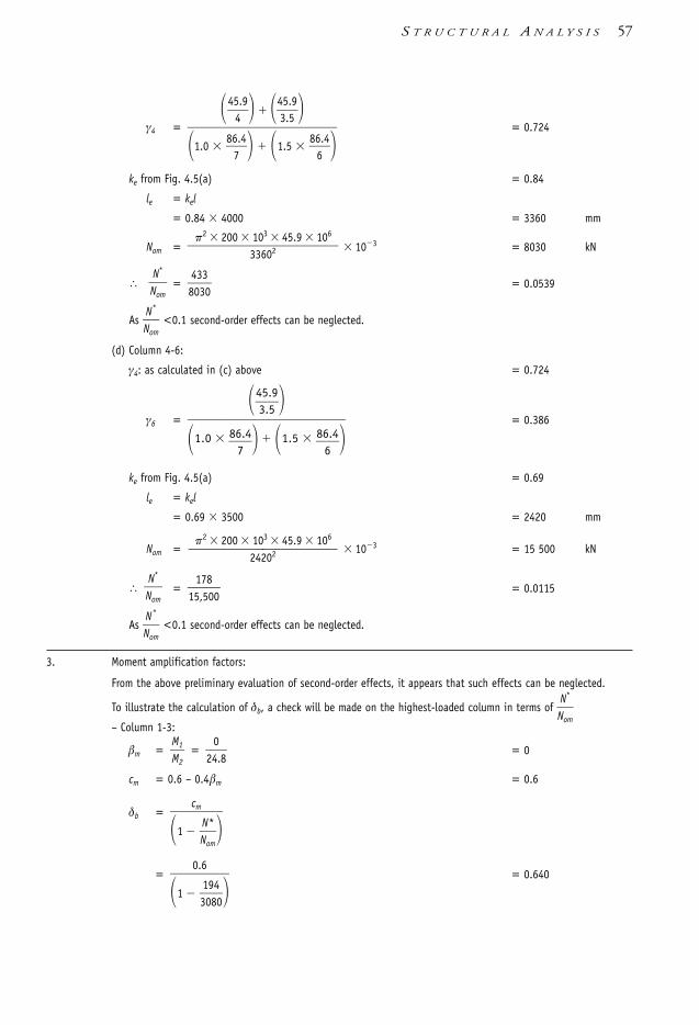
γ4 = = 0.724
ke from Fig. 4.5(a) = 0.84
le = kel
= 0.84 4000 = 3360 mm
Nom = 103 = 8030 kN
∴ = = 0.0539
As NN
o
*
m <0.1 second-order effects can be neglected.
(d) Column 4-6:
γ4: as calculated in (c) above = 0.724
γ6 = = 0.386
ke from Fig. 4.5(a) = 0.69
le = kel
= 0.69 3500 = 2420 mm
Nom = 103 = 15 500 kN
∴ = = 0.0115
As NN
o
*
m <0.1 second-order effects can be neglected.
3. Moment amplification factors:
From the above preliminary evaluation of second-order effects, it appears that such effects can be neglected.
To illustrate the calculation of δb, a check will be made on the highest-loaded column in terms of NN
o
*
m
– Column 1-3:
βm = = = 0
cm = 0.6 – 0.4βm = 0.6
δb =
= = 0.6400.6
1 3109840
cm
1 NN
o
*
m
024.8
M1M2
17815,500
N*
Nom
2 200 103 45.9 106
24202
435..59
1.0 86
7.4 1.5
866.4
4338030
N*
Nom
2 200 103 45.9 106
33602
45
4.9
435..59
1.0 86
7.4 1.5
866.4
S T R U C T U R A L A N A L Y S I S 57
1106 SDHB 00-04 Final 8/6/05 12:03 PM Page 57

Since δb <1.0 adopt δb = 1.0. Hence, no moment amplification needs to be applied to Column 1-3 (let aloneany other column).
The beam members need not be assessed for second-order effects as their axial loads were relatively low (thehighest N*/Nom was 0.008) with the first-storey beams being in tension.
The design moments therefore equal the bending moments obtained from the elastic first-order analysis.
An elastic second-order analysis of the total structure indicated an 8% peak bending moment difference (forColumn 1-3) to that from a first-order elastic analysis. This level of change in bending moments (<10%)indicates that second-order effects are negligible for the loaded structural frame.
Note: The example represents a typical frame in a low-rise building. Had the axial load in a column exceeded(say) 0.60Nom, then the value of δb would have become larger than 1.0. This would be typical of columns inhigh-rise buildings.
4.7.2 Example 4.2
Step Description and calculations Result Units
Problem definition: Determine the design moments for the sway frame shown below by using the method ofmoment amplification.
This example considers a sway frame and constituent members with out-of-plane behaviour prevented. The beamsare also relatively lightly loaded in compression.
Note: Notional horizontal forces (Clause 3.2.4 of AS 4100 and Section 3.7 of this Handbook) are not considered, asthere are other imposed lateral forces.
Load factors and combinations are for the strength limit state.
Fixed base4000
3500
7000 6000
1 2
15.3
49.3
94.347.3
26.7166
30.3
3397.637.9
22.4
78.4
15.3
8.39
14.0
29.4107
A
Section A-A All columnsAll connections are classed rigid
A
4 5
7 8 9
25
+ frame self-weight
16
39.8 15.5
33.4
6.50278114
46.6 116
14
186
3
40.7
47.0 mm
33.7 mm
104
29 kN
55 kN
47.0
25.5
44.2
43.969.4
28.828.8
58 S T E E L D E S I G N E R S ’ H A N D B O O K
(c) Bending moments (kNm) from elastic first-order analysis (only column bending momentshown with cross-hatching for clarity)
(d) Axial forces (kN) and sway deflections (mm)from elastic first-order analysis (all axialforces are compressive)
(a) Geometry (b) Loads (kN/m)
1106 SDHB 00-04 Final 8/6/05 12:03 PM Page 58

S T R U C T U R A L A N A L Y S I S 59
1. Trial section properties used in the analysis:
Member Section Ix mm4
1-4, 4-7 150 UC 30.0 17.6 106
2-5, 5-8 200 UC 46.2 45.9 106
3-6, 6-9 150 UC 30.0 17.6 106
Beams 310 UB 40.4 86.4 106
2. Determine the elastic buckling loads (assuming it is a braced member):
(a) Column 1-4:
γ1: rigid connection to base (Clause 4.6.3.4(b) of AS 4100) = 0.6
γ4 =
= = 0.764
ke from Fig. 4.5(b) = 1.22
le = kel
= 1.22 4000 = 4880 mm
Nom =
= 103 = 1460 kN
∴ = = 0.078
As N*/Nom <0.1 second-order effects can be neglected.
(b) Column 2-5:
γ2: rigid connection to base (Clause 4.6.3.4(b) of AS 4100) = 0.6
γ5 = = 0.919
ke from Fig. 4.5(b) = 1.24
le = ke l
= 1.24 4000 = 4960 mm
Nom = 103 = 3680 kN
∴ = = 0.076
As NN
o
*
m <0.1 second-order effects can be neglected.
2783680
N*
Nom
2 200 103 45.9 106
49602
45
4.9
435..59
1.0 86
7.4 1.0
866.4
1141460
N*
Nom
2 200 103 17.6 106
48802
2EI
le2
147..06
137..56
1.0 86
7.4
ΣIl
c
Σ
leIb
1106 SDHB 00-04 Final 8/6/05 12:03 PM Page 59

(c) Column 3-6:
γ3: rigid connection to base (Clause 4.6.3.4(b) of AS 4100) = 0.6
γ6 = = 0.655
ke from Fig. 4.5(b) = 1.20
le = kel
= 1.20 4000 = 4800 mm
Nom = 10–3 = 1510 kN
∴ = = 0.069
As NN
o
*
m <0.1 second-order effects can be neglected.
(d) Columns 4-7, 5-8 and 6-9:
These columns are less critically loaded and lower in effective lengths thantheir lower-storey counterparts and are not considered further.
3. Moment amplification factor for a ‘braced’ member, δb:
From the above preliminary evaluation of second-order effects, it appears that such effects can be neglected.However, to illustrate the calculation of δb, a check will be made on the lower-storey columns:
(a) Column 1-4:
βm = = = 0.476
cm = 0.6 – 0.4βm = 0.6 – (0.4 0.476) = 0.410
δb =
= = 0.445
Calculated δb < 1.0, ∴δb = 1.0.
(b) Column 2-5:
βm = = = 0.912
cm = 0.6 – 0.4βm = 0.6 – (0.4 0.912) = 0.235
δb = = 0.254
Calculated δb <1.0, ∴δb = 1.0
0.235
1 3267880
97.6107
M1M2
0.410
1 1141640
cm
1 NN
o
*
m
14.029.4
M1M2
1041510
N*
Nom
2 200 103 17.6 106
48002
17
4.6
137..56
1.0 86
6.4
60 S T E E L D E S I G N E R S ’ H A N D B O O K
1106 SDHB 00-04 Final 8/6/05 12:03 PM Page 60

S T R U C T U R A L A N A L Y S I S 61
(c) Column 3-6:
βm = = = 0.993
cm = 0.6 – 0.4βm = 0.6 – (0.4 × 0.993) = 0.203
δb = = 0.218
Calculated δb <1.0, ∴δb = 1.0.
As δb <1.0 adopt δb = 1.0 for all of the columns. Hence no ‘braced’ membermoment amplification needs to be applied to the columns.
The beam members need not be assessed for second-order effects, as
their axial loads were relatively low (the highest NN
o
*
m was 0.011).
4. Moment amplification factor for a sway member, δs:
The second-order effects from sway deformations is now checked by using the storey shear-displacement moment amplification method (Section 4.4.2.2):
(a) Lower storey:
c3 = = = 0.0497
δs =
= = 1.05
(δm)l s = moment amplification factor (overall) for lower storey
= max.[ δb , δs] = 1.05
where the maximum value of δb is 1.0 for the columns (see Step 3 above).
(b) Upper storey:
c3 = = 0.0266
δs= = 1.03
(δm)us = moment amplification factor (overall) for upper storey
= max.[ δb , δs] = 1.03
where the maximum value of δb is 1.0 for the columns (see Step 3 above).
5. Calculation of design bending moments:For each storey, the bending moments from the elastic first-order analysis are multiplied by δm.
(a) Lower storey:
M*ls = amplified peak lower-storey moment
= (Mm)ls (δm)ls
= 107 1.05 = 112 kNm
This can similarly be done for the other columns in the storey.
1(1 0.0266)
(46.6 116 40.7)
29(47.0 33.7)
3500
1(1 0.0497)
1(1 c3)
(114 278 104)
(55 29)33.74000
N*
V*
shs
0.203
1 1150140
43.944.2
M1M2
1106 SDHB 00-04 Final 8/6/05 12:03 PM Page 61

(b) Upper storey:
M*us = amplified peak upper-storey moment
= (Mm)us (δm)us
= 47 1.03 = 48.4 kNm
This can similarly be done for the other columns in the storey.
Due to the structural and loading configuration used in this example it is seen that the overall second-ordereffects are less than 10% when compared with the results from the elastic first-order analysis. However, higheraxial loads or larger deflections would have produced higher amplification factors. As noted in the Commentary toAS 4100, these braced and sway second-order effects could be neglected (δm <1.1). However, the above exampleassists to illustrate the braced and sway checks required for members in sway frames. The method used is validwhen amplification factors do not exceed 1.4.
An elastic second-order analysis of the total structure indicated a 5% peak column bending moment difference (forColumn 2-5) from that of a first-order elastic analysis, this indicating that the approximate amplification methodgave a result close to the rigorous and more accurate non-linear method. However, in this instance, the level ofchange in bending moments (<10%) from first-order analysis further indicates that second-order effects arenegligible for the loaded structural frame.
4.8 SummaryInterestingly, other literature on worked examples for in-plane second-order effects ofrectangular steel-framed structures generally get moment amplifications of around 10%.This is particularly the case when suitable section stiffness is used for deflectionconstraints on column sway etc. One could then surmise that the above second-ordereffects are minimal for practical structures. This became evident to the authors whendeveloping worked Examples 4.1 and 4.2, where changes of load magnitudes, sectionstiffness and base restraints for ‘realistic’ structures only produced second-order effectsthat were less than 10%. To try to trigger very significant second-order effects, there weresome obvious changes tested when ‘trialling’ worked Example 4.2. These included:• base restraint changed from rigid to pinned• decreasing the sections by one size• altering load magnitudewhich then produced second-order effects in the range of 60%–70% (as noted from asecond-order analysis program). However, the deformations—particularly the swaydeflections—were inordinately excessive in this instance (e.g. storey sway to columnheight being 1/30 when refactored for serviceability loads). Even though the abovesuggests that second-order effects may not be significant in realistic rectangular-framedsteel structures, the evaluation of these effects should not be dismissed, as they canbecome relevant for ‘flexible’ framing systems.
For the evaluation of second-order effects on pitched-roof portal frame buildings,Appendix CL in the Commentary to AS 4100 provides a simple approximation methodfor evaluating the elastic buckling load factor (λc), which then determines the swayamplification factor (δs). Two modes of in-plane portal frame buckling modes areconsidered—symmetrical and sway.
62 S T E E L D E S I G N E R S ’ H A N D B O O K
1106 SDHB 00-04 Final 8/6/05 12:03 PM Page 62

4.9 Further reading• For additional worked examples see Chapter 4 of Bradford, et al. [1997].• For a short summary on lower tier structural analysis in AS 4100 see Trahair [1992a].
This is also incorporated into Appendix CL of the AS 4100 Commentary.• For hand calculation of manual moment amplification methods for specific framing
configurations see Trahair [1992b,c,1993a]. These are also incorporated into AppendixCL of the AS 4100 Commentary.
• Additional references on the background to the structural analysis part of AS 4100 canbe found in Bridge [1994], Hancock [1994a,b], Harrison [1990], Petrolito & Legge[1995], and Trahair & Bradford [1998].
• For a classical text on structural analysis of rigid frames see Kleinlogel [1973].• For some authoritive texts on buckling see Bleich [1952], CRCJ [1971], Hancock
[1998], Timoshenko [1941], Timoshenko & Gere [1961], Trahair [1993b] andTrahair & Bradford [1998] to name a few.
S T R U C T U R A L A N A L Y S I S 63
1106 SDHB 00-04 Final 8/6/05 12:03 PM Page 63

5.1 Types of members subject to bendingThe term ‘beam’ is used interchangeably with ‘flexural member’. In general, the subjectmatter covers most of the AS 4100 rules and some additional design situations. A simpleclassification of beams and girders is presented in Table 5.1. The purpose of the table isto give an overview of the various design considerations and many types of applicationsof beams in building and engineering construction. It also serves as a directory tosubsections covering the particular design aspect.
Table 5.1 Design aspects covered for beam and girder design.
Aspect Subgroup Section
Section type: Solid bars 5.3 & 5.4Hot-rolled sections: UB, UC, PFC 5.3–5.5, 5.7, 5.8Plate web girders 5.3–5.8Tubular sections: CHS, RHS and SHS 5.3-5.5, 5.7, 5.8
Fabricated sections:Doubly symmetrical
I-section / UB / UC 5.3–5.5, 5.7, 5.8Box section / tube 5.3-5.5, 5.7, 5.8
Monosymmetrical 5.6
Design: Flexure 5.2–5.6Shear 5.8Biaxial bending/combined actions 5.7Torsion Appendix B
Loading: Major plane bending 5.3–5.5Minor plane bending 5.3Combined actions 5.7
Lateral restraints: 5.4
Special design aspects:
Serviceability 5.10Economy 5.11
c h a p t e r 5
Beams & Girders
1106 SDHB 05 Final 8/6/05 12:05 PM Page 64

Typical section shapes used for flexural members are shown in Figure 5.1.
Figure 5.1 Typical sections for beams: (a) hot-rolled (HR) universal section; (b) welded three (HR)plate I-section; (c) built-up HR universal section with HR channel (e.g. as in cranerunway); (d) built-up HR universal section with flanges stiffened by HR flats or cutplate; (e) HR section with HR flange plates; (f ) welded box section from HR angles;(g) welded box section from HR channels; (h) welded box section from HR plates;(i) compound HR channel section with intermittent ties (HR flats or plate);(j) compound HR universal section with intermittent ties (HR flats or plate); (k) cold-formed (CF) circular hollow section (CHS); (l) CF rectangular hollow section (RHS);(m) built-up CF hollow section with HR flats (e.g. in architectural applications);(n) built-up I-section using CF RHS flanges welded to HR plate (which can be flat orcorrugated plate—e.g. Industrial Light Beam (ILB)); and (o) tee-section split from HRuniversal section or made from HR plate/flats.
Depending on the type of end connections adopted in the design, structures can beclassified into the following types:
(a) Simple—End connections are such that a relatively small degree of rotational restraintabout the major axis is afforded to the beams. Consequently, it is assumed that nobending moments develop at the ends and the beams are designed as simplysupported.
(b) Rigid—End connections are such that the rotational restraint of the beam ends tendsto 100%. In practice it is acceptable if the restraint is at least 80%. Such connectionsare assumed in AS 4100 to possess enough rigidity to maintain the original includedangle between the beam end and the connected members.
(c) Semi-rigid—The end connections are specifically designed to give a limited andcontrolled stiffness. Using the selected joint stiffness, the beam is designed as part ofa frame with elastic nodes. These connection types are not commonly used, as a good
(a) (b) (c) (d) (e)
(f) (g) (h) (i) (j)
(k) (l) (m) (n) (o)
B E A M S & G I R D E R S 65
1106 SDHB 05 Final 8/6/05 12:05 PM Page 65

understanding of the relationship between flexural restraint and load effects isrequired. However, these types of connections can readily be incorporated into elasticcomputer analysis methods.
It must be realised that secondary members and non-structural elements can exert astrong influence on the design. For example, a beam may form a part of a floor bracingsystem from which it receives additional axial loads.
5.2 Flexural member behaviour It is helpful to consider the load deflection behaviour of a flexural member by means ofFigure 5.2. A beam of compact section that is not subject to local buckling, and isrestrained laterally and torsionally, would not fail until well after the onset of yielding, asshown by curve (a). Some beams fail before yielding, for one of four reasons:
(1) flexural (lateral) torsional buckling (b)
(2) local plate buckling of the compression flange or compression part of web (c)
(3) web shear yielding or shear buckling (d)
(4) web crushing (e).
Other types of failure can also prevent the full capacity of a beam from being reached,e.g. connection inadequacy, brittle tensile fracture, torsion and fatigue. The mainobjective of designing beams is to ensure that premature failures are ruled out as far aspracticable by using appropriate constructive measures.
Figure 5.2 Modes of failure of an I-section beam (a) section yield; (b) flexural-torsionalbuckling; (c) local flange buckling; (d) web buckling; (e) web crushing
5.3 Bending moment capacityThe two bending moment capacities to be considered in design are:• the nominal section moment capacity, and• the nominal member moment capacity.
Elevation
Flexural-torsionalbuckling
Plan
(c) Local flangebuckling
(d) Web buckling
(e) Web crushing0
(d)(e)
(c)
(b)
(a)
Deflection at mid-span, y
Mem
ber
Mom
ent,
Mb
Cross-sectionIsometric view
(a) Yielding
(b)
66 S T E E L D E S I G N E R S ’ H A N D B O O K
1106 SDHB 05 Final 8/6/05 12:05 PM Page 66

The nominal section moment capacity, Ms, refers to the flexural strength of a cross-section. The member moment capacity refers to the flexural-torsional capacity of thebeam as a whole.
The nominal section moment capacity about the major and minor axis is given by:
Msx = fy Zex
Msy = fy Zey
The first design requirement is that at all sections of the beam must satisfy:
Mx* φMsx
My* φMsy
where fy is the yield stress of steel, Zex and Zey are the effective section moduli, φ is thecapacity reduction factor of 0.9, and Mx
*, My* are the relevant design action effects.
The second, and often critical, requirement is that the member moment capacity beadequate. The value of the nominal member moment capacity, Mb, about the major axisis given by:
Mbx = αs αmMsx Msx
making sure that in all segments and subsegments of the beam satisfy:
Mx* φMbx
where αs is the slenderness reduction factor and αm is the moment modification factor(see Section 5.5). The slenderness reduction factor, αs, varies with the ratio of Msx /Mo,where Mo is termed the reference buckling moment. For equal-flanged I-beams andPFCs, Mo is given by
Mo = GJ + The value of αs varies between near 0.1, for very slender beams or beam segments, and1.0, for stocky beams:
αs = 0.6 MM
s
o
x2
+ 3 – MM
s
o
x
For unequal-flanged (monosymmetrical) beams, see Section 5.6.For CHS, SHS and RHS sections and solid bars having large J values and Iw = 0:
Mo = where E = 200 000 MPa, G = 80 000 MPa, J is the torsion constant, Iw is the warpingconstant (see Section 5.5), and le is the effective length for flexural-torsional buckling.
Flexural-torsional buckling does not occur in beams bent about their minor axis, andthus for such beams Mby = Msy, except where the load is applied at a point higher than1.0bf above the centre of gravity (where bf = flange width of the I- or channel section).
The factor αm depends on the shape of the bending moment diagram, and its valueranges between 1.0 for constant moment (always safe) up to 3.5 for some variablemoment shapes listed in Table 5.5 of this Handbook.
π2EIyGJ
le2
π2EIw
le2
π2EIy
le2
B E A M S & G I R D E R S 67
1106 SDHB 05 Final 8/6/05 12:05 PM Page 67

The product αsαm must not exceed 1.0, otherwise the value of Mbx would becomegreater than Ms. For example, with αm = 1.5 and αs = 0.8, the product is 1.2 >1.0, thusαm would effectively be reduced to:
αmr = = 1.25
As can be seen from the equation for Mo, an increase of the effective length has the effectof reducing the reference buckling moment Mo and thus the factor αs. It is thereforeadvantageous to reduce the effective length by incorporating additional lateral and/ortorsional restraints. If continuous lateral restraint is available the effective length can betaken as zero, making αs = 1.0, in which case Mbx = fy Zex. In practice, beams are oftendivided into several segments so as to reduce the effective length. Beam segments arelengths of beams between full or partial restraints (described in Section 5.4). The effectivelength, le, is taken as:
le = kt kl kr l
where l is the segment or subsegment length, kt is the twist restraint factor, kl is the loadheight factor, and kr is the lateral rotation restraint factor. The values of k-factors specifiedin AS 4100 are summarised in Tables 5.2.1 and 5.2.2 of this Handbook.
5.4 Beam segments and restraints
5.4.1 Definitions
The term ‘restraint’ denotes an element or connection detail used to prevent a beamcross-section from lateral displacement and/or lateral rotation about the minor axisand/or twist about the beam centre line. Restraints at beam supports are oftensupplemented by additional restraints along the the span—see Figure 5.3.
Figure 5.3 Arrangement of restraints
The following terms are used in AS 4100 and Trahair et al. [1993c,d] to describe cross-sectional restraints:
• Full restraint (F)—a restraint that prevents the lateral displacement of the critical flangeof the cross-section and prevents twisting of the section.
• Partial restraint (P)—a restraint that prevents the critical flange of the cross-sectionfrom displacing laterally and partly prevents the section from twisting.
• Lateral restraint (L)—a restraint that prevents lateral displacement of the critical flangewithout preventing the twist of the section.
(a) Restraints at ends and at intermediate point
Dashed line indicatesbuckled shape in lateralplane
(b) Continuous lateral restraint
1.0αs
68 S T E E L D E S I G N E R S ’ H A N D B O O K
1106 SDHB 05 Final 8/6/05 12:05 PM Page 68

• Nil restraint (U)—a cross-section that does not comply with types F, P or L—i.e.unrestrained.
• Continuous lateral restraint (C)—a critical flange restraint provided continuously by aconcrete slab, chequer plate or timber floor with the requirement that the segmentends are fully or partly restrained (practically resulting in le = 0). In this instance, anytorsional buckling deformations do not occur even though lateral restraints are onlyapplied. (See Figure 5.3(b)).
• Lateral rotation restraint (LR)—a restraint that prevents rotation of the critical flangeabout the section’s minor axis.
• Full lateral restraint—a beam or beam segment with F, P or L restraints to the criticalflange spaced (lf ) within the requirements of Clause 5.3.2.4 of AS 4100, such that thebeam can be regarded as continuously restrained, resulting in le = 0. Typical spacinglimits for equal-flanged I-sections are:
lf ry 80 + 50βm where βm ranges from –1.0 to +1.0. Further expressions are given in Clause 5.3.2.4 ofAS 4100 for other sections.
5.4.1.1 Additional termsCritical flange—the flange that would displace laterally and rotate further if the restraintswere removed. This is the compression flange of a simple beam and tension flange of acantilever.
Critical section—the cross-section that governs the beam design. Clause 5.3.3 of AS 4100notes this as the cross-section in a beam segment/subsegment with the largest ratio of M*
to Ms.
Segment—a portion of a beam between fully (F) or partially (P) restrained cross-sections.Restraint combinations (left and right) can be FF, PP or FP.
Segment length, l—length of the beam between restraints type F, P or L. For a beamhaving FF or PP end restraints and no mid-span restraints, the segment length is equalto the beam span. An additional lateral retraint at mid-span would result in a subsegmentlength of one-half span with end restraints of FL or PL.
Subsegment—a segment can be further subdivided into portions having at their ends atleast the lateral (L) restraints to the critical flange. Restraint combinations can be FL, PLor LL.
Figure 5.4 in this Handbook, Figure 5.4.1 and 5.4.2 of AS 4100 and the connectiondiagrams in Trahair et al. [1993c,d] show examples of restraint designations.
The division of a beam into segments and subsegments (see Figure 5.5) does not affectthe calculation of design bending moments and shears in the span—it affects only thecalculation of the reference buckling moment Mo, the factor αs and the breaking up ofthe bending moment distribution to respective beam segments and subsegments (for re-evaluation of αm).
250
fy
B E A M S & G I R D E R S 69
1106 SDHB 05 Final 8/6/05 12:05 PM Page 69

70 S T E E L D E S I G N E R S ’ H A N D B O O K
Figure 5.4 (a) Restraining systems for prevention of flexural-torsional buckling failure of beams
Figure 5.4(b) Examples of Full restraints for beams
C
Beam being restrainedFIXED NODE
SECTION AT INTERMEDIATE RESTRAINTS
SECTION AT BEARINGS
C C
C
C Stiffener
To fixed support
Fly brace
Gusset
Fully welded
Angle tie
To fixedpoint
BearingStiffener
Fixedconnection
Relativelystiff beam
C
ColumnFly brace(one or both sides) or C
here
CPurlin/Girt
Legend:C = critical flange = flange to be restrained
or C here
or Chere
or Chere
10 mmmin
CONTINUOUS
LATERAL AND TORSIONAL
LATERAL AND TORSIONAL LATERAL ONLY
LATERAL ANDTORSIONAL
LATERAL ONLY
C C
C
C C C
C
C
or C here
LegendC = critical flange
= flange to be restrained
C(on topflange)
or C here
or C here
or C here
1106 SDHB 05 Final 8/6/05 12:05 PM Page 70

Figure 5.4(c) Examples of Partial restraints for beams
Figure 5.4(d) Examples of Lateral restraints for beams
Flexible Gusset plate
Plug weld
Checker plate
C
C
C
Purlin
To fixedpoint
Fully welded
C C
C C
C
Fly brace
Webcleat only
Flexibleend plate
R.C. slab
Flexibleend plate
a > 70
a >70
Relativelyflexible tie
Gusset, two bolts
<d
–––2
<d
–––2
or C here
or C here
C C
C
or C here
C
B E A M S & G I R D E R S 71
1106 SDHB 05 Final 8/6/05 12:05 PM Page 71

Figure 5.4(e) Lateral Rotational restraints for beams
Figure 5.5 The division of a beam into segments and subsegments
3 Subsegments
Segment 1
F orU
F orLO LO
Segment 2 Segment 3
P PFP
P
1–1 1–2 1–3 2 –
3
U
Moment shape for Segment 1 and subsegment 1–2 (between bold lines)
F orP
F Lateral and torsional restraint — fullP Lateral and torsional restraint — partial
PLAN
F or
LO Lateral only — lateralU Unrestrained
ELEVATION
F orPF or
Moment shapefor Segment 3
Heavy endplate
Fully weldedtop and bottom
Torsional stiff end post
Half circularhollow section
Stiffeners
Plan Plan Plan
Section A - A Section B - B
Section C - C
C
A A B B C C
72 S T E E L D E S I G N E R S ’ H A N D B O O K
1106 SDHB 05 Final 8/6/05 12:05 PM Page 72

B E A M S & G I R D E R S 73
5.4.2 Effective length factors
AS 4100 requires the effective length to be determined from the segment length andmodified by three factors (Table 5.6.3 of AS 4100):
le = kr kt kl l
kt is the factor for twist distortion of the cross-section web with the values rangingbetween 1.0 for end cross-section restraint designations FF, FL, FU and above 1.0 forother restraint cases (see Table 5.6.3(1) of AS 4100).
kr is the factor for the critical flange restraint against rotation about the minor principalaxis, having values of:
• 0.70 for restraint designations FF, FP and PP, with both ends held against rotationabout the y-axis
• 0.85 ditto, with one end only held• 1.0 for negligible lateral rotation restraint.
kl is a factor for the load application height above the shear centre and is equal to 1.0where the (downward) load is applied at or below the shear centre, rises to 1.4 for theload applied to or above the beam top flange, and climbs to 2.0 for a cantilever.
Tables 5.2.1 and 5.2.2 give values of kt , kl, kr for common beam applications.
5.4.3 Default values of kt, kl and kr
Accepting at face value points of attachment of bracing, shear connectors and the like aslateral restraints (LR) for a beam, without going into their type, behaviour andeffectiveness, simplifies calculations. The values of kt , kl and kr are mostly on theconservative side. A more detailed calculation as described above could provide shortereffective lengths, and consequently more economical beams. However, at this simpler levelof calculation, some important aspects are inherently more likely to be overlooked, such asthat the lateral restraints may be badly located, resulting in an inferior or unsafe design.
Table 5.2.1 Default values of kt, kl and kr to determine effective length, le of simple beams
Case Direction of action/load, and flange on which it acts kt kl kr
1 Action/load acts downwards on top flange 1.1 1.4 1.0
2 Action/load acts downwards at shear centre or bottom flange 1.1 1.0 1.0
Table 5.2.2 Default values of kt , kl and kr to determine effective length, le of cantilevers
Case Direction of action/load, and flange on which it acts kt kl kr
3 Action/load acts downwards on top flange 1.1 2.0 1.0
4 Action/load acts downwards at shear centre or bottom flange 1.1 1.0 1.0
Notes: 1 k t lies in the range 1.0 to 1.2+ for UB and UC, and 1.0 to 1.5+ for WB, WC and plate girders. Theabove-listed default values for kt are mainly for UB and UC.
2 If all the actions/loads are located at the restraints (i.e. segment end), then k l = 1.0 (except forcantilevers with unrestrained tip loads, kl = 2.0).
continued
1106 SDHB 05 Final 8/6/05 12:05 PM Page 73

74 S T E E L D E S I G N E R S ’ H A N D B O O K
3 It may not be safer to use k r = 0.85 or 0.7. If in doubt, use k r = 1.0.
4 If loads are constrained to the plane of the minor (y) axis, use k l = 1.0.
5 For downward (horizontal beam) or inward (vertical beam) acting loads in the above tables, the top oroutside flange is the critical flange C.
6 For upward or outward loading the bottom or inside flange is the critical flange. The above tabulatedvalues then apply when the “top flange” term is interchanged with “bottom flange” and vice versa,and the end restraint types are unchanged.
7 Change, for example in occupancy and loads, types of loads and reversals, and other aspects ofdifferent actions would require a more detailed determination of l e.
5.4.4 Capacity of lateral restraint elements
The restraining elements at the ends of segments and subsegments, which may be endbearings, ties or floor joists, must be able to transfer a nominal action specified in Clause5.4.3 of AS 4100. For a restraint required to prevent the lateral deflection of the criticalflange, the requirement is:
Nr* = 0.025Nf
*
where Nr* is the action to be resisted by the restraint, Nf
* is the segment flange force; foran equal-flanged section Nf
* = Mm* /h, where h is the distance between flange centroids,
and Mm* is the maximum bending moment in either of the adjoining segments.
In a beam having many segments, each lateral restraint element must be designed forthe specified restraining action except where the restraints are spaced more closely thanis necessary (Clause 5.4.3.1 of AS 4100).
Where a restraining element continues over several parallel beams into a reaction point,it is necessary to use the 0.025 Nf
* force only for the most critical beam and halve therestraint force for the each of the remaining beams.
5.4.5 Capacity of twist restraint elements
The restraining element preventing the twisting of the section is subject to theapplication of the N*
r force as for the lateral displacement restraint (Clause 5.4.3.2 ofAS 4100).
5.5 Detailed design procedure5.5.1 Effective section properties
5.5.1.1 GeneralAs noted in Section 5.3, the basic capacity check for a flexural member is given by:
M* φ αmαs Ze fy
provided that the value of M* does not exceed:
M* φ Ze fy
where αm and αs are factors respectively taking into account the distribution of thebending moment and the reduction of capacity due to flexural-torsional buckling effects.The value of factor αm is in the range of 1.0 to 3.5, while αs is in the range of 0.1 to 1.0.
1106 SDHB 05 Final 8/6/05 12:05 PM Page 74

B E A M S & G I R D E R S 75
The evaluation of these factors is given in Tables 5.5 to 5.8 inclusive.The value of the effective modulus of section, Ze, depends on the section geometry, or
the section compactness: compact, non-compact or slender. For all standard hot-rolledsections, welded plate sections and structural steel hollow sections the designer can readoff the Ze values direct from AISC [1999a], Onesteel [2003] and SSTM [2003b].
For non-standard fabricated sections it is necessary to carry out section compactnesschecks. The general procedure for the determination of the effective section modulus, Ze,is as follows:
(a) Calculate element slenderness values, λe, for each plate element carrying uniform orvarying longitudinal compression stresses:
λe = (b) Find the ratio
λλ
e
e
y for each element (ie flanges and webs)
(c) The whole section slenderness λs is taken to be equal to the λe value for the largest
ratio of λλ
e
e
y .
The values of the yield limit, λey, can be read from Table 5.2 of AS 4100, reproduced hereas Table 5.3. Several items of data must be assembled before entering the table:• number of supported edges• stress gradient between the plate edges: uniform or variable• residual stress severity (see notes for Table 5.3).
Table 5.3 Slenderness limits for plate elements
Plate type and Stress Residual Slenderness limitsboundary condition distribution stress category λep λey λed
Flat, One edge supported, Uniform SR 10 16 35other free HR 9 16 35
LW, CF 8 15 35HW 8 14 35
Gradient SR 10 25 –HR 9 25 –LW, CF 8 22 –HW 8 22 –
Flat, Both edges Uniform SR 30 45 90supported HR 30 45 90
LW, CF 30 40 90HW 30 35 90
Gradient SR, HR, LW, CF, HW 82 115 –
Circular hollow section SR, HR, CF 50 120 –LW, HW 42 120 –
Notes: 1. SR = stress relieved 2. See Section 2.5 for further information.HR = hot-rolled (e.g. UB, UC, PFC, etc.)CF = cold-formed (hollow sections)LW = lightly weldedHW = heavily welded (WB, WC) continued
fy250
bt
1106 SDHB 05 Final 8/6/05 12:05 PM Page 75

Example: Fabricated I-beam with 270 x 10 flanges and 530 x 6 web in Grade 250 plate steel (assume HW residualstress classification)
Element λe λep λey λe /λey
Flange outstands1,2,3,4 13.2 8 14 0.943 ← Critical elementWeb 88.3 82 115 0.768
Section slenderness: λs = 13.2 λsp = 8 λsy = 14 (Section is non-compact)
For circular hollow sections, λs can be determined by:
λs = .
For all section types, the effective section modulus, Ze , is then determined from thefollowing “compactness” classifications:
λs λsp compact sectionλsp λs λsy non-compact section
λs λsy slender section
5.5.1.2 Compact sectionsIn a compact section there is no possibility of local flange or web buckling (fromlongitudinal compression stresses) to prevent the attainment of full section plasticity, i.e.:
Ze = S 1.5 Z
where S is the plastic section modulus determined for the fully plasticised section, i.e.using rectangular stress block; Z is the elastic section modulus calculated on the basis oflinear variation of stress through the depth of section. Sectional property tables forstandard rolled sections, welded sections and hollow sections give values of Z, S and Ze
(AISC [1999a], Onesteel [2003], SSTM [2003a,b]). Typical values of these parametersfor general sections are given in Table 5.4.
Table 5.4 Comparison of Z, S and Ze values
SECTION Zx Sx SZx
x Zex
Square/Rectangular (Flat) Bar
t6d2
t4d2
1.50 Sx
Round bar
3d2
3
d6
3
1.70(>1.50) 1.5Zx
UB, UC Prop.Tables Prop.Tables 1.10 to 1.15 (0.957 to 1.00)Sx
WB, WC Prop.Tables Prop.Tables 1.10 to 1.18 (0.912 to 1.00)Sx
CHS (d
3o4
2
do
di4)
(do
3
6di
3) 1.29 to 1.47 (0.912 to 1.00)Sx
RHS Prop.Tables Prop.Tables 1.18 to 1.34 (0.730 to 1.00)Sx
SHS Prop.Tables Prop.Tables 1.16 to 1.33 (0.704 to 1.00)Sx
Notes: The above section listings are based on generally available sections (AISC [1999a], Onesteel [2003],SSTM [2003a,b]).
fy250
dot
76 S T E E L D E S I G N E R S ’ H A N D B O O K
1106 SDHB 05 Final 8/6/05 12:05 PM Page 76

B E A M S & G I R D E R S 77
Where sections feature relatively large holes, the section modulus must be reduced ifthe area reduction of either flange is:
∆Af 1 – Af or >20% flange area for Grade 300 steel.
The reduced elastic and plastic section modulus may be calculated for the net area or,more conveniently, by:
Zred = Z AA
n
g and Sred = S
AA
n
g
where An is the net area of the whole section and Ag is the gross area of the section.When computing the reduced area, any deductions for fasteners should be treated as
for connections of tensile members. The above method of reduction of section moduli due to the presence of holes is also
applicable to the calculation of Z and S for Non-compact and Slender sections.
5.5.1.3 Non-compact sections Where one or more plate elements comprising the section are non-compact, that is λs
exceeds λsp and is less than or equal to λsy, the section is deemed to be Non-compact.With Non-compact sections it is possible that some local buckling may take place beforethe attainment of section plasticity, i.e.:
Ze = Z cz(Zc – Z ) where cz =
where Zc is the effective section modulus (Ze) assuming the section is Compact (seeSection 5.5.1.2).
Values of Ze for standard rolled sections, welded I-sections and hollow sections can beread off directly from AISC [1999a], Onesteel [2003], SSTM [2003a,b].
5.5.1.4 Slender sections The term ‘slender section’ should not be confused with ‘slender beam’. Where theslenderness of any plate element is more than the yield limit, λey, the section is classifiedas slender. Normally it is best to avoid using slender sections, but it is sometimesnecessary to check a section of this type. There are three situations to consider:
(a) Section elements having uniform compression (i.e. no stress gradient), e.g. flanges ofUB or UC bent about the major principal axis:• Method 1:
Ze = Z • Method 2:
Ze = Zr, where Zr is the elastic section modulus of a modified sectionobtained by removing the excess width of plates whose b/t exceeds theλey limit (see Figure 5.6(d)).
(b) Sections with slenderness determined by a stress gradient in plate elements with oneedge unsupported in compression, e.g. UB or UC bent about its minor principal axis:
Ze = Z 2λsyλs
λsyλs
(λsy – λs)( λsy – λsp)
fy0.85fu
1106 SDHB 05 Final 8/6/05 12:05 PM Page 77

78 S T E E L D E S I G N E R S ’ H A N D B O O K
(c) Circular hollow sections with λs > λsy
Ze = min ( Ze1, Ze2)
where Ze1 = Z and Ze2 = Z 2
Values of Ze for standard rolled sections, welded I-sections and hollow sections can beread off direct from AISC [1999a], Onesteel [2003], SSTM [2003a,b].
Figure 5.6 shows examples of sections having slender elements.
Figure 5.6 Cross-sections with slender elements
5.5.2 Continuously laterally restrained beams
This category embraces all beams bent about their minor axis and beams bent about themajor axis and fully restrained against flexural-torsional buckling. To be fully restrained,the critical flange of the beam must be either continuously restrained in the lateraldirection or restrained at close intervals, not exceeding le /ry = 20. In addition, the endconnections of the beam must be restrained against twisting and lateral displacement.
The spacing of effective lateral restraints must be such as to ensure that no capacity islost on account of flexural-torsional buckling—see Section 5.4.1, AISC [1999a] orSSTM [2003b].
Typical beams of this type are:
(a) beams carrying a concrete slab that engages the top (critical) flange or uses shearconnectors at relatively close spacing (0.60 m for small sizes and 1.0–1.5 m forlarger sizes)
(b) beams supporting chequer plate flooring and connected by intermittent welds
(c) purlins connected to roof sheeting by fasteners at every third sheeting ridge andloaded by dead load, live load plus wind pressure (with an overall inward effect).
The slenderness factor αs is in this case equal to 1.0. The moment modification factor αm
also has a value of 1.0. The design moment capacity of a beam with full lateral restraintis simply:
M* φ Ms
with Ms = Ze fy the result is:
M* φ Ze fy
b
(a) Flange buckl ing
Stress d i s t r ibut ion
(c) Box f lange buckl ing (d) Excess ive outs tands(b) Web buckl ing
b
t
t
Inef fect ivepartof
web
b
t Inef fect ivepartof
f lange
2λsyλs
λsyλs
1106 SDHB 05 Final 8/6/05 12:05 PM Page 78
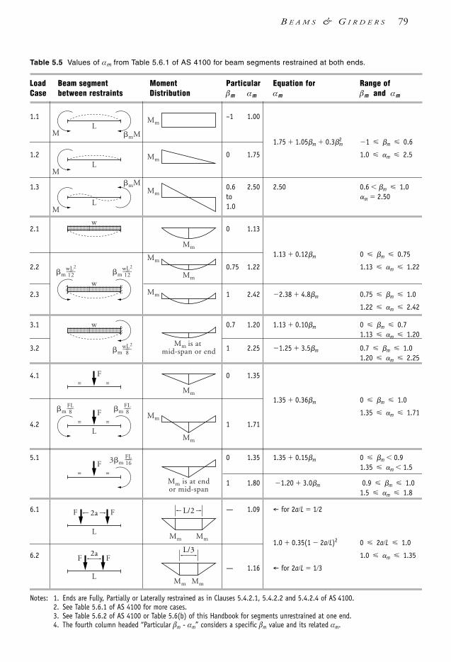
B E A M S & G I R D E R S 79
Table 5.5 Values of αm from Table 5.6.1 of AS 4100 for beam segments restrained at both ends.
Load Beam segment Moment Particular Equation for Range ofCase between restraints Distribution βm αm αm βm and αm
1.1 –1 1.00
1.75 1.05m 0.32m 1 m 0.6
1.2 0 1.75 1.0 m 2.5
1.3 0.6 2.50 2.50 0.6 m 1.0to m 2.501.0
2.1 0 1.13
1.13 0.12m 0 m 0.75
2.2 0.75 1.22 1.13 m 1.22
2.3 1 2.42 2.38 4.8m 0.75 m 1.0
1.22 m 2.42
3.1 0.7 1.20 1.13 0.10m 0 m 0.71.13 m 1.20
3.2 1 2.25 1.25 3.5m 0.7 m 1.01.20 m 2.25
4.1 0 1.35
1.35 0.36m 0 m 1.0
1.35 m 1.71
4.2 1 1.71
5.1 0 1.35 1.35 0.15m 0 m 0.91.35 m 1.5
1 1.80 1.20 3.0m 0.9 m 1.01.5 m 1.8
6.1 — 1.09 ← for 2aL 12
1.0 0.35(1 2aL)2 0 2aL 1.0
6.2 1.0 m 1.35
— 1.16 ← for 2aL 13
Notes: 1. Ends are Fully, Partially or Laterally restrained as in Clauses 5.4.2.1, 5.4.2.2 and 5.4.2.4 of AS 4100.2. See Table 5.6.1 of AS 4100 for more cases.3. See Table 5.6.2 of AS 4100 or Table 5.6(b) of this Handbook for segments unrestrained at one end.4. The fourth column headed “Particular βm - αm” considers a specific βm value and its related αm.
Mm
ML
mM
Mm
ML
Mm
ML
mM
Mm
Mm
Mm is at mid-span or end
Mm
Mm
w
Mm
Mm
m
F==
Mm
Mm is at endor mid-span
L
Mm Mm
w
wL2——12 m
wL2——12
w
mwL2——
8
mFL——8 m
FL——8
L
L
F==
3mFL——16F
==
FF 2a
FF2a
L/2
Mm Mm
L/3
1106 SDHB 05 Final 8/6/05 12:05 PM Page 79

80 S T E E L D E S I G N E R S ’ H A N D B O O K
For standard UB, UC and other sections the above procedure can be further reduced byreferring to AISC [1999a] or SSTM [2003b]. This is illustrated in Section 5.12.3.
5.5.3 Beams subject to flexural-torsional buckling
5.5.3.1 Description of the method This method relies on the effective length concept for compression members with givenend restraint conditions. This Section describes various tiered methods, which may besuitable for ordinary building structures. Where utmost economy in beam design isparamount it is best to use the buckling analysis method as noted in Clause 5.6.4 ofAS 4100.
5.5.3.2 Evaluation of the moment modification factor αm
A value of 1.0 can always be adopted for αm, but this is very conservative in manysituations. If a beam is continuously laterally restrained, αm = 1.0 (= αs) is automaticallyadopted as the section moment capacity is the maximum moment that can be obtained.Otherwise, there are two methods for determining the value of αm:
(i) value obtained or interpolated from Table 5.6.1 or 5.6.2 of AS 4100.(ii) value obtained from Clause 5.6.1.1(a)(iii) of AS 4100:
αm = but not exceeding 2.5.
The bending moment values of M2 to M4 correspond to the design bending moments atthe quarter point, middle and third quarter point on the beam segment/subsegmentbeing considered. M*
m is the maximum design bending moment. The first method is illustrated in Table 5.5 in this Handbook (based on Table 5.6.1 of
AS 4100). Table 5.6 gives the values of αm for simple loading patterns.
Table 5.6 Values of αm for beams with simple loading patterns
(a) Simply supported beams—restrained at both ends
j No LR 1 LR midspan 2 LRs at 13
points 2 LRs at 14
points
0 1.13 1.35 1.13 1.000.5 1.27 1.54 1.05 1.091 1.31 1.62 1.07 1.125 1.37 1.76 1.09 1.15
10 1.38 1.79 1.09 1.16
Notes: 1. W* Total uniformly distributed load.2. jW* Concentrated load as a multiple of W*.3. LR Full, Partial or Lateral restraint.4. The αm values for j 0 are based on the more exact solutions from Table 5.6.1 of AS 4100 whereas
the other values are calculated by superposition and Clause 5.6.1.1(a)(iii) of AS 4100.5. The 2 LR cases only consider the critical middle segment as it has the highest moment.
continued
jW*
W* W*
LR
jW*
W
LR LR
jW*
W*
LR LR
jW*
1.7M*m
(M2
2 M32 M4
2)
1106 SDHB 05 Final 8/6/05 12:05 PM Page 80
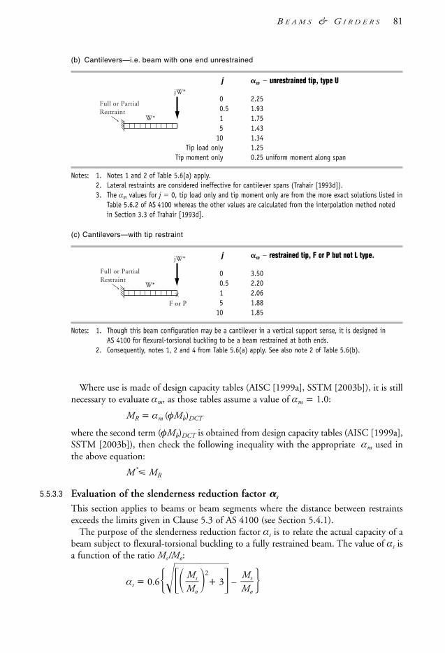
B E A M S & G I R D E R S 81
(b) Cantilevers—i.e. beam with one end unrestrained
j m unrestrained tip, type U
0 2.250.5 1.931 1.755 1.43
10 1.34Tip load only 1.25
Tip moment only 0.25 uniform moment along span
Notes: 1. Notes 1 and 2 of Table 5.6(a) apply.2. Lateral restraints are considered ineffective for cantilever spans (Trahair [1993d]).3. The αm values for j 0, tip load only and tip moment only are from the more exact solutions listed in
Table 5.6.2 of AS 4100 whereas the other values are calculated from the interpolation method notedin Section 3.3 of Trahair [1993d].
(c) Cantilevers—with tip restraint
j m restrained tip, F or P but not L type.
0 3.500.5 2.201 2.065 1.88
10 1.85
Notes: 1. Though this beam configuration may be a cantilever in a vertical support sense, it is designed in AS 4100 for flexural-torsional buckling to be a beam restrained at both ends.
2. Consequently, notes 1, 2 and 4 from Table 5.6(a) apply. See also note 2 of Table 5.6(b).
Where use is made of design capacity tables (AISC [1999a], SSTM [2003b]), it is stillnecessary to evaluate αm, as those tables assume a value of αm = 1.0:
MR = αm (φMb)DCT
where the second term (φMb)DCT is obtained from design capacity tables (AISC [1999a],SSTM [2003b]), then check the following inequality with the appropriate αm used inthe above equation:
M* MR
5.5.3.3 Evaluation of the slenderness reduction factor s
This section applies to beams or beam segments where the distance between restraintsexceeds the limits given in Clause 5.3 of AS 4100 (see Section 5.4.1).
The purpose of the slenderness reduction factor αs is to relate the actual capacity of abeam subject to flexural-torsional buckling to a fully restrained beam. The value of αs isa function of the ratio Ms/Mo:
αs = 0.62
+ 3 – MsMo
MsMo
F or P
W*
jW*
Full or PartialRestraint
W*
jW*
Full or PartialRestraint
1106 SDHB 05 Final 8/6/05 12:05 PM Page 81

82 S T E E L D E S I G N E R S ’ H A N D B O O K
where Ms is the section moment capacity and Mo is the reference buckling moment:
Mo = GJ +where le is the effective length of the single segment beam or of a beam segment. It isdetermined from:
le = kt kl kr lG = shear modulus of steel (80 000 MPa)J = torsion constantIw = warping constantkt , kl , kr are the components of the effective length factor k (see Section5.4.2 and 5.4.3)kt = twist factor, which depends on the flexibility of the webkl = load position factor, normally 1.0, increasing to 1.2 or more whenthe load is applied at the level of the top flangekr = ‘rotation’ factor, actually a factor taking into account the resistanceto rotation in plan of the flange at the end of the segment
As can be seen, Mo is a function of many variables: the ‘column’ term π2
le
E2
Iy is quite
dominant, and torsional/warping terms play an important role. The equation gives a hintof how to increase the flexural-torsional buckling resistance of a beam:
(a) by decreasing le and by increasing Iy
(b) by increasing J and Iw.
Finally, the slenderness factor αs used in calculating the nominal member momentcapacity, is noted above.
Values of αs are listed in Table 5.7 and plotted in Figure 5.7 for the purpose ofillustration. As can be seen from the plot, the values of αs are less than 1.0, except whenthe beam is ‘stocky’ and fails by yielding.
Table 5.7 Values of αs
Ms/Mo αs
0.05 1.0100.10 0.9810.20 0.9260.30 0.8750.40 0.8270.50 0.7820.60 0.7400.80 0.6651.00 0.6001.20 0.5441.40 0.4961.60 0.455 Figure 5.7 Plot of s vs M
M
o
s
1.80 0.4192.00 0.387
π2EIw
le2
π2EIy
le2
00
0.5
1.0
0%
100%
1 2 3
αs 1.0s
Ms–––Mo
Ms––– Mo
0.0670
1106 SDHB 05 Final 8/6/05 12:05 PM Page 82

B E A M S & G I R D E R S 83
Tables 5.8.1 and 5.8.2 give αs values for UB and UC sections.
Table 5.8.1 Slenderness reduction factors (αs) for UB Grade 300
Designation Effective length le m
2 3 4 5 6 7 8 9 10 11 12 14 16
610UB 125 0.940 0.839 0.728 0.622 0.530 0.456 0.395 0.347 0.308 0.277 0.250 0.210 0.181
113 0.937 0.831 0.715 0.605 0.511 0.435 0.373 0.325 0.287 0.255 0.231 0.193 0.165
101 0.927 0.810 0.684 0.567 0.469 0.392 0.332 0.286 0.249 0.221 0.198 0.163 0.139
530UB 92.4 0.912 0.787 0.659 0.545 0.453 0.381 0.326 0.282 0.250 0.223 0.201 0.168 0.144
82.0 0.908 0.777 0.643 0.523 0.430 0.356 0.302 0.259 0.227 0.202 0.181 0.150 0.128
460UB 82.1 0.897 0.766 0.637 0.528 0.441 0.375 0.324 0.284 0.254 0.227 0.207 0.175 0.152
74.6 0.893 0.757 0.623 0.512 0.423 0.356 0.307 0.267 0.236 0.212 0.192 0.161 0.139
67.1 0.889 0.749 0.611 0.493 0.403 0.338 0.285 0.248 0.218 0.194 0.175 0.147 0.126
410UB 59.7 0.879 0.734 0.695 0.484 0.398 0.333 0.286 0.250 0.221 0.198 0.179 0.151 0.131
53.7 0.861 0.703 0.555 0.440 0.355 0.293 0.248 0.214 0.188 0.168 0.151 0.127 0.109
360UB 56.7 0.875 0.732 0.600 0.494 0.413 0.352 0.305 0.268 0.240 0.216 0.197 0.167 0.145
50.7 0.871 0.719 0.582 0.471 0.389 0.328 0.282 0.247 0.219 0.197 0.179 0.151 0.131
44.7 0.851 0.689 0.545 0.429 0.347 0.288 0.244 0.212 0.186 0.167 0.151 0.127 0.109
310UB 46.2 0.873 0.730 0.598 0.498 0.415 0.355 0.310 0.274 0.245 0.222 0.230 0.172 0.150
40.4 0.857 0.697 0.560 0.450 0.370 0.311 0.268 0.234 0.208 0.187 0.170 0.144 0.125
32.0 0.813 0.627 0.478 0.372 0.299 0.247 0.211 0.184 0.162 0.146 0.132 0.111 0.097
250UB 37.3 0.828 0.668 0.537 0.441 0.370 0.317 0.277 0.245 0.220 0.200 0.183 0.156 0.137
31.4 0.813 0.640 0.500 0.399 0.328 0.277 0.239 0.210 0.187 0.169 0.154 0.130 0.144
25.7 0.742 0.550 0.414 0.325 0.265 0.222 0.192 0.169 0.151 0.136 0.125 0.105 0.092
200UB 29.8 0.805 0.647 0.523 0.433 0.367 0.317 0.279 0.248 0.224 0.204 0.187 0.160 0.140
25.4 0.789 0.616 0.485 0.391 0.327 0.278 0.242 0.214 0.193 0.174 0.159 0.136 0.119
22.3 0.788 0.609 0.473 0.376 0.310 0.263 0.228 0.200 0.179 0.162 0.148 0.126 0.109
18.2 0.648 0.459 0.343 0.272 0.223 0.191 0.166 0.147 0.132 0.119 0.109 0.093 0.081
180UB 22.2 0.674 0.516 0.411 0.339 0.288 0.249 0.220 0.197 0.177 0.162 0.148 0.127 0.112
18.1 0.641 0.469 0.362 0.294 0.245 0.211 0.185 0.164 0.148 0.134 0.123 0.106 0.092
16.1 0.623 0.444 0.336 0.268 0.223 0.191 0.167 0.148 0.133 0.121 0.111 0.094 0.083
150UB 18.0 0.622 0.473 0.377 0.311 0.264 0.229 0.202 0.181 0.163 0.149 0.137 0.117 0.103
14.0 0.566 0.409 0.313 0.254 0.212 0.183 0.160 0.143 0.129 0.117 0.107 0.092 0.080
1106 SDHB 05 Final 8/6/05 12:05 PM Page 83

Table 5.8.2 Slenderness reduction factors (αs) for UC Grade 300
Designation Effective length le m
2 3 4 5 6 7 8 9 10 12 14 16 18 20 22
310UC 158 0.997 0.954 0.908 0.875 0.816 0.775 0.736 0.699 0.667 0.606 0.566 0.510 0.471 0.437 0.408
137 0.994 0.950 0.898 0.846 0.798 0.751 0.708 0.670 0.634 0.570 0.517 0.472 0.432 0.398 0.370
118 0.991 0.945 0.890 0.834 0.779 0.728 0.680 0.637 0.599 0.532 0.477 0.431 0.392 0.363 0.331
96.8 0.990 0.936 0.874 0.808 0.746 0.687 0.636 0.585 0.542 0.471 0.414 0.369 0.331 0.300 0.277
250UC 89.5 0.997 0.919 0.854 0.796 0.737 0.689 0.644 0.601 0.536 0.501 0.449 0.404 0.368 0.336 0.311
72.9 0.969 0.902 0.827 0.755 0.691 0.631 0.578 0.533 0.496 0.428 0.379 0.337 0.303 0.275 0.252
200UC 59.5 0.943 0.864 0.785 0.711 0.649 0.598 0.549 0.508 0.472 0.412 0.364 0.325 0.294 0.268 0.245
52.2 0.941 0.850 0.766 0.688 0.622 0.565 0.516 0.474 0.632 0.377 0.331 0.294 0.265 0.240 0.220
46.2 0.939 0.849 0.751 0.672 0.601 0.541 0.490 0.447 0.410 0.351 0.306 0.271 0.242 0.220 0.200
150UC 37.2 0.892 0.790 0.703 0.629 0.565 0.513 0.467 0.429 0.395 0.342 0.300 0.266 0.240 0.217 0.199
30.0 0.869 0.748 0.645 0.561 0.493 0.439 0.394 0.357 0.326 0.278 0.240 0.212 0.190 0.172 0.157
23.4 0.857 0.719 0.603 0.510 0.451 0.384 0.341 0.305 0.278 0.232 0.201 0.175 0.156 0.141 0.128
100UC 14.8 0.780 0.654 0.560 0.485 0.424 0.376 0.338 0.306 0.279 0.237 0.206 0.181 0.162 0.147 0.134
Additional information given in Appendix H of AS 4100 can be applied to the casewhere the load is applied below (or above) the centroid of the section. The same appendixgives a procedure for calculating the reference elastic buckling moment Mo for sectionswith unequal flanges (monosymmetrical sections). A typical section of this type is thetop-hat section used for crane runway beams.
5.6 Monosymmetrical I-section beamsThese beams are symmetrical about the minor axis and have unequal flanges. A typicalexample is the UB section combined with a downturned channel, used for cranerunways. Figure 5.8 illustrates some typical monosymmetrical sections. The design ofmonosymmetrical sections is covered in Clause 5.6.1.2 and Appendix H of AS 4100.
Figure 5.8 Monosymmetrical beams: (a) fabricated I-section; (b) section calculation for Icy of(a)—only the compression flange is used (either above or below the x-axis, depending on the directionof bending); (c) UB section with downturned channel; and (d) section calculation for Icy of (c)—onecompression flange only.
Shear centre
Centroid
y y y
x
(a) (b) (c)
y
(d)
xShear centre
Centroid
84 S T E E L D E S I G N E R S ’ H A N D B O O K
1106 SDHB 05 Final 8/6/05 12:05 PM Page 84

B E A M S & G I R D E R S 85
The only difference in determining the nominal member moment capacity are theadditional terms that appear in the equation for the reference buckling moment (see alsoAppendix H of AS 4100):
Mo Py (GJ Pw 0.25βx2Py ) 0.5βx Py
where
Py Pw βx 0.8df 1
Iw Iy(d
4f )
2
for doubly-symmetric I-sections
Icydf2 (1 –
IIc
y
y) for monosymmetrical I-sections.
df distance between flange centroids
Icy second moment of area of the compression flange about thesection minor principle y-axis (see Figure 5.8).
5.7 Biaxial bending and bending with axial force
5.7.1 Biaxial bending
Biaxial bending occurs when bending moments are applied about both the major andminor principal axes. The method used in elastic design was to calculate the stressesabout both axes and total them up. In limit states design, due to the non-linear methodsadopted to optimise member economies, the method of superposition does not applyand design verification is done by the method of combined actions.
The capacity checks for biaxial bending without axial force are specified in Clauses 8.3and 8.4 of AS 4100. The calculation procedure used is covered in Section 6.3 of thisHandbook. Also the following, Section 5.7.2, discusses the capacity checks forgeneralised combined actions.
5.7.2 Bending combined with axial force
The flexural members subject to bending combined with a compressive axial force aretermed ‘beam-columns’. Typical beam-columns are columns and rafters of portal frames,beams doubling up as lateral bracing members and/or compression chords in windtrusses. Beam-columns in rigid and multistorey frames are dealt with in Chapter 6.
Unavoidably, the capacity calculations are somewhat complex to optimise memberefficiencies. The following combined actions checks are required by AS 4100:
• reduced section moment capacity, Mrx, bending about x-axis• reduced section moment capacity, Mry, bending about y-axis• biaxial section moment interaction• in-plane member moment capacity, Mix (about x-axis)• in-plane member moment capacity, Miy (about y-axis)• out-of-plane member moment capacity, Mox (about x-axis)• biaxial member moment interaction.
2IcyIy
π2EIw
le2
π2EIy
le2
1106 SDHB 05 Final 8/6/05 12:05 PM Page 85

86 S T E E L D E S I G N E R S ’ H A N D B O O K
The distinction between the section and member capacities is as follows:
• Section capacity is a function of section yield strength and local buckling behaviour• Member capacity is a function of section capacity, flexural-torsional buckling resistance
(beam action) and lateral buckling resistance (column action) of the member.
The verification method is covered in Section 6.3 which gives the general calculationprocedure.
5.8 Web shear capacity and web stiffeners5.8.1 General
Included in this Section are design methods for:• web shear• combined shear and bending• web buckling• web bearing.
With stiffened webs, the following aspects are relevant:• transverse, intermediate stiffener proportioning• end stiffeners• end posts• axial loads on stiffeners• longitudinal stiffeners.
The main elements of plate web girders and hot-rolled I-sections to be verified forstrength design are shown in Figure 5.12 and discussed as follows. Web thickness limitsare given in Table 5.9.
Table 5.9 Minimum web thickness, ky = Arrangement Minimum thickness tw
Unstiffened web bounded by two flanges: kyd1/180
Ditto for web attached to one flange (Tee): kyd1/90
Transversely stiffened web:
when 1.0 s/d1 3.0 (See Note 4 also) kyd1/200
0.74 s/d1 1.0 kys/200
s/d1 0.74 kyd1/270
Web having transverse and one longitudinal stiffener:
when 1.0 s/d1 2.4 kyd1/250
0.74 s/d1 1.0 kys/250
s/d1 0.74 kyd1/340
Webs having two longitudinal stiffeners and s/d1 1.5 kyd1/400
Webs containing plastic hinges kyd1/82
Notes: 1. The above limits are from Clauses 5.10.1, 5.10.4, 5.10.5 and 5.10.6 of AS 4100.2. d1 is the clear depth between the flanges3. s is the spacing of transverse stiffeners4. When s/d1 3.0 the web panel is considered unstiffened.
fy250
1106 SDHB 05 Final 8/6/05 12:05 PM Page 86

5.8.2 Shear capacity of webs
The nominal shear capacity of a web subject to approximately uniform shear stressdistribution is given in Clause 5.11.2 of AS 4100. For a single web bounded by twoflanges, as in I-section beams and channels, the shear stress distribution is relativelyuniform over the depth of the web. For such sections the nominal shear yield capacity ofa web, Vw, is as follows:
Vw = 0.6fy Aw for 82
where
ky = and Aw is the effective area of the web: Aw = (d1 – dd )t w
with d1 as the clear depth of the web, dd as height of any holes up to a height of 0.1d1
for unstiffened webs (0.3d1 if web is stiffened) and tw is the web thickness. (Note: seeStep 7 of Section 5.12.3 (Example 5.3) on the use of d1 for hot-rolled sections such asUB, UC and PFC). If known, the design yield stress of the web is used for fy in the aboveexpression.
For 82, Vw can be determined from Vb in Section 5.8.3. Non-uniform shear
stress distribution occurs when the section being checked for shear has two webs (e.g.RHS/SHS and box sections), only one flange or has no flanges at all. This is covered byClause 5.11.3 of AS 4100 as follows:
Vv = but not exceeding Vw
whereVw is noted above for approximately uniform shear stress distribution
f *vm = maximum shear stress
f *va = average shear stress
The ratio ff
*v*v
m
a is equal to 1.5 for a web without flanges, between 1.2 and 1.3 for webs
attached to one flange, and 1.0 to 1.1 for two flanges. A solution of this ratio forstructural Tees is given in AISC [1999a] and for RHS/SHS in SSTM [2003b].
A special case is circular hollow sections, for which:
Vw = 0.36fy Ae (see Clause 5.11.4 of AS 4100 for definition of Ae )
For all relevant sections, the web adequacy check requires that:
V* φVw or V* φVv where appropriate
and φ = capacity reduction factor = 0.9.
2Vw
0.9 + ff
*v*v
m
a
kyd1tw
fy250
kyd1tw
B E A M S & G I R D E R S 87
1106 SDHB 05 Final 8/6/05 12:05 PM Page 87

88 S T E E L D E S I G N E R S ’ H A N D B O O K
5.8.3 Buckling capacity of unstiffened webs
Apart from web failure by shear yielding, the web can fail by shear buckling. AS 4100
requires that all webs having a web thickness, tw, less than should be checked forshear buckling capacity as follows:
Vb = αv (0.6fy Aw)
where
αv = 2
ky = with d1, fy and Aw being described above in Section 5.8.2.
Finally, the overall check for shear buckling with φ = 0.9 is:
V * φVb
The web may be stiffened if the web shear yielding or buckling capacity is inadequate.Figure 5.9 illustrates various methods of stiffening the webs. This is considered furtherin Sections 5.8.6 and 5.8.7.
Figure 5.9 Methods of web stiffening
5.8.4 Shear and bending interaction for unstiffened webs
Shear capacity of webs in the locations of relatively high bending moment may have tobe reduced, as specified in Clauses 5.12.2 and 5.12.3 of AS 4100—the latter clause beingeasier to manipulate and herein considered further. The reduction factor αvm can becalculated from:
α vm = 2.2 – 1
(φ.6
MM
s)
*
for 0.75φMs M* φMs
4tw
Plan
One-sided
Vertical only Vertical and horizontal
Two-sided
Plan
0.2dp
tw
(max)
comp. flange
fy250
82twd1ky
ky d182
1106 SDHB 05 Final 8/6/05 12:05 PM Page 88
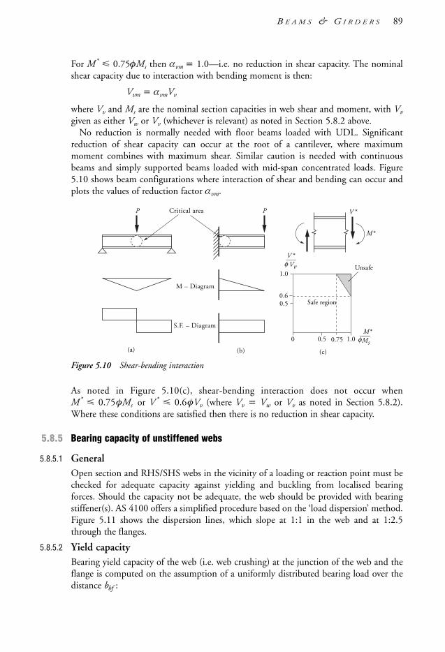
For M* 0.75φMs then αvm = 1.0—i.e. no reduction in shear capacity. The nominalshear capacity due to interaction with bending moment is then:
Vvm = αvmVv
where Vv and Ms are the nominal section capacities in web shear and moment, with Vv
given as either Vw or Vv (whichever is relevant) as noted in Section 5.8.2 above.No reduction is normally needed with floor beams loaded with UDL. Significant
reduction of shear capacity can occur at the root of a cantilever, where maximummoment combines with maximum shear. Similar caution is needed with continuousbeams and simply supported beams loaded with mid-span concentrated loads. Figure5.10 shows beam configurations where interaction of shear and bending can occur andplots the values of reduction factor αvm.
Figure 5.10 Shear-bending interaction
As noted in Figure 5.10(c), shear-bending interaction does not occur whenM* 0.75φMs or V* 0.6φVv (where Vv = Vw or Vv as noted in Section 5.8.2).Where these conditions are satisfied then there is no reduction in shear capacity.
5.8.5 Bearing capacity of unstiffened webs
5.8.5.1 GeneralOpen section and RHS/SHS webs in the vicinity of a loading or reaction point must bechecked for adequate capacity against yielding and buckling from localised bearingforces. Should the capacity not be adequate, the web should be provided with bearingstiffener(s). AS 4100 offers a simplified procedure based on the ‘load dispersion’ method.Figure 5.11 shows the dispersion lines, which slope at 1:1 in the web and at 1:2.5through the flanges.
5.8.5.2 Yield capacityBearing yield capacity of the web (i.e. web crushing) at the junction of the web and theflange is computed on the assumption of a uniformly distributed bearing load over thedistance bbf :
P Critical area
M – Diagram
S.F. – Diagram
P
V *––– Vv
M*––– Ms0
0.5
1.0
1.00.5
Safe region
Unsafeφ
φ
0.6
0.75
(a) (b) (c)
V *
M*
B E A M S & G I R D E R S 89
1106 SDHB 05 Final 8/6/05 12:05 PM Page 89
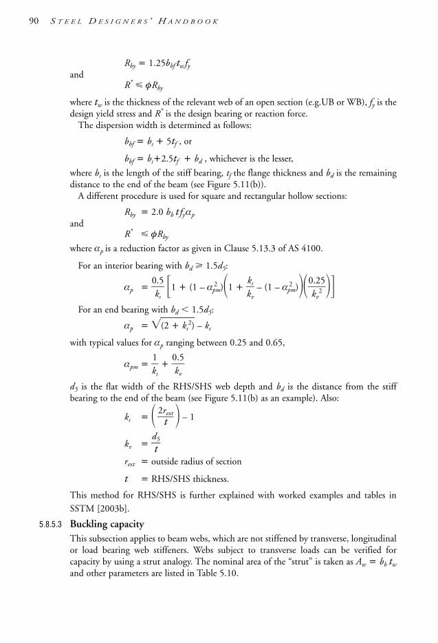
90 S T E E L D E S I G N E R S ’ H A N D B O O K
Rby = 1.25bbf tw fyand
R* φRby
where tw is the thickness of the relevant web of an open section (e.g.UB or WB), fy is thedesign yield stress and R* is the design bearing or reaction force.
The dispersion width is determined as follows:
bbf = bs + 5tf , or
bbf = bs+2.5tf + bd , whichever is the lesser,
where bs is the length of the stiff bearing, tf the flange thickness and bd is the remainingdistance to the end of the beam (see Figure 5.11(b)).
A different procedure is used for square and rectangular hollow sections:
Rby = 2.0 bb t fyαp
andR* φRby
where αp is a reduction factor as given in Clause 5.13.3 of AS 4100.
For an interior bearing with bd 1.5d5:
αp = 0
k.5
s 1 + (1 – α2
pm)1 + kk
v
s – (1 – α2
pm)0
k.2
v2
5
For an end bearing with bd 1.5d5:
αp = (2 + ks2) – ks
with typical values for αp ranging between 0.25 and 0.65,
αpm = k1
s +
0
k.
v
5
d5 is the flat width of the RHS/SHS web depth and bd is the distance from the stiffbearing to the end of the beam (see Figure 5.11(b) as an example). Also:
ks = – 1
kv = dt5
rext = outside radius of section
t = RHS/SHS thickness.
This method for RHS/SHS is further explained with worked examples and tables in
SSTM [2003b].
5.8.5.3 Buckling capacityThis subsection applies to beam webs, which are not stiffened by transverse, longitudinalor load bearing web stiffeners. Webs subject to transverse loads can be verified forcapacity by using a strut analogy. The nominal area of the “strut” is taken as Aw = bb tw
and other parameters are listed in Table 5.10.
2rextt
1106 SDHB 05 Final 8/6/05 12:05 PM Page 90

Table 5.10 Web slenderness ratios for unstiffened webs
I-section beam Hollow section
Effective width bb bb
Interior bearing slenderness ratio lre =
2.t5
w
d1
lre =
3.t5
w
d5 (for bd 1.5d5)
End bearing slenderness ratio lre =
2.t5
w
d1
lre =
3.t8
w
d5 (for bd 1.5d5)
Notes: 1. d1 = clear depth between flanges2. tw = thickness of web.3. bb = total bearing width dispersion at neutral axis (Figure 5.11(b))—see SSTM [2003b] or
Figure 5.13.1.3 of AS 4100 to calculate this for RHS/SHS.4. d5 = flat width of RHS/SHS web.
The effective width of the web section, bb, is determined on the basis of the rule ofdispersion (see Section 5.8.5.2 and Figure 5.11).
The next step is to obtain the value of the section slenderness factor αc (see Clause6.3.3 and Table 6.3.3(3) of AS 4100), assuming that the value of αb is equal to 0.5 andkf = 1.0. The web bearing buckling capacity is then given by:
φRbb = φαcAwfy
where αc is determined in Section 6 of AS 4100 and shown in Chapter 6 of thisHandbook. Then R* φRbb must be observed.
Figure 5.11 Web bearing and the load dispersion method
1:2.5 slope
2.52.5
2.5 2.5
11
1 1
11
11
11
1:2.5
1:11:1
1:2.5
45°
Stiff bearinglength , bs
End force
Interio r force
R
bb
bb
bb
bb
bd bs
bbfbbf
bs
bbf
bbf
tf
tf
Effectivecolumnsection
bs
11
(a) Force dispersion at end bearing points.
bb
(b) General force dispersion in I-section flange and web
B E A M S & G I R D E R S 91
1106 SDHB 05 Final 8/6/05 12:05 PM Page 91

5.8.5.4 Combined bending and bearingAS 4100 has additional rules for combined bending and bearing on square andrectangular hollow sections. The following interaction equation is used:
1
(
.
φ2
RR
b)
*
+ (φ
MM
*
s) 1.5
except when bb
s 1.0 and
d
t5 30, the following inequality is used:
0
(φ.8
RR
b)
*
+ (φ
MM
*
s) 1.0
where b is the width of the hollow section, M* is the design bending moment in thehollow section at R*, the applied bearing force. In other words, the presence of bendingmoment reduces the bearing capacity φRb and vice versa.
5.8.6 Webs with load bearing stiffeners
5.8.6.1 GeneralWhere the web alone has insufficient capacity to carry the imposed concentrated loadsand/or lateral forces it may be strengthened by bearing stiffeners directly adjacent to theload with full or partial contribution from the web—see Figure 5.12 and items 1 and 4in Figure 5.13. Clauses 5.14.1 to 5.14.5 of AS 4100 provide design procedures for thesetypes of web stiffeners.
The ends of load bearing stiffeners are tightly fitted to bear snugly against the loadedflange. Sufficient welds or other fasteners are to be provided along the length of thestiffeners to distribute the reaction or load to the web.
5.8.6.2 Geometry and stiffness requirementsA geometric limitation for the stiffener is that its outstand from the face of the web, bes,is such that:
bes
where ts is the thickness and fys is the design yield stress of the flat stiffener without theouter edge continuously stiffened (e.g. the stiffener is from flat bar or plate and not anangle section).
5.8.6.3 Yield capacityClause 5.14.1 of AS 4100 notes the yield capacity of a load bearing stiffener, Rsy, to be acombination of the yield capacity of the unstiffened web, Rby, and the yield capacity ofthe stiffener, i.e.
Rsy = Rby Asfys
where Rby is determined from Section 5.8.5.2 and As is the cross-section area of thestiffener. The design bearing load or reaction force, R*, must be less than or equal to φRsy
where φ = 0.9.
15ts
2f5ys
0
92 S T E E L D E S I G N E R S ’ H A N D B O O K
1106 SDHB 05 Final 8/6/05 12:05 PM Page 92

5.8.6.4 Buckling capacityThe buckling capacity of the web and load bearing stiffener combination, Rsb, areassessed to Clause 5.14.2 of AS 4100. This is similar to the method used for unstiffenedwebs where the web is analogised to a strut and designed to Section 6 of AS 4100. Thestrut effective cross-section, As, is taken as the stiffener area plus an effective length of theweb taken as the lesser of:
and 2
s
where tw is the web thickness and s is the web panel width or spacing to the next webstiffener—if present. Calculations are then done to evaluate the web-stiffener secondmoment of area about the axis parallel to the web, Is, and radius of gyration, rs
=AIs
s0.5.
The effective length, le, of the stiffener-web strut is taken as either the clear depthbetween flanges, d1, or 0.7d1 if the flanges are restrained by other structural elements inthe plane of the stiffener against rotation.
Having evaluated le/rs , the design capacity, φRsb, is then calculated by the method notedin Section 5.8.5.3 to evaluate αc (with αb = 0.5 and kf =1.0) and φ = 0.9 such that:
φRsb = φαcAs fy
φRsb must be greater than or equal to the design bearing load or reaction force, R*.
5.8.6.5 Torsional end restraintsLoad-bearing stiffeners are also used to provide torsional restraint at the support(s).Clause 5.14.5 of AS 4100 requires the second moment of area of a pair of stiffeners, Is,about the centreline of the web satisfies:
Is
where
αt = 0.60 and 0 αt 4
d = depth of section
tf = thickness of critical flange (see Section 5.4.1)
R* = design reaction at the support/bearing
F* = total design load on the member between supports
= load-bearing stiffener slenderness ratio noted in Section 5.8.6.4lery
230
rley
td3tf R
*
1000F*
17.5tw
2f5y
0
B E A M S & G I R D E R S 93
1106 SDHB 05 Final 8/6/05 12:05 PM Page 93

94 S T E E L D E S I G N E R S ’ H A N D B O O K
Figure 5.12 Critical areas for consideration of web stiffeners
5.8.7 Webs stiffened by intermediate transverse stiffeners
5.8.7.1 GeneralThere are situations where webs should be made as light as possible or have shear andimposed forces in excess of the web capacity. Web stiffeners are employed to make theweb perform better in these instances. The main benefit of intermediate transversestiffeners (see Figure 5.12 and item 3 of Figure 5.13) is in the increase of the bucklingresistance of the web. It should be realised that there is a cost involved in fitting thestiffeners and quite often a thicker, plain web will be a better choice. The design of theintermediate web stiffeners is covered in Clause 5.15 of AS 4100.
Intermediate web stiffeners are usually fillet-welded to the web. Intermittent fillet weldscan be used for beams and girders not subjected to weather or corrosive environments,otherwise it is recommended that continuous fillet welds be used. The stiffeners should bein contact with the top flange but a maximum gap of 4tw is recommended between thebottom (tension) flange and the end of the stiffener. Flat plate stiffeners are usuallyemployed for beams and girders up to 1200 mm deep, and angle stiffeners with one legoutstanding are used for deeper girders so as to increase their stiffness. Intermediatestiffeners may be placed on one or both sides of a web. Requirements for such stiffenersare noted below.
Figure 5.13 Web stiffeners: 1 - load bearing stiffener; 2 - end plate; 3 - intermediate transversestiffener; 4 - load bearing stiffener; 5 - longitudinal stiffener.
12
5
3 4
tw
Section A - A
4tw
5 5
e
0.2d2
A
A
For a definition of e see Section 5.8.8 and for d2 see Section 5.8.9.
Bearing on masonry, concrete or steel member/element
Fracture in bottom flange
Flange yields
Local flange buckling
Bearing stiffener buckling
Web bearing yielding
Flexural-torsional buckling
Web shear buckling
Load bearingstiffener
Intermediate transversestiffener
d1 = depth between flanges
s
1106 SDHB 05 Final 8/6/05 12:05 PM Page 94

B E A M S & G I R D E R S 95
5.8.7.2 Geometry and stiffness requirements
(a) The minimum area of an intermediate stiffener, As, should comply with Clause5.15.3 of AS 4100:
As 0.5γAw (1 – αv) ck where ck = ks
ks ds
p (s = spacing between stiffeners and dp = depth of web)
γ = 2.4 for a single plate stiffener (one side of the web)= 1.8 for a single angle stiffener= 1.0 for a pair of stiffeners (one each side of the web)
αv = 8d2
p k
tw
y2
ka
s2 + b 1.0
ky = 2
f5y
0
a = 0.75 and b = 1.0 for 1.0 ks 3.0
a = 1.0 and b = 0.75 for ks 1.0
(b) The outstand of intermediate transverse stiffeners must satisfy the provisions ofSection 5.8.6.2.
(c) From Clause 5.15.5 of AS 4100, the minimum flexural stiffness depends on whetheror not the stiffener receives applied loads and moments. A stiffener not so loadedmust have a minimum stiffness of:
Is = 0.75 d1tw3 for
ds
1 1.41
= 1.5 d
s21
3tw3
for ds
1 1.41
An increase in the second moment of area of intermediate web stiffeners, Is , is requiredby Clause 5.15.7 of AS 4100 when the stiffeners carry external imposed forces, shearsand moments. This may arise from cross-beams and the like with their eccentric verticalloads to give such design action effects as (M *F *
pe) acting perpendicular to the web.The increased second moment of area, ∆Is, is given by:
∆Is = d 31
whereF *
n = design force normal to the web
M * + F *pe = design moments normal to the web
F *p = design eccentric force parallel to the web
2F *n
(M *
d1
F *p e)
Etw
ks2
(1 + ks
2)
V*
(φVu)
1106 SDHB 05 Final 8/6/05 12:05 PM Page 95

e = eccentricity of F *p from the web
tw = thickness of the web
d1 = depth between flanges.
An increase in strength of a intermediate transverse stiffener is necessary to carry imposedtransverse loads parallel to the web such as the reaction from a cross-beam. In thisinstance the stiffener must be designed as a load bearing stiffener (see Section 5.8.6).
5.8.7.3 Yield capacityDue to the nature of loading on intermediate transverse stiffeners, yield capacity checksare not undertaken.
5.8.7.4 Buckling capacityBuckling capacity checks are undertaken on intermediate transverse stiffeners whichmust satisfy Clause 5.15.4 of AS 4100 as such:
V * φ(Rsb + Vb)
whereφ = capacity reduction factor = 0.9
Rsb = nominal buckling capacity of the stiffener (see Section 5.8.6.4)
and Vb is the nominal shear buckling capacity:
Vb = αvαdαf (0.6fyAw)
whereAw = gross sectional web area = d1 × tw
αv = 2 b 1.0
tw = web thickness
dp = depth of web or deepest web panel
ky = ks =
s = horizontal spacing between stiffeners
a = 0.75 and b = 1.0 for 1.0 ks 3.0
a = 1.0 and b = 0.75 for ks 1.0
αd = 1 ; or
= 1.0 for end web panels with end posts with specific shearbuckling conditions (see Clause 5.15.2.2 of AS 4100)
αf = 1.0 ; or
1 v1.15v(1 ks
2)
sdp
fy250
aks
2
82twdpky
96 S T E E L D E S I G N E R S ’ H A N D B O O K
1106 SDHB 05 Final 8/6/05 12:05 PM Page 96

= 1.6 with specific bfo conditions (see below)
bfo = flange restraint factor, taken as the least of the following:
= ; or
= distance from the mid-plane of the web to the nearest edge at aflange (or zero if no flange present); or
= half the clear distance between webs for two or more webs
with tf being the nearest flange thickness and d1 is the clear web depth between flanges.The values of αv αd range from 1.0 for stocky webs to 0.2 for slender webs. These
values are plotted for ease of use in Figure 5.14. For the evaluation of buckling capacityof a stiffened web which contains other design actions (axial load, significant bendingmoment, patch loading on flange not necessarily on a stiffener, etc), reference should bemade to Appendix I of AS 4100.
Figure 5.14 Web buckling factor (αv αd )
5.8.7.5 Connecting stiffeners to websWelds or other fasteners connecting each intermediate transverse stiffener not subject toexternal loads are required by Clause 5.15.8 of AS 4100 to transmit a minimum shearforce in kN/mm of:
v*w =
where bes is the stiffener outstand from the web face and tw is the web thickness.
5.8.8 End posts
As noted in Clause 5.15.9 of AS 4100, end posts are required for end panels of beamsand girders (also see Clause 5.15.2.2 of AS 4100) and are composed of a load bearingstiffener and a parallel end plate separated by a distance e (see items 1 and 2 of Figure5.13). This stiffener-end plate combination also provides torsional restraint to thebeam/girder end(s).
0.0008t2wfy
bes
00 1 2 3
s––dp
0.5
1.0
250
150
200
50100
αvαddp––tw
fy–––250( )Bearing stiffener
Intermediatetransverse
web stiffener
dp d1
s
=
12tfky
0.6
1 4
d0b
21 t
f
w
ot2f
B E A M S & G I R D E R S 97
1106 SDHB 05 Final 8/6/05 12:05 PM Page 97
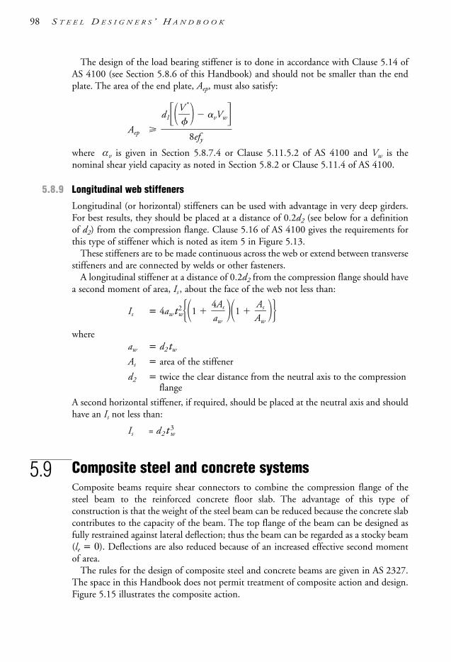
The design of the load bearing stiffener is to done in accordance with Clause 5.14 ofAS 4100 (see Section 5.8.6 of this Handbook) and should not be smaller than the endplate. The area of the end plate, Aep, must also satisfy:
Aep
where αv is given in Section 5.8.7.4 or Clause 5.11.5.2 of AS 4100 and Vw is thenominal shear yield capacity as noted in Section 5.8.2 or Clause 5.11.4 of AS 4100.
5.8.9 Longitudinal web stiffeners
Longitudinal (or horizontal) stiffeners can be used with advantage in very deep girders.For best results, they should be placed at a distance of 0.2d2 (see below for a definitionof d2) from the compression flange. Clause 5.16 of AS 4100 gives the requirements forthis type of stiffener which is noted as item 5 in Figure 5.13.
These stiffeners are to be made continuous across the web or extend between transversestiffeners and are connected by welds or other fasteners.
A longitudinal stiffener at a distance of 0.2d2 from the compression flange should havea second moment of area, Is , about the face of the web not less than:
Is = 4awt2w1 1
whereaw = d2tw
As = area of the stiffener
d2 = twice the clear distance from the neutral axis to the compressionflange
A second horizontal stiffener, if required, should be placed at the neutral axis and shouldhave an Is not less than:
Is = d2t 3w
5.9 Composite steel and concrete systemsComposite beams require shear connectors to combine the compression flange of thesteel beam to the reinforced concrete floor slab. The advantage of this type ofconstruction is that the weight of the steel beam can be reduced because the concrete slabcontributes to the capacity of the beam. The top flange of the beam can be designed asfully restrained against lateral deflection; thus the beam can be regarded as a stocky beam(le = 0). Deflections are also reduced because of an increased effective second momentof area.
The rules for the design of composite steel and concrete beams are given in AS 2327.The space in this Handbook does not permit treatment of composite action and design.Figure 5.15 illustrates the composite action.
AsAw
4Asaw
d1V
*
vVw
8efy
98 S T E E L D E S I G N E R S ’ H A N D B O O K
1106 SDHB 05 Final 8/6/05 12:05 PM Page 98

B E A M S & G I R D E R S 99
Figures 5.15 Composite steel and concrete beam
5.10 Design for serviceabilityFlexural elements have to be checked for the serviceability limit state, which includes thecheck of deflections, bolt slip, vibration and corrosion. As the serviceability limit stateoccurs at ‘working’ loads rather than ultimate design loads, the structure can be regardedas behaving elastically. For a deflection check, it is sufficient to carry out a first-orderelastic analysis (without amplification factors) based on ‘working’ (unfactored loads), useelastic section properties and compute the deformations. See Sections 1.8, 5.12, 5.13,10.9, 10.11 and Appendices B and C of this Handbook for additional information onserviceability analysis/design and using elastic methods.
Deflections are computed as a part of structural analysis. The load cases for deflectioncalculations consist of nominal (unfactored) loads. Deflections at the ultimate limit stateof strength are usually of no consequence and are therefore not subject to limitation.Some guidance on deflection limits are given in AS/NZS 1170.0 or Appendix B ofAS 4100. Additional information can be found in Chapter 10 of this Handbook.Nevertheless, deflection limits should be based on dictates of true serviceability ratherthan adhering to some ratio of deflection to span.
5.11 Design for economyTwo main causes of uneconomical design in flexural members are the use of non-compact/slender sections and beams having excessive member slenderness in the lateraldirection. Non-compact/slender sections utilise only a part of the cross-section, andtherefore material is wasted. Also, increasing the size of the beam to meet the deflectionlimit can waste material. Often it is possible to introduce continuity or rigid endconnections to overcome the deflection limit without wasting material.
Excessive slenderness can be measured by the magnitude of the slenderness reductionfactor αs (Section 5.3). A beam having a value of αs less than 0.70 is regarded asuneconomical. Wherever possible, such beams should be redesigned in one of thefollowing ways:• by introducing more lateral restraints (i.e. shorter segment lengths) or• by changing the section to one that exhibits better flexural-torsional resistance such as
wide flange, or top-hat section or a hollow section.
Consideration should be given to using concrete floor slabs with some positive means ofconnection (e.g. shear studs) to the beam, or to providing positive connection betweenthe steel floor plate and the beam by tack welding, etc.
CConc
CSt
TStSt
ConcConc
St
1106 SDHB 05 Final 8/6/05 12:05 PM Page 99

100 S T E E L D E S I G N E R S ’ H A N D B O O K
Longer-span beams are sometimes governed by considerations of acceptabledeflections. In many instances it is possible to satisfy the deflection limit without loss ofsection efficiency, choosing deeper beams of lighter section.
Finally, the detailing of end connections and web stiffeners needs appropriate attentionso as to avoid costly cutting, fitting and welding.
Reference should also be made to Section 1.11 for other aspects of designing foreconomy.
5.12 Examples
5.12.1 Example 5.1
Step Description and computation Result Unit
(a) Select a trial section using Grade 400 steel for the simply supportedbeam shown. The actions/loads are applied to the top flange. Find asection with the AISC Design Capacity Tables (AISC [1999a]) using theproperties of section and moment capacities listed. Assume the ends ofthe beam are securely held by bolts through the bottom flangeanchored to the supports.
There are no intermediate lateral restraints between the supports.
(b) Check the trial section chosen in (a) for bending moment usingAS 4100.
(c) Place one intermediate lateral restraint (LR) in the centre of the span.Comment on the difference between having none and one intermediatelateral restraint.
(a) Select a trial section using AISC [1999a]
1 Data
1.1 Steel grade 400 MPa
1.2 Actions/loads (unfactored)Uniformly distributed permanent action/dead load 4.17 kN/mUniformly distributed imposed action/live load 8.00 kN/mConcentrated permanent action/dead load 104 kNConcentrated imposed action/live load 140 kN
448
437
806
630
437 22
7
PG 104 kNPQ 140 kN
wG 4.17 kN/mwQ 8.00 kN/m
Note: Design actions 1.2G 1.5Q
1106 SDHB 05 Final 8/6/05 12:05 PM Page 100

1.3 Design action effects (from equilibrium and load factors)Design moment M* 806 kNmDesign shear V* 235 kN
1.3.1 M* for Step 1.4 and part (c) with its 1 intermediate LR to calculate αm
M*m for Step 1.4 and part (c) = M*
3 for Step 1.4 = 806 kNmM*
2 for part (c) = 227 kNmM*
3 for part (c) = M*2 and M*
4 for Step 1.4 = 437 kNmM*
4 for part (c) = 630 kNm
1.4 Moment modification factor αm in AS 4100 Clause 5.6.1.1(a)(iii)
This calculates to αm = 1.35
2 Effective length of beam le in AS 4100 Clause 5.6.3
2.1 Factors kt, kl and kr assumed for first trial (see Table 5.2.1 for default values):kt = see Note 1 in Table 5.2.1 (for WB conservatively say) = 1.4kl = loads acting on top flange, acting downwards = 1.4kr = see Section 5.4.2 also = 1.0ls = distance between lateral restraints (LRs) = span when there are
no intermediate LRs between the supports = 8.0 mle = kt kl kr ls
= 1.4 × 1.4 × 1.0 × 8.0 = 15.7 (round up for trial design, say) 16.0 m
3 Trial a section using AISC [1999a] which is conservatively based on αm = 1.0:
M* is reduced by 1α.
m
0 =
11..305
to benefit from the higher αm
αm = 1.0 listed in the AISC tables as follows:
Mr* =
Mαm
*
= 18.0365
= 597 kNm
Enter AISC [1999a] Table 5.3-2 page 5-44 or Chart page 5-45 with le and M*
r , choose 900WB218 Grade 400 with moment capacity Answer to (a)699 kNm calling this φMbr to satisfy the inequality: No int. LR
M*r φMbr → 597 699 → true OK
(b) Check selection 900WB218 Grade 400 in (a) for bending using AS 4100
4 Properties of 900WB218 Grade 400 is taken fromAISC [1999a] Tables 3.1-1(A) and (B) pages 3-6 and 3-7
d1 = 860 mmtf = 25.0 mmtw = 12.0 mmAg = 27 800 mm2
Ix = 4060 × 106 mm4
Iy = 179 × 106 mm4
Zex = 9.84 × 106 mm3
ry = 80.2 mmE = Young’s modulus … AS 4100 Notation … = 200 × 103 MPaG = shear modulus = … AS 4100 Notation … = 80 × 103 MPaJ = torsion constant = 4020 × 103 mm4
Iw = warping constant = 35.0 × 1012 mm6
Section slenderness = Non-compact aboutboth x- and y-axis
fyf = 360 MPafyw = 400 MPa
B E A M S & G I R D E R S 101
1106 SDHB 05 Final 8/6/05 12:05 PM Page 101

5 A better value of kt to get le is now possible with the benefit of having established the trial section in (a):
kt = twist restraint factor. Bolts through the bottom flange securelyfastening the end of the beam to the support provide the end with partiallyrestrained cross-section of type P as in AS 4100 Figure 5.4.2.2. The topflange is the critical flange if loads act on it, and towards centre of section.Then AS 4100 Table 5.6.3(1) for restraint arrangement PP gives:
kt = 1 + 2dl
10.5
tw
tf3
= 1 2 × 8806000
0.5 × 2152..00
3= 1.24
6 le = Effective length adjusted for actual kt
= kt kl kr ls= 1.24 × 1.4 × 1.0 × 8000 = 13 900 mm
7 Mo = reference buckling given by AS 4100 Equation 5.6.1.1(3):
Equation is split into 3 parts A, B and C in these calculations:
7.1 Let A =
= π2 × 200 × 103 × 179 × = 1.83 × 10⁶ N
7.2 Let B =
= π2 × 200 × 103 × 35.0 × = 3.58 × 10¹¹ Nmm2
7.3 Let C = GJ
= 80 × 103 × 4020 × 103 = 322 × 109 Nmm2
7.4 Equations are recombined into:
Mo = [A(C B)]= [1.83 × 106 ×(322 × 109 3.58 × 10¹¹)] = 1.12 × 10⁹ Nmm
= 1120 kNm
8 Msx = Ms = nominal section moment capacity:= fy Zex AS 4100 Clause 5.2.1= 360 × 9.84 × 106 = 3540 × 106 Nmm= 3540 kNm
φMsx = 0.9 × 3540 … AS 4100 Table 3.4 for φ …= 3190 kNm
9 αs = slenderness reduction factor AS 4100 Equation 5.6.1.1(2)
= 0.6 MM
o
s2
2 3 – MM
o
s
= 0.6 + 3 – = 0.26635401120
35402
11202
1012
139002
π2EIw
le2
106
139002
π2EIy
le2
102 S T E E L D E S I G N E R S ’ H A N D B O O K
1106 SDHB 05 Final 8/6/05 12:05 PM Page 102

B E A M S & G I R D E R S 103
10 φMb = member moment capacity AS 4100 Equation 5.6.1.1(1)= φ αm αs Ms
= 0.9 × 1.35 × 0.266 × 3540 1140 kNm φMs = 3190 OK
10.1 M* φMb in AS 4100 Clause 5.1 is satisfied with:806 1140 being true900WB218 Grade 400 is OK with efficiency
1810460
= 0.71 = 71% Answer to (b)
Note: This may be considered excessive in terms of reserve of capacityhowever a check of all of the WBs smaller and lighter than 900WB218Grade 400 will note they are not adequate for bending from the loading/restraintconditions. This is due to the significant influence of the PP end restraintconditions on kt and subsequently le for deeper “girder” type (non-universal)members (see Table 5.2.1).
(c) Effect of additional LR …using AS 4100 and AISC [1999a] …
11 Improved value of αm = moment modification factor with 1 LR
from AS 4100 Clause 5.6.1.1(a)(iii) gives
αm =
= 2.5 = 1.71
Note the earlier value of αm = 1.35 in Step 1.4
12 Much better/smaller effective length le from AS 4100 Clause 5.6.3 and assume same kt = 1.24 givesle = kt kl kr ls
= 1.24 × 1.4 × 1.0 × 4000 = 6940 mmNote previously from (b) in Step 6, le = 13 900 mm.
13 M*r =
Mαm
*
= reduced M* to use with tables to gain benefit of
αm = 1.71 being greater than the αm = 1.0 built into the tables:
M*r =
18.0761
= 471 kNm
13.1 Select beam from AISC [1999a] Table 5.3-2 or Chart pages 5-44 and 45 for le = 6.94 m and M*
r = 471 kNm gives:700WB115 Grade 400 …which has φMbr for le = 7.0 m = 472 kNmto satisfy M*
r φMbr → 471 472 → true OKand also AS 4100 Clause 5.2.1 requires
φMbr → 472 → 472 760 → true OK
where φMsx = 1300 kNm is also from AISC [1999a] Table 5.3.2 page 5-44700WB115 Grade 400 satisfies bending moment capacity φMb
13.2 Now recheck kt and l e (with improved PL restraint condition instead of the previous PP) due to the revised beam section. Repeat Steps 5 & 12 to 13.1 with results only shown:
kt = from AS 4100 Table 5.6.3(1) with a different formula 1.08
l e = 1.08 1.4 1.0 4000 = 6050 (round to) 6000 mm
φMbr (from AISC[1999a] with inbuilt αm = 1.0) = 577 kNm
13001.71
φMsx
αm
1.7 × 806[2272 + 4372 + 6302]
1.7Mm*
[M2
*2 +M3*2 + M4
*2]
1106 SDHB 05 Final 8/6/05 12:05 PM Page 103
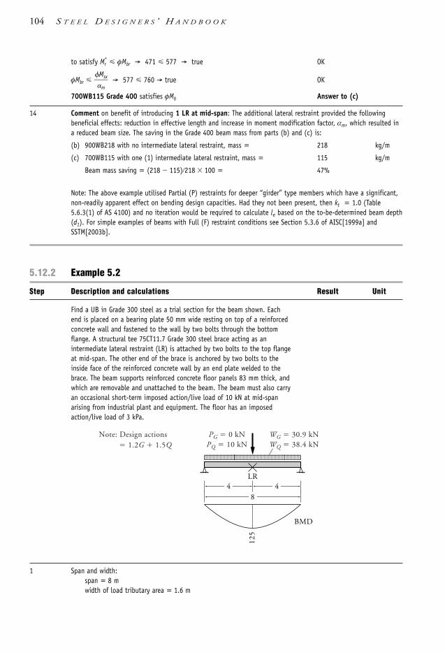
104 S T E E L D E S I G N E R S ’ H A N D B O O K
to satisfy Mr* φMbr → 471 577 → true OK
φMbr
M
m
sx → 577 760 → true OK
700WB115 Grade 400 satisfies φMb Answer to (c)
14 Comment on benefit of introducing 1 LR at mid-span: The additional lateral restraint provided the followingbeneficial effects: reduction in effective length and increase in moment modification factor, αm, which resulted ina reduced beam size. The saving in the Grade 400 beam mass from parts (b) and (c) is:
(b) 900WB218 with no intermediate lateral restraint, mass = 218 kg/m
(c) 700WB115 with one (1) intermediate lateral restraint, mass = 115 kg/m
Beam mass saving = (218 115)218 100 = 47%
Note: The above example utilised Partial (P) restraints for deeper “girder” type members which have a significant,non-readily apparent effect on bending design capacities. Had they not been present, then kt = 1.0 (Table5.6.3(1) of AS 4100) and no iteration would be required to calculate le based on the to-be-determined beam depth(d1). For simple examples of beams with Full (F) restraint conditions see Section 5.3.6 of AISC[1999a] andSSTM[2003b].
5.12.2 Example 5.2
Step Description and calculations Result Unit
Find a UB in Grade 300 steel as a trial section for the beam shown. Eachend is placed on a bearing plate 50 mm wide resting on top of a reinforcedconcrete wall and fastened to the wall by two bolts through the bottomflange. A structural tee 75CT11.7 Grade 300 steel brace acting as anintermediate lateral restraint (LR) is attached by two bolts to the top flangeat mid-span. The other end of the brace is anchored by two bolts to theinside face of the reinforced concrete wall by an end plate welded to thebrace. The beam supports reinforced concrete floor panels 83 mm thick, andwhich are removable and unattached to the beam. The beam must also carryan occasional short-term imposed action/live load of 10 kN at mid-spanarising from industrial plant and equipment. The floor has an imposedaction/live load of 3 kPa.
1 Span and width:span = 8 mwidth of load tributary area = 1.6 m
448
125
PG 0 kNPQ 10 kN
WG 30.9 kNWQ 38.4 kN
LR
BMD
Note: Design actions 1.2G 1.5Q
1106 SDHB 05 Final 8/6/05 12:05 PM Page 104
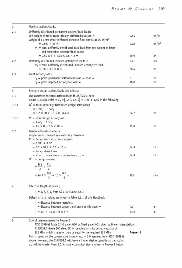
B E A M S & G I R D E R S 105
2 Nominal actions/loads.
2.1 Uniformly distributed permanent actions/dead loads:self-weight of steel beam initially estimated/guessed = 0.54 kN/mweight of 83 mm thick reinforced concrete floor panels at 25 kN/m3
= 0.083 × 25 = 2.08 kN/m2
WG = total uniformly distributed dead load from self-weight of beam and removable concrete floor panels
= 0.54 × 8 + 2.08 × 1.6 × 8 = 30.9 kN
2.2 Uniformly distributed imposed action/live loads = 3.0 kPaWQ = total uniformly distributed imposed action/live load
= 3.0 × 1.6 × 8 = 38.4 kN
2.3 Point actions/loads:PG = point permanent action/dead load = none = 0 kNPQ = point imposed action/live load = 10.0 kN
3 Strength design actions/loads and effects:
3.1 Use combined factored actions/loads in AS/NZS 1170.0Clause 4.2.2(b) which is Ed =[1.2 G, 1.5 Q] = 1.2G + 1.5Q in the following:
3.1.1 W* = total uniformly distributed design action/load= 1.2WG + 1.5WQ
= 1.2 × 30.9 + 1.5 × 38.4 = 94.7 kN
3.1.2 P* = point design action/load= 1.2PG + 1.5PQ
= 1.2 × 0 + 1.5 × 10 = 15.0 kN
3.2 Design action/load effects:simple beam is loaded symmetrically, therefore:R* = design reaction at each support
= 0.5W* + 0.5P*
= 0.5 × 94.7 + 0.5 × 15 = 54.9 kN= design shear force= V* = … when there is no overhang … = 54.9 kN
M* = design moment
= W8
*L +
P4
*L
= 94.7 × 88.0 + 15 ×
84.0 = 125 kNm
4 Effective length of beam le
le = kt kl kr ls from AS 4100 Clause 5.6.3
Default kt kl kr values are given in Table 5.2.1 of this Handbook
ls = distance between restraints= distance between support and brace at mid-span = 4.0 m
le = 1.1 × 1.4 × 1.0 × 4 = 6.16 m
5 Size of beam-conservative Answer 1AISC [1999a] Table 5.3-5 page 5-50 or Chart page 5-51 gives by linear interpolation:410UB59.7 Grade 300 steel OK for bending with its design capacity of 126 kNm which is greater than or equal to the required 125 kNm Answer 1
This is based on the conservative value of αm = 1.0 assumed from AISC [1999a]above. However, the 410UB59.7 will have a higher design capacity as the acutal αm will be greater than 1.0. A more economical size is given in Answer 2 below.
1106 SDHB 05 Final 8/6/05 12:05 PM Page 105

106 S T E E L D E S I G N E R S ’ H A N D B O O K
6 Moment modification factor αm
Load ratio WP*
* = 1954..07
= 0.158
Table 5.6(a), 1 LR mid-span with j = 0.158 interpolates to give αm = 1.41
7 Size of beam—more economical answer: making good use of new/better αm = 1.41 as follows:
Find reduced design moment Mr* =
Mαm
*
= 11.2451
= 88.7 kNm
Enter AISC [1999a] Table 5.3-5 page 5-50 with its inbuilt αm = 1.0, and using le = 6.16 m
Get a reduced φMb for 360UB50.7 and call it φMbr = 91.9 kNm360UB50.7 Grade 300 is OK Answer 2because Mr
* φMbr → 88.7 91.9 → true, satisfied
5.12.3 Example 5.3
Step Description and calculations Result Unit
Check the suitability of a 360UB50.7 Grade 300 for the beam inExample 5.2. This solution relies mainly on AS 4100 and minimally onAISC [1999a], for example, to get basic section properties. Omitdeflection checks.
The next Example 5.3.1 is simpler because much more extensive use is madeof AISC [1999a] as an aid, giving a shorter solution.
Beam
Slabs
LR
LR
Intermediate LR
Reinforced concrete chamber
Brace/LR
1600 1600
Beam
8000
8000
PQ 10 kN
LR
8000
P* 15 kNW * 94.7 kN
R *
DESIGN ACTIONS/LOADSStrength Limit State Only
NOMINAL ACTIONS/LOADS
ELEVATIONCROSS-SECTION
Load factors & combination usedEd [1.2G 1.5Q]:W* 1.2 WG 1.5 WQ
94.7 kNP* 1.2 PG 1.5 PQ
15.0 kN
R *
UB (slightly conservative) 0.54 kN/m
Slab (permanent actions) 2.08 kPa
Imposed action 3 kPa
Width of tributary area 1.6 m
1106 SDHB 05 Final 8/6/05 12:05 PM Page 106
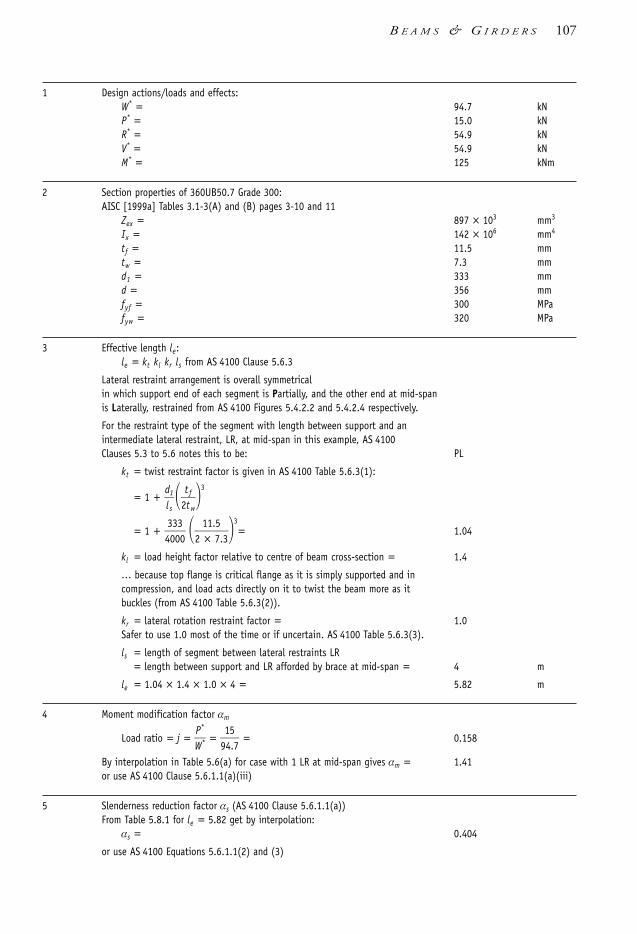
B E A M S & G I R D E R S 107
1 Design actions/loads and effects:W* = 94.7 kNP* = 15.0 kNR* = 54.9 kNV* = 54.9 kNM* = 125 kNm
2 Section properties of 360UB50.7 Grade 300:AISC [1999a] Tables 3.1-3(A) and (B) pages 3-10 and 11
Zex = 897 × 103 mm3
Ix = 142 × 106 mm4
tf = 11.5 mmtw = 7.3 mmd1 = 333 mmd = 356 mmfyf = 300 MPafyw = 320 MPa
3 Effective length le:le = kt kl kr ls from AS 4100 Clause 5.6.3
Lateral restraint arrangement is overall symmetricalin which support end of each segment is Partially, and the other end at mid-spanis Laterally, restrained from AS 4100 Figures 5.4.2.2 and 5.4.2.4 respectively.
For the restraint type of the segment with length between support and anintermediate lateral restraint, LR, at mid-span in this example, AS 4100Clauses 5.3 to 5.6 notes this to be: PL
kt = twist restraint factor is given in AS 4100 Table 5.6.3(1):
= 1 + dl s
1
2ttf
w3
= 1 + 4303030
2 1×1.
75.3
3= 1.04
kl = load height factor relative to centre of beam cross-section = 1.4
… because top flange is critical flange as it is simply supported and incompression, and load acts directly on it to twist the beam more as itbuckles (from AS 4100 Table 5.6.3(2)).
kr = lateral rotation restraint factor = 1.0Safer to use 1.0 most of the time or if uncertain. AS 4100 Table 5.6.3(3).
ls = length of segment between lateral restraints LR= length between support and LR afforded by brace at mid-span = 4 m
le = 1.04 × 1.4 × 1.0 × 4 = 5.82 m
4 Moment modification factor αm
Load ratio = j = WP*
* = 9145.7 = 0.158
By interpolation in Table 5.6(a) for case with 1 LR at mid-span gives αm = 1.41or use AS 4100 Clause 5.6.1.1(a)(iii)
5 Slenderness reduction factor αs (AS 4100 Clause 5.6.1.1(a))From Table 5.8.1 for le = 5.82 get by interpolation:
αs = 0.404
or use AS 4100 Equations 5.6.1.1(2) and (3)
1106 SDHB 05 Final 8/6/05 12:05 PM Page 107

108 S T E E L D E S I G N E R S ’ H A N D B O O K
6 Bending
6.1 Section moment capacity φMsx from AS 4100 Clause 5.2.1 isφMsx = φ fy Zex
= 0.9 × 300 × 897 × 1100
3
6 = 242 kNm
φ is given in AS 4100 Table 3.4
6.2 Member moment capacity φMbx
φMbx = αm αs φMsx φMsx AS 4100 Equation 5.6.1.1(1)= 1.41 × 0.404 × 242 = 138 φMsx = 242 = 138 kNm
6.3 M* φMbx in AS 4100 Clause 5.1 is OK because:
125 138 requirement is true/satisfied Member capacity φMb OK
7 Web shear capacity φVv:
φVv = φ 0.6 fyw Aw = φ 0.6 fyw d tw
= 0.9 × 0.6 × 320 × 356 × 170.3
3 = 449 kN
V* φVv is satisfied because 54.9 449 is true. Web shear φVv OK
In the absence of horizontal web stiffeners: Can use d1 for dp in webslenderness dp/tw which in hot-rolled I-sections such as UB and UC allsatisfy AS 4100 Clause 5.11.2(a) meaning their webs are stocky to permitfull shear yield Vw = 0.6 fyw Aw given in Clause 5.11.4 to be used. Similarlyfor WC and PFC. A cursory examination of d1/tw in WB sections in tablesshows a few possible exceptions for considering web shear buckling.
Note also that d was used instead of d1 in the above φVv calculation forhot-rolled (HR) sections as opposed to welded sections when d1 would beused. This is due to HR sections such as UB and UC having full steel “flow”at the web-flange junction from the manufacturing process. However, thesame can’t be said for other types of fabricated sections. Part 5 of AISC[1999a] also notes this differentiation.
Shear and bending interaction need not be considered as the peak shearforce (V* = 54.9 kN) is less than 60% of the design shear capacity (φVv = 449 kN) – see Section 5.8.4.
8 Web bearing at supports
8.1 Web bearing yield … AS 4100 Clause 5.13.3 and Figure 5.13.1.1(b) inverted
bs = length of stiff bearing= width of bearing plate = 50 mm
bbf = length of bearing between web and flange= bs + 2.5 tf AS 4100 Clause 5.13.1= 50 + 2.5 × 11.5 = 78.8 mm
φRby = web bearing yield capacity … at support= φ1.25 bbf tw fy AS 4100 Clause 5.13.3 … fy = fyw
= = 207 kN
R* φRby is satisfied because 54.9 207 is true Web bearing yield φRby OK… yield part of AS 4100 Clause 5.13.2
8.2 Web bearing buckling … at support
bb = width of web notionally as a column loaded axially with R*
= bbf d22
0.9 × 1.25 × 78.8 × 7.3 × 320
103
1106 SDHB 05 Final 8/6/05 12:05 PM Page 108

B E A M S & G I R D E R S 109
= bbf d21
= 78.8 3323
= 245 mm
End portion of beam as a column with cross-section twbb with area An …also αb = 0.5 and kf = 1.0 … AS 4100 Clause 5.13.4 …
An = tw bb
= 7.3 × 245 = 1790 mm2
End as column with geometric slenderness lre
lre =
2.5tw
d1
= 2.5 × 373.33
= 114
λn = modified slenderness to suit material properties …
AS 4100 Clause 6.3.3
λn = kf 2f5y
0
= 1141.0 322500
= 129
αb = member constant for residual stress distribution = 0.5
αc = slenderness reduction factor to be applied to column section capacity … AS 4100 Table 6.3.3(3)
αc = 0.345
φRbb = web bearing buckling capacity … at support …
= φ αc fyw An
= 0.9 × 0.345 × 320 × 1170930
= 178 kN
R* φRbb is satisfied because 54.9 178 is true
… buckling part of AS 4100 Clause 5.13.2 Web bearing buckling φRbb OK
8.3 Web bearing in conclusion is … OK
9 Deflection. See Example 5.3.1. OK
5.12.3.1 Example 5.3.1
A simplified check of the beam shown in Example 5.3 is done for moment, shear and web bearing capacity, anddeflection.
Use aids from this Handbook and AISC [1999a]. A detailed check is done in Example 5.3.2.
Given:Span l is 8 m.The beam top flange is connected at mid-span by a brace from the RC wall giving lateral restraint (LR).The beam ends receive lateral restraint from bolts anchoring the bottom flange to the supporting walls via 50 mmwide bearing plates.Downward actions/loads act on the top flange.Beam is 360UB50.7 Grade 300.
ler
1106 SDHB 05 Final 8/6/05 12:05 PM Page 109

Step Quantity Result Unit
Data360UB50.7 Grade 300
Ix = 142 × 106 mm4
tf = 11.5 mmtw = 7.3 mmd1 = 333 mm
1 Nominal actions/loads are the same as in Examples 5.2 and 5.3. Loads when consolidated, reduce down to:
1.1 Total uniformly distributed permanent action/dead load WG including self-weight of beam and concrete panels.WG = 30.9 kN
1.2 Total uniformly distributed imposed action/live load WQ
WQ = 38.4 kN
1.3 Point permanent action/dead load PG
PG = 0 kN
1.4 Point imposed action/live load PQ
PQ = 10 kN
2 Strength design actions/loads and effects are calculated from nominal loads in Step 1. Briefly repeating from Example 5.2 gives:
W* = 1.2 × 30.9 + 1.5 × 38.4 = 94.7 kNP* = 1.2 × 0 + 1.5 × 10 = 15.0 kNR* = 0.5 × (94.7 + 15) = ...symmetrical...= 54.9 kNV* = R* = …no overhang …= 54.9 kN
M* = 94.7 × 88.0 + 15 ×
84.0 = 125 kNm
3 Effective length of segment le between support and LR at mid-span-ls = 4.0 m
k values are obtained from Table 5.2.1 of this Handbook
le = kt kl kr ls= 1.1 × 1.4 × 1.0 × 4 = 6.16 m
4 Moment modification factor αm for the shape of the bending moment diagramFrom Table 5.6(a) for 1 LR at mid-span, … or AS 4100 Clause 5.6.1.1(a)(iii) … with
j = WP*
* = 1954..07
= 0.158
Get αm = 1.41
Elevation
Nominal actions/loadsare shown
Cross-section
Total UDL WG 30.9 kN permanent action/dead load and UDL WQ 38.4 kN imposed action/live load
ls 4 m ls 4 ml 8 m
PQ 10 kN imposed action/live load
LR LR at mid-span360UB50.7 Grade 300 beam
BeamBrace
Reinforcedconcrete wall
110 S T E E L D E S I G N E R S ’ H A N D B O O K
1106 SDHB 05 Final 8/6/05 12:05 PM Page 110

5 Blank (previous Example 5.3 required αs . Its use is not overt in AISC [1999a] and does not need to be specifically calculated here).
6 Moment capacity φM
6.1 Section moment capacity φMs
AISC [1999a] Table 5.3-5 page 5-50 or Table 5.2-5 page 5-38 … get φMs = 242 kNm
6.2 Member moment capacity φMb
With le = 6.16 m in AISC [1999a] Table 5.3-5 page 5-50 or Chart page 5-51 get φMb1 for αm = 1.0:
φMb1 = 91.9 kNm
Improve on φMb1 for αm = 1.41, getting
φMb = αm φMb1
= 1.41 × 91.9 = 130 kNm
Check section moment capacity φMs is not exceeded by φMb because of anoverly large αm …
φMb φMs → 130 242 → true, satisfied … OK
and φMb = 130 kNm
(Step 6.2 of the last example notes φMb (= φMbx) = 138 kN, the slight difference being due to linear interpolation approximations and numerical rounding).
AS 4100 Clause 5.1 requires …
M* φMb → 125 130 → true, satisfied … OK
360UB50.7 Grade 300 is satisfactory for bending ... and Moment capacity φMb OK
7 Web shear capacity φVv
AISC [1999a] Table 5.3-5 page 5-50φVv = 449 kNR* φVv → 54.9 449 = true … and Web shear φVv OK
8 Web bearing capacity φRb (at end supports)bs = … 50 wide bearing plate … = 50 mm
bbf = bs + 2.5 tf AS 4100 Clause 5.13.1= 50 + 2.5 × 11.5 = 78.8 mm
bb = bbf + d21 AS 4100 Figure 5.13.1.1(b) inverted
= 78.8 + 3323
= 245 mm
φ
bR
b
bb = 0.725 AISC [1999a] Table 5.2-5 page 5-38
φRbb = 0.725 × bb
= 0.725 × 245 = 178 kN
φ
bR
b
b
f
y = 2.63 AISC [1999a] Table 5.2.5 page 5–38
φRby = 2.63 × bbf
= 2.63 × 78.8 = 207 kN
φRb = Min (φRby, φRbb)= Min (207,178) = 178 kN
R* φRb → 54.9 178 is true, satisfied … and Web bearing φRb OK
B E A M S & G I R D E R S 111
1106 SDHB 05 Final 8/6/05 12:05 PM Page 111

9 Deflection. Refer to AS/NZS 1170.0 Clause 4.3 combining (a) and (b) with Table 4.1, and AS 4100 Appendix B, AISC [1999a] Table T5.3 page 5-19 or Appendix C of this Handbook.
9.1 Serviceability design actions/loads for deflection:
W* = WG + ψlWQ = 30.9 + 0.6 × 38.4 = 53.9 kN
P* = PG + ψsPQ = 0 + 1.0 × 10 = 10.0 kN
9.2 Actual deflection δ = +
= + = 16.4 mm
9.3 Permissible deflection ∆ = 25
l0
= 8205000
= 32 mm
δ ∆ → 16.4 32 → true, satisfactory … and Deflection δ OK
Further deflection requirements are noted in Section 1.8.
10 Summary
360UB50.7 Grade 300 is 112350
= 0.96 or 96% effective in
bending capacity. Web shear, bearing yield and buckling, and deflection are all satisfactory. All OK
Addendum Shear–bending interaction
As an example, check a section of the beam 2 m from the support in which:V* = 31.2 kNM* = 86.0 kNm
AISC [1999a] Table 5.3-5 page 5-50 or Table 5.2-5 page 5-38 gives:φMs = 242 kNm0.75φMs = 182 kNm
From AS 4100 Clause 5.12.3because M* 0.75φMs → 86.0 182 is true, satisfiedthen φVVm = φVV = 449 kNThus V* φVV → 31.2 449 is true, satisfied.Shear–bending interaction is OK
Note: Example 5.3.1 above involves the same beam and loads used in Examples 5.2 and 5.3. Example 5.2 established a360UB50.7 Grade 300 as a possible trial section for the beam. Example 5.3 without aids and relying mainly on AS4100 shows the selection is satisfactory for moment and web capacities.
Example 5.3.1 uses aids from this Handbook and AISC [1999a] to simplify the calculations to check moment andweb capacities and deflection. It includes some comments and references.
10.0 × 103 × 80003
(48 × 2 x 105 × 142 x 106)
5 × 53.9 × 103 × 80003
(384 × 2 × 105 × 142 × 106)
P*L3
48EI
5W*L3
384EI
112 S T E E L D E S I G N E R S ’ H A N D B O O K
1106 SDHB 05 Final 8/6/05 12:05 PM Page 112

5.12.3.2 Example 5.3.2
Example 5.3.1 is revisited showing only calculations.Do a complete check of the beam shown.
Span l is 8 m.Top flange has 1 lateral restraint (LR) at mid-span. Ends are partially restrained (P) by anchor bolts in the bottomflange. Bearing plates are 50 mm wide.
Actions/loads sit directly on the top flange, and act downwards.Beam is 360UB50.7 Grade 300.
Step Quantity Result Unit
Data
360UB50.7 Grade 300Ix = 142 × 106 mm4
tf = 11.5 mmtw = 7.3 mmd1 = 333 mmZex = 897 × 103 mm3
fyf = 300 MPaIy = 9.60 × 106 mm4
J = 241 × 103 mm4
Iw = 284 × 109 mm6
1 Nominal actions/loads are
1.1 Total uniformly distributed permanent action/dead load including self-weight of beam and concrete panels WG = 30.9 kN
1.2 Total uniformly distributed imposed action/live load WQ = 38.4 kN
1.3 Point permanent action/dead loadPG = 0 kN
1.4 Point imposed action/live loadPQ = 10 kN
2 Strength design actions/loads and effectsW* = 1.2 × 30.9 + 1.5 × 38.4 = 94.7 kNP* = 1.2 × 0 + 1.5 × 10 = 15.0 kNR* = 0.5 × (94.7 + 15) = 54.9 kNV* = R* = 54.9 kN
M* = 94.7 × 88.0 + 15 ×
84.0 = 125 kNm
Elevation
Total UDL WG 30.9 kN permanent action/dead load and UDL WQ 38.4 kN imposed action/live load
ls 4 m ls 4 ml 8 m
PQ 10 kN imposed action/live load
LR 360UB50.7 Grade 300 beam
Nominal actions/loadsare shown
B E A M S & G I R D E R S 113
1106 SDHB 05 Final 8/6/05 12:05 PM Page 113

3 Beam segment effective length based on default k values in Table 5.2.1(could also use the more precise evaluation of kt as noted in Step 3of Example 5.3—but not in this instance)l e = 1.1 × 1.4 × 1.0 × 4 = 6.16 m
4 Section moment capacity, φMs
Ms = 300 × 897 × 1100
3
6 = 269 kNm
φMs = 0.9 × 269 = 242 kNm
5 Moment modification factor αm from Table 5.6(a), 1 LR mid-span
j = WP*
* = 1954..07
= 0.158
αm = 1.41
6 Slenderness reduction factor, αs
A = = 499 103 N
B = = 14.8 109 Nmm2
C = 80 103 241 103 = 19.3 109 Nmm2
Mo = = 130 kNm
as = 0.62 3 = 0.378
7 Member moment capacity φMb = φMb = 0.9 × 1.41 × 0.378 × 269 = 129 kNmφMb φMs → 129 242 true, satisfiedM* φMb → 125 129 true, satisfied.Moment capacity φMb OK
8 Web shear capacity (see step 7 of Example 5.3 for calculation of φVv)φVv = 449 kNR* φVv → 54.9 449 is satisfied. φVv OK
9 Web bearing capacity φRb (note: φRby/bbf and φRbb/bb can be evaluated from Step 8 of Example 5.3)bs = 50 mmbbf = 50 + 2.5 × 11.5 = 78.8 mmbb = 78.8 + 333/2 = 245 mmφRbb = 0.725 × 245 = 178 kNφRby = 2.63 × 78.8 = 207 kNφRb = Min (207,178) = 178 kNR* φRb → 54.9 178 is satisfied. Web bearing φRb OK
10 Serviceability design actions/loads for deflection: See Step 9 of Example 5.3.1 for a full calculation.
11 Summary
360UB50.7 Grade 300 is 97% efficient in bending/moment capacity. Web shear, bearing yield and buckling, and deflection are also satisfactory. OK
269130
269130
499 103 (19.3 109 14.8 109)
106
π2 200 103 284 109
61602
π2 200 103 9.6 106
61602
114 S T E E L D E S I G N E R S ’ H A N D B O O K
1106 SDHB 05 Final 8/6/05 12:05 PM Page 114

B E A M S & G I R D E R S 115
5.12.4 Example 5.4
Step Description and calculations Result Unit
The welded girder shown has loads applied to the top flange. The girder is partially restrained at thesupports and two intermediate points indicated by LR at the third points along the span. The flanges arethicker over the central portion of the span. The bottom flanges are 10 mm thinner than the top flanges.Check the moment capacity.
Data:AS/NZS 3678 Steel grade (special grade used instead of standard Grade 250) = 300Span of girder = 21 000 mmDesign actions/loads and effects:
P* = 250 kNW* (including self-weight) = 840 kNR* = 1045 kNM* in segment CE at mid-span = 6140 kNmM* in segments AC and EG at C and E 5460 kNm
1 Section properties of full section in middle segment CE(see Section 9.3.1 and Appendix B.3 also):
d = 1510 d1 = 1400 tw = 32 mmTop flange: bf = 450 tf = 60 mmBottom flange: bf = 450 tf = 50 mmAg = 94 300 mm2
Ix = 33.4 × 109 mm4
Iy = 839 × 106 mm4
Zx top = 46.1 × 106 mm3
Zx bot = 42.5 × 106 mm3
ry = 94.3 mm
Torsion constant: J = Σ 0.333bt3 = 66.4 × 106 mm4
Iy of critical flange alone = Icy:
Icy = 60 ×
124503
= 456 × 106 mm4
Distance between centroids of flanges, df :
df = 1510 – 30 – 25 = 1455 mm
Warping constant: Iw = Ic yd f21 –
IIc
y
y (AS 4100, Appendix H, Clause H4)
1770
3410
4500
LR
BMD
P*W*
P* P* P* P*
A C E G
LR
21 m
5460
6140
kNm
777
1510
450
Full Section … CE
Reduced Section… AC & EG
450
32
60
50
40
30
321470
Note: End segment AC is the same as for EG.
5860
1106 SDHB 05 Final 8/6/05 12:05 PM Page 115

116 S T E E L D E S I G N E R S ’ H A N D B O O K
= 456 × 106 × 14552× 1 – 485369
= 441 × 1012 mm6
Equal area axis from bottom = 795 mm
Plastic modulus of full section Sx = 51.5 × 106 mm3
2 Section properties of reduced section in end segment AC and EG(see Section 9.3.1 and Appendix B.3 also):
d = 1470 d1 = 1400 tw = 32 mmTop flange: bf = 450 tf = 40 mmBottom flange: bf = 450 tf = 30 mmAg = 76 300 mm2
Ix = 23.4 × 109 mm4
Iy = 535 × 106 mm4
Zx top = 33.6 × 106 mm3
Zx bot = 30.3 × 106 mm3
ry = 83.8 mmTorsion constant: J = Σ 0.333bt3 = 28.9 × 106 mm4
Iy of critical flange alone = I c y :
I c y = 40 ×
124503
= 304 × 106 mm4
Distance between centroids of flanges, df :
df = 1470 – 20 – 15 = 1435 mm
Warping constant: Iw = Ic yd f21 –
IIc
y
y (AS 4100, Appendix H, Clause H4)
= 304 × 106 × 14352 × 1 – 350345
= 270 × 1012 mm6
Equal area axis from bottom = 785 mmPlastic modulus of reduced section Sx = 38.1 × 106 mm3
3 Section slenderness λs of full section in middle segment CE:
3.1 Element slenderness λe from AS 4100 Clause 5.2.2:
λe = bt
2f5y
0
3.2 Top flange element λe (assume lightly welded longitudinally (LW)):
λe = 26009
228500
= 3.69
λλ
e
e
y =
31.659
= 0.246
3.3 Bottom flange element λe (assume lightly welded longitudinally (LW)):
λe = 25009
228500
= 4.42
λλ
e
e
y =
41.452
= 0.295
3.4 Web element λe (assume lightly welded longitudinally (LW)):
λe = 143020
228500
= 46.3
λλ
e
e
y =
4161.53
= 0.403
1106 SDHB 05 Final 8/6/05 12:05 PM Page 116

B E A M S & G I R D E R S 117
3.5 Which element is the most slender is given by:
max (0.246, 0.295, 0.403) = 0.403
0.403 is identified with the web which is the critical element web critical
3.6 Section slenderness λs:
Section as a whole has its slenderness λs controlled by λe of webλe is analogous to strength of a chain = … weakest link …with elements as links …and λs = λe of web = 46.3
With web critical. Web is supported along two edges by flanges, and bendingstress varies from compression to tension
From AS 4100 Table 5.2, λsp = λep of web = 82
λs λsp = true because 46.3 82 = true …
… to comply with AS 4100 Clause 5.2.3….… and λs of full section in middle segment CE is … Compact
4 Section slenderness λs of reduced section in end segment AC:can show that the bottom flange governs with
λsp = λep = 8
so that λs λsp is true, satisfied.
λs of reduced section in end segment AC is … Compact
5 Effective section modulus Zex of full section in middle segment CE:
Being compact: Zex = Sx Then Zex of full section = 51.5 × 106 mm3
Check: Sx 1.5 Zx OK
6 Effective section modulus Zex of reduced section in end segment AC:
Being compact: Zex = Sx Then Zex of reduced section = 38.1 × 106 mm3
Check: Sx 1.5 Zx OK
7 Effective length le of middle segment CE:
Downwards loads act on top flange, makes it critical flangeRestraints are all partial, giving arrangement PP
AS 4100 Table 5.6.3(1)
kt = 1 + 2ld
s
w
0.t5
w
tf3
= 1+2 × 17400000
× 0.5 × 63023
= 1.33
kr = for unrestrained lateral rotation of flange about y-axis 1.0
kl = for PP and load within segment = 1.4
le = kt kl kr ls= 1.33 × 1.4 × 1.0 × 7000 = 13 000 mm
8 Effective length le of end segment AC:
Using assumptions from Step 7 above.
kt= 1+2 × 17400000
× 0.5 × 43023
= 1.10kr = 1.0kl = 1.4l e = 1.10 × 1.4 × 1.0 × 7000 = 10 800 mm
The reason for the lower effective length is due to the reduced difference in stiffness between the web and the flange.
1106 SDHB 05 Final 8/6/05 12:05 PM Page 117

118 S T E E L D E S I G N E R S ’ H A N D B O O K
9 Slenderness reduction factor αs for middle segment CE requires:
AS 4100 Clauses 5.6.1.1(a) and 5.6.1.2
Coefficient βx = 0.8 df 2II
y
cy – 1
= 0.8 × 1455 × 2 ×83
495×6 ×
101606
– 1 = 101 mm
9.1 Let A =
= = 9.80 × 10⁶ N
9.2 Let B = π2
le
E2Iw
= = 5.15 × 10¹² Nmm2
9.3 Let C = GJ
= 80 × 103 × 66.4 × 106 = 5.31 × 10¹² Nmm2
9.4 Mo = reference buckling moment of full section in middle segment CE requires AS 4100 Clause 5.6.1.2:
Mo = A [C + B + 0.25 βx2 A] + 0.5 βx A = 10.6 × 10⁹ Nmm
= 10 600 kNm
9.5 Ms = nominal section moment capacity of full section in middle segment CE:
Ms = fy Zex
= 280 × 51.5 × 106 = 14.4 × 10⁹ Nmm
= 14 400 kNm
φMs = 0.9 × 14400 = 13 000 kNm
9.6 αs = slenderness reduction factor for middle segment CE (AS 4100 Equation 5.6.1.1(2)):
= 0.6 MM
o
s2
2 + 3 – MM
o
s
= 0.6 + 3 – 1140460000
= 0.506
10 Moment modification factor αm for middle segment CE (AS 4100 Clause 5.6.1.1(a)(iii)):
αm =
= 2.5 = 1.01
11 φMb = member moment capacity of full section in middle segment CE:= φ αm αs Ms
= 0.9 × 1.01 × 0.506 × 14400 = 6620 kNm
12 M* φMb requirement in AS 4100 Clause 5.1: 6140 6620 true OK
M* φMs is also good: 6140 13 000 true OK
φMb of full section in middle segment CE is adequate for moment capacity. Full section CEOK in bending
1.7 × 6140(58602+ 61402 + 58602)
1.7 M*m
(M*
22 + M*
32 + M*
42)
144002
106002
π2 × 200 × 103 × 441 × 1012
130002
π2 × 200 × 103 × 839 × 106
130002
π2 EIy
l e2
1106 SDHB 05 Final 8/6/05 12:05 PM Page 118

B E A M S & G I R D E R S 119
13 Slenderness reduction factor αs for end segment AC requires:
AS 4100 Clauses 5.6.1.1(a) and 5.6.1.2
Coefficient βx = 0.8 df 2II
y
cy – 1
= 0.8 × 1435 × 2 ×53
350×4 ×
101606
– 1 = 157 mm
13.1 Let A = π2
le
E2Iy
= = 9.05 × 10⁶ N
13.2 Let B = π2
le
E2Iw
= = 4.57 × 10¹² Nmm2
13.3 Let C = GJ
= 80 × 103 × 28.9 × 106 = 2.31 × 10¹² Nmm2
13.4 Mo = reference buckling moment of reduced section in end segment AC requires AS 4100 Clause 5.6.1.2
Mo = A [C B 0.25 βx2 A] 0.5 βx A = 8.63 × 10⁹ Nmm
= 8630 kNm
13.5 Ms = nominal moment section capacity of reduced section in end segment AC:
Ms = fy Zex
= 280 × 38.1 × 106 = 10.7 × 10⁹ Nmm= 10 700 kNm
φMs = 0.9 × 10700 = 9630 kNm
13.6 αs = slenderness reduction factor for end segment AC:
= 0.6MM
o
s2
2 + 3 – MM
o
s
= 0.6 18067300022
+ 3 – 180673000
= 0.534
14 αm = moment modification factor for end segment AC
=
= 2.5 = 1.57
15 φMb = member moment capacity of reduced section in end segment AC
= φ αm αs Ms
= 0.9 × 1.57 × 0.534 × 10700 = 8070 kNm
16 M* φMb requirement in AS 4100 Clause 5.1: 5460 8070 true OK
M* φMs is also good: 5460 9630 true OK
φMb of reduced section in end segment AC is adequate for moment Reduced section ACcapacity. OK in bending
1.7 × 5460(17702+ 34102 + 45002)
1.7 M*m
(M*
22 + M*
32 + M*
42)
π2 × 200 × 103 × 270 × 1012
108002
π2 × 200 × 103 × 535 × 106
108002
1106 SDHB 05 Final 8/6/05 12:05 PM Page 119

120 S T E E L D E S I G N E R S ’ H A N D B O O K
5.12.5 Example 5.5
Step Description and calculations Result Unit
The welded girder shown has loads applied to the top flange. The girder is continuously laterally restrained alongthe span and at the supports. Web stiffeners are spaced at 1500 mm. Check the girder for moment capacity, andits web capacity to take shear and bearing. Stiff bearing length is 200 mm at supports.
Dimensions and other details of the girder are tabulated below.
1 DataAS/NZS 3678 Steel grade (special grade used instead of standard Grade 250) = 300Span of girder 15 000 mm
1.1 Cross-section dimensions:d = 1260 mmd1 = 1200bf = 500 mmtf = 30 mmtw = 8 mm
1.2 Properties of section:Ag = 39 600 mm2
Ix = 12.5 × 109 mm4
Iy = 625 × 106 mm4
Zx = 19.8 × 106 mm3
ry = 126 mmTorsion constant: J Σ 0.333bt3 9.20 × 106 mm4
Warping constant: Iw Iy
4df
2
= = 236 × 1012 mm6
Plastic modulus Sx = 21.3 × 106 mm3
2 Actions/loads
2.1 Nominal actions/loads:Self-weight, uniformly distributed load 3.12 kN/mPermanent action/dead load, UDL 9.38 kN/mImposed action/live load, UDL 18 kN/mPoint imposed action/live load at mid-span 250 kN
2.2 Design actions/loads and effectsAS/NZS 1170.0 Clause 4.2.2(b)
w* = 1.2 wG + 1.5 wQ
= 1.2 × (3.12 + 9.38) + 1.5 × 18 = 42.0 kN/mW* = w*l
= 42.0 × 15 = 630 kN
625 × 106 × (1260 – 30)2
4
1500Is load bearing
stiffener required?
Elevation of plate girder
Web stiffenersStiff bearing length 200
P*W*
End post—if required
Top flange is continuouslylaterally restrained
15 000
1260
1106 SDHB 05 Final 8/6/05 12:05 PM Page 120
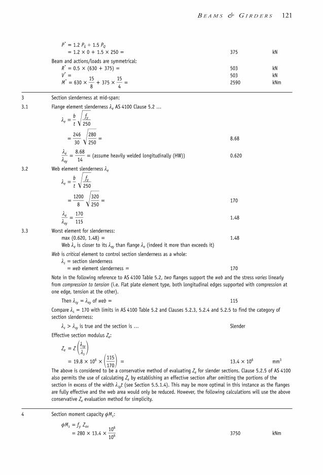
P* = 1.2 PG 1.5 PQ
= 1.2 × 0 + 1.5 × 250 = 375 kN
Beam and actions/loads are symmetrical:R* = 0.5 × (630 + 375) = 503 kNV* = 503 kNM* = 630 ×
185 + 375 ×
145 = 2590 kNm
3 Section slenderness at mid-span:
3.1 Flange element slenderness λe AS 4100 Clause 5.2 …
λe = bt
2f5y
0
= 23406
228500
= 8.68
λλ
e
e
y =
81.648
= (assume heavily welded longitudinally (HW)) 0.620
3.2 Web element slenderness λe
λe = bt
2f5y
0
= 12
800
322500
= 170
λλ
e
e
y =
117105
1.48
3.3 Worst element for slenderness:max (0.620, 1.48) = 1.48Web λe is closer to its λey than flange λe (indeed it more than exceeds it)
Web is critical element to control section slenderness as a whole:λs = section slenderness
= web element slenderness = 170
Note in the following reference to AS 4100 Table 5.2, two flanges support the web and the stress varies linearlyfrom compression to tension (i.e. Flat plate element type, both longitudinal edges supported with compression atone edge, tension at the other).
Then λsy = λey of web = 115
Compare λs = 170 with limits in AS 4100 Table 5.2 and Clauses 5.2.3, 5.2.4 and 5.2.5 to find the category ofsection slenderness:
λs > λsy is true and the section is … Slender
Effective section modulus Ze:
Ze = Z λλs
s
y
= 19.8 × 106 × 111750
= 13.4 × 106 mm3
The above is considered to be a conservative method of evaluating Ze for slender sections. Clause 5.2.5 of AS 4100also permits the use of calculating Ze by establishing an effective section after omitting the portions of thesection in excess of the width λsyt (see Section 5.5.1.4). This may be more optimal in this instance as the flangesare fully effective and the web area would only be reduced. However, the following calculations will use the aboveconservative Ze evaluation method for simplicity.
4 Section moment capacity φMs:
φMs = fy Zex
= 280 × 13.4 × 1100
6
6 3750 kNm
B E A M S & G I R D E R S 121
1106 SDHB 05 Final 8/6/05 12:05 PM Page 121

122 S T E E L D E S I G N E R S ’ H A N D B O O K
5 Member moment capacity φMb:φMb = αm αs φMs φMs
αm = 1.0 for a continuously restrained beamαs = 1.0 for a continuously restrained beamφMb = 1.0 × 1.0 × 3750 = φMs in this instance = 3750 kNmM* < φMb is satisfied because 2590 < 3750 is true member moment
capacity φMb OK
6 Minimum web thickness:
ds
1 =
11520000
= ds
p = 1.25
and 1 ds
1 3.0 in AS 4100 Clause 5.10.4(a) is satisfied True
to give minimum web thickness tw required:
minimum tw = 2d01
0
2f5y
0
= 1220000
322500
= 6.79 mm
tw = 8 actual > 6.79 web tw = 8 is OK
7 Web shear capacity φVv :
7.1 Web slenderness =
= dtw
p =
12800 = 150
dtw
p = 72.5 … and because 150 > 72.5 True …
… web can buckle instead of yielding in shear … from AS 4100 Clause 5.11.2(b) Vu = Vb
7.2 From AS 4100 Clauses 5.11.2(b) and 5.11.5.1, the nominalshear buckling capacity, Vb , of an unstiffened web is:
Vb = αvVw Vw
where
αv = 2
= 2
= 0.233
Vw = nominal shear yield capacity= 0.6fyAw = 0.6fydptw
= = 1840 kN
ThereforeφVb = 0.9 0.233 1840 = 386 kN
φVw ………. satisfies φVb criterionhowever,
V* φVb which is unsatisfactory as 503 386 and the web needs to be stiffened for shear buckling by intermediate transverse web stiffeners. This is understandable as the web is very slender.
0.6 320 1200 8
103
82
12
800
322500
82
dtw
p
2f5y
0
82
322500
1106 SDHB 05 Final 8/6/05 12:05 PM Page 122

B E A M S & G I R D E R S 123
7.3 Nominal web shear buckling capacity in a web with (vertical) intermediatetransverse stiffeners (as per the initial diagram to this worked example).Assume intermediate transverse stiffeners are
2 No. 150 x 10 Grade 300 flat bars each side of the web.As noted in AS 4100 Clause 5.15.4, the buckling capacity ofthe web/stiffener combination must satisfy:
V* φ(Rsb + Vb)where
Rsb = nominal buckling capacity of web/intermediate stiffeneras noted in AS 4100 Clause 5.14.2 … with le = d1 (as the flanges are not connected to the stiffener),αb = 0.5 and kf = 1.0 ……
Vb = nominal shear buckling capacity for a stiffened webas noted in AS 4100 Clause 5.11.5.2… with αd = αf = 1.0
lewc = effective length of web cross-section area on each side of stiffener for column action
= min. of or 2s
= min. of or 15
200 = min.[124; 750 ] = 124 mm
Aws = effective cross-section area of web/stiffener
= 2 (150 10) 2 (124 8) = 4980 mm2
Iws = second moment of area of web/stiffenertaken about axis parallel to the web.
= = 24.4 × 106 mm4
rws = 24.
449
80106
= 70.0 mm
rlww
s
s = web/stiffener compression member slenderness ratio
= rd
w
1
s =
17200.00
= 17.1
λn = web compression member modified slenderness ratio
= rlww
s
s(kf)
2f5y
0
(note: where indicated, allow for the lower fy of the stiffener i.e. from 320 → 310 MPa)
= 17.1 1.0 321500
= 19.0
αc = web compression member slenderness reduction factorfrom AS 4100 Table 6.3.3(3), αc = 0.972
Rsb = design bearing buckling capacity of a unstiffened web
= cAws fy
2 124 83
12
10 (300 8)3
12
17.5 8
322500
17.5 tw
2f5y
0
1106 SDHB 05 Final 8/6/05 12:05 PM Page 123

=0.972
1409
380 310 = 1500 kN
(note: where indicated, revert back to the higher fy of the web as it controls shear buckling i.e. from 310 → 320 MPa). From AS 4100 Clause 5.11.5.2:
ds
p =
11520000
= 1.25
For 1.0 ds
p 3.0:
αv = 2
1.0 1.0
= 2
(10..2755)2 + 1.0 = 0.346
αd = as noted above in Vb definition (in step 7.3) = 1.00
αf = as noted above in Vb definition (in step 7.3) = 1.00
Vb = αv αd αf Vw
= = 638 kN
Then φ(Rsb + Vb) = 0.9 (1500 638) = 1920 kN
V* φ(Rsb + Vb) OK as 503 1920 kN Intermediatestiffeners OK
Checks for stiffener minimum area (AS 4100 Clause 5.15.3),minimum stiffness (AS 4100 Clause 5.15.5) and outstandof stiffeners (AS 4100 Clause 5.15.6) show that this intermediatetransverse stiffener configuration and loading type is also adequate.
Shear and bending interaction need not be considered as the peak shear force (V* = 503 kN) is less than 60% of the design shear capacity with the stiffened web (φVv = 1920 kN) – see Section 5.8.4.
8 Web bearing at a support:
8.1 Bearing lengths
AS 4100 Figures 5.13.1.1 and 2 use notation for end force bearing (see Figure in Example 5.6 also):
bs stiff bearing length … as specified in description of girder … 200 mm
bbf bearing length at junction of flange and web for yield
bs 2.5 tf 200 2.5 × 30 275 mm
bb … used later in step 8.3… length of web at mid height … width of “column”
bbf d21
275 12
200 875 mm
0.346 1.00 1.00 (0.6 320 1200 8)
103
82
150 322500
0.75
ds
p2
82
dtw
p
2f5y
0
124 S T E E L D E S I G N E R S ’ H A N D B O O K
1106 SDHB 05 Final 8/6/05 12:05 PM Page 124

B E A M S & G I R D E R S 125
8.2 Bearing yield capacity φRby (unstiffened):
φRby φ1.25 bbf tw fy
792 kN
R* φRby OK because 503 792 true Web bearing yield OK
8.3 Web buckling at support (unstiffened)
8.3.1 Slenderness of web analogised as a columnFrom AS 4100 Clause 5.13.4 –
αb web compression member section constant 0.5
kf web compression member form factor 1.0
Awc web compression member cross-section area
tw bb 8 875 = 7000 mm2
(note: bb is calculated above in Step 8.1 andfurther explained in Section 5.8.5.3).
lre = web compression member slenderness ratio
= 2.
t5
w
d1 =
2.5
81200 = 375
λn = web compression member modified slenderness ratio
= lre(kf)
2f5y
0
= 375 1.0 322500
= 424
αc = web compression member slenderness reduction factor from AS 4100 Table 6.3.3(3), ac = 0.0422
φRbb = design bearing buckling capacity of an unstiffened web
= c Awc fy
= = 85.1 kN
AS 4100 Clause 5.13.2 requires R* φRbb … which is not satisfied because 503 < 85.1 is false Web bearing
buckling fails
Load bearing stiffeners are required for the web.Example 5.6 considers the design of such load-bearing stiffeners.
5.12.6 Example 5.6
Step Description Result Unit
The plate girder in Example 5.5 shows load-bearing stiffeners are required at the ends terminating at the supports.Intermediate web stiffeners are placed at 1500 centres. Steel is Grade 300. The following is an example of load-bearing stiffener design.
Check the adequacy of a pair of 200 × 25 stiffeners placed within the stiff bearing length bs, which is given as200 mm.
0.9 0.0422 7000 320
103
0.9 × 1.25 × 275 × 8 × 320
103
1106 SDHB 05 Final 8/6/05 12:05 PM Page 125

126 S T E E L D E S I G N E R S ’ H A N D B O O K
Elevation of left end of girder
1 Design reaction R* is calculated in Example 5.5:
R* = 503 kN
2 Girder cross-section dimensions:
d = 1260 bf = 500 t f = 30 tw = 8 d1 = 1200 mm
3 Stiffeners, Area Ast one pair, 2 No. 200 × 25mm:
Ast = 2 × 200 × 25 = 10 000 mm2
4 Material properties:
Grade 300 steel
Design yield stress values from Table 2.3 or AS 4100 Table 2.1 for AS/NZS 3678 Grade 300 plate:
Web with tw = 8 gives fyw = 320 MPa
Stiffeners with ts = 25 gives fys = 280 MPa
5 Stiffener outstand, check:
Stiffener outstand bes in AS 4100 5.14.3 is limited to:
bes
= = 354 mm
Actual outstand = 200 354 OK
6 Stiffener spacing s:
s = spacing between stiffeners = 1500 mm
2s
= 15
200 750 mm
15 25
228500
15ts
2f5ys
0
'Effective'column
Web 8 thick
Extent of web as column
Load-bearing stiffeners2 - 200 25
Intermediate webstiffeners at 1500 spacingFlange 500 30
Flange 500 30
d1 1200
R* 503 kN
R*
tf 30
lewc 124100
bc 224
bbf 275
30
Stiff bearing length bs 200
bc width of web-stiffener 'column'
1106 SDHB 05 Final 8/6/05 12:05 PM Page 126

7 Yield capacity of the web/load-bearing stiffener The web and load-bearing stiffener combine to act as an axiallyloaded column (see note at the end of the example).
This must satisfy AS 4100 Clause 5.14.1:
R* φRsy
where
R* = design bearing or reaction force
Rsy = nominal yield capacity of the stiffened web
= Rby AsfysRby = 1.25bb ftw fyw = = 880 kN
(note: bbf is calculated in Step 8.1 of Example 5.5 and further explained in Section 5.8.5.2).
As = area of stiffener in contact with the flange
= 2 (200 25) = 10 000 mm2
(note: allow for the lower fy of the stiffener not the webi.e. from 320 → 280 MPa)
then
φRsy = 0.9 880 1000
1003
280 = 3310 kN
R* φRsy … which is satisfied because 503 3310 Web/Stiffeneryielding is OK
8 Buckling capacity of the web/load-bearing stiffener The web and load-bearing stiffener combine to act as an axiallyloaded column (see note at the end of the example)
This must satisfy AS 4100 Clause 5.14.2:
R* Rsb
where
Rsb = nominal buckling capacity of web/load-bearing stiffener
with le = d1 (or 0.7d1 if the flanges are rotationally
restrained by other structural elements in the
plane of the stiffener), b = 0.5, and kf = 1.0
lewc = effective length of web cross-section area oneach side of stiffener for column action
= min. of or 2s
= min. of or 15
200 = min.[124; 750 ] = 124 mm
Aws = effective cross-section area of web/stiffener (see Figure at the beginning of the example)
= 2 (200 25) (100 124) 8 = 11 800 mm2
Iws = second moment of area of web/stiffenertaken about axis parallel to the web ….
17.5 8
322500
17.5 tw
2f5y
0
1.25 275 8 320
103
B E A M S & G I R D E R S 127
1106 SDHB 05 Final 8/6/05 12:05 PM Page 127

128 S T E E L D E S I G N E R S ’ H A N D B O O K
= 25 (4
1020 8)3
(100
11224) 83
= 142 × 106 mm4
rws = 14
121
801006
= 110 mm
rlww
s
s = web/stiffener compression member slenderness ratio
= rd
w
1
s =
1121000
= 11.0
(Note: had the flanges been restrained against torsion (in the plane of the stiffener) then lws could have been 0.7d1 instead of d1).
λn = web/stiffener compression member modified slenderness ratio
= rlww
s
s(kf)
2f5y
0
(note: where indicated, allow for the lower fy of the stiffener i.e. from 320 → 280 MPa)
= 11.0 1.0 228500
= 11.6
αc = web compression member slenderness reduction factorfrom AS 4100 Table 6.3.3(3), αc = 0.997
φRsb = design bearing buckling capacity of the web/stiffener
= 0.9c Aws fy
= = 2960 kN
R* φRsb OK as 503 2960 kN Load-bearingstiffeners OK
9 Requirement for an End Post
AS 4100 Clauses 5.15.9 and 5.15.2.2 note that an end post is required if the end web panel width, send, does not satisfy the following criteria:
(a) V* φVb from AS 4100 Clause 5.11.5.2 with αd = 1.0, and
(b) does not undergo any shear and bending interaction effect (from AS 4100 Clause 5.12)
Additionally, AS 4100 Clause 5.14.5 notes the following:
(c) a minimum stiffness of load-bearing stiffeners if they are the sole means of providing torsional end restraints to the member supports.
Checking the above:
(a) sden
p
d=
11520000
= 1.25
From Step 7.3 in Example 5.5 with αd = 1.0:
αv = 0.346
αf = 1.0
φVb = 0.9 638 = 574 kN
V* φVb OK as 503 574 kN at the supports
(b) There is no shear and bending interaction as the end supportssee the highest shear force and the lowest moment.
(c) If the load-bearing stiffener is the sole means of beam supporttorsional restraint, the second moment of area of a pairof stiffeners, Is, about the web centreline must satisfy:
0.9 0.997 11800 280
103
1106 SDHB 05 Final 8/6/05 12:05 PM Page 128

Is ≥ 10
0t
0d
3
Ftf*R*
where
rley = web/stiffener compression member
slenderness ratio as calculated in Step 8 = 11.0
αt = 0.60 (for 0 αt 4.0) = 4.0
R* = 503 kN
F* = 2 503 = 1006 kN
then minimum Is (=Ismin )
Ismin = 140.000
12603
103006
503 = 120x106 mm4
From Step 8 above, actual Is is
Is = 142x106 mm4
The minimum stiffness for the load-bearing stiffener issatisfied as Is Ismin → 142 × 106 120 × 106 Load-bearing stiffener
OK for torsional stiffness
Hence no End plate is required. No End plate required.
If the design end shear force or the stiffener spacing increasesan end plate designed to AS 4100 Clause 5.15.9 may have to be provided.
Note 1 Buckling web and stiffeners are analogised to a column buckling about the horizontal axis along the web.Buckling about the vertical axis along the stiffeners is prevented by the continuity of the web beyondthe extent of the section used in the calculations.
Comment The calculations detailed above for web and load-bearing stiffener buckling, plus the check in Example5.5 to see whether load-bearing stiffeners are required or not, are lengthy to do manually in repetitivecalculations. Conclusions can be drawn from the results, and short-cuts judiciously applied. This is moreso if a decision is made at the outset to provide stiffeners for whatever reason.
5.13 Further reading• For additional worked examples see Chapter 5 of Bradford, et al [1997].• For bending moment/shear force distribution and deflection of beams see Syam
[1992], Young & Budynas [2002] or Appendix C of this Handbook.• Rapid beam sizing with industry standard tables and steel sections can be found in
AISC [1999a] and SSTM [2003b].• For some authoritative texts on buckling see Bleich [1952], CRCJ [1971], Hancock
[1998], Timoshenko [1941], Timoshenko & Gere [1961], Trahair [1993b] andTrahair & Bradford [1998] to name a few.
• For typical beam connections also see AISC [1985,1997,2001], Hogan & Thomas[1994], Syam & Chapman [1996] and Trahair, et al [1993c].
230
rley
B E A M S & G I R D E R S 129
1106 SDHB 05 Final 8/6/05 12:05 PM Page 129

• Clause 5.3.1 of AS 4100 notes that beams/beam segments must have at least one endwith a F or P restraint. The only departure from this is for beam sub-segments whichhave LL—i.e L at both ends. This does increase the member moment capacity,however, in this instance the beam sub-segment must be part of an overall beam/beamsegment that has an F or P restraint to react against any twisting of the critical flange.To establish the link between F, P, L and U beam restraint categories to practicalconnections see Trahair, et al [1993c].
• Watch out for designing cantilevers (in a lateral and torsional restraint sense) where,even though the actual length is used in effective length calculations, the αm is differentto that used for beam segments with both ends restrained—see Trahair [1993d] forfurther details.
• An excellent reference on composite steel-concrete construction behaviour, design andsystems is Oehlers & Bradford [1995].
130 S T E E L D E S I G N E R S ’ H A N D B O O K
1106 SDHB 05 Final 8/6/05 12:05 PM Page 130

6.1 Types of compression members Compression members used in building structures can be divided broadly into columns,beam-columns, struts and compression members in trusses. A more detailedclassification system is given in Table 6.1.
Table 6.1 Classification of compression & beam-column members
Aspect Subdivision Section
Member type Solid shafts:
• Single (element) shaft 6.2-6.4
• Uniform section 6.2-6.5
• Variable section 6.3.3
Compound shafts:
• Latticed members 6.5
• Battened members 6.5
Construction Steel alone:
• Rolled sections 6.2-6.4
• Welded sections 6.2-6.4
• Thin-walled sections NC
Composite steel and concrete:
• Externally encased 6.6
• Concrete filled 6.6
Loading Axial without/with bending:
• Axial 6.2
• Axial load with uniaxial bending 6.3
• Axial load with biaxial bending 6.3
Restraints Restraint position
• End restraints only 6.7
• Intermediate restraints 6.7
NC = Not covered by this text.
c h a p t e r 6 Compression & Beam-ColumnMembers
1106 SDHB 06 Final 8/6/05 12:07 PM Page 131

6.2 Members loaded only axially
6.2.1 Failure modes
A member subject to an axial compressive load can fail in one of four modes:
• compressive yielding (squashing)• local buckling• column buckling in the elastic range• column buckling in the inelastic range.
The prominence of each of these failure modes is dependent on several factors including:section slenderness, member slenderness, strength, influence of restraints andconnections, level of material imperfections, level of geometric imperfections andresidual stresses.
6.2.2 Compressive yielding
Only very ‘stocky’ compression members fail by yielding. The ultimate load at whichsuch a member uniformly yields is often called the ‘squash’ capacity, and is given by:
Ns = An fy
where fy is the design yield stress and An is the net area of the section. The gross cross-section area, Ag , may be used if the unfilled cross-section holes are relatively small. Toqualify as ‘stocky’ the column would have a slenderness ratio, l / r, of less than 25,approximately. Some bearing blocks and stocky struts fall into this category.
6.2.3 Local buckling
Steel sections in compression are considered to be generally composed of flat plateelements. The only departure from this model are Circular Hollow Sections (CHS)which are composed of curved (i.e. circular) elements. Regardless, these elements may be‘stocky’, slender or somewhere in between. For steel sections with slender (or near-slender) elements subject to compression stresses, the possibility of a short wavelengthbuckle (i.e localised “rippling”) may develop before the section yields. When this occurs,the section is considered to have undergone local buckling. This is different to overallmember buckling where the buckle half-wavelength is nearly the length of the member.AS 4100 considers this behaviour by modifying the ‘squash’ capacity (see Section 6.2.2)with a local buckling form factor, kf .
The phenomena of local buckling is also encountered for sections subject to bending(Section 5). In this instance, the section elements subject to compression stresses (eitheruniform or varying from tension to compression) categorise the section as eithercompact, non-compact or slender. However, unlike bending where not every element mayhave compression stresses, compression members need to have every element assessedfor the possibility of local buckling so as to determine the overall section behaviour.
132 S T E E L D E S I G N E R S ’ H A N D B O O K
1106 SDHB 06 Final 8/6/05 12:07 PM Page 132

6.2.4 Buckling in the elastic range
Failure by pure elastic (column) buckling can occur only in slender compression members.The theoretical elastic buckling load, Nom, is given by the classic Euler equation:
Nom = π2E
l 2
Imin
For columns with the same end restraint conditions about both principal axes and notingthat
r2min =
IAm
n
in one obtains:
Nom =
where E is Young’s modulus of elasticity (E = 200 000 MPa), Imin is the second momentof area about the minor principal axis, l the column length and An the net cross-sectionarea. This equation has validity only with perfectly straight columns, free of residualstresses, loaded at the centre of gravity and knife-edge supports. Such ideal conditionscan be achieved only in laboratory conditions.
The Euler equation overestimates the column capacity, increasingly as l /r drops below200, and thus it cannot be used for column capacity evaluation. The expression for Nom
does, however, provide a useful notion of the bifurcation buckling load. It also showsthat the capacity of a column is inversely proportional to the square of the slendernessratio l /r, and proportional to the section area.
6.2.5 Failure in the inelastic range
In the real world, compression members have imperfections, and consequently thedesign buckling capacity of practical columns is less than predicted by the theoreticalelastic buckling load, Nom. The main reasons for the discrepancy are:• initial lack of straightness (camber)• initial eccentricity of axial loads• residual stresses induced during manufacture and fabrication.
It is difficult to fabricate columns having a camber less than l/1000, approximately. Thusthere is always a small eccentricity of load at column mid-length. The effect of a camber ofl/1000 (indeed l/500 for manufactured sections) has been included in the design standard,with an understanding that it should be checked for excessive camber before erection.
Residual stresses are a result of manufacture and fabrication. Rolled sections developresidual stress fields as a result of some non-uniform cooling during manufacture.Welded sections develop residual stresses as a result of weld shrinkage forces. Residualstresses for hollow sections arise from cold-forming. Further sources of residual stressesare cold straightening and hot-dip galvanizing.
Verification of strength needs to be carried out for:• critical cross-sections (combined axial and bending capacity) • member as a whole (member buckling capacity).
π2EAn
rm
l
in2
C O M P R E S S I O N & B E A M - C O L U M N M E M B E R S 133
1106 SDHB 06 Final 8/6/05 12:07 PM Page 133

Exhaustive testing programs have been carried out overseas and in Australia to ascertainthe precise influence of the initial camber and the residual stresses. AS 4100 is based onthis research, as discussed in Sections 6.2.9 and 6.2.10.
Figure 6.1 shows a comparison between ‘squash’ capacity, elastic buckling capacity,and the design axial capacity for a typical UB section.
6.2.6 Glossary of terms
Area, effective, Ae The effective area, calculated from the sum of effective sectionelements.
Area, gross, Ag The calculated nominal area of the total cross-section.
Area, net, An The area of the section less the areas lost by penetrations and unfilledholes, as determined in accordance with Section 6.2.1 of AS 4100.
Biaxial bending capacity Capacity of a member subject to bending moments about boththe major and the minor principal axes, combined with axial load (if present).
Capacity reduction factor, φ A knockdown factor for nominal strength (=0.9 forcompression members).
Form factor, kf Ratio of the effective to the gross area of a cross-section.
In-plane capacity, Mix , Miy Member bending moment capacity, where bending andbuckling takes place in the same plane. Examples are CHS, SHS sections bent about anyaxis, I-sections and PFC sections bent about their minor axis.
Member elastic buckling load, Nom Critical buckling load of an idealised elastic column.
Member slenderness, λ The ratio of the effective length of the member to the respectiveradius of gyration.
Nominal section capacity, Ns Compression capacity based on net section times the formfactor times the section yield stress.
Out-of-plane capacity, Mox Member bending moment capacity, where bending occursin the major plane and buckling takes place in the lateral direction (flexural-torsional andcolumn buckling). Examples are I-sections and PFC sections bent about their major axis.
Plate element slenderness, λe The ratio of b/t times a yield stress adjustment factor, usedin the calculation of the net area of the section.
Uniaxial bending capacity Capacity of a member subject to a single principal axisbending moment combined with axial load.
The elastic buckling load of a compression member is given by:
Nom = (
πk
2
e lE)
I2 =
where E is the Young’s modulus of elasticity equal to 200 000 MPa, I is the secondmoment of area about the axis of buckling, An is the net area of the section, ke is themember effective length factor and l is the member length.
π2EAn
kre l2
134 S T E E L D E S I G N E R S ’ H A N D B O O K
1106 SDHB 06 Final 8/6/05 12:07 PM Page 134

The member effective length factor ke is equal to 1.0 for columns with pins at bothends, and varies for other end restraint conditions as shown in Figures 4.3 and 4.4.
The ratio kre l is termed the slenderness ratio.
A comparison between the column elastic buckling load and the design membercapacity is shown in Figure 6.1.
Figure 6.1 Plot of non-dimensionalised compression capacity
6.2.7 Concentrically loaded compression members
AS 4100 makes a distinction between section and member capacities. The nominalsection capacity is the yield (squash) capacity of the net/effective section. The membercapacity is concerned with resistance to column buckling and flexural-torsional buckling(the latter buckling mode is applicable when combined actions are present).
The relevant design capacities are:
(a) Nominal section capacity:
Ns = k f An f y
where kf is the section form factor:
kf = AA
g
e
checking that the following inequality is satisfied:
N* φNs
(b) Nominal member capacity is given by:
Nc = αc Ns = αckf An fy Ns
checking that the following inequality is satisfied:
N* φNc
1
0.9
0.8
0.7
0.6
0.5
0.4
0.3
0.2
0.1
00 40 80 120 160 200 240 28020 60 100 140 180 220 260 300
Slenderness ratiole–––r
Nom––––Afy
Scatter bandof actualcolumn
capacities
Nom
l
Non-dimensionalelastic buckling load:
Section yield limit
C O M P R E S S I O N & B E A M - C O L U M N M E M B E R S 135
1106 SDHB 06 Final 8/6/05 12:07 PM Page 135

where An is the net section area, αc is the slenderness reduction factor computed inaccordance with Clause 6.3.3 of AS 4100. The value of αc cannot exceed 1.0 and can beas low as 0.020 for very slender members.
The evaluation of the net/effective section properties and slenderness reduction factoris dealt with in Sections 6.2.9 and 6.2.10.
6.2.8 Design capacities of beam-columns
The term ‘beam-column’ denotes a compression member subjected to bending actioneffects in addition to compressive axial load. Beam-columns are prevalent in practicebecause the effects of frame action and induced eccentricity, result in bending momentstransmitted to the columns.
The design bending moments in beam-columns need to be amplified, as detailed inChapter 4, unless they are obtained from a second-order or buckling analysis. Thesection properties and slenderness reduction factors are determined in the same way forcolumns subject only to axial compression, and for beams subject only tobending/moments. The uniaxial moment capacity of a beam-column is reduced in thepresence of the axial force. Additionally, biaxial bending further reduces the momentcapacity. The design verification of beam-columns is presented in Section 6.3.
6.2.9 Section capacity and properties of columns & beam-columns
In general, many manufactured standard steel sections are considered as ‘stocky’.Nevertheless, some standard sections are classified as slender. AISC [1999a], Onesteel[2003] and SSTM [2003a,b] clearly indicate those sections. The main concern is thatlocal buckling of slender plate elements can occur before the attainment of the sectioncapacity. From Clause 6.2 of AS 4100 the nominal section capacity in compression is:
Ns = k f An f y
The net section area is computed as follows:
An = Ag – Ad
where Ad is the sum of area deductions for holes and penetrations. No deductions needto be made for filled holes for the usual 16 to 24 mm bolt diameters and penetrationsthat are smaller than specified in Clause 6.2.1 of AS 4100. The form factor, kf , isdetermined from:
kf = AA
g
e where Ag = Σ(biti) in this instance. (See Figure 6.2 also).
The effective cross-sectional area is computed from:
Ae = Σ(bei ti) Ag
bei = λey i ti 2
f5
yi
0 bi
where bei is the effective width of the i-th plate element of the section.
λeyi is the plate yield slenderness limit, obtained from Table 6.2, bi is the clear width ofa plate element having two plates supporting it longitudinally from crumpling (the web
136 S T E E L D E S I G N E R S ’ H A N D B O O K
1106 SDHB 06 Final 8/6/05 12:07 PM Page 136

between the flanges), or the outstand of the element supported along one longitudinaledge only (the flange of an open section), and ti and fyi are respectively the thickness anddesign yield stress of the plate element being considered (see Figure 6.2).
Table 6.2 Plate element yield slenderness limits (from Table 6.2.4 of AS 4100).
Plate element slenderness Long. edges support Residual stresses Yield limit λey
Flange or web: One only SR, HR 16
LW, CF 15
HW 14
Both SR, HR 45
LW, CF 40
HW 35
Circular hollow section: All 82
Legend: SR = stress-relieved, CF = cold-formed, HR = hot-rolled or hot-finished, LW = lightly welded (longitudinally), HW= heavily welded (longitudinally).
Ae n
i 1beiti where bei bi
e
e
y
i
i bi and ei
b
ti
i 2f5yi
0 ; eyi from Table 6.2
U unsupported edge
Figure 6.2 Effective area calculation for compression members. Note that ‘clear’ widths are used forflat plate elements—see also Example 6.2 (Section 6.9.2). For circular elements see Example 6.1(Section 6.9.1).
Another section property required for column calculations is the member slendernesratio, λn (see Section 6.2.10). This is dependent on the radii of gyration, r, defined as:
rx = AIx
n
ry = AIy
n
Section property tables (AISC [1999a], Onesteel [2003] and SSTM [2003a,b]) list thevalues of rx and ry for all standard sections. For a preliminary estimate, the radius ofgyration can be approximately guessed from the depth of section, as shown in Table 6.3.
b4 b5 b4
b1 b1b2
b3
U U
b2 b3
t1 t2
t5t4
t3
t2 t3
t1
t4
U
n = No. of elements in the section U
C O M P R E S S I O N & B E A M - C O L U M N M E M B E R S 137
1106 SDHB 06 Final 8/6/05 12:07 PM Page 137

Table 6.3 Approximate values of radius of gyration
Section rx r ry
UB/WB 0.41d 0.22b
UC/WC 0.43d 0.25b
PFC 0.40d 0.32b
CHS 0.34do
Box, RHS, SHS 0.37d 0.40b
Solid square bar 0.29a
Solid round bar 0.25d
6.2.10 Member capacity and slenderness reduction factor for columns & beam-columns
From Clause 6.3.3 of AS 4100, the expression for nominal member capacity, Nc, isgiven by:
Nc = αc Ns = αckf An fy Ns
where αc is the slenderness reduction factor, which depends on the slenderness ratio lre ,
form factor kf , yield stress of steel fy and section constant αb.The evaluation of the effective length is described in Chapter 4 (specifically Section 4.5).
Some special cases are described in this Section. This method relies on the effectivelength concept, and attempts to reduce a column with various end restraint conditionsto an equivalent pin-ended column of modified length le , such that its capacity closelymatches the capacity of the real column. The modified compression member slenderness,λn, is a means used to reduce the number of tables:
λn = lre
2
k5f f0y
Using the modified slenderness ratio λn only a single graph or table is required for allvalues of yield stress, as shown in Table 6.6, to determine αc.
Effective lengths of columns with idealised (though typically considered) end restraintsare shown in Figure 6.3. Members in latticed frames are given in Table 6.4 and membersin other frames are shown in Section 4.5.3.
Figure 6.3 Effective length factors for idealised columns (see also Figure 4.3).
l
FREE
FIX
PIN
PIN
PIN
FIX FIX
FIXSLIDING
ke le––l
2.2 1.0 0.85 0.70 1.2
138 S T E E L D E S I G N E R S ’ H A N D B O O K
1106 SDHB 06 Final 8/6/05 12:07 PM Page 138

Table 6.4 Effective lengths for compression members in trusses
Member Buckling plane Effective length l e
In plane of truss 1.0 l1 or l2
Out of truss plane 1.0 l3 or l4
In plane of truss 1.0 l 1
Out of plane 1.0 l 1
In plane of truss 1.0 l 2
Out of plane l 11 43PTll1
3
but not less than 0.7l3
In plane of truss 1.0 l 1 if P1 P2
0.75 l 1 if P2 0
or tensile
Out of plane 1.0 l 2
In plane of truss 1.0 l 2
Out of plane 1.0 l 1
Two values of λn (see above) should normally be calculated, one for buckling about themajor principal axis and the other about the minor principal axis.
The manual procedure for calculating the slenderness reduction factor αc is given inAS 4100 as follows:
Factor αa:
αa =
Member section constant αb = (see Table 6.5).Combined slenderness:
λ = λn + αaαb
Imperfection factor:η = 0.00326 (λ – 13.5), but η 0
2100 (λn – 13.5)(λn
2 –15.3λn + 2050)
C O M P R E S S I O N & B E A M - C O L U M N M E M B E R S 139
l 1
l 3
l 4
l 2
P
T
l1P
l1
l 3
P
T
l2
l1 l 2
P1
P2
l1
l 2
P
1106 SDHB 06 Final 8/6/05 12:07 PM Page 139

Factor ξ:
ξ =
The slenderness reduction factor, αc, is then calculated as follows:
αc = ξ1 – 1 – 9
ξ0
λ2 1.0
Values of αc can be calculated from the above equations or be readily evaluated by linearinterpolation in Table 6.6 of this Handbook (or Table 6.3.3(3) of AS 4100).
The influence of the residual stress pattern on the capacity of a column is representedby the section constant αb. For the selection of the constant αb the following attributesare needed:
• section type• method of manufacture and fabrication giving rise to residual stresses• thickness of the main elements• form factor kf .
Table 6.5 lists the values of the section constant αb.
Table 6.5 Values of compression member section constant αbkf = section form factor (kf = 1.0 for stocky (i.e. “compact”) sections)
Section Manufacturing Thickness Section constant, αb, for type method mm kf = 1.0 kf 1.0
RHS, SHS, CHS Hot-formed, or cold-formed and stress-relieved Any –1.0 −0.5
Cold-formed, not stress-relieved Any –0.5 −0.5
UB, UC Hot-rolled <40* 0 0
40* +1.0 +1.0
Channels Hot-rolled Any +0.5 +1.0
Angles, T-sections Hot-rolled or flame-cut ex UB/UC Any +0.5 +1.0
Plate web I/H girders Flame-cut edges Any 0 +0.5
As-rolled plate edges 40* +0.5 +0.5
“ “ >40* +1.0 +1.0
Box section Welded sections Any 0 0
Other sections Any +0.5 +1.0
Note: 1) ‘Any’ means any practical thickness.2) * indicates flange thickness.
The plot of the slenderness reduction factor, αc , against the modified slenderness ratio,λn, in Figure 6.4 shows five column buckling curves, one for each αb value of –1.0, –0.5, 0,+0.5 and +1.0, representing the different levels of residual stress and imperfections. The–1.0 curve is associated with sections having the lowest imperfections (e.g. hollowsections) and residual stress. The value of αc can also be readily read off Table 6.6.
9
λ02
+ 1 + η
29
λ02
140 S T E E L D E S I G N E R S ’ H A N D B O O K
1106 SDHB 06 Final 8/6/05 12:07 PM Page 140

Table 6.6 Values of compression member slenderness reduction factor αc
λn = modified slenderness, lre (kf)
2f5y
0
αb = section constant as per Table 6.5
λn Value of section constant αb
–1.0 –0.5 0 +0.5 +1.0
10 1.000 1.000 1.000 1.000 1.000
15 1.000 0.998 0.995 0.992 0.990
20 1.000 0.989 0.978 0.967 0.956
25 0.997 0.979 0.961 0.942 0.923
30 0.991 0.968 0.943 0.917 0.888
40 0.973 0.940 0.905 0.865 0.818
50 0.944 0.905 0.861 0.808 0.747
60 0.907 0.862 0.809 0.746 0.676
70 0.861 0.809 0.748 0.680 0.609
80 0.805 0.746 0.681 0.612 0.545
90 0.737 0.675 0.610 0.547 0.487
100 0.661 0.600 0.541 0.485 0.435
110 0.584 0.528 0.477 0.431 0.389
120 0.510 0.463 0.421 0.383 0.348
130 0.445 0.406 0.372 0.341 0.313
140 0.389 0.357 0.330 0.304 0.282
150 0.341 0.316 0.293 0.273 0.255
160 0.301 0.281 0.263 0.246 0.231
170 0.267 0.251 0.236 0.222 0.210
180 0.239 0.225 0.213 0.202 0.192
190 0.214 0.203 0.193 0.184 0.175
200 0.194 0.185 0.176 0.168 0.161
210 0.176 0.168 0.161 0.154 0.148
220 0.160 0.154 0.148 0.142 0.137
230 0.146 0.141 0.136 0.131 0.127
240 0.134 0.130 0.126 0.122 0.118
250 0.124 0.120 0.116 0.113 0.110
260 0.115 0.111 0.108 0.105 0.102
270 0.106 0.103 0.101 0.098 0.096
280 0.099 0.096 0.094 0.092 0.089
290 0.092 0.090 0.088 0.086 0.084
300 0.086 0.084 0.082 0.081 0.079
C O M P R E S S I O N & B E A M - C O L U M N M E M B E R S 141
Steel grade 2
f
5y
0
200 0.894
250 1.00
300 1.10
350 1.18
450 1.34
Notes:
1) Linear interpolation permitted.
2) More intermediate values of λn can befound in Table 6.3.3(3) of AS 4100.
1106 SDHB 06 Final 8/6/05 12:07 PM Page 141

Modified slenderness ratio λn = lre
2
kf
5
f0y
Figure 6.4 Values of compression member slenderness reduction factor c under the influence of nand section constant b (see Table 6.5 to see the relationship between b and the relevant steelsection).
Finally, the nominal member capacity, Nc, is calculated as follows:
Nc = αckf An fy ≤ Ns
where An is the net area of the section, that is An = Ag – Ad , and if there are nodeductions for unfilled holes, An = Ag.
Though not explicitly evident in the above series of equations to develop the memberaxial compression capacity, Section 6 of AS 4100 only considers flexural buckling (i.e. nottwisting, etc) to be the predominant buckling mode for the member stability design ofcolumns. Hence, open sections such as some angles, tees and short cruciforms may not beadequately handled by AS 4100 as they have a propensity to twist rather than essentiallyflexurally buckle. Refer to Clause C6.3.3 of the AS 4100 Commentary for furtherguidance on the buckling design of these sections under axial compression loadings.
Additionally, most structural steel members that are loaded in compression generallybuckle about either principal axis. Therefore, like flexural members, it is necessary tocalculate section/member properties (e.g. slenderness ratios) and capacities about thex-and y-axis for column design.
The tedium of manual calculation of the member design capacities for relativelystraightforward columns can be avoided by the use of AISC [1999a] for hot-rolled andwelded open sections and SSTM [2003b] for hollow sections.
1
0.9
0.8
0.7
0.6
0.5
0.4
0.3
0.2
0.1
00 40 80 120 160 200 240 28020 60 100 140 180 220 260 300
αc
αb
1
0.5
0
0.5
1
142 S T E E L D E S I G N E R S ’ H A N D B O O K
1106 SDHB 06 Final 8/6/05 12:07 PM Page 142

6.3 Design of beam-columns
6.3.1 Concepts
The term ‘beam-column’ arises from the members subject to combined actions of axialforce and bending. Design of beam-columns is covered by Section 8 of AS 4100. Themethod of calculation of the design compression capacity Nc is described in Section 6.2of the Handbook applies equally to beam-columns.
Compression members are almost always subject to combined compression andbending. The bending moments may arise from the eccentric application of the load,from lateral loads applied to columns, and from the overall frame action. Light trusseshaving only insignificant node eccentricities can be designed neglecting the inducedsecondary bending moments.
Interaction between the axial compression force and bending moments produces threeeffects:
• Column buckling and bending interaction amplifies bending moments, as discussed inChapter 4 of the Handbook.
• Axial compression force reduces the bending capacity of the beam-column.• Bending about both the major and minor axes (biaxial bending) reduces axial member
and bending capacity (see Figure 6.5).
The design bending capacity of a beam-column is determined in the same way as forbeams covered in Chapter 5. The procedure adopted in AS 4100 is to divide theverification of combined action capacity into:
• section capacity verification concerned with checking that no section is loaded beyondits bending capacity
• member capacity verification concerned with the interaction between buckling andbending both in plane and out of plane
• biaxial bending interaction (see Figure 6.5).
Figure 6.5 Biaxial bending and axial load interaction space
It is important to distinguish between three types of beam-column member behaviourmodes:
N*––––φNc
My*––––φMiy
Mx*––––φMcx
C O M P R E S S I O N & B E A M - C O L U M N M E M B E R S 143
1106 SDHB 06 Final 8/6/05 12:07 PM Page 143

(a) in-plane, where member deformations from imposed loads and subsequent bucklingdeformations occur in the same plane. This includes:
• members bending about their minor principal axis (y-axis)—that is, load and bucklingdeformations are only in the x-z plane (e.g. Figure 6.6(a)). The buckling is primarilydue to column action and, in this instance, members bending about their minor axiscannot undergo flexural-torsional buckling.
• members bending about their major principal axis (x-axis) and only constrained tobuckle about this axis also—that is, load and buckling deformations are only in the y-zplane (e.g. Figure 6.6(b)). The buckling is due to column action as flexural-torsionalbuckling, which can only occur about the minor principal axis, is suppressed.
(b) out-of-plane, where member deformations from imposed loads do not occur in thesame plane as the buckling deformations—e.g. Figure 6.6(c). Practically, this occursfor beam-columns subject to bending moments about the major principal axis(x-axis) with buckling deformations about the minor principal axis (y-axis). Theinteraction between column buckling and flexural-torsional buckling needs to beconsidered as the latter buckling mode is not suppressed.
(c) biaxial bending, where bending occurs about both principal axis (x- and y-axis) withor without axial loads. The loading and buckling deformations present in thissituation are a combination of (a) and (b) with subsequent interaction effects.
The procedures from Chapter 5 on bending apply to all the above three beam-columndesign situations—of particular note for (b) in determining flexural-torsional bucklingbehaviour. It should also be noted that, in general, sections with a large ratio of Msx /Msy
and bending moments acting about their x-axis are prone to out-of-plane behaviour.Sections bent about their y-axis are subject to in-plane buckling only, except where theimposed loads are applied high above the centre of gravity.
Figure 6.6 Combined axial compression and bending : (a) in-plane bending about weak axis withcolumn buckling; (b) in-plane bending about strong axis with column buckling; (c) out-of-plane bending to column & flexural-torsional buckling
yy
My*N*
∆x
(a)
x
x
Mx*
N*
Restraints
(b)
x
yy
N*
Mx*
(c)
Minor axisbending
Major axisbending
Major axisbending andflexural-torsionalbuckling
x
x
z z z
x
yy
∆y ∆y
indicates buckled shape∆ = deformation due to bending load action
144 S T E E L D E S I G N E R S ’ H A N D B O O K
1106 SDHB 06 Final 8/6/05 12:07 PM Page 144

6.3.2 Beam-column verification procedure
The following procedures begin with a lower tier approach, which may be suitable forordinary building structures but tends to be conservative. Thereafter, more economicalhigher tier design methods are highlighted. The procedure for designing beam-columnsis given as follows.
Step 1: Frame analysis Analyse the frame for design actions and their combinations giving the most adverseaction effects. Carry out a second-order analysis or moment amplification procedurewith first-order elastic analysis as described in Chapter 4. Determine the effective lengthsof the column using the methods described in Chapter 4 and, from these, determine thenominal buckling loads and moment amplification factors (if required).
Step 2: Data assemblyThe complete set of data required for manual or computer calculations is as follows:
Design actions (loads) and design action effects:N* = design axial load
M*xi = design bending moment about the x-axis: at end A, end B, and
intermediate points of high bending moments, i = 1, 2, 3 …
M*yi = ditto, about the y-axis.
Design bending moments are bending moments obtained from a second-order analysisor a first-order analysis factored by an amplification factor (see Chapter 4).
Member and section data required:l = actual length between full, partial and lateral restraints for
bending about the x-axis
lx = actual length between restraints for column buckling about thex-axis
ly = ditto, about the y-axis
fy = design yield stress
An, kf, Zex , Zey , Ix , Iy , J, Iw , rx , ry
and other sectional data such as compactness, flange thicknesses, etc. (see AISC [1999a],Onesteel [2003], SSTM [2003a,b]).
Step 3: Effective section properties Calculate the net section by deducting larger holes and cut-outs but not filled bolt holes,as described in Section 6.2.9.
Step 4: Effective lengths—column actionFor a simple method of calculating column effective lengths:
lex = kex lx
ley = key ly
where kex and key are the effective length factors obtained from Figure 6.3 for simpleframed buildings or from Table 6.4 for triangulated frames. For further reading oncolumn effective lengths, see Section 4.5.
C O M P R E S S I O N & B E A M - C O L U M N M E M B E R S 145
1106 SDHB 06 Final 8/6/05 12:07 PM Page 145

Step 5: Column slenderness reduction factors αcx and αcy
The term ‘slenderness reduction factor’ used in Clause 6.3.3 of AS 4100 refers to thereduction of the section capacity on account of column slenderness.
Step 6: Axial compression capacity As noted in Section 6.2.7, the axial compression capacity is:
Ns = kf An fy
Nc = αc Ns = αckf An fy Ns
checking that N* φNs and N* φNc with φ = 0.9.
Step 7: Moment capacityChapter 5 gives full details and aids for calculating the beam slenderness reduction factor,αs , and the reference buckling moment, Mo. The beam slenderness reduction factor isgiven by:
αs = 0.6MM
o
s2
+ 3 – MM
o
s
where the section moment capacity Ms is obtained from Ms = Ze fy .
The reference buckling moment for a doubly symmetric section is given by:
Mo = π2
le
E2IyGJ +
π2
lE
e2
Iw
where the effective length for bending, le, about the x-axis is noted in Section 5.4.2 andgiven by
le = krktkl l
The nominal member moment capacities are given by:
Mbx = αmαsMsx Msx
where αm is the moment modification factor (see Section 5.5.3.2), and
Ms = fyZe
The design moment capacity checks with φ = 0.9 are:
M*x φMbx
M*y φMsy
The beam-column design process is slightly more complex and may involve trial-and-error steps. The designer can modify the outcome by exercising control over the position,type and stiffness of the lateral restraints to achieve overall economy.
Step 8: Reduced section moment capacity due to combined actionsAs noted in Clauses 8.3.2 and 8.3.3 of AS 4100, this is basically a reduction in bendingcapacity of a section subject to combined axial compression and uniaxial bending. Onlyelastically designed members are considered here.
Using the lowest tier, for any section bent about the major principal axis:
146 S T E E L D E S I G N E R S ’ H A N D B O O K
1106 SDHB 06 Final 8/6/05 12:07 PM Page 146

Mrx = nominal section moment capacity, bending about the x-axis,reduced by axial force (tension or compression)
= Msx 1 – φNN
*
s
Less conservatively, for compact doubly symmetrical I-sections, and rectangular andsquare hollow sections (for tension members and compression members with kf = 1):
Mrx = 1.18 Msx 1 – φNN
*
s Msx
A relatively accurate check can be applied for compression members with kf <1.0:
Mrx = Msx 1 – φNN
*
s 1 + 0.18
λλ
1
2 Msx
where λ1 = (82 – λe ) and λ2 = (82 – λey ), refer to the plate slenderness of the web (seeTable 5.3).
For any section bent about the minor principal axis (lowest tier):
Mry = nominal section moment capacity, bending about the y-axis,reduced by axial force (tension or compression)
Mry = Msy 1 – φNN
*
s
Alternatively, for compact doubly symmetrical I-sections:
Mry = 1.19 Msy 1 – φNN
*
s 2 Msy
and for compact RHS and SHS hollow sections:
Mry = 1.18 Msy 1 – φNN
*
s Msy
Final checks required (with φ = capacity factor = 0.9):
Mx* φMrx
My* φMry
Step 9: Section capacity under biaxial bendingAs noted in Clause 8.3.4 of AS 4100, the following interaction inequality canconservatively be used for any type of section:
φNN
*
s +
φMM
*x
sx +
φMM
*y
sy 1.0
Alternatively, for compact doubly symmetrical I-sections, rectangular and square hollowsections:
φMM
*x
rx γ
+ φMM
*y
ry γ
1.0
C O M P R E S S I O N & B E A M - C O L U M N M E M B E R S 147
1106 SDHB 06 Final 8/6/05 12:07 PM Page 147

148 S T E E L D E S I G N E R S ’ H A N D B O O K
where γ = 1.4 + φNN
*
s 2.0, Mrx and Mry are values calculated for uniaxial bending.
Step 10: In-plane member moment capacity Having determined the section moment capacities at critical section(s) of the member, itis necessary to determine the capacities of the member as a whole. This time thecompression member capacity, Nc, is used instead of the section capacity, Ns. In-planebuckling, entails bending and column buckling, both occurring in the same plane (seeSection 6.3.1(a)).
The design procedure for checking this mode of failure is given in Clause 8.4.2.2 ofAS 4100 for elastically analysed/designed compression members. Plasticallyanalysed/designed members are covered by Clause 8.4.3 of AS 4100. This is the onlyclause to specifically consider plastic methods under combined actions and gives limitson section type (i.e. only doubly symmetric I-sections), member slenderness, webslenderness and plastic moment capacities.
For a general section analysed elastically with compression force, the in-plane membermoment capacity, Mi, is given by:
Mix = Msx 1 – φNN
*
cx
Miy = Msy 1 – φNN
*
cy
where Nc is the member axial capacity for an effective length factor ke = 1.0 for bothbraced and sway members, unless a lower value of ke can be established for bracedmembers. All this is premised on using the appropriate le for N* φNc when themember is designed for compression alone.
The above two expressions for Mi can be slightly confusing as, depending on the axisof bending, only Mix or Miy needs to be evaluated for uniaxial bending with axialcompression force. As an example, for My
* acting with N* only, Miy is only evaluated. Mix
is not evaluated as there is no bending about that axis. The reverse applies for x-axisbending. Mix and Miy will need to be calculated if both M *
x and My* are present with axial
force, N* — see Step 12 for member capacity under biaxial bending.Alternatively, for doubly symmetrical, compact I-sections, rectangular and square
hollow sections bending about the x-axis, with kf = 1.0:
Mix = Msx[(1 – c2) c3 + (1.18c2c30.5)] Mrx
where c2 = (0.5 + 0.5βm)3
c3 = 1 – φNN
*
cx
βm = = ratio of smaller to larger end bending moments (positivein reverse curvature)
Similarly, the in-plane member moment capacity for bending and buckling about the y-axis, Miy , can be evaluated by changing the x subscript into y for the above higher tierequation for Mix.
For the final check (with φ = capacity factor = 0.9):
M1xM2x
1106 SDHB 06 Final 8/6/05 12:07 PM Page 148

M*x φMix or M*
y φMiy as appropriate.
Step 11: Out-of-plane member moment capacityThis check is for flexural-torsional buckling in conjunction with column buckling. Insuch situations the axial compression force aggravates the flexural-torsional bucklingresistance of columns bent about the major principal axis. As an example, the typicalportal frame column is oriented such that its major principal plane of bending occurs inthe plane of the frame, with buckling ocurring out of plane. From Clause 8.4.4 of AS4100, the value of the out-of-plane member moment capacity, Mox, is obtained for anysection, conservatively by:
Mox = Mbx 1 – φNN
*
cy
where Ncy is the nominal member capacity calculated for out-of-plane buckling (aboutthe y-axis), Mbx is the nominal member moment capacity of a member without fulllateral restraint and having a moment modification factor (αm) reflective of the momentdistribution along the member (see Section 5.5.3.2) or conservatively taken as αm = 1.0.
There is an alternative expression for Mox given in Clause 8.4.4.1 of AS 4100, whichshould give a less conservative solution at the expense of some extra computational effort.This alternative method has the following limitations: sections must be compact, doublysymmetrical I-sections, having kf = 1.0. Additionally, both ends of the segment must beat least partially restrained:
Mox = αbc Mbxo 1 – φNN
*
c y 1 –
φNN*
o z Mr x
where αbc =
Mbxo = nominal member moment capacity without full lateral restraintwith αm = 1.0
and, Noz =
where l z is the distance between partial or full torsional restraints and βm defined inStep 10.
Step 12: Member capacity under biaxial bendingWhere a compression member is subject to the simultaneous actions of N* (if present),M*
x and M*y , the following check is required:
φMM
x*
cx1.4
+ φMM
y*
iy1.4
1.0
Mcx in the first term of the inequality should be the lesser of Mix and Mox (see Step 10and 11 above). Miy is also noted in Step 10.
A GJ + π2
lE
z2
Iw
(Ix + Iy)
1
(0.5 – 0.5βm) + (0.5 + 0.5βm)30.4 – 0.
φ23
NN
cy
*
C O M P R E S S I O N & B E A M - C O L U M N M E M B E R S 149
1106 SDHB 06 Final 8/6/05 12:07 PM Page 149

Step 13: The influence of self-weight-induced momentSelf-weight of members made of rolled or tube sections can reduce the compressioncapacity quite significantly. Self-weight should be included with the design actionsapplied to the member.
As an example, Woolcock et al. [1999] provide a rigorous method (and capacity tables)for compression bracing and self-weight.
Step 14: Design reviewThe adequacy, efficiency and economy of the solutions should be subjected to thoroughappraisal. A ‘what if ’ analysis should be carried out, questioning in particular the sectionmake-up, steel grade and feasibility of added restraints.
6.3.3 Variable section columns
Variable section or non-prismatic beam-columns are sometimes used in portal frames astapered columns and rafters. There are a number of published methods (Bleich [1952],CRCJ [1971], Lee et al. [1972]) for the evaluation of elastic critical buckling load, Nom,of such columns. A conservative method of verification of the compression capacity ofvariable section columns is presented in Clause 6.3.4 of AS 4100. The first step aftercomputing the value of Nom is to compute the section capacity Ns of the smallest sectionin the column (conservative). Based on this, compute the modified slenderness using:
λn = 90and proceed as discussed in Sections 6.2.10 and 6.3.2.
6.4 Struts in triangulated structuresThe web members in simple trusses are often connected eccentrically, as shown inFigure 6.7. This may be due to geometric considerations, however, in most instances,fabrication economy will dictate connection eccentricity for easier cutting, fittingand welding.
Eccentricity may be evident in two planes at a connection. The eccentricity may be inthe plane of the truss (Figure 6.7(a)) and/or in the orthogonal plane to the truss (Figure6.7(b)). Lighter trusses using angle sections generally have this double eccentricity andthe design provisions for such connections can be found in Clause 8.4.6 of AS 4100.Although AS 4100 and its Commentary do not specifically mention the evaluation of,and limits for, an in-plane eccentricity, it may be used as a good starting point fordetermining connection capacity for such trusses.
In large trusses carrying considerable loads, the members should be connectedconcentrically (i.e. all member centrelines coincide at a point in the connection therebynegating secondary effects as bending moments at the connection). If this significantlyinfringes on fabrication economics (which it will in many instances) then allowance mustbe made for the second-order moments from bending eccentricities. Due to the natureof the sections used (e.g. I-section chords), the inherent eccentricity to be considered is
NsNom
150 S T E E L D E S I G N E R S ’ H A N D B O O K
1106 SDHB 06 Final 8/6/05 12:07 PM Page 150

in-plane. Member design would then follow the normal method of design for combinedactions. Connection loading and design would be done separately (see Chapter 8).
Figure 6.7 The configuration and effect of eccentric node connections in trusses: (a) elevation of in-truss plane eccentricity in angle trusses; (b) section of out-of-plane eccentricity in angletrusses; (c) in-plane buckled shape of members in trusses; and (d) elevation of in-planeeccentricity in tubular trusses.
Tubular trusses are gaining much popularity, and these types of trusses can be readilydesigned for connection eccentricity to satisfy aesthetics and fabrication economies.Again, due to the nature of the members, the only eccentricity to consider is in-plane(Figure 6.7(d)). There has been much research work done on these connections whichcan provide ready design solutions for adequate connection strength and behaviour(CIDECT [1991,1992], Syam & Chapman [1996]). Such connection design modelspermit significant eccentricities (within limits) such that secondary bending momentscan be neglected. Connection loading and design is part of the connection model, andmember design would follow the normal method of design for combined actions.
Of note, tubular connections as shown in Figure 6.7(d) should have a gap between thetwo diagonal members with clear separation between adjacent welds. Unless there areother mitigating factors, overlap diagonal member connections should be avoided forarguments of fabrication economy.
6.5 Battened and laced strutsCompression members can be composed of two or more main components tied togetherby “lacing” or “battens” to act as one compression member. “Back-to-back” membersalso fall into this category (see items l, m, n, o in Figure 6.13). Special provisions forbattening, lacing and shear connections are given in Clauses 6.4 and 6.5 of AS 4100.When these rules are complied with, the compound struts can be verified for capacity asif they were one column shaft (see Figures 6.8 and 6.9 and 6.10).
Buckled shape
e
eg
(a)
(b)
(c)
(d)
C O M P R E S S I O N & B E A M - C O L U M N M E M B E R S 151
1106 SDHB 06 Final 8/6/05 12:07 PM Page 151

Figure 6.8 Laced compression members
Figure 6.9 Battened compression members
(C1 C2) b22
C2 4t5 mm F.W. min.
Vb (
Vnb
*
ds
b
b
)
Mb (
V2n
*s
b
b
)
b2 a/2
b1 a
sb
y1 1
y
y y
l
x x
N*
N*
V*
l /350r1
0.6l r1 —rx
b bt
a a
sb
db
+M
C1
t db––50
V*l
C2
V*l
b2 3/4a
b1 a
l
N*
V*
50r1
0.6l r1 —rx
ry rx
y
y
1
x x
a
V2
V1
S
α 50 (40 – 70)
Tie plate
V2 Vc/l
V1 Vd/l
l
d
c
N*
N*
V*V*
Position V force to produce max.force in lacing bar
152 S T E E L D E S I G N E R S ’ H A N D B O O K
1106 SDHB 06 Final 8/6/05 12:07 PM Page 152

C O M P R E S S I O N & B E A M - C O L U M N M E M B E R S 153
Figure 6.10 Back-to-back compression members
The function of the battens or lacing is to prevent main components from acting asseparate columns and thus reduce the capacity of the battened member. The capacity ofthe compound column without effective battens or lacing would decrease to just twicethe capacity of each main component. The battens or lacing members must be designedto resist the action of a lateral force V * applied at any position of the member:
V * = 0.01N* (Clause 6.4.1 of AS 4100)
whereNs = nominal section capacity of the compression member (Section
6.2.9)Nc = nominal member capacity (Section 6.2.10)N* = design axial force applied to the compression memberλn = the modified member slenderness (Clauses 6.4.3.2 and 6.3.3 of
AS 4100)
AS 4100 also requires the following items to be satisfied for laced (Clause 6.4.2),battened (Clause 6.4.3) and back-to-back (Clause 6.5) compression members:
• configuration requirements for back-to-back members• maximum slenderness ratio of main component• slenderness ratio calculation of the overall composite member• lacing angle (where relevant)• effective length of a lacing/batten element• slenderness ratio limit of a lacing/batten element
πN*NN
c
s – 1
λn
t1 10 min. 10 max.
Washer thickness
Number of HS bolts:1 bolt if B 1252 bolts if B 150
B B
2—3
b approx. t
At least2 lines
of bolts
Gusset
sb
sbl
N*
N*
V*
40r1l /30.6l
r1 —rx
ry rx ry rx
y y
y
1
1
50 mm max
1
1y
xx
S —r1
V* 0.25 V* ( )1
1106 SDHB 06 Final 8/6/05 12:07 PM Page 153

• mutual opposite side lacing requirement (where relevant)• tie plates (for lacing systems)• minimum width and thickness of a batten (for batten systems)• minimum design loads (for batten and back-to-back systems)
Figures 6.8 to 6.10 illustrate the configuration and principal design rules for thesemembers.
Battens and their connections (Figure 6.9) have to be designed for the effects of forceV * applied laterally at any point. The actions on the battens are as follows:
(a) Shear parallel to the axis of the main components:
Vl* =
nV
b
*
dsbb
where nb is the number of battens resisting the shear, db is the lateral distance betweenthe centres of weld groups or bolts, and sb is the batten spacing (see Figures 6.9 and 6.10).
(b) Design bending moment:
M* = V2n
*s
b
b
6.6 Composite steel and concrete columnsCombining steel and concrete has advantages over bare steel columns where large axialloads are encountered, as for example in high-rise construction. The basic principle isthat the load is shared between the steel shaft and the concrete. Composite columns maybe constructed in a variety of ways:
• concrete-filled tubular columns (sometimes called externally reinforced concrete columns)• concrete-encased I-section columns• concrete-encased latticed columns (which are not common).
Typical composite column sections are shown in Figure 6.11. The benefits of these formsof column construction include higher load carrying capacities, increased fire resistanceand faster construction times. An Australian Standard for designing these types ofcolumns is currently under preparation. In lieu of a local Standard, many structuraldesigners have been using Eurocode 4 (EC 4) and CIDECT [1994,1995] for suitableguidance in this area.
Figure 6.11 Composite steel and concrete column sections: (a) concrete filled tube (may/may nothave internally placed reinforcing; (b) concrete encased I-section.
Steel tube
UC section
(a) (b)
154 S T E E L D E S I G N E R S ’ H A N D B O O K
1106 SDHB 06 Final 8/6/05 12:07 PM Page 154

C O M P R E S S I O N & B E A M - C O L U M N M E M B E R S 155
6.7 Restraining systems for columns and beam-columnsEnd restraints are usually not a problem with beam-columns, because there is usuallyadequate torsional and lateral stiffness at the bases and at the beam-to-columnconnections. The connections should, however, be checked for their ability to preventtwisting of the beam-column section, particularly if any flexible or web cleat connectionsare employed. A concrete floor would provide full torsional restraint to the beam-columnshaft at the floor levels.
Intermediate lateral-torsional restraints are often used with open sections to reduce theeffective length, thus increasing the beam-column member capacity. The stiffness andcapacity of the restraints are important. Restraints should be designed so that thebuckling by twisting is prevented. UB and UC sections need both the flanges of beam-columns to be restrained. This can be achieved with restraint braces of sufficient flexuraland/or axial stiffness and detailing that ensures that both column flanges are restrainedagainst flexural or torsional buckling. Hollow sections are easy to restrain because theyhave relatively high flexural or torsional capacity and are not susceptible to torsionalbuckling. Some details of flexural-torsional restraints are shown in Figure 6.12.
Figure 6.12 Beam-columns braced by girts on one flange only: (a) with ties attached to the oppositeflange; (b) with fly braces stabilising the other flange; (c) with rigid connection usingextended girt cleats and more (H.S.) bolts.
For columns, Clause 6.6 of AS 4100 requires some minimum loads to be resisted bycompression member restraints and associated connections. These restraining membersshould generally be designed to transmit the greater of the following:
• any notional horizontal forces (see Section 3.7) required to be transmitted by thecolumn system and any other restraint forces prevailing from the design loads toreaction points, or
• 2.5% of the maximum member axial compression force at the restraint position (thismay be reduced on a group restraint basis if the restraint spacing is more closely spacedthan is required for the member to attain its full section compression capacity).
l
s
(a) (b) (c)
1106 SDHB 06 Final 8/6/05 12:07 PM Page 155

For a series of parallel compression members being restrained by a line of restraints,AS 4100 permits a reduction in the accumulation of restraint forces for parallel membersbeyond the connected member. This reduction is from 2.5% to 1.25% and applies for thesituation of no more than seven parallel members being restrained by the line of restraints.
Interestingly, Clause 9.1.4 of AS 4100 which considers the minimum design actionson connections, requires a minimum load of 0.03 (3%) times the capacity of thetension/compression member. Hence for restraint connections, the 3% rule should beused instead of 2.5% for restraint elements.
6.8 Economy in the designThe cost of construction dictates that sections be efficiently designed. The simpleprinciple is to design columns in such a way that the ratio of radius of gyration to thesection depth or width is as high as possible, and that the αc (for columns) and αs (forbeam-columns) values are as high as possible. Some column sections that are usuallyemployed in practice are shown in Figure 6.13. If possible, compound sections shouldbe avoided in the interest of economy. However, where heavy loads are to be resisted bythe column, the use of compound sections may be the only feasible solution.
Figure 6.13 Typical compression member sections: (a) Circular Hollow Sections (CHS); (b) Rectangular/Square Hollow Sections (RHS/SHS); (c) welded box from angles; (d) welded box from channels; (e) welded box from plates; (f) boxed-off I-section; (g) Universal Column (UC) or Universal Beam (UB) section; (h) flange platedUC/UB; (i) Welded Column (WC) or welded 3-plate column; (j) hybrid universalsection with channel stiffening of flanges; (k) flange reinforced welded 3-plate columnsection; (l) laced/battened channel section column—toes inwards; (m) laced/battenedchannel section column—toes outwards; (n) laced/battened I-section column; (o) laced/battened angle section column.
(l) (m) (n) (o)
(g) (h) (i) (j) (k)
(a) (b) (d)(c) (e) (f)
156 S T E E L D E S I G N E R S ’ H A N D B O O K
1106 SDHB 06 Final 8/6/05 12:07 PM Page 156

C O M P R E S S I O N & B E A M - C O L U M N M E M B E R S 157
As can be seen from Figure 6.4, the slenderness ratio, le /r, gives an indication of howefficient the column will be in resisting axial compression. It follows that the spacing oflateral restraints should be chosen so as to minimise the slenderness ratio or, in practicalterms, to aim for an l /ry of less than 100 for columns.
Open sections such as UC or UB sections have a large ratio of r /d about the strongaxis (where d = section depth), and the designer can utilise this beneficial feature byorienting the column section so that its web is in the plane of the frame action. This,however, necessitates closer spacing of restraints in the weak plane.
Tubular sections (CHS, SHS and RHS) have relatively large ratios of r /d and are lesssensitive to combined actions, and thus also make economical compression members, ascan be seen from Table 6.7.
Table 6.7 compares column capacities between various steel sections to obtain anoverall ranking of column efficiencies based on these sections. The sections vary fromcross-section areas totally away from the section centre (e.g. hollows sections), to steelelements crossing/near the section centre (UC and EA), to those with the cross-sectionessentially located on the section centre (Round Bar). Though the parameters of le/r, r/dand αc are a useful indication of relative efficiency within a section type, they do not fullytake into account the strength and mass of the section. The last parameter is a directindication of the plain steel cost. Consequently, Table 6.7 has been formatted to includethe ratio of design compression member capacity to its mass and is expressed inkN/(kg/m)—or much how capacity can we “squeeze” out of every kilogram of therelevant section. Obviously, the higher the ratio the better.
Interestingly, hollow sections stand out over the other sections and occupy the first twopositions in the ranking. The SHS is placed in the top ranking as it harnesses the benefitsof higher strength in this application. CHS and SHS may switch about in rankingdepending on the overall slenderness of the column. Irregardless, from Table 6.7, it isevident that tubular sections are more efficient than “open” type sections in columnapplications. Also quite noteworthy are the significant differences with much lessefficient column sections like angle and solid sections—particularly the latter with a verylow kN/(kg/m) value. The only missing information is the $/tonne or $/m cost for eachsection type to get a good estimate of relative value and efficiency between section types.Due to the variability of such information, it may be obtained from steel suppliers,Watson et al [1996] or AISC [1997] which provides some basic information on this area.However, based on current general costings and price differentials (at time ofpublication), Table 6.7 provides a good reflection of efficient column section ranking inthis method of assessment.
1106 SDHB 06 Final 8/6/05 12:07 PM Page 157

Table 6.7 Comparison and ranking of compression capacity efficiency of various sections withN* = 950 kN, le= 3500 mm for axis of buckling as noted. (Rank 1 = most efficient,7 = least efficient).
Rank Section Grade Mass r le /r r/d αc (k
gNm
c
)
kg/m mm kN/(kg/m)
1 C450L0 26.2 58.2 60.1 0.388 0.741 38.2
150 × 150 × 6.0 SHS
2 C350L0 31.5 75.4 46.4 0.344 0.885 35.6
219.1 × 6.0 CHS
3 300 37.2 68.4 51.2 0.422 0.830 28.5
150UC37.2
4 300 46.2 51.0 68.6 0.251 0.714 24.6
200UC46.2
5 300 45.0 48.3 72.5 0.273 0.617 21.2
125 × 125 × 12.0EA
6 300* 60.1 39.3 89.1 0.256 0.520 16.7
200 × 200 × 20.0EA
7 300* 88.8 30.0 117 0.250 0.367 11.8
120 mm dia. Round Bar
Note: *fy = 280 MPa. Also, it is assumed that the sections with angles will be controlled by minor axis buckling.
158 S T E E L D E S I G N E R S ’ H A N D B O O K
y
y
y
y
1106 SDHB 06 Final 8/6/05 12:07 PM Page 158

6.9 Examples
6.9.1 Example 6.1
Step Description and calculations Result Unit
Verify the capacity of the tubular compression member subjected to axialload only. The member end connections are pinned to prevent any momentdeveloping at these ends. The two ends of the member are braced againstlateral sway in both directions.
Data
Design axial load N* = 1030 kN
Member length l = 3800 mm
1 Guess the trial section
219.1 x 6.0 CHS Grade C350L0 (SSTM [2003b] Table 3.1-2(1) page 3-8) with properties:
Ag = 4020 mm2
r = 75.4 mm
fy = 350 MPa
2 Section slenderness λe, form factor kf , net area An
λe = dto
2f5y
0 … AS 4100 Clause 6.2.3…
= 2169.0.1
325500
= 51.1
λey = … AS 4100 Table 6.2.4 …= 82
de1 = do λλe
e
y do … AS 4100 Clause 6.2.4
= 219.15812.1 219.1
= 278 219.1 = 219.1 mm
de2 = do 3
λλ
e
ey2
… AS 4100 Clause 6.2.4
= 219.1 35×1.1
822
= 5080 mm
de = min (de1, de2) = effective outside diameter
= min (219.1, 5080) = 219.1 mm
di = internal diameter
= de – 2t
= 219.1 – 2 × 6.0 = 207.1 mm
Effective area Ae = π4de
2
– π4d i
2
= π × 2
419.12
– π × 2
407.12
= 4020 mm2
Pin N*N*
l
C O M P R E S S I O N & B E A M - C O L U M N M E M B E R S 159
1106 SDHB 06 Final 8/6/05 12:07 PM Page 159

which obviously equals the gross cross-section area, Ag
kf = AA
g
e
= 44002200
= 1.0
Area of holes Ah = … no holes in section … = 0 mm2
Net area An = Ae Ah
= 4020 – 0 = 4020 mm2
3 Nominal section capacity Ns … AS 4100 Clause 6.2 …
Ns = kf An fy
= 1.0 × 4
1002
30 × 350 = 1410 kN
4 Effective length of the member leMember is effectively pinned at both ends:
le = kel … Figure 6.3 or AS 4100 Figure 4.6.3.2 …
= 1.0 × 3800 3800 mm
lre =
37850.40
= 50.4
Modified slenderness λn
λn = lre
k2f
5f0y
… AS 4100 Clause 6.3.3 …
= 50.4 × 1.02×50
350 = 59.6
5 Member section constant αb for shape of section …residual stress
Cold-formed (non-stress relieved) CHS category, and k f = 1.0: AS 4100 Table 6.3.3(1):
αb = –0.5
6 Axial member capacity φNc
From Table 6.6 or AS 4100 Table 6.3.3(3) interpolate to get slenderness reduction factor αc
αc = 0.864
Nc = αc Ns
= 0.864 × 1410 = 1220 kN
Nc Ns = true as 1220 1410 = true OK
φNc = 0.9 × 1220 = 1100 kN
N* φNc = true as 1030 1100 = true OK
219.1 6.0 CHS Grade C350L0 is satisfactory for member axial capacity Answer (@ 31.5 kg/m)
The same result would be obtained if the above compression member is adiagonal in a truss with its ends welded to a gusset and connectedconcentrically. The effective length would then be equal to the geometriclength of the diagonal member.
160 S T E E L D E S I G N E R S ’ H A N D B O O K
1106 SDHB 06 Final 8/6/05 12:07 PM Page 160

6.9.2 Example 6.2
Step Description and calculations Result Unit
Using Example 6.1, check the adequacy of a Square Hollow Section (SHS) being used instead of the previously selected CHS. (This example shows thecalculation method to be used for sections in which the effective area does not equal the gross cross-section area for compression member calculations).
Data: As noted in Example 6.1 –
Design axial compression load, N* = 1030 kN
Member length, l = 3800 mm
1 Select a trial section
200 x 200 x 5.0 SHS Grade C450L0 (SSTM [2003b] Table 3.1-4(1)) page 3-13 with properties – b = d = 200 mmt = 5.0 mm
Ag = 3810 mm2
r = rx = 79.1 mmfy = 450 MPa
2 Section slenderness, λe, effective area, Ae, form factor, kf and net area, An
For uniform compression all four cross-section elements are the same andtheir element slenderness, λe, can be expressed as
λe = … AS 4100 Clause 6.2.3 …
where, bcw = clear width = b 2t = 190 mm
= = 51.0
Effective width, be, for each compression element
be = b cw bcw … AS 4100 Clause 6.2.4 with flat …
… element both long edges, CF residual stress classification…
= 190 = 149 mm
clearly the elements are not fully effective as be bcw
Effective area, Ae, is then
Ae = 4bet = 4 (149 5.0) = 2980 mm2
Form factor, kf
kf = ≈ = = 0.784
Area of holes, Ah
Ah = … no holes in section … 0 mm2
Net area of cross-section, An
An = Ag Ah = 3810 0 = 3810 mm2
3 Nominal section capacity, Ns …. AS 4100 Clause 6.2 …..
Ns =kf An fy = 0.784 3810 450/103 = 1340 kN
29804 190 5.0
Ae4bcwt
AeAg
4051.0
eye
450250
190
5
fy250
bcwt
C O M P R E S S I O N & B E A M - C O L U M N M E M B E R S 161
1106 SDHB 06 Final 8/6/05 12:07 PM Page 161

4 Effective length of the compression member, lele = … as noted in Example 6.1 … 3800 mm
= = 48.0
Modified slenderness, λn … AS 4100 Clause 6.3.3 …
λn = = 48.0 = 57.0
5 Member section constant, αb , … From AS 4100 Table 6.3.3(2) … with Cold-formed (non-stress relieved) RHS category and kf 1.0
αb = -0.5
6 Axial member capacity, φNc
From Table 6.6 or AS 4100 Table 6.3.3(3) interpolate to get the slendernessreduction factor, αc
αc = 0.876
Nc = cNs = 0.876 1340 = 1170 kN
Nc Ns = true as 1170 1340 = true OK
φNc = 0.9 1170 = 1050 kN
N* φNc = true as 1030 1050 = true OK
200 200 5.0 SHS Grade C450L0 is also satisfactory for Answer (@ 29.9 kg/m)member axial design capacity.
6.9.3 Example 6.3
Step Description and calculations Result Unit
Verify the capacity of the beam-column shown below. Use a UC section in Grade 300 steel. The column is fixed atthe base and braced as shown. The top of the column is pinned and laterally restrained by braces. Beams B1 andB2 are connected to the column using simple construction to AS 4100 Clause 4.3.4.
Beam reactions R act at eccentricities e to the column. The values of R and e are shown in the data below.
9000
4500
4500
exRG1RQ1
eyRG2RQ2
B1
Column cap
Brace
(a) North elevation (b) East elevation
Column
Fixed
Column cap
Brace
Fixed
B2
0.784 450
250kf fy250
ler
380079.1
ler
162 S T E E L D E S I G N E R S ’ H A N D B O O K
1106 SDHB 06 Final 8/6/05 12:07 PM Page 162
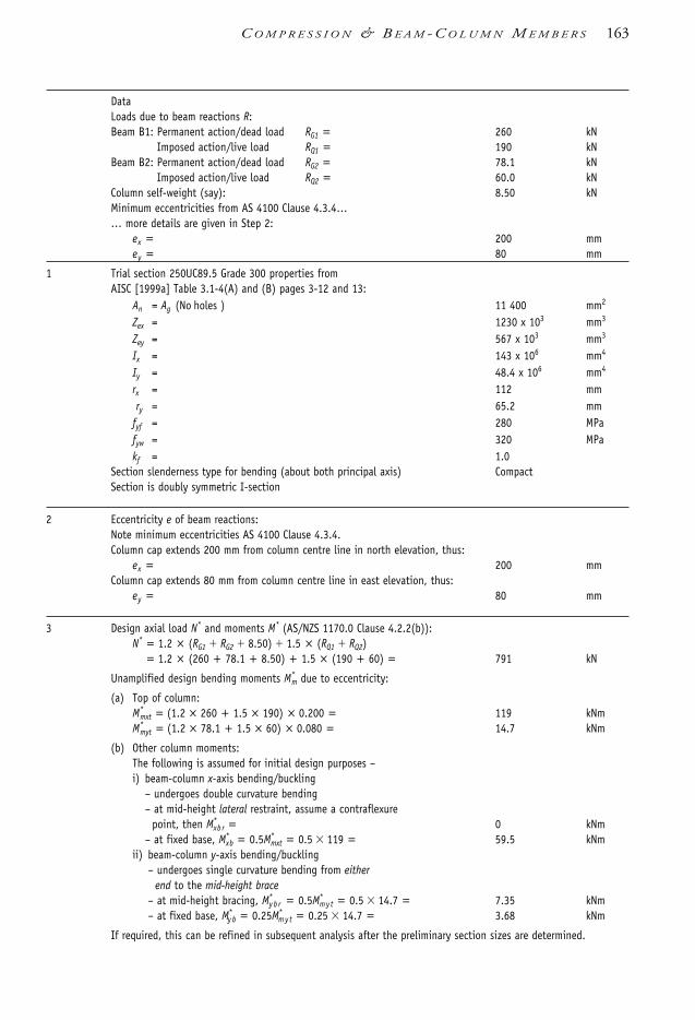
DataLoads due to beam reactions R:Beam B1: Permanent action/dead load RG1 = 260 kN
Imposed action/live load RQ1 = 190 kNBeam B2: Permanent action/dead load RG2 = 78.1 kN
Imposed action/live load RQ2 = 60.0 kNColumn self-weight (say): 8.50 kNMinimum eccentricities from AS 4100 Clause 4.3.4…… more details are given in Step 2:
ex = 200 mmey = 80 mm
1 Trial section 250UC89.5 Grade 300 properties fromAISC [1999a] Table 3.1-4(A) and (B) pages 3-12 and 13:
An = Ag (No holes ) 11 400 mm2
Zex = 1230 x 103 mm3
Zey = 567 x 103 mm3
Ix = 143 x 106 mm4
Iy = 48.4 x 106 mm4
rx = 112 mmry = 65.2 mm
fyf = 280 MPafyw = 320 MPakf = 1.0
Section slenderness type for bending (about both principal axis) CompactSection is doubly symmetric I-section
2 Eccentricity e of beam reactions:Note minimum eccentricities AS 4100 Clause 4.3.4.Column cap extends 200 mm from column centre line in north elevation, thus:
ex = 200 mmColumn cap extends 80 mm from column centre line in east elevation, thus:
ey = 80 mm
3 Design axial load N* and moments M* (AS/NZS 1170.0 Clause 4.2.2(b)):N* = 1.2 × (RG1 RG2 8.50) 1.5 × (RQ1 RQ2)
= 1.2 × (260 + 78.1 + 8.50) + 1.5 × (190 + 60) = 791 kN
Unamplified design bending moments M*m due to eccentricity:
(a) Top of column:M*
mxt = (1.2 × 260 + 1.5 × 190) × 0.200 = 119 kNmM*
myt = (1.2 × 78.1 + 1.5 × 60) × 0.080 = 14.7 kNm
(b) Other column moments: The following is assumed for initial design purposes – i) beam-column x-axis bending/buckling
– undergoes double curvature bending– at mid-height lateral restraint, assume a contraflexure
point, then M*xb r = 0 kNm
– at fixed base, M*xb = 0.5M*
mxt = 0.5 119 = 59.5 kNmii) beam-column y-axis bending/buckling
– undergoes single curvature bending from eitherend to the mid-height brace
– at mid-height bracing, M*y b r = 0.5M*
my t = 0.5 14.7 = 7.35 kNm– at fixed base, M*
y b = 0.25M*my t = 0.25 14.7 = 3.68 kNm
If required, this can be refined in subsequent analysis after the preliminary section sizes are determined.
C O M P R E S S I O N & B E A M - C O L U M N M E M B E R S 163
1106 SDHB 06 Final 8/6/05 12:07 PM Page 163
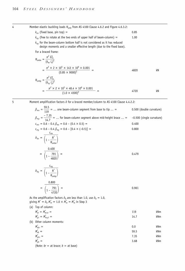
4 Member elastic buckling loads Nomb from AS 4100 Clause 4.6.2 and Figure 4.6.3.2:
kex (fixed base, pin top) = 0.85
key (free to rotate at the two ends of upper half of beam-column) = 1.00
key for the beam-column bottom half is not considered as it has reduceddesign moments and a smaller effective length (due to the fixed base).
For a braced frame:
Nombx = (πke
2
x
Elx
I)x2
= = 4820 kN
Nomby = (πke
2
y
Ely
I)y2
= = 4720 kN
5 Moment amplification factors δ for a braced member/column to AS 4100 Clause 4.4.2.2:
βmx = 5191.95
= … one beam-column segment from base to tip … = 0.500 (double curvature)
βmy = –174..375
= … for beam-column segment above mid-height brace … = –0.500 (single curvature)
cmx = 0.6 – 0.4 βmx = 0.6 – (0.4 × 0.5) = 0.400
cmy = 0.6 – 0.4 βmy = 0.6 – [0.4 × (–0.5)] = 0.800
δbx =
= = 0.479
δby =
= = 0.961
As the amplification factors δb are less than 1.0, use δb = 1.0,giving M* = δb M*
m = 1.0 × M*m = M*
m in Step 3
(a) Top of column:
M*xt = M*
mxt = 119 kNm
M*y t = M*
my t = 14.7 kNm
(b) Other column moments:
M*xb r = 0.0 kNm
M*xb = 59.5 kNm
M*yb r = 7.35 kNm
M*yb = 3.68 kNm
(Note: br = at brace; b = at base)
0.800
1 – 4779210
cmy
1 – No
N
m
*
by
0.400
1 – 4789210
cmx
1 – No
N
m
*
bx
π2 × 2 × 105 × 48.4 × 106 × 0.001
(1.0 × 4500)2
π2 × 2 × 105 × 143 × 106 × 0.001
(0.85 × 9000)2
164 S T E E L D E S I G N E R S ’ H A N D B O O K
1106 SDHB 06 Final 8/6/05 12:07 PM Page 164

(c) Maximum design moments:
Mx* = M*
mx = max.(119, 59.5) 119 kNm
My* = M*
my = max.(14.7, 7.35, 3.68) 14.7 kNm
For bending/buckling about the y-axis this is applicable to thesegment above the beam-column mid-height brace.
6 Section capacities of 250UC89.5 Grade 300:
6.1 Axial section capacity Ns to AS 4100 Clause 6.2.1:
Ns = kf An fy
= 1.0 × 11400 × 280 × 0.001 = 3190 kN
φNs = 0.9 × 3190 = 2870 kN
6.2 Section moment capacities Ms to AS 4100 Clause 5.2.1:
Msx = fy Zex
= 280 × 1
120360 × 103
= 344 kNm
φMsx = 0.9 × 344 = 310 kNm
Msy = fy Zey
= 280 ×
15067
6× 103
= 159 kNm
φMsy = 0.9 × 159 = 143 kNm
6.2.1 This step is required to calculate the intermediate values of nominal sectionmoment capacities reduced by axial force, Mi (see AS 4100 Clauses 8.3.2and 8.3.3) prior to Step 6.3.2 for the biaxial bending check. It alsoillustrates the use of the combined actions section capacity check for thecase of axial load with only uniaxial bending. The following is restricted todoubly symmetrical sections which are compact. If the beam-column sectiondoes not satisfy this criteria then 1.0 is used instead of 1.18 and 1.19 forMrx and Mry respectively below and the N*/φNs term in the Mry equation isnot squared.
Reduced section moment capacities for compact, doubly symmetric I-sections:
In the presence of axial compression, and kf = 1.0, can use AS 4100 Clause 8.3.2(a), in which:
Mrx = 1.18 Msx 1 – (φ
NN
*
s) Msx
= 1.18 × 344 × 1 – 2789710
= 294 kNm
Mrx Msx is satisfied as 294 344 is true OK
If there was only uniaxial bending about the major principalx-axis with axial compression, then M* φMrx need only besatisfied for the combined actions section capacity check.
Section is doubly symmetrical I, and compact. Then can use AS 4100 Clause 8.3.3(a), in which:
Mry = 1.19 Msy 1 – (φ
NN
*
s
2
)2 Msy
= 1.19 × 159 × 1 – 2789710
2
2 = 175 kNm
Mry Msy is not satisfied as 175 159 is false No good
Mry is reduced down to … = 159 kNm
C O M P R E S S I O N & B E A M - C O L U M N M E M B E R S 165
1106 SDHB 06 Final 8/6/05 12:07 PM Page 165

If there was only uniaxial bending about the minor principaly-axis with axial compression, then M* φMry need only besatisfied for the combined actions section capacity check.
6.3 Biaxial section capacity in AS 4100 Clause 8.3.4 allows for:
6.3.1 Any type of section:
φNN
*
s +
φMM
x*
sx +
φMM
y*
sy 1
2789710
+ 131190
+ 1144.37
1
0.762 1 = true, satisfied OK
Biaxial section capacity with conservative check gives 76% “capacity” usage.The following: Step 6.3.2 is more economical if applicable/used.
6.3.2 Compact doubly symmetrical I-section only:
γ = 1.4 + φNN
*
s 2.0
=1.4 + 2789710
2.0 = 1.68
(φMM*x
rx) γ
+ (φMMy*
ry) γ
1 from AS 4100 Clause 8.3.4
(0.91×19
294)1.68
+ (0.91×4.7
159)1.68
= 0.283
As 0.283 1 = true, section OK for biaxial section capacity. Answer1Biaxial section capacity with higher tier check gives 28% use of “capacity” compared with 76% in Step 6.3.1.Above is not applicable if non-compact/asymmetrical I-section, but canalso be used for compact RHS/SHS to AS 1163:
7 Member capacities of 250UC89.5 Grade 300 to AS 4100 Clauses 6.3.2 and 6.3.3:
7.1 Axial member capacity Nc :lex = 0.85 × 9000 = … 0.85 is taken from Step 4 … = 7650 mmley = 1.0 × 4500 = … 1.0 is taken from Step 4 … = 4500 mm
lre
x
x =
7161520
= 68.3
lre
y
y =
46550.20
= 69.0
Modified slenderness:
λnx = lre
x
x
k2f
5f0y
= 68.3 ×
1.02×50
280 = 72.3
λny = lre
y
y
k2f
5f0y
= 69.0 ×
1.02×50
280 = 73.0
UB categorised HR, and kf = 1.0 to AS 4100 Table 6.3.3(1):αb = member section constant = 0
Table 6.6 or AS 4100 Table 6.3.3(3) for slenderness reduction factor αc:αc x = 0.733
166 S T E E L D E S I G N E R S ’ H A N D B O O K
1106 SDHB 06 Final 8/6/05 12:07 PM Page 166

αc y = 0.728Ncx and Ncy are Ns as αc x and αc y are 1.0Ncx = αc x Ns
= 0.733 × 3190 = … Ns from Step 6.1 … = 2340 kN
Ncy = αc y Ns
= 0.728 × 3190 = 2320 kN
7.2 In-plane member moment capacity, φMi , to AS 4100 Clause 8.4.2.2:
7.2.1 This is sometimes a confusing part of AS 4100 and may require some further explanation. The fundamentalpremise of combined action interaction checks is to reduce the relevant moment capacity due to the presence ofan axial load working against the column capacity. Hence, for a particular beam-column segment, the three (3)nominal moment capacities that require reduction when an axial compressive load (N*) is present, are:
(a) section moment capacity about the major principal axis, Msx
(b) section moment capacity about the minor principal axis, Msy
(c) member moment capacity for bending about the x-axis, Mbx (there cannot be the equivalent of this forbending about the y-axis).
The behaviour of (a) and (b) is mainly constrained to their respective in-plane interaction effects as loading anddeformations occur in the same plane. Therefore, for combined actions, Msx is reduced by N* and the in-planecolumn member capacity Ncx. This also applies to Msy which is reduced by N* and Ncy.
However, (c) has loading effects and (buckling) deformations in mutually orthogonal planes – i.e. out-of-plane.From a member interaction perspective, Mbx must then be reduced by N* and Ncy as the buckling deformationsfrom Mbx and Ncy are in the same plane. The out-of-plane interaction check is considered in Step 7.3.
7.2.2 Mix : AS 4100 Clause 8.4.2.2 with x-axis as the principal axis gives –
Mix = Msx1
NN
*
cx
= 344 × 1 0.9 ×
7912340 = 215 kNm
φMix = 0.9 × 215 = 194 kNm
Mx* φMix is true as 119 194 is true. Mx
* = 119 is in the summary at the end of Step 5. OK
7.2.3 Miy : AS 4100 Clause 8.4.2.2 with y-axis as the principal axis gives –
As for Step 7.2.2 but replacing x with y.
Miy = Msy1
NN
*
cy
= 159 × 1 0.9 ×
7912320 = 98.8 kNm
φMiy = 0.9 × 98.8 = 88.9 kNm
My* φMiy is true as 14.7 ≤ 88.9 is true. My
* = 14.7 is from Step 5. OK
7.3 Out-of-plane member moment capacity, φMox , to AS 4100 Clause 8.4.4.1:
7.3.1 As noted in Step 7.2.1, Mbx must be reduced by N* and Ncy .
7.3.2 Effective length, le:
Both column flanges are connected to wind bracing at mid-height of the column.
l e is the effective length of the beam part in a beam-column member. See AS 4100 Clause 5.6.3. For the top (more critical) part of the beam-columnwith FF restraint condition (see (b) East elevation):
l e = k t k l k r l s = … with no transverse loads … = 4.5 m
C O M P R E S S I O N & B E A M - C O L U M N M E M B E R S 167
1106 SDHB 06 Final 8/6/05 12:07 PM Page 167

7.3.3 Moment modification factor, αm :
For the beam-column bending about the x-axis, there are two segmentssubject to out-of plane flexural-torsional buckling and y-axis columnbuckling. These segments are above and below the mid-height brace pointwith the upper segment having the larger moment and subject to furtherinvestigation.
From Step 5, the ratio of the smaller to the larger bending moment, βm
(positive if in double curvature) for the upper segment beam-column is:
m mx MM
*x*x
b
t
r
101.09
0.0
From Load Case 1.2 of Table 5.5 (or AS 4100 Table 5.6.1 Case1):
αm = 1.75 + 1.05m + 0.3m2
= 1.75 + 0.0 + 0.0 = 1.75
7.3.4 Member moment capacity about the (strong) x-axis, φMbx, decreases with increasing flexural-torsional buckling. Use l e = 4.5 m from Step 7.3.2 to read the value of φMbx directly as follows:
φMbx1 = member moment capacity with αm =1.0 from AISC [1999a] Table 5.3-6 page 5-52 for a 250UC89.5 Grade 300:
φMbx1 = … top segment of beam-column … = 255 kNm
φMbx = moment capacity with αm = 1.75 is:
φMbx = αm φMbx1 φMsx (φMsx = 310 kNm from Step 6.2)
= 1.75 × 255 = 446 kNm
φMbx φMsx = false as 446 310 is false → φMbx = 310 kNm
M*x φMbx is satisfied because 119 310 is true OK
Mbx = φM
φbx
= 301.90
= 344 kNm
Mox = out-of-plane moment member capacity from AS 4100 Clause 8.4.4.1:
Mox = Mbx1
NN
*
cy
= 344 × 1 0.9 ×
7912320 = 214 kNm
7.4 Nominal moment member capacity about x-axis, φMcx is given by:
Mcx = lesser of moments Mix and Mox
= min (Mix, Mox)
= min (215, 214) = … with 215 from step 7.2.2 … = 214 kNm
φMcx = 0.9 × 214 = 193 kNm
7.5 Biaxial bending member moment capacity:
Step 5 gives Mx* = 119 kNm
My* = 14.7 kNm
Step 7.2.3 gives φMiy = 88.9 kNm
AS 4100 Clause 8.4.5.1 requires compliance with interaction inequality:
MM
x*
cx
1.4
MMy*
iy
1.4
1
111993
1.4
1848..79
1.4= 0.589 1
0.589 1 = true, satisfied OK
168 S T E E L D E S I G N E R S ’ H A N D B O O K
1106 SDHB 06 Final 8/6/05 12:07 PM Page 168

250UC89.5 Grade 300 is adequate for member moment capacities in biaxial bending. Only 59% of member “capacity” is used. Answer2
6.9.4 Example 6.4
Step Description and calculations Result Unit
Verify the capacity of the beam-column shown below. The section is a150UC30.0. Use Grade 300 steel. The rigid jointed frame is unbraced in theplane of the main frame action (north elevation). In-plane bendingmoments Mx
* have been determined by second-order analysis. Out-of-planeaction is of the ‘simple construction’ type, and bracing is provided at rightangles to the plane of the main frame. The main frame beams are310UB40.4 at spacing of 7000 centre-to-centre of columns.
Note: Rx* is the vertical load exerted by the top beam onto the beam-column in the North elevation.
DataRx
* = 69.0 kNRy
* = 47.0 kN
Simple construction … AS 4100 Clause 4.3.4 … ey = 80 mm
Column self-weight & other contributing dead loads = 8.10 kN
In-plane frame bending moments on the beam-column from a second-orderanalysis (which requires no further amplification)
M*x_top = 35.0 kNm
M*x_mid= … at mid-height beam … = 3.50 kNm
Design axial load, N*
N* = 69.0 + 47.0 + 8.10 = 124 kN
NOTE: This worked example will focus on the upper beam-column segmentas it is more critically loaded.
4000
4000
7000
(a) North elevation (b) East elevation
Fixed Fixed
Brace
Brace
R*xIb
IbIc
7000 columncentres
ey R*y
C O M P R E S S I O N & B E A M - C O L U M N M E M B E R S 169
1106 SDHB 06 Final 8/6/05 12:07 PM Page 169

1 Properties of trial section using 150UC30.0 Grade 300:AISC [1999a] Tables 3.1.4(A) and (B) pages 3–12 and 13:Geometry of section = doubly symmetrical I = DSISlenderness of section about x-axis = Compact xSlenderness of section about y-axis = Compact ykf = 1.0An = Ag … No holes … = 3860 mm2
Zex = 250 × 103 mm3
Zey = 110 × 103 mm3
Ix = 17.6 × 106 mm4
Iy = 5.62 × 106 mm4
rx = 67.5 mmry = 38.1 mmfyf = 320 MPafyw = 320 MPaBeam 310UB40.4 (from previous page of AISC [1999a] to that above)Ix = 86.4 × 106 mm4
2 Effective length of column le:
2.1 Effective length of column lex in plane of unbraced frame (northern elevation)AS 4100 Clause 4.6.3.4:
γ1 =
= = … at the joint with the middle beam … 0.713
2 = = … at the joint with the top beam … = 0.356
where βe and the other terms are explained in Sections 4.5.3 and 4.7
kex = chart: AS 4100 Figure 4.6.3.3(b) for sway members = 1.17
lex = kexl= 1.17 × 4000 = 4680 mm
2.2 Effective length of braced column l ey in plane perpendicular to frame. Beam to column connection uses simple construction to accord with AS 4100 Figure 4.6.3.2:
l ey = key l= 1.0 × 4000 = 4000 mm
3 Member elastic buckling loads Nom:
Nomx = πl
2
ex
E2Ix
= = 1590 kNπ2 × 2 × 105 × 17.6 × 106 × 0.001
46802
147..06
1.0
7.086.4
147..06
+ 147..06
1.0 ×7.0
86.4
Σ Il
c
Σ βe
lI
b
170 S T E E L D E S I G N E R S ’ H A N D B O O K
1106 SDHB 06 Final 8/6/05 12:07 PM Page 170

Nomby = πl
2
ey
E2Iy
= = 693 kN
4 Second-order effects on bending moments on beam-column
4.1 In-plane of frame (north elevation)
No further assessment required as results are from a second-order analysis –hence use moments noted in Data.
4.2 Out-of-plane to frame (east elevation)
4.2.1 First-order elastic analysis
It is assumed the beam-column undergoes double-curvature bending withthe following –
M*y_top = moment eccentricity from top of column beam reaction
= 47.0 0.080 = 3.76 kNm
M*y_mid = 1.0 kNm
4.2.2 Moment amplification for a braced member
The top segment is considered to be in single curvature with no transverseloads. From AS 4100 Clause 4.4.2.2:
βmy = ratio of the smaller to larger bending moment (negative for single curvature)
=
3.17.60
= –0.266
cmy = 0.6 0.4my = 0.6 0.4 × (0.266) = 0.706
Nomby = Elastic flexural buckling load about y-axis
= π2EIy /l 2ey … from Step 3 … = 693 kN
δb = = = 0.860
= … as δb 1.0 then δb = 1.0
Hence, no moment amplification required and the first-order analysis resultsare sufficient.
4.2.3 Maximum design moments:
Mx*= M*
mx = max.(35.0, 3.50) 35.0 kNm
My*= M*
my = max.(3.76, 1.0) 3.76 kNm
5 Section capacities:
5.1 Axial section capacity Ns :
Ns = kf An fy= 1.0 × 3860 × 320 × 0.001 = 1240 kN
5.2 Section moment capacities Ms in absence of axial load:
Msx = fy Zex
= 320 × 2
15006
× 103
80.0 kNm
Msy = fy Zey
= 320 × 1
11006
× 103
35.2 kNm
0.706
1 162943
cm
1 No
N
m
*
by
π2 × 2 × 105 × 5.62 × 106 × 0.001
40002
C O M P R E S S I O N & B E A M - C O L U M N M E M B E R S 171
1106 SDHB 06 Final 8/6/05 12:07 PM Page 171

6 Combined actions section capacity
Reduced moment section capacity Mr , due to presence of axial load N*. Top segment/half of column is critical as it has largest moment M*.
6.1 Reduced section moment capacity about x-axis, Mrx :
Section is DSI, compact x and kf = 1.0 Therefore can use:AS 4100 Clause 8.3.2(a)
Mrx = 1.18 Msx1 – φNN
*
s
= 1.18 × 80.0 × 1 – 0.9 ×
1241240 = 83.9 kNm
Mrx Msx = false as 83.9 80.0 = false → Mrx = 80.0 kNm
6.2 Reduced section moment capacity about y-axis, My :
Section is DSI, compact y and kf = 1.0. Therefore, can use:AS 4100 Clause 8.3.3(a)
Mry = 1.19 Msy1 – φNN
*
s2
= 1.19 × 35.2 × 1 – 0.9 ×124
12402 = 41.4 kNm
Mry Msx = false as 41.4 35.2 = false → Mry = 35.2 kNm
6.3 Biaxial bending section capacity for compact doubly symmetrical I-section:
γ = 1.4 + φNN
*
s
= 1.4 + (0.9 ×
1241240)
= 1.51 2.0 → 1.51
(φMMx*
rx)γ
+ (φMMy*
ry)γ
1 …AS 4100 Clause 8.3.4
(0.93×5.0
80.0)1.51
+ (0.93×.76
35.2)1.51
= 0.377
As 0.377 1 = true, section OK for biaxial bendingsection capacity Answer1
7 Member capacities:
7.1 Axial member capacity:
7.1.1 Slenderness ratio lre
lre
x
x =
46678.50
= 69.3
lre
y
y =
43080.10
= 105
Modified slenderness:
λnx = lre
x
x
k2f
5f0y
= 69.3 ×
1.02×50
320 = 78.4
λny = lre
y
y
k2f
5f0y
172 S T E E L D E S I G N E R S ’ H A N D B O O K
1106 SDHB 06 Final 8/6/05 12:07 PM Page 172

= 105 × 1.0
2×50
320 = 119
7.1.2 Slenderness reduction factor αc:UB categorised HR, and kf = 1.0: AS 4100 Table 6.3.3(1) gives:
αb = ... member section constant ... = 0
Table 6.6 or AS 4100 Table 6.3.3(3), interpolate to get member slenderness reduction factor αc:
αcx = 0.692αcy = 0.426
7.1.3 Axial member capacity φNc :
Ncx = αcx Ns
= 0.692 × 1240 = 858 kNφNcx = 0.9 × 858 = 772 kN
Ncy = αcy Ns
= 0.426 × 1240 = 528 kNφNcy = 0.9 × 528 = 475 kNφNcx and φNcy are φNs as αcx and αcy are 1.0
7.2 In-plane member moment capacity, φMi :
7.2.1 Mix — see explanation in Step 7.2.1 and 7.2.2 of Example 6.3:
Mix = Msx 1 – (φ
NN
*
cx)
= 80.0 × 1 – 172742
= 67.2 kNm
φMix = 0.9 × 67.2 = 60.5 kNm
Mx* φMix in AS 4100 Clause 8.4.2.2:
As ... 35.0 60.5 is true, then Mx* φMix = true, satisfied OK
7.2.2 Miy — see explanation in Step 7.2.1 and 7.2.3 of Example 6.3:
Miy = Msy 1 – (φ
NN
*
c y)
= 35.2 × 1 – 142745
= 26.0 kNm
φMiy = 0.9 × 26.0 = 23.4 kNm
As 3.76 23.4 true, then My* φMiy = true, satisfied OK
7.3 Out-of-plane member moment capacity, φMox :
See explanation in Step 7.2.1 and 7.3 of Example 6.3.
7.3.1 Bending effective length of beam-column segment l e :Both column flanges are connected to wind bracing at mid-height of the column.
le = effective length of beam-column segment:= kt kl kr Ls
= 1.0 × 1.0 × 1.0 × 4.0 = … with no transverse loads … 4.0 m
7.3.2 From the Data section of this worked example, the ratio of the smaller to larger bending moment, βm, (positive if in double curvature) for the upper segment beam-column is:
βm = βmx = –335..50
= –0.10
C O M P R E S S I O N & B E A M - C O L U M N M E M B E R S 173
1106 SDHB 06 Final 8/6/05 12:07 PM Page 173

From Load Case 1.1 & 1.2 of Table 5.5 (or AS 4100 Table 5.6.1 Case 1):
αm = moment modification factor
= 1.75 1.05βm 0.3β2m … (for –1 βm 0.6) …
= 1.75 [1.05 × (–0.10)] + [0.3 × (–0.10)2] = 1.65
7.3.3 Nominal member moment capacity about x-axis, Mbx, in absence of axial load.
For a 150UC30.0 Grade 300 with αm = 1.0 and le = 4.0m from:
φMbx1 = member moment capacity for αm = 1.0 using AISC [1999a] Table 5.3-6 page 5-52:
φMbx1 = 46.4 kNm
Mbx1 = φM
φbx1 =
406..94
= 51.6 kNm
For a 150 UC30.0 Grade 300 with αm = 1.65 then:
Mbx = αm Mbx1
= 1.65 × 51.6 = 85.1 kNm
Mbx Msx = false as 85.1 80.0 = false → Mbx = 80.0 kNm
7.3.4 Out-of-plane member moment capacity in presence of axial load, Mox: AS 4100 Clause 8.4.4.1:
Mox = Mbx 1 – (φ
NN
*
cy)
= 80.0 × 1 – 142745
= 59.1 kNm
7.3.5 Critical member moment capacity about x-axis, Mcx
Mcx = min.[ Mix, Mox ] from AS 4100 Clause 8.4.5.1
= min.[67.2, 59.1] = …… 67.2 from Step 7.2.1….. = 59.1 kNm
φMcx = 0.9 59.1 = 53.2 kNm
7.4 Biaxial bending member moment capacity
From AS 4100 Clause 8.4.5.1:
1.4 1.4
1
1.4 1.4
= 0.634 1
0.634 1 = true … satisfactory … → OK
150UC30.0 Grade 300 is adequate for member moment capacity in biaxial bending. Only 63% of member “capacity” used. Answer 2
3.7623.4
35.053.2
My*
Miy
Mx*
Mcx
174 S T E E L D E S I G N E R S ’ H A N D B O O K
1106 SDHB 06 Final 8/6/05 12:07 PM Page 174
6.10 Further reading• For additional worked examples see Chapter 6 and 8 of Bradford, et al. [1997].• Rapid column/beam-column sizing with industry standard tables and steel sections can
be found in AISC [1999a] and SSTM [2003b].• Compression bracing members should allow for the combined actions of compression
load and self-weight. Woolcock, et al. [1999] provides some excellent guidance anddesign tables for this situation.
• For some authoritative texts on buckling see Bleich [1952], CRCJ [1971], Hancock[1998], Timoshenko [1941], Timoshenko & Gere [1961], Trahair [1993b] andTrahair & Bradford [1998] to name a few.
• For typical column/compression member connections also see AISC[1985,1997,2001], Hogan & Thomas [1994], Syam & Chapman [1996] and Trahair,et al. [1993c].
C O M P R E S S I O N & B E A M - C O L U M N M E M B E R S 175
1106 SDHB 06 Final 8/6/05 12:07 PM Page 175

7.1 Types of tension members Tension members are predominantly loaded in axial tension, although inevitably they areoften loaded in combined tension and bending. The bending moments may arise fromeccentricity of the connections, frame action and self-weight of the members. A simpleclassification of tension members is presented in Table 7.1. This table gives an overviewof the many types of tension member applications in building construction; it also servesas a directory to subsections covering the particular design aspects.
Table 7.1 Classification of tension members
Aspect Subgroup Section
(a) Type of constructionSection type:
Rigid I-sections, hollow sections 7.2–7.5Angles and channels 7.2–7.5
Flexible Plates, bars 7.4Steel rods 7.6Steel wire ropes 7.7
Construction Single section 7.2–7.5Compound sections 7.4.4
(b) By position of restraintsEnd restraints at connections 7.4–7.5End and intermediate restraints 7.4.4
(c) By type of loadsAxial tension only 7.4.1Combined tension and bending 7.4.2
(d) By load fluctuation
Predominantly static loads 7.3–7.5Dynamic loads 7.2, 7.5.4Impact –
c h a p t e r 7
Tension Members
1106 SDHB 07 Final 8/6/05 12:08 PM Page 176

7.2 Types of constructionTubular tension members are increasingly used as they offer high capacities coupled withrelatively high bending stiffness. Additionally, tubular members have superior resistanceto axial compression loads, which is important for axially loaded members subject toreversal of loads.
Flexible members such as rods and steel wire ropes are often used in structures exposedto view, where the architect may prefer the member to be of the smallest possible size.Where load reversal can occur, the flexible members should be used in a cross-overarrangement such that one member is in tension while the other is allowed to buckleunder compression load, unless both members are pretensioned to a level wherecompression will not occur. Steel wire ropes are also used for guying purposes. The mainadvantage of high-strength bars and steel strand is that they exhibit superior tensioncapacity at a minimum weight.
Tubular and angle tension members are typically used for tensile web members, andtension chords in trusses, wall and roof bracing members, hangers, stays and eaves ties.Where the load on the member changes from tension to compression, the membershould be checked for compression capacity as well as tension capacity. Where thetension members are slender (l /r 200) and cross one another in the braced panel, itcan be assumed that the compression member will buckle, with the result that thetension member must be designed to resist 100% of the applied panel shear force. Figure7.1 illustrates several types of situations in which tension members are used.
Figure 7.1 Typical tension member application
Tension members composed of two or more sections can be used where the tensionmember is relatively long. Compound members provide greater bending rigidity thansingle members. Therefore they show less sag (i.e. the ‘take up’ of tension load is not thatrapid when there is excessive sag) and are less likely to vibrate under fluctuating load.They can resist quite large bending moments and can act in either tension or
Legend:
Purlin (may bein compression)
Wall bracing
Compression or bending memberDiagonal tension members
Roof bracing
T E N S I O N M E M B E R S 177
1106 SDHB 07 Final 8/6/05 12:08 PM Page 177
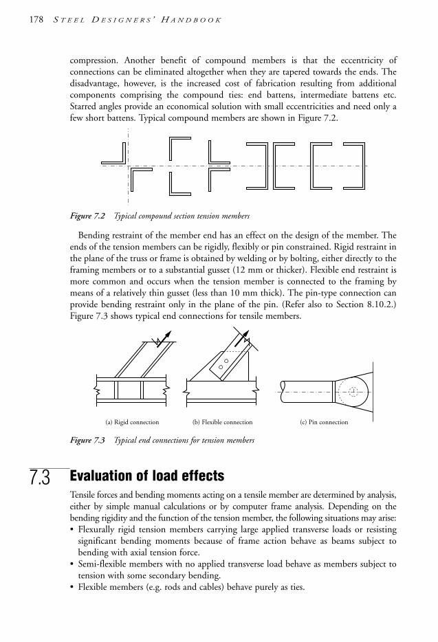
compression. Another benefit of compound members is that the eccentricity ofconnections can be eliminated altogether when they are tapered towards the ends. Thedisadvantage, however, is the increased cost of fabrication resulting from additionalcomponents comprising the compound ties: end battens, intermediate battens etc.Starred angles provide an economical solution with small eccentricities and need only afew short battens. Typical compound members are shown in Figure 7.2.
Figure 7.2 Typical compound section tension members
Bending restraint of the member end has an effect on the design of the member. Theends of the tension members can be rigidly, flexibly or pin constrained. Rigid restraint inthe plane of the truss or frame is obtained by welding or by bolting, either directly to theframing members or to a substantial gusset (12 mm or thicker). Flexible end restraint ismore common and occurs when the tension member is connected to the framing bymeans of a relatively thin gusset (less than 10 mm thick). The pin-type connection canprovide bending restraint only in the plane of the pin. (Refer also to Section 8.10.2.)Figure 7.3 shows typical end connections for tensile members.
Figure 7.3 Typical end connections for tension members
7.3 Evaluation of load effects Tensile forces and bending moments acting on a tensile member are determined by analysis,either by simple manual calculations or by computer frame analysis. Depending on thebending rigidity and the function of the tension member, the following situations may arise: • Flexurally rigid tension members carrying large applied transverse loads or resisting
significant bending moments because of frame action behave as beams subject tobending with axial tension force.
• Semi-flexible members with no applied transverse load behave as members subject totension with some secondary bending.
• Flexible members (e.g. rods and cables) behave purely as ties.
(a) Rigid connection (b) Flexible connection (c) Pin connection
178 S T E E L D E S I G N E R S ’ H A N D B O O K
1106 SDHB 07 Final 8/6/05 12:08 PM Page 178

T E N S I O N M E M B E R S 179
Consequently, different design procedures need to be applied to various types of tensionmembers. Typical examples of flexurally rigid members are rigid bracing systems in heavyframes. These members should be designed as flexural members carrying axial forces.Where load reversal can occur, the compression capacity usually governs.
Some examples of semi-flexible members are tubular and light, hot-rolled sections usedin trusses and braces for wall and roof bracing systems. These members typically have l/rratios of between 100 and 300. With these members, tension load predominates butbending due to self-weight may be significant (Woolcock & Kitipornchai [1985]). Thereis a need to assess the effects of end connection eccentricity where the member is bolted orwelded by a lap-type connection, or when the connection centroid is offset to the tiecentroid, or when not all the tie cross-section elements are connected. For this case, AS4100 provides a simplified method of assessment of the member capacity (see Section 7.4).
Flexible tension members, such as guy cables, rod braces, bow girder ties and hangers,act predominantly in pure tension. With longer members it is necessary to check theamount of sag of the cable and the longer-term resistance to fatigue.
7.4 Verification of member capacity
7.4.1 Tension capacity
7.4.1.1 GeneralThe nominal axial capacity of a member loaded in tension, Nt, is calculated inaccordance with Clause 7.2 of AS 4100 as follows:
Nt 0.85kt An fu, or
Nt Ag fy , whichever is the lesser.
The section is adequate in tension if:
N * Nt
where N * design axial tension forceAg gross area of cross-section.An the net cross-sectional area: An Ag Ad Aa Ag
Ad the area lost by holesAa the allowance for staggered holes, for each side step on ply
thickness t (see Clause 9.1.10.3 of AS 4100):
0.25
fy the yield stress used in design
sp staggered pitch, the distance measured parallel to the direction ofthe force (see Clause 9.1.10.3(b) of AS 4100)
sg gauge, perpendicular to the force, between centre-to-centre ofholes in consecutive lines (see Clause 9.1.10.3(b) of AS 4100)
fu the tensile strength used in design
sp2t
sg
1106 SDHB 07 Final 8/6/05 12:08 PM Page 179

the capacity reduction factor 0.9 for sections other than threaded rods 0.8 for threaded rods (assumed to behave like a bolt) 0.3–0.4 recommended for cables (not given in AS 4100)
kt a correction factor for end eccentricity and distribution of forces(see Table 7.3.2 of AS 4100 or Table 7.2 in this Handbook).
The factor kt is taken as 1.0 if the member connection is designed for uniform forcedistribution across the end section, which is achieved when:• each element of the member section is connected• there is no eccentricity (i.e. the connection centroid coincides with the member centroid)• each connected element is capable of transferring its part of the force.
As long as the ratio of AA
n
g is larger than (0.85
fykt fu ), the failure can be expected to be
ductile gross yielding; otherwise, failure will occur by fracture across the weakest section.The factor of 0.85 provides additional safety against the latter event.
7.4.1.2 Members designed as ‘pinned’ at the endsThe rigorous computation of bending moment due to eccentricity caused by connectingonly some elements of the section can be avoided by the use of the correction factor kt
(see Bennetts et al. [1986]). A value of kt less than 1.0 applies where some elements ofthe section are not effectively connected, or where minor connection eccentricity exists,so that a non-uniform stress distribution is induced (see Figure 7.4 and Table 7.2). Themethod is convenient for designing building bracing systems and truss web members.
Table 7.2 The correction factor for distribution of forces in tension members, kt
Configuration kt Note
One-sided connection to:Single angle 0.75 Unequal angle—connected by short leg
0.85 OtherwiseTwin angles on same side 0.75 Unequal angle—connected by short leg
of gusset/plate 0.85 OtherwiseChannel 0.85 Connected by web only
Tee (from UB/UC) 0.90 Flange connected only
0.75 Web connected only (suggested value)
Back-to-back connection:Twin angles 1.0 On opposite sides of gusset/plateTwin channels 1.0 Web connected on opposite sides of gusset/plateTwin tees 1.0 Flange connected on opposite sides of gusset/plate
Connections to flanges onlyUB, UC, WB, WC and PFC 0.85 See note below
Note: The length of the flange-to-gusset connection is to be greater than the depth of the section. See Clause7.3.2 of AS 4100 for further information on the above.
If a bending moment is applied to the member because of gross eccentricity or framebending action, the member should be designed for combined tension and bending (seeSection 7.4.2).
180 S T E E L D E S I G N E R S ’ H A N D B O O K
1106 SDHB 07 Final 8/6/05 12:08 PM Page 180

Particular care should be given to avoiding feature or details that may give rise to brittlefracture, especially when the member has to operate at relatively low ambienttemperatures. Notches can be introduced by poor thermal cutting practices, micro-cracking around punched holes, welding defects or damage during handling and erection.
Figure 7.4 End connections for tension members producing non-uniform stress distribution
7.4.2 Combined actions – tension and bending
This section covers the situations where member axial tension forces, N*, are presentwith bending moments from frame action (end moments), applied transverse forces orgross connection eccentricity. The design provisions for these combined actions followthe same method and terminology for beam-columns (Chapter 6) where, except for out-of-plane checks, the section/member moment capacity is reduced by the presence ofaxial load.
(a) Section capacity checkClause 8.3 of AS 4100 notes either of the following should be satisfied – (i) Uniaxial bending about the major principal (x-) axis with tension:
M *x Mrx
where
Mrx = Msx 1 or
for a higher tier assessment of compact, doubly symmetric I-sections, RHSand SHS
Mrx = 1.18Msx 1
NN
*
t Msx
(ii) Uniaxial bending about the minor principal (y-)axis with tension:
M y* Mry
N*
Nt
Gusset
T E N S I O N M E M B E R S 181
1106 SDHB 07 Final 8/6/05 12:08 PM Page 181

where
Mry = Msy 1 or
for a higher tier assessment of compact, doubly symmetric I-sections, RHSand SHS
Mry = HTMsy1
NN
*
t
n
Msy
where HT = 1.19 & n = 2 for I-sections and HT = 1.18 & n = 1 for RHS/SHS.
(iii) Biaxial bending with tension:
1.0 or
for a higher tier assessment of compact, doubly symmetric I-sections, RHSand SHS
1.0
where
γ = 1.4 2.0
and Mrx and Mry are evaluated as noted as above.
(b) Member capacity check For elastic design, Clause 8.4 of AS 4100 notes the following should be satisfied—(i) In-plane capacity—for uniaxial bending with tension: use where relevant either
(a)(i) or (a)(ii) above. For biaxial bending with tension: use (a)(iii) above.(ii) Out-of-plane capacity – for bending about the major principal (x-)axis with
tension which may buckle laterally:
M*x Mox
where
Mox = Mbx1 Mrx
where Mrx is noted in (a)(i) above and Mbx is the nominal member momentcapacity for the member when subjected to bending (see Section 5.3). It isinteresting to note that axial tension has a beneficial effect on the member whenunder x-axis bending and designing for flexural-torsional buckling. This is seenby the addition of the N */φNt term in the above equation for Mox—as opposedto a subtraction which is noted for compression loadings with bending (see Step 11of Section 6.3.2). Also, as noted in Chapter 6, there are no out-of-plane capacitiesto be checked for minor principal (y-)axis bending with axial tension.
(iii) Out-of-plane capacity – for biaxial bending with tension
1.4 1.4
1.0 where My
*
Mry
M *x
Mtx
N *
Nt
N *
Nt
M y*
Mry
M *x
Mrx
M y*
Msy
M *x
Msx
N *
Nt
N *
Nt
182 S T E E L D E S I G N E R S ’ H A N D B O O K
1106 SDHB 07 Final 8/6/05 12:08 PM Page 182

Mtx is the lesser of Mrx (see (a)(i) above) and Mox (see (b)(ii) above), and Mry isnoted in (a)(ii) above.
(c) Quick combined action checks: For bracing systems and ties, tension members withcombined actions generally have major principal (x-)axis bending moments. Basedon this a conservative check for all section types is to use the lower tier provisions of(a)(i) and (b)(ii) above. Where noted, the higher tier provisions may be used forcompact, doubly symmetric I-sections and RHS/SHS which can have significantdesign capacity increases. For other types of bending (e.g. y-axis or biaxial) therelevant parts are used from above. Hence, it is seen that not all the above provisionsare used for each situation – perhaps only less than a third of them.
7.4.3 Tension and shear
Tensile capacity is reduced in the presence of shear across the section. Based on extensivetests on bolts, the interaction curve for tension and shear is an elliptical function, and theverification of capacity can be carried out by using the following interaction formula:
0.
N8N
t*
t2.0
0.
V8V
*
v2.0
1.0
It should be noted that the above interaction inequality was developed specifically forbolts which are unique in terms of their method of concentrated loading (with respect tothe overall element) and are exposed to different boundary conditions than thatencountered by typical structural elements (e.g. confinement effects from the bolt holeonto the bolt, etc.).
Unlike bolts, there appears to be no significant work or design provisions on theinteraction effects of tension and shear on structural members. However, if required fordesign purposes, and in lieu of any other advice, the above inequality may be used as astarting point for considering this type of loading interaction. If used, then a rough ruleof thumb is if the shear force is less than 60% of the member shear capacity then nointeraction need be considered with tension capacity (and vice versa). It should be notedthat situations where the shear force is greater than 60% of the shear capacity are rare.
7.4.4 Compound members
Tension members can be composed of two or more sections where it is necessary to increasetheir lateral stiffness as, for example, when members are alternately loaded in tension andcompression. Clause 7.4 of AS 4100 specifies the minimum requirements for battens andlacing plates. The effective steel area of a compound tension member equals the sum ofsection areas provided that battening complies with the provisions of AS 4100, as illustratedin Figure 7.5.
7.5 End connection fasteners and detailing 7.5.1 General
Wherever possible, end connections should be so designed that the centroidal axes of themember and gusset coincide with one another and every part of the member section isconnected. It is not always practical to eliminate eccentricity at the connections but it is
T E N S I O N M E M B E R S 183
1106 SDHB 07 Final 8/6/05 12:08 PM Page 183

(a) Back-to-back tension members
(b) Battened tension members
(c) Laced tension members (cross sections are the same as for battened tension members)
Figure 7.5 Compound tension members (Note: x & y are local principal axes for the maincomponent, n & p are local non-principal (i.e. “rectangular”) axes for the maincomponent, and; X & Y are global principal axes for the compound member).
essential that the effects of eccentricity be taken into account in the design. A typicalexample is a truss node where heavy (or large) truss members are used with centroidal
Tie p late Lacing
Max 300 r y
c2
t c2
——60 t
c2——
60
PP
Max 210 r3
2
2
50 – 70
3 3
Sect ion 2–2
Main component
End batten Batten min t
l
n
Y Y Y, x x , Y
n
X
X
y
y
y
y
X
X
Max 300 r y
C2
b2 C2C2
——60
C2——
2 b2
PP
Max 300 r y
y
y
Gusset with thickness, tg Washer or packing Max tg
l
Y , p
Y, p
X, x
X, x
P p
P p
n y y n
y
y
y
y
PP
Max 300 r y
Max 300 r y
n
Y
YX
X
184 S T E E L D E S I G N E R S ’ H A N D B O O K
1106 SDHB 07 Final 8/6/05 12:08 PM Page 184

axes of web members not meeting at a common node. In such a case the bendingmoment resulting from the offset should be distributed to all members meeting at anode, in proportion to their stiffness. However, as noted in Section 6.4, there are manysituations where this can be either neglected or readily considered in design e.g. fortubular and light to medium trusses.
7.5.2 Simple detailing method
Single- and double-angle members are often connected through one leg of the angle, webof a channel or flanges only of the UB section or a channel. A method of evaluation ofmembers with such connections is outlined in Section 7.4.1. The actual connectiondesign (bolting, welding, etc.) is covered in Chapter 8. Typical connection details of thistype are illustrated in Figure 7.4.
7.5.3 Detailing of rigid and semi-rigid connections
Connections of this type can be made either direct to the main member or to a centrallysituated gusset. In either case it is good practice to avoid significant eccentricities. Theimportant point in detailing the connection is that the axial force and any bendingmoments are transferred in such a manner that the capacity of each element of theconnection is maintained.
There are situations where it is not feasible (or economical) to totally eliminate the in-plane connection eccentricity, and in such cases the member should be checked forcombined actions (see Chapter 5 and 6 of this Handbook and Section 8 of AS 4100).
Bolted connections are preferred by most steel erectors, and they should be used unlessthe number of bolts required becomes too large. Welded connections are used mostly inthe fabrication of subassemblies such as trusses and bow girders. Their use in the erectionis restricted to special cases, such as large connections where the number of bolts wouldbe excessive and too costly.
7.5.4 Balanced detailing of fasteners
Wherever practicable, the centroid of the fastener group should be detailed to coincidewith the centroid of the member. It is sometimes not practical to achieve this idealwithout added complications, e.g. as in truss nodes. Some eccentricity of the fastenergroup with respect to the member centroid can be tolerated in statically loadedstructures, and this is confirmed by tests carried out in the USA. A typical example isgiven in Figure 7.6. However, it must be stressed that unbalanced connections have beenfound to have an inferior performance in fatigue-loaded structures.
Figure 7.6 Welded connections
de e d
——5
(a) Balanced weld group
Centroid of angle section
Weld group centroid
(b) Slightly unbalanced weld group
T E N S I O N M E M B E R S 185
1106 SDHB 07 Final 8/6/05 12:08 PM Page 185
Splices in tension members should be checked for a minimum connection force, whichshould not be less than 30% of the member capacity. It is recommended that the splicedetail and the fasteners be arranged to be balanced with respect to the tension membercentroid so as to avoid introducing bending moments at the midpoint of the member.For design of connections and fasteners, see Chapter 8.
7.6 Steel rodsSteel rods are often used as tension members, particularly in lightweight steel structures.Typical uses are for wind bracing systems, underslung or bow girders, mast stays andhangers. Their main advantage is in compactness, especially when higher-strength rodsare employed.
Threaded sockets usually terminate rod ends. A lower-cost end termination is bythreading the ends of the rods through a bracket so a nut can be used to secure them inplace. Threads made by a thread-cutting tool suffer from a drawback that the effectivesection area is reduced by 10%–14%. A better way is to form the threads by a roll-forming process, where the metal is merely deformed to produce the grooves so that thegross bar area can be used in capacity computations.
High-strength steel rods have the advantage of keeping the rod diameter as small aspossible. The types often used are the VSL Stress Bar and MACALLOY 80 rods. Theyachieve steel strengths up to 610 MPa in smaller diameters. They are factory-threaded,using a rolled thread to avoid stress raisers. Couplers are used to form longer stays. Fittingthe bar into the structure can be difficult without using turnbuckles or threaded forks.
The amount of sag in rods is a function of the span and the tension stress in the rod.Woolcock et al. [1999] suggest the following expression for the tensile stress in the rodunder catenary action, fat :
fat 9.62 × 10⁶ ly
2
c MPa
where yc is the mid-length deflection (sag) of the tie. Suggested upper limits for l /yc are100 for industrial buildings and 150 for institutional buildings.
High-strength rods are often used in lightweight structures where larger forces need tobe transmitted with as small a size as possible.
A measure of initial tension is essential to keep the rods reasonably straight. Over-tightening in the field can be a problem for rods and connections, and a minimum sagshould also be specified on the drawings. See Woolcock et al. [1999] for furtherinformation.
7.7 Steel wire ropesSteel wire ropes or cables are used where relatively large tensions are being resisted. Theindividual wires in the cable are produced by repeated ‘drawing’ through special dies,such that after each draw the wire is reduced in diameter. This is repeated several timesuntil the desired diameter is reached. The drawing process has the virtue of increasingthe yield strength and the ultimate strength of the wire. The typical value of breaking
186 S T E E L D E S I G N E R S ’ H A N D B O O K
1106 SDHB 07 Final 8/6/05 12:08 PM Page 186

tensile strength, fu, is 1770 MPa for imported Bridon [1998] strands and 1470 MPa forthe local Waratah strands.
The following types of cables are used in steel construction:• Spiral strand: Consists of wires laid out in the form of a spiral. Used for applications
where relatively high values of Young’s modulus of elasticity, E, is important.• Parallel strand: Uses cables consisting of parallel wires (bridge design). Possesses
relatively high E values.• Locked coil strand: Similar to spiral strand, but with outer wires specially shaped to
make a compact cable.• Structural steel rope: Made of small wire strands wound spirally.
It should be borne in mind that the Young’s modulus of elasticity of the cables can beconsiderably lower than for rolled-steel sections. Table 7.3 illustrates this.
Table 7.3 Young’s modulus of elasticity, E, for various tendon types
Tendon type Diameter Young’s modulus, E % of rolledmm GPa of steel E
Steel rods: 200 100
Spiral strand cable: 30 175 87
31 to 45 170 85
45 to 65 165 83
66 to 75 160 80
> 76 155 78
Parallel wire strand: all dia 195 98
Structural rope: all dia 125 63
Note: Extract from the Bridon [1998] catalogue.
For breaking strength of cables, see Table 7.4.
Table 7.4 Properties of steel wire ropes for guying purposes
Strand dia, mm Breaking strength, kN
13 171
16 254
19 356
22 455
25 610
30 864
Note: Cables up to 100 mm nominal diameter have been used.
While these capacities look quite impressive, it should be realised that larger ‘safetyfactors’ are necessary: that is, lower-capacity factors, φ, are used because of suchunknowns as dynamic behaviour, fatigue, corrosion damage or rigging mistakes.
T E N S I O N M E M B E R S 187
1106 SDHB 07 Final 8/6/05 12:08 PM Page 187

188 S T E E L D E S I G N E R S ’ H A N D B O O K
Thus capacity factors are in the range of 0.3 to 0.4, which is equivalent to saying thatthe utilisation factor is as low as 27%–36%, compared with rods having a utilisationfactor of better than 90%, although associated with lower tensile strength.
The end terminations or sockets (forks) transfer the tensile action from the tendon tothe framing gusset(s). The cables are secured in the sockets by molten zinc/lead alloycapable of withstanding 120% of the cable breaking load (see Figure 7.7).
Where adjustment of cable length is required, use is made of turnbuckles or riggingscrews. These are proprietary items designed to overmatch the cable capacity. Typical endterminations are also shown in Figure 7.7.
Figure 7.7 End terminations for rods and cables
Corrosion protection of the cables is an important consideration. Cable manufacturersuse special procedures to provide uniform thickness of galvanizing. Often a specialpliable coat of paint incorporating aluminium flakes or other proprietary system furtherprotects the cables. It is important to inspect the coating at 3 to 5-year intervals andrepair any damage as soon as possible (Lambert [1996]).
Angles and hollow section tension members develop some bending stresses as aconsequence of the sag due to self-weight. Woolcock et al. [1999] have demonstrated thatpretensioning would not be very effective for these sections. In the stricter sense the bendingmoment caused by self-weight does reduce the tensile (section) capacity of the tensionmember, even though the reduction may be only 10%. Hangers from the purlins or otherstiff members at points along the span may be used to reduce the sag. Another method is toattach to the member a ‘sag eliminator’ catenary rod of relatively small diameter.
The magnitude of the mid-span bending moment for a member subject to tension andbending due to self-weight can be determined by the following approximate formula(Timoshenko [1941]):
Mm* =
Where M*m is the mid-span bending moment of a pin-ended tensile member with
length l, ws is the UDL due to self-weight, z2 = N4E
*lI
2
and N* the tension force. The value
of the M*m moment will be slightly reduced by a member not connected by pins.
0.125ws l2
(1 + 0.417z 2)
Pin capSocket
(a) Forged socket (b) Milled socket
1106 SDHB 07 Final 8/6/05 12:08 PM Page 188

7.8 Examples
7.8.1 Example 7.1
Step Description and calculations Result Unit
Check the capacity of a 2 m long tension member used to suspend anoverhead crane runway beam. It consists of a 250UC89.5 Grade 300 I-section with end connections by its flanges only as described in AS 4100 Clause 7.3.2(b).
The vertical actions/loads N with their eccentricities e, and the horizontalaction H are tabulated at the start of the calculations:
1 Action/loads N, H
Permanent action/dead load NG 99.0 kN
Imposed action/live load NQ = 210 kN
Imposed action/live load HQ = 18.0 kN
Eccentricities
ex = 280 mm
ey = 0 mm
l = 2.0 m
2 Properties of 250UC89.5 Grade 300
AISC [1999a] Tables 3.1-4(A) and (B) pages 3-12 and 13
An = Ag = … no holes to deduct … = 11 400 mm2
Zex = 1230 × 103 mm3
Zey = 567 × 103 mm3
fyf = 280 MPa
fyw = 320 MPa
Table 2.3 or AISC [1999a] Table T2.1 page 2-3 …
fu = 440 MPa
(a) Elevation (b) Plan
Column
Bracket
Crane runway beam
Tensionmember/hanger
N*
H*
ex l
T E N S I O N M E M B E R S 189
1106 SDHB 07 Final 8/6/05 12:08 PM Page 189

3 Design action/load effects from runway reactions N*, H* and M*x …
AS/NZS 1170.0, Clause 4.2.2(b) …
Design axial tensile action/load N*
N* = 1.2 NG + 1.5 NQ
= 1.2 × 99.0 + 1.5 × 210 = 434 kN
Design horizontal transverse action/load H*
H* = 1.2 HG + 1.5 HQ
= 1.5 × 18.0 = 27.0 kN
Design bending moment M*xM*x = H*l + N*ex
M*x = 27.0 × 2 + 434 × 0.280 = 176 kNm
4 Axial section capacity φNt …
AS 4100 Clause 7.2 … tension failure: yield or fracture?
4.1 Gross yielding Nty
Nty = Ag fy
= 1140
1000
×0
280 = 3190 kN
4.2 Fracture Ntf
kt = correction factor for distributon of forces = 0.85 (Table 7.2 or AS 4100 Clause 7.3.2(b))
Ntf = 0.85 kt An fu
= = 3620 kN
4.3 Nt = min (Nty, Ntf)= min (3190, 3620) = 3190 kN
4.4 φNt = 0.9 × 3190 = 2870 kN
… check N* φNt → 434 2870 → true OK
5 Section moment capacity φMsx and φMrx
AS 4100 Clause 5.2.1 gives …
5.1 Msx = fyf Zex
= 280 × 1
120360 × 103
= 344 kNm
φMsx = 0.9 × 344 = 310 kNm
5.2 φMrx = reduced φMsx by presence of axial action/load N*
… AS 4100 Clause 8.3.2 … in symmetrical compact I- …
φMrx = 1.18 φMsx 1 – φNN*
t
= 1.18 × 310 × 1 – 2483740
= 310 but … kNm
… check φMrx φMsx → 310 310 → true, satisfied OK
and φMrx = 310 kNm
5.3 M*x φMrx …does this satisfy AS 4100 Clause 8.3.2?As 176 310 → true, it does satisfy reduced section momentcapacity φMrx for combined axial tensile load and uniaxial bending about x-axis. Note φMrx = φMix in-plane moment capacity, which is different from out-of-plane moment capacity in Step 6. OK
0.85 × 0.85 × 11400 × 440
1000
190 S T E E L D E S I G N E R S ’ H A N D B O O K
1106 SDHB 07 Final 8/6/05 12:08 PM Page 190

T E N S I O N M E M B E R S 191
6 Member moment capacity φMbx in which bending about x-axis undergoes flexural-torsional buckling about y-axis … also called out-of-plane moment capacity φMox … AS 4100 Clauses 5.6 and 8.4.4.2 …
6.1 On face value, one could assume that the member in question is acombination of a tension member and a cantilever subject to a tip momentand (horizontal) tip load. However, it would also be fair to assume that thecrane runway beam via its support bracket actually supplies lateral (i.e.parallel to the runway beam) and torsional restraint to the cantilever tip.Based on the top of the tension member being connected to the roof truss itwould be reasonable to further assume that even though the tension memberis a cantilever in the plane of loading, it actually has flexural-torsionalbuckling restraints at both segment ends and can be designated as FF.
The effective length, le, calculation is straightforward (from AS 4100 Table5.6.3) except that one may take kr = 0.85 as the tip is rotationallyrestrained (about its y-axis) by the crane beam and its support bracket.However, the more conservative value of 1.0 will be used. Consequently,
le = “beam” effective length
= kt kl kr l = 1.0 1.0 1.0 2.0 = 2.0 m
From Table 5.6.1 of AS 4100 or Table 5.5 here, the moment modificationfactor, αm, is notionally between that of an end moment that produces aconstant bending moment along the member length (αm = 1.0) and atransverse force at the end (with linearly varying moment along the length –i.e. αm = 1.75). A reasonably accurate value of αm can be obtained from theparabolic approximation method of AS 4100 Clause 5.6.1.1(a)(iii) with thesuperposition of the two bending moment diagrams. However, initially trythe more conservative approach of –
αm = 1.0
6.2 Use AISC [1999a] Table 5.3-6 page 5-52 as an aid to get φMbx
of 250UC89.5 Grade 300 … with αm = 1.0 and le = 2.0m …
Then φMbx = … in absence of axial load N* … = 302 kNm
and Mbx = φM
φbx
= 300.92
= 336 kNm
6.3 AS 4100 Clause 8.4.4.2 gives Mox in beneficial presence of axial tensile action/load N* mitigating flexural-torsional buckling
Mox = Mbx 1 + (φNN*
t) Mrx
= 336 × 1 + 2483740
= 387 kNm
φMox = 0.9 × 387= … in presence of axial load N* … = 348 kNm
… check φMox φMrx → 348 310 → false, then φMox = 310 kNm
6.4 M*x φMox requirement in AS 4100 Clause 8.4.4.2 is
176 310 → true, satisfied OK
Member out-of-plane moment capacity φMox in presence of axial load N*is adequate. Member in-plane moment capacity φMix was satisfied inStep 5.3 OK
6.5 Summary: Both section and member capacities are satisfied by 250UC89.5 Grade 300 OK
1106 SDHB 07 Final 8/6/05 12:08 PM Page 191

7.8.2 Example 7.2
Step Description and calculations Result Unit
Select a section for a diagonal tension member of a truss. Verify its capacity.Use one equal angle in Grade 300 steel with one line of M20/S fasteners in one leg.Axial actions/loads are given at the start of the calculations.
1 Axial action/loads, N
Permanent action/dead load NG = 99.0 kN
Imposed action/live load NQ = 121 kN
2 Design action/load N*
AS/NZS 1170.0, Clause 4.2.2(b) …
N* = 1.2 NG + 1.5 NQ
= 1.2 × 99.0 + 1.5 × 121 = 300 kN
3 Trial section 1 – 1251258 EA Grade 300 with one leg attached …Properties
AISC [1999a] Tables 3.1-9(A)-1 and 3.1-9(B)-1 pages 3-20 and 21 … Ag = 1900 mm2
An = 1900 – (20 + 2) × 8 1720 mm2
Table 2.3 or AISC [1999a] Table T2.1 page 2-3 … fy = 320 MPafu = 440 MPa
4 Section capacity φNt … AS 4100 Clause 7.2 … tension failure: gross yielding or fracture?
4.1 Gross yielding Nty
Nty = Ag fy
= 190
100×00
320 = 608 kN
4.2 Fracture Nt f
Nt f = 0.85 kt An fu
= = 547 kN
where kt = 0.85 is from Table 7.2 or AS 4100 Table 7.3.2 Case(i)
0.85 × 0.85 × 1720 × 440
1000
N
N
N
A
Gusset
Singleangle
(a) Elevation (b) Detail at A
192 S T E E L D E S I G N E R S ’ H A N D B O O K
1106 SDHB 07 Final 8/6/05 12:08 PM Page 192
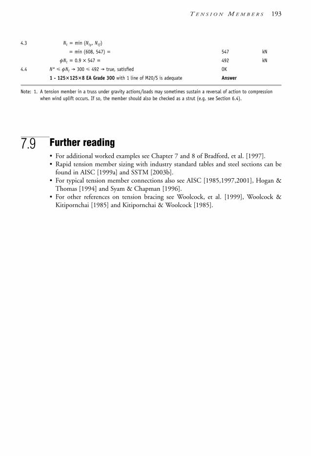
4.3 Nt = min (Nty, Ntf)
= min (608, 547) = 547 kN
φNt = 0.9 × 547 = 492 kN
4.4 N* φNt → 300 492 → true, satisfied OK
1 - 1251258 EA Grade 300 with 1 line of M20/S is adequate Answer
Note: 1. A tension member in a truss under gravity actions/loads may sometimes sustain a reversal of action to compressionwhen wind uplift occurs. If so, the member should also be checked as a strut (e.g. see Section 6.4).
7.9 Further reading• For additional worked examples see Chapter 7 and 8 of Bradford, et al. [1997].• Rapid tension member sizing with industry standard tables and steel sections can be
found in AISC [1999a] and SSTM [2003b].• For typical tension member connections also see AISC [1985,1997,2001], Hogan &
Thomas [1994] and Syam & Chapman [1996].• For other references on tension bracing see Woolcock, et al. [1999], Woolcock &
Kitipornchai [1985] and Kitipornchai & Woolcock [1985].
T E N S I O N M E M B E R S 193
1106 SDHB 07 Final 8/6/05 12:08 PM Page 193

8.1 Connection and detail design
8.1.1 General
This chapter covers the design of elements whose function is to transfer forces from amember to the footings, from one member to another, or from non-structural buildingelements to the structure. Typical connections used in constructional steelwork are listedbelow:• Shop connections and fixtures: direct connections between members; for example, in
welded trusses, welded or bolted subframes, brackets and fixtures.• Site connections and splices: column and beam splices, beam-to-beam and beam-to-
column connections, column bases-to-footing connections.
Site connections are usually bolted for speed of erection, but in special circumstanceswelding is used. The reasons for the popularity of bolted site connections are:• low sensitivity to unavoidable dimensional inaccuracies in fabrication, shop detailing
or documentation
Table 8.1 Connections chapter contents
Subject Subsection
Types of connections & design principles 8.1Bolted connections 8.2 to 8.3Bolt installation and tightening 8.2.5 to 8.2.7Design of bolted connections 8.3Connected plate elements 8.4Welded connections 8.5 to 8.8Types of welded joints 8.6Design of a connection as a whole 8.9 to 8.10Hollow section connections 8.10.1Pin connections 8.10.2
c h a p t e r 8
Connections
1106 SDHB 08 Final 8/6/05 12:09 PM Page 194
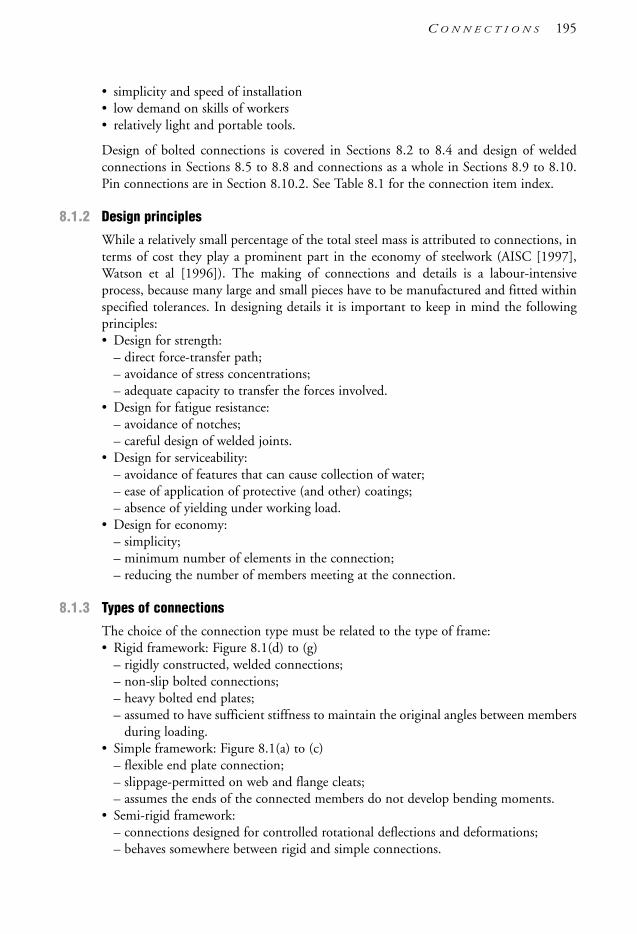
• simplicity and speed of installation• low demand on skills of workers• relatively light and portable tools.
Design of bolted connections is covered in Sections 8.2 to 8.4 and design of weldedconnections in Sections 8.5 to 8.8 and connections as a whole in Sections 8.9 to 8.10.Pin connections are in Section 8.10.2. See Table 8.1 for the connection item index.
8.1.2 Design principles
While a relatively small percentage of the total steel mass is attributed to connections, interms of cost they play a prominent part in the economy of steelwork (AISC [1997],Watson et al [1996]). The making of connections and details is a labour-intensiveprocess, because many large and small pieces have to be manufactured and fitted withinspecified tolerances. In designing details it is important to keep in mind the followingprinciples:• Design for strength:
– direct force-transfer path;– avoidance of stress concentrations;– adequate capacity to transfer the forces involved.
• Design for fatigue resistance:– avoidance of notches;– careful design of welded joints.
• Design for serviceability:– avoidance of features that can cause collection of water;– ease of application of protective (and other) coatings;– absence of yielding under working load.
• Design for economy:– simplicity;– minimum number of elements in the connection;– reducing the number of members meeting at the connection.
8.1.3 Types of connections
The choice of the connection type must be related to the type of frame:• Rigid framework: Figure 8.1(d) to (g)
– rigidly constructed, welded connections;– non-slip bolted connections;– heavy bolted end plates;– assumed to have sufficient stiffness to maintain the original angles between members
during loading.• Simple framework: Figure 8.1(a) to (c)
– flexible end plate connection;– slippage-permitted on web and flange cleats;– assumes the ends of the connected members do not develop bending moments.
• Semi-rigid framework:– connections designed for controlled rotational deflections and deformations;– behaves somewhere between rigid and simple connections.
C O N N E C T I O N S 195
1106 SDHB 08 Final 8/6/05 12:09 PM Page 195

The type of framing adopted is often governed by the optimum connection type for thatparticular project. For example, if the framework for an office building will not beexposed to view, then all-bolted field connections may be chosen purely due to the needfor rapid erection; the frame will thus be of simple construction, possibly braced by thelift core. In contrast, if the steel framework of a building will be exposed to view, thenthe choice may be braced framework with pin-type connections or, alternatively, a rigidframe system with welded connections.
Connections can also be categorised by the fastener type used:• Welded connections using:
– butt welds;– fillet welds;– compound (butt-fillet) welds.
• Bolted connections using:– snug-tight bolting denoted by “/S”;– controlled post-tensioned bolting:
– working by bearing contact denoted by “/TB”;– working by the friction grip principle denoted by “/TF”.
• Pins and pinned connections.
Another useful way to categorise connections is by the construction stage:• workshop connections: mostly welded;• site connections: mostly bolted.
Various types of beam-column connections are shown in Figure 8.1.
Figure 8.1 Types of field connections (a) to (d) bolted; (e) to (g) welded on site (or in the shop ifthe beam is a stub piece).
8.1.4 Minimum design actions
In recognition of the crucial importance of connection design, AS 4100 requiresconnections to be designed for forces at times larger than the member design actions.When the size of the member is larger than required for strength design, the connection
(a) (b) (c)
(e) (f) (g)
(d)
or oror
196 S T E E L D E S I G N E R S ’ H A N D B O O K
1106 SDHB 08 Final 8/6/05 12:09 PM Page 196

design actions must not be less than the specified minimum. Table 8.2 summarises thesecode requirements.
Table 8.2 Minimum design actions on connections as specified in Clause 9.1.4 of AS 4100
Type and location Minimum actions Notes
N*min or V*
min M*min
Tension members (excl. threadedrod bracing)
Splices and end connections 0.3φNt 0 Nt = nom. membertension capacity
Threaded rod bracing memberwith turnbuckles φNt
Compression membersEnd connections 0.3φNc 0 Nc = nom. member
compression capacity Splices, at restrained points 0.3φNc 0
Splices, at unrestrained points 0.3φNc 0.001 δ N*ls δ = amplification factorδb or δs (Section 4.4 or Clause 4.4 of AS 4100)
ls = distance between pointsof lateral restraint
Fasteners in splices prepared for full bearing contact 0.15φNc 0
Flexural membersSplices in flexural members 0 0.3 φMb Mb = nom. member
moment capacity
Ditto, but acting in shear only V* M*v V* = design shear force
M*v = moment due to V*
eccentricity on theconnector group
Beam connections inRigid construction 0 0.50 φMb
Simple construction min[0.15φVv , 40 kN] 0 Vv = nominal shear capacity
Member subject tocombined actions simultaneously satisfy the above relevant requirements
Note: φ is generally taken as 0.9 as per member design. There are separate design action effects and behaviourrequirements for earthquake load combinations—see Section 13 of AS 4100.
8.2 Bolted connections8.2.1 General
Bolted connections used in steel construction are of several types, described as follows:• Simple framework (minimal rotational restraint to member ends):
– flexible end plate connection;– web and flange cleat—slippage-permitted;– pin-type connection
C O N N E C T I O N S 197
1106 SDHB 08 Final 8/6/05 12:09 PM Page 197

• Semi-rigid framework (connections designed for controlled deformations)• Rigid framework (maximum rotational restraint to the member end).
8.2.2 Definition of bolting terms
Bearing-type joint A bolted joint designed for maximum utilisation of HS structuralbolts, which is achieved by allowing joint slip to take place and thus bring the bolt shankto bear on the walls of the holes; resistance to joint shear is derived by a combination offrictional resistance and bearing resistance (though design provisions only consider thelatter type of resistance).
Commercial bolts Bolts of Property Class 4.6 steel, manufactured to medium tolerances.
Direct-tension indication (DTI) device Generally described as a flat washer with protrusionson one side of the washer. The protrusion side of the washer is placed under the bolt headand squashes under a pre-determined load. It is used as a primary means of installation forfull tensioning of bolts.
Edge distance The distance from the centre of a bolt hole to a free edge (or anadjacent hole).
Effective clamping force Net clamping force in a joint subject to tension parallel to thebolt axes; the applied tensile force has the effect of reducing the pre-compression of thejoint plies.
Effective cross-section Area used in stress calculations being equal to the gross cross-sectionalarea less deductions for bolt or other holes and for excessive plate width (if applicable).
Faying surface Surfaces held in contact by bolts (the mating surfaces).
Friction grip bolts An obsolete term (see friction-type joint).
Friction-type joint A bolted joint using HS structural bolts designed so that the shearbetween the plies is lower than the safe frictional resistance of the pre-compressed matingsurfaces, resulting in a non-slip joint. Attention to ply surface preparation around thebolt area is required for such joints.
Full tensioning A method of bolt tensioning capable of imparting to the bolt a minimumtension of at least 75% of the bolt proof stress. This permits a “stiffer” joint in terms ofload-deflection behaviour. Two categories of bolting can be derived from such boltinstallations—fully tensioned bearing (designated as “/TB”) and fully tensioned friction(designated as “/TF”).
Grip Total thickness of all connected plies of a joint.
Gross cross-sectional area Area computed from the cross-sectional dimensions withoutregard to any deductions.
High-strength interference body bolts These bolts, made of high-strength steel, aredesigned for a driving fit (interference fit).
High-strength structural bolts Bolts made of high-strength steel (typically PropertyClass 8.8) to commercial tolerances, and suitable for applications requiring hightightening torques.
198 S T E E L D E S I G N E R S ’ H A N D B O O K
1106 SDHB 08 Final 8/6/05 12:09 PM Page 198

HS High strength—as in high strength structural bolts.
Lapped connection Same as shear connection.
Lap-type moment connection Resistance against rotation due to moment acting in theplane of the mating surface and is achieved by bolts stressed in shear.
Load factor Safety factor against slip in friction-type joints.
Mild steel bolts An obsolete term (see Commercial bolts).
Minimum bolt tension Minimum tensile force induced in the bolt shank by initialtightening, approximately equal to the bolt proof load, see Full tensioning also.
Moment connection Flange-type or end plate moment connections are subjected tomoments acting in a plane perpendicular to the mating surfaces.
Part-turn tightening Relies on the relationship between the bolt extension and theinduced tension (see Section 9 of AS 4100). It is used as a primary means of installationfor full tensioning of bolts.
Pin An unthreaded rod permitting the rotation of plies around the rod axis.
Pitch The distance between bolt centres along a line—also referred to as spacing.
Ply A single thickness of steel component (plate, flat bar, section flange/web, etc.)forming the joint.
Precision bolts Bolts, available in several grades of carbon steel, are manufactured to ahigh tolerance and are used mainly in mechanical engineering.
Proof load Bolt tension at proportional limit.
Prying force Additional forces on bolts subject to tension induced by the flexing of the plies.
Shear connection In this type of connection the forces are parallel to the matingsurfaces, and the bolts are stressed in shear.
Slip factor Coefficient of friction between the mating surfaces/plies.
Snug-tight bolts Bolts tensioned sufficiently to bring into full contact the matingsurfaces of the bolted parts. Designated in Australia and New Zealand as “/S”.
Stress area Cross-sectional area of bolt used in verifying stresses in bolts subject totension; it is approximately 10% larger than the core area (area at the root of thread).
Tension connection In this type of connection the mating surfaces are perpendicular tothe direction of the applied tensile force, and the bolts are stressed in axial tension.
Tension and shear connection Applied tensile force is inclined to the mating surfaces,thus the bolts are subjected to combined shear and tension.
Torque-control tightening Method of tightening using either a hand-operated torquewrench or a power-operated tool; the method relies on the relationship involving frictionbetween the bolt and nut threads and the applied torque. This is not a primary boltinstallation method in AS 4100 (used for inspection only).
C O N N E C T I O N S 199
1106 SDHB 08 Final 8/6/05 12:09 PM Page 199

200 S T E E L D E S I G N E R S ’ H A N D B O O K
8.2.3 Types of bolts and installation category
Bolts used in steel construction are categorised as follows:• Property Class 4.6 commercial bolts conforming to AS 1111
These bolts are made of low carbon steel similar to Grade 250 steel and generally usedin structural steel construction.
• Property Class 8.8, high-strength structural bolts conforming to AS/NZS 1252These bolts are made of medium carbon steel using quenching and tempering toachieve enhanced properties. Consequently they are sensitive to high heat input, forexample welding.
• Property Class 8.8, 10.9 and 12.9 precision boltsThese bolts are manufactured to very close tolerances, suitable for mechanical assembly.They can find their use as fitted bolts in structural engineering. Bolts marketed underthe brand name ‘Unbrako’ and ‘Huck’ are in this category.
Higher-grade structural bolts, designation 10.9, are used in special circumstances wherevery large forces are transmitted and space is limited. One variety of these boltsincorporates a self-limiting initial tension feature (Huckbolt).
Property Class 10.9 and 12.9 bolts are susceptible to hydrogen pick-up, possiblyleading to delayed brittle fracture. Hydrogen pick-up can occur from the pickling processused in galvanizing or from rust formation in service. Specialist advice should be soughtbefore specifying these bolts.
Property Class 4.6 commercial bolts are suitable only for snug-tight installationdesignated as 4.6/S bolting category.
Property Class 8.8 structural bolts are capable of being highly tensioned. Theirdesignation is 8.8/TB or 8.8/TF depending on whether they are used in bearing modeor friction mode connections respectively. They are also typically used for snug-tightinstallation designated as 8.8/S bolting category.
The details of commonly used bolts are given in Table 8.3 with other pertinent detailsin Tables 8.4(a) to (c).
Table 8.3 Characteristic properties of structural bolts
Property Standard Min. tensile Min. yieldClass strength, MPa stress, MPa
4.6 AS 1111 400 2408.8 AS/NZS 1252 830 660
Property Class 4.6 and 8.8 bolts are available in nominal sizes of M12, M16, M20,M24, M30 and M36 as either untreated or galvanized. The larger-size bolts, M30 andM36, can be fully tensioned only by using special impact wrenches and should thereforenot be used indiscriminately.
The use of washers is subject to the following rules:• Use one hardened washer under the head or nut, whichever is used for tightening.• Use a second washer where the bolt holes have clearance over 3 mm.• Use thicker and larger washers with slotted holes.• Use tapered washers where the flanges are tapered.
An excellent reference for bolting of steel structures is Firkins & Hogan [1990].
1106 SDHB 08 Final 8/6/05 12:09 PM Page 200

Table 8.4(a) Bolt dimensions for Property Class 4.6 bolts to AS 1111Tensile strength: 400 MPa. Yield stress: 240 MPa
Shank Tensile stress Thread pitch Bolt head/Nut width Bolt head/Nut widthdia, mm area, mm2 mm across flats, mm across corners, mm
12 84.3 1.75 18 20
16 157 2.0 24 26
20 245 2.5 30 33
24 353 3.0 36 40
30 561 3.5 46 51
36 817 4.0 55 61
Table 8.4(b) Bolt dimensions for Property Class 8.8 bolts to AS/NZS 1252Tensile strength 830 MPa. Yield stress: 660 MPa
Shank Tensile stress Thread pitch Bolt head/Nut width Bolt head/Nut widthdia, mm area, mm2 mm across flats, mm across corners, mm
16 157 2.0 27 31
20 245 2.5 34 39
24 353 3.0 41 47
30 561 3.5 50 58
36 817 4.0 60 69
Table 8.4(c) Main attributes of Property Class 8.8 bolts to AS/NZS 1252
Bolting/Torque 8.8/S 8.8/TB 8.8/TF
Attribute Snug-tight Fully tensioned, Fully tensioned, bearing type friction type
Shear jointTightening Snug-tight Torque control Torque control
Contact surfaces Any Bare metal Bare metal (critical)
Joint slippage Possible Some slippage Unlikely
Getting loose Possible Unlikely Unlikely
Tightening tool Hand wrench Torque wrench Torque wrench
Tension jointTightening Snug tight Torque control Same as 8.8/TB
Contact surfaces Any Painting OK Same as 8.8/TB
Joint slippage Unlikely Zero Same as 8.8/TB
Getting loose Unlikely Zero Same as 8.8/TB
Compression jointContact surfaces Any condition Any condition —
Joint slippage Some possible Zero —
Getting loose if vibrating Unlikely Not possible —
Cost of installation Low Medium to high High
Notes: The torque control is either by “load indicating washer” or “turn of the nut” method. Torquewrench/measurement only used for inspection purposes in AS 4100.
C O N N E C T I O N S 201
1106 SDHB 08 Final 8/6/05 12:09 PM Page 201

8.2.4 Modes of force transfer
Two characteristic modes of force transfer are used:• bearing mode for joints where connection is allowed to slip until the bolts come in
bearing contact;• friction or ‘friction grip’ mode for joints intended not to slip under limit loads.
Further discussion on the bolting types is given in Sections 8.2.5, 8.2.6, 8.3 and 8.4.Figure 8.2 illustrates the modes of force transfer.
Figure 8.2 Modes of force transfer at a bolted lap joint (a) bearing and shear on bolt;(b) friction grip.
Some confusion can occasionally arise when special tight-fitting bolts (interferencebody bolts) are specified, because they are often called ‘high-strength bearing bolts’. Theshanks of these bolts are manufactured with small, sharp protrusions so that bolts can bedriven into a slightly undersized hole for a very tight fit. These bolts permit thetransmission of very high shear forces without slip but at a cost penalty. Their use isrestricted to bridge and heavy construction.
The following points are pertinent for selection:• magnitude of loads• intended condition of mating surfaces (whether they are to be painted, galvanized or
left “as rolled”)• maximum joint-slip permitted• presence of load fluctuations or fatigue.
In order to comply with AS 4100 high-strength bolting requirements, only the followingsurface treatments can be used: flame-cleaned plain steel, shot-blasted plain steel, hotzinc sprayed and sandblasted, and inorganic zinc-rich paint. By modifying the slip factor,µ, which is assumed as 0.35 in AS 4100, it is also possible to use grit-blasted or wire-brushed hot-dip galvanized steel.
It is often desirable and economical to paint the steel in the fabricator’s painting facilitybefore shipping it to the site. When the steelwork is prepainted it is necessary to applymasking to the areas of the mating surfaces where friction bolting is used. Usinginorganic zinc silicate paint is advantageous, as a relatively high friction coefficient canbe achieved and masking may not be necessary.
8.2.5 Bolts in snug-tight connections (4.6/S & 8.8/S)
When bolts are installed as snug-tight (without controlled tension), they are assumed toact like pins (see Figure 8.2(a)). Shear forces transferred through bolts depend entirely on
(a) (b)
202 S T E E L D E S I G N E R S ’ H A N D B O O K
1106 SDHB 08 Final 8/6/05 12:09 PM Page 202

the shear capacity of the bolts and the bearing capacity of the ply. Tensile forces largerthan the initial tension, transferred through the bolts, can open up the joint between thebolted plates because of the elongation of the bolt.
Under conditions of load reversal, snug-tight bolts should not be used for transfer ofshear, as joint movement would result. This could cause damage to the protectivefinishes, and to the faying surfaces, and nuts might undo themselves. Shear and tensionconnections subject to high-cycle load fluctuations should be specified for fullytensioned, Property Class 8.8 bolts.
Both the Property Class 4.6 and 8.8 bolts can be installed as snug-tight: that is,tensioned just sufficiently to bring the bolted elements into full contact. The usualspecification for snug-tight bolting is: the snug-tight condition is achieved when the fulleffort of an averagely fit worker, using a standard hand wrench (podger spanner) or a fewimpacts of an impact wrench, where the bolt or nut will not turn any further.
The behaviour of snug-tight bolts is shown in Figure 8.3. For the strength limit state,design capacities for snug-tight bolts (i.e. 4.6/S or 8.8/S) can be calculated as describedin Section 8.3.1.1, or read from Table 8.5(a). Due to the inherent extra slip in its load-deformation characteristics, snug-tight bolts are generally used in simple or flexibleconnections (see Figure 8.1(a) to (c)).
The possibility of ply crushing and tearout may also need to be evaluated (see Sections8.3.1.1(d) and (e), 8.4.1 and 8.4.2) for snug-tight bolted connections. Generally, snug-tight bolts are not used/permitted in dynamic loading (fatigue) situations.
8.2.6 Property Class 8.8 bolts, tension-controlled
Property Class 8.8 bolts, or high-strength structural bolts, installed under controlledtensioning procedures, can be designed to act as:• bolts in bearing mode, 8.8/TB• bolts in friction mode, 8.8/TF.
Figure 8.3 Behaviour of high-strength structural bolts. Slip load 1 applies to tension-controlled HSstructural bolts using a slip factor of 0.35. Slip load 2 applies to snug-tight bolts.
There is no physical difference between the bolts themselves used in either of thesemodes. The only difference is that the treatment of the mating surface of friction-boltedjoints (designation /TF) should be such as to ensure a high coefficient of friction.
00 1 2 3 4
20
40 36
55
51
60
80
100
Slip load 2
Slip (mm)
Load
, P (
kN)
Slip load 1
Bearing mode
Tension-controlled
Snug-tight
Friction mode“Safe” load for
“Safe” load for
M20
SLIP
P
P
de
de
t
C O N N E C T I O N S 203
1106 SDHB 08 Final 8/6/05 12:09 PM Page 203

Property Class 8.8 bolts have heavier heads and nuts than Property Class 4.6 boltsbecause they have to resist larger initial tension and applied tensile loads. Boltingcategory 8.8/TB requires no special preparation of the mating surfaces, while category8.8/TF depends on the value of the friction coefficient of the surfaces in contact.
When bolts carry tension only, it is acceptable to leave the paint coat covering themating surfaces, and bolting category 8.8/TB is appropriate.
The behaviour of fully-tensioned bolts is shown in Figure 8.3.
8.2.6.1 Property Class 8.8 bolts, tension-controlled in bearing modeconnections (8.8/TB)Bolts designed for bearing mode of action rely mainly on a dowel-type action to transfershear forces (see Figure 8.2(a)). As the load increases, the bolted elements will slipsufficiently to bring the bolt shank into contact with the wall of the bolt hole. This hasthe effect of stressing the bolt shank in shear and in bearing, and thus the term ‘bearing-type joint’ is used.
At the worst, the slip may become as large as the bolt hole clearance, say 2–3 mm forstandard bolt holes. Bolt slips approaching these values have occurred in practice, butonly when the bolts were incorrectly tensioned. A joint slip of at least 1 mm should beassumed in design, because the bolts are fully tensioned, and a part of the load istransferred by friction-grip action.
The fundamental difference between tension-controlled bearing mode (/TB) andsnug-tight (/S) bolts is seen by the behaviour of these bolt types in Figure 8.3. Clearly,for the same Property Class, /S bolts slip much earlier than /TB bolts during the (shear)loading process. So the basic advantage of /TB bolts is the extra stiffness supplied over /Sbolts by delaying slip from the pre-tensioning process. This advantage of extra stiffnessto the overall joint is significantly used in rigid type connections—where snug–tightconnections are generally not used (or permitted). Much research and testing has beendone with /TB bolts in rigid and semi-rigid connections to correlate behaviour to designassumptions for this joint type.
For the strength limit state, design capacities for tension-controlled Property Class 8.8bolts designed for bearing mode (i.e. 8.8/TB) can be calculated as described in Section8.3.1.1, or read from Table 8.5(b). The value of the capacity reduction factor, φ, istaken as 0.8.
Interestingly, these capacities are the same as for the snug-tight Property Class 8.8 bolts(i.e. 8.8/S). This is due to both bolt categories have the same limiting condition for thestrength limit state. The only difference is the extra rigidity offered by the /TB bolts thataffects the load-slip performance which is very important for some connection types—e.g. rigid and semi-rigid connections (see Figure 8.1(d) and, if bolted, (g)).
For 8.8/TB bolts, like 8.8/S bolts, ply crushing and tearout capacities also have to beevaluated—more so in this instance as bolt strength is higher (see Sections 8.3.1.1(d) and(e), 8.4.1 and 8.4.2). Also, /TB bolts are used in dynamic loading (fatigue) situationswhen friction mode type bolts are seen to be uneconomical.
8.2.6.2 Property Class 8.8 bolts, tension-controlled in friction modeconnections (8.8/TF)The principal mode of action of friction-grip bolts is to use the friction resistancedeveloped under initial tensioning of the bolts. As long as the working shear force is less
204 S T E E L D E S I G N E R S ’ H A N D B O O K
1106 SDHB 08 Final 8/6/05 12:09 PM Page 204

than the frictional resistance on the preloaded joint, there is no slippage and the jointmay be regarded as behaving elastically. The term applicable to this type of joint is‘friction-type joint’, but a more descriptive term sometimes used is ‘friction-grip joint’.The physical contact between the bolt shank and the bolt hole is not essential in this modeof load transfer, but should be anticipated in case of joint slippage. Each bolt can transfera force equal to the frictional resistance of the mating surfaces surrounding the bolt.
Table 8.5(a) Design capacities for snug-tightened (category /S) bolts
Bolt size Property Class 4.6 bolts (4.6/S) Property Class 8.8 bolts (8.8/S)
Axial tension Single Shear * Axial tension Single Shear*mm φNtf (kN) φVf (kN) φNt f (kN) φVf (kN)
M12 27.0 15.1 [22.4] – –M16 50.2 28.6 [39.9] 104 59.3 [82.7]M20 78.4 44.6 [62.3] 163 92.6 [129]M24 113 64.3 [89.7] 234 133 [186]M30 180 103 [140] 373 214 [291]M36 261 151 [202] 541 313 [419]
Notes: 1. *Single plane shear values are for bolts with threads included in the shear plane, and shear values in[ ] are for bolts with threads excluded from the shear plane.
Table 8.5(b) Design bolt capacities for category 8.8/TB bolts
Bolt size Axial tension Single shear
Threads included Threads excludedmm φNtf (kN) φVf (kN) φVf (kN)
M16 104 59.3 82.7M20 163 92.6 129M24 234 133 186M30 373 214 291M36 541 313 419
Note: Threads included/excluded refer to threads included in or excluded from the shear plane.
Table 8.5(c) Design capacities for category 8.8/TF bolts installed in round holes (kh = 1.0)
Bolt size Bolt tension, kN Axial tension, kN Single shear, kNat installation µ = 0.25 µ = 0.30 µ = 0.35
Nti φNtf φVs f φVs f φVsf
M16 95 66.5 16.6 20.0 23.3M20 145 101 25.4 30.5 35.5M24 210 147 36.8 44.1 51.5M30 335 234 58.6 70.4 82.1M36 490 343 85.7 103 120
Note: Axial tension design capacity (φNtf) is only used for shear-tension interaction checks for /TF bolts.
C O N N E C T I O N S 205
1106 SDHB 08 Final 8/6/05 12:09 PM Page 205

As mentioned above, snug-tight bolts (/S) and tensioned-controlled in bearing modebolts (/TB) are typically designed for the strength limit state. Unlike, /S and /TB bolts,tension-controlled friction mode bolts (/TF), are generally designed for the serviceabilitylimit state as slip (or deflection) is being limited.
For the serviceability limit state, design capacities for tension-controlled Property Class8.8 bolts designed for friction mode (i.e. 8.8/TF) can be calculated as described inSection 8.3.1.2, or read from Table 8.5(c). The design shear capacities in Table 8.5(c) aregiven for three values of coefficient of friction. The value of the “special” serviceabilitycapacity reduction factor, φ, is taken as 0.7 as noted in Clause 3.5.5 of AS 4100. The/TF bolts can be used in dynamic loading (fatigue) situations though are somewhatpenalised by their lower load carrying capacity. If used in this situation, fatigue checks donot have to be undertaken on /TF bolts (unless the bolt has prying forces under tensionloads—see Table 11.5.1(3) of AS 4100).
Even though /TF bolts are designed for the serviceability limit state, AS 4100 alsorequires /TF bolts to be designed for the strength limit state. In this instance, the /TBstrength design provisions are used with the strength limit state load factors, combinationand capacity reduction factors.
The design value of the coefficient of friction depends on the surface preparation forthe category 8.8/TF bolts. Table 8.6 has been compiled from various published sources,and it shows the importance of the surface preparation.
Table 8.6 Values of coefficient of friction, µ
Surface description Coefficient of friction, µAverage Minimum
Plain steel:– as rolled, no flaking rust 0.35 0.22– flame-cleaned 0.48 0.35– grit-blasted 0.53 0.40
Hot-dip galvanized:– as received 0.18 0.15– lightly sandblasted 0.30 0.20
Hot-zinc sprayed:– as received 0.35 0.23
Painted:– ROZP primed 0.11 0.05– inorganic zinc silicate 0.50 0.40– other paint systems Tests required Test required
8.2.6.3 Interference body boltsInterference body bolts are manufactured for driving into well-aligned holes, facilitatedby sharp protrusions or ‘knurls’ over the surface of the bolt shank. Because there is nogap between the bolt and the hole, it is possible to achieve a zero-slip joint.
The design of these bolts may be based on either friction-type (category 8.8/TF) orbearing-type joints (category 8.8/TB), whichever permits larger loads per bolt. This is
206 S T E E L D E S I G N E R S ’ H A N D B O O K
1106 SDHB 08 Final 8/6/05 12:09 PM Page 206

because, for thinner plates, the friction-type design permits higher design capacities,while for thicker plates the bearing-type design will be more advantageous.
8.2.7 Installation and tightening of HS structural bolts
The first prerequisite is that the mating surfaces must be true, even without projections,so that they can be brought in close contact over the whole area to be bolted with aminimum of pressure.
If bolts are designed for friction mode (friction-type joint) the surfaces must be in thecondition prescribed in the job specification or, if unspecified, in accordance with AS 4100. The job specification may require a bare steel mating surface complying withAS 4100 or may prescribe the type of surface preparation or finish that has been usedas the basis of design. Sometimes galvanizing or zinc-rich paint is specified, but thismust be checked against the design assumption of the slip factor value. The steelworkspecification should note exactly which surface preparation is required by design.
When bolts are designed for bearing mode (bearing-type joint) the mating surfacesmay be left primed or painted. In either case, any oil, dirt, loose rust, scale or other non-metallic matter lodged on the mating surfaces must be removed before assembly. Whenbolts are used in tension joints, no special preparation is required.
HS structural bolts may be provided with only one hardened washer under the nut orbolt head, whichever is turned during tightening. A tapered washer should always beplaced against a sloping surface, in which case the turning end is on the opposite side toprevent rotation of the tapered washer. Three methods of tightening are in use:• part-turn method (primary method)• direct-tension indication method (primary method)• torque control method (secondary method for inspection only).
The part-turn method (Clause 15.2.5.2 of AS 4100) relies on the known ratio of the bolttensile force to the number of turns of the nut. This is described in AS 4100. Forexample, to achieve the minimum bolt tension in a 24 mm bolt, 150 mm long, it isnecessary to rotate the nut or the head half a turn from the snug-tight condition. It isimportant to check that the other end does not rotate, which may occur as a result ofseizure of the nut because of rusty threads or insufficient thread clearances. The latter cansometimes be experienced with galvanized bolts.
The direct-tension indication method (Clause 15.2.5.3 of AS 4100) makes use of aspecially designed load-indicating device that are washers with protrusions on one facesuch that initially an air gap exists between the washer and the metal. The tightening ofthe bolt produces pressure on the protrusions, gradually squashing them. When therequired bolt tension is reached, the gap diminishes to a specified minimum that can beascertained by a blade gauge. This method is more reliable than the part-turn and torquecontrol methods.
The torque control method (Appendix K of AS 4100) relies on the laboratory-established relationship between torque and bolt tension that is dependent on thecoefficient of friction between the thread surfaces in contact. Oiled threads requireconsiderably less torque than dry threads to achieve the minimum bolt tension (thetorque ratio can be as much as 1:2). Rust on the threads would further increase thetorque. Due to this variability, AS 4100 (and Australian practice) has relegated this
C O N N E C T I O N S 207
1106 SDHB 08 Final 8/6/05 12:09 PM Page 207

tightening method to inspection purposes only. It is considered to be an independentmethod to assess the presence of gross under-tensioning.
The first stage in the bolt-tightening procedure requires the bolt to be brought into asnug-tight condition that is intended to draw the plies into firm contact, eliminating anyair gaps over the entire joint area. If the surfaces cannot be drawn together, it is essentialto eliminate the mismatch between the plates before the bolts are tightened to fulltension. The final bolt tightening from snug-tight condition to the maximum prescribedbolt tension should proceed progressively from the central bolts to the peripheral boltsor, in another type of bolt disposition, from the bolts closest to the most rigid part of thejoint towards the free edges.
Apart from the effect of the thread condition, there is a need to carefully calibratepower-operated wrenches, and to maintain these in calibrated condition. The ‘stall’ orcut-off torque of power-operated wrenches cannot be maintained for long at thepredetermined level, and frequent calibrations are necessary.
Whichever method of tightening is employed, the minimum bolt tensions mustcomply with Clause 15.2.5 of AS 4100.
AS 4100 also notes that the reuse of HS structural bolts that have been fully tightenedshall be avoided—as, for example, if a joint were required to be taken apart andreassembled. The reason for this is that the bolt material becomes strain-hardened whentensioned at or above the proof stress, and less than the original extension is available atthe repeated tightening, with the consequent danger of fracture later in service. Ifre-used, HS structural bolts should only be placed in their original hole with the samegrip. Retensioning of galvanized bolts is not permitted. The above bolt re-use provisionsdo not include “touching up” of previously tensioned bolts.
It is emphasised that tightening of HS structural bolts is not an exact science, and a lotof sound judgement and field experience is required if the design assumptions are to berealised on the job.
8.3 Design and verification of bolted connections
8.3.1 Capacity of a single bolt
The appropriate limit states for design of bolts are the strength limit state and theserviceability limit state. Durability also may be a factor for consideration.
Recent work on bolt strengths shows that the design criteria in the old AS 1250 (thepredecessor to AS 4100) were too conservative. The bolt capacities specified in AS 4100are substantially higher than the capacities back-calculated from the superseded AS 1250.Thus the number of bolts in a connection required by AS 4100 will be only about 60%of the number computed by the old code. It is now more important than ever to carryout an accurate design of bolted joints and take into account all design actions occurringat the joint. This should include prying action and the least favourable combinationof loads.
208 S T E E L D E S I G N E R S ’ H A N D B O O K
1106 SDHB 08 Final 8/6/05 12:09 PM Page 208

8.3.1.1 Strength limit stateClause 9.3.2 of AS 4100 considers the strength limit state design of bolts and applies to/S, /TB and /TF bolting categories.
(a) Bolts in shearThe nominal bolt shear capacity, Vf , is calculated as follows.Where there are no shear planes in the threaded region and nx shear planes in theunthreaded region:
Vf = 0.62 kr fu f nx Ao
Where there are nn shear planes in the threaded region and no shear planes in theunthreaded region:
Vf = 0.62 kr fu f nn Ac
Where there are nn shear planes in the threaded region and nx shear planes in theunthreaded region:
Vf = 0.62 kr fu f (nn Ac + nx Ao )
wherefu f = minimum tensile strength of the boltAc = core area (at the root of the threads)Ao = bolt shank areakr = reduction factor for length of bolt line
= 1.0 for connections other than lap connections, otherwise= 1.0 for lengths up to 300 mm, and 0.75 for lengths over 1300
mm (interpolation should be used in between).
It is worth noting that the capacities of bolts are based on the minimum tensile strengthfu f rather than the yield strength.
The overall inequality to be observed is:
V* φVf
where V * is the design shear force on the bolt/bolt group and the capacity reductionfactor, φ, is 0.8 from Table 3.4 of AS 4100.
The normal commercial practice of thread lengths is based on the formula: length =two bolt diameter + 6 mm. The usual bolt projection allowance is roughly 1.25diameter + 6 mm. This means that the length of thread projecting into the bolt hole isroughly 0.75 times the bolt diameter if the outer ply is thinner than 0.75 bolt diameters.This is quite common in building structures, where plate thicknesses are often less than16 mm. In such instances it may be more economical to use shorter bolts and allowthreads to project into the shear plane, provided the bolt capacity has been checked onthis basis.
(b) Bolts in tensionThe nominal capacity of a bolt in tension, Nt f , is calculated from:
Nt f = As fu f
C O N N E C T I O N S 209
1106 SDHB 08 Final 8/6/05 12:09 PM Page 209

where fu f is the tensile strength of bolt material, and As is the tensile stress area of thebolt (see AS 1275 or Table 8.4(a) or (b)). The tensile stress area is roughly 10% largerthan the core area.
Tensile connections utilising end plates may be subject to an increase in tensionbecause of the leverage or prying action. Section 8.3.2.4 discusses the measures requiredto minimise any prying action.
The overall inequality to be observed is:
N*t f φNt f
where N*tf is the bolt design tension force and the capacity reduction factor is 0.8.
(c) Bolts carrying shear and tension are required to satisfy the following interactioninequality:
(φV
V
f*
f )
2+ (φ
N
N
*t
t
f
f )
2 1.0
where Vf is the nominal shear capacity, and Nt f is the nominal tension capacity withφ = 0.8.
(d) Crushing capacity of the ply material from bolt bearingThe nominal ply crushing bearing capacity:
Vb = 3.2 tpdf fup
where tp is the ply thickness, df is the bolt diameter, and fup is the tensile strength ofthe ply.
The following condition must be satisfied: V * φVb with φ = 0.9 (note the differing φcompared to bolt shear and tension). See Section 8.4.2 also.
(e) Bearing capacity of the ply material from bolt tearoutThe nominal ply tearout capacity of the ply in contact with the bolt:
Vp = aetp fup
where ae is the minimum distance from the ply edge to the hole centre in the directionof the bearing force, fup is the tensile strength and tp is the thickness of the ply.The following condition must be satisfied: V * φVp with φ = 0.9 (again, note thediffering φ compared to bolt shear and tension). See Section 8.4.2 also.
8.3.1.2 Serviceability limit stateThis limit state is relevant only for friction-type connections where connection slip isintended to be prevented at serviceability loads (i.e. for the /TF bolting category). FromClause 9.3.3.1 of AS 4100, the nominal shear capacity of a bolt for a friction-typeconnection, Vs f , is:
Vs f = µnei Nti kh
wherekh = factor for hole type: 1.0 for standard holes, 0.85 for oversize holes
and short slots, and 0.70 for long slotted holes;
210 S T E E L D E S I G N E R S ’ H A N D B O O K
1106 SDHB 08 Final 8/6/05 12:09 PM Page 210
µ = coefficient of friction between plies, which varies from 0.05 forsurfaces painted with oil-based paints to 0.35 for grit-blasted baresteel. Tests are required for other finishes;
Nti = minimum bolt tension imparted to the bolts during installation(see Table 8.5(c)), and
ne i = number of shear planes.
The following inequality must be satisfied:
V *s f φVsf
where V *sf is the design shear force in the plane of the interfaces and φ = 0.7.
8.3.2 Capacity of bolt groups
8.3.2.1 GeneralConnections in building structures use a minimum of two bolts and often more thaneight bolts. The bolts used in a connection form a group. A bolt group may be acted onby loads and bending moments in the plane of the bolt group (in-plane) or at right anglesto it (out-of-plane loading). See Figure 8.4.
Elastic analysis of bolt groups is permitted by AS 4100 and is subject to the followingassumptions:• Plate elements being bolted are rigid and all connectors fit perfectly.• The overall bolt group design actionsV *
x , Vy* and M * may be superposed for simplicity.
• An ‘instantaneous centre of rotation’ (ICR) is evaluated for the bolt group. The ICRis the point at which the bolt group rotates about when subject to the overall boltgroup design actions. This point may be the bolt group centroid or a point rationallydetermined from the joint’s rotational behaviour (see below).
• The forces from the group design action effects acting on individual bolts areproportional to the distance from the bolt to the centre of rotation.
• The ‘critical’ bolt(s) is then considered to be the bolt(s) furthest from the ICR. Theterm ‘critical’ bolt(s) refers to the bolt (or bolts) subject to the greatest shear forcearising from the combined effects from the overall bolt group design actions. The‘critical’ bolt is then used for the design check of the overall bolt group.
• Conventional analysis uses the ICR concept in conjunction with superpositionprinciples. Using a bolt group with in-plane design actions as an example, a puremoment acting only on the bolt group has the ICR positioned at the bolt groupcentroid. Whereas, when the same bolt group is subject to shear force only, the ICR ispositioned at infinity. In-plane loadings are generally composed of moments and shearforces which can then be simply modelled by superposition of the above two individualaction effects. That is, uniformly distributing shear forces to all bolts in the groupwhilst also assuming that bolt group rotation from moment effects occurs about thegroup centroid. Using this method the critical bolt is generally the furthest from thebolt group centroid.
The latter above-listed technique is the most commonly used method of analysis forbolt groups.
C O N N E C T I O N S 211
1106 SDHB 08 Final 8/6/05 12:09 PM Page 211

Figure 8.4 Bolt groups
The method of verifying the bolt group design capacity is well described in detail byHogan & Thomas [1994]. A method of superposition will be used.
The first step is to determine the bolt group second moments of area (Figure 8.4(a)):
Ix = Σxn2
Iy = Σyn2
Ip = Ix + Iy = Σ(xn2 +yn
2)
where Ix and Iy are second moments of area of bolts about the bolt group centroid axis,and Ip is the polar second moment of area of the bolts in the group, each bolt having asection area of unity (assuming all bolts are the same size in the bolt group).
8.3.2.2 Bolt groups subject to in-plane actionsBased on the above assumptions, and as noted in Figure 8.4(a) and (b), the resultantdesign bolt shear force in the bolt farthest away from the centre of bolt group is:
V *res =
Vn*
y +
M*i
Ix
p
max 2
+Vn
*x
+M*i
Iy
p
max2
where n is the number of bolts in the bolt group, V *y and V *
x are the applied forces invertical and horizontal directions, M*
i is the moment (applied and from eccentric shearforces) on the bolt group, and ymax and xmax are the distances from the centroid of thebolt group to the farthest corner bolt.
T1
T2
Ti
Tn
yc
Ti
yi
T2T2
T1T1
xn
yn
y ex V *
CC
y Mo*
Mo*=
Vo*
Vo*
eVo*
Mi*= M1* exVy*Centroid
(a) Group geometry and loading (b) In-plane loading (resolved)
(d) Out-of-plane loading — Beam-column connection
(c) Out-of-plane loading — General
Imposed centreof rotationCompression zone
BoltGroup
Centroid
yV*y
V *x V *xxM*1
M*i
d/6
d
e
212 S T E E L D E S I G N E R S ’ H A N D B O O K
1106 SDHB 08 Final 8/6/05 12:09 PM Page 212

Generally, when the vector resultant loads are determined for the farthest bolt, V *res
(which, in this instance, is considered to be the most critically loaded bolt), the followinginequality can be used to check the adequacy of the whole bolt group:
V *res min. [φVf , φVb , φVp]
where, for the farthest bolt, φVf is the design shear capacity, φVb the ply crushing designbearing capacity and φVp the ply tearout design bearing capacity (as noted in Sections8.3.1.1(a), (d) and (e) respectively).
Hogan & Thomas [1994] provide further background, short-cuts and design aids onbolt groups loaded in this manner.
8.3.2.3 Bolt groups subject to out-of-plane actionsFigure 8.4(c) and (d) show typical bolt groups loaded out-of-plane. From force/momentequilibrium principles, Figure 8.4(c) notes that there are bolts which are not loaded asthey are positioned in the bearing (compression) part of the connection and require nofurther consideration. The forces in the tension region bolts can be evaluated byassuming a linear distribution of force from the neutral axis to the farthest bolts—theselatter bolts being the more critically loaded.
Due to the bolt, plate and support flexibility, a problem exists to determine where theneutral axis (NA) is placed. There is not much guidance available on precisely evaluatingthe NA position. However, some limited guidance is provided by such publications asAISC(US) [1993], CISC [1991] and Owens & Cheal [1989]. A conservative approachis to assume the NA is placed at the bolt group centroid line. A better approximation,which appears to be empirically based, is to assume the NA is positioned at d/6 from thebottom of the end plate which has a depth d (see Figure 8.4(c)). After the NA positionhas been assumed, the following can be undertaken to evaluate the tension load in thefarthest (most critical) bolts.
Using equilibrium principles and Figure 8.4(c):
ΣTi yi + Cyc = M *o and ΣTi = C
and the principle of proportioning from similar triangles provides:
Ti = T1 yy
1
i
the following can ascertained for the critically loaded farthest bolts:
T1 = Σ[yi
M(yi
o
y1
yc)]
The yi terms can be determined from the geometry set by the NA placement. T1 mustbe divided by the number of bolts in the top row, n1, to evaluate the peak tension forceon each critical bolt. Finally, the design shear force on each bolt, V *, can beconservatively determined by uniformly distributing the bolt group shear force, V *
o , toeach bolt—i.e. V * = V *
o n. The interaction equation of Section 8.3.1.1(c) is then usedwith V *
f = V * and N *tf = T1 n1.
In specific joint configurations such as rigid beam-to-column connections (Figure8.4(d)), some standard connection design models (Hogan & Thomas [1994], AISC(US)[1993]) further assume that the two top rows of bolts about the top flange uniformlyresist most—if not all—of the tension force from out-of-plane moments. The reasoningfor this is due to the flange-web to end plate connection providing significant stiffness
C O N N E C T I O N S 213
1106 SDHB 08 Final 8/6/05 12:09 PM Page 213

214 S T E E L D E S I G N E R S ’ H A N D B O O K
for tension forces to be drawn to it. Alternatively, some design models use an “imposedcentre of rotation” placed at a “hard spot” through which all the compression force acts.However, these connection design models also commonly assume that the overall shearforce is shared equally by all the bolts in the bolt group.
The above design models do not consider increased bolt tensions due to pryingactions. This is considered in Section 8.3.2.4 below.
8.3.2.4 Prying actionAs noted in Figure 8.5, prying action occurs in T-type or butt-type connections with boltsin tension. Bending of the end plate causes the edges of the end plate to bear hard on themating surface, and the resulting reaction must be added to the bolt tension. AS 4100 hasno specific provisions for determinating forces involved in prying action, but variousauthors have suggested methods of estimating the magnitude of prying forces (see Hogan& Thomas [1994] which suggests allowing for 20–33% increase in bolt tension force).
Figure 8.5 Prying action: (a) end plate elevation; (b) rigid end plate; (c) medium thickness endplate; (d) thick end plate, and; (e) stiffened end plate. (Note: generally Q1 Q 2 whereQ is the additional ply reaction to induce prying forces into the bolt).
Based on the published results, prying action can be kept to a minimum by using thefollowing measures:• increasing the ratio a/b to at least 0.75 (see Figure 8.5(a))• increasing the bolt spacing to at least 90 mm• increasing the end plate thickness to at least 1.25 times the bolt size.The other option is to stiffen the end plates, as shown in Figure 8.5(e). The latter optionshould be applied as a last resort, as welding of gussets will raise the cost of fabrication.
Figure 8.5 notes the instances when prying actions may occur. Relatively rigid endplates (b) unable to flex will separate from the support face rather than bend and noprying action occurs. Small thickness end plates (not shown) undergo pronounceddouble curvature bending and do not attract prying actions. Medium thickness endplates (c) undergo single curvature or limited double curvature bending causing the endplate edges to also contact the support surface, creating new reaction points therebyincreasing the bolt tension loads. Thick plates (d) undergo single curvature bendingunder flexure and, as noted in (c), attract prying forces. Stiffened end plates (e) behavelike (b) and prying forces are negligible if at all present.
8.3.2.5 Combined in-plane & out-of-plane actionsOccasionally, bolt groups are loaded both in-plane and out-of-plane. The proceduredescribed in Hogan and Thomas [1994] combines the in-plane and out-of-plane forcesusing a general procedure.
b
aBt
Bt
P
(a) (c)
GussetsQ1
Q1
Q 2
Q 2
(b) (d) (e)
1106 SDHB 08 Final 8/6/05 12:09 PM Page 214

8.4 Connected plate elements
8.4.1 Bolt holes and connection geometry
Bolt holes are usually made larger in diameter than the bolt shank for several practicalreasons. First, the bolt shank diameter may vary by ±1%, while the hole diameter canalso vary depending on the drill bits. Second, the fabrication of steel members or unitscan never be absolutely precise and is subject to position and fabrication tolerances.
As specified in AS 4100 and noted in Table 8.7, the bolt holes should be made largerthan the nominal diameter by:• 2 mm for M12, M16, M20 and M24 bolts• 3 mm for bolts larger than M24.
One exception is that bolt holes in base plates are made larger by up to 6 mm, for all boltsizes, to allow for the larger tolerances in holding-down bolt positions. Larger clearancesare permitted only under the proviso that plate washers or hardened-steel washers areused, and that the possibility of significant connection slip has been examined.
Slotted holes are sometimes used to allow for temperature movements or to ease theproblems of erection of complex units. Special provisions for slotted holes in AS 4100 areas in Table 8.7.
Short slots may be provided in all joined plies if plate washers or hardened washers areused. Long slots can be provided only in one ply of two-ply lap joints, or in alternate pliesfor multi-ply joints. In addition, the holes of long slots must be completely covered,including an overlap for joint movement, using plate washers 8 mm or thicker.
Table 8.7 Standard and slotted hole sizes as noted in Clause 14.3.5.2 of AS 4100
Bolt Nominal Base plate Oversize/slotted Short slotted Longslottedsize hole dia. hole dia. hole width/dia. hole length hole length
mm mm mm mm mm
M12 14 18 20 22 30
M16 18 22 24 26 40
M20 22 26 28 30 50
M24 26 30 32 34 60
M30 33 36 38 40 75
M36 39 42 45 48 90
Circular bolt holes may be fabricated by drilling or by punching if special conditionsof AS 4100 are met. For steel material of Grade 250/300 and static loading, themaximum thickness of plate that can be punched is 22.4/18.7 mm respectively. If thejoint is dynamically loaded the maximum thickness for punching is reduced to 12 mm.
Slotted holes can be fabricated by machine flame-cutting, punching or milling. Handflame-cutting would not comply with AS 4100. Figure 8.6 shows the spacing of bolts.Table 8.8 gives the edge distances.
C O N N E C T I O N S 215
1106 SDHB 08 Final 8/6/05 12:09 PM Page 215

Figure 8.6 Standard bolt gauges and pitches for M20 bolts (see AISC [1985], AISC [1999a] forfurther information).
Table 8.8 Minimum edge distances as specified in AS 4100
Condition of the plate element edge Distance from centre of the hole
Sheared or hand flame-cut 1.75 df
Rolled plate or section or machine thermally cut, sawn, milled or planed 1.50 df
Rolled edge of hot-rolled flat bar or section 1.25 df
Edge distance will also be governed by bolt tearout failureon the ply (Clause 9.3.2.4 of AS 4100 or Section 8.3.1.1(e)).
The minimum and the maximum pitch is also specified in Clause 9.6 of AS 4100: Maximum edge distance: 12tp 150 mmMinimum pitch: 2.5dfMaximum pitch: 15tp 200 mm
8.4.2 Capacity of bolted elements
The capacity of the bolted element in a lap joint designed for bearing depends on theplate thickness, grade of steel and edge distance in the direction of force. The design mustguard against bolt failure and the following types of connection failure: • fracture across the connected element (Figure 8.7(a) and(e))• bearing failure at bolt interface• tearing failure.
The first noted failure mode, fracture across the connected element, is consideredwhen designing the bolted element for tension (Section 7 of AS 4100 or Section 7.4.1 ofthis Handbook). In this instance, the check considers gross yielding and net fracture—the latter check takes into account the onset of fracture from reduced cross-section areafrom holes and non-uniform force distribution effects.
As noted in Section 8.3.1.1(d), the second of the above failure modes, bearing (orcrushing) failure at the bolt-ply interface, is verified from:
Vb = 3.2df tp fup
where fup is the yield strength of the plate material.The failure-bearing stress is thus 3.2 times the plate tensile strength because of the
three-dimensional stress condition at the bolt-ply interface, whether the bolt threads arepresent at the bearing surface or not (see Figure 8.7(c)).
Tearing failure (see Section 8.3.1.1(e)) is usually more critical than bearing-type failure.The capacity of the connected element depends to a large degree on the end distance ae
(see Figure 8.7(d)). The tear-out capacity of the plate is verified by: Vp = aetp fup
70 70
70 or 90
7055 35
35
70
35
216 S T E E L D E S I G N E R S ’ H A N D B O O K
1106 SDHB 08 Final 8/6/05 12:09 PM Page 216
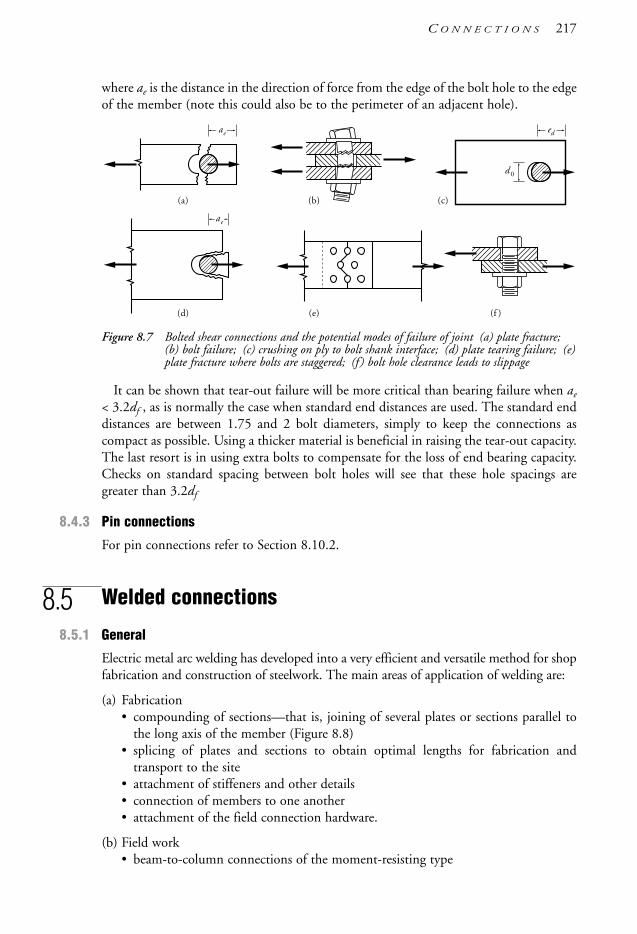
where ae is the distance in the direction of force from the edge of the bolt hole to the edgeof the member (note this could also be to the perimeter of an adjacent hole).
Figure 8.7 Bolted shear connections and the potential modes of failure of joint (a) plate fracture;(b) bolt failure; (c) crushing on ply to bolt shank interface; (d) plate tearing failure; (e)plate fracture where bolts are staggered; (f ) bolt hole clearance leads to slippage
It can be shown that tear-out failure will be more critical than bearing failure when ae
< 3.2df , as is normally the case when standard end distances are used. The standard enddistances are between 1.75 and 2 bolt diameters, simply to keep the connections ascompact as possible. Using a thicker material is beneficial in raising the tear-out capacity.The last resort is in using extra bolts to compensate for the loss of end bearing capacity.Checks on standard spacing between bolt holes will see that these hole spacings aregreater than 3.2df
8.4.3 Pin connections
For pin connections refer to Section 8.10.2.
8.5 Welded connections
8.5.1 General
Electric metal arc welding has developed into a very efficient and versatile method for shopfabrication and construction of steelwork. The main areas of application of welding are:
(a) Fabrication• compounding of sections—that is, joining of several plates or sections parallel to
the long axis of the member (Figure 8.8)• splicing of plates and sections to obtain optimal lengths for fabrication and
transport to the site• attachment of stiffeners and other details• connection of members to one another• attachment of the field connection hardware.
(b) Field work• beam-to-column connections of the moment-resisting type
d0
edae
(a) (b) (c)
(d) (e) (f )
ae
C O N N E C T I O N S 217
1106 SDHB 08 Final 8/6/05 12:09 PM Page 217
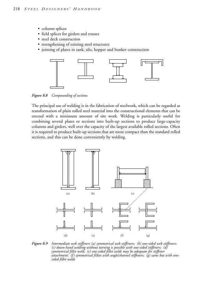
218 S T E E L D E S I G N E R S ’ H A N D B O O K
• column splices• field splices for girders and trusses• steel deck construction• strengthening of existing steel structures• jointing of plates in tank, silo, hopper and bunker construction
Figure 8.8 Compounding of sections
The principal use of welding is in the fabrication of steelwork, which can be regarded astransformation of plain rolled steel material into the constructional elements that can beerected with a minimum amount of site work. Welding is particularly useful forcombining several plates or sections into built-up sections to produce large-capacitycolumns and girders, well over the capacity of the largest available rolled sections. Oftenit is required to produce built-up sections that are more compact than the standard rolledsections, and this can be done conveniently by welding.
Figure 8.9 Intermediate web stiffeners (a) symmetrical web stiffeners; (b) one-sided web stiffeners;(c) down-hand welding without turning is possible with one-sided stiffeners; (d)symmetrical fillet weld; (e) one-sided fillet welds may be adequate for stiffenerattachment; (f ) symmetrical fillets with angle/channel stiffeners; (g) same but with one-sided fillet welds
(d) (e) (f)
(a) (b) (c)
(g)
1106 SDHB 08 Final 8/6/05 12:09 PM Page 218
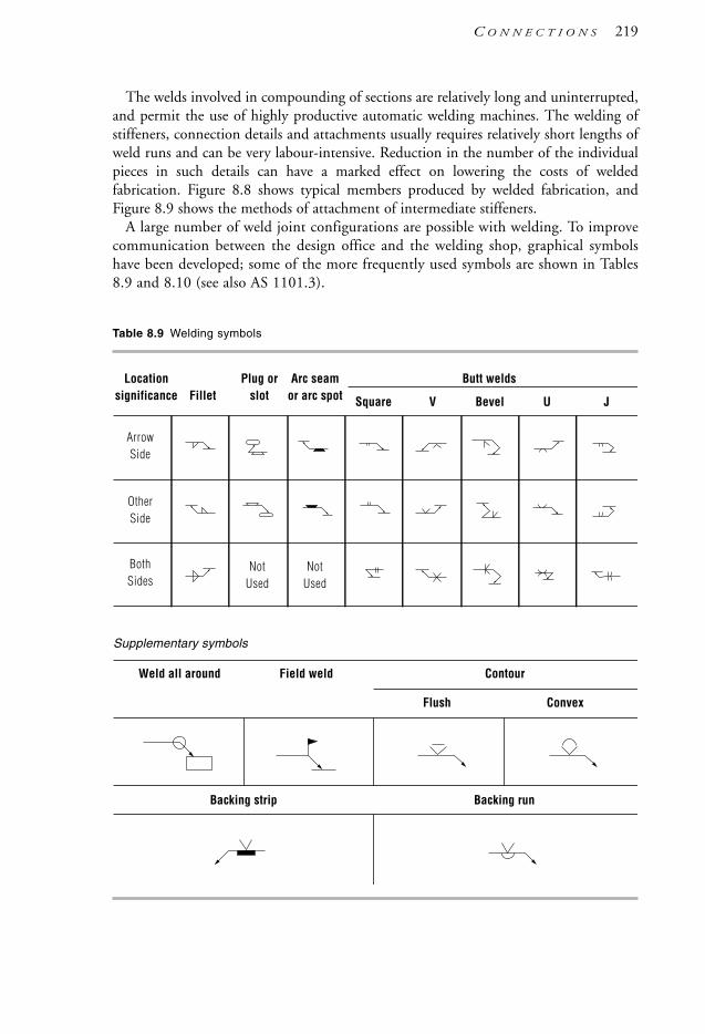
The welds involved in compounding of sections are relatively long and uninterrupted,and permit the use of highly productive automatic welding machines. The welding ofstiffeners, connection details and attachments usually requires relatively short lengths ofweld runs and can be very labour-intensive. Reduction in the number of the individualpieces in such details can have a marked effect on lowering the costs of weldedfabrication. Figure 8.8 shows typical members produced by welded fabrication, andFigure 8.9 shows the methods of attachment of intermediate stiffeners.
A large number of weld joint configurations are possible with welding. To improvecommunication between the design office and the welding shop, graphical symbolshave been developed; some of the more frequently used symbols are shown in Tables8.9 and 8.10 (see also AS 1101.3).
Table 8.9 Welding symbols
Weld all around Field weld Contour
Flush Convex
Backing strip Backing run
Locationsignificance Fillet
Plug orslot
Arc seamor arc spot Square V U JBevel
ArrowSide
OtherSide
BothSides
NotUsed
NotUsed
Supplementary symbols
Butt welds
C O N N E C T I O N S 219
1106 SDHB 08 Final 8/6/05 12:09 PM Page 219

Table 8.10 Examples of use of welding symbols
Continuous, one-sided fillet weld of 6 mm leg size along the length of the line indicated by arrow. Fillet weld is on the arrow side of the joint.
Intermittent 6 mm fillet weld having incremental lengths of 70 mm spaced at 180 mm. Arrow side only.
Staggered intermittent weld as for 4 (both sides).
Butt welds: (d) double bevel; (e) double vee; (f) double U.
As for 3, but the flag indicates that this weld is to be done in the field.
As for 1, but instead of being applied along a line, this weld is to be carried out all around, and this is indicated by a small circle.
Same as for 1, but the weld is on the side opposite to where the arrow points.
Continuous, double-sided fillet weld.
Same as 9(d) but a special procedure is to be used as specified under item 9 of the procedure sheet.
Same as 8(b) but a backing strip is to be used.
Same as 8(b) but the root of the weld is to be gouged and a backing weld run applied.
Square butt weld. No grooves are prepared for this weld (suitable only for thin plates).
Plug weld. Weld is on arrow side of the joint.
Same as 14, but both faces are to be ground flush.
Double-bevel butt weld reinforced with fillet welds for a betterstress dispersion.
Same as 8(b) but weld is to have a convex contour.
Same as 8(b) but weld is to have a flush contour obtained by grinding.
Butt welds: (a) single bevel; (b) single vee; (c) single U.
1
2
3
4
5
6
7
8
9
10
11
12
13
14
15
16
17
18
(a) (b) (c)
(d) (e) (f)
6
9
6
6 70 (110)
6 70 (110)
Symbols Description of weldNo.
220 S T E E L D E S I G N E R S ’ H A N D B O O K
1106 SDHB 08 Final 8/6/05 12:09 PM Page 220

8.5.2 Definition of welding terms
Brittle fracture Sudden fracture of parts in tension without appreciable yield strain. Thecauses of brittle fracture are: first, a low notch toughness of the material at the particularservice temperature or poor impact energy requirement leading to an inability to absorbenergy inputs from impulse or dynamic loads; second, the presence of sharp notches inthe form of cracks, crack-like inclusions, lack of fusion and incomplete penetration.
Butt weld A weld made by depositing weld metal into a groove at the join between thetwo elements being joined. The weld penetration may be through the entire thickness ofthe elements being welded (see Complete/Incomplete penetration butt welds also).
Complete penetration butt weld (CPBW ) A butt weld completely filling the grooves andcompletely fusing all abutting faces.
Compound weld A hybrid weld defined as a fillet weld placed immediately adjacent toa butt weld.
Design throat thickness Applicable to fillet welds and incomplete penetration butt welds,the depth of weld metal for strength calculation purposes. For fillet welds it is theperpendicular distance from the unattached (non-fusion) weld face to the root (corner)of the weld. For incomplete penetration butt welds it is to the depth of the preparation(e.g. the bevel) and is dependent on the angle of bevel/Vee and the welding process used.
Effective length of weld Length of the full-size weld, excluding the end craters.
Effective throat thickness of butt weld For a complete penetration butt weld, this is thethickness of the thinner plate; for an incomplete penetration butt weld, the effectivethroat thickness is taken as the sum of the depths of fused weld metal. (See also Designthroat thickness).
Electrode See Welding consumable.
Fillet weld Welds which generally have a triangular cross-section and are fused on twofaces to the parent metal. Apart from the requirement of a clean surface, these weldstypically require no edge or surface preparation.
Flux, welding A substance used during welding to help clean the fusion surfaces, toreduce oxidation, and to promote floating of slag and impurities to the surface of theweld pool.
Heat-affected zone (HAZ) A narrow zone of the parent metal adjacent to the weld metal;the changes in the grain size and absorption of gases, especially hydrogen, can promotebrittleness in the HAZ.
Incomplete penetration butt weld (IPBW ) A butt weld which, unlike complete penetrationbutt welds, has weld parent metal fusion occuring at less than the total depth of the joint.
Parent metal Metal to be joined by welding.
Penetration Depth of fusion of the weld into the parent metal.
Prequalified weld A term describing a weld procedure (including weld groovepreparation) in accordance with AS/NZS 1554 known to be capable of producingsound welds, without the need for procedural tests, to behave in a manner as assumedin design.
C O N N E C T I O N S 221
1106 SDHB 08 Final 8/6/05 12:09 PM Page 221

Plug weld A weld deposited into a space provided by cutting or drilling a circular holein a plate so that the overlapped plate can be fused.
Slag Fused, non-metallic crust formed over the exposed face of the weld that protectsthe deposited weld metal during cooling.
Slot weld Similar to a plug weld but slot-like in shape.
Weld category See Weld quality.
Weld metal The deposited metal from the electrode or wire (sometimes called weldconsumable) which fuses with the parent metal components to be joined.
Weld preparation Preparation of the fusion faces for welding; such preparation mayconsist of removal of mill scale, grinding of groove faces, cutting of the bevels andaligning of the parts, to obtain correct root gap, etc.
Weld quality A measure of the permitted level of defects present on deposited welds.Weld qualities/categories can generally be either SP (structural purpose) or GP (generalpurpose) and possess a pre-determined capacity reduction factor, φ, for the weld instrength design calculations. See WTIA [2004] for further details on SP and GP welds.
Weldability Term used to describe the ease of producing crack-free welds under normalfabrication conditions. While all steels can be welded by observing the proper proceduresand using the right amount of preheat, it should be realised that the inconvenience ofusing high-preheat temperatures and the constraints imposed by special procedures makecertain types of steel unsuitable for building construction. Steels conforming withAS 1163 (all grades), AS/NZS 3678/3679 (Grades 200, 250, 300 and 350) are weldablewithout the use of preheat, subject to certain limits.
Welding consumable The weld metal in (covered) rod or wire form, prior to beingmelted and deposited as weld metal.
Wire/welding wire See Welding consumable.
8.5.3 Welding processes
A large number of welding processes are available for the joining of metals, but relativelyfew of these are in widespread use in steel fabrication. These are:
(a) Manual metal arc welding (MMAW)Welding consumable: stick electrode with flux coatingShielding medium: Gases and slag generated from flux coatingPower source: generator, transformer or rectifierDeposition rate: lowSuitability: extremely versatile, but low production rates increase the costs of welded fabrication.
(b) Semi-automatic metal arc welding(i) Gas metal arc welding (GMAW)
Welding consumable: solid bare steel wire fed through gunShielding medium: Gas-carbon dioxide (CO2) or CO2 mixed with Argon andOxygen fed through gun
222 S T E E L D E S I G N E R S ’ H A N D B O O K
1106 SDHB 08 Final 8/6/05 12:09 PM Page 222

Power source: DC generatorDeposition rate: highSuitability: most applications, except field welding.
(ii) Flux cored arc welding (FCAW)Welding consumable: hollow steel tubular electrode, filled with flux, fed through gunShielding medium: may be used with or without inert shielding gasPower source: AC transformerDeposition rate: highSuitability: most applications, including field welding, but good access is essential.
(c) Automatic metal arc welding: Submerged arc welding (SAW)Welding consumable: solid steel wire electrode fed through gunShielding medium: granular flux fed through hopper at weld pointPower source: high-output AC transformer or generatorDeposition rate: very highSuitability: best suited for long automated weld runs with excellent access.
(d) Stud welding (SW): special process for instant welding of steel studs (AS/NZS1554.2).
(e) Electroslag welding: special process for welding thick plates and joints capable ofdepositing large volumes of weld metal in one automatic operation.
In terms of cost per kilogram of the deposited weld metal, the most costly weldingprocess is MMAW, followed by GMAW and FCAW, while SAW is potentially the lowest-cost process. However, the choice of the welding process depends on other factors,among which are:• accessibility of the weld runs, and the amount of turning and handling of components
required to complete all welds in a member; the designer can at least partly influencethe decision
• the inventory of the welding equipment held by the fabricator and the availability ofskilled welders and operators
• the general standard established by the particular welding shop in achieving weldpreparations and fitting tolerances
• the type of steel used for the structure and thickness of the plates• the maximum defect tolerances permitted by specification.
The fabricator’s welding engineer is the best-qualified person for choosing the optimalwelding procedures to be used in order to produce welds of specified quality within otherconstraints. As far as the designer is concerned, it is the performance of the welds in thefinished structure that is of primary concern, and the designer’s safeguards are mainly inthe inspection of welds.
8.5.4 Strength of welded joints
The term ‘welded joint’ embraces the weld metal and the parent metal adjoining theweld. A welded joint may fail in one of the following modes:• ductile fracture at a nominal stress in the vicinity of the ultimate strength of the weld
metal or the parent metal, whichever is the lower
C O N N E C T I O N S 223
1106 SDHB 08 Final 8/6/05 12:09 PM Page 223
• brittle fracture at a nominal stress lower than ultimate strength and sometimes lowerthan the working stress
• progressive fracturing by fatigue after a certain number of stress cycles• other causes such as corrosion, corrosion fatigue, stress corrosion and creep, but these
are relatively rare in steel structures.
The design objective of welded joints is to ensure that failure can occur only in a ductilemode and only after considerable yielding has taken place. This is particularly important,considering that yielding often occurs in many sections of a steel structure at, or below,the working loads as a result of the ever-present residual stresses and unintentional stressconcentrations. Welded joints must be capable of undergoing a large amount of strain(of the order of 0.5%–1.0% preferably) without brittle fracture. To achieve this, thefollowing factors must be controlled:
(a) The parent material must be ductile, or notch-tough, at the service temperatureintended and for the thickness required
(b) The details of joints must be such that stress concentrations are minimised
(c) Reduction of ductility by triaxial stressing should be avoided at critical joints
(d) Weld defects should be below the specified maximum size
(e) Welded fabrication should not substantially alter material properties.
A welded structure made of Grade 300 steel having a Charpy V-notch impact energyvalue of at least 27 joules at the intended service temperature, and with a reasonablecontrol over factors (b) and (e), will most likely behave in a ductile manner if loadedpredominantly by static loads. Most building structures and industrial structuresconstructed during the past four decades have performed satisfactorily where theycomplied with these limitations.
Special-quality welding and special care in material selection and detailing are requiredfor earthquake-resistant structures and structures subjected to fatigue and/or low servicetemperatures. Further information on these areas can be found in WTIA [2004].
The degree of care in preserving the ductile behaviour of the members and partsstressed in tension increases where the following factors occur: medium- and high-strength steels, thick plates and sections, complex welded joints, low temperatures,dynamic and impulse loads, metallurgical inclusions and welding defects. Impact testingof the materials to be used and procedural testing of the weldments are essential insafeguarding ductility.
8.5.5 Specification and validation of welded construction
The specification embraces the working drawings and written technical requirementscontaining complete instructions for welded fabrication and erection, including thepermissible tolerances and defect sizes. The term ‘validation’ applies to a multitude ofsafeguards necessary to ensure that the intentions of the design (assumed to be fullyspecified) have been realised in the completed structure. The purpose of the specificationis to communicate to the firm responsible for fabrication and erection all the geometricaland technical requirements for the particular project, and should include at least thefollowing information.
224 S T E E L D E S I G N E R S ’ H A N D B O O K
1106 SDHB 08 Final 8/6/05 12:09 PM Page 224

On the working drawings:
(a) plans, sections and general details describing the whole structure
(b) the types and the sizes of all welds
(c) any special dressing of the exposed weld surfaces by grinding, etc.
(d) the minimum tensile strength of the welding electrodes, where more than onestrength is used
(e) the class of welding: GP, SP or special-quality welding
(f ) special welding sequences, and weld groove preparations where these are critical fordesign
(g) identification of the critical joints that will be subject to radiographic and/orultrasonic inspection
(h) the relevant welding Standard (e.g. AS/NZS 1554.1, etc.).
In the technical requirements (specification):
(a) the chemical and the physical requirements for the steel sections and plates (this isgenerally done by specific reference to material Standards)
(b) the weld defect tolerances for each of the classes of the welds used
(c) alignment and straightness tolerances for welded joints
(d) special post-weld treatment of welds by peening, post-weld heat treatment, and thelike, where required by design
(e) the nature, type and frequency of welding prequalification procedures and inspections
(f ) whether the personnel involved in welding would be subjected to testing of anyparticular kind
(g) the type and frequency of non-destructive testing: visual, magnetic particle,radiographic, ultrasonic or other
(h) the type and frequency of material testing for physical validation of the welded joints
(i) other requirements, such as the use of low-hydrogen electrodes for manual metal arcwelding, or the minimum preheating of the material prior to welding aimed atreducing the risk of cracking.
Items (b) to (i) in the technical specification may be covered by appropriate referencesto the welding Standard (e.g. AS/NZS 1554.1, etc.).
The specification has probably a greater impact on the economy of weldedconstruction than all other considerations, mainly because of the various clauses coveringthe quality of workmanship and defect tolerances. The designer would ideally prefer thehighest standards of workmanship to achieve a virtually defect-free weld. This may betechnologically possible, but the cost of achieving such a goal would be prohibitive. Theonly practical solution is to specify weld defect tolerances and to introduce several weld-quality categories for the designer to choose from.
C O N N E C T I O N S 225
1106 SDHB 08 Final 8/6/05 12:09 PM Page 225

AS/NZS 1554.1 provides for two weld categories. Weld category SP is intended to beused for relatively high-stressed welds, and category GP for low-stressed and non-structural welds. Valuable guidance for correct choice may be found in Technical Note 11(WTIA [2004]). From the designer’s viewpoint, the validation of welds, or qualityassurance, is particularly important so that the assumptions made in the calculations ofstrength of the structure can be verified. There are three stages in validation:
(a) Setting-up stage: selection of materials, welding electrodes and other weldingconsumables, procedural tests, testing of welders.
(b) Working stage: checking of the preparations for the weld grooves and fusion faces,preheat temperatures, slag removal, soundness of each weld run in a multi-run weld,the weld contour, and other defects capable of visual inspection.
(c) Post-weld stage: detection of defects that can reduce the strength of the structurebelow the acceptable limits using visual and other non-destructive techniques.
All three stages may be involved on critical projects where it is essential to set up an earlywarning system so that any problems detected in the shop can be resolved by prompt actionwithout waiting for the final validation. On less critical projects, especially where staticloads predominate and brittle fracture is not a serious threat, stage (c) may be sufficient.
The frequency of testing, or the percentage of the total length of weld to be examined,depends on many factors, such as:• the nature of the load (static or dynamic) and stress level• the consequences of the risk of failure• the susceptibility of the weld type to welding defects (butt welds are more prone to
cracking than fillet welds)• the susceptibility of the specified steel to cracks• the standard of workmanship in the particular welding shop.
8.5.6 Selection of weld type
Welded joints may be divided into butt splices, lap splices, T-joints, cruciform and cornerjoints. For each of these joints there is a choice of three main types of welds: butt, filletor compound. Figure 8.10 notes some useful information on joint (butt splices andT-joints shown) and weld types (butt welds shown).
From purely strength considerations, butt joints are preferable. However, the carerequired in preparing the plates for welding plus carrying out the welding makes thesewelds relatively costly. Fillet welds, in contrast, require only minimal weld preparationsand are more straightforward in execution, therefore less costly. Of course, from thestructural point of view, fillet welds are inferior to butt welds because they substantiallyalter the flow of stress trajectories, and this becomes a serious drawback in welded jointssubject to fatigue.
Compound welds consisting of a butt and a fillet weld are often used to provide asmoother transition. This is often done to reduce the stress concentrations at the corners.The choice of the weld groove type for butt welds is a matter of economy and reductionof distortion during welding. Butt welds of the double-vee, double-J and U type haveconsiderably less weld metal than bevel butts and therefore require less labour andwelding consumables for their execution.
226 S T E E L D E S I G N E R S ’ H A N D B O O K
1106 SDHB 08 Final 8/6/05 12:09 PM Page 226

Figure 8.10 Weld preparations and weld configurations for manually welded butt splices and T-joints: (a) single bevel and single vee with backing run; (b) single bevel and singlevee with backing strip; (c) double bevel and double vee, and; (d) double J and double U
8.5.7 Avoidance of lamellar tearing
Care is needed in detailing welded joints of the T and corner type, where restrained weldshrinkage forces are transmitted through the weld into a plate in the through-thicknessdirection, as shown in Figure 8.11. The tensile strength in the through-thicknessdirection of a relatively thick plate, say over 20 mm, is lower than the tensile strength inthe plane of the plate. The reduction in strength has been attributed to non-metallicinclusions produced during the plate rolling process. Modern steels are manufacturedwith greater care and exhibit good through-thickness properties. Nevertheless, it isadvisable when detailing welded joints in thick plates to avoid details that in the pasthave led to lamellar tearing. Figure 8.11 shows some acceptable and unacceptable jointtypes. Fabrication shops can play an important role in combating this problem by usingsuitable welding procedures. For critical joints involving plates more than 30 mm thick,the designer may consider specifying the use of through-thickness ultrasonically scannedplates. The scanning is carried out by the steelmaker (and a price surcharge applies).
8.5.8 Economy in detailing welded connections
The principal aim in detailing connections is to achieve the lowest-cost connectionhaving an adequate strength and performance in service. The main cost components arematerial and labour, the latter being predominant. AISC [1997] and Watson et al. [1996]provide some useful information and guidance in this regard.
Material savings can be achieved by:• reduction in the number of parts making up a connection
45°
60°30°min
45°min
30°min
max 2
min 8min 8
min 4
max 4
45°
45°min
45°min
60°min
2–4
2–4 2–4
2–4
2–4
max 2
2–42–4 Backing
run Backingstrip
3 max3 max
3 max2max
(a)
(c)
(b)
(d)
C O N N E C T I O N S 227
1106 SDHB 08 Final 8/6/05 12:09 PM Page 227

• reduction in the volume of the deposited weld metal by choosing efficient weld typesand weld groove shapes.
Figure 8.11 Detailing of weldments to avoid lamellar tearing (a, h) should be avoided if at allpossible; (b) better details; (c, f ) sometimes susceptible to lamellar tearing;(d, e, g, i) safe detail. Note: For modern steels, the above may mainly apply for thick tovery thick “plate” elements.
Labour cost savings from these measures can be further enhanced by:• standardisation of connections• simplicity of the detail• symmetrical arrangement of detail• good access for welding and inspection• realistic specification that matches the class of welding and inspection to the required
performance• using fillet welds in preference to butt welds, except where there are specific design
reasons to the contrary• avoiding the use of unnecessarily large sizes of fillet welds.
In statically loaded structures not subject to low service temperatures, fillet welds can besuccessfully used for most joints and details, except for flange and web splices without endplates. It is desirable to leave some freedom of choice for longitudinal welds (such as web-
Lamellar tear
Lamellar tears
Small gap
Bolted webconnection
3
1
12
2
1
2 3
(a)
(c)
(f ) (g) (h) (i)
(d) (e)
(b)Lamellar tear Small gap
228 S T E E L D E S I G N E R S ’ H A N D B O O K
1106 SDHB 08 Final 8/6/05 12:09 PM Page 228

to-flange joints) to the fabricator, who may be well equipped to use deep-penetrationfillets instead of normal fillets.
Detailing of joints subject to fatigue or other special circumstances requires a differentapproach, because strength considerations become much more important than economyin terms of the capital cost only. In such instances, fillet welds are avoided as far aspossible because they cause stress concentrations and reduce the fatigue life of the joint.Detailing in general must be done with more care, so that abrupt changes in thickness ordirection are completely avoided.
8.6 Types of welded joints
8.6.1 Butt welds
The principal advantages of butt welds are the simplicity of the joint and the minimalchange of the stress path. Static tension test results indicate that their average tensilestrength is practically the same as that of the base metal, provided that the weld is free ofsignificant imperfections and its contour is satisfactory. The disadvantage of butt weldsis that they require expensive plate edge preparation and great care in following thecorrect welding procedures. Butt welds may be classed as complete penetration orincomplete penetration (see Section 8.5.2 for a definition of these weld types). Thefollowing applications are usually encountered:
(a) Butt welds subject to a static tensile force: Complete penetration butt welds (CPBW)with convex contour are the best choice. Single-bevel or V-joints prepared for down-hand welding keep the welding costs low, but distortion needs to be kept undercontrol.
(b) Butt welds subject to a static compressive force: Because the stresses in compressionmembers are usually reduced by buckling and bearing considerations, these welds canbe incomplete penetration butt welds (IPBW) designed to carry the load.
(c) Butt welds subject to an alternating or fluctuating tensile stress with more than0.5 × 104 repetitions during the design life (fatigue): CPBW with flush contours anda very low level of weld imperfections are essential in this application.
(d) As for (c) but carrying a predominantly compressive force: CPBW with convexcontour and good-quality welding are sufficient.
(e) Butt welds subject to shear forces: These welds are less sensitive to the shape and formof the weld contour and to weld imperfections. Often, it is satisfactory to use IPBW.
The use of IPBW is subject to certain limitations, as specified in Clause 9.7.2 ofAS 4100. Typical uses of IPBW are seen in:
(a) Longitudinal welds connecting several plates or sections to form a welded plate girder,a box girder or column and similar, especially when thick plates are used and thestresses in the welds are too low to require a complete-penetration weld. One exceptionis in structures or members subjected to fatigue, where these welds are not permitted,for example in bridges, crane bridges, and certain machinery support structures.
C O N N E C T I O N S 229
1106 SDHB 08 Final 8/6/05 12:09 PM Page 229

(b) Transverse welds to column splices or to column base plates, where axial forces aretoo low to warrant the use of a CPBW, or are milled for contact bearing so that theweld acts only as a positioning device, but providing that the columns are not subjectto tension other than that due to wind loads.
The strength of butt welds can be affected by weld imperfections, causing stressconcentrations and reduction in the cross-sectional area. The reduction in strength isparticularly severe in welded joints subjected to fatigue. Figure 8.12 illustrates some of theweld imperfections: namely, undercut, over-reinforcement, notch effect caused by lack ofgradual transition from the thicker to the thinner material, slag inclusions, gas pockets(porosity) and incomplete fusion. No cracks in the weld metal/HAZ can be tolerated.
Figure 8.12 Weld defects in butt welds and how they influence (the position of ) potential fracture
Figure 8.13 shows typical preparations of plates for manually deposited butt welds.The choice of preparation depends on economy and the need to control weldingdistortions. Double-V and U butt welds use less weld metal, and this can be a greatadvantage with thick plates.
Figure 8.13 Plate edge preparations for complete penetration butt welds (CPBW)(except for (g)and(h)): (a) single vee butt; (b) single vee butt with backing bar; (c) bevel at T-joint; (d)bevel at T-joint with backing bar; (e) double vee butt; (f ) U butt; (g)single veepreparation for incomplete penetration butt welds (IPBW), and (h) double veepreparation for IPBW. [Note: DTT = design throat thickness of IPBW].
IPBW produced by automated arc processes may possess deep penetration welds that cantransmit loads that are higher than the more manual processes. Subject to the workshopdemonstration of production welds, Clause 9.7.2.3(b)(iii) of AS 4100 permits the extrapenetration to be added to the weld design throat thickness in this instance.
(a) (b) (c) (d)
(e) ( f ) (h)(g)
DTT DTT
DTT
Undercut Over-reinforcement Notch
WRONGTransition
RIGHTTransition
Slag inclusionsIncomplete fusion 1–3 (4 for fatigue)
1Gas pockets
230 S T E E L D E S I G N E R S ’ H A N D B O O K
1106 SDHB 08 Final 8/6/05 12:09 PM Page 230

8.6.2 Fillet welds
The advantages and disadvantages of fillet welds can be stated in the following way:
(a) From the cost of fabrication perspective, fillet welds have an advantage over buttwelds for the same force transmitted. This is mainly due to the absence of platebevelling, which adds to the cost of weld preparation and fit-up required for buttjoints. Also, the speed of welding, including all phases of preparation, is faster thanfor butt welds. For these reasons fillet welds are used to a much greater extent thanbutt welds for leg sizes smaller than 10 mm.
(b) As far as the distribution of stresses in welds are concerned, fillet welds are inferior tobutt welds. The stress path through a side weld in a lap joint is not a direct one, andstress concentrations are always present; the same can be said for a fillet-weldedT-joint or a cruciform joint. This is not a deterrent where the forces arepredominantly static, as is the case with most building structures, as long as thedesign is carried out in accordance with established practice (see Figure 8.14).
Figure 8.14 Types of welds and stress trajectories (a) transverse butt welds; (b) longitudinal andtransverse fillet welds; (c) intermittent fillet welds; (d) plug and slot welds
fv
fv
Potentialfracture
(a)
(b)
(c)(d)
Intermittentfillet weld Slot weld Plug weld
C O N N E C T I O N S 231
1106 SDHB 08 Final 8/6/05 12:09 PM Page 231

(c) From the point of view of resistance to fatigue, fillet welds are inferior to butt welds.This is because there exists both an abrupt change in the direction of the stresstrajectory and a notch-like effect at the root of the fillet weld. This results in stressconcentrations and a triaxial stress state, and can lead to brittle fracture when theweldment is subjected to a large number of load cycles (fatigue failure).
The main uses of fillet welds are:
(a) For lap splices. The transfer of force from one plate to another is through shear in theweld. Fillet welds can be arranged to be parallel with the member axial force(longitudinal welds) or at right angles to it (transverse welds), or a combination ofboth.
(b) For T-joints. The two modes of transfer of forces are: compression or tension andshear through weld.
(c) For corner joints similar to T-joints.
(d) For structural plug and slot welds. Non-structural plug welds are permitted to befilled in flush with the surface of the plate, but such welds are rarely sound and theycontain many cracks. Fillet welds run around the periphery of the hole can reliablybe used to transmit the forces.
Where the forces transmitted by fillet welds are relatively small and the structure is notexposed to weather, it may be advantageous to use intermittent welds. Their benefitsinclude using less filler metal and causing less distortion during welding. They may notshow cost savings, however, because of frequent stop–start operations.
The inspection of fillet welds can usually be specified to include inspection during thepreparation of material, fit-up and actual welding. Typical weld defects found in filletwelds are shown in Figure 8.15 as well as design concepts and terminology. Inspectionmust, of course, ascertain that the leg size and weld length specified in the design havebeen achieved.
Figure 8.15 Fillet welds: (a) typical defects, and; (b) concepts and terminology.
The fact that the strength of fillet welds has a direct relationship to the nominal tensilestrength of the weld consumable used leads to the necessity of specifying on the drawings
Effect ive leg
Root gap
Apparent leg
Idea l weldcontour
Weldtoe
ThroatThickness t 1
Depth of penetrat ion
Over lap
Undercut
Excess ive convexi ty
Excess iveconcavi ty
Excess iveroot gap
Lack offus ion
(a)Des ign
Weld root
Theoret ica lfa i lureplane
Weldpenetrat ion
Theoret ica l weld shape( i sosce les t r iangle)
Leg length(b)
232 S T E E L D E S I G N E R S ’ H A N D B O O K
1106 SDHB 08 Final 8/6/05 12:09 PM Page 232

not only the physical weld size but also the type of weld consumable to be used, especiallywhen E48XX/W50X or higher-grade weld consumables have been assumed in the design.
Fillet welds produced by submerged arc welding will have a deep penetration into theroot area, which is beneficial because a larger throat thickness is obtained; thus, for the sameleg length, deep-penetration fillet welds will carry larger forces per unit length than manualwelds. In order to increase the economy of welding, this type of deep penetration weldshould be specified by the throat thickness rather than leg length, and the effective throatthickness calculated as a sum of 71% of the leg length plus 85% of the depth of penetration(Clause 9.7.3.4 of AS 4100). For this to occur, procedural tests are required to demonstratethat the specified weld dimensions have been achieved in the welding workshop.
8.6.3 Compound welds
A compound weld is considered to be a hybrid of a fillet and butt weld—i.e. bydefinition in AS 1101.3, the former weld type is superimposed onto the latter.
The design throat thickness (DTT) of a compound weld depends on whether there isa complete penetration butt weld (CPBW) or an incomplete penetration butt weld(IPBW) present. That is for a compound weld with:
• CPBW—the DTT is the size of the butt weld without reinforcement, and for;• IPBW—the DTT is the shortest distance from the root of the IPBW to the face of the
fillet weld.
Figure 9.7.5.2 of AS 4100 explains the compound weld configuration and the evaluationof the DTT.
8.7 Structural design of simple welds
8.7.1 Butt welds
8.7.1.1 GeneralButt welds can be regarded as being integral to the parent metal, with the limiting stressesapplicable to the parent metal also applying to the welds. As noted in Section 8.6.1, buttwelds can be broadly split into two groups—complete penetration butt welds andincomplete penetration butt welds. This is not only due to the depth of weld fusionthrough the parent metal thickness but also in the methods used to assess their respectivedesign capacities.
8.7.1.2 Complete penetration butt welds (CPBW)Clause 9.7.2.7(a) of AS 4100 notes that the design capacity of a CPBW is equal to thenominal capacity of the weakest part being joined multiplied by a capacity reductionfactor, φ, which is commensurate with the weld quality. From Table 3.4 of AS 4100,φ = 0.9 for CPBW with SP quality and φ = 0.6 for CPBW with GP quality. Thisapplies to CBPW subject to transverse and shear loads.
Based on the above, for two similar plates joined by a CPBW with SP quality (φ = 0.9)welded to AS/NZS 1554.1 or AS/NZS 1554.5, the AS 4100 definition notes that the
C O N N E C T I O N S 233
1106 SDHB 08 Final 8/6/05 12:09 PM Page 233

weld is as strong as the joined plate elements and no further calculation is required (if theplates have been already sized for the design loads). If the lower quality GP category isused instead of the SP category for this connection type (i.e. with φ = 0.6), the CPBWwill have a lower design capacity than each of the two similar connected plates by a factorof (0.6/0.9=) 0.667.
8.7.1.3 Incomplete penetration butt welds (IPBW)As the weld fusion in a IPBW does not cover the full depth of the joint, Clause 9.7.2.7(b)of AS 4100 states that IPBW are to be designed as fillet welds (see Section 8.7.2). Thedesign throat thickness for IPBW are noted in Clause 9.7.2.3(b) of AS 4100, Section8.6.1 of this Handbook and shown typically in Figure 8.13(g) and (h). The capacityreduction factor, φ, for IPBW is also the same as that for fillet welds.
8.7.2 Fillet welds
Stress distribution in a fillet weld is extremely complex, and certain simplifyingassumptions are necessary to facilitate the design. The usual assumptions are:
(a) The failure plane intersects the root of the fillet and has an inclination such that it isat right angles to the hypotenuse of the theoretical weld shape of a 90-degree isoscelestriangle (with the corner at the 90-degree angle being regarded as the weld root). SeeFigure 8.15(b).
(b) The stresses (normal and shear) on this failure plane are uniformly distributed.
The above assumptions become quite realistic at the ultimate limit state of the weld asplastic deformations take place. In general, the resultant forces acting on the failure planemay be composed of:• shear force parallel to the weld longitudinal axis• shear force perpendicular to the weld longitudinal axis and in the theoretical failure
plane (Figure 8.15(b))• normal force (compressive or tensile) to the theoretical plane (Figure 8.15(b)).
Clause 9.7.3.10 of AS 4100 provides a method for evaluating the design capacity ofsingle fillet welds. The method is based on the premise that the capacity of a fillet weldis determined by the nominal shear capacity across the weld throat/failure plane (Figure8.15(b)) such that:
vw = nominal capacity of a fillet weld per unit length
= 0.6fuwttkr
wherefuw = nominal tensile strength of the weld metal
tt = design throat thickness (see Figure 8.15(b), for equal leg fillet welds, tt is equal to tw 2 where tw = the fillet weld leg length)
kr = reduction factor to account for welded lap connection length (lw)
= 1.0 for lw 1.7 m
= 1.10 – 0.06lw for 1.7 lw 8.0 m
= 0.62 for lw 8.0 m
234 S T E E L D E S I G N E R S ’ H A N D B O O K
1106 SDHB 08 Final 8/6/05 12:09 PM Page 234

C O N N E C T I O N S 235
The typical nominal tensile strengths, fuw , used by the Australian/NZ steel constructionindustry are 410 MPa (i.e. E41XX/W40X) and 480 MPa (E48XX/W50X). The designthroat thickness of a equal-leg fillet weld is taken as 2 times the leg length (seeFigure 8.15(b)).
The reduction factor, kr , accounts for non-uniform shear flows that occur for longlengths of longitudinal welds in lap connections. Note this weld length must be greaterthan 1.7 m for the reduction factor to “kick-in”—hence kr = 1.0 is generally used. Thefillet weld is considered adequate if:
v* φvw
where, from Table 8.12, φ is either 0.8 (for SP quality welds) or 0.6 (for GP quality welds)or 0.7 (for SP category longitudinal welds to RHS with t 3mm) and v* is the design forceper unit length of weld. Note that, unlike other design Standards, this “force” is taken asthe vector resultant of all the forces acting on the fillet weld and, hence, it is independentof direction of force. Values of φvw for typical fillet weld sizes are listed in Table 8.11.
As noted in Section 8.7.1.3, the design capacity of an incomplete penetration buttweld is determined in the same manner as for fillet welds. In this instance, vw is calculatedwith kr = 1.0 and tt can be evaluated by Clause 9.7.2.3(b) of AS 4100.
The minimum leg size of a fillet weld is governed by the thickness of the thinnest platejoined. The limitation is due to the difficulties in obtaining a sound weld if the platethickness is much larger than the weld size.
It is not uncommon in the fabrication shop to set the plates slightly apart so as toobtain a small gap, which helps with control of weld shrinkage stresses. Gaps can alsooccur because of poor fit-up. When this occurs, the fillet leg size must be increased bythe gap width, otherwise the effective throat thickness will be reduced.
Table 8.11 Design capacities of equal-leg fillet welds (in kN per 1 mm weld length)
Leg size SP welds GP welds Notetw (mm) E41 E48 E41 E48
3 0.417 0.489 0.313 0.367 E4 0.557 0.652 0.417 0.489 E5 0.696 0.815 0.522 0.611 E6 0.835 0.978 0.626 0.733 P8 1.11 1.30 0.835 0.978 P10 1.39 1.63 1.04 1.22 S12 1.67 1.96 1.25 1.47 S
Notes: 1. E = economy size for welds carrying relatively small forces; P = preferred sizes, single-pass welds; S = special sizes for transmission of large forces where multi-pass welding is unavoidable.
2. E41 refers to E41XX/W40X (with fuw = 410 MPa) and E48 refers to E48XX/W50X (with fuw = 480 MPa)welding consumables.
3. For SP longitudinal fillet welds to RHS with t 3 mm, multiply the listed SP design capacities by 0.875(= 0.7/0.8) which is due to the differing capacity reduction factor for this type of parent material weld.
8.7.3 Compound welds
As noted in Clause 9.7.5.3 of AS 4100, the strength limit state design of compoundwelds shall satisfy the strength requirements of a butt weld (Section 8.7.1).
1106 SDHB 08 Final 8/6/05 12:09 PM Page 235

8.8 Analysis of weld groups
8.8.1 General
Analysis of weld groups is greatly simplified when the following assumptions are made:
(a) The welds are regarded as homogeneous, isotropic and elastic elements.
(b) The parts connected by welding are assumed to be rigid, but this assumption shouldnot be made if there is doubt about the rigidity of adjoining plates.
(c) The effects of residual stresses, stress concentration and triaxial stress conditions areneglected on the assumption that the ultimate strength of weld groups is notsignificantly affected by these parameters.
Table 8.12 Capacity reduction factors, φ, for welds
Weld categoryType of weld SP GP
Complete-penetration butt welds 0.90 0.60
Longitudinal fillet welds in RHS tubes (t 3.0 mm) 0.70 NA
Other fillet welds, incomplete-penetration butt welds and weld groups 0.80 0.60
Note: NA stands for not applicable.
8.8.2 Weld groups subject to in-plane actions
The following assumptions are made.
Figure 8.16 Weld group loaded by in-plane actions: (a) Geometry and resolved actions aboutcentroid, and; (b) initial in-plane actions.
The plate elements being joined by fillet welds behave rigidly in the plane of the weldgroup. Design actions (V *
x , V *y , M
*z ) applied away from the centroid of the weld group
(Figure 8.16(b)) may be treated as being applied at the centroid plus moments(Figure 8.16(a)) with forces V *
x ,V *y and resolved moment (using the sign convention in
Figure 8.16):
M *o = Σ(V *
x ey + V *y ex ) − M *
z
The procedure for the analysis and design of weld groups subject to in-plane loadingsis similar to that encountered for bolt groups loaded under the same conditions. Themethod follows the detailed proofs and outcomes from Hogan & Thomas [1994]. The
M*ey
oV*x
y
M*z
ex
yV* V*
(a) (b)
= weld groupcentroid
xV*
236 S T E E L D E S I G N E R S ’ H A N D B O O K
1106 SDHB 08 Final 8/6/05 12:09 PM Page 236

resultant force per unit length, v*res, at the most critically loaded part of the weld group
subject to in-plane forces and eccentric moment is:
v*res = [(v*
x )2+ (v*y )2]
where forces in the welds, per unit length, are:
v*x =
Vlw
*x
− MIw
*o
p
ys
v*y =
Vlw
*y
+ MIw
*o
p
xs
where xs and ys are the for the weld segment farthest from the centroid of the weld group,lw the total length of the weld in the weld group, and the polar second moment of areaof the weld group is:
Iwp = Σ(xs2ds + ys
2ds)
xs and ys are the coordinates of a weld segment, and ds is its length, thus:
lw = Σds
8.8.3 Weld groups subject to out-of-plane actions
The analysis for out-of-plane actions on a weld group uses the same assumptions asadopted for in-plane actions. The results for rigid plate elements are similar to those ofthe in-plane actions. Should the transverse plate element be flexible, it will be necessaryto neglect forces in welds in the flexible parts of the transverse plate element.
Allowing for coordinate axis changes from those in in-plane actions, the out-of-planeactions about the weld group centroid are the forces, V *
y and V *z (see Figure 8.17), and
the resolved moment:
M *o = Σ (V *
y ez + V *z ey ) − M *
x
In many situations, V *z , ey and M *
x are taken as zero. Generally, the resultant force perunit length, v*
res , at the most critically loaded part of the weld group subject to out-of-plane forces and eccentric moment is:
v*res = (vy
* )2 (v*z )2
where forces in the welds, per unit length, are:
vy* =
Vlw
y*
v*z =
Vlw
*z
+ MIw
*o
x
ys
where ys is for the weld segment farthest from the centroid of the weld group, lw the totallength of the weld in the weld group and the second moment of area about the x-axis ofthe weld group is:
Iwx = Σys2ds
C O N N E C T I O N S 237
1106 SDHB 08 Final 8/6/05 12:09 PM Page 237

ys is the coordinate of a weld segment, and ds is its length, thus:
lw = Σds
Figure 8.17 Weld group with out-of-plane actions.
Figure 8.18 Alternative procedure for weld group loaded out-of-plane
A simpler alternative method to is break the weld group up into sub-groups based on themost significant form of loading seen by the sub-group. A case in point is where the weldgroup follows the perimeter of an I-section. The welds around the flanges are assumed toresist the full bending moment and the welds about the web resist the total shear force(see Figure 8.18). It is assumed that the fillet welds are ductile enough to allow someredistribution of internal forces. The method is executed as such:
N *w = flange forces (separated by a distance d2 between flange
centroids)
= Md2
*o
The flange fillet welds then each resist the out-of-plane force N *w which is assumed to be
uniformly distributed, i.e.
N *w φvvf lwf
whereφvvf = design capacity of flange fillet welds per unit weld length
(Section 8.7.2 and Table 8.11)
lwf = perimeter length of each flange fillet weld
The web fillet weld sub-group is assessed in the same manner by:
V *z φvvw lww
N*
d2
M* o
o
w
d2
N*w
V*z
N*M* w
d1
zV*
zV*xM*
weld group centroid
ez
yV*
238 S T E E L D E S I G N E R S ’ H A N D B O O K
1106 SDHB 08 Final 8/6/05 12:09 PM Page 238

whereφvvw = design capacity of web fillet welds per unit weld length (Section
8.7.2 and Table 8.11)
lww = perimeter length of web fillet welds
= 2d1
Light truss webs are often composed of angles, being either single or double members.The balanced detailing of connections is important and, ideally, should be done so thatthe centroid of the connection is somewhat coincident with the centroidal line of theconnected member (see Figure 8.19). However, as noted in Section 7.5.4, much researchhas been done to indicate that balanced connections are not required for statically (andquasi-statically) loaded structures as there is no significant decrease of connectioncapacity for small eccentricities. However, balanced connections are considered to begood detailing practice for connections in dynamically loaded applications subject tofatigue design.
Figure 8.19 Balanced connections: Truss diagonal to chord connection
8.8.4 Combined in-plane & out-of-plane actions
Occasionally, welded connections are subjected to triaxial loadings. The general methoddescribed in Sections 8.8.2 and 8.8.3 can readily be adapted to deal with simultaneousapplication of in-plane and out-of-plane forces (see also Hogan & Thomas [1994]).
8.9 Design of connections as a whole
8.9.1 Design and detailing
8.9.1.1 GeneralDesigning a connection as a whole means designing the part of the member beingconnected, the corresponding part of the other member or support, intermediatecomponents as plates/gussets/brackets and the fasteners transferring the forces. Oftenother members connect to the same node, and so they have to be integrated into thenode. The art of detailing connections and nodes is to use the simplicity and directnessof force transfer. The tendency to excessive stiffening should be resisted in the interest ofeconomy. Using slightly thicker material can produce an adequately strong connection ata lower cost.
Balanced Unbalanced
C O N N E C T I O N S 239
1106 SDHB 08 Final 8/6/05 12:09 PM Page 239

The connection as a whole needs to be checked for strength and serviceability limitstates. Careful attention should be paid to the trajectory of forces all the way from theconnected member to the member being connected.
In detailing connections it is important to preserve the designer’s intent with respectto the connection rigidity. If a pinned connection is intended, it should be detailed torotate freely or at least to offer only minimal resistance to rotation. However, if a fixedconnection was assumed in the analysis, then it should be detailed so as to offer adequatestiffness to resist joint rotation.
Figure 8.20 Design of welded moment connections: (a) geometrical dimensions; (b) forces incolumn web and in stiffener plates (two beam connection shown but can be used forsingle beam connections)
The design of a rigid welded connection (e.g. multi-storey beam to column connectionor portal frame knee connection) is outlined here as an example. The connection detailshown in Figure 8.20 indicates the design action effects involved. Failure modes of theconnection of this type (to name a few) are:• weld failure, at beam flanges and web• column web crushing failure (web yield)• column web fracture (upper flange area)• column web shear buckling failure• column web compressive buckling.
The procedure for verifiying the connection capacity is as follows.
8.9.1.2 Beam flange weld capacityUsing a simple procedure, it is assumed that the flange butt welds (CPBW) alone resistall of the bending moment (Figure 8.20(a)):
N *w =
Md2
*
dp
V'u Vu Vus
t f b
k c
twc
A f
A f
Vu
dc
L1
Pst
Pst
M*
H1
Vu
H2
(a) (b)
tfc
V*
M*
tfb
d2 d12 1M*
2V* V*1
brc
240 S T E E L D E S I G N E R S ’ H A N D B O O K
1106 SDHB 08 Final 8/6/05 12:09 PM Page 240

C O N N E C T I O N S 241
where d2 is the mid-flange to mid-flange distance. As explained in Section 8.7.1.2 thenominal butt weld capacity is then:
Nw = fy f A f
where fyf is the flange design yield stress and Af is the area of one flange. For final checkwith φ = 0.9 for SP quality welds:
Nw* φNw
It should be noted that if this inequality is not satisfied then a total member check shouldbe undertaken. Alternatively, if it is more than satisfied, then IPBW or continuous filletwelds should be considered.
8.9.1.3 Beam web weld capacityAgain using simple theory, the two web fillet welds carry all the shear force but no moment:
Vw = 2vww d1 tt = 2 × (0.6fuw tt kr )d1tt
whereVw = nominal capacity of the web fillet weld groupvww= nominal capacity of the web fillet weld per unit length
(Section 8.7.2)fuw = nominal tensile strength of the weld metaltt = design throat thickness of the fillet weldkr = lap length reduction factor (taken as 1.0 in this instance)d1 = clear web depth between flanges
Verify the web weld capacity with φ = 0.8 for SP quality welds:
V * φVw
8.9.1.4 Column web capacity in bearing (crushing)Load from the beam flange is dissipated through the column flange a distance of 2.5times the depth of dissipation, which is equal to the sum of the column flange thicknessand the flange-web transition radius. This is distance kc shown in Figure 8.20(a). Thecritical area of the column web is thus:
Ac w = (tf b + 5kc ) tw c
The bearing capacity of the web is thus:
Rbc = 1.25 f y c Ac w (see Section 5.8.5.2)
The design beam flange force is conservatively:
R*b f =
Md2
*
Verify capacity with φ = 0.9:
R*bf φRb c
If the web capacity is insufficient, it will be necessary to stiffen the web. A web stiffeneris in many ways similar to a beam bearing stiffener and should be designed to Clause 5.14of AS 4100.
1106 SDHB 08 Final 8/6/05 12:09 PM Page 241

8.9.1.5 Column flange capacity at beam tension flange regionSeveral references (e.g. Hogan & Thomas [1994]) note that the column providesresistance to the beam tension flange pulling away by flexure of the column flanges andby the tension resistance of the “central rigid portion” connecting the column flanges tothe column web. This overall resistance can be expressed as:
Rt = fyc(tf bbrc + 7t 2fc )
where fyc and tfc is the design yield stress and flange thickness of the column, tf b is the beamflange thickness, brc is equal to the column web thickness plus two column fillet radius(Figure 8.20(a)). This capacity must then satisfy the following inequality with φ = 0.9:
N *w φRt
8.9.1.6 Column web capacity in shear yielding and shear bucklingThe column web panel bounded by the flanges is subjected to a design shear force of(Vc
* + N *w ) where Vc
* is the design shear force present in the column and N *w are the
concentrated flange forces evaluated in Section 8.9.1.2.The nominal column shear capacity, Vb, is determined in Sections 5.8.2 and 5.8.3:
Vb = 0.6 αv fy c d1 tw 0.6 fy c Aw
The capacity check now follows with φ = 0.9:
(V*c + N*
w) φVb
If the shear buckling capacity of the web is found to be inadequate, the capacity may beincreased by a diagonal stiffener or by increasing the web thickness in the knee panel.
8.9.1.7 Column web capacity in compressive bucklingThe unstiffened slender web may fail by compression buckling. The problem is similarto the beam web at a bearing support. Reference should be made to Chapter 5(particularly Section 5.8.5) for a typical design method. In the event that web bucklingoccurs, it will be necessary to stiffen the web with a horizontal stiffener.
8.9.1.8 Other checksDepending on the connection loadings, stiffness and other geometric conditions,subsequent investigations may be required for stiffener design for this connection type.Further information on this and the above connection design routines can be found inHogan & Thomas [1994]. This reference is quite detailed and uses the abovemethodology of breaking the connection into components and investigates thecomponent’s strength and stiffness requirements. The above connection type is generallytermed the “welded moment connection”. Hogan & Thomas [1994] consider thisconnection in detail as well as:
• industry standardized connections (see Section 8.9.2 below)• stiff seat connections• bracing cleat connections• column base plate connections (pinned type).
Typical hollow section connections are considered in detail by Syam & Chapman [1996].
242 S T E E L D E S I G N E R S ’ H A N D B O O K
1106 SDHB 08 Final 8/6/05 12:09 PM Page 242

8.9.2 Standardized connections
Standardized connections (AISC [1985]) cover the most frequently used connectiontypes. The advantage of using these connections is that they are rationalised to suiteconomical fabrication while providing the designer with predesigned details. Animportant feature of the standardized connections is that they are designed for bolting inthe field and welding for fabrication. Experience over many years in Australia and NewZealand has shown that bolted field connections are more economical than the weldedones. The following field-bolted connection types are in widespread use:• angle seat connection• shear plate (bearing pad) connection• flexible end plate connection• angle cleat connection• web side plate connection• bolted moment end plate connection• bolted splice connections.
Figure 8.21 shows examples of welded connections. At the time of this Handbook’spublication, work is being undertaken to revise AISC [1985] into a series of guides.
Figure 8.21 Typical welded connections
8.10 Miscellaneous connections
8.10.1 Hollow section connections
Structural hollow sections continue to gain favour with architects and engineers and areused in many structural forms. These include long-spanning applications, trusses, portalframe applications, portalised trusses, columns, bracing, etc. Their increased use comesfrom better engineering efficiencies and aesthetics for use in common and high profileapplications.
Due to this there are now various connection types used for hollow sections. Many ofthese connection types are considered in CIDECT [1991,1992], Syam & Chapman[1996] and Eurocode 3 (EC3). A few of them have simple connection design models
Field splice- bolted- welded- bolted/welded
Fully shop welded beam stub, spliced on site Field welded moment connection –using fillet-welded web cleats
Locating bolts 4.6/S procedure
Erectioncleat
Type D (shear) stiffener
or or
or
(a) (b) (c)
C O N N E C T I O N S 243
1106 SDHB 08 Final 8/6/05 12:09 PM Page 243

244 S T E E L D E S I G N E R S ’ H A N D B O O K
which can be developed from first principles via Standards as AS 4100. Other connectiontypes require testing or other forms of analysis to determine behaviour. A few of thewelded “tube-to-tube” connections—as noted in Figure 8.22—fall into this category.
In an N-type tubular lattice truss, for example, the web members connected to thechords transmit forces into the chord walls, creating a complex stress state. There areseveral modes of failure to be checked:• punching through chord wall• flexural failure of chord face• tensile fracture of web members• bearing failure of chord walls• buckling of the chord side walls• overall chord shear failure.
A large amount of research has been carried out in Europe, Canada, Japan and severalother countries. Design rules have been formulated for easy use (as noted in the abovementioned references) to cover most of the connection types found in practice.
For more complex connections, recourse can be made to a finite element computerprogram using a material non-linearity option.
Figure 8.22 Types of welded hollow section joints.
8.10.2 Pin connections
8.10.2.1 General Pin joints find their use where the connected parts must be free to rotate about oneanother during assembly and within the service life. The angle of rotation is usually verysmall—i.e. less than 1 degree. Often pins are used for the purpose of visually expressingthe connection or to avoid the looks of an alternative large bolted joint. There are many
N joint T joint
Y jointX jointsKT joint
K joints
gap overlap gap (shown) or overlap
gap (shown) or overlap
1106 SDHB 08 Final 8/6/05 12:09 PM Page 244

precautions to be taken in the design of pins to ensure a satisfactory performance of theseconnections. Basically, the pin joint consists of eye plates, gussets, pin and pin caps.Optional radial spherical bearings may be needed to allow for the two-way rotationsinduced by lateral actions (Figure 8.23(e)).
The usual pin arrangement is a single “eye plate” (i.e. the plate element(s) connectedto the member) fitted between two “gussets” (i.e. the plate element(s) at the support)—see Figure 8.23(a). Sometimes there are two member connected eye plates acting againsta single gusset—Figure 8.23(b). Additional information on pin connections can befound in Riviezzi [1985].
The design of pin joints at the ends of tension members is covered by Clauses 7.5 and9.5 of AS 4100. Clause 7.5 gives the required geometry for the connected plateelement(s) and Clause 9.5 applies to the pins as fasteners with some reference to plydesign. Clause 9.5 is also used for members subject to compression loads.
8.10.2.2 Ply design and detailing—Tension membersThe two forms of pin joints used in practice are termed the ‘dog-bone’ and ‘flush pinjoint’.
(a) ‘Dog-bone’ form pin connection
The most materially efficient design, as shown in Figure 8.23(c), derives from the ‘dog-bone’ type shape. Clause 7.5 of AS 4100 is based on empirically derived provisions thatwere used in previous editions of the Australian/British Standards and successful pastpractice. These provisions are intended to prevent tear-out and plate “dishing” failures.
Clause 7.5(d) of AS 4100 implies the use of the more optimal requirement of constantplate thickness to avoid eccentricities of load paths within the connection—unlessjudicious placement of non-constant thickness plies are used. Applying the criterion ofconstant thickness leads to a design situation where the required width of the connectedplate away from the connection, i.e. D1 as noted in Figure 8.23(c), is such that:
D1
NT
*
i
whereN * = design axial tensile forceφ = capacity factor = 0.9Ti = min.[ fyiti, 0.85kti fui ti]fy i = design yield stress of the eye plate/gusset element iti = thickness of the eye plate/gusset element ikti = correction factor for distribution of forces = 1.0 (away from
the joint)fui = design tensile strength of the eye plate/gusset element i
C O N N E C T I O N S 245
1106 SDHB 08 Final 8/6/05 12:09 PM Page 245

246 S T E E L D E S I G N E R S ’ H A N D B O O K
Figure 8.23 Pin connections
(b) Internal gusset
tp
(a) External gusset
(c) “Dog-bone” form
(e) Two-way rotation
(d) Flush form
Lateralrotation
Radial-sphericalbearing
D1
D2D2 D3
θ1
θ2 D4
D3dp
dp
D1
D2D5r
D3
D3
D5
1106 SDHB 08 Final 8/6/05 12:09 PM Page 246
Clause 7.5(a) of AS 4100 requires ti to satisfy the following for an unstiffened pinconnection:
ti 0.25D2
From Figure 8.23(c), Clause 7.5(b) of AS 4100 requires the following for D3 on the eyeplate/gusset with θ1 = θ2 = 45 degrees:
D3 D1
This would seem generous according to research carried out at the University of WesternSydney and reported by Bridge [1999] which notes that D3 = 0.667D1 is more optimal.This research showed, at best, a very modest improvement in strength when usingD3 = D1 in lieu of D3 = 0.667D1.
From Clause 7.5(c) of AS 4100, the overall width of the eye plate, D4, is given by
D4 1.33D1 + dp
where dp is the pin hole/pin diameter.It should be noted that the dog-bone design is seldom used in buildings due to the
complex profile cutting of plates which produces additional effort and large amounts ofoff-cuts.
(b) Flush form pin connection
This type of connection (i.e flush edges with circular ends) is commonly used in tubularmember to pin connections as depicted in Figure 8.23(d). The “design” required widthof the connected plate, D5r , is conservatively calculated in a similar manner to the dog-bone form (with kt still taken as 1.0), i.e.
D5r
NT
*
i
The overall width of the eye plate/gusset element is then:
D5 = 2D5r + dp
This means that the distance from the edge of the eye plate/gusset to the edge of the pinhole is equal to the design required width of the connected plate, D5r (= D3 inFigure 8.23(d)).
In order to prevent local plate “dishing” under load, the eye plate/gusset thickness, ti,is conservatively calculated to be not less than one-quarter of the effective outstand, i.e.:
ti 0.25D5r
8.10.2.3 Ply design and detailing—Tension and/or compression membersClause 9.5.4 of AS 4100 notes that the eye plate/gusset bearing and tearout provisions ofClause 9.3.2.4 for bolt design should also be observed for plies in pin connections, i.e.:
V *b φVb
whereV *
b = design pin bearing force on ply element iVb = min.[φ3.2dpti fui, φaeti fui]φ = capacity factor = 0.9
C O N N E C T I O N S 247
1106 SDHB 08 Final 8/6/05 12:09 PM Page 247

248 S T E E L D E S I G N E R S ’ H A N D B O O K
where dp, ti, fui are described above and the (directional) minimum edge distance fromthe edge of the hole to the edge of the ply, ae, is explained in Section 8.4.2. Tensionmembers with pin connections should observe these provisions as well as those listed inSection 8.10.2.2.
Bridge [1999], also recommends a further serviceability limit state check to safeguardexcessive pin hole elongation:
tp 1.6
Nφ
s
f
*
yidp
where Ns* is the serviceability limit state load and φ = 0.9.
8.10.2.4 Design and detailing—Pins(a) Pin in shear and bending
Pins are stressed in bending as well as shear due to transverse loads acting on the pin. Forpins in double shear, and allowing for gaps between the plies and unavoidableeccentricity, the following calculation method is recommended. The strength limit statedesign actions on the pin are evaluated as:
Vf* = design shear force
= = 0.6N *
M * = design bending moment
=
where N * = member design axial load transmitted by the pin connectionte = external ply thicknessti = internal ply thicknessg = gap between plies required for ease of erection
The reason for the 1.2 shear force coefficient is that in practice there may be a less thanperfect assembly of the eye plates/gussets with the possibility of lateral forces from windand structural actions. The result is that the axial load could act eccentrically. Additionally,the pin must resist the whole load as a single element in a single load path situation whichmeans the automatic analogy of the pin acting like a beam is not totally valid.
Clause 9.5.1 of AS 4100 notes that V*f , must satisfy:
Vf* φVf
where φ = capacity factor = 0.8Vf = 0.62 fypns Ap
fyp = design yield stress of the pinns = number of shear planes on the pin
= 2 for the design actions considered aboveAp = pin cross-section area
N *(2te ti 2g)
4
1.2N *
2
1106 SDHB 08 Final 8/6/05 12:09 PM Page 248
In terms of bending moments, Clause 9.5.3 of AS 4100 notes that M* must satisfy:
M* φMp
where φ = capacity factor = 0.8Mp = fypSS = plastic section modulus of the pin
= d f36
df = pin diameter ( dp)
(b) Pin in bearing
V *bi is the pin design bearing force from ply i, and the following is required from Clause
9.5.2 of AS 4100:
V *bi φVbi
where φVbi = design bearing capacity on the pin from ply iφ = capacity factor = 0.8
Vbi = 1.4 fypd f tikp
fyp = design yield stress of the pin
df = pin diameter ( dp)
ti = thickness of ply i bearing on the pin
kp = factor for pin rotation
= 1.0 for pins without rotation, or
= 0.5 for pins with rotation
Too high a contact pressure can produce “cold welding” of the pin to the pin holesurfaces, thus causing fretting of the surfaces subject to rotation. It is then furtherrecommended that the pin diameter and material grade be chosen such that the contactpressure on the pin is limited to 0.8fyp for the serviceability limit state check, i.e.:
V *bs φ0.8 fypdf ti
whereV *
bs = serviceability limit state bearing force on the pin, and
φ = capacity factor = 0.8
8.10.2.5 Design and detailing—Clearances and materialsSome clearance must exist between the hole and the pin so as to make assembly possible.The clearance should not exceed 0.05 times the pin diameter if the pin and the eye platesare not galvanized, and 1.0 mm larger if they are. Zinc coating tends to be uneven in thevicinity of holes and thus there is a need to increase the clearance and remove any blobsand runs left after the zinc bath.
Pins can be made of a variety of materials—e.g. mild steel, high strength steel andGrade 316 stainless steel. A lot of care needs to be given to the prevention of directmetallic contact between the contact surfaces to prevent galvanic corrosion.
C O N N E C T I O N S 249
1106 SDHB 08 Final 8/6/05 12:09 PM Page 249

250 S T E E L D E S I G N E R S ’ H A N D B O O K
The pin must be prevented from creeping out of the hole. One way to do this is byusing shoulder bolts with crowned nuts for cotter pins, by retainer plates, or by cap platesscrewed onto the ends of the pin. The latter solution can be quite pleasing in appearance.
8.10.2.6 Corrosion protectionThe corrosion protection solutions used in practice for pins are a combination of:• treating the pin with molybdenum disulfide in dry form or grease (Rockol)• using Denco corrosion-inhibiting grease• galvanizing the pin and the eye plates’ surfaces• applying a plasma-sprayed metallic protection coating.
The lubrication initially provided is meant to be renewed periodically, but in practice thisrarely happens. Grease nipples, grease distribution channels and grooves should beconsidered for pins over 60 mm in diameter.
Corrosion protection of eye plate mating surfaces is equally important. The followingpoints are relevant:• Pin plates should be corrosion-protected on all surfaces.• There is limited access for inspection in service, and long-lasting protection is required.• Grease may not retain its quality for more than, say, 3 years, and thus the means for
periodical regreasing should be built in.
8.11 Examples
8.11.1 Example 8.1
Step Description and calculations Result Unit
Determine the number of bolts and the geometry of a lap splice in the tension member shown. Use Grade 300 steel and M20 8.8/S bolts in double shear arrangement
DataMember design axial tension force N* = 800 kNMember design bending moment M* = 0 kN
Break in tie member35 70 35M20 8.8/S bolts
Two 180 12splice platesOne 200 20
tie member(Not to scale)
N* N*200 180
1106 SDHB 08 Final 8/6/05 12:09 PM Page 250

C O N N E C T I O N S 251
Tie member section: 200 × 20 flat (simple rectangular section)Gross section area Agm = 200 × 20 = 4000 mm2
Net section area Anm = 4000 − (2 × 22 × 20) = 3120 mm2
Design yield stress fym …Table 2.3 or AS 4100 Table 2.1 … 280 MPaDesign tensile strength fum …Table 2.3 or AS 4100 Table 2.1 … 440 MPa
Splice plate section: 180 × 12 flat (simple rectangular section)Gross section area Ags = 180 × 12 = 2160 mm2
Net section area Ans = 2160 − (2 × 22 × 12) = 1630 mm2
Design yield stress fys …Table 2.3 or AS 4100 Table 2.1 … 300 MPaDesign tensile strength fus …Table 2.3 or AS 4100 Table 2.1 … 440 MPa
1 Check tie member tension design capacity φNtm
AS 4100 Clause 7.2 considers two possible failure modes:
1.1 FractureφNtfm = φ0.85ktAnmfum
= = 1050 kN
1.2 Gross yieldφNtym = φAgmfym
= = 1010 kN
1.3 Member design capacityφNtm = min (φNtfm , φNtym) = min (1050, 1010) 1010 kN
N* φNtm is true as 800 1010 is true … satisfactory … → OK
2 Check minimum design actions on splice connection N*cmin
From AS 4100 Clause 9.1.4(b)(v)
N*cmin = 0.3φNtm = 0.3 × 1010 = 303 kN
As N* N*cmin is true as 800 303 is true … then N* = 800 kN
3 Check splice plate (from flats) tension design capacity φNts
Using the same method as in Step 1:
φNtfs = × 2 = 1100 kN
φNtys = × 2 = 1170 kN
φNts = min (1100, 1170) 1100 kN
N* φNts is true as 800 1100 is true … satisfactory … → OK
4 Total number of M20 8.8/S bolts required for each side of the splice = Nb
4.1 Capacity of an M20 8.8/S bolt in single shear with threads excluded from shear planes φVfx1
Table 8.5(a) givesφVf x1 = … for threads excluded from a single shear plane … = 129 kN/bolt
In double shear with threads excluded from shear planes …φVf x2 = 2 × φVf x1
= 2 × 129 = 258 kN/boltGeometrical configuration requires two bolts/row ina transverse section, then …
Nb =
NVf
*
x2 =
820508
= 3.10 bolts but …
0.9 2160 300
1000
0.9 0.85 1.0 1630 440
1000
0.9 4000 280
1000
0.9 0.85 1.0 3120 440
1000
1106 SDHB 08 Final 8/6/05 12:09 PM Page 251

252 S T E E L D E S I G N E R S ’ H A N D B O O K
4.2 It is rare to get a reasonable bolt length for the plies being joined that has threads excluded in both shear planes for this joint configuration unless there is a large “stickout” length … try bolts with threads included in one shear plane …
Table 8.5(a) givesφVfn1 = … for threads included in a single shear plane … = 92.6 kN/bolt
Nb = = = 3.61 = say 4 bolts
Use 4 M20 8.8/S bolts in each end of member. Threads may be included in one shear plane but not two. Answer
5 Check the above against AS 4100 Clause 9.3.2.1, Tables 9.3.2.1 and 3.4
5.1 Shear capacity φVf of a boltDistance from first to last bolt centreline on half the joint is 70 300 mm, thenReduction factor for splice length, kr = 1.0
φVf = φ0.62 fuf kr (nn Ac + nx Ao)… n = no. of shear planes for Ac and Ao = 1
= 0.8 × 0.62 × 830 × 1.0 × = 222 kN
where fuf is from Table 8.3and Ac and Ao are from AISC [1999a] Table 10.3-2 Page 10-10Four bolts have a capacity = 4 φVf = 4 × 222 = 888 kN
N* 4 φVf → 800 888 → true, satisfied φVf is … OK
5.2 Bolt bearing capacity φVb of a bolt AS 4100 Clause 9.3.2.4
5.2.1 Bolt bearing design capacity based on edge distance, φVbed
ae = centre of hole to edge or adjacent hole in direction of N*
= min (35, 70) = 35 mm
tp = min (20, 2 × 12) = min (20, 24) = 20 mm
fup is the same for the member and splice plates
φVbed = φaetp fup
= = 277 kN
Four bolts have a capacity = 4 φVbed = 4 × 277 = 1110 kN
N* 4 φVbed → 800 1110 → true, satisfied for ae = 35 OK …… φVbed for edge distance (tearout) is satisfactory.
5.2.2 φVbcon of a bolt in local bearing failure (crushing) of plate due to bolt contact
φVbcon = φ 3.2 df tp fup
= = 507 kN
Four bolts have a capacity = 4 φVbcon = 4 × 507 = 2030 kN
N* 4 φVbcon → 800 2030 → true, satisfied in local bearing OK …
… φVbcon for bolt bearing/failure (crushing) is satisfactory
5.3 Conclusion on bolted splice with four M20 8.8/S bolts on each end with minimum edge distance 35 is adequate. Threads as in Step 4.2. Check is OK
0.9 × 3.2 × 20 × 20 × 440
1000
0.9 × 35 × 20 × 440
1000
(1 × 225 + 1 × 314)
1000
800(129 92.6)
N*
(Vfx1 Vfn1)
1106 SDHB 08 Final 8/6/05 12:09 PM Page 252

8.11.2 Example 8.2
Step Description and calculations Result Unit
Determine the adequacy of the bolts on the bracket shown. Use Grade 300steel, and M20 8.8/S bolts in single shear.
This is an eccentric connection with the action/load in the plane of thefasteners/bolts. Action is eccentric to the centroid of the bolts.
Solution uses AISC [1999a].
Data
Design force on bracket, P* = 120 kNEccentricity of P* from bolt group centroid = e = 300 mm
Data for plate tear-out and bearing:Bracket is 250PFC Grade 300AISC [1999a] Table 3.1-7 (A) page 3–18Thickness of bracket web = tw = 8.0 mmEdge distance, centre of bolt to end of bracket = ae = (see ae below for UC) = 48 mmTensile strength = fu = 440 MPa
Column is 250UC89.5 Grade 300AISC [1999a] Table 3.1-4 (A) page 3–12:Thickness of flange = tf = 17.3 mmWidth of flange = bf = 256 mmEdge distance to edge of flange = ae =
[bf – (22
× 80)] =
[256 –2
160] = 48 mm
Tensile strength = fu = 440 MPa
1 Design action effects on group of bolts, M*, V*
M* = P*e= 120 × 0.300 = 36.0 kNm
V* = P* = 120 kN
Note: This is a sample exercise on bolt/ply adequacy and no checks on minimum design actions are undertaken (AS 4100 Clause 9.1.4). See Examples 8.1, 8.4 to 8.6 for such examples.
x
yP*
90
e
80
Bracket
250PFC
C centroid of bolt groupwith number of bolts: nb 6
Flange of250UC89.5 column
6 - M20 8.8/S bolts
F*
Fy*
Fx*
C
ae
C O N N E C T I O N S 253
1106 SDHB 08 Final 8/6/05 12:09 PM Page 253

254 S T E E L D E S I G N E R S ’ H A N D B O O K
2 Polar moment of inertia/second moment of area Ip about C Bolt size is chosen for simplicity initially with shank area = 1 mm2
… disregards level of stress … set when size is selected/specified.
Ip = Σ(xi2 + yi
2) where i = 1 to nb
= 6 × 802 + 4 × 902 = 70 800 mm4/mm2
3 Consider design action effect F* on the top right corner bolt as the critical bolt.Using the simplified method noted in Sections 8.3.2.1 and 8.3.2.2.
Fx* = horizontal/x-component of F*
= MI
*y
p
c … with yc to critical bolt
= 36.0 ×
701800
6
0× 90
= 45 800 N
Fy* = vertical/y-component of F*
= MI
*
p
xc +
nV*
b … with xc to critical bolt
= 36.0 ×
701800
6
0× 80
+ 120 ×
6103
= 60 700 N
F* = resultant force on corner bolt(s)
= (Fx*2 +Fy
*2)
= (458002 + 607002) = 76 000 N= design capacity of bolt required = 76.0 kN
… Table 8.5(a) or AISC [1999a] Table T9.3 page 9-51- M20 8.8/S bolt in single shear, threads in shear plane has design capacity φVfn = 92.6 kN… and F* φVfn → 76.0 92.6 → true, satisfied OK
6- M20 8.8/S threads in shear plane are adequate for bolt shear capacity Answer
4 Plate tear-out … edge distance bearing
fu = ... for both UC and PFC bracket... 440 MPa
tp = min (tw, tf)= min (8.0, 17.3) = 8.0 mm
ae = edge distance = 48 mm
φVbed = φaetp fup = 0.9 × 48 × 8.0 × 440/103 = 152 kN
Note from AISC [1999a] Table T9.5 page 9-8, φVbed = 152 kN
As F* φVbed → 76.0 152 is true, satisfied … Plate tear-out is … OK
5 Bearing … bolt contact bearing on ply with tw = tp = 8.0 …i.e. the thinner ply with the same fup
φVbcon = φ3.2dftp fup = 0.9 × 3.2 × 20 × 8.0 × 440/103 = 203 kNNote from AISC [1999a] Table T9.3 page 9-5, φVbcon = 203 kNAs F* φVbcon → 76.0 203 is true, satisfied … Bearing on bracket/web … OK
6 Bolt, bracket, bearing capacity and edge distance are adequate.
1106 SDHB 08 Final 8/6/05 12:09 PM Page 254

C O N N E C T I O N S 255
8.11.3 Example 8.3
Step Description and calculations Result Unit
Check the capacity of the bolts in the rigid end plate connection in whichthe plate is welded to the end of the beam shown. The bolts are specifiedas M20 8.8/TB. The plate material is Grade 300 steel.
Note this is an eccentric connection in which P* is out-of-plane of the bolts at distance e, perpendicularly.
Data
Action/load effects on connectionDesign moment M* = …from analysis or P*e … = 120 kNmDesign shear force V* = 110 kNNumber of bolts in the bolt group nb = 6
1 Assumptions:
1.1 Connection is regarded as a beam end.
1.2 At ultimate load the beam rotates about ‘hard-spot’ having a centroid at the mid-height of the compression flange through which the compressivebearing load acts. See Section 8.3.2.3 for further information.
1.3 Bolts behave perfectly elastic.
1.4 Minimum design actions (AS 4100 Clause 9.1.4) is not considered in thisinstance as the beam size is not known and the capacity of the bolts andassociated plies are being investigated. For typical calculations on minimumdesign actions see Examples 8.1, 8.4 to 8.6
2 Ix = Second moment of area of the bolt group composed of 3 rows each with 2 bolts.
2.1 For simplest calculations, initially assume bolts of a size with shank area of 1 mm2. Level of stress in bolt is ignored until a choice of bolt size is made later to keep within the specified bolt capacity …
2.2 Ix = Σ(nbi yi2) … where nbi = no of bolts in row i (= row number 1, 2, and 3)
= 2 × 3002 + 2 × 2202 + 2 × 602 = 284 000 mm4/mm2
P*
Beam
Column
Row 1
Row 2
Row 3
Mid-height ofcompression flange,
and ‘hard spot’
e
300
220
60
Vf*
V*
M*
Ntf* N*
N*
N*
t1
t2
t3
1106 SDHB 08 Final 8/6/05 12:09 PM Page 255

3 Design actions N*tf and Vf
* in one fastener/bolt in top row… axial tensile strain/force is greatest here in row 1 with 2 bolts:
3.1 N*tf = N*
t1 = horizontal/tension force on fastener
= M
I
*
x
y1
= 120 ×
281400
6
0×0
300 = 127 000 N
= 127 kN
3.2 Vf* =
nV*
b = vertical/shear force uniformly distributed to each fastener
= 110
6000 = 18 300 N
= 18.3 kN
3.3 Capacities of a M20 8.8/TB threads excluded from shear plane… Table 8.5(b) gives:
φVf = 129 kN
φNt f = 163 kN
3.4 Combined shear and tension… AS 4100 Clause 9.3.2.3 …
φVVf*
f2
+ φNN
*tf
tf2
= 1182.93
2+
112673
2= 0.627
1.0 OK
3.5 6- M20 8.8/TB bolts threads excluded from shear plane is … OK
Note: if threads were included in the shear plane, the bolts would still be adequate as the above interaction equationwould equal 0.646.
4 Prying action affecting the 2 top bolts/fastenersMeasures to counteract prying are:
4.1 Make end plate thickness at least 1.2 df = 1.2 × 20 = 24 mm
4.2 Increase the top bolt design tension force by 20% (see Section 8.3.2.4):N*
t f = 127 × 1.20 = 152 kN
Recalculate the combined force check
1182.93
2+
115623
2= 0.890
1.0 OK
4.3 End plate connection is adequate for prying action
Comments: The simple analysis used in the above example is considered adequate for the connection considered – i.e. anI-section welded to an end plate which is then bolted to a support. The other simple analysis technique noted inSection 8.3.2.3 can basically give the same result. As the beam section or flange proportions were not known, thesimpler Hogan & Thomas [1994] model could not be used in this instance.
256 S T E E L D E S I G N E R S ’ H A N D B O O K
1106 SDHB 08 Final 8/6/05 12:09 PM Page 256

8.11.4 Example 8.4
Step Description and calculations Result Unit
Determine the size of the fillet weld to connect one end of the diagonaltension member to the joint in the truss shown.
Member size is 1- 100 × 100 × 8 EA. Grade 300 steel.
Electrode is E48XX/W50X. Weld is SP category.
Data
Member size: 100 × 100 × 8 EA Grade 300 steel
Ag = 1500 mm2
Design axial tensile action/force, Nt* = 190 kN
Design action effect/bending moment = 0 kNm
1 Static/quasi-static action/load effects on connection
1.1 Design dataDesign axial tension force, Nt
* = 190 kNDesign bending moment, M* = 0 kNm
1.2 Minimum actions on the connection
1.2.1 Tension members … AS 4100 Clause 9.1.4(b)(iii) … requires 0.3φNt
AISC [1999a] Tables 7-20(2) page 7-15 gives thefollowing for a 100x100x8.0EA
φNt = … for welded no holes, eccentric connection = 430 kN0.3φNt = 0.3 × 430 = 129 kNNt
* 0.3φNt → 190 129 → true, satisfied → Nt* = 190 kN
1.3 Design actions for calculationsNt
* = 190 kN
2 Try fillet weld with leg size, t = 6 mm… made with weld electrode of Grade and category … E48XX/W50X, SP
3 Strength of fillet weld φVv
… AS 4100 Clause 9.7.3.10 and Table 3.4
φVv = φ0.6 fuw tt kr
= 0.8 × 0.6 × 480 × 62 × 1.0 = 978 N/mm
Centroid of welds
Membercentroidal axis
60
80
27.5
72.5
45.8
Gusset plate
(Not to scale)
10018.3
Nt*
C O N N E C T I O N S 257
1106 SDHB 08 Final 8/6/05 12:09 PM Page 257

Alternatively, φVv = 0.978 kN/mm= 978 N/mm
… from AISC [1999a] Table T9.8 page 9-12
4 (Total) length, lw, of fillet weld required to resist Nt*
lw = φNVt*
v =
199070800
= 194 mm
Available length = 100 + 60 + 80 = 240 mm
Length of 6 mm equal leg fillet weld OK
5 Position of weld group centroid
Centroid should coincide as closely as practicable with the centroidal axis of the connected member to minimise the eccentricity e of Nt
*, and therefore M*. Though not important for statically (and quasi-statically)loaded connections (see Section 8.8.3 and Figure 8.19)it may become noteworthy for fatigue applications.
6 6 mm equal leg fillet weld (see Step 2) is satisfactory.
8.11.5 Example 8.5
Step Description and calculations Result Unit
Check the welded connection between a continuously laterally restrained410UB53.7 beam and a 310UC96.8 column using E48XX/W50X electrodesand SP category welding procedure/quality for structural purpose.
Steel is Grade 300.
Note this is an eccentric connection with out-of-plane weld loading due to M*
1 Action/load effects on connection
1.1 Design dataDesign bending moment, M* = 166 kNmDesign shear force, V* = 36.0 kN
Beam
15.4
10.9
7.6
Column
Fillet welds(dimensions are for UB section)
M* 381
196
V* 403
178
258 S T E E L D E S I G N E R S ’ H A N D B O O K
1106 SDHB 08 Final 8/6/05 12:09 PM Page 258

1.2 Minimum actions on the connection
1.2.1 Moment … AS 4100 Clause 9.1.4(b)(i) … requires 0.5 φMbx
Beam is continuously laterally restrainedAISC [1999a] Table 3.1-3(B) page 3-11 gives the following for a 410UB53.7
Zex = effective section modulus about the x-axis = 1060 × 103 mm3
fy f = 320 MPa
then φMsx = φMbx = = 305 kNm
0.5φMbx = 0.5 × 305 = 153 kNmM* 0.5φMbx → 166 153 → true, satisfied → M* = 166 kNm
1.2.2 Shear force … AS 4100 Clause 9.1.4(b)(ii) … not applicableas the Clause only specifies this for simple construction.
1.3 Design actions for calculationsM* = 166 kNmV* = 36.0 kN
2 Section properties …
2.1 Column
310UC96.8 Grade 300 … AISC [1999a] Table 3.1-4 (A) page 3-12
tf = 15.4 mm
2.2 Beam
410UB53.7 Grade 300: AISC [1999a] Tables 3.1-3(A) pages 3-10 gives
d = 403 bf = 178 d1 = 381 tf = 10.9 tw = 7.6 mm
2.3 E48XX/W50X electrodes … Table 8.11 or AS 4100 Table 9.7.3.10(1) …
fuw = 480 MPa
(a) Simple solution—proportioning method
3 Method is as follows
3.1 Flange forces N*f due to M* as a couple are resisted by flange welds alone
df = distance between flange centres
= (381 +
2403)
= 392 mm
= 0.392 m
N*f =
Mdf
*
= 01.36962
= 423 kN
lff = length of two fillet welds on each side of a flange (assume continuous through web)
= 2 × 178 … disregard the weld returns at the flange ends … = 356 mm
V*ff = design shear force on fillet welds on flange
= Nlff
*f
= 432536
= 1.19 kN/mm
0.9 320 1060 103
106
C O N N E C T I O N S 259
1106 SDHB 08 Final 8/6/05 12:09 PM Page 259

3.1.1 Minimum size fillet weld tw min AS 4100 Table 9.7.3.2
t = max (tf col, tf beam) = max (15.4, 10.9) = 15.4 mm
tw min = 6 min mm
3.1.2 Maximum size of fillet weld tw max AS 4100 Clause 9.7.3.3
tw max = Not applicable … no fillet weld along a free edge … -
3.1.3 Select size of fillet weld tw f for flanges using weld capacity φvw in Table 8.11 for Category SP welds and E48XX/W50X electrodesgives φvwf = 1.30 kN/mm for tw = 8mmV*
ff φvwf → 1.19 1.30 then
tw f = … flange fillet welds … 8 mm
tw min and tw max are satisfied Answer flange
3.2 Web shear forces are wholly resisted by web fillet welds
3.2.1 lfw = length of two fillet welds to each side of web= 2 × 381 = 762 mm
3.2.2 V*fw = design shear force on fillet welds on web
= lV
fw
*
= 3766.20
= 0.0472 kN/mm
3.2.3 Minimum size fillet weld tw min AS 4100 Table 9.7.3.2
t = max (tf col, tw beam) = max (15.4, 7.6) = 15.4 mm
tw min = 6 mm
3.2.4 Maximum size of fillet weld tw max AS 4100 Clause 9.7.3.3
tw max = Not applicable … no fillet weld along a free edge … -
3.2.5 Select size of fillet weld tww for web using weld capacity φvw in Table 8.11 for Category SP welds and E48XX/W50X electrodes …
tw = 3 with φvw = 0.489 0.0472 … web fillet welds … 3 but … mmin which tw = 3 for web does not satisfy tw min = 6Use tw = tw min = … for web fillet welds … 6 mm
Answer web
3.2.6 Use 8 mm fillet welds in flanges and 6 mm fillet welds along web.E48XX/W50X and SP quality. Answer(a)
(b) Alternate solution—using rational elastic analysis
4 Second moment of area of weld group Iwx … welds with throat thickness 1 mm
Iwx = 4 × 178 × 1962 + 2 × 3813/12 = … approx. … 36.6 × 106 mm4/mm
Aw = area of weld group with throat thickness 1 mm= 4 × 178 + 2 × 381 = … approx. … 1470 mm2/mm
4.1 Forces in N/mm2 at extremity of weld group with throat thickness 1 mm are:
4.1.1 Flange force f *x =
MI
*
xw
yc
= 166 × 106 × 202/(36.6 × 106) = 916 N/mm
4.1.2 Web force f *y =
AV
w
*
= 36.
104×70
103
= 24.5 N/mm
260 S T E E L D E S I G N E R S ’ H A N D B O O K
1106 SDHB 08 Final 8/6/05 12:09 PM Page 260

4.1.3 Resultant force f *r = (f*
x2 +f*
y2)
= (9162 + 24.52) … at most critically loaded point …
= 916 N/mm
4.1.4 Throat size of fillet weld tt required
tt = (φ0.
f6
*r
fuw) … AS 4100 Clause 9.7.3.10 …
= (0.8 ×
901.66
× 480) = … throat size … 3.98 mm
Size of fillet weld tw
tw = 0.7
tt07 =
03..79087
= 5.63 mm
4.1.5 Minimum size of fillet weld shown in (a) solution is 6 mm
4.1.6 Use 6 mm fillet welds along flanges and web. E48XX/W50X and SP. Answer (b)
Comment Solution (a) ignores any moment capacity in the fillet welds on the web, necessitating larger-size fillet welds in the flange. Moreover, minimum fillet weld requirements impose larger fillet welds in the web tosatisfy thermal (in terms of welding heat input) rather than strength demands, leading overall to less economicalsize welds in this instance.
8.11.6 Example 8.6
Step Description and calculations Result Unit
Determine the weld size for the 250PFC Grade 300 bracket shown. Weldingconsumbles are E48XX/W50X and welding quality is SP, structural purpose.
Column flange Column flange
8
15
11
P*
PFC
800
80
250
160
Elevation End view
(Not to scale)
C O N N E C T I O N S 261
1106 SDHB 08 Final 8/6/05 12:09 PM Page 261

1 Action/load effects on connection
1.1 Design dataDesign action/force, P* = 80.0 kNDesign shear force, V* = 80.0 kNDesign bending moment, M* = P*e = 80.0 × 0.800 = 64.0 kNm
1.2 Minimum actions on the connection
1.2.1 Moment … AS 4100 Clause 9.1.4(b)(i) … requires 0.5φMbx
Bracket is a cantilever with load acting down on top flangeas critical flange. Assuming no other loads or restraints afterthis point, the effective length to load point is (see Table 5.2.2 also)
l e = k tk lk r l= 1.1 × 2.0 × 1.0 × 0.800 = 1.76 m
Moment modification factor… AS 4100 Table 5.6.2 …αm = 1.25
AISC [1999a] Table 5.3-9, page 5-56 gives the following for a 250PFCφMbx1 = design member moment capacity with αm = 1.0 = 93.7 kNmφMbx = 93.7 × 1.25 = 117 kNm0.5φMbx = 0.5 × 117 = 58.5 kNm
M* 0.5φMbx → 64 58.5 → true, satisfied → M* = 64.0 kNm
1.2.2 Shear force … AS 4100 Clause 9.1.4(b)(ii) … not applicableas the Clause only specifies this for simple construction.
1.3 Design actions for calculationsV* = 80.0 kNM* = 64.0 kNm
2 Second moment of area of weld group Iwx … welds with throat thickness 1 mm
Iwx = 2 × 160 × 1252 + = 7.60 × 106 mm4/mm
Iwy = 2 × 250 × 802 + = 3.88 × 106 mm4/mm
Iwp = Iwx + Iwy
= 7.60 × 10⁶ + 3.88 × 106 = 11.5 × 106 mm4/mm
Aw = area of weld group with throat thickness 1 mm= 2 × 250 + 2 × 160 = 820 mm2/mm
3 Forces f* in corner of two welds. Throat thickness 1 mm.Coordinates of centroid C of weld group: xc = 80 and yc = 125 mmfrom bottom left corner in elevation view
f *x = force in x-direction
= MI
*
w
y
p
c
= 64.0
11×.5
1×06
1×06
125 = 696 N/mm
f *y = force in y-direction
= MIw
*x
p
c +
AV
w
*
= 64.
101×.5
1×06
1×06
80 +
80.082
×0
103
= 543 N/mm
2 × 1603
12
2 × 2503
12
262 S T E E L D E S I G N E R S ’ H A N D B O O K
1106 SDHB 08 Final 8/6/05 12:09 PM Page 262

f *r = resultant force on unit weld @ critical point
= ( f*x2 +f*y
2)
= (6962 + 5432) = 883 N/mm
4 Size of fillet weld, tw required … with SP category, then φ = 0.80
4.1 Throat size tt = (φ0.
f6
*r
fuw)
= (0.8 ×
808.63
× 480) = 3.83 mm
4.2 Fillet weld size tw … size of leg, taken as an equal leg length fillet weld
tw = 2tt
= 2 × 3.83 = 5.42 mm
4.3 Minimum size of fillet weld to minimise weld cracking from too rapid cooling … AS 4100 Table 9.7.3.2 …
4.3.1 PFC flange to column flange: t = max (15, 11) = 15 mmminimum fillet weld on PFC flange = 5 mm
4.3.2 PFC web to column flange: t = max (8, 11) = 11 mmminimum fillet weld on PFC web = 5 mm
4.4 Maximum size of fillet weld that can be accommodated …for PFC web to column flange fillet weld (see end view)AS 4100 Figure 9.7.3.3(b) gives tw t – 1 = t PFC web – 1 = 8 – 1 = 7 mm
4.5 Use 6 mm fillet weld. E48XX/W50X SP category Answer
Comment: On step 3—Corner welds at the top right and bottom right have the highest shear stress, being the furthest fromthe ‘modelled’ Instantaneous Centre of Rotation (ICR).
8.12 Further reading• For additional worked examples see Chapter 9 of Bradford, et al. [1997], Hogan &
Thomas [1994] and Syam & Chapman [1996].• For typical structural steel connections also see AISC [1985,1997,2001], Hogan &
Thomas [1994] and Syam & Chapman [1996].• Welding symbols are further explained in AS 1103.1.• A practical designer’s guide to welding can be found in Technical Note 11 of the
WTIA [2004].• An internationally respected reference on bolts and other single point fasteners is
Kulak, et al. [1987].• Material Standards for bolts and screws include AS 1275, AS 1110, AS 1111, AS 1112,
AS/NZS 1252, AS/NZS 1559 and AS/NZS 4291.1. For bolts, nuts and washers seealso Firkins & Hogan [1990].
C O N N E C T I O N S 263
1106 SDHB 08 Final 8/6/05 12:09 PM Page 263

9.1 Basic conceptsThe plastic method of frame analysis is concerned with predicting the ultimate load-carrying capacity of steel structures. In this method of analysis, the structure is consideredto be at an ultimate (i.e. strength) limit state. Any further increase in load would causethe framework to collapse, rather like a mechanism. One of the prerequisites of plasticframe analysis is that the structure will not fail by rupture (brittle failure) but bydeformations, which may progressively grow without any increase in the load. Anotherprerequisite is that no buckling or frame instability will occur prior to the formation ofa collapse mechanism.
The simple plastic design method implicit in AS 4100 is based on the followingassumptions:
(a) The material has the capacity to undergo considerable plastic deformation withoutdanger of fracture.
(b) Ductility of steel (that is, a long yield plateau) is important for the development ofplastic zones (plastic hinges).
(c) Rigid connections must be proportioned for full continuity and must be able totransmit the calculated plastic moment (the moment attained at plastic hinge).
(d) No instability (buckling) must occur prior to the formation of a sufficient number ofplastic hinges, to transform the structure into a mechanism.
(e) The ratio between the magnitudes of different loads remains constant from theformation of the first plastic hinge to the attainment of the mechanism.
(f ) Frame deformations are small enough to be neglected in the analysis.
In summary, the plastic design method is a (ultimate) limit-state design procedure for thederivation of ‘plastic moments’ for given design loads, followed by the selection of steelsections matching these moments.
c h a p t e r 9
Plastic Design
1106 SDHB 09-End Final 8/6/05 12:11 PM Page 264

9.2 Plastic analysisPlastic analysis of structures differs fundamentally from elastic analysis, as can be seenfrom the following comparison:
(a) Elastic analysis of indeterminate two-dimensional structures is based on theconditions of equilibrium and continuity.(i) Equilibrium. The three conditions of equilibrium must be maintained, that is:
ΣFx 0, ΣFy 0 and ΣMz 0
(ii) Continuity. The shape of the elastically deformed structure must show nodiscontinuities at the rigid joints between members or at the supports or alongthe members, unless hinges or sliding supports are incorporated in the design.
(b) Plastic analysis of indeterminate structures is based on the conditions of equilibrium,mechanism and plastic moment limit:(i) Equilibrium. As for elastic design.(ii) Mechanism condition. Discontinuities in the deflected shape of the structure form
at points where plastic deformations lead to formation of plastic hinges, allowingthe structure to deform as a mechanism.
(iii)Plastic moment limit. No bending moment in the structure may ‘exceed’ themaximum moment capacity (plastic moment—i.e. the strength limit state designsection moment capacity).
It must not be overlooked that the principle of superposition of load cases does not applyto plastic design but only to elastically analysed structures free of second-order effects (seeBeedle [1958]). The two principal methods for plastic analysis are:
(a) Mechanism method. This is essentially an upper bound procedure: that is, thecomputed maximum (ultimate) load corresponding to an assumed mechanism willalways be greater or at best equal to the theoretical maximum load.
(b) Statical method. This is a lower bound solution using the principles of statics infinding the location of plastic hinges at a sufficient number of sections to precipitatetransformation of the structure into a mechanism. Equlibrium equations are onlyused in this instance.
Only a brief description of the mechanism method is given here. (See Beedle [1958] fora more detailed outline of the design procedure.)
The first step consists of determining the types of mechanisms that can possibly formunder the given load pattern. The position of the plastic hinges can only be setprovisionally, and the final positions are determined during the process of analysis, whichis by necessity a trial-and-error procedure. The second step involves setting the virtualwork equations and their solution for the plastic moment, Mp . The third step consists ofa moment diagram check to see that there is no location between the plastic hinges wherethe bending moment is larger than the plastic moment, because by definition the plasticmoment is the largest moment that the section can resist. Furthermore, the location of theplastic hinge must coincide with the point where the plastic moment occurs.
P L A S T I C D E S I G N 265
1106 SDHB 09-End Final 8/6/05 12:11 PM Page 265

The idealised stress–strain diagram used in plastic design is composed of two straightlines: a rising line representing the elastic response up to the yield level, and a horizontalline at the level of the yield plateau representing the plastic response. The strainhardening portion of the stress–strain diagram (see Figure 9.1) is disregarded in simpleplastic theory. The plastic strain at the end of the yield plateau should be numericallyequal to at least six times the elastic strain at the onset of yielding. Steels exhibiting plasticstrains of this magnitude are suitable for structures designed by plastic theory, becausethey assure a ductile behaviour. (See also Section 9.4).
Figure 9.1 Development of plastic hinge in a simple supported beam (a) bending moment diagramfor gradually increasing load; (b) flexural stress diagrams corresponding to the various stages shown in (a); (c) deflected shape of a plastified beam; (d) load versus deflection diagram
1
(a) Bending moment diagram
(b)
(c) (d)
Stage ‘1’ Stage ‘2’ Stage ‘3’
Seviceability loading
2 3
1
1
2
2
3
3
fy fy fy
MP fy S
MY fy Z
ME 0.60fy Z
ME
My
M2
MP
ME
My
M2
MP
P
266 S T E E L D E S I G N E R S ’ H A N D B O O K
1106 SDHB 09-End Final 8/6/05 12:11 PM Page 266

9.3 Member design
9.3.1 Plastic modulus of the section
The neutral axis used in elastic design has no real counterpart in plastic design. The changeof stress from compression to tension occurs at an axis which, for want of a better term, willbe called the ‘equal area’ axis. This axis divides the section into two equal areas, Ah, eachbeing equal to one-half of the cross-sectional area, A. For equilibrium, Ah 0.5A, asfyc fyt where fyc and fyt are the design yield stresses for the compression and tension regionsrespectively. The plastic modulus for a symmetrical section is thus:
S 2(Ah yh ) Ayh
where yh is the distance (lever arm) from the ‘equal area’ axis to the centroid of Ah.For an unsymmetrical section:
S Ah1 × yh1 Ah2 × yh2 Ah (yh1 yh2 )
where the terms are defined in Figure 9.2. The modulus used in plastic design is theeffective modulus, Ze , which is equal to S, the plastic section modulus, but must notexceed the value of 1.5Z (where Z is the elastic section modulus). It is a requirement ofAS 4100 that only compact sections be used at the locations of plastic hinges. Table 5.4lists the comparisons between S and Z values for several common sections.
Figure 9.2 Computation of plastic modulus (a) for a doubly symmetrical section; (b) for a sectionwith one axis of symmetry only—a-a is the ‘equal area’ axis and x-x is the neutral axis
From Table 5.4, it can be seen from the comparison of the values of Sx and Zx the plasticsection modulus is numerically larger by 10%–18% for the standard doubly symmetricI-sections (UB, UC, WB, WC) sections bending about the x-axis. Thus, if a compactbeam is designed by the plastic method, the design load on the beam would be at leastequal to the value derived by elastic design. This is particularly so for staticallydeterminate (non-redundant) beam members and flexural elements. For other cases,particularly in statically indeterminate (redundant) members, plastic design gives valuesof the design load which can be up to 33% higher than the one derived by elastic design(Trahair & Bradford [1998]). See also Section 9.3.4. However, these benefits are negatedif deflections control the design (Section 9.6).
9.3.2 Plastic moment capacity
The design moment capacity of a section, Mp (the fully plastic moment), is themaximum value of the bending moment that the section can resist in the fully yielded
a, xyh
Ah
a ayh1
yh2
Ah1
Ah = =Ah1 Ah2
Ah2
(a) (b)
a, x
x x
P L A S T I C D E S I G N 267
1106 SDHB 09-End Final 8/6/05 12:11 PM Page 267

condition: that is, all the steel in the cross-section is stressed to the yield stress. No furtherincrease of moment is assumed to be possible in simple plastic theory, and a segment ofa beam would, under this condition, deform progressively without offering the slightestincrease of resistance. The maximum moment capacity of a fully restrained beam, in theabsence of axial load, is given by:
Mp Ze fy
where Ze is the effective section modulus computed in accordance with Section 5.5.1.2or 9.3.1.
The presence of axial force has the effect of reducing the value of Mp (see Clause 8.4.3of AS 4100).
9.3.3 Plastic hinge
‘Plastic hinge’ is the term applying to the localised zone of yielding where the momentcapacity, Mp, is reached. The length of the yielded zone depends on the membergeometry and distribution of the transverse loads, but for the purposes of the simpleplastic theory it is assumed that this length is very small and can be likened to a hinge.Unlike a hinge in the usual sense, a plastic hinge will allow rotation to take place onlywhen the moment at the hinge has reached the value of the plastic moment, Mp.
9.3.4 Collapse mechanism
Collapse mechanism or ‘mechanism’ is a term applying to the state of the structureapproaching total collapse. The mechanism condition is reached when a sufficientnumber of plastic hinges have developed and, even though no further load is or can beapplied, the deformation of the structure progressively increases until the structure ceasesto be stable. The following examples illustrate the mechanism condition.
A simply supported beam needs only one plastic hinge to form a mechanism, asillustrated in Figure 9.3. The response of the beam remains linear and elastic almost tothe stage when the stress in the extreme fibre has reached the value of the yield stress.From there on further increases of the load induce progressive yielding of the cross-section until the whole section has yielded and the plastic hinge has fully developed. Theslightest increase of load beyond this point will trigger the plastic hinge into rotation,that will continue over a short space of time and lead to very large deformations, endingin failure. No fracture is expected to occur before the hinge location becomes quite large,because structures designed by simple plastic theory are required to be made of a ductilesteel and designed to remain ductile. (For further reading, consult Neal [1977]).
Figure 9.3 Collapse mechanism of a simply supported beam
MP 8w*l
2——
θ
Plastic hinge
Stress diagramat the plastic hinge
f y
f y
w*
268 S T E E L D E S I G N E R S ’ H A N D B O O K
1106 SDHB 09-End Final 8/6/05 12:11 PM Page 268

P L A S T I C D E S I G N 269
One noteworthy observation is that statically determinate systems such as single-spansimply-supported beams will give the same result for elastic and plastic analysis/design interms of ultimate beam loading. This is due to the system “failing” when the elastic peakmoment is reached which, in terms of plastic analysis, sees the coincidental formation ofa hinge and the structure collapses from becoming a mechanism.
In the case of a fixed-end beam, three plastic hinges are required to transform it into amechanism. The first plastic hinges to form as the load increases are those at the fixedends, as in the earlier elastic stage the maximum bending moments develop at thesepositions. After the formation of plastic hinges at the ends, further increase of the loadwill not produce any further increase of the moment at the fixed ends (which are at theplastic moment capacity). However, moment redistribution will occur from any loadincrease and the moment at mid-span will then increase until the maximum momentcapacity is reached, accompanied by the formation of the third plastic hinge, as shownin Figure 9.4. Thereafter, collapse occurs as the beam/structure becomes a mechanism.As can be seen, the plastic moment (design moment) is given by:
Mp w1
*
6
l 2
(i.e. w*max
16
lM2
p )
This compares with the limiting negative moment over the supports calculated byelastic theory:
M* w1
*
2
l 2
(i.e. w*max
12
lM2
p assuming that Mp is the maximum
moment in this instance).
The elastic (non-critical) moment at mid-span (not relevant for design) is one-half of theelastic support moment. From the above, it can be seen that plastic analysis and designpermits a (
1162 × 100 ) 33% increase in beam load carrying capacity over elastic
analysis methods. This translates to a 25% reduction in required moment capacity forplastic design and is particularly true when the strength limit state governs.
Figure 9.4 Collapse mechanism of fixed-end beam
w*
l
A B
MA MA
MP
MP
MP
M 0
MP
plastic hinges
M1
Mmax
MP 16w*l
2——
1106 SDHB 09-End Final 8/6/05 12:11 PM Page 269

Continuous beams and frames also benefit from plastic design. Three cases should beconsidered for equal span continuous beams:
• External supports hinged: Mp w1
*
2
l 2
• External supports fixed: Mp w1
*
6
l 2
• External supports elastically fixed into columns: intermediate of the above two values
Plastic (design) moments are thus approximately 25% less than the moments computedby elastic theory. Material savings are realisable even when the loads are arranged in theleast favourable pattern (checkerboard loading).
From the above, it can be surmised that distinct advantages can be had from bendingmoment distributions/redistributions which can only occur in statically indeterminatestructures. However, statically determinate structures cannot display momentredistribution characteristics and, hence, there is no advantage in using plastic design forsuch structural systems. Additionally, as noted in Section 9.3.1, any advantage obtainedfrom plastic design may be offset by serviceability constraints.
9.4 BeamsThe applicability of plastic analysis and design are listed in Clause 4.5 of AS 4100 whichnotes specific limitations to be observed (see below) and also the requirement forequilibrium and boundary conditions to be satisfied.
Due to the products tested, the current AS 4100 limitations restrict plasticanalysis/design to the following member types:• hot-formed, compact, doubly symmetric I-sections• minimum yield stress shall not exceed 450 MPa• to ensure adequate moment redistribution, the steel’s stress-strain characteristics shall
not be significantly different to those of the AS/NZS 3678 & 3679.1 steels (unless thesteel has a yield stress plateau extending at least six times the yield strain; fu /fy 1.2;the AS 1391 tensile test elongation is not less than 15%, and; the steel displays strain-hardenability)
• not subject to impact loading or fluctuating loading requiring fatigue assessment, and• with connections that are either “full strength” to cope with plastic hinge formation at
the joint or “partial strength” that do not suppress the generation of plastic hinges inthe structural system
The above must be observed unless adequate structural ductility and member/connectionrotational capacities can be demonstrated.
Embracing the above, there is no subsequent distinction made in AS 4100 betweensection capacities for beam (only) actions designed by elastic analysis and those designedby plastic analysis. Consequently, for plastically analysed and designed beams, Clause 5.1of AS 4100 notes the beam nominal section capacity, Ms, to be:
Ms = Ze fy
270 S T E E L D E S I G N E R S ’ H A N D B O O K
1106 SDHB 09-End Final 8/6/05 12:11 PM Page 270
whereZe = effective section modulus
= plastic section modulus, S, for compact doubly-symmetricI-sections
fy = yield stress used in design ( 450 MPa)
and, somewhat like the elastic analysis method (which requires M* φMs), the followingmust be satisfied:
M* ≈ φMs
i.e. Ze = S ≈ Mφfy
*
Any significant difference between M * and φMs will invalidate the analysis or design—i.e. if M * is much lower than φMs then the plastic mechanism(s) cannot occur and if M *
is much higher than φMs the member is inadequate. References such as Pikusa &Bradford [1992] and Trahair & Bradford [1998] note (via worked examples) that due tothe approximate nature of load estimation and analysis, the actual member S should onlybe a few percent less (say up to 5%–7%) than the above calculated S. Design checks interms of ultimate/collapse loads or moments may also be used instead of the abovemethod using S.
The above provisos for plastic analysis/design fundamentally ensure the developmentof plastic collapse mechanisms. This is explicitly seen with the suppression of localbuckling effects with the requirement for compact sections.
Though not explicitly stated in AS 4100, but implied by its basic aims, the possibilityof flexural-torsional buckling must also be suppressed so that plastic hinges can begenerated where required. In essence this means that for plastic analysis/design, restraintspacing on beams must be such that the member moment capacity, Mb , equals thesection moment capacity, Ms (i.e there is no need to calculate αm , αs , etc unless theseparameters are used to establish the fundamental criterion of the section momentcapacity being fully mobilised).
Other checks required for plastic design of beams include shear capacity (based on thefully plastic shear capacity of the web—see Section 5.8.2), bending and shear interaction(see Section 5.8.4) and bearing (Sections 5.8.5 and 5.8.6). For shear ductility, webstiffeners are also required at or near plastic hinges where the factored shear force exceedsthe section shear capacity by 10% (Clause 5.10.6 of AS 4100).
9.5 Beam-columns
9.5.1 General
Members subject to combined bending and axial load are termed ‘beam-columns’. Allpractical columns belong to this category because the eccentricity of the load is alwayspresent, no matter how small, or from flexural loads via elastic connections to beams.Each beam-column should be verified for section capacity at critical sections and formember capacity of the beam-column as a whole. When required, Clause 4.5.4. of
P L A S T I C D E S I G N 271
1106 SDHB 09-End Final 8/6/05 12:11 PM Page 271

272 S T E E L D E S I G N E R S ’ H A N D B O O K
AS 4100 requires plastically analysed beam-columns to consider second-order effectsfrom the interaction of bending and compression (see also Section 9.5.6).
9.5.2 Section capacities—uniaxial bending with axial loads
Since its first release, AS 4100 only considers the plastic design of single-plane beams,beam-columns and frames. The reasoning for this was due to the complexity of assessingthe plastic interaction behaviour of biaxial bending effects and translating this intopractical design provisions. Consequently, Clause 8.4.3 of AS 4100 only considers onetype of combined action check for plastic analysis/design, that of in-plane capacity of amember subject to uniaxial bending and axial load. Though complex, the reader isdirected to Trahair & Bradford [1998] for further information on the plastic design ofmembers subject to biaxial bending.
Combined bending and axial load result in a reduced section moment capacity, whichis determined by the same interaction equations as for elastically designed structures (seeChapter 5).
For a compact, doubly symmetrical I-section member subject to uniaxial bending andtension or compression, the reduced plastic moment capacity (φMprx or φMpry) shall becalculated as follows:
(a) For doubly symmetrical section members bent about the major principal axis:
φMprx = 1.18φMsx 1 φNN
*
s φMsx
(b) For members bent about the minor principal axis:
φMpry = 1.19φMsy 1 φNN
*
s2 φMsy
where φMsx and φMsy are the design section moment capacities (see Section 5.3), N * thedesign axial load and φNs the axial design section capacity (see Section 6.2.7(a) for axialcompression or Section 7.4.1.1 for axial tension with φNs = φNt ). The peak designmoment, M*, must then satisfy either:
M*x φMprx or
M*y φMpry
There may be some further iterations to this check as the limiting moment is reducedwhen axial load is present and the analysis may need to be redone. Clause C8.4.3.4 ofthe AS 4100 Commentary provides further guidance on this design routine. Note thatfor beam-columns subject to axial compression, there are additional limits on memberand web slenderness—see Section 9.5.4 and 9.5.5 below. For further details, refer toClause 8.4.3.4 of AS 4100.
9.5.3 Biaxial bending
Not considered in AS 4100. See Section 9.5.2.
1106 SDHB 09-End Final 8/6/05 12:11 PM Page 272

9.5.4 Member slenderness limits
From Clause 8.4.3.2 of AS 4100 the member slenderness for members subject to axialcompression and bent in the plane of the frame containing a plastic hinge shall satisfy:
φNN
*
s
2
when φNN
*
s 0.15 and
φNN
*
s
when φNN
*
s 0.15
It should be noted that the member may not have plastic hinges and should be designedelastically when:
φNN
*
s and
φNN
*
s 0.15
where βm the ratio of the smaller to the larger end bending moments, and
Nol π
l
2E2
I
9.5.5 Web slenderness limits
In members containing plastic hinges, the design axial compression force shall satisfy:
SR φNN
*
s , dn
dt1
2
f5y
00.5
, and Table 9.1
Table 9.1 Web slenderness limits as noted in Clause 8.4.3.3 of AS 4100.
Inequality to be satisfied Range
SR 0.60 – 1d3n
7 45 dn 82
SR 1.91 – 2d7
n
.4 1.0 25 dn 45
SR 1.0 0 dn 25
Where web slenderness exceeds 82, the member must not contain any plastic hinges:that is, the member must be designed elastically in the plastically analysed structure orthe frame should be redesigned.
1 + βm NN
o
s
l0.5
1 + βm + NN
o
s
l0.5
1 + βm NN
o
s
l 0.5
1 + βm +NN
o
s
l0.5
(0.6 + 0.4 βm)
NN
o
s
l0.5
P L A S T I C D E S I G N 273
1106 SDHB 09-End Final 8/6/05 12:11 PM Page 273

9.5.6 Second-order effects
When required, Clause 4.5.4 of AS 4100 notes that second-order effects (Section 4.3)need to be evaluated for beam-column members and/or frames analysed by first-orderplastic analysis methods. The rational evaluation of second-order effects may beneglected when:
• 10 λc
• 5 λc 10 provided the design load effects are amplified by a factor δp
where δp =
A second-order plastic analysis must be undertaken when the elastic buckling load factor,λc, is less than 5. For the member/frame, λc is the ratio of the elastic buckling load set tothe design load set. See Clause 4.7 of AS 4100 or Section 4.4.2.2 for methods ofevaluating λc. Woolcock et al. [1999] also notes that most practical portal frames satisfyλc 5 and that second-order plastic analysis is generally not required.
9.6 DeflectionsUntil the formation of the first plastic hinge, the frame behaves elastically and thedeflections can be determined by linear elastic theory. The formation of the first plastichinges nearly always occurs after reaching the serviceability load. Further loading inducesformation of further plastic hinges and the behaviour becomes markedly non-linear. Thedeflections at serviceability loads can be computed by the elastic method (Beedle [1958],Neal [1977]). Some deviations occur because the connections are not perfectly rigid, butthis is mostly offset by the likelihood of the partial fixity of column bases. However,deflections in plastically designed frames are usually larger than with frames that havebeen elastically designed.
If deflections are needed to be computed for ultimate loads, the computations becomerather involved. Beedle [1958] and Neal [1977] give methods for the evaluation of plasticdeflections. For gable frames, Melchers [1980] and Parsenajad [1993] offer relativelysimple procedures, the latter with useful charts and tables for rafters.
Interestingly, from an Australian perspective, plastic analysis and design is notcommonly used. Some general reasons reported include the complexity of analysis andextra fabrication requirements to ensure no onset of instabilities (local buckling, webbuckling, flexural-torsional buckling, etc). In terms of analysis, where superpositionprinciples cannot be used, it is said that Australian loading conditions on structures areunsymmetrical—i.e. typically wind loads govern. Whereas in Europe, where gravity loadsgovern (especially snow loading, etc), such symmetrical loading types can be betterhandled by plastic analysis.
However, one of the main reasons offered for the low popularity of plastic design inAustralia is that serviceability limits generally govern flexural/sway designs.Consequently, any savings offered by plastic analysis will be more than offset bycompliance with serviceability requirements.
0.9
1 λ1
c
274 S T E E L D E S I G N E R S ’ H A N D B O O K
1106 SDHB 09-End Final 8/6/05 12:11 PM Page 274

9.7 Portal frame analysisExample 9.1 illustrates an application of the mechanism analysis method of fixed-endbeams. For a preliminary design of portal frames with horizontal rafters, Table 9.2 givesthe necessary coefficients.
Table 9.2 Formulae for plastic moments of portal frames; Icol Ibeam
Vertical loads only
Mp 116wu
*l2 Mp 14
Pu*l
Mp 18
Pu*l Mp
116wu
* l2 18
Pu* l
Mp 16
Pu* l
Mp 12
Mo.max
Horizontal loads only
Mp 12
H*h Mp 14
whu* h2
Mixed loads
Case 1 Case 2
w*hu wu
* hl
2, then:
w*hu wu
* hl
2Mp
14
whu* h2
Mp 14
whu* h 2
Note: The principle of superposition of loads does not hold in plastic analysis; allloads must therefore be considered simultaneously, case after case.
Gable frames with a small ratio of apex rise to half spans can be designed as if therafters were straight, because there is a negligible effect of a small kink such as occurs inrafters when metal cladding (4 degree slope, or 1 in 14) is used.
P L A S T I C D E S I G N 275
l
w*u
Pu *
Pu * Pu
*
Mo 1–2Mo
Pu * Pu
* Pu *
Pu *
w*u
l
MP
MP
h
w *hu
w*u
MP
MP
w *hu
w *u
lh
H *
h w *hu
1106 SDHB 09-End Final 8/6/05 12:11 PM Page 275

276 S T E E L D E S I G N E R S ’ H A N D B O O K
Plastic moments of a single bay portal frame with pinned bases and a rafter slope notexceeding 6 degrees can be determined using coefficient Kp given in Figure 9.5:
Mp Kpw*l 2
See Section 9.5.6 for information on second-order effects and the above. Pikusa andBradford [1992] and Woolcock et al. (1999) should be consulted for further study ofplastic analysis of portal frames.
Figure 9.5 Chart for plastic moment coefficients for pinned base, gabled portal frames
9.8 Examples
9.8.1 Example 9.1
Step Description and computation Result Unit
Verify the size of the beam shown using plastic design method. The beamhas adequate restraints to ensure no flexural-torsional buckling occurs.
Data:
Trial section: 410UB53.7 Grade 300… from AISC [1999a] Table 3.1-3(B), page 3-11…
Section compactness for plastic design... Compact-OK
Loads:Uniformly distributed permanent action/dead load, G 27.0 kN/mUniformly distributed imposed action/live load, Q 45.0 kN/m
1 Simple span bending moment:
Mo = 18
× (1.2G 1.5Q) × 6.02
Q
G
Fix Fix6.0 m
MP KP w*l 2
MP
MP
KP
0
0
0.2
0.4
0.7C 0.6
C 0.7
0
0.05
0.10
0.15
0.20
0.1 0.2 0.3
l
I
I6 f
w *u
w *hu
—h
2 w *uw * hu
C —–—h
2
l 2w*u
w *hu
h
f h
l 2
1106 SDHB 09-End Final 8/6/05 12:11 PM Page 276

= 18
× (1.2 × 27.0 1.5 × 45.0) × 6.02 = 450 kNm
2 Draw the bending moment diagram and move the closing line so as to obtain equal negative and positive bending moments (see Figure 9.4 also):
MA* = 0.5Mo
= 12
× 450 … neglecting sign = 225 kNm
M1* = 0.5 Mo = 225 kNm
3 For the plastic analysis/design of beams:
Mbx = Msx … i.e. no flexural-torsional buckling …
From AISC [1999a] Table 5.2-5, page 5-38 for a 410UB53.7 Grade 300
φMsx = 304 kNm
M*A and M*
1
The difference between φMsx and M*A or M*
1 is excessiveand a lighter section is sought. Try a 360UB44.7 Grade 300 with
φMsx = 222 kNm
4. Check adequacy of 360UB44.7 Grade 300 for plastic moment:
φMs MA* and M*
A ≈ φMs True
φMs M1* and M*
1 ≈ φMs True
NOTE: See Section 9.4 on satisfying these inequalities and the relative magnitudes of M* to φMs.
5. Verify adequacy of 360UB44.7 Grade 300 for other design checks5.1 Additional data
V* = 12
(1.2G 1.5Q)l … at the end supports
= 12
(1.2 27 1.5 4.5) 6.0 = 300 kN
From AISC [1999a] Tables 3.1–3(A) and (B), pages 3–10 and 3–11
d = section depth = 352 mmtw = web thickness = 6.90 mmfyw = design yield strength of the web = 320 MPa
End connections are full depth welded end plates
5.2 Plastic web shear capacity, φVu (Section 5.8.2)
φVu = φ0.6fywAw = φ0.6fywdtw
= 0.9 0.6 320 (352 6.90)/103 = 420 kN
Check with AISC [1999a] Table 5.2-5, page 5–38
φVu = φVv = 420 kN
and indicates the web is compact and confirms the above calculationV* φVu is true as 300 420 → OK
5.3 Shear-bending interaction (Section 5.8.4)0.6φVu = 0.6 420 = 252 kN
V* 0.6φVu is not true as 300 252 is false Not OKand the reduced design shear capacity must be evaluated
φVvm= design web capacity in the presence of bending moment= φαvmVv
P L A S T I C D E S I G N 277
1106 SDHB 09-End Final 8/6/05 12:11 PM Page 277

= 2.2 1φ.6MM
s
*
φVu …. as 0.75φMs M* φMs
= 2.2 1.6
2
22225
420 = 243 kN
V* φVvm is not true either as 300 243 is false Web stiffeners required
The webs require shear stiffeners in the vicinity of the plastic hinges at theend supports (no further calculations done here—see Section 5.8.7 and aimfor V* 0.6φ(Rsb Vb) as a suggested minimum) with no re-analysisrequired. Also, thickening the web (by plate reinforcement) at the endsupports is an option, however, this changes the ultimate load for plasticcollapse and re-analysis is then required.
5.4 Load bearing
Bearing capacity calculations at reaction points do not need to be evaluatedas fully welded end plate connections are used. These “full strength”connections are required as plastic hinges occur at the reaction points.Clause 5.4.3(a) of AS 4100 requires the full strength connection to have amoment capacity not less than the connected member. Additionally, someconstraints on rotation capacity are noted—this is typically complied withby testing or using industry accepted rigid connections (Chapter 8).
6. The second trial can be adopted for the design.
7. Comparison with the elastic design:The (peak) bending moment at the fixed supports would then be:
M*A
112 × (1.2 × 27.0 1.5 × 45.0) × 6.02 300 kNm
As 300 222, the second trial section would be inadequate.Thus a larger section would be required if elastic design were used (i.e. 410UB53.7 with φMsx = 304 kNm which is heavier by 20%.)
9.9 Further reading• For additional worked examples see Chapters 4 and 8 of Bradford et al. [1997],
Chapter 8 of Woolcock et al. [1999] and Trahair & Bradford [1998].• Well-known texts on plastic analysis and design include Beedle [1958], Baker &
Heyman [1969], Morris & Randall [1975], Neal [1977], Horne [1978] and Trahair &Bradford [1998].
• Further references on the application of plastic analysis and design include Heyman[1971], Massonnet [1979], Manolis & Beskos [1979], Horne & Morris [1981] andWoolcock et al. [1999].
• The fundamental aim of plastic analysis and design is to ensure the adequatedevelopment of plastic collapse mechanisms. Unless otherwise demonstrated, this maybe attained by the member having full lateral restraint or ensuring that discreterestraints (F, P, L) are placed so that segment lengths cannot undergo flexural-torsionalbuckling—i.e. segments are of sufficient length that they are considered to be fullylaterally restrained (Clause 5.3.2.4 of AS 4100). These restraints and their spacings canbe determined by referring to Chapter 5 and Trahair et al. [1993c].
278 S T E E L D E S I G N E R S ’ H A N D B O O K
1106 SDHB 09-End Final 8/6/05 12:11 PM Page 278

10.1 IntroductionStructural framing comprises all members and connections required for the integrity ofa structure. Building structures may vary in size from a single-storey dwelling framing toa large mill building or high-rise framing, but the design principles involved are muchthe same. This section deals with practical design aspects and miscellaneous designmatters. It starts with the selection of the form of structural framing and continues withthe practical design of structural components (Table 10.1).
Table 10.1 Contents
Subject Subsection
Mill-type buildings 10.2
Roof trusses 10.3
Portal frames 10.4
Steel frames for low-rise structures 10.5
Purlins and girts 10.6
Floor systems for industrial buildings 10.7
Crane runway girders 10.8
Deflection limits 10.9
Fire resistance 10.10
Fatigue 10.11
Painted and galvanized steelwork 10.12
Structures serve many functions, stemming from the overall building design:• providing the support for the building envelope (walls, roof, fenestrations)• resisting the environmental forces acting on the building envelope• supporting the floors, machinery and service (live) loads/actions• supporting their own weight.
c h a p t e r 10
Structural Framing
1106 SDHB 09-End Final 8/6/05 12:39 PM Page 279
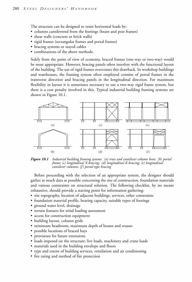
The structure can be designed to resist horizontal loads by:• columns cantilevered from the footings (beam and post frames)• shear walls (concrete or brick walls)• rigid frames (rectangular frames and portal frames)• bracing systems or stayed cables• combinations of the above methods.
Solely from the point of view of economy, braced frames (one-way or two-way) wouldbe most appropriate. However, bracing panels often interfere with the functional layoutof the building. The use of rigid frames overcomes this drawback. In workshop buildingsand warehouses, the framing system often employed consists of portal frames in thetransverse direction and bracing panels in the longitudinal direction. For maximumflexibility in layout it is sometimes necessary to use a two-way rigid frame system, butthere is a cost penalty involved in this. Typical industrial building framing systems areshown in Figure 10.1.
Figure 10.1 Industrial building framing systems: (a) truss and cantilever column bent; (b) portalframe; (c) longitudinal X-bracing; (d) longitudinal K-bracing; (e) longitudinalcantilever columns; (f ) portal-type bracing
Before proceeding with the selection of an appropriate system, the designer shouldgather as much data as possible concerning the site of construction, foundation materialsand various constraints on structural solution. The following checklist, by no meansexhaustive, should provide a starting point for information gathering:• site topography, location of adjacent buildings, services, other constraints• foundation material profile, bearing capacity, suitable types of footings• ground water level, drainage• terrain features for wind loading assessment• access for construction equipment• building layout, column grids• minimum headroom, maximum depth of beams and trusses• possible locations of braced bays• provisions for future extensions• loads imposed on the structure: live loads, machinery and crane loads• materials used in the building envelope and floors• type and extent of building services, ventilation and air conditioning• fire rating and method of fire protection
(a)
(b)
(c)
(d) (f )
(e)
280 S T E E L D E S I G N E R S ’ H A N D B O O K
1106 SDHB 09-End Final 8/6/05 12:11 PM Page 280

• means of egress and other statutory requirements.
Some additional variables influencing the selection of the structural form are as follows:• roof slope (minimum, maximum)• type of sheeting and purlins/girts• spacing of column grids• height of columns between the floors• feasibility of using fixed column bases• architectural preferences for the overall form of the building.
The building framework consists of a variety of members and connections, and theindividual elements can number tens of thousands in a high-rise building. The tendency,nowadays, is to reduce the number of framing elements to a minimum and optimise theweight for reasons of economy. The designer of steel-framed buildings should develop amastery in marshalling relevant facts and developing a satisfactory framing solution.
This section is intended to give practical hints on the design of framing for low-risebuildings, connections and miscellaneous other considerations. Further reading on thetopic can be found in AISC [1997].
10.2 Mill-type buildings
10.2.1 General arrangement—in-plane of frame
The structural framing for ‘mill-type’ (i.e. medium–heavy type industrial) buildingsusually consists of a series of bents, arranged in parallel. These bents (portal-type frames)resist all vertical and lateral loads acting in their plane. Forces acting in the longitudinaldirections—that is, perpendicularly to the bents—are resisted by bracing panels arrangedat intervals. The following framing systems are commonly used:• cantilevered columns with simply supported roof trusses• rigid-jointed frames with fixed or pinned bases.
Figure 10.2 illustrates these framing types.
Figure 10.2 Framing systems: (a) truss and cantilevered column bent; (b) rigid truss and columnbent; (c) two-pin portal; (d) fixed-base portal; (e) three-pin portal; (f ) two-pinmono-slope rafter portal
(a)M
(d)
(b)
(e)
(c)Note:
(f)
M
M
M
MM
= pin joint
S T R U C T U R A L F R A M I N G 281
1106 SDHB 09-End Final 8/6/05 12:11 PM Page 281

10.2.1.1 Cantilevered columns with simply supported roof trussesThe main advantage of this type of framing is that it is not too sensitive to the foundationmovement. Another advantage is in its relatively easy erection. Because there is only a pinconnection between the columns and the roof trusses, the wind forces and lateral forcesfrom cranes are resisted solely by the columns, cantilevering from the footings.
10.2.1.2 Rigid framesWith regard to the rigidity of column-to-footing connections, rigid frames can have fixedor pinned bases. The roof member can be a rolled or welded plate section, or alternativelya truss. This may also apply to the columns or both roof and column members to act likea portalised truss. Frames designed for base fixity rely on the rigidity of the foundation,particularly on the rotational rigidity. Fixed-base frames are structurally very efficient,and therefore very economical, but their footings tend to be costly (if feasible).
Pinned-base frames—that is, frames with flexible connections to the footings—derivetheir resistance to lateral forces from their rigid knee action. This type of framing iscommonly used for buildings of relatively low span-to-column height. The main advantageis in reduced footing costs, as the footings need not resist very large bending moments.
10.2.2 Longitudinal bracing
Columns of mill-type buildings are oriented such that their strong axis is parallel to thelongitudinal axis of the building. This means that, without bracing in the longitudinaldirection, the building would be too flexible—if not unstable. Figure 10.3 shows typicallongitudinal bracing systems. The location of the braced bays should be carefully plannedto avoid interfering with the operational requirements and to obtain the right structuralsolution. Wherever possible, the bracing should be situated close to the position wherethe first frames will be erected, to facilitate the overall building erection.
Figure 10.3 Longitudinal bracing systems (alternate configurations shown at end): (a) wall panels between frames with minimal openings, and; (b) wall panels with significant openings
Thermal expansion joints may be required in buildings longer than 80 metres, unlessit can be proven by analysis that the principal members will not be overstressed ifexpansion joints are placed farther apart. The columns and rafters are usually doubled atthe expansion joint to achieve complete separation of the structure within a small gap.
Bracing elements must be designed for all forces from wind and crane operation(acceleration, braking, surge and impact against buffers). Where high-capacity cranes areused, it is best to provide double bracing systems, one for wind bracing and another inthe plane of the crane runway girders.
Ties
Strut
(a)
(b)
282 S T E E L D E S I G N E R S ’ H A N D B O O K
1106 SDHB 09-End Final 8/6/05 12:11 PM Page 282

Bracing in the plane of the roof has the function of transferring wind loads acting onthe end walls to the vertical bracing. The roof bracing is usually designed in the form ofa horizontal truss or ‘wind girder’. Two examples are shown (see Figure 10.4). See alsoSection 10.3.1 and Figure 10.8.
Figure 10.4 Wind bracing in the roof plane
10.3 Roof trusses
10.3.1 General
Roof rafters spanning more than 20 m can often be designed, quite economically, in theform of trusses. The saving in weight stems from the fact that truss web members use lesssteel than the solid webs of UB sections or plate girders. The fabrication cost of trussesis marginally higher, but this is offset by the saving in steel.
The usual span-to-depth ratio of steep roof trusses is 7.5 to 12, depending on themagnitude of loads carried. The truss can be designed with sloping top chords and ahorizontal bottom chord, but this could make the mid-span web members too long.Constant depth (near-flat roof ) design is preferable as far as the fabrication is concerned.The Warren and Pratt types of trusses are used extensively because they have structuraladvantages and a good appearance. The following design rules should be observed:• the panel width should be constant• even number of panels avoids cross-braces• diagonal web members should be in tension under worst-case loading (unless hollow
sections are used)
Figure 10.5 The usual range of depths of roof trusses
00
1
2
3
4
5
6
10 20
D
Span, m
Dep
th, m
large W
* /l
small W * /l
30 40
W *
l
S T R U C T U R A L F R A M I N G 283
1106 SDHB 09-End Final 8/6/05 12:11 PM Page 283

• the inclination angle of the diagonals should be between 35° and 50°• if at all possible, the purlins and verticals should closely coincide.
Figure 10.5 gives the range of depths for various spans between simple supports of aWarren or Pratt truss in which the parameter W */l at each end of the indicative rangehas the total design load W * as an equivalent uniformly distributed load along the span.The length l is the span of the truss between simple supports. The parameter is acombined indicator of the effects of varying the span and the intensity of loading. Forexample, a large/high value could be due to either a small span or high concentration ofloads or both. Conversely, the opposite is true. It is seen that the magnitude of W * andspan influences the required truss depth and thus upper and lower limits are indicated.
Figure 10.6 shows the roof truss framing types and Figure 10.7 gives some data on the‘older’ type of roof truss designs.
Figure 10.6 Framing systems incorporating roof trusses of the Pratt type: (a) cantilevered columnand pin connected trusses; (b) portal-type truss
Figure 10.7 Approximate mass for roof trusses of high pitch, steep roof (Fink type)
Diagram Span, m Mass, kg kN
5 – 7 160 – 210 1.6 – 2.1
8 – 11 210 – 270 2.1 – 2.7
12 – 14 270 – 400 2.7 – 4.0
15 – 16 400 – 620 4.0 – 6.2
17 – 20 620 – 950 6.2 – 9.5
22 – 30 950 – 1100 9.5 – 11.0
M
W W
M
284 S T E E L D E S I G N E R S ’ H A N D B O O K
1106 SDHB 09-End Final 8/6/05 12:11 PM Page 284

As an aid to calculating the self-weight of trusses, Table 10.2 gives some rough weightestimates.
Table 10.2 Approximate self-weight of trusses.
Span (m) Self-weight (kN/m2), over span truss spacing
10 0.11
20 0.12
30 0.16
40 0.22
As noted above, portal frame/mill-type buildings resist in-plane actions (e.g. cross wind-loads, etc) by in-plane flexural stiffness. Also, Section 10.2.2 notes the role of longitudinalbracing to stabilise the primary structural frame in the out-of-plane (building longitudinal)direction. The loads transmitted by longitudinal bracing include those arising from:• wind loads acting on the upper half of the end walls• frictional drag effects on the roof, and • accumulated “lateral” bracing system restraint forces (e.g. from purlins and fly-braces).
These longitudinal loads are subsequently transmitted to the roof bracing (Figure 10.4)and then down the wall bracing to the foundations. In terms of load eccentricities, it isadvantageous to place the roof bracing in close proximity to the purlins as the latterelements may also form part of the bracing system as well as providing restraint to thecritical compression elements of primary roof members.
Clauses 6.6.1 to 6.6.3 of AS 4100 should be consulted for the evaluation of accumulatedrestraint forces. Woolcock et al. [1999] argue that these forces are unlikely to be critical forroof trusses and should be neglected for I-section rafters in such applications.
Notes:(1) Unless special studies are made, lateral forces from rafters should be accumulated at the braced bay.(2) Nc
*= compression force in top truss chord, which for illustrative purposes, is assumed to be the same for allroof trusses in the figure.
Figure 10.8 Forces in the longitudinal bracing system in the plane of the compression chords
Pr
Pr = 0.025N*c
1.5Pr
2.0Pr2.5Pr
N*c
N*c
roof bracing
wall bracing
S T R U C T U R A L F R A M I N G 285
1106 SDHB 09-End Final 8/6/05 12:11 PM Page 285

10.3.2 Truss node connections
The term ‘node’ applies to the juncture of two or more members. Truss node connectionscan be designed as:• direct connections • gusseted connections • pin connections.
Direct node connections occur where members are welded directly to one another,without the need for gussets or other elements (e.g. tubular joints). Where the chords aremade from large angles or tee-sections, it is possible to connect angle web membersdirectly to the chords.
Gusseted node connections used to be predominant at the time when rivets were usedas fasteners, and later when bolting was introduced. Their main disadvantage is that thetransfer of forces is indirect and that they are not aesthetically pleasing. Their advantageis that it is easier to make all members intersect at the theoretical node point—in contrastto direct connections, where some eccentricity is unavoidable.
Pin connections are generally used when aesthetics are important.
10.3.3 Open sections
A truss design popular with designers is using double-channel or angle chords anddouble-angle web members. The result is that the truss is symmetrical with respect to itsown plane, and that no torsional stresses develop. The sections used with this type ofdesign are shown in Figures 10.10(g) to (i). Trusses of small to intermediate span can bebuilt from single angles, as shown in Figure 10.9. The designer may be tempted to placethe verticals and the diagonals on different sides (as in Figure 10.9(a)), but researchresults show that this practice produces twisting of the chords and bending in the webmembers. See Clause 8.4.6 of AS 4100 for design provisions on this topic. It isrecommended that the verticals and the diagonals be placed on the same side of the chordmembers, as shown in Figure 10.9(b). The same figure, to its right, indicates how to startdistributing bending moments induced by the eccentricity of the web member withrespect to the node by the moment distribution method.
Figure 10.9 Gusset-free connections for trusses (a) centre of gravity lines intersect at the node;(b) eccentric connection can be a practical way of detailing but additional bendingstresses are induced
e
centroid
centroid
P1e sin α
P1
P2e
(a)
(b)
α
1–2UB
286 S T E E L D E S I G N E R S ’ H A N D B O O K
1106 SDHB 09-End Final 8/6/05 12:11 PM Page 286

The typical sections used in trusses are shown in Figure 10.10. Large-span trusses andtrusses carrying heavy loading are often composed of rolled steel sections, as shown inFigures 10.11 and 10.12, though with the ready availability of larger and thicker CHS,RHS & SHS, hollow sections are also used in such applications.
Figure 10.10 Typical sections for truss members: (a) to (f ) commonly used in welded construction(though (a), (c), (d) and (e) may be bolted), and; (g) to (k) common sections used forchord and web/diagonal members
10.3.4 Closed sections
Tubular trusses are being increasingly used because of their structural efficiency and inherentclean lines. Structurally, tubular members offer superior capacities, because the steel used isGrade C350 or C450 (the latter becoming more popular nowadays) and, except for RHS,their radius of gyration is the same in all directions. Tubes need less paint per linear metre,which is particularly important when upkeep costs and aesthetics are considered.
Figure 10.11 Typical node connections for trusses composed of rolled sections: (a) gussetlessconstruction using Tee-chords; (b) gussets are required where diagonals carry largeforces; (c) Tee-diagonals and chords, gussetless; (d) and (e) node detail for heavytrusswork, and (f ) riveted/bolted nodes
(a) (b) (c)
(d) (e) (f)
(a) (b) (c) (d) (e) (f)
(i)(h)(g) (j) (k)
S T R U C T U R A L F R A M I N G 287
1106 SDHB 09-End Final 8/6/05 12:11 PM Page 287

Figure 10.12 Typical connections for roof trusses composed of rolled-steel sections: (a) portal-type Pratttruss; (b) Fink truss with large eaves overhang; (c) alternative chord cross-sections
Tubular node connections can be of a direct or gusseted (i.e. plate face reinforcement)type. The latter is used only where large loads are being transmitted through the node.
Web members can be connected with no gap for higher strength (Figure 10.14(a) and(b)), although a positive gap makes fabrication easier and is more commonly used (Figure10.14(c) without a chord face reinforcement plate). Some possible tubular splices andnode connections are shown in Figures 10.13 and 10.14, respectively. Further reading onbehaviour, design, detailing and fabrication of hollow section trusses can be found inPacker & Henderson [1997], CIDECT [1991, 1992] and Syam & Chapman [1996].
Figure 10.13 Splices for tubular truss members: (a) sandwich plate splice; (b) sandwich plate spliceat chord reduction; (c) jacket splice; (d) welded butt splice; (e) welded butt splice withreducer, and; (f ) flange splice. (Note: CHS shown but (a), (b), (d) and (f ) also applyto RHS/SHS members).
0.4 OD(a)
(d)
(c)
(f)
(b)
(e)
1–2UB
(a)
1–2UB
UB
End of angles connectedby single-sided continuousfillet welds U.N.O.
1–2UB
1–2UB
(b)
(c)
288 S T E E L D E S I G N E R S ’ H A N D B O O K
1106 SDHB 09-End Final 8/6/05 12:11 PM Page 288

Figure 10.14 Some typical connections for roof trusses composed of tubular sections: (a) directcontact overlap connection without eccentricity; (b) direct contact overlap connectionwith eccentricity; (c) direct contact gap connection with/without eccentricity (withchord face reinforcing plate shown—without reinforcing plate is very common);(d) T-joint with chord face reinforcing plate (for very heavy loads—otherwise noreinforcing plate is also popular); (e) connection detail at support (note vertical stubportion with flange splice for lifting onto support); (f ) concentric reducer where chordsection is stepped down (alternatively, if the overall section is not stepped down thenthe wall thickness is reduced—the latter applies for RHS/SHS); (g) slotted-gussetconnections; (h) flattened end connections, and; (i) slit tube connections. (Note: CHSshown but all connections, except (f ) with reducer and flattened tube in (h), readilyapply for RHS/SHS. See Figure 8.22 for other tubular truss connectionconfigurations).
10.4 Portal frames
10.4.1 General
Portal frames are used extensively for the framing of single-storey buildings. Portal framesoffer cost advantages over other framing systems for short to medium spans. Otheradvantages they offer over truss systems are low structural depth, clean appearance andease of coating maintenance.
Portal frames derive their resistance to vertical and lateral loads through frame action.When fixed bases are used, the structural action is enhanced because all members are thenfully utilised, but there is a cost penalty for larger footings that often precludes their use.
The design of the knee joint is of prime importance, as this is one of the criticalelements in the frame. Figure 10.15 shows some typical knee connections. Figure 10.16
(a) (b) (c)
(d) (e) (f)
(g) (h) (i)
seal plate
thinner wall
gap
reinforcing plate (optional/non-preferred)
reinforcing plate(optional/non-preferred)
S T R U C T U R A L F R A M I N G 289
1106 SDHB 09-End Final 8/6/05 12:11 PM Page 289

290 S T E E L D E S I G N E R S ’ H A N D B O O K
gives typical depths and self-weights for portal frames that can be used in the preliminarydesign. Frame forms for single-bay and multi-bay portal frames are shown in Figure 10.17.
An excellent publication on the analysis and design of portal frame buildings isWoolcock et al. [1999].
Figure 10.15 Portal frame knee connections: (a) field welded connections; (b) lateral bracing A-B(see (a)—note a single tube member placed midway between A and B may also beused); (c) bolted moment end plate connection; (d) stub connection. (See Hogan &Thomas [1994] for details and design models for the above connections and Hogan& Syam [1997] for haunching of portal frame knee joints).
Figure 10.16 Data for preliminary sizing of hinged base frames: (a) usual range of rafter depths;(b) dead load of rafters expressed as kN/m2; design height to eaves is 5 m, windRegion A.
0 0
0.1
0.2
200
400
600
800
1000
1200
Dep
th, m
m
Dea
d L
oad,
kN
/m2
0 10 20Span, m
30 40 0 10 20
(a) (b)
Span, m30 40
DS
S 8 m
S 4 m
S 8 m
S 4 m
1400
L
A
B
A
B
UBHS bolts
(a) (b)
(c) (d)
with haunch(optional)
1106 SDHB 09-End Final 8/6/05 12:11 PM Page 290

Figure 10.17 Types of portal frames for industrial buildings: (a) constant (sometimes calledprismatic) cross-section; (b) to (d) tapered members; (e) portal with column cranerunway brackets; (f ) stepped column portal; (g) separate crane post; (h) rafter hungcrane runways; (i) to (k) multiple bays
(a) (b)
(c) (d)
(e) (f)
(g)
(i)
(j)
(k)
(h)
S T R U C T U R A L F R A M I N G 291
1106 SDHB 09-End Final 8/6/05 12:11 PM Page 291

292 S T E E L D E S I G N E R S ’ H A N D B O O K
Figure 10.18 Design chart to evaluate key design action effects in two-pin portal frames. See alsoSection 4.3 for calculation of second-order effects.
10.4.2 Structural analysis
Structural analysis of portal frames is not covered in this Handbook (Woolcock et al.[1999] is very useful). As an aid to preliminary design, use can be made of the plot inFigure 10.18 and of the design formulae in Table 10.3. For a more accurate hand analysis,the designer should refer to Kleinlogel [1973] for a classic text on the subject. Table 10.3only considers first-order elastic analysis. However, AS 4100 requires such frames toinclude second-order effects where relevant. Consequently, reference should also be madeto Section 4.3 for the evaluation of second-order effects for elastic analysis of portalframes. In lieu of ‘manual’ techniques, sophisticated structural analysis software packagesare readily available [Microstran, Multiframe, SpaceGass and Strand7] which can rapidlyhandle linear/non-linear analysis with design along with many other functions.
Table 10.3 Formulae for forces/bending moments in portal frames—first-order elastic analysis
Applied loads Forces and moments
Notation
b1 hl ; f1
hf
k1 I
I2
1
h
s ; k2
hl ; k3 f1
2 3f1 k1 3
1.00.30 0.20
Coefficient C1
LegendC1C2
Coefficient C2
0.10
0.8
0.6
0.4
f/l
0.2
00.04 0.05 0.06 0.07
k 0.00.51.01.52.0
k
k I2h / I1s
HE C1w1h + C2w2 l 2 / h
MD He.h
3.0 2.5
2.0
1.51.0
0.8
0.6
0.4
0.2
A
B
E
DC f
I1
I2
w1
w2
HEHAl
s
h
A
B
fC
DI1 I1
EHA
VA
I2
HEVE
hl
s
1106 SDHB 09-End Final 8/6/05 12:11 PM Page 292

Applied loads Forces and moments
1 HA HE wl 2(1
4hk
0
3
.625f1)
VA VE 0.5wl
MB MD HAh
2 HA HE
VA w2bl
2
MB MD HAh
3 HA HE
VA Plb
MB MD HAh
4 HA wh(5k1
6k
6
3
f1 12)
HE HAwh
VA VE w2hl
2
MB HAh
MD HEh (w
2h2)
5 HA
HE HAwf
VA VE wf(2
2hl f)
MB HAh
MD HEh
6 HA P(2k1
4k3
3
f1 6)
HE HA P
VA VE Plh
MB HAh
MD HE h
7 Displacement imposed at E:
HA HE
s
1
h
.52
∆
k
E
3
I2
MB ME HAh
Notes: See Section 4.3 for the evaluation of second-order effects for the above structural and loadingconfigurations.
wf(3 k1 2.5f1 0.625f12)
2k3
Pb(6 6b1 4f1b1 3f1)
4k3
wb2(6 3f1 4b1 2f1b12)
8hk3
S T R U C T U R A L F R A M I N G 293
P
w
w
b
b
P
w
w
1106 SDHB 09-End Final 8/6/05 12:11 PM Page 293

10.5 Steel frames for low-rise buildingsFraming systems for low-rise buildings can take many forms. The framing systemscommonly used are:• two-way braced• core braced, using concrete or steel core with steel gravity frame and simple connections• one-way braced, using rigid frame action in the other direction• two-way rigid frames with no bracing.
The frames of the two-way braced and the core braced types are often used for their lowunit cost and simple construction. The beam-to-column connections for such frames canbe in the form of flexible end plates or web-side plate connections.
Rigid frames featuring two-way rigidity may require more steel material but permit lessrestrictrions in layout and functions and, like braced frames, are sometimes employed insevere earthquake zones because they offer higher ductility.
Figure 10.19 Simple connection design method illustrated: (a) typical braced multi-storey frame;(b) assumed connection eccentricity; (c) bending moment distribution on upper andlower column shafts
The framing connections for low-rise buildings are usually of the field bolted type.Welding in-situ is not favoured by erectors because welding could not be properly carriedout without staging and weather shields. Site welding can cause delays in constructionbecause of the need for stringent inspection and consequent frequent remedying of defects.
Figures 10.19 to 10.24 show some often used connection details.
Mc o Rc•ec
Mc11
Mc11M oc
Mc12M oc
Mc12
I1 h1
(a)
(b) (c)
A
B
C
C
D
B
D
E
F
A
B
C
D
E
F
A
B
C
D
E
F
C
Rc
ec
h2
h1
Mc o
I1 h1 I2 h2—————————
I2 h2
I1 h1 I2 h2—————————
I1
I2
294 S T E E L D E S I G N E R S ’ H A N D B O O K
1106 SDHB 09-End Final 8/6/05 12:11 PM Page 294

Figure 10.20 Bolted connections for structures designed by simple method. See Hogan & Thomas[1994] and AISC [1985] for futher information on these connections.
Figure 10.21 Flexible bolted connections: (a) flexible angle seat; (b) bearing pad connection;(c) flexible end plate; (d) coped flexible end plate; (e) angle cleat connection. See Hogan & Thomas [1994] and AISC [1985] for futher information on theseconnections.
(a) (b)
(c) (d) (e)
Shear plateCFW
CFW
(a) (b)
S T R U C T U R A L F R A M I N G 295
1106 SDHB 09-End Final 8/6/05 12:11 PM Page 295

Figure 10.22 Bolted beam-to-column connections: (a) web side plate (flexible) connection;(b) bolted moment (rigid) end plate connection; (c) other applications of boltedmoment (rigid) end plate. See Hogan & Thomas [1994] for further information onthese connections.
Figure 10.23 Welded rigid beam-to-column connections: (a) directly welded connection (note beammay not be coped and is typically connected by fillet and butt welds along allperimeter to column face—not shown); (b) fully welded connection using momentplates. See Hogan & Thomas [1994] for further information on these connections.
cope
(a) (b)
column flange connectionplate optional (alternativelycolumn web stiffeners orno colunm stiffener—bothnot shown)
(a)
(b)
(c)if required
+M +MV
296 S T E E L D E S I G N E R S ’ H A N D B O O K
1106 SDHB 09-End Final 8/6/05 12:11 PM Page 296

Figure 10.24 Typical welded column-to-base connections and column splices with partial-penetration butt welds
10.6 Purlins and girtsThe main function of purlins and girts (shown in Figure 10.27) is to support the metalcladding. In addition, purlins and girts are used to provide lateral restraint to the raftersand columns. Both elements use the same sections and materials, and so in furtherdiscussion girts can be omitted. Purlins are made by cold-forming operations using high-strength steel strip. Some manufacturers offer yield strengths of 550 MPa for thinnersections, say up to 2.0 mm. Cold-formed purlins are therefore very cost-effective, andhave almost completely displaced hot-rolled sections, timber and other related materials.
The usual cross-sectional shapes are (Cee) C- and (Zed) Z-sections in sizes up to300 mm, and larger if specially ordered. The section thicknesses range from 1.0 to 3.0 mmdepending on the purlin size. The strip is pre-galvanized and usually requires no furthercorrosion protection.
Owing to the small torsion constant of purlins, special care is required to avoid lateraland torsional instability. All purlin sections have flanges stiffened with downturned lipsto increase their local and flexural-torsional buckling resistance. The rules relevant fordesign of cold-formed steel purlins are contained in AS/NZS 4600.
To enhance the flexural-torsional behaviour of purlins, it is necessary to approach thedesign as follows:• For inward loading (i.e. for dead, live and wind loads on purlins or wind pressure on
girts), it is assumed that the metal cladding provides enough lateral resistance toachieve an effective length factor of 1.0.
• For outward loading (negative wind pressure), the inner flanges are assumed not to berestrained by the cladding, and purlin bridging is used where necessary. The bridgingprovides the necessary lateral and torsional resistance and can be counted on as themeans of division into beam segments.
(a)
(d)
(c)(b)
(e)
T
T
Land, 1–21–4 T 1–
21–4 T
1–21–
4 T
1–21–
4 T
Erection cleat
T
cT t
t c
S T R U C T U R A L F R A M I N G 297
1106 SDHB 09-End Final 8/6/05 12:11 PM Page 297
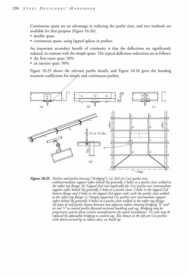
Continuous spans are an advantage in reducing the purlin sizes, and two methods areavailable for that purpose (Figure 10.26):• double spans• continuous spans, using lapped splices in purlins.
An important secondary benefit of continuity is that the deflections are significantlyreduced, in contrast with the simple spans. The typical deflection reductions are as follows:• the first outer span: 20%• an interior span: 50%.
Figure 10.25 shows the relevant purlin details, and Figure 10.26 gives the bendingmoment coefficients for simple and continuous purlins.
Figure 10.25 Purlins and purlin bracing (“bridging”): (a) Zed (or Cee) purlin overend/intermediate support rafter bolted (by generally 2 bolts) to a purlin cleat welded tothe rafter top flange; (b) Lapped Zed (not applicable for Cee) purlin over intermediatesupport rafter bolted (by generally 2 bolts to a purlin cleat, 2 bolts in the lapped Zedbottom flange and 2 bolts in the lapped Zed upper web) with the purlin cleat weldedto the rafter top flange; (c) Simply supported Cee purlins over intermediate supportrafter bolted (by generally 4 bolts) to a purlin cleat welded to the rafter top flange;(d) plan of roof purlin layout between two adjacent rafters showing bridging “b” andtie rod “r” to control purlin flexural-torsional buckling and sag. Bridging may beproprietary systems from certain manufacturers for quick installation. Tie rods may bereplaced by adjustable bridging to control sag. Also shown to the left are Cee purlinswith down-turned lip to reduce dust, etc build up.
(a) (b)
12 or 16 dia.b
b
ridge
raft
er
raft
er
b
b
rr
r
b
b
r
r
rr
(c)
ll1
(d)
298 S T E E L D E S I G N E R S ’ H A N D B O O K
1106 SDHB 09-End Final 8/6/05 12:11 PM Page 298
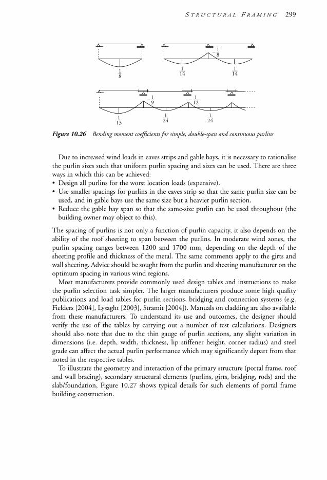
Figure 10.26 Bending moment coefficients for simple, double-span and continuous purlins
Due to increased wind loads in eaves strips and gable bays, it is necessary to rationalisethe purlin sizes such that uniform purlin spacing and sizes can be used. There are threeways in which this can be achieved:• Design all purlins for the worst location loads (expensive).• Use smaller spacings for purlins in the eaves strip so that the same purlin size can be
used, and in gable bays use the same size but a heavier purlin section.• Reduce the gable bay span so that the same-size purlin can be used throughout (the
building owner may object to this).
The spacing of purlins is not only a function of purlin capacity, it also depends on theability of the roof sheeting to span between the purlins. In moderate wind zones, thepurlin spacing ranges between 1200 and 1700 mm, depending on the depth of thesheeting profile and thickness of the metal. The same comments apply to the girts andwall sheeting. Advice should be sought from the purlin and sheeting manufacturer on theoptimum spacing in various wind regions.
Most manufacturers provide commonly used design tables and instructions to makethe purlin selection task simpler. The larger manufacturers produce some high qualitypublications and load tables for purlin sections, bridging and connection systems (e.g.Fielders [2004], Lysaght [2003], Stramit [2004]). Manuals on cladding are also availablefrom these manufacturers. To understand its use and outcomes, the designer shouldverify the use of the tables by carrying out a number of test calculations. Designersshould also note that due to the thin gauge of purlin sections, any slight variation indimensions (i.e. depth, width, thickness, lip stiffener height, corner radius) and steelgrade can affect the actual purlin performance which may significantly depart from thatnoted in the respective tables.
To illustrate the geometry and interaction of the primary structure (portal frame, roofand wall bracing), secondary structural elements (purlins, girts, bridging, rods) and theslab/foundation, Figure 10.27 shows typical details for such elements of portal framebuilding construction.
1–8
– 1–9
– 1–8
1—14
1—14
1—12
1—13
1—24
1—24
– –
S T R U C T U R A L F R A M I N G 299
1106 SDHB 09-End Final 8/6/05 12:11 PM Page 299

Figure 10.27 Isometric view of typical single-storey framework showing pinned-base portal frames,purlins, girts and other stabilising elements
10.7 Floor systems for industrial buildings
10.7.1 Types of construction
The selection of the type of industrial floor depends on the floor use and the loadintensity and application. Consideration should be given to wear and skid resistance, andalso the need to change layout, plant and services.
sag rod
bridging
purlin
purlinlap
facial purlin
portal frame
rafter
strut purlin
knee (fly) braces
strut spacer
roof braces
sidewall brace rodsclear-span frame column
sidewall girt
corner column
eave strut
300 S T E E L D E S I G N E R S ’ H A N D B O O K
1106 SDHB 09-End Final 8/6/05 12:11 PM Page 300

The following types of floor are in frequent use:
(a) Steel floor plate (chequer plate) supported on closely spaced floor joists Advantages are:rapid construction, ability to give lateral restraint to the beams and to provide floorbracing. Disadvantages are: high cost and high noise transmission.
(b) Steel grid flooring over steel joists Main advantages are: self-cleaning, low weight,rapid placing and ability to alter layout. Disadvantages are: low resistance to pointloads, need for a separate floor bracing system and difficulty of upkeep of its coatingsystem.
(c) Reinforced concrete floor slabs Advantages are: good load-carrying resistance,increased stiffness, suppression of noise and even surface for rolling loads. Frictionbetween the slab and the beam may provide full lateral restraint. Disadvantages are:high unit weight, difficulties in making alterations and relatively high cost.
(d) Composite reinforced concrete slab Same as (c), with an additional advantage ofeconomy offered by the composite action with steel beams (via shear studs) and thefacility of providing full lateral restraint to the beams.
10.7.2 Steel floor plate
Steel floor plate or ‘checker plate’ is rolled with an angular pattern to improve skidresistance. It is available in thicknesses ranging from 5 to 12 mm and is manufacturedfrom Grade 250 steel. The best corrosion protection for the floor plates is by hot-dipgalvanizing, but care must be exercised to prevent distortion.
The highest resistance to floor loads is obtained with all four edges supported, but theratio of sides should not exceed 1:4. This requires floor beams and joists at relatively closespaces of between 900 and 1200 mm. The fixing to the supporting frame is best providedin the form of slot welds (20 × 40 mm) at roughly 1000 mm spacing. Welding is alsoused to join the individual panels.
The plate tables in AISC [1999a] are very useful for design. Deflections are usuallylimited to l /100 under localised loads.
10.7.3 Steel grid flooring/grating
A popular type of steel grid flooring consists of vertical flats (20–65 mm high and3–6 mm wide) spaced at 30–60 mm, and cross-connected at 50–200 mm for stabilityand load sharing. The load capacities of grid flooring are usually based on acomputational model derived from tests, because there are too many variables to considerin designing grids from first principles. The manufacturer’s data sheets are usuallyemployed in the design (Weldlok [2001], Webforge [2001]).
The fixing of the steel flooring is by proprietary clips at approximately 1.0 m spacing.It is important that clips be installed as soon as the grid flooring is laid, as a precautionagainst fall-through accidents.
S T R U C T U R A L F R A M I N G 301
1106 SDHB 09-End Final 8/6/05 12:11 PM Page 301

10.8 Crane runway girders
10.8.1 General
Lifting and transporting heavy loads and bulk materials is almost entirely done bymechanical appliances. Overhead travelling cranes and monorails are commonly used inindustrial buildings. Cranes travel on rails supported by runway girders. Monorails arerunway beams that carry hoists on units travelling on their bottom flanges.
The design of crane runway beams differs from the design of floor beams in thefollowing ways:• the loads are determined in accordance with AS 1418.1, the Crane Code• the loads are moving• lateral loading is usually involved• localised stresses occur in the web at the top flange junction• lateral buckling with twisting needs to be considered• fatigue assessment may be required because of repetitive load cycling.
In recognition of these special aspects of crane runway design, a new part of the cranecode has been published as AS 1418.18. For an introduction to the design of cranerunway girders, see Gorenc [2003].
10.8.2 Loads and load combinations
Because the operation of a crane is not a steady-state operation, there are significantdynamic effects to consider. This is done in practice by applying dynamic loadmultipliers to the loads computed for a static system.
These multipliers take into account the travelling load fluctuations, the hoistingimpacts, and lateral inertial and tracking loads. AS 1418.18 provides a method for theevaluation of special loads occurring in operation and the dynamic multipliers to be usedwith these loads.
Several types of lateral loads occur with cranes:• lateral loads caused by the acceleration/braking of the crane trolley• lateral loads caused by the oblique travelling tendency of the cranes• lateral loads caused by longitudinal acceleration/braking of the crane bridge.
The load combination table of AS 1418.18 is much more elaborate than the one usedfor building design. It specifies, for each load combination, the value of multipliers forthe dynamic effects and for the likelihood of more than two load types occurring at once.
10.8.3 Bending moments and shear forces
The maximum design bending moment is a function of the load position. The loadposition at which the maximum moment occurs must be found by trial and error orby a suitable routine. Any linear elastic computer program can be used byincrementing the position of the leading load. For a two-axle crane, it is possible toarrive at the direct evaluation of design moments using the methods shown inTable 10.4 and Figure 10.28.
302 S T E E L D E S I G N E R S ’ H A N D B O O K
1106 SDHB 09-End Final 8/6/05 12:11 PM Page 302

Table 10.4 Load effects for moving loads
Load disposition Load effects
1 One concentrated moving load:
(RA)max P, when x 0
M1 Px(L
L x), at x 0.5L 0.25a
Mmax P4L, when x
L2
2 Two equal moving loads:
Case 1: a 0.586L
(RA)max P 1 (L
La)
, when x 0
RA P(2L
L2x a)
M1 RAx
M2 RA(x a) Pa
Mmax P(L
2L0.5a)2
, at x 0.5L 0.25a
3 Two equal moving loads:
Case 2: a 0.586L
The maximum bending moment occurs when only one loadis on the span:
Mm P4L , when x
L2
4 Two unequal moving loads:
Case 3: a 0.5 0.0
P
8
1
6P2L
(RA)max P1 P2(L
L
a), when x 0
RA P1(L
L
x)
P2(L
L
x a)
M1 RAx
M2 M1 (RA P1)a
The maximum bending moment occurs at:
xm 0.5L (P1
P
2a
P2)
4(a) Mmax (P1
L
P2)xm2
continued
a 2a 4
a 2
Mi
x a
c2c
M1 M2
A B
P1
P2
x a
M1 M2
A BP1 P2
AB
ai m
P P
Mi Mm
Envelope of Mm
A B
x al
P P
M1 M2
A Bx a
l
M
P
S T R U C T U R A L F R A M I N G 303
1106 SDHB 09-End Final 8/6/05 12:11 PM Page 303

4(b) Two unequal moving loads:
Case 4: a > 0.5 0.0
P
8
1
6P2L
Only the larger load is relevant; the other is off the span:
Mm P
41L , when x
L2
Figure 10.28 Influence lines for moments and shears and absolute maximum envelopes formoments and shears
10.9 Deflection limits
10.9.1 General
In contrast to the stringent code requirements for strength design, the deflection limits arelargely left to the designer to decide on. One reason for the lack of detailed rules ondeformation limits is that the subject is too variable and complex; the other is that designersare in a better position to set realistic limits appropriate to the particular project.
0.1 0.2 0.3 0.4 0.5
0.5
0.5
V at 0V0 (Y1 Y2)
Y1 Y2
0.25
1.0
0.24
0.24
M at 0.5
(a) Influence line for x = 0.5L
(b) Influence line for x = 0.4 & 0.6
(c) BM envelope
(d) Shear envelope
0.6
0.66
0.4 0.6
0.7 0.8 0.9
0.44
x a
P P
Mmax
V
max
V
max
c2 c(a•c) (a•c)
Mm1
Mm2
Envelope of Mm
m
—–2
304 S T E E L D E S I G N E R S ’ H A N D B O O K
1106 SDHB 09-End Final 8/6/05 12:11 PM Page 304

In AS 4100, the deflection limits come under the serviceability limit state. A structuremay become unserviceable for a number of reasons:• inability to support masonry walls without inducing cracking• possibility of ponding of rainwater because of excessive sag• floor slopes and sags interfering with the operations performed on the floor (bowling
alley, forklift truck operations)• damage to machinery that may be sensitive to floor movement• mal-operation of cranes when runway beam deformations are excessive• floor vibrations that may be felt by users as disturbing• deflections and tilting that may cause damage or malfunction to the non-structural
building components (walls, doors, fenestration)• large differential deflection between adjacent frames that may cause damage to
cladding or masonry wall.
The difficulty in stipulating appropriate deflection limits lies in the fact that there aremany different types of buildings, occupancies and floor uses. The only practical way outis to determine, at an early design stage, all the constraints on deflections of criticalbuilding elements. Clause 3.5.3 of AS 4100 states that deflection limits should beappropriate to the structure, its intended use, the nature of loading and the elementssupported by it. The same Clause gives very general instructions for determining thedeflection limits. Appendix B of AS 4100 suggests some deflection limits which havenow been somewhat superseded by AS/NZS 1170.0. Refer to a summary of deflectionlimits in Sections 1.8 and 5.10.
The following additional drift (sway) limits are also suggested:
• 5
H00 where masonry partition walls are built between the frames
• 3
H00 where reinforced concrete walls abut the frames
• 2
H00 to 3
H00 where lightweight partitions are in contact with frames
• 1
H00 to 2
H00 where the operation of doors and windows could be impaired
where H is the floor-to-floor/ceiling/roof height. The results of a survey into portal framedeflection limits applied in practice are reported by Woolcock et al. [1986, 1999].
10.9.2 Deflection calculations
Load combinations for the serviceability limit state are noted in Section 1.8. Forexample, for the dead plus live load case, the load combination is:
1.0G ψsQ
where ψs ranges from 0.7 to 1.0. Other load combinations are given in AS/NZS 1170.0.Thus the structural analysis has to be organised in such a way that strength limit state
load cases are separated from the serviceability load cases—the latter case only requiringfirst-order elastic analysis (i.e. without second-order effects). It is also important for themodelling to be such that the maximum deflections can readily be obtained.
S T R U C T U R A L F R A M I N G 305
1106 SDHB 09-End Final 8/6/05 12:11 PM Page 305

For simple structures it is sufficiently accurate to carry out a manual method ofdeflection calculation. For example, the UDL on a simply supported beam produces thefollowing maximum deflection:
ym 5
4
M
8Es*l
I
2
where Ms* is the serviceability design bending moment obtained from an elastic analysis.
For other load distributions and end moments, it is simple to use a correction coefficient,K1 , from Table C.2.3 in Appendix C of this Handbook. The deflection equation is then:
ym 521
I
103Msl2
K1
where K1 depends on the type and distribution of loads. For continuous beams, the effectof end bending moments can be taken into account at mid-span by subtracting thedeflection induced by these moments. A useful reference for manual calculations ofdeflections is Syam [1992] and Appendix C of this Handbook.
10.10 Fire resistanceThe fire resistance levels are specified in terms of endurance (in minutes) of the structuralframing when it is subjected to a notional fire event. The notional fire event is definedby means of a standard time–temperature relationship given in the Building Code ofAustralia (BCA). The required levels of fire resistance are given in the BCA on the basisof standard fire tests performed to date. The member being tested is deemed to reach itsperiod of structural adequacy (PSA) when the deflection of the member exceeds thespecified limits—that is, the limit state of fire endurance.
Now that AS 4100 includes a section on fire resistance, it is no longer necessary tosubject the steel structure to a standard fire test in order to determine its PSA. Section 12of AS 4100 contains the rules for design verification of structural steel members in a fireevent. Both unprotected and fire-protected members are covered. The difference betweenthe two types of members is as follows:• Unprotected members can resist the fire for a period that is a function of the ratio of
mass to exposed surface area.• Protected members rely on the thickness and thermal properties of protective material
to endure for a specified period of fire exposure (PSA). (Note: these provisions do notconsider concrete encasement or concrete filling.)
The properties of the protective material are given in Bennetts et al. [1990].Typical examples of unprotected steelwork are single-storey industrial structures,
parking stations and hangar roofs. Fire-protected members are usually employed inmedium- and high-rise building structures.
One of the consequences of the high temperatures that develop in a fire event is thatthe modulus of elasticity and the yield stress of steel members reduce very significantly(see Section 12 of AS 4100). A secondary effect is that the coefficient of temperatureexpansion increases, causing the members affected to expand, resulting in additionalaction effects in the steelwork.
306 S T E E L D E S I G N E R S ’ H A N D B O O K
1106 SDHB 09-End Final 8/6/05 12:11 PM Page 306

Because the incidence of fire is a relatively rare event, the applicable load combination,given in AS/NZS 1170.0, is:
1.1 G ψl Q
where ψl is the long-term combination factor which is between 0.4 to 1.0. This may betypically taken as 0.4 for UDLs on general floors (see Table 4.1 of AS/NZS 1170.0).It is not required to include wind or earthquake forces in any load combinations whenthis limit state is considered.
In lieu of the above, the BCA also permits a risk-based approach to the fire engineeringof steel structures. Verification of the structural adequacy against fire is a very complexdesign task that requires considerable training and experience beyond the knowledge ofthe requirements of the BCA and AS 4100. Thomas et al. [1992] and O’Meagher et al.[1992], provide a good introduction to the methods used. Obtaining professional advicefrom relevant experts could prove invaluable.
10.11 Fatigue
10.11.1 Introduction
Machinery support elements in industrial structures are often subject to fluctuatingloading with a large number of load cycles. The resulting stresses in structural elementsvary cyclically and the difference between the upper and lower stresses is termed the‘stress range’. Repeated cycling can induce fatigue damage to a steel element and can leadto fatigue fracture. Distinction should be made between the high-cycle/low-stress fatigue,where stresses rarely reach yield, and the low-cycle/high-strain fatigue. The latter type offatigue is characterised by repeated excursions into yield and strain hardening regions, asfor example in an earthquake event. The rest of this Section is concerned with high-cycle/low-stress fatigue.
The fatigue damage potential increases with:• magnitude of the stress range experienced in service and the number of stress cycles• existence of notches, stress risers and discontinuities, weld imperfections and injuries
to material• thickness of the plate element if it exceeds 25 mm.
10.11.2 Stress range concept
Exhaustive research effort conducted in Europe and the USA in the past three decadeshas confirmed that stress range is the major parameter in fatigue assessment. AS 4100reflects these findings. Fatigue damage will occur even if stress fluctuations are entirely incompression. The stress range, f, at a point in the structure or element is expressed as:
f = fmax − fmin
Prior to the European fatigue research findings, there was a school of thought that saidcompression stress cycles pose little risk of fatigue damage. The true situation withwelded structures is that welds and the material adjacent to welds are in a state of highresidual tension due to weld shrinkage forces. Thus the effective tensile stress in theseareas fluctuates from tension yield to compression.
S T R U C T U R A L F R A M I N G 307
1106 SDHB 09-End Final 8/6/05 12:11 PM Page 307

The second fact borne out by the European research is that the steel grade is largelyirrelevant in welded steelwork. On the other hand, the higher-strength steels machinedand free of severe notches do have a higher fatigue strength/endurance. High-strengthsteel elements fabricated by welding are not treated differently from Grades 250 or300 steels because the imperfections produced by product manufacturing, welding andfabrication are the main problem. AS 4100 does not give guidance here, as machinedstructural elements are rare in building structures.
Stress risers are geometric features at which stress concentrations develop, usually becauseof local peaks of stress where the calculated nominal stress locally increases several-fold.Stress risers such as those that occur at weld imperfections, and others can be found in:• small weld cracks (micro-cracks) along the toes of butt and fillet welds (large weld
cracks are not permitted at all)• porosity (gas bubbles) and slag inclusions• lack of fusion between the parent plate and the weld in butt welds• undercut in fillet and butt welds• misalignment of adjoining plates• excessive weld reinforcement• rough weld surface contours• weld craters at ends of weld runs• rapid geometric or configuration changes in a localised sense.
Other stress risers occur at thermally cut surfaces that are excessively rough, and aroundpunched holes. All these are generally associated with the notch-like defects or tiny cracksinherent in these processes. Cyclic stressing at such defects gives rise to stressconcentrations and subsequently leads to lower fatigue strength.
Reliable welding inspection and good structural detailing is very important and can detectand/or mitigate the effects of most of these defects. The welding code, AS/NZS 1554.1,gives the permissible weld defect tolerances for each of the two ‘weld categories’, GP andSP. Weld category GP is for general-purpose welding and SP for structural (special-purpose) welding. Weld category GP should not be used in structures subject to fatigue.The third, very special category, which may be termed ‘SX’, is specified in AS/NZS1554.5. It entails higher weld quality and thus tighter defect tolerances, as required forstructures subject to high cycle fatigue (e.g. bridges).
10.11.3 Detail category
Some details are more prone to fatigue damage than others. It is thus necessary tocategorise the welded joints and other details by the severity of the expected stressconcentration. The geometry of the detail is an important factor in categorisation.
The term ‘detail category’ (DC) is used to describe the severity of stress concentrationsand triaxial stressing of details, and for normal stresses, this ranges from DC 36 to 180.DC 180 is about the best that can be achieved with as-rolled steel plate or shapes, withno welding, holing and notching. DC 36, on the other hand, applies to details withconsiderable discontinuities. For example, a typical welded plate web girder flange isgiven a DC 112 if web stiffeners are not used, but if the web stiffeners are used the DCdrops to 71. Table 11.5.1 of AS 4100 gives the DC numbers for a great variety ofsituations. For detail categories above 112 it is necessary to apply more stringent weld
308 S T E E L D E S I G N E R S ’ H A N D B O O K
1106 SDHB 09-End Final 8/6/05 12:11 PM Page 308

inspection and tolerance limits, such as specifying weld category SX from AS 1554.5,applicable to fatigue-loaded structures.
As noted in the fatigue strength versus number of cycles (S–N) curves, the DCnumbers for normal stresses in AS 4100 coincide with the stress ranges at 2 millioncycles, as can be seen in Figure 10.29. The slope of the lines representing the DCnumbers is 1 in 3 for less than 5 million cycles and 1 in 5 beyond 5 million cycles. TheS–N curves for shear stresses are also shown in Figure 10.29.
Figure 10.29 Fatigue strength vs number of cycles (S–N) curves for normal and shear stresses (see Figure 11.6.1 and 11.6.2 of AS 4100 for further information)
10.11.4 Number of cycles
The number of stress cycles over the life of the structure has a predominant influence onthe fatigue resistance of a member or detail. Once the fatigue crack has started growingit will propagate with every stress cycle. A crack of say 1 mm in length may take years toreach 10 mm in length, gradually accelerating. In general, the fatigue life has three stages:crack initiation, crack propagation and fracture. The fatigue life is usually the periodmeasured from the commissioning of the structure to the time when fatigue crack growthbecomes a safety and/or maintenance problem. It is not possible to determine that point
Slopeαs 3
Limitfor weld(at SP)
Shear stresscurves
with slopeαs 5(100)(80)
105 220
30
40
50
60
80
100
150
200
300
400
500
3 4 5 6 106 2 3
Number of stress cycles (nsc)
Un
corr
ecte
d f
atig
ue
stre
ngt
h (
ff ),
MP
a
4 5 6 107 1082 3 4 5 6
Slopeαs 5
Constant stress rangefatigue limit (f3)
(DC) Detail category (f rn)
Control line for DC categorisation
133
160
MPa118103
928374665952464137332927
20232529
180
140125112100908071635650454036
500
400
300
200
150
100
80
303236
606573
4045
5157
Note: Equations are shown inFigure 10.30. See Section 10.11.4.2(j)for the shear stress range equation.
S T R U C T U R A L F R A M I N G 309
1106 SDHB 09-End Final 8/6/05 12:11 PM Page 309

310 S T E E L D E S I G N E R S ’ H A N D B O O K
in time with any precision except by documenting the inspection and monitoring theyearly cost of weld repairs.
The design life is usually (at least) 30 years for buildings and bridges. It is accepted bymost building (asset) owners that periodical inspection and repairs will be necessary inthe later part of the structure’s life.
Fluctuations in loads may be uniform or variable. Uniform fluctuations produceconstant stress range cycles. Variable fluctuations produce variable stress range cycles.Variable cycling is first converted to constant stress range cycles by various techniques,such as the ‘rainflow’ counting method in conjunction with Miner’s rule.
The evaluation of the number of cycles and stress amplitudes is usually done on oneof the following bases:• characteristic parameters of the vibrator (machine), for example support steelwork for
a pump or vibrating screen—constant ranges• prescribed number of cycles, as in crane and bridge Standards—constant ranges• time and motion analysis, as in a container crane structure—variable stress ranges• Wind tunnel tests, where stress cycles result from wind-induced oscillations—stochastic.
10.11.5 Fatigue assessment
10.11.5.1 IntroductionThe purpose of fatigue assessment is to estimate the fatigue damage potential over thedesign life of the structure. The stresses are evaluated by using unfactored loads becausestructural fatigue performance is considered to be a serviceability limit state.
10.11.5.2 Fatigue assessment guide(a) Restrictions, and suitable structures:
Areas not covered for fatigue design by Clause 11.1 of AS 4100 are:• corrosion or immersion in reducing fatigue life• high stress-low cycle fatigue• thermal fatigue• stress corrosion cracking.
Other structures that are suitable for the application of Section 11 of AS 4100 mustsatisfy its other requirements for their design and construction. The examples of thestructures that may be suitable are: rail and highway bridges, crane runway girders,machinery support structures, cranes and the like. For existing structures only, thefatigue loading is to embrace the actual service loading for a design life that includesthe cumulated fatigue damage from previous service and its planned future use.
Limits on yield stress, yielding in structures, stress range and weld quality: • although the S–N curves in Clause 11.6 of AS 4100 may be applied to structural
steels with fy 700 MPa, the lower limit in Clause 1.1.1(b) of AS 4100 governswith fy 450 MPa. The curves can be used for bolts with fy 1000 MPa.
• prohibits the application of Section 11 of AS 4100 fatigue design to structureswhich are designed to yield, or if the stress range exceeds 1.5 fy .
• weld category SP is mandatory in Clause 11.1.5 of AS 4100 for up to andincluding DC 112. Above this, weld quality is to AS/NZS 1554.5. Further detailsare given in Sections 10.11.2 and 10.11.3.
1106 SDHB 09-End Final 8/6/05 12:11 PM Page 310

(b) Fatigue loads to Clause 11.2 of AS 4100. They are based upon emulating the actual service loads (including dynamic effects,impact actions, etc.) as: • loading should imitate as much as possible the actual service loading anticipated
throughout the design life of the structure. The design life must include itsaccumulated fatigue damage.
• various crane loads are given in AS 1418.1, 3 and 5.• do include the loads from perturbations and resonance, dynamic effects from
machinery, and induced oscillations (e.g. structural response of lightly dampedstructures as in some cranes, and in masts, poles, towers, vents, and chimneys by wind).
• the effect of impact may be very important.
(c) A nominal event is the loading sequence on the structure, (connection or detail): • An event may cause one or more sequence of stress cycles.
(d) Stresses at a point due to loads:• A cyclic sequence of varying loads causes stresses to repeat at different points in the
structure. The type and intensity of stress depends on the location of the pointsbeing investigated, type of structure, materials used, the quality of theconstruction, fabrication defects, design limitations, transportation, erection andthe type and arrangement of the loads at each instant. Normal (perpendicular toplane) stresses, and shear (parallel to plane) stresses are required in the evaluationof the fatigue damage.
(e) Design spectrum:An elastic analysis is performed to obtain the design stresses. An alternative is todeduce the stress history from strain measurements. See Clause 11.3.1 of AS 4100.• holes, cut-outs and re-entrant corners (details of which are not a characteristic of
the DC) have additional effects taken into account separately, and are included byusing the appropriate stress concentration factors. See for example, Table 10.5 forhollow sections.
• joint eccentricity, deformations, secondary bending moments, or partial jointstiffness should also have their effects determined and included.
• compile and sum the spectra of stress ranges ( f ) versus number of stress cycles (nsc)for each of the loading cases to give the design spectrum for the fatigue assessment.
• do not use the constant stress fatigue limit ( f3) unless it is certain that other stressranges, which may occur during fabrication, transportation, erection or service ofthe structure, will not exceed it. Caution is required in using f3 (see Figure 10.29).
• be conservative (with less risk), and adopt the premise that compressive stressranges are as damaging as tensile stress ranges (unless proven to the contrary).
(f ) Detail Category (DC):Match, select and assign a DC to the structure from Tables 11.5.1(1) to (4) of AS 4100.See frn in Figure 10.30 and Section 10.11.2 for further information on DC. Variationsin frn for some DCs are noted in Clause C11.5.1 of the AS 4100 Commentary.• it is the responsibility of the design engineer to produce complete documented
details to which all subsequent work done by others, do not vary in any respect,
S T R U C T U R A L F R A M I N G 311
1106 SDHB 09-End Final 8/6/05 12:11 PM Page 311

including those of a seemingly trivial nature, such as making good temporary cut-outs, and attachments, during fabrication, transportation or erection. The designengineer of the structure must be kept fully cognizant of all matters affecting thedetail at all times to commissioning and during operation.
(g) Stress evaluation:• The stress analysis (at a point) on a plane, having normal and shear stresses, for
simple load cases, is accomplished with principal stresses. Using principal stressesis only acceptable if there is a complete coincidence of point, plane, time, andreasonable cycle regularity. In the absence of a complete coincidence, the fatiguedamage from the normal and shear stress ranges are added using Miner’s rule. Ifthis does not occur, Clause C11.3.1(b) of the AS 4100 Commentary notes thefollowing to be used:
φffr
*n
n 3
φff
*s
rs 5
1.0
where f *n and f *
s are the design normal and shear stress ranges respectively.
frn and frs are the reference fatigue strengths ( DC number) for the normal andthe shear stress ranges respectively (see Figure 10.29).
φ is the capacity reduction factor. See Section 10.11.6.
Should the simultaneous presence of the normal and shear stresses on a plane lead tothe formation of fatigue cracks at two distinct locations, no combinations need beconsidered because they indicate more than one load path and structural redundancy.
(h) Design stress ranges f *. • The difference of the extremes of the stresses at each point gives a stress range, f ,
for the point i.e. f = fmax fmin. Then the design stress range, f *, is the maximumof f , i.e. f * max (f ) where f is from the subset of all the points common to beingin the same cycles band for the incident load (active in the load sequence). Thesubset varies with the incident loads. This f * is used to assess the fatigue damage tothe structure for the same cycles band and repeated for the other cycles band.Figure 10.30 also emphasises the fact that the fatigue strength is evaluateddifferently in each cycles band. Repeat for all the points.
• In variable stress range evaluations, both the constant stress range fatigue limit f3 ,(as φf3c), and the design stress ranges f *, (as f *
i and f *j ), are simultaneously
dependent on exponent 3 when φf3c f *i or nsc is within the cycles band 3, and
dependent on exponent 5 when φf5c f *i φf3c or nsc is within the cycles band
5, provided φf5c f * is satisfied. f5c is the cut-off limit. See Figure 10.30, and thei and j ranges in Clause 11.8.2(a) of AS 4100. f * is dependent on the (sub)set ofrelevant points (and their disposition) in the structure during the incident load,and being within the same cycles band.
(i) Fatigue strengths and limits (Normal-constant stress range):• The characteristics of a typical of S–N curve (two lines at different slopes of αs) are
summarised in Figure 10.30. The line expresses the relationship between the(uncorrected) fatigue strength, ff , and the number of stress cycles, nsc. The
312 S T E E L D E S I G N E R S ’ H A N D B O O K
1106 SDHB 09-End Final 8/6/05 12:11 PM Page 312

corresponding equations are shown at the top. Grundy [1985] describes thedevelopment of S–N curves.
There are two cycle bands, and from Clause 11.6.2 of AS 4100, each curve isbilinear and is defined by:
f f3 = when nsc 5 106, and
f f5 = when 5 106 nsc 108
where frn is the reference fatigue strength (uncorrected) at nr 2 106 cycles.Also see Figure 10.30.
(j) Fatigue strength (Shear-constant stress range)• Two S–N curves, DC 80 and 100, are shown in Figure 10.29. There is only one
cycles band, and from Clause 11.6.2 of AS 4100, each curve appears as a singlestraight line defined by:
f 5f
f 5rs 2
ns
c
106
when nsc 108
where frs is the reference fatigue strength (uncorrected) at nr = 2 106 cycles.
(k) Thickness effect:• A thicker material (plate) creates a three-dimensional distress effect to reduce its
fatigue strength. Clause 11.1.7 of AS 4100 provides a thickness correction factor,βt f :
βt f 2
tp
50.25
for a transverse fillet/butt welded connection involving a plate thickness, tp, greater than 25 mm, or otherwise
1.0• The corrected fatigue strength, fc, is given by:
fc βt f ff
ff has the variant forms frn, frs, f3 and f5 in the same clause.
(l) Compliance with the fatigue strength (Constant stress range only):• the structure complies with Clause 11.8.1 of AS 4100 if it satisfies at all points, the
inequality (it is not explicit whether it is normal or shear stress, or both):
φff
*
c 1.0
where: f * is the design constant stress range and φfc is the corrected fatigue strength.
(m)Exemption from fatigue assessment is available (Constant stress range for bothnormal, and shear stress ranges), if Clause 11.4 of AS 4100 is satisfied:
f * φ 27 MPa
nsc 2 106 φ
f *
36 3
(Note: worst DC 36 frn)
f 55 108
nsc
f 3rn 2 106
nsc
S T R U C T U R A L F R A M I N G 313
1106 SDHB 09-End Final 8/6/05 12:11 PM Page 313

where f * is the design stress range (for each of normal and shear stress), nsc is thenumber of stress cycles and φ is noted in Section 10.11.6.
FATIGUE STRENGTH ff for NORMAL STRESS RANGE.
f 3f =
f 3rn
n2
sc
106
f 5f =
f 55
nsc
108
(αs = slope = 3) cycles band 3 (αs = 5) cycles band 5.
Number of Stress cycles (nsc)
Note: The constant stress range ff depends on frn when nsc is in the cycles band 3, and on f5 inthe cycles band 5. In variable stress range ff is f3 used with index 3 (nsc in band 3) or 5 (band 5)and f * relative to φf3c. Use the correction factor, βt f , given in Paragraph (k) to get fc = βt f ff .At n5, the highest fc (i.e. fc f3c), at which, if there are any cracks, they are not expected togrow. At nsc = 108, the highest fc (i.e. fc f5c ), at which cracks are not considered to occur. Seethe Glossary in Paragraph (r) to clarify the descriptions of f3, and amplitude. There is more onthe variable stress range in Paragraphs (h) and (o).
Figure 10.30 An S–N curve for normal constant stress range. The significance of referencevalue frn , and fatigue limits f3 and f5 are noted.
314 S T E E L D E S I G N E R S ’ H A N D B O O K
105 108nsc n5 5 106nr 2 106
f f
f f
f rn
f3
f5
Fati
gue
Stre
ngth
ff
(Unc
orre
cted
)
S–N curvefor fatiguelife of a DCfor Normalstress range.
ff = Fatigue strength at nsc in Arrow position in DC, correspondingto the point being evaluated in the structure. When ff iscorrected for thickness to fc, then satisfying ( f * φfc), permits a point to be exempt from further assessment (in constantstress range).
frn = Reference fatigue strength at nr is provided inthe (matching) Detail Category (DC) selected.It is used to get ff when nsc is in the (αs = 3)cycles band. See equation at the top left of thediagram. (See also f5).
f3 = Endurance fatigue limit at n5 isgiven by the DC. It is used invariable stress range to assessaccumulated fatigue damage. It isalso a limit to grant exemption of apoint from further assessment bysatisfying f * φf3c.
f5 = Fatigue limit at nsc = 108 is given byDC. Used to get ffwhen nsc is in the αs = 5 band. See equation top right& Note below.
1106 SDHB 09-End Final 8/6/05 12:11 PM Page 314

S T R U C T U R A L F R A M I N G 315
(n) Exemption from further assessment at a point (normal constant stress range) isavailable if Clause 11.7 of AS 4100 is satisfied:
f * φf3c
where f3c is the fatigue limit f3 corrected for thickness effect. See Figure 10.30, andParagraph (k).
(o) Compliance with the fatigue strength (Variable stress range):
The basis for evaluating the fatigue damage in one design stress range (and its numberof cycles in the incident load sequence) is shown in Figure 10.30, and in two designstress ranges (albeit involving normal and shear stresses) in Paragraph (g) as Miner’srule. As an extension, it is used here in a similar manner, to sum the fatigue damagecumulatively (as constant stress ranges). See Paragraphs (h) and (s) for more details:• normal stress range: See Clause 11.8.2(a) of AS 4100 which requires compliance
with the inequality:
5
∑in1
i
0
(6
f(φ
*i
f)
3
3
c)3
5
∑jn1
j
0
(6
f(φ
*j
f)
3
5
c)5 1.0
• shear stress range: See Clause 11.8.2(b) of AS 4100. It is necessary to satisfy theinequality:
2
∑k
1
n0k
6
(
(
fφ
*k
f)
rs
5
c)5 1.0
where:• ∑i is for i design stress ranges ( f *
i ) for which φf3c f *i
• ∑j is for j design stress ranges ( f *j ) for which φf5c f *
j φf3c
• ∑k is for k design stress ranges ( f *k ) for which φf5c f *
k
• ni, nj and nk are the respective numbers of cycles of nominal loading eventproducing f *. See Notation in Clause 11.1.3 of AS 4100.
• f3c , see Paragraph (n). • frsc is the DC reference fatigue strength at nr for shear stress, corrected for the
thickness of material. See Figure 10.30. • φ is the capacity reduction factor, (1.0 or 0.7). See Section 10.11.6.
(p) Punching limitation on plate thickness:Punched holes are only permitted in plates less than or equal to 12.0 mm. See Clause11.9 of AS 4100.
(q) Notes:• The evaluation of the history of fatigue loads, and the culling of the stress cycles in
the spectrum (of stress range versus the number of stress cycles) for counting arevery complex. See Grundy [2004] who cites fatigue damage to civil engineeringstructures (e.g. bridges) as predominantly being due to variable stress range cycling.Examples of this, and other aspects, such as the pairing of stress maxima andminima (from a multitude of stresses) for amplitude, are given.
• Also see the Flow chart for fatigue assessment in Figure C11 of the AS 4100Commentary.
1106 SDHB 09-End Final 8/6/05 12:11 PM Page 315
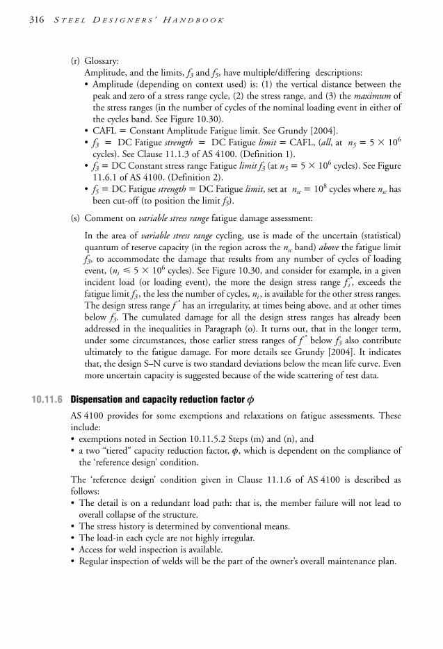
(r) Glossary:Amplitude, and the limits, f3 and f5, have multiple/differing descriptions: • Amplitude (depending on context used) is: (1) the vertical distance between the
peak and zero of a stress range cycle, (2) the stress range, and (3) the maximum ofthe stress ranges (in the number of cycles of the nominal loading event in either ofthe cycles band. See Figure 10.30).
• CAFL = Constant Amplitude Fatigue limit. See Grundy [2004].• f3 = DC Fatigue strength = DC Fatigue limit = CAFL, (all, at n5 = 5 106
cycles). See Clause 11.1.3 of AS 4100. (Definition 1).• f3 = DC Constant stress range Fatigue limit f3 (at n5 = 5 106 cycles). See Figure
11.6.1 of AS 4100. (Definition 2).• f5 = DC Fatigue strength = DC Fatigue limit, set at nsc = 108 cycles where nsc has
been cut-off (to position the limit f5).
(s) Comment on variable stress range fatigue damage assessment:
In the area of variable stress range cycling, use is made of the uncertain (statistical)quantum of reserve capacity (in the region across the nsc band) above the fatigue limitf3, to accommodate the damage that results from any number of cycles of loadingevent, (ni 5 106 cycles). See Figure 10.30, and consider for example, in a givenincident load (or loading event), the more the design stress range f *
i , exceeds thefatigue limit f3 , the less the number of cycles, ni , is available for the other stress ranges.The design stress range f * has an irregularity, at times being above, and at other timesbelow f3. The cumulated damage for all the design stress ranges has already beenaddressed in the inequalities in Paragraph (o). It turns out, that in the longer term,under some circumstances, those earlier stress ranges of f * below f3 also contributeultimately to the fatigue damage. For more details see Grundy [2004]. It indicatesthat, the design S–N curve is two standard deviations below the mean life curve. Evenmore uncertain capacity is suggested because of the wide scattering of test data.
10.11.6 Dispensation and capacity reduction factor φAS 4100 provides for some exemptions and relaxations on fatigue assessments. Theseinclude:• exemptions noted in Section 10.11.5.2 Steps (m) and (n), and• a two “tiered” capacity reduction factor, φ, which is dependent on the compliance of
the ‘reference design’ condition.
The ‘reference design’ condition given in Clause 11.1.6 of AS 4100 is described asfollows:• The detail is on a redundant load path: that is, the member failure will not lead to
overall collapse of the structure.• The stress history is determined by conventional means.• The load-in each cycle are not highly irregular.• Access for weld inspection is available.• Regular inspection of welds will be the part of the owner’s overall maintenance plan.
316 S T E E L D E S I G N E R S ’ H A N D B O O K
1106 SDHB 09-End Final 8/6/05 12:11 PM Page 316

The value of the design capacity factor is taken as follows:• φ = 1.0 for elements complying with the ‘reference design’ condition• φ 0.7 when the element in question does not comply with the reference design
condition. For instance, the element is on a non-redundant load path, e.g. wherethe failure of the member being considered is not kept in check by an adjoiningstructure or other fail-safe feature (see Clause 11.1.6 of AS 4100).
Welded tubular elements may be subject to high local stress concentrations, which arenot of great consequence to the design of ordinary building structures but are importantwhen stresses are fluctuating. The AS 4100 method is to increase the stress range using amultiplier (Table 10.5) instead of considering the effects of connection stiffness andeccentricities. Clause 11.3.1 of AS 4100 provides information on the use and limitationsof this method—e.g. the design throat thickness of a fillet weld must be greater than thehollow section thickness. Alternatively, CIDECT [2001] can be used for hollow sectionssubject to high levels of fatigue.
Table 10.5 Stress range multipliers for node connections of tubular trusses
Description Type of detail Chords Verticals Diagonals
Gap joints K-type 1.5 (1.5) 1.0 (1.0) 1.3 (1.5)
N-type 1.5 (1.5) 1.8 (2.2) 1.4 (1.6)
Overlap joints K-type 1.5 (1.5) 1.0 (1.0) 1.2 (1.3)
N-type 1.5 (1.5) 1.65 (2.0) 1.25 (1.4)
Note: Values in parenthesis apply to RHS/SHS and values outside parenthesis apply to CHS.
10.11.7 Improvement of fatigue life
Worthwhile improvements in the fatigue strength of welded components can be achievedby such weld improvement techniques as weld toe peening, toe grinding and toeremelting. It is important to obtain advice from an experienced welding engineer beforeembarking on these refinements. This is because small cracks often exist at toes(micro-cracks) which act as fatigue initiators in butt and fillet welds. Fillet welds areparticularly prone to such defects, as shown by their lower DC numbers. Hammerpeening is particularly effective and easy to apply; it consists of hitting the weld toesalong the whole length of weld with a hammer having small round point. The benefit isseen in reversing the tensile stress arising from weld shrinkage at the toe of the weld, intoa compressive stress. The other two techniques aim to remove the weld metal along theweld toes where micro-cracks are found by grinding away the burr or by arc remelting.It must be stressed that experienced operators supervised by a welding engineer shouldbe employed. Butt welds can also be given a ‘beneficiation’ treatment by improving theweld contours through grinding and peening the weld toes. Other specialised methodsof reducing residual stresses in the welds and in parent material are:• stress relieving, normalising—a process for reducing the residual stresses in the welds
using heat (500°–620°C) followed by (forced) air cooling.• warm stressing: a process of subjecting the welded structure to its service loads when
the temperature of the steel is above, say, 20°C.
S T R U C T U R A L F R A M I N G 317
1106 SDHB 09-End Final 8/6/05 12:11 PM Page 317

Advice from and supervision by a welding engineer is essential when contemplating theuse of these processes.
10.12 Corrosion protection
10.12.1 Methods of protection
Structural steels are susceptible to corrosion, and some method of corrosion protection isnecessary for steelwork exposed to a corrosive environment. However, corrosion protectioncan be omitted where weather-resistant steels are used in a mildly corrosive environment,or where standard steel grades are shielded from a corrosive environment as, for example,within the ceiling space or within the clad envelope of an air-conditioned building.
The principal methods of corrosion protection are painting and galvanizing. However,the whole subject of corrosion protection is too wide to cover in this Handbook, andother references should be consulted. AS/NZS 2312 is a good source of information. Seealso Section 10.13 on further reading.
10.12.2 Painting steelwork
Painting is specified for the majority of steelwork, and a variety of coating systems areavailable. The usual coating system consists of a corrosion-inhibiting primer and severaltopcoats. Traditional painting systems relied on anti-corrosive agents incorporated in theprimer coat, and on impermeability of the coating system. Modern coating systems usehigh-performance anti-corrosive ingredients, and a thinner coat of paint that requiremeticulous surface preparation. An example of such a paint system consists of inorganiczinc primer applied over a surface that has been grit-blasted to bright metal.
The importance of good surface preparation cannot be overemphasised. Steel, asmanufactured, is covered with a tightly adherent layer of mill scale, light rust, oil andimpurities. No paint can adhere to such a surface and stay on without blistering andpeeling. Brush cleaning used to be a traditional method of surface preparation, but thedurability of the coating over such a surface was not satisfactory. See also Section 10.13on further reading.
10.12.3 Galvanizing steelwork
Galvanizing provides effective protection against the corrosion of steelwork in mostoperating environments. The process known as hot-dip galvanizing consists ofimmersing the specially prepared steel elements in a bath of molten zinc, underconditions of carefully controlled temperature (about 450°C) and duration. Theresulting protective zinc layer is metallurgically and mechanically bonded to the steel, toprovide reliable barrier and sacrificial protection.
The preparation of steel surfaces must be thorough in order to achieve effectivebonding. All loose scale, rust and contaminants such as grease, dirt, wax-crayon, paintmarks, welding slag and flux must be removed; this is often done by caustic cleaning,followed by pickling in hydrochloric acid. The last step, before immersion in the zincbath, is fluxing. This prevents the formation of an oxide layer and promotes completefusing of the zinc coat.
318 S T E E L D E S I G N E R S ’ H A N D B O O K
1106 SDHB 09-End Final 8/6/05 12:11 PM Page 318

A well-executed galvanizing treatment provides a thickness of protection of up to 100+microns (depending on parent metal thickness amongst other factors). The coating layer isbasically split into two sub-layers: the lower layer, consisting of an alloy of zinc and iron;and an upper layer of pure zinc. Steel composition is important in this respect because anexcess content of silicon or phosphorus can result in a zinc/iron layer of excessive thickness,featuring unsightly dark-grey spots. When ordering steel sections and plates, the steelmanufacturer/supplier must be made aware that galvanizing will be applied.
The steel elements to be galvanized should be designed with galvanizing in mind. Thedesign aspects of particular importance for well-executed galvanized protection areas follows:• the disposition of long-run welds; unbalanced weld shrinkage forces. Also, asymmetrical
compound sections can increase the bow distortion in the member after galvanizing• venting and drainage of hollow sections: without venting there is a danger of bursting
during galvanizing and inadequate drainage will see unnecessary accumulation of zinc• detail design: full drainage of the molten zinc during withdrawal from the zinc bath
must be assured, for example full-length stiffeners should be snipped at the corners toallow drainage.
Fabricators should also be careful when sequencing the welded fabrication so as tominimise distortion. This is of particular importance when the welding elements consistof a mixture of thin and heavy plates and sections.
It is sometimes necessary to straighten members exhibiting relatively largeasymmetrical patterns of residual stresses induced during fabrication. It is preferable toidentify those prior to galvanizing so that hot straightening can be carried out prior togalvanizing. Cold straightening is less desirable because new residual stress patterns canbe introduced, with the risk that distortion may not be completely avoided.Straightening after the galvanizing is often unavoidable, but care should be exercised toavoid damage to the galvanized surface through physical injury, cracking and peeling ofthe zinc coating.
One way of avoiding problems with distortion is to pre-galvanize the sections, thencarry out welded splices, and protect the galvanized coat damaged by welding with azinc-rich protective coating applied over grit-blasted bare steel.
In general, galvanizing contractors have developed expertise in dealing with the aboveproblems and good-quality work can be achieved with proper planning and consultation.
As far as the economy of galvanizing is concerned, the decision should be based on a life-cycle costing that takes into account the initial cost of corrosion protection together withthe cost of coating maintenance. The cost analysis should be prepared with particularattention to severity of exposure to corrosive media. In a benign environment it is unlikelythat galvanizing would be more economical than some other low-cost protective treatment,while in a mild or aggressive (e.g. industrial) environment galvanizing is likely to be verycost-effective.
There are now many galvanized coating systems available. In its broadest sensegalvanizing can be considered to be either the:• traditional “post-fabrication” (or “batch”) galvanizing which provides relatively thick,
robust and reliable zinc coatings (these are provided to AS/NZS 4680)• automated (or “in-line”) galvanizing in which the zinc layer is controlled during a
mechanised process (supplied to such Standards AS/NZS 4791 and AS/NZS 4792)
S T R U C T U R A L F R A M I N G 319
1106 SDHB 09-End Final 8/6/05 12:11 PM Page 319

Additionally, for the automated processes, galvanizing can be further broken down into:• thermal immersion (i.e. “hot-dip” type)—see above• electro-galvanized (non-thermal)—as say, AS 4750 • zinc sprayed.
Publications such as GAA [2000] provide very useful information on galvanizing toAS/NZS 4680 as well as its properties, design, detailing, specification, inspection anddurability. AS/NZS 2312 is also a good reference on the durability of the abovegalvanizing systems for particular corrosion environments. The Galvanizers Associationof Australia (GAA) should be contacted (see Appendix A.6) for expert advice on all theabove galvanizing systems—specifically inherent properties and suitable applications.
10.13 Further reading• As noted earlier, AISC [1997] and Woolcock, et al. [1999] provide some good
information on structural framing systems and sub-systems. The former referenceoffers general advice on all systems and the latter considers more detailed informationon portal frame buildings. Though slightly dated, and in imperial measurements, AISE[1979] could be consulted as a guide on the design and construction of mill buildings.
• Interestingly, another good reference to consider is Ogg [1987]. Though written forarchitects, (the author is a qualified engineer and architect) the text and figures interms of history and technical detail is of high quality and makes for noteworthyreading of structural steelwork and cladding systems.
• For fire design, AS 4100 and references as Bennetts, et al. [1987,1990], O’Meagher, etal. [1992] and Thomas, et al. [1992] consider various aspects of the standard fire testas noted in AS 1530.4. Alternatively, a risk-based assessment could be undertaken tothe satisfaction of the regulators.
• For fatigue design, the internationally renowned fundamental text by Gurney [1979]should be consulted for steel and other metals. Alternatively, some very goodinformation can be obtained from Grundy [1985,2004] which reflects on localStandards. The AS 4100 Commentary (Figure C11) provides a flow-chart on the useof the fatigue design provisions in AS 4100.
• The situation with corrosion protection coatings is not static with many galvanizedcoating systems now present and sophisticated paint coating systems continuallyevolving. An excellent reference to consult is AS/NZS 2312 which describes thesesystems and provides guidance on system durability when the corrosion environmentis assessed—it also assists in assessing the latter item as well. Account must be taken of“macro” and “micro” environmental effects which are noted by the Standard (though,understandably, it is termed a “Guide”). AS/NZS 2311 should also be consulted forpainting of buildings. Francis [1996] provides a good summary on the mechanisms forsteelwork corrosion and an update of the systems available.
• There are various galvanizing Standards such as AS/NZS 4680, AS/NZS 4792, etc. Ofthese, AS/NZS 4680 (which replaced the now withdrawn AS 1650) considerstraditional after-fabrication galvanizing, which provides the thickest deposition of zinc
320 S T E E L D E S I G N E R S ’ H A N D B O O K
1106 SDHB 09-End Final 8/6/05 12:11 PM Page 320

S T R U C T U R A L F R A M I N G 321
and is commonly used in medium to aggressive environments. The other galvanizingStandards consider automated and semi-automated processes for the deposition of zincwith controlled thickness/coverage. GAA [2000] and the Galvanizers Association ofAustralia (GAA) can provide guidance in this area (see Appendix A.6).
• Paints for steel structures are noted in AS/NZS 2312 and AS/NZS 3750. Of these, zinc-rich paints are popular for structural steelwork (e.g. inorganic zinc silicates) which notonly provide corrosion protection by barrier action but also by sacrificial action.However, in many instances, structural steelwork within building envelopes may onlyrequire a primer-coat (say red-oxide zinc phosphate)—if there is to be any coating at all.
1106 SDHB 09-End Final 8/6/05 12:11 PM Page 321

A.1 ContentsAppendix A contains the following sub-sections, references and other information:
A.2 Standards and codesA.3 ReferencesA.4 Computer softwareA.5 Steel manufacturer/supplier websitesA.6 Steel industry association websites
A.2 Standard and codesReaders should note that the list of Standards in this section is not exhaustive and islimited to the most essential Standards. The year of revision (coupled with amendments(not listed) current at the time of publication of this Handbook) can change at any time,and the reader should make sure that only the current revisions/amendments are used.
Australian Building Codes Board (ABCB) – www.abcb.gov.au
BCA, The Building Code of Australia, 2003.
Committé Européen de Normalisation (CEN)[European Committee for Standardization] – www.cenorm.be
EC 3, Eurocode 3, Design of steel structures, Part 1.1 General rules and rules for buildings,1993-1-1:1992.
EC 4, Eurocode 4, Design of composite steel and concrete structures, Part 1.1: General rulesand rules for buildings, 1994-1-2:1994.
A p p e n d i x A
Bibliography
1106 SDHB 09-End Final 8/6/05 12:11 PM Page 322

Standards Australia – www.standards.com.au
AS 1085.1, Railway track material – Part 1: Steel rails, 2002AS 1101.3, Graphical symbols for general engineering – Part 3: Welding and non-destructive
examination, 1987.AS 1110, ISO metric hexagon bolts and screws.AS 1110.1, Product grades A & B – Bolts, 2000.AS 1110.2, Product grades A & B – Screws, 2000.AS 1111, ISO metric hexagon bolts and screws.AS 1111.1, Product grades C – Bolts, 2000.AS 1111.2, Product grades C – Screws, 2000.AS 1112, ISO metric hexagon nuts.AS 1112.1, Style 1 – Product grades A and B, 2000.AS 1112.2, Style 2 – Product grades A and B, 2000.AS 1112.3, Style 1 – Product grade C, 2000.AS 1163, Structural steel hollow sections, 1991.AS 1170.1, Minimum design loads on structures – Part 1: Dead and live loads and load
combinations, 1989.AS 1170.2, Minimum design loads on structures – Part 2: Wind loads, 1989.AS 1170.3, Minimum design loads on structures – Part 3: Snow loads, 1990 (plus
supplementary Commentary).AS 1170.4, Minimum design loads on structures – Part 4: Earthquake loads, 1993 (plus
supplementary Commentary).AS 1210, Pressure vessels, 1997.AS 1250, SAA steel structures code, 1981 (superseded).AS 1275, Metric screw threads for fasteners, 1985.AS 1391, Methods for tensile testing of metals, 1991.AS 1397, Steel sheet and strip, hot-dipped zinc-coated or aluminium/zinc-coated, 2001.AS 1418.1, Cranes, hoists and winches – Part 1: General requirements, 2002.AS 1418.3, Cranes, hoists and winches – Part 3: Bridge, gantry, portal cranes (including
container cranes) and jib cranes, 1997.AS 1418.5, Cranes, hoists and winches – Part 5: Mobile cranes, 2002.AS 1418.18, Cranes hoists and winches – Part 18: Crane runways and monorails, 2001.AS 1530.4, Methods for fire tests on building materials, components and structures – Part 4:
Fire-resistance tests of elements of building construction, 1997.AS 1548, Steel plates for pressure equipment, 1995.AS 1650, Galvanized coatings, 1989 (superseded).AS 1657, Fixed platforms, walkways, stairways and ladders – Design, construction and
installation, 1992.AS 2074, Cast steels, 2003.AS 2327.1, Composite structures – Part 1: Simply supported beams, 2003.AS 3597, Structural and pressure vessel steel – Quenched and tempered plate, 1993.AS 3600, Concrete structures, 2001.AS 3774, Loads on bulk solids containers, 1996 (plus supplementary Commentary).AS 3828, Guidelines for the erection of building steelwork, 1998.AS 3990, Mechanical equipment – Steelwork, 1993.AS 3995, Design of steel lattice towers and masts, 1994.
A P P E N D I X A : B I B L I O G R A P H Y 323
1106 SDHB 09-End Final 8/6/05 12:11 PM Page 323

AS 4100, Steel structures, 1998.AS 4100 Commentary, AS 4100 Supplement 1, Steel Structures – Commentary, 1999.AS 4750, Electrogalvanized (zinc) coatings on ferrous hollow and open sections.AS 5100, Bridge design, (numerous parts), 2004.
Standards Australia & Standards New Zealand
AS/NZS 1170.0, Structural design actions – Part 0: General principles, 2002 (plussupplementary Commentary).
AS/NZS 1170.1, Structural design actions – Part 1: Permanent, imposed and other actions,2002 (plus supplementary Commentary).
AS/NZS 1170.2, Structural design actions – Part 2: Wind actions, 2002 (plussupplementary Commentary).
AS/NZS 1170.3, Structural design actions – Part 3: Snow and ice actions, 2003 (plussupplementary Commentary).
AS/NZS 1252, High strength steel bolts with associated nuts and washers for structuralengineering, 1996.
AS/NZS 1554.1, Structural steel welding – Part 1: Welding of steel structures, 2004.AS/NZS 1554.2, Structural steel welding – Part 2: Stud welding (Steel studs to steel), 2003.AS/NZS 1554.3, Structural steel welding – Part 3: Welding of reinforcing steel, 2002.AS/NZS 1554.4, Structural steel welding – Part 4: Welding of high strength quench and
tempered steels, 2004.AS/NZS 1554.5, Structural steel welding – Part 5: Welding of steel structures subject to high
levels of fatigue loading, 2004.AS/NZS 1554.6, Structural steel welding – Part 6: Welding stainless steels for structural
purposes, 1994.AS/NZS 1559, Hot-dip galvanized steel bolts with associated nuts and washers for tower
construction, 1997.AS/NZS 1594, Hot-rolled steel flat products, 2002.AS/NZS 1595, Cold rolled, unalloyed steel sheet and strip, 1998.AS/NZS 2311, Guide to painting of buildings, 2000.AS/NZS 2312, Guide to the protection of structural steel against atmospheric corrosion by the
use of protective coatings, 2002.AS/NZS 3678, Structural steel – Hot-rolled plates, floorplates and slabs, 1996.AS/NZS 3679.1, Structural steel – Hot-rolled bars and sections, 1996.AS/NZS 3679.2, Structural steel – Welded I sections, 1996.AS/NZS 3750, Paints for steel structures, (numerous parts and years).AS/NZS 4291.1, Mechanical properties of fasteners made of carbon steel and alloy steel –
Bolts, screws and studs, 2000. AS/NZS 4600, Cold-formed steel structures, 1996.AS/NZS 4600 Supplement 1, Cold-formed steel structures – Commentary, 1998.AS/NZS 4671, Steel reinforcing materials, 2001.AS/NZS 4680, Hot-dip galvanized (zinc) coatings on fabricated ferrous articles, 1999.AS/NZS 4791, Hot-dip galvanized (zinc) coatings on ferrous open sections, applied by an in-
line process.AS/NZS 4792, Hot-dip galvanized (zinc) coatings on ferrous hollow sections, applied by a
continuous or specialized process, 1999.
324 S T E E L D E S I G N E R S ’ H A N D B O O K
1106 SDHB 09-End Final 8/6/05 12:11 PM Page 324

Standards New Zealand – www.standards.co.nz
NZS 3404.1, Part 1: Steel structures standard, 1997.NZS 3404.2, Part 2: Commentary to the steel structures standard, 1997.
A.3 ReferencesNotes:1)AISC/ASI: In 2002, the Australian Institute of Steel Construction (AISC) merged with
the Steel Institute of Australia (SIA) to become the Australian Steel Institute (ASI).2)BHP Steel Long Products/Tubemakers became Onesteel in 2000.3)BHP Steel/Bluescope: BHP Steel Flat Products became Bluescope Steel in 2003.4)PTM/SSTM: Palmer Tube Mills became Smorgon Steel Tube Mills in 2003.
AISC, 1985, Standardized structural connections, third ed., Australian Institute of SteelConstruction.
AISC, 1987, Safe load tables for structural steel, sixth ed., Australian Institute of SteelConstruction.
AISC, 1997, Economical structural steelwork, fourth ed., Australian Institute of SteelConstruction.
AISC, 1999a, Design capacity tables for structural steel, Vol 1: Open sections, third ed.,Syam, A.A. (editor), Australian Institute of Steel Construction.
AISC, 1999b, Design capacity tables for structural steel, Vol. 2: Hollow sections, second ed.,Syam, A.A. & Narayan, K. (editors), Australian Institute of Steel Construction.
AISC, 2001, Australian Steel Detailers’ Handbook, Syam, A.A. (editor), first edition,second printing, Australian Institute of Steel Construction.
AISC(US), 1993, Manual of Steel Construction – Volume II Connections: ASD (9’thed.)/LRFD (1’st ed.), American Institute of Steel Construction.
AISE, 1979, Guide for the design and construction of mill buildings, AISE Technical ReportNo. 13, American Society of Iron and Steel Engineers.
Baker, J.F. & Heyman, J., 1969, Plastic design of frames – 1. Fundamentals, CambridgeUniversity Press.
Beedle L.S., 1958, Plastic design of steel frames, John Wiley.Bennetts, I.D., Thomas, I.R. & Hogan, T.J., 1986, Design of statically loaded tension
members, Civil Engineering Transactions, Vol. CE28, No. 4, Institution of EngineersAustralia.
Bennetts, I.D., Proe, D.J. & Thomas I.R., 1987, Guidelines for assessment of fire resistanceof structural steel members, Australian Institute Steel Construction.
Bennetts, I.D., Thomas, I.R., Proe, D.J. & Szeto, W.T., 1990, Handbook of fire protectionmaterials for structural steel, Australian Institute of Steel Construction.
BHP Steel, 2002, Xlerplate & Xlercoil product/technical information and size schedules,BHP Steel (now called Bluescope Steel).
Bisalloy, 1998, Bisplate range of grades, Bisalloy Steel.Bleich, F., 1952, Buckling strength of metal structures, McGraw-Hill.Bradford, M.A., Bridge, R.Q. & Trahair, N.S., 1997, Worked examples for steel structures,
third ed., Australian Institute of Steel Construction.
A P P E N D I X A : B I B L I O G R A P H Y 325
1106 SDHB 09-End Final 8/6/05 12:11 PM Page 325

326 S T E E L D E S I G N E R S ’ H A N D B O O K
Bridge, R.Q. & Trahair, N.S., 1981, Thin walled beams, Steel Construction, Vol. 15,No.1, Australian Institute of Steel Construction.
Bridge, R.Q., 1994, Introduction to methods of analysis in AS 4100-1990, SteelConstruction, Vol. 28, No. 3, Paper 1, Syam, A.A. (editor), Australian Institute of SteelConstruction.
Bridge, R.Q., 1999, The design of pins in steel structures, Proceedings of the 2’ndInternational Conference on Advances in Steel Structures, Hong Kong.
Bridon, 1998, Structural systems, second ed., Bridon International Ltd.Burns, P.W., 1999, Information technology in the Australian steel construction industry, Vol.
33, No. 3, Syam, A.A. (editor), Australian Institute of Steel Construction.CASE, 1993, Pi, Y.L., & Trahair, N.S., Inelastic bending and torsion of steel I- beams,
Research Report No. R683, November 1993, Centre for Advanced StructuralEngineering, The University of Sydney.
CASE, 1994, Pi, Y.L., & Trahair, N.S., Plastic collapse analysis of torsion, Research ReportNo. R685, March 1994, Centre for Advanced Structural Engineering, The Universityof Sydney.
CASE, 1994, Pi, Y.L., & Trahair, N.S., Torsion and bending design of steel members,Research Report No. R686, March 1994, Centre for Advanced Structural Engineering,The University of Sydney.
CIDECT, 1991, Wardenier, J., Kurobane, Y., Packer, J.A., Dutta, D. & Yeomans, N.,Design guide for circular hollow section (CHS) joints under predominantly static loading,Verlag TUV Rheinland.
CIDECT, 1992, Packer, J.A., Wardenier, J., Kurobane, Y., Dutta, D. & Yeomans, N.,Design guide for rectangular hollow section (RHS) joints under predominantly staticloading, Verlag TUV Rheinland.
CIDECT, 1994, Twilt, L., Hass, R., Klingsch, W., Edwards, M. & Dutta, D., Designguide for structural hollow section columns exposed to fire, Verlag TUV Rheinland.
CIDECT, 1995, Bergmann, R., Matsui, C., Meinsma, C. & Dutta, D., Design guide forconcrete filled hollow section columns under static and seismic loading, Verlag TUVRheinland.
CIDECT, 2001, Zhao, X.L., Herion, S., Packer, J.A., Puthli, R.S., Sedlacek, G.,Wardenier, J., Weynand, K., van Wingerde, A.M. and Yeomans, N.F., Design guide forcircular and rectangular hollow section welded joints under fatigue loading, Verlag TUVRheinland.
CISC, 1991, Handbook of Steel Construction, first ed., Canadian Institute of SteelConstruction.
CRCJ, 1971, Handbook of structural stability, Column Research Committee of Japan,Corona.
Crandall, S.H., Dahl, N.C. & Lardner, T.J., 1978, An introduction to the mechanics ofsolids, second ed. with SI units, McGraw-Hill.
EHA, 1986, Engineers Handbook Aluminium – Design Data, second ed., The AluminiumDevelopment Council of Australia (Limited).
Fielders, 2004, Specifying Fielders – Fielders Design Manual, Fielders.Firkins, A. & Hogan, T.J., 1990, Bolting of steel structures, Syam, A.A. (editor), Australian
Institute of Steel Construction.
326 S T E E L D E S I G N E R S ’ H A N D B O O K
1106 SDHB 09-End Final 8/6/05 12:11 PM Page 326

Francis, R.F., 1996, An update on the corrosion process and protection of structural steelwork,Steel Construction, Vol. 30, No.3, Syam, A.A. (editor), Australian Institute of SteelConstruction.
GAA, 1999, After-fabrication hot dip galvanizing, fifteenth edition, GalvanizersAssociation of Australia.
Gorenc, B.E. & Tinyou, R., 1984, Steel designers’ handbook (working stress design), fifthed., University of New South Wales Press.
Gorenc, B.E., 2003, Design of crane runway girders, second edition, Australian Instituteof Steel Construction.
Grundy, P., 1985, Fatigue limit state for steel structures, Civil Engineering Transactions,Vol. CE27, No.1, The Institution of Engineers Australia.
Grundy P, 2004, Fatigue design of steel structures, Steel Construction, Vol. 38 No. 10,Australian Steel Institute.
Gurney, T.R., 1979, Fatigue of welded structures, second ed., Cambridge University Press.Hall, A.S., 1984, An introduction to the mechanics of solids, second ed., John Wiley.Hancock, G.J., 1994a, Elastic method of analysis of rigid jointed frames including second
order effects, Steel Construction, Vol. 28, No. 3, Paper 2, Syam, A.A. (editor),Australian Institute of Steel Construction.
Hancock, G.J., 1994b, Second order elastic analysis solution technique, Steel Construction,Vol. 28, No. 3, Paper 3, Syam, A.A. (editor), Australian Institute of Steel Construction.
Hancock, G.J., 1998, Design of cold-formed steel structures, third ed., Australian InstituteSteel Construction.
Harrison, H.B., 1990, Structural analysis and design, Parts 1 and 2, Pergamon Press.Hens, C.P. & Seaberg, P.A., 1983, Torsional analysis of steel members, American Institute
of Steel Construction.Heyman, J., 1971, Plastic design of frames – 2. Fundamentals, Cambridge University Press.Hogan, T.J. & Thomas, I.R., 1994, Design of structural connections, fourth ed., Syam,
A.A. (editor), Australian Institute of Steel Construction.Hogan, T.J. & Syam, A.A., 1997, Design of tapered haunched universal section members in
portal frame rafters, Steel Construction, Vol. 31, No. 3, Syam, A.A. (editor), AustralianInstitute of Steel Construction.
Horne, M.R., 1978, Plastic theory of structures, second edition, Pergamon Press.Horne, M.R. & Morris, L.J., 1981, Plastic design of low-rise frames, Granada.Hutchinson, G.L., Pham, L. & Wilson, J.L., 1994, Earthquake resistant design of steel
structures – An introduction for practicing engineers, Steel Construction, Vol.28, No.2,Syam, A.A. (editor), Australian Institute of Steel Construction.
Johnston, B.G., Lin, F.J. & Galambos, T.V., 1986, Basic steel design, Prentice Hall,Engelwood, NJ.
Keays, R., 1999, Steel stocked in Australia – A summary for designers of heavy steelwork,Steel Construction Vol. 33, No. 2, Syam, A.A. (editor), Australian Institute of SteelConstruction.
Kitipornchai, S. & Woolcock, S.T., 1985, Design of diagonal roof bracing rods and tubes,Journal of Structural Engineering, Vol. 115, No.5, American Society of CivilEngineers.
Kleinlogel, A., 1973, Rigid frame formulae, Frederick Unger, UK.
A P P E N D I X A : B I B L I O G R A P H Y 327
1106 SDHB 09-End Final 8/6/05 12:11 PM Page 327

Kneen, P., 2001, An overview of design aids for structural steelwork, Steel Construction,Vol. 35, No. 2, Australian Institute of Steel Construction.
Kotwal, S., 1999a, The evolution of Australian material Standards for structural steel, SteelConstruction, Vol. 33, No. 2, Syam, A.A. (editor), Australian Institute of SteelConstruction.
Kotwal, S., 1999b, The evolution of Australian material Standards for pressure vessel plate,Steel Construction, Vol. 33, No. 2, Syam, A.A. (editor), Australian Institute of SteelConstruction.
Kulak, G.L., Fisher, J.W. & Struik, J.H.A., 1987, Guide to design criteria for bolted andriveted joints, second edition, John Wiley and Sons.
Lambert, M.J., 1996, The life of mast stay ropes, Journal of the International Associationof Shell and Spatial Structures, Vol.37, No.121.
Lay, M.G., 1982a, Structural Steel Fundamentals, Australian Road Research Board.Lay, M.G., 1982b, Source book for the Australian steel structures code AS 1250, Australian
Institute of Steel Construction.Lee, G.C., Morrell, M.L. & Ketter, R.L., 1972, Design of tapered members, Bulletin No.
173, Welding Research Council, Australia.Lysaght, 2003, Purlin and Girt Users Manual, Lysaght/Bluescope Steel.McBean, P.C., 1997, Australia’s first seismic resistant eccentrically braced frame, Steel
Construction, Vol.31, No.1, Syam, A.A. (editor), Australian Institute of SteelConstruction.
Manolis, G.D. & Beskos, D.E., 1979, Plastic design aids for pinned-base gabled frames,(reprint from American Institute of Steel Construction), Steel Construction, Vol. 13,No. 4, Australian Institute of Steel Construction.
Massonnet, C., 1979, European recommendations (ECCS) for the plastic design of steelframes, (reprint from Acier-Stahl-Steel), Steel Construction, Vol. 13, No. 4, AustralianInstitute of Steel Construction.
Melchers, R.E., 1980, Service load deflections in plastic structural design, Proceedings, Part2, Vol. 69, Institution of Civil Engineers, UK.
Morris, L.J. & Randall, A.L., 1975, Plastic design, Constrado, London, UK.Murray, T.M., 1990, Floor vibration in buildings: Design methods, Australian Institute of
Steel Construction.Neal, B.G., 1977, The plastic methods of structural analysis, third ed., Chapman and Hall.O’Meagher, A.J., Bennetts, I.D., Dayawansa, P.H. & Thomas, I.R., 1992, Design of
single storey industrial buildings for fire resistance, Steel Construction Vol. 26, No. 2,Syam, A.A. (editor), Australian Institute of Steel Construction.
Oehlers, D.J. & Bradford, M.A., 1995, Composite steel and concrete structural members –Fundamental behaviour, first edition, Pergamon.
Ogg, A., 1987, Architecture in steel, Royal Australian Institute of Architects (RAIA). Onesteel, 2003, Hot rolled and structural steel products catalogue, third ed., Onesteel.Owens, G.W., & Cheal, B.D., 1989, Structural Steelwork Connections, Butterworths & Co.Packer, J.A. & Henderson, J.E., 1997, Hollow structural section connections and trusses –
A design guide, Canadian Institute of Steel Construction.Parsenajad, S., 1993, Deflections in pinned-base haunched gable frames, Steel Construction,
Vol. 27, No. 3, Syam, A.A. (editor), Australian Institute of Steel Construction.
328 S T E E L D E S I G N E R S ’ H A N D B O O K328 S T E E L D E S I G N E R S ’ H A N D B O O K
1106 SDHB 09-End Final 8/6/05 12:11 PM Page 328

Petrolito, J. & Legge, K.A., 1995, Benchmarks for non-linear elastic frame analysis, SteelConstruction, Vol. 29, No. 1, Syam, A.A. (editor), Australian Institute of SteelConstruction.
Pi, Y.L. & Trahair, N.S., 1996, Inelastic bending and torsion of steel I- beams, Journal ofStructural Engineering, Vol. 120, No. 12, American Society of Civil Engineers.
Pikusa, S.P. & Bradford, M.A., 1992, An approximate simple plastic analysis of portal framestructures, Steel Construction, Vol. 26, No. 4, Syam, A.A. (editor), Australian Instituteof Steel Construction.
Popov, E.P., 1978, Introduction to the mechanics of solids, second edition, Prentice-Hall,Englewood Cliffs, NJ.
Riviezzi, G., 1984, Curving structural steel, Steel Construction, Vol. 18, No. 3, AustralianInstitute of Steel Construction.
Riviezzi, G., 1985, Pin connections, Steel Construction, Vol. 19, No. 2, AustralianInstitute of Steel Construction.
Schmith, F.A., Thomas, F.M. & Smith, J.O., 1970, Torsion analysis of heavy box beams instructures, Journal of Structural Division, Vol. 96, No. ST3, American Society of CivilEngineers.
SSTM, 2003a, Product Manual, Syam, A.A. (editor), Smorgon Steel Tube Mills.SSTM, 2003b, Design capacity tables for structural steel hollow sections, Syam, A.A.
(editor), Smorgon Steel Tube Mills. Stramit, 2004, Stramit Purlins, Girts and Bridging, Stramit, 2004.Syam, A.A., 1992, Beam formulae, Steel Construction, Vol. 26, No.1, Syam, A.A.
(editor), Australian Institute of Steel Construction.Syam, A.A. & Hogan, T.J., 1993, Design capacity tables for structural steel, Steel
Construction, Vol. 27, No.4, Syam, A.A. (editor), Australian Institute of SteelConstruction.
Syam, A.A., 1995, A guide to the requirements for engineering drawings of structuralsteelwork, Steel Construction, Vol. 29, No. 3, Syam, A.A. (editor), Australian Instituteof Steel Construction.
Syam, A.A. & Chapman, B.G., 1996, Design of structural steel hollow section connections,Vol. 1: Design models, Australian Institute of Steel Construction.
Terrington, J.S., 1970, Combined bending and torsion of beams and girders, Journal, No.31, Parts 1 and 2, Constructional Steelwork Association, UK.
Thomas, I.R., Bennetts, I.D. & Proe, D.J., 1992, Design of steel structures for fire resistancein accordance with AS 4100, Steel Construction, Vol. 26, No. 3, Syam, A.A. (editor),Australian Institute of Steel Construction.
Timoshenko, S.P., 1941, Strength of materials, Vol.2, Van Nostrand Co.Timoshenko, S.P. & Gere, J.M., 1961, Theory of elastic stability, second ed., McGraw-
Hill.Trahair, N.S., 1992a, Steel structures: Lower tier analysis, Limit States Data Sheet DS02,
Australian Institute of Steel Construction/Standards Australia. (Also reprinted in theAS 4100 Commentary).
Trahair, N.S., 1992b, Steel structures: Moment amplification of first-order elastic analysis,Limit States Data Sheet DS03, Australian Institute of Steel Construction/StandardsAustralia. (Also reprinted in the AS 4100 Commentary).
A P P E N D I X A : B I B L I O G R A P H Y 329
1106 SDHB 09-End Final 8/6/05 12:11 PM Page 329

Trahair, N.S., 1992c, Steel structures: Elastic in-plane buckling of pitched roof portal frames,Limit States Data Sheet DS04, Australian Institute of Steel Construction/StandardsAustralia. (Also reprinted in the AS 4100 Commentary).
Trahair, N.S., 1993a, Steel structures: Second-order analysis of compression members, LimitStates Data Sheet DS05, Australian Institute of Steel Construction/StandardsAustralia. (Also reprinted in the AS 4100 Commentary).
Trahair, N.S., 1993b, Flexural-torsional buckling of structures, E. & F.N. Spon.Trahair, N.S., Hogan, T.J. & Syam, A.A., 1993c, Design of unbraced beams, Steel
Construction, Vol. 27, No. 1, Syam, A.A. (editor), Australian Institute of SteelConstruction.
Trahair, N.S., 1993d, Design of unbraced cantilevers, Steel Construction, Vol. 27, No. 3,Syam, A.A. (editor), Australian Institute of Steel Construction.
Trahair, N.S. & Bradford, M.A., 1998, The behaviour and design of steel structures toAS 4100, third ed. – Australian, E. & F. N. Spon.
Trahair, N.S. & Pi, Y.L., 1996, Simplified torsion design of compact I-beams, SteelConstruction, Vol. 30, No. 1, Syam, A.A. (editor), Australian Institute of SteelConstruction.
Watson, K.B., Dallas, S., van der Kreek, N. & Main, T., 1996, Costing of steelwork fromfeasibility through to completion, Steel Construction, Vol. 30, No. 2, Syam, A.A.(editor), Australian Institute of Steel Construction.
Webforge, 2001, Steel Grating, Webforge.Weldlok, 2001, Weldlok Grating, Weldlok Industries (a division of Graham Group).Woodside, J.W., 1994, Background to the new loading code – Minimum design loads on
structures, AS 1170 Part 4: Earthquake loads, Steel Construction, Vol. 28, No. 2, Syam,A.A. (editor), Australian Institute of Steel Construction.
Woolcock, S.T. & Kitipornchai, S., 1985, Tension bracing, Steel Construction, Vol. 19,No. 1, Australian Institute of Steel Construction.
Woolcock, S.T. & Kitipornchai, S., 1986, Portal frame deflections, Steel Construction,Vol. 20, No. 3, Australian Institute of Steel Construction.
Woolcock, S.T., Kitipornchai, S. & Bradford, M.A., 1999, Design of portal framebuildings, third ed., Australian Institute of Steel Construction.
WTIA, 2004, Technical Note 11 – Commentary on the Standard AS/NZS 1554 Structuralsteel welding, Cannon, B. (editor) & Syam, A.A. (editor in part), Welding TechnologyInstitute of Australia/Australian Steel Institute.
Young, W.C. & Budynas, R.G., 2002, Roark’s formulas for stress and strain, seventh ed.,McGraw-Hill.
A.4 Computer softwareStructural analysis and design software referred to in this Handbook:• Microstran – by Engineering Systems (www.engsys.com.au or www.microstran.com)• Multiframe – Formation Design (www.formsys.com/multiframe)• SpaceGass – by Integrated Technical Software (www.spacegass.com)• Strand7 – by G+D Computing (www.strand.aust.com)
330 S T E E L D E S I G N E R S ’ H A N D B O O K
1106 SDHB 09-End Final 8/6/05 12:11 PM Page 330

Structural steel software developers/suppliers providing other types of structural steelsoftware:
• Engineering Software Solutions (www.ess.com.au) – various analysis, design, costingand fabrication software.
• Strucad (www.acecad.co.uk) – 3D modeling and steel detailing.• X-Steel (www.tekla.com/www.pacificcomputing.com) – 3D modeling and steel
detailing.
A.5 Steel manufacturer/supplier websitesThough the listing is not exhaustive, some websites of relevant interest include :• Ajax Fasteners (www.ajaxfast.com.au)• Bisalloy Steel (www.bisalloy.com.au)• Bluescope Steel (www.bluescopesteel.com)• Fielders (www.fielders.com.au)• Lincoln Electric (www.lincolnelectric.com)• Lysaght (www.lysaght.com)• OneSteel (www.onesteel.com)• Smorgon Steel (www.smorgonsteel.com.au)• Smorgon Steel Tube Mills (www.smorgonsteel.com.au/tubemills)• Stramit (www.stramit.com.au)• Webforge (www.webforge.com.au)• Weldlok/Graham Group (www.weldlok.com.au/www.grahamgroup.com.au)
A.6 Steel industry association websitesThough the listing is not exhaustive, some websites of relevant interest include:• American Institute of Steel Construction [AISC(US)] – www.aisc.org• Australasian Corrosion Association [ACA] – www.corrprev.org.au• Australian Stainless Steel Development Association [ASSDA] – www.assda.asn.au• Australian Steel Institute [ASI – previously the Australian Institute of Steel
Construction (AISC) and Steel Institute of Australia (SIA)] – www.steel.org.au• Blast Cleaning and Coating Association of Australia [BCCA] – www.bcca.asn.au• British Constructional Steelwork Association [BCSA] – www.steelconstruction.org• Corrosion Prevention Centre [CPC] – www.corrprev.org.au• European Convention for Constructional Steelwork [ECCS] – www.steelconstruct.com• Galvanizers Association of Australia [GAA] – www.gaa.com.au• Heavy Engineering Research Association [HERA] – www.hera.org.nz• International Iron and Steel Institute [IISI] – www.worldsteel.org• National Asssociation of Steel Framed Housing [NASH] – www.nash.mx.com.au• National Association of Testing Authorities [NATA] Australia – www.nata.asn.au• NATSPEC – www.cis.asn.au• Steel Construction Institute (U.K.) [SCI] – www.steel-sci.org• Surface Coatings Association Australia [SCAA] – www.scaa.asn.au• Welding Technology Institute of Australia [WTIA] – www.wtia.com.au
A P P E N D I X A : B I B L I O G R A P H Y 331
1106 SDHB 09-End Final 8/6/05 12:11 PM Page 331

B.1 ContentsAppendix B contains the following sub-sections:
B.2 IntroductionB.3 Elastic section propertiesB.4 Biaxial and triaxial stressesB.5 Stresses in connection elementsB.6 Unsymmetrical bendingB.7 Beams subject to torsionB.8 Further reading
B.2 IntroductionThe elastic design method or “permissible stress” method is occasionally used in designfor the following applications:• elastic section properties for deflection calculations• triaxial and biaxial stresses (e.g. as used in structural/mechanical components modelled
by finite element (F.E.) methods using elements with more than one dimension—plates, bricks, etc)
• stress range calculations for fatigue assessment• stresses in connection elements• elastic torsion analysis • other permissible stress-based design procedures (e.g. in mechanical, pressure vessel,
vehicular, etc applications).
Additionally, past designs based on the permissible stress method may need to beappraised to give the designer some knowledge of pre-limit states design. Readers shouldnote that the permissible stress method of design is also known as “working stress” or
A p p e n d i x B
Elastic Design Method
1106 SDHB 09-End Final 8/6/05 12:11 PM Page 332

“allowable stress”—the latter term being more commonly used in the USA. The purposeof this section is to outline material pertaining to the elastic method of design.
Due to the nature of loading and differing “limiting” design conditions, mechanicaland process engineers prefer—if not require—to stay with permissible stress methods toevaluate the “working” capacity of steel members and connections. AS 3990 (which isessentially a “rebadged” version of AS 1250—the predecessor to AS 4100) is used quitecommonly in these instances. Another good reference on the topic is a previous editionof this Handbook (Gorenc & Tinyou [1984]).
Lastly, as is evidenced in the body of the Handbook and this Appendix, many of theparameters used in elastic design methods are also used in evaluating the various limitingconditions for the limit states design of steel structures.
B.3 Elastic section properties
B.3.1 Cross-section area
It is necessary to distinguish the “gross” cross-section area and the “effective” (or “net”)cross-section area. The effective cross-section area is determined by deducting bolt holesand other ineffective areas of the cross-section which have excessive slenderness (seeSection 4 of AS 3990). The cross-section may then be considered to be a “compound”area—i.e. composed of a series of rectangular and other shape elements which form thegross cross-section.
B.3.2 Centroids and first moments of area
After establishing the compound area, the centroid of the section about a specific axis isthen determined. The centroid is sometimes called the centre of area (or mass or gravity)and is further explained in numerous fundamental texts on mathematical, structural andmechanical engineering. Essentially, the coordinate of the centroid position (xc , yc) froma datum point for the compound area made up of n elements about a specific axis can beevaluated by:
xc
yc
where Ai, xi and yi are respectively the area and centroidal coordinates from the datumpoint/axis for area element i. The terms Ai xi and Ai yi are called the first moments of area.
n
1
( Aiyi)
n
1Ai
n
1
( Ai xi)
n
1Ai
A P P E N D I X B : E L A S T I C D E S I G N M E T H O D 333
1106 SDHB 09-End Final 8/6/05 12:11 PM Page 333

B.3.3 Second moments of area
The second moment of area (Ix and Iy) of a compound section is given by:
Ix = n
1Ixi Ai (yi yc )2
Iy = n
1Iyi Ai (xi xc )2
If the datum point is shifted to the centroid then xc and yc are taken as zero in the aboveequations for I. Values of I for standard hot-rolled open sections, welded I-sections andstructural steel hollow sections are listed in AISC [1987] (given with other permissiblestress design data), AISC [1999a], Onesteel [2003] and SSTM [2003a,b].
B.3.4 Elastic section modulus
The elastic section modulus (Z ) is used in stress calculations and is determined from thesecond moment of area in the following manner:
Zx = and Zy =
where ye and xe are the distances from the neutral axis to the extreme point(s) of thesection. Z has two values for unsymmetrical sections about the axis under consideration,the more critical being the lower Z value which has the larger distance from the neutral axis.
B.3.5 Sample calculation of elastic section properties
The calculation of the above section properties can be done in the following manner withthe trial section noted in Figure B.1. Assume initially that all plate elements havefy = 250 MPa and use Table 5.2 of AS 4100 to ascertain the slenderness limits of theflange outstand and web.
Figure B.1 Trial section
(a) Compactness of flanges: The top flange is the more critical of the flanges as it is thethinnest for the equal flange width section. The element slenderness of the top flangeoutstand, λef, is:
λef = = 250250
(200 8)
2 12
fy250
bt
12 1
2
3
4
12
16
8
180
376
200
416
200
yi
Iyxe
Ixye
334 S T E E L D E S I G N E R S ’ H A N D B O O K334 S T E E L D E S I G N E R S ’ H A N D B O O K
1106 SDHB 09-End Final 8/6/05 12:11 PM Page 334

= 8.00 λep (= 8 from Table 5.2 of AS 4100 for LW plate)
The flange outstand is compact and fully effective though λef is at its limit. If λef λep
then only the effective part of the outstand—i.e. beff (= λept) is considered in thesection calculation and the balance of the outstand is disregarded.
(b) Compactness of web:
λew = = = 47.0 λep (= 82 from Table 5.2 of AS 4100)
The web is compact and therefore fully effective.The total area and first moment of area are listed in Table B.1 with centre of
gravity subsequently calculated below.
Table B.1 Area and first moment of area for trial section
Section Size Areas, Aei Distance, yi Product, Aeiyipart, i mm mm mm2 mm mm3
1 top flange 200 ×12 2400 410 984 ×103
2 web 376 ×8 3010 216 650 ×103
3 bottom flange 200 ×12 2400 22 52.8 ×10³
4 btm. flange plate 180 ×16 2880 8 23.0 ×10³
Sum totals: 10 700 mm2 1710×103 mm3
Distance from base to neutral axis (i.e. centre of graxity x-axis):
yc = ΣΣAAei
e
y
i
i =
171
1
0
07
00
103
= 160 mm
The intermediate values required for the evaluation of the second moment of area arelisted in Table B.2.
Table B.2 Second moment of area, Ix
Section Areas, Aei Distance, ei Product, Aeiei2 Ixi
part, i mm2 mm mm4 mm4
1 top flange 2400 250 150 ×106 0 (negligible)
2 web 3010 56.0 9.44 ×10⁶ 35.4 ×10⁶
3 bottom flange 2400 –138 45.7 ×10⁶ 0 (negligible)
4 btm. flange plate 2880 –152 66.5×10⁶ 0 (negligible)
Note: ei yi – yc and Ixi ab3/12 where a and b are the relevant plate dimensions.
250250
376
8
fy
250
bt
A P P E N D I X B : E L A S T I C D E S I G N M E T H O D 335
1106 SDHB 09-End Final 8/6/05 12:11 PM Page 335

336 S T E E L D E S I G N E R S ’ H A N D B O O K336 S T E E L D E S I G N E R S ’ H A N D B O O K
The trial section second moment of area about the x-axis is:
Ix = 4
1Ixi Ai(yi yc)
2
= (35.4 150 9.44 45.7 66.5) 106 = 307 106 mm4
The trial section elastic section moduli about the x-axis is:
ZxT = = = = 1200 103 mm3
(to top flange outer fibre)
ZxB = yI
e
x
B =
Iyx
c = = 1920 103 mm3
(to bottom flange outer fibre)
B.3.6 Calculated normal stresses
The term ‘calculated’ stress is used to denote a nominal stress determined by simpleassumptions and not a peak stress that occurs in reality. Stresses occurring in realitywould need to include the residual stresses induced by rolling and thermal cutting, stressconcentrations around holes and at notches, and triaxial stresses. This can be doneexperimentally or by carrying out a finite element analysis but is a more complex exercise.
The normal or “axial” stress on a tension member or tie, σa, with an effective cross-section area, Ae, subject to an axial force, N, is:
σa = AN
e 0.6 fy
The same applies to a stocky compression member (not prone to buckling).A longer strut fails by buckling, and the following check is necessary:
σac = AN
e permissible stress for buckling
The permissible stress for buckling depends on the strut slenderness ratio, L/r , where:
Lr
= L
re f f where Leff is the effective buckling length and r =
AI
For further details, see Section 6 of AS 3990.Bending stresses, σb, on a ‘stocky’ beam with an elastic section modulus, Z, subject to
bending moment, M, are given by:
σb = MZ
0.66fy
For a slender beam, that is, a beam prone to flexural-torsional buckling:
MZx
x permissible stress for flexural-torsional buckling
See Section 5 of AS 3990 for the method of determining permissible bending stresses.
307 106
160
307 106
(416 160)
Ix(D yc)
IxyeT
1106 SDHB 09-End Final 8/6/05 12:11 PM Page 336

A P P E N D I X B : E L A S T I C D E S I G N M E T H O D 337
For bending combined with axial tension or bending with axial compression on ashort/stocky member:
0
σ.6
a
fy
0.
σ66
b
fy 1.0
Bending and axial compression of a slender member must be verified by the method ofcalculation given in Section 8 of AS 3990.
B.3.7 Calculated shear stresses
In general, for a flanged section subject to shear down the web, the transverse shearstress is:
τ = IV
x
Qtw
where V is the shear force, Q is the first moment of area of the part of the section abovethe point where the shear stress is being calculated, Ix is the second moment of area aboutthe x-axis and tw is the web thickness. For an equal-flanged I-beam, the average shearstress is:
τav = tw
Vd
where d is the depth of the I-section. As the maximum shear stress at the neutral axis areonly slightly higher than the shear stresses at the flanges, the average shear stress is takenas the maximum shear stress for such sections.
Conversely, a plate standing up vertically has a maximum shear stress at the neutralaxis of:
τmax = 1.
t5
dV
which is 50% more than the average shear stress.The maximum permissible shear stress is generally taken as:
τvm 0.45fyFor I- sections, channels, plate girders, box and hollow sections, the average shear stressshould satisfy:
τav 0.37fythis would reduce for slender webs, or be different for stiffened webs as noted in Clause5.10.2 of AS 3990.
B.4 Biaxial and triaxial stressesThe design provisions noted in many typical structural steel design Standards (AS 3390,AS 4100, NZS 3404 and other similar national Standards) consider stress states whichare generally uniaxial (single direction) in nature. These assumptions readily lendthemselves to structural elements with:
elemental thicknesses (t) member depth (d ) member length (L)
1106 SDHB 09-End Final 8/6/05 12:11 PM Page 337

However, for structural elements in which the stress state is more complex with normalstresses in three mutually orthogonal directions and associated shear stresses, othermethods of assessing the “failure” condition are required. Such applications include plateswith double curvature bending and through-thickness shearing, pressure/cylindricalvessel design, stressed skin construction, induced stresses in thick/very thick elements,connection stresses from welding, etc. In these instances, an assessment of the triaxialstress state would have to be undertaken. These methods lend themselves to permissibledesign principles.
Indeed, many of the structures and elements considered in AS 3990, AS 4100, etccould be analysed for the triaxial stress state condition—e.g. in structural connectionssuch as the beam flange welded to column flange connections with/without columnflange/web stiffeners. The stress state is more than uniaxial and complex. However, toassess these and other situations by triaxial stress state methods for “stick” type structuresrequires much effort and in many instances can be avoided by simplifying rationalassumptions, research outcomes and good structural detailing.
If triaxial stress state analysis is undertaken, the following failure condition (developedfrom the von Mises yield criterion) is generally applied where an equivalent stress, eq ,is established and must be less than or equal to a factored limit which embraces thecommonly used yield stress, fy, from a uniaxial tensile test:
2eq = (x y )
2 (y z )2 (z x )2 3 2xy 3 2
yz 3 2zx 2f y
2
where x , y , z are the normal stresses and xy , yz , zx are the shear stresses for theelement/point under consideration. If the principal axis stresses (1, 2, 3 ) are onlyconsidered (i.e. shear stresses are zero) the above equation reduces to:
2eq = (1 2 )2 (2 3 )2 (3 1 )2 2f y
2
For elements subject to a biaxial stress state (i.e. with normal stresses in only twodirections such as steel plates subject to bending and membrane stresses, thin pressurevessels, etc), the above non-principal axes criterion can be reduced with minormodification to the following with a permissible stress limit (Lay [1982b],Trahair & Bradford [1998]):
eq ( x2 y
2 xy 32xy) fy
Depending on the text being referenced, the value of is between 0.60 to 0.66. Theabove equation is the basis for fillet weld design in AS 3990.
From the above, for the condition of uniaxial normal and shear stress, the followingmay be used in permissible stress design:
eq ( x2 32) fy
This can now be used to develop the permissible stress limits for the case of pure uniaxialstress ( 0) and pure shear stress present (eq 0).
The critical aspect of biaxial and triaxial stress states is to relate it to a failure condition.Many texts on strength of materials consider several theories on these types of conditions.Some of these include:
338 S T E E L D E S I G N E R S ’ H A N D B O O K
1106 SDHB 09-End Final 8/6/05 12:11 PM Page 338

• Maximum normal stress theory—states that the failure condition of an element subjectto biaxial or triaxial stresses is reached when the maximum normal stress attains itsuniaxial stress limiting condition. This theory is in good agreement with testing ofbrittle materials and failure generally manifests itself as yielding or fracture.
• Maximum shearing stress theory—considers the failure condition of an element subjectto biaxial or triaxial stresses to occur when the maximum shearing stress attains thevalue of shear stress failure from a simple axial tension/compression test. Though morecomplex it gives a good reflection of ductile material behaviour.
• von Mises Yield Criterion—also called Huber or Hencky Yield Criterion or Maximumenergy of distortion theory. This is the most commonly used failure condition (notedabove) and provides a good assessment of ductile materials.
B.5 Stresses in connection elementsConnection elements consist of gussets, web and end plates, eye plates, connection anglesand a variety of other details. These elements are not easy to design correctly and oftenfall into the ‘too hard’ basket. Judging by published reports, the number of collapsescaused by inadequate connections is significant.
The force distribution from the fasteners (bolts, welds) into the gusset plate follows thedispersion rule, so named because the highly stressed areas widen down the load path.The angle of dispersion in working stress design is 30-45 degrees from the member axis.
Interestingly, apart from bolt shear design, fillet/incomplete penetration butt welddesign and bearing design, most of the AS 4100 limit state connection design provisionsand associated (separately published) connection design models are “soft-converted”from permissible stress methods. This is due to the rational basis and simplicity of thesemethods in lieu of the detailed research, testing and application required of limit statesconnection models.
B.6 Unsymmetrical bendingThe term ‘unsymmetrical bending’ has been used in permissible stress design and refersto bending about an axis other than the principal axes. For doubly symmetrical sections,this means the load plane passes through the centroid but is inclined to the principalaxes. In monosymmetrical sections (I-beam with unequal flanges) and in channelsections, two conditions should be distinguished:
(a) The load plane passes through the shear centre which is the centre of twisting, withthe result of bending and no twisting occuring.
(b) The load plane does not pass through the shear centre, and bending is accompaniedby torsion.
Figure B.2 illustrates the two conditions.
A P P E N D I X B : E L A S T I C D E S I G N M E T H O D 339
1106 SDHB 09-End Final 8/6/05 12:11 PM Page 339

Figure B.2 Biaxial bending of monosymmetrical sections
Unsymmetrical bending without torsion is treated differently in the strength limit statedesign method of AS 4100. The loads are resolved into components parallel with theprincipal planes and the bending moments determined accordingly. The sectioncapacities are determined for each principal plane, and a check is made for biaxialbending capacity using an interaction equation as described in Chapter 6. SeeSection B.7 for the interaction of bending and torsion.
B.7 Beams subject to torsion
B.7.1 General
The most optimal sections for torsional loads are closed sections (i.e. hollow sections orsolid circular) which don’t warp. Of these, circular sections are the most optimal and areinitially used to theoretically determine torsional behaviour. Like members subject tobending, the behaviour of circular members when subject to torsional loads are assumedto have plane sections that remain plane but rotate (about the longitudinal axis) withrespect to each other. Additionally, within a circular cross-section there is theassumption that shear strain (and hence shear stress) varies in direct proportion to theradius in the cross-section—i.e. no shearing at the centre and highest shear strain at thecircumference. For circular and closed section members, torsional loadings are resistedby uniform torsion.
Some modification of torsional behaviour theory is required for non-circular sections.For non-circular hollow sections (e.g. RHS/SHS), allowance must be made for the highershear stresses at the corners. A method for this is described in SSTM [2003b]. Asignificant change in torsional behaviour occurs with open sections which resist torsionalloads by a combination of uniform torsion and warping torsion as noted in Figure B.3.
F*s.c.
(a) Biaxial bending without torsion (b) Biaxial bending with torsion
Legend: s.c shear centre; c.g. centre of gravity
s.c.c.g.
s.c.
c.g.
c.g.
s.c.
c.g.
ee
F*
F* F*
340 S T E E L D E S I G N E R S ’ H A N D B O O K
1106 SDHB 09-End Final 8/6/05 12:11 PM Page 340

From this it can be surmised that uniform torsion embrace cross-sectional shear stresseswhereas warping torsion embrace shear and normal (out-of-plane) stresses. Due to thiscomplexity, there are no readily available “manual” or closed form solutions in structuralcodes for routine design of open sections subject to torsional loadings.
Figure B.3 Uniform torsion and warping of open sections
Consequently, there are no provisions in AS 4100 for dealing with members subjecteither to pure torsion or to torsion with bending. However, the AS 4100 Commentarygives a general outline of the problem and some specific recommendations fordetermining the capacity of members subject to bending and torsion.
Basically, there are three types of behaviour of members subject to torsion:• self-limiting or secondary torsion, which occurs when there are lateral restraint
members that are able to prevent excessive angle of twist• free torsion, where there are restraints against lateral displacements but no restraints
against twisting• bending with destabilising torsion, where no restraints are available and the torsion
interacts unfavourably with flexural-torsional bending.
Torsion of the self-limiting type occurs quite often. For example, a floor beamconnected to a girder using a web cleat generates torsion in the girder, which diminishesas the slack in the bolts is taken up, without causing any significant torsion effects in thegirder. In such cases torsion can easily be neglected in capacity verification.
Free and destabilising torsion, in contrast, do not diminish with the increased angle oftwist and therefore cannot be neglected. There are no detailed provisions for computingtorsional effects in AS 4100 (although the AS 4100 Commentary offers useful advice).This is because the subject of torsion with bending is too broad and complex for(building) structural applications. In many cases the designer may have no choice but touse the elastic solutions described in the literature on the subject (Terrington [1970]) orrefer to more recent references (Trahair & Pi [1996]). Table B.3 provides some memberbehaviour information for free torsion.
MtTorsion Warping
A P P E N D I X B : E L A S T I C D E S I G N M E T H O D 341
1106 SDHB 09-End Final 8/6/05 12:11 PM Page 341

Table B.3 Angle of twist, θ, and torsion shear stress, τ
Section Characteristic Angle of twist/dimensions Shear stress
Round bar r = radius θ 2 (G
Mπt
rL4)
d = diameter 3(G2πMdt4)L
τ (
2
π
M
r 3t
)
(1π6dM3)
t
Circular Tube ro = external radius θ [G π
2(rM
o4t L
ri4)]
ri = internal radius [Gπ
3(2do
4Mt
dL
i4)]
do = external diameter τ [π(
2ro
M4
t rro
i4)]
di = internal diameter [π
1(6do
4M
t
dd
i
o4)]
Square bar s = side θ 7.1
(G0s4M)t L
τ 4.8
s13
Mt
Plate b = long side θ (Gα
M
1
t
tL3b)
t = thickness τ (α2
Mtt2b)
I-section bi = element width θ (MJt
GL)
ti = element thickness τmax Mt t
Jmax
J = torsion constant = Σ(α2ti3bi)
α2 see for Plate
Box, other sections See Bridge & Trahair [1981]
Notes: 1. Above sections are for members loaded only by equal and opposite twisting moments, Mt , and endsections are free to warp.
2. θ = angles of twist.3. τ = torsional shear stress (for square bar/plate this is at the mid-point of the longer side and for
non-circular sections this may not be the peak shear stress).4. L = length of member free to rotate without warping restraints between points of Mt being applied.5. G = shear modulus of elasticity (taken as 80 103 MPa for steel).6. For RHS and SHS see Section 3 of SSTM [2003b].
342 S T E E L D E S I G N E R S ’ H A N D B O O K
bt
1.0 2.0 4.0 6.0 8.0 10.0 10.0
α1 0.141 0.229 0.281 0.298 0.307 0.312 0.333
α2 0.208 0.245 0.282 0.298 0.307 0.312 0.333
1106 SDHB 09-End Final 8/6/05 12:59 PM Page 342

B.7.2 Torsion without bending
The torsional resistance of a beam twisting about its (longitudinal) z-axis is usuallydivided into: uniform (St Venant) torsion and non-uniform (Warping) torsion—seeFigures B.3, B.4 and B.7. Uniform-torsion occurs in bars, flats, angles, box-sections andhollow sections. Warping generally occurs when the (cross-) section is no longer planar(i.e. parts of the section do not remain in its original plane) during the plane’sdisplacement as the member twists. The warping resistance against twisting (or torsion)develops if the displacement is (wholly or partially) prevented, (e.g. by an immovable orresisting contiguous section of the beam, or construction). Increased warping resistanceimproves member moment capacity (resistance). Non-uniform torsion arises in parallel-flanged open-sections (e.g. I-sections and channels). Warping resistance results from thedifferential in-plane bending of parallel plate elements such as the beam flanges. On theother hand, open sections consisting of one plate, or having two intersecting plates (e.g.angles and T sections) have negligible warping resistance.
B.7.2.1 Uniform torsionIn a member under uniform torsion with none of the cross-sections restrained againstwarping, the torsional moment Mz is:
Mz G
LJ φ
where φ is the angle of twist over the length L and J is the torsional constant.For an open section consisting of rectangular elements of width b and thickness t :
J ∑b3
t3
where each
b3
t3
term is the torsion constant of that element. For example, J for anI-section becomes:
J (2 bf tf
3
3
d1tw3)
where d1 d 2tf (see also Table B.3 for a more precise evaluation of J ).For a box section of any shape and enclosing only one internal cell, J is given by:
J
where s/t is the length-to-thickness ratio of the component walls along the periphery of
the section. In particular, a thin-walled round hollow section has:
Ao π
4
d 2
,
∑ ts
πtd,
J πd
4
3t
4Ao2
Σts
A P P E N D I X B : E L A S T I C D E S I G N M E T H O D 343
1106 SDHB 09-End Final 8/6/05 12:11 PM Page 343

The concept of the enclosed area Ao can also be extended to closed box tubes, where:
Ao (D t) (B t)
In this expression, D is the overall depth of the box and B is its width.The above expressions are valid only for closed sections such as tubes and box sections,
because their sections after twisting remain in their plane within practical limits ofaccuracy, and the torsional resistance contributed by the parts of the cross -section isproportional to their distance from the centre of twist.
For an I-section member under uniform torsion such that flange warping isunrestrained (see Figure B.5), the pattern of shear stress takes the form shown inFigure B.4.
Figure B.4 Torque-induced shear flow for uniform torsion
Uniform torsion can also arise in I-beams, channels and other open sections whereflanges are not restrained against warping. Open sections are substantially less rigidtorsionally than sections of the same overall dimensions and thickness with flangesrestrained against warping.
The torsional rigidity of a member is GJ, where G is the shear modulus of elasticity(80 000 MPa for steel) and J is the torsion constant. A circular section, whether solid orhollow, is the only instance in which J takes the same value as the polar second momentof area. For other sections, J is less than the polar second moment of area and may beonly a very small fraction of it.
As noted in AS 3990, the verification of torsional capacity can be based on the elasticdesign method by limiting the shear stresses under design loads (factored loads) to:
fv 0.45 fy
This is conservative because plastic theory predicts higher shear capacity. Many references(e.g. Trahair & Pi [1996]) suggest a 28% increase in capacity by using the von MisesYield Criterion:
fv 0.60 fy
For an open section or a circular tube under uniform torsion, the maximum shear stress,fv , is:
fv M
Jzt
in which the maximum fv occurs in the thickest part of the cross-section.
T
(a) Closed tube (b) Open section (c) Bar (d) I–section
T T T
344 S T E E L D E S I G N E R S ’ H A N D B O O K
1106 SDHB 09-End Final 8/6/05 12:11 PM Page 344
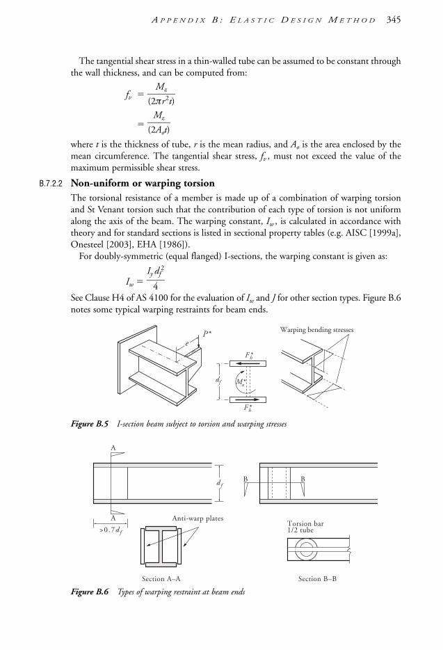
The tangential shear stress in a thin-walled tube can be assumed to be constant throughthe wall thickness, and can be computed from:
fv (2
M
πrz2t)
(2
M
Ao
z
t)
where t is the thickness of tube, r is the mean radius, and Ao is the area enclosed by themean circumference. The tangential shear stress, fv , must not exceed the value of themaximum permissible shear stress.
B.7.2.2 Non-uniform or warping torsionThe torsional resistance of a member is made up of a combination of warping torsionand St Venant torsion such that the contribution of each type of torsion is not uniformalong the axis of the beam. The warping constant, Iw , is calculated in accordance withtheory and for standard sections is listed in sectional property tables (e.g. AISC [1999a],Onesteel [2003], EHA [1986]).
For doubly-symmetric (equal flanged) I-sections, the warping constant is given as:
Iw Iy
4
df2
See Clause H4 of AS 4100 for the evaluation of Iw and J for other section types. Figure B.6notes some typical warping restraints for beam ends.
Figure B.5 I-section beam subject to torsion and warping stresses
Figure B.6 Types of warping restraint at beam ends
d fB
A
Anti-warp plates
Section A–A Section B–B
Torsion bar1/2 tube
A
B
>0.7d f
P*e
F*h
F*h
df
Warping bending stresses
M *z
A P P E N D I X B : E L A S T I C D E S I G N M E T H O D 345
1106 SDHB 09-End Final 8/6/05 12:11 PM Page 345

B.7.3 Torsion with bending—working stress method
A method of analysis to determine the normal stress due to torsion is given by Terrington[1970]. When warping of the flanges is totally prevented (Figure B.6), the shear stressthrough the thickness of the flange is practically constant and takes the distributionshown in Figure B.7(b). Under these conditions each flange is subjected to a shear flowlike that in an ordinary rectangular section beam carrying a horizontal transverse load.The most effective way of achieving complete restraint against warping of the flanges ofan I-section is to box in the section by the addition of plates welded to the tips of theflanges (Figure B.6 again).
Figure B.7 Shear stress distributions
Away from a location in which flange warping is restrained, the shear stress distributionis generally a combination of that shown in Figure B.7(a) and (b). The farther away thesection of a beam is from a location of warping restraint, the more similar is thedistribution to that in Figure B.7(a). A rough approximation of the distance necessaryfrom a position of flange warping restraint to a point along the beam in which theinfluence of restraint is negligible (and thus approaching the distribution inFigure B.7(a)) is given by:
a EGIJw
where a is the torsion bending constant, and Iw is the warping constant (seeSections 5.5.3.3, 5.6, B.7.2.2 of this Handbook and Appendix H of AS 4100), that is:
Iw Iy
4
h 2
, approximately, for an equal-flanged I-section or a channel where h df distance between flange centroids.
The torsion bending constant, a, is combined with the span, L, into a dimensionlessparameter L /a for use in Tables B.4(a) and B.4(b), which have been adapted fromJohnston et al. [1986]. The influence of warping and uniform torsion based on beamdistance from a warping restraint is shown in Figure B.8.
fV
(a) Uniform torsion for (b) Warping torsion for torsionally
fV
section free to warp restrained section (not free to warp).
346 S T E E L D E S I G N E R S ’ H A N D B O O K
1106 SDHB 09-End Final 8/6/05 12:11 PM Page 346

Figure B.8 Plot of percentage of warping torsion as a function of La
(from Johnston et al. [1986])
Although box sections are most suitable, sometimes short stocky lengths of I-sectionsmay be adequate in strength and stiffness for use in combined bending and torsion. Ifthe span, L, of a cantilever beam is less than 0.5a (Figure B.8), the pair of flanges act liketwin beams loaded in opposite directions to take all the applied torsional moment,M*
z (Figure B.5). For an I-section cantilever beam, carrying a load at the free tip with aneccentricity, e, to the centre of the beam, then from Figure B.5 the horizontal force, F*
h ,acting on each flange is given by:
F*h
M
h
*z
Ph
*e
Tables B.4(a) and B.4(b) include simple approximate expressions for the maximumflange moment, Mf y , due to the flange warping restraint and the maximum angle oftwist, φt , for some common cases of torsional loading. Short and long beams are covereddirectly by the formulae quoted, while beams of intermediate length require the use ofcoefficients that may be interpolated.
Based on the selected section, geometric configuration (load type, beam length,support type), load eccentricity and eccentric load magnitude, the maximum (or total)angle of twist, φt , can be obtained directly from Tables B.4(a) or B.4(b). These tablesalso provide the maximum flange moment due to warping in the normal direction (i.e.about the x-axis), Mf y , which must then be added to the x-axis moment, Mx, based onno eccentricity (i.e. e = 0). These combined moments when calculated to a stress formatmust then be below the permissible stress for that section based on e = 0.
Intermediate and long beams using open I-sections in combined bending and torsionare feasible only if the applied twisting moment, M*
z, is small. Large moments produceexcessive twisting, which becomes unacceptable.
A more accurate solution may be obtained analytically by using the finite elementmethod or by solving the differential equation:
Mz GJφ' EIwφ'''
where φ' dθ/dz which is the change of angle of twist along the member andφ''' d3θ /dz3.
00 0.5 1.0 1.5 2.0
50%
100%
A
B
% warping torsion
RatioL––a
L
Note:A = Warping torsion predominant, not free to warpB = Pure torsion predominant, free to warp
P*
A P P E N D I X B : E L A S T I C D E S I G N M E T H O D 347
1106 SDHB 09-End Final 8/6/05 12:11 PM Page 347

348 S T E E L D E S I G N E R S ’ H A N D B O O K
Tab
le B
.4(a
)A
pp
roxi
ma
te f
lan
ge
be
nd
ing
mo
me
nt,
Mfy
, a
bo
ut
sect
ion
y-a
xis
of
on
e f
lan
ge
an
d t
ota
l an
gle
of
twis
t,
t,o
f b
ea
m f
or
con
cen
tra
ted
loa
ds
at
an
ecce
ntri
city
,e,
toth
esh
ear
cent
reve
rtic
alax
is.
Bea
ms
are
tors
iona
llyre
stra
ined
atsu
ppor
ts:
a
E GI Jw ,
h
d
t f,
P
P*(a
sno
ted
inS
ectio
n8.
7.3)
1Ca
ntile
ver
L a
0.5
0.5
L a
2
.0L a
2.
0
M fy
P heL
M fy
P hea
k 1φ t
P Ge Ja
k 2M f
y
P hea
L a0.
51.
01.
52.
0
φ t
0.32
P Ge Ja L a 3
k 10.
460
0.75
00.
920
0.97
0a
E GI Jw
φ t
GPe J[L
a]
k 20.
038
0.23
70.
570
1.00
0
2Si
mpl
e be
amL a
1.
01.
0
L a
4.0
L a
4.0
M fy
P 4e hL
M fy
P 2e ha
k 1φ t
2Pe Ga J
k 2M f
y
P 2e ha
L a1.
01.
52.
02.
53.
03.
54.
0
φ t
0.16
P Ge Ja 2L a 3
k 10.
460
0.62
00.
750
0.85
00.
920
0.96
00.
970
φ t
2P Ge JL 2
a
k 20.
038
0.12
10.
237
0.38
70.
570
0.78
61.
000
3Co
ntin
uous
spa
ns, e
qual
L a
2.
02.
0
L a
8.0
L a
8.0
leng
th, e
qual
ly lo
aded
M fy
P 8e hL
M fy
P 2e ha
k 1φ t
P Ge Ja
k 2M f
y
P 2e ha
L a2.
03.
04.
05.
06.
07.
08.
0
φ t
0.32
P Ge Ja 4L a 3
k 10.
460
0.62
00.
750
0.85
00.
920
0.96
00.
970
φ t
P Ge JL 4
a
k 20.
038
0.12
10.
237
0.38
70.
570
0.78
61.
000
L
Mf y
φt
P
dt f
P
e
Sect
ion
also
app
lies
to c
ases
2 a
nd 3
L Mfy
φt
P P L Mfy
φt
1106 SDHB 09-End Final 8/6/05 12:11 PM Page 348

A P P E N D I X B : E L A S T I C D E S I G N M E T H O D 349
Tab
le B
.4(b
)A
pp
roxi
ma
te f
lan
ge
be
nd
ing
mo
me
nt,
Mfy
, a
bo
ut
sect
ion
y-a
xis
of
on
e f
lan
ge
an
d t
ota
l an
gle
of
twis
t,
t,o
f b
ea
m f
or
a U
DL
at
an
ecc
en
tric
ity,
e,
to t
he
sh
ea
r ce
ntr
e v
ert
ica
l axi
s. B
ea
ms
are
to
rsio
na
lly r
est
rain
ed
at
sup
po
rts:
a
E G
I Jw ,
h
d
t f, w
w
* N/m
m,
W
wL
.
1Ca
ntile
ver
L a
0.5
0.5
L a
3
.0L a
3.
0
M fy
w 2L h2 e
M fy
wL
hea k 1
φ t
w GL Jea k 2
M fy
wL
hea 1
La
L a0.
51.
01.
52.
02.
53.
0
φ t
0.11
4 w GL Jea
aL 3k 1
0.23
60.
396
0.52
30.
615
0.67
40.
698
φ t
w GL Jea 2L a
1
a L
k 20.
013
0.09
20.
214
0.37
90.
587
0.83
8
2Si
mpl
e be
amL a
1.
01.
0
L a
6.0
L a
6.0
M fy
w 8L h2 e
M fy
wL
hea k 1
φ t
w GL Jea k 2
M fy
we
ha2
L a1.
02.
03.
04.
05.
06.
0
φ t
0.09
4 w GL Jea
2L a 3k 1
0.13
80.
166
0.18
10.
183
0.17
30.
150
φ t
w GL Jea 8L a
a L
k 20.
012
0.08
20.
178
0.30
00.
448
0.62
2
3Co
ntin
uous
spa
ns, e
qual
leng
th, e
qual
ly lo
aded
L a
2.
02.
0
L a
8.0
L a
8.0
M fy
w 1L 22 he
M fy
wL
hea k 1
φ t
w 2L Ge Ja k 2
M fy
wL
hea 1 2
a L
L a2.
03.
04.
05.
06.
07.
08.
0
φ t
0.15
1 w GL Jea
4L a 3k 1
0.15
70.
218
0.26
90.
311
0.34
30.
365
0.37
7φ t
w GL Jea
8L a
1 2 k 2
0.03
80.
121
0.23
70.
387
0.57
00.
786
1.00
0
L
w k
N/m
Mfy
φt
W
e
Sect
ion
also
app
lies
to c
ases
2 a
nd 3
d
t f
L
w k
N/m
Mfy
φt L
w k
N/m
Mfy
φt
1106 SDHB 09-End Final 8/6/05 12:11 PM Page 349

350 S T E E L D E S I G N E R S ’ H A N D B O O K
The appropriate boundary conditions should be applied to find the function φinvolving hyperbolic and exponential functions. Standard solutions for the function φfor a variety of cases are published. Many aids are available to shorten the labour ofcomputation. Three idealised boundary conditions are possible:
(a) Free end, in which the end of the beam is free to twist and also free to warp. Anexample is the free tip of a cantilever beam:
φ ≠ 0, φ' ≠ 0, φ'' 0
(b) Pinned end, in which the end of the beam is free to twist and not free to warp:
φ ≠ 0, φ' ≠ 0, φ'' ≠ 0
Some examples are beam-to-column connections with reasonably shallow web sideplates, and flexible end plate connections.
(c) Fixed end, in which the end of the beam is not free to twist and not free to warp:
φ 0, φ' 0, φ'' ≠ 0
An example of such a connection is a moment connection.Charts are available for the direct reading of the values of the torsion functions, φ, φ', φ'' and φ''' for given values of L /a, and the position along the beam as a fraction of the span z /L . See Terrington [1970].
B.7.4 Torsion—plastic & limit states design
Procedures have been developed for plastic analysis and design of beams subject tobending and torsion. See Trahair & Pi [1996] and Pi & Trahair [1994] for furtherinformation or Centre for Advanced Structural Engineering, The University of Sydney,research reports R683, R685 and R686 (CASE [1993, 1994 a,b]).
Though somewhat mentioned earlier in this Appendix, there are no specific provisionson torsion design in AS 4100, AS 3990 and its predecessor AS 1250. This is reflective ofmany other similar national codes. Further information on the reasons for the currentsituation on torsion design can be found in Clause C8.5 of the AS 4100 Commentary.This publication also gives some very good guidance on dealing with torsional loadings(either singly or in combination with bending) in a limit states design format. It alsohighlights some other references (as noted above) for practical design problems calculatedin limit states that are compatible with AS 4100.
B.8 Further reading• AS 3990 (previously AS 1250) should be consulted for elastic design using permissible
stress principles. Lay [1982b] is good reference to reflect on the background of thisStandard.
• Gorenc & Tinyou (1984) also provide much useful information on this topic.• EHA [1986] is a handbook for engineers on aluminium in Australia. It includes useful
tables, formulae and brief notes on shear centre, torsion constants, maximum stress,
1106 SDHB 09-End Final 8/6/05 12:11 PM Page 350

ultimate torque, and warping constants, over a largish range of (unusual) structuralshapes (sections), roots and bulbs (as welds).
• Additional references for torsional analysis and design are Schmith et al. [1970] andHens & Seaberg [1983].
• Various formulae for stress and strain analysis in uniaxial, biaxial and triaxial stresssystems can be found in Young & Budynas [2002].
• There are numerous texts on behaviour/strength of materials and associated failurecriterion for structural elements subject to biaxial and triaxial stresses. Some suggestedgood base texts on the topic include Popov [1978], Crandall et al. [1978] and Hall[1984].
A P P E N D I X B : E L A S T I C D E S I G N M E T H O D 351
1106 SDHB 09-End Final 8/6/05 12:11 PM Page 351

A p p e n d i x C
Design Aids C.1 Contents
Appendix C contains the following sub-sections, information and design aids:
C.2 Beam formulae: Moments, shear forces & deflectionsTable C.2.1(a) Moments, shear forces and deflections—cantilevers Table C.2.1(b) Moments, shear forces and deflections—simply supported beamsTable C.2.1(c) Moments, shear forces and deflections—simply supported beam
with overhangTable C.2.1(d) Moments, shear forces and deflections—continuous beamsTable C.2.2 Bending moment values for various load casesTable C.2.3 Rapid deflection calculation of symmetrical beam sections
C.3 Section properties & AS 4100 design section capacitiesTable C.3.1 Section properties & design section capacities: WB—Grade 300Table C.3.2 Section properties & design section capacities: WC—Grade 300Table C.3.3 Section properties & design section capacities: UB—Grade 300Table C.3.4 Section properties & design section capacities: UC—Grade 300Table C.3.5 Section properties & design section capacities: PFC—Grade 300Table C.3.6 Section properties & design section capacities: CHS—Grade C350L0Table C.3.7 Section properties & design section capacities: RHS—Grade
C450L0 (DualGrade)Table C.3.8 Section properties & design section capacities: SHS — Grade
C450L0 (DualGrade)
C.4 Miscellaneous cross-section parametersTable C.4.1 Geometrical properties of plane sections
C.5 Information on other construction materialsTable C.5.1 Cross-section area (mm2) of D500N reinforcing bars to AS/NZS 4671Table C.5.2 Cross-sectional area of D500N bars per metre width (mm2/m) Table C.5.3 Reinforcing fabric to AS/NZS 4671Table C.5.4 Dimensions of ribbed hard-drawn reinforcing wire (D500L) Table C.5.5 Metric brickwork measurements
C.6 General formulae—miscellaneous Table C.6.1 Bracing formulaeTable C.6.2 Trigonometric formulae
C.7 Conversion factors Table C.7.1 Conversion factors
1106 SDHB AppC Final 8/6/05 12:01 PM Page 352

A P P E N D I X C : D E S I G N A I D S 353
C.2 Beam formulae: Moments, shear forces & deflectionsTable C.2.1 (a) Moments, shear forces and deflections—cantilevers
Note: M = bending moment; V = shear force; y = deflection. See also Syam [1992].
a
x
b a
PaPx
P
P
b
straight
at x 0 at x 0
straight
at momentapplication
straight straight
W
W
M
V
y
W
W
x
a b c a b
Wx2–—2a
Wa3–—8EI
Wa3–—8EI
4b—3a
Wa—2
(1 )
W——24EI (8a
3 18a
2b 12ab
2 3b
3
12a2c 12abc 4b
2c )
b–2W(a )
Pa3–—3EI
Pa3–—3EI
3b—2a(1 )
Ma2–—2EI
Ma2–—2EI
2b—a(1 )
M
V 0
M
V
y
M
1106 SDHB AppC Final 8/6/05 12:01 PM Page 353

354 S T E E L D E S I G N E R S ’ H A N D B O O K
Table C.2.1 (b) Moments, shear forces and deflections—simply supported beams
Note: M = bending moment; V = shear force; y = deflection. See also Syam [1992].
L
P P P
P
P
L
L–2
P–2
P–2
a a
L
a ca
L
P P
( ) b a
Max. deflection approx.and always occurs within0.774L of beam centre
P
b
For approx. max. deflection addvalues for each load P givenin adjacent (left) diagram.
L–2
b
PL3——48EI
Pa(b 2c)—————L
P (b 2c)—————L
Pc (b 2a)—————L
P (b 2a)—————L
PL3——48EI
3a—L
4a3—L3
( )PL3——6EI
3a—4L
a3—L3
Pb—L
Pa—L
PL—4
Pab–—L
V
y
M
V
y
M
Pa
1106 SDHB AppC Final 8/6/05 12:01 PM Page 354

A P P E N D I X C : D E S I G N A I D S 355
Table C.2.1 (b) Moments, shear forces and deflections—simply supported beams (continued)
Note: M = bending moment; V = shear force; y = deflection. See also Syam [1992].
L
0.5774 L
0.5193 L
W
L
L L
W
a b c
d
d a ( c)
d
W
5WL3———384EI
WL3——60EI
W———384EI
W—2
W—2
W—2
W—2
W—3
2W—–3
W—2b
b—L
b—2
( c)
(8L3 4Lb
2 b
3) when a c
W—L
b—2
( a) W—L
b—2
W L—8
W
(d2 a
2)
2W—Lw 2W—
Lw
0.1283 WL
WL3————76.69EI
WL—6
V
y
M
V
y
M
1106 SDHB AppC Final 8/6/05 12:01 PM Page 355

356 S T E E L D E S I G N E R S ’ H A N D B O O K
Table C.2.1 (b) Moments, shear forces and deflections—simply supported beams (continued)
Note: M = bending moment; V = shear force; y = deflection. See also Syam [1992].
L
P
P
P
P
L–3
L
P
1.5P
1.5P
P
L–4
P
L
L
n is even
n is odd
a b
ymax = 0.104
( )
P P
L–n
PPP(n 1) forces
valid for n 4(otherwise see adjacent diagrams)
for n 10 consider as UDL
P
23PL3————648EI
19PL3———384EI
Mab——3EI
a b
PL—3
M
nPL–—8
(n21)PL————8n
(n1)P–———2
MmaxL2
–———EI
PL—2
Mb—L
M—L
a—L
b—L
Ma—L
V
y
M
V
y
M
x
for 0 x a y 6MEI
xL
(L2 3b2 x2)
& if a b then max. y occurs at x = (L23) b2
1106 SDHB AppC Final 8/6/05 12:01 PM Page 356

A P P E N D I X C : D E S I G N A I D S 357
Table C.2.1 (c) Moments, shear forces and deflections—simply supported beams with overhang
Note: M = bending moment; V = shear force; y = deflection. See also Syam [1992].
x0.5774 L
wL2–—8
wN 2–—2
L 2—8
N 2—2
N 2—L2
wN 2——2
wL—–2
w( )
(5 24 )
N
wN
L N
Q L N
N L N
wN wN
wN
Q L N
wL4———384EI
N 2—L2
N 3
—L3(1 6 3 )wL3N———
24EIN—L(2 )wLN
3———
8EI
N—L(4 3 )wLN 3
———24EI
wL2N 2———16EI
wx———24EIL (L
4 2L
2x
2 Lx
3 2L
2N 2
2N 2x2)
w—2L(L
2 N 2)
w——8L2(L a )
2(L a )
2
w—2L(L
2 N 2 )
w(L 2N)
w (L N )
wN
wN 2——2
wN
wN 2–—2
wN
N 2—L2(2 1)wL3Q———
24EI
wL2N 2———31.25EI
wLN 2Q———12EI
N 2—L2
N 3—L3(3 4 1)wL3N———
24EI
wN 2——2L
V
y
M
V
y
M
Curve (A)
Curve (B)
;
max. y between supports
M Curve (A) Curve (B) (& Max. M may not be at centre)
Max. M between supports
1106 SDHB AppC Final 8/6/05 12:01 PM Page 357

358 S T E E L D E S I G N E R S ’ H A N D B O O K
2A B C
1
A B C DL L L1
A B C D1
A B C D2
A B C D21
A B C D1
W W
Table C.2.1 (d) Moments, shear forces and deflections—continuous beams
Loaded spans Reactions, Loading pattern on loaded spansmoments,
deflections
A 0.375 0.313 0.667B 1.250 1.375 2.667M1 0.070 at 0.375 from A 0.156 0.222MB 0.125 0.188 0.333∆1 0.0054 at 0.421 from A
A 0.438 0.406 0.833B 0.625 0.688 1.337C 0.063 0.094 0.167M1 0.096 at 0.438 from A 0.203 0.278MB 0.063 0.094 0.167∆1 0.0092 at 0.472 from A
A 0.400 0.350 0.733B 1.100 1.150 2.267M1 0.080 at 0.400 from A 0.175 0.244MB 0.100 0.150 0.267∆1 0.0069 at 0.446 from A
A 0.450 0.425 0.867B 0.550 0.575 1.133M1 0.101 at 0.450 from A 0.213 0.289MB 0.050 0.075 0.133∆1 0.0099 at 0.479 from A
A 0.050 0.075 0.133B 0.550 0.575 1.133M2 0.075 at 0.5 from B 0.175 0.200MB 0.050 0.075 0.133∆2 0.0068 at 0.5 from B
A 0.383 0.325 0.690B 1.200 1.300 2.533C 0.450 0.425 0.866D 0.033 0.050 0.090M1 0.073 at 0.383 from A 0.163 0.230M2 0.054 at 0.583 from B 0.138 0.170MB 0.117 0.175 0.311MC 0.033 0.050 0.089∆1 0.0059 at 0.43 from A
A 0.433 0.400 0.822B 0.650 0.725 1.400C 0.100 0.150 0.266D 0.017 0.025 0.044M1 0.094 at 0.433 from A 0.200 0.274MB 0.067 0.100 0.178MC 0.017 0.025 0.044∆1 0.0089 at 0.471 from A
Note: Reactions A, B, C, etc are in terms of W. Moments M are in terms of WL. Deflections ∆ are in terms ofWL3/EI. Locations of M1, M2, etc and ∆ are in terms of L. L = span. See also Syam [1992].
WW
2
A B CL L1
1106 SDHB AppC Final 8/6/05 12:01 PM Page 358

A P P E N D I X C : D E S I G N A I D S 359
Table C.2.1 (d) Moments, shear forces and deflections—continuous beams (continued)
Loaded spans Reactions, Loading pattern on loaded spansmoments,
deflections
A 0.393 0.339 0.714B 1.143 1.214 2.381C 0.929 0.892 1.810M1 0.077 at 0.393 from A 0.170 0.238M2 0.036 at 0.536 from B 0.116 0.111MB 0.107 0.161 0.286MC 0.071 0.107 0.190∆1 0.0065 at 0.44 from AA 0.446 0.420 0.857B 0.572 0.607 1.192C 0.464 0.446 0.904D 0.572 0.607 1.192E 0.054 0.080 0.144M1 0.098 at 0.446 from A 0.210 0.286M3 0.081 at 0.482 from C 0.183 0.222MB 0.054 0.080 0.143MC 0.036 0.054 0.096MD 0.054 0.080 0.143∆1 0.0097 at 0.477 from AA 0.380 0.319 0.680B 1.223 1.335 2.595C 0.357 0.286 0.618D 0.598 0.647 1.262E 0.442 0.413 0.846M1 0.072 at 0.38 from A 0.160 0.226M2 0.061 at 0.603 from B 0.146 0.194M4 0.098 at 0.558 from D 0.207 0.282MB 0.121 0.181 0.321MC 0.018 0.027 0.048MD 0.058 0.087 0.155∆4 0.0094 at 0.525 from DA 0.036 0.054 0.096B 0.464 0.446 0.906C 1.143 1.214 2.381M2 0.056 0.143 0.174MB 0.036 0.054 0.095MC 0.107 0.161 0.286A 0.433 0.400 0.822B 0.652 0.728 1.404C 0.107 0.161 0.286D 0.027 0.040 0.072E 0.005 0.007 0.012M1 0.094 0.200 0.274MB 0.067 0.100 0.178MC 0.018 0.027 0.048MD 0.005 0.007 0.012A 0.049 0.074 0.132B 0.545 0.567 1.120C 0.571 0.607 1.190D 0.080 0.121 0.214E 0.013 0.020 0.036M2 0.074 0.173 0.198MB 0.049 0.074 0.131MC 0.054 0.080 0.143MD 0.013 0.020 0.036
Note: Reactions A, B, C, etc are in terms of W. Moments M are in terms of WL. Deflections ∆ are in terms ofWL3/EI. Locations of M1, M2, etc and ∆ are in terms of L. L = span. See also Syam [1992].
A B C D EL L L L1 2
1 3A B C D E
1 2 4A B C D E
2A B C D E
1A B C D E
2A B C D E
W
W WW
1106 SDHB AppC Final 8/6/05 12:01 PM Page 359

360 S T E E L D E S I G N E R S ’ H A N D B O O K
Table C.2.2 Bending moment values for various load cases
Bending Moments
Loads Simple beam Fixed end beam
MC MA MC MB
ba
C0.25 WL
0.167 WL
0.167 WL
0.150 WL
0.125 WL
0.167 WL
0.0833 WL
0.125 WL
0.111 WL
0.104 WL
0.100 WL
0.0833 WL
0.104 WL
0.0625 WL
0.125
0.111
0.104
0.100
0.0833
0.104
0.0625
0.125
0.0556
0.0625
0.0500
0.0417
0.0625
0.0208
W
A B
CA B
CA B
C
W
A B
b
xa
xa(1 )
xa
a
a
C
M
A B
C
W
A B
C
W
A B
C
W
WA
W
W
B
CA B
C
W
A B
MCMA MB
W ab—L
a—2L x (m
32m
22)a–
2
W (1 )2
M (3aL)
a—2L
M a–L
W ab2—L2
b—L2
M (3bL)a—L2
ma–L
W a2b—L2
W 2a2b2——L3
a–2
M b–L a L2–
3
La L2–3
1–3
M
L
CA B
L
CA B
MA W12
L m (3m2 8m 6)
MB W12
L m2(4 3m)
MC W12
L m2( 1.5m5 6m4 6m3 6m2
15m 8)
1106 SDHB AppC Final 8/6/05 12:01 PM Page 360

A P P E N D I X C : D E S I G N A I D S 361
Table C.2.3 Rapid deflection calculation of symmetrical beam sections
ym = K1 ,mm
= K1 ,mm
Case Load diagram B.M. diagram Case M K1
Note: To use the Table – (1) Determine the Case type.(2) Evaluate M (in kNm) and K1 for the respective Case.(3) Obtain I (or ZC) (in mm multiples) from external references/evaluation.(4) Calculate the maximum beam deflection ym from the above equation.
1.001
0.9502
1.023
1.104
0.8005
0.7676
0.7337
0.5958
1.209
1
2
3
4
5
6
7
8
9
M
W
P
P P
P P
P
P
P
P P
M
M
M
M
M
M
M
M M
M
M
521 103ML2
ZC
521 103ML2
I
L
ymD
C
M = maximum bending moment in table below, kNmL = span of beam, mK1 = deflection coefficient in table belowI = second moment of area, mm4 (note the units) = ZCZ = elastic section modulus, mm3 (note the units)C = length from neutral axis to outer fibre, mm (see figure)E = Young’s modulus of elasticity
= 200 × 106 kN/m2 (assumed in the equation)
W8
L
P2
L
P3
L
P4
L
P4
L
2P
9
L
3
1
P6
L
M
M
1106 SDHB AppC Final 8/6/05 12:01 PM Page 361

C.3 Section properties & AS 4100 design section capacities
Table C.3.1 Section properties and AS 4100 design section capacities: WB—Grade 300
362 S T E E L D E S I G N E R S ’ H A N D B O O K
Section Properties
Designation & Mass per m
Gross Area ofCross-Section
About x-axis About y-axis TorsionConstant
WarpingConstant
Ag Ix Zx Sx rx Iy Zy Sy ry J Iw
kg/m mm2 106mm4 103mm3 103mm3 mm 106mm4 103mm3 103mm3 mm 103mm4 109mm6
1200 WB 455 57900 15300 25600 28200 515 834 3330 5070 120 22000 280000
423 53900 13900 23300 25800 508 750 3000 4570 118 16500 251000
392 49900 12500 21100 23400 500 667 2670 4070 116 12100 221000
342 43500 10400 17500 19800 488 342 1710 2630 88.6 9960 113000
317 40300 9250 15700 17900 479 299 1500 2310 86.1 7230 98500
278 35400 7610 13000 15000 464 179 1020 1600 71.1 5090 58700
249 31700 6380 10900 12900 449 87.0 633 1020 52.4 4310 28500
1000 WB 322 41000 7480 14600 16400 427 342 1710 2620 91.3 9740 84100
296 37800 6650 13100 14800 420 299 1490 2300 89.0 7010 73000
258 32900 5430 10700 12300 406 179 1020 1590 73.8 4870 43400
215 27400 4060 8120 9570 385 90.3 602 961 57.5 2890 21700
900 WB 282 35900 5730 12400 13600 399 341 1710 2590 97.5 8870 67900
257 32700 5050 11000 12200 393 299 1490 2270 95.6 6150 58900
218 27800 4060 8930 9960 382 179 1020 1560 80.2 4020 35000
175 22300 2960 6580 7500 364 90.1 601 931 63.5 2060 17400
800 WB 192 24400 2970 7290 8060 349 126 840 1280 71.9 4420 19600
168 21400 2480 6140 6840 341 86.7 631 964 63.7 2990 13400
146 18600 2040 5100 5730 331 69.4 505 775 61.1 1670 10600
122 15600 1570 3970 4550 317 41.7 334 519 51.7 921 6280
700 WB 173 22000 2060 5760 6390 306 97.1 706 1080 66.4 4020 11500
150 19100 1710 4810 5370 299 65.2 521 798 58.4 2690 7640
130 16600 1400 3990 4490 290 52.1 417 642 56.0 1510 6030
115 14600 1150 3330 3790 281 41.7 334 516 53.5 888 4770
x x
y
y
Note: For dimensions, other design capacities and related information see AISC [1999a] or Onesteel [2003].
1106 SDHB AppC Final 8/6/05 12:01 PM Page 362

A P P E N D I X C : D E S I G N A I D S 363
Properties for Design to AS 4100 Design Section Capacities to AS 4100
Yield Stress FormFactor
About x-axis About y-axis Design SectionAxial Capacities
Design Section MomentCapacity about
Design ShearCapacity along
Designation & Mass per m
Flange Web Compact-ness
Compact-ness
Tens Comp x-axis y-axis y-axis
fyf fyw kf Zex Zey φNt φNs φMsx φMsy φVvx
MPa MPa – (C,N,S) 103mm3 (C,N,S) 103mm3 kN kN kNm kNm kN kg/m
280 300 0.837 C 28200 C 5000 14600 12200 7110 1260 2900 1200 WB 455
280 300 0.825 C 25800 C 4500 13600 11200 6510 1130 2900 423
280 300 0.811 C 23400 N 4000 12600 10200 5910 1010 2900 392
280 300 0.783 C 19800 C 2560 11000 8580 4980 646 2900 342
280 300 0.766 C 17900 C 2240 10200 7780 4500 565 2900 317
280 300 0.733 C 15000 C 1530 8930 6540 3790 387 2900 278
280 300 0.701 C 12900 C 949 7980 5600 3250 239 2900 249
280 300 0.832 C 16400 C 2560 10300 8580 4130 646 2490 1000 WB 322
280 300 0.817 C 14800 C 2240 9520 7780 3720 565 2490 296
280 300 0.790 C 12300 C 1530 8280 6540 3100 387 2490 258
300 300 0.738 C 9570 C 903 7390 5450 2580 244 2490 215
280 310 0.845 C 13600 C 2560 9050 7650 3440 645 1730 900 WB 282
280 310 0.830 C 12200 C 2240 8250 6840 3070 565 1730 257
280 310 0.800 C 9960 C 1530 7010 5610 2510 386 1730 218
300 310 0.744 C 7500 C 901 6030 4480 2020 243 1730 175
280 310 0.824 C 8060 C 1260 6150 5070 2030 318 1190 800 WB 192
280 310 0.799 C 6840 C 946 5380 4300 1720 238 1190 168
300 310 0.763 N 5710 C 757 5020 3830 1540 204 1190 146
300 310 0.718 N 4530 N 498 4210 3020 1220 135 1190 122
280 310 0.850 C 6390 C 1060 5540 4710 1610 267 1100 700 WB 173
280 310 0.828 C 5370 C 782 4810 3980 1350 197 1100 150
300 310 0.795 C 4490 C 626 4480 3560 1210 169 1100 130
300 310 0.767 C 3790 N 498 3940 3020 1020 134 1100 115
1106 SDHB AppC Final 8/6/05 12:01 PM Page 363

Table C.3.2 Section properties and AS 4100 design section capacities: WC - Grade 300
364 S T E E L D E S I G N E R S ’ H A N D B O O K
Section Properties
Designation & Mass per m
Gross Area ofCross-Section
About x-axis About y-axis TorsionConstant
WarpingConstant
Ag Ix Zx Sx rx Iy Zy Sy ry J Iw
kg/m mm2 106mm4 103mm3 103mm3 mm 106mm4 103mm3 103mm3 mm 103mm4 109mm6
500 WC 440 56000 2150 8980 10400 196 835 3340 5160 122 30100 40400
414 52800 2110 8800 10100 200 834 3340 5100 126 25400 40400
383 48800 1890 7990 9130 197 751 3000 4600 124 19900 35700
340 43200 2050 7980 8980 218 667 2670 4070 124 13100 38800
290 37000 1750 6930 7700 218 584 2330 3540 126 8420 33300
267 34000 1560 6250 6950 214 521 2080 3170 124 6370 29400
228 29000 1260 5130 5710 208 417 1670 2540 120 3880 23000
400 WC 361 46000 1360 6340 7460 172 429 2140 3340 96.5 24800 16300
328 41800 1320 6140 7100 178 427 2140 3270 101 19200 16200
303 38600 1180 5570 6420 175 385 1920 2950 99.8 14800 14300
270 34400 1030 4950 5660 173 342 1710 2610 99.8 10400 12500
212 27000 776 3880 4360 169 267 1330 2040 99.4 5060 9380
181 23000 620 3180 3570 164 214 1070 1640 96.4 3080 7310
144 18400 486 2550 2830 163 171 854 1300 96.3 1580 5720
350 WC 280 35700 747 4210 4940 145 286 1640 2500 89.6 16500 7100
258 32900 661 3810 4450 142 258 1470 2260 88.5 12700 6230
230 29300 573 3380 3910 140 229 1310 2000 88.4 8960 5400
197 25100 486 2940 3350 139 200 1140 1740 89.3 5750 4600
x x
y
y
Note: For dimensions, other design capacities and related information see AISC [1999a] or Onesteel [2003].
1106 SDHB AppC Final 8/6/05 12:02 PM Page 364

A P P E N D I X C : D E S I G N A I D S 365
Properties for Design to AS 4100 Design Section Capacities to AS 4100
Yield Stress FormFactor
About x-axis About y-axis Design SectionAxial Capacities
Design Section MomentCapacity about
Design ShearCapacity along
Designation & Mass per m
Flange Web Compact-ness
Compact-ness
Tens Comp x-axis y-axis y-axis
fyf fyw kf Zex Zey φNt φNs φMsx φMsy φVvx
MPa MPa – (C,N,S) 103mm3 (C,N,S) 103mm3 kN kN kNm kNm kN kg/m
280 280 1.00 C 10400 C 5010 14100 14100 2620 1260 2420 500 WC 440
280 280 1.00 C 10100 C 5010 13300 13300 2540 1260 1940 414
280 280 1.00 C 9130 C 4510 12300 12300 2300 1140 1940 383
280 280 1.00 C 8980 C 4000 10900 10900 2260 1010 1700 340
280 300 1.00 N 7570 N 3410 9320 9320 1910 860 1460 290
280 300 1.00 N 6700 N 2970 8570 8570 1690 747 1460 267
300 300 1.00 N 5210 N 2200 7830 7830 1410 593 1460 228
280 280 1.00 C 7470 C 3210 11600 11600 1880 810 2120 400 WC 361
280 280 1.00 C 7100 C 3200 10500 10500 1790 808 1480 328
280 280 1.00 C 6420 C 2880 9730 9730 1620 727 1480 303
280 280 1.00 C 5660 C 2560 8660 8660 1430 646 1320 270
280 300 1.00 N 4360 N 2000 6800 6800 1100 504 1130 212
300 300 1.00 N 3410 N 1510 6210 6210 922 408 1130 181
300 300 1.00 N 2590 N 1120 4970 4970 698 303 907 144
280 280 1.00 C 4940 C 2450 9000 9000 1240 618 1160 350 WC 280
280 280 1.00 C 4450 C 2210 8290 8290 1120 557 1160 258
280 280 1.00 C 3910 C 1960 7380 7380 986 495 1040 230
280 300 1.00 C 3350 C 1720 6330 6330 844 433 891 197
1106 SDHB AppC Final 8/6/05 12:02 PM Page 365

Table C.3.3 Section properties and AS 4100 design section capacities: UB - Grade 300
Note: For dimensions, other design capacities and related information see AISC [1999a] or Onesteel [2003].
366 S T E E L D E S I G N E R S ’ H A N D B O O K
Section Properties
Designation & Mass per m
Gross Area ofCross-Section
About x-axis About y-axis TorsionConstant
WarpingConstant
Ag Ix Zx Sx rx Iy Zy Sy ry J Iw
kg/m mm2 106mm4 103mm3 103mm3 mm 106mm4 103mm3 103mm3 mm 103mm4 109mm6
610 UB 125 16000 986 3230 3680 249 39.3 343 536 49.6 1560 3450
113 14500 875 2880 3290 246 34.3 300 469 48.7 1140 2980
101 13000 761 2530 2900 242 29.3 257 402 47.5 790 2530
530 UB 92.4 11800 554 2080 2370 217 23.8 228 355 44.9 775 1590
82.0 10500 477 1810 2070 213 20.1 193 301 43.8 526 1330
460 UB 82.1 10500 372 1610 1840 188 18.6 195 303 42.2 701 919
74.6 9520 335 1460 1660 188 16.6 175 271 41.8 530 815
67.1 8580 296 1300 1480 186 14.5 153 238 41.2 378 708
410 UB 59.7 7640 216 1060 1200 168 12.1 135 209 39.7 337 467
53.7 6890 188 933 1060 165 10.3 115 179 38.6 234 394
360 UB 56.7 7240 161 899 1010 149 11.0 128 198 39.0 338 330
50.7 6470 142 798 897 148 9.60 112 173 38.5 241 284
44.7 5720 121 689 777 146 8.10 94.7 146 37.6 161 237
310 UB 46.2 5930 100 654 729 130 9.01 109 166 39.0 233 197
40.4 5210 86.4 569 633 129 7.65 92.7 142 38.3 157 165
32.0 4080 63.2 424 475 124 4.42 59.3 91.8 32.9 86.5 92.9
250 UB 37.3 4750 55.7 435 486 108 5.66 77.5 119 34.5 158 85.2
31.4 4010 44.5 354 397 105 4.47 61.2 94.2 33.4 89.3 65.9
25.7 3270 35.4 285 319 104 2.55 41.1 63.6 27.9 67.4 36.7
200 UB 29.8 3820 29.1 281 316 87.3 3.86 57.5 88.4 31.8 105 37.6
25.4 3230 23.6 232 260 85.4 3.06 46.1 70.9 30.8 62.7 29.2
22.3 2870 21.0 208 231 85.5 2.75 41.3 63.4 31.0 45.0 26.0
18.2 2320 15.8 160 180 82.6 1.14 23.0 35.7 22.1 38.6 10.4
180 UB 22.2 2820 15.3 171 195 73.6 1.22 27.1 42.3 20.8 81.6 8.71
18.1 2300 12.1 139 157 72.6 0.975 21.7 33.7 20.6 44.8 6.80
16.1 2040 10.6 123 138 72.0 0.853 19.0 29.4 20.4 31.5 5.88
150 UB 18.0 2300 9.05 117 135 62.8 0.672 17.9 28.2 17.1 60.5 3.56
14.0 1780 6.66 88.8 102 61.1 0.495 13.2 20.8 16.6 28.1 2.53
x x
y
y
1106 SDHB AppC Final 8/6/05 12:02 PM Page 366

A P P E N D I X C : D E S I G N A I D S 367
Properties for Design to AS 4100 Design Section Capacities to AS 4100
Yield Stress FormFactor
About x-axis About y-axis Design SectionAxial Capacities
Design Section MomentCapacity about
Design ShearCapacity along
Designation & Mass per m
Flange Web Compact-ness
Compact-ness
Tens Comp x-axis y-axis y-axis
fyf fyw kf Zex Zey φNt φNs φMsx φMsy φVvx
MPa MPa — (C,N,S) 103mm3 (C,N,S) 103mm3 kN kN kNm kNm kN kg/m
280 300 0.950 C 3680 C 515 4020 3820 927 130 1180 610 UB 125
280 300 0.926 C 3290 C 451 3650 3370 829 114 1100 113
300 320 0.888 C 2900 C 386 3510 3110 782 104 1100 101
300 320 0.928 C 2370 C 342 3190 2960 640 92.2 939 530 UB 92.4
300 320 0.902 C 2070 C 289 2840 2560 558 78.0 876 82.0
300 320 0.979 C 1840 C 292 2830 2770 496 79.0 788 460 UB 82.1
300 320 0.948 C 1660 C 262 2570 2440 449 70.8 719 74.6
300 320 0.922 C 1480 C 230 2320 2130 399 62.0 667 67.1
300 320 0.938 C 1200 C 203 2060 1940 324 54.8 548 410 UB 59.7
320 320 0.913 C 1060 C 173 1980 1810 304 49.8 529 53.7
300 320 0.996 C 1010 C 193 1960 1950 273 52.0 496 360 UB 56.7
300 320 0.963 C 897 C 168 1750 1680 242 45.5 449 50.7
320 320 0.930 N 770 N 140 1650 1530 222 40.4 420 44.7
300 320 0.991 C 729 C 163 1600 1590 197 44.0 356 310 UB 46.2
320 320 0.952 C 633 C 139 1500 1430 182 40.0 320 40.4
320 320 0.915 N 467 N 86.9 1180 1070 134 25.0 283 32.0
320 320 1.00 C 486 C 116 1370 1370 140 33.5 283 250 UB 37.3
320 320 1.00 N 395 N 91.4 1150 1150 114 26.3 265 31.4
320 320 0.949 C 319 C 61.7 941 893 92.0 17.8 214 25.7
320 320 1.00 C 316 C 86.3 1100 1100 90.9 24.9 225 200 UB 29.8
320 320 1.00 N 259 N 68.8 930 930 74.6 19.8 204 25.4
320 320 1.00 N 227 N 60.3 826 826 65.3 17.4 174 22.3
320 320 0.990 C 180 C 34.4 668 661 51.8 9.92 154 18.2
320 320 1.00 C 195 C 40.7 813 813 56.2 11.7 186 180 UB 22.2
320 320 1.00 C 157 C 32.5 663 663 45.2 9.36 151 18.1
320 320 1.00 C 138 C 28.4 589 589 39.8 8.19 135 16.1
320 320 1.00 C 135 C 26.9 661 661 38.9 7.74 161 150 UB 18.0
320 320 1.00 C 102 C 19.8 514 514 29.3 5.70 130 14.0
1106 SDHB AppC Final 8/6/05 12:02 PM Page 367

Table C.3.4 Section properties and AS 4100 design section capacities: UC - Grade 300
Note: For dimensions, other design capacities and related information see AISC [1999a] or Onesteel [2003].
368 S T E E L D E S I G N E R S ’ H A N D B O O K
Section Properties
Designation & Mass per m
Gross Area ofCross-Section
About x-axis About y-axis TorsionConstant
WarpingConstant
Ag Ix Zx Sx rx Iy Zy Sy ry J Iw
kg/m mm2 106mm4 103mm3 103mm3 mm 106mm4 103mm3 103mm3 mm 103mm4 109mm6
310 UC 158 20100 388 2370 2680 139 125 807 1230 78.9 3810 2860
137 17500 329 2050 2300 137 107 691 1050 78.2 2520 2390
118 15000 277 1760 1960 136 90.2 588 893 77.5 1630 1980
96.8 12400 223 1450 1600 134 72.9 478 725 76.7 928 1560
250 UC 89.5 11400 143 1100 1230 112 48.4 378 575 65.2 1040 713
72.9 9320 114 897 992 111 38.8 306 463 64.5 586 557
200 UC 59.5 7620 61.3 584 656 89.7 20.4 199 303 51.7 477 195
52.2 6660 52.8 512 570 89.1 17.7 174 264 51.5 325 166
46.2 5900 45.9 451 500 88.2 15.3 151 230 51.0 228 142
150 UC 37.2 4730 22.2 274 310 68.4 7.01 91.0 139 38.5 197 39.6
30.0 3860 17.6 223 250 67.5 5.62 73.4 112 38.1 109 30.8
23.4 2980 12.6 166 184 65.1 3.98 52.4 80.2 36.6 50.2 21.1
100 UC 14.8 1890 3.18 65.6 74.4 41.1 1.14 22.9 35.2 24.5 34.9 2.30
x x
y
y
1106 SDHB AppC Final 8/6/05 12:02 PM Page 368

A P P E N D I X C : D E S I G N A I D S 369
Properties for Design to AS 4100 Design Section Capacities to AS 4100
Yield Stress FormFactor
About x-axis About y-axis Design SectionAxial Capacities
Design Section MomentCapacity about
Design ShearCapacity along
Designation & Mass per m
Flange Web Compact-ness
Compact-ness
Tens Comp x-axis y-axis y-axis
fyf fyw kf Zex Zey φNt φNs φMsx φMsy φVvx
MPa MPa – (C,N,S) 103mm3 (C,N,S) 103mm3 kN kN kNm kNm kN kg/m
280 300 1.00 C 2680 C 1210 5070 5070 676 305 832 310 UC 158
280 300 1.00 C 2300 C 1040 4400 4400 580 261 717 137
280 300 1.00 C 1960 C 882 3780 3780 494 222 606 118
300 320 1.00 N 1560 N 694 3340 3340 422 187 527 96.8
280 320 1.00 C 1230 C 567 2870 2870 309 143 472 250 UC 89.5
300 320 1.00 N 986 N 454 2520 2520 266 123 377 72.9
300 320 1.00 C 656 C 299 2060 2060 177 80.6 337 200 UC 59.5
300 320 1.00 C 570 C 260 1800 1800 154 70.3 285 52.2
300 320 1.00 N 494 N 223 1590 1590 133 60.3 257 46.2
300 320 1.00 C 310 C 137 1280 1280 83.6 36.9 226 150 UC 37.2
320 320 1.00 C 250 C 110 1110 1110 71.9 31.7 180 30.0
320 320 1.00 N 176 N 73.5 859 859 50.7 21.2 161 23.4
320 320 1.00 C 74.4 C 34.4 543 543 21.4 9.91 83.8 100 UC 14.8
1106 SDHB AppC Final 8/6/05 12:02 PM Page 369

Tab
le C
.3.5
(a)
Se
ctio
n p
rop
ert
ies
an
d A
S 4
10
0 d
esi
gn
se
ctio
n c
ap
aci
ties:
PF
C -
Gra
de
30
0
Note
:(1
)Fo
r dim
ensi
ons,
oth
er d
esig
n ca
paci
ties
and
rela
ted
info
rmat
ion
see
AISC
[19
99a]
or O
nest
eel [
2003
].(2
)x L
is t
he d
ista
nce
from
the
bac
k of
web
to
cent
roid
and
xo
is fr
om t
he c
entr
oid
to t
he s
hear
cen
tre
alon
g th
e x-
axis
.(3
)Z yL
is t
he e
last
ic s
ectio
n m
odul
us a
bout
the
y-a
xis
to t
he P
FC w
eb a
nd Z
yRis
to
the
PFC
toes
.
370 S T E E L D E S I G N E R S ’ H A N D B O O K
Sect
ion
Prop
erti
es
Desi
gnat
ion
Mas
spe
rm
etre
Gros
sAr
ea o
fCr
oss-
Sect
ion
Coor
di-
nate
of
Cent
roid
Coor
di-
nate
of
Shea
rCe
ntre
Abou
t x-
axis
Abou
t y-
axis
Tors
ion
Cons
tant
War
ping
Cons
tant
dA g
x Lx o
I xZ x
S xr x
I yZ yL
Z yRS y
r yJ
I w
mm
kg/m
mm
2m
mm
m10
6 mm
410
3 mm
310
3 mm
3m
m10
6 mm
410
3 mm
310
3 mm
310
3 mm
3m
m10
3 mm
410
9 mm
6
380
PFC
55.2
7030
27.5
56.7
152
798
946
147
6.48
236
89.4
161
30.4
472
151
300
PFC
40.1
5110
27.2
56.1
72.4
483
564
119
4.04
148
64.4
117
28.1
290
58.2
250
PFC
35.5
4520
28.6
58.5
45.1
361
421
99.9
3.64
127
59.3
107
28.4
238
35.9
230
PFC
25.1
3200
22.6
46.7
26.8
233
271
91.4
1.76
77.8
33.6
61.0
23.5
108
15.0
200
PFC
22.9
2920
24.4
50.5
19.1
191
221
80.9
1.65
67.8
32.7
58.9
23.8
101
10.6
180
PFC
20.9
2660
24.5
50.3
14.1
157
182
72.9
1.51
61.5
29.9
53.8
23.8
81.4
7.82
150
PFC
17.7
2250
24.9
51.0
8.34
111
129
60.8
1.29
51.6
25.7
46.0
23.9
54.9
4.59
125
PFC
11.9
1520
21.8
45.0
3.97
63.5
73.0
51.1
0.65
830
.215
.227
.220
.823
.11.
64
100
PFC
8.33
1060
16.7
33.9
1.74
34.7
40.3
40.4
0.26
716
.08.
0114
.415
.913
.20.
424
75PF
C5.
9275
413
.727
.20.
683
18.2
21.4
30.1
0.12
08.
714.
568.
2012
.68.
130.
106
1106 SDHB AppC Final 8/6/05 12:02 PM Page 370

A P P E N D I X C : D E S I G N A I D S 371T
able
C.3
.5(b
)S
ect
ion
pro
pe
rtie
s a
nd
AS
41
00
de
sig
n s
ect
ion
ca
pa
citie
s: P
FC
- G
rad
e 3
00
Note
:(1
) Fo
r dim
ensi
ons,
oth
er d
esig
n ca
paci
ties
and
rela
ted
info
rmat
ion
see
AISC
[19
99a]
or O
nest
eel [
2003
].(2
) Z ey
Lan
d φ
Msy
Lis
for b
endi
ng a
bout
the
y-a
xis
caus
ing
com
pres
sion
in t
he w
eb.
(3)
Z eyR
and
φM
syR
is fo
r ben
ding
abo
ut t
he y
-axi
s ca
usin
g co
mpr
essi
on in
the
toe
s.
Prop
erti
es fo
r Des
ign
to A
S 41
00De
sign
Sec
tion
Cap
acit
ies
to A
S 41
00
Desi
gnat
ion
Mas
s pe
rm
etre
Yiel
d St
ress
Form
Fact
orAb
out
x-ax
isAb
out
y-ax
isDe
sign
Sec
tion
Axia
l Cap
acit
ies
Desi
gn S
ecti
on M
omen
tCa
paci
ty a
bout
Desi
gn S
hear
Ca
paci
ty a
long
Flan
geW
ebTe
nsCo
mp
x-ax
isy-
axis
y-ax
is
df yf
f ywk f
Z exZ ey
LZ ey
RφN
tφN
sφM
sxφM
syL
φMsy
RφV
vx
mm
kg/m
MPa
MPa
–10
3 mm
310
3 mm
310
3 mm
3kN
kNkN
mkN
mkN
mkN
380
PFC
55.2
280
320
1.00
946
115
134
1770
1770
238
28.9
33.8
657
300
PFC
40.1
300
320
1.00
564
82.3
96.6
1380
1380
152
22.2
26.1
415
250
PFC
35.5
300
320
1.00
421
88.7
89.0
1220
1220
114
24.0
24.0
346
230
PFC
25.1
300
320
1.00
271
45.1
50.4
864
864
73.3
12.2
13.6
258
200
PFC
22.9
300
320
1.00
221
46.7
49.1
788
788
59.7
12.6
13.2
207
180
PFC
20.9
300
320
1.00
182
44.9
44.8
718
718
49.0
12.1
12.1
187
150
PFC
17.7
320
320
1.00
129
38.5
38.5
645
649
37.0
11.1
11.1
156
125
PFC
11.9
320
320
1.00
72.8
22.8
22.8
435
438
21.0
6.58
6.56
102
100
PFC
8.33
320
320
1.00
40.3
12.0
12.0
304
306
11.6
3.46
3.46
72.6
75PF
C5.
9232
032
01.
0021
.46.
846.
8421
621
76.
161.
971.
9749
.2
y y
xx
x L x o
LR
Shea
r ce
ntre
d
1106 SDHB AppC Final 8/6/05 12:02 PM Page 371

Tab
le C
.3.6
(a)
Se
ctio
n p
rop
ert
ies
an
d A
S 4
10
0 d
esi
gn
se
ctio
n c
ap
aci
ties:
CH
S -
Gra
de
C3
50
L0
Note
: For
dim
ensi
ons,
oth
er d
esig
n ca
paci
ties,
ava
ilabi
lity
and
rela
ted
info
rmat
ion
see
SSTM
[20
03a,
b].
372 S T E E L D E S I G N E R S ’ H A N D B O O K
Dim
ensi
ons
Sect
ion
Prop
erti
esPr
oper
ties
for D
esig
n to
AS
4100
Desi
gn S
ecti
on C
apac
itie
s to
AS
4100
Desi
gnat
ion
Mas
spe
rm
Gros
sSe
ctio
nAr
eaAb
out
any
axis
Tors
ion
Cons
tant
Form
Fact
orAb
out
any
axis
Desi
gn S
ecti
on
Axia
l Cap
acit
ies
Des.
Sec
tion
M
omen
t Ca
p’y
abou
t an
y ax
is
Desi
gn
Shea
r Ca
paci
ty
Desi
gn
Tors
ion
Capa
city
Com
pact
-ne
ssTe
nsCo
mp
do
t
A g
IZ
Sr
Jk f
Z exφN
tφN
sφM
sφV
vφM
z
mm
mm
kg/m
mm
210
6 mm
410
3 mm
310
3 mm
3m
m10
6 mm
4–
(C,N
,S)
103 m
m3
kNkN
kNm
kNkN
m
508.
0
16.
0 CH
S19
424
700
749
2950
3870
174
1500
1.00
C38
7077
9077
9012
2028
0011
1012
.5 C
HS15
319
500
598
2350
3070
175
1200
1.00
N30
0061
3061
3094
522
1088
910
.0 C
HS12
315
600
485
1910
2480
176
970
1.00
N23
1049
3049
3072
717
7072
2
457.
0
16.
0 CH
S17
422
200
540
2360
3110
156
1080
1.00
C31
1069
8069
8098
125
1089
312
.5 C
HS13
717
500
431
1890
2470
157
863
1.00
N24
6055
0055
0077
519
8071
410
.0 C
HS11
014
000
351
1540
2000
158
702
1.00
N19
1044
2044
2060
015
9058
1
406.
4
16.
0 CH
S15
419
600
374
1840
2440
138
749
1.00
C24
4061
8061
8076
922
3069
712
.5 C
HS12
115
500
300
1480
1940
139
601
1.00
C19
4048
7048
7061
117
5055
910
.0 C
HS97
.812
500
245
1200
1570
140
490
1.00
N15
4039
2039
2048
414
1045
58.
0 CH
S78
.610
000
199
978
1270
141
397
1.00
N11
8031
5031
5037
211
4037
0
355.
6
16.
0 CH
S13
417
100
247
1390
1850
120
493
1.00
C18
5053
8053
8058
219
4052
412
.5 C
HS10
613
500
199
1120
1470
121
397
1.00
C14
7042
4042
4046
415
3042
210
.0 C
HS85
.210
900
162
912
1190
122
324
1.00
C11
9034
2034
2037
612
3034
58.
0 CH
S68
.687
4013
274
296
712
326
41.
00N
928
2750
2750
292
991
281
323.
9
12.
5 CH
S96
.012
200
148
917
1210
110
297
1.00
C12
1038
5038
5038
213
9034
710
.0 C
HS77
.498
6012
275
198
611
124
31.
00C
986
3110
3110
310
1120
284
8.0
CHS
62.3
7940
99.1
612
799
112
198
1.00
N78
125
0025
0024
690
023
16.
0 CH
S47
.059
9075
.746
860
611
215
11.
00N
556
1890
1890
175
680
177
273.
1
12.
5 CH
S80
.310
200
87.1
638
850
92.2
174
1.00
C85
032
2032
2026
811
6024
110
.0 C
HS64
.982
7071
.652
569
393
.114
31.
00C
693
2600
2600
218
937
198
8.0
CHS
52.3
6660
58.6
429
562
93.8
117
1.00
C56
221
0021
0017
775
616
26.
0 CH
S39
.550
3044
.932
942
894
.589
.81.
00N
409
1590
1590
129
571
124
5.0
CHS
33.1
4210
37.9
277
359
94.8
75.7
1.00
N32
813
3013
3010
347
810
5
219.
1
12.
5 CH
S63
.781
1043
.439
753
473
.286
.91.
00C
534
2560
2560
168
920
150
10.0
CHS
51.6
6570
36.0
328
438
74.0
72.0
1.00
C43
820
7020
7013
874
512
48.
0 CH
S41
.653
1029
.627
035
774
.759
.21.
00C
357
1670
1670
112
602
102
6.0
CHS
31.5
4020
22.8
208
273
75.4
45.6
1.00
N27
212
7012
7085
.545
678
.75.
0 CH
S26
.433
6019
.317
622
975
.738
.61.
00N
221
1060
1060
69.5
381
66.5
d o
t
1106 SDHB AppC Final 8/6/05 12:02 PM Page 372

Dim
ensi
ons
Sect
ion
Prop
erti
esPr
oper
ties
for D
esig
n to
AS
4100
Desi
gn S
ecti
on C
apac
itie
s to
AS
4100
Desi
gnat
ion
Mas
spe
rm
Gros
sSe
ctio
nAr
eaAb
out
any
axis
Tors
ion
Cons
tant
Form
Fact
orAb
out
any
axis
Desi
gn S
ecti
on
Axia
l Cap
acit
ies
Des.
Sec
tion
M
omen
t Ca
p’y
abou
t an
y ax
is
Desi
gn
Shea
r Ca
paci
ty
Desi
gn
Tors
ion
Capa
city
Com
pact
-ne
ssTe
nsCo
mp
d o
t
A gI
ZS
rJ
k fZ ex
φNt
φNs
φMs
φVv
φMz
mm
mm
kg/m
mm
210
6 mm
410
3 mm
310
3 mm
3m
m10
6 mm
4–
(C,N
,S)
103 m
m3
kNkN
kNm
kNkN
m
168.
3
10.
0 CH
S39
.049
7015
.618
625
156
.131
.31.
00C
251
1570
1570
79.0
564
70.3
8.0
CHS
31.6
4030
13.0
154
206
56.7
25.9
1.00
C20
612
7012
7064
.845
758
.3
6.0
CHS
24.0
3060
10.1
120
158
57.4
20.2
1.00
C15
896
496
449
.834
745
.3
5.0
CHS
20.1
2570
8.56
102
133
57.8
17.1
1.00
C13
380
880
842
.029
138
.4
4.0
CHS
16.2
2060
6.97
82.8
108
58.1
13.9
1.00
N10
565
065
033
.023
431
.3
165.
1
3.5
CHS
13.9
1780
5.80
70.3
91.4
57.1
11.6
1.00
N86
.656
056
027
.320
126
.6
3.0
CHS
12.0
1530
5.02
60.8
78.8
57.3
10.0
1.00
N71
.948
148
122
.617
323
.0
139.
7
3.5
CHS
11.8
1500
3.47
49.7
64.9
48.2
6.95
1.00
N63
.747
247
220
.117
018
.8
3.0
CHS
10.1
1290
3.01
43.1
56.1
48.3
6.02
1.00
N53
.340
640
616
.814
616
.3
114.
3
3.6
CHS
9.83
1250
1.92
33.6
44.1
39.2
3.84
1.00
C44
.139
439
413
.914
212
.7
3.2
CHS
8.77
1120
1.72
30.2
39.5
39.3
3.45
1.00
N39
.535
235
212
.412
711
.4
101.
6
3.2
CHS
7.77
989
1.20
23.6
31.0
34.8
2.40
1.00
C31
.031
231
29.
7611
28.
92
2.6
CHS
6.35
809
0.99
119
.525
.535
.01.
981.
00N
25.1
255
255
7.90
91.7
7.38
88.9
3
.2 C
HS6.
7686
20.
792
17.8
23.5
30.3
1.58
1.00
C23
.527
127
17.
4197
.76.
74
2.6
CHS
5.53
705
0.65
714
.819
.430
.51.
311.
00C
19.4
222
222
6.10
79.9
5.59
76.1
3
.2 C
HS5.
7573
30.
488
12.8
17.0
25.8
0.97
61.
00C
17.0
231
231
5.36
83.1
4.85
2.3
CHS
4.19
533
0.36
39.
5512
.526
.10.
727
1.00
C12
.516
816
83.
9560
.53.
61
60.3
2
.9 C
HS4.
1152
30.
216
7.16
9.56
20.3
0.43
21.
00C
9.56
165
165
3.01
59.3
2.71
2.3
CHS
3.29
419
0.17
75.
857.
7420
.50.
353
1.00
C7.
7413
213
22.
4447
.52.
21
48.3
2
.9 C
HS3.
2541
40.
107
4.43
5.99
16.1
0.21
41.
00C
5.99
130
130
1.89
46.9
1.67
2.3
CHS
2.61
332
0.08
813.
654.
8716
.30.
176
1.00
C4.
8710
510
51.
5337
.71.
38
42.4
2
.6 C
HS2.
5532
50.
0646
3.05
4.12
14.1
0.12
91.
00C
4.12
102
102
1.30
36.9
1.15
2.0
CHS
1.99
254
0.05
192.
453.
2714
.30.
104
1.00
C3.
2780
.080
.01.
0328
.80.
926
33.7
2
.6 C
HS1.
9925
40.
0309
1.84
2.52
11.0
0.06
191.
00C
2.52
80.0
80.0
0.79
428
.80.
694
2.0
CHS
1.56
199
0.02
511.
492.
0111
.20.
0502
1.00
C2.
0162
.762
.70.
634
22.6
0.56
3
26.9
2
.3 C
HS1.
4017
80.
0136
1.01
1.40
8.74
0.02
711.
00C
1.40
56.0
56.0
0.44
020
.20.
381
2.0
CHS
1.23
156
0.01
220.
907
1.24
8.83
0.02
441.
00C
1.24
49.3
49.3
0.39
117
.70.
343
A P P E N D I X C : D E S I G N A I D S 373T
able
C.3
.6(b
)S
ect
ion
pro
pe
rtie
s a
nd
AS
41
00
de
sig
n s
ect
ion
ca
pa
citie
s: C
HS
- G
rad
e C
35
0L
0
Note
: For
dim
ensi
ons,
oth
er d
esig
n ca
paci
ties,
ava
ilabi
lity
and
rela
ted
info
rmat
ion
see
SSTM
[20
03a,
b].
d o
t
1106 SDHB AppC Final 8/6/05 12:02 PM Page 373

Table C.3.7(a) Section properties and AS 4100 design section capacities: RHS - Grade C450L0 (DualGrade)
Note: For dimensions, other design capacities, availability and related information see SSTM [2003a,b].
374 S T E E L D E S I G N E R S ’ H A N D B O O K
Dimensions Section Properties
Designation Massperm
GrossSection
Area
About x-axis About y-axis TorsionConstant
d b t Ag Ix Zx Sx rx Iy Zy Sy ry J
mm mm mm kg/m mm2 106mm4 103mm3 103mm3 mm 106mm4 103mm3 103mm3 mm 106mm4
400 300 16.0 RHS 161 20500 453 2260 2750 149 290 1940 2260 119 58612.5 RHS 128 16300 370 1850 2230 151 238 1590 1830 121 47110.0 RHS 104 13300 306 1530 1820 152 197 1320 1500 122 3848.0 RHS 84.2 10700 251 1260 1490 153 162 1080 1220 123 312
400 200 16.0 RHS 136 17300 335 1670 2140 139 113 1130 1320 80.8 29012.5 RHS 109 13800 277 1380 1740 141 94.0 940 1080 82.4 23610.0 RHS 88.4 11300 230 1150 1430 143 78.6 786 888 83.6 1948.0 RHS 71.6 9120 190 949 1170 144 65.2 652 728 84.5 158
350 250 16.0 RHS 136 17300 283 1620 1990 128 168 1340 1580 98.5 35512.5 RHS 109 13800 233 1330 1620 130 139 1110 1290 100 28710.0 RHS 88.4 11300 194 1110 1330 131 116 927 1060 101 2358.0 RHS 71.6 9120 160 914 1090 132 95.7 766 869 102 1916.0 RHS 54.4 6930 124 706 837 134 74.1 593 667 103 146
300 200 16.0 RHS 111 14100 161 1080 1350 107 85.7 857 1020 78.0 19312.5 RHS 89.0 11300 135 899 1110 109 72.0 720 842 79.7 15810.0 RHS 72.7 9260 113 754 921 111 60.6 606 698 80.9 1308.0 RHS 59.1 7520 93.9 626 757 112 50.4 504 574 81.9 1066.0 RHS 45.0 5730 73.0 487 583 113 39.3 393 443 82.8 81.4
250 150 16.0 RHS 85.5 10900 80.2 641 834 85.8 35.8 478 583 57.3 88.212.5 RHS 69.4 8840 68.5 548 695 88.0 30.8 411 488 59.0 73.410.0 RHS 57.0 7260 58.3 466 582 89.6 26.3 351 409 60.2 61.29.0 RHS 51.8 6600 53.7 430 533 90.2 24.3 324 375 60.7 56.08.0 RHS 46.5 5920 48.9 391 482 90.8 22.2 296 340 61.2 50.56.0 RHS 35.6 4530 38.4 307 374 92.0 17.5 233 264 62.2 39.05.0 RHS 29.9 3810 32.7 262 317 92.6 15.0 199 224 62.6 33.0
200 100 10.0 RHS 41.3 5260 24.4 244 318 68.2 8.18 164 195 39.4 21.59.0 RHS 37.7 4800 22.8 228 293 68.9 7.64 153 180 39.9 19.98.0 RHS 33.9 4320 20.9 209 267 69.5 7.05 141 165 40.4 18.16.0 RHS 26.2 3330 16.7 167 210 70.8 5.69 114 130 41.3 14.25.0 RHS 22.1 2810 14.4 144 179 71.5 4.92 98.3 111 41.8 12.14.0 RHS 17.9 2280 11.9 119 147 72.1 4.07 81.5 91.0 42.3 9.89
152 76 6.0 RHS 19.4 2470 6.91 90.9 116 52.9 2.33 61.4 71.5 30.7 5.985.0 RHS 16.4 2090 6.01 79.0 99.8 53.6 2.04 53.7 61.6 31.2 5.13
150 100 10.0 RHS 33.4 4260 11.6 155 199 52.2 6.14 123 150 38.0 14.39.0 RHS 30.6 3900 10.9 145 185 52.9 5.77 115 140 38.5 13.28.0 RHS 27.7 3520 10.1 134 169 53.5 5.36 107 128 39.0 12.16.0 RHS 21.4 2730 8.17 109 134 54.7 4.36 87.3 102 40.0 9.515.0 RHS 18.2 2310 7.07 94.3 115 55.3 3.79 75.7 87.3 40.4 8.124.0 RHS 14.8 1880 5.87 78.2 94.6 55.9 3.15 63.0 71.8 40.9 6.64
y
y
xx d
b
t
1106 SDHB AppC Final 8/6/05 12:02 PM Page 374

A P P E N D I X C : D E S I G N A I D S 375
Properties for Design to AS 4100 (fy = 450 MPa) Design Section Capacities to AS 4100 (fy = 450 MPa) Dimensions
FormFactor
About x-axis About y-axis Design SectionAxial Capacities
Design Section Moment
Capacity about
Design ShearCapacities
along
Design Torsion Capacity
DesignationCompact-
nessCompact-
nessTens Comp x-axis y-axis y-axis x-axis
kf ZexZey φNt φNs φMsx φMsy φVvx φVvy φMz d b t
– (C,N,S) 103mm3 (C,N,S) 103mm3 kN kN kNm kNm kN kN kNm mm mm mm
1.00 C 2750 N 2230 7840 8300 1110 905 2790 2080 771 400 300 16.0 RHS0.996 C 2230 S 1580 6250 6590 901 641 2220 1670 628 12.5 RHS0.877 N 1600 S 1120 5070 4710 649 454 1800 1360 518 10.0 RHS0.715 S 1140 S 800 4100 3110 463 324 1450 1100 425 8.0 RHS1.00 C 2140 N 1300 6620 7010 866 527 2730 1310 485 400 200 16.0 RHS0.996 C 1740 S 936 5290 5580 705 379 2170 1060 401 12.5 RHS0.855 C 1430 S 658 4310 3900 581 266 1760 875 334 10.0 RHS0.745 N 1150 S 464 3490 2750 467 188 1420 715 275 8.0 RHS1.00 C 1990 C 1580 6620 7010 807 641 2400 1700 543 350 250 16.0 RHS1.00 C 1620 N 1200 5290 5600 657 487 1920 1370 446 12.5 RHS0.943 N 1320 S 865 4310 4300 533 350 1560 1120 370 10.0 RHS0.833 N 928 S 614 3490 3080 376 249 1260 910 304 8.0 RHS0.622 S 611 S 399 2650 1750 247 162 957 694 235 6.0 RHS1.00 C 1350 C 1020 5390 5710 548 414 2020 1310 354 300 200 16.0 RHS1.00 C 1110 C 842 4340 4590 450 341 1620 1060 294 12.5 RHS1.00 C 921 N 628 3540 3750 373 254 1320 875 246 10.0 RHS0.903 N 746 S 447 2880 2750 302 181 1070 715 204 8.0 RHS0.753 S 474 S 288 2190 1750 192 116 813 548 158 6.0 RHS1.00 C 834 C 583 4170 4410 338 236 1630 918 203 250 150 16.0 RHS1.00 C 695 C 488 3380 3580 282 198 1320 759 173 12.5 RHS1.00 C 582 N 404 2780 2940 236 164 1080 632 146 10.0 RHS1.00 C 533 N 352 2520 2670 216 143 976 577 135 9.0 RHS1.00 C 482 N 299 2270 2400 195 121 875 521 122 8.0 RHS0.843 N 368 S 191 1730 1550 149 77.5 668 402 96.0 6.0 RHS0.762 N 275 S 144 1460 1180 111 58.5 561 340 81.8 5.0 RHS1.00 C 318 C 195 2010 2130 129 79.1 833 389 71.0 200 100 10.0 RHS1.00 C 293 C 180 1840 1940 119 73.1 758 359 66.0 9.0 RHS1.00 C 267 N 163 1650 1750 108 65.9 681 327 60.7 8.0 RHS0.967 C 210 S 110 1270 1310 85.1 44.4 522 257 48.5 6.0 RHS0.855 C 179 S 82.2 1080 974 72.6 33.3 440 219 41.7 5.0 RHS0.745 N 144 S 58.0 873 688 58.4 23.5 355 179 34.4 4.0 RHS1.00 C 116 N 70.2 944 1000 47.0 28.4 389 187 26.4 152 76 6.0 RHS1.00 C 99.8 N 55.2 801 848 40.4 22.3 329 160 22.9 5.0 RHS1.00 C 199 C 150 1630 1720 80.7 60.9 611 389 51.3 150 100 10.0 RHS1.00 C 185 C 140 1490 1580 74.8 56.5 559 359 47.9 9.0 RHS1.00 C 169 C 128 1350 1430 68.5 51.8 504 327 44.2 8.0 RHS1.00 C 134 N 101 1050 1110 54.4 40.7 389 257 35.6 6.0 RHS1.00 C 115 N 78.5 885 937 46.6 31.8 329 219 30.7 5.0 RHS0.903 N 93.2 S 55.9 720 688 37.8 22.6 267 179 25.5 4.0 RHS
1106 SDHB AppC Final 8/6/05 12:02 PM Page 375

Table C.3.7(b) Section properties and AS 4100 design section capacities: RHS - Grade C450L0 (DualGrade)
Note: For dimensions, other design capacities, availability and related information see SSTM [2003a,b].
376 S T E E L D E S I G N E R S ’ H A N D B O O K
Dimensions Section Properties
Designation Massperm
GrossSection
AreaAbout x-axis About y-axis
TorsionConstant
d b t Ag Ix Zx Sx rx Iy Zy Sy ry J
mm mm mm kg/m mm2 106mm4 103mm3 103mm3 mm 106mm4 103mm3 103mm3 mm 106mm4
150 50 5.0 RHS 14.2 1810 4.44 59.2 78.9 49.5 0.765 30.6 35.7 20.5 2.304.0 RHS 11.6 1480 3.74 49.8 65.4 50.2 0.653 26.1 29.8 21.0 1.933.0 RHS 8.96 1140 2.99 39.8 51.4 51.2 0.526 21.1 23.5 21.5 1.50
127 51 6.0 RHS 14.7 1870 3.28 51.6 68.9 41.9 0.761 29.8 35.8 20.2 2.205.0 RHS 12.5 1590 2.89 45.6 59.9 42.6 0.679 26.6 31.3 20.6 1.933.5 RHS 9.07 1150 2.20 34.7 44.6 43.7 0.526 20.6 23.4 21.3 1.44
125 75 6.0 RHS 16.7 2130 4.16 66.6 84.2 44.2 1.87 50.0 59.1 29.6 4.445.0 RHS 14.2 1810 3.64 58.3 72.7 44.8 1.65 43.9 51.1 30.1 3.834.0 RHS 11.6 1480 3.05 48.9 60.3 45.4 1.39 37.0 42.4 30.6 3.163.0 RHS 8.96 1140 2.43 38.9 47.3 46.1 1.11 29.5 33.3 31.1 2.432.5 RHS 7.53 959 2.07 33.0 40.0 46.4 0.942 25.1 28.2 31.4 2.05
102 76 6.0 RHS 14.7 1870 2.52 49.4 61.9 36.7 1.59 42.0 50.5 29.2 3.385.0 RHS 12.5 1590 2.22 43.5 53.7 37.3 1.41 37.0 43.9 29.7 2.913.5 RHS 9.07 1150 1.68 33.0 39.9 38.2 1.07 28.2 32.6 30.5 2.14
100 50 6.0 RHS 12.0 1530 1.71 34.2 45.3 33.4 0.567 22.7 27.7 19.2 1.535.0 RHS 10.3 1310 1.53 30.6 39.8 34.1 0.511 20.4 24.4 19.7 1.354.0 RHS 8.49 1080 1.31 26.1 33.4 34.8 0.441 17.6 20.6 20.2 1.133.5 RHS 7.53 959 1.18 23.6 29.9 35.1 0.400 16.0 18.5 20.4 1.013.0 RHS 6.60 841 1.06 21.3 26.7 35.6 0.361 14.4 16.4 20.7 0.8862.5 RHS 5.56 709 0.912 18.2 22.7 35.9 0.311 12.4 14.0 20.9 0.7542.0 RHS 4.50 574 0.750 15.0 18.5 36.2 0.257 10.3 11.5 21.2 0.616
76 38 4.0 RHS 6.23 793 0.527 13.9 18.1 25.8 0.176 9.26 11.1 14.9 0.4663.0 RHS 4.90 625 0.443 11.7 14.8 26.6 0.149 7.82 9.09 15.4 0.3732.5 RHS 4.15 529 0.383 10.1 12.7 26.9 0.129 6.81 7.81 15.6 0.320
75 50 6.0 RHS 9.67 1230 0.800 21.3 28.1 25.5 0.421 16.9 21.1 18.5 1.015.0 RHS 8.35 1060 0.726 19.4 24.9 26.1 0.384 15.4 18.8 19.0 0.8914.0 RHS 6.92 881 0.630 16.8 21.1 26.7 0.335 13.4 16.0 19.5 0.7543.0 RHS 5.42 691 0.522 13.9 17.1 27.5 0.278 11.1 12.9 20.0 0.5932.5 RHS 4.58 584 0.450 12.0 14.6 27.7 0.240 9.60 11.0 20.3 0.5052.0 RHS 3.72 474 0.372 9.91 12.0 28.0 0.199 7.96 9.06 20.5 0.4141.6 RHS 3.01 383 0.305 8.14 9.75 28.2 0.164 6.56 7.40 20.7 0.337
75 25 2.5 RHS 3.60 459 0.285 7.60 10.1 24.9 0.0487 3.89 4.53 10.3 0.1442.0 RHS 2.93 374 0.238 6.36 8.31 25.3 0.0414 3.31 3.77 10.5 0.1201.6 RHS 2.38 303 0.197 5.26 6.81 25.5 0.0347 2.78 3.11 10.7 0.0993
65 35 4.0 RHS 5.35 681 0.328 10.1 13.3 22.0 0.123 7.03 8.58 13.4 0.3203.0 RHS 4.25 541 0.281 8.65 11.0 22.8 0.106 6.04 7.11 14.0 0.2592.5 RHS 3.60 459 0.244 7.52 9.45 23.1 0.0926 5.29 6.13 14.2 0.2232.0 RHS 2.93 374 0.204 6.28 7.80 23.4 0.0778 4.44 5.07 14.4 0.184
50 25 3.0 RHS 3.07 391 0.112 4.47 5.86 16.9 0.0367 2.93 3.56 9.69 0.09642.5 RHS 2.62 334 0.0989 3.95 5.11 17.2 0.0328 2.62 3.12 9.91 0.08432.0 RHS 2.15 274 0.0838 3.35 4.26 17.5 0.0281 2.25 2.62 10.1 0.07061.6 RHS 1.75 223 0.0702 2.81 3.53 17.7 0.0237 1.90 2.17 10.3 0.0585
y
y
xx d
b
t
1106 SDHB AppC Final 8/6/05 12:02 PM Page 376

A P P E N D I X C : D E S I G N A I D S 377
Properties for Design to AS 4100 (fy = 450 MPa) Design Section Capacities to AS 4100 (fy = 450 MPa) Dimensions
FormFactor
About x-axis About y-axis Design SectionAxial Capacities
Design Section Moment
Capacity about
Design ShearCapacities
along
Design Torsion Capacity
Designation
Compact- ness
Compact- ness Tens Comp x-axis y-axis y-axis x-axis
kfZex Zey φNt φNs φMsx φMsy φVvx φVvy φMz d b t
– (C,N,S) 103mm3 (C,N,S) 103mm3 kN kN kNm kNm kN kN kNm mm mm mm
1.00 C 78.9 N 31.8 694 735 31.9 12.9 316 97.2 13.8 150 50 5.0 RHS0.877 C 65.4 S 22.7 567 526 26.5 9.19 257 81.6 11.7 4.0 RHS0.713 C 51.4 S 14.5 436 329 20.8 5.89 195 64.2 9.30 3.0 RHS1.00 C 68.9 C 35.8 715 757 27.9 14.5 315 114 13.3 127 51 6.0 RHS1.00 C 59.9 N 30.6 610 646 24.3 12.4 267 99.6 11.8 5.0 RHS0.905 C 44.6 S 18.5 442 423 18.1 7.49 192 74.8 9.04 3.5 RHS1.00 C 84.2 C 59.1 816 864 34.1 23.9 317 184 21.0 125 75 6.0 RHS1.00 C 72.7 N 50.5 694 735 29.5 20.5 269 158 18.3 5.0 RHS1.00 C 60.3 N 37.4 567 600 24.4 15.1 219 130 15.3 4.0 RHS0.845 N 46.5 S 24.2 436 390 18.8 9.80 167 101 12.0 3.0 RHS0.763 N 34.7 S 18.2 367 296 14.1 7.39 140 85.1 10.2 2.5 RHS1.00 C 61.9 C 50.5 715 757 25.1 20.5 255 187 17.0 102 76 6.0 RHS1.00 C 53.7 C 43.9 610 646 21.7 17.8 218 160 14.9 5.0 RHS1.00 C 39.9 N 29.8 442 468 16.1 12.1 157 117 11.2 3.5 RHS1.00 C 45.3 C 27.7 586 621 18.4 11.2 244 111 9.94 100 50 6.0 RHS1.00 C 39.8 C 24.4 503 532 16.1 9.88 208 97.2 8.87 5.0 RHS1.00 C 33.4 N 20.3 414 438 13.5 8.23 170 81.6 7.58 4.0 RHS1.00 C 29.9 N 17.1 367 388 12.1 6.92 151 73.1 6.85 3.5 RHS0.967 C 26.7 S 13.9 322 329 10.8 5.63 131 64.2 6.08 3.0 RHS0.856 C 22.7 S 10.4 271 246 9.18 4.22 110 54.7 5.22 2.5 RHS0.746 N 18.2 S 7.33 219 173 7.37 2.97 88.9 44.7 4.31 2.0 RHS1.00 C 18.1 C 11.1 303 321 7.34 4.50 126 58.3 4.03 76 38 4.0 RHS1.00 C 14.8 N 8.92 239 253 6.00 3.61 97.2 46.7 3.31 3.0 RHS1.00 C 12.7 N 7.00 202 214 5.14 2.83 82.2 40.1 2.87 2.5 RHS1.00 C 28.1 C 21.1 471 499 11.4 8.56 178 111 7.11 75 50 6.0 RHS1.00 C 24.9 C 18.8 407 431 10.1 7.61 153 97.2 6.41 5.0 RHS1.00 C 21.1 C 16.0 337 357 8.56 6.47 126 81.6 5.52 4.0 RHS1.00 C 17.1 N 12.8 264 280 6.92 5.17 97.4 64.2 4.47 3.0 RHS1.00 C 14.6 N 9.95 223 236 5.91 4.03 82.3 54.7 3.85 2.5 RHS0.904 N 11.8 S 7.07 181 173 4.77 2.86 66.8 44.7 3.19 2.0 RHS0.799 N 8.26 S 5.01 147 124 3.34 2.03 54.0 36.4 2.62 1.6 RHS1.00 C 10.1 N 4.05 176 186 4.07 1.64 79.1 24.3 1.73 75 25 2.5 RHS0.878 C 8.31 S 2.88 143 133 3.36 1.17 64.2 20.4 1.47 2.0 RHS0.746 C 6.81 S 2.02 116 91.6 2.76 0.816 51.9 17.0 1.23 1.6 RHS1.00 C 13.3 C 8.58 261 276 5.38 3.48 106 52.5 3.05 65 35 4.0 RHS1.00 C 11.0 C 7.11 207 219 4.45 2.88 82.3 42.3 2.54 3.0 RHS1.00 C 9.45 N 5.95 176 186 3.83 2.41 69.7 36.5 2.21 2.5 RHS0.985 C 7.80 S 4.37 143 149 3.16 1.77 56.7 30.1 1.85 2.0 RHS1.00 C 5.86 C 3.56 149 158 2.37 1.44 61.1 27.7 1.26 50 25 3.0 RHS1.00 C 5.11 C 3.12 128 135 2.07 1.26 52.1 24.3 1.12 2.5 RHS1.00 C 4.26 N 2.58 105 111 1.73 1.05 42.6 20.4 0.952 2.0 RHS1.00 C 3.53 N 1.92 85.4 90.4 1.43 0.777 34.7 17.0 0.800 1.6 RHS
1106 SDHB AppC Final 8/6/05 12:02 PM Page 377

Table C.3.8(a) Section properties and AS 4100 design section capacities: SHS - Grade C450L0 (DualGrade)
Note: For dimensions, other design capacities, availability and related information see SSTM [2003a,b].
378 S T E E L D E S I G N E R S ’ H A N D B O O K
Dimensions Section Properties
Designation Massperm
GrossSection
Area
About x-,y- and n-axis TorsionConstant
d b t Ag Ix Zx Zn Sx rx J
mm mm mm kg/m mm2 106mm4 103mm3 103mm3 103mm3 mm 106mm4
400 400 16.0 SHS 186 23700 571 2850 2140 3370 155 93012.5 SHS 148 18800 464 2320 1720 2710 157 74410.0 SHS 120 15300 382 1910 1400 2210 158 604
350 350 16.0 SHS 161 20500 372 2130 1610 2530 135 61412.5 SHS 128 16300 305 1740 1300 2040 137 49310.0 SHS 104 13300 252 1440 1060 1670 138 4018.0 SHS 84.2 10700 207 1180 865 1370 139 326
300 300 16.0 SHS 136 17300 226 1510 1160 1810 114 37812.5 SHS 109 13800 187 1240 937 1470 116 30510.0 SHS 88.4 11300 155 1030 769 1210 117 2508.0 SHS 71.6 9120 128 853 628 991 118 203
250 250 16.0 SHS 111 14100 124 992 774 1210 93.8 21212.5 SHS 89.0 11300 104 830 634 992 95.7 17310.0 SHS 72.7 9260 87.1 697 523 822 97.0 1429.0 SHS 65.9 8400 79.8 639 477 750 97.5 1298.0 SHS 59.1 7520 72.3 578 429 676 98.0 1166.0 SHS 45.0 5730 56.2 450 330 521 99.0 88.7
200 200 16.0 SHS 85.5 10900 58.6 586 469 728 73.3 10312.5 SHS 69.4 8840 50.0 500 389 607 75.2 85.210.0 SHS 57.0 7260 42.5 425 324 508 76.5 70.79.0 SHS 51.8 6600 39.2 392 297 465 77.1 64.58.0 SHS 46.5 5920 35.7 357 268 421 77.6 58.26.0 SHS 35.6 4530 28.0 280 207 327 78.6 44.85.0 SHS 29.9 3810 23.9 239 175 277 79.1 37.8
150 150 10.0 SHS 41.3 5260 16.5 220 173 269 56.1 28.49.0 SHS 37.7 4800 15.4 205 159 248 56.6 26.18.0 SHS 33.9 4320 14.1 188 144 226 57.1 23.66.0 SHS 26.2 3330 11.3 150 113 178 58.2 18.45.0 SHS 22.1 2810 9.70 129 96.2 151 58.7 15.6
125 125 10.0 SHS 33.4 4260 8.93 143 114 178 45.8 15.79.0 SHS 30.6 3900 8.38 134 106 165 46.4 14.58.0 SHS 27.7 3520 7.75 124 96.8 151 46.9 13.36.0 SHS 21.4 2730 6.29 101 76.5 120 48.0 10.45.0 SHS 18.2 2310 5.44 87.1 65.4 103 48.5 8.874.0 SHS 14.8 1880 4.52 72.3 53.6 84.5 49.0 7.25
100 100 10.0 SHS 25.6 3260 4.11 82.2 68.1 105 35.5 7.509.0 SHS 23.5 3000 3.91 78.1 63.6 98.6 36.1 7.008.0 SHS 21.4 2720 3.66 73.2 58.6 91.1 36.7 6.456.0 SHS 16.7 2130 3.04 60.7 47.1 73.5 37.7 5.155.0 SHS 14.2 1810 2.66 53.1 40.5 63.5 38.3 4.424.0 SHS 11.6 1480 2.23 44.6 33.5 52.6 38.8 3.633.0 SHS 8.96 1140 1.77 35.4 26.0 41.2 39.4 2.792.5 SHS 7.53 959 1.51 30.1 21.9 34.9 39.6 2.35
y n
ny
xx d
b
t
1106 SDHB AppC Final 8/6/05 12:02 PM Page 378

A P P E N D I X C : D E S I G N A I D S 379
Properties for Design to AS 4100 Design Section Capacities to AS 4100 (fy = 450 MPa) Dimensions
FormFactor
About x- and y-axis Design SectionAxial Capacities
Des. Section Moment
Cap’y about x-axis
Design Shear Capacity
along y-axis
Design Torsion Capacity
Designation
Compact- ness
Tens Comp
kf Zex φNt φNs φMsx φVvx φMz d b t
– (C,N,S) 103mm3 kN kN kNm kN kNm mm mm mm
1.00 N 3320 9060 9600 1350 2830 1060 400 400 16.0 SHS0.994 S 2310 7210 7580 937 2250 856 12.5 SHS0.785 S 1650 5840 4850 670 1820 703 10.0 SHS1.00 C 2530 7840 8300 1020 2440 790 350 350 16.0 SHS1.00 N 1900 6250 6620 768 1950 644 12.5 SHS0.904 S 1350 5070 4850 548 1580 530 10.0 SHS0.715 S 971 4100 3110 393 1280 434 8.0 SHS1.00 C 1810 6620 7010 732 2060 562 300 300 16.0 SHS1.00 C 1470 5290 5600 596 1650 461 12.5 SHS1.00 N 1080 4310 4560 436 1340 382 10.0 SHS0.840 S 768 3490 3110 311 1090 314 8.0 SHS1.00 C 1210 5390 5710 489 1670 373 250 250 16.0 SHS1.00 C 992 4340 4590 402 1350 309 12.5 SHS1.00 N 811 3540 3750 329 1100 258 10.0 SHS1.00 N 699 3210 3400 283 1000 236 9.0 SHS1.00 N 586 2880 3050 237 899 213 8.0 SHS0.753 S 380 2190 1750 154 685 165 6.0 SHS1.00 C 728 4170 4410 295 1290 222 200 200 16.0 SHS1.00 C 607 3380 3580 246 1050 188 12.5 SHS1.00 C 508 2780 2940 206 864 158 10.0 SHS1.00 C 465 2520 2670 188 786 146 9.0 SHS1.00 N 415 2270 2400 168 707 132 8.0 SHS0.952 S 272 1730 1750 110 541 103 6.0 SHS0.785 S 207 1460 1210 83.8 456 87.9 5.0 SHS1.00 C 269 2010 2130 109 624 82.9 150 150 10.0 SHS1.00 C 248 1840 1940 101 570 76.8 9.0 SHS1.00 C 226 1650 1750 91.5 515 70.2 8.0 SHS1.00 N 175 1270 1350 71.0 397 55.7 6.0 SHS1.00 N 135 1080 1140 54.6 336 47.8 5.0 SHS1.00 C 178 1630 1720 72.0 504 54.2 125 125 10.0 SHS1.00 C 165 1490 1580 66.8 462 50.6 9.0 SHS1.00 C 151 1350 1430 61.2 419 46.6 8.0 SHS1.00 C 120 1050 1110 48.6 325 37.4 6.0 SHS1.00 N 101 885 937 41.1 276 32.3 5.0 SHS1.00 N 73.2 720 762 29.7 225 26.7 4.0 SHS1.00 C 105 1250 1320 42.6 384 31.6 100 100 10.0 SHS1.00 C 98.6 1150 1210 39.9 354 29.8 9.0 SHS1.00 C 91.1 1040 1100 36.9 323 27.8 8.0 SHS1.00 C 73.5 816 864 29.8 253 22.7 6.0 SHS1.00 C 63.5 694 735 25.7 216 19.8 5.0 SHS1.00 N 51.9 567 600 21.0 177 16.5 4.0 SHS0.952 S 34.4 436 440 13.9 135 12.9 3.0 SHS0.787 S 26.1 367 305 10.6 114 11.0 2.5 SHS
1106 SDHB AppC Final 8/6/05 12:02 PM Page 379

Table C.3.8(b) Section properties and AS 4100 design section capacities: SHS - Grade C450L0 (DualGrade)
Note: For dimensions, other design capacities, availability and related information see SSTM [2003a,b].
380 S T E E L D E S I G N E R S ’ H A N D B O O K
Dimensions Section Properties
Designation Massperm
GrossSection
Area
About x-,y- and n-axis TorsionConstant
d b t Ag Ix Zx Zn Sx rx J
mm mm mm kg/m mm2 106mm4 103mm3 103mm3 103mm3 mm 106mm4
89 89 6.0 SHS 14.7 1870 2.06 46.4 36.4 56.7 33.2 3.555.0 SHS 12.5 1590 1.82 40.8 31.5 49.2 33.8 3.063.5 SHS 9.07 1150 1.38 31.0 23.3 36.5 34.6 2.252.0 SHS 5.38 686 0.858 19.3 14.0 22.3 35.4 1.33
75 75 6.0 SHS 12.0 1530 1.16 30.9 24.7 38.4 27.5 2.045.0 SHS 10.3 1310 1.03 27.5 21.6 33.6 28.0 1.774.0 SHS 8.49 1080 0.882 23.5 18.1 28.2 28.6 1.483.5 SHS 7.53 959 0.797 21.3 16.1 25.3 28.8 1.323.0 SHS 6.60 841 0.716 19.1 14.2 22.5 29.2 1.152.5 SHS 5.56 709 0.614 16.4 12.0 19.1 29.4 0.9712.0 SHS 4.50 574 0.505 13.5 9.83 15.6 29.7 0.790
65 65 6.0 SHS 10.1 1290 0.706 21.7 17.8 27.5 23.4 1.275.0 SHS 8.75 1110 0.638 19.6 15.6 24.3 23.9 1.124.0 SHS 7.23 921 0.552 17.0 13.2 20.6 24.5 0.9393.0 SHS 5.66 721 0.454 14.0 10.4 16.6 25.1 0.7332.5 SHS 4.78 609 0.391 12.0 8.91 14.1 25.3 0.6242.0 SHS 3.88 494 0.323 9.94 7.29 11.6 25.6 0.5091.6 SHS 3.13 399 0.265 8.16 5.94 9.44 25.8 0.414
50 50 6.0 SHS 7.32 932 0.275 11.0 9.45 14.5 17.2 0.5185.0 SHS 6.39 814 0.257 10.3 8.51 13.2 17.8 0.4694.0 SHS 5.35 681 0.229 9.15 7.33 11.4 18.3 0.4033.0 SHS 4.25 541 0.195 7.79 5.92 9.39 19.0 0.3212.5 SHS 3.60 459 0.169 6.78 5.09 8.07 19.2 0.2752.0 SHS 2.93 374 0.141 5.66 4.20 6.66 19.5 0.2261.6 SHS 2.38 303 0.117 4.68 3.44 5.46 19.6 0.185
40 40 4.0 SHS 4.09 521 0.105 5.26 4.36 6.74 14.2 0.1923.0 SHS 3.30 421 0.0932 4.66 3.61 5.72 14.9 0.1582.5 SHS 2.82 359 0.0822 4.11 3.13 4.97 15.1 0.1362.0 SHS 2.31 294 0.0694 3.47 2.61 4.13 15.4 0.1131.6 SHS 1.88 239 0.0579 2.90 2.15 3.41 15.6 0.0927
35 35 3.0 SHS 2.83 361 0.0595 3.40 2.67 4.23 12.8 0.1022.5 SHS 2.42 309 0.0529 3.02 2.33 3.69 13.1 0.08892.0 SHS 1.99 254 0.0451 2.58 1.95 3.09 13.3 0.07411.6 SHS 1.63 207 0.0379 2.16 1.62 2.57 13.5 0.0611
30 30 3.0 SHS 2.36 301 0.0350 2.34 1.87 2.96 10.8 0.06152.5 SHS 2.03 259 0.0316 2.10 1.65 2.61 11.0 0.05402.0 SHS 1.68 214 0.0272 1.81 1.39 2.21 11.3 0.04541.6 SHS 1.38 175 0.0231 1.54 1.16 1.84 11.5 0.0377
25 25 3.0 SHS 1.89 241 0.0184 1.47 1.21 1.91 8.74 0.03332.5 SHS 1.64 209 0.0169 1.35 1.08 1.71 8.99 0.02972.0 SHS 1.36 174 0.0148 1.19 0.926 1.47 9.24 0.02531.6 SHS 1.12 143 0.0128 1.02 0.780 1.24 9.44 0.0212
20 20 2.0 SHS 1.05 134 0.00692 0.692 0.554 0.877 7.20 0.01211.6 SHS 0.873 111 0.00608 0.608 0.474 0.751 7.39 0.0103
y n
ny
xx d
b
t
1106 SDHB AppC Final 8/6/05 12:02 PM Page 380

A P P E N D I X C : D E S I G N A I D S 381
Properties for Design to AS 4100 Design Section Capacities to AS 4100 (fy = 450 MPa) Dimensions
FormFactor
About x- and y-axis Design SectionAxial Capacities
Des. Section Moment
Cap’y about x-axis
Design Shear Capacity
along y-axis
Design Torsion Capacity
Designation
Compact- ness
Tens Comp
kf Zex φNt φNs φMsx φVvx φMz d b t
– (C,N,S) 103mm3 kN kN kNm kN kNm mm mm mm
1.00 C 56.7 715 757 23.0 222 17.4 89 89 6.0 SHS1.00 C 49.2 610 646 19.9 190 15.3 5.0 SHS1.00 N 35.8 442 468 14.5 138 11.5 3.5 SHS0.704 S 15.7 262 196 6.37 81.6 7.04 2.0 SHS1.00 C 38.4 586 621 15.6 181 11.7 75 75 6.0 SHS1.00 C 33.6 503 532 13.6 156 10.4 5.0 SHS1.00 C 28.2 414 438 11.4 129 8.78 4.0 SHS1.00 C 25.3 367 388 10.2 114 7.90 3.5 SHS1.00 N 22.2 322 341 8.99 99.4 6.98 3.0 SHS1.00 N 17.0 271 287 6.90 84.0 5.98 2.5 SHS0.841 S 12.1 219 196 4.91 68.2 4.91 2.0 SHS1.00 C 27.5 494 523 11.1 153 8.31 65 65 6.0 SHS1.00 C 24.3 426 451 9.85 132 7.43 5.0 SHS1.00 C 20.6 352 373 8.34 109 6.36 4.0 SHS1.00 C 16.6 276 292 6.71 85.0 5.11 3.0 SHS1.00 N 13.7 233 247 5.54 72.0 4.40 2.5 SHS0.978 S 9.80 189 196 3.97 58.6 3.63 2.0 SHS0.774 S 7.01 153 125 2.84 47.5 2.98 1.6 SHS1.00 C 14.5 357 378 5.89 109 4.30 50 50 6.0 SHS1.00 C 13.2 311 330 5.33 96.0 3.95 5.0 SHS1.00 C 11.4 261 276 4.61 80.6 3.47 4.0 SHS1.00 C 9.39 207 219 3.80 63.4 2.86 3.0 SHS1.00 C 8.07 176 186 3.27 54.0 2.48 2.5 SHS1.00 N 6.58 143 151 2.66 44.2 2.07 2.0 SHS1.00 N 4.74 116 123 1.92 35.9 1.71 1.6 SHS1.00 C 6.74 199 211 2.73 61.4 2.02 40 40 4.0 SHS1.00 C 5.72 161 170 2.32 49.0 1.72 3.0 SHS1.00 C 4.97 137 145 2.01 42.0 1.51 2.5 SHS1.00 C 4.13 112 119 1.67 34.6 1.27 2.0 SHS1.00 N 3.37 91.5 96.9 1.36 28.3 1.06 1.6 SHS1.00 C 4.23 138 146 1.71 41.8 1.26 35 35 3.0 SHS1.00 C 3.69 118 125 1.50 36.0 1.11 2.5 SHS1.00 C 3.09 97.0 103 1.25 29.8 0.945 2.0 SHS1.00 C 2.57 79.2 83.9 1.04 24.4 0.792 1.6 SHS1.00 C 2.96 115 122 1.20 34.6 0.869 30 30 3.0 SHS1.00 C 2.61 99.0 105 1.06 30.0 0.778 2.5 SHS1.00 C 2.21 81.7 86.5 0.893 25.0 0.667 2.0 SHS1.00 C 1.84 67.0 70.9 0.746 20.6 0.564 1.6 SHS1.00 C 1.91 92.1 97.5 0.776 27.4 0.553 25 25 3.0 SHS1.00 C 1.71 79.9 84.6 0.694 24.0 0.503 2.5 SHS1.00 C 1.47 66.4 70.3 0.594 20.2 0.438 2.0 SHS1.00 C 1.24 54.8 58.0 0.500 16.7 0.375 1.6 SHS1.00 C 0.877 51.1 54.1 0.355 15.4 0.258 20 20 2.0 SHS1.00 C 0.751 42.5 45.0 0.304 12.9 0.224 1.6 SHS
1106 SDHB AppC Final 8/6/05 12:02 PM Page 381

C.4 Miscellaneous cross-section parameters
382 S T E E L D E S I G N E R S ’ H A N D B O O K
Table C.4.1 Geometrical properties of plane sections
Section Area Centroidal Second moment Elastic section distance of inertia modulus
c Ix , I1 Iy Zx Zy rx
Apexb2h
h3
Ix b3h6
3
h4b8
3
b2h4
2
b2h4
2
4.24h
Base
I1 b1h2
3
b1h2
2
3.14r2r
d2
0.785r 4 0.785r 4 0.785r 3 0.785r3 0.5r
( 0.785d 2) ( 0.0491d 4) ( 0.0982d 3) ( 0.25d)
Crown
1.57r 2 0.424r 0.393r4 0.110r4 0.393r 3 0.191r 3 0.264r
Base
0.259r3
bd d2
Ix b1d2
3
d1b2
3
bd6
2
d6b2
0.289d
I1 bd3
3
tan2 = In
2
Inp
Ip
A t (b c)
N 2b(
2
b
cct)
P 2d(b
2
act)
Inp 4(
abb
cdtc)
In 13
t(d P)3 bP3 a(P t)3Ip
13
t (bN)3 dN3 c(Nt )3Ix =
Iy = In Ip2cos2θ
In Ip2
In Ip2cos2θ
In Ip2
h
b
y
y
xxc
1 1
rd
y
y
xxc
d
r
x
x
y yc
d
y
y
x xc
b1 1
a
N
b
nn
p
p
x
x
y
y
dc
t
t
centroidP
θ
x- and y-axis are the major and minor principal axisrespectively (with Ixy = 0). Minimum I = Iy. The productsecond moment of inertia about the n-, p-axis (Inp) is–ve when the heel of the angle (with respect to thecentroid) is in the 1st (top right) or 3rd (bottom left)quadrants and positive otherwise.
1106 SDHB AppC Final 8/6/05 12:02 PM Page 382

Table C.4.1 Geometrical properties of plane sections (continued)
Section Area A and Second moment Radius of Elastic sectionCentroidal dist. of area gyration modulus
A, c Ix rx Zx
A
4(d2 d0
2) Ix 6
4(d 4 d0
4) rx 14
(d2 d02) Z
3
2d(d4 d0
4)
c 2d
A (d t )t Ix
8(d t)3t rx 0.354d Z
4
(d
dt)3t
c 2d
0.393(d t)3t
A bd b0d0 Ix 112(bd3 b0d0
3) rx I
Ax Zx
61d(bd3 b0d0
3)
c 2d
A 2bt Ix 1b2(d 3 d0
3) rx I
Ax Zx
6bd(d 3 d0
3)
c 2d
A b1t1 b2t2 rx I
Ax Ztop
c
I
1
x
c1
y1 = Zbtm c
I
2
x
y2 = c2 d c1 Ix b
11t
213
b
12t
223
b1t1 y12 b2t2 y2
2
A 2bT (d 2T )t d0 d 2T rx IAx Zx
I
cx
c 2d
Ix 1b2(d 3 d0
3) 112d0
3t
c2 t22
c1 t12
12
b1t12 b2t2d
12
t2
A
A P P E N D I X C : D E S I G N A I D S 383
d
cx x
do
d
x x
tc
xc
b
d – – xdo
bo
c t
t
b
x do d – – x
b2
b1
xd
y1
y2
c1
c2
t1
t2
– –
xddo
c T
Tt
b
x – –
1106 SDHB AppC Final 8/6/05 12:02 PM Page 383

C.5 Information on other construction materials
384 S T E E L D E S I G N E R S ’ H A N D B O O K
Table C.5.1 Cross-section area (mm2) of D500N reinforcing bars to AS/NZS 4671
Bar size (mm)
No. 10 12 16 20 24 28 32 36
1 80 110 200 310 450 620 800 10202 160 220 400 620 900 1240 1600 20403 240 330 600 930 1350 1860 2400 30604 320 440 800 1240 1800 2480 3200 40805 400 550 1000 1550 2250 3100 4000 5100
6 480 660 1200 1860 2700 3720 4800 61207 560 770 1400 2170 3150 4340 5600 71408 640 880 1600 2480 3600 4960 6400 81609 720 990 1800 2790 4050 5580 7200 9180
10 800 1100 2000 3100 4500 6200 8000 10200
11 880 1210 2200 3410 4950 6820 8800 1122012 960 1320 2400 3720 5400 7440 9600 1224013 1040 1430 2600 4030 5850 8060 10400 1326014 1120 1540 2800 4340 6300 8680 11200 1428015 1200 1650 3000 4650 6750 9300 12000 15300
16 1280 1760 3200 4960 7200 9920 12800 1632017 1360 1870 3400 5270 7650 10540 13600 1734018 1440 1980 3600 5580 8100 11160 14400 1836019 1520 2090 3800 5890 8550 11780 15200 1938020 1600 2200 4000 6200 9000 12400 16000 20400
Table C.5.2 Cross-sectional area of D500N bars per metre width (mm2/m) to AS/NZS 4671
Barspacing Bar size (mm)(mm) 10 12 16 20 24 28 32 36
50 1600 220075 1067 1467 2667
100 800 1100 2000 3100 4500125 640 880 1600 2480 3600 4960150 533 733 1333 2067 3000 4133 5338 6800175 457 629 1143 1771 2571 3543 4571 5828
200 400 550 1000 1550 2250 3100 4000 5100250 320 440 800 1240 1800 2480 3200 4080300 267 367 667 1033 1500 2067 2667 3400350 229 314 571 886 1286 1771 2286 2914
400 200 275 500 775 1125 1550 2000 2550500 160 220 400 620 900 1240 1600 2040600 133 183 333 517 750 1033 1333 1700
1000 80 110 200 310 450 620 800 1020
1106 SDHB AppC Final 8/6/05 12:02 PM Page 384

A P P E N D I X C : D E S I G N A I D S 385
Table C.5.4 Dimensions of ribbed hard-drawn reinforcing wire (D500L) to AS/NZS 4671
Size Area Mass per Unitmm mm2 Length, kg/m
4.0 12.6 0.0994.75 17.7 0.1396.00 28.3 0.222
6.75 35.8 0.2517.60 45.4 0.3568.55 57.4 0.451
9.50 70.9 0.55610.65 89.1 0.69911.90 111.2 0.873
Table C.5.3 Reinforcing fabric to AS/NZS 4671
Ref. Longitudinal Cross Area of Mass perNo. Wires Wires Cross-Section Unit Area
Size Pitch Size Pitch Long l Cross
mm mm mm mm mm2/m mm2/m kg/m2
Rectangular Meshes
RL1218 11.90 100 7.6 200 1112 227 10.9RL1118 10.65 100 7.6 200 891 227 9.1RL1018 9.50 100 7.6 200 709 227 7.6RL918 8.55 100 7.6 200 574 227 6.5
RL818 7.60 100 7.6 200 454 227 5.6RL718 6.75 100 7.6 200 358 227 4.7
Square Meshes
SL81 7.60 100 7.60 100 454 454 7.3SL102 9.50 200 9.50 200 354 354 5.6SL92 8.55 200 8.55 200 287 287 4.5SL82 7.60 200 7.60 200 227 227 3.6
SL72 6.75 200 6.75 200 179 179 2.8SL62 6.00 200 6.00 200 141 141 2.3SL52 4.75 200 4.75 200 89 89 1.5SL42 4.0 200 4.0 200 63 63 1.0
1106 SDHB AppC Final 8/6/05 12:02 PM Page 385
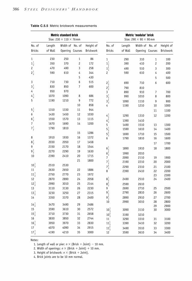
386 S T E E L D E S I G N E R S ’ H A N D B O O K
Table C.5.5 Metric brickwork measurements
Notes:1. Length of wall or pier: n (Brick Joint) 10 mm.2. Width of openings: n (Brick Joint) 10 mm.3. Height of brickwork: n (Brick Joint).4. Brick joints are to be 10 mm normal.
Metric standard brickSize: 230 110 76mm
No. of Length Width of No. of Height of
Bricks of Wall Opening Courses Brickwork
1 230 250 1 861
12
350 370 2 1722 470 490 3 2582
12
590 610 4 3445 430
3 710 730 6 5153
12
830 850 7 6004 950 9704
12
1070 1090 8 6865 1190 1210 9 772
10 8585
12
1310 1330 11 9446 1430 1450 12 10306
12
1550 1570 13 11157 1670 1690 14 12007
12
1790 181015 1286
8 1910 1930 16 13728
12
2030 2050 17 14589 2150 2170 18 15449
12
2270 2290 19 163010 2390 2410 20 1715
21 180010
12
2510 253011 2630 2650 22 188611
12
2750 2770 23 197212 2870 2890 24 205812
12
2990 3010 25 214413 3110 3130 26 223013
12
3230 3250 27 231514 3350 3370 28 2400
14 12
3470 3490 29 248615 3590 3610 30 257215
12
3710 3730 31 265816 3830 3850 32 274416
12
3950 3970 33 283017 4070 4090 34 291517
12
4190 4210 35 3000
Metric ‘modular’ brickSize: 290 90 90 mm
No. of Length Width of No. of Height of
Bricks of Wall Opening Courses Brickwork
1 290 310 1 1001
13
390 410 2 200
123
490 510 3 3002 590 610 4 400
5 500
213
690 710 6 600
223
790 8103 890 910 7 7003
13
990 1010 8 800
323
1090 1110 9 9004 1190 1210 10 1000
11 1100
413
1290 1310 12 1200
423
1390 14105 1490 1510 13 13005
13
1590 1610 14 1400
523
1690 1710 15 15006 1790 1810 16 1600
17 1700
613
1890 1910 18 1800
623
1990 20107 2090 2110 19 19007
13
2190 2210 20 2000
723
2290 2310 21 21008 2390 2410 22 2200
23 23008
13
2490 2510 24 2400
823
2590 26109 2690 2710 25 25009
13
2790 2810 26 2600
923
2890 2910 27 270010 2990 3010 28 2800
29 290010
13
3090 3110 30 3000
1023
3190 321011 3290 3310 31 310011
13
3390 3410 32 3200
1123
3490 3510 33 330012 3590 3610 34 3400
1106 SDHB AppC Final 8/6/05 12:02 PM Page 386
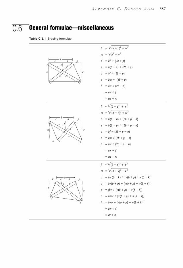
C.6 General formulae—miscellaneous
A P P E N D I X C : D E S I G N A I D S 387
Table C.6.1 Bracing formulae
f (b p)2 w 2m b2 w2d b2 (2b p)
e b(b p) (2b p)
a bf (2b p)
c bm (2b p)
h bw (2b p)
aw f
cw m
f = (b p)2 w 2m (b n)2 w 2d b(b n) (2b p n)
e b(b p) (2b p n)
d bf (2b p n)
c bm (2b p n)
h bw (2b p n)
aw f
cw m
f = (b p)2 w2m (b k)2 v 2d bw (b k) [v(b p) w(b k)]
e bv(b p) [v(b p) w(b k)]
a fbv [v(b p) w(b k)]
c bmw [v(b p) w(b k)]
h bvw [v(b p) w(b k)]
aw f
cv m
b
m fw w
a ch
e d p
m
f
w w
a ch
be
n
d p
m f
vw
a ch
bek d p
1106 SDHB AppC Final 8/6/05 12:02 PM Page 387

388 S T E E L D E S I G N E R S ’ H A N D B O O K
Table C.6.2 Trigonometric formulae
a2 c2 b2
b2 c 2 a 2
c 2 a 2 b2
Known Required
a b c Area
a ,b tan ab
tan ba
a2 b2 a2b
a ,c sin ac
cos ac
c2 a2
, a 90° a cot sin
a
a2 c
2ot
, b 90° b tan co
bs
b2 t2an
, c 90° c sin c cos c2 si
4n 2
Let: then: a2 b2 c2 2bc cos
s a b
2 c b2 a2 c2 2ac cos
c 2 a 2 b 2 2ab cos
K Known Required
b c
a, b, c tan
2
s Ka
tan
2
s
Kb
tan
2
s
Kc
— —
a, , — — 180° ( ) asisnin
asisnin
*
a, b, — sin b s
ain 180° ( )* —
bsisnin
*
a, b, tan b
a sainco
s 180° ( )* — — a2 b2 2ab cos
Area sK s (s a)(s b)(s c) ab s
2in
bc s2in
ac s2in
Note: * indicates a non-dependant variable calculated elsewhere in this row is used.
(s a) (s b ) (s c)
s
ac 2 a2
2
b
90°b
ac
a
b
ac
1106 SDHB AppC Final 8/6/05 12:02 PM Page 388
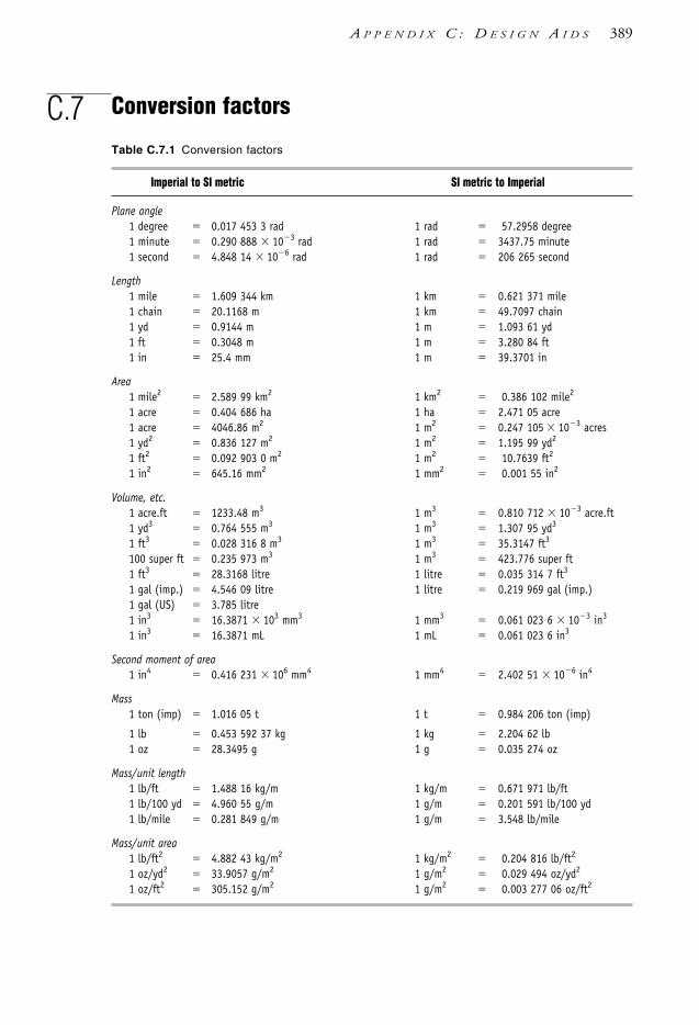
C.7 Conversion factors
A P P E N D I X C : D E S I G N A I D S 389
Table C.7.1 Conversion factors
Imperial to SI metric SI metric to Imperial
Plane angle1 degree 0.017 453 3 rad 1 rad 57.2958 degree1 minute 0.290 888 103 rad 1 rad 3437.75 minute1 second 4.848 14 106 rad 1 rad 206 265 second
Length1 mile 1.609 344 km 1 km 0.621 371 mile1 chain 20.1168 m 1 km 49.7097 chain1 yd 0.9144 m 1 m 1.093 61 yd1 ft 0.3048 m 1 m 3.280 84 ft1 in 25.4 mm 1 m 39.3701 in
Area1 mile2 2.589 99 km2 1 km2 0.386 102 mile2
1 acre 0.404 686 ha 1 ha 2.471 05 acre1 acre 4046.86 m2 1 m2 0.247 105 103 acres1 yd2 0.836 127 m2 1 m2 1.195 99 yd2
1 ft2 0.092 903 0 m2 1 m2 10.7639 ft2
1 in2 645.16 mm2 1 mm2 0.001 55 in2
Volume, etc.1 acre.ft 1233.48 m3 1 m3 0.810 712 103 acre.ft1 yd3 0.764 555 m3 1 m3 1.307 95 yd3
1 ft3 0.028 316 8 m3 1 m3 35.3147 ft3
100 super ft 0.235 973 m3 1 m3 423.776 super ft1 ft3 28.3168 litre 1 litre 0.035 314 7 ft3
1 gal (imp.) 4.546 09 litre 1 litre 0.219 969 gal (imp.)1 gal (US) 3.785 litre1 in3 16.3871 103 mm3 1 mm3 0.061 023 6 103 in3
1 in3 16.3871 mL 1 mL 0.061 023 6 in3
Second moment of area1 in4 0.416 231 106 mm4 1 mm4 2.402 51 106 in4
Mass1 ton (imp) 1.016 05 t 1 t 0.984 206 ton (imp)
1 lb 0.453 592 37 kg 1 kg 2.204 62 lb1 oz 28.3495 g 1 g 0.035 274 oz
Mass/unit length1 lb/ft 1.488 16 kg/m 1 kg/m 0.671 971 lb/ft1 lb/100 yd 4.960 55 g/m 1 g/m 0.201 591 lb/100 yd1 lb/mile 0.281 849 g/m 1 g/m 3.548 lb/mile
Mass/unit area1 lb/ft2 4.882 43 kg/m2 1 kg/m2 0.204 816 lb/ft2
1 oz/yd2 33.9057 g/m2 1 g/m2 0.029 494 oz/yd2
1 oz/ft2 305.152 g/m2 1 g/m2 0.003 277 06 oz/ft2
1106 SDHB AppC Final 8/6/05 12:02 PM Page 389

390 S T E E L D E S I G N E R S ’ H A N D B O O K
Table C.7.1 Conversion factors (continued)
Imperial to SI metric SI metric to Imperial
Mass/unit time1 lb/s 0.453 592 kg/s 1 kg/s 2.204 62 lb/s1 ton/h 1.016 05 t/h 1 t/h 0.984 207 ton/h
Density (mass/unit volume)1 lb/ft3 16.0185 kg/m3 1 kg/m3 0.062 428 lb/ft3
1 lb/yd3 0.593 278 kg/m3 1 kg/m3 1.685 56 lb/yd3
1 ton (imp)/yd3 1.328 94 t/m3 1 t/m3 0.752 48 ton (imp)/yd3
Force1 lbf 4.448 22 N 1 N 0.224 809 lbf1 tonf (imp) 9.964 02 kN 1 kN 0.100 361 tonf (imp)
Moment of force (torque)1 kip.in 0.112 985 kN.m 1 kN.m 8.850 75 kip.in1 kip.ft 1.355 82 kN.m 1 kN.m 0.737 562 kip.ft1 tonf (imp).ft 3.037 04 kN.m 1 kN.m 0.329 269 tonf (imp).ft
Force / unit length1 lbf/ft 14.5939 N/m 1 N/m 0.068 522 lbf/ft1 tonf (imp)/ft 32.6903 kN/m 1 kN/m 0.030 590 tonf (imp)/ft
Modulus of elasticity, pressure, stress1 tonf (imp)/in2 15.4443 MPa 1 MPa 0.064 749 tonf (imp)/in2
1 kip/in2 6.894 76 MPa 1 MPa 0.145 038 kip/in2
1 tonf (imp)/ft2 107.252 kPa 1 MPa 9.323 85 tonf (imp)/ft2
1 kip/ft2 47.8803 kPa 1 kPa 0.020 885 4 kip/ft2
Work, energy, heat1 lb.ft 1.355 82 J 1 J 0.737 562 lbf.ft1 Btu 1055.06 J = 0.293 W.h 1 J 0.947 813 103 Btu
Power, rate of heat flow1 hp 0.7457 kW 1 kW 1.341 02 hp1 Btu/h 0.293 071 W 1 W 3.412 14 Btu/h
Thermal conductivity1 Btu/(ft.h.˚F) 1.730 73 W/(m.K) 1 W/(m.K) 0.577 789 Btu/(ft.h.˚F)
Coefficient of heat transfer1 Btu/(ft2.h.˚F) 5.678 26 W/(m2.K) 1 W/(m2.K) 0.176 10 Btu/(ft2.h.˚F)
1106 SDHB AppC Final 8/6/05 12:02 PM Page 390

A P P E N D I X C : D E S I G N A I D S 391
Table C.7.1 Conversion factors (continued)
Imperial to SI metric SI metric to Imperial
Temperature value˚C
59
(˚F 32) ˚F 95
˚C 32
Temperature interval
1˚C 59
˚F 1˚F 95
˚C
Velocity, speed1 ft/s 0.3048 m/s 1 m/s 3.280 84 ft/s
3.600 km/h1 mile/h 1.609 344 km/h 1 km/h 0.621 371 mile/h
0.2778 m/s1 mile/h 0.447 04 m/s 1 m/s 2.236 94 mile/h1 knot 1.852 km/h 1 km/h 0.5340 knot1 knot 0.514 m/s 1 m/s 1.943 knot1 knot 1.151 mile/h
Acceleration1 ft/s2 0.3048 m/s2 1 m/s2 3.280 84 ft/s2
Volumetric flow1 ft3/s 0.028 316 8 m3/s 1 m3/s 35.3147 ft3/s1 ft3/min 0.471 947 litre/s 1 litre/s 2.118 88 ft3/min1 gal (imp)/min 0.075 682 litre/s 1 litre/s 13.1981 gal (imp)/min1 gal (imp)/h 1.262 80 103 litre/s 1 litre/s 791.888 gal (imp)/h1 million gal/day 0.052 6168 m3/s 1 m3/s 19.0053 million gal (imp)/day1 acre ft/s 1233.481 m3/s 1 m3/s 0.8107 103 acre.ft/s
1106 SDHB AppC Final 8/6/05 12:02 PM Page 391

392 S T E E L D E S I G N E R S ’ H A N D B O O K
Table C.7.1 Conversion factors (continued)
Conversion from Imperial, or MKS, Conversion from SI to Imperial orto SI units MKS units
(i) Force
(ii) Line load
pound force per ft run
1 lbf/ft 14.594 N/m
kilopound per ft run1 kip/ft 14.594 kN/m
ton force per ft run1 ton/ft 32.690 kN/m
kilogramforce per metre1 kgf/m 9.807 N/m
0.6720 lbf/ft
newton per metre1 N/m 0.0685 lbf/ft
kilonewton per metre1 kN/m 68.52 lbf/ft
0.0306 tonf/ft 0.0685 kip/ft 101.97 kgf/m
pound force1 lbf 4.448 20 N
4.448 20 105 dyne 32.174 pdl
kilopound force1 kip 4.448 kN1 kip 1000 lbf
ton force (long)1 tonf 9.964 kN1 tonf 2240 lbf
poundal1 pdl 0.138 26 N1 pdl 0.0311 lbf
kilogram force1 kgf 9.806 65 N1 kgf 2.2046 lbf
70.931 pdl
megapond (technical unit)1 Mp 9.806 65 kN1 Mp 1000 kgf
2204.6 lbf
megadyne (c.g.s. unit)1 Mdyn 10.00 N1 Mdyn 2.2481 lbf
72.33 pdl
newton1 N 0.224 81 lbf
7.233 pdl 0.101 97 kgf
kilonewton1 kN 224.81 lbf
0.2248 kip 0.1003 tonf 101.972 kgf 0.101 97 megapond
1106 SDHB AppC Final 8/6/05 12:02 PM Page 392

A P P E N D I X C : D E S I G N A I D S 393
Table C.7.1 Conversion factors (continued)
Conversion from Imperial, or MKS, Conversion from SI to Imperial orto SI units MKS units
(iii) Stress, pressure, distributed load
(iv) Bending, moment, torquepound force inch
1 lbf.in 0.1130 N.m
pound force foot1 lbf.ft 1.356 N.m
ton force (imp) inch1 tonf.in 0.2531 kN.m
ton force (imp) foot1 tonf.ft 3.0372 kN.m
kilopound force inch1 kip.in 0.1130 kN.m
kilopound force foot1 kip.ft 1.356 kN.m
kilogram force centimetre1 kgf.cm 0.0981 N.m
0.0723 lbf.ft
megapond metre1 Mp.m 9.81 kN.m
newton metre1 N.m 8.851 lbf.in
0.7376 lbf.ft 10.20 kgf.cm
kilonewton metre1 kN.m 737.6 lbf.ft
3.951 tonf (imp).in 0.3293 tonf (imp).ft 8.851 kip.in 0.7375 kip.ft 0.1020 Mp.m
pound force per sq in1 lbf/sq in 6.895 kPa1 lbf/sq in 0.006895 MPa
ton force per sq in (long ton)1 tonf (imp)/sq in 15.44 MPa
2240 lbf/sq in
ton force per sq ft1 tonf (imp)/sq ft 107.25 kPa
kilopound force per sq in1 ksi 6.895 MPa
kilopound force per sq ft1 ksf 47.88 kPa
kilogram force per sq cm1 kgf/cm2 98.07 kPa
14.223 lbf/sq in
atmosphere1 atm 101.3 kPa
14.696 lbf/sq in
bar1 bar 14.504 lbf/sq in
100 kPa 1.02 kgf/cm2
megapascal(meganewton per sq metre)
1 MPa 145.04 lbf/sq in
0.145 ksi 20.885 ksf 9.32 tonf (imp)/sq ft
kilopascal1 kPa 0.020 89 ksf
0.009 32 tonf (imp)/sq ft
pascal1 Pa 1.45 104 lbf/sq in
1 N/m2
1106 SDHB AppC Final 8/6/05 12:02 PM Page 393

A = area of cross-section
= reaction at point A
Aa = area allowance for staggered boltholes
Ac = minor diameter area of a bolt – i.e.core area (at the root of the threads)
Acw = critical area of column web in bearing (crushing)
Ad = sum of area deductions for holes andpenetrations
Ae = effective area of a cross-section
Aei = effective area of element i
Aep = area of end plate
Af = flange area
Ag = gross area of a cross-section
Agm = gross section area of tie membersection
Ags = gross section area of splice platesection
Ah, Ah1, Ah2 = one-half of A (area definition)
Ai = area of element/member i
An = net area of a cross-section
Anm = net section area of tie membersection
Ans = net section area of splice platesection
Ao = plain shank area of a bolt
= enclosed area of a hollow section(torsion)
Ap = cross-sectional area of a pin
Aref = reference area, at height upon whichthe wind pressure acts
As = tensile stress area of a bolt
= web stiffener area plus an effectivelength of the web
= area of a stiffener or stiffeners incontact with a flange
= area of an intermediate web stiffener
Aw = gross sectional area of a web
= effective area of a web
Aws = effective cross-section area ofweb-stiffener
a = distance, dimension
= intermediate value for minimum areaof an intermediate stiffener
= torsion bending constant
= acceleration coefficient (earthquakeactions)
= centroid spacing of longitudinalelements in laced/battenedcompression members
a, b, c = dimensions
ae = minimum distance from the edge of ahole to the edge of a ply measured inthe direction of the component of aforce plus half the bolt diameter
AISC = Australian Institute of SteelConstruction (now ASI)
AISC(US) = American Institute of SteelConstruction
AS = Australian Standard
ASI = Australian Steel Institute (previouslyAISC)
AS/NZS = joint Australian & New ZealandStandard
B = width of section
= reaction at point B
b = width
= lesser dimension of a web panel
= long side of a plate element (i.e. b t)
= intermediate value for minimum areaof an intermediate stiffener
= distance, dimension
bb, bbf, bbw = bearing widths as defined in Chapter5 (Section 5.8)
bcw = clear element width of an element forcompression section capacitycalculations
Notation
The symbols used in this Handbook conform to the notation in AS 4100 and, where applicable, AS/NZS 1170.When not noted in these Standards, the symbols are based on their particular definitions.
1106 SDHB Index Final 8/6/05 12:13 PM Page 394

= clear width of an element outstandfrom the face of a supporting plateelement
= clear width of a supported elementbetween faces of supporting plateelements
bd = bearing width as defined in Chapter 5 (Section 5.8), equals bo
be = effective width of a plate element
beff = effective width of a plate element
bei = effective width of the i-th plateelement of a section
bes = stiffener outstand from the faceof a web
bf = width of a flange
bfo = flange restraint factor for bucklingcapacity of a web with intermediatestiffeners
bi = element width of the i-th plateelement of a section
bo = bearing widths as defined in Chapter 5 (Section 5.8), equals bd
brc = dimension of web thickness plusflange-web fillet radius
bs = stiff bearing length
b1, b2 = batten width for laced and battenedmembers
= widths
b5 = flat width of web (RHS/SHS)
BCA = Building Code of Australia
C = earthquake design coefficient
= total bearing force in the compression region of a bolt grouploaded out-of-plane
= reaction at point C
= length from neutral axis to outer fibre
Cdyn = wind dynamic response factor
Cfig = aerodynamic shape factor – internaland external wind pressures
C1, C2 = corner fillet weld lengths for battens
C2 = lateral distance between centroids ofthe welds or fasteners on battens
c = distance, dimension
= shear force dimension for lacedcompression members
= distance from centroid to edge
c1, c2 = distances from centroid to edge
ck = intermediate value used to calculateminimum area of an intermediatestiffener
cm = factor for unequal moments
cmx, cmy = cm for bending/buckling about x- andy-axis
cz = element slenderness ratio used tocalculate Ze for Non-compact sections
c2, c3 = intermediate values for evaluating thehigher tier of Mix
c3 = intermediate variable for shear-storeycalculation method of δs
CF = cold-formed (for hollow sections)
CFW = Continuous Fillet Weld
CG = centre of gravity
CHS = Circular Hollow Section (to AS 1163)
CIDECT = Comité International pour leDéveloppement et l’Étude de laConstruction Tubulaire
CPBW = Complete Penetration Butt Weld
D = depth of section
= reaction at point D
= depth (outside)
D0 = depth (inside)
D1 = width of ‘dog-bone’ form pinconnection
D2, D3, D4 = dimensions of ‘dog-bone’ form pinconnection
D3, D5, D5r = dimensions of Flush form pinconnection
D5 = width of Flush form pin connection
d = depth of a section
= diameter of circle
= maximum cross-sectional dimension ofa member
= shear force dimension for lacedcompression members
db = lateral distance between centroids ofthe welds or fasteners on battens
dc = depth of columns
dd = height of any holes in a web
de, de1, de2 = effective outside diameter of a CHS
df = diameter of a fastener (bolt or pin)
= distance between flange centroids
di = inside diameter of a CHS
dn = web slenderness ratio for plasticdesign
do = outside diameter of a CHS
dp = clear transverse dimension of a webpanel
= depth of deepest web panel in alength
= pin diameter
N O T A T I O N 395
1106 SDHB Index Final 8/6/05 12:13 PM Page 395

dr = reaction eccentricity from simplysupported beams
ds = length of a weld segment in a weldgroup
d1 = clear depth between flanges ignoringfillets or welds
d2 = twice the clear distance from theneutral axis to the compressionflange
= distance from column centre line to column face adjacent to beamconnection
= distance between flange centroids
d5 = flat width of web (for RHS/SHSbearing loads)
DC = Detail Category (for fatigue designSection 12 of AS 4100)
DCT = Design Capacity Tables
DTI = Direct Tension Indication device
DTT = Design Throat Thickness (for welds)
dia = diameter
E = Young’s modulus of elasticity, (200 103 MPa in AS 4100 and 205 103 MPa in NZS 3404)
= nominal action effect
= reaction at point E
Ed = design action effect (e.g. axial force,shear force, bending moment)
e = eccentricity
= distance between end plate and aload-bearing stiffener
= eccentricity of Fp* from the web
ec = bearing force eccentricity on column cap plate
ed = edge distance
ei = distance between element centroidand effective section centroid
emin = minimum eccentricity
ex, ey, ez = eccentricity
EA = Equal Angle (AS/NZS 3679.1)
ERW = electric resistance welding
E41XX/W40X = lower strength weld consumable type
E48XX/W50X = higher strength weld consumabletype
F = full restraint at section forflexural-torsional buckling
F = action in general, force or load
= design wind force
Fx = force in the x-axis direction
Fy = force in the y-axis direction
= yield stress (commonly describedas fy)
F* = total design load on a memberbetween supports
F*h = design horizontal force acting on each
flange from warping
Fn* = design force normal to a web panel
Fp* = design eccentric force parallel to a
web panel
ƒ = stress range (for fatigue)
ƒat = tensile stress in a rod under catenaryaction
ƒc = corrected fatigue strength forthickness of material
ƒƒ = uncorrected fatigue strength
ƒmax = maximum stress in a stress range(fatigue)
ƒmin = minimum stress in a stress range(fatigue)
ƒrn = detail category reference fatiguestrength at nr cycles – normal stress
ƒrnc = corrected detail category referencefatigue strength – normal stress
ƒrs = detail category reference fatiguestrength at nr cycles – shear stress
ƒrsc = corrected detail category referencefatigue strength – shear stress
fu = tensile strength used in design
fuf = minimum tensile strength of a bolt
fui = design tensile strength of a pinmember/connection eye plate/gussetelement i
fum = design tensile strength of a tiemember section
fup = design tensile strength of a ply
fus = design tensile strength of a spliceplate section
fuw = nominal tensile strength of weldmetal
fv = shear stress, tangential shear stress(torsion)
fy = yield stress used in design
fyc = design yield stress of a column
= design yield stress for thecompression region of a plastic hinge
fyf = design yield stress of a flange element
fyi = design yield stress of the i-th plateelement of a section
= design yield stress of a pinmember/connection eye plate/gussetelement i
396 S T E E L D E S I G N E R S ’ H A N D B O O K
1106 SDHB Index Final 8/6/05 12:13 PM Page 396

fym = design yield stress of tie membersection
fyp = yield stress of a pin used in design
fys = yield stress of a stiffener used indesign
= design yield stress of splice platesection
fyt = design yield stress for the tensionregion of a plastic hinge
fyw = design yield stress of a web element
ƒ3 = detail category fatigue strength atconstant amplitude fatigue limit
ƒ3c = corrected detail category fatiguestrength at constant amplitudefatigue limit
ƒ5 = detail category fatigue strength atcut-off limit
ƒ5c = corrected detail category fatiguestrength at cut-off limit
ƒ* = design stress range (for fatigue)
f *i, f *
j, f*k = design stress range for loading event
i, j, k
fn* = design normal stress
fs* = design shear stress
f *va = average design shear stress in a web
f *vm = maximum design shear stress in a web
FCAW = Flux Cored Arc Welding
FLT = Flats or Flat section (to AS/NZS3679.1)
FW = fillet weld
G = shear modulus of elasticity, 80 103 MPa
= nominal dead load (AS 1170.1) ornominal permanent action (AS/NZS1170)
Gg = gravity load on the structure(earthquake actions)
G* = design dead load/permanent action, G
g = gravity constant (9.81 m/s2)
= gap between plies required for pinconnections
GAA = Galvanizers Association of Australia
GMAW = Gas Metal Arc Welding
GP = General Purpose weld category/quality
H = floor-to-floor/ceiling/roof height
= column height
HQ = imposed/live horizontal/transverseload
HT = factor for higher tier combinedtension and bending check on Mry
H* = design horizontal load/action
h = height of column/building
= distance between flange centroids
= height
hs = storey height
HAZ = Heat-Affected Zone (for weldments)
HERA = Heavy Engineering ResearchAssociation (NZ)
HR = Hot-Rolled or Hot-Finished
HS = High Strength (as in high strengthbolts)
HW = Heavily welded longitudinally
I = second moment of area of a cross-section
= structure importance factor
Ib = I for a beam
Ic = I for a column
Icy = I of a compression flange about thesection minor principal y-axis
Imin = I about the minor principal y-axis
In = I about rectangular n-axis (e.g. forangles)
Inp = product second moment of area aboutthe n- and p-axis
Ip = polar second moment of area of abolt/weld group
= I about rectangular p-axis (e.g. forangles)
Is = I of a pair of stiffeners or a singlestiffener
Iw = warping constant for a cross-section
Iwp = polar second moment of area of aweld group
Iws = I of web-stiffener taken about axisparallel to the web
Iwx = second moment of area about thex-axis of a weld group
Ix = I about the cross-section majorprincipal x-axis
Ixi = Ix for element/member i
Ixy = product second moment of area aboutthe x- and y-axis (=0)
Iy = I about the cross-section minorprincipal y-axis
Iyi = Iy for element/member i
i = integer, number
ICR = Instantaneous Centre of Rotation (forbolt and weld groups)
IPBW = Incomplete Penetration Butt Weld
ISO = International Organization forStandardisation
J = torsion constant for a cross-section
N O T A T I O N 397
1106 SDHB Index Final 8/6/05 12:13 PM Page 397

j = integer, number
= multiple of concentrated load to UDL
Kp = plastic moment coefficient for portalframes
K1 = deflection correction coefficient
k = integer, number
kc = dimension of flange thickness plusflange-web fillet radius
ke = member effective length factor
kex = member effective length factorbetween restraints for columnbuckling about the x-axis
key = member effective length factorbetween restraints for columnbuckling about the y-axis
kf = form factor for members subject toaxial compression
kh = factor for different hole types
kl = effective length factor for load height
kp = bearing factor for pin rotation
kr = effective length factor for restraintagainst lateral rotation
= reduction factor for the length of abolted or welded lap spliceconnection
ks = ratio used to calculate αp and αpm forRHS/SHS under bearing loads
= ratio used to calculate minimum areaof an intermediate stiffener
kt = effective length factor for twistrestraint
= correction factor for distribution offorces in a tension member
kti = kt for a pin member/connection eyeplate/gusset element i
kv = ratio of RHS/SHS flat width of web(d5) to thickness (t)
ky = yield stress normalisation factor
k1, k2 = factors for warping torsion
L = lateral restraint at section for flexural-torsional buckling
L = see relevant definitions for l (AS 4100uses l instead of L though NZS 3404use the latter symbol)
Leff = effective buckling length
L1 = load dispersion width in column webat the kc dimension from the flangeface
= the equivalent definition of l inpermissible design Standards
l = span
= member length
= length of beam segment or sub-segment
lb = length of a beam member
lc = length of a column member
le = effective length of a compressionmember
= effective length of a laterally and/ortorsionally restrained flexural member
lex = member effective length betweenrestraints for column buckling aboutthe x-axis
ley = member effective length betweenrestraints for column buckling aboutthe y-axis
lf = spacing of F, P or L restraints along abeam for continuously lateral restraint
ls = segment length
lw = welded lap connection length
= total length of weld in a weld group
lwf = perimeter length of each flange filletweld
lws = effective length of the cross-sectionarea on each side of a stiffener forcolumn action
lww = perimeter length of web fillet welds
lx = member actual length betweenrestraints for column buckling aboutthe x-axis
ly = member actual length betweenrestraints for column buckling aboutthe y-axis
lz = distance between partial or fulltorsional restraints
l1, l2 etc. = lengths
l/r = member slenderness ratio based onactual length
le/r = member slenderness ratio based oneffective length
le/rs = slenderness ratio of web-stiffenercombination
le/ry = load-bearing stiffener slendernessratio
lws/rws = web-stiffener compression memberslenderness ratio
LODMAT = Lowest One-Day Mean AmbientTemperature
LR = lateral restraint
LW = Lightly welded longitudinally
L0 = guaranteed impact properties of thesteel from a low temperature impacttest at 0°C
398 S T E E L D E S I G N E R S ’ H A N D B O O K
1106 SDHB Index Final 8/6/05 12:13 PM Page 398

L15 = guaranteed impact properties of thesteel from a low temperature impacttest at –15°C
M = nominal bending moment
MB = moment at point B
Mb = nominal member moment capacity
= moment on a batten in a battenedcompression member
Mbr = Mb from DCT (AISC [1999a], SSTM[2003b]) with αm = 1.0
Mbx = Mb about major principal x-axis
Mbxo = Mbx for a uniform distribution ofmoment
Mb1 = Mb from DCT (AISC [1999a], SSTM[2003b]) with αm = 1.0
MC = moment at point C
Mcx = lesser of Mix and Mox
MD = moment at point D
Md = wind direction multiplier
Mfy = maximum flange moment (fromtwisting)
Mi = nominal in-plane member momentcapacity
Mix = Mi about major principal x-axis
Miy = Mi about minor principal y-axis
Mm = same as Mmax
Mmax = maximum moment
Mm1, Mm2 = same as Mmax
Mo = reference elastic buckling moment fora member subject to bending
= nominal out-of-plane member momentcapacity
Mox = nominal out-of-plane member momentcapacity about major principal x-axis
= maximum depth of overall envelope ina bending moment diagram
Mp = fully plastic moment
= nominal moment capacity of a pin
Mpr = nominal plastic moment capacityreduced for axial force
Mprx = Mpr about x-axis
Mpry = Mpr about y-axis
Mr = corrected (φMb)DCT with αm
Mrx = Ms about major principal x-axisreduced by axial force
Mry = Ms about minor principal y-axisreduced by axial force
Ms = nominal section moment capacity
= wind shielding multiplier – upwindbuilding effect
Msx = Ms about x-axis
Msy = Ms about y-axis
MsyL = Msy causing compression in left-mostouter-fibre (for bending about verticaly-axis)
MsyR = Msy causing compression in right-mostouter-fibre (for bending about verticaly-axis)
Mt = twisting moment
= wind topographical multiplier
Mtx = lesser of Mrx and Mox
Mx = moment about x-axis
My = bending moment for outer-fibreyielding
Mz = twisting moment about z-axis
= nominal torsion capacity
Mz,cat = wind multiplier for building heightand terrain category
M1, M2 etc. = moment at point 1, 2 etc.
M1x, M2x = the smaller and larger end bendingmoments to evaluate βm for thehigher tier of Mix
M* = design bending moment
= design bending/twisting moment on abolt/weld group
M*i = (resolved) design in-plane
bending/twisting moment on abolt/weld group
M*m = maximum calculated M* along the
length of a member or in a segment
= mid-span bending moment of a pin-ended tensile member due to self-weight ws
M*mx = M* about x-axis for the
member/segment being considered
M*mxt = maximum M* about x-axis at top of
column
M*my = M* about y-axis for the
member/segment being considered
M*myt = maximum M* about y-axis at top of
column
M*o = design bending/twisting moment on a
bolt/weld group
M*r = design moment reduced by αm
M*s = serviceability design bending moment
M*x = M* about x-axis
M*xb = M* about x-axis at base
M*xbr = M* about x-axis at brace
M*xi = M* about x-axis for member i = 1, 2,
3 etc.
N O T A T I O N 399
1106 SDHB Index Final 8/6/05 11:13 PM Page 399

M*xt = maximum M* about x-axis at top
of column
M*x_mid = M* about x-axis at mid-height beam
M*x_top = M* about x-axis at top of column
M*y = M* about y-axis
M*yb = M* about y-axis at base
M*ybr = M* about y-axis at brace
M*yi = M* about y-axis for member
i = 1, 2, 3 etc.
M*yt = maximum M* about y-axis at top
of column
M*y_mid = M* about y-axis at mid-height beam
M*y_top = M* about y-axis at top of column
M*z = M* about z-axis
= design twisting moment
M*1 = design in-plane bending/twisting
moment on a bolt/weld group
M*1, M*
2 = M* at points/region 1, 2
M*2, M*
3, M*4 = M* at quarter-, mid- and
three-quarter points of a beamsegment/sub-segment
MMAW = Manual Metal Arc Welding
N = nominal axial force (tension orcompression)
= loaded beam overhang dimension
NG = permanent/dead axial load
NQ = imposed/live axial load
Nc = nominal member capacity incompression
Ncx = Nc for member buckling about majorprincipal x-axis
Ncy = Nc for member buckling about minorprincipal y-axis
Nol = (classic) Euler buckling equation
Nom = elastic flexural buckling load of amember
Nomb = Nom for a braced member
Nombx = Nomb buckling about the x-axis
Nomby = Nomb buckling about the y-axis
Noms = Nom for a sway member
Noz = nominal elastic torsional bucklingcapacity of a member
Ns = nominal section capacity of acompression member
= nominal section capacity foraxial load
Nt = nominal section capacity in tension
Ntf = nominal tension capacity of a bolt
Nti = minimum bolt tension at installation
= tension induced in a bolt duringinstallation
N* = design axial force, tensile orcompressive
= member design axial load transmittedby the pin connection
N*f = segment flange force
N*r = design axial force in a restraining
member
N*s = pin serviceability limit state bearing
load
N*t = design axial tension force on a
member
N*tf = design tensile force on a bolt
N*w = flange weld forces
n = number of (plate, etc.) elements in asection
= index for higher tier combined tensionand bending check on Mry
= number of bolts in a bolt group
= rectangular n-axis (e.g. for angles)
nb = number of battens in a battenedcompression member
nei = number of effective interfaces
ni, nj, nk = number of cycles of nominal loadingevent i, j, k
nn = number of shear planes with threadsin the shear plane – boltedconnections
nr = reference number of stress cycles
ns = number of shear planes on a pin
nsc = number of stress cycles
nx = number of shear planes withoutthreads in the shear plane – boltedconnections
n1 = number of bolts in the furthest boltrow in a bolt group loaded out-of-plane
n5 = 5 106 stress cycles
NA = Not Applicable
= Neutral Axis
NZ = New Zealand
NZS = NZ Standard
P = partial restraint at section forflexural-torsional buckling
P = concentrated load
PG = concentrated permanent/dead load
PQ = concentrated imposed/live load
Pst = diagonal stiffener load in column web
P1, P2 = concentrated load
400 S T E E L D E S I G N E R S ’ H A N D B O O K
1106 SDHB Index Final 8/6/05 12:13 PM Page 400

= axial load
P* = force/load
P*u = ultimate design concentrated load
p = rectangular p-axis (e.g. for angles)
PFC = Parallel Flange Channel (to AS/NZS 3679.1)
PLT = Plate (to AS/NZS 3678)
PSA = Period of structural adequacy (for fire resistance)
Q = nominal live load (AS 1170.1) ornominal imposed action (AS/NZS 1170)
= first moment of area
= unloaded beam overhang dimension
Q1, Q2 = prying reaction at end of bent plate
Q* = design live load/imposed action
QA = Quality Assurance
R = nominal resistance
= return period
RA = reaction at support A
Rb = nominal bearing capacity of a web
= lesser of Rbb and Rby for unstiffenedwebs
Rbb = nominal bearing buckling capacity
Rbc = nominal capacity of a column webfrom flange bearing
Rby = nominal bearing yield capacity
Rf = structural response factor (earthquakeactions)
RG1, RG2 = permanent/dead load reaction 1, 2etc.
RQ1, RQ2 = imposed/live load reaction 1, 2 etc.
Rsb = nominal buckling capacity of astiffened web
Rsy = nominal yield capacity of a stiffenedweb
Rt = nominal column flange capacity atbeam tension flange
Ru = nominal capacity
R* = design bearing force
= design reaction
R*bf = flange load on column web for
bearing (crushing)
R*x , R
*y = design reaction about x- and y-axis
r = radius of gyration
= fillet radius
= corner radius
= radius (i.e. half-diameter)
rext = outside radius of a section
ri = inside radius
rmin = radius of gyration about the minorprincipal y-axis
ro = outside radius
rs = radius of gyration of web-stiffenercombination about the axis parallel tothe web
rws = same as rsrx = radius of gyration about major
principal x-axis
ry = radius of gyration about minorprincipal y-axis
RC = Reinforced Concrete
RHS = Rectangular Hollow Section (to AS1163)
RND = Round Bar (to AS/NZS 3679.1)
S = plastic section modulus
= site factor (earthquake actions)
= spacing between lacing in lacedcompression members
Sb = flexural stiffness of beams at a joint
Sc = flexural stiffness of columns at a joint
Sred = reduced S due to presence ofrelatively large holes
Sx = plastic section
Sy = plastic section modulus about they-axis
S* = design action effect
s = spacing between stiffeners
= width of a web panel
= side dimension
= half perimeter of a triangle
sb = batten spacing in battened andback-to-back compression members
send = web depth of end panel
sp = staggered pitch, the distancemeasured parallel to the direction offorce
sg = gauge, perpendicular to the force,between consecutive centre-to-centreof holes
SAW = Submerged Arc Welding
SC = shear centre
SHS = Square Hollow Section (to AS 1163)
SP = Structural (or Special) Purpose weldcategory/quality
SQ = Square Bar (to AS/NZS 3679.1)
SR = stress relieved
SR = axial compression load ratio forplastic design of webs
N O T A T I O N 401
1106 SDHB Index Final 8/6/05 12:13 PM Page 401

SSTM = Smorgon Steel Tube Mills
SW = Stud Welding
S–N = fatigue strength versus number ofcycles curve(s)
T = the structure period (earthquakeactions)
= tension force
Ti = design tension force on bolt i loadedout-of-plane in a bolt group
= tension capacity of a pinmember/connection eye plate/gussetelement i
T1, T2 etc. = design tension forces on bolts loadedout-of-plane in a bolt group
t = thickness
te = external ply thickness of a pinconnection
tf = thickness of a flange
tfb = thickness of beam flange
tfc = thickness of a column flange
tg = gusset thickness for back-to-backtension members
ti = element thickness of the i-th plateelement of a section
= thickness of a pin member/connectioneye plate/gusset element i
= internal ply thickness of a pinconnection
tp = thickness of ply/plate
ts = thickness of a stiffener
tt = design throat thickness (DTT) ofa weld
tw = thickness of a web
= size of a fillet weld (leg length)
twc = thickness of column web
TFB = Taper Flange Beam (to AS/NZS3679.1)
TFC = Taper Flange Channel (to AS/NZS3679.1)
U = unrestrained at section forflexural-torsional buckling
UA = Unequal Angle (to AS/NZS 3679.1)
UB = Universal Beam (to AS/NZS 3679.1)
UC = Universal Column (to AS/NZS 3679.1)
UDL = Uniformly Distributed Load
UNO = Unless Noted Otherwise
UTS = Ultimate Tensile Strength
V = shear force, nominal shear force
= base shear force (earthquake actions)
VR = gust speed applicable to the regionfor an annual probability ofexceedance of 1/R
Vb = nominal shear buckling capacity of aunstiffened/stiffened web
= nominal column web capacity in shearyielding and shear buckling
= nominal bearing capacity of a ply or apin
= shear force on a batten in a battenedcompression member
Vbi = design bearing capacity on a pin fromply i
Vdes,θ = design wind speed = maximum valueof Vsit, β
Vf = nominal shear capacity of a bolt orpin – strength limit state
Vp = nominal ply tearout capacity frombolt bearing
Vsf = nominal shear capacity of a bolt –serviceability limit state
Vsit, β = site wind speed
Vu = nominal shear capacity of a web withuniform shear stress distribution
Vv = nominal shear capacity of aweb/member
Vvm = nominal web shear capacity in thepresence of bending moment
Vvx = nominal shear capacity of aweb/member (shear along the y-axis)
Vvy = nominal shear capacity of aweb/member (shear along the x-axis)
Vw = nominal shear yield capacity of a web
V* = design shear force
= design horizontal storey shear force atlower column end
= design transverse shear force
V*b = design bearing force on a ply at a
bolt or pin connection
V*bi = design bearing force on a pin from ply
i
V*bs = serviceability limit state bearing force
on a pin
V*c = design shear force present in the
column of a beam-column joint
V*f = design shear force on a bolt or pin –
strength limit state
V*o = eccentric out-of-plane design shear
force on a bolt/weld group
V*res = vector resultant of forces acting on a
bolt/weld in a bolt/weld group
402 S T E E L D E S I G N E R S ’ H A N D B O O K
1106 SDHB Index Final 8/6/05 12:13 PM Page 402

V*sf = design shear force on a bolt –
serviceability limit state
V*x = design shear force on a bolt/weld
group in the x-direction
V*y = design shear force on a bolt/weld
group in the y-direction
V*z = design shear force on a bolt/weld
group in the z-direction
V*1, V
*2 = design shear force
vvf = nominal capacity of flange fillet weldsper unit length
vvw = nominal capacity of web fillet weldsper unit length
vw = nominal capacity of a fillet weld per unit length
v* = design shear force on a fillet weld per unit length
v*res = resultant shear force on a bolt/weld
in a bolt group
v*w = design shear force on a fillet weld
per unit length
= minimum shear force per unit lengthon the connection between stiffenerto web
v*x = resultant shear force in the x-axis
direction on a bolt/weld in abolt/weld group
v*y = resultant shear force in the y-axis
direction on a bolt/weld in abolt/weld group
v*z = resultant shear force in the z-axis
direction on a bolt/weld in abolt/weld group
W = total load from nominal UDL
= wind action/load
WG = total load from permanent/dead UDL
WQ = total load from imposed/live UDL
W* = total load from design UDL
w = nominal UDL
wG = permanent/dead UDL
wQ = imposed/live UDL
ws = self-weight UDL
w* = design UDL
w*hu = w*
u in the horizontal direction
w*u = ultimate design UDL
WB = Welded Beam (to AS/NZS 3679.2)
WC = Welded Column (to AS/NZS 3679.2)
WTIA = Welding Technology Institute ofAustralia
x = major principal axis coordinate
xL = coordinate of centroid
xc = x-axis coordinate to the centroidfrom a datum point/axis
xe = distance from neutral axis toextreme fibre in the x-direction
xi = dimension i in the x-direction
xm = distance along x-axis to maximumbending moment
xn = distance along x-axis to bolt n
xo = coordinate of shear centre
xs = x-axis coordinate of a weld segmentwith length ds in a weld group
Y1, Y2 = coordinates
y = minor principal axis coordinate
= beam deflection
yc = y-axis coordinate to the centroid froma datum point/axis
= mid-length deflection (sag) of a tierod under catenary action
= distance from NA to compressionblock centroid in a bolt group loadedout-of-plane
ye = distance from neutral axis to extremefibre in y-direction
yeB = distance from neutral axis to bottomextreme fibre in y-direction
yeT = distance from neutral axis to topextreme fibre in y-direction
yh = distance from overall section centroidto centroid of Ah
yi = dimension i in the y-direction
= lever arm to design tension force onbolt i loaded out-of-plane in a boltgroup
ym = maximum beam deflection
yn = distance along y-axis to bolt n
ys = y-axis coordinate of a weld segmentwith length ds in a weld group
y1 = distance from NA to furthest bolt rowin a bolt group loaded out-of-plane
y1, y2 = distance from NA to flange centroids1, 2
Z = elastic section modulus
Zc = Ze for a compact section
Ze = effective section modulus
Zex = Ze about the x-axis
Zey = Ze about the y-axis
ZeyL = Zy to left-most outer-fibre (for bending about vertical axis)
ZeyR = Zy to right-most outer-fibre (for bending about vertical axis)
N O T A T I O N 403
1106 SDHB Index Final 8/6/05 12:13 PM Page 403
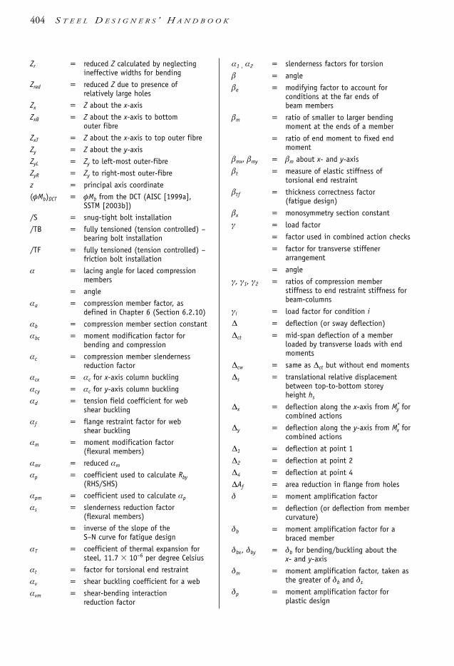
Zr = reduced Z calculated by neglectingineffective widths for bending
Zred = reduced Z due to presence ofrelatively large holes
Zx = Z about the x-axis
ZxB = Z about the x-axis to bottomouter fibre
ZxT = Z about the x-axis to top outer fibre
Zy = Z about the y-axis
ZyL = Zy to left-most outer-fibre
ZyR = Zy to right-most outer-fibre
z = principal axis coordinate
(φMb)DCT = φMb from the DCT (AISC [1999a],SSTM [2003b])
/S = snug-tight bolt installation
/TB = fully tensioned (tension controlled) –bearing bolt installation
/TF = fully tensioned (tension controlled) –friction bolt installation
α = lacing angle for laced compressionmembers
= angle
αa = compression member factor, asdefined in Chapter 6 (Section 6.2.10)
αb = compression member section constant
αbc = moment modification factor forbending and compression
αc = compression member slendernessreduction factor
αcx = αc for x-axis column buckling
αcy = αc for y-axis column buckling
αd = tension field coefficient for web shear buckling
αf = flange restraint factor for web shear buckling
αm = moment modification factor (flexural members)
αmr = reduced αm
αp = coefficient used to calculate Rby(RHS/SHS)
αpm = coefficient used to calculate αp
αs = slenderness reduction factor (flexural members)
= inverse of the slope of the S–N curve for fatigue design
αT = coefficient of thermal expansion forsteel, 11.7 10–6 per degree Celsius
αt = factor for torsional end restraint
αv = shear buckling coefficient for a web
αvm = shear-bending interactionreduction factor
α1 , α2 = slenderness factors for torsion
β = angle
βe = modifying factor to account forconditions at the far ends ofbeam members
βm = ratio of smaller to larger bendingmoment at the ends of a member
= ratio of end moment to fixed endmoment
βmx, βmy = βm about x- and y-axis
βt = measure of elastic stiffness oftorsional end restraint
βtf = thickness correctness factor (fatigue design)
βx = monosymmetry section constant
γ = load factor
= factor used in combined action checks
= factor for transverse stiffenerarrangement
= angle
γ, γ1, γ2 = ratios of compression memberstiffness to end restraint stiffness forbeam-columns
γi = load factor for condition i
∆ = deflection (or sway deflection)
∆ct = mid-span deflection of a memberloaded by transverse loads with endmoments
∆cw = same as ∆ct but without end moments
∆s = translational relative displacementbetween top-to-bottom storeyheight hs
∆x = deflection along the x-axis from M*y for
combined actions
∆y = deflection along the y-axis from M*x for
combined actions
∆1 = deflection at point 1
∆2 = deflection at point 2
∆4 = deflection at point 4
∆Af = area reduction in flange from holes
δ = moment amplification factor
= deflection (or deflection from membercurvature)
δb = moment amplification factor for abraced member
δbx, δby = δb for bending/buckling about the x- and y-axis
δm = moment amplification factor, taken asthe greater of δb and δs
δp = moment amplification factor forplastic design
404 S T E E L D E S I G N E R S ’ H A N D B O O K
1106 SDHB Index Final 8/6/05 12:13 PM Page 404

δs = moment amplification factor for asway member
ξ = compression member factor
η = compression member imperfectionfactor
θ = angle, twist angle
= angle between principal axis and axis under consideration
θ1, θ2 = angle dimension for ‘dog-bone’ form pin connection
π = pi (≈ 3.14159)
ψa = reduction factor of imposed loads dueto area
ψc = combination factor for imposedactions
ψl = factor for determiningquasi-permanent values (long-term) of actions
ψs = factor for determining frequent values(short-term) of actions
λ = member slenderness ratio
= elastic buckling load factor
λc = elastic buckling load factor
λe = plate element slenderness
λed = plate element deformation slenderness limit
λef = flange element slenderness
λei = plate slenderness of the i-th plateelement of a section
λep = plate element plasticityslenderness limit
λey = plate element yield slenderness limit
λeyi = plate yield slenderness limit of thei-th plate element of a section
λew = web element slenderness
λms = modified compression memberslenderness
λn = modified compression memberslenderness
λnx = λn for column buckling about thex-axis
λny = λn for column buckling about they-axis
λs = section slenderness
λsp = section plasticity slenderness limit
λsy = section yield slenderness limit
λ1, λ2 = plate element slenderness values forevaluating the higher tier of Mrx
µ = slip factor
ν = Poisson’s ratio, 0.25
Ω = safety/permissible stress factor
ρ = density
ρair = density of air for wind actions (1.2kg/m3)
σa = tension/stocky compression memberaxial stress
σac = compression member axial stress
σb = bending stress
σeq = equivalent (limiting) stress
σx = normal stress in the x-axis direction
σy = normal stress in the y-axis direction
σz = normal stress in the z-axis direction
σ1 = normal stress in the principal 1-axis direction
σ2 = normal stress in the principal 2-axis direction
σ3 = normal stress in the principal 3-axis direction
τ = shear stress, torsional shear stress
τav = average shear stress
τmax = maximum shear stress
τvm = maximum permissible shear stress
τxy = shear stress in the x-y plane
τyz = shear stress in the y-z plane
τzx = shear stress in the z-x plane
φ = capacity factor
= angle of twist over length L (torsion)
φt = angle of twist (torsion)
φ’ = d θ /d z
φ’’ = d 2θ /d z2
φ’’’ = d 3θ /d z3
N O T A T I O N 405
1106 SDHB Index Final 8/6/05 12:13 PM Page 405

Actions 29-38bridge design 38combinations 5, 8, 10, 29composite construction 38crane and hoist loads 38crane runway girders 302dead see Actions, permanent earthquake 25factors see relevant part in Actionsfatigue 311fire resistance 307floor vibration 38general 29imposed 32live, see Actions, imposedmiscellaneous see Actions, othernotional horizontal forces, 37other 36permanent 29platforms, walkways, stairways and ladders 38silo 38steelwork erection 38temperature 37wind 33
Analysis 39-63braced members and frames 43, 45elastic 39-63, 145elastic buckling moment see Elastic buckling
momentelastic flexural buckling load see Elastic flexural
buckling loadfactor for unequal end moments 53moment amplification method 45plastic see Plastic analysisportal frames 292second-order 39, 43, 45, 145 see also Analysis,
moment amplification methodsecond-order effects see Analysis, second-orderstructural subdivision 42types for structural forms 40unbraced members and frames 43, 45worked examples 55-62
Area see Section properties
Battened struts see Compression members, battenedBeam behaviour
flexural-torsional buckling see Beamslocal buckling 66web crushing 66web shear buckling 66web shear yielding 66
Beam effective length 66, 73default k-values 73effective length 66, 73, 81lateral rotation restraint factor 66, 73load height factor 66, 73twist restraint factor 66, 73
Beam end connectionsrigid 64semi-rigid 64simple 64
Beams 64-130behaviour see Beam behaviourbending with axial force see Beam-columns biaxial bending see Beam-columns compact sections see Beams, compactnesscompactness 74, 76, 77composite see Composite steel and concrete systemscritical flange 69deflection of see Serviceability design for economy 99effective length see Beam effective lengtheffective section properties, 74end connections 64flexural-torsional buckling 66, 78, 80formulae, moments, shear forces & deflections 353 local buckling 66, 74-78, see also Beam-columnsmember moment capacity 66, 74, 78moment modification factor 66, 74, 80monosymmetrical 84non-compact sections see Beams, compactnessplastic analysis see Plastic analysisplastic design see Plastic designreference buckling moment 66, 82, 84residual stress category, 74residual stresses see Beams, residual stress categoryrestraints see Restraints – beams section element slenderness limits 74section moment capacity 66, 78, 80section properties see Section propertiessegments/subsegments 69serviceability see Serviceabilityslender sections see Beams, compactnessslenderness reduction factor 66, 74, 80, 81webs and web stiffeners see Webs and web stiffenersworked examples 100-130
Beam-columns 143-150, also see Compression members analysis 145bending with axial force 85, 135, 143biaxial bending 85, 134, 135, 143, 145, 149composite see Composite steel and concrete systemsdata required 145
Index
1106 SDHB Index Final 8/6/05 12:13 PM Page 406

design for economy 156effective lengths 145member capacity, in-plane 143, 145member capacity, out-of-plane 143, 145moment modification factor 145plastic design see Plastic designreference buckling moment 145restraints see Restraints – beams or columnssection capacity 143, 145slenderness reduction factor 145triangulated structures, in 150uniaxial bending 134, 135, 143, 145variable section 150worked examples 162-174
Bearing capacity see Webs and web stiffenersBearing stiffeners see Webs and web stiffenersBending
biaxial see Beam-columnsuniaxial see Beamsunsymmetrical 339with axial loads see Beam-columns or Tension
members, combined with bendingBending moment capacity
member 66section 66
Bent (framing terminology) 281Bolt capacities – serviceability limit state
shear 210Bolt capacities – strength limit state 208
shear 209shear and tension 210tension 209
Bolt groupscombined in-plane and out-of-plane loading 214general 211instantaneous centre of rotation 211in-plane loading 211, 212out-of-plane loading 211, 213
Bolt holesbase plate 215edge distances 215fabrication method 215geometry 215minimum edge distances 215slotted 215spacing 215standard 215
Bolt installation 207direct-tension indication method 198, 207fully tensioned-bearing 195, 198, 203, 204, 207fully tensioned-friction 195, 198, 203, 204, 207part-turn method 198, 207snug-tight 195, 198, 203, 207
Bolt types 200commercial 198, 200, 203high strength structural 198, 200, 203interference body 202, 206precision bolts 198, 200
re-use 207torque control method 198, 200, 207
Bolted connections 197-217 see also Connectionsbolt design capacities see Bolt capacitiesbolt groups 211, see also Bolt groupsbolt types see Bolt typescoefficient of friction 204definitions 198fatigue 200, 203, 204force transfer mode 202friction-grip see Bolt installation, fully tensioned-
frictioninstallation see Bolt installationply design capacities see Ply capacitiesprying forces 214standardized connections see Standardized
connectionssurface treatments 198, 200, 202worked examples 250, 253, 255
Braced frames 40, 43accumulated restraint forces 285
Bracing formulae 387Brickwork measurements 386Brittle fracture
general 11, 26hydrogen cracking 28transition temperature 26
Bucklinglocal buckling – beams see Beamslocal buckling – columns see Compression membersmember buckling – beams see Beams, flexural-
torsional bucklingmember buckling – columns see Compression
membersweb buckling see Webs and web stiffenersweb shear buckling see Webs and web stiffenersweb stiffener buckling see Webs and web stiffeners
Butt welds see Weld types, butt weld
Capacity see Design capacityCapacity (reduction) factors
bending moment 66connections 194-263fatigue design 316general 5, 9, 25
Carbon steel see Steel types and gradesCarbon-manganese steel see Steel types and gradesCased columns see Composite steel and concrete systemsCentroids 333Codes see Standards & codesCollapse 268
beams 268load 268mechanism 268
Columns see Compression membersCombined actions see Beam-columns or Tension
members, combined with bending momentsCommercial bolts see Bolt types
I N D E X 407
1106 SDHB Index Final 8/6/05 12:13 PM Page 407

Compact section see Beams, compactnessComplete penetration butt welds see Weld typesComposite steel and concrete systems
beams 98beam-columns 154columns 154
Compound struts see Compression members, back-to-back, battened or laced as appropriate
Compound welds see Weld types, compound weldCompression members 131-175
back-to-back 151battened 151cased see Composite steel and concrete systemscomposite see Composite steel and concrete systemscompound see Compression members, back-to-back,
battened or laced as appropriatecompressive yielding 132concentrically loaded 135-142cross-section areas 134design for economy 156effective lengths 134, 138effective section properties 134, 135, 136elastic buckling see also Compression members,
member bucklingfailure modes 132form factor 132, 134, 135, 136inelastic buckling see also Compression members,
member bucklinglaced 151lateral restraint see Restraints – columns local buckling 132member buckling 133, 134member capacity 134, 135member slenderness ratio 137modified compression member slenderness 138residual stresses 133, 138restraints see Restraints – columnssection capacity 134, 135, 136section properties see Section propertiesslenderness ratio 133, 134slenderness reduction factor 135, 138subject to bending see Beam-columnstriangulated structures, in 150tubular trusses, in 150worked examples 159-174
Computer software 330-331Connections 194-263
bolted see Bolted connectionsdesign of whole connections 239-243 see also Rigid
welded connectiondesign principles and detailing 195, 239elements, stresses in 339hollow section connections 242, 243minimum design actions 197pin connections see Pin connectionsstandardized connections 243truss node 150, 243, 286
tubular connections see Connections, hollow sectionconnections
types 195welded see Welded connectionsworked examples 250-263
Conversion factors 389Corrosion protection 318-319
galvanizing 318-320painting 318pins 250
Costing of steelwork see Economy in designCrane runway girders 302
bending moments 302shear forces 302
Critical flange see Beams
Dead loads see Actions, permanentDeflection 304-306 see also Serviceability
general 10limits 304load factors and combinations 305plastic analysis/design 273torsional 342, 343, 348-349
Density of solids 29Design action effects see Actions and AnalysisDesign aids 13 see also Appendices A to C and Further
reading at the end of each chapterDesign capacity see relevant section of
beamsbeam-columnscompression membersconnectionstension members
Design capacity tables 362Design methods
limit states 5permissible stress 332, 336, 337plastic design 264
Developments in steel structures 1Ductility 20
Earthquake loading & design see Actions, earthquakeEconomy in design
beams 99costing of steelwork 11general 11
Edge distances see Bolt holes, edge distancesEffective cross-section area
beams see Beams, effective section propertiescolumns see Compression members, effective section
propertiesshear see Beams, effective section propertiestension members see Tension members, areas
Effective length factor see Effective lengths ofEffective lengths of
beams see Beam effective lengthbeam-columns see Beam-columns, effective lengths
408 S T E E L D E S I G N E R S ’ H A N D B O O K
1106 SDHB Index Final 8/6/05 12:13 PM Page 408

columns see Compression member, effective lengthsElastic buckling moment 66, 81, 84Elastic design methods 332-351
biaxial stresses 337-339connection elements 339section properties 333-337torsion 340-345torsion with bending 346-350triaxial stresses 337-339unsymmetrical bending 339-340
Elastic flexural buckling load 50-53general 50idealised end connections 50members in frames 51
Elastic section modulus 334Engineering design process 2Euler formula 133
Failure criterion, general 337-339Maximum normal stress theory 337Maximum shearing stress theory 337von Mises yield criterion 337
Fatigue 307-318assessment guide 310capacity reduction factors 316detail category 308improving fatigue life 317loading 311number of cycles 309strengths and limits 312stress range 307, 312S–N curves 309, 314thickness effect 313
Fillet welds see Weld types, fillet weldFire resistance 306Floor plate 300, 301 see also Floor systemsFloor systems
composite reinforced concrete slab 300industrial buildings 300reinforced concrete slab 300steel chequer plate 300, 301steel grid/grating 300, 301steel plate 300, 301
Form factor see Compression membersFull penetration butt welds see Weld types, complete
penetration butt weld
Galvanizing (corrosion protection) 318Girders
latticed 283-289stiffened web 86-98
Girts see PurlinsGrid flooring/grating 300, 301 see also Floor systems
Heat-affected zone see Welded connectionsHigh strength structural bolts see Bolt types
Impact properties see Steel, impact propertiesIncomplete penetration butt welds see Weld typesInstantaneous centre of rotation see Bolt groups or Weld
groupsIntermediate web stiffeners see Webs and web stiffeners,
intermediate transverse stiffenersIn-plane capacity checks see Beam-columns
Killed steel 20
Laced struts see Compression members, lacedLamellar tearing see Welded connectionsLateral restraints – see RestraintsLateral-torsional buckling see Beams, flexural-torsional
bucklingLength, effective see Effective lengths ofLimit states design
actions see Actionsbrittle fracture 11 see also Brittle fractureearthquake 11fatigue 11 see also Fatiguefire 11, 306general 5glossary 13serviceability 10 see also Deflectionstability 11strength limit state 9 see also Beams, Beam-columns,
Compression members, Tension membersLive loads see Actions, imposedLoad factor see ActionsLoads see ActionsLocal buckling
beam see Beamscolumns see Compression members
Low-rise structures 294connection details 294-297
Material & design requirements 15-28 see also SteelMechanical properties see Steel, mechanical propertiesMechanism see Collapse mechanismMill-type buildings 281Moment amplification see Analysis, moment
amplification method
Nominal Capacity see relevant section ofbeamsbeam-columnscompression membersconnectionstension members
Non-compact section see Beams, compactnessNormal stresses, elastic 336Notch-ductile steel see Steel, impact propertiesNotional horizontal forces, see Actions, notional
horizontal forces
Out-of-plane capacity checks see Beam-columns
I N D E X 409
1106 SDHB Index Final 8/6/05 12:13 PM Page 409

Painting (corrosion protection) 318Permissible stress 336-339
axial compression 336axial tension 336bending 336biaxial stresses 337combined actions 336normal 336shear 337torsion 343transverse shear 337triaxial stresses 337
Pin connections 198, 244-250corrosion protection 250general 244pin design & detailing 248, 249ply design & detailing 245, 247
Pinned base portals see Portal framesPlastic analysis 39, 40, 264-278
deflections 273-274further reading 278mechanism method 265, 268portal frames 274-275statical method 265torsion 350worked example 276
Plastic design 264-278analysis see Plastic analysisbasic concepts 264beams 270-271beam-columns 271-273biaxial bending 272deflections 273-274frames 271further reading 278member design 267-270member slenderness limits 272plastic section modulus 267restrictions 270second-order effects 273torsion 350uniaxial bending with axial loads 271web slenderness limits 273worked example 276
Plastic hinge 268Plastic moment 267Plastic section modulus 267Plate elements (for bolted joints)
bolt hole geometry see Bolt holesconnection geometry 215
Ply capacities (for bolted joints) see also Plate elementsbolt tearout 210, 216ply crushing 210, 216
Portal frames 289knee connections 290pinned base 289types 291
Proof stress see SteelProperty class see Bolt typesProtective treatment for
corrosion resistance see Corrosion protectionfire resistance see Fire resistance
Purlins 297bridging 297-298, 300spacing 299
Radius of gyration see Section propertiesReference buckling moment see BeamsReferences 325-330Residual stresses
beams see Beamscolumns see Compression members
Restraints – beamscontinuous 68, 69full 68, 69full lateral 68, 69lateral 68, 69lateral restraints, capacity of 74lateral rotation 68, 69partial 68, 69twist restraints, capacity of 74unrestrained 68, 69
Restraints – columnsgeneral 155minimum loads 155notional horizontal forces 155
Rigid welded connection 240-242beam flange weld capacity 240beam web weld capacity 241column flange capacity 241, 242column web capacity 242other design checks 242
Rods, steel see Tension members, steel rodsRoof trusses 283
Second moment of area 334Second-order analysis see AnalysisSection classification see Section propertiesSection properties
area 179, 333area, allowance for staggered holes 179 see also
Section properties, area, netarea, deduction due to holes see Section properties,
netarea, gross see Section properties, areaarea, net 179centroid 333columns 135, 136effective area 134, 136effective section modulus 66, 74elastic section modulus 76, 334first moment of area 333form factor 135, 136geometrical properties 362-381, 382-383, 384-385
410 S T E E L D E S I G N E R S ’ H A N D B O O K
1106 SDHB Index Final 8/6/05 12:13 PM Page 410

gross area 134, 333net area 134, 136, 333plastic section modulus 76radius of gyration 93, 133, 136reduced properties due to holes 77second moment of area 334section classification 74-78, 132, 135-138shear centre 339
Seismic loading & design see Actions, earthquakeServiceability design
beams 99bolt serviceability see Bolt capacities – serviceability
limit statecorrosion see Corrosion protection
Shearbuckling see Webs and web stiffenerscentre see Section propertiesstresses, elastic 337
Slender section see Beams, compactnessSlenderness factor see Beams and/or Compression
membersSlenderness ratio
beams see Beamscolumns see Compression members
Standardized connections 242, 243Standards & codes 4
ABCB 322CEN 322Standards Australia, 323-324Standards New Zealand, 324-325
Steel see also Steel types and gradescoefficient of thermal expansion 16creep strength 16hardness 16impact properties 16 see also Brittle fracturematerial properties 24 see also Physical propertiesmechanical properties 16 see also Physical propertiesphysical properties 16, 24products (sections) 15, 64, 157, 176, 177proof stress 16reinforcing products 384residual stress categories 24, 74, 136scope and exclusions 24stress-strain diagrams 16ultimate tensile strength 16, 20weather resistant steel 20yield stress/strength 16, 20Young’s modulus of elasticity 16
Steel grades see Steel types and grades Steel industry associations see WebsitesSteel manufacturers see WebsitesSteel types and grades 19-24
availability 20ductility 20grades 19, 20low cost-to-strength ratio 20weldability 19
Steel suppliers see WebsitesStiffened webs see Webs and web stiffenersStiffeners see Webs and web stiffenersStress, elastic
biaxial 337 normal 336shear 337torsion see Torsiontriaxial 337
Stress–strain diagram see SteelStructural analysis see Analysis or Plastic analysisStructural design principles
general 5limit states design method see Limit states design
Structural framing 279-321cantilevered columns 282crane runway girders 302-304deflections 304-306fire resistance 306-307flooring systems 300-301industrial buildings 280longitudinal bracing 282low-rise buildings 294-297mill-type building 281-283portal frames 289-293purlins and girts 297-300rigid frames 282roof trusses 283-289
Struts see Compression membersSway frames 40, 43
Tensile strength see Steel, ultimate tensile strengthTension members 176-193
areas see Section propertiescombined with bending moments 176, 181 combined with shear 183compound members 177, 183correction factor for end eccentricity and
distribution of forces 179effective section area see Tension members, areasend connection detailing see Tension members, end
connectionsend connections 183, 184, 185flexible 178flexurally rigid 178gross section yielding 179load effects 178member capacity 179net section fracture 179pin-type 177, 180plastic design see Plastic design, beam-columnssag 177, 186semi-flexible 178splices 185steel rods 186steel tendons see Tension members, steel wire ropessteel wire ropes 186
I N D E X 411
1106 SDHB Index Final 8/6/05 12:13 PM Page 411

types of construction 177worked examples 189-193
Thermal expansion coefficient see SteelThermal expansion joints 282Throat thickness of welds see Welded connections, design
throat thicknessTorsion 340-350
constant 342, 343limit state design 350non-uniform see Torsion, warpingpermissible stresses 343plastic design 350St Venant see Torsion, uniformshear centre see Section propertiestorsional moment 343torsional rigidity 343twist angle 342, 343, 348-349uniform 337, 343warping 340, 345warping constant 345warping restraints 345with bending 346without bending 343
Trigonometric formulae 388Trusses
closed sections 287hollow sections 287node connections 286open section members 286roof 283self-weight 285
Ultimate tensile strength see SteelUniform torsion see TorsionUnsymmetrical bending 339
Warping constant 345Warping torsion see TorsionWebs and web stiffeners 86-98
bearing buckling capacity 89, 90bearing yield capacity 89buckling see Webs and web stiffeners, bearing
buckling capacitycombined bending and bearing (RHS/SHS only) 92combined bending and shear 88connection forces for intermediate transverse
stiffeners 97end posts 97intermediate transverse stiffeners 94load bearing stiffeners 92longitudinal web stiffeners 98shear buckling 88shear capacity 87torsional end restraints 93web proportioning 86, 90, 95worked examples 106, 109, 120-130
Websites 322, 323, 325, 330, 331Weld groups 236-239
capacity reduction factors 236combined in-plane and out-of-plane actions 239general 236in-plane actions 236out-of-plane actions 237
Weld types 195, 221, 226butt weld 221, 229, 233complete penetration butt weld (CPBW) 221, 229,
233compound weld 221, 233, 235fillet weld 221, 231, 233full strength butt weld see Weld types, complete
penetration butt weldincomplete penetration butt weld (IPBW) 221, 229,
234partial penetration butt weld see Weld types,
incomplete penetration butt weldplug weld 221, 231slot weld see Weld types, plug weldweld group see Weld groups
Weldability 19Welded connections 217-239 see also Connections
capacity (reduction) factors 233, 234, 235, 236defects 224, 229definitions 221 design throat thickness 221, 231, 233, 234economical design and detailing 227general 217GP category see Welded connections, weld categoryHeat-affected zone (HAZ) 221, 229imperfections see Welded connections, defectslamellar tearing 227reduction factor for welded lap connection length
234 see also Weld types, fillet weldSP category see Welded connections, weld categoryspecification and validation 224standardized connections see Standardized
connectionsstrength 223weld category 221, 224weld quality see Welded connections, weld categoryweld size see Welded connections, design throat
thickness and definitionsworked examples 257, 258, 261
Weldingconsumables 221processes 222symbols 217
Wind bracing 283Wind loads see Actions, windWire ropes, steel see Tension members, steel wire ropes
Yield stress see SteelYoung’s modulus of elasticity see Steel
412 S T E E L D E S I G N E R S ’ H A N D B O O K
1106 SDHB Index Final 8/6/05 12:13 PM Page 412

Picture Credits FRONT COVER:Roof of Westpac Call Centre Cannon Hill (Brisbane). Steel concept and design bybigspace™ featuring 66 m column-free office space from post-tensioned steel withexternal main frame from Grade C450L0 (DualGrade™) galvanized structural steelhollow sections. The bigspace™ brand is a registered trademark of s2 corporation pty ltd.
BACK COVER (Top):Structural frame for the 20,000 m2 Laminex Distribution Centre warehouse next tothe Gateway Bridge in Brisbane. Developed, built and owned by Australand and leasedto Laminex as their Queensland Distribution Centre for laminates, boards andassociated products. The building is 110 m wide using hollow section trusses with acentral row of columns giving a 55 m width of column-free space.
BACK COVER (Middle):The Frome Street carpark structural framing system. This eight-storey open-deckcarpark in Adelaide with 15 m clear spans, is Australia’s first eccentrically bracedseismic-resistant steel frame building, and was designed by Wallbridge & Gilbertconsulting engineers.
BACK COVER (Bottom):Alumina storage building structure for Alcoa’s Pinjarra (WA) Alumina Refinery. The building is 98 m in diameter, 42 m high and has a storage volume of 100,000tonnes with no internal columns. Structural design was by Connell Wagner Pty Ltd.
P I C T U R E C R E D I T S 413
1106 SDHB Index Final 8/6/05 12:13 PM Page 413

STEEL DESIGNERS’
GORENC TINYOU SYAM
HANDBOOK
BRANKO RON AR U N This seventh, thoroughly updated edition of Steel Designers’ Handbook will be an invaluable tool to all practising structural engineers, as well as engineering students. It introduces the main concepts relating to design in steel and replaces the sixth edition, published in 1996. This edition has been prepared in response to the new structural Design Actions Standard, AS/ANZ 1170, as well as feedback from users. It is based on Australian Standard (AS) 4100: 1998 and provides added background to that Standard.
The book makes extensive use of worked numerical examples to demonstrate the methods of calculating the capacities of structural elements. These examples have been extensively revised from the previous edition, with further examples added. The worked examples are cross-referenced to the relevant clauses in AS 4100: 1998.
Between them, the authors have close to 100 years’ experience of solving engineering problems. All three have practised in all phases of the design and specifi cations of steel structures ranging from commercial to institutional structures; while two, Arun Syam and Branko Gorenc, have served on numerous Standard Australia committees related to steel construction.
U N S W P R E S S
STEEL DESIGNERS ’ GORENC TINYOU SYAM
UNSWP R E S S
HAND BOOK
7E D I T I ON
77E D I T I O N
steeldesigncover.indd 1 17/6/05 3:34:35 PM