
Post Office Electrical Engineers' Journal - Sam Hallas
124
THE POST OFFICE ELECTRICAL ENGINEERS' JOURNAL Vol. 51 Part 2 JULY 1958
-
Upload
khangminh22 -
Category
Documents
-
view
0 -
download
0
Transcript of Post Office Electrical Engineers' Journal - Sam Hallas

THE POST OFFICE
ELECTRICAL ENGINEERS'
JOURNAL
Vol. 51 Part 2 JULY 1958
CONTENTS
Page
SUBSCRIBERS' SO-POINT LINEFINDER SYSTEM W. H. Fox, A.M.I.E.E., J. L. K. Ashwell and A. L. Weaver . . . . . . . . . . . . . . . . . . . . . . . . . . . . . . . . . . . 81
TELEPRINTING OVER LONG-DISTANCE RADIO LINKS, Part 1-General Methods of Radio Telegraphy-A. C. Croisdale, M.B.E., B.Sc.(Eng.), A.M.I.E.E. . . . . . . . . . . . . . . . . . . . . . . . . . . . . . . . . . 88
A NOVEL WAY OF PROVIDING A CABLE ROUTE ACROSS A BUSY AND CONGESTED WATER-WAY-S. W. Jennings, A.M.I.E.E., and W. D. Priestley ............................. 94
A TESTER FOR PULSE REGENERATORS R. A. Fran�ois .......................... . ....... . , . , . . . . . . . . . . . . . . . . . . . . . . . . . . . . . . . . . . . . 100
A SINGLE-OPERATOR LETTER-SORTING MACHINE, Part 1-lntroduction and the Experimental Mac hine-G. P. Copping, B.Sc.(Eng.), A.M.I.E.E., and K. L. Beak, Assoc iate I.Mec h.E., Assoc iate l.E.E................................................................................... 104
A SHORT HISTORY OF CODES OF PRACTICE FOR THE OPENING AND RESTORATION OF TRENCHES IN PUBLIC STREETS-W. C. Ward, B.Sc.(Eng.), M.I.E.E. . . . . . . . . . . . . . . . . . . . . 108
THE VERTICAL CONVEYANCE OF MAIL H. J, Langton, A.M.I.E.E................................................................. 112
RADIO INTERFERENCE, Part 4-Measuring Equipment A. Mac pherson, B.Sc .(Eng.), A.M.I.E.E. . . . . . . . . . . . . . . . . . . . . . . . . . . . . . . . . . . . . . . . . . . . . . . . . . . . . 115
AN AUTOMATIC TESTER FOR SUBSCRIBERS' LINES AND APPARATUS E. W. Chapman and H. C. Nott . . . . . . . . . . . . . . . . . . . . . . . . . . . . . . . . . . . . . . . . . . . . . . . . . . . . . . . . . . . 120
A MICROWAVE MODEL EQUIPMENT FOR USE IN THE STUDY OF THE DIRECTIVITY CHARACTERISTICS OF SHORT-WAVE AERIALS, Part 1-General Considerations and Desc ription of Model Equipment-D. W. Morris, B.Sc.(Eng.), A.M.I.E.E., E. W. Thurlow, A.M.I.E.E., and W. N. Genna, Assoc iate I.E.E.. . . . . . . . . . . . . . . . . . . . . . . . . . . . . . . . . . . . . . . . . . . . . . . . . . . . . . . . . 126
A DIFFERENTIAL GAIN MONITORING PANEL FOR TESTING SUBMERGED TELEPHONE REPEATERS-H. J. Groves, B.Sc.(Eng.), A.M.I.E.E., and S. A. Taylor, B.Sc.(Tec h.) . . . . . . . . . . . . 132
DESIGN FEATURES OF THE LEE GREEN MAGNETIC-DRUM REGISTER-TRANSLATOR K. G. Marwing, B.Sc ., A.M.I.E.E. . . . . . . . . . . . . . . . . . . . . . . . . . . . . . . . . . . . . . . . . . . . . . . . . . . . . . . . . . 137
RECORDING DECIBELMETERS A. P. Parsons and F. E. Didc ock . ............... , , .. , ... , ... , .. , , . , . . . . . . . . . . . . . . . . . . . . . . . 145
NOTES AND COMMENTS . , ....... .. , . , , , , ... , .. , , , , . . . . . . . . . . . . . . . . . . . . . . . . . . . . . . . . . . . . 150
INSTITUTION OF POST OFFICE ELECTRICAL ENGINEERS . . . . . . . . . . . . . . . . . . . . . . . . . . . . . 150
REGIONAL NOTE ................ , ........ , . , , , ...... , , . , . . . . . .. . . . . . . . . . . . . . . . . . . . . . . . . . . 152
ASSOCIATE SECTION-SILVER JUBILEE CELEBRATIONS IN THE NORTH EASTERN REGION ..................... , ........................................................ 153
ASSOCIATE SECTION-EXHIBITION TO MARK THE SILVER JUBILEE OF THE DUNDEE CENTRE .............................................................................. 155
ASSOCIATE SECTION NOTES . . . . . . . . . . . . . . . . . . . . . . . . . . . . . . . . . . . . . . . . . . . . . . . . . . . . . . . . . . . 156
STAFF CHANGES . . . . . . . . . . . . . . . . . . . . . . . . . . . . . . . . . . . . . . . . . . . . . . . . . . . . . . . . . . . . . . . . . . . . . . . . 160
BOOK REVIEWS ......................... 87, 93, 103, 111, 114, 119, 125, 131, 136, 144, 149, 152, 159, 162
Pric e 2/6 net
THE POST OFFICE
ELECTRICAL. ENGINEERS' JOURNAL
Vol. 51 Part 2 JULY 1958
Subscribers' 50-Point Linefinder System W. H. FOX, A.M.I.E.E., J. L. K. ASHWELL and A. L. WEAVERt
U.D.C. 621.395.341.22
Although linefinders have been used in the past by the Post Office for the connexion of telephone subscribers' lines to tst selectors, the present standard practice is to provide a subscriber's uniselector for each line. Recent studies of subscribers' calling rates have shown that there is a wide field of application for a simple Iinefinder scheme for lines that have a low calling rate. This article reviews the circumstances in which Unefinders or uniselectors are advantageous, outlines the recent studies of subscribers' calling rates and describes a new linefinder scheme
that lias been adopted by the Post Office.
INTRODUCTION
IT is the present practice of the British Post Office to provide exchange equipment on the basis of the average busy hour traffic per line, and to equip each
subscriber's line with a uniselector, regardless of whether the particular subscriber originates many or few calls. Linefinder schemes, which were used earlier, have certain disadvantages, particularly for lines with high calling rates, but for lines with low calling rates they can undoubtedly offer economies. It was therefore decided to re-examine the present basis of design of exchanges to determine whether it would be possible, by using linefinder working for some of the subscribers in an exchange, to reduce the overall equipment costs without adversely affecting the service. A limited statistical study was made of the distribution of calling rates of subscribers in this country, and this indicated that a large proportion of the total subscribers account for a very small proportion of the total traffic, and hence must have very low calling rates. This suggested that substantial economies might be achieved if a new linefinder system were to be developed to cater for low-calling-rate subscribers whilst retaining the present uniselector system for the comparatively small number of heavier users. It was also recognized that added economies would result if such a linefinder system coultl bi; designed, at little extra cost, to cater for shared service (with separate metering) by means of a single calling equipment.
This article describes the main features of such a Iinefinder system, which has been developed jointly by the Post Office and the British telephone manufacturers, and will, in due course, become the standard method of providing service for both exclusive-service and
t Mr. Fox is an Executive Engineer and Mr. Ashwell an Assistant Engineer in the Telephone Development and Maintenance Branch, E.-in-C.'s Office. Mr. Weaver is with Ericsson Telephones, Ltd.
A
shared-service subscribers with low calling rates at all standard automatic exchanges equipped with 2000-type uniselector line circuits. The system may also be used at n1ost exchanges equipped with pre-2000-type uniselector line circuits. HISTORY OF THE USE OF LINEFINDERS AND UNISELECTORS
Before describing the new system it is desirable to refer briefly to the considerations which have, hitherto, influenced the use of linefinder and uniselector systems in this country. It has long been recognized that the comparative economics of uniselector and Jinefinder systems are directly related to the average calling rates of the lines to be served, the advantage resting with linefinder systems where the average calling rate is low.
z 0
;,
0
0
� 110 B
0
�106 �
i'i x
wl02 �
�
0
0
� 980 ;l 0
� 94 ;l c;
0
( !'.. v---. Vi
/ v
OUTBREAK OF 1939·45 WAR
\ A \ "'
\ ,,....,
"i r END OF 1939�45 I
WAR .
� 900 - - - � - - - - - -
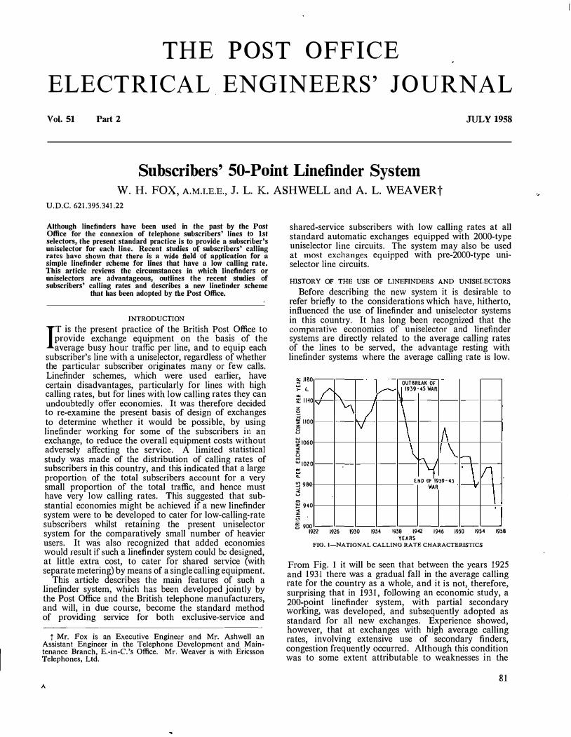
YEARS FIG. I-NATIONAL CALLING RATE CHARACTERISTICS
From Fig. 1 it will be seen that between the years 1925 and 1931 there was a gradual fall in the average calling rate for the country as a whole, and it is not, therefore, surprising that in 1931, following an economic study, a 200-point linefinder system, with partial secondary working, was developed, and subsequently adopted as standard for all new exchanges. Experience showed, however, that at exchanges with high average calling rates, involving extensive use of secondary finders, congestion frequently occurred. Although this condition was to some extent attributable to weaknesses in the
81
.,

initial circuit design, investigation showed that the linefinders were less efficient than uniselectors in catering for unexpected ·increases in calling rate.1 In September, 1938, following a comprehensive cost study, a decision was taken to restrict the use of the linefinder system to exchanges where the average busy hour calling rate was below 0·6 calls per line.
It will be seen from Fig. 1 that a gradual rise in the calling rate occurred between 1931 and 1938, and this undoubtedly contributed to linefinder congestion which, in turn, gave rise to this change in policy.
As might be expected, the average calling rate fell sharply during the 1939-45 war, but towards the end of the war, when the question of post-war exchange design was being considered, there were signs of an increase in the average calling rate which it was expected would continue in the immediate post-war period. This influenced a decision to employ the uniselector system as the future standard for all new exchanges and extensions to existing exchanges. A revised cost corn� parison made at that time indicated that uniselectors were more economical than linefinders for calling rates of0·4 and over, and, as some 96 per cent of the exchanges were shown to have average calling rates in excess of this figure, it was not considered worth while to produce and maintain a second standard type of equipment for the remaining 4 per cent.1 The decision to adopt uniselectors as the standard system did not preclude the possibility of the future development of a simpler and cheaper linefinder system when a measure of stability had been reached in post-war conditions and it was possible to estimate with some reliability the rate of growth and distribution of telephone traffic. The gradual fall in average calling rates which has occurred since 1947 provided further justification for the re-examination of the merits of linefinder and uniselector systems, and has, in turn, led to the development of the system described in this article.
PRESENT DISTRIBUTION OF SUBSCRIBERS' CALLING RATES
The large expansion of the telephone service since the 1939-45 war (Fig. 2) has taken place primarily in residential areas, and the resultant increase in the proportion of residential to business subscribers-except in the purely city business exchanges-doubtless accounts
82
. .,
I j
5
I/ ' 0
I 5
A 0
/ ENO OF 1939-45
WAR
5
1,.........-/
0
v ·5 E IB - - IM - - - - �
YEARS
FIG. 2-GRO\VTH OF EXCHANGE CONNEXIONS
0
0
0
�25 0 � <
�20 0
� � z 15 8
0
0
0
I / l/v
v _.,!/ -
10 M � 40 � H M M 90 I�
PERCENTAGE OF RESIDENTIAL EXCHANGE CONNEXIONS
FIG. 3-DISTRIBUTION OF CALLING RATES OF RESIDENTIAL CONNEXIONS BASED ON THREE PROVINCIAL NON-DIRECTOR EXCHANGES
AND ONE LONDON DIRECTOR EXCHANGE
to a very large extent for the marked fall in the average calling rate that has occurred since 1947.
Recent records of the numbers of calls originated by a random sample of residential subscribers at four selected exchanges, Bedford, Colchester, Torquay and Wimbledon, have confirmed that the proportion of the total lines with low calling rates is very high. The distribution of calling rates at each of these exchanges followed a remarkably similar pattern, and the curve shown in Fig. 3 represents the average for the four exchanges. It will be seen that as many as 90 per cent of the subscribers originated less than 175 calls per half year, or less than one call per day. Although these figures relate to residential subscribers, a record taken of all metered calls at Chelmsford exchange over a 6-month period (Fig. 4) showed that 99 per cent of the subscribers originated 70 per cent of the total local calls,
70
0
0
0
0
0
Q IO
I I
v v v
L--L---
20 � � 50 u ro eo 90 wo PERCENTAGE OF SUBSCRle.ERS
FIG, 4-----LOCAL CALL DISTRIBUTION AT CHELMSFORD EXCHANGE (4,500 EXCHANGE CONNEXIONS OF \VHICH 38 PER CENT ARE BUSINESS
CONNEXIONS)
i.e. about 30 per cent of the total traffic was originated by only 1 per cent of the subscribers. As 38 per cent of the subscribers at Chelmsford are in the business category, this suggests that, in addition to the residential subscribers, many of the business subscribers must have low
1 FRANCIS, H. E. Post-War Exchange Design. l.P.O.E.E. Printed Paper No. 181, 1943.

calling ra.tes. Such conditions are thought to be typical of many exchanges in this country.
Consideration of these data suggested that substantial savings would be achieved if a simple linefinder system were to be developed to cater for both exclusiveservice and shared-service subscribers with low calling rates-principally residential subscribers-whilst continuing to employ individual uniselectors for the heavier users.
THE NEW LINEFINDER SYSTEM
Outline of the System The new linefinder system is based on the use of
50-point, non-homing, rotary-type linefinders (standard Post Office Type 2 uniselectors) arranged in groups of five, on the banks of which are multipled 49 subscribers' line circuits. The 50th outlet is used for testing purposes only. Each linefinder is trunked to a regular subscriber's uniselector, which functions as a selector hunter. The trunking arrangements are shown in Fig. 5.
The group of 49 line circuits is divided into five subgroups, each with a different linefinder as first choice. This arrangement enables calls originated simultaneously in each of the sub-groups to be set up simultaneously. Calls originated simultaneously within any one subgroup are set up sequentially but without appreciable delay.
CirCuit Operation Linejinder Start. A simple linefinder "start" arrange
ment, as shown in Fig. 6, is provided by commoning
CT
lR '41 - '49 •1i---/.---.--+-+-----t VIA I
LINEFIND E R No.5
LINEFINDERS I No.3&-4 : [er
LRll-2D qf---/.--+--t-t---� LINEF1NDER No.2
C T L R I -ID qf---/.�--t-11-<'-----' LI NEFI N DER No. I
FIG. 6-LINEFINDER START ARRANGEMENT
together the "start" contacts of the line relays (LR) in groups of ten, and associating each group directly with
NEW 50-POINT LINEFINDER EQUIPMENT EXISTING SUBSCRIBERS' I t ST. LINE CIRCUIT SElECTOR
.. ..... \ .
one linefinder circuit; thus, line circuits within t.he same 10-line group are usually seized by that linefinder. Exceptions to this are:-
LOW-CALUNG·RATE EXCLUSIVE
SERVICE OR SHAREOSERVICE
SUBSCRIBER
LINEFINDER CONTROL ANO SHARED-SERVICE
DISCRIMINATION EQUIPMENT
MULTIPLE-CHAIN START AND _j' LINEFINDER ASSIGNMENT
-HIGH-CALUNC'G+·R�AT�E--------------�·+ SUBSCRIBER
I
..... ··· ········�
... ....
----------
(a) When the linefinder is already engaged, relay CT is operated, and the start signal is then passed to the next free linefinder.
(b) When simultaneous calls are originated in different JO-line groups, several linefinders search, and the first linefinder to arrive on the outlet of a calling line will seize it, irrespective of the 10-line group in which it is situated .
FIG. S-BLOCK SCHEMATIC DIAGRAM SHO\VING TRUNKING ARRANGEMENTS FOR HIGH· AND Outgoing Calls. Fig. 7 shows the
subscriber's line circuit, together with the elements concerned with switch
ing a linefinder to a calling line.
LOW-CALLING·RATE SUBSCRIBERS .
The system incorporates facilities for shared service by means of a single line circuit-comprising two Post Office 600-type relays-per pair of sharing subscribers. Hence, each group of linefinders can accommodate either 49 exclusive-service subscribers or up to 98 sharedservice subscribers, dependent on the average calling. rates of the subscribers within the group.
The avoidance of both secondary working and common control eqnipment has contributed to a simplification of the general circuit arrangements as compared with earlier linefinder systems.
Shared-service working is free from the principal disabilities of the present system. The use of a single line circuit per pair of sharing subscribers, however, necessitates a minor change in operating procedure. The Y subscriber can call only by depressing the "Call Exchange" button on the telephone after removing the receiver. Depression of the button by the X subscriber may take place either before or after removal of the receiver, but in the interests of uniformity it has been decided to instruct all shared-service subscribers to remove the receiver before depressing the button.
FINAl SEtECTOR MULT.
,......,.-.. l.D.F. MULT. LOCAL
TO M.D.F. 1 'X' OR
EXCLUSIVESERVICE
SUBSCRIBER
-----� �
.. ..
Sb
.. +
I KA
·· ·�-, �,. p p K ·"p S�-----1i • �KA I• I l� •
FINAL I '•, •I SEltCTOR MULT ,' & SO
,,--.. ' - ,' K LFSO KB KB , , TO M.O.F. + ' 5+5 LFdm -
Y SUBSCRIBER 4/ T •1i-J1 • 1• "i J• �p -:- ST
FIG. 7-SUBSCRIBER'S LINE CIRCUIT AND LINEFINDER SWITCHING, CIRCUIT
83:

CALL EXCHANGC
W�en � su_bscriber removes the receiver, relay LR in
the hne cu·cu1t operates to the loop and in turn operates relay ST in a linefinder circuit, as described above. Unless the linefinder is already resting on the outlet corresponding to the calling line it self-drives to find the outlet marked by battery via relay Kin the line circuit of the calling line. When this outlet is reached, relay KA in the linefinder operates to cut the drive circuit of the linefinder. Relay KA operates relay Kin the line circuit and relay KB in the linefinder. The operation of relay K switches the subscriber's line through to the linefinder and the restoration to normal of relay LR disconnects the start condition. The operation of relay KB provides a holding circuit for relay Kand releases relay KA.
L__.J __ . . J1.-_''_rl_
BU
-'�-I
TO
.. HU.---•�.X SUBSCRIBE!t5 A WIRC Y SUBSCRIBER's 8 WIRC
FIG. 9-SHARED-SERVICE TELEPHONE CIRCUIT
It will be seen from Fig. 7 that the final selector multiple of a calling line is unguarded until a linefinder finds the marked outlet. To guard the multiple immediately relay LR operates would require an additional contact on that relay, the provision of which would reduce the line loop resistance limit below the requirement of 1,000 ohms. Apart from this, however, it is considered an advantage that an incoming call should be permitted to switch to a line on \Vhich a call is being originated, provided that the ,_originating call has not reached the �tage of receipt of dial tone. It is possible that, if the 1ncom1ng call is to a shared line, the call may be connected to the wrong party, but the chance of this occurring has been calculated as less than two in a million.
·
l s t selector. Should the call be from a shared line relay SW will not operate at this stage as terminal MY of a shared line is not connected to battery but relay SW will operate when the caller presses the Call Exchange button on the telephone.
When anX subscriber presses the Call Exchange button, earth is connected to the B wire of the line (Fig. 9) to operate relay SW (Fig. 8(a)), whereas for a Y subscriber e
.arth is connec;ted t? the A wire to operate relay Y in th�
hnefinder, wluch, in turn, operates relay SW. The operation of relay SW switches the call through to the· lst selector, while the operation of relay Y disconnects the n1eter circuit of the X subscriber, and prepares for the operation of the Y subscriber's meter.
Each linefinder has a thermal device, relay LFB (Fig. 8(a)), which is operated within 20-30 seconds of a start condition being applied if either,
(a) the lrnefinder fails to find the calling line, or Simultaneously with the linefinder searching, the un1selector (selector hunter) associated with the linefinder taken into use searches for a free lst selector (Fig. 8(b)). When a selector and the calling line have both been found, relay SW in the linefinder circuit is offered via arc MY to terminal MY (Fig. 8(a)). If the call is from an excl�sive line, relay SW operates to battery connected to termmal MY, and the call is switched through to the
(b) a shared-service subscriber, whose line has been found, fails to press the Call Exchange button.
Li11efinder Fails to Find. The start condition that operates relay ST, via a contact of relay CT, also energizes relay LFB. Consequently, if relay CT does not operate within the OJ".er�te lag of relay LFB (20-30 seconds) then relay LFB will itself operate. The contact of relay LFB
84
_...·/ sw
��[r1:���fL '
L
_!
�- \�. -�----------.-------�-"''
0
r··. 12).::.--
2:f ..... ·
FROM SUBSCRIBERS' LINE CIRCUITS
(FIG. 7.)
\ ..
· · SO J tST
4:::::::.�,:�--------t-
"
--,",r_""swo-
."'._v-4
Y-
---<-+ J. + ;,_' T _
_
___ +u}···\
± �1:- u,. ,�,� · ·' CT I' 2.f .. ···
___::.i.:"' P KB LFA 0 ...
\ .•..•• ,, "):.�;,.' �
y
y j' _,_..._�,,.''-.-".' ·:;;,_
-- lsr l�HI· 1-"" SW p -
,
-- p 24·····
SUBSCRl� LFA PG fY LFAJ. METERS , LINEFJNDERr--CT PG
�
KB
I
START lftG.6.) ST ill PG CT
�Unt� . • L�gft ..... -·· ·: _;:� ""f" I� fr M_
j_MV : MY :-..,...____: PG �� t \ KB CT "'f" , -,. METER SEEi
NOTE ··•... PG�---------'""-' t Ml .t_ , Ml' SW ··SO ,· - __ .,,...._._. """1 1'
M(�!-- ��I· '( --l-,�.-------------4" . ··'"'-------' Exclus1vE-7._K .)
VICE HETER -: / ' NOTE:- FOR EXCLUSIVE SERVICE 1
-1--�.·... �M,,X.___, CONNECT TERMINAL MY
I TO TERMINAL SW ····· ·50
TO I ST. SELECTORS
FIG. 8(a)-LINEFINDER CIRCmT, SHOWING METHOD OF DISCRIMINATING BET\VEEN CALLS FROM SHARED-SERVICE AND EXCLUSIV:&SERVICE SUBSCRIBERS
FIG. 8(b}---SUBSCR1BER'S 2000-TYPE UNISELECTOR CIRCUIT USED AS SELECTOR HUNTER

operates relay PG, which in turn operates relay CT, thus transferring the start condition to the next free Iinefinder (Fig. 6).
Shared-Service Subscriber Fails to Press "Call Exchange" Button. The application of a loop to a sharedservice line will cause a linefinder to find the line concerned, bnt relay SW will not operate unless the Call Exchange button is pressed. Hence, relay LFB remains energized, and on operation completes the circuit for the operation of relay PG, which, in turn, connects relay LFA to the positive and negative wires. If the loop condition is still present, relay LFA operates and holds relay ST. The P.G. condition at the lst selector is maintained by earth connected to the negative wire by a contact of relay ST as long as the loop condition persists. Should the caller now press the Call Exchange button (i.e. after operation of relay LFB) it will be ineffective, and in order to make a call it will be necessary for the caller to clear and call again.
Metering. The four basic types of metering, i.e. positive battery, 4-\vire earth, 4-wire battery, and booster battery metering, are catered for hy alternative connexions on U points and adjacent connexion strip terminals. This is a particularly useful feature as it allows equipment that may be installed in an exchange nearing the end of its life to be subsequently recovered and re-used in another exchange having a different type of metering. The various alternative connexions for the different types of metering are not, however, shown in Fig. 8.
Incoming Calls. Incoming calls are dealt with in the usual way, the final selector taken into use testing into relay K of the appropriate line circuit.
Temporarily Out-of-Service (T.O.S.) Facilities. T.0.S. facilities are given on exclusive lines in the usual way, but, due to the use of a single calling equipment per pair of sharing subscribers, special arrangements are necessary for giving these facilities to individual subscribers on a shared line.
A Y subscriber is made T.O.S. by insulating the K relay contact that normally connects earth to line. This prevents the Y subscriber operating relay LR, and makes the operation of relay LR by the X subscriber dependent on earth from the Call Exchange button.
·
An X subscriber is made T.O.S. by disconnecting the straps between terminals LY and KE and between terminals LR and LX in Fig. 10, and providing a strap between terminals LR and LY. This prevents the X subscriber operating relay LR, and makes the operation of relay LR by the Y subscriber dependent upon the Call Exchange button.
Number Unobtainable (N.U.) tone is given in the normal manner on incoming calls to X and Y subscribers' lines to which T.0.S. conditions have been applied.
If either subscriber on a shared line is made T.O.S., a P.G. condition is not given should the line be looped. This is not considered to be a serious
LINEF1NDER RELAY
I SETS
LltlEFINDER s
I IOFT6f 1 N.
-·.
'
I "
:e· r 26
�14
RS I
I
l.ClF. (\.::.. LOCAL 46&49/so
lK ��LY KE t
t ---
-- ·�··J:----i ""�'� For tiormal service use connexions - -- - --To make X subscriber T.O.S. omit connexions------- and use
conne)(ions - o -t> - o - o -
To make Y subscriber T.O.S. insulate contact of relay K which normally connects earth lo line
FIG. 10--T.o.s. ARRANGEMENTS FOR SHARED-SERVICE LINES
shortcoming as T.0.S. conditions are not normally applied for long periods.
The special T.0.S. facilities referred to above are provided only on outlets 48 and 49 of the linefinder, it being considered uneconomic to provide four additional tags per calling equipment merely to provide T.O.S. facilities for X subscribers' lines. When it is necessary to make an X subscriber T.O.S. the line concerned must be connected to line circuit 48 or 49 in a linefinder group in order that use can be made of the special tags provided. Re-jumpering of lines for this purpose should be infrequent as statistics show that the incidence of T.0.S. is low, and it is often the same subscribers that are concerned in each half year.
Rack Design. In order to conform with standard exchange layouts it has been decided to use a standard 4 ft 6 in. wide rack for mounting the equipment. As a rack 10 ft 6 in. high will accommodate .ten linefinder groups-thus providing calling equipment for 490 exclusive lines, or up to 980 shared-service lines-an appreciable saving in space is ·achieved compared with the standard uniselector rack.
Details of the rack layout are shown in Fig. 11. The
RS J RS I RS 2 ' 4
GROUP ,1
SHELF E GROUPS 9 & 10
SHELF 8 GROUPS 3 & 4
-
RS RS 5 I
RS I RS I RS 2 ' 4
GROUP ?
I ',' I': I 'i I �F I ': 11 ',' I ': I� I ': I � I I GROUP t GROUP 2
LINE RELAYS 49 " LINE RELAYS GROUP I l8 " GROUP 2
LINE RELA\"S ��I , . LINE RELAYS
GROUP l I GROUP 2 - -
4FT6lN. FIG, 11-LAYOUT OF LINEFINDER RACK
I 1
RS I 5 I
r I I r r I I r
49 : '8 I
r 25 r 13J
i
SHELF A GROUPS t 1.2
85
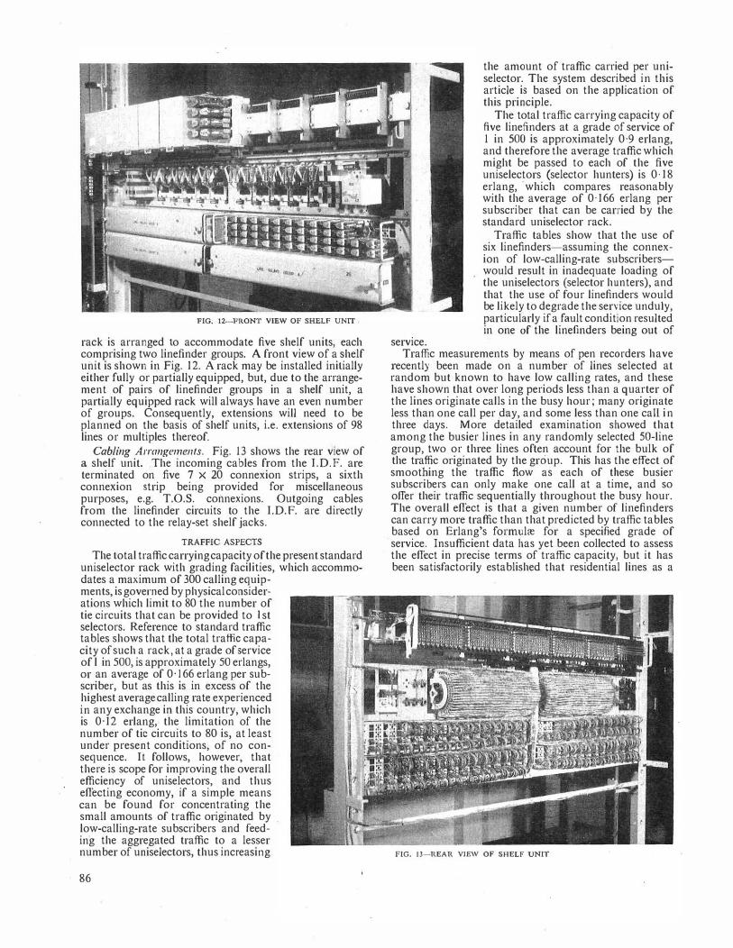
FIG; 12-FRONT VIBW OF SHELF UNIT
rack is arranged to accommodate five shelf units, each comprising two linefinder groups. A front view of a shelf unit is shown in Fig. 12. A rack may be installed initially either fully or partially equipped, but, due to the arrangement of pairs of linefinder groups in a shelf unit, a partially equipped rack will always have an even number of groups. Consequently, extensions will need to be planned on the basis of shelf units, i.e. extensions of 98 lines or multiples thereof.
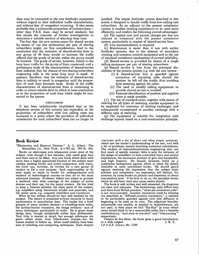
Cabling Arrangements. Fig. 13 shows the rear view of a shelf unit. The incoming cables from the I.D.F. are terminated on five 7 x 20 connexion strips, a sixth connexion strip being provided for miscellaneous purposes, e.g. T.O.S. connexions. Outgoing cables from the linefinder circuits to the I.D. F. are directly connected to the relay-set shelf jacks.
TRAFFIC ASPECTS
The total traffic carrying capacity of the present standard uniselector rack with grading facilities, which accommodates a maximum of 300 calling equip-ments, is governed by physical considerations which limit to 80 the number of tie circuits that can be provided to I st selectors. Reference to standard traffic tables shows that the total traffic capacity of such a rack, at a grade of service of l in 500, is approximately 50 erlangs, or an average of 0· 166 erlang per subscriber, but as this is in excess of the highest average calling rate experienced in any exchange i1.1 this country, which is 0· 12 erlang, the limitation of the number of tic circuits to 80 is, at least under present conditions, of no consequence. It follows, however, that there is scope for improving the overall efficiency of uniselectors, and thus effecting economy, if a simple means can be found for concentrating the small amounts of traffic originated by low-calling-rate subscribers and feeding the aggregated traffic to a lesser number of uniselectors, thus increasing
86
service.
the amount of traffic carried per uniselector. The system described in this article is based on the application of this principle.
The total traffic carrying capacity of five linefinders at a grade of service of 1 in 500 is approximately 0·9 erlang, and therefore the average traffic which might be passed to each of the five uniselectors (selector hunters) is 0· 18 erlang, ·which compares reasonably with the average of 0· 166 erlang per subscriber that can be carried by the standard uniselector rack.
Traffic tables show that the use of six linefinders-assuming the connexion of low-calling-rate subscriberswould result in inadequate loading of the uniselectors (selector hunters), and that the use of four linefinders would be likely to degrade the service unduly, particularly if a fault condition resulted in one of the linefinders being out of
Traffic measurements by means of pen recorders have recently been made on a number of lines selected at random but known to have low calling rates, and these have shown that over long periods less than a quarter of the lines originate calls in the busy hour; many originate less than one call per .day, and some less than one call in three days. More detailed examination showed that among the busier lines in any randomly selected SO-line group, two or three lines often account for the bulk of the traffic originated by the group. This has the effect of smoothing the traffic flow as each of these busier subscribers can only make one call at a time, and so offer their traffic sequentially throughout the busy hour. The overall effect is that a given number of linefinders can carry more traffic than that predicted by traffic tables based on Erlang's fonnulre for a specified grade of service. Insufficient data has yet been collected to assess the effect in precise terms of traffic capacity, but it has been satisfactorily established that residential lines as a
FIG. 13-REAR VIEW OF SHELF UNIT
class may be connected to the new linefinder equipment without regard to their individual traffic characteristics, and without fear of congestion occurring. It also seems probable that a substantial proportion of business linesother than P.B.X. lines-may be served similarly, but this awaits the outcome of further investigations to determine a suitable method of selecting these lines.
The fact that the new system caters for shared service by means of one line termination per pair of sharing subscribers might, on first consideration, lead to the conclusion that the inclusion of shared-service lines in any group of 49 lines would so increase the traffic offered that the grade of service within the group would be lowered. The grade of service, however, relates to the busy hour traffic for the group of lines concerned, and a preliminary study of the characteristics of shared-service lines indicates that the chance of two sharing subscribers originating calls in the same busy hour is small. It appears, therefoTe, that the inclusion of shared-service lines is unlikely to result in congestion until the proportion of such lines becomes large. Study of the traffic characteristics of shared-service lines is continuing in order to obtain reliable data on which to base conclusions as to the proportion of such lines which might be connected to the system.
CONCLUSIONS
It has been satisfactorily established that as the telephone service of thls country has expanded, so the proportion of subscribers with low calling rates has increased to a point where the provision of individual uniselectors for such subscribers' lines can no longer be
Book Review "Electronics and Electron Devices." A. L. Albert. The
Macmillan Co., New York. xi + 582 pp. 394 ill. 44s. Books on electronics now adequately cover most of the
subject, wide though it has become; only small gaps here and there wait to be filled. Any ne\V book which deals with more than a highly specialized fraction of the subject must overlap existing books and invite comparison with them; the book can, however, be written for a new group of readers or for a new purpose. Such opportunities as do exist apply as much to books for undergraduates and students of technological courses as they do to the more advanced treatises. Professor Albert has aimed to provide a textbook with wide coverage of the subject of active devices and their use, for the junior student. He has tried to keep a balance between the older parts of the subject, e.g. amplifiers using thermionic triodes and pentodes, and the newer parts, e.g. 1nagnetic amplifiers and transistors.
What he has written should be very well received by the student. The theory is presented without recourse to much mathematics or quantitative data. The reader has a brief glimpse of many modern devices-a travelling-wave valve, the surface-barrier transistor, the image orthicon-and of many techniques, particularly in radio. He is given some design data, though incidentally rather than deliberately. Very little is treated in detail, but enough references are given-albeit s·ome from little-known sources-for the keener student to follow up. More could usefully have been said of switching and computing techniques. Each chapter
justified. The simple linefinder system described in thls article is designed to handle traffic from low-calling-rate subscribers. As an adjunct to the present uniselector system it enables existing uniselectors to be used more efficiently, and confers the following overall advantages:
(a) The capital cost and annual charges per line are reduced as compared 'vith the present uniselector system, particularly in respect of shared-service lines.
(b) Less accommodation is required. (c) Maintenance is easier than it was with earlier
linefinder systems, due to the absence of secondary working and common control equipment and to the use of standard uniselector mechanisms of proved reliability.
(d) Shared service is provided by means of a single calling equipn1ent per pair of sharing subscribers.
(e) Shared service is free from the principal disabilities of the present system, e.g. with the new system:
(i) A shared-service line is guarded against connexion of incoming calls should the receiver be left off the cradle, thus avoiding false metering against the caller.
(ii) The need to modify calling equipments to provide shared service is avoided.
(iii) External identification of positive and negative wires is made possible.
(f) The use of standard racks, together with means of catering for all types of metering, enables equipment to be employed for extension of existing exchanges, and subsequently re-employed at another exchange with a different type of metering.
(g) The equipment is suitable for integration with exchange layouts based on a unit-construction principle.
concludes with a list of short and often simple questions which test the reader's understanding of the text, and with a list of problems, usually involving numerical calculations. The student of telecommunications engineering may not find much of specific interest; little is said, for instance, of the design of amplifiers to have controlled input and output impedances, the maximum product of gain and bandwidth, and high linearity. He should, however, build up a qualitative background against which to place the details available in more specialized books. He should guard against receiving the impression that the subject lacks subtlety and complexity-an impression left behind, for instance, by some books on physics and chemistry of about intermediate level. If he fails to do so, the specialist books which he will later read may cause severe shocks.
The book is well written and well presented; the diagrams are clear and adequate. The terminology used differs here and there from British practice; "ohms per centimetre cube" is not reco1nn1ended. Junction transistors rnade by alloying are described as "diffused-junction transistors," a mistake to be particularly guarded against now that diffusion is beginning to be used on its own. The adjectives bistable, monostable and astable, as applied to multivibrators, are not used; in their place we find "flip-flop" (a noun which many would think to be a monostable rather than a bistable multivibrator), "start-stop or one-shot" and "free-running" respectively.
Despite its few flaws, the book gives a good introduction to a wide subject. J. R. T. l.P.0.E.E. Library No. 2389.
87

Teleprinting Over Long-Distance Radio Links Part 1-General Methods of Radio Telegraphy
A. C. CROISDALE, M.B.E., B.Sc.(Eng.), A.M.I.E.E.t U.D.C. 621.396.3:621.396.65
This article, which will be published in two parts, discusses methods of working 5-unit telegraphy over radio links. Part 1 reviews difficulties caused by the vagaries of radio transn1ission and describes n1ethods used for the transn1ission of telegraph signals. Part 2 describes auto1natic-error-correcting n1ethods and the
improvement in performance which they offer.
INTRODUCTION
SINCE the introduction of the teleprinter in the late l920's its use has superseded virtually all other forms of printing telegraphy in the internal services
of all the major countries of the world. Teleprinters are also widely used for international telegraph communication on the continent of Europe and bet\veen the United Kingdom and the Continent by means of voice-frequency1 telegraph circuits carried in telephone cables. It was realized before the 1939-45 war that a requirement existed for teleprinter circuits between the United Kingdom and those overseas countries to which radio is the co1nmunication medium. During the war various methods2 of radio-teleprinter working Were devised, and expansion of telex and telegraph renter-torenter services has further encouraged the development of high-performance radio-telep1inter systems.
·
At the present time various radio-telegraph systems are in use for the transmission of overseas public telegrams. Many of them employ the morse code or doublecurrent cable code (d.c.c.c.), a code which is based upon the morse code. The most important Commonwealth routes are equipped with synchronous 2-channel timedivision d.c.c.c. systems, which were first introduced by Cable & Wireless, Ltd., in 1930. As this system is based on morse practice it does not facilitate interconnexion between teleprinter networks, which is desirable from an operating point of view. The increasing use of teleprinters throughout the Commonwealth and elsewhere has produced a need for a system designed specifically for teleprinter working and has led to the adoption of automatic-error-correcting systems. It will be seen later that modern systems of radio-teleprinter working embodying automatic error-correction provide a much higher standard than any of the older morse systems and that the objective of error-free printed copy has been achieved under all but the worst transmission conditions. The modern radio-teleprinter systems are equally suitable for public telegram traffic, international telex, i.e. subscriber-to-subscriber switched service, and renter-to-renter private circuits.
To describe the basic problems of transmission of teleprinter signals it is necessary to explain that the receiving machine is synchronized for each 5-unit signal by the use of a start-stop cycle. Each 5-unit start-stop character consists of a "start" signal followed by five intelligence signals, each of the same duration as the start signal (each signal unit is called an element), and finally the cycle is terminated by a "stop" signal of reversed polarity to that of the start signal (see Fig. I).
t Senior Executive Engineer, Telegraph Branch, E.-in-C.'s Office.
88
SPACE
HARK !. LE:::'l'LEH<N1ELEHEN1· ElEHENx· ELEHEN1· START I 2 l 4 S STOP
20ms 2 20m 20ms 20ms 20ms lOms.
r ' ' ' '
l-------- 1150ms UK INLAND--------+! l----145lms USED OH TIHE DIVISION SYSTEHS----1
Timings refer to a SO-baud 7�-unit signal In the U.K. Space= positive potential,
Mark= negative potential
FIG. 1-EXAMPLE OF 5-UNIT CODE:-LETTER Y (MSMSMJ
The use of this principle has the great merit that synchronization is simplified. and the effect of any speed difference between the transmitter and the receiver is confined to each character and is not cumulative over successive characters. The transmission of a start-stop 5-unit character involves the use of two signalling conditions, which are usually referred to as "mark" (M) and "space" (S). Spacing elements in the code employ a signalling condition corresponding to a start signal, whilst n1arking elements employ a signalling condition corresponding to a stop signal. In the United Kingdom positive polarity is employed for spacing elements and the start signal, and negative polarity for marking elements and the stop signal. Excessive mutilation of any element of the signal can cause an error to be printed and, worse, severe mutilation of the start or stop elements can cause loss of synchronism, which can persist through a number of subsequent characters. In fact, the start-stop system is particularly vulnerable to mutilations when transmission conditions are adverse and requires a better signal/noise ratio for its successful operation than systems employing "synclu·onous" signalling over the radio path, which are therefore generally superior to normal start-stop working in this respect.
One complication in international teleprinter working is that the modulation rate and alphabet used in American teletypewriter systems do not, unfortunately, conform to the international standard established by the C.C.I.T.T., to which all European and most Commonwealth countries conform. (See Table 1.)
TABLE 1 Comparison of Teleprinter ._Modulation Rates
Modulation rate (bauds) Signal element duration (n1s) Stop signal duration (units) Character cycle duration (units)
Character cycle (ms)
European (C.C.l.T.T.) American
50 20
1-5 7·5 (preferred
(standard) 150
45 ·5 22 approx.
l '42 7·42
163'3
Many teleprinters in use on the Continent still employ a 7-unit transmitting cycle and this, as well as the foregoing factors, has to be taken into account in providing international radio-teleprinter facilities. The problems of wor�ing teleprinter services over radio circuits are
I
11 '
therefore to overcome the effects of mutilation of signal elements at various signalling speeds and accommodate different operating cycles in some cases.
This article describes methods of providing satisfactory radio-teleprinter services on a world-wide basis and gives reasons for ihe adoption of automatic error-correcting systems.
TELEGRAPH SYSTEMS USED OVER RADIO LINKS
General A radio transmission may employ a carrier which is
amplitude-, frequency- or phase-modulated. Originally most radio-telegraph transmissions were of the amplitudemodulated type, the modulating signal keying the transmitter so that the carrier frequency was either transmitted ("On") or suppressed ("Off"). This method suffers from the disadvantage that during the off period of the carrier there is no signal to operate the automatic gain control (a.g.c.) of the receiver. The most common methods of operating telegraph circuits over main h.f. radio links are now,
(a) frequency-shift keying (including multiple frequency-shift keying),
(b) "on-off" keying, and (c) an independent sideband (i.s.b.) modulated by
n1ulti-frequency tones.
Phase modulation is seldom used.
Frequency-Shift Keying (fs.k.) and Multiple FrequencyShift Keying
Frequency-shift keying is effected by varying the allocated radio frequency between two closely spaced limits corresponding respectively to the marking and the spacing condition of the telegraph signal. Hence a signal is always present to control the a.g.c. of the receiver.
Two conditions on each of two telegraph channels can be signalled by transmitting any one of four radio carrier frequencies. For example:
SENDING SEND
TELEPRINTER CH I
TI) OTHER
T\110 CHANNELS
TO OTHER
T\110 CHANNELS
Channel A Channel B
Radio frequency Jc, indicates M and M Radio frequency Jc, indicates M and S Radio frequency Jc, indicates S and M Radio frequency Jc, indicates S and S A typical frequency-separation between each of the
above is 400 c/s. This multiple frequency-shift system is termed Four Frequency Diplex or Twinplex.3 Signalling on the channels A and B may or may not be synchronized.
The radio transmitters used for the above methods may be Class A , i.e. "linear," or Class C, i.e. "nonlinear." When output stages of the transmitter are used in class C amplification, a much higher transmitter efficiency is obtainable.
Frequency-Division Telegraph Systen1 used on SingleSideband (s.s.b.) Radio Transmitters
To provide a number of telegraph channels, frequencydivision systems may be used which involve transmission of a number .of v.f. tones in an audio channel of a linear transmitter, employing i.s.b. working.
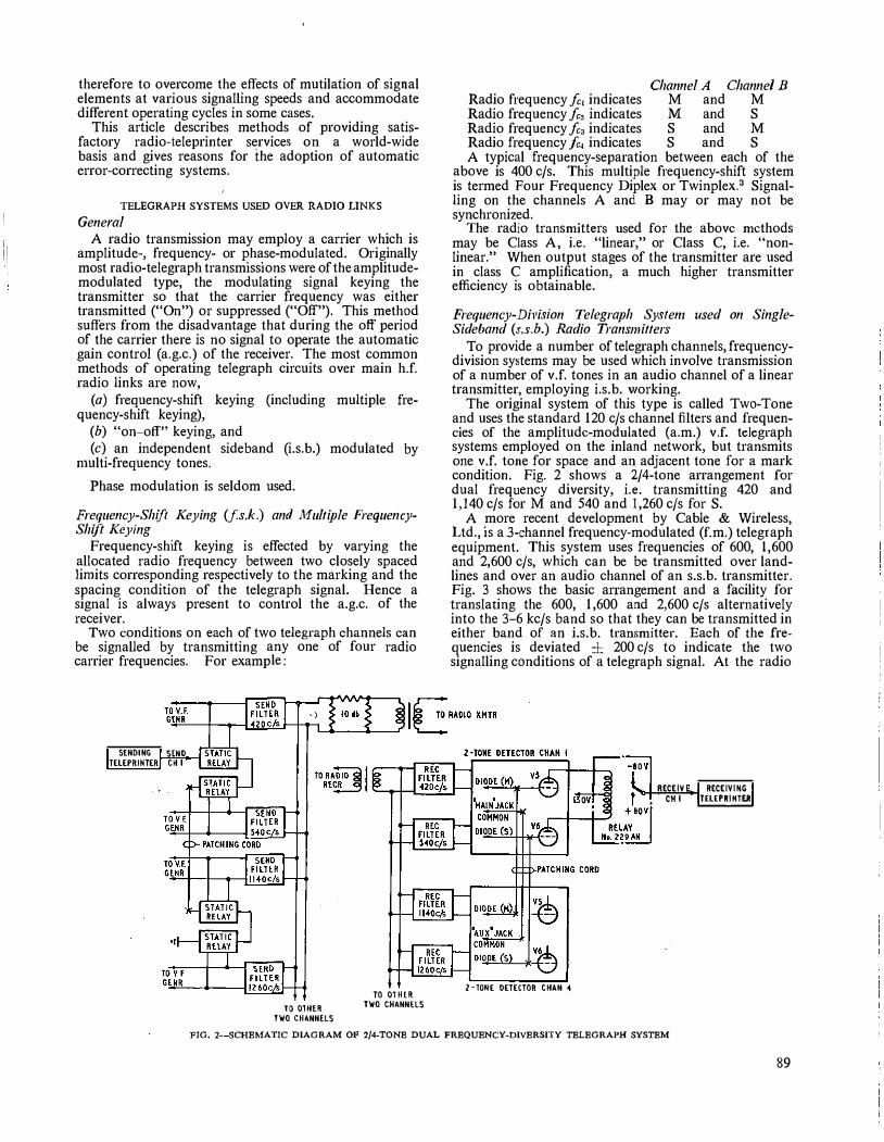
The original system of this type is called Two-Tone and uses the standard 120 c/s channel filters and frequencies of the amplitude-modulated (a.m.) v.f. telegraph systems employed on the inland network, but transmits one v.f. tone for space and an adjacent tone for a mark condition. Fig. 2 shows a 2/4-tone arrangement for dual frequency diversity, i.e. transmitting 420 and 1,140 c/s for M and 540 and l,260 c/s for S.
A more recent development by Cable & Wireless, Ltd., is a 3-channel frequency-modulated (f.m.) telegraph equipment. This system uses frequencies of 600, 1,600 and 2,600 c/s, which can be be transmitted over landlines and over an audio channel of an s.s.b. transmitter. Fig. 3 shows the basic arrangement and a facility for translating the 600, 1,600 and 2,600 c/s alternatively into the 3-6 kc/s band so that they can be transmitted in either band of an i.s.b. transmitter. Each of the frequencies is deviated ± 200 c/s to indicate the two signalling conditions of a telegraph signal. At the radio
2-TONE DETECTOR CHAN 4
RECEIV RECEIVING CH I TELEPR1HTER
FIG, 2-SCHEt.fATIC DIAGRAM OF 2/4-TONE DUAL FREQUENCY-DIVERSITY TELEGRAPH SYSTEM
89

CHAN I OSCILLATOR
KEYING MODULATOR
INPUT 3600 c/s
CHAMZ OSCILLATOR
KEYIMG MODULATOR
INPUT 4600 c/s
LOW-PASS FILT�RS
LOW-PASS FILTERS
LOW-PASS FILTERS
�-+-�"=<r,-M-PL _IF_IE_R, t�lN5Hrl OF RADIO TRAHSHllTER
of telegraph channels is given, in rapid succession, exclusive use of a common transmission path. Synchronized transmitting and receiving distributors allocate each channel to the common transmission path for a fixed period. Special methods of input are employed to present the 5-unit start-stop signals to the system at the correct instants. In the case of a time-division multiplex system either of two methods may be employed for the sharing of the aggregate time-"elementinterleaving'' or "character interleaving."
Element interleaving as applied to a 2-channel system implies that an element from channel 1 is transmitted, followed by an element from channel 2, then another from channel 1, etc.
Character interleaving implies that a complete character from channel 1 is transmitted, followed by a character from channel 2, etc.
In a 4-channel system the usual arrangement of interleaving is character interleaving of channel I with channel 2, and of channel 3 with channel 4, but
FIG. 3-THREE-CHANNEL TELEGRAPH MODULATOR (W.H.A.55) FOR I.S.B. RADIO TRANSMITIERS the combination of these pairs of
receiving station each channel is selected by a separate receiver. The channels are capable of signalling at speeds up to 200 bauds and hence a time-division telegraph system can be operated over each channel. While the use of a separate telegraph-type radio receiver is necessary for each telegraph channel, the facility of receiving each channel at a different location and the simplicity of the equipment are attractive.
·
Development in the Post Office of an improved multichannel telegraph system employing recently developed techniques4•5 is proceeding, for use between major communication centres.
Frequency-division telegraph transmission on an i.s. b. channel is attractive because of its economic use of r.f. band-width and equipment. The system loses in signal/noise ratio because of the small amount of radio power devoted to each channel. It will be seen later, however, that the use of error-correcting time-division telegraph equipment makes it possible to obtain good teleprinter service over. a link of this nature.
Tbne-Division Telegraph Syste1ns
It has been explained very briefly that the 5-unit code is liable to print errors in the event of mutilation of any telegraph elements. This liability arises because of the lack of "redundancy" (i.e. unused combinations) in the code, so that a mutilation of any signal element will produce a combination used by another character, and also because the instants of examination of the elements of a start-stop telegraph signal are timed in relation to the start signal of each character, which may itself be time-distorted, hence reducing the margin of successive elements in that character. The latter dis� advantage is overcome by the employment of synchronous transmission techniques, and time-division systems, being synchronous, have an inherent advantage over start-stop signalling for this reason.
Time-division working implies that each of a number
90
channels is by element interleaving. The use of a synchronous system requires that a
character be composed of an exact number of elements and, although five elements are the minimum required to transmit the 5-unit alphabet, a sixth element may be needed to transmit the additional supervisory signals of "call" and "clear" for telex working or some other special facility. Synchronizing is continuously provided by timing derived from the transitions of the received elements themselves.
In time-division multiplex working the rate at which signals have to be transmitted over the radio link is the aggregate of the signalling rates of the individual channels. The multiplex signal transmitted is called the aggregate signal, and for a given channel-speed its telegraph speed therefore increases in proportion to the number of channels served. The band-width required for a time-division multiplex system is fundamentally related to the aggregate signalling speed; the higher the speed the greater is the band-width required. Also, in common with frequency-division systems, the band-width required may be affected by the methods adopted to counteract noise and fading.
Choice of Frequency· or Tin1e-Division Methods
When a; time-division telegraph signal is transmitted by keying the carrier of a radio transmitter, the channels of the time-division system benefit compared with a frequency-division system by having the maximum power of the transmitter available to each in turn, and hence they will give the maximum signal/noise ratio at the receiver. However, the duration of e3ch signal element is reduced and this can constitnte a limiting factor.
If time division is applied to the channels of afrequencydivision radio telegraph system the number of different tones transmitted simultaneously for a given number of channels is less than if all the channels were provided by frequency division. This results in a higher power being available for each tone. Time division may also

assist to some extent in interconnexion between countries where two different teleprinter cycles are in use (this will be referred to again in Part 2). Time division also facilitates the further sub-division of the channels to give t or ! character rate sub-channels for leased services. A i rate sub-channel transmits 200 characters per minute and a i rate sub-channel 100 characters per minute.
The use of time division introduces problems of storage of telegraph signals at the input to the system and shortens the aggregate signal elements. The use of frequency division permits any modulation rate up to the channel limit and any type of signalling code to be transmitted and also permits the through transmission of special signals, such as dialling.
One very important aspect of time-division working, which may impose a limit upon the number of channels that may be operated in one system, is the effect of "multi-path" distortion. Depending upon the length and nature of the radio link, multi-path transmission may cause path time differences up to 4 ms. With 50-baud signalling (i.e. 20 ms elements) this effect only represents 20 per cent distortion but at 200 bauds (i.e. 5 ms elements) a multi-path delay difference of 4 ms would cause 80 per cent distortion and the signals would be incapable of correct reception. It will thus be clear that if multi-path effects are serious they impose an overriding restriction on the number of channels that can be operated successfully in a time-division multiplex system. For this reason the Post Office favours the use of systems in which the aggregate signalling speed does not exceed 100 bauds, e.g. 2-channel 7-unit error-correcting systems. In such cases the effect of even 4 ms delay due to multi-path transmission alone would cause not more than 40 per cent distortion, and this is just tolerable. The successful operation of 4-channel time-division systems is possible only on links over which time-delay distortion is not serious, and as in any event their margin of operation is less than that of 2-channel systems, their probability of error is greater when the signal/noise ratio is adverse. Nevertheless, 4-channel error-correcting systems are in fairly common use, as the mutilations due to multi-path propagation are mainly detected and merely reduce the traffic clearance slightly.
Time-division working obviously necessitates the employment of synchronized transmitting and receiving equipment, and since modern methods enable a high degree of accuracy to be maintained in the transmitted signals and in the speed and phase of the transmitting and receiving multiplex distributors, it is possible to withstand a large amount of signal distortion on the radio path. In practice a receiving margin of at least ±45 per cent is readily maintained on multiplex equipment and the received signals are regenerated by the receiving multiplex equipment before retransmission to the local receiving instruments, or to a landline channel.
If radio links need to be relayed then synchronous regeneration of the aggregate signals can be provided.
CAUSES OF MUTILATION OF TELEGRAPH SIGNALS ON RADIO
LINKS
Radio signals are affected by fading and multi-path propagation, noise, and interference from adjacent radio emissions. Where possible, means of mitigating these effects are adopted.6
Fading of Radio Signals in the 3 Mc/s to 30 Mc/s Range Fading of radio signals is a random phenomenon
which has certain characteristics important to telegraphy: (i) The received signal level varies approximately
according to a Rayleigh distribution, rarely giving changes of level greater than 20 db below median level, which is that level exceeded by the signal for 50 per cent of the time.
(ii) The time between successive upward crossings of the median signal level is called the fading "quasi" period and experience indicates that this is rarely less than one second in duration.
(iii) The fading of two individual frequencies used for telegraph signals may be different at any instant; this is termed frequency selective fading.
Where the fading is selective, airnngements can be made to use two or more tones for each telegraph signalling condition, and the receiver can then select the stronger received tone at any instant. This is termed frequency diversity, and has the disadvantage of
(a) requiring two or more tones to be transmitted, with consequent reduction in power level, to avoid overloading the transmitter, and
(b) using extra frequency band-width.
The disadvantages of frequency diversity can be overcome by the use of two or more receiving aerials spaced several wavelengths apart to provide alternative signals and arranging that the receiver can select the stronger of these space-diversity signals. Dual frequency-diversity or dual space-diversity reception reduces the "drop-out" time on a radio link to a very small fraction. When a number of receivers are used in diversity the a.g.c. of the receivers is linked so that noise will not be introduced by a path suffering a deep fade.
Noise
The performance of telegraph channels in the presence of noise depends on the signal/noise ratio and the nature of the noise. Obviously the signal/noise ratio is dependent on the signal level and hence the power transmitted per telegraph channel should be as high as possible. For this reason a transmitter employing on/off or frequency-shift keying has an advantage over one employing frequency division, since, where multiple tones are transmitted, the levels must be reduced due to the increase in the number of the tones to avoid overloading the transmitter and causing consequent intermodulation products.
The effects of noise and interference from other radio emissions on adjacent radio frequencies can be mitigated by filters of narrow band-width. Diversity reception also offers an improvement in respect of signal/noise ratio.
PERFORMANCE OF TELEGRAPH SYSTEMS ON RADIO
Over the years much thought has been given to methods of detecting telegraph signals so as to give the highest accuracy of received signals. The problem is to determine whether or not a signalling element is present. Examination of the signal element at a telegraph radio receiver may be,
(a) by integration of the voltage present during the element arrival time, or
(b) by checking whether the signal level exceeds a given level continuously during a predetermined fraction of the element period.
91

Where the resulting telegraph receiver output, in a direct-current form, is applied to a synchronous telegraph equipment the signal is examined either at the centre point of each element or possibly at several points.
At the radio receiver the performance will depend upon the relative values of signal voltage and noise volrnge, i.e. the signal/noise ratio, normally expressed in decibels. It is beneficial therefore either to improve the signal level, possibly by increasing the transmitter power, or to reduce the noise level by reducing the receiver band-width to a minimum (and perhaps by changing the radio frequency). The use of diversity is effective in selecting the larger of two incoming signals from either spaced aerials or spaced frequencies. To mitigate the confusion caused by the amplification of the noise components by the a.g.c. of the receivers it is necessary to ensure that equal gain is provided on each diversity path, at any instant. Th.is is provided for in the telegraph radio receiver.
The performance of 50-baud telegraph channels of the start-stop system in the presence of noise is illustrated by Fig. 4. This is for "white" noise spread over
0 ' '
I ' '
I ' ' ' '
0
jrv:�• ,
/F.M ,
I I
0
/ / I I
. 0-
I I / � /
� �4 � M 20 24 10 14 NOISE LEVEL BELOW SIGNAL LEVEL (db) (NOISE IN 120cj, FILTER BAND)
Note.-The vercentage distortion shown as ordinate value was a Probability exceeded only once in 10.000 in�tancfs (!he P(4) distortion)
FIG. 4---EFFECT OF RANDOM NOISE lNTERFERENCE ON DISTORTION (Q9S SIGNALS AT 50 BAUDS)
the band of frequencies accepted by the channel filters; the channels are spaced 120 c/s apart. The f.m. system' has a shift of ± 30 c/s and it shows a considerable advantage in the presence of noise. This f.m. equipment can be adapted for space-diversity radio reception but is not so nsed by the Post Office.
Fig. 5 shows the error liability in ideal diversity reception of Rayleigh-fading binary telegraph signals' for varying signal/noise energy ratios and for up to four diversity paths. The term signal/noise energy ratio is the ratio of the energy in a signal element to the noise power per unit band-width (also an energy). How far existing receivers fall below the ideal can then be assessed in terms of decibels below the ideal receiver. The work done by the Post Office Radio Experimental and Development Branch's Laboratories•.•. • also shows the improvement which can be obtained in performance of
92
�
ii! :::
to I
' � 10-� : � !::! : u � 0
� ' � io-o �
0 � �
IO-•
·-ffllH:U:R nf -
\ "\ ' ' ·-\ \ ' ' S UNI CODE
�· ' ' 7 UNI CODE DETECTED ERR RS
"'\ ,, ' .
7 UNIT COD UNDE.T CTED ERRORS-' ' '
" ., ' " \ "\ . \ I \ I \ .
\ I ' I \ ' '
' '
' " ' ' I " I \
I . I \\ \ I
� I \ ·, I . '
" ' " ' . \\ ' ' '.
\1 \ I
.,, � \ \ I
·' \\ I\ I \\ -
\'
10 zo 30 '40 50db EFFECTIVE CHARACTER SIGNAL/NOISE ENERGY RATIO PER BRANCH Eco
'•o
FIG. 5-ERRORLIA1HLITIES OF 5-UNIT AND 7-UNIT ERROR-DETECTING
CODES IN NON-DUAL- AND QUADRUPLE-DIVERSITY RECEPTION OF RAYLEIGH-FADING SIGNALS
tone signalling systems in conditions where the fading is frequency-dependent (called selective fading), by processing the mark. and space tones independently.
In practice the performance of telegraph systems varies0 widely depending on the factors enumerated already. The geographical positions10 of the radio stations may affect the radio link performance; east to west links are more difficult than north to south, particularly when the route passes throngh the auroral zone.
The use of synchronous working11 gives two 1najor advantages: it provides for examination of elements on an accurately-controlled time-base which gives practically double the distortion margin compared with startstop working, and it obviates loss of synchronism of the receiving teleprinter. Loss of synchronism could result in a sequence of incorrect chatactets being prinlcd before the teleprinter gets back into the stop condition correctly, and is ready to print properly synchronized characters.
The use of electronic regenerative repeaters12 on start�stop circuits provides a greater margin of acceptable distortion, up to about :!: 45 per cent, and a facility is available for rejecting false start signals, which may be produced by radio conditions, when these start signals are less than a certain duration. The main function of the regenerative repeater is to restore the shape of the signal, but it also provides the facilities described above and in addition can insert a stop signal at the end
of the character even if this is missing from the radio signal.
Synchronous telegraph systems provide regeneration inherently and the condition of loss of synchronism cannot arise on the channel outputs.
Briefly, then, it can be stated that where radio propagation conditions are good, start-stop telegraph systems can provide a satisfactory service during limited periods of the day or night; the use of synchronous working can improve the period of satisfactory working, but to achieve the desired reliability of printing for the telex and renter-to-renter services some major improvement is necessary for 24-hour service. The C.C.I.T.T. recommend that for telex service over a circuit including a radio link an error rate of not more than 10 errors per 100,000 characters is desirable, and this is at least one order higher than that achieved by normal radiotelegraph systems.
The solution to this. problem has been pursued by many engineers over the last 20 years, with various systems of error-detecting and error-correcting codes, but the automatic error-correcting system invented by Dr. Van Duuren, of the Netherland Post and Telegraph Department, has special merit in method and facilities and on typical radio circuits it provides an improvement in error rate of roughly I 00 to I.
It may be mentioned that automatic error-correction will make the performance of even a poor radio link better, but improvement to the radio link itself will be repaid by a greater traffic-carrying capacity.
(To be continued)
Book Review "Receiving Aerial Systems." I. A. Davidson, B.A. Heywood
& Co., Ltd. 152+viii pp. 78 ill. 2Js.
Here is a book on a topical subject-the short title on the cover does not reveal that the book concerns itself solely with domestic receiving aerials, i.e. those used for the reception· of sound and television broadcasting. Many readers will expect to find convincing explanations of the operation of the many types of aerial which now don1inate the urban skyline; to a large degree they wi11 be disappointed. Despite the author's obvious intent to fill a gap in the literature, it must be said that the book fails short of its initial promise.
An early chapter in which the author discu5.5es fundamental concepts concerning aerials might have been less confusing and more useful if the steps in the argument had been explained with greater care. In a later chapter, basic principles ,concerning v.h.f. propagation are treated only briefly ; one would have expected to see, in a practical book of this nature, some illustration of the field strength contours round a v.h.f. broadcasting station and some quantitative indication both of the average rate of attenuation with radial distance and the local variations of field strength in various types of terrain.
A single chapter is devoted to aerials for sound broadcasting reception generally, and following this, the author deals with the half-wave dipole aerial and its use in more complicated aerials, mainly the two-element H-aerial and the Yagi aerial with three or more elements. The information provided on gain and directivity loses much of its value, however, since the author does not say whether
References 1 HARRIS, L. H., JOLLEY, E. H., and MORRELL, F. 0. Recent
Developments in Telegraph Transmission and Their Application to the British Telegraph Services. Journal l.E.E., Papers No. 483 and 485, March and May 1937 (Vol. 80, p. 237).
2 DAVISON, G. N., and PICKARD, R. J. A Multi-Channel Radio Telegraph Equipment. P.O.E.E.J., Vol. 41, p. 148, Oct. 1948.
3 BUFF, C. Twinplex and Twinmode Radiotelegraph Systems. Electrical Co1111111111icatio11, p. 20, 1952.
HEWARD, S. C. Frequency Shift Diplex. Electronic E11gi11eeri11g, Vol. 26, p. 268, June 1954.
'
4 ALLNATT, J, W., JoNES, E. D. J., and LAW, H. B. Frequency Diversity in the Reception of Selectivity Fading Binary Frequency-Modulated Signals. Proceedings I.E.E., Paper No. 2151R, March 1957 (Vol. 104, Part B, p. 98).
5 LAW, H. B. The Signal/Noise Perfonnance Rating of Receivers for Long Distance Synchronous Radio Telegraph Systems using Frequency Modulation. Proceedings I.E.E., Paper No. 2103R, March 1957 (Vol. 104, Part B, p. 124).
6 LAVER, F. J. M. An Introduction to Some Technical Factors affecting Point-to-Point Radiocomn1unication Systems. Proceedings l.E.E., Paper No. 1925R, Nov. 1955 (Vol. 102, Part B, p. 733).
7 CmTTLEBURGH, W. F. S., GREEN, D., and HEYWOOD, A. W. A Frequency-Modulated Voice Frequency Telegraph Syste1n. P.O.E.E.J., Vol. 50, p. 69, July 1957.
8 LAW, H. B. The Detectability of Fading Radiotelegraph Signals in Noise. Proceedings I.E.E., Paper No. 2104R, March 1957 (Vol. 104, Part B, p. 130).
9 HUMBY, A. M., MINNIS, c. M., and HITCHCOCK, R. J. Performance Characteristics of High-Frequency Radiotelcgraph Circuits. Proceedings I.E.E., Paper No. 1787R, July 1955 (Vol. 102, Part B, p. 513).
10 DIETSCH, C. G. The Tangier Radio Relay System. R.C.A. Review, Vol. 14, p. 557, Dec. 1953.
11 SCOTT, D. Commonwealth Radio Communication Services. Electronic Engineering, Vol. 26, p. 224, June 1954.
12 CARTER, R. o., WHEELER, L. K., and FROST, A. c. An Electronic Regenerative Repeater for 7! Unit Start-Stop Telegraph Signals. P.O.E.E.J., Vol. 41, p. 222, Jan. 1949.
actual measured performance or calculated theoretical performance is· being quoted. It would seem that most of the information falls into the latter category, but if so, it is not clear whether mutual coupling effects between elements have been taken into account. One or two statements such as that front-to-back ratios of better than 30 db are achievable in fairly simple aerials leads one to suppose that only a relatively simple theoretical treatment has been used.
Here indeed lies the main weakness of the book since the practical modifications to calculated performance are largely ignored or covered by statements that "of course, in practice, things are much more complicated." It is interesting to note that the author recognizes that particular aerial configurations may be adopted as much from considerations of appearance and mechanical convenience as from the need for desired electrical characteristics.
Three of the later chapters deal with r.f. cables and accessories, the 1nechanical design of aerials and their installation, and contain useful practical information. From these chapters, and from the book as a whole, many of those who have to select and erect television aerials will undoubtedly benefit. Nevertheless if the book is specifically directed to this class of reader, a more careful and reasoned explanation of the funda1nentals and a much fuller treatment of the actual results obtained in the field would have been invaluable.
The information is attractively presented, with generally simple and appropriate diagrams, but some of the figures require further annotation to be of full value.
J. K. S.J.
I.P.0.E.E. Library No. 2487.
93

A Novel Way of Providing a Cable Route Across a Busy and Congested Water-way
S. W. JENNINGS, A.M.I.E.E., and W. D. PRIESTLEYt U.D.C. 621.315.232:621.315.28
This article describes the unusual method used to provide a cable route across the River Waveney at Lowestoft, Suffolk, without using subaqueous cable. A shaft lined with Larssen piling was sunk in the ground on each side of the harbour and, after culling a bole in the piling, a sleeve-pipe was thrust through the hole and the sand to the back of the cast-iron wall of the harbour. The sand between the end of the sleeve-pipe and the harbour wall was consolidatetl chemically and a hole drilled through it and the harbour wall. The shore sections of the 18 in. diameter cablepipe were then thrust through the harbour walls from the two shafts and jointed to the main-crossing pipe, which was sunk in a
trench dredged in the bed of the harbour.
INTRODUCTION
THE need to provide access from the North Sea to the various harbour installations and shipbuilding yards at Lowestoft, Suffolk, precludes the
economic provision of a fixed bridge across the River Waveney. The existing telephone cables crossing the river are of subaqueous type and cause British Railways, who are responsible for the maintenance of the harbour, considerable difficulty when dredging. British Railways were approached regarding the provision of three additional subaqueous cables but. they could not accept the increased obstruction.
As the nearest fixed bridge is some miles up-river all the practicable routes examined required the crossing of the River Waveney below the level of the river bed, clear of dredging operations. In view of the route taken by the existing cables and the need for access to the site for heavy equipment, etc., it was decided that the crossing should be made on the sea side of the swing bridge across the river, approximately 6 ft to the east of the electricity cables.
Test borings were made on both sides of the harbour and indicated that the sub-soil consisted mainly of fine sand with a small amount of larger material. There was standing water at approximately 10 ft below ground level. The presence of waterlogged sand prevented the work being carried out by excavation and tunnelling. A further difficulty would have been the cutting of the cast-iron piling which forms the face of the harbour walls. The provision of temporary coffer dams to allow the cast-iron piling to be cut "in the dry" was also considered but the considerable cost involved and the inevita.ble disturbance to shipping did not commend this method.
The procedure eventually adopted was as follows: (a) Provide shafts constructed with Larssen piling at
each side of the harbour as close as possible to the back of the concrete capping of the harbour wall.
(b) Fabricate a flat datum face on the corrugated profile of the Larssen piling. This face consisted of a square plate welded to the piling in such a manner as to maintain the watertightness of the shaft when the piling was cut.
(c) Mount on this plate a 24 in. damper-plate valve.
tThe authors are, respectively, Executive Engineer and Assistant Engineer, External Plant and Protection Branch E.-in-C.'s Office.
'
94
(d) c.ut a �2 in. diameter hole in the piling either by trepanrung with a cutter or by a specialist diver using oxy-arc equipment under water.
(e) Thrust a 20 in. diameter sleeve-pipe from the shaft through the damper-plate valve and through the sand to the back of the cast-iron harbour wall.
(f) Chemically consolidate the sand between the end of the sleeve-pipe and the back of the harbour wall.
(g) Trepan a 19 in. diameter hole in the harbour wall using the sleeve-pipe as a guide for the trepanning cutter.
(h) Push the shore sections of the 18 in. diameter cable:�ipe through the sleeve-pipe and the harbour wall and J?m them to the main-crossing pipe using Johnson couplings.
SHAFTS
The shafts were constructed using Larssen Section No. 3 steel piling driven to a depth of 45 ft. The sand wit�n the shafts was excavated to a depth of 35 ft and a remf?rced concrete floor, 2 ft thick, was provided. To resist the upward force on this floor due to the hydrostatic pressure, large-section angles were welded to the piling near the top surface of the concrete. The shafts, which were subsequently lined with reinforced concrete, are approximately . 8 ft from front to back and 6 ft wide.
Datum faces(Fig. l)on the pilingwere used as mounting plates for the valves through which all operations had to be performed. They were welded to the steel piling at right angles to the line joining their centres, i.e. the centre line
FIG. I-PLATE WELDED TO PILING TO FORM DATUM FACB

FIG. 2-DAMPER·PLATE VALVE
of the final crossing, both horizontally and vertically. Gusset plates were welded between t)le plate and the corrugated face of the piling to seal the joint.
The damper-plate valves (Fig. 2) were next fixed to the mounting plates. No attempt was made to ensure that these valves would be completely watertight as it was considered more important that they could be shut with sand or other obstructions in the channel in which the plate slides. Considerable difficulty was experienced with the shutting of these valves and minor modifications were necessary on site.
CUTTING THE HOLES IN THE LARSSEN PILING
The contractor employed on cutting the holes in the piling specialized in the trepanning of holes in largediameter water and gas mains while still under pressure. One of the machines used for this work, suitably modified, was mounted on the inner face of the valve in the north shaft (Fig. 3) and an attempt made to trepan the 22 in. diameter hole. This machine is driven by a 5 h.p. compressed-air motor geared to give a final shaft speed of 2·5 rev/min, and provision is made for an automatic forward feed of approximately 0·009 in./
t°' revolution, i.e. 0·024 in./min advance. The machine was started and no difficulty was encountered until the face of the piling was penetrated. Progress became more difficult as the cutter advanced due to small stones being drawn into the cut from the back of the piling until the cutter refused to advance further. The cut was at this stage 2 in. deep out of a total depth of approximately 12 in. In spite of continued efforts it proved impossible to progress further and this method was therefore abandoned in favour of :flooding the shafts and using the oxy-arc process.
The cutting of steel under water presents many problems but the oxy-arc process, developed during the Second World W,ar, is a considerable advance on the older oxy-acetylene technique. The steel is preheated by a high-current-density arc struck between a hollow carbon electrode and the steel to be cut. Oxygen is passed
through the centre of the electrode at a pressure of approximately 50 lb/in2 above that due to the depth of water. The steel burns in the oxygen leaving a cut approximately ! in. wide.
The shafts were flooded and the hole cut in the south-side shaft using oxy-arc cutting equipment, and although some difficulty was . experienced the work was completed in approximately 8 hours' cutting time. To remove the cut piece presented difficulty owing to the probability that sand would run into the shaft through the hole and undermine the buildings on the quay before the damper valve could be shut. To prevent this an extension was bolted to the damper valve which allowed the cut piece to be drawn back beyond the damper plate without opening the full diameter of the hole. The damper plate was, of course, shut by the diver before the shaft was pumped out.
THRUSTING THE SLEEVE-PIPE
The harbour wall consists of cast-iron T-section piling 18 in. by 9 in., approximately 2i in. thick. These piles are placed at an angle of approximately 15° to the vertical with the flat face outwards and are capped with concrete.
The 20 in. sleeve-pipe was supplied in 4 ft lengths, this being the longest that could be conveniently handled in the space available. The first section of pipe was provided with a cast-iron bearing at its leading end; it was also cut to the angle of the harbour piling and slotted to embrace the tee in an attempt to improve the
FIG. �-TREPANNTNG MACHINE
95

intimacy of contact with the cast-iron piling. Even though considerable clearance was provided it was not found possible to push the pipes with the accuracy required to take advantage of this slot.
A simple gland was bolted to the damper-plate valve and the first section of sleeve-pipe was pushed through this gland to within I in. of the damper plate. A simple stopper, similar in construction to the gland, was assembled within the sleeve-pipe. This stopper remained stationary while the pipe was thrust forward and was provided to prevent sand flowing into the shaft through the sleeve-pipe. Two pieces of angle-iron were welded to the front plate of the stopper to provide attachments for two lengths of channel-iron, the further ends of which were bolted to similar brackets welded to the back of the shaft. These channels were needed to resist the pressure applied to the stopper by the water in the quay (approximately 9 lb/in').
The damper plate was then raised and the pipe pushed . forward by means of a 50-ton hydraulic jack operated by a remote pump fitted with a pressure gauge to allow the actual force applied by the jack to be controlled. The first section of pipe was pushed forward until the trailing end was within 6 in. of the gland. Special brackets were then bolted between the stopper, sleevepipe and the damper valve to hold the stopper against the water pressure whilst the second section of sleevepipe was placed in position for welding to the previous section. The eight sections of sleeve-pipe, four for each side, had already been prepared for butt welding before delivery to site and no difficulty was experienced.
The welding having been completed, the jacking of the pipe was continued. A sudden increase in the pressure indicated by the gauge was thought to be due to "sand plugging" and this was confirmed by the reduction in the pressure needed to push the pipe forward after water had been allowed to escape through a central hole in the stopper, the flow of water having disturbed the sand. It was found necessary to open this central hole fairly frequently, and after some 8 ft of pipe had been pushed in it became necessary to loosen the sand within the pipe with jointed rods. The distance
5HP. AIR MOTOR & GLJ.ftso.x.
OAHl'£R PI.ATE 'IALVE
lARSSEll PILING
SlHYE PIPE
JOINHO SJ!AFT DRIVE
COOSOLl�ATEO SANO rn:
CL 8£.1.RlllG
to be pushed had been calculated from observations made with surveying instruments and as the pipe approached the harbour piling very careful watch was kept on the gauge to guard against damage to the harbour wall. The pressure required, provided no sand plug was allowed to form, did not vary with the length of pipe being pushed as much as had been expected. In .fact, once the pipe had been pushed approximately 4 ft the pressure remained almost constant.
CHEMICAL CONSOLIDATIO�
The chemical consolidation of the sand between the end of the sleeve-pipe and the back of the harbour wall was carried out through It in. diameter holes drilled in the 1nounting plate and Larssen piling of the shaft.
The chemical consolidation of sandy soils consists essentially of the injection into the soil of two or more chemicals, both of which must be soluble in water and of low viscosity. These chemicals are usually injected one after the other with as little time lag as possible. The solutions are so chosen that double decomposition takes place and at least one of the products is insoluble and has a natural affinity for the sand. This results in the sand particles being cemented together, thus preventing the sand running. The chemicals used on this project were sodium silicate and ·calcium chloride, with an additive to make the mixture less viscous. Double decomposition produces calcium silicate, an insoluble salt having a strong affinity for sand, and sodium chloride, i.e. common salt. The calcium silicate acts as a cement and binds the sand grains together. The resulting material has a compressive strength of approximately 300 lb/in'.
After carrying out the chemical injections, the central pilot hole in the stopper was opened in order to provide a measure of control over the flow of sand and water in the event of the consolidated material not being capable of withstanding the hydrostatic pressure of the sand and water above it. No attempt was made to remove the stopper until the pilot hole had been open for at least 24 hours. The removal of what remained of the sand
CLllARBO\IR Plllflf;
CUP DRILL
IHSEllTEO CUTTIRS
RM.AMO l£YEl
in the sleeve-pipe presented no difficulty until a point approximately 2 ft from the harbour piling was reached when it was found that, as had been expected, the consolidation had extended within the pipe. The material was removed with various tools de-signed and made on the spot.
TREPANNING THE CAST-IRON PILING
OF THE HARBOUR WALL
FIG. 4-ARRANGEMENT OF CUP DRILL FOR TREPANNING HOLE IN THE HARBOUR-WALL PILING
A cup drill, having 12 inserted cutters rotating inside the sleevepipe and fitted with a drive shaft, was used to trepan the hole in the cast-iron piling of the harbour wall. The arrangement of the drill can be seen from Fig. 4. The length of the individual sections of the drive shaft was limited to 4 ft by the space available between the change block and the back wall of the piling. A change block was
96

'.\ ·..; 'ii
FIG. S -JOINT USED IN CUTTER DRIVE SHAFT TO MAINTAIN THE CYLINDRICAL PROFILE OF THE SHAFT
used to enable the cutter to be removed and reinserted without flooding the shaft should regrinding or replacement of the cutters be necessary once the cast-iron harbour piling had been penetrated. The change block consisted of a length of tube, approximately 24 in. internal diameter and long enough to house the cup drill. It was fitted wJh an external flange at one end for bolting to the damper valve and was closed at the other end by a plate carrying a central bearing through which the drive shaft could pass. A special type of joint was used to maintain the cylindrical profile of the shaft (Fig. 5).
The remainder of the machine (Fig. 6) was fixed to the flange by four2 in. diameter steel rods and the end of the shaft was fitted to the worm-wheel extension by three radially drilled ! in. diameter tapped holes. The machine was designed for chain drive from a 5 h.p. compressed-
The chain drive has been omitted for clarity
FIG. &-MACHINE USED TO TREPAN THE HARBOUR-WALL PILING
n
air motor and reduction gear which, owing to the restricted space on the floor of the shaft, was mounted on a platform approximately 4 ft above the trepanning machine. The worm drive to the shaft moved forward along the 2 in. diameter rods as the cutter advanced and continuous adjustment was necessary to the motor platform to keep the chain from jumping round the sprockets. Should any further work of this nature be attempted this arrangement would need considerable improvement.
The speed of rotation of the cutter was 2·5 rev/min and the forward feed was under the control of the operator. A feed of as little as 0·002 in. per revolution was possible. After some initial difficulties with the cutting tips a special grade of "Wimet" was employed, and not only did the cutters tipped with this material complete the cut on the north side but also made a full cut on the south side with only two of the 12 cutters sustaining significant damage. This speaks very highly for the material as the cutters were required to cut the cast-iron piling as well as the very hard stony material immediately behind it. This material (Fig. 7), resembling very hard
·· ··! ',f
FIG. 7-PIECE OF CAST-IRON PILING AND STONY MATEIUAL TREPANNED FROM HARBOUR WALL
concrete, appeared to be composed of sand and stone consolidated by the migration of iron from the piling over a period of nearly a century. When the cut was completed the cutter was drawn back into the change block, the dampervalve closed and the machine dismantled and removed from the shaft. The other wall of the harbour was trepanned in a similar manner.
SHORE SECTIONS OF THE CABLE-PIPE
It was necessary to assemble the cable-pipe from lengths of less than 5 ft. A gland, similar in design to that used for the sleeve-pipe but of a size suitable for the 18 in. diameter cable-pipe, was bolted to the damper valve. The first section of pipe was fitted with an expanding stopper. Lugs had been welded at 120° spacing on the inside of the pipe to form abutments for the stopper and prevent the hydrostatic pressure from forcing the· stopper through the pipe. The pipe was inserted through the gland to within l in. of the damper plate. The valve was opened and pushing continued until the trailing end of the pipe was within
97

6 in. of the gland face. Chain pullers were used to push the pipe as little resistance was expected. The pipe was then retained against the water pressure and the second section of pipe welded on. Pushing and adding sections continued until the pipe protruded approximately 1 ft beyond the outside of the harbour piling. Care was taken to prevent rotation of the pipe. A ! in. plate was then welded on to the shaft end of the pipe to maintain watertightness when the expanding stopper was removed by the diver.
MAIN-CROSSING PIPE
A trench was dredged across the harbour allowing a clearance of 1 ft below the pipe. An unforeseen difficulty arose due to the presence on the harbour bed of the remains of many wooden piles (Fig. 8), which had been
FIG. 8-0LD PILES DREDGED FROM HARBOUR BED
cut off at bed level when the harbour was widened many years before. Eventually the trench was excavated and soundings were taken to ensure that adequate clearance had been allowed.
The main-crossing pipe had already been assembled on the quay from four sections and was some 85 ft long. A horizontal shelf was provided l t in. below the diameter to simplify subsequent cabling and to provide more "ways" without the cables becoming trapped and having to be abandoned.
The pipe sections were butt-welded together and the joints reinforced with i in. thick mild-steel collars, fillet-welded to the pipe. The protection, asphalt reinforced with fibre glass, was continued over the joint's by hand.
The conditions in the harbour made it necessary for the diver to work entirely by feel, and it was necessary to provide slings to maintain the pipe in a position such that the shelf would remain horizontal without any assistance from the diver. Each sling (Fig. 9) consisted of a mild-steel bar welded to the top of the pipe, which was supported by two wire ropes of equal length.
The construction of the Johnson couplings used for jointing the shore sections to the main-crossing pipe left some doubt as to the reliability of their electrical continuity. and arrangements were made to provide a connexion to the main-crossing pipe for cathodic protection.
98
FIG. 9-END OF MAIN-CROSSING PTPE, SHOWING SLING AND WOODEN DISK
The ends of the pipe were then closed with 1 in. thick wooden disks resting against the shelf, which had been set back 2 in. from the end of the pipe for this purpose. As a precaution against the disk rotating about the shelf edge a small bracket had b�en welded to the top of the pipe to resist the pressure on the disk. The joint between the wooden disk and the pipe was caulked with cotton to effect a watertight seal.
The pipe, weighing about 4 tons, was lowered over the side of the quay into the water (Fig. 10). Although
FIG. JO-MAIN-CROSSING Pll'E BEING FLOATED INTO POSITION

buoyant in itself, the pipe was further supported by a timber cradle. The work of warping the pipe across the harbour had to be timed carefully to minimize the effect of tidal flow tluough the harbour lock. On the advice of the local harbour officials it was decided that the work should commence 1 hour before low water and that every endeavour should be made to complete the sinking of the pipe within 2 hours. The pipe was warped into position over the trench and the slings were attached to chain tackles slung from baulks of timber protruding over the harbour wall.
The rear ends of these timbers were attached to the Larssen piling. Holes were then drilled in the wooden disks in the ends of the pipe and the timbers released from the pipe. The pipe gradually settled and eventually sank almost 2 hours after low water, but no difficulty was experienced with tidal flow. The diver was immediately sent down to plug the holes in the wooden disks to prevent additional water flowing into the pipe and increasing the effective weight to be handled when fitting the Johnson couplings (Fig, 11).
The bolls have been omilled for clarity
FIG. I I-EXPLODED VIEW OF A JOHNSON COUPLING
One end of the pipe was then raised, under instruction from the diver, and the pipe was pulled into the coupling by pulling shorewards on· the lifting chain. This coupling was then bolted together hand-tight by the diver. The diver then moved to the other side of the harbour and under his instruction the pipe was positioned to allow the Johnson coupling to pass over the pipe. The shore section was then pushed into the coupling and the bolts were fully tightened. The coupling that had been left hand-tight was also fully tightened.
The diver next drove wooden wedges, as closely spaced as possible, into the gap between the pipes and the holes in the harbour piling to reduce the flow of water when the glands and damper valves were removed. The glands and valves were recovered and the annular gap between the sleeve-pipe and cable-pipe was filled with
wooden wedges in a similar manner. The ftow of water on the south side made this task difficult and considerable caulking was necessary before the flow was reduced to reasonable limits. The surplus length of pipe was cut off leaving sufficient to protrude 2 in. beyond the concrete lining. The wooden disks were removed by breaking them out with sections of tubing screwed together.
Examination revealed a dip in the completed pipe at the south-side coupling of approximately It in. and a similar error had occurred in the horizontal plane. These errors were less than had been expected and credit must be given to the Post Office direct-labour gang that had carried out all the pipe pushing. Close examination failed to reveal any leaks. The annular gaps between the face plates, the sleeve-pipes and the shore sections of the cable-pipes were finally sealed by welding rings of mild-steel plate to the cable-pipe and the face plate.
The diver then built four equally-spaced supporting piers under the pipe. The dry concrete, with which the bags used for these piers were filled, was mixed with the excavated sand and stone as the aggregate. Approximately 75 bags were used in each pier. Concrete was also placed underwater to provide approximately 18 in. of cover round the Johnson couplings to increase their mechanical stability. The resident British Railways engineer arranged for the trench to be filled with sand and shingle dredged from the outer harbour.
The shafts were lined with reinforced concrete having a minimum thickness of 6 in. The· reinforcement was calculated to give adequate strength to the shafts in the event of the Larssen piling being completely corroded away. Lastly the working platforms, ladders, cable tacking bars, etc., were installed in preparation for cabling.
CONCLUSIONS
Many lessons were. learned and the equipment was modified as the work was carried out. The final cost was some £10,000 lower than the most optimistic estimate using conventional methods and, as has been stated earlier, it is doubtful if the dislocation to shipping us.ing conventional methods could have been tolerated by the harbour authorities. The writers are convinced that the experience gained would make the undertaking of a similar project a relatively easy task.
ACKNOWLEDGEMENTS
The work was spread over some two years and it is therefore impossible to mention all those who gave assistance. Much of the work of drilling and pushing was carried out by a normal Post Office direct-labour gang. This versatile and conscientious gang was typical of Post Office employees in general.
The writers would also like to mention their colleagues in the Engineering Dept., Regional Headquarters and Area office for the valuable assistance given during the work. The ready co-operation afforded by the British Railways engineer, Mr. P. Runnicles, and by Mr. G.
Overy, of the firm of similar name, did much to make the work a success. Finally, the writers wish to express their thanks to Mr. J. P. Harding for his valuable assistance in the preparation of this article.
99
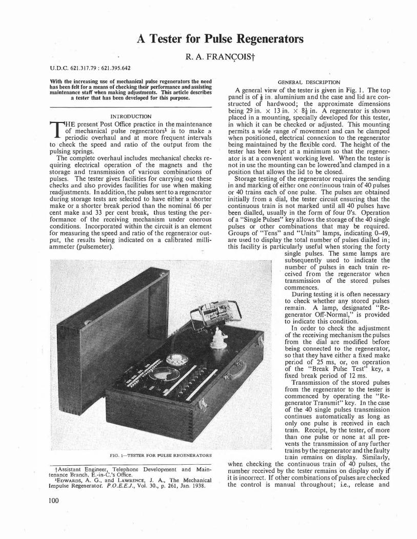
A Tester for Pulse Regenerators
R. A. FRANyOISt U.D.C. 621.317.79: 621.395.642
With the increasing use of mechanical pulse regenerators the need has been felt for a means of checking their performance and assisting maintenance sfaff when making adjustments. This article describes
a tester that has been developed for Ibis purpose.
INTRODUCTION
THE present Post Office practice in the maintenance of mechanical pulse regenerators1 is to make a periodic overhaul and at more frequent intervals
to check the speed and ratio of the output from the pulsing springs.
The complete overhaul includes mechanical checks requiring electrical operation of the magnets and the storage and transmission of various combinations of pulses. The tester gives facilities for carrying out these checks and also provides facilities for use when making readjustments. In addition, the pulses sent to a regenerator during storage tests are selected to have either a shorter make or a shorter break period than the nominal 66 per cent make and 33 per cent break, thus testing the performance of the receiving mechanism under onerous conditions. Incorporated within the circuit is an element for measuring the speed and ratio of the regenerator output, the results being indicated on a calibrated milliammefer (pulsemeter).
FIG. I-TESTER FOR PULSE REGENERATORS
t Assistant Engineer, Telephone Development and Maintenance Branch, E.-in-C.'s Office.
1EoWARDS, A. G., and LAWRENCE, J. A., The Mechanical Impulse Regenerator. P.O.E.E.J., Vol. 30., p. 261, Jan. 1938.
100
GENERAL DESCRIPTION
A general view of the tester is given in Fig. 1. The top panel is of-! in. aluminium and the case and lid are constructed of hardwood; the approximate dimensions being 29 in. x 13 in. x. 8! in. A regenerator is shown placed in a mounting, specially developed for this tester, in which it can be checked or adjusted. This mounting permits a wide range of movement and can he clamped when positioned, electrical connexion to the regenerator being maintained by the flexible cord. The height of the tester has been kept at a minimum so that the regenerator is at a convenient working level. When the tester is not in use the mounting can be lowered�and clamped in a position that allows the lid to be closed.
Storage testing of the regenerator requires the sending in and marking of either one continuous train of 40 pulses or 40 trains each of one pulse. The pulses are obtained initially from a dial, the tester circuit ensuring that the continuous train is not marked until all 40 pulses have been dialled, usually in the form of four O's. Operation of a "Single Pulses" key allows the storage of the 40 single pulses or other combinations that may be required. Groups of "Tens" and "Units" lamps, indicating 0-49, are used to display the total number of pul�es dialled in; this facility is particularly useful when storing the forty
single pulses. The same lamps are subsequently used to indicate the number of pulses in each train received from the regenerator when transmission of the stored pulses commences.
During testing it is often necessary to check whether any stored pulses remain. A lamp, designated "Regenerator Off-Normal," is provided to indicate this condition.
In order to check the adjustment of the receiving mechanism the pulses from the dial are modified before being connected to the regenerator, so that they have either a fixed make period of 25 ms, or, on operation of the "Break Pulse Test" key, a fixed break period of 12 ms.
Transmission of the stored pulses from the regenerator to the tester is commenced by operating the "Regenerator Transmit" key. In the case of the 40 single pulses transmission continues automatically as long as only one pulse is received in each train. Receipt, by the tester, of more than one pulse or none at all prevents the t�·ansmission of any further trains by the regenerator and the faulty train remains on display. Similarly,
when checking the continuous train of 40 pulses, the number received by the tester remains on display only if it is incorrect. If other combinations of pulses are checked the control is manual throughout; i.e., release and

re-operation of the Regenerator Transmit key will be required for each train.
Keys are provided for controlling saturate, operate and non-operate tests of the marking magnet, saturate and operate tests of the receiving magnet and a saturate test of the transmitting magnet. These facilities cover all the electrical tests at present required when checking mechanical adjustments.
based on the principle that if the current through a suitably damped meter is periodically interrupted the meter indicates the average value of the current. Therefore the ratio scale indicates the percentage make ratio of the pulses measured and is independent of speed. The speed measurement depends on the same principle. A capacitor charged to a certain voltage is discharged via the meter circuit during a short period at the beginning
f'REGE"NEiiATOR � CP9/t0' OR 1 ,,_-'V\/V'_. h.--<' _____ L_._, Hi· I
1" � - .I.
I MARKI NG l l MAGNET I - � i
I I
I --t--__,,
,
TI! I TH dm
'uN1TS\AMP5 0-9 I
I I I I I CP5/6 T 1 • ,._�_.-<>... OR �· .. )
"ti)�--t--...... f-11·1 I MAGNET
RC KRY I I � I T RANSMITTING I
NOTE l MRI
•I
KO
� .. -:r
I I � I I KO I 66°10 BK 1
1,-�.-"':,_ _
_ _ _ � _ Jt,,
: I I I
RO I I '1.11_ I N I ' 1t1u---r-___.,. 9-1,, I
I I : I
I I
I ON I I K
�
BT IG --�
"--.....-- -+-___. f-11·\ ADA l RECEIVING I
IG ON I
MAGNET I •I •I - L/"-'\/\l\l'-lf-i1• , _______ J
f-i,,
r--o!CP:::-•----'7;L .
'-���-d",10 a Note l .-Units lamps multipled at inlervals of ten contacts
"'
Note 2.-Capacitors are strapped 10 give required pulse lengths
FIG. 2-DIALLING-IN AND STORAGE TESTS
of each pulse, and the average current will therefore be dependent on the speed of the pulses and independent of any ratios likely to be met in practice. To assist in reading the results accurately it is arranged that the meter can be preset to the expected result before the pulses are connected. The meter pointer therefore has only a short distance to travel before taking up its final position, which is advantageous when only a small number of pulses are available for measurement.
The speed and ratio element can also be used for checking the tester dial and the fixed make and break pulses generated by the tester. Keys designated "Check Dial," "Check Make Pulses" and "Check Break Pulses" control the connexion of the appropriate output to the element. The presetting facility is particularly useful when making these tests since in each case a maximum of only ten pulses per train is available.
A terminal, provided for use when calibrating the tester, is mounted on the front panel; it also affords a convenient connexion point if it is desired to use the tester for measuring the speed or ratio of the output from other items of equipment.
CIRCUIT OPERATION Dialling-In and Stornge Tests
The elements of the circuit for dialling pulses into the regenerator and checking their storage and transmission are shown in Fig. 2.
With the Break Pulse Test
Facilities are given for checking the speed and ratio of the output from either pair of regenerator pulsing springs. The pulsemeter used for these tests has two scales; a ratio scale reading 0-100 per cent and a speed scale reading 0-15 pulses/sec, the normal accuracy of reading being of the order of I per cent. The ratio test is
key (KBT) and the Single Pulses key (KSP) norinal, the circuit is prepared for dialling in pulses, having a fixed make
period of 25 ms, to the receiving magnet and storing them as one continuous train of 40. The "Dial" key (KD) is operated, operating relays DA.and DR. Relay DR energizes the marking magnet and completes a circuit for the 0 unit lamp; relay DA operates relay B. When dialling commences relay DA pulses and each time it releases a
IOI
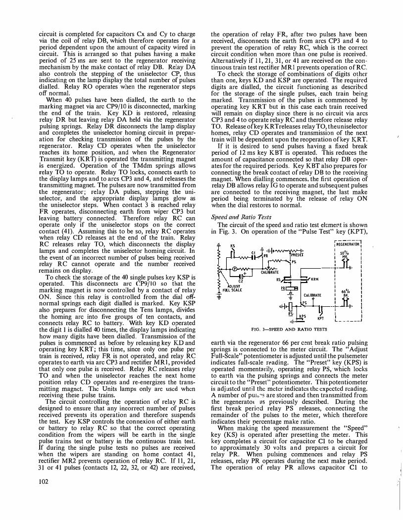
circuit is completed for capacitors Cx and Cy to charge via the coil of relay DB, which therefore operates for a period dependent upon the amount of capacity wired in circuit. This is arranged so that pulses having a make period of 25 ins are sent to the regenerator receiving mechanism by the make contact of relay DB. Relay DA also controls the stepping of the uniselector CP, thus indicating on the lamp display the total number of pulses dialled. Relay RO operates when the regenerator steps off normal.
When 40 pulses have been dialled, the earth to the marking magnet via arc CP9/10 is disconnected, marking the end of the train. Key KD is restored, releasing relay DR but leaving relay DA held via the regenerator pulsing springs. Relay DR disconnects the lamp display and con1pletes the uniselector homing circuit in preparation for checking transmission of the pulses by the regenerator. Relay CD operates when the uniselector reaches its home position, and when the Regenerator Transmit key (KR T) is operated the transmitting magnet is energized. Operation of the TMdm springs allows relay TO to operate. Relay TO locks, connects earth to the display lamps and to arcs CP3 and 4, and releases the transmitting magnet. The pulses are now transmitted from the regenerator; relay DA pulses, stepping the uniselector, and the appropriate display lamps glow as the uniselector steps. When contact 3 is reached relay FR operates, disconnecting earth from wiper CP3 but leaving battery connected. Therefore relay RC can operate only if the uniselector stops on the correct contact (41). Assuming this to be so, relay RC operates when relay CD releases at the end of the train. Relay RC releases relay TO, which disconnects the display lamps and completes the uniselector homing circuit. In the event of an incorrect-number of pulses being received relay RC cannot operate and the number received remains on display.
To check the storage of the 40 single pulses key KSP is operated. This disconnects arc CP9/10 so that the marking magnet is now controlled by a contact of relay ON. Since this relay is controlled from the dial offnormal springs each digit dialled is marked. Key KSP also prepares for disconnecting the Tens lamps, divides the homing arc into five groups of ten contacts, and connects relay RC to battery. With key KD operated the digit 1 is dialled 40 times, the display lamps indicating how many digits have been dialled. Transmission of the pulses is commenced as before by releasing key KD and operating key KRT; this time, since only one pulse per train is received, relay FR is not operated, and relay RC operates to earth via arc CP3 and rectifier MRI, provided that only one pulse is received. Relay RC releases relay TO and when the uniselector reaches the next home position relay CD operates and re-energizes the transmitting magnet. The Units lamps only arc used when receiving these pulse trains.
The circuit controlling the operation of relay RC is designed to ensure that any incorrect number of pulses received prevents its operation and therefore suspends the test. Key KSP controls the connexion of either earth or battery to relay RC so that the correct operating condition from the wipers will be earth in the single pulse trains test or battery in the continuous train test. If during the single pulse tests no pulses are received when the wipers are standing on home contact 41, rectifier MR2 prevents operation of relay RC. If II, 21, 31 or 41 pulses (contacts 12, 22, 32, or 42) are received,
102
the operation of relay FR, after two pulses have been received, disconnects the earth from arcs CP3 and 4 to prevent the operation of relay RC, which is the correct circuit condition when more than one pulse is received. Alternatively if 11, 21, 31, or 41 are received on the continuous train test rectifier MRI prevents operation of RC.
To check the storage of combinations of digits other than one, keys KD and KSP are operated. The required digits are dialled, the circuit functioning as described for the storage. of the single pulses, each train being marked. Transmission of the pulses is commenced by operating key KRT but in this case each train received will remain on display since there is no circuit via arcs CP3 and 4 to operate relay RC and therefore release relay TO. Release of key KRTreleases relay TO, theuniselector homes, relay CD operates and transmission of the next train will be dependent upon the reoperation of key KRT.
If it is desired to send pulses having a fixed break period of 12 ms key KBT is operated. This reduces the amount of capacitance connected so that relay DB operates for the required periods. Key KBT also prepares for connecting the break contact of relay DB to the receiving magnet. When dialling commences, the first operation of relay DB allows relay IG to operate and subsequent pulses are connected to the receiving magnet, the ]ast make period being terminated by the release of relay ON when the dial restores to normal.
Speed and Ratio Tests The circuit of the speed and ratio test element is shown
in Fig. 3. On operation of the "Pulse Test" key (KPT),
+
C2
CALIBRATE
iREGENEiiATORl : so0/o : I MK. [
.-------i .. Jtl. : I I I I ·.-E::---:=r KRM 1 I I 66°/o
CALIBRATE I B"K.
"f-1-0i�' r-+Jt,. �-· Ws K�T .1 I •If---'- L ______ J
FIG. 3-SPEED AND RATIO TESTS
earth via the regenerator 66 per cent break ratio pulsing springs is connected to the meter circuit. The "Adjust Full-Seale" potentiometer is adjusted until the pulsemeter indicates full-scale reading. The "Preset" key (KPS) is operated momentarily, operating relay PS0which locks to earth via the pulsing springs and connects the meter circuit to the "Preset" potentiometer. This potentiometer is adjusted until the meter indicates the expected reading. A number of puiv '' are stored and then transmitted from the regenerato1 as previously described. During the first break period relay PS releases, connecting the remainder of the pulses to the meter, which therefore indicates their percentage make ratio.
When making the speed measurement the "Speed" key (KS) is operated after presetting the meter. This key completes a circuit for capacitor Cl to be charged to approximately 30 volts and prepares a circuit for relay PR. When pulsing commences and relay PS releases, relay PR operates during the next make period. The operation of relay PR allows capacitor Cl to
discharge via the meter circuit. This discharge occurs once per pulse and under these conditions the meter indicates the speed of the pulses.
To check the other pair of regenerator pulsing springs, which are normally broken, the "Regenerator 50 per cent Make" key (KRM) is operated after making the full-scale adjustment. The 66 per cent break ratio springs are used to hold and then release relay PS as before, the pulses from the SU per cent make ratio springs then being connected to the meter.
CALIBRATION
Both the speed and ratio circuit and the circuit controlling the length of the fixed make and break pulses require calibration. This should only be necessary initially or if certain components are changed. A source of continuous pulses at a speed of 10 pulses/sec ± 1 per cent is required for carrying out the calibrations.
The pulses are connected to the "Calibrate" terminal (see Fig. 3), and with key KS operated the Adjust FullScale potentiometer is adjusted until the meter indicates JO pulses/sec. After restoring key KS the pulse source is short-circuited and the "Calibrate" potentiometer adjusted until the meter indicates full scale. The setting of this potentiometer is then fixed.
Relay DA is now pulsed continuously by connecting the pulses in place of the dial pulsing springs (see Fig. 2)
Book Review "Electronic Measuring Instruments." E. H. W. Banner.
Chapman & Hall, Ltd. xvi + 496 pp. 242 ill. 56s. The second edition of "Electronic Measuring Instru
ments" follows the first in layout, but is one-quarter longer; measuring instruments for radio engineering are still di!liberately and, on balance, wisely excluded. There is undoubted scope and need for books on electronic measuring instruments-scope because the types of instrument alld their purposes are multiplying rapidly and spreading into more and more industries, and need because a knowledge of their accuracy, reliability, flexibility and pitfalls, such as a sound textbook can give, is required to augment experience in making the optimum use of instruments-but it is less certain that one book can satisfy all who might be attracted by the title. Professional engineers require a critical reference book, instrument designers an analytical book dealing with design techniques and component parts, and students a description, \Vith some analysis, of the wellestablished, simpler instruments. The book under review cannot be considered to fill a gap for any class of reader though all may find something of interest.
It opens with a chapter devoted to the virtues of the components on which the users observe the quantities being measured. A group of chapters (Part II) describes the key electronic components used in instruments. They are undistinguished and, in view of the excellent books available on some of the components, could be curtailed. Some corrections have been made to the first edition, but others, including the following two mentioned in a review of the first edition, have not: confusion remains, between a statement and diagrams, about the relative closeness of the spectral response of selenium and emission photocells to that of the eye, and the two broken curves for the forward i/v relationship of a selenium rectifier continue to convey
and operating key KO. The Check Break Pulses key (not shown in Fig. 2) and key KBT are operated. Under these conditions the ratio of the fixed break pulses is indicated on the meter and the amount of capacity Cx connected is adjusted until the required reading is obtained; i.e., 88 per cent make ratio. With these two keys restored and the Check Make Pulses key operated the fixed make pulses are adjusted in a similar manner by capacitors Cy; in this case until a reading of 25 per cent make ratio is obtained.
CONCLUSION
The tester described above should prove useful to staff engaged on the maintenance of regenerators. For other applications where speed and ratio measurements are required the appropriate part of the circuit has been developed as a separate item. Production of the testers will commence shortly and it is hoped that !he first models will be available towards the end of 1958.
ACKNOWLEDGEMENTS
It is desir.ed to acknowledge the assistance of colleagues in the Telephone Development and Maintenance Branch, E.-in-C.'s Office, both in the development of the tester and the preparation of this article; in particular, that of members of the Circuit Laboratory and Mr. K. R. Howse, who was responsible for the physical design.
little information (what temperatures apply and what are the equivalent curves for the copper-oxide rectifier?). Other mistakes have entered. The basic circuit for negative voltage feedback is misdrawn; the output of the symmetrical multivibrator is shown as coming from one valve and described as coming from the other. Pure germanium is not almost an insulator at room temperature; its conductivity may be only 0·02 (ohm-cm)-1 but that is a billion (a British billion at that!!) times that of mica or porcelain. The statement that junction transistors with common.base connexion haVe input impedances of about 25 ohms might well be read as generally true, instead of applying only for the emitter current of the example which follows.
Part III describes the instruments based on the components of Part II. A good selection is made, but too often -though not in a well-written chapter on radiation measuring instruments-the descriptions Jack authority, clarity and sometimes accuracy. A paragraph on distributed amplifiers is typical of the lack of precision encountered; we read "this [which] circuit capacitance is used as the shunt element of a transmission line [singular]. A series of valves is used in cascade [parallel would be as near the mark], the anodes and grids being connected through inductors," the reader being left to decide whether the inductors connect anodes to grids, or anodes to anodes and grids to grids.
The last Part describes a miscellany of instruments, including counters, vacuum gauges and some whose key components may not generally be recognized as depending on electronic effects (e.g. strain gauges, inductive and capacitive transducers, and moisture meters). The page or so given to magnetic amplifiers is best not read by any newcomer to the subject.
The book is well presented and reasonably priced, but its writing, all too frequently, falls short of the standard required to recommend it. J. R. T.
103

A Single-Operator Letter-Sorting Machine Part I-Introduction and the Experimental Machine
G. P. COPPING, B.SdEng.), A.M.T.E.E., and K. L. BEAK, Associate I.Mech.E., AS6ociate I.E.E.t
U.D.C. 681.178
With manual sorling it is impracticable, for physical reasons, to break down letter mail into more than approximately 50 selections in one sorting operation, and because of this limitation it is necessary for a large proportion of the mail to undergo immediately a second sorting operation. The machine described enables a sorter-operator to direct letters into any one of hearly 150 selection boxes, with the importanl advantage that in the majority of sorting offices it would largely obviate the need for a second handling. AJso, the physical load on a sorter is greatly reduced and his output is increased. The machine has successfully completed field trials and a number of them are being made and are due lo be brought into use this year. Part 1 of the article introduces the subject and describes the experimental machine used in the field trials. Part 2, to be published later, will describe the production machine, nhich differs in a number of respects from the experimental one.
INTRODUCTION
THE introduction of mechanical means for handling the mails in bulk has progressed steadily for many years but, apart from the wide introduction of
stamp cancelling machines, little has been done to mechanize the essential individual processing of items of letter mail. Recently, however, an experimental machine (Fig. I) that eases the problem of sorting letters has successfully completed field trials and a number of machines have been ordered and are due to go into operation this year. The device comprises a branched
letter-conveying system, designed for the use of one sorter-operator, which enables him to direct mail into any one of nearly 150 selection boxes.
In order to appreciate fully the advantages the machine offers, it is necessary to consider the routing and handling systems which have been evolved to deal with letter mail. As both the postal service and the telephone service are concerned with the transmission of information between individuals, the routing systems of the two bear a striking resemblance. For example, if there is great community of interest between two large towns conversations passing between the two will probably be conveyed directly in a 60-circuit carrier supergroup, whilst the mails will be conveyed in special bags which will not be opened or rerouted during transit between the two towns. Carrying the comparison further, we find in the case of lighter traffic flows that letters with a common destination are tied in bundles and then mixed in a bag with other bundles for different destinations. This bag has to be opened at an intermediate sorting office in order that the contents can be rerouted and rebagged, still bundled, for the next stage in their journey. This can be likened to the demodulation of supergroups
t The authors arc, respectively, Senior Executive Engineer and Executive Engineer, Post Office Research Station.
FIG. I-THE EXPERIMENTAL LETIER-SORTING MACHINE
104
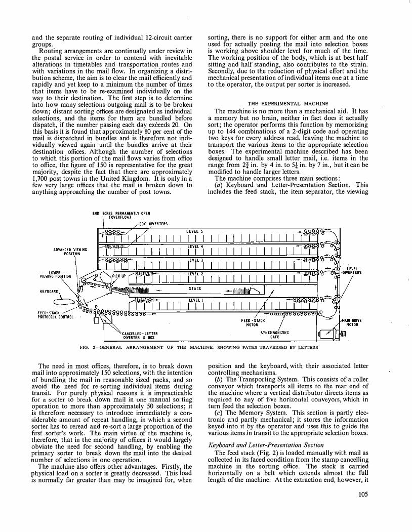
and the separate routing of individual 12-circuit carrier groups.
Routing arrangements are continually under review in the postal service in order to contend with inevitable alterations in timetables and transportation routes and with variations in the mail flow. In organizing a distribution scheme, the aim is to clear the mail efficiently and rapidly and yet keep to a minimum the number of times that items haye to be re-examined individually on the way to their destination. The first step is to determine into how many selections outgoing mail is to be broken down; distant sorting offices are designated as individual selections, and the items for them are bundled before dispatch, if the number passing each day exceeds 20. On this basis it is found that approximately 80 per cent of the mail is dispatched in bundles and is therefore not individually viewed again until the bundles arrive at their destination offices. Although the number of selections to which this portion of the mail flows varies from office to office, the figure of 150 is representative for the great majority, despite the fact that there are approximately 1,700 post towns in the United Kingdom. It is only in a few very large offices that the mail is broken down to anything approaching the number of post towns.
END BOXES PERMANENTLY OPEN {OVERFLO'W)
CANCELLED- LETTER OIVERTER ' BOX
sorting, there is no support for either arm and the one used for actually posting the mail into selection boxes is working above shoulder level for much of the time. The working position of the body, which is at best half sitting and half standing, also contributes to the strain. Secondly, due to the reduction of physical effort and the mechanical presentation of individual items one at a time to the operator, the output per sorter is increased.
THE EXPERIMENTAL MACHINE
The machine is no more than a mechanical aid. It has a memory but no brain, neither in fact does it actually sort; the operator performs this function by memorizing up to 144 combinations of a 2-digit code and operating two keys for every address read, leaving the machine to transport the various items to the appropriate selection boxes. The experimental machine described has been designed to handle small letter mail, i.e. items in the range from 2! in. by 4 in. to 5! in. by 7 in., but it can be modified to handle larger letters.
The machine comprises three main sections: (a) Keyboard and Letter-Presentation Section. This
includes the feed stack, the item separator, the viewing
FIG. 2--GENERAL ARRANGEMENT OF THE MACHINE, SHO\VING PATHS TRAVERSED BY LE1TERS
The need in most offices, therefore, is to break down mail into approximately 150 selections, with the intention of bundling the mail in reasonable sized packs, and so avoid the need for re-sorting individual items during transit. For purely physical reasons it is impracticable for a sorter to break down mail in one _1nanual sorting operation to more than approximately 50 selections; it is therefore neoessary to introduce immediately a considerable amount of repeat handling, in which a second sorter has to reread and re-sort a large proportion of the first sorter's work. The main virtue of the machine is, therefore, that in the majority of offices it would largely obviate the need for second handling, by enabling the primary sorter to break down the mail into the desired
number of selections in one operation. The machine also offers other advantages. Firstly, the
physical load on a sorter is greatly decreased. This load is normally far greater than may be imagined for, when
position and the keyboard, with their associated letter controlling mechanisms.
(b) The Transporting System. This consists of a roller conveyor which transports all items to the rear end of the machine where a vertical distributor directs items as required to any of five horizontal conveyors, which in turn feed the selection boxes.
(c) The Memory System. This section is partly electronic and partly mechanical; it stores the information keyed into it by the operator and uses this to guide the various items jn transit to the appropriate selection boxes.
Keyboard and Letter-Presentation Section The feed slack (Fig. 2) is loaded manually with mail as
collected in its faced condition from the stamp cancelling machine in the sorting office. The stack is carried horizontally on a belt which extends almost the full length of the machine. At the extraction end, however, it
105
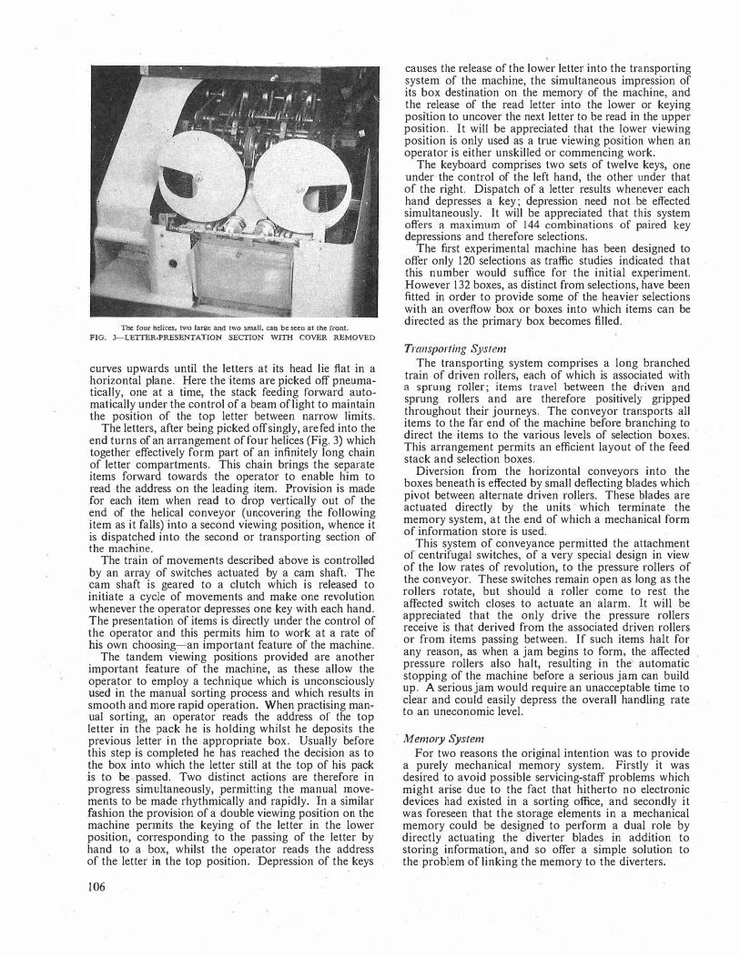
The four helices. 1wo large and two sma11, can be seen at the front.
FIG. 3-LETTER-PRESENTAJION SECTION WITH COVER REMOVED
curves upwards until the letters at its head lie flat in a horizontal plane. Here the "items are picked off pneumatically, one at a time, the stack feeding forward automatically under the control of a beam of light to maintain the position of the top letter between narrow limits.
The letters, after being picked off singly, are fed into the end turns of an arrangement of four helices (Fig. 3) which together effectively form part of an infinitely long chain of letter compartments. This chain brings the separate items forward towards the operator to enable him to read the address on the leading item. Provision is made for each item when read to drop vertically out of the end of the helical conveyor (uncovering the following item as it falls) "into a second viewing position, whence it is dispatched into the second or transporting section of the machine.
The train of movements described above is controlled by an array of switches actuated by a cam shaft. The cam shaft is geared to a clutch which is released to initiate .a cycle of movements and make one revolution whenever the operator depresses one key with each hand. The presentation of items is directly under the control of the operator and this permits him to work at a rate of bis own choosing-an important feature of the machine.
The tandem viewing positions provided are another important feature of the machine, as these allow the operator to employ a technique which is unconsciously used in the manual sorting process and which results in smooth and more rapid operation. When practising manual sorting, an operator reads the address of the top letter in the pack he is holding whilst he deposits the previous letter in the appropriate box. Usually before this step is completed he has reached the decision as to the box into which the letter still at the top of his pack is to be passed. Two distinct actions are therefore in progress simultaneously, permitting the manual movements to be made rhythmically and rapidly. In a similar fashion the provision of a double viewing position on the machine permits the keying of the letter in the lower position, corresponding to the passing of the letter by hand to a box, whilst the operator reads the address of the letter in the top position. Depression of the keys
106
causes the release of the lower letter into the transporting system of the machine, the simultaneous impression of its box destination on the memory of the machine, and the release of the read Jetter into the lower or keying position to uncover the next letter to be read in the upper position. It will be appreciated that the lower viewing position is only used as a true viewing position when an operator is either unskilled or commencing work.
The keyboard comprises two sets of twelve keys, one under· the control of the left hand, the other under that of the right. Dispatch of a Jetter results whenever each hand depresses a key; depression need not. be effected simultaneously. It will be appreciated that this system offers a maximum of 144 combinations of paired key depressions and therefore selections.
The first experimental machine has been designed to offer only 120 selections as traffic studies indicated that this number would suffice for the initial experiment. However 132 boxes, as distinct from selections, have been fitted in order to provide some of the heavier selections with an overflow box or boxes into which items can be directed as the primary box becomes filled.
Transporting System
The transporting system comprises a long branched train of driven rollers, each of which is associated with a sprung roller; items travel between the driven and sprung rollers and are therefore positively gripped throughout their journeys. The conveyor transports all items to the far end of the machine before branching to direct the items to the various levels of selection boxes. This arrangement permits an efficient layout of the feed stack and selection boxes.
Diversion from the horizontal conveyors into the boxes beneath is effected by small deflecting blades which pivot between alternate driven rollers. These blades are actuated directly by the units· which terminate the memory system, at the end of which a mechanical form of information store is used.
This system of conveyance permitted the attachment of centrifugal switches, of a very special design in view of the low rates of revolution, to the pressure rollers of the conveyor. These switches remain open as Jong as the rollers rotate, but should a roller come to rest the affected switch closes to actuate an alarm. It will be appreciated that the only drive the pressure rollers receive is that derived from the associated driven rollers or from items passing between. If such items halt for any reason, as when a jam begins to form, the affected pressure rollers also halt, resulting in the' automatic stopping of the machine before a serious jam can build up. A serious jam would require an unacceptable time to clear and could easily depress the overall handling rate to an uneconomic level.
Memory System
For two reasons the original intention was to provide a purely mechanical memory system. Firstly it was desired to avoid possible servicing-staff problems which might arise due to the fact that hitherto no electronic devices had existed in a sorting office, and secondly it was foreseen that the storage ·elements in a mechanical memory could be designed to perform a dual role by directly actuating the diverter blades in addition to storing information, and so offer a simple solution to the problem of linking· the memory to the diverters.
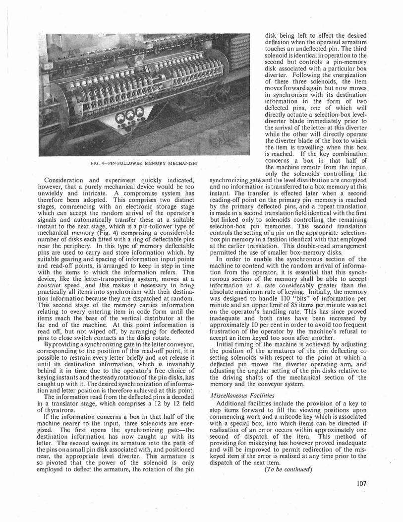
FIG. 4-PIN-FOLLO\VER MEMORY MECHANISM
Consideration and experiment quickly indicated, however, that a purely mechanical device would be foo unwieldy and intricate. A compromise system has therefore been adopted. This comprises two distinct stages, commencing with an electronic storage stage which can accept the random arrival of the operator's signals and automatically transfer these at a suitable instant to the next stage, which is a pin-follower type of mechanical memory (Fig. 4) comprising a considerable number of disks each fitted with a ring of defl.ectable pins near the periphery. In this type of memory deflectable pins are used to carry and store information wl1ich, by suitable gearing and spacing of information input points and read-off points, is arranged to keep in step in time with the items to which the information refers. This device, like the letter-transporting system, moves at a constant speed, and this makes it necessary to bring practically all items into synchronism with their destination information because they are dispatched at random. This second stage of the memory carries information relating to every entering item in code form until the items reach the base of the vertical distributor at the far end of the machine. At this point information is read off, but not wiped off, by arranging for deflected pins to close switch contacts as the disks rotate.
By providing a synchronizing gate in the letter conveyor, corresponding to the position of this read-off point, it is possible to restrain every letter briefly and not release it until its destination information, which is invariably behind it in time due to the operator's free choice of keying instants and the steady rotation of the pin disks, has caught up with it. The desired synchronization of information and letter position is therefore achieved at this point.
The information read from the deflected pins is decoded in a translator stage, which comprises a 12 by 12 field of thyratrons.
If the information concerns a box in that half of the machine nearer to the input, three solenoids are energized. The first opens the synchronizing gate-the destination information has now caught up with its letter. The second swings its armature into the path of the pins on a small pin disk associated with, and positioned near, the appropriate level diverter. This armature is so pivoted that the power of the solenoid is only employed to deflect the armature, the rotation of the pin
disk being left to effect the desired deflexion when the operated armature touches an undefiected pin. The third solenoid is identical in operation to the second but controls a pin-memory disk associated with a particular box diverter. Following the energization of these three solenoids, the item moves forward again but now moves in synchronism with its destination information in the form of two deflected pins, one of which will directly actuate a selection-box leveldiverter blade immediately prior to the arrival of the letter at this diverter while the other will directly operate the diverter blade of the box to which tbe item is travelling when this box is reached. If the key combination concerns a box in that half of the machine remote from the input, only the solenoids controlling the
syncl1ro11izing gate and the level distribution are energized and no information is transferred to a box memory at this instant. The transfer is effected later when a second reading-off point on the primary pin memory is reached by the primary deflected pins, and a repeat translation is made in a second translation field identical with the first but linked only to solenoids controlling the remaining selection-box pin memories. This second translation controls the setting of a pin on the appropriate selectionbox pin memory in a fashion identical with that employed at the earlier translation. This double-read arrangement permitted the use of smaller box-memory disks.
In order to enable the synchronous section of the machine to contend with the random arrival of information from the operator, it is essential that this synchronous section of the memory shall be able to accept information at a rate considerably greater than the absolute maximum rate of keying. Initially, the memory was designed to handle 110 "bits" of information per minute and an upper limit of 85 items per minute was set on the operator's handling rate. This has since proved inadequate and both rates have been increased by approximately 10 per cent in order to avoid too frequent frustration of the operator by the machine's refusal to accept an item keyed too soon after another.
Initial timing of the maclline is achieved by adjusting the position of the armatures of the pin deflecting or setting solenoids with respect to the point at which a deflected pin moves the diverter operating arm, and adjusting the angular setting of the pin disks relative to the dri.ving shafts of the mechanical section of the memory and the conveyor system.
Miscellaneous Facilities
Additional facilities include the provision of a key to step items forward to fill the viewing positions upon commencing work and a miscode key which is associated with a special box, into which items can be directed if realization of an error occurs within approximately one second of dispatch of the item. This method of providing fur miskeying bas however proved inadequate and will be improved to permit redirection of the miskeyed item if the error is realised at any time prior to the dispatch of the next item.
(To be continued)
107
A Short History of Codes of Practice for the Opening and Restoration of Trenches in Public Streets
W. C. WARD, B.Sc.(Eng.), M.I.E.E.t U.D.C. 621.315.233.001.3
For many years the opening and closing of trenches in publi� str�ets by the various public utilities was not covered by common legislahon, and each operated under its own statutory powers . A number of important principles were, however, established by a n1emorandum of agreement between the Post Office and the highway 3;utho�i��s, which was issued in 1933. In April 1951, when the Pubhc Utihhes Street Works Act, 1950, became operative, all public utilities were placed on the same footing and subject to the same conditions i.n their relations with the road authorities. A number of road authorities in conjunction with the public utilities' local organizations, produced codes of practice covering the procedure to be followed in the execution of street works under the Act, until, in December 1957 a joint code of practice, known as the Street Works Code (Cod� of Practice), was agreed nationally by representatives of
the highway authorities and the public utility undertakers.
INTRODUCTION
BEFORE the Public Utilities Street Works Act, 1950,' became operative, the various public utilities, i.e. electricity, gas, Post Office and water, each operated
under its own statutory powers, and was not aligned with any of the other undertakers by common legislation.
The relationships between street authorities and the Post Office on the one hand, and street authorities and gas, water and electricity undertakings. on the other, often derived from very different trad1t1ons. Whereas the telephone service had from a very early stage developed on a national basis under a centralized control, the other undertakings generally developed from parochial beginnings. Very often they were operated by the local council, which was also responsible for the highways. In these circumstances, undertakers, other than the Post Office, seldom encountered problems connected wi_th the restoration of street surfaces following the excavation of trenches, since the costs involved either formed part of the local authorities' general t;xpenditure and were never sharply focused as one of the operating expe�ses of the utility concerned or, where they formed a defimte charge, they were invariably accepted by the utility since there was no basis of comparison.
With the Post Office, conditions were very different. Not only were local operations subject to firm direction from headquarters, but a strict financial control also operated. Where the street authority's agreement could be obtained, all restoration was carried out by the Post Office duct coutractor, but where the street authority carried out the permanent reinstatement, the charges were subjected to close scrutiny. In either case any demands by a street authority for additional requirements, such as strengthening material in trenches, were almost invariably contested.
This attitude led at times to sharp controversies with street authorities, and sometimes local zeal armed with the weight and organization of a Government department proved too much for small, loosely-knit local authorities. In some cases this resulted in poor restoration work being carried out and Post Office duct laying operations became the subject of a certain amount of adverse comment by road engineers.
t Assistant Staff Engineer, External Plant and Protection Branch, E.-in-C.'s Office.
108
THE MEMORANDA OF AGREEMENT, 1929 AND 1933
In 1927 the North-Western District of the Institution of Municipal and County Engineers appointed a special sub-committee2 to consider the question of the reinstatement of trenches opened by the Post Office, and this body formulated a number of proposals, many of which threatened seriously to embarrass the Post Office.
The Post Office was anxious to end this unsatisfactory state of affairs, and in March 1928 approached the central body of the Institution of Municipal and County Engineers suggesting a joint discussion of the problems involved. A number of joint meetings were arranged, and an agreed memorandum was produced late in 1929.' This memorandum gave great satisfaction to both sides as the following extract from the Journal of the Institute of Municipal and County Engineers• shows.
"The long-standing question of Post Office trenches in highways has been settled with the Post Office Engineering Department. These negotiations may be regarded as extremely satisfactory, and the willingness of the departmental officials to meet the reasonable views of the engineers responsible for highway maintenance deserves recognition."
This memorandum of agreement was not accepted immediately' by all the professional associations representing highway authorities, but after a further series of meetings between highway authorities' representatives and the Post Office it was amended slightly to become a memorandum of agreement' prepared jointly by the Institution of Municipal and County Engineers, the Association of Municipal Corporations, the County Councils Association, the Urban District Councils Association and the Post Office. It was issued in October 1933.
The memorandum established a number of important principles, some legal, some financial and some engineering in character. In the legal field it specified the period during which the Post Office wonld be liable for accidents to third parties. In the financial field it fixed the margins over the actual width of excavation which would be paid for in restoring various types of surface, and also detailed the manner in which various items which were proper to be included in local authorities' accounts would be paid for. It also covered the question of payment for broken flags, kerbs, setts, etc., and established the principle of joint inspection of the route by the Post Office and the street authority, to note the condition of footway and carriageway surfaces, particularly in respect of broken flags, kerbs and setts.
In the engineering field the memorandum covered the provision of additional strengthening material in cases where it would not otherwise be possible to restore the original foundation of the highway. It also laid down methods to be adoptedin back-filling trenches and tunnels.
The memorandum of agreement was not legally binding on any local authority, but the weight of �he organizations that sponsored it made it an authoritative document which could not lightly be ignored. In the 24 years which have passed since it was produced it has proved most valuable.
NATIONALIZATION OF GAS AND ELECTRICITY INDUSTRIES
Soon after the end of the Second World War, the gas and electricity industries were nationalized and were reorganized on a national basis. The change in the relationship between their local undertakings and the street authorities which this produced did not always involve immediate changes in the conditions under which trenches were reinstated, but it provided for the first time an established machinery for comparison of methods and interchange of information between the area establishments of the nationalized bodies. It made necessary a proper system of charging by local authorities for reinstatement works which they carried out in those cases where such a system did not previously exist.
The water undertakings have not been nationalized, but the British Waterworks Association negotiates with local authorities where necessary on behalf of its members.
THE PUBLIC UTlLITIES STREET WORKS ACT, 1950
In early 1939 a joint committee of the House of Lords and the House of Commons was established under the chairmanship of Lord Carnock' to examine the legislation governing street works by public utilities, and the committee reported later in the same year, making various recommendations. The Public Utilities Street Works Act1 was drafted on the basis of this report, and when it became law on 26 April 1951 it placed all the public utilities on the same footing and subject to the same conditions in their relations with road authorities.
Part I of the Act (Sections 3 to 14) and the First, Second, and Third Schednles contain the "Street Works Code," which establishes a procedure for submitting plans and sections to the road authority for agreement before an undertaker starts work 'in a public street or road. The code covers various points, including the amount of notice to be given before starting work, the determination of the mode of executing major works, reinstatement requirements and the protection afforded to sewer authorities and to transport undertakings.
The other parts of the Act do not impinge directly on the methods and procedures for excavating trenches, but the Third Schedule associated with the Act deals in some detail with the organization and the responsibilities of the interested parties for the interim and permanent restoration of trenches.
When the Act had been operating for a few months, the need for more precise arrangements for procedure began to become apparent. The Street Works Code is clear in the principles it establishes, but an Act of Parliament is not a suitable medium to provide for detailed procedure. Thus a number of road authorities, e.g. the Lancashire County Council,' the Middlesex County Council and the Northumberland County Council, entered into negotiations with the pub]ic utilities' local organizations and produced codes of practice covering in some detail the procedures to be followed in the execution of street works under the Street Works Act.
A number of codes of practice \Vere produced in tl1is manner, and although they were all useful documents, and generally followed similar lines, they did in most cases contain important differences. From the way things \Vere going, it seemed that before long every road authority might produce its own code of practice, differing in some respects even from those of its neighbour's.
This was an undesirable state of affairs. The same work undertaken by a public utility may embrace the
territory of two or three, and sometimes more, road authorities, and it is confusing and often invidious if a contractor has to operate under different conditions on various sections of the same work. It may be difficult for a contractor to tender standard "per yard run" rates under such conditions. It was found, moreover, that factors to which one authority attached little or no importance would loom large in the estimation of another.
THE UNDERTAKER'S MODEL CODE
Thus it was that in the autumn of 1951 the Gas Council proposed to the other utilities that it would be useful to compile a model code of practice, and to facilitate the preparation of this code the Central Electricity Authority collated particulars of the local agreements already entered into. The intention was that copies of this model code should be supplied to all the local organizations of the various utilities to acquaint them with the standards to be aimed at, and to be offered by them as the basis for an agreed code in any negotiations which might take place with road authorities. The code was duly produced and was issued in April 1952 to all Gas and Electricity Boards, to Water Undertakings and Telephone Areas.
INSTITUTION OF MUNICIPAL ENGINEERS
AND COUNTY SURVEYORS SOCIETY'
S RECOMMENDATIONS
In August 1953 the Institution of Municipal Engineers and the County Surveyors Society issued their own model code of practice,' and while this followed the general form of the undertaker's model code mentioned above, it contained a number of conditions which were unfavourable to the undertakers, and in some cases went beyond the provisions of the Act. It also embodied clauses allowing local authorities to incorporate their own detailed specifications for interim and permanent restoration, which the public utilities prefer to regard as matters for negotiation outside a code of practice.
NEGOTIATION OF A JOINT CODE OF PRACTICE
Representatives of the public utilities met to consider the Municipal Engineers' and County Surveyors' model code and to consider whether any further action should be taken. The Post Office representatives at this ·meeting pointed out the existence of its 1933 Memorandum of Agreement with Highway Authorities, and explained how useful this had proved. In view of changes brought about by the Public Utilities Street Works Act, however, the ag1eement required revision, and a new approach to the road authorities' representative associations was being considered. It was generally agreed that a national code of practice, acceptable to all public utilities and the Institution of Municipal Engineers and the County Surveyors Society, should be the aim.
The representatives of the public utilities met on a number of occasions to agree views on the various clauses of the code to be discussed, and eventually a series of meetings were arranged with representatives of the Institution of Municipal Engineers and the County Surveyors Society which culminated ip. the preparation of a series of recommendations agreed by all the representatives concerned. The recommendations were subsequently approved by the parent body of each representative.
109

MAIN PROVISIONS OF CODE
The document that has been produced is known as the Street Works Code (Code of Practice).* The new code applies to England and Wales, but not as yet to Scotland where some of the undertakings involved operate under separate organizations to their counter� parts in England and Wales. A separate series of discussions is taking place in Edinburgh which will probably result in the production of a Scottish Code differing from the present one only in minor details. The Public Utilities Street Works Act does not apply to Northern Ireland.
The main provisions of the new Code of Practice are as follows.
Paragraphs 1 and 2 deal with general matters, such as definitions, and the nee}! for all notices to be in ink.
Paragraph 3. Under paragraph 5 (3) of the 3rd Schedule of the Street Works Act a street authority has to give notice to an undertaker when it is about to begin permanent reinstatement, and paragraph 6 (I) makes the undertaker responsible for the surface until this notice has been given. Various bodies have interpreted these provisions differently so far as they determine the date when the street authority assumes responsibility for the surface.
Paragraph 3 of the new Code of Practice states clearly that the street authority shall be deemed to have "taken over" the site on a date to be specified in the notice served under paragraph 5 (3) or the 3rd Schedule of the Act.
Paragraph 4 allows for the substitution of written descriptions instead of plans and sections where this is mutually agreed. The idea underlying this proposal was the need to save draughtsman's time.
Paragraph 5. Section 6 and paragraph 5 of the ls! Schedule of the Act require undertakers to give a specified length of notice before commencing work. Paragraph 5 of the new code amplifies this notice to state clearly the place and date at which the work will commence.
Paragraph 6 debars connexions to drains and sewers without prior sanction.
Paragraph 7 lays down that manhole covers, etc., shall conform as nearly as possible to the surface of the road or footpath.
Paragraph 8 of the Code amplifies Section 8 of the Act in respect of safety requirements. It complies with the "Traffic Code for Road Works, 1957" issued by the Scottish Home Department and the Ministry of Transport and Civil Aviation, and details the road signs and signals to be used when an undertaker's works obstruct the highway.
Paragraph 9 stresses the need for care not to damage or obstruct any property on or adjacent to the highway, including basements.
Paragraph 10 caters for adopting special measures, including, where necessary, overtime and shift working, to keep the dislocation of traffic to a minimum on highways carrying large volu1nes of traffic.
Paragraph 11 deals with the temporary closing of streets and includes the minimum notice which an undertaker is required to give before a street can be closed.
Paragraph 12 covers the joint inspection by undertaker and council of streets of lower classification which
*A limited number of copies of the code of practice are available for sale. Copies may be obtained on application from the Post Office Engineering Dept., External Plant and Protection Branch (Cn 5), Alder House, Lo�don, E.C.1.
110
have to be strengthened due to the diversion of traffic from other highways on account of an undertaker's works. The cost in such cases is borne by the undertaker.
Paragraph l 3 provides for the methods and materials used for back-filling tunnels to be agreed with the engineer and surveyor of the street authority, and for 48 hours' notice to be given before back-filling starts. Provision for the payment of an indemnity if the tunnel is back-filled with material other than concrete was made in the 1933 Memorandum of Agreement. No corresponding provision is made in the present code.
This paragraph also provides for notice to be given if a thrust-boring machine is to be used.
Paragraph 14 deals with the stacking of material excavated from trenches.
Paragraph 15 covers the arrangements for paying for broken flags, kerbs and channelling. The halving agreement for flags, etc., that were broken before an undertaker's work commenced and which was embodied in the 1933 Memorandum of Agreement is not included in this paragraph, but a footnote quotes the 50-50 basis of payment as one commonly in use. This paragraph stipulates a joint inspection by the undertaker and the engineer and surveyor both before a trench is opened and before it is finally reinstated.
Paragraph l 6 deals with the method of cutting and the measurement of trenches cut through surfaces of concrete construction.
Paragraph 17 mentions the necessity for adequate support for the sides of excavations.
Paragraph 18 provides for back-filling in layers not exceeding 9 in., whereas the 1933 Memorandum of Agreement provides for back-filling in layers not exceeding 6in.
Paragraph 19 covers the special supervision by the council of interim restoration on works of unusual character or magnitude, and payment by undertakers of the cost involved.
Paragraph 20 provides for a street authority to give emergency attention at the undertaker's expense to interim restoration work, which is still the undertaker·s liability.
Paragraph 21 recommends that all work of interim restoration other than the surface shall be regarded as part of the permanent restoration.
Paragraph 22 covers the procedure to be followed where permanent reinstatement is carried out by the undertakers.
Paragraph 23 outlines the arrangements for putting in hand the permanent reinstatement in those cases where the council have elected to do it.
Section (d) contains a very important provision, giving undertakers the option of themselves carrying out the permanent reinstatement where it is being unduly delayed because the street authority has not the resources immediately available to do it.
Paragraph 24 states the arrangements for a council to notify an undertaker of further reinstatement works necessary during the statutory period of six months after the final reinstatement, during which the undertaker is liable for maintenance.
Paragraph 25 covers the provision of extra strengthening material in old carriageways which have been consolidated by use and traffic over a period of years. The provisions of this paragraph are similar to those dealing with the same subject in the 1933 Memorandum of Agreement.

Paragraphs 26 and 27 deal with the measurement of trenches and the use of trimming allowances or margins.
The recommended margins are 3 in. each side of the trench in asphalt, tarmacadam, gravel, flint and the like, 4} in. in wood, setts or brick paving, and 6 in. in all pavings and surfaces on reinforced concrete foundations. These margins correspond with those agreed in the 1933 Memorandum.
Paragraph 28 details the method of charging by street authorities, and states the items which are to be included in accounts. Percentages are to be used for some items, and these must be certified by the street authorities' authorized officer.
Paragraph 29 covers the payment by undertakers of additional cost incurred by a council when undertakers carry out work in conjunction with the reconstruction, improvements or repaving of streets and bridges.
Paragraph 30 details the procedure for settling disputes arising out of the code.
Paragraph 31 states that the Code operates only so far as it is not inconsistent with any statutory provisions affecting the parties concerned.
CONCLUSION
The new Code of Practice is expected to be of great use to both the public utilities and the street authorities in reaching agreements on questions affecting the opening and restoration of trenches. It is the first occasion on
Book Review "Television Receiving Equipment." Fourth edition. W. T.
Cocking. Iliffe & Sons, Ltd. 454 pp. 274 ill. 30s. This welcome further edition of Mr. Cocking's well-known
book on Television Receiving Equipment has been greatly changed. Some of the earlier material has been omitted, practically every chapter has been rewritten and a great deal of information has been added to bring the book up to date.
A comparison of this present volume with its predecessor, the third edition, published in 1950, provides an interesting commentary on the evolution of British television receivers. At that time "straight" receivers were still common and the necessity for superheterodyne receivers was only just beginning to be felt as the number of transmitters in the country increased. Now, with the coming of transmissions in Band III, superhetyrodyne receivers are essential. Of the intermediate frequency of those superheterodyne receivers existing in 1950 it was said: "13 Mc/s is a common choice and a higher frequency is rarely, if ever, used." Times have changed and modern .practice, recommended by the British Radio Equipment Manufacturers' Association (B.R.E.M.A.), is to use 34·65 Mc/s. Some of the reasons for this choice are given in detail in the chapter entitled "The Intermediate Frequency.''
Automatic gain control was rarely found in receivers in 1950; nowadays it is almost universal in the sound section and is becoming quite common in the vision section. This development has been brought about by the desirability of being able to switch from one channel to another without having to adjust a gain control. Mr. Cocking's new book describes some of the methods used for automatic gain control of the vision signal. These are more complicated than in the case of sound since the average vision-signal level transmitted does not remain constant but varies substantially with picture content.
which all the public utilities and national representatives of the highway authorities have voluntarily co-operated to reach agreement on matters by no means devoid of controversy. The success of this venture may well point the way to further co-operation.
References 1 PAGE, E. A. The Public Utilities Street Works Act, 1950.
P.O.E.E.J., Vol. 45, p. 8, Apr. 1952. 2 Reinstatement of Trenches. Special Committee's Recom
mendations at Municipal and County Engineers Meeting. Tire S11r11eyor, 16 Dec. 1927.
3 Reinstatement of Post Office Trenches. The Journal of the /11stitulio11 of Municipal and County Engineers, Vol. LVI, No. 14, p. xix, 7 Jan. 1930.
4 Fifty-seventh Annual Report of the Council, 1929-30. The Journal of the /11stitutio11 of Municipal and County Engineers, Vol. LVI, No. 26, p. 1450, 24 June 1930.
5 County Councils Association-Report of Proceedings at Meeting of the Executive Council. Local Goven1n1rt11t Journal, 30 Jan. 1932.
6 Reinstatement of Post Office Trenches. The Journal of the /11stitutio11 of Municipal and County Engineers, Vol. LX, No. 15, p. 1139, 16 Jan. 1934.
7 Report by Joint Committee of the House of Lords and the House of Commons on the breaking up of Streets by Statutory Undertakers, HC 134, H.M.S.O., 1939.
8 THOMPSON, W. R. The Public Utilities Street Works Act, 1950; Its Implementation as regards Road Openings and Reinstatements. The Sun1eyor and A1u11icipal and County Engineer, 10 Jan. 1953.
9 Recommendations on Procedure relating to the Opening and Reinstatement of Trenches. Issued by the Institution of Municipal Engineers and the County Surveyors Society, Aug. 1953.
Regarding the size of pictures it is interesting to notice that in 1950 .the author said: "for those with small rooms a 12-in. tube is unnecessarily large." This may be true but the modern fashion is for larger tubes of 14 or 17 in. and the author wisely refrains from any similar comment in his new book. Although larger tubes of 21 in. diameter are at present available in many models it seems as though the popular limit may have been reached at 17 in.
· In the earlier book a considerable section was devoted to electric deflection. Although a short time ago it seemed as though this principle might stage a come-back, this does not now appear to be the case so this section is omitted and attention is confined to magnetic deflection, which is very fully dealt with.
The chapter dealing with the television signal has been considerably expanded to give details not only of the British 405-line system but also the American 525-line and the European· 625-line and 819-line systems. Mr. Cocking draws some interesting comparisons between these various systems and concludes that the British system is "just the right practical compromise between the conflicting requirements of horizontal and vertical definition, visibility of line structure and band-width." This is a view that may be disputed in some quarters now that larger size picture tubes are becoming common.
The amateur constructor or experimenter will find this book most valuable for not only does it describe the theoretical operation of many different circuits but also the theory is liberally interspersed with practical details and actual component values. The professional receiver engineer will also find much of interest but may suffer from the lack of information on some overseas developments such as inter-carrier sound reception and ultra-highfrequency receivers.
T.K. I.P.O.E.E. Library No. 1976.
II I
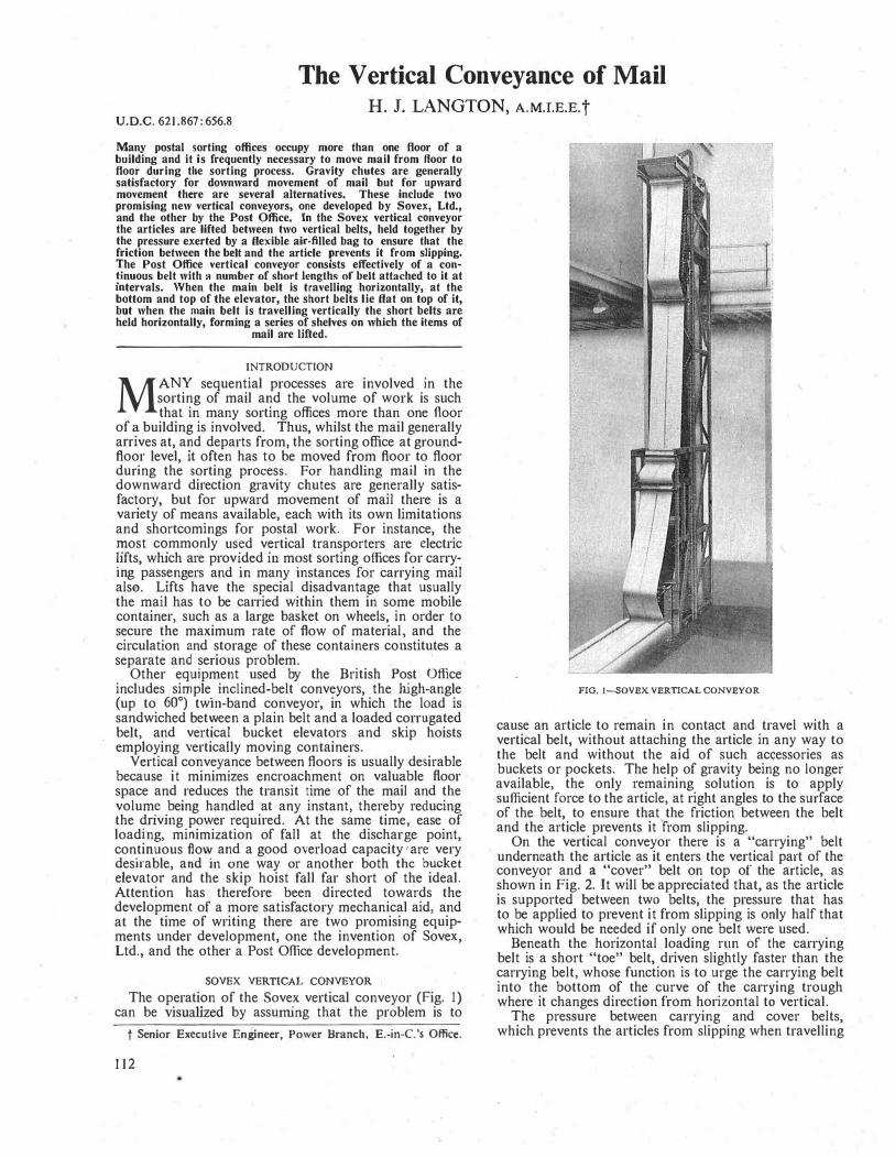
The Vertical Conveyance of Mail H. J. LANGTON, A.M.I.E.E.t
U.D.C. 621.867: 656.8
Many postal sorting offices occupy more than one floor of a building and it is frequently necessary to move mail from floor to flo?r during the sorting process. Gravity chutes are generally satisfactory for downward movement of mail but for upward movement there are several alternatives. These include two promising new vertical conveyors, one developed by Sovex, Ltd., and tit� other by the Post Office. Jn the Sovex vertical conveyor the articles are lifted between two vertical belts held together by the pressure exerted by a flexible air-filled bag t� ensure that the friction between the b�Jt and the article prevents it from slipping. The Post Office vertical conveyor consists effectively of a con!inuous belt with 11 number .of short lengths of belt attached to it at mtervals. When the main belt is travelling horizontally, at the bottom and top of the elevator, the short belts lie flat on top of it but when the main belt is travelling vertically the short belts ar� held horizontally, forming a series of shelves on which the items of
mail are lifted.
INTRODUCTION
MANY sequential processes are involved in the sorting of mail and the volume of work is such that in many sorting offices more than one floor
of� building is involved. Thus, whilst the mail generally arnves at, a?d departs from, the sorting office at groundfloor level, it often has to be moved from floor to floor during the sorting process. For handling mail in the downward direction gravity chutes are generally satisfactory, but for upward movement of mail there is a variety of means available, each with its own limitations and shortcomings for postal work. For instance, the
�ost c�mmonly us�d v�rtical transporters are electric �1fts, which are prov�ded lll m?st sorting offices for carrymg pass�ngers and lll many instances for carrying mail also. 1:-1fts have the special disadvantage that usually the mail has to be carried within them in some mobile container, such as a large basket on wheels in order to secure the maximum rate of flow of mate/ial and the circulation and storage of these containers co�stitutes a separate and serious problem.
Other equipment used by the British Post Office includes simple. inclined-belt conveyors, the high-angle (up to 60°) twrn-band conveyor, in which the load is sandwiched bet�een a plain belt and a loaded corrugated belt, and vertical bucket elevators and skip hoists employing vertically moving containers.
Vertical conveyance between floors is usually desirable because it minimizes encroachment on valuable floor space and reduces the transit time of the mail and the volum� .
being handled at any instant, thereby reducing the dnvlllg power required. At the same time ease of load!ng, minimization of fall at the discharge point, con
.tmuous flov.: and a good overload capacity 'are very
desirable, and 111 one way or another both the bucket
elevator and the skip hoist fall far short of the ideal. Attention has therefore been directed towards the development of a more satisfactory mechanical aid and at the time of writing there are two promising equipments under development, one the invention of Sovex Ltd., and the other a Post Office development.
'
SOVEX VERTICAL CONVEYOR
The op.erati?n of the Sove?' vertical conveyor (Fig. 1) can be visualized by assummg that the problem is to
t Senior Executive Eniineer, Power Branch, E.-in-C.'s Office.
112
FIG. 1-SOVEX VERTICAL CONVEYOR
cause an article to remain in contact and travel with a vertical belt, without attaching the article in any way to the belt and without the aid of such accessories as buckets or pockets. The help of gravity being no longer available, the only remaining solution is to apply sufficient force to the article, at right angles to the surface of the belt, to ensure that the friction between the belt and the article prevents it from slipping.
On the vertical conveyor there is a "carrying" belt underneath the article as it enters the vertical part of the conveyor and a "cover" belt on top of the article, as shown in Fig. 2. It will be appreciated that, as the article is supported between two belts, the pressure that has to _be applied to prevent it from slipping is only half that which would be needed if only one belt were used.
Beneath the horizontal loading run of the carrying belt is a short "toe" belt, driven slightly faster than the carrying belt, whose function is to urge the carrying belt into the bottom of the curve of the carrying trough where it changes direction from horizontal to vertical.
The pressure between carrying and cover belts, which prevents the articles from slipping when travelling

FIG. 2-PARCELS ENTERING THE SOVEX CONVEYOR
vertically, is produced by an air bag made of flexible, but substantially non-stretching, material (Fig. 3) capable of withstanding internal pressure, such as rubberized fabric, synthetic plastic, leather or canvas, To avoid excessive wear, the bag, maintained under a low internal pressure, exerts the necessary force without pressing directly against the moving cover belt. This is achieved by separating the bag from the cover belt by a suspended stationary belt, or curtain, of flexible wire
'
•:�JJL;;;;.;.;.""""1...1111.._ ___ _ ___ _ ..z;i_,•t l<l--"'�� . __ :.:Lj FIG. 3--SOVEX VERTICAL CONVEYOR, SHOWING THE AIR BAO
c
mesh. Alternatively, the curtain may take the form of a belt of tl1in, flexible metal, tough rubber or fabric; a flexible roller bed may be employed or the bag itself furnished with a protective facing.
The air bag, the wire-mesh curtain, the cover and the carrying belts are contained in a rectangular mild-steel duct, and the air bag is so designed that wlien fully inflated it completely fills the duct and exerts pressure on the wire-mesh belt. The wire-mesh belt in turn presses the cover and carrying belts against one side of the duct.
When an article enters the vertical part of the conveyor, carried between the cover and carrying belts, the air bag is deformed to an extent depending upon the size of the article that is being carried. An amount of air equal in volume to this deformation must be allowed to escape from the bag, and this same volume must be restored as the article leaves the vertical part of the conveyor. In other words, pressure of air in the bag must be kept constant,· whilst the volume of air in the bag must be varied with the load on the conveyor-the volume decreasing with increasing load.
The pressure exerted by the air bag through the wiremesh belt on a filled sack, for example, enables the carrying belt to raise the sack vertically with it. The flabbiness of the bag allows it to adapt itself by deformation to the shape of the sack and to exert pressure on it in an enveloping fashion, this deformation and envelopment progressing up the bag as the sack is raised. The bag has a cross-section specially designed to facilitate local expansion and contraction, and to minimize friction.
There are various ways in which the pressure required in the bag can be maintained. If the bag is non-porous, it can be connected by a duct to a flexible overflow reservoir; if porous, it can be permanently connected to an air compressor or air line. Again, a deliberate leakage gap may be provided between compressor and bag, so that if the pressure tends to rise, increased back leakage will occur at the gap. But whatever the means employed, it is essential to ensure that the variations in the volume of air in the bag, with varying loads on the conveyor, can take place rapidly and with minimum variation in pressure.
POST OFFICE VERTICAL ELEVATOR
The general principles of the Post Office vertical elevator can be seen from Fig. 4, which is a view of an experimental model of the device. Four main carrying chains are used in this elevator and these are constrained in guides so that two lie side by side at each side of the elevator on the horizontal section, and run one at each corner of the structure during the vertical rise. The outer chains, with reference to their position on a horizontal run, are bridged at intervals by connecting bars and, likewise, the inner chains are bridged at similar intervals but at points well apart from those at which the outer chains are bridged.
Various configurations of conveyor belting can be affixed to these bridging bars but in principle it can be regarded as a scheme in which
(a) a continuous belt is supported on all the innerchain bridging bars, and
(b) short lengths of belt are connected between the outer-chain bridging bars and the inner-chain bridging bars.
By this form of c<'Jnstruction the elevator has the characteristics of a continuous belt with short lengths of
113

FIG. 4-EXPERIMENTAL MODEL OF THll POST OFFICE VERTICAL ELEVATOR
conveyor belt laid on top during a horizontal run and the general appearance of a vertical escalator, in which the short lengths of conveyor belt form the horizontal steps, during a vertical run. At the head of the elevator these "steps" reform on top of the continuous belt to
Book Review "The Synthesis of Passive Networks." Ernst A. Guillemin.
Chapman & Hall, London. 741 pp.· 459 ill. 120s. The author of this book is a professor of electrical com
munication at the Massachusetts Institute of Technology with which be has been associated for over 30 years. Much of this time has been devoted to network theory and for many years he has held a unique reputation throughout the world as a leading authority on the subject. In the early 'thirties he published a two-volume book, "Communication Networks," which covered most of the network theory then known. The excellence of this book established his reputation as a teacher of the first rank and the book has remained a best-seller ever since.
The 15 years or so which followed its first publication saw great progress in network theory and by the end of the war "Communication Networks" no longer adequately covered the subject. Apart from technical advances in
114
resume the flat-belt characteristic of the horizontal run, and the return circuit is completed in similar orientation. Thus, mail deposited on the lower horizontal section is separated into discrete loads by the belt "shelves" for vertical conveyance and discharged as from a continuous horizontal conveyor at the top.
Due to the separation into discrete loads there is a risk of items overhanging the front edges of the "shelves" and perhaps toppling out during the vertical rise; mail is, of course, constrained at the sides by side-plates. There are a number of possible ways of dealing with this problem and at present the preferred method is to use a loading assister (not shown in Fig. 4, because it has been removed to avoid obscuring more-important features of the elevator). The loading assister consists simply of a short belt conveyor, running at about It times the linear speed of the main elevator, which is pivoted on the axis of its lower (driving) roller and presses towards the vertical flight of the main elevator with a suitable pressure. An article overhanging the "shelf" edge by more than an inch or two will thus come gradually into contact with the assister belt and be urged into a safer attitude on the "shelf" by being caused to pivot on its opposite end. The assister is pivoted so that the pressure exerted ori an overhanging item can be reasonably constant, the assister swinging away from the main elevator in the case of an overhanging but nevertheless safelywedged item. The assister can also be arranged to act as a loading gauge by operating a stop switch in the event of excessive travel .
·
CONCLUSION
At the present time, one installation of the Sovex vertical conveyor is on field trial at a London office and an installation of the Post Office vertical conveyor is being planned for another London office. It is too early as yet to draw comparisons between the two and indeed it is quite likely that each will find its own special field of application in the vertical conveyance of mail.
ACKNOWLEDGEME�
The author wishes to express his appreciation of the assistance given by Sovex, Ltd., in preparing the article and for their permission to use the photographs shown in Fig. 1-3.
network theory the treatment of fundamental circuit theory had become more comprehensive with the introduction of the concepts of complex-function theory. A new edition of the book would hardly have been appropriate, and Professor Guillemin boldly began a complete rewriting of the subject which was intended to appear as a connected sequence of several volumes.
The first one of the new series, "The Mathematics of Circuit Analysis," appeared in 1949,� Wd the second, "Introductory Circuit Theory," in 1953. h�tween them they covered the necessary preliminaries, as indicated by their titles. The present book is the third in the series and its purpose is to study the principles underlying the different design schemes currently available to the network specialist. It relies entirely on the previous two books for all the basic concepts and, apart from a lengthy preface, it starts with negligible preamble on the subject in hand. Except for the last two chapters, the book is concerned exclusively with
(Co11ti1111ed 011 p. I 19)

Radio Interference
Part 4-Measuring Equipment
A. MACPHERSON, B.SdEng.), A.M.I.E.E.t U.D.C. 621.317.7 :621.396.82
The general principles and technical requirements of radio.
interference measuring equipment are outlined and details are given of equipment which has been developed by the Post Office for use in this field. Further articles in the series will deal with incidental
radiation de,·ices and the control of radio interference
INTRODUCTION
THE previous article in the series described how radio interference is generated and propagat�d, and how it can be limited to reasonable proportions hy
the use of suppressors. Although most complaints of interference in the field can be dealt with and the interference adequately suppressed without using measuring equipment, such equipment is essential when the actual level of interference from an appliance has to be assessed. This need arises \Vhen it is desired to determine the efficacy of a certain method of suppression or when it is necessary to know if the level of interference from a particular appliance is within an assigned limit. The latter need is of particular interest to the Post Office, and to industry generally, in connexion with the administration of the Wireless Telegraphy Act, 1949, under which the Postmaster-General may issue specific regulations for the control of radio interference, or for testing for compliance with British Standard (B.S.) 800' or any similar standard.
To ensure consistency and uniformity of the quantitative values given by a range of measuring sets, one of two alternatives may be adopted. Either all the sets must be as near as possible identical in circuit details and construction or they must conform to a comprehensive performance specification. Historically, the first alternative was followed both within this country and internationally. Over a period of some 20 years technical knowledge and experience has been acquired so that it is now possible to specify the essential performance requirements of interference measuring equipment. In this country a British Standard, B.S.727,' has been produced and a similar, but slightly condensed, specification has been incorporated in each of the Statutory Regulations, issued by the Postmaster-General, dealing with the control of specific sources of radio interference. Internationally, similar specifications have now been drafted and will, it is hoped, be approved for publication in the near future.
This article discusses briefly the requirements of an: interference measuring set, gives details of the essential performance specification and describes actual sets which have been developed by the Post Office. Some of these have been produced in quantity and are in current use.
BASIC CHARACTERISTICS OF RADIO INTERFERENCE
As has been discussed in the previous article of this series, radio interference most commonly occurs due to rapid fluctuations of current such as are experienced in commutator motors or due to the sudden switching on or off of an electric circuit, as in some types of thermo-
t Senior Executive Engineer, Radio Experimental and Development Branch, E.-in-C.'s Office.
statically controlled devices. Before discussing the requirements of noise measuring equipment it is necessary to consider in more detail the nature of the quantities to be measured. The atnount of annoyance caused by a particular source of interference depends upon the form of the current changes as well as upon the response of the radio receiver concerned. When the rapid changes of current in the interfering source are repeated at a rate that is relatively low compared with the band-width of the receiver, distinct transient wave-trains occur in the output of the receiver. As the pulse repetition rate is increased the transient trains tend to overlap and eventually the noise in the receiver output becomes similar to that caused by the familiar :fluctuation noise. Apart from these two extremes many forms of radio interference commonly experienced consist of a mixture of impulsive and continuous noise.
The frequency spectrum of the noise due to pulses is very wide, the actual width depending upon the rate of the current changes, but in its progress through the receiver the noise characteristics are modified considerably by the relatively narrow band-width of the receiver itself. Thus the subjective effect of the interference from any one source, as heard at the receiver output, depends on two major factors: the nature of the interference at the point of origin and the characteristics of the receiver, in particular its band-width. A further factor, which is of considerable importance in the ultimate analysis of the radio interference problem, is the nature of the service affected. Over the past 20 years or so, interest has been centred on sound broadcasting, with television rapidly assuming equal importance. For this reason the develop� ment of interference measuring equipment and the associated techniques has been directed almost exclusively to the sound broadcasting field. This means that attention has been focused on the problem so far as it affects the general public, to the apparent exclusion of any consideration for the vast range of commercial pointto-point and mobile radio services, navigational aids, etc. Apart from any question of policy, this course has some technical justification in that experience has shown that interference measuring equipment designed primarily for one particular type of service can, with suitable weighting of the reading given, be applied to the conditions of many other services. Television is a particular illustration of this, since measuring equipment designed initially for use on the sound broadcasting service is currently used quite successfully for measuring interference with the television service.
PRINCIPLES OF INTERFERENCE MEASUREMENT
When attention was first directed to the design of an interference measuring set something over 20 years ago it was decided that the essential requirement was to use a receiver having a band-width similar to that of the typical broadcast receiver, followed by a valve
voltmeter which had time-constant characteristics such that the reading obtained was representative of the subjective annoyance effect of the interference that
I1S.
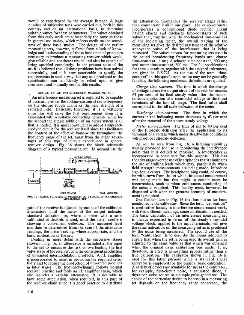
would be experienced by the average listener. A large number of subjective tests were carried out, both in this country and on an international basis, to determine suitable values for these parameters. The values obtained from this early work are substantially the same as those in general use to-day, which reflects credit on the soundness of these basic studies. The design of the earlier measuring sets, however, suffered from a lack of knowledge and understanding of those fundamental principles necessary to produce a measuring re_ceiver which would give reliable and consistent results and also be capable of being specified completely. In the present state of the art it is believed that all these problems have been solved successfully, and it is now practicable to specify the requirements in such a way that any sets produced to the specification can confidently be relied upon to give consistent and mutually compatible results.
DESIGN OF AN INTERFERENCE MEASURING SET
An interference measuring set is required to be capable of measnring either the voltage existing at radio frequency on the electric supply mains or the field strength of a radiated field. Basically, therefore, it is a voltmeter since this will serve the first requirement when it is associated with a suitable connecting network, while for the second the simple addition of an aerial system is all that is needed. It is most convenient to adopt a superheterodyne circuit for the receiver itself since this facilitates the control of the effective band-width throughout the frequency range of the set, apart from the other advantages of this type of circuit experienced in general receiver design. Fig. 16 shows the block schematic diagram of a typical measuring set. In normal use the
I I
I RAOIO RECEIVER �VALVE-VOLTMETER FIO. 16---BLOCK SCHEMATIC DIAGRAM OF TYPICAL INTERFERENCE
MEASURING SET
gain of the receiver is adjusted by means of the calibrated attenuators until the meter at the output indicates standard deflexion, or, \Vhere a meter with a scale calibrated in decibels is used, until the meter needle is showing a convenient deflexion. The· measured level can then be determined from the sum of the attenuator readings, the meter reading, where appropriate, and the basic calibration of the set.
Dealing in more detail with the successive stages shown in Fig. 16, an attenuator is included at the input to the set to minimize the risk of overloading the first valve stage of the receiver, with the consequent production of unwanted intermodulation products. A r.f. amplifier is incorporated to assist in providing the required selectivity and to reduce the production of unwanted products in later stages. The frequency-changer .follows normal receiver practice and feeds an i.f. amplifier chain, which also includes a variable attenuator. It is desirable to have some attenuation, when required, in this part of the receiver chain since it is good practice to distribute
116
the attenuation thuoughout the receiver stages rather than concentrate it all in one place. The valve-voltmeter incorporates a conventional diode rectifier circuit having charge and discharge time-constants of such values that, together with the mechanical time-constant of the indicating meter, the overall reading of the measuring set gives the desired assessment of the relative annoyance value of the interference that is being measured. The values chosen for measuring sets used in the sound broadcasting frequency bands are: charge time-constant, 1 ms; discharge time-constant, 500 ms; and meter time-constant, 300 ms. The full specifications for these quantities, together with the assigned tolerances, are given in B.S.727. As the use of the term "timeconstant" in this specific application may not be generally familiar, the following condensed definitions are quoted.
Charge time-constant. The time in which the change of voltage across the output circuit of the rectifier reaches 63 per cent of its final steady value after the instantaneous application of a sinusoidal voltage to the input terminals of the last i.f. stage. The final value shall correspond to the full-scale deflexion of the meter.
Discharge time-constant. The time in which the current in the indicating meter decreases by 63 per cent after the removal of the above steady voltage.
Meter time-constant. The time of riso to 80 per cent of the full-scale deflexion after the application to its terminals of a voltage which under steady-state conditions will produce full-scale defiexion.
As will be seen from Fig. 16, a listening circuit is usually provided for use in monitoring the interference noise that it is desired to measure. A loudspeaker is incorporated in some sets for this purpose. This has the advantage over the use of headphones thatit eliminates the use of trailing leads which may, particularly when field strength measurements are being made, introduce significant errors. The headphone plug could, of course, be withdrawn from the set while the actual measurement was being made but this might in certain cases be inconvenient, such as when continuous monitoring of the noise is required. This facility must, however, be dispensed with when the greatest accuracy of measurement is required.
One further item in Fig. 16 that has not so far been mentioned is the calitrator. Since the term "calibration" is used rather loosely in interferenc;e measurement work, with two different meanings, some clarification is Needed. The basic calibration of an interference measuring set is always expressed in terms of the steady sinusoidal voltage which, applied to the input terminals, will give the same indication on the measuring set as is produced by the noise being measured. The second use of the term "calibration" is to describe the means adopted to ensure that when the set is being used its overall gain is adjusted to the same value as that which was obtained when the original basic calibration Was made. It is, therefore, in effect a gain-setting process rather than a true calibration. The calibrator shown in Fig. 16 is used for this latter purpose while a standard signal generator is employed for the original basic calibration. A variety of devices are available for use as the calibrator, for example, first-circuit noise, a saturated diode, a thyratron noise source or a simple pulse-generator. The choice of the particular device to be used in a measuring set depends on the frequency range concerned, the

� +S �
�
� 0
I -s li! ;fi -10 .. x !:c: -IS
!:i i= -20 � � -25 " �
� -JO � �
i!!i -J� iii ... --40
t �
/_
I; � / /
/.
I; :,; � / --/
/>; -
f/ /
� � / / / ::/'.
-� -
�
--·-
v
. -
v v� t7 /
'/ � v '/--'. �
-
\
� /
/ \ /-: �
� � \
% � :'.'.\ -12 -10 -a -6 -'I -2 o +z +4 +6 +a +10 +rz
DEYIATIOtl FROH MID-BAND FREQUENCY (kc/5) The overall response curve of the measuring set should be within the shaded area.
FIG. 17-TYPICAL LIMITS OF OVERALL FREQUENCY CHARACTERISTIC
permissible complexity of the equipment both from the operational and economic aspect and, to some extent, on the preference of the designer.
An important parameter in the design of a measuring set is the overall band-width. This is usually defined in terms of a mask giving the permissible tolerances which must be met. The actual band-width chosen depends primarily on the frequency range which the set is to cover, and by way of example the form of mask used for sets covering the medium and long-wave broadcast bands is shown in Fig. 17 .
A further design consideration which is of great importance in interference measuring equipment is what is termed the overload factor. The value of this factor indicates the extent to which linearity of the overall gain through the measuring set is maintained constant for input voltage levels above that of the sinusoidal voltage input required to produce standard deflexion of the indic;ating meter. This is of the greatest importance when the input voltage consists of a single pulse or, in the extreme case, a step function. In this case the actual peak voltage necessary at the input, and through the early stages of the set, to produce standard deflexion at the output will be many times greater than that of a simple sinusoidal voltage producing the same deflexion. The evaluation of the overload factor necessary in any particular design of measuritlg set is a very complex matter involving consideration of the band-width and the time-constants of the voltmeter. It is not appropriate to give a full analysis of the overload factor evaluation in this article, but as an indication of the order of the quantities involved it may be noted that the value given in B.S.727 for measuring sets covering the frequency range 150 kc/s to 30 Mc/s is 26 db, while that for the range 30 Mc/s to 150 Mc/s is 40 db, the difference being primarily due to the increased band-width of the set covering the latter range.
USE OF AN INTERFERENCE MEASURING SET In the previous section the design of equipment for measuring interference in terms of the voltage applied to the input terminals of a set has been discussed. In order that this equipment may be used in practice for the measurement of interference certain additions are required.
For the measurement of the interference voltages injected into the supply mains by an appliance a resistive network is needed to provide a standard load impedance. The value adopted in the Post Office and by the British Standards Institution is 150 ohms line-to-earth impedance for frequencies up to 30 Mc/s and 75 ohms for the higher frequencies. These values are based on the average of a large number of measurements made on typical domestic electricity supply installations. In addition to the measuring network, an isolating network is desirable to reduce the possible error produced by any interference voltage which may exist on the supply mains themselves and also to minimize the shunting effect on the measuring network produced by the mains impedance, which may in some instances be of very low value. Fig. 18 gives a typical network arrangement
A.C. MAINS SIJPPLY
LINE Z
I
RI I
, "'' 1 - , , , , "" �- -, HATCHING TRAHSfDRHER
� _ _J 1F REQUIRED
I ,sw O I
I
TO MEASIJRIHG
SET
Up lo 30 Mc/s: Rt = R2 = 75 olun.s; R3 = 150 oluns Above 30 Mc/s: Rt = R1 = 0 ohms; RJ = 75 ohms
FIG. 18-ARRANGEMENT FOR MAINS-VOLTAGE AND FIELD-STRENGTH MEASUREMENTS
and shows how the measuring set and the interfering appliance are connected. The isolating network or filter comprises LI, L2, Cl and C2, while R l and R2 constitute the measuring network, in conjunction with the input impedance of the measuring set, which is usually 75 ohms. Capacitors C3 and C4 are isolating or blocking capacitors providing negligible impedance to radio frequencies and high impedance to the 50 c/s mains frequency. A switch, SW, enables the measuring set to be connected to each mains line in turn, the other being shunted to earth through an impedance of75 ohms or 150 ohms, depending on the frequency range of the set.
For the measurement of the field strength of radiated interference an aerial system is required, consisting of a rod, loop or dipole according to the desired conditions of measurement. The aerial may in some sets be connected to the input of the measuring set by means of a further position on the switch, as shown in Fig. 18. The overall calibration of the system for the measurement of field strength n1ay be derived from that of the measuring set itself together with a knowledge of the aerial characteristics. Alternatively, the complete equipment may be calibrated in a known field or against a standard field-strength measuring set.
117

POST OFFICE DESIGNS OF INTERFERENCE MEASURING SETS
Interference measuring sets have been designed by the Post Office up to the present time for use in the frequency range from 15 kc/s to 600 Mc/s. It is not possible within the scope of this article to give a detailed description of all the sets and only a brief mention of their salient features are given in this section.
Measuring Set MS 6 (Fig. 19) This set covers the range 15 kc/s to 160 kc/s. A band
width of 200 c/s is used, together with time-constants of 45 ms charge and 500 ms discharge. The standard interference measuring set indicating meter is used. The calibrator used for gain-setting is a saturated noise diode.
FIG. 19-MEASUR1NG SET MS 6
FIG. 20-MEASURING SET R.I. NO. 1
Measuring Set R.l. No. 1 (Fig. 20) This is the set in most common use in the Post Office,
and covers the range from 150 kc/s to 30 Mc/s with a gap between 400 kc/s and 550 kc/s, this being around the i.f. frequency. The band-width is 9 kc/s and the charge time-constant is l ms, the other time-constant and the meter being of standard form as for the MS 6. The calibrator is a saturated noise diode and a special feature of this set is that the setting for calibration and other conditions for bringing the set into use, together with the correct sequence switching of the attenuators, are all controlled from a single knob.
Measuring Set MS 7 This is a special measuring set which was designed to
118
cover the i.f. gap of the measuring set R.I. No. 1, and it also covers the 11 Mc/s to 30 Mc/s range rather more accurately than the latter set. This has been achieved by using a higher intermediate frequency· of l ·675 Mc/s. In all other respects it is similar to the R.I. No. 1 set.
Measuring Set R.I. No. 2 (Fig. 21) This set was originaUy designed to cover the frequency
range 30 Mc/s to 150 Mc/s but was later extended up to 220 Mc/s. It consists of a basic i.f. and valve-voltmeter unit, together with a range of four separate frequencychanger units. A special feature is that piston attenuators are used throughout, that in the i.f. amplifier being continuously variable. The band-width is 100 kc/s and the
.-
FIO. 21-MllASURING SET R.I. NO. 2
FIO. 22-MEASURING SET MS 9
time-constants and meter characteristics are the same as in the R.I. No. 1 set. No separate calibrator is provided for this set, the gain being set by reference to first-circuit noise.
Measuring Set MS 9 (Fig. 22) This set covers the range 150 Mc/s to 600 Mc/s and in
its circuit design is the most modern of the interference measuring sets. The band-width is 150 kc/s and the charge time-constant is 60 µ.s, the other meter features being standard. A switched coaxial attenuator is included in the input of the set while a continuously variable piston attenuator is located in the i.f. amplifier. The calibrator is a pulse generator using a hydrogen-filled

relay with mercury-wetted contacts that operate at· 100 c/s as part of the inner conductor of a short coaxial delay line. This unit gives an output that is nearly constant with frequency up to 600 Mc/s and enables the set to be made direct-reading on voltage measurements.
Of the sets described briefly above, only the R.I. No. I and the R.I. No. 2 have been produced in quantity and brought into use as part of the equipment of the Post Office Radio Interference Service. The remainder are at present only in use as laboratory tools or for special applications.
CONCLUSION
This article has outlined the problems associated with the design of interference measuring equipment and the principles stated are those generally accepted in this country and promulgated through the appropriate British Standards. In the international field other
Book Review "The Synthesis of Passive Networks"-cu11ti11ued f1·011i p. 114. various aspects of the synthesis problem for one- and two-terminal-pair networks.
By way of explanation, the synthesis problem for a oneterrninal-pair (or two-terminal) network is, firstly, to discover the necessary and sufficient conditions for a given function of frequency to be the impedance (or admittance) of such a network, and secondly, given a function satisfying these conditions to devise a practical method of designing or (in the jargon), of synthesizing a network which has this impedance. The problem for the two-terminal-pair network can be similarly stated although the situation is more elaborate, partly because several different starting points are possible.
The book begins with a study of the driving-point and transfer impedances of passive networks and quickly shows how the fundamental physical assumption that the network contains no energy sources can be replaced by the simple mathematical concept of the positive-real function. This theme is elaborated and several practical techniques for testing whether a given function is positive-real are described.
Then follow two chapters about the synthesis of the restricted class of driving-point impedances produced by networks containing· only two kinds of elements (LC, RC and RL). These cases are important because they are completely solved in a practical fashion and form a model
. for later work. Most of the results were originally. due to Foster and Cauer. The treatment emphasizes the important feature that one function can be provided by many different networks and this leads on to the following chapter, which deals more generally with equivalent networks, i.e. networks having identical external behaviour but different internal circuit arrangements. .
At this stage the general external properties of twotern1inal-pair networks arc introduced and followed by a discussion of synthesis techniques for such networks when they contain only reactances. Some of these have practical applications to filter design, which probably forms the most common example of network synthesis in use so far.
Following a chapter on miscellaneous mathematical tools, which will be needed later, comes what might be regarded as the central feature of the book, namely, the synthesis of the most general driving-point impedance. This problem was first solved in 1931 by Brune, whose solution is a masterpiece in network theory which laid the foundation for almost all future work. Remarkably enough, the next epoch-making step in network theory, due to Darlington in 1939, gave an alternative and equally
countries have been working along similar lines and have reached similar conclusions on the salient features. As has already been stated there is every hope that there will soon be an internationally acceptable common specification for interference measuring equipment.
The measuring sets described in this article are confined to those developed by the Post Office but it should be pointed out that other organizations in this country have been active in this field. Also, there are a number of sets being produced by commercial firms, in some instances based on Post Office designs.
(To be continued)
References 1 B.S. 800 : 1954. Limits of Radio Interference (British
Standards Institution). 2 B.S. 727 : 1954. Characteristics and Performance of Appara
tus for Measurement of Radio Interference (British Standards Institution).
important solution to the same problem, although at the time it came as a by-product of his main thesis, which was the synthesis of reaclance networks. These two methods are both described in great detail.
In each of these schemes the resulting circuit employs mutual inductance, frequently with unity coupling factor, and for many years it was questioned whether these coupled coiJs were a necessary feature of every general impedance synthesis or whether they were merely a consequence of using the special circuit arrangements proposed by Brune and Darlington. The answer appeared in 1949, very quietly, in a short and academic letter to the Journal of Applied Physics from R. Bott and R. J. Duffin, who showed that, for a price, one could avoid coupled coils completely; the price turned out to be an enormous increase-in the number of components. The publication of this existence theorem stimulated a wave of research into other and more economical circuits without mutual inductance, but so far with no complete success. Professor Guillernin devotes a whole chapter to this work and includes some of his own contributions.
The remainder of the book deals with a mjscellany of more sophisticated methods of synthesizing transfer impedances, including those for RC-networks, \Vhich are at present enjoying some popularity because of servomechanism applications. The last two chapters discuss how physically-realizable network functions may be constructed to approximate various typical ideal requirements. They deal, for example, with the construction of functions with a filter-type behaviour and with the difficult problem of finding functions to have a prescribed time response. Here, optimum general techniques are usually not available, except for filters, and the two chapters tend to consist of bits and pieces, mainly to illustrate the principles involved in this branch of the subject.
The professed aim of the whole book is to teach the fundamentals of network theory rather than to act as a work of reference for designers. To this end technical details have everywhere been sacrified and the discussions of basic issues elaborated with the skill and insight we have come to expect from the author. The style of writing is racy (" ... by having a little boy toss coulombs at the capacitances") and at times even a 1ittle careless.. Minor slips are only to be expected in the first edition of a book this size, and a few have been noticed, but they are of little consequence-locating slips in a textbook can be a useful part of a student's education. The book will appeal primarily to those with some special interest in network theory and to them its reading will be an exciting event.
H.J. 0. l.P.0.E.E. Library No. 2484.
119

An Automatic Tester for Subscribers' Lines and Apparatus E. W. CHAPMAN and H. C. NOTTt
U .D.C. 621.317. 79: 621.395.365.2
The tester described in this article enables tests to be made automatically on subscribers' telephone lines and apparatus without the assistance of a test-clerk. A 3-digit code is dialled from the subscriber's telephone to obtain access to the tester in the exchange, via the normal exchange equipment and access relay-sets, and this is followed by the subscriber's own number, which steps test selectors to connect the tester directly to the subscriber's line, With the cooperation of the man at the subscriber's premises the tester makes a series of tests, a fault being indicated by an appropriate verbal announcement At the end of the tests a further digit is dialled to release the tester (lr transfer the call to the exchange clerk or test-
desk.
INTRODUCTION
T
HE installation of a telephone instrument for a new subscriber is an operation which will always be necessary, whatever technical progress may be.made
with line plant and switching equipment. Observahon of working parties in the London Telecommunications Region has shown that a fault seldom occurs during the installation of a new line, the failure rate being of the order of 5 per cent. The cost of comprehensive testing of each line is therefore important, though the time taken to make the tests is quite small compared with the overall time spent in obtaining the test-clerk's services, especially when the number of new lines being provided is high, due to line plant expansion or an exchange equipment extension. Provid.ed that a functional test from the subscriber's instrument ·were satisfactory, very little risk would be run if service were given without a more comprehensive test.
To confirm this an experiment was conducted at five installation offices in the London Telecommunications Region. Exclusive exchange lines at all exchanges in the installation areas concerned were jumpered on receipt of the advice notes, and installation of each line was completed without acceptance by the test-clerks. After a period of seven months the results were:
Total lines fitted 4,010 Completed without a fault 95 ·8 per cent Completed with test-desk assistance 3·4 per cent Developed a fault within I month 0·8 per cent
However, the general adoption of this procedure was deferred pending trials of an automatic new-line tester which had been produced in the meantime by the SouthEast Area. This equipment (referred to in this article as the Model 1 tester) enables a comprehensive test to be carried out from the subscriber's instrument without the intervention of a test-clerk.
MODEL I SUBSCRIBER'S LINE TESTER
The Model I tester consists of a small apparatus rack enclosed in a wooden case, designed to stand alongside the end position of the test-desk, i.e. that normally occupied by the advice-note duty technician. The face panel of the cabinet carries a strip of fault-indicating lamps and an interception jack which enables the testclerk to enter the circuit with his position test cord.
The tester is provided with two outlets connected from a code-selector level, and connexion to it is made by
tTheauthors are, respectively, Executive Engineer and Assistant Engineer, London Telecommunications Region.
120
dialling a 3-digit code followed by the subscriber's number. The tester is permanently connected to a testselector, which is associated with the line to be tested by the numerical digits sent in. The facilities afforded are as follows:
(a) Queuing of one call (when tester engaged). (b) Limit test of line insulation. (c) Limit test of loop resistance. (d) Limit test of dial speed. (e) Limit test of shared-service earth resistance.
(f) Limit test of rectifier-element back resistance. (g) Controlled transfer of the call to the exchange
clerk. (h) Fault indication by lamp to the test-clerk. The sequence of operations in testing an exchange
line is given in Table I.
Installation Procedure A major change in installation procedure is necessary
when the tester is used, inasmuch as a successful test of a new installation is referred directly to the exchange clerk, via the tester, who then reverses the call and puts the line into service. Apparatus details are called over to the test-desk when the completed advice note is handed in to the installation office. By adopting this procedure installation staff are independent of the test-desk for most of their work.
Maintenance Procedure
The ability to test a subscriber's line and instrument in a very short time and without involving any additional labour has obvious advantages for maintenance work. Wherever a tester is available, subscriber's apparatus maintenance staff are expected to make a routine test of each installation visited, regardless of the original fault.
Field Trials Several Model 1 testers have been in use in the London
Telecommunications Region for more than 12 months. As the tester caters for shared-service and exclusive exchange lines, and P.B.X. and P.A.B.X. extensions can be tested without difficulty, it is used for all new work, except coin-box circuits. Records of 7 months work gave the following results:
Total lines fitted 2,730 Completed without fault 94·7 per cent Rejected by the tester . . . . 5 · 3 per cent
Only one circuit developed a fault in the first month. The proportion of failures is slightly greater than the
no-test experiment produced. This is to be expected, because all Circuits are now being rigorously tested, and is confirmed by the insignificant number of faults occurring during the first month of service. Areas have estimated an average labour saving of 15 min per advice note, but it is clearly impossible to obtain an accurat.e assessment of the time that would have been spent in completing the same advice notes without the services of the tester. The full benefit of the tester will not be felt until the majority of exchanges are equipped with them. The routine tests being made by maintenance men are currently producing

TABLE 1 Operation of Model 1 Tester
Procedure Test Applied
l. Remove handset, obtain diaUing Queue for tester tone, dial code followed by the
Connexion to tester subscriber's telephone number --
2. Replace handset Insulation test , Ringing conditions
3. Remove handset Loop resistance
4. Dial 1350 Dial test \
5. (Exclusive line or shared-service common metering)
Conditions Correct
Continuous ring tone
Interrupted N.U. tone
Bell rings
Interrupted dial tone
Interrupted dial tone will con-tinue to be heard
Conditions Faulty
N.U. tone} Dial or again busy tone
No ring, lift hand-set after 30 sec (See note)
(See note)
(See note)
(a) Dial 3 Line conqected to exchange Ring tone -clerk Exchange clerk answers
(b) Dial 5 Tester released Normal dial tone received ' 6. (Shared-service separate metering)
Call.ing earth tested, line Ring tone (a) Dial 2 and press button connected to exchange Exchange clerk answers (See note)
clerk (b) Dial 4 and press button Tester released Normal"dinl tone received
Note: After 30 sec ringing tone will be receiveq and the test-clerk will intercept the call. ·
a failure rate of 3 per cent, due to faulty dials and line insulation in approximately equal proportions.
MODEL 2 SUBSCRIBER'S LINE TESTER
During the early stages of the trial of the Model 1 tester it became obvious that the potential value of the equipment for maip.tenance work justified changes in the design. The disadvantages of the Model 1 tester are as follows:
·
(a) Under fault conditions interception by the test-clerk is necessary to advise the caller of the nature of the fault.
(b) The maintenance control officer cannot tell whether an installation has been checked by the tester when the clearance of a fault is being reported by the , maintenance staff.
(c) The tester is held engaged for the duration of a
SU8SCRl8ERS TELEPHONE
SU8SCRl8ER0S
UNISELECTOR ..
, •• �- IST CODE O sELECTOR
-= Q2MDCODE - SELECTOR --- -
TEST SELECTOR
--
TEST [] = FINAL -
SELECTOR_ = ---
---
EXCHANGE CLERK0S
TELEPHONE
,-----------4
TEST DESK CIRCUIT No I
CIRCUIT Ho 2
FIG. I-TRUNKING OF MODEL 2 SUDSCRIDER'S LINE TESTER
call to the exchange clerk, or while waiting interception by the test-clerk.
The circuit has therefore been redesigned to provide access relay-sets, connected to the code-selector level, which seize the tester for test purposes only and release it when the call is transferred. The trunking arrangement� are shown in Fig. 1. These access relay-sets are suitable for both director and non-director exchanges. In practice two relay-sets will probably be sufficient for a 10,000-line exchange as the holding time of the tester is only 15 sec.
Fault indication by lamps on the tester has been replaced by transmitting verbal announcements to the caller. The announcements are recorded on· a small magnetic drum (Fig. 2). Advantage has been taken of the availability of twelve tracks to include operating instructions, thus avoiding the need for non-standard tone signals. The text of the recordings is as follows:
(a) Operating instructions: "Waiting for tester"; "start test"; "tester out-of-service"; "testing O.K."
FIG. 2-MAGNBTIC DRUM
121

(b) Fault announcements: "low insulation A-wire"; "low insulation B-wire"; "low insulation A to B"; "high loop resistance"; "faulty dial pulses"; "dial fast"; "dial slow"; "calling-earth high resistance."
The signals from the play-back heads are fed through a transistor amplifier with a gain of approximately'70 db and an output to line of 1 mW. Two amplifiers are fitted, one being fed continuously by the queuing announcement "waiting for tester" and the other connected to the appropriate head as required.
The test-clerk is notified of the telephone number of the subscriber's installation from which the call has been originated by the visual display of the four numerical
·digits in sequence (0·6 sec on, 0·6 sec off) with a 3-sec pause between repetitions.
The need to include a dial pulse-ratio test was considered, but no evidence could be found of dials that passed the speed test having an incorrect pulse ratio and this proposal was abandoned.
Fig. 3 is a photograph of the prototype of the Model 2 tester. This was constructed as a demonstration set and additional apparatus bad to be included. The operating procedure is indicated in Table 2.
Fault Localization
As will be seen from the table the tester can be released as an alternative to transferring the call. This facility enables tests to be made from intermediate points using a portable telephone (Telephone No. 250) to locate an insulation fault, providing the resistance is not so low as to render the circuit unworkable. This feature will be particularly valuable in the London Telecommunications Region where the minimum acceptable insulation resistance has been raised to 2 megohms. The method is also useful to subscriber's-apparatus maintenance staff provided they have a Telephone No. 280, which consists of a handset fitted with a dial.
Circuit Details
A line is connected to the tester by dialling from the subscriber's instrument a 3-digit code followed by the numerical portion of the subscriber's number. The four
SUBSCRllER'S Llfff TCS IER
I
The tester shown in the photograph includes apparatus to enable It to function as a demonstration set
FIG. 3-PROTOTYPE OF THE MODEL 2 TESTER
numerical trains of pulses are repeated through the access relay-set to operate the associated test-selector. They are also registered on storage switches for line
TABLE 2
Operation of Model 2 Tester
Procedure Test Applied Conditions correct Conditions Faulty --
1. Remove handset, obtain dial tone, Queue for tester "Waiting for tester" N.U. tone} Dial dial the code followed by subscriber's announced or again telephone number busy tone Connexion to tester "Start test" announced
-
2. Replace handset Insulation test No ring, or ring and Bell rings
Ringing conditions fault announced --
3. Remove handset Loop resistance Dial tone Fault announced --
4. Dial I Dial test Dial tone Fault announced Dial 3 Dial test Dial tone Fault announced DialO Dial test Dial tone Fault announced
5. Dial appropriate digit 3 Transfer to exchange clerk Ring tone 5 Release from tester "Testing OK" announced 7 Transfer to test desk Ring tone
6. (Shared-service separate metering)
I Press the calling button after dialling Calling earth As in 5 above Fault announced a digit, as in 5 above
122

identification at a later stage. If an engaged test-final selector is encountered after the second pulse train the resulting reversal of polarity on the "operate" pair to the test selector prevents any further pulse repetition. The last two pulse trains are absorbed, and busy tone is returned to the caller.
If the test-final selector is free, the fourth numerical pulse train will position the wipers on the bank multiple of the calling line, which will, of course, be engaged. The busy condition produces a reversal of polarity on the test selector "operate" pair, and detection of this reversal causes the access relay-set to be offered to the tester. Should the tester be engaged, a verbal announcement, "waiting for tester" is returned to the caller. As soon as the tester is free it is seized by the access relayset and the test-selector "test" pair is connected to the tester. The "waiting" announcement is now replaced by the "start test" announcement, which is fed back from the tester. On receiving tlus instruction the caller clears the line by replacing the handset. This action releases the subscriber's line equipment and the code-selectors used for setting up the call.
Upon the removal of the busy condition from the final-selector multiple the polarity of the test-selector "operate" pair reverts to normal. The access relay-set now operates the start relay in the teste1· and the test-switch steps off the home position to begin the test cycle.
The initial steps of the test-switch are used to examine the exchange termination to determine whether an exclusive or shared-service line is being tested (Fig. 4).
TESTER : TEST SELECTOR \ SUBSCRIBER'S LINE ,-------l----+.=--4-JK EQUIPMENT
• TS
TEST PAIR
'·· .:
'+
l T
'
�b ... .......... ' T � t .,. -
I---<>�� ,�HARED SERVICE) (EXCLUSIVE)
E�---il• I I K
J�.·�--;--D-'�" TS \ :OPERATE I '1 i:PAIR I A 1 / : I FL.j-<.. '
••••• I � I
FIG. 4---DISCRIMINATING BETWEEN EXCLUSIVE AND SHARED-SER VICE LINES
This is achieved by releasing the Krelay of the subscriber's line equipment and offering relay ES to the A wire and B wire in turn. If an earth condition is found, indicating an exclusive line; relay ES operates and Jocks for the duration of the test cycle. For a shared-service line relay ES cannot operate as no earth exists on the exchange ternunation. The non-operation of relay ES prepares the tester for a check of the calling-earth resistance at the end of the test cycle. This method of detecting sharedservice lines is not suitable for circuits connected to the new 50-point subscribers' linefinder and an alternative circuit is being developed.
While this discrimination is taking place the correct operation of the valve-voltmeter is checked by applying operate and non-operate conditions (Fig. 5). Lineinsulation tests then follow in the sequence A wire to
A ..i;;- -
@f ____ � SUBSCRIBER'S TEUPHONE \ TS
\. I e •. l ....... . .
TO VALVE· VOLTMETER
\ TSL \ ' ..
� ... . ..... i
FLI KER EARTH
\ T�s""-;61=��=,--, •• ...... !o
1·5H FIG. 5-INSULATION-TEST CIRCUIT
1·8H 2·2H
earth; B wire to earth, and A wire to B wire. These tests are made with an 80-volt battery in series with a 27,000-ohm resistor. The potential difference across this resistor is 0·98 volts for an insulation resistance of 2·2 megohms, and l · 18volts for an insulation resistance of l ·8 megohms. The difference between these potentials (0·2 volt) is used to control relay VT in the valve-voltmeter. The operation of this relay signifies a satisfactory insulation value and causes the test-switch to step on.
The Principle of the Valve-Voltmeter (Fig. 6). An input of 0·98 volts across Rl develops V, volts across the anode load resistor, R3 of valve VI. An opposing
Rf 27k R2 500 + 250V
Rl 47k
R4 l80k
RVI zn
R5 BOk
FIG. 6-VALVE·VOLTMETER CIRCUIT
+ IOOV
potential V, volts exists continuously across R4 and RV!, and is adjusted to the same value as V,. As the algebraic sum of V, and V, is zero the potential between the cathode and grid of V2 is also zero. Under these conditions the anode current of V2 is 18 mA and relay VT is operated.
If the input voltage across Rl is increased, the voltage V, across R3 falls. The steady voltage V, (across R4 and RV!) is now greater than V, and negative bias equal to V, - V, volts is applied to the grid of V2. If this bias reaches 4 volts the anode current of V2 is reduced to zero and relay VT cannot operate.
The voltage amplification of the first stage is sufficient to cut off the anode current of V2 when the input changes by 0·2 volts, corresponding to the difference between line insulation values of l ·8 megohms and 2·2 megohms.
Ringing and Dial Tests. If insulation tests are satisfactory, ringing current is applied to the line in order to test the bell. The receipt of ringing indicates to the caller that the line insulation tests have been completed and he lifts the handset. Tripping the ringing steps the test-switch to the next outlet, applying a resistance
123
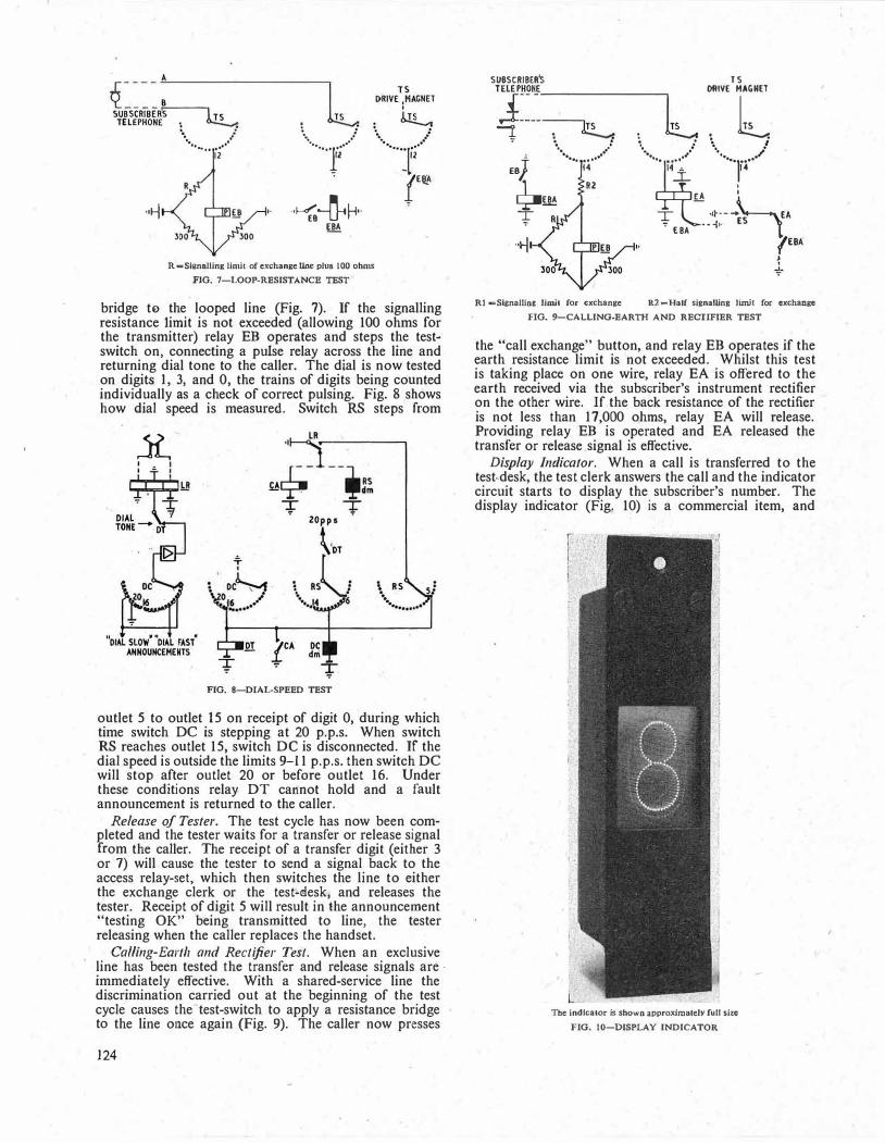
q----: SUBSCRIBER� TS TELEPHON( \ b..!.!-.
··ii
·.. .: ·
·.. ..
··
.... i2
.l ' ........ 'f/
··���·· EBA
R -slannlling limit of exchange Une plue 100 ohms
FIG. 7-LOOP-RESISTANCB TEST
bridge te the looped line (Fig. 7). If the signalling resistance limit is not exceeded (allowing 100 ohms for the transmitter) relay EB operates and steps the testswitch on, connecting a pulse relay across the line and returning dial tone to the caller. The dial is now tested on digits I, 3, and 0, the trains of digits being counted individually as a ch,eck of correct pulsing. Fig. 8 shows how dial speed is measured. Switch RS steps from
jl,
: � : I
FIG. 8-DIAL-SPEED TEST
outlet 5 to outlet 15 on receipt of digit 0, during which time switch DC is stepping at 20 p.p.s. When switch RS reaches outlet 15, switch DC is disconnected. If the dial speed is outside the limits 9-11 p.p.s. then switch DC will stop after outlet 20 or before outlet 16. Under these conditions relay DT cannot hold and a fault announcement is returned to the caller.
Release of Tester. The test cycle has now been completed and the tester waits for a transfer or release signal from the caller. The receipt of a transfer digit (either 3 or 7) will cause the tester to send a signal back to the access relay-set, which then switches the line to either the exchange clerk or the test-clesk, and releases the tester. Receipt of digit 5 will result in the announcement "testing OK" being transmitted to line, the tester releasing when the caller replaces the handset.
Calling-Earth and Rectifier Test. When an exclusive line has been tested the transfer and release signals are -immediately effective. With a shared-service line the discrimination carried out at the beginning of the test cycle causes the test-switch to apply a resistance bridge to the line once again (Fig. 9). The caller now presses
124
SU8SCRIBER's
TJ��:�TS J. : � ':' �. l
.. ..· .. •" ee} ..
. i4"
TS
' l �'"( \, ./ \ l
14 "" 14 J_
I
�EBA T
.
. *. ...... .. . .. ! .. ... �
EA I
T - ··�-- .... \.__EA � EBA ---!•· ES 1
"ri 7EBA {
"*'
Rt -SignolUnc limit for exchange R2=Half sienalUne Umlt for exchange
FIG. 9-CALLING-EARTH AND RECTIFIER TEST
the "call exchange" button, and relay EB operates if the earth resistance limit is not exceeded. Whilst this test is taking place on one wire, relay EA is offered to the earth received via the subscriber's instrument rectifier on the other wire. If the back resistance of the rectifier is not less than 17,000 ohms, relay EA will release. Providing relay EB is operated and EA released the transfer or release signal is effective.
Display Indicator. When a call is transferred to the test.desk, the test clerk answers the call and the indicator circuit starts to display the subscriber's number. The display indicator (Fig. 10) is a commercial item, and
The indicator ls shown approximately full size
FIG. JO-DISPLAY INDICATOR

exploits the phenomenon exhibited by Perspex of confining a beam of light within the material. Thin sheets of Perspex are engraved with digits 0 to 9 (one digit per sheet) and the sheets superimposed. When the edge of any sheet is illuminated (a 12-volt l ·2-watt lamp is used) the digit is displayed by reflected light from the side wall of the engraved surface. In the pattern which it is proposed to use the size of the display is approximately !in. by Ii in.
The display indicator was not included in the prototype of the Model 2 tester and does not therefore appear in Fig. 3.
Fault Announcing. The fault announcement has to be transmitted when a test failure occurs, i.e. when the
VTB�··,,]
- - - - ._,,....-; t· .. , TO PLAY-BA
.
CK HEADS ·f <] TS ; GIVING FAULT
: ANNOUNCEMENTS
suescRieER� -� �·· .... ..,. • • •••• .: TELEPHONE
3 SEC TIME PULSE
FIG. 11-FAULT-ANNOUNCING AND TIMlNG cmcmT
Book Review
"Frequency Modulation." A. W. Keen. Sir Isaac Pitman & Sons, Ltd. 274 pp. 135 .ill. 30s.
The introduction of the B.B.C. very-high-frequency broadcasts using frequency modulation has tended to increase the complexity of v.h.f. receivers to a technical level rather beyond the enthusiastic layman. The amateur radio constructor who builds his own equipment in a "do-it-yourself" spirit is apt to be deterred by the complica· tions of f.m. receivers. There is no doubt in the mind of Mr. Keen, however, that, provided his reader understands the basic principles of amplitude modulation, he can grasp the technique of frequency modulation receiver circuitry without undue difficulty and without appreciable mathematical knowledge. He says in his preface that his book is "only intended as an introduction to a highly teclmical subject." He makes this include a history of the interesting development of f.m. receiver circuits, because, although f.m. has only recently become widely known, radio laboratories have shown a strong scientific interest in its possibilities for many years.
The author first describes the fundamental vectorial representation of frequency modulation and shows how it is closely linked with phase modulation. This is presented admirably and with a clarity that must be the result of much teaching experience in the subject. He then describes, in historical order, many of the circuits that have been developed for generatillg and detecting frequency modulated signals. Techniques used in equipment employed for the reception of broadcasting form his main basis for dis·
test-switch does not step on. It is necessary to delay the application of the announcement to allow time for the test to take place. This delay is provided by a 3-sec time-pulse generated by a uniselector, which is controlled by the exchange I-sec earth pulse supply. If the test-switch remains on any outlet for a period of between 3 and 6 sec the time-pulse operates relay VTB (Fig. 11), which connects the fault announcement. The time-pulse uniselector starts from its home position at the beginning of the test cycle, and on reaching the 25th outlet forces release of the tester, giving a maximum holding time of 25 sec. A satisfactory test can be completed in about 15 sec but the margin of 10 sec is occasionally useful when the subscriber's bell is being tested.
CONCLUSION The availability of this equipment will undoubtedly
enable an economy to be achieved in labour costs and improve the service given to subscribers. Field staff soon acquire confidence in the tester and are favourably disposed towards it since it completely avoids waiting (possibly under uncomfortable working conditions) for co-operation.
ACKNOWLEDGEMENTS The authors extend their thanks to staff of the Tele
phone Development and Maintenance Branch, E.-in-C.'s Office, for assistance wkh the circuit design, and to Mr. G. W. Thomas, Subscribers' Apparatus and Miscellaneous Services Branch, E.-in·C.'s Office, who was responsible for the development of the verbal announcing equipment.
cussion. Broadband techniques are not covered, presumably because interest in this aspect is limited to the highly specialized field of trunk communication engineers. Chapters on the general mechanical construction of f.m. transmitters and receivers are included in the work and there are also very interesting chapters on v.h.f. aerials and on interference and distortion in f.m. reception.
The main text is entirely non-mathematical, and it is a tribute to· the author's skill that so much of this subject can be grasped without any mathematics whatever. However, lest students take this statement too much to heart, let it be said that the subject is much more comprehensible if read mathematically and that the mathematical approach is the only possible avenue for would-be circuit designers.
Mr. Keen has recognised this in Appendix I to the book, which he entitles "The Mathematics of Frequency Modula .. tion," as this contains all the analysis which the more erudite readers would expect to find in the main text. Appendix 11 contains seven pages of selected bibliography on the subject; the compilation of this list must have involved much labour and the result is very rewarding, adding a great deal to the value of the book to the student.
This book can be recommended to any broadcast receiver enthusiast. If he is already an expert, he may well find the non-mathematical treatment of the subject refreshing. If he is still living in the world of amplitude modulation, Mr. Keen ca·n give him a sound idea of the basic concepts of frequency modulation. Science libraries, particularly at schools and colleges, should find this book very popular and it will give much food for thought to their engineering students.
C.F.F.
125

•
A Microwave Model Equipment for Use in the Study of the Directivity Characteristics of Short-Wave Aerials
Part 1-General Considerations and Description of Model Equipment
D. W. MORRIS, B.Sc.lEng.), A.M.T.E.E., E.W. THURLOW, A.M.T.E.E.,
and W. N. GENNA, Associate I.E.E.t U.D.C. 62l.396.67.00l.57:621.3.0t2.12
With the present-day congestion of the short-wave frequency band, aerial systems for point-to-point short-wave services n1ust be highly directional, both in bearing and angle of elevation, to reduce the risk of interference from unwanted signals. A detailed knowledge of the three-dimensional directivity characteristics is therefore essential in the design of ntodcrn short-wave aerials. The practical difficulties of either measuring or calculating the directional characteristics of full-size short-Wa\'e aerials are considerable, and a technique has been developed for studying the performance of such aerials by the use of sn1all models operating at microwave frequencies. Part 1 of this article discusses briefly the principles involved, gives an outline description of the equipment and considers the accuracy realizable with this type of measurement. Part 2 of the article will contain the results of tests made during
investigations using the model aerial equipment.
INTRODUCTION
THE primary design consideration in the development of early long-distance short-wave radio links was the achievement of such transmitter powers, aerial
gains and receiver sensitivities and selectivities as would enable telephone and telegraph circuits to be set up with signal/noise ratios adequate for conunercial operation. In general the factors which limited the operation of the circuits were "radio" noise, i.e. the noise picked up by the receiving aerial, and "receiver" noise, i.e. the noise generated in the receiver itself.
The subsequent growth of the demand for international and intercontinental communications gave rise to a steady expansion in the use of circuits operating in the short�wave frequency band, with the result that this frequency band is now so overcrowded that many frequency assignments overlap and there are risks of interference between the various services. Thus, with present-day short-wave circuits the operational limit is frequently set by the ratio of wanted/unwanted signal levels appearing at the receiver input, rather than by the level of the wanted signal relative to radio and/or receiver noise as in the past.
This change of emphasis in considering the performance of short-wave links applies particularly to the aerials used at the terminal radio stations. The aerials have always been required to be directional (directed towards the corresponding distant station) since only with the aerial gains thereby achieved could the required signal/ noise ratios be attained with practical transmitter powers. Thus the forward gain of a directional short-wave aerial was generally accepted as its most important characteristic, the response in other directions being regarded as of secondary importance. However, with the increased liability to interference between services encountered in recent years, it is very desirable that the aerial-systems used for modern point-to-point short-wave services should be studied with the response in "off-course" directions as one of the essential criteria.
tThe authors are, respectively, Senior Executive Engineer and Executive Engineer, Radio Experimental and Development Branch, E.-in-C. 's Office, and Executive Engineer, Radio Planning and Provision Branch, E.-in-C.'s Office.
126
Consider a directional ae1ial used, for example, at the receiving station of a long-distance point-to-point radio link. In general, unwanted off-course signals received by the aerial could arrive at any azimuth and any angle of elevation (depending on geographical and propagation conditions), and it is therefore necessary to have detailed knowledge of the three-dimensional directivity characteristics of the aerial if its ability to discriminate against off-course signals is to be fully described. However, the actual measurement of these characteristics on a short� Wf!Ve aerial is very difficult. If such measurements are attempted by observing the response of the aerial to long-distance signals, i.e. signals that have been reflected from the ionosphere, the irregularities and movements of the ionosphere tend to mask the performance of the aerial under test. These propagation effects can be eliminated by observing signals transmitted directly from an aircraft flying around the aerial at various heights and at a distance of several miles (depending on the physical size of the aerial under test). This is a laborious and expensive undertaking, den1anding not only the use of an aircraft but also an order of flight accuracy that requires high-grade air-navigation equipment, and even then is only possible under favourable weather conditions.
Because of these difficulties it has been customary, when considering problems of aerial performance, to use directivity characteristics that have been derived theoretically. The theoretical studies rely on certain simplifying assumptions, which only approximate to the practical conditions existing in the aerial, and inevitably involve much laborious computation for a comparatively limited amount of information, but they give a useful guide showing the general adequacy or otherwise of any specific design of aerial for any particular application.
With the growing problem of interference referred to above it has become necessary for the performance of short-wave aerials to be studied more fully and with greater accuracy than formerly, and to this end the microwave model aerial equipment described in this article has been developed. The equipment enables detailed and comprehensive directivity characteristics of a short-wave aerial to be determined quickly and accurately and, moreover, the information is recorded in a very convenient form.
PRINCIPLE OF MODEL AERIAL TECHNIQUE
The radiation characteristics of an aerial formed by perfect conductors are governed by the ratio of its linear dimensions to the operational wavelength. This fact suggests that it should be possible to investigate the properties of a physically large aerial by the use of a scale model. To assess the validity of such a technique it is necessary to study Maxwell's equations as they relate to the electric and magnetic characteristics of the media forming and surrounding an aerial. Such a study reveals that if an electromagnetic system is to be exactly

simulated on a different scale certain conditions need to be satisfied, and these are conveniently expressed by stating that the following equations must remain unchanged:
/M::.!2/2 = K1 . . . . . . . . . . . . . . . . . . . . . . . . . . . . . . (1) µGl2f = K2 ................................ (2)
where µ = the permeability of the medium, E = the permittivity of the medium,
G = the conductivity of the medium, l = a typical dimension of the system,
- f = the operational frequency, and Kr, K2 are constants.
If I is reduced by a factor n, it is theoretically possible to satisfy both equations by increasingµ by a factor n2, but this would necessitate the use of ferromagnetic materials with consequent practical difficulties. A better approach would be that of reducing l by factor n and increasing both/ and G by the same factor n; in this way both equations would again be satisfied.
The principal media employed in the construction of short-wave aerials are copper for the conductors, and ceramic or glass for the insulators. Considering the conductors, copper is a nearly perfect conductor so that the value of G in this case already approaches infinity and therefore cannot be increased significantly in practice. However, when G approaches infinity, K2 of equation (2) also approaches infinity and no great error -results if, in fact, G is not scaled for the conductors,
As far as the insulators are concerned the conductivity of glass or ceramic is close to zero, since these materials are virtually perfect insulators. No significant error results if the value of G for these materials is taken as zero, in which case again no scaling of G is required.
The conductivity of the ground over which an aerial is erected has considerable influence on its directivity characteristics. In the British Isles ground conductivity can vary widely depending upon the nature of the soil, ranging from salt marsh, which possesses very high conductivity, to rocky soil, which may be 1,000 times more resistive. To render the results of model tests easily applicable to soil of any conductivity it is convenient to make the tests over a perfectly conducting medium, and to apply a theoretical correction factor to provide information relating to specific practical conditions. The model aerial is erected therefore over a metal artificial ground plane, whose conductivity approaches infinity.
A model of the aerial to be studied, constructed in accordance with the above principles, is energized by·an r.f. source of the appropriate frequency, and the resultant electromagnetic field is examineq by an observation. aerial. The spacing between the test and observation aerials must be such that the radiated field in the vicinity of the observation aerial has resolved into a substantiaily plane-polarized wave. For most practical purposes a phase deviation across the aperture of the observation aerial of A/16 is not considered harmful, since the resulting loss of gain is only 0· 1 db. This condition is commonly adopted, and can be shown to obtain when:
s = 2aA/>. ............ (3) where A = the width of the aperture
of the model aerial, a = the width of the aperture
of the observation aerial, s = the spacing between the aerials,
and >., A, a and s are measured in the same units. It will be observed that if the aerials have identical
apertures this reduces to:-s = 2A2/>. ............................ (4)
The width of the aperture of a typical wire aerial, such as a rhombic, is not easily defined, but for the purpose of designing the equipment described it has been taken as the minor axis of the aerial. The apertu�e width of the observation aerial employed is 3;\ at the centre frequency of the equipment, and, assuming a test aerial having a similar aperture, requires a minimum spacing of 18>.. The actual spacing adopted is about twice this distance, corresponding to a phase deviation across the observation aerial of only ;\/32.
CONSTRUCTION OF MODEL AERIALS
In constructing a model aerial all the essential dimensions of the full-scale aerial are reduced on a precise scale, with the one exception of the diameter of the wire. In the full-scale aerial, most of the current attenuation is usually due to radiation loss and only about 5 per cent is accounted for by wire-resistance loss, so the latter has
. no significant effect on the current distribution in the wires and hence does not influence the directivity characteristics of the aerial. Resistance loss per unit length varies inversely with the diameter of the wire and also directly with the square root of the frequency, and it is therefore necessary to choose for the model a wire of larger diameter than the scaled diameter to ensure that the loss resistance remains a small fraction of the radiation resistance. Inevitably this departure results in a small reduction of the characteristic impedance of the model, but this discrepancy is not serious.
The connexion between the aerial and the coaxial feeds from the waveguide probes is usually by open-wire transmission line, employing rectangular spacers punched out of thin mica sheet. The same material is used, when necessary, for insulators at other parts of the aerial construction. When model aerials require termination, it is convenient to use an iron-wire transmission line; with this method a return loss exceeding 30 db is readily· obtained. Fig. 1 shows a typical model three-wire rhombic aerial mounted on a turntable, with the open-
FIG. I-TYPICAL MODEL RHOMBIC AERIAL
127

wire feeder and associated quarter-wave matching sections on the right; the ironwire transmission line terminating the aerial at its left-hand end can be seen supported on short "poles".
nn
SQUARE·LAW
TES T AERIAL
2300 -4100
Mc/s OSCILLATOR
The most precise work is necessary when modelling resonant aerials as the resonant elements are critical of length and spacing and for satisfactory operation the geometry of the rig needs to be perfectly symmetrical. The construction of scale models of . multi-el€ment resonant a€rials is particularly tedious and involves adjustments of a magnitude more appropriate to watch-making than to radio engineering.
DISPLAY 11·8 kc/s V\/\,
HIGH- GAINt-------<>-...+ AMPLIFIER DECIBEL
DESCRIPTION OF MODEL EQUIPMENT The aerial under test is mounted on a
rotating turntable forming part of an artificial ground plane, and is energized frdm an amplitude-modulated r.f. source. At a suitable distance away is set up the receiving aerial feeding a detector; the output from the detector, after passin·g through appropriate amplifiers and a time-base generator, is applied to a cathode ray oscilloscope on which is displayed the azimuthal directivity character-istic of the rotating aerial.
Fig. 2 shows a general view of the equipment and a block schematic diagram is shown
DI SPLAY TUBE
in Fig. 3. At the centre frequency (3,000 Mc/s), the artificial ground plane is 24.\ long and 12.\ wide, the rotating portion being a close-fitting disc 9.\ in diameter, centred on the major axis of the ground plane near to one end. This arrangement is convenient for aecommodating the ground reflection region in front of aerials occupying a large ground area, without unnecessarily extending the ground plane in the reverse direction.
The r.f. oscillator is of a conventional coaxial-line, velocity-modulated type, giving a power output of some 200 mW over the frequency range 2,300-4, 100 Mc/s. Modulation is derived from an 11 ·8 kc/s crystal oscillator followed by a square-wave generator. Square-waveform
FIG. 2-GENERAL VIEW OF EQUIPMENT
128
DISPLAY 11·8 kc/s LOG
AMPLIFIER
'----+--VV'v-----l 11·8 kc/s OSCILLATOR
11·8 kc/s IGH·LEVELt----� MPLIFIER
FIG.·
3-BLOCK SCHEMATIC DIAGRAM OF THE EQUIPMENT
modulation is used to obviate the effects of any frequency modulation which could impair the operation of the overall system. Coupling between the oscillator and the terminals of the aerial is effected by coaxial cable and a section of waveguide fixed diametrically across the underside of the turntable. Simple impedance matching in the form of a short, adjustable section of telescopic coaxial line is included at the oscillator output. To energize the waveguide a coaxial cable is passed through a hollow spindle in the turntable driving mechanism, shown in Fig. 4, and the central c�mductor is extended to penetrate into the waveguide on its axis of rotation.
To avoid reflections, the waveguide is terminated a,t " each end by a wedge-shaped piece of
thin card, coated on both sides with a graphite compound, placed along the major axis of the wave guide in the E plane (i.e. the plane of the electric field for TE01 mode of operation). Aerial feeds, ·either unbalanced or balanced, are·then obtained from otie or both ends of a continuous wire probe inserted across the waveguide in the E plane. Such an arrangement affords an advantage over two separate probes for giving balanced feeds in that two voltages equal in magnitude .and opposite in phase are automatically produced, thus eliminating the need for adjusting the penetration and separation of the probes with changes of oscillator frequency. The probes are connected to two short lengths of coaxial cable, which pass through the turntable to its upper side, followed by a feeder system
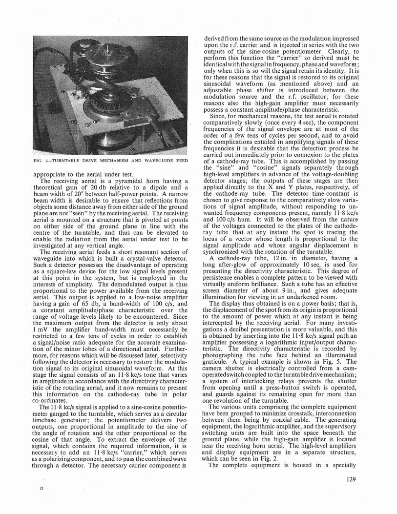
FIG. 4-TURNTABLE DRIVE MECHANISM AND WAVEGUIDE FEED
appropriate to the aerial under test. The receiving aerial is a pyramidal horn having a
theoretical gain of 20 db relative to a dipole and a beam width of 20° between half-power points. A narrow beam width is desirable to ensure that reflections from objects some distance away from either side of the ground plane are not "seen" by the receiving aerial. The receiving aerial is mounted on a structure that is pivoted at points on either side of the ground plane in line with the centre of the turntable, and thus can be elevated to enable the radiation from the aerial under test to be investigated at any vertical angle.
The receiving aerial feeds a short resonant section of waveguide into which is built a crystal-valve detector. Such a detector possesses the disadvantage of operating as a square-law device for the low signal leveJs present at this point in the system, but is employed in the interests of simplicity. The demodulated output is thus proportional to the power available from the receiving aerial. This output is applied to a low-noise amplifier having a gain of 65 db, a band-width of 100 c/s, and a constant amplitude/phase characteristic over the range of voltage levels likely to be encountered. Since the maximum output from the detector is only about 1 m V the amplifier band-width must necessarily be restricted to a few tens of cycles in order to establish a signal/noise ratio adequate for the accurate examination of the minor lobes of a directional aerial. Furthermore, for reasons which will·be discussed later, selectivity following the detector is necessary to restore the modulation signal to its original sinusoidal waveform. At this stage the signal consists of an 11 ·8 kc/s tone that varies in amplitude in accordance with the directivity characteristic of the rotating aerial, and it now remains to present
·this information on the cathode-ray tube in polar co-ordinates.
The 11 ·8 kc/s signal is applied to a sine-cosine potentiometer ganged to the turntable, which serves as a circular timebase generator; the potentiometer delivers two outputs, one proportional in amplitude to the sine of the angle of rotation and the other proportional to the cosine of that angle. To extract the envelope of the signal, which contains the required information, it is necessary to add an 11 ·8 kc/s "carrier," which serves as a polarizing component, and to pass the combined wave through a detector. The necessary carrier component is
D
derived from the same source as the modulation impressed upon the r.f. carrier and is injected in series with the two outputs of the sine-cosine potentiometer. Clearly, to perform this function the "carrier" so derived must be identical with the signal in frequency, phase and waveform; only when this is so will the signal retain its identity. It is for these reasons that the signal is restored to its original sinusoidal waveform (as mentioned above) and an adjustable phase shifter is introduced between the modulation source and the r.f. oscillator; for ,these reasons also the high-gain amplifier must necessarily possess a constant amplitude/phase characteristic.
Since, for mechanical reasons, the test aerial is rotated comparatively slowly (once every 4 sec), the component frequencies of the signal envelope are at most of the order of a few tens of cycles per second, and to avoid the complications entailed in amplifying signals of these frequencies it is desirable that the detection process be carried out immediately prior to connexion to the plates of a cathode-ray tube. This is accomplished by passing the "sine" and "cosine" signals separately through high-level amplifiers in advance of the voltage-doubling detector stages; the outputs of these stages are then applied directly to the X and Y plates, respectively, of the cathode-ray tube. The detector time-constant is chosen to give response to the comparatively slow variations of signal amplitude, without responding to unwanted frequency components present, namely 11 ·8 kc/s and 100 c/s hum. It will be observed from the nature of the voltages connected to the plates of the cathoderay tube that at any instant the spot is tracing the locus of a vector whose length is proportional to the signal amplitude and whose angular displacement is synchronized with the rotation of the turntable.
A cathode-ray tube, 12 in. in diameter, having a
long after-glow of approximately 10 sec, is used for presenting the directivity characteristic. This degree of persistence enables a complete pattern to be viewed with virtually uniform brilliance. Such a tube 'has an effective screen diameter of about 9 in., and gives adequate illumination for viewing in an undarkened room.
The display thus obtained is on a power basis; that is, the displacement of the spot from its origin is proportional to the amount of power which at any instant is being intercepted by the receiving aerial. For many investigations a decibel presentation is more valuable, and this is obtained by inserting into the 11 ·8 kc/s signal path an amplifier possessing a logarithmic input/output characteristic. The directivity characteristic is recorded by photographing the tube face behind an illuminated graticule. A typical example is shown in Fig. 5. The camera shutter is electrically controlled from a camoperated switch coupled to the turntable drive mechanism; a system of interlocking relays prevents the shutter from opening until a press-button switch is operated, and guards against its remaining open for more than one revolution of the turntable. .
The various units comprising the complete equipment have been grouped to minimize crosstalk, interconnexion between them being by coaxial cable. The generating equipment, the logarithmic amplifier, and the supervisory switching units are built into the space beneath the ground plane, whµe the high-gain amplifier is located near the receiving horn aerial. The high-level amplifiers and display equipment are in a separate structure, which can be seen in Fig. 2.
The complete equipment is housed in a specially
129
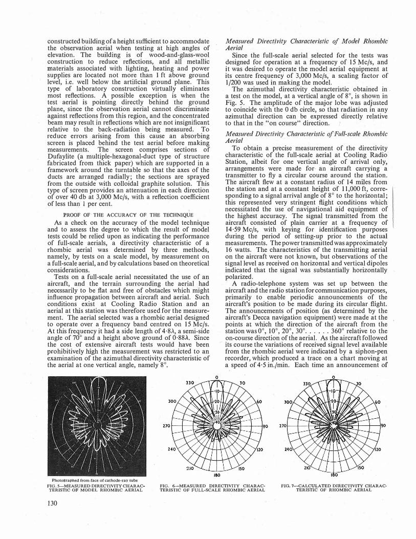
constructed building of a height sufficient to accommodate the observation aerial when testing at high angles of elevation. The building is of wood-and-glass-wool construction to reduce reflections, and all metallic materials associated with lighting, heating and power supplies are located not more than 1 ft above ground level, i.e. well below the artificial ground plane. This type of laboratory construction virtually eliminates most reflections. A possible exception is when the test aerial is pointing directly behind the ground plane, since the observation aerial cannot discriminate against reflections from this region, and the concentrated beam may result in reflections which are not insignificant relative to the back-radiation being measured. To reduce errors arising from this cause an absorbing screen is placed behind the test aerial before making measurements. The screen comprises · sections of Dufaylite (a multiple-hexagonal-duct type of structure fabricated from thick paper) which are supported in a framework around the turntable so that the axes of the ducts are arranged radially; the sections are sprayed from the outside with colloidal graphite solution. This type of screen provides an attenuation in each direction of over 40 db at 3,000 Mc/s, with a reflection coefficient of less than 1 per cent.
PROOF OF THE ACCURACY OF THE TECHNIQUE
As a check on the accuracy of the model technique and to assess the degree to which the result of model tests could be relied upon as indicating the performance of full-scale aerials, a directivity characteristic of a rhombic aerial was determined by three methods, namely, by tests on a scale model, by measurement on a full-scale aerial, and by calculations based on theoretical considerations.
Tests on a full-scale aerial necessitated the use of an aircraft, and the terrain surrounding the aerial had necessarily to be fiat and free of obstacles which might influence propagation between aircraft and aerial. Such conditions exist at Cooling Radio Station and an aerial at this station was therefore used for the measurement. The aerial selected was a rhombic aerial designed to operate over a frequency band centred on 15 Mc/s. At .this frequency it had a side length of 4·8,\, a semi-side angle of 70° and a height above ground of 0·88/i. Since the cost of extensive aircraft tests would have been prohibitively high the measurement was restricted to an examination of the azimuthal directivity characteristic of the aerial at one vertical angle, namely 8°.
0
ISO
Measured Directivity Characteristic of Model Rhombic Aerial
Since the full-scale aerial selected for the tests was designed for operation at a frequency of 15 Mc/s, and it was desired to operate the model aerial equipment at its centre frequency of 3,000 Mc/s, a scaling factor of 1 /200 was used in making the model.
The azimuthal directivity characteristic obtained in a test on the model, at a vertical angle of 8°, is shown in Fig. 5. The amplitude of the major lobe was adjusted to coincide with the 0 db circle, so that radiation in any azimuthal direction can be expressed directly relative to that in the "on course" direction.
Measured Directivity Characteristic of'Full-scale Rhombic Aerial
To obtain a precise measurement of the directivity characteristic of the full-scale aerial at Cooling Radio Station, albeit for one vertical angle of arrival only, arrangements were made for an aircraft carrying a transmitter to fly a circular course around the station. The aircraft flew at a constant radius of 14 miles from the station and at a constant height of 11,000 ft, corresponding to a signal arrival angle of 8° to the horizontal; this represented very stringent flight conditions which necessitated the use of navigational aid equipment of the highest accuracy. The signal transmitted from the aircraft consisted of plain carrier at a frequency of 14·59 Mc/s, with keying for identification purposes during the period of setting-up prior to the actual measurements. The power transmitted was approximately 16 watts. The characteristics of the transmitting aerial on the aircraft were not known, but observations of the signal level as received on horizontal and vertical dipoles indicated that the signal was substantially horizontally polarized.
A radio-telephone system was set up between the aircraft and the radio station for communication purposes, primarily to enable periodic announcements of the aircraft's position to be made during its circular flight. The announcements of position (as determined by the aircraft's Decca navigation equipment) were made at the points at which the direction of the aircraft from the station was 0°, 10°, 20°, 30° ... ... 360° relative to the on-course direction of the aerial. As the aircraft followed its course the variations of received signal level available from the rhombic aerial were indicated by a siphon-pen recorder, which produced a trace on a chart moving at a speed of 4·5 in./min. Each time an announcement of
Photographed from face of cathode-ray tube
FIG. 5-MEASURED DIRECTIVITY CHARACTERISTIC OF MODEL RHOMBlC AERIAL
FIG. &-MEASURED DIRECTIVITY CHARAC
TERISTIC OF FULL-SCALE RHOMBIC AERIAL
FIG. ?-CALCULATED DIRECTIVITY CHARAC· TERISTIC OF RHOMBIC AERIAL
130
the aircraft's position was received a mark was made on the chart.
The recorder was operated from the a.g.c. voltage of a receiver connected to the rhombic aerial, since a.g.c. voltage is an indication of receiver input level. A calibration of the recorder chart readings in terms of receiver input level was made using a standard signal generator. The signal levels, expressed relative to the signal level measured in the on-course direction, were then plotted against azimuthal angle as determined from the position of the aircraft, thus providing a complete directivity characteristic as measured at a vertical angle of 8°. This diagram is shown in Fig. 6, and may be compared directly with that obtained from the model, given in Fig. 5. It can be seen that good agreement
* MORRIS, D. w., SHADDICK, w. G., and THURLOW, E. w. Short-Wave Directional Aerial-Systems. P.O.E.E.J.,Vol. 47, p. 212, and Vol. 48, p. 29, Jan. and Apr. 1955.
exists between the results obtained by the two methods, extending to. the finer detail with some precision.
Calculated Directivity Characteristic of Rhombic Aerial The calculation of the corresponding theoretical direc
tivity characteristic of the rhombic aerial has been carried out by the method described in an article published in an earlier issue of this Journal.* A simplifying assumption of a uniform current distribution along the wires has been adopted. This assumption only approximates to the practical conditions existing in the aerial, and it was thought that a comparison of the directivity characteristic thus obtained with that derived from the fullscale tests would give a useful indication· of the significance of the resulting errors. The calculated directivity characteristic is shown in Fig. 7. It will be seen to agree fairly well with the full-scale characteristic, but in some _
respects not as closely as does the characteristic obtained from the model.
(To be continued)
Book Review "Telecommunication Economics." T. J. Morgan.
Macdonald & Co., Ltd. 450 pp. 112 ill. 50s. The importance of this book is recognized in a foreword
by the Engineer-in-Chief, and students and planning engineers particularly will no doubt agree with him that one of the few gaps in their bookshelves has now been very ably filled.
The earlier chapters give a detailed exposition of the fundamentals of economics, including the nature and use of c.apital, interest
.and depreciation, and postulate the assump
tion, some may say fallacy, on which all such theory must rest, namely, that capital is always available. Mr. Morgan shows why, when funds are short, such studies are still necessary to establish which of certain uneconomical alternatives should be adopted, but others will claim a more ready familiarity with what is often Robson's choice!
Interest rates for cost comparisons must be carefully chosen in these modern times when the rate is likely to fluctuate to a far greater extent than in the pre-war era. This is well illustrated graphically in a study on p. 182 which sho.ws the effect of varying rates on the economic planning penods for underground cables, and in view of this the author should perhaps have explained the reason for his apparent preference for a rate of 5 per cent.
Several chapters are devoted to the various methods employed in studies, together with the mathematics and formulae concerned, and follow on with well-written accounts of the preliminaries to design and the use of eco
.non;iics in the telecommunications field. This stage,
which mcludes the sales and traffic forecasting of requirements, inevitably brings the first deviations from pure mathematics into the story and prepares the way for a very full account of the use of economics in all our own planning activities, including local and main lines, replacement studies, multi-office area layouts, and buildings.
The cynics will note that the principles of replacement studies are introduced on p. 231 with the well-known example, which exposes the fallacy mentioned earlier proving it can be more economical to replace an old car by giving it away and buying a new one! This serves to emphasise that economics are subservient not only to credit
but also to policy for, in the words of Professor Shackle, ... "human decisions are the stuff of economics" . . . These influences make certain of the theories of academic value only, but such comment may truly be made of much of our education and does not detract from the results of Mr. Morgan's industry.
As may be expected in a work of this magnitude, certain of the opinions expressed will find dissentients and some of the issues have been over-simplified and dealt with too briefly. An important example of this concerns the apparent conclusion, on pp. 228, 229, that shared service has not been proved on economic grounds. Many engineers will agree with this, particularly in the design of new cabling schemes, but that view again ignores the underlying and governing factor of insufficiency of capital, and the value of satisfying over half a million customers while making possible the deferment of main and branch cables. The recent developments in the use of line connector and line-finder equipment which have occurred since this book was written extend the policy of reducing the cost of the telephone service by making more shared use of our plant and should have greater appeal to both the economist and the engineer.
Among the many other intriguing themes will be found the theory, which has been advanced during recent years without so far finding favour, that the growth of subscribers' lines in a national telephone system tends to follow, for a long period, an exponential law. The writer has found this most useful in comparing telephone progress in different countries and as a comparison with sales forecasts in the larger exchange areas, but the limitations of the formula must be realized. The real difficulties and errors in forecasting lie not in the sum total for the individual exchanges, but in the distribution of the growth within the exchange area, and most of us know to our cost that there are no laws which govern the behaviour of the separate parts of the network! The development and use in the most economic way of costly public utility networks were never more needed than now; in this book will be found most of the tools required, and although experience will sometimes provide the answer without the mathematics, the wise man must always be ready to prove his conclusions. He can now be much better equipped as a result of Mr. Morgan's work. and at what, in these days, is an economic price. N. c. de L
1311

A Differential Gain Monitoring Panel for Testing Submerged Telephone Repeaters
H. J. GROVES, B.Sc.(Eng.), A.M.I.E.E., and s. A. TAYLOR, B.Sc.(Tech.)t U.D.C. 621.317.341: 621.395.64: 621.315.28
A method of monitoring the transmission gain of submerged telephone repeaters and repeater systems is described. The levels of a test signal are measured at the input and output of the repeater system and compared using a bridge circuit. Any difference between the two levels is recorded by a recording decibelmeter connected in one arm of the bridge. Reference is made in the article to the use of the method for testing individual repeaters, and its application to the testing of the Newfoundland-Nova Scotia section of the
transatlantic telephone cable is described.
INTRODUCTION
T
HE stability of transmission gain of early British submerged repeaters was tested by recording on charts, over a period of time, the input and output
transmission levels of the repeaters, any changes in gain being shown by discrepancies between the charts. This method was not satisfactory for the following reasons:
(a) Germanium-rectifier bridges with similar electrical characteristics had to be provided for the two recording decibelmeters (recorders) since the frequency range to be measured extended beyond the frequency range for which the recorders were designed.
(b) The charts had to be removed from the recorders daily when comparing them, as one had to be superimposed on the other to check whether any changes
tExecutive Engineers, Post Office Research Station.
RECORDER i!ili--: A I --� ' t
I
.L ... .0 : ";' 1
I I
in output level had been caused by a change in input level.
(c) It was difficult to obtain recorders having exactly the same sensitivities to sudden changes in level and therefore accurate comparison between charts was difficult.
(d) If the input-level recorder failed it meant that no comparison could be made with the output-level recorder and therefore monitoring time was wasted.
(e) Accuracies of approximately ±0·25 db could be attained by this method but it was desired to improve this to ±0·1 db.
THE DIFFERENTIAL GAIN MONITORING PANEL
Fig. 1 is a block schematic diagram of a method which compares input and output levels of a system on a single
RECORDING OECIBELMETER
A DIFFERENTIAL GAIN B MONITORING PANEL
INPUT OUTPUT
FIG. !-COMPARISON OF INPUT AND OUTPUT LEVELS IN A ZERO-GAIN TRANSMISSION SYSTEM
H.T. o----�·(+11ov.)
L----1-----I------- '
132
L----- ------------- -- ---- ....
Note. Built-in resistors for checking performance of monitoring·panel
FIG. 2-CIRCUIT OF DIFFERENTIAL GAIN MONITORING PANEL

recording decibelmeter. If the loss in the attenuator equals the gain of the amplifier or repeater, the signal levels at A and B are equal and no current flows in the recorder. If the amplifier or repeater gain changes, the level at B changes causing a current to flow in the record�r.
The circuit employed is shown in Fig. 2. Basically it is a pair of level measuring sets adapted to feed a bridge with a recording decibelmeter connected in one arm. The reactance of this recorder (0·18 henry at 1,000 c/s) would cause the bridge to be seriously unbalanced to the alternating components of rectification, and could result in the output of the diode rectifiers of one half of the panel being coupled to the feedback path of the other half of the panel. To prevent this, the feed to the bridge is through four chokes.
The recording meter used is a moving coil instrument of approximately 400 ohms d.c. resistance and a full� scale deflexion of 1 mA (Post Office Decibelmeter No. 14A/CTA1). The movement is mecha.nically adjusted to mid-scale with no current flowing in the recorder, in order that increases and decreases of gain may be measured when the recorder is working in the. bridge.
A signal level of 0·775 volts r.m.s. at one input of the monitoring panel with the other input disconnected would give a direct current of 2·3 mA through the recorder. A change of 1 db from, for example, 0 to ± 1 db relative to 0·775 volts, at either input will give a change in current of ±0·26 mA or approximately one-quarter of the fullscale deflexion of 4 in. Thus 1 in. on the chart corresponds to 1 db. The signal input to either half of the panel should not exceed about l · 1 volts ( +3 db relative to 0·775 volt) or overloading will result.
The recorder when working must be run.with the movement slightly away from its mechanical zero position so that in the event of a fault developing in - the test equipment, e.g. power failure, the recorder restores to its mechanical zero, thus indicating a fault condition. This is accomplished by means of adjustment to one of the feedback resistors. The difficulty is, however, to produce a deflexion sufficiently large to be useful and substantially unaffected by changes in the oscillator
140
�120 -< :i.
�100
1-:z ... � 80 ::> 0
"" 60 ... 0 "'
0
� 40 "'
20
_l,.../
_i..--
> v
l./v /
/
./ �--_....,.....
/
i.--�-A
0 -4 -J -2 -I 0 +I +2 +J +4
INPUT LEVELS (db RELATIVE TO 0·775 VOLTS)
Initial unbalance current i_n the recorder:
A-None; B-2011A; C-50µA; D-JOOµA
FIG. 3-EFFECT OF INITIAL UNBALANCE ON RECORDER CURRENT
FIG. 4-DIFFERENTIAL GAIN MONITORING PANEL
output of, say, ±3 db when the monitor panel is working at maximum sensitivity, i.e. 0·775-volt input. Fig. 3 shows the effect on the bridge current through the recorder of simultaneou,s variations.of both input voltages for different initial unbalance currents in the bridge. It can be seen from Curve A that no change in current will occur if the two halves of the panel are exactly balanced, i.e. no current flows in the recorder for equal input voltages to both halves. However, as soon as the gain of one half is varied by changing its feedback the out-of-. balance current changes when the applied voltages change. Fig. 3, Curve B, shows that a permanent deflexion of approximately 20µA (approximately equal to l6 in. on the scale) might be used without introducing serious errors due to changes in oscillator level. /
. With the panel set as recommended the balance of the two halves is unaffected by variations of ±20 per cent
·in the h. t. and l.t. power supplies. As the panels were developed for use in submerged
repeater testing it was necessary to place exacting conditions on the manufacture of the monitoring panels to ensure a very high degree of reliability. Fig. 4 shows a photograph of the complete unit.
Operation of Monitoring Panel . The equipment is adjusted by applying a 0·775-volt signal at the te�t frequency to each half of the panel in turn and adjusting the appropriate wire-wound feedback resistors to give a current of 2·3 mA in an external lowresistance meter. Tags A, B and C (Fig. 2) are provided for the connexions of the meter, together with an internal 400-ohm resistor. The apparatus under tes.t must be arranged as a zero-gain system, as already . stated, and the panel connected across the input and output of the system. The recorder deflexion is then adjusted to read ·approximately is in. off-centre by slightly unbalancing the feedback control resistors.
The performance of the monitor panel may be checked periodically by using the built-in resistors provided for this purpose (Fig. 2), which give a 1 db change to either input. This check should indicate faults present in either half of the panel.
Use of Monitoring Panel in Confidence Trials.on Repeaters Submerged repeaters are subjected to various exhaus
tive tests before they are accepted for service and, in particular, because gain stability is of paramount importance, repeaters are arranged as a zero-gain system
133

R-Recording decibelmeter D-Differential gain monitoring panel P-Power-separatin& filter
FIG. 5-CIRCUIT USED FOR CONFIDENCE TRIALS ON REPEATERS
and monitored for 3 months using differential gain monitoring panels. A schematic diagram of such a monitoring circuit is shown in Fig. 5. In this application, with the aid of directional filters, gain monitoring is carried out at suitable frequencies in both directions simultaneously. The monitoring panels are duplicated to provide an extra check on the repeater and a check on each other. Recording decibelmeters are also included to check the output levels from the oscillators, the mains voltage and line current to the repeater. Such an arrangement was used to make a life test lasting for over one year of a production repeater as used in the Aberdeen-Bergen submerged repeater scheme. A similar arrangement was used in the factory testing of individual repeaters for the British section of the transatlantic telephone cable. The results were very satisfactory and it was apparent that with modifications this scheme could be applied to testing complete systems.
TESTING THE NEWFOUNDLAND-NOVA SCOTIA SECTION
OF THE TRANSATLANTIC TELEPHONE CABLE SYSTEM
The normal method of monitoring the performance of a cable that includes a number of repeaters is to record the levels of a test signal at the sending and receiving stations. This method suffers from all of the disadvantages discussed for single-repeater monitoring. Further, as the testing stations are separated the charts cannot be compared at once.
For a single-cable submerged-repeater system using different frequency bands for the two directions of transmission, it is possible to monitor the gain from one station if a frequency-changing device is connected at the distant station to transpose a signal from the send band to the receive band. A normal system contains one more section of cable than the number of submerged repeaters and an extra repeater or similar amplifier will be required at the distant station to obtain satisfactory levels. If a similar frequency changer is connected through directional filters at the local station a signal will be generated which can be compared with the signal returned from the system; changes in gain of
134
the system being indicated by a difference between the two signals. This method will allow a differential monitoring panel to be used and thus the system can be monitored with greater accuracy and reliability.
The method described was used in carrying out a confidence run of the British section of the transatlantic telephone cable between Newfoundland and Nova Scotia.2 The land section across Newfoundland,3 from Clarenville to Terrenceville, of approximately 63 statute miles, containing two repeaters, was to be installed first and then monitored until the sea section \Vas laid some five months later. This posed some special problems, for the land section terminated in a cable hut at Terrenceville where power supplies were not available. Thus it was necessary to use Clarenville as the controlling station, transmitting in the h.f. band and receiving in the l.f. band, and to operate the frequency-changing equipment at Terrenceville from the line current used for energizing the repeaters. It was required that gain changes of the order of O· l db should be observable and also that the received system noise should be monitored.
Equip1nent at Terrenceville
The equipment at Terrenceville was required to work completely unattended and, if possible, to be as reliable as the submerged repeaters. For these reasons the basis of the equipment was an extra transatlantic telephone cable type of repeater; this compensated for the attenuation of the final section of cable and ensured reasonable levels for operation of the frequency changer. A siliconcarbide disk was used as the frequency changer as this is a reliable component and could be connected to the "A" (h.f. band output) end of the repeater without any additional components or filters in the transmission path, as would be required for most other types of. frequency changer. The silicon-carbide disk has a temperature coefficient of 0·02 dbf°C, and as the hut was unheated a thermostatically-controlled oven heated by the line current was provided. The repeater circuit was modified to that shown in Fig. 6. The normal supervisory equipment was removed to provide space for mounting the extra equipment. The silicon-carbide disk was sealed in a glass envelope and enclosed in a thermally-insulated oven together with the thermostat and two banks of 50-volt lamps (Post Office Lamps No. 2, 50 volts) acting as heating elements. Each bank of lamps was protected by a short-circuiting fuse of the type used in the repeaters in the transatlantic telephone cable.'
To increase the signal level at the silicon-carbide disk the h.f. equalizer was removed from the repeater and connected in the transmit path at Clarenville. As it was desired to monitor the system noise in the TerrencevilleClarenville direction over the band 104 kc/s to 108 kc/s, a high-pass filter with a cut-off frequency of 196 kc/s was connected in the "B" (l.f. band output) end to suppress the noise of the testing repeater. A dummy load connected to the testing repeater allowed the two normal system repeaters to be operated at a high voltage similar to that which would be obtained when the sea section was connected.
Equipment at Clarenvil!e
It was desirable that no fault on the monitoring equipment should give a false indication of a change on the system. The duplication of units to achieve this result would have led to a very complex arrangement and as a compromise only the amplifiers and differential

A EMO (TD DUHHY
LOAD) 1-----1 �
8 EMO (TO SYSTEM)
FIG. 6-BLOCK SCHEMATIC DIAGRAM OF TESTING REPEATER AT TERRENCEVILLE
monitoring panels in the gain-comparison paths were duplicated. A block schematic diagram of the arrangement used is shown in Fig. 7 .
Test signals of 380 kc/s and 530 kc/s were obtained from crystal oscillators, combined in a bridge network, and fed to the high-pass directional filters of the comparison path and, through a series of pads and equalizers, to the high-pass filter of the system path. The 230 kc/s (2A-B) product produced by the silicon-carbide disk in the comparison path passes through the low-pass directional filter and a high-pass filter to restrict the band-width, and is amplified and applied to one input of the differential monitoring panel.
The test signals are also transmitted over the system and produce the 230 kc/s product at the "B" end of the test repeater, at Terrenceville, and this signal returns and is amplified and applied to the other input to the differential monitoring panel. The pads and equalizers in the transmit path enable the levels at the system frequency changer at Terrenceville to be made equal to those on the comparison path at Clarenville. On the receive side the lowpass directional filters are followed by high-pass filters to
312kc/s 260 kc/s 208 kc:/s
CABLE
NOISE RECEIVE LEVEL LEVEL
(1'0ko/>) R-Recording decibelmeter D-Differential gain monitoring panel
restrict the band-width. These reduce other intermodulation products or noise from the system to an in .. significant level at the input to the differential monitoring panel and thus prevent any unbalance condition on the comparison circuit, which \Vould appear as an apparent gain variation.
As a further check on the satisfactory operation of the system it was required to 11101lltor the noise received in the !.f. band at Clarenville. To obtain a true noise reading it was necessary to choose a band free from intermodulation products. The band used was 104 kc/s to 108 kc/s, and as already mentioned the noise of the test repeater was suppressed over this band. The noise monitoring circuit is shown in Fig. 7.
When driven by a differential monitoring panel the recorder used covers a range of approximately ±2 db, and for larger differences between input levels, contacts on the recorder are arranged to switch off the h.t. supply in order to protect the recorder movement against overload. (See Fig. 2 .) A separate recorder was used to monitor directly the received 230 kc/s and as the 380 kc/s and 530 kc/s oscillator output levels were also recorded a check was maintained on the system even when the differential gain monitoring panels were switched off.
As an aid to determining the cause of any change observed on the system the mains voltage and frequency and the direct current supplied to the cable were also monitored.
With the exception of the power-supply recorders the equipment was mounted on two 5 -ft portable racks.
Operation By connecting a silicon-carbide disk at the junction
of the system filters the equipment can be adjusted and checked for satisfactory operation before connexion is made to the system. The differential gain monitoring panels are adjusted in the normal way, as already
described, with a 230 kc/s input level of0·775 volts. Each oscillator output is adjusted to give a level of + 10 db relative to l mW on the frequency changer in the comparison path and pads in the system send path are adjusted to give the same level on the test frequency changer at the distant end. With this condition shunt resistol's at the inputs to the differential monitoring panels are adjusted to give input levels of 0·775 volts.
CONCLUSION
FIG. 7-BLOCK SCHEMATIC DIAGRAM OF MONITORfNG EQUIPMENT AT CLARENVILLE
The equipment was brought into use at Clarenville in December 1955 and operated satisfactorily under the supervision of the local staff for four months. During this period the system was energized by temporary power units which could not maintain the line current to the required ±I per cent when the heating circuit for the oven at Terrenceville switched on. Consequently, the oven was disconnected and the resulting temperature differences between the two silicon-carbide disks caused some variations in the gain monitoring
135

circuit, but these were small compared with the change in attenuation of the cable with temperature. The area in which the cable is laid is particularly subject to magnetic storms, often severe enough to induce some 200 volts in the cable, and during these storms a marked increase in system noise was recorded. When the sea section, between Terrenceville and Sydney Mines, Nova Scotia, was installed in May 1956 the test repeater was moved to Sydney Mines to enable. the complete system to be monitored.
ACKNOWLEDGEMENT
Acknowledgements are due to Mr. M. S. E. Gregory, now with the Ministry of Supply, from whose unpublished memoranda the authors have drawn freely for this article.
Book Reviews
''Fundamentals of Electron Devices.'' K. R. Spangenberg. McGraw-Hill Publishing Co., Ltd. xii + 505 pp. 393 ill. 75s.
When Professor Spangenberg writes a book-and dedicates it to that very well-known author, F. E. Termanwe may expect something worth attention. His first book in the McGraw-Hill series on Electrical and Electronic Engineering, "Vacuum Tubes," established him as a writer of authority, clarity and purpose. His second, "Funda· menta]s of Electron Devices," is an attempt at a unified treatment of thermionic valves and transistors by way of the common features of their internal physical mechanisms and their basic circuit applications. Jt is clear from his preface that the author thinks that engineers need to know something of the physics of transistors if they are to make best use of what otherwise might seen1 "a somewhat mysterious device."
The opening chapters deal with electrons and ions and their motion in electric and magnetic fields. A chapter on the atom prepares the way for one largely devoted to semiconductors-stressing their basic structure and the mobility and diffusion of charge carriers in the1n. Junctions next receive attention; included is the metal-vacuum boundary, across which takes place the long-familiar thermionic emission, the subject of the next chapter. The emphasis then turns, still descriptively, to three groups of components: vacuum and semiconductor diodes, thermionic valves with control grids, and transistors. The 30 pages devoted to the second group is a masterly condensation of the main features and properties, while the treatment of the other two groups is adequate. So far, however, the similarities between vacuum and solid devices have not dominated the book.
Equivalent circuits are developed from the general equation for quadripoles and the properties of the devices. But is a general approach desirable for valves, \Vhere the coupling between output and input is rarely important and the input impedance rarely demands a second thought? A lengthy and important chapter on small-signal amplifiers follows; it is all sound, even if inevitably conventional, but the emitter follower should be more highly rated in the table (Fig. 13.5) showing the possible ways of connecting the transistor. The author is clearly on better grounds for his parallel treatment in the next two chapters on oscillators and non-linearity in small-signal applications. Large-signal applications are only briefly dealt with; class-B operation is certainly popular with designers of output stages using transistors but class C remains confined to valve. circuits. Multivibrator circuits have much in common whether using valves or transistors. Chapters on photoelectric components and on noise conclude the book-except for 13 short appendices, 16 pages of problems and a bibliography.
This is an informative and well-balanced book, rarely ambiguous and adequately illustrated. But it must be doubted whether the author justifies his approach; the
136
References
1 PARSONS, A. P., and D1ncocK, F. E. Recording Decibelmeters. P.O.E.E.J., Vol. 51, p. 145, July 1958.
2 The Transatlantic Telephone Cable. P.O.E.E.J., Vol. 49, Part 4, Jan. 1957.
3 ROBINSON, H. E., and ASH, B. Transatlantic Telephone Cable--The Overland Cable in Newfoundland. P.O.E.E.J., Vol. 49, pp. 1 and 110, Apr. and July 1956.
.i. BROCKBANK, R. A., WALKER, D. c., and WELSBY, v. G. Repeater Design for the Newfoundland-Nova Scotia Link. P.O.E.E.J., Vol. 49, p. 389, Jan. 1957.
older generation of electronic engineers may consider the transistor and its circuits in the light of the thermionic valve and its circuits; but how far ought the new generation to ·
try to use a common approach to the two? Newcomers to the subject of transistors should certainly read the book, two or three times, and keep it by them; even if they are not converted to the author's views of the necessity for stressing the similarities of the valve and the transistor, they will have made as good a start as they can to taking the mystery out of the transistor. I.P.O.E.E. Library No. 2495. J. R. T.
"Basic Automatic Control Theory." G. J. Murphy, Ph.D. D. Van Nostrand Company. ix + 557 pp., over 400 ill. 67s. 6d.
The theory of automatic control systems, such as are used in industrial processes, fire-control systems and navigational systems, has been subject to intensive development over the past decade or so, and new developments are still being made. The foundations of the subject are now dealt with in educational establishments, and this particular volume has evolved from a post-graduate course at the University of Minnesota, where Dr. Murphy is Assistant Professor of Electrical Engineering, although he has had industrial experience of control systems. This "basic theory" starts pretty well from scratch; it stops short of non-linear systems, noisy inputs, and sampled-data systems, nor does it deal with time series and z-transforms, which, essential in sampled-data systems, are also useful in approximate analysis of continuous systems.
The heart of the book is a very thorough, logical, chiefly mathematical, treatment of the analysis and synthesis of linear systems in general and feedback systems in particular.
There are general chapters on the Laplace transformation and on transfer functions: the latter includes a section on signal-flow graphs, a useful concept recently introduced to the communication field by Mason. The general perH formance of systems, in particular their stability, is then considered both from the time-response and frequencyresponse point of view .. All this is, of course, basically familiar to telecommunication engineers, but there is much that is unfamiliar. Son1e of this is merely different jargon; but the job that the systems have to do, and the components that are used, lead to essential differences.
This treatment is backed up by general introductory chapters; a description of the various electric, magnetic, mechanical, hydraulic, and pneumatic elements that enter into control systems, with suitable linear approximations for their behaviour; an introduction to analogue co1nputers; solution of polynomial equations; elementary con1plex variable theory; and a table of Laplace transforms. Each chapter concludes with exan1ples fo r the s tudent
This is an excellent introduction to control theory. Particularly good is the way in which the author attains a high mathematical standard while keeping at least one foot firmly on practical ground. W. E.T.
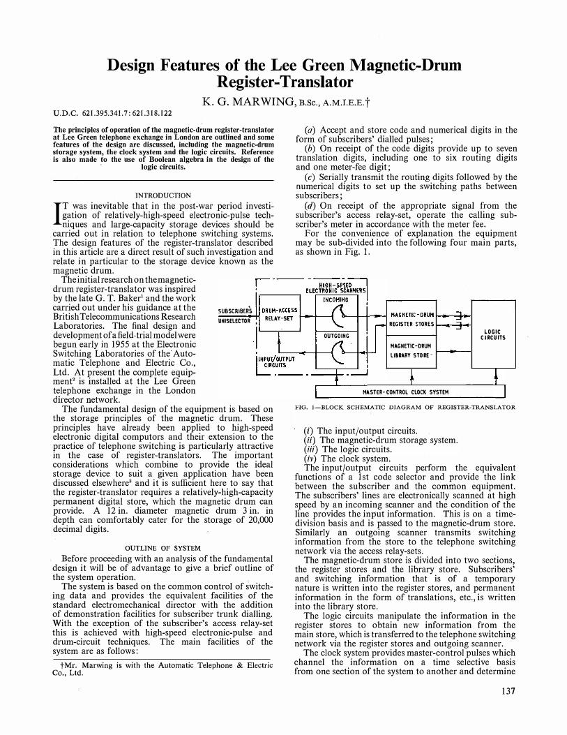
Design Features of the Lee Green Magnetic-Drum Register-Translator
K. G. MAR WING, B.Sc., A.M.I.E.E.t U.D.C. 621.395.341.7: 621.318.122
The principles of operation of the magnetic-drum register-translator at Lee Green telephone exchange in London are outlined and some features of the design are discussed, including the magnetic-drum storage system, the clock system and the logic circuits. Reference is also made to the use of Boolean algebra in the design of the ·
logic circuits.
INTRODUCTION
IT was inevitable that in the post-war period investigation of relatively-high-speed electronic-pulse techniques and large-capacity storage devices should be
carried out in relation to telephone switching systems. The design features of the register-translator desclibed in this article are a direct result of such investigation and relate in particular to the storage device known as the magnetic drum.
The initial research on the magneticdrum register-translator was inspired by the late G. T. Baker1 and the work carried out under his guidance at the British Telecommunications Research Laboratories. The final design and development of a field-trial model were begun early in 1955 at the Electronic Switching Laboratories of the Automatic Telephone and Electric Co., Ltd. At present the complete equipment2 is installed at the Lee Green telephone exchange in the London director network.
SUBSCRIBERS UHISELECTOR ,
I RELAY-SET
The fundamental design of the equipment is based on the storage principles of the magnetic drum. These principles have already been applied to high-speed electronic digital computors and their extension to the practice of telephone switching is particularly attractive in the case of register-translators. The important considerations which combine to provide the ideal storage device to suit a given application have been discussed elsewhere3 and it is sufficient here to say that the register-translator requires a relatively-high-capacity permanent digital store, which the magnetic drum can provide. A 12 in. diameter magnetic drum 3 in. in depth can comfortably cater for the storage of 20,000 decimal digits.
OUTLINE OF SYSTEM
Before proceeding with an analysis of the fundamental design it will be of advantage to give a brief outline of the system operation.
The system is based on the common control of switching data and provides the equivalent facilities of the standard electromechanical director with the addition of demonstration facilities for subscriber trunk dialling. With the exception of the subscriber's access relay-set this is achieved with high-speed electronic-pulse and drum-circuit techniques. The main facilities of the system are as follows:
tMr. Marwing is with the Automatic Telephone & Electric Co., Ltd.
(a) Accept and store code and numerical digits in the form of subscribers' dialled pulses;
(b) On receipt of the code digits provide up to seven translation digits, including one to six routing digits and one meter-fee digit;
( c) Serially transmit the routing digits followed by the numerical digits to set up the switching paths between subscribers;
(d) On receipt of the appropriate signal from the subscriber's access relay-set, operate the calling subscriber's meter in accordance with the meter fee.
For the convenience of explanation the equipment may be sub-divided into the following four main parts, as shown in Fig. 1.
<>--+--+-__ _, MAGNETIC-ORUM �-..._,� REGISTER STORES 1---_...�
OUTGOIHG
MAGNETIC· ORUM
LllRARY STORE - I-_., _ _,
MA STER-CONTROL CLOCK SYSTEM
LOGIC CIRCUITS
FIG. !-BLOCK SCHEMATIC DIAGRAM OF REGISTER-TRANSLATOR
(i) The input/output circuits. (ii) The magnetic-drum storage system. (iii) The logic circuits. (iv) The clock system. The input/output circuits perform the equivalent
functions of a I st code selector and provide the link between the subscriber and the comn'l.on equipment. The subscribers' lines are electronically scanned at high speed by an incoming scanner and the condition of the line provides the input information. This is on a timedivision basis and is passed to the magnetic-drum store. Similarly an outgoing scanner transmits switching information from the store to the telephone switching network via the access relay-sets. .
The magnetic-drum store is divided into two sections, the register stores and the library store. Subscribers' and switching information that is of a temporary nature is written into the register stores, and permanent information in the form of translations, etc., is written into the library store.
The logic circuits manipulate the information in the register stores to obtain new information from the main store, which is transferred to the telephone switching network via the register stores and outgoing scanner.
The clock system provides master-control pulses which channel the information on a time selective basis from one section of the system to another and determine
137

the precise operation of any switch within the equipment. The pulses also provide a convenient means of subdividing the periphery of the magnetic drum into timing periods.
THE MAGNETIC DRUM
A photograph of the magnetic drum and magnetic-head assembly is shown in Fig. 2. Essentially it consists
use but the process has no detrimental effect on the magnetic state of the cell and may - be repeated indefinitely.
The centre-to-centre spacing between adjacent tracks is 0·05 in., the distance being chosen to eliminate interference between tracks. However, due to the physical dimensions of the magnetic-head mounts this spacing prevents the magnetic heads of adjacent tracks
being assembled on the same mounting block. The problem is solved by maintaining a constant distance between heads on the same block and varying the height of the block base. In this way provision is made for 30 individual recording tracks on the nickel surface.
THE MAGNETIC-DRUM STORAGE SYSTEM
The representation of numerical or · control information on the magnetic
drum is by means of the binary coee. The code is based on the radix 2 and digits are represented by 0 or 1. Thus only two predetermined conditions are required to represent any digit in the code. A unit magnetic cell on the drum surface is considered to have two magnetic states since the leading half of the cell relative to the magnetic head may have positive or negative magnetic polarity. The relation between the binary code and the unit magnetic cell is fixed by choosing a leading positive polarity
FIG. 2-MAGNETIC DRUM AND MAGNETIC-HEAD ASSEMBLY to represent a 1 and a leading negative polarity for 0. This binary representation of store data is consistent
of a 12 in. diameter non-magnetic cylinder coated on the outer peripheral surface with a ferromagnetic material, which forms a recording medium. The material in this instance is electro-deposited nickel 0·0002 in. thick. The cylinder or drum rotates at a high peripheral velocity with the nickel surface in close proximity to sets of magnetic recording heads. The space between the magnetic heads and drum prevents damage to the nickel surface and is nominally 0·001 in. The magnetic heads are usually termed "read" �nd "write" heads.
The application of signals tb the magnetic recording surface3'4 is accomplished by passing a pulse of current through the winding of the magnetic core of the write head. The core has a gap 0·001 in. wide adjacent to the drum surface. The energized core produces a magnetic flux across the gap which magnetizes a minute area of the magnetic surface appearing under the gap at that instant. These elemental areas are called unit magnetic cells or dots and a series of such cells appearing under the gap during one complete revolution of the drum traces out a magnetic track. The reproduction of the signals from the magnetic tracks is practically the reverse process. A read head positioned in the same horizontal plane as the original write head detects the condition of the magnetic cells on the magnetic track. Thus as successive cells pass under the gap of the read head the localized magnetic field induces a characteristic signal voltage across the core winding of the read head. These signals require amplification and detection before
138
with the. representation of all information throughout the equipment.
1
The practical method of binary digital recording on the magnetic drum is by means of the "phase modulation" system4 developed at the Manchester University Computing Laboratories. The intrinsic magnetic pattern associated with this form of recording enables the digits to be densely packed with precise indication of the state of the magnetic cells. In the equipment being described 100 binary-digit cells or dots are recorded per linear inch of the magnetic track at a frequency of 100 kc/s. To simplify the description of the circuit techniques involved in the phase modulation system, a specific storage condition, characteristic of the magneticdrum 'register-translator, will be explained.
·
The storage of any single decimal digit on the magnetic drum is contained in four binary-digit cells, and each digit stored in this manner is allocated two binarydigit control cells, the "incoming busy" dot and the "outgoing busy" dot. These six storage cells define a "word" store on a magnetic track. As an arbitrary choice assume that it is required to store the decimal digit 9 and to mark or "write l" in the incoming busy control dot.
The voltage, current and magnetic waveforms required by the phase modulation system are illu.strated in Fig. 3
and a schematic diagram of the regenerative-loop circuit particular to this type of storage is given in Fig. 4. The waveforms are drawn on a zero-displacement time-scale,
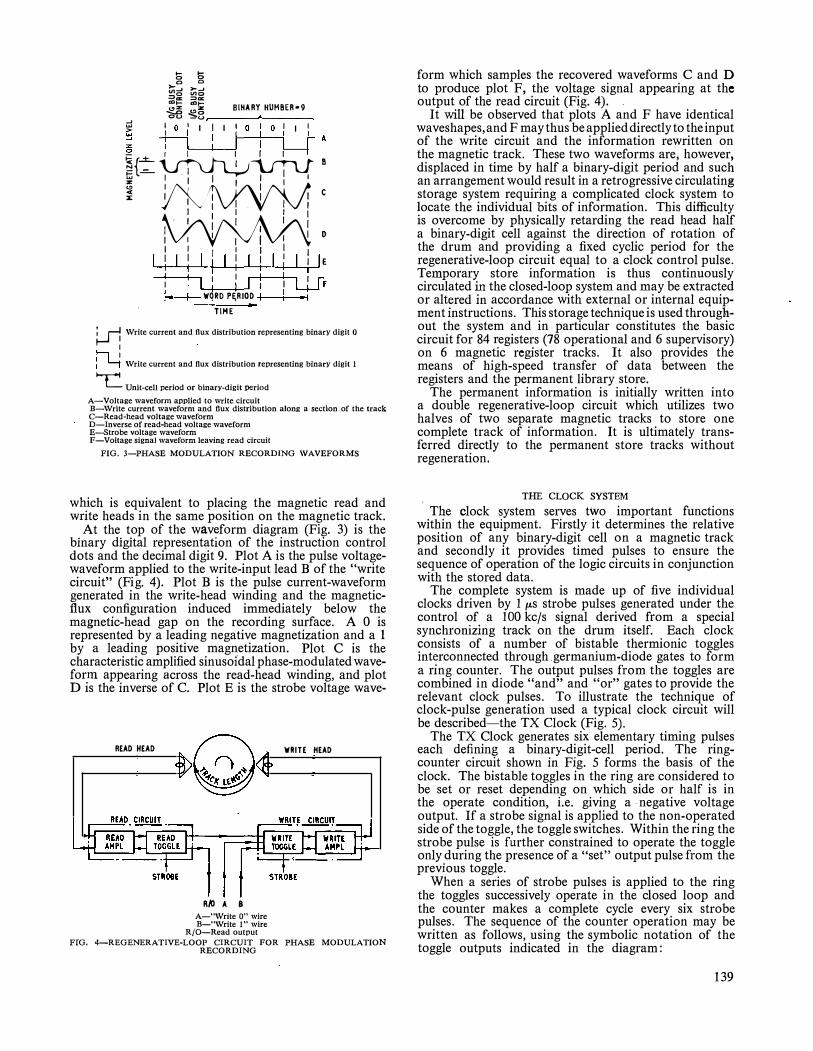
5 6 0 0
�c: lj;C:: =>a::: =>a: 1:D1- alt-� .g3 BINARY HUMBER•9
g I 0 1 I I I I 0 I 0 I I I � -+------j I 1----l----J I- A � i L____j_J I L_J i=+ �l lfll
;:5{- I B ;:: -=- . I I � I I I I I I I
"' �' � I I I . I I c
1 I I I
� D I I I 1 I I I I I I I I I I I I I I I I E I I · I I I · 1 · I I I I I I I I I I I I I I I L+-fF � WQRD P�RIOD I i , I
TIME
� \Vrite current and flux distribution representing binary digit o
I ii i ; � \Vrite current and flux distribution representing binary digit 1
L Unit-cell period or binary-digit period
A-Voltage waveform applied to write circuit B-\Vrite current waveform and flux distribution along a section of the track C-Read-head voltage waveform D-Inverse of read-head voltage waveform E--Strobe voltage waveform F-Voltage signal waveform leaving read circuit
FIG. 3-PHASE MODULATION RECORDING WAVEFORMS
wh_ich is equivalent to placing the magnetic read and wnte heads in the same position on the magnetic track.
. At the. t.op of the wav�form diagram (Fig. 3) is the bmary digital representat10n of the instruction control dots and the decimal digit 9. Plot A is the pulse voltagewaveform applied to the write-input lead B of the "write circuit" (Fig . 4). Plot B is the pulse current-waveform generated in the write-head winding and the magneticfiux cc;infiguration induced immediately below the magnetic-head gap on the recording surface. A 0 is represented by a leading negative magnetization and a 1 by a leading positive magnetization. Plot C is the characteristic amplified sinuso1dal phase-modulated wavefor_m apl?earing across the read-head winding, and plot Dis the mverse of C. Plot E is the strobe voltage wave-
READ HEAD
R,\1 A 8 A-"\Vrite O" wire B-"\Vrite 1" wire
R/0-Read output
WRITE HEAD
FfG. 4-REGENERATIVE-LOOP CIRCUIT FOR PHASE MODULATION RECORDING
form which samples the recovered waveforms C and D to produce plot F, the voltage signal appearing at the output of the read circuit (Fig. 4). .
It will be observed that plots A and F have identical waveshapes, and F may thus be applied directly to the input of the write circuit and the information rewritten on the magnetic track. These two waveforms are however displaced in time by half a binary-digit period and such an arrangement would result in a retrogressive circulating storage system requiring a complicated clock system to �ocate the individual �its of information. This difficulty is overcome by physically retarding the read head half a binary-digit cell against the direction of rotation of the drum and providing a fixed cyclic period for the regenerative-loop circuit equal to a clock control pulse. Temporary store information is thus continuously circulated � the closed-loop system and may be extracted or alt�red m �ccorda�ce with external or internal equipment mstruct10ns. This storage technique is used throughout the system and in particular constitutes the basic circuit for 84 �egiste�s (78 operational and 6 supervisory) on 6 magnetic register tracks. It also provides the means of high-speed transfer of data between the registers and the permanent library store.
The permanent information is initially written into a double regenerative-loop circuit which utilizes two halves of two separate magnetic tracks to store one complet� track of information. It is ultimately transferred directly to the permanent store tracks without regeneration.
. THE CLOCK SYSTEM
_T�e clock �ystem serves two important functions within the eqmpment. Firstly it determines the relative position of any binary-digit cell on a magnetic track and secondly it provides timed pulses to ensure the sequence of operation of the logic circuits in conjunction with the stored data.
The complete system is made up of five individual clocks driven by 1 µ,s strobe pulses generated under the control c;if_ a 100 kc/s signal derived from a special synchromzmg track on the drum itself. Each clock �onsists of a number of bistable thermionic toggles mt�rconnected through .germanium-diode gates to form a nng counter. The output pulses from the toggles are combined in diode "and" and "or" gates to provide the relevant clock pulses. To illustrate the technique of clock-pulse generation used a typical clock circuit will be described-the TX Clock (Fig. 5).
The TX Clock generates six elementary timing pulses each de�nin� a bin�ry-d�git-cell period. The ringcounter circmt shown m Fig. 5 forms the basis of the clock. The bistable toggles in the ring are considered to be set or reset depending on which side or half is in the operate condition, i.e . giving a ·negative voltage o_utput . If a strobe signal is applied to the non-operated side of the toggle, the toggle switches. Within the ring the strobe pulse is further constrained to operate the toggle only .during the presence of a "set" output pulse from the prev10us toggle.
When a series of strobe pulses is applied to the ring the toggles successively operate in the closed loop and the counter makes a complete cycle every six strobe pu�ses. The sequence of the counter operation may be wntten as follows, using the symbolic notation of the toggle outputs indicated in the diagram:
139

JµS
\ -i 1-JUl
TOGGLE MA
SET
RESET
TOGGLE MB
SET
RESET
100 kc/s STROBE.___�---'-------<------------------� PULSE
seen that the inherent states of the counter are equal to eight and not six. That is, the counter has three toggles each having two output conditions, giving 23 states for the complete ring. This ambiguity can be troublesome since it produces a condition known as "out of mode" operation. In the above case only two modes of operation exist, but the number of modes increases with the number of toggles making up the ring counter. The two separate modes of the 3-toggle ring counter (Fig. 5) are shown symbolically below in the binary-digital form, together with the eight possible states.
M��
lrx1
M
k!
frxz
Mh<C
lrxl MA, MB, MC-"Set" outputs of bistable toggles MA, MB and MC MA, MB, MC-"Reset" outputs of bistable toggles MA, MB, and MC -
TX H-Clock pulse outputs
M�C
Trx6
FIG. 5-FUNCTIONAL DIAGRAM OF TX CLOCK RING COUNTER
MA-+ MB to be read as MA set, sets MB MB-+ MC to be read as MB set, sets MC
MB, MC-+ MA to be read as MB and MC set, reset MA MA-+ MB to be read as MA reset, resets MB MB-+ MC to be read as MB reset, resets MC MC-+ MA to be read as MC reset, sets MA
Thus six rectangular pulse outputs are generated by a complete cycle of the counter. These pulses have an equivalent length of three strobe-pulse intervals and occur sequentially at periods equal to the strobe-pulse interval. Combining the appropriate outputs through "and" gates provides six successive TX clock pulses with repetition rates of one-sixth of the strobe frequency and with pulse widths of one strobe-pulse interval. The selection of the appropriate toggle output to give the correct TX pulse is easily determined by reference to the table below.
Toggle Output Toggle operates during following Notation States of the Counter
MA 1 2 3 MA 4 5 6 MB 2 3 4 MB 5 6 MC 3 4 5 MC 1 2 6
The first column gives toggle designations, indicating the "set" and "reset" outputs and the second column gives the operate state of the respective outputs during an intrinsic cycle of the ring counter. Thus the set output of toggle MA is in the operate condition during the first, second and third states of the counter while the reset output MA is in this condition during the remaining states. By inspection the table shows that the toggle outputs MA and MB are simultaneously in the operate condition during the first state of the counter and at no other time; hence combination of these two outputs in an "and" gate gives the first TX clock pulse TXI, and the remaining five TX clock pulses may be similarly derived. Tables such as these were used continually during the design and proved invaluable with the more complex ring counters.
At this point it may be of interest to digress and consider a particular design problem associated with the above type of ring counter. If the 6-state ring counter described in the above paragraphs is analysed it can be
140
MA 0 1 0 1 0 1 0 1
Available States MB MC
0 0 0 0 I 0 1 0 0 1 0 1 1 1 1 1
MA 0 1 1 1 0 0
Wanted Mode MB MC
0 0 0 0 1 0 1 1 1 1 0 1
Unwanted Mode
MA MB MC 0 1 0 1 0 1
The unwanted mode must be eliminated to prevent incorrect pulse generation. The problem was initially overcome by deductions from the "circuit logic" but this method proved unsatisfactory with large rings. Eventually a mathematical solution was obtained for even counters by W. E. Thompson of the Post Office Research Station, and finally by D. Hurst5 of the Automatic Telephone & Electric Co., Ltd., for both odd and even counters. The solution of the problem is stated in the following rule for odd or even ring counters: "If N equals the number of bistable toggles in the ring counter then the last M toggles must be in the reset condition before the first is set, where M > t(N + 1). The practical solution of the problem is obtained by the introduction to the ring counter circuit of the appropriate number of control gates, as determined by the above rule. The additional control gate required in the above example is shown dotted in Fig. 5.
The relation between clock pulses and the binary digital information on the magnetic drum may be understood by reference to the "build up" of a single register store on one of the register tracks. Fig. 6 shows sections of the register track and the register store indicating the clock-timing periods and operational functions of the binary-digit and word stores. A TX pulse period is allocated to each binary-digit cell. Six TX pulses are equal to a word period or TY pulse. Twenty-one TY pulses make up a register period or TZ pulse and 14 TZ pulses comprise a complete register track. A register track is equivalent to half the period of rotation of the drum, a TW pulse. Thus a prerequisite of the clock system is that the TX period must be a sub-multiple of the TY period, the TY period a sub-multiple of the TZ period, etc. This condition is attained by restricting the strobe drive of successive clocks to coincidence with the last pulse period of the preceding clock.
The TX, TY, TZ and TW clocks have 6 , 21, 14 and

-�n�-T�,,T-,,,t--T-Y4-21 ________,:I
I I II II II SE CTION OF/
REGISTER TRACK
gram which, under the control of the clocks and coupled with instructions from the store, performs high-speed switching functions of a complex nature. The complexity of the switching operations is considerably reduced by application of a modified form of Boolean algebra to the design. This form of Boolean algebra is sometimes called "circuit algebra" but due to its extremely distant relationship to mathematical algebra the term circuit logic is preferred.
I I I I I I I I UNIT MAGNE TIC
I .... b CELLS OR BINARY g o DIGIT PERIOD S
. ,._ � l�s I��
... ffi ,_ .... ... ... :IC :IC
I.;:� .......... :::> :::> :IC :IC
I I I I I I
� "' ......... 0
ro oO ' ... ..... >- >-..... "'"' ... ,.,. :::> :::> .Cil> ·m"" ... ,_ I"' .... ... z: z ::c 0 :E
"'0
,� � 0 -
I I I I I I I I I I I ..... I c
I :IC"' -cc <>o :!::;;
>-!:: a:"' c-z:O
I iii
I TYPICA L BUILD UP OF WORD .STORES
(a) Allocation of Timing Periods and Binary-Digit Cells
BUl�D UP OF REGISTER S TORES (b) Allocation of Timing Periods and Word Stores
FIG. 6-ARRANGEMENT OF A REGISTER TRACK ON THE MAGNETIC DRUM
Boolean algebra may be said to have a binary base since only two different quantities need be considered, 0 and 1. Now this is the case in the logic and clock circuits. The pulses are either positive or negative, the bistable toggles are either "on" or "off" and the gates are either open or closed. That is, each element may be considered to be in the 0 or 1 state. The next step in the application of the algebra to circuit design is the correlation of the interconnexion of the circuit and pulse elements with the arithmetical symbols of addition and multiplication. Considering the two typical diode gates shown in Fig. 7; in (a) the "and" gate is considered to have a pulse output at C if pulse inputs of the correct polarity appear simultaneously at A and B; and in (b) a pulse output occurs at C if pulses occur at A or B or both. This is equivalent to saying in the case of (a), the "and" gate,
6 states respectively. The TW clock has the largest cyclic period of 100 ms-the major cycle, which it will be noted is equal to the nominal pulsing period of the dial. The TX, TY and TZ clocks provide the minor cycles of the system, with perio,ds of 56·6µs, 1·19ms and 16·6 ms, respectively. A n elemental TX pulse thus has a period of 9·43 µs. These four sets of clock pulses are distributed within the system and satisfy all the timing requirements of the logic circuits and drum store with the exception of metering. The metering system is a special case which requires the provision of a 30-state clock. For economic reasons the clock is made up of two minor-cycle ring counters having 15 and two states and provides only two outputs, TMM and TMT. These outputs are in the form of a train of selected meter and TX clock pulses, which repeat every 3 sec and are related specifically to the meter fee or meter rate. The pulse train TMM caters for the multimetering facilities and TMT for the timed metering facilities for subscriber trunk dialling.
THE LOGIC CIRCUITS
The logic circuits comprise basic circuit elements similar to the clocks; that is, bistable thermionic toggles and germanium diode "and" and "or" gates. These elements are interconnected to form a permanent internal pro-
AXB=C Ax 0 =0
OXB=O or
and in the case of (b), the "or" gate,
1 x 1 = 1 1 x 0 = 0 0 x 1 = 0
A+B=C l+l =l A + 0 = C or 1 + 0 = 1
O+B=C O+l=l The right-hand group of equations are the results of
multiplication and addition of the Boolean algebraic quantities 0 and 1. Thus provided that the pulses at A, B and C are of equal amplitude and lie between the same voltage levels, the two sets of equations are equivalent. This leads directly to the use of the multiplication symbol when we consider a circuit "and" function and the addition symbol when we consider a circuit "or" function.
The final link in the association of the circuit elements
:i'=�c :J�' (a) "And" Gate- A x B = C (b) "Or" Gate- A + B = C
FIG. 7-TYPICAL DIODE GATES
141

with the algebra is contained in the fundamental concept of the Boolean "not" function as identified by 0 and meaning "not O." As only two values exist in the algebra, if it is "not O" then it must be I. Consider the bistable toggle MA in Fig. 8; the set and reset outputs
0-MA
�MA FIG. 8-BISTABLE
TOGGLE
may be written MA and MA respectively and comply with the above concept, "not MA" being equal to 1 since both outputs are identical. The interconnexion or combination of the circuit elements and pulses may now be realized symbolically. Thus referring to the functional diagram in Fig. 9 (a),
the logic functions of the circuit may be written in the form of the equation:-
MA . MB . TXl . TY2 + MC . TY20 = POI
where the dot is the shorthand form of the multiplication sign.
With the introduction of an additional premise the above form of Boolean algebra may be modified to extend its usefulness in design. The new premise is simply to allow the right-hand side of the equation to operate toggles directly. For example,
MA . TX3 . TY6 + TX4 . TY5 = MC -MB . TX2 . TYlO . TW 2 = MC
Hence toggle MC is set and reset in a�dance with the elements of the left-hand side of the equation. The equivalent functional circuit is shown in Fig. 9 (b). The complete design of the logic circuits was evolved, without circuit diagrams, using this modified form of Boolean algebra and consists entirely of a series of equations similar to those shown above.
A practical example of the use of Boolean algebra or circuit logic, taken from the design of the magneticdrum register-translator, is shown in Fig. 10, with the equivalent functional circuit and drum store. The example chosen is that of the facility of multi-metering. The requirements are:
(a) to detect presence of called-subscriber-answered condition via a signal from the access relay-set, and
(b) to transmit one to four pulses to the calling subscriber's meter according to the feemarked in the store.
HA
SET MA
RESET TXI
MB TYZ SET
RESET !1D TY5 POi
MC MB
SET MC SET
TYZO RESET RESET
The following is an outline of the circuit operation. The circuit operates to mark the register store on the drum indicating the called-subscriber-answered condition in the relay set. A stored meter-digit in the register is associated with this marked condition and the appropriate number of pulses are sent to the subscriber's meter in accordance with the multi-metering timing pulses from the meter clock. The meter clock, as stated, generates 30 clock pulses with individual pulse periods of 100 ms, equivalent to six revolutions of the register regenerative-loop circuit. Selected meter pulses are combined with one or more binary-digit timing pulses (TX pulses) to provide the meter-pulse train, as follows, TMM = TXI. TMl + TX4. TM7 + TX5. (TMll + 1 5) + TX6. TM19 + TX2.TM30.
The TMM pulse train is compared with a meter-fee digit in the register word-store TY2 (see Fig. 6), to determin� the fee appropriate to the call. For example, assuming the meter-fee-digit store TY2 on a register track of the drum has been written in from the library store, marking up TX4 and TX5. The resulting comparison of the meter-digit-store signal with the TMM pulse train provides three coincidences or three multi-metering pulses, which are sent to the relay-set during one complete cycle of the meter clock. Thus, dependent on the binary digits marked in the TY2 store, a predetermined number of pulses will be sent to operate the subscriber's meter.
The detailed steps of the operation may be simplified as follows by using the circuit logic (Fig. 10).
(a) A PID signal from the relay set, indicating the called-subscriber-answered condition, marks a 1 in the multi-metering start dot TXl, TY2 (see Fig. 6) at the beginning of the meter-clock cycle.
PID. TXI. TY2. TMM = SBS SBS is the "write l" signal applied to the magnetic-drum write circuit.
(b) The toggle MAG is set by the signal SLS at the timing period TXl, TY2 on detection of the 1 marked in the multi-metering start dot.
SLS. TXI. TY2 = MAG (c) The set condition of MAG and a. "read 1" signal
SLS, at the time (TX4 - 6). TY2. TMM, set the toggle MBG in accordance with the binary digits marked in the
meter-digit store.
MC
SET
RESET
MAG. SLS. (TX4 - 6). TY2. TMM =MBG
(cl) With MBG set at the timing period TY21 an output signal or pulse POI is sent to the relay-set.
MBG. TY21 = POI
(e) The timing pulses TX6, TY21 reset the toggles MAG and MBG at the end of the register period.
TX6. TY21 = MAG =MBG
(a) MA x � x TXI x TY2 + MC x TY20 = POI (b) MA x TX3 X TY6 + TX4 x TYS = MC
(f) The above circuit operations are repeated each time a binary-digit meter-store pulse (TX4 - 6) coincides with one of the pulses in the TMM meter-clock pulse-train until the end of the clock cycle. The toggle MAG is then set as in (b) above.
1 4 2
MB X TX2 X TY!O X TW2 = MC
FIG. 9-LOGIC CIRCUITS AND EQUIVALENT ALGEBRAIC EQUATIONS SLS. TXI. TY2 = MAG

ACCESS RELAY-SET
S11S
TMM
TY CLOCK
MAG
SET
RESET
SB S -�
MBG
SET
RESET
T>'ZI
!TO PULSE SU11SCRIBER's
POi METER VIA ACCESS RELAY· SET
(a) PID.TX1.TY2.TMM
(b) SLS.TX1.TY2
SBS Mark multi-metering start dof at beginning of clock cycle if called subscriberJs on line.
-
MAG Set to multi-metering start dot. (c) MAG.SLS.CTX4·6).TY2.TMM (d) MBG.TY21 (e) TX6.TY21
MBG Set according to rate indicated in TY2 store. POI Send pulse to operate subscriber's meter. MAG Reset at end of register period.
MBG
( f) Repeat of cycle (g) MAG.TX2.TY2.TMM SBS Mark multi-metering-complete dot at end of clock cycle. (h) SLS.TX2.TY2 MAG Reset on subsequent qtcles to prevent further metering nperation.
TMM=TX1.TM!+TX4.TM7+TX5.(TM11+15)+TX6.TM19+TX2.TM30
FIG. 10-FUNCTIONAL DIAGRAM OF MAGNETIC-DRUM MULTI-METERING FACILITY AND EQUIVALENT CIRCUIT LOGIC
(g) The condition of MAG at the timing period TX2, TY2, TMM marks a 1 in the multi-metering-complete dot in the register.
MAG. TX2. TY2. TMM = SBS
(h) The marked condition of the multi-meteringcomplete dot resets the toggle MAG to prevent further metering pulses being sent to the relay-set.
SLS. TX2. TY2 = MAG
THE EQUIPMENT
The magnetic-drum register-translator equipment is shown in Fig. 11. It consists of a suite of three racks,
housing, from left to right, (i) the power supply, (ii) the electromechanical and supervisory equipment and (iii) the magnetic-drum assembly and electronic control equipment. The mounting of the logic and drum circuit elements, i.e. the electronic control equipment, forms a special feature of the design. These elements are mounted on standard plug-in card units which in turn are mounted on standard plug-in panels (Fig. 12) immediately above the magnetic-drum assembly. Each panel performs a complete functional operation in the control system, e.g. the TZ Clock panel. This "plug in" and functional arrangement assists both the modification of design and maintenance during the exacting conditions of field trial.
143
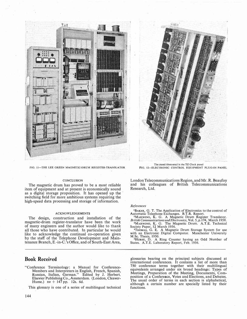
FIG. 11-THE LEE GREEN MAGNETIC-DRUM REGISTER-TRANSLATOR
CONCLUSION
The magnetic drum has proved to be a most reliable item of equipment and at present is economically sound as a digital storage proposition. It has opened up the switching field for more ambitious systems requiring the high-speed data processing and storage of information.
ACKNOWLEDGEMENTS
The design, construction and installation of the magnetic-drum register-translator have been the work of many engineers and the author would like to thank all those who have contributed. Jn particular he would like to acknowledge the continual co-operation given by the staff of the Telephone Development and Maintenance BraIJ.ch, E.-in-C.'s Office, and of South-East Area,
Book Received
"Conference Terminology: a Manual for ConferenceMembers and Interpreters in English, French, Spanish, Russian, Italian, German." Edited by J. Herbert. Elsevier Publishing Co., Amsterdam. (London, CleaverHume.) xv + 147 pp .. 12s. 6d.
This glossary is one of a series of multilingual technical
144
;_
The panel illustrated is the TZ Clock panel
FIG. 12-ELECTRONIC CONTROL EQUIPMENT PLUG-IN PANEL
London Telecommunications Region, and Mr. R. Beaufoy and his colleagues of British Telecommunications Research, Ltd.
References
1BAKER, G. T. The Application of Electronics to the control of Automatic Telephone Exchanges. B.T.R. Report.
2MARWING, K. G. A Magnetic Drum Register Translator. British Co1111111111icatio11sa11d Electro11ics, Vol. 5, p.174, March 1958.
3MARWING, K. G. The Magnetic Drum. A.T.E. Technical Society Paper, 12 March 1956.
'THOMAS, G. E. A Magnetic Drum Storage System for use with an Electronic Digital Computor. Manchester University M.Sc. Thesis, 1950.
5HURsT, D. A Ring Counter having an Odd Number of States. A.T.E. Laboratory Report, Feb. 1956.
glossaries bearing on the principal subjects discussed at international conferences. It contains a list of more than 750 conference terms together with their multilingual equivalents arranged under six broad headings: Types of Meetings, Preparation of the Meeting, Documents, Composition of a ConfereRce, Votes and Elections, and Debates. The usual order of terms in each section is alphabetical, although a certain number are specially listed by their functions.

Recording Decibelmeters A. P. PARSONS and F. E. DIDCOCKt
U.D.C. 621.317.741.087.6
Recording decibelmeters play a major part in the tracing of faults in telecommunication circuits, and there are now several types of instrument that are used by the Post Office. These instruments are described in this article and details are given of
their performance.
INTRODUCTION
.
THE forerunner of the present range of recording decibelmeters used by the Post Office was a modified commercial recording milliammeter, the
'Decibelmeter No. lOA/L. It was used for indicating the transmission level of test' signals transmitted over telecommunication circuits, but due to its bulkiness and need for constant attention it was not favoured as a maint�nance aid. With the efforts being made to improve the trunk network it became necessary to improve maintenance technique, and recording decibelmeters began to play a major part in tracing incipient
adapter plate is provided with the 14A/CTA instrument - to enable it to be fitted in place of the Decibelmeter No.
14A/L. With the development of more reliable rectifier
elements the 14A/CTA instrument became usable over the major part of the carrier frequency spectrum; it has for some time also been used for monitoring the pilot signals of coaxial cable links by using a germanium rectifier circuit external to the decibelmeter and connecting it at a point of high signal level.
The Decibelmeter No. 14A/CTA was used extensively at the United Kingdom end of the transatlantic telephone cable system, whilst a version of the instrument modified to suit the local mains supplies was also used at the North American terminals. However, the thickness of the trace of the instrument and the closeness of the scale indication made it difficult to distinguish small level variations, and to overcome this difficulty the
·Left to right: Declbelmeters No. 28A/CTA, No.19A/CTA and No.14A/CTA, Portable
FIG. I-RECORDING DECIBELMETERS
faults by long-term monitoring. These techniques were also applied to coaxial systems and much useful information about changes of pilot signal level was obtained. The Decibelmeter No. 14A/L was especially designed for this use and has been sufficiently discussed elsewhere.* Later, an instrument offering additional refinements, with a reduction in weight and size, was found to be more suitable for Post Office use than its predecessors and was introduced as the Decibelmeter No. 14A/CTA. This instrument and the Decibelmeter No. 14A/L perform similar functions and are interchangeable. An
tMr. Parsons is an Executive Engineer, Subscribers' Apparatus and Miscellaneous Services Branch, E.-in-C.'s Office, and Mr. Didcock is an Assistant Engineer, Transmission and Main Lines Branch, E.-in-C. 's Office.
_
*MYERS, H. G. Fault Location in Transmission Equipment by Vibration Testing and Continuous Monitoring. P.O.E.E.J., Vol. 42, p. 189, Jan. 1950.
E
Decibelmeter No. 19A/CTA was developed. A modified version of the instrument, known as the Decibelmeter No. 28A/CTA, was also developed for mounting on 51-type transmission equipment racks.
The present range of recording instruments consists, therefore, of the Decibelmeters No. 14A/L, 14A/CTA, 19A/CTA and 28A/CTA. Additionally there are portable versions of the 14A/L, 14A/CTA and 19A/CTA. Three of these instruments are shpwn in Fig. I.
·
CONSTRUCTION
Except for the scale ranges the diffei'ences between the 14A/CTA, l19A/CTA and 28A/CTA instruments are minor and are given later in the article. The description which follows, although of the Decibelmeter No. 14A/CTA, is applicable to the three types.
145

Movement
Magnetic System. The magnetic system has a centre core magnet which is held by non-ferrous spacers within a soft-iron cylinder, which completes the magnetic circuit. The annular air gap between the magnet and the cylinder is 0·28 cm (0· 118 in.) long and the cylinder has a wall thickness of 0·80 cm. This construction reduces the flux leakage and gives a negligible external field, and has the further advantage of screening the movement from the effects of external magnetic fields. To achieve the large torque necessary to operate the writing pen with the minimum of current in the moving coil an Alcomax 3 magnet is used. This magnet, because of its high energy content, makes maximum use of the limited space available. It provides a flux density of 0·45 webers/m2 (4,500 gauss) in the annular air gap. The area of the pole face is approximately 30 cm2, giving a total flux of 13·5 x 10-4 webers (135,000 maxwells).
Moving Coil. The moving coil has no former and for the Decibelmeter No. 14A/CTA is wound with 800 turns of 40 S.W.G. enamelled copper wire. This gives a torque of 17-18 gramme-centimetres with 1 mA flowing in the coil. The moving coil is pivoted in spring jewelled bearings and has the usual two torque or control springs, with a third coil spring provided to make connexion to the moving member of the alarm-contact system. It has negligible controlling effect on the moving coil. For suppressed-zero requirements the suppression is obtained by tensioning the torque springs the required amount. Both springs are used for this purpose to obviate any tendency of the moving coil to cant due to its length. Fixed to the upper end of the moving coil is the carrier which supports the pen-arm.
Damping. The moving coil has no former that can be used for damping the movement and a damping resistor is therefore provided of approximately 20 times the resistance of the moving coil. Thus 5 per cent of the power input to the 14A/CTA instrument is dissipated in the damping resistor.
Zero-Setting Control. The instrument is provided with a set-zero control accessible from the front of the instrument. Rotation of this control alters the position of a movable arm to which is fixed the outer end of the lower torque spring. This alters the rest position of the moving-coil assembly and gives a very fine control of the zero-setting.
Alarm Contacts and External Connexions. A moving contact is attached to the lower pivot of the moving coil and moves between "high" and "low" adjustable contacts. The contacts are of platinum-iridium alloy and are capable of making and breaking a circuit carrying 500 mA at 50 volts d.c. when suitably sparkquenched, although the normal current carried is only 20 mA . The "high" and "low" contacts are mechanically coupled to sliding pointers which move over a numericaUy calibrated scale.
As all external connexions to the instrument are soldered, the internal wiring is terminated on the solder tags of a connexion panel.
The Writing System The movement described above efficiently transfers
the electrical intelligence received by the instrument into a mechanical deflexion of the pen-arm carrier. There are many methods by which this deflexion may
146
be translated into a permanent record. All of these use a moving chart, but the ways in which the chart is marked are widely divergent. Some use specially treated paper which requires a chemical change to produce the record, whilst others require a current to pass through the chart, which is not necessarily made of paper. The system adopted on Post Office recording instruments is that of writing with ink on a paper chart. This system has the advantages that no special preparation of the paper is necessary and no additional source of current is required to mark the chart. It can, however, have disadvantages in that a supply of ink must be maintained in the instrument and also that when the instrument is not used for any length of time the ink may dry and clog the pen, though this can be avoided by the choice of a suitable ink.
There are two alternative methods of feeding the ink to the pen and these will be described separately. They are (a) gravity or siphon feed and (b) capillary feed. The relative merits of these two methods will be dealt with in a later article. Provision has been made on the latest decibelmeters for the use of either method.
Gravity-Feed Inking System. The ink trough is located on two vertical slides which project downwards from the top front edge of the instrument case, and is retained by spring clips. The gravity-feed pen consists of an inverted U-shaped siphon tube, one limb of which is immersed in the ink supply and the other shaped to form the pen-point. If the siphon tube is filled with ink, the ink flows continuously to the pen-tip since the ink level in the reservoir is higher than the pen-tip. The rate of flow of ink to the pen-tip is controlled by the difference of level between the ink trough and the pen-tip and by the internal size of the siphon tube. The siphon tube is so designed that the optimum flow is obtained with the ink trough half-full. Above this the increased pressure may cause the pen· to flood. The pen is held in the penarm by a shaped steel strip soldered to the top portion of the siphon tube.
Capillary-Feed Inking System. The ink trough is retained between slides on the face plate of the movement. The pen consists of a shaped capillary tube held by the inherent springiness of the tube between a bush formed in the pen-arm and a V-shaped slot at the end of the pen-arm. On filling the capillary tube, the ink is drawn to the paper by capillary action. The pen tip is above the level of the ink supply. Should flooding occur, a syphon would be created which would cause the excess ink to flow back into the ink trough.
Pen-Arms. With both inking systems the pen-arms have cross-members on which knife-edges are formed. The knife-edges of the pen-arm rest in V-shaped slots in the pen-arm-support carrier mounted on the movement. The pressure of the pen on the paper chart is adjusted by counterbalance weights at the rear of the pen-arm to be approximately 7 mg.
Chart Rolls. Each chart is 65 ft long and provides 1 month's supply at a chart speed of 1 in./hour. The last
. 6 ft of the chart has a broad red diagonal line printed over the calibrations to indicate that there is only sufficient chart for a further 3 days' operation. For a.c. measurements the charts are calibrated in decibels relative to 1 mW in 600 ohms. A line marked "Z" is provided for zero-setting the movement. Charts are available for d.c. measurements but are not normally
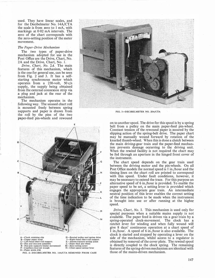
used. They have linear scales, and for the Decibelmeter No. 14A/CTA the scale is from zero to 1 mA, with markings at 0·02 mA intervals. The zero of the chart corresponds with the zero-setting position of the meter movement.
The Paper-Drive M echanisn1 The two types of paper-drive
mechanism adopted for use in the Post Office are the Drive, Chart, No. 2A and the Drive, Chart, No. I.
Drive, Chart, No. 2A. The main features of this mechanism, which is the one for general use, can be seen from Fig. 2 and 3. It has a selfstarting synchronous motor which operates from a 230-volt, 50 c/s supply, the supply being obtained from the external connexion strip via a plug and jack at the rear of the mechanism.
The mechanism operates in the following way. The unused chart roll is mounted freely between spring supports and paper is drawn from the roll by the pins · of the two paper-feed pin-wheels and rewound
o r�·- . . . . · . . I -I . , I - , r . . �
c
Bi
•
E
N
A-Clock retaining clip D-Upper paper strap C-Left-hand chart-roll support D-Pen and pen-arm assembly E--Pen-arm supports (meter movement) F-Capiilary-fecd ink trough G-Paper guide disk
H-Rewind pulley and spring drive J-Right-hand chart-roll support
K-Alarm-contacts setting guide L-Paper-feed pin-wheel
M-Zero-sening screw N-Chart-speed selling lever
FIG. 2-DECIBELMETER NO. 14A/CTA REMOVED FROM CASE
FIG. 3-DECIBELMETER NO. 28A/CTA
on.to another spool. The drive for this spool is by a spring belt from a pulley on the main paper-feed· pin-wheel. Constant tension of the rewound paper is assured by the slipping action of the spring-belt drive. The paper chart may be manually wound forward by rotation of the knurled thumb-wheel. When this is done a clutch between the main driving-gear train and the paper-feed mechanism prevents damage occurring to the driving unit. When the re'h'.ind facility is not required the chart may be fed through an aperture in the hinged front cover of the instrument.
The chart speed depends on the gear train used between the driving motor and the pin-wheels. On all Post Office models the normal speed is I in./hour and the timing lines on the chart roll are printed to correspond with this speed. Under fault conditions, however, it may be necessary to extend the trace. For this purpose an alternative speed of 6 in./hour is provided. To enable the paper speed to be set, a setting lever is provided which engages the appropriate gear train. An intermediate neutral position of this lever enables the correct setting of the time indication to be made when the instrument is brought into use or after running at the higher speed .
Dril'e, Chart, No. 1. This mechanism is used only for special purposes when a suitable mains supply is not available. The paper feed is driven via a gear train by a spring-operated clock-movement. The clock has a ratchet lever for winding and when fully wound will give 8 days' continuous operatio·n at a chart speed of I in./hour. A speed of 6 in./hour is also available. The clock is started and. stopped by operating a lever on the side of the mechanism, whilst access to a regulator is obtained by removal of the cover plate. The rewind spool is directly coupled to the clock spring. The remaining features of the spring-driven mechanism are identical with those of the mains-driven mechanism.
147
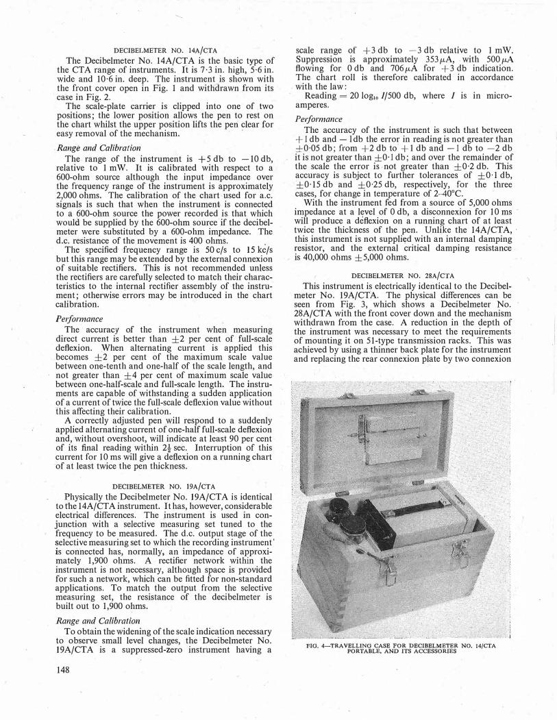
DI;CIBELMETER NO. 14A/CTA
The Decibelmeter No. 14A/C[A is the basic type of the CTA range of instruments. It is 7·3 in. high, 5·6 in. wide and 10·6 in. deep. The instrument _is shown with the front cover open in Fig. 1 and withdrawn from its case in Fig. 2. .
The scale-plate carrier is clipped into one of . two positions; the lower position allows the pen to rest on the chart whilst the upper position lifts the peri clear for easy removal of the mechanism. · ·
Range and Calibration
The range of the instrument is + 5 db to -10 db, relative to 1 mW. It is calibrated with respect to a 600-ohm source although the input impedance over the frequency range of the instrument is approximately 2,000 ohms. The calibration of the chart used for a.c. signals is such that when the instrument is connectt;d to a 600-ohm source the power recorded is that which would be supplied by the 600-ohm source if the decibelmeter were substituted by a 600-ohm impedance. The d.c. resistance of the movement is 400 ohms.
·
The specified frequency range is 50 c/s to 15 kc/s but this range may be extended by the external connexion of suitable rectifiers. This is not recommended unless the rectifiers are carefully selected to match their characteristics to the internal rectifier assembly of the instrument; otherwise errors may be introduced in the chart calibration.
Pe1forma11ce
The accuracy of the instrument when measuring direct current is better than ±2 per cent of full-scale deflexion. When alternating current is applied this becomes ±2 per cent of the maximum scale value between one-tenth and one-half of the scale length, and not greater than ±4 per cent of maximum scale value between one-half-scale and full-scale length. The instruments are capable of withstanding a sudden ·application of a current of twice the full-scale deflexion value without this affecting their calibration.
A correctly adjusted pen will respond to a suddenly applied alternating current of one-half full-scale deflexion and, without overshoot, will indicate at least 90 per cent of its final reading within 2t sec. Interruption of this current for 10 ms will give a deflexion on a running chart of at least twice the pen thickness.
DECIBELMETER NO. 19A/CTA
Physically the Decibelmeter No. 19A/CTA is identical to the 14A/CTA instrument. It has, however, considerable electrical differences. The instrument is used in conjunction with a selective measuring set tuned to the frequency to be measured. The d.c. output stage of the selective measuring set to which the recording instrument' is connected has, normally, an impedance of approximately 1,900 ohms. A rectifier network within the instrument is not necessary, although space is provided for such a network, which can be fitted for non-standard applications. To match the output from the selective measuring set, the resistance of the decibelmeter is built out to 1,900 ohms.
Range and Calibration To obtain the widening of the scale indication necessary
to observe small level changes, the Decibelmeter No. 19A/CTA is a suppressed-zero instrument having a
148
scale range of +3 db to -3 db relative to 1 mW. Suppression is approximately 353 µA, . with 500 µ,A flowing for 0 db and 706 µA for +3 db indication. The chart roll is therefore calibrated· in accordance with the law:
Reading = 20 log10 I/500 db, where I is in microamperes.
Pe1formance
The accuracy of the instrument is such that between + 1 db and - l db the error in reading is not greater than ±0·05 db; from +2 db to +1 db and -1 db to -2 db it is not greater than ±0· 1 db; and over the remainder of the scale the error is not greater than ±0·2 db. This accuracy is subject to further tolerances of ±0·1 db, ±0·15 db and ±0·25 db, respectively, for the three cases, for change in temperature of 2-40°C.
With the instrument fed from a source of 5,000 ohms impedance at a level of 0 db, a disconnexion for 10 ms , will produce a deflexion on a running chart of at least twice the thickness of the pen. Unlike the 14A/CTA, ·
this instrument is not suppli�d with an internal damping resistor, and the external critical damping resistance is 40,000 ohms ±5,000 ohms.
DECIBELMETER NO. 28A/CTA
This instrument is electrically identical to the Decibelmeter No. 19A/CTA. The physical differences can be seen from Fig. 3, which shows a Decibelmeter No. 28A/CT A with the front cover down and the mechanism withdrawn from the case. A reduction in the depth of the instrument was necessary to meet the requirements of mounting it on 51-type transmission racks. This was achieved by using a thinner back plate for the instrument and replacing the rear connexion plate by two connexion
FIG. 4--TRAVELLlNG CASE FOR DECIBELMETER NO. 14/CTA PORTABLE, AND ITS ACCESSORIES

strips, one on each side of the instrument, with the two sets of terminals connected in parallel. Connexions to the instrument when mounted on a rack may be made to either of the terminal strips, depending upon whether the instrument is fitted at the right-hand or left-hand side of the rack. The strip not in use is enclosed by an insulated protecting cover carrying a warning notice. This can be seen in Fig. 1. A specially designed safety plug is used to connect the mains supply for the synchronous motor. This plug makes the mains connexion inaccessible when in position. Two Decibelmeters No. 28A/CTA can be fitted on a 51-type equipment rack side-by-side, occupying a height equal to three apparatus units (a total of 51 in.). A separate dust cover is fitted which encloses the instruments but leaves two apertures through which the chart traces can be observed.
PORTABLE INSTRUMENTS
It is sometimes necessary to monitor a signal under fault conditions for short periods at places where a recording instrument is not normally used. For this
Book Review
"Progress in Semiconductors," Vol. 2. Edited by A. F. Gibson, P. Aigrain and R. E. Burgess. Heywood & Co., London. vii + 280 pp. 146 ill. 63s.
This is the second of a planned continuing series of approximately annual review volumes. It contains eight papers, contributed during the period July to November 1956, by specialists in their respective fields.
The first paper is concerned with semiconductors, such as the germanium-silicon alloys, which-contain a substantial degree of atomic disorder. The most promising theoretical picture of the electronic and optical properties of such crystals, as explained in the paper, involves the concept of a "virtual crystal" of periodic structure, from which the real disordered crystal departs by an amount that may be treated as a perturbation similar to that due to imperfections in the more perfect monatomic semiconductor crystals such as germanium and silicon.
The second paper is on the properties of the nine compound semiconductors comprising the phosphides, arsenides and antimonides of aluminium, gallium and indium. These compounds have physical and electrical properties qualitatively similar to those of silicon and germanium, and are of potential or actual technical interest because of the quantitative differences which offer scope for extending the range of application of semiconductor devices. The paper draws attention to the problems inv.olved in the preparation of monocrystalline specimens of the materials with good control of their purity or of desired doping impurity.
The third paper is entitled "Radiation Effects in Semiconductors." The term "radiation" is used in the specialized sense related mainly to bombardment by high-energy particles-mostly fast neutrons from an atomic reactor, and fast electrons. The mechanism whereby damage is caused to the crystal structure, and the properties of the defects produced, are considered, together with the phenomena of annealing-out observed even below 0°C. Most of the data relates to germanium and silicon.
The fourth paper on "Lifetimes of Free Electrons and Holes in Solids" develops the author's philosophically comprehensive, yet logically simple, approach to his subject, which is aimed at the understanding of recombination processes in phosphors and photoconductors as well as in transistor-type semiconductors.
purpose portable versions of the 14A/CTA and 19A/CTA instruments are available. Their performance is identical to that of the rack-mounted instruments. They are fitted additionally with slide-runner feet and a carrying handle and are transported in strong wooden carrying cases, each of which accommodates the instrument, two pens and pen-arms, a pen filler, a bottle of ink and two chart rolls. Fig. 4 shows the Decibelmeter No. 14A/CTA, Portable and accessories in its travelling case. The conversion of the rack-mounted 19A/CTA instrument to pQrtable fo1·m is simply carried out by fitting the additional parts required and providing the carrying case.
CONCLUSION
The technique of using recording decibelmeters for circuit observations is now firmly established as a maintenance aid and their application to other problems will doubtless increase as potential users become aware of the advantages of obtaining a permanent record of otherwise unobserved transient conditions.
The fifth paper describes the production of high-quality germanium single crystals by means of the horizontal growing method in which the solid-liquid interface is maintained accurately in the (111) crystalline plane during growth. A greatly reduced density of dislocations in the grown crystal and a high and uniform minority-carrier lifetime are obtained. The paper includes some good photographs of etch-pit patterns resulting from controlled treatments of the crystal during growth.
The sixth paper reviews the solubility, segregation and diffusion properties of the more significant donor, acceptor and trapping impurities in germanium and discusses their electrical and optical properties in more detail. The methods given for the determination of the (possibly multiple) energy levels of trapping impurities are particularly interesting.
The seventh paper is concerned with two distinct effects: that due to the imperfect thermal "contact" between the mobile charge carriers (electrons and holes) and the crystal lattice of a semiconductor; and that arising directly from the high-velocity collisions between carriers and lattice atoms. The former leads to an increase in resistivity at highcurrent densities and the latter to the generation of additional majority and minority carriers at still higher current densities-IJ.either effect requiring the presence of a p-n junction or other barrier layer.
The eighth paper describes the three basic mechanisms of electro luminescence: "intrinsic" electro luminescence, due solely to the action of the electric field in the bulk crystal; "carrier injection" electroluminescence, due to the recombination of carriers injected at rectifying boundaries; and "electrophotoluminescence," the transient enhancement of the luminescence of a phosphorescent material following photo-excitation. The supporting evidence relies upon the interpretation of the voltage-dependence of the luminescence, its phase-shift relative to the voltage, and its microscopic spacial distribution.
The volume will appeal mainly to specialists working on the physics and technology of semiconductor materials, but it should be read also by engineers desirous of appreciating the more subtle characteristics of some present devices and of foreseeing the basic properties of some devices yet to leave the laboratory.
F.F. R.
149

Notes and Comments Birthday Honours
The Board of Editors offers congratulations to the following members of the Engineering Department honoured by Her Majesty The Queen in the Birthday Honours List: Aberdeen Telephone Area Baxter, W. S.
Belfast Telephone Area .. Canterbury Telephone Area Cardiff Telephone Area .. Coventry Telephone Area East Telephone Area, London
Telecommunications Region ..
Home Counlies Region ..
North Telephone Area, London Telecommunications Region ..
Southampton Telephone Area ..
Wilson, W. E. . . Phillips, H. C. . . Holbrook, T. H. Lawrence, J. S. D. J.
Loveday, T. C.
H udson, W. E.
Morris, L. A. Lowe, R. C.
Subscriber Trunk Dialling-Special Issue of the Journal
Executive Engineer
Technical Officer Inspector Technician, Class I Technician, Class I
Area Engineer
Chief Regional Engineer
Technical Officer Technician, Class I ..
Member of the Most Excellent Order of the British Empire
British Empire Medal British Empire Medal British Empire Medal British Empire Medal
Member of the Most Excellent Order of the British Empire
Officer of the Most Excellent 01:der of the British Empire
British Empire Medal British Empire Medal ·
The January 1959 Journal (Vol. 51, Part 4) will be a special and enlarged issue devoted entirely to articles about subscriber trunk dialling. The general plan for subscriber trunk dialling will be described and specialized articles will deal with individual items of equipment, such as the register translators. A description of the first installation, at Bristol, will be included and information will be given about subsequent steps in the introduction of subscriber trunk clialling. Further details about this special issue will be given in the October 1�>"58 Journal.
Institution of Post Office Electrical Engineers Secretary to the Institution
Mr. H. E. Wilcockson has resigned from the position of Secretary to the Institution, having served in that capacity since 1951.
·
Readers will wish to note that the new Secretary is Mr. S. Welch, Telephone Development and Maintenance Branch, Engineer-in-Chief's Office, Alder House, Aldersgate Street, London, E.C.l .
President-Associate Section
Mr. A. H. C. Knox, Deputy Chief Regional Engineer, Engineering Branch, Home Counties Region, 131 Great Titch.field Street, London, W.I, has been appointed President of the Associate Section and has taken up his new duties.
The Council of the Institution records its appreciation of the considerable services of the retiring President, Mr. R. W. Palmer, who held the appointment since 1954.
Mr. W. H. Fox-Honorary Local Secretary, London Centre
Mr. W. H. Fox is due to retire in the near future and has regretfully relinquished the post of Honorary Secretary of the London Centre. He has served in that capacity for the past eleven years, was Assistant Local Secretary for four years previous to that, and has served the Institution in various capacities for the past 25 years. To express their appreciation of bis energetic and enthusiastic services on their behalf, the London Centre members, both Senior and Associate, organized a presentation which took place at the Institution of Electrical Engineers at the final meeting of the Centre's 1957-58 session, on 12 May 1958.
Mr. D. A. Barron, Assistant Engineer-in-Chief and Chairman of· Council, made the presentation on behalf of the Centre. He expressed the Institution's appreciation of Mr. Fox's notable services and took the opportunity to congratulate Mr. Fox on his election to Honorary Membership of the Institution, previously announced by
150
the President of the Institution, Brigadier Sir Lionel H. Harris, the Engineer-in-Chief. In happy vein, as is evident from the photograph, Mr. Barron covered Mr. Fox's unique record as an Institution, telecommunications, and
MR. BARRON MAKING THE PRESENTATION TO MR. FOX
horticultural expert. He stressed the high regard the London Centre had for Mr. Fox as over 1,200 members had subscribed to the presentation.
Mr. Barron also made a presentation to Mrs. Fox on behalf of the Centre, for, quoting Mr. H. G. Beer, the Chairman of the Centre, allowing her husband to be away so much on Institution business.

Essay Competition 1957-58-Results
A prize of £5 5s. and an Institution Certificate have been awarded to the following competitor in respect of the essay named:
J. G. Philip, Technical Officer, Aberdeen (Scotland). "Public Speaking in Relation to the G.P.O. Engineering Department."
Prizes of £3 3s. each and Institution Certificates have been awarded to the following four competitors:
R. J. Lukehurst, Technical Officer, Canterbury (H.C. Region). "Inter-Departmental Staff Relations."
K. 0. Verity, Technical Officer, Long Distance Area (L.T. Region). "Telecommunications and Atomic Energy."
T. A. D. Clark, Technical Officer, Colchester (H.C. Region). "The Technical Officer, the Youth-inTraining and the Manual Exchange."
J. A. Armitage, Technical Officer, Preston (N.W. Region). "The Electronic Random Number Indicating Equipment."
Institution Certificates of Merit have been awarded to: R. I. Jenkins, Technical Officer, Haverfordwest (Wales
and Border Counties). "Radio Waves and Beyond." M. G. Hamilton, Technical Officer, Bournemouth
(H.C. Region). "Transistors and Telecommunications."
A. Richmond, Technical Officer, Ohan (Scotland). "A T.0.'s Life in the Outer Hebrides."
D. M. Rennolds, Technical Officer, Bristol (S.W. Region). "Developments at Bristol Trunk Exchange."
H. Belchamber, Technician Class I, Southsea (H.C. Region). "The Park Road Job."
The Council of the Institution records its appreciation to Messrs. W. S. Procter, G. Spears and A. J. Leckenby who kindly undertook to adjudicate upon the essays entered for the competition.
N.B.-Particulars of the next competition, entry for which closes on 31 December 1958, and a review of the abovementioned prize-winning essays, will be published later.
S. WELCH, Secretary.
Additions to the Library 2469 Our Nuclear Adventure. D. G. Arnott (Brit. 1957).
Attempts to provide sufficient information for the ordinary person to take an intelligent interest in the technical developments of our newest and greatest adventure and in the political and social issues which
. .accompany it. 2470 Radio Circuits. W. E. Miller (Brit. 1951).
A stage-by-stage practical description of the working of superheterodyne radio receivers. Little previous knowledge of radio circuits is assumed.
2471 Satellites and Space Flights. E. Burgess (Brit. 1957). Shows how the earth-satellite program has become
possible because of developments in military rockets and how it can lead to interplanetary probe missiles.
'
2472 Fundamental Principles of Transistors. J. Evans (Brit. 1957).
<!ives a sound grasp of the main principles and is designed for the young graduate entering the field of transistors.
2473 An Introduction to Automatic Digital Computers. R. K. Livesley (Brit. 1957).
Mainly for engineers who are faced with tedious calculations, so that they can judge the possibility of using these machines in their numerical work.
2474 Applied Building Constmction. A. Medlycott(Brit. 1957). Covers the syllabus for first-year students.
2475 An Introduction to Transistor Circuits. E. H. CookeYarborough (Brit. 1957).
An introduction to the advantages of transistors to their present limitations, and to circuit designs which exploit the unique properties of transistors.
2476 Transmission-Line Theory. R. W. P. King (Amer. 1955).
Concerned primarily with the high-frequency aspects of transmission lines, and is designed to serve as a necessary and fundamental introduction preceding serious work in wave-guides and cavities as well as antennae.
2477 Industrial Television. H. A. McGhee (Brit. 1957). Covers the design and application of television
equipment in industry, education and science. 2478 Electricity in Building. A. L. Osborne (Brit. 1957).
Provides an introduction to current practices for those unfamiliar with the subject.
2479 Building Elements. R. L. Davies and J. L. Petty (Brit. 1956).
Deals with the structural elements of a building · i.e. walls, floors, roofs, windows, etc., and treats the�
mainly in terms of their functions; 2480 Advanced Mathematics for Technical Students, Pt. II.
H. V. Lowry and H. A. Hayden (Brit. 1957). Covers the. work normally done by students taking
mathematics as a subject in Pt. II of an engineering degree.
2481 The Exploration of Space by Radio. R. H. Brown and A. C. B. Lovell (Brit. 1957).
Describes some of the results and possibilities of the investigation of the universe by radio methods.
2482 Light Colour and Vision. Y. Le Grand (French 1957). D��ls with the reaction of the retina, when its light
sens1tlve cells absorb light of various wavelengths. 2483 A Management Guide to Electronic Computers. W. D.
Bell (Amer. 1957). A simple non-technical explanation of what an
electronic computer is and what it will do. 2484 Synthesis of Passive Networks. E. A. Guillemin
(Amer. 1957). . A logical and comprehensive approach to linear pas
sive network synthesis covering both the approximation problem and the realization techniques.
2485 Electronics in the Office. Office Management Asso-ciation (Brit. 1957). .
A book on the practical use of computers. 2486 Fluorescent Lighting. C. Zwikker (ed.) (Cont. 1952).
A review of the scientific and technical fundamentals and of the applications of the fluorescent lamp and its accessories.
2487 Receiving Aerial Systems. I. A. Davidson (Brit. 1957). The design of aerials for the reception of broad
casting and television signals is discussed, together with some practical aspects related to their construction and installation.
2488 Managers: Making or Marring Them. J. D. Edwards (Brit. 1957).
Describes the steps necessary to analyse or solve the probli::ms met with in the development of the top executive.
2489 High-Fidelity Sound Reproduction. E. Molloy (ed.) (Brit. 1958).
Brings together authoritative and balanced information about high-fidelity sound reproduction in terms readily understood by the engineer and the keen amateur.
2490 The Economic and Social Consequences of Automation. F. Pollock (German 1957).
Gives sufficient information and discusses problems which will enable the reader to form his own judgment on the validity of the hopes and fears raised by the "second industrial revolution."
2491 Photography in Colour with Kodak Films. E. S. Bomrack (Brit. 1957).
Shows how to get the best results when using "Kodachrome," "Ektachrome" and "Kodacolour" and is aimed at the non-professional.
'
W. D. FLORENCE, Librarian.
151

Regional Note
Midland Region CONTACT WITH 132 KV GRID LINE
A .mos� unusual mishap occurred recently at a power crossmg m the Coventry Telephone Area. The crossing concerned is at Grendon in the Wollaston exchange area, where the Northampton-Bedford 132kV power line crosses a local Post Office route . Although the Post Office lines had been placed underground for the specified distance on each side of the point of crossing, this normal safeguard was not sufficient in the circumstances to prevent a contact between a Post Office wire and grid line.
·
A spare Post Office wire, which had broken at a joint n�ar t.he pole next to the power.crossing terminal pole, was lymg. m the roadwa� but was still attached to the crossing lenrnnal pole; the wire was caught up by a passing bus and dragged along towards the far end of the crossing. The wire eventually broke away from the bus and sprang up into the power conductors, which were about 35 ft above ground level where they crossed the road. The resulting fault caused a length of one power conductor to burn through and the feeder was put out of commission for several hours.
On the Post Office route the underground cable at the power crossing was blown out at the top of the capping on each terminal pole, and another underground power crossing cable, some It miles nearer to the exchange, was also damaged. The photograph shows damaged portions of the cables, which were recovered (A) from the pole to which the broken wire was attached, (B) from the far end of the same crossing and (C) from the crossing nearer to the exchange.
At the power crossing wher_e the fault occurred there were two working lines, and although it was a spare wire which actually made contact with the power line, the fuses and protectors on the working lines operated at the exchange.
Book Review
"Variable Capacitors and Trimmers." G. W. A. Dummer. Sir Isaac Pitman & Sons. 169 pp. Illustrated. 32s. 6d.
This is number four in a series of books on radio and electronic components that Sir Isaac Pitman & Sons are publishing, the first three volumes having covered fixed and variable resistors and fixed capacitors. The series is intended to provide the radio industry with a reference library that will give designers and manufacturers an outline of how components behave when in actual use in circuits the performance limitations that particular components ea� be expected to have under normal conditions and how the behaviour may vary under extremes of temperature humidity and mechanical shock. The author, Mr . G. W. A'. Dummer, has had wide experience in the subject at the Ministry of Supply. As head of the components research ai:d testing team he ha� become thoroughly acquainted with the theory and practice of up-to-date electrical measuring techniques. He has also had unrivalled opportunity to survey the wide field covered by manufacturers' components, to analyse their manufacturing techniques and to observe the trends of component development.
This volume on variable capacitors summarizes the
152
DAMAGED PORTIONS OF THE POST OFFICE CABLES
At the power crossing nearer the exchange, four more subscribers' lines were connected, and the fuses and protectors of these lines also operated. There was no damage to protectors or apparatus at the subscribers' premises.
There was unfortunately no current-recording apparatus in the grid line, so there was no indication of the actual fault current which flowed. H. H.
A.E.N.
author's experience in this important aspect of component !llanufacture. The book opens with a chapter on general information such as standard specifications and their range o.f applications, on basic capacitor theory, equivalent ClfCUtts and power factor. The book then turns to the practical side with tables of properties of the many dielectric materials now on the market and the classes of capacitors into which the materials can best be fitted. Measurement techniques occupy a chapter to themselves. The treatment is rather sketchy, but there is sufficient information in block diagram form to give a good survey of the subject.
The latter half of the book describes in a critical manner the construction of many well-known forms of variable cap.acitor and . tabulates the practical details needed by designers workmg on component layouts. Test results on shock-resistance and stability under vibration are also included in this chapter. Some readers would be surprised to see that even the minimum operating torque is specified for many types of adjustable capacitors.
This is a reference book that should be available to all drawing offices engaged on the preparation of production details for electronic equipment. It is probably the only reference work on variable capacitors so far published in this country. c. F. F.

Associate Section
Silver Jubilee Celebrations in the North Eastern Region
The several Centres in the North Eastern Region celebrated the Associate Section Silver Jubilee in various ways, most of them arranging special lectures and visits. Their committees and members are to be congratulated on their successful efforts. Three Centres organized exhibitions, the wide range of which is evident from the following reports. The good attendances and interest displayed by the visitors were very rewarding to the organizers, and the Region's pride in what their efforts have accomplished is well justified.
The inauguration in January of the North Eastern Region's Associate Section quarterly journal signalled the striking progress made by Associate Centres in this Region. The second issue of the journal was published in April. This little publication, at 6d. a copy, has a large potential circulation if given the support it deserves. See your local committee man and become a regular subscriber. '
A. C. HOLMES, Regional Liaison Officer.
Scarborough Centre
To celebrate the Associate Section Silver Jubilee a telecommunications exhibition was held on Saturday and Sunday, 22 and 23 February, in the Head Post Office, Scarborough. The opening ceremony was performed by the Mayor of Scarborough, Councillor R. P. Robinson, who was accompanied by the Deputy Mayor, Councillor W. J. Hardcastle.
By Courtesy of Scarborough aud District Newspapers, Lid.
THE MAYOR OF SCARBOROUGH AT THE OPENING CEREMONY
The exhibition traced the history of the telephone from the first Graham Bell instrument (1876) to the latest printedcircuit telephone (1958). Also on show was a 1958-type cordless switchboard. The exhibits on jointing showed a method of jointing lead and polythene cables ; a special joint-box was built in the room to show how this type of work is carried out. A demonstration set showing the operation of an automatic exchange was on view together with various demonstration boards, for which we would like to take this opportunity of thanking the Regional Training School staffs at Otley and Harrogate. Two teleprinters, an automatic transmitter and a reperforator were inter-connected and this added to the general interest of the exhibition.
Also included was a display of radio interference items and the local Technical Officer on radio duties had quite an exciting week-end successfully demonstrating suppressed and unsuppressed items with the aid of a portable television receiver.
On view were photographs showing the advancement of the Post Office in all branches from the 1870's to the present day.
More than 2,000 people visited the exhibition and over 1,500 visited the Scarborough telephone exchange.
I would like to take this opportunity of thanking all those who helped to make this a most successful exhibition.
W. BRADLEY, Honorary Secretary,
Scarborough Centre, Associate Section.
Hull Centre
From Tuesday to Thursday, 25-27 February, an exhibition was held at the Hull College of Technology by the courtesy of Mr. Emlyn Jones (Principal) and Mr. W. S. Milner (Head of the Department of Electrical Engineering). Two laboratories on the ground floor of the new building in Queen's Gardens, well equipped with power and lighting, were made available for the exhibition.
To illustrate the wide scope of the duties of Associate Section members, working models were constructed of the automatic telephone answering device and a 2 v.f. dialling link ; these were connected to a U.A.X. No. 12-possibly the only U.A.X. used with a 2 v.f. subscriber. A 10-line P.A.B.X. with two main exchange lines and eight extensions was installed. One of the extensions was a Plan 7E; on another extension circuit was the new Ericsson 3 +9 P.M.B.X. This in turn had four loop-call extensions. Visitors could make calls from one extension to another but outgoing calls to the main exchange were barred so as to leave the lines available for exhibition purposes. .
Examples of early subscribers' apparatus included a model of the Graham-Bell telephone, one of the Gower-Bell instruments, the skeleton magneto instrument and an early " candle-stick" telephone. One of the early Western Electric rotary selectors was on show together with a display of working pre-2000 selectors. Among the telegraph exhibits was a morse key and sounder and a working Wheatstone ABC set-a fascinating instrument for most visitors.
HULL EXHIBITION: TELEX AND OTHER EQUIPMENT
153
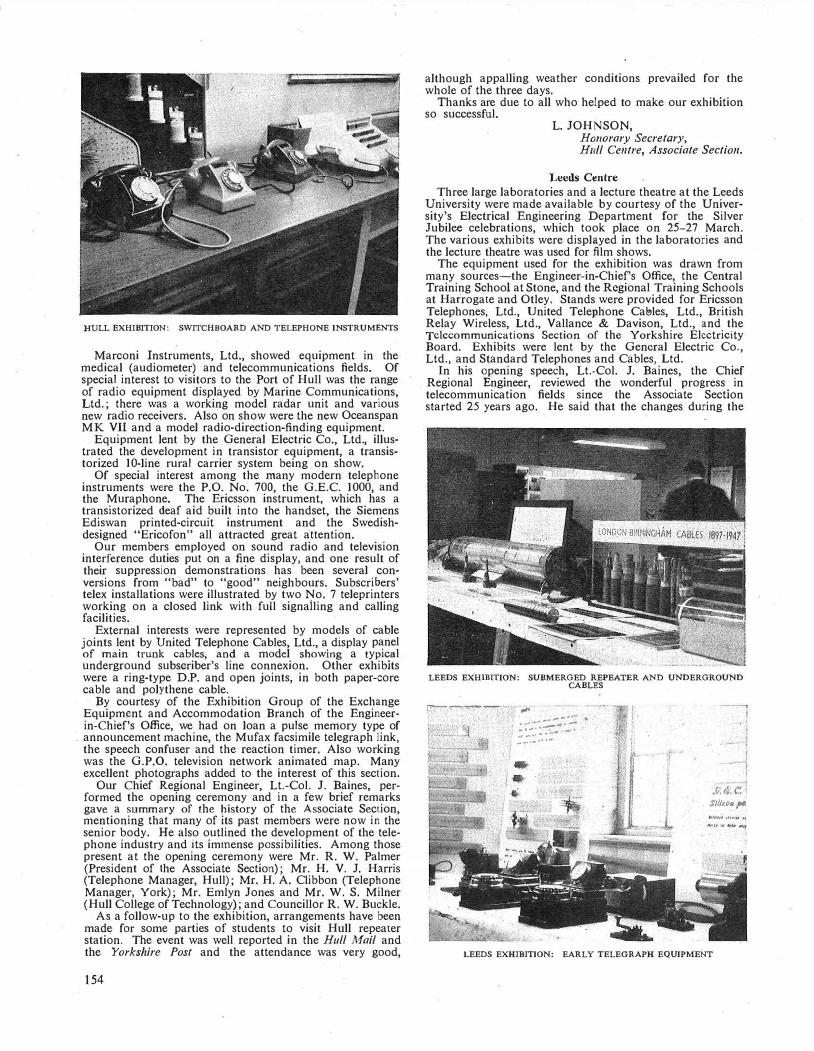
HULL EXHIBITION: SWITCHBOARD AND TELEPHONE INSTRUMENTS
Marconi Instruments, Ltd., showed equipment in the medical (audiometer) and telecommunications fields. Of special interest to visitors to the Port of Hull was the range of radio equipment displayed by Marine Communications, Ltd.; there was a working model radar unit and various new radio receivers. Also on show were the new Oceanspan MK Vil and a model radio-direction-finding equipment.
Equipment lent by the General Electric Co., Ltd., illustrated the development in transistor equipment, a transistorized 10-line rural carrier system being on show.
Of special interest among the many modern telephone instruments were the P.O. No. 700, the G.E.C. 1000, and the Muraphone. The Ericsson instrument, which has a transistorized deaf aid built into the handset, the Siemens Ediswan printed-circuit instrument and the Swedishdesigned "Ericofon" all attracted great attention.
Our members employed on sound radio and television interference duties put on a fine display, and one result of their suppression demonstrations has been several conversions from "bad" to "good" neighbours. Subscribers' telex installations were illustrated by two No. 7 teleprinters working on a closed link with full signalling and calling facilities.
External interests were represented by models of cable joints lent by United Telephone Cables, Ltd., a display panel of main trunk cables, and a model showing a typical underground subscriber's line connexion. Other exhibits were a ring-type D.P. and open joints, in both paper-core cable and polythene cable.
By courtesy of the Exhibition Group of the Exchange Equipment and Accommodation Branch of the Engineerin-Chief's Office, we had on loan a pulse memory type of
. announcement machine, the Mufax facsimile telegraph link, the speech confuser and the reaction timer. Also working was the G.P.0. television network animated map. Many excellent photographs added to the interest of this section.
Our Chief Regional Engineer, Lt.-Col. J. Baines, performed the opening ceremony and in a few brief remarks gave a summary of the history of the Associate Section, mentioning that many of its past members were now in the senior body. He also outlined the development of the telephone industry and its immense possibilities. Among those present at the opening ceremony were Mr. R. W. Palmer (President of the Associate Section); Mr. H. V. J. Harris (Telephone Manager, Hull); Mr. H. A. Clibbon (Telephone Manager, York); Mr. Emlyn Jones and Mr. W. S. Milner (Hull College of Technology); and Councillor R. W. Buckle.
As a follow-up to the exhibition, arrangements have been made for some parties of students to visit Hull repeater station. The event was well reported in the Hull Mail and the Yorkshire Post and the attendance was very good,
154
although appalling weather conditions prevailed for the whole of the three days.
Thanks are due to all who helped to make our exhibition so successful.
·
L. JOHNSON, Honorary Secretary, Hull Centre, Associate Section.
Leeds Centre Three large laboratories and a lecture theatre at the Leeds
University were made available by courtesy of the University's Electrical Engineering Department for the Silver Jubilee celebrations, which took place on 25-27 March. The various exhibits were displayed in the laboratories and the lecture theatre was used for film shows.
The equipment used for the exhibition was drawn from many sources-the Engineer-in-Chief's Office, the Central Training School at Stone, and the Regional Training Schools at Har"rogate and Otley. Stands were provided for Ericsson Telephones, Ltd., United Telephone Cal!>les, Ltd., British Relay Wireless, Ltd., Vallance & Davison, Ltd., and the Telecommunications Section of the Yorkshire Electricity Board. Exhibits were lent by the General Electric Co., Ltd., and Standard Telephones and Cables, Ltd.
In his opening speech, Lt.-Col. J. Baines, the Chief . Regional Engineer, reviewed the wonderful progress in
telecommunication fields since the Associate Section started 25 years ago. He said that the changes during the
LEEDS EXHIBITION: SUBMERGED REPEATER AND UNDERGROUND CABLES
r---r--� ,.I<
J :::.::.=:::�'.:7: _,.... ....... ... �1
. -j
.v.6:t: Slllto11 po. l•�lfl' •l•llU ft
//l/1<11 ... ltffl' ....
LEEDS EXHIBITION: EARLY TELEGRAPH EQUIPMENT
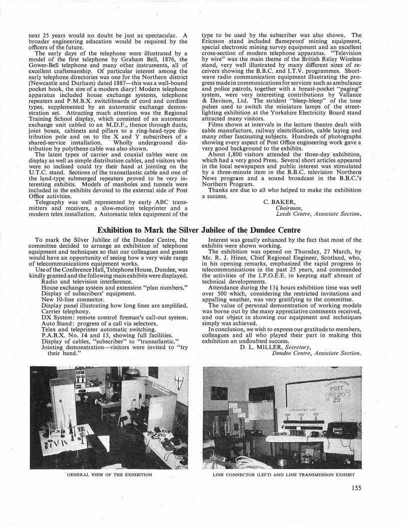
next 25 years would no doubt be just as spectacular. A broader engineering education would be required by the officers of the future.
The early days of ,the telephone were illustrated by a model of the first telephone by Graham Bell, 1876, the Gower-Bell telephone and many other instruments, all of excellent craftsmanship. Of particular interest among the early telephone directories was one for the Northern district (Newcastle and Durham) dated 1887-this was a well-bound pocket book, the size of a modern diary! Modern telephone apparatus included house exchange systems, telephone repeaters and P.M.B.X. switchboards of cord and cordless types, supplemented by an automatic exchange demonstration set. Attracting much attention was the Regional Training School display, which consisted of an automatic exchange unit cabled to an M.D.F., thence through ducts, joint boxes, cabinets and pillars to a ring-head-type distribution pole and on to the X and Y subscribers of a shared-service installation. · Wholly underground distribution by polythene cable was also shown.
The latest types of carrier and coaxial cables were on display as well as simple distribution cables, and visitors who were so inclined could try their hand at jointing on the U.T.C. stand. Sections of the transatlantic cable and one of the land-type submerged repeaters proved to be very interesting exhibits. Models of manholes and tunnels were included in the exhibits devoted to the external side of Post Office activities.
Telegraphy was well represented· by early ABC transmitters and receivers, a slow-motion teleprinter and a modern telex installation. Automatic telex equipment of the
type to be used by the subscriber was also shown. The Ericsson stand included flameproof mining equipment, special electronic mining survey equipment and an excellent cross-section of modern telephone apparatus. "Television by wire" was the main theme of the British Relay. Wireless stand, very well illustrated by many different sizes of receivers showing the B.B.C. and I.T.V. programmes. Shortwave radio communication equipment illustrating the progress made in communications for services such as ambulance and police patrols, together with a breast-pocket "paging" system, were very interesting contributions by Vallance & Davison, Ltd. The strident "bleep-bleep" of the tone pulses used to switch the miniature lamps of the streetlighting exhibition at the Yorkshire Electricity Board stand attracted many visitors.
Films shown at intervals in the lecture theatre dealt with <;able manufacture, railway electrification, cable laying and many other fascinating subjects. Hundreds of photographs showing every aspect of Post Office engineering work gave a very good background to the exhibits.
About 1,800 visitors attended the three-day exhibition, which had a very good Press. Several short articles appeared in the local newspapers and public interest was stimulated by a three-minute item in the B.B.C. television Northern News program and a sound broadcast in the B.B.C.'s Northern Program.
Thanks are due to all who helped to make the exhibition a success.
C. BAKER, Chairman, Leeds Centre, Associate Section.
Exhibition to Mark the Silver Jubilee of the Dundee Centre
To niark the Silver Jubilee. of the Dundee Centre, the committee decided to arrange an exhibition of telephone equipment and techniques so that our colleagues and guests would have an opportunity of seeing how a very wide range of telecommunications equipment works.
Use of the ConferenceHall, Telephone House, Dundee, was kindly granted and the following main exhibits were displayed.
Radio and television interference. House exchange system and extension "plan numbers." Display of subscribers' equipment. New 10-line connector. Display panel illustrating how long lines are amplified. Carrier telephony. DX System: remote control fireman's call-out system. Auto Stand: progress of a call via selectors. Telex and teleprinter automatic switching. P.A.B.X. No. 14 and 15, showing full facilities. Display of cables, "subscriber" to "transatlantic." Jointing demonstration-visitors were invited to "try
their hand."
GENERAL VIEW OF THE EXHIBITION .
Interest was greatly enhanced by the fact that most of the exhibits were shown working.
The exhibition was opened on Thursday, 27 March, by Mr. R. J. Hines, Chief Regional Engineer, Scotland, who, in his opening remarks, emphasized, the rapid progress in telecommunications in the past 25 years, and commended the activities of the I.P.O.E.E. in keeping staff abreast of technical developments. .
Attendance during the 13t hours exhibition time was well over 500 which, considering the restricted invitations and appalling weather, was very gratifying to the committee.
The value of personal demonstration of working models was borne out by the many appreciative comments received, and our object in showing our equipment and techniques simply was achieved.
In conclusion, we wish to express our gratitude to members, colleagues and all who played their part in making this exhibition an undoubted success. '
D. L. MILLER, Secretary, . Dundee Centre, Associate Section.
LINE CONNECTOR (LEFT) AND LINE TRANSMISSION EXHIBIT
155

Associate Section Notes Aberdeen Centre
We reached 25 years of age this session and our Centre marked the Silver Jubilee by issuing a Bulletin and by holding a dinner function.
The Bulletin comprised: A foreword by Mr. R. J. Hines, Chairman, Scottish
Centres. An outline of the purpose and organization of the
Associate Section. The Minutes of the Inauguration Meeting at Aberdeen
in 1933, followed by extracts from the minutes of the meetings and papers given over the 25 years.
Articles, anecdotes and verse contributed by senior members, including an article by Mr. R. W. Palmer and four articles and a verse by five Aberdeen members, two of whom were founder members of the Aberdeen Centre. Also included were seven articles by Associates (including a combined effort by the Youths-in-Training). The articles were of a general nature-"The London Centre Exhibition," "A Day in the Life of a Lerwick Linesman," "Write an Essay," "Reading a Paper," and "Looking Ahead" give an indication of the varied subject matter.
In the Imperial Hotel, Aberdeen, on Friday, 11 April 1958, an excellent "Bill of Fare" was provided. Forty members and seventeen guests from the Senior Section attended. A number of the guests were founder members of our Centre.
The guests included: Mr. R. J. Hines, Chairman, Scottish Centres; Mr. J. W. Rance, Secretary, East Scottish Centres; Mr. R. C. Birnie, our President; and Mr. J. B. Duff, Chairman, Aberdeen Sub-Section.
The after-dinner speeches were well received and a social evening followed.
J. G. P.
Glasgow and Scotland West Centre
The 1957-58 session has been reasonably successful. The membership stands at about 150 with an average attendance at meetings of about 23. Visits are most popular, but unfortunately numbers must be limited and the three visits this session were completely booked at short notice. They were: The Observatory at Glasgow University, the synchrotron at Glasgow University, and the Department of Scientific and Industrial Research at East Kilbride. One more visit remains to be made, to the weather ship Weather Explorer at Greenock. The program for the year covered a very wide field, from transistors and transistorized amplifiers, through valve manufacture and the radio telescope to the synchrotron and its uses, with a "Matter of Opinion" quiz (on all aspects of telecommunications) and a pictorial record of life in North America thrown in for good measure.
We congratulate our chairman, Mr. W. T. Warnock, on his appointment as Deputy Principal at the Central Training School, Stone.
J. F.
Ayr Centre
The program of activities for this session ended in early May with the holding of the annual general meeting.
The first meeting of the year was to have been a talk on "Meteorology," but rather topically the weather was so bad at that time that it became obvious a very poor attendance could be expected and the meeting was cancelled.
During February a talk on "Finance" was given by Mr. S. B. Smith, Telephone Manager. This meeting was well attended and proved te be of much interest.
A most enjoyable visit was paid in March to the U.S.A.F. Air-Sea Rescue Base at Prestwick Airport. The various forms of equipment and aircraft used in this task were on
156
view and a first-hand account of the capabilities of the various aircraft was given by the pilots. This was followed by a film showing the aircraft and equipment in use and the different modes of rescue from the air.
Although membership has shown little change in the past year, attendances at visits and meetings have been most encouraging.
L. R. L. P.
Edinburgh Centre
The annual general meeting of the Edinburgh Centre was held pn 2 April 1958, the following officers and committee being elected for the 1958-59 session: Chairman: Mr. T. J. A. Potter; Secretary/Treasurer: Mr. D. M. Plenderleith; Committee: Messrs. R. P. Donaldson, D. S. Henderson, W. Mackie and J. Philips.
The second part of the evening was devoted to a quiz between teams from the automatic exchange and the repeater station.
The first meeting of the 1958-59 session will be held in the latter part of September, when a program of films from various sources will be presented. It is hoped that the transatlantic telephone cable film will be available.
Medway Centre
The last meeting of the 1957-58 session was held on 3 April 1958, when Mr. K. Verity of the London Centre presented his paper on "Radioactivity-Some Peaceful Uses"; we are greatly indebted to Mr. P. Sayers and members of his committee for their assistance and co-operation.
The past session has been very successful and the writer would like to express appreciation to those speakers who often came long distances in inclement weather to make the meetings possible; attendances at the meetings, we feel, however, were rewarding. We would also like to thank the Regional Liaison Officer for his interest in the Centre and for visits to our meetings. The activities during the past session have been as follows:
October 1957: A.G.M. and "Some Further Aspects of Cable Corrosion," by Mr. Arnold.
November 1957: "High Speed Photography," by Messrs. Mack and Hubbard.
December 1957: "Transatlantic Link" film and talk, by Mr. P. T. F. Kelly.
January 1958: "London Television Switching Centre," demonstration and talk, by Mr. W. L. Newman.
February 1958: Visit to the Television Switching Centre, Museum Exchange.
March 1958: "The Newfoundland Overland Route," film and talk, by Messrs. H. E. Robinson and B. Ash.
April 1958: "Radioactivity-Some Peaceful Uses," by Mr. K. Verity.
E. J. R. S.
Hastings Centre
The winter's session just finished has been more of a success than usual, due almost entirely to the efforts of the members not only in turning up to meetings but also in giving papers.
Five meetings have been devoted to the reading of the following papers, which include three by local members:
"Air Navigation," by Mr. Guest of the Brighton Area. "Fuel Economy in the Home," by Mr. K. Noakes. "The New P.A.B.X.," by Mr. L. R. Hills. "Group Charging," by Messrs. S. E. C. Theobald and
T. W. Whitmore. "Yachts and Boat Building," by Mr. "Tiny" Bridge
land, a local yacht and hydroplane enthusiast. One debate was held, "Does the subscriber get a fair deal."
Mr. L. W. Barratt, Area Engineer, was in the chair to see that at least the "pro's" and "con's" had a fair deal.

The annual contest between the Hastings and Tunbridge Wells Centres took place in April, this year at Hastings. The program was in two parts, "What's my Hobby" and a quiz, Hastings winning the day by 45 points to 38. Mr. L. W. Barratt, as question-master, was assisted by Mr. A. A. Rodwell and Mr. W. E. Thompson as judges and Mr. G. Offord as timekeeper.
The annual general meeting held in March resulted in few changes, those elected being: Chairman: Mr. J. N. Haynes; Secretary: Mr. L. J. S. Walters; Librarian: Mr. K.
Noakes; Committee: Messrs. E. J. Dyer, L. R. Hills, R. P. Holdstock, B. H. Loker, S. E. C. Theobald and T. W. Whitmore; Auditors: Messrs. H. W. Owles and W. T. Finch.
L. J. s. w.
Slough Centre
The annual general meeting was held in April when the following officials were elected: President: Mr. E. W. Weaver, Telephone Manager, Reading Area; Chairman: Mr. N. Cloke; Secretary: Mr. F. Rigby; Treasurer: Mr. R. Lambert; Committee: Messrs. F. Gemmel, L. Dolling and J. O'Neill.
A film, "Foothold on Antarctica," by courtesy of the Petroleum Film Bureau, was also shown.
The following visits were also arranged: May: Visit to Pinewood film studios. August: Visit to Morris Motors, Ltd., at Oxford.
F. R.
Portsmouth Centre
The 1957-58 session started with the annual general meeting in June, with a full complement of committee officers. The program to date has been fairly well carried out, but leaves room for improvements.
In January we were pleased to see the transatlantic telephone cable film; augmented by a talk by Mr. P. T. F. Kelly.
On 10 April, Mr. A. H. C. Knox, Deputy Chief Regional Engineer, came to visit us and gave a well-informed talk on "Some Aspects of Promotion Procedure," a vital and topical subject.
On the evening of 15 April about 16 members spent a very interesting visit on board a submarine, H.M.S. Thule, at its home base at Gosport. We learned something of the work and life in a submarine. The trip back in the dark wasn't quite so enjoyable, but, thanks to the Navy, we made it!
On 23 April we enjoyed an excellent coach trip to E.M.I. at Hayes, Middlesex.
We congratulate one of our foremen-jointers, Mr. H. Belchamber, for his success in the 1957 essay competition with his local thriller, "The Park Road Job."
J. s.
Guildford Centre
During the 1957-58 session of the Guildford Centre the program comprised two lectures, six film shows and seven visits.
Mr. J. Evans, Chief Clerk, Guildford Telephone Area, gave a very interesting talk on the "Allocation and Control of Money in the Post Office" and Mr. E. N. Harcourt spoke on "Cable Corrosion-Some Causes and Cures." The film programs were of engineering and general interest and visits were made to the B.B.C. Riverside Television Studios, I.C.I. Paint Division, Slough, Submarine Cables, Ltd., Erith, H.M.T.S. Monarch, Isle of Grain Oil Refinery, Wilkinson Sword Co., Ltd., and the London Centre's
Jubilee Exhibition. At the annual general meeting on 17 April the following
officers and committee were elected for the 1958-59 session. President: Mr. E. J. Masters; Vice-President: Mr. H. M. Wells; Chairman: Mr. F. D. Noble; Secretary: Mr. E. N. Harcourt; Assistant Secretary: Mr. F. J. T.
White; Treasurer: Mr. F. B. Amey; Committee: Messrs. D. J. Calfe, F. R. Lancaster, R. J. Mercer, J. W. C. Moon, M. Spice and W. G. Surtees; Auditors: Messrs. A. J. Daborn and T. A. Rolfe.
The committee are now preparing the program for the coming session and look forward to increasing support from our 160 members.
E.N.H.
Canterbury Centre
The annual general meeting held at Telephone House, Canterbury, on Friday, 2 May, was followed by dinner at the Chaucer Hotel, Canterbury.
The guest speaker at the dinner was Mr. A. J. Thompson, of the Exchange Equipment and Accommodation Branch, Engineer-in-Chief's Office. Mr. Thompson gave a talk, illustrated with slides, on aspects and progress of the subscriber trunk dialling program. Guests and senior section members included Mr. A. H. C. Knox and Mr. H. W.
Harrison, Regional Liaison Officer to the Associate Section. Mr. Scarborough, Telephone Manager, presided at the dinner.
The committee for the 1958-59 session is as follows: Chairman: Mr. V. Dungey; Vice-Chairman: Mr. A. G. Lee; Secretary: Mr. M. S. J. Green; Treasurer: Mr. W. J. Allen; Thane! Representatives: Messrs. R. P. O'Connor and H. Shugrue; Folkestone Representative: Mr. C. Cox; Dover Representative; Mr. J. Sharp; Canterbwy Representatives: Messrs. F. Sulliven and Trevett.
It was proposed and carried at this annual general meeting that a book token award, to the value of one guinea, should be made to each Associate Section member who presents a paper on any subject of general interest at an ordinary meeting of the Canterbury Centre.
M. S.J. G.
Shepton Mallet Centre
The Shepton Mallet Centre was formed in September 1957 to meet a local demand, the neighbouring Centres not being very accessible. Some doubts were expressed at first as to whether such a small Centre could succeed (less than 20 members), but experience has shown that good results can be expected.
The meetings so far have included a technical film show, a lecture on trunk mechanization, and one very enjoyable evening when we were fortunate enough to have as our guest Mr. R. W. Palmer, Principal of the Central Training School at Stone. We were also pleased to have with us Mr. L. R. Hargrave, Secretary of the South West Centre, I.P.0.E.E.
The members have shown a commendable ingenuity in raising funds so that the Centre has a comfortable financial start. It is hoped that our experience may encourage others who wonder if a Centre can be run with so few members. Warm thanks are due to Mr. Hargrave of the South West Centre and to members of the Bath Centre for their unstinting help.
V. H. P.
Bradford Centre
A very successful session ended on Wednesday, 4 June, with the annual general meeting, followed by a film show. The year's program included four papers. These were "Post-War Developments in Telecommunications," given by Mr. W. J. Hardy; "Holidays Abroad" illustrated by colour slides, given by Mr. Redfern; in February, Mr. J. Sunderland of the Traffic Division gave a talk on "The Organization and Functions of the Traffic Division at Area Level," and finally we travelled to Leeds to hear Mr. Gardener of Mullard's on "Radio and Special Quality Valves."
The April visit to the atomic power station at Calder Hall proved most interesting and informative. At the time
157

of writing the program for the 1958-59 session has yet to be arranged, but the item for October is already decided. This is a visit to London Airport, for which purpose a 36-seater Dakota has been booked to take our members to and from London.
In April three of our committee members left us to take up their new posts with the Traffic Division, and to Messrs. Hardy, Rowley and Naylor we say thank you, and the best of luck in the future! A. P. B.
Leeds Centre
The factory of British Insulated Callender's Cables, Ltd., was visited on 21 February when 50 members travelled by motor coach to Prescot. The detailed tour of the telephone cable section was most instructive. On behalf of the firm, Mr. Kennedy-Walker welcomed the party and invited us to come again to see other sections of the works. An excellent lunch concluded a most enjoyable visit.
"Television by Wire" was the subject of an illustrated talk given by Mr. C. W. Oakley of British Relay Wireless, Ltd., (Leeds) on 10 March at the Griffin Hotel. He explained the company's methods of planning an area for distribution; these were very similar to those employed by the Post Office for local lines, and polythene cable was largely used. Mr. Oakley went on to describe the equipment at the relay stations and the methods of installation at subscribers' premises. He dealt ably with numerous questions which indicated how interested his hearers had been in his subject.
During Easter week a pleasant journey through the Dukeries, Nottinghamshire, took us to the Ericsson works at Beeston, where we were received by Messrs. Mountney and Walker, and at once commenced a tour of the whole works. Before the excellent lunch in the sports pavilion we went through the telephone components department, where we were impressed by the high quality of the finished article and noticed, too, the happy atmosphere prevailing. Then followed visits to other departments and tea in the canteen. Before we said farewell, Messrs. Ericsson extended a further invitation for some future occasion for those members who had been unable to take part. C. B.
Newcastle Centre
Although notes from the Newcastle Centre have not appeared for a considerable time the Centre has been quite active and the membership has continued to increase. The list below shows the wide variety of subjects covered in
the 1957-58 session. September 1957: "Railway Signalling," by Mr. R. B.
Williams of British Railways. October 1957: "Cathodic Protection of Underground
Cables," by Mr. C. F. Carr of Newcastle Associate Centre.
November 1957: "The Work of the Traffic Division," by Mr. R. G. H. Doughty, Chief Telecommunications Superintendent, Newcastle.
January 1958: "Magnetic Tape Recorders," by Mr. F. M. Inglis of Ediswan Electric, Ltd.
February 1958: Film show. April 1958: "Journey Through Space," by Mr. F. J.
Ackfield of the Newcastle Evening Chronicle. The excellent program and quality of the talks justified a
better attendance. Please make the 1958-59 meetings a "must."
Your officers for 1958-59 are: Chairman: Mr. L. Lodge; Vice-Chairman: Mr. F. W. Nevin; Secretary: Mr. R. A. Hutchinson; Assistant Secretary: Mr. H. G. Bayliss; Treasurer: Mr. D. 0. Kaiser; Committee: Messrs. C. F. Carr, D. Monaghan, J. McNulty, H. Terris, K. T. Ramsay and F. Walker.
The program will be published on the usual notice boards in due course. Please get in touch with your nearest officer if you want further information or have any suggestions to make. R. A. H.
158
Sheffield Centre
The year commenced with a social evening. After a show of travel films by British Railways, a supper was served to more than a hundred members and friends.
At our February meeting Messrs. Hubbard and Mack of the Engineer-in-Chief's Office gave us their paper on "Optical Aids to Development and Maintenance." Lantern slides and films illustrated the use of photographically recorded oscillograms and projection measuring techniques. The highlight of the paper was the demonstration of high�speed camera technique. Film taken at 3,000 frames per second is projected at 1/400th of that speed, and by studying carriage bounce in the 2,000-type selector by this method the antibounce plate was successfully developed. We were fascinated by slow-motion pictures of a misaligned wiper attempting to enter a bank, and saw film of the development of a new type of wiper.
We were indebted to James Neill & Co. ("Eclipse") for our March program. Mr. F. G. Tyack, Sales Manager of the Magnet Department, wrote a paper on "Permanent Magnets" for our Centre and sufficient copies in the form of a handsome 36-page book were produced by his department to enable our members to study the details in advance. The lecture was illustrated by slides, demonstrations and samples and dealt with all the practical magnet applications with which the firm is concerned. Mr. Tyack showed us how improved magnetic alloys and manufacturing techniques have led to much smaller and yet more powerful magnets. Following the lec�ure, two works visits have been made to see the manufacture and testing of the many types of magnet made by the firm.
In return, three parties of the staff of the Magnet Department have been taken round Sheffield automatic trunk exchange and repeater station.
Finally, during April, at the request of many members, Mr. F. S. Brasher gave a repeat of his prize-winning paper on "Modern Tape Recorders"; again it drew a full house.
J.E. S.
Sunderland Centre
On Friday, 31 January 1958, we were pleased to receive our liaison officer from the Newcastle Headquarters. The chosen topic for discussion was "Organization Within the Post Office Engineering Department" and Mr. Copley did full justice to it by giving a well-delivered talk which held the attention of the audience to the end.
Our next meeting was on Friday, 28 February, when the Centre was visited by Messrs. R. Ord and Simmons of the Signals Section Engineering Department, N.E. Region, of British Railways. Mr. Ord talked about the principles of signalling used on the railways and was assisted by Mr. Simmons, who operated a working model illustrating the method of track signalling. Various items of equipment were on show, all of which helped to make it an interesting evening.
This talk was followed by a visit on the morning -of Saturday, 8 March 1958, to British Railways, Newcastle. The weather could hardly have been worse for the occasion, but the 12 members who made up the party were recompensed by being given a very comprehensive and most interesting tour of the Newcastle and Manor House signal boxes and relay rooms. The Sunderland Centre was very glad to invite Mr. Ord and his staff to Sunderland on the following Thursday when they made a three-hour tour of the telephone exchange.
Four weeks later, on 28 March 1958, there was further evidence of the interest which other industries attach tosuch activities as the I.P.0.E.E. are endeavouring to stimulate, when Mr. G. W. Milner, assistant to the Area Electrical Engineer, and Mr. R. Davis, Assistant Group Electrical Engineer, brought to the Sunderland Centre a large number of specimens of cables used in the mines, together with other equipment. Both speakers were very much in

command of their subject and gave good talks on power distribution in the mines. Slides were used to show the type of switchgear which members will see when they visit the mines this coming autumn.
The next meeting was to have been at Durham on Friday, 25 April, but, as members now know, due to unforeseen
·circumstances this has had to be postponed until September of this year.
On Thursday, 24 April, we had our annual general meeting when two films were shown, as follows:
"The Back of Beyond" (B.P. & Shell-Mex) "Corrosion in Action" (Mond Nickel Co., Ltd.).
This was followed by the election of the following officers for the 1958-59 session: Chairman: Mr. M. Cummings; Vice-Chairman: Mr. A. Beattie; Secretary: Mr. W. Coulson; Committee: Messrs. G. R. Brown, J. Howe (Librarian), D. Collins, J. McRoy and R. Summers.
The outgoing officers take this opportunity of thanking those members who have attended the meetings and visits during the current session and hope that not only will they support the next committee but attract other members also.
The program for the next session is already in preparation but we would very much welcome any ideas .members may have. D. A. C.
London Centre
The London Centre's 1957-58 session, the 25th of the Associate Section, ended on 30 May with a lecture on "Sound Reproduction," by Mr. R. E. Cooke of Wharfdale's. It was an extremely interesting lecture, with demonstrations including stereophonic sound.
The London Centre submitted three papers for consideration for an Institution award, by Messrs. J. L. Garland, P. W. Goodwin and K. 0. Verity. Mr. Verity read his paper to the Chatham Centre as well as to the London Centre, and it is our intention to encourage the interchange of Associate Section lecturers. To this end, in the forthcoming session Mr. Verity is lecturing at Sunderland, and Mr. Brasher from Chesterfield is coming to London.
At the annual general meeting the following officers were confirmed in their appointments: Chairman: Mr. A. G. Welling; Vice-Chairman: Mr. H. A. Horwood; Secretary/ Editor: Mr. P. Sayers; Treasurer: Mr. W. C. Peek; Assistant Secretary: Mr. W. H. Upton; Librarian: Mr. S. Challoner; Visit Secretary: Mr. B. C. Hatch; Radio Secretary: Mr. E. R. Lamb.
The thanks of the London Centre are extended to Mr. F. C. Greening, our Liaison Officer, for his continued help throughout the session.
Book Review
"Definitions and Formulae for Students (Electrical)," 3rd Edition. Kemp and Powell. Sir Isaac Pitman & Sons. 52 pp. 2s.
The popularity of this small booklet may be gauged by the fact that since first compiled by Mr. Kemp and published in 1928 it has been reprinted many times and is now available in a third edition revised by Mr. Powell.
The booklet is divided into two sections, the first section comprising definitions arranged in alphabetical order, the second containing formulae grouped under various main headings. The arrangement is neat and comprehensive and the electrical student should have little difficulty in locating any definition or formulae he is likely to require.
Acknowledgement is made in the preface to British Standards publications although no specific numbers are quoted. Many of the definitions are copies of those in B.S. 205, others have been amended slightly. It is very difficult (if not impossible) to word a definition so that it will completely satisfy everybody but on the whole the definitions appear to be quite adequate for the purpose of
There are still a number of copies of the London Centre's Silver Jubilee Quarterly Journal available at ls. each from P. Sayers, LD/EF4, Post Office Engineering Department, Wren House, St. Paul's Churchyard, London, E.C.4.
The 1958-59 session is opening with a lecture by a member of Sir Vivian Fucbs's Antarctic party of the South Pole crossing, which will be held at the Institution of Electrical Engineers on 18 September 1958, at 6.0 p.m. (Tickets at 2s. each, including tea, are available from P. Sayers, address as above.) Other lectures will cover Magnetic Tape. Recorders, Plastics, Technical Film Show, the Magnetic Drum, and Special Effects in Television.
P. S.
Coventf.y Centre
The 1957-58 session of the Coventry Centre commenced last May with a very enjoyable visit to the British Industries Fair at Castle Bromwich. Following this, in July, an exceptionally interesting evening visit was made to the Post Office Radio Station at Bearley. This visit gave a good example of the different type of equipment used by receiving stations as compared with transmitting stations, the latter having been visited .during the previous session. In September an afternoon visit was made to the B.T.H. works at Rugby, and the department where electric lamps are manufactured was of special interest. During October an evening meeting was held and films borrowed from the Shell-Mex and B.P. library were shown to an appreciative audience. In January a member of Coventry's Public Health Department gave an excellent talk on the work carried out by his department.
The annual general meeting was held in April and the following officers and committee were elected: Chairman: Mr. D. Hubbard; Vice-Chairman: Mr. G. W. Parker; Secretary: Mr. R. J. Ellis; Assistant Secretary: Mr. K. W. G. Hartup; Treasurer: Mr. A. B. G. Howard; Librarian: Mr. E. H. Cook. Committee: Messrs. B. Thompson, A. J. Hartup, R. A. Clement, G. Watts and J. Bygraves; Liaison Officer: Mr. E. F. Cooper; Auditors: Messrs: S. C. C. Bentall and K. Thomas.
Following the annual general meeting several very good films, again by courtesy of the Shell-Mex & B.P., were shown to the members.
For the present session visits have been arranged to the Standard Motor Co., Coventry, the Motor Industry Research Association at Lindley and, in November, an evening visit is planned to the new Central Police Station.
R. J.E.
the booklet. It is, however, a pity that where there are two or more synonymous terms, the one preferred by British Standards Institute has not been indicated.
A book of this nature does require careful editing and it is, therefore, rather surprising to find a number of obvious errors in the definition section. For example, the student is referred to "form factor" for a definition of "crest or peak factor," yet neither of these terms is mentioned in the definition of "form factor" and the student might well conclude that the three terms are synonymous. He may· also be confused when he finds the same definition appended to the terms "diamagnetic" and "paramagnetic." There are also a number of minor discrepancies, for example, under the heading "great calorie" the student is referred to kilogramme calorie, but this term is not included, although no doubt he will quickly realize that the cross-reference should have been kilo-calorie. In this connexion it might have been as well to mention that kilo-calorie is the preferred term according to B.S. 205.
The formulae section appears to be free from error and no doubt this will be the one that the student will find most useful. H. J. s. M.
159

Staff Changes
Name Region
Senr. Exec. Engr. to Asst. Staff Engr. Duerdoth, W. T. . . E.-in-C.O.
Seni-. Exec. Engr. to Reg. Engr. Grant, C. G. . . . . L.T. Reg.
Exec. Engr. to Area Engr. Thirsk, R. D. . . N.W. Reg. to Scot.
Exec. Engr. to Senr. Exec. Engr. Hannant, K. A. N.W. Reg. to E.-in-C.O . .. Lamb, W. H.. . . L.T. Reg. . . Walker, R. C. W. L.T. Reg. . .
Hesketh, J. F. E.-in-C.O . .. Bidgood, D. F. S.W. Reg. to Scot.
Exec. Engr. (Open Competition) Coots, E. J. . . E.-in - C.O.
Exec. Engr. (Limited Competition) Westcott, R. J. E.-in-C.O. Hitchcock, J. D. H.C. Reg. Barrow, R. V. E.-in-C.O. Porter, D. W. S.W. Reg.
Soutar, D. Scot. Taylor, F. J. W. E.-in-C.O. Muckett, R. G. E.-in-C.0. Burt, R. E. S.W. Reg.
Lomas, T. E.-in-C.O. Bluett, R. J. . . E.-in-C.O. Williamson, J. B. Mid. Reg.
Little, A. J. E.-in-C.O. Lifford, S. E.-in-C.O. Harrison, P. . . N.E. Reg. Haines, G. E. . . E.-in-C.O. Kelsey, R. . . N.W. Reg . .. Fountain, L. J. E.-in-C.O. Barella, E. P. E.-in-C.O.
Luff, W. N.1. Rowbottom, M. Scot. Mc Clure, W. A. E.-in - C.O. Jones, J. R. W.B.C . . Spurgin, D. A. E.-in-C.O. Boag, J. F. E.-in-C.O. Roche, D. J. . . E.-in - C.O. Luther,. S. F. . . S.W. Reg. Allen, J. A. W. E.-in-C.O.
Asst. Engr. to Exec. Engr. Coles, G. E. . . H.C. Reg. Roberts, C. J. Scot. to S.W. Reg. Spurlock, K. E. W.B.C. to S.W. Reg. Watley, L. J. W. L.T. Reg. . .
Vicary, P. F. . . E.-in-C.O. . . Corp, B. W.B.C. Chatwin, W. . . W.B.C. to N.W. Reg. Quellin, A. A... N.W. Reg . .. Eccles, J. E.-in-C.O. . . Staunton, H. P. H.C. Reg. to E.-in-C.O. Axford, E. R. . . E.-in-C.O.
Asst. Engr. to Asst. Postal Collfr. II
Saunders, D. G. E.-in-C.O. to Mid. Reg.
Asst. Engr. (Open Competition) Peggs, B. D. . . E.-in-C.O.
Inspector to Asst. Engr. Stanbury, C. R. Edgar, J.
Day, T. E. Steel, M. P. Curtis, E. W. Saunders, H.
160
L.P. Reg. L.P. Reg. W.B.C.
N.E. Reg. N.E. Reg. N.W. Reg . ..
Promotions
Date
6.3.58
10.4.58
14.4.58
17.2.58 12.2.58 12.2.58 23.4.58
5.5.58
1.3.58
14.4.58 14.4.58 14.4.58 14.4.58 14.4.58 14.4.58 14.4.58 14.4.58 14.4.58 14.4.58 14.4.58 14.4.58 14.4.58 14.4.58 14.4.58 14.4.58 14.4.58 14.4.58 14.4.58 14.4.58 14.4.58 14.4.58 14.4.58 14.4.58 14.4.58 14.4.58 14.4.58
3.2.58 17.2.58 10.2.58
4.2.58 17.2.58 18.3.58 10.3.58
6.3.58 21.4.58 21.4.58 25.4.58
24.2.58
1.4.58
23.4.56 10.2.58 30.9.54 20.1.58
3.2.58 25.4.58
Name
Tech. Offr. to Asst. Engr. Wilks, L. Barnes, E. L. . . Bowles, D. W. Thomson, W. E. G.
Knaggs, A. Hensby, W. W. S. Dalton, S. S. . . Murphy, M. J. Marshall, G . .. Gelder, M. Walmsley, T. A.
Massen, N. A. Hamilton, K. A. Toplis, I. J.
Farmer, J. W. Jevans, H. T . . . Mewes, L. L . . . Cook, K. F . . . Patience, A. Willison, F. M.
Robins, A. Clift, A. A.
Anderson, G. 0. Skinner, F. R. Atkins, G. W ... Saunders, W. A. F. Slight, J. R. Rodger, J. Stephen, G. Castle, E. W. Ainsworth, E. . . Shaw, M. Ward, F. W . .. Gilder, J. Herington, 0. E. Jeffrey, D. C . .. Mansell, R. C. Nickson, A. L. Owens, L. L. .. Emerson, J. C. Gorvin, L. W. Cork, H. L.
Glossop, E. F. Lewis, M. F. J. Pattington, J . . .
Vause, K. A . . . Hayward, G. W. Hughes, R. Gallop, W. C. D. Moore, R. B . ..
Dsman. to Assi. Engr. Bevan, J. S.
Dawson, J. M.
Tech. Ojfr. to Inspector Harding, W. G. Broomfield, A. G. Cranfield, B. S. Martin, L. J . ..
Tech. I to Inspector Harding, R. W. Simpson, J. A. Darley, A. H ... Taylor, L. Bumpsteed, F. L.
Reeve, E. A . . . Radden, J. C .. . Russell, W. G. Lindsay, J. C. Hend<irson, W. Davey, R. E . .. Hambly, B. T.
Region
E.T.E. E.T.E.
L.T. Reg. L.T. Reg. E.-in-C.O. E.-in-C.0.
N.E. Reg. N.E. Reg. N.E. Reg. N.E. Reg. N.E. Reg. N.E. Reg. N.E. Reg. Mid. Reg. Mid. Reg. L.T. Reg. L.T. Reg. L.T. Reg. E.-in-C.O. Scot. E.T.E.
Mid. Reg. Scot. E.-in-C.O.
L.T. Reg. to E.-in-C.O. S.W. Reg. to E.-in-C.O. E.-in-C.O . . . Scot. to E.-in - C.O. Scot. H.C. Reg . . . N.W. Reg . . . N.W. Reg . . . N.W. Reg . . . N.E. Reg. Mid. Reg. Scot. Mid. Reg. L.T. Reg. L.T. Reg. L.T. Reg. L.T. Reg. L.T. Reg. L.T. Reg. L.T. Reg. L.T. Reg. L.T. Reg. L.T. Reg. L.T. Reg. L.T. Reg. N.W. Reg . ..
E.-in-C.O. Scot.
L.T. Reg. L.T. Reg. H.C. Reg. H.C. Reg.
Mid. Reg. N.E. Reg. N.E. Reg. Mid. Reg. Mid. Reg. L.T. Reg. L.T. Reg. L.T. Reg. Mid. Reg. Scot. H.C. Reg. H.C. Reg.
Date
11.2.58 1.2.58
24.3.57 15.2.58 28.1.58 28.1.58 15,8.57 25.5.57 5.12.57 13.9.57 2.12.57 12.9.57 23.7.55
4.4.56 10.2.58
24.11.57 13.7.57
28.11.56 7.2.58
13.2.58 10.3.58
3.3.58 8.3.58 3.3.58 1.3.58 1.3.58 6.3.58 1.3.58
29.3.58 18.3.58 21.3.58 21.3.58 28.3.58
9.6.57 19.9.55
8.4.58 15.12.55
1.3.58 30.4.58
1.4.58 1.4.58
23.5.58 1.4.58 1.5.58 6.2.58 1.5.58 1.5.58
17.3.58 12.3.58 28.4.58
6.3.58 29.3.58
7.2.58 3.1.58
31.3.58 8.4.58
29.10.56 8.11.57
1.1.58 13.3.57 10.2.58 16.1.58 25.1.58
28.10.57 11.3.57
1.3.58 14.4.58 14.4.58
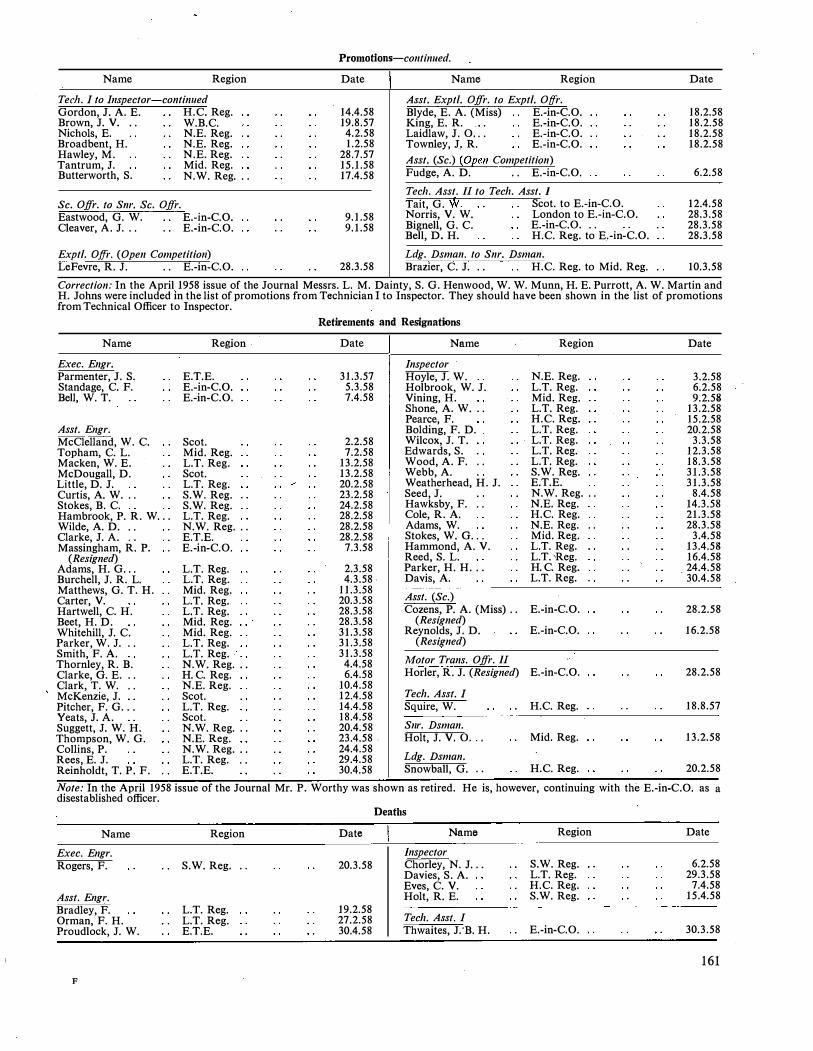
Name Region
Ted1. I to I11spector-continued Gordon, J. A. E. H.C. Reg. Brown, J. V. . . W.B.C.
Nichols, E. N.E. Reg. Broadbent, H. N.E. Reg.
Hawley, M. N.E. Reg. Tantrum, J. Mid. Reg. Butterworth, S. N.W. Reg . ..
Sc. Ojfr. to Snr. Sc. Ojfr. Eastwood, G. W. E.-in - C.O. Cleaver, A. J. . . . . E.-in - C.O.
Exptl. Offr. (Ope11 Competitio11) LeFevre, R. J. . . E.-in-C.O.
Promotions-co11ti1111ed.
Date
14.4.58 19.8.57
4.2.58 1.2.58
28.7.57 15.1.58 17.4.58
9.1.58 9.1.58
28.3.58
Name Region
Asst. Exptl. Ojfr. to Exptl. O[fr. Blyde, E. A. (Miss) E.-in -C.O.
King, E. R. E.-in -C.O. Laidlaw, J. 0.. . E.-in -C.O. Townley, J, R. E.-in - C.O.
Asst. (Sc.) (Open Competition) Fudge, A. D. . . E.-in -C.O.
Tech. Asst. II to Tech. Asst. I Tait, G. W. Scot. to E.-in-C.O.
Norris, V. W. London to E.-in-C.O. Bignell, G. C. E.-in - C.O. . . Bell, D. H. H.C. Reg. to E.-in - C.O.
Ldg. Dsman. to Snr. Dsman. Brazier, C. J. . . H.C. Reg. to Mid. Reg.
Date
18.2.58 18.2.58 18.2.58 18.2.58
6.2.58
12.4.58 28.3.58 28.3.58 28.3.58
10.3.58
Correction: In the April 1958 issue of the Journal Messrs. L. M. Dainty, S. G. Henwood, W. W. Munn, H. E. Purrott, A. W. Martin and H. Johns were included in the list of promotions from Technician I to Inspector. They should have been shown in the list of promotions from Technical Officer to Inspector.
Name
Exec. Engr. Parmenter, J. S. Standage, C. F. Bell, W. T.
Asst. Engr. McClelland, W. C. Topham, C. L.
Macken, W. E. McDougall, D. Little, D. J. Curtis, A. W . .. Stokes, B. C. Hambrook, P.R. W ... Wilde, A. D. . . Clarke, J. A. . . Massingham, R. P.
(Resigned) Adams, H. G ... Burchell, J. R. L.
Matthews, G. T. H. Carter, V.
Hartwell, C. H. Beet, H. D. Whitehill, J. C.
Parker, W. J . .. Smith, F. A. Thornley, R. B. Clarke, G. E. . . Clark, T. W. . .
McKenzie, J. Pitcher, F. G ... Yeats, J. A. Suggett, J. W. H. Thompson, W. G.
Collins, P. Rees, E. J. Reinholdt, T. P. F.
Region
E.T.E. E.-in -C.O. E.-in - C.O.
Scot. Mid. Reg. L.T. Reg. Scot. L.T. Reg. S.W. Reg. S.W. Reg. L.T. Reg. N.W. Reg . .. E.T.E. E.-in - C.O.
L.T. Reg. L.T. Reg. Mid. Reg. L.T. Reg. L.T. Reg. Mid. Reg. Mid. Reg. L.T. Reg. L.T. Reg. N.W. Reg . .. H.C. Reg. N.E. Reg . Scot. L.T. Reg. Scot. N.W. Reg . .. N.E. Reg. N.W. Reg . .. L.T. Reg . . . E.T.E.
Retirements and Resignations
Date
31.3.57 5.3.58 7.4.58
2.2.58 7.2.58
13.2.58 13.2.58 20.2.58 23.2.58 24.2.58 28.2.58 28.2.58 28.2.58
7.3.58
2.3.58 4.3.58.
11.3.58 20.3.58 28.3.58 28.3.58 31.3.58 31.3.58 31.3.58
4.4.58 6.4.58
10.4.58 12.4.58 14.4.58 18.4.58 20.4.58 23.4.58 . 24.4.58 29.4.58 30.4.58
Name
Inspector Hoyle, J. W. Holbrook, W. J. Vining, H. Shone, A. W . .. Pearce, F. Bolding, F. D. Wilcox, J. T. Edwards, S. Wood, A. F. Webb, A.
. .
Weatherhead, H. J. Seed, J. Hawksby, F. Cole, R. A. Adams, W.
. .
Stokes, W. G ... Hammond, A. V. Reed, S. L. Parker, H. H . .. Davis, A.
Asst. (Sc.) Cozens, P. A. (Miss) ..
(Resigned) Reynolds, J. D.
(Resigned)
Motor Trans. Ojfr. II
Horler, R. J. (Resigned)
Tech. Asst. I Squire, W.
S11r. Dsman. Holt, J. V. 0 ...
Ldg. Dsman. Snowball, G. . .
Region
N.E. Reg. L.T. Reg. Mid. Reg. L.T. Reg. H.C. Reg. L.T. Reg. L.T. Reg. L.T. Reg. L.T. Reg. S.W. Reg. E.T.E.
N.W. Reg . .. N.E. Reg. H.C. Reg. N.E. Reg. Mid. Reg. L.T. Reg. L.T. 'Reg. H.C. Reg. L.T. Reg.
E.-in - C.O.
E.-in -C.O.
E.-in - C.O.
H.C. Reg.
Mid. Reg.
H.C. Reg.
. .
Date
3.2.58 6.2.58 9.2.58
13.2.58 15.2.58 20.2.58
3.3.58 12.3.58 18.3.58 31.3.58 31.3.58
8.4.58 14.3.58 21.3.58 28.3.58
3.4.58 13.4.58 16.4.58 24.4.58 30.4.58
28.2.58
16.2.58
28.2.58
18.8.57
13.2.58
20.2.58
Note: In the April 1958 issue of the Journal Mr. P. Worthy was shown as retired. He is, however, continuing with the E.-in - C.O. as a disestablished officer.
Deaths
Name Region Date Name Region Date
Exec. Engr. Inspector Rogers, F. S.W. Reg. .. 20.3.58 Chorley, N. J ... S.W. Reg. 6.2.58
Davies, S. A. L.T. Reg. 29.3.58 Eves, C. V. H.C. Reg. 7.4.58
Asst. Engr. Holt, R. E. S.W. Reg. 15.4.58
Bradley, F. L.T. Reg. 19.2.58 Tech. Asst. I Orman, F. H. L.T. Reg. 27.2.58
Proudlock, J. W. E.T.E. 30.4.58 Thwaites, J:B. H. E.-in - C.O. 30.3.58
161
F
Transfers
Name Region Date
Snr. Exec. Engr. Warnock, W. T. Scot. to E.-in-C.O . . . 31.3.58
Exec. Engr. Blair, G. M. . . E.-in-C.O. to Home Office 3.2.58 Brown, W. D . .. E.-in-C.O. to H.C. Reg. 3.2.58 Gray, J. A. E.-in-C.0. to E.T.E. 28.4.58
Asst. Engr: Gee, J. A. E.-in-C.O. to Nigeria 16.2.58 Peake, W. Mid. Reg. to E.-in-C.O. 17.2.58
Book Review "Fernschreib-Ubertragungstechnik. "H. Fiilling (in German).
R. Oldenbourg, Munich. 154 pp. 148 ill. D.M. 16.80.
This is an excellently produced book with good typography and clear line diagrams, but its usefulness to the majority of the readers of the Post Office Electrical Engineers' Joumal is severely curtailed by the language barrier, for, in the experience of the reviewer, a sound knowledge of foreign languages.is unfortunately rare among students of telegraphy.
The subject of "Teleprinter Transmission Technique" is dealt with under seven main headings: (a) The problem of telegraph transmission, (b) The fundamentals of telegraph transmission, (c) Basic circuits of teleprinter transmission, (d) Basic apparatus elements of v.f. telegraphy, (e) V.F. telegraph systems, ( f) Teleprinter signal regenerators, and (g) Measuring apparatus for teleprinter transmission.
Section (b) is not concerned with the basic phenomena of wave propagation in transmission lines, but deals with telegraph distortion with great clarity and ample illustration. The spectrum of the telegraph signal and the effects of a limited frequency band for transmission are treated in a conventional manner, but very clearly.
It is a pity that there is no discussion of random interference and the modes of addition of distortion in tandemconnected circuits. A brief mention of these points is
BOARD OF EDITORS
D. A. BARRON, M.Sc., M.I.E.E., Chairman. L. F. SCANTLEBURY, Whit.Sch., A.C.G.I., DJ.C., M.l.E.E. H. G. BEER, Whit.Sch., A.C.G.I. T. H. FLOWERS, M.B.E., B.Sc.(Eng.), M.I.E.E. W. J. E. TOBIN, B.Sc.(Eng.), A.C.G.I., D.I.C., A.M.I.E.E. A. H. C. KNOX, B.Sc.(Eng.), M.I.E.E. R. F. WALDEGRAVE. E. DAVIS, A.M.I.E.E., Managing Editor. J. H. BROADHURST, A.M.I.E.E. }Assistant Editors. A. G. LEIGHTON, B.Sc.(Eng.), A.M.I.E.E. B. FARR, Secretary-Treasurer.
Copyright
The entire contents of this Journal are covered by general copyright, and special permission is necessary for reprinting long extracts, but Editors are welcome to use not more than one-third of any article, provided credit is given at the beginning or end thus: "From the Post Office Electrical Engineers' Journal."
The Board of Editors is not respemsible for the statements made or the opinions expressed in any of the articles in this Journal, unless such statement is made specifically by the Board.
Communications
All communications should be addressed to the Managing Editor, P.O.E.E. Journal, Engineer-in-Chief's Office, Alder House, Aldersgate Street, London, E.C.1. Telephone: HEAdquarters 1234. Remittances should be made payable to "The P.O.E.E. Journal" and should be crossed " & Co."
·
162
Name
Asst. E11gr.-collfi11ued Laurie, D. Croxson, V. E. Crawford, A. Housley, G. J. T. P. Warwick, F. L. S. Forty, A.S. Shires, N. N.
Ldg. Dsman. Howell, K. G.
. .
Region
L.T. Reg. to Scot .. E.-in-C.O. to L.T. Reg. E.-in-C.O. to Nigeria E.-in-C.0. to War Office .. E.-in-C.O. to E.T.E. E.-in-C.0. to Guernsey E.T.E. to Cyprus . .
Mid. Reg. to H.C. Reg.
Date
24.2.58 21.3.58 28.3.58
1.4.58 6.4.58 8.4.58
10.4.58
3.3.58
warranted, in a modern work, even if space is limited. Similarly, the treatment of band-limitation might have been slightly extended beyond the "ideal filter" concept.
Section (d) covers the elements of amplitude-modulated v.f. telegraph systems very well; the portion concerning level compensation in receivers is excellent. The treatment of filters is brief and deals mainly with the differential equivalent of the lattice form, which is the most usual in German practice.
The section dealing with systems (section (e)) describes the features of current German systems, both single-tone and two-tone, for local-line and radio use. The amount of space devoted to two-tone systems could have profitably been reduced to provide room for some description of the properties of f.m. telegraphy, mention of which the author relegates to a footnote.
Regeneration includes a mention of electronic regenerators that is so sketchy that at least a reference to literature might have been made.
Current German practice in measuring apparatus appears to be adequately covered.
Summing up, this appears to be a good outline of <;urrent German practice and principles of v.f. telegraph transmission, with a basically good treatment of the subject of telegraph distortion.
L.K.W.
Binding Cases
Cases for binding are available, and may be obtained from the Local Agents for 3s. Subscribers can have their copies of volumes bound, at a cost of 10s. 6d., by sending the complete set of parts to the Local Agents or to the P.O.E.E. Joumal, Engineer-inChief's Office, Alder House, Aldersgate Street, London, E.C.l. Orders for binding for Vol. 1-19 should indicate whether the original binding case with black lettering, or the later pattern with gold, is required. Cases with gold lettering are the only type stocked from Vol. 20 onwards.
Back Numbers
The price of the Journal, which is published quarterly, is 2s. 6d. (3s. 3d. post free) per copy, or 13s. per annum, post free. Back numbers can be supplied, subject to availability of stocks, at 2s. 6d. (3s. 3d. each post free). Orders for back numbers may be sent to the P.O.E.E. Jouma/, Engineer-in-Chief's Office, Alder House, Aldersgate Street, London, E.C.1, or to the Publishers.
Employees of the British Post Office can obtain the Journal through Local Agents at the reduced price of 2s. per copy.
Advertisements
All communications relating to space reservations should be addressed to the Advertisement Editor, P.O.E.E. Journal, Alder House, Aldersgate Street, London, E.C. l. Communications regarding advertisement copy, proofs, etc., should be addressed to the Publishers, Messrs. Birch & Whittington (Prop. Dorling & Co. (Epsom) Ltd.), Depot Road, Epsom, Surrey.
\
INDEX TO ADVERTISERS
PAGE PAGE
Alton Battery Co., Ltd., The xxix Mullard, Ltd . . . viii, xxiv
Austinlite, Ltd. xxii
Automatic Coil Winder & Electrical Equipment Co:, Ltd. xxxix
National Salt Glazed Pipe Manufacturers' Association . . ix
Neil, James, & Co. . . xxxvii
Automatic Telephone & Electric Co., Ltd.
British Institute of Engineering Technology
British Insulated Callender's Cables, Ltd . . .
Brodie & Askham, Ltd.
xxx, xxxi, xxxvi
xxxvii
vii
xxxvii
xxviii
Painton of Northampton
Pirelli-General Cable Works, Ltd.
Pitman, Sir Isaac, & Sons, Ltd.
Pye, Ltd.
·Rawlplug Co., Ltd., The
xxiii
.. 'xxxix
. . iv, xxv
ii, iii
v Dale Eiectric (Yorkshire), Ltd.
E.M.I. Institutes iv Siemens Edison Swan Ltd. vi, xii, xiii, xviii, xix, -xxxii
Ericsson Telephones, Ltd.
Ferranti, Ltd . ..
General Electric Co., Ltd., The
Ghana Public Service Commission ..
xi
iv
xiv, xv, xxxiv, xxxv
xxviii
Smith, Frederick & Co.
Standard Telephones & Cables, Ltd.
Telephone Manufacturing Co., Ltd.
Tungstone Products, Ltd.
xxv
xvi, xxi, xxvi, xxvii, xl
x, xxv
. . xxxiii
Great Northern Telegraph Co., Ltd.
K.G.M. Electronics, Ltd.
xv ii Turner, Ernest, Electrical Instruments, ·Ltd. xxviii
Marconi's Wireless Telegraph Co., Ltd. . . xxxviii
Westinghouse Brake & Signal Co., Ltd.
Winn & Coales, Ltd .. .
MULTI-INDICATOR TYPE Ml
e Wide viewing angle - ± 45° in vertical and
horizontal planes.
e High level of illumination.
e Simplicity of operation.
e Reliability.
The Indicator provides an ideal method for the selective display of
numbers or letters for:-
Indicator Boards
Timing system and clock displays
Telegraph and Telephone Channel Indicators
Digital Voltmeters, etc.
For further information write or telephone:
KG M e_lectronics limited -
xx
x
.The Barons St. Margarets ·Middlesex Telephone: POPesgrove 0031

SO watt
V.H.F. Fixed
Station
V.H.F. Fi.i·ed
Station
Boot Mounting
"Ranger" V.H.F.
(F.M. or A.M.)
Mobile
Radiotelephone
Remote Control Unit
for H.F. Fi:i:ed Station
2 Mcfs Transistor Oscillator
TO Hi. H OUlE Of EOl�IUU>H
ltADIO THHHONE (QUIJHINf
"l HllCOHMUtllCATIOl·H LTO
Designed a�d made by Pye
Microwave
Television
Link
1 k\V V_.H.F. or H.F.
Fixed Station
60 watt H.F.
Fixed Station
ii
Throughout the entire field of radio . .
communications Pye Telecommunications
design and make equipment for almost
every conceivable application. The range
shown here is by no means complete.
The items selected are intended to show
the versatility and enterprise of our
designers.
PYE TELECOMMUNICATIONS LTD. Telephone: Teversham 3131
�---:---� - � . �·.
Pulse and Bar Waveform
Generator

Dash Mo1mttno "Ranger"
V.H.F. (F.M. or A.M.)
Mobile Radiotelephone Fan Marker
Beacon
7 ' ..
Instrument Landing System
Telecommunications Ltd.
With Service Depots and
Distributors in 91 countries
all over the world, your Pye
communications equipment
will be backed by an organi
sation which is second to
none. It is at your service
for the asking.
Newmarket Road, Cambridge
Telegrams: Pyetelecom Cambridge
7-channel
M111tiplex
Terminal
��" ; .. ., ... �� 'I
Music Link
iii
Control
Equipment
CIZ Army Wireless Set
We offer comprehensive home training in a wide range of subjects, including P.M.G. Certificates, City and Guilds Grouped Certificates in Telecommunications, A.M.Brit.l.R.E. Examination, Radio Amateur's Licence, Radio and Television Servicing Certificates, General Radio and Television Courses, Radar, Sound Recording, etc. Also Courses in all other branches of Engineering.
With the following Courses, Practical Kits are available.
Radio, Televis ion, Mechanics, Electricity, Chemistry,
Photography, Carpe.ntry; also . Draughtsmanship,
Commercial Art, Amateur S.W. Radio, Languages, etc.
TELECOMMUNICATIONS PRINCIPLES (IN M.K.S. UNITS)
By R. N. Renton, C.G.I.A., M.l.E.E. 2nd Edition. This new edition, based entirely on the M.K.S. system, contains all the basic essential details of electricity and magnetism that every student of telephony, telegraphy or radio (including television) needs to know. Covers the syllabus for the C. and G. examination in Telecommunications Principles, Grades I, II and III. 45/- p.et.
SOLUTION OF PROBLEMS IN ELECTRICAL TECHNOLOGY
By H. Cotton, M.B.E., D.Sc., M.I.E.E., and P. V. Parry, M.Sc.(Eng.), A.M.I.E.E. This book contains a collection of graded worked examples (using the M.K.S. system) covering a wide range of electrical science and practice, as well as a number of questions (with answers) to be worked by
• ---------- Write now---------�
the reader. Almost two-thirds of the 350 examples given are worked out in full . 20/- net.
IC.6�
for FREE BROCHURE stating subjects of interest to:-
E.M.I. INSTITUTES Dept. 97, LONDON, W.4
An -Educational Organisation serving the E.M.I. Group of Companies, including
"HIS MASTER'S VOICE", COLUMBIA, etc. JUL1S8
PITMAN TECHNICAL BOOKS
Parker Street, K/ngsway, London, WC2
t:::;:-� '-��:---:-:::- ;--- -- . . �. ' ' .
WAND 3t" SEALED INS TRUMENTS
·: · · . .
. FER RA NT:l>S.EAlE D'/lN STRUM EN TS/· . '\ . ..... ·.. ' ' ' .. ' ·'/ ' ,.i
2" SEALED INSTRUMENT
TYPE APPROVED
, --
. ·COMPLY WITH , · < I ' ·.
RCS.lll AND RCL 231 'rt
Ferranti sealed instrume�ts comply \vith
'the requiren-ients of the Joi_nt Service
-Radio Components Standard_isation
Committee. Full Type· Approval has
been obtained
Humidity Class
. Category 40/85.
for 2" instruments,
H.l and Temperature
FERRANTI LTD MOSTON MANCHESTER 10
London Office: KERN HOUSE 36 KINGSWAY w.c.2
FI 167 iv

SOLID OR
CAVITY
MATERIALS
Rawlplug fixing devices save you time and money
U91
SCREW FIXINGS Use tile famous RA \VLPLUG for 11eat, firm fixl11gs in brick. sto11e, etc. All sizes for up to t• diameter Coach Screws. nawlplugs are walerTJroofed a11d 1111a1Jected by climatic conditlo11s.
BOLT FIXINGS For boltf11g down macl1i11es, Ilg/It or heavy, use RA \VLBOLTS. a dry fixing t11at
grips by erpa11sion. No cold cllfsel/f11g, 110 waiti11g for ceme11t to llarden. Sizes up to 1'
bolt diameter.
CAVITY FIXINGS The amazing RA \VLNUT, screwed up from Ille· fro11t, forms Its 01vn rivet /1ead bel1i11d the material-airllg/1t, watertight, vibration-proof, saueak-proo/I For all t/ifn or /101/ow materials.
Fixing methods that served well enough in by
gone days fall far short of modern standards of
efficiency, when an average machine can be safely
bolted down and in operation within an hour or
so of arrival !
Rawlplug Fixing Devices always save time and
therefore money, for it is a -simple fact that on
every screw and bolt fixing job, in solid or cavity
materials, you'll make strong, absolutely safe
fixings in far less time than by any other method.
You can easily prove this for yourself. The first
step is to write for full details of the 21 different
types of Rawlplug Fixing Devices. Write us now
-and if after studying our literature, you have
any difficulties about a particular problem, our
Technical Service specialists will be delighted
to advise you without obligation.
FIXING DEVICES
THE RAWLPLUG COMPANY LTD
CROMWELL ROAD, LONDON, S.W.7
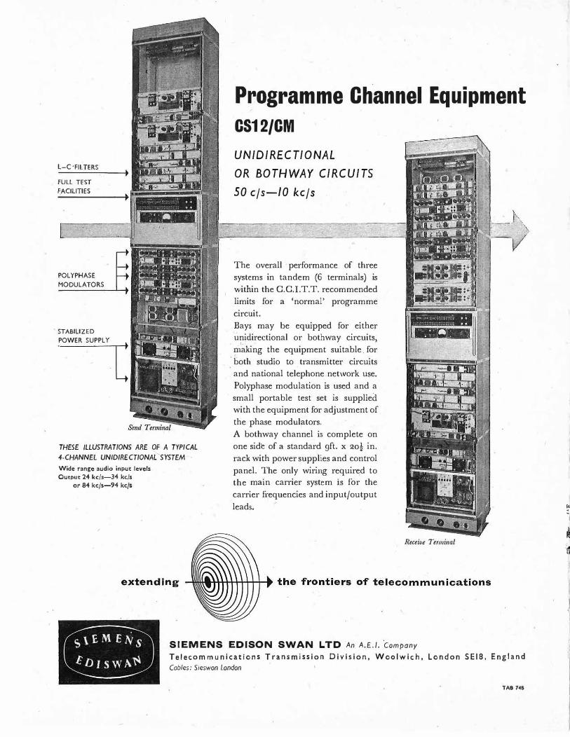
L-C ·FJL TERS
FULL TEST
FACILITIES
I ..
POLYPHASE
MODULATORS
STABILIZED
_POWER SUPPLY c
·- . " , . 0 .j
• .. .j <I
... .
• � J
THESE ILLUSTRATIONS ARE OF A TYPICAL 4-CHANNEL UN/DIRECTIONAL SYSTEM Wide range audio input levels
Output 24 kc/s-34 kc/s
or 84 kc/s-94 kc/s
/
extending
Programme Channel Equipment
CS12/CM
UNIDIRECTIONAL OR BOTHWAY CIRCUITS
50 c/s-10 kc/s
The overall · performance of three
systems in tandem (6 terminals) is
within the C.C.l.T.T. recommended
limits for a 'normal' programme
circuit.
Bays may be equipped for either unidirectional or bothway circuits,
i:naking the equipment suitable. for
both studio to transmitter circuits
and national telephone network use.
Polyphase modulation is used and a
small portable test set is supplied
with the equipment for adjustment of
the phase modulators.
A bothway channel is complete on
one side of a standard gft. x 20t in.
rack with power supplies and control
panel. The only wiring required to
the main carrier system is for the
carrier frequencies and input/output
leads.
Receive Terminal
s\£MEJ\is ED1swf\�
SIEMENS EDISON SWAN LTD .An A.E.I. ·company Telecommunications Transmission Division, Woolwich, London SEl8, England
Cables: Sieswon London
TAB 7�8

G
for interrconrriecting.
electronic equipn1e11t
BICC make Coaxial Radio Frequency Connectors with
moulded-on terminations for use with-
Ground and airborne radar equipment
Ground and airborne radio
transmitters and receivers
Terminations include a standard range
(with appropriate panel mounting units)
designed to Ministry of Supply requirements.
In addition, there are a .number of
BICC designs for other applications.
BICC t(j{($iat R.F. CONNECTORS
BRITISH INSULATED CALLENDER'S CABLES LIMITED,
21 Bloomsbury Street, London, W.C.1

Permanent
Magnets
I
The Mullard range of permanent magnet materials
meets the majority of present day magnet require
ments. To assist designers in choosing the correct
magnet .material for a given purpose, some of the
advantages of these materials and a few of their
applications, are given below:
'Ticonal' GX has the highest energy content of the
commercially available permanent magnet ma
terials. It is difficult and expensive to manufacture,
and should only be used where minimum size and
weight are extremely important with cost a
1100 . 1400
-H
1200 \000
XIOOO
B"
secondary factor. These magnets are predominantly
anisotropic and are only manufactured in block
and cylindrical form, with a straight magnetic
axis.
'Tico.nal' G represents the best compromise be
tween performance and cost of any permanent
magnet material available. It is comparatively
easy to manufacture into any required shape and
gives a high and uniform performance. It is strongly
recommended · for general purposes and is used
throughcmt the world for the majority of permanent
magnet applications.
,-.------, I I I I
:No.4: I I I I L------..J
The Choice of Magnet ·Materials Advertisements in this series deal with· general design considerations. If you require more specific information on the use of permanent magnets, please send your enquiry to the address below, mentioning the Design Advisory Service.
'Ticonal' L is primarily intended for use in loudspeaker assemblies. A permanent magnet of higher
Bd value than is obtainable from 'Ticonal' G has
certain technical advantages.
'Ticonal' C has slightly lower magnetic properties than 'Ticonal' G but with a higher coercive force;
this material is particularly useful in motors,
dynamos and other dynamic· applications.
'Ticonal' K is a relatively new material and only certain shapes are available at present. Its magnetic
characteristics' facilitate the use of very short
magnets. It has an exceptionally high coercive force
and is recommended in the design of moving coil
instrument circuits where a magnet forms the inner
core of the system.
'Reco' 3A is isotropic (non-directional) and can
therefore be magnetised equally in any direction.
It is of comparatively low performance but is
particularly suitable fo.r multi-polar applications
or inexpensive magnets where hig.h performance is
not essential.
'Magnadur' 1 is one of the new ceramic magnets.
As it contains no cobalt or nickel it is therefore
inexpensive to manufacture. It has an unusually
high coercive force and is particularly useful for
applications where the magnet is subjected to
alternating fields of any frequency.
/
Principal Characteristics of Mullard Permanent Magnets
MAGNET BH (max) x 106 Br He Bd Hd 1Ticonal' GX 7.5 13,500 720 12,000 625 1Ticonal 1 G 5.7 13,480 583 11,000 520 1Ticonal' L SA 13,500 575 12,000 450 'Ticonal' C 5.0 12,500 680 9,620 520 'Ticonal' K 4.0 9,000 1,300 5,000 800 'Reco' 3A 1. 7 7,200 645 4,350 390 'Magnadur' I 0.95 2,000 1,750 950 1,000
If you wish to receive reprints of this advertisement and others in this series, write to the address below.
MULLARD LIMITED, COMPONENT D.IVI SION, MULLARD HOUSE, TORRINGTON P LA CE, W.C.I . Tel. LANgham 6 6 3l
MC26S
viii

Breathgasting ! '1That's a superb shot!" exclaimed Baron Rabbit. "You have easily surmounted that formidable obstacle."
"Aye," said MacRabbit, "these conduits make life very difficult for us underground golfers."
"Yet they make life easier for the surface pe.ople! These are vitrified clay conduits-strong and glassy smooth. Electric cables slide easily through them. They facilitate installation and
Flabbertaking ! servicing of important cables."
"Acids in the soil cannot harm vitrified clay conduits-they almost last for ever/' ·said MacRabbit. "Think of the money they s_ave !"
"I thought that point would appeal to you!" said the Baron. "Salt glazed vitrified clay conduits are breathgasting."
"Salt glazed vitrified clay conduits are
fiabbertaking !" agreed MacRabbit.
Put down Salt Glazed Vitrified Clay Pipes and Conduits-they stay down for centuries! NATIONAL SALT GLAZED PIPE MANUFACTURERS
' ASSOCIATION
Parent
Uni I
Remote
Subsidiary
U11it
SUBSCRIBERS'
LINE CONCENTRATOR
An all relay communication system providing Telephone Service for TEN subscribers over TWO connecting links to an exchange ... it is not a Party line ... is fully secret , using standard telephone sets ... drastically reduces plant costs without sacrificing facilities ... complete system can be installed in a few hours . . . neither battery nor power leads
. are required
at remote Subsidiary Unit nor premises for housing it ... maximum reliability ... visual and audible alarms provided in Parent Excha9ge to indicate line faults ... a faulty junction
automatically taken out of service. The scheme can also provide . .. Night service for selected subscribers to Exchange with restricted hours of attendance ... release of cable pairs to fully loaded D.Ps., or on cable routes pending new plant ... service to blocks of Fiats as alternative to P.B.X ... service for Exhibitions, Race lVIeetings etc., by making pairs available without additional plant.
Writefor technical data
TELEPHONE MANUFACTURING CO LTD Hollingsworth Works , Dulwich, London SE21 Telephone G IPsy Hill 221 1
The pipelines in this 1,765-ft. tunnel under the River Tees between the l.C.I. Works at Wilton and Billingham were wrapped with DENSO TAP� some years ago. A recent inspection showed not a sign of corrosion!
DENSO TAPE is but one of a whole family of anticorrosive products-each engineered for specific uses.
Have your corrosion problem solved once and for all by:
PRODUCIS TRADE MARK
x
Plrotograplr by courtesy of Imperial Clremical Industries Ltd.
WINN & COALES LTD. DENSO HOUSE, CHAPEL ROAD, LONDON, S.E. 27 'Phone: GIPsy Hill 4247 'Grams: Denselte, Wesr.nor1 London
FLAMEPROOF TELEPHONE SYSTEMS that are as versatile as their standard counterparts,
are today an essential requirement of all modern Oil Refineries and Chemical Plants.
The development and manufacture, by Ericsson Telephones Ltd., of this class of
equipment represents an important contribution towards safety in industry.
The Desk Telephone, incorporating the latest B.P.O. 1000 n loop circuit, may be
used on Auto or C.B. systems. A push button can be provided for operator recall, etc.
The Telephone Bell, which constitutes a separate unit, also serves as the rigid line
termination point and is provided with four entries, one of which is used for the desk
cord connection to the instrument. The unit may also be used as an extension bell, in
which case blanking plugs are supplied for the unused entries.
The Distribution Box, with its main cable chamber and ten individually switched
outlets provides positive line isolation together with easy and economic line distribu
tion. The capacity of the box is 10 pairs for local distribution and 40 pairs for looping
through to other boxes. The line terminal chambers can be opened only with the
switch in the 'OFF' position, which cannot be moved to 'ON' while the chambers
remain open.
With the exception of the main chamber sealing gland, all glands are threaded for
t in. conduit entry. The range covers the following permissible cable connections:
Conduit, Single wire a�moured cable, Tough rubber sheathed and Mineral insulated.
Illustrated above is a block schematic showing a typical telephone system based
on this new equipment.
UN/CATION EQUIPMENT & CHEMICAL INDUSTRIES
Certified by the Ministry of Power
FLP. 3651
FLP. 3652
FLP. 3653
This equipment conforms to B.S.S. 229. The Telephone and Bell/ Terminal Unit are accepted by the B.P.O. as their Type Nos. N.266 and N.69.A respectively.
ERICSSON TELEPHONES LIMITED
ETELCO LIMITED HEAD OFFICE: 22 LINCOLNS INN FIELDS, LONDON, W.C.2. TEL: HOLBORN 6936
WORKS: BEESTON, NOTTINGHAM & SUNDERLAND.

Photo by courtesy of
Australian News and Information B•;reau.
SIEMENS EDISON SWAN LTD. are proud to feature the Sydney (New SouthWales) Semi-Automatic Trunk Exchange as a major contribution to the development of the Australian Post Office trunk switching plan. A large proportion of the equipment, including 77 operating positions was cut into service in November 1957, and when installation of the remainder is completed in mid-1958 the Sydney equipment ·will comprise the largest Cordless Trunk Exchange in the British Commonwealth. An impression of the magnitude of the initial project µiay be gained from the following:-
1'1ain Operating Positions ... 197 Trunk Lines . . . . . . I020 Local Area Junctions ..... 1850
Described opposite are the major features of the equipment but of particular interest is the extent to which automatic switching tecJrniques are employed. The Sydney Trunk Exchange incorporates the experience gained over many years study of the complex problems of trunk mechanisation. The Australian Post Office is joined by other progre�sive Administrations throughout the world in recognising the effectiveness of cordless operating positions, in conjunction with our motor uniselector switching apparatus, in meeting the demands of modern trunk switching.
The Largest Cordless Trunk Exchange in
the British Commonwealth
i
in Sydney
CORDLESS POSITIONS economise operator effort and stimulate efficiency. The metal and plastic positions are arranged in convenient small suites.
AUTOMATIC SWITCHING is c.arried out exclusively by our High Speed Motor Uniselector, the ideal trunk switching mechanism. It combines reliability and ease of maintenance with outstanding flexibility of application.
TRANSIT CALLS, also calls to the local area are routed without operator intervention. Code translation and automatic alternative routing facilities are available.
CALL QUEUEIN.G equipment controls the distribution of incoming traffic to operators who may be assigned to meet fluctuations in route traffic.
CALL STORAGE facilities ensure maximum trunk occupancy. Demand service can be maintained despite route congestion.
KEYSENDERS are available to all operators and afford code translation and alternative routing facilities.
TRUNK LINES of many types are served-Voice Frequency signalling, D.C. dialling, Carrier signalling, etc.
TRANSMISSION performance is optimum due to the use of 4-wire svvitching and automatic pad-control.
SUPERVISION of traffic handling and of staff is centralised; the exchange carr operate as a trunk switching unit of maximum efficiency.
SUBSCRIBER TRUNK DIALLING can readily be added to the system on a progressive basis.
It is important to appreciate that
the 111a1ry features ef our trunk
switching system may be ajiplied
with equal effect to requirements
much smaller than those des
cribed.
SIEMENS EDISON SWAN LIMITED An A.E./. Company
,Public Telephone Division, Woolwich, London S.E.18. Telephone: Woolwich 2020.
When it's essential
S.G.e radio equi me
touch. • •
serve you - tor .1ess!
now available
G.E.C. S-CIRCUIT JUNCTION RADIO EQUIPMENT
providing 5 speech circuits each having a bandwidth of.
300 c/s lo 3400 c/s
This operates over distances of up to 40 miles (65 km), without repeaters in
any one of the following frequency bands:
71.5 Mc/s lo 100 Mc/s
132 Mc/s to 156 Mc/s
156 Mc/s to 184 Mc/s
235 Mc/s to 270 Mc/s
Helical aerials having a forward gain of 13 db are available for the frequency
band 156 Mc/s to r 84 Mc/s in addition to the,standard Yagi aerial.
For further information, please write J or Standard Specification SPO .50 SI.
THE GENERAL ELECTRIC COMPANY LTD OF ENGLAND TELEP H 0 NE,
· RAD I 0 AND TELE VIS I 0 N W 0 R KS, C 0 VENTRY
• 'll!'t------lH
G.E.C. 14.

/
• the keyword of
S.T.C.
MAGNETIC MATERIALS Quality is a consistent feature of S.T.C. Magnetic
. Materials, the use of
which in its own systems and equipment ensures full appreciation of the
properties essential for uniform electrical characteristics and stable perform
ance. S.T.C. Magnetic Materials are available to industry for all applications.
has lower initial permeability than Permalloy 'C' but has higher values of flux density. It is suitable for use where high permeability to alternating field is required super-. imposed upon a steady polarising field.
for highest initial permeability, useful for wide-band frequency transformers, current transformers, chokes, relays and magnetic shielding.
for very high resistivity without undue lowering of the maximum flux density. Variation of permeability with frequency is small. Ideal for H.F. applications. 1
for high flux density, very rectangular hysteresis loop, with a retentivity of at least 95% of its saturation value and low coercive force. Ideal for saturable reactors, magnetic amplifiers, digital computers, memory devices, etc.
for high permeability with a very high value of rra'Limum flux density. Finds special application for me as high quality receiver diaphragms, also motor gener� t )rs and servo-mechanisms in aircraft where weight and volume are important factors.
Siandard Telep!to11es and Cables Limiied Registered Office: Connaught House, Aldwych, W.C.2
MAGNETIC MATERIALS DEPT: NORTH WOOLWICH LONDON E.16
Hl6H
SPEED AUTOMATIC MORSE EQUIPMENT
Undulator Model 309 Max. operating speed 300 words per minute. Other models available with double recording part and with amplifier/rectifier for tone frequency signals.
Morseinker Model 1515 , Used for training purposes, Motor-driven. Also available with built-in amplifier/rectifier for tone frequency signals. Springdriven models also available.
Keyboard Perforator Model 50 Provided with locking device which pcevents the simultaneous depression of two keys. Max. operating speed 750 characters per minute.
---·
Converter Model 2201 For the conversion of a perforated Morse Code, or Cable Code, tape into a perforated 5-unit Code tape or into 5-unit signals at standard teleprinter speed.
Transmitter Model 112 Speed range 13-250 words per minute. For training schools model 113 having a speed range of 5-35 words per minute is recommended.
Reperforator Model 451 . A truly synchronous receiver which produces
a perforated tape similar to the one used for transmission. Normal speed range 40-200 words per minute.
Converter Model 2206 For the conversion of a perforated 5-unit Code tape into a perforated Morse Code, or Cable Code, tape.
OREAT NORTHERN TELEORAPH WORKS DIVISION OF THE GREAT NORTHERN TEL EGRAPH CO. LTD.
4, SYD HAVNS PLAD S
COPENHAGEN SV, DENMARK
xvii
I LONDON OFFICE: 5, ST. He:LEN'S PLACE
LONDONE. C.3.
1859 Malta-Alexandria Telegraph Cable Consultants for the British Government.
1863 lndo-European Telegraph Operation. Open Wire Line 2,750 miles long, including three submarine cables.
1873 Gutta Percha Submarine Telegraph Cable made for Platino Brazileira Telegraph Co. 1,129 Nautical Miles, Rio - de - Janeiro -Montevideo.
1874 Atlantic Telegraph Cable made and laid by Cable Ship Faraday I for Direct United States Cable Co. -3,112 Nautical Miles.
1891 First cross-Channel Gutta Percha Telephone Cable, St. Margarets Bay to Sangatte (French Coast), for first telephone circuits between London and Paris.
1895 Telegraph Cable laid up the River Amazon for Amazon Telegraph Co. 1,639 �autical Miles.
Right: Early Atlamic Telegraph Cable
Below: Early Type A1ultiple-Twi11
Telephone Cable
Below right: r89r A11glo-Fre11ch Sub
marine Telephone Cable
1903 Multiple Twin Paper-Insulated Telephone Cable made containing 1212/10 lb. conductors.
1908 Composite Multiple-Twin Telephone-Telegraph un-derground cable made for Western Trunk Lines to South Wales, 3 ·66 inch diameter.
1910 First Coil Loaded G.P. Telephone Cable Anglo�French across the English Channel.
1911 First Balata Insulated Coil Loaded Telephone Cable Anglo-Belgian cross-Channel.
1913 First Coil Loaded Multiple-: Twin Trunk Telephone Cable laid in Manchester area.
r926 Pacific Cable
1919 Continuously Loaded Bal;:ita Submarine Telephone Cable, Norway.
1923 Cable Ship Faraday II in operation. Cable laying, New York-Canso, 1,000 Nautical Miles.
1924 First Anglo-Dutch Continuously Loaded ·
Paper Insulated Telephone Cable.
1926 Continuously Loaded Pacific Telegraph Cable for the "All Red Cable Route", Fanning Island-Suva.
r935 Bass Straits Submarine Cabli
� .. 1 ,,. • • • ' - .. - • --- - -,. .- -- - -- - - - • - - ---... -:. �- -- - - . -
EDl.SON SWAN From the early gutta percha covered telegraph cable of one hundred years ago to the modern multi-channel q1bles for telephony and for television transmission, the name of Siemens has been intimately associated with many important advances in telecommunications. To-day it is linked with two other famous names in the electrical industry. The combination of Siemens and Edison Swan marks the start of a new era in which this great enterprise, with its wealth of exp�rience, can look forward with added confidence to making even more important contributions in the future.
· (Above) r937 London Television Network Feeder Cable
(Below) r936 Type Carrier Cable
1929 First Submarine Telephone Cable laid to the Isle of Man.
1935 Paragutta Submarine Co-axial Telephone Cable for carrier working. Bass Straits, Tasmania.
Long Distance Co-axial Cable with
swT01111ding audio quads
Vertical illustration : Modem Type of
Paper Insulated Distribution Cable
1936 London-Oxford, 12 Channel Carrier Cable.
1937 London Television Network Cable. Balanced Pair, Crimped Conductor. Alexandra · Palace to Broadcasting House, including Houses of Parliament, Westminster Abbey, Buckingham Palace, St. James's Palace, Victoria Station.
1942 Plastic Insulated Telephone and Radar Cables being manufactured.
1949 First Sealed Tube Co-axial Cable for wide band carrier and television transmission.
1950 All-Plastic Telephone Type Cable ·manufactured up to 252 pairs and 3t inch diameter.
1956 First Atlantic Telephone Cable made by Submarine Cables Ltd., jointly owned by Siemens Edison Swan Ltd., and The Telegraph Construction and Maintenance Co. Ltd.
SIEMENS EDISON SWAN LIMITED An A.E.I. Company
Telephone Cable Division Woolwich, London, S.E.r8. Telephone: Woolwich 2020. P.D.2/2·

Repeater Station, Ryde, Isle of Wight.
(Courtesy of British Post Office)
WESTINGHOUSE
RECTIF�IERS employing either mechanically regulated or
transductor systems with electronic, magnetic
or transistorised control will bring your plant
up to date.
Manufacturers of silicon, germanium, selenium and copper-oxide rectifiers Westinghovse Brake and Signal Co. Ltd., 82 York Way, King's Cross, London, N.l. 'Phone: TERminus 6432
xx

The Nodistron
Gl0/200E
/ /
A NEW NUMERICAL DISPLAY TUBE
/ /
/ /
/ /
------
--------
/
----
This new Numerical Indicator tube
is designed for use in any direct read out
equipment. It is a cold cathode device, the
cathodes being shaped in the form of
numerals and brought out to separate
pins on a duodecal base. The application of
approximately 200 volts between any specified
--
cathode and the common anode causes a glow discharge
in the form of any individual numeral from 0 to 9.
Sia11dard Telephones a11d Cahles limired SPECIAL VALVE SALES DEPARTMENT
CONNAUGHT HOUSE 63 ALDWYCH LONDON W.C.2
xxi
Powe:r without fail
- .A..UTOM.A..TIC.A..LLV
This mains standby plant is one of seventeen manufactured for
Standard Telephones and Cables Ltd., and is for installation overseas.
It comprises two fully automatic units controlled by a single
switchgear cubicle. One unit is a Regenerative Flywheel' No break' set,
the other a' Normally Stationary' set. Dual standby is provided
This is what happens
1. Mains within limits. The three-phase electric motor drives both flywheel and
alternator of the 'No-Brealc' set (foreground), the alternator supplying regu
lated single phase current to the telecommunications equipment.
2. Mains outside limits. The electric motpr is discomiected, the diesel engine
starts automatically and when up to speed is connected to the alternator by
the magnetic clutch. During this cycle, stored energy in the flywheel drives
the alternator, thus maintaining a continuous power supply within the closest
limits of frequency and voltage.
3. Mains restored within limits. The electric motor is automatically reconnected
and resumes the drive, the magnetic clutch opens and the diesel engine shuts
down.
4. Should the 'No-Break' set develop a fault, the 'Normally Stationary' set
(background, left) starts and takes over supply to the equipment. The sets are
designed to restrict the supply interruption to the minimum possible under
the circumstances of the fault. Manual paralleling of the two sets is provided
for maintenance periods.
CONTROL. Automatic controls and indicators are provided to ensure reliable
operation in accordance with designed limits.
xxii
AUTOMATIC POWER PLANT
Tailor-made. by
STONE-CHANCE LTD.
(makers of Sumo Pumps and
Stone-Chance Lighthouses)
CRAWLEY, SUSSEX.
I
H
• THE N-EW "MICROCON"
PRINTED CIRCUIT CONNECTORS
Microcon Printed Circuit Connectors are designed to meet
the requirement for a light, compact, multi-way plug and
socket, giving greater reliability and longer life than the edge
connector method. Other patterns will soon be available, as
well as the ten-way connector shown here.
The pitch of soldering tags is suitable for a board pCnched to a standard module of 0·1".
Two types of plug are available-the first has the solder tags ori.e·ntated at 90° to the contact blades, the second has solder tags that are a continuation of the blades.
A metal cover can be fitted to either the plug with the straight blades or to the socket, and the mating unit can be supplied with wire retaining loops.
The two- part diecast cover, whose inner surfaces are insulated against short-circuiting, allows the connections to be checked physically and electrically without disturbing the clamping of the cable.
For polarizing purposes, when several connectors are mounted in .close proximity, one or more contacts can be removed from each plug in various combinations, the corresponding contact in the mating socket being blankec:J off by special polarizing keys.
Illustrated are some of the styles available
Write for technical leaflet
Painton & Co. Ltd. KINGSTHORPE NORTHAMPTON
Tel: 32354-5-6 Telegrams: 'Ceil, Northampton'
xxiii
Improved splice loading with the L219
The new economical
loading coil
Smaller construction
Permits smaller splices
'
Arising from the increasing demand for a smaller coil which can be employed in splice loading, the L219 has been developed. In the design Mullard Equipment Limited were assisted by their own production experience and information given by overseas users. The result is a simple, low cost component (to grade 3 spec.) suitable for small or large splice loading units.
By using a new grade of Ferroxcube pot core the overall volume of the coil is considerably reduced. The coil is resin sealed in a small cylindrical aluminium canister ensuring complete protection from climatic effects. The windings of the coils are brought out on flying leads.
LIFE SIZE COIL
L219
Key factors in this development are the clamping arrangements which, with the new coil, permit much smaller splice housing. On small cables, coils are mounted lengthways in pairs with great compactness. For larger cables, coils are mounted radially, each mounting plate accommodating up to seven coils. Clamping plates, coils, etc. can be supplied as kits.
Please write for full details of these new loading coils
MULLARD EQUIPMENT LIMITED A Company ·or the Mui lard Group
M ullard House. Torrington Place. London W .C.1 . Telephone: Langham 6633
'{fi!} ME614a
xxiv

If you are interested
in CAPACITORS to
TELECOMMUNICATIONS STANDARDS
®offeryou RELIABILITY+ '•.,or .. ••' POLYSTYRENE CAPACITORS
BRITISH POST OFFICE TYPES
TELECOMMUNICATIONS PRINCIPLES (IN M.K.S. UNITS)
Dy R. N. Rcn1on, C.G.l.A .. M.1.E.E. 2nd Edition. This new cdhlon, based entirely on the M.K.S. S)'Slcm, con1ains all the basic essential de1ails of clec1rici1y and magnetism that every student of telephony, telegraph)' or radio (including le1evJsion) needs to know. Covers 1hc syllabus ror the C. and G. examination in Telecommunications rrinc:iple.s, Grades J, 11 and Ill. 4Ss. net.
FREQUENCY MODULATION
Dy A. W. Keen, M.l.R.E., A.M.I.E.E. This is 1hc Orst book or lcs kind to provide a compact but comprehensive dcs:riptJon of the 1echnkalilies of the transmjuing and receiving sidu of f.nl. broadcasting ttthniquc. A readable aooroach 10 1he subject for 1he pra:cising radio engineer nnd designer. 30s. net.
WORKED RADIO CALCULATIONS Graded p,.acticol Examples
8y Alfred T. Witts, A.M.l.E.E. 2nd Edition. This book wlll help all cm.Jiu mcchank:s aml win;lcss SlmJetHs 10 111as1cr cornplc1ely the various mathematical cqua1ions that occur throughout their training. This new cdillon which incorporates the M.K.S. S)'Slcm includes most of the Jmoortanc formulae. 12s. 6d. net.
• ELECTRIC LIFTS
8¥ R. S. Phillips, M.1.E.E. 4th Elition. A new and up.to-date edilion. l l forms a complete manual on lhe current 1>rac1lcc in the design, installation, working, and malntcnancc of lifts. 63s. net.
PITMAN TECHNICAL BOOKS
Parker Street, Kingsway, London WC2
xxv
TMC POLYSTYRENE CAPACITORS offer the Engineer an insulation 50 times greater than Mica with comparable stability plus an attractive price advantage.
In addition to standard ranges of me tallized paper, precision paper and silvered mica capacitors, we also have many designs and ratings suitable for abnormal conditions and unusual locations.
Write to
Component Sales Division
TELEPHONE MANUFACTURING CO. LTD.
CRAY WORKS· ST. MARY CRAY· ORPINGTON· KENT
Telephone: ORPINGTON 26611
for the right connection
FREDERICK SMITH AND COMPANY ANACONDA WORKS · SALFORD 3 · LANCS

STC pioneered the first "micro-ray" telephone
and teleprinter transmission across the English
Channel in 1931 and installed the first major
television link in Europe in 1952.
Thousands of route miles of STC microwave \
telephone and television links are in service
all over the world.
Experience gained i n the planning, the manu
facture, and the installation of S.H.F. links
throughout the world makes S TC the leaders
in microwave radio systems.
The technical skill and expert advice of STC
engineers are at your disposal.
•
s /,If/"
4000 Mc/s S.H.F. LINK
STC 4000 Mc/s frequency-modulated S.H.F. radio link_ can carry either a both-way television circuit or up to 600 telephone circuits with a performance which meets C.C.I.T.T. requirements for international circuits. Facilities for throughgroup and through-supergroup working can be provided between two S.H.F. radio systems or between a radio link and a standard coaxial cable system. Repeaters are unattended and a comprehensive alarm and supervisory system is provided.
7000 Mc/s S.H.F. LINK
STC 7000 Mc/s F.M. S.H.F. radio link is designed for use
, on feeder routes and is capable of carrying several telephone supergroups or television. Facilities can be provided for interworking with other radio links or with coaxial cable systems.
PORTABLE S.H.F. LINKS
Th.is equipment is light in weight and is quickly and easily assembled on site.
1931 'MICRO-RAY' 1950 DOVER-CALAIS 1953 CORONATION DEMONSTRATION TELEVISION TELEVISION
\'
Siandard Telephones and Cables Limtred TELECOMMUNICATION ENGINEERS
microwave radio systems for telephone and television STC super-high-frequency links have been supplied to the following countries:
Austria Brazil Great Britain Japan South Africa Spain
Orders have been received from:
Australia Malaya New Zealand Switzerland
The reliable, high-quality performance of STC S.H.F. systems depends on modern STC valves such as the klystron, coaxial line oscillator, and travelling wave amplifier tubes.
Standard Telephones & Cables Limited pioneered th� Travelling Wave Amplifier and engineered the first commercial S.H.F. television link using a travelling
_wave tube.
1960 PERMANENT S.H.F. LINK
STC continue to make history
with cross-cha1U1el imernational
communications.
In 1960 the first permanent
S.H.F. radio link wiU be installed
between Folkestone and Lille. It
will provide multi-circuit tele
phone and television chaiUlels.
V.M. Conxin/ Li11e Ouillntor
A11 neri,1/ system of II typi<11/ s·rc per111a11mt S.H.F. /i11k.
Tr1111elli11g IVnve Amplifier Tube.
CONNAUGHT HOUSE ALDWYCH LONDON W.C.2
xxvii

Measuring
AS leading manufacturers of precision instruments for specific requirements and applications, Ernest Turner have over 35 years of experience in dealing with the problems of instrumentation in a rapidly advancing industry. In radio, television, nucleonics, air and marine navigation, medical research, telecommunications, atomic power; in Britain and in many other parts of the worldin tropical and temperate climates-on land, sea and in the air Ernest Turner instruments are giving re"liable service.
ERNEST TURNER ELECTRICAL INSTRUMENTS· LTD. Full details of all T11rneJ• instru1ne11ts and equipment ai·e contained in Catalogue No. 85, available on 1·equest.
HIGH WYCOMBE BUCKS ENGL�NO
GHANA PUBLIC SERVICE COMMISSION
Applications are invited for the following vacancies in the
DEPARTMENT OF POSTS AND TELECOMMUNICATIONS
ENGINEERS/ASST. ENGINEERS: Chargeship of Telecommunication Engineering District or Assistant to Engineer. Responsible for installation and satisfactory maintenance by subordinale staff of overhead and underground telegraph and telephone lines; telegraph apparatu: including teleprinters. automatic and manual telephone exchanges, \:&.rrier telephone apparatus and V.H.F. telegraph, railway block signalling and control apparatus; transport, small petrol and diesel engine generators. Must possess a B.Sc. (Engineering) or other recognised engineering degree plus two years• practical experience or have passed Parts I, II and III of the examination of the Institution of Electrical Engineers. Salary in range £ 1,080-£2,080 a year.
RADIO ENGINEER/ASST. RADIO ENGINEER: Chargeship of Radio Engineering Division or Assistant to Engineer, responsible for the 1cchnical side of radio telecommunication including the installation and maintenance of medium, H.F. and V.H.F. W/T and R/T stations operated by the Post Office, Police and Civil Aviation Departments and of associated power plants and supervision of subordinato staff. Candidates must possess a B.Sc. (Engineering) or other recognised engineering degree plus 2 years• practical experience or must have passed Parts I and II of the examination of the Institution of Electrical Engineers. Prcrcr'ence will be given 10 cnn didatcs who have had subsequent experience with leading manufacturer or the British Post Office. including experience with H.F. and V.H.F., fixed and mobile equipment. and air and sea navigational aids. Salary in range £ 1,080-£2,080 a year.
Appointments arc on contract for two tours each of 18-24 months' duration. Gratuity at rate of £12 IOs. for each completed month of residential service payable on completion of contract. Outfit allowance £30-£60 on first aP.pointment. Free first-class passages for officer, wife and up to 3 children under I 8 years and in addition nn education allowance for children when not resident in Ghana of £I 00 a cl1ild for up to 3 children under 18 years. Generou1 home leave on full pay. Income tax at low local rates. Preservation of superannuation or pension rights, where applicable, can be arranged.
For further particulars and application form write, stating a,se, qualifications and experience, to:
THE DIRECTOR OF RECRUITMENT,
GHANA HIGH COMMISSIONER'S OFFICE,
13 BELGRAVE SQUARE, LONDON, S.W.I
xxviii
TRY THE NEW WA�
SUPPORTS CABLE DRUMS WITHOUT JACKS
Are you st ill using the clumsy, dangerous old method of hoisting
cable drums on jacksl To·day scores of up·to·date firms arc using the Roll·•-Drum. Thay all report excellent results! The
Roll·a·Drum operates swiftly on smooth·running: rollers from ground level. Compared with the price of similar·capacity ja(ks it is a very economical proposition indeed, £11. 10s. or £23,
acc ording to size. Obtain leaflet and discount details by return.
DALE ELECTRIC (Yorkshire) LIMITED ELECTRICITY BUILDINGS, FILEY, YORKSHIRE. Tel: 2301 (3 lines). Grams: 'Daleclric• Filey.

For some forty
years, the Al ton
Company has been
manufacturing batteries.
Today, in the minds of
electrical engineers in I
Great Britain and sixty-
five overseas countries, the
name Alton stands for all that
is best in stationary batteries.
'BATTERIES OF MERIT
Stationary batteries of 10to15,000 Ah.
Also renewal plates for all makes of
battery, British and Continental.
THE ALTON BATTERY COMPANY LTD · ALTON · RANTS ·TELEPHONE: ALTON 2267, 2268. TELEGRAMS: BATTERY, ALTON
xxix
NORTH SEA
ZUTPHEN EKCHANGE
@ LEEUWARDEN
AUTOMATIC
@ GRONINGEN
EMMEN /
@ I I I
I
I
�
'-, -- ...... _,,....,
....
I \
I I I
'
I
I ,
I I I I I
I
I
TELEPHONE , !
LOND/ I

STROWGER SERVES
THE
NETHERLANDS
NATIONAL
DIALLING
NETWORK
Approximately 100,000 lines of A. T.E. type 2027 Strowger equipment have been supplied to the
Netherlands P.T.T. since 1947. The principal
features of the system are :-* Subscriber Trunk Diallinc * Time and Distance Meterinc * Unit Type Rack Construction
-------FROM 1�' GROUP SELECTOR NATIONAL NETWORK
== }-6�TO == 2�0 GROUP - SELECTOR
FINAL SELECTORS
& ELECTRIC COMPANY L·IMITED
\M & LIVER POOL AT 7091

I •
HULL chooses
the 'telephone of today'
I .
-!
l. __
The introduction of the Siemens Ediswan new 'Centenary'
telephone by the Corporation of Kingston upon Hull
Telephone Department is a sequel to the foresight shown
by them over a quarter of a century ago, when they decided
to adopt the original Siemens 'Neophone' which was to become
famous as the World's most efficient telephone.
centenary neophone
SIEMENS EDISON SWAN LTD An A.E.I. Company Telephone Division. Woolwich, London S.E.18. Tel: Woolwich 2020

TUNGSTONE BATTERIES have been designed to meet
Post Office, British Standards and other national Post
and Telegraph Specifications. They are being used in
Power Stations, Telephone Exchanges, etc., all over the
British Isles, Australia, India, New Zealand,
South Africa, West Indies, Portugal, Venezuela, etc.
This ill11s/ratio11 shows • • •
the i11stal/atio11 of a 60 cell
TUNGSTONE Ba/lery, Type BSSDW 23.
giving capacity of 1,100 a.Ii.
at the 9 hr. rate.
BATTER I E 5-
TUNGSTONE PRODUCTS LTD
Salisbury Square, London, E.C.4 Telephone: FLEet St. 8011
Works: Market Harborough, Leics.
xxxiii
TC?AR

Everything for telecomrnunications
THE GENERAL ELECTRIC COMPANY LIMITED OF ENGLAND

Th
.
e General Electric Co
multiplex and m lt' .
�pany is to supply
.
U 1-CtrCUit •
eqmpment to .
microwave rad'
. provide 24 500 .
LO
the Posts & Tel
, circuit miles c
ecomm . .
1or
the U 't
umcat10n·s D
m ed Kingd .
epartment f
T .
om of L1by
o
npoli and Mi
a on routes bet
surata · T · .
ween
between Benghazi
, npoll and Idris, and
G E C .
and Derna .
. . . wide band
S p
radio rela .
.
. . 0.5501 and G.E C
m � eqmpment type
S.P.0.1370 will b
. . ult1plex equipment t
Fio . fi
e employed
ype
1 urthe · .r.
·
r 111;ormaf'
Standard Sp :,;
1011 please write for tl
ec11,cations.
1ese
Co11s11lta11ts . H . ycon-Page L'b • I ya.
TELEPHONE RADIO AND TELEVISION
240 circuit � terminal rack
(fess covers) .
WORKS . . COVENTRY . ENGLAND
G5Cl3
transmission equipment
designed for continuous service
A.T.E. Line Transmission equipment is designed and built to facilitate shipment and
erection. Plug in panels and quickly detachable functional units facilitate installation and
maintenance. Systems are engineered to meet the performance characteristics as recommended
by the C.C.l.T.T. Alternative systems can be supplied to .meet special requirements.
All A. T.E. line transmission systems are available with in-built
out-band signalling facilities
AUTOMATIC TELEPHONE & ELECTRIC CO. LTD.,
STROWGER HOUSE, ARUNDEL STREET, LONDON, W.C.2. Telephone: TEMple Bar 9262 AT 8731

Up-to-date manufacturing methods make • •
SPEAKER MAGNETS. SUPREME FOR
PERFORMANCE
AND VALUE •
Investigate the technical and economic
advantages of Semi-Columnar Alcomax.
FINISH • • • •
Manufacture by Shell-Moulding.
*Write for literature
PM 108/56-Loud Speaker Magnets.
PM 169/57-Semi-Columnar Alcomax Magnets.
Bulletin M 10/57-Eclipse Shell-Moulded Permanent Magnets.
IY1ade by the designers and manufacturers of Eclipse Permanenl Magnet Chucks:
J A M E S N E I l l & C 0 • ( S H E F F I E L ·o) l T D SHEFFIELD ENGLAND· HI•
GENERATING EQUIPMENT
from SOOw to 100 kW
A Typical 12 kVA Set
FULLY AUTO - NON AUTO
BRODIE & ASKHAM LTD., 57/61 ST. ALBANS ROAD,
WATFORD, HERTS. PHONE: GRAMS:
WATFORD 5175 BRODASK, WATFORD
xxxvii
VALUABLE FREE BOOK Tells You How to Pass Your C. & G.or Promotion Exam. at First Attempt!
All Post Office Engineering personnel who arc anxious to obtain early promotion should at once send for a copy of our handbook "EliGINEERING OPPORTONITW," which among other intensely interesting matter describes our unique methods of preparation for TECHNICAL APPOINTMENTS IN THE POST OFFICE (Assistant Engineer-New Slylo and Aa..i.stanl Traffic Superlnten· dent), CITY AND GUILDS EXAMINATIONS In Principles of Telecommunications (1-5), Radlo (1-4), Telephone Exchange Systems (1·3), Tel&o graphy (1) , Line Transmission (1 and 2), Lines Plant Practice (1 and 2), Mathematics for Telecommunications (1-5), Electrical Engineering Practice (Prelim. Inter. and Fi nal), and outlines a wide range of non-examination courses in all branches of Eleotrioal, Meebanical, Civil, Automobile, Aeronautical and Radlo Engineering.
Assistant Engineer and Assistant Traffic Superintendent. Open competitions now resumed. Age extensions for established Civil Servants. Ask us for
full details.
We definitely guarantee
"NO PASS-NO FEE"
If you intend to make the most of today's oppor· tunities, you cannot afford to miss reading "ENGINEER
ING OPPORTUNITIES." It tells you everything you want to l<now to secure advancement, and describes many oppor·
tunities you may now be missing through lack o( information. Send for your copy to-day-FREE and without obligation.
BRITISH INSTITUTE
BI E T OF ENGINEERING TECHNOLOGY 369 COLLEGE HOUSE,
29-31 WRIGHT'S LANE, LONDON, W.8

MARCONI COMPLETE COMMUNICATION SYSTEMS
-all the world over
LONG-DISTANCE H.F. TELEGRAPH SYSTEMS
High Frequency systems form a major part of world-wide radio
telegraph communication services. Marconi's have recently designed
new equipment for such systems incorporating the latest electronic
developments to save time and labour, reduce operating costs and
eliminate faults. The company is unique in the resourcefulness and
skill it can bring to the complete engineering of a system from the
surveying stage onwards to the maintenance after it has been install�d,
and the training of the staff to operate it at maximum efficiency.
The Lifeline of Corrununication is in experienced hands
MARCONI Complete Communication Systems
MARCONI'S WIRELESS TELEGRAPH COMPANY LIMITED, CHELMSFORD, ESSEX, ENGLAND
LC IS
')

f1RELLL5ENERAL PAPER INSULATED TRUNK CABLES
TELEVISION CABLES RADIO FREQUENCY CABLES CABLE WORKS LTD.
COAXIAL CABLES
PIRELLI- GENERAL CABLE WORKS LIMITED, SOUTHAMPTON
DOlJGLAS � MACADIE Automatic
COIL WINDERS
The large illustration depicts the improved "Douglas" Fully Automatic Multi-Winder, specially developed for the high speed production of large quantities of coils with or without paper interleaving. It will produce round, square
or rectangular coils up to 6 in. each in length and up to 4i in. diameter. As many as I 2 smaller coils can be wound simultaneously within the total available winding length of 15 in. at headstock speeds of between 600 and 2,000 r.p.m.
A copy of our complete Catalogue will be sent to interested executives 011 application.
Sole Pro1>rielort and Manufacwrers: .£ "\Y® L TD
------------------A vocet House, 92-96 Vauxhall Bridge Road, London, S.W.1 Telebhone: VICloria 340.f (9 lines) C.2
xxxix

Siandard
circuit SMALL-DIAMETER CO-AXIAL
C ABLE TELEPHONE SYSTEM
The new Standard Small Diameter Coaxial Cable System ia ideal for the economic provision of telephone circuits over trunk routes of comparative low traffic density.
It is designed to provide 300 speech circuits over a pair of coaxial tubes using the frequency band of 60 to 1,300 kc/s. Each speech circuit has an effective band-width of 300 to 3,400 c/s and meets the full C.C.I.T.T. performance for "circuit /ictif" over a route distance of 1,600 miles (2,500 km).
The system is fully flexible and among other facilities provides the following:-
( a) Each telephone circuit may be passed directly to the local trunk switchboard as a two- or four-wire circuit.
(b) Individual 12-circuit groups or 60-circuit super-groups may be interconnected at the appropriate stage, between systems radiating from the station.
(c) On any of the telephone circuits it is possible to employ up to 24 voice frequency telegraph circuits in the range 420c/s to 3,180c/s.
____ am _________ _ -
-------litMfE•Dii 11):)$11:.t-------The repeater
1111ft may be quickly r e
moved from the buried repeater housing
for i11spectlo11 and mal11ten
""'-....,......,;isa� ance.
Two. four or more of the small diameter coaxial cores which are used with this system, can be laid up together with paper or polythene pairs or quads. The laid-up cable may then be sheathed with lead or plastic. The use of an expanded polythene dielectric makes the coaxial cores mechanically robust. The construction of the cable makes it very suitable for aerial installation particularly where size and weight are important factors.
Siandard Te!epfto11es and Cuhles Limiled Registered Office: Connought House, Aldwych, London, W.C.2
TRANS MISSIO N DIVISION: NORTH WOOLWICH . LONDON E.16
Prln1cd by SANDERS PHILLIPS & CO . . LTD .. The Dar1111rd Press, Cbrysscll Road, London, S.W.9, ancl
Published by BIRCH ,!< WHIITINGTON (Prop, Dorll111r cfc Co. IE11so111(, Ltd.), Epsom, Surrcv