SIMOREG DC Master - SAM себе PLC
712
SIMOREG DC Master 6RA70 Series Operating Instructions Microprocessor-Based Converters from 6kW to 1900kW for Variable-Speed DC Drives Edition 09 Order-No.: 6RX1700-0AD76
-
Upload
khangminh22 -
Category
Documents
-
view
0 -
download
0
Transcript of SIMOREG DC Master - SAM себе PLC

SIMOREG DC Master6RA70 Series
Operating Instructions
Microprocessor-Based Converters from 6kW to 1900kWfor Variable-Speed DC Drives
Edition 09 Order-No.: 6RX1700-0AD76

General 01.02
© Siemens AG 1998 All rights reserved
These Operating Insructions are available in the following languages:
Language German French Spanish Italian
Order No. 6RX1700-0AD00 6RX1700-0AD77 6RX1700-0AD78 6RX1700-0AD72
Converter software version:As these Operating Instructions went to print, SIMOREG DC Master converters were being delivered from thefactory with software version 2.0 installed.
These Operating Instructions also apply to other software versions.
Earlier software versions: Some parameters described in this document might not be stored in the software(i.e. the corresponding functionality is not available on the converter) or someparameters will have a restricted setting range. If this is the case, however,appropriate reference to this status will be made in the Parameter List.
Later software versions: Additional parameters might be available on the SIMOREG DC Master (i.e. extrafunctions might be available which are not described in these OperatingInstructions) or some parameters might have an extended setting range. In thiscase, leave the relevant parameters at their factory setting, or do not set anyparameter values which are not described in these Instructions !
The software version of the SIMOREG DC Master can be read in parameters r060 and r065.
The latest software version is available at the following Internet site:
http://www4.ad.siemens.de/view/cs/en/8467834
The reproduction, transmission or use of this document or contents isnot permitted without express written authority. Offenders will be liablefor damages. All rights, including rights created by patent grant orregistration of a utility model or design, are reserved.
We have checked that the contents of this publication agree with thehardware and software described herein. Nonetheless, differencesmight exist and therefore we cannot guarantee that they are completelyidentical. The information given in this publication is reviewed at regularintervals and any corrections that might be necessary are made in thesubsequent printings. Suggestions for improvement are welcome at alltimes. SIMOREG ® is a registered trademark of Siemens

01.02 Contents
Siemens AG 6RX1700-0AD76 0-1SIMOREG DC Master Operating Instrctions
0 ContentsPage
1 Safety information
2 Type spectrum2.1 Converter order number code 2-4
2.2 Rating plate 2-5
2.3 Packaging label 2-5
2.4 Ordering information for options using codes 2-6
3 Description3.1 Applications 3-1
3.2 Design 3-1
3.2.1 Special features of devices with 460V rated connection voltage 3-2
3.2.2 Installation of SIMOREG devices in cabinets in accordance with UL508C standards 3-2
3.3 Mode of operation 3-2
3.4 Technical data 3-3
3.4.1 Load types 3-3
3.4.1.1 Load cycles for 1Q applications 3-4
3.4.1.2 Load cycles for 4Q applications 3-5
3.4.2 Converters 3AC 400V, 30A to 125A, 1Q 3-7
3.4.3 Converters 3AC 400V, 210A to 600A, 1Q 3-8
3.4.4 Converters 3AC 400V, 850A to 2000A, 1Q 3-9
3.4.5 Converters 3AC 460V, 30A to 125A, 1Q 3-10
3.4.6 Converters 3AC 460V, 210A to 600A, 1Q 3-11
3.4.7 Converters 3AC 460V, 850A to 1200A, 1Q 3-12
3.4.8 Converters 3AC 575V, 60A to 600A, 1Q 3-13
3.4.9 Converters 3AC 575V, 800A to 2200A, 1Q 3-14
3.4.10 Converters 3AC 690V, 720A to 2000A, 1Q 3-15
3.4.11 Converters 3AC 830V, 900A to 1900A, 1Q 3-16
3.4.12 Converters 3AC 400V, 15A to 125A, 4Q 3-17
3.4.13 Converters 3AC 400V, 210A to 600A, 4Q 3-18
3.4.14 Converters 3AC 400V, 850A to 2000A, 4Q 3-19
3.4.15 Converters 3AC 460V, 30A to 125A, 4Q 3-20
3.4.16 Converters 3AC 460V, 210A to 600A, 4Q 3-21
3.4.17 Converters 3AC 460V, 850A to 1200A, 4Q 3-22
3.4.18 Converters 3AC 575V, 60A to 600A, 4Q 3-23
3.4.19 Converters 3AC 575V, 850A to 2200A, 4Q 3-24

Contents 01.02
0-2 Siemens AG 6RX1700-0AD76SIMOREG DC Master Operating Instrctions
Page
3.4.20 Converters 3AC 690V, 760A to 2000A, 4Q 3-25
3.4.21 Converters 3AC 830V, 950A to 1900A, 4Q 3-26
3.5 Applicable standards 3-28
3.6 Certification 3-29
3.7 Abbreviations 3-29
4 Shipment, unpacking4.1 Remove the transportation protection for devices with 1500A to 2200A rated DC 4-1
5 Installation5.1 Dimension diagrams for standard devices 5-3
5.1.1 Converters: 3AC 400V and 460V, 30A, 1Q 5-3
5.1.2 Converters: 3AC 400V and 575V, 60A to 280A, 1Q 5-4
5.1.3 Converters: 3AC 400V and 575V, 400A, 1Q 5-5
5.1.4 Converters: 3AC 400V and 575V, 600A, 1Q 5-6
5.1.5 Converters: 3AC 400V, 575V and 690V, 720A to 850A, 1Q 5-7
5.1.6 Converters: 3AC 400V,460V, 575V, 690V and 830V, 900A to 1200A, 1Q 5-8
5.1.7 Converters: 3AC 400V, 575V, 690V and 830V, 1500A to 2200A, 1Q 5-9
5.1.8 Converters: 3AC 400V and 460V, 15A to 30A, 4Q 5-10
5.1.9 Converters: 3AC 400V and 575V, 60A to 280A, 4Q 5-11
5.1.10 Converters: 3AC 400V and 575V, 400A to 600A, 4Q 5-12
5.1.11 Converters: 3AC 400V, 575V and 690V, 760A to 850A, 4Q 5-13
5.1.12 Converters: 3AC 400V, 460V, 575V, 690V and 830V, 950A to 1200A, 4Q 5-14
5.1.13 Converters: 3AC 400V, 575V, 690V and 830V, 1500A to 2200A, 4Q 5-15
5.2 Dimension diagrams of the devices with additional cable connectionson the top of the device 5-16
5.2.1 Converters: 3AC 460V, 60A to 125A, 1Q 5-16
5.2.2 Converters: 3AC 460V, 210A to 280A, 1Q 5-17
5.2.3 Converters: 3AC 460V, 450A to 600A, 1Q 5-18
5.2.4 Converters: 3AC 460V, 850A, 1Q 5-19
5.2.5 Converters: 3AC 460V, 60A to 125A, 4Q 5-20
5.2.6 Converters: 3AC 460V, 210A to 280A, 4Q 5-21
5.2.7 Converters: 3AC 460V, 450A to 600A, 4Q 5-22
5.2.8 Converters: 3AC 460V, 850A, 4Q 5-23
5.3 Mounting options 5-24
5.3.1 Terminal expansion board CUD2 5-24
5.3.2 Optional supplementary boards 5-25
5.3.2.1 Local bus adapter (LBA) for mounting optional supplementary boards 5-25
5.3.2.2 Mounting of optional supplementary boards 5-25

01.02 Contents
Siemens AG 6RX1700-0AD76 0-3SIMOREG DC Master Operating Instrctions
Page
6 Connections6.1 Installation instructions for proper EMC installation of drives 6-2
6.1.1 Fundamental principles of EMC 6-2
6.1.1.1 What is EMC 6-2
6.1.1.2 Noise radiation and noise immunity 6-2
6.1.1.3 Limit values 6-2
6.1.1.4 SIMOREG converters in industrial applications 6-3
6.1.1.5 Non-grounded supply systems 6-3
6.1.1.6 EMC planning 6-3
6.1.2 Proper EMC installation of drives (installation instructions) 6-4
6.1.2.1 General 6-4
6.1.2.2 Rules for proper EMC installation 6-4
6.1.2.3 Converter component arrangement 6-13
6.1.2.4 List of the recommended radio interference suppression filters 6-14
6.1.3 Information on line-side harmonics generated by converters in afully-controlled three-phase bridge circuit configuration 6-15
6.2 Block diagrams with recommended connection 6-17
6.2.1 Converters: 15A to 125A 6-17
6.2.2 Converters: 210A to 280A 6-18
6.2.3 Converters: 400A to 2200A with a 3-phase fan 6-19
6.2.4 Converters: 450A to 850A with a 1-phase fan 6-20
6.3 Parallel connection of converters 6-21
6.3.1 Circuit diagram showing parallel connection of SIMOREG converters 6-21
6.3.2 Parameterization of SIMOREG converters for parallel connection 6-22
6.3.2.1 Standard operating mode 6-22
6.3.2.2 Operating mode "N+1 mode" (redundancy mode) 6-23
6.4 Power connections 6-25
6.4.1 Converters: 30A, 1Q 6-25
6.4.2 Converters: 60A, 1Q 6-26
6.4.3 Converters: 90A to 280A, 1Q 6-27
6.4.4 Converters: 400A to 600A, 1Q 6-28
6.4.5 Converters: 720A, 1Q 6-29
6.4.6 Converters: 800 to 850A, 1Q 6-30
6.4.7 Converters: 900A to 950A, 1Q 6-31
6.4.8 Converters: 1000 to 1200A, 1Q 6-32
6.4.9 Converters: 1500 to 2200A, 1Q 6-33
6.4.10 Converters: 15 to 30A, 4Q 6-35
6.4.11 Converters: 60A, 4Q 6-36
6.4.12 Converters: 90A to 210A, 4Q 6-37
6.4.13 Converters: 280A, 4Q 6-38

Contents 01.02
0-4 Siemens AG 6RX1700-0AD76SIMOREG DC Master Operating Instrctions
Page
6.4.14 Converters: 400A, 4Q 6-39
6.4.15 Converters: 450A to 600A, 4Q 6-40
6.4.16 Converters: 760A, 4Q 6-41
6.4.17 Converters: 850A, 4Q 6-42
6.4.18 Converters: 950A to 1000A, 4Q 6-43
6.4.19 Converters: 1100 to 1200A, 4Q 6-44
6.4.20 Converters: 1500 to 2200A, 4Q 6-45
6.5 Field supply 6-47
6.6 Fuses and commutating reactors 6-50
6.6.1 Commutating reactors 6-50
6.6.2 Fuses 6-50
6.6.2.1 Recommended fuses for field circuit 6-50
6.6.2.2 Fuses for armature circuit 6-50
6.6.2.2.1 Converters 1Q: 400V, 575V, 690V and 830V 6-50
6.6.2.2.2 Converters 1Q: 460V 6-51
6.6.2.2.3 Converters 4Q: 400V, 575V, 690V and 830V 6-52
6.6.2.2.4 Converters 4Q: 460V 6-53
6.6.2.3 F1 and F2 fuses in the power interface 6-53
6.7 Terminal arrangement 6-54
6.8 Terminal assignments 6-57
7 Start-up7.1 General safety information 7-1
7.2 Operator control panels 7-3
7.2.1 Simple operator control panel (PMU) 7-3
7.2.2 User-friendly operator control panel (OP1S) 7-4
7.3 Parameterization procedure 7-6
7.3.1 Parameter types 7-6
7.3.2 Parameteratization on simple operator control panel 7-6
7.4 Reset to default value and adjust offset 7-8
7.5 Start-up procedure 7-9
7.6 Manual optimization (if necessary) 7-18
7.6.1 Manual setting of armature resistance RA (P110) andarmature inductance LA (P111) 7-18
7.6.2 Manual setting of field resistance RF (P112) 7-19
7.7 Starting up optional supplementary boards 7-20
7.7.1 Procedure for starting up technology boards (T100, T300, T400) 7-20
7.7.2 Sequence of operations for starting up PROFIBUS boards (CBP2) 7-22
7.7.2.1 Mechanisms for processing parameters via the PROFIBUS 7-24
7.7.2.2 Diagnostic tools 7-25
7.7.3 Sequence of operations for starting up CAN bus boards (CBC) 7-29

01.02 Contents
Siemens AG 6RX1700-0AD76 0-5SIMOREG DC Master Operating Instrctions
Page
7.7.3.1 Description of CBC with CAN Layer 2 7-30
7.7.3.2 Description of CBC with CANopen 7-34
7.7.3.2.1 Introduction to CANopen 7-34
7.7.3.2.2 Functionality of CBC with CANopen 7-35
7.7.3.2.3 Requirements for operating the CBC with CANopen 7-36
7.7.3.3 Diagnostic tools 7-36
7.7.4 Procedure for starting up SIMOLINK boards (SLB) 7-40
7.7.5 Procedure for staring up expansion boards (EB1 and EB2) 7-44
7.7.6 Procedure for starting up the pulse encoder board (SBP) 7-45
7.7.7 Sequence of operations for starting up DeviceNet boards (CBD) 7-46
7.7.7.1 Diagnostic tools 7-52
7.7.8 Sequence of operations for starting up the serial I/O board (SCB1) 7-54
7.7.8.1 Diagnostic tools 7-56
7.7.9 Structure of request/response telegrams 7-57
7.7.10 Transmission of double-word connectors for technology and communication modules 7-60
8 Function diagrams
9 Function descriptions9.1 General explanations of terms and functionality 9-1
9.2 Computation cycles, time delay 9-6
9.3 Switch-on, shutdown, enabling 9-7
9.3.1 OFF2 (voltage disconnection) - control word 1, bit 1 9-7
9.3.2 OFF3 (Fast stop) - control word 1, bit 2 9-7
9.3.3 Switch-on / shutdown (ON / OFF) terminal 37 - control word 1, bit 0 9-8
9.3.4 Operating enable (enable) terminal 38 - control word 1, bit 3 9-11
9.4 Ramp-function generator 9-11
9.4.1 Definitions 9-12
9.4.2 Operating principle of ramp-function generator 9-12
9.4.3 Control signals for ramp-function generator 9-13
9.4.4 Ramp-function generator settings 1, 2 and 3 9-13
9.4.5 Ramp-up integrator 9-14
9.4.6 Ramp-function generator tracking 9-14
9.4.7 Limitation after ramp-function generator 9-15
9.4.8 Velocity signal dv/dt (K0191) 9-15
9.5 Inching 9-15
9.6 Crawling 9-16
9.7 Fixed setpoint 9-16
9.8 Safety shutdown (E-Stop) 9-17
9.9 Activation command for holding or operating brake (low active) 9-18
9.10 Switch on auxiliaries 9-21

Contents 01.02
0-6 Siemens AG 6RX1700-0AD76SIMOREG DC Master Operating Instrctions
Page
9.11 Switch over parameter sets 9-21
9.12 Speed controller 9-22
9.13 Serial interfaces 9-23
9.13.1 Serial interfaces with USS® protocol 9-24
9.13.2 Serial interfaces with peer-to-peer protocol 9-27
9.14 Thermal overload protection of DC motor(I2t monitoring of motor) 9-31
9.15 Dynamic overload capability of power section 9-34
9.15.1 Overview of functions 9-34
9.15.2 Configuring for dynamic overload capability 9-35
9.15.3 Characteristics for determining the dynamic overload capabilityfor intermittent overload operation 9-37
9.16 Speed-dependent current limitation 9-68
9.16.1 Setting the speed-dependent current limitation for motorswith commutation transition 9-69
9.16.2 Setting of speed-dependent current limitation for motorswithout commutation transition 9-70
9.17 Automatic restart 9-71
9.18 Field reversal 9-71
9.18.1 Direction of rotation reversal using field reversal 9-72
9.18.2 Braking with field reversal 9-73
9.19 Status description of some bits of status word ZSW1 9-75
10 Faults / Alarms10.1 Fault messages 10-1
10.1.1 General information about faults 10-1
10.1.2 List of fault messages 10-2
10.1.2.1 Supply faults 10-2
10.1.2.2 Interface error 10-5
10.1.2.3 External faults 10-7
10.1.2.4 Fault messages from motor sensors 10-8
10.1.2.5 Drive faults 10-8
10.1.2.6 External faults 10-9
10.1.2.7 Drive faults 10-9
10.1.2.8 Start-up faults 10-12
10.1.2.9 External faults 10-17
10.1.2.10 Start-up faults 10-17
10.1.2.11 Hardware faults 10-19
10.1.2.12 Internal faults 10-20
10.1.2.13 Communication errors with supplementary boards 10-22
10.1.2.14 Faults messages from supplementary boards 10-23
10.2 Alarms 10-24

01.02 Contents
Siemens AG 6RX1700-0AD76 0-7SIMOREG DC Master Operating Instrctions
Page
11 Parameter list
12 List of connectors and binectors12.1 Connector list 12-1
12.2 Binector list 12-27
13 Maintenance13.1 Procedure for updating software (upgrading to a new software version) 13-2
13.2 Replacement of components 13-3
13.2.1 Replacement of fan 13-3
13.2.2 Replacement of PCBs 13-7
13.2.3 Replacement of thyristor modules on converters up to 1200A 13-8
13.2.4 Replacement of fuses and thyristor assemblies on converters of 1500A and above 13-9
14 Servicing14.1 Technical Support 14-1
14.1.1 Time zone Europe and Africa 14-1
14.1.2 Time zone America 14-1
14.1.3 Time zone Asia / Australia 14-1
14.2 Spare parts 14-2
14.3 Repairs 14-2
14.4 On-site servicing 14-2
15 DriveMonitor15.1 Scope of delivery 15-1
15.2 Installing the software 15-1
15.3 Connecting the SIMOREG to the PC 15-1
15.4 Setting up an online link to the SIMOREG 15-2
15.5 Further information 15-2
16 Environmental compatibility
17 Applications
18 Appendix18.1 Additional documentation 18-1
Sheet for customer feedback 18-3

Contents 01.02
0-8 Siemens AG 6RX1700-0AD76SIMOREG DC Master Operating Instrctions

12.00 Safety Information
SIEMENS AG 6RX1700-0AD76 1-1SIMOREG DC Master Operating Instructions
1 Safety information
WARNINGHazardous voltages and rotating parts (fans) are present in this electrical equipment duringoperation. Non-observance of the safety instructions can result in death, severe personal injuryor substantial property damage.
Only qualified personnel should work on or around the equipment after first becomingthoroughly familiar with all warning and safety notices and maintenance procedures containedherein. The successful and safe operation of this equipment is dependent on proper handling,installation, operation and maintenance.
Definitions:• QUALIFIED PERSONNEL
For the purpose of this Instruction Manual and product labels, a "Qualified person" is someonewho is familiar with the installation, construction and operation of the equipment and the hazardsinvolved. He or she must have the following qualifications:
1. Trained and authorized to energize, de-energize, clear, ground and tag circuits andequipment in accordance with established safety procedures.
2. Trained in the proper care and use of protective equipment in accordance with establishedsafety procedures.
3. Trained in rendering first aid.
• DANGERindicates an imminently hazardous situation which, if not avoided, will result in death or seriousinjury.
• WARNINGindicates a potentially hazardous situation which, if not avoided, could result in death or seriousinjury.
• CAUTIONused with the safety alert symbol indicates a potentially hazardous situation which, if notavoided, may result in minor or moderate injury.
• CAUTIONused without the safety alert symbol indicates a potentially hazardous situation which, if notavoided, may result in property damage.
• NOTICENOTICE used without the safety alert symbol indicates a potentially situation which, if notavoided, may result in an undesireable result or state.

Safety Information 12.00
1-2 SIEMENS AG 6RX1700-0AD76SIMOREG DC Master Operating Instrctions
NOTEThese operating instructions do not purport to cover all details or variations in equipment, nor toprovide for every possible contingency to be met in connection with installation, operation ormaintenance.
Should further information be desired or should particular problems arise which are not coveredsufficiently for the purchaser's purposes, the matter should be referred to the local SiemensSales Office.
The contents of these operating instructions shall not become part or modify any prior or existingagreement, commitment or relationship. The Sales Contract contains the entire obligations ofSiemens. The warranty contained in the contract between the parties is the sole warranty ofSiemens. Any statements contained herein do not create new warranties or modify the existingwarranty.
DANGERConverters contain hazardous electrical voltages, Death, severe bodily injury or significantmaterial damage can occur if the safety measures are not followed.
1. Only qualified personnel, who are knowledgeable about the converters and the providedinformation, can install, start up, operate, troubleshoot or repair the converters.
2. The converters must be installed in accordance with all relevant safety regulations (e.g. DINVDE) as well as all other national or local regulations. Operational safety and reliability mustbe ensured by correct grounding, cable dimensioning and appropriate short-circuitprotection.
3. All panels and doors must be kept closed during normal operation.
4. Before carrying out visual checks and maintenance work, ensure that the AC power supplyis disconnected and locked out. Before the AC supply is disconnected, both converters andmotors have hazardous voltage levels. Even when the converter contactor is open,hazardous voltages are still present.
5. When making measurements with the power supply switched on, electrical connectionsmust not be touched under any circumstances. Remove all jewelry from wrists and fingers.Ensure that the test equipment is in good conditions and operationally safe.
6. When working on units which are switched on, stand on an insulating surface, i.e. ensurethat you are not grounded.
7. Carefully follow the relevant instructions and observe all danger, warning and cautionaryinstructions.
8. This does not represent a full listing of all the measures necessary for safe operation of theequipment. If you require other information or if certain problems occur which are nothandled in enough detail in the information provided in the Instruction Manual, pleasecontact your local Siemens office.

12.00 Safety Information
SIEMENS AG 6RX1700-0AD76 1-3SIMOREG DC Master Operating Instructions
CAUTION
Electrostatically sensitive devices
The converter contains electrostatically sensitive devices. These can easily be destroyed if they are nothandled correctly. If, however, it is absolutely essential for you to work on electronic modules, please paycareful attention to the following instructions:
• Electronic modules (PCBs) should not be touched unless work has to be carried out on them.
• Before touching a PCB, the person carrying out the work must himself be electrostatically discharged.The simplest way of doing this is to touch an electrically conductive earthed object, e.g. socket outletearth contact.
• PCBs must not be allowed to come into contact with electrically insulating materials − plastic foil,insulating table tops or clothing made of synthetic fibers −
• PCBs may only be set down or stored on electrically conducting surfaces.
• When carrying out soldering jobs on PCBs, make sure that the soldering tip has been earthed.
• PCBs and electronic components should generally be packed in electrically conducting containers (suchas metallized-plastic boxes or metal cans) before being stored or shipped.
• If the use of non-conducting packing containers cannot be avoided, PCBs must be wrapped in aconducting material before being put in them. Examples of such materials include electrically conductingfoam rubber or household aluminium foil.
For easy reference, the protective measures necessary when dealing with sensitive electronic componentsare illustrated in the sketches below.
a = Conductive flooring d = Anti-static overall
b = Anti-static table e = Anti-static chain
c = Anti-static footwear f = Earthing connections of cabinets
a
b
e
d
f f f
d
ac
e
d
f f
b
ca
Seated workstation Standing workstation Standing/seated workstation
WARNINGHazardous voltages and rotating parts (fans) are present in this electrical equipment duringoperation.
Non-observance of the safety instructions can result in death, severe personal injury orsubstantial property damage.
Only qualified personnel should work on or around the equipment after first becomingthoroughly familiar with all warning and safety notices and maintenance procedures containedherein.
The successful and safe operation of this equipment is dependent on proper handling,installation, operation and maintenance.

Safety Information 12.00
1-4 SIEMENS AG 6RX1700-0AD76SIMOREG DC Master Operating Instrctions

01.02 Type spectrum
Siemens AG 6RX1700-0AD76 2-1SIMOREG DC Master Operating Instructions
2 Type spectrum
600A converters 1200A converter 2200A converter 850A converters
60A converters

Type spectrum 01.02
2-2 Siemens AG 6RX1700-0AD76SIMOREG DC Master Operating Instructions
Converter order no. Type designation–––––––––––––––––––––––––––––––––––––––––––––––––––––––––––––––––6RA7018 - 6DS22 - 0 D485 / 30 Mre - GeE6S226RA7025 - 6DS22 - 0 D485 / 60 Mre - GeE6S226RA7028 - 6DS22 - 0 D485 / 90 Mre - GeE6S226RA7031 - 6DS22 - 0 D485 / 125 Mre - GeE6S22
6RA7075 - 6DS22 - 0 D485 / 210 Mre - GeEF6S226RA7078 - 6DS22 - 0 D485 / 280 Mre - GeEF6S226RA7081 - 6DS22 - 0 D485 / 400 Mre - GeEF6S226RA7085 - 6DS22 - 0 D485 / 600 Mre - GeEF6S226RA7087 - 6DS22 - 0 D485 / 850 Mre - GeEF6S226RA7091 - 6DS22 - 0 D485 / 1200 Mre - GeEF6S22
6RA7093 - 4DS22 - 0 D485 / 1600 Mre - GeEF4S226RA7095 - 4DS22 - 0 D485 / 2000 Mre - GeEF4S22
6RA7018 - 6FS22 - 0 D550 / 30 Mre - GeE6S226RA7025 - 6FS22 - 0 D550 / 60 Mre - GeE6S226RA7028 - 6FS22 - 0 D550 / 90 Mre - GeE6S226RA7031 - 6FS22 - 0 D550 / 125 Mre - GeE6S22
6RA7075 - 6FS22 - 0 D550 / 210 Mre - GeEF6S226RA7078 - 6FS22 - 0 D550 / 280 Mre - GeEF6S226RA7082 - 6FS22 - 0 D550 / 450 Mre - GeEF6S226RA7085 - 6FS22 - 0 D550 / 600 Mre - GeEF6S226RA7087 - 6FS22 - 0 D550 / 850 Mre - GeEF6S226RA7091 - 6FS22 - 0 D550 / 1200 Mre - GeEF6S22
6RA7025 - 6GS22 - 0 D690 / 60 Mre - GeE6S226RA7031 - 6GS22 - 0 D690 / 125 Mre - GeE6S22
6RA7075 - 6GS22 - 0 D690 / 210 Mre - GeEF6S226RA7081 - 6GS22 - 0 D690 / 400 Mre - GeEF6S226RA7085 - 6GS22 - 0 D690 / 600 Mre - GeEF6S226RA7087 - 6GS22 - 0 D690 / 800 Mre - GeEF6S226RA7090 - 6GS22 - 0 D690 / 1000 Mre - GeEF6S22
6RA7093 - 4GS22 - 0 D690 / 1600 Mre - GeEF4S226RA7095 - 4GS22 - 0 D690 / 2000 Mre - GeEF4S226RA7096 - 4GS22 - 0 D690 / 2200 Mre - GeEF4S22
6RA7086 - 6KS22 - 0 D830 / 720 Mre - GeEF6S226RA7088 - 6KS22 - 0 D830 / 950 Mre - GeEF6S22
6RA7093 - 4KS22 - 0 D830 / 1500 Mre - GeEF4S226RA7095 - 4KS22 - 0 D830 / 2000 Mre - GeEF4S22
6RA7088 - 6LS22 - 0 D1000 / 900 Mre - GeEF6S22
6RA7093 - 4LS22 - 0 D1000 /1500 Mre - GeEF4S226RA7095 - 4LS22 - 0 D1000 /1900 Mre - GeEF4S22
Rated RatedDC voltage DC current

01.02 Type spectrum
Siemens AG 6RX1700-0AD76 2-3SIMOREG DC Master Operating Instructions
Converter order no. Type designation–––––––––––––––––––––––––––––––––––––––––––––––––––––––––––––––––6RA7013 - 6DV62 - 0 D420 / 15 Mreq - GeG6V626RA7018 - 6DV62 - 0 D420 / 30 Mreq - GeG6V626RA7025 - 6DV62 - 0 D420 / 60 Mreq - GeG6V626RA7028 - 6DV62 - 0 D420 / 90 Mreq - GeG6V626RA7031 - 6DV62 - 0 D420 / 125 Mreq - GeG6V62
6RA7075 - 6DV62 - 0 D420 / 210 Mreq - GeGF6V626RA7078 - 6DV62 - 0 D420 / 280 Mreq - GeGF6V626RA7081 - 6DV62 - 0 D420 / 400 Mreq - GeGF6V626RA7085 - 6DV62 - 0 D420 / 600 Mreq - GeGF6V626RA7087 - 6DV62 - 0 D420 / 850 Mreq - GeGF6V626RA7091 - 6DV62 - 0 D420 / 1200 Mreq - GeGF6V62
6RA7093 - 4DV62 - 0 D420 / 1600 Mreq - GeGF4V626RA7095 - 4DV62 - 0 D420 / 2000 Mreq - GeGF4V62
6RA7018 - 6FV62 - 0 D480 / 30 Mreq - GeG6V626RA7025 - 6FV62 - 0 D480 / 60 Mreq - GeG6V626RA7028 - 6FV62 - 0 D480 / 90 Mreq - GeG6V626RA7031 - 6FV62 - 0 D480 / 125 Mreq - GeG6V62
6RA7075 - 6FV62 - 0 D480 / 210 Mreq - GeGF6V626RA7078 - 6FV62 - 0 D480 / 280 Mreq - GeGF6V626RA7082 - 6FV62 - 0 D480 / 450 Mreq - GeGF6V626RA7085 - 6FV62 - 0 D480 / 600 Mreq - GeGF6V626RA7087 - 6FV62 - 0 D480 / 850 Mreq - GeGF6V626RA7091 - 6FV62 - 0 D480 / 1200 Mreq - GeGF6V62
6RA7025 - 6GV62 - 0 D600 / 60 Mreq - GeG6V626RA7031 - 6GV62 - 0 D600 / 125 Mreq - GeG6V62
6RA7075 - 6GV62 - 0 D600 / 210 Mreq - GeGF6V626RA7081 - 6GV62 - 0 D600 / 400 Mreq - GeGF6V626RA7085 - 6GV62 - 0 D600 / 600 Mreq - GeGF6V626RA7087 - 6GV62 - 0 D600 / 850 Mreq - GeGF6V626RA7090 - 6GV62 - 0 D600 / 1100 Mreq - GeGF6V62
6RA7093 - 4GV62 - 0 D600 / 1600 Mreq - GeGF4V626RA7095 - 4GV62 - 0 D600 / 2000 Mreq - GeGF4V626RA7096 - 4GV62 - 0 D600 / 2200 Mreq - GeGF4V62
6RA7086 - 6KV62 - 0 D725 / 760 Mreq - GeGF6V626RA7090 - 6KV62 - 0 D725 / 1000 Mreq - GeGF6V62
6RA7093 - 4KV62 - 0 D725 / 1500 Mreq - GeGF4V626RA7095 - 4KV62 - 0 D725 / 2000 Mreq - GeGF4V62
6RA7088 - 6LV62 - 0 D875 / 950 Mreq - GeGF6V62
6RA7093 - 4LV62 - 0 D875 /1500 Mreq - GeGF4V626RA7095 - 4LV62 - 0 D875 /1900 Mreq - GeGF4V62
Rated RatedDC voltage DC current

Type spectrum 01.02
2-4 Siemens AG 6RX1700-0AD76SIMOREG DC Master Operating Instructions
2.1 Converter order number code
6 R A - - 0 -
Code letters defined acc. Options:to general MLFB guidelines: Z: With option
Converter model: Innovation23: SIMOREG Comp. 4th Gen.24: SIMOREG Comp. 4th Gen. Digital Closed-loop control:70: SIMOREG DC Master 1: Uncontrolled field
2: Controlled field
Closed-loop control:Rated DC currents and cooling: 1: 1Q analogNatural cooling: Separate cooling 2: 1Q digitalAmbient temp. Ambient temp.+45°C +35°C / +40°C on 6RA70 7: 4Q analog
6: 4Q digital00: 5001: ≥3.6.......<4.1 5102: ≥4.1.......<4.65 52 Converter connection:03: ≥4.65.....<5.25 5304: ≥5.25.....<6.0 54 A:05: ≥6.0.......<6.8 55 B:06: ≥6.8.......<7.75 56 C:07: ≥7.75.....<8.8 57 D: B2HZ (1Q)08: ≥8.8.......<10.0 58 .09: 59 .10: ≥10.0.....<11.5 60: ≥31.5.....<36.0 K: (B2) A (B2) C (4Q)11: ≥11.5.....<13.0 61: ≥36.0.....<41.0 .12: ≥13.0.....<14.5 62: ≥41.0.....<46.5 .13: ≥14.5.....<16.5 63: ≥46.5.....<52.5 S: B6C (1Q)14: ≥16.5.....<19.0 64: ≥52.5.....<60.0 T:15: ≥19.0.....<21.5 65: ≥60.0.....<68.0 U:16: ≥21.5.....<24.5 66: ≥68.0.....<77.5 V: (B6) A (B6) C (4Q)17: ≥24.5.....<28.0 67: ≥77.5.....<88.018: ≥28.0.....<31.5 68: ≥88.0.....<10019: 69: Rated supply voltage:20: ≥31.5.....<36.0 70: ≥100......<11521: ≥36.0.....<41.0 71: ≥115......<130 A:22: ≥41.0.....<46.5 72: ≥130......<145 B: 230V23: ≥46.5.....<52.5 73: ≥145......<165 C:24: ≥52.5.....<60.0 74: ≥165......<190 D: 400V25: ≥60.0.....<68.0 75: ≥190......<215 E:26: ≥68.0.....<77.5 76: ≥215......<245 F: 440V - 480V27: ≥77.5.....<88.0 77: ≥245......<280 G: 500V - 575V28: ≥88.0.....<100 78: ≥280......<315 H: 660V29: 79: K: 690V - 750V30: ≥100......<115 80: ≥315.......<360 L: 830V31: ≥115......<130 81: ≥360.......<41032: ≥130......<145 82: ≥410...... <465 Thyristor construction33: ≥145......<165 83: ≥465...... <525 and fuse assembly:34: ≥165......<190 84: ≥525...... <60035: ≥190......<215 85: ≥600...... <680 0: Control units without power section36: ≥215......<245 86: ≥680...... <775 1: USA Power37: ≥245......<280 87: ≥775...... <880 2: USA Base38: ≥280......<315 88: ≥880...... <1000 3: Disk thyristors, produced in China39: 89: 4: Disk thyristors with fuse assembly40: 90: ≥1000..... <1150 5: Thyristor modules, produced in China41: 91: ≥1150..... <1300 6: Thyristor modules42: 92: ≥1300..... <1450 7:43: 93: ≥1450..... <1650 8: ANL44: 94::≥1650..... <1900 9:45: 95: ≥1900..... <2150
96: ≥2150..... <2400

01.02 Type spectrum
Siemens AG 6RX1700-0AD76 2-5SIMOREG DC Master Operating Instructions
2.2 Rating plate
SIMOREGs DC - CONVERTER
1)Order No. / Type 1P 6RA70 . . - . . . . . - 0 2)
3)
4)Serial No. S Q6 . . . . . . . . . .
ARMATUREInput 3AC . . . V . . . A 50/60Hz
Suitable for use on a circuit capable of delivering not morethan . . . kA rms symmetrical amperes , . . . V maximum.
Output (DC-Rating) DC . . . V . . . AOutput (US-Rating) DC . . . V . . . A
FIELD SUPPLYInput 2AC . . . V . . . A 50/60HzOutput DC . . . V . . . AProd. State 5)
Cooling6)
EN 60146
Made in Austria
1) Bar code for order number (MLFB)
2) A -Z is affixed after the MLFB foroptions
3) Code for options (order-specific)
4) Bar code, serial number (order-specific)
5) Product version
6) Space for other symbol
e.g.:
2.3 Packaging label
DC - CONVERTER sStromrichterStatic ConverterVariateur
D . . . / . . . . M . . . -GeE . . . . 2
6RA70 . . - . . . . . - 0 1)EN 60146
1P 6RA70 . . - . . . . . - 0 . . . , . . . , . . . , . . . , . . . , . . . 2)
S Q6 . . . . . . . . . . QTY 1
SW - STAND E - STAND
Q . . . . . . (Version) (Version)
- - - - - -Made in Austria
1) Space for othersymbol
e.g.:
2) A -Z is affixed tothe MLFB foroptions,followed by thecode for therelevant option(order-specific)

Type spectrum 01.02
2-6 Siemens AG 6RX1700-0AD76SIMOREG DC Master Operating Instructions

01.02 Type spectrum
Siemens AG 6RX1700-0AD76 2-7SIMOREG DC Master Operating Instructions
2.4 Ordering information for options using codesSIMOREG converter order no. with suffix Zandcodes (several codes together) and/or
plaintext (if required)
Options Codes Order No.
Technology software in the basic converter ("Free functionblocks")
S00 6RX1700-0AS00
Module terminal expansion (CUD2) K00 6RX1700-0AK00
SIMOVIS PC - PMU (RS232) connecting cable, 3m 6SX7005-0AB00
SU1 RS232 - RS485 iInterface converter, including mountingaccessories, main connection: 1CA 115V / 230V
6SX7005-0AA00
User-friendly operator control panel (OP1S) 6SE7090-0XX84-2FK0
AOP1 adapter for mounting OP1A in cubicle door, including5 m connecting cable
6SX7010-0AA00
PMU-OP1S connecting cable, 3m 6SX7010-0AB03
PMU-OP1S connecting cable, 5m 6SX7010-0AB05
LBA Local bus adapter for the electronics boxLBA is always needed to install supplementary boards(see Section 5.3.2)
K11 6SE7090-0XX84-4HA0
ADB Adapter boardADB is always needed to install CBC, CBP, EB1, EB2,SBP and SLB boards
K01, K02 5) 6SE7090-0XX84-0KA0
SBP Pulse encoder evaluation board 1) 2) 3)(miniature-format board; ADB required)
C14, C15C16, C17 5)
6SX7010-0FA00
EB1 Terminal expansion board 3)(miniature-format board; ADB required)
G64, G65G66, G67 5)
6SE7090-0XX84-0KB0
EB2 Terminal expansion board 3)(miniature-format board; ADB required)
G74, G75G76, G77 5)
6SE7090-0XX84-0KC0
SLB SIMOLINK board 1) 3)(miniature-format board; ADB required)
G44, G45G46, G47 5)
6SX7010-0FJ00
CBP2 Communications board with interface for SINEC- L2-DP, (PROFIBUS) 1) 3)(miniature-format board; ADB required)
G94, G95G96, G97 5)
6SX7010-0FF05
CBC Communications board with interface for CAN protocol1) 3)(miniature-format board; ADB required)
G24, G25G26, G27 5)
6SX7010-0FG00
CBD Communications board with interface for DeviceNetprotocol 1) 3)(miniature-format board; ADB required)
G54, G55G56, G57 5)
6SX7010-0FK00
SCB1 Serial Communication Board 1 (Master for SCI1 andSCI2 with FO link) 3) 4)
6SE7090-0XX84-0BC0
SCI1 Serial Communication Interface 1(terminal expansion with FO link to SCB1) forattachment to DIN EN 50022 rail 4)
6SE7090-0XX84-3EA0
6 R A 7 00 Z

Type spectrum 01.02
2-8 Siemens AG 6RX1700-0AD76SIMOREG DC Master Operating Instructions
Options Codes Order No.
SCI2 Serial Communication Interface 2(terminal expansion with FO link to SCB1) forattachment to DIN EN 50022 rail 4)
6SE7090-0XX84-3EF0
T100 module incl. hardware operating instructions withoutsoftware module) 3)
6SE7090-0XX87-0BB0
Hardware operating instructions for T100 6SE7080-0CX87-0BB0
MS100 "Universal Drive“ software module for T100 (EPROM)without manual
6SE7098-0XX84-0BB0
Manual for MS100 "Universal Drive" software module
German 6SE7080-0CX84-0BB1
English 6SE7087-6CX84-0BB1
French 6SE7087-7CX84-0BB1
Spanish 6SE7087-8CX84-0BB1
Italian 6SE7087-2CX84-0BB1
T300 technology board with 2 connecting leads, SC58 andSC60, terminal block SE300 and hardware operatinginstructions 3)
6SE7090-0XX84-0AH0
T400 technology board (incl. short description) 3)
T400 hardware and configuring manual6DD1606-0AD06DD1903-0EA0
Operating instructions for SIMOREG DC Master
Operating instructions in German D00 6RX1700-0AD00
Operating instructions in Italian D72 6RX1700-0AD72
Operating instructions in English D76 6RX1700-0AD76
Operating instructions in French D77 6RX1700-0AD77
Operating instructions in Spanish D78 6RX1700-0AD78
Operating Instructions and SIMOVIS in all the abovelanguages available on CD-ROM
D64 6RX1700-0AD64
No description D99
1) This boards can be ordered under two different numbers, i.e.
• under the order number of the board without accessories (such as connectors and Short Guide)
• as a retrofit kit: Board with connectors and Short Guide
Board Order number of board (w/o accessories) Order number of retrofit kit
ADB 6SE7090-0XX84-0KA0 6SE7010-0KA00
SBP 6SE7090-0XX84-0FA0 6SE7010-0FA00
EB1 6SE7090-0XX84-0KB0 6SE7010-0KB00
EB2 6SE7090-0XX84-0KC0 6SE7010-0KC00
SLB 6SE7090-0XX84-0FJ0 6SE7010-0FJ00
CBP2 6SE7090-0XX84-0FF5 6SE7010-0FF05
CBC 6SE7090-0XX84-0FG0 6SE7010-0FG00
CBD 6SE7090-0XX84-0FK0 6SE7010-0FK00

01.02 Type spectrum
Siemens AG 6RX1700-0AD76 2-9SIMOREG DC Master Operating Instructions
The retrofit kit must be ordered to install boards in the SMOREG converter so that the correct connectorsfor system cabling and the Short Guide are also available.
The LBA local bus adapter and ADB adapter board must be ordered as additional components forinstalling supplementary boards in the SIMOREG converter. These adapters are available under separateorder numbers.
2) A pulse encoder evaluation circuit is a standard component of the basic SIMOREG converter. The SBPneed therefore be ordered only in configurations requiring evaluation of a second pulse encoder.
3) An LBA local bus adapter is required to install this board in a SIMOREG converter. The adapter isavailable under a separate order number.
4) Supplied packed separately, including 10 m fiber-optic cable.
5) The last figure in the order code identifies the module location or slot of the electronic box (see Section5.3.2):
1 . . . Board location 22 . . . Board location 34 . . . Slot D5 . . . Slot E6 . . . Slot F7 . . . Slot G

01.02 Description
Siemens AG 6RX1700-0AD76 3-1SIMOREG DC Master Operating Instructions
3 Description
3.1 ApplicationsSeries 6RA70 SIMOREG DC MASTER converters are fully digital, compact units for three-phasesupply which supply the armature and field of variable-speed DC drives with rated armaturecurrents of between 15A and 2200A. The compact converters can be connected in parallel tosupply currents of up to 12000A. The field circuit can be supplied with currents of up to 85A (currentlevels depend on the armature rated current).
3.2 DesignSeries 6RA70 SIMOREG DC MASTER converters are characterized by their compact, space-saving construction. Their compact design makes them particularly easy to service and maintainsince individual components are readily accessible. The electronics box contains the basicelectronic circuitry as well as any supplementary boards.
All SIMOREG DC MASTER units are equipped with a PMU simple operator panel mounted in theconverter door. The panel consists of a five-digit, seven-segment display, three LEDs as statusindicators and three parameterization keys. The PMU also features connector X300 with a USSinterface in accordance with the RS232 or RS485 standard.The panel provides all the facilities for making adjustments or settings and displaying measuredvalues required to start up the converter.
The OP1S optional converter operator panel can be mounted either in the converter door orexternally, e.g. in the cubicle door. For this purpose, it can be connected up by means of a 5 m longcable. Cables of up to 200 m in length can be used if a separate 5 V supply is available. The OP1Sis connected to the SIMOREG via connector X300. The OP1S can be installed as an economicalternative to control cubicle measuring instruments which display physical measured quantities.The OP1S features an LCD with 4 x 16 characters for displaying parameter names in plaintext.German, English, French, Spanish and Italian can be selected as the display languages.The OP1S can store parameter sets for easy downloading to other devices.
The converter can also be parameterized on a standard PC with appropriate software connected tothe serial interface on the basic unit. This PC interface is used during start-up, for maintenanceduring shutdown and for diagnosis in operation. Furthermore, converter software upgrades can beloaded via this interface for storage in a Flash memory.
On single-quadrant converters, the armature is supplied via a fully controlled three-phase bridgeB6C and, on four-quadrant devices, via two fully controlled three-phase bridges in circulating-current-free, inverse-parallel connection (B6)A(B6)C.The field is supplied via a single-phase, branch-pair half-controlled 2-pulse bridge connectionB2HZ.The frequencies of the armature and field supply voltages may be different (in a range from 45 to65 Hz). Operation in the extended frequency range between 23 Hz and 110 Hz is available onrequest. The armature circuit supply phase sequence is insignificant.
For converters with 15A to 850A (1200A at 400V supply voltage) rated DC current, the powersection for armature and field is constructed of isolated thyristor modules. The heat sink is thuselectrically isolated. On devices with a higher rated DC current, the power section for the armaturecircuit is constructed of disk thyristors and heat sinks (thyristor assemblies) at voltage potential. Thehousing and terminal covers on power connections provide protection against accidental contact foroperators working in the vicinity. All connecting terminals are accessible from the front.
The power section cooling system is monitored by means of temperature sensors.

Description 01.02
3-2 Siemens AG 6RX1700-0AD76SIMOREG DC Master Operating Instructions
3.2.1 Special features of devices with 460V rated connection voltage• This device series is available with rated direct currents of 30A to 1200A.
• Devices with rated direct currents of 450A to 1200A are equipped with a 1-phase fan.
• On devices with rated direct currents of 60A to 850A, the power terminals are located on theunderside and on the top of the device.
3.2.2 Installation of SIMOREG devices in cabinets in accordance with UL 508 Cstandards• When the drive is provided in a panel (enclosure), the panel is ventilated and designated
"Type 1".
• The minimum size panel (enclosure) to be used with the drive is 600 mm length, 600 mm width,2200 mm hight.
3.3 Mode of operationAll open-loop and closed-loop drive control and communication functions are performed by twopowerful microprocessors. Drive control functions are implemented in the software as programmodules which can be "wired up" by parameters.
The rated DC currents (continuous DC currents), load class Ι, specified on the rated plate can beexceeded by 180%, the permissible overload during being dependent on individual converters. Themicroprocessor calculates the current I2t value of the power section cyclically to ensure that thethyristors are not damaged in overload operation.
A selection table for overload operation can be found in Section 9 ”Description of functions".
Converters self-adapt to the frequency of the available supply voltage in the range from 45 to 65 Hz(armature and field are independent).
Operation in the extended frequency range between 23 Hz and 110 Hz is available on request.

01.02 Description
Siemens AG 6RX1700-0AD76 3-3SIMOREG DC Master Operating Instructions
3.4 Technical data
3.4.1 Load typesTo adapt the SIMOREG DC Master to the load profile of the working machine as efficiently aspossible, you can dimension it using the load cycle.
The setting on the SIMOREG DC Master is made in parameter P067.
Load class Load for converter Load cycle
DC I
(P067=1)IDC I continuous (IdN)
100%
DC II
(P067=2)IDC II for 15 min and 1.5 x IDC II for 60 s
100% 150%
15min
DC III
(P067=3)IDC III for 15 min and 1.5 x IDC III for 120 s
100% 150%
15min
DC IV
(P067=4)IDC IV for 15 min and 2 x IDC IV for 10 s
100%200%
15min
US rating
(P067=5)
IUS for 15 min and 1.5 x IUS for 60 s
Note:In this setting, an ambient or coolanttemperature of 45°C is permissible for alldevice types.
100% 150%
15min
NOTICEIf you set a value of > 1 in P067, you must ensure that the "Dynamic overload capability of powermodule“ is enabled, i.e. a value of > 0 must be set in parameter P075.
The SIMOREG DC Master does not monitor for compliance with the criteria of the load class setin parameter P067. If permitted by the power module, the unit can operate for overload periodsin excess of those defined by the load class. The actual permissible overload period for theinstalled power module is always longer than the overload period defined for the load class. TheSIMOREG DC Master does monitor the actual permissible overload period for the powermodule. See Section 9.15.

Description 01.02
3-4 Siemens AG 6RX1700-0AD76SIMOREG DC Master Operating Instructions
3.4.1.1 Load cycles for 1Q applications
Load cycles
Tu DC I DC II DC III DC IV US ratingTu=45°C
continuous 15min100%
60sec150%
15min100%
120 sec150%
15min100%
10sec200%
15min100%
60sec150%
Recommended
SIMOREG DC Master
° C A A A A A A A A A
400V, 1Q
6RA7018-6DS22 45 30 24,9 37,4 24,2 36,3 22,4 44,8 24,9 37,4
6RA7025-6DS22 45 60 51,4 77,1 50,2 75,3 46,4 92,8 51,4 77,1
6RA7028-6DS22 45 90 74,4 111,6 72,8 109,2 65,4 130,8 74,4 111,6
6RA7031-6DS22 45 125 106,1 159,2 103,4 155,1 96,3 192,6 106,1 159,2
6RA7075-6DS22 40 210 164,9 247,4 161,4 242,1 136,5 273,0 157,5 236,3
6RA7078-6DS22 40 280 226,8 340,2 219,3 329,0 201,0 402,0 215,8 323,7
6RA7081-6DS22 40 400 290,6 435,9 282,6 423,9 244,4 488,8 278,4 417,6
6RA7085-6DS22 40 600 462,6 693,9 446,3 669,5 413,2 826,4 443,4 665,1
6RA7087-6DS22 40 850 652,3 978,5 622,4 933,6 610,1 1220,2 620,2 930,3
6RA7091-6DS22 40 1200 879,9 1319,9 850,8 1276,2 786,6 1573,2 842,6 1263,9
6RA7093-4DS22 40 1600 1255,5 1883,3 1213,1 1819,7 1139,9 2279,8 1190,1 1785,2
6RA7095-4DS22 40 2000 1510,2 2265,3 1456,3 2184,5 1388,8 2777,6 1438,7 2158,1
460V, 1Q
6RA7018-6FS22 45 30 24,9 37,4 24,2 36,3 22,4 44,8 15,0 22,5
6RA7025-6FS22 45 60 51,4 77,1 50,2 75,3 46,4 92,8 30,0 45,0
6RA7028-6FS22 45 90 74,4 111,6 72,8 109,2 65,4 130,8 60,0 90,0
6RA7031-6FS22 45 125 106,1 159,2 103,4 155,1 96,3 192,6 100,0 150,0
6RA7075-6FS22 40 210 164,9 247,4 161,4 242,1 136,5 273,0 140,0 210,0
6RA7078-6FS22 40 280 226,8 340,2 219,3 329,0 201,0 402,0 210,0 315,0
6RA7082-6FS22 40 450 320,6 480,9 311,2 466,8 274,3 548,6 255,0 382,5
6RA7085-6FS22 40 600 462,6 693,9 446,3 669,5 413,2 826,4 430,0 645,0
6RA7087-6FS22 40 850 652,3 978,5 622,4 933,6 610,1 1220,2 510,0 765,0
6RA7091-6FS22 40 1200 879,9 1319,9 850,8 1276,2 786,6 1573,2 850,0 1275,0
575V, 1Q
6RA7025-6GS22 45 60 51,4 77,1 50,2 75,3 46,4 92,8 51,4 77,1
6RA7031-6GS22 45 125 106,1 159,2 103,4 155,1 96,3 192,6 106,1 159,2
6RA7075-6GS22 40 210 164,9 247,4 161,4 242,1 136,5 273,0 157,5 236,3
6RA7081-6GS22 40 400 290,6 435,9 282,6 423,9 244,4 488,8 278,4 417,6
6RA7085-6GS22 40 600 462,6 693,9 446,3 669,5 413,2 826,4 443,4 665,1
6RA7087-6GS22 40 800 607,7 911,6 581,5 872,3 559,3 1118,6 578,0 867,0
6RA7090-6GS22 40 1000 735,8 1103,7 713,4 1070,1 648,0 1296,0 700,4 1050,6
6RA7093-4GS22 40 1600 1255,5 1883,3 1213,1 1819,7 1139,9 2279,8 1190,1 1785,2
6RA7095-4GS22 40 2000 1663,0 2494,5 1591,2 2386,8 1568,4 3136,8 1569,5 2354,3
6RA7096-4GS22 40 2200 1779,6 2669,4 1699,9 2549,9 1697,2 3394,4 1678,0 2517,0

01.02 Description
Siemens AG 6RX1700-0AD76 3-5SIMOREG DC Master Operating Instructions
Load cycles
Tu DC I DC II DC III DC IV US ratingTu=45°C
continuous 15min100%
60sec150%
15min100%
120 sec150%
15min100%
10sec200%
15min100%
60sec150%
Recommended
SIMOREG DC Master
° C A A A A A A A A A
690V, 1Q
6RA7086-6KS22 40 720 553,1 829,7 527,9 791,9 515,8 1031,6 525,9 788,9
6RA7088-6KS22 40 950 700,1 1050,2 677,1 1015,7 624,4 1248,8 668,1 1002,2
6RA7093-4KS22 40 1500 1156,9 1735,4 1118,2 1677,3 1047,0 2094,0 1101,9 1652,9
6RA7095-4KS22 40 2000 1589,3 2384,0 1522,2 2283,3 1505,5 3011,0 1503,9 2255,9
830V, 1Q
6RA7088-6LS22 40 900 663,8 995,7 642,0 963,0 592,1 1184,2 633,5 950,3
6RA7093-4LS22 40 1500 1156,9 1735,4 1118,2 1677,3 1047,0 2094,0 1101,9 1652,9
6RA7095-4LS22 40 1900 1485,4 2228,1 1421,6 2132,4 1396,9 2793,8 1414,2 2121,3
3.4.1.2 Load cycles for 4Q applications
Load cycles
Tu DC I DC II DC III DC IV US ratingTu=45°C
continuous 15min100%
60sec150%
15min100%
120 sec150%
15min100%
10sec200%
15min100%
60sec150%
Recommended
SIMOREG DC Master
° C A A A A A A A A A
400V, 4Q
6RA7013-6DV62 45 15 13,9 20,9 13,5 20,3 12,6 25,2 13,9 20,9
6RA7018-6DV62 45 30 24,9 37,4 24,2 36,3 22,4 44,8 24,9 37,4
6RA7025-6DV62 45 60 53,1 79,7 51,8 77,7 47,2 94,4 53,1 79,7
6RA7028-6DV62 45 90 78,2 117,3 76,0 114,0 72,2 144,4 78,2 117,3
6RA7031-6DV62 45 125 106,1 159,2 103,6 155,4 95,4 190,8 106,1 159,2
6RA7075-6DV62 40 210 164,9 247,4 161,4 242,1 136,5 273,0 157,5 236,3
6RA7078-6DV62 40 280 226,8 340,2 219,3 329,0 201,0 402,0 215,8 323,7
6RA7081-6DV62 40 400 300,1 450,2 292,4 438,6 247,4 494,8 285,5 428,3
6RA7085-6DV62 40 600 470,8 706,2 453,9 680,9 410,4 820,8 450,1 675,2
6RA7087-6DV62 40 850 658,3 987,5 634,2 951,3 579,6 1159,2 626,4 939,6
6RA7091-6DV62 40 1200 884,1 1326,2 857,5 1286,3 768,8 1537,6 842,3 1263,5
6RA7093-4DV62 40 1600 1255,5 1883,3 1213,1 1819,7 1139,9 2279,8 1190,1 1785,2
6RA7095-4DV62 40 2000 1477,7 2216,6 1435,3 2153,0 1326,7 2653,4 1404,6 2106,9

Description 01.02
3-6 Siemens AG 6RX1700-0AD76SIMOREG DC Master Operating Instructions
Load cycles
Tu DC I DC II DC III DC IV US ratingTu=45°C
continuous 15min100%
60sec150%
15min100%
120 sec150%
15min100%
10sec200%
15min100%
60sec150%
Recommended
SIMOREG DC Master
° C A A A A A A A A A
460V, 4Q
6RA7018-6FV62 45 30 24,9 37,4 24,2 36,3 22,4 44,8 15,0 22,5
6RA7025-6FV62 45 60 53,1 79,7 51,8 77,7 47,2 94,4 30,0 45,0
6RA7028-6FV62 45 90 78,2 117,3 76,0 114,0 72,2 144,4 60,0 90,0
6RA7031-6FV62 45 125 106,1 159,2 103,6 155,4 95,4 190,8 100,0 150,0
6RA7075-6FV62 40 210 164,9 247,4 161,4 242,1 136,5 273,0 140,0 210,0
6RA7078-6FV62 40 280 226,8 340,2 219,3 329,0 201,0 402,0 210,0 315,0
6RA7082-6FV62 40 450 320,6 480,9 311,2 466,8 274,3 548,6 255,0 382,5
6RA7085-6FV62 40 600 470,8 706,2 453,9 680,9 410,4 820,8 430,0 645,0
6RA7087-6FV62 40 850 658,3 987,5 634,2 951,3 579,6 1159,2 510,0 765,0
6RA7091-6FV62 40 1200 884,1 1326,2 857,5 1286,3 768,8 1537,6 850,0 1275,0
575V, 4Q
6RA7025-6GV62 45 60 53,1 79,7 51,8 77,7 47,2 94,4 53,1 79,7
6RA7031-6GV62 45 125 106,1 159,2 103,6 155,4 95,4 190,8 106,1 159,2
6RA7075-6GV62 40 210 164,9 247,4 161,4 242,1 136,5 273,0 157,5 236,3
6RA7081-6GV62 40 400 300,1 450,2 292,4 438,6 247,4 494,8 285,5 428,3
6RA7085-6GV62 40 600 470,8 706,2 453,9 680,9 410,4 820,8 450,1 675,2
6RA7087-6GV62 40 850 658,3 987,5 634,2 951,3 579,6 1159,2 626,4 939,6
6RA7090-6GV62 40 1100 804,7 1207,1 782,6 1173,9 689,6 1379,2 766,8 1150,2
6RA7093-4GV62 40 1600 1255,5 1883,3 1213,1 1819,7 1139,9 2279,8 1190,1 1785,2
6RA7095-4GV62 40 2000 1663,0 2494,5 1591,2 2386,8 1568,4 3136,8 1569,5 2354,3
6RA7096-4GV62 40 2200 1779,6 2669,4 1699,9 2549,9 1697,2 3394,4 1678,0 2517,0
690V, 4Q
6RA7086-6KV62 40 760 598,7 898,1 575,4 863,1 532,9 1065,8 569,3 854,0
6RA7090-6KV62 40 1000 737,3 1106,0 715,2 1072,8 639,5 1279,0 702,3 1053,5
6RA7093-4KV62 40 1500 1171,6 1757,4 1140,1 1710,2 1036,6 2073,2 1116,2 1674,3
6RA7095-4KV62 40 2000 1477,7 2216,6 1435,3 2153,0 1326,7 2653,4 1404,6 2106,9
830V, 4Q
6RA7088-6LV62 40 950 700,8 1051,2 679,8 1019,7 607,8 1215,6 667,6 1001,4
6RA7093-4LV62 40 1500 1171,6 1757,4 1140,1 1710,2 1036,6 2073,2 1116,2 1674,3
6RA7095-4LV62 40 1900 1485,4 2228,1 1421,6 2132,4 1396,9 2793,8 1414,2 2121,3

01.02 Description
Siemens AG 6RX1700-0AD76 3-7SIMOREG DC Master Operating Instructions
3.4.2 Converters 3AC 400V, 30A to 125A, 1Q
Order No. 6RA70 . . – 6DS22
18 25 28 31
Rated supply voltage armature 1) V 3AC 400 (+15% / – 20%)
Rated input current armature 2) A 25 50 75 104
Rated supply voltage electronicspower supply
V 2AC 380 (– 25%) to 460 (+15%); In=1A or1AC 190 (– 25%) to 230 (+15%); In=2A
(– 35% for 1min)
Rated supply voltage field 1) V 2AC 400 (+15% / – 20%) 7)
Rated frequency Hz 45 to 65 10)
Rated DC voltage 1) V 485
Rated DC current A 30 60 90 125
Overload capability 6) max. 180% of rated DC current
Rated output kW 14,5 29 44 61
Power loss at rated DC current(approx.)
W 163 240 347 400
Rated DC voltage field 1) V max. 325
Rated DC current field A 5 10
Operational ambient temperature °C 0 to 45 at Irated 3)
self-cooled
Storage and transporttemperature
°C – 25 to +70
Installation altitude above sea level ≤ 1000 m at rated DC current 4)
Control stability ∆n = 0.006% of the rated motor speed, valid for pulse encoder operation anddigital setpoint
∆n = 0.1% of the rated motor speed, valid for analog tacho or analogsetpoint 5)
Environmental class DIN IEC 721-3-3 3K3
Degree of protect. DIN 40050IEC 144
IP00
Dimensions (HxWxD) mm 385x265x239 385x265x283
Dimension diagram see Section 5.1.1 5.1.2
Weights (approx.) kg 11 14 16 16
Explanation at end of list of tables

Description 01.02
3-8 Siemens AG 6RX1700-0AD76SIMOREG DC Master Operating Instructions
3.4.3 Converters 3AC 400V, 210A to 600A, 1Q
Order No. 6RA70 . . – 6DS22
75 78 81 85
Rated supply voltage armature 1) V 3AC 400 (+15% / – 20%)
Rated input current armature 2) A 175 233 332 498
Rated supply voltage electronicspower supply
V 2AC 380 (– 25%) to 460 (+15%); In=1A or1AC 190 (– 25%) to 230 (+15%); In=2A
(– 35% for 1min)
Rated supply voltage fan V DC 24V internal 3AC 400 (±15%) 50Hz3AC 460 (±10%) 60Hz
Fan rated current A 0,3 8)
Air flow rate m3/h 100 570
Fan noise level dBA 40 73
Rated supply voltage field 1) V 2AC 400 (+15% / – 20%) 7)
Rated frequency Hz 45 to 65 10)
Rated DC voltage 1) V 485
Rated DC current A 210 280 400 600
Overload capability 6) max. 180% of rated DC current
Rated output kW 102 136 194 291
Power loss at rated DC current(approx.)
W 676 800 1328 1798
Rated DC voltage field 1) V max. 325
Rated DC current field A 15 25
Operational ambient temperature °C 0 to 40 at Irated 3)
forced-cooled
Storage and transporttemperature
°C – 25 to +70
Installation altitude above sea level ≤ 1000 m at rated DC current 4)
Control stability ∆n = 0.006% of the rated motor speed, valid for pulse encoder operation anddigital setpoint
∆n = 0.1% of the rated motor speed, valid for analog tacho or analogsetpoint 5)
Environmental class DIN IEC 721-3-3 3K3
Degree of protect. DIN 40050IEC 144
IP00
Dimensions (HxWxD) mm 385x265x283 625x268x318
Dimension diagram see Section 5.1.2 5.1.3 5.1.4
Weights (approx.) kg 16 17 30
Explanation at end of list of tables

01.02 Description
Siemens AG 6RX1700-0AD76 3-9SIMOREG DC Master Operating Instructions
3.4.4 Converters 3AC 400V, 850A to 2000A, 1Q
Order No. 6RA70 . . – 6DS22 6RA70 . . – 4DS22
87 91 93 95
Rated supply voltage armature 1) V 3AC 400 (+15% / – 20%)
Rated input current armature 2) A 705 995 1326 1658
Rated supply voltage electronicspower supply
V 2AC 380 (– 25%) to 460 (+15%); In=1A or1AC 190 (– 25%) to 230 (+15%); In=2A
(– 35% for 1min)
Rated supply voltage fan V 3AC 400 (±15%) 50Hz3AC 460 (±10%) 60Hz
3AC 400 (±10%) 50Hz3AC 460 (±10%) 60Hz
3AC 400 (±10%) 50Hz3AC 460 (±10%) 60Hz
50Hz 60Hz 50Hz 60Hz
Fan rated current A 0,3 8) 1,0 9) 1,25 9) 1,0 9) 1,25 9)
Air flow rate m3/h 570 1300 1300 2400 2400
Fan noise level dBA 73 83 87 83 87
Rated supply voltage field 1) V 2AC 400 (+15% / – 20%) 7)
Rated frequency Hz 45 to 65 10)
Rated DC voltage 1) V 485
Rated DC current A 850 1200 1600 2000
Overload capability 6) max. 180% of rated DC current
Rated output kW 412 582 776 970
Power loss at rated DC current(approx.)
W 2420 4525 5710 6810
Rated DC voltage field 1) V max. 325
Rated DC current field A 30 40
Operational ambient temperature °C 0 to 40 at Irated 3)
forced-cooled
Storage and transporttemperature
°C – 25 to +70
Installation altitude above sea level ≤ 1000 m at rated DC current 4)
Control stability ∆n = 0.006% of the rated motor speed, valid for pulse encoder operation and digitalsetpoint
∆n = 0.1% of the rated motor speed, valid for analog tacho or analogsetpoint 5)
Environmental class DIN IEC 721-3-3 3K3
Degree of protect. DIN 40050IEC 144
IP00
Dimensions (HxWxD) mm 700x268x362 780x410x362 880x450x500
Dimension diagram see Section 5.1.5 5.1.6 5.1.7
Weights (approx.) kg 40 80 125
Explanation at end of list of tables

Description 01.02
3-10 Siemens AG 6RX1700-0AD76SIMOREG DC Master Operating Instructions
3.4.5 Converters 3AC 460V, 30A to 125A, 1Q
Order No. 6RA70 . . – 6FS22
18 25 28 31
Rated supply voltage armature 1) V 3AC 460 (+15% / – 20%)
Rated input current armature 2) A 25 50 75 104
Rated supply voltage electronicspower supply
V 2AC 380 (– 25%) to 460 (+15%); In=1A or1AC 190 (– 25%) to 230 (+15%); In=2A
(– 35% for 1min)
Rated supply voltage field 1) V 2AC 460 (+15% / – 20%)
Rated frequency Hz 45 to 65 10)
Rated DC voltage 1) V 550
Rated DC current A 30 60 90 125
Overload capability 6) max. 180% of rated DC current
Rated output kW 16,5 33 49,5 68,7
Power loss at rated DC current(approx.)
W 172 248 363 417
Rated DC voltage field 1) V max. 375
Rated DC current field A 5 10
Operational ambient temperature °C 0 to 45 at Irated 3)
self-cooled
Storage and transporttemperature
°C – 25 to +70
Installation altitude above sea level ≤ 1000 m at rated DC current 4)
Control stability ∆n = 0.006% of the rated motor speed, valid for pulse encoder operation anddigital setpoint
∆n = 0.1% of the rated motor speed, valid for analog tacho or analogsetpoint 5)
Environmental class DIN IEC 721-3-3 3K3
Degree of protect. DIN 40050IEC 144
IP00
Dimensions (HxWxD) mm 385x265x239 385x265x313
Dimension diagram see Section 5.1.1 5.2.1
Weights (approx.) kg 11 15 17 17
Explanation at end of list of tables

01.02 Description
Siemens AG 6RX1700-0AD76 3-11SIMOREG DC Master Operating Instructions
3.4.6 Converters 3AC 460V, 210A to 600A, 1Q
Order No. 6RA70 . . – 6FS22
75 78 82 85
Rated supply voltage armature 1) V 3AC 460 (+15% / – 20%)
Rated input current armature 2) A 175 233 374 498
Rated supply voltage electronicspower supply
V 2AC 380 (– 25%) to 460 (+15%); In=1A or1AC 190 (– 25%) to 230 (+15%); In=2A
(– 35% for 1min)
Rated supply voltage fan V DC 24V internal 1AC 230 (±10%)
50Hz 60Hz
Fan rated current A 0,55 0,55
Air flow rate m3/h 100 570 570
Fan noise level dBA 40 73 76
Rated supply voltage field 1) V 2AC 460 (+15% / – 20%)
Rated frequency Hz 45 to 65 10)
Rated DC voltage 1) V 550
Rated DC current A 210 280 450 600
Overload capability 6) max. 180% of rated DC current
Rated output kW 115 154 247 330
Power loss at rated DC current(approx.)
W 700 792 1519 1845
Rated DC voltage field 1) V max. 375
Rated DC current field A 15 25
Operational ambient temperature °C 0 to 40 at Irated 3)
forced-cooled
Storage and transporttemperature
°C – 25 to +70
Installation altitude above sea level ≤ 1000 m at rated DC current 4)
Control stability ∆n = 0.006% of the rated motor speed, valid for pulse encoder operation anddigital setpoint
∆n = 0.1% of the rated motor speed, valid for analog tacho or analogsetpoint 5)
Environmental class DIN IEC 721-3-3 3K3
Degree of protect. DIN 40050IEC 144
IP00
Dimensions (HxWxD) mm 385x265x313 625x268x318
Dimension diagram see Section 5.2.2 5.2.3
Weights (approx.) kg 17 18 32
Explanation at end of list of tables

Description 01.02
3-12 Siemens AG 6RX1700-0AD76SIMOREG DC Master Operating Instructions
3.4.7 Converters 3AC 460V, 850A to 1200A, 1Q
Order No. 6RA70 . . – 6FS22
87 91
Rated supply voltage armature 1) V 3AC 460 (+15% / – 20%)
Rated input current armature 2) A 705 995
Rated supply voltage electronicspower supply
V 2AC 380 (– 25%) to 460 (+15%); In=1A or1AC 190 (– 25%) to 230 (+15%); In=2A
(– 35% for 1min)
Rated supply voltage fan V 1AC 230 (±10%) 1AC 230 (±10%)
50Hz 60Hz 50Hz 60Hz
Fan rated current A 0,55 0,55 2,6 3,3
Air flow rate m3/h 570 570 1300 1300
Fan noise level dBA 73 76 82 85
Rated supply voltage field 1) V 2AC 460 (+15% / – 20%)
Rated frequency Hz 45 to 65 10)
Rated DC voltage 1) V 550
Rated DC current A 850 1200
Overload capability 6) max. 180% of rated DC current
Rated output kW 467 660
Power loss at rated DC current(approx.)
W 2514 4620
Rated DC voltage field 1) V max. 375
Rated DC current field A 30
Operational ambient temperature °C 0 to 40 at Irated 3)
forced-cooled
Storage and transporttemperature
°C – 25 to +70
Installation altitude above sea level ≤ 1000 m at rated DC current 4)
Control stability ∆n = 0.006% of the rated motor speed, valid for pulse encoder operation anddigital setpoint
∆n = 0.1% of the rated motor speed, valid for analog tacho or analogsetpoint 5)
Environmental class DIN IEC 721-3-3 3K3
Degree of protect. DIN 40050IEC 144
IP00
Dimensions (HxWxD) mm 700x268x362 780x410x362
Dimension diagram see Section 5.2.4 5.1.6
Weights (approx.) kg 42 80
Explanation at end of list of tables

01.02 Description
Siemens AG 6RX1700-0AD76 3-13SIMOREG DC Master Operating Instructions
3.4.8 Converters 3AC 575V, 60A to 600A, 1Q
Order No. 6RA70 . . – 6GS22
25 31 75 81 85
Rated supply voltage armature 1) V 3AC 575 (+10% / – 20%)
Rated input current armature 2) A 50 104 175 332 498
Rated supply voltage electronicspower supply
V 2AC 380 (– 25%) to 460 (+15%); In=1A or1AC 190 (– 25%) to 230 (+15%); In=2A
(– 35% for 1min)
Rated supply voltage fan V DC24Vinternal
3AC 400 (±15%) 50Hz3AC 460 (±10%) 60Hz
Fan rated current A 0,3 8)
Air flow rate m3/h 100 570
Fan noise level dBA 40 73
Rated supply voltage field 1) V 2AC 460 (+15% / – 20%)
Rated frequency Hz 45 to 65 10)
Rated DC voltage 1) V 690
Rated DC current A 60 125 210 400 600
Overload capability 6) max. 180% of rated DC current
Rated output kW 41 86 145 276 414
Power loss at rated DC current(approx.)
W 265 454 730 1550 1955
Rated DC voltage field 1) V max. 375
Rated DC current field A 10 15 25
Operational ambient temperature °C 0 to 45 at Irated 3)
self-cooled0 to 40 at Irated 3)
forced-cooled
Storage and transporttemperature
°C – 25 to +70
Installation altitude above sea level ≤ 1000 m at rated DC current 4)
Control stability ∆n = 0.006% of the rated motor speed, valid for pulse encoder operation anddigital setpoint
∆n = 0.1% of the rated motor speed, valid for analog tacho or analogsetpoint 5)
Environmental class DIN IEC 721-3-3 3K3
Degree of protect. DIN 40050IEC 144
IP00
Dimensions (HxWxD) mm 385x265x283 625x268x318
Dimension diagram see Section 5.1.2 5.1.3 5.1.4
Weights (approx.) kg 14 16 30
Explanation at end of list of tables

Description 01.02
3-14 Siemens AG 6RX1700-0AD76SIMOREG DC Master Operating Instructions
3.4.9 Converters 3AC 575V, 800A to 2200A, 1Q
Order No. 6RA70 . . – 6GS22 6RA70 . . – 4GS22
87 90 93 95 96
Rated supply voltage armature 1) V 3AC 575 (+10% / – 20%)
Rated input current armature 2) A 663 829 1326 1658 1824
Rated supply voltage electronicspower supply
V 2AC 380 (– 25%) to 460 (+15%); In=1A or1AC 190 (– 25%) to 230 (+15%); In=2A
(– 35% for 1min)
Rated supply voltage fan V 3AC 400 (±15%) 50Hz3AC 460 (±10%) 60Hz
3AC 400 (±10%) 50Hz3AC 460 (±10%) 60Hz
3AC 400 (±10%) 50Hz3AC 460 (±10%) 60Hz
50Hz 60Hz 50Hz 60Hz
Fan rated current A 0,3 8) 1,0 9) 1,25 9) 1,0 9) 1,25 9)
Air flow rate m3/h 570 1300 1300 2400 2400
Fan noise level dBA 73 83 87 83 87
Rated supply voltage field 1) V 2AC 460 (+15% / – 20%)
Rated frequency Hz 45 to 65 10)
Rated DC voltage 1) V 690
Rated DC current A 800 1000 1600 2000 2200
Overload capability 6) max. 180% of rated DC current
Rated output kW 552 690 1104 1380 1518
Power loss at rated DC current(approx.)
W 2638 4130 5942 7349 7400
Rated DC voltage field 1) V max. 375
Rated DC current field A 30 40 85
Operational ambient temperature °C 0 to 40 at Irated 3)
forced-cooled
Storage and transporttemperature
°C – 25 to +70
Installation altitude above sea level ≤ 1000 m at rated DC current 4)
Control stability ∆n = 0.006% of the rated motor speed, valid for pulse encoder operation and digitalsetpoint
∆n = 0.1% of the rated motor speed, valid for analog tacho or analogsetpoint 5)
Environmental class DIN IEC 721-3-3 3K3
Degree of protect. DIN 40050IEC 144
IP00
Dimensions (HxWxD) mm 700x268x362 780x410x362 880x450x500
Dimension diagram see Section 5.1.5 5.1.6 5.1.7
Weights (approx.) kg 40 80 125
Explanation at end of list of tables

01.02 Description
Siemens AG 6RX1700-0AD76 3-15SIMOREG DC Master Operating Instructions
3.4.10 Converters 3AC 690V, 720A to 2000A, 1Q
Order No. 6RA70 . . – 6KS22 6RA70 . . – 4KS22
86 88 93 95
Rated supply voltage armature 1) V 3AC 690 (+10% / – 20%)
Rated input current armature 2) A 597 788 1244 1658
Rated supply voltage electronicspower supply
V 2AC 380 (– 25%) to 460 (+15%); In=1A or1AC 190 (– 25%) to 230 (+15%); In=2A
(– 35% for 1min)
Rated supply voltage fan V 3AC 400 (±15%) 50Hz3AC 460 (±10%) 60Hz
3AC 400 (±10%) 50Hz3AC 460 (±10%) 60Hz
3AC 400 (±10%) 50Hz3AC 460 (±10%) 60Hz
50Hz 60Hz 50Hz 60Hz
Fan rated current A 0,3 8) 1,0 9) 1,25 9) 1,0 9) 1,25 9)
Air flow rate m3/h 570 1300 1300 2400 2400
Fan noise level dBA 73 83 87 83 87
Rated supply voltage field 1) V 2AC 460 (+15% / – 20%)
Rated frequency Hz 45 to 65 10)
Rated DC voltage 1) V 830
Rated DC current A 720 950 1500 2000
Overload capability 6) max. 180% of rated DC current
Rated output kW 598 789 1245 1660
Power loss at rated DC current(approx.)
W 2720 4380 6706 8190
Rated DC voltage field 1) V max. 375
Rated DC current field A 30 40
Operational ambient temperature °C 0 to 40 at Irated 3)
forced-cooled
Storage and transporttemperature
°C – 25 to +70
Installation altitude above sea level ≤ 1000 m at rated DC current 4)
Control stability ∆n = 0.006% of the rated motor speed, valid for pulse encoder operation and digitalsetpoint
∆n = 0.1% of the rated motor speed, valid for analog tacho or analogsetpoint 5)
Environmental class DIN IEC 721-3-3 3K3
Degree of protect. DIN 40050IEC 144
IP00
Dimensions (HxWxD) mm 700x268x362 780x410x362 880x450x500
Dimension diagram see Section 5.1.5 5.1.6 5.1.7
Weights (approx.) kg 40 80 125
Explanation at end of list of tables

Description 01.02
3-16 Siemens AG 6RX1700-0AD76SIMOREG DC Master Operating Instructions
3.4.11 Converters 3AC 830V, 900A to 1900A, 1Q
Order No. 6RA70 . . – 6LS22 6RA70 . . – 4LS22
88 93 95
Rated supply voltage armature 1) V 3AC 830 (+10% / – 20%)
Rated input current armature 2) A 746 1244 1575
Rated supply voltage electronicspower supply
V 2AC 380 (– 25%) to 460 (+15%); In=1A or1AC 190 (– 25%) to 230 (+15%); In=2A
(– 35% for 1min)
Rated supply voltage fan V 3AC 400 (±10%) 50Hz3AC 460 (±10%) 60Hz
3AC 400 (±10%) 50Hz3AC 460 (±10%) 60Hz
50Hz 60Hz 50Hz 60Hz
Fan rated current A 1,0 9) 1,25 9) 1,0 9) 1,25 9)
Air flow rate m3/h 1300 1300 2400 2400
Fan noise level dBA 83 87 83 87
Rated supply voltage field 1) V 2AC 460 (+15% / – 20%)
Rated frequency Hz 45 to 65 10)
Rated DC voltage 1) V 1000
Rated DC current A 900 1500 1900
Overload capability 6) max. 180% of rated DC current
Rated output kW 900 1500 1900
Power loss at rated DC current(approx.)
W 4638 6778 8700
Rated DC voltage field 1) V max. 375
Rated DC current field A 30 40
Operational ambient temperature °C 0 to 40 at Irated 3)
forced-cooled
Storage and transporttemperature
°C – 25 to +70
Installation altitude above sea level ≤ 1000 m at rated DC current 4)
Control stability ∆n = 0.006% of the rated motor speed, valid for pulse encoder operation anddigital setpoint
∆n = 0.1% of the rated motor speed, valid for analog tacho or analogsetpoint 5)
Environmental class DIN IEC 721-3-3 3K3
Degree of protect. DIN 40050IEC 144
IP00
Dimensions (HxWxD) mm 780x410x362 880x450x500
Dimension diagram see Section 5.1.6 5.1.7
Weights (approx.) kg 80 125
Explanation at end of list of tables

01.02 Description
Siemens AG 6RX1700-0AD76 3-17SIMOREG DC Master Operating Instructions
3.4.12 Converters 3AC 400V, 15A to 125A, 4Q
Order No. 6RA70 . . – 6DV62
13 18 25 28 31
Rated supply voltage armature 1) V 3AC 400 (+15% / – 20%)
Rated input current armature 2) A 13 25 50 75 104
Rated supply voltage electronicspower supply
V 2AC 380 (– 25%) to 460 (+15%); In=1A or1AC 190 (– 25%) to 230 (+15%); In=2A
(– 35% for 1min)
Rated supply voltage field 1) V 2AC 400 (+15% / – 20%) 7)
Rated frequency Hz 45 to 65 10)
Rated DC voltage 1) V 420
Rated DC current A 15 30 60 90 125
Overload capability 6) max. 180% of rated DC current
Rated output kW 6,3 12,6 25 38 52,5
Power loss at rated DC current(approx.)
W 117 163 240 312 400
Rated DC voltage field 1) V max. 325
Rated DC current field A 3 5 10
Operational ambient temperature °C 0 to 45 at Irated 3)
self-cooled
Storage and transporttemperature
°C – 25 to +70
Installation altitude above sea level ≤ 1000 m at rated DC current 4)
Control stability ∆n = 0.006% of the rated motor speed, valid for pulse encoder operation anddigital setpoint
∆n = 0.1% of the rated motor speed, valid for analog tacho or analogsetpoint 5)
Environmental class DIN IEC 721-3-3 3K3
Degree of protect. DIN 40050IEC 144
IP00
Dimensions (HxWxD) mm 385x265x239 385x265x283
Dimension diagram see Section 5.1.8 5.1.9
Weights (approx.) kg 11 11 14 14 16
Explanation at end of list of tables

Description 01.02
3-18 Siemens AG 6RX1700-0AD76SIMOREG DC Master Operating Instructions
3.4.13 Converters 3AC 400V, 210A to 600A, 4Q
Order No. 6RA70 . . – 6DV62
75 78 81 85
Rated supply voltage armature 1) V 3AC 400 (+15% / – 20%)
Rated input current armature 2) A 175 233 332 498
Rated supply voltage electronicspower supply
V 2AC 380 (– 25%) to 460 (+15%); In=1A or1AC 190 (– 25%) to 230 (+15%); In=2A
(– 35% for 1min)
Rated supply voltage fan V DC 24V internal 3AC 400 (±15%) 50Hz3AC 460 (±10%) 60Hz
Fan rated current A 0,3 8)
Air flow rate m3/h 100 570
Fan noise level dBA 40 73
Rated supply voltage field 1) V 2AC 400 (+15% / – 20%) 7)
Rated frequency Hz 45 to 65 10)
Rated DC voltage 1) V 420
Rated DC current A 210 280 400 600
Overload capability 6) max. 180% of rated DC current
Rated output kW 88 118 168 252
Power loss at rated DC current(approx.)
W 676 800 1328 1800
Rated DC voltage field 1) V max. 325
Rated DC current field A 15 25
Operational ambient temperature °C 0 to 40 at Irated 3)
forced-cooled
Storage and transporttemperature
°C – 25 to +70
Installation altitude above sea level ≤ 1000 m at rated DC current 4)
Control stability ∆n = 0.006% of the rated motor speed, valid for pulse encoder operation anddigital setpoint
∆n = 0.1% of the rated motor speed, valid for analog tacho or analogsetpoint 5)
Environmental class DIN IEC 721-3-3 3K3
Degree of protect. DIN 40050IEC 144
IP00
Dimensions (HxWxD) mm 385x265x283 625x268x318
Dimension diagram see Section 5.1.9 5.1.10
Weights (approx.) kg 16 17 30
Explanation at end of list of tables

01.02 Description
Siemens AG 6RX1700-0AD76 3-19SIMOREG DC Master Operating Instructions
3.4.14 Converters 3AC 400V, 850A to 2000A, 4Q
Order No. 6RA70 . . – 6DV62 6RA70 . . – 4DV62
87 91 93 95
Rated supply voltage armature 1) V 3AC 400 (+15% / – 20%)
Rated input current armature 2) A 705 995 1326 1658
Rated supply voltage electronicspower supply
V 2AC 380 (– 25%) to 460 (+15%); In=1A or1AC 190 (– 25%) to 230 (+15%); In=2A
(– 35% for 1min)
Rated supply voltage fan V 3AC 400 (±15%) 50Hz3AC 460 (±10%) 60Hz
3AC 400 (±10%) 50Hz3AC 460 (±10%) 60Hz
3AC 400 (±10%) 50Hz3AC 460 (±10%) 60Hz
50Hz 60Hz 50Hz 60Hz
Fan rated current A 0,3 8) 1,0 9) 1,25 9) 1,0 9) 1,25 9)
Air flow rate m3/h 570 1300 1300 2400 2400
Fan noise level dBA 73 83 87 83 87
Rated supply voltage field 1) V 2AC 400 (+15% / – 20%) 7)
Rated frequency Hz 45 to 65 10)
Rated DC voltage 1) V 420
Rated DC current A 850 1200 1600 2000
Overload capability 6) max. 180% of rated DC current
Rated output kW 357 504 672 840
Power loss at rated DC current(approx.)
W 2420 4525 5708 6810
Rated DC voltage field 1) V max. 325
Rated DC current field A 30 40
Operational ambient temperature °C 0 to 40 at Irated 3)
forced-cooled
Storage and transporttemperature
°C – 25 to +70
Installation altitude above sea level ≤ 1000 m at rated DC current 4)
Control stability ∆n = 0.006% of the rated motor speed, valid for pulse encoder operation and digitalsetpoint
∆n = 0.1% of the rated motor speed, valid for analog tacho or analogsetpoint 5)
Environmental class DIN IEC 721-3-3 3K3
Degree of protect. DIN 40050IEC 144
IP00
Dimensions (HxWxD) mm 700x268x362 780x410x362 880x450x500
Dimension diagram see Section 5.1.11 5.1.12 5.1.13
Weights (approx.) kg 45 85 145
Explanation at end of list of tables

Description 01.02
3-20 Siemens AG 6RX1700-0AD76SIMOREG DC Master Operating Instructions
3.4.15 Converters 3AC 460V, 30A to 125A, 4Q
Order No. 6RA70 . . – 6FV62
18 25 28 31
Rated supply voltage armature 1) V 3AC 460 (+15% / – 20%)
Rated input current armature 2) A 25 50 75 104
Rated supply voltage electronicspower supply
V 2AC 380 (– 25%) to 460 (+15%); In=1A or1AC 190 (– 25%) to 230 (+15%); In=2A
(– 35% for 1min)
Rated supply voltage field 1) V 2AC 460 (+15% / – 20%)
Rated frequency Hz 45 to 65 10)
Rated DC voltage 1) V 480
Rated DC current A 30 60 90 125
Overload capability 6) max. 180% of rated DC current
Rated output kW 14,4 28,8 43 60
Power loss at rated DC current(approx.)
W 172 248 328 417
Rated DC voltage field 1) V max. 375
Rated DC current field A 5 10
Operational ambient temperature °C 0 to 45 at Irated 3)
self-cooled
Storage and transporttemperature
°C – 25 to +70
Installation altitude above sea level ≤ 1000 m at rated DC current 4)
Control stability ∆n = 0.006% of the rated motor speed, valid for pulse encoder operation anddigital setpoint
∆n = 0.1% of the rated motor speed, valid for analog tacho or analogsetpoint 5)
Environmental class DIN IEC 721-3-3 3K3
Degree of protect. DIN 40050IEC 144
IP00
Dimensions (HxWxD) mm 385x265x239 385x265x313
Dimension diagram see Section 5.1.8 5.2.5
Weights (approx.) kg 11 15 15 17
Explanation at end of list of tables

01.02 Description
Siemens AG 6RX1700-0AD76 3-21SIMOREG DC Master Operating Instructions
3.4.16 Converters 3AC 460V, 210A to 600A, 4Q
Order No. 6RA70 . . – 6FV62
75 78 82 85
Rated supply voltage armature 1) V 3AC 460 (+15% / – 20%)
Rated input current armature 2) A 175 233 374 498
Rated supply voltage electronicspower supply
V 2AC 380 (– 25%) to 460 (+15%); In=1A or1AC 190 (– 25%) to 230 (+15%); In=2A
(– 35% for 1min)
Rated supply voltage fan V DC 24V internal 1AC 230 (±10%)
50Hz 60Hz
Fan rated current A 0,55 0,55
Air flow rate m3/h 100 570 570
Fan noise level dBA 40 73 76
Rated supply voltage field 1) V 2AC 460 (+15% / – 20%)
Rated frequency Hz 45 to 65 10)
Rated DC voltage 1) V 480
Rated DC current A 210 280 450 600
Overload capability 6) max. 180% of rated DC current
Rated output kW 100 134 216 288
Power loss at rated DC current(approx.)
W 700 792 1519 1845
Rated DC voltage field 1) V max. 375
Rated DC current field A 15 25
Operational ambient temperature °C 0 to 40 at Irated 3)
forced-cooled
Storage and transporttemperature
°C – 25 to +70
Installation altitude above sea level ≤ 1000 m at rated DC current 4)
Control stability ∆n = 0.006% of the rated motor speed, valid for pulse encoder operation anddigital setpoint
∆n = 0.1% of the rated motor speed, valid for analog tacho or analogsetpoint 5)
Environmental class DIN IEC 721-3-3 3K3
Degree of protect. DIN 40050IEC 144
IP00
Dimensions (HxWxD) mm 385x265x313 625x268x318
Dimension diagram see Section 5.2.6 5.2.7
Weights (approx.) kg 17 18 32
Explanation at end of list of tables

Description 01.02
3-22 Siemens AG 6RX1700-0AD76SIMOREG DC Master Operating Instructions
3.4.17 Converters 3AC 460V, 850A to 1200A, 4Q
Order No. 6RA70 . . – 6FV62
87 91
Rated supply voltage armature 1) V 3AC 460 (+15% / – 20%)
Rated input current armature 2) A 705 995
Rated supply voltage electronicspower supply
V 2AC 380 (– 25%) to 460 (+15%); In=1A or1AC 190 (– 25%) to 230 (+15%); In=2A
(– 35% for 1min)
Rated supply voltage fan V 1AC 230 (±10%) 1AC 230 (±10%)
50Hz 60Hz 50Hz 60Hz
Fan rated current A 0,55 0,55 2,6 3,3
Air flow rate m3/h 570 570 1300 1300
Fan noise level dBA 73 76 82 85
Rated supply voltage field 1) V 2AC 460 (+15% / – 20%)
Rated frequency Hz 45 to 65 10)
Rated DC voltage 1) V 480
Rated DC current A 850 1200
Overload capability 6) max. 180% of rated DC current
Rated output kW 408 576
Power loss at rated DC current(approx.)
W 2514 4620
Rated DC voltage field 1) V max. 375
Rated DC current field A 30
Operational ambient temperature °C 0 to 40 at Irated 3)
forced-cooled
Storage and transporttemperature
°C – 25 to +70
Installation altitude above sea level ≤ 1000 m at rated DC current 4)
Control stability ∆n = 0.006% of the rated motor speed, valid for pulse encoder operation anddigital setpoint
∆n = 0.1% of the rated motor speed, valid for analog tacho or analogsetpoint 5)
Environmental class DIN IEC 721-3-3 3K3
Degree of protect. DIN 40050IEC 144
IP00
Dimensions (HxWxD) mm 700x268x362 780x410x362
Dimension diagram see Section 5.2.8 5.1.12
Weights (approx.) kg 47 85
Explanation at end of list of tables

01.02 Description
Siemens AG 6RX1700-0AD76 3-23SIMOREG DC Master Operating Instructions
3.4.18 Converters 3AC 575V, 60A to 600A, 4Q
Order No. 6RA70 . . – 6GV62
25 31 75 81 85
Rated supply voltage armature 1) V 3AC 575 (+10% / – 20%)
Rated input current armature 2) A 50 104 175 332 498
Rated supply voltage electronicspower supply
V 2AC 380 (– 25%) to 460 (+15%); In=1A or1AC 190 (– 25%) to 230 (+15%); In=2A
(– 35% for 1min)
Rated supply voltage fan V DC24Vinternal
3AC 400 (±15%) 50Hz3AC 460 (±10%) 60Hz
Fan rated current A 0,3 8)
Air flow rate m3/h 100 570
Fan noise level dBA 40 73
Rated supply voltage field 1) V 2AC 460 (+15% / – 20%)
Rated frequency Hz 45 to 65 10)
Rated DC voltage 1) V 600
Rated DC current A 60 125 210 400 600
Overload capability 6) max. 180% of rated DC current
Rated output kW 36 75 126 240 360
Power loss at rated DC current(approx.)
W 265 455 730 1550 1955
Rated DC voltage field 1) V max. 375
Rated DC current field A 10 15 25
Operational ambient temperature °C 0 to 45 at Irated 3)
self-cooled0 to 40 at Irated 3)
forced-cooled
Storage and transporttemperature
°C – 25 to +70
Installation altitude above sea level ≤ 1000 m at rated DC current 4)
Control stability ∆n = 0.006% of the rated motor speed, valid for pulse encoder operation anddigital setpoint
∆n = 0.1% of the rated motor speed, valid for analog tacho or analogsetpoint 5)
Environmental class DIN IEC 721-3-3 3K3
Degree of protect. DIN 40050IEC 144
IP00
Dimensions (HxWxD) mm 385x265x283 625x268x318
Dimension diagram see Section 5.1.9 5.1.10
Weights (approx.) kg 14 16 30
Explanation at end of list of tables

Description 01.02
3-24 Siemens AG 6RX1700-0AD76SIMOREG DC Master Operating Instructions
3.4.19 Converters 3AC 575V, 850A to 2200A, 4Q
Order No. 6RA70 . . – 6GV62 6RA70 . . – 4GV62
87 90 93 95 96
Rated supply voltage armature 1) V 3AC 575 (+10% / – 20%)
Rated input current armature 2) A 705 912 1326 1658 1824
Rated supply voltage electronicspower supply
V 2AC 380 (– 25%) to 460 (+15%); In=1A or1AC 190 (– 25%) to 230 (+15%); In=2A
(– 35% for 1min)
Rated supply voltage fan V 3AC 400 (±15%) 50Hz3AC 460 (±10%) 60Hz
3AC 400 (±10%) 50Hz3AC 460 (±10%) 60Hz
3AC 400 (±10%) 50Hz3AC 460 (±10%) 60Hz
50Hz 60Hz 50Hz 60Hz
Fan rated current A 0,3 8) 1,0 9) 1,25 9) 1,0 9) 1,25 9)
Air flow rate m3/h 570 1300 1300 2400 2400
Fan noise level dBA 73 83 87 83 87
Rated supply voltage field 1) V 2AC 460 (+15% / – 20%)
Rated frequency Hz 45 to 65 10)
Rated DC voltage 1) V 600
Rated DC current A 850 1100 1600 2000 2200
Overload capability 6) max. 180% of rated DC current
Rated output kW 510 660 960 1200 1320
Power loss at rated DC current(approx.)
W 2780 4515 5942 7349 7400
Rated DC voltage field 1) V max. 375
Rated DC current field A 30 40 85
Operational ambient temperature °C 0 to 40 at Irated 3)
forced-cooled
Storage and transporttemperature
°C – 25 to +70
Installation altitude above sea level ≤ 1000 m at rated DC current 4)
Control stability ∆n = 0.006% of the rated motor speed, valid for pulse encoder operation and digitalsetpoint
∆n = 0.1% of the rated motor speed, valid for analog tacho or analogsetpoint 5)
Environmental class DIN IEC 721-3-3 3K3
Degree of protect. DIN 40050IEC 144
IP00
Dimensions (HxWxD) mm 700x268x362 780x410x362 880x450x500
Dimension diagram see Section 5.1.11 5.1.12 5.1.13
Weights (approx.) kg 45 85 145
Explanation at end of list of tables

01.02 Description
Siemens AG 6RX1700-0AD76 3-25SIMOREG DC Master Operating Instructions
3.4.20 Converters 3AC 690V, 760A to 2000A, 4Q
Order No. 6RA70 . . – 6KV62 6RA70 . . – 4KV62
86 90 93 95
Rated supply voltage armature 1) V 3AC 690 (+10% / – 20%)
Rated input current armature 2) A 630 829 1244 1658
Rated supply voltage electronicspower supply
V 2AC 380 (– 25%) to 460 (+15%); In=1A or1AC 190 (– 25%) to 230 (+15%); In=2A
(– 35% for 1min)
Rated supply voltage fan V 3AC 400 (±15%) 50Hz3AC 460 (±10%) 60Hz
3AC 400 (±10%) 50Hz3AC 460 (±10%) 60Hz
3AC 400 (±10%) 50Hz3AC 460 (±10%) 60Hz
50Hz 60Hz 50Hz 60Hz
Fan rated current A 0,3 8) 1,0 9) 1,25 9) 1,0 9) 1,25 9)
Air flow rate m3/h 570 1300 1300 2400 2400
Fan noise level dBA 73 83 87 83 87
Rated supply voltage field 1) V 2AC 460 (+15% / – 20%)
Rated frequency Hz 45 to 65 10)
Rated DC voltage 1) V 725
Rated DC current A 760 1000 1500 2000
Overload capability 6) max. 180% of rated DC current
Rated output kW 551 725 1088 1450
Power loss at rated DC current(approx.)
W 2850 4605 6706 8190
Rated DC voltage field 1) V max. 375
Rated DC current field A 30 40
Operational ambient temperature °C 0 to 40 at Irated 3)
forced-cooled
Storage and transporttemperature
°C – 25 to +70
Installation altitude above sea level ≤ 1000 m at rated DC current 4)
Control stability ∆n = 0.006% of the rated motor speed, valid for pulse encoder operation and digitalsetpoint
∆n = 0.1% of the rated motor speed, valid for analog tacho or analogsetpoint 5)
Environmental class DIN IEC 721-3-3 3K3
Degree of protect. DIN 40050IEC 144
IP00
Dimensions (HxWxD) mm 700x268x362 780x410x362 880x450x500
Dimension diagram see Section 5.1.11 5.1.12 5.1.13
Weights (approx.) kg 45 85 145
Explanation at end of list of tables

Description 01.02
3-26 Siemens AG 6RX1700-0AD76SIMOREG DC Master Operating Instructions
3.4.21 Converters 3AC 830V, 950A to 1900A, 4Q
Order No. 6RA70 . . – 6LV62 6RA70 . . – 4LV62
88 93 95
Rated supply voltage armature 1) V 3AC 830 (+10% / – 20%)
Rated input current armature 2) A 788 1244 1575
Rated supply voltage electronicspower supply
V 2AC 380 (– 25%) to 460 (+15%); In=1A or1AC 190 (– 25%) to 230 (+15%); In=2A
(– 35% for 1min)
Rated supply voltage fan V 3AC 400 (±10%) 50Hz3AC 460 (±10%) 60Hz
3AC 400 (±10%) 50Hz3AC 460 (±10%) 60Hz
50Hz 60Hz 50Hz 60Hz
Fan rated current A 1,0 9) 1,25 9) 1,0 9) 1,25 9)
Air flow rate m3/h 1300 1300 2400 2400
Fan noise level dBA 83 87 83 87
Rated supply voltage field 1) V 2AC 460 (+15% / – 20%)
Rated frequency Hz 45 to 65 10)
Rated DC voltage 1) V 875
Rated DC current A 950 1500 1900
Overload capability 6) max. 180% of rated DC current
Rated output kW 831 1313 1663
Power loss at rated DC current(approx.)
W 4870 7153 8700
Rated DC voltage field 1) V max. 375
Rated DC current field A 30 40
Operational ambient temperature °C 0 to 40 at Irated 3)
forced-cooled
Storage and transporttemperature
°C – 25 to +70
Installation altitude above sea level ≤ 1000 m at rated DC current 4)
Control stability ∆n = 0.006% of the rated motor speed, valid for pulse encoder operation anddigital setpoint
∆n = 0.1% of the rated motor speed, valid for analog tacho or analogsetpoint 5)
Environmental class DIN IEC 721-3-3 3K3
Degree of protect. DIN 40050IEC 144
IP00
Dimensions (HxWxD) mm 780x410x362 880x450x500
Dimension diagram see Section 5.1.12 5.1.13
Weights (approx.) kg 85 145
Explanation at end of list of tables

01.02 Description
Siemens AG 6RX1700-0AD76 3-27SIMOREG DC Master Operating Instructions
1) The armature/field supply voltage can be lower than the rated armature/field voltage (setting inparameter P078, input voltages down to 85V are permissible for converters with rated supplyvoltage of 400V). The output voltage is reduced accordingly.
The specified output DC voltage can be guaranteed up to an undervoltage corresponding to 5%of line voltage (rated supply voltage armature/field).
2) Values apply to output rated DC current.
3) Load factor K1 (direct current) as a function of coolant temperature (see P077 Section 11).K1 > 1 permitted only if K1 * K2 ≤ 1.Total derating factor K = K1 * K2 (K2 see below)
Load factor K1Ambienttemperature or
coolanttemperature
in devices with self-cooling in devices with enhancedair cooling
≤ + 30ºC+ 35ºC+ 40ºC+ 45ºC+ 50ºC+ 55ºC+ 60ºC
1,181,121,061,000,940,880,82 b)
1,101,051,000,950,90 a)
a) In spite of derating, converters of ≥400 A with forced air cooling may be operated at anambient or coolant temperature of 50°C only if the rated supply voltage of the converter fanis safely within the limited tolerance range of 400V + 10% –15%.
b) Not permissible when T400 or OP1S is used.
4) Load values as a function of installation altitude (refer to P077 in Section 11)Total derating factor K = K1 * K2 (K1 see above)
Installationaltitude
[m]
Deratingfactor K2
1000
2000
3000
4000
5000
1,0
0,835
0,74
0,71
0,670
20
40
60
80
100%
Installation altitude1000 2000 3000 4000 5000 m
Percentage load "b"
67%
b1
Curve b1: Reduction factor of load values (DC current) at installation altitudes above 1000 m
The supply voltages of all circuits are available up to an installation altitude of 5000 m for basicinsulation.

Description 01.02
3-28 Siemens AG 6RX1700-0AD76SIMOREG DC Master Operating Instructions
Converters for 830V rated supply voltage are an exception:Up to 4000m 830VUp to 4500m 795VUp to 5000m 727V
5) Conditions
The control stability (closed-loop PI control) is referred to the rated motor speed and applieswhen the SIMOREG converter is warm The following conditions are applicable:
- Temperature changes of ±10 °K
- Line voltage changes corresponding to +10% / – 5% of the rated input voltage
- Temperature coefficient of temperature-compensated tacho-generators 0.15‰ per 10 °K(applies only to analog tacho-generator)
- Constant setpoint (14-bit resolution)
6) Also refer to Section 3.3 and 9.
7) Also permissible for 2AC 460 (+15% / – 20%).
8) Motor protection type 3RV1011-0DA1 or 3RV1011-0EA1 trimmed to 0.3A manufactured bySiemens is to be provided for blower motor type R2D220-AB02-19 in drive models 6RA7081,6RA7085, 6RA7087 with rated input voltage 400V or 575V.
9) Motor protection type 3RV1011-0KA1 or 3RV1011-1AA1 trimmed to 1.25A manufactured bySiemens is to be provided for blower motor type RH28M-2DK.3F.1R in drive models 6RA7090,6RA7091, 6RA7093, 6RA7095 with rated input voltage 400V or 575V.
10) Operation in the extended frequency range between 23 Hz and 110 Hz is available on request.
3.5 Applicable standardsVDE 0106 Part 100Arrangement of operator control elements in the vicinity of components/parts at hazardous voltagelevels.
VDE 0110 Part 1Insulation coordination for electrical equipment in low-voltage installations.Degree of pollution 2 for boards and power section.Only non-conductive contamination is permissible.”Moisture condensation is excluded, as the components are only permitted for humidity class F."
EN60146 T1-1 / VDE 0558 T11Semiconductor converterGeneral requirements and line-commutated converters
DIN EN50178 / VDE 0160Regulations for equipping electrical power systems with electronic equipment.
EN61800-3Variable-speed drives, part 3, EMC Product Standard including special testing procedures
DIN IEC 60068-2-6 acc. to severity grade 12 (SN29010 Part1)Mechanical stressing
UL 508 C Power Conversion Equipment

01.02 Description
Siemens AG 6RX1700-0AD76 3-29SIMOREG DC Master Operating Instructions
3.6 CertificationThe products referred to in this document are manufactured and operated in accordance withDIN ISO 9001 (Certificate Register No.: 257-0).
3.7 AbbreviationsADB Adapter Board, carrier for miniature-format supplementary boards
CAN Field bus specification of user organization CiA (CAN in Automation)(Controller Area Network)
CB Supplementary Communication Board
CBC Supplementary board for CAN Bus link(Communication Board CAN Bus)
CBD Supplementary board for DeviceNet link(Communication Board DeviceNet)
CBP2 Supplementary board for PROFIBUS link(Communication Board PROFIBUS)
COB Communication Object for CAN Bus communication
CUD1 Electronics board C98043-A7001 of SIMOREG DC Master(Control Unit / Direct Current)
CUD2 Terminal expansion board C98043-A7006 for CUD1
DeviceNet Field bus specification of ODVA (Open DeviceNet Vendor Association)
DP Distributed Peripherals
EB1 Supplementary board with additional inputs/outputs (Expansion Board 1)
EB2 Supplementary board with additional inputs/outputs (Expansion Board 2)
GSD file Device master data file defining the communication features of the PROFIBUScommunication board
ID Identifier for CAN Bus communication
IND Parameter Index
LBA Connection module for mounting supplementary modules(Local Bus Adapter)
LWL Fiber-optic cable
MSAC_C1 Designation of a transmission channel for PROFIBUS(Master Slave Acyclic / Class 1)
MSCY_C1 Designation of a transmission channel for PROFIBUS(Master Slave Cyclic / Class 1)
OP1S Optional device operating panel with plaintext display and internal memory forparameter sets (Operator Panel 1 / Store)
PKE Parameter identifier
PKW Reference to parameter (parameter identifier value)
PMU Simple operator panel of SIMOREG DC Master (Parameterization Unit)
PNU Parameter number
PPO Definition of number of parameter and process data words for PROFIBUScommunication (Parameter Process Data Object)
PROFIBUS Field bus specification of PROFIBUS user organization (Process Field Bus)
PWE Parameter value

Description 01.02
3-30 Siemens AG 6RX1700-0AD76SIMOREG DC Master Operating Instructions
PZD Process data
SBP Supplementary board for linking tacho (Sensor Board Pulse)
SCB1 Supplementary board for linking SCI1 or SCI2 via fiber optic cable(Serial Communication Board 1)
SCI1 Supplementary board with additional inputs/outputs; I/O slave module on SCB1(Serial Communication Interface 1)
SCI2 Supplementary board with additional inputs/outputs; I/O slave module on SCB1(Serial Communication Interface 2)
SIMOLINK Field bus specification for fiber optic ring bus (Siemens Motion Link)
SLB Supplementary board for SIMOLINK link (SIMOLINK Board)
STW Control word
T100 Supplementary board with technology functions (Technology Board 100)
T300 Supplementary board with technology functions (Technology Board 300)
T400 Supplementary board with technology functions (Technology Board 400)
TB Technology board T100, T300 or T400
USS Universal serial interface
ZSW Status word

01.02 Shipment, Unpacking
Siemens AG 6RX1700-0AD76 4-1SIMOREG DC Master Operating Instructions
4 Shipment, unpackingSIMOREG converters are packed in the production works according to the relevant ordering data. Aproduct packing label is attached to the box.
Protect the package against severe jolts and shocks during shipment, e.g. when setting it down.
Carefully observe the information on the packaging relating to transportation, storage and properhandling.
The SIMOREG device can be installed after it has been unpacked and the shipment checked forcompleteness and/or damage.
The packaging materials consist of cardboard and corrugated paper and can be disposed ofaccording to locally applicable waste disposal regulations.
If you discover that the converter has been damaged during shipment, please inform your shippingagent immediately.
4.1 Remove the transportation protection for devices with 1500A to2200A rated DC
Remove the brackets for cabinet mountingby cutting open the cable ties and fix themto the outside of the device if required.
Remove the six M8 hexagon-head nuts.
Remove the two M8 hexagon-head nutsand the transportation bracket.
Remove the two banding strips.
Remove the transportation sheet afterassembling the device and before startupby removing the six M6 hexagon-headnuts.
2
1
2
4
3
5

Shipment, Unpacking 01.02
4-2 Siemens AG 6RX1700-0AD76SIMOREG DC Master Operating Instructions

01.02 Installation
Siemens AG 6RX1700-0AD76 5-1SIMOREG DC Master Operating Instructions
5 Installation
CAUTIONFailure to lift the converter in the correct manner can result in bodily injury and/or propertydamage.
The device must always be lifted by properly trained personnel using the appropriate equipment(i.e. protective gloves, etc.).
To preclude the risk of deformation damage to the housings of converters with rated DC currentof 720A or higher, the lifting lugs used to raise them must not be subjected to any horizontalforces.
The user is responsible for installing the converter, motor, transformer as well as otherequipment according to safety regulations (e.g. DIN, VDE), as well as all other relevant nationalor local regulations regarding cable dimensioning and protection, grounding, isolating switch,overcurrent protection, etc.
The converter must be installed in accordance with the relevant safety regulations (e.g. DIN,VDE), as well as all other relevant national and local regulations. It must be ensured that thegrounding, cable dimensioning and appropriate short-circuit protection have been implementedto guarantee operational safety and reliability.
Installation of SIMOREG devices in cabinets in accordance with UL 508 C standardsWhen the drive is provided in a panel (enclosure), the panel is ventilated and designated "Type 1".
The minimum size panel (enclosure) to be used with the drive is 600 mm length, 600 mm width,2200 mm hight.
Possible lifting method for converters with rated DC current of 1500A to 2200A

Installation 01.02
5-2 Siemens AG 6RX1700-0AD76SIMOREG DC Master Operating Instructions
Cubicle mounting of converters with rated DC current of 1500A to 2200A
• These converters are supplied with 2 fixing angles .LThese can be bolted to the SIMOREGunit by means of the supplied M6 hexagon-head screws (3 per angle) to assist cubicle mounting.
• The unit can then be supported by 2 further angles (not included in scope of supply) in thecontrol cubicle.
• The converters must be bolted to the cubicle rear panel in 4 places.
WARNINGA clearance of at least 100 mm must be left above and below the converter in order to ensurean unrestricted cooling air intake and outlet.
The converter may overheat if this clearance is not provided!

01.02 Installation
Siemens AG 6RX1700-0AD76 5-3SIMOREG DC Master Operating Instructions
5.1 Dimension diagrams for standard devices
5.1.1 Converters: 3AC 400V and 460V, 30A, 1Q10
1010
1010
s
1W1
1V1
1U1 1D
11C
1
15
385
350
366
70
239 22
760
265
230
V8 V7
V5+V
2V1
+V4
V3+V
6
T2T3
X300
XF1
XF2
100 1) 100 1)
for M
6
17.5
112.
5
12.5
63.5
1) M
inim
um c
lear
ance
for a
ir ci
rcul
atio
n
An
adeq
uate
coo
ling
air s
uppl
y m
ust b
e pr
ovid
ed
Tigh
teni
ng to
rque
for c
usto
mer
con
nect
ions
:1U
1, 1
V1, 1
W1,
1C
1, 1
D1
= 1,
5 N
m=
25
Nm

Installation 01.02
5-4 Siemens AG 6RX1700-0AD76SIMOREG DC Master Operating Instructions
5.1.2 Converters: 3AC 400V and 575V, 60A to 280A, 1Q
s
350
283
265
230
15
385
3737
108
129
1U1V8 V7
V1+V
4
T2T3
R10
0
36610
1D1
1V1
1C1
1W1
X300
XF1
XF2
100 1) 100 1)
V3+V
6V5
+V2
for M
8
for M
6
17.5
271.
5
12.5
48.5
48.5
48.5
1) M
inim
um c
lear
ance
for a
ir ci
rcul
atio
n
An
adeq
uate
coo
ling
air s
uppl
y m
ust b
e pr
ovid
ed
Fan
in d
evic
es ≥=
210A
onl
y1U
1, 1
V1, 1
W1,
1C
1, 1
D1
= 13
Nm
= 25
Nm
Tigh
teni
ng to
rque
for c
usto
mer
con
nect
ions
:
Max
. con
duct
or s
ize
for c
able
s w
ith c
able
eye
in a
ccor
danc
e w
ith D
IN 4
6234
: 2 x
95
mm
2

01.02 Installation
Siemens AG 6RX1700-0AD76 5-5SIMOREG DC Master Operating Instructions
5.1.3 Converters: 3AC 400V and 575V, 400A, 1Q
10
10
s
XF1
XF2
V7V8
625
602
318
268
230
120
160
35
133
4U1
4V1
4W1
39
1U1
1V1
1D1
1C1
1W1
T2
19
X300
T3
R100
585 100 1) 100 1)
V1+V
4V3
+V6
V5+V
2
for M
8
for M
10
306.
517
9.7
123.
7
47.5
47.5
47.5
47.5
for M
10
1) M
inim
um c
lear
ance
for a
ir ci
rcul
atio
n
An
adeq
uate
coo
ling
air s
uppl
y m
ust b
e pr
ovid
ed
1U1,
1V1
, 1W
1, 1
C1,
1D
1 =
25 N
m=
50 N
m
Tigh
teni
ng to
rque
for c
usto
mer
con
nect
ions
:
1U1,
1V1
, 1W
1 =
2 x
150
mm
2
1C1,
1D
1 =
2 x
185
mm
2
Max
. con
duct
or s
ize
for c
able
s w
ith c
able
eye
in a
ccor
danc
e w
ith D
IN 4
6234
:

Installation 01.02
5-6 Siemens AG 6RX1700-0AD76SIMOREG DC Master Operating Instructions
5.1.4 Converters: 3AC 400V and 575V, 600A, 1Q
10
10
s
XF1
XF2
V7V8
625
602
318
268
230
120
160
35
133
4U1
4V1
4W1
39
1U1
1V1
1D1
1C1
1W1
T2
19
X300
T3
R10
0
585 100 1) 100 1)
V1+V
4V3
+V6
V5+V
2
for M
8
for M
10
306.
517
9.7
123.
7
47.5
47.5
47.5
47.5
for M
10
1) M
inim
um c
lear
ance
for a
ir ci
rcul
atio
n
An
adeq
uate
coo
ling
air s
uppl
y m
ust b
e pr
ovid
ed
1U1,
1V1
, 1W
1, 1
C1,
1D
1 =
25 N
m=
50 N
m
Tigh
teni
ng to
rque
for c
usto
mer
con
nect
ions
:
1U1,
1V1
, 1W
1 =
2 x
150
mm
2
1C1,
1D
1 =
2 x
185
mm
2
Max
. con
duct
or s
ize
for c
able
s w
ith c
able
eye
in a
ccor
danc
e w
ith D
IN 4
6234
:

01.02 Installation
Siemens AG 6RX1700-0AD76 5-7SIMOREG DC Master Operating Instructions
5.1.5 Converters: 3AC 400V, 575V, and 690V, 720A to 850A, 1Q
10
10
12
XF1
XF2
1U1
1V1
1W1
3033
3030
3030
205
162
119
7613
9
275
510
5585
700
268
230
1915
035
0
677
660
192
40
1D1
1C1
T2 T3
V8
V1+V
4V3
+V6
V5+V
2
V7
X300
100 1) 100 1)
for M
12
Lifti
ng lu
g Ø
20fo
r M8
for M
10
1) M
inim
um c
lear
ance
for a
ir ci
rcul
atio
n
An
adeq
uate
coo
ling
air s
uppl
y m
ust b
e pr
ovid
ed
1U1,
1V1
, 1W
1, 1
C1,
1D
1 =
44 N
m=
50 N
m
Tigh
teni
ng to
rque
for c
usto
mer
con
nect
ions
:
Max
. con
duct
or s
ize
for c
able
s w
ith c
able
eye
in a
ccor
danc
e w
ith D
IN 4
6234
: 4 x
150
mm
2

Installation 01.02
5-8 Siemens AG 6RX1700-0AD76SIMOREG DC Master Operating Instructions
5.1.6 Converters: 3AC 400V, 460V, 575V, 690V, and 830V, 900A to 1200A, 1Q
1015
4U1
4V1
4W1
XF1
XF2
3056
122
188
254
320
406
394
30
140
310
15019
441
032
045
20780
765
717740
R10
0
R10
0
V4
V7 V8
s
362
350
X30
0
100 1) 100 1)
220
T2T3 1W
11U
11V
11C
1
30
30
30
1D1
F4F6
F2
F1F3
F5
V1 + V4
V3 + V6
V5 + V2
155
3030
3030
for M
10
Lifti
ng lu
g Ø
20 for M
12
for M
12
1) M
inim
um c
lear
ance
for c
ircul
atio
n
An
adeq
uate
coo
ling
air s
uppl
y m
ust b
e pr
ovid
ed
1U1,
1V1
, 1W
1, 1
C1,
1D
1 =
44 N
m=
60 N
m
Tigh
teni
ng to
rque
for c
usto
mer
con
nect
ions
:
Max
. con
duct
or s
ize
for c
able
s w
ith c
able
eye
in a
ccor
danc
e w
ith D
IN 4
6234
: 4 x
150
mm
2

01.02 Installation
Siemens AG 6RX1700-0AD76 5-9SIMOREG DC Master Operating Instructions
5.1.7 Converters: 3AC 400V, 575V, 690V, and 830V, 1500A to 2200A, 1Q
840 150 1)
10
1U1
1V1
1W1
1D1
1C1
347
4040
205
63
40
40
35
313
40
171
40
450
360
855
880
433
235
45
4U1
4V1
4W1
V21
V23
V25
V11
V13
V15
XF1
XF2
T2T3
F111
F112
F131
F132
F151
F152
T2T3
F141
F142
F161
F162
F121
F122
304 26
0
500
160 1)30
2)
30
158
47fo
r M12
63,5
for M
10
for M
12
for M
12
View
of r
ear t
hyris
tor l
evel
Fron
t vie
w w
ithou
t doo
rs
Cus
tom
er te
rmin
als
Cab
le d
uct
1) M
inim
um c
lear
ance
for a
ir ci
rcul
atio
n
An
adeq
uate
coo
ling
air s
uppl
y m
ust b
e pr
ovid
ed
2) R
emov
e tra
nspo
rt co
ver b
y un
doin
g 6
M6
h
exag
on h
ead
scre
ws
befo
re s
tart-
up
Lifti
ng lu
g Ø
22
1U1,
1V1
, 1W
1, 1
C1,
1D
1 =
44 N
m=
60 N
m
Tigh
teni
ng to
rque
for c
usto
mer
con
nect
ions
:
Max
. con
duct
or s
ize
for c
able
s w
ith c
able
eye
in a
ccor
danc
e w
ith D
IN 4
6234
:1U
1, 1
V1, 1
W1
= 4
x 24
0 m
m2
1C1,
1D
1 =
8 x
240
mm
2

Installation 01.02
5-10 Siemens AG 6RX1700-0AD76SIMOREG DC Master Operating Instructions
5.1.8 Converters: 3AC 400V and 460V, 15A to 30A, 4Q10
1010
1010
s
1W1
1V1
1U1 1D
1(1
C1)
1C1
(1D
1)
15
385
350
366
70
239 22
760
265
230
V8 V7 V1
V2
V3V5
V4V6
T2T3
X300
XF1
XF2
100 1) 100 1)
17.5
112.
5
12.5
63.5
for M
6
1) M
inim
um c
lear
ance
for a
ir ci
rcul
atio
n
An
adeq
uate
coo
ling
air s
uppl
y m
ust b
e pr
ovid
ed
Tigh
teni
ng to
rque
for c
usto
mer
con
nect
ions
:1U
1, 1
V1, 1
W1,
1C
1, 1
D1
= 1,
5 N
m=
25
Nm

01.02 Installation
Siemens AG 6RX1700-0AD76 5-11SIMOREG DC Master Operating Instructions
5.1.9 Converters: 3AC 400V and 575V, 60A to 280A, 4Q
s
350
283
265
230
15
385
3737
108
129
1U1V8 V7
V1
V2
V3V5
V4V6
T2T3
R10
0
36610
1D1
(1C
1)1V
11C
1(1
D1)
1W1
X300
XF1
XF2
100 1) 100 1)
for M
817.5
271.
5
12.5
48.5
48.5
48.5
for M
6
1) M
inim
um c
lear
ance
for a
ir ci
rcul
atio
n
An
adeq
uate
coo
ling
air s
uppl
y m
ust b
e pr
ovid
ed
Fan
in d
evic
es ≥=21
0A o
nly
1U1,
1V1
, 1W
1, 1
C1,
1D
1 =
13 N
m=
25 N
m
Tigh
teni
ng to
rque
for c
usto
mer
con
nect
ions
:
Max
. con
duct
or s
ize
for c
able
s w
ith c
able
eye
in a
ccor
danc
e w
ith D
IN 4
6234
: 2 x
95
mm
2

Installation 01.02
5-12 Siemens AG 6RX1700-0AD76SIMOREG DC Master Operating Instructions
5.1.10 Converters: 3AC 400V and 575V, 400A to 600A, 4Q
10
10
s
XF1
XF2
V7V8
625
602
318
268
230
120
160
35
133
4U1
4V1
4W1
39
1U1
1V1
1D1
(1C
1)1C
1(1
D1)
1W1
V1V3
V5
T2
V4V6
V2
19
X300
T3
R10
0
585 100 1) 100 1)
for M
8
for M
10
306.
517
9.7
123.
7
47.5
47.5
47.5
47.5
for M
10
1) M
inim
um c
lear
ance
for a
ir ci
rcul
atio
n
An
adeq
uate
coo
ling
air s
uppl
y m
ust b
e pr
ovid
ed
1U1,
1V1
, 1W
1, 1
C1,
1D
1 =
25 N
m=
50 N
m
Tigh
teni
ng to
rque
for c
usto
mer
con
nect
ions
:
1U1,
1V1
, 1W
1 =
2 x
150
mm
2
1C1,
1D
1 =
2 x
185
mm
2
Max
. con
duct
or s
ize
for c
able
s w
ith c
able
eye
in a
ccor
danc
e w
ith D
IN 4
6234
:

01.02 Installation
Siemens AG 6RX1700-0AD76 5-13SIMOREG DC Master Operating Instructions
5.1.11 Converters: 3AC 400V, 575V, and 690V, 760A to 850A, 4Q
XF1
XF2
1U1
1V1
1W1
3033
3030
3030
205
162
119
7613
9
510
5585
700
268
230
1915
035
0
85
67710
192
1C1
(1D
1)
T2 T3
V1 V3 V5V8
V4 V6 V2
V7
X300
1D1
(1C
1)
12
275
40
660 100 1) 100 1)
for M
12
Lifti
ng lu
g Ø
20fo
r M8
for M
10
1) M
inim
um c
lear
ance
for a
ir ci
rcul
atio
n
An
adeq
uate
coo
ling
air s
uppl
y m
ust b
e pr
ovid
ed
1U1,
1V1
, 1W
1, 1
C1,
1D
1 =
44 N
m=
50 N
m
Tigh
teni
ng to
rque
for c
usto
mer
con
nect
ions
:
Max
. con
duct
or s
ize
for c
able
s w
ith c
able
eye
in a
ccor
danc
e w
ith D
IN 4
6234
: 4 x
150
mm
2

Installation 01.02
5-14 Siemens AG 6RX1700-0AD76SIMOREG DC Master Operating Instructions
5.1.12 Converters: 3AC 400V, 460V, 575V, 690V, and 830V, 950A to 1200A, 4Q
20
10
V1V3
V5
4U1
4V1
4W1
XF1
XF2
3066
122
198 25
433
0
406
394
30
140
310
15019
441
032
045
780
767
717740
1U1
1V1
1W1
1D1
(1C
1)1C
1(1
D1)
F4F6
F2
R10
0
R10
0
V4V6
V2
T2T3
V7 V8
F1F3
F5
362
350
100 1) 100 1)
15
155
3030
3030
1U1
s
X30
0
for M
10
Lifti
ng lu
g Ø
20 for M
12
for M
12
1) M
inim
um c
lear
ance
for a
ir ci
rcul
atio
n
An
adeq
uate
coo
ling
air s
uppl
y m
ust b
e pr
ovid
ed
1U1,
1V1
, 1W
1, 1
C1,
1D
1 =
44 N
m=
60 N
m
Tigh
teni
ng to
rque
for c
usto
mer
con
nect
ions
:
max
. con
duct
or s
ize
for c
able
s w
ith c
able
eye
in a
ccor
danc
e w
ith D
IN 4
6234
: 4 x
150
mm
2

01.02 Installation
Siemens AG 6RX1700-0AD76 5-15SIMOREG DC Master Operating Instructions
5.1.13 Converters: 3AC 400V, 575V, 690V, and 830V, 1500A to 2200A, 4Q
10
1U1
1V1
1W1
1D1
(1C
1)1C
1(1
D1)
347
4040
205
63
40
30
35
313
40
171
40
450
360
855
880
304
433
260
500
30
45
4U1
4V1
4W1
V14
V16
V12
V21
V23
V25
V24
V26
V22
V11
V13
V15
T2T3
F141
F142
F161
F162
F121
F122
XF1
XF2
T2T3
F111
F112
F131
F132
F151
F152
840 150 1) 160 1)
2)
433
235
158
1W1 40
4763
.5
for M
10
for M
12fo
r M12
for M
12
View
of r
ear t
hyris
tor l
evel
Fron
t vie
w w
ithou
t doo
rs
Cus
tom
er te
rmin
als
Cab
le d
uct
1) M
inim
um c
lear
ance
for a
ir ci
rcul
atio
n
An
adeq
uate
coo
ling
air s
uppl
y m
ust b
e pr
ovid
ed
2) T
rans
portb
lech
dur
ch lö
sen
von
6 Se
chsk
ants
chra
uben
M6
v
or In
betri
ebna
hme
entfe
rnen
!
Lifti
ng lu
g Ø
22
1U1,
1V1
, 1W
1, 1
C1,
1D
1 =
44 N
m=
60 N
m
Tigh
teni
ng to
rque
for c
usto
mer
con
nect
ions
:
Max
. con
duct
or s
ize
for c
able
s w
ith c
able
eye
in a
ccor
danc
e w
ith D
IN 4
6234
:1U
1, 1
V1, 1
W1
= 4
x 24
0 m
m2
1C1,
1D
1 =
8 x
240
mm
2

Installation 01.02
5-16 Siemens AG 6RX1700-0AD76SIMOREG DC Master Operating Instructions
5.2 Dimension diagrams of the devices with additional cableconnections on the top of the device
5.2.1 Converters: 3AC 460V, 60A to 125A, 1Q
s
X300
371U
1
10
1D1
1V1
1C1
1W1
1U1
1D1
1V1
1C1
1W1
48,5
3748
48
3763
,537
4848
265
230
17,5
385
12,5
15
15913
8
36690
10
350
313
100 1) 100 1)
301,
5
XF1
XF2
for M
8
for M
6
1) M
inim
um c
lear
ance
for a
ir ci
rcul
atio
n
An
adeq
uate
coo
ling
air s
uppl
y m
ust b
e pr
ovid
ed
1U1,
1V1
, 1W
1, 1
C1,
1D
1 =
13 N
m=
25 N
m
Tigh
teni
ng to
rque
for c
usto
mer
con
nect
ions
:
Max
. con
duct
or s
ize
for c
able
s w
ith c
able
eye
in a
ccor
danc
e w
ith D
IN 4
6234
: 2 x
95
mm
2

01.02 Installation
Siemens AG 6RX1700-0AD76 5-17SIMOREG DC Master Operating Instructions
5.2.2 Converters: 3AC 460V, 210A to 280A, 1Q
s
X300
371U
1
10
1D1
1V1
1C1
1W1
1U1
1D1
1V1
1C1
1W1
48,5
3748
48
3763
,537
4848
265
230
17,5
385
12,5
15
15913
8
366
9010
350
313
100 1) 100 1)
301,
5
XF1
XF2
for M
817.5
12.5
for M
6
1) M
inim
um c
lear
ance
for a
ir ci
rcul
atio
n
An
adeq
uate
coo
ling
air s
uppl
y m
ust b
e pr
ovid
ed
1U1,
1V1
, 1W
1, 1
C1,
1D
1 =
13 N
m=
25 N
m
Tigh
teni
ng to
rque
for c
usto
mer
con
nect
ions
:
Max
. con
duct
or s
ize
for c
able
s w
ith c
able
eye
in a
ccor
danc
e w
ith D
IN 4
6234
: 2 x
95
mm
2

Installation 01.02
5-18 Siemens AG 6RX1700-0AD76SIMOREG DC Master Operating Instructions
5.2.3 Converters: 3AC 460V, 450A to 600A, 1Q31
8
585 100 1) 100 1)
10
604
602
268
230
133
19
3947
,547
,547
,547
,5
47,5
47,5
47,5
47,5
39
1U1
1V1
1D1
1C1
1W1
1U1
1V1
1D1
1C1
1W1
XF1
XF2
62521
10
125
164
35
306,
515
5 139
s
X300
for M
8
for M
10
for M
10
1) M
inim
um c
lear
ance
for a
ir ci
rcul
atio
n
An
adeq
uate
coo
ling
air s
uppl
y m
ust b
e pr
ovid
ed
1U1,
1V1
, 1W
1, 1
C1,
1D
1 =
25 N
m=
50 N
m
Tigh
teni
ng to
rque
for c
usto
mer
con
nect
ions
:
Max
. con
duct
or s
ize
for c
able
s w
ith c
able
eye
in a
ccor
danc
e w
ith D
IN 4
6234
:1U
1, 1
V1, 1
W1
= 2
x 15
0 m
m2
1C1,
1D
1 =
2 x
185
mm
2

01.02 Installation
Siemens AG 6RX1700-0AD76 5-19SIMOREG DC Master Operating Instructions
5.2.4 Converters: 3AC 460V, 850A, 1Q
10
12
130
147
192
355
700
360
333076
3011
930
162
3020
530
30 65111130
275
40
A
677 12
230
19
268
X300
100 1) 100 1)
1U1
1V1
1W1
1D1
1C1
1U1
1V1
1W1
1D1
1C1
660
Lifti
ng lu
g Ø
20fo
r M8
1) M
inim
um c
lear
ance
for a
ir ci
rcul
atio
n
An
adeq
uate
coo
ling
air s
uppl
y m
ust b
e pr
ovid
ed
View
A
for M
12
for M
10
1U1,
1V1
, 1W
1, 1
C1,
1D
1 =
44 N
m=
50 N
m
Tigh
teni
ng to
rque
for c
usto
mer
con
nect
ions
:
Max
. con
duct
or s
ize
for c
able
s w
ith c
able
eye
in a
ccor
danc
e w
ith D
IN 4
6234
: 4 x
150
mm
2

Installation 01.02
5-20 Siemens AG 6RX1700-0AD76SIMOREG DC Master Operating Instructions
5.2.5 Converters: 3AC 460V, 60A to 125A, 4Q
s
X300
371U
1
10
1D1
(1C1
)1V
11C
1(1
D1)
1W1
1U1
1D1
(1C
1)1V
11C
1(1
D1)
1W1
48,5
3748
48
3763
,537
4848
265
230
17,5
385
12,5
15
15913
8
366
90
10
350
313
100 1) 100 1)
301,
5
XF1
XF2
for M
8
for M
6
1) M
inim
um c
lear
ance
for a
ir ci
rcul
atio
n
An
adeq
uate
coo
ling
air s
uppl
y m
ust b
e pr
ovid
ed
1U1,
1V1
, 1W
1, 1
C1,
1D
1 =
13 N
m=
25 N
m
Tigh
teni
ng to
rque
for c
usto
mer
con
nect
ions
:
Max
. con
duct
or s
ize
for c
able
s w
ith c
able
eye
in a
ccor
danc
e w
ith D
IN 4
6234
: 2 x
95
mm
2

01.02 Installation
Siemens AG 6RX1700-0AD76 5-21SIMOREG DC Master Operating Instructions
5.2.6 Converters: 3AC 460V, 210A to 280A, 4Q
s
X300
371U
1
10
1D1
(1C
1)1V
11C
1(1
D1)
1W1
1U1
1D1
(1C
1)1V
11C
1(1
D1)
1W1
48,5
3748
48
3763
,537
4848
265
230
17,5
385
12,5
15
15913
8
366
90
10
350
313
100 1) 100 1)
301,
5
XF1
XF2
for M
817.5
12.5
for M
6
1) M
inim
um c
lear
ance
for a
ir ci
rcul
atio
n
An
adeq
uate
coo
ling
air s
uppl
y m
ust b
e pr
ovid
ed
1U1,
1V1
, 1W
1, 1
C1,
1D
1 =
13 N
m=
25 N
m
Tigh
teni
ng to
rque
for c
usto
mer
con
nect
ions
:
Max
. con
duct
or s
ize
for c
able
s w
ith c
able
eye
in a
ccor
danc
e w
ith D
IN 4
6234
: 2 x
95
mm
2

Installation 01.02
5-22 Siemens AG 6RX1700-0AD76SIMOREG DC Master Operating Instructions
5.2.7 Converters: 3AC 460V, 450A to 600A, 4Q31
8
585 100 1) 100 1)
10
604
602
268
230
133
19
3947
,547
,547
,547
,5
47,5
47,5
47,5
47,5
39
1U1
1V1
1D1
(1C
1)1C
1(1
D1)
1W1
1U1
1V1
1D1
(1C
1)1C
1(1
D1)
1W1
XF1
XF2
62521
10
125
164
35
306,
515
5 139
s
X300
for M
8
for M
10
for M
10
1) M
inim
um c
lear
ance
for a
ir ci
rcul
atio
n
An
adeq
uate
coo
ling
air s
uppl
y m
ust b
e pr
ovid
ed
1U1,
1V1
, 1W
1, 1
C1,
1D
1 =
25 N
m=
50 N
m
Tigh
teni
ng to
rque
for c
usto
mer
con
nect
ions
:
Max
. con
duct
or s
ize
for c
able
s w
ith c
able
eye
in a
ccor
danc
e w
ith D
IN 4
6234
:1U
1, 1
V1, 1
W1
= 2
x 15
0 m
m2
1C1,
1D
1 =
2 x
185
mm
2

01.02 Installation
Siemens AG 6RX1700-0AD76 5-23SIMOREG DC Master Operating Instructions
5.2.8 Converters: 3AC 460V, 850A, 4Q
10
12
130
147
192
355
700
360
333076
3011
930
162
3020
530
30 65111130
275
40
A
67712
230
19
268
X300
100 1) 100 1)
1U1
1V1
1W1
1D1
(1C
1)1C
1(1
D1)
1U1
1V1
1W1
1D1
(1C
1)1C
1(1
D1)
660
Lifti
ng lu
g Ø
20fo
r M8
1) M
inim
um c
lear
ance
for a
ir ci
rcul
atio
n
An
adeq
uate
coo
ling
air s
uppl
y m
ust b
e pr
ovid
ed
View
A
for M
12
for M
10
1U1,
1V1
, 1W
1, 1
C1,
1D
1 =
44 N
m=
50 N
m
Tigh
teni
ng to
rque
for c
usto
mer
con
nect
ions
:
Max
. con
duct
or s
ize
for c
able
s w
ith c
able
eye
in a
ccor
danc
e w
ith D
IN 4
6234
: 4 x
150
mm
2

Installation 01.02
5-24 Siemens AG 6RX1700-0AD76SIMOREG DC Master Operating Instructions
5.3 Mounting options
5.3.1 Terminal expansion board CUD2
CUD2
CUD13
1
2
4
5
• Remove electronics board CUD1 from the electronics box by undoing the two fixing screws .
• Attach the 3 hexagon-head bolts supplied at position on the CUD1 electronics board with thescrews and fixing elements supplied and insert the two plug connectors .The two plug connectors must be positioned such that the short pin ends are inserted in thesocket connectors of the CUD1 and the long pin ends in the socket connectors of the CUD2.
• Position board CUD2 in such a way that the two plug connectors are properly contacted.• Secure board CUD2 in position using the supplied screws and retaining elements .
• Insert electronics board CUD1 into electronics box and tighten up the two fixing screws againas instructed.

01.02 Installation
Siemens AG 6RX1700-0AD76 5-25SIMOREG DC Master Operating Instructions
5.3.2 Optional supplementary boards
WARNINGSafe operation is dependent upon proper installation and start-up by qualified personnel underobservance of all warnings contained in these operating instructions.
Boards must always be replaced by properly qualified personnel.
Boards must not be inserted or removed when the power supply is connected.
Failure to observe this warning can result in death, severe physical injury or substantial propertydamage.
CAUTIONThe boards contain ElectroStatic Discharge Sensitive Devices (ESDS). Before touching aboard, make sure that your own body has been electrostatically discharged. The easiest way todo this is to touch a conductive, earthed object (e.g. bare metal part of cubicle) immediatelybeforehand.
5.3.2.1 Local bus adapter (LBA) for mounting optional supplementary boardsOptional supplementary boards can be installed only in conjunction with the LBA option. If an LBA isnot already fitted in the SIMOREG converter, one must be installed in the electronics box toaccommodate the optional board.
How to install an LBA local bus adapter in the electronics box:
♦ Undo the two fixing screws on the CUD1board and pull board out by special handles.
♦ Push LBA bus extension into electronicsbox (see picture on right for position) until itengages.
♦ Insert CUD1 board in left-hand boardlocation again and tighten fixing screws inhandles.
Location 2 (Options)Location 3 (Options)Location 1 (CUD1)
5.3.2.2 Mounting of optional supplementary boardsSupplementary boards are inserted in the slotsof the electronics box. Option LBA (local busadapter) is required to fit supplementary boards.The designations of the board locations or slotsare shown in the adjacent diagram.
CU
Dx
F D
EG
Arrangement ofboard locations 1 to 3and slots D to G inelectronics box
1 3 2

Installation 01.02
5-26 Siemens AG 6RX1700-0AD76SIMOREG DC Master Operating Instructions
Supplementary boards may be inserted in any slot subject to the following restrictions:
NOTICE♦ Slot 3 must not be used until slot 2 is already occupied.
♦ A technology board must always be installed in board location 2 of the electronics box.
♦ If a technology board is used in conjunction with one communication board, then thecommunication board must be fitted in slot G (miniature-format boards, for example CBP2and CBC) or slot 3 (large-format board SCB1).A type T400 technology module can also be used with two communication boards of typeCBC, CBD or CBP2 (see Section 7.7.1, Procedure for starting up technology boards).
♦ It is not possible to operate boards EB1, EB2, SLB and SBP in conjunction with a technologyboard.
♦ The data of large-format boards are always output under slot E or slot G, i.e. the softwareversion of a technology board, for example, is displayed in r060.003.
♦ In addition to the LBA, miniature-format boards (for example CBP2 and CBC) also require anADB (adapter board, support board). Due to their very compact physical dimensions, theseboards must be inserted in an ADB before they can be installed in the electronics box.
♦ No more than 2 supplementary boards of the same type may be installed in one converter(e.g. 2 EB1s).
The diagram below shows which locations or slots can be used for the supplementary boards youwish to install and which board combinations are possible:
Use TB?
TB on its own?
yes
yes
TB in slot 2
Required: LBA
Only one of the following boards can be used in addition to the TB: CBC, CBD, CBP2, SCB1TB in location 2 and CBC, CBD, CBP2 in slot G with ADB in location 3 or SCB1 in location 3.Exception: T400 with twocommunication modules(see Section 7.7.1, Procedure for starting uptechnology boards)
no
no
Required: LBA and ADB (for CBx only)
SCB1 in lacation 2
Use SCB1?
yes
no
SCB1 on its own?
yes
no
Required: LBA
A maximum of two of theminiature-format boards CBC, CBD, CBP2, EB1 and EB2 orone of the miniature-format boards SLB or SBP can beinstalled in addition to the SCB1.SCB1 can be installed in either location 2 or lacation 3.The ADB required for the otherboard(s) is then inserted in theother location in each case.
Required: LBA and ADB (for miniature-format boardsonly)
A maximum total of 4 boardscan be installed, these mayinclude no more than two of the miniature-format boards CBC, CBD, CBP2, EB1 and EB2 or one of the miniature-format boards SLB or SBP.A maximum of two miniature-format boards may be insertedin the ADB.Location 3 may not be usedunless a board has alreadybeen inserted in lacation 2.
Required: LBA and ADBs (depending on number of miniature-format boards)
TB = T100, T300 or T400
For information about starting up supplementary boards, please refer to Section 7.7 "Starting upoptional supplementary boards".

01.02 Connections
Siemens AG 6RX1700-0AD76 6-1SIMOREG DC Master Operating Instructions
6 Connections
WARNINGThe converters are operated at high voltages.
Disconnect the power supply before making any connections!
Only qualified personnel who are thoroughly familiar with all safety notices contained in theoperating instructions as well as erection, installation, operating and maintenance instructionsshould be allowed to work on these devices.
Non-observance of the safety instructions can result in death, severe personal injury orsubstantial property damage.
Failure to make the correct connections may result in irreparable damage to the unit.
Voltage may be present at the power and control terminals even when the motor is stopped.
The snubber capacitors might still be carrying hazardous voltage after isolation from the supply.For this reason, the converter must not be opened for at least two minutes after switch-off.
When working on the open converter, remember that live parts are exposed. The unit mustalways be operated with the standard front covers in place.
The user is responsible for ensuring that the motor, SIMOREG converter and other devices areinstalled and connected up in accordance with the approved codes of practice of the countryconcerned and any other regional or local codes that may apply. Special attention must be paidto proper conductor sizing, fusing, grounding, isolation and disconnection measures and toovercurrent protection.
These converters contain hazardous rotating machinery (fans) and control rotating mechanicalcomponents (drives). Death, serious bodily injury or substantial property damage may occur ifthe instructions in the relevant operating manuals are not observed.
The successful and safe operation of this equipment is dependent on careful transportation,proper storage and installation as well as correct operation and maintenance.

Connections 01.02
6-2 Siemens AG 6RX1700-0AD76SIMOREG DC Master Operating Instructions
6.1 Installation instructions for proper EMC installation of drives
NOTEThese installation instructions do not purport to handle or take into account all of the equipmentdetails or versions or to cover every conceivable operating situation or application. If you requiremore detailed information, or if special problems occur, which are not handled in enough detail inthis document, please contact your local Siemens office.
The contents of these installation instructions are not part of an earlier or existing agreement orlegal contract and neither do they change it. The actual purchase contract represents thecomplete liability of the A&D Variable-Speed Drives Group of Siemens AG. The warrantconditions, specified in the contract between the two parties, is the only warranty which will beaccepted by the A&D Variable-Speed Drives Group. The warranty conditions specified in thecontract are neither expanded nor changed by the information provided in the installationinstructions.
6.1.1 Fundamental principles of EMC
6.1.1.1 What is EMCEMC stands for "electromagnetic compatibility" and defines the capability of a piece of equipment tooperate satisfactory in an electromagnetic environment without itself causing electromagneticdisturbances that would adversely affect other items of equipment in its vicinity.
Thus, different items of equipment must not adversely affect one another.
6.1.1.2 Noise radiation and noise immunityEMC is dependent on two characteristics of the equipment/units involved, i.e. radiated noise andnoise immunity. Items of electrical equipment can either be fault sources (transmitters) and/or noisereceivers.Electromagnetic compatibility exists if the fault sources do not adversely affect the function of thenoise receivers.An item of equipment can be both a fault source and a fault receiver. For example, the powersection of a converter must be regarded as a fault source and the control section as a noisereceiver.
6.1.1.3 Limit valuesElectrical drives are governed by Product Standard EN 61800-3. According to this standard, it is notnecessary to implement all EMC measures for industrial supply networks. Instead, a solutionadapted specifically to the relevant environment can be applied. Accordingly, it may be moreeconomical to increase the interference immunity of a sensitive device rather than implementingnoise suppression measures for the converter. Thus, solutions are selected depending on theircost-effectiveness.
SIMOREG DC Master converters are designed for industrial applications (industrial low-voltagesupply system, i.e. a system that does not supply domestic households).

01.02 Connections
Siemens AG 6RX1700-0AD76 6-3SIMOREG DC Master Operating Instructions
Noise immunity defines the behaviour of a piece of equipment when subjected to electromagneticdisturbance. The Product Standard regulates the requirements and assessment criteria for thebehaviour of equipment in industrial environments. The converters in this description comply withthis Standard (Section 6.1.2.3).
6.1.1.4 SIMOREG converters in industrial applicationsIn an industrial environment, equipment must have a high level of noise immunity whereas lowerdemands are placed on noise radiation.SIMOREG DC Master converters are components of an electrical drive system in the same way ascontactors and switches. Properly qualified personnel must integrate them into a drive systemconsisting, at least, of the converter, motor cables and motor. Commutating reactors and fuses arealso required in most cases. Limit values can only be maintained if these components are installedand mounted in the correct way. In order to limit the radiated noise according to limit value "A1", theappropriate radio interference suppression filter and a commutating reactor are required in additionto the converter itself. Without an RI suppression filter, the noise radiated by a SIMOREG DCMaster converters exceeds limit value "A1" as defined by EN55011.
If the drive forms part of a complete installation, it does not initially have to fulfil any requirementsregarding radiated noise. However, EMC legislation requires the installation as a whole to beelectromagnetically compatible with its environment.If all control components in the installation (e.g. PLCs) have noise immunity for industrialenvironments, it is not necessary for each drive to meet limit value "A1" in its own right.
6.1.1.5 Non-grounded supply systemsNon-grounded supply systems (IT systems) are used in a number of industrial sectors in order toincrease plant availability. In the event of a ground fault, no fault current flows so that the plant canstill produce. When RI suppression filters are installed, however, a ground fault does cause a faultcurrent to flow, resulting in shutdown of the drives and, in some cases, destruction of thesuppression filter. For this reason, the Product Standard does not define limit values for thesesupply systems. From the economic viewpoint, RI suppression should, if required, be implementedon the grounded primary side of the supply transformer.
6.1.1.6 EMC planningIf two units are not electromagnetically compatible, you can either reduce the noise radiated by thenoise source, or increase the noise immunity of the noise receiver. Noise sources are generallypower electronics units with a high power consumption. To reduce the radiated noise from theseunits, complex, costly filters are required. Noise receivers are predominantly control equipment andsensors including evaluation circuitry. Increasing the noise immunity of less powerful equipment isgenerally easier and cheaper. In an industrial environment, therefore, it is often more cost-effectiveto increase noise immunity rather than reduce radiated noise. For example, in order to adhere tolimit value class A1 of EN 55011, the noise suppression voltage at the mains connection may bemax. 79 dB(µV) between 150 kHz and 500 kHz and max. 73 dB (µV) (9 mV or 4.5 mV) between500 kHz and 30 MHz.In industrial environments, the EMC of the equipment used must be based on a well-balancedmixture of noise radiation and noise immunity.
The most cost-effective RI suppression measure is the physical separation of noise sources andnoise receivers, assuming that it has already been taken into account when designing themachine/plant. The first step is to define whether each unit is a potential noise source (noiseradiator or noise receiver). Noise sources are, for example, PLCs, transmitters and sensors.Components in the control cabinet (noise sources and receivers) must be physically separated, ifnecessary through the use of metal partitions or metal enclosures for individual components. Figure1 shows an example component layout in a control cabinet.

Connections 01.02
6-4 Siemens AG 6RX1700-0AD76SIMOREG DC Master Operating Instructions
6.1.2 Proper EMC installation of drives (installation instructions)
6.1.2.1 GeneralSince drives can be operated in a wide range of differing environments and the electricalcomponents used (controls, switched-mode power supplies, etc.) can widely differ with respect tonoise immunity and radiation, any mounting/installation guideline can only represent a practicalcompromise. For this reason, EMC regulations do not need to be implemented to the letter,provided that measures are checked out on a case by case basis.
In order to guarantee electromagnetic compatibility in your cabinets in rugged electricalenvironments and fulfil the standards specified by the relevant regulatory bodies, the following EMCregulations must be observed when designing and installing cabinets.
Rules 1 to 10 generally apply. Rules 11 to 15 must be followed to fulfil standards governing radiatednoise.
6.1.2.2 Rules for proper EMC installation
Rule 1All the metal components in the cabinet must be conductively connected over a large surface areawith one another (not paint on paint!). Serrated or contact washers must be used where necessary.The cabinet door should be connected to the cabinet through the shortest possible grounding straps(top, center, bottom)..
Rule 2Contactors, relays, solenoid valves, electromechanical hours counters, etc. in the cabinet, and, ifapplicable, in adjacent cabinets, must be provided with quenching elements, for example, RCelements, varistors, diodes. These devices must be connected directly at the coil.
Rule 3Signal cables 1) should enter the cabinet at only one level wherever possible.
Rule 4Unshielded cables in the same circuit (incoming and outgoing conductors) must be twisted wherepossible, or the area between them kept as small as possible in order to prevent unnecessarycoupling effects.
Rule 5Connect spare conductors to the cabinet ground (ground 2)) at both ends to obtain an additionalshielding effect.
Rule 6Avoid any unnecessary cable lengths in order to reduce coupling capacitances and inductances.
Rule 7Crosstalk can generally be reduced if the cables are installed close to the cabinet chassis ground.For this reason, wiring should not be routed freely in the cabinet, but as close as possible to thecabinet frame and mounting panels. This applies equally to spare cables.
Rule 8Signal and power cables must be routed separately from one another (to prevent noise from beingcoupled in). A minimum 20 cm clearance should be maintained.If the encoder cables and motor cables cannot be routed separately, then the encoder cable mustbe decoupled by means of a metal partition or installation in a metal pipe or duct. The partition ormetal duct must be grounded at several points.

01.02 Connections
Siemens AG 6RX1700-0AD76 6-5SIMOREG DC Master Operating Instructions
Rule 9The shields of digital signal cables must be connected to ground at both ends (source anddestination). If there is poor potential bonding between the shield connections, an additionalpotential bonding cable of at least 10 mm² must be connected in parallel to the shield to reduce theshield current. Generally speaking, the shields can be connected to the cabinet housing (ground 2))at several points. The shields may also be connected at several locations outside the cabinet.
Foil-type shields should be avoided. Their shielding effect is poorer by a factor of 5 as compared tobraided shields.
Rule 10The shields of analog signal cables may be connected to ground at both ends (conductively over alarge area) if potential bonding is good. Potential bonding can be assumed to be good if all metalparts are well connected and all the electronic components involved are supplied from the samesource.The single-ended shield connection prevents low-frequency, capacitive noise from being coupled in(e.g. 50 Hz hum). The shield connection should then be made in the cabinet. In this case, the shieldmay be connected by means of a sheath wire.
Rule 11The RI suppression filter must always be mounted close to the suspected noise source. The filtermust be mounted over the largest possible area with the cabinet housing, mounting plate, etc.Incoming and outgoing cables must be routed separately.
Rule 12To ensure adherence to limit value class A1, the use of RI suppression filters is obligatory.Additional loads must be connected on the line side of the filter.
The control system used and the other wiring in the cubicle determines whether an additional linefilter needs to be installed.
Rule 13A commutating reactor must be installed in the field circuit for controlled field supplies.
Rule 14A commutating reactor must be installed in the converter armature circuit.
Rule 15Unshielded motor cables may be used in SIMOREG drive systems.The line supply cable must be routed at a distance of at least 20 cm from the motor cables (field,armature). Use a metal partition if necessary.
Footnotes:1) Signal cables are defined as:
Digital signal cable: Analog signal cable.:
Pulse encoder cables e.g. + 10 V setpoint cable
Serial interfaces, e.g. PROFIBUS-DP
2) The term "Ground" generally refers to all metallic, conductive components which can beconnected to a protective conductor, e.g. cabinet housing, motor housing, foundation grounder,etc.

Connections 01.02
6-6 Siemens AG 6RX1700-0AD76SIMOREG DC Master Operating Instructions
Cabinet design and shielding:
The cabinet design illustrated in Figure 1 is intended to make the user aware of EMC-criticalcomponents. The example does not claim to include all possible cabinet components and theirrespective mounting possibilities.
Details which influence the noise immunity/radiation of the cabinet and are not absolutely clear inthe overview diagram are described in Figures 1a - 1d.
Figures 2a -2d show details of different shield connection techniques with ordering sourceinformation.
Arrangement of RI suppression filters and commutating reactors:Section 6.1.2.3 shows how RI suppression filters and commutating reactors are arranged in theSIMOREG DC Master system. The specified sequence for mounting reactors and filters must beobserved. The line-side and load-side filter cables must be physically separated. Fuses forsemiconductor protection are selected according to Section 6.6.2.

01.02 Connections
Siemens AG 6RX1700-0AD76 6-7SIMOREG DC Master Operating Instructions
SIMOREG DC Master
Main contactor
Cable clamping bar
Shield rail
Connecting terminals
Commutating reactor
Cable duct
Line filter
Shield rail
Connecting terminals Main switch
Circuit-breakers
Circuit breaker
Commutating reactor for field
Fuse-links/miniaturecircuit-breakers
Converter filter3AC
Fuse-links
Control trans-former for fan
PE conductor(position is not critical) Customer terminal DC
Customer terminal 3AC
Customer terminal of field windingPulse encoder
Fig. 1b
Fig. 1c or 1dShield connection
Fig. 1a
Fig. 1e
Shield rail
s
Fuse-links
Fig. 1: Example of a cabinet design with a SIMOREG DC Master 15 A to 850 A

Connections 01.02
6-8 Siemens AG 6RX1700-0AD76SIMOREG DC Master Operating Instructions
Cable clamping bar
Shield connection according to thefollowing variants 1,2,3 and 4.
Connect to cabinet housing atboth ends in conductive,large-surface connection!
Shield at plant end as well(e.q. on pulse encoder)
Cable duct
Do not use shieldrail as strain reliefΤCable clamping bar
Fig. 1a: Shield at cable entry point to cabinet
Connect to cabinet housing at both ends in a conductive,large-area connection!
Terminals
Analog signal lineData line
(e.g. PROFIBUS-DP)Data line
(e.g. pulse encoder)
Shield at the plant end as well(e.g. on pulse encoder)
Fig. 1b: Shielding in the cabinet

01.02 Connections
Siemens AG 6RX1700-0AD76 6-9SIMOREG DC Master Operating Instructions
X172
X173
X174
X175
XRXSXT XP
XF1 XF2
X163
X164
X161
X171
X162
The customer connections must be routed above the electronics box.
Fig. 1c: Connecting shields on SIMOREG DC Master converters up to 850A
X171
X172
X173
X174
X175
XPXR
XSXT
Fig. 1d: Connecting shields on SIMOREG DC Master >850A

Connections 01.02
6-10 Siemens AG 6RX1700-0AD76SIMOREG DC Master Operating Instructions
L1L2
L3
L1L2
L3
NETZ/LINE LAST/LOAD
Connector line filter over largesurface to cabinet housing!
Electronics supply and mainsconnection for field supply
Mains connection
Connect thePE conduct
Seperate filtered andunfiltered cables
Fig. 1e: Line filter for SIMOREG DC Master 6RA70 electronics power supply

01.02 Connections
Siemens AG 6RX1700-0AD76 6-11SIMOREG DC Master Operating Instructions
Shield connections:
Variant 1: Variant 2:
Fig. 2a: Terminal on a copper busbar, max.cable diameter 15 mm
Fig. 2b: Terminal on copper busbar, max. cablediameter 10 mm
Caution!
The conductor might be damaged if the terminalscrew is over-tightened.
Note:
Terminals:5 mm busbar thicknessOrder No. 8US1921-2AC0010 mm busbar thicknessOrder No. 8US1921-2BC00
Note:
Terminals:Order No. 8HS7104,8HS7104, 8HS7174, 8HS7164

Connections 01.02
6-12 Siemens AG 6RX1700-0AD76SIMOREG DC Master Operating Instructions
Variant 3: Variant 4:
Fig. 2c: Metallized tubing or cable ties on a baremetal comb-type/serrated rail
Fig. 2d: Clamp and metallic mating piece on acable clamping rail
Note:
Comb-type rail:Item No. J48028
Note:
Siemens 5VC55... cable clamps;Clamping rails in various sizes:Item No. K48001 to 48005

01.02 Connections
Siemens AG 6RX1700-0AD76 6-13SIMOREG DC Master Operating Instructions
6.1.2.3 Arrangement of components for converters
Arrangement of reactors and RI suppression filter
1U1 1V1 1W13U1 3W15U1 5W1
1C1 1D1
M
3C 3D
1) 2)
3)
4)
5N1
NC
400V230V
5U1 5W15N1
5)
Line voltage
Field ArmaturePower supply inputeither 230V or 400V
SIMOREG-converter
1) The commutating reactor in the field circuit is dimensioned for the rated motor field current.
2) The commutating reactor in the armature circuit is dimensioned for the motor rated current in thearmature.The line current equals DC times 0.82.
3) The RI suppression filter for the armature circuit is dimensioned for the motor rated current inthe armature.The line current equals DC times 0.82
4) The RI suppression filter for the electronics power supply alone with 400 V is dimensionedfor ≥1A.The RI suppression filter for the field circuit and electronics power supply with 400 V isdimensioned for the rated current of the motor field plus 1A.
5) The RI suppression filter for the electronics power supply with 230 V is dimensioned for ≥2A.
CAUTIONWhen RI suppression filters are installed, commutating reactors must always be insertedbetween the filter and device input to decouple the surge suppression circuits and protect the Xcapacitors.The commutating reactors must be selected from Catalog DA93.1. The RI suppression filtersmust be selected from Catalog DA93.1 or according to the table of EPCOS filters below.

Connections 01.02
6-14 Siemens AG 6RX1700-0AD76SIMOREG DC Master Operating Instructions
6.1.2.4 List of recommended RI suppression filters made by EPCOS:
Rated currentRI suppression
filter (A)
RI suppression filterOrder number
Terminalcross-section
(mm²)Holes for M . .
Weight(kg)
DimensionsHxWxD(mm)
8 B84143-G8-R11* 4 mm² 1,3 80 x 230 x 5020 B84143-G20-R11* 4 mm² 1,3 80 x 230 x 5036 B84143-G36-R11* 6 mm² 2,8 150 x 280 x 6050 B84143-G50-R11* 16 mm² 3,3 150 x 60 x 33066 B84143-G66-R11* 25 mm² 4,4 150 x 330 x 8090 B84143-G90-R11* 25 mm² 4,9 150 x 330 x 80120 B84143-G120-R11* 50 mm² 7,5 200 x 380 x 90150 B84143-G150-R11* 50 mm² 8,0 200 x 380 x 90220 B84143-G220-R11* 95 mm² 11,5 220 x 430 x 110
150 B84143-B150-S** M10 13 140 x 310 x 170180 B84143-B180-S** M10 13 140 x 310 x 170250 B84143-B250-S** M10 15 115 x 360 x 190320 B84143-B320-S** M10 21 115 x 360 x 260400 B84143-B400-S** M10 21 115 x 360 x 260600 B84143-B600-S** M10 22 115 x 410 x 2601000 B84143-B1000-S** M12 28 165 x 420 x 3001600 B84143-B1600-S** 2 x M12 34 165 x 550 x 3002500 B84143-B2500-S** 4 x M12 105 200 x 810 x 385
*) The code for the construction type must be inserted instead of *:0 = 480 V 2 = 530 V
**) The code for the construction type must be inserted instead of **:20 = 500 V 21 = 760 V 24 = 690 V
*) RI suppression filters produce discharge currents. VDE 0160 stipulates a 10 mm² PE connection.To ensure an optimum filtering effect, it is absolutely essential to mount the filters and converter ona single metal plate.
In the case of converters with a 3-phase connection, the minimum rated current of the filterequals the output DC of the converter times 0.82.With a two-phase connection (field supply and electronics supply), only two phases are connectedto the three-phase RI suppression filter. In this case, the line current equals the field DC (plus 1A forthe electronics supply).
Important technical data of Siemens RI suppression filters:
Rated supply voltage 3AC 380-460 V (± 15%)
Rated frequency 50/60 Hz (± 6%)
Operating temperature 0° C to +40° C
Degree of protection IP20 (EN60529) IP00 with 500 A and above
For further technical data about RI suppression filters, please refer to the Operating Instructions:SIMOVERT Master Drives RI Suppression Filters EMC Filters, Order number:6SE7087-6CX87-0FB0.

01.02 Connections
Siemens AG 6RX1700-0AD76 6-15SIMOREG DC Master Operating Instructions
6.1.3 Information on line-side harmonics generated by converters in afully-controlled three-phase bridge circuit configuration B6C and (B6)A(B6)CConverters for the medium power range usually consist of fully-controlled three-phase bridge circuitconfigurations. An example of the harmonics generated by a typical system configuration for twofiring angles (α = 20° and α = 60°) is given below.
The values have been taken from an earlier publication entitled "Harmonics in the Line-Side Currentof Six-Pulse Line-Commutated Converters" written by H. Arremann and G. Möltgen, SiemensResearch and Development Dept., Volume 7 (1978) No. 2, Springer-Verlag 1978.
Formula have been specified with which the short circuit power SK and armature inductance La ofthe motor to which the specified harmonics spectrum applies can be calculated depending on theapplicable operating data [line voltage (no-load voltage Uv0), line frequency fN and DC current Id].A dedicated calculation must be performed if the actual system short circuit power and/or actualarmature reactance deviate from the values determined by this method.
The spectrum of harmonics listed below is obtained if the values for short circuit power SK at theconverter supply connection point and the armature inductance La of the motor calculated by thefollowing formula correspond to the actual plant data. If the calculated values differ, the harmonicsmust be calculated separately.
a.) α = 20° b.) α = 60°
Fundamental factor g = 0.962 Fundamental factor g = 0.953
νννν Iνννν/I1 νννν Iνννν/I1 νννν Iνννν/I1 νννν Iνννν/I1
5 0.235 29 0.018 5 0.283 29 0.026
7 0.100 31 0.016 7 0.050 31 0.019
11 0.083 35 0.011 11 0.089 35 0.020
13 0.056 37 0.010 13 0.038 37 0.016
17 0.046 41 0.006 17 0.050 41 0.016
19 0.035 43 0.006 19 0.029 43 0.013
23 0.028 47 0.003 23 0.034 47 0.013
25 0.024 49 0.003 25 0.023 49 0.011
The fundamental-frequency current I1 as a reference quantity is calculated by the followingequation:
d1 0.817 II ××= g
where Id DC current of operating point under investigation
where g Fundamental factor (see above)
The harmonic currents calculated from the above tables are valid only for
I.) Short-circuit power SK at converter supply connection point
( )SUXK
v 02
NVA=

Connections 01.02
6-16 Siemens AG 6RX1700-0AD76SIMOREG DC Master Operating Instructions
where
( )Ω×−×=−= DNd
vDKN Lf
IU
XXX π203536.0 0
and
Uv0 No-load voltage in V at the converter supply connection point
Id DC current in A of operating point under investigation
fN Line frequency in Hz
LD Inductance in H of commutating reactor used
XD Impedance of the commutating reactorXN Impedance of the networkXK Impedance at the converter terminals
II.) Armature inductance La
( )H0488.0N
0va
dI××=
fU
L
A separate calculation must be performed if the actual values for short-circuit power SK and/orarmature inductance La deviate from the values calculated on the basis of the above equations.
ExampleLet us assume that a drive has the following data:
Uv0 = 400 VId = 150 AfN = 50 HzLD = 0.169 mH (4EU2421-7AA10 where ILn = 125 A)
When
Ω=×××−×= − 0412.010169.050215040003536.0 3
N πX
the required system short-circuit power at the converter supply connection point is as follows:
MVA88.30412.0
4002
K ==S
and the required motor armature inductance as follows:
mH60.215050
4000488.0a =×
×=L
The harmonic currents Iν listed in the tables above (where I1 = g x 0.817 x Id for firing angles α =20° and α = 60°) apply only to the values SK and La calculated by the above method. If thecalculated and actual values are not the same, the harmonics must be calculated separately.
For the purpose of dimensioning filters and compensation circuits with reactors, the harmonicvalues calculated by these equations can be applied only if the values calculated for SK and La tallywith the actual values of the drive. If they do not, they must be calculated separately (this isespecially true when using compensated motors as these have a very low armature inductance).

01.02 Connections
Siemens AG 6RX1700-0AD76 6-17SIMOREG DC Master Operating Instructions
6.2 Block diagram with recommended connection
6.2.1 Converters: 15A to 125A
12
34
56
78
910
1112
103
104
ES/
P24 E-S
top
105106
107
108
8-270V
M
3AC
50-
60H
z, 4
00V-
575V
3AC
50-
60H
z, 4
00V
-460
V
1U11V1
1W1
3U1
3W1
5U1
5W1 =∼
K1
2
M G1
1C1
(1D
1)1D
1(1
C1)
∼ ∼ ∼
∼
∼
∼
==
fU
3D3C
1
X10
1
X10
2
C98
043-
A70
02 /
A70
03
C98
043-
A70
10 /
C98
043-
A70
14+1
5
PMU
O
P1S
X30
0
C98
043-
A70
05
X10
2
X11
-X16
X21
-X26
X6
X7
X3.
4
X3.
1
X3.
2
X3.
3
XT
XS
XP
+-
5N1NC
34 37 38 393635
CO
MP
X >
Y
P15
M
26 27 28 29 30 31 32 33
200m
A m
ax.
5446 47 48
DA
DA
MM
14 15 16 1712 13M
10k
M P10
± 1
% /
10 m
A
1 2 3 4 5 6 7
N10
± 1
% /
10 m
A
22 23
Tx+
Tx-
Rx+
/Tx+
Rx-
/Tx-
RS4
85M
CO
MP
X >
Y
CO
MP
X >
Y
= ∼
2C
9804
3-A
7001
X10
9
56 57 58 59 60
X10
7
X11
0 / X
111
CU
D1
M24
M
M
P24
MM
&
X10
8
X10
1
C98
043-
A70
09
45 40 41 42 43
50 51 52
MM
8 9 10 11
DA
DA
MM
18 19 20 21
211
212
213
214
215
210
204
205
P24
_S
#K
TY84
/ P
TC
Tx+
Tx-
Rx+
/Tx+
Rx-
/Tx-
RS4
85M+
M
Rx+
/Tx+
Rx-
/Tx-
61 62 63 64 65
44
53
C98
043-
A70
06
1)
X11
0 / X
111
Rx+
/Tx+
Rx-
/Tx-
Rx+
/Tx+
Rx-
/Tx-
Rx+
/Tx+
Rx-
/Tx-
P24
MM
S_I
MP
T/R
R/T Clk
M
MM21
721
6
X16
5
X16
6
EEP
RO
M
KTY
84 /
PTC
110
109
K1
XR
K1
# #
# # #
#
RS
485
RS2
32
P24
_S1)
P24
_S1)
X16
1
X16
4
X16
4
X16
4
X16
3X
163
X16
2
X17
4
X17
1
X17
3
X17
1
X17
5
X17
2
5/15
V
XF1
XF2
BA
BA
BA
BA
BA
BA
M+B
A
BA
U/I
U/I
M+BA BA
5U1
5W1
XP
5N1
1AC
50-
60H
z, 2
30V
2)
Shu
nt
Load
Ana
log
tach
o
E-S
top
Ele
ctro
nics
pow
er s
uppl
y
Arm
atur
e cu
rrent
Tem
pera
ture
mon
itorin
g
Sup
ply
volta
gear
mat
ure
Arm
atur
e vo
ltage
Sup
ply
volta
ge fi
eld
Fiel
d cu
rren
t act
ual v
alue
Gat
ing
pulse
s ar
mat
ure
Gat
ing
puls
es fi
eld
Fan
cont
rol a
nd m
onito
ring
1) P
24_S
tota
l max
. 200
mA
2) is
requ
ired
for 4
Q c
onve
rters
to
-S
witc
h-on
/sh
utdo
wn
Ena
ble
sign
al
Trac
k 1
>
Trac
k 2
>
Zero
mar
k >
Sup
ply
Mai
nse
tpoi
nt
Ope
n- a
ndcl
osed
-loop
cont
rol f
orar
mat
ure
and
field
Arm
atur
e cu
rrent
Ana
log
tach
o
Rea
r pan
el w
iring
Mot
orte
mpe
ratu
reBin
ary
sele
ct in
puts
Bin
ary
sele
ct in
puts
Par
alle
l sw
itch
inte
rface
(2x)
Pow
er O
N
Sel
ectio
n
BA
= el
ectro
nica
lly s
witc
habl
e bu
s te
rmin
atio
nU
/I =
elec
troni
cally
sw
itcha
ble
volta
ge /
curre
nt in
put
RS2
32 /
RS
485
to X
300I a
ct
or
TB a
nd C
B bo
ards
CU
D2
(opt
iona
l)

Connections 01.02
6-18 Siemens AG 6RX1700-0AD76SIMOREG DC Master Operating Instructions
6.2.2 Converters: 210A to 280A1
23
45
67
89
1011
12
103
104
ES/
P24 E-S
top
105106
107
108
8-270V
M
3AC
50-
60H
z, 4
00V-
575V
3AC
50-
60H
z, 4
00V
-460
V
1U11V1
1W1
3U1
3W1
5U1
5W1 =∼
K1
2
M G1
1C1
(1D
1)1D
1(1
C1)
∼ ∼ ∼
∼
∼
∼
==
fU
3D3C
1
X10
1
X10
2
C98
043-
A700
2 / A
7003
C98
043-
A70
14+1
5
PMU
O
P1S
X30
0
C98
043-
A70
05
X10
2X7
5
X11-
X16
X21-
X26
X6 X7 X3.4
X3.1
X3.
2
X3.3
XT
XS
XP
+-
5N1NC
34 37 38 393635
CO
MP
X >
Y
P15
M
26 27 28 29 30 31 32 33
200m
A m
ax.
5446 47 48
DA
DA
MM
14 15 16 1712 13M
10k
M P10
± 1
% /
10 m
A
1 2 3 4 5 6 7
N10
± 1
% /
10 m
A
22 23
Tx+
Tx-
Rx+
/Tx+
Rx-
/Tx-
RS4
85M
CO
MP
X >
Y
CO
MP
X >
Y
= ∼
2C
9804
3-A
7001
X109
56 57 58 59 60
X107
X11
0 / X
111
CU
D1
M24
M
M
P24
MM
&
X10
8
X10
1
C98
043-
A70
09
45 40 41 42 43
50 51 52
MM
8 9 10 11
DA
DA
MM
18 19 20 21
211
212
213
214
215
210
204
205
P24
_S
#K
TY84
/ P
TC
Tx+
Tx-
Rx+
/Tx+
Rx-
/Tx-
RS4
85M+
M
Rx+
/Tx+
Rx-
/Tx-
61 62 63 64 65
44
53
C98
043-
A700
6
1)
X11
0 / X
111
Rx+
/Tx+
Rx-
/Tx-
Rx+
/Tx+
Rx-
/Tx-
Rx+
/Tx+
Rx-
/Tx-
P24
MM
S_I
MP
T/R
R/T Clk
M
MM21
721
6
X16
5
X166
EEP
RO
M
KTY
84 /
PTC
110
109
K1
XR
K1
# #
# # #
#
RS4
85
RS2
32
P24
_S1)
P24
_S1)
X16
1
X16
4
X16
4
X16
4
X16
3X
163
X162
X174
X171
X173
X17
1
X17
5
X17
2
5/15
V
XF1
XF2
BA
BA
BA
BA
BA BA
M+B
A
BA
U/I
U/I
M+BA BA
5U1
5W1
XP
5N1
1AC
50-
60H
z, 2
30V
M M
2)
Shu
nt
Load
Anal
ogta
cho
E-St
op
Elec
troni
cs p
ower
sup
ply
Arm
atur
e cu
rrent
Tem
pera
ture
mon
itorin
g
Supp
ly v
olta
gear
mat
ure
Arm
atur
e vo
ltage
Supp
ly v
olta
ge fi
eld
Fiel
d cu
rren
t act
ual v
alue
Gat
ing
pulse
s ar
mat
ure
Gat
ing
puls
es fi
eld
Fan
cont
rol
and
mon
itorin
g or
air f
low
mon
itorin
g
Fan
cont
rol a
nd m
onito
ring
to
-S
witc
h-on
/sh
utdo
wn
Ena
ble
sign
al
Trac
k 1
>
Trac
k 2
>
Zero
mar
k >
Supp
ly
Mai
nse
tpoi
nt
Ope
n- a
ndcl
osed
-loop
cont
rol f
orar
mat
ure
and
field
Arm
atur
e cu
rrent
Ana
log
tach
o
Rea
r pan
el w
iring
Mot
orte
mpe
ratu
reBin
ary
sele
ct in
puts
Bin
ary
sele
ct in
puts
Para
llel s
witc
hin
terfa
ce(2
x)
Powe
r ON
Sel
ectio
n
RS2
32 /
RS
485
to X
300I a
ct
or
TB a
nd C
B bo
ards
CU
D2
(opt
iona
l)
1) P
24_S
tota
l max
. 200
mA
2) is
requ
ired
for 4
Q c
onve
rters
BA
= el
ectro
nica
lly s
witc
habl
e bu
s te
rmin
atio
nU
/I =
elec
troni
cally
sw
itcha
ble
volta
ge /
curre
nt in
put

01.02 Connections
Siemens AG 6RX1700-0AD76 6-19SIMOREG DC Master Operating Instructions
6.2.3 Converters: 400A to 2200A with a 3-phase fan1
23
45
67
89
1011
12
103
104
ES/
P24 E-S
top
105106
107
108
8-270V
M
3AC
50-
60H
z, 4
00V-
830V
3AC
50-
60H
z, 4
00V
-460
V
1U11V1
1W1
3U1
3W1
5U1
5W1 =∼
K1
2
M G1
1C1
(1D
1)1D
1(1
C1)
∼ ∼ ∼
∼
∼
∼
==
fU
3D3C
1
X10
1
X10
2
C98
043-
A700
2 / A
7003
C98
043-
A70
04 /
C98
043-
A70
14+1
5
PMU
O
P1S
X30
0
C98
043-
A70
05
X10
2X7
5
X11-
X16
X21-
X26
X6 X7 X3.4
X3.1
X3.
2
X3.3
XT
XS
XP
+-
5N1NC
34 37 38 393635
CO
MP
X >
Y
P15
M
26 27 28 29 30 31 32 33
200m
A m
ax.
5446 47 48
DA
DA
MM
14 15 16 1712 13M
10k
M P10
± 1
% /
10 m
A
1 2 3 4 5 6 7
N10
± 1
% /
10 m
A
22 23
Tx+
Tx-
Rx+
/Tx+
Rx-
/Tx-
RS4
85M
CO
MP
X >
Y
CO
MP
X >
Y
= ∼
2C
9804
3-A
7001
X109
56 57 58 59 60
X107
X11
0 / X
111
CU
D1
M24
M
M
P24
MM
&
X10
8
X10
1
C98
043-
A70
09
45 40 41 42 43
50 51 52
MM
8 9 10 11
DA
DA
MM
18 19 20 21
211
212
213
214
215
210
204
205
P24
_S
#K
TY84
/ P
TC
Tx+
Tx-
Rx+
/Tx+
Rx-
/Tx-
RS4
85M+
M
Rx+
/Tx+
Rx-
/Tx-
61 62 63 64 65
44
53
C98
043-
A700
6
1)
X11
0 / X
111
Rx+
/Tx+
Rx-
/Tx-
Rx+
/Tx+
Rx-
/Tx-
Rx+
/Tx+
Rx-
/Tx-
P24
MM
S_I
MP
T/R
R/T Clk
M
MM21
721
6
X16
5
X166
EEP
RO
M
KTY
84 /
PTC
110
109
K1
XR
K1
# #
# # #
#
RS4
85
RS2
32
P24
_S1)
P24
_S1)
X16
1
X16
4
X16
4
X16
4
X16
3X
163
X162
X174
X171
X173
X17
1
X17
5
X17
2
5/15
V
XF1
XF2
BA
BA
BA
BA
BA BA
M+B
A
BA
U/I
U/I
M+BA BA
5U1
5W1
XP
5N1
1AC
50-
60H
z, 2
30V
4U14V1
4W1
M 3 ~
2)
Shu
nt
Load
Anal
ogta
cho
E-St
op
Elec
troni
cs p
ower
sup
ply
Arm
atur
e cu
rrent
Tem
pera
ture
mon
itorin
g
Supp
ly v
olta
gear
mat
ure
Arm
atur
e vo
ltage
Supp
ly v
olta
ge fi
eld
Fiel
d cu
rren
t act
ual v
alue
Gat
ing
pulse
s ar
mat
ure
Gat
ing
puls
es fi
eld
Fan
cont
rol
and
mon
itorin
g or
air f
low
mon
itorin
g
Fan
cont
rol a
nd m
onito
ring
to
-S
witc
h-on
/sh
utdo
wn
Ena
ble
sign
al
Trac
k 1
>
Trac
k 2
>
Zero
mar
k >
Supp
ly
Mai
nse
tpoi
nt
Ope
n- a
ndcl
osed
-loop
cont
rol f
orar
mat
ure
and
field
Arm
atur
e cu
rrent
Ana
log
tach
o
Rea
r pan
el w
iring
Mot
orte
mpe
ratu
reBin
ary
sele
ct in
puts
Bin
ary
sele
ct in
puts
Para
llel s
witc
hin
terfa
ce(2
x)
Powe
r ON
Sel
ectio
n
RS2
32 /
RS
485
to X
300I a
ct
or
TB a
nd C
B bo
ards
CU
D2
(opt
iona
l)
1) P
24_S
tota
l max
. 200
mA
2) is
requ
ired
for 4
Q c
onve
rters
BA
= el
ectro
nica
lly s
witc
habl
e bu
s te
rmin
atio
nU
/I =
elec
troni
cally
sw
itcha
ble
volta
ge /
curre
nt in
put

Connections 01.02
6-20 Siemens AG 6RX1700-0AD76SIMOREG DC Master Operating Instructions
6.2.4 Converters: 450A to 850A with a 1-phase fan1
23
45
67
89
1011
12
103
104
ES/
P24 E-S
top
105106
107
108
8-270V
M
3AC
50-
60H
z, 4
00V-
690V
3AC
50-
60H
z, 4
00V
-460
V
1U11V1
1W1
3U1
3W1
5U1
5W1 =∼
K1
2
M G1
1C1
(1D
1)1D
1(1
C1)
∼ ∼ ∼
∼
∼
∼
==
fU
3D3C
1
X10
1
X10
2
C98
043-
A700
2 / A
7003
C98
043-
A70
14+1
5
PMU
O
P1S
X30
0
C98
043-
A70
05
X10
2X7
5
X11-
X16
X21-
X26
X6 X7 X3.4
X3.1
X3.
2
X3.3
XT
XS
XP
+-
5N1NC
34 37 38 393635
CO
MP
X >
Y
P15
M
26 27 28 29 30 31 32 33
200m
A m
ax.
5446 47 48
DA
DA
MM
14 15 16 1712 13M
10k
M P10
± 1
% /
10 m
A
1 2 3 4 5 6 7
N10
± 1
% /
10 m
A
22 23
Tx+
Tx-
Rx+
/Tx+
Rx-
/Tx-
RS4
85M
CO
MP
X >
Y
CO
MP
X >
Y
= ∼
2C
9804
3-A
7001
X109
56 57 58 59 60
X107
X11
0 / X
111
CU
D1
M24
M
M
P24
MM
&
X10
8
X10
1
C98
043-
A70
09
45 40 41 42 43
50 51 52
MM
8 9 10 11
DA
DA
MM
18 19 20 21
211
212
213
214
215
210
204
205
P24
_S
#K
TY84
/ P
TC
Tx+
Tx-
Rx+
/Tx+
Rx-
/Tx-
RS4
85M+
M
Rx+
/Tx+
Rx-
/Tx-
61 62 63 64 65
44
53
C98
043-
A700
6
1)
X11
0 / X
111
Rx+
/Tx+
Rx-
/Tx-
Rx+
/Tx+
Rx-
/Tx-
Rx+
/Tx+
Rx-
/Tx-
P24
MM
S_I
MP
T/R
R/T Clk
M
MM21
721
6
X16
5
X166
EEP
RO
M
KTY
84 /
PTC
110
109
K1
XR
K1
# #
# # #
#
RS4
85
RS2
32
P24
_S1)
P24
_S1)
X16
1
X16
4
X16
4
X16
4
X16
3X
163
X162
X174
X171
X173
X17
1
X17
5
X17
2
5/15
V
XF1
XF2
BA
BA
BA
BA
BA BA
M+B
A
BA
U/I
U/I
M+BA BA
5U1
5W1
XP
5N1
1AC
50-
60H
z, 2
30V
M 1~
4U14N1
2)
Shu
nt
Load
Anal
ogta
cho
E-St
op
Elec
troni
cs p
ower
sup
ply
Arm
atur
e cu
rrent
Tem
pera
ture
mon
itorin
g
Supp
ly v
olta
gear
mat
ure
Arm
atur
e vo
ltage
Supp
ly v
olta
ge fi
eld
Fiel
d cu
rren
t act
ual v
alue
Gat
ing
pulse
s ar
mat
ure
Gat
ing
puls
es fi
eld
Fan
cont
rol
and
mon
itorin
g or
air f
low
mon
itorin
g
Fan
cont
rol a
nd m
onito
ring
to
-S
witc
h-on
/sh
utdo
wn
Ena
ble
sign
al
Trac
k 1
>
Trac
k 2
>
Zero
mar
k >
Supp
ly
Mai
nse
tpoi
nt
Ope
n- a
ndcl
osed
-loop
cont
rol f
orar
mat
ure
and
field
Arm
atur
e cu
rrent
Ana
log
tach
o
Rea
r pan
el w
iring
Mot
orte
mpe
ratu
reBin
ary
sele
ct in
puts
Bin
ary
sele
ct in
puts
Para
llel s
witc
hin
terfa
ce(2
x)
Powe
r ON
Sel
ectio
n
RS2
32 /
RS
485
to X
300I a
ct
or
TB a
nd C
B bo
ards
CU
D2
(opt
iona
l)
1) P
24_S
tota
l max
. 200
mA
2) is
requ
ired
for 4
Q c
onve
rters
BA
= el
ectro
nica
lly s
witc
habl
e bu
s te
rmin
atio
nU
/I =
elec
troni
cally
sw
itcha
ble
volta
ge /
curre
nt in
put

01.02 Connections
Siemens AG 6RX1700-0AD76 6-21SIMOREG DC Master Operating Instructions
6.3 Parallel connection of converters
6.3.1 Circuit diagram showing parallel connection of SIMOREG converters
3AC 50-60Hz, 400V3AC 50-60Hz, 575V3AC 50-60Hz, 690V3AC 50-60Hz, 830V
3AC 50-60Hz, 400V
1U1 1V1 1W1L1 L2 L3
1C1(1D1)
1D1(1C1)3C 3D
2)
1)
3)
X166X165
1U1 1V1 1W13U13W1L1 L2 L3 5W15U1
1C1(1D1)
1D1(1C1)
M
3C 3D
2)
1)
3)
1U1 1V1 1W1L1 L2 L3
1C1(1D1)
1D1(1C1)3C 3D
2)
1)
3)
5N1
4)
NC
3U13W15W15U15N1
4)
NC
3U13W15W15U15N1
4)
NC
CUD2X166X165CUD2 CUD2
X166X165
5) 5) 5)
34 37 38
CUD1
34 37 38
CUD1
34 37 38
CUD1
SIMOREG-converter (Slave)
Fan Armature
SIMOREG-converter (Master) SIMOREG-converter (Slave)
FieldPower supply
Fan ArmatureFieldPower supply
Fan ArmatureFieldPower supply
1) The same phase sequence is required between 1U1 /1V1 /1W1.
2) The same phase sequence is required between 1C1 / 1D1.
3) The converters are connected by means of an (8-pin) shielded Patch cable of type UTP CAT5according to ANSI/EIA/TIA 568, such as those used in PC networking.A standard 5 m cable can be ordered directly from Siemens (order number: 6RY1707-0AA08).(n-1) cables are needed to connect n converters in parallel.The bus terminator must be activated (U805=1) on the converter at each end of the bus.
4) These fuses may only be used on converters up to 850A.
5) For converters up to 850A in 4Q operation only
The terminal expansion option (CUD2) is required for each converter in a parallel connection.
A maximum of 6 converters can be connected in parallel.When several converters are connected in parallel, the master unit should be positioned in thecenter to allow for signal transit times. Maximum length of paralleling interface cable betweenmaster and slave converters at each end of bus: 15m.
For the purpose of current distribution, separate commutating reactors of the same type arerequired for each SIMOREG converter. Current distribution is determined by the differential reactortolerance. A tolerance of 5% or higher is recommended for operation without derating (reducedcurrent).Caution:Parallel connections may only be made between converters with the same DC current rating!

Connections 01.02
6-22 Siemens AG 6RX1700-0AD76SIMOREG DC Master Operating Instructions
6.3.2 Parameterization of SIMOREG converters for parallel connection
6.3.2.1 Standard operating mode
Master Slaves
U800 = 1 Paralleling interface active U800 = 2 Paralleling interface activeUse master firing pulses
U803 = 0 "N+1 mode" not active
U804.01 = 30 control word 1
U804.02 = 31 control word 2
U804.03 = 167Actual speed value
U804.01 = 32 status word 1
U805 = 1 (bus termination) on the two end units(at both physical ends of the bus cable)
0 (no bus termination) on all other units
U806 = 12 master for one slave13 master for 2 slaves14 master for 3 slaves15 master for 4 slaves16 master for 5 slaves
Set U806.02 like U806.01
U806 = 2 1 slaveU806 = 2 and 3 2 slavesU806 = 2, 3 and 4 3 slavesU806 = 2,3,4 and 5 4 slavesU806 = 2,3,4,5 and 6 5 slaves
Set U806.02 like U806.01
P082 <> 0 operating mode for field P082 = 0 internal field is not used
Set P083 depending on the source of theactual speed value
P083 = 4 Freely connected actual speed value
P609 = 6023 Use actual speed value of master
P100 = unitsSIMOREGofNumber
currentmotorRated P100 = unitsSIMOREGofNumber
currentmotorRated
Set P648, P649 depending on the sourceof the control word
P648 = 6021 Use control word 1 from master
P649 = 6022 Use control word 2 from master
P821.01 = 31 Suppress alarm A031P110 = Actual armature resistance
x no. of SIMOREG converters
P111 = Actual armature inductancex no. of SIMOREG converters
The optimization run for current controllerand precontrol (P051 = 25) sets theseparameters correctly.
P110 = set as on master
P111 = set as on master
For further details about the operating principle of parallel connections between SIMOREGconverters, please refer to Section 8, Function Diagrams, Sheet 41 (paralleling interface).
Notes:
• Control commands "Switch-on/Shutdown", "Enable operation", "Emergency stop" etc. must beconnected to a group of parallel-connected SIMOREG converters via the master device.Terminals 37 and 38 must be permanently connected to terminal 34 on the slave !
• Optimization runs must be started on the master device. All slaves must be connected andready to run when optimization is started.

01.02 Connections
Siemens AG 6RX1700-0AD76 6-23SIMOREG DC Master Operating Instructions
6.3.2.2 Operating mode "N+1 mode" (redundancy mode)
Master Standby master Slaves
U800 = 1 Paralleling interfaceactive
U800 = 2 Paralleling interface activeUse master firing pulses
U803 = 1 "N+1 mode" active
U804.01 = 30 control word 1U804.02 = 31 control word 2U804.03 = 167actual speed valueU804.04 = anyU804.05 = any
U804.06 = 32 status word 1U804.07 = anyU804.08 = anyU804.09 = anyU804.10 = any
U804.01 = 32 status word 1U804.02 = anyU804.03 = anyU804.04 = anyU804.05 = any
U804.06 = 30 control word 1U804.07 = 31 control word 2U804.08 = 167 actual speed valueU804.09 = anyU804.10 = any
U804.01 = 32 status word 1U804.02 = anyU804.03 = anyU804.04 = anyU804.05 = any
U804.06 = anyU804.07 = anyU804.08 = anyU804.09 = anyU804.10 = any
U805 = 1 (bus termination) on the two end units(at both physical ends of the bus cable)
0 (no bus termination) on all other units
U806.01 = 12 master + 1 slave13 master + 2 slaves14 master + 3 slaves15 master + 4 slaves16 master + 5 slaves
U806.02 = 2 slave 2
U806.01 = 2 slave 2
U806.02 = 12 master + 1 slave13 master + 2 slaves14 master + 3 slaves15 master + 4 slaves16 master + 5 slaves
U806.01 = 3 2 slavesU806.01 = 3 and 4 3 slavesU806.01 = 3,4 and 5 4 slavesU806.01 = 3,4,5 and 6 5 slaves
U806.02 = set like U806.01
P082 <> 0 operating mode forfield
P082 = 0 internal field is not used
P083, set according to source of the actual speed value P083 = 4 Freely connectedactual speed value
P609 = 6023 Use actual speedvalue of master
P100 = unitsSIMOREGofNumber
currentmotorRated
P648, P649, set according to source of the control word P648 = 6021 Use control word 1from master
P649 = 6022 Use control word 2from master
P821.01 = 31Suppress alarmA031
U807 = 0.000s telegram failure does not lead to a fault messageP110 =Actual armature resistance
x no. of SIMOREG converters
P111 = Actual armatureinductancex no. of SIMOREGconverters
The optimization run for currentcontroller and precontrol(P051 = 25) sets these parameterscorrectly.
P110 = set as on master
P111 = set as on master

Connections 01.02
6-24 Siemens AG 6RX1700-0AD76SIMOREG DC Master Operating Instructions
For further details about the operating principle of parallel connections between SIMOREGconverters, please refer to Section 8, Function Diagrams, Sheet G45 (paralleling interface).
Notes:
In this mode it is possible to maintain operation with the remaining SIMOREG units if one unitshould fail (e.g. fuse blown in the power section). The functional SIMOREG units continue to runwithout interruption if one unit fails. During configuration, make sure that the power of only n units(instead of n+1 units) is sufficient for the application.
• Control commands "Switch-on/Shutdown", "Enable operation", "Emergency stop" etc. must beconnected to a group of parallel-connected SIMOREG converters via the master device AND viathe "standby" master device.Terminals 37 and 38 must be permanently connected to terminal 34 on the slaves!
• The speed setpoint and the actual speed value must be connected to a group of parallel-connected SIMOREG converters via the master device AND via the "standby" master device. !
• All parameters except for those in the above list must be set identically on the master and the"standby" master.
• Optimization runs must be started on the master device. All slaves must be connected andready to run when optimization is started.

01.02 Connections
Siemens AG 6RX1700-0AD76 6-25SIMOREG DC Master Operating Instructions
6.4 Power connections
6.4.1 Converters: 30A, 1Q
15 12
21
13 16
21
11 14
21
C98
043-
A700
2
X3-3
X3-2
X3-
1X
3-4
R76
R75
103
104
105
106
107
108
109
110
X10
1
XT
XRXS
X102
V1 + V4
G1
G2
K A
AK1U
1 1V
1 1W
1
k l
K L
K Llk
T2T3
a
C98
043-
A701
0
1C1
1D1
XU
1X
W1
XV1
XU
2X
W2
XV2
B60
0
B60
1B
602
B60
3
XC1
XC2
XD
1
XD
2
1W1
1V1
1U1
1D1
1C1
AKAK
AK
KK
K
AA
A
V5+V
2
X12
X15
V3+V
6
X16
X13
V1+V
4
X14
X11
X14
-1X
14-2
X11
-1X
11-2
V3 + V6
G1
G2
K A
AK
X16
-1X
16-2
X13
-1X
13-2
V5 + V2
G1
G2
K A
AK
X12
-1X
12-2
X15
-1X
15-2
X7 X6
C98
043-
A700
2
ϑ
aa
T2T3
R10
0
X11
X14
X13
X16
X15
X12
G2
G1
G2
G1
G2
G1
F2 M1A
5U1
5W1
XP
F1 M1A
5N1
32
1N
C
XP
32
1
F2 M1A
5U1
5W1
F1 M1A
5N1
25X
25-1
X25
-2X
25
Tach
o ±=
270V
Tach
o gr
ound
ES/
S
P24
/ES
ES/
P
ES/
P_R
eset
NS
NS
Tach
o
to A
7009
- X
101
T2, T
3Pr
imar
y co
nduc
tor o
nL1
: 15A
-con
verte
rs
fe
d th
roug
h 2x
L2: 3
0A-c
onve
rters
fed
thro
ugh
1x
Arra
ngem
ent o
f thy
risto
r mod
ules
Cab
les
are
desi
gnat
ed a
s sp
ecifi
ed a
t end
s
AC 1
90 to
230
VAC
380
to 4
60V
or
a =
Rhe
ythe
rm 1
20 2
.5m
m2
All c
able
s ar
e Be
tath
erm
145
1m
m2 u
nles
s ot
herw
ise
desi
gnat
ed
G (G
ate)
lead
s
yel
low
K (c
atho
de) l
eads
r
ed

Connections
01.02
6-26Siem
ens AG 6R
X1700-0AD76
SIMO
REG
DC
Master O
perating Instructions
6.4.2 C
onverters: 60A, 1Q
C98043-A7002
X101
F2M1A
5U15W1XP
1U1 1V1 1W1
k
l
K
L
K
Ll
k
T2
T3
a
1C1 1D1
F1M1A
5N1
3 2 1NC
XP
3 2 1
X7
X6
C98043-A7002
ϑ
F2M1A
5U15W1
F1M1A
5N1
R100
1W11V11U1 1D1 1C1
AKAKAK
KKK
AAA
V1 + V4
G2
b b
cD (L-)C (L+)
C98043-A7007
D (L-)C (L+)
C98043-A7007
D (L-)C (L+)
C98043-A7007
X_AC
X_AC
X_AC
c
X75-1
X75-2
C98043-A7015
X102
X14 X11 X16 X13 X12 X15
T3
T2
C
X3-3X3-2
X3-1X3-4
R76
R75
B600
B601B602
B603
103
104
105
106107
108
109
110
XT
XR
XS
X75-3
X75-4
C98043-A7014
G1 G2 G1 G2 G1
15 1
V5 + V2
K
AKX15-2X15-1
12
X12-2X12-1
2
A
G2G1
13 1
V3 + V6
K
AKX13-2X13-1
16
X16-2X16-1
2
A
G2G1
11 1
V1 + V4
K
AKX11-2X11-1
14
X14-2X14-1
2
A
G2G1
V3 + V6 V5 + V2
X25-1X25-2
AC 190 to 230V
to A7009 - X101
AC 380 to 460V or
Arrangement of thyristor modules
Cables are designated as specified at ends
G (Gate) leads yellowK (cathode) leads red
a = copper busbar 20 x 3b = copper busbar 20 x 5c = Raychem 44A0311-20-9All cables are Betatherm 145 1mm2 unless otherwise designated
Tacho ±=
270V
Tacho ground
ES/S
P24/ES
ES/P
ES/P_Reset
NS
NS
Tacho

01.02C
onnections
Siemens AG
6RX1700-0AD
766-27
SIMO
REG
DC
Master O
perating Instructions
6.4.3 C
onverters: 90A to 280A, 1Q
C98043-A7002
X101
1U1 1V1 1W1
k
l
K
L
K
Ll
k
T3
a
1C1 1D1
X7
X6
C98043-A7002
ϑ
R100K2 G2 K1 G1K2 G2 K1 G1K2 G2 K1 G1
b b
cD (L-)C (L+)
C98043-A7007
D (L-)C (L+)
C98043-A7007
D (L-)C (L+)
C98043-A7007
X_AC
X_AC
X_AC
c
MX75-1
X75-2
X91-1
X91-2 E301C98043-A7015
X102
X14 X11 X16 X13 X12 X15
T2
C
X3-3X3-2
X3-1X3-4
R76
R75
B600
B601B602
B603
103
104
105
106107
108
109
110
XT
XR
XS
MX75-3
X75-4
X92-1
X92-2 E302
C98043-A7014
F2M1A
5U15W1XP
F1M1A
5N1
3 2 1NC
XP3 2 1
F2M1A
5U15W1
F1M1A
5N1
15 1
V5 + V2
K
AKX15-2X15-1
12
X12-2X12-1
2
A
13 1
V3 + V6
K
AKX13-2X13-1
16
X16-2X16-1
2
A
11 1
V1 + V4
K
AKX11-2X11-1
14
X14-2X14-1
2
A
G1K1 G2K2
G1K1
G1K1
G2K2
G2K2
AKAKAK
KKK
AAA
V1 + V4 V3 + V6 V5 + V2
X25-1X25-2
T2
1W11V11U1 1D1 1C1
AK
K
A
V1 + V4
K2G2
X14 X11
T3
K1G1
AK
K
A
V5 + V2
K2G2
X12 X15K1G1
AK
K
A
V3 + V6
K2G2
X16 X13K1G1
T2
1W11V11U1 1D1 1C1
T3
T2
1W11V11U1 1D1 1C1
AK
K
A
V1 + V4
G2K2
X14 X11
T3
G1K1
AK
K
A
V5 + V2
G2K2
X12 X15G1K1
AK
K
A
V3 + V6
G2K2
X16 X13G1K1
to A7009 - X101
Cables are designed as specified at ends
G (Gate) leads yellowK (cathode) leads red
Top-mounted fad from D... / 210 only
a = copper busbar 20 x 3b = copper busbar 20 x 5c = Raychem 44A0311-20-9All cables are Betatherm 145 1mm2 unless otherwise designated
Tacho ±=270V
Tacho ground
ES/S
P24/ES
ES/P
ES/P_Reset
NS
NS
Tacho
AC 190 to 230VAC 380 to 460V or
Arrangement of thyristor modules
Converters: 460V / 210A
Converters: 400V / 90A, 125A and 210A 460V / 90A and 125A 575V / 125A and 210A
Converters: 460V and 575V / 280A

Connections
01.02
6-28Siem
ens AG 6R
X1700-0AD76
SIMO
REG
DC
Master O
perating Instructions
6.4.4 C
onverters: 400A to 600A, 1Q
C98043-A7002
X101
1U1 1V1 1W1
k
l
K
L
K
Ll
k
T2
T3
a
1C1 1D1
X7
X6
C98043-A7002
ϑ
R100
1W11V11U1 1D1 1C1
AK
K
A
V1 + V4
K2 G2 G1 K1
b b
C98043-A7015
X102
X14 X11
T3
T2 X3-3X3-2
X3-1X3-4
R76
R75
B600
B601B602
B603
103
104
105
106
107
108
109
110
XT
XR
XS
4U1 4V1 4W1
M3~
c
C98043-A7011 DC
95
c
C
R11R10
R13R12
R15R14
96 97 92 93 94
91 90
U1 V1 W1 U2 V2 W2
AK
K
A
V3 + V6
K2 G2 G1 K1
X16 X13
AK
K
A
V5 + V2
K2 G2 G1 K1
X12 X15
C
C98043-A7014
F2M1A
5U15W1XP
F1M1A
5N1
3 2 1NC
XP
3 2 1
F2M1A
5U15W1
F1M1A
5N1
15 1
V5 + V2
K
AKX15-2X15-1
12
X12-2X12-1
2
A
13 1
V3 + V6
K
AKX13-2X13-1
16
X16-2X16-1
2
A
11 1
V1 + V4
K
AKX11-2X11-1
14
X14-2X14-1
2
A
G1K1 G2K2
G1K1
G1K1
G2K2
G2K2
X25-1X25-2
T2
1W11V11U1 1D1 1C1
AK
K
A
V1 + V4
G2K2
X14 X11
T3
G1K1
AK
K
A
V5 + V2
G2K2
X12 X15G1K1
AK
K
A
V3 + V6
G2K2
X16 X13G1K1
T2
1W11V11U1 1D1 1C1
AK
K
A
V1 + V4
K2G2
X14 X11
T3
K1G1
AK
K
A
V5 + V2
K2G2
X12 X15K1G1
AK
K
A
V3 + V6
K2G2
X16 X13K1G1
4U1 4N1
M1~
to A7009 - X101
Arrangement of thyristor modules
Cables are designated as specified at ends
G (Gate) leads yellowK (cathode) leads red
a = copper busbar 30 x 5b = copper busbar 35 x 5c = Raychem 44A0311-20-9All cables are Betatherm 145 1mm2 unless otherwise designated
Tacho ±=
270V
Tacho ground
ES/S
P24/ES
ES/P
ES/P_Reset
NS
NS
Tacho
E301Fan
AC 190 to 230VAC 380 to 460V or
Converters: 400V / 400A
Converters: 575V / 400A
Converters: 460V / 450A 400V to 575V / 600A
or
Converters: 460V

01.02C
onnections
Siemens AG
6RX1700-0AD
766-29
SIMO
REG
DC
Master O
perating Instructions
6.4.5 C
onverters: 720A, 1Q
C98043-A7003
X101
1U1 1V1 1W1
k
l
K
L
K
Ll
k
T3
a
X7
X6
C98043-A7003
ϑR100
C98043-A7015
X102
T2 X3-3X3-2
X3-1X3-4
R76
R75
B600
B601B602
B603
103
104
105
106
107108
109
110
XT
XR
XS
4U1 4V1 4W1
M3~
b
C98043-A7014
1C1 1D1
a aC98043-A7011
91
R10
99 98
90
U V WR12 R14
b
C98043-A7011
91
R11
99 98
90
U V WR13 R15
b
F2M1A
5U15W1XP
F1M1A
5N1
3 2 1NC
XP
3 2 1
F2M1A
5U15W1
F1M1A
5N1
T2
1W11V11U1 1D1 1C1
AK
K
A
V1 + V4
K1 G1 G2 K2
X14X11
T3
AK
K
A
V3 + V6
K1 G1 G2 K2
X16X13
AK
K
A
V5 + V2
K1 G1 G2 K2
X12X15
15 1
V5 + V2
K
AKX15-2X15-1
12
X12-2X12-1
2
A
13 1
V3 + V6
K
AKX13-2X13-1
16
X16-2X16-1
2
A
11 1
V1 + V4
K
AKX11-2X11-1
14
X14-2X14-1
2
A
G1K1 G2K2
G1K1
G1K1
G2K2
G2K2
X25-1X25-2
to A7009 - X101
Cables are designated as specified at ends
G (Gate) leads yellowK (Kathoden) leads red
a = copper busbar 60 x 5b = Raychem 44A0311-20-9All cables are Bettherm 145 1mm2 unless otherwise designated
Tacho ±=
270V
Tacho ground
ES/S
P24/ES
ES/P
ES/P_Reset
NS
NS
Tacho
E301Fan
AC 190 to 230VAC 380 to 460V or
Arrangement of thyristor modules

Connections
01.02
6-30Siem
ens AG 6R
X1700-0AD76
SIMO
REG
DC
Master O
perating Instructions
6.4.6 C
onverters: 800 to 850A, 1Q
C98043-A7002
X101
1U1 1V1 1W1
k
l
K
L
K
Ll
k
T3
a
X7
X6
C98043-A7002
ϑR100
C98043-A7015
X102
T2 X3-3X3-2
X3-1X3-4
R76
R75
B600
B601B602
B603
103104
105
106
107
108
109
110
XT
XR
XS
b
C98043-A7014
1C1 1D1
a aC98043-A7011
92
R10
93 94
90
U V WR12 R14
b
C98043-A7011
92
R11
93 94
90
U V WR13 R15
b
F2M1A
5U15W1XP
F1M1A
5N1
3 2 1NC
XP
3 2 1
F2M1A
5U15W1
F1M1A
5N1
T2
1W11V11U1 1D1 1C1
AK
K
A
V1 + V4
K1 G1 G2 K2
X14X11
T3
AK
K
A
V3 + V6
K1 G1 G2 K2
X16X13
AK
K
A
V5 + V2
K1 G1 G2 K2
X12X15
15 1
V5 + V2
K
AKX15-2X15-1
12
X12-2X12-1
2
A
13 1
V3 + V6
K
AKX13-2X13-1
16
X16-2X16-1
2
A
11 1
V1 + V4
K
AKX11-2X11-1
14
X14-2X14-1
2
A
G1K1 G2K2
G1K1
G1K1
G2K2
G2K2
X25-1X25-2
4U1 4V1 4W1
M3~
4U1 4N1
M1~
to A7009 - X101
Cables are sesignated as specified at ends
G (Gate) leads yellowK (Kathoden) leads red
a = copper bar 60 x 5b = Raychem 44A0311-20-9All cables are Betatherm 145 1mm2 unless otherwise designated
Tacho ±=
270V
Tacho ground
ES/S
P24/ES
ES/P
ES/P_Reset
NS
NS
Tacho
AC 190 to 230VAC 380 to 460V or
Arrangement of thyristor modules
E301Fan
Converters: 460V
or

01.02C
onnections
Siemens AG
6RX1700-0AD
766-31
SIMO
REG
DC
Master O
perating Instructions
6.4.7 C
onverters: 900A to 950A, 1Q
F5 F2F3 F6
C98043-A7003
X101
X7
X6
C98043-A7003
ϑR100
X102
X3-3X3-2
X3-1X3-4
R76
R75
B600
B601B602
B603
103104
105
106
107
108
109
110
XT
XR
XS
4U1 4V1 4W1
M3~
F1
C98043-A7004C98043-A7004
U2U1
W2W1V2V1
F2M1A
5U15W1XP
F1M1A
5N1
3 2 1NC
XP
3 2 1
F2M1A
5U15W1
F1M1A
5N1
1U1 1V1 1W1
a
b
1C1 1D1
a aC98043-A7011
91
R10
99 98
90
U V WR12 R14
b
C98043-A7011
91
R11
99 98
90
U V WR13 R15
b
15 1
V5 + V2
K
AKX15-2X15-1
12
X12-2X12-1
2
A
13 1
V3 + V6
K
AKX13-2X13-1
16
X16-2X16-1
2
A
11 1
V1 + V4
K
AKX11-2X11-1
14
X14-2X14-1
2
A
G1
X25-1X25-2
K1 G2K2
G1K1
G1K1
G2K2
G2K2
k
l
K
L
K
Ll
k
T3T2
F3
F5
F4
F6
F2
T2
1W11V11U1 1D1 1C1
AK
K
A
V1 + V4
K2 G2 G1 K1
X14 X11
T3
AK
K
A
V3 + V6
K2 G2 G1 K1
X16 X13
AK
K
A
V5 + V2
K2 G2 G1 K1
X12 X15
F1 F4
to A7009 - X101
Cables are designated as specified at ends
G (Gate) leads yellowK (cathode) leads red
a = copper busbar 60 x 10b = Raychem 44A0311-20-9All cables are Betatherm 145 1mm2 unless otherwise designated
Tacho ±=270V
Tacho ground
ES/S
P24/ES
ES/P
ES/P_Reset
NS
NS
Tacho
E301Fan
AC 190 to 230VAC 380 to 460V or
Arrangement of thyristor modules

Connections
01.02
6-32Siem
ens AG 6R
X1700-0AD76
SIMO
REG
DC
Master O
perating Instructions
6.4.8 C
onverters: 1000 to 1200A, 1Q
F5 F2F3 F6
C98043-A7002
X101
X7
X6
C98043-A7002
ϑR100
X102
X3-3X3-2
X3-1X3-4
R76
R75
B600B603
103
104105
106
107
108
109
110
XT
XR
XS
4U1 4V1 4W1
M3~
F1
C98043-A7004C98043-A7004
U2U1
W2W1V2V1
F2M1A
5U15W1XP
F1M1A
5N1
3 2 1NC
XP
3 2 1
F2M1A
5U15W1
F1M1A
5N1
1U1 1V1 1W1
a
b
1C1 1D1
a aC98043-A7011
92
R10
93 94
90
U V WR12 R14
b
C98043-A7011
92
R11
93 94
90
U V WR13 R15
b
15 1
V5 + V2
K
AKX15-2X15-1
12
X12-2X12-1
2
A
13 1
V3 + V6
K
AKX13-2X13-1
16
X16-2X16-1
2
A
11 1
V1 + V4
K
AKX11-2X11-1
14
X14-2X14-1
2
A
G1
X25-1X25-2
K1 G2K2
G1K1
G1K1
G2K2
G2K2
k
l
K
L
K
Ll
k
T3T2
F3
F5
F4
F6
F2
T2
1W11V11U1 1D1 1C1
AK
K
A
V1 + V4
K2 G2 G1 K1
X14 X11
T3
AK
K
A
V3 + V6
K2 G2 G1 K1
X16 X13
AK
K
A
V5 + V2
K2 G2 G1 K1
X12 X15
F1 F4
B601B602
to A7009 - X101
Cables are designated as specified at ends
G (Gate) leads yellowK (cathode) leads red
a = copper busbar 60 x 10b = Raychem 44A0311-20-9All cables are Bettherm 145 1mm2 unless otherwise designated
Tacho ±=270V
Tacho Ground
ES/S
P24/ES
ES/P
ES/P_Reset
NS
NS
Tacho
E301Fan
AC 190 to 230VAC 380 to 460V or
Arrangement of thyristor modules

01.02C
onnections
Siemens AG
6RX1700-0AD
766-33
SIMO
REG
DC
Master O
perating Instructions
6.4.9 C
onverters: 1500 to 2200A, 1Q
X101
1U1
k
l
K
L
K
Ll
k
T3
a
1C1 1D1
X7 X6
ϑR100
b b
X102
T2 X3-3X3-2
X3-1X3-4
R76
R75
B600
B601B602
B603
103
104
105
106
107
108
109
110
XT
XR
XS
4U1 4V1 4W1
M3~
1V1 1W1
C98043-A7004C98043-A7004
U1V1W1
c
U2V2W2
11 1
V1G1X11-1X11-2 K1
V11
F2M1A
5U15W1XP
F1M1A
5N1
3 2 1NC
XP
3 2 1
F2M1A
5U15W1
F1M1A
5N1
11 1
V3G1X13-1X13-2 K1
V13
11 1
V5G1X15-1X15-2 K1
V15
142
V4 G2 X14-1X14-2K2
V14
142
V6 G2 X16-1X16-2K2
V16
142
V2 G2 X12-1X12-2K2
V12
X25-1X25-2
F142
F141
F111
F112
F162
F161
F131
F132
F122
F121
F151
F152
to A7009 - X101
Cables are designated as specified at ends
Converters D485/... and D690/...C98043-A7002Converters D830/... and D1000/...C98043-A7003
G (Gate) leads yellowK (cathode) leads red
a = copper busbar 80 x 10b = copper busbar 50 x 10c = Raychem 44A0311-20-9All cables are Betatherm 145 1mm2 unless otherwise designated
Tacho ± 270V
Tacho ground
ES/S
P24/ES
ES/P
ES/P_Reset
NS
NS
Tacho
E301Fan
AC 190 to 230VAC 380 to 460V or
Converters D485/... and D690/...C98043-A7002Converters D830/... and D1000/...C98043-A7003

Connections 01.02
6-34 Siemens AG 6RX1700-0AD76SIMOREG DC Master Operating Instructions
Arrangement of thyristor blocks
V14 V16 V12
V11 V13 V15
At rear
At front

01.02 Connections
Siemens AG 6RX1700-0AD76 6-35SIMOREG DC Master Operating Instructions
6.4.10 Converters: 15 to 30A, 4Q
22 25
12
26 23
12
24 21
12
15 12
21
13 16
21
11 14
21
C98
043-
A700
2
X3-
3X
3-2
X3-
1X3
-4
R76
R75
103
104
105
106
107
108
109
110
X10
1
XT
XRXS
X102
V4
G1
G2
KA
X24-
1A
K
V1G
1
G2
K A
AK
1U1
1V1
1W1
k l
K L
K Llk
T2T3
a
C98
043-
A701
0
1C1
(1D
1)1D
1(1
C1)
XU
1X
W1
XV1
XU
2X
W2
XV2
B600
B601
B60
2
B60
3
XC
1
XC
2
XD
1
XD
2
1W1
1V1
1U1
1D1
1C1
AKA
KAK
KK
K
AA
A
V5
X12
X15
V3
X16
X13
V1X14
X11
AKA
KAK
KK
K
AA
A
V2
X25
X22
V6
X23
X26
V4 X21
X24
(1C
1)(1
D1)
X24-
2
X21-
1X2
1-2
X14-
1X
14-2
X11-
1X1
1-2
V6
G1
G2
KA
X26-
1A
K
V3G
1
G2
K A
AKX2
6-2
X23-
1X2
3-2
X16-
1X
16-2
X13-
1X1
3-2
V2
G1
G2
KA
X22-
1A
K
V5G
1
G2
K A
AKX2
2-2
X25-
1X2
5-2
X12-
1X
12-2
X15-
1X1
5-2
X7 X6
C98
043-
A700
2
ϑ
aa
T2T3
R10
0
X11
X14 X1
3
X16
X15
X12
X22
X25
X23
X26X21
X24
G1
G2
G1
G2
G1
G2
G2
G1
G2
G1
G2
G1
F2 M1A
5U1
5W1
XP
F1 M1A
5N1
32
1N
C
XP
32
1
F2 M1A
5U1
5W1
F1 M1A
5N1
Tach
o ± =
270V
Tach
o gr
ound
ES/
S
P24
/ES
ES/
P
ES/
P_R
eset
NS
NS
Tach
o
to A
7009
- X
101
a =
Rhe
ythe
rm 1
20 2
.5m
m2
All c
able
s ar
e Be
tath
erm
145
1m
m2 u
nles
s ot
herw
ise
desi
gnat
ed
T2, T
3Pr
imar
y co
nduc
tor o
nL1
: 15A
con
verte
rs
fe
d th
roug
h 2x
L2: 3
0A c
onve
rters
fed
thro
ugh
1x
Arra
ngem
ent o
f thy
risto
r mod
ules
Cab
les
are
desi
gnat
ed a
s sp
ecifi
ed a
t end
s
AC 1
90 to
230
VAC
380
to 4
60V
or
G (G
ate)
lead
s
yel
low
K (c
atho
de) l
eads
r
ed

Connections
01.02
6-36Siem
ens AG 6R
X1700-0AD76
SIMO
REG
DC
Master O
perating Instructions
6.4.11 C
onverters: 60A, 4Q
C98043-A7002
X101
F2M1A
5U15W1XP
1U1 1V1 1W1
k
l
K
L
K
Ll
k
T2
T3
a
1C1(1D1)
1D1(1C1)
F1M1A
5N1
3 2 1NC
XP
3 2 1
X7
X6
C98043-A7002
ϑ
F2M1A
5U15W1
F1M1A
5N1
R100
1W11V11U1 1D1(1C1)
1C1(1D1)
AKAKAK
KKK
AAA
V5V3V1
G2
AKAKAK
KKK
AAA
V2V6V4
11 1V1G1
K
AAK
X11-1X11-2
24 2
X24-2X24-1 G2 21
X21-1X21-2
14
X14-2X14-1
13X13-1X13-2
26
X26-2X26-1
23X23-1X23-2
16
X16-2X16-1
15X15-1X15-2
22
X22-2X22-1
25X25-1X25-2
12
X12-2X12-1
b b
cD (L-)C (L+)
C98043-A7007
D (L-)C (L+)
C98043-A7007
D (L-)C (L+)
C98043-A7007
X_AC
X_AC
X_AC
c
X75-1
X75-2
C98043-A7015
X102
X21 X14 X23 X16 X25 X12
X24 X11 X26 X13 X22 X15
T3
T2
C
X3-3X3-2
X3-1X3-4
R76
R75
B600
B601B602
B603
103
104
105
106107
108
109
110
XT
XR
XS
X75-3
X75-4
C98043-A7014
G1 G2 G1 G2 G1
G1 G2 G1 G2 G1 G2
1V3G1
K
AAK
2 G2
1V5G1
K
AAK
2 G2
2V4 G2
A
KAK1G1
2V6 G2
A
K1G1
2V2 G2
A
K1G1
AK
AK
AC 190 to 230V
to A7009 - X101
AC 380 to 460V or
Arrangement of thyristor modules
Cables are designated as specified at ends
G (Gate) leads yellowK (cathode) leads red
a = copper busbar 20 x 3b = copper busbar 20 x 5c = Raychem 44A0311-20-9All cables are Betatherm 145 1mm2 unless otherwise designated
Tacho ±=270V
Tacho ground
ES/S
P24/ES
ES/P
ES/P_Reset
NS
NS
Tacho

01.02C
onnections
Siemens AG
6RX1700-0AD
766-37
SIMO
REG
DC
Master O
perating Instructions
6.4.12 C
onverters: 90A to 210A, 4Q
C98043-A7002
X101
1U1 1V1 1W1
k
l
K
L
K
Ll
k
T3
a
1C1(1D1)
1D1(1C1)
X7
X6
C98043-A7002
ϑ
R100
11 1
V1G1K
AAK
X11-1X11-2 K1
24 2
K2X24-2X24-1 G2 211
V4G1K
AAK
X21-1X21-2K1
142
K2 X14-2X14-1G2
13 1
V3G1K
AAK
X13-1X13-2 K1
26 2
K2X26-2X26-1 G2 231
V6G1K
AAK
X23-1X23-2K1
162
K2 X16-2X16-1G2
15 1
V5G1K
AAK
X15-1X15-2 K1
22 2
K2X22-2X22-1 G2 251
V2G1K
AAK
X25-1X25-2K1
122
K2 X12-2X12-1G2
b b
cD (L-)C (L+)
C98043-A7007
D (L-)C (L+)
C98043-A7007
D (L-)C (L+)
C98043-A7007
X_AC
X_AC
X_AC
c
MX75-1
X75-2
X91-1
X91-2 E301C98043-A7015
X102
T2
C
X3-3X3-2
X3-1X3-4
R76
R75
B600
B601B602
B603
103
104
105
106
107
108
109
110
XT
XR
XS
MX75-3
X75-4
X92-1
X92-2 E302
C98043-A7014
F2M1A
5U15W1XP
F1M1A
5N1
3 2 1NC
XP3 2 1
F2M1A
5U15W1
F1M1A
5N1
T2
1W11V11U1 1D1(1C1)
1C1(1D1)
AKAKAK
KKK
AAA
V5
K2 G2 K1 G1
V3
K2 G2 K1 G1
V1
K2 G2 K1 G1
AKAKAK
KKK
AAA
V2
G1 K1 G2 K2
V6
G1 K1 G2 K2
V4
G1 K1 G2 K2
X21 X14 X23 X16 X25 X12
X24 X11 X26 X13 X22 X15
T3
T2
1W11V11U1 1D1(1C1)
1C1(1D1)
AKAKAK
KKK
AAA
V5V3V1
AKAKAK
KKK
AAA
V2V6V4
T3
G2K2
X12X25
G1K1
G2K2
X14X21
G1K1
G2K2
X16X23
G1K1
K2G2
X24 X11K1G1
K2G2
X22 X15K1G1
K2G2
X26 X13K1G1
to A7009 - X101
Cables are designated as specified at ends
G (Gate) leads yellowK (cathode) leads red
Top-mounted FanD... / 210 only
a = copper busbar 20 x 3b = copper busbar 20 x 5c = Raychem 44A0311-20-9All cables are Betatherm 145 1mm2 unless otherwise designated
Tacho ±=270V
Tacho ground
ES/S
P24/ES
ES/PES/P_Reset
NS
NS
Tacho
AC 190 to 230VAC 380 to 460V or
Arrangement of thyristor modules
Converters: 460V / 210A
Converters: 400V / 90A, 125A and 210A 460V / 90A and 125A 575V / 125A and 210A

Connections
01.02
6-38Siem
ens AG 6R
X1700-0AD76
SIMO
REG
DC
Master O
perating Instructions
6.4.13 C
onverters: 280A, 4Q
C98043-A7002
X101
1U1 1V1 1W1
k
l
K
L
K
Ll
k
T2
T3
a
1C1(1D1)
1D1(1C1)
X7
X6
C98043-A7002
ϑR100
1W11V11U1 1D1(1C1)
1C1(1D1)
AKAKAK
KKK
AAA
V5V3V1
AKAKAK
KKK
AAA
V2V6V4
11 1
V1G1K
AAK
X11-1X11-2 K1
24 2
K2X24-2X24-1 G2 211
V4G1K
AAK
X21-1X21-2K1
142
K2 X14-2X14-1G2
13 1
V3G1K
AAK
X13-1X13-2 K1
26 2
K2X26-2X26-1 G2 231
V6G1K
AAK
X23-1X23-2K1
162
K2 X16-2X16-1G2
15 1
V5G1K
AAK
X15-1X15-2 K1
22 2
K2X22-2X22-1 G2 251
V2G1K
AAK
X25-1X25-2K1
122
K2 X12-2X12-1G2
b b
cD (L-)C (L+)
C98043-A7007
D (L-)C (L+)
C98043-A7007
D (L-)C (L+)
C98043-A7007
X_AC
X_AC
X_AC
c
MX75-1
X75-2
X91-1
X91-2 E301C98043-A7015
X102
T3
T2
C
X3-3X3-2
X3-1X3-4
R76
R75
B600
B601B602
B603
103
104105
106
107
108
109
110
XT
XR
XS
MX75-3
X75-4
X92-1
X92-2 E302
C98043-A7014
F2M1A
5U15W1XP
F1M1A
5N1
3 2 1NC
XP3 2 1
F2M1A
5U15W1
F1M1A
5N1
K2G2
X12X25
K1G1
K2G2
X14X21
K1G1
K2G2
X16X23
K1G1
G2K2
X24 X11G1K1
G2K2
X22 X15G1K1
G2K2
X26 X13G1K1
to A7009 - X101
Arrangement of thyrister modules
Cables are designated as specified at ends
G (Gate) leads yellowK (cathode) leads red
Top-mounted FanD... / 210 onlya = copper busbar 20 x 3b = copper busbar 20 x 5c = Raychem 44A0311-20-9All cables are Betatherm 145 1mm2 unless otherwise designated
Tacho ±=
270V
Tacho ground
ES/S
P24/ES
ES/P
ES/P_Reset
NS
NS
Tacho
AC 190 to 230VAC 380 to 460V or

01.02C
onnections
Siemens AG
6RX1700-0AD
766-39
SIMO
REG
DC
Master O
perating Instructions
6.4.14 C
onverters: 400A, 4Q
C98043-A7002
X101
1U1 1V1 1W1
k
l
K
L
K
Ll
k
T3
a
1C1(1D1)
1D1(1C1)
X7
X6
C98043-A7002
ϑ
R100
11 1
V1G1K
AAK
X11-1X11-2 K1
24 2
K2X24-2X24-1 G2 211
V4G1K
AAK
X21-1X21-2K1
142
K2 X14-2X14-1G2
13 1
V3G1K
AAK
X13-1X13-2 K1
26 2
K2X26-2X26-1 G2 231
V6G1K
AAK
X23-1X23-2K1
162
K2 X16-2X16-1G2
15 1
V5G1K
AAK
X15-1X15-2 K1
22 2
K2X22-2X22-1 G2 251
V2G1K
AAK
X25-1X25-2K1
122
K2 X12-2X12-1G2
b b
C98043-A7015
X102
T2 X3-3X3-2
X3-1X3-4
R76
R75
B600
B601B602
B603
103
104
105
106
107
108
109
110
XT
XR
XS
4U1 4V1 4W1
M3~
c
C98043-A7011 DC
95
c
C
R11R10
R13R12
R15R14
96 97 92 93 94
91 90
U1 V1 W1 U2 V2 W2
C
C98043-A7014
F2M1A
5U15W1XP
F1M1A
5N1
3 2 1NC
XP
3 2 1
F2M1A
5U15W1
F1M1A
5N1
T2
1W11V11U1 1D1(1C1)
1C1(1D1)
AKAKAK
KKK
AAA
V5V3V1
AKAKAK
KKK
AAA
V2V6V4
T3
G2K2
X12X25
G1K1
G2K2
X14X21
G1K1
G2K2
X16X23
G1K1
K2G2
X24 X11K1G1
K2G2
X22 X15K1G1
K2G2
X26 X13K1G1
T2
1W11V11U1 1D1(1C1)
1C1(1D1)
AKAKAK
KKK
AAA
V5V3V1
AKAKAK
KKK
AAA
V2V6V4
T3
K2G2
X12X25
K1G1
K2G2
X14X21
K1G1
K2G2
X16X23
K1G1
G2K2
X24 X11G1K1
G2K2
X22 X15G1K1
G2K2
X26 X13G1K1
to A7009 - X101
Tacho ±=
270V
Tachoground
ES/S
P24/ES
ES/P
ES/P_Reset
NS
NS
Tacho
E301Fan
AC 190 to 230VAC 380 to 460V or
Cables are designated as specified at ends
G (Gate) leads yellowK (cathode) leads red
a = copper busbar 20 x 3b = copper busbar 20 x 5c = Raychem 44A0311-20-9All cables are Betatherm 145 1mm2 unless otherwise designated
Arrangement of thyristor modules
Converters: 575 / 400A
Converters: 400V / 400A

Connections
01.02
6-40Siem
ens AG 6R
X1700-0AD76
SIMO
REG
DC
Master O
perating Instructions
6.4.15 C
onverters: 450A to 600A, 4Q
C98043-A7002
X101
1U1 1V1 1W1
k
l
K
L
K
Ll
k
T2
T3
a
1C1(1D1)
1D1(1C1)
X7
X6
C98043-A7002
ϑR100
1W11V11U1 1D1(1C1)
1C1(1D1)
AK
K
A
V1
K2 G2 G1 K1
AK
K
A
V4
K1 G1 G2 K2
11 1
V1G1K
AAK
X11-1X11-2 K1
24 2
K2X24-2X24-1 G2 211
V4G1K
AAK
X21-1X21-2K1
142
K2 X14-2X14-1G2
13 1
V3G1K
AAK
X13-1X13-2 K1
26 2
K2X26-2X26-1 G2 231
V6G1K
AAK
X23-1X23-2K1
162
K2 X16-2X16-1G2
15 1
V5G1K
AAK
X15-1X15-2 K1
22 2
K2X22-2X22-1 G2 251
V2G1K
AAK
X25-1X25-2K1
122
K2 X12-2X12-1G2
b b
C98043-A7015
X102
X21 X14
X24 X11
T3
T2 X3-3X3-2
X3-1X3-4
R76
R75
B600
B601B602
B603
103
104
105106
107
108
109
110
XT
XR
XS
c
C98043-A7011 DC
95
c
C
R11R10
R13R12
R15R14
96 97 92 93 94
91 90
U1 V1 W1 U2 V2 W2
AK
K
A
V3
K2 G2 G1 K1
X26 X13
AK
K
A
V5
K2 G2 G1 K1
X22 X15
AK
K
A
V6
K1 G1 G2 K2
X23 X16
AK
K
A
V2
K1 G1 G2 K2
X25 X12
C
C98043-A7014
F2M1A
5U15W1XP
F1M1A
5N1
3 2 1NC
XP
3 2 1
F2M1A
5U15W1
F1M1A
5N1
4U1 4V1 4W1
M3~
4U1 4N1
M1~
to A7009 - X101
Arrangement of thyristor modules
Cables are designated like specified at ends
G (Gate)leads yellowK (cathode) leads red
a = copper busbar 30 x 5b = copper busbar 35 x 5c = Raychem 44A0311-20-9All cables are Betatherm 145 1mm2 unless otherwise designated
Tacho ±=270V
Tachoground
ES/SP24/ES
ES/P
ES/P_Reset
NS
NS
Tacho
AC 190 to 230VAC 380 to 460V or
or
E301Fan
Converters: 460V

01.02C
onnections
Siemens AG
6RX1700-0AD
766-41
SIMO
REG
DC
Master O
perating Instructions
6.4.16 C
onverters: 760A, 4Q
C98043-A7003
X101
1U1 1V1 1W1
k
l
K
L
K
Ll
k
T2
T3
a
X7
X6
C98043-A7003
ϑR100
1W11V11U1 1D1(1C1)
1C1(1D1)
AK
K
A
V1
K2 G2 G1 K1
AK
K
A
V4
K1 G1 G2 K2
11 1
V1G1K
AAK
X11-1X11-2 K1
24 2
K2X24-2X24-1 G2 211
V4G1K
AAK
X21-1X21-2K1
142
K2 X14-2X14-1G2
13 1
V3G1K
AAK
X13-1X13-2 K1
26 2
K2X26-2X26-1 G2 231
V6G1K
AAK
X23-1X23-2K1
162
K2 X16-2X16-1G2
15 1
V5G1K
AAK
X15-1X15-2 K1
22 2
K2X22-2X22-1 G2 251
V2G1K
AAK
X25-1X25-2K1
122
K2 X12-2X12-1G2
C98043-A7015
X102
X21 X14
X24 X11
T3
T2 X3-3X3-2
X3-1X3-4
R76
R75
B600
B601B602
B603
103
104
105
106
107
108
109
110
XT
XR
XS
4U1 4V1 4W1
M3~
b
AK
K
A
V3
K2 G2 G1 K1
X26 X13
AK
K
A
V5
K2 G2 G1 K1
X22 X15
AK
K
A
V6
K1 G1 G2 K2
X23 X16
AK
K
A
V2
K1 G1 G2 K2
X25 X12
C98043-A7014
1C1(1D1)
1D1(1C1)
a aC98043-A7011
91
R10
99 98
90
U V WR12 R14
b
C98043-A7011
91
R11
99 98
90
U V WR13 R15
b
F2M1A
5U15W1XP
F1M1A
5N1
3 2 1NC
XP
3 2 1
F2M1A
5U15W1
F1M1A
5N1
to A7009 - X101
Arrangement of thyristor modules
Cables are designated as specified at ends
G (Gate) leads yellowK (cathode) leads red
a = copper busbar 60 x 5b = Raychem 44A0311-20-9All cables are Betatherm 145 1mm2 unless otherwise designated
Tacho ±=
270V
Tacho ground
ES/S
P24/ES
ES/P
ES/P_Reset
NS
NS
Tacho
E301Fan
AC 190 to 230VAC 380 to 460V or

Connections
01.02
6-42Siem
ens AG 6R
X1700-0AD76
SIMO
REG
DC
Master O
perating Instructions
6.4.17 C
onverters: 850A, 4Q
C98043-A7002
X101
1U1 1V1 1W1
k
l
K
L
K
Ll
k
T2
T3
a
X7
X6
C98043-A7002
ϑR100
1W11V11U1 1D1(1C1)
1C1(1D1)
AK
K
A
V1
K2 G2 G1 K1
AK
K
A
V4
K1 G1 G2 K2
11 1
V1G1K
AAK
X11-1X11-2 K1
24 2
K2X24-2X24-1 G2 211
V4G1K
AAK
X21-1X21-2K1
142
K2 X14-2X14-1G2
13 1
V3G1K
AAK
X13-1X13-2 K1
26 2
K2X26-2X26-1 G2 231
V6G1K
AAK
X23-1X23-2K1
162
K2 X16-2X16-1G2
15 1
V5G1K
AAK
X15-1X15-2 K1
22 2
K2X22-2X22-1 G2 251
V2G1K
AAK
X25-1X25-2K1
122
K2 X12-2X12-1G2
C98043-A7015
X102
X21 X14
X24 X11
T3
T2 X3-3X3-2
X3-1X3-4
R76
R75
B600
B601B602
B603
103
104
105
106
107108
109
110
XT
XR
XS
b
AK
K
A
V3
K2 G2 G1 K1
X26 X13
AK
K
A
V5
K2 G2 G1 K1
X22 X15
AK
K
A
V6
K1 G1 G2 K2
X23 X16
AK
K
A
V2
K1 G1 G2 K2
X25 X12
C98043-A7014
1C1(1D1)
1D1(1C1)
a aC98043-A7011
92
R10
93 94
90
U V WR12 R14
b
C98043-A7011
92
R11
93 94
90
U V WR13 R15
b
F2M1A
5U15W1XP
F1M1A
5N1
3 2 1NC
XP
3 2 1
F2M1A
5U15W1
F1M1A
5N1
4U1 4V1 4W1
M3~
4U1 4N1
M1~
to A7009 - X101
Arrangement of thyristor modules
Cables are designated as specified at ends
G (Gate) leads yellowK (cathode) leads red
a = copper busbar 60 x 5b = Raychem 44A0311-20-9All cables are Betatherm 145 1mm2 unless otherwise designated
Tacho ±=270V
Tacho ground
ES/S
P24/ES
ES/P
ES/P_Reset
NSNS
Tacho
AC 190 to 230VAC 380 to 460V or
E301Fan
Converters: 460V
or

01.02C
onnections
Siemens AG
6RX1700-0AD
766-43
SIMO
REG
DC
Master O
perating Instructions
6.4.18 C
onverters: 950A to 1000A, 4QC98043-A7003
X101
1U1
k
l
K
L
K
Ll
k
T3
a
1C1(1D1)
1D1(1C1)
X7
X6
C98043-A7003
ϑR10011 1
V1G1K
AAK
X11-1X11-2 K1
24 2
K2X24-2X24-1 G2 211
V4G1K
AAK
X21-1X21-2K1
142
K2 X14-2X14-1G2
13 1
V3G1K
AAK
X13-1X13-2 K1
26 2
K2X26-2X26-1 G2 231
V6G1K
AAK
X23-1X23-2K1
162
K2 X16-2X16-1G2
15 1
V5G1K
AAK
X15-1X15-2 K1
22 2
K2X22-2X22-1 G2 251
V2G1K
AAK
X25-1X25-2K1
122
K2 X12-2X12-1G2
a a
X102
T2 X3-3X3-2
X3-1X3-4
R76
R75
B600
B601B602
B603
103
104
105
106
107
108
109
110
XT
XR
XS
4U1 4V1 4W1
M3~
C98043-A7011
91
R10
99 98
90
U V WR12 R14
F4F1
F6F3
F2F5
1V1 1W1
C98043-A7004C98043-A7004
U1V1W1
b
b
U2V2W2
C98043-A7011
91
R11
99 98
90
U V WR13 R15
b
T2
1W11V11U1 1D1(1C1)
1C1(1D1)
AK
K
A
V1
K2 G2 G1 K1
AK
K
A
V4
K1 G1 G2 K2
X21 X14
X24 X11
T3
AK
K
A
V3
K2 G2 G1 K1
X26 X13
AK
K
A
V5
K2 G2 G1 K1
X22 X15
AK
K
A
V6
K1 G1 G2 K2
X23 X16
AK
K
A
V2
K1 G1 G2 K2
X25 X12
F2F5F6F3F4F1
F2M1A
5U15W1XP
F1M1A
5N1
3 2 1NC
XP
3 2 1
F2M1A
5U15W1
F1M1A
5N1
to A7009 - X101
Cables are designatedas specified at ends.
G (Gate) leads yellowK (cathode) leads réd
a =copper busbar 60 x 10b = Raychem 44A0311-20-9All cables are Betatherm 145 1mm2 unless otherwise designated
Tacho ±=270V
Tacho ground
ES/S
P24/ES
ES/P
ES/P_Reset
NS
NS
Tacho
E301Fan
Arrangement of thyristor modules
AC 190 to 230VAC 380 to 460V or

Connections
01.02
6-44Siem
ens AG 6R
X1700-0AD76
SIMO
REG
DC
Master O
perating Instructions
6.4.19 C
onverters: 1100 to 1200A, 4QC98043-A7002
X101
1U1
k
l
K
L
K
Ll
k
T3
a
1C1(1D1)
1D1(1C1)
X7
X6
C98043-A7002
ϑR10011 1
V1G1K
AAK
X11-1X11-2 K1
24 2
K2X24-2X24-1 G2 211
V4G1K
AAK
X21-1X21-2K1
142
K2 X14-2X14-1G2
13 1
V3G1K
AAK
X13-1X13-2 K1
26 2
K2X26-2X26-1 G2 231
V6G1K
AAK
X23-1X23-2K1
162
K2 X16-2X16-1G2
15 1
V5G1K
AAK
X15-1X15-2 K1
22 2
K2X22-2X22-1 G2 251
V2G1K
AAK
X25-1X25-2K1
122
K2 X12-2X12-1G2
a a
X102
T2 X3-3X3-2
X3-1X3-4
R76
R75
B600
B601B602
B603
103
104
105
106
107
108
109
110
XT
XR
XS
4U1 4V1 4W1
M3~
C98043-A7011
92
R10
93 94
90
U V WR12 R14
F4F1
F6F3
F2F5
1V1 1W1
C98043-A7004C98043-A7004
U1V1W1
b
b
U2V2W2
C98043-A7011
92
R11
93 94
90
U V WR13 R15
b
T2
1W11V11U1 1D1(1C1)
1C1(1D1)
AK
K
A
V1
K2 G2 G1 K1
AK
K
A
V4
K1 G1 G2 K2
X21 X14
X24 X11
T3
AK
K
A
V3
K2 G2 G1 K1
X26 X13
AK
K
A
V5
K2 G2 G1 K1
X22 X15
AK
K
A
V6
K1 G1 G2 K2
X23 X16
AK
K
A
V2
K1 G1 G2 K2
X25 X12
F2F5F6F3F4F1
F2M1A
5U15W1XP
F1M1A
5N1
3 2 1NC
XP
3 2 1
F2M1A
5U15W1
F1M1A
5N1
to A7009 - X101
Cables arer designated as specified at ends
G (Gate) leads yellowK (cathode) leads red
a = copper bar 60 x 10b = Raychem 44A0311-20-9All cables areBetatherm 145 1mm2 unless otherwise designated
Tacho ±=
270V
Tacho ground
ES/S
P24/ES
ES/P
ES/P_Reset
NS
NS
Tacho
E301Fan
Arrangement of thyristor modules
AC 190 to 230VAC 380 to 460V or

01.02C
onnections
Siemens AG
6RX1700-0AD
766-45
SIMO
REG
DC
Master O
perating Instructions
6.4.20 C
onverters: 1500 to 2200A, 4Q
X101
1U1
k
l
K
L
K
Ll
k
T3
a
1C1(1D1)
1D1(1C1)
X7 X6
ϑR100
b b
X102
T2 X3-3X3-2
X3-1X3-4
R76
R75
B600
B601B602
B603
103
104
105
106
107
108
109
110
XT
XR
XS
4U1 4V1 4W1
M3~
1V1 1W1
C98043-A7004C98043-A7004
XU1XV1
XW1
c
XU2XV2XW2
11 1V1
X11-2X11-1
24 3
X24-2X24-1
V3X13-2X13-1
26 3
X26-2X26-1
V5X15-2X15-1
22 3
X22-2X22-1
V2
X25-2X25-1
123
X12-2X12-1
211
V4
X21-2X21-1
143
X14-2X14-1
V6
X23-2X23-1
163
X16-2X16-1
V11
V24
V13
V26
V15
V22
V14
V21
V16
V23
V12
V25
F2M1A
5U15W1XP
F1M1A
5N1
3 2 1NC
XP
3 2 1
F2M1A
5U15W1
F1M1A
5N1
12
34
13 112
34
15 112
34
43
21
251
43
21
231
43
21
F142
F141
F111
F112
F162
F161
F131
F132
F122
F121
F151
F152
to A7009 - X101
Cables are designated as specified at ends
Converters D420/... and D600/...C98043-A7002Converters D725/... and D875/...C98043-A7003
G (Gate) leads yellowK (cathode) leads red
a = copper busbar 80 x 10b = copper busbar 50 x 10c = Raychem 44A0311-20-9All cables are Betatherm 145 1mm2 unless otherwise designated
Tacho ±=
270V
Tacho ground
ES/S
P24/ES
ES/P
ES/P_Reset
NS
NS
Tacho
E301Fan
AC 190 to 230VAC 380 to 460V or
Converters D420/... and D600/...C98043-A7002Converters D725/... and D875/...C98043-A7003

Connections 01.02
6-46 Siemens AG 6RX1700-0AD76SIMOREG DC Master Operating Instructions
Arrangement of thyristor blocks
V14
V21
V16
V23
V12
V25
V24
V11
V26
V13
V22
V15
At rear
At front

01.02 Connections
Siemens AG 6RX1700-0AD76 6-47SIMOREG DC Master Operating Instructions
6.5 Field supply
Converter type D . . . / 15 to 30
V7
G1G2
KA
3U1
C98043-A7010
3W1
V8KA
3D 3C
AK
AKAK
R1
R2
R1 R2
A7010-L1 3A15A 0R1 0R1
A7010-L2 5A30A 0R1 0R05
XF1-1XF1-2
XF2-1 XF2-2
Module Rated DC current field
Rated DCcurrent armature
Gating leads are Betatherm 145 1mm²

Connections 01.02
6-48 Siemens AG 6RX1700-0AD76SIMOREG DC Master Operating Instructions
Converter type D . . . / 60 to 850
V7
G1G2
KA
3U1
C98043-A7014
3W1
V8KA
3D 3C
AK
AKAK
R1
R2
R3
R4
R5
R1 R2
A7014-L1 10A 0R04 0R04
R3
—
R4
—
R5
—
A7014-L2 15A 0R04 0R04 0R04 0R04 0R04
A7014-L2 25A 0R04 0R04 0R04 0R04 0R04
XF1-1XF1-2
XF2-1 XF2-2
A7014-L2 30A 0R04 0R04 0R04 0R04 0R04
X102
C98043-A7015
Gating leads are 145 1mm²
Module Rated DCcurrent field
Rated DCcurrent armature
60A to 125A
210A to 280A
400A to 600A
720A to 850A
to A7002 - X102

01.02 Connections
Siemens AG 6RX1700-0AD76 6-49SIMOREG DC Master Operating Instructions
Converter type D . . . / 900 to 2200
V7
G1G2
KA
3U1 3W1
V8KA
3D 3C
AK
AKAK
R1
R2
R3
R4
R5
R1 R2
A7004-L1/-L2 30A 0R04 0R04
A7004-L1/-L2
R3
0R04
R4
0R04
R5
0R04
XF1-1XF1-2
XF2-1 XF2-2
X102
C98043-A7004
U1V1
W1
U2V2
W2
R6
0R04
R7
0R04
R8
0R04
R6
R7
R8
a a
a
40A 0R04 0R04 0R04 0R04 0R04 0R04 0R04 0R04
A7004-L3 85A 0R01 0R01 0R01 0R01 0R01 0R01 0R01 0R012200A
a = Betatherm 145 6mm² Gating leads are Betatherm 145 1mm²
Module Rated DCcurrent field
Rated DCcurrent armature
900A to 1200A
to A7002 - X102
1500A to 2000A

Connections 01.02
6-50 Siemens AG 6RX1700-0AD76SIMOREG DC Master Operating Instructions
6.6 Fuses and commutating reactors
6.6.1 Commutating reactorsCommutating reactors can be selected from Catalog DA93.1.The line impedance including commutating reactors must be equivalent of between 4% and 10%short-circuit voltage. Commutating reactors can be provided by the customer to limit commutatingvoltage dips in the supply system (subject to local regulations).
6.6.2 FusesFor technical data, configuring data and dimension drawings, please refer to Catalog DA94.1.
It is essential to use "UL-listed" or "UL-recognized" fuses for protection of devices in accordancewith UL standards.
6.6.2.1 Recommended fuses for field circuit
Converter unitRated DC current
Max. permissiblefield current
1 Siemens fuse 1 Bussmann fuseFWP 700V ЯU
A A Order No. A Order No. A
15 3 5SD420 16 FWP-5B 530 5 5SD420 16 FWP-5B 5
60 to 125 10 5SD420 16 FWP-15B 15210 to 280 15 5SD440 25 FWP-20B 20400 to 600 25 5SD440 25 FWP-30B 30710 to 1200 30 5SD480 30 FWP-35B 35
1500 to 2000 40 3NE1802-0 1) 40 FWP-50B 502200 85 3NE8021-1 1) 100 FWP- 100B 100
1) UL-recognized
6.6.2.2 Fuses for armature circuit
6.6.2.2.1 Converters 1Q: 400V, 575V, 690V and 830V
ConverterOrder No.
C / V 3 line fusesSiemens ЯU
Order No. C / VA / V A / V
6RA7018-6DS22 30 / 400 3NE8003-1 35 / 690
6RA7025-6DS22 60 / 400 3NE1817-0 50 / 690
6RA7025-6GS22 60 / 575 3NE1817-0 50 / 690
6RA7028-6DS22 90 / 400 3NE1820-0 80 / 690
6RA7031-6DS22 125 / 400 3NE1021-0 100 / 690
6RA7031-6GS22 125 / 575 3NE1021-0 100 / 690
6RA7075-6DS22 210 / 400 3NE3227 250 / 1000
6RA7075-6GS22 210 / 575 3NE3227 250 / 1000
6RA7078-6DS22 280 / 400 3NE3231 350 / 1000
6RA7081-6DS22 400 / 400 3NE3233 450 / 1000
6RA7081-6GS22 400 / 575 3NE3233 450 / 1000
6RA7085-6DS22 600 / 400 3NE3336 630 / 1000
6RA7085-6GS22 600 / 575 3NE3336 630 / 1000
6RA7087-6DS22 850 / 400 3NE3338-8 800 / 800
6RA7087-6GS22 800 / 575 3NE3338-8 800 / 800
6RA7086-6KS22 720 / 690 3NE3337-8 710 / 900

01.02 Connections
Siemens AG 6RX1700-0AD76 6-51SIMOREG DC Master Operating Instructions
ConverterOrder No.
C / V Branch fusesSiemens ЯU
Qty. Order No. C / VA / V A / V
6RA7091-6DS22 1200 / 400 6 3NE3338-8 800 / 800
6RA7090-6GS22 1000 / 575 6 3NE3337-8 710 / 900
6RA7088-6KS22 950 / 690 6 3NE3337-8 710 / 900
6RA7088-6LS22 900 / 830 6 3NE3337-8 710 / 900
6RA7093-4DS22 1600 / 400 6 6RY1702-0BA02 1000 / 660
6RA7093-4GS22 1600 / 575 6 6RY1702-0BA02 1000 / 660
6RA7093-4KS22 1500 / 690 6 6RY1702-0BA03 1000 / 1000
6RA7093-4LS22 1500 / 830 6 6RY1702-0BA03 1000 / 1000
6RA7095-4DS22 2000 / 400 6 6RY1702-0BA01 1250 / 660
6RA7095-4GS22 2000 / 575 6 6RY1702-0BA01 1250 / 660
6RA7095-4KS22 2000 / 690 12 6RY1702-0BA04 630 / 1000
6RA7095-4LS22 1900 / 830 12 6RY1702-0BA04 630 / 1000
6RA7096-4GS22 2200 / 575 6 6RY1702-0BA05 1500 / 660
Branch fuses are included in converter, external semiconductor fuses are not needed.
6.6.2.2.2 Converters 1Q: 460V
ConverterOrder No.
C / V 3 line fusesSiemens ЯU
3 line fusesBussmann ЯU
3 line fusesBussmann ЯU
Order No. C / V Order No. C / V Order No. C / VA / V A / V A / V A / V
6RA7018-6FS22 30 / 460 3NE1815-0 25 / 690 170M1562 32 / 660 FWH-35B 35 /500
6RA7025-6FS22 60 / 460 3NE1817-0 50 / 690 170M1565 63 / 660 FWH-60B 60 /500
6RA7028-6FS22 90 / 460 3NE1820-0 80 / 690 170M1567 100 / 660 FWH-100B 100 /500
6RA7031-6FS22 125 / 460 3NE1021-0 100 / 690 170M1568 125 / 660 FWH-125B 125 /500
6RA7075-6FS22 210 / 460 3NE3227 250 / 1000 170M3166 250 / 660 FWH-225A 225 /500
6RA7078-6FS22 280 / 460 3NE3231 350 / 1000 170M3167 315 / 660 FWH-275A 275 /500
6RA7082-6FS22 450 / 460 3NE3233 450 / 1000 170M3170 450 / 660 FWH-450A 450 /500
6RA7085-6FS22 600 / 460 3NE3336 630 / 1000 170M4167 700 / 660 FWH-600A 600 /500
6RA7087-6FS22 850 / 460 3NE3338-8 800 / 800 170M5165 900 / 660 FWH-800A 800 /500
FWH-... and FWP-... fuses are not mechanically compatible with the 3NE... or 170M... fuses.
ConverterOrder No.
C / V Branch fusesSiemens ЯU
Qty. Order No. C / VA / V A / V
6RA7091-6FS22 1200 / 460 6 3NE3338-8 800 / 800
Branch fuses are included in converter, external semiconductor fuses are not needed.

Connections 01.02
6-52 Siemens AG 6RX1700-0AD76SIMOREG DC Master Operating Instructions
6.6.2.2.3 Converters 4Q: 400V, 575V, 690V and 830V
ConverterOrder No.
C / V 3 line fusesSiemens ЯU
1 DC fuseSiemens ЯU
Order No. I / U Order No. C / VA / V A / V A / V
6RA7013-6DV62 15 / 400 3NE1814-0 20 / 690 3NE1814-0 20 / 690
6RA7018-6DV62 30 / 400 3NE8003-1 35 / 690 3NE4102 40 / 1000
6RA7025-6DV62 60 / 400 3NE1817-0 50 / 690 3NE4120 80 / 1000
6RA7025-6GV62 60 / 575 3NE1817-0 50 / 690 3NE4120 80 / 1000
6RA7028-6DV62 90 / 400 3NE1820-0 80 / 690 3NE4122 125 / 1000
6RA7031-6DV62 125 / 400 3NE1021-0 100 / 690 3NE4124 160 / 1000
6RA7031-6GV62 125 / 575 3NE1021-0 100 / 690 3NE4124 160 / 1000
6RA7075-6DV62 210 / 400 3NE3227 250 / 1000 3NE3227 250 / 1000
6RA7075-6GV62 210 / 575 3NE3227 250 / 1000 3NE3227 250 / 1000
6RA7078-6DV62 280 / 400 3NE3231 350 / 1000 3NE3231 350 / 1000
6RA7081-6DV62 400 / 400 3NE3233 450 / 1000 3NE3233 450 / 1000
6RA7081-6GV62 400 / 575 3NE3233 450 / 1000 3NE3233 450 / 1000
6RA7085-6DV62 600 / 400 3NE3336 630 / 1000 3NE3336 630 / 1000
6RA7085-6GV62 600 / 575 3NE3336 630 / 1000 3NE3336 630 / 1000
6RA7087-6DV62 850 / 400 3NE3338-8 800 / 800 3NE3334-0B 1) 500 / 1000
6RA7087-6GV62 850 / 575 3NE3338-8 800 / 800 3NE3334-0B 1) 500 / 1000
6RA7086-6KV62 760 / 690 3NE3337-8 710 / 900 3NE3334-0B 1) 500 / 1000
1) Two fuses connected in parallel
ConverterOrder No.
C / V Branch fusesSiemens ЯU
Qty. Order No. C / VA / V A / V
6RA7091-6DV62 1200 / 400 6 3NE3338-8 800 / 800
6RA7090-6GV62 1100 / 575 6 3NE3338-8 800 / 800
6RA7090-6KV62 1000 / 690 6 3NE3337-8 710 / 900
6RA7088-6LV62 950 / 830 6 3NE3337-8 710 / 900
6RA7093-4DV62 1600 / 400 6 6RY1702-0BA02 1000 / 660
6RA7093-4GV62 1600 / 575 6 6RY1702-0BA02 1000 / 660
6RA7093-4KV62 1500 / 690 6 6RY1702-0BA03 1000 / 1000
6RA7093-4LV62 1500 / 830 6 6RY1702-0BA03 1000 / 1000
6RA7095-4DV62 2000 / 400 6 6RY1702-0BA01 1250 / 660
6RA7095-4GV62 2000 / 575 6 6RY1702-0BA01 1250 / 660
6RA7095-4KV62 2000 / 690 12 6RY1702-0BA04 630 / 1000
6RA7095-4LV62 1900 / 830 12 6RY1702-0BA04 630 / 1000
6RA7096-4GV62 2200 / 575 6 6RY1702-0BA05 1500 / 660
Branch fuses are included in converter, external semiconductor fuses are not needed.

01.02 Connections
Siemens AG 6RX1700-0AD76 6-53SIMOREG DC Master Operating Instructions
6.6.2.2.4 Converters 4Q: 460V
ConverterOrder No.
C / V 3 line fusesSiemens ЯU
3 line fusesBussmann ЯU
3 line fusesBussmann ЯU
Order No. C / V Order No. C / V Order No. C / VA / V A / V A / V A / V
6RA7018-6FV62 30 / 460 3NE1815-0 25 / 690 170M1562 32 / 660 FWH-35B 35 /500
6RA7025-6FV62 60 / 460 3NE1817-0 50 / 690 170M1565 63 / 660 FWH-60B 60 /500
6RA7028-6FV62 90 / 460 3NE1820-0 80 / 690 170M1567 100 / 660 FWH-100B 100 /500
6RA7031-6FV62 125 / 460 3NE1021-0 100 / 690 170M1568 125 / 660 FWH-125B 125 /500
6RA7075-6FV62 210 / 460 3NE3227 250 / 1000 170M3166 250 / 660 FWH-225A 225 /500
6RA7078-6FV62 280 / 460 3NE3231 350 / 1000 170M3167 315 / 660 FWH-275A 275 /500
6RA7082-6FV62 450 / 460 3NE3233 450 / 1000 170M3170 450 / 660 FWH-450A 450 /500
6RA7085-6FV62 600 / 460 3NE3336 630 / 1000 170M4167 700 / 660 FWH-600A 600 /500
6RA7087-6FV62 850 / 460 3NE3338-8 800 / 800 170M5165 900 / 660 FWH-800A 800 /500
ConverterOrder No.
C / V 1 DC fuseSiemens ЯU
1 DC fuseBussmann ЯU
Order No. C / V Order No. C / VA / V A / V A / V
6RA7018-6FV62 30 / 460 3NE4102 40 / 1000 FWP-35B 35 / 660
6RA7025-6FV62 60 / 460 3NE4120 80 / 1000 FWP-70B 70 / 660
6RA7028-6FV62 90 / 460 3NE4122 125 / 1000 FWP-125A 125 / 660
6RA7031-6FV62 125 / 460 3NE4124 160 / 1000 FWP-150A 150 / 660
6RA7075-6FV62 210 / 460 3NE3227 250 / 1000 FWP-250A 250 / 660
6RA7078-6FV62 280 / 460 3NE3231 350 / 1000 FWP-350A 350 / 660
6RA7082-6FV62 450 / 460 3NE3334-0B 500 / 1000 FWP-500A 500 / 660
6RA7085-6FV62 600 / 460 3NE3336 630 / 1000 FWP-700A 700 / 660
6RA7087-6FV62 850 / 460 3NE3334-0B 1) 500 / 1000 FWP-1000A 1000 / 660
FWH-... and FWP-... fuses are not mechanically compatible with the 3NE... or 170M... fuses.
1) Two fuses connected in parallel
ConverterOrder No.
C / V Branch fusesSiemens ЯU
Qty. Order No. C / VA / V A / V
6RA7091-6FV62 1200 / 460 6 3NE3338-8 800 / 800
Branch fuses are included in converter, external semiconductor fuses are not needed.
6.6.2.3 F1 and F2 fuses in the power interfaceOnly UL listed or UL recognized fuses must be used for UL listed converters.
Wickmann 198 1A / 250 V 5 x 20 mm time lagWickmann 343 1A / 250 V 6,3 x 32 mm time lagSchurter FSD 1A / 250 V 5 x 20 mm time lag Ordering Code 0034.3987Schurter FST 1A / 250 V 5 x 20 mm time lag Ordering Code 0034.3117

Connections 01.02
6-54 Siemens AG 6RX1700-0AD76SIMOREG DC Master Operating Instructions
6.7 Terminal arrangement
Module C98043-A7001 (CUD1)
34353637383946474854
5657585960
2627282930313233
1234567222324
121314151617
X107
X109
X171
X172
X173
X174
X175
C98043-A7001

01.02 Connections
Siemens AG 6RX1700-0AD76 6-55SIMOREG DC Master Operating Instructions
Module C98043-A7006 (CUD2)
210211212213214215216217 X161
6162636465 X162
44454041424350515253 X163
89101118192021204205 X164
C98043-A7006

Connections 01.02
6-56 Siemens AG 6RX1700-0AD76SIMOREG DC Master Operating Instructions
Module C98043-A7002 or C98043-A7003
103 104 105 106 107 108 109 110 5N1 5W1 5U1
X102
XT XS XR XP
F2
F1
Module C98043-A7010
X102
XF1 XF2
3U1 3W1 3C 3D
Module C98043-A7014XF1 XF2
3U1 3W1 3C 3D
6.8 Terminal assignments
WARNINGThe converter might sustain serious or irreparable damage if connected incorrectly.
The power cables and/or busbars must be secured mechanically outside the converter.
Power section Terminal type:
15A and 30A units KDS10 PCB feed-through terminal (screw-type terminal)Maximum cross-section 10mm2, finely stranded
60A to 280A units 1U1,1V1,1W1: Through-hole for M8 (3x20 copper bus)1C1,1D1: Through-hole for M8 (5x20 copper bus)

01.02 Connections
Siemens AG 6RX1700-0AD76 6-57SIMOREG DC Master Operating Instructions
400A and 600A units 1U1,1V1,1W1: Through-hole for M10 (5x30 copper bus)1C1,1D1: Through-hole for M10 (5x35 copper bus)
710A to 850A units Through-hole for M12 (5x60 copper bus)
950A to 1200A units Through-hole for M12 (10x60 copper bus)
1500A to 2200A units 1U1,1V1,1W1: Through-hole for M12 (10x80 copper bus)1C1,1D1: Through-hole for M12 (10x50 copper bus)
The converters are designed for a permanent power supply connection according to DIN VDE 0160Section 6.5.2.1.PE conductor connection: Minimum cross-section 10mm2. (see Section 5.1 for connection options).
The connection cross-sections must be determined according to the applicable regulations, e.g.DIN VDE 100 Part 523, DIN VDE 0276 Part 1000.
Function Terminal Connection values/RemarksArmature supply input
PE conductor
Armature circuit motorconnection
1U11V11W1
1C1 (1D1)1D1 (1C1)
see technical data in Section 3.4
Field circuit Terminal type:
15A to 850A units MKDS terminal block (screw-type terminal)Maximum connection cross-section 4mm2, finely stranded
1200A to 2000A units G10/4 converter terminal (screw-type terminal)Maximum connection cross-section 10mm2, finely stranded
2200A units UK16N converter terminal (screw-type terminal)Maximum connection cross-section 16mm2, finely stranded
Function Terminal Connection values/RemarksSupply connection XF1-2 3U1 2AC 400 (– 20%), 2AC 460 (+10%)
XF1-1 3W1Field winding connection XF2-2 3C Rated DC voltage 325V / 373V
XF2-1 3D For 2AC 400 / 460 supply connectionElectronics power supply
Terminal type: Type 49 plug-in terminalMaximum cross-section 1.5mm2, finely stranded
Function Connec-tion
TerminalXP
Connection values/Remarks
Incoming supply400V
12
NC 3
5U15W15N1
2AC 380 to 460 (+15% / – 25%); In=1A(– 35% for 1min)
Internal fuse protection with F1, F2 on board C98043-A7002or -A7003 (see Section 6.6.2.3)external fuse protection 6A, characteristic C recommended
orIncoming supply230V
123
5U15W15N1
1AC 190 (– 25%) to 230 (+15%); In=2A (– 35% for 1min)
Internal fuse protection with F1, F2 on board C98043-A7002or -A7003 (see Section 6.6.2.3)external fuse protection 6A, characteristic C recommended

Connections 01.02
6-58 Siemens AG 6RX1700-0AD76SIMOREG DC Master Operating Instructions
NOTEIn the case of line voltages which exceed the tolerance range specified in Section 3.4, theelectronics supply voltage, field circuit mains supply connection and converter fan connectionmust be adjusted by means of transformers to the permissible value stated in Section 3.4. It isessential to use an isolating transformer for rated line voltages in excess of 460V.
The rated supply voltage for the armature circuit (index 001) and the field circuit (index 002) mustbe set in parameter P078.
Fan(for forced-cooled converters ≥ 400A)
Terminal type: DFK-PC4 plug-in terminal (screw-type)Maximum connection cross-section 4mm2 , finely stranded
The insulation on the supply cables must be taken up to the terminal housing.
Function Terminal Connection values/RemarksIncoming supply 400V to 460V 4U1
4V14W1
3AC 400 to 460For further details, see technical data in Section 3.4
PE conductororIncoming supply 230V 4U1
4N11AC 230For further details, see technical data in Section 3.4
WARNINGThe converter might overheat if the incorrect phase sequence is connected (incorrect directionof rotation of fan).Check:• On converters up to 850A (fan at bottom), check whether fan is rotating in direction of arrow• On converters of > 850A (fan at top), check whether fan is rotating in counter-clockwise
direction (to left) when viewed from aboveCaution: Rotating parts can cause physical injuries!

01.02 Connections
Siemens AG 6RX1700-0AD76 6-59SIMOREG DC Master Operating Instructions
Open-loop and closed-loop control sectionTerminal type: X171 to X175 Plug-in terminal (screw-type)
Maximum connection cross-section 1.5mm2
XR, XS, XT MSTB2.5 plug-in terminalMaximum connection cross-section 2.5mm2
Analog inputs - setpoint inputs, reference voltage (see also Section 8, sheet G113)
Function TerminalX174
Connection values/Remarks
Reference MP10N10
123
±1% at 25°C (stability 0.1% per 10°K); 10mA short-circuit-proof
Select input main setpoint +main setpoint –
45
Select input analog 1 +analog 1 –
67
Differential inputParameter settings: ±10V; 150kΩ
Resolution can be parameterized up to approx. 555µV(±14bits)
Parameter settings: 0 - 20mA; 300Ω4 - 20mA; 300Ω
Common mode suppression: ±15V
Analog inputs - actual speed inputs, tacho inputs (see also Section 8, sheet G113)
Function TerminalXT
Connection values/Remarks
Tacho connection 8V to 270V 103Ground analog M 104
±270V; >143kΩ

Connections 01.02
6-60 Siemens AG 6RX1700-0AD76SIMOREG DC Master Operating Instructions
Pulse encoder input (see also Section 8, sheet G145)
Function TerminalX173
Connection values/Remarks
Supply (+13,7V to+15,2V) 26 200mA; short-circuit-proof (electronic protection)Overload response: Fault message F018
Ground pulse encoder M 27Track 1 Positive terminal
Negative terminal2829
Load: ≤5.25mA at 15V(w/o switching losses, see below for cable, cable length,shield connection)
Track 2 Positive terminalNegative terminal
3031
Switching hysteresis: See belowPulse/pause ratio: 1:1
Zero marker Positive terminalNegative terminal
3233
Level of input pulses: See belowTrack offset: Table 1 see belowPulse frequency: Table 2 see belowCable length: See below
Characteristic data of pulse tacho evaluation electronics
Level of input pulses:Encoder signals (symmetrical and asymmetrical) up to a max. 27V differential voltage can be processed bythe evaluated electronics.
Electronic adaptation of evaluation electronics to signal voltage of encoder:
– Rated input voltage range 5V P142=0 (see also Section 8, sheet 17):Low level: Differential voltage <0.8VHigh level: Differential voltage >2.0VHysteresis: >0.2VCommon-mode control range: ±10V
– Rated input voltage range 15V P142=1 (see also Section 8, sheet 17):Low level: Differential voltage <5.0VHigh level: Differential voltage >8.0V Restriction: See switching frequencyHysteresis: >1VCommon-mode control range: ±10V
If the pulse encoder does not supply symmetrical encoder signals, then its ground must be routed as atwisted-pair lead with every signal cable and connected to the negative terminals of track 1, track 2 and thezero marker.
Switching frequency:The maximum frequency of the encoder pulses is 300kHz. To ensure correct evaluation of the encoderpulses, the minimum distance Tmin between two encoder signal edges (tracks 1 and 2) specified in the tablemust be observed:
Table 1:Rated input voltage 5V Rated input voltage 15V
Differential voltage 1) 2V >2.5V 8V 10V >14VTmin 2) 630ns 380ns 630ns 430ns 380ns
1) Differential voltage at terminals of evaluation electronics2) The phase error LG (deviating from 90°), which may occur as the result of encoder and cable, can be
calculated from Tmin :LG= ± (90° – fp * Tmin * 360° * 10–6)LG [°] = phase errorfp [kHz] = pulse frequencyTmin [ns] = minimum distance between edges
This formula applies only if the encoder pulse ratio is 1:1.

01.02 Connections
Siemens AG 6RX1700-0AD76 6-61SIMOREG DC Master Operating Instructions
If the pulse encoder is incorrectly matched to the encoder cable, disturbing cable reflections will be producedat the receive end. These reflections must be damped so that the encoder pulses can be correctly evaluated.The limit values listed in the table below must be maintained to ensure that the resultant power loss in theadapting element of the evaluation electronics is not exceeded.
Table 2:
fmax 50kHz 100kHz 150kHz 200kHz 300kHzDifferential voltage 3) Up to 27V Up to 22V Up to 18V Up to 16V Up to 14V
3) Differential voltage of encoder pulses at no load(approximate encoder power supply voltage)
Cable, cable length, shield connection:The encoder cable capacitance must be recharged at each encoder edge change. The RMS value of thiscurrent is proportional to the cable length and the pulse frequency and must exceed the current specified bythe encoder manufacturer. A suitable cable as recommended by the encoder manufacturer must be used.The maximum cable length must not be exceeded. Generally, a twisted cable pair with common pair shield issufficient for each track. Crosstalk between the cables is thus reduced. The shielding of all pairs protectsagainst noise pulses. The shield must be connected to the shield bar of the SIMOREG converter over thelargest possible surface area.
Temperature sensor inputs (motor interface 1) (see also Section 8, sheet G185)
Function TerminalX174
Connection values/Remarks
Motor temperatureConnection of the temperaturesensor
2223
Sensor acc. to P490 index 1
Ground analog M 24
Analog outputs (see also Section 8, sheet G115)
Function TerminalX175
Connection values/Remarks
Actual currentGround analog M
1213
0. . .±10V corresponds to 0. . .±200%Converter rated DC current (r072.002)Max. load 2mA, short-circuit-proof
Select output analog 1Ground analog M
1415
Select output analog 2Ground analog M
1617
0. . . ±10V, max. 2mAshort-circuit-proofResolution ±11bits

Connections 01.02
6-62 Siemens AG 6RX1700-0AD76SIMOREG DC Master Operating Instructions
Binary control inputs (see also Section 8, sheet G110)
Function TerminalX171
Connection values/Remarks
Supply (output) 34 24V DC, internal short-circuit-proof supply referred tointernal ground.The sum of the currents drawn from terminals 34, 44 and210 must not exceed 200 mA.Overload response: Fault message F018
Ground digital M 35Select input binary 1 36Power On / ShutdownH signal: Power ON
Line contactor CLOSED + (withH signal at terminal 38),acceleration along ramp-function generator ramp tooperating speed.
L signal: ShutdownDeceleration along ramp-function generator ramp ton < nmin (P370) + , controllerdisable + line contactor OPEN.See Section 9.3 for exactfunction description.
37
Enable operationH signal: Controller enabledL signal: Controller disabled
See Section 9.3.4 for exactfunction description
38
Select input binary 2 39
H signal:+13V to +33VL signal:– 33V to +3V or terminal open8.5mA at 24V
Safety shutdown (E-STOP, see also Section 9.8)
Function TerminalXS
Connection values/Remarks
Supply for safety shutdown (output) 106 24V DC, max. load 50mA, short-circuit-proofOverload response: Fault message F018
Safety shutdown switch 105 Ie = 20mASafety shutdown pushbutton 107 NC contact Ie = 30mASafety shutdown Reset 108 NO contact Ie = 10mA
NOTICEEither terminal 105 or terminals 107 + 108 may be used!
Terminal 105 is connected to terminal 106 in the delivery state.

01.02 Connections
Siemens AG 6RX1700-0AD76 6-63SIMOREG DC Master Operating Instructions
Binary control outputs (see also Section 8, sheet G112)
Function TerminalX171
Connection values/Remarks
Select output binary 1Ground M
4647
Select output binary 2Ground M
4854
H signal: +20V to +26VL signal: 0 to +2VShort-circuit-proof 100mAInternal snubber circuit (free-wheeling diode)Overload response: Fault message F018
Binary control outputs (isolated relay outputs)
Function TerminalXR
Connection values/Remarks
Relay for line contactor 109110
Load capability:≤250V AC, 4A; cosΦ=1≤250V AC, 2A; cosΦ=0,4≤30V DC, 2AExternal fuse protection 4A, characteristic Crecommended
Serial interface 1 RS232 (9-pin SUBMIN D socket connector)X300Use a shielded connecting cable! Ground shield at both ends!
Con. pinX300
Function
1 Housing earth2 Receive cable to RS232 (V.24) standard3 Send and receive cables to RS485, two-wire, positive differential input/output4 Input: Reserved for later use5 Ground6 5 V voltage supply for OP1S7 Send cable to RS232 (V.24) standard8 Send and receive cables to RS485, two-wire, positive differential input/output9 Ground
Cable length: Up to 15m according to EIA Standard RS232CUp to 30 m capacitive load, max. 2.5nF (cable and receiver)
A serial connection to a PLC or PC can be made using connector X300 on the PMU, allowing the converter tobe controlled and operated from a central control center or room.

Connections 01.02
6-64 Siemens AG 6RX1700-0AD76SIMOREG DC Master Operating Instructions
Serial interface 2 RS485
Function TerminalX172
Connection values/Remarks
TX+ 56 RS485, 4-wire send cable, positive differential inputTX- 57 RS485, 4-wire send cable, negative differential inputRX+/TX+ 58 RS485, 4-wire receive cable, positive differential input, 2-wire
send/receive cable, positive differential inputRX-/TX- 59 RS485, 4-wire receive cable, negative differential input, 2-wire
send/receive cable, negative differential inputM 60 Ground
Cable length: For transmission rate =187.5kBd 600mFor transmission rate ≤93.75kBd 1200m
The following must be observed: DIN 19245 Part 1The potential difference between the data reference potentials M of all interfaces must notexceed -7V / +12V. If this cannot be guaranteed, then equipotential bonding must beprovided.
Activation of interface 1 or 2:
– Set the baud rate in parameter P783 or P793.
– Set the protocol in parameter P780 or P790.

01.02 Connections
Siemens AG 6RX1700-0AD76 6-65SIMOREG DC Master Operating Instructions
Options:Terminal expansion CUD2 (C98043-A7006)
Terminal type: Plug-in terminal (screw-type)Max. connection cross-section 1.5mm2
Motor interface (see also function diagrams, Section 8, sheets G185 and G186)
Function TerminalX164
Connection values/Remarks
Motor temp. positive terminalMotor temp. negative terminal
204205
Sensor acc. to P490 index 2
TerminalX161
Supply binary inputs(output)
210 24V DC, internal short-circuit-proof supply referred tointernal ground.The sum of the currents drawn from terminals 34, 44and 210 must not exceed 200 mA.Overload response: Fault message F018
Binary inputBinary inputBinary inputBinary input
211212213214
H signal:+13V to +33VL signal:– 33V to +3V or terminal openInput resistance = 2.8kΩ
Ground for binary inputsGround for binary inputsM
215216217
can be isolated from internal ground(open wire jumper between terminals216 and 217)
Analog inputs (see also Section 8, sheet G114)
Function TerminalX164
Connection values/Remarks
Select input analog 2Ground analog
89
Select input analog 3Ground analog
1011
±10V, 52kΩResolution: ±10bitCommon mode suppression: ±15V
Analog outputs (see also Section 8, sheet G116)
Function TerminalX164
Connection values/Remarks
Select output analog 3Ground analog M
1819
Select output analog 4Ground analog M
2021
0. . . ±10V, max. 2mAShort-circuit-proofResolution ±11bit

Connections 01.02
6-66 Siemens AG 6RX1700-0AD76SIMOREG DC Master Operating Instructions
Binary inputs (see also Section 8, sheet G111)
Function TerminalX163
Connection values/Remarks
Supply 44
Ground digital M 45
24V DC, internal short-circuit-proof supply referred tointernal ground.The sum of the currents drawn from terminals 34, 44 and210 must not exceed 200 mA.Overload response: Fault message F018
Select input binary 3 40Select input binary 4 41Select input binary 5 42Select input binary 6 43
H signal:+13V to +33VL signal:– 33V to +3V or terminal open8.5mA at 24V
Binary outputs (see also Section 8, sheet G112)
Function TerminalX163
Connection values/Remarks
Select output binary 3Ground M
5051
Select output binary 4Ground M
5253
H signal:+20V to +26VL signal:0 to +2VShort-circuit-proof 100mAInternal snubber circuit (free-wheeling diode)Overload response: Fault message F018
Serial interface 3 RS485
Function TerminalX162
Connection values/Remarks
TX+ 61 RS485, 4-wire send cable, positive differential inputTX- 61 RS485, 4-wire send cable, negative differential inputRX+/TX+ 63 RS485, 4-wire receive cable, positive differential input, 2-wire
send/receive cable, positive differential inputRX-/TX- 64 RS485, 4-wire receive cable, negative differential input, 2-wire
send/receive cable, negative differential inputM 65 Ground
Cable length: For transmission rate =187.5kBd 600mFor transmission rate ≤93.75kBd 1200m
The following must be observed: DIN 19245 Part 1The potential difference between the data reference potentials M of all interfaces must notexceed -7V / +12V. If this cannot be guaranteed, then equipotential bonding must beprovided.
Activate interface 3:
– Set the baud rate in parameter P803.
– Set the protocol in parameter P800.

01.02 Start-Up
SIEMENS AG 6RX1700-0AD76 7-1SIMOREG DC Master Operating Instructions
7 Start-Up
7.1 General safety information for start-up
DANGERBefore commencing with start-up on the converters (90A to 600A), make sure that thetransparent terminal cover is mounted in the correct position (see Section 5.1).
CAUTIONBefore handling any boards (in particular, the A7001 electronics board), please make sure thatyour body is electrostatically discharged to protect electronic components against high voltagescaused by electrostatic charges. The simplest way of doing this is to touch a conductive, groundedobject (e.g. bare metal cabinet component immediately beforehand).
PCBs must not be allowed to come into contact with highly insulating materials (e.g. plastic foil,insulating table tops or clothing made of synthetic fibers).
PCBs may only be set down on electrically conducting surfaces.
WARNINGHazardous voltages and rotating parts (fans) are present in this electrical equipment duringoperation. Non-observance of the safety instructions can result in death, severe personal injuryor substantial property damage.
Hazardous voltage may be present at the signaling relays in the customer’s installation.
The converters must not be connected to a supply with earth-leakage circuit-breaker (VDE0160, Section 6.5) since, in the event of a fault to frame or ground, the fault current may containa DC component that will either prevent or hinder a higher-level e.l.c.b. from tripping. In thiscase, all loads connected to this e.l.c.b. have no protection either.
Only qualified personnel who are thoroughly familiar with all safety notices contained in theoperating instructions as well as erection, installation, operating and maintenance instructionsshould be allowed to work on these devices.
The successful and safe operation of this equipment is dependent on careful transportation,proper storage and installation as well as correct operation and maintenance.
The converter is at a hazardous voltage level even when the line contactor is open. The gatingboard (board mounted directly to lower part of housing) has many circuits at hazardous voltagelevels. Before carrying out any maintenance or repair work, all converter power sources mustbe disconnected and locked out.
These instructions do not claim to list all of the measures required to ensure safe and reliableoperation of the converter. For special applications, additional, supplementary information orinstructions might be required. If problems do occur and you feel in any way uncertain, pleasecontact your local Siemens office or representative.
The use of unauthorized parts in the repair of this converter and handling of the equipment byunqualified personnel can give rise to hazardous conditions which may cause death, severepersonal injury or substantial property damage. All safety notices contained in this instructionmanual and attached to the converter itself must be carefully observed.
Please read the safety information given in Section 1 of this instruction manual.

Start-Up 01.02
7-2 SIEMENS AG 6RX1700-0AD76SIMOREG DC Master Operating Instructions
7.2 Operator control panelsThe basic converter is equipped with a simple operator panel (PMU) as standard. A user-friendlypanel with plaintext display (OP1S) can be connected as an option.
7.2.1 Simple operator control panel (PMU “Parameterization Unit“)The simple operator control panel is mounted in the converter door and consists of a 5-digit, 7-segment display with three status display LEDs and three parameterization keys below.
All adjustments and settings that need to be undertaken for the purpose of start-up can be made onthe simple control panel.
X300
Run Ready Fault
• P key
− Switches over between parameter number (parameter mode), parameter value (valuemode) and index number (index mode) on indexed parameters.
− Acknowledges active fault messages.
− P and RAISE keys to switch a fault message and alarm to the background (see Section10, Fault Messages and Alarms)
− P and LOWER key to switch a fault message and alarm from the background back to theforeground display on the PMU (see Section 10, Fault Messages and Alarms)
• UP key ()
− Selects a higher parameter number in parameter mode. When the highest number isdisplayed, the key can be pressed again to return to the other end of the number range(i.e. the highest number is thus adjacent to the lowest number).
− Increases the selected and displayed parameter value in value mode.
− Increases the index in index mode (for indexed parameters)
− Accelerates an adjustment process activated with the DOWN key (if both keys arepressed at the same time).
• DOWN key ()
− Selects a lower parameter number in parameter mode. When the lowest number isdisplayed, the key can be pressed again to return to the other end of the number range(i.e. the lowest number is thus adjacent to the highest number).
− Decreases the selected and displayed parameter value in value mode.
− Decreases the index in index mode (for indexed parameters)
− Accelerates an adjustment process activated with the UP key (if both keys are pressed atthe same time).

01.02 Start-Up
SIEMENS AG 6RX1700-0AD76 7-3SIMOREG DC Master Operating Instructions
LED displays
Run green LEDLED illuminated in “Torque direction active” state (MI, MII, M0).
(see r000 in Section 11)
Ready yellow LEDLED illuminated in “Ready” state (o1 .. o7).
(see r000 in Section 11)
Fault red LEDLED illuminated in “Fault signal present” state (o11)
(see r000 in Section 11 and Faults and Alarms (Section 10))
LED flashing An alarm is active (see Faults and Alarms in Section 10).
7.2.2 User-friendly operator control panel (OP1S)The optional, user-friendly, operator control panel with plaintext display (order no.: 6SE7090-0XX84-2FK0) is mounted in the special location provided in the converter door.
This location provides a connection to the serial basic converter interface SST1.
Parameters can be selected directly through input of the parameter number via the keyboard of theOP1S. The following interrelationships apply:
Displayednumber
Number to be keyed inon OP1S
rxxx, Pxxx (0)xxxBasic converterparameter Uxxx, nxxx 2xxx
Hxxx, dxxx 1xxxTechnology boardparameter Lxxx, cxxx 3xxx
If the RAISE or LOWER key on the OP1S is used to select adjacent parameter numbers, then anymissing numbers in the range of basic converter parameters are skipped.
This automatic skipping over missing numbers does not work for technology board parameters. Inthis case, the numbers of existing parameters must be entered directly.
The OP1S switches to operational display a few secondsafter initialization.
By pressing the <P> key, you can switch from theoperating display to the Basic Menu in which you caneither select "Free access" to all parameters or a variety offunctions. Details of these functions can be found in thefunction diagram "OP1S operational display" (Section 8,Sheet Z12) and the OP1S operating instructions.
The converter parameters can be set in "Free access"status.
You can return to the operating status display by pressingthe <R> key (several times if necessary).
Operating statusdisplay
Basic menu
Free access
<P>
<P> <R>
<R>

Start-Up 01.02
7-4 SIEMENS AG 6RX1700-0AD76SIMOREG DC Master Operating Instructions
Control bits from OP1S operator panel:(see also function diagram "OP1S operational display" (Section 8, Sheet Z12) and the OP1Soperating instructions)
Data are exchanged between the OP1S and SIMOREG 6RA70 converter via the G-SST1 interface(RS485) and USS protocol.
The OP1S operator panel transfers the following control bits in process data word 1 in the USSmessage:
Key on OP1S Function *) Bit in PZD word1(connector K2001) Binector
ON key / OFF key (I / 0) ON / OFF1 Bit 0 B2100
Reset Acknowledge Bit 7 B2107
Jog Jog (inch) Bit 8 B2108
Reverse Enable positive direction of rotation Bit 11 B2111
Enable negative direction of rotation Bit 12 B2112
UP key Increase motorized potentiometer Bit 13 B2113
DOWN key Decrease motorized potentiometer Bit 14 B2114
*) Suggested functions. Since binectors can be freely wired up to any selector switch, the control signals from the OP1Scan be used for any type of control task in the SIMOREG 6RA70.
Connection of control signals from the OP1S for the suggested functions:
Functions can be implemented via the OP1S only if the following conditions are fulfilled:1) Bit-by-bit input of control bits in control word 1 (P648 = 9), see also Section 8, Function
Diagrams, Sheet 332) OP1S in "Operational display" status
ON / OFF1:Parameterization of switch-on/shutdown via OP1S by settingP654 = 2100Please also note AND operation with "Switch-on/Shutdown" from terminal 37 (see also FunctionDiagrams, Sheet 14 in Section 8 and Section "Switch-on/Shutdown (ON / OFF) terminal 37" inSection 9)
Acknowledge:Parameterization of fault message acknowledgements via OP1S by settingP665, P666 or P667 = 2107Faults can always be acknowledged by pressing the <P> key on the PMU.
Inching:Parameterization of inching via OP1S by settingP668 or P669 = 2108Selection of source of inching setpoint via the corresponding index of P436 (see "Inching setpoint"function diagram)
Direction of rotation enable:Parameterization of direction of rotation enabling via OP1S by settingP671 = 2111 (positive direction of rotation)P672 = 2112 (negative direction of rotation)
Motorized potentiometer:Parameterization of motorized potentiometer via OP1S by settingP673 = 2113 (higher)P674 = 2114 (lower)P644 = 240 (main setpoint from motorized potentiometer)

01.02 Start-Up
SIEMENS AG 6RX1700-0AD76 7-5SIMOREG DC Master Operating Instructions
7.3 Parameterization procedureParameterization is the process of changing setting values (parameters) via the operator panel,activating converter functions or displaying measured values.
Parameters for the basic converter are called P, r, U or n parameters. Parameters for an optionalsupplementary board are called H, d, L or c parameters.
The basic unit parameters are displayed first on the PMU, followed by the technology boardparameters (if such a board is installed). It is important not to confuse the parameters of theoptional S00 technology software of the basic unit with the parameters of an optional supplementaryboard (T100, T300 or T400).
Depending on how parameter P052 is set, only some parameter numbers (see Section 11,Parameter List) are displayed.
7.3.1 Parameter typesDisplay parameters are used to display current quantities such as the main setpoint, armaturevoltage, setpoint/actual value difference of speed controller, etc. The values of display parametersare read-only values and cannot be changed.
Setting parameters are used to both display and change quantities such as the rated motorcurrent, thermal motor time constant, speed controller P gain, etc.
Indexed parameters are used to both display and change several parameter values which are allassigned to the same parameter number.
7.3.2 Parameterization on simple operator control panelAfter the electronics supply voltage has been switched on, the PMU is either in the operationaldisplay state and indicating the current operating status of the SIMOREG 6RA70 (e.g. o7.0), or inthe fault/alarm display state and indicating a fault or alarm (e.g. F021).
Operational states are described under parameter r000 in Section 11 and the fault and alarmmessages in Section 10.
1. To reach the parameter number level from the operational display state (e.g. o7.0), press the Pkey and then the <Up> or <Down> key to select individual parameter numbers.
2. To reach the parameter index level (for indexed parameters) from the parameter number level,press P and then the <Up> or <Down> key to select individual indices.If you press P when a non-indexed parameter is displayed, you go directly to the parametervalue level.
3. To reach the parameter value level from the parameter index level (for indexed parameters),press P.
4. On the parameter value level, you can change the setting of a parameter value by pressing the<Up> or <Down> key.
NOTEParameters can be altered only if the following conditions are fulfilled:- The appropriate access authorization is set in key parameter P051, e.g. “40” (see Section 11,
“Parameter List”).
- The converter is the correct operational state. Parameters with characteristic “offline” cannotbe changed when the converter is in the “Run” (online) state. To change parameters with thischaracteristic, switch the converter to the ≥o1.0 status (“Ready”).
- The values of display parameters can never be changed (read only).

Start-Up 01.02
7-6 SIEMENS AG 6RX1700-0AD76SIMOREG DC Master Operating Instructions
5. Manual shifting
If the 5 existing digits on the 7-segment display are not sufficient to display a parameter value, thedisplay first shows just 5 digits (see Fig. 7.1). To indicate that digits are concealed to the right or leftof this “window”, the right-hand or left-hand digit flashes. By pressing the <P>+<Down> or<P>+<Up> key, you can shift the window over the remaining digits of the parameter value.As an orientation guide, the position of the right-hand digit within the overall parameter value isdisplayed briefly during manual shifting.
Example:Parameter value “208.173“"208.17" is displayed when the parameter is selected. When theP and LOWER keys are pressed, "1" appears briefly followed by“08.173“, i.e. the right-hand digit 3 is the 1st position in theparameter value.When the P and RAISE keys are pressed, "2" appears brieflyfollowed by “208.17“, i.e. the right-hand digit 7 is the 2nd positionin the parameter value.
Fig. 7.1 Shifting the PMU display for parameter values with more than 5 digits
+P
+P
6 5 4 3 2 1
6 5 4 3 2 1
6. Press the P key to return to the parameter number level from the parameter value level.
Tables 7.1 and 7.2 below show an overview of displays which may appear on the PMU:
Parameter number Index Parameter value
e. g. e. g. e. g.
Displayparameters
Basic unit
Technology
or
or
Settingparameters
Basic unit
Technology
or
or
Table7.1 Display of visualization and setting parameters on the PMU
Actual value Parameter valuenot (currently)
possible
Alarm Fault
Display
Table 7.2 Status displays on the PMU
NOTEParameters are described in the Parameter List in Section 11 and faults and alarms in Section 10.

01.02 Start-Up
SIEMENS AG 6RX1700-0AD76 7-7SIMOREG DC Master Operating Instructions
7.4 Reset to default value and adjust offsetRestoring parameters values to defaults (works settings) and performing an internal converteroffset adjustment.
The "Restore factory setting" function must be executed after every software update if the convertersoftware has been updated from version 1.0 or 1.1.
With converter SW version 1.2 and later, it is no longer necessary to execute "Restore factorysettings" after a software update because the parameter settings prior to the update remain valid.
The “Restore to default” function can be executed if a defined basic setting is to be established, e.g.in order to carry out a complete new start-up operation.
NOTICEWhen the “Restore to default” function is activated, all parameters set for a specific installationare overwritten (deleted). We therefore recommend that all old settings be read out beforehandwith Drive Monitor and stored on a PC or programmer.
“Restore to default” must be followed by a completely new start-up operation or else theconverter will not be “ready” with respect to safety.
Execution of function:
1. Set parameter P051 = 212. Transfer parameter values to the non-volatile memory.
The parameter values are stored in non-volatile storage (EEPROM) so that they will still beavailable when the converter is switched off. This operation takes at least 5 s (but may also lastseveral minutes). The number of the parameter currently being processed is displayed on thePMU during the process. The electronics power supply must remain connected while thisoperation is in progress.
3. Offset adjustmentsParameter P825.ii is set (takes approx. 10 s).
The offset adjustment can also be activated as an individual function by means of parameterP051 = 22.

Start-Up 01.02
7-8 SIEMENS AG 6RX1700-0AD76SIMOREG DC Master Operating Instructions
7.5 Start-up procedure
WARNINGThe converter is at a hazardous voltage level even when the line contactor is open. The gatingboard (board mounted directly to lower part of housing) has many circuits at hazardous voltagelevels.
Non-observance of the safety instructions given in this manual can result in death, severepersonal injury or substantial property damage.
1 Access authorization
P051 . . . Key parameter0 Parameter cannot be changed
40 Parameter can be changed
P052 . . . Selection of parameters to be displayed0 Only parameters that are not set to default are visible3 All parameters are visible
2 Adjustment of converter rated currents
NOTICEOn North American manufactured Base Drive assemblies (Type 6RA70xx-2xxxx) the US ratingmust be set in Parameter P067.
The rated converter armature DC current must be adapted by the setting in parameter P076.001(in %) or parameter P067, if::
0,5current DC armature Rated
current armature Max. <
The rated converter field DC current must be adjusted by the setting in parameter P076.002 (in %)if:
0,5current DC field converter Rated
current field Max. <
3 Adjustment to actual converter supply voltage
P078.001 . . . Supply voltage for armature circuit (in volts)P078.002 . . . Supply voltage for field circuit (in volts)

01.02 Start-Up
SIEMENS AG 6RX1700-0AD76 7-9SIMOREG DC Master Operating Instructions
4 Input of motor data
In the parameters below, the motor data must be entered as specified on the motor rating plate.
P100 . . . Rated armature current (in amps)P101 . . . Rated armature voltage (in volts)P102 . . . Rated field current (in amps)P104 . . . Speed n1 (in rpm) see also Section 9.16P105 . . . Armature current I1 (in amperes) see also Section 9.16P106 . . . Speed n2 (in rpm) see also Section 9.16P107 . . . Armature current I2 (in amperes) see also Section 9.16P108 . . . Maximum operating speed n3 (in rpm) see also Section 9.16P109 . . . 1 = speed-dependent current limitation active see also Section 9.16P114 . . . Thermal time constant of motor (in minutes) see also Section 9.14
(if necessary: activate fault signal F037 with P820!)
5 Actual speed sensing data
5.1 Operation with analog tacho
P083 = 1: The actual speed is supplied from the “Main actual value” channel (K0013)(terminals XT.103, XT.104)
P741 Tacho voltage at maximum speed (– 270,00V to +270,00V)
5.2 Operation with pulse encoder
P083 = 2: The actual speed is supplied by the pulse encoder (K0040)
P140 Selecting a pulse encoder type (pulse encoder types see below)0 No encoder/"Speed sensing with pulse encoder" function not selected1 Pulse encoder type 12 Pulse encoder type 1a3 Pulse encoder type 24 Pulse encoder type 3
1. Pulse encoder type 1Encoder with two pulse tracks mutually displaced by 90° (with/without zero marker)
Track 1X173 28, 29
Track 2X173 30, 31
Zero markerX173 32, 33
Heidenhain RODTeldix Rotaswitch Serie 26

Start-Up 01.02
7-10 SIEMENS AG 6RX1700-0AD76SIMOREG DC Master Operating Instructions
2. Pulse encoder type 1aEncoder with two pulse tracks mutually displaced by 90° (with/without zero marker).The zero marker is converted internally to a signal in the same way as on encodertype 1.
Track 1X173 28, 29
TrackX173 30, 31
Zero markerX173 32, 33
internal zero marker
Hübner OG9DN, POG9DN
Teldix Rotaswitch Serie 25Honeywell HDM Series
≤ 360°
225 ± 60°
3. Pulse encoder type 2Encoder with one pulse track per direction of rotation (with/without zero marker).
Track 1X173 28, 29
Track 2X173 30, 31
Zero markerX173 32, 33
CCW rotationCW rotation
4. Pulse encoder type 3Encoder with one pulse track and one output for direction of rotation (with/withoutzero marker).
Track 1X173 28, 29
Track 2X173 30, 31
Zero markerX173 32, 33
CCW rotationCW rotation
Pulse output
Rot. direction
Zero marker
P141 Number of pulses of pulse encoder (in pulses/rev)
P142 Matching to pulse encoder signal voltage0 Pulse encoder outputs 5 V signals1 Pulse encoder outputs 15V signals
Matching of internal operating points to signal voltage of incoming pulse encodersignals.
NOTICEResetting parameter P142 to the alternative setting does not switch over the supplyvoltage for the pulse encoder (terminals X173.26 and 27).Terminal X173.26 always supplies +15V. An external voltage supply is must beprovided for pulse encoders requiring a 5V supply.
P143 Setting the maximum speed for pulse encoder operation (in pulses/rev)The speed set in this parameter corresponds to an actual speed (K0040) of 100%.

01.02 Start-Up
SIEMENS AG 6RX1700-0AD76 7-11SIMOREG DC Master Operating Instructions
5.3 Operation without tacho (EMF control)
P083 = 3: The actual speed is supplied from the “Actual EMF” channel (K0287),but weighted with P.
P115 EMF at maximum speed(1.00 to 140.00% of rated converter supply voltage (r078.001)).
5.4 Freely wired actual value
P083 = 4: The actual value input is defined with P609.
P609 Number of connector to which actual speed controller value is connected.
6 Field data
6.1 Field control
P082 = 0: Internal field is not used(e.g. with permanent-field motors)
P082 = 1: The field is switched together with the line contactor(field pulses are enabled/disabled when line contactor closes/opens)
P082 = 2: Automatic connection of standstill field set via P257 after a delay parameterized viaP258, after operating status o7 or higher has been reached
P082 = 3: Field current permanently connected
6.2 Field weakening
P081 = 0: No field weakening as a function of speed or EMF
P081 = 1: Field weakening operation as a function of internal EMF control so that, in the fieldweakening range, i.e. at speeds above rated motor speed (= “threshold speed”),the motor EMF is maintained constantly at setpointEMFset (K289) = P101 – P100 * P110.
7 Selection of basic technological functions
7.1 Current limits
P171 Motor current limit in torque direction I (in% of P100)
P172 Motor current limit in torque direction II (in% of P100)
7.2 Torque limits
P180 Torque limit 1 in torque direction I(in % of rated motor torque)
P181 Torque limit 1 in torque direction II(in % of rated motor torque)

Start-Up 01.02
7-12 SIEMENS AG 6RX1700-0AD76SIMOREG DC Master Operating Instructions
7.3 Ramp-function generator
P303 Acceleration time 1 (in seconds)
P304 Deceleration time 1 (in seconds)
P305 Initial rounding 1 (in seconds)
P306 Final rounding 1 (in seconds)
8 Execution of optimization runs
8.1 The drive must be in operating state o7.0 or o7.1 (enter SHUTDOWN!).
8.2 Select one of the following optimization runs in key parameter P051:
P051 = 25 Optimization run for precontrol and current controller for armature and field
P051 = 26 Speed controller optimization runcan be preceded by selection of the degree of dynamic response of the speedcontrol loop with P236, where lower values produce a softer controller setting.
P051 = 27 Optimization run for field weakening
P051 = 28 Optimization run for compensation of friction moment and moment of inertia
P051 = 29 Speed controller optimization run for drives with oscillating mechanical system.
8.3 The SIMOREG converter switches to operating state o7.4 for several seconds and then to o7.0or o7.1 and waits for the input of SWITCH-ON and OPERATING ENABLE..
Enter the commands SWITCH-ON and OPERATING ENABLE.
The flashing of the decimal point in the operational status display on the PMU (simple operatorcontrol panel) indicates that an optimization run will be performed after the switch-on command.
If the switch-on command is not given within 30 s, this waiting status is terminated and faultmessage F052 displayed.
8.4 As soon as the converter reaches operating status <o1.0 (RUN), the optimization run isexecuted.An activity display appears on the PMU, consisting of two 2-digit numbers, separated by a barthat moves up and down. These two numbers indicate (for SIEMENS personnel) the currentstatus of the optimization run.
P051 = 25 Optimization run for precontrol and current controller for armature and field(process lasts approximately 40s)The current controller optimization run may be executed without a mechanicalload coupled to the motor; it may be necessary to lock the rotor.The following parameters are set automatically: P110, P111, P112, P155, P156,P255, P256, P826.
CAUTIONPermanent-field motors (and motors with an extremely high residual flux) must bemechanically locked during this optimization run.

01.02 Start-Up
SIEMENS AG 6RX1700-0AD76 7-13SIMOREG DC Master Operating Instructions
WARNINGThe set current limits are not effective during the current controlleroptimization run. 75% of the rated motor armature current flows forapproximately 0.7s. Furthermore, individual current spikes ofapproximately 120% of the motor rated armature current aregenerated.
P051 = 26 Speed controller optimization run (process lasts approximately 6s)The degree of dynamic response of the speed control loop can be selected withP236, where lower values produce a softer control loop. P236 must be set beforethe speed controller is optimized, and affects the settings of P225, P226, andP228.For the purpose of speed controller optimization, the ultimate mechanical loadshould be connected to the motor where possible, since the parameter settingsare determined by the measured moment of inertia.The following parameters are set automatically: P225, P226 and P228.
Note:The speed controller optimization run takes only the filtering of the actual speedcontroller value parameterized in P200 into account and, if P083=1, filtering of themain actual value parameterized in P745.When P200 < 20ms, P225 (gain) is limited to a value of 30.00.The speed controller optimization run sets P228 (speed setpoint filter) to thesame value as P226 (speed controller integration time) (for the purpose ofachieving an optimum control response to abrupt setpoint changes).
WARNINGDuring the speed controller optimization run, the motor is acceleratedat a maximum of 45% of its rated armature current. The motor mayreach speeds of up to approximately 20% of maximum speed.
If field weakening is selected (P081 = 1), if closed-loop torque control (P170=1) or torque limiting(P169=1) is selected or if a variable field current setpoint is applied:
P051 = 27 Optimization run for field weakening (process lasts approx. 1min)This optimization run may also be started without a mechanical load.The following parameters are set automatically: P117 to P139, P275 and P276.
Note:In order to determine the magnetization characteristic, the field current setpoint isreduced during the optimization run from 100% of the motor rated field current asset in P102 down to a minimum of 8%. The field current setpoint is limited to aminimum according to P103 by parameterizing P103 to values < 50% of P102 forthe duration of the run. This might be necessary in the case of uncompensatedmotors with a very high armature reaction.
The magnetizing characteristic is approximated linearly to 0, starting from themeasuring point, at a minimum field current setpoint.
To execute this optimization run, the minimum field current (P103) must beparameterized to less than 50% of the rated motor field current (P102).

Start-Up 01.02
7-14 SIEMENS AG 6RX1700-0AD76SIMOREG DC Master Operating Instructions
WARNINGDuring this optimization run, the drive accelerates to approximately80% of rated motor speed (the armature voltage corresponds tomaximum 80% of the rated motor armature voltage (P101)).
P051 = 28 Optimization run for compensation of friction momentand moment of inertia (if desired) (process lasts approx. 40s)
The following parameters are set automatically: P520 to P530, P540
WARNING
The drive accelerates up to maximum speed during this optimizationrun.
On completion of this run, the friction and inertia moment compensation functionmust be activated manually by setting P223=1.
When the operating mode is switched from current control to torque control withP170, the optimization run for friction and inertia moment compensation must berepeated.
Note:The speed controller may not be parameterized as a pure P controller or as acontroller with droop when this optimization run is executed.
P051 = 29 Speed controller optimization run on drives with oscillating mechanicalcomponents (takes up to 10 minutes)The following parameters are set automatically: P225, P226 and P228.
The frequency response of the controlled system for frequencies of 1 to 100 Hz arerecorded during this optimization run.
The drive is first accelerated up to a base speed (P565, FS=20%). A sinusoidalspeed setpoint with low amplitude (P566, FS=1%) is then injected. The frequencyof this supplementary setpoint is changed in steps of 1 Hz from 1 Hz to 100 Hz. Anaverage is calculated from a programmable number of current peaks (P567,WE=300) for each frequency.[The value set in P567 is significant in determining the time taken to perform therun. With a setting of 300, the run can take about 3 to 4 minutes.]
The optimum speed controller setting for the controlled system is calculated on thebasis of the frequency response measured for the system.
WARNINGThis optimization run must not be carried out if the motor is coupled toa mechanical load which is capable of moving the torque-free motor(e.g. a vertical load).

01.02 Start-Up
SIEMENS AG 6RX1700-0AD76 7-15SIMOREG DC Master Operating Instructions
8.5 At the end of the optimization run, P051 is displayed on the operator panel and the driveswitches to operating state o7.2.
NOTICEIn the case of drives with a limited travel path, the optimization run for field weakening (P051=27)may not be interrupted by the SHUTDOWN command until the 1st field weakening measuringpoint has been plotted. Likewise, the optimization run for the friction moment and moment ofinertia compensation function (P051=28) may not be interrupted by SHUTDOWN until themeasuring point at 10% of maximum speed has been determined. Premature interruption in bothcases will lead to activation of fault message F052. When either of these optimization runs isrestarted (P051=27 or P051=28), it will be continued at a more advanced position. In this way, therespective run can be completed in several stages, even if the travel path is limited.
Note:The respective optimization run is executed completely after a restart if a) a fault message isactivated during the optimization run, b) if the electronics supply is disconnected before therelevant optimization run is restarted, c) if another function dataset than the one before is selectedor d) if another optimization run is started in-between.
The parameters of the function data set selected in each case are optimized.
While optimization runs are being executed, the function data set selection must not be changedor else a fault message will be activated.
NOTEOptimization runs should be executed in the order listed above (precontrol and current controller,speed controller, field weakening control, friction moment and moment of inertial compensation).
The determined parameters are dependent on the motor temperature. Values set automaticallywhen the motor is cold can be used as effective defaults.
For highly dynamic drives, the optimization run P051=25 should be repeated after the drive hasbeen operated under load (i.e. when motor is warm).
9 Checking and possible fine adjustment of maximum speed
After the optimization runs have been executed, the maximum speed must be checked and its settingcorrected if necessary.If it is necessary to change the maximum speed setting by more than about 10%, the control responseof the speed control loop must be checked. It may be necessary to repeat the speed controlleroptimization run or re-optimize the controller manually.
The optimization runs for field weakening and friction motor and moment of inertial compensation mustbe repeated every time the maximum speed setting is altered.
10 Checking the drive settings
The optimization runs do not provide optimum results for every application. The controller settingsmust therefore be checked by suitable means (oscilloscope, DriveMonitor, Trace etc.). In some cases,manual re-optimization will be necessary.

Start-Up 01.02
7-16 SIEMENS AG 6RX1700-0AD76SIMOREG DC Master Operating Instructions
11 Manual (post-)optimization (if necessary)
Precontrol and current controller for armature and field
Instructions on how to manually set parameters for the precontrol function can be found in Section 7.2“Manual optimization”.
Speed controllerP200 Actual speed filteringP225 Speed controller P gainP226 Speed controller integration timeP227 Speed controller droopP228 Speed setpoint filtering
Note:P228 is set to the same value as P226 (speed controller integration time) during the speed controlleroptimization run (P051=26) (for the purpose of achieving an optimum control response to abruptsetpoint changes). When the ramp-function generator is used, it may be better to parameterize a lowerspeed setpoint filtering value (P228).
Setting of empirical values or optimization using setpoint control boxes according to generallyapplicable optimization guidelines.
EMF controller
P275 EMF controller P gainP276 EMF controller integration time
Setting of empirical values or optimization using setpoint control boxes according to generallyapplicable optimization guidelines.
12 Setting of supplementary functions
e.g. activating monitoring functions
NOTEIn the factory setting, the following fault signals are deactivated with parameters P820.01 toP820.06:
F007 (overvoltage)F018 (short circuit at the binary outputs)F031 (controller monitoring speed controller)F035 (drive blocked)F036 (no armature current can flow)F037 (i2t monitoring of motor)
Activate the monitoring functions required in your applications by replacing the fault number inquestion with the value 0.
e.g. activating the free function blocks
NOTEFreely assignable function blocks are enabled in parameter U977.For enabling instructions, please refer to Section 11, Parameter List, description of parametersU977 and n978.

01.02 Start-Up
SIEMENS AG 6RX1700-0AD76 7-17SIMOREG DC Master Operating Instructions
13 Documentation of setting values• Read out parameters with DriveMonitor (see Section 15 “DriveMonitor”)
or
• Document parametersIf P052=0, only parameters that are not set to the default setting are displayed on the operatorcontrol panel.
7.6 Manual optimization (if required)
7.6.1 Manual setting of armature resistance RA (P110) and armature inductanceLA (P111)
• Setting of armature circuit parameters according to motor listDisadvantage: The data is very inaccurate and/or the actual values deviate significantly.
The feeder resistances are not taken into account in the armature circuit resistance.Additional smoothing reactors and feeder resistances are not taken into account in the armaturecircuit inductance.
• Rough estimation of armature circuit parameters from motor and supply data
Armature circuit resistance P110
(P100) [A] current armature motor Rated 10(P101) [V] voltage armature motor Rated ][ΩRA
∗=
The basis for this formula is that 10% of the rated armature voltage drops across armaturecircuit resistor RA at rated armature current.
Armature circuit inductance P111
(P100) [A] current armature motor Rated(P071) [V] section power armature of voltagesupply converter Rated 1.4[mH]L A
∗=
The basis for this formula is the empirical value: The transition from discontinuous to continuouscurrent is at approx. 30% of the rated motor armature current.
• Calculation of armature circuit parameters based on current/voltage measurement
− Select current-controlled operation: P084=2
− Set parameter P153=0 (precontrol deactivated)
− The field must be switched off by setting P082=0 and, in the case of excessively high residualflux, the rotor of the DC motor locked so that it cannot rotate.
− Set the overspeed protection threshold P354=5%
− Enter a main setpoint of 0
− If ”ENABLE OPERATION” is applied and the “SWITCH ON” command entered, an armaturecurrent of approximately 0% now flows.

Start-Up 01.02
7-18 SIEMENS AG 6RX1700-0AD76SIMOREG DC Master Operating Instructions
Calculation of armature circuit resistance P110 from measured armature current andarmature voltage values
− Increase the main setpoint (displayed at r001) slowly until the actual armature currentvalue (r019 in % of rated converter armature current) reaches approximately 70% of therated motor armature current.
− Read out r019 (actual armature current value) and convert to amps (using P100)
− Read out r038 (actual armature voltage in volts)
− Calculate the armature circuit resistance:
amps)to(converted r019r038[W]RA =
− Set the armature circuit resistance in parameter P110
Calculation of armature circuit inductance P111 from measured armature current attransition from discontinuous to continuous current
− Make an oscilloscope trace of the armature current (e.g. at terminal 12)Increase the main setpoint (displayed at r001) slowly starting from 0 until the armaturecurrent reaches the transition from discontinuous to continuous current.
− Measure armature current at transition (at standstill EMF=0) ILG, EMF=0 or read out thevalue of r019 and convert to amps using P100.
− Measure the phase-to-phase voltage of the armature power section Usupply or read outthe value of r015.
− Calculate the armature circuit inductance using the following formula:
[A]I[V]U0.4[mH]L
EMFLG,
supply A
=
∗=
− Set the armature circuit inductance in parameter P111.
7.6.2 Manual setting of field circuit resistance RF (P112)• Rough estimation of field circuit resistance RF (P112) from motor rated field data
(P102) current field motor Rated
voltage field motor RatedRF =
• Adapt the field circuit resistance RF (P112) using a field current setpoint/actual valuecomparison
− Set parameter P112=0 to produce a 180° field precontrol output, and thus an actual fieldcurrent value = 0
− Set parameter P082=3 to ensure that the field remains permanently energized, even whenthe line contactor has dropped out
− Set parameters P254=0 and P264=0, i.e. only field precontrol active and field currentcontroller disabled
− Set parameter P102 to the rated field current
− Increase parameter P112 until the actual field current (r035 converted to amps be means ofr073.002) is equal to the required setpoint (P102).
− Reset parameter P082 to the plant operating value.

01.02 Start-Up
SIEMENS AG 6RX1700-0AD76 7-19SIMOREG DC Master Operating Instructions
7.7 Starting up optional supplementary boardsFor board mounting instructions, see Section 5.3.2 , Mounting Optional Supplementary Boards.This section also contains details on the number of supplementary boards that can be installed andin which slots they may be inserted.
The basic converter automatically detects all installed supplementary boards during power-up.
All communications-related settings must be made by means of parameters. The function diagramsin Section 8 show a general overview of the parameters provided for this purpose.
If two boards of the same type (e.g. two EB1s) are installed in a converter, the slots in which theyare installed determine the parameter settings. The board in the slot with the lower slot letter is the1st board (e.g. the 1st EB1) of this particular type and the board with the higher letter the 2nd board(e.g. 2nd EB1).The 1st board is parameterized via index 1 and the 2nd board via index 2 of the correspondingparameter (e.g. to define the signal type of the analog inputs of boards of type EB1, parameterU755.001 is used for the 1st EB1 and parameter U755.002 for the 2nd EB1).
7.7.1 Procedure for starting up technology boards (T100, T300, T400):
NOTEFreely configurable technology boards T300 and T400 are guaranteed to operate correctly (boardrunup and data exchange with the SIMOREG 6RA70). The user, however, must bearresponsibility for ensuring that the system is properly configured.
1 Disconnect the power supply and insert the board in location 2.
2 Power up the system again to gain access to the parameters of the technology board (d andH parameters, as well as c and L parameters if programmed).
The process data are interconnected at the basic converter end by means of the appropriateconnectors and binectors (see Section 8, function diagram Z110)For meaning of bits of control and status words, please see Section 8, Sheets G180 to G183.
If a communication board is used in addition to a technology board, then data are exchangedwith the basic converter via the technology board. The basic converter cannot directly accessthe data of the communication board. The connections of the transfer data are thendetermined by the configuration or parameter settings of the technology board.
Module T100 comprising software submodule MS100 already contains several technologyfunctions and arithmetic, control, and logic modules, which are freely configurable usingparameters. This software can be expanded with customized components, if required.
As module T300 has already been replaced by T400, T300 should only be used in specialcircumstances.
Only one communication module (CBC, CBD, CBP2, SCB1) is permitted in slot G in additionto the technology modules T100 and T300 in slot 2.
Module T400 is already available with standard configurations for frequent applications. Theypermit the use of several functions (e.g. inputs/outputs, serial interfaces, link to acommunications module) without any additional configuration.

Start-Up 01.02
7-20 SIEMENS AG 6RX1700-0AD76SIMOREG DC Master Operating Instructions
As from configuration software D7-SYS V4.0 R07/98, it is possible to configure not only one,but two communications modules (CBC, CBD, CBP2) for module T400. These modules arethen located on an ADB in slots G (1. CB) and F (2. CB).In this case, the 2nd CB is not configured with parameters of the basic device, but the CBparameters must be configured as modifiable parameters of the T400.Possible communications paths are shown in the figure below. For details of how to configurea T400, please consult the relevant documentation (e.g. SIMADYN D – ConfiguringInstructions T400, 6DD1903-0EA0 etc.).
BASEBOARD TECHBOARD
Configuration channelto COMBOARD
Setpoint channel
Actual value channel
Parameter channelBASEBOARD
Parameter channelTECHBOARD
Warning channelfrom COMBOARD
1st COMBOARD
Dual-port RAMDual-port RAM
2nd COMBOARD
Dual-port RAM
Parameter channel fromoperator panel on CUD1
Warning channelfrom TECHBOARD
Fault channelfrom TECHBOARD
CUD1 - module of theSIMOREG DC Masters6RA70
FB-@DRIVE
ReceiverFB-CRV
FB-PTRANS transfers parameters
TransmitterFB-CTV
TransmitterFB-CTV
ReceiverFB-CRV
FB@DRIVE (BBF=0)processes parameters
for number ranges1000 to 1999 and
3000 to 3999
Rece
iver
FB-C
RV
Tran
smitt
erFB
-CTV
Para
met
erch
anne
l
Setp
oint
s
Actu
alva
lues
lokal USS slaveinterface
FB@DRIVE (BBF=0)processes parameters
for number ranges1000 to 1999 and
3000 to 3999
ReceiverFB-CRV
TransmitterFB-CTV
FB-CBCONF
Configuration of the 1st COMBOARD usingCB parameters U710 to U72
Rece
iver
FB-C
RV
Tran
smitt
erFB
-CTV
Para
met
erch
anne
l
Setp
oint
s
Actu
alva
lues
lokal USS slaveinterface
Configuration channelto COMBOARD
Setpoint channel
Actual value channel
Parameter channelBASEBOARD
Parameter channelTECHBOARD
Warning channelfrom COMBOARD
Configuration channelto COMBOARD
Setpoint channel
Actual value channel
Parameter channelBASEBOARD
Parameter channelTECHBOARD
Warning channelfrom COMBOARD
FB-TFAWreceives
andtransmitsalarm andwarning
messages
The SIMOREG DC Master 6RA70 does not permit direct evaluation of the signals of a pulsegenerator connected to the terminals of the CUD1 by the T400.

01.02 Start-Up
SIEMENS AG 6RX1700-0AD76 7-21SIMOREG DC Master Operating Instructions
7.7.2 Sequence of operations for starting up PROFIBUS boards (CBP2):
1 Switch off the power supply and insert the board or adapter with board. For board mountinginstructions, see Section 5.3.2 , Mounting Optional Supplementary Boards.
2 The following are important communication parameters. Index 1 of each parameter is set forthe 1st communication board (1st CB) and index 2 for the 2nd communication board (2nd CB):
- U712 PPO type, definition of the number of words in the parameter and process datasection of the telegram (required only if the PPO type cannot be set via PROFIBUS-DP master)
- U722 Telegram failure time for process data (0 = deactivated)The DP master configuring data determine whether the slave (CBP2) must monitortelegram traffic with the master. If this monitoring function is activated, the DP masterpasses a time value (watchdog time) to the slave when the link is set up. If no dataare exchanged within this period, the slave terminates the process data exchangewith the SIMOREG converter. The latter can monitor the process data as a functionof U722 and activate fault message F082.
- P918 Bus address
- P927 Parameterization enable (need only be set if parameters are to be assigned viaPROFIBUS)
- The process data of the 1st or 2nd communication board are connected by means of theappropriate connectors and binectors (see Section 8, function diagrams Z110 and Z111)For meaning of bits of control and status words, please see Section 8, Sheets G180 toG183.
3 Turn the electronics supply voltage off and on again or set U710.001 or U710.002 to "0" totransfer the values of parameters U712, U722 and P918 to the supplementary board.
WARNINGThis initialization process will interrupt the communication of any supplementaryboard that has already been started up.
The CBP2 (Communication Board PROFIBUS) serves to link drives and higher-level automationsystems via the PROFIBUS-DP. For the purpose of PROFIBUS, it is necessary to distinguishbetween master and slave converters.
Masters control the data traffic via the bus and are also referred to as active nodes. Thereare two classes of master:DP masters of class 1 (DPM1) are central stations (e.g. SIMATIC S5, SIMATIC S7 orSIMADYN D) which exchange data with slaves in predefined message cycles.DPM1s support both a cyclic channel (transmission of process data and parameter data)and an acyclic channel (transmission of parameter data and diagnostic data).DP masters of class 2 (DPM2) are programming, configuring or operatorcontrol/visualization devices (e.g. DriveMonitor) which are used in operation to configure,start up or monitor the installation.DPM2s support only an acyclic channel for transferring parameter data.
The contents of the data frames transferred via these channels are identical to the structureof the parameter section (PKW) as defined by the USS specification.

Start-Up 01.02
7-22 SIEMENS AG 6RX1700-0AD76SIMOREG DC Master Operating Instructions
The following diagram shows the services and channels supported by a CBP2:
CPU DriveMonitor
MSCY_C1 MSAC_C1 MSAC_C2
PPO DS 0 DS 100
(Class 1 master) (Class 2 master)
Cyclic channel Acyclic channel Acyclic channel
PKWJob/response
PZDSetpoint/actual values
Diagnosis PKWJob/response
PKWJob/response
PZDSetpoint/actual values
Parameter channel Process data channel
Slaves (e.g. CBP, CB1) may only respond to received messages and are referred to aspassive nodes.
PROFIBUS (Process Field Bus) combines high baud rates (to RS485 standard) with simple, low-cost installation. The PROFIBUS baud rate can be selected within a range of 9.6 kbaud to 12Mbaud and is set for all devices connected to the bus when the bus system is started up.The bus is accessed according to the token-passing method, i.e. permission to transmit for adefined time window is granted to the active stations (masters) in a "logical ring". The master cancommunicate with other masters, or with slaves in a subordinate master-slave process, within thistime window.PROFIBUS-DP (Distributed Peripherals) predominantly utilizes the master-slave method and datais exchanged cyclically with the drives in most cases.
The user data structure for the cyclic channel MSCY_C1 (see picture above) is referred to as aParameter Process(data) Object (PPO) in the PROFIBUS profile for variable-speed drives. Thischannel is also frequently referred to as the STANDARD channel.The user data structure is divided into two different sections which can be transferred in eachtelegram:
PZD sectionThe process data (PZD) section contains control words, setpoints, status words and actualvalues.
PKW sectionThe parameter section (PKW - Parameter ID Value) is used to read and write parametervalues.
When the bus system is started up, the type of PPO used by the PROFIBUS master to address thedrive is selected. The type of PPO selected depends on what functions the drive has to perform inthe automation network.
Process data are always transferred and processed as priority data in the drive.Process data are "wired up" by means of connectors of the basic unit (drive) or via technologyboard parameters, if these are configured.
Parameter data allow all parameters of the drive to be accessed, allowing parameter values,diagnostic quantities, fault messages, etc. to be called by a higher-level system without impairingthe performance of the PZD transmission.

01.02 Start-Up
SIEMENS AG 6RX1700-0AD76 7-23SIMOREG DC Master Operating Instructions
A total of five PPO types are defined:
PKW section PZD section
PKE IND PWE PZD1STW
1ZSW
1
PZD2HSWHIW
PZD3 PZD4 PZD5 PZD6 PZD7 PZD8 PZD9 PZD10
1st
word2nd
word3rd
word4th
word1st
word2nd
word3rd
word4th
word5th
word6th
word7th
word8th
word9th
word10th
word
PPO1
PPO2
PPO3
PPO4
PPO5
PKW: Parameter ID value IND: Index ZSW Status wordPZD: Process data PWE: Parameter value HSW: Main setpointPKE: Parameter identifier STW: Control word ISW: Main actual value
The acyclic channel MSCY_C2 (see diagram above) is used exclusively for the start-up andservicing of DriveMonitor.
7.7.2.1 Mechanisms for processing parameters via the PROFIBUS:The PKW mechanism (with PPO types 1, 2 and 5 and for the two acyclic channels MSAC_C1 andMSAC_C2) can be used to read and write parameters. A parameter request job is sent to the drivefor this purpose. When the job has been executed, the drive sends back a response. Until itreceives this response, the master must not issue any new requests, i.e. any job with differentcontents, but must repeat the old job.
The parameter section in the telegram always contains at least 4 words:
PKE INDParameter identifier Index Parameter value 1
PWE1 (H word)Paramter value 2PWE2 (L word)
Details about the telegram structure can be found in Section 7.7.9, "Structure of request/responsetelegrams“, and in the PROFIBUS profile "PROFIBUS Profile, Drive technology" of the user'sorganization PROFIBUS International (http://www.profibus.com).
The parameter identifier PKE contains the number of the relevant parameter and an identifierwhich determines the action to be taken (e.g. "read value").
The index IND contains the number of the relevant index value (equals 0 in the case of nonindexedparameters). The IND structure differs depending on the communication mode:
- Definition in the PPOs (structure of IND with cyclical communication via PPOs)
- Definition for acyclical channels MSAC_C1 and MSAC_C2 (structure of IND with acyclicalcommunication)
The array subindex (referred to simply as "subindex" in the PROFIBUS profile) is an 8-bit valuewhich is transferred in the high-order byte (bits 8 to 15) of the index (IND) when data aretransferred cyclically via PPOs. The low-order byte (bits 0 to 7) is not defined in the DVA profile.The low-order byte of the index word is used in the PPO of CBP2 to select the correct numberrange (bit7 = Page Select bit) in the case of parameter numbers of > 1999.
In the case of acyclical data traffic (MSAC_C1, MSAC_C2) the number of the index is transferredin the low-order byte (bits 0 to 7). Bit 15 in the high-order byte is used as the Page Select bit. Thisassignment complies with the USS specification.

Start-Up 01.02
7-24 SIEMENS AG 6RX1700-0AD76SIMOREG DC Master Operating Instructions
Index value 255 (request applies to all index values) is meaningful only for acyclical transmissionvia MSAC_C1. The maximum data block length is 206 bytes with this transmission mode.
The parameter value PWE is always transferred as double word (32-bit value) PWE1 and PWE2.The high-order word is entered as PWE1 and the low-order word as PWE2. In the case of 16-bitvalues, PWE1 must be set to 0 by the master.
ExampleRead parameter P101.004 (for details, see Section 7.7.9, "Structure of request/responsetelegrams“):
Request identifier PKE = 0x6065 (request parameter value (array) P101),Index IND = 0004h = 4dParameter value PWE1 = PWE2 = 0
SIMOREG response:
Response identifier PKE = 0x4065,Index IND = 0004h = 4dValue of P101.004 = 0190h = 400d (PWE1 = 0, because it is not a double word parameter)
Rules for job/response processing:A job or a response can only ever refer to one parameter.
The master must send the job repeatedly until it receives an appropriate response from theslave. The master recognizes the response to the job it has sent by analyzing the responseidentifier, the parameter number, the parameter index and the parameter value.
The complete job must be sent in one telegram. The same applies to the response.
The actual values in repeats of response telegrams are always up-to-date values.
If no information needs to be fetched via the PKW interface (but only PZD) in cyclicoperation, then a "No job" job must be issued.
PROFIBUS devices have a variety of difference performance features. In order to ensure that allmaster systems can correctly address each supplementary board, the characteristic features ofeach board are stored in a separate device master file (GSD).You need file <siem8045.gsd> for CBP2.The appropriate file can be chosen in the selection menu for the SIMOVERT MASTER DRIVESfiles in later versions of the configuring tool.If a device master file is not available in the menu, it can be collected from an Internet site. TheInternet address is http://www4.ad.siemens.de/view/cs/en/4647098.Product Support/PROFIBUS GSD files/Drives/ . Have all entries displayed using the search functionand click on the search results.
SIMOVERT/SIMOREG/SIMADYN CBPFile: siem8045.gsd
The communication boards can only be operated on a non-Siemens master as a DP standardslave, the corresponding GSD file containing all necessary information for this mode.
Detailed information about communication via PROFIBUS can be found in Section 8.2 of thecompendium for SIMOVERT MASTER DRIVES Motion Control (order no. 6SE7080-0QX50). Thedescription in this document is fully applicable in every respect, except that the specified parameternumbers differ from those used on the SIMOREG DC MASTER 6RA70.
7.7.2.2 Diagnostic tools:LED displays of CBP2 (flashing LEDs mean normal operation):
Red LED Status of CBP2Yellow LED Communication between SIMOREG and CBP2Green LED Communication between CBP2 and PROFIBUS

01.02 Start-Up
SIEMENS AG 6RX1700-0AD76 7-25SIMOREG DC Master Operating Instructions
As a start-up support tool, the PROFIBUS board supplies data which can be displayed in n732.001to n732.032 (1st CB) or n732.033 to n732.064 (2nd CB).The values of the indices are as follows:
Index Meaning for CBP2001/033 CBP_Status
Bit0: "CBP Init", CBP is being initialized or waiting to be initialized by the basic unit(not set in normal operation)
Bit1: "CBP Online", CBP is selected by basic unit(set in normal operation)
Bit2: "CBP Offline", CBP not selected by basic unit(not set in normal operation)
Bit3: Illegal bus address (P918)(not set in normal operation)
Bit4: Diagnostic mode activated (U711 <> 0)(not set in normal operation)
Bit8: Incorrect identifier bytes transferred (incorrect configuring message from PROFIBUS Master)(not set in normal operation)
Bit9: Incorrect PPO type (incorrect configuring message from PROFIBUS Master)(not set in normal operation)
Bit10: Correct configuring data received from PROFIBUS_DP Master (set in normal operation)Bit12: Fatal error detected by DPS Manager software (not set in normal operation)Bit13: Program in endless loop in main.c (loop can only be exited by a Reset)Bit15: Program in communications online loop (loop can only be exited through re-initialization by basic unit)
002/034 SPC3_StatusBit0: Offline/Passive Idle
(0=SPC3 is operating in normal mode (offline)1=SPC3 is operating in Passive Idle)
Bit2: Diag flag(0=diagnostic buffer has been picked up by master1= diagnostic buffer has not been picked up by master)
Bit3: RAM Access Violation, memory access >1.5kB(0=no address violation, 1=for addresses > 1536 bytes, 1024 is subtracted from address and accessmade to the new address)
Bit4+5: DP state (00=Wait_Prm, 01=Wait_Cfg, 10=Data_Ex, 11=not possible)Bit6+7: WD state (00=Baud search, 01=Baud_Control, 10=DP_Control, 11=not possible)Bit8-11: Baud rate (0000=12MBd, 0001=6MBd, 0010=3MBd, 0011=1,5MBd, 0100=500kBd, 0101=187.5kBd,
0110=93.75kBd, 0111=45.45kBd, 1000=19.2kBd, 1001=9.6kBd)Bit12-15: SPC3-Release (0000=Release 0)
003/035 SPC3_Global_ControlsBits remain set until the next DP global commandBit1: 1=Clear_Data message receivedBit2: 1=Unfreeze message receivedBit3: 1=Freeze message receivedBit4: 1=Unsync message receivedBit5: 1=Sync message received
004/036 L byte: No. of received error-free messages (DP Standard only)H byte: Reserved
005/037 L byte: "Timeout" counterH byte: Reserved
006/038 L byte: "Clear Data" counterH byte: Reserved
007/039 L byte: "Heartbeat counter error" counterH byte: Reserved
008/040 L byte: No. bytes for special diagnosisH byte: Reserved
009/041 L byte: Mirroring of slot identifier 2H byte: Mirroring of slot identifier 3
010/042 L byte: Mirroring of P918 (CB bus addr.)H byte: Reserved
011/043 L byte: "Re-config. by CUD" counterH byte: "Initialization runs" counter
012/044 L byte: Error ID DPS manager errorH byte: Reserved

Start-Up 01.02
7-26 SIEMENS AG 6RX1700-0AD76SIMOREG DC Master Operating Instructions
Index Meaning for CBP2013/045 L byte: PPO type found
H byte: Reserved014/046 L byte: Mirroring of "DWord specifier ref"015/047 H byte: Mirroring of "DWord specifier act"016/048 L byte: DPV1:DS_Write, pos. ack. counter
H byte: Reserved017/049 L byte: DPV1:DS_Write, neg. ack. counter
H byte: Reserved018/050 L byte: DPV1:DS_Read, pos. ack. counter
H byte: Reserved019/051 L byte: DPV1:DS_Read, neg. ack. counter
H byte: Reserved020/052 L byte: DP/T:GET DB99 pos. ack. counter
H byte: DP/T:PUT DB99 pos. ack. counter021/053 L byte: DP/T:GET DB100 ps. ack. counter
H byte: DP/T:PUT DB100 ps. ack. counter022/054 L byte: DP/T:GET DB101 ps. ack. counter
H byte: DP/T:PUT DB101 ps. ack. counter023/055 L byte: DP/T service neg. acknow. counter
H byte: DP/T:Application association pos. acknow. counter024/056 Reserved025/057 Date of creation: Day, month026/058 Date of creation: Year027/059 Software version (Vx.yz, display x)028/060 Software version (Vx.yz, display yz)029/061 Software version: Flash-EPROM checks.030/062 Reserved031/063 Reserved032/064 Reserved
Fault and alarm messages:For details about fault messages, see Section 10.
Fault F080An error occurred as board CBP2 was being initialized, e.g. incorrect value of a CBparameter, incorrect bus address or defective module.
Fault F081The heartbeat counter (counter on CBP2) which is monitored by SIMOREG for "signs of life"from the board has not changed for at least 800 ms.
Fault F082Failure of PZD telegrams or a fault in the transmission channel.
Alarm A081 (1st CB) or alarm A089 (2nd CB)The identifier byte combinations transmitted by the DP master in the configuration telegramdo not match the permitted identifier byte combinations (configuring error on DP master)Effect: No link can be established with the DP master, reconfiguration necessary.

01.02 Start-Up
SIEMENS AG 6RX1700-0AD76 7-27SIMOREG DC Master Operating Instructions
Alarm A082 (1st CB) or alarm A090 (2nd CB)No valid PPO type can be determined from the configuration telegram from the DP master.Effect: No link can be established with the DP master, reconfiguration necessary.
Alarm A083 (1st CB) or alarm A091 (2nd CB)No user data, or only invalid data, are being received from the DP master.Effect:The process data are not transferred to the basic unit. When the telegram failuremonitoring function is active (U722 set to value other than 0), this disturbance generates faultmessage F082 with fault value 10.
Alarm A084 (1st CB) or alarm A092 (2nd CB)The exchange of data between the communication board and DP master has beeninterrupted (e.g. cable break, bus connector removed or DP master switched off).Effect: When the telegram failure monitoring function is active (U722 set to value other than0), this disturbance generates fault message F082 with fault value 10.
Alarm A085 (1st CB) or alarm A093 (2nd CB)Error in the DPS software of the communication board.Effect: Fault message F081 is generated.
Alarm A086 (1st CB) or alarm A094 (2nd CB)Failure of heartbeat counter detected by SIMOREG DC master.Effect: Interruption in communication with PROFIBUS.
Alarm A087 (1st CB) or alarm A095 (2nd CB)DP slave software has detected serious fault, fault number in diagnostic parameter n732.08.Effect:Total communication failure (secondary fault F082).
Alarm A088 (1st CB) or alarm A096 (2nd CB)At least 1 configurable internode transmitter is not yet active or has failed again (for details,see diagnostic parameter n732).Effect:If a transmitter is not yet active, the associated setpoints are set to "0" as analternative. If an internode transmitter fails again, transmission of the setpoints to theSIMOREG may be interrupted depending on the setting of U715 (with secondary fault F082).

Start-Up 01.02
7-28 SIEMENS AG 6RX1700-0AD76SIMOREG DC Master Operating Instructions
7.7.3 Sequence of operations for starting up CAN bus boards (CBC):
1 With the power supply switched off, insert the board with adapter board (ADB) into the slot.For board mounting instructions, see Section 5.3.2 , Mounting Optional SupplementaryBoards.
2 The following are important communication parameters. Index 1 of each parameter is set forthe 1st communication board (1st CB) and index 2 for the 2nd communication board (2nd CB):Exception: In parameter U721, i001 to i005 are applicable to the 1st CB and i006 to i010 tothe 2nd CB (indices 3 to 5 and 8 to 10 are reserved).The meaning of the parameters also differs depending on the setting of U721, i.e. CAN-Layer2 (U721=0) and CANopen (U721=1):
CAN-Layer 2 CANopen
U711 Basic identifier for PKW Request/PKW Response 1st Receive-PDO
U712 Basic identifier for PZD Receive 2nd Receive-PDO
U713 Basic identifier for PZD Send 3rd Receive-PDO
U714 Number of PZD for PZD Send 4th Receive-PDO
U715 Updating rate for PZD Send 1st Transmit-PDO
U716 Basic identifier for PZD Receive-Broadcast 2nd Transmit-PDO
U717 Basic identifier for PZD Receive-Multicast 3rd Transmit-PDO
U718 Basic identifier for PZD Receive-Internode 4th Transmit-PDO
U719 Basic identifier for PKW Request-Broadcast Response to Life Time Event
U720 Baud rate when U721.002 or U721.007 = 0:0=10kbit/s, 1=20kbit/s, 2=50kbit/s, 3=100kbit/s,4=125kbit/s, 5=250kbit/s, 6=500kbit/s,7=Reserved, 8=1Mbit/s
Baud rate when U721.002 or U721.007 = 0:0=10kbit/s, 1=20kbit/s, 2=50kbit/s, 3=100kbit/s,4=125kbit/s, 5=250kbit/s, 6=500kbit/s,7=Reserved, 8=1Mbit/s
U721.01or
U721.06
0 = Functionality according to Layer 2 of ISO-OSI-7 Layer Model
1 = Functionality according to Layer 7 of ISO-OSI-7 Layer Model (CANopen)
U721.02or
U721.07
Bus timing (this should not be changed) Bus timing (this should not be changed)
U722 Telegram failure time (0 = deactivated) Telegram failure time (0 = deactivated)
P918 Bus address (node ID) Bus address (node ID)
P927 Parameterizing enable (required only in caseswhere parameter values must be altered via theCAN Bus)
Parameterizing enable (required only in caseswhere parameter values must be altered via theCAN Bus)
The process data of the 1st or 2nd communication board are connected by means of theappropriate connectors and binectors (see Section 8, function diagrams Z110 and Z111)For meaning of bits of control and status words, please see Section 8, Sheets G180 to G183.
3 Turn the electronics supply voltage off and on again or set U710.001 or U710.002 to "0" totransfer the values of parameters U711 to U721 and P918 to the supplementary board.Note: The initialization process may interrupt the communication link to a supplementaryboard which is already operational.
WARNINGThis initialization process will interrupt the communication of any supplementaryboard that has already been started up.
The CAN (Controller Area Network) fieldbus is being used increasingly for industrial applications inspite of its limited network length (max. 40 m with a data transmission rate of 1 Mbaud).

01.02 Start-Up
SIEMENS AG 6RX1700-0AD76 7-29SIMOREG DC Master Operating Instructions
Data are transferred by means of telegrams. Each data message, the so-called COBs(Communication Objects), has its own individual identifier and contains a maximum of 8 bytes ofuser data. The CBC board uses the Standard Message Format with 11-bit identifier. Simultaneoususe by other nodes of Extended Message Format with 29-bit identifiers is tolerated, but messageswith this format are not evaluated.Nodes on the bus determine from the identifier which telegrams apply to them. The COBs to besent and received by each node must be defined before data transmission commences.The identifiers also determine bus accessing priority. Low identifiers gain faster access to the bus,i.e. they have higher priority then high identifiers.
Errored telegrams can be reliably detected by means of a number of interactive error detectionmechanisms. A transmission is automatically repeated when errors are detected.
The figure below shows a diagram of the CAN architecture model that is oriented toward the ISO-OSI-7 layer reference model. The CBC supports the functionalities provided by layers 2 and 7 ofthis model.
Functionality according to layer 2The user data from the user software (as COBs on byte level) must be transferred directly to layer 2(see also the examples of PZD and PKW data exchange given further down).
Functionality according to layer 7 (CANopen)Process data are exchanged rapidly by means of so-called PDOs (Process Data Objects)analogous to the transmission method used for layer 2.Parameter data are exchanged by means of so-called SDOs (Service Data Objects).
CAN protocol Device net
Device profileApplication Communication
profileCIA
DS 301
Layer 7 Application layer
CIA CALDS 201 .. 205, 207
CANopenCAL
Device netspecification
includes:- Device profile
– Communicationprofile
– Application layer
Layer 3-6
Layer 2 Data link layer ISO-DIS 11898
Physical layer,electrical
Communication
Layer 1Physical layer,
mechanicalCIA DS 102-1 Device Net ODVA
7.7.3.1 Description of CBC with CAN Layer 2User data are exchanged between the CAN master and the CAN boards on the drives, i.e. theslaves. User data are categorized as either process data (control and status information, setpointsand actual values) or data which relate to parameters.Process data (PZDs) are time-critical and therefore processed faster by the drive (every 3.3 ms atsystem frequency of 50 Hz) than the non-time-critical PKW data (parameter identifier value), whichis processed by the drive every 20 ms.All settings required to operate the communication board are made in drive parameters (seeSection 8, function diagrams Z110 and Z111).
Process data (PZD) are categorized as either data received by the drive (control words andsetpoints: PZD Receive) or data transmitted by the drive (status words and actual values: PZDSend). A maximum of 16 PZDs can be transferred in either direction; these are divided into COBswith 4 data words each by the communication board. In other words, 4 COBs are required totransfer 4 PZD words, with each COB requiring its own separate identifier. Identifiers are assignedin the CB parameters as shown in the following diagram:

Start-Up 01.02
7-30 SIEMENS AG 6RX1700-0AD76SIMOREG DC Master Operating Instructions
x4 + +1
+2
+3
Node addressof drive (P918)
Basic identifier for parameterizingPZD Receive (U712)
PZD Receive 1 (setpoints 1 to 4)
PZD Receive 2 (setpoints 5 to 8)
PZD Receive 3 (setpoints 9 to 12)
PZD Receive 4 (setpoints 13 to 16)
Example of PZD Receive:
P918 = 1 This settings assigns identifier 100 to the first 4 receive PZDs,U712 = 96 identifier 101 to the second 4 receive PZDs, etc.
x4 + +1
+2
+3
Node address of drive (P918)
Basic identifier forPZD send (U713)
PZD Send 2 (actual values 5 to 8)
PZD Send 1 (actual values 1 to 4)
PZD Send 3 (actual values 9 to 12)
PZD-Send 4 (actual values 13 to 16)
Example of PZD Send:
P918 = 1 This setting assigns identifier 200 to the first 4 send PZDs,U713 = 196 identifier 201 to the second 4 send PZDs, etc.
How received data are utilized by the drive or which data are to be sent by the drive is determinedby connectors (see Section 8, function diagrams Z110 and Z111).
3 different modes of COB transmission can be selected in CB parameter 5 (U715):
U715 = 0 Actual values are transmitted only on request (Remote TransmissionRequests)
U715 = 1 to 65534 Actual values are transmitted after the set time [ms] or on request(Remote Transmission Requests)
U715 = 65535 Actual values are transmitted if the values have changed (event) or onrequest (Remote Transmission Requests). This option should only beused in cases where values seldom change so as to prevent excessivebus loading.
Structure of a telegram for PZD data exchange:The telegram consists of the following data words:
IdentifierID
Process data word 1PZD1
Process data word 2PZD2
Process data word 3PZD3
Process data word 4PZD4
ID is the CAN identifier that is defined for the COB in question by parameterization.
PZDx are process data words

01.02 Start-Up
SIEMENS AG 6RX1700-0AD76 7-31SIMOREG DC Master Operating Instructions
Example of a PZD setpoint telegram:
Using the receive identifier of the above example
Receive identifier 100d 0064h1. Setpoint 40063d 9C7Fh control word 12. Setpoint 8192d 2000h speed setpoint 50%3. Setpoint 123d 007Bh4. Setpoint 0d 0h
Using the CAN BusAnalyser++ from Steinbeis, the setpoint data appear as follows (data fieldlength = 8 bytes, low and high bytes are shown swapped round):
Identifier Data field
64 00 7F 9C 00 20 7B 00 00 00
ID PZD1 PZD2 PZD3 PZD4
The following functions are also available, each allowing a maximum of 16 process data to betransferred:
PZD Receive BroadcastThis function is used to send setpoints and control words from the master to all slaves onthe bus simultaneously. With this option, an identical identifier must be set on all slavesutilizing the function. This common identifier is set in CB parameter 6 (U716). The first 4PZDs are transferred with the value set in U716 and the second 4 PZDs with the value inU716+1, etc.
PZD Receive MulticastThis function is used to send setpoints and control words from the master to a group ofslaves on the bus simultaneously. With this option, all slaves within the group using thefunction must be set to an identical identifier. This group identifier is set in CB parameter 7(U717). The first 4 PZDs are transferred with the value set in U717 and the second 4 PZDswith the value in U717+1, etc.
PZD Receive InternodeThis function is used to receive setpoints and control words from another slave, allowingPZDs to be exchanged between drives without intervention by a CAN master. For thispurpose, the identifier of PZD Receive Internode on the receiving slave must be set to theidentifier of PZD Send on the transmitting slave. This identifier is set in CB parameter 8(U718). The first 4 PZDs are transferred with the value set in U718 and the second 4 PZDswith the value in U718+1, etc.
Notes regarding PZD transmission:Control word 1 must always be transferred as the first PZD word for setpoints. If control word2 is needed, then it must be transferred as the fourth PZD word.
Bit 10 (control by PLC) must always be set in control word 1 or else the drives will not acceptsetpoints and control words.
The consistency of process data can only be guaranteed within a COB. If more than 4 datawords are needed, these must be divided among several COBs. Since drives accept the dataasynchronously, the data transferred in several COBs may not always be accepted andprocessed in the same processing cycle.For this reason, interrelated data should be transferred within the same COB. If this is notpossible, data consistency can be assured by means of control word bit 10 (control by PLC),i.e. by setting the bit to "off" in the first COB to temporarily prevent the drive from acceptingthe data from the communications board. The remaining data are then transmitted. Finally, aCOB containing a control word bit 10 set to "on" is transmitted. Since a drive can accept up to16 PZDs simultaneously from the communication board, data consistency is assured.

Start-Up 01.02
7-32 SIEMENS AG 6RX1700-0AD76SIMOREG DC Master Operating Instructions
Since a variety of different functions can be used to transfer PZDs simultaneously, data areoverlayed in the drive. For example, the first PZD from PZD Receive and PZD ReceiveBroadcast are always interpreted as the same control word 1. For this reason, care should betaken to ensure that data are transferred in meaningful combinations.
Two CAN identifiers are required for the purpose of processing parameters, i.e. one CAN identifierfor PKW Request (parameter request job to drive) and one CAN identifier for PKW Response(parameter response by drive). These assignments are made in CB parameters as shown in thefollowing diagram:
x2 +
+1
Node addressof drive (P918)
Basic identifier forparameterizing (U711)
PKW Request
PKW Response
Example of PKW data exchange:
P918 = 1 This setting assigns identifier 300 to the parameter job (request)U711 = 298 and identifier 301 to the parameter response.
Structure of a telegram for PKW data exchange:The telegram consists of the following data words:
IdentifierID
Parameter identifierPKE
Parameter indexIND
Parameter value 1PWE1
Parameter value 2PWE2
ID is the CAN identifier that is defined for the COB in question by parameterization.
PKE contains the request or response ID and the parameter number
Request or response ID Parameter numberPNU
Bit 0 to bit 10 contain the number of the parameter concerned. Bit 12 to bit 15 contain therequest or response ID.
The index IND contains the value 0 for unindexed parameters, for indexed parameters itcontains the corresponding index value. Bit15 also has a special function as the page selectbit for parameter numbers greater than 1999.The index value 255 means that the request concerns all indices of the parameter inquestion. For a change request, the parameter values must then be passed on for all indicesof the parameter. Because a COB can only contain up to 4 data words (8 bytes) of net data,use of this request is only possible for parameters with (up to ) 2 indices. In the otherdirection, the drive supplies all index values in the response telegram to a read request.
Details about the telegram structure can be found in Section 7.7.9, "Structure ofrequest/response telegrams“.
Example of a PKW request:Changing the parameter value of the indexed parameter P301.02 (in the RAM) to -95.00%.
The example telegram therefore contains the following values:
Request identifier 300d 012Ch For use of the IDs of the example aboveRequest code 7d 7h "Change parameter value (array word)"Parameter number 301d 012Dh => PKE = 712DhIndex 2d 0002hParameter value 9500d DAE4h

01.02 Start-Up
SIEMENS AG 6RX1700-0AD76 7-33SIMOREG DC Master Operating Instructions
Using the CAN BusAnalyser++ from Steinbeis, the transmit data appear as follows (data fieldlength = 8 bytes, low and high bytes are shown swapped round):
Identifier Data field
2C 01 2D 71 02 00 E4 DA 00 00
ID PKE IND PWE1
The following transfer function is also available:
PKW Request BroadcastA parameter job (request) is processed simultaneously by all slaves on the bus. The nodeaddress is not used to generate the CAN identifier because this must be set identically on allslaves utilizing the PKW Request Broadcast function. This common identifier is set in CBparameter 9 (U719). The corresponding parameter response is made with the CAN identifierfor PKW Response described above.
Notes regarding PKW transmission:The length of the job and the response is always 4 words. Jobs which apply to all indices of aparameter (e.g. "Request all indices") are not possible.
As a general rule, the low-order byte (in words) or the low-order word (in double words) istransferred first. SIMOREG 6RA70 does not use double word parameters itself, these jobscan only be executed where access is available to technology board parameters (e.g. T400).
The CBC does not respond to a parameter request job until the drive data are available. Thisnormally takes 20 ms. The response times will be longer only if change (write) jobs includingstorage of the value in the EEPROM are received from other sources (e.g. serial basicconverter interface), resulting in a delay in job execution.
In certain system states (e.g. initialization states), parameter processing is greatly delayed ordoes not take place at all.
The master may not issue a new parameter request job until any current parameter job hasbeen acknowledged.
7.7.3.2 Description of CBC with CANopen
7.7.3.2.1 Introduction to CANopenCANopen is a standardized application for distributed, industrial automation systems based on CANand the CAL communication standard. CANopen is a standard of CAN in Automation (CiA) and wasin widespread use shortly after it became available.
CANopen can be regarded in Europe as the definitive standard for the implementation of industrialCAN-based system solutions.
CANopen is based on a so-called "communication profile" which specifies the underlyingcommunication mechanisms and their definition [CiA DS-301].
The main types of device deployed for automating industrial systems, such as digital and analoginput/output modules [CiA DS-401], drives [CiA DS-402], control panels [CiA DS-403], controllers[CiA DS-404], PLCs [CiA DS-405] or encoders [CiA DS-406], are described in so-called "deviceprofiles". These profiles define the functionality of standard equipment of the relevant type.
A central componentof the CANopen standard is the definition of device functionality using an"Object Directory" (OD). This object directory is subdivided into two sections, one which containsgeneral information about the device, such as identification, manufacturer's name, etc. and thecommunication parameters, and the other describing the scope of device functions. An entry("object") in the object directory is identified by means of a 16-bit index and an 8-bit subindex.
The "application objects" of a device, such as input and output signals, device parameters, devicefunctions or network variables, are made accessible in standardized form via the network by meansof the entries in the object directory.

Start-Up 01.02
7-34 SIEMENS AG 6RX1700-0AD76SIMOREG DC Master Operating Instructions
Similar to other field bus systems, CANopen employs two basic data transmission mechanisms:The rapid exchange of short process data via so-called "process data objects" (PDOs) and theaccessing of entries in the object directory via so-called "service data objects“ (SDOs). Processdata objects are generally transferred either event-oriented, cyclically or on request as broadcastobjects without an additional protocol overhead. SDOs are used mainly to transmit parametersduring the device configuring process and generally for the transmission of longer data areas.
A total of 8 bytes of data can be transferred in a PDO. The assignment between application objectsand a PDO (transfer object) can be set by means of a structure definition ("PDO mapping") storedin the OD and is thus adaptable to the individual operating requirements of a device.
SDOs are transmitted as a confirmed data transfer with two CAN objects in each case between twonetwork nodes. The relevant object directory entry is addressed through the specification of indexand subindex. Messages of unrestricted length can be transferred in principle. The transmission ofSDO messages involves an additional overhead.
Standardized, event-oriented, high priority alarm messages ("Emergency Messages“) areavailable for signaling device malfunctions.
The functionality required for the preparation and coordinated starting of a distributed automationsystem corresponds to the mechanisms defined under CAL Network Management (NMT); this alsoapplies to the "Node Guarding" principle underpinning the cyclical node monitoring function.
Identifiers can be entered directly into the data structures of the object directory to assign CANmessage identifiers to PDOs and SDOs; predefined identifiers can be used for simple systemstructures.
7.7.3.2.2 Functionality of CBC with CANopenThe CBC with CANopen supports only minimal boot-up as defined in communication profile CiaADS-301 (Application Layer and Communication Profile).
Up to four Receive PDOs and four Transmit PDOs are available. Parameters U711 to U714 can beprogrammed to select the mapping and communication properties of the Receive PDOs andparameters U715 to U718 to set the mapping and communication properties of the Transmit PDOs.
Dynamic mapping, i.e. changing the assignment between the objects from the object directory anda PDO in operation, is not supported by the CBC. Transmission type and identifier of thecommunication objects (PDO, SDO, SYNC, EMCY and Node Guarding Object) can, however, beset via SDOs in operation. These settings override the settings of the CP parameters and areerased when the supply voltage is switched off.
One server SDO is available.
Another available communication object is the SYNC object. Using a synchronization message, theCAN master can synchronize the transmission and reception of PDOs for the whole network("synchronous PDOs").
The EMCY object (Emergency Object) is implemented. This telegram is used to signal all faultsand alarms generated in the SIMOREG system via the CAN Bus.
The network functionality is monitored via the Node Guarding Telegram with which the masteraddresses the slaves cyclically. Each slave must individually respond to this telegram within aparameterizable time frame.
If the master does not receive a response to its request, the communication link to the slave mustbe malfunctioning in some way (e.g. cable break, bus connector removed, etc.).
If the slave does not receive a Node Guarding Telegram from the master within a particular timeperiod (Life Time Event), it can assume that there is error in the communication link. The reactionof the slave to this event can be parameterized in parameter U719.
Canopen modes Velocity Mode (speed control) and Profile Torque Mode (torque control), both inaccordance with CiA DS-401 (Device Profile for Drives and Motion Control), and the manufacturer-specific Current Mode (current control) are implemented.

01.02 Start-Up
SIEMENS AG 6RX1700-0AD76 7-35SIMOREG DC Master Operating Instructions
7.7.3.2.3 Requirements for operating the CBC with CANopenTo be able to operate the CBC with CANopen, the following two conditions must be fulfilled:
- SIMOREG firmware, V1.9 and later
- CBC firmware, V2.2 and later
To be able to operate the individual CANopen profiles, certain parameter settings must be made inthe SIMOREG.
7.7.3.3 Diagnostic tools:LED displays on the CBC (flashing LEDs indicate normal operation):
Red LED Status of CBCYellow LED Communication between SIMOREG and CBCGreen LED Communication between CBC and CAN Bus
LED
red yellow greenStatus
flashing flashing flashing Normal operation
flashing off on CBC waiting for commencement of initialization by SIMOREG
flashing on off CBC waiting for end of initialization by SIMOREG
flashing flashing off No PZD data exchange via CAN Bus
flashing on on CBC defective

Start-Up 01.02
7-36 SIEMENS AG 6RX1700-0AD76SIMOREG DC Master Operating Instructions
Diagnostic parameter n732:Indices i001 to i032 apply to a CBC as the first communication board; indices i033 to i064 apply to aCBC as the second communication board.
Value Meaning
n732.001or
n732.033
0
1257131415202122233536484950515253545556575859606162636465666768
12335
25725827327451351452953076977078578610251026104110421092
No faultFault F080/fault value 5 is displayed under fault conditions:
Fault values for CAN layer 2:
Incorrect address on CAN Bus (P918 / slave address)Incorrect CAN identifier with PKW Request (U711)Incorrect CAN identifier with PKW Request-Broadcast (U719)Incorrect CAN identifier with PZD Receive (U712)Incorrect CAN identifier with PZD Transmit (U713)PZD transmit length = 0 (U714)PZD transmit length > 16 , i.e. too long (U714)Incorrect CAN identifier with PZD Receive-Broadcast (U716)Incorrect CAN identifier with PZD Receive-Multicast (U717)Incorrect CAN identifier with PZD Receive-Internode (U718)Invalid baud rate (U720)Incorrect CAN protocol type (U721)PKW Request-Broadcast (U719) without PKW Request (U711)Overlap between CAN identifier PKW and PKW BroadcastOverlap between CAN identifier PKW and PZD ReceiveOverlap between CAN identifier PKW and PZD TransmitOverlap between CAN identifier PKW and PZD Receive-BroadcastOverlap between CAN identifier PKW and PZD Receive-MulticastOverlap between CAN identifier PKW and PZD Receive-InternodeOverlap between CAN identifier PKW Broadcast and PZD ReceiveOverlap between CAN identifier PKW Broadcast and PZD TransmitOverlap between CAN identifier PKW Broadcast and PZD Receive-BroadcastOverlap between CAN identifier PKW Broadcast and PZD Receive-MulticastOverlap between CAN identifier PKW Broadcast and PZD Receive-InternodeOverlap between CAN identifier PZD Receive and PZD TransmitOverlap between CAN identifier PZD Receive and PZD Receive-BroadcastOverlap between CAN identifier PZD Receive and PZD Receive-MulticastOverlap between CAN identifier PZD Receive and PZD Receive-InternodeOverlap between CAN identifier PZD Transmit and PZD Receive-BroadcastOverlap between CAN identifier PZD Transmit and PZD Receive-MulticastOverlap between CAN identifier PZD Transmit and PZD Receive InternodeOverlap between CAN identifier PZD Receive-Broadcast and PZD Receive-MulticastOverlap between CAN identifier PZD Receive-Broadcast and PZD Receive-InternodeOverlap between CAN identifier PZD Receive-Multicast and PZD Receive-Internode
Fault values for CANopen:
Incorrect bus address (P918)Invalid baud rate (U720)Incorrect CAN protocol type (U721)Invalid mapping of 1st Receive PDO (U711)Invalid transmission type of 1st Receive PDO (U711)Invalid mapping of 1st Transmit PDO (U715)Invalid transmission type of 1st Transmit PDO (U715)Invalid mapping of 2nd Receive PDO (U712)Invalid transmission type of 2nd Receive PDO (U712)Invalid mapping of 2nd Transmit PDO (U716)Invalid transmission type of 2nd Transmit PDO (U716)Invalid mapping of 3rd Receive PDO (U713)Invalid transmission type of 3rd Receive PDO (U713)Invalid mapping of 3rd Transmit PDO (U717)Invalid transmission type of 3rd Transmit PDO (U717)Invalid mapping of 4th Receive PDO (U714)Invalid transmission type of 4th Receive PDO (U714)Invalid mapping of 4th Transmit PDO (U718)Invalid transmission type of 4th Transmit PDO (U718)Invalid Life Time Event or incorrect basic unit parameterized (U719)
n732.002or
n732.034
Number of correctly received PZD CAN telegrams since Power ON
Irrelevant for CANopen
n732.003or
n732.035
Number of PZD telegrams lost since Power ONTelegrams will be lost if the CAN Bus master sends PZD telegrams faster than they canbe processed by the slave.
Irrelevant for CANopen

01.02 Start-Up
SIEMENS AG 6RX1700-0AD76 7-37SIMOREG DC Master Operating Instructions
Value Meaning
n732.004or
n732.036
Counter of Bus Off states since Power ON (alarm A084)
n732.005or
n732.037
Counter of Error Warning states since Power ON (alarm A083)
n732.006or
n732.038
Status of the CAN controller
n732.007or
n732.039
Number of errors occurring during reception of PCD frames
n732.008or
n732.040
Type of error occurring during reception of PCD frames
n732.009or
n732.041
Value of error occurring during reception of PCD frames
n732.010or
n732.042
Number of correctly transmitted PZD CAN telegrams since Power ON
Irrelevant for CANopen
n732.011or
n732.043
Number of errors during transmission of PZD telegramsPZD telegrams cannot be transmitted when the bus is overloaded
Irrelevant for CANopen
n732.012or
n732.044
Type of error occurring during transmission of PCD frames
n732.013or
n732.045
Value of error occurring during transmission of PCD frames
n732.014or
n732.046
Number of correctly processed PKW requests and responses since Power ON
Irrelevant for CANopen
n732.015or
n732.047
Number of PKW request processing errors, e.g. owing to bus overload or missingresponses from CUD1 (see below for error type)
Irrelevant for CANopen
n732.016or
n732.048091112
Type of PKW request processing error:No errorError transmitting the PKW response (while waiting for a free channel)Timeout waiting for the PKW response from the CUD1Timeout waiting for a free channel (bus overload)
Irrelevant for CANopen
n732.017or
n732.049
Value of error occurring while processing PKW requests
n732.018or
n732.050
Number of lost PKW requests
Irrelevant for CANopen
n732.026or
n732.058
Software version of CBC(e.g. "12“ = version 1.2, see also r060)
n732.027or
n732.059
Software identifier(extended software version identifier, see also r065)
n732.028or
n732.060
Date of generation of CBC softwareDay (H byte) and month (L byte)
n732.029or
n732.061
Date of generation of CBC softwareYear

Start-Up 01.02
7-38 SIEMENS AG 6RX1700-0AD76SIMOREG DC Master Operating Instructions
Fault and alarm messages:Detailed information about fault messages can be found in Section 10.
Fault F080An error occurred during initialization of the CBC board, e.g. incorrect setting of a CBparameter, incorrect bus address or defective board.
Fault F081The heartbeat counter (counter on CBC) which is monitored by SIMOREG for "signs of life"from the board has not changed for at least 800 ms.
Fault F082Failure of PZD telegrams or a fault in the transmission channel
Alarm A083 (Error Warning)Errored telegrams are being received or sent and the error counter on the supplementaryboard has exceeded the alarm limit.Errored telegrams are ignored. The data most recently transferred remain valid. If the erroredtelegrams contain process data, fault message F082 with fault value 10 may be activated asa function of the telegram failure time set in U722. No fault message is generated for PKWdata.
Alarm A084 (Bus Off)Errored telegrams are being received or sent and the error counter on the supplementaryboard has exceeded the fault limit.Errored telegrams are ignored. The data most recently transferred remain valid. If the erroredtelegrams contain process data, fault message F082 with fault value 10 may be activated asa function of the telegram failure time set in U722. No fault message is generated for PKWdata.

01.02 Start-Up
SIEMENS AG 6RX1700-0AD76SIMOREG DC Master Operating Instructions
7.7.4 Procedure for starting up SIMOLINK boards (SLB):
1 Disconnect the power supply and insert adapter board (ADB) containing SLB in a location.Please remember to insert a board in location 2 before you use location 3. .
2 The SLBs must be connected up using fiber optics in such a manner as to avoid longdistances between two units (max. 40m with plastic fiber optics and max. 300 m with glassfiber optics). Please also note that the transmitter (in center of SLB) on one unit is connectedto the receiver (at corner of SLB) on the next unit. These connections must be made on allunits until they are linked in a closed circuit.
3 The following are important communication parameters. Index 1 of each parameter is set forthe 1st SIMOLINK board (1st SLB) and index 2 for the 2nd SIMOLINK board (2nd SLB) (the useof a 2nd SLB is planned for future software versions):
- U740 Node address (address 0 identifies the dispatcher)Node addresses must be assigned consecutively unless a SIMOLINK master isbeing used.
- U741 Telegram failure time (0 = deactivated)- U742 Transmitter power
The output of the fiber optic transmitter module can be set on each active bus node.- U744 Reserved for SLB selection (leave at 0 setting)- U745 Number of channels (telegrams) used per node
The SLB with dispatcher function assigns the same number of channels to all nodes- U746 Traffic cycle time
In contrast to converters of the SIMOVERT series, the line-synchronous SIMOREG convertercannot be synchronized with the cycle time of the SIMOLINK bus in order to minimum thedata interchange time.The user data in the telegrams are exchanged cyclically (6x per mains period, i.e. every 3.3ms at 50 HZ) between the SIMOREG converter and the SLB, irrespective of the cycle time onthe bus (U746). A shorter cycle time still means, however, that the data are transferred morequickly after they have been made available by the converter or more up-to-date informationfor the converter.
U745 and U746 together determine the number of addressable nodes (this can be checkedwith diagnostic parameter n748.4 in the converter with the dispatcher board).
No. of addressable nodes =
The number of nodes serves only to check wheset in U745 and U746. These parameters mus
A maximum of 201 nodes (dispatcher and 200SIMOLINK bus. Node addresses 201 to 255 arConsequently, with 8 channels per node, a busduration.
[ ] 1*218,3746 ususU −+
7-39
ther data can be exchanged with the valuest otherwise be corrected.
transceivers) can be connected to thee reserved for special telegrams and others. cycle can be a maximum of 6.4 ms in
74536,6 Uus

Start-Up 01.02
7-40 SIEMENS AG 6RX1700-0AD76SIMOREG DC Master Operating Instructions
4 Process data are connected to the SIMOLINK board through assignment of thecorresponding connectors and/or binectors to telegram addresses and channel numbers(see Section 8, Sheet SIMOLINK Board: Receiving, Transmitting“).
Example:
U749.01 = 0.2 means that the values of node 0 / channel 2 are read as word1(K7001) and word2 (K7002)
U740.01 = 1U751.01 = 32U751.02 = 33
means that node 1 in channel 0 transmits status word 1 (K0032) asword1 and status word 2 (K0033) as word2
Changes to the settings of the receive data parameters do not take effect until the electronicspower supply is switched on again.
WARNINGChanging parameters U740, U745, U746 and U749 causes re-initialization,resulting in an interruption in communication with all drives linked to theSIMOLINK bus.
SIMOLINK (Siemens Motion Link) is a digital, serial data transmission protocol which uses fiberoptics as a transmission medium. The SIMOLINK drive link has been developed to allow a fast,cyclic exchange of process data (control information, setpoints, status information and actualvalues) via a closed ring bus.Parameter data cannot be transferred via SIMOLINK.
SIMOLINK consists of the following components:SIMOLINK MasterActive bus node as interface to higher-level automation systems (e.g. SIMATIC M7 orSIMADYN)SIMOLINK Board (SLB)Active bus node as interface for drives on SIMOLINKSIMOLINK SwitchPassive bus node with switching function between two SIMOLINK ring busses. Theseparating filter and concentrator are identical in terms of hardware, but perform differentfunctions. Separating filters are used to reverse the signal flow, e.g. in order to link the nodeson one ring bus to another ring bus after the failure of their master. Concentrators allow ringsegments to be star-connected to form a complete ring.Fiber optic cablesTransmission medium between the SIMOLINK nodes. Glass or plastic fiber optic cables canbe used. The permissible maximum distances between adjacent nodes in the ring differsdepending on the type of fiber optic used (plastic: max 40m, glass: max. 300m).
SIMOLINK is a closed fiber optic ring. One of the nodes on the bus has a dispatcher function(SIMOLINK master or SLB parameterized as the dispatcher). This dispatcher node is identified bynode address 0 and controls communication on the bus. Using SYNC telegrams, it supplies thecommon system clock cycle for all nodes and sends telegrams in ascending sequence of telegramaddresses and channel numbers in the task table. The task table contains all telegrams which aretransmitted cyclically in normal data interchange.

01.02 Start-Up
SIEMENS AG 6RX1700-0AD76 7-41SIMOREG DC Master Operating Instructions
When an SLB is employed as the dispatcher, the task table is configured solely on the basis ofdrive parameters. The following restrictions apply as compared to the use of a SIMOLINK masteras the dispatcher:
Flexible address lists with gaps in address sequence are not allowed on the bus. Addressesare assigned consecutively to the nodes, starting with address 0.The number of telegrams (channels) used per node is identical for all nodes.It is not possible to use application-specific special data.
All other active bus nodes apart from the dispatcher are transceivers. These simply forwardtelegrams (with updated contents in some cases) along the bus.
Active bus nodes receive and/or send telegrams (SIMOLINK master, dispatcher, transceivers).Passive bus nodes simply forward received telegrams along the bus without changing theircontents (separating filters, concentrators).
A separate address is assigned to each active bus node; the dispatcher is always assigned nodeaddress 0.A maximum of 8 telegrams can be transferred per active node. The number of telegrams used pernode is a parameterizable quantity.Telegrams are identified by the node address and distinguished by their channel number ofbetween 0 and 7, with 2 data words transferred as user data in each telegram. The first channelnumber starts with 0 and is counted in ascending sequence.
Telegram
Word0 Word1
Application Flags
Channel number
Node address
The assignment between connector values to be transferred and individual telegrams and channelsis also parameterized (see Section 8, Sheet Z122).
Transmission of double-word connectors:The values of double-word connectors can be transmitted in the first four channels (selected withU749.01 to U749.04 in the receive direction or with U751.01 to U751.08 in the transmissiondirection). In the receive direction, the values of any two adjacent connectors (K) are combined toform a double-word connector (KK) (e.g. K7001 and K7002 to KK7031). These double-wordconnectors can be connected to other function blocks in the usual way. For details of how toconnect with double-word connectors, see Section 9.1, subsection, " The following rules apply tothe selection of double-word connectors ".In the transmission direction, a double-word connector is applied by entering the same double-wordconnector at two contiguous indices of selection parameter U751.Examples:
.04
.01
.03
.02
U751 (0)94989498401
KK9498KK9498K0401
402K0402Word
L-Word
Word
H-Word2x the same KK - number
.04
.01
.03
.02
U751 (0)94989499401
KK9498KK9499K0401
402K0402Word
H-Word
Word
H-Word2 different KKs !

Start-Up 01.02
7-42 SIEMENS AG 6RX1700-0AD76SIMOREG DC Master Operating Instructions
Apart from these data, a SIMOLINK master can also send special telegrams with application-specific data (addresses 201 to 204 and channel number 0). An SLB as dispatcher does notsupport these special telegrams.If a transceiver stops receiving telegrams due to an interruption, it automatically transmits specialtelegram "Time Out“.
The transmission rate is 11 Mbits/s. The data telegrams are transmitted in direct succession,followed by a SYNC telegram and a pause telegram, within one bus cycle. Transferring the datatelegrams without pauses ensures a higher data throughput. At a data transmission rate of 11Mbit/s, the transmission time for one telegram is 6.36µs.
. . . Bus cycle
Data telegrams
BreakSYNC
The assignment of telegrams to nodes is determined by the type of SIMOLINK application, i.e.peer-to-peer functionality or master-slave functionality.When an SLB is configured as the dispatcher, only the peer-to-peer functionality is available.
Peer-to-peer functionalityIn this mode, there is no defined logical master for distributing information. The drives have equalstatus in logical terms and exchange data with one another via the ring bus. One node (SLB)specifies the bus cycle in its dispatcher role to keep the transmission alive. All nodes receive and/orsend user data. Dispatcher and transceivers can read any telegram, but may only write informationin the telegrams specifically assigned to them (node address = address in telegram).
Master-slave functionalityA logical master (e.g. SIMATIC) supplies all nodes with information on the one hand and, on theother, specifies the bus clock cycle (dispatcher function). All other nodes behave as describedabove under peer-to-peer functionality, i.e. they receive and/or send user data, but are onlypermitted to read or write telegrams containing their address.In contrast to peer-to-peer functionality, the restrictions described above (no gaps in addresssequence, uniform number of used channels, no special data) do not apply. The master has its own8 channels for transferring data, but can also use telegrams with the address and channel numbersof the transceivers for its data transmissions.
NOTEAn external 24V power supply to the SIMOLINK modules ensures that communication with theother bus nodes continues if a device fails.However, this power supply does not prevent the short interruption in communication when thedevice is switched on again when establishing communication is forced.

01.02 Start-Up
SIEMENS AG 6RX1700-0AD76 7-43SIMOREG DC Master Operating Instructions
7.7.5 Procedure for staring up expansion boards (EB1 and EB2)
1 Remove connector X480 from the EB1 board for safety reasons. A short circuit couldotherwise occur should the signal direction of the bidirectional binary inputs/outputs beincorrectly parameterized (see also point 3).This risk of short circuits does not exist on EB2 boards.
2 The analog inputs on the EB1 can be used either as current or voltage inputs, the modebeing selected by setting jumpers (X486, X487, X488) appropriately (see FunctionDiagrams, Section 8). The same applies to EB2 (X498); on this board, the analog output canalso be configured as a current or voltage source (X499).
3 Parameterize the desired functions for the inputs and outputs (see Function Diagrams,Section 8).If you wish to operate a bidirectional binary input/output on an EB1 as an input, please notethat the output circuit must be deactivated in the corresponding parameter (e.g. U769.01=0).A short circuit will otherwise occur if the signal levels of the external input and output signalsare opposed.Switch off the device.
4 With the power supply disconnected, insert the adapter board with expansion board in alocation. Please remember to insert a board in location 2 before you use location 3.
5 EB1 boards only: Plug connector X480 back into board.
Expansion boards EB1 and EB2 expand the range of terminals on the basic converter. A total of 2EB1 boards and 2 EB2 boards may be installed in one SIMOREG DC MASTER 6RA70. The EB1and/or EB2 are plugged into adapter (carrier) boards (ADB). 2 boards may be mounted on eachADB.
The EB1 provides the following expansion terminals:3 binary inputs4 bidirectional binary inputs/outputs1 analog input for differential signal (current or voltage input)2 analog inputs (single ended), can also be used as binary inputs2 analog outputs1 connector for external 24 V voltage supply to binary outputs
The EB2 provides the following expansion terminals:2 binary inputs1 connector for external 24 V voltage supply to binary outputs1 relay output with changeover contacts3 relay outputs with NO contacts1 analog input for differential signal (current or voltage input)1 analog output (current or voltage output)
For further details, see Section 8, function diagrams for expansion boards EB1 and EB2.

Start-Up 01.02
7-44 SIEMENS AG 6RX1700-0AD76SIMOREG DC Master Operating Instructions
7.7.6 Procedure for starting up the pulse encoder board (SBP)
1 Set the switches (for encoder supply and bus terminating resistors) on the SBP board:If one pulse encoder is connected to one SBP board, then the three switches for busterminating resistors must be switched to ON.If one pulse encoder is connected to several SBP boards, then the three switches for busterminating resistors must be switched to ON only on the last SBP.The fourth switch connects and disconnects the supply voltage for the encoder.(Caution: Switch open means supply voltage connected)
2 Disconnect power supply and insert adapter with board into location. Please remember toinsert a board in location 2 before you use location 3.
3 Connect the terminals on strips X400, X401 on the pulse encoder board to the appropriateterminals on the encoder (for circuit example, refer to operating instructions for pulseencoder board). If you connect unipolar signals, a ground connection for all signals toterminal 75 (CTRL-) is sufficient. For very long lines or high interference irradiation, werecommend jumpering terminals 69, 71, and 75 (A-, B-, and CTRL-) and connecting toencoder ground. The zero track of the pulse encoder is not evaluated by SIMOREG andneed not therefore be connected.The terminals designated coarse pulse1, coarse pulse2 and fine pulse2 can be used asdigital inputs for any function (see Function Diagrams in Section 8)
4 Please make the following settings:
- U790 Voltage level of inputs0: HTL unipolar1: TTL unipolar2: HTL differential input3: TTL/RS422 differential input
- U791 Level of encoder supply0: 5V voltage supply1: 15V voltage supply
- U792 Pulse encoder resolution
- U793 Type of pulse encoder0: Encoder with A/B track (two tracks displaced by 90 degrees)1: Encoder with separate forward and reverse track
- U794 Reference speed
(For further details, see Section 11, description of parameters U790- U794)
The pulse encoder board SBP (Sensor Board Pulse) supports commercially available pulseencoders with pulse frequencies up to 410kHz. The voltage level of the encoder signals can beparameterized. TTL or HTL level pulses, bipolar or unipolar, can be used.
A voltage supply for 5V and 15V encoders is provided on the board.
Evaluation of a temperature sensor is not supported on SIMOREG DC MASTER 6RA70 converters.

01.02 Start-Up
SIEMENS AG 6RX1700-0AD76 7-45SIMOREG DC Master Operating Instructions
7.7.7 Sequence of operations for starting up DeviceNet boards (CBD):
1 With the power supply switched off, insert the board or adapter board with board in the slot.Please note that slot 2 (on right) must always be occupied before slot 3 (in center) can beused.
2 Wire up the DeviceNet using appropriate cabling (see below for details of cables).
3 The following parameters are relevant with respect to communications. Index 1 of therelevant parameter applies to the 1st communication board (1st CBx) and index 2 to the 2nd
communication board (2nd CBx):
- U711 CB parameter1Definition of number of words in the process data area that the SIMOREG sends asa response to a request by the master (produced data). The following options can beselected:U711 = 170 ... 4 PZD (status word and actual values)U711 = 171 ... 8 PZD (status word and actual values)U711 = 172 ... 16 PZD (status word and actual values)
- -U712CB parameter2Definition of number of words in the process data area that SIMOREG expects toreceive after a request from the master (consumed data). The following options canbe selected:U712 = 120 ... 4 PZD (control word and setpoints)U712 = 121 ... 8 PZD (control word and setpoints)U712 = 122 ... 16 PZD (control word and setpoints)
U711 and U712 can be parameterized independently of one another. The first 4 PZD words(produced data) are always sent after a request from the master.
- -U720CB parameter10Definition of the DeviceNet transmission rate. The following options can be selected:U720 = 0 ....... 125kbaudU720 = 1 ....... 250kbaudU720 = 2 ....... 500kbaud
- U722 CB/TB telegram failure timeDefinition of the time period within which at least 1 telegram with PZDs must beexchanged before a fault message is generated.This parameter should be set to "0" first (monitoring function deactivated). Once thenetwork is operating correctly, a time value can be set within which PZDs arenormally exchanged.
- P918 Bus addressDefinition of DeviceNet MAC ID for the CBD in the 0 to 63 range.
- P927 Parameterizing enable (necessary only if parameter values need to be altered viaDeviceNet)
- The process data of the 1st or 2nd communication board are wired up by means of theappropriate connectors or binectors (see Section 8, function diagrams Z110 and Z111). Formeaning of the control and status word bits, see Section 8, Sheets G180 to G183.
4 Switch the electronics power supply off and on again or set U710.001 or U710.002 to "0" totransfer the values of parameters U712, U720, U722 and P918 to the supplementary board.

Start-Up 01.02
7-46 SIEMENS AG 6RX1700-0AD76SIMOREG DC Master Operating Instructions
WARNINGThis initialization process will interrupt the communication of any supplementaryboard that has already been started up.
The CBD board supports "DeviceNet Explicit Messages“ for the transfer of process data, as well as"DeviceNet I/O Messages“ for the transmission of parameter data. The meaning of the data withinan I/O message is determined by the corresponding "Connection ID".
The CBD supports the "Predefined Master/Slave Connection Set“ defined in the DeviceNetSpecification. Both "poll" and "bit strobe I/O messages“ are supported.
The CBD adheres to the "DeviceNet Device Profile for Communication Adapter“ (Device Type 12).This profile has been selected to allow the DeviceNetMaster to utilize all the options and extendedfunctions provided by the SIMOREG.
DeviceNet messages can be divided roughly into 3 groups:
- DeviceNet configuration data, e.g. channel assignment, timeouts and I/O messages, forwhich explicit messages are used
- Process data, e.g. control/status word and setpoints/actual values, for which I/Omessages are used
- Parameter data, for which manufacturer-specific PKW objects and explicit messages areused, to read or modify drive parameter settings
The drive is controlled by process data. The number of process data words is determined either bythe value of particular CB parameters (U711 and U712) after booting, or dynamically by theDeviceNet.
The master uses a manufacturer-specific PKW object to read or modify drive parameters viaDeviceNet, utilizing the explicit messaging channel. The user thus has access via DeviceNet to allSIMOREG parameters and any installed technology board (e.g. detailed diagnostic information andfault messages).
DeviceNet specifies a shielded cable with 2 individually screened two-wire conductors for signaltransmission and power supply. 2 types of different cross-sections may be used, i.e. "Thin Cable“and "Thick Cable“.Thick cables are used in networks of >100m in length and thin cables for spur lines and networks of<100m.The following cable types are recommended for use as DeviceNet bus cables:
Thin cable:Belden 3084AThick cable:Belden 3082A, 3083A or 3085A
Pin assignment and color coding are defined as follows:
Pin Function Color of wire in DeviceNet cable
X438.1 V- Black (power supply ground)
X438.2 CAN- Blue
X438.3 Shield
X438.4 CAN+ White
X438.5 V+ Red ( +24V supply +/- 1% )
Recommended bus connector:Phoenix Combicon MSTB 2.5/5-ST-5.08-AU

01.02 Start-Up
SIEMENS AG 6RX1700-0AD76 7-47SIMOREG DC Master Operating Instructions
Transmission rates and bus cable lengths:
Spur line length (thin cable)Transmission rate
Max. cable length(thick cable)
Maximum Cumulative
125kbaud 500m 6m 156m
250kbaud 250m 6m 78m
500kbaud 100m 6m 39m
To ensure proper functioning, both ends of the bus cable must be terminated by a terminatingresistor (121Ω metal film resistor, +/- 1%, 0.25W).
The DeviceNet cable screen should be earthed at ONE point (e.g. at the power supply). Earthingthe screen at several locations can produce ground loops and cause malfunctions.
Telegrams transmitted via DeviceNet have the same useful data structure as those used in CANBus communication.
A CAN telegram comprises the protocol header, CAN identifier, up to 8 bytes of useful data and theprotocol trailer.
The methods applied for DeviceNet transmissions allow useful data of any length to be transferred.Data which are longer than 8 bytes can be transmitted in fragmented form (in several consecutivetelegrams).
PZD object (process data)Both control words and setpoints as well as status words and actual values (process data) aretransmitted by means of DeviceNet I/O message connections. The number of process data to betransferred (4, 8 or 16) depends on which DeviceNet I/O assembly instance has been selected. Thequantity of process data transmitted by the drive can differ from the quantity received.
Options for defining the number of PZD:
- "Consumed Connection Path“ with "Poll I/O" (direction: Master -> drive)U712 = 120 ... 4 PZD (control word and setpoints)U712 = 121 ... 8 PZD (control word and setpoints)U712 = 122 ... 16 PZD (control word and setpoints)
- "Produced Connection Path“ with "Poll I/O“ (direction: Drive -> master)U711 = 170 ... 4 PZD (status word and actual values)U711 = 171 ... 8 PZD (status word and actual values)U711 = 172 ... 16 PZD (status word and actual values)
- "Produced Connection Path“ with "Bit Strobe I/O“U711 = 170 ... 4 PZD (status word and actual values); cannot be changed
The meaning of each process data word is determined by the assignment of connectorsparameterized in the drive (see function diagrams in Section 8, particularly "Data exchange with 1st
and 2nd CB"). Process data can be exchanged between the SIMOREG and CBD 6x per line period,i.e. every 3.3ms at 50Hz, but is dependent on the data exchange mode via DeviceNet. For furtherdetails, see also "Information about PZD transmission" in Section 7, "Sequence of operations forstarting up CAN Bus boards“.
Information about PZD transmission:The low-order byte or word is always transferred before the high-order byte or word.
Control word 1 must always be sent as the first PZD word. If control word 2 is also used, this mustalways be sent as the 4th PZD word.
Bit10 in control word 1 ("control requested“) must always be set or else no new setpoints will beaccepted from the drive.
The second PZD word should normally contain the main setpoint.

Start-Up 01.02
7-48 SIEMENS AG 6RX1700-0AD76SIMOREG DC Master Operating Instructions
The consistency of a block of data words is guaranteed within a DeviceNet I/O message connectioneven in cases where more than 4 PZD words are used and the transmission data is distributedamong several telegrams. The data are not transferred from the CBD to the drive until all datawords have been received.
PKW object (parameter data)The manufacturer-specific PKW object (class 100) is used to read and modify parameters of thedrive or a technology board by means of the DeviceNet master (PKW = parameter identifier value).Explicit messaging mode is used for this purpose.
Only two instances are implemented for the PKW object: Instance 0 permits access to classattributes and instance 1 (always set to "1") access to all parameter numbers (see DeviceNetobjects below).
Apart from the protocol header and trailer specific to DeviceNet, the structure of a telegram isfollows:
Parameter identifierPKE
Parameter indexIND
Parameter value1PWE1
Parameter value2PWE2
For details about this telegram area, see also Section 7.7.9, Structure of request/responsetelegrams. The useful data area of PROFIBUS, CAN Bus and DeviceNet telegrams is structuredidentically.
DeviceNet GET SingleThis object is used to read parameter values and 9 bytes in length.
Byte DeviceNet identification1 [FRAG] [XID] [SRC/DST MAC ID]2 [R/R] [Service] 0x0E [Get_Attribute_Single]3 Class 100 [PKW object] manufacturer-specific4 Instance 1 [Instance number] always set to 15 Attribute 1 [Attribute number] always set to 16 Parameter ID, L byte7 PKE Parameter ID, H byte8 Parameter index, L byte9 IND Parameter index, H byte
DeviceNet SET SingleThis object is used to modify parameter values and 14 bytes in length
Byte DeviceNet identification1 [FRAG] [XID] [SRC/DST MAC ID]2 [Fragmentation Protocol]3 [R/R] [Service] 0x10 [Set_Attribute_Single]4 Class 100 [PKW object] manufacturer-specific5 Instance 1 [Instance number] always set to 16 Attribute 1 [Attribute number] always set to 17 Parameter ID, L byte8 PKE Parameter ID, H byte9 Parameter index, L byte
10 IND Parameter index, H byte11 Parameter value, L word, L byte12 PWE1 Parameter value, L word, H byte13 Parameter value, H word, L byte14 PWE2 Parameter value, H word, H byte

01.02 Start-Up
SIEMENS AG 6RX1700-0AD76 7-49SIMOREG DC Master Operating Instructions
DeviceNet ResponseThis object is used to respond to requests of the above type and 8 bytes in length.
Byte DeviceNet identification1 [FRAG] [XID] [SRC/DST MAC ID]2 [R/R] [Service] 0x8E [Get/Set_Attribute_Single]
0x903 Parameter ID, L byte4 PKE Parameter ID, H byte5 Parameter value, L word, L byte6 PWE1 Parameter value, L word, H byte7 Parameter value, H word, L byte8 PWE2 Parameter value, H word, H byte
ExamplesRead parameter P101.004 using GET Single (for details in the shaded data area, see also Section7, Starting up PROFIBUS boards):
Byte DeviceNet identification1 [FRAG] [XID] [SRC/DST MAC ID]2 [R/R] [Service] 0x0E [Get_Attribute_Single]3 Class 100 [PKW object] manufacturer-specific4 Instance 1 [Instance number] always set to 15 Attribute 1 [Attribute number] always set to 16 0x65 Parameter ID, L byte7 PKE 0x60 Parameter ID, H byte8 4 Parameter index, L byte9 IND 0 Parameter index, H byte
Request identifier = 0x6065 (request parameter value (array) P101), Index = 0004h = 4d
Response by SIMOREG:Byte DeviceNet identification
1 [FRAG] [XID] [SRC/DST MAC ID]2 [R/R] [Service] 0x8E [Get_Attribute_Single]3 0x65 Parameter ID, L byte4 PKE 0x40 Parameter ID, H byte5 0x90 Parameter value, L word, L byte6 PWE1 0x01 Parameter value, L word, H byte7 0x00 Parameter value, H word, L byte8 PWE2 0x00 Parameter value, H word, H byte
Response identifier = 0x4065, value of P101.004 = 0190h = 400d (PWE2 remains unused becauseit is not a double word parameter)

Start-Up 01.02
7-50 SIEMENS AG 6RX1700-0AD76SIMOREG DC Master Operating Instructions
Modify parameter U099.001 using SET Single (for details in the shaded data area, see also Section7, Starting up PROFIBUS boards):
Byte DeviceNet identification1 [FRAG] [XID] [SRC/DST MAC ID]2 [Fragmentation Protocol]3 [R/R] [Service] 0x10 [Set_Attribute_Single]4 Class 100 [PKW object] manufacturer-specific5 Instance 1 [Instance number] always set to 16 Attribute 1 [Attribute number] always set to 17 0x63 Parameter ID, L byte8 PKE 0x70 Parameter ID, H byte9 0x01 Parameter Index, L byte
10 IND 0x80 Parameter Index, H byte11 0xC8 Parameter value, L word, L byte12 PWE1 0x00 Parameter value, L word, H byte13 0x00 Parameter value, H word, L byte14 PWE2 0x00 Parameter value, H word, H byte
Request identifier = 7063h (modify parameter value (array) U099), index = 0001h = 1d (bit 15 isalso set in the H byte in order to address the parameter number range from 2000 to 4000), value =00C8h = 200d
Response by SIMOREG:Byte DeviceNet identification
1 [FRAG] [XID] [SRC/DST MAC ID]2 [R/R] [Service] 0x90 [Set_Attribute_Single]3 0x63 Parameter ID, L byte4 PKE 0x40 Parameter ID, H byte5 0xC8 Parameter value, L word, L byte6 PWE1 0x00 Parameter value, L word, H byte7 0x00 Parameter value, H word, L byte8 PWE2 0x00 Parameter value, H word, H byte
Response identifier = 0x4063, value of U099.001 = 00C8h = 200d (PWE2 remains unused becauseSIMOREG 6RA70 has no double word parameters)
Information about PKW transmission:The length of a request from the master is two words (for GET Single) or 4 words (SET Single). Thelength of a SIMOREG response is always 3 words.
The low-order byte or word is always sent before the high-order byte or word.
The master may generate a new PKW request only after it has received a response from the slaveto the previous request.
The master identifies the response to the transmitted request byevaluating the response identifierevaluating the parameter numberevaluating the parameter value (if further identification is needed)
The CBD slave does not respond to a parameter request until it has received the relevant data fromthe drive. The time delay depends on the type of request, but is at least 20 ms. During theinitialization phase after Power ON or a re-initialization operation due to a change in a CBparameter setting, requests may not be processed at all, in which case the ensuing delay could beas much as 40 s.

01.02 Start-Up
SIEMENS AG 6RX1700-0AD76 7-51SIMOREG DC Master Operating Instructions
7.7.7.1 Diagnostic tools:LED displays on the CBD (steadily flashing LEDs indicate normal operation):
Red Status of CBD (software working correctly)Yellow Communication between SIMOREG and CBDGreen PZD data exchange between CBD and DeviceNet
LED
red yellow greenStatus
flashing flashing flashing Normal operation
flashing off on CBD waiting for commencement of initialization by SIMOREG
flashing on off CBD waiting for end of initialization by SIMOREG
flashing flashing off No PZD data exchange via DeviceNet
flashing on on CBD defective
Diagnostic parameter n732:
Indices i001 to i032 apply to a CBD as the first communication board, while indices i033 to i064apply to a CBD as the second communication board.
Value Meaning
n732.001or
n732.033
0
12317
OkFault F080/fault value 5 is displayed under fault conditions:
DeviceNet MAC ID (P918 / slave address) incorrectDeviceNet polled I/O produced connection path (U711) incorrectDeviceNet polled I/O produced consumed path (U712) incorrectBaud rate (U720) incorrect
n732.002or
n732.034
The displayed decimal values must be converted to hexadecimal values. In hexadecimalnotation, every digit of the 16-bit data word has a meaning:
Bit8Bit9Bit10Bit11Thousands place Units placeTens place
Thousands place:(Idle Indicator)0 = device not idle;A poll or bit stroberequest with lengthother than 0 was lastreceived1 = device idle; Apoll or bit stroberequest with lengthequal to 0 was lastreceived
Hundreds place:(Channel Allocation)The meaning ofindividual bits is asfollowsBit8: 1 = ExplicitChannel allocatedBit9: 1 = I/O PollChannel allocatedBit10: 1 = I/O BitStrobe ChannelallocatedBit11: 1 = Reserved
Tens place:Reserved
Units place:(network status)0 = CBD not online(Dup_MAC_ID testnot yet complete)1 = CBD online, butnot assigned to amaster2 = CBD online andassigned to themaster3 = data cannot beexchanged via bus(multiple MAC IDs orBus Off)
n732.003or
n732.035
Number of correctly received telegrams since Power ON. The value contains all Group2DeviceNet messages including those that are not addressed to this CBD.
n732.008or
n732.040
Number of correctly received PZD telegrams since Power ON
n732.009or
n732.041
Number of Bus Off states since Power ON (alarm A084)
n732.019or
n732.051
Number of correctly transmitted telegrams since Power ON
n732.026or
n732.058
Software version of CBDs( e.g. "12“ = Version 1.2, see also r060)

Start-Up 01.02
7-52 SIEMENS AG 6RX1700-0AD76SIMOREG DC Master Operating Instructions
Value Meaning
n732.027or
n732.059
Software identifier(extended software version identifier, see also r065)
n732.028or
n732.060
Date of generation of CBD software (day and month)(e.g. "2508“ = 25th August)
n732.029or
n732.061
Date of generation of CBD software (year)
Fault and alarm messages:For details about fault messages, see Section 10.
Fault F080An error occurred as board CBD was being initialized, e.g. incorrect value of a CB parameter,incorrect bus address or defective board.
Fault F081The heartbeat counter (counter on CBD) which is monitored by SIMOREG for "signs of life"from the board has not changed for at least 800 ms.
Fault F082Failure of PZD telegrams or a fault in the transmission channel.
Alarm A081Idle condition alarm; a PZD telegram of length = 0 has been received either in the "poll" or"bit strobe I/O message channel". The alarm is reset when a PZD telegram of normal lengthis received.Faulty CAN messages of this type are ignored. The last transmitted data remain valid.
Alarm A083 (error alarm)Telegrams containing errors are being received or transmitted and the error counter on thesupplementary board has exceeded the alarm limit.The faulty telegrams are ignored. The last transmitted data remain valid. If the faultytelegrams contain process data, fault message F082 with fault value 10 may be generated asa function of the telegram failure time set in U722.
Alarm A084Faulty DeviceNet CAN telegrams have been received or transmitted, causing the internalerror counter to overrun.Faulty CAN messages of this type are ignored. The last transmitted data remain valid.

01.02 Start-Up
SIEMENS AG 6RX1700-0AD76 7-53SIMOREG DC Master Operating Instructions
7.7.8 Sequence of operations for starting up the serial I/O board (SCB1):
1 With the power supply disconnected, insert the SCB1 board into slot 2 (or, if you haveinstalled a technology board, into slot 3).
2 Set bus address on SCI using DIP-Fix switch S1 (each SCI slave requires its own addressnumber):
Slave 1 Slave 2
Address number 1 2
Switch setting S1 open closed
3 Mount the interface board(s) on the rail, make the connection to the 24 V power supply andthe fiber optic connection between SCB1 and SCI.
4 The SCB1 board is used in conjunction with the SIMOREG DC master only as the master forSCI slaves.Depending on the type of SCI slaves used and the functions required, the followingparameters are relevant with respect to board operation (for details, see function diagrams inSection 7, and parameter list in Section 11):
- U690 Configuration of analog inputs of SCI1The type of input signal for each input is parameterized via the indices.
- U691 Smoothing time constant of analog inputs of SCI1Filtering of the input signal for each input is parameterized via the indices.
- U692 Zero calibration of analog inputs of SCI1The input signal for each input is zero calibrated via the indices.
- U693 Actual value output via analog outputs of SCI1A connector number is selected via the indices to define the output quantity at eachoutput.
- U694 Gain of analog outputs of SCI1The gain for each output is parameterized via the indices.
- U695 Zero calibration of analog outputs of SCI1The output signal for each output is zero calibrated via the indices.
- U698 Binector selection for binary outputs of SCI1Selection of binectors whose states are output via the binary outputs of the SCIs.
- Display parameters n697 (diagnostic information) and n699 (display of input/output data)facilitate troubleshooting during start-up.
5 Switch the electronics power supply off and on again or set U710.001 or U710.002 to "0" totransfer the values of parameters U690 to U698 to the supplementary board.Note: This initialization process will interrupt the communication of any supplementary boardthat has already been started up.

Start-Up 01.02
7-54 SIEMENS AG 6RX1700-0AD76SIMOREG DC Master Operating Instructions
Option board SCB1 (Serial Communication Board 1) is used to link the 6RA70 SIMOREG DCmaster to board SCI1 or SCI2 (Serial Communication Interface) using a fiber optic connection(recommendation: Siemens plastic fiber optic cable, CA-1V2YP980/1000,200A or Siemens glass-fiber cable, CLY-1V01S200/230,10A). These boards can be used if the CUD2 terminal expansionmodule is not large enough or safe electrical isolation via fiber optics is an absolute necessity.This board only allows the SCB1 master to exchange data with the SCI slaves. Data cannot beexchanged between the SCI slaves themselves.
A maximum of 2 SCIs, of either the same or different types, can be connected to the SCB1.
SCI1 or SCI2 are terminal expansion boards which are mounted on a rail outside the SIMOREG DCmaster and supplied with 24 V DC voltage (-17% +25%, 1A) from an external source.
The interface boards extend the converter by the following additional inputs/outputs:
SCI1 SCI2
10 binary inputs 16 binary inputs
8 binary outputs 12 binary outputs
3 analog inputs
3 analog outputs
Reception of SCI data by the SCB1 or transmission to the SCIs is synchronized, i.e. the data of twoslaves is received simultaneously or transmitted simultaneously.
Details about the functions and connections of inputs and outputs are shown in the functiondiagrams in Section 8.
CAUTIONSCI boards have no external enclosure to protect them against direct contact or ingress ofpollutants. To protect them against damage, they must be installed in a housing or in the controlcabinet of a higher-level system.The maximum permissible length of fiber optic cables is 10m.
An input filter must be fitted for the external power supply of the interface boards.
Ground SCI at X80 using a short lead.
Analog inputs on SCI1: Only the voltage input or the current input may be used for eachchannel.
Analog outputs on SCI1: Only the voltage input or the current input may be used for eachchannel. The outputs are short-circuit-proof.
The binary driver outputs are short-circuit-proof. Relays may only be connected to these outputsin conjunction with an external power supply.
The binary relay outputs are not designed for protective separation.
To protect them against static discharge, the boards may only be placed on conductivesurfaces.

01.02 Start-Up
SIEMENS AG 6RX1700-0AD76 7-55SIMOREG DC Master Operating Instructions
Recommended circuit for connecting SCB1 to SCI1 and SCI2 using fiber optic cables:
SCB1
SCI2SCI1
U121 U125
U425 U421 U435 U431
X427 X437
24V
X428X429 X438X439
WARNINGIf the 24 V voltage supply for an SCI slave fails which data are being exchanged between theSCB1 and an SCI, then the "1" signal applied at a binary input is sent to the SCB1 or SIMOREGas an "0" shortly before the power finally fails.In contrast, the "1" remains applied in the SIMOREG in the event of an interruption in the fiberoptic connection.
If an external voltage (logical "1") has already been applied to a binary input when the electronicssupply voltage is switched on, this status will not be registered until the external voltage isdisconnected and reconnected again.
7.7.8.1 Diagnostic tools:LED display on SCB1:
LED on Reset stateLED flashing Normal operationLED off Error
LED display on SCI1 or SCI2 slave:
LED on Reset stateLED flashing 12Hz frequency No telegram traffic (e.g. fiber optic cable not
connected)5Hz frequency Faulty telegram traffic (e.g. fiber optic ring
interrupted or other slave has no supplyvoltage)
0.5Hz frequency Normal operationLED off Error
Details about fault or alarm messages which may occur in relation to SCB1 or SCI (F070 to F079and A049 and A050) can be found in Section 10.

Start-Up 01.02
7-56 SIEMENS AG 6RX1700-0AD76SIMOREG DC Master Operating Instructions
7.7.9 Structure of request/response telegramsThere is no basic difference between the useful data area in the request and response telegramsfor PROFIBUS and CAN Bus. There are differences, for example, in the protocol frame and in thesequence in which H and L bytes are transmitted. The structures shown here are those of aSIMOREG DC Master, i.e. the values are displayed in the same way as they would be forparameters n733 and n735, for example. The structure of the protocol frame and the transmissionsequence of bytes are therefore described where necessary in the sections containing the start-updescription for the appropriate board.
Each request and each response basically comprises three areas apart from the telegram framewith header and trailer:
Header TrailerIndexIND
Parameter valuePWE
Parameter identifierPKE
The parameter identifier (PKE) contains a request or response identifier (i.e. type of request orresponse) and the number of the addressed parameter. The spontaneous signaling bit SPM (bit11)is not used on the SIMOREG DC master.
Header TrailerIndexIND
SPM
Parameter valuePWE
Parameter identifierPKE
Task/ response identifier Parameter number (PNU)
Bits 0 to 10 contain the number of the parameter specified in the request.
Owing to the length restriction of the bit field (11 bits), a parameter number (PNU) higher than1999 must be converted to another code for use in the parameter identifier; the Page Select Bit inthe index is used for this purpose:
Parameterarea
Displayednumber
Input on OP1S PNU in parameteridentifier
Page Select Bit(index bit 15)
Pxxx, rxxx 0 - 999 0 - 999 0Basic unit Uxxx, nxxx 2000 - 2999 0 - 999 1Hxxx, dxxx 1000 - 1999 1000 - 1999 0Technology
board Lxxx, cxxx 3000 - 3999 1000 - 1999 1
In the case of a request, for example, which specifies parameter U280 (2280), therefore, PNU =280 must be entered in the parameter identifier and bit 15 set in the index.

01.02 Start-Up
SIEMENS AG 6RX1700-0AD76 7-57SIMOREG DC Master Operating Instructions
Bits 12 to 15 contain the request identifier or the associated response identifier as shown in thefollowing list:
Response identifierRequestidentifier
Meaning
positive negative
0 No request 0
1 Request parameter value (word or double word) 1 or 2
2 Modify parameter value (word) 1
3 Modify parameter value (double word) 2
4 Request descriptive element 3
5 Reserved -
6 Request parameter value (array) (word or double word) 4 or 5
7 Modify parameter value (array - word) 4
8 Modify parameter value (array-double word) 5
9 Request number of array elements 6
10 Reserved -
11 Modify parameter value (array-double word) and store in EEPROM 5
12 Modify parameter value (array-word) and store in EEPROM 4
13 Modify parameter value (double word) and store in EEPROM 2
14 Modify parameter value (word) and store in EEPROM 1
15 Request text 15
7 or 8
If the drive has been unable to process the request, it does not return the associated responseidentifier, but error identifier 7 (or 8) instead.In this case, an error code defining the error in more detail as shown in the following list is returnedas a parameter value:
Error code Meaning
0 Illegal parameter number (PNU) No PNU specified
1 Parameter value cannot be modified Visualization parameter
2 Lower or upper value limit violated
3 Faulty subindex
4 Parameter is not indexed (no array)
5 Incorrect data type
6 Parameter value can only be reset
7 Descriptive element cannot be modified
8 PPO Write (acc. to "Information Report") is not available
9 Parameter description is not available
10 Incorrect access level
11 No parameterizing enable (P927)
12 Keyword missing Key parameter P051 incorrectly set
13 Text cannot be read cyclically
15 No text
16 PPO Write missing
17 Incorrect operating state
19 Value cannot be read cyclically
101 Parameter number currently deactivated
102 Channel not wide enough

Start-Up 01.02
7-58 SIEMENS AG 6RX1700-0AD76SIMOREG DC Master Operating Instructions
Error code Meaning
103 PKW number incorrect Applies only to serial interfaces
104 Illegal parameter value Applies to BiCo selection parameters
105 Indexed parameter
106 Request not implemented in drive
107 Text cannot be modified
108 Incorrect number of parameter values Applies to "Change all indices" request
The index IND contains a "0" for non-indexed parameters; a 8-bit long index value is entered (in thelow-order byte) for indexed parameters.Bit 15 (Page Select bit) has a special function. This is used to identify parameter numbers higherthan 1999 (see above for details of recoding parameter numbers).Exception: In the case of cyclical PROFIBUS services, the L and H byte sequence is reversed (see"Start-up of PROFIBUS boards").
Header TrailerIndexIND
Bit15
Parameter valuePWE
Parameter identifierPKE
Index, L byteIndex, H byte
An index value of 255 means that the request applies to all indices of the relevant parameter. In thecase of a modification request, the parameter values for all indices of the parameter must betransferred. Conversely, the drive supplies all index values in its response to a read request.
The parameter value PWE is treated like a double word (PWE1 and PWE2). The high word is setto 0 when a single word is transferred.
Header TrailerIndexIND
PWE2PWE1
Parameter valuePWE
Parameter identifierPKE

01.02 Start-Up
SIEMENS AG 6RX1700-0AD76 7-59SIMOREG DC Master Operating Instructions
7.7.10 Transmission of double-word connectors for technology andcommunication modulesIn the receive direction, the values of two adjacent connectors (K) are combined to form a singledouble-word connector (KK) (e.g. K3002 and K3003 to KK3032). These double-word connectorscan themselves be connected to other function blocks in the usual way. For details of how toconnect double-word connectors, see Section 9.1, subsection, " The following rules apply to theselection of double-word connectors ".In the transmit direction, a double-word connector is applied by entering the same double-wordconnector in two contiguous indices of the selection parameter.Example:
.04
.01
.03
.02
U7343294989498401
K0032KK9498KK9498K0401
WordL-Word
Word
H-Word2x the same KK - number
.04
.01
.03
.02
U7343294989499401
K0032KK9498KK9499K0401
WordH-Word
Word
H-Word2 different KKs !

01.02 Function diagrams
SIEMENS AG 6RX1700-0AD76 8-1SIMOREG DC Master Operating Instructions
8 Function diagramsGeneral Page
Key to symbols ........................................................................................................................ 8-5
Basic functionsG100 Overview ................................................................................................................................. 8-6G101 Hardware configuration ........................................................................................................... 8-7
Inputs and outputsG110 Binary inputs terminals 36 to 39 (CUD1)................................................................................. 8-8G111 Binary inputs terminals 40 to 43 (CUD2)................................................................................. 8-9G112 Binary outputs terminals 46/47 and 48/54 (CUD1) ............................................................... 8-10
Binary outputs terminals 50/51 and 52/53 (CUD2) ............................................................... 8-10G113 Analog inputs terminals 4/5, 6/7 (CUD2), and 103/104 (power interface)............................. 8-11G114 Analog inputs terminals 8/9 and 10/11 (CUD2)..................................................................... 8-12G115 Analog outputs terminals 12/13, 14/15, and 16/17 (CUD1) .................................................. 8-13G116 Analog outputs terminals 18/19 and 20/21 (CUD2) .............................................................. 8-14G117 E-Stop, Relay output line contactor (power interface)........................................................... 8-15
Setpoint generationG120 Fixed values .......................................................................................................................... 8-16
Fixed control bits ................................................................................................................... 8-16Constant fixed values and control bits .................................................................................. 8-16
G121 Connector and binector displays ........................................................................................... 8-17G124 Connector selector switch ..................................................................................................... 8-18G125 Evaluation of a 4-step master switch .................................................................................... 8-19G126 Motorized potentiometer........................................................................................................ 8-20G127 Fixed setpoint ........................................................................................................................ 8-21G128 Oscillation / square-wave generator...................................................................................... 8-22G129 Inching setpoint ..................................................................................................................... 8-23G130 Crawling setpoint / terminal 37.............................................................................................. 8-24G135 Setpoint processing............................................................................................................... 8-25G136 Ramp-function generator ...................................................................................................... 8-26
Internal controlG140 Brake control ......................................................................................................................... 8-27
Actual speed valueG145 Pulse generator evaluation.................................................................................................... 8-28
ControllersG150 Starting pulse - speed controller ........................................................................................... 8-29G151 Speed controller (1)............................................................................................................... 8-30G152 Speed controller (2)............................................................................................................... 8-31G153 Friction compensation ........................................................................................................... 8-32
Compensation of moment of inertia (dv/dt injection)............................................................. 8-32G160 Torque limitation, speed limit controller ................................................................................ 8-33G161 Current limitation ................................................................................................................... 8-34G162 Closed-loop armature current control.................................................................................... 8-35G163 Auto-reversing stage, armature gating unit ........................................................................... 8-36G165 Closed-loop EMF control....................................................................................................... 8-37G166 Closed-loop field current control, field gating unit ................................................................. 8-38G167 Field current monitoring ........................................................................................................ 8-39
Serial interfacesG169 Serial interfaces: connector-type converters......................................................................... 8-40G170 USS interface 1 (PMU).......................................................................................................... 8-41G171 USS interface 2 (CUD1)........................................................................................................ 8-42G172 USS interface 3 (CUD2)........................................................................................................ 8-43G173 Peer-to-peer interface 2 (CUD1) ........................................................................................... 8-44G174 Peer-to-peer interface 3 (CUD2) ........................................................................................... 8-45

Function diagrams 01.02
8-2 SIEMENS AG 6RX1700-0AD76SIMOREG DC Master Operating Instructions
Page
Program structureG175 Data sets ............................................................................................................................... 8-46
Control words, status wordsG180 Control word 1 ....................................................................................................................... 8-47G181 Control word 2 ....................................................................................................................... 8-48G182 Status word 1......................................................................................................................... 8-49G183 Status word 2......................................................................................................................... 8-50
MiscellaneousG185 Motor interface (1) ................................................................................................................. 8-51G186 Motor interface (2) / binary inputs, terminals 211 to 214 ....................................................... 8-52G187 Messages (1)......................................................................................................................... 8-53G188 Messages (2)......................................................................................................................... 8-54G189 Fault memory......................................................................................................................... 8-55G195 Paralleling interface ............................................................................................................... 8-56G200 Field reversal with SIMOREG single-quadrant device .......................................................... 8-57

01.02 Function diagrams
SIEMENS AG 6RX1700-0AD76 8-3SIMOREG DC Master Operating Instructions
Freely assignable function blocks(Technology software in the basic converter, S00 option) Page
B100 Table of contents ........................................................................................................ 8-59B101 Startup of the technology software (option S00)......................................................... 8-60
MonitoringB110 Voltage monitor for electronics power supply ............................................................. 8-61
Fixed valuesB110 100 Fixed values................................................................................................................ 8-61
Alarm, fault messagesB115 32 Fault message triggers ............................................................................................... 8-62
8 Alarm message triggers.............................................................................................. 8-62
Connector / binector convertersB120 3 Connector / binector converters.................................................................................. 8-63B121 3 Binector / connector converters .................................................................................. 8-64
Mathematical functionsB125 15 Adders / subtracters.................................................................................................... 8-65
4 Sign inverters .............................................................................................................. 8-652 Switchable sign inverters ............................................................................................ 8-65
B130 12 Multipliers.................................................................................................................... 8-66B131 6 Dividers ....................................................................................................................... 8-67
3 High-resolution multipliers / dividers ........................................................................... 8-67B135 4 Absolute-value generators with filter........................................................................... 8-69
Limiters, limit-value monitorsB134 3 Limiters ....................................................................................................................... 8-68B135 3 Limiters ....................................................................................................................... 8-69B136 3 Limit-value monitors with filter..................................................................................... 8-70B137,B138 7 Limit-value monitors without filter.......................................................................... 8- 71,72
Processing of connectorsB139 4 Averagers.................................................................................................................... 8-73B140 4 Maximum selections ................................................................................................... 8-74
4 Minimum selections .................................................................................................... 8-74B145 2 Tracking / storage elements ....................................................................................... 8-75
2 Connector memories .................................................................................................. 8-75B150 15 Connector changeover switches.................................................................................. 8-76
High-resolution blocksB151 2 limit-value monitors (for double-word connectors)...................................................... 8-77
2 connector-type converters .......................................................................................... 8-772 adders/subtracters (for double-word connectors) ....................................................... 8-77
Position/positional deviation acquisition, Root extractorB152 1 Position/positional deviation acquisition....................................................................... 8-78B153 1 Root extractor .............................................................................................................. 8-79
Control elementsB155 3 Integrators................................................................................................................... 8-80
3 DT1 elements ............................................................................................................. 8-80B156... 10 Derivative / delay elements (LEAD / LAG blocks)................................................ 8-81...83B158
CharacteristicsB160 9 Characteristic blocks................................................................................................... 8-84B161 3 Dead zones................................................................................................................. 8-85
1 Setpoint branching ...................................................................................................... 8-85
Ramp-function generatorB165 1 Simple ramp-function generator ................................................................................. 8-86
ControllersB170 1 Technology controller.................................................................................................. 8-87B180... 10 PI controllers ........................................................................................................ 8-88...97B189

Function diagrams 01.02
8-4 SIEMENS AG 6RX1700-0AD76SIMOREG DC Master Operating Instructions
Page
Velocity / speed calculators, variable inertiaB190 1 Velocity / speed calculator........................................................................................... 8-98
1 Speed / velocity calculator........................................................................................... 8-98B191 1 Calculation variable inertia .......................................................................................... 8-99
Multiplexers for connectorsB195 3 Multiplexer ..................................................................................................................8-100
CounterB196 1 16-bit software counter...............................................................................................8-101
Logical functionsB200 2 Decoders / demultiplexers, binary to 1 of 8............................................................... 8-102B205 28 AND elements with 3 inputs each ............................................................................. 8-103B206 20 OR elements with 3 inputs each ............................................................................... 8-104
4 EXCLUSIVE OR elements with 2 inputs each .......................................................... 8-104B207 16 Inverters .................................................................................................................... 8-105
12 NAND elements with 3 inputs each........................................................................... 8-105B210 14 RS flipflops ................................................................................................................ 8-106B211 4 D flipflops .................................................................................................................. 8-107B215 6 Timers (0.000...60.000s)........................................................................................... 8-108B216 4 Timers (0.00...600.00s)............................................................................................. 8-109
5 Binary signal selector switches ................................................................................. 8-109
NOTEFreely assignable function blocks are enabled in parameter U977.For enabling instructions, please refer to Section 11, Parameter List, description of parameters U977and n978.
Optional supplementary boards Page
Z100 Table of contents................................................................................................................. 8-110Z110 Data exchange with a technology board (TB) or the 1st communications board (CB) ........ 8-111Z111 Data exchange with the 2nd communications board (CB).................................................... 8-112Z112 1st EB1: Analog inputs ......................................................................................................... 8-113Z113 1st EB1: Analog outputs ....................................................................................................... 8-114Z114 1st EB1: 4 bidirectional inputs- / outputs, 3 digital inputs ..................................................... 8-115Z115 2nd EB1: Analog inputs ........................................................................................................ 8-116Z116 2nd EB1: Analog outputs ...................................................................................................... 8-117Z117 2nd EB1: 4 bidirectional inputs- / outputs, 3 digital inputs .................................................... 8-118Z118 1st EB2: Analog input, Analog output, 2 digital inputs, 4 relay outputs ................................ 8-119Z119 2nd EB2: Analog input, Analog output, 2 digital inputs, 4 relay outputs................................ 8-120Z120 SBP pulse encoder evaluation ............................................................................................ 8-121Z121 SIMOLINK board: Configuration, diagnosis......................................................................... 8-122Z122 SIMOLINK board: Receiving, transmitting........................................................................... 8-123Z123 OP1S operator panel........................................................................................................... 8-124Z124 Interfaces: connector-type converters ................................................................................. 8-125Z130 SCB1 with SCI1: SCI1 binary inputs slave 1 ....................................................................... 8-126Z131 SCB1 with SCI1: SCI1 binary inputs slave 2 ....................................................................... 8-127Z135 SCB1 with SCI1: SCI1 binary outputs slave 1 ..................................................................... 8-128Z136 SCB1 with SCI1: SCI1 binary outputs slave 2 ..................................................................... 8-129Z140 SCB1 with SCI2: SCI2 binary inputs slave 1 ....................................................................... 8-130Z141 SCB1 with SCI2: SCI2 binary inputs slave 2 ....................................................................... 8-131Z145 SCB1 with SCI2: SCI2 binary outputs slave 1 ..................................................................... 8-132Z146 SCB1 with SCI2: SCI2 binary outputs slave 2 ..................................................................... 8-133Z150 SCB1 with SCI1: SCI1 analog inputs slave 1 ...................................................................... 8-134Z151 SCB1 with SCI1: SCI1 analog inputs slave 2 ...................................................................... 8-135Z155 SCB1 with SCI1: SCI1 analog outputs slave 1.................................................................... 8-136Z156 SCB1 with SCI1: SCI1 analog outputs slave 2.................................................................... 8-137

01.02Function diagram
s
SIEMEN
S AG 6R
X1700-0AD76
8-5SIM
OR
EG D
C M
aster Operating Instructions
Key to sym
bols
875 64321
- 000 -
6
.01
.02
.03
.04
.01
.02
.03
.01
.02
.03
.04
.01
.02
y
y
y
x
x
x
[G152.1]
K0401
B0161
K0040
P462.F(10,00s)0,01...300,00s
r045.02
B0202
P818 (1)B
P046 (0)BBBB
BU320
BB
5005101
P510 (2)K
P606 (9)KKKK
0141
P601KK
P697.B (1)B
KK9498
P510 (0)KK
U181 (0)KKKK9498
U181KKK0401
P044KKK9498
9498
401
9498
Key to symbols
Ramp-up time
Setting parameterFactory setting in parentheses".F"= parameter in a function parameter set0.00...300.00s = setting range
Display parameterParameter number = r045.02 = index 2 of parameter
Binector(freely connectable binary signal)
Connector assigned to a fixed quantity(i.e. not optional)
Binector assigned to a fixed quantity(i.e. not optional)
Identifier for a freely assignablefunction block(Number of function block)
FS
FS
Selection of a binectorFactory setting in parenthesesSetting range = all binector numbersSelected binector can be specified in symbol
Selection of binectors via "indexed" parameterFactory setting in parenthesesSetting range = all binector numbersSelected binectors for each index can be specified
Selection of binectors via "indexed" parameterFactory settings differ for each indexSetting range = all binector numbersSelected binectors for each index can be specified in symbol
Selection of a connectorFactory setting in parenthesesSetting range = all binector numbersSelected connector can be specified in symbol
Selection of connectors via "indexed" parameterFactory setting in parenthesesSetting range = all connector numbersSelected connectors for each indexcan be specified in symbol
Selection of connectors via "indexed" parameterFactory settings differ for each indexSetting range = all connector numbersSelected connectors for each indexcan be specified in symbol
Selection of a binectorFactory setting in parentheses".B" = Parameter in BICO data setSetting range = all binary numbersSelected binector can be specified in symbol
Connector(freely connectable 16-bit value)
Double-word connector(freely connectable 32-bit value)
(see also Section 9.1)
Selection of a double-word connectorFactory setting in parenthesesSetting range = all connector numbersSelected connector can be specified in symbol
Selection of double-word connectors:
y - LOW word = LOW word of x (KK9498)y - HIGH word = HIGH word of x (KK9498)
y - LOW word = 0y - HIGH word = x (K0401)
y (Word) = HIGH word of x (KK9498)
Reference to another sheet in function diagrams, destination symbol[Sheet.Column]

Function diagrams
01.02
8-6SIEM
ENS AG
6RX1700-0AD
76SIM
OR
EG D
C M
aster Operating Instructions
Basic functions Sheets G
100 to G200
Sheet G100
Overview
875 64321
abcd
- G100 -
[G110 - G130]
[G135] [G136] [G136]
[G151, G152]
[G160] [G161]
[G162] [G163]
[G165][G165]
[G166] [G166]
Ramp-functiongeneratorsetpoint limiting
Setpoint limitingramp-function generator
Ramp-function generator
Setpointlimiting
Setpoint limitingspeed controller
Actual valuespeed controller
Speed controller
Torque limiting
Torque limits
Current setpoint
generation
Current limiting
Armature current limits
Actual valuearmature current
controller
Current controller
Precontrol
Legend :
equalsa ... Analog inputb ... Serial interfacec ... Basic converter functiond ... Supplementary board
Currentcontroller
Current limiting
EMF controller
Field currentlimits
Precontrol Precontrol
Overview
Setpoint processing
Armaturegating unit
Field gatingunit
Main setpoint
Additional setpointbefore r-f generator
Additional setpoint
Additional setpoint speed controller
Additional setpoint speed
controller limitingAdditional
current setpoint
Additional setpointbefore r-f generator
Additional setpointbefore r-f generator
from
= Parameterizable connection /disconnection points
Additional setpointEMF controller
Additional fieldcurrent setpoint
EMF setpoint
generation
EMF actual valuegeneration
Additional torque setpoint
Field currentactual value

01.02Function diagram
s
SIEMEN
S AG 6R
X1700-0AD76
8-7SIM
OR
EG D
C M
aster Operating Instructions
Sheet G101
Hardw
are configuration
875 64321
- G101 -
CU
Dx
F D
EG
1 3 2
0
1
0
1
0
1
0
1
r063.002
r063.003
r063.004
r063.005
r064.002
r064.003
r064.004
r064.005
r065.002
r065.003
r065.004
r065.005
U910.003
U910.004
U910.005
U910.002
r063.001 r064.001 r065.001
r060 r061 r062
P067
P075
P076
P077
P078
r068
r069
r070
r071
r072
r073
r074
Arrangement of boardlocations 1 to 3 and slotsD to G in electronics boxHardware configuration
Board code Board compatibility Software identifiers
Board in location 1
Board in slot D
Board in slot E
Board in slot F
Board in slot G
.001 CUD
.002 Slot D
.003 Slot E
.004 Slot F
.005 Slot G
.001 Year
.002 Month
.003 Day
.004 Hour
.005 Minute.001 Converter firmware.002 Boot sector
Software version
Checksum
Creation dateof software
Software
Load class
Control word forpower section
Reduction of converterrated DC current
Total thermalreduction factor
Reduction of converterrated supply voltage
Options according to rating plate
Serial number
MLFB (order number)
Converter ratedsupply voltage (armature)
Converter ratedDC current (armature)
Converter ratedDC current (field)
Converter ratedsupply voltage (field)
Definition of SIMOREG DC Master power section
Select / deselect slots

Function diagrams
01.02
8-8SIEM
ENS AG
6RX1700-0AD
76SIM
OR
EG D
C M
aster Operating Instructions
Sheet G110
Binary inputs term
inals 36 to 39875 64321
P24_S34
24V
5V39
M
1
1
24V
5V36
M
M35
24V
5V
37
M
1
24V
5V
38
M
1
39 38 37 3640414243
211212213214
- G110 -
X171
E-Stop
CUD1
[G130.1]
[G180.2]
[G145.2]B0016
B0017
B0011
B0010
B0012
B0013
B0014
B0015
r010
K0020
Binary inputs (1)
Switch-on/Shutdown (to Sheet "Crawling setpoint / Terminal 37")
Enable operation (to sheet "Control word 1")
Display of terminal states on 7-segment display
IRES (to sheet "Pulse encoder evaloation")

01.02Function diagram
s
SIEMEN
S AG 6R
X1700-0AD76
8-9SIM
OR
EG D
C M
aster Operating Instructions
Sheet G111
Binary inputs term
inals 40 to 43
875 64321
1
24V
5V42
M
1
24V
5VB0024
43
M
1
24V
5V41
M
1
24V
5V40
M
P24_S44
M45
- G111 -
X163 CUD2
[G145.2]
B0023
B0022
B0025
B0024
B0021
B0020
B0019
B0018
For display of terminal states on7-segment display, see block diagram "Binary inputs (1)"
Binary inputs (2)
(to sheet "Pulse encoder evaloation")Enable counter for zero markers

Function diagrams
01.02
8-10SIEM
ENS AG
6RX1700-0AD
76SIM
OR
EG D
C M
aster Operating Instructions
Sheet G112
Binary outputs term
inals 46/47, 48/54, 50/51 and 52/53875 64321
461
TT 0
1
47
<1>
M
48
1
TT 0
1
54
<1>
M
50
1
TT 0
1
51
<1>
M
521
TT 0
1
53
<1>
M
P24
52 50 48 46109110
- G112 -
X171
X163
r011
K0021
P775 (0ms)(0...10000ms)
P771 (0)B
P776 (0ms)(0...10000ms)
P772 (0)B
P777 (0ms)(0...10000ms)
P773 (0)B
P778 (0ms)(0...10000ms)
P774 (0)B
P770.01 (0)
r011
P770.02 (0)
P770.03 (0)
P770.04 (0)
CUD1
CUD2
Binary outputs
<1> With log. "1": Output transistor is conductive
ON/OFF delay Inversion
ON/OFF delay Inversion
P776 (0ms)(0...10000ms)
ON/OFF delay Inversion
ON/OFF delay Inversion
Indication of terminal states on 7-segment display

01.02Function diagram
s
SIEMEN
S AG 6R
X1700-0AD76
8-11SIM
OR
EG D
C M
aster Operating Instructions
Sheet G113
Analog inputs terminals 4/5, 6/7, and 103/104
875 64321
i±10V
u20mA
0
1
P701100%*
10V =100%20mA=100%
-1
-1
1
2
3
0
-1
0%
1
04
5
6
7
i±10V
u20mA
0
1
P711100%*
-1
-1
1
2
3
0
-1
0%
1
0
(i ≤ 2mA)
10V =100%20mA=100%
0
1
-1
-1
1
2
3
0
-1
0%
1
0
M
8 - 270V103
104
(i ≤ 2mA)
1 02 1 02
1 02 1 02
P700 (0)
- G113 -
X174
XT
X174
P702 (0,00) P703 (0)P705 (0)
P701.F(100,0) r001
K0011
P706 (1)B
P704 (0)B
K0010
B0050
P707 (12Bit)
P712 (0,00) P713 (0)P715 (0)
P711.F(100,0)
P710 (0)
r003
K0015
P716 (1)B
P714 (0)B
K0014
B0051
P717 (12Bit)
---0 ... 20mA4 ... 20mA
-10V ... +10V --- ---
-100% ... +100% 0 ... +100% 0 ... +100%
100%100%100%
0%0%0%
012
KxxxxIU
P741.F (60,00)1ms
K0012
P742 (0,00)
P743 (0)
P745 (0)
r002
K0013
P746 (1)B
P744 (0)B
CUD1
CUD1
Power-Interface
Analog inputs (1)
Hardware-Smoothing 1ms
Normalisation Offset
Sign reversalSwitch in
analog input
Filter time [ms]
Filtering
Analog selectinput
main setpoint
Open circuit
Resolution
Normalisation Offset
Sign reversalSwitch in
analog input
Filter time [ms]
Filtering
Signal type
B
Analog selectinput 1
Open circuit
Hardware-Smoothing 1ms
Resolution
OffsetNormalisationSignal type
Normalisation Offset
Sign reversalSwitch in
analog input
Filter time [ms]
Filtering
Analog input main
actual value
1 = "Fault F046"
1 = "Fault F047"
Signal type
AD
AD
AD

Function diagrams
01.02
8-12SIEM
ENS AG
6RX1700-0AD
76SIM
OR
EG D
C M
aster Operating Instructions
Sheet G114
Analog inputs terminals 8/9 and 10/11
875 64321
±10Vu
0
1
1ms
P721100%*
10V = 100%
-1
-1
1
2
3
0
-1
0%
1
08
9
±10Vu
0
1
1ms
P731100%*
10V = 100%
-1
-1
1
2
3
0
-1
0%
1
010
11
- G114 -
X164
P722 (0,00) P723 (0)P725 (0)
P721.F(100,0) r004
K0017
P726 (1)B
P724 (0)B
K0016
P732 (0,00) P733 (0)P735 (0)
P731.F(100,0) r005
K0019
P736 (1)B
P734 (0)B
K0018
CUD2
Hardware-smoothing
Analog inputs (2)(to ground)
Normalisation Offset
Sign reversalSwitch in
analog input
Filter time [ms]
Filtering
Analog selectinput 2
Hardware-smoothing
Normalisation Offset
Sign reversal
Filter time [ms]
Filtering
Analog selectinput 3
AD
AD
Switch in analog input

01.02Function diagram
s
SIEMEN
S AG 6R
X1700-0AD76
8-13SIM
OR
EG D
C M
aster Operating Instructions
Sheet G115
Analog outputs terminals 12/13, 14/15, and 16/17
875 64321
-1
-1
1
2
3
0
x yy [V] = * P753
x100% 14
15M
-1
-1
1
2
3
0
x yy [V] = * P758
x100% 16
17M
-1
-1
1
2
3
0
12
13M
- G115 -
X175
P751 (0)
P752 (0)
K0026
-10,00...+10,00VP754 (0,00)
-200,00...+199,99V
P753 (10,00)
P750 (0)K
(0...10000ms)r006
P756 (0)
K0027
P758
P755 (0)K
P757 (0)(0...10000ms) -200,00...+199,99V
P758 (10,00)-10,00...+10,00V
P759 (0,00)r007
P749 (0)
1ms
CUD1
Analog outputs (1)
Filter time OffsetNormalization
Filter time Normalization Offset
lact
Internalactual current
100%Uout [V] =
K0026* normalization [V] + offset [V]
100%Uout [V] =
K0027* normalization [V] + offset [V]
Analog output 1
Analog output 2
AD
AD
Actual current display
actual current

Function diagrams
01.02
8-14SIEM
ENS AG
6RX1700-0AD
76SIM
OR
EG D
C M
aster Operating Instructions
Sheet G116
Analog outputs terminals 18/19 and 20/21
875 64321
-1
-1
1
2
3
0
x yy [V] = * P763
x100% 18
19M
-1
-1
1
2
3
0
x yy [V] = * P768
x100% 20
21M
- G116 -
P761 (0)
P762 (0)
K0028
-10,00...+10,00VP764 (0,00)
-200,00...+199,99VP763 (10,00)
P760 (0)K
(0...10000ms)r008
P766 (0)
K0029
P765 (0)K
P767 (0)(0...10000ms) -200,00...+199,99V
P768 (10,00)-10,00...+10,00V
P769 (0,00)r009
X164
CUD2
Analog outputs (2)
Filter time OffsetNormalization
Filter time Normalization Offset
100%Uout [V] =
K0028* normalization [V] + offset [V]
100%Uout [V] =
K0029* normalization [V] + offset [V]
Analog output 3
Analog output 4
AD
AD

01.02Function diagram
s
SIEMEN
S AG 6R
X1700-0AD76
8-15SIM
OR
EG D
C M
aster Operating Instructions
Sheet G117
E-Stop, Relay output line contactor
875 64321
52 50 48 46109110 - G117 -
XR
109
110
10
107
108
106
105
24 V
XS
PowerInterface
1≥
107
108
106
105
XS
24 V
[G180.2]
1
[G163.6]
1
00
[G182.2]
r011
U619.B(124)B
Power-Interface
r011
K0021
B0169
B0168
U616
Indication of terminal states on 7-segment display
Line contactor
PowerON
E-Stop, relay output line contactor
InitiateE Stop
"E Stop" switch(NC contact)
"E Stop"button(NC contact)
"Reset E Stop" button(NO contact) Reset
E Stop
InitiateE Stop
Pushbutton operation Switch operation
NOTICE
Either terminal 105 or terminals 107 + 108 may be used!Terminal 105 is connected to terminal 106 in the delivery state.
0 = E Stop1 = no E Stop
to sheet "Control word 1"
E Stop
energize line contactor
to status word 1
Instantaneous pulse disable on E Stop

Function diagrams
01.02
8-16SIEM
ENS AG
6RX1700-0AD
76SIM
OR
EG D
C M
aster Operating Instructions
Sheet G120
Fixed values, fixed control bits, constant fixed values and control bits875 64321
- G120 -
K0401
K0402
K0403
P404.F (0,00)
K0404
P405.F (0,00)
K0405
P406.F (0,00)
K0406
P407.F (0,00)
K0407
P408.F (0,00)
K0408
K00000,00 %
K0001100,00 %
K0002200,00 %
K0003-100,00 %
K0004-200,00%
K000550,00 %
K0006150,00 %
K0007-50,00 %
K0008-150,00%
B00000
B00011
P412.F (0)
K0412
P413.F (0)
K0413
P414.F (0)
K0414
P415.F (0)
K0415
P416.F (0)
K0416
P421.F (0)
B0421
P422.F (0)
B0422
P423.F (0)
B0423
P424.F (0)
B0424
P425.F (0)
B0425
P426.F (0)
B0426
P427.F (0)
B0427
P428.F (0)
B0428
P409.F (0,00)
K0409
P410.F (0,00)
K0410
P411.F (0,00)
K0411
P403.F (0,00)
P402.F (0,00)
P401.F (0,00)
Constant fixed valuesand control bits
11 fixed values 8 fixed control bitssetting range
-199.99 to +199.99%
5 fixed valuessetting range
-32768 to +32767

01.02Function diagram
s
SIEMEN
S AG 6R
X1700-0AD76
8-17SIM
OR
EG D
C M
aster Operating Instructions
Sheet G121
Connector and binector displays
875 64321
.01
.02
.03
.04
.05
.06
.07
.01
.02
.03
.04
.01
.02
- G121 -
.01
.02
.03
.04
.05
.01
.02
.03
.04
.05
P044 (0)KKKKKKK
r043.01
r043.02
r043.03
r043.04
r043.05
r043.06
r043.07
P046 (0)BBBB
r045.01
r045.02
r045.03
r045.04
r041.02τ=≈=300 ms
K
r041.01τ=≈=300 msP042 (0)
K
U044 (0)KKKKK
n045.01
n045.02
n045.03
n045.04
n045.05
U046 (0)KKKKK
n047.01
n047.02
n047.03
n047.04
n047.05
Connector displays
Binector displaysHigh-resolution connector displays with filtering
Display in % (-200.0 to 199.9 %) Display decimal (-32768 to 32767) Display hexadecimal (0000h to FFFFh)
Display in % (-200.0 to 199.9 %)

Function diagrams 01.02
8-18 SIEMENS AG 6RX1700-0AD76SIMOREG DC Master Operating Instructions
Sheet G124 Connector selector switch8
75
64
32
1
10.0
1.0
2
- G12
4-
10.0
3
.01
.02
10.0
1.0
2
10.0
3
.01
.02
P456
(0)
B
K023
0
P455
(0)
K KB K
P458
(0)
B
K023
1
P457
(0)
K KB K
Con
nect
or s
elec
tor s
witc
h

01.02Function diagram
s
SIEMEN
S AG 6R
X1700-0AD76
8-19SIM
OR
EG D
C M
aster Operating Instructions
Sheet G125
Evaluation of a 4-step master sw
itch
875 64321
- G125 -
SR
SL
S2
S3
S4
SL / SR S2 S3 S4
n4
n3
n2
n1
0
1
0
1
0
1
0 0%
1
0
1
0
=1
∗ =-1
B
B
B
B
U660 (0)B
U661 (0)
U662 (0)
U663 (0)
U664 (0)
U665(10,00%) U666(25,00%) U667(40,00%) U668(100,00%)
K0510
U665
U666
U667
U668
Evaluation of a 4-step master switch
Travel command 1
Travel command 2
Setpoint step S2
Setpoint step S3
Setpoint step S4
Setpoint of the 4-positionmaster switch
Slow Medium Fast Fulle.g. 20%
e.g. 50%
e.g. 80%
e.g. 100%
Output signal = K510 Speed setpoint in 4 steps
Input signals= Control commands from the master switch= Activation of the setpoint steps

Function diagrams
01.02
8-20SIEM
ENS AG
6RX1700-0AD
76SIM
OR
EG D
C M
aster Operating Instructions
Sheet G126
Motorized potentiom
eter
y
y = 0
y = x
dy/dt
x1 1
0
1
0
0
1
0
1 0
60 1
875 64321
-1*
1≥
1 0
0 0
1 1
0 1
- G126 -
1
0
-1*
[G180.6]
[G180.6]
P462.F(10,00s)(0,01...300,00s)
P461.F (0)K
K0241
K0240
K0242
P467.F(0,0)(-199,9...+199,9%)
P468.F(+100,00%)(-199,99...+199,99%)
P469.F(-100,00%)(-199,99...+199,99%)
P463.F(10,00s)(0,01...300,00s)
P464.F(10,00s)(0,01...300,00s)
B0241
P472.B (0)B
P471.B (0)B
P470.B (0)B
B0240
P466.F (0)K
P473.F (0)
P460.F (1)
Bit14
Bit13
Motorized potentiometer
Acceleration time
Output = 0
(Capacitor symbolizes value memory)
Automatic setpoint
Clockwise/Counterclockwise
Manual/Automatic Set motorized potentiometer
Setting value
Setpoint from motorized potentiometer
MOP Starting value
MOP max.MOP min.
0 ... The motorized potentiometer ramp-function generator is bypassed in automatic mode (effect as for P462 and P463 = 0)1 ... The motorized potentiometer ramp-function generator is effective in the manual and automatic modes
0 ... No storage of output value : K240 is set to 0 in all operating states of > o5 The starting point after ON is specified by P467 (MOP starting value)1 ... Non-volatile storage of output value : K240 remains stored in all operating states
Decelerartion time Time difference
Increase motorized potentiometerfrom control word 1
Decrease motorized potentiometerfrom control word1
Ramp-function generator with permanent memory
Acceleration/deceleration completed
Motorized potentiometer operating mode
P465.F(0)(0 or 1)

01.02Function diagram
s
SIEMEN
S AG 6R
X1700-0AD76
8-21SIM
OR
EG D
C M
aster Operating Instructions
Sheet G127
Fixed setpoint
875 64321
.01
.02
.03
.04
.06
.07
.08
.05
.01
.02
.03
.04
.06
.07
.08
.05
10 1
0 10 1
0 10 1
0 10 1
0
1
0
1≥
&&
&&
&&
&&
1≥
1≥
1≥
- G127 -
[G181.5]
[G181.5]
[G136.3]
P430 (0)BBBBBBBB
P431 (0)KKKKKKKK
P433.F (11)K
K0209
P432.08
P432.07
P432.06
P432.05
P432.04
P432.03
P432.02
P432.01
K0204
Fixed setpoint
Select injectionof fixedsetpoint
Selectsetpoint
Select fixed setpoint 0from control word 2
Select fixed setpoint 1from control word 2
Bypass ramp-function generator
to sheet "Ramp-function generator"

Function diagrams
01.02
8-22SIEM
ENS AG
6RX1700-0AD
76SIM
OR
EG D
C M
aster Operating Instructions
Sheet G128
Oscillation, square-w
ave generator875 64321
1
0
t
%
P481
P483P482
P480
- G128 -
P484.F(209)K
K0208
P480.F P482.F
P481.F P483.F
K0203
P485.B (0)B
Oscillating / square-wave generator
Oscillation
Oscillating setpoint
Setpoint1 Setpoint2
Time1 Time2
Square-wave generator

01.02Function diagram
s
SIEMEN
S AG 6R
X1700-0AD76
8-23SIM
OR
EG D
C M
aster Operating Instructions
Sheet G129
Inching setpoint
875 64321
.01
.02
.03
.04
.06
.07
.08
.05
.01
.02
.03
.04
.06
.07
.08
.05
10 1
0 10 1
0 10 1
0 10 1
0
1
0
1≥
&&
&&
&&
&&
1≥
1
00%
=1
1≥
1≥
&
- G129 -
[G180.6]
[G180.6]
[G136.3]
[G180.2][G130.7]
P435 (0)BBBBBBBB
P436 (0)KKKKKKKK
P438.F(208)K
K0207
P437.08
P437.07
P437.06
P437.05P437.04
P437.03
P437.02
P437.01
K0202
Inching setpoint
Select injectionof inching
setpoint
Selectsetpoint
Inching, bit 0from control word 1
Inching, bit 1from control word 1
On commandfrom INCH(to control word 1)
ON commandfrom ON/OFF1
(from sheet"Crawling setpoint")
Bypass ramp-function generator
to sheet "Ramp-function generator"

Function diagrams
01.02
8-24SIEM
ENS AG
6RX1700-0AD
76SIM
OR
EG D
C M
aster Operating Instructions
Sheet G130
Craw
ling setpoint / terminal 37
875 64321
.01
.02
.03
.04
.06
.07
.08
.05
.01
.02
.03
.04
.06
.07
.08
.05
10 1
0 10 1
0 10 1
0 10 1
0
1
0
1≥
&&
&&
&&
&&
1≥
D Q
R
1
1
10
<1>
&
D Q
R
1
1≥
1≥
1
0
1≥....
<1>
- G130 -
[G110.5]
[G180.2]
[G129.6]
[G180.2]
[G136.3]
P440 (0)BBBBBBBB
P441 (0)KKKKKKKK
P443.F(207)K
K0206
P442.08
P442.07
P442.06
P442.05
P442.04
P442.03
P442.02
P442.01
P444.B (0)B
P445
P654.B (1)B
K0201
Crawling setpoint / Terminal 37
Selectinjection of
crawling setpoint
Selectcrawling setpoint
Selectionfor shutdown
Level/edge
<1> Flip-Flops are reset when P445=0
Selection forswitch-on/shutdown
Switch-on/shutdownfrom terminal 37
(from Sheet "Binary inputs 1")
ON command fromCRAWL(to control word 1)
Switch-on commandfrom ON/OFF1(to control word 1)
to sheet"Ramp-function generator"
Bypass ramp-function generator
to sheet "Ramp-function generator"

01.02Function diagram
s
SIEMEN
S AG 6R
X1700-0AD76
8-25SIM
OR
EG D
C M
aster Operating Instructions
Sheet G135
Setpoint processing
875 64321
-1 1 0
0 0
1 1
0 1
0 %
.01
.02
.03
.04
.01
.02
.03
.04
<1><1><1><1>
- G135 -
1
0
K0195 U608.F (15,00%)
K0194
U607.B (1)B
[G136.1]
[G180.6]
[G180.6]
P644.F(206)K
K0193
B0210P645.F (0)K
P635.F(194)K
P320.F (100,00)(-300,00...300,00 %)
P321.F (100,00)(-300,00...300,00 %)
P642 (2)KKKK
P643 (9)KKKK
r029
K0196
K0197K0198P322.F (1)
K
P323.F (1)K
Setpoint processing
to ramp-function generatorinput
Main setpoint
Minimum
Maximum
<1> When P643.0x=9, the limit selected via P642.0x acts with inverted sign as a negative limit
Enable positive direction of rotation from control word 1
Enable negative direction of rotation from control word 1
no direction of rotationenabled
Additional setpoint

Function diagrams
01.02
8-26SIEM
ENS AG
6RX1700-0AD
76SIM
OR
EG D
C M
aster Operating Instructions
Sheet G136
Ram
p-function generator
<1>
y = 0
y
1≥
.01
.02
.03
.04
.01
.02
.03
.04
<1><1><1><1>
1≥
.01
.02
0 0 P303 - P3060 1 P311 - P3141 0 P307 - P310
2 3
3 2 1 04567
15
875 64321
- G136 -
.01
.02
x
0
1
1
0 1
0
&T 0
1≥
.01
.02
1≥
.04
.03
.05
.06
KK0047
[G135.7]
[G136.6]
[G180.6]
[G180.6]
[G182.6]
[G182.6]
[G180.7]
[G180.6]
[G127.6] [129.6] [130.7]
[G182.2]
r027dv/dt
P542.F
K0191
K0190
K0181
K0183
K0170
K0182
P632 (1)KKKK
P633 (9)KKKK
P300.F
P301.F
P634K
B0206
B0208
B0207
B0209
P637.B (0)B
P638.B (0)B
K190
0
r316
r315.1 r315.2 r315.3 r315.4
0:1:2:3:4:5:7:
15:
B0161
P311.FP307.F
P312.FP308.F
P313.FP309.F
P314.FP310.FP636 (1)
KK
P303.F P304.F P305.F P306.F
K0190
P639 (167)K
K0192
r028
P640.B (0)B
P641.B (0)B
P646.B (1)B
P319.F (0,00)(0,00...10,00 s)
0%
K
B0104
B0104
K0193
B0211
KKKK
negativesetpoint limit
Lowest positivesetpoint limit
positivesetpoint limit
Limitation afterRFG has responded
Highest negativesetpoint limit
When P633.0x = 9, the positive limitselected via P632.0x acts with invertedsign as negative limit
Parameter selection
RFG-setting 2
RFG setting 3
Lower transitionrounding
Upper transitionrounding
... RFG setting 3 [s]
... RFG setting 2 [s]
Setpoint
RFG output
RFG input
... RFG setting 1 [s]
from starting integrator control(see P302)
Time difference [s]
Ramp-up/downtime
RoundingThis changeover to RFG settings 2 and 3has priority over the input of RFG setting 3by the starting integrator control
Ramp-function generator
Minimum
Maximum
Speed setpoint
Enable setpoint fromcontrol word 1
ramp-up
ramp-down
RFG activeto status word 1
Select bypassramp-function
generator
Ramp-functiongenerator setting
Effectiveparameters
n-act + ∆
n-act - ∆
RFG status
Enable ramp-function generator fromcontrol word 1 (with "0"-Signal: y=0)
Enable changeover of starting integrator
Display of RFG status on r316
Ramp-function generator enableRamp-function generator startSetpoint enable & /OFF1Set ramp-function generatorTrack ramp-function generatorBypass ramp-function generatorRamp-downRamp-up
Ramp-up time Ramp-down time
Shutdown
Bypass ramp-function generator fromsheets "Fixed setpoint", "Inching
setpoint", "Crawling setpoint"
Operating state - -, I or II
ON delay
Setting value
Set ramp-functiongenerator
Run
Ramp-function generatorstart from control word 1
FS
Effective times for emergency stop (OFF3):
P296.F Ramp-down time
P297.F Lower transition rounding
P298.F Upper transition rounding
Control parameterP295.F OvershootP302.F Starting integratorP317.F RFG trackingP318.F Set RFG on shutdown
Decelerationdistance

01.02Function diagram
s
SIEMEN
S AG 6R
X1700-0AD76
8-27SIM
OR
EG D
C M
aster Operating Instructions
Sheet G140
Brake control
0T
875 64321
QSET(Q=1)
RESET(Q=0) Q
0T
1
21
11≥
1≥
&
&
- G140 -
[G182.6]
[G187.6]
[G180.6]
B0255
B0250
B0104
P080
B0164
Footnote 1:The signal "automatic restart" is generated by the sequence control.If the voltage at the power section fails briefly in the "operating" state (see P086)(and if automatic restart is selected, i.e. P086 > 0), the "operating" signal goes to log. "0" and the "automatic restart" signal to log. "1" during this time.This causes the brake to remain open during this short time without torque.
Footnote 2:A negative value in P087 means that the signal "Open brake" is delayed with respect to the enablefor the firing pulses for the thyristor. Only this case is shown in this function diagram.
Brake control
Brake opening time
P088 (0.00)(0.00...10.00 s)
Delayed firing pulse disable
Close brake
Open brake
Priority:1. RESET2. SET
Firing pulse disable(1 = firing pulse disabled)
Automatic restart(see footnote 1)
OFF1 or OFF3from the sequence control
Operation
1 = n<nmin
P087 (0.00)(-10.00...0.00 s) [see footnote 2]
from control word 1

Function diagrams
01.02
8-28SIEM
ENS AG
6RX1700-0AD
76SIM
OR
EG D
C M
aster Operating Instructions
Sheet G145
Pulse generator evaluation875 64321
26
27
28
29
30
31
32
33
M
COMPX > Y
COMPX > Y
COMPX > Y
P15200mA max.
- G145 -
X173
24V
5V
M
24V
5V
MCUD2
CUD1
CUD1
IRES1
1
0
2
3&
0
[G110.5]
[G111.5]
1
<3>
<4>
&
K0040
B0052
K0043
K0044
K0042
K0041P144.F P145.F
P141P140
P1425V/15V (0/1)
P143.F P147.F
P146.F
r024
P451.F
P148.F
X171
X163
39
40
K0910
K0911
K0912
P453.B (1)B
P452.B (0)B
P450.F
KK0046
B0053
B0054
K0048
n024.001
see also Sheet"Binary inputs 2"
Track 1
Track 2
Zero marker
No. ofencoderpulses
Actual speed value from pulse encoder
Pulse encoder evaluation
Pulse encoder evaluation
Position LOW <1>
Position HIGH <1>
No. of zero markers
Pulse encoder
type
Maximum speed
Multiple evalution of
encoder signals
Aut.switchover of multipleevaluation
Measuring time
Resetposition counter
Position counterhysteresis
Automatic switchoverof measuring time
Speed measurement
Position sensing
Pulse encodersupply
<1> Value range FF80 0000H to 007F FFFFH (= -8388608 to +8388607 dec)
Pulse encodermonitoringON/OFF
1 = "Fault F048" with fault value 1
Pulse encoder faulty
Fault in speed measurementwith pulse encoder
Adjustment to pulseencoder supply
Enable counterfor zero markers
(1 = enable)
Reset position counter(dependent on setting
in parameter P450)(0 = reset)
1 = "Fault F048" with fault value 2
Raw data of pulse encoder evaluation
Measuring time
Number of pulses
Status register
see also Sheet"Binary inputs 1"
Position <2>
Overflow
Underflow
<2> Value range 8000 0000H to 7FFF FFFFH<3> Position counter
0=enable 1=reset (K0042, K0043, K0046:=0)<4> Counter for zero markers 0=reset (K0044:=0) 1=enable
Actual speed value from pulse encoderin rpm

01.02Function diagram
s
SIEMEN
S AG 6R
X1700-0AD76
8-29SIM
OR
EG D
C M
aster Operating Instructions
Sheet G150
Starting pulse - speed controller
875 64321
- G150 -
1
0
<1>
<1>
<1>
<1>
K0454
U656 (452)KK0452
U657.B (0)B
U655 (451)KK0451
K0453
U652.F (50,00%)
U651.F (0,00%)
U653.F (0,00%)
Starting pulse - speed controller
<1> 100% corresponds to 100% of the rated current of the motor (P100)
Rated motor current (P100.F)
Rated converter current (r072.002)
This connector can be used as a settingvalue for the I component of the speedcontroller (Sheet G152, P631)

Function diagrams
01.02
8-30SIEM
ENS AG
6RX1700-0AD
76SIM
OR
EG D
C M
aster Operating Instructions
Sheet G151
Speed controller (1)
0 %
1
0-1
y
x
x
y
875 64321
- G151 -
y
x
x
y
y
x
x
y
[G152.6] [G152.6]
[G181.5]
P630 (162)K
K0176
r219P553.F (0)
P550.F (3,00)(0,10 ... 200,00)
P556.F (0,00)(0,00 ... 100,00 %)
P559.F (0,00)(0,00 ... 100,00 %)
P225.F (3,0)(0,10 ... 200,00)
P562.F(100,00)(0,00...199,99%)
P563.F(-100,00)(-199,99...0,00%)
r218P554.F (0)
P551.F (0,650)(0,010 ... 10,000)
P557.F (0,00)(0,00 ... 100,00 %)
P560.F (0,00)(0,00 ... 100,00 %)
P226.F (0,650)(0,010 ... 10,000)
r217P555.F (0)
P552.F (0,0)(0,0 ... 10,0)
P558.F (0,00)(0,00 ... 100,00 %)
P561.F (0,00)(0,00 ... 100,00 %)
P227.F (0,0)(0,0 ... 10,0)
K K
K
Speed controller (1)
dn(droop)
I comp. n contr.
n contr. Kp(act)
n contr. Kp1
Adap.point 1 Adap.point 2
P225.F (3.0)(0.10 ... 200.00)
n contr. Kp2
Enable droop fromcontrol word 2
n contr. Tn(act)
n contr. Tn1
Adap.point 1 Adap.point 2
n contr. Tn2
Adap.point 1 Adap.point 2
n contr. droop Kp1
n contr. droop Kp2
n contr. droop Kp (act)
Adaptation of the P gain
Droop (with adaptation)
Speed controller P gainto Sheet Speed controller 2
Adaptation of the integration time
Speed controller integration timeto Sheet Speed controller 2

01.02Function diagram
s
SIEMEN
S AG 6R
X1700-0AD76
8-31SIM
OR
EG D
C M
aster Operating Instructions
Sheet G152
Speed controller (2)
-1
T1 Tv
0123
0%
135,05P115*
Kp Tn
0%
1
0
4
&
B
AB<A
875 64321
- G152 -
1
0
10
1
01-1
[G151.4]
[G151.8]
[G181.5]
[G162.7]
[G153.7]
[G181.5]
[G200.3]
[G113.8]
[G145.7]
[G152.3]
P627 (178)K K0169
K0168
P629 (177)K K0178
P625.F(170)K
P626.F(167)K
P628 (179)K K0177
P083.F
K0166
K0167
r025
K0013
P115.F
K0161
K0148
P620 (165)K
P631 (0)K
P695.B (0)B
P696.B (0)B
B0205
P223.F
K0174
K0179
dn
P621 (176)K
P622 (174)K
P623 (179)K
P624 (0)K
K0165
K0162
P206.F (0)(0 ... 100ms)
P205.F (0)(0 ... 1000ms)
P204.F (0)(0 ... 3)
P203.F (1)(1 ... 140 Hz)
P228.F (0)(0 ... 10000 ms)
P200.F (0)(0 ... 10000 ms)
P202.F (0)(0 ... 3)
P201.F (1)(1 ... 140 Hz)
P502 (0)K
K0040
P609 (0)K
K0160
K0164
P222.F
K0166
P698.B (1)B
r026
P229.F
0%
1≥
r023
r219 r218
P221.F
P230.F (0)0..10000 ms
n(set, smooth)
n(act, smooth)
n(act)
n(set,limit)
Speed controller (2)
Main actual value
M(set,n contr.)
Set.val.I-comp.n contr.
Contr. dev.
Set I-comp. n contr.
Stop I-comp. n contr.
n(act)n(act,filter)
quality
Resonant frequency
Smooth. n(set)
Smooth. n(act)
quality
Resonant frequency
Actual value frompulse encoder
Internalactual EMF
value
Friction andmoment of
inertiacompensation
Speed controllersetpoint/act. val. deviation
I component
P component
Absolute actual speed value
Switchover speed
Switchover toP controller
Enable speed controller fromcontrol word 2 and sequencing control
Master/slave drive from control word 2:Make I component follow on slave driveso that M(set, n contr.) = M(set, limit) and setspeed setpoint = actual speed value (K0179)
Fast stop
Fast stop
Stop I component when αG-limitation,current limitation, torque limitation, speed
limiting controller reached
Speed controller integration timefrom Sheet Speed controller 1
Speed controller P gainfrom Sheet Speed controller 1
Reverse polarity of actual speed value on fieldreversal and applied negative field direction
from Sheet "Field reversal withSIMOREG single-quadrant device"
Hysteresis
Setting period ofI-comp.n contr.

Function diagrams
01.02
8-32SIEM
ENS AG
6RX1700-0AD
76SIM
OR
EG D
C M
aster Operating Instructions
Sheet G153
Friction compensation,
Com
pensation of mom
ent of inertia (dv/dt injection)
0% 100%
-100%n
P520
P521
P530
-P530
1
00%
875 64321
- G153 -
[G152.7]
[G136.6]
[G152.4]
[G152.4]
[G152.8]
.01
.02
(0...10000ms)P546.F (0)
P697.B (1)B
K0173
K0152
P619 (191)K
K0164
K0174
P541.F
P540.F
K0150
K0172
K0171
K0191
P543.F
P519K 179
0K
Filter time
Enable dv/dt injection
Threshold
Setp./act. val. diff.
n controller setpoint
Compensation of moment of inertia (dv/dt injection)
Friction compensation
Friction characteristicP520.F to P530.F
Friction momentand moment of inertiacompensation
dv/dt * P542from ramp-function generator
FS

01.02Function diagram
s
SIEMEN
S AG 6R
X1700-0AD76
8-33SIM
OR
EG D
C M
aster Operating Instructions
Sheet G160
Torque limitation, speed lim
it controller
2
1
x
y
.01
.02
.03
.04
10&
B
AB>A
.01 <1>
.02 <1>
.03 <1>
.04 <1>
10
10
10
Mϕ
K
y2
y1
y2 y1
x
x
1
0.01.020
141 x
y1
0
1
0
875 64321
- G160 -
1
Mϕ
Mϕ
.05
.05 <1>
1
[G152.3]
[G166.5]
[G166.5]
[G182.7]
[G152.8]
[G166.5][G181.5]
P501.B (0)K
P500.B(170)K
P607.B(148)K
P605 (2)KKKK
K0166
P184.F (0,00)
P180.F P182.F
P181.F P183.F
K0290
K0290
P512.F (105,0)(0,0...199,9 %)
P513.F (-105,0)(-199,9...0,0 %)
P515.F (3,00)(0,10...200,00)
Kp
P510 (2)K
P511 (4)K
B0201
K0140
K0134
K0290
K0137
K0136
P170.F (0)
P601KK
K0141
P694.B (0)B
P606 (9)KKKK
K0148
P084 (1)
B0111 r022
K0147 K0145
r021
K0143
B0202
K0144
B0203
<2> <2>
<2> <2>
P171.F(100,0%)
P172.F(-100,0%)
P169.F P509 (167)K
<2><2>
B0192
B0193
P100.F________r072.002
P100.F________r072.002
K
K
<2>
<2>P173.B (0)
B
P503.F(100%)
M(set, n contr.)
Torque limitation, speed limit controller
Minimum
Torque limitchangeover
Changeover speed
Maximum
<1> When P606.0x = 9, the positive limit selected via P605.0x acts with inverted sign as a negative limit
Motor flux
Motor flux
Upper torquelimit active
Lower torquelimit active
M(set, limit)
Changeover betweencurrent control andtorque control
Mlimit2(act)
Mlimit1(act)
Motor flux
Speed limit controller
n(max,pos. rot.)n(max,neg. rot.)
Limit controller active
Master/slave drivefrom control word 2(0 = master, 1 = slave)
Emergency stop
Iset
<2>With this Parameters, 100% corresponds to the rated motor armature current (P100)
(n act)
Absolute actual speed
Pos. speed limit reached
Neg. speed limit reached
M(set, n contr.)
FS
Minimum
Maximum

Function diagrams
01.02
8-34SIEM
ENS AG
6RX1700-0AD
76SIM
OR
EG D
C M
aster Operating Instructions
Sheet G161
Current lim
itation
1
0
1≥
.01
.02
.03
.041
0
1
0
x
y
x y.03.040
∗ =-1
.05
875 64321
- G161 -
1
.06
.07
.01
.02
.03
.04
.05
.06
.07
[G180.8]
[G182.7]
[G152.3]
[G160.3]
P075 P077
P104 (n1)
P105 (i1)
P106 (n2)
P107 (i2)
P108 (n3)
P109 (0)
K0133
K0147
P604 (9)KKKK
K0131
K0120
K0132
K0166B0161
B0111
P601KK
134
K
B0200
B0194
B0195
P171.F *)(100,0%)
P603KKKKKKK
11111
22
P172.F *)(-100,0%)
P100.F________r072.002
P100.F________r072.002
KK
Current limitation
I limit
|n act|
Speed-depend. currentlimit
I²t monitoring of power section
Minimum
9=neg. signal effectiveacc. to P603.xx
-150% * P077(4Q converter)0%(1Q converter)
Armature current setpoint
Lowest pos.current limit "+Ia_limit"
Highest pos.current limit"-Ia_limit"
Shutdown
Emergency stop
Min.
pos. current limit
neg. current limit
Absolute actual speed
Minimum
Maximum
*) With these parameters, 100% corresponds to the rated motor armature current (P100)
Current limitation active
Armature current controllersetpoint before current limitation
1Q/4Q converter
Max.
FS
Pos. current limit reached
Neg. current limit reached
(see Section 9)
FS
Min.
Min.
Max.
Max.

01.02Function diagram
s
SIEMEN
S AG 6R
X1700-0AD76
8-35SIM
OR
EG D
C M
aster Operating Instructions
Sheet G162
Closed-loop arm
ature current control
-
+
Kp Tn
MII
MI
-1*
M0
875 64321
- G162 -
1
0
K0122
.05.06
r019*)
[G166.5]
[G161.8]
[G163.2]
[G163.2]
P157.F
P158.F
P110.F P111.F
K0102
K0113
K0111
K0112
K0110
K0121
P155.F P156.F
K0305
K0120
r020*)
K0118
K0119
P602 (117)KK0117
K0114
K0116
K0290
K0142
K0115
K0306
P153.F
P164.F P154.F
P163.F (3)
K0123
K0124
P162.F (1)
P601KK0125 125
0K
P176.F(1)
P175.F(1)
K
K
P191.F (0)(0...10000ms)
P190.F (0)(0...10000ms)
K0107
K0109
K0103
B0190
K0149
P100.F r072.002
B0057
Current controller-armature
Actual torqueMotor flux
internal actualarmature current
Set armaturecurrent
Actual value
Precontrol_armatureV_control_A
I_armature_set
Control wordarmature precontrol
Line frequency
Line voltage (armature)
Requested torquedirection
αG α Wor limitation reached
*) The following applies with these parameters or connectors: 100% corresponds to the rated motor armature current (P100)
Closed-loop armature current control
Armature current controller
set/actual diff.
P comp.
I comp.
output
Setpoint
Absolute actualarmature current
Switchover between reducedgearbox stressing and
current setpoint integrator
Acceleration time forreduced gearbox stressing or
current setpoint integrator
Armaturecircuit
resistance
Armaturecircuit
inductance
stop I component
Average value over1 current peak
0=Reset Pcomp.
0=Reset Icomp.
Calculated EMF
Measured actualEMF value
Filtering/averaging
FS
Filter time
Filter time
Average value over6 current peaks *)
I component :=0
from sheet"Auto-reversing stage, armature gating unit":
Average value over6 current peaks
Conducting angle
Pulsating current
Overcurrentmonitoring
Fault F030

Function diagrams
01.02
8-36SIEM
ENS AG
6RX1700-0AD
76SIM
OR
EG D
C M
aster Operating Instructions
Sheet G163
Auto-reversing stage, armature gating unit
MI 1MI 2MI 3MI 4MI 5MI 6
MII 1MII 2MII 3MII 4MII 5MII 6
0.05%
I0
II
P159
α
α
G
W
1≥
B0220
875 64321
- G163 -
=
[G162.7]
[G162.7]
[G162.4]
[G152.6][G161.7]
[G160.8]
[G160.5]
[G160.5]
.01
.02
.03
.04
[G117.7]
P152.F
P826.ii
P159.F
P151.F
P150.F
r018
K0100
K0101
P079
P165.B(220)B
B0204
B0200
B0201
B0202
B0203
P179 P160P161
K0106
B0196
B0197
P177 (1)B
P178 (1)B
P160.F(0,000s)
P161.F (0)
P179.F (0)K0119
102000
P600KKKK
Armaturegating unit
Short/longpulses
Auto-reversing stage
αW shift
"Enable a torquedirection with torque
direction changeover"
Requestedtorque direction
Auto-reversing stage, armature gating unit
I=0 signal
Filtering of linefrequencytracking
Correction ofzero passages
or 165 degreeswith pulsating current
Changeover threshold
Limitation activeon speed controller
Current limitation
Limitation controller
Upper torque limit
Lower torque limit
active
0...Enable signal for M0 or MII1...Enable signal for M0 or MI
Enabled torque directionfor parallel drive
αG-limit reached
αW-limit reached
0=No torque direction1=Torque direction I2=Torque direction II
no immediatepulse disable
fire all thyristorssimultaneously
Additionaldead interval
Number of additional αW pulseswith disabled second pulses
Number of additional αW pulseswith enabled second pulses
αG α Wor limitation reachedstop I component
I component :=0
to sheet "Closed-loop armature current control":
FS
Instantaneous pulse disable on E Stop

01.02Function diagram
s
SIEMEN
S AG 6R
X1700-0AD76
8-37SIM
OR
EG D
C M
aster Operating Instructions
Sheet G165
Closed-loop EM
F control
-
+
.01
.02
.03
.04
.01
.02
.03
.04
1
0100% .01.02.03.04
277000
Kp Tn
.01
.02
.03
.04
289000
-
0%1
2
α -+
1
0
ua
ia
875 64321
- G165 -
.05
.05
[G152.3]
[G163.2]
r037
P119.F P120.F
P139.F
P616 (286)KK0286
K0285K0287
P614 (1)KKKK
P613 (1)KKKK
P081
K0276K0278
K277P611KKKK
K0283
K0284
K0281
K0282
K0280
K0293
P273.F
P275.F P276.F P277.F
P693.B (1)B
P615KKKK
K0288
K0289
r039
P100.F P101.F
P110.F
P272
K0101
K0166
P118.F
K0273
K0275
K0274
P103.F
P102.F
P110.F
P111.F
100%
0%
P284.F P274.F
K
K
P282.F (0)
(0...10000ms)P281.F (0)
P280.F (0)(0...10000ms)
P283.F (0)
Ra
EMF
Ra
La
FS
EMF controllerActual value
Setpoint
Enable EMFcontroller
Automatic field reduction ifEMF too high for braking operation
EMF controller precontrolI_field_set
100% of P102
n_f-w start n_act
EMF_set
Absolute actual speed
n_rated to
field characteristicn_f-w start = P119*EMF_set/P118
Stop I component
Field currentsetpoint limitation
Minimum motorfield current
Minimum
With
ope
ratin
g st
atus
>=o
10 :
Set
poin
t upp
er li
mit
="ol
d" K
265
With
ope
ratin
g st
atus
>=0
5 :
Set
poin
t upp
er li
mit
= 20
0%("
Rel
ease
")
Field current setpoint
Closed-loop EMF control
EMF controller set/actual diff.
EMF controlller set/actual diff. after droop
EMF controller P comp.
EMF controller I comp.
EMF controller output
Droop
Ia_rated Ua_rated
P151 - 5 degreesor (pulsating)
165 degrees - 5 degrees
EMK_rated
Rated motorfield current
Enable precontrol
u ... ai ... a
measured armature voltagemeasured armature current Upper field current
setpoint limit
Lower field currentsetpoint limit
Minimum
Maximum
Minimum
0=Reset P comp. to
zero
0=ResetI comp. to
zero
FS
Filter time
Filter time

Function diagrams
01.02
8-38SIEM
ENS AG
6RX1700-0AD
76SIM
OR
EG D
C M
aster Operating Instructions
Sheet G166
Closed-loop field current control, field gating unit
-
+
Kp Tn
r073.002P102
t
α
α
G
W
=
*
1
0
1≥
&
875 64321
- G166 -
1
0
10
2
1≥
&
<2>
<2>
[G166.3]
[G165.5]
[G165.8]
[G182.6]
P255.F P256.F
P112.F
r035*)
r036*)
P257.F
P258.F
P250.F
P251.F
P252.F
P612 (266)K
K0265
K0263
K0261
K0262
K0260
K0271
K0252P610 (252)
K
K0251 K0250
r034
K0290
K0275
K0268
K0304
P692.B (0)B
B0124
K0266
P082
P264.F P254.F
P263.F P253.F
0%
P263 (1)
K0268
K0293 <1>
P260.F (0)(0...10000ms)
P261.F (0)(0...10000ms)
Current controller fieldActual value
Setpoint
Line voltage(field)
Field circuit resistance
Internal actualfield current
Motor flux
Field current controller
set/actual diff.
P comp.
I comp.
output
Field precontrolV_control_F
I_field_set
Field current setpoint
Standstill fieldInject standstill excitation
Delay time
Line contactor CLOSED
StopI component
αG αWor limitation reached
*) With these parameters, 100% corresponds to the rated motor field current (P102)
Filtering of linefrequency tracking
Firingpulse 1/3
Firingpulse 2/4
Closed-loop field current control, field gating unit
0=ResetP comp.
0=ResetI comp.
1=Enableprecontrol
Select inputvalue for fluxcalculation
P082 =0: Field firing pulses disabled1: Field firing pulses enabled with ≤ o5.02: Standstill field with ≥ o7.03: Field firing pulses are always enabled4: Field gating pulses enabled with "Auxiliaries ON" (B0251)11..14: External 40.00 A - field power module r073.001=40.00 A otherwise as for P082=1...421..24: External field device Setpoint from K0268 Actual value to P612 r073.001 and r073.002=U838 (P076.002 is ineffective) otherwise as for P082=1...4
Field characteristicP120.F to P139.F
<1> With "Standstill field" K0268
Filter time
Filter time
P082 = 2, 12 or 22
P82<21 (no external field device)
P82=21 and operating state > o5.0P82=24 and auxiliaries OFF
If field firing pulses are disabled,the setpoint will be reset to 0
1 = Field firing pulses disabled

01.02Function diagram
s
SIEMEN
S AG 6R
X1700-0AD76
8-39SIM
OR
EG D
C M
aster Operating Instructions
Sheet G167
Field current monitoring
875 64321
- G167 -
1≥& T 0
B
AB>A
B
AB<A
1P265.B (1)
B
P396.F (50)1...100%
P397.F (0,50)0,02...60,00s
P082 > 0P082 < 20
K0268
K0265
Fault F005
ThresholdMonitoring time
Selection of external fieldcurrent monitoring signal
Field current monitoring
2% of r073.002
Actual value at fieldcurrent controller input
Setpoint at fieldcurrent controller input

Function diagrams
01.02
8-40SIEM
ENS AG
6RX1700-0AD
76SIM
OR
EG D
C M
aster Operating Instructions
Sheet G169
Serial interfaces: connector-type converters875 64321
- G169 -
LOWHIGH
LOWHIGH
LOWHIGH
LOWHIGH
LOWHIGH
LOWHIGH
LOWHIGH
LOWHIGH
LOWHIGH
LOWHIGH
LOWHIGH
LOWHIGH
LOWHIGH
LOWHIGH
LOWHIGH
LOWHIGH
LOWHIGH
LOWHIGH
LOWHIGH
LOWHIGH
LOWHIGH
LOWHIGH
LOWHIGH
LOWHIGH
LOWHIGH
LOWHIGH
LOWHIGH
LOWHIGH
LOWHIGH
LOWHIGH
LOWHIGH
LOWHIGH
LOWHIGH
LOWHIGH
LOWHIGH
LOWHIGH
LOWHIGH
LOWHIGH
LOWHIGH
LOWHIGH
LOWHIGH
LOWHIGH
LOWHIGH
LOWHIGH
LOWHIGH
KK2032K2002
K2003
K2004
K2005
K2006
K2007
K2008
K2009
K2010
K2011
K2012
K2013
K2014
K2015
K2016
KK2033
KK2034
KK2035
KK2036
KK2037
KK2038
KK2039
KK2040
KK2041
KK2042
KK2043
KK2044
KK2045
KK6082K6002
K6003
K6004
K6005
K6006
K6007
K6008
K6009
K6010
K6011
K6012
K6013
K6014
K6015
K6016
KK6083
KK6084
KK60085
KK6086
KK6087
KK6088
KK6089
KK6090
KK6091
KK6092
KK6093
KK6094
KK6095
KK9082K9002
K9003
K9004
K9005
K9006
K9007
K9008
K9009
K9010
K9011
K9012
K9013
K9014
K9015
K9016
KK9083
KK9084
KK9085
KK9086
KK9087
KK9088
KK9089
KK9090
KK9091
KK9092
KK9093
KK9094
KK9095
KK2031K2001
KK6081K6001
KK9081K9001
Serial interfaces: connector-type converters
USS interface 1 (G170) USS interface 2 (G171) USS interface 3 (G172)
Peer-to-peer interface 2 (G173) Peer-to-peer interface 3 (G174)

01.02Function diagram
s
SIEMEN
S AG 6R
X1700-0AD76
8-41SIM
OR
EG D
C M
aster Operating Instructions
Sheet G170
USS interface 1
.04
.01
.03
.02
.06
.05
.07
.08
.10
.09
.14
.11
.13
.12
.16
.15
Rx+/Tx+
Rx-/Tx-
RS485M
1
1
RS232
1≥
2
3
4
5
6
7
8
9
TxDRxD
1
M
+5V
Submin D
M+
10 10
875 64321
- G170 -
015
.01
.16
PMU
<1>
<1>
K
KK
KP784
KKK
KKK
K2001K2002K2003K2004K2005K2006K2007K2008K2009K2010K2011K2012K2013K2014K2015K2016
B2100Bit 0 ... Bit 15
B2200B2300B2400
B2500B2600
B2700B2800
B2900
KK
KKKK
r810.17 r810.18 r810.19 r810.20 r811.17 r811.18 r811.19 r811.20
B2115
B2215B2315B2415
B2515B2615B2715
B2815
B2915
P780 (2)
P787 (0,000s)
P786 (0)
P783 (6)
P781 (2)
P782 (127)
r789
P927
1s
B2030
B2031
P788 (2030)B
X300:G-SST1
P785.001 (0)
32167
033000000000000
U116 (0)B
B
K2020
r810.01 to .16 r811.01 to .16
USS interface 1
Word 1Word 2Word 3Word 4Word 5Word 6Word 7Word 8Word 9Word 10
Process datafrom USS interface
Word 1Word 2Word 3Word 4Word 5Word 6Word 7Word 8Word 9
Word 10
Process Datato USS interface
Receive data Transmit data
Word 11Word 12Word 13Word 14Word 15Word 16
every 16 bits
Word 11Word 12Word 13Word 14Word 15Word 16
Word 1: Param.-ID (PKE)
Word 2: Param.Index
Word 3: Param.Value Low Word
Word 4: Param.Value High Word
Parameter
processing
Word 1: Param.-ID (PKE)
Word 2: Param.Index
Word 3: Param.Value Low Word
Word 4: Param.Value High Word
USS parameter data USS parameter data
Bus terminator
1 = "Fault F011"
Fault message trigger
USS On/Off
Slave address
Baud rate
Length of process data
Length of parameter data
Telegram monitoring time
USS diagnostic parameter
Enable parameterization
1 = "Telegram monitoring timeout"
Parameters for USS interface
FS
Binector / connectorconverter
P785.002=0:Bit 10 is not treated as "control by PLC".P785.002=1:Bit 10 is treated as "control by PLC",i.e. when bit 10=0, the other bits of word 1 as well aswords 2 to 16 are not written to connectors K2001 to K2016or to binectors B2100 to 2915.All these connectors and binectors retain their old values.
For transmission of double-word connectors see Section 9.13.1
See also connector type converter on sheet G169

Function diagrams
01.02
8-42SIEM
ENS AG
6RX1700-0AD
76SIM
OR
EG D
C M
aster Operating Instructions
Sheet G171
USS interface 2
.04
.01
.03
.02
.06
.05
.07
.08
.10
.09
.14
.11
.13
.12
.16
.15
Tx+
Tx-
Rx+/Tx+
Rx-/Tx-
RS485M
56
57
58
59
60
1
1
M+
10 10
X172
015
.01
.16
875 64321
- G171 -
CUD1
<1>
<1>
Bit 0 ... Bit 15
P790 (0)
P797 (0,000s)
P796 (0)
P793 (6)
P791 (2)
P792 (127)
r799
P927
1sB6030
B6031
P798 (6030)B
K6001K6002K6003K6004K6005K6006K6007K6008K6009K6010K6011K6012K6013K6014K6015K6016
B6100B6200
B6300B6400
B6500
B6600B6700
B6800B6900
B6115
B6215
B6315B6415
B6515
B6615B6715
B6815B6915
r812.17 r812.18 r812.19 r812.20 r813.17 r813.18 r813.19 r813.20
G-SST2
P795.001 (0)K
KK
KP794
KKK
KKK
K
KKKK
321670
3300000000000
K 0
U117 (0)B
B
K6020
r812.01 to .16
USS interface 2
Word 1Word 2Word 3Word 4Word 5Word 6Word 7Word 8Word 9Word 10
Word 1Word 2Word 3Word 4Word 5Word 6Word 7Word 8Word 9
Word 10
Process datato USS interface
Receive data Transmit data
Word 11Word 12Word 13Word 14Word 15Word 16
Word 11Word 12Word 13Word 14Word 15Word 16
Word 1: Param.-ID (PKE)
Word 2: Param.Index
Word 3: Param.Value Low Word
Word 4: Param.Value High Word
Parameter
processing
Word 1: Param.-ID (PKE)
Word 2: Param.Index
Word 3: Param.Value Low Word
Word 4: Param.Value High Word
USS parameter data USS parameter data
Process datafrom USS interface
1 = "Fault F012"
Fault message trigger
USS On/Off
Slave address
Baud rate
Length of process data
Length of parameter data
Parameters for USS interface
Telegram monitoring time
USS diagnostic parameter
Enable parameterization
1 = "Telegram monitoring timeout"
Bus terminator
every 16 bits
r813.01 to .16
Binector / connectorconverter
FS
P795.002=0:Bit 10 is not treated as "control by PLC".P795.002=1:Bit 10 is treated as "control by PLC",i.e. when bit 10=0, the other bits of word 1 as well aswords 2 to 16 are not written to connectors K6001 to K6016or to binectors B6100 to 6915.All these connectors and binectors retain their old values.
For transmission of double-word connectors see Section 9.13.1
See also connector type converter on sheet G169

01.02Function diagram
s
SIEMEN
S AG 6R
X1700-0AD76
8-43SIM
OR
EG D
C M
aster Operating Instructions
Sheet G172
USS interface 3
.04
.01
.03
.02
.06
.05
.07
.08
.10
.09
.14
.11
.13
.12
.16
.15
61
62
63
64
65
1
Tx+
Tx-
Rx+/Tx+
Rx-/Tx-
M RS485
1
M+
10 10
875 64321
- G172 -
X162
015
.01
.16
CUD2
<1>
<1>
Bit 0 ... Bit 15
r814.17 r814.18 r814.19 r814.20 r815.17 r815.18 r815.19 r815.20
G-SST3
K9001K9002K9003K9004K9005K9006K9007K9008K9009K9010K9011K9012K9013K9014K9015K9016
B9100
B9200B9300
B9400B9500
B9600B9700
B9800
B9900
B9215B9315
B9415B9515
B9615B9715
B9815
B9915
P800 (0)
P807 (0,000s)
P806 (0)
P803 (13)
P801 (2)
P802 (127)
r809
P927
1sB9030
B9031
P808 (9030)B
P805.001 (0)
B9115
K
KK
KP804
KKK
KKK
KK
KKKK
32167033000000000000
U118 (0)B
B
K9020Binector / connectorconverter
USS interface 3
Word 1Word 2Word 3Word 4Word 5Word 6Word 7Word 8Word 9Word 10
Process datafrom USS interface
r815.01 to .16
Word 1Word 2Word 3Word 4Word 5Word 6Word 7Word 8Word 9
Word 10
Process datato USS interface
Receive data Transmit data
Word 11Word 12Word 13Word 14Word 15Word 16
Word 11Word 12Word 13Word 14Word 15Word 16
Word 1: Param.-ID (PKE)
Word 2: Param.Index
Word 3: Param.Value Low Word
Word 4: Param.Value High Word
Parameter
processing
Word 1: Param.-ID (PKE)
Word 2: Param.Index
Word 3: Param.Value Low Word
Word 4: Param.Value High Word
USS parameter data
Bus terminator
1 = "Fault F013"
Fault message trigger
USS On/Off
Slave address
Baud rate
Length of process data
Length of parameter data
Parameters for USS interface
Telegram monitoring time
USS diagnostic parameter
Enable parameterization
1 = "Telegram monitoring timeout"
r814.01 to .16
every 16 bits
USS parameter data
FS
P805.002=0:Bit 10 is not treated as "control by PLC".P805.002=1:Bit 10 is treated as "control by PLC",i.e. when bit 10=0, the other bits of word 1 as well aswords 2 to 16 are not written to connectors K9001 to K9016or to binectors B9100 to 9915.All these connectors and binectors retain their old values.
For transmission of double-word connectors see Section 9.13.1
See also connector type converter on sheet G169

Function diagrams
01.02
8-44SIEM
ENS AG
6RX1700-0AD
76SIM
OR
EG D
C M
aster Operating Instructions
Sheet G173
Peer-to-peer interface 2
.01
.02
.03
.04
.05
Tx+
Tx-
Rx+/Tx+
Rx-/Tx-
RS485M
56
57
58
59
60
G-SST2
M+
10 10
875 64321
- G173 -
X172
1
0
1
0
<1>
<2>
015
.01
.16
CUD1
P790 (0)
P797 (0,000s)
P793 (6)
P791 (2)
r799
K6001
K6005K6004K6003K6002
P798 (6030)B
1s
B6030
B6031
P795.001 (0)
Bit 0 ... Bit 15B6100
B6200B6300B6400
B6500
B6115
B6215B6315B6415
B6515
P817 (1)B
P816 (1)B
U117 (0)B
B
K6020
K
KP794
KKK
32167
0330
Binector / connectorconverter
r812.01 to .05 r813.01 to .05
Peer-to-peer interface 2
Receive data Transmit data
Peer-to-peer On/Off
Baud rate
No. of words (1...5)
Parametes for peer-to-peer interface :
Telegram monitoring time
Peer-to-peer diagnostic parameter
Word 1Word 2Word 3Word 4Word 5
Fault signal trip1 = "Telegram monitoring timeout"
Bus terminator
1 = "Fault F012"
every 16Bits
to precedingdrive
to following drive
<1> Binector = 0: Output drivers are high resistance
<2> Binector = 0: Telegram sign-of-life-monitorig is not active
Enable data send
Enable data receive
Word 1Word 2Word 3Word 4Word 5
FS
For transmission of double-word connectors see Section 9.13.2
See also connector type converter on sheet G169

01.02Function diagram
s
SIEMEN
S AG 6R
X1700-0AD76
8-45SIM
OR
EG D
C M
aster Operating Instructions
Sheet G174
Peer-to-peer interface 3
.01
.02
.03
.04
.05RS485
M+
10 10
875 64321
- G174 -
1
0
1
0
<1>
<2>
61
62
63
64
65
Tx+
Tx-
Rx+/Tx+
Rx-/Tx-
M
G-SST3
X162
015
.01
.16
CUD2
1s
P805.001 (0)
P819 (1)B
P818 (1)B
P800 (0)
P807 (0,000s)
P803 (13)
P801 (2)
r809
P808 (9030)B
B9031
B9030
K9001
K9005K9004K9003K9002
Bit 0 ... Bit 15B9100
B9200B9300B9400
B9500
B9115
B9215B9315B9415
B9515
U118 (0)B
B
K9020
K
KP804
KKK
32167
0330
Binector / connectorconverter
r814.01 to .05 r815.01 to .05
Peer-to-peer interface 3
Receive data Transmit data
Peer-to-peer On/Off
Baud rate
No. of Words (1...5)
Parameters for peer-to-peer interface:
Telegram monitoring time
Peer-to-peer diagnostic parameter
Word 1Word 2Word 3Word 4Word 5
Fault signal trip1 = "Telegram monitoring timeout"
Bus terminator
1 = "Fault F013"
every 16Bits
from preceding drive
to following drive
<1> Binector = 0: Output drivers are high resistance
<2> Binector = 0: Telegram sign-of-life monitoring is not active
Enable data send
Enable Data receive
Word 1Word 2Word 3Word 4Word 5
FS
For transmission of double-word connectors see Section 9.13.2See also connector type converter on sheet G169

Function diagrams
01.02
8-46SIEM
ENS AG
6RX1700-0AD
76SIM
OR
EG D
C M
aster Operating Instructions
Sheet G175
Data sets
xxxxxxxxxxxxxxxxxxxxxxxxxxxx
...
xxxxxxxxxxxxxxxxxxxxxxxxxxxx...
875 64321
- G175 -
[G181.5]
[G181.5]
[G181.5]
P055. (012)(011...143) r056
P057 (012)011...121 r058
K0034
K0035
Switchover between function parameters
Index 1Parameternumber Index 2
Function data set bit 0from control word 2
Function data set bit 1from control word 2
Index 3 Index 4 active function data set
Target data set (1...4)
Source data set (1...4)
Switchover between binectorand connector parameters
Index 1 Index 2
Bico data setfrom control word 2
active Bico data set
Target data set (1/2)
Source data set (1/2)
Note: The applicable parametersare identified by thecode ".F"
Note:The applicable parametersare identified by the code ".F"
Data sets
Parameternumber
Copy function data set
Copy Bico data set

01.02Function diagram
s
SIEMEN
S AG 6R
X1700-0AD76
8-47SIM
OR
EG D
C M
aster Operating Instructions
Sheet G180
Control w
ord 1
&
&
1≥
3 2 1 Bit04567
Bit89101112131415
&
1≥
875 64321
- G180 -
1
&
[G136.3]
[G136.1]
[G136.1]
[G129.2]
[G129.2]
[G135.6]
[G135.6]
[G126.2]
[G126.2]
[G117.7]
[G110.5]
[G130.7]
[G130.7]
[G129.7]
[G140.3]
[G140.3]
Bit 0
Bit 1
Bit 2
Bit 3
Bit 4
Bit 5
Bit 6
Bit 7
Bit 8
Bit 9
Bit 10
Bit 11
Bit 12
Bit 13
Bit 14
Bit 15
P667.B (0)B
P666.B (0)B
P665.B (0)B
B
B
B
B
B
P655.B (1)B
P656.B (1)
P657.B (1)
P658.B (1)
P659.B (1)
P660.B (1)
P675.B (1)B
P674.B (0)B
P673.B (0)B
P672.B (1)B
P671.B (1)B
P668.B (0)B
P669.B (0)B
P661.B (1)B
P662.B (1)B
P663.B (1)B
P664.B (1)B
<1>
<1>
r650
K0030
P360.01 (0ms)(0...10000ms)
P648.B (9)K
B0160
B0161
150ms
0=OFF1, shutdown via ramp-function generator followed by pulse disable1=ON, operating condition (edge-controlled)
0=OFF2, pulse disable, motor coasts to standstill1=operating condition
0=OFF3, fast stop1=operating condition
1=Enable, enable pulses0=Pulse disable
1=Enable ramp-function generator0=Set ramp-function generator to 0
1=Ramp-function generator start0=Ramp-function generator stop
1=Enable setpoint0=Disable setpoint
0 =>1 edge Acknowledge
1=Inching bit 0
1=Inching bit 1
1=Control by PLC0=No control by PLC
1=Enable positive direction of rotation0=Positive direction of rotation disabled
1=Enable negative direction of rotation0=Negative direction of rotation disabled
1=Increase motorized potentiometer
1=Decrease motorized potentiometer
0=External fault 1 (F021)1=No external fault
Bit No. Meaning
Pulse generator
Control word 1Control word 1
to sequencing control
to sequencing control
to sequencing control
to sequencing control,to brake control
to sequencing control,to brake control
Enable operation(from Sheet "Binary inputs 1")
Display of control word 1 (r650)on 7-segment display
External fault 1
Fault F021
to sheet "Ramp-function generator"
to sheet "Ramp-function generator"
to sheet "Ramp-function generator"
to sheet "Setpoint processing"
to sheet "Setpoint processing"
to sheet"Motorized potentiometer"
to sheet"Motorized potentiometer"
to sheet "Inching setpoint"
to sheet "Inching setpoint"
Switch-on commmand from ON/OFF1(from sheet "Crawling setpoint
/ Terminal 37")
Switch-on command from CRAWL(from sheet "Crawling setpoint")
Switch-on command from INCHING(from sheet "Inching setpoint")
When P648 = 9, bit-serial input of control bits (P654 to P675 are effective)When P648 <> 9, word-serial input of control bits (P654 to P675 are not effective)
Terminals 37 and 38 are always active. They are ANDed with bit 0 or bit 3.
E-Stop
from optimization runfrom control logic for field reversal
Bit 10 is displayed in connector K0030 andparameter r650 when control word 1 isinput in word mode. It is not, however, functional. The mode of functioning of bit 10is shown on Sheets G170, G171,G172, Z110 and Z111
from E-Stop, relay outp.line contactor

Function diagrams
01.02
8-48SIEM
ENS AG
6RX1700-0AD
76SIM
OR
EG D
C M
aster Operating Instructions
Sheet G181
Control w
ord 2
19 18 17 Bit1620212223
Bit2425262728293031
875 64321
- G181 -
[G175.4]
[G175.4]
[G127.2]
[G127.2]
[G151.3]
[G152.6]
[G160.2] [G152.7]
[G175.4]
Bit 16
Bit 17
Bit 18
Bit 19
Bit 20
Bit 21
Bit 22
Bit 23
Bit 24
Bit 25
Bit 26
Bit 27
Bit 28
Bit 29
Bit 30
Bit 31P691.B (0)
B
P690 (0)B
P689.B (1)B
P688.B (1)B
P687.B (0)B
P684.B (1)B
P685.B (1)B
P680.B (0)B
P681.B (0)B
P676.B (0)B
r651
K0031
P677.B (0)B
P686.B (1)B
P360.02 (0ms)(0...10000ms)
P360.03 (0ms)(0...10000ms)
P360.04 (0ms)(0...10000ms)
P649.B (9)K
Control word 2
Bit No. Meaning
Control word 2
Select function data set bit 0
Select function data set bit 1
Spare
Spare
Select fixed setpoint 0
Select fixed setpoint 1
Spare
1=Enable speed controller droop0=Speed controller droop disabled
1=Enable speed controller0=Speed controller disabled
0=External fault 2 (F022)1=No external fault 2
0=Master drive (speed control)1=Slave drive (torque control)
0=External alarm 1 (A021)1=No external alarm 1
0=External alarm 2 (A022)1=No external alarm 2
0=Select Bico data set 11=Select Bico data set 2
Main contactor check-back signal to sequencing control
Spare
Display of control word 2 (r651)on 7-segment display
External fault 2
Fault F022
External alarm 2
Alarm A022
External alarm 1
Alarm A021
to sheet "Data sets"
to sheet "Data sets"
to sheet "Speed controller (2)"
to sheet "Speed controller (1)"
to sheet "Fixed setpoint"
to sheet "Fixed setpoint"
to sheet "Data sets"
to sheets"Torque limitation" and"Speed controller (2)"
When P649 = 9, bit-serial input of control bits (P676 to P691 are effective)When P649 <> 9, word-serial input of control bits (P676 to P691 are not effective)

01.02Function diagram
s
SIEMEN
S AG 6R
X1700-0AD76
8-49SIM
OR
EG D
C M
aster Operating Instructions
Sheet G182
Status word 1
1
1
1
1
1
1
1
1
1
1
1
1
1
1
3 2 1 Bit04567
Bit89101112131415
875 64321
- G182 -
[G187.6]
[G187.6]
[G136.5]
[G188.3]
[G117.5]
r652
K0032
B0100
B0101B0102
B0103
B0104
B0105
B0106
B0107
B0108
B0109
B0110
B0111
B0112
B0113
B0114
B0115
B0116
B0117
B0120
B0121
B0122B0123
B0124
B0125
B0126
B0127
B0128
B0129
Bit 0
Bit 1
Bit 2
Bit 3
Bit 4
Bit 5
Bit 6
Bit 7
Bit 8
Bit 9
Bit 10
Bit 11
Bit 12
Bit 13
Bit 14
Bit 15
Status word 1
Meaning
Status word 1
1 = Ready to switch on0 = Not ready to switch on
1 = Ready to operate (pulses disabled)0 = Not ready to operate
1 = Run (output terminals energized)0 = Pulses disabled
1 = Fault is active (pulses disabled)0 = No fault is active
0 = OFF2 applied1 = No OFF2 applied
0 = OFF3 applied1 = No OFF3 applied
1 = Switch-on inhibit0 = No switch-on inhibit (converter can be switched on)
1 = Alarm is active0 = No alarm is active
0 = Setpoint/actual value deviation detected1 = No setpoint/actual value deviation detected
1 = PZD control requests (always 1)
1 = Undervoltage fault (F006)0 = No undervoltage fault is active
1 = Request to energize main contactor0 = Request not to energize main contactor
1 = Ramp-function generator active0 = Ramp-function generator not active
1 = Positive speed setpoint0 = Negative speed setpoint
Spare
from sequencing control
from sheet "Signals (1)"
from alarm processing
from fault processing
from fault processing
from sheet "Signals (1)"
from sheet "Signals (2)"
from sequencing control
from sequencing control
rom sequencing control
from sequencing control
from sequencing control
from sequencing control
from ramp-function generator
Bit No.Display of status word 1 (r652)
on 7-segment display
1=Actual value ≥≥≥≥ comparison setpoint (P373)0=Actual value < comparison setpoint (P373)
from relay output line contactor

Function diagrams
01.02
8-50SIEM
ENS AG
6RX1700-0AD
76SIM
OR
EG D
C M
aster Operating Instructions
Sheet G183
Status word 2
1
1
1
1
1
1
1
1
1
1
19 18 17 Bit1620212223
Bit2425262728293031
875 64321
- G183 -
[G188.7]
Bit 16
Bit 17
Bit 18
Bit 19
Bit 20
Bit 21
Bit 22
Bit 23
Bit 24
Bit 26
Bit 27
Bit 28
Bit 29
Bit 30
Bit 31
r653
K0033
B0136
B0137
B0138
B0139
B0140
B0141
B0142
B0143
B0144
B0145
B0146
B0147
B0148
B0149
B0150
B0151
B0152
B0153
B0156
B0157
Bit 25
Status word 2
Meaning
Status word 2
from sheet "Signals"
from alarm processing
from fault processing
from alarm processing
from alarm processing
from alarm processing
from fault processing
from sequencing control
from sequencing control
from sequencing control
Spare
0 = Overspeed (A038 and F038)1 = No overspeed
1 = External fault 1 active (F021)0 = No external fault 1 active
1 = External fault 2 acrive (F022)0 = No external fault 2 active
1 = External alarm active (A021 or A022)0 = No external alarm active
1 = Motor overtemperature alarm active (A029)0 = No motor overtemperature alarm active
1 = Motor overtemperature fault active (F029)0 = No motor overtemperature fault active
spare
1 = Motor locked fault active (F035)0 = No motor locked fault active
spare
spare
spare
Spare
1 = Power section overload alarm active (A039) 0 = No overload alarm active
1 = Power section overtemperature fault active (F067)0 = No overtemperature faultactive
1 = Power section overtemperature alarm active (A067)0 = No overtemperature alarm active
Display of status word 2 (r653)on 7-segment display
Bit Nr.

01.02Function diagram
s
SIEMEN
S AG 6R
X1700-0AD76
8-51SIM
OR
EG D
C M
aster Operating Instructions
Sheet G185
Motor interface (1)
875 64321
204
205
22
23# 1≥
1≥
10
23
10
23
- G185 -
X174
X164
<1>
<1>
<1>
<1>
1≥
1≥
1
2
<3>
<3>
#
1
2
<4>
<4>
10
23
10
23
1≥
1≥
<2>
<2>
CUD1
CUD2
01:202:215:2
01:202:215:2
P491.F
P492.Fr012.02
P490.01
P491.F
P492.F
K0051
r012.01
0,6 s
P490.02
K0052
P493.F
P494.F
B0184
B01850,6 s
1...KTY84 (P490.01=1)2...PTC (P490.01=2,3,4,5)
1...KTY84 (P490.02=1)2...PTC (P490.02=2,3,4,5)
Motor interface (1)
Motor temperaturealarm (analog)
Motor temperature 1
Select temperature sensor
Alarm temperature
Trip temperature
Motor temperaturefault analog 1
Motor temperature alarm analog 1
1 = "Alarm A029"
Motor temperature 2
Select temperature sensor
Alarm temperature
Trip temperature
Motor temperaturefault analog 2
Motor temperature alarm analog 2
Motor temperature fault (analog)
1 = "Fault F029"(PTC alarm) 01:1
(PTC trip) 02:1(KTY84) 15:1
(PTC alarm) 01:1(PTC trip) 02:1
(KTY84) 15:1
<1> Parameter r012 and connectors K0051 / K0052 output valid values only if a KTY84 is selected. When a PTC is selected, r012 and K0051 / K0052 always output "0".
PTC response temperature
PTC response temperature
<2> Response temperature used depends on the type of PTC

Function diagrams
01.02
8-52SIEM
ENS AG
6RX1700-0AD
76SIM
OR
EG D
C M
aster Operating Instructions
Sheet G186
Motor interface (2) / binary inputs, term
inals 211 to 214
210
215
M
1
211
M
+
1
212
M
+
1
213
M
+
1
214
M
+
1
1
1
1
+24V
13:213:1
56:3
56:2
56:1
90:1 90:2
230V ~ 10
2
10
2
10
2
<1>
<1>
<1>
T 0&
<1>
T 0
T 0
T 0
10
2
216
217
P24_S
875 64321
- G186 -
X161 CUD2
B0041
B0040
B0043
B0042
B0045
B0044
B0047
B0046
P495.F
P496.F
P497.F
P498.F
B0181
B0183
B0180
B0182
Motor interface (2)Binary inputs (3)
For display of terminal states on 7-segment display , see
block diagram "Binary inputs (1)"(G110)
Air-flowmonitor
SPMAlarm box
Brush length fault (binary)
Brush length monitoring (binary)0 = Fault
Bearing condition monitoring (binary)1 = Fault
Motor fan monitoring (binary)0 = Fault
Motor temperature monitoring (binary)
0 = Fault
B earing cond it ion fau lt (b ina ry)
Bearing condition alarm (binary)
Motor fan fault (binary)
Motor fan alarm (binary)
40s ON delayOperating status < o6
10s ON delay
Brush length alarm (binary)
2s ON delay
10s ON delay
M oto r tem pera tu refau lt (b ina ry)
Motor temperature alarm (binary)
1 = "Fault F025"
1 = "Fault F026"
1 = "Fault F027"
1 = "Fault F028"
1 = "Alarm A026"
1 = "Alarm A027"
1 = "Alarm A025"
1 = "Alarm A028"
<1> If parameter is set to 0, the associated binary input can be used as a select input for any desired application

01.02Function diagram
s
SIEMEN
S AG 6R
X1700-0AD76
8-53SIM
OR
EG D
C M
aster Operating Instructions
Sheet G187
Messages (1)
0 T
0
1
T0
0
1
0
1
&0T
875 64321
- G187 -
1
0 T
0
1
1
[G182.2]
[G182.2]
P388.F (3,00)(0,00...199,99%) P390.F (3,0)
(0,0...100,0 s)
P373.F (100,00)(0,00...199,99%)
P374.F (3,00)(0,00...199,99%)
P389.F (1,00)(0,00...199,99%)
P370.F (0,50)(0,00...199,99%)
P590 (174)K
P591 (167)K
P375.F (3,0)(0,0...100,0 s)
P593 (167)K
P088 (0,00)(0,00...10,00 s)
P371.F (0,50)(0,00...199,99%)
P592 (167)K
B0165
B0164
P376.F (3,00)(0,00...199,99%) P378.F (3,0)
(0,0...100,0 s)
P377.F (1,00)(0,00...199,99%)
P596 (174)K
P597 (167)K
B0172
B0173
n(comp.)
OFF delay
n(comp.hyst.)
OFF shutdown speed
Firing pulse disableOFF1 or OFF3 fromsequencing control
Comparison (time)
n(act)Comparison (time)
OFF shutdown speed (hyst.)
Setp./act.val. dev. (perm.)Setp./act.val. dev. (time)
OFF delay
Setp./act.val. hyst.
Signals (1)
n(act)
n(act)
Comparison setpoint reachedto status word 1, bit 10
Setpoint/act. value deviationto status word 1, bit 8
0 = "Fault F031"
0 = "Alarm A031"
n(set, smooth)
n<nmin
Setp./act.val. dev. (perm.)Setp./act.val. dev. (time)
OFF delay
Setp./act.val. hyst.
n(act)
Setpoint/act. value deviation 2n(set, smooth)
(1 = Zündimpulse gesperrt)

Function diagrams
01.02
8-54SIEM
ENS AG
6RX1700-0AD
76SIM
OR
EG D
C M
aster Operating Instructions
Sheet G188
Messages (2)
0
1
0
1
0
1
875 64321
- G188 -
x yy
x
If < Ifmin
If < Ifx
If
0
1x yy
x
If
[G200.1]
[G200.1]
[G166.3]
[G166.3]
[G166.3]
[G182.2] [G183.2]
P381.F (-120,0)(-199,9...0,0%)
P380.F (120,0)(0,0...199,9%)
P594 (170)K
P595 (167)K
B0215K0265
B0216K0265
K0268
n(act)
n(max. neg. rot.) n(max. pos. rot.)
n(set)
Signals (2)
Positive speed setpointto status word 1, bit14
Overspeed tostatus word 2, bit 18
1 = "Fault F038"
1 = "Alarm A038"
P394.F (3,00% of r073.02)(0,00...199,99% of r073.02)
Field current threshold Ifmin
P399.F (1,00% of r073.02)(0,00...100,00% of r073.02)
Hysteresis
P398.F (80,00% of K0268)(0,00...199,99% of K0268)
Field current threshold Ifx
Limit-value monitor If < Ifmin
Limit-value monitor If < Ifx
P395.F (1.00% of r073.02)(0.00...100.00% of r073.02)
Hysteresis
to control logic for field reversal(Sheet "Field reversal")
Setpoint at the input ofthe field current controller
Actual value at the input ofthe field current controller
Actual value at the input ofthe field current controller
to control logic for field reversal(Sheet "Field reversal")

01.02Function diagram
s
SIEMEN
S AG 6R
X1700-0AD76
8-55SIM
OR
EG D
C M
aster Operating Instructions
Sheet G189
Fault mem
ory
875 64321
- G189 -
<1>
<1> K0801:
r048
r947.01.02.03
r949.01.02.03
r049.01
.04
.05
.06
.07
.08
.04
.05
.06
.07
.08
r947.09.10.11
r949.09
.12
.13
.14
.15
.16
.10
.11
.12
.13
.14
.15
.16
r947.17.18.19
r949.17
.20
.21
.22
.23
.24
.18
.19
.20
.21
.22
.23
.24
r947.25.26.27
r949.25
.28
.29
.30
.31
.32
.26
.27
.28
.29
.30
.31
.32
r947.33.34.35
r949.33
.36
.37
.38
.39
.40
.34
.35
.36
.37
.38
.39
.40
r947.41.42.43
r949.41
.44
.45
.46
.47
.48
.42
.43
.44
.45
.46
.47
.48
r947.49.50.51.52.53.54.55.56
.50
.51
.52
.53
.54
.55
.56
r947.57.58.59
r949.57
.60
.61
.62
.63
.64
.58
.59
.60
.61
.62
.63
.64
r949.49
r049.02 r049.03
r049.04 r049.05 r049.06
r049.07 r049.08
K0801K9811 K9812 K9813
K9814
K9817
K9815
K9818
K9816K0311
Current fault
Fault No. Fault value
Hours run
meter
Fault trip from sequencing control
Operation fromsequencing control
Fault No. Fault value
1. acknowledged fault
Fault No. Fault value
2. acknowledged fault
Fault No. Fault value
3. acknowledged fault
Fault No. Fault value
4. acknowledged fault 5. acknowledged fault
6. acknowledged fault 7. acknowledged fault
Fault memory
Hours run Fault time (hours run) Fault time (hours run) Fault time (hours run)
Fault time (hours run) Fault time (hours run) Fault time (hours run)
Fault time (hours run)Fault time (hours run)
Fault No.
Fault No. Fault No.
Fault value
Fault valueFault value
LOW byte: Current alarm numberHIGH byte: Current fault number

Function diagrams
01.02
8-56SIEM
ENS AG
6RX1700-0AD
76SIM
OR
EG D
C M
aster Operating Instructions
Sheet G195
Paralleling interface
.01
.02
.03
.04
.05
1
1
875 64321
- G195 -
10
2
Rx+/Tx+
Rx-/Tx-
Rx+/Tx+
Rx-/Tx-
Rx+/Tx+
Rx-/Tx-
Rx+/Tx+
Rx-/Tx-
01
01
01
01
2..6
12..16 1≥
X165
X166
3 2 1 0456
1≥
&
CUD2
[G195.6]
[G195.6]
[G195.6]
[G195.6]
[G195.6]
U800 (0)
U807 (0,100s)
U806 (2)
n809
n813.01 bis .05
K6021
K6025K6024K6023K6022
U804 (0)KKKKK
U808(6040)B
1s
B6041
Bit 0 ... Bit 15B6220 B6235
K6031
K6035K6034K6033K6032
Bit 0 ... Bit 15B6320 B6335
16Bit
K6041
K6045K6044K6043K6042
Bit 0 ... Bit 15B6420 B6435
16Bit
K6051
K6055K6054K6053K6052
Bit 0 ... Bit 15B6520 B6535
16Bit
K6061
K6065K6064K6063K6062
Bit 0 ... Bit 15B6620 B6635
16Bit
U800 (0)
B6040
U805 (0)
U806 (2)
RS485
RS485
RS485
RS485
Imp.,α
n810
n810:
B6223B6323
B6423
B6523
B6623 1 = F044
16Bit
U803 (0)
Receiving data Transmit data
On/Off
Telegram monitoring time
Diagnostic parameter
(to next drive)
Fault signal trip
1 = "Telegram monitoring timeout"
Word 1Word 2Word 3Word 4Word 5
Bus terminator
1 = "Fault F014"
Paralleling interface
from master
from slave 3
from slave 4
from slave 5
from slave 6
Torque direction,thyristor selection
Firing pulse
Internal firingpulse
Summation firing pulse
Parameters for paralleling interface:
Bus adress
Internal summation firing pulse
fromSlave 2
frommaster
CLK from Master
CLK to slaves
Display active slaves(see right)
On master: Display of responding slavesOn slave: Display of slave addresses to which master is sending valid telegrams
Master (12...16) /Slave (2...6)
Word 1Word 2Word 3Word 4Word 5
Word 1Word 2Word 3Word 4Word 5
Word 1Word 2Word 3Word 4Word 5
Word 1Word 2Word 3Word 4Word 5
Word 1Word 2Word 3Word 4Word 5
n812.01 to .05
n812.06 to .10
n812.11 to .15
n812.16 to .20
n812.21 to .25
Word1.bit3 = Fault
U800 <> 0Operating state <o1.0
U806 >10
Operating mode forparallel connection

01.02Function diagram
s
SIEMEN
S AG 6R
X1700-0AD76
8-57SIM
OR
EG D
C M
aster Operating Instructions
Sheet G200
Field reversal with SIM
OR
EG single-quadrant device
875 64321
- G200 -
46
47
M
48
54
M
X171(CUD1)
M
K20
K21
k20 k21
RS V1
1C1 1D1 3C 3D
*)
RS RS V1
k20
k21
[G188.5]
[G188.5]
[G152.1]
P580.B (0) B0260
B0261
P582.B (0)B
P092 (0,0...10,0s)
P771 (0)B
P775=0 P770.01=0
P772 (0)B
P770.02=0
260
261
P776=0
B
B0215
B0216
P581.B (0)B
P583 (167)K
Direction of rotation reversalusing field reversal
field reversal
Forward direction
Reverse direction
Field reversal with SIMOREG single-quadrant converter
Control logicfor
field reversal
(not inverted)
*) Protective circuit
a) with protective resistor
1000 VRS = ----------------- I field rated
b) with varistor
A protective circuit with varistor canbe used if the following applies: I field rated2 * L----------------------- < 400 Ws 2
RS ≤ 1.5 kΩ
V1 = B32k420 (SIOV, block varistor)
(not inverted)
If < Ifmin (from Sheet Messages 2)
If < Ifx (from Sheet Messages 2)
1 = Switch on field contactor 1 (positive field direction)
1 = Switch on field contactor 2 (negative field direction)
Actual speed value
.01 (3,0s): Delay time for field reduction before opening of the current field contactor.02 (0,2s): Delay time before actuation of the new field contactor.03 (0,1s): Delay time before enable of the field firing pulses.04 (3,0s): Delay time after field build-up before armature enable
Binary outputTerminal 46 / 47
(see Sheet"Binary outputs")
Binary outputTerminal 48 / 54
(see Sheet"Binary outputs")
(no delay)
(no delay)
Reverse polarity actual speed value K0167to Sheet "Speed controller (2)"
Braking withfield reversal

Function diagrams 01.02
8-58 SIEMENS AG 6RX1700-0AD76SIMOREG DC Master Operating Instructions
Free function blocks Sheets B100 to B216Technology software in the basic converter, S00 option
NOTE
Freely assignable function blocks are enabled in parameter U977.For enabling instructions, please refer to Section 11, Parameter List, description of parameters U977and n978.
The setting for the sequence in which these function blocks are executed is made using parametersU960, U961, U962, and U963.

01.02Function diagram
s
SIEMEN
S AG 6R
X1700-0AD76
8-59SIM
OR
EG D
C M
aster Operating Instructions
Sheet B100
Table of contents
875 64321
- B100 -
Function diagram SIMOREG 6RA70 - Contents of the technology software in the basic converter, option S00 Content Sheet
1 Position/positional deviation acquisition B152 1 Root extractor B153
Control elements 3 Integrators B155 3 DT1 elements B155 10 Derivative/delay elements (LEAD / LAG blocks) B156 - B158
Characteristics 9 Characteristic blocks B160 3 Dead zones B161 1 Setpoint branching B161
Ramp function generator 1 Simple ramp function generator B165
Controllers 1 Technology controller B170 10 PI controllers B180 - B189
Velocity/speed controller,variable moment of inertia 1 Velocity/speed calculator B190 1 Speed/velocity calculator B190 1 Calculation of variable inertia B191
Multiplexer for connectors 3 Multiplexers B195
Counter 1 16-bit software counter B196
Logic functions 2 Decoders/demultiplexers binary to 1 from 8 B200 28 AND elements with 3 inputs each B205 20 OR elements with 3 inputs each B206 4 EXCLUSIVE OR elements with 2 inputs each B206 16 Inverters B207 12 NAND elements with 3 inputs each B207 14 RS flipflop B210 4 D flipflop B211 10 Timers B215, B216 5 Binary signal selector switches B216
Content Sheet
Startup of the technology software (option S00) B101
Fixed values 100 Fixed values B110
Monitoring 1 Voltage monitor for electronics power supply B110
Alarm, fault messages 8 Alarm message triggers B115 32 Fault message triggers B115
Connector/binector converter 3 Connector/binector converter B120 3 Binector/connector converter B121
Mathematical functions 15 Adders/subtracters B125 4 Sign inverters B125 2 Switchable sign inverters B125 12 Multipliers B130 6 Dividers B131 3 High-resolution multipliers/dividers B131 4 Absolute-value generator with filtering B135
Limiters, limit-value monitors 3 Limiters B134 3 Limiters B135 3 Limit-value monitors with filtering B136 4 Limit-value monitors without filtering B137 3 Limit-value monitors without filtering B138
Processing of connectors 4 Averagers B139 4 Maximum selections B140 4 Minimum selections B140 2 Tracking/storage elements B145 2 Connector memories B145 15 Connector changeover switches B150
High-resolution blocks 2 limit-value monitors (for double connectors) B151 2 connector-type converters B151 2 adders/subtracters (for double connectors) B151

Function diagrams
01.02
8-60SIEM
ENS AG
6RX1700-0AD
76SIM
OR
EG D
C M
aster Operating Instructions
Sheet B101
Startup of the technology software (option S00)
875 64321
- B101 -
5 time slices are available: Time slice Sampling time 1 1 * T0 (firing-pulse-synchronous time slice) <1> 2 2 * T0 (firing-pulse-synchronous time slice) <1> 4 4 * T0 (firing-pulse-synchronous time slice) <1> 10 20 ms (not firing-pulse-synchronous) 20 Block is not calculated <2>
<1> T0 = Mean distance between 2 firing pulses T0 = 3.33 ms at 50 Hz line frequency T0 = 2.78 ms at 60 Hz line frequency
<2> All function blocks for which a time slice <20 is set are activated
Function block No. Setting with parameter 1 U950.01 2 U950.02 . . . .
99 U950.99 100 U950.100 101 U951.01 102 U951.02 . . . .
199 U951.99 200 U951.100 201 U952.01 202 U952.02 . . . .
299 U952.99 300 U952.100
1. Enabling
2. Setting and activating the sampling times
3. Execution sequence
Permanent enabling U977 = PIN number n978 = 2000
Temporary enabling U977 = 1500 n978 = 1xxx (xxx = hours remaining)
The execution sequence of the function blocks can be defined with parameters U960, U961, and U962.
Startup of the technology software in the basic converter (option S00)
4. Automatic setting The execution sequence of the function blocks and their activation can also be made automatic:
= function block number287
The sampling times must be chosen in such a way that the maximum processor load (n009.02) is indicated on average as <90%.
U969 = 1: Restore standard sequence U960, U961, and U962 are set to the factory setting = 2: Set optimum sequence U960, U961, and U962 are set in such a way that as few deadtimes as possible occur = 3: Set standard setting of the sampling times. U950, U951, and U952 are set to the factory setting! = 4: Automatic activation/deactivation U950, U951, and U952 are set in such a way that the unwired function blocks are deselected and the wired function blocks are selected (activated), if they are not yet selected. The time slice 10 (sampling time 20 ms) is set for all function blocks not previously activated, unchanged for all previously activated function blocks.
For each function block, it is necessary to define in which "time slice" (i.e. with which sampling time) it is processed.(Note: In the factory setting of the parameters, all existing function blocks are activated)

01.02Function diagram
s
SIEMEN
S AG 6R
X1700-0AD76
8-61SIM
OR
EG D
C M
aster Operating Instructions
Sheet B110
Voltage monitor for electronics pow
er supply, fixed values
875 64321
100ms
10ms
- B110 -
.01
.02
.03
.98
.99
.100
B9050
B9051
U099 (0)
U099 (0)U099 (0)
U099 (0)
U099 (0)U099 (0)
K9501K9502
K9503
K9598K9599
K9600
Voltage monitor for electronics power supply
POWER ON
POWER ON
POWER OFF
100 fixed values

Function diagrams
01.02
8-62SIEM
ENS AG
6RX1700-0AD
76SIM
OR
EG D
C M
aster Operating Instructions
Sheet B115
Fault message triggers, alarm
message triggers
875 64321
- B115 -
256
257
258
259
.02
.02
.02
.02
.05
.06
.07
.08
.05
.06
.07
.08
.05
.06
.07
.08
.05
.06
.07
.08
286
287
288
289
.01
.02
.03
.04
.01
.02
.03
.04
.01
.02
.03
.04
.01
.02
.03
.04
2
3
4
5
6
7
8
9
.01
.01
.01
.01
U104 (0)B
U105 (0)B
U106 (0)B
U107 (0)B
U100 (0)BBBB
U102 (0)BBBB
U103 (0)BBBB
U101 (0)BBBB
U100 (0)BBBB
U102 (0)BBBB
U103 (0)BBBB
U101 (0)BBBB
U104 (0)B
U105 (0)B
U106 (0)B
U107 (0)B
1 = "Alarm A019"
1 = "Alarm A020"
1 = "Alarm A053"
1 = "Alarm A054"
8 alarm message triggers
1 = F019 fault value 11 = F019 fault value 21 = F019 fault value 31 = F019 fault value 4
1 = F053 fault value 11 = F053 fault value 21 = F053 fault value 31 = F053 fault value 4
1 = F054 fault value 11 = F054 fault value 21 = F054 fault value 31 = F054 fault value 4
1 = F020 fault value 11 = F020 fault value 21 = F020 fault value 31 = F020 fault value 4
32 fault message triggers
1 = F023 fault value 11 = F023 fault value 21 = F023 fault value 31 = F023 fault value 4
1 = F033 fault value 11 = F033 fault value 21 = F033 fault value 31 = F033 fault value 4
1 = F034 fault value 11 = F034 fault value 21 = F034 fault value 31 = F034 fault value 4
1 = F024 fault value 11 = F024 fault value 21 = F024 fault value 31 = F024 fault value 4
1 = "Alarm A023"
1 = "Alarm A024"
1 = "Alarm A033"
1 = "Alarm A034"

01.02Function diagram
s
SIEMEN
S AG 6R
X1700-0AD76
8-63SIM
OR
EG D
C M
aster Operating Instructions
Sheet B120
Connector / binector converters
875 64321
023456789101112131415 1
3 2 1 Bit04567
Bit89101112131415
023456789101112131415 1023456789101112131415 1
023456789101112131415 1
023456789101112131415 1
- B120 -
12
10 11
n012<1>
B9084
U110 (0)K
B9085B9086
B9087B9088
B9089B9090
B9091B9092
B9093B9094
B9095B9096
B9097B9098
B9099
n011<1>
B9068B9069
B9070B9071
B9072B9073
B9074B9075
B9076B9077
B9078B9079
B9080B9081
B9082B9083
n010<1>
B9052B9053
B9054B9055
B9056B9057
B9058B9059
B9060B9061
B9062B9063
B9064B9065
B9066B9067
U112 (0)K
U111 (0)K
3 connector/binector converters
Bit field 3Connector / binector converter 3
Bit field 2Connector / binector converter 2
Bit field 1Connector / binector converter 1
<1> 7-segment display of bit fields by converters n010, n011 and n012

Function diagrams
01.02
8-64SIEM
ENS AG
6RX1700-0AD
76SIM
OR
EG D
C M
aster Operating Instructions
Sheet B121
Binector / connector converters
875 64321
3 2 1 Bit04567
Bit89101112131415
.07
.04
.01
.02
.06
.05
.08
.10
.09
.13
.12
.11
.14
.16
.15
.03
023456789101112131415 1
.07
.04
.01
.02
.06
.05
.08
.10
.09
.13
.12
.11
.14
.16
.15
.03
023456789101112131415 1
.07
.04
.01
.02
.06
.05
.08
.10
.09
.13
.12
.11
.14
.16
.15
.03
023456789101112131415 1
15
1413
- B121 -
875 64321
n013 <1>
U113 (0)BBBBBBBBBBBBBBBB
K9113
n014 <1>
U114 (0)BBBBBBBBBBBBBBBB
K9114
n015 <1>
BBBBBBBBBBBBBBBB
K9115
U115 (0)
3 binector / connector converter
Bit field 4Binector / connector converter 1
Bit field 5Binector / connector converter 2
Bit field 6Binector / connector converter 3
<1> 7-segment-display of bit fields by converters n013, n014 and n015

01.02Function diagram
s
SIEMEN
S AG 6R
X1700-0AD76
8-65SIM
OR
EG D
C M
aster Operating Instructions
Sheet B125
Adders / subtracters, sign inverters
875 64321
1
0
-1y = -x
yx
1
0
-1y = -x
yx
-1y = -x
yx
-1y = -x
yx
-1y = -x
yx
-1y = -x
yx
.01
.02
.03
.01
.02
.03
.01
.02
.03
.01
.02
.03
.01
.02
.03
.01
.02
.03
.01
.02
.03
.01
.02
.03
.01
.02
.03
.01
.02
.03
.01
.02
.03
.01
.02
.03
- B125 -
20
21
22
23
24
25
26
27
28
29
30
31
35
36
37
38
40
41
.04
.05
.06
.04
.05
.06
.04
.05
.06
32
34
33
U140 (0)K
U141 (0)B
U142 (0)K
U143 (0)B
U135 (0)K
U136 (0)K
U138 (0)K
K9120
U120 (0)KKK
U126 (0)KKK
U121 (0)KKK
U127 (0)KKK
U122 (0)KKK
U128 (0)KKK
U123 (0)KKK
U129 (0)KKK
U124 (0)KKK
U130 (0)KKK
U125 (0)KKK
U131 (0)KKK
U137 (0)K
K9121
K9122
K9123
K9124
K9125
K9126
K9127
K9128
K9129
K9130
K9131
K9135
K9136
K9137
K9138
K9140
K9141
U120 (0)KKK
U121 (0)KKK
U122 (0)KKK
K9132
K9134
K9133
15 adders / subtracters 4 sign inverters 2 switchable sign inverters

Function diagrams
01.02
8-66SIEM
ENS AG
6RX1700-0AD
76SIM
OR
EG D
C M
aster Operating Instructions
Sheet B130
Multipliers
875 64321
x1 x2100%
*
y.03 x1.04 x2
x1 x2100%
*
y.05 x1.06 x2
x1 x2100%
*
y.03 x1.04 x2
x1 x2100%
*
y.05 x1.06 x2
- B130 -
294 295
296 297
x1 x2100%
*
y.03 x1.04 x2
x1 x2100%
*
y.05 x1.06 x2
x1 x2100%
*
y.03 x1.04 x2
x1 x2100%
*
y.05 x1.06 x2
290 291
292 293
x1 x2100%
*
y.01 x1.02 x2
x1 x2100%
*
y.01 x1.02 x2
x1 x2100%
*
y.01 x1.02 x2
x1 x2100%
*
y.01 x1.02 x2
50
51
52
53
KK
KK
KK
KK
U152 (0) U152 (0)
U153 (0) U153 (0)
K9434 K9435
K9436 K9437
KK
KK
KK
KK
U150 (0) U150 (0)
U151 (0) U151 (0)
K9430 K9431
K9432 K9433
KK
KK
KK
KK
U150 (0)
U151 (0)
U152 (0)
U153 (0)
K9150
K9151
K9152
K9153
12 multipliers

01.02Function diagram
s
SIEMEN
S AG 6R
X1700-0AD76
8-67SIM
OR
EG D
C M
aster Operating Instructions
Sheet B131
Dividers, H
igh-resolution multipliers / dividers
875 64321
x1 100%x2
y
*
.01 x1
.02 x2
x1 100%x2
y
*
.01 x1
.02 x2
x1 100%x2
y
*
.01 x1
.02 x2
x4=x1 * x2
x4 (32Bit).01 x1.02 x2 y
y =x4 / x3
.03 x3
x4=x1 * x2
x4 (32Bit).01 x1.02 x2 y
y =x4 / x3
.03 x3
x4=x1 * x2
x4 (32Bit).01 x1.02 x2 y
y =x4 / x3
.03 x3
45
46
47
- B131 -
55
56
57
x1 100%x2
y
*
.03 x1
.04 x2
x1 100%x2
y
*
.03 x1
.04 x2
x1 100%x2
y
*
.03 x1
.04 x2
42
43
44
x1 x2 x3 y
100% 100% 100% 100% 100% 40% 50% 80%-200% -200% -200% -200%
KKK
KKK
KKK
KK
KK
KK
U145 (1)
U146 (1)
U147 (1)
K9145
K9146
K9147
U155 (1)
U156 (1)
U157 (1)
K9155
K9156
K9157
KK
KK
KK
U145 (1)
U146 (1)
U147 (1)
K9142
K9143
K9144
6 dividers 3 high-resolution multipliers / dividers
With division by 0 (x2 = 0): when x1 > 0: y = +199.99% when x1 = 0: y = 0.00% when x1 < 0: y = -199.99%
With division by 0 (x3 = 0): when x4 > 0: y = +199.99% when x4 = 0: y = 0.00% when x4 < 0: y = -199.99%
Examples:

Function diagrams
01.02
8-68SIEM
ENS AG
6RX1700-0AD
76SIM
OR
EG D
C M
aster Operating Instructions
Sheet B134
Limiters
875 64321
.04
.05
.06
B+
B– X<B–
X>B+B+
B–
yx
y
x
-1
.04
.05
.06
B+
B– X<B–
X>B+B+
B–
yx
y
x
-1
.04
.05
.06
B+
B– X<B–
X>B+B+
B–
yx
y
x
-1
212
213
214
- B134 -
B9157
B9158
B9159
B9295
B9296
U175K
K
K
0
9174
9175
B9156
U176.02(100,00)
U178.02(100,00)
U180.02(100,00)
K9174
K9177
K9260
K9175
K9178
K9261
K9176
K9179
K9262
U177K
K
K
0
9177
9178
U179K
K
K
0
9260
9261
3 limiters
FS
FS
FS

01.02Function diagram
s
SIEMEN
S AG 6R
X1700-0AD76
8-69SIM
OR
EG D
C M
aster Operating Instructions
Sheet B135
Absolute-value generators with filter, lim
iters
875 64321
-1
-1
1
2
3
0
-1
-1
1
2
3
0
-1
-1
1
2
3
0
-1
-1
1
2
3
0
.01
.02
.03
B+
B– X<B–
X>B+B+
B–
yx
y
x
-1
.01
.02
.03
B+
B– X<B–
X>B+B+
B–
yx
y
x
-1
.01
.02
.03
B+
B– X<B–
X>B+B+
B–
yx
y
x
-1
60
61
62
63
65
66
67
- B135 -
K
K
K
K
B9151
B9152
B9153
B9154
B9155
U175K
K
K
0
9165
9166
B9150
U176.01(100,00)
U178.01(100,00)
U180.01(100,00)
0...10000ms
0...10000ms
0...10000ms
0...10000ms
U160 (0)
U163 (0)
U166 (0)
U169 (0)
U161 (0)
U164 (0)
U167 (0)
U170 (0)
U162 (0)
U165 (0)
U168 (0)
U171 (0)
K9160
K9161
K9162
K9163
K9165
K9168
K9171
K9166
K9169
K9172
K9167
K9170
K9173
U177K
K
K
0
9168
9169
U179K
K
K
0
9171
9172
4 absolute-value generators with filter 3 limiters
Filter time
Filter time
Filter time
Filter time
FS
FS
FS

Function diagrams
01.02
8-70SIEM
ENS AG
6RX1700-0AD
76SIM
OR
EG D
C M
aster Operating Instructions
Sheet B136
Limit-value m
onitors with filter
875 64321
B
A<B
A=B
A
|A|<B
A
B
AB
B
U188
B
A
0
0
0
<1>
.01
.02
B
A<B
A=B
A
|A|<B
A
B
AB
BB
A
0
0
0
<1>
.01
.02
B
A<B
A=B
A
|A|<B
A
B
AB
BB
A
0
0
0
<1>
.01
.02
U188
U188
U188
U188/2
U192 U192
U192
U192
U192/2
U196 U196
U196
U196
U196/2
- B136 -
7270
71
B9160
B9162
B9161
K9181
U186 (0,00)
B9163
B9165
B9164
B9166
B9168
B9167
0,00...100,00U188 (0,00)
0...10000msU187 (0)
U185KK
09181
K9180
K9183
U190 (0,00)
0,00...100,00U192 (0,00)
0...10000msU191 (0)
U189KK
09183
K9182
K9185
U194 (0,00)
0,00...100,00U196 (0,00)
0...10000msU195 (0)
U193KK
09185
K9184
3 limit-value monitors with filter
<1> Example: -50% < -40%
Hysteresis
Filter time
Hysteresis
Filter time
Hysteresis
Filter time
FS
FS
FS

01.02Function diagram
s
SIEMEN
S AG 6R
X1700-0AD76
8-71SIM
OR
EG D
C M
aster Operating Instructions
Sheet B137
Limit-value m
onitors without filter
875 64321
B
A<B
A=B
A
|A|<B
A
B
AB
BB
A
0
0
0
<1>
.01
.02
B
A<B
A=B
A
|A|<B
A
B
AB
BB
A
0
0
0
<1>
.01
.02
B
A<B
A=B
A
|A|<B
A
B
AB
BB
A
0
0
0
<1>
.01
.02
B
A<B
A=B
A
|A|<B
A
B
AB
BB
A
0
0
0
<1>
.01
.02
73
- B137 -
U199 U199
U199
U199
U199/2
74
U202 U202
U202
U202
U202/2
75
76
U205 U205
U205
U205
U205/2
U208 U208
U208
U208
U208/2
B9169
B9171
B9170
B9172
B9174
B9173
B9175
B9177
B9176
B9178
B9180
B9179
0,00...100,00U199 (0,00)
K9186
U198 (0,00)U197
KK
09186
0,00...100,00U202 (0,00)
K9187
U201 (0,00)U200
KK
09187
0,00..100,00U205 (0,00)
K9188
U204 (0,00)U203
KK
09188
0,00...100,00U208 (0,00)
K9189
U207 (0,00)U206
KK
09189
4 limit-value monitors without filter
<1> Example: -50% < -40%
Hysteresis
Hysteresis
Hysteresis
Hysteresis
FS
FS
FS
FS

Function diagrams
01.02
8-72SIEM
ENS AG
6RX1700-0AD
76SIM
OR
EG D
C M
aster Operating Instructions
Sheet B138
Limit-value m
onitors without filter
875 64321
B
A<B
A=B
A
|A|<B
A
B
AB
BB
A
0
0
0
<1>
.01
.02
B
A<B
A=B
A
|A|<B
A
B
AB
BB
A
0
0
0
<1>
.01
.02
B
A<B
A=B
A
|A|<B
A
B
AB
BB
A
0
0
0
<1>
.01
.02
77
- B138 -
U212 U212
U212
U212
U212/2
78
U215 U215
U215
U215
U215/2
79
U218 U218
U218
U218
U218/2
B9181
B9183
B9182
B9184
B9186
B9185
B9187
B9189
B9188
0,00...100,00U212 (0,00)
K9190
U211 (0,00)U210
KK
09190
0,00...100,00U215 (0,00)
K9191
U214 (0,00)U213
KK
09191
0,00...100,00U218 (0,00)
K9192
U217 (0,00)U216
KK
09192
3 limit-value monitors without filter
<1> Example: -50% < -40%
Hysteresis
Hysteresis
Hysteresis
FS
FS
FS

01.02Function diagram
s
SIEMEN
S AG 6R
X1700-0AD76
8-73SIM
OR
EG D
C M
aster Operating Instructions
Sheet B139
Averagers
875 64321
- B139 -
.01 x y
16n
.02 x y
17n
.03 x y
18n
.04 x y
19n
U172 (0)K K9455
U173.01 (1)
U172 (0)K K9456
U173.02 (1)
U172 (0)K K9457
U173.03 (1)
U172 (0)K K9458
U173.04 (1)
Number of valuesfor averaging
averagingover
n values
Number of valuesfor averaging
Number of valuesfor averaging
Number of valuesfor averaging
averagingover
n values
averagingover
n values
averagingover
n values
4 averagers

Function diagrams
01.02
8-74SIEM
ENS AG
6RX1700-0AD
76SIM
OR
EG D
C M
aster Operating Instructions
Sheet B140
Maxim
um selections, m
inimum
selections875 64321
y.01 x1.02 x2.03 x3
y.01 x1.02 x2.03 x3
80
- B140 -
81
MIN
MAX y.04 x1.05 x2.06 x3
174
MAX
y.04 x1.05 x2.06 x3
177
MIN y.07 x1.08 x2.09 x3
178
MIN y.10 x1.11 x2.12 x3
179
MIN
y.07 x1.08 x2.09 x3
175
MAX y.10 x1.11 x2.12 x3
176
MAX
U220 (0)KKK
K9193
U221 (0)KKK
K9194
U221 (0)KKK
K9463
U221 (0)KKK
K9464
U221 (0)KKK
K9465
U220 (0)KKK
K9460
U220 (0)KKK
K9461
U220 (0)KKK
K9462
Maximum selection
y = maximum of x1, x2, x3 (e.g. -40% greater than -50%)
Minimum selection
y = minimum of x1, x2, x3 (e.g. -50% lower than -40%)

01.02Function diagram
s
SIEMEN
S AG 6R
X1700-0AD76
8-75SIM
OR
EG D
C M
aster Operating Instructions
Sheet B145
Tracking / storage elements, connector m
emories
875 64321
TRACK
RESET (y=0)
STORE
<1>
.01
.02
.03
x y
TRACK
RESET (y=0)
STORE
<1>
.01
.02
.03
x y
SET(y=x)
POWER ON RESET(y=0)
SET(y=x)
POWER ON RESET(y=0)
- B145 -
82 83
84 85
U223 (0)BBB
K9195U222 (0)
K
U228 (0)K
U229 (0)B
K9197
U224 (0)1 Τy=x freeze y
1 Τy=x freeze y
U226 (0)BBB
K9196U225 (0)
K
U227 (0)
U230 (0)K
U231 (0)B
K9198
<2> <2>
2 tracking / storage elements
Priority:1. RESET2. TRACK3. STORE
Priority:1. RESET2. TRACK3. STORE
Power On Mode1 Τy=x freeze y
Power On Mode1 Τy=x freeze y
<1> Power On Mode: U224/U227=0: No "non-volatile" storage: Zero appears at output when voltage recovers U224/U227=1: "Non-volatile" storage: When power is disconnected or fails, the current output value is stored and output again when voltage is reconnected/recovers.
<2> from voltage monitor for electronics power supply
2 connector-memories

Function diagrams
01.02
8-76SIEM
ENS AG
6RX1700-0AD
76SIM
OR
EG D
C M
aster Operating Instructions
Sheet B150
Connector changeover sw
itches875 64321
1
0.01.02
1
0.01.02
1
0.01.02
1
0.01.02
1
0.01.02
1
0.01.02
1
0.01.02
1
0.01.02
1
0.01.02
1
0.01.02
90
- B150 -
91
92
93
94
95
96
97
98
99
1
0.03.04
1
0.03.04
1
0.03.04
1
0.03.04
1
0.03.04
196
197
198
199
229
.01
.01
.01
.01
.01
.02
.02
.02
.02
.02
U241 (0)B
K9210
U240 (0)KK
U243 (0)B
K9211
U242 (0)KK
U245 (0)B
K9212
U244 (0)KK
U247 (0)B
K9213
U246 (0)KK
U249 (0)B
K9214
U248 (0)KK
U251 (0)B
K9215
U250 (0)KK
U253 (0)B
K9216
U252 (0)KK
U255 (0)B
K9217
U254 (0)KK
U257 (0)B
K9218
U256 (0)KK
U259 (0)B
K9219
U258 (0)KK
U251 (0)B
K9265
U250 (0)KK
U253 (0)B
K9266
U252 (0)KK
U255 (0)B
K9267
U254 (0)KK
U257 (0)B
K9268
U256 (0)KK
U259 (0)B
K9269
U258 (0)KK
15 connector changeover switches

01.02Function diagram
s
SIEMEN
S AG 6R
X1700-0AD76
8-77SIM
OR
EG D
C M
aster Operating Instructions
Sheet B151
High-resolution blocks
875 64321
- B151 -
B
A<B
A=B
A
|A|<BA
B
A
B
BB
A
0
0
0
<1>
.01
.02
68
U182.01 U182.01
U182.01
U182.01
U182.01/2
B
A<B
A=B
A
|A|<BA
B
A
B
BB
A
0
0
0
<1>
.03
.04
69
U182.02 U182.02
U182.02
U182.02
U182.02/2
.01
.02LOWHIGH
298
.03
.04LOWHIGH
299
.01
.02
.03
48
.04
.05
.06
49
B9680
B9682
B9681
KKKK
U181 (0)
0,00...100,00U182.01 (0,00)
B9683
B9685
B9684
KKKK
U181 (0)
0,00...100,00U182.02 (0,00)
KK
U098 (0)
KK9498
KK
U098 (0)
KK9499
KK9490
U132 (0)KKKKKK
K9491
KK9492
U132 (0)KKKKKK
K9493
<1> Example: -50% < -40%
Hysteresis
Hysteresis
High-resolution blocks
Limit-value monitors (for double connectors)
Adders / subtracters(for double connectors)
Connector-type converters

Function diagrams
01.02
8-78SIEM
ENS AG
6RX1700-0AD
76SIM
OR
EG D
C M
aster Operating Instructions
Sheet B152
Position/positional deviation acquisition875 64321
- B152 -
54
1
00
U673U674*
.01
.02
.03
.04
.05
.06
.07
.08
<1>
<1>
.01
.01
.02 1≥ SET(y=x)
POWER ONRESET(y=0)<2>
1
0
0
.01
.02
.03
.04 1≥ SET(y=x)
POWER ONRESET(y=0)<2>
1
0
0
.02
.05
.06 1≥ SET(y=x)
POWER ONRESET(y=0)<2>
1
0
0
.03
KK9483
K9484
U671 (0)BB
U672 (9471)KK
U671 (0)BB
U672 (9472)KK
U670 (46)KK
U670 (0)KK
KK9482
KK9481
U673(1)
U671 (0)BB
U672 (9473)K
U675 (0)B
U676 (9474)KK
KK9471
KK9472
KK9473
KK9474
U677 (0)
U677 (0)U677 (0)
U677 (0)
U677 (0)U677 (0)
U677 (0)U677 (0)
U674(1)
ResetSet
Priority:1. RESET2. SET
Priority:1. RESET2. SET
Fixed values for set valuesThe output connectors are calculatedby the following formula:KK9481 = 65536*U677.002 + U677.001KK9482 = 65536*U677.004 + U677.003KK9483 = 65536*U677.006 + U677.005KK9484 = 65536*U677.008 + U677.007That makes high-resolution setting possible.
Priority:1. RESET2. SET
Position/positional deviation acquisition
Positionactual value 1
Position 1
Position 1Set value
ResetSet
Positionactual value 2
Position 2
Position 2Set value
ResetSet
Positional deviationSet value
Positional deviationtransformation ratio
Subtract offsetpositional deviation
Offset positional deviation
<1> U873 must be set less than or equal to U674 (otherwise F058 is output with fault value 14)
<2> from voltage monitor for electronics power supply

01.02Function diagram
s
SIEMEN
S AG 6R
X1700-0AD76
8-79SIM
OR
EG D
C M
aster Operating Instructions
Sheet B153
Root extractor
875 64321
- B153 -
58
0
1
U680 (9483)KK K9485
U683.001
U682
U681
U682
B9686
U681 (1) U682 (1)
U681
U683.001
U68
4.00
1
B9687
U684.001 U683.002 U684.002
U683.002U
684.
002
Output
Input
Hysteresis
Parameters:
U683.001 and U684.001: Setting of the magnitude of the root function With parameter U683.001 you can define at which input value the output of the root function will take on value U684.001.
U683.002 and U684.002: Setting of the maximum gradient With parameter U683.002 you can define at which input value the limitation straight line will take on value U684.002.
x value y value x value y value
Root extractor
Definition of the root function Definition of the maximum gradient
Threshold

Function diagrams
01.02
8-80SIEM
ENS AG
6RX1700-0AD
76SIM
OR
EG D
C M
aster Operating Instructions
Sheet B155
Integrators, DT1 elem
ents875 64321
x
t
y
yx
Tn
1 0
yy
t
.01
.02
- B155 -
100
x
t
y
yx
Tn
1 0
.01
.02
101
x
t
y
yx
Tn
1 0
.01
.02
102U269 (10)
U270 (0)B
U271 (0)K
U268 (0)K K9222
B
-1
yy
t-1
yy
t-1
103 104 105(0...1000ms) (0...1000ms)
U273 (0) U274 (0)(0...1000ms) (0...1000ms)
U276 (0) U277 (0)(0...1000ms) (0...1000ms)
U279 (0) U280 (0)
U272 (0)K
U275 (0)K
U278 (0)K
(10...65000ms)U261 (10)
U262 (0)B
U263 (0)K
U260 (0)K K9220
B
U265 (10)
U266 (0)B
U267 (0)K
U264 (0)K K9221
B
(10...65000ms) (10...65000ms)
K9223
K9224
K9225
K9226
K9227
K9228
s(transfer function: G(s) = Tv * ------------ ) 1 + s T1
Derivativeaction
time (Tv) Filter time (T1) Filter time (T1) Filter time (T1)
Set integrator
Setting value
Integral-action time (Tn)
3 integrators
Stopintegrator
Set integrator
Setting value
Integral-action time (Tn)
Stopintegrator
Set integrator
Setting value
Integral-action time (Tn)
Stopintegrator
3 DT1 elements
Derivativeaction
time (Tv)
Derivativeaction
time (Tv)

01.02Function diagram
s
SIEMEN
S AG 6R
X1700-0AD76
8-81SIM
OR
EG D
C M
aster Operating Instructions
Sheet B156
Derivative / delay elem
ents (LEAD / LAG
blocks)
875 64321
- B156 -
270T1Tv
.01 .01
.01
272
.03 .03
.03
271
.02 .02
.02
273
.04 .04
.04
T1Tv
T1Tv T1Tv
U550 (0)K K9400
U553 (1)K
U554.01 (100ms)
U551 (1)K
U552.01 (100ms)
U550 (0)K K9402
U553 (1)K
U554.03 (100ms)
U551 (1)K
U552.03 (100ms)
U550 (0)K K9403
U553 (1)K
U554.04 (100ms)
U551 (1)K
U552.04 (100ms)
U550 (0)K K9401
U553 (1)K
U554.02 (100ms)
U551 (1)K
U552.02 (100ms)
0...10000ms 1...10000ms 0...10000ms 1...10000ms
0...10000ms 1...10000ms 0...10000ms 1...10000ms
4 LEAD / LAG blocksTransfer function:
1 + sTvG(s) = ---------
1 + sT1
Derivative action time Filter time
Derivative action time Filter time
Derivative action time Filter time
Derivative action time Filter time

Function diagrams
01.02
8-82SIEM
ENS AG
6RX1700-0AD
76SIM
OR
EG D
C M
aster Operating Instructions
Sheet B157
Derivative / delay elem
ents (LEAD / LAG
blocks)875 64321
- B157 -
274 276
275 277
T1Tv
.05 .05
.05
.07 .07
.07
.06 .06
.06
.08 .08
.08
T1Tv
T1Tv T1Tv
U550 (0)K K9404
U553 (1)K
U554.05 (100ms)
U551 (1)K
U552.05 (100ms)
U550 (0)K K9406
U553 (1)K
U554.07 (100ms)
U551 (1)K
U552.07 (100ms)
U550 (0)K K9407
U553 (1)K
U554.08 (100ms)
U551 (1)K
U552.08 (100ms)
U550 (0)K K9405
U553 (1)K
U554.06 (100ms)
U551 (1)K
U552.06 (100ms)
0...10000ms 1...10000ms 0...10000ms 1...10000ms
0...10000ms 1...10000ms 0...10000ms 1...10000ms
4 LEAD / LAG blocksTransfer function:
1 + sTvG(s) = ---------
1 + sT1
Derivative action time Filter time
Derivative action time Filter time
Derivative action time Filter time
Derivative action time Filter time

01.02Function diagram
s
SIEMEN
S AG 6R
X1700-0AD76
8-83SIM
OR
EG D
C M
aster Operating Instructions
Sheet B158
Derivative / delay elem
ents (LEAD / LAG
blocks)
875 64321
- B158 -
278
279
T1Tv
.09 .09
.09
.10 .10
.10
T1Tv
U550 (0)K K9408
U553 (1)K
U554.09 (100ms)
U551 (1)K
U552.09 (100ms)
U550 (0)K K9409
U553 (1)K
U554.10 (100ms)
U551 (1)K
U552.10 (100ms)
0...10000ms 1...10000ms
0...10000ms 1...10000ms
2 LEAD / LAG blocksTransfer function:
1 + sTvG(s) = ---------
1 + sT1Derivative action time Filter time
Derivative action time Filter time

Function diagrams
01.02
8-84SIEM
ENS AG
6RX1700-0AD
76SIM
OR
EG D
C M
aster Operating Instructions
Sheet B160
Characteristic blocks
875 64321
yx
2 3
x
y
1
10
+200%
-200%
x10
x1
y1
y10
yx
2 3
x
y
1
10
+200%
-200%
x10
x1
y1
y10
yx
2 3
x
y
1
10
+200%
-200%
x10
x1
y1
y10
280 282 284
- B160 -
yx
2 3
x
y
1
10
+200%
-200%
x10
x1
y1
y10
yx
2 3
x
y
1
10
+200%
-200%
x10
x1
y1
y10
yx
2 3
x
y
1
10
+200%
-200%
x10
x1
y1
y10
281 283 285
yx
2 3
x
y
1
10
+200%
-200%
x10
x1
y1
y10
yx
2 3
x
y
1
10
+200%
-200%
x10
x1
y1
y10
yx
2 3
x
y
1
10
+200%
-200%
x10
x1
y1
y10
106 107 108
U284.02 (0)K K9412
U287.02 (0)K K9414
U281.02 (0)K K9410
U284.03 (0)K K9413
U287.03 (0)K K9415
U281.03 (0)K K9411
U284.01 (0)K K9230
U287.01 (0)K K9231
U281.01 (0)K K9229
U286.11 to .20 (0)
U285.11 to .20 (0)
U289.11 to .20 (0)
U288.11 to .20 (0)
U283.11 to .20 (0)
U282.11 to .20 (0)
9 characteristic blocks
Y values
X values
Y values
X values
Y values
X values
U286.21 to .30 (0)
U285.21 to .30 (0)
U289.21 to .30 (0)
U288.21 to .30 (0)
U283.21 to .30 (0)
U282.21 to .30 (0)
Y values
X values
Y values
X values
Y values
X values
U286.01 to .10 (0)
U285.01 to .10 (0)
U289.01 to .10 (0)
U288.01 to .10 (0)
U283.01 to .10 (0)
U282.01 to .10 (0)
Y values
X values
Y values
X values
Y values
X values

01.02Function diagram
s
SIEMEN
S AG 6R
X1700-0AD76
8-85SIM
OR
EG D
C M
aster Operating Instructions
Sheet B161
Dead zones, Setpoint branching
875 64321
xx
y
y-z
z
x x
y
y
U298
U297
100%
U299
xx
y
y-z
z
xx
y
y-z
z
112
111
109
110
- B161 -
-100%
-U297
-U298
U290 (0)K K9232
U291 (0,00)
U292 (0)K K9233
U293 (0,00)
U294 (0)K K9234
U295 (0,00)
U299 (0,00)
U297(0,00) U298(100,00)
U296 (0)K K9235
3 dead zones
Dead zone z
Dead zone z
Dead zone z
Setpoint branching
Hysteresis
Minimumspeed
Maximumspeed

Function diagrams
01.02
8-86SIEM
ENS AG
6RX1700-0AD
76SIM
OR
EG D
C M
aster Operating Instructions
Sheet B165
Simple ram
p-function generator875 64321
freeze y
y
y=0
x
POWER ON
1
10 10
0s 0s
TH TR
y=x
R
S
Q
<1>
.01
.02
.03
<2>
113
- B165 -
BU301
BB
001
U300 (0)K K9236
B9190
B9191
U302 (0,00) U303 (0,00)
FS
Simple ramp-function generator
1 = Enable simple ramp-function generator0 = Reset simple ramp-function generator
Stop simple ramp-functiongenerator
Bypass simple ramp-functiongenerator
0 = Ramp-function generator initial run
Priority:1. S (SET)2. R (RESET)
Ramp-up time Ramp-down time
<2> from voltage monitor for electronics power supply
<1> When U301.01 = 9191, the ramp-function generator operates only once after it has been enabled (edge log. "0" to "1")

01.02Function diagram
s
SIEMEN
S AG 6R
X1700-0AD76
8-87SIM
OR
EG D
C M
aster Operating Instructions
Sheet B170
Technology controller
875 64321
1
0
0
1
0%0%
-+
0,10...30,00
1 0
10
0%
Y2
Y1
Y
X1 X2 X
Y
X
Kp Tn
x y
1
01
1000
11000
.01
.02
.03
.04
.01
.02
.03
.04
1 0
-1*
- B170 -
114
<1>
<1>
U490.F(0,00)
U480 (0)KKKK
U484 (0)KKKK
K9243
n017 U487.F(0,00)
K9244
U489 (0)K
U492.F(1,00)
U493.F(1,00)
U491.F(100,00)
U482.F(0,000)U483.F(0)
U497.F(0,0)
U498.F(100,00)
U499.F(-100,00)
K9242
K9246
U494.F(3,000)
U488.F(3,00)
U495.F(0)
U505 (0)K
K9247
K9248
U508.F(100,0)
U507 (1)K
U512.F(100,0)
U511 (1)K
K9252
U510.F(100,0)
U509 (9252)K
K9250
K9254
K9253
K9251
n019
n018
U500 (0)B
U506 (0)B
U486 (0)B
U496 (0)B
0,00...200,00%
B9499
n016
K9240 K9241
U481.F(0,00s)
0,10...30,00
U485.F (0,00)
U502.F (0)
U503.F (1) U504.F (1)
K9245
K9249
Kp-factor
0 = D component acts only in actual-value channel1 = Normal PID controller: D component is applied for control deviation
Enable technology controller
P component
I component
technology controller
Setpoint
Actual value
Tresholds
Filter time [s]
Inject additionalsetpoint
Droop injection
Kp adaptation
Set I component
D component
Setting value for I component
Filter time
Technology controller
Technology controlleroutput
Setpoint
0 = Reset Pcomponent
0 = Reset Icomponent
Positive limit
Negative limit
Controller at output limit
Kp-factors
Stop I component

Function diagrams
01.02
8-88SIEM
ENS AG
6RX1700-0AD
76SIM
OR
EG D
C M
aster Operating Instructions
Sheet B180
PI controller 1875 64321
Kp Tn
-1*
Kp
1 sTn
0 0
1
0 0
1
1
X YU530 (0)
K
U533 (0)K
U542 (1)K
U536 (1)K
K
U531 (0)B
U532 (0)B
U538 (1)K
U534 (1)K
T1
B
B
K
BBB
260
K9300
U535.01 (0 ms)
.01
.01
1
.01
.01
.11
.11
.01
.11
.21
.31
.41
U539.01(3,000 s)
U537.01(3,00)
U540.01 (1) U541.01 (1)
.01
.01
K9301
K9302
U543.01(100,0)
K9306
K9305K9303
.01
B9660(K9305)
U545.01(100,0)
U544 (9306)
K9304
K9307
B9650
.01
B9670
(K9307)
- B180 -
PI-controller
PI-controller Transfer function:
1 1 + sTnG(s) = --------- * Kp * ---------
1 + sT1 sTn
P component
I component
0 = Reset Pcomponent
0 = Reset Icomponent
Positive limit
Negative limit
Controller at output limit
Enable PI-controller
Filter time
Set PI-controller
1 = set I component <4>
setting value for I component
1 = set output <2>
0 = disable PI-controller <1>1 = freeze I component <5>
setting value for PI-controller output
<1> disable PI-controller: P component = 0 I component = 0 output = 0<2> set output: P component active I component = setting value - P component output = setting value<3> freeze output: P component active I component = frozen output - P component output is frozen<4> set I component: P component active I component = setting value output = P component + I component
1 = freeze output <3>
Priority:1. disable PI-controller2. set output3. freeze output4. set I component5. freeze I component6. freeze I component in pos. direction7. freeze I component in neg. direction
1 = freeze I comp. in pos. direction <6>1 = freeze I comp. in neg. direction <7>
PI-controller output
Stop I component inpos.direction and limit
it to positive limit Controller at pos.output limit
Controller at neg.output limit
<5> freeze I component: P component active I component is frozen output = P component + I component<6> freeze I component in pos. direction: P component active if controller input (X) is positive, I component is frozen output = P component + I component<7> freeze I component in neg. direction: P component active if controller input (X) is negative, I component is frozen output = P component + I component
Stop I component inneg.direction and limit
it to negative limit

01.02Function diagram
s
SIEMEN
S AG 6R
X1700-0AD76
8-89SIM
OR
EG D
C M
aster Operating Instructions
Sheet B181
PI controller 2
875 64321
Kp Tn
-1*
Kp
1 sTn
0 0
1
0 0
1
1
X YU530 (0)
K
U533 (0)K
U542 (1)K
U536 (1)K
K
U531 (0)B
U532 (0)B
U538 (1)K
U534 (1)K
T1
B
B
K
BBB
261
K9310
U535.02 (0 ms)
.02
.02
2
.02
.02
.12
.12
.02
.12
.22
.32
.42
U539.02(3,000 s)
U537.02(3,00)
U540.02 (1) U541.02 (1)
.02
.02
K9311
K9312
U543.02(100,0)
K9316
K9315K9313
.02
B9661(K9315)
U545.02(100,0)
U544 (9316)
K9314
K9317
B9651
.02
B9671
(K9317)
- B181 -
PI-controller
PI-controller Transfer function:
1 1 + sTnG(s) = --------- * Kp * ---------
1 + sT1 sTn
P component
I component
0 = Reset Pcomponent
0 = Reset Icomponent
Positive limit
Negative limit
Controller at output limit
Enable PI-controller
Filter time
Set PI-controller
1 = set I component <4>
setting value for I component
1 = set output <2>
0 = disable PI-controller <1>1 = freeze I component <5>
setting value for PI-controller output
<1> disable PI-controller: P component = 0 I component = 0 output = 0<2> set output: P component active I component = setting value - P component output = setting value<3> freeze output: P component active I component = frozen output - P component output is frozen<4> set I component: P component active I component = setting value output = P component + I component
1 = freeze output <3>
Priority:1. disable PI-controller2. set output3. freeze output4. set I component5. freeze I component6. freeze I component in pos. direction7. freeze I component in neg. direction
1 = freeze I comp. in pos. direction <6>1 = freeze I comp. in neg. direction <7>
PI-controller output
Stop I component inpos.direction and limit
it to positive limit Controller at pos.output limit
Controller at neg.output limit
<5> freeze I component: P component active I component is frozen output = P component + I component<6> freeze I component in pos. direction: P component active if controller input (X) is positive, I component is frozen output = P component + I component<7> freeze I component in neg. direction: P component active if controller input (X) is negative, I component is frozen output = P component + I component
Stop I component inneg.direction and limit
it to negative limit

Function diagrams
01.02
8-90SIEM
ENS AG
6RX1700-0AD
76SIM
OR
EG D
C M
aster Operating Instructions
Sheet B182
PI controller 3875 64321
Kp Tn
-1*
Kp
1 sTn
0 0
1
0 0
1
1
X YU530 (0)
K
U533 (0)K
U542 (1)K
U536 (1)K
K
U531 (0)B
U532 (0)B
U538 (1)K
U534 (1)K
T1
B
B
K
BBB
262
K9320
U535.03 (0 ms)
.03
.03
3
.03
.03
.13
.13
.03
.13
.23
.33
.43
U539.03(3,000 s)
U537.03(3,00)
U540.03 (1) U541.03 (1)
.03
.03
K9321
K9322
U543.03(100,0)
K9326
K9325K9323
.03
B9662(K9325)
U545.03(100,0)
U544 (9326)
K9324
K9327
B9652
.03
B9672
(K9327)
- B182 -
PI-controller
PI-controller Transfer function:
1 1 + sTnG(s) = --------- * Kp * ---------
1 + sT1 sTn
P component
I component
0 = Reset Pcomponent
0 = Reset Icomponent
Positive limit
Negative limit
Controller at output limit
Enable PI-controller
Filter time
Set PI-controller
1 = set I component <4>
setting value for I component
1 = set output <2>
0 = disable PI-controller <1>1 = freeze I component <5>
setting value for PI-controller output
<1> disable PI-controller: P component = 0 I component = 0 output = 0<2> set output: P component active I component = setting value - P component output = setting value<3> freeze output: P component active I component = frozen output - P component output is frozen<4> set I component: P component active I component = setting value output = P component + I component
1 = freeze output <3>
Priority:1. disable PI-controller2. set output3. freeze output4. set I component5. freeze I component6. freeze I component in pos. direction7. freeze I component in neg. direction
1 = freeze I comp. in pos. direction <6>1 = freeze I comp. in neg. direction <7>
PI-controller output
Stop I component inpos.direction and limit
it to positive limit Controller at pos.output limit
Controller at neg.output limit
<5> freeze I component: P component active I component is frozen output = P component + I component<6> freeze I component in pos. direction: P component active if controller input (X) is positive, I component is frozen output = P component + I component<7> freeze I component in neg. direction: P component active if controller input (X) is negative, I component is frozen output = P component + I component
Stop I component inneg.direction and limit
it to negative limit
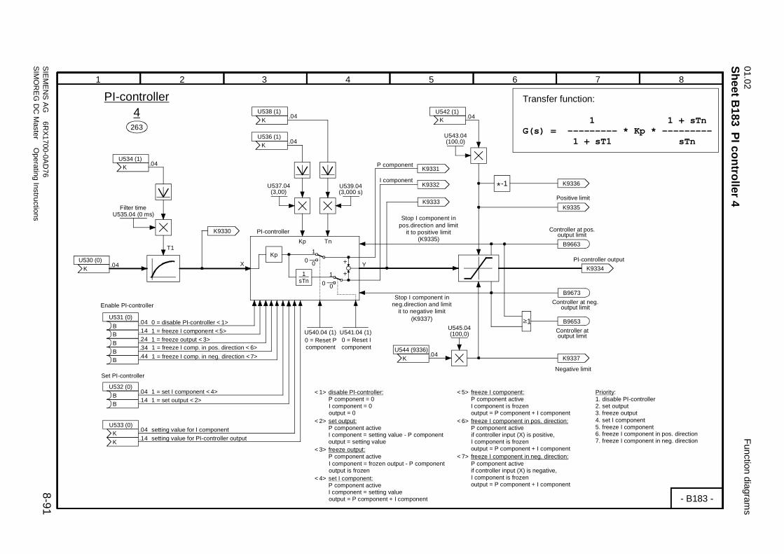
01.02Function diagram
s
SIEMEN
S AG 6R
X1700-0AD76
8-91SIM
OR
EG D
C M
aster Operating Instructions
Sheet B183
PI controller 4
875 64321
Kp Tn
-1*
Kp
1 sTn
0 0
1
0 0
1
1
X YU530 (0)
K
U533 (0)K
U542 (1)K
U536 (1)K
K
U531 (0)B
U532 (0)B
U538 (1)K
U534 (1)K
T1
B
B
K
BBB
263
K9330
U535.04 (0 ms)
.04
.04
4
.04
.04
.14
.14
.04
.14
.24
.34
.44
U539.04(3,000 s)
U537.04(3,00)
U540.04 (1) U541.04 (1)
.04
.04
K9331
K9332
U543.04(100,0)
K9336
K9335K9333
.04
B9663(K9335)
U545.04(100,0)
U544 (9336)
K9334
K9337
B9653
.04
B9673
(K9337)
- B183 -
PI-controller
PI-controller Transfer function:
1 1 + sTnG(s) = --------- * Kp * ---------
1 + sT1 sTn
P component
I component
0 = Reset Pcomponent
0 = Reset Icomponent
Positive limit
Negative limit
Controller at output limit
Enable PI-controller
Filter time
Set PI-controller
1 = set I component <4>
setting value for I component
1 = set output <2>
0 = disable PI-controller <1>1 = freeze I component <5>
setting value for PI-controller output
<1> disable PI-controller: P component = 0 I component = 0 output = 0<2> set output: P component active I component = setting value - P component output = setting value<3> freeze output: P component active I component = frozen output - P component output is frozen<4> set I component: P component active I component = setting value output = P component + I component
1 = freeze output <3>
Priority:1. disable PI-controller2. set output3. freeze output4. set I component5. freeze I component6. freeze I component in pos. direction7. freeze I component in neg. direction
1 = freeze I comp. in pos. direction <6>1 = freeze I comp. in neg. direction <7>
PI-controller output
Stop I component inpos.direction and limit
it to positive limit Controller at pos.output limit
Controller at neg.output limit
<5> freeze I component: P component active I component is frozen output = P component + I component<6> freeze I component in pos. direction: P component active if controller input (X) is positive, I component is frozen output = P component + I component<7> freeze I component in neg. direction: P component active if controller input (X) is negative, I component is frozen output = P component + I component
Stop I component inneg.direction and limit
it to negative limit

Function diagrams
01.02
8-92SIEM
ENS AG
6RX1700-0AD
76SIM
OR
EG D
C M
aster Operating Instructions
Sheet B184
PI controller 5875 64321
Kp Tn
-1*
Kp
1 sTn
0 0
1
0 0
1
1
X YU530 (0)
K
U533 (0)K
U542 (1)K
U536 (1)K
K
U531 (0)B
U532 (0)B
U538 (1)K
U534 (1)K
T1
B
B
K
BBB
264
K9340
U535.05 (0 ms)
.05
.05
5
.05
.05
.15
.15
.05
.15
.25
.35
.45
U539.05(3,000 s)
U537.05(3,00)
U540.05 (1) U541.05 (1)
.05
.05
K9341
K9342
U543.05(100,0)
K9346
K9345K9343
.05
B9664(K9345)
U545.05(100,0)
U544 (9346)
K9344
K9347
B9654
.05
B9674
(K9347)
- B184 -
PI-controller
PI-controller Transfer function:
1 1 + sTnG(s) = --------- * Kp * ---------
1 + sT1 sTn
P component
I component
0 = Reset Pcomponent
0 = Reset Icomponent
Positive limit
Negative limit
Controller at output limit
Enable PI-controller
Filter time
Set PI-controller
1 = set I component <4>
setting value for I component
1 = set output <2>
0 = disable PI-controller <1>1 = freeze I component <5>
setting value for PI-controller output
<1> disable PI-controller: P component = 0 I component = 0 output = 0<2> set output: P component active I component = setting value - P component output = setting value<3> freeze output: P component active I component = frozen output - P component output is frozen<4> set I component: P component active I component = setting value output = P component + I component
1 = freeze output <3>
Priority:1. disable PI-controller2. set output3. freeze output4. set I component5. freeze I component6. freeze I component in pos. direction7. freeze I component in neg. direction
1 = freeze I comp. in pos. direction <6>1 = freeze I comp. in neg. direction <7>
PI-controller output
Stop I component inpos.direction and limit
it to positive limit Controller at pos.output limit
Controller at neg.output limit
<5> freeze I component: P component active I component is frozen output = P component + I component<6> freeze I component in pos. direction: P component active if controller input (X) is positive, I component is frozen output = P component + I component<7> freeze I component in neg. direction: P component active if controller input (X) is negative, I component is frozen output = P component + I component
Stop I component inneg.direction and limit
it to negative limit

01.02Function diagram
s
SIEMEN
S AG 6R
X1700-0AD76
8-93SIM
OR
EG D
C M
aster Operating Instructions
Sheet B185
PI controller 6
875 64321
Kp Tn
-1*
Kp
1 sTn
0 0
1
0 0
1
1
X YU530 (0)
K
U533 (0)K
U542 (1)K
U536 (1)K
K
U531 (0)B
U532 (0)B
U538 (1)K
U534 (1)K
T1
B
B
K
BBB
265
K9350
U535.06 (0 ms)
.06
.06
6
.06
.06
.16
.16
.06
.16
.26
.36
.46
U539.06(3,000 s)
U537.06(3,00)
U540.06 (1) U541.06 (1)
.06
.06
K9351
K9352
U543.06(100,0)
K9356
K9355K9353
.06
B9665(K9355)
U545.06(100,0)
U544 (9356)
K9354
K9357
B9655
.06
B9675
(K9357)
- B185 -
PI-controller
PI-controller Transfer function:
1 1 + sTnG(s) = --------- * Kp * ---------
1 + sT1 sTn
P component
I component
0 = Reset Pcomponent
0 = Reset Icomponent
Positive limit
Negative limit
Controller at output limit
Enable PI-controller
Filter time
Set PI-controller
1 = set I component <4>
setting value for I component
1 = set output <2>
0 = disable PI-controller <1>1 = freeze I component <5>
setting value for PI-controller output
<1> disable PI-controller: P component = 0 I component = 0 output = 0<2> set output: P component active I component = setting value - P component output = setting value<3> freeze output: P component active I component = frozen output - P component output is frozen<4> set I component: P component active I component = setting value output = P component + I component
1 = freeze output <3>
Priority:1. disable PI-controller2. set output3. freeze output4. set I component5. freeze I component6. freeze I component in pos. direction7. freeze I component in neg. direction
1 = freeze I comp. in pos. direction <6>1 = freeze I comp. in neg. direction <7>
PI-controller output
Stop I component inpos.direction and limit
it to positive limit Controller at pos.output limit
Controller at neg.output limit
<5> freeze I component: P component active I component is frozen output = P component + I component<6> freeze I component in pos. direction: P component active if controller input (X) is positive, I component is frozen output = P component + I component<7> freeze I component in neg. direction: P component active if controller input (X) is negative, I component is frozen output = P component + I component
Stop I component inneg.direction and limit
it to negative limit

Function diagrams
01.02
8-94SIEM
ENS AG
6RX1700-0AD
76SIM
OR
EG D
C M
aster Operating Instructions
Sheet B186
PI controller 7875 64321
Kp Tn
-1*
Kp
1 sTn
0 0
1
0 0
1
1
X YU530 (0)
K
U533 (0)K
U542 (1)K
U536 (1)K
K
U531 (0)B
U532 (0)B
U538 (1)K
U534 (1)K
T1
B
B
K
BBB
266
K9360
U535.07 (0 ms)
.07
.07
7
.07
.07
.17
.17
.07
.17
.27
.37
.47
U539.07(3,000 s)
U537.07(3,00)
U540.07 (1) U541.07 (1)
.07
.07
K9361
K9362
U543.07(100,0)
K9366
K9365K9363
.07
B9666(K9365)
U545.07(100,0)
U544 (9366)
K9364
K9367
B9656
.07
B9676
(K9367)
- B186 -
PI-controller
PI-controller Transfer function:
1 1 + sTnG(s) = --------- * Kp * ---------
1 + sT1 sTn
P component
I component
0 = Reset Pcomponent
0 = Reset Icomponent
Positive limit
Negative limit
Controller at output limit
Enable PI-controller
Filter time
Set PI-controller
1 = set I component <4>
setting value for I component
1 = set output <2>
0 = disable PI-controller <1>1 = freeze I component <5>
setting value for PI-controller output
<1> disable PI-controller: P component = 0 I component = 0 output = 0<2> set output: P component active I component = setting value - P component output = setting value<3> freeze output: P component active I component = frozen output - P component output is frozen<4> set I component: P component active I component = setting value output = P component + I component
1 = freeze output <3>
Priority:1. disable PI-controller2. set output3. freeze output4. set I component5. freeze I component6. freeze I component in pos. direction7. freeze I component in neg. direction
1 = freeze I comp. in pos. direction <6>1 = freeze I comp. in neg. direction <7>
PI-controller output
Stop I component inpos.direction and limit
it to positive limit Controller at pos.output limit
Controller at neg.output limit
<5> freeze I component: P component active I component is frozen output = P component + I component<6> freeze I component in pos. direction: P component active if controller input (X) is positive, I component is frozen output = P component + I component<7> freeze I component in neg. direction: P component active if controller input (X) is negative, I component is frozen output = P component + I component
Stop I component inneg.direction and limit
it to negative limit

01.02Function diagram
s
SIEMEN
S AG 6R
X1700-0AD76
8-95SIM
OR
EG D
C M
aster Operating Instructions
Sheet B187
PI controller 8
875 64321
Kp Tn
-1*
Kp
1 sTn
0 0
1
0 0
1
1
X YU530 (0)
K
U533 (0)K
U542 (1)K
U536 (1)K
K
U531 (0)B
U532 (0)B
U538 (1)K
U534 (1)K
T1
B
B
K
BBB
267
K9370
U535.08 (0 ms)
.08
.08
8
.08
.08
.18
.18
.08
.18
.28
.38
.48
U539.08(3,000 s)
U537.08(3,00)
U540.08 (1) U541.08 (1)
.08
.08
K9371
K9372
U543.08(100,0)
K9376
K9375K9373
.08
B9667(K9375)
U545.08(100,0)
U544 (9376)
K9374
K9377
B9657
.08
B9677
(K9377)
- B187 -
PI-controller
PI-controller Transfer function:
1 1 + sTnG(s) = --------- * Kp * ---------
1 + sT1 sTn
P component
I component
0 = Reset Pcomponent
0 = Reset Icomponent
Positive limit
Negative limit
Controller at output limit
Enable PI-controller
Filter time
Set PI-controller
1 = set I component <4>
setting value for I component
1 = set output <2>
0 = disable PI-controller <1>1 = freeze I component <5>
setting value for PI-controller output
<1> disable PI-controller: P component = 0 I component = 0 output = 0<2> set output: P component active I component = setting value - P component output = setting value<3> freeze output: P component active I component = frozen output - P component output is frozen<4> set I component: P component active I component = setting value output = P component + I component
1 = freeze output <3>
Priority:1. disable PI-controller2. set output3. freeze output4. set I component5. freeze I component6. freeze I component in pos. direction7. freeze I component in neg. direction
1 = freeze I comp. in pos. direction <6>1 = freeze I comp. in neg. direction <7>
PI-controller output
Stop I component inpos.direction and limit
it to positive limit Controller at pos.output limit
Controller at neg.output limit
<5> freeze I component: P component active I component is frozen output = P component + I component<6> freeze I component in pos. direction: P component active if controller input (X) is positive, I component is frozen output = P component + I component<7> freeze I component in neg. direction: P component active if controller input (X) is negative, I component is frozen output = P component + I component
Stop I component inneg.direction and limit
it to negative limit

Function diagrams
01.02
8-96SIEM
ENS AG
6RX1700-0AD
76SIM
OR
EG D
C M
aster Operating Instructions
Sheet B188
PI controller 9875 64321
Kp Tn
-1*
Kp
1 sTn
0 0
1
0 0
1
1
X YU530 (0)
K
U533 (0)K
U542 (1)K
U536 (1)K
K
U531 (0)B
U532 (0)B
U538 (1)K
U534 (1)K
T1
B
B
K
BBB
268
K9380
U535.09 (0 ms)
.09
.09
9
.09
.09
.19
.19
.09
.19
.29
.39
.49
U539.09(3,000 s)
U537.09(3,00)
U540.09 (1) U541.09 (1)
.09
.09
K9381
K9382
U543.09(100,0)
K9386
K9385K9383
.09
B9668(K9385)
U545.09(100,0)
U544 (9386)
K9384
K9387
B9658
.09
B9678
(K9387)
- B188 -
PI-controller
PI-controller Transfer function:
1 1 + sTnG(s) = --------- * Kp * ---------
1 + sT1 sTn
P component
I component
0 = Reset Pcomponent
0 = Reset Icomponent
Positive limit
Negative limit
Controller at output limit
Enable PI-controller
Filter time
Set PI-controller
1 = set I component <4>
setting value for I component
1 = set output <2>
0 = disable PI-controller <1>1 = freeze I component <5>
setting value for PI-controller output
<1> disable PI-controller: P component = 0 I component = 0 output = 0<2> set output: P component active I component = setting value - P component output = setting value<3> freeze output: P component active I component = frozen output - P component output is frozen<4> set I component: P component active I component = setting value output = P component + I component
1 = freeze output <3>
Priority:1. disable PI-controller2. set output3. freeze output4. set I component5. freeze I component6. freeze I component in pos. direction7. freeze I component in neg. direction
1 = freeze I comp. in pos. direction <6>1 = freeze I comp. in neg. direction <7>
PI-controller output
Stop I component inpos.direction and limit
it to positive limit Controller at pos.output limit
Controller at neg.output limit
<5> freeze I component: P component active I component is frozen output = P component + I component<6> freeze I component in pos. direction: P component active if controller input (X) is positive, I component is frozen output = P component + I component<7> freeze I component in neg. direction: P component active if controller input (X) is negative, I component is frozen output = P component + I component
Stop I component inneg.direction and limit
it to negative limit

01.02Function diagram
s
SIEMEN
S AG 6R
X1700-0AD76
8-97SIM
OR
EG D
C M
aster Operating Instructions
Sheet B189
PI controller 10
875 64321
Kp Tn
-1*
Kp
1 sTn
0 0
1
0 0
1
1
X YU530 (0)
K
U533 (0)K
U542 (1)K
U536 (1)K
K
U531 (0)B
U532 (0)B
U538 (1)K
U534 (1)K
T1
B
B
K
BBB
269
K9390
U535.10 (0 ms)
.10
.10
10
.10
.10
.20
.20
.10
.20
.30
.40
.50
U539.10(3,000 s)
U537.10(3,00)
U540.10 (1) U541.10 (1)
.10
.10
K9391
K9392
U543.10(100,0)
K9396
K9395K9393
.10
B9669(K9395)
U545.10(100,0)
U544 (9396)
K9394
K9397
B9659
.10
B9679
(K9397)
- B189 -
PI-controller
PI-controller Transfer function:
1 1 + sTnG(s) = --------- * Kp * ---------
1 + sT1 sTn
P component
I component
0 = Reset Pcomponent
0 = Reset Icomponent
Positive limit
Negative limit
Controller at output limit
Enable PI-controller
Filter time
Set PI-controller
1 = set I component <4>
setting value for I component
1 = set output <2>
0 = disable PI-controller <1>1 = freeze I component <5>
setting value for PI-controller output
<1> disable PI-controller: P component = 0 I component = 0 output = 0<2> set output: P component active I component = setting value - P component output = setting value<3> freeze output: P component active I component = frozen output - P component output is frozen<4> set I component: P component active I component = setting value output = P component + I component
1 = freeze output <3>
Priority:1. disable PI-controller2. set output3. freeze output4. set I component5. freeze I component6. freeze I component in pos. direction7. freeze I component in neg. direction
1 = freeze I comp. in pos. direction <6>1 = freeze I comp. in neg. direction <7>
PI-controller output
Stop I component inpos.direction and limit
it to positive limit Controller at pos.output limit
Controller at neg.output limit
<5> freeze I component: P component active I component is frozen output = P component + I component<6> freeze I component in pos. direction: P component active if controller input (X) is positive, I component is frozen output = P component + I component<7> freeze I component in neg. direction: P component active if controller input (X) is negative, I component is frozen output = P component + I component
Stop I component inneg.direction and limit
it to negative limit

Function diagrams
01.02
8-98SIEM
ENS AG
6RX1700-0AD
76SIM
OR
EG D
C M
aster Operating Instructions
Sheet B190
Velocity / speed calculator875 64321
iD
- B190 -
115
n020
n022
n021
n023
U519.F (1,00) U520.F (1450)
(-32,768...32,767 m/s)
(-32,768...32,767 m/s)
U515 (0)K
U516 (0)K
K9256
K9257
U517 (0)K
U518.F (6500,0)(10,0...6553,5mm)
U522 (16,38)(0,01...327,67m/s)
U523 (1638)(10...60000mm)
U521 (16,38)(0,01...327,67m/s)
Velocity / speed calculator
Actual speed
Setpoint velocity
Actual velocity
Setpoint speed
Gear ratio Rated speed
Velocity-speed calculator
Speed-velocity calculator
nact
vset
vact
nset
n rated
vact = ----------------- ∗ --------
D ∗ π=∗ nrated
D ∗ π=∗ nrated nact
i 100%
nset = ----------------- ∗ 100%vset ∗ i
Min. diameter
Diameter
Normalization
Normalization
Normalization

01.02Function diagram
s
SIEMEN
S AG 6R
X1700-0AD76
8-99SIM
OR
EG D
C M
aster Operating Instructions
Sheet B191
Calculation variable inertia
875 64321
- B191 -
116
.01
.02
.03
.04
K9258
U525 (1)KKKK
U526 (10000)(10...60000mm)
U527 (10000)(10...60000mm)
U528 (10000)(10...60000mm)
U529 (1,00)(0,10...100,00)
JV
Variable inertia
D
DCore
Dmax
K
Variable inertia
D4 - DCore4
JV = ------------------ * K Dmax
4
Normalization diameter
Normalization diameterof sleeve
Normalization of max. diameter

Function diagrams
01.02
8-100SIEM
ENS AG
6RX1700-0AD
76SIM
OR
EG D
C M
aster Operating Instructions
Sheet B195
Multiplexer
875 64321
- B195 -
.01
.02
.03
.01
.02
.03
.04
.06
.07
.08
.05
B1B2B3X0X1X2X3X4X5X6X7
Y
.04
.05
.06
.01
.02
.03
.04
.06
.07
.08
.05
B1B2B3X0X1X2X3X4X5X6X7
Y
.07
.08
.09
.01
.02
.03
.04
.06
.07
.08
.05
B1B2B3X0X1X2X3X4X5X6X7
Y
B3 B2 B1 Y
0 0 0 X0 0 0 1 X1 0 1 0 X2 0 1 1 X3 1 0 0 X4 1 0 1 X5 1 1 0 X6 1 1 1 X7
86
87
88
U310 (0)BBB
U311 (0)KKKKKKKK
K9450
U310 (0)BBB
U312 (0)KKKKKKKK
K9451
U310 (0)BBB
U313 (0)KKKKKKKK
K9452
3 Multiplexers

01.02Function diagram
s
SIEMEN
S AG 6R
X1700-0AD76
8-101SIM
OR
EG D
C M
aster Operating Instructions
Sheet B196
16-bit software counter
875 64321
- B196 -
89
.01
.03
.04
&
1 &
1
.02
.01
.02
.03
.04
.05
<1>
7 7
2 2
34
56
7
23
45
67
34
23
23
45
67
24
56
7
<2>
<2>
K9443
K9444
U316K
K
K
9441
U317B
B
UP
DOWNB
B
B
0
0
0
0
1
K 9442
9443
9444
K9441
K9442
K9445
0...65535n314
OUT
0...65535U315.01 (0)
0...65535U315.02 (65535)
0...65535U315.03 (0)
0...65535U315.04 (0)
B9290
B9291
POWER ON
FS
FSSet counterto minimumvalue
Set counterto startvalue
Set counterto settingvalue
Binary output
(Binary code)
Count up
Count down
Stop counter
Set counter
Enable counter
Minimum value
Maximum value
Setting value
Start value
Minimum counter value
Maximum counter value
Counter setting value
Counter start value
Priority:1. Enable counter2. Set counter3. Stop counter4. Count up / down
Overflow
Underflow
from sheet B110
Counter output
Count up
Count down
Overflow
Underflow
Example: Minimum value = 2, Maximum value = 7
16-bit software counterMaximum counting frequency = 1 / scanning time <3>
<1> The counter is set to the start value after POWER ON
<2> The start and setting values are limited to the range (minimum value..maximum value)
<3> Example: The counter operates in the time slice 1 → max. counting frequency = 300 Hz
Note: The sampling time and sequence of the upstream signal processor must also be taken into account

Function diagrams
01.02
8-102SIEM
ENS AG
6RX1700-0AD
76SIM
OR
EG D
C M
aster Operating Instructions
Sheet B200
Decoders / dem
ultiplexers, binary to 1 of 8875 64321
.01
.02
.03
i0i1i2
Q0
Q1
Q2
Q3
Q4
Q5
Q6
Q7
/Q0
/Q1
/Q2
/Q3
/Q4
/Q5
/Q6
/Q7
118
i2-i1-i00 0 00 0 10 1 00 1 11 0 01 0 11 1 01 1 1
Q0 Q1 Q2 Q3 Q4 Q5 Q6 Q7 /Q0 /Q1 /Q2 /Q3 /Q4 /Q5 /Q6 /Q71 0 0 0 0 0 0 00 1 0 0 0 0 0 00 0 1 0 0 0 0 00 0 0 1 0 0 0 00 0 0 0 1 0 0 00 0 0 0 0 1 0 00 0 0 0 0 0 1 00 0 0 0 0 0 0 1
0 1 1 1 1 1 1 11 0 1 1 1 1 1 11 1 0 1 1 1 1 11 1 1 0 1 1 1 11 1 1 1 0 1 1 11 1 1 1 1 0 1 11 1 1 1 1 1 0 11 1 1 1 1 1 1 0
.01
.02
.03
i0i1i2
Q0
Q1
Q2
Q3
Q4
Q5
Q6
Q7
/Q0
/Q1
/Q2
/Q3
/Q4
/Q5
/Q6
/Q7
119
- B200 -
U318 (0)BBB
B9250
B9251
B9252
B9253
B9254
B9255
B9256
B9257
B9260
B9261
B9262
B9263
B9264
B9265
B9266
B9267
U319 (0)BBB
B9270
B9271
B9272
B9273
B9274
B9275
B9276
B9277
B9280
B9281
B9282
B9283
B9284
B9285
B9286
B9287
2 decoders / demultiplexers, binary to 1 of 8

01.02Function diagram
s
SIEMEN
S AG 6R
X1700-0AD76
8-103SIM
OR
EG D
C M
aster Operating Instructions
Sheet B205
AND
elements
875 64321
&.01.02.03
&.01.02.03
&.01.02.03
&.01.02.03
&.01.02.03
&.01.02.03
&.01.02.03
&.01.02.03
&.01.02.03
&.01.02.03
&.01.02.03
&.01.02.03
&.01.02.03
&.01.02.03
&.01.02.03
&.01.02.03
&.01.02.03
&.01.02.03
&.01.02.03
&.01.02.03
&.01.02.03
&.01.02.03
&.01.02.03
&.01.02.03
&.01.02.03
&.01.02.03
&.01.02.03
&.01.02.03
- B205 -
120
121
122
123
124
125
126
127
128
129
130
131
132
133
134
135
136
137
138
139
140
141
142
143
144
145
146
147
U320 (1)BBB
B9350
B9351
B9352
B9353
B9355
B9356
B9357
B9358
B9359
B9360
B9361
B9362
B9363
B9364
B9365
B9366
B9367
B9368
B9369
B9370
B9371
B9372
B9373
B9374
B9375
B9376
B9377
B9354
U321 (1)BBB
U322 (1)BBB
U323 (1)BBB
U324 (1)BBB
U325 (1)BBB
U326 (1)BBB
U327 (1)BBB
U328 (1)BBB
U329 (1)BBB
U330 (1)BBB
U331 (1)BBB
U332 (1)BBB
U333 (1)BBB
U334 (1)BBB
U335 (1)BBB
U336 (1)BBB
U337 (1)BBB
U338 (1)BBB
U339 (1)BBB
U340 (1)BBB
U341 (1)BBB
U342 (1)BBB
U343 (1)BBB
U344 (1)BBB
U345 (1)BBB
U346 (1)BBB
U347 (1)BBB
28 AND elements with 3 inputs each

Function diagrams
01.02
8-104SIEM
ENS AG
6RX1700-0AD
76SIM
OR
EG D
C M
aster Operating Instructions
Sheet B206
OR
elements, EXC
LUSIVE O
R elem
ents875 64321
.01
.02
.03 1≥
.01
.02
.03 1≥
.01
.02
.03 1≥
.01
.02
.03 1≥
.01
.02
.03 1≥
.01
.02
.03 1≥
.01
.02
.03 1≥
.01
.02
.03 1≥
.01
.02
.03 1≥
.01
.02
.03 1≥
.01
.02
.03 1≥
.01
.02
.03 1≥
.01
.02
.03 1≥
.01
.02
.03 1≥
.01
.02
.03 1≥
.01
.02
.03 1≥
.01
.02
.03 1≥
.01
.02
.03 1≥
.01
.02
.03 1≥
.01
.02
.03 1≥
=1.01.02
=1.01.02
=1.01.02
=1.01.02
150
151
152
153
154
155
156
157
158
159
160
161
162
163
164
165
166
167
168
169
170
171
172
173
- B206 -
B9380
B9381
B9382
B9383
B9384
B9387
B9388
B9389
B9390
B9391
B9394
B9395
B9396
B9397
B9398
B9385
B9386
B9392
B9393
B9399
B9195
B9196
B9197
B9198
U350 (0)BBB
U351 (0)BBB
U352 (0)BBB
U353 (0)BBB
U354 (0)BBB
U355 (0)BBB
U356 (0)BBB
U357 (0)BBB
U358 (0)BBB
U359 (0)BBB
U360 (0)BBB
U361 (0)BBB
U362 (0)BBB
U363 (0)BBB
U364 (0)BBB
U365 (0)BBB
U366 (0)BBB
U367 (0)BBB
U368 (0)BBB
U369 (0)BBB
U370 (0)BB
U371 (0)BB
U372 (0)BB
U373 (0)BB
20 OR elements with 3 inputs each 4 EXCLUSIVE OR elementswith 2 inputs each

01.02Function diagram
s
SIEMEN
S AG 6R
X1700-0AD76
8-105SIM
OR
EG D
C M
aster Operating Instructions
Sheet B207
Inverters, NAN
D elem
ents
875 64321
&.01.02.03
&.01.02.03
&.01.02.03
&.01.02.03
&.01.02.03
&.01.02.03
1 1
1 1
1 1
1 1
1 1
1 1
1 1
1 1
&.01.02.03
&.01.02.03
&.01.02.03
&.01.02.03
&.01.02.03
&.01.02.03
180
181
182
183
184
185
186
187
188
189
190
191
192
193
194
195
- B207 -
200
201
202
203
204
205
206
207
208
209
210
211
B9470
B9471
B9472
B9473
B9474
B9475
B9450 B9458
B9451 B9459
B9460
B9453 B9461
B9454 B9462
B9455 B9463
B9456 B9464
B9457 B9465
B9476
B9477
B9478
B9479
B9480
B9481
B9452
U380 (0)B
U381 (0)B
U382 (0)B
U383 (0)B
U384 (0)B
U385 (0)B
U386 (0)B
U387 (0)B
U388 (0)B
U389 (0)B
U390 (0)B
U391 (0)B
U392 (0)B
U393 (0)B
U394 (0)B
U395 (0)B
U400 (1)BBB
U401 (1)BBB
U402 (1)BBB
U403 (1)BBB
U404 (1)BBB
U405 (1)BBB
U406 (1)BBB
U407 (1)BBB
U408 (1)BBB
U409 (1)BBB
U410 (1)BBB
U411 (1)BBB
16 inverters 12 NAND elements with 3 inputs each

Function diagrams
01.02
8-106SIEM
ENS AG
6RX1700-0AD
76SIM
OR
EG D
C M
aster Operating Instructions
Sheet B210
RS flipflops
875 64321
POWER ON
QSET(Q=1)
RESET(Q=0) Q
.01
.02
POWER ON
QSET(Q=1)
RESET(Q=0) Q
.01
.02
POWER ON
QSET(Q=1)
RESET(Q=0) Q
.01
.02
POWER ON
QSET(Q=1)
RESET(Q=0) Q
.01
.02
POWER ON
QSET(Q=1)
RESET(Q=0) Q
.01
.02
POWER ON
QSET(Q=1)
RESET(Q=0) Q
.01
.02
POWER ON
QSET(Q=1)
RESET(Q=0) Q
.01
.02
POWER ON
QSET(Q=1)
RESET(Q=0) Q
.01
.02
POWER ON
QSET(Q=1)
RESET(Q=0) Q
.01
.02
POWER ON
QSET(Q=1)
RESET(Q=0) Q
.01
.02
POWER ON
QSET(Q=1)
RESET(Q=0) Q
.01
.02
POWER ON
QSET(Q=1)
RESET(Q=0) Q
.01
.02
POWER ON
QSET(Q=1)
RESET(Q=0) Q
.01
.02
POWER ON
QSET(Q=1)
RESET(Q=0) Q
.01
.02
- B210 -
1
1
1
1
1
1
1
1
1
1
1
1
1
1
<1>
<1>
<1>
<1>
<1>
<1>
<1>
<1>
<1>
<1>
<1>
<1>
<1>
<1>
220
221
222
223
224
215
216
217
218
219
225
226
227
228
B9550
B9551
B9552
B9553
B9554
B9555
B9556
B9557
B9558
B9559
B9560
B9561
B9562
B9563
B9564
B9565
B9566
B9567
B9568
B9569
B9570
B9571
B9572
B9573
B9574
B9575
B9576
B9577
U415 (0)BB
U416 (0)BB
U417 (0)BB
U418 (0)BB
U419 (0)BB
U420 (0)BB
U421 (0)BB
U422 (0)BB
U423 (0)BB
U424 (0)BB
U425 (0)BB
U426 (0)BB
U427 (0)BB
U428 (0)BB
14 RS flipflops
Priority:1. RESET2. SET
<1> from voltage monitor for electronics power supply

01.02Function diagram
s
SIEMEN
S AG 6R
X1700-0AD76
8-107SIM
OR
EG D
C M
aster Operating Instructions
Sheet B211
D flipflops
875 64321
SET (Q=1)
D
RESET (Q=0)
STORE
POWER ON
Q
Q.01.02.03.04
SET (Q=1)
D
RESET (Q=0)
STORE
POWER ON
Q
Q.01.02.03.04
SET (Q=1)
D
RESET (Q=0)
STORE
POWER ON
Q
Q.01.02.03.04
SET (Q=1)
D
RESET (Q=0)
STORE
POWER ON
Q
Q.01.02.03.04
230
231
232
233
1
1
1
1
- B211 -
<1>
<1> <1>
<1>
BB
B9490
B9491
B9492
B9493
B9494
B9495
B9496
B9497
U430 (0)BB
BB
U432 (0)BB
BB
U433 (0)BB
BB
U431 (0)BB
Priority:1. RESET2. SET3. STORE
4 D flipflops
<1> from voltage monitor for electronics power supply

Function diagrams
01.02
8-108SIEM
ENS AG
6RX1700-0AD
76SIM
OR
EG D
C M
aster Operating Instructions
Sheet B215
Timers (0,000...60,000s)
875 64321
T
0T O
1TO
2TT
T 3
1
T
0T O
1TO
2TT
T 3
1
T
0T O
1TO
2TT
T 3
1
T
0T O
1TO
2TT
T 3
1
T
0T O
1TO
2TT
T 3
1
T
0T O
1TO
2TT
T 3
1
- B215 -
240
241
242
243
244
245
.01
.02.01.02
.01
.02
.01
.02.01.02
.01
.02
U441 (0,000)(0,000...60,000s) U442 (0)
B9580
B9581
U444 (0,000)(0,000...60,000s) U445 (0)
B9582
B9583
U447 (0,000)(0,000...60,000s) U448 (0)
B9584
B9585
U450 (0,000)(0,000...60,000s) U451 (0)
B9586
B9587
U453 (0,000)(0,000...60,000s) U454 (0)
B9588
B9589
U456 (0,000)(0,000...60,000s) U457 (0)
B9590
B9591
U440 (0)B
U443 (0)B
U446 (0)B
U449 (0)B
U452 (0)B
U455 (0)B
B B B
BBB
6 timers
ON delay
OFF delay
ON/OFF delay
Pulse generator
Mode
ON delay
OFF delay
ON/OFF delay
Pulse generator
Mode
ON delay
OFF delay
ON/OFF delay
Pulse generator
Mode
ON delay
OFF delay
ON/OFF delay
Pulse generator
Mode
ON delay
OFF delay
ON/OFF delay
Pulse generator
Mode
ON delay
OFF delay
ON/OFF delay
Pulse generator
Mode
1 = Reset 1 = Reset 1 = Reset
1 = Reset1 = Reset1 = Reset

01.02Function diagram
s
SIEMEN
S AG 6R
X1700-0AD76
8-109SIM
OR
EG D
C M
aster Operating Instructions
Sheet B216
Timers (0,00...600,00s), B
inary signal selector switches
875 64321
T
0T O
1TO
2TT
T 3
1
T
0T O
1TO
2TT
T 3
1
T
0T O
1TO
2TT
T 3
1
T
0T O
1TO
2TT
T 3
1
1
0.01.02.03
1
0.01.02.03
1
0.01.02.03
1
0.01.02.03
1
0.01.02.03
246
247
248
249
- B216 -
250
251
252
253
254
.01
.02.01.02
.01
.02.01.02
U459 (0,00)(0,00...600,00s) U460 (0)
B9592
B9593
U462 (0,00)(0,00...600,00s) U463 (0)
B9594
B9595
U465 (0,00)(0,00...600,00s) U466 (0)
B9596
B9597
U468 (0,00)(0,00...600,00s) U469 (0)
B9598
B9599
B9482
B9483
B9484
B9485
B9486
U458 (0)B
U461 (0)B
U464 (0)B
U467 (0)B
U470 (0)BBB
U471 (0)BBB
U472 (0)BBB
U473 (0)BBB
U474 (0)BBB
B
B
B
B
4 timers
ON delay
OFF delay
ON/OFF delay
Pulse generator
Mode
ON delay
OFF delay
ON/OFF delay
Pulse generator
Mode
ON delay
OFF delay
ON/OFF delay
Pulse generator
Mode
ON delay
OFF delay
ON/OFF delay
Pulse generator
Mode
5 binary signal selector switches
1 = Reset 1 = Reset
1 = Reset1 = Reset

Function diagrams
01.02
8-110SIEM
ENS AG
6RX1700-0AD
76SIM
OR
EG D
C M
aster Operating Instructions
Optional supplem
entary boards Sheets Z100 to Z156Sheet Z100
Table of contents875 64321
- Z100 -
Function diagram SIMOREG 6RA70 - Contents of optional supplementary boards
Content Sheet
Data exchange with a technology board (TB) or the 1st communication board (CB) Z110Data exchange with the 2nd communication board (CB) Z1111st EB1 analog inputs Z1121st EB1 analog outputs Z1131st EB1 bidirectional inputs/outputs, digital inputs Z1142nd EB1 analog inputs Z1152nd EB1 analog outputs Z1162nd EB1 bidirectional inputs/outputs, digital inputs Z1171st EB2 analog input, digital inputs, relay outputs Z1182nd EB2 analog input, digital inputs, relay outputs Z119SBP pulse encoder evaluation Z120SIMOLINK board configuration, diagnosis Z121SIMOLINK board receiving, transmitting Z122OP1S operator panel Z123Interfaces: connector-type converters Z124SCB1 with SCI1: SCI1 binary inputs slave 1 Z130SCB1 with SCI1: SCI1 binary inputs slave 2 Z131SCB1 with SCI1: SCI1 binary outputs slave 1 Z135SCB1 with SCI1: SCI1 binary outputs slave 2 Z136SCB1 with SCI2: SCI2 binary inputs slave 1 Z140SCB1 with SCI2: SCI2 binary inputs slave 2 Z141SCB1 with SCI2: SCI2 binary outputs slave 1 Z145SCB1 with SCI2: SCI2 binary outputs slave 2 Z146SCB1 with SCI1: SCI1 analog inputs slave 1 Z150SCB1 with SCI1: SCI1 analog inputs slave 2 Z151SCB1 with SCI1: SCI1 analog outputs slave 1 Z155SCB1 with SCI1: SCI1 analog outputs slave 2 Z156

01.02Function diagram
s
SIEMEN
S AG 6R
X1700-0AD76
8-111SIM
OR
EG D
C M
aster Operating Instructions
Sheet Z110D
ata exchange with a technology board (TB
) orthe 1
st comm
unications board (CB
)
.04
.01
.03
.02
.06
.05
.07
.08
.10
.09
.14
.11
.13
.12
.16
.15
875 64321
- Z110 -
<1>
<1>
T 0
015
.01
.16
U728 (0)B
B
K3020
U734 (0)KKKKK
1sB3030
B3031
KKKKKKKKKKK
K3001K3002K3003K3004K3005K3006K3007K3008K3009K3010K3011K3012K3013K3014K3015K3016
B3100Bit 0 ... Bit 15
B3200
B3300B3400
B3500B3600
B3700B3800
B3900
B3115B3215
B3315B3415
B3515B3615
B3715B3815
B3915U722.03 (0 ms)
U722.01 (0 ms)
B3035
CB parameters 1 to 10
CB or TB diagnosis
CB parameter 11
1 = "Fault F082"
Initialize link to supplementary boards
Parameters for the 1st CB board
Messagemonitoring time
Message monitoring for received process data:
Valid for the following configurations:- CB only- TB only- CB after TB (CB in slot G)- 2 CBs (for CB with the lower slot letter)
Bit 10 must be set in word 1 of thereceive data to ensure that theprocess data are accepted as validdata. Control word 1 must thereforebe transferred as the first PZD word.
(fault value 10)
Display parameter job (PKW) from CB
Display parameter response (PKW) to CB
Display parameter job (PKW) from TB
Display parameter response (PKW) to TB
Receive data
Word 1Word 2Word 3Word 4Word 5Word 6Word 7Word 8Word 9Word 10
Transmit data
Fault message trigger
1 = "Telegram monitoring timeout"
Word 11Word 12Word 13Word 14Word 15Word 16
Word 1Word 2Word 3Word 4Word 5Word 6Word 7Word 8Word 9Word 10Word 11Word 12Word 13Word 14Word 15Word 16
every 16 bits
Data exchange with a technology board (TB) or the 1st communications board (CB)
from supplementary board to supplementary board
n733.01 to .16 n735.01 to .16
Bus address
Enable parameterization
U711-U720 Index.01
n732 Index.01-.32
n738 Index.01-.04
n739 Index.01-.04
U721 Index.01-.05
P918 Index.01
n738 Index.09-.12
n739 Index.09-.12
U710 Index.01
P9271 = "Fault delay timeout"
Fault delay time
When bit 10 ("control by PLC") = 0,the other bits of word 1, as well as words2 to 16 are not written to connectors K3001 to K3016or to binectors B3100 to 3915.All these connectors and binectors retain their old values.
Binector / connectorconverter
For transmission of double-word connectors see Section 7.7.10See also connector type converter on sheet Z124

Function diagrams
01.02
8-112SIEM
ENS AG
6RX1700-0AD
76SIM
OR
EG D
C M
aster Operating Instructions
Sheet Z111D
ata exchange with the 2
nd comm
unications board (CB
)
.04
.01
.03
.02
.06
.05
.07
.08
.10
.09
.14
.11
.13
.12
.16
.15
875 64321
- Z111 -
<1>
<1>
T 0
015
.01
.16
KKKKKKKKKKKKKKKK
Bit 0 ... Bit 15
U736 (0)K8001K8002K8003K8004K8005K8006K8007K8008K8009K8010K8011K8012K8013K8014K8015K8016
B8100B8200B8300
B8400B8500
B8600B8700B8800
B8900
B8115B8215B8315
B8415
B8515B8615
B8715B8815
B8915
1sB8030
B8031
U722.04 (0 ms)
U722.02 (0 ms)
B8035
U729 (0)B
B
K8020
Parameters for the 2nd CB board
Data exchange with the 2nd communications board (CB)
U710 Index.02
U711-U720 Index.02
n732 Index.33-.64
n738 Index.05-.08
n739 Index.05-.08
P927
U721 Index.06-.10
P918 Index.02
Message monitoring for received process data:
Valid for the following configurations:
- 2 CBs (for CB with the higher slot letter)
Bit 10 must be set in word 1 of thereceive data to ensure that theprocess data are accepted as validdata. Control word 1 must thereforebe transferred as the first PZD word.
Receive data
Word 1Word 2Word 3Word 4Word 5Word 6Word 7Word 8Word 9Word 10
Transmit data
Word 11Word 12Word 13Word 14Word 15Word 16
Word 1Word 2Word 3Word 4Word 5Word 6Word 7Word 8Word 9Word 10Word 11Word 12Word 13Word 14Word 15Word 16
every 16 bits
from supplementary board to supplementary board
n733.17 to .32 n735.17 to .32
CB parameters 1 to 10
CB or TB diagnosis
CB parameter 11
Initialize link to supplementary boards
Display parameter job (PKW) from CB
Display parameter response (PKW) to CB
Bus address
Enable parameterization
1 = "Fault F082"
Messagemonitoring time
(fault value 10)
Fault message trigger
1 = "Telegram monitoring timeout"
Binector / connectorconverter
1 = "Fault delay timeout"
When bit 10 ("control by PLC") = 0,the other bits of word 1, as well as words2 to 16 are not written to connectors K8001 to K8016or to binectors B8100 to 8915.All these connectors and binectors retain their old values.
Fault delay time
For transmission of double-word connectors see Section 7.7.10See also connector type converter on sheet Z124

01.02Function diagram
s
SIEMEN
S AG 6R
X1700-0AD76
8-113SIM
OR
EG D
C M
aster Operating Instructions
Sheet Z1121
st EB1: Analog inputs
875 64321
i±10V
u±20mA
0
1
U756.1100%*
10V =100%20mA=100%
-1
-1
1
2
3
0
-1
0%AD 1
050
51
(|i| ≤ 2mA)
- Z112 -
1 2 3X488
0
1
U756.2100%*
10V=100%
-1
-1
1
2
3
0
-1
0%AD 1
052
1 2 3X486
0
1
U756.3100%*
10V=100%
-1
-1
1
2
3
0
-1
0%AD 1
053
1 2 3X487
54
±10V
±10V
24V
+ -
AI1
AI2
AI3
-100,00...100,00%U757.1 (0,00)
U758.1 (0)0...10000msU760.1 (0)
-1000,0...1000,0U756.1(100,0)
n762.1
K5101
U761.1 (1)B
U759.1 (0)B
B5101
(0/1=10V/20mA)U755.1 (0)
20mA 10V
-100,00...100,00%U757.2 (0,00)
U758.2 (0)0...10000msU760.2 (0)
-1000,0...1000,0U756.2(100,0)
n762.2
K5102
U761.2 (1)B
U759.2 (0)B
B510210V
-100,00...100,00%U757.3 (0,00)
U758.3 (0)0...10000msU760.3 (0)
-1000,0...1000,0U756.3(100,0)
n762.3
K5103
U761.3 (1)B
U759.3 (0)B
B510310V
Standardization
OffsetSign reversal
Analog inputconnection
Open circuit
Hardware smoothing 220 µs
Signal type
13 bits + sign
Time constant
Smoothing
Standardization
OffsetSign reversal
Analog inputconnection
Hardware smoothing 220 µs 13 bits + sign
Time constant
Smoothing
High at input (voltage at term. 52 > 8V)Digital input
Standardization
OffsetSign reversal
Analog inputconnection
Hardware smoothing 220 µs 13 bits + sign
Time constant
Smoothing
High at input (voltage at term. 53 > 8V)Digital input
Analog inputs (to ground)also usable as digital inputs
Digital inputs24V
Analog inputs±10V
Analog input 1 (differential input)1st EB1:
1st EB1:

Function diagrams
01.02
8-114SIEM
ENS AG
6RX1700-0AD
76SIM
OR
EG D
C M
aster Operating Instructions
Sheet Z1131
st EB1: Analog outputs
875 64321
- Z113 -
-1
-1
1
2
3
0
x yy [V] = *
x
100% AD
47U766.1
-1
-1
1
2
3
0
x yy [V] = *
x
100% AD
48
49M
U766.2
AO1
AO2
U764.1 (0)
K5104
U763.1 (0)K
U765.1 (0)(0...10000ms) -200,00...+199,99V
U766.1 (10,00)-10,00...+10,00VU767.1 (0,00)n768.1
U764.2 (0)
K5105
U763.2 (0)K
U765.2 (0)(0...10000ms) -200,00...+199,99V
U766.2 (10,00)-10,00...+10,00VU767.2 (0,00)n768.2
-10V...+10V
-10V...+10V
Time constant Standardization Offset
11 Bit + VZ
Time constant Standardization Offset
11 bits + sign
100%Uout [V] =
K5104* Standardization [V] + Offset [V]
100%Uout [V] =
K5105* Standardization [V] + Offset [V]
1st EB1: Analog outputs

01.02Function diagram
s
SIEMEN
S AG 6R
X1700-0AD76
8-115SIM
OR
EG D
C M
aster Operating Instructions
Sheet Z1141
st EB1: 4 bidirectional inputs- / outputs, 3 digital inputs
875 64321
- Z114 -
24V
5V
24V
5V
1
24V
5V
24V
5V
23
24
25
26
20
21
2243 42 41 4046 45 44
24V
1
1
1
1
1
1
38
39
43
44
45
46
40
41
42
DIO1
DIO2
DIO3
DIO4
DI1
DI2
DI3B5116
B5117
B5114
B5115
B5112
B5113
Out
In
B5104
B5105
U769.1 (0)B
Out
In
B5106
B5107
U769.2 (0)B
Out
In
B5108
B5109
U769.3 (0)B
Out
In
B5110
B5111
U769.4 (0)B
Out
In
Out/In
Out In
K5106
n770.1
M_external
Display of terminal states in n770.1 on the PMU
4 bidirectional inputs / outputs1st EB1:
1st EB1: 3 digital inputs
Outputs InputsNOTICE
If one of the terminals 43 to 46 is to be used as an input, the corresponding output must be set to"0" (transistor blocked)!
Example: Terminal 45 = input => U769.3=0
Outputs
Inputs

Function diagrams
01.02
8-116SIEM
ENS AG
6RX1700-0AD
76SIM
OR
EG D
C M
aster Operating Instructions
Sheet Z1152
nd EB1: Analog inputs
875 64321
i±10V
u±20mA
0
1
U756.4100%*
10V =100%20mA=100%
-1
-1
1
2
3
0
-1
0%AD 1
050
51
(|i| ≤ 2mA)
- Z115 -
1 2 3X488
0
1
U756.5100%*
10V=100%
-1
-1
1
2
3
0
-1
0%AD 1
052
1 2 3X486
0
1
U756.6100%*
10V=100%
-1
-1
1
2
3
0
-1
0%AD 1
053
1 2 3X487
54
±10V
±10V
24V
+ -
AI1
AI2
AI3
-100,00...100,00%U757.4 (0,00)
U758.4 (0)0...10000msU760.4 (0)
-1000,0...1000,0U756.4(100,0)
n762.4
K5201
U761.4 (1)B
U759.4 (0)B
B5201
(0/1=10V/20mA)U755.2 (0)
20mA 10V
-100,00...100,00%U757.5 (0,00)
U758.5 (0)0...10000msU760.5 (0)
-1000,0...1000,0U756.5(100,0)
n762.5
K5202
U761.5 (1)B
U759.5 (0)B
B520210V
-100,00...100,00%U757.6 (0,00)
U758.6 (0)0...10000msU760.6 (0)
-1000,0...1000,0U756.6(100,0)
n762.6
K5203
U761.6 (1)B
U759.6 (0)B
B520310V
Standardization
OffsetSign reversal
Analog inputconnection
Open circuit
Hardware smoothing 220 µs
Signal type
13 bits + sign
Time constant
Smoothing
Standardization
OffsetSign reversal
Analog inputconnection
Hardware smoothing 220 µs 13 bits + sign
Time constant
Smoothing
High at input (voltage at term. 52 > 8V) Digital input
Standardization
OffsetSign reversal
Analog inputconnection
Hardware -smoothing 220 µs 13 bits + sign
Time constant
Smoothing
High at input (voltage at Kl. 53 > 8V)Digital input
Analog inputs (to ground)also usable as digital inputs
Digital inputs24V
Analog inputs±10V
Analog input 1 (differential input)2nd EB1:
2nd EB1:

01.02Function diagram
s
SIEMEN
S AG 6R
X1700-0AD76
8-117SIM
OR
EG D
C M
aster Operating Instructions
Sheet Z1162
nd EB1: Analog outputs
875 64321
- Z116 -
-1
-1
1
2
3
0
x yy [V] = *
x
100% AD
47U766.3
-1
-1
1
2
3
0
x yy [V] = *
x
100% AD
48
49M
U766.4
AO1
AO2
U764.3 (0)
K5204
U763.3 (0)K
U765.3 (0)(0...10000ms) -200,00...+199,99V
U766.3 (10,00)-10,00...+10,00VU767.3 (0,00)n768.3
U764.4 (0)
K5205
U763.4 (0)K
U765.4 (0)(0...10000ms) -200,00...+199,99V
U766.4 (10,00)-10,00...+10,00VU767.4 (0,00)n768.4
-10V...+10V
-10V...+10V
Time constant Standardization Offset
11 bits + sign
Time constant Standardization Offset
11 bits + sign
100%Uout [V] =
K5204* Standardization [V] + Offset [V]
100%Uout [V] =
K5205* Standardization [V] + Offset [V]
2nd EB1: Analog outputs

Function diagrams
01.02
8-118SIEM
ENS AG
6RX1700-0AD
76SIM
OR
EG D
C M
aster Operating Instructions
Sheet Z1172
nd EB1: 4 bidirectional inputs- / outputs, 3 digital inputs
875 64321
- Z117 -
24V
5V
24V
5V
1
24V
5V
24V
5V
23
24
25
26
20
21
2243 42 41 4046 45 44
24V
1
1
1
1
1
1
38
39
43
44
45
46
40
41
42
DIO1
DIO2
DIO3
DIO4
DI1
DI2
DI3B5216
B5217
B5214
B5215
B5212
B5213
Out
In
B5204
B5205
U769.5 (0)B
Out
In
B5206
B5207
U769.6 (0)B
Out
In
B5208
B5209
U769.7 (0)B
Out
In
B5210
B5211
U769.8 (0)B
Out
In
Out/In
Out In
K5206
n770.2
M_external
Display of terminal states in n770.2 on the PMU
4 bidirectional inputs / outputs2nd EB1:
2nd EB1: 3 digital inputs
Outputs Inputs
Outputs
Inputs
NOTICE
If one of the terminals 43 to 46 is to be used as an input, the corresponding output must be set to"0" (transistor blocked)!
Example: Terminal 45 = input => U769.7=0

01.02Function diagram
s
SIEMEN
S AG 6R
X1700-0AD76
8-119SIM
OR
EG D
C M
aster Operating Instructions
Sheet Z1181
st EB2: Analog input, Analog output, 2 digital inputs, 4 relay outputs
875 64321
i
±10V
u
± 20mA
0
1
U776.1100%*
10V =100%20mA=100%
-1
-1
1
2
3
0
-1
0%
1
049
50
(|i| ≤ 2mA)
- Z118 -
1 2 3X498
x yy [V] = *
x
100%47U786.1
-1
-1
1
2
3
0
1
2
3
IU
1
24V
5V53
1
24V
5V54
20
21
24V
51
52
41 39 54 5345 43 .01.02.03.04
22
23
24
25
48
3839
40
46
45
44
43
42
41
X499
DI1
DI2
AI
AO
DO1
DO2
DO3
DO4
-100,00...100,00%U777.1 (0,00)
U778.1 (0)0...10000msU780.1 (0)
-1000,0...1000,0U776.1(100,0) n782.1
K5111
U781.1 (1)B
U779.1 (0)B
B5121
(0/1=10V/20mA)U775.1 (0)
20mA 10V
U784.1 (0)
K5112
U783.1 (0)K
U785.1 (0)(0...10000ms) -200,00...+199,99V
U786.1 (10,00)-10,00...+10,00VU787.1 (0,00)n788.1
Uout = -10V...+10V
Iout =-20...+20mA
B5122
B5123
B5124
B5125
P24_aux
U774 (0)BBBB
K5113
n773.1
Standardization
OffsetSign reversal
Analog inputconnection
Open circuit
Hardware smoothing 220 µs
Signal type Time constant
Smoothing
Analog input (differential input)1st EB2:
Analog output1st EB2:
M_external
M_external
M_external
Display of terminal states in n773.1 on the PMU
1st EB2: 2 digital inputs 1st EB2: 4 relay outputs
Time constant Standardization Offset
9 bits + sign
100%Uout [V] =
K5112* Standardization [V] + Offset [V]
11 bits + sign
Smoothing
AD
AD

Function diagrams
01.02
8-120SIEM
ENS AG
6RX1700-0AD
76SIM
OR
EG D
C M
aster Operating Instructions
Sheet Z1192
nd EB2: Analog input, Analog output, 2 digital inputs, 4 relay outputs
875 64321
i
±10V
u
± 20mA
0
1
U776.2100%*
10V =100%20mA=100%
-1
-1
1
2
3
0
-1
0%
1
049
50
(|i| ≤ 2mA)
- Z119 -
1 2 3X498
x yy [V] = *
x
100%47U786.2
-1
-1
1
2
3
0
1
2
3
IU
1
24V
5V53
1
24V
5V54
20
21
24V
51
52
41 39 54 5345 43 .05.06.07.08
22
23
24
25
48
3839
40
46
45
44
43
42
41
X499
DI1
DI2
AI
AO
DO1
DO2
DO3
DO4
-100,00...100,00%U777.2 (0,00)
U778.2 (0)0...10000msU780.2 (0)
-1000,0...1000,0U776.2(100,0) n782.2
K5211
U781.2 (1)B
U779.2 (0)B
B5221
(0/1=10V/20mA)U775.2 (0)
20mA 10V
U784.2 (0)
K5212
U783.2 (0)K
U785.2 (0)(0...10000ms) -200,00...+199,99V
U786.2 (10,00)-10,00...+10,00VU787.2 (0,00)n788.2
Uout = -10V...+10V
Iout =-20...+20mA
B5222
B5223
B5224
B5225
P24_aux
U774 (0)BBBB
K5213
n773.2
Standardization
OffsetSign reversal
Analog inputconnection
Open circuit
Hardware smoothing 220 µs
Signal type Time constant
Smoothing
Analog inputs (differential input)2nd EB2:
Analog output2nd EB2:
M_external
M_external
M_external
Display of terminal states in n773.2 an der PMU
2nd EB2: 2 digital inputs 2nd EB2: 4 Relay outputs
Time constant Standardization Offset
9 bits + sign
100%Uout [V] =
K5212* Standardization [V] + Offset [V]
11 Bit + VZ
Smoothing
AD
AD

01.02Function diagram
s
SIEMEN
S AG 6R
X1700-0AD76
8-121SIM
OR
EG D
C M
aster Operating Instructions
Sheet Z120SB
P pulse encoder evaluation
875 64321
- Z120 -
X400
X401
6061626364
6566
67
686970717273
7475
+5/15V
u
&
<1>
<2><2>
<2><2>
1
0
2
0
1 &
U792 (1024)
n795
B7000
B7001B7002B7003
B0055
B0056
U796
n024.02
K0039
KK0036
K0038
U794 (500,0)
+ Vss- Vss
CTRL +CTRL - = M
Voltage levelU790.01: A/B, CTRL trackU790.02: Zero pulse
Supply voltageU791 = 0: 5VU791 = 1: 15V
Reference speed50.0...6500.0
Encoder typeU793=0: A/B trackU793=1: Forward/reverse tracks
Number of lines100...20000
Track A + Track A -Track B +Track B -
Position
<1> 0=Enable position counter (KK0038) 1=Reset (KK0038:=0)<2> The signals "coarse pulse 2" and "fine pulse 2" are only routed to binectors B7002 and B7003 in the SIMOREG DC Master. They have no other function.
Zero pulse +Zero pulse -
Track A
Track B
Zero pulse
Control track
Overflow
Underflow
SBP pulse encoder evaluation
Power supplyPulse encoder
Ground coarse/fineCoarse pulse 1Coarse pulse 2Fine pulse 2
Coarse pulse 1Coarse pulse 2
Fine pulse 2
Control track
Pulse encoder evaluation
Speed measurement
Speed actual value in rpm
Speed actual value
Resetposition counter
Position acquisition
value range:8000 0000H to 7FFF FFFFH

Function diagrams
01.02
8-122SIEM
ENS AG
6RX1700-0AD
76SIM
OR
EG D
C M
aster Operating Instructions
Sheet Z121SIM
OLIN
K board: C
onfiguration, diagnosis875 64321
- Z121 -
U741.01 (0 ms)0...6500ms
0T
f<1>
<1>
B7030
U753 (0,0)0,0...100,0 s
U740.01 (0)0...200
U742.01 (3)
U744 (0)B
U745.01 (3)1...8
U746.01 (1,20)1,00...6,50ms
B7040
Time out
n748
B7050
Fault message trigger
1 = "Fault F015"
Fault delay
Telegram failure
Telegram monitoringtime
Monitoring is activated after the first valid telegram
SLB nodeaddress
Transmit power
Selection ofactive SLB
SLB configuration
Generalsection
Dispatcher-specificsection
Moduleaddress = 0
SLB channel selection
SLB cycle time
SLB diagnosis
Dispatcher specificsection
Moduleaddress = 0
1 = 0...15m2 = 15...25m3 = 25...40mCable length
SLB diagnosis i001: No. of error-free synchronizing telegrami002: No. of CRC errorsi003: No. of timeout errorsi004: last accessible bus addressi005: Address node transmitting the special "timeout" telegrami006:Implemented bus cycle timei007: Number of re-configurationsi008: reserved...i016:reserved
Starting alarm
Alarm message trigger
1 = "Alarm A015"
U746 + 3,18 µs 1f: No. of addressed nodes = ( ---------------------- – 2) • -------- 6,36 µs U745
"SIMOLINK starting" alarm
6,36 µs = time for 1 telegram
SIMOLINK board: Configuration, diagnosis

01.02Function diagram
s
SIEMEN
S AG 6R
X1700-0AD76
8-123SIM
OR
EG D
C M
aster Operating Instructions
Sheet Z122SIM
OLIN
K board: R
eceiving, transmitting
875 64321
.04
.01
.03
.02
.06
.05
.07
.08
.10
.09
.14
.11
.13
.12
.16
.15
- Z122 -
TxDE
OE
ORxD
U751 (0)KKKKKKKKKKKKKKKK
K7001K7002K7003K7004K7005K7006K7007K7008K7009K7010K7011K7012K7013K7014K7015K7016
B7100Bit 0 ... Bit 15
B7200B7300B7400
B7500B7600
B7700B7800B7900
B7115
B7215B7315B7415
B7515B7615
B7715B7815
B7915
U749.01
U749.02
U749.03
U749.04
U749.05
U749.06
U749.07
U749.08
K7101K7102K7103K7104K7105K7106K7107K7108
SIMOLINKSIMOLINK
Receive data
Word 1Word 2Word 3Word 4Word 5Word 6Word 7Word 8Word 9Word 10
Transmit data
Word 11Word 12Word 13Word 14Word 15Word 16
Word 1Word 2Word 3Word 4Word 5Word 6Word 7Word 8Word 9Word 10Word 11Word 12Word 13Word 14Word 15Word 16
16 bits each
Channel 0
Channel 1
Channel 2
Channel 3
Channel 4
Channel 5
Channel 6
Channel 7
U749.xx: Parameter value =Address.ChannelNumber(before/after decimal point.)
Word 1Word 2Word 3Word 4Word 5Word 6Word 7Word 8
Specialdata
Receive Transmit
SIMOLINK board: Receiving, transmitting
n750.01 to .16 n752.01 to .16
For transmission of double-word connectors see Section 7.7.4 "Procedure for starting up SIMOLINK boards"
See also connector type converter on sheet Z124

Function diagrams
01.02
8-124SIEM
ENS AG
6RX1700-0AD
76SIM
OR
EG D
C M
aster Operating Instructions
Sheet Z123O
P1S operator panel875 64321
- Z123 -
I
O
Jog
0
1 2 3
4 5 6
7 8 9
+/- Reset
FaultRun
P
6.0% 0.0V 0025.00%25.00%
#∗
I O
Jog
Reset<1>
<1>
<1>
B2100
B2107
B2108
B2111
B2113
B2114
B2112
U049.005 U049.004 U049.003
U049.001 U049.002OP operation. display
1st line on leftFS=19:
display of r019Motor current act. value
OP operation. display1st line on right
FS=38:display of r038
act. armature voltage val.Active node (=Bus address P786)OP operation.display
3rd lineFS=28:
display of r028Speed setpoint
Reversing key
Raise key
Lower key
Key for the operatinglevel switchover
0 to 9: Numerical keys
Reset key
Sign key
ON key
OFF key
Inching (Jog) keyON / OFF1
Acknowledge
Inching 1
Positive direction of rotation
Negative direction of rotation
Raise motor pot.
Lower motor pot.
(B2100 must also be connectedto bit 1 or 2 in control word 1for OFF2 or OFF3.)
The control commands from the OP1S panel are transferred via word 1 in the USS protocoland can be wired up to other functions via the binectors below (see also Section 7.2.2).
OP1S operator panel
<1> This key works only when the OP1S is in the "Operational display" state
Torque direc. 1 LC Display(4 lines x 16 characters)
OP operation display4th lineFS=59:
display of r059Operating state
OP operation.display2nd lineFS=25:
display of r025Speed controller act. value

01.02Function diagram
s
SIEMEN
S AG 6R
X1700-0AD76
8-125SIM
OR
EG D
C M
aster Operating Instructions
Sheet Z124Interfaces: connector-type converters
875 64321
- Z124 -
LOWHIGH
LOWHIGH
LOWHIGH
LOWHIGH
LOWHIGH
LOWHIGH
LOWHIGH
LOWHIGH
LOWHIGH
LOWHIGH
LOWHIGH
LOWHIGH
LOWHIGH
LOWHIGH
LOWHIGH
LOWHIGH
LOWHIGH
LOWHIGH
LOWHIGH
LOWHIGH
LOWHIGH
LOWHIGH
LOWHIGH
LOWHIGH
LOWHIGH
LOWHIGH
LOWHIGH
LOWHIGH
LOWHIGH
LOWHIGH
LOWHIGH
LOWHIGH
LOWHIGH
LOWHIGH
LOWHIGH
LOWHIGH
LOWHIGH
LOWHIGH
LOWHIGH
LOWHIGH
LOWHIGH
LOWHIGH
LOWHIGH
LOWHIGH
KK3032K3002
K3003
K3004
K3005
K3006
K3007
K3008
K3009
K3010
K3011
K3012
K3013
K3014
K3015
K3016
KK3033
KK3034
KK3035
KK3036
KK3037
KK3038
KK3039
KK3040
KK3041
KK3042
KK3043
KK3044
KK3045
K8002
K8003
K8004
K8005
K8006
K8007
K8008
K8009
K8010
K8011
K8012
K8013
K8014
K8015
K8016
KK7032K7002
K7003
K7004
K7005
K7006
K7007
K7008
KK7033
KK7034
KK7035
KK7036
KK7037
KK3031K3001 K8001
KK7031K7001
KK8032
KK8033
KK8034
KK8035
KK8036
KK8037
KK8038
KK8039
KK8040
KK8041
KK8042
KK8043
KK8044
KK8045
KK8031
KK7132K7102
K7103
K7104
K7105
K7106
K7107
K7108
KK7133
KK7134
KK7135
KK7136
KK7137
KK7131K7101
Interfaces: connector-type converters
Technology board /1st communications board (Z110) 2nd communications board (Z111) SIMOLINK board (Z122)

Function diagrams
01.02
8-126SIEM
ENS AG
6RX1700-0AD
76SIM
OR
EG D
C M
aster Operating Instructions
Sheet Z130SC
B1 w
ith SCI1: SC
I1 binary inputs slave 1875 64321
- Z130 -
124V
5V
124V
5V
124V
5V
124V
5V
124V
5V
124V
5V
124V
5V
124V
5V
124V
5V
124V
5V
20
21
22
23
24
25
26
27
28
29
B3
B4
B5
B6
B7
B8
A3
A4
A5
A6
A7
A8
A1B9
B10B11
A2A9
A10A1124V DC
~~P24
M
~~
24V
<1> <1>
<1>
X427B4100
B4120
B4101
B4121
B4102
B4122
B4103
B4123
B4104
B4124
B4105
B4106
B4107
B4108
B4109
B4125
B4126
B4127
B4128
B4129
n699.01
Supply for theSCI1 board
=Supply of binary inputs via SCI1
=external supply of binary inputs
Reference point forbinary inputs 1 to 5
Reference point forbinary inputs 6 to 10
SCB1 with SCI1: SCI1 - binary inputs slave 1SCI slave 1
Binary input 1
Binary input 2
Binary input 3
Binary input 4
Binary input 5
Binary input 6
Binary input 7
Binary input 8
Binary input 9
Binary input 10
Supply forbinary inputs
(optional)

01.02Function diagram
s
SIEMEN
S AG 6R
X1700-0AD76
8-127SIM
OR
EG D
C M
aster Operating Instructions
Sheet Z131SC
B1 w
ith SCI1: SC
I1 binary inputs slave 2
875 64321
- Z131 -
124V
5V
124V
5V
124V
5V
124V
5V
124V
5V
124V
5V
124V
5V
124V
5V
124V
5V
124V
5V
20
21
22
23
24
25
26
27
28
29
B3
B4
B5
B6
B7
B8
A3
A4
A5
A6
A7
A8
A1B9
B10B11
A2A9
A10A1124V DC
~~P24
M
~~
24V
<1> <1>
<1>
X427B4200
B4220
B4201
B4221
B4202
B4222
B4203
B4223
B4204
B4224
B4205
B4206
B4207
B4208
B4209
B4225
B4226
B4227
B4228
B4229
n699.05
Supply for theSCI1 board
= Supply of binary inputs via SCI1
= external supply of binary inputs
Reference point forbinary inputs 1 to 5
Reference point forbinary inputs 6 to 10
SCB1 with SCI1: SCI1 - binary inputs slave 2SCI slave 2
Binary input 1
Binary input 2
Binary input 3
Binary input 4
Binary input 5
Binary input 6
Binary input 7
Binary input 8
Binary input 9
Binary input 10
Supply forbinary inputs
(optional)

Function diagrams
01.02
8-128SIEM
ENS AG
6RX1700-0AD
76SIM
OR
EG D
C M
aster Operating Instructions
Sheet Z135SC
B1 w
ith SCI1: SC
I1 binary outputs slave 1875 64321
- Z135 -
B1
B2
X429
X427
1
2
3
4
5
6
7
8
9
10
11
12
13
14
15
16
17
18
.01
.02
.03
.04
.06
.07
.08
.05
20
21
22
23
24
25
26
27
U698 (0)BBBBBBBB
n699.09
SCB1 with SCI1: SCI1 - binary outputs slave 1
Binary output 1
Binary output 2
Binary output 3
Binary output 4
Binary output 5
Binary output 6
Binary output 7
Binary output 8100 mA short-circuit-proof

01.02Function diagram
s
SIEMEN
S AG 6R
X1700-0AD76
8-129SIM
OR
EG D
C M
aster Operating Instructions
Sheet Z136SC
B1 w
ith SCI1: SC
I1 binary outputs slave 2
875 64321
- Z136 -
B1
B2
X429
X427
1
2
3
4
5
6
7
8
9
10
11
12
13
14
15
16
17
18
.13
.14
.15
.16
.18
.19
.20
.17
20
21
22
23
24
25
26
27
U698 (0)BBBBBBBB
n699.13
SCB1 with SCI1: SCI1 - binary outputs slave 2
Binary output 1
Binary output 2
Binary output 3
Binary output 4
Binary output 5
Binary output 6
Binary output 7
Binary output 8100 mA short-circuit-proof

Function diagrams
01.02
8-130SIEM
ENS AG
6RX1700-0AD
76SIM
OR
EG D
C M
aster Operating Instructions
Sheet Z140SC
B1 w
ith SCI2: SC
I2 binary inputs slave 1875 64321
- Z140 -
124V
5V
1
1
1
1
20
21
22
23
24
26
27
25
X437
1
1
1
24V
5V
24V
5V
24V
5V
24V
5V
24V
5V
24V
5V
24V
5V
124V
5V
1
1
1
1
1
1
1
24V
5V
24V
5V
24V
5V
24V
5V
24V
5V
24V
5V
24V
5V
28
29
210
211
212
214
215
213
B1
B2
B3
B4
B5
B6
B7
B8
B9
A1
A2
A3
A4
A5
A6
A7
A8
A9
24V DC
~~~~P24
M
X437
X437
B10B11B12A10A11A12
24V
<1>
<1>
<1>
1
2
3
4
5
6
7
8
9
10
11
12
13
14
15
16
9
10
11
12
13
14
15
16
B4100
B4120
B4101
B4121
B4102
B4122
B4103
B4123
B4104
B4124
B4105
B4125
B4106
B4126
B4107
B4127
B4108
B4128
B4109
B4129
B4110
B4130
B4111
B4131
B4112
B4132
B4113
B4133
B4114
B4134
B4115
B4135
n699.01
SCI slave 1
SCB1 with SCI2: SCI2 - binary inputs slave 1
Supply of SCI2 board
Supply forbinary inputs
(optional)
=Supply of binary inputs via the SCI2
= external supply of binary inputs
SCI slave 1Binary inputBinary input
Reference point forbinary inputs 9 to 16
Reference point forbinary inputs 1 to 8

01.02Function diagram
s
SIEMEN
S AG 6R
X1700-0AD76
8-131SIM
OR
EG D
C M
aster Operating Instructions
Sheet Z141SC
B1 w
ith SCI2: SC
I2 binary inputs slave 2
875 64321
- Z141 -
124V
5V
1
1
1
1
20
21
22
23
24
26
27
25
X437
1
1
1
24V
5V
24V
5V
24V
5V
24V
5V
24V
5V
24V
5V
24V
5V
124V
5V
1
1
1
1
1
1
1
24V
5V
24V
5V
24V
5V
24V
5V
24V
5V
24V
5V
24V
5V
28
29
210
211
212
214
215
213
B1
B2
B3
B4
B5
B6
B7
B8
B9
A1
A2
A3
A4
A5
A6
A7
A8
A9
24V DC
~~~~P24
M
X437
X437
B10B11B12A10A11A12
24V
<1>
<1>
<1>
1
2
3
4
5
6
7
8
9
10
11
12
13
14
15
16
9
10
11
12
13
14
15
16
B4200
B4220
B4201
B4221
B4202
B4222
B4203
B4223
B4204
B4224
B4205
B4225
B4206
B4226
B4207
B4227
B4208
B4228
B4209
B4229
B4210
B4230
B4211
B4231
B4212
B4232
B4213
B4233
B4214
B4234
B4215
B4235
n699.05
SCI slave 2
SCB1 with SCI2: SCI2 - binary inputs slave 2
SCB1/SCI process data
Supply for theSCI2 board
Supply forbinary inputs
(optional)
=Supply of binary inputs via SCI2
=external supply of binary inputs
SCI slave 2Binary inputBinary input
Reference point forbinary inputs 9 to 16
Reference point forbinary inputs 1 to 8

Function diagrams
01.02
8-132SIEM
ENS AG
6RX1700-0AD
76SIM
OR
EG D
C M
aster Operating Instructions
Sheet Z145SC
B1 w
ith SCI2: SC
I2 binary outputs slave 1875 64321
- Z145 -
X439
X438
1
2
3
4
5
6
7
8
9
10
11
12
13
14
15
16
17
18
.01
.02
.03
.04
.06
.07
.08
.05
B1
B2
20
21
22
23
24
25
26
27
.10
.11
.12
.09
B3
B4
B5
B6
A1
A2
A3
A4
28
29
210
211
P24
M
A5
A6
U698 (0)BBBBBBBB
n699.09
BBBB
SCB1 with SCI2: SCI2 - binary outputs slave 1
Binary output 8
Binary output 9
Binary output 10
Binary output 11
Binary output 12
Auxiliary voltage P24 VDC
Auxiliary voltage M forbinary outputs
Binary output 1
Binary output 2
Binary output 3
Binary output 4
Binary output 5
Binary output 6
Binary output 7

01.02Function diagram
s
SIEMEN
S AG 6R
X1700-0AD76
8-133SIM
OR
EG D
C M
aster Operating Instructions
Sheet Z146SC
B1 w
ith SCI2: SC
I2 binary outputs slave 2
875 64321
- Z146 -
X439
X438
1
2
3
4
5
6
7
8
9
10
11
12
13
14
15
16
17
18
.13
.14
.15
.16
.18
.19
.20
.17
B1
B2
20
21
22
23
24
25
26
27
.22
.23
.24
.21
B3
B4
B5
B6
A1
A2
A3
A4
28
29
210
211
P24
M
A5
A6
U698 (0)BBBBBBBB
n699.13
BBBB
SCB1 with SCI2: SCI2 - binary outputs slave 2
Binary output 8
Binary output 9
Binary output 10
Binary output 11
Binary output 12
Auxiliary voltage P24 VDC
Auxiliary voltage M forbinary outputs
Binary output 1
Binary output 2
Binary output 3
Binary output 4
Binary output 5
Binary output 6
Binary output 7

Function diagrams
01.02
8-134SIEM
ENS AG
6RX1700-0AD
76SIM
OR
EG D
C M
aster Operating Instructions
Sheet Z150SC
B1 w
ith SCI1: SC
I1 analog inputs slave 1875 64321
- Z150 -
X428
U±10V
I±20mA
1
2
3
4
5
6
7
8
9
10
11
3
4
4
5
<2>
<2>
<2>
<1>
<1>
<1>
<2>
<1>
U692.01(0) U691.01(2) n699.02
K4101
0...2U690.01(0) -20,00...20,00V 0...15
U692.02(0) U691.02(2) n699.03
K4102
0...2U690.02(0) -20,00...20,00V 0...15
U692.03(0) U691.03(2) n699.04
K4103
0...2U690.03(0) -20,00...20,00V 0...15
SCB1 with SCI1: SCI1 analog inputs slave 1
Hardware-Smoothing 1ms
Offset
Hardware-Smoothing 1ms
Offset
Hardware-Smoothing 1ms
Offset
+10 V / 5 mA for potentiometer, short-circuit-proof
-10 V / 5 mA for potentiometer, short-circuit-proof
Smoothing
Smoothing
Smoothing
Smoothing time constant T = 2 ms * 2U691
U690 Voltage input Current input Kl. X428.3, .6, .9 Kl. X428.5, .8, .11
0 -10 ... 10 V -20 ... 20 mA 1 0 ... 10 V 0 ... 20 mA 2 - 4 ... 20 mA
Analog input 2
Analog input 3
Analog input 1
SCI Slave 1
Signal type
Signal type
Signal type
Signal type
12 bits + sign
AD
AD
AD
12 bits + sign
12 bits + sign

01.02Function diagram
s
SIEMEN
S AG 6R
X1700-0AD76
8-135SIM
OR
EG D
C M
aster Operating Instructions
Sheet Z151SC
B1 w
ith SCI1: SC
I1 analog inputs slave 2
875 64321
- Z151 -
X428
U±10V
I±20mA
1
2
3
4
5
6
7
8
9
10
11
3
4
4
5
<2>
<2>
<2>
<1>
<1>
<1>
<2>
<1>
U692.04(0) U691.04(2) n699.06
K4201
0...2U690.04(0) -20,00...20,00V 0...15
U692.05(0) U691.05(2) n699.07
K4202
0...2U690.05(0) -20,00...20,00V 0...15
U692.06(0) U691.06(2) n699.08
K4203
0...2U690.06(0) -20,00...20,00V 0...15
SCB1 with SCI1: SCI1 analog inputs slave 2
Hardware-Smoothing 1ms
Offset
Hardware-Smoothing 1ms
Offset
Hardware-Smoothing 1ms
Offset
+10 V / 5 mA for potentiometer, short-circuit-proof
-10 V / 5 mA for potentiometer, short-circuit-proof
Smoothing
Smoothing
Smoothing
Smoothing time constant T = 2 ms * 2U691
U690 Voltage input Current input Kl. X428.3, .6, .9 Kl. X428.5, .8, .11
0 -10 ... 10 V -20 ... 20 mA 1 0 ... 10 V 0 ... 20 mA 2 - 4 ... 20 mA
Analog input 2
Analog input 3
Analog input 1
SCI Slave 2
Signal type
Signal type
Signal type
Signal type
12 bits + sign
12 bits + sign
12 bits + sign
AD
AD
AD

Function diagrams
01.02
8-136SIEM
ENS AG
6RX1700-0AD
76SIM
OR
EG D
C M
aster Operating Instructions
Sheet Z155SC
B1 w
ith SCI1: SC
I1 analog outputs slave 1875 64321
yy [V] = * U694.01
x100%
14
12
M
- Z155 -
X428
UI
x
13
yy [V] = * U694.02
x100%
17
15
M
UI
x
16
yy [V] = * U694.03
x100%
20
18
M
UI
x
19
-100,00...+100,00V-320,00...+320,00VU694.01 (10,00)
U693.01(0)K
U695.01 (0,00)n699.10
-100,00...+100,00V-320,00...+320,00VU694.02 (10,00)
U693.02(0)K
U695.02 (0,00)n699.11
-100,00...+100,00V-320,00...+320,00VU694.03 (10,00)
U693.03(0)K
U695.03 (0,00)n699.12
Iout = -20 ... 20 mA
Iout = -20 ... 20 mA
Iout = -20 ... 20 mA
Analog output 1
AD
SCB1 with SCI1: SCI1 analog outputs slave 1
Gain Offset
Analog output 2
AD
Gain Offset
Analog output 3
AD
Gain Offset

01.02Function diagram
s
SIEMEN
S AG 6R
X1700-0AD76
8-137SIM
OR
EG D
C M
aster Operating Instructions
Sheet Z156SC
B1 w
ith SCI1: SC
I1 analog outputs slave 2
875 64321
yy [V] = * U694.04
x100%
14
12
M
- Z156 -
X428
UI
x
13
yy [V] = * U694.05
x100%
17
15
M
UI
x
16
yy [V] = * U694.06
x100%
20
18
M
UI
x
19
-100,00...+100,00V-320,00...+320,00VU694.04 (10,00)
U693.04(0)K
U695.04 (0,00)n699.14
-100,00...+100,00V-320,00...+320,00VU694.05 (10,00)
U693.05(0)K
U695.05 (0,00)n699.15
-100,00...+100,00V-320,00...+320,00VU694.06 (10,00)
U693.06(0)K
U695.06 (0,00)n699.16
Iout = -20 ... 20 mA
Iout = -20 ... 20 mA
Iout = -20 ... 20 mA
Analog output 1
AD
SCB1 with SCI1: SCI1 analog outputs slave 2
Gain Offset
Analog output 2
AD
Gain Offset
Analog output 3
AD
Gain Offset

Function diagrams 01.02
8-138 SIEMENS AG 6RX1700-0AD76SIMOREG DC Master Operating Instructions

01.02 Function descriptions
SIEMENS AG 6RX1700-0AD76 9-1SIMOREG DC Master Operating Instructions
9 Function descriptions
NOTEThe available scope of converter functions is shown in the function diagrams (block diagrams) inSection 8.Section 9 does not attempt to provide a complete description of all these functions, but to explainin further detail certain individual features, which cannot be adequately illustrated in graphic form,and provide examples of their application.
9.1 General explanations of terms and functionalityFunction blocksAlthough the illustrated function blocks have been implemented in digital form (as software modules),the function diagrams can be "read" in a similar way to the circuit diagrams of analog equipment.
ConfigurabilityThe converter is characterized by the optional configurability of the function blocks provided. "Optionalconfigurability" means that the connections between individual function blocks can be selected bymeans of parameters.
ConnectorsAll output variables and important computation quantities within the function blocks are available in theform of "connectors" (e.g. for further processing as input signals to other function blocks). Thequantities accessed via connectors correspond to output signals or measuring points in an analogcircuit and are identified by their "connector number" (e.g. K0003 = connector 3).
Special cases:K0000 to K0008 are fixed values with signal levels corresponding to 0, 100, 200, -100,-200, 50, 150, -50 and -150%.K0009 is assigned to different signal quantities. Which signal quantity it actually refers tois dependent on the selector switch (parameter) at which connector number 9 is set. Adescription can be found under the relevant parameter number in the Parameter List. Ifthe Parameter List or block diagram does not contain any reference to a special functionin relation to selection of connector K0009, then the selector switch (parameter)concerned must not be set to "9".
The internal numerical representation of connectors in the software is generally as follows:100% corresponds to 4000 hexadecimal = 16384 decimal. The resolution is 0.006% (step change).
Connectors have a value range of -200% to +199.99%.For a list of available connectors, please refer to Section 12.
Example: The data received via peer-to-peer 2 are available at connectors K6001 to K6005(Section 8, Sheet G173)
Tx+
Tx-
Rx+/Tx+
Rx-/Tx-
RS485M
56
57
58
59
60
G-SST2
X172
1
0
1
0
K6001
K6005K6004K6003K6002
r812.01 to .05
Word 1Word 2Word 3Word 4Word 5
Receive data

Function descriptions 01.02
9-2 SIEMENS AG 6RX1700-0AD76SIMOREG DC Master Operating Instructions
Double-word connectors (SW 1.9 and later)Double-word connectors are connectors with a 32-bit value range (i.e. LOW word and HIGH word witha double-word value range of 00000000Hex to FFFFFFFFHex ).
-100 % to +100 % corresponds to connector values of C0000000 Hex to 40000000 Hex(= -1073741824 to +1073741824 decimal). This means that the value range in the upper 16 bits (HIGHword) of a double-word connector is the same as for a "normal" connector (C000 Hex to 4000 Hex or -16384 to +16384 decimal for -100 % to +100 %). The extra 16 bits in the LOW word as compared to a"normal connector" afford, therefore, an improved resolution of the connector value by a factor of65536. For information about how to use double-word connectors see also the section in "Thefollowing rules apply to the selection of double-word connectors" below.
Double-word connector symbol in function diagrams:KK9498
BinectorsAll binary output quantities and important binary output signals of the function blocks are available as"Binectors" (connectors for binary signals). Binectors can assume states log. "0" and log."1". Thequantities accessed via binectors correspond to output signals or measuring points in a digital circuitand are identified by their "Binector number" (e. g. B0003 = binector 3).
Special cases: B0000 = Fixed value log."0"B0001 = Fixed value log."1"
A list of available binectors can be found in Section 12.
Example: The status of terminal 36 is available at B0010 and, in inverted form, at binector B0011(Section 8, Sheet G110)
1
24V
5V36
M B0011
B0010
Selection switches, connections(see also Section "Data sets")
The inputs of function blocks are defined at "selection switches" by setting the appropriate selectionparameters. The input is defined by entering the number of the connector or binector to be applied asthe input quantity in the parameter for the relevant selection switch.
Representation in function diagrams (examples):P750 (0)K
Selection of a connectorParameter number = P750, factory setting = 0 (i. e. fixed value 0%)
P704 (0)B
Selection of a binectorParameter number = P704, factory setting = 0 (i. e. fixed value 0)
.01
.02
.03
.04
P613 (1)KKKK
Selection of connectors ("indexed" parameter with 4 indices)Parameter number = P613, factory setting = 1 (i. e. fixed value 100%; this factorysetting applies to all the indices of P613)
.01
.02
.03
.04
277000
P611KKKK
FS Selection of connectors ("indexed" parameter with 4 indices)Parameter number = P611Factory setting for index .01 = 277 (i. e. connection with connector K0277)Factory setting for indices .02 to .04 = 0 (i. e. fixed value 0%)

01.02 Function descriptions
SIEMENS AG 6RX1700-0AD76 9-3SIMOREG DC Master Operating Instructions
P046 (0)BBBB
.01
.02
.03
.04
Selection of binectors ("indexed" parameter with 4 indices)Parameter number = P046, factory setting = 0 (i. e. fixed value 0, this factory settingapplies to all the indices of P046)
U181 (0)KK
Selection of a double-word connector (SW 1.9 and later)Parameter number = U181, factory setting = 0 (i.e. fixed value 0%)
The selected setting can be entered in the empty field (fields). The value in brackets next to theparameter number is the factory setting of the selection parameter.
The following rules apply to the selection of double-word connectors (SW 1.9 and later):
U181 (0)KKKK9498 9498
Double-word connector to double-word connector selection:
The double word for subsequent processing comprises:LOW word = LOW word of double-word connector (KK9498)HIGH word = HIGH word of double-word connector (KK9498)
U181KKK0401 401
Connector to double-word connector selection:
The double word for subsequent processing comprises:LOW word = 0HIGH word = selected connector (K0401)
P044KKK9498 9498
Double-word connector to connector selection:
HIGH word of the double-word connector (KK9498) is connected to anotherblock,the LOW word of the double-word connector (KK9498) is not used
.01
.02
U751 (0)94989498
KK9498KK9498
LHK
KThere are exceptions in the selection of transmission data for the serialinterfaces and in the transmission of optional expansion modules(technology and communications modules, SIMOLINK module):If the same double-word connector is entered in two contiguous indices ofthe selection parameter, the entire value (the LOW and HIGH word) will beused.
.01
.02
U751 (0)KK9498KK9499
HH
94989499K
KIf different double-word connectors are entered in two contiguous indices ofthe selection parameter, in both cases only the HIGH word of the twodouble-word connectors will be used.

Function descriptions 01.02
9-4 SIEMENS AG 6RX1700-0AD76SIMOREG DC Master Operating Instructions
Examples: Some examples of how to handle connectors and binectors are given below.
Example 1: As a function of the status of terminal 36 (B0010 - see Section 8, Sheet G110), analogselectable input 1 (terminals 6 and 7) must be made available, either with the correctsign or inverted sign, at the function block output (= connector K0015).This output value must then be injected as an additional setpoint and outputsimultaneously at analog output terminal 14.
The following settings need to be made to create the correct links:
1. P714 = 10: Selects binector B0010 (status of terminal 36) as the control signal for sign reversal.Parameter P716 remains set at 1 (= fixed value 1, delivery state), thereby ensuring thatthe analog input is switched in continuously.
Section 8, Sheet G113:
0
1
-1
-1
1
2
3
0
-1
0%
1
0
P713 (0)P715 (0)
r003
K0015
P716 (1)B
P714 (0)BB10
Sign reversalConnection ofanalog input
Filter time [ms]
Filter
2. P645 = 15: Applies connector K0015 to the additional setpoint input when the setpoint is processed
Section 8, Sheet G135:
.01
.02
.03
.04
<1><1><1><1>
P644.F(206)K
P645.F (0)K
K0194
P643 (9)KKKK
r029
K0197K0198
15
P321.F (100.00)(-300.00...300.00 %)
Main setpoint
Maximum
Additional setpoint
3. P750 = 15: Applies connector K0015 to the input of the function block for the analog outputterminal 14. This example of K0015 illustrates how it is possible to apply a connector asan input signal to any number of function blocks.
Section 8, Sheet G115:
-1
-1
1
2
3
0
P751 (0)
P752 (0)
P750 (0)K
(0...10000ms)
15
Filter time

01.02 Function descriptions
SIEMENS AG 6RX1700-0AD76 9-5SIMOREG DC Master Operating Instructions
Example 2: The contents of connectors K0401 and K0402 must be output on the connector displays(parameter r043)
The following settings need to be made to create the correct links:
P044.index01 = 401: Links connector K0401 to the 1st connector displayP044.index02 = 402: Links connector K0402 to the 2nd connector display
Section 8, Sheet G121:
.01
.02
.03
.04
.05
.06
.07
401402
P044 (0)KKKKKKK
r043.01
r043.02
r043.03
r043.04
r043.05
r041.06
r043.07
The following values are now displayed in parameter r043:
r043.index01: Contents of connector K0401r043.index02: Contents of connector K0402r043.index03
to
r043.index07: Parameter P044.index.03 to 07 remain at the works setting (0) (value inbrackets next to parameter number) in this example, i. e. the contents ofconnector K0000 (=fixed value 0) are displayed on r043.index.03 to .07.
Setting parameters(see also Section "Data sets")
In addition to the parameters that are used to select a signal (connector, binector), there are alsoparameters which define an operating mode or the parameter value of some function.
Representation in function diagrams:Apart from parameter numbers, the function diagrams may also contain the factory setting, functionand value range of parameters as supplementary information.
P109 (0) Setting parameterParameter number = P109, factory setting = 0
P462.F(10.00s)(0.01...300.00s)
Ramp-up time
Setting parameter in function parameter set (".F" after parameter number)Parameter number = P462, factory setting = 10.00sValue range = 0.01...300.00sParameter for setting ramp-up time
Examples: P700 in Section 8, Sheet G113 defines the signal type of the analog input(voltage input ±10V, current input 0...20mA, current input 4...20mA).
P705 in Section 8, Sheet G113 defines the filter time for the analog input (adjustablein ms).
Parameters P520 to P530 in Section 8, Sheet G153 determine the shape of the frictioncharacteristic.
P465 in Section 8, Sheet G126 determine whether the time settings must be multipliedby a factor of 1 or 60.

Function descriptions 01.02
9-6 SIEMENS AG 6RX1700-0AD76SIMOREG DC Master Operating Instructions
Data setsSee also Section "Switch over parameter sets"
Switch over function parameters (function data sets):
4 different sets of some parameters (function parameters) are available and can be selected by meansof the "Switch over function parameters" function. The switchover operation is controlled by controlword 2 (bits 16 and 17, see Section 8, Sheets G181 and G175). Index .01, .02, .03 or .04 of theseparameters is operative depending on the status of the control bit.The parameters of this parameter set are identified by an ".F" next to the parameter number in thefunction diagrams and by "FDS" under the parameter number in the tabulated parameter list.The parameters belonging to the function parameter set must not be confused with other parameterswhich, by chance, also have 4 indices. The latter parameters are not affected by the "Switch overfunction parameters" function.
Switch over binector and connector parameters (Bico data sets):
2 different sets of some selection switches are available and can be selected by means of the "Switchover binector and connector parameters" function. The switchover function is controlled by controlword 2 (bit 30, see Section 8, Sheets G181 and G175). The status of the control bit determineswhether index.01 or index .02 of the parameter is operative.The parameters of the Bico data set are identified by a ".B" next to the parameter number in thefunction diagrams and by "BDS" under the parameter number in the tabulated parameter list.The parameters belonging to the Bico data set must not be confused with other parameters which, bychance, also have 2 indices. The latter parameters are not affected by the "Switch over binector andconnector parameters" function.
Display parametersThe values of certain signals can be output using display parameters (r parameters, n parameters).Connector displays (Section 8, Sheet G121) can be used to link all connectors with display parametersso that they can be displayed.
Representation in function diagrams:Apart from the parameter number, the function diagrams may also include a function description forthe parameter as supplementary information.
r316RFG status Display parameter
Parameter number = r316
Display of RFG (ramp-function generator) status
9.2 Computation cycles, time delayFunctions associated with analog inputs, analog outputs, binary inputs, binary outputs and interfaces,as well as function blocks associated with the motorized potentiometer, setpoint generation, ramp-function generator and closed-loop speed and armature current controls, are called up and calculatedin synchronism with the armature firing pulses (i.e. every 3.333 ms at a line frequency of 50 Hz).
Function blocks associated with the closed-loop EMF and field current controls (shown in Section 8,Sheets G165 and G166) are called and calculated in synchronism with the field firing pulses (i.e. every10 ms at a line frequency of 50 Hz).
The parameter settings are processed in a further computation cycle with a cycle time of 20 ms. Theexecution of optimization runs is also controlled from this cycle.
With regard to the transfer of parameter values via interfaces, it is important to remember that sometransferred parameters must be converted to this 20 ms cycle before they can be applied, for example,in the armature firing pulse cycle.

01.02 Function descriptions
SIEMENS AG 6RX1700-0AD76 9-7SIMOREG DC Master Operating Instructions
9.3 Switch-on, shutdown, enabling
9.3.1 OFF2 (voltage disconnection) - control word 1, bit 1The OFF2 signal is low active (log."0" state = voltage disconnection).
The following operating modes are possible:
P648 = 9: The control bits in control word 1 are input bit-serially. OFF2 is generated from the ANDoperation between the binectors selected with P655, P656 and P657 (see Section 8,Sheet G180).
P648 ≠ 9: The connector selected via P648 is used as control word 1. Bit 1 of this word then controlsthe OFF2 function.
Sequence of operations for "Disconnect voltage":1. Input "Disconnect voltage" command2. Disable technology controller, ramp-function generator, n and I controllers3. Iset = 0 is applied4. The pulses are disabled when I = 05. Output signal "Close operating brake" (binector B0250 = 0, when P080 = 2)6. Converter reaches operating state o10.0 or higher7. An "older" actual field current value (K0265) is input as the field current setpoint upper limit
(function is "released" in operating states of ≤o5)8. The "Line contactor closed" relay drops out9. Drive coasts to a standstill (or is braked by the operating brake)10. Parameterizable delay time (P258) runs down11. The field is reduced to a parameterizable value (P257)12. When n < nmin (P370, P371) has been reached, the "Close holding brake" signal is output
(binector B0250 = 0, when P080 = 1)
9.3.2 OFF3 (Fast stop) - control word 1, bit 2The OFF3 signal is LOW active (log."0" state = fast stop).
The following operating modes are possible:
P648 = 9: The control bits in control word 1 are input bit-serially. OFF3 is generated from the ANDoperation between the binectors selected with P658, P659 and P660 (see Section 8,Sheet G180).
P648 ≠ 9: The connector selected via P648 is used as control word 1. Bit 2 of this word then controlsthe OFF3 function.
Sequence of operations for ”Fast stop”:1. Input "Fast stop" command (e.g. binary input wired up to "Fast stop")2. Technology controller and ramp-function generator are disabled3. Enter nset = 04. up to SW 1.84: Decelerate along current limit
from SW 1.90: Decelerate along reversal ramp acc. to P296, P297, P2985. Wait until n < nmin (P370, P371)6. Output signal "Close operating or holding brake" (binector B0250 = 0)7. Wait for brake closing time (P088) to run down8. Enter Iset = 09. Ramp-function generator and n controller are disabled10. The pulses are disabled when I = 011. The "Line contactor closed" relay drops out12. Converter reaches operating state o9.0 or higher13. Delay time for field current reduction (P087) runs down14. The field is reduced to a parameterizable value in P257

Function descriptions 01.02
9-8 SIEMENS AG 6RX1700-0AD76SIMOREG DC Master Operating Instructions
Sequence of operations for cancellation of "Fast stop":1. Stop applying "Fast stop" command2. Enter "Standstill" command (e.g. via "Switch-on/shutdown" terminal)3. Converter exits operating state o8
P258P088
P087
n < n (P370,P371) n > n n < n
ON
External fast stop
Sandstill field
Shutdown
Controller disabled
Switch-on/Shutdown
Fast stop
Internal fast stop
Internal controller enable
Internal setpoint enable
Actual speed
Brake control signal (B0255)(holding brake)
Internal standstillfield input
min
No fast stop
No fast stop
Controller enabled
Setpoint enabled
Setpoint reached
min
Release brake
No standstill field
Internal fast stop
Setpoint =0
min
Setpoint reached
Close brake
P087 Brake release time (positive in this example)P088 Brake closing timeP258 Delay for automatic field current reduction
− The "Fast stop" command need only be applied as a short pulse (> 10 ms). It is then stored internally. Thememory can be reset only by applying the "Shutdown" command.
− All "Fast stop" commands are ANDed by the SIMOREG converter, i.e. all commands must be set to "No faststop" before the function can be deactivated.
− When n < nmin (P370, P371) is reached for the first time, an internal interlock is activated which prevents thedrive from attempting to brake again if the motor is turned by external forces. The n < nminsignal then disappears again.
9.3.3 Switch-on / shutdown (ON / OFF) terminal 37 - control word 1, bit 0The "Switch-on / shutdown" (ON / OFF) function is controlled via the "Switch-on command of ON /OFF1" (= ANDing between signal from terminal 37 and binector selected in parameter P654, level- oredge-triggered, see below) and bit 0 of connector selected as the control word in P648.
The following operating modes are possible:
P648 = 9: The control bits in control word 1 are input bit-serially. "ON / OFF" is controlled via the"Switch-on command of ON / OFF1".
P648 ≠ 9: The connector selected in P648 is used as control word 1. Bit 0 of the control word isANDed with the "Switch-on command of ON / OFF1" to produce the "ON / OFF"command (ON only if both signals are log. "1").
P445 = 0: The "Switch-on command of ON / OFF1" is generated as an AND operation between thesignal from terminal 37 and the binector selected in P654 (level-triggered, 0 = shutdown,1 = switch-on).

01.02 Function descriptions
SIEMENS AG 6RX1700-0AD76 9-9SIMOREG DC Master Operating Instructions
P445 = 1: Edge triggering of "Switch-on command of ON / OFF1":The switch-on command is stored on the 0 → 1 transition (see Section 8, Sheet G130).The binector selected in P444 must be in the log. "1" state. The memory is reset when thisbinector switches to the log. "0" state.
In the following example circuit, the ON key (NO contact) is connected to terminal 37 and the shutdownkey (NC contact) to terminal 36. Connector 3003 (= word 3 of DPRAM interface on board in slot 2) isused as control word 1.
The following parameter values must be set:
P444=10 Connects binector 10 (= status of terminal 36) to the reset input of the memory for the ONsignal (and to the reset input of the memory for the CRAWL command)
P445=1 Selects edge triggering of "Switch-on command of ON / OFF1" (and injection of thecrawling setpoint)
P648=3003 Connector K3003 is assigned status of control word 1.
The combination of the control bit for ON/OFF from the DPRAM control word (K3003.bit0 in thisexample) and the switch-on command from the converter terminal is shown in the boxes with dot-dashline borders.
P24_S34
24V
5V
36
M
M35
24V
5V
37
M
B0010
.01
.02
.03
D Q
R
1
1
10
<1>
&
D Q
R
1
1≥
1≥
1
0
1≥....
<1>
P440 (0)BBB
P444.B (0)B
P445 = 1
P654.B (1)B
10 1≥
P648.B (9)K3003
1≥
&9
=9/
1
P648
CUD1
Switch-on / shutdown
Selection forshutdown
Selection forswitch-on / shutdown
Select injection of
crawing setpoint
Level / Edge
Bit No.
0=OFF1, Shutdown1=ON, op. cond.
Meaning
(When P648 = 9 bit-serialinput of control bits)
Switch-on c.of ON/OFF1
ON
Shut-down
Control word 1
Switch-on comm.of ON/OFF1
Controlwordbit 0
Section 8, Sheet G110 Section 8, Sheet G130 Section 8, Sheet G180
Bit 0
Bit 1
K3003.bit0
Sequence of operations for switching on drive:1. Enter the "Switch-on" command (e.g. via terminal "Switch-on/shutdown”)2. The converter exits operating state 073. The "Line contactor closed" relay picks up4. The field current reduction command is cancelled
If "Enable operation" signal is applied:
5. With a positive brake release time (P087), output signal "Release holding or operating brake"(binector B0250 = 1) and wait for P087 in operating state 01.0,with a negative brake release time (PO87 negative), go to step 6 immediately, brake remainsclosed (binector B0250 = 0)
6. Technology controller, ramp-function generator, n controller and I controller are enabled7. When a negative brake release time (P087) has run down, output signal "Release holding or
operating brake" (binector B0250 = 1).

Function descriptions 01.02
9-10 SIEMENS AG 6RX1700-0AD76SIMOREG DC Master Operating Instructions
Sequence of operations for shutting down drive:1. Enter the "Shutdown" command (e.g. via terminal "Switch-on / shutdown”)2. Decelerate along ramp-function generator ramp3. Wait until n < nmin (P370, P371)4. Output signal "Close holding or operating brake" (binector B0250 = 0)5. Wait for brake closing time (P088) to run down6. Input iset = 07. Technology controller, ramp-function generator and n controller are disabled8. The pulses are disabled when I = 09. The "Line contactor closed" relay drops out10. The converter reaches operating state o7.0 or higher11. Delay for field current reduction (P258) runs down12. The field is reduced to a parameterizable value (P257)
P258P088
P087
n < n (P370,P371) n > n n < n
ON
Sandstill field
Shutdown
Controller disabled
Switch-on/Shutdown
Internal controller enable
Internal setpoint enable
Actual speed
Brake control signal (B0255)(holding brake)
Internal standstillfield input
min
Controller enabled
Setpoint reached
min
Release brake
No standstill field
Setpoint =0
min
Setpoint reached
Close brake
Setpoint enabled
P087 Brake release time (positive in this example)P088 Brake closing timeP258 Delay for automatic field current reduction
− When n < nmin (P370, P371) is reached for the first time, an internal interlock is activated whichprevents the drive from attempting to brake again if the motor is turned by external forces. Then < nmin signal then disappears again.
− Changing the parameter setting between level and edge triggering affects the "Switch-on","Shutdown" and "Crawl" commands.
− The "Switch-on" and "Crawl" commands are applied alternately when edge triggering is selected,i.e. a "Switch-on" edge at terminal 37 cancels a "Crawl" function triggered beforehand, and a"Crawl" edge at a binector selected in P440 cancels an active "Switch-on" edge.
− The converter cannot be restarted automatically after a brief failure of the electronics power supplywhen edge triggering is selected.
− In order to ensure that "Shutdown" still works after "rewiring of parameters", if lower current ortorque limits are applied or when additional setpoints are injected, certain functions areautomatically deactivated when the "Shutdown" command is entered.All torque limits are made inoperative while the drive brakes down to n < nmin. Of all the currentlimits, only the system current limit (P171 and P172), the speed-dependent current limit and thelimit derived from I2t monitoring of the power section remain operative.

01.02 Function descriptions
SIEMENS AG 6RX1700-0AD76 9-11SIMOREG DC Master Operating Instructions
9.3.4 Operating enable (enable) terminal 38 - control word 1, bit 3The Enable signal is HIGH active (log."1" state = Enable).
The following operating modes are possible:
P648 = 9: The control bits in control word 1 are input bit-serially. The operating enable command isgenerated from the AND operation between the enable signal from terminal 38 and thebinector selected in P661 (see Section 8, Sheet G180).
P648 ≠ 9: The connector selected in P648 is used as control word 1. Bit 3 of this connector isANDed with the signal that is generated as for P648=9 to produce the operating enablesignal.
To ensure that the "Operating enable" function can be activated, the conditions defined in the followingdiagram must be fulfilled:
&9
=9/
1
P648
&P661.B (1)
B
Control word 1, bit 3 1 = Enable, pulse enable0 = Pulse disable
Bit 3 of connector selectedas control word in P648
Operating enable(from terminal 38)
Sequence of operations for enabling operation (if a switch-on command is applied):1. Enter the "Enable operation" command2. With a positive brake release time (P087), output a "Release holding or operating
brake" signal (binector B0250 = 1) and wait for P087 to run down in operating state o1.0,with a negative brake release time (P087 negative), go to step 3 immediately, brakeremains closed (binector B0250 = 0)
3. Technology controller, ramp-function generator, n and I controllers are enabled4. Converter reaches operating state I, II or – –5. When a negative brake release time (P087) has run down, output signal "Release holding or
operating brake" (binector B0250 = 1).
Sequence of operations for cancellation of operating enable:1. Cancel "Enable operation" command2. Disable technology controller, ramp-function generator, n and I controllers3. Enter Iset = 04. The pulses are disabled when I = 05. Output signal "Close operating brake" (binector B0250 = 0, when P080 = 2)6. The converter reaches operating state 0.10 or higher7. Drive coasts to a standstill (or is braked by the operating brake)8. When n < nmin (P370, P371) is reached, the signal "Close holding brake" is output (binector
B0250, when P080 = 1)
9.4 Ramp-function generatorSee also Section 8, Sheet G136
NOTICEThe following conditions must be fulfilled for the ramp-function generator to work:
− Ramp-function generator enable = 1 (control word 1.bit 4 = 1)
− Enable setpoint = 1 (control word 1.bit 6 = 1)

Function descriptions 01.02
9-12 SIEMENS AG 6RX1700-0AD76SIMOREG DC Master Operating Instructions
9.4.1 DefinitionsRamp-up = Acceleration from low, positive to high, positive speeds (e.g. from 10% to 90%) or from
low, negative to high, negative speeds (e.g. from -10% to -90%)
Ramp-down =Deceleration from high, positive to low, positive speeds (e.g. from 90% to 10%) or fromhigh, negative to low, negative speeds (e.g. from -90% to -10%)
On transition from negative to positive speeds, e.g. -10% to +50%:From -10% to 0 = ramp-down andFrom 0 to +50% = ramp-up and vice versa
Ramp-up time refers to the time required by the ramp-function generator to reach the 100% outputvalue, with a lower and upper transition rounding of 0 and a step change in the inputquantity from 0 to 100% or from 0 to -100%. The rate of rise at the output is the same inresponse to smaller step changes in the input quantity.
Ramp-down time refers to the time required by the ramp-function generator to reach the 100% outputvalue, with a lower and upper transition rounding of 0 and a step change in the inputquantity from 100% to 0 or from -100% to 0. The rate of rise at the output is the same inresponse to smaller step changes in the input quantity.
9.4.2 Operating principle of ramp-function generator
HLZ
HLZ
RLZ RLZ
AR ER AR 1) AR AR ARER 2) AR 3)
AR/2 ER/2
AR/2
AR/2 ER/2
(K0192)
(K0190)
K0190K0192100%
-100%
K0191(dv/dt)
t
tdy/dt (K0191)
Ramp generator setpoint
Ramp generator outout
HLZ ... Ramp-up time (H303, H307, H311), RLZ ... Ramp-down time (H304, H308, H312)AR ... Lower transition rounding (H305, H309, H313), ER ... Upper transition rounding (H306, H310, H314)
1) Transition from ramp-down gradient to ramp-up gradient2) The lower rounding switches to the upper rounding before the maximum ramp-down gradient is reached3) Due to the input step change, only the last part of the upper transition rounding is executed here

01.02 Function descriptions
SIEMENS AG 6RX1700-0AD76 9-13SIMOREG DC Master Operating Instructions
9.4.3 Control signals for ramp-function generatorThe ramp-function generator operating mode can be preset by the following control signals:
Ramp-function generator start (control word 1.bit 5):1 = Setpoint is injected at ramp-function generator input0 = Ramp-function generator is stopped at current value (generator output is injected as generator
input).
Enable setpoint (control word 1.bit 6):1 = Setpoint enabled at ramp-function generator input0 = Ramp-function generator setting 1 is activated and 0 applied at the input (generator output is
reduced to 0)
Set ramp-function generator:1 = The ramp-function generator output is set to the setting value (selected in P639)
Enable ramp-function generator (control word 1.bit 4):0 = Ramp generator disabled, generator output is set to 01 = Ramp-function generator enabled
Ramp-up integrator operation (parameter P302):See below and Section 11, Parameter List, parameter P302
Enable switchover of ramp-up integrator (select via P646):See below
Ramp-function generator settings 2 and 3See below
Ramp-function generator tracking ON (parameter P317):See below and Section 11, Parameter List, parameter P317
Set ramp-function generator on shutdown (parameter P318):See Section 11, Parameter List, parameter P318
Bypass ramp-function generator:1 = Ramp-function generator operates with ramp-up/ramp-down time of 0
The function is controlled via the binector selected in P641.The ramp generator can also be bypassed in INCHING, CRAWLING and INJECTION OF FIXEDSETPOINT modes.
9.4.4 Ramp-function generator settings 1, 2 and 3Selection via binectors selected in parameters P637 and P638
Status of binector Effective Effective Effective Effective
Selected via parameter R-F generator ramp-up ramp- lower upper
P637 P638 setting time down time rounding rounding
0 0 1 P303 P304 P305 P306
1 0 2 P307 P308 P309 P310
0 1 3 P311 P312 P313 P314
1 1 Not permitted, activates fault message F041 (selection not clear)
The ramp-function generator settings preset via the binectors selected in P637 and P638 have priorityover the generator setting specified via the ramp-up integrator.

Function descriptions 01.02
9-14 SIEMENS AG 6RX1700-0AD76SIMOREG DC Master Operating Instructions
9.4.5 Ramp-up integratorThe ramp-up integrator is activated by setting P302 = 1, 2 or 3. After an "ON" command ("Switch-on","Inching", "Crawling"), ramp-function generator setting 1 (P303 to P306) is applied until the ramp-function generator output reaches the required setpoint for the first time.
The remaining sequence of operations is controlled by the "Enable switchover of ramp-up integrator"function (binector selected in P646).
Enable switchover of ramp-up integrator = 1:As soon as the ramp-function generator output reaches the required setpoint for the first time afterthe "ON" command, the ramp generator setting selected in P302 is activated automatically.
Enable switchover of ramp-up integrator = 0:Ramp-function generator setting 1 (P303 to P306) remains active after the generator output hasreached its setpoint until the "Enable switchover of ramp-up integrator" function is switched to 1.The ramp-function generator setting selected in P302 is then activated.
When the enable signal for ramp-up integrator switchover is cancelled (→ 0), ramp-function generatorsetting 1 is activated again and, with a new enable command (→ 1), this setting continues to remainactive until the generator output has reached its setpoint again. The ramp generator setting selected inP302 is then activated again.
When a "Shutdown" command is given, the drive is shut down according to setting 1.
Note:Activation of "Ramp-function generator setting 2" (P307 to P310, selected in P637), or "Ramp-functiongenerator setting 3" (P311 to P314, selected in P368), has priority over the generator setting selectedby means of the "Ramp-up integrator" function.
9.4.6 Ramp-function generator trackingThe ramp-function generator output (K0190) is limited to the following values when ramp-functiongenerator tracking is activated:
actp
itlimact
p
itlim nK
25.1MoutputRFGnK
25.1M +∗+<<+∗−
When P170 = 1 (torque control), the following equation applies:
actp
motoritlim,Aact
p
motoritlim,A nK
25.1IoutputRFGnK
25.1I +∗∗+<<+∗∗− ΦΦ
When P170 = 0 (current control), the following equation applies:
istp
itlim,Aact
p
itlim,A nK
25.1IoutputRFGnK
25.1I +∗+<<+∗−
Φmotor Normalized motor flux (1 at rated field current)nact Actual speed value (K0167)+ Mlimit Lowest positive torque limit (K0143)– Mlimit Lower negative torque limit (K0144)+ IA, limit Lowest positive current limit (K0131)– IA, limit Lowest negative current limit (K0132)Kp Effective speed controller gain
However, if the value added to nact were to correspond to less than 1%, then +1% or –1% would beadded.
The purpose of the "Ramp-function generator tracking" function is to ensure that the ramp generatorvalue cannot deviate excessively from the actual speed value once the torque or current limit has beenreached.
Note:When ramp-function generator tracking is selected, the filter time for the speed setpoint should be setto a low value in P228 (preferably to 0).

01.02 Function descriptions
SIEMENS AG 6RX1700-0AD76 9-15SIMOREG DC Master Operating Instructions
9.4.7 Limitation after ramp-function generatorSince the input signal can be freely selected, this limiter stage can be used completely independentlyof the ramp-function generator.
A special feature of this limiter is that the lower limit can also be set to positive values and the upperlimit to negative values (see P300 and P301). This type of limit setting then acts as a lower limit(minimum value) for the ramp generator output signal in the other sign direction.
Example: P632.01-04 = 1 (= 100.00%)P300 = 100.00 (%)P301 = 10.00 (%)P633.01-04 = 9 (= -100.00%)results in a limitation of the value range for K0170 to between +10.00% and +100.00%
9.4.8 Velocity signal dv/dt (K0191)This signal specifies the change in the ramp-function generator output K0190 in the time period set inP542.
9.5 InchingSee also Section 8, Sheet G129
The INCHING function can be preset via the binectors selected with indices .01 to .08 of parameterP435 or via bits 8 and 9 of control word 1 (logic operation, see function diagram in Section 8).
When the control word option is used, the following operating modes are possible (see also Section 8,Sheet 33):
P648 = 9: The control bits in control word 1 are input bit-serially. The binectors selected in P668 andP669 determine bits 8 and 9 of control word 1 and thus the input of the INCH command.
P648 ≠ 9: The connector selected in P648 is used as control word 1. Bits 8 and 9 of this wordcontrol the input of the INCH command.
The "Inching" function can be executed only if "Shutdown" and "Operating enable" are applied.
The "Inch" command is input when one or several of the named sources (binectors, bits in controlword) change to the log. "1" state. In this case, a setpoint selected in parameter P436 is assigned toeach source.An inching setpoint of 0 is applied if the inch command is input by two or more sources simultaneously.
Parameter P437 can be set to define for each possible inch command source (binector, bit in controlword - logic operation, see block diagram in Section 8) whether or not the ramp-function generatormust be bypassed. When the ramp generator is bypassed, it operates with ramp-up/down times of 0.
Sequence of operations for entering Inching command:If the "Inch" command is entered, the line contactor is energized via the "Line contactor closed" relayand the inching setpoint applied via the ramp-function generator (for exact sequence, see thedescription of "Switch-on / Shutdown" in Section 9.3.3).
Sequence of operations for cancellation of Inching:After the "Inch" command has been cancelled, the sequence of operations commences in the sameway as for "Shutdown" (see Section 9.3.3). After n < nmin has been reached, the controllers aredisabled and the line contactor opened after a parameterizable delay (P085) of between 0 and 60 s(operating state 07.0 or higher). The drive remains in operating state 01.3 while the parameterizabledelay period (max. 60.0 s) runs down.

Function descriptions 01.02
9-16 SIEMENS AG 6RX1700-0AD76SIMOREG DC Master Operating Instructions
9.6 CrawlingSee also Section 8, Sheet G130
The "Crawling" function can be activated in operating state o7 and, with "Operation enabled", in theRun state.
The "Crawl" command is entered when one or several of the binectors selected in P440 switches to thelog. "1" state. A setpoint selected in parameter P441 is assigned to each binector. If the "Crawl"command is entered via several binectors, the setpoint values are added (limited to ±200%).
Parameter P442 can be set to define for each possible crawl command source (binector) whether ornot the ramp-function generator must be bypassed. When the ramp generator is bypassed, it operateswith ramp-up/down times of 0.
Level / edgeP445 = 0: Level-triggered
Binector selected in P440 = 0: No crawlBinector selected in P440 = 1: Crawl
P445 = 1: Edge-triggeredThe input of "Crawl" is stored when the binector state changes from 0 → 1 (see Section 8,Sheet G130). The binector selected in P444 must be in the log. "1" state at the same time.The memory is reset when the latter binector changes state to log. "0" (see also examplecircuit in Section 9.3.3, Switch-on / Shutdown).
Sequence of operations for entering Crawl command:If the "Crawl" command is entered in operating state o7, the line contactor is energized via the "Linecontactor closed" relay and the crawling setpoint applied via the ramp-function generator.If the "Crawl" command is entered in the "Run" state, the drive decelerates from the operating speed tothe crawling setpoint via the ramp-function generator.
Sequence of operations for cancellation of Crawling:With "Crawling" active, but no "Switch-on" command applied:If all bits which activate the "Crawling" function switch to log. "0", the controllers are disabledafter n < nmin is reached and the line contactor de-energized (operating state o7.0 or higher).
With "Crawling" active from "Run" operating state:If all bits which activate the "Crawling" function switch to log. "0" and if the conditions for the "Run"operating state are still fulfilled, then the drive accelerates from the set crawling speed to the operatingspeed via the ramp-function generator.
See also Section 9.3.3 (switch-on / shutdown) with regard to edge triggering, automatic restart and theeffect of the current and torque limits during braking.
9.7 Fixed setpointSee also Section 8, Sheet G127
The "Fixed setpoint" function can be activated in the "Run" state with the "Enable controllers" signalapplied.
The "Fixed setpoint" function can be input via the binectors selected via indices .01 to .08 of parameterP430 and via bits 4 and 5 of control word 2 (= bits 20 and 21 of complete control word) (see functiondiagram in Section 8 for logic operation).

01.02 Function descriptions
SIEMENS AG 6RX1700-0AD76 9-17SIMOREG DC Master Operating Instructions
When the control word method is used, the following operating modes are possible (see also Section8, Sheet G181):
P649 = 9: The control bits in control word 2 are input bit-serially. The binectors selected via P680and P681 determine bits 4 and 5 of control word 2 (= bits 20 and 21 of complete controlword), and thus input of the "Fixed setpoint" function.
P649 ≠ 9: The connector selected via P649 is used as control word 2. Bits 4 and 5 of this wordcontrol the input of "Fixed setpoint”.
The "Fixed setpoint" function is input when one or several of the named sources (binectors, bits incontrol word) switch to the log. "1" state. In this case, a setpoint selected in parameter P431 isassigned to each source. If "Fixed setpoint" is input via several sources simultaneously, the associatedsetpoints are added (limited to ±200%).
Parameter P432 can be set to define for each possible fixed setpoint source (binector, bit in controlword - logic operation, see block diagram in Section 8) whether or not the ramp-function generatormust be bypassed. When the ramp generator is bypassed, it operates with ramp-up/down times of 0.
Sequence for entering Fixed Setpoint function:The fixed setpoint is injected instead of the main setpoint.
Sequence for cancellation of Fixed Setpoint function:When all the possible sources for injecting the fixed setpoint (binectors, bits in control word) havechanged back to log. "0", the setpoint selected in parameter P433 (main setpoint) is switched throughagain.
9.8 Safety shutdown (E-Stop)
• Switch operation(switch between terminals XS-105 and XS-106; XS-107 open; XS-108 open)Opening this switch activates the safety shutdown operation.
• Pushbutton operation(Stop pushbutton with NC contact between terminals XS-107 and XS-106; Reset pushbutton withNO contact between terminals XS-108 and XS-106; XS-105 open)
Stop pushbutton pressed: Safety shutdown is executed and storedReset pushbutton pressed: Storage of safety shutdown is cancelled
Sequence of operations for entering E-STOP command:1. Enter "E-STOP" command2. Disable ramp-function generator, n and I controllers3. Iset = 0 is applied4. a) U616 = 0: E-Stop has same effect as OFF2 (as soon as I = 0, the firing pulses are disabled)
b) U616 = 1: E-Stop disables the output of firing pulses immediately (without waiting for I = 0)5. Output signal "Close operating brake" (binector B0250 = 0, when P080 = 2)6. Converter reaches operating state o10.0 or higher7. An "older" actual field current value (K0265) is input as the field current setpoint upper limit
(function is "released" in operating states of ≤o5)8. Relay ”Power contactor on” (terminal 109/110) drops out9. Drive coasts to a standstill (or is braked by the operating brake)10. Parameterizable delay time (P258) runs down11. The field is reduced to a parameterizable value (P257)12. When n < nmin (P370, P371) has been reached, the "Close holding brake" signal is output
(binector B0250 = 0, when P080 = 1)
Note:15ms after entry of "E Stop" the hardware causes relay "Power contactor on" (terminal 109/110).todrop out (even if Item 8 of this sequence has not yet been reached).

Function descriptions 01.02
9-18 SIEMENS AG 6RX1700-0AD76SIMOREG DC Master Operating Instructions
9.9 Activation command for holding or operating brake (low active)The signal for controlling the brake is available at binector B0250:
log. "0" state = Close brakelog. "1" state = Release brake
In order to drive a brake, this binector must be "wired up" to a binary output, e.g. by setting P771 to 250for connection to output terminals 46 /47 (see Section 8, Sheet G112, for other possible settings).
The following parameters influence the action of the brake control signal:
P080 = 1 The brake is a holding brake:"Close brake" command is entered only when n < nmin (P370, P371)
P080 = 2 The brake is an operating brake:The "Close brake" command is entered even when the motor is running
P087 Brake release time:A positive value prevents the motor from acting against the brake as it is releasedA negative value causes the motor to act against the brake while it is still closed inorder to prevent the occurrence of a brief, torque-free interval
P088 Brake closing time:Causes the motor to produce a torque while the brake is closing
P319 Delay time for enabling ramp-function generatorAfter the controllers have been enabled, a setpoint of 0 is input for the time sethere. This time should be set such that the brake has actually been released whenthe timer runs down. This is of particular importance when P087 is set to a negativevalue.
The following diagrams illustrate the chronological sequence of the brake control function with a signallevel change at inputs "Switch-on / Shutdown" (e.g. terminal 37) and "Operating enable " (terminal 38).With respect to the brake control, input commands "Inching", "Crawling" or "Fast stop" have the sameaffect as "Switch-on / Shutdown", and input commands "Voltage disconnection" or "E-Stop" the sameaffect as cancelling the "Operating enable" command.The command "Close brake" is output during the optimization run for precontrol and current controller(P051 = 25).

01.02 Function descriptions
SIEMENS AG 6RX1700-0AD76 9-19SIMOREG DC Master Operating Instructions
Operating brake (P080 = 2), positive brake release time (P087)
**
*
P088
P087P087
o1.1 I,II,- - o1.0 o1.0
t
o7.0
3)5)
o7.0
*3)
1)
I,II,- -
n < n (P370,P371)
P319 P319
minB0164
"disable"
"close"
"OFF""ON"
"enable"
"release"Brake contr. signal(B0255)
Oper. state
Actual speed
Internal contr. enable
Switch-on/shutdown(term. 37)
Oper. enable(term. 38)
Speed setpoint
Holding brake (P080 = 1), positive brake release time (P087)
P088
P087
t
n < n (P370,P371)
o1.1 I,II,- - o1.0 o7.0 o7.0 I,II,- -
**3)
5)
* 2)
P319
minB0164
"disable"
"close"
"OFF"
"ON"
"enable"
"release"Brake contr. signal(B0255)
Oper. state
Actual speed
Internal contr. enable
Switch-on/shutdown(term. 37)
Oper. enable(term. 38)
Speed setpoint
*1) Drive is braked mechanically by means of operating brake*2) Drive coasts to standstill, "Close holding brake" not output until n < nmin*3) Time for the brake to open before the motor produces a torque (P087 positive)*5) Time for the brake to close while the motor is still producing a torque (P088)

Function descriptions 01.02
9-20 SIEMENS AG 6RX1700-0AD76SIMOREG DC Master Operating Instructions
Operating brake (P080 = 2), negative brake release time (P087)
P319 P319
P088
t
n < n (P370,P371)
**4)
5)
*1)
o1.1 I,II,- - o7.0 o7.0 I,II,- -
P087
*4)
P087
minB0164
"disable"
"close"
"OFF""ON"
"enable"
"release"Brake contr. signal(B0255)
Oper. state
Actual speed
Internal contr. enable
Switch-on/shutdown(term. 37)
Oper. enable(term. 38)
Speed setpoint
Holding brake (P080 = 1), negative brake release time (P087)
P088
t
n < n (P370,P371)
P319
o1.1 I,II,- - o7.0 o7.0 I,II,- -
*5)
* 2)
*4)
P087
minB0164
"disable"
"close"
"OFF"
"ON"
"enable"
"release"Brake contr. signal(B0255)
Oper. state
Actual speed
Internal contr. enable
Switch-on/shutdown(term. 37)
Oper. enable(term. 38)
Speed setpoint
*1) Drive is braked mechanically by means of operating brake*2) Drive coasts to standstill, "Close holding brake" not output until n < nmin*4) In this case, the motor is still rotating against the closed brake (P087 negative)*5) Time for the brake to close while the motor is still producing torque (P088)

01.02 Function descriptions
SIEMENS AG 6RX1700-0AD76 9-21SIMOREG DC Master Operating Instructions
9.10 Switch on auxiliariesThe function acts as a switch-on command for auxiliaries (e.g. motor fan).
The "Switch on auxiliaries" signal is available at binector B0251:
log. "0" state = Auxiliaries OFFlog. "1" state = Auxiliaries ON
To act as the auxiliaries drive signal, this binector must be "wired up" to a binary output, e.g. by settingP771 to 251 for connection to output terminals 46 / 47 (see Section 8, Sheet G112, for other possiblesettings).
The "Switch on auxiliaries" signal switches to "high" at the same time as the "Switch on" command.The converter then waits in operating state o6.0 for a parameterizable delay period (P093). The linecontactor is closed on expiry of the delay.When the "Shutdown" command is entered, the firing pulses are disabled when n < nmin is reachedand the line contactor drops out. The "Switch on auxiliaries" signal switches to "low" after aparameterizable delay period (P094). However, if the "Switch on" command is entered again beforethis delay has expired, then the converter does not stay in operating state o6.0, but the line contactor isclosed immediately instead.
9.11 Switch over parameter setsSee also in Section 9.1 under heading "Data sets"
WARNINGParameter sets can be switched over while the converter is in operation (online). As a result,depending on the setting of the control bits when the motor is running, the configuration orfunctions may be altered in such a way as to produce dangerous operating conditions.
For this reason, we strongly recommend that a "basic" parameter set containing all basicparameter settings is created first and then copied into the other parameter sets. Theintentional changes of the "basic" version should then be entered in each parameter set.
The "Switch over parameter sets" function affects function parameters (identified by an ".F" next toparameter number in block diagrams in Section 8) and Bico parameters (identified by a ".B" next toparameter number in block diagrams in Section 8).
The following operating modes are possible (see also Section 8, Sheet G181):
P649 = 9: The control bits in control word 2 are input bit-serially.The binectors selected in P676 and P677 determine bits 0 and 1 of control word 2 (= bits16 and 17 of complete control word), and thus the input of the function data set.The binector selected in P690 determines bit 14 of control word 2 (= bit 30 of completecontrol word), and thus the input of the Bico data set.
P649 ≠ 9: The connector selected in P649 is used as control word 2.Bits 0 and 1 of control word 2 (bits 16 and 17 of complete control word) control the input ofthe function data set. Bit 14 (= bit 30 of complete control word) controls the input of theBico data set.

Function descriptions 01.02
9-22 SIEMENS AG 6RX1700-0AD76SIMOREG DC Master Operating Instructions
Control word Active function data setBit 16 Bit17 (active index)
0 0 11 0 20 1 31 1 4
Control word Active Bico data setBit30 (active index)
0 11 2
Caution:
The parameter set selection must not be changed while the optimization run is in progress.Error message F041 will otherwise be output after 0.5 s.
When the "Switch over parameter sets" function is activated, a time delay of up to 25ms may occurbefore the newly selected parameter set actually becomes operative.
For information about copying parameter sets, please see Section 11 (Parameter List), parametersP055 and P057.
9.12 Speed controllerSee also Section 8, Sheets G151 and G152
Control signals for speed controllerThe control signals for "Enable speed controller droop", "Enable speed controller" and "Switch overmaster/slave drive" are supplied by control word 2. The following operating modes are possible (seealso Section 8, Sheet G181):
P649 = 9: The control bits in control word 2 are input bit-serially.The binectors selected in P684, P685 and P687 determine bits 8, 9 and 11 of control word2 (= bits 24, 25 and 27 of complete control word), and thus the functions "Enable speedcontroller droop", "Enable speed controller" and "Switch over master/slave drive".
P649 ≠ 9: The connector selected in P649 is used as control word 2.Bits 8, 9 and 11 control the functions "Enable speed controller droop", "Enable speedcontroller" and "Switch over master/slave drive".
Enable speed controller:
0 = Disable controller, controller output (K0160) = 0, P component (K0161) = 0, Icomponent (K0162) = value of connector selected in P631
1 = Enable controller
Enable droop:
0 = Droop is not active1 = Droop is active

01.02 Function descriptions
SIEMENS AG 6RX1700-0AD76 9-23SIMOREG DC Master Operating Instructions
Switch over master/slave drive:
0 = Master drive1 = Slave drive
When "Slave drive" is selected, the I component of the speed controller ismade to "track" such that M(set,n contr.) = M(set,limit.), the speed setpoint is set to equalthe actual speed (K0179) (enable tracking with P229).
Set I component (selection of control signal via parameter P695):
When 0 1 signal transition of selected binector, the I component is set to the settingvalue (selected in parameter P631)
Stop I component (selection of control signal via parameter P696):
0 = I component enabled1 = Stop I component
Limitation active:
This signal is in the log. "1" state when the upper or lower torque limitation is violated, thespeed limiting controller is active, the current limitation is active or when the firing anglefor the armature circuit reaches the αG-limit.In this case, the I component of the speed controller is stopped.
Switch over to P controller:
The P controller function is activated (I component = 0) when the speed drops to belowthe changeover value.
D component in actual value channel or setpoint/actual value deviation channelAs a basis for selecting the correct derivative action time, it is necessary to calculate the maximumpossible rate of rise at the derivative action element input, i.e. the period of time required by the inputsignal to change from 0 to 100% at this maximum rate of rise. The derivative action time shouldpreferably be set to a shorter value than this period.
9.13 Serial interfacesThe SIMOREG 6RA70 converter is equipped with the following serial interfaces:
− G-SST1 (serial interface 1)Connector X300 on board A7005 (operator panel)USS® protocolprovided for the purpose of connection the OP1S operator panel
− G-SST2 (serial interface 2)Terminal strip X172 (terminals 56 to 60) on board A7001USS® and peer-to-peer protocol, parameterizable
Additionally if board A7006 (terminal expansion) is installed:
− G-SST3 (serial interface 3)Terminal strip X162 (terminals 61 to 65)USS® and peer-to-peer protocol, parameterizable
Interface hardwareThe hardware of G-SST1 is designed to operate in RS232 and RS485 standard / two-wire mode, andG-SST2 and G-SST3 in RS485 standard / two and four-wire mode. For connectors and terminalassignments, see Section 8, Sheets G170 to G174.The maximum cable length for a peer-to-peer connection from the transmitter to the last receiverconnected to the same transmission output is 1000 m. The same maximum cable length applies to thebus cable of a USS connection. The maximum cable length is only 500 m for both types of connectionif a baud rate of 187500 bd is selected.

Function descriptions 01.02
9-24 SIEMENS AG 6RX1700-0AD76SIMOREG DC Master Operating Instructions
USS:A maximum of 32 nodes can be connected in the bus configuration (i.e. 1 master and max. 31 slaves).The bus connector must be activated on the two bus nodes which form each end of the bus circuit.
Peer-to-peer:Up to 31 other drives can be connected in parallel to the transmit cable of one drive. With a "parallelconnection", the bus connector must be activated on the last connected drive.
9.13.1 Serial interfaces with USS® protocolSpecification for the USS® protocol: Order No. E20125-D0001-S302-A1
The SIEMENS USS® protocol is implemented in all digital converter devices supplied by SIEMENS. Itcan be used to provide a point-to-point or bus-type link to a master station. Any mixture of convertertypes can be connected up to the same bus line. The USS protocol makes it possible to access allrelevant process data, diagnostic information and parameters of the SIMOREG converter.
The USS protocol is a pure master-slave protocol. In this case, a converter device can only everfunction as slave. Converter devices will transmit a telegram to the master only if they have receivedone from it first. In other words, converters linked via the USS protocol cannot exchange data directlywith one another (they can do this only via a peer-to-peer link).
Useful data which can be transferred via the USS protocolSheets G170 to G172 in Section 8 show how useful data can be interconnected and list theparameters relevant for configuring USS interfaces.
If parameters need to be read and/or written via the USS interface, then "Parameter data length"(P782, P792, P802) must be set to 3, 4 or 127 (select setting 4 only if double word parameters need tobe transferred). If parameters do not need to be transferred, the "Parameter data length" must be setto 0.
The number of process data words to be transferred is basically identical for the transmit and receivedirections and can be set in "Process data length" (P781, P791, P801). Numeric representation "100%equals 4000h = 16384d" applies to all connectors.
Transfer of double-word connectors:In the receive direction, the values of any two adjacent connectors (K) are combined to form a double-word connector (KK) (e.g. K2002 and K2003 to KK2032). These double-word connectors can beconnected in the usual way to other function blocks. For details of how to connect with double-wordconnectors, see Section 9.1, subsection "The following rules apply to the selection of double-wordconnectors".In the transmission direction, a double-word connector is applied by entering the same double-wordconnector at two contiguous indices of the selection parameter.
Examples:
.04
.01
.03
.02
P78432
401
K0032KK9498KK9498K0401
WordL-Word
Word
H-Word94989498K
KK
K
.04
.01
.03
.02
P784WordH-Word
Word
H-Word2 differentdouble-word connectors
K0032KK9498KK9499K0401
32
401
94989499K
KK
K

01.02 Function descriptions
SIEMENS AG 6RX1700-0AD76 9-25SIMOREG DC Master Operating Instructions
Numeric representation of parameter numbers and values on serial interfacesThe mode of numeric representation of a parameter value is determined by the parameter "type"assigned to each parameter in the Parameter List. The different types of parameter are explained atthe beginning of the list. Parameters are always transmitted in the form specified in the "Value range"column of the Parameter List; any decimal point, however, is omitted (example: display value123.45 → the number 12345d = 3039h is transferred via the serial interface).
Diagnostics and monitoring functions for USS interfacesAll transmitted and received useful data words can be checked (directly at the internal softwaretransfer point from/to USS driver) by means of display parameters r810 / r811, r812 / r813 or r814 /r815.
Diagnostic parameters r789, r799 or r809 provide information about the chronological distribution oferrored and error-free telegrams, as well as the nature of any communication errors that haveoccurred.
A watchdog can be set in P787, P797 or P807 which can initiate a shutdown on faults (F011, F012 orF013) in the case of timeout. By connecting binectors B2031, B6031 or B9031 to the fault messagetriggers (using P788=2031 / P798=6031 / P808=9031), it is possible to acknowledge these faultmessages even if the fault is active continuously, thereby ensuring that the drive can still be operatedmanually after the USS interface has failed.
Important !The serial interfaces for the USS protocol are parameterized with the same parameters used toconfigure the peer-to-peer protocol, although the setting ranges are different in some cases (see Notesfor relevant parameters in Parameter List, Section 11).

Function descriptions 01.02
9-26 SIEMENS AG 6RX1700-0AD76SIMOREG DC Master Operating Instructions
USS protocol: Brief start-up guide for 6RA70 converters
G-SST1RS232 / RS485
G-SST1RS485
for connection of an OP1S
G-SST2 / G-SST3RS485
Select USS protocol P780 = 2 P780 = 2 P790 / P800 = 2
Baud rate P783 = 1 to 13, corresponding to300 to 187500 baud
P783 = 6 (9600 Bd) or7 (19200 Bd)
The baud rate setting must beidentical for every node in busoperation
P793 / P803 = 1 to 13,corresponding to 300 to 187500baud
No. of process data (PZD No.)(applies to Receive and Send)
P781 = 0 to 16 P781 = 2 P791 / P801 = 0 to 16
PZD assignment for control wordand setpoints(received process data)
All received process data aretaken to connectors and must bewired up as required
If the control bits from the OP1Sare to be used:Word 1 (connector K2001):
Wiring up of control bits from OP1S, see Sec. 7.2.2
Word 2 (connector K2002): Not used
All received process data aretaken to connectors and must bewired up as required
No. of PKW P782 =0: No PKW data3 / 4: 3 / 4 PKW data words127: Variable data length for
slave → master
P782 = 127 variable data length P792 / P802 =0: No PKW data3 / 4: 3 / 4 PKW data words127: Variable data length for
slave → master
PZD assignment for actualvalues(transmitted process data)
Selection of transmitted valuesvia P784
Word 1: P784.i01=32 (stat. word 1 K0032)
Word 2: P784.i02=0
Selection of transmitted valuesvia P794 / P804
Node address P786 = 0 to 30 P786 = 0 to 30Every node must have its own,unique address for bus operation
P796 / P806 = 0 to 30
Telegram failure time P787 = 0.000 to 65.000s P787 = 0.000s P797 / P807 = 0.000 to 65.000s
Bus termination P785 = 0: Bus term. OFF1: Bus term. ON
P785 = 0: Bus term. OFF1: Bus term. ON
P795 / P805 =0: Bus term. OFF1: Bus term. ON
Bus / point-to-pointcommunication
RS232: Only point-to-pointoperation possible
RS485: Bus operation possible
Bus operation possible Bus operation possible
2-wire / 4-wire transmissionvia RS485 interface
2-wire operation is selectedautomatically
2-wire operation is selectedautomatically
2-wire operation is selectedautomatically
Cable Connector assignments, seeSect. 6.8 or Sheet G170 inSect. 8
See operating instructions forOP1S operator panel
Connector assignments, seeSect. 6.8 or Sheets G171, G172in Sect. 8

01.02 Function descriptions
SIEMENS AG 6RX1700-0AD76 9-27SIMOREG DC Master Operating Instructions
Connection example for a USS bus
4 11
14+
8 6 4
SIMATIC S5
-
Rx Tx
1210X3
X3
150 Ω
1) 2)
Rx Tx
6RA70
- ++
Rx Tx
6RA70
- ++
Rx Tx
6RA70
- ++
59 58 59 58 59 58
CP524 with RS485-module ...0AA43(Jumper X3: 20-18 -->
2-wire cable)
SUB-D connector15-pin
Master(Bus terminating
resistors activated)
Slave 1(Bus terminating
resistors deactivated)
Slave 2(Bus terminating
resistors deactivated)
Slave n (n<=31))(Bus terminating
resistors activated)
1) The interface cable shields must be connected directly on the converter with the lowest possible impedance to converter or cubicle earth (e.g. via clamp).2) Twisted cable, e.g. LIYCY 2x0.5 sqmm; with longer cables, an equipotential bonding conductor must be used to ensure that the difference in frame potentials between nodes stays below 7 V.
9.13.2 Serial interfaces with peer-to-peer protocolThe term "Peer-to-peer link" refers to a "Link between partners of equal status". In contrast to theclassic master/slave bus system (e.g. USS and PROFIBUS), the same converter can function as boththe master (setpoint source) and the slave (setpoint receiver) in a peer-to-peer link.
Signals can be transferred in fully digital form from one converter to another via the peer-to-peer link,for example:
− Velocity setpoints for producing a setpoint cascade, e.g. on paper, foil and wire-drawing machinesand on fiber-drawing machinery.
− Torque setpoints for closed-loop load distribution controls on drives that are coupled mechanicallyor via the material, e.g. longitudinal-shaft drives on printing presses or S-roll drives
− Acceleration setpoints (dv/dt) for acceleration precontrol on multi-motor drives.
− Control commands
Useful data which can be transferred via the peer-to-peer linkSheets G173 and G174 in Section 8 show how useful data can be interconnected and list theparameters relevant for configuring peer-to-peer links. Any connectors can be parameterized astransmit data (numeric representation: 100% equals 4000h = 16384d).
Parameters cannot be transferred via the peer-to-peer link.
Transfer of double-word connectors:In the receive direction, the values of any two adjacent connectors (K) are combined to form a double-word connector (KK) (e.g. K6001 and K6002 to KK6081). These double-word connectors can beconnected in the usual way to other function blocks. For details of how to connect with double-wordconnectors, see Section 9.1, subsection "The following rules apply to the selection of double-wordconnectors".In the transmission direction, a double-word connector is applied by entering the same double-wordconnector at two contiguous indices of the selection parameter.

Function descriptions 01.02
9-28 SIEMENS AG 6RX1700-0AD76SIMOREG DC Master Operating Instructions
Examples:
.04
.01
.03
.02
P794KK9498KK9498K0401K0402
L-WordH-Word
Word
Word401
94989498K
K
K402K
.04
.01
.03
.02
P794KK9498KK9499K0401K0402
H-WordH-Word
Word
Word401
94989499K
K
K402K
2 differentdouble-word connectors
Diagnostics and monitoring functions for peer-to-peer linkAll transmitted and received useful data words can be checked (directly at the internal softwaretransfer point from/to peer driver) by means of display parameters r812 / r813 or r814 / r815.Diagnostic parameters r799 or r809 provide information about the chronological distribution of erroredand error-free telegrams, as well as the nature of any communication errors that have occurred. Awatchdog can be set in P797 or P807 which can initiate a shutdown on faults (F012 or F013) in thecase of timeout. By connecting binectors B6031 or B9031 to the fault message triggers (usingP798=6031 / P808=9031), it is possible to acknowledge these fault messages even if the fault is activecontinuously, thereby ensuring that the drive can still be operated manually after the peer-to-peerinterface has failed.
Important !The serial interfaces for the peer-to-peer protocol are parameterized with the same parameters used toconfigure the USS protocol, although the setting ranges are different in some cases (see Notes forrelevant parameters in Parameter List, Section 11).
Peer-to-peer communication, 4-wire operationSerial linking of converter to converter (partners of equal status).The signal flow can pass through the drives, for example, in a series connection. In this case, eachdrive forwards the data after processing only to the next drive (classic setpoint cascade).
Brief start-up guide for 6RA70 converters
G-SST2RS485
G-SST3RS485
Select peer-to-peer protocol P790 = 5 P800 = 5
Baud rate P793 = 1 to 13 corresponding to 300 to 187500baud
P803 = 1 to 13 corresponding to 300 to 187500baud
No. of process data (PZD No.)(applies to Receive and Send)
P791 = 1 to 5 P801 = 1 to 5
PZD assignment for controlword and setpoints(received process data)
All received process data are taken to connectorsand must be wired up as required
All received process data are taken to connectorsand must be wired up as required
No. of PKW No parameters can be transferred No parameters can be transferred
PZD assignment for actualvalues(transmitted process data)
Selection of transmitted values via P794(indices .01 to .05)
Selection of transmitted values via P804(indices .01 to .05)
Telegram failure time P797 = 0.000 to 65.000s P807 = 0.000 to 65.000s
Bus termination P795 = 0: Bus term. OFF1: Bus term. ON(depending on type of link)
P805 = 0: Bus term. OFF1: Bus term. ON(depending on type of link)
2-wire / 4-wire transmissionvia RS485 interface
"4-wire" operation is automatically selected "4-wire" operation is automatically selected
Cable Terminal assignments, see Section 6.8 or SheetG173 in Section 8
Terminal assignments, see Section 6.8 or SheetG174 in Section 8

01.02 Function descriptions
SIEMENS AG 6RX1700-0AD76 9-29SIMOREG DC Master Operating Instructions
Examples of peer-to-peer links
Rx Tx
2)
+
56575859-- ++
6RA70
Rx Tx
+
56575859-- ++
6RA70
Rx Tx
+
56575859-- ++
6RA70
Rx Tx
+
56575859-- ++
6RA70
Peer link type "Series connection"Each drive receives its own individual setpoint from the drive connected upstream (classic setpoint cascade)1) The interface cable shields must be connected directly on the converter with the lowest possible impedance to converter or cubicle earth (e.g. via a clamp).2) Twisted cable, e.g. LIYCY 2x0.5 sqmm; with longer cables, an equipotential bonding conductor must be used to ensure that the difference in frame potentials between nodes stays below 7 V.3) Optional data feedback loop via which drive 1 can monitor operation of the entire peer chain.
Drive 1(Activate bus terminating
resistors when a data feed-back loop is used)
Drive 2(Bus terminating
resistors activated)
Drive 3(Bus terminating
resistors activated)
Drive nn=any number
(Bus terminatingresistors activated)
Data feedback loop 3)
2)1)
Rx Tx
+
56575859-- ++
6RA70
Rx Tx
+
56575859-- ++
6RA70
Rx Tx
+
56575859-- ++
6RA70
Rx Tx
+
56575859-- ++
6RA70
Peer link type "Parallel connection"Up to 31 drives receive identical setpoints from drive 11) The interface cable shields must be connected directly on the converter with the lowest possible impedance to converter or cubicle earth (e.g. via a clamp).2) Twisted cable, e.g. LIYCY 2x0.5 sqmm; with longer cables, an equipotential bonding conductor must be used to ensure that the difference in frame potentials between nodes stays below 7V.
Drive 1 Drive 2(Bus terminating
resistors deactivated)
Drive 3(Bus terminating
resistors deactivated)
Drive n (n <= 32)(Bus terminating
resistors activated)

Function descriptions 01.02
9-30 SIEMENS AG 6RX1700-0AD76SIMOREG DC Master Operating Instructions
2)1)
Rx
+
56575859-- ++
6RA70
Rx
+
56575859- +
6RA70
Rx
+
56575859- ++
6RA70
Rx
+
56575859- ++
6RA70
10
Tx
- +
10
Tx
10
Tx
10
Tx
- -
Peer link type "Bus connection"Up to 31 drives receive identical setpoints from one drive. The setpoint source drive is selected with"Enable transmit" = 1. "Enable transmit" = 0 must be preset for all other drives.
1) The interface cable sheilds must be connected directly on the converter with the lowest possible impedance to converter or or cubicle earth (e.g. via a clamp).2) Twisted cable, e.g. LIYCY 2x0.5 sqmm; with longer cables, an equipotential bonding conductor must be used to ensure that the difference in frame potentials between nodes stays below 7V.
Bus terminatingresistors deactivated
Bus terminatingresistors deactivated
Bus terminatingresistors activated
Transm.data
Enabletransmit=1
Bus terminatingresistors activated
Enabletransmit=0
Enabletransmit=0
Enabletransmit=0

01.02 Function descriptions
SIEMENS AG 6RX1700-0AD76 9-31SIMOREG DC Master Operating Instructions
9.14 Thermal overload protection of DC motor(I2t monitoring of motor)The I2t monitoring function is parameterized in parameters P100 and P114. If these parameters areadapted correctly, the motor is protected against overloading (not all-round motor protection).This monitoring function is disabled in the factory setting of the parameters (P820 i006 = 37).
AdaptationP114: A time constant Tmotor in minutes for the I2t monitoring function must be entered in
parameter P114.
P113, P100: The permissible continuous current of the motor must be defined by parameters P100 andP113.The permissible continuous current is the product of the calculation P113 * P100.
Warning characteristic / switch-off characteristicIf the motor is loaded constantly, for example, with about 125% of the permissible continuous motorcurrent, then alarm A037 is triggered after a time constant (P114) has elapsed. If the load is notreduced, then the drive is shut down when the switch-off characteristic is reached and fault messageF037 displayed.Warning/switch-off times for other loads can be calculated from the diagram.
Alarm message triggering by motor I2t monitoring functionThis diagram shows how long it takes for an alarm message to be triggered if, after a long preloadingperiod (> 5 * T_th), a new constant load value is injected abruptly.
T_th = P114 .. thermal time constant of motor
0
0,5
1
1,5
2
2,5
3
3,5
4
4,5
5
0 0,5 1 1,5 2 2,5 3
Time / thermal time constant of motor
Load
cur
rent
/ pe
rmis
sibl
e co
ntin
uous
cur
rent
(P10
0 x
P113
)
0% preloading20% preloading40% preloading60% preloading80% preloading

Function descriptions 01.02
9-32 SIEMENS AG 6RX1700-0AD76SIMOREG DC Master Operating Instructions
Fault message triggering by motor I2t monitoring functionThis diagram shows how long it takes for a fault message to be triggered if, after a long preloadingperiod (> 5 * T_th), a new constant load value is injected abruptly.
T_th = P114 .. thermal time constant of motor
0
0,5
1
1,5
2
2,5
3
3,5
4
4,5
5
0 0,5 1 1,5 2 2,5 3
Time / thermal time constant of motor
Load
cur
rent
/ pe
rmis
sibl
e co
ntin
uous
cur
rent
(P10
0 x
P113
) 0% preloading20% preloading40% preloading60% preloading80% preloading
CAUTIONWhen the electronics power supply fails for longer than 2 s, the calculated motor preloadingvalue is lost. When the supply is reconnected, the system assumes that the connected motor hasnot been loaded at all!If the electronics power supply fails and the converter is switched on again within 2 s (e.g. via the"Automatic restart" function), then the temperature calculation is based on the last calculated l2tvalue of the motor..
The I2t monitoring function reproduces only a rough thermal image of the motor, i.e. it does notprovide all-round motor protection.
If P114 (Tmotor) is set to zero, then the I2t monitoring function is deactivated.

01.02 Function descriptions
SIEMENS AG 6RX1700-0AD76 9-33SIMOREG DC Master Operating Instructions
Calculation of thermal equivalent time constant (P114)It must be noted that the thermal equivalent time constant is dependent on the maximum overcurrent.
Thermal equivalent time constant of 1G . 5/1H . 5 DC motors according to Catalog DA12.
100 120 140 160 180 2001
40
2
4
3
5
6
8
10
20
30
P114
I [%]IIrated
Irated ... Rated motor armature current (=P100)
I ... Maximum overcurrent at which motor is operated
NOTES• When other motor types are connected, the manufacturer's specifications apply.• If you are using DC motors 1G.5 / 1H.5 as specified in catalog DA12, parameter P113 must
be set to 1.00

Function descriptions 01.02
9-34 SIEMENS AG 6RX1700-0AD76SIMOREG DC Master Operating Instructions
9.15 Dynamic overload capability of power section
9.15.1 Overview of functionsThe converter rated DC current specified on the rating plate (= maximum permissible continuous directcurrent when P077 = 1.00) may be exceeded in operation. The amount and permissible duration of theoverload are subject to limits which are explained in more detail below.
The absolute upper limit for the absolute value of overload currents corresponds to 1.8 times theconverter rated DC current * P077 (= r072.001 * P077). The maximum overload period depends bothon the time characteristic of the overload current and on the load history of the converter and differsdepending on the installed power section.
Every overload must be preceded by an "underload" (load phase at load current < P077 * rated DCcurrent). After the maximum permissible overload period has expired, the load current must bereduced to a value of at least ≤ P077 * converter rated DC current.
The dynamic overload period is made possible by a thermal monitoring function (I2t monitor) in thepower section. This uses the time characteristic of the actual load current to calculate the timecharacteristic of the thyristor temperature rise over ambient temperature. When the converter isswitched on, the calculation commences with the initial values that were calculated before theconverter power supply was last switched off/last failed. Allowance can be made for ambient conditions(ambient temperature, installation altitude) by the setting in parameter P077.In the delivery state, the ambient temperature is always set to the maximum permissible value(i.e. 45°C for naturally cooled converters and 35°C for converters with forced cooling).
The I2t monitoring function responds when the calculated thyristor temperature rises exceeds thepermissible limit. Two alternative responses to the monitor can be parameterized:
P075 = 1: Alarm A039 with reduction of armature current setpoint to P077 * converter rated DCcurrent
P075 = 2: Fault F039 followed by converter shutdown
The I2t monitoring function can be deactivated. In this case, the armature current is limited to thesetting in P077 * converter rated DC current (= P077 * r072.001).
Connector K310 contains the calculated thyristor overtemperature as a % of the maximum permissibleconverter-specific thyristor overtemperature:
80°C on 15A to 60A converters85°C on 90A to 140A converters90°C on converters of > 200A converter rated armature DC current.

01.02 Function descriptions
SIEMENS AG 6RX1700-0AD76 9-35SIMOREG DC Master Operating Instructions
9.15.2 Configuring for dynamic overload capabilitySection 9.15.3 provides the following information for each converter model:
− Maximum overload period tan for starting with cold power section and specified constant overloadwith an overload factor of X (i.e. loading with X times the converter rated DC current * P077) (seesmall table at top right)
− Maximum current interval tab (maximum cooling time) until the power section reaches the "cold"state (see below small table at top right)
− Limit characteristics fields for calculating overload capability in thermally settled, intermittentoverload operation (periodic load cycles).(In tabulated form: Top leftAs curve with logarithmic y axis: Curve at bottom leftAs curve with linear y axis: Curve at bottom right)
Important:The power section is in the "cold" state when the calculated thyristor temperature corresponds to lessthan 5 % of its maximum permissible value. This state can be scanned via a binary selectable output.
Note:If load cycles are started with a cold power section at least slightly within the specified load cycle limits,then the thermally settled state can be reached without tripping the I2t monitor.If the I2t monitoring function is parameterized for a shutdown response (P075 = 2), the convertershould not be allowed to operate too close to the limit characteristic when periodic load cycles areconfigured with a load cycle time of longer or slightly shorter or equal to 300 s.In all other cases, and especially when parameterizing reduction of the armature current setpoint(P075 = 1) as the I2t monitoring trip response, it is possible to fully utilize the maximum overloadcapability defined by the limit characteristic.
Structure of limit characteristics fields for intermittent overload duty:Each characteristics field refers to a load cycle of intermittent overload operation with a total period of300 s.This type of load cycle consists of two periods,i.e. the base-load duty period (armature actual current ≤ P077 * converter rated DC current)and the overload period (actual armature current ≥ P077 * converter rated DC current).
Each limit characteristic displays the maximum permissible overload period Tp overthe maximum base-load current Ig for a specific overload factor X for each converter model.For the remainder of the load cycle, the current may not exceed the base-load current as defined bythe overload factor.If no limit characteristic is specified for a particular overload factor, then the characteristic for the next-higher overload factor must be applied.
The limit characteristics fields apply to a load cycle time of 300s.For load cycle times of < 300s, the overload period must be reduced proportionally (load cycle/300s).For load cycle times of > 300s, the overload period is the same as that for a cycle time of 300s, but thebase-load period is correspondingly longer.
The limit characteristics fields apply for a setting of P077 = 1.00. If P077 is set to ≤ 1.00, i.e. in the caseof thermal derating, the currents which actually flow must be weighted with a factor of 1/P077:
Overload factor X for characteristic = Actual overload current
P converter rated DC current077 *
Actual maximum base-load current = P077 * max. base-load current acc. to character-istic in % of converter rated DC current

Function descriptions 01.02
9-36 SIEMENS AG 6RX1700-0AD76SIMOREG DC Master Operating Instructions
Basic tasks for configuring periodic overload operationTerms: Base-load duty period300 = min. base-load duty period for 300 s cycle time
Overload period300 = max. overload period for 300 s cycle time
Basic task 1:Known quantities: Converter type, cycle time, overload factor, overload period
Quantities to be found: Minimum base-load duty period and maximum base-load current
Solution: Selection of limit characteristic for specified converter type and overload factor
Cycle time < 300s: Overload period300 = (300s/cycle time) * overload periodCycle time ≥ 300s: Overload period300 = Overload periodIf: Overload period300 > overload period300 for base-load current = 0Then: Required load cycle cannot be configured,Otherwise: Determine the maximum base-load current for overload period300 from thelimit characteristic
Example 1:
Known quantities: 30A/4Q converter; cycle time 113.2s; overload factor = 1.45; overload period = 20s
Quantities to be found: Minimum base-load period and maximum base-load current
Solution: Limit characteristic for 30A/4Q converter, overload factor 1.5Overload period300 = (300s/113.2s) * 20s = 53sBase-load period300 = 300s – 53s = 247s →Maximum base-load current = approx. 45% of I rated = 13.5A
Basic task 2:Known quantities: Converter type, cycle time, overload factor, base-load current
Quantities to be found: Minimum base-load period and maximum overload period
Solution: Selection of limit characteristic for specified converter type and overload factorDetermine overload period300 for base-load current from limit characteristic
Cycle time < 300s:Max. overload period = (cycle time/300s) * overload period300Min. base-load period = cycle time – max. overload period
Cycle time ≥ 300s:Max. overload period = overload period300Min. base-load period = cycle time – max. overload period
Example 2:
Known quantities: 30A/4Q converter; cycle time 140s; current overload factor = 1.15;base-load current = 0.6*Irated = 18A
Quantities to be found: Minimum base-load period and maximum overload period
Solution: Limit characteristic for 30A/4Q converter, overload factor 1.2Base-load current = 60% of I rated → overload period300 = 126.35sMax. overload period = (140s/300s) * 126.35s = approx. 58sMin. base-load period = 140s – 58s = 82s

01.02 Function descriptions
SIEMENS AG 6RX1700-0AD76 9-37SIMOREG DC Master Operating Instructions
9.15.3 Characteristics for determining the dynamic overload capability for intermittentoverload operation
6RA7013-6DV62
Tp (s) Tp (s) Tp (s) Tp (s) Tp (s) Tp (s)Ig (%) X=1.8 X=1.5 X=1.4 X=1.3 X=1.2 X=1.1
0 95.420 152.660 179.100 211.080 250.440 300.00010 88.298 145.785 172.818 205.833 247.077 300.00020 80.245 137.837 165.438 199.620 243.106 300.00030 71.148 128.570 156.707 192.183 238.150 300.00040 60.760 117.657 146.280 183.060 231.964 300.000 X tan (s)50 48.911 104.704 133.676 171.763 224.061 300.000 1.1 ∞60 35.280 89.040 118.105 157.453 213.554 300.000 1.2 163370 19.600 69.916 98.440 138.528 199.098 300.000 1.3 111280 5.512 46.107 72.987 112.909 177.737 300.000 1.4 83390 0.838 15.990 38.903 76.140 143.360 300.000 1.5 65194 0.670 5.590 22.080 56.520 120.320 300.000 1.8 38298 0.503 2.651 8.750 31.800 93.013 300.000
100 0.419 1.182 2.085 19.440 79.360 300.000 tab (s) = 2281
6RA7013-6DV62 15A/400V
0,1
1,0
10,0
100,0
1000,0
0 10 20 30 40 50 60 70 80 90 100
Base-load current as % of rated DC current
Ove
rload
per
iod
in s
with
cyc
le ti
me
of 3
00s
X=1,8
X=1,5
X=1,4
X=1,3
X=1,2
X=1,1
6RA7013-6DV62 15A/400V
0
50
100
150
200
250
300
0 10 20 30 40 50 60 70 80 90 100
Base-load current as % of rated DC current
Ove
rload
per
iod
in s
with
cyc
le ti
me
of 3
00s
X=1,8
X=1,5
X=1,4
X=1,3
X=1,2
X=1,1

Function descriptions 01.02
9-38 SIEMENS AG 6RX1700-0AD76SIMOREG DC Master Operating Instructions
6RA7018-6DS22 and 6RA7018-6FS22.6RA7018-6DV62 and 6RA7018-6FV62
Tp (s) Tp (s) Tp (s) Tp (s) Tp (s) Tp (s)Ig (%) X=1.8 X=1.5 X=1.4 X=1.3 X=1.2 X=1.1
0 45.520 97.480 122.400 153.020 191.300 240.30010 39.447 90.410 115.380 146.357 185.582 236.59420 32.616 82.061 106.977 138.295 178.589 231.97030 25.093 72.179 96.909 128.483 169.899 226.11340 17.093 60.500 84.768 116.423 158.923 218.466 X tan (s)50 9.069 46.750 70.012 101.402 144.877 208.253 1.1 143960 2.993 30.889 51.992 82.375 126.350 194.047 1.2 90670 0.466 13.944 30.536 57.809 101.038 173.048 1.3 63180 0.314 1.750 8.127 26.755 64.820 139.207 1.4 45690 0.162 0.554 0.880 1.491 14.255 76.260 1.5 33394 0.101 0.346 0.550 0.932 1.758 34.440 1.8 12398 0.041 0.138 0.220 0.373 0.703 11.787
100 0.010 0.035 0.055 0.093 0.176 0.460 tab (s) = 2169
6RA7018-6DS22 30A/1Q 400V 6RA7018-6FS22 30A/1Q 460V6RA7018-6DV62 30A/4Q 400V6RA7018-6FV62 30A/4Q 460V
0,1
1,0
10,0
100,0
1000,0
0 10 20 30 40 50 60 70 80 90 100
Base-load current as % of rated DC current
Ove
rload
per
iod
in s
with
cyc
le ti
me
of 3
00s
X=1,8
X=1,5
X=1,4
X=1,3
X=1,2
X=1,1
6RA7018-6DS22 30A/1Q 400V 6RA7018-6FS22 30A/1Q 460V6RA7018-6DV62 30A/4Q 400V6RA7018-6FV62 30A/4Q 460V
0
50
100
150
200
250
300
0 10 20 30 40 50 60 70 80 90 100
Base-load current as % of rated DC current
Ove
rload
per
iod
in s
with
cyc
le ti
me
of 3
00s
X=1,8
X=1,5
X=1,4
X=1,3
X=1,2
X=1,1

01.02 Function descriptions
SIEMENS AG 6RX1700-0AD76 9-39SIMOREG DC Master Operating Instructions
6RA7025-6DS22. 6RA7025-6FS22 and 6RA7025-6GS22
Tp (s) Tp (s) Tp (s) Tp (s) Tp (s) Tp (s)Ig (%) X=1.8 X=1.5 X=1.4 X=1.3 X=1.2 X=1.1
0 70.600 122.800 146.660 175.280 210.100 253.32010 63.372 115.270 139.406 168.624 204.640 250.03020 55.152 106.462 131.198 160.650 198.004 245.96830 45.796 96.080 120.544 151.002 189.831 240.86240 35.187 83.785 108.182 139.149 179.545 234.267 X tan (s)50 23.257 69.086 93.111 124.364 166.345 225.415 1.1 207160 10.164 51.369 74.442 105.480 148.834 213.073 1.2 135270 2.022 30.087 51.000 80.716 124.642 194.690 1.3 98880 0.620 6.095 21.643 47.267 89.280 164.645 1.4 75690 0.330 0.876 1.097 4.671 33.840 106.744 1.5 59294 0.213 0.568 0.711 1.362 5.483 65.650 1.8 29698 0.097 0.259 0.324 0.621 2.083 22.677
100 0.039 0.104 0.131 0.250 0.383 1.190 tab (s) = 2169
6RA7025-6DS22 60A/1Q 400V6RA7025-6FS22 60A/1Q 460V6RA7025-6GS22 60A/1Q 575V
0,1
1,0
10,0
100,0
1000,0
0 10 20 30 40 50 60 70 80 90 100Base-load current as % of rated DC current
Ove
rload
per
iod
in s
with
cyc
le ti
me
of 3
00s
X=1,8
X=1,5
X=1,4
X=1,3
X=1,2
X=1,1
6RA7025-6DS22 60A/1Q 400V6RA7025-6FS22 60A/1Q 460V6RA7025-6GS22 60A/1Q 575V
0
50
100
150
200
250
300
0 10 20 30 40 50 60 70 80 90 100Base-load current as % of rated DC current
Ove
rload
per
iod
in s
with
cyc
le ti
me
of 3
00s
X=1,8
X=1,5
X=1,4
X=1,3
X=1,2
X=1,1

Function descriptions 01.02
9-40 SIEMENS AG 6RX1700-0AD76SIMOREG DC Master Operating Instructions
6RA7025-6DV62. 6RA7025-6FV62 and 6RA7025-6GV62
Tp (s) Tp (s) Tp (s) Tp (s) Tp (s) Tp (s)Ig (%) X=1.8 X=1.5 X=1.4 X=1.3 X=1.2 X=1.1
0 72.980 130.400 156.740 188.460 227.300 275.94010 65.811 123.227 149.957 182.498 222.876 274.17520 57.585 114.814 141.930 175.350 217.469 272.03430 48.150 104.895 132.360 166.711 210.816 269.37940 37.259 93.130 120.832 156.101 202.443 265.933 X tan (s)50 24.678 79.007 106.735 142.839 191.669 261.301 1.1 253560 10.683 61.827 89.233 125.906 177.370 254.787 1.2 144670 2.634 40.555 66.989 103.596 157.563 245.064 1.3 101680 0.716 14.001 37.903 72.993 128.433 228.970 1.4 76190 0.439 1.241 4.225 28.730 81.603 197.474 1.5 58794 0.328 0.927 1.420 7.154 53.876 174.472 1.8 28398 0.217 0.614 0.940 3.179 20.823 130.537
100 0.162 0.457 0.700 1.191 4.296 108.570 tab (s) = 2522
6RA7025-6DV62 60A/4Q 400V6RA7025-6FV62 60A/4Q 460V6RA7025-6GV62 60A/4Q 575V
0,1
1,0
10,0
100,0
1000,0
0 10 20 30 40 50 60 70 80 90 100
Base-load current as % of rated DC current
Ove
rload
per
iod
in s
with
cyc
le ti
me
of 3
00s
X=1,8
X=1,5
X=1,4
X=1,3
X=1,2
X=1,1
6RA7025-6DV62 60A/4Q 400V6RA7025-6FV62 60A/4Q 460V6RA7025-6GV62 60A/4Q 575V
0
50
100
150
200
250
300
0 10 20 30 40 50 60 70 80 90 100Base-load current as % of rated DC current
Ove
rload
per
iod
in s
with
cyc
le ti
me
of 3
00s
X=1,8
X=1,5
X=1,4
X=1,3
X=1,2
X=1,1

01.02 Function descriptions
SIEMENS AG 6RX1700-0AD76 9-41SIMOREG DC Master Operating Instructions
6RA7028-6DS22 and 6RA7028-6FS22
Tp (s) Tp (s) Tp (s) Tp (s) Tp (s) Tp (s)Ig (%) X=1.8 X=1.5 X=1.4 X=1.3 X=1.2 X=1.1
0 44.040 99.800 126.140 157.960 196.940 245.56010 36.508 91.356 117.870 150.323 190.607 241.69020 28.138 81.553 108.144 141.179 182.942 236.93030 18.933 70.135 96.619 130.216 173.518 230.88540 9.535 56.833 82.883 116.804 161.716 223.119 X tan (s)50 3.430 41.356 66.380 100.170 146.594 212.760 1.1 187960 1.190 23.503 46.481 79.223 126.664 198.343 1.2 118670 0.432 5.814 22.736 52.448 99.405 176.957 1.3 83180 0.293 0.954 2.778 18.590 60.445 142.178 1.4 60490 0.154 0.502 0.790 1.309 6.765 76.545 1.5 44394 0.099 0.321 0.506 0.837 1.579 32.480 1.8 15198 0.043 0.141 0.221 0.366 0.691 11.259
100 0.015 0.050 0.079 0.131 0.247 0.648 tab (s) = 2668
6RA7028-6DS22 90A/1Q 400V6RA7028-6FS22 90A/1Q 460V
0,1
1,0
10,0
100,0
1000,0
0 10 20 30 40 50 60 70 80 90 100
Base-load current as % of rated DC current
Ove
rload
per
iod
in s
with
cyc
le ti
me
of 3
00s
X=1,8
X=1,5
X=1,4
X=1,3
X=1,2
X=1,1
6RA7028-6DS22 90A/1Q 400V6RA7028-6FS22 90A/1Q 460V
0
50
100
150
200
250
300
0 10 20 30 40 50 60 70 80 90 100
Base-load current as % of rated DC current
Ove
rload
per
iod
in s
with
cyc
le ti
me
of 3
00s
X=1,8
X=1,5
X=1,4
X=1,3
X=1,2
X=1,1

Function descriptions 01.02
9-42 SIEMENS AG 6RX1700-0AD76SIMOREG DC Master Operating Instructions
6RA7028-6DV62 and 6RA7028-6FV62
Tp (s) Tp (s) Tp (s) Tp (s) Tp (s) Tp (s)Ig (%) X=1.8 X=1.5 X=1.4 X=1.3 X=1.2 X=1.1
0 94.460 141.260 162.280 187.240 217.380 254.46010 86.466 133.232 154.580 180.222 211.582 250.78720 77.462 123.966 145.592 171.911 204.624 246.33630 67.269 113.195 135.009 161.976 196.128 240.74340 55.667 100.540 122.390 149.907 185.555 233.598 X tan (s)50 42.361 85.483 107.108 134.954 172.084 224.091 1.1 191160 27.004 67.315 88.261 115.992 154.347 210.906 1.2 132070 9.972 44.985 64.499 91.200 129.983 191.381 1.3 100780 1.781 17.079 33.595 57.466 94.473 159.668 1.4 80490 0.581 1.302 2.533 9.867 37.987 99.089 1.5 65994 0.354 0.792 1.108 1.680 7.117 56.044 1.8 39198 0.126 0.283 0.396 0.600 2.441 18.841
100 0.013 0.028 0.040 0.060 0.103 0.239 tab (s) = 2658
6RA7028-6DV62 90A/4Q 400V 6RA7028-6FV62 90A/4Q 460V
0,1
1,0
10,0
100,0
1000,0
0 10 20 30 40 50 60 70 80 90 100
Base-load current as % of rated DC current
Ove
rload
per
iod
in s
with
cyc
le ti
me
of 3
00s
X=1,8
X=1,5
X=1,4
X=1,3
X=1,2
X=1,1
6RA7028-6DV62 90A/4Q 400V 6RA7028-6FV62 90A/4Q 460V
0
50
100
150
200
250
300
0 10 20 30 40 50 60 70 80 90 100
Base-load current as % of rated DC current
Ove
rload
per
iod
in s
with
cyc
le ti
me
of 3
00s
X=1,8
X=1,5
X=1,4
X=1,3
X=1,2
X=1,1

01.02 Function descriptions
SIEMENS AG 6RX1700-0AD76 9-43SIMOREG DC Master Operating Instructions
6RA7031-6DS22. 6RA7031-6FS22 and 6RA7031-6GS22
Tp (s) Tp (s) Tp (s) Tp (s) Tp (s) Tp (s)Ig (%) X=1.8 X=1.5 X=1.4 X=1.3 X=1.2 X=1.1
0 71.160 122.540 146.140 174.380 208.680 251.08010 63.409 114.371 138.230 167.128 202.695 247.41320 54.716 104.905 128.959 158.516 195.483 242.88730 45.000 93.880 118.003 148.165 186.653 237.22640 34.184 80.975 104.942 135.556 175.626 229.911 X tan (s)50 22.239 65.756 89.153 119.928 161.525 220.178 1.1 199460 9.830 47.787 69.886 100.161 142.928 206.664 1.2 131870 2.269 26.730 46.225 74.573 117.429 186.607 1.3 96880 0.655 5.378 17.613 40.970 80.571 153.963 1.4 74390 0.340 0.863 1.270 3.395 25.315 91.948 1.5 58294 0.214 0.544 0.799 1.258 3.159 49.218 1.8 28998 0.088 0.224 0.329 0.518 1.231 16.851
100 0.025 0.064 0.094 0.148 0.267 0.667 tab (s) = 3110
6RA7031-6DS22 125A/1Q 400V6RA7031-6FS22 125A/1Q 460V6RA7031-6GS22 125A/1Q 575V
0,1
1,0
10,0
100,0
1000,0
0 10 20 30 40 50 60 70 80 90 100
Base-load current as % of rated DC current
Ove
rload
per
iod
in s
with
cyc
le ti
me
of 3
00s
X=1,8
X=1,5
X=1,4
X=1,3
X=1,2
X=1,1
6RA7031-6DS22 125A/1Q 400V6RA7031-6FS22 125A/1Q 460V6RA7031-6GS22 125A/1Q 575V
0
50
100
150
200
250
300
0 10 20 30 40 50 60 70 80 90 100Base-load current as % of rated DC current
Ove
rload
per
iod
in s
with
cyc
le ti
me
of 3
00s
X=1,8
X=1,5
X=1,4
X=1,3
X=1,2
X=1,1

Function descriptions 01.02
9-44 SIEMENS AG 6RX1700-0AD76SIMOREG DC Master Operating Instructions
6RA7031-6DV62. 6RA7031-6FV62 and 6RA7031-6GV62
Tp (s) Tp (s) Tp (s) Tp (s) Tp (s) Tp (s)Ig (%) X=1.8 X=1.5 X=1.4 X=1.3 X=1.2 X=1.1
0 74.560 125.660 148.680 176.040 209.100 249.76010 66.512 117.485 140.799 168.832 203.128 245.97220 57.377 107.974 131.548 160.259 195.896 241.30330 46.984 95.363 120.584 149.925 187.042 235.48740 35.141 83.679 107.433 137.311 175.983 227.952 X tan (s)50 21.702 67.946 91.425 121.613 161.810 217.919 1.1 216060 6.944 48.910 71.581 101.600 143.079 203.951 1.2 145370 1.340 25.670 46.462 75.329 117.208 183.226 1.3 107980 0.603 2.501 14.468 39.467 79.328 149.404 1.4 83690 0.304 0.749 1.080 1.686 19.379 84.405 1.5 66294 0.184 0.454 0.655 1.022 1.811 38.066 1.8 34498 0.065 0.159 0.230 0.358 0.635 12.764
100 0.005 0.012 0.017 0.027 0.047 0.113 tab (s) = 3112
6RA7031-6DV62 125A/4Q 400V6RA7031-6FV62 125A/4Q 460V6RA7031-6GV62 125A/4Q 575V
0,1
1,0
10,0
100,0
1000,0
0 10 20 30 40 50 60 70 80 90 100
Base-load current as % of rated DC current
Ove
rload
per
iod
in s
with
cyc
le ti
me
of 3
00s
X=1,8
X=1,5
X=1,4
X=1,3
X=1,2
X=1,1
6RA7031-6DV62 125A/4Q 400V6RA7031-6FV62 125A/4Q 460V6RA7031-6GV62 125A/4Q 575V
0
50
100
150
200
250
300
0 10 20 30 40 50 60 70 80 90 100Base-load current as % of rated DC current
Ove
rload
per
iod
in s
with
cyc
le ti
me
of 3
00s
X=1,8
X=1,5
X=1,4
X=1,3
X=1,2
X=1,1

01.02 Function descriptions
SIEMENS AG 6RX1700-0AD76 9-45SIMOREG DC Master Operating Instructions
6RA7075-6DS22. 6RA7075-6FS22 and 6RA7075-6GS226RA7075-6DV62. 6RA7075-6FV62 and 6RA7075-6GV62
Tp (s) Tp (s) Tp (s) Tp (s) Tp (s) Tp (s)Ig (%) X=1.8 X=1.5 X=1.4 X=1.3 X=1.2 X=1.1
0 1.080 21.600 50.720 91.660 149.600 235.56010 0.902 14.843 43.009 83.652 142.448 231.60820 0.733 8.313 34.150 74.216 133.825 226.74130 0.585 4.428 24.068 63.100 123.347 220.62840 0.456 2.419 12.873 50.001 110.490 212.789 X tan (s)50 0.344 1.369 4.870 34.589 94.498 202.443 1.1 680.0060 0.246 0.826 1.995 16.667 74.278 188.324 1.2 318.0070 0.160 0.486 0.947 3.749 48.370 167.990 1.3 167.0080 0.085 0.264 0.480 1.081 15.400 136.377 1.4 78.0090 0.024 0.150 0.286 0.581 1.407 80.999 1.5 25.0094 0.015 0.109 0.209 0.424 1.025 45.980 1.8 0.9698 0.010 0.069 0.131 0.266 0.644 16.631
100 0.007 0.048 0.092 0.187 0.454 1.956 tab (s) = 766
6RA7075-6DS22 210A/1Q 400V6RA7075-6FS22 210A/1Q 460V6RA7075-6GS22 210A/1Q 575V6RA7075-6DV62 210A/4Q 400V6RA7075-6FV62 210A/4Q 460V6RA7075-6GV62 210A/4Q 575V
0,1
1,0
10,0
100,0
1000,0
0 10 20 30 40 50 60 70 80 90 100Base-load current as % of rated DC current
Ove
rload
per
iod
in s
with
cyc
le ti
me
of 3
00s
X=1,8
X=1,5
X=1,4
X=1,3
X=1,2
X=1,1
6RA7075-6DS22 210A/1Q 400V6RA7075-6FS22 210A/1Q 460V6RA7075-6GS22 210A/1Q 575V6RA7075-6DV62 210A/4Q 400V6RA7075-6FV62 210A/4Q 460V6RA7075-6GV62 210A/4Q 575V
0
50
100
150
200
250
300
0 10 20 30 40 50 60 70 80 90 100
Base-load current as % of rated DC current
Ove
rload
per
iod
in s
with
cyc
le ti
me
of 3
00s
X=1,8
X=1,5
X=1,4
X=1,3
X=1,2
X=1,1

Function descriptions 01.02
9-46 SIEMENS AG 6RX1700-0AD76SIMOREG DC Master Operating Instructions
6RA7078-6DS22 and 6RA7078-6FS226RA7078-6DV62 and 6RA7078-6FV62
Tp (s) Tp (s) Tp (s) Tp (s) Tp (s) Tp (s)Ig (%) X=1.8 X=1.5 X=1.4 X=1.3 X=1.2 X=1.1
0 21.300 65.680 90.400 123.700 169.960 237.50010 16.768 58.584 82.846 116.025 163.015 233.24920 12.534 50.641 74.247 107.139 154.795 228.09230 8.923 41.770 64.461 96.798 144.953 221.70840 6.091 31.938 53.316 84.699 133.042 213.585 X tan (s)50 4.023 21.435 40.632 70.460 118.418 203.028 1.1 72960 2.540 11.925 26.420 53.609 100.127 188.753 1.2 38170 1.437 5.650 12.725 33.714 76.841 168.506 1.3 23780 0.638 2.410 4.605 12.943 46.698 137.624 1.4 15590 0.202 0.673 1.290 2.842 11.433 85.548 1.5 10394 0.142 0.474 0.748 1.265 4.192 53.870 1.8 2498 0.083 0.276 0.435 0.736 2.017 20.682
100 0.053 0.177 0.279 0.472 0.930 4.088 tab (s) = 840
6RA7078-6DS22 280A/1Q 400V6RA7078-6FS22 280A/1Q 460V6RA7078-6DV62 280A/4Q 400V6RA7078-6FV62 280A/4Q 460V
0,1
1,0
10,0
100,0
1000,0
0 10 20 30 40 50 60 70 80 90 94 98 100
Base-load current as % of rated DC current
Ove
rload
per
iod
in s
with
cyc
le ti
me
of 3
00s
X=1,8
X=1,5
X=1,4
X=1,3
X=1,2
X=1,1
6RA7078-6DS22 280A/1Q 400V6RA7078-6FS22 280A/1Q 460V6RA7078-6DV62 280A/4Q 400V6RA7078-6FV62 280A/4Q 460V
0
50
100
150
200
250
300
0 10 20 30 40 50 60 70 80 90 94 98 100
Base-load current as % of rated DC current
Ove
rload
per
iod
in s
with
cyc
le ti
me
of 3
00s
X=1,8
X=1,5
X=1,4
X=1,3
X=1,2
X=1,1

01.02 Function descriptions
SIEMENS AG 6RX1700-0AD76 9-47SIMOREG DC Master Operating Instructions
6RA7081-6DS22 and 6RA7081-6GS22
Tp (s) Tp (s) Tp (s) Tp (s) Tp (s) Tp (s)Ig (%) X=1.8 X=1.5 X=1.4 X=1.3 X=1.2 X=1.1
0 0.820 4.500 10.140 23.420 54.060 121.08010 0.680 3.657 8.318 20.184 49.209 115.90620 0.555 2.859 6.478 16.703 43.560 109.70830 0.447 2.141 4.767 13.079 37.094 102.25440 0.355 1.507 3.309 9.437 29.872 93.218 X tan (s)50 0.276 0.969 2.145 6.057 22.145 82.116 1.1 130.4060 0.207 0.584 1.237 3.414 14.378 68.216 1.2 53.9070 0.146 0.352 0.617 1.658 7.250 50.437 1.3 21.7080 0.090 0.201 0.309 0.621 2.518 28.154 1.4 8.9090 0.039 0.090 0.131 0.221 0.532 6.682 1.5 3.8094 0.020 0.054 0.086 0.150 0.361 2.134 1.8 0.7298 0.010 0.029 0.046 0.079 0.191 1.000
100 0.006 0.016 0.025 0.044 0.106 0.434 tab (s) = 198
6RA7081-6DS22 400A/1Q 400V6RA7081-6GS22 400A/1Q 575V
0,1
1,0
10,0
100,0
1000,0
0 10 20 30 40 50 60 70 80 90 100
Base-load current as % of rated DC current
Ove
rload
per
iod
in s
with
cyc
le ti
me
of 3
00s
X=1,8
X=1,5
X=1,4
X=1,3
X=1,2
X=1,1
6RA7081-6DS22 400A/1Q 400V6RA7081-6GS22 400A/1Q 575V
0
50
100
150
200
250
300
0 10 20 30 40 50 60 70 80 90 100
Base-load current as % of rated DC current
Ove
rload
per
iod
in s
with
cyc
le ti
me
of 3
00s
X=1,8
X=1,5
X=1,4
X=1,3
X=1,2
X=1,1

Function descriptions 01.02
9-48 SIEMENS AG 6RX1700-0AD76SIMOREG DC Master Operating Instructions
6RA7081-6DV62 and 6RA7081-6GV62
Tp (s) Tp (s) Tp (s) Tp (s) Tp (s) Tp (s)Ig (%) X=1.8 X=1.5 X=1.4 X=1.3 X=1.2 X=1.1
0 1.640 5.320 13.720 42.460 90.020 179.46010 1.446 4.438 10.202 36.010 83.305 173.78620 1.235 3.666 7.483 28.596 75.421 166.96130 1.023 2.985 5.525 20.318 66.139 158.67240 0.814 2.372 4.105 12.433 55.130 148.477 X tan (s)50 0.617 1.812 3.019 7.189 41.929 135.711 1.1 282.060 0.437 1.296 2.136 4.358 25.980 119.321 1.2 112.070 0.277 0.829 1.382 2.660 10.258 97.514 1.3 47.080 0.137 0.443 0.743 1.449 3.915 66.912 1.4 13.090 0.036 0.155 0.275 0.549 1.454 20.405 1.5 4.994 0.018 0.068 0.148 0.349 0.832 5.925 1.8 1.598 0.011 0.039 0.089 0.210 0.499 2.825
100 0.007 0.025 0.059 0.140 0.333 1.276 tab (s) = 338
6RA7081-6DV62 400A/4Q 400V6RA7081-6GV62 400A/4Q 575V
0,1
1,0
10,0
100,0
1000,0
0 10 20 30 40 50 60 70 80 90 100
Base-load current as % of rated DC current
Ove
rload
per
iod
in s
with
cyc
le ti
me
of 3
00s
X=1,8
X=1,5
X=1,4
X=1,3
X=1,2
X=1,1
6RA7081-6DV62 400A/4Q 400V6RA7081-6GV62 400A/4Q 575V
0
50
100
150
200
250
300
0 10 20 30 40 50 60 70 80 90 100Base-load current as % of rated DC current
Ove
rload
per
iod
in s
with
cyc
le ti
me
of 3
00s
X=1,8
X=1,5
X=1,4
X=1,3
X=1,2
X=1,1

01.02 Function descriptions
SIEMENS AG 6RX1700-0AD76 9-49SIMOREG DC Master Operating Instructions
6RA7082-6FS22 and 6RA7082-6FV62
Tp (s) Tp (s) Tp (s) Tp (s) Tp (s) Tp (s)Ig (%) X=1.8 X=1.5 X=1.4 X=1.3 X=1.2 X=1.1
0 1.460 6.560 12.320 23.900 49.460 103.62010 1.248 5.412 10.423 20.816 44.704 98.24920 1.039 4.266 8.442 17.528 39.262 91.82930 0.844 3.189 6.455 14.096 33.181 84.14140 0.663 2.248 4.583 10.599 26.601 74.867 X tan (s)50 0.495 1.512 2.959 7.189 19.783 63.575 1.1 109.860 0.344 0.980 1.736 4.192 13.053 49.724 1.2 49.070 0.213 0.587 0.959 2.008 6.836 33.160 1.3 22.480 0.110 0.289 0.460 0.847 2.353 15.936 1.4 11.190 0.032 0.090 0.138 0.248 0.542 2.830 1.5 5.794 0.014 0.051 0.083 0.149 0.320 0.947 1.8 1.398 0.005 0.018 0.029 0.051 0.110 0.325
100 0.000 0.001 0.001 0.002 0.005 0.014 tab (s) = 206
6RA7082-6FS22 450A/1Q 460V6RA7082-6FV62 450A/4Q 460V
0,1
1,0
10,0
100,0
1000,0
0 10 20 30 40 50 60 70 80 90 100
Base-load current as % of rated DC current
Ove
rload
per
iod
in s
with
cyc
le ti
me
of 3
00s
X=1,8
X=1,5
X=1,4
X=1,3
X=1,2
X=1,1
6RA7082-6FS22 450A/1Q 460V6RA7082-6FV62 450A/4Q 460V
0
50
100
150
200
250
300
0 10 20 30 40 50 60 70 80 90 100Base-load current as % of rated DC current
Ove
rload
per
iod
in s
with
cyc
le ti
me
of 3
00s
X=1,8
X=1,5
X=1,4
X=1,3
X=1,2
X=1,1

Function descriptions 01.02
9-50 SIEMENS AG 6RX1700-0AD76SIMOREG DC Master Operating Instructions
6RA7085-6DS22. 6RA7085-6FS22 and 6RA7085-6GS22
Tp (s) Tp (s) Tp (s) Tp (s) Tp (s) Tp (s)Ig (%) X=1.8 X=1.5 X=1.4 X=1.3 X=1.2 X=1.1
0 8.020 28.640 43.300 67.520 111.260 202.24010 6.452 25.538 39.388 62.591 105.453 197.54320 4.806 22.113 35.022 56.979 98.665 191.80230 3.158 18.383 30.202 50.655 90.734 184.77440 1.837 14.378 24.930 43.582 81.467 176.031 X tan (s)50 1.118 10.177 19.228 35.738 70.653 164.977 1.1 331.060 0.704 5.955 13.179 27.126 58.067 150.647 1.2 137.070 0.422 2.214 7.058 17.825 43.557 131.462 1.3 74.080 0.222 0.792 1.876 8.028 27.146 104.647 1.4 44.090 0.094 0.281 0.479 1.235 9.525 65.500 1.5 28.094 0.069 0.206 0.342 0.626 3.179 45.238 1.8 6.998 0.044 0.131 0.218 0.398 1.504 22.342
100 0.031 0.094 0.156 0.285 0.666 10.894 tab (s) = 381
6RA7085-6DS22 600A/1Q 400V6RA7085-6FS22 600A/1Q 460V6RA7085-6GS22 600A/1Q 575V
0,1
1,0
10,0
100,0
1000,0
0 10 20 30 40 50 60 70 80 90 100
Base-load current as % of rated DC current
Ove
rload
per
iod
in s
with
cyc
le ti
me
of 3
00s
X=1,8
X=1,5
X=1,4
X=1,3
X=1,2
X=1,1
6RA7085-6DS22 600A/1Q 400V6RA7085-6FS22 600A/1Q 460V6RA7085-6GS22 600A/1Q 575V
0
50
100
150
200
250
300
0 10 20 30 40 50 60 70 80 90 100Base-load current as % of rated DC current
Ove
rload
per
iod
in s
with
cyc
le ti
me
of 3
00s
X=1,8
X=1,5
X=1,4
X=1,3
X=1,2
X=1,1

01.02 Function descriptions
SIEMENS AG 6RX1700-0AD76 9-51SIMOREG DC Master Operating Instructions
6RA7085-6DV62. 6RA7085-6FV62 and 6RA7085-6GV62
Tp (s) Tp (s) Tp (s) Tp (s) Tp (s) Tp (s)Ig (%) X=1.8 X=1.5 X=1.4 X=1.3 X=1.2 X=1.1
0 6.320 34.420 55.620 86.300 133.680 219.66010 4.768 29.728 50.173 80.420 127.741 215.46520 3.249 24.577 43.899 73.524 120.691 210.35530 2.016 19.130 36.764 65.460 112.287 203.99740 1.293 13.684 28.809 56.012 102.199 196.025 X tan (s)50 0.868 8.632 20.340 44.942 89.953 185.803 1.1 423.060 0.575 4.294 12.167 32.342 74.877 172.318 1.2 183.070 0.354 1.497 5.361 18.343 55.975 153.824 1.3 105.080 0.192 0.645 1.347 6.565 32.161 126.914 1.4 63.090 0.079 0.283 0.483 0.911 7.922 83.908 1.5 36.094 0.058 0.208 0.355 0.662 2.177 58.269 1.8 5.298 0.037 0.132 0.226 0.421 0.852 25.724
100 0.026 0.094 0.161 0.301 0.190 9.452 tab (s) = 452
6RA7085-6DV62 600A/4Q 400V6RA7085-6FV62 600A/4Q 460V6RA7085-6GV62 600A/4Q 575V
0,1
1,0
10,0
100,0
1000,0
0 10 20 30 40 50 60 70 80 90 100Base-load current as % of rated DC current
Ove
rload
per
iod
in s
with
cyc
le ti
me
of 3
00s
X=1,8
X=1,5
X=1,4
X=1,3
X=1,2
X=1,1
6RA7085-6DV62 600A/4Q 400V6RA7085-6FV62 600A/4Q 460V6RA7085-6GV62 600A/4Q 575V
0
50
100
150
200
250
300
0 10 20 30 40 50 60 70 80 90 100Base-load current as % of rated DC current
Ove
rload
per
iod
in s
with
cyc
le ti
me
of 3
00s
X=1,8
X=1,5
X=1,4
X=1,3
X=1,2
X=1,1

Function descriptions 01.02
9-52 SIEMENS AG 6RX1700-0AD76SIMOREG DC Master Operating Instructions
6RA7087-6DS22. 6RA7087-6FS22. 6RA7087-6GS22 and6RA7086-6KS22
Tp (s) Tp (s) Tp (s) Tp (s) Tp (s) Tp (s)Ig (%) X=1.8 X=1.5 X=1.4 X=1.3 X=1.2 X=1.1
0 19.240 45.900 61.540 84.160 119.400 180.06010 15.940 40.913 55.837 77.668 112.234 173.37620 12.583 35.472 49.571 70.427 104.059 165.49130 9.370 29.557 42.685 62.357 94.724 156.07840 6.534 23.164 35.118 53.350 84.017 144.712 X tan (s)50 4.195 16.405 26.816 43.272 71.675 130.776 1.1 29660 2.356 9.869 17.861 31.981 57.378 113.369 1.2 16170 1.101 4.796 9.197 19.447 40.710 91.195 1.3 10280 0.392 1.619 3.225 7.482 21.279 62.331 1.4 7090 0.132 0.383 0.585 1.209 3.936 23.947 1.5 5094 0.080 0.234 0.357 0.586 1.125 7.453 1.8 1998 0.029 0.084 0.128 0.211 0.405 2.565
100 0.003 0.009 0.014 0.023 0.045 0.122 tab (s) = 516
6RA7087-6DS22 850A/1Q 400V6RA7087-6FS22 850A/1Q 460V6RA7087-6GS22 800A/1Q 575V6RA7086-6KS22 720A/1Q 690V
0,1
1,0
10,0
100,0
1000,0
0 10 20 30 40 50 60 70 80 90 100Base-load current as % of rated DC current
Ove
rload
per
iod
in s
with
cyc
le ti
me
of 3
00s
X=1,8
X=1,5
X=1,4
X=1,3
X=1,2
X=1,1
6RA7087-6DS22 850A/1Q 400V6RA7087-6FS22 850A/1Q 460V6RA7087-6GS22 800A/1Q 575V6RA7086-6KS22 720A/1Q 690V
0
50
100
150
200
250
300
0 10 20 30 40 50 60 70 80 90 100
Base-load current as % of rated DC current
Ove
rload
per
iod
in s
with
cyc
le ti
me
of 3
00s
X=1,8
X=1,5
X=1,4
X=1,3
X=1,2
X=1,1

01.02 Function descriptions
SIEMENS AG 6RX1700-0AD76 9-53SIMOREG DC Master Operating Instructions
6RA7087-6DV62. 6RA7087-6FV62. 6RA7087-6GV62 and6RA7086-6KV62
Tp (s) Tp (s) Tp (s) Tp (s) Tp (s) Tp (s)Ig (%) X=1.8 X=1.5 X=1.4 X=1.3 X=1.2 X=1.1
0 13.760 53.220 74.980 103.760 143.740 203.66010 10.426 46.039 67.417 95.971 136.188 197.68720 7.840 37.973 58.820 87.013 127.352 190.50730 5.681 28.968 49.019 76.651 116.928 181.77540 4.005 19.373 37.798 64.573 104.480 170.947 X tan (s)50 2.631 11.176 25.080 50.350 89.409 157.197 1.1 382.060 1.548 6.126 12.836 33.449 70.819 139.217 1.2 228.070 0.787 3.058 5.774 14.946 47.335 114.694 1.3 150.080 0.303 1.132 2.146 4.802 17.887 79.242 1.4 102.090 0.106 0.382 0.596 0.981 2.723 23.486 1.5 68.094 0.066 0.236 0.368 0.606 1.150 5.393 1.8 13.598 0.025 0.090 0.141 0.232 0.439 1.942
100 0.005 0.017 0.027 0.044 0.084 0.217 tab (s) = 582
6RA7087-6DV62 850A/4Q 400V6RA7087-6FV62 850A/4Q 460V6RA7087-6GV62 850A/4Q 575V6RA7086-6KV62 760A/4Q 690V
0,1
1,0
10,0
100,0
1000,0
0 10 20 30 40 50 60 70 80 90 100
Base-load current as % of rated DC current
Ove
rload
per
iod
in s
with
cyc
le ti
me
of 3
00s
X=1,8
X=1,5
X=1,4
X=1,3
X=1,2
X=1,1
6RA7087-6DV62 850A/4Q 400V6RA7087-6FV62 850A/4Q 460V6RA7087-6GV62 850A/4Q 575V6RA7086-6KV62 760A/4Q 690V
0
50
100
150
200
250
300
0 10 20 30 40 50 60 70 80 90 100
Base-load current as % of rated DC current
Ove
rload
per
iod
in s
with
cyc
le ti
me
of 3
00s
X=1,8
X=1,5
X=1,4
X=1,3
X=1,2
X=1,1

Function descriptions 01.02
9-54 SIEMENS AG 6RX1700-0AD76SIMOREG DC Master Operating Instructions
6RA7090-6GS22. 6RA7088-6KS22 and 6RA7088-6LS22
Tp (s) Tp (s) Tp (s) Tp (s) Tp (s) Tp (s)Ig (%) X=1.8 X=1.5 X=1.4 X=1.3 X=1.2 X=1.1
0 5.200 17.360 27.520 44.980 78.220 148.06010 4.317 14.787 24.058 40.280 72.007 141.53720 3.462 12.144 20.380 35.203 65.028 133.87930 2.652 9.551 16.541 29.781 57.253 124.82840 1.916 7.132 12.653 24.043 48.664 114.020 X tan (s)50 1.296 4.984 8.952 18.058 39.296 100.938 1.1 185.060 0.807 3.136 5.740 12.075 29.251 84.905 1.2 86.070 0.436 1.655 3.148 6.812 18.728 65.123 1.3 46.080 0.183 0.689 1.282 2.925 8.727 41.287 1.4 26.090 0.052 0.173 0.301 0.692 2.145 15.025 1.5 16.094 0.035 0.115 0.200 0.359 0.793 6.128 1.8 4.698 0.017 0.058 0.100 0.179 0.397 2.491
100 0.009 0.029 0.050 0.090 0.198 0.672 tab (s) = 296
6RA7090-6GS22 1000A/1Q 575V6RA7088-6KD22 950A/1Q 690V6RA7088-6LS22 900A/1Q 830V
0,1
1,0
10,0
100,0
1000,0
0 10 20 30 40 50 60 70 80 90 100
Base-load current as % of rated DC current
Ove
rload
per
iod
in s
with
cyc
le ti
me
of 3
00s
X=1,8
X=1,5
X=1,4
X=1,3
X=1,2
X=1,1
6RA7090-6GS22 1000A/1Q 575V6RA7088-6KS22 950A/1Q 690V6RA7088-6LS22 900A/1Q 830V
0
50
100
150
200
250
300
0 10 20 30 40 50 60 70 80 90 100Base-load current as % of rated DC current
Ove
rload
per
iod
in s
with
cyc
le ti
me
of 3
00s
X=1,8
X=1,5
X=1,4
X=1,3
X=1,2
X=1,1

01.02 Function descriptions
SIEMENS AG 6RX1700-0AD76 9-55SIMOREG DC Master Operating Instructions
6RA7090-6KV62 and 6RA7088-6LV62
Tp (s) Tp (s) Tp (s) Tp (s) Tp (s) Tp (s)Ig (%) X=1.8 X=1.5 X=1.4 X=1.3 X=1.2 X=1.1
0 4.080 14.280 25.460 46.360 82.600 152.26010 3.442 12.036 21.667 41.114 76.322 145.78220 2.794 9.811 17.755 35.237 69.058 138.04830 2.164 7.746 13.929 28.803 60.682 128.75240 1.586 5.854 10.403 22.049 51.032 117.487 X tan (s)50 1.093 4.142 7.334 15.493 39.973 103.686 1.1 218.060 0.693 2.616 4.748 9.849 27.665 86.554 1.2 99.070 0.378 1.385 2.597 5.516 15.554 64.950 1.3 50.080 0.160 0.581 1.049 2.324 6.650 37.418 1.4 25.090 0.048 0.147 0.250 0.516 1.525 9.360 1.5 13.094 0.030 0.093 0.159 0.313 0.690 3.399 1.8 3.698 0.013 0.040 0.068 0.134 0.296 1.337
100 0.004 0.013 0.023 0.045 0.099 0.305 tab (s) = 373
6RA7090-6KV62 1000A/4Q 690V6RA7088-6LV62 950A/4Q 830V
0,1
1,0
10,0
100,0
1000,0
0 10 20 30 40 50 60 70 80 90 100
Base-load current as % of rated DC current
Ove
rload
per
iod
in s
with
cyc
le ti
me
of 3
00s
X=1,8
X=1,5
X=1,4
X=1,3
X=1,2
X=1,1
6RA7090-6KV62 1000A/4Q 690V6RA7088-6LV62 950A/4Q 830V
0
50
100
150
200
250
300
0 10 20 30 40 50 60 70 80 90 100
Base-load current as % of rated DC current
Ove
rload
per
iod
in s
with
cyc
le ti
me
of 3
00s
X=1,8
X=1,5
X=1,4
X=1,3
X=1,2
X=1,1

Function descriptions 01.02
9-56 SIEMENS AG 6RX1700-0AD76SIMOREG DC Master Operating Instructions
6RA7090-6GV62
Tp (s) Tp (s) Tp (s) Tp (s) Tp (s) Tp (s)Ig (%) X=1.8 X=1.5 X=1.4 X=1.3 X=1.2 X=1.1
0 3.220 11.460 21.200 41.120 77.020 146.84010 2.667 9.464 17.531 35.592 70.260 139.76320 2.126 7.683 13.963 29.586 62.571 131.41530 1.627 5.916 10.688 23.294 53.843 121.51840 1.190 4.393 7.839 17.098 43.959 109.666 X tan (s)50 0.820 3.030 5.441 11.577 32.922 95.330 1.1 208.060 0.514 1.864 3.435 7.202 21.337 77.776 1.2 91.070 0.276 0.992 1.817 3.943 11.248 55.976 1.3 43.680 0.116 0.412 0.746 1.595 4.679 29.109 1.4 20.590 0.032 0.107 0.194 0.388 1.042 6.405 1.5 10.594 0.020 0.068 0.123 0.246 0.559 2.255 1.8 2.998 0.008 0.029 0.052 0.104 0.235 0.905
100 0.003 0.009 0.016 0.032 0.074 0.230 tab (s) = 366
6RA7090-6GV62 1100A/4Q 575V
0,1
1,0
10,0
100,0
1000,0
0 10 20 30 40 50 60 70 80 90 100
Base-load current as % of rated DC current
Ove
rload
per
iod
in s
with
cyc
le ti
me
of 3
00s
X=1,8
X=1,5
X=1,4
X=1,3
X=1,2
X=1,1
6RA7090-6GV62 1100A/4Q 575V
0
50
100
150
200
250
300
0 10 20 30 40 50 60 70 80 90 100Base-load current as % of rated DC current
Ove
rload
per
iod
in s
with
cyc
le ti
me
of 3
00s
X=1,8
X=1,5
X=1,4
X=1,3
X=1,2
X=1,1

01.02 Function descriptions
SIEMENS AG 6RX1700-0AD76 9-57SIMOREG DC Master Operating Instructions
6RA7091-6DS22 and 6RA7091-6FS22
Tp (s) Tp (s) Tp (s) Tp (s) Tp (s) Tp (s)Ig (%) X=1.8 X=1.5 X=1.4 X=1.3 X=1.2 X=1.1
0 6.700 20.140 30.440 47.720 79.460 143.34010 5.627 17.447 26.910 42.992 73.349 136.83920 4.569 14.613 23.126 37.864 66.463 129.21630 3.550 11.728 19.129 32.352 58.749 120.19840 2.589 8.916 14.988 26.479 50.180 109.427 X tan (s)50 1.737 6.321 10.873 20.297 40.779 96.405 1.1 18060 1.061 4.043 7.101 13.974 30.640 80.494 1.2 8870 0.568 2.139 3.952 8.086 19.951 61.016 1.3 4980 0.231 0.850 1.571 3.492 9.534 37.886 1.4 3090 0.066 0.204 0.340 0.754 2.231 12.898 1.5 1994 0.042 0.130 0.208 0.373 0.780 4.891 1.8 698 0.018 0.056 0.089 0.160 0.334 1.859
100 0.006 0.019 0.030 0.053 0.111 0.344 tab (s) = 312
6RA7091-6DS22 1200A/1Q 400V6RA7091-6FS22 1200A/1Q 460V
0,1
1,0
10,0
100,0
1000,0
0 10 20 30 40 50 60 70 80 90 100
Base-load current as % of rated DC current
Ove
rload
per
iod
in s
with
cyc
le ti
me
of 3
00s
X=1,8
X=1,5
X=1,4
X=1,3
X=1,2
X=1,1
6RA7091-6DS22 1200A/1Q 400V6RA7091-6FS22 1200A/1Q 460V
0
50
100
150
200
250
300
0 10 20 30 40 50 60 70 80 90 100Base-load current as % of rated DC current
Ove
rload
per
iod
in s
with
cyc
le ti
me
of 3
00s
X=1,8
X=1,5
X=1,4
X=1,3
X=1,2
X=1,1

Function descriptions 01.02
9-58 SIEMENS AG 6RX1700-0AD76SIMOREG DC Master Operating Instructions
6RA7091-6DV62 and 6RA7091-6FV62
Tp (s) Tp (s) Tp (s) Tp (s) Tp (s) Tp (s)Ig (%) X=1.8 X=1.5 X=1.4 X=1.3 X=1.2 X=1.1
0 4.720 16.220 28.320 49.780 86.080 154.62010 3.939 13.465 23.936 43.976 79.248 147.67820 3.170 10.843 19.451 37.560 71.456 139.48130 2.433 8.442 15.098 30.588 62.575 129.72740 1.761 6.301 11.133 23.292 52.441 118.002 X tan (s)50 1.194 4.415 7.745 16.227 40.916 103.748 1.1 22360 0.747 2.766 4.958 10.189 28.161 86.175 1.2 10470 0.403 1.445 2.686 5.632 15.673 64.163 1.3 5480 0.167 0.596 1.074 2.344 6.604 36.340 1.4 2890 0.048 0.157 0.270 0.511 1.482 8.816 1.5 1594 0.030 0.099 0.170 0.323 0.682 3.100 1.8 498 0.013 0.041 0.071 0.134 0.283 1.202
100 0.004 0.012 0.021 0.039 0.083 0.253 tab (s) = 383
6RA7091-6DV62 1200A/4Q 400V6RA7091-6FV62 1200A/4Q 460V
0,1
1,0
10,0
100,0
1000,0
0 10 20 30 40 50 60 70 80 90 100
Base-load current as % of rated DC current
Ove
rload
per
iod
in s
with
cyc
le ti
me
of 3
00s
X=1,8
X=1,5
X=1,4
X=1,3
X=1,2
X=1,1
6RA7091-6DV62 1200A/4Q 400V6RA7091-6FV62 1200A/4Q 460V
0
50
100
150
200
250
300
0 10 20 30 40 50 60 70 80 90 100
Base-load current as % of rated DC current
Ove
rload
per
iod
in s
with
cyc
le ti
me
of 3
00s
X=1,8
X=1,5
X=1,4
X=1,3
X=1,2
X=1,1

01.02 Function descriptions
SIEMENS AG 6RX1700-0AD76 9-59SIMOREG DC Master Operating Instructions
6RA7093-4KS22 and 6RA7093-4LS22
Tp (s) Tp (s) Tp (s) Tp (s) Tp (s) Tp (s)Ig (%) X=1.8 X=1.5 X=1.4 X=1.3 X=1.2 X=1.1
0 11.960 33.580 51.120 78.920 123.920 203.84010 10.354 29.516 45.777 72.560 117.063 198.46320 8.711 25.272 39.920 65.342 109.063 191.95430 7.058 20.967 33.657 57.190 99.707 183.97340 5.420 16.716 27.174 48.056 88.721 174.045 X tan (s)50 3.850 12.626 20.753 38.057 75.770 161.434 1.1 40760 2.466 8.783 14.690 27.663 60.472 145.020 1.2 18370 1.400 5.269 9.208 17.798 42.676 122.948 1.3 10080 0.640 2.374 4.467 9.313 23.903 92.099 1.4 5990 0.175 0.674 1.251 2.786 8.505 47.471 1.5 3594 0.107 0.324 0.360 1.251 3.933 26.380 1.8 1198 0.061 0.185 0.206 0.649 1.802 9.232
100 0.038 0.116 0.128 0.347 0.736 2.516 tab (s) = 565
6RA7093-4KS22 1500A/1Q 690V6RA7093-4LS22 1500A/1Q 830V
0,1
1,0
10,0
100,0
1000,0
0 10 20 30 40 50 60 70 80 90 100Base-load current as % of rated DC current
Ove
rload
per
iod
in s
with
cyc
le ti
me
of 3
00s
X=1,8
X=1,5
X=1,4
X=1,3
X=1,2
X=1,1
6RA7093-4KS22 1500A/1Q 690V6RA7093-4LS22 1500A/1Q 830V
0
50
100
150
200
250
300
0 10 20 30 40 50 60 70 80 90 100
Base-load current as % of rated DC current
Ove
rload
per
iod
in s
with
cyc
le ti
me
of 3
00s
X=1,8
X=1,5
X=1,4
X=1,3
X=1,2
X=1,1

Function descriptions 01.02
9-60 SIEMENS AG 6RX1700-0AD76SIMOREG DC Master Operating Instructions
6RA7093-4KV62 and 6RA7093-4LV62
Tp (s) Tp (s) Tp (s) Tp (s) Tp (s) Tp (s)Ig (%) X=1.8 X=1.5 X=1.4 X=1.3 X=1.2 X=1.1
0 8.440 26.800 42.880 73.260 130.180 238.58010 7.298 23.608 38.359 66.907 123.241 234.84420 6.151 20.256 33.532 59.860 115.099 230.28030 5.028 16.808 28.460 52.162 105.514 224.63740 3.954 13.363 23.204 43.906 94.199 217.465 X tan (s)50 2.959 10.070 17.875 35.241 80.852 208.159 1.1 546.060 2.080 7.079 12.713 26.356 65.306 196.012 1.2 195.070 1.339 4.489 8.111 17.545 47.882 178.187 1.3 92.080 0.729 2.403 4.373 9.623 29.713 151.885 1.4 47.090 0.265 0.975 1.724 3.773 12.681 108.266 1.5 27.094 0.150 0.550 1.013 2.173 7.327 82.134 1.8 7.898 0.092 0.316 0.565 1.174 3.792 49.566
100 0.063 0.198 0.341 0.675 2.025 33.283 tab (s) = 480
6RA7093-4KV62 1500A/4Q 690V6RA7093-4LV62 1500A/4Q 830V
0,1
1,0
10,0
100,0
1000,0
0 10 20 30 40 50 60 70 80 90 100Base-load current as % of rated DC current
Ove
rload
per
iod
in s
with
cyc
le ti
me
of 3
00s
X=1,8
X=1,5
X=1,4
X=1,3
X=1,2
X=1,1
6RA7093-4KV62 1500A/4Q 690V6RA7093-4LV62 1500A/4Q 830V
0
50
100
150
200
250
300
0 10 20 30 40 50 60 70 80 90 100
Base-load current as % of rated DC current
Ove
rload
per
iod
in s
with
cyc
le ti
me
of 3
00s
X=1,8
X=1,5
X=1,4
X=1,3
X=1,2
X=1,1

01.02 Function descriptions
SIEMENS AG 6RX1700-0AD76 9-61SIMOREG DC Master Operating Instructions
6RA7093-4DS22 and 6RA7093-4GS226RA7093-4DV62 and 6RA7093-4GV62
Tp (s) Tp (s) Tp (s) Tp (s) Tp (s) Tp (s)Ig (%) X=1.8 X=1.5 X=1.4 X=1.3 X=1.2 X=1.1
0 15.040 41.340 61.280 91.820 140.780 227.36010 12.954 36.316 55.103 84.796 133.569 222.65020 10.869 31.083 48.348 76.885 125.211 216.96930 8.805 25.773 41.070 67.986 115.478 210.01740 6.830 20.551 33.418 57.998 104.075 201.343 X tan (s)50 4.928 15.577 25.708 46.892 90.612 190.226 1.1 518.060 3.200 10.975 18.373 34.932 74.597 175.591 1.2 219.070 1.825 6.826 11.783 23.052 55.559 155.476 1.3 122.080 0.871 3.283 6.134 12.641 33.675 127.036 1.4 73.090 0.264 1.028 1.905 4.482 13.555 81.104 1.5 45.094 0.144 0.496 0.964 2.176 7.393 55.811 1.8 14.598 0.091 0.304 0.550 1.133 3.350 28.291
100 0.065 0.208 0.342 0.612 1.328 14.530 tab (s) = 548
6RA7093-4DS22 1600A/1Q 400V6RA7093-4GS22 1600A/1Q 575V6RA7093-4DV62 1600A/4Q 400V6RA7093-4GV62 1600A/4Q 575V
0,1
1,0
10,0
100,0
1000,0
0 10 20 30 40 50 60 70 80 90 100Base-load current as % of rated DC current
Ove
rload
per
iod
in s
with
cyc
le ti
me
of 3
00s
X=1,8
X=1,5
X=1,4
X=1,3
X=1,2
X=1,1
6RA7093-4DS22 1600A/1Q 400V6RA7093-4GS22 1600A/1Q 575V6RA7093-4DV62 1600A/4Q 400V6RA7093-4GV62 1600A/4Q 575V
0
50
100
150
200
250
300
0 10 20 30 40 50 60 70 80 90 100Base-load current as % of rated DC current
Ove
rload
per
iod
in s
with
cyc
le ti
me
of 3
00s
X=1,8
X=1,5
X=1,4
X=1,3
X=1,2
X=1,1

Function descriptions 01.02
9-62 SIEMENS AG 6RX1700-0AD76SIMOREG DC Master Operating Instructions
6RA7095-4LS22 and 6RA7095-4LV62
Tp (s) Tp (s) Tp (s) Tp (s) Tp (s) Tp (s)Ig (%) X=1.8 X=1.5 X=1.4 X=1.3 X=1.2 X=1.1
0 27.940 59.320 77.240 103.320 141.420 200.36010 24.487 53.864 71.061 96.528 134.447 194.56820 20.784 47.829 64.114 88.735 126.266 187.59230 16.870 41.224 56.347 79.809 116.633 179.03540 12.774 34.075 47.728 69.588 105.208 168.391 X tan (s)50 8.585 26.448 38.274 57.927 91.562 154.899 1.1 513.060 4.759 18.459 28.103 44.762 75.176 137.352 1.2 259.070 2.224 10.297 17.464 30.275 55.529 113.823 1.3 160.080 0.866 3.403 6.908 15.091 32.654 81.138 1.4 108.090 0.248 0.644 1.152 2.475 8.588 35.600 1.5 76.094 0.151 0.383 0.561 0.901 2.175 14.997 1.8 30.898 0.055 0.139 0.203 0.326 0.772 5.118
100 0.006 0.016 0.024 0.038 0.070 0.179 tab (s) = 1056
6RA7095-4LS22 1900A/1Q 830V6RA7095-4LV62 1900A/4Q 830V
0,1
1,0
10,0
100,0
1000,0
0 10 20 30 40 50 60 70 80 90 100
Base-load current as % of rated DC current
Ove
rload
per
iod
in s
with
cyc
le ti
me
of 3
00s
X=1,8
X=1,5
X=1,4
X=1,3
X=1,2
X=1,1
6RA7095-4LS22 1900A/1Q 830V6RA7095-4LV62 1900A/4Q 830V
0
50
100
150
200
250
300
0 10 20 30 40 50 60 70 80 90 100Base-load current as % of rated DC current
Ove
rload
per
iod
in s
with
cyc
le ti
me
of 3
00s
X=1,8
X=1,5
X=1,4
X=1,3
X=1,2
X=1,1

01.02 Function descriptions
SIEMENS AG 6RX1700-0AD76 9-63SIMOREG DC Master Operating Instructions
6RA7095-4DS22
Tp (s) Tp (s) Tp (s) Tp (s) Tp (s) Tp (s)Ig (%) X=1.8 X=1.5 X=1.4 X=1.3 X=1.2 X=1.1
0 14.080 35.260 51.320 75.880 114.220 178.88010 12.164 30.801 45.618 69.144 106.834 172.19120 10.242 26.203 39.457 61.597 98.330 164.21930 8.340 21.590 32.954 53.180 88.514 154.61040 6.490 17.086 26.323 43.913 77.142 142.861 X tan (s)50 4.731 12.802 19.857 34.013 63.949 128.285 1.1 321.060 3.124 8.827 13.843 24.086 48.749 109.844 1.2 164.070 1.755 5.256 8.476 15.005 32.049 86.007 1.3 96.080 0.750 2.411 3.965 7.384 16.379 54.679 1.4 59.090 0.150 0.644 1.059 1.958 4.647 18.411 1.5 38.094 0.091 0.280 0.455 0.758 1.781 7.489 1.8 13.798 0.033 0.101 0.164 0.273 0.632 2.595
100 0.004 0.011 0.018 0.030 0.057 0.148 tab (s) = 600
6RA7095-4DS22 2000A/1Q 400V
0,1
1,0
10,0
100,0
1000,0
0 10 20 30 40 50 60 70 80 90 100Base-load current as % of rated DC current
Ove
rload
per
iod
in s
with
cyc
le ti
me
of 3
00s
X=1,8
X=1,5
X=1,4
X=1,3
X=1,2
X=1,1
6RA7095-4DS22 2000A/1Q 400V
0
50
100
150
200
250
300
0 10 20 30 40 50 60 70 80 90 100
Base-load current as % of rated DC current
Ove
rload
per
iod
in s
with
cyc
le ti
me
of 3
00s
X=1,8
X=1,5
X=1,4
X=1,3
X=1,2
X=1,1

Function descriptions 01.02
9-64 SIEMENS AG 6RX1700-0AD76SIMOREG DC Master Operating Instructions
6RA7095-4KS22
Tp (s) Tp (s) Tp (s) Tp (s) Tp (s) Tp (s)Ig (%) X=1.8 X=1.5 X=1.4 X=1.3 X=1.2 X=1.1
0 26.880 59.700 79.780 108.360 151.120 220.20010 23.649 54.174 73.569 101.610 144.367 215.31820 20.327 48.089 66.581 93.882 136.463 209.40630 16.978 41.460 58.758 85.031 127.152 202.14440 13.665 34.367 50.050 74.872 116.097 193.067 X tan (s)50 10.445 27.004 40.484 63.200 102.850 181.458 1.1 479.760 7.380 19.715 30.318 49.860 86.799 166.159 1.2 248.570 4.552 12.906 20.226 35.021 67.180 145.210 1.3 155.780 2.097 6.899 11.149 20.032 43.331 114.998 1.4 104.890 0.496 2.090 3.812 7.485 17.833 68.545 1.5 73.494 0.243 0.828 1.607 3.608 9.406 43.196 1.8 28.798 0.135 0.427 0.770 1.602 3.935 18.871
100 0.081 0.227 0.351 0.599 1.200 6.709 tab (s) = 663
6RA7095-4KS22 2000A/1Q 690V
0,1
1,0
10,0
100,0
1000,0
0 10 20 30 40 50 60 70 80 90 100Base-load current as % of rated DC current
Ove
rload
per
iod
in s
with
cyc
le ti
me
of 3
00s
X=1,8
X=1,5
X=1,4
X=1,3
X=1,2
X=1,1
6RA7095-4KS22 2000A/1Q 690V
0
50
100
150
200
250
300
0 10 20 30 40 50 60 70 80 90 100Base-load current as % of rated DC current
Ove
rload
per
iod
in s
with
cyc
le ti
me
of 3
00s
X=1,8
X=1,5
X=1,4
X=1,3
X=1,2
X=1,1

01.02 Function descriptions
SIEMENS AG 6RX1700-0AD76 9-65SIMOREG DC Master Operating Instructions
6RA7095-4GS22 and 6RA7095-4GV62
Tp (s) Tp (s) Tp (s) Tp (s) Tp (s) Tp (s)Ig (%) X=1.8 X=1.5 X=1.4 X=1.3 X=1.2 X=1.1
0 39.720 80.060 103.680 136.840 185.580 262.16010 35.381 73.782 96.869 129.838 179.331 259.40220 30.789 66.849 89.218 121.817 171.987 256.04330 25.968 59.224 80.620 112.580 163.277 251.93540 20.951 50.876 70.958 101.897 152.798 246.641 X tan (s)50 15.779 41.819 60.123 89.469 140.037 241.189 1.1 1247.560 10.524 32.135 48.069 74.951 124.224 230.257 1.2 421.270 5.568 22.016 34.904 58.026 104.256 216.666 1.3 241.980 2.295 11.757 21.027 38.670 78.552 195.547 1.4 159.290 0.753 3.171 7.298 17.853 45.497 158.419 1.5 111.994 0.411 1.542 3.225 9.642 30.440 134.458 1.8 46.698 0.280 0.883 1.640 4.265 15.415 96.988
100 0.214 0.553 0.848 1.576 7.902 78.254 tab (s) = 1064
6RA7095-4GS22 2000A/1Q 575V6RA7095-4GV62 2000A/4Q 575V
0,1
1,0
10,0
100,0
1000,0
0 10 20 30 40 50 60 70 80 90 100
Base-load current as % of rated DC current
Ove
rload
per
iod
in s
with
cyc
le ti
me
of 3
00s
X=1,8
X=1,5
X=1,4
X=1,3
X=1,2
X=1,1
6RA7095-4GS22 2000A/1Q 575V6RA7095-4GV62 2000A/4Q 575V
0
50
100
150
200
250
300
0 10 20 30 40 50 60 70 80 90 100
Base-load current as % of rated DC current
Ove
rload
per
iod
in s
with
cyc
le ti
me
of 3
00s
X=1,8
X=1,5
X=1,4
X=1,3
X=1,2
X=1,1

Function descriptions 01.02
9-66 SIEMENS AG 6RX1700-0AD76SIMOREG DC Master Operating Instructions
6RA7095-4DV62 and 6RA7095-4KV62
Tp (s) Tp (s) Tp (s) Tp (s) Tp (s) Tp (s)Ig (%) X=1.8 X=1.5 X=1.4 X=1.3 X=1.2 X=1.1
0 8.620 23.520 35.400 56.300 94.920 164.42010 7.378 20.361 31.064 50.189 87.161 157.18620 6.169 17.114 26.540 43.681 78.348 148.56330 5.012 13.871 21.887 36.852 68.439 138.18840 3.922 10.752 17.198 29.797 57.475 125.541 X tan (s)50 2.910 7.889 12.663 22.639 45.671 109.901 1.1 27460 1.992 5.385 8.571 15.623 33.425 90.316 1.2 12870 1.197 3.281 5.173 9.344 21.245 65.970 1.3 6580 0.559 1.596 2.535 4.520 10.275 38.038 1.4 3790 0.107 0.428 0.709 1.302 2.929 11.665 1.5 2394 0.062 0.195 0.311 0.533 1.179 4.610 1.8 898 0.022 0.070 0.112 0.192 0.421 1.613
100 0.002 0.008 0.012 0.021 0.043 0.115 tab (s) = 493
6RA7095-4DV62 2000A/4Q 400V6RA7095-4KV62 2000A/4Q 690V
0,1
1,0
10,0
100,0
1000,0
0 10 20 30 40 50 60 70 80 90 100Base-load current as % of rated DC current
Ove
rload
per
iod
in s
with
cyc
le ti
me
of 3
00s
X=1,8
X=1,5
X=1,4
X=1,3
X=1,2
X=1,1
6RA7095-4DV62 2000A/4Q 400V6RA7095-4KV62 2000A/4Q 690V
0
50
100
150
200
250
300
0 10 20 30 40 50 60 70 80 90 100Base-load current as % of rated DC current
Ove
rload
per
iod
in s
with
cyc
le ti
me
of 3
00s
X=1,8
X=1,5
X=1,4
X=1,3
X=1,2
X=1,1

01.02 Function descriptions
SIEMENS AG 6RX1700-0AD76 9-67SIMOREG DC Master Operating Instructions
6RA7096-4GS22 and 6RA7096-4GV62
Tp (s) Tp (s) Tp (s) Tp (s) Tp (s) Tp (s)Ig (%) X=1,8 X=1,5 X=1,4 X=1,3 X=1,2 X=1,1
0 39,000 75,480 96,440 125,460 167,360 231,50010 34,653 69,163 89,521 118,189 160,398 226,80320 30,048 62,221 81,784 109,887 152,267 221,14730 25,226 54,625 73,140 100,396 142,699 214,18740 20,218 46,366 63,494 89,496 131,303 205,444 X tan (s)50 15,067 37,482 52,786 76,940 117,591 194,231 1,1 75360 9,838 28,083 41,038 62,485 100,872 179,350 1,2 34070 5,003 18,370 28,453 46,016 80,237 158,741 1,3 20980 2,073 8,650 15,482 27,901 54,722 128,525 1,4 14290 0,636 2,032 3,781 9,411 24,713 80,823 1,5 10294 0,341 0,930 1,630 3,521 12,433 54,030 1,8 4598 0,190 0,496 0,818 1,616 4,978 20,492
100 0,114 0,279 0,412 0,663 1,251 3,722 tab (s) = 985
6RA7096-4GS22 2200A/ 1Q 575V6RA7096-4GV62 2200A/ 4Q 575V
0,1
1,0
10,0
100,0
1000,0
0 10 20 30 40 50 60 70 80 90 100Base-load current as % of rated DC current
Ove
rload
per
iod
in s
with
cyc
le ti
me
of 3
00s
X=1,8
X=1,5
X=1,4
X=1,3
X=1,2
X=1,1
6RA7096-4GS22 2200A/ 1Q 575V6RA7096-4GV62 2200A/ 4Q 575V
0
50
100
150
200
250
300
0 10 20 30 40 50 60 70 80 90 100Base-load current as % of rated DC current
Ove
rload
per
iod
in s
with
cyc
le ti
me
of 3
00s
X=1,8
X=1,5
X=1,4
X=1,3
X=1,2
X=1,1

Function descriptions 01.02
9-68 SIEMENS AG 6RX1700-0AD76SIMOREG DC Master Operating Instructions
9.16 Speed-dependent current limitationThe speed-dependent current limitation protects the commutator and brushes of the DC motor at highspeeds.The necessary parameter settings (P104 to P107) can be taken from the motor rating plate.The maximum operating speed of the motor (P108) must also be entered. This must be the same asthe actual maximum operating speed.
The actual maximum operating speed is determined by:
− P143 with actual speed supplied by a pulse encoder,
− P741 with actual speed supplied by an analog tacho,
− P115 in operation without a tachometer.
Furthermore, the speed-dependent current limitation must be activated by setting P109 = 1!
CAUTIONSetting the speed-dependent current limitation function to the wrong value may cause excessiveloading of the commutator and brushes, resulting in a drastic reduction in brush life!

01.02 Function descriptions
SIEMENS AG 6RX1700-0AD76 9-69SIMOREG DC Master Operating Instructions
9.16.1 Setting the speed-dependent current limitation for motors with commutationtransition
I
S1
S1
n n n
I
I
I
10
3
20
2
1
1 3 2
I
~1/n (commutation limit curve)
Converter rated DC current
Current limit
Invention point
I
nn
P
P
II
I
n
3
2
P
rated
A
rated
rated
rated
E motor
Motor rating plate data nE = Point at which speed-dependentcurrent limitation intervenes
• Permissible limit values n3 = Maximum operating speed
I10 = 1.4 * I1I20 = 1.2 * I2
The current limitation curve is determined by n1, I10, n2 and I20.
Parameters:P104 = n1
P105 = I1 (used by unit to calculate I10)
P106 = n2
P107 = I2 (used by unit to calculate I20)
P108 = n3 (defines speed normalization)
P109 = 0 ... speed-dependent current limitation deactivated1 ... speed-dependent current limitation activated
Example of a motor rating plate:
* S H U N T -MOT. 1GG5162-0GG4 . -6HU7-ZNRE EN 60034
V n1 1/MIN n2 I1 A I2 KW46-380 50-1490 78.0-78.5 0.880-26.0
380 3400 / 4500 REG. 80.0 / 58.0 26.0 / 19.0ERR. V A THYR.: B6C LV= 0MH 380V/ 50HZSEP. 310 2.85 IP 23 IM B3
77/51 0.87/0.60 I.CL.FZ: A11 G18 K01 K20 SEP. VENTIL.

Function descriptions 01.02
9-70 SIEMENS AG 6RX1700-0AD76SIMOREG DC Master Operating Instructions
9.16.2 Setting of speed-dependent current limitation for motors withoutcommutation transition
n n
I
3 = n
= I
I
S1
S1
3
n
I20
21
21
~1/n (commutation limit curve)
Converter rated DC current
Current limitInvention point
n
= PP
I
I
I
3
2
P
I
n
A
rated
rated
motor
rated
rated
Motor rating plate data nE = Point at which speed-dependentcurrent limitation intervenes
• Permissible limit values n3 = Maximum operating speed
I20 = 1.2 * I2
Example of a motor rating plate:
* S H U N T -MOT. 1GG5116-0FH40-6HU7-ZNRE EN 60034
V n2 = n1 1/MIN A KW46-380 50-2300 36.0-37.5 0.265-12.0
380 6000 REG. 38.5 I2 = I1 12.0ERR. V A THYR.: B6C LV= 0MH 380V/ 50HZSEP. 310 1.45 IP 23 IM B3
54 0.32 I.CL.FZ: A11 G18 K01 K20 SEP. VENTIL.

01.02 Function descriptions
SIEMENS AG 6RX1700-0AD76 9-71SIMOREG DC Master Operating Instructions
9.17 Automatic restartThe "Automatic restart" function is controlled by the setting in parameter P086:
P086 = 0 No automatic restartP086 = 0.1s to 2.0s ”Automatic restart" in seconds
The purpose of the "Automatic restart" function is to prevent the SIMOREG converter from switchingimmediately to the "FAULT" state, but allow it to return to the "Run" state after the elimination of certainfault conditions such as brief failures in supply voltages, brief undervoltage or overvoltage, very high orvery low line frequencies or in the case of an excessive deviation between the field current actual valueand setpoint.
The appropriate fault message is output only if one of the following fault conditions prevailscontinuously for longer than the "Automatic restart time" set in P086 (maximum time delay within whichfault condition must be eliminated for "Automatic restart"):
F001 Failure of electronics supply in operation (5U1, 5W1)
F004 Armature supply phase failure (1U1, 1V1, 1W1)
F005 Fault in field circuit (field supply phase failure (3U1, 3W1) or
Ifield act < 50% Ifield set)
F006 Undervoltage (armature or field supply)
F007 Overvoltage (armature or field supply)
F008 Line frequency (armature or field supply) less than 45Hz
F009 Line frequency (armature or field supply) greater than 65 Hz
When one of the fault conditions associated with faults F003 to F006, F008, F009 is active and theautomatic restart time delay is still running, the converter dwells in operating state 04.0 (with armatureline voltage faults) or 05.0 (with field line voltage or field current faults).
Failures in the electronics supply lasting up to several 100 ms are bridged by the back-up powersupply. With longer failures, the failure time is measured by measuring the voltage across one"discharge capacitor" and, if the failure has not lasted as long as the "Restart time" set in P086, theconverter restarted again immediately provided that the corresponding control signals (e.g. "Switch-on", "Operating enable") are still applied.
When the "Switch-on", "Shutdown" and "Crawl" functions are edge-triggered (see P445 = 1), theconverter cannot be restarted automatically after the power supply backup has been used.
9.18 Field reversal (also refer to Section 8 “Function diagrams” Sheet G200)
By reversing the current polarity in the field winding of the DC motor (i.e. through field reversal), a drivewhich incorporates a 6RA70 single-quadrant converter (with only a single armature conductiondirection) will be able to operate in other quadrants of the speed/torque characteristic (reversal ofrotational direction and braking). Two contactors in the field circuit (1, 2) are required to reverse thepolarity of the field voltage.
The signal level of binectors B0260 ("Close field contactor 1") and B0261 ("Close field contactor 2") aredefined in an internal operating sequence involving functions "Direction of rotation reversal using fieldreversal" and "Braking with field reversal". These binectors are used to control the two reversingcontactors for changing the field polarity. A snubber circuit must be installed in the field circuit.
Level of B0260: 0 No contactor control1 Control for one contactor for switching through positive field direction.
Level of B0261: 0 No contactor control1 Control for one contactor for switching through negative field direction.

Function descriptions 01.02
9-72 SIEMENS AG 6RX1700-0AD76SIMOREG DC Master Operating Instructions
9.18.1 Direction of rotation reversal using field reversalThis function is controlled by the binector selected in P580.
The "Direction of rotation reversal using field reversal" has a switch function and defines the fielddirection and, if a positive speed setpoint is applied, also the direction of rotation.
Level: 0 Positive field direction is selected(”Close field contactor 1” (B0260) = 1, ”Close field contactor 2”(B0261) = 0)
1 Negative field direction is selected(”Close field contactor 1” (B0260) = 0, ” Close field contactor 2”(B0261) = 1)
Changing the logic level of the binector controlling the "Direction of rotation reversal using fieldreversal" function initiates an internal sequence which brakes the motor and accelerates it in theopposite direction.
While the field reversal process is in progress, the logic level of the controlling binector is irrelevant, i.e.once the function has commenced, it is completed without interruption. Only on completion is anothercheck made to establish whether the logic level of the controlling binector actually coincides with thecurrently selected field direction.
Note:Only positive speed setpoints are meaningful.
Sequence of control operations when "Direction of rotation reversal using field reversal" isapplied:1. Drive is rotating in rotational direction 1 (or is at standstill)
2. Logic level of binector controlling the "Direction of rotation reversal using field reversal" changes
3. Internal field reversal process takes place (only if a braking operation has not already beenactivated by pushbutton function "Braking with field reversal"):3.1 Wait for armature current IA = 0 and then armature pulse disable
(drive then dwells in operating state ≥ o1.4)3.2 Disable field firing pulses (also causes K0268=0)3.3 Wait for Ifield (K0265) < Ifield min (P394)3.4 Waiting time according to P092.i001 (0.0 to 10.0 s, factory setting 3.0 s)3.5 Open current field contactor (B0260 = 0 or B0261 = 0)3.6 Waiting time according to P092.i002 (0,0 to 10,0 s, factory setting 0,2 s)3.7 Close new field contactor (B0261 = 1 or B0260 = 1)3.8 Reverse polarity of actual speed value (except when P083 = 3 ... EMF as actual speed
value)3.9 Waiting time according to P092.i003 (0,0 to 10,0 s, factory setting 0,1 s)3.10 Enable field firing pulses3.11 Wait for Ifield (K0265) > Ifield set (K0268)*P398/100%3.12 Waiting time according to P092.i004 (0,0 to 10,0 s, factory setting 3,0 s)3.13 Enable armature firing pulses
(It is possible to exit operating mode o1.4)
4. Drive brakes and then accelerates in rotational direction 2 (or remains at standstill)
Note:If the actual speed value polarity is reversed internally as a result of field reversal, P083 (but notP083=3) is supplied with inverted signal values (see Section 8, Sheet G152). When the ramp-functiongenerator is in use, it is advisable to set P228=0 (no speed controller setpoint filtering). Otherwise,initial braking along the current limit may occur in connection with the actual speed value polarityreversal and setting of the ramp-function generator output (to (reversed) actual speed value (or tovalue set in P639) in operating state o1.4).

01.02 Function descriptions
SIEMENS AG 6RX1700-0AD76 9-73SIMOREG DC Master Operating Instructions
9.18.2 Braking with field reversalThis function is controlled by the binector selected in P581.
"Braking with field reversal" has a pushbutton function.
If the logic level of the binector controlling the "Braking with field reversal" function = 1 (for at least30 ms) and the converter is in an operating state ≤ o5 (line contactor closed), an internal process isactivated for braking the drive down to n < nmin The original field direction is then selected.
The motor cannot accelerate again in the original rotational direction until the braking command hasbeen cancelled (binector level = 0) and an acknowledgement given with "Shutdown" and "Switch-on".
Sequence of control operations when "Braking with field reversal" is applied:1. Drive rotates in direction 1
2. The binector controlling the "Braking with field reversal" function = 1 for more than 30 ms
3. Internal field reversal process takes place (only if the line contactor is closed (in operating stateof ≤ o5) and the drive is not already in braking mode. Braking is detected by a negative internalactual speed (resulting from reversal of the real actual speed polarity in the negative fielddirection):3.1 Wait for armature current IA = 0 and then armature pulse disable
(drive then dwells in operating state ≥ o1.4)3.2 Disable field firing pulses (also causes K0268=0)3.3 Wait for Ifield (K0265) < Ifield min (P394)3.4 Waiting time according to P092.i001 (0,0 to 10,0 s, factory setting 3,0 s)3.5 Open current field contactor (B0260 = 0 or B0261 = 0)3.6 Waiting time according to P092.i002 (0,0 to 10,0 s, factory setting 0,2 s)3.7 Close new field contactor (B0261 = 1 or B0260 = 1)3.8 Reverse polarity of actual speed value (except when P083 = 3 ... EMF as actual speed
value)3.9 Waiting time according to P092.i003 (0,0 to 10,0 s, factory setting 0,1 s)3.10 Enable field firing pulses3.11 Wait for Ifield (K0265) > Ifield set (K0268)*P398/100%3.12 Waiting time according to P092.i004 (0,0 to 10,0 s, factory setting 3,0 s)3.13 Enable armature firing pulses (It is possible to exit operating mode o1.4)
4. Internal sequence for braking the drive:4.1 Internal setting of nset = 0 at the ramp function generator input, the drive brakes4.2 Wait for n < nmin (P370)4.3 Wait for armature current IA = 0 and thus armature pulse disable
(drive then switches to operating state o7.2)4.4 Wait for cancellation of braking command through binector level = 0 (as long as
level = 1, drive is held in operating state o7.2)
5. Internal sequence for switching over to original field direction (only if the current field direction isnot the same as the direction requested by the "Direction of rotation reversal using field reversal"function):5.1 Wait for armature current IA = 0 and then armature pulse disable
(drive then dwells in operating state ≥ o1.4)5.2 Disable field firing pulses (also causes K0268=0)5.3 Wait for Ifield (K0265) < Ifield min (P394)5.4 Waiting time according to P092.i001 (0,0 to 10,0 s, factory setting 3,0 s)5.5 Open current field contactor (B0260 = 0 or B0261 = 0)5.6 Waiting time according to P092.i002 (0,0 to 10,0 s, factory setting 0,2 s)5.7 Close new field contactor (B0261 = 1 or B0260 = 1)5.8 Reverse polarity of actual speed value (except when P083 = 3 ... EMF as actual speed
value)5.9 Waiting time according to P092.i003 (0,0 to 10,0 s, factory setting 0,1 s)5.10 Enable field firing pulses5.11 Wait for Ifield (K0265) > Ifield set (K0268)*P398/100%5.12 Waiting time according to P092.i004 (0,0 to 10,0 s, factory setting 3,0 s)5.13 Armature firing pulses are possible again

Function descriptions 01.02
9-74 SIEMENS AG 6RX1700-0AD76SIMOREG DC Master Operating Instructions
6. Drive is in operating state o7.2Drive can be accelerated in original rotational direction after acknowledgement by an external"Shutdown" and "Switch-on" command.
Please also read the Note at the end of the section 9.18.1.
Delay times for field reversal (parameter P092)
P394
P092.001
P092.002 P092.003
K268 * P398
P092.004
B260
B261
Field contactor 1
Field contactor 2
closed
open
closed
open
IA
IF
Bild 9.18.1

01.02 Function descriptions
SIEMENS AG 6RX1700-0AD76 9-75SIMOREG DC Master Operating Instructions
9.19 Status description of some bits of status word ZSW1
0 1
III- -I ,II ,- -
o1
o2
o3
o4
o5
o6
o7
o8
o9
o10
o11
o120 1 0 1 0 1 0 1 0 1 0 1
CodeOperating status
M0, MI or MII(=RUN)
Waiting for operating enable (=READY)
reserved
Test phase
Wait for voltage(armature)
Wait for field current
Wait status before closingthe line contactor
Wait for switch-on(=READY TO SWITCH-ON)
Wait for acknowledgementof the switch-on inhibit
Fast stop (OFF3)
Voltage disconnect (OFF2)
Fault
Electronics notinitialized
Bit 6
Switc
h-on
inhi
bit
Bit 5
(low
act
ive)
Fast
sto
p (O
FF3)
Bit 4
(low
act
ive)
Volta
ge d
isco
nnec
t (O
FF2)
Bit 3
Faul
tBi
t 2R
unBi
t 1R
eady
Bit 0
Rea
dy to
sw
itch-
on

Function descriptions 01.02
9-76 SIEMENS AG 6RX1700-0AD76SIMOREG DC Master Operating Instructions

01.02 Faults / Alarms
SIEMENS AG 6RX1700-0AD76 10-1SIMOREG DC Master Operating Instructions
10 Faults and alarmsWhen a fault or alarm message is activated, it is displayed both on the simple operator control panel(PMU) and on the OP1S user-friendly operator control panel (see also Section 7.2, Operator controlpanels).An alarm stops being displayed immediately the cause of the alarm signal has been eliminated.A fault message must be cancelled by pressing the P key on the PMU or Reset key on the OP1S (panelmust be in "Operational display" status) as soon as the cause has been eliminated.
NOTESetting parameters when fault or alarm message is active
On the PMU:You can shift an active fault message or alarm "to the background" by pressing the P key andHigher key simultaneously on the PMU.If you do not press any key on the PMU within a 30 s period, the fault message or active alarm inthe background is automatically displayed again.You can fetch a message back to the foreground earlier by pressing the P key and Lower keysimultaneously on the PMU when the parameter number level is selected.
On the OP1S:You can set parameters normally even if a fault message or alarm is active.
10.1 Fault messages
10.1.1 General information about faultsFault message display:
On the PMU: F (fault) and a three-digit number. The red LED (Fault) lights up.On the OP1S: On bottom line of operational display: The red LED (Fault) lights up.
Only one current fault message can be displayed at a time, i.e. other simultaneously active faults areignored.
Many fault messages (see List of Fault Messages) can only be active in certain operating states.
The system responses to a fault are as follows:
• The armature current is reduced, the firing pulses are disabled and the SIMOREG unit switches tooperating state o11.0 (fault)
• Fault message is displayed on the operator panel (PMU, OP1S)
• B0106 ( = status word 1, bit 3) is set and B0107 cancelled (see also alarm bits for special faultssuch as undervoltage, overtemperature, external faults, etc.)
• Parametersr047 (fault diagnostic memory)r049 (fault time)r947 (fault memory, see also r947 in Section 11, Parameter List)r949 (fault value)P952 (number of faults)are updated
A text is also displayed for each individual fault in parameter r951 (fault text list). These texts can, forexample, be displayed on the OP1S.
If a fault is not acknowledged before the electronics supply voltage is switched off, then fault messageF040 will be displayed when the supply is next switched on.

Faults / Alarms 01.02
10-2 SIEMENS AG 6RX1700-0AD76SIMOREG DC Master Operating Instructions
10.1.2 List of fault messages
NOTEFurther information about the causes of fault messagesWhen a fault message is activated, values providing more information about the fault cause arestored in parameter r047. Where the values can be interpreted by the user, they are included inthe following list of fault messages.The value in r047.001 is referred to as the "fault value". This is also stored in r949 which alsocontains the fault values belonging to older fault messages. The values in r047 are overwrittenwhen the next fault message occurs.Values for r047 which are not included in the list below can help a SIEMENS specialist to locate afault cause. For this reason, all indices of parameter r047 should be read out whenever a faultmessage occurs, even if the meaning of the individual indices of parameter r047 is not specifiedfor every fault message listed below.
Please note: Before you contact SIEMENS with any query regarding a fault message, pleasemake a note of the contents of all indices of parameter r047.
Fault Description
No. Cause as a function of fault value(r047.001, r949.001 or r949.009 with acknowledged error)
Further information (r047.002 to r047.016)
10.1.2.1 Supply faultsF001 Failure of electronics power supply
(active in all operating states)
Failure of the electronics supply voltage (terminals 5U1, 5W1, 5N1) in “RUN” state for longer than the “restart” time set inparameter P086 or the electronics are operating on undervoltage.
Possible fault causes:• Line contactor has opened in “RUN” state• Brief supply failure• Supply voltage too low
Fault value: r047 Index 002 to 016:
1 Electronics supply voltage in “RUN” has been interruptedfor longer than setting in P086
i002 Duration of actual supply failure in 1/10 seconds
2 Supply failure prewarning responds periodically -
3 Supply failure prewarning is active for longer than 1.28 s -F004 Phase failure in armature supply
(active in operating states of ≤ o4)
The supply voltage RMS value, calculated from the area of each supply half-wave (rectified average value * peak factor), mustbe greater than the response value for phase failure monitoring
100%P353 P078.001 ∗
The distance between two identical supply zero passages of a phase must not exceed 450 degrees.If one of these two conditions remains unfulfilled for longer than the “restart time” set in P086, a fault message is activated.After switch-on, the converter waits in operating states o4 and o5 together for a period not exceeding the setting in P089 forvoltage to appear at the power terminals (and for field current) before activating the fault message.
Possible fault causes:• Parameter P353 is incorrectly set• Armature phase has failed• Line contactor opened in operation• Fuse has blown on three-phase side in armature circuit• Fuse has blown in power section• Interruption in a thyristor firing pulse cable (auxiliary cathodes at connectors X12, X14, X16 are voltage carriers).

01.02 Faults / Alarms
SIEMENS AG 6RX1700-0AD76 10-3SIMOREG DC Master Operating Instructions
Fault Description
No. Cause as a function of fault value(r047.001, r949.001 or r949.009 with acknowledged error)
Further information (r047.002 to r047.016)
Fault value:
1 Voltage failure has occurred in armature supply (1U1, 1V1, 1W1) (when P086=0)2 Delay time set in parameter P089 has expired in operating state o43 Fuse has blown in power section4 Voltage failure has lasted longer than period set in P086 (if this is >0)6 The "Main contactor checkback" (control word 2 bit 31) [see also P691] did not switch to "1" before the time set in P095
ran out, or switched back to "0" during operation [V1.8 and later].F005 Fault in the field circuit
(active in operating states of ≤ o5)
The line voltage RMS value calculated from the area of each network half-wave (rectification average value * peak factor) mustbe greater than the response value for phase failure monitoring
100%P353P078.002 ∗
The distance between two identical network zero passages of the voltage for the field converter must not exceed 450 degrees.
The actual field current K0265 equals < 50% of the required field current setpoint K0268 for more than 500ms. This monitoringfunction is effective only if the field current setpoint corresponds to >2% of the converter rated field current.[In SW 1.9 and later, the percentage (50%) and time (500ms) can be altered in P396 and P397 respectively]
If one of the fault conditions described persists in operation (or ≤=o4) for longer than the “restart” time set in P086, the faultmessage is output.
After the converter is switched on, it waits in operating state o5 for a period not exceeding the setting in P089 for the field supplyvoltage or sufficiently high field current before this fault message is activated.
Monitoring for timeout as the field decays or builds up after initiation of field reversal (fault values 6 and 7) is not implementeduntil SW 1.7 and later.
Possible fault causes• Threshold for phase failure (P353) set incorrectly• Field phase failed• Line contactor opened during operation• Fuse blown in the field circuit• Field current controller and/or field current precontrol not optimized or badly optimized (check P112, P253 to P256; possibly
execute current controller optimization)• Check P396 (field current monitoring threshold) and P397 (field current monitoring time)• If the fault value is 6: Offset fault in the actual field current value sensing, relevant parameter: P825.i01-i03 (Offset depends
on P076.i02) or P394, P395 (Threshold and hysteresis for message I_field < I_field_min) must be checked• If the fault value is 7: Circuit for the "new" field direction is interrupted (e.g. because the contactor for "new" field direction
does not pick up), P398, P399 (Threshold and hysteresis for message I_field < I_field_x) must be checked
Fault value:
1 Voltage failure occurred in the field supply (terminals 3U1 and 3W1) (if P086 = 0)2 Delay time according to P089 elapsed in state o5.1 (waiting for voltage at the field power section)3 Delay time according to P089 elapsed in state o5.0
(waiting until Ifield act (K0265) is > 50% of the instantaneous field current setpoint K0268)[threshold settable in P396 as of SW 1.9]
4 After P086 > 0 has elapsed (time for automatic restart) in operating state ≤ o4:Voltage failure in the field supply or Ifield act (K0265) < 50% Ifield set (K0268) for longer than 500 ms[settable via P396 and P397 as of SW 1.9]
5 When P086 = 0 (no automatic restart) in operating state ≤ o4:Ifield act (K0265) < 50% Ifield set (K0268) for longer than 500 ms[settable via P396 and P397 as of SW 1.9]
6 If field reduction before field reversal, I_field ≤ I_field_min (P394) is not reached within 30 s7 If field build-up after field reversal, I_field > I_field_x (P398) is not reached within 30 s

Faults / Alarms 01.02
10-4 SIEMENS AG 6RX1700-0AD76SIMOREG DC Master Operating Instructions
Fault Description
No. Cause as a function of fault value(r047.001, r949.001 or r949.009 with acknowledged error)
Further information (r047.002 to r047.016)
F006 Undervoltage(active in operating states of ≤ o4)
The voltage at terminals 1U1, 1V1 or 1W1 and 3U1, 3W1 is lower than the response threshold for longer than the “restart time”set in P086.
Response threshold for armature supply voltage:
)100%P351(1P078.001 +∗
Response threshold for field supply voltage:
)100%P351(1P078.002 +∗
Possible fault causes• Line undervoltage• Monitoring values set too sensitively or incorrectly (P351, P078)
Fault value: r047 Index 002 to 016:
1 Undervoltage has occured i002 Number of phase that has activated fault message0....Phase UV1....Phase VW2....Phase WU3....Phase field
i003 Incorrect voltage value (normalized to 16384)
4 Undervoltage persists for longer than time set inparameter P086 (if this is set to >0)
-
F007 Overvoltage(active in operating states of ≤ o4)
The voltage at terminals 1U1, 1V1 or 1W1 and 3U1, 3W1 is higher than the response threshold (for longer than the “restart time”set in P086).
Response threshold for armature supply voltage:
)100%P352(1P078.001 +∗
Response threshold for field supply voltage:
)100%P352(1P078.002 +∗
Possible fault causes• Line overvoltage• Monitoring values set too sensitively or incorrectly (P352, P078)
NOTICEThis monitoring function is deactivated in the delivery state. It can be activated via parameter P820.
Fault value: r047 Index 002 to 016:
1 Overvoltage has occurred 002 Number of phase that has activated fault message0....Phase UV1....Phase VW2....Phase WU3....Phase field
i003 Incorrect voltage value (normalized to 16384)
4 Undervoltage persists for longer than time set inparameter P086 (if this is >0)
-
F008 Line frequency less than the minimum line frequency acc. to parameter P363(active in operating states of ≤ o5)
This fault message is activated if the line frequency is less than the minimum line frequency (for longer than the “restart time” setin parameter P086).
Note: Up to software version 1.7 the threshold for activation of the fault message (minimum line frequency) is 45Hz.

01.02 Faults / Alarms
SIEMENS AG 6RX1700-0AD76 10-5SIMOREG DC Master Operating Instructions
Fault Description
No. Cause as a function of fault value(r047.001, r949.001 or r949.009 with acknowledged error)
Further information (r047.002 to r047.016)
Fault value:
1 Frequency of the armature supply < minimum line frequency2 Frequency of the field supply < minimum line frequency4 Line frequency less than the minimum line frequency for longer than set in parameter P086 (if >0)
F009 Line frequency greater than the maximum line frequency acc. to parameter P364(active in operating states of ≤ o5)
This fault message is activated if the line frequency is greater than the maximum line frequency (for longer than the “restart time”set in parameter P086).
Note: Up to software version 1.7 the threshold for activation of the fault message (maximum line frequency) is 65Hz
Fault value:
1 Frequency of the armature supply > maximum line frequency2 Frequency of the field supply > maximum line frequency4 Line frequency greater than the maximum line frequency for longer than set in parameter P086 (if >0)
10.1.2.2 Interface errorF011 Telegram failure at GSST1
when P780 = 2:USS telegram failure at G-SST1(active from the first receipt of a valid protocol in all operating states)
After the receipt of the first valid protocol, no further telegrams have been received within the time period set in parameter P787.
Possible fault causes• Cable break• Error in USS master
F012 Telegram failure at GSST2
when P790 = 2:USS telegram failure at G-SST2(active from the first receipt of a valid protocol in all operating states)
After the receipt of the first valid protocol, no further telegrams have been received within the time period set in parameter P797.
Possible fault causes• Cable break• Error in USS master
when P790 = 4 or 5 and P798 = 32 or 33:Peer-to-peer telegram failure at G-SST2(active in operating states of ≤ o6)
After the receipt of the first valid protocol, no further telegrams have been received within the time period set in parameter P797.
Possible fault causes• Interruption in connecting cable• EMC interference on connecting cable• P797 is set too low

Faults / Alarms 01.02
10-6 SIEMENS AG 6RX1700-0AD76SIMOREG DC Master Operating Instructions
Fault Description
No. Cause as a function of fault value(r047.001, r949.001 or r949.009 with acknowledged error)
Further information (r047.002 to r047.016)
F013 Telegram failure at GSST3
when P800 = 2 and P808 = 32 or 33:USS telegram failure to G-SST3(active from the first receipt of a valid protocol in all operating states)
After the receipt of the first valid protocol, no further telegrams have been received within the time period set in parameter P807.
Possible fault causes• Cable break• Error in USS master
when P800 = 4 or 5:Peer-to-peer telegram failure at G-SST3(active in operating states of ≤ o6)
After the receipt of the first valid protocol, no further telegrams have been received within the time period set in parameter P807.
Possible fault causes• Interruption in connecting cable• EMC interference on connecting cable• P807 is set too low
F014 Telegram failure at paralleling interface(active when U800 = 1 or 2 from the first receipt of a valid protocol in all operating states)
After the receipt of the first valid protocol, no further telegrams have been received within the time period set in parameter U807.
Possible fault causes• Interruption in connecting cable• EMC interference on connecting cable• U807 is set too low
F015 Telegram failure on one SIMOLINK board(active when U741 > 0 as soon as the first valid telegram is received)
After receipt of one valid telegram, no further valid telegrams have arrived within the period set in parameter U741.
Possible fault causes• Break in connecting cable• Parameter setting change during telegram exchange (for parameters see Section 11 "Configuration of SIMOLINK board)• U741 is set to low
Fault value:
1 Telegram failure on 1st SLB2 Reserved
F016 Hardware fault on expansion board EB1
Fault value:
1 Fault on first EB12 Fault on second EB1
F017 Hardware fault on expansion board EB2
Fault value:
1 Fault on first EB22 Fault on second EB2

01.02 Faults / Alarms
SIEMENS AG 6RX1700-0AD76 10-7SIMOREG DC Master Operating Instructions
Fault Description
No. Cause as a function of fault value(r047.001, r949.001 or r949.009 with acknowledged error)
Further information (r047.002 to r047.016)
F018 Short circuit or overloading of binary outputs(active in all operating states)
Possible fault causes• Short circuit or overload at terminals 46, 48, 50 or 52 and 26 or 34
Fault value: r047 Index 002 to 016:
1 Short circuit or overload at binary outputs i002 Bit 8 = 1: Overload at terminal 46Bit 9 = 1: Overload at terminal 48Bit 10 = 1: Overload at terminal 50Bit 11 = 1: Overload at terminal 52Bit 12 = 1: Overload at terminal 26 (15 V output)Bit 13 = 1: Overload at terminal 34, 44 and/or 210
(24 V output)
NOTICEThis monitoring function is deactivated in the delivery state. It can be activated via parameter P820.
10.1.2.3 External faultsF019 Fault message from free function block FB286
(active in all operating states)
Fault value:1 the binector wired via parameter U100 Index.005 is in the state log.”1”2 the binector wired via parameter U100 Index.006 is in the state log.”1”3 the binector wired via parameter U100 Index.007 is in the state log.”1”4 the binector wired via parameter U100 Index.008 is in the state log.”1”
F020 Fault message from free function block FB287(active in all operating states)
Fault value:1 the binector wired via parameter U101 Index.005 is in the state log.”1”2 the binector wired via parameter U101 Index.006 is in the state log.”1”3 the binector wired via parameter U101 Index.007 is in the state log.”1”4 the binector wired via parameter U101 Index.008 is in the state log.”1”
F021 External fault 1(active in all operating states)
Bit 15 in control word 1 was in the log. "0" state for longer than the time set in P360 index 001F022 External fault 2
(active in all operating states)
Bit 26 in control word 2 was in the log. "0" state for longer than the time set in P360 index 002F023 Fault message from free function block FB2
(active in all operating states)
Fault value:1 the binector wired via parameter U100 Index.001 is in the state log.”1”2 the binector wired via parameter U100 Index.002 is in the state log.”1”3 the binector wired via parameter U100 Index.003 is in the state log.”1”4 the binector wired via parameter U100 Index.004 is in the state log.”1”
F024 Fault message from free function block FB3(active in all operating states)
Fault value:1 the binector wired via parameter U101 Index.001 is in the state log.”1”2 the binector wired via parameter U101 Index.002 is in the state log.”1”3 the binector wired via parameter U101 Index.003 is in the state log.”1”4 the binector wired via parameter U101 Index.004 is in the state log.”1”

Faults / Alarms 01.02
10-8 SIEMENS AG 6RX1700-0AD76SIMOREG DC Master Operating Instructions
Fault Description
No. Cause as a function of fault value(r047.001, r949.001 or r949.009 with acknowledged error)
Further information (r047.002 to r047.016)
10.1.2.4 Fault messages from motor sensorsF025 Brush length too short
(active in operating states of ≤=o3)
When parameter P495=2 (binary sensing of brush length), fault message at log.”0” signal (longer than 10s) at terminal 211
Possible fault causes• Encoder for brush length has responded• Open circuit in encoder cable
F026 Bearings in bad condition(active in operating states of ≤=o6)
When parameter P496=2 (bearing condition sensing) fault message at log. “1” signal (longer than 2 s) at terminal 212
Possible fault causes• Encoder for bearing condition has responded
F027 Air-flow monitoring of motor fan(active in operating states of <=o6)
When parameter P497=2 (air-flow monitoring), fault message at log ”0” signal (longer than 40s) at terminal 213
Possible fault causes• Encoder for fan monitoring has responded• Open circuit in encoder cable
F028 Motor overtemperature(active in operating states of ≤=o6)
When parameter P498=2 (thermostat connected), fault message at log. “0” signal (longer than 10s) at terminal 214
Possible fault causes• Thermostat for monitoring motor temperature has responded• Open circuit in encoder cable
F029 Motor overtemperature(active in all operating states)
Select via P493=2 or 3 (temperature sensor at terminals 22 / 23) orP494=2 or 3 (temperature sensor at terminals 204 / 205)
When parameter P490.01=1 (KTY84 at terminals 22 / 23) or P490.02=1 (KTY84 at terminals 204 / 205):The fault message is activated if the motor temperature reaches or exceeds the value set in parameter P492.
When parameter P490.01=2, 3, 4 or 5 (PTC thermistor at terminals 22 / 23) or P490.02=2, 3, 4 or 5 (PTC thermistor at terminals204/ 205):The fault message is activated if the motor temperature reaches or exceeds the response value of the selected PTC thermistor.
Fault value:
1 Fault activation through temperature sensor at terminals 22 / 232 Fault activation through temperature sensor at terminals 204 / 205
10.1.2.5 Drive faults
NOTICEThe monitoring functions F031, F035, F036, and F037 are deactivated in the delivery state.They can be activated via parameter P820.F030 Pulse blocked because armature current actual value too high
(active in all operating states)
Armature actual value Ia at end stop
Possible causes of error:• Power dips during regenerative operation• Current control loop not optimized

01.02 Faults / Alarms
SIEMENS AG 6RX1700-0AD76 10-9SIMOREG DC Master Operating Instructions
Fault Description
No. Cause as a function of fault value(r047.001, r949.001 or r949.009 with acknowledged error)
Further information (r047.002 to r047.016)
F031 Speed controller monitoring(active in operating states of – –, I, II)
The monitor responds when the difference between the connectors selected in P590 and P591 (factory setting: Setpoint/actualvalue difference of speed controller) exceeds the limit set in parameter P388 for longer than the time set in parameter P390.
Possible fault causes• Open control loop• Controller not optimized• P590 or P591 is not correctly parameterized
10.1.2.6 External faultsF033 Fault message from free function block FB4
(active in all operating states)
Fault value:1 the binector wired via parameter U102 Index.001 is in the state log.”1”2 the binector wired via parameter U102 Index.002 is in the state log.”1”3 the binector wired via parameter U102 Index.003 is in the state log.”1”4 the binector wired via parameter U102 Index.004 is in the state log.”1”
F034 Fault message from free function block FB5(active in all operating states)
Fault value:1 the binector wired via parameter U103 Index.001 is in the state log.”1”2 the binector wired via parameter U103 Index.002 is in the state log.”1”3 the binector wired via parameter U103 Index.003 is in the state log.”1”4 the binector wired via parameter U103 Index.004 is in the state log.”1”
10.1.2.7 Drive faultsF035 Drive is blocked
(active in operating states of – –, I, II)
This monitoring function responds if the following conditions are fulfilled for longer than the period set in parameter P355:• Positive or negative torque or armature current limit• The armature current is higher than 1% of the converter rated armature DC current• The actual speed is less than 0.4% of maximum speed
Possible fault causes• Drive is blocked
F036 No armature current is flowing(active in operating states of – –, I, II)
This monitoring function responds if the armature firing angle is at the rectifier stability limit for more than 500 ms and thearmature current is less than 1% of the converter rated armature DC current.
Possible fault causes• Armature circuit is open
(e.g. DC fuses have blown, open circuit, etc.)• Rectifier stability limit αG (P150) is incorrectly set• Drive is operating at αG limit (e.g. due to supply undervoltag)• EMF is too high because maximum speed setting is too high,
refer to P083, P115, P143, P741)• EMF is too high because field weakening is not selected (refer to P082)• EMF is too high because field current is set too high (refer to P102)• EMF is too high because transition speed for field weakening is set too high (refer to P101) ??
F037 I2t motor monitor has responded(active in operating states of – –, I, II)
This monitoring function responds when an I2t value is reached which corresponds to the final temperature at 110% of the ratedmotor armature current.
Possible fault causes• Parameter P114 is incorrectly set• Drive has been operating for too long at >110% of rated motor armature current

Faults / Alarms 01.02
10-10 SIEMENS AG 6RX1700-0AD76SIMOREG DC Master Operating Instructions
Fault Description
No. Cause as a function of fault value(r047.001, r949.001 or r949.009 with acknowledged error)
Further information (r047.002 to r047.016)
F038 Overspeed(active in operating states of – –, I, II)
This fault message is activated if the actual speed value (selected in P595) exceeds the positive (P380) or negative (P381)threshold by 0.5%.
Possible fault causes• Lower current limit has been input• Current-controlled operation• P512, P513 are set too low• Tachometer cable contact fault in operation close to maximum speed
F039 I2t power section monitor has responded(active in operating states of – –, I, II)
This monitoring function responds if the calculated I2t value of the power section reaches the permissible value for the powersection concerned (see also P075).
Possible fault causes• Drive has been operating at overload for too long• Parameter P075 is incorrectly set• Parameter P077 is incorrectly set
F040 Electronics supply disconnected in active fault status(active in all operating states)
This fault message is activated if the electronics power supply has been disconnected, even though a fault was displayed andnot yet acknowledged.
Possible fault causes• Not all fault messages have been acknowledged
Fault value:
Last active fault messageF041 Ambiguous selection of parameter set or ramp-function generator
(active in all operating states)
• While an optimization run is in progress, the funtion data set selection must not be changed. Fault F041 is displayed ifanother, different function data set is selected while an optimization run is being executed.
• Check whether ramp-function generator parameter set 1 or 2 or 3 (parameters P303 to P314) is clearly selected. Ifparameter sets 2 and 3 are selected simultaneously for more than 0.5s, then fault message F041 is displayed. While theparameter set selection is ambiguous, the system continues to apply the last clearly identified ramp-function generatorparameters.
Possible fault causes• P676 or P677 (selection of binectors which determine the active function data set in control word 2, bits 16 and 17) is
incorrectly set• P637 or P638 (selection of binectors which determine ramp-function generator setting) is incorrectly set
Fault value:
2 The selection of the function data set has been changed during an optimization run3 Ambiguous selection of ramp-function generator parameter set

01.02 Faults / Alarms
SIEMENS AG 6RX1700-0AD76 10-11SIMOREG DC Master Operating Instructions
Fault Description
No. Cause as a function of fault value(r047.001, r949.001 or r949.009 with acknowledged error)
Further information (r047.002 to r047.016)
F042 Tachometer fault(active in operating states of – –, I, II)
A check is performed every 20ms to ensure that (K0287) EMF Actual
(K0179) speedActual is > +5%
If the check result is incorrect for 4 times in succession, the fault message is activated.
The following rule applies:100% actual speed = maximum speed100% actual EMF = ideal average DC voltage at α ≥ 0, i.e. when the thyristor bridge is fully gated
The ideal DC voltage average value at α = 0 is π
23P078.001 ∗∗
The monitoring function is effective only if the EMF > a % of π
23P078.001 ∗∗
"a" is a percentage that can be set in parameter P357 (default setting 10%).The monitoring function is effective only if the armature current is > 2% of the converter rated DC current set in r072.002.
Possible fault causes• Open circuit in tachometer or pulse encoder cable.• Tachometer of pulse encoder cable incorrectly connected.• Pulse encoder supply has failed.• Polarity for actual speed value (P743) is incorrectly set.• Armature circuit data (P110 und P111) are incorrectly set (execute current controller optimization run).• Tachometer or pulse encoder defective• Pulse encoder supply voltage is incorrectly set (P140)• The field polarity is not reversed by the external hardware when the field is reversed.
Fault value: r047 Index 002 to 016:
1 Open circuit in tachometer or pulse encoder cable i002 Actual speed value (K0179) in case of fault
2 Polarity of tachometer or pulse encoder is incorrect i003 Actual EMF value (K0287) in case of faultF043 EMF too high for braking operation
(active in operating states of – –, I, II)
This fault message is activated if the following 5 conditions are fulfilled when a torque direction reversal is requested (selectionof MI or MII):• P272=0 (fault message is parameterized and not alarm + field weakening)• A parameterized, additional, torque-free interval (P160 ≠ 0) has expired• Parallel drive is ready for engagement of the new torque direction• The absolute value of the armature current (K0118) requested in the new torque direction is >0.5% of P072• The calculated firing angle (K0101) for the armature current requested for the new torque direction is >165 degrees.
Possible fault causes• No “speed-dependent field weakening" (P081=0) is parameterized even though operation in the field weakening range is
needed for the requested maximum speedNote:In motor operation, it is possible to reach EMF values corresponding to the peak of the phase-to-phase supply voltage at afiring angle of αG=30° (rectifier stability limit P150) and low armature currents.
• Setpoint EMF for field weakening operation too high (parameter P101 is set too high)• Supply voltage dip• EMF controller or field current controller is not optimized, possibly resulting in excessive EMF on power-up.
Fault value: r047 Index 002 to 016:
Calculated firing angle (armature) before limitation (K0101) i002 Instantaneously measured actual EMF (K0287)i003 Armature current controller setpoint (K0118)
F044 A slave connected to the paralleling interface is not operating(active when U800 = 1 or 2 and U806>10 (master) after receipt of the first valid protocol in operating states – –, I, II)
Fault value:
1 A fault message is active on a slave2 A slave is not in operation (e.g. because its enable input is set to "0")

Faults / Alarms 01.02
10-12 SIEMENS AG 6RX1700-0AD76SIMOREG DC Master Operating Instructions
Fault Description
No. Cause as a function of fault value(r047.001, r949.001 or r949.009 with acknowledged error)
Further information (r047.002 to r047.016)
F046 Analog select input for main setpoint (terminals 4 and 5) faulty(active in operating states of ≤ o6)
This fault message is activated when P700=2 (current input 4 to 20 mA) and an input current of less than 2mA is flowing.
Possible fault causes• Open circuit in supply cable• P700 is incorrectly set
F047 Analog select input 1 (terminals 6 and 7) is faulty(active in operating states of ≤ o6)
This fault message is activated when P710=2 (current input 4 to 20 mA) and an input current of less than 2mA is flowing.
Possible fault causes• Open circuit in supply cable• P710 is incorrectly set
F048 Fault in measuring channel for digital speed sensing using pulse encoder(active in all operating states)
1. Disturbances on encoder cables:Faults on the encoder cables (transitions to 0 with a 1 signal or to 1 with a 0 signal) are signalled as a rotational direction changeby the evaluation circuit. Frequent changes in rotational direction can occur only at speeds around 0.The fault message is activated if 10 consecutive pulse encoder signal evaluations identify “direction of rotation change” at aspeed of ≥=48 rev/min and an EMF > threshold (see below).
2. Pulse encoder defective:The fault message is activated if, at an EMF > threshold (see below) 10 consecutive pulse encoder signal evaluations identify“implausible charracteristics” of these signals (i.e. frequent rotational direction changes, edges too close together, failure of anencoder cable or short circuit between two encoder cables).
Possible fault causes• EMC-related interference on a pulse encoder signal (terminals 28 to 31)• Pulse encoder defective• Interruption in an encoder cable• Short circuit between an encoder cable and the supply voltage or another encoder cable• P110 or P111 is incorrectly set (resulting in incorrectly calculation of EMF)
Note:When the speed encoder is operating correctly, signal sequences, which are characteristic of a faulty pulse encoder ordisturbances on the pulse encoder cables, may occur continuously at the input terminals (e.g. continuous changes in rotationaldirection or short pulse intervals) at about 0 speed, e.g. as the result of slight oscillation around a bright/dark transition on thespeed encoder disk).
For this reason, fault F048 is not activuated until the EMF > 10% of π
23P078.001 ∗∗ .
Fault value:
1 Disturbances on encoder cables2 Defective pulse encoder
10.1.2.8 Start-up faultsF050 Optimization run not possible
(active in all operating states)
A fault has occurred during an optimization run.
NOTEThe contents of r047, Index 002 to 016, can provide specialists with more detailed information about fault causes. For thisreason, please read out and document all the indices associated with this fault and pass them on when you contact Siemens forhelp.

01.02 Faults / Alarms
SIEMENS AG 6RX1700-0AD76 10-13SIMOREG DC Master Operating Instructions
Fault Description
No. Cause as a function of fault value(r047.001, r949.001 or r949.009 with acknowledged error)
Further information (r047.002 to r047.016)
Fault value:
1 Armature current is too low when α=30° and EMF=0.(average armature current <75% of IA, motor or <75% of IA, rated)Possible cause:• Armature circuit interrupted• High-resistance load• P150 (Alpha G limit) has been set to excessively high value
2 It was not possible to determine the armature circuit resistance (P110) because the armature current was ≥ 37.5 % ofP100 in fewer than 20 of the 150 firing cycles of the measuring phase.Possible cause:• Armature current of 37.5% of P100 (I A, motor) is no longer possible (although a current of 75% of P100 was alreadyflowing, maybe a fuse has blown).
3 Armature current peaks are too small at α=30° and EMF=0(armature current peak value <50% of IA, motor or <50% of IA,rated)Possible cause:• Armature circuit inductance is too high (field supply from armature terminals)• P150 (Alpha G limit) has been set to excessively high valuePossible remedy:• Reduce P100 (IA,motor) while this optimization run is in progress
4 The armature circuit inductance (P111) cannot be determined from the sampled values of the armature current and linevoltage of the armature current crest last generatedPossible cause:• P100 (IA,motor) or r072.i002 (IA,rated) very much smaller than actual motor rated current of the armature• LA >327.67mH (armature circuit inductance too large)• P100 (IA,motor) very much smaller than r072.i002 (IA,rated)• Armature circuit short-circuited
5 Offset adjustment of actual field current sensing is not possible(value detected for P825 is outside permissible value range)Possible cause:• Fault in actual field current sensing circuit
(defective A7004 gating board or A7001 electronics board)
7 The field circuit resistance (P112) is indeterminable(the actual field current does not reach the internally specified setpoint of 95% of P102 as a result of P112 variation)Possible cause:• RA >3276.7Ω• Fault in actual field current sensing circuit (defective gating board or A7001 electronics board)• The command “Inject standstill field” is applied• P102 is set too high• A thyristor in the field bridge is not firing
8 80% of rated EMF (K287=P101 – P100 * P110) cannot be reached within 15s (or maximum of the three set accelerationtimes)Possible cause:• Acceleration time (P303, P307, P311) is set too low• P101 does not match the set maximum speed (UA at nmax < P101) or setting for P102 is too low• The command “Ramp-function generator enable”=0 or ”Ramp-function generator stop”=1
9 Field current control loop is not stable enough to record field characteristics(30s after injection of internal field current setpoint, actual field current is deviating by more than (0.39% of P102 + 0.15 %of r073.002) from the setpoint)Possible cause:• Field current controller or field current precontrol is not optimized or optimized badly (check P112, P253 to P256 or
execute a current controller optimization run (P051=25))
10 Field characteristic is not uniform(i.e. in spite of field current setpoint reduction, the flux values of this measuring point calculated from EMF and actualspeed are rising)Possible cause:• High armature reaction and sharp load variations during recording of field characteristics• Field current controller or field current precontrol is not optimized or optimized badly (check P112, P253 to P256 or
execute a current controller optimization run (P051=25))

Faults / Alarms 01.02
10-14 SIEMENS AG 6RX1700-0AD76SIMOREG DC Master Operating Instructions
Fault Description
No. Cause as a function of fault value(r047.001, r949.001 or r949.009 with acknowledged error)
Further information (r047.002 to r047.016)
11 A lower field current limit of ≥=50% of P102 (I F,motor) is applied(for this reason, it is not possible to plot a minimum of 9 field weakening measuring points)Possible cause:• P103 ≥ 50% of P102
Check P614 !
12 The drive has reached the positive torque limit even though the applied field current setpoint is still ≥=50% of P102(IF,motor)Possible cause:• Armature current is very “unsteady”, e.g. due to high speed controller P gain setting in P225 (on drive with high
integral-action time). In this case, setting a lower actual speed filtering value in P200 and execution of another speedcontroller optimization run (P051=26) may help.
• Check torque limits
13 The drive has reached the positive armature current limit even through the applied field current setpoint is still ≥=50% ofP102 (IF,motor)Possible cause:• Armature current is very “unsteady”, e.g. due to high speed controller P gain setting in P225 (on drive with high
integral-action time). In this case, setting a lower actual speed filtering value in P200 and execution of another speedcontroller optimization run (P051=26) may help
• Check armature current limits
14 The speed has changed by more than 12.5% at a constant speed setpoint even through the applied field current setpointis still ≥=50% of P102 (I F,motor)
Possible cause: as for fault value 12
15 The EMF setpoint is too small to plot a field characteristic
EMFset = UA – IA,motor * RA = P101 – P100 * P110 < 10% of 1.35 * P078.i001
(e.g. P078.i001 = 400 V . . . minimum EMFset = 54 V)
16 Field weakening operation is not allowed in operation without a tachometer (P083=3)
17 The field current controller cannot be optimized because the field circuit time constant cannot be determined (actual fieldcurrent does not decay after switch-off to below 0.95*initial value within approximately 1s or to below 0.8 * 0.95*initialvalues within approximately 2 s)Possible cause:• Setting in P103 is too high• Field circuit inductance is too high• Fault in actual field current sensing circuit (gating board or A7001 electronics board defective)• Ratio r073.02 / P102 is too high (change P076.02 if necessary)
18 Field weakening range is too wide, i.e. during power-up (at full field) to a speed setpoint of +10% nmax , the |EMK| is >77% of setpoint EMF (P101 – P100 * P110)Possible cause:• Maximum speed setting is incorrect• Pulse encoder parameters are incorrect (P140 to P143)• Parameters for tachometer adaptation are incorrect (P741)• Setpoint EMF is not correct (P101, P100, P110)• An excessively high load torque (in positive or negative direction, e.g. a suspended load) causes the drive to rotate,
one of the armature current or torque limits may be parameterized too low
19 A steady-state actual speed of +10%, +20%, +30% . . . or +100% of the maximum speed cannot be reached within 3minutes (or maximum value of the three set acceleration times) in speed-controlled operation (the speed setpoint/actualvalue difference averaged over 90 firing cycles must equal <0.1% nmax for a specific time period)Possible cause:• Acceleration time is set too low (P303, P307, P311)• Drive is blocked• An excessively high load torque (in positive or negative direction, e.g. a suspended load) causes the drive to rotate,
one of the armature current or torque limits may be parameterized too low• Poor speed controller setting (P225, P226, P228) or speed controller is parameterized as pure P controller or with
droop• A band elimination filter (P201, P202 or P203, P204) is active• Command “Ramp-function generator enable” =0 or ”Ramp-function generator STOP” =1 is applied

01.02 Faults / Alarms
SIEMENS AG 6RX1700-0AD76 10-15SIMOREG DC Master Operating Instructions
Fault Description
No. Cause as a function of fault value(r047.001, r949.001 or r949.009 with acknowledged error)
Further information (r047.002 to r047.016)
20 Current limit is too low(With speed controller optimization run: Less than 30% or 45% of P100 (I A,motor) + the armature current required for zerospeed,With optimization run for friction moment and moment of inertia compensation: Less than 20% of P100 (I A, motor) + thearmature current required for a steady-state speed corresponding to 10% of maximum speed)
21 Field weakening range is too wide (nact < +7% nmax produces |EMF| > 54% setpoint EMF)(setpoint EMF= K289= P101 – P100 * P110)
Possible cause:• Maximum speed setting is incorrect• Pulse encoder parameters are incorrect (P140 to P143)• Parameters for tachometer adaptation are incorrect (P741)• Setpoint EMF is not correct (P101, P100, P110)• Caution:
Even a high absolute negative actual speed value can produce an | EMF | of > 54% setpoint EMF
22 With speed controller optimization run:With an acceleration current equaling 20% or 30% of P100 (I A, motor) + armature current required for zero speed orWith optimization run for friction moment and moment of inertia compensation:With an acceleration current equaling the current required to achieve a steady-state speed of 10% of maximum speed +20% of P100 (I A, motor), the maximum speed cannot be reached within 45s +7%Possible cause:• Centrifugal mass is too large• Drive is blocked, heavily speed-dependent or excessively high load torque• “Active” load is attempting to maintain a certain speedPossible remedy:• Increase P100 while the optimization run is in progress in order to raise the applied acceleration current during
optimization (during the speed controller optimization run, a maximum of 45% of I A, motor (+ armature current for zerospeed) is applied as the armature current setpoint, IA,motor (P100) can thus be increased to 2.2 times the value atmaximum without exceeding 100% I A, motor during optimization)
23 With speed controller optimization run:With an acceleration current equaling 20% or 30% of P100 (I A, motor) + armature current required for zero speed orWith optimization run for friction moment and moment of inertia compensation:With an acceleration current equalling the current required to achieve a steady-state speed of 10% of maximum speed +20% of P100 (I A, motor), the maximum speed or 100% of setpoint EMF cannot be reached within 90s +13%Possible cause:• Flywheel mass is too large• Drive is blocked, heavily speed-dependent or excessively high load torque• “Active” load is attempting to maintain a certain speedPossible remedy:• Increase P100 while the optimization run is in progress in order to raise the applied acceleration current during
optimization (during the speed controller optimization run, a maximum of 45% of I A, motor (+ armature current for zerospeed) is applied as the armature current setpoint, IA,motor (P100) can thus be increased to 2.2 times the value atmaximum without exceeding 100% I A, motor during optimization)
24 With speed controller optimization run:The actual speed does not drop to below +2% of maximum speed or to below the speed threshold n min set in P370 within2 minutesWith optimization run for field weakening:The actual speed does not drop to below +2% of maximum speed or to below the speed threshold n min set in P370 within10 minutesWith optimization run for friction moment and moment of inertia compensation:The actual speed does not drop to below +2% of maximum speed or to below the speed threshold n min set in P370 within11 or 2 minutesPossible cause:• Single-quadrant drive coasts to a standstill too slowly

Faults / Alarms 01.02
10-16 SIEMENS AG 6RX1700-0AD76SIMOREG DC Master Operating Instructions
Fault Description
No. Cause as a function of fault value(r047.001, r949.001 or r949.009 with acknowledged error)
Further information (r047.002 to r047.016)
25 The average armature current required for the speed range from +7% to approximately +13% of maximum speed to coverthe friction and/or steady-state load torque cannot be calculatedPossible cause:• Drive with very little friction or very small integral-action time and, as a result of the very short measuring time,
computational inaccuracies during evaluation• Distorted or disturbed actual speed value• Large flywheel mass that is coupled to the drive via long shaft with high torsion, possibly via a
coupling with large amount of playPossible remedy:• Reduce P100 for duration of the optimization run to decrease the acceleration current applied during optimization and
thus to lengthen the measuring time
26 Load torque too high (nset =0% nmax results in nict ≥=40% nmax) (actual speed value is averaged over 90 firing cycles,speed monitoring at ≥=40% nmax does not start for 1s after application of speed setpoint of nset=0)Possible cause:• An excessively high load torque (in a positive or negative direction, e.g. suspended load) causes the drive to rotate
(the speed controller parameters are parameterized according to the factory setting during this run)• One of the armature current or torque limits is parameterized too low (the motor field may not be reaching full field
strength fast enough with the result that the initial motor torque is too low)• Maximum speed setting is incorrect• Pulse encoder parameters are incorrect (P140 to P143)• Parameters for tachometer adjustment are not correct (P741)
27 Load torque is too high (nset=0% nmax results in |EMF| >100% setpoint EMF) (EMF monitoring at ≥ (P101 – P100 * P110)does not start for 1 s after application of speed setpoint of nset=0)Possible cause:• An excessively high load torque (in a positive or negative direction, e.g. suspended load) causes the drive to rotate
(the speed controller parameters are parameterized according to the factory setting during this run)• One of the armature current or torque limits is parameterized too low (the motor field may not be reaching full field
strength fast enough with the result that the initial motor torque is too low)• Maximum speed setting is incorrect• Pulse encoder parameters are incorrect (P140 to P143)• Parameters for tachometer adjustment are not correct (P741)• Setpoint EMF settings are incorrect (P101, P100, P110)
28 A steady-state actual speed corresponding to 0% of maximum speed cannot be reached within 0 s in speed-controlledoperation (the speed setpoint/actual value difference averaged over 90 firing cycles must be <1.0% nmax for a total of 4s)
Possible cause: As for fault value 26
29 The calculated armature circuit inductance is greater than 327.67 mH, therefore P111 = 327,67 mH has been set. All otherparameters (the current controller parameters P155 and P156 too) have been set correctly despite that. (For the realarmature circuit inductance in mH, see r047.i010).Possible cause:• e.g. field supply from the armature terminals
30 The calculated armature circuit inductance is greater than 327.67 mH and the calculated armature circuit resistance isgreater than 32.767 Ω, therefore P111 = 327,67 mH and P110 = 32,767 Ω has been set. All other parameters have alsobeen set. However, the values of the current controller parameters P155 and P156 might differ from the optimum setting.Possible cause:• e.g. field supply from the armature terminals
31 The calculated armature circuit resistance is greater than 32.767 Ω, therefore P110 = 32,767 Ω has been set. All otherparameters have also been set. Possibly the calculated P111 and therefore also the current controller parameters P155and P156 have been distorted by the limitation in P110 .Possible cause:• e.g. field supply from the armature terminals
r047 Index 002:
1 Fault has occurred during optimization run for current controller and precontrol for armature and field (selected by meansof P051=25)
2 Fault has occurred during optimization run for speed controller (selected through setting P051=26)3 Fault has occurred during optimization run for field weakening (selected through setting P051=27)4 Fault has occurred during internal offset adjustments (selected through P051=22)5 Fault has occurred in optimization run for friction and moment of inertia compensation (selected through setting P051=28)

01.02 Faults / Alarms
SIEMENS AG 6RX1700-0AD76 10-17SIMOREG DC Master Operating Instructions
Fault Description
No. Cause as a function of fault value(r047.001, r949.001 or r949.009 with acknowledged error)
Further information (r047.002 to r047.016)
F052 Optimization run aborted as a result of external cause(active in operating states of – –, I, II)
This fault message is activated when the converter ceases operating in the RUN state (state I, II or --) during an optimization run(and thus in response to every FAULT) or if the EMERGENCY STOP or SHUTDOWN command is applied. The optimization runis aborted. Only those parameters which had been fully optimized prior to activation of the fault message are altered.When the STANDSTILL command is applied, this fault message is not activated if the optimization run for field weakening isinterrupted after the 1st field weakening measuring point has been recorded or, in the case of the optimization run for friction andmoment of inertia compensation, after the measuring point at 10% maximum speed has been determined. In these cases, therun may be interrupted by STANDSTILL so as to be able to complete the run in several stages (by repeated restarts) for alimited travel path.
Fault value: r047 Index 002 to 016:
1 Run was aborted because converter is no longeroperating in RUN mode
2 Run was aborted because EMERGENCY STOPcommand was applied (speed controller setpoint =0)
3 Run was aborted because STANDSTILL command wasapplied (ramp-function generator setpoint=0)
4 Operation has been aborted because P051 was changedduring the optimization run
5 Run was aborted because SWITCH-ON command wasnot applied within 30 s of selection of optimization run
6 Operation has been aborted because the OPERATINGENABLE command was not entered within 1 minute ofselection of the optimization run.
7 Operation has been aborted because converter was notin operating state < o7.2 15 s after selection of theoptimization run with P051 = 25, 26, 27 or 28 (input ofOFF1 command may have been forgotten)
i002=1 Fault has occurred during optimization run for currentcontroller and precontrol for armature and field(selected by means of P051=25)
i002=2 Fault has occurred during optimization run for speedcontroller (selected through setting P051=26)
i002=3 Fault has occurred during optimization run for fieldweakening (selected through setting P051=27)
i002=5 Fault has occurred in optimization run for friction andmoment of inertia compensation (selected throughsetting P051=28)
10.1.2.9 External faultsF053 Fault message from free function block FB288
(active in all operating states)
Fault value:1 the binector wired via parameter U102 Index.005 is in the state log.”1”2 the binector wired via parameter U102 Index.006 is in the state log.”1”3 the binector wired via parameter U102 Index.007 is in the state log.”1”4 the binector wired via parameter U102 Index.008 is in the state log.”1”
F054 Fault message from free function block FB289(active in all operating states)
Fault value:1 the binector wired via parameter U103 Index.005 is in the state log.”1”2 the binector wired via parameter U103 Index.006 is in the state log.”1”3 the binector wired via parameter U103 Index.007 is in the state log.”1”4 the binector wired via parameter U103 Index.008 is in the state log.”1”
10.1.2.10 Start-up faultsF055 No field characteristic recorded
(active in operating states of – –, I, II)
Possible fault causes• The optimization run for field weakening (P051=27) has not yet been executed.
Fault value:
1 P170 = 1 (”torque control”) selected, but “no valid field characteristic has been recorded” (P117=0) yet2 P081 = 1 (”speed-dependent field weakening”) selected, but “no valid field characteristic has been recorded” (P117=0) yet
(P117=0)

Faults / Alarms 01.02
10-18 SIEMENS AG 6RX1700-0AD76SIMOREG DC Master Operating Instructions
Fault Description
No. Cause as a function of fault value(r047.001, r949.001 or r949.009 with acknowledged error)
Further information (r047.002 to r047.016)
F056 Important parameter is not set(active in operating states of ≤=o6)
This fault message is activated if certain parameters are still set to 0.
Fault value:
1 Speed controller actual value selection in P083 is still set to 02 Rated motor armature current in P100 is still set to 0.0
3 Rated motor field current in P102 is still set to 0.00 (fault message only when P082 ≠ 0)4 Rated DC current of external field device is still set to 0.00 in U838 (error message if P082 >= 21 only)
F058 Parameter settings are not consistent(active in operating states of ≤ o6)
Inconsistent values have been set in mutually dependent parameters.
Fault value:
2 The parameters for speed-dependent current limitation are not set correctly (the following applies: P105>P107 (I1>I2) andP104 < P106 (n1<n2))
3 The field characteristic is not uniform4 The first threshold for P gain adaptation of the speed controller set in parameter P556 is higher than the second threshold
setting in parameter P5595 P557 is set to greater than P5606 P558 is set to greater than P5617 If P083=1 (analog tachometer), then P746 may not equal 0 (main actual value is not connected)8 If P083=2 (pulse encoder), then P140 may not equal x0 (no pulse encoder installed)9 If P083=3 (EMF control) then P082 may not equal x1x (field weakening operation)10 P090 (stabilization time for supply voltage) >P086 (time for automatic restart)11 P090 (stabilization time for supply voltage) >P089 (waiting time in state o4 or o5)12 P445=1 is set (switch-on, shutdown and crawl act as a pushbutton) although no binector is parameterized as a shudown
button (P444=0)13 If P067 > 1, then P075 must also be > 014 Parameter U673 > U674 (this setting is not permitted; see function diagram B152)15 Parameter P169 = 1 and P170 = 1 (impermissible setting)
F059 Technology option S00 is disabled/will be disabled soon(active in all operating statuses)
Fault value:
1 Time credit for S00 = 0 hrsThe technology option S00 for 500 operating hours no longer applies. The functions are now no longer available, but theparameter settings have been retained.If you wish to continue using technology option S00, please contact your nearest Siemens Sales Office to obtain the PINnumber you will require to permanently enable this option.You will need to know the serial number of your SIMOREG DC Master. For further details, please refer to the description ofparameters U977 and n978 in Chapter 11 of the Parameter List.
2 Time credit S00 < 100 Std.The remaining time period of temporary enabling of technology option S00 is now less than 100 operating hours. Thetechnology functions will not be available for much longer.If you wish to continue using technology option S00, please contact your nearest Siemens Sales Office to obtain the PINnumber you will require to permanently enable this option.for permanent enabling of technology option S00.You will need to know the serial number of your SIMOREG DC Master. For further details, please refer to the description ofparameters U977 and n978 in Chapter 11 of the Parameter List.
3 S00 operation will not be possible if an SLB cycle time of < 1 ms is setOwing to the available capacity of the electronics board, it is not possible to operate the S00 technology option at thesame time as a SIMOLINK bus with an extremely short cycle time (U746 < 1 ms).See also parameter U746.

01.02 Faults / Alarms
SIEMENS AG 6RX1700-0AD76 10-19SIMOREG DC Master Operating Instructions
Fault Description
No. Cause as a function of fault value(r047.001, r949.001 or r949.009 with acknowledged error)
Further information (r047.002 to r047.016)
10.1.2.11 Hardware faultsF061 Fault message from thyristor check function
(active in operating state o3)
This fault message can be activated only if the thyristor check is activated via parameter P830.
If “Thyristor defective” or “Thyristor unable to block” is signaled, then the relevant thyristor module must be replaced.
Possible causes for irreparable damage to thyristors:• Interruption in snubber circuit• Current controller and precontrol are not optimized (excessive current peaks)• Inadequate cooling (e.g. fan is not operating, ambient temperature is too high, fan is rotating in wrong direction (incorrect
phase sequence), inadequate air supply, heatsink is very dirty)• Excessive voltage peaks in incoming supply system• External short circuit or fault to ground (check armature circuit)
If “Thyristor unable to block” is signaled, the cause can generally be attributed to a firing circuit fault, rather than to a defectivethyristor.
Possible causes:• Firing pulse cable to relevant thyristor is interrupted• Ribbon cable X101 or X102 is incorrectly inserted or interrupted• Defective electronics or gating board• Internal interruption in gating cable in thyristor module
The designations of the firing cables and associated thyristors can be found in Section 6.4 (power connections).
Fault value:
1 Defective thyristor (short circuit in module V1, on 15A and 30 converters: V1 or V4)2 Defective thyristor (short circuit in module V2, on 15A and 30 converters: V2 or V5)3 Defective thyristor (short circuit in module V3, on 15A and 30 converters: V3 or V6)4 Defective thyristor (short circuit in module V4, on 15A and 30 converters: V4 or V1)5 Defective thyristor (short circuit in module V5, on 15A and 30 converters: V5 or V2)6 Defective thyristor (short circuit in module V6, on 15A and 30 converters: V6 or V3)
8 Fault to ground in armature circuit
9 I=0 message defectivePossible fault cause• Defective A7001 electronics board
11 Thyristor cannot be fired (X11)12 Thyristor cannot be fired (X12)13 Thyristor cannot be fired (X13)14 Thyristor cannot be fired (X14)15 Thyristor cannot be fired (X15)16 Thyristor cannot be fired (X16)17 2 or more thyristors (MI) cannot be fired
Possible fault cause• Armature circuit interrupted
21 Thyristor cannot be fired (X21)22 Thyristor cannot be fired (X22)23 Thyristor cannot be fired (X23)24 Thyristor cannot be fired (X24)25 Thyristor cannot be fired (X25)26 Thyristor cannot be fired (X26)27 2 or more thyristors (MII) cannot be fired

Faults / Alarms 01.02
10-20 SIEMENS AG 6RX1700-0AD76SIMOREG DC Master Operating Instructions
Fault Description
No. Cause as a function of fault value(r047.001, r949.001 or r949.009 with acknowledged error)
Further information (r047.002 to r047.016)
31 Thyristor unable to block (X11 or X21)32 Thyristor unable to block (X12 or X22)33 Thyristor unable to block (X13 or X23)34 Thyristor unable to block (X14 or X24)35 Thyristor unable to block (X15 or X25)36 Thyristor unable to block (X16 or X26)
10.1.2.12 Internal faultsF062 Fault in parameter memory
(active in all operating states)
Software monitoring of correct functioning of the EEPROM module (non-volatile memory) on the A7009 board.The EEPROM values contains all data which must be protected in the case of a power failure (i.e. parameter values and processdata which must remain stored during power failures).
The following are monitored:• Connection between the A7001 electronics board and the EEPROM on the A7009 backplane wiring assembly• Whether the parameter values stored on the EEPROM are within the permissible value range• Whether data are being correctly stored on the EEPROM. For this purpose, values are read and checked for correctness
after they are transferred to the module• Whether the checksum of the non-volatile process data in the EEPROM is correct
Possible causes for all fault types:Excessive EMC-related interference is present (e.g. due to unprotected contactors, unscreened cables, loose shieldconnections)Fault value: r047 Index 002 to 016:
1 Connection to EEPROM is faulty
Possible fault causes• A7001 electronics board is defective• A7009 backplane wiring assembly is defective• Plug-in connection X109 is defective
2 Parameter value is outside permissible value range
Possible fault causes• “Restore to default value” has never been executed
with this software (e.g. after software replacement)• A7009 backplane wiring assembly is defective
Possible remedy:• Acknowledge fault, execute “Restore to default value”
and start up the drive again
i002 Number of faulty parameteri003 Index of faulty parameteri004 Faulty parameter value
3 Parameter value cannot be stored on EEPROM
Possible fault causes• A7001 electronics board is defective• A7009 backplane wiring assembly is defective• Plug-in connection X109 is defective
i002 Address of fault memory locationi003 Faulty value in EEPROMi004 Correct parameter value
11 Checksum of non-volatile data (part 1)is not correct
12 Checksum of non-volatile data (part 2)is not correct
13 Checksum of non-volatile data (part 3)is not correct
20 Checksum of configuring table of parameter values is notcorrect
Possible fault causes• Defective EEPROM• “Restore to default value” has never been executed
with this software (e.g. after software replacement) Possible remedy:• Acknowledge fault, execute “Restore to default value”
and start up the drive again! Check interferencesuppression measures and improve if necessary.
i002 Calculate checksumi003 Checksum found in EEPROM

01.02 Faults / Alarms
SIEMENS AG 6RX1700-0AD76 10-21SIMOREG DC Master Operating Instructions
Fault Description
No. Cause as a function of fault value(r047.001, r949.001 or r949.009 with acknowledged error)
Further information (r047.002 to r047.016)
F063 Errors in compensation data of analog inputs and outputs(active in all operating states)
This function monitors whether the factory-set compensation data for the analog inputs and outputs are plausible
Possible fault cause:• Defective A7001 or A7006 electronics board
Fault value: r047 Index 002 to 016:
11 Incorrect number of words in compensation valuesfor analog inputs and outputs of A7001
i002 Incorrect number of words
12 Checksum error in compensation values foranalog inputs and outputs of A7001
i002 Calculated checksumi003 Errored checksum
13 Incorrect value among compensation values foranalog inputs and outputs of A7001
i002 Incorrect value
23 Incorrect value among compensation values foranalog inputs and outputs of A7006
i002 Incorrect value
F064 Watchdog timer has initiated a reset(active in all operating states)
An internal microprocessor hardware counter monitors whether the program for calculating the firing pulses runs at least onceevery 14 ms (program is executed on average every 2.7 to 3.3 ms). If this is not the case, the counter initiates a reset, F064 isthen displayed.
Possible fault causes• A7001 electronics board is defective• Excessive EMC-related interference is present (e.g. due to unprotected contactors, unscreened cables, loose shield
connections)F065 Illegal microprocessor status
(active in all operating states)
An internal microprocessor hardware function monitors the microprocessor for illegal operating states.
Possible fault causes• A7001 electronics board is defective• Excessive EMC-related interference is present (e.g. due to unprotected contactors, unscreened cables, loose shield
connections)F067 Converter cooling faulty
(active in operating states of ≤ o13)
The heatsink temperature monitoring function is activated 6s after connection of the electronics supply.
(The current heat sink temperature is indicated at parameter r013 and on connector K050)
Fault value: r047 Index 002 to 016:
1 Heatsink temperature > impermissible heatsinktemperature
i002 Measured heatsink temperature (16384 .. 100°C)
2 Heatsink temperature sensor is defective i003 Measured ADC value
3 Converter fan is defectiveF068 Analog measuring channel faulty (main setpoint, main actual value or analog select input)
(active in all operating states)
Hardware monitoring of measuring circuits
Possible fault causes• A7001 module defective• Measuring circuit saturated (input voltage at terminals 4 and 5 or 6 and 7 higher than approx. 11.3V)
Fault value:
1 Measuring channel for main setpoint / analog select input 1 faulty (terminals 4 and 5)2 Measuring channel for main actual value faulty (terminals 103 and 104)3 Measuring channel for analog select input 1 faulty (terminals 6 and 7)

Faults / Alarms 01.02
10-22 SIEMENS AG 6RX1700-0AD76SIMOREG DC Master Operating Instructions
Fault Description
No. Cause as a function of fault value(r047.001, r949.001 or r949.009 with acknowledged error)
Further information (r047.002 to r047.016)
F069 MLFB data are faulty(active in all operating states)
Possible fault causes• Excessive EMC-related interference is present
(e.g. due to unprotected contactors, unscreened cables, loose shield connections)• A7009 backplane wiring assembly is defective
Fault value: r047 Index 002 to 016:
1 MLFB code number (r070) = MLFB code number (r070)is illegal
i002 Incorrect MLFB code number
2 MLFB data checksum error -
3 Works number checksum error -
4 Number of words of MLFB data is incorrect -
10.1.2.13 Communication errors with supplementary boardsF070 SCB1: Serious initialization error
(active in all operating states)SCB1 and SCI cannot power up correctly (see diagnostic parameter n697 for details)
Fault value:
12 No connection to slave 122 No connection to slave 2
F073 SCB1: Current below 4mA minimum value at analog input1 of slave 1(active in all operating states)The cause of the fault may be a cable break
F074 SCB1: Current below 4mA minimum value at analog input2 of slave 1(active in all operating states)The cause of the fault may be a cable break
F075 SCB1: Current below 4mA minimum value at analog input3 of slave 1(active in all operating states)The cause of the fault may be a cable break
F076 SCB1: Current below 4mA minimum value at analog input1 of slave 2(active in all operating states)The cause of the fault may be a cable break
F077 SCB1: Current below 4mA minimum value at analog input2 of slave 2(active in all operating states)The cause of the fault may be a cable break
F078 SCB1: Current below 4mA minimum value at analog input3 of slave 2(active in all operating states)The cause of the fault may be a cable break
F079 SCB1: Telegram failure(active in all operating states)Check function of SCB1 (activity LEDs) and connection to SCI slaves (fiber optics)
F080 Error in initialization of a CB/TB board
Possible causes for fault values 1 and 6:• CB/TB board is defective• CB/TB board is not installed correctly• CB/TB board is taking too long to run up (e.g. due to very complex TB configuration)
Fault value (r949 index 001): r047 index 002 to 016:
1 The "Heartbeat counter“ of the CB/TB has not started tocount within 20 s
i015 Code number of board:1 TB or 1st CB2 2nd CB
2 The product version of the installed CT/TB board is notcompatible with the SIMOREG 6RA70 converter
i002 Code number of slot containing incompatible board:2 Slot D3 Slot E4 Slot F5 Slot G6 CB when configuration includes TB

01.02 Faults / Alarms
SIEMENS AG 6RX1700-0AD76 10-23SIMOREG DC Master Operating Instructions
Fault Description
No. Cause as a function of fault value(r047.001, r949.001 or r949.009 with acknowledged error)
Further information (r047.002 to r047.016)
5 Parameters P918, U711 to U721 are not correctly set ornot accepted after a change by means of U710 = 0setting. (The meanings of these parameters are definedin the manual for the relevant CB board, see alsofunction diagrams, Section 8, Sheets Z110 and Z111)
i015 Code number of board:1 TB or 1st CB2 2nd CB
6 The initialization run for a CB/TB board has not beencompleted within 40 s
i015 Code number of board:1 TB or 1st CB2 2nd CB
F081 CB/TB heartbeat errorCB/TB has not incremented the monitoring counter for a periodof 800 msPossible causes of fault• CB/TB board is defective• CB/TB board is not correctly installed
i015 Code number of board:1 TB or 1st CB2 2nd CB
F082 CB/TB message timeout or error in data exchange
Possible causes of fault• CB/TB PZD message timeout (with fault value 10)• Excessive EMC-related interference
(e.g. due to unprotected contactors, unscreened cables, loose screen connections)• CB/TB board is defective• CB/TB board is not correctly inserted
Fault value (r949 index 001): r047 Index 002 to 016:
1 Fault in alarm channel from CB to basic unit i015 Code number of board:1 TB or 1st CB2 2nd CB
2 Fault in alarm channel from TB to basic unit
3 Fault in fault channel from TB to basic unit
5 Fault in parameter job channel from CB to basic unit i015 Code number of board:1 TB or 1st CB2 2nd CB
6 Fault in parameter response channel from basic unit toCB
i015 Code number of board:1 1st TB or 1st CB2 2nd CB
7 Fault in parameter job channel from TB to basic unit
8 Fault in parameter response channel from basic unit toTB
10 CB/TB process data failure (message timeout period setin U722)
i015 Code number of board:1 TB or 1st CB2 2nd CB
11 Fault in parameter job channel from PMU to TB
12 Fault in parameter response channel from TB to PMU
15 Fault in setpoint channel from CB/TB to basic unit i015 Code number of board:1 TB or 1st CB2 2nd CB
16 Fault in actual value channel from basic unit to CB/TB i015 Code number of board:1 TB or 1st CB2 2nd CB
10.1.2.14 Fault messages from supplementary boardsF101toF147
This group of fault messages is activated by supplementary boardsPlease refer to the operating manual of the relevant supplementary board for explanation of the fault messages and fault values

Faults / Alarms 01.02
10-24 SIEMENS AG 6RX1700-0AD76SIMOREG DC Master Operating Instructions
10.2 Alarm messagesAlarm message display:
On the PMU: A (Alarm) and a three-digit number. The red LED (Fault) flashes.On the OP1S: On the bottom line of the operational display. The red LED (Fault) flashes.
An alarm message cannot be acknowledged, but disappears automatically when the cause has beeneliminated.
Several alarm messages can be active at the same time, these are then displayed in succession.
Many alarms (see List of Alarm Messages) can only be active in certain operating states.
The system responses to an alarm are as follows:
• Alarm message is displayed on the operator panel (PMU, OP1S)
• B0114 ( = status word 1, bit 7) is set and B0115 is cancelled(see also special alarm bits in status word 2, e.g. for an external alarm, overload, etc.)
• The corresponding bit in one of the alarm words r953 (K9801) to r960 (K9808) is set
Alarm
No.
Description
A015 Simolink start(active in all operating states)
Although the board has been initialized, it cannot yet exchange telegrams (parameters have not yet been correctly configuredon all nodes or the boards have not yet been linked via fiber optics to form a closed ring).
A018 Short circuit at binary outputs(active in all operating states)
Hardware monitoring function to check for short circuit at one of the binary select outputs (see also F018 and r011).A019 Alarm message from free function block FB256
(active in all operating states)
The binector wired via parameter U104 Index.002 is in the state log.”1”A020 Alarm message from free function block FB257
(active in all operating states)
The binector wired via parameter U105 Index.002 is in the state log.”1”A021 External alarm 1
(active in all operating states)
Bit 28 in control word 2 was in the log. "0" state for longer than the time set in P360 index 003.A022 External alarm 2
(active in all operating states)
Bit 29 in control word 2 was in the log. "0" state for longer than the time set in P360 index 004.A023 Alarm message from free function block FB6
(active in all operating states)
The binector wired via parameter U104 Index.001 is in the state log.”1”A024 Alarm message from free function block FB7
(active in all operating states)
The binector wired via parameter U105 Index.001 is in the state log.”1”

01.02 Faults / Alarms
SIEMENS AG 6RX1700-0AD76 10-25SIMOREG DC Master Operating Instructions
Alarm
No.
Description
A025 Brush length too short(active in all operating states)
When parameter P495=1 (binary sensing of brush length):Alarm in response to log. “0” signal (longer than 10s) at terminal 211
Possible causes• Encoder for brush length has responded• Interruption in encoder cable
A026 Poor bearing condition(active in all operating states)
When parameter P496=1 (bearing condition sensing):Alarm in response to log. “0” signal (longer than 2s) at terminal 212
Possible causes• Encoder for bearing condition has responded
A027 Air flow monitoring(active in operating states of <=o6)
When parameter P497=1 (air flow monitoring):Alarm in response to log. “0” signal (longer than 40s) at terminal 213
Possible causes• Encoder for fan monitoring has responded• Interruption in encoder cable
A028 Motor overtemperature(active in all operating states)
When parameter P498=1 (thermostat connected):Alarm in response to log. “0” signal (longer than 10s) at terminal 214
Possible causes• Thermostat for monitoring motor temperature has responded• Interruption in encoder cable
A029 Motor overtemperature(active in all operating states)
Selection via P493=1 or 3 (thermostat at terminals 22 / 23) orP494=1 or 3 (thermostat at terminals 204 / 205)
When parameter P490.01=1 (KTY84 at terminals 22 / 23) or P490.02=1 (KTY84 at terminals 204 / 205):The alarm is activated if the motor temperature reaches or exceeds the values set in parameter P492.
When parameter P490.01=2, 3, 4 or 5 (PTC thermistor at terminals 22 / 23) or P490.02=2, 3, 4 or 5 (PTC thermistor atterminals 204 / 205):The alarm is activated if the motor temperature reaches or exceeds the trip value of the selected PTC.
A031 Speed controller monitoring(active in operating states of – –, I, II)
The monitor responds when the difference between the connectors selected in P590 and P591 (factory setting: Setpoint/actualvalue difference of speed controller) exceeds the limit set in parameter P388 for longer than the time set in parameter P390.
Possible causes• Control loop interrupted• Controller is not optimized• P590 or P591 is not correctly parameterized
A033 Alarm message from free function block FB8(active in all operating states)
The binector connected via parameter U106 Index.001 is in the log. "1" stateA034 Alarm message from free function block FB9
(active in all operating states)
The binector connected via parameter U107 Index.001 is in the log. "1" state

Faults / Alarms 01.02
10-26 SIEMENS AG 6RX1700-0AD76SIMOREG DC Master Operating Instructions
Alarm
No.
Description
A035 Drive blocked(active in operating states of – –, I, II)
The monitoring function responds if the following conditions are fulfilled for longer than the time set in parameter P355:• Positive or negative torque or armature current limit reached• Armature current is greater than 1% of converter rated armature DC current• The actual speed value is less than 0.4% of maximum speed
A036 No armature current can flow(active in operating states of – –, I, II)
This monitoring function responds if the armature firing angle is at the rectifier stability limit for more than 500 ms and thearmature current is less than 1% of the converter rated armature DC current.
A037 I2t motor monitor has responded(active in operating states of – –, I, II)
The alarm is activated when the calculated I2t value of the motor reaches the value which corresponds to the final temperatureat 100% of permissible continuous motor current (= P113*P100).
A038 Overspeed(active in operating states of – –, I, II)
The monitoring function responds if the actual speed value (selected in P595) exceeds the positive (P512) or negative (P513)threshold by 0.5%.
Possible causes• Lower current limit has been input• Current-controlled operation• P512, P513 are set too low• Tachometer cable contact fault in operation close to maximum speed
A039 I2t value of power section too high(active in all operating states)
This alarm is activated if the permissible I2t value for the relevant power section is reached. At the same time, the current limitis set to P077 * 100% of the converter rated DC current. This limit is not cancelled again until the setpoint drops below 100% ofthe converter rated DC current. See also Fault F039 and Parameter P075.
A043 Automatic field current reduction if EMF is too high in operation(active in operating states of – –, I, II)
This alarm is active only when parameter P272=1 and activated if the following equation applies to firing angle α (armature)before limitation (K101):
α > (αW (inverter stability limit acc. to P151) – 5 degrees) or , at a low (pulsating) currentα > (165 degrees – 5 degrees)
The field is reduced simultaneously with A043, implemented through control of the armature firing angle to (αW (or 165degrees) - 5 degrees) using a P controller whose output reduces the EMF controller setpoint. For this reason, “Field currentsetpoint input through internal EMF control” (PO81=1) must be parameterized.When a change in torque direction is requested, both torque directions are inhibited until the calculated control angle (K101) is<165 degrees for the armature current requested in the new torque direction, i.e. until the field, and thus the EMF, have beenreduced accordingly.See also parameter P082.
A044 An alarm is active on one slave connected to the paralleling interface(active in all operating states)
A046 Analog select input for main setpoint (terminals 4 and 5) faulty(active in operating states of ≤ o6)
This alarm is activated when P700=2 (current input 4 to 20 mA) and the input current is less than 3mA.A047 Analog select input 1 (terminals 6 and 7) faulty
(active in operating states of ≤ o6)
This alarm is activated when P710=2 (current input 4 to 20 mA) and the input current is less than 3mA.A049 SCB1: No SCI slave connected
(active in all operating states)
A050 SCB1: Not all required SCI slaves are available(active in all operating states)
The SCI slave required to perform the parameterized functions is not availableA053 Alarm message from free function block FB258
(active in all operating states)
The binector connected via parameter U106 Index.002 is in the log. "1" state

01.02 Faults / Alarms
SIEMENS AG 6RX1700-0AD76 10-27SIMOREG DC Master Operating Instructions
Alarm
No.
Description
A054 Alarm message from free function block FB259(active in all operating states)
The binector connected via parameter U107 Index.002 is in the log. "1" stateA059 Remaining time for temporary enabling of the S00 technology option is now less than 100 operating hours
(active in all operating statuses)
Remaining time for temporary enabling of the S00 technology option is now less than 100 operating hours. The functions willsoon be unavailable.If you wish to continue using technology option S00, please contact to your nearest Siemens Regional Office for a PIN numberfor permanent enabling of technology option S00.You will need to know the serial number of your SIMOREG DC Master. For further details, please refer to the description ofparameters U977 and n978 in Chapter 11 of the Parameter List.
A067 Converter cooling faulty(active in all operating states)
The heatsink temperature is > 90 °C.The monitoring function is activated 6s after the electronics supply is connected.
(The current heat sink temperature is indicated at parameter r013 and on connector K050)A081toA088
CB alarm of 1st CB(active in all operating states ≤ o11)
The meaning of these alarms depends on the type of board used.For further information, refer to Section 7.7, Start-Up of Optional Supplementary Boards, in the relevant board description.
A089toA096
CB alarm of 2nd CB(active in all operating states ≤ o11)
The meaning of these alarms depends on the type of board used.For further information, refer to Section 7.7, Start-Up of Optional Supplementary Boards, in the relevant board description.
A097toA128
TB alarms(active in operating states ≤ o11)
For more information about TECH BOARD alarms, please refer to Operating Instructions or Configuring Guide of the relevantboard.

Faults / Alarms 01.02
10-28 SIEMENS AG 6RX1700-0AD76SIMOREG DC Master Operating Instructions

01.02 Parameter list
SIEMENS AG 6RX1700-0AD76 11-1SIMOREG DC Master Operating Instructions
11 Parameter listOverview
Range of parameternumbers
Function
r000 Operating displayr001 - P050 General visualization parametersP051- r059 Access authorization levelsr060 - r065 Definition of SIMOREG DC MASTER converterP067 - P079 Definition of SIMOREG DC MASTER power sectionP080 - P096 Setting values for converter controlP100 - P139 Definition of motorP140 - P148 Definition of pulse encoder, speed sensing using pulse encoderP150 - P165 Closed-loop armature current control, auto-reversing stage, armature gating unitP169 - P191 Current limitation, torque limitationP200 - P236 Speed controller (further parameters for the speed controller P550 - P567)
P250 - P265 Closed-loop field current control, field gating unitP272 - P284 Closed-loop EMF controlP295 - P319 Ramp-function generatorP320 - P323 Setpoint processingP351 - P364 Setting values for monitoring functions and limitsP370 - P399 Setting values for limit-value monitorsP401 - P416 Settable fixed valuesP421 - P428 Fixed control bitsP430 - P445 Digital setpoint input (fixed setpoint, inching and crawling setpoints)P450 - P453 Position sensing with pulse encoderP455 - P458 Connector selector switchesP460 - P473 Motorized potentiometerP480 - P485 OscillationP490 - P498 Definition of "Motor interface”P500 - P503 Configuring of torque shell inputP509 - P515 Speed limiting controllerP520 - P530 Friction compensationP540 - P546 Compensation of moment of inertia (dv/dt injection)P550 - P567 Speed controller (further parameters for the speed controller P200 - P236)
P580 - P583 Field reversalP590 - P597 Input quantities for signalsP600 - P646 Configuring of closed-loop controlP648 - P691 Control word, status wordP692 - P698 Further configuring measuresP700 - P746 Analog inputs (main actual value, main setpoint, selectable inputs)P749 - P769 Analog outputsP770 - P778 Binary outputsP780 - P819 Configuration of serial interfaces on basic converterP820 - P821 Deactivation of monitoring functionsr824 - r829 Compensation valuesP830 Thyristor diagnosisP831 - P899 Parameters for DriveMonitor and OP1SP918 - P927 Profile parametersr947 - r952 Fault memoryr953 - r960 Visualization parameters: Alarmsr964 Device identification

Parameter list 01.02
11-2 SIEMENS AG 6RX1700-0AD76SIMOREG DC Master Operating Instructions
Range of parameternumbers
Function
r967 - r968 Visualization parameters: Control and status wordP970 - r999 Resetting and storing parameters, list of existing and modified P and r parametersU005 - U007 Password protection, key/lock mechanismn009 Processor utilizationn024 - U098 MiscellaneousU116 - U118 Binector / connector converter for the serial interfacesU607 - U608 Setpoint reductionU616 Definition of the function of inputs and outputsU619 Definition of the function of the relay output at terminals 109 / 110U651 - U657 Starting pulse speed controllerU660 - U668 Evaluation of a 4-step master switch for cranesU690 - n699 Configuration of SCB1 with SCI1U710 - n739 Configuration of supplementary boards in board locations 2 and 3U740 - U753 Configuration of the SIMOLINK boardU755 - n770 Configuration of the EB1 expansion boardU773 - n788 Configuration of the EB2 expansion boardU790 - U796 Configuration of the SBP pulse encoder boardU800 - n813 Configuration of paralleling interfaceU819 - U833 Parameters for SIMOREG CM (Control Module)U838 Rated DC current of external field deviceU840 Simulation operationn845 - n909 Parameters for DriveMonitorU910 Slot deactivationn911 - n949 Parameters for DriveMonitorn953 - n959 Parameters for DriveMonitorU979 Parameter access for expertsn980 - n999 List of existing and modified U and n parameters

01.02 Parameter list
SIEMENS AG 6RX1700-0AD76 11-3SIMOREG DC Master Operating Instructions
Parameters for technology software in the basic converter, S00 option("freely assignable function blocks")
Range of parameternumbers
Function
n010 - n023 DisplaysU099 Settable fixed valuesU100 - U107 Triggering of faults and alarmsU110 - U115 Connector/binector converters, binector/connector convertersU120 - U171 Mathematical functionsU172 - U173 Processing of connectors (averager)U175 - U218 Limiter, limit-value monitorsU220 - U259 Processing of connectorsU260 - U299 Integrators, DT1 elements, characteristics, dead zones, setpoint branchingU300 - U303 Simple ramp-function generatorU310 - U313 Multiplexern314 - U317 CounterU318 - U411 Logic functionsU415 - U474 Storage elements, timers and binary signal selector switchesU480 - U512 Technology controllerU515 - U523 Velocity/speed calculatorsU525 - U529 Variable moment of inertiaU530 - U545 PI controllerU550 - U554 Closed-loop control elementsU670 - U677 Position/positional deviation acquisitionU680 - U684 Root extractorU950 - U952 Sampling timesU960 - U969 Altering the processing sequence of function blocksU977 - n978 Enabling of technology software in basic unit, S00 option ("freely assignable function blocks")

Parameter list 01.02
11-4 SIEMENS AG 6RX1700-0AD76SIMOREG DC Master Operating Instructions
Overview of abbreviations
Example:PNU*
FDS
Description Value range[Unit]Steps
No. indicesFactorysettingType
SeeChange(Access /Status)
P520* 1)
FDS2) 8) 9)
(G153)10)
Friction at 0% speed
Setting as % of converter rated DC current or converter rated torque
0.0 to 100.0[%]0.1%4)
Ind: 4FS=0.0 5)
Type: O2 3)
P052 = 3P051 ≥ 20Online6)
1) An * under the parameter number means that the parameter requires confirmation, i.e. the altered valuedoes not take effect until the P key is pressed.
2) Abbreviation indicating that the parameter belongs to a data set (refers only to indexed parameters) (seeSection 9.11 “Switch over parameter sets“)
FDS Parameter belongs to the function data set (see Section 9.1, subsection "Data sets")BDS Parameter belongs to the BICO data set (see Section 9.1, subsection "Data sets")
3) Specification of parameter typeO2 Unsigned 16-bit valueI2 Signed 16-bit valueO4 Unsigned 32-bit valueI4 Signed 32-bit valueV2 Bit-coded quantityL2 Nibble-coded quantity
4) Setting steps for access via PKW mechanism
5) Factory setting
6) Minimum setting required (P052) to allow display of the relevant parameterMinimum access level required (P051) to allow modification of the relevant parameterOnline: The parameter can be changed in all converter operating statesOffline: The parameter can only be changed in converter operating states of ≥ o1.0
8)S00 Parameter belongs to the technology software in the basic converter, S00 option
9) The "OP parameter number" (i.e. the number to be entered via the OP1S operator panel) is specified inbrackets in the "PNU" column for all parameters which are not "P parameters" or "r parameters": e.g. (2010)under n010 or (2100) under U100.
10) The parameter is shown in the specified function diagram in Section 8 (here G153).

01.02 Parameter list
SIEMENS AG 6RX1700-0AD76 11-5SIMOREG DC Master Operating Instructions
PNU Description Value range[Unit]Steps
No. indicesFactorysettingType
SeeChange(Access /Status)
11.1 Operating status display
r000 Operating status display
Status display, fault and alarm messages
Torque direction M0, MI or MII (=RUN)- - No torque direction activeI Torque direction I active (MI)I I Torque direction II active (MII)
o1 Waiting for operating enable (=READY)o1.0 Brake release delay time running.o1.1 Waiting for operating enable at terminal 38.o1.2 Waiting for operating enable via binector (acc. to selection in
P661) or control word, bit 3 (acc. to selection in P648)o1.3 Inching command cancellation delay time running.o1.4 Waiting for field to be reversed.
Waiting for cancellation of command "Brake by field reversal"o1.5 Waiting for operating enable from optimization run
(the optimization run does not output the operating enablesignal at the end until n<nmin has been reached andSHUTDOWN input).
o1.6 Waiting for cancellation of immediate pulse disable via binector(acc. to selection with P177) [SW 1.8 and later]
o2 Wait for setpoint > P091.002o2.0 If |n-set| (|K0193|) and |n-actual| (K0166) are less than
P091.002, the firing pulses are disabled and the drive goes intostate o2.0. [SW 2.0 and later]
o3 Test phaseo3.0 Waiting for completion of thyrsitor check (selectable function).o3.1 Waiting for completion of line symmetry check.o3.2 Waiting for a DC contactor to pick upo3.3 Waiting for "Main contactor checkback"
(control word 2 bit 31, see P691) [SW 1.8 and later]
o4 Waiting for voltage (armature)o4.0 Waiting for voltage at power terminals 1U1, 1V1, 1W1 (the
threshold set in parameters P351 and P353 must be exceeded,see also P078.001)
o4.1 Waiting for fuse monitoring to signal OK [SW 1.7 and later]
o5 Waiting for field currento5.0 Waiting until actual field current (K0266) equals >50% of field
current setpoint (K0275) and for "I field extern > I f min".o5.1 Waiting for voltage at power terminals 3U1, 3W1
(the threshold set in parameters P351 and P353 must beexceeded, see also P078.002)
NOTEThe converter dwells in states o4 and o5 for a maximum total delaytime that is set in parameter P089. The appropriate fault message isoutput if the corresponding conditions are still not fulfilled at the end ofthis period.
o6 Wait status before the line contactor is closedo6.0 Waiting for auxiliaries to be switched on (delay in P093)o6.1 Waiting for a setpoint ≤=P091 to be applied to the ramp-function
generator input (K0193)
o7 Waiting for switch-on command (=READY TO SWITCH ON)o7.0 Waiting for switch-on command via terminal 37.o7.1 Waiting for switch-on command via binector (acc. to selection in
P654) or control word, bit 0 (acc. to selection in P648).o7.2 Waiting for cancellation of internal shutdown through input of an
internal shutdown command orwaiting for cancellation of command "Braking with field reversal"
Ind: NoneType: O2
P052 = 3

Parameter list 01.02
11-6 SIEMENS AG 6RX1700-0AD76SIMOREG DC Master Operating Instructions
PNU Description Value range[Unit]Steps
No. indicesFactorysettingType
SeeChange(Access /Status)
o7.3 Waiting for completion of "Restore factory settings" operation.o7.4 Waiting for switch-on command before execution of an
optimization runo7.5 Wait for completion of "Read in parameter set" operation.o7.6 Wait for completion of "Load MLFB" operation (performed at
factory)o7.9 reserved for firmware download for optional supplementary
modules [SW 2.0 and later]
o8 Waiting for acknowledgement of starting lockouto8.0 Waiting for acknowledgement of starting lockout through input
of SHUTDOWN command (OFF1).o8.1 Simulation operation active (see under U840) [SW1.7 and later]
o9 Fast stop (OFF3)o9.0 Fast stop has been input via binector (acc. to selection in P658)
or control word, bit 1 (acc. to selection in P648).o9.1 Fast stop has been input via binector (acc. to selection in
P659).o9.2 Fast stop has been input via binector (acc. to selection in
P660).o9.3 Fast stop is stored internally (memory can be reset by
cancelling FAST STOP command and entering SHUTDOWN).
o10 Voltage disconnection (OFF2)o10.0 Voltage disconnection has been input via binector (acc. to
selection in P655) or control word, bit 1 (acc. to selection inP648).
o10.1 Voltage disconnection has been input via binector (acc. toselection in P656).
o10.2 Voltage disconnection has been input via binector (acc. toselection in P657).
o10.3 E-Stop (safety shutdown) has been input via terminal 105 or107
o10.4 Wait for receipt of a valid telegram on G-SST1 (only if telegramfailure time monitoring is set with P787 ≠=0)
o10.5 Waiting for receipt of a valid telegram on G-SST2 (only iftelegram failure time monitoring is set with P797 ≠=0)
o10.6 Waiting for receipt of a valid telegram on G-SST3 (only iftelegram failure time monitoring is set with P807 ≠=0)
o11 Faulto11.0 = Fxxx Fault message is displayed, red LED lights up.
o12 Electronics initialization in progresso12.1 Basic converter electronics initialization in progresso12.2 Initialization of supplementary board in location 2 in progresso12.3 Initialization of supplementary board in location 3 in progresso12.9 Restructuring of parameters in non-volatile storage after
software update (takes approx. 15s)
o13 Software update in progresso13.0 Waiting for arrival of start command from HEXLOAD PC routine
(press the DOWN key to abort this status and start a RESET)o13.1 Deletion of Flash EPROM in progressxxxxx Display of address currently being programmedo13.2 The Flash EPROM has been successfully programmed
(a RESET is performed automatically after approx. 1 second)o13.3 Programming of the Flash EPROM has failed
(press UP key to return to operating state o13.0)
o14 Loading of boot sector in progress(this operation is performed only in factory)
o15 Electronics not connected to voltageDark display: Waiting for voltage at terminals 5U1, 5W1(electronics supply voltage).

01.02 Parameter list
SIEMENS AG 6RX1700-0AD76 11-7SIMOREG DC Master Operating Instructions
PNU Description Value range[Unit]Steps
No. indicesFactorysettingType
SeeChange(Access /Status)
11.2 General visualization parameters
r001
(G113)
Display of terminals 4 and 5 (main setpoint) -200.0 to 199.99[%]0.01%
Ind: NoneType: I2
P052 = 3
r002
(G113)
Analog input, terminals 103 and 104 (main actual value) -200.0 to 199.99[%]0.01%
Ind: NoneType: I2
P052 = 3
r003
(G113)
Analog input, terminals 6 and 7 (selectable input 1) -200.0 to 199.99[%]0.01%
Ind: NoneType: I2
P052 = 3
r004
(G114)
Analog input, terminals 8 and 9 (selectable input 2) -200.0 to 199.99[%]0.01%
Ind: NoneType: I2
P052 = 3
r005
(G114)
Analog input, terminals 10 and 11 (selectable input 3) -200.0 to 199.99[%]0.01%
Ind: NoneType: I2
P052 = 3
r006
(G115)
Analog output, terminals 14 and 15
Display of output value before normalization and offset
-200.0 to 199.99[%]0.01%
Ind: NoneType: I2
P052 = 3
r007
(G115)
Analog output, terminals 16 and 17
Display of output value before normalization and offset
-200.0 to 199.99[%]0.01%
Ind: NoneType: I2
P052 = 3
r008
(G116)
Analog output, terminals 18 and 19
Display of output value before normalization and offset
-200.0 to 199.99[%]0.01%
Ind: NoneType: I2
P052 = 3
r009
(G116)
Analog output, terminals 20 and 21
Display of output value before normalization and offset
-200.0 to 199.99[%]0.01%
Ind: NoneType: I2
P052 = 3
r010
(G110)
Display of status of binary inputs
Representation on operator panel (PMU):
3 2 1 04567
89101112131415
Segment ON: Corresponding terminal is activated(HIGH level is applied)
Segment OFF: Corresponding terminal is not activated(LOW level is applied)
Segment or bit0 ........ Terminal 361 ........ Terminal 37 (switch-on)2 ........ Terminal 38 (operating enable)3 ........ Terminal 394 ........ Terminal 405 ........ Terminal 416 ........ Terminal 427 ........ Terminal 438 ........ Terminal 2119 ........ Terminal 212
10 ........ Terminal 21311 ........ Terminal 21412 ........ Safety shutdown (E-Stop is applied) 1)13 ........ (not used)14 ........ (not used)15 ........ (not used)
1) The safety shutdown command is applied (segment dark) if- terminal XS-105 is open (switch operation, see also Section 9)
or- terminal XS-107 (Stop pushbutton) is opened briefly and terminal XS-
108 (Reset pushbutton) is not yet activated (pushbutton operation, see also Section 9)
Ind: NoneType: V2
P052 = 3

Parameter list 01.02
11-8 SIEMENS AG 6RX1700-0AD76SIMOREG DC Master Operating Instructions
PNU Description Value range[Unit]Steps
No. indicesFactorysettingType
SeeChange(Access /Status)
r011
(G112)(G117)
Display of status of binary outputs
Representation on operator panel (PMU):
3 2 1 04567
89101112131415
Segment ON: Corresponding terminal is activated(HIGH level is applied) or overloaded or short-circuited
Segment OFF: Corresponding terminal is not activated(LOW level is applied) or not overloaded or not short-circuited
Display of status of binary output terminals:Segment or bit
0 ..... Terminal 46 1 ..... Terminal 48 2 ..... Terminal 50 3 ..... Terminal 52 7 ..... Terminal 109/110 (relay contact for line contactor)
Display of overloading of binary outputs:Segment or bit
8 ..... Terminal 46 9 ..... Terminal 4810 .... Terminal 5011 .... Terminal 5212 .... Terminal 26 (15V output)13 .... Terminal 34, 44 and/or 210 (24V output)
Ind: NoneType: V2
P052 = 3
r012
(G185)
Motor temperature
Display of motor temperature when a KTY 84 temperature sensor isconnected (P490.x=1).A value of "0" is always output in r012 when a PTC thermistor or notemperature sensor is installed.
i001: Motor temperature 1 (sensor at terminals 22 / 23)i002: Motor temperature 2 (sensor at terminals 204 / 205)
-58 to +200[°C]1°C
Ind: 2Type: I2
P052 = 3
r013 Heatsink temperature
Display of heatsink temperature
-47 to +200[°C]1°C
Ind: NoneType: I2
P052 = 3
r014 Temperature rise
i001: Calculated motor temperature rise (see P114)i002: Calculated thyristor temperature rise (see P075)
0.0 to 200.0[%]0.1%
Ind: 2Type: O2
P052 = 3
r015 Display of line voltage (armature)
(generated as arithmetic rectification average, RMS value display applies tosinusoidal voltage, average over 3 line-to-line voltages)
0.0 to 1500.0[V]0.1V
Ind: NoneType: O2
P052 = 3
r016 Display of line voltage (field)
(generated as arithmetic rectification average, RMS value display applies tosinusoidal voltage)
0.0 to 800.0[V]0.1V
Ind: NoneType: O2
P052 = 3
r017 Display of line frequency 0.00 to 120.00[Hz]0.01Hz
Ind: NoneType: O2
P052 = 3
r018
(G163)
Display of firing angle (armature) 0.00 to 180.00[degrees]0.01degrees
Ind: NoneType: O2
P052 = 3
r019
(G162)
Display of actual armature current
The internal actual armature current value is displayed (arithmetic averagebetween two gating pulses)
-400.0 to 400.0[% of P100]0.1% of P100
Ind: NoneType: I2
P052 = 3
r020
(G162)
Display of the absolute value of armature current setpoint 0.0 to 300.0[% of P100]0.1% of P100
Ind: NoneType: I2
P052 = 3

01.02 Parameter list
SIEMENS AG 6RX1700-0AD76 11-9SIMOREG DC Master Operating Instructions
PNU Description Value range[Unit]Steps
No. indicesFactorysettingType
SeeChange(Access /Status)
r021
(G160)
Display of torque setpoint after torque limitation
Steps: 1 =∧ 0.1% of rated motor torque (=rated motor armature current(P100) * magnetic flux at rated motor field current (P102))
-400.0 to 400.0[%]0.1% (see columnon left)
Ind: NoneType: I2
P052 = 3
r022
(G160)
Display of torque setpoint before torque limitation
Steps: 1 =∧ 0.1% of rated motor torque (=rated motor armature current(P100) * magnetic flux at rated motor field current (P102))
-400.0 to 400.0[%]0.1% (see columnon left)
Ind: NoneType: I2
P052 = 3
r023
(G152)
Display of speed controller setpoint/actual value deviation -200.00 to 199.99[%]0.01%
Ind: NoneType: I2
P052 = 3
r024
(G145)
Display of actual speed value from pulse encoder -200.00 to 199.99[%]0.01%
Ind: NoneType: I2
P052 = 3
r025
(G152)
Display of actual speed controller value -200.0 to 199.99[%]0.01%
Ind: NoneType: I2
P052 = 3
r026
(G152)
Display of speed controller setpoint -200.0 to 199.99[%]0.01%
Ind: NoneType: I2
P052 = 3
r027
(G136)
Display of ramp-function generator output -200.00 to 199.99[%]0.01%
Ind: NoneType: I2
P052 = 3
r028
(G136)
Display of ramp-function generator input -200.00 to 199.99[%]0.01%
Ind: NoneType: I2
P052 = 3
r029
(G135)
Display of main setpoint before limitation -200.00 to 199.99[%]0.01%
Ind: NoneType: I2
P052 = 3
r034
(G166)
Display of firing angle (field) 0.00 to 180.00[degrees]0.01degrees
Ind: NoneType: O2
P052 = 3
r035
(G166)
Display of field current controller actual value 0.0 to 199.9[% of P102]0.1% of P102
Ind: NoneType: O2
P052 = 3
r036
(G166)
Display of field current controller setpoint 0.0 to 199.9[% of P102]0.1% of P102
Ind: NoneType: O2
P052 = 3
r037
(G165)
Display of actual EMF value -1500.0 to 1500.0[V]0.1V
Ind: NoneType: I2
P052 = 3
r038 Display of actual armature voltage value -1500.0 to 1500.0[V]0.1V
Ind: NoneType: I2
P052 = 3
r039
(G165)
Display of EMF setpoint
This parameter displays the EMF setpoint which is applied as the controlquantity in the field-weakening range.This value is calculated from:
Umotorrated – Imotorrated * RA (= P101 – P100 * P110)
0.0 to 1500.0[V]0.1V
Ind: NoneType: O2
P052 = 3

Parameter list 01.02
11-10 SIEMENS AG 6RX1700-0AD76SIMOREG DC Master Operating Instructions
PNU Description Value range[Unit]Steps
No. indicesFactorysettingType
SeeChange(Access /Status)
r040 Display of limitations:
Representation on operator panel (PMU):
3 2 1 04567
89101112131415
Segment ON: Corresponding limitation is reachedSegment OFF: Corresponding limitation is not reached
Segment or bit0 αW limit (field) reached (P251)1 Negative current limit (field) reached (K0274)2 αW limit (armature) reached (αW acc. to P151
for continuous current, 165° for discontinuous current)3 ....... Negative current limit (armature) reached (K0132)4 ....... Negative maximum speed reached (P513)
Speed limiting controller responds (B0201)5 ....... Negative torque limit reached (B0203)6 ....... Neg. limitation at ramp generator output reached (K0182)7 ....... Neg. limitation at ramp generator input reached (K0197)8 ....... αG limit (field) reached (P250)9 ....... Positive current limit (field) reached (K0273)
10 ....... αG limit (armature) reached (P150)11 ....... Positive current limit (armature) reached (K0131)12 ....... Positive maximum speed reached (P512)
Speed limiting controller responds (B0201)13 ....... Positive torque limit reached (B0202)14 ....... Pos. limitation at ramp generator output reached (K0181)15 ....... Pos. limitation at ramp generator input reached(K0196)
Note: This parameter has the same bit assignments as connector K0810.
Ind: NoneType: V2
P052 = 3
Connector and binector displaysr041
(G121)
High-resolution connector display:
i001: Display of connector selected in P042.01i002: Display of connector selected in P042.02
The display value is filtered with a time constant of 300ms (see Section 8,Sheet G121)
-200.00 to 199.99[%]0.01%
Ind: 2Type: I2
P052 = 3
P042*
(G121)
High-resolution connector display:
i001: Selection of connector to be displayed in r041.01i002: Selection of connector to be displayed in r041.02
The display value is filtered with a time constant of 300ms (see Section 8,Sheet G121)
All connectornumbers1
Ind: 2FS=0Type: L2
P052 = 3P051 = 40Online
r043
(G121)
Connector display:
i001: Display of connector selected in P044.01i002: Display of connector selected in P044.02i003: Display of connector selected in P044.03i004: Display of connector selected in P044.04i005: Display of connector selected in P044.05i006: Display of connector selected in P044.06i007: Display of connector selected in P044.07
-200.0 to 199.9[%]0.1%
Ind: 7Type: I2
P052 = 3
P044*
(G121)
Connector display:
i001: Selection of connector displayed in r043.01i002: Selection of connector displayed in r043.02i003: Selection of connector displayed in r043.03i004: Selection of connector displayed in r043.04i005: Selection of connector displayed in r043.05i006: Selection of connector displayed in r043.06i007: Selection of connector displayed in r043.07
All connectornumbers1
Ind: 7FS=0Type: L2
P052 = 3P051 = 40Online
r045
(G121)
Binector display:
i001: Display of binector selected in P046.01i002: Display of binector selected in P046.02i003: Display of binector selected in P046.03i004: Display of binector selected in P046.04
0 to 1 Ind: 4Type: O2
P052 = 3

01.02 Parameter list
SIEMENS AG 6RX1700-0AD76 11-11SIMOREG DC Master Operating Instructions
PNU Description Value range[Unit]Steps
No. indicesFactorysettingType
SeeChange(Access /Status)
P046*
(G121)
Binector display:
i001: Selection of binector displayed in r045.01i002: Selection of binector displayed in r045.02i003: Selection of binector displayed in r045.03i004: Selection of binector displayed in r045.04
All binector numbers1
Ind: 4FS=0Type: L2
P052 = 3P051 = 40Online
r047 Display of fault diagnostic memory
Provides more detailed information about the cause of a fault afteractivation of a fault message (see Section 10).
i001 Word 1 (fault value)i002 Word 2...i016 Word 16 (fault number)
0 to 655351
Ind: 16Type: O2
P052 = 3
r048
(G189)
Hours run
Display of time (hours) in which drive has been operating in states I, II or - -.All times of ≥ approx. 0.1 s are included in the count.
0 to 65535[hours]1 hour
Ind: NoneType: O2
P052 = 3
r049
(G189)
Fault time
Display of time at which the current fault, and the last 7 acknowledgedfaults, were activated.
i001: Current fault hoursi002: 1st acknowledged fault hoursi003: 2nd acknowledged fault hoursi004: 3rd acknowledged fault hoursi005: 4th acknowledged fault hoursi006: 5th acknowledged fault hoursi007: 6th acknowledged fault hoursi008: 7th acknowledged fault hours
0 to 65535[hours]1 hour
Ind: 8Type: O2
P052 = 3
P050*
Language
Language of plaintext display on optional OP1S operator panel and inDriveMonitor PC service routine
0: German1: English2: Spanish3: French4: Italian
0 to 41
Ind: NoneFS=0Type: O2
P052 = 3P051 ≥ 0Online
11.3 Access authorization levels
P051*
Key parameters
0 No access authorization6 Do not set (for use by DriveMonitor)7 Do not set (for use by DriveMonitor)21 Restore factory settings
All parameters are reset to their defaults (factory settings).Parameter P051 is then automatically reset to factory setting"40".
22 Execute internal offset compensation (see Section 7.4)25 Optimization run for precontrol and current controller (armature
and field) (see Section 7.5)26 Optimization run for speed controller (see Section 7.5)27 Optimization run for field weakening (see Section 7.5)28 Optimization run for compensation of friction and moment of
inertia (see Section 7.5)29 Optimization run for the speed controller with an oscillating
mechanical system (see Section 7.5)40 Access authorization to parameter values for authorized service
personnel
see column on left Ind: NoneFS=40Type: O2
P052 = 3P051 ≥ 0Online
P052*
Selection of display parameters
0 0 Display only parameters that are not set to original factorysettings
1 Display only parameters for simple applications3 Display all parameters used
0, 1, 3 Ind: NoneFS=3Type: O2
P052 = 3P051 ≥ 0Online

Parameter list 01.02
11-12 SIEMENS AG 6RX1700-0AD76SIMOREG DC Master Operating Instructions
PNU Description Value range[Unit]Steps
No. indicesFactorysettingType
SeeChange(Access /Status)
P053*
Control word for the permanent memory [SW 1.7 and later]
Disabling or enabling write accesses to the permanent memory
i001: Disabling or enabling write accesses to the parameter memory0 Only save parameter P053 in the permanent memory;
parameter changes are active immediately but the changedvalues are only stored temporarily and are lost when theelectronics supply voltage is switched off
1 Save all parameter values in the permanent memoryi002: Disabling or enabling write accesses to the memory of the
nonvolatile process data0 Do not save nonvolatile process data in the permanent
memory1 Save all nonvolatile process data in the permanent memoryIf the nonvolatile process data are not stored (P053.002=0),data are lost when the electronics supply of the SIMOREG DCMaster is switched off, i.e. they have the value 0 after theelectronics supply is switched on again:K0240: Setpoint of the motor potentiometerK0309: Motor heatingK0310: Thyristor heatingK9195: Output of the 1st tracking/storage elementK9196: Output of the 2nd tracking/storage element
0 to 11
Ind: 2FS=1Type: O2
P052 = 3P051 = 0on-line
P054 OP1S – Background lighting
0 ON continuously1 ON when panel is in use
0, 1 Ind: NoneFS=0Type: O2
P052 = 3P051 ≥ 0Online
P055* (G175)
Copy function data set
This parameter allows parameter set 1, 2, 3 or 4 to be copied to parameterset 1, 2, 3 or 4. This function is applicable only to parameters with 4 indicesin the function data set (see also Section 9.1, Data sets and Section 9.11,and Section 8, Sheet G175).
0xy Do nothing, automatic resetting value at the end of a copyoperation.
1xy The contents of parameter set x (source data set, x=1, 2, 3 or 4)are copied to parameter set y (target data set, y=1, 2, 3 or 4)(parameter set x remains unchanged, the original contents ofparameter set y are overwritten).x and y are the respective parameter set numbers (1, 2, 3 or 4)of the source and target parameter sets.
Each copy operation is started by switching P055 over into parameter modewhen P055=1xy.During the copy operation, the numbers of the parameters being copied aredisplayed on the operator panel (PMU).At the end of the copy operation, P055 is reset to P055=0xy.
011 to 1431
Ind: NoneFS=012Type: L2
P052 = 3P051 = 40Offline
r056(G175)
Display of active function data set 1 to 41
Ind: NoneType: O2
P052 = 3
P057*
(G175)
Copy Bico data set
This parameter allows parameter set 1 or 2 to be copied to parameter set 1or 2. This function is applicable only to parameters with 2 indices in theBico data set (see also Section 9.1, Data sets and Section 9.11, andSection 8, Sheet G175).
0xy Do nothing, automatic resetting value at the end of a copyoperation.
1xy The contents of parameter set x (source data set, x=1 or 2) arecopied to parameter set y (target data set, y=1 or 2) (parameterset x remains unchanged, the original contents of parameter sety are overwritten).x and y are the respective parameter set numbers (1 or 2) of thesource and target parameter sets.
Each copy operation is started by switching P057 over into parameter modewhen P057=1xy.During the copy operation, the numbers of the parameters being copied aredisplayed on the operator panel (PMU).At the end of the copy operation, P057 is reset to P057=0xy.
011 to 1211
Ind: NoneFS=012Type: L2
P052 = 3P051 = 40Offline

01.02 Parameter list
SIEMENS AG 6RX1700-0AD76 11-13SIMOREG DC Master Operating Instructions
PNU Description Value range[Unit]Steps
No. indicesFactorysettingType
SeeChange(Access /Status)
r058(G175)
Display of active Bico data set 1 to 21
Ind: NoneType: O2
P052 = 3
r059 Display of operating state
Meaning as for r000
0.0 to 14.50.1
Ind: NoneType: O2
P052 = 3
11.4 Definition of SIMOREG DC MASTER converter
r060
(G101)
Software version
Converter software releasei001: CUDi002: Slot D (board location 2)i003: Slot E (board location 2)i004: Slot F (board location 3)i005: Slot G (board location 3)
0.0 to 9.90.1
Ind: 5Type: O2
P052 = 3
r061
(G101)
Creation date of software
i001: Yeari002: Monthi003: Dayi004: Houri005: Minute
Ind: 5Type: O2
P052 = 3
r062
(G101)
Checksum
i001: Converter firmware checksumi002: Boot sector checksum
Ind: 2Type: L2
P052 = 3
r063
(G101)
Board code
Identification code of boards mounted in locations 1 to 3 of electronics box.
CU
Dx
F D
EG
1 3 2
Arrangement ofboard locations 1 to 3and slots D to G inelectronics box
i001: Board in location 171: CUD172: CUD1 + CUD2
i002: Board in slot D (upper slot of location 2)111: Pulse encoder board (SBP) [SW 1.8 and later]131 to 139: Technology board141 to 149: Communications board151, 152, 161: Special board (EB1, EB2, SLB)
i003: Board in slot E (lower slot of location 2)111: Pulse encoder board (SBP) [SW 1.8 and later]131 to 139: Technology board141 to 149: Communications board151, 152, 161: Special board (EB1, EB2, SLB)
i004: Board in slot F (upper slot of location 3)111: Pulse encoder board (SBP) [SW 1.8 and later]141 to 149: Communications board151, 152, 161: Special board (EB1, EB2, SLB)
i005: Board in slot G (lower slot of location 3)111: Pulse encoder board (SBP) [SW 1.8 and later]141 to 149: Communications board151, 152, 161: Special board (EB1, EB2, SLB)
Ind: 5Type: O2
P052 = 3

Parameter list 01.02
11-14 SIEMENS AG 6RX1700-0AD76SIMOREG DC Master Operating Instructions
PNU Description Value range[Unit]Steps
No. indicesFactorysettingType
SeeChange(Access /Status)
r064
(G101)
Board compatibility
Compatibility identifier of boards in locations 1 to 3 of electronics box.The compatibility identifier is bit-coded. To ensure the compatibility of aboard, it must have a "1" setting at the same bit location of the parametervalue as the CUD (in location 1 / index i001).
Indices:i001: Compatibility identifier of board in location 1i002: Compatibility identifier of board in slot Di003: Compatibility identifier of board in slot Ei004: Compatibility identifier of board in slot Fi005: Compatibility identifier of board in slot G
Example:Index Value Bit representation Compatible with CUDi001 253 0000 0000 1111 1101i002 002 0000 0000 0000 0010 noi003 001 0000 0000 0000 0001 yes
Ind: 5Type: O2
P052 = 3
r065
(G101)
Software identifiers
Extended software version identifiers in locations 1, 2, and 3 of theelectronics box
Indices:i001: Software identifier of the board in location 1i002: Software identifier of the board in slot Di003: Software identifier of the board in slot Ei004: Software identifier of the board in slot Fi005: Software identifier of the board in slot G
Ind: 5Type: O2
P052 = 3
11.5 Definition of SIMOREG DC MASTER power section
P067*
(G101)
Load class [SW1.8 and later]
1 Load class DC I2 Load class DC II3 Load class DC III4 Load class DC IV5 US rating
The load classes are described in Chapter 3.4.1.Depending on the load class selected, the device rated DC of theSIMOREG DC Master is reduced to a value of different magnitude to suitthe power section and load class.The current value of the device rated DC is indicated in parameterr072.002.Notes:If the device rated DC is reduced via parameter P076.001, the lesser of thetwo values is active.If you set a value of > 1 in P067, you must ensure that the "Dynamicoverload capability of power module“ is enabled, i.e. a value of > 0 must beset in parameter P075.The SIMOREG DC Master does not monitor for compliance with the criteriaof the load class set in parameter P067. If permitted by the power module,the unit can operate for overload periods in excess of those defined by theload class. The permissible overload period for the installed power moduleis always longer than the period defined for the load class. The SIMOREGDC Master does monitor the actual permissible overload period for thepower module. See Section 9.15.
1 to 51
Ind: NoneFS=1Type: O2
P052 = 3P051 = 40off-line
r068
(G101)
Options according to rating plate
0 No option1 Option L04 (low voltage, 85V)2 Option K01 (terminal expansion)3 L04 and K01
Ind: NoneType: 02
P052 = 3

01.02 Parameter list
SIEMENS AG 6RX1700-0AD76 11-15SIMOREG DC Master Operating Instructions
PNU Description Value range[Unit]Steps
No. indicesFactorysettingType
SeeChange(Access /Status)
r069
(G101)
Serial number of SIMOREG DC Master converter
i001: 1st and 2nd places of serial numberi002: 3rd and 4th places of serial numberi003: 5th and 6th places of serial numberi004: 7th and 8th places of serial numberi005: 9th and 10th places of serial numberi006: 11th and 12th places of serial numberi007: 13th and 14th places of serial numberi008 to i015: 0i016: Checksum for serial number
The serial number ASCII code is displayed in this parameter. The numberis output in plaintext on the OP1S panel.
Ind: 16Type: L2
P052 = 3
r070
(G101)
MLFB (order number) of SIMOREG DC Master converter
The corresponding MLFB is displayed in encoded form in this parameter.The MLFB is displayed in plaintext on the OP1S panel.
0 to 571
Ind: NoneType: O2
P052 = 3
r071
(G101)
Converter rated supply voltage (armature)
Converter rated supply voltage (armature) as specified on rating plate
10 to 830[V]1V
Ind: NoneType: O2
P052 = 3
r072
(G101)
Converter rated DC current (armature)
i001: Converter rated DC current (armature) as specified on ratingplate (output DC current at power terminals 1C1 and 1D1)
i002: Actual converter rated DC current (armature) according tosetting in parameter P076.001 or P067
1.0 to 6553.5[A]0.1A
Ind: 2Type: O2
P052 = 3
r073
(G101)
Converter rated DC current (field)
i001: Converter rated DC current (field) as specified on rating plate(output DC current at power terminals 3C and 3D)
i002: Actual converter rated DC current (field) as set in parameterP076.002
1.00 to 100.00[A]0.01A
Ind: 2Type: O2
P052 = 3
r074
(G101)
Converter rated supply voltage (field)
Converter rated supply voltage (field) as specified on rating plate
10 to 460[V]1V
Ind: NoneType: O2
P052 = 3

Parameter list 01.02
11-16 SIEMENS AG 6RX1700-0AD76SIMOREG DC Master Operating Instructions
PNU Description Value range[Unit]Steps
No. indicesFactorysettingType
SeeChange(Access /Status)
P075*
(G101)(G161)
Control word for power section
Selection of operating characteristics of thermal monitor (I2t monitoring) ofpower section (see also Section 9.16 ”Dynamic overload capability of powersection”).The ”Dynamic overload capability of the power module“ allows theSIMOREG DC Master to operate for short periods on armature currentsthat are higher than the converter rated DC current specified on the ratingplate (=r072.001).The permissible overload period is determined solely by the power moduleand the preceding operating history.The "thermal power module monitoring" function does not monitor operationin compliance with the load class criteria set in parameter P067. Ifpermitted by the power module, the unit can operate for overload periods inexcess of those defined by the load class.
0 Dynamic overload capability is not permittedThe armature current is limited to P077 * r072.001.
1 Dynamic overload capability is permitted, alarm A039The armature current is limited to P077 * 1.8 * r072.001 as longas the calculated thyristor temperature does not exceed thepermitted value.If the temperature exceeds the permitted value, the SIMOREGDC Master protects itself by reducing the current limit to P077 *r072.001. Alarm A039 is output at the same time.The armature current setpoint limit is not increased to P077 *1.8 * r072.001 (alarm A039 also disappears) until the calculatedthyristor temperature has dropped below the limit value againand the armature current setpoint is lower than the converterrated DC current (r072.001).
2 Dynamic overload capability is permitted, fault F039The armature current is limited to P077 * 1.8 * r072.001 as longas the calculated thyristor temperature does not exceed thepermitted value.Fault message F039 is output if the permissible temperaturelimit is exceeded.
0 to 21
Ind: NoneFS=0Type: O2
P052 = 3P051 = 40Offline
P076*
(G101)
Reduction of converter rated DC current
i001: Reduction of converter rated DC current (armature)i002: Reduction of converter rated DC current (field)
For the purpose of achieving a close match between the converter andmotor, the converter rated DC current is reduced to the value entered here.
The current value of the device rated DC is indicated in parameterr072.002.The following values can be set:10.0%, 20.0%, 33.3%, 40.0%, 50.0%, 60.0%, 66.6% 70.0%, 80.0%, 90.0%and 100.0%Note:If a load class is selected in parameter P067 which causes a reduction inthe converter rated DC current, then the lower of the two parameter settingvalues is effective.
see column on left Ind: 2FS=100.0Type: O2
P052 = 3P051 = 40Offline

01.02 Parameter list
SIEMENS AG 6RX1700-0AD76 11-17SIMOREG DC Master Operating Instructions
PNU Description Value range[Unit]Steps
No. indicesFactorysettingType
SeeChange(Access /Status)
P077
(G101)(G161)
Total thermal reduction factor
The factor set in this parameter effects a reduction in the armature currentlimit (as defined by the setting in P075).
The converter must be derated in the following instances:– Operation at high ambient temperatures:
If the ambient temperature is higher than 45°C (on naturally air-cooledconverters) or 35°C (on converters with forced air-cooling), the possibleload capability of the converter decreases as a consequence of themaximum permissible thyristor junction temperature by percentagereduction "a" as specified in the table in Section 3.4, resulting in atemperature reduction factor ofktemp = k1
– Installation altitudes of over 1000m above sea level:In this case, the lower air density and thus less effective cooling reducethe possible load capability of the converter to the percentage load "b1"specified in the table in Section 3.4, resulting in an installation altitudereduction factor ofkaltitude = k2
P077 must be set as follows: P077 = ktemp * kaltitude
Note:A general reduction in the converter rated DC current (through appropriatesetting of parameter P076.001) can be included in this calculation.
0.50 to 1.000.01
Ind: NoneFS=1.00Type: O2
P052 = 3P051 = 40Offline
P078
(G101)
Reduction of converter rated supply voltage
i001: Rated input voltage converter armaturei002: Rated input voltage converter field
The rated voltage value of the power system actually used to supply thepower section must be set in this parameter.This setting acts as the reference for the undervoltage, overvoltage andphase failure monitoring functions (see also P351, P352 and P353) as wellas for connectors K0285 to K0289, K0291, K0292, K0301 K0302, K0303and K0305
NOTEIf a SIMOREG converter is operated at a rated input voltage that islower than its rated supply voltage, then the rated DC voltage specifiedin the technical data (Section 3.4) cannot be reached !
i001: 10 to r071i002: 10 to r074[V]1V
Ind: 2FS=i001: r071i002: 400Vexcept whenr071 = 460Vthen 460VType: O2
P052 = 3P051 = 40Offline
P079*
(G163)
Short pulses / long pulses, armature gating unit
0 Short pulses (0.89 ms=approx. 16 degrees at 50 Hz) are outputon the armature gating unit.
1 Long pulses (pulse duration up to approx. 0.1 ms before nextpulse) are output on the armature gating unit (e.g. required incases where field is supplied via armature terminals).
0 to 11
Ind: NoneFS=0Type: O2
P052 = 3P051 = 40Offline
11.6 Setting values for converter control
P080*
(G140)
Control word for brake control
1 The brake is a holding brake(When the "Operating enable" command is cancelled or whenthe "Voltage disconnection" or "E-Stop" command is input, the"Close brake" command is not input until n< nmin (P370, P371)is reached.)
2 The brake is an operating brake(When the "Operating enable" command is cancelled or whenthe "Voltage disconnection" or "E-Stop" command is input, the"Close brake" command is input immediately, i.e. while themotor is still rotating.)
1 to 2 Ind: NoneFS=1Type: O2
P052 = 3P051 = 40Offline

Parameter list 01.02
11-18 SIEMENS AG 6RX1700-0AD76SIMOREG DC Master Operating Instructions
PNU Description Value range[Unit]Steps
No. indicesFactorysettingType
SeeChange(Access /Status)
P081*
(G165)
EMF-dependent field weakening
0 No field-weakening operation as a function of speed or EMF(100% of rated motor field current is applied constantly as theinternal field current setpoint).
1 Field-weakening operation by internal closed-loop EMF controlto ensure that in field-weakening operation, i.e. at speeds abovethe motor rated speed (="field-weakening activation limitspeed”), the motor EMF is maintained constantly at the setpointEMFset (K0289) = P101 – P100 * P110 (field current setpoint isthe product of the EMF controller output and the precontrolcomponent determined by the actual speed according to thefield characteristic).
NOTICEWhen P081=1, a valid field characteristic must be available (P117=1),otherwise the optimization run for field weakening (P051=27) must beexecuted.
0 to 11
Ind: NoneFS=0Type: L2
P052 = 3P051 = 40Offline

01.02 Parameter list
SIEMENS AG 6RX1700-0AD76 11-19SIMOREG DC Master Operating Instructions
PNU Description Value range[Unit]Steps
No. indicesFactorysettingType
SeeChange(Access /Status)
P082*
(G166)
Operating mode for field
No field
0 No field is used (e.g. in the case of permanent-field motors).The field gating pulses are disabled. Unlike all other cases, themotor flux (K0290) is not calculated according to the fieldcharacteristic (P120 to P139) as a function of the actual fieldcurrent (K0265), but set to the value for 100% rated flux.Internal field power module
1 The field is switched with the line contactor - this setting mustbe selected if the mains supplies for the field and armaturepower sections are connected or disconnected simultaneously(field gating pulses are enabled/disabled at the same time asthe line contactor is closed/opened, the field current decays withthe field time constant).
2 Automatic injection of standstill field set in P257 after expiry of atime period set in P258, after converter has reached operatingstate o7 or higher.
3 Field ACTIVE continuously.
4 The field is switched with the "Auxiliaries ON“ (B0251) signal
External field power module (40.00A field)11 Board C98043-A7044 (40A field power module) is inserted at
connector X102 on board C98043-A7002 or C98043-A7003.The field is controlled as described in para. 1.
12 As described in para. 11, butthe field is controlled as described in para. 2.
13 As described in para. 11, butthe field is controlled as described in para. 3.
14 As described in para. 11, butthe field is controlled as described in para. 4.External field device
21 An external field device is used. The setpoint for the externalfield device is supplied via connector K0268 (e.g. via an analogoutput or the peer-to-peer interface).The rated DC current of the external field device is set inparameter U838. This value is also displayed in parameterr073.001. P076.002 is inoperative.If the external field device supplies an actual field current signal,then this can be fed in at P612. If not, then P263 should be setto 1 or 2.If the external field device supplies an "I field < I field min“signal, then this can be fed in at P265.The field is controlled as described in para. 1.
22 As described in para. 21, butthe field is controlled as described in para. 2.
23 As described in para. 21, butthe field is controlled as described in para. 3.
24 As described in para. 21, butthe field is controlled as described in para. 4.
NOTICEEven though changes to the parameter value from > 0 to = 0 areaccepted in operating states of ≥ o1.0, they do not take effect until theconverter reaches an operating state of ≥ o7.0.[Values 11 to 24 can be set only in SW 1.9 and later]
0 to 241
Ind: NoneFS=2Type: O2
P052 = 3P051 = 40Offline

Parameter list 01.02
11-20 SIEMENS AG 6RX1700-0AD76SIMOREG DC Master Operating Instructions
PNU Description Value range[Unit]Steps
No. indicesFactorysettingType
SeeChange(Access /Status)
P083*FDS
(G152)
Selection of actual speed value
0 Actual speed value is not yet selected (fixed value 0%)1 Actual speed value supplied by "Main actual value” channel
(K0013) (terminals XT.103, XT.104)2 Actual speed value supplied by "Actual speed from pulse
encoder” channel (K0040)3 Actual speed value supplied by "Actual EMF" channel (K0287),
but weighted with P115 (operation without tacho)Note:The effectiveness of the overspeed monitoring function (seeSection 8, function diagram G188) is restricted, since very highmotor speeds can be reached if the EMF is utilized as theactual speed value when the actual field current value is toolow.
4 Actual speed value is wired up freely (selected in P609)
0 to 41
Ind: 4FS=0Type: O2
P052 = 3P051 = 40Offline
P084*
(G160)
Selection of closed-loop speed / current or torque control
1 Operation under closed-loop speed control2 Operation under closed-loop current / torque control (the
setpoint supplied by the ramp-function generator output is inputas a current or torque setpoint (speed controller is bypassed)
1 to 21
Ind: NoneFS=1Type: O2
P052 = 3P051 = 40Offline
P085 Wait period after cancellation of inching command
After an inching command has been cancelled, the drive dwells in operatingstate o1.3 for the time period set in this parameter with the controllersdisabled, but the line contactor closed. This wait period does notcommence until n<nmin (P370, P371) is reached. If a new inchingcommand is input within this period, then the drive switches to the nextoperating state (o1.2 or lower). However, if the time runs out without a newinching command being entered, then the line contactor drops out and thedrive switches to operating state o7 (see also Section 9).
0.0 to 60.0[s]0.1s
Ind: NoneFS=10.0Type: O2
P052 = 3P051 = 40Online
P086 Voltage failure period for automatic restart
If the voltage fails (F001, F004) at one of the terminals 1U1, 1V1, 1W1,3U1, 3W1, 5U1 or 5W1, or if it drops below a certain threshold (F006undervoltage) or exceeds a certain threshold (F007 overvoltage), or itsfrequency is too low (F008 frequency <45Hz) or too high (F009 frequency>65Hz), or if the actual field current drops to below 50% of the field currentsetpoint for more than 0.5s (F005), then the corresponding fault message isactivated only if the fault condition has not been eliminated within the"Automatic restart" period set in this parameter.
The gating pulses and controllers are disabled while the fault conditions arepresent. The converter dwells in operating state o4 (in the case of armatureline voltage fault) or o5 (in the case of field line voltage or field current fault)or in o13.
Setting this parameter to 0.0s deactivates the "Automatic restart" function.
0.0 to 2.0[s]0.1s
Ind: NoneFS=0.4Type: O2
P052 = 3P051 = 40Online
P087
(G140)
Brake release time
-10.00 to -0.01 sThe "Release brake" command is delayed in relation to enabling of thegating pulses for thyristors and controllers (i.e. operating state I, II or --) bythe delay time set in this parameter. During this period, the motor rotatesagainst the closed brake. This setting is useful, for example, for verticalloads.
0.00 to +10.00 sWhen a "Switch-on" or "Inching" or "Crawling" command is input with"Operating enable", the drive dwells in operating state o1.0 for the delayperiod set in this parameter; the internal controller enabling signal, and thusenabling of the thyristor gating pulses, do not take effect until the delayperiod has elapsed so as to give the holding brake time to open.
-10.00 to 10.00[s]0.01s
Ind: NoneFS=0.00Type: I2
P052 = 3P051 = 40Online

01.02 Parameter list
SIEMENS AG 6RX1700-0AD76 11-21SIMOREG DC Master Operating Instructions
PNU Description Value range[Unit]Steps
No. indicesFactorysettingType
SeeChange(Access /Status)
P088
(G140)(G187)
Brake closing time
When the "Switch-on" or "Inching" or "Crawling" command is cancelled, orwhen the "Switch-on" command is not applied, or when the "Fast stop"command is input, the internal controller disabling signal, and thus thethyristor gating pulse disabling signal, is not actually activated after n<nminhas been reached until the time delay set in this parameter has elapsed.During this period, the drive continues to produce a torque (operating stateI, II or – –), so as to give the holding brake enough time to close.
0.00 to 10.00[s]0.01s
Ind: NoneFS=0.00Type: O2
P052 = 3P051 = 40Online
P089 Maximum wait time for voltage to appear at power section
When the line contactor has dropped out and the "Switch-on" or "Inching"or "Crawling" command is applied, the converter waits in operating stateso4 and o5 for voltage to appear at the power section, for the actual fieldcurrent value (K0265) to reach > 50% of the field current setpoint (K0268).The corresponding fault message is activated if no power section voltageand no field current is detected. This parameter specifies the maximumtotal delay period in which the drive may dwell in operating states o4 and o5(response threshold for function which checks for voltage at power section,see parameter P353).
0.0 to 60.0[s]0.1s
Ind: NoneFS=2.0Type: O2
P052 = 3P051 = 40Online
P090 Stabilization time for line voltage
When the line contactor has dropped out and the "Switch-on" or "Inching"or "Crawling" command is applied, or after a phase failure has beendetected in the armature or field mains supply with active "Automaticrestart" function (P086>0), the converter dwells in operating state o4 and o5until voltage appears at the power section. Line voltage is not assumed tobe applied to the power terminals until the amplitude, frequency and phasesymmetry have remained within the permissible tolerance for a periodexceeding the setting in this parameter. The parameter applies to both thearmature and field power connections.Caution:The setting in P090 must be lower than the settings in P086 (except whenP086=0.0) and P089!
0.01 to 1.00[s]0.01s
Ind: NoneFS=0.02Type: O2
P052 = 3P051 = 40Online
P091 Setpoint threshold
i001: Threshold for function "Switch on only if setpoint is low“The converter can be switched on only if a setpoint|K0193| ≤=P091.001 is applied to the ramp-function generatorinput. If the applied setpoint is higher, the converter dwells instate o6 after "switch-on" until the absolute setpoint value is≤=P091.001.
i002: Threshold for function"Automatic pulse disable if setpoint is low“ [SW 2.0 and later]If |n-set| (|K0193|) and |n-act| (K0166) are less than P091.002,the firing pulses are disabled and the drive goes into state o2.0.
0.00 to 199.99[%]0.01%
Ind: 2FS=i001: 199.99i002: 0.00Type: O2
P052 = 3P051 = 40Online

Parameter list 01.02
11-22 SIEMENS AG 6RX1700-0AD76SIMOREG DC Master Operating Instructions
PNU Description Value range[Unit]Steps
No. indicesFactorysettingType
SeeChange(Access /Status)
P092
(G200)
Delay times for field reversal
These times are used to control a reversing contactor for reversing the fieldpolarity on a 1-quadrant converter with field reversal.
i001: Delay time for the field reduction before opening of the currentfield contactorWhen field polarity reversal is initiated, the delay time set inP092.i001 elapsed after reaching Ifield (K0265) < Ifield min(P394) before the current field contactor is opened.
i002: Delay time before actuation of the new field contactor[only SW 1.7 and later]After opening the current field contactor the delay time set inP092.i002 elapsed before the field contactor for the "new" fielddirection is actuated (drop-out delay time of the contactor use isusually longer then the pick-up delay time).
i003: Delay time for enabling the field firing pulses[only SW 1.7 and later]After actuation of the field contactor for the "new" field direction,the delay time acc. to P092.i003 elapses before the field firingpulses are enabled. This time must be longer than the pick-updelay time of the contactor used.
i004: Delay time after the field build-up before armature enable[only SW 1.7 and later]After - directly following the field firing pulse enable - the actualfield current value Ifield in the "new" field direction has reachedthe value Ifield (K0265) > Ifield set (K0268)*P398/100%, thedelay time acc. to P092.i004 elapses. Then the internal(armature) "Operating enable of field reversal" is issued, i.e. theStopping of the drive in operating state ≥ o1.4 is canceled. Thisdelay time permits waiting of the end of overshooting of theactual field current value and therefore overshooting of the EMFof the DC machine straight after the field current has been builtup again, before the "armature operating enable" is issued. Thisis intended to prevent armature overcurrents due to excessiveEMF during overshooting.
0.0 to 10.0[s]0.1s
Ind: 4FS=i001: 3.0i002: 0.2i003: 0.1i004: 3.0Type: O2
P052 = 3P051 = 40on-line
P093 Pick-up delay for line contactor
Pick-up of the line contactor is delayed in relation to "Switch on auxiliaries"by the time delay set in this parameter.
0.0 to 120.0[s]0.1s
Ind: NoneFS=0.0Type: O2
P052 = 3P051 = 40Online
P094 Switch-off delay for auxiliaries
Switch-off of the auxiliaries is delayed in relation to dropout of the linecontactor by the time delay set in this parameter.
0.0 to 6500.0[s]0.1s
Ind: NoneFS=0.0Type: O2
P052 = 3P051 = 40Online
P095 Pick-up time for a contactor in the DC circuit
If the DC output (terminals 1C1 and 1D1) is switched through to the motorvia a contactor, and if this contactor is controlled by the "Relay for linecontactor" (terminals 109 and 110), then the gating pulses may not beenabled until the contactor has safely picked up. For this purpose, it may benecessary to parameterize an additional delay time for the pick-upoperation. The timer set in P095 commences during a pick-up operationwhen the converter reaches operating state o5. If the timer has still not rundown by the time the converter exits state o4, then the converter dwells instate o3.2 until the timer has finished.During the time period set in P095, the "Main contactor checkback" signalmust also switch to "1" if this function is activated (see P691). Otherwisethe converter dwells in state o3.3 until the timer has finished and faultmessage F004 is then output with fault value 6.
0.00 to 1.00[s]0.01s
Ind: NoneFS=0.00Type: O2
P052 = 3P051 = 40Online
P096 After-running time for the device fan [SW 1.6 and later]
After the drive has been shut down (operating state ≥ 7.0 reached)the device fan continues to run until the power section has cooled down.With this parameter you can set the minimum duration for the after-runningtime.Note:If the field current is not switched off after the drive is shut down (seeP082), the field current can prevent cooling of the power section. In thiscase, the equipment blower is never switched off.
0.0 to 60.0[min]0.1min
Ind: NoneFS=4.0Type: O2
P052 = 3P051 = 40on-line

01.02 Parameter list
SIEMENS AG 6RX1700-0AD76 11-23SIMOREG DC Master Operating Instructions
PNU Description Value range[Unit]Steps
No. indicesFactorysettingType
SeeChange(Access /Status)
11.7 Definition of motor
P100*FDS(G165)
Rated motor armature current (acc. to motor rating plate)
0.0 Parameter not yet set
0.0 to 6553.0[A]0.1A
Ind: 4FS=0.0Type: O2
P052 = 3P051 = 40Offline
P101*FDS
(G165)
Rated motor armature voltage (acc. to motor rating plate)
Notes:One of the functions of this parameter is to determine the point at whichfield-weakening operation commences.If possible, the rated motor armature voltage + the voltage drop in the motorfeeder cable (for a current setting acc. to P100) should be set in P101.
10 to 2000[V]1V
Ind: 4FS=400Type: O2
P052 = 3P051 = 40Offline
P102*FDS(G165)
Rated motor field current (acc. to motor rating plate)
0.00 Parameter not yet set
0.00 to 600.00[A]0.01A
Ind: 4FS=0.00Type: O2
P052 = 3P051 = 40Online
P103*FDS(G165)
Minimum motor field current
Note:P103 must be set to <50% of P102 to execute the optimization run for fieldweakening (P051=27).
0.00 to 100.00[A]0.01A
Ind: 4FS=0.00Type: O2
P052 = 3P051 = 40Offline
P104*FDS
(G161)
Speed n1 (acc. to motor rating plate)
1st point (speed value) in speed-dependent current limitation.
This parameter is used together with P105, P106, P107 and P108 to definethe characteristic of the current limiting value as a function of actual speed.
1 to 10000[rev/min]1rev/min
Ind: 4FS=5000Type: O2
P052 = 3P051 = 40Offline
P105*FDS
(G161)
Armature current I1 (acc. to motor rating plate)
1st point (current value) in speed-dependent current limitation.
This parameter is used together with P104, P106, P107 and P108 to definethe characteristic of the current limiting value as a function of actual speed.
0.1 to 6553.0[A]0.1A
Ind: 4FS=0.1Type: O2
P052 = 3P051 = 40Offline
P106*FDS
(G161)
Speed n2 (acc. to motor rating plate)
2nd point (speed value) in speed-dependent current limitation.This parameter is used together with P104, P105, P107 and P108 to definethe characteristic of the current limiting value as a function of actual speed.
1 to 10000[rev/min]1rev/min
Ind: 4FS=5000Type: O2
P052 = 3P051 = 40Offline
P107*FDS
(G161)
Armature current I2 (acc. to motor rating plate)
2nd point (current value) in speed-dependent current limitation.
This parameter is used together with P104, P105, P106 and P108 to definethe characteristic of the current limiting value as a function of actual speed.
0.1 to 6553.0[A]0.1A
Ind: 4FS=0.1Type: O2
P052 = 3P051 = 40Offline
P108*FDS
(G161)
Maximum operating speed n3
When the speed-dependent current limitation is in use, the maximum speedwhich is defined by the selection of the actual speed source as set in P083,must be entered in this parameter:
When P083=1 (analog tacho):Speed at which a tacho voltage as set in P741 is reached
When P083=2 (pulse encoder):Same value as maximum speed set in P143
When P083=3 (operation without tacho):Speed at which EMF as set in P115 is reached
1 to 10000[rev/min]1rev/min
Ind: 4FS=5000Type: O2
P052 = 3P051 = 40Offline
P109*FDS(G161)
Control word for speed-dependent current limitation
0 Speed-dependent current limitation is deactivated1 Speed-dependent current limitation is activated
0 to 11
Ind: 4FS=0Type: O2
P052 = 3P051 = 40Offline
P110FDS(G162)(G165)
Armature circuit resistance
This parameter is set automatically during the optimization run forprecontrol and current controller (armature and field) (P051=25).
0.000 to 32.767[Ω]0.001Ω
Ind: 4FS=0.000Type: O2
P052 = 3P051 = 40Online

Parameter list 01.02
11-24 SIEMENS AG 6RX1700-0AD76SIMOREG DC Master Operating Instructions
PNU Description Value range[Unit]Steps
No. indicesFactorysettingType
SeeChange(Access /Status)
P111FDS(G162)(G165)
Armature circuit inductance
This parameter is set automatically during the optimization run forprecontrol and current controller (armature and field) (P051=25).
0.000 to 327.67[mH]0.01mH
Ind: 4FS=0.00Type: O2
P052 = 3P051 = 40Online
P112
FDS(G166)
Field circuit resistance
This parameter is set automatically during the optimization run forprecontrol and current controller (armature and field) (P051=25).
0.0 to 3276.7[Ω]0.1Ω
Ind: 4FS=0.0Type: O2
P052 = 3P051 = 40Online
P113*FDS
Continuous current factor torque control / current control
This parameter defines the current to be permitted as a continuous currentby the I2t motor monitoring function without activation of alarm messageA037 or fault message F037.This current is the product of calculation P113 * P100.
0.50 to 2.000.01
Ind: 4FS=1.00Type: O2
P052 = 3P051 = 40Offline
P114
FDS
Thermal time constant of motor(see Section 9.15)
0.0 I2t monitoring deactivated
0.0 to 80.0[min]0.1min
Ind: 4FS=10.0Type: O2
P052 = 3P051 = 40Online
P115
FDS
EMF at maximum speed in operation without tachometer
(see also Section 8, Function Diagram Sheet G152)This parameter is used to adjust the speed in cases where the internalactual EMF value is applied as the actual speed value. P115 defines theEMF which corresponds to maximum speed as a percentage of P078.001.
1.00 to 140.00[% of P078.001]0.01%
Ind: 4FS=100.00Type: O2
P052 = 3P051 = 40Online
P117*FDS
(G152)
Control word for field characteristic
0 No valid field characteristic has yet been recorded1 Valid field characteristic (P118 to P139 valid)
The parameter is set automatically during the field-weakening optimizationrun (P051=27).
0 to 11
Ind: 4FS=0Type: O2
P052 = 3P051 = 40Offline
P118
FDS
(G165)
Rated EMF value
(see also Section 8, Sheet G165)EMF that is reached with a full field (according to parameter P102) and aspeed as set in parameter P119.The parameter is set automatically during the field-weakening optimizationrun (P051=27) and specifies in this case the setpoint EMF in the field-weakening range.
Note:As regards the closed-loop field-weakening control, only the ratio betweenP118 and P119 is relevant. The EMF setpoint in the field-weakening rangeis determined by (P101 – P100 * P110). When the setting in P100, P101 orP110 is changed subsequently, the field-weakening optimization run neednot be repeated. However, P118 then no longer defines the setpoint EMF inthe field-weakening range.When the setting in parameter P102 is changed subsequently, the field-weakening optimization run must be repeated, the same applies if themaximum speed setting is subsequently re-adjusted.
0 to 1400[V]1V
Ind: 4FS=340Type: O2
P052 = 3P051 = 40Offline
P119
FDS
(G165)
Rated speed
Speed at which an actual EMF value as set in parameter P118 is reachedat full field (according to parameter P102).This parameter is set automatically during the optimization run for fieldweakening (P051=27) and specifies in this case the field-weakeningactivation limit speed.
Note:As regards the closed-loop field-weakening control, only the ratio betweenP118 and P119 is relevant. When the setting in P100, P101 or P110 ischanged subsequently, the field-weakening optimization run need not berepeated. However, P119 then no longer defines the field-weakeningactivation limit speed.When the setting in parameter P102 is changed subsequently, the field-weakening optimization run must be repeated, the same applies if themaximum speed setting is subsequently re-adjusted.
0.0 to 199.9[%]0.1%
Ind: 4FS=100.0Type: O2
P052 = 3P051 = 40Offline

01.02 Parameter list
SIEMENS AG 6RX1700-0AD76 11-25SIMOREG DC Master Operating Instructions
PNU Description Value range[Unit]Steps
No. indicesFactorysettingType
SeeChange(Access /Status)
Magnetization characteristic (field characteristic)
Parameters P120 to P139 determine the curve shape of the magnetization characteristic (field characteristic) in normalizedrepresentation (see example field characteristic below for further details).
Note:When the setting in parameter P102 is changed subsequently, the field-weakening optimization run must be repeated, because thisalters the degree of saturation and thus the shape of the magnetization characteristic. (When parameter P100, P101 or P110, or themaximum speed adjustment, is subsequently altered, the settings in P120 to P139 remain the same, but the values in P118 and/or P119are changed).r120FDS(G165)(G166)
Field current for 0% motor flux (field characteristic, point no. 0) 0.0[% of P102]0.1% of P102
Ind: 4Type: O2
P052 = 3
P121FDS(G165)(G166)
Field current for 5% motor flux (field characteristic, point no. 1) 0.0 to 100.0[%]0.1% of P102
Ind: 4FS=3.7Type: O2
P052 = 3P051 = 40Offline
P122FDS(G165)(G166)
Field current for 10% motor flux (field characteristic, point no. 2) 0.0 to 100.0[% of P102]0.1% of P102
Ind: 4FS=7.3Type: O2
P052 = 3P051 = 40Offline
P123FDS(G165)(G166)
Field current for 15% motor flux (field characteristic, point no. 3) 0.0 to 100.0[% of P102]0.1% of P102
Ind: 4FS=11.0Type: O2
P052 = 3P051 = 40Offline
P124FDS(G165)(G166)
Field current for 20% motor flux (field characteristic, point no. 4) 0.0 to 100.0[% of P102]0.1% of P102
Ind: 4FS=14.7Type: O2
P052 = 3P051 = 40Offline
P125FDS(G165)(G166)
Field current for 25% motor flux (field characteristic, point no. 5) 0.0 to 100.0[% of P102]0.1% of P102
Ind: 4FS=18.4Type: O2
P052 = 3P051 = 40Offline
P126FDS(G165)(G166)
Field current for 30% motor flux (field characteristic, point no. 6) 0.0 to 100.0[% of P102]0.1% of P102
Ind: 4FS=22.0Type: O2
P052 = 3P051 = 40Offline
P127FDS(G165)(G166)
Field current for 35% motor flux (field characteristic, point no. 7) 0.0 to 100.0[% of P102]0.1% of P102
Ind: 4FS=25.7Type: O2
P052 = 3P051 = 40Offline
P128FDS(G165)(G166)
Field current for 40% motor flux (field characteristic, point no. 8) 0.0 to 100.0[% of P102]0.1% of P102
Ind: 4FS=29.4Type: O2
P052 = 3P051 = 40Offline
P129FDS(G165)(G166)
Field current for 45% motor flux (field characteristic, point no. 9) 0.0 to 100.0[% of P102]0.1% of P102
Ind: 4FS=33.1Type: O2
P052 = 3P051 = 40Offline
P130FDS(G165)(G166)
Field current for 50% motor flux (field characteristic, point no. 10) 0.0 to 100.0[% of P102]0.1% of P102
Ind: 4FS=36.8Type: O2
P052 = 3P051 = 40Offline
P131FDS(G165)(G166)
Field current for 55% motor flux (field characteristic, point no. 11) 0.0 to 100.0[% of P102]0.1% of P102
Ind: 4FS=40.6Type: O2
P052 = 3P051 = 40Offline
P132FDS(G165)(G166)
Field current for 60% motor flux (field characteristic, point no. 12) 0.0 to 100.0[% of P102]0.1% of P102
Ind: 4FS=44.6Type: O2
P052 = 3P051 = 40Offline
P133FDS(G165)(G166)
Field current for 65% motor flux (field characteristic, point no. 13) 0.0 to 100.0[% of P102]0.1% of P102
Ind: 4FS=48.9Type: O2
P052 = 3P051 = 40Offline
P134FDS(G165)(G166)
Field current for 70% motor flux (field characteristic, point no. 14) 0.0 to 100.0[% of P102]0.1% of P102
Ind: 4FS=53.6Type: O2
P052 = 3P051 = 40Offline

Parameter list 01.02
11-26 SIEMENS AG 6RX1700-0AD76SIMOREG DC Master Operating Instructions
PNU Description Value range[Unit]Steps
No. indicesFactorysettingType
SeeChange(Access /Status)
P135FDS(G165)(G166)
Field current for 75% motor flux (field characteristic, point no. 15) 0.0 to 100.0[% of P102]0.1% of P102
Ind: 4FS=58.9Type: O2
P052 = 3P051 = 40Offline
P136FDS(G165)(G166)
Field current for 80% motor flux (field characteristic, point no. 16) 0.0 to 100.0[% of P102]0.1% of P102
Ind: 4FS=64.9Type: O2
P052 = 3P051 = 40Offline
P137FDS(G165)(G166)
Field current for 85% motor flux (field characteristic, point no. 17) 0.0 to 100.0[% of P102]0.1% of P102
Ind: 4FS=71.8Type: O2
P052 = 3P051 = 40Offline
P138FDS(G165)(G166)
Field current for 90% motor flux (field characteristic, point no. 18) 0.0 to 100.0[% of P102]0.1% of P102
Ind: 4FS=79.8Type: O2
P052 = 3P051 = 40Offline
P139FDS(G165)(G166)
Field current for 95% motor flux (field characteristic, point no. 19) 0.0 to 100.0[% of P102]0.1% of P102
Ind: 4FS=89.1Type: O2
P052 = 3P051 = 40Offline

01.02 Parameter list
SIEMENS AG 6RX1700-0AD76 11-27SIMOREG DC Master Operating Instructions
PNU Description Value range[Unit]Steps
No. indicesFactorysettingType
SeeChange(Access /Status)
Example of a field characteristicThe example characteristic exhibits a sharper curvature (i.e. a lower degree of saturation) than the field characteristic produced by thefactory setting.
P124 P129 P134
P123
P122
P121
r120
P128
P127
P126
P125
P133
P132
P131
P130 P135
P136
P137
P138
P139 100,0% If
1)100
95
90
85
80
75
70
65
60
55
50
45
40
35
30
25
20
15
10
5
0
Φ
Field current in % of P102
Motor flux in % of ratet flux
1) For actual field currents If of > 100% of P102, the characteristic is extended linearly for internal calculation of the motor flux.

Parameter list 01.02
11-28 SIEMENS AG 6RX1700-0AD76SIMOREG DC Master Operating Instructions
PNU Description Value range[Unit]Steps
No. indicesFactorysettingType
SeeChange(Access /Status)
11.8 Definition of pulse encoder, speed sensing using pulse encoder
The following types of pulse encoder can be used (type selection in P140):
1. Pulse encoder type 1Encoder with two pulse tracks mutually displaced by 90° (with/without zero marker)
Track 1X173 28, 29
Track 2X173 30, 31
Zero markerX173 32, 33
2. Pulse encoder type 1aEncoder with two pulse tracks mutually displaced by 90° (with/without zero marker). The zero marker is converted internally to asignalin the same way as on encoder type 1.
≤ 360°
225 ± 60°
Track 1X173 28, 29
Track 2X173 30, 31
Zero markerX173 32, 33
internal zero marker
3. Pulse encoder type 2Encoder with one pulse track per direction of rotation (with/without zero marker).
Track 1X173 28, 29
Track 2X173 30, 31
Zero markerX173 32, 33
CCW rotationCW rotation
4. Pulse encoder type 3Encoder with one pulse track and one output for direction of rotation (with/without zero marker).
Track 1X173 28, 29
Track 2X173 30, 31
Zero markerX173 32, 33
CCW rotationCW rotation
Pulse output
Rot. direction
Zero marker

01.02 Parameter list
SIEMENS AG 6RX1700-0AD76 11-29SIMOREG DC Master Operating Instructions
PNU Description Value range[Unit]Steps
No. indicesFactorysettingType
SeeChange(Access /Status)
Notes on selecting a pulse encoder (number of pulses):
The lowest speed which can be measured by a pulse encoder is calculated with the following equation:
141PX121973min]/rev[n min
∗∗= Formula applies with a nominal measuring time of 1 ms when P146=0 and P147=0
The following applies:X = 1 for 1x evaluation of pulse encoder signals (P144=0)
2 for 2x evaluation of pulse encoder signals (P144=1)4 for 4x evaluation of pulse encoder signals (P144=2)see also ”Single/multiple evaluation of encoder pulses”
Lower speeds are interpreted as n=0.
The frequency of the pulse encoder signals at terminals 28 and 29 or 30 and 31 must not be higher than 300 kHz.The highest speed which can be measured by a pulse encoder is calculated with the following equation:
141P18000000min]/rev[n max =
When selecting a pulse encoder, therefore, it is important to ensure that the lowest possible speed ≠ 0 is significantly higher than nminand the highest possible speed does not exceed nmax.
min]/rev[nX21973IM
min∗>> Equations for selection of pulses per revolution IM of pulse encoder
min]/rev[n18000000IM
max≤
Single/multiple evaluation of encoder pulses:
The setting for single/multiple evaluation of encoder pulses is applicable for both the speed and position sensing functions.
1x evaluation: Only the rising edges of one pulse track are evaluated (applies to all encoder types).2x evaluation: The rising and falling edges of one pulse track are evaluated (can be set for encoder types 1, 1a and 2).4x evaluation: The rising and falling edges of both pulse tracks are evaluated (can be set for encoder types 1 and 1a)
See parameters P450 and P451 for position sensing function
P140
(G145)
Selection of pulse encoder type
See beginning of this Section (11.8) for pulse encoder types0 No encoder/"Speed sensing with pulse encoder" function not
selected1 Pulse encoder type 12 Pulse encoder type 1a3 Pulse encoder type 24 Pulse encoder type 3
0 to 41
Ind: NoneFS=0Type: O2
P052 = 3P051 = 40Offline
P141
(G145)
Number of pulses of pulse encoder 1 to 32767[pulses/rev]1 pulse/rev
Ind: NoneFS=500Type: O2
P052 = 3P051 = 40Offline
P142
(G145)
Matching to pulse encoder signal voltage
0 Pulse encoder outputs 5 V signals1 Pulse encoder outputs 15V signals
Matching of internal operating points to signal voltage of incoming pulseencoder signals.
CAUTIONResetting parameter P142 to the alternative setting does not switchover the supply voltage for the pulse encoder (terminals X173.26 and27). Terminal X173.26 always supplies +15V. An external voltagesupply is must be provided for pulse encoders requiring a 5V supply.
0 to 11
Ind: NoneFS=1Type: O2
P052 = 3P051 = 40Offline

Parameter list 01.02
11-30 SIEMENS AG 6RX1700-0AD76SIMOREG DC Master Operating Instructions
PNU Description Value range[Unit]Steps
No. indicesFactorysettingType
SeeChange(Access /Status)
P143FDS(G145)
Setting the maximum speed for pulse encoder operation
The speed set in this parameter corresponds to an actual speed (K0040) of100%.
1.0 to 6500.0[rev/min]0.1rev/min
Ind: 4FS=500.0Type: O4
P052 = 3P051 = 40Online
Control parameters for speed sensing with pulse encoder P144 to P147:
P144 and P147 determine the basic setting for actual speed sensing by means of pulse encoder (single or multiple evaluation of pulseencoder signals and nominal measuring time) and thus also define the lowest possible measurable speed (minimum speed).
P145 and P146 can be used in special cases to extend the measurable speed range down to even lower speeds, on the basis of theminimum speed defined by the settings in P144 and P147.P144*FDS
(G145)
Multiple evaluation of encoder signals
0 1x evaluation of pulse encoder signals1 2x evaluation of pulse encoder signals (for encoder types 1, 1a, 2)2 4x evaluation of pulse encoder signals (for encoder types 1, 1a)
Note:In contrast to the 1x evaluation method, 2x or 4x evaluation reduces theminimum measurable speed by a factor of 2 or 4 respectively, but mayproduce an "unsteady" actual speed value on encoders with unequalpulse/pause ratio or without an exact 90° displacement between encodersignals.
0 to 21
Ind: 4FS=2Type: O2
P052 = 3P051 = 40Offline
P145*FDS
(G145)
Automatic measuring range switchover for measurement of lowspeeds - switchover of multiple evaluation
0 Automatic switchover of multiple evaluation of pulse encodersignals OFF (i.e. P144 is always active)
1 Automatic switchover of multiple evaluation of pulse encodersignals ON (i.e. when P144 = 0, 2x evaluation is selected forlow speeds and 4x evaluation for very low speeds. When P144= 1, 4x evaluation is selected for low speeds)As opposed to P145 = 0, this setting reduces the minimummeasurable speed by up to a factor of 4.
Caution:Switching over the multiple evaluation method for encoder pulses alsoaffects the position sensing function in the measuring channel. For thisreason, this setting may not be used in conjunction with positioningoperations. Connectors K0042 to K0044 are inoperative when P145 = 1.
0 to 11
Ind: 4FS=0Type: O2
P052 = 3P051 = 40Offline
P146*FDS
(G145)
Automatic measuring range switchover for measurement of lowspeeds - switchover of measuring time
0 Automatic switchover of measuring time OFF(i.e. P147 is always active)
1 Automatic switchover of measuring time ONThis setting extends the measuring time for low speeds (basedon the measuring time set in P147, i.e. when P147 = 0, thenominal measuring time is switched over to 2 ms for low speedsand to 4 ms for very low speeds. When P147 = 1, the nominalmeasuring time is switched over to 4 ms for low speeds)
Caution:When P146=1, the minimum measurable speed can be reduced by up to afactor of 4 as opposed to a 0 setting. However, this setting results in alonger actual speed sensing delay in the extended minimum speed range.
0 to 11
Ind: 4FS=0Type: O2
P052 = 3P051 = 40Offline

01.02 Parameter list
SIEMENS AG 6RX1700-0AD76 11-31SIMOREG DC Master Operating Instructions
PNU Description Value range[Unit]Steps
No. indicesFactorysettingType
SeeChange(Access /Status)
P147*FDS
(G145)
Nominal measuring time of pulse encoder signal evaluation
0 Nominal measuring time 1 ms, gating-pulse-synchronizedmeasurement
1 Nominal measuring time 2 ms, gating-pulse-synchronizedmeasurement (produces "steadier" actual speed value thansetting 0)
2 Nominal measuring time 4 ms, gating-pulse-synchronizedmeasurement (for drives with high moment of inertia, produces"steadier" actual speed value than setting 0)
12 Nominal measuring time 0.2 ms, asynchronous measurement13 Nominal measuring time 0.3 ms, asynchronous measurement...20 Nominal measuring time 1 ms, asynchronous measurement
Note:12 to 20 Nominal measuring time 0.2 ms to 1 ms, asynchronous
measurementfor highly dynamic drives, reduces dead time in the actualspeed value channel, but "less steady" actual speed value thanachieved with setting 0 to 2 [can be set only in SW 1.9 andlater]
Notice:When P147=1 or 2 the minimum measurable speed can be reduced by afactor of 2 or 4 respectively as opposed to 0 or 12 to 20. However, thesesettings increase the actual speed sensing delay. For this reason, P200should be parameterized to at least 5ms before the optimization run for thespeed controller is executed.
0 to 201
Ind: 4FS=0Type: O2
P052 = 3P051 = 40Offline
P148*FDS
(G145)
Pulse encoder monitoring function
0 Pulse encoder monitoring OFF (activation of F048 in responseto a defective pulse encoder is disabled)
1 Pulse encoder monitoring ON (hardware monitoring of pulseencoder signals for implausible behaviour (i.e. frequent speedchanges, distance between edges too short, encoder cabledefect or short between two encoder cables) may causeactivation of F048)
0 to 11
Ind: 4FS=1Type: O2
P052 = 3P051 = 40Offline
11.9 Closed-loop armature current control, auto-reversing stage, armature gatingunit
P150
FDS
(G163)
Alpha G limit (armature)
Rectifier stability limit for firing angle of armature converter.
0 to 165[degrees]1 degrees
Ind: 4FS=5 / 30(for 1Q / 4Qconverters)Type: O2
P052 = 3P051 = 40Online
P151
FDS
(G163)
Alpha W limit (armature)
Inverter stability limit for firing angle of armature converter.This firing angle limitation is active only when the armature current iscontinuous. In the case of a discontinuous armature current, the firing angleis limited to 165 degrees.
120 to 165[degrees]1 degrees
Ind: 4FS=150Type: O2
P052 = 3P051 = 40Online
P152*FDS
(G163)
Line frequency correction (armature)
The internal line synchronization for the armature gating pulses derivedfrom the power terminals (armature mains infeed) is averaged over thenumber of line periods set in this parameter. In operation on "weak" powersupplies with unstable frequencies, for example, on a diesel-drivengenerator (isolated operation), this parameter must be set lower than foroperation on "constant V/Hz" systems in order to achieve a higherfrequency correction speed.
1 to 20 Ind: 4FS=20Type: O2
P052 = 3P051 = 40Online

Parameter list 01.02
11-32 SIEMENS AG 6RX1700-0AD76SIMOREG DC Master Operating Instructions
PNU Description Value range[Unit]Steps
No. indicesFactorysettingType
SeeChange(Access /Status)
P153*FDS
(G162)
Control word for the armature precontrol
0 Armature precontrol disabled, output of the precontrol=165°1 Armature precontrol active2 Armature precontrol active but EMF influence only active on
change in torque direction3 Armature precontrol active but without EMF influence., i.e. for
precontrol, the EMF is assumed to be 0.(recommended setting for supplying large inductance fromarmature terminals, e.g. solenoids, field supply)[can only be set on SW 1.7 and later]
0 to 31
Ind: 4FS=1Type: O2
P052 = 3P051 = 40off-line
P154*FDS(G162)
Set armature current controller I component to zero
0 Set controller I component to zero (i.e. to obtain pure Pcontroller)
1 Controller I component is active
0 to 11
Ind: 4FS=1Type: O2
P052 = 3P051 = 40Offline
P155
FDS
(G162)
Armature current controller P gain
Proportional gain of armature current controllerThis parameter is automatically set during the optimization run forprecontrol and current controller (armature and field) (P051=25).See also parameter P175
0.01 to 200.000.01
Ind: 4FS=0.10Type: O2
P052 = 3P051 = 40Online
P156
FDS
(G162)
Armature current controller reset time
This parameter is automatically set during the optimization run forprecontrol and current controller (armature and field) (P051=25).See also parameter P176
0.001 to 10.000[s]0.001s
Ind: 4FS=0,200Type: O2
P052 = 3P051 = 40Online
P157*FDS
(G162)
Control word for current setpoint integrator
0 Reduced gearbox stressingThe integrator is active only after a change in torque direction(acts as ramp-function generator for armature current setpointonly until the output reaches the setpoint at the integrator inputfor the 1st time after a change in torque direction).
1 Current setpoint integratorThe integrator is always active (acts as ramp-function generatorfor the armature current setpoint)
0 to 11
Ind: 4FS=0Type: O2
P052 = 3P051 = 40Offline
P158
FDS
(G162)
Ramp-up time for current setpoint integrator (reduced gearboxstressing)
Period of an acceleration ramp with a setpoint step change from 0% to100% at r072.002.For older DC machines (i.e. unsuitable for steep rates of current rise),P157=1 and P158=0.040 must be set.
0.000 to 1.000[s]0.001s
Ind: 4FS=0.000Type: O2
P052 = 3P051 = 40Online
P159
FDS
(G163)
Switchover threshold for auto-reversing stage (armature)
P159
I
II
0
requested torque direction
Speed controller output
0.05%
0.00 to 100.00[%]0.01% of n controlleroutput
Ind: 4FS=0.01Type: O2
P052 = 3P051 = 40Online
P160
FDS
(G163)
Additional torque-free interval
Additional torque-free interval for torque direction change in 4Q operation.It is particularly important to set this parameter to values of > 0 forconverter armatures which supply large inductances (e.g. lifting solenoids).
0.000 to 2.000[s]0.001s
Ind: 4FS=0.000Type: O2
P052 = 3P051 = 40Online

01.02 Parameter list
SIEMENS AG 6RX1700-0AD76 11-33SIMOREG DC Master Operating Instructions
PNU Description Value range[Unit]Steps
No. indicesFactorysettingType
SeeChange(Access /Status)
P161
FDS
(G163)
Additional Alpha W pulses with disabled second pulses
Number of additional Alpha W pulses with disabled second pulses afterdetection of I=0 message prior to a change in torque direction.It is particularly important to set this parameter to values of > 0 forconverter armatures which supply large inductances (e.g. lifting solenoids).These pulses cause the current to decay prior to a change in torquedirection. When it drops below the thyristor holding current value, thecurrent is suddenly chopped by the unfired second thyristor and the residualenergy stored in the load inductor must be dissipated via a suppressorcircuit (e.g. a varistor) to prevent the load inductor from producing a surgevoltage. See also P179.
0 to 1001
Ind: 4FS=0Type: O2
P052 = 3P051 = 40Online
P162*FDS
(G162)
EMF calculation method for armature precontrol
0 The EMF derived from the measured armature voltage isapplied
1 The EMF derived from the calculated armature voltage isapplied(the purpose of this setting is to prevent the occurrence of anylow-frequency (< 15 Hz) armature current fluctuations)
0 to 11
Ind: 4FS=1Type: O2
P052 = 3P051 = 40Offline
P163*FDS
(G162)
EMF filtering method for armature precontrol
0 No filtering1 Filtering element, filter time constant = approx. 10 ms
(for use by works engineers only)2 Averaging over the last 2 EMF values
(for use by works engineers only )3 Averaging over the last 3 EMF values
0 to 31
Ind: 4FS=3Type: O2
P052 = 3P051 = 40Offline
P164*FDS(G162)
Set armature current controller P component to zero
0 Set controller P component to zero (i.e. to obtain pure Icontroller)
1 Controller P component is active
0 to 11
Ind: 4FS=1Type: O2
P052 = 3P051 = 40Offline
P165*BDS
(G163)
Select the binector to control the "Enable a torque direction for torquedirection change" function
0 = Binector B00001 = Binector B0001etc.
Binector status =0 ... Enable for M0 or MII1 ... Enable for M0 or MI
All binector numbers1
Ind: 2FS=220Type: L2
P052 = 3P051 = 40Offline
11.10 Current limitation, torque limitation
P169*FDS(G160)
Select closed-loop torque / current control
See parameter P170
0 to 11
Ind: 4FS=1Type: O2
P052 = 3P051 = 40Offline
P170*FDS
(G160)
Select closed-loop torque / current control
P169 P170 0 0 Closed-loop current control and current limitation 0 1 Closed-loop torque control with torque limitation (the
torque setpoint is converted to a current setpoint: Currentsetpoint = torque setpoint / motor flux)Current limitation is active additionally
1 0 Closed-loop current control with torque limitation (thespecified torque limit is converted to a current limit:Current limit = torque limit / motor flux)Current limitation is active additionally
1 1 Do not set!
Note:A valid field characteristic (P117=1) must be available when P169 orP170=1. If one is not, the optimization run for field weakening (P051=27)must be executed.P263 determines the input quantity for the motor flux calculation.
0 to 11
Ind: 4FS=0Type: O2
P052 = 3P051 = 40Offline

Parameter list 01.02
11-34 SIEMENS AG 6RX1700-0AD76SIMOREG DC Master Operating Instructions
PNU Description Value range[Unit]Steps
No. indicesFactorysettingType
SeeChange(Access /Status)
P171FDS(G160)(G161)
System current limit in torque direction I 0.0 to 300.0[% of P100]0.1% of P100
Ind: 4FS=100.0Type: O2
P052 = 3P051 = 40Online
P172FDS(G160)(G161)
System current limit in torque direction II -300.0 to 0.0[% of P100]0.1% of P100
Ind: 4FS=-100.0Type: I2
P052 = 3P051 = 40Online
P173*BDS
(G160)
Source for "Torque control / Current control" switchover[SW 1.9 and later]
The binector selected here has the same effect as parameter P170.0 = binector B00001 = binector B0001etc.
All binector numbers1
Ind: 2FS=0Type: L2
P052 = 3P051 = 40Offline
P175*FDS(G162)
Source for variable P gain [SW 1.8 and later]
The content of the selected connector acts as the P gain for the armaturecurrent controller after multiplication with P155.
All connectornumbers1
Ind: 4FS=1Type: L2
P052 = 3P051 = 40off-line
P176*FDS(G162)
Source for variable Integration time [SW 1.8 and later]
The content of the selected connector acts as the integration time for thearmature current controller after multiplication with P156.
All connectornumbers1
Ind: 4FS=1Type: L2
P052 = 3P051 = 40off-line
P177*BDS
(G163)
Source for the command "no immediate pulse disable"[SW 1.8 and later]
A low signal causes the armature firing pulses to be disabled immediatelywithout waiting for the I=0 signal or without outputting alpha-W pulses forcurrent reduction. The additional alpha-W pulses (acc. to parameter P161)are not output either. As long as this command is pending, it is not possibleto fall below operating state o1.6.This command can be used, for example, if it is not a motor that is suppliedby the SIMOREG DC Master but a field and the current is to be reduced viaan external parallel-connected de-excitation resistance.
All binector numbers1
Ind: 2FS=1Type: L2
P052 = 3P051 = 40off-line
P178*BDS
(G163)
Source for the command "fire all thyristors simultaneously"[SW 1.8 and later]
Setting this command (high signal) causes all six thyristors of the thyristorbridge I to be fired continuously and simultaneously. Switchover to longpulses is automatic. This command is only active if no line voltage isapplied to the armature power section .
All binector numbers1
Ind: 2FS=0Type: L2
P052 = 3P051 = 40off-line
P179
FDS
(G163)
Additional Alpha W pulses with disabled second pulses[SW 1.9 and later]
Number of additional Alpha W pulses with disabled second pulses afterdetection of I=0 message prior to a change in torque direction.It is particularly important to set this parameter to values of > 0 forconverter armatures which supply large inductances (e.g. lifting solenoids).These pulses cause the current to decay before a change in torquedirection; the thyristors are fired in pairs to prevent sudden chopping, andthe generation of a surge voltage by the load inductor, when the currentdrops below the thyristor holding current.When a change in torque direction is required, the current in the existingdirection must be reduced.
This is achieved in the following ways:If P179 > 0:
1) Alpha W pulses with enabled second pulsesuntil the I=0 signal arrives
2) Additional Alpha W pulses with enabled second pulses(number as set in P179.F)
3) Additional Alpha W pulses with disabled second pulses(number as set in P161.F)
4) Additional torque-free interval (period as set in P160.F)If P179 = 0:
1) Alpha W pulses with disabled second pulsesuntil the I=0 signal arrives
2) Additional Alpha W pulses with disabled second pulses(number as set in P161.F)
3) Additional torque-free interval (period as set in P160.F)
0 to 1001
Ind: 4FS=0Type: O2
P052 = 3P051 = 40on-line

01.02 Parameter list
SIEMENS AG 6RX1700-0AD76 11-35SIMOREG DC Master Operating Instructions
PNU Description Value range[Unit]Steps
No. indicesFactorysettingType
SeeChange(Access /Status)
P180
FDS(G160)
Positive torque limit 1 -300.00 to 300.00[%]0.01%of rated motor torque
Ind: 4FS=300.00Type: I2
P052 = 3P051 = 40Online
P181
FDS(G160)
Negative torque limit 1 -300.00 to 300.00[%]0.01%of rated motor torque
Ind: 4FS=-300.00Type: I2
P052 = 3P051 = 40Online
P182
FDS
(G160)
Positive torque limit 2
If "Torque limit switchover" is selected (state of binector selected in P694=1) and the speed is higher than the threshold speed set in parameterP184, then torque limit 2 is activated in place of torque limit 1.
-300.00 to 300.00[%]0.01%of rated motor torque
Ind: 4FS=300.00Type: I2
P052 = 3P051 = 40Online
P183
FDS
(G160)
Negative torque limit 2
If "Torque limit switchover" is selected (state of binector selected in P694=1) and the speed is higher than the threshold speed set in parameterP184, then torque limit 2 is activated in place of torque limit 1.
-300.00 to 300.00[%]0.01%of rated motor torque
Ind: 4FS=-300.00Type: I2
P052 = 3P051 = 40Online
P184
FDS
(G160)
Threshold speed for torque limits
If "Torque limit switchover" is selected (state of binector selected in P694=1) and the speed (K0166) is higher than the threshold speed set inparameter P184, then torque limit 2 (P182, P183) is activated in place oftorque limit 1 (P180, P181).
0.00 to 120.00[%]0.01%of maximum speed
Ind: 4FS=0.00Type: O2
P052 = 3P051 = 40Online
P190
FDS
(G162)
Filter time for setpoint for armature current precontrol[SW 1.9 and later]
Filtering of the armature current setpoint at the input of the precontrol forthe armature current controller.The purpose of this filter is to decouple the armature current precontrolfrom the armature current controller.
0 to 10000[ms]1ms
Ind: 4FS=0Type: O2
P052 = 3P051 = 40on-line
P191
FDS
(G162)
Filter time for setpoint for armature current controller[SW 1.9 and later]
Filtering of the armature current setpoint at the input of the armature currentcontroller.The purpose of this filter is to decouple the armature current precontrolfrom the armature current controller.
0 to 10000[ms]1ms
Ind: 4FS=0Type: O2
P052 = 3P051 = 40on-line
11.11 Speed controller
further parameters for the speed controller P550 - P567Setting values for speed controller - actual value/setpoint processing
P200
FDS(G152)
Filter time for actual speed controller value
Filtering of the actual speed value by means of a PT1 element.This filter setting is taken into account by the speed controller optimizationrun (P051=26).
0 to 10000[ms]1ms
Ind: 4FS=0Type: O2
P052 = 3P051 = 40Online
P201FDS(G152)
Band-stop 1: Resonant frequency 1 to 140[Hz]1Hz
Ind: 4FS=1Type: O2
P052 = 3P051 = 40Online
P202
FDS
(G152)
Band-stop 1: Quality
0 Quality = 0.51 Quality = 12 Quality = 23 Quality = 3
0 to 31
Ind: 4FS=0Type: O2
P052 = 3P051 = 40Online
P203FDS(G152)
Band-stop 2: Resonant frequency 1 to 140[Hz]1Hz
Ind: 4FS=1Type: O2
P052 = 3P051 = 40Online
P204
FDS
Band-stop 2: Quality
0 Quality = 0.51 Quality = 12 Quality = 23 Quality = 3
0 to 31
Ind: 4FS=0Type: O2
P052 = 3P051 = 40Online
P205FDS(G152)
D element: Derivative-action time 0 to 1000[ms]1ms
Ind: 4FS=0Type: O2
P052 = 3P051 = 40Online

Parameter list 01.02
11-36 SIEMENS AG 6RX1700-0AD76SIMOREG DC Master Operating Instructions
PNU Description Value range[Unit]Steps
No. indicesFactorysettingType
SeeChange(Access /Status)
P206FDS(G152)
D element: Filter time 0 to 100[ms]1ms
Ind: 4FS=0Type: O2
P052 = 3P051 = 40Online
r217
(G152)
Indication of the active droop of the speed controller [SW 1.7 and later] 0.0 to 10.0[%]0.1%
Ind: NoneType: O2
P052 = 3
r218(G151)(G152)
Indication of the active integration time of the speed controller[SW 1.7 and later]
0.010 to 10.000[s]0.001s
Ind: NoneType: O2
P052 = 3
r219(G151)(G152)
Display of effective P gain of speed controller 0.01 to 200.000.01
Ind: NoneType: O2
P052 = 3
P221
FDS(G152)
Speed controller: Hysteresis for PI/P controller switchover[SW 1.9 and later]
See P222 for further details.
0.00 to 100.00[%]0.01% of maximumspeed
Ind: 4FS=2.00Type: O2
P052 = 3P051 = 40Online
P222
FDS
(G152)
Speed controller: PI / P controller switchover threshold
0.00 Automatic switchover from PI to P controller deactivated.
> 0.00 Depending on the actual speed (K0166), the PI controllerswitches over to a P controller if the speed drops below thethreshold set in parameter P222. The integrator is not switchedin again (with value of 0) until the actual speed is > P222 +P221.This function allows the drive to be stopped without overshootusing a zero setpoint with the controllers enabled.
This function is active only if the binector selected in P698 is inthe log. "1" state.
0.00 to 10.00[%]0.01% of maximumspeed
Ind: 4FS=0.00Type: O2
P052 = 3P051 = 40Online
Setting values for speed controller
P223*FDS(G152)
Control word for speed controller precontrol
0 Speed controller precontrol disabled1 Speed controller precontrol acts as torque setpoint (is added to
n controller output)
0 to 11
Ind: 4FS=0Type: O2
P052 = 3P051 = 40Offline
P224*FDS
Control word for speed controller I component
0 Set controller I component to 0 (i.e. to achieve a pure Pcontroller)
1 Controller I component is activeThe I component is stopped when a torque or current limit isreached
2 Controller I component is activeThe I component is stopped when a torque limit is reached
3 Controller I component is activeThe I component is stopped only when ±199.99% is reached
0 to 31
Ind: 4FS=1Type: O2
P052 = 3P051 = 40Offline
P225
FDS
(G151)
Speed controller P gain
See also setting values for "Speed controller adaptation" function (P550 toP559).This parameter is set automatically during the speed controller optimizationrun (P051=26).
0.10 to 200.000.01
Ind: 4FS=3.00Type: O2
P052 = 3P051 = 40Online
P226FDS(G151)
Speed controller reset time
This parameter is set automatically during the speed controller optimizationrun (P051=26).
0.010 to 10.000[s]0.001s
Ind: 4FS=0,650Type: O2
P052 = 3P051 = 40Online
Speed controller droop
Function: A parameterizable feedback loop can be connected in parallel to the I and P components of the speed controller (acts onsummation point of setpoint and actual value).
P227
FDS
(G151)
Speed controller droop
A 10% speed droop setting causes a 10% deviation in the speed from thesetpoint at a 100% controller output (100% torque or armature currentsetpoint) ("softening" of closed-loop control).See also P562, P563, P630 and P684
0.0 to 10.0[%]0.1%
Ind: 4FS=0.0Type: O2
P052 = 3P051 = 40Online

01.02 Parameter list
SIEMENS AG 6RX1700-0AD76 11-37SIMOREG DC Master Operating Instructions
PNU Description Value range[Unit]Steps
No. indicesFactorysettingType
SeeChange(Access /Status)
P228
FDS
(G152)
Filter time for speed setpoint
Filtering of setpoint by means of a PT1 element.This parameter is automatically set to the same value as the speedcontroller reset time during the speed controller optimization run (P051=26).It may be useful to parameterize lower values when the ramp-functiongenerator is in use.
0 to 10000[ms]1ms
Ind: 4FS=0Type: O2
P052 = 3P051 = 40Online
P229*FDS
(G152)
Control of I component tracking for slave drive
0 On a slave drive, the I component of the speed controller ismade to follow such that M(set, ncontr.) = M(set, limit),the speed setpoint is set to the actual speed value
1 Tracking deactivated
0 to 11
Ind: 4FS=0Type: O2
P052 = 3P051 = 40Offline
P230
FDS
(G152)
Setting period of speed controller integrator [SW 1.9 and later]
After a positive edge at the binector set in P695, the integrator of the speedcontroller is set to the instantaneous value of the connector set in P631.If a time of > 0 is set on P230, this setting operation is not performed justonce, but the speed controller integrator is set continually to the settingvalue for the parameterized time period.
0 to 10000[ms]1ms
Ind: 4FS=0Type: O2
P052 = 3P051 = 40on-line
P234*FDS
Set speed controller P component to zero
0 Set controller P component to zero (i.e. to obtain a pure Icontroller)
1 Controller P component is active
0 to 11
Ind: 4FS=1Type: O2
P052 = 3P051 = 40Offline
P236*FDS
Specifying the dynamic response of the speed control loop[SW 2.0 and later]
The parameter value is used as the optimization criterion for the speedcontrol loop.Note:Changes to this value do not take effect until the speed controlleroptimization run (P051 = 26, see Section 7.5) has been executed.Setting instructions:- For drives, for example, with gear backlash, optimization should be
started with low dynamic response values (from 10%).- For drives with top synchronism and dynamic response requirements,
values up to 100% should be used.
10 to 100[%]1
Ind: 4FS=75Type: O2
P052 = 3P051 = 40online
11.12 Closed-loop field current control, field gating unit
P250FDS(G166)
Alpha G limit (field)
Rectifier stability limit for firing angle of field converter
0 to 180[degrees]1 degree
Ind: 4FS=0Type: O2
P052 = 3P051 = 40Online
P251FDS(G166)
Alpha W limit (field)
Inverter stability limit for firing angle of field converter
0 to 180[degrees]1 degree
Ind: 4FS=180Type: O2
P052 = 3P051 = 40Online
P252*FDS
(G166)
Filtering of line frequency correction (field)
The internal line synchronization for the field gating pulses derived from thefield mains infeed terminals is filtered with this time constant. In operationon "weak" power supplies with unstable frequencies, for example, on adiesel-driven generator (isolated operation), the filter time constant must beset lower than for operation on "constant V/Hz" systems in order to achievea higher frequency correction speed.
Using the units position, the line synchronization function can be alteredadditionally as follows:When the parameter is set to an uneven number, the measured line zerocrossings for line synchronization are subjected to an extra "filter", mayimprove performance in the case of difficulties with brief mains interruptions(e.g. power supply via sliding current collectors), but may only be set forconstant V/Hz power supplies (not for weak isolated supply systems).
0 to 200[ms]1ms
Ind: 4FS=200Type: O2
P052 = 3P051 = 40Offline
P253*FDS
(G166)
Control word for field precontrol
0 Field precontrol disabled, precontrol output = 180°
1 Field precontrol active, output is dependent on field currentsetpoint, field line voltage, P112
0 to 11
Ind: 4FS=1Type: O2
P052 = 3P051 = 40Offline

Parameter list 01.02
11-38 SIEMENS AG 6RX1700-0AD76SIMOREG DC Master Operating Instructions
PNU Description Value range[Unit]Steps
No. indicesFactorysettingType
SeeChange(Access /Status)
P254*FDS(G166)
Set field current controller I component to zero
0 Set controller I component to zero (i.e. to obtain pure Pcontroller)
1 Controller I component is active
0 to 11
Ind: 4FS=1Type: O2
P052 = 3P051 = 40Offline
P255
FDS(G166)
Field current controller P gain
This parameter is set automatically during the optimization run forprecontrol and current controller (armature and field) (P051=25).
0.01 to 100.000.01
Ind: 4FS=5.00Type: O2
P052 = 3P051 = 40Online
P256
FDS(G166)
Field current controller reset time
This parameter is set automatically during the optimization run forprecontrol and current controller (armature and field) (P051=25).
0.001 to 10.000[s]0.001s
Ind: 4FS=0,200Type: O2
P052 = 3P051 = 40Online
P257
FDS
(G166)
Standstill field
Value to which the field current is reduced when "Automatic field currentreduction" function is parameterized (by means of P082=2) or with signal-driven selection of "Standstill excitation" function (selected in P692).
0.0 to 100.0[%]0.1% of P102
Ind: 4FS=0.0Type: O2
P052 = 3P051 = 40Online
P258
FDS
(G166)
Delay time with automatic field current reduction
Delay after which the field current is reduced to the value set in parameterP257 with automatic or signal-driven "Field current reduction" function whenthe drive is stopped after operating state o7.0 or higher is reached.
0.0 to 60.0[s]0.1s
Ind: 4FS=10.0Type: O2
P052 = 3P051 = 40Online
P260
FDS
(G166)
Filter time for setpoint for field current precontrol [SW 1.9 and later]
Filtering of the field current setpoint at the input of the precontrol for thefield current controller.The purpose of this filter is to decouple the field current precontrol from thefield current controller.
0 to 10000[ms]1ms
Ind: 4FS=0Type: O2
P052 = 3P051 = 40on-line
P261
FDS
(G166)
Filter time for setpoint for field current controller [SW 1.9 and later]
Filtering of the field current setpoint at the input of the field currentcontroller.The purpose of this filter is to decouple the field current precontrol from thefield current controller.
0 to 10000[ms]1ms
Ind: 4FS=0Type: O2
P052 = 3P051 = 40on-line
P263*FDS
(G166)
Input quantity for motor flux calculation
0 The input quantity for the motor flux calculation is the fieldcurrent controller actual value according to P612 (K0265), to beused in connection with a fully compensated DC machine
1 The input quantity for the motor flux calculation is the precontroloutput for the EMF controller (K0293)(exception: Field current controller setpoint (K0268) with activestandstill field or with disabled field pulses), to be used inconnection with an non-compensated DC machine. The EMFcontroller must be active when this setting is selected (EMFcontroller compensates the armature reaction).
2 The input quantity for the motor flux calculation is the fieldcurrent controller setpoint (K0268). Advantage: Quantitiesderived from the setpoint are generally "steadier" than thosederived from actual values.
0 to 21
Ind: 4FS=1Type: O2
P052 = 3P051 = 40Offline
P264*FDS(G166)
Set field current controller P component to zero
0 Set controller P component to zero (i.e. to obtain pure Icontroller)
1 Controller P component is active
0 to 11
Ind: 4FS=1Type: O2
P052 = 3P051 = 40Offline
P265*BDS
(G167)
Source for selection of external field current monitoring signal [SW 1.9 and later]
Selection of the binector to supply the field monitoring signal when anexternal field device is used.(status "1" = field current is o.k., If > If-min)
The converter waits for this signal in state o5.0 as part of the power ONroutine. If the signal disappears during operation, the drive is shut downwith fault message F005, fault value 4.
0 = binector B00001 = binector B0001etc.
All binector numbers1
Ind: 2FS=1Type: L2
P052 = 3P051 = 40off-line

01.02 Parameter list
SIEMENS AG 6RX1700-0AD76 11-39SIMOREG DC Master Operating Instructions
PNU Description Value range[Unit]Steps
No. indicesFactorysettingType
SeeChange(Access /Status)
11.13 Closed-loop EMF control
P272*
(G165)
Operating mode of closed-loop EMF control
0 Fault message F043 (”EMF too high for braking operation") isactive: If the EMF is too high when a torque direction change isrequested (i.e. if the calculated firing angle (K0101) for thearmature current in the new torque direction is > 165 degrees),both torque directions are disabled. If, at the same time, theabsolute value of the armature current required in the newtorque direction is > 0.5% of rated converter DC current (P072),fault message F043 is activated (see Section 10 for possiblefault causes).
1 Alarm A043 and automatic field reduction if EMF is too high inbraking operation.If the EMF is too high in braking operation (i.e. if the followingapplies to the armature firing angle α before limitation (K0101):α > (αW – 5 degrees)), alarm A043 is activated (αW is theinverter stability limit according to P151 or 165 degrees with adiscontinuous armature current).The field is reduced with activation of A043. This field reductionis achieved by regulating the armature firing angle to (αW – 5degrees) by means of a P controller, whose output reduces theEMF controller setpoint. "Field weakening operation by internalclosed-loop EMF control" (P081=1) must therefore beparameterized so that the field reduction can take effect.When a torque direction change is requested, both torquedirections remain disabled until the field, and thus the EMF,have been reduced accordingly (i.e. until the calculated firingangle (K0101) for the armature current required in the newtorque direction is <165 degrees).
0 to 11
Ind: NoneFS=0Type: O2
P052 = 3P051 = 40Offline
P273*FDS(G165)
Control word for EMF controller precontrol
0 EMF controller precontrol disabled, precontrol output = ratedmotor field current (P102)
1 EMF controller precontrol is active
0 to 11
Ind: 4FS=1Type: O2
P052 = 3P051 = 40Offline
P274*FDS(G165)
Set EMF controller I component to zero
0 Set controller I component to zero (i.e. to obtain pure Pcontroller)
1 Controller I component is active
0 to 11
Ind: 4FS=1Type: O2
P052 = 3P051 = 40Offline
P275*FDS(G165)
EMF controller P gain
This parameter is automatically set during the field weakening optimizationrun (P051=27).
0.10 to 100.000.01
Ind: 4FS=0.60Type: O2
P052 = 3P051 = 40Online
P276*FDS(G165)
EMF controller reset time
This parameter is automatically set during the field weakening optimizationrun (P051=27).
0.010 to 10.000[s]0.001s
Ind: 4FS=0.200Type: O2
P052 = 3P051 = 40Online
P277*FDS(G165)
EMF controller droop 0.0 to 10.0[%]0.1%
Ind: 4FS=0.0Type: O2
P052 = 3P051 = 40Online
P280
FDS(G165)
Filter time for setpoint for EMF controller precontrol [SW 1.9 and later]
Filtering of the EMF setpoint at the input of the EMF controller precontrol.The purpose of this filter is to decouple the EMF controller precontrol fromthe EMF controller.
0 to 10000[ms]1ms
Ind: 4FS=0Type: O2
P052 = 3P051 = 40on-line
P281
FDS(G165)
Filter time for setpoint for EMF controller [SW 1.9 and later]
Filtering of the EMF setpoint at the input of the EMF controller.The purpose of this filter is to decouple the EMF controller precontrol fromthe EMF controller.
0 to 10000[ms]1ms
Ind: 4FS=0Type: O2
P052 = 3P051 = 40on-line
P282
FDS(G165)
Filter time for actual value for EMF controller [SW 1.9 and later]
Filtering of actual EMF value at the input of the EMF controller.
0 to 10000[ms]1ms
Ind: 4FS=0Type: O2
P052 = 3P051 = 40on-line

Parameter list 01.02
11-40 SIEMENS AG 6RX1700-0AD76SIMOREG DC Master Operating Instructions
PNU Description Value range[Unit]Steps
No. indicesFactorysettingType
SeeChange(Access /Status)
P283
FDS(G165)
Filter time for actual value for EMF controller precontrol[SW 1.9 and later]
Filtering of actual speed value at the input of the EMF controller precontrol.The purpose of this filter is to stabilize the EMF controller precontrol, evenwhen the actual speed signal is unsteady or distorted by harmonics.
0 to 10000[ms]1ms
Ind: 4FS=0Type: O2
P052 = 3P051 = 40on-line
P284*FDS(G165)
Set EMF controller P component to zero
0 Set controller P component to zero(i.e. to obtain pure I controller)
1 Controller P component is active
0 to 11
Ind: 4FS=1Type: O2
P052 = 3P051 = 40Offline
11.14 Ramp-function generator
(see also Section 8, Sheet G136 and Section 9)See P639 and P640 for ramp-function generator setting parametersP295
FDS
(G136)
Mode for rounding the ramp-function generator [SW 1.9 and later]
0 If the setpoint is reversed during ramp-up (or ramp-down),acceleration (deceleration) is aborted and initial rounding of thedeceleration (acceleration) process begins immediately. Thesetpoint is not increased (decreased) any further, but the signalat the ramp-function generator output has a breakpoint (i.e. astep change in the acceleration rate).
Ramp generatoroutput
Ramp generatorinput
1 If the setpoint is reversed during ramp-up or ramp-down,acceleration/deceleration gradually changes todeceleration/acceleration. The setpoint increases/decreasesfurther, but there is no breakpoint in the signal at the generatoroutput (i.e. there is no step change in the acceleration rate).
Ramp generatoroutput
Ramp generatorinput
0 to 1
1
Ind: 4FS=0Type: O2
P052 = 3P051 = 40on-line
P296
FDS(G136)
Ramp-down time of ramp generator with emergency stop (OFF3)[SW 1.9 and later]
When the "Emergency stop" command is issued, the drive must normallybrake down to 0 speed along the current limit. If the mechanical design ofthe drive makes this option impermissible or undesirable, then a value of> 0 can be set here. In this case, the drive brakes along the decelerationramp programmed here when the "Emergency stop" command is issued.
0.00 to 650.00[s]0.01 s
Ind: 4FS=0.00Type: O2
P052 = 3P051 = 40on-line
P297
FDS(G136)
Lower transition rounding of ramp generator with emergency stop(OFF3) [SW 1.9 and later]
0.00 to 100.00[s]0.01s
Ind: 4FS=0.00Type: O2
P052 = 3P051 = 40on-line
P298
FDS(G136)
Upper transition rounding of ramp generator with emergency stop(OFF3) [SW 1.9 and later]
0.00 to 100.00[s]0.01s
Ind: 4FS=0.00Type: O2
P052 = 3P051 = 40on-line

01.02 Parameter list
SIEMENS AG 6RX1700-0AD76 11-41SIMOREG DC Master Operating Instructions
PNU Description Value range[Unit]Steps
No. indicesFactorysettingType
SeeChange(Access /Status)
Limitation at ramp-function generator output (setpoint limiting)
The effective limitations are:Upper limit: Minimum value of P300 and the four connectors selected with P632Lower limit: Maximum value of P301 and the four connectors selected with P633
Note: The limiting values for both the positive and negative setpoint limits can have a positive or negative sign. The negative setpointlimit, for example, can therefore be parameterized to a positive value and the positive setpoint limit to a negative value.
P300FDS(G136)
Positive limitation at ramp-function generator output -200.00 to 199.99[%]0.01%
Ind: 4FS=100.00Type: I2
P052 = 3P051 = 40Online
P301FDS(G136)
Negative limitation at ramp-function generator output -200.00 to 199.99[%]0.01%
Ind: 4FS=-100.00Type: I2
P052 = 3P051 = 40Online
P302*FDS
(G136)
Select ramp-function generator / ramp-up integrator mode
0 Normal ramp-function generator operationRamp-function generator setting 1 (P303 to P306) is applied.When a binary selectable input parameterized as "Ramp-function generator setting 2" (P307 to P310)” (selected in P637)or ”Ramp-function generator setting 3" (P311 to P314)”(selected in P638), generator setting 2 or 3 is applied asappropriate.
1 Ramp-up integrator operation: When the setpoint is reached forthe first time, ramp-function generator setting 1 is switched overto a ramp-up/down times = 0
2 Ramp-up integrator operation: When the setpoint is reached forthe first time, ramp-function generator setting 1 is switched overto generator setting 2 (P307 to P310)
3 Ramp-up integrator operation: When the setpoint is reached forthe first time, ramp-function generator setting 1 is switched overto generator setting 3 (P311 to P314)
0 to 31
Ind: 4FS=0Type: O2
P052 = 3P051 = 40Offline
Ramp-function generator parameter set 1
P303FDS(G136)
Ramp-up time 1 0.00 to 650.00[s]0.01s
Ind: 4FS=10.00Type: O2
P052 = 3P051 = 40Online
P304FDS(G136)
Ramp-down time 1 0.00 to 650.00[s]0.01s
Ind: 4FS=10.00Type: O2
P052 = 3P051 = 40Online
P305FDS(G136)
Lower transition rounding 1 0.00 to 100.00[s]0.01s
Ind: 4FS=0.00Type: O2
P052 = 3P051 = 40Online
P306FDS(G136)
Upper transition rounding 1 0.00 to 100.00[s]0.01s
Ind: 4FS=0.00Type: O2
P052 = 3P051 = 40Online
Ramp-function generator parameter set 2
Ramp-function generator parameter set 2 is selected via the binector parameterized in P637.P307FDS(G136)
Ramp-up time 2 0.00 to 650.00[s]0.01s
Ind: 4FS=10.00Type: O2
P052 = 3P051 = 40Online
P308FDS(G136)
Ramp-down time 2 0.00 to 650.00[s]0.01s
Ind: 4FS=10.00Type: O2
P052 = 3P051 = 40Online
P309FDS(G136)
Lower transition rounding 2 0.00 to 100.00[s]0.01s
Ind: 4FS=0.00Type: O2
P052 = 3P051 = 40Online
P310FDS(G136)
Upper transition rounding 2 0.00 to 100.00[s]0.01s
Ind: 4FS=0.00Type: O2
P052 = 3P051 = 40Online
Ramp-function generator parameter set 3
Ramp-function generator parameter set 3 is selected via the binector parameterized in P638.P311FDS(G136)
Ramp-up time 3 0.00 to 650.00[s]0.01s
Ind: 4FS=10.00Type: O2
P052 = 3P051 = 40Online
P312FDS(G136)
Ramp-down time 3 0.00 to 650.00[s]0.01s
Ind: 4FS=10.00Type: O2
P052 = 3P051 = 40Online

Parameter list 01.02
11-42 SIEMENS AG 6RX1700-0AD76SIMOREG DC Master Operating Instructions
PNU Description Value range[Unit]Steps
No. indicesFactorysettingType
SeeChange(Access /Status)
P313FDS(G136)
Lower transition rounding 3 0.00 to 100.00[s]0.01s
Ind: 4FS=0.00Type: O2
P052 = 3P051 = 40Online
P314FDS(G136)
Upper transition rounding 3 0.00 to 100.00[s]0.01s
Ind: 4FS=0.00Type: O2
P052 = 3P051 = 40Online
Displays
r315
(G136)
Display of effective times
i001: Display of effective ramp-up timei002: Display of effective ramp-down timei003: Display of effective lower transition roundingi004: Display of effective upper transition rounding
0.00 to650.00 / 10.00[s]0.01s
Ind: 4Type: O2
P052 = 3
r316
(G136)
Display of ramp-function generator status
Mode of representation on operator panel (PMU):
3 2 1 04567
15
Segment:
0 RFG enable 1 RFG start 2 Setpoint enable & /OFF1 3 Set RFG 4 RFG tracking 5 Bypass RFG 7 Ramp-down15 Ramp-up
Ind: NoneType: V2
P052 = 3
P317*FDS(G136)
Ramp-function generator tracking
0 Ramp-function generator tracking is not active1 Ramp-function generator tracking is active
0 to 11
Ind: 4FS=0Type: O2
P052 = 3P051 = 40Offline
P318*FDS(G136)
Set ramp-function generator output
This parameter determines how the ramp-function generator output is set atthe commencement of a "Shutdown" process:
0 The ramp-function generator output is not set at thecommencement of a "Shutdown" process”
1 At the commencement of "Shutdown", the output is set to theactual speed value K0167 (actual speed value K0167 is"unfiltered")
2 At the commencement of "Shutdown", the output is set to theactual speed value K0179 (value is filtered by PT1 in P200,other filters may also be active)(setting may not be used in conjunction with P205 > 0)
During a "Shutdown" process, the limitation at the ramp-function generatoroutput is not effective. P318 must be set to 1 or 2 to prevent any(temporary) excess speed during "Shutdown" when the generator output islimited.
0 to 21
Ind: 4FS=0Type: O2
P052 = 3P051 = 40Offline
P319FDS(G136)
Delay time for enabling ramp-function generator [SW 1.5 and later] 0.00 to 10.00[s]0.01s
Ind: 4FS=0.00Type: O2
P052 = 3P051 = 40Online
11.15 Setpoint processing
P320
FDS(G135)
Multiplier for main setpoint -300.00 to 300.00[%]0.01%
Ind: 4FS=100.00Type: I2
P052 = 3P051 = 40Online
P321
FDS(G135)
Multiplier for additional setpoint -300.00 to 300.00[%]0.01%
Ind: 4FS=100.00Type: I2
P052 = 3P051 = 40Online

01.02 Parameter list
SIEMENS AG 6RX1700-0AD76 11-43SIMOREG DC Master Operating Instructions
PNU Description Value range[Unit]Steps
No. indicesFactorysettingType
SeeChange(Access /Status)
P322*FDS(G135)
Source for multiplier for main setpoint
0 = Connector K00001 = Connector K0001etc.
All connectornumbers1
Ind: 4FS=1Type: L2
P052 = 3P051 = 40Offline
P323*FDS(G135)
Source for multiplier for additional setpoint
0 = Connector K00001 = Connector K0001etc.
All connectornumbers1
Ind: 4FS=1Type: L2
P052 = 3P051 = 40Offline
11.16 Setting values for monitoring functions and limits
Setting values for monitoring functions
P351
FDS
Threshold for undervoltage trip
If the line voltage drops below a specific value (P078) and does not returnto the permissible tolerance range within the "Restart time" set in P086,fault message F006 is activated. The drive dwells in operating state o4 oro5 while the line undervoltage persists.
-90 to 0[%]Armature:1% of P078.001Field:1% of P078.002
Ind: 4FS=-20Type: I2
P052 = 3P051 = 40Online
P352
FDS
Source for overvoltage trip
If the line voltage exceeds a specific value (P078) and does not return tothe permissible tolerance range within the "Restart time" set in P086, faultmessage F007 is activated.
0 to 99[%]Armature:1% of P078.001Field:1% of P078.002
Ind: 4FS=20Type: O2
P052 = 3P051 = 40Online
P353
FDS
Response threshold for phase failure monitoring
If the line voltage drops below the permissible value in operating states of≤=o4 and does not return to an "acceptable" value within the "Restart time"set in P086, fault message F004 or F005 is activated.The drive dwells in operating state o4 or o5 for the period that the linevoltage remains below the threshold and during the subsequent voltagestabilization period set in P090.
When a switch-on command is entered, the converter dwells in operatingstates o4 and o5 for a maximum total delay period for both states set inP089 until the voltages in all phases exceed the threshold set in thisparameter before fault message F004 or F005 is activated.
10 to 100[%]Armature:1% of P078.001Field:1% of P078.002
Ind: 4FS=40Type: O2
P052 = 3P051 = 40Online
P355
FDS
Stall protection time
F035 is activated if the conditions for the "Stall protection" fault messageare fulfilled for longer than the period set in P355.
When P355=0.0, the "Drive blocked" monitoring function (F035) isdeactivated and alarm A035 is likewise suppressed.
0.0 to 600.0[s]0.1s
Ind: 4FS=0,5Type: O2
P052 = 3P051 = 40Online
P357
FDS
Threshold for tachometer interruption monitoring
F042 is suppressed if the actual EMF value is lower than the value set inP357.The setting is entered as a % of the ideal mean DC voltage value at α=0,i.e. as a % of P078.001 * 1.35
10 to 70[%]1%
Ind: 4FS=10Type: O2
P052 = 3P051 = 40Online
P360
(G180)(G181)
Response delay for external faults and alarms
The fault message or alarm is not activated on the converter until theappropriate input or corresponding control word bit (as selected in P675,P686, P688 or P689) has been in the LOW state for at least the time periodset in this parameter (see also Section 8, Sheets G180 and G181).
i001: Delay for external fault 1i002: Delay for external fault 2i003: Delay for external alarm 1i004: Delay for external alarm 2
0 to 10000[ms]1ms
Ind: 4FS=0Type: O2
P052 = 3P051 = 40Online
P361
FDS
Delay time for the undervoltage monitoring [SW 1.7 and later]
Activation of the fault message F006 (line undervoltage) is delayed by thetime that can be set in this parameter. During this delay time firing pulsesare output!Another time which is parameterized for automatic restarting (P086) onlybegins after the time set here has elapsed.
0 to 60000[ms]1ms
Ind: 4FS=0Type: O2
P052 = 3P051 = 40on-line

Parameter list 01.02
11-44 SIEMENS AG 6RX1700-0AD76SIMOREG DC Master Operating Instructions
PNU Description Value range[Unit]Steps
No. indicesFactorysettingType
SeeChange(Access /Status)
P362
FDS
Delay time for the overvoltage monitoring [SW 1.7 and later]
Activation of the fault message F007 (line overvoltage) is delayed by thetime that can be set in this parameter. During this delay time firing pulsesare output!Another time which is parameterized for automatic restarting (P086) onlybegins after the time set here has elapsed.
0 to 60000[ms]1ms
Ind: 4FS=10000Type: O2
P052 = 3P051 = 40on-line
P363
FDS
Threshold for the minimum line frequency [SW 1.8 and later]
If the line frequency falls below the value set here and does not rise aboveit again within the "restart" time set in P086, the fault message F008 isactivated. As long as the line frequency is below the value set here, thedrive is kept in operating state o4 or o5.[values < 45.0 Hz can be set in SW 1.9 and later]
CAUTIONOperation in the extended frequency range between 23 Hz and 110 Hzis available on request.
23.0 to 60.0[Hz]0.1 Hz
Ind: 4FS=45.0Type: O2
P052 = 3P051 = 40on-line
P364
FDS
Threshold for the maximum line frequency [SW 1.8 and later]
If the line frequency rises above the value set here and does not fall belowit again within the "restart" time set in P086, the fault message F009 isactivated. As long as the line frequency is above the value set here, thedrive is kept in operating state o4 or o5.
CAUTIONOperation in the extended frequency range between 23 Hz and 110 Hzis available on request.
50.0 to 110.0[Hz]0.1 Hz
Ind: 4FS=65.0Type: O2
P052 = 3P051 = 40on-line
11.17 Setting values for limit-value monitors
(see also Section 8, Sheet G187 und G188)n < nmin signal
P370
FDS
(G187)
Speed threshold nminSpeed threshold for n < nmin limit-value monitor.
Note:This threshold also affects the sequence of control operations for"Shutdown", "Fast stop", cancellation of the "Inching" or "Crawling"command, the "Braking with field reversal" function and the brake controloperation (see Section 9).
0.00 to 199.99[%]0.01% of maximumspeed
Ind: 4FS=0,50Type: O2
P052 = 3P051 = 40Online
P371
FDS(G187)
Hysteresis for n < nmin signal
This value is added to the response threshold if n < nmin is active.
0.00 to 199.99[%]0.01% of maximumspeed
Ind: 4FS=0,50Type: O2
P052 = 3P051 = 40Online
n < ncomp. signal
P373
FDS(G187)
Speed threshold ncomp.Speed threshold for n < ncomp. signal
0.00 to 199.99[%]0.01% of maximumspeed
Ind: 4FS=100.00Type: O2
P052 = 3P051 = 40Online
P374
FDS(G187)
Hysteresis for < ncomp. signal (n < ncomp. signal)
This value is added to the response threshold if n < ncomp. is active.
0.00 to 199.99[%]0.01% of maximumspeed
Ind: 4FS=3.00Type: O2
P052 = 3P051 = 40Online
P375FDS(G187)
OFF delay for n < ncomp. signal 0.0 to 100.0[s]0.1s
Ind: 4FS=3.0Type: O2
P052 = 3P051 = 40Online
Setpoint/actual value deviation 2
P376
FDS(G187)
Permissible setpoint/actual value deviation 2 [SW 1.9 and later] 0.00 to 199.99[%]0.01% of maximumspeed
Ind: 4FD=3.00Type: O2
P052 = 3P051 = 40on-line

01.02 Parameter list
SIEMENS AG 6RX1700-0AD76 11-45SIMOREG DC Master Operating Instructions
PNU Description Value range[Unit]Steps
No. indicesFactorysettingType
SeeChange(Access /Status)
P377
FDS(G187)
Hysteresis for setpoint/actual value deviation 2 signal[SW 1.9 and later]
This value is added to the response threshold if a setpoint/actual valuedeviation signal is active
0.00 to 199.99[%]0.01% of maximumspeed
Ind: 4FS=1.00Type: O2
P052 = 3P051 = 40on-line
P378FDS(G187)
Response delay for setpoint/actual value deviation signal 2[SW 1.9 and later]
0.0 to 100.0[s]0.1s
Ind: 4FS=3.0Type: O2
P052 = 3P051 = 40on-line
Overspeed
P380
FDS(G188)
Maximum speed in positive direction of rotation 0.0 to 199.9[%]0.1% of maximumspeed
Ind: 4FS=120.0Type: O2
P052 = 3P051 = 40Online
P381
FDS(G188)
Maximum speed in negative direction of rotation -199.9 to 0.0[%]0.1% of maximumspeed
Ind: 4FS=-120.0Type: I2
P052 = 3P051 = 40Online
Setpoint/actual value deviation 1
P388
FDS(G187)
Permissible deviation between setpoint and actual value 1 0.00 to 199.99[%]0.01% of maximumspeed
Ind: 4FS=3.00Type: O2
P052 = 3P051 = 40Online
P389
FDS(G187)
Hysteresis for setpoint/actual value deviation signal 1
This value is added to the response threshold if a setpoint/actual valuedeviation signal is active
0.00 to 199.99[%]0.01% of maximumspeed
Ind: 4FS=1.00Type: O2
P052 = 3P051 = 40Online
P390FDS(G187)
Response delay for setpoint/actual value deviation signal 1 0.0 to 100.0[s]0.1s
Ind: 4FS=3.0Type: O2
P052 = 3P051 = 40Online
If < If min signal
P394
FDS
(G188)
Field current threshold If minField current threshold for If < If min limit-value monitor.
Note:This threshold affects the sequence of control operations for the "Directionof rotation reversal using field reversal" and "Braking with field reversal"functions (see Section 9).The If < If min signal is connected to binector B0215, the actual value atfield current controller input K0265 is applied as If.B0215 = 0 when K0265 > threshold set in P394B0215 = 1 when K0265 < threshold set in P394 + hysteresis set in P3950 → 1 transition takes place when K0265 < P3941 → 0 transition takes place when K0265 > P394 + P395
0.00 to 199.99[%]0.01% of converterrated field DCcurrent (r073.i02)
Ind: 4FS=3.00Type: O2
P052 = 3P051 = 40Online
P395
FDS(G188)
Hysteresis for If < If min signal
This value is added to the response threshold if If < If min is active.(see also P394)
0.00 to 100.00[%]0.01% of converterrated field DCcurrent (r073.i02)
Ind: 4FS=1.00Type: O2
P052 = 3P051 = 40Online
Field current monitoring
Fault message F005 is activated if the actual field current (K0265) is lower than the percentage of the field current setpoint (K0268) set inP396 for longer than the time set in parameter P397.
Note:Fault message F005 is only activated, however, if the field current setpoint is > 2% of the converter rated DC current of the field(r073.i02) ist.
P396
FDS
(G167)
Threshold for field current monitoring [SW 1.9 and later] 1 to 100[%]0.01% of setpoint atfield current con-troller input (K0268)
Ind: 4FS=50Type: O2
P052 = 3P051 = 40on-line
P397
FDS(G167)
Field current monitoring time [SW 1.9 and later] 0.02 to 60.00[s]0.01s
Ind: 4FS=0.50Type: O2
P052 = 3P051 = 40on-line

Parameter list 01.02
11-46 SIEMENS AG 6RX1700-0AD76SIMOREG DC Master Operating Instructions
PNU Description Value range[Unit]Steps
No. indicesFactorysettingType
SeeChange(Access /Status)
If < If x signal
P398
FDS
(G188)
Field current threshold If xSetpoint-oriented field current threshold for If < If x limit-value monitor.
Note:This threshold affects the sequence of control operations for the "Directionof rotation reversal using field reversal" and "Braking with field reversal"functions (see Section 9).The If < If x signal is connected to binector B0216, the actual value at fieldcurrent controller input K0265 is applied as If.B0216 = 0 when K0265 > threshold set in P398B0216 = 1 when K0265 < threshold set in P398 + hysteresis set in P3990 → 1 transition takes place when K0265 < P3981 → 0 transition takes place when K0265 > P398 + P399
0.00 to 199.99[%]0.01% of setpoint atfield currentcontroller input(K0268)
Ind: 4FS=80.00Type: O2
P052 = 3P051 = 40Online
P399
FDS
(G188)
Hysteresis for If < If x signal
This value is added to the response threshold if If < If x is active.(see also P398)
0.00 to 100.00[%]0.01% of converterrated field DCcurrent (r073.i02)
Ind: 4FS=1.00Type: O2
P052 = 3P051 = 40Online
11.18 Settable fixed values
Function: The value set in the parameter is applied to the specified connectorP401FDS(G120)
K401 fixed value
is applied to connector K0401
-199.99 to 199.99[%]0.01%
Ind: 4FS=0.00Type: I2
P052 = 3P051 = 40Online
P402FDS(G120)
K402 fixed value
is applied to connector K0402
-199.99 to 199.99[%]0.01%
Ind: 4FS=0.00Type: I2
P052 = 3P051 = 40Online
P403FDS(G120)
K403 fixed value
is applied to connector K0403
-199.99 to 199.99[%]0.01%
Ind: 4FS=0.00Type: I2
P052 = 3P051 = 40Online
P404FDS(G120)
K404 fixed value
is applied to connector K0404
-199.99 to 199.99[%]0.01%
Ind: 4FS=0.00Type: I2
P052 = 3P051 = 40Online
P405FDS(G120)
K405 fixed value
is applied to connector K0405
-199.99 to 199.99[%]0.01%
Ind: 4FS=0.00Type: I2
P052 = 3P051 = 40Online
P406FDS(G120)
K406 fixed value
is applied to connector K0406
-199.99 to 199.99[%]0.01%
Ind: 4FS=0.00Type: I2
P052 = 3P051 = 40Online
P407FDS(G120)
K407 fixed value
is applied to connector K0407
-199.99 to 199.99[%]0.01%
Ind: 4FS=0.00Type: I2
P052 = 3P051 = 40Online
P408FDS(G120)
K408 fixed value
is applied to connector K0408
-199.99 to 199.99[%]0.01%
Ind: 4FS=0.00Type: I2
P052 = 3P051 = 40Online
P409FDS(G120)
K409 fixed value
is applied to connector K0409
-199.99 to 199.99[%]0.01%
Ind: 4FS=0.00Type: I2
P052 = 3P051 = 40Online
P410FDS(G120)
K410 fixed value
is applied to connector K0410
-199.99 to 199.99[%]0.01%
Ind: 4FS=0.00Type: I2
P052 = 3P051 = 40Online
P411FDS(G120)
K411 fixed value
is applied to connector K0411
-199.99 to 199.99[%]0.01%
Ind: 4FS=0.00Type: I2
P052 = 3P051 = 40Online
P412FDS(G120)
K412 fixed value
is applied to connector K0412
-32768 to 327671
Ind: 4FS=0Type: I2
P052 = 3P051 = 40Online
P413FDS(G120)
K413 fixed value
is applied to connector K0413
-32768 to 327671
Ind: 4FS=0Type: I2
P052 = 3P051 = 40Online
P414FDS(G120)
K414 fixed value
is applied to connector K0414
-32768 to 327671
Ind: 4FS=0Type: I2
P052 = 3P051 = 40Online
P415FDS(G120)
K415 fixed value
is applied to connector K0415
-32768 to 327671
Ind: 4FS=0Type: I2
P052 = 3P051 = 40Online

01.02 Parameter list
SIEMENS AG 6RX1700-0AD76 11-47SIMOREG DC Master Operating Instructions
PNU Description Value range[Unit]Steps
No. indicesFactorysettingType
SeeChange(Access /Status)
P416FDS(G120)
K416 fixed value
is applied to connector K0416
-32768 to 327671
Ind: 4FS=0Type: I2
P052 = 3P051 = 40Online
11.19 Fixed control bits
Function: The value set in the parameter is applied to the specified binectorP421FDS(G120)
B421 fixed bit
is applied to binector B0421
0 to 11
Ind: 4FS=0Type: O2
P052 = 3P051 = 40Online
P422FDS(G120)
B422 fixed bit
is applied to binector B0422
0 to 11
Ind: 4FS=0Type: O2
P052 = 3P051 = 40Online
P423FDS(G120)
B423 fixed bit
is applied to binector B0423
0 to 11
Ind: 4FS=0Type: O2
P052 = 3P051 = 40Online
P424FDS(G120)
B424 fixed bit
is applied to binector B0424
0 to 11
Ind: 4FS=0Type: O2
P052 = 3P051 = 40Online
P425FDS(G120)
B425 fixed bit
is applied to binector B0425
0 to 11
Ind: 4FS=0Type: O2
P052 = 3P051 = 40Online
P426FDS(G120)
B426 fixed bit
is applied to binector B0426
0 to 11
Ind: 4FS=0Type: O2
P052 = 3P051 = 40Online
P427FDS(G120)
B427 fixed bit
is applied to binector B0427
0 to 11
Ind: 4FS=0Type: O2
P052 = 3P051 = 40Online
P428FDS(G120)
B428 fixed bit
is applied to binector B0428
0 to 11
Ind: 4FS=0Type: O2
P052 = 3P051 = 40Online
11.20 Digital setpoint input (fixed setpoint, inching and crawling setpoints)
(see also Section 8, Sheets G127, G129 and G130)Fixed setpoint
Function: Up to 8 connectors can be selected in P431 indices .01 to .08. These can be applied as an additional fixed setpoint (K0204,K0209) via the binectors selected in P430, indices .01 to .08 (setpoint is applied when binector switches to log. "1" state).P432 indices .01 to .08 can be set to define for each setpoint individually whether the ramp-function generator must bebypassed on setpoint injection.
If fixed setpoint injection is not selected, the connector set in P433 is applied to K0209.
P430*
(G127)
Source for fixed-setpoint injection
Selection of binector to control injection of the fixed setpoint("1" state = fixed setpoint injected).
0 = binector B00001 = binector B0001etc.
All binector numbers1
Ind: 8FS=0Type: L2
P052 = 3P051 = 40Offline
P431*
(G127)
Source for fixed setpoint
Selection of connector to be injected as the fixed setpoint
0 = connector K00001 = connector K0001etc.
All connectornumbers1
Ind: 8FS=0Type: L2
P052 = 3P051 = 40Offline
P432*
(G127)
Source for selection of ramp-function generator bypass
Selection as to whether or not ramp-function generator must be bypassedwhen the fixed setpoint is injected.The ramp-function generator is bypassed if the AND operation between thebinector selected via an index of P430 and the setting in the same index ofP432 produces a log. "1"
0 to 11
Ind: 8FS=0Type: O2
P052 = 3P051 = 40Offline

Parameter list 01.02
11-48 SIEMENS AG 6RX1700-0AD76SIMOREG DC Master Operating Instructions
PNU Description Value range[Unit]Steps
No. indicesFactorysettingType
SeeChange(Access /Status)
P433*FDS
(G127)
Source for standard setpoint
Selection of the connector to be applied if fixed-setpoint injection is notselected
0 = connector K00001 = connector K0001etc.
All connectornumbers1
Ind: 4FS=11Type: L2
P052 = 3P051 = 40Offline
Inching setpoint
Function: Up to 8 connectors can be selected in P436 indices .01 to .08. These can be applied as an inching setpoint (K0202, K0207)via the binectors selected in P435, indices .01 to .08 (setpoint is applied when binector switches to log. "1" state). P437 indices.01 to .08 can be set to define for each setpoint individually whether the ramp-function generator must be bypassed on setpointinjection. If more than one inching setpoint is injected, an output value corresponding to inching setpoint = 0% is applied.
If inching setpoint injection is not selected, the connector set in P438 is applied to K0207.
P435*
(G129)
Source for injection of inching setpoint
Selection of binector to control injection of the inching setpoint("1" state = inching setpoint injected).
0 = binector B00001 = binector B0001etc.
All binector numbers1
Ind: 8FS=0Type: L2
P052 = 3P051 = 40Offline
P436*
(G129)
Source for inching setpoint
Selection of connector to be injected as the inching setpoint
0 = connector K00001 = connector K0001etc.
All connectornumbers1
Ind: 8FS=0Type: L2
P052 = 3P051 = 40Offline
P437*
(G129)
Source for selection of ramp-function generator bypass
Selection as to whether or not ramp-function generator must be bypassedwhen the inching setpoint is injected.The ramp-function generator is bypassed if the AND operation between thebinector selected via an index of P435 and the setting in the same index ofP437 produces a log. "1".
0 to 11
Ind: 8FS=0Type: O2
P052 = 3P051 = 40Offline
P438*FDS
(G129)
Source for standard setpoint
Selection of the connector to be applied if inching-setpoint injection is notselected
0 = connector K00001 = connector K0001etc.
All connectornumbers1
Ind: 4FS=208Type: L2
P052 = 3P051 = 40Offline
Crawling setpoint
Function: Up to 8 connectors can be selected in P441 indices .01 to .08. These can be applied as an additional crawling setpoint(K0201, K0206) via the binectors selected in P440, indices .01 to .08. P445 can be set to define whether the setpoint must beapplied when the selected binectors have reached the log. "1" state (when P445=0) or in response to a 0 →=1 transition (whenP445=1). When setpoint injection in response to a 0 →=1 transition is selected, the setpoint injection function is reset when thebinector selected in P444 switches to the log. "0" state. P442 indices .01 to .08 can be set to define for each setpointindividually whether the ramp-function generator must be bypassed on setpoint injection.
If crawling setpoint injection is not selected, the connector set in P443 is applied to K0206.
P440*
(G130)
Source for injection of crawling setpoint
Selection of binector to control injection of the crawling setpoint.
0 = binector B00001 = binector B0001etc.
All binector numbers1
Ind: 8FS=0Type: L2
P052 = 3P051 = 40Offline
P441*
(G130)
Source for crawling setpoint
Selection of connector to be injected as the crawling setpoint
0 = connector K00001 = connector K0001etc.
All connectornumbers1
Ind: 8FS=0Type: L2
P052 = 3P051 = 40Offline

01.02 Parameter list
SIEMENS AG 6RX1700-0AD76 11-49SIMOREG DC Master Operating Instructions
PNU Description Value range[Unit]Steps
No. indicesFactorysettingType
SeeChange(Access /Status)
P442*
(G130)
Source for selection of ramp-function generator bypass
Selection as to whether or not ramp-function generator must be bypassedwhen the crawling setpoint is injected.The ramp-function generator is bypassed if the AND operation between thebinector selected via an index of P440 and the setting in the same index ofP442 produces a log. "1".
0 to 11
Ind: 8FS=0Type: O2
P052 = 3P051 = 40Offline
P443*FDS
(G130)
Source for standard setpoint
Selection of the connector to be applied if crawling-setpoint injection is notselected
0 = connector K00001 = connector K0001etc.
All connectornumbers1
Ind: 4FS=207Type: L2
P052 = 3P051 = 40Offline
P444*BDS
(G130)
Source for standstill command
Selection of the binector to control the standstill operation (OFF1) orresetting of crawling setpoint injection when P445=1 (log. "0" state = reset).
0 = binector B00001 = binector B0001etc.
All binector numbers1
Ind: 2FS=0Type: L2
P052 = 3P051 = 40Offline
P445*
(G130)
Selection of level/edge for switch-on/crawling
Selection to define whether ON command must be input via terminal 37and the crawling setpoint injected in response to a log. "1" level or to a 0→=1 transition
0 ON with log. "1" state at terminal 37 andinjection of crawling setpoint with binectors selected in P440 inlog. "1" state
1 ON in response to 0 →=1 transition at terminal 37 andinjection of crawling setpoint in response to 0 →=1 transition ofbinectors selected in P440With this setting, the ON command or injection command forthe crawling setpoint is stored. The memory is reset when thebinector selected in P444 switches to the log. "0" state.
0 to 11
Ind: NoneFS=0Type: O2
P052 = 3P051 = 40Offline
11.21 Position sensing with pulse encoder
See parameters P140 to P148 for pulse encoder definition and monitoringP450*FDS
(G145)
Resetting of position counter
0 Reset position counter OFF1 Reset position counter with zero marker2 Reset position counter with zero marker when LOW signal is
applied to terminal 393 Reset position counter when LOW signal is applied to terminal
39Note: Counter resetting with P450 = 2 and 3 is executed in the hardwareand is not affected by how the binectors controlled by terminal 39 areinterconnected
0 to 31
Ind: 4FS=1Type: O2
P052 = 3P051 = 40Offline
P451*FDS
(G145)
Position counter hysteresis
0 Hysteresis for rotational direction reversal OFF1 Hysteresis for rotational direction reversal ON (the first pulse
encoder input pulse after a change in rotational direction is notcounted)
0 to 11
Ind: 4FS=0Type: O2
P052 = 3P051 = 40Offline
P452*BDS
(G145)
Source for "Reset position counter" command [SW 1.9 and later]
Selection of binector to control resetting of the position counter.
0 = binector B00001 = binector B0001etc.
All binector numbers1
Ind: 2FS=0Type: L2
P052 = 3P051 = 40off-line

Parameter list 01.02
11-50 SIEMENS AG 6RX1700-0AD76SIMOREG DC Master Operating Instructions
PNU Description Value range[Unit]Steps
No. indicesFactorysettingType
SeeChange(Access /Status)
P453*BDS
(G145)
Source for "Enable zero marker counter" command [SW 1.9 and later]
Selection of binector to control enabling of the zero marker counter
0 = binector B00001 = binector B0001etc.
All binector numbers1
Ind: 2FS=1Type: L2
P052 = 3P051 = 40off-line
11.22 Connector selector switches
(see also Section 8, Function Diagram Sheet G124)P455*
(G124)
Source for inputs of connector selector switch 1 [SW 1.9 and later]
Selection of connectors for the input signals for connector selector switch 1.
0 = connector K00001 = connector K0001etc.
All connectornumbers1
Ind: 3FS=0Type: L2
P052 = 3P051 = 40off-line
P456*
(G124)
Source for control of connector selector switch 1 [SW 1.9 and later]
Selection of binectors to control connector selector switch 1.
0 = binector B00001 = binector B0001etc.
All binector numbers1
Ind: 2FS=0Type: L2
P052 = 3P051 = 40off-line
P457*
(G124)
Source for inputs of connector selector switch 2 [SW 1.9 and later]
Selection of connectors for the input signals for connector selector switch 2.
0 = connector K00001 = connector K0001etc.
All connectornumbers1
Ind: 3FS=0Type: L2
P052 = 3P051 = 40off-line
P458*
(G124)
Source for control of connector selector switch 2 [SW 1.9 and later]
Selection of binectors to control connector selector switch 2.
0 = binector B00001 = binector B0001etc.
All binector numbers1
Ind: 2FS=0Type: L2
P052 = 3P051 = 40off-line
11.23 Motorized potentiometer
(see also Section 8, Sheet G126)P460*FDS
(G126)
Control word for motorized potentiometer ramp-function generator
0 The motorized potentiometer ramp generator is bypassed inAutomatic mode (same effect as for P462 and P463 = 0.01, i.e.the generator output is made to follow the automatic setpointwithout delay)
1 Motorized potentiometer ramp generator is active in Manual andAutomatic modes
0 to 11
Ind: 4FS=1Type: O2
P052 = 3P051 = 40Offline
P461*FDS
(G126)
Source for setpoint in Automatic mode
Selection of the connector to be applied as the Automatic setpoint to theramp-function generator in the motorized potentiometer
0 = connector K00001 = connector K0001etc.
All connectornumbers1
Ind: 4FS=0Type: L2
P052 = 3P051 = 40Offline
P462FDS(G126)
Ramp-up time for motorized potentiometer 0.01 to 300.00[s]0.01s
Ind: 4FS=10.00Type: O2
P052 = 3P051 = 40Online
P463FDS(G126)
Ramp-down time for motorized potentiometer 0.01 to 300.00[s]0.01s
Ind: 4FS=10.00Type: O2
P052 = 3P051 = 40Online

01.02 Parameter list
SIEMENS AG 6RX1700-0AD76 11-51SIMOREG DC Master Operating Instructions
PNU Description Value range[Unit]Steps
No. indicesFactorysettingType
SeeChange(Access /Status)
P464
FDS
(G126)
Time difference for dy/dt
Setting of dt for the output of dy/dt at a connector,i.e. on K0241 the change in the output quantity (K0240) is output within thetime set in P464, multiplied by the factor set in P465(unit of time setting is [s] if P465=0 or [min] if P465=1)Example: The ramp-function generator is currently ramping up with a ramp-
up time of P462=5s, i.e. a ramp-up operation from y=0% toy=100% takes 5s.- A time difference dt of P464=2s is set.- A dy/dt of 40% appears at connector K0241 since the dywithin
the set dt of 2 s equals (2s/5s)*100%.
0.01 to 300.00[s]0.01s
Ind: 4FS=10.00Type: O2
P052 = 3P051 = 40Online
P465*FDS
(G126)
Factor of expansion for motorized potentiometer
The effective ramp-up time, ramp-down time or time difference for dy/dt isthe product of the time setting in parameter P462, P463 and P464respectively, multiplied by the factor set in this parameter.
0 Parameters P462, P463 and P464 are multiplied by a factor of 11 Parameters P462, P463 and P464 are multiplied by a factor of 60
0 to 11
Ind: 4FS=0Type: O2
P052 = 3P051 = 40Online
P466*FDS
(G126)
Source for motorized potentiometer setting value
Selection of the connector to be injected as the motorized potentiometersetting value
0 = connector K00001 = connector K0001etc.
All connectornumbers1
Ind: 4FS=0Type: L2
P052 = 3P051 = 40Offline
P467FDS(G126)
Motorized potentiometer starting value
Starting value of motorized potentiometer after ON when P473 = 0
-199.9 to 199.9[%]0.1%
Ind: 4FS=0.0Type: I2
P052 = 3P051 = 40Online
P468FDS(G126)
Setpoint for "Raise motorized potentiometer”
Motorized potentiometer manual operation: Setpoint for "Raise motorizedpotentiometer"
-199.99 to 199.99[%]0.01%
Ind: 4FS=100.00Type: I2
P052 = 3P051 = 40Online
P469FDS(G126)
Setpoint for "Lower motorized potentiometer ”
Motorized potentiometer manual operation: Setpoint for "Lower motorizedpotentiometer"
-199.99 to 199.99[%]0.01%
Ind: 4FS=-100.00Type: I2
P052 = 3P051 = 40Online
P470*BDS
(G126)
Source for clockwise/counter-clockwise switchover
Selection of binector to control "Clockwise/counter-clockwiseswitchover"("0" state = clockwise).
0 = binector B00001 = binector B0001etc.
All binector numbers1
Ind: 2FS=0Type: L2
P052 = 3P051 = 40Offline
P471*BDS
(G126)
Source for manual/automatic switchover
Selection of binector to control "Manual/automatic switchover"("0" state = manual).
0 = binector B00001 = binector B0001etc.
All binector numbers1
Ind: 2FS=0Type: L2
P052 = 3P051 = 40Offline
P472*BDS
(G126)
Source for set motorized potentiometer
Selection of binector to control "Set motorized potentiometer"("0" to "1" transition = set motorized potentiometer).
0 = binector B00001 = binector B0001etc.
All binector numbers1
Ind: 2FS=0Type: L2
P052 = 3P051 = 40Offline
P473*FDS
(G126)
Storage of output value
0 No storage of output value:The output is set to 0 in all operating states of >o5.The starting point after ON is determined by P467 (MOPstarting value).
1 Non-volatile storage of output value:The output value remains stored in all operating states and aftervoltage disconnection or failure. The last value stored is outputagain after voltage recovery/reconnection.
0 to 11
Ind: 4FS=0Type: O2
P052 = 3P051 = 40Offline

Parameter list 01.02
11-52 SIEMENS AG 6RX1700-0AD76SIMOREG DC Master Operating Instructions
PNU Description Value range[Unit]Steps
No. indicesFactorysettingType
SeeChange(Access /Status)
11.24 Oscillation
Function:Parameters P480 to P483 define the waveshape of a rectangular signal (oscillation setpoint K0203). The value set in P480 determinesthe signal level for the time period set in P481 and the value set in P482 the signal level for the time period set in P483.
Oscillation: Selected in P485. The free-running rectangular signal is switched through to the output K0208.
P480
FDS(G128)
Oscillation setpoint 1 -199.9 to 199.9[%]0.1% of maximumspeed
Ind: 4FS=0,5Type: I2
P052 = 3P051 = 40Online
P481FDS(G128)
Oscillation time 1 0.1 to 300.0[s]0.1s
Ind: 4FS=0.1Type: O2
P052 = 3P051 = 40Online
P482
FDS(G128)
Oscillation setpoint 2 -199.9 to 199.9[%]0.1% of maximumspeed
Ind: 4FS=-0,4Type: I2
P052 = 3P051 = 40Online
P483FDS(G128)
Oscillation time 2 0.1 to 300.0[s]0.1s
Ind: 4FS=0.1Type: O2
P052 = 3P051 = 40Online
P484*FDS(G128)
Source for standard setpoint
Selection of connector to be injected as the output value when the"Oscillation" function is not selected
0 = connector K00001 = connector K0001etc.
All connectornumbers1
Ind: 4FS=209Type: L2
P052 = 3P051 = 40Offline
P485*BDS(G128)
Source for oscillation selection
Selection of binector to control activation of the "Oscillation" function(log. "1" state = oscillation active)
0 = binector B00001 = binector B0001etc.
All binector numbers1
Ind: 2FS=0Type: L2
P052 = 3P051 = 40Offline
11.25 Definition of "Motor interface"
(see also Section 8, Sheets G185 und G186)
CAUTION!The encoders for measurement and monitoring of the brush length, bearing condition, air flow and motor temperature must besafely isolated from the power circuit.
P490*
(G185)
Selection of temperature sensor for analog monitoring of motortemperature
i001: Temperature sensor at terminals 22 / 23:i002: Temperature sensor at terminals 204 / 205:
Settings:
0 No temperature sensor1 KTY842 PTC thermistor with R=600Ω 1)3 PTC thermistor with R=1200Ω 1)4 PTC thermistor with R=1330Ω 1)5 PTC thermistor with R=2660Ω 1)
1) PTC thermistor according to DIN 44081 / 44082 with specified R atrated response temperature, 1330Ω on Siemens motors (setting 4 mustbe selected). When a PTC thermistor is selected as the temperaturesensor, it is not necessary to set parameters P491 and P492 (alarmand trip temperatures). These two temperatures are predetermined bythe type of PTC thermistor installed. Whether an alarm or fault is outputwhen the operating point of the PTC thermistor is reached depends onhow the relevant input is parameterized (P493.F or P494.F).
0 to 51
Ind: 2FS=0Type: O2
P052 = 3P051 = 40Offline

01.02 Parameter list
SIEMENS AG 6RX1700-0AD76 11-53SIMOREG DC Master Operating Instructions
PNU Description Value range[Unit]Steps
No. indicesFactorysettingType
SeeChange(Access /Status)
P491FDS(G185)
Analog monitoring of motor temperature: Alarm temperature
Operative only when P490.x=1.
0 to 200[°C]1°C
Ind: 4FS=0Type: O2
P052 = 3P051 = 40Online
P492FDS(G185)
Analog monitoring of motor temperature: Trip temperature
Operative only when P490.x=1.
0 to 200[°C]1°C
Ind: 4FS=0Type: O2
P052 = 3P051 = 40Online
P493*FDS
(G185)
Motor temperature analog 1 (temperature sensor at terminals 22 / 23):Tripping of alarm or fault message
Motor temperature grasped with KTY84
0 Monitoring deactivated1 Alarm (A029) at temperature > P4912 Fault message (F029) at temperature > P4923 Alarm (A029) at temperature > P491 and
fault message (F029) at temperature > P492Motor temperature grasped with PTC thermistor
0 Monitoring deactivated1 Alarm message (A029) when operating point of PTC thermistor
is reached2 Fault message (F029) when operating point of PTC thermistor
is reached3 Illegal setting
0 to 31
Ind: 4FS=0Type: O2
P052 = 3P051 = 40Offline
P494*FDS
(G185)
Motor temperature analog 2 (temperature sensor at terminals 204 /205): Tripping of alarm or fault message
Motor temperature grasped with KTY84
0 Monitoring deactivated1 Alarm (A029) at temperature > P4912 Fault message (F029) at temperature > P4923 Alarm (A029) at temperature > P491 and
fault message (F029) at temperature > P492Motor temperature grasped with PTC thermistor
0 Monitoring deactivated1 Alarm message (A029) when operating point of PTC thermistor
is reached2 Fault message (F029) when operating point of PTC thermistor
is reached3 Illegal setting
0 to 31
Ind: 4FS=0Type: O2
P052 = 3P051 = 40Offline
P495*FDS
(G186)
Brush length sensing: Tripping of alarm or fault message
0 No brush length sensing (terminal 211 is not scanned)1 Binary brush length sensing (terminal 211 is scanned)
Alarm (A025) in response to 0 signal2 Binary brush length sensing (terminal 211 is scanned)
Fault message (F025) in response to 0 signal
0 to 21
Ind: 4FS=0Type: O2
P052 = 3P051 = 40Offline
P496*FDS
(G186)
Bearing condition: Tripping of alarm or fault message
0 No bearing condition sensing (terminal 212 is not scanned)1 Bearing condition sensing (terminal 212 is scanned)
Alarm (A026) in response to 1 signal2 Bearing condition sensing (terminal 212 is scanned)
Fault message (F026) in response to 1 signal
0 to 21
Ind: 4FS=0Type: O2
P052 = 3P051 = 40Offline
P497*FDS
(G186)
Air flow: Tripping of alarm or fault message
0 No air flow monitoring (terminal 213 is not scanned)1 Air flow monitoring (terminal 213 is scanned)
Alarm (A027) in response to 0 signal2 Air flow monitoring (terminal 213 is scanned)
Fault message (F027) in response to 0 signal
0 to 21
Ind: 4FS=0Type: O2
P052 = 3P051 = 40Offline

Parameter list 01.02
11-54 SIEMENS AG 6RX1700-0AD76SIMOREG DC Master Operating Instructions
PNU Description Value range[Unit]Steps
No. indicesFactorysettingType
SeeChange(Access /Status)
P498*FDS
(G186)
Temperature switch: Tripping of alarm or fault message
0 No temperature switch connected (terminal 214 is not scanned)1 Temperature switch connected (terminal 214 is scanned)
Alarm (A028) in response to 0 signal2 Temperature switch connected (terminal 214 is scanned)
Fault message (F028) in response to 0 signal
0 to 21
Ind: 4FS=0Type: O2
P052 = 3P051 = 40Offline
11.26 Configuring of torque shell input
P500*BDS
(G160)
Source for torque setpoint for slave drive
Selection of the connector to be injected as the torque setpoint for aslave drive
0 = connector K00001 = connector K0001etc.
All connectornumbers1
Ind: 2FS=170Type: L2
P052 = 3P051 = 40Offline
P501*BDS
(G160)
Source for additional torque setpoint
Selection of connector to be injected as the additional torque setpoint
0 = connector K00001 = connector K0001etc.
All connectornumbers1
Ind: 2FS=0Type: L2
P052 = 3P051 = 40Offline
P502*
(G152)
Source for value to be added to speed controller output
Selection of connector to be injected as the value to be added to the speedcontroller output (in addition to friction and moment of inertia compensation)
0 = connector K00001 = connector K0001etc.
All connectornumbers1
Ind: NoneFS=0Type: L2
P052 = 3P051 = 40Offline
P503FDS(G160)
Multiplier for torque setpoint in slave mode -300.00 to 300.00[%]0.01%
Ind: 4FS=100.00Type: I2
P052 = 3P051 = 40on-line
11.27 Speed limiting controller
(see also Section 8, Sheet G160)
The output of the speed limiting controller comprises a positive (K0136) and a negative (K0137) torque limit. These limits are applied tothe torque limitation.P509*(G160)
Source for input quantity (n-act) of speed limiting controller
0 = connector K00001 = connector K0001etc.
All connectornumbers1
Ind: NoneFS=167Type: L2
P052 = 3P051 = 40Offline
P510*
(G160)
Source for pos. torque limit of speed limiting controller
Selection of the connector to be injected as the limit value for torquelimitation 1
0 = connector K00001 = connector K0001etc.
All connectornumbers1
Ind: NoneFS=2Type: L2
P052 = 3P051 = 40Offline
P511*
(G160)
Source for neg. torque limit of speed limiting controller
Selection of the connector to be injected as the limit value for torquelimitation 2
0 = connector K00001 = connector K0001etc.
All connectornumbers1
Ind: NoneFS=4Type: L2
P052 = 3P051 = 40Offline
P512FDS(G160)
Maximum speed in positive direction of rotation 0.0 to 199.9[%]0.1% of rated speed
Ind: 4FS=105.0Type: O2
P052 = 3P051 = 40Online
P513FDS(G160)
Maximum speed in negative direction of rotation -199.9 to 0.0[%]0.1% of rated speed
Ind: 4FS=-105.0Type: I2
P052 = 3P051 = 40Online

01.02 Parameter list
SIEMENS AG 6RX1700-0AD76 11-55SIMOREG DC Master Operating Instructions
PNU Description Value range[Unit]Steps
No. indicesFactorysettingType
SeeChange(Access /Status)
P515FDS(G160)
P gain of speed limiting controller 0.10 to 200.000.01
Ind: 4FS=3.00Type: O2
P052 = 3P051 = 40Online
11.28 Friction compensation
(see also Section 8, Sheet G153)
Parameters P520 to P530 are the armature current and torque setpoint required for a stationary input signal (factory setting: speedcontroller actual value K0179) of 0%, 10% to 100% of the maximum value (in steps of 10%).These parameters are intermediate points along the friction curve. Depending on P170 (0 or 1) they are either an armature current or atorque setpoint and are set automatically when the friction and moment of inertia compensation (P051=28) are optimized. P520 is thenset to 0.0%.The intermediate points are interpolated linearly during which the output of the friction compensation assumes the sign of the input signal.P530 is specified by the friction compensation even for input signals >100% of the maximum signal.During operation in both directions we recommend leaving P520 at 0.0% in order to avoid armature current vibration at 0% of the inputsignal.P519*
(G153)
Source for input signal of the friction compensation[SW 2.0 and later]
Selection of the input signals that are added and led to the input of thefriction compensation.
i001 Input signal, with signi002 Input signal with absolute value generator
Settings:0 = Connector K00001 = Connector K0001etc.
All connectornumbers1
Ind: 2FS=i001: 179i002: 0Type: L2
P052 = 3P051 = 40offline
P520
FDS(G153)
Friction at 0% speed
Setting as % of converter rated DC current or rated torque
0.0 to 100.0[%]0.1%
Ind: 4FS=0.0Type: O2
P052 = 3P051 = 40Online
P521
FDS(G153)
Friction at 10% speed
Setting as % of converter rated DC current or rated torque
0.0 to 100.0[%]0.1%
Ind: 4FS=0.0Type: O2
P052 = 3P051 = 40Online
P522
FDS(G153)
Friction at 20% speed
Setting as % of converter rated DC current or rated torque
0.0 to 100.0[%]0.1%
Ind: 4FS=0.0Type: O2
P052 = 3P051 = 40Online
P523
FDS(G153)
Friction at 30% speed
Setting as % of converter rated DC current or rated torque
0.0 to 100.0[%]0.1%
Ind: 4FS=0.0Type: O2
P052 = 3P051 = 40Online
P524
FDS(G153)
Friction at 40% speed
Setting as % of converter rated DC current or rated torque
0.0 to 100.0[%]0.1%
Ind: 4FS=0.0Type: O2
P052 = 3P051 = 40Online
P525
FDS(G153)
Friction at 50% speed
Setting as % of converter rated DC current or rated torque
0.0 to 100.0[%]0.1%
Ind: 4FS=0.0Type: O2
P052 = 3P051 = 40Online
P526
FDS(G153)
Friction at 60% speed
Setting as % of converter rated DC current or rated torque
0.0 to 100.0[%]0.1%
Ind: 4FS=0.0Type: O2
P052 = 3P051 = 40Online
P527
FDS(G153)
Friction at 70% speed
Setting as % of converter rated DC current or rated torque
0.0 to 100.0[%]0.1%
Ind: 4FS=0.0Type: O2
P052 = 3P051 = 40Online
P528
FDS(G153)
Friction at 80% speed
Setting as % of converter rated DC current or rated torque
0.0 to 100.0[%]0.1%
Ind: 4FS=0.0Type: O2
P052 = 3P051 = 40Online
P529
FDS(G153)
Friction at 90% speed
Setting as % of converter rated DC current or rated torque
0.0 to 100.0[%]0.1%
Ind: 4FS=0.0Type: O2
P052 = 3P051 = 40Online
P530
FDS(G153)
Friction at 100% speed and higher
Setting as % of converter rated DC current or rated torque
0.0 to 100.0[%]0.1%
Ind: 4FS=0.0Type: O2
P052 = 3P051 = 40Online

Parameter list 01.02
11-56 SIEMENS AG 6RX1700-0AD76SIMOREG DC Master Operating Instructions
PNU Description Value range[Unit]Steps
No. indicesFactorysettingType
SeeChange(Access /Status)
11.29 Compensation of moment of inertia (dv/dt injection)
(see also Section 8, Sheet G153)P540
FDS
(G153)
Acceleration time
The acceleration time is the time that would be needed to accelerate thedrive from 0% to 100% of maximum speed (with no friction) at 100%converter rated DC current (armature) and 100% rated motor field current(i.e. 100% flux). It is a measure of the moment of inertia on the motor shaft.This parameter is set automatically during the optimization run for frictionand moment of inertia compensation (P051=28).
0.00 to 650.00[s]0.01s
Ind: 4FS=0.00Type: O2
P052 = 3P051 = 40Online
P541
FDS(G153)
P gain of acceleration
Proportional gain for "SAD-dependent acceleration" function (see alsoparameter P543)
0.00 to 650.000.01
Ind: 4FS=0.00Type: O2
P052 = 3P051 = 40Online
P542
FDS
(G136)
Time difference for dy/dt of ramp-function generator
Ramp-function generator:Setting of dt for the output of dy/dt at a connector, i.e. at K0191, the changein the output quantity of the ramp-function generator (K0190) is outputwithin the period set in P542
Example: The ramp-function generator is currently ramping up with a ramp-up time of P311=5s, i.e. a ramp-up operation from y=0% toy=100% takes 5s.- A time difference dt of P542=2s is set.- A dy/dt of 40% appears at connector K0191 since the dy
within the set dt of 2 s equals (2s/5s)*100%..
0.01 to 300.00[s]0.01s
Ind: 4FS=0.01Type: O2
P052 = 3P051 = 40Online
P543
FDS
(G153)
Threshold for SAD-dependent acceleration
With respect to the SAD-dependent acceleration function, only thecomponent of the speed controller setpoint/actual value difference whichhas an absolute value in excess of the threshold set in this parameter isswitched through (see also parameter P541).
Input (setp./act. val. diff.)
Output (value to be multiplied by P541)
199.99%
199.99%
-200.00%
-200.00%
negativethreshold(-P543)
positivethreshold(P543)
0.00 to 100.00[%]0.01% of maximumspeed
Ind: 4FS=0.00Type: O2
P052 = 3P051 = 40Online
P546FDS(G153)
Filter time for compensation of moment of inertia 0 to 10000[ms]1ms
Ind: 4FS=0Type: O2
P052 = 3P051 = 40Online

01.02 Parameter list
SIEMENS AG 6RX1700-0AD76 11-57SIMOREG DC Master Operating Instructions
PNU Description Value range[Unit]Steps
No. indicesFactorysettingType
SeeChange(Access /Status)
11.30 Speed controller
(see also Section 8, Sheet G151)further parameters for the speed controller P200 - P236
Speed controller adaptation
The parameters of the speed controller (Kp, Tn, droop) can be altered as a function of any connector to adapt the speed controlleroptimally to a changing controlled system.The diagrams below show the active P gain, the active Integration time and the active droop depending on the value of the set connector.
Adaptation of the P gain:
P550
P225
KP
Inputselected in P553
Threshold 2P559
Threshold 1P556
Adaptation of the integration time:
P551
P226
Tn
Inputselected in P554
Threshold 2P560
Threshold 1P557
Adaptation of the droop:
P552
P227
St
Inputselected in P555
Threshold 2P561
Threshold 1P558
For parameter pairs P225/P550, P226/P551 and P227/P552 all values can be set completely mutually independently, e.g., P550 doesnot have to be greater than P225. The above diagrams show only the effect of the individual parameters.Threshold 1 must always be set smaller than threshold 2, otherwise the fault message F058 is activated.
P550FDS(G151)
P gain in the adaptation range
Value of Kp, if Influencing quantity ≤ Threshold 1
0.10 to 200.000.01
Ind: 4FS=3.00Type: O2
P052 = 3P051 = 40on-line
P551FDS(G151)
Integration time in the adaptation range [SW 1.7 and later]
Value of Tn, if Influencing quantity ≤ Threshold 1
0.010 to 10.000[s]0.001s
Ind: 4FS=0.650Type: O2
P052 = 3P051 = 40on-line
P552FDS(G151)
Droop in the adaptation range [SW 1.7 and later]
Value of droop, if Influencing quantity ≤ Threshold 1
0.0 to 10.0[%]0.1%
Ind: 4FS=0.0Type: O2
P052 = 3P051 = 40on-line
P553*FDS
(G151)
Source for the Influencing quantity of the Kp adaptation
Selection of which connector is connected at the influencing quantity foradaptation of the n controllers P gain
0 = connector K00001 = connector K0001etc.
All connectornumbers1
Ind: 4FS=0Type: L2
P052 = 3P051 = 40off-line

Parameter list 01.02
11-58 SIEMENS AG 6RX1700-0AD76SIMOREG DC Master Operating Instructions
PNU Description Value range[Unit]Steps
No. indicesFactorysettingType
SeeChange(Access /Status)
P554*FDS
(G151)
Source for the Influencing quantity of the Tn-adaptation[SW 1.7 and later]
Selection of which connector is connected at the influencing quantity foradaptation of the n controllers integration time
0 = connector K00001 = connector K0001etc.
All connectornumbers1
Ind: 4FS=0Type: L2
P052 = 3P051 = 40off-line
P555*FDS
(G151)
Source for the Influencing quantity of the droop adaptation[SW 1.7 and later]
Selection of which connector is connected at the influencing quantity foradaptation of the n controllers droop
0 = Connector K00001 = Connector K0001etc.
All connectornumbers1
Ind: 4FS=0Type: L2
P052 = 3P051 = 40off-line
P556FDS(G151)
Adaptation n controller P gain: Threshold 1 0.00 to 100.00[%]0.01%
Ind: 4FS=0.00Type: O2
P052 = 3P051 = 40on-line
P557FDS(G151)
Adaptation n controller integration time: Threshold 1 [SW 1.7 and later] 0.00 to 100.00[%]0.01%
Ind: 4FS=0.00Type: O2
P052 = 3P051 = 40on-line
P558FDS(G151)
Adaptation n controller droop: Threshold 1 [SW 1.7 and later] 0.00 to 100.00[%]0.01%
Ind: 4FS=0.00Type: O2
P052 = 3P051 = 40on-line
P559FDS(G151)
Adaptation n controller P gain: Threshold 2 0.00 to 100.00[%]0.01%
Ind: 4FS=0.00Type: O2
P052 = 3P051 = 40on-line
P560FDS(G151)
Adaptation n controller integration time: Threshold 2 [SW 1.7 and later] 0.00 to 100.00[%]0.01%
Ind: 4FS=0.00Type: O2
P052 = 3P051 = 40on-line
P561FDS(G151)
Adaptation n controller droop: Threshold 2 [SW 1.7 and later] 0.00 to 100.00[%]0.01%
Ind: 4FS=0.00Type: O2
P052 = 3P051 = 40on-line
Speed controller - speed droop limitation
P562FDS(G151)
Positive speed droop limitation 0.00 to 199.99[%]0.01%
Ind: 4FS=100.00Type: O2
P052 = 3P051 = 40Online
P563FDS(G151)
Negative speed droop limitation -199.99 to 0.00[%]0.01%
Ind: 4FS=-100.00Type: I2
P052 = 3P051 = 40Online
Speed controller optimization for drives with oscillating mechanical system
On drives with oscillating mechanical components, it can be useful to optimize the speed controller using optimization run P051=29. Thefrequency response of the controlled system for frequencies from 1 Hz to 100 Hz is recorded during optimization.
The drive is first accelerated up to a base speed (P565, FS=20%). A sinusoidal speed setpoint with low amplitude (P566, FS=1%) is theninjected. The frequency of this supplementary setpoint is incremented in 1 Hz steps from 1 Hz up to 100 Hz. An average per frequency iscalculated over a parameterizable number of current peaks (P567, FS=300).
P565 Base speed for frequency response recording [SW 1.9 and later] 1.0 to 30.0[%]0.1%
Ind: NoneFS=20.0Type: O2
P052 = 3P051 = 40on-line
P566 Amplitude for frequency response recording [SW 1.9 and later] 0.01 to 5.00[%]0.01%
Ind: NoneFS=1.00Type: O2
P052 = 3P051 = 40on-line
P567 Number of current peaks for frequency response recording[SW 1.9 and later]
While the frequency response is being recorded, an average over thenumber of current peaks set here is calculated for each measuringfrequency. High values improve the result, but extend the measuring time.When P567 = 1000, the frequency response recording takes about 9minutes.
100 to 10001
Ind: NoneFS=300Type: O2
P052 = 3P051 = 40on-line

01.02 Parameter list
SIEMENS AG 6RX1700-0AD76 11-59SIMOREG DC Master Operating Instructions
PNU Description Value range[Unit]Steps
No. indicesFactorysettingType
SeeChange(Access /Status)
11.31 Field reversal
(see also Section 9)P580*BDS
(G200)
Source for selection of "Direction of rotation reversal using fieldreversal”
Selection of binector to control the "Direction of rotation reversal using fieldreversal" function
0 = binector B00001 = binector B0001etc.
Signal 0: Positive field direction is selected (B0260 = 1, B0261 = 0),actual speed value is not inverted
Signal 1: Negative field direction is selected (B0260 = 0, B0261 = 1),actual speed value is inverted
All binector numbers1
Ind: 2FS=0Type: L2
P052 = 3P051 = 40Offline
P581*BDS
(G200)
Source for selection of "Braking with field reversal”
Selection of binector to control the ”Braking with field reversal" function
0 = binector B00001 = binector B0001etc.
Signal change 0→1: Reversal of field direction (causes braking);When n<n-min is reached, the original field directionis selected again. The drive switches to state o7.2
All binector numbers1
Ind: 2FS=0Type: L2
P052 = 3P051 = 40Offline
P582*BDS
(G200)
Source for selection of "Field reversal” [SW 1.9 and later]
Selection of binector to control "Field reversal" function
0 = binector B00001 = binector B0001etc.
Signal 0: Positive field direction is selected (B0260 = 1, B0261 = 0)Signal 1: Negative field direction is selected (B0260 = 0, B0261 = 1)
All binector numbers1
Ind: 2FS=0Type: L2
P052 = 3P051 = 40off-line
P583*
(G200)
Source for actual speed signal for field reversal logic[SW 1.9 and later]
Selection of connector to be used as actual speed value for the fieldreversal logic.
0 = binector B00001 = binector B0001etc.
All connectornumbers1
Ind: NoneFS=167Type: L2
P052 = 3P051 = 40off-line
11.32 Input quantities for signals
(see also Section 8, Sheet G187 and G188)P590*
(G187)
Source for setpoint of “nset = nact signal 1”
Setpoint/actual value deviation signal:Selection of connector to be injected as input quantity "nset" for thesetpoint/actual value deviation signal.
0 = connector K00001 = connector K0001etc.
All connectornumbers1
Ind: NoneFS=174Type: L2
P052 = 3P051 = 40Offline
P591*
(G187)
Source for actual value of "n-set = n-act signal 1"
Setpoint/actual value deviation signal:Selection of connector to be injected as input quantity "nact" for thesetpoint/actual value deviation signal.
0 = connector K00001 = connector K0001etc.
All connectornumbers1
Ind: NoneFS=167Type: L2
P052 = 3P051 = 40Offline

Parameter list 01.02
11-60 SIEMENS AG 6RX1700-0AD76SIMOREG DC Master Operating Instructions
PNU Description Value range[Unit]Steps
No. indicesFactorysettingType
SeeChange(Access /Status)
P592*
(G187)
Source for actual value of "n < ncomp. signal”
n < ncomp. signal:Selection of connector to be injected as input quantity (n) for the n <ncomp. signal.
0 = connector K00001 = connector K0001etc.
All connectornumbers1
Ind: NoneFS=167Type: L2
P052 = 3P051 = 40Offline
P593*
(G187)
Source for actual value of “n < nmin signal”
n < nmin signal:Selection of connector to be injected as input quantity (n) for the n < nminsignal.
0 = connector K00001 = connector K0001etc.
All connectornumbers1
Ind: NoneFS=167Type: L2
P052 = 3P051 = 40Offline
P594*
(G188)
Source for input quantity of "Polarity signal”
Polarity signal of speed setpoint:Selection of connector to be injected as input quantity "nset" for the polaritysignal of the speed setpoint.
0 = connector K00001 = connector K0001etc.
All connectornumbers1
Ind: NoneFS=170Type: L2
P052 = 3P051 = 40Offline
P595*
(G188)
Source for actual value of "Overspeed signal”
Overspeed signal:Selection of connector to be injected as input quantity "nact" for theoverspeed signal.
0 = connector K00001 = connector K0001etc.
All connectornumbers1
Ind: NoneFS=167Type: L2
P052 = 3P051 = 40Offline
P596*
(G187)
Source for setpoint of "nset = nact signal 2” [SW 1.9 and later]
Setpoint/actual value deviation signal:Selection of connector to be injected as input quantity "nset" for thesetpoint/actual value deviation signal.
0 = connector K00001 = connector K0001etc.
All connectornumbers1
Ind: NoneFS=174Type: L2
P052 = 3P051 = 40off-line
P597*
(G187)
Source for actual value of “nset = nact signal 2” [SW 1.9 and later]
Setpoint/actual value deviation signal:Selection of connector to be injected as input quantity "nact" for thesetpoint/actual value deviation signal.
0 = connector K00001 = connector K0001etc.
All connectornumbers1
Ind: NoneFS=167Type: L2
P052 = 3P051 = 40off-line
11.33 Configuring of closed-loop control
Setting values for configuring of torque shellP600*
(G163)
Source for gating unit input (armature)
i001 to i004:Selects which connectors are applied as the gating unit input(armature). All four values are added.
Settings:0 = connector K00001 = connector K0001etc.
All connectornumbers1
Ind: 4FS=i001: 102i002: 0i003: 0i004: 0Typ: L2
P052 = 3P051 = 40off-line

01.02 Parameter list
SIEMENS AG 6RX1700-0AD76 11-61SIMOREG DC Master Operating Instructions
PNU Description Value range[Unit]Steps
No. indicesFactorysettingType
SeeChange(Access /Status)
P601*
(G160)(G161)(G162)
Source for armature current controller setpoint
i001,i002 Speed limiting controller:Selection of connectors to be injected as input quantities forthe speed limiting controller. Both values are added.
i003,i004 Current limitation:Selection of connectors to be injected as armature currentcontroller setpoint (before current limitation). Both valuesare added.
i005,i006 Current control: [SW 1.8 and later]Selection of which connectors are connected as the armaturecurrent controller setpoint (before current controller). Thetwo values are added. The magnitude is formed from thevalue selected with index 6.
Settings:0 = connector K00001 = connector K0001etc.
All connectornumbers1
Ind: 6FS=i001: 141i002: 0i003: 134i004: 0i005: 125i006: 0Type: L2
P052 = 3P051 = 40Offline
P602*
(G162)
Source for armature current controller actual value
Selection of connector to be injected as armature current controlleractual value
0 = connector K00001 = connector K0001etc.
All connectornumbers1
Ind: NoneFS=117Type: L2
P052 = 3P051 = 40Offline
P603*
(G161)
Source for variable current limit in torque direction I
i001..i004Selection of connector to be injected as variable current limitin torque direction INormalization: +100% corresponds to P100*P171
i005 Selection of connector to be injected as current limit in torquedirection I with Fast Stop or ShutdownNormalization: +100% corresponds to P100*P171
i006 Selection of connector to be injected as variable current limitin torque direction INormalization: +100% corresponds to r072.002[can be set in SW 1.9 and later]
i007 Selection of connector to be injected as current limit in torquedirection I with Emergency Stop or ShutdownNormalization: +100% corresponds to r072.002[can be set in SW 1.9 and later]
Settings:0 = connector K00001 = connector K0001etc.
All connectornumbers1
Ind: 7FS=i001: 1i002: 1i003: 1i004: 1i005: 1i006: 2i007: 2Type: L2
P052 = 3P051 = 40Offline

Parameter list 01.02
11-62 SIEMENS AG 6RX1700-0AD76SIMOREG DC Master Operating Instructions
PNU Description Value range[Unit]Steps
No. indicesFactorysettingType
SeeChange(Access /Status)
P604*
(G161)
Source for variable current limit in torque direction II
i001..i004Selection of connector to be injected as variable current limitin torque direction IINormalization: -100% corresponds to P100*P172
i005 Selection of connector to be injected as current limit in torquedirection II with Fast Stop or ShutdownNormalization: -100% corresponds to P100*P172
i006 Selection of connector to be injected as variable current limitin torque direction IINormalization: -100% corresponds to r072.002[can be set in SW 1.9 and later]
i007 Selection of connector to be injected as current limit in torquedirection II with Emergency Stop or ShutdownNormalization: -100% corresponds to r072.002[can be set in SW 1.9 and later]
Settings:0 = connector K0000...8 = connector K00089 = value as set in parameter P603.ixx ∗ (−1)10 = connector K0010etc.
All connectornumbers1
Ind: 7FS=9Type: L2
P052 = 3P051 = 40Offline
P605*
(G160)
Source for variable positive torque limit
Torque limitation:Selection of connectors to be injected as the variable positive torque limit
i001..i004Normalization:100% of the connector value corresponds to the positivesystem torque limit according to Ia=P171 and If = P102
i005 Normalization:100% of the connector value corresponds to the positivetorque limit according to Ia=r072.002 and If = P102[can be set in SW 1.9 and later]
0 = connector K00001 = connector K0001etc.
All connectornumbers1
Ind: 5FS=2Type: L2
P052 = 3P051 = 40Offline
P606*
(G160)
Source for variable negative torque limit
Torque limitation:Selection of connectors to be injected as the variable negative torquelimit
i001..i004Normalization:100% of the connector value corresponds to the negativesystem torque limit according to Ia=P172 and If = P102
i005 Normalization:100% of the connector value corresponds to the negativetorque limit according to Ia=r072.002 and If = P102[can be set in SW 1.9 and later]
0 = connector K0000...8 = connector K00089 = value as set in parameter P605 ∗ (−1)10 = connector K0010etc.
All connectornumbers1
Ind: 5FS=9Type: L2
P052 = 3P051 = 40Offline
P607*BDS
(G160)
Source for torque setpoint for master drive
Torque limitation:Selection of connector to be injected as the torque setpoint for a masterdrive
0 = connector K00001 = connector K0001etc.
All connectornumbers1
Ind: 2FS=148Type: L2
P052 = 3P051 = 40Offline

01.02 Parameter list
SIEMENS AG 6RX1700-0AD76 11-63SIMOREG DC Master Operating Instructions
PNU Description Value range[Unit]Steps
No. indicesFactorysettingType
SeeChange(Access /Status)
Speed controller
P609*
(G152)
Source for actual speed controller value
Selection of connector to be injected as the actual speed controller valuewhen P083=4
0 = connector K00001 = connector K0001etc.
All connectornumbers1
Ind: NoneFS=0Type: L2
P052 = 3P051 = 40Offline
Setting values for configuring of closed-loop field and EMF control
P610*
(G166)
Source for gating unit input (field)
Selection of connector to be applied to the gating unit input (field)
0 = connector K00001 = connector K0001etc.
All connectornumbers1
Ind: NoneFS=252Type: L2
P052 = 3P051 = 40Offline
P611*
(G165)
Source for field current controller setpoint
Limitation at EMF controller output:Selection of connectors to be injected as the field current controllersetpoint. The connectors selected in the four indices are added.
0 = connector K00001 = connector K0001etc.
All connectornumbers1
Ind: 4FS=i001: 277i002: 0i003: 0i004: 0Type: L2
P052 = 3P051 = 40Offline
P612*
(G166)
Source for actual field current controller value
Selection of connector to be injected as the actual field current controllervalue
0 = connector K00001 = connector K0001etc.
All connectornumbers1
Ind: NoneFS=266Type: L2
P052 = 3P051 = 40Offline
P613*
(G165)
Source for variable field current setpoint upper limit
Limitation at EMF controller output
Selection of connector to be injected as the variable field current setpointupper limit
i001..i004Normalization:100% of the connector value corresponds to the ratedexcitation current of the motor (P102)
i005 Normalization:100% of the connector value corresponds to the actualconverter rated DC current (field) (r073.002)[can be set in SW 1.9 and later]
0 = connector K00001 = connector K0001etc.
All connectornumbers1
Ind: 5FS=1Type: L2
P052 = 3P051 = 40Offline
P614*
(G165)
Source for variable field current setpoint lower limit
Limitation at EMF controller output
Selection of connector to be injected as the variable field current setpointlower limit
i001..i004Normalization:100% of the connector value corresponds to the minimumexcitation current of the motor (P103)
i005 Normalization:100% of the connector value corresponds to the actualconverter rated DC current (field) (r073.002)[can be set in SW 1.9 and later]
0 = connector K00001 = connector K0001etc.
All connectornumbers1
Ind: 5FS=1Type: L2
P052 = 3P051 = 40Offline

Parameter list 01.02
11-64 SIEMENS AG 6RX1700-0AD76SIMOREG DC Master Operating Instructions
PNU Description Value range[Unit]Steps
No. indicesFactorysettingType
SeeChange(Access /Status)
P615*
(G165)
Source for EMF controller setpoint
Selection of connectors to be injected as the EMF controller setpoint. Theconnectors selected in the four indices are added.
0 = connector K00001 = connector K0001etc.
All connectornumbers1
Ind: 4FS=i001: 289i002: 0i003: 0i004: 0Type: L2
P052 = 3P051 = 40Offline
P616*
(G165)
Source for actual EMF controller value
Selection of connector to be injected as the actual EMF controller value
0 = connector K00001 = connector K0001etc.
All connectornumbers1
Ind: NoneFS=286Type: L2
P052 = 3P051 = 40Offline
Configuring of injection of acceleration value
P619*
(G153)
Source for acceleration injection value
Selection of connector to be applied as the acceleration injection value
0 = connector K00001 = connector K0001etc.
All connectornumbers1
Ind: NoneFS=191Type: L2
P052 = 3P051 = 40Offline
Speed controller
Speed controller, setpoint/actual value deviation
Function: The connectors selected in parameters P621 and P622 are added and those selected in P623 and 624 subtracted
P620*
(G152)
Source for speed controller setpoint/actual value deviation
Selection of connector to be injected as the control deviation
0 = connector K00001 = connector K0001etc.
All connectornumbers1
Ind: NoneFS=165Type: L2
P052 = 3P051 = 40Offline
P621*
(G152)
Source for speed controller setpoint
0 = connector K00001 = connector K0001etc.
All connectornumbers1
Ind: NoneFS=176Type: L2
P052 = 3P051 = 40Offline
P622*
(G152)
Source for speed controller setpoint
0 = connector K00001 = connector K0001etc.
All connectornumbers1
Ind: NoneFS=174Type: L2
P052 = 3P051 = 40Offline
P623*
(G152)
Source for actual speed controller value
0 = connector K00001 = connector K0001etc.
All connectornumbers1
Ind: NoneFS=179Type: L2
P052 = 3P051 = 40Offline
P624*
(G152)
Source for actual speed controller value
0 = connector K00001 = connector K0001etc.
All connectornumbers1
Ind: NoneFS=0Type: L2
P052 = 3P051 = 40Offline
Speed controller: Filtering of setpoint and actual value, band-stop filters
P625*FDS
(G152)
Source for speed controller setpoint
Selection of connector to be injected as the input signal for speed setpointfiltering
0 = connector K00001 = connector K0001etc.
All connectornumbers1
Ind: 4FS=170Type: L2
P052 = 3P051 = 40Offline

01.02 Parameter list
SIEMENS AG 6RX1700-0AD76 11-65SIMOREG DC Master Operating Instructions
PNU Description Value range[Unit]Steps
No. indicesFactorysettingType
SeeChange(Access /Status)
P626*FDS
(G152)
Source for actual speed controller value
Selection of connector to be injected as the input signal for actual speedvalue filtering
0 = connector K00001 = connector K0001etc.
All connectornumbers1
Ind: 4FS=167Type: L2
P052 = 3P051 = 40Offline
P627*
(G152)
Source for input of D element
Selection of connector to be injected as the input signal for the D element
0 = connector K00001 = connector K0001etc.
All connectornumbers1
Ind: NoneFS=178Type: L2
P052 = 3P051 = 40Offline
P628*
(G152)
Source for input of band-stop filter 1
Selection of connector to be injected as the input signal for band-stop filter1
0 = connector K00001 = connector K0001etc.
All connectornumbers1
Ind: NoneFS=179Type: L2
P052 = 3P051 = 40Offline
P629*
(G152)
Source for band-stop filter 2
Selection of connector to be injected as the input signal for band-stop filter2
0 = connector K00001 = connector K0001etc.
All connectornumbers1
Ind: NoneFS=177Type: L2
P052 = 3P051 = 40Offline
Speed controller droop
P630*
(G151)
Source for influencing quantity for speed droop
Selection of connector to be injected as the influencing quantity
0 = connector K00001 = connector K0001etc.
All connectornumbers1
Ind: NoneFS=162Type: L2
P052 = 3P051 = 40Offline
Setting the speed controller I component
Function: When the binector selected in P695 switches state from log. "0" to log. "1", the I component of the speed controller is set tothe value of the connector selected in P631.With this function it is possible, for example, to use the same signal (binector) to control controller enabling commands andsetting of the I component.
P631*
(G152)
Source for setting value for speed controller integrator
Selection of connector to be injected as the setting value for the Icomponent
0 = connector K00001 = connector K0001etc.
All connectornumbers1
Ind: NoneFS=0Type: L2
P052 = 3P051 = 40Offline
Setting values for configuring the setpoint processing function and ramp-function generator
Limitation at ramp-function generator output (setpoint limitation)
(see also Section 8, Sheet G136)
The effective limitations are:Upper limit: Minimum value of P300 and the four connectors selected with P632Lower limit: Maximum value of P301 and the four connectors selected with P633
Note: The limiting values for both the positive and negative setpoint limits can have a positive or negative sign. The negative setpointlimit, for example, can therefore be parameterized to a positive value and the positive setpoint limit to a negative value.
P632*
(G136)
Source for variable positive limitation at ramp-function generatoroutput
Selection of connectors to be injected at the variable positive limitation atthe ramp-function generator output (setpoint limitation).
0 = connector K00001 = connector K0001etc.
All connectornumbers1
Ind: 4FS=1Type: L2
P052 = 3P051 = 40Offline

Parameter list 01.02
11-66 SIEMENS AG 6RX1700-0AD76SIMOREG DC Master Operating Instructions
PNU Description Value range[Unit]Steps
No. indicesFactorysettingType
SeeChange(Access /Status)
P633*
(G136)
Source for variable negative limitation at ramp-function generatoroutput
Selection of connectors to be injected at the variable negative limitationat the ramp-function generator output (setpoint limitation).
0 = connector K0000...8 = connector K00089 = value as set in parameter P632 ∗ (−1)10 = connector K0010etc.
All connectornumbers1
Ind: 4FS=9Type: L2
P052 = 3P051 = 40Offline
P634*
(G136)
Source for limitation input at ramp-function generator output
Selection of connectors which must be added up to provide the limitationinput at the ramp-function generator output (setpoint limitation).
0 = connector K00001 = connector K0001etc.
All connectornumbers1
Ind: 2FS=i001: 190i002: 0Type: L2
P052 = 3P051 = 40Offline
P635*FDS
(G135)
Source for ramp-function generator setpoint
Selection of connector to be injected as the ramp-function generatorsetpoint
0 = connector K00001 = connector K0001etc.
All connectornumbers1
Ind: 4FS=194Type: L2
P052 = 3P051 = 40Offline
P636*
(G136)
Source for reduction signal for ramp-function generator times
Selection of connector to be injected as the reduction signal for theramp-function generator times
i001 acts on ramp-up and ramp-down time (P303, P304)i002 acts on lower and upper transition roundings (P305, P306)i003 acts on ramp-up time (P303)i004 acts on ramp-down time (P304)i005 acts on lower transition rounding (P305)i006 acts on upper transition rounding (P306)
0 = connector K00001 = connector K0001etc.
All connectornumbers1
Ind: 6FS=1Type: L2
P052 = 3P051 = 40Offline
P637*BDS
(G136)
Source for selection of "Ramp-function generator setting 2"
Selection of binector to control switchover to "Ramp-function generatorsetting 2".With a log. "1" signal at the binector, ramp-function generator parameter set2 (P307 - P310) is selected. This function has a higher priority than theramp-up integrator function.
0 = binector B00001 = binector B0001etc.
All binector numbers1
Ind: 2FS=0Type: L2
P052 = 3P051 = 40Offline
P638*BDS
(G136)
Source for selection of "Ramp-function generator setting 3”
Selection of binector to control switchover to "Ramp-function generatorsetting 3".With a log. "1" signal at the binector, ramp-function generator parameter set3 (P311 - P314) is selected. This function has a higher priority than theramp-up integrator function.
0 = binector B00001 = binector B0001etc.
All binector numbers1
Ind: 2FS=0Type: L2
P052 = 3P051 = 40Offline

01.02 Parameter list
SIEMENS AG 6RX1700-0AD76 11-67SIMOREG DC Master Operating Instructions
PNU Description Value range[Unit]Steps
No. indicesFactorysettingType
SeeChange(Access /Status)
P639*
(G136)
Source for the ramp-function generator setting values
Selection of the connectors that are connected as the ramp-functiongenerator setting values.
i001 Setting value for the ramp-function generator output in state log."1" of the binector selected via P640
i002 Setting value for the ramp-function generator output if the driveis not in state "Operating" (B0104=0) and the binector selectedvia P640 is in state log. "0"[i002 only available with SW 1.6 and later]
0 = Connector K00001 = Connector K0001etc.
All connectornumbers1
Ind: 2FS=167Type: L2
P052 = 3P051 = 40≥off-line
P640*BDS
(G136)
Source for selection of "Set ramp-function generator”
Selection of binector to control the "Set ramp-function generator"function
0 = binector B00001 = binector B0001etc.
All binector numbers1
Ind: 2FS=0Type: L2
P052 = 3P051 = 40Offline
P641*BDS
(G136)
Source for selection of "Bypass ramp-function generator”
Selection of binector to control the "Bypass ramp-function generator"function
0 = binector B00001 = binector B0001etc.
All binector numbers1
Ind: 2FS=0Type: L2
P052 = 3P051 = 40Offline
P642*
(G135)
Source for variable positive limitation of main setpoint
Selection of connectors to be injected at the variable positive limitation ofthe main setpoint.The lowest value in each case of the connectors selected via the 4 indicesis applied as the limit.
Note: Negative values at the selected connectors result in a negativemaximum value at the output of the limitation.
0 = connector K00001 = connector K0001etc.
All connectornumbers1
Ind: 4FS=2Type: L2
P052 = 3P051 = 40Offline
P643*
(G135)
Source for variable negative limitation of main setpoint
Selection of connectors to be injected at the variable negative limitationof the main setpoint.The lowest value in each case of the connectors selected via the 4 indicesis applied as the limit.
Note: Positive values at the selected connectors result in a positiveminimum value at the output of the limitation.
0 = connector K0000...8 = connector K00089 = value as set in parameter P642 ∗ (−1)10 = connector K0010etc.
All connectornumbers1
Ind: 4FS=9Type: L2
P052 = 3P051 = 40Offline
P644*FDS
(G135)
Source for main setpoint
Selection of connector to be injected as the main setpoint
0 = connector K00001 = connector K0001etc.
All connectornumbers1
Ind: 4FS=206Type: L2
P052 = 3P051 = 40Offline
P645*FDS
(G135)
Source for additional setpoint
Selection of connector to be injected as an additional setpoint
0 = connector K00001 = connector K0001etc.
All connectornumbers1
Ind: 4FS=0Type: L2
P052 = 3P051 = 40Offline

Parameter list 01.02
11-68 SIEMENS AG 6RX1700-0AD76SIMOREG DC Master Operating Instructions
PNU Description Value range[Unit]Steps
No. indicesFactorysettingType
SeeChange(Access /Status)
P646*BDS
(G136)
Source for enable signal for ramp-up integrator switchover
Selection of binector to control enabling of the ramp-function integratorswitchover function.
0 = binector B00001 = binector B0001etc.
All binector numbers1
Ind: 2FS=1Type: L2
P052 = 3P051 = 40Offline
11.34 Control word, status word
Selection of sources of control words 1 and 2
P648* BDS (G180)
Source for control word 1
Selection of connector to act as the source for control word 1.
0 = connector K0000...8 = connector K00089 = parameters P654 to P675 are effective
(every individual bit of control word 1 is input by a binector)10 = connector K0010etc.
All connectornumbers1
Ind: 2FS=9Type: L2
P052 = 3P051 = 40Offline
P649* BDS (G181)
Source for control word 2
Selection of connector to act as the source for control word 2.
0 = connector K0000...8 = connector K00089 = parameters P676 to P691 are effective
(every individual bit of control word 2 is input by a binector)10 = connector K0010etc.
All connectornumbers1
Ind: 2FS=9Type: L2
P052 = 3P051 = 40Offline
Display of control words 1 and 2
r650 (G180)
Display of control word 1
Mode of representation on operator panel (PMU):
3 2 1 04567
89101112131415
Segments 0 to 15 correspond to bits 0 to 15 of the control word
Segment ON: Corresponding bit is in log. "1" stateSegment OFF: Corresponding bit is in log. "0" state
Ind: NoneType: V2
P052 = 3
r651 (G181)
Display of control word 2
Mode of representation on operator panel (PMU):
3 2 1 04567
89101112131415
Segments 0 to 15 correspond to bits 16 to 31 of the control word
Segment ON: Corresponding bit is in log. "1" stateSegment OFF: Corresponding bit is in log. "0" state
Ind: NoneType: V2
P052 = 3

01.02 Parameter list
SIEMENS AG 6RX1700-0AD76 11-69SIMOREG DC Master Operating Instructions
PNU Description Value range[Unit]Steps
No. indicesFactorysettingType
SeeChange(Access /Status)
Display of status words 1 and 2
r652 (G182)
Display of status word 1
Mode of representation on operator panel (PMU):
3 2 1 04567
89101112131415
Segments 0 to 15 correspond to bits 0 to 15 of the status word
Segment ON: Corresponding bit is in log. "1" stateSegment OFF: Corresponding bit is in log. "0" state
Ind: NoneType: V2
P052 = 3
r653 (G183)
Display of status word 2
Mode of representation on operator panel (PMU):
3 2 1 04567
89101112131415
Segments 0 to 15 correspond to bits 16 to 31 of the status word
Segment ON: Corresponding bit is in log. "1" stateSegment OFF: Corresponding bit is in log. "0" state
Ind: NoneType: V2
P052 = 3
The following parameters are used to select the binectors (some of which are gated with one another or with other signals) to be appliedto the individual bits of the control word.The settings of all these parameters are as follows:
0 = binector B00001 = binector B0001etc.
The functions and logic operations are also shown on Sheets G180 and G181 in Section 8.
Control word 1
P654*BDS(G130)
Source for control word 1, bit0
(0=OFF1, 1=ON; ANDed with terminal 37)
All binector numbers1
Ind: 2FS=1Type: L2
P052 = 3P051 = 40Offline
P655*BDS(G180)
1st source for control word 1, bit1
(0=OFF2; ANDed with 2nd and 3rd sources for bit1)
All binector numbers1
Ind: 2FS=1Type: L2
P052 = 3P051 = 40Offline
P656*BDS(G180)
2nd source for control word 1, bit1
(0=OFF2; ANDed with 1st and 3rd sources for bit1)
All binector numbers1
Ind: 2FS=1Type: L2
P052 = 3P051 = 40Offline
P657*BDS(G180)
3rd source for control word 1, bit1
(0=OFF2; ANDed with 1st and 2nd sources for bit1)
All binector numbers1
Ind: 2FS=1Type: L2
P052 = 3P051 = 40Offline
P658*BDS(G180)
1st source for control word 1, bit2
(0=OFF3=Fast stop; ANDed with 2nd and 3rd sources for bit2)
All binector numbers1
Ind: 2FS=1Type: L2
P052 = 3P051 = 40Offline
P659*BDS(G180)
2nd source for control word 1, bit2
(0=OFF3=Fast stop; ANDed with 1st and 3rd sources for bit2)
All binector numbers1
Ind: 2FS=1Type: L2
P052 = 3P051 = 40Offline
P660*BDS(G180)
3rd source for control word 1, bit2
(0=OFF3=Fast stop; ANDed with 1st and 2nd sources for bit2)
All binector numbers1
Ind: 2FS=1Type: L2
P052 = 3P051 = 40Offline
P661*BDS(G180)
Source for control word 1, bit3
(0=pulse disable, 1=enable; ANDed with terminal 38)
All binector numbers1
Ind: 2FS=1Type: L2
P052 = 3P051 = 40Offline

Parameter list 01.02
11-70 SIEMENS AG 6RX1700-0AD76SIMOREG DC Master Operating Instructions
PNU Description Value range[Unit]Steps
No. indicesFactorysettingType
SeeChange(Access /Status)
P662*BDS(G180)
Source for control word 1, bit4
(0=set ramp-function generator to zero, 1=enable ramp-function generator)
All binector numbers1
Ind: 2FS=1Type: L2
P052 = 3P051 = 40Offline
P663*BDS(G180)
Source for control word 1, bit5
(0=ramp-function generator stop, 1=ramp-function generator start)
All binector numbers1
Ind: 2FS=1Type: L2
P052 = 3P051 = 40Offline
P664*BDS(G180)
Source for control word 1, bit6
(0=enable setpoint, 1=disable setpoint)
All binector numbers1
Ind: 2FS=1Type: L2
P052 = 3P051 = 40Offline
P665*BDS(G180)
1st source for control word 1, bit7
(0→1 transition=acknowledge; ORed with 2nd and 3rd sources for bit7)
All binector numbers1
Ind: 2FS=0Type: L2
P052 = 3P051 = 40Offline
P666*BDS(G180)
2nd source for control word 1, bit7
(0→1 transition=acknowledge; ORed with 1st and 3rd sources for bit7)
All binector numbers1
Ind: 2FS=0Type: L2
P052 = 3P051 = 40Offline
P667*BDS(G180)
3rd source for control word 1, bit7
(0→1 transition=acknowledge; ORed with 1st and 2nd sources for bit7)
All binector numbers1
Ind: 2FS=0Type: L2
P052 = 3P051 = 40Offline
P668*BDS(G180)
Source for control word 1, bit8
(1=inching bit0)
All binector numbers1
Ind: 2FS=0Type: L2
P052 = 3P051 = 40Offline
P669*BDS(G180)
Source for control word 1, bit9
(1=inching bit1)
All binector numbers1
Ind: 2FS=0Type: L2
P052 = 3P051 = 40Offline
P671*BDS(G180)
Source for control word 1, bit11
(0=pos. direction of rotation disabled, 1=pos. direction of rotation enabled)
All binector numbers1
Ind: 2FS=1Type: L2
P052 = 3P051 = 40Offline
P672*BDS(G180)
Source for control word 1, bit12
(0= neg. direction of rotation disabled, 1= neg. direction of rotation enabled)
All binector numbers1
Ind: 2FS=1Type: L2
P052 = 3P051 = 40Offline
P673*BDS(G180)
Source for control word 1, bit13
(1=raise motorized potentiometer)
All binector numbers1
Ind: 2FS=0Type: L2
P052 = 3P051 = 40Offline
P674*BDS(G180)
Source for control word 1, bit14
(1=lower motorized potentiometer)
All binector numbers1
Ind: 2FS=0Type: L2
P052 = 3P051 = 40Offline
P675*BDS(G180)
Source for control word 1, bit15
(0=external fault, 1=no external fault)
All binector numbers1
Ind: 2FS=1Type: L2
P052 = 3P051 = 40Offline
Control word 2
P676*BDS(G181)
Source for control word 2, bit16
(select function data set bit 0)
All binector numbers1
Ind: 2FS=0Type: L2
P052 = 3P051 = 40Offline
P677*BDS(G181)
Source for control word 2, bit17
(select function data set bit 1)
All binector numbers1
Ind: 2FS=0Type: L2
P052 = 3P051 = 40Offline
P680*BDS(G181)
Source for control word 2, bit20
(select fixed setpoint 0)
All binector numbers1
Ind: 2FS=0Type: L2
P052 = 3P051 = 40Offline
P681*BDS(G181)
Source for control word 2, bit21
(select fixed setpoint 1)
All binector numbers1
Ind: 2FS=0Type: L2
P052 = 3P051 = 40Offline

01.02 Parameter list
SIEMENS AG 6RX1700-0AD76 11-71SIMOREG DC Master Operating Instructions
PNU Description Value range[Unit]Steps
No. indicesFactorysettingType
SeeChange(Access /Status)
P684*BDS(G181)
Source for control word 2, bit24
(0=n controller speed droop disabled, 1=enabled)
All binector numbers1
Ind: 2FS=1Type: L2
P052 = 3P051 = 40Offline
P685*BDS(G181)
Source for control word 2, bit25
(0=n controller disabled, 1=n controller enabled)
All binector numbers1
Ind: 2FS=1Type: L2
P052 = 3P051 = 40Offline
P686*BDS(G181)
Source for control word 2, bit26
(0=external fault 2, 1=no external fault 2)
All binector numbers1
Ind: 2FS=1Type: L2
P052 = 3P051 = 40Offline
P687*BDS(G181)
Source for control word 2, bit27
(0=master drive, speed control, 1=slave drive, torque control)
All binector numbers1
Ind: 2FS=0Type: L2
P052 = 3P051 = 40Offline
P688*BDS(G181)
Source for control word 2, bit28
(0=external alarm 1, 1=no external alarm 1)
All binector numbers1
Ind: 2FS=1Type: L2
P052 = 3P051 = 40Offline
P689*BDS(G181)
Source for control word 2, bit29
(0=external alarm 2, 1=no external alarm 2)
All binector numbers1
Ind: 2FS=1Type: L2
P052 = 3P051 = 40Offline
P690*(G181)
Source for control word 2, bit30
(0=select Bico data set 1, 1=select Bico data set 2)
All binector numbers1
Ind: NoneFS=0Type: L2
P052 = 3P051 = 40Offline
P691*BDS
(G181)
Source for control word 2, Bit31 [SW 1.8 and later]
Main contactor checkback signal:(0 = main contactor dropped out, 1 = main contactor picked up)
This control input is intended as a means of looping an auxiliary contact ofthe main contactor into the device control.During the Power ON routine, this signal must switch to "1" within the timeperiod set in P095. If it does not, or it disappears during operation, faultmessage F004 with fault value 6 is activated.
P691 = 0: Bit 31 of control word 2 is inoperative.(This setting of P691 is always active, regardless of whethercontrol word 2 is input in word mode [P649 = 9] or bit mode[P649 <> 9])
P691 = 1: Bit 31 of control word 2 is inoperative.(This setting of P691 is active only when control word 2 is inputin bit mode, i.e. when P649 <> 9)
All binector numbers1
Ind: 2FS=0Type: L2
P052 = 3P051 = 40Offline
11.35 Further configuring measures
P692*BDS
(G166)
Source for selection of injection of standstill field
Selection of binector to control injection of the standstill field ("0" state =inject standstill field)
Note: The delay time set in P258 is not effective when this function isactive.
0 = binector B00001 = binector B0001etc.
All binector numbers1
Ind: 2FS=0Type: L2
P052 = 3P051 = 40Offline
P693*BDS
(G165)
Source for selection of enabling command for EMF controller
Selection of binector which is to control enabling of the EMF controller
0 = binector B00001 = binector B0001etc.
All binector numbers1
Ind: 2FS=1Type: L2
P052 = 3P051 = 40Offline

Parameter list 01.02
11-72 SIEMENS AG 6RX1700-0AD76SIMOREG DC Master Operating Instructions
PNU Description Value range[Unit]Steps
No. indicesFactorysettingType
SeeChange(Access /Status)
P694*BDS
(G160)
Source for selection of enabling command for "Torque limitswitchover”
Selection of binector which is to control enabling of the "Torque limitswitchover" function (1=enable, see also Sheet G160 in Section 8 andP180 to P183)
0 = binector B00001 = binector B0001etc.
All binector numbers1
Ind: 2FS=0Type: L2
P052 = 3P051 = 40Offline
P695*BDS
(G152)
Source for selection of "Set speed controller I component" function
Selection of binector to control the "Set I component" function
0 = binector B00001 = binector B0001etc.
When the binector selected in P695 switches from log. "0" to log. "1", the Icomponent of the speed controller is set to the value of the connectorselected in P631.With this function it is possible, for example, to use the same signal(binector) to control controller enabling commands and setting of the Icomponent.
All binector numbers1
Ind: 2FS=0Type: L2
P052 = 3P051 = 40Offline
P696*BDS
(G152)
Source for selection of "Stop speed controller I component" function
Selection of binector to control the "Stop I component" function
0 = binector B00001 = binector B0001etc.
When the binector selected in P696 changes to the log. "1" state, the Icomponent of the speed controller is stopped.
All binector numbers1
Ind: 2FS=0Type: L2
P052 = 3P051 = 40Offline
P697*BDS
(G153)
Source for selection of enabling of dv/dt injection
Selection of binector to control enabling of dv/dt injection (state "1" =enable)
0 = binector B00001 = binector B0001etc.
All binector numbers1
Ind: 2FS=1Type: L2
P052 = 3P051 = 40Offline
P698*BDS
(G152)
Source for selection of enabling command for speed controller PI / Pfunction switchover
Selection of binector to control enabling of the PI / P controller switchoverfunction (see also P222)
0 = binector B00001 = binector B0001etc.
All binector numbers1
Ind: 2FS=1Type: L2
P052 = 3P051 = 40Offline
11.36 Analog inputs (main actual value, main setpoint, selectable inputs)
(see also Section 8, Sheets G113 and G114)Analog input terminals 4 / 5 (main setpoint)
P700*
(G113)
Signal type of "Main setpoint" analog input
0 = Voltage input 0 to ±10 V1 = Current input 0 to 20 mA2 = Current input 4 to 20 mA
0 to 21
Ind: NoneFS=0Type: O2
P052 = 3P051 = 40Offline

01.02 Parameter list
SIEMENS AG 6RX1700-0AD76 11-73SIMOREG DC Master Operating Instructions
PNU Description Value range[Unit]Steps
No. indicesFactorysettingType
SeeChange(Access /Status)
P701
FDS
(G113)
Normalization of "Main setpoint" analog input
This parameter specifies the percentage value which is generated for aninput voltage of 10V (or an input current of 20mA) at the analog input.
The following generally applies:For voltage input:
P V YX
701 10[%] = ∗ X .. Input voltage in volts
Y .. % value which is generated for inputvoltage X
With current input:
P mA YX
701 20[%] = ∗ X .. Input current in mA
Y .. % value which is generated for inputcurrent X
-1000.0 to 1000.0[%]0.1%
Ind: 4FS=100.0Type: I2
P052 = 3P051 = 40Online
P702
(G113)
Offset for "Main setpoint" analog input -200.00 to 199.99[%]0.01%
Ind: NoneFS=0.00Type: I2
P052 = 3P051 = 40Online
P703*
(G113)
Mode of signal injection at "Main setpoint" analog input
0 = Injection of signal with sign1 = Injection of absolute value of signal2 = Injection of signal with sign, inverted3 = Injection of absolute value of signal, inverted
0 to 31
Ind: NoneFS=0Type: O2
P052 = 3P051 = 40Offline
P704*
(G113)
Source for selection of sign reversal at "Main setpoint" analog input
Selection of binector to control sign reversal at the analog input ("1" state= reverse sign)
0 = binector B00001 = binector B0001etc.
All binector numbers1
Ind: NoneFS=0Type: L2
P052 = 3P051 = 40Offline
P705
(G113)
Filtering time for "Main setpoint" analog input
Note: Hardware filtering of approximately 1 ms is applied as standard.
0 to 10000[ms]1ms
Ind: NoneFS=0Type: O2
P052 = 3P051 = 40Online
P706*
(G113)
Source for enabling of "Main setpoint" analog input
Selection of binector to control enabling of the analog input ("1" state =enabled)
0 = binector B00001 = binector B0001etc.
All binector numbers1
Ind: NoneFS=1Type: L2
P052 = 3P051 = 40Offline

Parameter list 01.02
11-74 SIEMENS AG 6RX1700-0AD76SIMOREG DC Master Operating Instructions
PNU Description Value range[Unit]Steps
No. indicesFactorysettingType
SeeChange(Access /Status)
P707*
(G113)
Resolution of "Main setpoint" analog input
The voltage applied to the analog input is converted to a digital value (A/Dconversion) for further processing. The method used calculates an averagevalue of the input voltage over a specific measuring time.The A/D conversion process produces a scale for the voltage range of 0 to± 10V, the number of steps (divisions) along this scale can be set in P707(i.e. the smallest possible differentiable change in the input voltage(quantization) can be set in this parameter). The number of scale steps orintervals is referred to as "Resolution".The resolution is normally specified in bits:
± 11 bits means 2 * 2048 scale divisions± 12 bits means 2 * 4096 scale divisions± 13 bits means 2 * 8192 scale divisions± 14 bits means 2 * 16384 scale divisions
The following applies:The higher the resolution, the longer the averaging time and thus also thedelay period between the application of an analog step change and theearliest possible moment of availability of the digital value for furtherprocessing.For this reason, it is important to find a compromise between the resolutionand delay period.
Param. Resolution Quantization Delay periodvalue better than11 ± 11 bits 4.4 mV 0.53 ms12 ± 12 bits 2.2 mV 0.95 ms13 ± 13 bits 1.1 mV 1.81 ms14 ± 14 bits 0.56 mV 3.51 ms
If the analog input is operating as a current input (0 to 20 mA or 4 to 20mA), the above applies analogously.
11 to 14[Bit]1 bit
Ind: NoneFS=12Type: O2
P052 = 3P051 = 40Offline
Analog input terminals 6 / 7 (analog selectable input 1)
P710*
(G113)
Signal type of "Analog selectable input 1"
0 = Voltage input 0 to ±10 V1 = Current input 0 to 20 mA2 = Current input 4 to 20 mA
0 to 21
Ind: NoneFS=0Type: O2
P052 = 3P051 = 40Offline
P711
FDS
(G113)
Normalization of "Analog selectable input 1"
This parameter specifies the percentage value which is generated for aninput voltage of 10V (or an input current of 20mA) at the analog input.
The following generally applies:For voltage input:
P V YX
711 10[%] = ∗ X .. Input voltage in volts
Y .. % value which is generated for inputvoltage X
With current input:
P mA YX
711 20[%] = ∗ X .. Input current in mA
Y .. % value which is generated for input current X
-1000.0 to 1000.0[%]0.1%
Ind: 4FS=100.0Type: I2
P052 = 3P051 = 40Online
P712
(G113)
Offset for "Analog selectable input 1" -200.00 to 199.99[%]0.01%
Ind: NoneFS=0.00Type: I2
P052 = 3P051 = 40Online
P713*
(G113)
Mode of signal injection at "Analog selectable input 1"
0 = Injection of signal with sign1 = Injection of absolute value of signal2 = Injection of signal with sign, inverted3 = Injection of absolute value of signal, inverted
0 to 31
Ind: NoneFS=0Type: O2
P052 = 3P051 = 40Offline
P714*
(G113)
Source for selection of sign reversal at "Analog selectable input 1"
Selection of binector to control sign reversal at the analog input ("1" state= reverse sign)
0 = binector B00001 = binector B0001etc.
All binector numbers1
Ind: NoneFS=0Type: L2
P052 = 3P051 = 40Offline

01.02 Parameter list
SIEMENS AG 6RX1700-0AD76 11-75SIMOREG DC Master Operating Instructions
PNU Description Value range[Unit]Steps
No. indicesFactorysettingType
SeeChange(Access /Status)
P715
(G113)
Filtering time for "Analog selectable input 1"
Note: Hardware filtering of approximately 1 ms is applied as standard.
0 to 10000[ms]1ms
Ind: NoneFS=0Type: O2
P052 = 3P051 = 40Online
P716*
(G113)
Source for enabling of "Analog selectable input 1"
Selection of binector to control enabling of the analog input ("1" state =enabled)
0 = binector B00001 = binector B0001etc.
All binector numbers1
Ind: NoneFS=1Type: L2
P052 = 3P051 = 40Offline
P717*(G113)
Resolution of "Analog selectable input 1"
See P707
10 to 14[Bit]1 bit
Ind: NoneFS=12Type: O2
P052 = 3P051 = 40Offline
Analog input terminals 8 / 9 (analog selectable input 2)
P721
FDS
(G114)
Normalization of "Analog selectable input 2"
This parameter specifies the percentage value which is generated for aninput voltage of 10V (or an input current of 20mA) at the analog input.
The following generally applies:For voltage input:
P V YX
721 10[%] = ∗ X .. Input voltage in volts
Y .. % value which is generated for inputvoltage X
With current input:
P mA YX
721 20[%] = ∗ X .. Input current in mA
Y .. % value which is generated for input current X
-1000.0 to 1000.0[%]0.1%
Ind: 4FS=100.0Type: I2
P052 = 3P051 = 40Online
P722
(G114)
Offset for "Analog selectable input 2" -200.00 to 199.99[%]0.01%
Ind: NoneFS=0.00Type: I2
P052 = 3P051 = 40Online
P723*
(G114)
Mode of signal injection at "Analog selectable input 2"
0 = Injection of signal with sign1 = Injection of absolute value of signal2 = Injection of signal with sign, inverted3 = Injection of absolute value of signal, inverted
0 to 31
Ind: NoneFS=0Type: O2
P052 = 3P051 = 40Offline
P724*
(G114)
Source for selection of sign reversal at "Analog selectable input 2"
Selection of binector to control sign reversal at the analog input ("1" state= reverse sign)
0 = binector B00001 = binector B0001etc.
All binector numbers1
Ind: NoneFS=0Type: L2
P052 = 3P051 = 40Offline
P725
(G114)
Filtering time for "Analog selectable input 2"
Note: Hardware filtering of approximately 1 ms is applied as standard.
0 to 10000[ms]1ms
Ind: NoneFS=0Type: O2
P052 = 3P051 = 40Online
P726*
(G114)
Source for enabling of "Analog selectable input 2"
Selection of binector to control enabling of the analog input ("1" state =enabled)
0 = binector B00001 = binector B0001etc.
All binector numbers1
Ind: NoneFS=1Type: L2
P052 = 3P051 = 40Offline

Parameter list 01.02
11-76 SIEMENS AG 6RX1700-0AD76SIMOREG DC Master Operating Instructions
PNU Description Value range[Unit]Steps
No. indicesFactorysettingType
SeeChange(Access /Status)
Analog input terminals 10 / 11 (analog selectable input 3)
P731
FDS
(G114)
Normalization of "Analog selectable input 3"
This parameter specifies the percentage value which is generated for aninput voltage of 10V (or an input current of 20mA) at the analog input.
The following generally applies:For voltage input:
P V YX
731 10[%] = ∗ X .. Input voltage in volts
Y .. % value which is generated for inputvoltage X
With current input:
P mA YX
731 20[%] = ∗ X .. Input current in mA
Y .. % value which is generated for input current X
-1000.0 to 1000.0[%]0.1%
Ind: 4FS=100.0Type: I2
P052 = 3P051 = 40Online
P732
(G114)
Offset for "Analog selectable input 3" -200.00 to 199.99[%]0.01%
Ind: NoneFS=0.00Type: I2
P052 = 3P051 = 40Online
P733*
(G114)
Mode of signal injection at "Analog selectable input 3"
0 = Injection of signal with sign1 = Injection of absolute value of signal2 = Injection of signal with sign, inverted3 = Injection of absolute value of signal, inverted
0 to 31
Ind: NoneFS=0Type: O2
P052 = 3P051 = 40Offline
P734*
(G114)
Source for selection of sign reversal at "Analog selectable input 3"
Selection of binector to control sign reversal at the analog input ("1" state= reverse sign)
0 = binector B00001 = binector B0001etc.
All binector numbers1
Ind: NoneFS=0Type: L2
P052 = 3P051 = 40Offline
P735
(G114)
Filtering time for "Analog selectable input 3"
Note: Hardware filtering of approximately 1 ms is applied as standard.
0 to 10000[ms]1ms
Ind: NoneFS=0Type: O2
P052 = 3P051 = 40Online
P736*
(G114)
Source for enabling of "Analog selectable input 3"
Selection of binector to control enabling of the analog input ("1" state =enabled)
0 = binector B00001 = binector B0001etc.
All binector numbers1
Ind: NoneFS=1Type: L2
P052 = 3P051 = 40Offline
Analog input terminals 103 / 104 (main actual value)
P741
FDS
(G113)
Normalization for "Main actual value”
Rated value of input voltage at nmax (=tachometer voltage at maximumspeed)This parameter defines the maximum speed when P083=1.
-270.00 to 270.00[V]0.01V
Ind: 4FS=60.00Type: I2
P052 = 3P051 = 40Online
P742
(G113)
Offset for "Main actual value" analog input -200.00 to 199.99[%]0.01%
Ind: NoneFS=0.00Type: I2
P052 = 3P051 = 40Online
P743*
(G113)
Mode of signal injection at "Main actual value" analog input
0 = Injection of signal with sign1 = Injection of absolute value of signal2 = Injection of signal with sign, inverted3 = Injection of absolute value of signal, inverted
0 to 31
Ind: NoneFS=0Type: O2
P052 = 3P051 = 40Offline
P744*
(G113)
Source for selection of sign reversal at "Main actual value" analoginput
Selection of binector to control sign reversal at the analog input ("1" state= reverse sign)
0 = binector B00001 = binector B0001etc.
All binector numbers1
Ind: NoneFS=0Type: L2
P052 = 3P051 = 40Offline
P745
(G113)
Filtering time for "Main actual value" analog input
Note: Hardware filtering of approximately 1 ms is applied as standard.
0 to 10000[ms]1ms
Ind: NoneFS=0Type: O2
P052 = 3P051 = 40Online

01.02 Parameter list
SIEMENS AG 6RX1700-0AD76 11-77SIMOREG DC Master Operating Instructions
PNU Description Value range[Unit]Steps
No. indicesFactorysettingType
SeeChange(Access /Status)
P746*
(G113)
Source for enabling of "Main actual value" analog input
Selection of binector to control enabling of the analog input ("1" state =enabled)
0 = binector B00001 = binector B0001etc.
All binector numbers1
Ind: NoneFS=1Type: L2
P052 = 3P051 = 40Offline
11.37 Analog outputs
(see also Section 8, Sheets G115 and G116)Analog output terminals 12 / 13 (actual current display)
P749*
(G115)
Control word for terminal 12 (actual current display)
0 Output with correct sign(positive voltage: Current in torque direction MI)(negative voltage: Current in torque direction MII)
1 Output of absolute value (positive voltage only)2 Output with sign, inverted
(positive voltage: Current in torque direction MII)(negative voltage: Current in torque direction MI)
3 Output of absolute value, inverted (negative voltage only)
0 to 31
Ind: NoneFS=0Type: O2
P052 = 3P051 = 40Online
Analog output terminals 14 / 15
P750*
(G115)
Source for output value at analog output 1
Selection of connector whose value is to applied to the analog output
0 = connector K00001 = connector K0001etc.
All connectornumbers1
Ind: NoneFS=0Type: L2
P052 = 3P051 = 40Online
P751*
(G115)
Mode of signal injection at analog output 1
0 = Injection of signal with correct sign1 = Injection of absolute value of signal2 = Injection of signal with sign, inverted3 = Injection of absolute value of signal, inverted
0 to 31
Ind: NoneFS=0Type: O2
P052 = 3P051 = 40Online
P752
(G115)
Filtering time for analog output 1 0 to 10000[ms]1ms
Ind: NoneFS=0Type: O2
P052 = 3P051 = 40Online
P753
(G115)
Normalization of analog output 1
y V x P[ ]%
= ∗ 753100
x = Normalization input (corresponds to filtering output)y = Normalization output (corresponds to output voltage at analog output
with offset = 0)
-200.00 to 199.99[V]0.01V
Ind: NoneFS=10.00Type: I2
P052 = 3P051 = 40Online
P754
(G115)
Offset for analog output 1 -10.00 to 10.00[V]0.01V
Ind: NoneFS=0.00Type: I2
P052 = 3P051 = 40Online
Analog output terminals 16 / 17
P755*
(G115)
Source for output value at analog output 2
Selection of connector whose value is to applied to the analog output
0 = connector K00001 = connector K0001etc.
All connectornumbers1
Ind: NoneFS=0Type: L2
P052 = 3P051 = 40Online
P756*
(G115)
Mode of signal injection at analog output 2
0 = Injection of signal with correct sign1 = Injection of absolute value of signal2 = Injection of signal with sign, inverted3 = Injection of absolute value of signal, inverted
0 to 31
Ind: NoneFS=0Type: O2
P052 = 3P051 = 40Online
P757
(G115)
Filtering time for analog output 2 0 to 10000[ms]1ms
Ind: NoneFS=0Type: O2
P052 = 3P051 = 40Online

Parameter list 01.02
11-78 SIEMENS AG 6RX1700-0AD76SIMOREG DC Master Operating Instructions
PNU Description Value range[Unit]Steps
No. indicesFactorysettingType
SeeChange(Access /Status)
P758
(G115)
Normalization of analog output 2
y V x P[ ]%
= ∗ 758100
x = Normalization input (corresponds to filtering output)y = Normalization output (corresponds to output voltage at analog output
with offset = 0)
-200.00 to 199.99[V]0.01V
Ind: NoneFS=10.00Type: I2
P052 = 3P051 = 40Online
P759
(G115)
Offset for analog output 2 -10.00 to 10.00[V]0.01V
Ind: NoneFS=0.00Type: I2
P052 = 3P051 = 40Online
Analog output terminals 18 / 19
P760*
(G116)
Source for output value at analog output 3
Selection of connector whose value is to applied to the analog output
0 = connector K00001 = connector K0001etc.
All connectornumbers1
Ind: NoneFS=0Type: L2
P052 = 3P051 = 40Online
P761*
(G116)
Mode of signal injection at analog output 3
0 = Injection of signal with correct sign1 = Injection of absolute value of signal2 = Injection of signal with sign, inverted3 = Injection of absolute value of signal, inverted
0 to 31
Ind: NoneFS=0Type: O2
P052 = 3P051 = 40Online
P762
(G116)
Filtering time for analog output 3 0 to 10000[ms]1ms
Ind: NoneFS=0Type: O2
P052 = 3P051 = 40Online
P763
(G116)
Normalization of analog output 3
y V x P[ ]%
= ∗ 763100
x = Normalization input (corresponds to filtering output)y = Normalization output (corresponds to output voltage at analog output
with offset = 0)
-200.00 to 199.99[V]0.01V
Ind: NoneFS=10.00Type: I2
P052 = 3P051 = 40Online
P764
(G116)
Offset for analog output 3 -10.00 to 10.00[V]0.01V
Ind: NoneFS=0.00Type: I2
P052 = 3P051 = 40Online
Analog output terminals 20 / 21
P765*
(G116)
Source for output value at analog output 4
Selection of connector whose value is to applied to the analog output
0 = connector K00001 = connector K0001etc.
All connectornumbers1
Ind: NoneFS=0Type: L2
P052 = 3P051 = 40Online
P766*
(G116)
Mode of signal injection at analog output 4
0 = Injection of signal with correct sign1 = Injection of absolute value of signal2 = Injection of signal with sign, inverted3 = Injection of absolute value of signal, inverted
0 to 31
Ind: NoneFS=0Type: O2
P052 = 3P051 = 40Online
P767
(G116)
Filtering time for analog output 4 0 to 10000[ms]1ms
Ind: NoneFS=0Type: O2
P052 = 3P051 = 40Online
P768
(G116)
Normalization of analog output 4
y V x P[ ]%
= ∗ 768100
x = Normalization input (corresponds to filtering output)y = Normalization output (corresponds to output voltage at analog output
with offset = 0)
-200.00 to 199.99[V]0.01V
Ind: NoneFS=10.00Type: I2
P052 = 3P051 = 40Online
P769
(G116)
Offset for analog output 4 -10.00 to 10.00[V]0.01V
Ind: NoneFS=0.00Type: I2
P052 = 3P051 = 40Online

01.02 Parameter list
SIEMENS AG 6RX1700-0AD76 11-79SIMOREG DC Master Operating Instructions
PNU Description Value range[Unit]Steps
No. indicesFactorysettingType
SeeChange(Access /Status)
11.38 Binary outputs
(see also Section 8, Sheet G112)P770*
(G112)(G200)
Control word for binary selectable outputs
i001: 0 Binary selectable output at terminal 46 is not inverted1 Binary selectable output at terminal 46 is inverted
i002: 0 Binary selectable output at terminal 48 is not inverted1 Binary selectable output at terminal 48 is inverted
i003: 0 Binary selectable output at terminal 50 is not inverted1 Binary selectable output at terminal 50 is inverted
i004: 0 Binary selectable output at terminal 52 is not inverted1 Binary selectable output at terminal 52 is inverted
0 to 11
Ind: 4FS=0Type: O2
P052 = 3P051 = 40Online
P771*
(G112)(G200)
Source for output value at binary output 1
Selection of binector to be injected at binary selectable output, terminal 46
0 = binector B00001 = binector B0001etc.
All binector numbers1
Ind: NoneFS=0Type: L2
P052 = 3P051 = 40Online
P772*
(G112)(G200)
Source for output value at binary output 2
Selection of binector to be injected at binary selectable output, terminal 48
0 = binector B00001 = binector B0001etc.
All binector numbers1
Ind: NoneFS=0Type: L2
P052 = 3P051 = 40Online
P773*
(G112)
Source for output value at binary output 3
Selection of binector to be injected at binary selectable output, terminal 50
0 = binector B00001 = binector B0001etc.
All binector numbers1
Ind: NoneFS=0Type: L2
P052 = 3P051 = 40Online
P774*
(G112)
Source for output value at binary output 4
Selection of binector to be injected at binary selectable output, terminal 52
0 = binector B00001 = binector B0001etc.
All binector numbers1
Ind: NoneFS=0Type: L2
P052 = 3P051 = 40Online
P775
(G112)(G200)
Delay for output value at binary output 1
The logic level at the binary selectable output changes only if the internalsignal level remains constant for the set delay period (internal signal levelchanges which do not last as long as this delay period are not switchedthrough to the output)
0 to 10000[ms]1ms
Ind: NoneFS=0Type: O2
P052 = 3P051 = 40Online
P776
(G112)(G200)
Delay for output value at binary output 2
The logic level at the binary selectable output changes only if the internalsignal level remains constant for the set delay period (internal signal levelchanges which do not last as long as this delay period are not switchedthrough to the output)
0 to 10000[ms]1ms
Ind: NoneFS=0Type: O2
P052 = 3P051 = 40Online
P777
(G112)
Delay for output value at binary output 3
The logic level at the binary selectable output changes only if the internalsignal level remains constant for the set delay period (internal signal levelchanges which do not last as long as this delay period are not switchedthrough to the output)
0 to 10000[ms]1ms
Ind: NoneFS=0Type: O2
P052 = 3P051 = 40Online
P778
(G112)
Delay for output value at binary output 4
The logic level at the binary selectable output changes only if the internalsignal level remains constant for the set delay period (internal signal levelchanges which do not last as long as this delay period are not switchedthrough to the output)
0 to 10000[ms]1ms
Ind: NoneFS=0Type: O2
P052 = 3P051 = 40Online

Parameter list 01.02
11-80 SIEMENS AG 6RX1700-0AD76SIMOREG DC Master Operating Instructions
PNU Description Value range[Unit]Steps
No. indicesFactorysettingType
SeeChange(Access /Status)
11.39 Configuration of serial interfaces on basic converter
G-SST 1 (RS485 / RS232 on X300) (see also Section 8, Sheet G170 and Section 9)
P780*(G170)
Selection of protocol for G-SST1 basic converter interface
0 Setting has no function2 USS protocol8 for factory purposes9 For internal factory test purposes
0, 2, 8, 91
Ind: NoneFS=2Type: O2
P052 = 3P051 = 40Offline
P781*(G170)
Number of process data for G-SST1
When P780 = 0 or 9 is selected: Parameter is irrelevant
When USS protocol (P780=2) is selected: Number of PZD elements
0 No process data are expected or sent in the USS protocol1...16 Number of process data words in USS protocol (same number
applies to transmission and receipt)The received PZD elements (1 to max. 16) are available atconnectors (K2001 to K2016) and, in some cases, bit-serially atbinectors for "internal wiring" purposes.The PZD elements to be transmitted (1 to max. 16) are selectedin parameters P784.01 to P784.16.
0 to 161
Ind: NoneFS=2Type: O2
P052 = 3P051 = 40Offline
P782*(G170)
Length of parameter jobs for G-SST1
This parameter is effective only when P780=2 (USS protocol).
0 No PKW data are expected or sent in the USS protocol.3, 4 3 or 4 PKW data words are expected in the USS protocol and 3
or 4 PKW data words are also sent (for transmission ofparameter values).
127 Number of PKWs is determined by the telegram length
0, 3, 4, 1271
Ind: NoneFS=127Type: O2
P052 = 3P051 = 40Offline
P783*(G170)
Baud rate for G-SST1
1 300 baud2 600 baud3 1200 baud4 2400 baud5 4800 baud6 9600 baud7 19200 baud8 38400 baud9 56700 baud11 93750 baud13 187500 baud
1 to 131
Ind: NoneFS=6Type: O2
P052 = 3P051 = 40Offline
P784*(G170)
Source for transmit data for G-SST1
Selection of connectors to be transferred as transmit data to the USSmaster via USS interface 1.
i001: Selection for word 1i002: Selection for word 2...i016: Selection for word 16
Applicable settings:0 = connector K00001 = connector K0001etc.
All connectornumbers1
Ind: 16FS=i001: 32i002: 167i003: 0i004: 33i005-i016: 0Type: L2
P052 = 3P051 = 40Offline
P785
(G170)
Options for G-SST1
i001: 0 = Bus terminator OFF1 = Bus terminator ON
i002: 0 = Bit 10 of the 1st receive word does not function as "Controlby PLC".1 = Bit 10 of the 1st receive word does function as "Control byPLC“, i.e. when bit 10 = 0, all other bits of the 1st receive word,as well as receive words 2 to 16, are not written to connectorsK2001 to K2016, or to binectors B2100 to B2915. All theseconnectors and binectors retain their old values.
0 to 11
Ind: 2FS=0Type: O2
P052 = 3P051 = 40Offline

01.02 Parameter list
SIEMENS AG 6RX1700-0AD76 11-81SIMOREG DC Master Operating Instructions
PNU Description Value range[Unit]Steps
No. indicesFactorysettingType
SeeChange(Access /Status)
P786*(G170)
USS bus address for G-SST1
This parameter is functional only when P780=2 (USS protocol). Address viawhich the unit can be addressed in USS bus operation.
0 to 301
Ind: NoneFS=0Type: O2
P052 = 3P051 = 40Offline
P787
(G170)
Telegram failure time for G-SST1
The failure time set in this parameter is valid when setting P780=2 (USSprotocol) is selected.
0.000 No time monitoring0.001...65.000 Time which may elapse between the receipt of two
telegrams addressed to the unit before a fault messageis activated.
Fault message F011 is activated if no valid telegram is received within thistime period.
Note:The telegram monitoring function is active• from the receipt of the first error-free telegram after connection of the
electronics power supply• from the receipt of the first error-free telegram after the telegram
monitor has responded (i.e. monitoring timeout).
0.000 to 65.000 [s] 0.001s
Ind: None FS=0.000 Type: O2
P052 = 3P051 = 40 Offline
P788* (G170)
Source for activation of F011
Selection of binector which will activate fault message F011 when itswitches to log. "1"
2030 = binector B2030 2031 = binector B2031
2030, 2031 Ind: None FS=2030 Type: L2
P052 = 3P051 = 40 Offline
r789
(G170)
Diagnostic information for G-SST1
Free-running counter, overflow at 65535
i001: Number of error-free telegrams i002: Number of errored telegrams:
Byte frame, parity, overrun or BCC error i003: Number of byte frame errors i004: Number of overrun errors i005: Parity error i006: STX error:
Start interval before STX not observed,telegram residual transfer time not observed,delay time of LGE character too long,erroneous STX, i.e. ≠ 02
i007: Violation of telegram residual transfer time i008: Block check error i009: Incorrect telegram length:
With P782=3 or 4 only:The length of the received telegram is ≠ P781 + P782(Note: If the received values are correct, they will be processedeven when this error has been detected)
i010: Timeout error:No valid telegram has been received for a period exceeding thesetting in P787. After the occurrence of a timeout error, thiscounter is not activated again until the next valid telegram isreceived.
Ind: 10 Type: O2
P052 = 3
G-SST 2 (RS485 on X172) (see also Section 8, Sheets G171 and G173 and Section 9)
P790* (G171) (G173)
Selection of protocol for G-SST2 basic converter interface
0 Setting has no function 2 USS protocol 5 ”Peer-to-peer” communication 9 For internal factory test purposes
0, 2, 5, 9 1
Ind: None FS=0 Type: O2
P052 = 3P051 = 40 Offline

Parameter list 01.02
11-82 SIEMENS AG 6RX1700-0AD76SIMOREG DC Master Operating Instructions
PNU Description Value range[Unit]Steps
No. indicesFactorysettingType
SeeChange(Access /Status)
P791* (G171) (G173)
Number of process data for G-SST2
When P790 = 0 or 9 is selected: Parameter is irrelevant
When USS protocol (P790=2) is selected: Number of PZD elements
0 No process data are expected or sent in the USS protocol 1...16 Number of process data words in USS protocol (same number
applies to transmission and receipt)The received PZD elements (1 to max. 16) are available atconnectors (K6001 to K6016) and, in some cases, bit-serially atbinectors for "internal wiring" purposes.The PZD elements to be transmitted (1 to max. 16) are selectedin parameters P794.01 to P794.16.
When peer-to-peer (P790= 5) is selected: Number of transferred words
0 Illegal setting 1...5 Number of transferred words 6...16 Illegal setting
0 to 16 1
Ind: None FS=2 Type: O2
P052 = 3P051 = 40 Offline
P792* (G171)
Length of parameter jobs for G-SST2
This parameter is effective only when P790=2 (USS protocol).
0 No PKW data are expected or sent in the USS protocol.3, 4 3 or 4 PKW data words are expected in the USS protocol and 3
or 4 PKW data words are also sent (for transmission ofparameter values).
127 Number of PKWs is determined by the telegram length
0, 3, 4, 127 1
Ind: None FS=127 Type: O2
P052 = 3P051 = 40 Offline
P793* (G171) (G173)
Baud rate for G-SST2
1 300 baud2 600 baud3 1200 baud4 2400 baud5 4800 baud6 9600 baud7 19200 baud8 38400 baud9 56700 baud11 93750 baud13 187500 baud
1 to 13 1
Ind: None FS=6 Type: O2
P052 = 3P051 = 40 Offline
P794* (G171) (G173)
Source for transmit data for G-SST2
Selection of connectors to be transferred as transmit data via basicconverter interface 2 When USS protocol (P790=2) is selected:
i001: Selection for word 1 i002: Selection for word 2 ... i016: Selection for word 16
When peer-to-peer (P790=5) is selected:
i001: Selection for word 1 i002: Selection for word 2 ... i005: Selection for word 5 i006: Not used ... i016: Not used
Applicable settings: 0 = connector K0000 1 = connector K0001 etc.
All connectornumbers 1
Ind: 16 FS= i001: 32 i002: 167 i003: 0 i004: 33 i005-i016: 0 Type: L2
P052 = 3 P051 = 40 Offline

01.02 Parameter list
SIEMENS AG 6RX1700-0AD76 11-83SIMOREG DC Master Operating Instructions
PNU Description Value range[Unit]Steps
No. indicesFactorysettingType
SeeChange(Access /Status)
P795
(G171) (G173)
Options for G-SST2
i001: 0 = Bus terminator OFF1 = Bus terminator ON
i002: 0 = Bit 10 of the 1st receive word does not function as "Controlby PLC".1 = Bit 10 of the 1st receive word does function as "Control byPLC“, i.e. when bit 10 = 0, all other bits of the 1st receive word,as well as receive words 2 to 16, are not written to connectorsK6001 to K6016, or to binectors B6100 to B6915. All theseconnectors and binectors retain their old values.
0 to 1 1
Ind: 2 FS=0 Type: O2
P052 = 3P051 = 40 Offline
P796* (G171)
USS bus address for G-SST2
This parameter is functional only when P790=2 (USS protocol). Address viawhich the unit can be addressed in USS bus operation.
0 to 30 1
Ind: None FS=0 Type: O2
P052 = 3P051 = 40 Offline
P797
(G171) (G173)
Telegram failure time for G-SST2
The failure time set in this parameter is valid when setting P790=2 (USSprotocol) or P790=5 (peer-to-peer) is selected.
0.000 No time monitoring0.001...65.000 Time which may elapse between the receipt of two
telegrams addressed to the unit before a fault messageis activated.
Fault message F012 is activated if no valid telegram is received within thistime period.
Note:The telegram monitoring function is active• from the receipt of the first error-free telegram after connection of the
electronics power supply• from the receipt of the first error-free telegram after the telegram
monitor has responded (i.e. monitoring timeout). Since the telegram transfer time is dependent on the set baud rate, thefollowing minimum setting values for P797 are recommended: Baud rate as set in P793: Recommended minimum value for P797:
300 baud 0.520s600 baud 0.260s
1200 baud 0.140s2400 baud 0.080s
≥ 4800 baud 0.040s Note:If the "Automatic restart" function is selected (P086>0) on the peer-to-peercommunication partner, then only a parameter setting of P797>P086 (onthe communication partner) is meaningful.
0.000 to 65.000 [s] 0.001s
Ind: None FS=0.000 Type: O2
P052 = 3P051 = 40 Offline
P798* (G171) (G173)
Source for activation of F012
Selection of binector which will activate fault message F012 when itswitches to log. "1"
6030 = binector B6030 6031 = binector B6031
6030, 6031 Ind: None FS=6030 Type: L2
P052 = 3P051 = 40 Offline

Parameter list 01.02
11-84 SIEMENS AG 6RX1700-0AD76SIMOREG DC Master Operating Instructions
PNU Description Value range[Unit]Steps
No. indicesFactorysettingType
SeeChange(Access /Status)
r799
(G171) (G173)
Diagnostic information for G-SST2
Free-running counter, overflow at 65535
i001: Number of error-free telegrams i002: Number of errored telegrams:
Byte frame, parity, overrun or BCC error i003: Number of byte frame errors i004: Number of overrun errors i005: Parity error i006: STX error:
Start interval before STX not observed,telegram residual transfer time not observed,delay time of LGE character too long,erroneous STX, i.e. ≠ 02
i007: Violation of telegram residual transfer time (USS prot. only) i008: Block check error i009: Incorrect telegram length:
With P792=3 or 4 only:The length of the received telegram is ≠ P791 + P792(Note: If the received values are correct, they will be processedeven when this error has been detected)
i010: Timeout error:No valid telegram has been received for a period exceeding thesetting in P797. After the occurrence of a timeout error, thiscounter is not activated again until the next valid telegram isreceived.
Ind: 10 Type: O2
P052 = 3
G-SST 3 (RS485 on X162) (see also Section 8, Sheets G172 and G174 and Section 9)
P800* (G172) (G174)
Selection of protocol for G-SST3 basic converter interface
0 Setting has no function 2 USS protocol 5 ”Peer-to-peer” communication 9 For internal factory test purposes
0, 2, 5, 9 1
Ind: None FS=0 Type: O2
P052 = 3P051 = 40 Offline
P801* (G172) (G174)
Number of process data for G-SST3
When P800 = 0 or 9 is selected: Parameter is irrelevant
When USS protocol (P800=2) is selected: Number of PZD elements
0 No process data are expected or sent in the USS protocol 1...16 Number of process data words in USS protocol (same number
applies to transmission and receipt)The received PZD elements (1 to max. 16) are available atconnectors (K6001 to K6016) and, in some cases, bit-serially atbinectors for "internal wiring" purposes.The PZD elements to be transmitted (1 to max. 16) are selectedin parameters P804.01 to P804.16.
When peer-to-peer (P800= 5) is selected: Number of transferred words
0 Illegal setting 1...5 Number of transferred words 6...16 Illegal setting
0 to 16 1
Ind: None FS=2 Type: O2
P052 = 3P051 = 40 Offline
P802* (G172)
Length of parameter jobs for G-SST3
This parameter is effective only when P800=2 (USS protocol).
0 No PKW data are expected or sent in the USS protocol.3, 4 3 or 4 PKW data words are expected in the USS protocol and 3
or 4 PKW data words are also sent (for transmission ofparameter values).
127 Number of PKWs is determined by the telegram length
0, 3, 4, 127 1
Ind: None FS=127 Type: O2
P052 = 3 P051 = 40 Offline

01.02 Parameter list
SIEMENS AG 6RX1700-0AD76 11-85SIMOREG DC Master Operating Instructions
PNU Description Value range[Unit]Steps
No. indicesFactorysettingType
SeeChange(Access /Status)
P803* (G172) (G174)
Baud rate for G-SST3
1 300 baud2 600 baud3 1200 baud4 2400 baud5 4800 baud6 9600 baud7 19200 baud8 38400 baud9 56700 baud11 93750 baud13 187500 baud
1 to 13 1
Ind: None FS=13 Type: O2
P052 = 3P051 = 40 Offline
P804* (G172) (G174)
Source for transmit data for G-SST3
Selection of connectors to be transferred as transmit data via basicconverter interface 3 When USS protocol (P800=2) is selected:
i001: Selection for word 1 i002: Selection for word 2 ... i016: Selection for word 16
When peer-to-peer (P800=5) is selected:
i001: Selection for word 1 i002: Selection for word 2 ... i005: Selection for word 5 i006: Not used ... i016: Not used
Applicable settings: 0 = connector K0000 1 = connector K0001 etc.
All connectornumbers 1
Ind: 16 FS= i001: 32 i002: 167 i003: 0 i004: 33 i005-i016: 0 Type: L2
P052 = 3P051 = 40 Offline
P805
(G172) (G174)
Options for G-SST3
i001: 0 = Bus terminator OFF1 = Bus terminator ON
i002: 0 = Bit 10 of the 1st receive word does not function as "Controlby PLC".1 = Bit 10 of the 1st receive word does function as "Control byPLC“, i.e. when bit 10 = 0, all other bits of the 1st receive word,as well as receive words 2 to 16, are not written to connectorsK9001 to K9016, or to binectors B9100 to B9915. All theseconnectors and binectors retain their old values.
0 to 1 1
Ind: 2 FS=0 Type: O2
P052 = 3 P051 = 40 Offline
P806* (G172)
USS bus address for G-SST3
This parameter is functional only when P800=2 (USS protocol). Address viawhich the unit can be addressed in USS bus operation.
0 to 30 1
Ind: None FS=0 Type: O2
P052 = 3P051 = 40 Offline

Parameter list 01.02
11-86 SIEMENS AG 6RX1700-0AD76SIMOREG DC Master Operating Instructions
PNU Description Value range[Unit]Steps
No. indicesFactorysettingType
SeeChange(Access /Status)
P807
(G172) (G174)
Telegram failure time for G-SST3
The failure time set in this parameter is valid when setting P800=2 (USSprotocol) or P800=5 (peer-to-peer) is selected.
0.000 No time monitoring0.001...65.000 Time which may elapse between the receipt of two
telegrams addressed to the unit before a fault messageis activated.
Fault message F013 is activated if no valid telegram is received within thistime period.
Note:The telegram monitoring function is active• from the receipt of the first error-free telegram after connection of the
electronics power supply• from the receipt of the first error-free telegram after the telegram
monitor has responded (i.e. monitoring timeout). Since the telegram transfer time is dependent on the set baud rate, thefollowing minimum setting values for P807 are recommended: Baud rate as set in P803: Recommended minimum value for P807:
300 baud 0.520s600 baud 0.260s
1200 baud 0.140s2400 baud 0.080s
≥ 4800 baud 0.040s Note:If the "Automatic restart" function is selected (P086>0) on the peer-to-peercommunication partner, then only a parameter setting of P807>P086 (onthe communication partner) is meaningful.
0.000 to 65.000[s]0.001s
Ind: NoneFS=0.000Type: O2
P052 = 3P051 = 40Offline
P808* (G172)(G174)
Source for activation of F013
Selection of binector which will activate fault message F013 when itswitches to log. "1"
9030 = binector B9030 9031 = binector B9031
9030, 9031 Ind: NoneFS=9030Type: L2
P052 = 3P051 = 40Offline
r809
(G172)(G174)
Diagnostic information for G-SST3
Free-running counter, overflow at 65535
i001: Number of error-free telegrams i002: Number of errored telegrams:
Byte frame, parity, overrun or BCC error i003: Number of byte frame errors i004: Number of overrun errors i005: Parity error i006: STX error:
Start interval before STX not observed,telegram residual transfer time not observed,delay time of LGE character too long,erroneous STX, i.e. ≠ 02
i007: Violation of telegram residual transfer time (USS prot. only) i008: Block check error i009: Incorrect telegram length:
With PP802=3 or 4 only:The length of the received telegram is ≠ P801 + P802(Note: If the received values are correct, they will be processedeven when this error has been detected)
i010: Timeout error:No valid telegram has been received for a period exceeding thesetting in P807. After the occurrence of a timeout error, thiscounter is not activated again until the next valid telegram isreceived.
Ind: 10Type: O2
P052 = 3

01.02 Parameter list
SIEMENS AG 6RX1700-0AD76 11-87SIMOREG DC Master Operating Instructions
PNU Description Value range[Unit]Steps
No. indicesFactorysettingType
SeeChange(Access /Status)
r810
(G170)
Receive data on G-SST1
Display of data received via USS interface 1
i001: Display process data word 1...i016 Display process data word 16i017: Display parameter data word 1...i020: Display parameter data word 4
Ind: 20Type: L2
P052 = 3
r811
(G170)
Transmit data on G-SST1
Display of the data to be transmitted via USS interface 1
i001: Display process data word 1...i016 Display process data word 16i017: Display parameter data word 1...i020: Display parameter data word 4
Ind: 20Type: L2
P052 = 3
r812
(G171)(G173)
Receive data on G-SST2
When USS protocol (P790=2) is selected:Display of data received via USS interface 2
i001: Display process data word 1...i016 Display process data word 16i017: Display parameter data word 1...i020: Display parameter data word 4
When peer-to-peer (P790=5) is selected:Display of data received via peer-to-peer interface 2
i001: Receive data word 1...i005 Receive data word 5i006: Not used...i020 Not used
Ind: 20Type: L2
P052 = 3
r813
(G171)(G173)
Transmit data on G-SST2
When USS protocol (P790=2) is selected:Display of the data to be transmitted via USS interface 2
i001: Display process data word 1...i016 Display process data word 16i017: Display parameter data word 1...i020: Display parameter data word 4
When peer-to-peer (P790=5) is selected:Display of the data to be transmitted via peer-to-peer interface 2
i001: Transmit data word 1...i005 Transmit data word 5i006: Not used...i020 Not used
Ind: 20Type: L2
P052 = 3

Parameter list 01.02
11-88 SIEMENS AG 6RX1700-0AD76SIMOREG DC Master Operating Instructions
PNU Description Value range[Unit]Steps
No. indicesFactorysettingType
SeeChange(Access /Status)
r814
(G172)(G174)
Receive data on G-SST3
When USS protocol (P800=2) is selected:Display of data received via USS interface 3
i001: Display process data word 1...i016 Display process data word 16i017: Display parameter data word 1...i020: Display parameter data word 4
When peer-to-peer (P800=5) is selected:Display of data received via peer-to-peer interface 3
i001: Receive data word 1...i005 Receive data word 5i006: Not used...i020 Not used
Ind: 20Type: L2
P052 = 3
r815
(G172)(G174)
Transmit data on G-SST3
When USS protocol (P800=2) is selected:Display of the data to be transmitted via USS interface 3
i001: Display process data word 1...i016 Display process data word 16i017: Display parameter data word 1...i020: Display parameter data word 4
When peer-to-peer (P800=5) is selected:Display of the data to be transmitted via peer-to-peer interface 3
i001: Transmit data word 1...i005 Transmit data word 5i006: Not used...i020 Not used
Ind: 20Type: L2
P052 = 3
Peer-to-peer interfaces: Enable transmission and receipt of telegrams:
If transmission on a peer-to-peer interface is disabled, the associated output drivers are connected to high impedance. If reception isdisabled on a peer-to-peer interface, then the telegram failure monitoring function is deactivated. P816 (G173)
Peer-to-peer 2: Source for data reception enabling command
0 = binector B00001 = binector B0001etc.
All binector numbers1
Ind: NoneFS=1Type: L2
P052 = 3P051 = 40Offline
P817
(G173)
Peer-to-peer 2: Source for data transmission enabling command
0 = binector B00001 = binector B0001etc.
All binector numbers1
Ind: NoneFS=1Type: L2
P052 = 3P051 = 40Offline
P818 (G174)
Peer-to-peer 3: Source for data reception enabling command
0 = binector B00001 = binector B0001etc.
All binector numbers1
Ind: NoneFS=1Type: L2
P052 = 3P051 = 40Offline
P819
(G174)
Peer-to-peer 3: Source for data transmission enabling command
0 = binector B00001 = binector B0001etc.
All binector numbers1
Ind: NoneFS=1Type: L2
P052 = 3P051 = 40Offline

01.02 Parameter list
SIEMENS AG 6RX1700-0AD76 11-89SIMOREG DC Master Operating Instructions
PNU Description Value range[Unit]Steps
No. indicesFactorysettingType
SeeChange(Access /Status)
11.40 Deactivation of monitoring functions
WARNINGIf monitoring functions are deactivated, there may be a risk to the safety of operating personnel or ofsubstantial property damage if a fault or error actually occurs!
P820*
Deactivation of fault messages
The numbers of all fault messages to be deactivated must be entered inthis parameter. Fault numbers can be entered in any order. 0 must beentered for any unused indices of the parameter.
Factory setting:
i001 = 7 (overvoltage)i002 = 18 (short circuit at binary outputs)i003 = 31 (monitoring of speed controller)i004 = 35 (drive blocked)i005 = 36 (armature current cannot flow)i006 = 37 (I2t motor monitoring function has responded)i007 to i099 = 0
0 to 1471
Ind: 99FS=see columnon leftType: O2
P052 = 3P051 = 40Online
P821*
Deactivation of alarms
The numbers of all alarm messages to be deactivated must be entered inthis parameter. Alarm numbers can be entered in any order. 0 must beentered for any unused indices of the parameter.
0 to 1471
Ind: 99FS= 0Type: O2
P052 = 3P051 = 40Online
11.41 Compensation values
r824 A7006 compensation values
These data contain compensation values for the analog section ofelectronics board A7006
0 to 655351
Ind: 10Type: O2
P052 = 3
P825 Offset compensation for actual field current channel
These data contain compensation values for the actual field current sensingfunction. They are automatically set during "Restore factory settings"(P051=21) and during the automatic offset compensation run (P051=22).
13000 to 250001
Ind: 3FS=19139Type: O2
P052 = 3P051 = 40Online
P826
(G163)
Correction of natural commutation timing
If there is a variation in the armature current peak value (in spite of aconstant firing angle), it can be corrected by offsetting the firing anglereference time of the appropriate line phase in parameter P826. One linephase (UV, UW, VW, VU, WU, WV) is assigned to each parameter index(i001 to i006).Increasing the parameter setting by a value of 1 corresponds to an increaseof 1.333 µs in the firing angle (0.024 degrees at 50Hz line frequency),consequently reducing the armature current peak in the appropriate linephase.P826 is automatically set during the optimization run for precontrol andcurrent controller (armature and field) (P051=25) (only when U800=0; whenU800=1 or 2, parameters P826.001 to 006 are set to 0).
Caution:Even an asymmetrical system causes variations in the magnitude ofarmature current peaks. However, the system asymmetry may alsochange.
-100 to 100 * 1.333[µs]1.333µs
Ind: 6FS=0Type: I2
P052 = 3P051 = 40Online
r827 Internal diagnosis
i001: Number of write access operations to EEPROMi002: Number of Page-Write access operations to EEPROMi003: Counter for DUAL-PORT RAM timeouts
0 to 655351
Ind: 3Type: O2
P052 = 3
r828 MLFB data
These data contain details about the power section design (model)
0 to 655351
Ind: 16Type: O2
P052 = 3

Parameter list 01.02
11-90 SIEMENS AG 6RX1700-0AD76SIMOREG DC Master Operating Instructions
PNU Description Value range[Unit]Steps
No. indicesFactorysettingType
SeeChange(Access /Status)
r829 A7001 compensation values
These data contain compensation values for the analog section ofelectronics board A7001
0 to 655351
Ind: 68Type: O2
P052 = 3
11.42 Thyristor diagnosis
P830*
Control word for thyristor diagnosis
0 Thyristor check function deactivated1 Thyristors are checked on initial SWITCH-ON or INCHING
command after connection of the electronics supply voltage.2 Thyristors are checked on every SWITCH-ON or INCHING
command.3 Thyristors will be checked on the next SWITCH-ON or
INCHING command. Parameter P830 is set to 0 if no fault isdetected.
Note:The thyristor check function may not be activated (setting P830=0 must beselected)− when the ”Enable a torque direction for torque direction change by
parallel drive” function is in use (see also parameter P165) or− when the converter is used to supply large inductances (e.g. field
supply from armature terminals, supply of lifting solenoids, etc.).
0 to 31
Ind: NoneFS=0Type: O2
P052 = 3P051 = 40Offline
11.43 Parameters for DriveMonitor and OP1S
P831tor849
Parameters for the Trace function of DriveMonitor
These parameters are settings for the data exchange between DriveMonitorand the SIMOREG converter. They must not be changed!
P052 = 3
r850toP899
Parameters for the OP1S
These parameters are settings for the data exchange between OP1S andthe SIMOREG converter. They must not be changed!
P052 = 3
11.44 Profile parameters
P918
(Z110)(Z111)
CB bus address
Protocol-dependent bus address for communication boards
Note:The validity of the bus address is monitored by the communication board.(Bus addresses 0 to 2 are reserved for Master stations on PROFIBUSboards and must not therefore be set for other purposes). If the value is notaccepted by the COM BOARD, fault F080 is displayed with fault value 5
0 to 2001
Ind: 2FS=3Type: O2
P052 = 3P051 = 40Offline
P927*(G170)(G171)(G172)(Z110)(Z111)
Parameterization enable
Enabling of interfaces for parameterization. A parameter value can only bealtered via an enabled interface.
0: None 1: Communications board (CB) 2: Parameterizing unit (PMU) 4: G-SST1 serial interface and OP1S 8: Reserved16: Technology board (TB)32: G-SST2 serial interface64: G-SST3 serial interface
Setting information:Every interface has a numeric code.The number for one specific interface, or the sum of various numbersassigned to several interfaces, must be entered in this parameter in orderto enable the relevant interface(s) for use as a parameterization interface.Example:Factory setting value 6 (=4+2) means that the PMU and G-SST1 interfacesare enabled for parameterization purposes.
0 to 1271
Ind: NoneFS=6Type: V2
P052 = 3P051 = 40Offline

01.02 Parameter list
SIEMENS AG 6RX1700-0AD76 11-91SIMOREG DC Master Operating Instructions
PNU Description Value range[Unit]Steps
No. indicesFactorysettingType
SeeChange(Access /Status)
11.45 Fault memory
r947
(G189)
Fault memory
Display of fault messages generated in response to recent faults. A faultvalue and fault time is assigned to each fault number (see Section 10 fordetails of fault numbers and fault values).The interrelationship between theassociated parameters is shown in the diagram below.The fault numbers of the last (maximum 8) fault events are stored under theindices of parameter P947. r947.001 displays the fault number of thecurrent (still not acknowledged) fault, index 9 displays the number of themost recent acknowledged fault, index 17 the fault number of the secondmost recent acknowledged fault, etc. An entry of "0" means that no "earlier"fault has occurred. Since only one fault message can be stored withrespect to any fault event on the SIMOREG 6RA70, only indices 1, 9, 17,25, 33, 41, 49 and 57 are relevant.A fault value is assigned to each fault number in the corresponding index ofparameter r949. This provides further information about the nature of thefault.In addition, the fault time (the current reading of the hours run counter asthe fault occurred (r048)), is stored for each fault in r049. The data for thecurrent (not yet acknowledged) fault are stored as the "Hours run counterreading" in index 1. The data for earlier, already acknowledged faults arestored under the following indices.
0
0
0
0
0
0
0
0
0
0
0
0
0
0
. . .
0
0
0
0
0
0
0
0
0
0
0
0
0
0
. . .
Index 1
Index 9
Index 17
Current
1st acknowl.
Current
r947Fault number
r949Fault value
r049Fault time [h]
Index 1
Index 2
Index 3
Index 4
Index 5
Index 6
Index 7
Index 8
Current
1st acknowl.
2nd acknowl. 2nd acknowl.
1st acknowl.
2nd acknowl.
3rd acknowl.
4th acknowl.
5th acknowl.
6th acknowl.
7th acknowl.
Plaintext information about the fault numbers is available under thecorresponding index of parameter r951.
Ind: 64Type: O2
P052 = 3
r949
(G189)
Fault value
Fault value of faults, allows more detailed diagnosis for a variety ofparameters.The fault values are stored in the same indices as the associated faultnumbers (r947) - see parameter r947.
Ind: 64Type: O2
P052 = 3
r951 Fault text 0 to 655351
Ind: 101Type: O2
P052 = 3

Parameter list 01.02
11-92 SIEMENS AG 6RX1700-0AD76SIMOREG DC Master Operating Instructions
PNU Description Value range[Unit]Steps
No. indicesFactorysettingType
SeeChange(Access /Status)
P952 Number of faults
Settings:0 Deletes the entire fault memory (r947, r949 and r049) by
resetting to 0Note: P952 cannot be reset while a fault is pending
>0 Display of the faults stored in the fault memory (r947, r949 andr049)
0 to 655351
Ind: NoneFS=0Type: O2
P052 = 3P051 = 40Offline
11.46 Visualization parameters: Alarms
r953 Alarm parameter 1
Display of active alarms in bit-coded form (A001 to A016).If one of the alarms between 1 and 16 is generated, the correspondingsegment in the display lights up.
4 3 2 15678
910111213141516
See Section 10.2 for meaning of individual alarms.
Ind: NoneType: V2
P052 = 3
r954 Alarm parameter 2
Display of active alarms in bit-coded form (A017 to A032).If one of the alarms between 17 and 32 is generated, the correspondingsegment in the display lights up.
20 19 18 1721222324
2526272829303132
See Section 10.2 for meaning of individual alarms
Ind: NoneType: V2
P052 = 3
r955 Alarm parameter 3
Parameter alarms 3If one of the alarms between 33 and 48 is generated, the correspondingsegment in the display lights up.
36 35 34 3337383940
4142434445464748
Ind: NoneType: V2
P052 = 3
r956 Alarm parameter 4
Parameter alarms 4If one of the alarms between 49 and 64 is generated, the correspondingsegment in the display lights up.
52 51 50 4953545556
5758596061626364
Ind: NoneType: V2
P052 = 3
r957 Alarm parameter 5
Parameter alarms 5If one of the alarms between 65 and 80 is generated, the correspondingsegment in the display lights up..
68 67 66 6569707172
7374757677787980
Ind: NoneType: V2
P052 = 3

01.02 Parameter list
SIEMENS AG 6RX1700-0AD76 11-93SIMOREG DC Master Operating Instructions
PNU Description Value range[Unit]Steps
No. indicesFactorysettingType
SeeChange(Access /Status)
r958 Alarm parameter 6
Parameter alarms 6 (CB alarms)If one of the alarms between 81 and 96 is generated, the correspondingsegment in the display lights up.
84 83 82 8185868788
8990919293949596
Ind: NoneType: V2
P052 = 3
r959 Alarm parameter 7
Parameter alarms 7 (TB alarms 1)If one of the alarms between 97 and 112 is generated, the correspondingsegment in the display lights up.
100 99 98 97101102103104
105106107108109110111112
Ind: NoneType: V2
P052 = 3
r960 Alarm parameter 8
Parameter alarms 8 (TB alarms 2)If one of the alarms between 113 and 128 is generated, the correspondingsegment in the display lights up.
116 115 114 113117118119120
121122123124125126127128
Ind: NoneType: V2
P052 = 3
11.47 Device identification
r964 Parameters for device identification on the PROFIBUS[SW 2.0 and later]
Display parameters to support overview and diagnosis of all nodes on thePROFIBUS-DP during and after commissioning(coding according to PROFIBUS profile V3)
i001: Display of the manufacturer of theSIMOREG DC Master 6RA70 : SIEMENS = 42
i002: Display of device type: SIMOREG DC Master 6RA70 = 4110i003: Display of the software version of the SIMOREG DC Master
6RA70(see r060.001)
i004: Display of year of generation of the software of the SIMOREGDC Master 6RA70: y y y y(see r061.001)
i005: Display of the month and day of generation of the software ofthe SIMOREG DC Master 6RA70: d d m m(see r061.003 and r061.002)
i006: Display of the controlled axes of the SIMOREG DC Master6RA70: 1
0 to 655351
Ind: 6Type: O2
P052 = 1
11.48 Visualization parameters: Control and status word
r967 Display of control word 1
Visualization parameter for control word 1 (bits 0-15)Identical to r650 (control word 1)
Ind: NoneType: V2
P052 = 3
r968 Display of status word 1
Visualization parameter for status word 1 (bits 0 - 15)Identical to r652 (status word 1)
Ind: NoneType: V2
P052 = 3

Parameter list 01.02
11-94 SIEMENS AG 6RX1700-0AD76SIMOREG DC Master Operating Instructions
PNU Description Value range[Unit]Steps
No. indicesFactorysettingType
SeeChange(Access /Status)
11.49 Resetting and storing parameters,list of existing and modified P and r parameters
P970*
Restore factory setting
Reset parameters to factory setting (default)
0: Parameter reset: All parameters are reset to their originalvalues (factory setting). This parameter is then automaticallyreset to 1.
1: No parameter reset
Note: Function can also be selected by setting P051=21.
0 to 11
Ind: NoneFS=1Type: O2
P052 = 3P051 = 40Offline
P971*
EEPROM transfer
Transfer of parameter values from RAM to EERPROM on switchover from0 to 1.It takes approximately 15s to process all values. The PMU remains in valuemode for this period.
0 to 11
Ind: NoneFS=0Type: O2
P052 = 3P051 = 40Offline
r980 List of existing parameter numbers, start
Visualization parameter for displaying the first 100 parameter numbers inthe P or r parameter range (0 to 999). The parameter numbers are listed inascending sequence.Repetition of a number over several indices means that there are no furtherparameter numbers in the 0 to 999 range.The list is continued at the parameter whose number is displayed underindex 101.See also r989
Ind: 101Type: O2
P052 = 3
r981 List of existing parameter numbers, continuation
See r980.
Ind: 101Type: O2
P052 = 3
r982 List of existing parameter numbers, continuation
See r980.
Ind: 101Type: O2
P052 = 3
r983 List of existing parameter numbers, continuation
See r980.
Ind: 101Type: O2
P052 = 3
r984 List of existing parameter numbers, continuation
See r980.
Ind: 101Type: O2
P052 = 3
r985 List of existing parameter numbers, continuation
See r980.
Ind: 101Type: O2
P052 = 3
r986 List of existing parameter numbers, continuation
See r980.
Ind: 101Type: O2
P052 = 3
r987 List of existing parameter numbers, continuation
See r980.
Ind: 101Type: O2
P052 = 3
r988 List of existing parameter numbers, continuation
See r980.
Ind: 101Type: O2
P052 = 3
r989 List of existing parameter numbers, continuation
Continuation of the list can be found under index 101. Please note:860 = r860 (TECH BOARD installed)2980 = n980
See also r980.
Ind: 101Type: O2
P052 = 3
r990 List of modified parameter numbers, start
Visualization parameter for displaying the first 100 modified parameters inthe P or r parameter range (0 to 999). The parameter numbers are listed inascending sequence.Repetition of a number over several indices means that there are no furthermodified parameters in the 0 to 999 range.The list is continued at the parameter whose number is displayed underindex 101.See also r999.
Ind: 101Type: O2
P052 = 3

01.02 Parameter list
SIEMENS AG 6RX1700-0AD76 11-95SIMOREG DC Master Operating Instructions
PNU Description Value range[Unit]Steps
No. indicesFactorysettingType
SeeChange(Access /Status)
r991 List of modified parameter numbers, continuation
See r990.
Ind: 101Type: O2
P052 = 3
r992 List of modified parameter numbers, continuation
See r990.
Ind: 101Type: O2
P052 = 3
r993 List of modified parameter numbers, continuation
See r990.
Ind: 101Type: O2
P052 = 3
r994 List of modified parameter numbers, continuation
See r990.
Ind: 101Type: O2
P052 = 3
r995 List of modified parameter numbers, continuation
See r990.
Ind: 101Type: O2
P052 = 3
r996 List of modified parameter numbers, continuation
See r990.
Ind: 101Type: O2
P052 = 3
r997 List of modified parameter numbers, continuation
See r990.
Ind: 101Type: O2
P052 = 3
r998 List of modified parameter numbers, continuation
See r990.
Ind: 101Type: O2
P052 = 3
r999 List of modified parameter numbers, continuation
Continuation of the list can be found under index 101. Please note:2990 = n990
See also r990.
Ind: 101Type: O2
P052 = 3
11.50 Password protection, key/lock mechanism
Key/lock mechanismTo prevent unintended parameterization of the devices and to protect the know-how stored in the parameterization, you can restrictaccess to the (basic converter) parameters and define your own passwords (=pairs of numbers that you can choose). This done inparameters:• U005 key and• U006 lock.If U005 and U006 are parameterized differently, it is only possible to access the following parameters:All visualization parameters (rxxx, nxxx)All parameters that can be changed with P051 = 0 (See parameter list)All "user parameters" (see Parameter U007)All other parameters neither be read nor altered.Only when U005 and U006 are parameterized to the same values, are these restrictions removed again.
When using the key-lock-mechanism you should follow this procedure:1. Program the den lock parameter U006 in both parameter indices with your specific password.2. Set Parameter P051 to the value 0. This activates the password you have just set (in U006).
After that, P051 can be set to 40 again and the password protection remains active.
Examples:
Lock Key Result
U006.1 = 0 (factory setting)U006.2 = 0
U005.1 = 0 (factory setting)U005.2 = 0
The key and lock are parameterized identically,all parameters are accessible
U006.1 = 12345U006.2 = 54321
U005.1 = 0U005.2 = 0
The key and lock are parameterized differently,only the visualization parameters, the parameters that can bealtered with P051=0, and the "user parameters" are accessible
U006.1 = 12345U006.2 = 54321
U005.1 = 12345U005.2 = 54321
The key and lock are parameterized identically,all parameters are accessible
NOTE: If you forget or lose your password, you can only regain access to all parameters by restoring the factory setting (P051=21).
U005(2005)*
Key [SW 1.7 and later]
Parameter for entering the keys for the key/lock mechanism
0 to 655351
Ind: 2FS=0Type: O2
P052 = 3P051 = 0on-line

Parameter list 01.02
11-96 SIEMENS AG 6RX1700-0AD76SIMOREG DC Master Operating Instructions
PNU Description Value range[Unit]Steps
No. indicesFactorysettingType
SeeChange(Access /Status)
U006(2006)*
Lock [SW 1.7 and later]
Parameter for entering the password for the key/lock mechanism
0 to 655351
Ind: 2FS=0Type: O2
P052 = 3P051 = 40on-line
U007(2007)*
Numbers of the user parameters [SW 1.7 and later]
Parameters for entering the numbers of those parameters that are to beaccessible if the key and lock are set differently.
NOTE: Parameters U000 to U999 must be entered as 2000 to 2999
0 to 9992000 to 20052008 to 29991
Ind: 100FS=0Type: O2
P052 = 3P051 = 40on-line
11.51 Processor utilization
n009(2009)
Processor utilization
This parameter is particularly relevant as regards the selection of functionblocks of technology software in the basic unit (option S00) and thedefinition of the time slices in which these function blocks are processed(see also Section 8, Function Diagram B101 and parameters U950 toU952).
i001: Current total processor utilizationi002: Extrapolated total processor utilization for maximum line
frequencyi003: Current total processor utilization by programs in time slice 10i004: Current total processor utilization by programs in time slice 4i005: Current total processor utilization by programs in time slice 2i006: Current total processor utilization by programs in time slice 1
0.0 to 100.0[%]0.1%
Ind: 6Type: O2
P052 = 3
11.52 Display parameters for technology functions with S00
Only active with optional technology software S00
Connector/binector convertersn010(2010)
S00
(B120)
Connector/binector converter 1 (bit field 1) FB 10
Displays the status of the bits in the bit field on the bars of the 7-segmentdisplay
3 2 1 04567
89101112131415
Segment ON: Bit (binector) = log. "1" stateSegment OFF: Bit (binector) = log. "0" state
Ind: NoneType: V2
P052 = 3
n011(2011)S00(B120)
Connector/binector converter 2 (bit field 2) FB 11
As for n010
Ind: NoneType: V2
P052 = 3
n012(2012)S00(B120)
Connector/binector converter 3 (bit field 3) FB 12
As for n010
Ind: NoneType: V2
P052 = 3
Binector/connector convertersn013(2013)
S00
(B121)
Binector/connector converter 1 (bit field 4) FB 13
Displays the status of the bits in the bit field on the bars of the 7-segmentdisplay
3 2 1 04567
89101112131415
Segment ON: Bit = log. "1" stateSegment OFF: Bit = log. "0" state
Ind: NoneType: V2
P052 = 3

01.02 Parameter list
SIEMENS AG 6RX1700-0AD76 11-97SIMOREG DC Master Operating Instructions
PNU Description Value range[Unit]Steps
No. indicesFactorysettingType
SeeChange(Access /Status)
n014(2014)S00(B121)
Binector/connector converter 2 (bit field 5) FB 14
As for n013
Ind: NoneType: V2
P052 = 3
n015(2015)S00(B121)
Binector/connector converter 3 (bit field 6) FB 15
As for n013
Ind: NoneType: V2
P052 = 3
Technology controllern016(2016)S00(B170)
Actual value display FB 260 -200.0 to 199.9[%]0.1
Ind: NoneType: I2
P052 = 3
n017(2017)S00(B170)
Setpoint display FB 260 -200.0 to 199.9[%]0.1
Ind: NoneType: I2
P052 = 3
n018(2018)S00(B170)
Display of effective Kp factor FB 260 0.00 to 30.000.01
Ind: NoneType: O2
P052 = 3
n019(2019)S00(B170)
Display of technology controller output FB 260 -200.0 to 199.9[%]0.1
Ind: NoneType: I2
P052 = 3
Velocity/speed calculatorn020(2020)S00(B190)
Display of actual speed FB 261 -200.0 to 199.9[%]0.1
Ind: NoneType: I2
P052 = 3
n021(2021)S00(B190)
Display of actual velocity FB 261 -32.768 to 32767[m/s]0.001
Ind: NoneType: I2
P052 = 3
n022(2022)S00(B190)
Display of setpoint velocity FB 261 -32.768 to 32767[m/s]0.001
Ind: NoneType: I2
P052 = 3
n023(2023)S00(B190)
Display of setpoint speed FB 261 -200.0 to 199.9[%]0.1
Ind: NoneType: I2
P052 = 3
11.53 Miscellaneous
n024
(2024)
Display of the speed actual value in rpm [SW 2.0 and later]
i001: Display of the speed actual value from the pulse generator inputof basic device X173
i002: Display of speed actual value from tacho module SBP
-32768 to 32767[rpm]1
Ind: 2Type: I2
P052 = 2
U040toU041
Reserved for later use [SW 2.0 and later]
These parameters must not be changed by the user!
P052 = 3

Parameter list 01.02
11-98 SIEMENS AG 6RX1700-0AD76SIMOREG DC Master Operating Instructions
PNU Description Value range[Unit]Steps
No. indicesFactorysettingType
SeeChange(Access /Status)
n042
(2042)
Warning memory [SW 2.0 and later]
Warning memory for flagging warnings that have occurred since theelectronics supply voltage was last switched on.The contents of the warning memory are lost when the electronics supplyvoltage is switched off and can be deleted with U043.The warnings are displayed in bit code as for r953 to r960
i001: Display of warnings 1 to 16i002: Display of warnings 17 to 32i003: Display of warnings 33 to 48i004: Display of warnings 49 to 64i005: Display of warnings 65 to 80i006: Display of warnings 81 to 96i007: Display of warnings 97 to 112i008: Display of warnings 113 to 128
See Section 10.2 for the meaning of the individual warnings
Ind: 8Type: V2
P052 = 2
U043*
(2043)
Deleting the warning memory [SW 2.0 and later]
Settings:0 Deletes the entire warning memory n042 by resetting it to 0.
Subsequently the parameter is automatically set back to value1.
1 Not active
0 to 11
Ind: noneFS=1Type: O2
P052 = 3
U044*
(2044)
Connector display, decimal [SW 2.0 and later]
Selects those connectors whose value is to be displayed as a decimal withn045
i001: Selects the connector to be displayed with n045.01i002: Selects the connector to be displayed with n045.02i003: Selects the connector to be displayed with n045.03i004: Selects the connector to be displayed with n045.04i005: Selects the connector to be displayed with n045.05
All connectornumbers1
Ind: 5FS=0Type: L2
P052 = 3P051 =40online
n045
(2045)
Connector display, decimal [SW 2.0 and later]
Decimal display with sign of the values of the connectors selected withU044. In the case of double-word connectors the H word is displayed.
i001: Display of the connector selected with U044.01i002: Display of the connector selected with U044.02i003: Display of the connector selected with U044.03i004: Display of the connector selected with U044.04i005: Display of the connector selected with U044.05
-32768 to 327671
Ind:5Type: I2
P052 = 3
U046*
(2046)
Connector display, hexadecimal [SW 2.0 and later]
Selection of connectors whose value is to be displayed as a hexadecimalvalue with n047l
i001: Selection of the connector to be displayed with n047.01i002: Selection of the connector to be displayed with n047.02i003: Selection of the connector to be displayed with n047.03i004: Selection of the connector to be displayed with n047.04i005: Selection of the connector to be displayed with n047.05
All connectornumbers1
Ind: 5FS=0Type: L2
P052 = 3P051 =40online
n047
(2047)
Connector display, hexadecimal [SW 2.0 and later]
Hexadecimal display of values of connectors selected with U046. In thecase of double-word connectors the H word is displayed.
i001: Display of the connector selected with U046.01i002: Display of the connector selected with U046.02i003: Display of the connector selected with U046.03i004: Display of the connector selected with U046.04i005: Display of the connector selected with U046.05
0000h to FFFFh1
Ind:5Type: L2
P052 = 3

01.02 Parameter list
SIEMENS AG 6RX1700-0AD76 11-99SIMOREG DC Master Operating Instructions
PNU Description Value range[Unit]Steps
No. indicesFactorysettingType
SeeChange(Access /Status)
U049
(2049)
OP1S operating display [SW 1.9 and later]
Function parameter for selecting parameters whose values must beincluded in the operating display of the optionalOP1S convenience operator panel.
i001: 1st line on lefti002: 1st line on righti003: 2nd line (actual value), visualization parameter onlyi004: 3rd line (setpoint)i005: 4th line
0 to 39991
Ind:5 FS= i001: 19 i002: 38 i003: 25 i004: 28i005: 59Type: O2
P052 = 3P051 =40on-line
Connector type converters
2 connectors are converted into one double word connector.U098(2098)*S00
(B151)
Operands for 1st connector type converter (result = K9498) FB 298Operands for 2nd connector type converter (result = K9499) FB 299
[SW 1.9 and later]
i001: Source for the low word of output connector K9498i002: Source for the high word of output connector K9498i003: Source for the low word of output connector K9499i004: Source for the high word of output connector K9499
Settings:0 = connector K00001 = connector K0001etc.
All connectornumbers1
Ind: 4FS=0Type: L2
P052 = 3P051 = 40off-line
11.54 Settable fixed values
Only active with optional technology software S00
U099(2099)
S00(B110)
Fixed value [SW 1.8 and later]
The values set in Index .001 to .100 are connected to connectors K9501 toK9600
-199.99 to 199.99[%]0.01%
Ind: 100FS=0.00Type: I2
P052 = 3P051 = 40on-line
11.55 Activation of fault messages and alarm messages
Only active with optional technology software S00
U100(2100)*S00
(B115)
Source for the activation of F023 and F019 FB 2, FB 286
Selection of the binectors that activate fault messages F023 or F019 on log."1"
0 = Binector B00001 = Binector B0001etc.
Up to SW 1.7: F023 (without fault value) if binector = 1 (FB 2)
SW 1.8 and later:i001: F023 with fault value 1 (FB 2)i002: F023 with fault value 2i003: F023 with fault value 3i004: F023 with fault value 4i005: F019 with fault value 1 (FB 286)i006: F019 with fault value 2i007: F019 with fault value 3i008: F019 with fault value 4
All binector numbers1
Ind: 8FS=0Type: L2
P052 = 3P051 = 40off-line

Parameter list 01.02
11-100 SIEMENS AG 6RX1700-0AD76SIMOREG DC Master Operating Instructions
PNU Description Value range[Unit]Steps
No. indicesFactorysettingType
SeeChange(Access /Status)
U101(2101)*S00
(B115)
Source for the activation of F024 and F020 FB 3, FB 287
Selection of the binectors that activate fault messages F024 or F020 on log."1"
0 = Binector B00001 = Binector B0001etc.
Up to SW 1.7: F024 (without fault value) if binector = 1 (FB 3)
SW 1.8 and later:i001: F024 with fault value 1 (FB 3)i002: F024 with fault value 2i003: F024 with fault value 3i004: F024 with fault value 4i005: F020 with fault value 1 (FB 287)i006: F020 with fault value 2i007: F020 with fault value 3i008: F020 with fault value 4
All binector numbers1
Ind: 8FS=0Type: L2
P052 = 3P051 = 40off-line
U102(2102)*S00
(B115)
Source for the activation of F033 and F053 FB 4, FB 288
Selection of the binectors that activate fault messages F033 or F053 onlog. "1"
0 = Binector B00001 = Binector B0001etc.
Up to SW 1.7: F033 (without fault value) if binector = 1 (FB 4)
SW 1.8 and later:i001: F033 with fault value 1 (FB 4)i002: F033 with fault value 2i003: F033 with fault value 3i004: F033 with fault value 4i005: F053 with fault value 1 (FB 288)i006: F053 with fault value 2i007: F053 with fault value 3i008: F053 with fault value 4
All binector numbers1
Ind: 8FS=0Type: L2
P052 = 3P051 = 40off-line
U103(2103)*S00
(B115)
Source for the activation of F034 and F054 FB 5, FB 289
Selection of the binectors that activate fault messages F034 or F054 on log."1"
0 = Binector B00001 = Binector B0001etc.
Up to SW 1.7: F034 (without Fault value) if binector = 1 (FB 5)
SW 1.8 and later:i001: F034 with fault value 1 (FB 5)i002: F034 with fault value 2i003: F034 with fault value 3i004: F034 with fault value 4i005: F054 with fault value 1 (FB 289)i006: F054 with fault value 2i007: F054 with fault value 3i008: F054 with fault value 4
All binector numbers1
Ind: 8FS=0Type: L2
P052 = 3P051 = 40off-line
U104(2104)*S00
(B115)
Source for the activation of A023 and A019 FB 6, FB 256
Selection of the binectors that activate alarm A023 or A019 on log. "1"
0 = Binector B00001 = Binector B0001etc.
Up to SW 1.7: A023 (FB 6)
SW 1.8 and later:i001: A023 (FB 6)i002: A019 (FB 256)
All binector numbers1
Ind: 2FS=0Type: L2
P052 = 3P051 = 40off-line

01.02 Parameter list
SIEMENS AG 6RX1700-0AD76 11-101SIMOREG DC Master Operating Instructions
PNU Description Value range[Unit]Steps
No. indicesFactorysettingType
SeeChange(Access /Status)
U105(2105)*S00
(B115)
Source for the activation of A024 and A020 FB 7, FB 257
Selection of the binectors that activate alarm A024 or A020 on log. "1"
0 = Binector B00001 = Binector B0001etc.
Up to SW 1.7: A024 (FB 7)
SW 1.8 and later:i001: A024 (FB 7)i002: A020 (FB 257)
All binector numbers1
Ind: 2FS=0Type: L2
P052 = 3P051 = 40off-line
U106(2106)*S00
(B115)
Source for the activation of A033 and A053 FB 8, FB 258
Selection of the binectors that activate alarm A033 or A053 on log. "1"
0 = Binector B00001 = Binector B0001etc.
Up to SW 1.7: A033 (FB 8)
SW 1.8 and later:i001: A033 (FB 8)i002: A053 (FB 258)
All binector numbers1
Ind: 2FS=0Type: L2
P052 = 3P051 = 40off-line
U107(2107)*S00
(B115)
Source for the activation of A034 and A054 FB 9, FB 259
Selection of the binectors that activate alarm A034 or A054 on log. "1"
0 = Binector B00001 = Binector B0001etc.
Up to SW 1.7: A034 (FB 9)
SW 1.8 and later:i001: A034 (FB 9)i002: A054 (FB 259)
All binector numbers1
Ind: 2FS=0Type: L2
P052 = 3P051 = 40off-line
11.56 Connector/binector converters, binector/connector converters
Only active with optional technology software S00
U110(2110)*S00
(B120)
Source for connector/binector converter 1 FB 10
Connector which must be converted to binectors B9052 (bit 0) to B9067 (bit15)
0 = connector K00001 = connector K0001etc.
All connectornumbers1
Ind: NoneFS=0Type: L2
P052 = 3P051 = 40Offline
U111(2111)*S00
(B120)
Source for connector/binector converter 2 FB 11
Connector which must be converted to binectors B9068 (bit 0) to B9083 (bit15)
0 = connector K00001 = connector K0001etc.
All connectornumbers1
Ind: NoneFS=0Type: L2
P052 = 3P051 = 40Offline
U112(2112)*S00
(B120)
Source for connector/binector converter 3 FB 12
Connector which must be converted to binectors B9084 (bit 0) to B9099 (bit15)
0 = connector K00001 = connector K0001etc.
All connectornumbers1
Ind: NoneFS=0Type: L2
P052 = 3P051 = 40Offline
U113(2113)*S00
(B121)
Source for binector/connector converter 1 FB 13
Binectors which must be converted to connector K9113i001: 1st binector (bit 0)i002: 2nd binector (bit 1)...i016: 16th binector (bit 15)
Settings:0 = binector B00001 = binector B0001etc.
All binector numbers1
Ind: 16FS=0Type: L2
P052 = 3P051 = 40Offline

Parameter list 01.02
11-102 SIEMENS AG 6RX1700-0AD76SIMOREG DC Master Operating Instructions
PNU Description Value range[Unit]Steps
No. indicesFactorysettingType
SeeChange(Access /Status)
U114(2114)*S00
(B121)
Source for binector/connector converter 2 FB 14
Binectors which must be converted to connector K9114i001: 1st binector (bit 0)i002: 2nd binector (bit 1)...i016: 16th binector (bit 15)
Settings:0 = binector B00001 = binector B0001etc.
All binector numbers1
Ind: 16FS=0Type: L2
P052 = 3P051 = 40Offline
U115(2115)*S00
(B121)
Source for binector/connector converter 3 FB 15
Binectors which must be converted to connector K9115i001: 1st binector (bit 0)i002: 2nd binector (bit 1)...i016: 16th binector (bit 15)
Settings:0 = binector B00001 = binector B0001etc.
All binector numbers1
Ind: 16FS=0Type: L2
P052 = 3P051 = 40Offline
11.57 Binector/connector converter for serial interfaces
U116(2116)*
(G170)
Source for binector/connector converter for GSST1 [SW1.4 and later]
Binectors which must be converted to connector K2020i001: 1st binector (bit 0)i002: 2nd binector (bit 1)...i016: 16th binector (bit 15)
Settings:0 = binector B00001 = binector B0001etc.
All binector numbers1
Ind: 16FS=0Type: L2
P052 = 3P051 = 40Offline
U117(2117)*
(G171)(G173)
Source for binector/connector converter for GSST2 [SW1.4 and later]
Binectors which must be converted to connector K6020i001: 1st binector (bit 0)i002: 2nd binector (bit 1)...i016: 16th binector (bit 15)
Settings:0 = binector B00001 = binector B0001etc.
All binector numbers1
Ind: 16FS=0Type: L2
P052 = 3P051 = 40Offline
U118(2118)*
(G172)(G174)
Source for binector/connector converter for GSST3 [SW1.4 and later]
Binectors which must be converted to connector K9020i001: 1st binector (bit 0)i002: 2nd binector (bit 1)...i016: 16th binector (bit 15)
Settings:0 = binector B00001 = binector B0001etc.
All binector numbers1
Ind: 16FS=0Type: L2
P052 = 3P051 = 40Offline
U119(2119)*
Parameters for the Trace function of DriveMonitor [SW1.4 and later]
This parameter is a setting for the exchange of process data betweenDriveMonitor and the SIMOREG converter. It must not be changed!

01.02 Parameter list
SIEMENS AG 6RX1700-0AD76 11-103SIMOREG DC Master Operating Instructions
PNU Description Value range[Unit]Steps
No. indicesFactorysettingType
SeeChange(Access /Status)
11.58 Mathematical functions
Only active with optional technology software S00
Adder / subtractor
The 3 operands of a function block are selected by 3 indices each of a parameter.
U120 to U131:The connectors selected via indices i001 and i002 are added, the connector selected via index i003 is subtracted.
U120 to U122 [SW 1.8 and later]:The connectors selected via indices i004 and i005 are added, the connector selected via index i006 is subtracted.
The result is limited to -200.00 to +199.99% and applied to the connector stated.U120(2120)*S00
(B125)
Operands for 1st adder / subtractor (result = K9120) FB 20Operands for 13th adder / subtractor (result = K9132) FB 32(SW 1.8 and later)
0 = Connector K00001 = Connector K0001etc.
All connectornumbers1
Ind: 6FS=0Type: L2
P052 = 3P051 = 40off-line
U121(2121)*S00
(B125)
Operands for 2nd adder / subtractor (result = K9121) FB 21Operands for 14th adder / subtractor (result = K9133) FB 33[SW 1.8 and later]
0 = Connector K00001 = Connector K0001etc.
All connectornumbers1
Ind: 6FS=0Type: L2
P052 = 3P051 = 40off-line
U122(2122)*S00
(B125)
Operands for 3rd adder / subtractor (result = K9122) FB 22Operands for 14th adder / subtractor (result = K9134) FB 34[SW 1.8 and later]
0 = Connector K00001 = Connector K0001etc.
All connectornumbers1
Ind: 6FS=0Type: L2
P052 = 3P051 = 40off-line
U123(2123)*S00(B125)
Operands for 4th adder / subtracter (result = K9123) FB 23
0 = connector K00001 = connector K0001etc.
All connectornumbers1
Ind: 3FS=0Type: L2
P052 = 3P051 = 40Offline
U124(2124)*S00(B125)
Operands for 5th adder / subtracter (result = K9124) FB 24
0 = connector K00001 = connector K0001etc.
All connectornumbers1
Ind: 3FS=0Type: L2
P052 = 3P051 = 40Offline
U125(2125)*S00(B125)
Operands for 6th adder / subtracter (result = K9125) FB 25
0 = connector K00001 = connector K0001etc.
All connectornumbers1
Ind: 3FS=0Type: L2
P052 = 3P051 = 40Offline
U126(2126)*S00(B125)
Operands for 7th adder / subtracter (result = K9126) FB 26
0 = connector K00001 = connector K0001etc.
All connectornumbers1
Ind: 3FS=0Type: L2
P052 = 3P051 = 40Offline
U127(2127)*S00(B125)
Operands for 8th adder / subtracter (result = K9127) FB 27
0 = connector K00001 = connector K0001etc.
All connectornumbers1
Ind: 3FS=0Type: L2
P052 = 3P051 = 40Offline
U128(2128)*S00(B125)
Operands for 9th adder / subtracter (result = K9128) FB 28
0 = connector K00001 = connector K0001etc.
All connectornumbers1
Ind: 3FS=0Type: L2
P052 = 3P051 = 40Offline
U129(2129)*S00(B125)
Operands for 10th adder / subtracter (result = K9129) FB 29
0 = connector K00001 = connector K0001etc.
All connectornumbers1
Ind: 3FS=0Type: L2
P052 = 3P051 = 40Offline

Parameter list 01.02
11-104 SIEMENS AG 6RX1700-0AD76SIMOREG DC Master Operating Instructions
PNU Description Value range[Unit]Steps
No. indicesFactorysettingType
SeeChange(Access /Status)
U130(2130)*S00(B125)
Operands for 11th adder / subtracter (result = K9130) FB 30
0 = connector K00001 = connector K0001etc.
All connectornumbers1
Ind: 3FS=0Type: L2
P052 = 3P051 = 40Offline
U131(2131)*S00(B125)
Operands for 12th adder / subtracter (result = K9131) FB 31
0 = connector K00001 = connector K0001etc.
All connectornumbers1
Ind: 3FS=0Type: L2
P052 = 3P051 = 40Offline
Adders / subtracters for double word connectors
The 3 operands of a function block are selected in each case via the three indices of a parameter.
The result is limited to -200.00 to +199.99% and switched through to the specified connector.U132(2132)*S00
(B151)
Operands for 1st adder / subtracter (result = K9490) FB 48Operands for 2nd adder / subtracter (result = K9491) FB 49
[SW 1.9 and later]
i001: Addition value for 1st adder/subtracteri002: Addition value for 1st adder/subtracteri003: Subtraction value for 1st adder/subtracteri004: Addition value for 2nd adder/subtracteri005: Addition value for 2nd adder/subtracteri006: Subtraction value for 2nd adder/subtracter
Settings:0 = connector K00001 = connector K0001etc.
All connectornumbers1
Ind: 6FS=0Type: L2
P052 = 3P051 = 40off-line
Sign inverters
The contents of the connector selected in the parameter are negated (two's complement). The result is applied to the specifiedconnector.U135(2135)*S00(B125)
Source for 1st sign inverter (result = K9135) FB 35
0 = connector K00001 = connector K0001etc.
All connectornumbers1
Ind: NoneFS=0Type: L2
P052 = 3P051 = 40Offline
U136(2136)*S00(B125)
Source for 2nd sign inverter (result = K9136) FB 36
0 = connector K00001 = connector K0001etc.
All connectornumbers1
Ind: NoneFS=0Type: L2
P052 = 3P051 = 40Offline
U137(2137)*S00(B125)
Source for 3rd sign inverter (result = K9137) FB 37
0 = connector K00001 = connector K0001etc.
All connectornumbers1
Ind: NoneFS=0Type: L2
P052 = 3P051 = 40Offline
U138(2138)*S00(B125)
Source for 4th sign inverter (result = K9138) FB 38
0 = connector K00001 = connector K0001etc.
All connectornumbers1
Ind: NoneFS=0Type: L2
P052 = 3P051 = 40Offline
Switchable sign inverters
The contents of the connector entered in the parameter for selection of a source is switched through, depending on the state of thebinector entered in the parameter for control bit selection, as an unchanged value (when control bit = 0) or as a negated value (two'scomplement, when control bit = 1). The result is applied to the specified connector.U140(2140)*S00(B125)
Source for 1st switchable sign inverter FB 40
Result = K91400 = connector K00001 = connector K0001etc.
All connectornumbers1
Ind: NoneFS=0Type: L2
P052 = 3P051 = 40Offline
U141(2141)*S00(B125)
Control bit for 1st switchable sign inverter FB 40
0 = binector B00001 = binector B0001etc.
All binector numbers1
Ind: NoneFS=0Type: L2
P052 = 3P051 = 40Offline

01.02 Parameter list
SIEMENS AG 6RX1700-0AD76 11-105SIMOREG DC Master Operating Instructions
PNU Description Value range[Unit]Steps
No. indicesFactorysettingType
SeeChange(Access /Status)
U142(2142)*S00(B125)
Source for 2nd switchable sign inverter FB 41
Result = K91410 = connector K00001 = connector K0001etc.
All connectornumbers1
Ind: NoneFS=0Type: L2
P052 = 3P051 = 40Offline
U143(2143)*S00(B125)
Control bit for 2nd switchable sign inverter FB 41
0 = binector B00001 = binector B0001etc.
All binector numbers1
Ind: NoneFS=0Type: L2
P052 = 3P051 = 40Offline
Divider
The two operands (x1, x2) for each divider are selected via 2 indices each of the parameter:Index i001 = x1, index i002 = x2Index i003 = x1, index i004 = x2 [SW 1.8 and later]
Formula: y xx
=∗1 100%
2For division by 0 (x2=0) the following applies:
for x1 > 0: y = +199.99% for x1 = 0: y = 0.00% for x1 < 0: y = -200.00%
y is limited to -200.00 to +199.99% and applied to the connector stated.U145(2145)*S00(B131)
Operands for 1st divider (result = K9145) FB 45Operands for 4th divider (result = K9142) FB 42
0 = Connector K00001 = Connector K0001etc.
All connectornumbers1
Ind: 4FS=1Type: L2
P052 = 3P051 = 40off-line
U146(2146)*S00(B131)
Operands for 2nd divider (result = K9146) FB 46Operands for 5th divider (result = K9143) FB 43
0 = Connector K00001 = Connector K0001etc.
All connectornumbers1
Ind: 4FS=1Type: L2
P052 = 3P051 = 40off-line
U147(2147)*S00(B131)
Operands for 3rd divider (result = K9147) FB 47Operands for 6th divider (result = K9144) FB 44
0 = Connector K00001 = Connector K0001etc.
All connectornumbers1
Ind: 4FS=1Type: L2
P052 = 3P051 = 40off-line
Multiplier
The two operands (x1, x2) for each multiplier are selected via 2 indices of the parameter each:Index i001 = x1, Index i002 = x2Index i003 = x1, Index i004 = x2 [SW 1.8 and later]Index i005 = x1, Index i006 = x2 [SW 1.8 and later]
Formula: y x x=
∗1 2100%
y is limited to -200.00 to +199.99% and applied to the connector stated.U150(2150)*S00
(B130)
Operands for 1st multiplier (result = K9150) FB 50Operands for 5th multiplier (result = K9430) FB 290Operands for 9th multiplier (result = K9431) FB 291
0 = Connector K00001 = Connector K0001etc.
All connectornumbers1
Ind: 6FS=0Type: L2
P052 = 3P051 = 40off-line
U151(2151)*S00
(B130)
Operands for 2nd multiplier (result = K9151) FB 51Operands for 6th multiplier (result = K9432) FB 292Operands for 10th multiplier (result = K9433) FB 293
0 = Connector K00001 = Connector K0001etc.
All connectornumbers1
Ind: 6FS=0Type: L2
P052 = 3P051 = 40off-line
U152(2152)*S00
(B130)
Operands for 3rd multiplier (result = K9152) FB 52Operands for 7thmultiplier (result = K9434) FB 294Operands for 11th multiplier (result = K9435) FB 295
0 = Connector K00001 = Connector K0001etc.
All connectornumbers1
Ind: 6FS=0Type: L2
P052 = 3P051 = 40off-line

Parameter list 01.02
11-106 SIEMENS AG 6RX1700-0AD76SIMOREG DC Master Operating Instructions
PNU Description Value range[Unit]Steps
No. indicesFactorysettingType
SeeChange(Access /Status)
U153(2153)*S00
(B130)
Operands for 4th multiplier (result = K9153) FB 53Operands for 8the multiplier (result = K9436) FB 296Operands for 12th multiplier (result = K9437) FB 297
0 = Connector K00001 = Connector K0001etc.
All connectornumbers1
Ind: 6FS=0Type: L2
P052 = 3P051 = 40off-line
High-resolution multipliers/dividers
The three operands are selected via the three indices of the parameter, i.e. index i001 = x1, index i002 = x2, index i003 = x3
Equations: x bit x x4 32 1 2( ) = ∗ , y xx
x xx
= =∗4
31 2
3Applicable for division by 0 (x2=0):
When x1 > 0: y = +199.99% When x1 = 0: y = 0.00% When x1 < 0: y = -200.00%
y is limited to -200.00 to +199.99% and applied to the specified connector.U155(2155)*S00(B131)
Operands for 1st multiplier/divider (result = K9155) FB 55
0 = connector K00001 = connector K0001etc.
All connectornumbers1
Ind: 3FS=1Type: L2
P052 = 3P051 = 40Offline
U156(2156)*S00(B131)
Operands for 2nd multiplier/divider (result = K9156) FB 56
0 = connector K00001 = connector K0001etc.
All connectornumbers1
Ind: 3FS=1Type: L2
P052 = 3P051 = 40Offline
U157(2157)*S00(B131)
Operands for 3rd multiplier/divider (result = K9157) FB 57
0 = connector K00001 = connector K0001etc.
All connectornumbers1
Ind: 3FS=1Type: L2
P052 = 3P051 = 40Offline
Absolute-value generators with filtering
U160(2160)*S00(B135)
Source for input quantity for 1st abs.-value generator with filter FB 60
0 = connector K00001 = connector K0001etc.
All connectornumbers1
Ind: NoneFS=0Type: L2
P052 = 3P051 = 40Offline
U161(2161)*S00(B135)
Signal injection mode for 1st abs.-value generator with filter FB 60
0 Injection of signal with correct sign1 Injection of absolute value of signal2 Injection of signal with sign, inverted3 Injection of absolute value of signal, inverted
0 to 31
Ind: NoneFS=0Type: O2
P052 = 3P051 = 40Offline
U162(2162)S00(B135)
Filter time for 1st abs.-value generator with filter FB 60 0 to 10000[ms]1
Ind: NoneFS=0Type: O2
P052 = 3P051 = 40Offline
U163(2163)*S00(B135)
Source for input quantity for 2nd abs.-value generator with filter FB 61
0 = connector K00001 = connector K0001etc.
All connectornumbers1
Ind: NoneFS=0Type: L2
P052 = 3P051 = 40Offline
U164(2164)*S00(B135)
Signal injection mode for 2nd abs.-value generator with filter FB 61
0 Injection of signal with correct sign1 Injection of absolute value of signal2 Injection of signal with sign, inverted3 Injection of absolute value of signal, inverted
0 to 31
Ind: NoneFS=0Type: O2
P052 = 3P051 = 40Offline
U165(2165)S00(B135)
Filter time for 2nd abs.-value generator with filter FB 61 0 to 10000[ms]1
Ind: NoneFS=0Type: O2
P052 = 3P051 = 40Offline
U166(2166)*S00(B135)
Source for input quantity for 3rd abs.-value generator with filter FB 62
0 = connector K00001 = connector K0001etc.
All connectornumbers1
Ind: NoneFS=0Type: L2
P052 = 3P051 = 40Offline

01.02 Parameter list
SIEMENS AG 6RX1700-0AD76 11-107SIMOREG DC Master Operating Instructions
PNU Description Value range[Unit]Steps
No. indicesFactorysettingType
SeeChange(Access /Status)
U167(2167)*S00(B135)
Signal injection mode for 3rd abs.-value generator with filter FB 62
0 Injection of signal with correct sign1 Injection of absolute value of signal2 Injection of signal with sign, inverted3 Injection of absolute value of signal, inverted
0 to 31
Ind: NoneFS=0Type: O2
P052 = 3P051 = 40Offline
U168(2168)S00(B135)
Filter time for 3rd abs.-value generator with filter FB 62 0 to 10000[ms]1
Ind: NoneFS=0Type: O2
P052 = 3P051 = 40Offline
U169(2169)*S00(B135)
Source for input quantity for 4th abs.-value generator with filter FB 63
0 = connector K00001 = connector K0001etc.
All connectornumbers1
Ind: NoneFS=0Type: L2
P052 = 3P051 = 40Offline
U170(2170)*S00(B135)
Signal injection mode for 4th abs.-value generator with filter FB 63
0 Injection of signal with correct sign1 Injection of absolute value of signal2 Injection of signal with sign, inverted3 Injection of absolute value of signal, inverted
0 to 31
Ind: NoneFS=0Type: O2
P052 = 3P051 = 40Offline
U171(2171)S00(B135)
Filter time for 4th abs.-value generator with filter FB 63 0 to 10000[ms]1
Ind: NoneFS=0Type: O2
P052 = 3P051 = 40Offline
11.59 Processing of connectors
Only active with optional technology software S00
Averager [SW 1.8 and later] FB 16, FB 17, FB 18, FB 19U172(2172)*S00
(B139)
Source for input signal [SW 1.8 and later]
i001: 1st averager (FB 16)i002: 2nd averager (FB 17)i003: 3rd averager (FB 18)i004: 4. averager (FB 19)
Settings:0 = Connector K00001 = Connector K0001etc.
All connectornumbers1
Ind: 4FS=0Type: L2
P052 = 3P051 = 40off-line
U173(2173)
S00(B139)
Number of sampling cycles [SW 1.8 and later]
i001: 1st averager (FB 16)i002: 2nd averager (FB 17)i003: 3rd averager (FB 18)i004: 4. averager (FB 19)
1 to 1001
Ind: 4FS=1Type: O2
P052 = 3P051 = 40on-line

Parameter list 01.02
11-108 SIEMENS AG 6RX1700-0AD76SIMOREG DC Master Operating Instructions
PNU Description Value range[Unit]Steps
No. indicesFactorysettingType
SeeChange(Access /Status)
11.60 Limiters, limit-value monitors
Only active with optional technology software S00Limiters
The input variable selected with index i001 or i004 of the 1st parameter is limited to the limit values selected with indices i002 and i003 ori005 and i006 and applied to the specified connector. Violation of the limit values is signaled by means of two binectors.U175(2175)*S00(B134)(B135)
Source for input signal and limits for limiter 1 FB 65
Output = connector K9167i001: Input signali002: Upper limiting value (L+)i003: Lower limiting value (L-)
Source for input signal and limits for limiter 4 FB 212[SW2.0 and later]
Output = connector K9176i004: Input signali005: Upper limiting value (L+)i006: Lower limiting value (L-)
Settings:0 = connector K00001 = connector K0001etc.
All connectornumbers1
Ind: 6FS=i001: 0i002: 9165i003: 9166i004: 0i005: 9174i006: 9175Type: L2
P052 = 3P051 = 40Offline
U176(2176)S00(B134)(B135)
Limit value for limiter FB 65, FB212
i001: Applied to connector K9165 (FB 65)i002: Applied to connector K9174 (FB 212) [SW2.0 and later]
-199.99 to 199.99[%]0.01%
Ind: 2FS=100.00Type: I2
P052 = 3P051 = 40Offline
U177(2177)*S00(B134)(B135)
Source for input signal and limits for limiter 2 FB 66
Output = connector K9170i001: Input signali002: Upper limiting value (L+)i003: Lower limiting value (L-)
Source for input signal and limits for limiter 5 FB 213[SW2.0 and later]
Output = connector K9179i004: Input signali005: Upper limiting value (L+)i006: Lower limiting value (L-)
Settings:0 = connector K00001 = connector K0001etc.
All connectornumbers1
Ind: 6FS=i001: 0i002: 9168i003: 9169i004: 0i005: 9177i006: 9178Type: L2
P052 = 3P051 = 40Offline
U178(2178)S00(B134)(B135)
Limit value for limiter FB 66, FB213
i001: Applied to connector K9168 (FB 66)i002: Applied to connector K9177 (FB 213) [SW2.0 and later]
-199.99 to 199.99[%]0.01%
Ind: 2FS=100.00Type: I2
P052 = 3P051 = 40Offline

01.02 Parameter list
SIEMENS AG 6RX1700-0AD76 11-109SIMOREG DC Master Operating Instructions
PNU Description Value range[Unit]Steps
No. indicesFactorysettingType
SeeChange(Access /Status)
U179(2179)*S00(B134)(B135)
Source for input signal and limits for limiter 3 FB 67
Output = connector K9173i001: Input signali002: Upper limiting value (L+)i003: Lower limiting value (L-)
Source for input signal and limits for limiter 6 FB 214[SW2.0 and later]
Output = connector K9262i004: Input signali005: Upper limiting value (L+)i006: Lower limiting value (L-)
Settings:0 = connector K00001 = connector K0001etc.
All connectornumbers1
Ind: 6FS=i001: 0i002: 9171i003: 9172i004: 0i005: 9260i006: 9261Type: L2
P052 = 3P051 = 40Offline
U180(2180)S00(B134)(B135)
Limit value for limiter FB 67, FB214
i001: Applied to connector K9171 (FB 67)i002: Applied to connector K9260 (FB 214) [SW2.0 and later]
-199.99 to 199.99[%]0.01%
Ind: 2FS=100.00Type: I2
P052 = 3P051 = 40Offline
Limit-value monitors for double word connectorsU181(2181)*S00
(B151)
Source for input signal (A) and operating threshold (B)for 1st limit-value monitor for double word connectors FB 68for 2nd limit-value monitor for double word connectors FB 69
[SW 1.9 and later]
i001: Input signal for 1st limit-value monitori002: Operating threshold for 1st limit-value monitori003: Input signal for 2nd limit-value monitori004: Operating threshold for 2nd limit-value monitor
Settings:0 = connector K00001 = connector K0001etc.
All connectornumbers1
Ind: 4FS=0Type: L2
P052 = 3P051 = 40off-line
U182(2182)
S00(B151)
Hysteresis for 1st limit-value monitor for double word connectorsFB 68Hysteresis for 2nd limit-value monitor for double word connectorsFB69
[SW 1.9 and later]
i001: Hysteresis for 1st limit-value monitori002: Hysteresis for 2nd limit-value monitor
0.00 to 100.00[%]0.01%
Ind: 2FS=0.00Type: O2
P052 = 3P051 = 40off-line
Limit-value monitors with filteringU185(2185)*S00(B136)
Source for input signal (A) and operating point (B) for FB 701st limit-value monitor with filtering
i001: Input signali002: Operating point
Settings:0 = connector K00001 = connector K0001etc.
All connectornumbers1
Ind: 2FS=i001: 0i002: 9181Type: L2
P052 = 3P051 = 40Offline
U186(2186)S00(B136)
Settable operating point for limit-value monitor FB 70
Applied to connector K9181
-200.00 to 199.99[%]0.01%
Ind: NoneFS=0.00Type: I2
P052 = 3P051 = 40Offline
U187(2187)S00(B136)
Filter time for 1st limit-value monitor with filtering FB 70 0 to 10000[ms]1
Ind: NoneFS=0Type: O2
P052 = 3P051 = 40Offline
U188(2188)S00(B136)
Hysteresis for 1st limit-value monitor with filtering FB 70 0.00 to 100.00[%]0.01%
Ind: NoneFS=0.00Type: O2
P052 = 3P051 = 40Offline

Parameter list 01.02
11-110 SIEMENS AG 6RX1700-0AD76SIMOREG DC Master Operating Instructions
PNU Description Value range[Unit]Steps
No. indicesFactorysettingType
SeeChange(Access /Status)
U189(2189)*S00(B136)
Source for input signal (A) and operating point (B) for FB 712nd limit-value monitor with filtering
i001: Input signali002: Operating point
Settings:0 = connector K00001 = connector K0001etc.
All connectornumbers1
Ind: 2FS=i001: 0i002: 9183Type: L2
P052 = 3P051 = 40Offline
U190(2190)S00(B136)
Settable operating point for limit-value monitor FB 71
Applied to connector K9183
-200.00 to 199.99[%]0.01%
Ind: NoneFS=0.00Type: I2
P052 = 3P051 = 40Offline
U191(2191)S00(B136)
Filter time for 2nd limit-value monitor with filtering FB 71 0 to 10000[ms]1
Ind: NoneFS=0Type: O2
P052 = 3P051 = 40Offline
U192(2192)S00(B136)
Hysteresis for 2nd limit-value monitor with filtering FB 71 0.00 to 100.00[%]0.01%
Ind: NoneFS=0.00Type: O2
P052 = 3P051 = 40Offline
U193(2193)*S00(B136)
Source for input signal (A) and operating point (B) for FB 723rd limit-value monitor with filtering
i001: Input signali002: Operating point
Settings:0 = connector K00001 = connector K0001etc.
All connectornumbers1
Ind: 2FS=i001: 0i002: 9185Type: L2
P052 = 3P051 = 40Offline
U194(2194)S00(B136)
Settable operating point for limit-value monitor FB 72
Applied to connector K9185
-200.00 to 199.99[%]0.01%
Ind: NoneFS=0.00Type: I2
P052 = 3P051 = 40Offline
U195(2195)S00(B136)
Filter time for 3rd limit-value monitor with filtering FB 72 0 to 10000[ms]1
Ind: NoneFS=0Type: O2
P052 = 3P051 = 40Offline
U196(2196)S00(B136)
Hysteresis for 3rd limit-value monitor with filtering FB 72 0.00 to 100.00[%]0.01%
Ind: NoneFS=0.00Type: O2
P052 = 3P051 = 40Offline
Limit-value monitors without filteringU197(2197)*S00(B137)
Source for input signal (A) and operating point (B) for FB 731st limit-value monitor without filtering
i001: Input signali002: Operating point
Settings:0 = connector K00001 = connector K0001etc.
All connectornumbers1
Ind: 2FS=i001: 0i002: 9186Type: L2
P052 = 3P051 = 40Offline
U198(2198)S00(B137)
Settable operating point for limit-value monitor FB 73
Applied to connector K9186
-200.00 to 199.99[%]0.01%
Ind: NoneFS=0.00Type: I2
P052 = 3P051 = 40Offline
U199(2199)S00(B137)
Hysteresis for 1st limit-value monitor without filtering FB 73 0.00 to 100.00[%]0.01%
Ind: NoneFS=0.00Type: O2
P052 = 3P051 = 40Offline

01.02 Parameter list
SIEMENS AG 6RX1700-0AD76 11-111SIMOREG DC Master Operating Instructions
PNU Description Value range[Unit]Steps
No. indicesFactorysettingType
SeeChange(Access /Status)
U200(2200)*S00(B137)
Source for input signal (A) and operating point (B) for FB 742nd limit-value monitor without filtering
i001: Input signali002: Operating point
Settings:0 = connector K00001 = connector K0001etc.
All connectornumbers1
Ind: 2FS=i001: 0i002: 9187Type: L2
P052 = 3P051 = 40Offline
U201(2201)S00(B137)
Settable operating point for limit-value monitor FB 74
Applied to connector K9187
-200.00 to 199.99[%]0.01%
Ind: NoneFS=0.00Type: I2
P052 = 3P051 = 40Offline
U202(2202)S00(B137)
Hysteresis for 2nd limit-value monitor without filtering FB 74 0.00 to 100.00[%]0.01%
Ind: NoneFS=0.00Type: O2
P052 = 3P051 = 40Offline
U203(2203)*S00(B137)
Source for input signal (A) and operating point (B) for FB 753rd limit-value monitor without filtering
i001: Input signali002: Operating point
Settings:0 = connector K00001 = connector K0001etc.
All connectornumbers1
Ind: 2FS=i001: 0i002: 9188Type: L2
P052 = 3P051 = 40Offline
U204(2204)S00(B137)
Settable operating point for limit-value monitor FB 75
Applied to connector K9188
-200.00 to 199.99[%]0.01%
Ind: NoneFS=0.00Type: I2
P052 = 3P051 = 40Offline
U205(2205)S00(B137)
Hysteresis for 3rd limit-value monitor without filtering FB 75 0.00 to 100.00[%]0.01%
Ind: NoneFS=0.00Type: O2
P052 = 3P051 = 40Offline
U206(2206)*S00(B137)
Source for input signal (A) and operating point (B) for FB 764th limit-value monitor without filtering
i001: Input signali002: Operating point
Settings:0 = connector K00001 = connector K0001etc.
All connectornumbers1
Ind: 2FS=i001: 0i002: 9189Type: L2
P052 = 3P051 = 40Offline
U207(2207)S00(B137)
Settable operating point for limit-value monitor FB 76
Applied to connector K9189
-200.00 to 199.99[%]0.01%
Ind: NoneFS=0.00Type: I2
P052 = 3P051 = 40Offline
U208(2208)S00(B137)
Hysteresis for 4th limit-value monitor without filtering FB 76 0.00 to 100.00[%]0.01%
Ind: NoneFS=0.00Type: O2
P052 = 3P051 = 40Offline
U210(2210)*S00(B138)
Source for input signal (A) and operating point (B) for FB 775th limit-value monitor without filtering
i001: Input signali002: Operating point
Settings:0 = connector K00001 = connector K0001etc.
All connectornumbers1
Ind: 2FS=i001: 0i002: 9190Type: L2
P052 = 3P051 = 40Offline
U211(2211)S00(B138)
Settable operating point for limit-value monitor FB 77
Applied to connector K9190
-200.00 to 199.99[%]0.01%
Ind: NoneFS=0.00Type: I2
P052 = 3P051 = 40Offline

Parameter list 01.02
11-112 SIEMENS AG 6RX1700-0AD76SIMOREG DC Master Operating Instructions
PNU Description Value range[Unit]Steps
No. indicesFactorysettingType
SeeChange(Access /Status)
U212(2212)S00(B138)
Hysteresis for 5th limit-value monitor without filtering FB 77 0.00 to 100.00[%]0.01%
Ind: NoneFS=0.00Type: O2
P052 = 3P051 = 40Offline
U213(2213)*S00(B138)
Source for input signal (A) and operating point (B) for FB 786th limit-value monitor without filtering
i001: Input signali002: Operating point
Settings:0 = connector K00001 = connector K0001etc.
All connectornumbers1
Ind: 2FS=i001: 0i002: 9191Type: L2
P052 = 3P051 = 40Offline
U214(2214)S00(B138)
Settable operating point for limit-value monitor FB 78
Applied to connector K9191
-200.00 to 199.99[%]0.01%
Ind: NoneFS=0.00Type: I2
P052 = 3P051 = 40Offline
U215(2215)S00(B138)
Hysteresis for 6th limit-value monitor without filtering FB 78 0.00 to 100.00[%]0.01%
Ind: NoneFS=0.00Type: O2
P052 = 3P051 = 40Offline
U216(2216)*S00(B138)
Source for input signal (A) and operating point (B) for FB 797th limit-value monitor without filtering
i001: Input signali002: Operating point
Settings:0 = connector K00001 = connector K0001etc.
All connectornumbers1
Ind: 2FS=i001: 0i002: 9192Type: L2
P052 = 3P051 = 40Offline
U217(2217)S00(B138)
Settable operating point for limit-value monitor FB 79
Applied to connector K9192
-200.00 to 199.99[%]0.01%
Ind: NoneFS=0.00Type: I2
P052 = 3P051 = 40Offline
U218(2218)S00(B138)
Hysteresis for 7th limit-value monitor without filtering FB 79 0.00 to 100.00[%]0.01%
Ind: NoneFS=0.00Type: O2
P052 = 3P051 = 40Offline
11.61 Processing of connectors
Only active with optional technology software S00Maximum selection FB 80, FB 174, FB 175, FB 176
The largest of the input values selected by 3 indices each of the parameter (x1, x2, x3) is applied to the output.U220(2220)*S00
(B140)
Source for maximum selection
0 = Connector K00001 = Connector K0001etc.
i001: x1 Maximum selection 1 (FB 80, Output = K9193)i002: x2 Maximum selection 1i003: x3 Maximum selection 1
SW 1.8 and later:i004: x1 Maximum selection 2 (FB 174, Output = K9460)i005: x2 Maximum selection 2i006: x3 Maximum selection 2i007: x1 Maximum selection 3 (FB 175, Output = K9461)i008: x2 Maximum selection 3i009: x3 Maximum selection 3i010: x1 Maximum selection 4 (FB 176, Output = K9462)i011: x2 Maximum selection 4i012: x3 Maximum selection 4
All connectornumbers1
Ind: 12FS=0Type: L2
P052 = 3P051 = 40off-line

01.02 Parameter list
SIEMENS AG 6RX1700-0AD76 11-113SIMOREG DC Master Operating Instructions
PNU Description Value range[Unit]Steps
No. indicesFactorysettingType
SeeChange(Access /Status)
Minimum selection FB 81, FB 177, FB 178, FB 179
The smallest of the input values selected by 3 indices each of the parameter (x1, x2, x3) is applied to the output.U221(2221)*S00
(B140)
Source for minimum selection
0 = Connector K00001 = Connector K0001etc.
i001: x1 Minimum selection 1 (FB 81, Output = K9194)i002: x2 Minimum selection 1i003: x3 Minimum selection 1
SW 1.8 and later:i004: x1 Minimum selection 2 (FB 177, Output = K9463)i005: x2 Minimum selection 2i006: x3 Minimum selection 2i007: x1 Minimum selection 3 (FB 178, Output = K9464)i008: x2 Minimum selection 3i009: x3 Minimum selection 3i010: x1 Minimum selection 4 (FB 179, Output = K9465)i011: x2 Minimum selection 4i012: x3 Minimum selection 4
All connectornumbers1
Ind: 12FS=0Type: L2
P052 = 3P051 = 40off-line
Tracking/storage elements
The tracking/storage elements are storage elements for the parameterized input quantity. The outputs are linked to connectors.
Transfer of the input quantity is controlled via the RESET, TRACK and STORE functions:
RESET: When the controlling binector reaches log. "1", the output is set to 0.00% (y=0)TRACK: When the controlling binector reaches log. "1", the output is set to the input value and then tracks it continuously (y=x). If the
TRACK signal switches from "1" to "0", the last value applied to the y output is "frozen"STORE: With a "0" to "1" transition of the controlling binector signal, the output is permanently set to the current input value (y=x). This
value then remains storedPriority 1. RESET, 2. TRACK, 3. STORE
Tracking/storage element 1U222(2222)*S00(B145)
Source for input quantity (x) FB 82
0 = connector K00001 = connector K0001etc.
All connectornumbers1
Ind: NoneFS=0Type: L2
P052 = 3P051 = 40Offline
U223(2223)*S00
(B145)
Source for control signals RESET, TRACK and STORE FB 82
i001: TRACKi002: STOREi003: RESET
Settings:0 = binector B00001 = binector B0001etc.
All binector numbers1
Ind: 3FS=0Type: L2
P052 = 3P051 = 40Offline
U224(2224)*S00
(B145)
Control word for Power On Mode FB 82
0 Volatile storage:Zero appears at output when voltage recovers
1 Non-volatile storage:When the voltage is disconnected or fails, the current outputvalue is stored and then output when the voltage recovers/isreconnected
0 to 11
Ind: NoneFS=0Type: O2
P052 = 3P051 = 40Offline
Tracking/storage element 2U225(2225)*S00(B145)
Source for input quantity (x) FB 83
0 = connector K00001 = connector K0001etc.
All connectornumbers1
Ind: NoneFS=0Type: L2
P052 = 3P051 = 40Offline

Parameter list 01.02
11-114 SIEMENS AG 6RX1700-0AD76SIMOREG DC Master Operating Instructions
PNU Description Value range[Unit]Steps
No. indicesFactorysettingType
SeeChange(Access /Status)
U226(2226)*S00
(B145)
Source for control signals RESET, TRACK and STORE FB 83
i001: TRACKi002: STOREi003: RESET
Settings:0 = binector B00001 = binector B0001etc.
All binector numbers1
Ind: 3FS=0Type: L2
P052 = 3P051 = 40Offline
U227(2227)*S00
(B145)
Control word for Power On Mode FB 83
0 Volatile storage:Zero appears at output when voltage recovers
1 Non-volatile storage:When the voltage is disconnected or fails, the current outputvalue is stored and then output when the voltage recovers/isreconnected
0 to 11
Ind: NoneFS=0Type: O2
P052 = 3P051 = 40Offline
Connector memories
The connector memories are memory elements for the input quantities selected via the parameters. The outputs are linked toconnectors.While the SET input is in the log. "1" state, output quantity y tracks input quantity x continuously. If the SET input changes state from log."1" to log. "0", the current value of x is stored and output continuously at y.Output (y) = 0 is set on POWER ON.
Connector memory 1U228(2228)*S00(B145)
Source for input quantity (x) FB 84
0 = connector K00001 = connector K0001etc.
All connectornumbers1
Ind: NoneFS=0Type: L2
P052 = 3P051 = 40Offline
U229(2229)*S00(B145)
Source for control signal SET FB 84
0 = binector B00001 = binector B0001etc.
All binector numbers1
Ind: NoneFS=0Type: L2
P052 = 3P051 = 40Offline
Connector memory 2U230(2230)*S00(B145)
Source for input quantity (x) FB 85
0 = connector K00001 = connector K0001etc.
All connectornumbers1
Ind: NoneFS=0Type: L2
P052 = 3P051 = 40Offline
U231(2231)*S00(B145)
Source for control signal SET FB 85
0 = binector B00001 = binector B0001etc.
All binector numbers1
Ind: NoneFS=0Type: L2
P052 = 3P051 = 40Offline
Connector changeover switches
Depending on the state of the control signal, one of the two input quantities is applied to the output (connector):Control signal = 0:The input quantity selected in index i001 is applied to the outputControl signal = 1: The input quantity selected in index i002 is applied to the output
Connector changeover switch 1 (output = K9210)U240(2240)*S00(B150)
Source for input quantities FB 90
0 = connector K00001 = connector K0001etc.
All connectornumbers1
Ind: 2FS=0Type: L2
P052 = 3P051 = 40Offline
U241(2241)*S00(B150)
Source for control signal FB 90
0 = binector B00001 = binector B0001etc.
All binector numbers1
Ind: NoneFS=0Type: L2
P052 = 3P051 = 40Offline

01.02 Parameter list
SIEMENS AG 6RX1700-0AD76 11-115SIMOREG DC Master Operating Instructions
PNU Description Value range[Unit]Steps
No. indicesFactorysettingType
SeeChange(Access /Status)
Connector changeover switch 2 (output = K9211)U242(2242)*S00(B150)
Source for input quantities FB 91
0 = connector K00001 = connector K0001etc.
All connectornumbers1
Ind: 2FS=0Type: L2
P052 = 3P051 = 40Offline
U243(2243)*S00(B150)
Source for control signal FB 91
0 = binector B00001 = binector B0001etc.
All binector numbers1
Ind: NoneFS=0Type: L2
P052 = 3P051 = 40Offline
Connector changeover switch 3 (output = K9212)U244(2244)*S00(B150)
Source for input quantities FB 92
0 = connector K00001 = connector K0001etc.
All connectornumbers1
Ind: 2FS=0Type: L2
P052 = 3P051 = 40Offline
U245(2245)*S00(B150)
Source for control signal FB 92
0 = binector B00001 = binector B0001etc.
All binector numbers1
Ind: NoneFS=0Type: L2
P052 = 3P051 = 40Offline
Connector changeover switch 4 (output = K9213)U246(2246)*S00(B150)
Source for input quantities FB 93
0 = connector K00001 = connector K0001etc.
All connectornumbers1
Ind: 2FS=0Type: L2
P052 = 3P051 = 40Offline
U247(2247)*S00(B150)
Source for control signal FB 93
0 = binector B00001 = binector B0001etc.
All binector numbers1
Ind: NoneFS=0Type: L2
P052 = 3P051 = 40Offline
Connector changeover switch 5 (output = K9214)U248(2248)*S00(B150)
Source for input quantities FB 94
0 = connector K00001 = connector K0001etc.
All connectornumbers1
Ind: 2FS=0Type: L2
P052 = 3P051 = 40Offline
U249(2249)*S00(B150)
Source for control signal FB 94
0 = binector B00001 = binector B0001etc.
All binector numbers1
Ind: NoneFS=0Type: L2
P052 = 3P051 = 40Offline
Connector changeover switches 6 and 11U250(2250)*S00(B150)
Source for input quantities FB 95 and FB 196
Output 6 = Connector K9215i001: 1st input signali002: 2nd input signal
Output 11 = Connector K9265 [SW2.0 and later]i003: 1st input signali004: 2nd input signal
Settings:0 = Connector K00001 = Connector K0001etc.
All connectornumbers1
Ind: 4FS=0Type: L2
P052 = 3P051 = 40Offline

Parameter list 01.02
11-116 SIEMENS AG 6RX1700-0AD76SIMOREG DC Master Operating Instructions
PNU Description Value range[Unit]Steps
No. indicesFactorysettingType
SeeChange(Access /Status)
U251(2251)*S00(B150)
Source for control signal FB 95 and FB 196
i001: Switchover for output 6i002: Switchover for output 11 [SW2.0 and later]
Settings:0 = Binector B00001 = Binector B0001etc.
All binector numbers1
Ind: 2FS=0Type: L2
P052 = 3P051 = 40Offline
Connector changeover switches 7 and 12U252(2252)*S00(B150)
Source for input quantities FB 96 and FB 197
Output 7 = Connector K9216i001: 1st input signali002: 2nd input signal
Output 12 = Connector K9266 [SW2.0 and later]i003: 1st input signali004: 2nd input signal
Settings:0 = Connector K00001 = Connector K0001etc.
All connectornumbers1
Ind: 4FS=0Type: L2
P052 = 3P051 = 40Offline
U253(2253)*S00(B150)
Source for control signal FB 96 and FB 197
i001: Switchover for output 7i002: Switchover for output 12 [SW2.0 and later]
Settings:0 = Binector B00001 = Binector B0001etc.
All binector numbers1
Ind: 2FS=0Type: L2
P052 = 3P051 = 40Offline
Connector changeover switches 8 and 13U254(2254)*S00(B150)
Source for input quantities FB 97 and FB 198
Output 8 = Connector K9217i001: 1st input signali002: 2nd input signal
Output 13 = Connector K9267 [SW2.0 and later]i003: 1st input signali004: 2nd input signal
Settings:0 = Connector K00001 = Connector K0001etc.
All connectornumbers1
Ind: 4FS=0Type: L2
P052 = 3P051 = 40Offline
U255(2255)*S00(B150)
Source for control signal FB 97 and FB 198
i001: Switchover for output 8i002: Switchover for output 13 [SW2.0 and later]
Settings:0 = Binector B00001 = Binector B0001etc.
All binector numbers1
Ind: 2FS=0Type: L2
P052 = 3P051 = 40Offline

01.02 Parameter list
SIEMENS AG 6RX1700-0AD76 11-117SIMOREG DC Master Operating Instructions
PNU Description Value range[Unit]Steps
No. indicesFactorysettingType
SeeChange(Access /Status)
Connector changeover switches 9 and 14U256(2256)*S00(B150)
Source for input quantities FB 98 and FB 199
Output 9 = Connector K9218i001: 1st input signali002: 2nd input signal
Output 14 = Connector K9268 [SW2.0 and later]i003: 1st input signali004: 2nd input signal
Settings:0 = Connector K00001 = Connector K0001etc.
All connectornumbers1
Ind: 4FS=0Type: L2
P052 = 3P051 = 40Offline
U257(2257)*S00(B150)
Source for control signal FB 98 and FB 199
i001: Switchover for output 9i002: Switchover for output 14 [SW2.0 and later]
Settings:0 = Binector B00001 = Binector B0001etc.
All binector numbers1
Ind: 2FS=0Type: L2
P052 = 3P051 = 40Offline
Connector changeover switches 10 and 15U258(2258)*S00(B150)
Source for input quantities FB 99 and FB 229
Output 10 = Connector K9219i001: 1st input signali002: 2nd input signal
Output 15 = Connector K9269 [SW2.0 and later]i003: 1st input signali004: 2nd input signal
Settings:0 = Connector K00001 = Connector K0001etc.
All connectornumbers1
Ind: 4FS=0Type: L2
P052 = 3P051 = 40Offline
U259(2259)*S00(B150)
Source for control signal FB 99 and FB 229
i001: Switchover for output 10i002: Switchover for output 15 [SW2.0 and later]
Settings:0 = Binector B00001 = Binector B0001etc.
All binector numbers1
Ind: 2FS=0Type: L2
P052 = 3P051 = 40Offline
11.62 Integrators, DT1 elements, characteristics, dead zones, setpoint branching
Only active with optional technology software S00
Integrator 1 (output = K9220)U260(2260)*S00(B155)
Source for input quantity FB 100
0 = connector K00001 = connector K0001etc.
All connectornumbers1
Ind: NoneFS=0Type: L2
P052 = 3P051 = 40Offline
U261(2261)S00(B155)
Integral-action time FB 100 10 to 65000[ms]1
Ind: NoneFS=10Type: O2
P052 = 3P051 = 40Online

Parameter list 01.02
11-118 SIEMENS AG 6RX1700-0AD76SIMOREG DC Master Operating Instructions
PNU Description Value range[Unit]Steps
No. indicesFactorysettingType
SeeChange(Access /Status)
U262(2262)*S00
(B155)
Source for control signals FB 100
i001 Source for "Stop integrator" signal(integrator is stopped when binector reaches log. "1" state)
i002 Source for "Set integrator" signal(when binector reaches log. "1" state, the integrator is set to thevalue entered in parameter U263)
Settings:0 = binector B00001 = binector B0001etc.
All binector numbers1
Ind: 2FS=0Type: L2
P052 = 3P051 = 40Offline
U263(2263)*S00(B155)
Source for setting value FB 100
0 = connector K00001 = connector K0001etc.
All connectornumbers1
Ind: NoneFS=0Type: L2
P052 = 3P051 = 40Offline
Integrator 2 (output = K9221)U264(2264)*S00(B155)
Source for input quantity FB 101
0 = connector K00001 = connector K0001etc.
All connectornumbers1
Ind: NoneFS=0Type: L2
P052 = 3P051 = 40Offline
U265(2265)S00(B155)
Integral-action time FB 101 10 to 65000[ms]1
Ind: NoneFS=10Type: O2
P052 = 3P051 = 40Online
U266(2266)*S00
(B155)
Source for control signals FB 101
i001 Source for "Stop integrator" signal(integrator is stopped when binector reaches log. "1" state)
i002 Source for "Set integrator" signal(when binector reaches log. "1" state, the integrator is set to thevalue entered in parameter U267)
Settings:0 = binector B00001 = binector B0001etc.
All binector numbers1
Ind: 2FS=0Type: L2
P052 = 3P051 = 40Offline
U267(2267)*S00(B155)
Source for setting value FB 101
0 = connector K00001 = connector K0001etc.
All connectornumbers1
Ind: NoneFS=0Type: L2
P052 = 3P051 = 40Offline
Integrator 3 (output = K9222)U268(2268)*S00(B155)
Source for input quantity FB 102
0 = connector K00001 = connector K0001etc.
All connectornumbers1
Ind: NoneFS=0Type: L2
P052 = 3P051 = 40Offline
U269(2269)S00(B155)
Integral-action time FB 102 10 to 65000[ms]1
Ind: NoneFS=10Type: O2
P052 = 3P051 = 40Online
U270(2270)*S00
(B155)
Source for control signals FB 102
i001 Source for "Stop integrator" signal(integrator is stopped when binector reaches log. "1" state)
i002 Source for "Set integrator" signal(when binector reaches log. "1" state, the integrator is set to thevalue entered in parameter U271)
Settings:0 = binector B00001 = binector B0001etc.
All binector numbers1
Ind: 2FS=0Type: L2
P052 = 3P051 = 40Offline

01.02 Parameter list
SIEMENS AG 6RX1700-0AD76 11-119SIMOREG DC Master Operating Instructions
PNU Description Value range[Unit]Steps
No. indicesFactorysettingType
SeeChange(Access /Status)
U271(2271)*S00(B155)
Source for setting value FB 102
0 = connector K00001 = connector K0001etc.
All connectornumbers1
Ind: NoneFS=0Type: L2
P052 = 3P051 = 40Offline
DT1 element 1 (output = K9223, inverted: K9224)U272(2272)*S00(B155)
Source for input quantity FB 103
0 = connector K00001 = connector K0001etc.
All connectornumbers1
Ind: NoneFS=0Type: L2
P052 = 3P051 = 40Offline
U273(2273)S00(B155)
Derivative-action time FB 103 0 to 1000[ms]1
Ind: NoneFS=0Type: O2
P052 = 3P051 = 40Online
U274(2274)S00(B155)
Filter time FB 103 0 to 1000[ms]1
Ind: NoneFS=0Type: O2
P052 = 3P051 = 40Online
DT1 element 2 (output = K9225, inverted: K9226)U275(2275)*S00(B155)
Source for input quantity FB 104
0 = connector K00001 = connector K0001etc.
All connectornumbers1
Ind: NoneFS=0Type: L2
P052 = 3P051 = 40Offline
U276(2276)S00(B155)
Derivative-action time FB 104 0 to 1000[ms]1
Ind: NoneFS=0Type: O2
P052 = 3P051 = 40Online
U277(2277)S00(B155)
Filter time FB 104 0 to 1000[ms]1
Ind: NoneFS=0Type: O2
P052 = 3P051 = 40Online
DT1 element 3 (output = K9227, inverted: K9228)U278(2278)*S00(B155)
Source for input quantity FB 105
0 = connector K00001 = connector K0001etc.
All connectornumbers1
Ind: NoneFS=0Type: L2
P052 = 3P051 = 40Offline
U279(2279)S00(B155)
Derivative-action time FB 105 0 to 1000[ms]1
Ind: NoneFS=0Type: O2
P052 = 3P051 = 40Online
U280(2280)S00(B155)
Filter time FB 105 0 to 1000[ms]1
Ind: NoneFS=0Type: O2
P052 = 3P051 = 40Online

Parameter list 01.02
11-120 SIEMENS AG 6RX1700-0AD76SIMOREG DC Master Operating Instructions
PNU Description Value range[Unit]Steps
No. indicesFactorysettingType
SeeChange(Access /Status)
Characteristic blocks
The curve of the characteristics can be defined by 10 points each:
Index i001 to i010 of the parameters for the x values (U282, U285, U288): x values for FB 106, FB 107, FB 108Index i001 to i010 of the parameters for the y values (U283, U286, U289):associated y values
SW1.8 and later:Index i011 to i020 of the parameters for the x values (U282, U285, U288):x values for FB 280, FB 282, FB 284Index i011 to i020 of the parameters for the y values (U283, U286, U289):associated y values
Index i021 to i030 of the parameters for the x values (U282, U285, U288):x values for FB 281, FB 283, FB 285Index i021 to i030 of the parameters for the y values (U283, U286, U289):associated y values
for x = -200.00% up to x value acc. to index i001 (or i011 or i021) of the parameter for the x values gilt:y = value acc. to index i001 (or i011 or i021) of the parameter for the y values
for x = x value acc. to index i010 (or i020 or i030) of the parameter for the x values to x = 200.00% gilt: y = value acc. to index i010 (or i020 or i030) of the parameter for the y values
The distance between two adjacent x or y values must not be more than 199.99% otherwise deviations from the required shape of thecharacteristic can arise.
Characteristic block 1 (output = K9229) FB 106Characteristic block 4 (output = K9410) [SW1.8 and later] FB 280Characteristic block 5 (output = K9411) [SW1.8 and later] FB 281U281(2281)*S00
(B160)
Source for input quantity
0 = Connector K00001 = Connector K0001etc.
Up to SW 1.7:Selected connector = input quantity for FB106
SW 1.8 and later:i001 Input quantity for FB106i002 Input quantity for FB280i003 Input quantity for FB281
All connectornumbers1
Ind: 3FS=0Type: L2
P052 = 3P051 = 40off-line
U282(2282)
S00
(B160)
x values
i001 1st characteristic point for FB106i002 2nd characteristic point for FB106...i010 10th characteristic point for FB106
SW 1.8 and later:i011 1st characteristic point for FB280i012 2nd characteristic point for FB280...i020 10th characteristic point for FB280
i021 1st characteristic point for FB281i022 2nd characteristic point for FB281...i030 10th characteristic point for FB281
-200.00 to 199.99[%]0.01
Ind:30FS=0.00Type: I2
P052 = 3P051 = 40on-line
U283(2283)
S00
(B160)
y values
i001 1st characteristic point for FB106i002 2nd characteristic point for FB106...i010 10th characteristic point for FB106
SW 1.8 and later:i011 1st characteristic point for FB280i012 2nd characteristic point for FB280...i020 10th characteristic point for FB280
i021 1st characteristic point for FB281i022 2nd characteristic point for FB281...i030 10th characteristic point for FB281
-200.00 to 199.99[%]0.01
Ind: 30FS=0.00Type: I2
P052 = 3P051 = 40on-line

01.02 Parameter list
SIEMENS AG 6RX1700-0AD76 11-121SIMOREG DC Master Operating Instructions
PNU Description Value range[Unit]Steps
No. indicesFactorysettingType
SeeChange(Access /Status)
Characteristic block 2 (output = K9230) FB 107Characteristic block 6 (output = K9412) [SW1.8 and later] FB 282Characteristic block 7 (output = K9413) [SW1.8 and later] FB 283U284(2284)*S00
(B160)
Source for input quantity
0 = Connector K00001 = Connector K0001etc.
up to SW 1.7:Selected connector = input quantity for FB107
SW 1.8 and later:i001 input quantity for FB107i002 input quantity for FB282i003 input quantity for FB283
All connectornumbers1
Ind: 3FS=0Type: L2
P052 = 3P051 = 40off-line
U285(2285)
S00
(B160)
x values
i001 1st characteristic point for FB107i002 2nd characteristic point for FB107...i010 10th characteristic point for FB107
SW 1.8 and later:i011 1st characteristic point for FB282i012 2nd characteristic point for FB282...i020 10th characteristic point for FB282
i021 1st characteristic point for FB283i022 2nd characteristic point for FB283...i030 10th characteristic point for FB283
-200.00 to 199.99[%]0.01
Ind: 30FS=0.00Type: I2
P052 = 3P051 = 40on-line
U286(2286)
S00
(B160)
y values
i001 1st characteristic point for FB107i002 2nd characteristic point for FB107...i010 10th characteristic point for FB107
SW 1.8 and later:i011 1st characteristic point for FB282i012 2nd characteristic point for FB282...i020 10th characteristic point for FB282
i021 1st characteristic point for FB283i022 2nd characteristic point for FB283...i030 10th characteristic point for FB283
-200.00 to 199.99[%]0.01
Ind: 30FS=0.00Type: I2
P052 = 3P051 = 40on-line
Characteristic block 3 (Output = K9231) FB 108Characteristic block 8 (Output = K9414) [SW1.8 and later] FB 284Characteristic block 9 (Output = K9415) [SW1.8 and later] FB 285U287(2287)*S00
(B160)
Source for input quantity
0 = Connector K00001 = Connector K0001etc.
up to SW 1.7:Selected connector = input quantity for FB108
SW 1.8 and later:i001 Input quantity for FB108i002 Input quantity for FB284i003 Input quantity for FB285
All connectornumbers1
Ind: 3FS=0Type: L2
P052 = 3P051 = 40off-line

Parameter list 01.02
11-122 SIEMENS AG 6RX1700-0AD76SIMOREG DC Master Operating Instructions
PNU Description Value range[Unit]Steps
No. indicesFactorysettingType
SeeChange(Access /Status)
U288(2288)
S00
(B160)
x values
i001 1st characteristic point for FB108i002 2nd characteristic point for FB108...i010 10th characteristic point for FB108
SW 1.8 and later:i011 1st characteristic point for FB284i012 2nd characteristic point for FB284...i020 10th characteristic point for FB284
i021 1st characteristic point for FB285i022 2nd characteristic point for FB285...i030 10th characteristic point for FB285
-200.00 to 199.99[%]0.01
Ind: 30FS=0.00Type: I2
P052 = 3P051 = 40on-line
U289(2289)
S00
(B160)
y values
i001 1st characteristic point for FB108i002 2nd characteristic point for FB108...i010 10th characteristic point for FB108
SW 1.8 and later:i011 1st characteristic point for FB284i012 2nd characteristic point for FB284...i020 10th characteristic point for FB284
i021 1st characteristic point for FB285i022 2nd characteristic point for FB285...i030 10th characteristic point for FB285
-200.00 to 199.99[%]0.01
Ind: 30FS=0.00Type: I2
P052 = 3P051 = 40on-line
Dead zones
The component of the input quantity (x) whose absolute value exceeds the threshold for the dead zone is applied to the output (y).
Dead zone 1 (output = K9232)U290(2290)*S00(B161)
Source for input quantity FB 109
0 = connector K00001 = connector K0001etc.
All connectornumbers1
Ind: NoneFS=0Type: L2
P052 = 3P051 = 40Offline
U291(2291)S00(B161)
Dead zone FB 109 0.00 to 100.00[%]0.01
Ind: NoneFS=0.00Type: O2
P052 = 3P051 = 40Online
Dead zone 2 (output = K9233)U292(2292)*S00(B161)
Source for input quantity FB 110
0 = connector K00001 = connector K0001etc.
All connectornumbers1
Ind: NoneFS=0Type: L2
P052 = 3P051 = 40Offline
U293(2293)S00(B161)
Dead zone FB 110 0.00 to 100.00[%]0.01
Ind: NoneFS=0.00Type: O2
P052 = 3P051 = 40Online
Dead zone 3 (output = K9234)U294(2294)*S00(B161)
Source for input quantity FB 111
0 = connector K00001 = connector K0001etc.
All connectornumbers1
Ind: NoneFS=0Type: L2
P052 = 3P051 = 40Offline
U295(2295)S00(B161)
Dead zone FB 111 0.00 to 100.00[%]0.01
Ind: NoneFS=0.00Type: O2
P052 = 3P051 = 40Online

01.02 Parameter list
SIEMENS AG 6RX1700-0AD76 11-123SIMOREG DC Master Operating Instructions
PNU Description Value range[Unit]Steps
No. indicesFactorysettingType
SeeChange(Access /Status)
Setpoint branching (output = K9234)The input quantity is weighted with 2 parameters:
Parameter U297 determines the output value with an input = 0%Parameter U298 determines the output value with an input = +100%
-U297 and -U298 apply in the case of negative input values.The hysteresis set in parameter U299 is applied for transitions from negative to positive input values and vice versaU296(2296)*S00(B161)
Source for input quantity FB 112
0 = connector K00001 = connector K0001etc.
All connectornumbers1
Ind: NoneFS=0Type: L2
P052 = 3P051 = 40Offline
U297(2297)S00(B161)
Minimum speed FB 112 0.00 to 200.00[%]0.01
Ind: NoneFS=0.00Type: O2
P052 = 3P051 = 40Online
U298(2298)S00(B161)
Maximum speed FB 112 0.00 to 200.00[%]0.01
Ind: NoneFS=100.00Type: O2
P052 = 3P051 = 40Online
U299(2299)S00(B161)
Hysteresis FB 112 0.00 to 100.00[%]0.01
Ind: NoneFS=0.00Type: O2
P052 = 3P051 = 40Online
11.63 Simple ramp-function generator
Only active with optional technology software S00
Please note: The output (y) = 0 is set in response to "Set simple ramp-function generator to zero" and POWER ONThe output (y) is frozen at the current value in response to "Stop simple ramp-function generator"The ramp-up and ramp-down times are set to zero in response to "Bypass simple ramp-function generator"
Ramp-up integrator:The simple ramp-function generator contains a flip-flop whose output is set to log. "0" (ramp generator initial run) after POWERON or when the ramp-function generator has been enabled. When the ramp-function generator output reaches a valuecorresponding to the input quantity (y=x) for the first time, the flip-flop output switches to log. "1" and remains in this state untilthe next enabling command. This output is linked to binector B9191. By parameterizing U301, index i001=919, it is possible toapply this binector to the "Bypass simple ramp-function generator" function and thus to implement a ramp-up integratorfunction.
U300(2300)*S00(B165)
Source for input quantity FB 113
0 = connector K00001 = connector K0001etc.
All connectornumbers1
Ind: NoneFS=0Type: L2
P052 = 3P051 = 40Offline
U301(2301)*S00
(B165)
Source for control signals FB 113
i001 Source for "Bypass simple ramp-function generator" signali002 Source for "Stop simple ramp-function generator" signali003 Source for "Reset / enable simple ramp-function generator"
signal(0 = reset to zero, 1 = enable)
Settings:0 = binector B00001 = binector B0001etc.
All binector numbers1
Ind: 3FS=i001: 0i002: 0i003: 1Type: L2
P052 = 3P051 = 40Offline
U302(2302)S00(B165)
Ramp-up time FB 113 0.00 to 300.00[s]0.01
Ind: NoneFS=0.00Type: O2
P052 = 3P051 = 40Online
U303(2303)S00(B165)
Ramp-down time FB 113 0.00 to 300.00[s]0.01
Ind: NoneFS=0.00Type: O2
P052 = 3P051 = 40Online

Parameter list 01.02
11-124 SIEMENS AG 6RX1700-0AD76SIMOREG DC Master Operating Instructions
PNU Description Value range[Unit]Steps
No. indicesFactorysettingType
SeeChange(Access /Status)
11.64 Multiplexer
Only active with optional technology software S00
FB86 = 1st multiplexer (output = K9450)FB87 = 2nd multiplexer (output = K9451)FB88 = 3rd multiplexer (output = K9452)
Function:An input quantity is connected through to the output depending on the control bits:
B3 B2 B1 Output y0 0 0 X00 0 1 X10 1 0 X20 1 1 X31 0 0 X41 0 1 X51 1 0 X61 1 1 X7
U310(2310)*S00
(B195)
Source for control bits for the multiplexer [SW 1.8 and later]
0 = Binector B00001 = Binector B0001etc.
i001: Control bit B1 for 1st multiplexeri002: Control bit B2i003: Control bit B3i004: Control bit B1 for 2nd multiplexeri005: Control bit B2i006: Control bit B3i007: Control bit B1 for 3rd multiplexeri008: Control bit B2i009: Control bit B3
All binector numbers1
Ind: 9FS=0Type: L2
P052 = 3P051 = 40off-line
U311(2311)*S00
(B195)
Source for input quantities for 1st multiplexer [SW 1.8 and later]
0 = Connector K00001 = Connector K0001etc.
i001 Input quantity X0i002 Input quantity X1i003 Input quantity X2i004 Input quantity X3i005 Input quantity X4i006 Input quantity X5i007 Input quantity X6i008 Input quantity X7
All connectornumbers1
Ind: 8FS=0Type: L2
P052 = 3P051 = 40off-line
U312(2312)*S00
(B195)
Source for input quantities for 2nd multiplexer [SW 1.8 and later]
0 = Connector K00001 = Connector K0001etc.
i001 Input quantity X0i002 Input quantity X1i003 Input quantity X2i004 Input quantity X3i005 Input quantity X4i006 Input quantity X5i007 Input quantity X6i008 Input quantity X7
All connectornumbers1
Ind: 8FS=0Type: L2
P052 = 3P051 = 40off-line

01.02 Parameter list
SIEMENS AG 6RX1700-0AD76 11-125SIMOREG DC Master Operating Instructions
PNU Description Value range[Unit]Steps
No. indicesFactorysettingType
SeeChange(Access /Status)
U313(2313)*S00
(B195)
Source for input quantities for 3rd multiplexer [SW 1.8 and later]
0 = Connector K00001 = Connector K0001etc.
i001 Input quantity X0i002 Input quantity X1i003 Input quantity X2i004 Input quantity X3i005 Input quantity X4i006 Input quantity X5i007 Input quantity X6i008 Input quantity X7
All connectornumbers1
Ind: 8FS=0Type: L2
P052 = 3P051 = 40off-line
11.65 Counters
Only active with optional technology software S00
Software counter FB 89
n314(2314)
S00(B196)
Display of output of software counter FB 89[SW 1.9 and later]
0 to 65535 Ind: NoneType: O2
P052 = 3
U315(2315)*S00
(B196)
Fixed values for setting/limiting inputs of software counter FB 89[SW 1.9 and later]
i001: Minimum valuei002: Maximum valuei003: Setting valuei004: Start value
0 to 655351
Ind: 4 FS= i001: 0 i002: 65535 i003: 0i004: 0Type: O2
P052 = 3P051 = 40off-line
U316(2316)*S00
(B196)
Source for setting/limiting inputs of software counter FB 89[SW 1.9 and later]
i001: Minimum valuei002: Maximum valuei003: Setting valuei004: Start value
Settings:0 = connector K00001 = connector K0001etc.
All connectornumbers1
Ind: 4 FS= i001: 9441 i002: 9442 i003: 9443i004: 9444Type: L2
P052 = 3P051 = 40off-line
U317(2317)*S00
(B196)
Source for control signals of software counter FB 89[SW 1.9 and later]
i001: Positive edge: Count upi002: Positive edge: Count downi003: Stop counteri004: Set counteri005: Enable counter
Settings:0 = binector B00001 = binector B0001etc.
All binector numbers1
Ind: 5 FS= i001: 0 i002: 0 i003: 0 i004: 0i005: 1Type: L2
P052 = 3P051 = 40off-line
11.66 Logic functions
Only active with optional technology software S00
Decoders/demultiplexers, binary to 1 of 8U318(2318)*S00
(B200)
Source for input signals for decoder/demultiplexer 1 FB 118
i001 Source for input signal, bit 0i002 Source for input signal, bit 1i003 Source for input signal, bit 2
Settings:0 = binector B00001 = binector B0001etc.
All binector numbers1
Ind: 3FS=0Type: L2
P052 = 3P051 = 40Offline

Parameter list 01.02
11-126 SIEMENS AG 6RX1700-0AD76SIMOREG DC Master Operating Instructions
PNU Description Value range[Unit]Steps
No. indicesFactorysettingType
SeeChange(Access /Status)
U319(2319)*S00
(B200)
Source for input signals for decoder/demultiplexer 2 FB 119
i001 Source for input signal, bit 0i002 Source for input signal, bit 1i003 Source for input signal, bit 2
Settings:0 = binector B00001 = binector B0001etc.
All binector numbers1
Ind: 3FS=0Type: L2
P052 = 3P051 = 40Offline
AND elements with 3 inputs each
The input signals selected via the 3 indices of the parameter are ANDed and the result of the logic operation applied to the specifiedbinector.U320(2320)*S00(B205)
Source for input signals, AND element 1 (output = B9350) FB 120
i001 Source for input 1i002 Source for input 2i003 Source for input 3
Settings:0 = binector B00001 = binector B0001etc.
All binector numbers1
Ind: 3FS=1Type: L2
P052 = 3P051 = 40Offline
U321(2321)*S00(B205)
Source for input signals, AND element 2 (output = B9351) FB 121
As for U320
All binector numbers1
Ind: 3FS=1Type: L2
P052 = 3P051 = 40Offline
U322(2322)*S00(B205)
Source for input signals, AND element 3 (output = B9352) FB 122
As for U320
All binector numbers1
Ind: 3FS=1Type: L2
P052 = 3P051 = 40Offline
U323(2323)*S00(B205)
Source for input signals, AND element 4 (output = B9353) FB 123
As for U320
All binector numbers1
Ind: 3FS=1Type: L2
P052 = 3P051 = 40Offline
U324(2324)*S00(B205)
Source for input signals, AND element 5 (output = B9354) FB 124
As for U320
All binector numbers1
Ind: 3FS=1Type: L2
P052 = 3P051 = 40Offline
U325(2325)*S00(B205)
Source for input signals, AND element 6 (output = B9355) FB 125
As for U320
All binector numbers1
Ind: 3FS=1Type: L2
P052 = 3P051 = 40Offline
U326(2326)*S00(B205)
Source for input signals, AND element 7 (output = B9356) FB 126
As for U320
All binector numbers1
Ind: 3FS=1Type: L2
P052 = 3P051 = 40Offline
U327(2327)*S00(B205)
Source for input signals, AND element 8 (output = B9357) FB 127
As for U320
All binector numbers1
Ind: 3FS=1Type: L2
P052 = 3P051 = 40Offline
U328(2328)*S00(B205)
Source for input signals, AND element 9 (output = B9358) FB 128
As for U320
All binector numbers1
Ind: 3FS=1Type: L2
P052 = 3P051 = 40Offline
U329(2329)*S00(B205)
Source for input signals, AND element 10 (output = B9359) FB 129
As for U320
All binector numbers1
Ind: 3FS=1Type: L2
P052 = 3P051 = 40Offline

01.02 Parameter list
SIEMENS AG 6RX1700-0AD76 11-127SIMOREG DC Master Operating Instructions
PNU Description Value range[Unit]Steps
No. indicesFactorysettingType
SeeChange(Access /Status)
U330(2330)*S00(B205)
Source for input signals, AND element 11 (output = B9360) FB 130
As for U320
All binector numbers1
Ind: 3FS=1Type: L2
P052 = 3P051 = 40Offline
U331(2331)*S00(B205)
Source for input signals, AND element 12 (output = B9361) FB 131
As for U320
All binector numbers1
Ind: 3FS=1Type: L2
P052 = 3P051 = 40Offline
U332(2332)*S00(B205)
Source for input signals, AND element 13 (output = B9362) FB 132
As for U320
All binector numbers1
Ind: 3FS=1Type: L2
P052 = 3P051 = 40Offline
U333(2333)*S00(B205)
Source for input signals, AND element 14 (output = B9363) FB 133
As for U320
All binector numbers1
Ind: 3FS=1Type: L2
P052 = 3P051 = 40Offline
U334(2334)*S00(B205)
Source for input signals, AND element 15 (output = B9364) FB 134
As for U320
All binector numbers1
Ind: 3FS=1Type: L2
P052 = 3P051 = 40Offline
U335(2335)*S00(B205)
Source for input signals, AND element 16 (output = B9365) FB 135
As for U320
All binector numbers1
Ind: 3FS=1Type: L2
P052 = 3P051 = 40Offline
U336(2336)*S00(B205)
Source for input signals, AND element 17 (output = B9366) FB 136
As for U320
All binector numbers1
Ind: 3FS=1Type: L2
P052 = 3P051 = 40Offline
U337(2337)*S00(B205)
Source for input signals, AND element 18 (output = B9367) FB 137
As for U320
All binector numbers1
Ind: 3FS=1Type: L2
P052 = 3P051 = 40Offline
U338(2338)*S00(B205)
Source for input signals, AND element 19 (output = B9368) FB 138
As for U320
All binector numbers1
Ind: 3FS=1Type: L2
P052 = 3P051 = 40Offline
U339(2339)*S00(B205)
Source for input signals, AND element 20 (output = B9369) FB 139
As for U320
All binector numbers1
Ind: 3FS=1Type: L2
P052 = 3P051 = 40Offline
U340(2340)*S00(B205)
Source for input signals, AND element 21 (output = B9370) FB 140
As for U320
All binector numbers1
Ind: 3FS=1Type: L2
P052 = 3P051 = 40Offline
U341(2341)*S00(B205)
Source for input signals, AND element 22 (output = B9371) FB 141
As for U320
All binector numbers1
Ind: 3FS=1Type: L2
P052 = 3P051 = 40Offline
U342(2342)*S00(B205)
Source for input signals, AND element 23 (output = B9372) FB 142
As for U320
All binector numbers1
Ind: 3FS=1Type: L2
P052 = 3P051 = 40Offline
U343(2343)*S00(B205)
Source for input signals, AND element 24 (output = B9373) FB 143
As for U320
All binector numbers1
Ind: 3FS=1Type: L2
P052 = 3P051 = 40Offline

Parameter list 01.02
11-128 SIEMENS AG 6RX1700-0AD76SIMOREG DC Master Operating Instructions
PNU Description Value range[Unit]Steps
No. indicesFactorysettingType
SeeChange(Access /Status)
U344(2344)*S00(B205)
Source for input signals, AND element 25 (output = B9374) FB 144
As for U320
All binector numbers1
Ind: 3FS=1Type: L2
P052 = 3P051 = 40Offline
U345(2345)*S00(B205)
Source for input signals, AND element 26 (output = B9375) FB 145
As for U320
All binector numbers1
Ind: 3FS=1Type: L2
P052 = 3P051 = 40Offline
U346(2346)*S00(B205)
Source for input signals, AND element 27 (output = B9376) FB 146
As for U320
All binector numbers1
Ind: 3FS=1Type: L2
P052 = 3P051 = 40Offline
U347(2347)*S00(B205)
Source for input signals, AND element 28 (output = B9377) FB 147
As for U320
All binector numbers1
Ind: 3FS=1Type: L2
P052 = 3P051 = 40Offline
OR elements with 3 inputs each
The input signals selected via the 3 indices of the parameter are ORed and the result of the logic operation applied to the specifiedbinector.U350(2350)*S00(B206)
Source for input signals, OR element 1 (output = B9380) FB 150
i001 Source for input 1i002 Source for input 2i003 Source for input 3
Settings:0 = binector B00001 = binector B0001etc.
All binector numbers1
Ind: 3FS=0Type: L2
P052 = 3P051 = 40Offline
U351(2351)*S00(B206)
Source for input signals, OR element 2 (output = B9381) FB 151
As for U350
All binector numbers1
Ind: 3FS=0Type: L2
P052 = 3P051 = 40Offline
U352(2352)*S00(B206)
Source for input signals, OR element 3 (output = B9382) FB 152
As for U350
All binector numbers1
Ind: 3FS=0Type: L2
P052 = 3P051 = 40Offline
U353(2353)*S00(B206)
Source for input signals, OR element 4 (output = B9383) FB 153
As for U350
All binector numbers1
Ind: 3FS=0Type: L2
P052 = 3P051 = 40Offline
U354(2354)*S00(B206)
Source for input signals, OR element 5 (output = B9384) FB 154
As for U350
All binector numbers1
Ind: 3FS=0Type: L2
P052 = 3P051 = 40Offline
U355(2355)*S00(B206)
Source for input signals, OR element 6 (output = B9385) FB 155
As for U350
All binector numbers1
Ind: 3FS=0Type: L2
P052 = 3P051 = 40Offline
U356(2356)*S00(B206)
Source for input signals, OR element 7 (output = B9386) FB 156
As for U350
All binector numbers1
Ind: 3FS=0Type: L2
P052 = 3P051 = 40Offline
U357(2357)*S00(B206)
Source for input signals, OR element 8 (output = B9387) FB 157
As for U350
All binector numbers1
Ind: 3FS=0Type: L2
P052 = 3P051 = 40Offline

01.02 Parameter list
SIEMENS AG 6RX1700-0AD76 11-129SIMOREG DC Master Operating Instructions
PNU Description Value range[Unit]Steps
No. indicesFactorysettingType
SeeChange(Access /Status)
U358(2358)*S00(B206)
Source for input signals, OR element 9 (output = B9388) FB 158
As for U350
All binector numbers1
Ind: 3FS=0Type: L2
P052 = 3P051 = 40Offline
U359(2359)*S00(B206)
Source for input signals, OR element 10 (output = B9389) FB 159
As for U350
All binector numbers1
Ind: 3FS=0Type: L2
P052 = 3P051 = 40Offline
U360(2360)*S00(B206)
Source for input signals, OR element 11 (output = B9390) FB 160
As for U350
All binector numbers1
Ind: 3FS=0Type: L2
P052 = 3P051 = 40Offline
U361(2361)*S00(B206)
Source for input signals, OR element 12 (output = B9391) FB 161
As for U350
All binector numbers1
Ind: 3FS=0Type: L2
P052 = 3P051 = 40Offline
U362(2362)*S00(B206)
Source for input signals, OR element 13 (output = B9392) FB 162
As for U350
All binector numbers1
Ind: 3FS=0Type: L2
P052 = 3P051 = 40Offline
U363(2363)*S00(B206)
Source for input signals, OR element 14 (output = B9393) FB 163
As for U350
All binector numbers1
Ind: 3FS=0Type: L2
P052 = 3P051 = 40Offline
U364(2364)*S00(B206)
Source for input signals, OR element 15 (output = B9394) FB 164
As for U350
All binector numbers1
Ind: 3FS=0Type: L2
P052 = 3P051 = 40Offline
U365(2365)*S00(B206)
Source for input signals, OR element 16 (output = B9395) FB 165
As for U350
All binector numbers1
Ind: 3FS=0Type: L2
P052 = 3P051 = 40Offline
U366(2366)*S00(B206)
Source for input signals, OR element 17 (output = B9396) FB 166
As for U350
All binector numbers1
Ind: 3FS=0Type: L2
P052 = 3P051 = 40Offline
U367(2367)*S00(B206)
Source for input signals, OR element 18 (output = B9397) FB 167
As for U350
All binector numbers1
Ind: 3FS=0Type: L2
P052 = 3P051 = 40Offline
U368(2368)*S00(B206)
Source for input signals, OR element 19 (output = B9398) FB 168
As for U350
All binector numbers1
Ind: 3FS=0Type: L2
P052 = 3P051 = 40Offline
U369(2369)*S00(B206)
Source for input signals, OR element 20 (output = B9399) FB 169
As for U350
All binector numbers1
Ind: 3FS=0Type: L2
P052 = 3P051 = 40Offline
EXCLUSIVE OR elements with 2 inputs each
The input signals selected via the 2 indices of the parameter are combined in an EXCLUSIVE OR (XOR) operation and the result appliedto the specified binector.U370(2370)*S00(B206)
Source for input signals, XOR element 1 (output = B9195) FB 170
i001 Source for input 1i002 Source for input 2
Settings:0 = binector B00001 = binector B0001etc.
All binector numbers1
Ind: 2FS=0Type: L2
P052 = 3P051 = 40Offline

Parameter list 01.02
11-130 SIEMENS AG 6RX1700-0AD76SIMOREG DC Master Operating Instructions
PNU Description Value range[Unit]Steps
No. indicesFactorysettingType
SeeChange(Access /Status)
U371(2371)*S00(B206)
Source for input signals, XOR element 2 (output = B9196) FB 171
As for U370
All binector numbers1
Ind: 2FS=0Type: L2
P052 = 3P051 = 40Offline
U372(2372)*S00(B206)
Source for input signals, XOR element 3 (output = B9197) FB 172
As for U370
All binector numbers1
Ind: 2FS=0Type: L2
P052 = 3P051 = 40Offline
U373(2373)*S00(B206)
Source for input signals, XOR element 4 (output = B9198) FB 173
As for U370
All binector numbers1
Ind: 2FS=0Type: L2
P052 = 3P051 = 40Offline
Inverters
The input signal is inverted and the result applied to the specified binector.U380(2380)*S00(B207)
Source for input signal, inverter 1 (output = B9450) FB 180
0 = binector B00001 = binector B0001etc.
All binector numbers1
Ind: NoneFS=0Type: L2
P052 = 3P051 = 40Offline
U381(2381)*S00(B207)
Source for input signal, inverter 2 (output = B9451) FB 181
As for U380
All binector numbers1
Ind: NoneFS=0Type: L2
P052 = 3P051 = 40Offline
U382(2382)*S00(B207)
Source for input signal, inverter 3 (output = B9452) FB 182
As for U380
All binector numbers1
Ind: NoneFS=0Type: L2
P052 = 3P051 = 40Offline
U383(2383)*S00(B207)
Source for input signal, inverter 4 (output = B9453) FB 183
As for U380
All binector numbers1
Ind: NoneFS=0Type: L2
P052 = 3P051 = 40Offline
U384(2384)*S00(B207)
Source for input signal, inverter 5 (output = B9454) FB 184
As for U380
All binector numbers1
Ind: NoneFS=0Type: L2
P052 = 3P051 = 40Offline
U385(2385)*S00(B207)
Source for input signal, inverter 6 (output = B9455) FB 185
As for U380
All binector numbers1
Ind: NoneFS=0Type: L2
P052 = 3P051 = 40Offline
U386(2386)*S00(B207)
Source for input signal, inverter 7 (output = B9456) FB 186
As for U380
All binector numbers1
Ind: NoneFS=0Type: L2
P052 = 3P051 = 40Offline
U387(2387)*S00(B207)
Source for input signal, inverter 8 (output = B9457) FB 187
As for U380
All binector numbers1
Ind: NoneFS=0Type: L2
P052 = 3P051 = 40Offline
U388(2388)*S00(B207)
Source for input signal, inverter 9 (output = B9458) FB 188
As for U380
All binector numbers1
Ind: NoneFS=0Type: L2
P052 = 3P051 = 40Offline
U389(2389)*S00(B207)
Source for input signal, inverter 10 (output = B9459) FB 189
As for U380
All binector numbers1
Ind: NoneFS=0Type: L2
P052 = 3P051 = 40Offline

01.02 Parameter list
SIEMENS AG 6RX1700-0AD76 11-131SIMOREG DC Master Operating Instructions
PNU Description Value range[Unit]Steps
No. indicesFactorysettingType
SeeChange(Access /Status)
U390(2390)*S00(B207)
Source for input signal, inverter 11 (output = B9460) FB 190
As for U380
All binector numbers1
Ind: NoneFS=0Type: L2
P052 = 3P051 = 40Offline
U391(2391)*S00(B207)
Source for input signal, inverter 12 (output = B9461) FB 191
As for U380
All binector numbers1
Ind: NoneFS=0Type: L2
P052 = 3P051 = 40Offline
U392(2392)*S00(B207)
Source for input signal, inverter 13 (output = B9462) FB 192
As for U380
All binector numbers1
Ind: NoneFS=0Type: L2
P052 = 3P051 = 40Offline
U393(2393)*S00(B207)
Source for input signal, inverter 14 (output = B9463) FB 193
As for U380
All binector numbers1
Ind: NoneFS=0Type: L2
P052 = 3P051 = 40Offline
U394(2394)*S00(B207)
Source for input signal, inverter 15 (output = B9464) FB 194
As for U380
All binector numbers1
Ind: NoneFS=0Type: L2
P052 = 3P051 = 40Offline
U395(2395)*S00(B207)
Source for input signal, inverter 16 (output = B9465) FB 195
As for U380
All binector numbers1
Ind: NoneFS=0Type: L2
P052 = 3P051 = 40Offline
NAND elements with 3 inputs each
The input signals selected via the 3 indices of the parameter are combined in an NAND operation and the result applied to the specifiedbinector.U400(2400)*S00(B207)
Source for input signals, NAND element 1 (output = B9470) FB 200
i001 Source for input 1i002 Source for input 2i003 Source for input 3
Settings:0 = binector B00001 = binector B0001etc.
All binector numbers1
Ind: 3FS=1Type: L2
P052 = 3P051 = 40Offline
U401(2401)*S00(B207)
Source for input signals, NAND element 2 (output = B9471) FB 201
As for U400
All binector numbers1
Ind: 3FS=1Type: L2
P052 = 3P051 = 40Offline
U402(2402)*S00(B207)
Source for input signals, NAND element 3 (output = B9472) FB 202
As for U400
All binector numbers1
Ind: 3FS=1Type: L2
P052 = 3P051 = 40Offline
U403(2403)*S00(B207)
Source for input signals, NAND element 4 (output = B9473) FB 203
As for U400
All binector numbers1
Ind: 3FS=1Type: L2
P052 = 3P051 = 40Offline
U404(2404)*S00(B207)
Source for input signals, NAND element 5 (output = B9474) FB 204
As for U400
All binector numbers1
Ind: 3FS=1Type: L2
P052 = 3P051 = 40Offline
U405(2405)*S00(B207)
Source for input signals, NAND element 6 (output = B9475) FB 205
As for U400
All binector numbers1
Ind: 3FS=1Type: L2
P052 = 3P051 = 40Offline

Parameter list 01.02
11-132 SIEMENS AG 6RX1700-0AD76SIMOREG DC Master Operating Instructions
PNU Description Value range[Unit]Steps
No. indicesFactorysettingType
SeeChange(Access /Status)
U406(2406)*S00(B207)
Source for input signals, NAND element 7 (output = B9476) FB 206
As for U400
All binector numbers1
Ind: 3FS=1Type: L2
P052 = 3P051 = 40Offline
U407(2407)*S00(B207)
Source for input signals, NAND element 8 (output = B9477) FB 207
As for U400
All binector numbers1
Ind: 3FS=1Type: L2
P052 = 3P051 = 40Offline
U408(2408)*S00(B207)
Source for input signals, NAND element 9 (output = B9478) FB 208
As for U400
All binector numbers1
Ind: 3FS=1Type: L2
P052 = 3P051 = 40Offline
U409(2409)*S00(B207)
Source for input signals, NAND element 10 (output = B9479) FB 209
As for U400
All binector numbers1
Ind: 3FS=1Type: L2
P052 = 3P051 = 40Offline
U410(2410)*S00(B207)
Source for input signals, NAND element 11 (output = B9480) FB 210
As for U400
All binector numbers1
Ind: 3FS=1Type: L2
P052 = 3P051 = 40Offline
U411(2411)*S00(B207)
Source for input signals, NAND element 12 (output = B9481) FB 211
As for U400
All binector numbers1
Ind: 3FS=1Type: L2
P052 = 3P051 = 40Offline
11.67 Storage elements, timers and binary signal selector switches
Only active with optional technology software S00
RS flipflops
RS flipflops with SET (Q=1) and RESET (Q=0) (priority: 1st RESET, 2nd SET). RESET setting is enabled on POWER ON.U415(2415)*S00(B210)
Source for SET and RESET for RS flipflop 1 FB 215(Outputs: Q = B9550, /Q = B9551)
i001 Source for SETi002 Source for RESET
Settings:0 = binector B00001 = binector B0001etc.
All binector numbers1
Ind: 2FS=0Type: L2
P052 = 3P051 = 40Offline
U416(2416)*S00(B210)
Source for SET and RESET for RS flipflop 2 FB 216(outputs: Q = B9552, /Q = B9553)
As for U415
All binector numbers1
Ind: 2FS=0Type: L2
P052 = 3P051 = 40Offline
U417(2417)*S00(B210)
Source for SET and RESET for RS flipflop 3 FB 217(outputs: Q = B9554, /Q = B9555)
As for U415
All binector numbers1
Ind: 2FS=0Type: L2
P052 = 3P051 = 40Offline
U418(2418)*S00(B210)
Source for SET and RESET for RS flipflop 4 FB 218(outputs: Q = B9556, /Q = B9557)
As for U415
All binector numbers1
Ind: 2FS=0Type: L2
P052 = 3P051 = 40Offline
U419(2419)*S00(B210)
Source for SET and RESET for RS flipflop 5 FB 219(outputs: Q = B9558, /Q = B9559)
As for U415
All binector numbers1
Ind: 2FS=0Type: L2
P052 = 3P051 = 40Offline
U420(2420)*S00(B210)
Source for SET and RESET for RS flipflop 6 FB 220(outputs: Q = B9560, /Q = B9561)
As for U415
All binector numbers1
Ind: 2FS=0Type: L2
P052 = 3P051 = 40Offline

01.02 Parameter list
SIEMENS AG 6RX1700-0AD76 11-133SIMOREG DC Master Operating Instructions
PNU Description Value range[Unit]Steps
No. indicesFactorysettingType
SeeChange(Access /Status)
U421(2421)*S00(B210)
Source for SET and RESET for RS flipflop 7 FB 221(outputs: Q = B9562, /Q = B9563)
As for U415
All binector numbers1
Ind: 2FS=0Type: L2
P052 = 3P051 = 40Offline
U422(2422)*S00(B210)
Source for SET and RESET for RS flipflop 8 FB 222(outputs: Q = B9564, /Q = B9565)
As for U415
All binector numbers1
Ind: 2FS=0Type: L2
P052 = 3P051 = 40Offline
U423(2423)*S00(B210)
Source for SET and RESET for RS flipflop 9 FB 223(outputs: Q = B9566, /Q = B9567)
As for U415
All binector numbers1
Ind: 2FS=0Type: L2
P052 = 3P051 = 40Offline
U424(2424)*S00(B210)
Source for SET and RESET for RS flipflop 10 FB 224(outputs: Q = B9568, /Q = B9569)
As for U415
All binector numbers1
Ind: 2FS=0Type: L2
P052 = 3P051 = 40Offline
U425(2425)*S00(B210)
Source for SET and RESET for RS flipflop 11 FB 225(outputs: Q = B9570, /Q = B9571)
As for U415
All binector numbers1
Ind: 2FS=0Type: L2
P052 = 3P051 = 40Offline
U426(2426)*S00(B210)
Source for SET and RESET for RS flipflop 12 FB 226(outputs: Q = B9572, /Q = B9573)
As for U415
All binector numbers1
Ind: 2FS=0Type: L2
P052 = 3P051 = 40Offline
U427(2427)*S00(B210)
Source for SET and RESET for RS flipflop 13 FB 227(outputs: Q = B9574, /Q = B9575)
As for U415
All binector numbers1
Ind: 2FS=0Type: L2
P052 = 3P051 = 40Offline
U428(2428)*S00(B210)
Source for SET and RESET for RS flipflop 14 FB 228(outputs: Q = B9576, /Q = B9577)
As for U415
All binector numbers1
Ind: 2FS=0Type: L2
P052 = 3P051 = 40Offline
D flipflops
D flipflops with RESET (Q=0), SET (Q=1) and STORE (Q=D on transition from 0 to 1) (priority: 1st RESET, 2nd SET, 3rd STORE).RESET setting is enabled on POWER ON.U430(2430)*S00
(B211)
Source for SET, D, STORE and RESET for D flipflop 1 FB 230(outputs: Q = B9490, /Q = B9491)
i001 Source for SETi002 Source for Di003 Source for STOREi004 Source for RESET
Settings:0 = binector B00001 = binector B0001etc.
All binector numbers1
Ind: 4FS=0Type: L2
P052 = 3P051 = 40Offline
U431(2431)*S00(B211)
Source for SET, D, STORE and RESET for D flipflop 2 FB 231(outputs: Q = B9492, /Q = B9493)
As for U430
All binector numbers1
Ind: 4FS=0Type: L2
P052 = 3P051 = 40Offline
U432(2432)*S00(B211)
Source for SET, D, STORE and RESET for D flipflop 3 FB 232(outputs: Q = B9494, /Q = B9495)
As for U430
All binector numbers1
Ind: 4FS=0Type: L2
P052 = 3P051 = 40Offline
U433(2433)*S00(B211)
Source for SET, D, STORE and RESET for D flipflop 4 FB 233(outputs: Q = B9496, /Q = B9497)
As for U430
All binector numbers1
Ind: 4FS=0Type: L2
P052 = 3P051 = 40Offline

Parameter list 01.02
11-134 SIEMENS AG 6RX1700-0AD76SIMOREG DC Master Operating Instructions
PNU Description Value range[Unit]Steps
No. indicesFactorysettingType
SeeChange(Access /Status)
Timer 1 (0.000 to 60.000s) (output = B9580, inverted: B9581)U440(2440)*S00(B215)
Source for input signal and reset signal for timer element 1 FB 240
i001 Source for input signali002 Source for reset signal for the pulse generator (if U442=3)
(in state "1", the pulse generator is set to "0")
Settings:0 = Binector B00001 = Binector B0001etc.
All binector numbers1
Ind: 2FS=0Type: L2
P052 = 3P051 = 40off-line
U441(2441)
S00(B215)
Time for timer 1 FB 240 0.000 to 60.000[s]0.001
Ind: NoneFS=0.000Type: O2
P052 = 3P051 = 40Offline
U442(2442)*S00(B215)
Mode for timer 1 FB 240
0 ON delay1 OFF delay2 ON / OFF delay3 Pulse generator with positive edge triggering
0 to 31
Ind: NoneFS=0Type: O2
P052 = 3P051 = 40Offline
Timer 2 (0.000 to 60.000s) (output = B9582, inverted: B9583)U443(2443)*S00(B215)
Source for input signal and reset signal for timer element 2 FB 241
As for U440
All binector numbers1
Ind: 2FS=0Type: L2
P052 = 3P051 = 40Offline
U444(2444)
S00(B215)
Time for timer 2 FB 241 0.000 to 60.000[s]0.001
Ind: NoneFS=0.000Type: O2
P052 = 3P051 = 40Offline
U445(2445)*S00(B215)
Mode for timer 2 FB 241
As for U442
0 to 31
Ind: NoneFS=0Type: O2
P052 = 3P051 = 40Offline
Timer 3 (0.000 to 60.000s) (output = B9584, inverted: B9585)U443(2443)*S00(B215)
Source for input signal and reset signal for timer element 3 FB 242
As for U440
All binector numbers1
Ind: 2FS=0Type: L2
P052 = 3P051 = 40Offline
U444(2444)
S00(B215)
Time for timer 3 FB 242 0.000 to 60.000[s]0.001
Ind: NoneFS=0.000Type: O2
P052 = 3P051 = 40Offline
U445(2445)*S00(B215)
Mode for timer 3 FB 242
As for U442
0 to 31
Ind: NoneFS=0Type: O2
P052 = 3P051 = 40Offline
Timer 4 (0.000 to 60.000s) (output = B9586, inverted: B9587)U449(2449)*S00(B215)
Source for input signal and reset signal for timer element 4 FB 243
As for U440
All binector numbers1
Ind: 2FS=0Type: L2
P052 = 3P051 = 40Offline
U450(2450)
S00(B215)
Time for timer 4 FB 243 0.000 to 60.000[s]0.001
Ind: NoneFS=0.000Type: O2
P052 = 3P051 = 40Offline

01.02 Parameter list
SIEMENS AG 6RX1700-0AD76 11-135SIMOREG DC Master Operating Instructions
PNU Description Value range[Unit]Steps
No. indicesFactorysettingType
SeeChange(Access /Status)
U451(2451)*S00(B215)
Mode for timer 4 FB 243
As for U442
0 to 31
Ind: NoneFS=0Type: O2
P052 = 3P051 = 40Offline
Timer 5 (0.000 to 60.000s) (output = B9588, inverted: B9589)U452(2452)*S00(B215)
Source for input signal and reset signal for timer element 5 FB 244
As for U440
All binector numbers1
Ind: 2FS=0Type: L2
P052 = 3P051 = 40Offline
U453(2453)
S00(B215)
Time for timer 5 FB 244 0.000 to 60.000[s]0.001
Ind: NoneFS=0.000Type: O2
P052 = 3P051 = 40Offline
U454(2454)*S00(B215)
Mode for timer 5 FB 244
As for U442
0 to 31
Ind: NoneFS=0Type: O2
P052 = 3P051 = 40Offline
Timer 6 (0.000 to 60.000s) (output = B9590, inverted: B9591)U455(2455)*S00(B215)
Source for input signal and reset signal for timer element 6 FB 245
As for U440
All binector numbers1
Ind: 2FS=0Type: L2
P052 = 3P051 = 40Offline
U456(2456)
S00(B215)
Time for timer 6 FB 245 0.000 to 60.000[s]0.001
Ind: NoneFS=0.000Type: O2
P052 = 3P051 = 40Offline
U457(2457)*S00(B215)
Mode for timer 6 FB 245
As for U442
0 to 31
Ind: NoneFS=0Type: O2
P052 = 3P051 = 40Offline
Timer 7 (0.00 to 600.00s) (output = B9592, inverted: B9593)U458(2458)*S00(B216)
Source for input signal and reset signal for timer element 7 FB 246
As for U440
All binector numbers1
Ind: 2FS=0Type: L2
P052 = 3P051 = 40Offline
U459(2459)
S00(B216)
Time for timer 7 FB 246 0.00 to 600.00[s]0.01
Ind: NoneFS=0.00Type: O2
P052 = 3P051 = 40Offline
U460(2460)*S00(B216)
Mode for timer 7 FB 246
As for U442
0 to 31
Ind: NoneFS=0Type: O2
P052 = 3P051 = 40Offline
Timer 8 (0.00 to 600.00s) (output = B9594, inverted: B9595)U461(2461)*S00(B216)
Source for input signal and reset signal for timer element 8 FB 247
As for U440
All binector numbers1
Ind: 2FS=0Type: L2
P052 = 3P051 = 40Offline
U462(2462)
S00(B216)
Time for timer 8 FB 247 0.00 to 600.00[s]0.01
Ind: NoneFS=0.00Type: O2
P052 = 3P051 = 40Offline

Parameter list 01.02
11-136 SIEMENS AG 6RX1700-0AD76SIMOREG DC Master Operating Instructions
PNU Description Value range[Unit]Steps
No. indicesFactorysettingType
SeeChange(Access /Status)
U463(2463)*S00(B216)
Mode for timer 8 FB 247
As for U442
0 to 31
Ind: NoneFS=0Type: O2
P052 = 3P051 = 40Offline
Timer 9 (0.00 to 600.00s) (output = B9596, inverted: B9597)U464(2464)*S00(B216)
Source for input signal and reset signal for timer element 9 FB 248
As for U440
All binector numbers1
Ind: 2FS=0Type: L2
P052 = 3P051 = 40Offline
U465(2465)
S00(B216)
Time for timer 9 FB 248 0.00 to 600.00[s]0.01
Ind: NoneFS=0.00Type: O2
P052 = 3P051 = 40Offline
U466(2466)*S00(B216)
Mode for timer 9 FB 248
As for U442
0 to 31
Ind: NoneFS=0Type: O2
P052 = 3P051 = 40Offline
Timer 10 (0.00 to 600.00s) (output = B9598, inverted: B9599)U467(2467)*S00(B216)
Source for input signal and reset signal for timer element 10 FB 249
As for U440
All binector numbers1
Ind: 2FS=0Type: L2
P052 = 3P051 = 40Offline
U468(2468)
S00(B216)
Time for timer 10 FB 249 0.00 to 600.00[s]0.01
Ind: NoneFS=0.00Type: O2
P052 = 3P051 = 40Offline
U469(2469)*S00(B216)
Mode for timer 10 FB 249
As for U442
0 to 31
Ind: NoneFS=0Type: O2
P052 = 3P051 = 40Offline
Binary signal selector switches
The control signal (binector) is selected via index i001 of the parameter.Control signal = 0: Binector as set in index i002 is applied to the outputControl signal = 1: Binector as set in index i003 is applied to the output
U470(2470)*S00(B216)
Source for input signals for binary signal selector switch 1 FB 250(output = B9482)
i001 Source for control signali002 Source for output signal when control signal = 0i003 Source for output signal when control signal = 1
Settings:0 = binector B00001 = binector B0001etc.
All binector numbers1
Ind: 3FS=0Type: L2
P052 = 3P051 = 40Offline
U471(2471)*S00(B216)
Source for input signals for binary signal selector switch 2 FB 251(output = B9483)
As for U470
All binector numbers1
Ind: 3FS=0Type: L2
P052 = 3P051 = 40Offline
U472(2472)*S00(B216)
Source for input signals for binary signal selector switch 3 FB 252(output = B9484)
As for U470
All binector numbers1
Ind: 3FS=0Type: L2
P052 = 3P051 = 40Offline
U473(2473)*S00(B216)
Source for input signals for binary signal selector switch 4 FB 253(output = B9485)
As for U470
All binector numbers1
Ind: 3FS=0Type: L2
P052 = 3P051 = 40Offline

01.02 Parameter list
SIEMENS AG 6RX1700-0AD76 11-137SIMOREG DC Master Operating Instructions
PNU Description Value range[Unit]Steps
No. indicesFactorysettingType
SeeChange(Access /Status)
U474(2474)*S00(B216)
Source for input signals for binary signal selector switch 5 FB 254(output = B9486)
As for U470
All binector numbers1
Ind: 3FS=0Type: L2
P052 = 3P051 = 40Offline
11.68 Technology controller
Only active with optional technology software S00
Technology controller: Actual valueU480(2480)*S00
(B170)
Source for actual value FB 114
Selection of connectors to be added as the actual value0 = connector K00001 = connector K0001etc.
All connectornumbers1
Ind: 4FS=0Type: L2
P052 = 3P051 = 40Offline
U481(2481)S00FDS(B170)
Filter time for actual value FB 114 0.00 to 600.00[s]0.01
Ind: 4FS=0.00Type: O2
P052 = 3P051 = 40Online
U482(2482)S00FDS(B170)
Derivative-action time for actual value (D component) FB 114
0.000 = D component deactivatedSee also U483
0.000 to 30.000[s]0.001
Ind: 4FS=0.000Type: O2
P052 = 3P051 = 40Online
U483(2483)*S00FDS(B170)
Factor for derivative-action time FB 114
0 Derivative-action time = U482 * 11 Derivative-action time = U482 * 1000
0 to 11
Ind: 4FS=0Type: O2
P052 = 3P051 = 40Offline
Technology controller: SetpointU484(2484)*S00(B170)
Source for setpoint FB 114
Selection of connectors to be added as the setpoint0 = connector K00001 = connector K0001etc.
All connectornumbers1
Ind: 4FS=0Type: L2
P052 = 3P051 = 40Offline
U485(2485)S00FDS(B170)
Injectable additional setpoint FB 114
This parameter setting is added to the setpoint when the binector selectedin U486 changes to the log. "1" state
-200.00 to 199.99[%]0.01
Ind: 4FS=0.00Type: I2
P052 = 3P051 = 40Online
U486(2486)*S00(B170)
Source for control bit for injection of additional setpoint FB 114
0 = binector B00001 = binector B0001etc.
All binector numbers1
Ind: NoneFS=0Type: L2
P052 = 3P051 = 40Offline
U487(2487)S00FDS(B170)
Filter time for setpoint FB 114 0.00 to 600.00[s]0.01
Ind: 4FS=0.00Type: O2
P052 = 3P051 = 40Online
Technology controller: Controller parametersU488(2488)S00FDS(B170)
P gain FB 114 0.10 to 200.000.01
Ind: 4FS=3.00Type: O2
P052 = 3P051 = 40Online
U489(2489)*S00(B170)
Source for input quantity (x) for Kp adaptation FB 114
0 = connector K00001 = connector K0001etc.
All connectornumbers1
Ind: NoneFS=0Type: L2
P052 = 3P051 = 40Offline

Parameter list 01.02
11-138 SIEMENS AG 6RX1700-0AD76SIMOREG DC Master Operating Instructions
PNU Description Value range[Unit]Steps
No. indicesFactorysettingType
SeeChange(Access /Status)
U490(2490)S00FDS(B170)
Characteristic for Kp adaptation: Threshold 1 (x1) FB 114 0.00 to 200.00[%]0.01
Ind: 4FS=0.00Type: O2
P052 = 3P051 = 40Online
U491(2491)S00FDS(B170)
Characteristic for Kp adaptation: Threshold 2 (x2) FB 114 0.00 to 200.00[%]0.01
Ind: 4FS=100.00Type: O2
P052 = 3P051 = 40Online
U492(2492)S00FDS(B170)
Characteristic for Kp adaptation: Minimum value (y1) FB 114
Minimum value of Kp factor (y) when x ≤ x1
0.10 to 30.000.01
Ind: 4FS=1.00Type: O2
P052 = 3P051 = 40Online
U493(2493)S00FDS(B170)
Characteristic for Kp adaptation: Maximum value (y2) FB 114
Maximum value of Kp factor (y) when x ≥ x2
0.10 to 30.000.01
Ind: 4FS=1.00Type: O2
P052 = 3P051 = 40Online
U494(2494)S00FDS(B170)
Reset time FB 114
See also U495
0.000 to 60.000[s]0.001
Ind: 4FS=3.000Type: O2
P052 = 3P051 = 40Online
U495(2495)*S00FDS(B170)
Factor for reset time FB 114
0 Reset time = U494 * 11 Reset time = U494 * 1000
0 to 11
Ind: 4FS=0Type: O2
P052 = 3P051 = 40Offline
Technology controller: Speed droop
A parameterizable feedback loop can be connected in parallel to the I and P components of the technology controller (acts on summationpoint of setpoint and actual value). This loop can be activated and deactivated by settings in parameter U496 (loop can also bedeactivated by setting U497 = 0).U496(2496)*S00(B170)
Source for control bit for speed droop injection FB 114
0 = binector B00001 = binector B0001etc.
All binector numbers1
Ind: NoneFS=0Type: L2
P052 = 3P051 = 40Offline
U497(2497)S00FDS(B170)
Speed droop FB 114
Example:A 10% speed droop setting causes a 10% reduction in the setpoint at a100% controller output ("softening" of closed-loop control).
0.0 to 60.0[%]0.1
Ind: 4FS=0.0Type: O2
P052 = 3P051 = 40Online
U498(2498)S00FDS(B170)
Positive limit for speed droop FB 114 0.00 to 199.99[%]0.01
Ind: 4FS=100.00Type: O2
P052 = 3P051 = 40Online
U499(2499)S00FDS(B170)
Negative limit for speed droop FB 114 -200.00 to 0.00[%]0.01
Ind: 4FS=-100.00Type: I2
P052 = 3P051 = 40Online
Technology controller: Control bitsU500(2500)*S00(B170)
Source for technology controller enabling command FB 114
0 = binector B00001 = binector B0001etc.
All binector numbers1
Ind: NoneFS=0Type: L2
P052 = 3P051 = 40Offline
U502(2502)*S00FDS(B170)
PI/PID controller switchover FB 114
0 PI controller (D component is applied only in actual-valuechannel)
1 PID controller (D component is applied for control deviation)
0 to 11
Ind: 4FS=0Type: O2
P052 = 3P051 = 40Offline

01.02 Parameter list
SIEMENS AG 6RX1700-0AD76 11-139SIMOREG DC Master Operating Instructions
PNU Description Value range[Unit]Steps
No. indicesFactorysettingType
SeeChange(Access /Status)
U503(2503)*S00FDS(B170)
Set P component to zero FB 114
0 Set controller P component to zero (i.e. to obtain pure Icontroller)
1 Controller P component is active
0 to 11
Ind: 4FS=1Type: O2
P052 = 3P051 = 40Offline
U504(2504)*S00FDS(B170)
Set I component to zero FB 114
0 Set controller I component to zero (i.e. to obtain pure Pcontroller)
1 Controller I component is active
0 to 11
Ind: 4FS=1Type: O2
P052 = 3P051 = 40Offline
Technology controller: Set I component
When the state of the binector selected in U506 switches from log. "0" to "1", the I component of the technology controller is set to thevalue parameterized in U505.With this function it is possible, for example, to use the same signal (binector) to control controller enabling commands and setting of theI component.U505(2505)*S00(B170)
Source for setting value for I component FB 114
0 = connector K00001 = connector K0001etc.
All connectornumbers1
Ind: NoneFS=0Type: L2
P052 = 3P051 = 40Offline
U506(2506)*S00(B170)
Source for control bit "Set I component" FB 114
0 = binector B00001 = binector B0001etc.
All binector numbers1
Ind: NoneFS=0Type: L2
P052 = 3P051 = 40Offline
Technology controller: Output, limitationU507(2507)*S00
(B170)
Source for variable positive limit FB 114
After multiplication with U508, the contents of the selected connector act asa positive limit for the technology controller output.
0 = connector K00001 = connector K0001etc.
Note:If the selected connector contains a negative value, a negative maximumvalue is applied to the output of this limiter stage.
All connectornumbers1
Ind: NoneFS=1Type: L2
P052 = 3P051 = 40Offline
U508(2508)S00FDS(B170)
Positive limit for output of technology controller FB 114
See also U507
0.0 to 199.9[%]0.1
Ind: 4FS=100.0Type: O2
P052 = 3P051 = 40Online
U509(2509)*S00
(B170)
Source for variable negative limit FB 114
After multiplication with U510, the contents of the selected connector act asa negative limit for the technology controller output.
0 = connector K00001 = connector K0001etc.
Note:If the selected connector contains a positive value, a positive minimumvalue is applied to the output of this limiter stage.
Note:Connector K9252 contains the positive limiting value with inverted signgenerated by U507 and U508. By setting U509=9252 and U510=100.00,therefore, it is possible to set the negative and positive limits symmetrically.
All connectornumbers1
Ind: NoneFS=9252Type: L2
P052 = 3P051 = 40Offline
U510(2510)S00FDS(B170)
Negative limit for output of technology controller FB 114
See also U509
0.0 to 199.9[%]0.1
Ind: 4FS=100.0Type: O2
P052 = 3P051 = 40Online

Parameter list 01.02
11-140 SIEMENS AG 6RX1700-0AD76SIMOREG DC Master Operating Instructions
PNU Description Value range[Unit]Steps
No. indicesFactorysettingType
SeeChange(Access /Status)
U511(2511)*S00(B170)
Source for variable weighting factor for output FB 114
After multiplication with U512, the contents of the selected connector act asa weighting factor for the technology controller output.
0 = connector K00001 = connector K0001etc.
All connectornumbers1
Ind: NoneFS=1Type: L2
P052 = 3P051 = 40Offline
U512(2512)S00FDS(B170)
Weighting factor for output FB 114
See also U511
-100.0 to 100.0[%]0.1
Ind: 4FS=100.0Type: I2
P052 = 3P051 = 40Online
11.69 Velocity/speed calculators
Only active with optional technology software S00
Speed/velocity calculator
Function:%100act_n
irated_nDact_v ∗∗∗= π
v_act Actual velocity (n021, U521, K9256)D Diameter (U517, U518)n_rated Rated speed (U520)i Gear ratio (U519)n_act Actual speed (U515)
U515(2515)*S00(B190)
Source for actual speed FB 115
0 = connector K00001 = connector K0001etc.
All connectornumbers1
Ind: NoneFS=0Type: L2
P052 = 3P051 = 40Offline
Velocity/speed calculator
Function: %100rated_nDiset_vset_n ∗
∗∗∗=
π
n_set Setpoint speed (n023, K9257)D Diameter (U517, U518, U523)n_rated Rated speed (U520)i Gear ratio (U519)v_set Setpoint velocity (U516)
U516(2516)*S00
(B190)
Source for set velocity FB 115
A value of 16384 in the selected connector is equivalent to the set velocityset in U522
0 = Connector K00001 = Connector K0001etc.
All connectornumbers1
Ind: NoneFS=0Type: L2
P052 = 3P051 = 40off-line
U517(2517)*S00
(B190)
Source for diameter FB 115
A value of 16384 in the selected connector is equivalent to the diameter setin U523
0 = Connector K00001 = Connector K0001etc.
All connectornumbers1
Ind: NoneFS=0Type: L2
P052 = 3P051 = 40off-line
U518(2518)S00FDS(B190)
Minimum diameter FB 115
Lower limit for diameter set in U517
10.0 to 6553,5[mm]0.1
Ind: 4FS=6500.0Type: O2
P052 = 3P051 = 40Online
U519(2519)S00FDS(B190)
Gear ratio (i) FB 115 1.00 to 300.000.01
Ind: 4FS=1.00Type: O2
P052 = 3P051 = 40Online

01.02 Parameter list
SIEMENS AG 6RX1700-0AD76 11-141SIMOREG DC Master Operating Instructions
PNU Description Value range[Unit]Steps
No. indicesFactorysettingType
SeeChange(Access /Status)
U520(2520)S00FDS(B190)
Rated speed (n_rated) FB 115 600 to 4000[rev/m]1
Ind: 4FS=1450Type: O2
P052 = 3P051 = 40Online
U521(2521)S00(B190)
Normalization for actual velocity [SW 1.8 and later]
16384 in K9256 correspond to the actual velocity set here
0.01 to 327,67[m/s]0.01
Ind: NoneFS=16,38Type: O2
P052 = 3P051 = 40on-line
U522(2522)S00(B190)
Normalization for set velocity [SW 1.8 and later]
See parameter U516
0.01 to 327,67[m/s]0.01
Ind: NoneFS=16,38Type: O2
P052 = 3P051 = 40on-line
U523(2523)S00(B190)
Normalization for diameter [SW 1.8 and later]
See parameter U517
10 to 60000[mm]1
Ind: NoneFS=1638Type: O2
P052 = 3P051 = 40on-line
11.70 Variable moment of inertia
Only active with optional technology software S00
Calculation of the variable moment of inertia FB 115
Function: KD
DDJ 4max
4Hülse
4V ∗−=
JV Variable moment of inertiaD DiameterDHülse Diameter of the sleeveDmax Maximum diameterK Constant
U525(2525)*S00
(B191)
Source for input quantities [SW 1.8 and later]
0 = Connector K00001 = Connector K0001etc.
i001 Diameter(16384 are equivalent to set diameter U526)
i002 Diameter of the sleeve(16384 are equivalent to set diameter U527 )
i003 Maximum diameter(16384 are equivalent to set diameter U528 )
i004 Constant(16384 are equivalent to set factor U529 )
All connectornumbers1
Ind: 4FS=1Type: L2
P052 = 3P051 = 40off-line
U526(2526)S00(B191)
Normalization for diameter [SW 1.8 and later]
See parameter U525
10 to 60000[mm]1
Ind: NoneFS=10000Type: O2
P052 = 3P051 = 40on-line
U527(2527)S00(B191)
Normalization for diameter of the sleeve [SW 1.8 and later]
See parameter U525
10 to 60000[mm]1
Ind: NoneFS=10000Type: O2
P052 = 3P051 = 40on-line
U528(2528)S00(B191)
Normalization for maximum diameter [SW 1.8 and later]
See parameter U525
10 to 60000[mm]1
Ind: NoneFS=10000Type: O2
P052 = 3P051 = 40on-line
U529(2529)S00(B191)
Normalization for constant K [SW 1.8 and later]
See parameter U525
0.01 to 100.000.01
Ind: NoneFS=1.00Type: O2
P052 = 3P051 = 40on-line

Parameter list 01.02
11-142 SIEMENS AG 6RX1700-0AD76SIMOREG DC Master Operating Instructions
PNU Description Value range[Unit]Steps
No. indicesFactorysettingType
SeeChange(Access /Status)
11.71 PI controller
Only active with optional technology software S00
PI controller 1 = FB260PI controller 2 = FB261PI controller 3 = FB262PI controller 4 = FB263PI controller 5 = FB264PI controller 6 = FB265PI controller 7 = FB266PI controller 8 = FB267PI controller 9 = FB268PI controller 10 = FB269U530(2530)*S00
(B180... B189)
Source for input quantity [SW 1.8 and later]
0 = Connector K00001 = Connector K0001etc.
i001: input quantity PI controller 1i002: input quantity PI controller 2...i010: input quantity PI controller 10
All connectornumbers1
Ind: 10FS=0Type: L2
P052 = 3P051 = 40off-line
Enable and setting of the PI controllersU531(2531)*S00
(B180... B189)
Source for control signals (enable PI controller) [SW 1.8 and later]
0 = Binector B00001 = Binector B0001etc.
i001: 0 = Disable controller PI controller 1i002: 0 = Disable controller PI controller 2...i010: 0 = Disable controller PI controller 10
i011: 1 = Freeze I component PI controller 1i012: 1 = Freeze I component PI controller 2...i020: 1 = Freeze I component PI controller 10
i021: 1 = Freeze output PI controller 1i022: 1 = Freeze output PI controller 2...i030: 1 = Freeze output PI controller 10
i031: 1 = Freeze I component in pos.direction PI controller 1i032: 1 = Freeze I component in pos.direction PI controller 2...i040: 1 = Freeze I component in pos.direction PI controller 10
i041: 1 = Freeze I component in neg.direction PI controller 1i042: 1 = Freeze I component in neg.direction PI controller 2...i050: 1 = Stop I component in neg.direction PI controller 10
All binector numbers1
Ind: 50FS=0Type: L2
P052 = 3P051 = 40off-line
U532(2532)*S00
(B180... B189)
Source for control signals (set PI controller) [SW 1.8 and later]
0 = Binector B00001 = Binector B0001etc.
i001: 0 = Set I component PI controller 1i002: 0 = Set I component PI controller 2...i010: 0 = Set I component PI controller 10
i011: 0 = Set output PI controller 1i012: 0 = Set output PI controller 2...i020: 0 = Set output PI controller 10
All binector numbers1
Ind: 20FS=0Type: L2
P052 = 3P051 = 40off-line

01.02 Parameter list
SIEMENS AG 6RX1700-0AD76 11-143SIMOREG DC Master Operating Instructions
PNU Description Value range[Unit]Steps
No. indicesFactorysettingType
SeeChange(Access /Status)
U533(2533)*S00
(B180... B189)
Source for Setting values [SW 1.8 and later]
0 = Connector K00001 = Connector K0001etc.
i001: Setting value for I component PI controller 1i002: Setting value for I component PI controller 2...i010: Setting value for I component PI controller 10
i011: Setting value for Output PI controller 1i012: Setting value for Output PI controller 2...i020: Setting value for Output PI controller 10
All connectornumbers1
Ind: 20FS=0Type: L2
P052 = 3P051 = 40off-line
Filtering of the input signalsU534(2534)*S00
(B180... B189)
Source for variable filtering time for the input signal [SW 1.8 and later]
The content of the selected connector acts as filtering time for the PIcontroller after multiplication with U535.
0 = Connector K00001 = Connector K0001etc.
i001: variable filtering time PI controller 1i002: variable filtering time PI controller 2...i010: variable filtering time PI controller 10
All connectornumbers1
Ind: 10FS=1Type: L2
P052 = 3P051 = 40off-line
U535(2535)
S00(B180... B189)
Filtering time for the input signal [SW 1.8 and later]
i001: filtering time PI controller 1i002: filtering time PI controller 2...i010: filtering time PI controller 10
0 to 10000[ms]1
Ind: 10FS=0Type: O2
P052 = 3P051 = 40on-line
Controller parametersU536(2536)*S00
(B180... B189)
Source for variable P gain [SW 1.8 and later]
The content of the selected connector acts as the P gain for the PIcontroller after multiplication with U537.
0 = Connector K00001 = Connector K0001etc.
i001: variable P gain PI controller 1i002: variable P gain PI controller 2...i010: variable P gain PI controller 10
All connectornumbers1
Ind: 10FS=1Type: L2
P052 = 3P051 = 40off-line
U537(2537)
S00(B180... B189)
PI controller P gain [SW 1.8 and later]
i001: P gain PI controller 1i002: P gain PI controller 2...i010: P gain PI controller 10
0.10 to 200.000.01
Ind: 10FS=3.00Type: O2
P052 = 3P051 = 40on-line
U538(2538)*S00
(B180... B189)
Source for variable Integration time [SW 1.8 and later]
The content of the selected connector acts as the integration time for the PIcontroller after multiplication with U539.
0 = Connector K00001 = Connector K0001etc.
i001: variable Integration time PI controller 1i002: variable Integration time PI controller 2...i010: variable Integration time PI controller 10
All connectornumbers1
Ind: 10FS=1Type: L2
P052 = 3P051 = 40off-line

Parameter list 01.02
11-144 SIEMENS AG 6RX1700-0AD76SIMOREG DC Master Operating Instructions
PNU Description Value range[Unit]Steps
No. indicesFactorysettingType
SeeChange(Access /Status)
U539(2539)
S00(B180... B189)
PI controller integration time [SW 1.8 and later]
i001: Integration time PI controller 1i002: Integration time PI controller 2...i010: Integration time PI controller 10
0.010 to 10.000[s]0.001
Ind: 10FS=3.000Type: O2
P052 = 3P051 = 40on-line
Control bitsU540(2540)*S00
(B180... B189)
Freeze P component [SW 1.8 and later]
0 Controller P component frozen (i.e. pure I controller)1 Controller P component active
i001: PI controller 1i002: PI controller 2...i010: PI controller 10
0 to 11
Ind: 10FS=1Type: O2
P052 = 3P051 = 40off-line
U541(2541)*S00
(B180... B189)
Freeze I component [SW 1.8 and later]
0 Controller I component frozen (i.e. pure P controller)1 Controller I component active
i001: PI controller 1i002: PI controller 2...i010: PI controller 10
0 to 11
Ind: 10FS=1Type: O2
P052 = 3P051 = 40off-line
Output, LimitationU542(2542)*S00
(B180... B189)
Source for variable positive limit [SW 1.8 and later]
The content of the selected connector acts as the positive limit for theoutput of the PI controller after multiplication with U543.
0 = Connector K00001 = Connector K0001etc.
i001: PI controller 1i002: PI controller 2...i010: PI controller 10
Note:If the content of the selected connector has a negative value, this causes anegative maximum value at the output of this limiter stage.
All connectornumbers1
Ind: 10FS=1Type: L2
P052 = 3P051 = 40off-line
U543(2543)S00(B180... B189)
Positive limit for the output of the PI controller [SW 1.8 and later]
See also U542
0.0 to 199.9[%]0.1
Ind: 10FS=100.0Type: O2
P052 = 3P051 = 40on-line
U544(2544)*S00
(B180... B189)
Source for variable negative Limit [SW 1.8 and later]
The content of the selected connector acts as the negative limit for theoutput of the technology controller after multiplication with U510.
0 = Connector K00001 = Connector K0001etc.
i001: PI controller 1i002: PI controller 2...i010: PI controller 10
Note:If the content of the selected connector has a positive value, this causes apositive minimum value at the output of this limiter stage.Note:Connectors K9306 to K9396 contain for PI controllers 1 to 10 the positivelimitation values formed by U542 and U543 with an inverted sign. In thisway it is possible to set the negative limitation symmetrically to the positivelimitation by setting U544= 9306 to 9396 and U545=100.0.
All connectornumbers1
Ind: 10FS=i001: 9306i002: 9316i003: 9326i004: 9336i005: 9346i006: 9356i007: 9366i008: 9376i009: 9386i010: 9396
Type: L2
P052 = 3P051 = 40off-line

01.02 Parameter list
SIEMENS AG 6RX1700-0AD76 11-145SIMOREG DC Master Operating Instructions
PNU Description Value range[Unit]Steps
No. indicesFactorysettingType
SeeChange(Access /Status)
U545(2545)S00(B180... B189)
Negative limit for the output of the PI controller [SW 1.8 and later]
See also U544
0.0 to 199.9[%]0.1
Ind: 10FS=100.0Type: O2
P052 = 3P051 = 40on-line
11.72 Closed-loop control elements
Only active with optional technology software S00
Derivative / delay elements SW 1.8 and later FB 270 to FB 279U550(2550)*S00
(B156)(B157)(B158)
Source for input quantity [SW 1.8 and later]
0 = Connector K00001 = Connector K0001etc.
i001: Input quantity derivative/delay element 1 (FB 270)i002: Input quantity derivative/delay element 2 (FB 271)i003: Input quantity derivative/delay element 3 (FB 272)i004: Input quantity derivative/delay element 4 (FB 273)i005: Input quantity derivative/delay element 5 (FB 274)i006: Input quantity derivative/delay element 6 (FB 275)i007: Input quantity derivative/delay element 7 (FB 276)i008: Input quantity derivative/delay element 8 (FB 277)i009: Input quantity derivative/delay element 9 (FB 278)i010: Input quantity derivative/delay element 10 (FB 279)
All connectornumbers1
Ind: 10FS=0Type: L2
P052 = 3P051 = 40off-line
U551(2551)*S00
(B156)(B157)(B158)
Source for multiplier for derivative-action time [SW 1.8 and later]
0 = Connector K00001 = Connector K0001etc.
i001: Multiplier derivative/delay element 1 (FB 270)i002: Multiplier derivative/delay element 2 (FB 271)I003: Multiplier derivative/delay element 3 (FB 272)i004: Multiplier derivative/delay element 4 (FB 273)i005: Multiplier derivative/delay element 5 (FB 274)i006: Multiplier derivative/delay element 6 (FB 275)i007: Multiplier derivative/delay element 7 (FB 276)i008: Multiplier derivative/delay element 8 (FB 277)i009: Multiplier derivative/delay element 9 (FB 278)i010: Multiplier derivative/delay element 10 (FB 279)
All connectornumbers1
Ind: 10FS=1Type: L2
P052 = 3P051 = 40off-line
U552(2552)
S00
(B156)(B157)(B158)
Derivative-action time [SW 1.8 and later]
i001: Der.-act.time deriv./delay element 1 (FB 270)i002: Der.-act.time deriv./delay element 2 (FB 271)i003: Der.-act.time deriv./delay element 3 (FB 272)i004: Der.-act.time deriv./delay element 4 (FB 273)i005: Der.-act.time deriv./delay element 5 (FB 274)i006: Der.-act.time deriv./delay element 7 (FB 276)i008: Der.-act.time deriv./delay element 8 (FB 277)i009: Der.-act.time deriv./delay element 9 (FB 278)i010: Der.-act.time deriv./delay element 10 (FB 279)
0 to 10000[ms]1
Ind: 10FS=100Type: O2
P052 = 3P051 = 40on-line
U553(2553)*S00
(B156)(B157)(B158)
Source for multiplier for filtering time [SW 1.8 and later]
0 = Connector K00001 = Connector K0001etc.
i001: Multiplier derivative/delay element 1 (FB 270)i002: Multiplier derivative/delay element 2 (FB 271)i003: Multiplier derivative/delay element 3 (FB 272)i004: Multiplier derivative/delay element 4 (FB 273)i005: Multiplier derivative/delay element 5 (FB 274)i006: Multiplier derivative/delay element 6 (FB 275)i007: Multiplier derivative/delay element 7 (FB 276)i008: Multiplier derivative/delay element 8 (FB 277)i009: Multiplier derivative/delay element 9 (FB 278)i010: Multiplier derivative/delay element 10 (FB 279)
All connectornumbers1
Ind: 10FS=1Type: L2
P052 = 3P051 = 40off-line

Parameter list 01.02
11-146 SIEMENS AG 6RX1700-0AD76SIMOREG DC Master Operating Instructions
PNU Description Value range[Unit]Steps
No. indicesFactorysettingType
SeeChange(Access /Status)
U554(2554)
S00
(B156)(B157)(B158)
Filtering time [SW 1.8 and later]
i001: Filtering time derivative/delay element 1 (FB 270)i002: Filtering time derivative/delay element 2 (FB 271)i003: Filtering time derivative/delay element 3 (FB 272)i004: Filtering time derivative/delay element 4 (FB 273)i005: Filtering time derivative/delay element 5 (FB 274)i006: Filtering time derivative/delay element 6 (FB 275)i007: Filtering time derivative/delay element 7 (FB 276)i008: Filtering time derivative/delay element 8 (FB 277)i009: Filtering time derivative/delay element 9 (FB 278)i010: Filtering time derivative/delay element 10 (FB 279)
0 to 10000[ms]1
Ind: 10FS=100Type: O2
P052 = 3P051 = 40on-line
11.73 Setpoint reduction
U607(2607)*BDS
(G135)
Source for activation of the setpoint reduction [SW 1.6 and later]
0 = Binector B00001 = Binector B0001etc.0 Setpoint reduction active
The Setpoint (before the ramp-function generator) is multipliedby the factor set in parameter U608
1 No setpoint reduction
All binector numbers1
Ind: 2FS=1Type: L2
P052 = 3P051 = 40off-line
U608(2608)FDS(G135)
Multiplier for speed setpoint on activation of the setpoint reduction[SW 1.6 and later]
0.00 to 100.00[%]0.01%
Ind: 4FS=15.00Type: O2
P052 = 3P051 = 40on-line
11.74 Definition of the function of inputs and outputs
U616(2616)
(G117)
Control word for input "E stop" (term. 105 to 108) [SW 2.0 and later]
0 = E stop has same effect as OFF21 = E stop immediately cancels the firing pulse chain (without waiting
for I = 0 and without outputting αw)
0 to 11
Ind: noneFS=0Type: O2
P052 = 3P051 = 40online
11.75 Definition of the function of the relay output at terminals 109 / 110
U619(2619)*BDS
(G117)
Source for the relay output "line contactor ON" (terminals 109 / 110)[SW 1.7 and later]
0 = Binector B00001 = Binector B0001etc.124 = Main contactor ON
All binector numbers1
Ind: 2FS=124Type: L2
P052 = 3P051 = 40off-line
11.76 Starting pulse – Speed controller
(See also Chapter 8 Function Diagram Sheet G150)
U651(2651)FDS(G150)
Starting pulse (integrator setting value for the speed controller)[SW 1.7 and later]
-100.00 to 100.00[%]0.01%
Ind: 4FS=0.00Type: I2
P052 = 3P051 = 40on-line
U652(2652)FDS(G150)
Multiplier for starting pulse with neg. setpoint [SW 1.7 and later]
if the starting pulse acc. to U651 is also used for pos. setpoint
0.00 to 200.00[%]0.01%
Ind: 4FS=50.00Type: O2
P052 = 3P051 = 40on-line
U653(2653)FDS(G150)
Starting pulse with neg. setpoint [SW 1.7 and later] -100.00 to 100.00[%]0.01%
Ind: 4FS=0.00Type: I2
P052 = 3P051 = 40on-line
U655(2655)*(G150)
Source for Starting pulse [SW 1.7 and later]
0 = Connector K00001 = Connector K0001etc.
All connectornumbers1
Ind: NoneFS=451Type: L2
P052 = 3P051 = 40off-line

01.02 Parameter list
SIEMENS AG 6RX1700-0AD76 11-147SIMOREG DC Master Operating Instructions
PNU Description Value range[Unit]Steps
No. indicesFactorysettingType
SeeChange(Access /Status)
U656(2656)*(G150)
Source for starting pulse with neg. setpoint [SW 1.7 and later]
0 = Connector K00001 = Connector K0001etc.
All connectornumbers1
Ind: NoneFS=452Type: L2
P052 = 3P051 = 40off-line
U657(2657)*BDS(G150)
Source for switchover starting pulse for pos./neg. setp.[SW 1.7 and later]
0 = Binector B00001 = Binector B0001etc.
All binector numbers1
Ind: 2FS=0Type: L2
P052 = 3P051 = 40off-line
11.77 Evaluation of a 4-step master switch for cranes
(See also Chapter 8 Function Diagram Sheet G125)
U660(2660)*(G125)
Source for travel command 1 [SW 1.7 and later]
0 = Binector B00001 = Binector B0001etc.
All binector numbers1
Ind: NoneFS=0Type: L2
P052 = 3P051 = 40off-line
U661(2661)*(G125)
Source for travel command 2 [SW 1.7 and later]
0 = Binector B00001 = Binector B0001etc.
All binector numbers1
Ind: NoneFS=0Type: L2
P052 = 3P051 = 40off-line
U662(2662)*(G125)
Source for switchover to setpoint step S2 [SW 1.7 and later]
0 = Binector B00001 = Binector B0001etc.
All binector numbers1
Ind: NoneFS=0Type: L2
P052 = 3P051 = 40off-line
U663(2663)*(G125)
Source for switchover to setpoint step S3 [SW 1.7 and later]
0 = Binector B00001 = Binector B0001etc.
All binector numbers1
Ind: NoneFS=0Type: L2
P052 = 3P051 = 40off-line
U664(2664)*(G125)
Source for switchover to setpoint step S4 [SW 1.7 and later]
0 = Binector B00001 = Binector B0001etc.
All binector numbers1
Ind: NoneFS=0Type: L2
P052 = 3P051 = 40off-line
U665(2665)(G125)
Setpoint for setpoint step S1 [SW 1.7 and later] 0.00 to 110.00[%]0.01%
Ind: NoneFS=10.00Type: O2
P052 = 3P051 = 40on-line
U666(2666)(G125)
Setpoint for setpoint step S2 [SW 1.7 and later] 0.00 to 110.00[%]0.01%
Ind: NoneFS=25.00Type: O2
P052 = 3P051 = 40on-line
U667(2667)(G125)
Setpoint for setpoint step S3 [SW 1.7 and later] 0.00 to 110.00[%]0.01%
Ind: NoneFS=40.00Type: O2
P052 = 3P051 = 40on-line
U668(2668)(G125)
Setpoint for setpoint step S4 [SW 1.7 and later] 0.00 to 110.00[%]0.01%
Ind: NoneFS=100.00Type: O2
P052 = 3P051 = 40on-line
11.78 Position/positional deviation acquisition
Only active with optional technology software S00U670(2670)*S00(B152)
Source for actual position values FB 54[SW 2.0 and later]
Selection of connector whose values are to be used as actual positionvalues.
i001: Actual position value 1i002: Actual position value 2
Settings:0 = Connector K00001 = Connector K0001etc.
All connectornumbers1
Ind: 2FS=i001: 46i002: 0Type: L2
P052 = 2P051 = 40offline

Parameter list 01.02
11-148 SIEMENS AG 6RX1700-0AD76SIMOREG DC Master Operating Instructions
PNU Description Value range[Unit]Steps
No. indicesFactorysettingType
SeeChange(Access /Status)
U671(2671)*S00(B152)
Source for setting/resetting signal for position acquisition FB 54[SW 2.0 and later]
Selection of binector whose value is to be used as the setting or resettingsignals.
i001: Reset actual position value 1i002: Set actual position value 1
i003: Reset actual position value 2i004: Set actual position value 2
i005: Reset positional deviationi006: Set positional deviation
Settings:0 = Binector B00001 = Binector B0001etc.
All binector numbers1
Ind: 6FS=0Type: L2
P052 = 2P051 = 40offline
U672(2672)*S00(B152)
Source for setting values FB 54[SW 2.0 and later]
Selection of connectors whose values are to be used as setting valuesi001: Setting value for position 1i002: Setting value for position 2i003: Setting value for positional deviation
Settings:0 = Connector K00001 = Connector K0001etc.
All connectornumbers1
Ind: 3FS=i001: 9471i002: 9472i003: 9473Type: L2
P052 = 2P051 = 40offline
U673(2673)*S00(B152)
Numerator of transformation ratio FB 54for actual position value 2 [SW 2.0 and later]
U673 must be less than or equal to U674, otherwise F058 is output withfault value 14
-32766 to 327661
Ind: noneFS=10000Type: I2
P052 = 2P051 = 40off-line
U674(2674)*S00(B152)
Denominator of transformation ratio FB 54for actual position value 2 [SW 2.0 and later]
1 to 327671
Ind: noneFS=10000Type: O2
P052 = 2P051 = 40offline
U675(2675)*S00(B152)
Source for connecting the positional deviation offset FB 54[SW 2.0 and later]
Selection of the binector whose value connects the offset of the positionaldeviation
Settings:0 = Binector B00001 = Binector B0001etc.
All binector numbers1
Ind: noneFS=0Type: L2
P052 = 2P051 = 40offline
U676(2676)*S00(B152)
Source for positional deviation offset FB 54[SW 2.0 and later]
Selection of the connector whose value is to be used as the offset of thepositional deviation
Settings:0 = Connector K00001 = Connector K0001etc.
All connectornumbers1
Ind: noneFS=9474Type: L2
P052 = 2P051 = 40offline

01.02 Parameter list
SIEMENS AG 6RX1700-0AD76 11-149SIMOREG DC Master Operating Instructions
PNU Description Value range[Unit]Steps
No. indicesFactorysettingType
SeeChange(Access /Status)
U677(2677)*S00(B152)
Source for the fixed values for position acquisition FB 54[SW 2.0 and later]
Selection of connectors whose values are to be used as fixed values forposition acquisition
i001: LOW word of double-word connector KK9471i002: HIGH word of double-word connector KK9471i003: LOW word of double-word connector KK9472i004: HIGH word of double-word connector KK9472i005: LOW word of double-word connector KK9473i006: HIGH word of double-word connector KK9473i007: LOW word of double-word connector KK9474i008: HIGH word of double-word connector KK9474
Settings:0 = Connector K00001 = Connector K0001etc.
All connectornumbers1
Ind: 8FS=0Type: L2
P052 = 2P051 = 40offline
11.79 Root extractor
Only active with optional technology software S00U680(2680)*S00(B153)
Source for the input of the root extractor FB 58[SW 2.0 and later]
Selection of the connector whose value is to be used for the root extractorinput.
Settings:0 = Connector K00001 = Connector K0001etc.
All connectornumbers1
Ind: noneFS=9483Type: L2
P052 = 2P051 = 40offline
U681(2681)S00(B153)
Operating point for limit monitoring indicator of the root extractorFB 58
[SW 2.0 and later]
applied to connector KK9483
1 to 655351
Ind: noneFS=1Type: O2
P052 = 2P051 = 40online
U682(2682)S00(B153)
Hysteresis for limit monitoring indicator of the root extractor FB 58[SW 2.0 and later]
1 to 655351
Ind: noneFS=1Type: O2
P052 = 2P051 = 40online
U683(2683)S00(B153)
x value for root function and gradient FB 58[SW 2.0 and later]
Definition of input values
i001: Distance between input value of root function and fictitiouspassage through zero for y value U684.001
i002: x value of gradient for y value U684.002
1 to 655351
Ind: 2FS=1000Type: O2
P052 = 2P051 = 40online
U684(2684)S00(B153)
y value for root function and gradient FB 58[SW 2.0 and later]
Definition of output values
i001: y value of root function for distance U683.001i002: y value of gradient for x value U683.002
0.01 to 199.99[%]0.01
Ind: 2FS=100.00Type: O2
P052 = 2P051 = 40online

Parameter list 01.02
11-150 SIEMENS AG 6RX1700-0AD76SIMOREG DC Master Operating Instructions
PNU Description Value range[Unit]Steps
No. indicesFactorysettingType
SeeChange(Access /Status)
11.80 Configuration of SCB1 with SCI
U690
(2690)
(Z150)(Z151)
Configuration of analog inputs of SCI1 [SW 1.9 and later]
Definition of type of input signals
Parameter value Terminals TerminalsX428/3, 6, 9 X428/5, 8, 11
0: -10 V ... + 10 V - 20 mA ... + 20 mA1: 0 V ... + 10 V 0 mA ... + 20 mA2: 4 mA ... + 20 mA
Notes:- Only one signal can be processed per input. Voltage or current signals
can be evaluated.- Voltage and current signals must be connected to different terminals.- Only unipolar signals are permitted with settings 1 and 2, i.e. the internal
process quantities are also unipolar.- When setting 2 is selected, an input current of< 2 mA causes shutdown
on faults (open-circuit monitoring)- The offset compensation for the analog inputs is set in parameter U692.
i001: Slave 1, analog input 1i002: Slave 1, analog input 2i003: Slave 1, analog input 3i004: Slave 2, analog input 1i005: Slave 2, analog input 2i006: Slave 2, analog input 3
0 to 21
Ind:6FS= 0Type O2
P052 = 3P051 =40on-line
U691
(2691)
(Z150)(Z151)
Smoothing time constant for analog inputs of SCI1 [SW 1.9 and later]
Formula: T = 2ms * 2 to the power of U691i001: Slave 1, analog input 1i002: Slave 1, analog input 2i003: Slave 1, analog input 3i004: Slave 2, analog input 1i005: Slave 2, analog input 2i006: Slave 2, analog input 3
0 to 151
Ind:6FS= 2Type O2
P052 = 3P051 =40on-line
U692
(2692)
(Z150)(Z151)
Offset compensation for analog inputs of SCI1 [SW 1.9 and later]
Setting instructions, see Operating Instructions for SCI1i001: Slave 1, analog input 1i002: Slave 1, analog input 2i003: Slave 1, analog input 3i004: Slave 2, analog input 1i005: Slave 2, analog input 2i006: Slave 2, analog input 3
-20.00 to 20.000.01V
Ind:6FS= 0Type I2
P052 = 3P051 =40on-line
U693
(2693)
(Z155)(Z156)
Actual value output via analog outputs of SCI1 [SW 1.9 and later]
Selection of connectors whose values are to be output (for details, seeOperating Instructions for SCI1)
i001: Slave 1, analog input 1i002: Slave 1, analog input 2i003: Slave 1, analog input 3i004: Slave 2, analog input 1i005: Slave 2, analog input 2i006: Slave 2, analog input 3
All connectornumbers1
Ind:6FS= 0Type L2
P052 = 3P051 =40on-line
U694
(2694)
(Z155)(Z156)
Gain for analog outputs of SCI1 [SW 1.9 and later]
Setting instructions, see Operating Instructions for SCI1i001: Slave 1, analog output 1i002: Slave 1, analog output 2i003: Slave 1, analog output 3i004: Slave 2, analog output 1i005: Slave 2, analog output 2i006: Slave 2, analog output 3
-320.00 to 320.000.01V
Ind:6FS= 10.00Type I2
P052 = 3P051 =40on-line

01.02 Parameter list
SIEMENS AG 6RX1700-0AD76 11-151SIMOREG DC Master Operating Instructions
PNU Description Value range[Unit]Steps
No. indicesFactorysettingType
SeeChange(Access /Status)
U695
(2695)
(Z155)(Z156)
Offset compensation for analog outputs of SCI1 [SW 1.9 and later]
Setting instructions, see Operating Instructions for SCI1i001: Slave 1, analog output 1i002: Slave 1, analog output 2i003: Slave 1, analog output 3i004: Slave 2, analog output 1i005: Slave 2, analog output 2i006: Slave 2, analog output 3
-100.00 to 100.000.01V
Ind:6FS= 0Type I2
P052 = 3P051 =40on-line
U696
(2696)
Telegram failure time for SCB1 [SW 1.9 and later]
Fault message F079 is displayed if no process data are exchanged with thesupplementary board within this delay period. The monitoring function isimplemented within a 20 ms cycle. For this reason, only setting valueswhich constitute a multiple of 20 ms are meaningful.
Settings:0 No time monitoring1...65000 Permissible time interval between two process data
exchange operations before a fault message is output.
Note:The telegram monitoring function is active• from the receipt of the first error-free telegram after connection of the
electronics power supply• from the receipt of the first error-free telegram after the telegram
monitor has responded (i.e. monitoring timeout).
0 to 65000[ms]1ms
Ind: NoneFS=0Type: O2
P052 = 3P051 =40Online
n697
(2697)
Diagnostic information of SCB1 [SW 1.9 and later]
Visualization parameter for displaying diagnostic info relating to SCB1.The displayed values overflow at "255“ (e.g. the number of telegramsbegins at "0" again after "255").
i001: Number of error-free telegramsi002: Number of error-free telegramsi003: Number of voltage failures on slavesi004: Number of interruptions in fiber-optic connectioni005: Number of missing response telegramsi006: Number of search telegrams for slave locationi007: ETX errori008: Number of configuration telegramsi009: Highest terminal numbers needed according to PZD
connection ( ) (parameterization of connectors or binectors)i010: Analog inputs/outputs required according to PZD connection of
setpoint channel and actual value output via SCI ( )(parameterization of appropriate connectors)
i011: Reservedi012: Reservedi013: SCB1 alarm wordi014: Setting defining whether slave no. 1 is needed and type if
applicable0: No slave required1: SCI12: SCI2
i015: Setting defining whether slave no. 2 is needed and type ifapplicable0: No slave required1: SCI12: SCI2
i016: SCI board: Initialization errori017: SCB1 generation: Yeari018: SCB1 generation: Day and monthi019: SCI slave1: Software versioni020: SCI slave1: Year of generationi021: SCI slave1: Day and month of generationi022: SCI slave2: Software versioni023: SCI slave2: Year of generationi024: SCI slave2: Day and month of generation
Ind:24Type O2
P052 = 3P051 =40on-line

Parameter list 01.02
11-152 SIEMENS AG 6RX1700-0AD76SIMOREG DC Master Operating Instructions
PNU Description Value range[Unit]Steps
No. indicesFactorysettingType
SeeChange(Access /Status)
U698
(2698)
(Z135)(Z136)(Z145)(Z146)
Binector selection for binary outputs of SCI1 [SW 1.9 and later]
Selection of binectors whose states are output via the binary outputs of theSCIs
i001: Binector selection for SCI slave1, binary output 1i002: Binector selection for SCI slave1, binary output 2i003: Binector selection for SCI slave1, binary output 3i004: Binector selection for SCI slave1, binary output 4i005: Binector selection for SCI slave1, binary output 5i006: Binector selection for SCI slave1, binary output 6i007: Binector selection for SCI slave1, binary output 7i008: Binector selection for SCI slave1, binary output 8i009: Binector selection for SCI slave1, binary output 9i010: Binector selection for SCI slave1, binary output 10i011: Binector selection for SCI slave1, binary output 11i012: Binector selection for SCI slave1, binary output12i013: Binector selection for SCI slave2, binary output 1i014: Binector selection for SCI slave2, binary output 2i015: Binector selection for SCI slave2, binary output 3i016: Binector selection for SCI slave2, binary output 4i017: Binector selection for SCI slave2, binary output 5i018: Binector selection for SCI slave2, binary output 6i019: Binector selection for SCI slave2, binary output 7i020: Binector selection for SCI slave2, binary output 8i021: Binector selection for SCI slave2, binary output 9i022: Binector selection for SCI slave2, binary output 10i023: Binector selection for SCI slave2, binary output 11i024: Binector selection for SCI slave2, binary output12
All binector numbers1
Ind:24FS= 0Type L2
P052 = 3P051 =40on-line
n699
(2699)
(Z130)(Z131)(Z135)(Z136)(Z140)(Z141)(Z145)(Z146)(Z150)(Z151)(Z155)(Z156)
Display of SCB1/SCI process data [SW 1.9 and later]
All values in hexadecimal representation
i001: SCI slave1, binary inputsi002: SCI slave1, analog input1i003: SCI slave1, analog input2i004: SCI slave1, analog input3i005: SCI slave2, binary inputsi006: SCI slave2, analog input1i007: SCI slave2, analog input2i008: SCI slave2, analog input3i009: SCI slave1, binary outputsi010: SCI slave1, analog output1i011: SCI slave1, analog output2i012: SCI slave1, analog output3i013: SCI slave2, binary outputsi014: SCI slave2, binary outputsi015: SCI slave2, analog output2i016: SCI slave2, analog output3
Ind:16Type L2
P052 = 3P051 =40on-line
11.81 Configuration of supplementary boards in board locations 2 and 3
U710(2710)*
(Z110)(Z111)
Initialize link to supplementary boards
i001 Initialization of 1st communications board (in slot with lower IDletter)
i002 Initialization of 2nd communications board (in slot with higher IDletter
Settings:0 The link to supplementary boards is re-initialized. After the
configuration parameters for supplementary boards have beenchanged, U710 must be set to 0 so that the new settings cantake effect.The parameter is then set automatically to 1.Note: Data transmission is interrupted while initialization is in
progress.
1 Deactivated
0 to 11
Ind: 2FS=1Type: O2
P052 = 3P051 = 40Offline

01.02 Parameter list
SIEMENS AG 6RX1700-0AD76 11-153SIMOREG DC Master Operating Instructions
PNU Description Value range[Unit]Steps
No. indicesFactorysettingType
SeeChange(Access /Status)
U711(2711)*(Z110)(Z111)
Communications board parameter 1 (CB parameter 1)
See documentation for installed COM BOARD.
This parameter is relevant only if a communications board is installed. Thevalidity of the setting is monitored by the CB. If the CB rejects the setting,fault message F080 is displayed with fault value 5Index 1 is used to parameterize the 1st CB (including CB behind TB) andindex 2 to parameterize the 2nd CB.
0 to 655351
Ind: 2FS=0Type: O2
P052 = 3Online
U712(2712)*(Z110)(Z111)
Communications board parameter 2 (CB parameter 2)
See U711
0 to 655351
Ind: 2FS=0Type: O2
P052 = 3Online
U713(2713)*(Z110)(Z111)
Communications board parameter 3 (CB parameter 3)
See U711
0 to 655351
Ind: 2FS=0Type: O2
P052 = 3Online
U714(2714)*(Z110)(Z111)
Communications board parameter 4 (CB parameter 4)
See U711
0 to 655351
Ind: 2FS=0Type: O2
P052 = 3Online
U715(2715)*(Z110)(Z111)
Communications board parameter 5 (CB parameter 5)
See U711
0 to 655351
Ind: 2FS=0Type: O2
P052 = 3Online
U716(2716)*(Z110)(Z111)
Communications board parameter 6 (CB parameter 6)
See U711
0 to 655351
Ind: 2FS=0Type: O2
P052 = 3Online
U717(2717)*(Z110)(Z111)
Communications board parameter 7 (CB parameter 7)
See U711
0 to 655351
Ind: 2FS=0Type: O2
P052 = 3Online
U718(2718)*(Z110)(Z111)
Communication Board Parameter 8 (CB-Parameter 8)
See U711
0 to 655351
Ind: 2FS=0Type: O2
P052 = 3Online
U719(2719)*(Z110)(Z111)
Communications board parameter 9 (CB parameter 9)
See U711
0 to 655351
Ind: 2FS=0Type: O2
P052 = 3Online
U720(2720)*(Z110)(Z111)
Communications board parameter 10 (CB parameter 10)
See U711
0 to 655351
Ind: 2FS=0Type: O2
P052 = 3Online
U721(2721)*(Z110)(Z111)
Communications board parameter 11 (CB parameter 11)
See U711
0 to 655351
Ind: 10FS=0Type: O2
P052 = 3Online

Parameter list 01.02
11-154 SIEMENS AG 6RX1700-0AD76SIMOREG DC Master Operating Instructions
PNU Description Value range[Unit]Steps
No. indicesFactorysettingType
SeeChange(Access /Status)
U722(2722)*
(Z110)(Z111)
Telegram failure time for CB and TB
i001: Telegram failure time for board location 2i002: Telegram failure time for board location 3i003: Fault delay time for 1st CB or TBi004: Fault delay time for 2nd CB
Settings for telegram failure time:0 No time monitoring; must be parameterized for sporadic
(acyclic) telegrams1...65500 Maximum permissible time interval between 2 data
exchanges before fault message F082 can be output
Settings for fault delay time:0 Instantaneous activation of F0821...65499 Fault delay time before F082 is activated.65500 F082 is never activated
If no process data are exchanged with the supplementary board for a periodin excess of the telegram failure time, fault message F082 is activated as afunction of the fault delay time.Monitoring takes place in a 20 ms cycle. For this reason, it is onlymeaningful to set values that are multiples of 20 ms.
t [ms]
U722.001or
U722.002
U722.003or
U722.004
lastreceive
telegram
B3035 = 1or
B8035 = 1
F082 and B3030 = 1B3031 = 1
orB8030 = 1B8031 = 1
Note:The telegram monitoring function is active• from the receipt of the first error-free telegram after connection of the
electronics power supply• from the receipt of the first error-free telegram after the telegram
monitor has responded (i.e. monitoring timeout).
0 to 65000[ms]1ms
Ind: 4FS=0Type: O2
P052 = 3Online
U728(2728)*
(Z110)
Source for binector/connector converter for 1st CB/TB[SW 1.9 and later]
Binectors to be converted to connector K3020i001: 1st binector (bit 0)i002: 2nd binector (bit 1)...i016: 16thbinector (bit 15)
Settings:0 = binector B00001 = binector B0001etc.
All binector numbers1
Ind: 16FS=0Type: L2
P052 = 3P051 = 40off-line
U729(2729)*
(Z111)
Source for binector/connector converter for 2nd CB [SW 1.9 and later]
Binectors to be converted to connector K8020i001: 1st binector (bit 0)i002: 2nd binector (bit 1)...i016: 16thbinector (bit 15)
Settings:0 = binector B00001 = binector B0001etc.
All binector numbers1
Ind: 16FS=0Type: L2
P052 = 3P051 = 40off-line

01.02 Parameter list
SIEMENS AG 6RX1700-0AD76 11-155SIMOREG DC Master Operating Instructions
PNU Description Value range[Unit]Steps
No. indicesFactorysettingType
SeeChange(Access /Status)
n732(2732)
(Z110)(Z111)
CB/TB diagnostics
Diagnostic information about an installed communications board (CB) ortechnology board (TB).
i001 - i032: 1. CB/TB (lower slot ID letter)i033 - i064: 2. CB (higher slot ID letter)i065, i066: 1. CB/TB (internal diagnostic data)i067, i068: 2. CB (internal diagnostic data)
For detailed information, please refer to operating instructions of relevantCB or TB.
Ind: 68Type: O2
P052 = 3
n733(2733)
(Z110)(Z111)
CB/TB receive data
Display of control words and setpoints (process data) that are transferred tothe basic converter from a communications board (CB) or technology board(TB).
i001: 1st process data word from 1st CB/TB...i016 16th process data word from 1st CB/TBi017: 1st process data word from 2nd CB...i032: 16th process data word from 2nd CB
Ind: 32Type: L2
P052 = 3
U734(2734)*
(Z110)
Transmit data for first CB/TB (lower slot ID letter)
Selection of connectors whose contents must be injected as transmit datato the first communications board (CB) or technology board (TB).
0 = connector K00001 = connector K0001etc.
This parameter not only defines the transmit data, but also their position inthe transmit telegram.
i001: Word 1 in PZD section of telegrami002: Word 2 in PZD section of telegram...i016: Word 16 in PZD section of telegram
Status word 1 (K0032) should be linked to word 1.
All connectornumbers1
Ind: 16FS=0Type: L2
P052 = 3Online
n735(2735)
(Z110)(Z111)
Display of transmit data to CB/TB
i001: 1st process data word to 1st CB or TB...i016 16th process data word to 1st CB or TBi017: 1st process data word to 2nd CB...i032: 16th process data word to 2nd CB
Ind: 32Type: L2
P052 = 3
U736(2736)*
(Z111)
Transmit data for second CB (higher slot letter)
Selection of connectors whose contents must be injected as transmit datato a communications board (CB) with a higher slot ID letter.
0 = connector K00001 = connector K0001etc.
This parameter not only defines the transmit data, but also their position inthe transmit telegram.
i001: Word 1 in PZD section of telegrami002: Word 2 in PZD section of telegram...i016: Word 16 in PZD section of telegram
Status word 1 (K0032) should be linked to word 1.
All connectornumbers1
Ind: 16FS=0Type: L2
P052 = 3Online

Parameter list 01.02
11-156 SIEMENS AG 6RX1700-0AD76SIMOREG DC Master Operating Instructions
PNU Description Value range[Unit]Steps
No. indicesFactorysettingType
SeeChange(Access /Status)
n738(2738)
(Z110)(Z111)
Display of PKW job from supplementary boards
i001: 1st word of PKW job from 1st CB...i004 4th word of PKW job from 1st CBi005: 1st word of PKW job from location 2nd CB...i008 4th word of PKW job from 2nd CBi009: 1st word of PKW job from TB...i012: 4th word of PKW job from TB
Details refer to “Function diagrams”, Section 8 Sheets Z110 and Z111
Ind: 12Type: L2
P052 = 3
n739(2739)
(Z110)(Z111)
Display of PKW response to supplementary boards
i001: 1st word of PKW job from 1st CB...i004 4th word of PKW job from 1st CBi005: 1st word of PKW job from location 2nd CB...i008 4th word of PKW job from 2nd CBi009: 1st word of PKW job from TB...i012: 4th word of PKW job from TB
Details refer to “Function diagrams”, Section 8 Sheets Z110 and Z111
Ind: 12Type: L2
P052 = 3
11.82 Configuring the SIMOLINK board
U740
(2740)
*
(Z121)
SLB Node address [SW 1.5 and later]
Node address of the SIMOLINK board (SLB) on the bus. The node addressdefines the telegrams to which the relevant board has write access. Thenode address also defines whether a node is to perform the additionalfunction of dispatcher.
0 = Dispatcher (generates telegram circulation)Not 0 = Transceiver
Only one node in a SIMOLINK ring may perform the function of dispatcher.Node address 0 may not be assigned to any node if a higher-level PLC isperforming the dispatcher function as the SIMOLINK master. When an SLBis selected to operate as dispatcher, all nodes must be assignedconsecutive addresses, starting with address 0 for the dispatcher.
i001: For first SLB in uniti002: Reserved
0 to 2001
Ind: 2FS=0Type: O2
P052 = 3P051 =40Offline
U741
(2741)
*
(Z121)
SLB Telegram failure time [SW 1.5 and later]
The telegram failure time defines the period within which a validsynchronizing telegram (SYNC telegram) must be received. Failure of anySYNC telegram to arrive within the set period indicates a communicationserror. The unit activates fault message F015 (see also U753) as a functionof U741.
0 = No telegram failure monitoring
i001: For first SLB in uniti002: Reserved
0 to 6500[ms]1
Ind: 2FS=0Type: O2
P052 = 3P051 =40Online

01.02 Parameter list
SIEMENS AG 6RX1700-0AD76 11-157SIMOREG DC Master Operating Instructions
PNU Description Value range[Unit]Steps
No. indicesFactorysettingType
SeeChange(Access /Status)
U742
(2742)
*
(Z121)
SLB Transmitter power [SW 1.5 and later]
Setting of power of fiber optic transmitter
1 = 0m to 15m (length of plastic fiber optic cable)2 = 15m to 25m (length of plastic fiber optic cable)3 = 25m to 40m (length of plastic fiber optic cable)
Operation at a lower transmitter power increases the service life of thetransmitter and receiver modules. Reducing the transmitter power alsoallows hidden fault sources on the transmission path (e.g. poor contacts onfiber optics) to be detected.
i001: For first SLB in uniti002: Reserved
1 to 31
Ind: 2FS=3Type: O2
P052 = 3P051 =40Online
U744
(2744)
*
(Z121)
SLB Selection of active SLB board [SW 1.5 and later]
Selection of the active SIMOLINK board (SLB) when two SLBs are installedin one unit.
0 = Binector B00001 = Binector B0001 etc.
A binector value of 0 means "SLB in low slot is active“.A binector value of 1 is reserved for "SLB in high slot is active".
All binector numbers Ind: NoneFS=0Type: L2
P052 = 3P051 =40Online
U745
(2745)
*
(Z121)
SLB No. of channels [SW 1.5 and later]
Number of channels which dispatcher provides for each transceiver.Together with U746, the number of channels determines the number ofaddressable nodes.This parameter is relevant only for the dispatcher.
i001: For first SLB in uniti002: Reserved
1 to 81
Ind: 2FS=3Type: O2
P052 = 3P051 =40Offline
U746
(2746)
*
(Z121)
SLB Cycle time [SW 1.5 and later]
The cycle time is the period required for all telegrams to be passed aroundthe SIMOLINK ring. Together with U745, the cycle time determines thenumber of addressable nodes.This parameter is relevant only for the dispatcher.
i001: For first SLB in uniti002: Reserved
Caution:Settings 0.20 ms to 0.99 ms are permissible only if option S00 is notactivated. Otherwise F059 with fault value 3 is output.If option S00 (free function blocks) is not activated and if an SLB cycle timeof < 1.00 ms is set in parameter U746, connectors K7001 to K7008 areupdated immediately every time a telegram is received. The otherconnectors (K7009 to K7016) and binectors B7100 to B7915 are updatedonly once in each computation cycle (= 1/6 line period). In addition, theconnectors selected in U751.001 to U751.008 are read with every transmittelegram and the relevant up-to-date value transmitted. The connectorsselected in parameters U751.009 to U751.016 are read only once in eachcomputation cycle and written to the transmit buffer of the SLB.[A cycle time of < 1.00 ms can be set in SW 1.9 and later]
0.20 to 6.50[ms]0.01
Ind:2FS=1.20Type: O2
P052 = 3P051 =40Offline
n748
(2748)
(Z121)
SLB Diagnosis [SW 1.5 and later]
Visualization parameter which displays diagnostic information for aninstalled SIMOLINK board (SLB)
i001: Number of error-free synchronizing telegramsi002: Number of CRC errorsi003: Number of timeout errorsi004: Last accessible bus addressi005: Address of node sending the special telegram "Timeout“i006: Implemented bus cycle timei007: Number of new configurationsi008: Reserved...i016: Reserved
Ind: 16Type: O2
P052 = 3

Parameter list 01.02
11-158 SIEMENS AG 6RX1700-0AD76SIMOREG DC Master Operating Instructions
PNU Description Value range[Unit]Steps
No. indicesFactorysettingType
SeeChange(Access /Status)
U749
(2749)
*
(Z122)
SLB Read address [SW 1.5 and later]
Definition of node addresses and channels from which the SLB must readdata (a total of 8 channels can be read according to the index entries). Thedigits before the decimal point in the input value define the node addressand those after the point the channel number (see also Section 7 "Startingup SIMOLINK boards" and Section 8 "SIMOLINK board: Receiving,transmitting").
Example:2.0 = address 2 channel 0
0.0 to 200.70.1
Ind: 8FS=0.0Type: O2
P052 = 3P051 =40Offline
n750
(2750)
(Z122)
SLB Receive data [SW 1.5 and later]
Visualization parameter for data received via the SIMOLINK board (seealso Section 7 "Starting up SIMOLINK boards" and Section 8 "SIMOLINKboard: Receiving, transmitting")
i001: Word 1 in PZD section of telegram...i016: Word 16 in PZD section of telegram
Ind: 16Type: L2
P052 = 3
U751
(2751)
*
(Z122)
SLB Transmit data selection [SW 1.5 and later]
Selection of connectors whose contents must be transferred as transmitdata by the SLB (see also Section 7 "Starting up SIMOLINK boards" andSection 8 "SIMOLINK board: Receiving, transmitting").
0 = connector K00001 = connector K0001etc.
In addition to the transmit data itself, its place in the transmit telegram isalso defined.
i001: Channel0, low wordi002: Channel0, high word...i015: Channel7, low wordi016: Channel7, high word
All connectornumbers
Ind: 16FS=0Type: L2
P052 = 3P051 =40Offline
n752
(2752)
(Z122)
SLB Display of transmit data [SW 1.5 and later]
Process data transmitted by SLB via SIMOLINK in hexadecimal notation(see also Section 7 "Starting up SIMOLINK boards" and Section 8"SIMOLINK board: Receiving, transmitting")
Ind: 16Type: L2
P052 = 3
U753
(2753)*(Z121)
SLB Fault delay [SW 1.5 and later]
Delay in activation of fault message F015 (see also U741)0 = fault message is activated immediately the telegram failure monitor
responds
0.0 to 100.0[s]0.1
Ind: NoneFS=0.0Type: O2
P052 = 3P051 =40Offline
11.83 Configuring the EB1 expansion board
U755
(2755)
*(Z112)(Z115)
Signal type of analog inputs on EB1 [SW 1.5 and later]
0 = Voltage input 0 to ± 10 V1 = Current input 0 to ± 20 mA
i001: AI1 of the first EB1i002: AI1 of the second EB1
0 to 11
Ind: 2FS=0Type: O2
P052 = 3P051 = 40Online

01.02 Parameter list
SIEMENS AG 6RX1700-0AD76 11-159SIMOREG DC Master Operating Instructions
PNU Description Value range[Unit]Steps
No. indicesFactorysettingType
SeeChange(Access /Status)
U756
(2756)
(Z112)(Z115)
Normalization of analog inputs on EB1 [SW 1.5 and later]
This parameter specifies the percentage value which is generated for aninput voltage of 10V (or an input current of 20mA) at the analog input.
The following general rule applies:
With a voltage input:
U V YX
756 10[%] = ∗ X .. input voltage in volts
Y .. % value which is generated for inputvoltage X
With a current input:
U mA YX
756 20[%] = ∗ X .. input current in mA
Y .. % value which is generated for input current X
i001: AI1 of the first EB1i002: AI2 of the first EB1i003: AI3 of the first EB1i004: AI1 of the second EB1i005: AI2 of the second EB1i006: AI3 of the second EB1
-1000.0 to 1000.0[%]0.1%
Ind: 6FS=100.0Type: I2
P052 = 3P051 = 40Online
U757
(2757)
(Z112)(Z115)
Offset for analog inputs on EB1 [SW 1.5 and later]
i001: AI1 of the first EB1i002: AI2 of the first EB1i003: AI3 of the first EB1i004: AI1 of the second EB1i005: AI2 of the second EB1i006: AI3 of the second EB1
-100.00 to 100.00[%]0.01%
Ind: 6FS=0.00Type: I2
P052 = 3P051 = 40Online
U758
(2758)
*
(Z112)(Z115)
Mode of signal injection at analog inputs on EB1 [SW 1.5 and later]
0 = Injection of signal with sign1 = Injection of absolute value of signal2 = Injection of signal with sign, inverted3 = Injection of absolute value of signal, inverted
i001: AI1 of the first EB1i002: AI2 of the first EB1i003: AI3 of the first EB1i004: AI1 of the second EB1i005: AI2 of the second EB1i006: AI3 of the second EB1
0 to 31
Ind: 6FS=0Type: O2
P052 = 3P051 = 40Offline
U759
(2759)
*
(Z112)(Z115)
Source for selection of sign reversal at [SW 1.5 and later]analog inputs on EB1
Selection of binector to control sign reversal at the analog input ("1" state= reverse sign)
0 = binector B00001 = binector B0001etc.
i001: AI1 of the first EB1i002: AI2 of the first EB1i003: AI3 of the first EB1i004: AI1 of the second EB1i005: AI2 of the second EB1i006: AI3 of the second EB1
All binector numbers1
Ind: 6FS=0Type: L2
P052 = 3P051 = 40Offline
U760
(2760)
*
(Z112)(Z115)
Filtering time for analog inputs on EB1 [SW 1.5 and later]
Note: Hardware filtering of approximately 0.2 ms is applied as standard
i001: AI1 of the first EB1i002: AI2 of the first EB1i003: AI3 of the first EB1i004: AI1 of the second EB1i005: AI2 of the second EB1i006: AI3 of the second EB1
0 to 10000[ms]1ms
Ind: 6FS=0Type: O2
P052 = 3P051 = 40Online

Parameter list 01.02
11-160 SIEMENS AG 6RX1700-0AD76SIMOREG DC Master Operating Instructions
PNU Description Value range[Unit]Steps
No. indicesFactorysettingType
SeeChange(Access /Status)
U761
(2761)
*
(Z112)(Z115)
Source for enabling of analog inputs on EB1 [SW 1.5 and later]
Selection of binector to control enabling of the analog input ("1" state =enabled)
0 = binector B00001 = binector B0001etc.
i001: AI1 of the first EB1i002: AI2 of the first EB1i003: AI3 of the first EB1i004: AI1 of the second EB1i005: AI2 of the second EB1i006: AI3 of the second EB1
All binector numbers1
Ind: 6FS=1Type: L2
P052 = 3P051 = 40Offline
n762
(2762)
(Z112)(Z115)
Display of analog inputs on EB1 [SW 1.5 and later]
i001: AI1 of the first EB1i002: AI2 of the first EB1i003: AI3 of the first EB1i004: AI1 of the second EB1i005: AI2 of the second EB1i006: AI3 of the second EB1
-200.0 to 199.99[%]0.01%
Ind: 6Type: I2
P052 = 3
U763
(2763)
*
(Z113)(Z116)
Source for output value at analog outputs on EB1 [SW 1.5 and later]
Selection of connector whose value must be output at the analog output
0 = connector K00001 = connector K0001etc.
i001: AO1 of the first EB1i002: AO2 of the first EB1i003: AO1 of the second EB1i004: AO2 of the second EB1
All connectornumbers1
Ind: 4FS=0Type: L2
P052 = 3P051 = 40Online
U764
(2764)
*
(Z113)(Z116)
Mode of signal injection at analog outputs on EB1 [SW 1.5 and later]
0 = Injection of signal with sign1 = Injection of absolute value of signal2 = Injection of signal with sign, inverted3 = Injection of absolute value of signal, inverted
i001: AO1 of the first EB1i002: AO2 of the first EB1i003: AO1 of the second EB1i004: AO2 of the second EB1
0 to 31
Ind: 4FS=0Type: O2
P052 = 3P051 = 40Online
U765
(2765)*(Z113)(Z116)
Filtering time for analog outputs on EB1 [SW 1.5 and later]
i001: AO1 of the first EB1i002: AO2 of the first EB1i003: AO1 of the second EB1i004: AO2 of the second EB1
0 to 10000[ms]1ms
Ind: 4FS=0Type: O2
P052 = 3P051 = 40Online
U766
(2766)
(Z113)(Z116)
Normalization of analog outputs on EB1 [SW 1.5 and later]
%100766Ux]V[y ∗=
x = normalization input (corresponds to filtering output)y = normalization output (corresponds to output voltage at analog output
with an offset of 0)
i001: AO1 of the first EB1i002: AO2 of the first EB1i003: AO1 of the second EB1i004: AO2 of the second EB1
-200.00 to 199.99[V]0.01V
Ind: 4FS=10.00Type: I2
P052 = 3P051 = 40Online
U767
(2767)
(Z113)(Z116)
Offset for analog outputs on EB1 [SW 1.5 and later]
i001: AO1 of the first EB1i002: AO2 of the first EB1i003: AO1 of the second EB1i004: AO2 of the second EB1
-10.00 to 10.00[V]0.01V
Ind: 4FS=0.00Type: I2
P052 = 3P051 = 40Online

01.02 Parameter list
SIEMENS AG 6RX1700-0AD76 11-161SIMOREG DC Master Operating Instructions
PNU Description Value range[Unit]Steps
No. indicesFactorysettingType
SeeChange(Access /Status)
n768
(2768)
(Z113)(Z116)
Display of analog outputs on EB1 [SW 1.5 and later]
i001: AO1 of the first EB1i002: AO2 of the first EB1i003: AO1 of the second EB1i004: AO2 of the second EB1
-200.0 to 199.99[%]0.01%
Ind: 4Type: I2
P052 = 3
U769
(2769)
*
(Z114)(Z117)
Source for output values at binary outputs on EB1 [SW 1.5 and later]
Selection of binectors to be applied to binary outputs at terminals 43 - 46.
0 = Binector B00001 = Binector B0001etc.
i001: BO1 of the first EB1i002: BO2 of the first EB1i003: BO3 of the first EB1i004: BO4 of the first EB1i005: BO1 of the second EB1i006: BO2 of the second EB1i007: BO3 of the second EB1i008: BO4 of the second EB1
All binector numbers1
Ind: 8FS=0Type: L2
P052 = 3P051 = 40Offline
n770
(2770)
(Z114)(Z117)
Display of status of binary inputs and outputs on EB1[SW 1.5 and later]
Representation on operator panel (PMU):
3 2 1 0456
Segment ON: Corresponding terminal is activated(HIGH level is applied)
Segment OFF: Corresponding terminal is not activated(LOW level is applied)
Segment or bit0 ........ Terminal 401 ........ Terminal 412 ........ Terminal 423 ........ Terminal 434 ........ Terminal 445 ........ Terminal 456 ........ Terminal 46
i001: Terminal states of first EB1i002: Terminal states of second EB1
Ind: 2Type: V2
P052 = 3

Parameter list 01.02
11-162 SIEMENS AG 6RX1700-0AD76SIMOREG DC Master Operating Instructions
PNU Description Value range[Unit]Steps
No. indicesFactorysettingType
SeeChange(Access /Status)
11.84 Configuring the EB2 expansion board
n773
(2773)
(Z118)(Z119)
Display of status of binary inputs and outputs on EB2[SW 1.5 and later]
Representation on operator panel (PMU):
3 2 1 045
Segment ON: Corresponding terminal is activated(HIGH level is applied)
Segment OFF: Corresponding terminal is not activated(LOW level is applied)
Segment or bit0 ........ Terminal 531 ........ Terminal 542 ........ Terminal 393 ........ Terminal 414 ........ Terminal 435 ........ Terminal 45
i001: Terminal states of first EB2i002: Terminal states of second EB2
Ind: 2Type: V2
P052 = 3
U774
(2774)
*
(Z118)(Z119)
Source for output values at binary outputs on EB2 [SW 1.5 and later]
Selection of binectors to be applied to binary outputs at terminals 39 - 46.
0 = binector B00001 = binector B0001etc.
i001: BO1 of the first EB2i002: BO2 of the first EB2i003: BO3 of the first EB2i004: BO4 of the first EB2i005: BO1 of the second EB2i006: BO2 of the second EB2i007: BO3 of the second EB2i008: BO4 of the second EB2
All binector numbers1
Ind: 8FS=0Type: L2
P052 = 3P051 = 40Online
U775
(2775)
*(Z118)(Z119)
Signal type of analog input on EB2 [SW 1.5 and later]
0 = voltage input 0 to ± 10 V1 = current input 0 to ± 20 mA
i001: AI1 of the first EB2i002: AI1 of the second EB2
0 to 11
Ind: 2FS=0Type: O2
P052 = 3P051 = 40Online
U776
(2776)
(Z118)(Z119)
Normalization of analog input on EB2 [SW 1.5 and later]
This parameter specifies the percentage value which is generated for aninput voltage of 10V (or an input current of 20mA) at the analog input.
The following general rule applies:With a voltage input:
U V YX
776 10[%] = ∗ X .. input voltage in volts
Y .. % value which is generated for inputvoltage X
With a current input:
U mA YX
776 20[%] = ∗ X .. input current in mA
Y .. % value which is generated for inputcurrent X
i001: AI of the first EB2i002: AI of the second EB2
-1000.0 to 1000.0[%]0.1%
Ind: 2FS=100.0Type: I2
P052 = 3P051 = 40Online

01.02 Parameter list
SIEMENS AG 6RX1700-0AD76 11-163SIMOREG DC Master Operating Instructions
PNU Description Value range[Unit]Steps
No. indicesFactorysettingType
SeeChange(Access /Status)
U777
(2777)(Z118)(Z119)
Offset for analog input on EB2 [SW 1.5 and later]
i001: AI of the first EB2i002: AI of the second EB2
-100.00 to 100.00[%]0.01%
Ind: 2FS=0.00Type: I2
P052 = 3P051 = 40Online
U778
(2778)
*
(Z118)(Z119)
Mode of signal injection at analog input on EB2 [SW 1.5 and later]
0 = Injection of signal with sign1 = Injection of absolute value of signal2 = Injection of signal with sign, inverted3 = Injection of absolute value of signal, inverted
i001: AI of the first EB2i002: AI of the second EB2
0 to 31
Ind: 2FS=0Type: O2
P052 = 3P051 = 40Offline
U779
(2779)
*
(Z118)(Z119)
Source for selection of sign reversal at [SW 1.5 and later] analog input on EB2
Selection of binector to control sign reversal at the analog input ("1" state= reverse sign)
0 = binector B00001 = binector B0001etc.
i001: AI of the first EB2i002: AI of the second EB2
All binector numbers1
Ind: 2FS=0Type: L2
P052 = 3P051 = 40Offline
U780
(2780)
(Z118)(Z119)
Filtering time for analog input on EB2 [SW 1.5 and later]
Note: Hardware filtering of approximately 0.2 ms is applied as standard
i001: AI of the first EB2i002: AI of the second EB2
0 to 10000[ms]1ms
Ind: 2FS=0Type: O2
P052 = 3P051 = 40Online
U781
(2781)
*
(Z118)(Z119)
Source for enabling of analog inputs on EB2 [SW 1.5 and later]
Selection of binector to control enabling of the analog input ("1" state =enabled)
0 = binector B00001 = binector B0001etc.
i001: AI of the first EB2i002: AI of the second EB2
All binector numbers1
Ind: 2FS=1Type: L2
P052 = 3P051 = 40Offline
n782
(2782)(Z118)(Z119)
Display of analog input on EB2 [SW 1.5 and later]
i001: AI of the first EB2i002: AI of the second EB2
-200.0 to 199.99[%]0.01%
Ind: 2Type: I2
P052 = 3
U783
(2783)
*
(Z118)(Z119)
Source for output value at analog output on EB2 [SW 1.5 and later]
Selection of connector whose value must be output at the analog output
0 = connector K00001 = connector K0001etc.
i001: AO of the first EB2i002: AO of the second EB2
All connectornumbers1
Ind: 2FS=0Type: L2
P052 = 3P051 = 40Online
U784
(2784)
*
(Z118)(Z119)
Mode of signal injection at analog output on EB2 [SW 1.5 and later]
0 = Injection of signal with sign1 = Injection of absolute value of signal2 = Injection of signal with sign, inverted3 = Injection of absolute value of signal, inverted
i001: AO of the first EB2i002: AO of the second EB2
0 to 31
Ind: 2FS=0Type: O2
P052 = 3P051 = 40Online
U785
(2785)(Z118)(Z119)
Filtering time for analog outputs on EB2 [SW 1.5 and later]
i001: AO of the first EB2i002: AO of the second EB2
0 to 10000[ms]1ms
Ind: 2FS=0Type: O2
P052 = 3P051 = 40Online

Parameter list 01.02
11-164 SIEMENS AG 6RX1700-0AD76SIMOREG DC Master Operating Instructions
PNU Description Value range[Unit]Steps
No. indicesFactorysettingType
SeeChange(Access /Status)
U786
(2786)
(Z118)(Z119)
Normalization of analog outputs on EB2 [SW 1.5 and later]
%100786Ux]V[y ∗=
x = normalization input (corresponds to filtering output)y = normalization output (corresponds to output voltage at analog output
with an offset of 0)
i001: AO of the first EB2i002: AO of the second EB2
-200.00 to 199.99[V]0.01V
Ind: 2FS=10.00Type: I2
P052 = 3P051 = 40Online
U787
(2787)(Z118)(Z119)
Offset for analog output on EB2 [SW 1.5 and later]
i001: AO of the first EB2i002: AO of the second EB2
-10.00 to 10.00[V]0.01V
Ind: 2FS=0.00Type: I2
P052 = 3P051 = 40Online
n788
(2788)(Z118)(Z119)
Display of analog outputs on EB2 [SW 1.5 and later]
i001: AO of the first EB2i002: AO of the second EB2
-200.00 to 199.99[%]0.01%
Ind: 2Type: I2
P052 = 3
11.85 Configuring the SBP pulse encoder board
U790(2790)*(Z120)
Configuration of input level of A/B and CRTL tracks [SW 1.5 and later]
0: HTL unipolar1: TTL unipolar2: HTL differential input3: TTL/RS422 differential input
0 to 31
Ind: NoneFS=1Type: O2
P052 = 3P051 = 40Offline
U791(2791)*
(Z120)
Configuration of encoder supply voltage [SW 1.5 and later]
The supply is subject to a current limit of 250mACaution: Setting the parameter incorrectly can damage the encoder (i.e. 15V voltage for an encoder which requires a 5 V supply).
0: 5V voltage supply1: 15V voltage supply
0 to 11
Ind: NoneFS=0Type: O2
P052 = 3P051 = 40Offline
U792(2792)*(Z120)
Number of pulses per revolution [SW 1.5 and later]
Number of lines on one track around circumference of disk
100 to 200001
Ind: NoneFS=1024Type: O2
P052 = 3P051 = 40Offline
U793(2793)*(Z120)
Encoder type [SW 1.5 and later]
0: Encoder with A/B track (two tracks displaced by 90 degrees)1: Encoder with separate forward and reverse tracks
0 to 11
Ind: NoneFS=0Type: O2
P052 = 3P051 = 40Offline
U794(2794)(Z120)
Reference speed [SW 1.5 and later]
When actual speed = reference speed a value of 100% is output in theappropriate diagnostic parameter (n795) and connector
50.0 to 6500.0[rev/min]0.1
Ind: NoneFS=500.0Type: O2
P052 = 3P051 = 40Online
n795(2795)(Z120)
Display of actual speed in % of reference speed [SW 1.5 and later] -200.00 to 199.99[%]
Ind: NoneType: I2
P052 = 3
U796(2796)*S00(Z120)
Resetting the position counter [SW 2.0 and later]
Setting the type of resetting for position acquisition
0 = free-running (no reset)1 = see function diagram Z1202 = see function diagram Z120
0 to 21
Ind: noneFS=0Type: O2
P052 = 2P051 = 40online

01.02 Parameter list
SIEMENS AG 6RX1700-0AD76 11-165SIMOREG DC Master Operating Instructions
PNU Description Value range[Unit]Steps
No. indicesFactorysettingType
SeeChange(Access /Status)
11.86 Configuration of paralleling interface
Notes about parameterization of the paralleling interface see Chapter 6.3.2
U800(2800)*
(G195)
Control word for parallel connection of SIMOREG converters
0: SIMOREG converters are not connected in parallel1: SIMOREG converters are connected in parallel
The gating pulses are generated by each individual converter2: SIMOREG converters are connected in parallel
The gating pulses are generated by the master for all slaves
0 to 21
Ind: NoneFS=0Type: O2
P052 = 3P051 = 40Offline
U803(2803)*
(G195)
Operating mode for the parallel connection [SW 1.7 and later]
0 Standard modeAll parallel-connected SIMOREG devices must be in continuousoperation. Failure (fault message, fuse blown) of one of theparallel-connected SIMOREG devices causes immediate pulsedisabling for all SIMOREG devices.
1 "N+1 mode" (redundancy mode)On failure (fault message, fuse blown) of one of the parallel-connected SIMOREG devices, operation is maintained with theremaining SIMOREG devices.
0 to 11
Ind: NoneFS=0Type: O2
P052 = 3P051 = 40off-line
U804(2804)*
(G195)
Transmit data on paralleling interface
Selection of connectors whose contents must be injected as transmit data(master to slaves or slave to master) for the paralleling interface.
0 = connector K00001 = connector K0001etc.
This parameter not only defines the transmit data, but also their position inthe transmit telegram.
i001: Word 1 of telegram...i005: Word 5 of telegrami006: word 1 of the telegram, if "standby master" [SW 1.7 and later]...i010: word 5 of the telegram, if "standby master" [SW 1.7 and later]
All connectornumbers1
Ind: 10FS=0Type: L2
P052 = 3P051 = 40Online
U805(2805)
(G195)
Control word for bus terminator of paralleling interface
0: No bus terminator1: Bus terminator active
0 to 11
Ind: NoneFS=0Type: O2
P052 = 3P051 = 40Online
U806(2806)*
(G195)
Address for the parallel connection of SIMOREG devices
i001: Address of the masters or of the slavesi002: Address of the "standby master" or slaves [SW 1.7 and later]
2: Slave device with address 23: Slave device with address 34: Slave device with address 45: Slave device with address 56: Slave device with address 612: Master device for 1 slave device with address 213: Master device for 2 slave devices with addresses 2 and 314: Master device for 3 slave devices with addresses 2, 3 and 415: Master device for 4 slave devices with addresses 2, 3, 4 and 516: Master device for 5 slave devices with addresses 2, 3, 4, 5 and
6In "Standard" mode (U803 = 0), i001 and i002 must be set to the samevalue.In "N+1 mode" (U803 = 1), a SIMOREG device has the "master" function, aSIMOREG device has the "standby Master" function and all other devicesare slaves. In the slaves, i001 and i002 must be set to the same value.On the master, a value of 12 to 16 must be set in i001, in i002 a value of 2to 6.In the "standby master", a value of 2 to 6 must be set in i001, in i002 avalue of 12 to 16.
see column on left Ind: 2FS=2Type: O2
P052 = 3P051 = 40off-line

Parameter list 01.02
11-166 SIEMENS AG 6RX1700-0AD76SIMOREG DC Master Operating Instructions
PNU Description Value range[Unit]Steps
No. indicesFactorysettingType
SeeChange(Access /Status)
U807(2807)
(G195)
Telegram failure time on paralleling interface
0 No time monitoring0.001...65.000 Permissible time interval between two data exchange
operations before a fault message is output.
Fault message F014 is displayed if no data are exchanged with the parallel-connected converter within this delay period.The monitoring function is implemented within a 20 ms cycle. For thisreason, only setting values which constitute a multiple of 20 ms aremeaningful.
Note:The telegram monitoring function is active• from the receipt of the first error-free telegram after connection of the
electronics power supply• from the receipt of the first error-free telegram after the telegram
monitor has responded (i.e. monitoring timeout).
0.000 to 65.000[s]0.001s
Ind: NoneFS=0.100Type: O2
P052 = 3P051 = 40Online
U808(2808)*
(G195)
Source for triggering of message F014
Selection of binector which must trigger message F014 when it switches tolog. "1"
6040 = binector B60406041 = binector B6041
6040, 6041 Ind: NoneFS=6040Type: L2
P052 = 3P051 = 40Offline
n809(2809)
(G195)
Diagnostic information for paralleling interface
i001 to i008=Free-running counter, overflow at 65535
i001: Error-free Telegram Counteri002: Errored Telegram Counteri003: Transmit Error Counteri004: Receive Error Counteri005: Phase Error Counteri006: Baud rate Error Counteri007: Bad BCC Counteri008: Timeout Counteri009: Bit 2: Valid telegram received from (if master) / for (if slave)
address 2...Bit6: Valid telegram received from (if master) / for (if slave)
address 6
0 to 65535 Ind: 9Type: O2
P052 ≥ 0

01.02 Parameter list
SIEMENS AG 6RX1700-0AD76 11-167SIMOREG DC Master Operating Instructions
PNU Description Value range[Unit]Steps
No. indicesFactorysettingType
SeeChange(Access /Status)
n810(2810)
(G195)
Diagnostic information for the paralleling interface
3 2 1 04567
89101112131415
Paralleling master: (i.e. when U800 = 1)
Segment0 ........1 ........2 ........ Illuminated: Slave with address 2 responding3 ........ Illuminated: Slave with address 3 responding4 ........ Illuminated: Slave with address 4 responding5 ........ Illuminated: Slave with address 5 responding6 ........ Illuminated: Slave with address 6 responding7 ........8 ........ Dark9 ........ Dark
10 ........11 ........12 ........13 ........14 ........15 ........ Illuminated: Master function active
Paralleling slave: (i.e. when U800 = 2)
Segment0 ........1 ........2 ........ Illuminated: Data for slave with address 2 are ok3 ........ Illuminated: Data for slave with address 3 are ok4 ........ Illuminated: Data for slave with address 4 are ok5 ........ Illuminated: Data for slave with address 5 are ok6 ........ Illuminated: Data for slave with address 6 are ok7 ........8 ........ Illuminated: Slave function active9 ........ Illuminated: Firing pulses of master are used
10 ........11 ........12 ........13 ........14 ........15 ........ Dark
Ind: NoneType: V2
P052 = 3

Parameter list 01.02
11-168 SIEMENS AG 6RX1700-0AD76SIMOREG DC Master Operating Instructions
PNU Description Value range[Unit]Steps
No. indicesFactorysettingType
SeeChange(Access /Status)
n812(2812)
(G195)
Receive data on paralleling interface
When U806=1 (master) is selectedi001 Receive data from slave with address 2, word 1...i005 Receive data from slave with address 2, word 5
i006 Receive data from slave with address 3, word 1...i010 Receive data from slave with address 3, word 5
i011 Receive data from slave with address 4, word 1...i015 Receive data from slave with address 4, word 5
i016 Receive data from slave with address 5, word 1...i020 Receive data from slave with address 5, word 5
i021 Receive data from slave with address 6, word 1...i025 Receive data from slave with address 6, word 5
When U806=2 to 6 (slave) is selected:i001 Receive data from master, word 1...i005 Receive data from master, word 5
i006 Not in use...i025 Not in use
0000 to FFFFH1
Ind: 25Type: L2
P052 ≥ 0
n813(2813)
(G195)
Transmit data on paralleling interface
When U806=1 (master) is selectedi001 Transmit data to slaves, word 1...i005 Transmit data to slaves, word 5
When U806=2 to 6 (slave) is selected:i001 Transmit data to master, word 1...i005 Transmit data to master, word 5
0 to FFFFH Ind: 5Type: L2
P052 ≥ 0
11.87 Parameters for SIMOREG CM (Control Module)
U819toU833(2819 to2833)
These parameters have no meaning for SIMOREG DC Master!The SIMOREG CM (Control Module, control section for converting orupgrading systems) requires these parameters.(for details see operating instructions for SIMOREG CM, order No.6RX1700-0BD76)
11.88 Rated DC current of external field device
U838(2838)*
Rated DC current of external field device [SW 1.9 and later]
0.00 Parameter not yet set
Note:This parameter is operative only if P082 >= 21.
0.00 to 600.00[A]0.01A
Ind: NoneFS=0.00Type: O2
P052 = 3P051 = 40on-line

01.02 Parameter list
SIEMENS AG 6RX1700-0AD76 11-169SIMOREG DC Master Operating Instructions
PNU Description Value range[Unit]Steps
No. indicesFactorysettingType
SeeChange(Access /Status)
11.89 Simulation operation
Simulation operationSimulation operation is used to test the power section (measurement of the firing pulses with a current probe). Firing pulses are output toa single thyristor (pulse distance = 20 ms, pulse duration = approx. 1 ms, firing pulse chopping as in normal operation). The thyristor isselected with parameter U840. The line voltage does not have to be applied during simulation operation.Simulation operation is activated by setting a value > 0 in Parameter U840.Simulation operation is then actually started when the SIMOREG DC master is in an operating state ≥ o7.As soon as the SIMOREG DC master is in simulation operation, it goes into operating state o8.1 (simulation operation).Simulation operation is exited by resetting parameter U840 to zero.U840(2840)*
Control parameters for simulation operation [SW 1.7 and later]
0 No simulation operation11 Firing cable 11...16 Firing cable 1621 Firing cable 21...26 Firing cable 26
0,11 to 16,21 to 261
Ind: NoneFS=0Type: O2
P052 = 3P051 = 40off-line
11.90 Parameter for DriveMonitor
n845ton909(2840 to2909)
These parameters are used by DriveMonitor
11.91 Slot deactivation
U910(2910)*
(G101)
Slot deactivation parameter [SW 1.9 and later]
Parameter for deactivating supplementary boards, e.g. during start-up ortroubleshooting (for details of slot identification codes, see diagram underparameter r063)
i001: -i002: Slot Di003: Slot Ei004: Slot Fi005: Slot G
0 Board in slot active1 Board in slot not active
The deactivated slot is ignored during the search for installedsupplementary boards when the supply voltage is next switched on.Likewise, activation of a slot does not take effect until the supply voltagehas been switched off and on again.Note:Slot E can simply be deactivated to conceal a technology board (largeformat).If a communications board is installed in addition to the technology board,and the technology board is concealed, then the communications board willnot be processed either.
0 and 11
Ind: 5FS=0Type: O2
P052 = 3P051 = 40off-line
11.92 Parameter for DriveMonitor
n911ton949(2911 to2949)
These parameters are used by DriveMonitor

Parameter list 01.02
11-170 SIEMENS AG 6RX1700-0AD76SIMOREG DC Master Operating Instructions
PNU Description Value range[Unit]Steps
No. indicesFactorysettingType
SeeChange(Access /Status)
11.93 Technology software in the basic converter, Option S00: Sampling times
Only active with optional technology software S00
Sampling timesFor each function block of the technology software S00, it is necessary to define in which "time slice" (i.e. with which sampling time) it isprocessed.
5 time slices are available:
Time slice Sampling time .1 1 * T0 (firing-pulse-synchronous time slice)2 2 * T0 (firing-pulse-synchronous time slice)4 4 * T0 (firing-pulse-synchronous time slice)
10 20 ms (not firing-pulse-synchronous )20 Block is not calculated
T0 = Mean distance between 2 firing pulsesT0 = 3.33 ms at 50 Hz line frequencyT0 = 2.78 ms at 60 Hz line frequency
Selection of time slices for function blocks FB1 to FB100
Index Functionblock
Timeslice(FS)
Index Functionblock
Timeslice(FS)
U950(2950)*S00
i001i002i003i004i005i006i007i008i009i010i011i012i013i014i015i016i017i018i019i020i021i022i023i024i025i026i027i028i029i030i031i032i033i034i035i036i037i038i039i040i041i042i043i044i045i046i047i048i049i050
FB1FB2FB3FB4FB5FB6FB7FB8FB9FB10FB11FB12FB13FB14FB15FB16FB17FB18FB19FB20FB21FB22FB23FB24FB25FB26FB27FB28FB29FB30FB31FB32FB33FB34FB35FB36FB37FB38FB39FB40FB41FB42FB43FB44FB45FB46FB47FB48FB49FB50
20201111111111111101010101111111111112221111201122211120201
i051i052i053i054i055i056i057i058i059i060i061i062i063i064i065i066i067i068i069i070i071i072i073i074i075i076i077i078i079i080i081i082i083i084i085i086i087i088i089i090i091i092i093i094i095i096i097i098i099i100
FB51FB52FB53FB54FB55FB56FB57FB58FB59FB60FB61FB62FB63FB64FB65FB66FB67FB68FB69FB70FB71FB72FB73FB74FB75FB76FB77FB78FB79FB80FB81FB82FB83FB84FB85FB86FB87FB88FB89FB90FB91FB92FB93FB94FB95FB96FB97FB98FB99
FB100
111101111020111120111202011111111111111111112011111111111
1, 2, 4, 10, 20 Ind: 100FS=see columnon leftType: O2
P052 = 3P051 = 40off-line

01.02 Parameter list
SIEMENS AG 6RX1700-0AD76 11-171SIMOREG DC Master Operating Instructions
PNU Description Value range[Unit]Steps
No. indicesFactorysettingType
SeeChange(Access /Status)
Selection of time slices for function blocks FB101 to FB200
Index Functionblock
Timeslice(FS)
Index Functionblock
Timeslice(FS)
U951(2951)*S00
i001i002i003i004i005i006i007i008i009i010i011i012i013i014i015i016i017i018i019i020i021i022i023i024i025i026i027i028i029i030i031i032i033i034i035i036i037i038i039i040i041i042i043i044i045i046i047i048i049i050
FB101FB102FB103FB104FB105FB106FB107FB108FB109FB110FB111FB112FB113FB114FB115FB116FB117FB118FB119FB120FB121FB122FB123FB124FB125FB126FB127FB128FB129FB130FB131FB132FB133FB134FB135FB136FB137FB138FB139FB140FB141FB142FB143FB144FB145FB146FB147FB148FB149FB150
11111111111111122011111111111111111111111111111120201
i051i052i053i054i055i056i057i058i059i060i061i062i063i064i065i066i067i068i069i070i071i072i073i074i075i076i077i078i079i080i081i082i083i084i085i086i087i088i089i090i091i092i093i094i095i096i097i098i099i100
FB151FB152FB153FB154FB155FB156FB157FB158FB159FB160FB161FB162FB163FB164FB165FB166FB167FB168FB169FB170FB171FB172FB173FB174FB175FB176FB177FB178FB179FB180FB181FB182FB183FB184FB185FB186FB187FB188FB189FB190FB191FB192FB193FB194FB195FB196FB197FB198FB199FB200
111111111111111111111111111111111111111111111101010101
1, 2, 4, 10, 20 Ind: 100FS=see columnon leftType: O2
P052 = 3P051 = 40off-line

Parameter list 01.02
11-172 SIEMENS AG 6RX1700-0AD76SIMOREG DC Master Operating Instructions
PNU Description Value range[Unit]Steps
No. indicesFactorysettingType
SeeChange(Access /Status)
Selection of time slices for function blocks FB201 to FB300
Index Functionblock
Timeslice(FS)
Index Functionblock
Timeslice(FS)
U952(2952)*S00
i001i002i003i004i005i006i007i008i009i010i011i012i013i014i015i016i017i018i019i020i021i022i023i024i025i026i027i028i029i030i031i032i033i034i035i036i037i038i039i040i041i042i043i044i045i046i047i048i049i050
FB201FB202FB203FB204FB205FB206FB207FB208FB209FB210FB211FB212FB213FB214FB215FB216FB217FB218FB219FB220FB221FB222FB223FB224FB225FB226FB227FB228FB229FB230FB231FB232FB233FB234FB235FB236FB237FB238FB239FB240FB241FB242FB243FB244FB245FB246FB247FB248FB249FB250
1111111111110101011111111111111101111202020202020111111101010101
i051i052i053i054i055i056i057i058i059i060i061i062i063i064i065i066i067i068i069i070i071i072i073i074i075i076i077i078i079i080i081i082i083i084i085i086i087i088i089i090i091i092i093i094i095i096i097i098i099i100
FB251FB252FB253FB254FB255FB256FB257FB258FB259FB260FB261FB262FB263FB264FB265FB266FB267FB268FB269FB270FB271FB272FB273FB274FB275FB276FB277FB278FB279FB280FB281FB282FB283FB284FB285FB286FB287FB288FB289FB290FB291FB292FB293FB294FB295FB296FB297FB298FB299FB300
11112011111010101010101010101010101010101010101010101010101010101010101010101010101010102020
1, 2, 4, 10, 20 Ind: 100FS=see columnon leftType: O2
P052 = 3P051 = 40off-line
11.94 Parameter for DriveMonitor
n953ton959(2953 to2959)
These parameters are used by DriveMonitor

01.02 Parameter list
SIEMENS AG 6RX1700-0AD76 11-173SIMOREG DC Master Operating Instructions
PNU Description Value range[Unit]Steps
No. indicesFactorysettingType
SeeChange(Access /Status)
11.95 Technology software in basic unit, S00 option:Altering the processing sequence of function blocks
Only active with optional technology software S00
Processing sequence of function blocksThe function blocks of the S00 technology software are processed within the computational cycle in the sequence defined in parametersU960 to U962:
1. Function block with number set in U960 index.001...100. Function block with number set in U960 index.100101. Function block with number set in U961 index.001...200. Function block with number set in U961 index.100201. Function block with number set in U962 index.001etc.
The numbers are parameterized in ascending sequence (1, 2, 3, …) in the factory setting (standard sequence).
Altering the processing sequence:If a new function block number is entered (i.e. moved from another location) in a certain index of parameter U960, U961 or U962, thenthe new processing sequence is defined such that the function block previously entered in this index will be processed after the newlyentered block. The gap which may be left at the old location of the moved (newly entered) function block is closed by shifting the functionblock numbers behind the space forward by one position.
Example 1:Starting with the standard sequence setting, the processing sequence must be altered such that function block 90 (analog signal selectorswitch) will be processed immediately after function block 83 (tracking/storage element):Function block no. 90 must be entered in the index in which the number of the function block previously processed after block 83 (84 inU960.9065) is currently stored. Function block numbers (84 and 85) in the following indices of U960 will be shifted up to the next indexautomatically.
838281
84859091
838281
90848591
U960.Index 062U960.Index 063U960.Index 064U960.Index 065U960.Index 066U960.Index 067U960.Index 068
Functionblock
Processingsequence
U960.Index 062U960.Index 063U960.Index 064U960.Index 065U960.Index 066U960.Index 067U960.Index 068
Functionblock
Processingsequence
Example 2:Starting with the standard sequence setting, the processing sequence must be altered such that function block 38 (sign inverter) will beprocessed immediately after function block 45 (divider):Function block number 38 must be entered in the index in which the number of the function block previously processed after functionblock 45 (46 in U960.i035) is currently stored. The function block numbers stored in the indices immediately above this position shift upby one index, then all numbers immediately above the gap left shift down automatically by one index.
403837
41454647
40
38
37
4145
4647
40
38
37
4145
4647
U960.Index 030U960.Index 031U960.Index 032U960.Index 033U960.Index 034U960.Index 035U960.Index 036
U960.Index 030U960.Index 031U960.Index 032U960.Index 033U960.Index 034U960.Index 035U960.Index 036
U960.Index 030U960.Index 031U960.Index 032U960.Index 033U960.Index 034U960.Index 035U960.Index 036
Functionblock
Processingsequence
Functionblock
Processingsequence
Functionblock
Processingsequence

Parameter list 01.02
11-174 SIEMENS AG 6RX1700-0AD76SIMOREG DC Master Operating Instructions
PNU Description Value range[Unit]Steps
No. indicesFactorysettingType
SeeChange(Access /Status)
U960(2960)*S00
Processing sequence of function blocks of S00 technologysoftware (1)
i001: Number of function block for 1st place in processingsequence
i002: Number of function block for 2nd place in processingsequence
etc.
Numbers of allfunction blocks
Ind: 100FS=StandardsequenceType: O2
P052 = 3P051 = 40Offline
U961(2961)*S00
Processing sequence of function blocks of S00 technologysoftware (2)
i001: Number of function block for 101st place in processingsequence
i002: Number of function block for 102nd place in processingsequence
etc.
Numbers of allfunction blocks
Ind: 100FS=StandardsequenceType: O2
P052 = 3P051 = 40Offline
U962(2962)*S00
Processing sequence of function blocks of S00 technologysoftware (3)
i001: Number of function block for 201st place in processingsequence
i002: Number of function block for 202nd place in processingsequence
etc.
Numbers of allfunction blocks
Ind: 100FS=StandardsequenceType: O2
P052 = 3P051 = 40Offline
U969(2969)*S00
Automatic setting and activation of the execution sequence
0 Return1 Set standard sequence:
The numbers of the function blocks are entered in ascendingorder in Parameters U960, U961 and U962. The parameter isthen automatically set to value 0.
2 Set optimum sequence:U960, U961, and U962 are set in such a way that as fewdeadtimes as possible occur. After that, the parameter isautomatically set to value 0 again.
3 Set standard setting of the sampling times.U950, U951, and U952 are set to the factory setting.
4 Automatic activation / deactivation:U950, U951 and U952 are set in such a way that the unwiredfunction blocks are deselected and the wired function blocks areselected (activated), if they are not yet selected.The time slice 10 (sampling time 20 ms) is set for all functionblocks not previously activated, the time slice is left unchangedfor all previously activated function blocks.
0 to 41
Ind: NoneFS=0Type: O2
P052 = 3P051 = 40off-line

01.02 Parameter list
SIEMENS AG 6RX1700-0AD76 11-175SIMOREG DC Master Operating Instructions
PNU Description Value range[Unit]Steps
No. indicesFactorysettingType
SeeChange(Access /Status)
11.96 Enabling of technology software in basic unit, S00 option("freely assignable function blocks")
The S00 technology option can only be utilized on SIMOREG DC Master converters on which this option has been enabled by a properPIN number. The software remains enabled after software updates, i.e. it need not be enabled again after new software has beeninstalled.
Permanent enabling of S00 technology option (subject to charge):Please proceed as follows if you wish to enable the S00 technology option:
1. Find out the serial number of your SIMOREG DC Master unit (e.g. "Q6K31253320005"):• The serial number is specified on the delivery note• The serial number is printed on the rating plate of the SIMOREG DC Master• The serial number can be displayed in parameter r069 on the OP1S
2. Find out the PIN number (a number between 2001 and 65535) which matches the converter serial number:• If you have ordered the SIMOREG Master with S00 option, you will find the PIN number printed on a sticker on the unit and
specified on the delivery note.• If not, please contact your local Siemens sales office to obtain the correct PIN number.
3. Enter the PIN number in parameter U977 and complete your entry by pressing button <P>. This parameter is automatically resetto 0 after the entry is made. Enter the PIN number with care as you only have five attempts.
4. Technology option S00 is now enabled, which can be verified in n978 = 2000.
Technology option S00 can be disabled by entering U997 = PIN - 1 (e.g. for test purposes). Parameter n978 then displays 500. Theoption is enabled again by entering U977 = PIN.
Temporary enabling of S00 technology option (free of charge):The S00 technology option can be enabled once, free of charge, on all converters for 500 hours of use by means of a special PINnumber. This 500-hour period can be used for test purposes or for the operation of replacement units which have been ordered withoutthe S00 option (i.e. to cover the period until a PIN number for permanent enabling is obtained).The 500 hours are counted by the hours run counter (r048) , i.e. only the time that the drive is actually switched on is counted. When the500-hour period has expired, the S00 option is disabled automatically if the PIN number for permanent enabling has not been entered inthe meantime.The special PIN number is: U977 = 1500 (identical number for all units)Temporary enabling of the option can be interrupted with PIN U977 = 500. The remaining time credit remains valid for the next period ofuse with the temporarily enabling PIN number.Alarm A059 is output if the time credit is less than 50 hours and the S00 technology option is temporarily enabled.Fault message F059 is displayed if the time credit of 500 hours has run out and the S00 option is still temporarily enabled.
System response when S00 technology option is not enabled:The connectors and binectors associated with freely assignable function blocks are not updated (they are set to 0 when the electronicsvoltage is connected; when the time credit for temporary enabling has run out, they remain frozen at the last recorded values until theelectronics voltage is disconnected again).
U977(2977)*S00
PIN number for S00 option
This parameter is automatically reset to "0" after entry of the PIN number.Take care to enter the PIN number correctly. You are only allowed up to 5attempts!
0 to 655351
Ind: NoneFS=0Type: O2
P052 = 3P051 = 40Offline
n978(2978)
S00
"S00 enabled" display
0 The optional S00 technology software is disabledThe time credit for temporary enabling has run out
xxx The optional S00 technology software is not enabled.xxx = number of credit hours which are still available for useunder temporary enabling PIN number
1xxx The optional SOO technology software is temporarily enabled.xxx = number of credit hours still available
2000 The optional S00 technology software is permanently enabled.
see column on left Ind: NoneType: O2
P052 = 3

Parameter list 01.02
11-176 SIEMENS AG 6RX1700-0AD76SIMOREG DC Master Operating Instructions
PNU Description Value range[Unit]Steps
No. indicesFactorysettingType
SeeChange(Access /Status)
11.97 Parameter access for experts
U979(2979)*
Parameter access for experts [SW 1.9 and later]
999 Parameter access for experts is activated.This means that even offline parameters can be modified inoperation.
Notes:The value of this parameter is lost when the electronics power supply isswitched off.Parameters can be modified only if both P051 and P052 as well as P927are set to the correct values.
0 to 20001
Ind: NoneFS=0Type: O2
P052 = 3P051 = 40on-line
11.98 List of existing and modified U and n parameters
n980(2980)
List of existing parameter numbers, continuation
Viewing parameter for displaying the first 100 parameter numbers in the Uor n parameter range (numbers 2000 to 2999).The parameters are arranged in ascending sequence.The list is continued in the parameter whose number is displayed in index101. This means, for example,
2981 = n981The first 0 to be displayed signals that no further parameter numbers arestored.
Ind: 101Type: O2
P052 = 3
n981(2981)
List of existing parameter numbers, continuation
See n980.
Ind: 101Type: O2
P052 = 3
n982(2982)
List of existing parameter numbers, continuation
See n980.
Ind: 101Type: O2
P052 = 3
n983(2983)
List of existing parameter numbers, continuation
See n980.
Ind: 101Type: O2
P052 = 3
n984(2984)
List of existing parameter numbers, continuation
See n980.
Ind: 101Type: O2
P052 = 3
n985(2985)
List of existing parameter numbers, continuation
See n980.
Ind: 101Type: O2
P052 = 3
n986(2986)
List of existing parameter numbers, continuation
See n980.
Ind: 101Type: O2
P052 = 3
n987(2987)
List of existing parameter numbers, continuation
See n980.
Ind: 101Type: O2
P052 = 3
n988(2988)
List of existing parameter numbers, continuation
See n980.
Ind: 101Type: O2
P052 = 3
n989(2989)
List of existing parameter numbers, continuation
See n980.
Ind: 101Type: O2
P052 = 3
n990(2990)
List of modified parameters, continuation
Viewing parameter for displaying the first 100 modified parameters in the Uor n parameter range (numbers 2000 to 2999).The parameters are arranged in ascending sequence.The list is continued in the parameter whose number is displayed in index101. This means, for example,
2991 = n991The first 0 to be displayed signals that there are no further modifiedparameters.
Ind: 101Type: O2
P052 = 3
n991(2991)
List of modified parameters, continuation
See n990.
Ind: 101Type: O2
P052 = 3
n992(2992)
List of modified parameters, continuation
See n990.
Ind: 101Type: O2
P052 = 3

01.02 Parameter list
SIEMENS AG 6RX1700-0AD76 11-177SIMOREG DC Master Operating Instructions
PNU Description Value range[Unit]Steps
No. indicesFactorysettingType
SeeChange(Access /Status)
n993(2993)
List of modified parameters, continuation
See n990.
Ind: 101Type: O2
P052 = 3
n994(2994)
List of modified parameters, continuation
See n990.
Ind: 101Type: O2
P052 = 3
n995(2995)
List of modified parameters, continuation
See n990.
Ind: 101Type: O2
P052 = 3
n996(2996)
List of modified parameters, continuation
See n990.
Ind: 101Type: O2
P052 = 3
n997(2997)
List of modified parameters, continuation
See n990.
Ind: 101Type: O2
P052 = 3
n998(2998)
List of modified parameters, continuation
See n990.
Ind: 101Type: O2
P052 = 3
n999(2999)
List of modified parameters, continuation
See n990.
Ind: 101Type: O2
P052 = 3

Parameter list 01.02
11-178 SIEMENS AG 6RX1700-0AD76SIMOREG DC Master Operating Instructions

01.02 Connectors and binectors
SIEMENS AG 6RX1700-0AD76 12-1SIMOREG DC Master Operating Instructions
12 List of connectors and binectors
12.1 Connector listThe values of connectors can be displayed via parameters r041, r042, r043 and P044.
The following numeric representation applies to all connectors:In the internal software representation, 100% corresponds to the number 4000 hex = 16384 dec. Thevalue range is -200.00% ... +199.99%, corresponding to 8000 hex ... 7FFF hex. The connectors aretransferred via the serial interfaces in this internal mode of representation.100% corresponds to converter rated quantities r072.i02 (currents, armature), r073.i02 (currents, field),P078.i01 (line voltages, armature).
Connector Description Normalization Functiondiag., Sheet
Fixed values
K0000 Fixed value 0 G120
K0001 Fixed value 100.00% 16384 =∧ 100% G120
K0002 Fixed value 200.00% 16384 =∧ 100% G120
K0003 Fixed value -100.00% 16384 =∧ 100% G120
K0004 Fixed value -200.00% 16384 =∧ 100% G120
K0005 Fixed value 50.00% 16384 =∧ 100% G120
K0006 Fixed value 150.00% 16384 =∧ 100% G120
K0007 Fixed value -50.00% 16384 =∧ 100% G120
K0008 Fixed value -150.00% 16384 =∧ 100% G120
K0009 Fixed value 0 or special function specified in each case
Analog inputs
K0010 Analog input, terminal 4 / 5 (main setpoint)Raw value after A/D conversion (unfiltered, not normalized)
16384 =∧ 100% G113
K0011 Analog input, terminal 4 / 5 (main setpoint)After normalization, offset injection, filtering
16384 =∧ 100% G113
K0012 Analog input, terminal 103 / 104 (main actual value)Raw value after A/D conversion (unfiltered, not normalized)
16384 =∧ 100% G113
K0013 Analog input, terminal 103 / 104 (main actual value)After normalization, offset injection, filtering
16384 =∧ 100% G113
K0014 Analog input, terminal 6 / 7 (analog selectable input 1)Raw value after A/D conversion (unfiltered, not normalized)
16384 =∧ 100% G113
K0015 Analog input, terminal 6 / 7 (analog selectable input 1)After normalization, offset injection, filtering
16384 =∧ 100% G113
K0016 Analog input, terminal 8 / 9 (analog selectable input 2)Raw value after A/D conversion (unfiltered, not normalized)
16384 =∧ 100% G114
K0017 Analog input, terminal 8 / 9 (analog selectable input 2)After normalization, offset injection, filtering
16384 =∧ 100% G114
K0018 Analog input, terminal 10 / 11 (analog selectable input 3)Raw value after A/D conversion (unfiltered, not normalized)
16384 =∧ 100% G114
K0019 Analog input, terminal 10 / 11 (analog selectable input 3)After normalization, offset injection, filtering
16384 =∧ 100% G114

Connectors and binectors 01.02
12-2 SIEMENS AG 6RX1700-0AD76SIMOREG DC Master Operating Instructions
Connector Description Normalization Functiondiag., Sheet
Binary inputs, binary outputs
K0020 Binary inputs, terminals 36 to 43 and 211 to 214, E StopBit0 = Status of terminal 36Bit1 = Status of terminal 37Bit2 = Status of terminal 38Bit3 = Status of terminal 39Bit4 = Status of terminal 40Bit5 = Status of terminal 41Bit6 = Status of terminal 42Bit7 = Status of terminal 43Bit8 = Status of terminal 211Bit9 = Status of terminal 212Bit10 = Status of terminal 213Bit11 = Status of terminal 214Bit12 = 0 ... E Stop is active
1 ... No E Stop is active
1 =∧ 1 G110
K0021 Binary outputs, terminals 46 to 52, 109/110Bit0 = Status of terminal 46Bit1 = Status of terminal 48Bit2 = Status of terminal 50Bit3 = Status of terminal 52Bit7 = Status of terminal 109/110
1 =∧ 1 G112G117
Analog outputs
K0026 Analog output, terminal 14 / 15 16384 =∧ 100% G115
K0027 Analog output, terminal 16 / 17 16384 =∧ 100% G115
K0028 Analog output, terminal 18 / 19 16384 =∧ 100% G116
K0029 Analog output, terminal 20 / 21 16384 =∧ 100% G116
Control word, status word
K0030 Control word 1 1 =∧ 1 G180
K0031 Control word 2 1 =∧ 1 G181
K0032 Status word 1 1 =∧ 1 G182
K0033 Status word 2 1 =∧ 1 G183
K0034 Active function data set [SW 2.0 and later]1 =∧ 1 G175
K0035 Active BICO data set [SW 2.0 and later]1 =∧ 1 G175
Evaluation of the pulse encoder board SBP [SW 1.6 and later]
KK0036 Position actual value of SBP [SW 2.0 and later]1 =∧ 1 Z120
K0038 Actual speed value of SBP in rev./min [SW 2.0 and later]1 =∧ 1 rpm Z120
K0039 Actual speed value of SBP 16384 =∧ 100% Z120
Pulse encoder evaluationThe pulse encoder evaluation function supplies an actual speed value (K0040 und K0041)and an actual position value (K0042, K0043, K0044, KK0046).The pulses of the pulse encoder are counted according to sign to generate the actual position value(a hardware counter is used for this purpose.)The setting in parameter P144 (multiple evaluation) is also relevant,i.e. when P144 = 0, every positive edge of the first track of the pulse encoder is counted,when P144 = 1, every edge of the first track of the encoder is counted,when P144 = 2, every edge of both tracks of the encoder is counted.When P145 = 1 (automatic switchover of multiple evaluation), the position sensor (K0042, K0043, K0044, KK0046) produces invaliddata!K0042 and K0043 together form a signed 24-bit actual position value.(value range: FF80 0000H to 007F FFFFH or –223 to +223 -1 )
K0040 Actual speed value from pulse encoder 16384 =∧ 100% G145
K0041 Absolute actual speed value from pulse encoder 16384 =∧ 100% G145
K0042 Actual position value, LOW wordLOW word of 24-bit actual position value
1 =∧ 1 G145

01.02 Connectors and binectors
SIEMENS AG 6RX1700-0AD76 12-3SIMOREG DC Master Operating Instructions
Connector Description Normalization Functiondiag., Sheet
K0043 Actual position value, HIGH wordHIGH word of 24-bit actual position value
1 =∧ 1 G145
K0044 Actual position value, number of zero markers 1 =∧ 1 G145
KK0046 Actual position value [SW 1.9 and later]Actual position value extended in the software to a 32-bit value(value range: 8000 0000H to 7FFF FFFFH or –231 to +231 -1 )
1 =∧ 1 G145
KK0047 Deceleration distance [SW 1.9 and later]When setpoint 0 is applied to the ramp-function generator input, the speedsetpoint at the generator output is reduced to zero according to the currentsettings for ramp-down and transition roundings.This double-word connector specifies the requisite deceleration distance asthe number of increments of the pulse encoder (defined in parameters P140ff.).This deceleration distance calculation is correct only on the condition thatthe parameterized ramp-down time and transition roundings do not changeduring the braking operation.
1 =∧ 1 G136
K0048 Actual speed value from pulse encoder in rpm [SW 2.0 and later]1 =∧ 1 rpm G145
Heatsink temperature
K0050 Heatsink temperature 16384 =∧ 100°C
Motor interface
K0050 is always set to 0 when a PTC thermistor or no temperature sensor is connected (P490.x=≠=1).
K0051 Motor temperature 1 (from sensor to terminal 22 / 23) 16384 =∧ 100°C G185
K0052 Motor temperature 2 (from sensor to terminal 204 / 205) 16384 =∧ 100°C G185
Closed-loop armature current control, auto-reversing stage, armature gating unit
K0100 Firing angle (armature) 16384 =∧ 0°0 =∧ 90°-16384 =∧ 180°
G163
K0101 Firing angle (armature) before limitation 16384 =∧ 0°0 =∧ 90°-16384 =∧ 180°
G163
K0102 Precontrol value + armature current controller output(gating unit input)
16384 =∧ 0°0 =∧ 90°-16384 =∧ 180°
G162
K0103pulses firing 2 between timeflow current of duration100% ∗ [SW 2.0 and later]16384 =∧ 100% G162
K0105 Code of triggered thyristor pair in a thyristor bridge for switching through thecorresponding line phase:
0 UV 2 UW 4 VW6 VU 8 WU 10 WV
1 =∧ 1
K0106 Selected torque direction 0 = No torque direction1 = Torque direction I2 = Torque direction II
G163
K0107 Internal actual current value, signed (armature), averaged over the last 6current peaks in each case, normalized to rated motor current
[SW 1.9 and later]
16384 =∧ 100% of P100 G162
K0109 Internal signed actual current value (armature), averaged over the last 6current peaks in each case
16384 =∧ 100% G162
K0110 Current controller output (armature) 16384 =∧ 100% G162
K0111 Current controller output, P component (armature) 16384 =∧ 100% G162
K0112 Current controller output, I component (armature) 16384 =∧ 100% G162
K0113 Current controller actual value/setpoint deviation (armature) 16384 =∧ 100% G162
K0114 Internal signed actual current value (armature), averaged over one firingcycle
16384 =∧ 100% G162
K0115 Current controller actual value (armature) 16384 =∧ 100% G162

Connectors and binectors 01.02
12-4 SIEMENS AG 6RX1700-0AD76SIMOREG DC Master Operating Instructions
Connector Description Normalization Functiondiag., Sheet
K0116 Absolute value of internal actual current (armature) 16384 =∧ 100% G162
K0117 Internal signed actual current value (armature) 16384 =∧ 100% G162
K0118 Current controller setpoint (armature) 16384 =∧ 100% G162
K0119 Current controller setpoint (armature) before absolute-value generation 16384 =∧ 100% G162
K0120 Current setpoint (armature) before reduced gear stressing 16384 =∧ 100% G161
K0121 Precontrol output (armature) 16384 =∧ 0°0 =∧ 90°-16384 =∧ 180°
G162
K0122 EMF which is applied as an input value for the armature precontrol(generated from K0123 or K0124 depending on P162, filtered acc. to P163) 16384 =∧ P078.001*
3 2π
G162
K0123 EMF= Ua−Ia*Ra−La*dia/dt, where the measured armature voltage is appliedas Ua(Note: K0287 is the result of PT1 filtering with 10ms)
16384 =∧ P078.001*3 2π
K0124 EMF= Ua−Ia*Ra−La*dia/dt, where the armature voltage calculated from thedelay angle, measured armature conduction interval and mean line voltageis applied as Ua. If this calculation cannot be made or is insufficientlyaccurate (e.g. with a conduction angle < 10°, average armature currentvalue < 2 % in r072.002), K0124 assumes the value set in K0123.
16384 =∧ P078.001*3 2π
K0125 Armature current setpoint after reduced gearbox stressing or currentsetpoint integrator
G162
Current limitation
K0131 Lowest positive current limit (armature) 16384 =∧ 100% G161
K0132 Highest negative current limit (armature) 16384 =∧ 100% G161
K0133 Current setpoint (armature) before limitation (incl. additional setpoint) 16384 =∧ 100% G161
K0134 Current setpoint (armature) before torque limitation 16384 =∧ 100% G160
Torque limitation, speed limiting controllerNormalization of torque connectors:An armature current corresponding to 100% of the converter rated DC current (r072.002) with a motor flux (K0290) corresponding to100 % of the rated motor field current (P102) produces a torque of 100%.Note:Whether connectors K0140, K0141, K0145 and K0147 act as the torque setpoint or the current setpoint depends on P170 (settingdetermines which quantity is divided by motor flux).
K0136 Speed limiting controller, active torque limit 1 16384 =∧ 100% G160
K0137 Speed limiting controller, active torque limit 2 16384 =∧ 100% G160
K0140 Torque setpoint (after speed limiting controller) 16384 =∧ 100% G160
K0141 Torque setpoint (after torque limitation) 16384 =∧ 100% G160
K0142 Actual torque value 16384 =∧ 100% G162
K0143 Upper torque limit 16384 =∧ 100% G160
K0144 Lower torque limit 16384 =∧ 100% G160
K0145 Torque setpoint before limitation (incl. additional setpoint) 16384 =∧ 100% G160
K0147 Torque setpoint before limitation (without additional setpoint) 16384 =∧ 100% G160
K0148 Torque setpoint (from speed controller) 16384 =∧ 100% G152
K0149 Torque actual value related to P100 * P102 [SW 2.0 and later]16384 =∧ 100% G162
Compensation of moment of inertia (dv/dt injection)
K0150 Component of precontrol for speed controllercalculated from d(K0168)/dt * P540
16384 =∧ 100% G153
K0152 Component of precontrol for speed controllercalculated from f(K0164) * P541 (= function of speed actual value/setpointdeviation in K0164)
16384 =∧ 100% G153

01.02 Connectors and binectors
SIEMENS AG 6RX1700-0AD76 12-5SIMOREG DC Master Operating Instructions
Connector Description Normalization Functiondiag., Sheet
Speed controllerSetpoint processing, ramp-function generator, friction and moment of inertia compensation
K0160 Speed controller output 16384 =∧ 100% G152
K0161 P component 16384 =∧ 100% G152
K0162 I component 16384 =∧ 100% G152
K0164 Setpoint/actual value deviation 16384 =∧ 100% G152
K0165 Generation of setpoint/actual value deviation output 16384 =∧ 100% G152
K0166 Selected actual speed value (absolute value) 16384 =∧ 100% G152
K0167 Selected actual speed value (signed) 16384 =∧ 100% G152
K0168 D component output * (-1) 16384 =∧ 100% G152
K0169 D component output 16384 =∧ 100% G152
K0170 Speed setpoint from ramp-function generator after limitation 16384 =∧ 100% G136
K0171 Precontrol for speed controller(friction and moment of inertia compensation)
16384 =∧ 100% G153
K0172 Component of precontrol determined by friction for speed controller 16384 =∧ 100% G153
K0173 Filtered component of precontrol determined by moment of inertia for speedcontroller
16384 =∧ 100% G153
K0174 Filtering element output for nset filtering 16384 =∧ 100% G152
K0176 Speed droop 16384 =∧ 100% G151
K0177 Band-stop output 1 16384 =∧ 100% G152
K0178 Band-stop output 2 16384 =∧ 100% G152
K0179 Filtering element output for nact filtering 16384 =∧ 100% G152
K0181 Lowest positive setpoint limit 16384 =∧ 100% G136
K0182 Highest negative setpoint limit 16384 =∧ 100% G136
K0183 Speed setpoint before limitation 16384 =∧ 100% G136
K0190 Ramp-function generator output (before speed setpoint limitation) 16384 =∧ 100% G136
K0191 dv/dt (rise in ramp-function generator output in time period set in P542) 16384 =∧ 100% G136
K0192 Effective ramp-function generator input variable 16384 =∧ 100% G136
K0193 Setpoint input for ramp-function generator 16384 =∧ 100% G135
K0194 Total of main setpoint (limited) + additional setpoint 16384 =∧ 100% G135
K0195 Ramp-function generator input before the setpoint reduction[SW 1.6 and later]
16384 =∧ 100% G135
K0196 Effective positive limit for main setpoint 16384 =∧ 100% G135
K0197 Effective negative limit for main setpoint 16384 =∧ 100% G135
K0198 Main setpoint before limitation 16384 =∧ 100% G135
Crawling setpoint, inching setpoint, oscillation, fixed setpoint
K0201 Crawling setpoint 16384 =∧ 100% G130
K0202 Inching setpoint 16384 =∧ 100% G129
K0203 Oscillation setpoint 16384 =∧ 100% G128
K0204 Fixed setpoint 16384 =∧ 100% G127
K0206 Crawling setpoint: Output value of function block 16384 =∧ 100% G130
K0207 Inching setpoint: Output value of function block 16384 =∧ 100% G129
K0208 Oscillation: Output value of function block 16384 =∧ 100% G128
K0209 Fixed setpoint: Output value of function block 16384 =∧ 100% G127
Connector selector switches
K0230 Output of connector selector switch 1 [SW 1.9 and later] 1 =∧ 1 G124
K0231 Output of connector selector switch 2 [SW 1.9 and later] 1 =∧ 1 G124

Connectors and binectors 01.02
12-6 SIEMENS AG 6RX1700-0AD76SIMOREG DC Master Operating Instructions
Connector Description Normalization Functiondiag., Sheet
Motorized potentiometer
K0240 Motorized potentiometer output (setpoint from potentiometer) 16384 =∧ 100% G126
K0241 dy/dt (rise in ramp-function generator output in time period set in P542 +P465)
16384 =∧ 100% G126
K0242 Ramp-function generator input in motorized potentiometer (setpoint) 16384 =∧ 100% G126
Closed-loop field current control, field gating unit
K0250 Firing angle (field) 16384 =∧ 0°0 =∧ 90°-16384 =∧ 180°
G166
K0251 Firing angle (field) before limitation 16384 =∧ 0°0 =∧ 90°-16384 =∧ 180°
G166
K0252 Precontrol value + field current controller output(gating unit input)
16384 =∧ 0°0 =∧ 90°-16384 =∧ 180°
G166
K0260 Current controller output (field) 16384 =∧ 100% G166
K0261 Current controller P component (field) 16384 =∧ 100% G166
K0262 Current controller I component (field) 16384 =∧ 100% G166
K0263 Current controller setpoint/actual value deviation (field) 16384 =∧ 100% G166
K0265 Actual value at field current controller input 16384 =∧ 100% G166
K0266 Absolute internal actual current value (field) 16384 =∧ 100% G166
K0268 Setpoint at field current controller input 16384 =∧ 100% G166
K0271 Precontrol output (field) 16384 =∧ 100% G166
Closed-loop EMF control
K0273 Lowest positive current limit (field) 16384 =∧ 100% G165
K0274 Lowest negative current limit (field) 16384 =∧ 100% G165
K0275 Current controller setpoint (field) before standstill field 16384 =∧ 100% G165
K0276 Current controller setpoint (field) before limitation 16384 =∧ 100% G165
K0277 Current controller setpoint (field) before summing stage at limiter input 16384 =∧ 100% G165
K0278 Precontrol value + EMF controller output 16384 =∧ 100% G165
K0280 EMF controller output 16384 =∧ 100% G165
K0281 P component of EMF controller 16384 =∧ 100% G165
K0282 I component of EMF controller 16384 =∧ 100% G165
K0283 EMF controller, setpoint/actual value deviation 16384 =∧ 100% G165
K0284 EMF controller, setpoint/actual value deviation after droop 16384 =∧ 100% G165
K0285 EMF controller actual value16384 =∧ P078.001*
3 2π
G165
K0286 Absolute value of actual EMF16384 =∧ P078.001*
3 2π
G165
K0287 Signed actual EMF value16384 =∧ P078.001*
3 2π
G165
K0288 EMF controller setpoint16384 =∧ P078.001*
3 2π
G165
K0289 EMF setpoint16384 =∧ P078.001*
3 2π
G165
K0290 Motor flux 16384 =∧ 100%100% motor flux is reachedat rated motor field current(P102)
G166
K0291 Absolute actual armature voltage16384 =∧ P078.001*
3 2π

01.02 Connectors and binectors
SIEMENS AG 6RX1700-0AD76 12-7SIMOREG DC Master Operating Instructions
Connector Description Normalization Functiondiag., Sheet
K0292 Signed actual armature voltage16384 =∧ P078.001*
3 2π
K0293 Precontrol output (EMF) 16384 =∧ 100% G165
General connectors
K0301 Line voltage U-V (armature) 16384 =∧ P078.001
K0302 Line voltage V-W (armature) 16384 =∧ P078.001
K0303 Line voltage W-U (armature) 16384 =∧ P078.001
K0304 Line voltage (field) 16384 =∧ 400V
K0305 Average line voltage (armature), filtered 16384 =∧ P078.001
K0306 Line frequency 16384 =∧ 50.0Hz
K0307 Motor power output
Normalization: 16384 =∧ P100 * (P101 – P100 * P110)
see Column 2
K0309 Calculated motor temperature rise
Normalization: 16384 =∧ the overtemperature which is reached at acontinuous current corresponding to the rated motorarmature current
see Column 2
K0310 Calculated thyristor temperature rise as % of maximum permissible thyristortemperature rise
16384 =∧ 100%
K0311 Hours run [SW 1.9 and later] 1 =∧ 1h G189
Fixed setpoints
K0401 Fixed value 1 (P401) 16384 =∧ 100% G120
K0402 Fixed value 2 (P402) 16384 =∧ 100% G120
K0403 Fixed value 3 (P403) 16384 =∧ 100% G120
K0404 Fixed value 4 (P404) 16384 =∧ 100% G120
K0405 Fixed value 5 (P405) 16384 =∧ 100% G120
K0406 Fixed value 6 (P406) 16384 =∧ 100% G120
K0407 Fixed value 7 (P407) 16384 =∧ 100% G120
K0408 Fixed value 8 (P408) 16384 =∧ 100% G120
K0409 Fixed value 9 (P409) 16384 =∧ 100% G120
K0410 Fixed value 10 (P410) 16384 =∧ 100% G120
K0411 Fixed value 11 (P411) 16384 =∧ 100% G120
K0412 Fixed value 12 (P412) 16384 =∧ 100% G120
K0413 Fixed value 13 (P413) 16384 =∧ 100% G120
K0414 Fixed value 14 (P414) 16384 =∧ 100% G120
K0415 Fixed value 15 (P415) 16384 =∧ 100% G120
K0416 Fixed value 16 (P416) 16384 =∧ 100% G120
Start pulse for the speed controller [SW 1.7 and later]
K0451 Fixed setting value 1 for the n controller I component 16384 =∧ 100% of P100 G150
K0452 Setting value 1 for the n controller I component, weighted 16384 =∧ 100% of P100 G150
K0453 Fixed setting value 2 for the n controller I component 16384 =∧ 100% of P100 G150
K0454 Setting value for the n controller I component 16384 =∧ 100% of P100 G150
4-step master switch [SW 1.7 and later]
K0510 Setpoint of the 4-step master switch 16384 =∧ 100% G125
General connectors
K0800 Operating status (code number) with one decimal place

Connectors and binectors 01.02
12-8 SIEMENS AG 6RX1700-0AD76SIMOREG DC Master Operating Instructions
Connector Description Normalization Functiondiag., Sheet
K0801 Latest fault and alarm messageLow byte: Latest alarm message
If several alarms are active simultaneously, the alarm with thelowest number if displayed here.Value "0" means that no alarm is active.
High byte: Latest fault messageValue "0" means that no fault is active.
G189
K0810 Limitation bitsThe meaning of these bits is described in Section 11, Parameter List, underparameter r040.
K0900 Optimization run, setpoint 0
K0901 Optimization run, setpoint 1
K0902 Optimization run, setpoint 2
K0903 Optimization run, setpoint 3
K0904 Optimization run, setpoint 4
Connectors for raw data of pulse encoder evaluation
K0910 Measuring time for speed evaluation of pulse encoder1 corresponds to 41.6666 ns if K0912 = xxxx xx0x (divisor 1:1)1 corresponds to 83.3333 ns if K0912 = xxxx x01x (divisor 1:2)1 corresponds to 166.666 ns if K0912 = xxxx x11x (divisor 1:4)This value is always slightly higher than the measuring time set in P147.
G145
K0911 Number of pulses during measuring time set in K0910The speed of the pulse encoder can be calculated from connectors K0910,K0911 and K0912 by the following equation:
time.Measencoderof.noPulse000000240911K]s/rev[nact ∗
∗=
Pulse number of encoder = 1*P141,if K0912 = xx0x xxxx (1x evaluation)Pulse number of encoder = 2*P141,if K0912 = x01x xxxx (2x evaluation)Pulse number of encoder = 4*P141,if K0912 = x11x xxxx (4x evaluation)Meas. time = 1* K0910 if K0912 = xxxx xx0x (divisor 1:1)Meas. time = 2* K0910 if K0912 = xxxx x01x (divisor 1:2)Meas. time = 4* K0910 if K0912 = xxxx x11x (divisor 1:4)
G145
K0912 Status of speed evaluation of pulse encoderxxxx xxx0 = asynchronous measurementxxxx xxx1 = (gating-pulse-)synchronized measurementxxxx xx0x = divisor 1:1xxxx x01x = divisor 1:2xxxx x11x = divisor 1:4xxx0 0xxx = pulse encoder type1 (P140 = 1)xxx1 0xxx = pulse encoder type1a (P140 = 2)xxx0 1xxx = pulse encoder type2 (P140 = 3)xxx1 1xxx = pulse encoder type3 (P140 = 4)xx0x xxxx = 1x evaluationx01x xxxx = 2x evaluationx11x xxxx = 4x evaluation0xxx xxxx = No pulse encoder error1xxx xxxx = Pulse encoder signal states occurred during the measurementwhich may not occur on a rotating pulse encoder. They indicate a signalshort circuit or an interruption in a pulse encoder signal.When the pulse encoder is stationary or oscillating around one position,signal states of this type are perfectly normal and do not indicate a signalfault.
G145

01.02 Connectors and binectors
SIEMENS AG 6RX1700-0AD76 12-9SIMOREG DC Master Operating Instructions
Connector Description Normalization Functiondiag., Sheet
K0960 Time interval between averaged line synchronization time reference pointand "unfiltered" zero crossing of scanned and software-filtered line voltagein 1.334 µs (when P152 = 1 to 20)
1 =∧ 1.334 µs
K0970 Positive line zero crossing of phase U-V (as T1 instant)
K0971 Negative line zero crossing of phase W-U (as T1 instant)
K0972 Positive line zero crossing of phase V-W (as T1 instant)
K0973 Negative line zero crossing of phase U-V (as T1 instant)
K0974 Positive line zero crossing of phase W-U (as T1 instant)
K0975 Negative line zero crossing of phase V-W (as T1 instant)
K0976 Positive line zero crossing, field supply
K0977 Negative line zero crossing, field supply
K0984 Last line zero crossing used (as T1 instant) (field)
K0985 Field firing instant (as T1 instant)
K0986 Last line zero crossing used (as T1 instant) (armature)
K0987 Armature firing instant (as T1 instant)
K0988 Firing pulse cycle time (time difference between current and previousarmature firing instant) in T1 increments of 1.334 µs each

Connectors and binectors 01.02
12-10 SIEMENS AG 6RX1700-0AD76SIMOREG DC Master Operating Instructions
Connector Description Normalization Functiondiag., Sheet
K0989 Information about torque direction and firing angle
Nibble 0 .. Torque direction0 = M0 (--)1 = MI2 = MII9 = The master waits in M0 until all slaves have reached the
RUN stateNibble 1 .. Code number for firing angle
1 = Firing angle requested by current controller+precontrolimplemented
2 = Firing angle requested by current controller+precontrolwas > P151. It has been implemented or limited to 165 °
3 = Alpha-W pulse at 165°4 = Alpha-W pulse at P151 angle setting5 = Firing angle requested by current controller+precontrol
could not be implemented due to strong pulse compression6 = Slave connected in parallel could not adapt its computing
cycle to the firing angle of the paralleling master7 = No firing angle received from paralleling master8 = The cycle time received from the paralleling master is too
long9 = The firing angle of the paralleling master has been
implementedNibble 2 .. Code number for requested torque direction
0: Not RUN ( ≥ o1.0)1: Torque direction acc. to current setpoint K119
(==> M0, MI, MII)2: Wait for enable from parallel drive [acc. to P165] (==> M0)3: Firing angle of > 165 degrees requested (==> M0)4: Additional wait time in auto-reversing stage (==> M0)5: Output 165-degree pulse without second pulse in the old
torque direction (==> MI, MII)6: Output Alpha-W pulse (as set in P151) without second
pulse in the old torque direction (==> MI, MII)7: Torque direction request during short-circuit test of thyristor
check function (==> MI)8: Torque direction request during open circuit test of thyristor
check function (==> M0, MI, MII)9: The selected thyristor pair is disabled during thyristor check
(==> M0)A: No meaningB: Torque direction of paralleling is being implemented
(==> M0, MI, MII)C: Simulation operation (==> MI, MII) [SW 1.8 and later]D: The command “Fire all thyristors simultaneously“ is being
executed(see also under P0176) [SW 1.8 and later]
E: Output 165-degree pulse with second pulse in the oldtorque direction (==> MI, MII) (see also P0179)
[SW 1.9 and later]F: Output Alpha-W pulse (as set in P151) with second pulse
in the old torque direction (==> MI, MII)(see also P0179) [SW 1.9 and later]
Nibble 3 .. Code number for zero current signal [SW 1.9 and later]0: The "I=0" signal is not evaluated because no change in
torque direction is required1: I <> 02: I = 0 for less than 0.1 msec3: I = 0 for more than 0.1 msec4: I = 0 for more than 0.6 msec5: Ia-act (K116) is < 1 % for more than 6 current peaks
K0990 Current total processor capacity utilization (C167)
K0991 Projected total processor capacity utilization (C167) for maximum linefrequency (65 Hz)
K0992 Total processor capacity (C167) currently utilized by background routines

01.02 Connectors and binectors
SIEMENS AG 6RX1700-0AD76 12-11SIMOREG DC Master Operating Instructions
Connector Description Normalization Functiondiag., Sheet
K0993 Total processor capacity (C167) currently utilized by routines synchronizedwith field firing pulses
K0994 Total processor capacity (C167) currently utilized by routines synchronizedwith armature firing pulses
Serial interface 1 (USS1 on G-SST1)
K2001 USS1 receive data, word 1 1 =∧ 1 G170
K2002 USS1 receive data, word 2 1 =∧ 1 G170
K2003 USS1 receive data, word 3 1 =∧ 1 G170
K2004 USS1 receive data, word 4 1 =∧ 1 G170
K2005 USS1 receive data, word 5 1 =∧ 1 G170
K2006 USS1 receive data, word 6 1 =∧ 1 G170
K2007 USS1 receive data, word 7 1 =∧ 1 G170
K2008 USS1 receive data, word 8 1 =∧ 1 G170
K2009 USS1 receive data, word 9 1 =∧ 1 G170
K2010 USS1 receive data, word 10 1 =∧ 1 G170
K2011 USS1 receive data, word 11 1 =∧ 1 G170
K2012 USS1 receive data, word 12 1 =∧ 1 G170
K2013 USS1 receive data, word 13 1 =∧ 1 G170
K2014 USS1 receive data, word 14 1 =∧ 1 G170
K2015 USS1 receive data, word 15 1 =∧ 1 G170
K2016 USS1 receive data, word 16 1 =∧ 1 G170
K2020 Output of binector/connector converter for G-SST1 [SW 1.4 and later] 1 =∧ 1 G170
KK2031 USS1 receive data, word 1 and 2 [SW 2.0 and later] 1 =∧ 1 G169
KK2032 USS1 receive data, word 2 and 3 [SW 2.0 and later] 1 =∧ 1 G169
KK2033 USS1 receive data, word 3 and 4 [SW 2.0 and later] 1 =∧ 1 G169
KK2034 USS1 receive data, word 4 and 5 [SW 2.0 and later] 1 =∧ 1 G169
KK2035 USS1 receive data, word 5 and 6 [SW 2.0 and later] 1 =∧ 1 G169
KK2036 USS1 receive data, word 6 and 7 [SW 2.0 and later] 1 =∧ 1 G169
KK2037 USS1 receive data, word 7 and 8 [SW 2.0 and later] 1 =∧ 1 G169
KK2038 USS1 receive data, word 8 and 9 [SW 2.0 and later] 1 =∧ 1 G169
KK2039 USS1 receive data, word 9 and 10 [SW 2.0 and later] 1 =∧ 1 G169
KK2040 USS1 receive data, word 10 and 11 [SW 2.0 and later] 1 =∧ 1 G169
KK2041 USS1 receive data, word 11 and 12 [SW 2.0 and later] 1 =∧ 1 G169
KK2042 USS1 receive data, word 12 and 13 [SW 2.0 and later] 1 =∧ 1 G169
KK2043 USS1 receive data, word 13 and 14 [SW 2.0 and later] 1 =∧ 1 G169
KK2044 USS1 receive data, word 14 and 15 [SW 2.0 and later] 1 =∧ 1 G169
KK2045 USS1 receive data, word 15 and 16 [SW 2.0 and later] 1 =∧ 1 G169
Process data exchange with 1st CB/TB
K3001 Receive data from 1st CB/TB, word 1 1 =∧ 1 Z110
K3002 Receive data from 1st CB/TB, word 2 1 =∧ 1 Z110
K3003 Receive data from 1st CB/TB, word 3 1 =∧ 1 Z110
K3004 Receive data from 1st CB/TB, word 4 1 =∧ 1 Z110
K3005 Receive data from 1st CB/TB, word 5 1 =∧ 1 Z110
K3006 Receive data from 1st CB/TB, word 6 1 =∧ 1 Z110
K3007 Receive data from 1st CB/TB, word 7 1 =∧ 1 Z110
K3008 Receive data from 1st CB/TB, word 8 1 =∧ 1 Z110
K3009 Receive data from 1st CB/TB, word 9 1 =∧ 1 Z110
K3010 Receive data from 1st CB/TB, word 10 1 =∧ 1 Z110

Connectors and binectors 01.02
12-12 SIEMENS AG 6RX1700-0AD76SIMOREG DC Master Operating Instructions
Connector Description Normalization Functiondiag., Sheet
K3011 Receive data from 1st CB/TB, word 11 1 =∧ 1 Z110
K3012 Receive data from 1st CB/TB, word 12 1 =∧ 1 Z110
K3013 Receive data from 1st CB/TB, word 13 1 =∧ 1 Z110
K3014 Receive data from 1st CB/TB, word 14 1 =∧ 1 Z110
K3015 Receive data from 1st CB/TB, word 15 1 =∧ 1 Z110
K3016 Receive data from 1st CB/TB, word 16 1 =∧ 1 Z110
K3020 Output of binector/connector converter for 1st CB/TB [SW 1.9 and later] 1 =∧ 1 Z110
KK3031 Receive data from 1st CB/TB, word 1 and 2 [SW 2.0 and later] 1 =∧ 1 Z124
KK3032 Receive data from 1st CB/TB, word 2 and 3 [SW 2.0 and later] 1 =∧ 1 Z124
KK3033 Receive data from 1st CB/TB, word 3 and 4 [SW 2.0 and later] 1 =∧ 1 Z124
KK3034 Receive data from 1st CB/TB, word 4 and 5 [SW 2.0 and later] 1 =∧ 1 Z124
KK3035 Receive data from 1st CB/TB, word 5 and 6 [SW 2.0 and later] 1 =∧ 1 Z124
KK3036 Receive data from 1st CB/TB, word 6 and 7 [SW 2.0 and later] 1 =∧ 1 Z124
KK3037 Receive data from 1st CB/TB, word 7 and 8 [SW 2.0 and later] 1 =∧ 1 Z124
KK3038 Receive data from 1st CB/TB, word 8 and 9 [SW 2.0 and later] 1 =∧ 1 Z124
KK3039 Receive data from 1st CB/TB, word 9 and 10 [SW 2.0 and later] 1 =∧ 1 Z124
KK3040 Receive data from 1st CB/TB, word 10 and 11 [SW 2.0 and later] 1 =∧ 1 Z124
KK3041 Receive data from 1st CB/TB, word 11 and 12 [SW 2.0 and later] 1 =∧ 1 Z124
KK3042 Receive data from 1st CB/TB, word 12 and 13 [SW 2.0 and later] 1 =∧ 1 Z124
KK3043 Receive data from 1st CB/TB, word 13 and 14 [SW 2.0 and later] 1 =∧ 1 Z124
KK3044 Receive data from 1st CB/TB, word 14 and 15 [SW 2.0 and later] 1 =∧ 1 Z124
KK3045 Receive data from 1st CB/TB, word 15 and 16 [SW 2.0 and later] 1 =∧ 1 Z124
SCB1 with SCI1
K4101 SCI, slave 1, analog input 1 [SW 1.9 and later] 1 =∧ 1 Z150
K4102 SCI, slave 1, analog input 2 [SW 1.9 and later] 1 =∧ 1 Z150
K4103 SCI, slave 1, analog input 3 [SW 1.9 and later] 1 =∧ 1 Z150
K4201 SCI, slave 2, analog input 1 [SW 1.9 and later] 1 =∧ 1 Z151
K4202 SCI, slave 2, analog input 2 [SW 1.9 and later] 1 =∧ 1 Z151
K4203 SCI, slave 2, analog input 3 [SW 1.9 and later] 1 =∧ 1 Z151
Expansion boards [SW 1.5 and later]
K5101 1st analog input of 1st plugged EB1 16384 =∧ 100% Z112
K5102 2nd analog input of 1st plugged EB1 16384 =∧ 100% Z112
K5103 3rd analog input of 1st plugged EB1 16384 =∧ 100% Z112
K5104 1st analog output of 1st plugged EB1 16384 =∧ 100% Z113
K5105 2nd analog output of 1st plugged EB1 16384 =∧ 100% Z113
K5106 Binary inputs and outputs of 1st plugged EB1 1 =∧ 1 Z114
K5111 Analog input of 1st plugged EB2 16384 =∧ 100% Z118
K5112 Analog output of 1st plugged EB2 16384 =∧ 100% Z118
K5113 Binary inputs and outputs of 1st plugged EB2 1 =∧ 1 Z118
K5201 1st analog input of 2nd plugged EB1 16384 =∧ 100% Z115
K5202 2nd analog input of 2nd plugged EB1 16384 =∧ 100% Z115
K5203 3rd analog input of 2nd plugged EB1 16384 =∧ 100% Z115
K5204 1st analog output of 2nd plugged EB1 16384 =∧ 100% Z116
K5205 2nd analog output of 2nd plugged EB1 16384 =∧ 100% Z116
K5206 Binary inputs and outputs of 2nd plugged EB1 1 =∧ 1 Z117
K5211 Analog input of 2nd plugged EB2 16384 =∧ 100% Z119
K5212 Analog output of 2nd plugged EB2 16384 =∧ 100% Z119

01.02 Connectors and binectors
SIEMENS AG 6RX1700-0AD76 12-13SIMOREG DC Master Operating Instructions
Connector Description Normalization Functiondiag., Sheet
K5213 Binary inputs and outputs of 2nd plugged EB2 1 =∧ 1 Z119
Serial interface 2 (USS2 / Peer-to-peer 2 on G-SST2)
K6001 USS2 / Peer2 receive data, word 1 1 =∧ 1 G171, G173
K6002 USS2 / Peer2 receive data, word 2 1 =∧ 1 G171, G173
K6003 USS2 / Peer2 receive data, word 3 1 =∧ 1 G171, G173
K6004 USS2 / Peer2 receive data, word 4 1 =∧ 1 G171, G173
K6005 USS2 / Peer2 receive data, word 5 1 =∧ 1 G171, G173
K6006 USS2 receive data, word 6 1 =∧ 1 G171
K6007 USS2 receive data, word 7 1 =∧ 1 G171
K6008 USS2 receive data, word 8 1 =∧ 1 G171
K6009 USS2 receive data, word 9 1 =∧ 1 G171
K6010 USS2 receive data, word 10 1 =∧ 1 G171
K6011 USS2 receive data, word 11 1 =∧ 1 G171
K6012 USS2 receive data, word 12 1 =∧ 1 G171
K6013 USS2 receive data, word 13 1 =∧ 1 G171
K6014 USS2 receive data, word 14 1 =∧ 1 G171
K6015 USS2 receive data, word 15 1 =∧ 1 G171
K6016 USS2 receive data, word 16 1 =∧ 1 G171
K6020 Output of binector/connector converter for G-SST2 [SW 1.4 and later] 1 =∧ 1 G171, G173
Paralleling interface
K6021 Word 1 from master / Word 1 from slave with address 2 1 =∧ 1 G195
K6022 Word 2 from master / Word 2 from slave with address 2 1 =∧ 1 G195
K6023 Word 3 from master / Word 3 from slave with address 2 1 =∧ 1 G195
K6024 Word 4 from master / Word 4 from slave with address 2 1 =∧ 1 G195
K6025 Word 5 from master / Word 5 from slave with address 2 1 =∧ 1 G195
K6031 Word 1 from slave with address 3 1 =∧ 1 G195
K6032 Word 2 from slave with address 3 1 =∧ 1 G195
K6033 Word 3 from slave with address 3 1 =∧ 1 G195
K6034 Word 4 from slave with address 3 1 =∧ 1 G195
K6035 Word 5 from slave with address 3 1 =∧ 1 G195
K6041 Word 1 from slave with address 4 1 =∧ 1 G195
K6042 Word 2 from slave with address 4 1 =∧ 1 G195
K6043 Word 3 from slave with address 4 1 =∧ 1 G195
K6044 Word 4 from slave with address 4 1 =∧ 1 G195
K6045 Word 5 from slave with address 4 1 =∧ 1 G195
K6051 Word 1 from slave with address 5 1 =∧ 1 G195
K6052 Word 2 from slave with address 5 1 =∧ 1 G195
K6053 Word 3 from slave with address 5 1 =∧ 1 G195
K6054 Word 4 from slave with address 5 1 =∧ 1 G195
K6055 Word 5 from slave with address 5 1 =∧ 1 G195
K6061 Word 1 from slave with address 6 1 =∧ 1 G195
K6062 Word 2 from slave with address 6 1 =∧ 1 G195
K6063 Word 3 from slave with address 6 1 =∧ 1 G195
K6064 Word 4 from slave with address 6 1 =∧ 1 G195
K6065 Word 5 from slave with address 6 1 =∧ 1 G195

Connectors and binectors 01.02
12-14 SIEMENS AG 6RX1700-0AD76SIMOREG DC Master Operating Instructions
Connector Description Normalization Functiondiag., Sheet
Serial interface 2 (USS2 / Peer-to-peer 2 on G-SST2)
KK6081 USS2 / Peer2 receive data, word 1 and 2 [SW 2.0 and later] 1 =∧ 1 G169
KK6082 USS2 / Peer2 receive data, word 2 and 3 [SW 2.0 and later] 1 =∧ 1 G169
KK6083 USS2 / Peer2 receive data, word 3 and 4 [SW 2.0 and later] 1 =∧ 1 G169
KK6084 USS2 / Peer2 receive data, word 4 and 5 [SW 2.0 and later] 1 =∧ 1 G169
KK6085 USS2 receive data, word 5 and 6 [SW 2.0 and later] 1 =∧ 1 G169
KK6086 USS2 receive data, word 6 and 7 [SW 2.0 and later] 1 =∧ 1 G169
KK6087 USS2 receive data, word 7 and 8 [SW 2.0 and later] 1 =∧ 1 G169
KK6088 USS2 receive data, word 8 and 9 [SW 2.0 and later] 1 =∧ 1 G169
KK6089 USS2 receive data, word 9 and 10 [SW 2.0 and later] 1 =∧ 1 G169
KK6090 USS2 receive data, word 10 and 11 [SW 2.0 and later] 1 =∧ 1 G169
KK6091 USS2 receive data, word 11 and 12 [SW 2.0 and later] 1 =∧ 1 G169
KK6092 USS2 receive data, word 12 and 13 [SW 2.0 and later] 1 =∧ 1 G169
KK6093 USS2 receive data, word 13 and 14 [SW 2.0 and later] 1 =∧ 1 G169
KK6094 USS2 receive data, word 14 and 15 [SW 2.0 and later] 1 =∧ 1 G169
KK6095 USS2 receive data, word 15 and 16 [SW 2.0 and later] 1 =∧ 1 G169
Process data exchange with SIMOLINK [SW 1.5 and later]
K7001 Receive data from SIMOLINK, word 1 1 =∧ 1 Z122
K7002 Receive data from SIMOLINK, word 2 1 =∧ 1 Z122
K7003 Receive data from SIMOLINK, word 3 1 =∧ 1 Z122
K7004 Receive data from SIMOLINK, word 4 1 =∧ 1 Z122
K7005 Receive data from SIMOLINK, word 5 1 =∧ 1 Z122
K7006 Receive data from SIMOLINK, word 6 1 =∧ 1 Z122
K7007 Receive data from SIMOLINK, word 7 1 =∧ 1 Z122
K7008 Receive data from SIMOLINK, word 8 1 =∧ 1 Z122
K7009 Receive data from SIMOLINK, word 9 1 =∧ 1 Z122
K7010 Receive data from SIMOLINK, word 10 1 =∧ 1 Z122
K7011 Receive data from SIMOLINK, word 11 1 =∧ 1 Z122
K7012 Receive data from SIMOLINK, word 12 1 =∧ 1 Z122
K7013 Receive data from SIMOLINK, word 13 1 =∧ 1 Z122
K7014 Receive data from SIMOLINK, word 14 1 =∧ 1 Z122
K7015 Receive data from SIMOLINK, word 15 1 =∧ 1 Z122
K7016 Receive data from SIMOLINK, word 16 1 =∧ 1 Z122
KK7031 Receive data from SIMOLINK, word 1 and 2 [SW 2.0 and later] 1 =∧ 1 Z124
KK7032 Receive data from SIMOLINK, word 2 and 3 [SW 2.0 and later] 1 =∧ 1 Z124
KK7033 Receive data from SIMOLINK, word 3 and 4 [SW 2.0 and later] 1 =∧ 1 Z124
KK7034 Receive data from SIMOLINK, word 4 and 5 [SW 2.0 and later] 1 =∧ 1 Z124
KK7035 Receive data from SIMOLINK, word 5 and 6 [SW 2.0 and later] 1 =∧ 1 Z124
KK7036 Receive data from SIMOLINK, word 6 and 7 [SW 2.0 and later] 1 =∧ 1 Z124
KK7037 Receive data from SIMOLINK, word 7 and 8 [SW 2.0 and later] 1 =∧ 1 Z124
K7101 Receive data from SIMOLINK, special data word 1 1 =∧ 1 Z122
K7102 Receive data from SIMOLINK, special data word 2 1 =∧ 1 Z122
K7103 Receive data from SIMOLINK, special data word 3 1 =∧ 1 Z122
K7104 Receive data from SIMOLINK, special data word 4 1 =∧ 1 Z122
K7105 Receive data from SIMOLINK, special data word 5 1 =∧ 1 Z122
K7106 Receive data from SIMOLINK, special data word 6 1 =∧ 1 Z122
K7107 Receive data from SIMOLINK, special data word 7 1 =∧ 1 Z122
K7108 Receive data from SIMOLINK, special data word 8 1 =∧ 1 Z122

01.02 Connectors and binectors
SIEMENS AG 6RX1700-0AD76 12-15SIMOREG DC Master Operating Instructions
Connector Description Normalization Functiondiag., Sheet
KK7131 Receive data from SIMOLINK, special data word 1 and 2 [SW 2.0 and later]1 =∧ 1 Z124
KK7132 Receive data from SIMOLINK, special data word 2 and 3 [SW 2.0 and later]1 =∧ 1 Z124
KK7133 Receive data from SIMOLINK, special data word 3 and 4 [SW 2.0 and later]1 =∧ 1 Z124
KK7134 Receive data from SIMOLINK, special data word 4 and 5 [SW 2.0 and later]1 =∧ 1 Z124
KK7135 Receive data from SIMOLINK, special data word 5 and 6 [SW 2.0 and later]1 =∧ 1 Z124
KK7136 Receive data from SIMOLINK, special data word 6 and 7 [SW 2.0 and later]1 =∧ 1 Z124
KK7137 Receive data from SIMOLINK, special data word 7 and 8 [SW 2.0 and later]1 =∧ 1 Z124
Process data exchange with 2nd CB
K8001 Receive data from 2nd CB, word 1 1 =∧ 1 Z111
K8002 Receive data from 2nd CB, word 2 1 =∧ 1 Z111
K8003 Receive data from 2nd CB, word 3 1 =∧ 1 Z111
K8004 Receive data from 2nd CB, word 4 1 =∧ 1 Z111
K8005 Receive data from 2nd CB, word 5 1 =∧ 1 Z111
K8006 Receive data from 2nd CB, word 6 1 =∧ 1 Z111
K8007 Receive data from 2nd CB, word 7 1 =∧ 1 Z111
K8008 Receive data from 2nd CB, word 8 1 =∧ 1 Z111
K8009 Receive data from 2nd CB, word 9 1 =∧ 1 Z111
K8010 Receive data from 2nd CB, word 10 1 =∧ 1 Z111
K8011 Receive data from 2nd CB, word 11 1 =∧ 1 Z111
K8012 Receive data from 2nd CB, word 12 1 =∧ 1 Z111
K8013 Receive data from 2nd CB, word 13 1 =∧ 1 Z111
K8014 Receive data from 2nd CB, word 14 1 =∧ 1 Z111
K8015 Receive data from 2nd CB, word 15 1 =∧ 1 Z111
K8016 Receive data from 2nd CB, word 16 1 =∧ 1 Z111
K8020 Output of binector/connector converter for 2nd CB [SW 1.9 and later] 1 =∧ 1 Z111
KK8031 Receive data from 2nd CB, word 1 and 2 [SW 2.0 and later] 1 =∧ 1 Z124
KK8032 Receive data from 2nd CB, word 2 and 3 [SW 2.0 and later] 1 =∧ 1 Z124
KK8033 Receive data from 2nd CB, word 3 and 4 [SW 2.0 and later] 1 =∧ 1 Z124
KK8034 Receive data from 2nd CB, word 4 and 5 [SW 2.0 and later] 1 =∧ 1 Z124
KK8035 Receive data from 2nd CB, word 5 and 6 [SW 2.0 and later] 1 =∧ 1 Z124
KK8036 Receive data from 2nd CB, word 6 and 7 [SW 2.0 and later] 1 =∧ 1 Z124
KK8037 Receive data from 2nd CB, word 7 and 8 [SW 2.0 and later] 1 =∧ 1 Z124
KK8038 Receive data from 2nd CB, word 8 and 9 [SW 2.0 and later] 1 =∧ 1 Z124
KK8039 Receive data from 2nd CB, word 9 and 10 [SW 2.0 and later] 1 =∧ 1 Z124
KK8040 Receive data from 2nd CB, word 10 and 11 [SW 2.0 and later] 1 =∧ 1 Z124
KK8041 Receive data from 2nd CB, word 11 and 12 [SW 2.0 and later] 1 =∧ 1 Z124
KK8042 Receive data from 2nd CB, word 12 and 13 [SW 2.0 and later] 1 =∧ 1 Z124
KK8043 Receive data from 2nd CB, word 13 and 14 [SW 2.0 and later] 1 =∧ 1 Z124
KK8044 Receive data from 2nd CB, word 14 and 15 [SW 2.0 and later] 1 =∧ 1 Z124
KK8045 Receive data from 2nd CB, word 15 and 16 [SW 2.0 and later] 1 =∧ 1 Z124
Serial interface 3 (USS3 / Peer-to-peer 3 on G-SST3)
K9001 USS3 / Peer3 receive data, word 1 1 =∧ 1 G172, G174
K9002 USS3 / Peer3 receive data, word 2 1 =∧ 1 G172, G174
K9003 USS3 / Peer3 receive data, word 3 1 =∧ 1 G172, G174
K9004 USS3 / Peer3 receive data, word 4 1 =∧ 1 G172, G174
K9005 USS3 / Peer3 receive data, word 5 1 =∧ 1 G172, G174
K9006 USS3 receive data, word 6 1 =∧ 1 G172

Connectors and binectors 01.02
12-16 SIEMENS AG 6RX1700-0AD76SIMOREG DC Master Operating Instructions
Connector Description Normalization Functiondiag., Sheet
K9007 USS3 receive data, word 7 1 =∧ 1 G172
K9008 USS3 receive data, word 8 1 =∧ 1 G172
K9009 USS3 receive data, word 9 1 =∧ 1 G172
K9010 USS3 receive data, word 10 1 =∧ 1 G172
K9011 USS3 receive data, word 11 1 =∧ 1 G172
K9012 USS3 receive data, word 12 1 =∧ 1 G172
K9013 USS3 receive data, word 13 1 =∧ 1 G172
K9014 USS3 receive data, word 14 1 =∧ 1 G172
K9015 USS3 receive data, word 15 1 =∧ 1 G172
K9016 USS3 receive data, word 16 1 =∧ 1 G172
K9020 Output of binector/connector converter for G-SST3 [SW 1.4 and later] 1 =∧ 1 G172, G174
KK9081 USS3 / Peer3 receive data, word 1 and 2 [SW 2.0 and later] 1 =∧ 1 G169
KK9082 USS3 / Peer3 receive data, word 2 and 3 [SW 2.0 and later] 1 =∧ 1 G169
KK9083 USS3 / Peer3 receive data, word 3 and 4 [SW 2.0 and later] 1 =∧ 1 G169
KK9084 USS3 / Peer3 receive data, word 4 and 5 [SW 2.0 and later] 1 =∧ 1 G169
KK9085 USS3 receive data, word 5 and 6 [SW 2.0 and later] 1 =∧ 1 G169
KK9086 USS3 receive data, word 6 and 7 [SW 2.0 and later] 1 =∧ 1 G169
KK9087 USS3 receive data, word 7 and 8 [SW 2.0 and later] 1 =∧ 1 G169
KK9088 USS3 receive data, word 8 and 9 [SW 2.0 and later] 1 =∧ 1 G169
KK9089 USS3 receive data, word 9 and 10 [SW 2.0 and later] 1 =∧ 1 G169
KK9090 USS2 receive data, word 10 and 11 [SW 2.0 and later] 1 =∧ 1 G169
KK9091 USS3 receive data, word 11 and 12 [SW 2.0 and later] 1 =∧ 1 G169
KK9092 USS3 receive data, word 12 and 13 [SW 2.0 and later] 1 =∧ 1 G169
KK9093 USS3 receive data, word 13 and 14 [SW 2.0 and later] 1 =∧ 1 G169
KK9094 USS3 receive data, word 14 and 15 [SW 2.0 and later] 1 =∧ 1 G169
KK9095 USS3 receive data, word 15 and 16 [SW 2.0 and later] 1 =∧ 1 G169
Technology software S00: Binector/connector converters
K9113 Output of binector/connector converter 1 FB 13 1 =∧ 1 B121
K9114 Output of binector/connector converter 2 FB 14 1 =∧ 1 B121
K9115 Output of binector/connector converter 3 FB 15 1 =∧ 1 B121
Technology software S00: Adders / Subtracters
K9120 Output of adder/subtracter 1 FB 20 16384 =∧ 100% B125
K9121 Output of adder/subtracter 2 FB 21 16384 =∧ 100% B125
K9122 Output of adder/subtracter 3 FB 22 16384 =∧ 100% B125
K9123 Output of adder/subtracter 4 FB 23 16384 =∧ 100% B125
K9124 Output of adder/subtracter 5 FB 24 16384 =∧ 100% B125
K9125 Output of adder/subtracter 6 FB 25 16384 =∧ 100% B125
K9126 Output of adder/subtracter 7 FB 26 16384 =∧ 100% B125
K9127 Output of adder/subtracter 8 FB 27 16384 =∧ 100% B125
K9128 Output of adder/subtracter 9 FB 28 16384 =∧ 100% B125
K9129 Output of adder/subtracter 10 FB 29 16384 =∧ 100% B125
K9130 Output of adder/subtracter 11 FB 30 16384 =∧ 100% B125
K9131 Output of adder/subtracter 12 FB 31 16384 =∧ 100% B125
K9132 Output of adder/subtracter 13 [SW 1.8 and later] FB 3216384 =∧ 100% B125
K9133 Output of adder/subtracter 14 [SW 1.8 and later] FB 3316384 =∧ 100% B125
K9134 Output of adder/subtracter 15 [SW 1.8 and later] FB 3416384 =∧ 100% B125

01.02 Connectors and binectors
SIEMENS AG 6RX1700-0AD76 12-17SIMOREG DC Master Operating Instructions
Connector Description Normalization Functiondiag., Sheet
Technology software S00: Sign inverters, switchable sign inverters
K9135 Output of sign inverter 1 FB 35 16384 =∧ 100% B125
K9136 Output of sign inverter 2 FB 36 16384 =∧ 100% B125
K9137 Output of sign inverter 3 FB 37 16384 =∧ 100% B125
K9138 Output of sign inverter 4 FB 38 16384 =∧ 100% B125
K9140 Output of switchable sign inverter 1 FB 40 16384 =∧ 100% B125
K9141 Output of switchable sign inverter 2 FB 41 16384 =∧ 100% B125
Technology software S00: Dividers, multipliers, high-resolution multipliers/dividers
K9142 Output of divider 4 [SW 1.8 and later] FB 4216384 =∧ 100% B131
K9143 Output of divider 5 [SW 1.8 and later] FB 4316384 =∧ 100% B131
K9144 Output of divider 6 [SW 1.8 and later] FB 4416384 =∧ 100% B131
K9145 Output of divider 1 FB 45 16384 =∧ 100% B131
K9146 Output of divider 2 FB 46 16384 =∧ 100% B131
K9147 Output of divider 3 FB 47 16384 =∧ 100% B131
K9150 Output of multiplier 1 FB 50 16384 =∧ 100% B130
K9151 Output of multiplier 2 FB 51 16384 =∧ 100% B130
K9152 Output of multiplier 3 FB 52 16384 =∧ 100% B130
K9153 Output of multiplier 4 FB 53 16384 =∧ 100% B130
K9155 Output of high-resolution multiplier/divider 1 FB 55 16384 =∧ 100% B131
K9156 Output of high-resolution multiplier/divider 2 FB 56 16384 =∧ 100% B131
K9157 Output of high-resolution multiplier/divider 3 FB 57 16384 =∧ 100% B131
Technology software S00: Absolute-value generator with filter
K9160 Output of absolute-value generator with filter 1 FB 60 16384 =∧ 100% B135
K9161 Output of absolute-value generator with filter 2 FB 61 16384 =∧ 100% B135
K9162 Output of absolute-value generator with filter 3 FB 62 16384 =∧ 100% B135
K9163 Output of absolute-value generator with filter 4 FB 63 16384 =∧ 100% B135
Technology software S00: Limiters
K9165 Limiter 1: Fixed limiting value FB 65 16384 =∧ 100% B135
K9166 Limiter 1: Positive limiting value * (-1) FB 65 16384 =∧ 100% B135
K9167 Limiter 1: Output FB 65 16384 =∧ 100% B135
K9168 Limiter 2: Fixed limiting value FB 66 16384 =∧ 100% B135
K9169 Limiter 2: Positive limiting value * (-1) FB 66 16384 =∧ 100% B135
K9170 Limiter 2: Output FB 66 16384 =∧ 100% B135
K9171 Limiter 3: Fixed limiting value FB 67 16384 =∧ 100% B135
K9172 Limiter 3: Positive limiting value * (-1) FB 67 16384 =∧ 100% B135
K9173 Limiter 3: Output FB 67 16384 =∧ 100% B135
K9174 Limiter 4: Fixed limiting value [SW 2.0 and later] FB 21216384 =∧ 100% B134
K9175 Limiter 4: Positive limiting value * (-1) [SW 2.0 and later] FB 21216384 =∧ 100% B134
K9176 Limiter 4: Output [SW 2.0 and later] FB 21216384 =∧ 100% B134
K9177 Limiter 5: Fixed limiting value [SW 2.0 and later] FB 21316384 =∧ 100% B134
K9178 Limiter 5: Positive limiting value * (-1) [SW 2.0 and later] FB 21316384 =∧ 100% B134
K9179 Limiter 5: Output [SW 2.0 and later] FB 21316384 =∧ 100% B134
Technology software S00: Limit-value monitor with filter
K9180 Limit-value monitor with filter 1: Filtered input quantity FB 70 16384 =∧ 100% B136
K9181 Limit-value monitor with filter 1: Fixed operating point FB 70 16384 =∧ 100% B136

Connectors and binectors 01.02
12-18 SIEMENS AG 6RX1700-0AD76SIMOREG DC Master Operating Instructions
Connector Description Normalization Functiondiag., Sheet
K9182 Limit-value monitor with filter 2: Filtered input quantity FB 71 16384 =∧ 100% B136
K9183 Limit-value monitor with filter 2: Fixed operating point FB 71 16384 =∧ 100% B136
K9184 Limit-value monitor with filter 3: Filtered input quantity FB 72 16384 =∧ 100% B136
K9185 Limit-value monitor with filter 3: Fixed operating point FB 72 16384 =∧ 100% B136
Technology software S00: Limit-value monitor without filter
K9186 Limit-value monitor without filter 1: Fixed operating point FB 73 16384 =∧ 100% B137
K9187 Limit-value monitor without filter 2: Fixed operating point FB 74 16384 =∧ 100% B137
K9188 Limit-value monitor without filter 3: Fixed operating point FB 75 16384 =∧ 100% B137
K9189 Limit-value monitor without filter 4: Fixed operating point FB 76 16384 =∧ 100% B137
K9190 Limit-value monitor without filter 5: Fixed operating point FB 77 16384 =∧ 100% B138
K9191 Limit-value monitor without filter 6: Fixed operating point FB 78 16384 =∧ 100% B138
K9192 Limit-value monitor without filter 7: Fixed operating point FB 79 16384 =∧ 100% B138
Technology software S00: Minimum selection, maximum selection
K9193 Minimum selection output FB 80 16384 =∧ 100% B140
K9194 Maximum selection output FB 81 16384 =∧ 100% B140
Technology software S00: Tracking/storage elements
K9195 Output of tracking/storage element 1 FB 82 16384 =∧ 100% B145
K9196 Output of tracking/storage element 2 FB 83 16384 =∧ 100% B145
Technology software S00: Connector memories
K9197 Output connector memory 1 FB 84 16384 =∧ 100% B145
K9198 Output connector memory 2 FB 85 16384 =∧ 100% B145
Technology software S00: Connector changeover switches
K9210 Output connector changeover switch 1 FB 90 16384 =∧ 100% B150
K9211 Output connector changeover switch 2 FB 91 16384 =∧ 100% B150
K9212 Output connector changeover switch 3 FB 92 16384 =∧ 100% B150
K9213 Output connector changeover switch 4 FB 93 16384 =∧ 100% B150
K9214 Output connector changeover switch 5 FB 94 16384 =∧ 100% B150
K9215 Output connector changeover switch 6 FB 95 16384 =∧ 100% B150
K9216 Output connector changeover switch 7 FB 96 16384 =∧ 100% B150
K9217 Output connector changeover switch 8 FB 97 16384 =∧ 100% B150
K9218 Output connector changeover switch 9 FB 98 16384 =∧ 100% B150
K9219 Output connector changeover switch 10 FB 99 16384 =∧ 100% B150
Technology software S00: Integrators
K9220 Output of integrator 1 FB 100 16384 =∧ 100% B155
K9221 Output of integrator 2 FB 101 16384 =∧ 100% B155
K9222 Output of integrator 3 FB 102 16384 =∧ 100% B155
Technology software S00: DT1 elements
K9223 Output of DT1 element 1 FB 103 16384 =∧ 100% B155
K9224 Output of DT1 element 1, inverted FB 103 16384 =∧ 100% B155
K9225 Output of DT1 element 2 FB 104 16384 =∧ 100% B155
K9226 Output of DT1 element 2, inverted FB 104 16384 =∧ 100% B155
K9227 Output of DT1 element 3 FB 105 16384 =∧ 100% B155
K9228 Output of DT1 element 3, inverted FB 105 16384 =∧ 100% B155

01.02 Connectors and binectors
SIEMENS AG 6RX1700-0AD76 12-19SIMOREG DC Master Operating Instructions
Connector Description Normalization Functiondiag., Sheet
Technology software S00: Characteristic blocks
K9229 Output of characteristic block 1 FB 106 16384 =∧ 100% B160
K9230 Output of characteristic block 2 FB 107 16384 =∧ 100% B160
K9231 Output of characteristic block 3 FB 108 16384 =∧ 100% B160
Technology software S00: Dead zones
K9232 Output of dead zone 1 FB 109 16384 =∧ 100% B161
K9233 Output of dead zone 2 FB 110 16384 =∧ 100% B161
K9234 Output of dead zone 3 FB 111 16384 =∧ 100% B161
Technology software S00: Setpoint branching
K9235 Setpoint branching output FB 112 16384 =∧ 100% B161
Technology software S00: Simple ramp-function generator
K9236 Simple ramp-function generator output FB 113 16384 =∧ 100% B165
Technology software S00: Technology controller
K9240 Technology controller, signed actual value FB 114 16384 =∧ 100% B170
K9241 Technology controller, absolute actual value FB 114 16384 =∧ 100% B170
K9242 D component FB 114 16384 =∧ 100% B170
K9243 Technology controller, setpoint FB 114 16384 =∧ 100% B170
K9244 Technology controller, filtered setpoint FB 114 16384 =∧ 100% B170
K9245 Setpoint/actual value deviation FB 114 16384 =∧ 100% B170
K9246 Setpoint/actual value deviation after droop FB 114 16384 =∧ 100% B170
K9247 P component FB 114 16384 =∧ 100% B170
K9248 I component FB 114 16384 =∧ 100% B170
K9249 Technology controller output before limitation FB 114 16384 =∧ 100% B170
K9250 Positive limit for technology controller output FB 114 16384 =∧ 100% B170
K9251 Negative limit for technology controller output FB 114 16384 =∧ 100% B170
K9252 Positive limit for technology controller output * (-1) FB 114 16384 =∧ 100% B170
K9253 Technology controller output after limitation FB 114 16384 =∧ 100% B170
K9254 Technology controller output after multiplication with weighting factor FB 114 16384 =∧ 100% B170
Technology software S00: Speed/velocity calculator, velocity/speed calculator
K9256 Speed/velocity calculator: Actual velocity FB 115 16384 =∧ 100% B190
K9257 Velocity/speed calculator: Speed setpoint FB 115 16384 =∧ 100% B190
Technology software S00: Variable moment of inertia [SW 1.8 and later] FB 116
K9258 Variable moment of inertia (output) 16384 =∧ 100% B191
Technology software S00: Limiters
K9260 Limiter 6: Fixed limiting value [SW 2.0 and later] FB 21416384 =∧ 100% B134
K9261 Limiter 6: Positive limiting value * (-1) [SW 2.0 and later] FB 21416384 =∧ 100% B134
K9262 Limiter 6: Output [SW 2.0 and later] FB 21416384 =∧ 100% B134
Technology software S00: Connector changeover switches
K9265 Output connector changeover switch 11 [SW 2.0 and later] FB 19616384 =∧ 100% B150
K9266 Output connector changeover switch 12 [SW 2.0 and later] FB 19716384 =∧ 100% B150
K9267 Output connector changeover switch 13 [SW 2.0 and later] FB 19816384 =∧ 100% B150

Connectors and binectors 01.02
12-20 SIEMENS AG 6RX1700-0AD76SIMOREG DC Master Operating Instructions
Connector Description Normalization Functiondiag., Sheet
K9268 Output connector changeover switch 14 [SW 2.0 and later] FB 19916384 =∧ 100% B150
K9269 Output connector changeover switch 15 [SW 2.0 and later] FB 22916384 =∧ 100% B150
Technology software S00: PI controller 1 [SW 1.8 and later] FB260
K9300 Input quantity filtered 16384 =∧ 100% B180
K9301 P component 16384 =∧ 100% B180
K9302 I component 16384 =∧ 100% B180
K9303 Output PI controller before limitation 16384 =∧ 100% B180
K9304 Output PI controller after limitation 16384 =∧ 100% B180
K9305 Positive limit for the output of the PI controller 16384 =∧ 100% B180
K9306 Positive limit for the output of the PI controller (K9305) ∗ -1 16384 =∧ 100% B180
K9307 Negative limit for the output of the PI controller 16384 =∧ 100% B180
Technology software S00: PI controller 2 [SW 1.8 and later] FB261
K9310 Input quantity filtered 16384 =∧ 100% B181
K9311 P component 16384 =∧ 100% B181
K9312 I component 16384 =∧ 100% B181
K9313 Output PI controller before limitation 16384 =∧ 100% B181
K9314 Output PI controller after limitation 16384 =∧ 100% B181
K9315 Positive limit for the output of the PI controller 16384 =∧ 100% B181
K9316 Positive limit for the output of the PI controller (K9315) ∗ -1 16384 =∧ 100% B181
K9317 Negative limit for the output of the PI controller 16384 =∧ 100% B181
Technology software S00: PI controller 3 [SW 1.8 and later] FB262
K9320 Input quantity filtered 16384 =∧ 100% B182
K9321 P component 16384 =∧ 100% B182
K9322 I component 16384 =∧ 100% B182
K9323 Output PI controller before limitation 16384 =∧ 100% B182
K9324 Output PI controller after limitation 16384 =∧ 100% B182
K9325 Positive limit for the output of the PI controller 16384 =∧ 100% B182
K9326 Positive limit for the output of the PI controller (K9325) ∗ -1 16384 =∧ 100% B182
K9327 Negative limit for the output of the PI controller 16384 =∧ 100% B182
Technology software S00: PI controller 4 [SW 1.8 and later] FB263
K9330 Input quantity filtered 16384 =∧ 100% B183
K9331 P component 16384 =∧ 100% B183
K9332 I component 16384 =∧ 100% B183
K9333 Output PI controller before limitation 16384 =∧ 100% B183
K9334 Output PI controller after limitation 16384 =∧ 100% B183
K9335 Positive limit for the output of the PI controller 16384 =∧ 100% B183
K9336 Positive limit for the output of the PI controller (K9335) ∗ -1 16384 =∧ 100% B183
K9337 Negative limit for the output of the PI controller 16384 =∧ 100% B183
Technology software S00: PI controller 5 [SW 1.8 and later] FB264
K9340 Input quantity filtered 16384 =∧ 100% B184
K9341 P component 16384 =∧ 100% B184
K9342 I component 16384 =∧ 100% B184
K9343 Output PI controller before limitation 16384 =∧ 100% B184
K9344 Output PI controller after limitation 16384 =∧ 100% B184

01.02 Connectors and binectors
SIEMENS AG 6RX1700-0AD76 12-21SIMOREG DC Master Operating Instructions
Connector Description Normalization Functiondiag., Sheet
K9345 Positive limit for the output of the PI controller 16384 =∧ 100% B184
K9346 Positive limit for the output of the PI controller (K9345) ∗ -1 16384 =∧ 100% B184
K9347 Negative limit for the output of the PI controller 16384 =∧ 100% B184
Technology software S00: PI controller 6 [SW 1.8 and later] FB265
K9350 Input quantity filtered 16384 =∧ 100% B185
K9351 P component 16384 =∧ 100% B185
K9352 I component 16384 =∧ 100% B185
K9353 Output PI controller before limitation 16384 =∧ 100% B185
K9354 Output PI controller after limitation 16384 =∧ 100% B185
K9355 Positive limit for the output of the PI controller 16384 =∧ 100% B185
K9356 Positive limit for the output of the PI controller (K9355) ∗ -1 16384 =∧ 100% B185
K9357 Negative limit for the output of the PI controller 16384 =∧ 100% B185
Technology software S00: PI controller 7 [SW 1.8 and later] FB266
K9360 Input quantity filtered 16384 =∧ 100% B186
K9361 P component 16384 =∧ 100% B186
K9362 I component 16384 =∧ 100% B186
K9363 Output PI controller before limitation 16384 =∧ 100% B186
K9364 Output PI controller after limitation 16384 =∧ 100% B186
K9365 Positive limit for the output of the PI controller 16384 =∧ 100% B186
K9366 Positive limit for the output of the PI controller (K9365) ∗ -1 16384 =∧ 100% B186
K9367 Negative limit for the output of the PI controller 16384 =∧ 100% B186
Technology software S00: PI controller 8 [SW 1.8 and later] FB267
K9370 Input quantity filtered 16384 =∧ 100% B187
K9371 P component 16384 =∧ 100% B187
K9372 I component 16384 =∧ 100% B187
K9373 Output PI controller before limitation 16384 =∧ 100% B187
K9374 Output PI controller after limitation 16384 =∧ 100% B187
K9375 Positive limit for the output of the PI controller 16384 =∧ 100% B187
K9376 Positive limit for the output of the PI controller (K9375) ∗ -1 16384 =∧ 100% B187
K9377 Negative limit for the output of the PI controller 16384 =∧ 100% B187
Technology software S00: PI controller 9 [SW 1.8 and later] FB268
K9380 Input quantity filtered 16384 =∧ 100% B188
K9381 P component 16384 =∧ 100% B188
K9382 I component 16384 =∧ 100% B188
K9383 Output PI controller before limitation 16384 =∧ 100% B188
K9384 Output PI controller after limitation 16384 =∧ 100% B188
K9385 Positive limit for the output of the PI controller 16384 =∧ 100% B188
K9386 Positive limit for the output of the PI controller (K9385) ∗ -1 16384 =∧ 100% B188
K9387 Negative limit for the output of the PI controller 16384 =∧ 100% B188
Technology software S00: PI controller 10 [SW 1.8 and later] FB269
K9390 Input quantity filtered 16384 =∧ 100% B189
K9391 P component 16384 =∧ 100% B189
K9392 I component 16384 =∧ 100% B189
K9393 Output PI controller before limitation 16384 =∧ 100% B189

Connectors and binectors 01.02
12-22 SIEMENS AG 6RX1700-0AD76SIMOREG DC Master Operating Instructions
Connector Description Normalization Functiondiag., Sheet
K9394 Output PI controller after limitation 16384 =∧ 100% B189
K9395 Positive limit for the output of the PI controller 16384 =∧ 100% B189
K9396 Positive limit for the output of the PI controller (K9395) ∗ -1 16384 =∧ 100% B189
K9397 Negative limit for the output of the PI controller 16384 =∧ 100% B189
Technology software S00: Derivative/delay elements
K9400 Derivative/delay element 1 output [SW 1.8 and later] FB 27016384 =∧ 100% B156
K9401 Derivative/delay element 2 output [SW 1.8 and later] FB 27116384 =∧ 100% B156
K9402 Derivative/delay element 3 output [SW 1.8 and later] FB 27216384 =∧ 100% B156
K9403 Derivative/delay element 4 output [SW 1.8 and later] FB 27316384 =∧ 100% B156
K9404 Derivative/delay element 5 output [SW 1.8 and later] FB 27416384 =∧ 100% B157
K9405 Derivative/delay element 6 output [SW 1.8 and later] FB 27516384 =∧ 100% B157
K9406 Derivative/delay element 7 output [SW 1.8 and later] FB 27616384 =∧ 100% B157
K9407 Derivative/delay element 8 output [SW 1.8 and later] FB 27716384 =∧ 100% B157
K9408 Derivative/delay element 9 output [SW 1.8 and later] FB 27816384 =∧ 100% B158
K9409 Derivative/delay element 10 output [SW 1.8 and later] FB 27916384 =∧ 100% B158
Technology software S00: Characteristic blocks
K9410 Output characteristic block 4 [SW 1.8 and later] FB 28016384 =∧ 100% B160
K9411 Output characteristic block 5 [SW 1.8 and later] FB 28116384 =∧ 100% B160
K9412 Output characteristic block 6 [SW 1.8 and later] FB 28216384 =∧ 100% B160
K9413 Output characteristic block 7 [SW 1.8 and later] FB 28316384 =∧ 100% B160
K9414 Output characteristic block 8 [SW 1.8 and later] FB 28416384 =∧ 100% B160
K9415 Output characteristic block 9 [SW 1.8 and later] FB 28516384 =∧ 100% B160
Technology software S00: Multiplier
K9430 Output multiplier 5 [SW 1.8 and later] FB 29016384 =∧ 100% B130
K9431 Output multiplier 6 [SW 1.8 and later] FB 29116384 =∧ 100% B130
K9432 Output multiplier 7 [SW 1.8 and later] FB 29216384 =∧ 100% B130
K9433 Output multiplier 8 [SW 1.8 and later] FB 29316384 =∧ 100% B130
K9434 Output multiplier 9 [SW 1.8 and later] FB 29416384 =∧ 100% B130
K9435 Output multiplier 10 [SW 1.8 and later] FB 29516384 =∧ 100% B130
K9436 Output multiplier 11 [SW 1.8 and later] FB 29616384 =∧ 100% B130
K9437 Output multiplier 12 [SW 1.8 and later] FB 29716384 =∧ 100% B130
S00 technology software: Software counter
K9441 Minimum value for software counter [SW 1.9 and later] FB 891 =∧ 1 B196
K9442 Maximum value for software counter [SW 1.9 and later] FB 891 =∧ 1 B196
K9443 Setting value for software counter [SW 1.9 and later] FB 891 =∧ 1 B196
K9444 Start value for software counter [SW 1.9 and later] FB 891 =∧ 1 B196
K9445 Software counter output [SW 1.9 and later] FB 891 =∧ 1 B196
Technology software S00: Multiplexer
K9450 Output multiplexer 1 [SW 1.8 and later] FB 8616384 =∧ 100% B195
K9451 Output multiplexer 2 [SW 1.8 and later] FB 8716384 =∧ 100% B195
K9452 Output multiplexer 3 [SW 1.8 and later] FB 8816384 =∧ 100% B195
Technology software S00: Averagers
K9455 Output averager 1 [SW 1.8 and later] FB 1616384 =∧ 100% B139

01.02 Connectors and binectors
SIEMENS AG 6RX1700-0AD76 12-23SIMOREG DC Master Operating Instructions
Connector Description Normalization Functiondiag., Sheet
K9456 Output averager 2 [SW 1.8 and later] FB 1716384 =∧ 100% B139
K9457 Output averager 3 [SW 1.8 and later] FB 1816384 =∧ 100% B139
K9458 Output averager 4 [SW 1.8 and later] FB 1916384 =∧ 100% B139
Technology software S00: Minimum selections, Maximum selections
K9460 Output Maximum selection 2 [SW 1.8 and later] FB 17416384 =∧ 100% B140
K9461 Output Maximum selection 3 [SW 1.8 and later] FB 17516384 =∧ 100% B140
K9462 Output Maximum selection 4 [SW 1.8 and later] FB 17616384 =∧ 100% B140
K9463 Output Minimum selection 2 [SW 1.8 and later] FB 17716384 =∧ 100% B140
K9464 Output Minimum selection 3 [SW 1.8 and later] FB 17816384 =∧ 100% B140
K9465 Output Minimum selection 4 [SW 1.8 and later] FB 17916384 =∧ 100% B140
Technology software S00: position fixed value, position actual value, positional deviation
KK9471 Position fixed value1 [SW 2.0 and later] FB 5416384 =∧ 100% B152
KK9472 Position fixed value2 [SW 2.0 and later] FB 5416384 =∧ 100% B152
KK9473 Position fixed value3 [SW 2.0 and later] FB 5416384 =∧ 100% B152
KK9474 Position fixed value4 [SW 2.0 and later] FB 5416384 =∧ 100% B152
KK9481 Position actual value 1 [SW 2.0 and later] FB 5416384 =∧ 100% B152
KK9482 Position actual value 2 [SW 2.0 and later] FB 5416384 =∧ 100% B152
KK9483 Positional deviation [SW 2.0 and later] FB 5416384 =∧ 100% B152
K9484 Positional deviation limited [SW 2.0 and later] FB 5416384 =∧ 100% B152
Technology software S00: root extractor
KK9485 Root extractor output [SW 2.0 and later] FB 5816384 =∧ 100% B153
S00 technology software: Adders / subtracters for double-word connectors
KK9490 Output of 1st adder / subtracter [SW 1.9 and later] FB 4816384*16384 =∧ 100% B151
K9491 Output of 1st adder / subtracter (limited) [SW 1.9 and later] FB 4816384 =∧ 100%/16384 B151
KK9492 Output of 2nd adder / subtracter [SW 1.9 and later] FB 4916384*16384 =∧ 100% B151
K9493 Output of 2nd adder / subtracter (limited) [SW 1.9 and later] FB 4916384 =∧ 100%/16384 B151
S00 technology software: Connector type converters
KK9498 Output of 1st connector type converter [SW 1.9 and later] FB 29816384*16384 =∧ 100% B151
KK9499 Output of 2nd connector type converter [SW 1.9 and later] FB 29916384*16384 =∧ 100% B151
Technology software S00: Fixed values [SW 1.8 and later]
K9501 Fixed value 1 (U099.01) [SW 1.8 and later]16384 =∧ 100% B110
K9502 Fixed value 2 (U099.02) [SW 1.8 and later]16384 =∧ 100% B110
K9503 Fixed value 3 (U099.03) [SW 1.8 and later]16384 =∧ 100% B110
K9504 Fixed value 4 (U099.04) [SW 1.8 and later]16384 =∧ 100% B110
K9505 Fixed value 5 (U099.05) [SW 1.8 and later]16384 =∧ 100% B110
K9506 Fixed value 6 (U099.06) [SW 1.8 and later]16384 =∧ 100% B110
K9507 Fixed value 7 (U099.07) [SW 1.8 and later]16384 =∧ 100% B110
K9508 Fixed value 8 (U099.08) [SW 1.8 and later]16384 =∧ 100% B110
K9509 Fixed value 9 (U099.09) [SW 1.8 and later]16384 =∧ 100% B110
K9510 Fixed value 10 (U099.10) [SW 1.8 and later]16384 =∧ 100% B110
K9511 Fixed value 11 (U099.11) [SW 1.8 and later]16384 =∧ 100% B110
K9512 Fixed value 12 (U099.12) [SW 1.8 and later]16384 =∧ 100% B110
K9513 Fixed value 13 (U099.13) [SW 1.8 and later]16384 =∧ 100% B110

Connectors and binectors 01.02
12-24 SIEMENS AG 6RX1700-0AD76SIMOREG DC Master Operating Instructions
Connector Description Normalization Functiondiag., Sheet
K9514 Fixed value 14 (U099.14) [SW 1.8 and later]16384 =∧ 100% B110
K9515 Fixed value 15 (U099.15) [SW 1.8 and later]16384 =∧ 100% B110
K9516 Fixed value 16 (U099.16) [SW 1.8 and later]16384 =∧ 100% B110
K9517 Fixed value 17 (U099.17) [SW 1.8 and later]16384 =∧ 100% B110
K9518 Fixed value 18 (U099.18) [SW 1.8 and later]16384 =∧ 100% B110
K9519 Fixed value 19 (U099.19) [SW 1.8 and later]16384 =∧ 100% B110
K9520 Fixed value 20 (U099.20) [SW 1.8 and later]16384 =∧ 100% B110
K9521 Fixed value 21 (U099.21) [SW 1.8 and later]16384 =∧ 100% B110
K9522 Fixed value 22 (U099.22) [SW 1.8 and later]16384 =∧ 100% B110
K9523 Fixed value 23 (U099.23) [SW 1.8 and later]16384 =∧ 100% B110
K9524 Fixed value 24 (U099.24) [SW 1.8 and later]16384 =∧ 100% B110
K9525 Fixed value 25 (U099.25) [SW 1.8 and later]16384 =∧ 100% B110
K9526 Fixed value 26 (U099.26) [SW 1.8 and later]16384 =∧ 100% B110
K9527 Fixed value 27 (U099.27) [SW 1.8 and later]16384 =∧ 100% B110
K9528 Fixed value 28 (U099.28) [SW 1.8 and later]16384 =∧ 100% B110
K9529 Fixed value 29 (U099.29) [SW 1.8 and later]16384 =∧ 100% B110
K9530 Fixed value 30 (U099.30) [SW 1.8 and later]16384 =∧ 100% B110
K9531 Fixed value 31 (U099.31) [SW 1.8 and later]16384 =∧ 100% B110
K9532 Fixed value 32 (U099.32) [SW 1.8 and later]16384 =∧ 100% B110
K9533 Fixed value 33 (U099.33) [SW 1.8 and later]16384 =∧ 100% B110
K9534 Fixed value 34 (U099.34) [SW 1.8 and later]16384 =∧ 100% B110
K9535 Fixed value 35 (U099.35) [SW 1.8 and later]16384 =∧ 100% B110
K9536 Fixed value 36 (U099.36) [SW 1.8 and later]16384 =∧ 100% B110
K9537 Fixed value 37 (U099.37) [SW 1.8 and later]16384 =∧ 100% B110
K9538 Fixed value 38 (U099.38) [SW 1.8 and later]16384 =∧ 100% B110
K9539 Fixed value 39 (U099.39) [SW 1.8 and later]16384 =∧ 100% B110
K9540 Fixed value 40 (U099.40) [SW 1.8 and later]16384 =∧ 100% B110
K9541 Fixed value 41 (U099.41) [SW 1.8 and later]16384 =∧ 100% B110
K9542 Fixed value 42 (U099.42) [SW 1.8 and later]16384 =∧ 100% B110
K9543 Fixed value 43 (U099.43) [SW 1.8 and later]16384 =∧ 100% B110
K9544 Fixed value 44 (U099.44) [SW 1.8 and later]16384 =∧ 100% B110
K9545 Fixed value 45 (U099.45) [SW 1.8 and later]16384 =∧ 100% B110
K9546 Fixed value 46 (U099.46) [SW 1.8 and later]16384 =∧ 100% B110
K9547 Fixed value 47 (U099.47) [SW 1.8 and later]16384 =∧ 100% B110
K9548 Fixed value 48 (U099.48) [SW 1.8 and later]16384 =∧ 100% B110
K9549 Fixed value 49 (U099.49) [SW 1.8 and later]16384 =∧ 100% B110
K9550 Fixed value 50 (U099.50) [SW 1.8 and later]16384 =∧ 100% B110
K9551 Fixed value 51 (U099.51) [SW 1.8 and later]16384 =∧ 100% B110
K9552 Fixed value 52 (U099.52) [SW 1.8 and later]16384 =∧ 100% B110
K9553 Fixed value 53 (U099.53) [SW 1.8 and later]16384 =∧ 100% B110
K9554 Fixed value 54 (U099.54) [SW 1.8 and later]16384 =∧ 100% B110
K9555 Fixed value 55 (U099.55) [SW 1.8 and later]16384 =∧ 100% B110
K9556 Fixed value 56 (U099.56) [SW 1.8 and later]16384 =∧ 100% B110
K9557 Fixed value 57 (U099.57) [SW 1.8 and later]16384 =∧ 100% B110
K9558 Fixed value 58 (U099.58) [SW 1.8 and later]16384 =∧ 100% B110
K9559 Fixed value 59 (U099.59) [SW 1.8 and later]16384 =∧ 100% B110
K9560 Fixed value 60 (U099.60) [SW 1.8 and later]16384 =∧ 100% B110
K9561 Fixed value 61 (U099.61) [SW 1.8 and later]16384 =∧ 100% B110

01.02 Connectors and binectors
SIEMENS AG 6RX1700-0AD76 12-25SIMOREG DC Master Operating Instructions
Connector Description Normalization Functiondiag., Sheet
K9562 Fixed value 62 (U099.62) [SW 1.8 and later]16384 =∧ 100% B110
K9563 Fixed value 63 (U099.63) [SW 1.8 and later]16384 =∧ 100% B110
K9564 Fixed value 64 (U099.64) [SW 1.8 and later]16384 =∧ 100% B110
K9565 Fixed value 65 (U099.65) [SW 1.8 and later]16384 =∧ 100% B110
K9566 Fixed value 66 (U099.66) [SW 1.8 and later]16384 =∧ 100% B110
K9567 Fixed value 67 (U099.67) [SW 1.8 and later]16384 =∧ 100% B110
K9568 Fixed value 68 (U099.68) [SW 1.8 and later]16384 =∧ 100% B110
K9569 Fixed value 69 (U099.69) [SW 1.8 and later]16384 =∧ 100% B110
K9570 Fixed value 70 (U099.70) [SW 1.8 and later]16384 =∧ 100% B110
K9571 Fixed value 71 (U099.71) [SW 1.8 and later]16384 =∧ 100% B110
K9572 Fixed value 72 (U099.72) [SW 1.8 and later]16384 =∧ 100% B110
K9573 Fixed value 73 (U099.73) [SW 1.8 and later]16384 =∧ 100% B110
K9574 Fixed value 74 (U099.74) [SW 1.8 and later]16384 =∧ 100% B110
K9575 Fixed value 75 (U099.75) [SW 1.8 and later]16384 =∧ 100% B110
K9576 Fixed value 76 (U099.76) [SW 1.8 and later]16384 =∧ 100% B110
K9577 Fixed value 77 (U099.77) [SW 1.8 and later]16384 =∧ 100% B110
K9578 Fixed value 78 (U099.78) [SW 1.8 and later]16384 =∧ 100% B110
K9579 Fixed value 79 (U099.79) [SW 1.8 and later]16384 =∧ 100% B110
K9580 Fixed value 80 (U099.80) [SW 1.8 and later]16384 =∧ 100% B110
K9581 Fixed value 81 (U099.81) [SW 1.8 and later]16384 =∧ 100% B110
K9582 Fixed value 82 (U099.82) [SW 1.8 and later]16384 =∧ 100% B110
K9583 Fixed value 83 (U099.83) [SW 1.8 and later]16384 =∧ 100% B110
K9584 Fixed value 84 (U099.84) [SW 1.8 and later]16384 =∧ 100% B110
K9585 Fixed value 85 (U099.85) [SW 1.8 and later]16384 =∧ 100% B110
K9586 Fixed value 86 (U099.86) [SW 1.8 and later]16384 =∧ 100% B110
K9587 Fixed value 87 (U099.87) [SW 1.8 and later]16384 =∧ 100% B110
K9588 Fixed value 88 (U099.88) [SW 1.8 and later]16384 =∧ 100% B110
K9589 Fixed value 89 (U099.89) [SW 1.8 and later]16384 =∧ 100% B110
K9590 Fixed value 90 (U099.90) [SW 1.8 and later]16384 =∧ 100% B110
K9591 Fixed value 91 (U099.91) [SW 1.8 and later]16384 =∧ 100% B110
K9592 Fixed value 92 (U099.92) [SW 1.8 and later]16384 =∧ 100% B110
K9593 Fixed value 93 (U099.93) [SW 1.8 and later]16384 =∧ 100% B110
K9594 Fixed value 94 (U099.94) [SW 1.8 and later]16384 =∧ 100% B110
K9595 Fixed value 95 (U099.95) [SW 1.8 and later]16384 =∧ 100% B110
K9596 Fixed value 96 (U099.96) [SW 1.8 and later]16384 =∧ 100% B110
K9597 Fixed value 97 (U099.97) [SW 1.8 and later]16384 =∧ 100% B110
K9598 Fixed value 98 (U099.98) [SW 1.8 and later]16384 =∧ 100% B110
K9599 Fixed value 99 (U099.99) [SW 1.8 and later]16384 =∧ 100% B110
K9600 Fixed value 100 (U099.100) [SW 1.8 and later]16384 =∧ 100% B110
General connectors
K9801 Alarm word 1 (= parameter r953)
K9802 Alarm word 2 (= parameter r954)
K9803 Alarm word 3 (= parameter r955)
K9804 Alarm word 4 (= parameter r956)
K9805 Alarm word 5 (= parameter r957)
K9806 Alarm word 6 (= parameter r958)
K9807 Alarm word 7 (= parameter r959)
K9808 Alarm word 8 (= parameter r960)

Connectors and binectors 01.02
12-26 SIEMENS AG 6RX1700-0AD76SIMOREG DC Master Operating Instructions
Connector Description Normalization Functiondiag., Sheet
K9811 Fault number 1 (= parameter r947.01, last fault number) G189
K9812 Fault number 2 (= parameter r947.09, second last fault number) G189
K9813 Fault number 3 (= parameter r947.17, third last fault number) G189
K9814 Fault number 4 (= parameter r947.25, fourth last fault number) G189
K9815 Fault number 5 (= parameter r947.33) G189
K9816 Fault number 6 (= parameter r947.41) G189
K9817 Fault number 7 (= parameter r947.49) G189
K9818 Fault number 8 (= parameter r947.57) G189
K9990 Current total processor capacity utilization (C163)
K9991 Projected total processor capacity utilization (C163) for maximum linefrequency (65Hz)
K9992 Current total processor capacity (C163) utilized by background routines
K9993 Current total processor capacity (C163) utilized by routines in foregroundcycle 4
K9994 Current total processor capacity (C163) utilized by routines in foregroundcycle 2
K9995 Current total processor capacity (C163) utilized by routines in foregroundcycle 1

01.02 Connectors and binectors
SIEMENS AG 6RX1700-0AD76 12-27SIMOREG DC Master Operating Instructions
12.2 Binector listThe states of binectors can be displayed via parameters r045 and P046.
Binector Name, description Functiondiag., Sheet
Fixed values
B0000 Fixed value 0 G120
B0001 Fixed value 1 G120
Binary inputs, terminals 36 to 43
B0010 Status of terminal 36 G110
B0011 Status of terminal 36, inverted G110
B0012 Status of terminal 37 G110
B0013 Status of terminal 37, inverted G110
B0014 Status of terminal 38 G110
B0015 Status of terminal 38, inverted G110
B0016 Status of terminal 39 G110
B0017 Status of terminal 39, inverted G110
B0018 Status of terminal 40 G111
B0019 Status of terminal 40, inverted G111
B0020 Status of terminal 41 G111
B0021 Status of terminal 41, inverted G111
B0022 Status of terminal 42 G111
B0023 Status of terminal 42, inverted G111
B0024 Status of terminal 43 G111
B0025 Status of terminal 43, inverted G111
B0032 No meaning
B0033 No meaning
B0034 No meaning
B0035 No meaning
Binary inputs, terminals 211 to 214 / motor interface
B0040 Status of terminal 211 / Brush length monitor (binary) (0=fault) G186
B0041 Status of terminal 211, inverted G186
B0042 Status of terminal 212 / Bearing condition monitor (binary) (1=fault) G186
B0043 Status of terminal 212, inverted G186
B0044 Status of terminal 213 / Motor fan monitor (binary) (0=fault) G186
B0045 Status of terminal 213, inverted G186
B0046 Status of terminal 214 / Motor temperature monitor (binary) (0=fault) G186
B0047 Status of terminal 214, inverted G186
Analog inputs
B0050 Analog input, terminal 4: 1 = Open circuit (i ≤ 2 mA) G113
B0051 Analog input, terminal 6: 1 = Open circuit (i ≤ 2 mA) G113
Pulse encoder evaluation
B0052 Fault in digital speed sensing circuit G145
B0053 Underflow of actual position value [SW 1.9 and later]This binector changes to 1 when connector KK0046 (actual position value extended in software to a 32-bitvalue) counts from value 8000 0000H (= –231) to value 7FFF FFFFH (= +231 –1).Binector B0053 does not change back to 0 until connector KK0046 assumes a value other than 7FFFFFFFH (= +231 –1) again.
G145

Connectors and binectors 01.02
12-28 SIEMENS AG 6RX1700-0AD76SIMOREG DC Master Operating Instructions
Binector Name, description Functiondiag., Sheet
B0054 Overrflow of actual position value [SW 1.9 and later]This binector changes to 1 when connector KK0046 (actual position value extended in software to a 32-bitvalue) counts from value 7FFF FFFFH (= +231 –1) to value 8000 0000H (= –231).Binector B0054 does not change back to 0 until connector KK0046 assumes a value other than 80000000H (= –231) again.
G145
Evaluation of the pulse encoder board SBP
B0055 Position acquisition of SBP, underflow [SW 2.0 and later] Z120
B0056 Position acquisition of SBP, overflow [SW 2.0 and later] Z120
Monitoring of the armature currents
B0057 Armature actual value too large (F030 triggered) [SW 2.0 and later] G162
Status word 1
B0100 Stat.word 1, bit 0: 0=not ready to switch on, 1=ready to switch on G182
B0101 Stat.word 1, bit 0 inverted G182
B0102 Stat.word 1, bit 1: 0=not ready, 1=ready (pulses disabled) G182
B0103 Stat.word 1, bit 1 inverted G182
B0104 Stat.word 1, bit 2: 0=pulses disabled, 1=Run (output terminals energized) G182
B0105 Stat.word 1, bit 2 inverted G182
B0106 Stat.word 1, bit 3: 0=no active fault, 1=active fault (pulses disabled) G182
B0107 Stat.word 1, bit 3 inverted G182
B0108 Stat.word 1, bit 4: 0=OFF2 active, 1=no active OFF2 G182
B0109 Stat.word 1, bit 4 inverted G182
B0110 Stat.word 1, bit 5: 0=OFF3 active, 1=no active OFF3 G182
B0111 Stat.word 1, bit 5 inverted G182
B0112 Stat.word 1, bit 6: 0=no starting lockout (unit can be switched on), 1=starting lockout active G182
B0113 Stat.word 1, bit 6 inverted G182
B0114 Stat.word 1, bit 7: 0=no active alarm, 1=alarm active G182
B0115 Stat.word 1, bit 7 inverted G182
B0116 Stat.word 1, bit 8: 0=setp./act. val. deviation detected, 1=no setp./act. val. deviation G182
B0117 Stat.word 1, bit 8 inverted G182
B0120 Stat.word 1, bit 10: 0=comparison setpoint not reached, 1=comparison setpoint reached G182
B0121 Stat.word 1, bit 10 inverted G182
B0122 Stat.word 1, bit 11: 0=undervoltage fault not active, 1=undervoltage fault active G182
B0123 Stat.word 1, bit11 inverted G182
B0124 Stat.word 1, bit 12: 0=main contactor request not active, 1=request to energize main contactor active G182
B0125 Stat.word 1, bit 12 inverted G182
B0126 Stat.word 1, bit 13: 0=ramp-function generator not active, 1=ramp-function generator active G182
B0127 Stat.word 1, bit 13 inverted G182
B0128 Stat.word 1, bit 14: 0=negative speed setpoint, 1=positive speed setpoint G182
B0129 Stat.word 1, bit 14 inverted G182
Status word 2
B0136 Stat.word 2, bit 18: 0=overspeed, 1=no overspeed G183
B0137 Stat.word 2, bit 18 inverted G183
B0138 Stat.word 2, bit 19: 0=no external fault 1 active, 1=external fault 1 active G183
B0139 Stat.word 2, bit 19 inverted G183
B0140 Stat.word 2, bit 20: 0=no external fault 2 active, 1=external fault 2 active G183
B0141 Stat.word 2, bit 20 inverted G183
B0142 Stat.word 2, bit 21: 0=no external alarm active, 1=external alarm active G183

01.02 Connectors and binectors
SIEMENS AG 6RX1700-0AD76 12-29SIMOREG DC Master Operating Instructions
Binector Name, description Functiondiag., Sheet
B0143 Stat.word 2, bit 21 inverted G183
B0144 Stat.word 2, bit 22: 0=no overload alarm active, 1=overload alarm active G183
B0145 Stat.word 2, bit 22 inverted G183
B0146 Stat.word 2, bit 23: 0=no overtemperature fault active, 1=overtemperature fault active G183
B0147 Stat.word 2, bit 23 inverted G183
B0148 Stat.word 2, bit 24: 0=no overtemperature alarm active, 1=overtemperature alarm active G183
B0149 Stat.word 2, bit 24 inverted G183
B0150 Stat.word 2, bit 25: 0=no motor overtemperature alarm active, 1=motor overtemperature alarm active G183
B0151 Stat.word 2, bit 25 inverted G183
B0152 Stat.word 2, bit 26: 0=no motor overtemperature fault active, 1=motor overtemperature fault active G183
B0153 Stat.word 2, bit 26 inverted G183
B0156 Stat.word 2, bit 28: 0=no motor blocked fault active, 1=motor blocked fault active G183
B0157 Stat.word 2, bit 28 inverted G183
Messages
B0160 0=AUS1 or AUS3 active, 1=no AUS1 and no AUS3 is pending G180
B0161 B0160 inverted G180
B0164 1 = n < nmin [SW 1.4 and later] G187
B0165 B0164 inverted [SW 1.4 and later] G187
B0166 1 = Voltage at power section is active [SW 1.4 and later]
B0167 B0166 inverted [SW 1.4 and later]
B0168 1 = E-Stop is active [SW 1.4 and later] G117
B0169 B0168 inverted [SW 1.4 and later] G117
B0172 Output of "Setpoint-actual value deviation 2" signal [SW 1.9 and later] G187
B0173 B0172 inverted [SW 1.9 and later] G187
Motor interface
B0180 1 = Monitoring brush length (Terminal 211=0) has responded, condition for A025 or F025 fulfilled G186
B0181 1 = Monitoring bearing state (terminal 212=1) has responded, condition for A026 or F026 fulfilled G186
B0182 1 = Monitoring motor fan (terminal 213=0) has responded, condition for A027 or F027 fulfilled G186
B0183 1 = Monitoring motor temperature (terminal 213=0) has responded, condition for A028 or F028 fulfilled G186
Temperature sensor inputs [SW 1.6 and later]
B0184 1=Alarm motor temperature 1 G185
B0185 1=Alarm motor temperature 2 G185
Alarms [SW 1.6 and later]
B0186 1=Alarm A037 (I2t motor) is pending
B0187 1=Alarm A039 (I2t power section) is pending
B0188 1=Alarm A067 (heat sink temperature) is pending
B0189 1=Alarm A067 (device fan) is pending
Torque limitation, current limitation, current controller, armature gating unit
B0190 0 = pulsating current, 1 = continuous current [SW 2.0 and later] G162
B0192 Speed limitation controller: Positive speed limit reached [SW 1.8 and later] G160
B0193 Speed limitation controller: Negative speed limit reached [SW 1.8 and later] G160
B0194 Current limitation: Positive current limit reached [SW 1.8 and later] G161
B0195 Current limitation: Negative current limit reached [SW 1.8 and later] G161
B0196 αG limit reached [SW 1.8 and later] G163
B0197 αW limit reached [SW 1.8 and later] G163

Connectors and binectors 01.02
12-30 SIEMENS AG 6RX1700-0AD76SIMOREG DC Master Operating Instructions
Binector Name, description Functiondiag., Sheet
B0198 Any positive limit (speed, torque, armature, αG) reached [SW 2.0 and later]
B0199 Any positive limit (speed, torque, armature, αW) reached [SW 2.0 and later]
B0200 Current limitation active G161
B0201 Speed limiting controller active G160
B0202 Upper torque limitation active G160
B0203 Lower torque limitation active G160
B0204 Torque or current limitation active or current controller at limitation G163
Speed controller
B0205 Speed controller enabling by sequencing control G152
Setpoint processing, ramp-function generator
B0206 Limitation after ramp-function generator (setpoint limitation) has responded G136
B0207 Ramp-function generator output = 0 (y = 0) G136
B0208 Ramp-function generator, ramp-up G136
B0209 Ramp-function generator, ramp-down G136
B0210 1 = no direction of rotation enabled G135
B0211 Ramp-function generator: Enable setpoint (1 = setpoint enabled) [SW 1.6 and later] G136
Limit-value monitor for field current
B0215 Limit-value signal If < If min (see P394, P395) G188
B0216 Limit-value signal If < If x (see P398, P399) G188
Armature gating unit
B0220 Enabled torque direction for parallel drive G163
Motorized potentiometer
B0240 Motorized potentiometer output = 0 (y = 0) G126
B0241 Ramp-up/ramp-down finished (y = x) G126
Brake control
B0250 Brake control (1=close brake, 0=release brake) G140
B0251 1=auxiliaries ON, 0=auxiliaries OFF s.Chap. 9.10
B0252 1=device fan on, 0=device fan off [SW 1.5 and later]
B0255 B0250 inverted [SW 1.4 and later] G140
B0256 B0251 inverted [SW 1.5 and later]
Field reversal
B0260 1=Close field contactor 1 (control command for one contactor for connection of positive field direction) G200
B0261 1=Close field contactor 2 (control command for one contactor for connection of negative field direction) G200
Fixed control bits
B0421 Control bit 1 (P421) G120
B0422 Control bit 2 (P422) G120
B0423 Control bit 3 (P423) G120
B0424 Control bit 4 (P424) G120
B0425 Control bit 5 (P425) G120
B0426 Control bit 6 (P426) G120
B0427 Control bit 7 (P427) G120
B0428 Control bit 8 (P428) G120

01.02 Connectors and binectors
SIEMENS AG 6RX1700-0AD76 12-31SIMOREG DC Master Operating Instructions
Binector Name, description Functiondiag., Sheet
Serial interface 1 (USS1 on G-SST1)
B2030 USS1 telegram monitoring timeout - maintained signal G170
B2031 USS1 telegram monitoring timeout - 1s pulse G170
Serial interface 1 (USS1 on G-SST1)
B2100 USS1 receive data, word 1, bit 0 G170
B2101 USS1 receive data, word 1, bit 1 G170
B2102 USS1 receive data, word 1, bit 2 G170
B2103 USS1 receive data, word 1, bit 3 G170
B2104 USS1 receive data, word 1, bit 4 G170
B2105 USS1 receive data, word 1, bit 5 G170
B2106 USS1 receive data, word 1, bit 6 G170
B2107 USS1 receive data, word 1, bit 7 G170
B2108 USS1 receive data, word 1, bit 8 G170
B2109 USS1 receive data, word 1, bit 9 G170
B2110 USS1 receive data, word 1, bit 10 G170
B2111 USS1 receive data, word 1, bit 11 G170
B2112 USS1 receive data, word 1, bit 12 G170
B2113 USS1 receive data, word 1, bit 13 G170
B2114 USS1 receive data, word 1, bit 14 G170
B2115 USS1 receive data, word 1, bit 15 G170
B2200 USS1 receive data, word 2, bit 0 G170
B2201 USS1 receive data, word 2, bit 1 G170
B2202 USS1 receive data, word 2, bit 2 G170
B2203 USS1 receive data, word 2, bit 3 G170
B2204 USS1 receive data, word 2, bit 4 G170
B2205 USS1 receive data, word 2, bit 5 G170
B2206 USS1 receive data, word 2, bit 6 G170
B2207 USS1 receive data, word 2, bit 7 G170
B2208 USS1 receive data, word 2, bit 8 G170
B2209 USS1 receive data, word 2, bit 9 G170
B2210 USS1 receive data, word 2, bit 10 G170
B2211 USS1 receive data, word 2, bit 11 G170
B2212 USS1 receive data, word 2, bit 12 G170
B2213 USS1 receive data, word 2, bit 13 G170
B2214 USS1 receive data, word 2, bit 14 G170
B2215 USS1 receive data, word 2, bit 15 G170
B2300 USS1 receive data, word 3, bit 0 G170
B2301 USS1 receive data, word 3, bit 1 G170
B2302 USS1 receive data, word 3, bit 2 G170
B2303 USS1 receive data, word 3, bit 3 G170
B2304 USS1 receive data, word 3, bit 4 G170
B2305 USS1 receive data, word 3, bit 5 G170
B2306 USS1 receive data, word 3, bit 6 G170
B2307 USS1 receive data, word 3, bit 7 G170
B2308 USS1 receive data, word 3, bit 8 G170
B2309 USS1 receive data, word 3, bit 9 G170
B2310 USS1 receive data, word 3, bit 10 G170

Connectors and binectors 01.02
12-32 SIEMENS AG 6RX1700-0AD76SIMOREG DC Master Operating Instructions
Binector Name, description Functiondiag., Sheet
B2311 USS1 receive data, word 3, bit 11 G170
B2312 USS1 receive data, word 3, bit 12 G170
B2313 USS1 receive data, word 3, bit 13 G170
B2314 USS1 receive data, word 3, bit 14 G170
B2315 USS1 receive data, word 3, bit 15 G170
B2400 USS1 receive data, word 4, bit 0 G170
B2401 USS1 receive data, word 4, bit 1 G170
B2402 USS1 receive data, word 4, bit 2 G170
B2403 USS1 receive data, word 4, bit 3 G170
B2404 USS1 receive data, word 4, bit 4 G170
B2405 USS1 receive data, word 4, bit 5 G170
B2406 USS1 receive data, word 4, bit 6 G170
B2407 USS1 receive data, word 4, bit 7 G170
B2408 USS1 receive data, word 4, bit 8 G170
B2409 USS1 receive data, word 4, bit 9 G170
B2410 USS1 receive data, word 4, bit 10 G170
B2411 USS1 receive data, word 4, bit 11 G170
B2412 USS1 receive data, word 4, bit 12 G170
B2413 USS1 receive data, word 4, bit 13 G170
B2414 USS1 receive data, word 4, bit 14 G170
B2415 USS1 receive data, word 4, bit 15 G170
B2500 USS1 receive data, word 5, bit 0 G170
B2501 USS1 receive data, word 5, bit 1 G170
B2502 USS1 receive data, word 5, bit 2 G170
B2503 USS1 receive data, word 5, bit 3 G170
B2504 USS1 receive data, word 5, bit 4 G170
B2505 USS1 receive data, word 5, bit 5 G170
B2506 USS1 receive data, word 5, bit 6 G170
B2507 USS1 receive data, word 5, bit 7 G170
B2508 USS1 receive data, word 5, bit 8 G170
B2509 USS1 receive data, word 5, bit 9 G170
B2510 USS1 receive data, word 5, bit 10 G170
B2511 USS1 receive data, word 5, bit 11 G170
B2512 USS1 receive data, word 5, bit 12 G170
B2513 USS1 receive data, word 5, bit 13 G170
B2514 USS1 receive data, word 5, bit 14 G170
B2515 USS1 receive data, word 5, bit 15 G170
B2600 USS1 receive data, word 6, bit 0 G170
B2601 USS1 receive data, word 6, bit 1 G170
B2602 USS1 receive data, word 6, bit 2 G170
B2603 USS1 receive data, word 6, bit 3 G170
B2604 USS1 receive data, word 6, bit 4 G170
B2605 USS1 receive data, word 6, bit 5 G170
B2606 USS1 receive data, word 6, bit 6 G170
B2607 USS1 receive data, word 6, bit 7 G170
B2608 USS1 receive data, word 6, bit 8 G170
B2609 USS1 receive data, word 6, bit 9 G170
B2610 USS1 receive data, word 6, bit 10 G170
B2611 USS1 receive data, word 6, bit 11 G170

01.02 Connectors and binectors
SIEMENS AG 6RX1700-0AD76 12-33SIMOREG DC Master Operating Instructions
Binector Name, description Functiondiag., Sheet
B2612 USS1 receive data, word 6, bit 12 G170
B2613 USS1 receive data, word 6, bit 13 G170
B2614 USS1 receive data, word 6, bit 14 G170
B2615 USS1 receive data, word 6, bit 15 G170
B2700 USS1 receive data, word 7, bit 0 G170
B2701 USS1 receive data, word 7, bit 1 G170
B2702 USS1 receive data, word 7, bit 2 G170
B2703 USS1 receive data, word 7, bit 3 G170
B2704 USS1 receive data, word 7, bit 4 G170
B2705 USS1 receive data, word 7, bit 5 G170
B2706 USS1 receive data, word 7, bit 6 G170
B2707 USS1 receive data, word 7, bit 7 G170
B2708 USS1 receive data, word 7, bit 8 G170
B2709 USS1 receive data, word 7, bit 9 G170
B2710 USS1 receive data, word 7, bit 10 G170
B2711 USS1 receive data, word 7, bit 11 G170
B2712 USS1 receive data, word 7, bit 12 G170
B2713 USS1 receive data, word 7, bit 13 G170
B2714 USS1 receive data, word 7, bit 14 G170
B2715 USS1 receive data, word 7, bit 15 G170
B2800 USS1 receive data, word 8, bit 0 G170
B2801 USS1 receive data, word 8, bit 1 G170
B2802 USS1 receive data, word 8, bit 2 G170
B2803 USS1 receive data, word 8, bit 3 G170
B2804 USS1 receive data, word 8, bit 4 G170
B2805 USS1 receive data, word 8, bit 5 G170
B2806 USS1 receive data, word 8, bit 6 G170
B2807 USS1 receive data, word 8, bit 7 G170
B2808 USS1 receive data, word 8, bit 8 G170
B2809 USS1 receive data, word 8, bit 9 G170
B2810 USS1 receive data, word 8, bit 10 G170
B2811 USS1 receive data, word 8, bit 11 G170
B2812 USS1 receive data, word 8, bit 12 G170
B2813 USS1 receive data, word 8, bit 13 G170
B2814 USS1 receive data, word 8, bit 14 G170
B2815 USS1 receive data, word 8, bit 15 G170
B2900 USS1 receive data, word 9, bit 0 G170
B2901 USS1 receive data, word 9, bit 1 G170
B2902 USS1 receive data, word 9, bit 2 G170
B2903 USS1 receive data, word 9, bit 3 G170
B2904 USS1 receive data, word 9, bit 4 G170
B2905 USS1 receive data, word 9, bit 5 G170
B2906 USS1 receive data, word 9, bit 6 G170
B2907 USS1 receive data, word 9, bit 7 G170
B2908 USS1 receive data, word 9, bit 8 G170
B2909 USS1 receive data, word 9, bit 9 G170
B2910 USS1 receive data, word 9, bit 10 G170
B2911 USS1 receive data, word 9, bit 11 G170
B2912 USS1 receive data, word 9, bit 12 G170

Connectors and binectors 01.02
12-34 SIEMENS AG 6RX1700-0AD76SIMOREG DC Master Operating Instructions
Binector Name, description Functiondiag., Sheet
B2913 USS1 receive data, word 9, bit 13 G170
B2914 USS1 receive data, word 9, bit 14 G170
B2915 USS1 receive data, word 9, bit 15 G170
Process data exchange with 1st CB/TB
B3030 Fault delay timeout for 1st CB/TB - maintained signal Z110
B3031 Fault delay timeout for 1st CB/TB - 1s pulse Z110
B3035 Telegram failure timeout for 1st CB/TB [SW 1.9 and later] Z110
Process data exchange with 1st CB/TB
B3100 Receive data from 1st CB/TB, word 1, bit 0 Z110
B3101 Receive data from 1st CB/TB, word 1, bit 1 Z110
B3102 Receive data from 1st CB/TB, word 1, bit 2 Z110
B3103 Receive data from 1st CB/TB, word 1, bit 3 Z110
B3104 Receive data from 1st CB/TB, word 1, bit 4 Z110
B3105 Receive data from 1st CB/TB, word 1, bit 5 Z110
B3106 Receive data from 1st CB/TB, word 1, bit 6 Z110
B3107 Receive data from 1st CB/TB, word 1, bit 7 Z110
B3108 Receive data from 1st CB/TB, word 1, bit 8 Z110
B3109 Receive data from 1st CB/TB, word 1, bit 9 Z110
B3110 Receive data from 1st CB/TB, word 1, bit 10 Z110
B3111 Receive data from 1st CB/TB, word 1, bit 11 Z110
B3112 Receive data from 1st CB/TB, word 1, bit 12 Z110
B3113 Receive data from 1st CB/TB, word 1, bit 13 Z110
B3114 Receive data from 1st CB/TB, word 1, bit 14 Z110
B3115 Receive data from 1st CB/TB, word 1, bit 15 Z110
B3200 Receive data from 1st CB/TB, word 2, bit 0 Z110
B3201 Receive data from 1st CB/TB, word 2, bit 1 Z110
B3202 Receive data from 1st CB/TB, word 2, bit 2 Z110
B3203 Receive data from 1st CB/TB, word 2, bit 3 Z110
B3204 Receive data from 1st CB/TB, word 2, bit 4 Z110
B3205 Receive data from 1st CB/TB, word 2, bit 5 Z110
B3206 Receive data from 1st CB/TB, word 2, bit 6 Z110
B3207 Receive data from 1st CB/TB, word 2, bit 7 Z110
B3208 Receive data from 1st CB/TB, word 2, bit 8 Z110
B3209 Receive data from 1st CB/TB, word 2, bit 9 Z110
B3210 Receive data from 1st CB/TB, word 2, bit 10 Z110
B3211 Receive data from 1st CB/TB, word 2, bit 11 Z110
B3212 Receive data from 1st CB/TB, word 2, bit 12 Z110
B3213 Receive data from 1st CB/TB, word 2, bit 13 Z110
B3214 Receive data from 1st CB/TB, word 2, bit 14 Z110
B3215 Receive data from 1st CB/TB, word 2, bit 15 Z110
B3300 Receive data from 1st CB/TB, word 3, bit 0 Z110
B3301 Receive data from 1st CB/TB, word 3, bit 1 Z110
B3302 Receive data from 1st CB/TB, word 3, bit 2 Z110
B3303 Receive data from 1st CB/TB, word 3, bit 3 Z110
B3304 Receive data from 1st CB/TB, word 3, bit 4 Z110
B3305 Receive data from 1st CB/TB, word 3, bit 5 Z110
B3306 Receive data from 1st CB/TB, word 3, bit 6 Z110

01.02 Connectors and binectors
SIEMENS AG 6RX1700-0AD76 12-35SIMOREG DC Master Operating Instructions
Binector Name, description Functiondiag., Sheet
B3307 Receive data from 1st CB/TB, word 3, bit 7 Z110
B3308 Receive data from 1st CB/TB, word 3, bit 8 Z110
B3309 Receive data from 1st CB/TB, word 3, bit 9 Z110
B3310 Receive data from 1st CB/TB, word 3, bit 10 Z110
B3311 Receive data from 1st CB/TB, word 3, bit 11 Z110
B3312 Receive data from 1st CB/TB, word 3, bit 12 Z110
B3313 Receive data from 1st CB/TB, word 3, bit 13 Z110
B3314 Receive data from 1st CB/TB, word 3, bit 14 Z110
B3315 Receive data from 1st CB/TB, word 3, bit 15 Z110
B3400 Receive data from 1st CB/TB, word 4, bit 0 Z110
B3401 Receive data from 1st CB/TB, word 4, bit 1 Z110
B3402 Receive data from 1st CB/TB, word 4, bit 2 Z110
B3403 Receive data from 1st CB/TB, word 4, bit 3 Z110
B3404 Receive data from 1st CB/TB, word 4, bit 4 Z110
B3405 Receive data from 1st CB/TB, word 4, bit 5 Z110
B3406 Receive data from 1st CB/TB, word 4, bit 6 Z110
B3407 Receive data from 1st CB/TB, word 4, bit 7 Z110
B3408 Receive data from 1st CB/TB, word 4, bit 8 Z110
B3409 Receive data from 1st CB/TB, word 4, bit 9 Z110
B3410 Receive data from 1st CB/TB, word 4, bit 10 Z110
B3411 Receive data from 1st CB/TB, word 4, bit 11 Z110
B3412 Receive data from 1st CB/TB, word 4, bit 12 Z110
B3413 Receive data from 1st CB/TB, word 4, bit 13 Z110
B3414 Receive data from 1st CB/TB, word 4, bit 14 Z110
B3415 Receive data from 1st CB/TB, word 4, bit 15 Z110
B3500 Receive data from 1st CB/TB, word 5, bit 0 Z110
B3501 Receive data from 1st CB/TB, word 5, bit 1 Z110
B3502 Receive data from 1st CB/TB, word 5, bit 2 Z110
B3503 Receive data from 1st CB/TB, word 5, bit 3 Z110
B3504 Receive data from 1st CB/TB, word 5, bit 4 Z110
B3505 Receive data from 1st CB/TB, word 5, bit 5 Z110
B3506 Receive data from 1st CB/TB, word 5, bit 6 Z110
B3507 Receive data from 1st CB/TB, word 5, bit 7 Z110
B3508 Receive data from 1st CB/TB, word 5, bit 8 Z110
B3509 Receive data from 1st CB/TB, word 5, bit 9 Z110
B3510 Receive data from 1st CB/TB, word 5, bit 10 Z110
B3511 Receive data from 1st CB/TB, word 5, bit 11 Z110
B3512 Receive data from 1st CB/TB, word 5, bit 12 Z110
B3513 Receive data from 1st CB/TB, word 5, bit 13 Z110
B3514 Receive data from 1st CB/TB, word 5, bit 14 Z110
B3515 Receive data from 1st CB/TB, word 5, bit 15 Z110
B3600 Receive data from 1st CB/TB, word 6, bit 0 Z110
B3601 Receive data from 1st CB/TB, word 6, bit 1 Z110
B3602 Receive data from 1st CB/TB, word 6, bit 2 Z110
B3603 Receive data from 1st CB/TB, word 6, bit 3 Z110
B3604 Receive data from 1st CB/TB, word 6, bit 4 Z110
B3605 Receive data from 1st CB/TB, word 6, bit 5 Z110
B3606 Receive data from 1st CB/TB, word 6, bit 6 Z110
B3607 Receive data from 1st CB/TB, word 6, bit 7 Z110

Connectors and binectors 01.02
12-36 SIEMENS AG 6RX1700-0AD76SIMOREG DC Master Operating Instructions
Binector Name, description Functiondiag., Sheet
B3608 Receive data from 1st CB/TB, word 6, bit 8 Z110
B3609 Receive data from 1st CB/TB, word 6, bit 9 Z110
B3610 Receive data from 1st CB/TB, word 6, bit 10 Z110
B3611 Receive data from 1st CB/TB, word 6, bit 11 Z110
B3612 Receive data from 1st CB/TB, word 6, bit 12 Z110
B3613 Receive data from 1st CB/TB, word 6, bit 13 Z110
B3614 Receive data from 1st CB/TB, word 6, bit 14 Z110
B3615 Receive data from 1st CB/TB, word 6, bit 15 Z110
B3700 Receive data from 1st CB/TB, word 7, bit 0 Z110
B3701 Receive data from 1st CB/TB, word 7, bit 1 Z110
B3702 Receive data from 1st CB/TB, word 7, bit 2 Z110
B3703 Receive data from 1st CB/TB, word 7, bit 3 Z110
B3704 Receive data from 1st CB/TB, word 7, bit 4 Z110
B3705 Receive data from 1st CB/TB, word 7, bit 5 Z110
B3706 Receive data from 1st CB/TB, word 7, bit 6 Z110
B3707 Receive data from 1st CB/TB, word 7, bit 7 Z110
B3708 Receive data from 1st CB/TB, word 7, bit 8 Z110
B3709 Receive data from 1st CB/TB, word 7, bit 9 Z110
B3710 Receive data from 1st CB/TB, word 7, bit 10 Z110
B3711 Receive data from 1st CB/TB, word 7, bit 11 Z110
B3712 Receive data from 1st CB/TB, word 7, bit 12 Z110
B3713 Receive data from 1st CB/TB, word 7, bit 13 Z110
B3714 Receive data from 1st CB/TB, word 7, bit 14 Z110
B3715 Receive data from 1st CB/TB, word 7, bit 15 Z110
B3800 Receive data from 1st CB/TB, word 8, bit 0 Z110
B3801 Receive data from 1st CB/TB, word 8, bit 1 Z110
B3802 Receive data from 1st CB/TB, word 8, bit 2 Z110
B3803 Receive data from 1st CB/TB, word 8, bit 3 Z110
B3804 Receive data from 1st CB/TB, word 8, bit 4 Z110
B3805 Receive data from 1st CB/TB, word 8, bit 5 Z110
B3806 Receive data from 1st CB/TB, word 8, bit 6 Z110
B3807 Receive data from 1st CB/TB, word 8, bit 7 Z110
B3808 Receive data from 1st CB/TB, word 8, bit 8 Z110
B3809 Receive data from 1st CB/TB, word 8, bit 9 Z110
B3810 Receive data from 1st CB/TB, word 8, bit 10 Z110
B3811 Receive data from 1st CB/TB, word 8, bit 11 Z110
B3812 Receive data from 1st CB/TB, word 8, bit 12 Z110
B3813 Receive data from 1st CB/TB, word 8, bit 13 Z110
B3814 Receive data from 1st CB/TB, word 8, bit 14 Z110
B3815 Receive data from 1st CB/TB, word 8, bit 15 Z110
B3900 Receive data from 1st CB/TB, word 9, bit 0 Z110
B3901 Receive data from 1st CB/TB, word 9, bit 1 Z110
B3902 Receive data from 1st CB/TB, word 9, bit 2 Z110
B3903 Receive data from 1st CB/TB, word 9, bit 3 Z110
B3904 Receive data from 1st CB/TB, word 9, bit 4 Z110
B3905 Receive data from 1st CB/TB, word 9, bit 5 Z110
B3906 Receive data from 1st CB/TB, word 9, bit 6 Z110
B3907 Receive data from 1st CB/TB, word 9, bit 7 Z110
B3908 Receive data from 1st CB/TB, word 9, bit 8 Z110

01.02 Connectors and binectors
SIEMENS AG 6RX1700-0AD76 12-37SIMOREG DC Master Operating Instructions
Binector Name, description Functiondiag., Sheet
B3909 Receive data from 1st CB/TB, word 9, bit 9 Z110
B3910 Receive data from 1st CB/TB, word 9, bit 10 Z110
B3911 Receive data from 1st CB/TB, word 9, bit 11 Z110
B3912 Receive data from 1st CB/TB, word 9, bit 12 Z110
B3913 Receive data from 1st CB/TB, word 9, bit 13 Z110
B3914 Receive data from 1st CB/TB, word 9, bit 14 Z110
B3915 Receive data from 1st CB/TB, word 9, bit 15 Z110
SCB1 with SCI
B4100 SCI, slave 1, binary input 1 [SW 1.9 and later] Z130, Z140
B4101 SCI, slave 1, binary input 2 [SW 1.9 and later] Z130, Z140
B4102 SCI, slave 1, binary input 3 [SW 1.9 and later] Z130, Z140
B4103 SCI, slave 1, binary input 4 [SW 1.9 and later] Z130, Z140
B4104 SCI, slave 1, binary input 5 [SW 1.9 and later] Z130, Z140
B4105 SCI, slave 1, binary input 6 [SW 1.9 and later] Z130, Z140
B4106 SCI, slave 1, binary input 7 [SW 1.9 and later] Z130, Z140
B4107 SCI, slave 1, binary input 8 [SW 1.9 and later] Z130, Z140
B4108 SCI, slave 1, binary input 9 [SW 1.9 and later] Z130, Z140
B4109 SCI, slave 1, binary input 10 [SW 1.9 and later] Z140
B4110 SCI, slave 1, binary input 11 [SW 1.9 and later] Z140
B4111 SCI, slave 1, binary input 12 [SW 1.9 and later] Z140
B4112 SCI, slave 1, binary input 13 [SW 1.9 and later] Z140
B4113 SCI, slave 1, binary input 14 [SW 1.9 and later] Z140
B4114 SCI, slave 1, binary input 15 [SW 1.9 and later] Z140
B4115 SCI, slave 1, binary input 16 [SW 1.9 and later] Z140
B4120 SCI, slave 1, binary input 1 inverted [SW 1.9 and later] Z130, Z140
B4121 SCI, slave 1, binary input 2 inverted [SW 1.9 and later] Z130, Z140
B4122 SCI, slave 1, binary input 3 inverted [SW 1.9 and later] Z130, Z140
B4123 SCI, slave 1, binary input 4 inverted [SW 1.9 and later] Z130, Z140
B4124 SCI, slave 1, binary input 5 inverted [SW 1.9 and later] Z130, Z140
B4125 SCI, slave 1, binary input 6 inverted [SW 1.9 and later] Z130, Z140
B4126 SCI, slave 1, binary input 7 inverted [SW 1.9 and later] Z130, Z140
B4127 SCI, slave 1, binary input 8 inverted [SW 1.9 and later] Z130, Z140
B4128 SCI, slave 1, binary input 9 inverted [SW 1.9 and later] Z130, Z140
B4129 SCI, slave 1, binary input 10 inverted [SW 1.9 and later] Z140
B4130 SCI, slave 1, binary input 11 inverted [SW 1.9 and later] Z140
B4131 SCI, slave 1, binary input 12 inverted [SW 1.9 and later] Z140
B4132 SCI, slave 1, binary input 13 inverted [SW 1.9 and later] Z140
B4133 SCI, slave 1, binary input 14 inverted [SW 1.9 and later] Z140
B4134 SCI, slave 1, binary input 15 inverted [SW 1.9 and later] Z140
B4135 SCI, slave 1, binary input 16 inverted [SW 1.9 and later] Z140
B4200 SCI, slave 2, binary input 1 [SW 1.9 and later] Z131, Z141
B4201 SCI, slave 2, binary input 2 [SW 1.9 and later] Z131, Z141
B4202 SCI, slave 2, binary input 3 [SW 1.9 and later] Z131, Z141
B4203 SCI, slave 2, binary input 4 [SW 1.9 and later] Z131, Z141
B4204 SCI, slave 2, binary input 5 [SW 1.9 and later] Z131, Z141
B4205 SCI, slave 2, binary input 6 [SW 1.9 and later] Z131, Z141
B4206 SCI, slave 2, binary input 7 [SW 1.9 and later] Z131, Z141
B4207 SCI, slave 2, binary input 8 [SW 1.9 and later] Z131, Z141

Connectors and binectors 01.02
12-38 SIEMENS AG 6RX1700-0AD76SIMOREG DC Master Operating Instructions
Binector Name, description Functiondiag., Sheet
B4208 SCI, slave 2, binary input 9 [SW 1.9 and later] Z131, Z141
B4209 SCI, slave 2, binary input 10 [SW 1.9 and later] Z141
B4210 SCI, slave 2, binary input 11 [SW 1.9 and later] Z141
B4211 SCI, slave 2, binary input 12 [SW 1.9 and later] Z141
B4212 SCI, slave 2, binary input 13 [SW 1.9 and later] Z141
B4213 SCI, slave 2, binary input 14 [SW 1.9 and later] Z141
B4214 SCI, slave 2, binary input 15 [SW 1.9 and later] Z141
B4215 SCI, slave 2, binary input 16 [SW 1.9 and later] Z141
B4220 SCI, slave 2, binary input 1 inverted [SW 1.9 and later] Z131, Z141
B4221 SCI, slave 2, binary input 2 inverted [SW 1.9 and later] Z131, Z141
B4222 SCI, slave 2, binary input 3 inverted [SW 1.9 and later] Z131, Z141
B4223 SCI, slave 2, binary input 4 inverted [SW 1.9 and later] Z131, Z141
B4224 SCI, slave 2, binary input 5 inverted [SW 1.9 and later] Z131, Z141
B4225 SCI, slave 2, binary input 6 inverted [SW 1.9 and later] Z131, Z141
B4226 SCI, slave 2, binary input 7 inverted [SW 1.9 and later] Z131, Z141
B4227 SCI, slave 2, binary input 8 inverted [SW 1.9 and later] Z131, Z141
B4228 SCI, slave 2, binary input 9 inverted [SW 1.9 and later] Z131, Z141
B4229 SCI, slave 2, binary input 10 inverted [SW 1.9 and later] Z141
B4230 SCI, slave 2, binary input 11 inverted [SW 1.9 and later] Z141
B4231 SCI, slave 2, binary input 12 inverted [SW 1.9 and later] Z141
B4232 SCI, slave 2, binary input 13 inverted [SW 1.9 and later] Z141
B4233 SCI, slave 2, binary input 14 inverted [SW 1.9 and later] Z141
B4234 SCI, slave 2, binary input 15 inverted [SW 1.9 and later] Z141
B4235 SCI, slave 2, binary input 16 inverted [SW 1.9 and later] Z141
Optional supplementary boards: 1st expansion board EB1 [SW 1.5 and later]
B5101 Analog input terminal 50 / 51: 1 = wire break (i ≤ 2 mA) Z112
B5102 Analog input terminal 52 (use as digital input): 1 = input voltage is > 8V (log "1") Z112
B5103 Analog input terminal 53 (use as digital input): 1 = input voltage is > 8V (log "1") Z112
B5104 State terminal 43 (bidirectional input/output) inverted Z114
B5105 State terminal 43 (bidirectional input/output) Z114
B5106 State terminal 44 (bidirectional input/output) inverted Z114
B5107 State terminal 44 (bidirectional input/output) Z114
B5108 State terminal 45 (bidirectional Input/output) inverted Z114
B5109 State terminal 45 (bidirectional input/output) Z114
B5110 State terminal 46 (bidirectional input/output) inverted Z114
B5111 State terminal 46 (bidirectional Input/output) Z114
B5112 State terminal 40 (digital input) inverted Z114
B5113 State terminal 40 (digital input) Z114
B5114 State terminal 41 (digital input) inverted Z114
B5115 State terminal 41 (digital input) Z114
B5116 State terminal 42 (digital input) inverted Z114
B5117 State terminal 42 (digital input) Z114
Optional supplementary boards: 1st Expansion board EB2 [SW 1.5 and later]
B5121 Analog input terminal 49 / 50: 1 = wire break (i ≤ 2 mA) Z118
B5122 State terminal 53 (digital input) inverted Z118
B5123 State terminal 53 (digital input) Z118
B5124 State terminal 54 (digital input) inverted Z118

01.02 Connectors and binectors
SIEMENS AG 6RX1700-0AD76 12-39SIMOREG DC Master Operating Instructions
Binector Name, description Functiondiag., Sheet
B5125 State terminal 54 (digital input) Z118
Optional supplementary boards: 2nd expansion board EB1 [SW 1.5 and later]
B5201 Analog input terminal 50 / 51: 1 = wire break (i ≤ 2 mA) Z115
B5202 Analog input terminal 52 (use as digital input): 1 = input voltage is > 8V (log "1") Z115
B5203 Analog input terminal 53 (use as digital input): 1 = input voltage is > 8V (log "1") Z115
B5204 State terminal 43 (bidirectional input/output) inverted Z117
B5205 State terminal 43 (bidirectional input/output) Z117
B5206 State terminal 44 (bidirectional input/output) inverted Z117
B5207 State terminal 44 (bidirectional input/output) Z117
B5208 State terminal 45 (bidirectional Input/output) inverted Z117
B5209 State terminal 45 (bidirectional input/output) Z117
B5210 State terminal 46 (bidirectional input/output) inverted Z117
B5211 State terminal 46 (bidirectional Input/output) Z117
B5212 State terminal 40 (digital input) inverted Z117
B5213 State terminal 40 (digital input) Z117
B5214 State terminal 41 (digital input) inverted Z117
B5215 State terminal 41 (digital input) Z117
B5216 State terminal 42 (digital input) inverted Z117
B5217 State terminal 42 (digital input) Z117
Optional supplementary boards: 2nd Expansion board EB2 [SW 1.5 and later]
B5221 Analog input terminal 49 / 50: 1 = wire break (i ≤ 2 mA) Z119
B5222 State terminal 53 (digital input) inverted Z119
B5223 State terminal 53 (digital input) Z119
B5224 State terminal 54 (digital input) inverted Z119
B5225 State terminal 54 (digital input) Z119
Serial interface 2 (USS2 / Peer-to-peer 2 on G-SST2)
B6030 USS2 / Peer2 - Telegram monitoring timeout - maintained signal G171, G173
B6031 USS2 / Peer2 - Telegram monitoring timeout - 1s pulse G171, G173
Paralleling interface
B6040 Telegram monitoring timeout - maintained signal G195
B6041 Telegram monitoring timeout - 1s pulse G195
Serial interface 2 (USS2 / Peer-to-peer 2 on G-SST2)
B6100 USS2 / Peer2 receive data, word 1, bit 0 G171, G173
B6101 USS2 / Peer2 receive data, word 1, bit 1 G171, G173
B6102 USS2 / Peer2 receive data, word 1, bit 2 G171, G173
B6103 USS2 / Peer2 receive data, word 1, bit 3 G171, G173
B6104 USS2 / Peer2 receive data, word 1, bit 4 G171, G173
B6105 USS2 / Peer2 receive data, word 1, bit 5 G171, G173
B6106 USS2 / Peer2 receive data, word 1, bit 6 G171, G173
B6107 USS2 / Peer2 receive data, word 1, bit 7 G171, G173
B6108 USS2 / Peer2 receive data, word 1, bit 8 G171, G173
B6109 USS2 / Peer2 receive data, word 1, bit 9 G171, G173
B6110 USS2 / Peer2 receive data, word 1, bit 10 G171, G173
B6111 USS2 / Peer2 receive data, word 1, bit 11 G171, G173
B6112 USS2 / Peer2 receive data, word 1, bit 12 G171, G173

Connectors and binectors 01.02
12-40 SIEMENS AG 6RX1700-0AD76SIMOREG DC Master Operating Instructions
Binector Name, description Functiondiag., Sheet
B6113 USS2 / Peer2 receive data, word 1, bit 13 G171, G173
B6114 USS2 / Peer2 receive data, word 1, bit 14 G171, G173
B6115 USS2 / Peer2 receive data, word 1, bit 15 G171, G173
B6200 USS2 / Peer2 receive data, word 2, bit 0 G171, G173
B6201 USS2 / Peer2 receive data, word 2, bit 1 G171, G173
B6202 USS2 / Peer2 receive data, word 2, bit 2 G171, G173
B6203 USS2 / Peer2 receive data, word 2, bit 3 G171, G173
B6204 USS2 / Peer2 receive data, word 2, bit 4 G171, G173
B6205 USS2 / Peer2 receive data, word 2, bit 5 G171, G173
B6206 USS2 / Peer2 receive data, word 2, bit 6 G171, G173
B6207 USS2 / Peer2 receive data, word 2, bit 7 G171, G173
B6208 USS2 / Peer2 receive data, word 2, bit 8 G171, G173
B6209 USS2 / Peer2 receive data, word 2, bit 9 G171, G173
B6210 USS2 / Peer2 receive data, word 2, bit 10 G171, G173
B6211 USS2 / Peer2 receive data, word 2, bit 11 G171, G173
B6212 USS2 / Peer2 receive data, word 2, bit 12 G171, G173
B6213 USS2 / Peer2 receive data, word 2, bit 13 G171, G173
B6214 USS2 / Peer2 receive data, word 2, bit 14 G171, G173
B6215 USS2 / Peer2 receive data, word 2, bit 15 G171, G173
Paralleling interface
B6220 Word 1 from master / Word 1 from slave with address 2, bit 0 G195
B6221 Word 1 from master / Word 1 from slave with address 2, bit 1 G195
B6222 Word 1 from master / Word 1 from slave with address 2, bit 2 G195
B6223 Word 1 from master / Word 1 from slave with address 2, bit 3 G195
B6224 Word 1 from master / Word 1 from slave with address 2, bit 4 G195
B6225 Word 1 from master / Word 1 from slave with address 2, bit 5 G195
B6226 Word 1 from master / Word 1 from slave with address 2, bit 6 G195
B6227 Word 1 from master / Word 1 from slave with address 2, bit 7 G195
B6228 Word 1 from master / Word 1 from slave with address 2, bit 8 G195
B6229 Word 1 from master / Word 1 from slave with address 2, bit 9 G195
B6230 Word 1 from master / Word 1 from slave with address 2, bit 10 G195
B6231 Word 1 from master / Word 1 from slave with address 2, bit 11 G195
B6232 Word 1 from master / Word 1 from slave with address 2, bit 12 G195
B6233 Word 1 from master / Word 1 from slave with address 2, bit 13 G195
B6234 Word 1 from master / Word 1 from slave with address 2, bit 14 G195
B6235 Word 1 from master / Word 1 from slave with address 2, bit 15 G195
Serial interface 2 (USS2 / Peer-to-peer 2 on G-SST2)
B6300 USS2 / Peer2 receive data, word 3, bit 0 G171, G173
B6301 USS2 / Peer2 receive data, word 3, bit 1 G171, G173
B6302 USS2 / Peer2 receive data, word 3, bit 2 G171, G173
B6303 USS2 / Peer2 receive data, word 3, bit 3 G171, G173
B6304 USS2 / Peer2 receive data, word 3, bit 4 G171, G173
B6305 USS2 / Peer2 receive data, word 3, bit 5 G171, G173
B6306 USS2 / Peer2 receive data, word 3, bit 6 G171, G173
B6307 USS2 / Peer2 receive data, word 3, bit 7 G171, G173
B6308 USS2 / Peer2 receive data, word 3, bit 8 G171, G173
B6309 USS2 / Peer2 receive data, word 3, bit 9 G171, G173

01.02 Connectors and binectors
SIEMENS AG 6RX1700-0AD76 12-41SIMOREG DC Master Operating Instructions
Binector Name, description Functiondiag., Sheet
B6310 USS2 / Peer2 receive data, word 3, bit 10 G171, G173
B6311 USS2 / Peer2 receive data, word 3, bit 11 G171, G173
B6312 USS2 / Peer2 receive data, word 3, bit 12 G171, G173
B6313 USS2 / Peer2 receive data, word 3, bit 13 G171, G173
B6314 USS2 / Peer2 receive data, word 3, bit 14 G171, G173
B6315 USS2 / Peer2 receive data, word 3, bit 15 G171, G173
Paralleling interface
B6320 Word 1 from slave with address 3, bit 0 G195
B6321 Word 1 from slave with address 3, bit 1 G195
B6322 Word 1 from slave with address 3, bit 2 G195
B6323 Word 1 from slave with address 3, bit 3 G195
B6324 Word 1 from slave with address 3, bit 4 G195
B6325 Word 1 from slave with address 3, bit 5 G195
B6326 Word 1 from slave with address 3, bit 6 G195
B6327 Word 1 from slave with address 3, bit 7 G195
B6328 Word 1 from slave with address 3, bit 8 G195
B6329 Word 1 from slave with address 3, bit 9 G195
B6330 Word 1 from slave with address 3, bit 10 G195
B6331 Word 1 from slave with address 3, bit 11 G195
B6332 Word 1 from slave with address 3, bit 12 G195
B6333 Word 1 from slave with address 3, bit 13 G195
B6334 Word 1 from slave with address 3, bit 14 G195
B6335 Word 1 from slave with address 3, bit 15 G195
Serial interface 2 (USS2 / Peer-to-peer 2 on G-SST2)
B6400 USS2 / Peer2 receive data, word 4, bit 0 G171, G173
B6401 USS2 / Peer2 receive data, word 4, bit 1 G171, G173
B6402 USS2 / Peer2 receive data, word 4, bit 2 G171, G173
B6403 USS2 / Peer2 receive data, word 4, bit 3 G171, G173
B6404 USS2 / Peer2 receive data, word 4, bit 4 G171, G173
B6405 USS2 / Peer2 receive data, word 4, bit 5 G171, G173
B6406 USS2 / Peer2 receive data, word 4, bit 6 G171, G173
B6407 USS2 / Peer2 receive data, word 4, bit 7 G171, G173
B6408 USS2 / Peer2 receive data, word 4, bit 8 G171, G173
B6409 USS2 / Peer2 receive data, word 4, bit 9 G171, G173
B6410 USS2 / Peer2 receive data, word 4, bit 10 G171, G173
B6411 USS2 / Peer2 receive data, word 4, bit 11 G171, G173
B6412 USS2 / Peer2 receive data, word 4, bit 12 G171, G173
B6413 USS2 / Peer2 receive data, word 4, bit 13 G171, G173
B6414 USS2 / Peer2 receive data, word 4, bit 14 G171, G173
B6415 USS2 / Peer2 receive data, word 4, bit 15 G171, G173
Paralleling interface
B6420 Word 1 from slave with address 4, bit 0 G195
B6421 Word 1 from slave with address 4, bit 1 G195
B6422 Word 1 from slave with address 4, bit 2 G195
B6423 Word 1 from slave with address 4, bit 3 G195
B6424 Word 1 from slave with address 4, bit 4 G195

Connectors and binectors 01.02
12-42 SIEMENS AG 6RX1700-0AD76SIMOREG DC Master Operating Instructions
Binector Name, description Functiondiag., Sheet
B6425 Word 1 from slave with address 4, bit 5 G195
B6426 Word 1 from slave with address 4, bit 6 G195
B6427 Word 1 from slave with address 4, bit 7 G195
B6428 Word 1 from slave with address 4, bit 8 G195
B6429 Word 1 from slave with address 4, bit 9 G195
B6430 Word 1 from slave with address 4, bit 10 G195
B6431 Word 1 from slave with address 4, bit 11 G195
B6432 Word 1 from slave with address 4, bit 12 G195
B6433 Word 1 from slave with address 4, bit 13 G195
B6434 Word 1 from slave with address 4, bit 14 G195
B6435 Word 1 from slave with address 4, bit 15 G195
Serial interface 2 (USS2 / Peer-to-peer 2 on G-SST2)
B6500 USS2 / Peer2 receive data, word 5, bit 0 G171, G173
B6501 USS2 / Peer2 receive data, word 5, bit 1 G171, G173
B6502 USS2 / Peer2 receive data, word 5, bit 2 G171, G173
B6503 USS2 / Peer2 receive data, word 5, bit 3 G171, G173
B6504 USS2 / Peer2 receive data, word 5, bit 4 G171, G173
B6505 USS2 / Peer2 receive data, word 5, bit 5 G171, G173
B6506 USS2 / Peer2 receive data, word 5, bit 6 G171, G173
B6507 USS2 / Peer2 receive data, word 5, bit 7 G171, G173
B6508 USS2 / Peer2 receive data, word 5, bit 8 G171, G173
B6509 USS2 / Peer2 receive data, word 5, bit 9 G171, G173
B6510 USS2 / Peer2 receive data, word 5, bit 10 G171, G173
B6511 USS2 / Peer2 receive data, word 5, bit 11 G171, G173
B6512 USS2 / Peer2 receive data, word 5, bit 12 G171, G173
B6513 USS2 / Peer2 receive data, word 5, bit 13 G171, G173
B6514 USS2 / Peer2 receive data, word 5, bit 14 G171, G173
B6515 USS2 / Peer2 receive data, word 5, bit 15 G171, G173
Paralleling interface
B6520 Word 1 from slave with address 5, bit 0 G195
B6521 Word 1 from slave with address 5, bit 1 G195
B6522 Word 1 from slave with address 5, bit 2 G195
B6523 Word 1 from slave with address 5, bit 3 G195
B6524 Word 1 from slave with address 5, bit 4 G195
B6525 Word 1 from slave with address 5, bit 5 G195
B6526 Word 1 from slave with address 5, bit 6 G195
B6527 Word 1 from slave with address 5, bit 7 G195
B6528 Word 1 from slave with address 5, bit 8 G195
B6529 Word 1 from slave with address 5, bit 9 G195
B6530 Word 1 from slave with address 5, bit 10 G195
B6531 Word 1 from slave with address 5, bit 11 G195
B6532 Word 1 from slave with address 5, bit 12 G195
B6533 Word 1 from slave with address 5, bit 13 G195
B6534 Word 1 from slave with address 5, bit 14 G195
B6535 Word 1 from slave with address 5, bit 15 G195

01.02 Connectors and binectors
SIEMENS AG 6RX1700-0AD76 12-43SIMOREG DC Master Operating Instructions
Binector Name, description Functiondiag., Sheet
Serial interface 2 (USS2 / Peer-to-peer 2 on G-SST2)
B6600 USS2 receive data, word 6, bit 0 G171
B6601 USS2 receive data, word 6, bit 1 G171
B6602 USS2 receive data, word 6, bit 2 G171
B6603 USS2 receive data, word 6, bit 3 G171
B6604 USS2 receive data, word 6, bit 4 G171
B6605 USS2 receive data, word 6, bit 5 G171
B6606 USS2 receive data, word 6, bit 6 G171
B6607 USS2 receive data, word 6, bit 7 G171
B6608 USS2 receive data, word 6, bit 8 G171
B6609 USS2 receive data, word 6, bit 9 G171
B6610 USS2 receive data, word 6, bit 10 G171
B6611 USS2 receive data, word 6, bit 11 G171
B6612 USS2 receive data, word 6, bit 12 G171
B6613 USS2 receive data, word 6, bit 13 G171
B6614 USS2 receive data, word 6, bit 14 G171
B6615 USS2 receive data, word 6, bit 15 G171
Paralleling interface
B6620 Word 1 from slave with address 6, bit 0 G195
B6621 Word 1 from slave with address 6, bit 1 G195
B6622 Word 1 from slave with address 6, bit 2 G195
B6623 Word 1 from slave with address 6, bit 3 G195
B6624 Word 1 from slave with address 6, bit 4 G195
B6625 Word 1 from slave with address 6, bit 5 G195
B6626 Word 1 from slave with address 6, bit 6 G195
B6627 Word 1 from slave with address 6, bit 7 G195
B6628 Word 1 from slave with address 6, bit 8 G195
B6629 Word 1 from slave with address 6, bit 9 G195
B6630 Word 1 from slave with address 6, bit 10 G195
B6631 Word 1 from slave with address 6, bit 11 G195
B6632 Word 1 from slave with address 6, bit 12 G195
B6633 Word 1 from slave with address 6, bit 13 G195
B6634 Word 1 from slave with address 6, bit 14 G195
B6635 Word 1 from slave with address 6, bit 15 G195
Serial interface 2 (USS2 / Peer-to-peer 2 on G-SST2)
B6700 USS2 receive data, word 7, bit 0 G171
B6701 USS2 receive data, word 7, bit 1 G171
B6702 USS2 receive data, word 7, bit 2 G171
B6703 USS2 receive data, word 7, bit 3 G171
B6704 USS2 receive data, word 7, bit 4 G171
B6705 USS2 receive data, word 7, bit 5 G171
B6706 USS2 receive data, word 7, bit 6 G171
B6707 USS2 receive data, word 7, bit 7 G171
B6708 USS2 receive data, word 7, bit 8 G171
B6709 USS2 receive data, word 7, bit 9 G171
B6710 USS2 receive data, word 7, bit 10 G171
B6711 USS2 receive data, word 7, bit 11 G171

Connectors and binectors 01.02
12-44 SIEMENS AG 6RX1700-0AD76SIMOREG DC Master Operating Instructions
Binector Name, description Functiondiag., Sheet
B6712 USS2 receive data, word 7, bit 12 G171
B6713 USS2 receive data, word 7, bit 13 G171
B6714 USS2 receive data, word 7, bit 14 G171
B6715 USS2 receive data, word 7, bit 15 G171
B6800 USS2 receive data, word 8, bit 0 G171
B6801 USS2 receive data, word 8, bit 1 G171
B6802 USS2 receive data, word 8, bit 2 G171
B6803 USS2 receive data, word 8, bit 3 G171
B6804 USS2 receive data, word 8, bit 4 G171
B6805 USS2 receive data, word 8, bit 5 G171
B6806 USS2 receive data, word 8, bit 6 G171
B6807 USS2 receive data, word 8, bit 7 G171
B6808 USS2 receive data, word 8, bit 8 G171
B6809 USS2 receive data, word 8, bit 9 G171
B6810 USS2 receive data, word 8, bit 10 G171
B6811 USS2 receive data, word 8, bit 11 G171
B6812 USS2 receive data, word 8, bit 12 G171
B6813 USS2 receive data, word 8, bit 13 G171
B6814 USS2 receive data, word 8, bit 14 G171
B6815 USS2 receive data, word 8, bit 15 G171
B6900 USS2 receive data, word 9, bit 0 G171
B6901 USS2 receive data, word 9, bit 1 G171
B6902 USS2 receive data, word 9, bit 2 G171
B6903 USS2 receive data, word 9, bit 3 G171
B6904 USS2 receive data, word 9, bit 4 G171
B6905 USS2 receive data, word 9, bit 5 G171
B6906 USS2 receive data, word 9, bit 6 G171
B6907 USS2 receive data, word 9, bit 7 G171
B6908 USS2 receive data, word 9, bit 8 G171
B6909 USS2 receive data, word 9, bit 9 G171
B6910 USS2 receive data, word 9, bit 10 G171
B6911 USS2 receive data, word 9, bit 11 G171
B6912 USS2 receive data, word 9, bit 12 G171
B6913 USS2 receive data, word 9, bit 13 G171
B6914 USS2 receive data, word 9, bit 14 G171
B6915 USS2 receive data, word 9, bit 15 G171
Optional supplementary boards: SBP pulse encoder evaluation [SW 1.5 and later]
B7000 State terminal 74 / 75 (check track) Z120
B7001 State terminal 65 (coarse pulse 1) Z120
B7002 State terminal 66 (coarse pulse 2) Z120
B7003 State terminal 67 (fine pulse 2) Z120
Optional supplementary boards: SIMOLINK board [SW 1.5 and later]
B7030 1 = Telegram failure Z121
B7040 1 = Time out Z121
B7050 1 = Alarm start-up Z121
B7100 Receive data from the SIMOLINK board, word 1 bit 0 Z122
B7101 Receive data from the SIMOLINK board, word 1 bit 1 Z122

01.02 Connectors and binectors
SIEMENS AG 6RX1700-0AD76 12-45SIMOREG DC Master Operating Instructions
Binector Name, description Functiondiag., Sheet
B7102 Receive data from the SIMOLINK board, word 1 bit 2 Z122
B7103 Receive data from the SIMOLINK board, word 1 bit 3 Z122
B7104 Receive data from the SIMOLINK board, word 1 bit 4 Z122
B7105 Receive data from the SIMOLINK board, word 1 bit 5 Z122
B7106 Receive data from the SIMOLINK board, word 1 bit 6 Z122
B7107 Receive data from the SIMOLINK board, word 1 bit 7 Z122
B7108 Receive data from the SIMOLINK board, word 1 bit 8 Z122
B7109 Receive data from the SIMOLINK board, word 1 bit 9 Z122
B7110 Receive data from the SIMOLINK board, word 1 bit 10 Z122
B7111 Receive data from the SIMOLINK board, word 1 bit 11 Z122
B7112 Receive data from the SIMOLINK board, word 1 bit 12 Z122
B7113 Receive data from the SIMOLINK board, word 1 bit 13 Z122
B7114 Receive data from the SIMOLINK board, word 1 bit 14 Z122
B7115 Receive data from the SIMOLINK board, word 1 bit 15 Z122
B7200 Receive data from the SIMOLINK board, word 2 bit 0 Z122
B7201 Receive data from the SIMOLINK board, word 2 bit 1 Z122
B7202 Receive data from the SIMOLINK board, word 2 bit 2 Z122
B7203 Receive data from the SIMOLINK board, word 2 bit 3 Z122
B7204 Receive data from the SIMOLINK board, word 2 bit 4 Z122
B7205 Receive data from the SIMOLINK board, word 2 bit 5 Z122
B7206 Receive data from the SIMOLINK board, word 2 bit 6 Z122
B7207 Receive data from the SIMOLINK board, word 2 bit 7 Z122
B7208 Receive data from the SIMOLINK board, word 2 bit 8 Z122
B7209 Receive data from the SIMOLINK board, word 2 bit 9 Z122
B7210 Receive data from the SIMOLINK board, word 2 bit 10 Z122
B7211 Receive data from the SIMOLINK board, word 2 bit 11 Z122
B7212 Receive data from the SIMOLINK board, word 2 bit 12 Z122
B7213 Receive data from the SIMOLINK board, word 2 bit 13 Z122
B7214 Receive data from the SIMOLINK board, word 2 bit 14 Z122
B7215 Receive data from the SIMOLINK board, word 2 bit 15 Z122
B7300 Receive data from the SIMOLINK board, word 3 bit 0 Z122
B7301 Receive data from the SIMOLINK board, word 3 bit 1 Z122
B7302 Receive data from the SIMOLINK board, word 3 bit 2 Z122
B7303 Receive data from the SIMOLINK board, word 3 bit 3 Z122
B7304 Receive data from the SIMOLINK board, word 3 bit 4 Z122
B7305 Receive data from the SIMOLINK board, word 3 bit 5 Z122
B7306 Receive data from the SIMOLINK board, word 3 bit 6 Z122
B7307 Receive data from the SIMOLINK board, word 3 bit 7 Z122
B7308 Receive data from the SIMOLINK board, word 3 bit 8 Z122
B7309 Receive data from the SIMOLINK board, word 3 bit 9 Z122
B7310 Receive data from the SIMOLINK board, word 3 bit 10 Z122
B7311 Receive data from the SIMOLINK board, word 3 bit 11 Z122
B7312 Receive data from the SIMOLINK board, word 3 bit 12 Z122
B7313 Receive data from the SIMOLINK board, word 3 bit 13 Z122
B7314 Receive data from the SIMOLINK board, word 3 bit 14 Z122
B7315 Receive data from the SIMOLINK board, word 3 bit 15 Z122
B7400 Receive data from the SIMOLINK board, word 4 bit 0 Z122
B7401 Receive data from the SIMOLINK board, word 4 bit 1 Z122
B7402 Receive data from the SIMOLINK board, word 4 bit 2 Z122

Connectors and binectors 01.02
12-46 SIEMENS AG 6RX1700-0AD76SIMOREG DC Master Operating Instructions
Binector Name, description Functiondiag., Sheet
B7403 Receive data from the SIMOLINK board, word 4 bit 3 Z122
B7404 Receive data from the SIMOLINK board, word 4 bit 4 Z122
B7405 Receive data from the SIMOLINK board, word 4 bit 5 Z122
B7406 Receive data from the SIMOLINK board, word 4 bit 6 Z122
B7407 Receive data from the SIMOLINK board, word 4 bit 7 Z122
B7408 Receive data from the SIMOLINK board, word 4 bit 8 Z122
B7409 Receive data from the SIMOLINK board, word 4 bit 9 Z122
B7410 Receive data from the SIMOLINK board, word 4 bit 10 Z122
B7411 Receive data from the SIMOLINK board, word 4 bit 11 Z122
B7412 Receive data from the SIMOLINK board, word 4 bit 12 Z122
B7413 Receive data from the SIMOLINK board, word 4 bit 13 Z122
B7414 Receive data from the SIMOLINK board, word 4 bit 14 Z122
B7415 Receive data from the SIMOLINK board, word 4 bit 15 Z122
B7500 Receive data from the SIMOLINK board, word 5 bit 0 Z122
B7501 Receive data from the SIMOLINK board, word 5 bit 1 Z122
B7502 Receive data from the SIMOLINK board, word 5 bit 2 Z122
B7503 Receive data from the SIMOLINK board, word 5 bit 3 Z122
B7504 Receive data from the SIMOLINK board, word 5 bit 4 Z122
B7505 Receive data from the SIMOLINK board, word 5 bit 5 Z122
B7506 Receive data from the SIMOLINK board, word 5 bit 6 Z122
B7507 Receive data from the SIMOLINK board, word 5 bit 7 Z122
B7508 Receive data from the SIMOLINK board, word 5 bit 8 Z122
B7509 Receive data from the SIMOLINK board, word 5 bit 9 Z122
B7510 Receive data from the SIMOLINK board, word 5 bit 10 Z122
B7511 Receive data from the SIMOLINK board, word 5 bit 11 Z122
B7512 Receive data from the SIMOLINK board, word 5 bit 12 Z122
B7513 Receive data from the SIMOLINK board, word 5 bit 13 Z122
B7514 Receive data from the SIMOLINK board, word 5 bit 14 Z122
B7515 Receive data from the SIMOLINK board, word 5 bit 15 Z122
B7600 Receive data from the SIMOLINK board, word 6 bit 0 Z122
B7601 Receive data from the SIMOLINK board, word 6 bit 1 Z122
B7602 Receive data from the SIMOLINK board, word 6 bit 2 Z122
B7603 Receive data from the SIMOLINK board, word 6 bit 3 Z122
B7604 Receive data from the SIMOLINK board, word 6 bit 4 Z122
B7605 Receive data from the SIMOLINK board, word 6 bit 5 Z122
B7606 Receive data from the SIMOLINK board, word 6 bit 6 Z122
B7607 Receive data from the SIMOLINK board, word 6 bit 7 Z122
B7608 Receive data from the SIMOLINK board, word 6 bit 8 Z122
B7609 Receive data from the SIMOLINK board, word 6 bit 9 Z122
B7610 Receive data from the SIMOLINK board, word 6 bit 10 Z122
B7611 Receive data from the SIMOLINK board, word 6 bit 11 Z122
B7612 Receive data from the SIMOLINK board, word 6 bit 12 Z122
B7613 Receive data from the SIMOLINK board, word 6 bit 13 Z122
B7614 Receive data from the SIMOLINK board, word 6 bit 14 Z122
B7615 Receive data from the SIMOLINK board, word 6 bit 15 Z122
B7700 Receive data from the SIMOLINK board, word 7 bit 0 Z122
B7701 Receive data from the SIMOLINK board, word 7 bit 1 Z122
B7702 Receive data from the SIMOLINK board, word 7 bit 2 Z122
B7703 Receive data from the SIMOLINK board, word 7 bit 3 Z122

01.02 Connectors and binectors
SIEMENS AG 6RX1700-0AD76 12-47SIMOREG DC Master Operating Instructions
Binector Name, description Functiondiag., Sheet
B7704 Receive data from the SIMOLINK board, word 7 bit 4 Z122
B7705 Receive data from the SIMOLINK board, word 7 bit 5 Z122
B7706 Receive data from the SIMOLINK board, word 7 bit 6 Z122
B7707 Receive data from the SIMOLINK board, word 7 bit 7 Z122
B7708 Receive data from the SIMOLINK board, word 7 bit 8 Z122
B7709 Receive data from the SIMOLINK board, word 7 bit 9 Z122
B7710 Receive data from the SIMOLINK board, word 7 bit 10 Z122
B7711 Receive data from the SIMOLINK board, word 7 bit 11 Z122
B7712 Receive data from the SIMOLINK board, word 7 bit 12 Z122
B7713 Receive data from the SIMOLINK board, word 7 bit 13 Z122
B7714 Receive data from the SIMOLINK board, word 7 bit 14 Z122
B7715 Receive data from the SIMOLINK board, word 7 bit 15 Z122
B7800 Receive data from the SIMOLINK board, word 8 bit 0 Z122
B7801 Receive data from the SIMOLINK board, word 8 bit 1 Z122
B7802 Receive data from the SIMOLINK board, word 8 bit 2 Z122
B7803 Receive data from the SIMOLINK board, word 8 bit 3 Z122
B7804 Receive data from the SIMOLINK board, word 8 bit 4 Z122
B7805 Receive data from the SIMOLINK board, word 8 bit 5 Z122
B7806 Receive data from the SIMOLINK board, word 8 bit 6 Z122
B7807 Receive data from the SIMOLINK board, word 8 bit 7 Z122
B7808 Receive data from the SIMOLINK board, word 8 bit 8 Z122
B7809 Receive data from the SIMOLINK board, word 8 bit 9 Z122
B7810 Receive data from the SIMOLINK board, word 8 bit 10 Z122
B7811 Receive data from the SIMOLINK board, word 8 bit 11 Z122
B7812 Receive data from the SIMOLINK board, word 8 bit 12 Z122
B7813 Receive data from the SIMOLINK board, word 8 bit 13 Z122
B7814 Receive data from the SIMOLINK board, word 8 bit 14 Z122
B7815 Receive data from the SIMOLINK board, word 8 bit 15 Z122
B7900 Receive data from the SIMOLINK board, word 9 bit 0 Z122
B7901 Receive data from the SIMOLINK board, word 9 bit 1 Z122
B7902 Receive data from the SIMOLINK board, word 9 bit 2 Z122
B7903 Receive data from the SIMOLINK board, word 9 bit 3 Z122
B7904 Receive data from the SIMOLINK board, word 9 bit 4 Z122
B7905 Receive data from the SIMOLINK board, word 9 bit 5 Z122
B7906 Receive data from the SIMOLINK board, word 9 bit 6 Z122
B7907 Receive data from the SIMOLINK board, word 9 bit 7 Z122
B7908 Receive data from the SIMOLINK board, word 9 bit 8 Z122
B7909 Receive data from the SIMOLINK board, word 9 bit 9 Z122
B7910 Receive data from the SIMOLINK board, word 9 bit 10 Z122
B7911 Receive data from the SIMOLINK board, word 9 bit 11 Z122
B7912 Receive data from the SIMOLINK board, word 9 bit 12 Z122
B7913 Receive data from the SIMOLINK board, word 9 bit 13 Z122
B7914 Receive data from the SIMOLINK board, word 9 bit 14 Z122
B7915 Receive data from the SIMOLINK board, word 9 bit 15 Z122
Process data exchange with 2nd CB
B8030 Fault delay timeout for 2nd CB - maintained signal Z111
B8031 Fault delay timeout for 2nd CB - 1s pulse Z111
B8035 Telegram failure timeout for 2nd CB [SW 1.9 and later] Z111

Connectors and binectors 01.02
12-48 SIEMENS AG 6RX1700-0AD76SIMOREG DC Master Operating Instructions
Binector Name, description Functiondiag., Sheet
Process data exchange with 2nd CB
B8100 Receive data from 2nd CB, word 1, bit 0 Z111
B8101 Receive data from 2nd CB, word 1, bit 1 Z111
B8102 Receive data from 2nd CB, word 1, bit 2 Z111
B8103 Receive data from 2nd CB, word 1, bit 3 Z111
B8104 Receive data from 2nd CB, word 1, bit 4 Z111
B8105 Receive data from 2nd CB, word 1, bit 5 Z111
B8106 Receive data from 2nd CB, word 1, bit 6 Z111
B8107 Receive data from 2nd CB, word 1, bit 7 Z111
B8108 Receive data from 2nd CB, word 1, bit 8 Z111
B8109 Receive data from 2nd CB, word 1, bit 9 Z111
B8110 Receive data from 2nd CB, word 1, bit 10 Z111
B8111 Receive data from 2nd CB, word 1, bit 11 Z111
B8112 Receive data from 2nd CB, word 1, bit 12 Z111
B8113 Receive data from 2nd CB, word 1, bit 13 Z111
B8114 Receive data from 2nd CB, word 1, bit 14 Z111
B8115 Receive data from 2nd CB, word 1, bit 15 Z111
B8200 Receive data from 2nd CB, word 2, bit 0 Z111
B8201 Receive data from 2nd CB, word 2, bit 1 Z111
B8202 Receive data from 2nd CB, word 2, bit 2 Z111
B8203 Receive data from 2nd CB, word 2, bit 3 Z111
B8204 Receive data from 2nd CB, word 2, bit 4 Z111
B8205 Receive data from 2nd CB, word 2, bit 5 Z111
B8206 Receive data from 2nd CB, word 2, bit 6 Z111
B8207 Receive data from 2nd CB, word 2, bit 7 Z111
B8208 Receive data from 2nd CB, word 2, bit 8 Z111
B8209 Receive data from 2nd CB, word 2, bit 9 Z111
B8210 Receive data from 2nd CB, word 2, bit 10 Z111
B8211 Receive data from 2nd CB, word 2, bit 11 Z111
B8212 Receive data from 2nd CB, word 2, bit 12 Z111
B8213 Receive data from 2nd CB, word 2, bit 13 Z111
B8214 Receive data from 2nd CB, word 2, bit 14 Z111
B8215 Receive data from 2nd CB, word 2, bit 15 Z111
B8300 Receive data from 2nd CB, word 3, bit 0 Z111
B8301 Receive data from 2nd CB, word 3, bit 1 Z111
B8302 Receive data from 2nd CB, word 3, bit 2 Z111
B8303 Receive data from 2nd CB, word 3, bit 3 Z111
B8304 Receive data from 2nd CB, word 3, bit 4 Z111
B8305 Receive data from 2nd CB, word 3, bit 5 Z111
B8306 Receive data from 2nd CB, word 3, bit 6 Z111
B8307 Receive data from 2nd CB, word 3, bit 7 Z111
B8308 Receive data from 2nd CB, word 3, bit 8 Z111
B8309 Receive data from 2nd CB, word 3, bit 9 Z111
B8310 Receive data from 2nd CB, word 3, bit 10 Z111
B8311 Receive data from 2nd CB, word 3, bit 11 Z111
B8312 Receive data from 2nd CB, word 3, bit 12 Z111
B8313 Receive data from 2nd CB, word 3, bit 13 Z111
B8314 Receive data from 2nd CB, word 3, bit 14 Z111

01.02 Connectors and binectors
SIEMENS AG 6RX1700-0AD76 12-49SIMOREG DC Master Operating Instructions
Binector Name, description Functiondiag., Sheet
B8315 Receive data from 2nd CB, word 3, bit 15 Z111
B8400 Receive data from 2nd CB, word 4, bit 0 Z111
B8401 Receive data from 2nd CB, word 4, bit 1 Z111
B8402 Receive data from 2nd CB, word 4, bit 2 Z111
B8403 Receive data from 2nd CB, word 4, bit 3 Z111
B8404 Receive data from 2nd CB, word 4, bit 4 Z111
B8405 Receive data from 2nd CB, word 4, bit 5 Z111
B8406 Receive data from 2nd CB, word 4, bit 6 Z111
B8407 Receive data from 2nd CB, word 4, bit 7 Z111
B8408 Receive data from 2nd CB, word 4, bit 8 Z111
B8409 Receive data from 2nd CB, word 4, bit 9 Z111
B8410 Receive data from 2nd CB, word 4, bit 10 Z111
B8411 Receive data from 2nd CB, word 4, bit 11 Z111
B8412 Receive data from 2nd CB, word 4, bit 12 Z111
B8413 Receive data from 2nd CB, word 4, bit 13 Z111
B8414 Receive data from 2nd CB, word 4, bit 14 Z111
B8415 Receive data from 2nd CB, word 4, bit 15 Z111
B8500 Receive data from 2nd CB, word 5, bit 0 Z111
B8501 Receive data from 2nd CB, word 5, bit 1 Z111
B8502 Receive data from 2nd CB, word 5, bit 2 Z111
B8503 Receive data from 2nd CB, word 5, bit 3 Z111
B8504 Receive data from 2nd CB, word 5, bit 4 Z111
B8505 Receive data from 2nd CB, word 5, bit 5 Z111
B8506 Receive data from 2nd CB, word 5, bit 6 Z111
B8507 Receive data from 2nd CB, word 5, bit 7 Z111
B8508 Receive data from 2nd CB, word 5, bit 8 Z111
B8509 Receive data from 2nd CB, word 5, bit 9 Z111
B8510 Receive data from 2nd CB, word 5, bit 10 Z111
B8511 Receive data from 2nd CB, word 5, bit 11 Z111
B8512 Receive data from 2nd CB, word 5, bit 12 Z111
B8513 Receive data from 2nd CB, word 5, bit 13 Z111
B8514 Receive data from 2nd CB, word 5, bit 14 Z111
B8515 Receive data from 2nd CB, word 5, bit 15 Z111
B8600 Receive data from 2nd CB, word 6, bit 0 Z111
B8601 Receive data from 2nd CB, word 6, bit 1 Z111
B8602 Receive data from 2nd CB, word 6, bit 2 Z111
B8603 Receive data from 2nd CB, word 6, bit 3 Z111
B8604 Receive data from 2nd CB, word 6, bit 4 Z111
B8605 Receive data from 2nd CB, word 6, bit 5 Z111
B8606 Receive data from 2nd CB, word 6, bit 6 Z111
B8607 Receive data from 2nd CB, word 6, bit 7 Z111
B8608 Receive data from 2nd CB, word 6, bit 8 Z111
B8609 Receive data from 2nd CB, word 6, bit 9 Z111
B8610 Receive data from 2nd CB, word 6, bit 10 Z111
B8611 Receive data from 2nd CB, word 6, bit 11 Z111
B8612 Receive data from 2nd CB, word 6, bit 12 Z111
B8613 Receive data from 2nd CB, word 6, bit 13 Z111
B8614 Receive data from 2nd CB, word 6, bit 14 Z111
B8615 Receive data from 2nd CB, word 6, bit 15 Z111

Connectors and binectors 01.02
12-50 SIEMENS AG 6RX1700-0AD76SIMOREG DC Master Operating Instructions
Binector Name, description Functiondiag., Sheet
B8700 Receive data from 2nd CB, word 7, bit 0 Z111
B8701 Receive data from 2nd CB, word 7, bit 1 Z111
B8702 Receive data from 2nd CB, word 7, bit 2 Z111
B8703 Receive data from 2nd CB, word 7, bit 3 Z111
B8704 Receive data from 2nd CB, word 7, bit 4 Z111
B8705 Receive data from 2nd CB, word 7, bit 5 Z111
B8706 Receive data from 2nd CB, word 7, bit 6 Z111
B8707 Receive data from 2nd CB, word 7, bit 7 Z111
B8708 Receive data from 2nd CB, word 7, bit 8 Z111
B8709 Receive data from 2nd CB, word 7, bit 9 Z111
B8710 Receive data from 2nd CB, word 7, bit 10 Z111
B8711 Receive data from 2nd CB, word 7, bit 11 Z111
B8712 Receive data from 2nd CB, word 7, bit 12 Z111
B8713 Receive data from 2nd CB, word 7, bit 13 Z111
B8714 Receive data from 2nd CB, word 7, bit 14 Z111
B8715 Receive data from 2nd CB, word 7, bit 15 Z111
B8800 Receive data from 2nd CB, word 8, bit 0 Z111
B8801 Receive data from 2nd CB, word 8, bit 1 Z111
B8802 Receive data from 2nd CB, word 8, bit 2 Z111
B8803 Receive data from 2nd CB, word 8, bit 3 Z111
B8804 Receive data from 2nd CB, word 8, bit 4 Z111
B8805 Receive data from 2nd CB, word 8, bit 5 Z111
B8806 Receive data from 2nd CB, word 8, bit 6 Z111
B8807 Receive data from 2nd CB, word 8, bit 7 Z111
B8808 Receive data from 2nd CB, word 8, bit 8 Z111
B8809 Receive data from 2nd CB, word 8, bit 9 Z111
B8810 Receive data from 2nd CB, word 8, bit 10 Z111
B8811 Receive data from 2nd CB, word 8, bit 11 Z111
B8812 Receive data from 2nd CB, word 8, bit 12 Z111
B8813 Receive data from 2nd CB, word 8, bit 13 Z111
B8814 Receive data from 2nd CB, word 8, bit 14 Z111
B8815 Receive data from 2nd CB, word 8, bit 15 Z111
B8900 Receive data from 2nd CB, word 9, bit 0 Z111
B8901 Receive data from 2nd CB, word 9, bit 1 Z111
B8902 Receive data from 2nd CB, word 9, bit 2 Z111
B8903 Receive data from 2nd CB, word 9, bit 3 Z111
B8904 Receive data from 2nd CB, word 9, bit 4 Z111
B8905 Receive data from 2nd CB, word 9, bit 5 Z111
B8906 Receive data from 2nd CB, word 9, bit 6 Z111
B8907 Receive data from 2nd CB, word 9, bit 7 Z111
B8908 Receive data from 2nd CB, word 9, bit 8 Z111
B8909 Receive data from 2nd CB, word 9, bit 9 Z111
B8910 Receive data from 2nd CB, word 9, bit 10 Z111
B8911 Receive data from 2nd CB, word 9, bit 11 Z111
B8912 Receive data from 2nd CB, word 9, bit 12 Z111
B8913 Receive data from 2nd CB, word 9, bit 13 Z111
B8914 Receive data from 2nd CB, word 9, bit 14 Z111
B8915 Receive data from 2nd CB, word 9, bit 15 Z111

01.02 Connectors and binectors
SIEMENS AG 6RX1700-0AD76 12-51SIMOREG DC Master Operating Instructions
Binector Name, description Functiondiag., Sheet
Serial interface 3 (USS3 / Peer-to-peer 3 on G-SST3)
B9030 USS3 / Peer3 - Telegram monitoring timeout - maintained signal G172, G174
B9031 USS3 / Peer3 - Telegram monitoring timeout - 1s pulse G172, G174
Technology software S00: Voltage monitor for electronics power supply
B9050 Power ON (100ms pulse on connection of voltage) B110
B9051 Power OFF (10ms pulse on disconnection of voltage) B110
Technology software S00: Connector/binector converters
B9052 Connector/binector converter 1, bit 0 FB 10 B120
B9053 Connector/binector converter 1, bit 1 FB 10 B120
B9054 Connector/binector converter 1, bit 2 FB 10 B120
B9055 Connector/binector converter 1, bit 3 FB 10 B120
B9056 Connector/binector converter 1, bit 4 FB 10 B120
B9057 Connector/binector converter 1, bit 5 FB 10 B120
B9058 Connector/binector converter 1, bit 6 FB 10 B120
B9059 Connector/binector converter 1, bit 7 FB 10 B120
B9060 Connector/binector converter 1, bit 8 FB 10 B120
B9061 Connector/binector converter 1, bit 9 FB 10 B120
B9062 Connector/binector converter 1, bit 10 FB 10 B120
B9063 Connector/binector converter 1, bit 11 FB 10 B120
B9064 Connector/binector converter 1, bit 12 FB 10 B120
B9065 Connector/binector converter 1, bit 13 FB 10 B120
B9066 Connector/binector converter 1, bit 14 FB 10 B120
B9067 Connector/binector converter 1, bit 15 FB 10 B120
B9068 Connector/binector converter 2, bit 0 FB 11 B120
B9069 Connector/binector converter 2, bit 1 FB 11 B120
B9070 Connector/binector converter 2, bit 2 FB 11 B120
B9071 Connector/binector converter 2, bit 3 FB 11 B120
B9072 Connector/binector converter 2, bit 4 FB 11 B120
B9073 Connector/binector converter 2, bit 5 FB 11 B120
B9074 Connector/binector converter 2, bit 6 FB 11 B120
B9075 Connector/binector converter 2, bit 7 FB 11 B120
B9076 Connector/binector converter 2, bit 8 FB 11 B120
B9077 Connector/binector converter 2, bit 9 FB 11 B120
B9078 Connector/binector converter 2, bit 10 FB 11 B120
B9079 Connector/binector converter 2, bit 11 FB 11 B120
B9080 Connector/binector converter 2, bit 12 FB 11 B120
B9081 Connector/binector converter 2, bit 13 FB 11 B120
B9082 Connector/binector converter 2, bit 14 FB 11 B120
B9083 Connector/binector converter 2, bit 15 FB 11 B120
B9084 Connector/binector converter 3, bit 0 FB 12 B120
B9085 Connector/binector converter 3, bit 1 FB 12 B120
B9086 Connector/binector converter 3, bit 2 FB 12 B120
B9087 Connector/binector converter 3, bit 3 FB 12 B120
B9088 Connector/binector converter 3, bit 4 FB 12 B120
B9089 Connector/binector converter 3, bit 5 FB 12 B120
B9090 Connector/binector converter 3, bit 6 FB 12 B120
B9091 Connector/binector converter 3, bit 7 FB 12 B120

Connectors and binectors 01.02
12-52 SIEMENS AG 6RX1700-0AD76SIMOREG DC Master Operating Instructions
Binector Name, description Functiondiag., Sheet
B9092 Connector/binector converter 3, bit 8 FB 12 B120
B9093 Connector/binector converter 3, bit 9 FB 12 B120
B9094 Connector/binector converter 3, bit 10 FB 12 B120
B9095 Connector/binector converter 3, bit 11 FB 12 B120
B9096 Connector/binector converter 3, bit 12 FB 12 B120
B9097 Connector/binector converter 3, bit 13 FB 12 B120
B9098 Connector/binector converter 3, bit 14 FB 12 B120
B9099 Connector/binector converter 3, bit 15 FB 12 B120
Serial interface 3 (USS3 / Peer-to-peer 3 on G-SST3)
B9100 USS3 / Peer3 receive data, word 1, bit 0 G172, G174
B9101 USS3 / Peer3 receive data, word 1, bit 1 G172, G174
B9102 USS3 / Peer3 receive data, word 1, bit 2 G172, G174
B9103 USS3 / Peer3 receive data, word 1, bit 3 G172, G174
B9104 USS3 / Peer3 receive data, word 1, bit 4 G172, G174
B9105 USS3 / Peer3 receive data, word 1, bit 5 G172, G174
B9106 USS3 / Peer3 receive data, word 1, bit 6 G172, G174
B9107 USS3 / Peer3 receive data, word 1, bit 7 G172, G174
B9108 USS3 / Peer3 receive data, word 1, bit 8 G172, G174
B9109 USS3 / Peer3 receive data, word 1, bit 9 G172, G174
B9110 USS3 / Peer3 receive data, word 1, bit 10 G172, G174
B9111 USS3 / Peer3 receive data, word 1, bit 11 G172, G174
B9112 USS3 / Peer3 receive data, word 1, bit 12 G172, G174
B9113 USS3 / Peer3 receive data, word 1, bit 13 G172, G174
B9114 USS3 / Peer3 receive data, word 1, bit 14 G172, G174
B9115 USS3 / Peer3 receive data, word 1, bit 15 G172, G174
Technology software S00: Limiters
B9150 Limiter 1: Positive limitation has responded FB 65 B135
B9151 Limiter 1: Negative limitation has responded FB 65 B135
B9152 Limiter 2: Positive limitation has responded FB 66 B135
B9153 Limiter 2: Negative limitation has responded FB 66 B135
B9154 Limiter 3: Positive limitation has responded FB 67 B135
B9155 Limiter 3: Negative limitation has responded FB 67 B135
B9156 Limiter 4: Positive limitation has responded [SW 2.0 and later] FB 212 B134
B9157 Limiter 4: Negative limitation has responded [SW 2.0 and later] FB 212 B134
B9158 Limiter 5: Positive limitation has responded [SW 2.0 and later] FB 213 B134
B9159 Limiter 5: Negative limitation has responded [SW 2.0 and later] FB 213 B134
Technology software S00: Limit-value monitor with filter
B9160 Limit-value monitor with filter 1: |A| < B has responded FB 70 B136
B9161 Limit-value monitor with filter 1: A < B has responded FB 70 B136
B9162 Limit-value monitor with filter 1: A = B has responded FB 70 B136
B9163 Limit-value monitor with filter 2: |A| < B has responded FB 71 B136
B9164 Limit-value monitor with filter 2: A < B has responded FB 71 B136
B9165 Limit-value monitor with filter 2: A = B has responded FB 71 B136
B9166 Limit-value monitor with filter 3: |A| < B has responded FB 72 B136
B9167 Limit-value monitor with filter 3: A < B has responded FB 72 B136
B9168 Limit-value monitor with filter 3: A = B has responded FB 72 B136

01.02 Connectors and binectors
SIEMENS AG 6RX1700-0AD76 12-53SIMOREG DC Master Operating Instructions
Binector Name, description Functiondiag., Sheet
Technology software S00: Limit-value monitor without filter
B9169 Limit-value monitor without filter 1: |A| < B has responded FB 73 B137
B9170 Limit-value monitor without filter 1: A < B has responded FB 73 B137
B9171 Limit-value monitor without filter 1: A = B has responded FB 73 B137
B9172 Limit-value monitor without filter 2: |A| < B has responded FB 74 B137
B9173 Limit-value monitor without filter 2: A < B has responded FB 74 B137
B9174 Limit-value monitor without filter 2: A = B has responded FB 74 B137
B9175 Limit-value monitor without filter 3: |A| < B has responded FB 75 B137
B9176 Limit-value monitor without filter 3: A < B has responded FB 75 B137
B9177 Limit-value monitor without filter 3: A = B has responded FB 75 B137
B9178 Limit-value monitor without filter 4: |A| < B has responded FB 76 B137
B9179 Limit-value monitor without filter 4: A < B has responded FB 76 B137
B9180 Limit-value monitor without filter 4: A = B has responded FB 76 B137
B9181 Limit-value monitor without filter 5: |A| < B has responded FB 77 B138
B9182 Limit-value monitor without filter 5: A < B has responded FB 77 B138
B9183 Limit-value monitor without filter 5: A = B has responded FB 77 B138
B9184 Limit-value monitor without filter 6: |A| < B has responded FB 78 B138
B9185 Limit-value monitor without filter 6: A < B has responded FB 78 B138
B9186 Limit-value monitor without filter 6: A = B has responded FB 78 B138
B9187 Limit-value monitor without filter 7: |A| < B has responded FB 79 B138
B9188 Limit-value monitor without filter 7: A < B has responded FB 79 B138
B9189 Limit-value monitor without filter 7: A = B has responded FB 79 B138
Technology software S00: Simple ramp-function generator
B9190 Ramp-function generator output = ramp-function generator input (y = x) FB 113 B165
B9191 0 = ramp-function generator initial run FB 113 B165
Technology software S00: EXCLUSIVE OR elements with 2 inputs each
B9195 Output of EXCLUSIVE OR element 1 FB 170 B206
B9196 Output of EXCLUSIVE OR element 2 FB 171 B206
B9197 Output of EXCLUSIVE OR element 3 FB 172 B206
B9198 Output of EXCLUSIVE OR element 4 FB 173 B206
Serial interface 3 (USS3 / Peer-to-peer 3 on G-SST3)
B9200 USS3 / Peer3 receive data, word 2, bit 0 G172, G174
B9201 USS3 / Peer3 receive data, word 2, bit 1 G172, G174
B9202 USS3 / Peer3 receive data, word 2, bit 2 G172, G174
B9203 USS3 / Peer3 receive data, word 2, bit 3 G172, G174
B9204 USS3 / Peer3 receive data, word 2, bit 4 G172, G174
B9205 USS3 / Peer3 receive data, word 2, bit 5 G172, G174
B9206 USS3 / Peer3 receive data, word 2, bit 6 G172, G174
B9207 USS3 / Peer3 receive data, word 2, bit 7 G172, G174
B9208 USS3 / Peer3 receive data, word 2, bit 8 G172, G174
B9209 USS3 / Peer3 receive data, word 2, bit 9 G172, G174
B9210 USS3 / Peer3 receive data, word 2, bit 10 G172, G174
B9211 USS3 / Peer3 receive data, word 2, bit 11 G172, G174
B9212 USS3 / Peer3 receive data, word 2, bit 12 G172, G174
B9213 USS3 / Peer3 receive data, word 2, bit 13 G172, G174

Connectors and binectors 01.02
12-54 SIEMENS AG 6RX1700-0AD76SIMOREG DC Master Operating Instructions
Binector Name, description Functiondiag., Sheet
B9214 USS3 / Peer3 receive data, word 2, bit 14 G172, G174
B9215 USS3 / Peer3 receive data, word 2, bit 15 G172, G174
Technology software S00: Decoders / demultiplexers, binary to 1 of 8
B9250 Decoder / demultiplexer 1: Q0 FB 118 B200
B9251 Decoder / demultiplexer 1: Q1 FB 118 B200
B9252 Decoder / demultiplexer 1: Q2 FB 118 B200
B9253 Decoder / demultiplexer 1: Q3 FB 118 B200
B9254 Decoder / demultiplexer 1: Q4 FB 118 B200
B9255 Decoder / demultiplexer 1: Q5 FB 118 B200
B9256 Decoder / demultiplexer 1: Q6 FB 118 B200
B9257 Decoder / demultiplexer 1: Q7 FB 118 B200
B9260 Decoder / demultiplexer 1: /Q0 FB 118 B200
B9261 Decoder / demultiplexer 1: /Q1 FB 118 B200
B9262 Decoder / demultiplexer 1: /Q2 FB 118 B200
B9263 Decoder / demultiplexer 1: /Q3 FB 118 B200
B9264 Decoder / demultiplexer 1: /Q4 FB 118 B200
B9265 Decoder / demultiplexer 1: /Q5 FB 118 B200
B9266 Decoder / demultiplexer 1: /Q6 FB 118 B200
B9267 Decoder / demultiplexer 1: /Q7 FB 118 B200
B9270 Decoder / demultiplexer 2: Q0 FB 119 B200
B9271 Decoder / demultiplexer 2: Q1 FB 119 B200
B9272 Decoder / demultiplexer 2: Q2 FB 119 B200
B9273 Decoder / demultiplexer 2: Q3 FB 119 B200
B9274 Decoder / demultiplexer 2: Q4 FB 119 B200
B9275 Decoder / demultiplexer 2: Q5 FB 119 B200
B9276 Decoder / demultiplexer 2: Q6 FB 119 B200
B9277 Decoder / demultiplexer 2: Q7 FB 119 B200
B9280 Decoder / demultiplexer 2: /Q0 FB 119 B200
B9281 Decoder / demultiplexer 2: /Q1 FB 119 B200
B9282 Decoder / demultiplexer 2: /Q2 FB 119 B200
B9283 Decoder / demultiplexer 2: /Q3 FB 119 B200
B9284 Decoder / demultiplexer 2: /Q4 FB 119 B200
B9285 Decoder / demultiplexer 2: /Q5 FB 119 B200
B9286 Decoder / demultiplexer 2: /Q6 FB 119 B200
B9287 Decoder / demultiplexer 2: /Q7 FB 119 B200
S00 technology software: Software counter
B9290 Output overflow software counter [SW 1.9 and later] FB 89 B196
B9291 Output underflow software counter [SW 1.9 and later] FB 89 B196
Technology software S00: Limiters
B9295 Limiter 6: Positive limitation has responded [SW 2.0 and later] FB 214 B134
B9296 Limiter 6: Negative limitation has responded [SW 2.0 and later] FB 214 B134
Serial interface 3 (USS3 / Peer-to-peer 3 on G-SST3)
B9300 USS3 / Peer3 receive data, word 3, bit 0 G172, G174
B9301 USS3 / Peer3 receive data, word 3, bit 1 G172, G174
B9302 USS3 / Peer3 receive data, word 3, bit 2 G172, G174
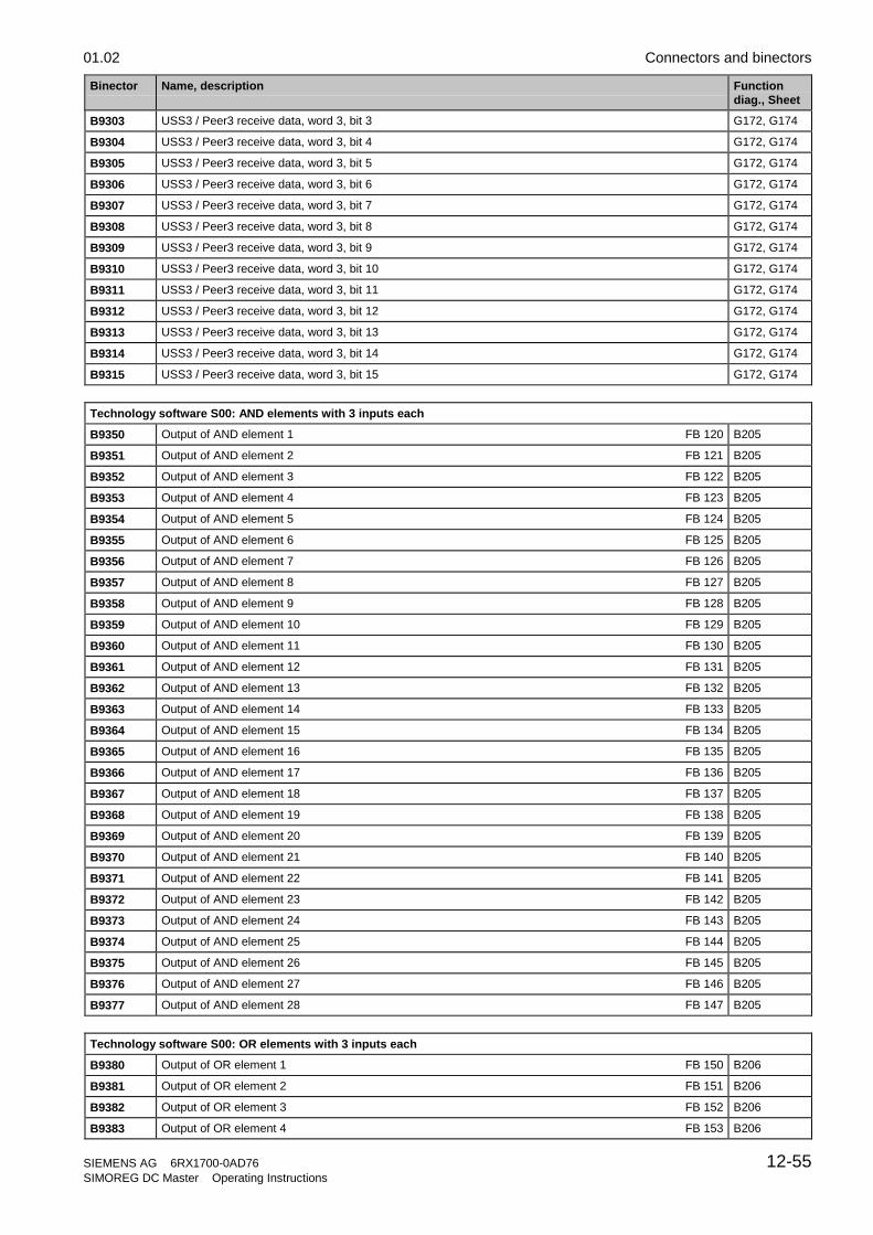
01.02 Connectors and binectors
SIEMENS AG 6RX1700-0AD76 12-55SIMOREG DC Master Operating Instructions
Binector Name, description Functiondiag., Sheet
B9303 USS3 / Peer3 receive data, word 3, bit 3 G172, G174
B9304 USS3 / Peer3 receive data, word 3, bit 4 G172, G174
B9305 USS3 / Peer3 receive data, word 3, bit 5 G172, G174
B9306 USS3 / Peer3 receive data, word 3, bit 6 G172, G174
B9307 USS3 / Peer3 receive data, word 3, bit 7 G172, G174
B9308 USS3 / Peer3 receive data, word 3, bit 8 G172, G174
B9309 USS3 / Peer3 receive data, word 3, bit 9 G172, G174
B9310 USS3 / Peer3 receive data, word 3, bit 10 G172, G174
B9311 USS3 / Peer3 receive data, word 3, bit 11 G172, G174
B9312 USS3 / Peer3 receive data, word 3, bit 12 G172, G174
B9313 USS3 / Peer3 receive data, word 3, bit 13 G172, G174
B9314 USS3 / Peer3 receive data, word 3, bit 14 G172, G174
B9315 USS3 / Peer3 receive data, word 3, bit 15 G172, G174
Technology software S00: AND elements with 3 inputs each
B9350 Output of AND element 1 FB 120 B205
B9351 Output of AND element 2 FB 121 B205
B9352 Output of AND element 3 FB 122 B205
B9353 Output of AND element 4 FB 123 B205
B9354 Output of AND element 5 FB 124 B205
B9355 Output of AND element 6 FB 125 B205
B9356 Output of AND element 7 FB 126 B205
B9357 Output of AND element 8 FB 127 B205
B9358 Output of AND element 9 FB 128 B205
B9359 Output of AND element 10 FB 129 B205
B9360 Output of AND element 11 FB 130 B205
B9361 Output of AND element 12 FB 131 B205
B9362 Output of AND element 13 FB 132 B205
B9363 Output of AND element 14 FB 133 B205
B9364 Output of AND element 15 FB 134 B205
B9365 Output of AND element 16 FB 135 B205
B9366 Output of AND element 17 FB 136 B205
B9367 Output of AND element 18 FB 137 B205
B9368 Output of AND element 19 FB 138 B205
B9369 Output of AND element 20 FB 139 B205
B9370 Output of AND element 21 FB 140 B205
B9371 Output of AND element 22 FB 141 B205
B9372 Output of AND element 23 FB 142 B205
B9373 Output of AND element 24 FB 143 B205
B9374 Output of AND element 25 FB 144 B205
B9375 Output of AND element 26 FB 145 B205
B9376 Output of AND element 27 FB 146 B205
B9377 Output of AND element 28 FB 147 B205
Technology software S00: OR elements with 3 inputs each
B9380 Output of OR element 1 FB 150 B206
B9381 Output of OR element 2 FB 151 B206
B9382 Output of OR element 3 FB 152 B206
B9383 Output of OR element 4 FB 153 B206

Connectors and binectors 01.02
12-56 SIEMENS AG 6RX1700-0AD76SIMOREG DC Master Operating Instructions
Binector Name, description Functiondiag., Sheet
B9384 Output of OR element 5 FB 154 B206
B9385 Output of OR element 6 FB 155 B206
B9386 Output of OR element 7 FB 156 B206
B9387 Output of OR element 8 FB 157 B206
B9388 Output of OR element 9 FB 158 B206
B9389 Output of OR element 10 FB 159 B206
B9390 Output of OR element 11 FB 160 B206
B9391 Output of OR element 12 FB 161 B206
B9392 Output of OR element 13 FB 162 B206
B9393 Output of OR element 14 FB 163 B206
B9394 Output of OR element 15 FB 164 B206
B9395 Output of OR element 16 FB 165 B206
B9396 Output of OR element 17 FB 166 B206
B9397 Output of OR element 18 FB 167 B206
B9398 Output of OR element 19 FB 168 B206
B9399 Output of OR element 20 FB 169 B206
Serial interface 3 (USS3 / Peer-to-peer 3 on G-SST3)
B9400 USS3 / Peer3 receive data, word 4, bit 0 G172, G174
B9401 USS3 / Peer3 receive data, word 4, bit 1 G172, G174
B9402 USS3 / Peer3 receive data, word 4, bit 2 G172, G174
B9403 USS3 / Peer3 receive data, word 4, bit 3 G172, G174
B9404 USS3 / Peer3 receive data, word 4, bit 4 G172, G174
B9405 USS3 / Peer3 receive data, word 4, bit 5 G172, G174
B9406 USS3 / Peer3 receive data, word 4, bit 6 G172, G174
B9407 USS3 / Peer3 receive data, word 4, bit 7 G172, G174
B9408 USS3 / Peer3 receive data, word 4, bit 8 G172, G174
B9409 USS3 / Peer3 receive data, word 4, bit 9 G172, G174
B9410 USS3 / Peer3 receive data, word 4, bit 10 G172, G174
B9411 USS3 / Peer3 receive data, word 4, bit 11 G172, G174
B9412 USS3 / Peer3 receive data, word 4, bit 12 G172, G174
B9413 USS3 / Peer3 receive data, word 4, bit 13 G172, G174
B9414 USS3 / Peer3 receive data, word 4, bit 14 G172, G174
B9415 USS3 / Peer3 receive data, word 4, bit 15 G172, G174
Technology software S00: Inverters
B9450 Output of inverter 1 FB 180 B207
B9451 Output of inverter 2 FB 181 B207
B9452 Output of inverter 3 FB 182 B207
B9453 Output of inverter 4 FB 183 B207
B9454 Output of inverter 5 FB 184 B207
B9455 Output of inverter 6 FB 185 B207
B9456 Output of inverter 7 FB 186 B207
B9457 Output of inverter 8 FB 187 B207
B9458 Output of inverter 9 FB 188 B207
B9459 Output of inverter 10 FB 189 B207
B9460 Output of inverter 11 FB 190 B207
B9461 Output of inverter 12 FB 191 B207
B9462 Output of inverter 13 FB 192 B207

01.02 Connectors and binectors
SIEMENS AG 6RX1700-0AD76 12-57SIMOREG DC Master Operating Instructions
Binector Name, description Functiondiag., Sheet
B9463 Output of inverter 14 FB 193 B207
B9464 Output of inverter 15 FB 194 B207
B9465 Output of inverter 16 FB 195 B207
Technology software S00: NAND elements with 3 inputs each
B9470 Output of NAND element 1 FB 200 B207
B9471 Output of NAND element 2 FB 201 B207
B9472 Output of NAND element 3 FB 202 B207
B9473 Output of NAND element 4 FB 203 B207
B9474 Output of NAND element 5 FB 204 B207
B9475 Output of NAND element 6 FB 205 B207
B9476 Output of NAND element 7 FB 206 B207
B9477 Output of NAND element 8 FB 207 B207
B9478 Output of NAND element 9 FB 208 B207
B9479 Output of NAND element 10 FB 209 B207
B9480 Output of NAND element 11 FB 210 B207
B9481 Output of NAND element 12 FB 211 B207
Technology software S00: Binary signal selector switches
B9482 Output of binary signal selector switch 1 FB 250 B216
B9483 Output of binary signal selector switch 2 FB 251 B216
B9484 Output of binary signal selector switch 3 FB 252 B216
B9485 Output of binary signal selector switch 4 FB 253 B216
B9486 Output of binary signal selector switch 5 FB 254 B216
Technology software S00: D flipflops
B9490 D flipflop 1: Output Q FB 230 B211
B9491 D flipflop 1: Output /Q FB 230 B211
B9492 D flipflop 2: Output Q FB 231 B211
B9493 D flipflop 2: Output /Q FB 231 B211
B9494 D flipflop 3: Output Q FB 232 B211
B9495 D flipflop 3: Output /Q FB 232 B211
B9496 D flipflop 4: Output Q FB 233 B211
B9497 D flipflop 4: Output /Q FB 233 B211
Technology software S00: Technology controller
B9499 Ramp-function generator output = ramp-function generator input (y = x) FB 113 B170
Serial interface 3 (USS3 / Peer-to-peer 3 on G-SST3)
B9500 USS3 / Peer3 receive data, word 5, bit 0 G172, G174
B9501 USS3 / Peer3 receive data, word 5, bit 1 G172, G174
B9502 USS3 / Peer3 receive data, word 5, bit 2 G172, G174
B9503 USS3 / Peer3 receive data, word 5, bit 3 G172, G174
B9504 USS3 / Peer3 receive data, word 5, bit 4 G172, G174
B9505 USS3 / Peer3 receive data, word 5, bit 5 G172, G174
B9506 USS3 / Peer3 receive data, word 5, bit 6 G172, G174
B9507 USS3 / Peer3 receive data, word 5, bit 7 G172, G174
B9508 USS3 / Peer3 receive data, word 5, bit 8 G172, G174
B9509 USS3 / Peer3 receive data, word 5, bit 9 G172, G174
B9510 USS3 / Peer3 receive data, word 5, bit 10 G172, G174

Connectors and binectors 01.02
12-58 SIEMENS AG 6RX1700-0AD76SIMOREG DC Master Operating Instructions
Binector Name, description Functiondiag., Sheet
B9511 USS3 / Peer3 receive data, word 5, bit 11 G172, G174
B9512 USS3 / Peer3 receive data, word 5, bit 12 G172, G174
B9513 USS3 / Peer3 receive data, word 5, bit 13 G172, G174
B9514 USS3 / Peer3 receive data, word 5, bit 14 G172, G174
B9515 USS3 / Peer3 receive data, word 5, bit 15 G172, G174
Technology software S00: RS flipflops
B9550 RS flipflop 1: Output Q FB 215 B210
B9551 RS flipflop 1: Output /Q FB 215 B210
B9552 RS flipflop 2: Output Q FB 216 B210
B9553 RS flipflop 2: Output /Q FB 216 B210
B9554 RS flipflop 3: Output Q FB 217 B210
B9555 RS flipflop 3: Output /Q FB 217 B210
B9556 RS flipflop 4: Output Q FB 218 B210
B9557 RS flipflop 4: Output /Q FB 218 B210
B9558 RS flipflop 5: Output Q FB 219 B210
B9559 RS flipflop 5: Output /Q FB 219 B210
B9560 RS flipflop 6: Output Q FB 220 B210
B9561 RS flipflop 6: Output /Q FB 220 B210
B9562 RS flipflop 7: Output Q FB 221 B210
B9563 RS flipflop 7: Output /Q FB 221 B210
B9564 RS flipflop 8: Output Q FB 222 B210
B9565 RS flipflop 8: Output /Q FB 222 B210
B9566 RS flipflop 9: Output Q FB 223 B210
B9567 RS flipflop 9: Output /Q FB 223 B210
B9568 RS flipflop 10: Output Q FB 224 B210
B9569 RS flipflop 10: Output /Q FB 224 B210
B9570 RS flipflop 11: Output Q FB 225 B210
B9571 RS flipflop 11: Output /Q FB 225 B210
B9572 RS flipflop 12: Output Q FB 226 B210
B9573 RS flipflop 12: Output /Q FB 226 B210
B9574 RS flipflop 13: Output Q FB 227 B210
B9575 RS flipflop 13: Output /Q FB 227 B210
B9576 RS flipflop 14: Output Q FB 228 B210
B9577 RS flipflop 14: Output /Q FB 228 B210
Technology software S00: Timers
B9580 Timer 1: Output FB 240 B215
B9581 Timer 1: Output inverted FB 240 B215
B9582 Timer 2: Output FB 241 B215
B9583 Timer 2: Output inverted FB 241 B215
B9584 Timer 3: Output FB 242 B215
B9585 Timer 3: Output inverted FB 242 B215
B9586 Timer 4: Output FB 243 B215
B9587 Timer 4: Output inverted FB 243 B215
B9588 Timer 5: Output FB 244 B215
B9589 Timer 5: Output inverted FB 244 B215
B9590 Timer 6: Output FB 245 B215
B9591 Timer 6: Output inverted FB 245 B215

01.02 Connectors and binectors
SIEMENS AG 6RX1700-0AD76 12-59SIMOREG DC Master Operating Instructions
Binector Name, description Functiondiag., Sheet
B9592 Timer 7: Output FB 246 B216
B9593 Timer 7: Output inverted FB 246 B216
B9594 Timer 8: Output FB 247 B216
B9595 Timer 8: Output inverted FB 247 B216
B9596 Timer 9: Output FB 248 B216
B9597 Timer 9: Output inverted FB 248 B216
B9598 Timer 10: Output FB 249 B216
B9599 Timer 10: Output inverted FB 249 B216
Serial interface 3 (USS3 / Peer-to-peer 3 on G-SST3)
B9600 USS3 receive data, word 6, bit 0 G172
B9601 USS3 receive data, word 6, bit 1 G172
B9602 USS3 receive data, word 6, bit 2 G172
B9603 USS3 receive data, word 6, bit 3 G172
B9604 USS3 receive data, word 6, bit 4 G172
B9605 USS3 receive data, word 6, bit 5 G172
B9606 USS3 receive data, word 6, bit 6 G172
B9607 USS3 receive data, word 6, bit 7 G172
B9608 USS3 receive data, word 6, bit 8 G172
B9609 USS3 receive data, word 6, bit 9 G172
B9610 USS3 receive data, word 6, bit 10 G172
B9611 USS3 receive data, word 6, bit 11 G172
B9612 USS3 receive data, word 6, bit 12 G172
B9613 USS3 receive data, word 6, bit 13 G172
B9614 USS3 receive data, word 6, bit 14 G172
B9615 USS3 receive data, word 6, bit 15 G172
Technology software S00: PI controller [SW 1.8 and later]
B9650 PI controller 1: Controller at output limitation FB 260 B180
B9652 PI controller 3: Controller at output limitation FB 262 B182
B9653 PI controller 4: Controller at output limitation FB 263 B183
B9654 PI controller 5: Controller at output limitation FB 264 B184
B9655 PI controller 6: Controller at output limitation FB 265 B185
B9656 PI controller 7: Controller at output limitation FB 266 B186
B9657 PI controller 8: Controller at output limitation FB 267 B187
B9658 PI controller 9: Controller at output limitation FB 268 B188
B9659 PI controller 10: Controller at output limitation FB 269 B189
B9660 PI controller 1: Controller at positive output limitation FB 260 B180
B9661 PI controller 2: Controller at positive output limitation FB 261 B181
B9662 PI controller 3: Controller at positive output limitation FB 262 B182
B9663 PI controller 4: Controller at positive output limitation FB 263 B183
B9664 PI controller 5: Controller at positive output limitation FB 264 B184
B9665 PI controller 6: Controller at positive output limitation FB 265 B185
B9666 PI controller 7: Controller at positive output limitation FB 266 B186
B9667 PI controller 8: Controller at positive output limitation FB 267 B187
B9668 PI controller 9: Controller at positive output limitation FB 268 B188
B9669 PI controller 10: Controller at positive output limitation FB 269 B189
B9670 PI controller 1: Controller at negative output limitation FB 260 B180
B9671 PI controller 2: Controller at negative output limitation FB 261 B181

Connectors and binectors 01.02
12-60 SIEMENS AG 6RX1700-0AD76SIMOREG DC Master Operating Instructions
Binector Name, description Functiondiag., Sheet
B9672 PI controller 3: Controller at negative output limitation FB 262 B182
B9673 PI controller 4: Controller at negative output limitation FB 263 B183
B9674 PI controller 5: Controller at negative output limitation FB 264 B184
B9675 PI controller 6: Controller at negative output limitation FB 265 B185
B9676 PI controller 7: Controller at negative output limitation FB 266 B186
B9677 PI controller 8: Controller at negative output limitation FB 267 B187
B9678 PI controller 9: Controller at negative output limitation FB 268 B188
B9679 PI controller 10: Controller at negative output limitation FB 269 B189
S00 technology software: Limit-value monitors for double-word connectors
B9680 Limit-value monitor 1: |A| < B has responded [SW 1.9 and later] FB 68 B151
B9681 Limit-value monitor 1: A < B has responded [SW 1.9 and later] FB 68 B151
B9682 Limit-value monitor 1: A = B has responded [SW 1.9 and later] FB 68 B151
B9683 Limit-value monitor 2: |A| < B has responded [SW 1.9 and later] FB 69 B151
B9684 Limit-value monitor 2: A < B has responded [SW 1.9 and later] FB 69 B151
B9685 Limit-value monitor 2: A = B has responded [SW 1.9 and later] FB 69 B151
Technology software S00: root extractor
B9686 |root extractor input| < threshold responded [SW 2.0 and later] FB 58 B153
B9687 |root extractor input| < threshold responded (inverted) [SW 2.0 and later] FB 58 B153
Serial interface 3 (USS3 / Peer-to-peer 3 on G-SST3)
B9700 USS3 receive data, word 7, bit 0 G172
B9701 USS3 receive data, word 7, bit 1 G172
B9702 USS3 receive data, word 7, bit 2 G172
B9703 USS3 receive data, word 7, bit 3 G172
B9704 USS3 receive data, word 7, bit 4 G172
B9705 USS3 receive data, word 7, bit 5 G172
B9706 USS3 receive data, word 7, bit 6 G172
B9707 USS3 receive data, word 7, bit 7 G172
B9708 USS3 receive data, word 7, bit 8 G172
B9709 USS3 receive data, word 7, bit 9 G172
B9710 USS3 receive data, word 7, bit 10 G172
B9711 USS3 receive data, word 7, bit 11 G172
B9712 USS3 receive data, word 7, bit 12 G172
B9713 USS3 receive data, word 7, bit 13 G172
B9714 USS3 receive data, word 7, bit 14 G172
B9715 USS3 receive data, word 7, bit 15 G172
B9800 USS3 receive data, word 8, bit 0 G172
B9801 USS3 receive data, word 8, bit 1 G172
B9802 USS3 receive data, word 8, bit 2 G172
B9803 USS3 receive data, word 8, bit 3 G172
B9804 USS3 receive data, word 8, bit 4 G172
B9805 USS3 receive data, word 8, bit 5 G172
B9806 USS3 receive data, word 8, bit 6 G172
B9807 USS3 receive data, word 8, bit 7 G172
B9808 USS3 receive data, word 8, bit 8 G172
B9809 USS3 receive data, word 8, bit 9 G172
B9810 USS3 receive data, word 8, bit 10 G172

01.02 Connectors and binectors
SIEMENS AG 6RX1700-0AD76 12-61SIMOREG DC Master Operating Instructions
Binector Name, description Functiondiag., Sheet
B9811 USS3 receive data, word 8, bit 11 G172
B9812 USS3 receive data, word 8, bit 12 G172
B9813 USS3 receive data, word 8, bit 13 G172
B9814 USS3 receive data, word 8, bit 14 G172
B9815 USS3 receive data, word 8, bit 15 G172
B9900 USS3 receive data, word 9, bit 0 G172
B9901 USS3 receive data, word 9, bit 1 G172
B9902 USS3 receive data, word 9, bit 2 G172
B9903 USS3 receive data, word 9, bit 3 G172
B9904 USS3 receive data, word 9, bit 4 G172
B9905 USS3 receive data, word 9, bit 5 G172
B9906 USS3 receive data, word 9, bit 6 G172
B9907 USS3 receive data, word 9, bit 7 G172
B9908 USS3 receive data, word 9, bit 8 G172
B9909 USS3 receive data, word 9, bit 9 G172
B9910 USS3 receive data, word 9, bit 10 G172
B9911 USS3 receive data, word 9, bit 11 G172
B9912 USS3 receive data, word 9, bit 12 G172
B9913 USS3 receive data, word 9, bit 13 G172
B9914 USS3 receive data, word 9, bit 14 G172
B9915 USS3 receive data, word 9, bit 15 G172
Trace function
B9999 Trigger condition of trace function is fulfilled [SW 1.8 and later]

Connectors and binectors 01.02
12-62 SIEMENS AG 6RX1700-0AD76SIMOREG DC Master Operating Instructions

01.02 Maintenance
SIEMENS AG 6RX1700-0AD76 13-1SIMOREG DC Master Operating Instructions
13 Maintenance
WARNINGHazardous voltage are present in this electrical equipment during operation.
A hazardous voltage may be present at the signaling relays in the customer installation.
Non-observance of the safety instructions can result in death, severe personal injury orsubstantial property damage.
When carrying out maintenance work on this converter, please read all safety instructionsincluded in this section and attached to the product itself.• Maintenance work on the converter may be carried out only by qualified personnel who are
thoroughly familiar with all safety notices in this manual and with the installation, operatingand maintenance instructions.
• Before carrying out visual checks and maintenance work, ensure that the AC power supplyis disconnected and locked out and that the converter is grounded. Before the AC supply isdisconnected, both converters and motors are at hazardous voltage levels. Even when theconverter contactor is open, hazardous voltages are still present.
• The snubber capacitors might still be carrying hazardous voltage after isolation from thesupply. For this reason, the converter must not be opened for at least two minutes afterswitch-off.
Only spare parts authorized by the manufacturer may be used.
The converter must be thoroughly protected against the ingress of dirt so as to prevent voltageflashovers and this irreparable damage. Dust and foreign bodies, and especially contaminationdrawn in through the cooling air flow, must be carefully removed at regular intervals depending onthe degree of pollution, but at least once every 12 months. The converter must be cleaned with dry,compressed air, max. 1 bar, or with a vacuum cleaner.
Please note the following with respect to converters with forced air cooling:
The fan bearings are designed for a service lifetime of 30000 hours. The fans should be replaced inplenty of time in order to maintain the availability of the thyristor sets.
13.1 Procedure for updating software
1Read out and write down all parametercontents.(also note software version in r060.001 andr065.001!)
Note:The parameter set can be transferred to a PC orprogramming device by means of DriveMonitor(see also Section 15).
2Switch off electronics power supply
3Connect one COM port on the PC toconnector X300 on the converter
Cable order number: 6SX7005-0AB00(see also Section 15.3)
4Switch on electronics power supply AND pressdown the UP key on the PMU of theSIMOREG converter at the same time
The SIMOREG converter switches tooperating state o13.0
Note:A software update can be started only from thePMU panel and not via an OP1S or theDriveMonitor system

Maintenance 01.02
13-2 SIEMENS AG 6RX1700-0AD76SIMOREG DC Master Operating Instructions
5Open a DOS window on the PC and enterprogram call:HEXLOAD 7001Axxx.H86 7001Bxxx.H86 COMx
Start the program by pressing Return The software update is performedautomatically
Note:HEXLOAD.EXE: Loading program7001Axxx.H86 and 7001Bxxx.H86:Data files which contain the SIMOREG softwarexxx is the SW releaseCOMx: COM1 or COM2
6 When the software has been updatedsuccessfully, the SIMOREG switches tooperating state o13.2 for approx. 1 s
The SIMOREG converter then switches tooperating state o12.9 in many cases(depending on which SW version waspreviously installed in the converter) forapproximately 15s.
Note:The currently programmed addressed is displayedon the PMU while the update is in progressThe current status of the update routine isdisplayed on the PC
7Check the checksum:Comparison of the value of parameter r062.001 with the checksum in the Internet under menu item"Info" (see the inside page of the cover sheet of the operation instructions).
8Was the electronics supply disconnected whileStep 6 was in progress?
? yes
9bAcknowledge any fault message that mayappear on the SIMOREG device
no 10b
Restore default setting(see Section 7.4)
11bStart up the converter again(see Section 7.5)Note:The parameter set stored in Step 1 above canbe loaded from a PC or programming deviceby means of DriveMonitor.
12 End

01.02 Maintenance
SIEMENS AG 6RX1700-0AD76 13-3SIMOREG DC Master Operating Instructions
13.2 Replacement of components
13.2.1 Replacement of fan
WARNINGThe converter fan may be replaced only by properly qualified personnel.
The snubber capacitors might still be carrying hazardous voltage after isolation from the supply.For this reason, the converter must not be opened for at least two minutes after switch-off.
Non-observance of the safety instructions can result in death, severe personal injury orsubstantial property damage.
Replacement of fan on 210A to 280A converters
2
1
4
3
The two fans are mounted on the underside of the converter.
• Remove connector .
• Release the two retaining clips on the fan and swing fan out downwards.
Installation:
• When mounting the fan make sure it is in the correct mounting position (blowing directionupward, see arrow on the fan housing).
• Insert the fan into lugs and push upwards until it engages in retaining clips
• Insert connector again.

Maintenance 01.02
13-4 SIEMENS AG 6RX1700-0AD76SIMOREG DC Master Operating Instructions
Replacement of fan on 400A to 850A converters
4U1
4V1
4W1
PE
1
2
The fan is mounted on the underside of the converter.
• Remove connector .
• Use a T20 screwdriver to undo the two Torx screws .
• Lift the fan using the fixing straps and pull out downwards.
Installation:
• Push fan box up along the rear panel right up over the fixing clips.
• Tighten the two Torx screws with 2.5 Nm.
• Insert connector .

01.02 Maintenance
SIEMENS AG 6RX1700-0AD76 13-5SIMOREG DC Master Operating Instructions
Replacement of fan on 900A to 1200A converters
3
1
2
The fan is mounted on top of the converter.
• Remove connector .
• Use a T20 screwdriver to undo the two Torx screws .• Undo the M6 hexagonal nut .
• Pull fan upwards out of its guideway and then forwards to remove. Take care to protect the fieldmodule mounted on the left (risk of mechanical damage!).
Installation:
• Insert fan into guideway from above.
• Tighten the two Torx screws with 10 Nm.
• Tighten hexagonal nut M6 with 10 Nm.
• Insert connector .

Maintenance 01.02
13-6 SIEMENS AG 6RX1700-0AD76SIMOREG DC Master Operating Instructions
Replacement of fan on 1500A to 2200A converters
WARNINGWhen dismantling the fan-mounting box, please remember that it weighs 12 kg.
Non-observance of this warning can result in severe personal injury or substantial propertydamage.
2
1
The fan is mounted on top of the converter.
• Remove connector .
• Undo the M6 hexagonal nut .
• Swing fan upwards and pull it out towards you, taking care to protect the field module mountedon the left against any mechanical damage!
Installation:
• Tilting the fan from the front and upward (see Fig.), slot it into the two rear guide tabs and thentilt it downward as far as it will go.
• Tighten hexagonal nut M6 with 10 Nm.
• Insert connector .

01.02 Maintenance
SIEMENS AG 6RX1700-0AD76 13-7SIMOREG DC Master Operating Instructions
13.2.2 Replacement of PCBs
WARNINGPCBs may be replaced only by properly qualified personnel.
PCBs must not be removed or inserted when the power supply is connected.
Non-observance of the safety instructions can result in death, severe personal injury orsubstantial property damage.
CAUTIONPCBs contains electrostatically sensitive devices. Before touching a PCB, the person carryingout the work must himself be electrostatically discharged. The simplest way of doing this is totouch an electrically conductive earthed object, e.g. socket outlet earth contact.

Maintenance 01.02
13-8 SIEMENS AG 6RX1700-0AD76SIMOREG DC Master Operating Instructions
13.2.3 Replacement of diodes and thyristor modules for devices up to 1200AThe diodes and thyristor modules are mounted by means of self-tapping screws. When a module isreplaced, the support surfaces on the heatsink must be cleaned and a new layer of thermo-lubricantapplied to the thyristor module. To fix the modules always used screws with a metric thread of thesame length as the original screws and fixing elements (washer and spring lock washer). Whenscrewing the modules to the busbars and boards, also use screws with a metric thread and thesame length as the original screws and fixing elements (washer and spring lock washer).
NOTICEThe layer of thermo-lubricant (silicone-free, type H-T-C made by Electrolube) applied to the modules mustbe so thin and even that the baseplate is still clearly visible underneath!
Module design
Tightening torque on module: 3,5 NmTightening torque of current terminals: 3 Nm
Tightening torque on module: 3,5 NmTightening torque of current terminals: 5 Nm
Tightening torque on module: 6 NmTightening torque of current terminals: 12 Nm Tightening torque on module: 6 Nm
Tightening torque of current terminals: 15 Nm

01.02 Maintenance
SIEMENS AG 6RX1700-0AD76 13-9SIMOREG DC Master Operating Instructions
13.2.4 Replacement of fuses and thyristor assemblies on converters of 1500A andabove
1
2
3
7
8
4
5
6
25 Nm
6 Nm
6 Nm
10 Nm
25 Nm
• Undo the M6 hexagonal nut .
• Swing the fan upwards and hold in place with support rail .
• Remove the brace with the attached protective cover by undoing the 2 M6 hexagon-headscrews.
• Remove fuses by undoing the 2 hexagon-head screws on each (M10 or M12 depending onconverter model).
• Undo the M10 hexagon-head screw and swing thyristor assembly out towards you.
• Undo assembly locking mechanism (M6 hexagonal nut) , and pull out thyristor assembly upwards at an angle.
• Install the new components in the reverse order.
Caution: The fuse mounting screws are of different lengths!

Maintenance 01.02
13-10 SIEMENS AG 6RX1700-0AD76SIMOREG DC Master Operating Instructions

01.02 Servicing / Spare Parts
SIEMENS AG 6RX1700-0AD76 14-1SIMOREG DC Master Operating Instructions
14 ServicingSiemens supplies thoroughly tried and tested products and systems of the highest quality. Toensure maximum availability of our products and systems in your plant, we offer extensive after-sales services and support.
For further information about our services and your regional Siemens contacts, please go to ourInternet website:
www.siemens.de/automation/csi_en/service
14.1 Technical SupportYou can obtain technical assistance with our products, systems and solutions from our TechnicalSupport service. Whether you have a simple query, or need help in solving a more difficult, complextask, our Central Technical Support specialists will be pleased to advise you. Our Central TechnicalSupport service is available in English and German.
14.1.1 Time zone Europe and AfricaTel.: +49 (0)180 5050-222
Fax: +49 (0)180 5050-223
Email: [email protected]
Mo.-Fr.: 7:00 to 17:00 (CET)
14.1.2 Time zone America24 Hour Hotline: +1 800 333 7421
Tel.: +1 423 461 2522
Fax: +1 423 461 2466
Email: [email protected]
Mo.-Fr.: 8:00 to 17:00 (local time: Eastern Time)
14.1.3 Time zone Asia / AustraliaTel.: +65 (0)740-7000
Fax: +65 (0)740-7001
Email: [email protected]
Mo.-Fr.: 8:30 to 17:30 (local time: Singapore)

Servicing / Spare Parts 01.02
14-2 SIEMENS AG 6RX1700-0AD76SIMOREG DC Master Operating Instructions
14.2 Spare partsInformation about spare parts can be found in Catalog DA 21.1 E. You will find this catalog on theCD-ROM (order separately under order number: 6RX1700-0AD64, or with product order byspecifying Z option –Z-D64) and via Internet website:
http://www4.ad.siemens.de/view/cs/en/9260805
14.3 RepairsIf you wish to have a part or unit repaired, please call or write to your regional Siemens contact forrepairs.
14.4 On-site servicingQualified specialists can offer an on-site repair and maintenance service to increase the availabilityof your plant. Repair and/or maintenance support can be charged according to time and cost orprovided within the scope of a service contract at a flat rate. Services charged on a time/cost basiswill be available within the normal working hours of the relevant region subject to an appropriatecall-out period.
For on-site servicing, please call your regional Siemens contact.
NOTE
If you contact us with a query, please specify the following converter data:• Converter order number and serial number
• Software version
• Hardware version of basic electronics board (screen printing on component side)
• Hardware version and software version of supplementary boards (if installed)

01.02 DriveMonitor
SIEMENS AG 6RX1700-0AD76 15-1SIMOREG DC Master Operating Instructions
15 DriveMonitorThe DriveMonitor software tool is available to assist the start-up, parameterization and diagnosis ofSIMOREG 6RA70 units via a PC.
15.1 Scope of deliveryDriveMonitor is supplied on a CD-ROM together with the operating manual and sampleapplications.
Order No. 6RX1700-0AD64
It can also be ordered as an option in conjunction 6RA70 units. The relevant short code for thisoption is D64.
15.2 Installing the softwareYou can find a brief overview of the CD contents in START.HTM. If you have installed an HTMLbrowser (e.g. Internet Explorer or Netscape Navigator) on your PC, you can open the overview bydouble clicking on START.HTM. If you do not have an HTML browser, you can find similarinformation in text format in file README.TXT.
After you have chosen an installation language by selecting links DriveMonitor – Installation ofDriveMonitor- Start Installation, you can call the DriveMonitor installation routine.
Some Internet Browsers are not capable of starting programs directly. If this is the case on your PC,a "Setup.exe - Save as" dialog appears after you select Start Installation.
You can then start the Setup program manually in sub-catalog
DriveMonitor\setup\setup.exe
Then follow the instructions displayed by the installation routine.
The default installation path for DriveMonitor is C:\DriveMon\P7VRVISX\System. A "DriveMonitor"icon is also placed on your desktop.
15.3 Connecting the SIMOREG to the PCThe simplest method is to link connector X300 in the front panel of the SIMOREG unit to aCOM port on the PC using the connecting cable available under order no. 6SX7005-0AB00.
1
2
3
4
59
8
7
61
2
3
4
59
8
7
6
PC COMxsocket
6RA70 X300connector
X30012 RxD (RS232)3 Rx+/Tx+ (RS485)45 Ground6 +5V (OP1S)7 TxD (RS232)8 Rx-/Tx- (RS485)9 Ground

DriveMonitor 01.02
15-2 SIEMENS AG 6RX1700-0AD76SIMOREG DC Master Operating Instructions
15.4 Setting up an online link to the SIMOREGDriveMonitor always starts in offline mode. For this reason, you must open or create an offline filewhich has been set up specifically for the device and software version:
To open an existing offline file:
• File - Open <select parameter file>(if the parameter file has been created in SIMOVIS, the drive type SIMOREG DC Master andthe software version used must then be set. If you want to set up an online link to the drive, youmust click the ONLINE button and enter the bus address set in the device)
To create a new offline file:
• File - New - Based on Factory Setting <select drive type and software version> . (If you want toset up an online link to the drive, you must click the ONLINE button and enter the bus addressset in the device) <enter file name>
• File - New - Empty Parameter Set <select drive type and software version> (If you want to setup an online link to the drive, you must click the ONLINE button and enter the bus address setin the device) <enter file name>
The data regarding drive type and software version are stored in the DNL file. You can then startthe program in future by the normal Windows method, i.e. by double clicking on a DNL file, withoutfurther system queries.
You can open the ONLINE Settings screen under Options to check, and if necessary change, theinterface parameters such as COM port and baud rate.
You can set the bus address and number of transmitted process data under File - Drive Settings.
To switch to online mode, select View - Online or the appropriate button on the toolbar. If themessage "Device is not networked" then appears, then "Offline mode" is currently selected. Youcan switch to online mode under File - Drive Settings.
15.5 Further informationThe engineering tool Drive ES is available for the diagnosis of complex installations containingseveral drives as well as Profibus-based drive communication.
Several different packages of Drive ES are available:
• Drive ES Basic Data management in Step 7 projects, drive communications via Profibusor USSOrder No.:6SW1700-5JA00-1AA0
• Drive ES Graphic Interconnection of Option S00 free functions blocks using the CFCinterconnection editorOrder No.:6SW1700-5JB00-1AA0
• Drive ES Simatic Provides function blocks for SIMATIC CPUs and sample projects forcommunication with the SIMOREG unitOrder No.:6SW1700-5JC00-1AA0
IMPORTANTDriveMonitor will run under Windows95/98/Me or Windows NT4 / Windows 2000, but not underWindows 3.x.

12.00 Environmental compatibility
SIEMENS AG 6RX1700-0AD76 16-1SIMOREG DC Master Operating Instructions
16 Environmental compatibilityEnvironmental aspects of developmentThe number of parts has been greatly reduced through the use of highly integrated componentsand a modular design of the entire converter series. As a consequence, the power consumed in theproduction process is significantly lower.
Particular importance has been attached to reducing the volume, mass and diversity of metal andplastic parts.
Front components: PC + ABS Cycoloy GE-Plastics
ABS Novodur Bayer
Plastic components inconverter:
PC Lexan 141-R
PA 6.6
SE1-GFN1 Noryl
Insulation: PC (FR) fl Makrolon or Lexan
Keyboard membrane: Polyester membrane 0.15 mm
Rating plate: Polyester membrane
Flame arresters containing halogen and insulating materials containing silicone have been replacedby pollutant-free materials on all major components.
Environmental compatibility was an important criterion in the selection of supplied parts.
Environmental aspects of productionMost supplied parts are shipped in reusable packaging. The packaging material itself is recyclable,consisting mainly of cardboard.
With the exception of the converter housing, surface coating materials have not been applied.
The production process is free of emissions.
Environmental aspects of disposalThe unit features screw and snap-on connections that can be separated easily to dismantle it intorecyclable mechanical components.
The printed circuit boards can be disposed of by thermal processing. The percentage ofcomponents containing dangerous substances is low.

Environmental compatibility 12.00
16-2 SIEMENS AG 6RX1700-0AD76SIMOREG DC Master Operating Instructions

01.02 Applications
SIEMENS AG 6RX1700-0AD76 17-1SIMOREG DC Master Operating Instructions
17 ApplicationsDescriptions of applications (e.g. Winder Application, 12-Pulse Operation, Master-Slave Operation,Operation of 6RA70 as Field Supply Unit and others) can be found on the CD-ROM (orderseparately under order number: 6RX1700-0AD64, or with product order by specifying Z option –Z-D64) and via Internet website:
http://www4.ad.siemens.de/view/cs/en/8467615

Applications 01.02
17-2 SIEMENS AG 6RX1700-0AD76SIMOREG DC Master Operating Instructions

02.00 Appendix
SIEMENS AG 6RX1700-0AD76 18-1SIMOREG DC Master Operating Instructions
18 Appendix
18.1 Further documentationCatalog DA21 Converters
Catalog DA21E Spare parts
Catalog DA22 Cabinet-mounted converters

Appendix 02.00
18-2 SIEMENS AG 6RX1700-0AD76SIMOREG DC Master Operating Instructions

02.00 Appendix
SIEMENS AG 6RX1700-0AD76 18-3SIMOREG DC Master Operating Instructions
Comments sheetWe have made every effort to critically edit this Instruction Manual. However, if you still come acrossprinting errors, we should be grateful if you would let us know.
We would also be grateful if you could let us have your opinion of this Instruction Manual and theconverter itself!
Contact your local Siemens office for any comments - either negative or positive!
Many thanks!
SIEMENS AG Austria, Electronics Plant, Vienna
From: Name: Date:
Company:
Address:
Tel.:
To: SIEMENS Office
Address:
Please pass on toSIEMENS AG AustriaElectronics Plant, Vienna
Concerns: Comments for the 6RA70 Instruction Manual, Edition

Appendix 02.00
18-4 SIEMENS AG 6RX1700-0AD76SIMOREG DC Master Operating Instructions


01.02
Siemens AGElektronikwerk WienPostfach 83, A-1211 Wien
© Siemens AG, 1998Subject to change without notice
Siemens Aktiengesellschaft Order No.: 6RX1700-0AD76
Printed in Austria
The following versions have appeared so far: Version Internal Part No.
03 C98130-A1256-A2-03-761904 C98130-A1256-A2-04-761905 C98130-A1256-A2-05-761906 C98130-A1256-A2-06-7619
06.1 C98130-A1256-A2-07-761907 C98130-A1256-A2-08-761908 C98130-A1256-A2-09-761909 C98130-A1256-A2-10-7619
Version 09 consists of the following sections
Section Pages Date of edition
0 Contents 8 01.021 Safety information 4 12.002 Type spectrum 8 01.023 Description 30 01.024 Shipment, unpacking 2 01.025 Installation 26 01.026 Connections 66 01.027 Start-up 60 01.028 Function diagrams 138 01.029 Function descriptions 76 01.0210 Faults / Alarms 28 01.0211 Parameter list 178 01.0212 List of connectors and binectors 62 01.0213 Maintenance 10 01.0214 Servicing 2 01.0215 DriveMonitor 2 01.0216 Environmental compatibility 2 12.0017 Applications 2 01.0218 Appendix 4 02.00