Improving Firmware development at Axis Communications - sam
90
Improving firmware development at Axis Communications Lund University Faculty of Engineering Department of Computer Science Authors: Sebastian Nordin Christoffer Weidmar Examiner: Dietmar Pfahl, LTH Supervisors: Pontus Bergendahl, Axis Communications AB Patrick Berling, Axis Communications AB August 2011
-
Upload
khangminh22 -
Category
Documents
-
view
1 -
download
0
Transcript of Improving Firmware development at Axis Communications - sam
Improving firmware development at Axis Communications
Lund University Faculty of Engineering Department of Computer Science
Authors: Sebastian Nordin
Christoffer Weidmar
Examiner: Dietmar Pfahl, LTH
Supervisors: Pontus Bergendahl, Axis Communications AB
Patrick Berling, Axis Communications AB
August 2011


III
Preface This master thesis was performed at the firmware department of Axis
Communications AB in Lund, in collaboration with the Department of Computer
Science at Lund Institute of Technology. The thesis marks the final examination
towards our Master of Science in Industrial Engineering and Management.
The thesis corresponds to 30 ECTS, which equals one semester of studies. The
thesis work was commenced in March and completed in August of 2011.
We found the work to be both challenging and inspirational; it has provided us
with knowledge that will surely be beneficial for us in our future professional
careers.
We would hereby like to extend our deepest gratitude to:
The firmware development department at Axis for their invaluable
feedback and cooperation in the progression of the thesis work. The
personnel at Axis Communications in Lund welcomed us with great
enthusiasm.
Pontus Bergendahl and Patrick Berling, our supervisors at Axis, for their
patience and support throughout the thesis. Without their input and
dedication this thesis would not have been possible.
Dietmar Pfahl, examiner and co-supervisor, for his observations,
comments and helpful guidance throughout the entirety of our thesis
work.
Martin Höst, Professor at Lund University Faculty of Engineering, for
providing us with important initial guidance and feedback.
Björn Carlsson, consultant at Jayway, for skillfully providing deepened
knowledge in areas related to the thesis.
Lund, August 2011
Sebastian Nordin and Christoffer Weidmar

IV
Abstrakt Titel: Analys och förbättring av firmware utvecklingen på Axis
Communications
Författare: Sebastian Nordin
Christoffer Weidmar
Handledare: Pontus Bergendahl, Manager på Axis Communications
Patrick Berling, Project Manager på Axis Communications
Examinator: Dietmar Pfahl, Docent, Institutionen för Datavetenskap på
Lunds Universitet, Lunds Tekniska Högskola
Problem: Hur kan firmware utvecklingen förbättras genom att använda
teorier inom mjukvaruutveckling och affärs-orienterade
metoder?
Syfte: Identifiera problem i befintliga processer och föreslå
förbättringar.
Begränsningar: Detta examensarbete fokuserar enbart på de aspekter av
programvaruteknik som relaterar till firmware utveckling.
Arbetsprocess: Kvalitativa data samlades in från intern dokumentation och
processobservationer. Litteraturstudier gav en teoretisk
bakgrund som användes för att framställa det
förbättringsförslag som presenteras i arbetet.
Slutsats: Denna avhandling understryker vikten av att beakta både
affärs-och mjukvarumässiga dimensioner inom moderna
teknikintensiva företag. Genom att kombinera teorier kan
organisationer utnyttja fördelarna från båda.
Arbetsuppdelning Christoffer Weidmar ansvarig för delar rörande Business
Process Management.
Sebastian Nordin ansvarig för delar rörande Software Product
Lines.
Nyckelbegrepp: Firmware utveckling, hantering av affärsprocesser,
produktlinjer, mjukvaruutveckling

V
Abstract Title: Improving Firmware development at Axis Communications
Authors: Sebastian Nordin
Christoffer Weidmar
Supervisors: Pontus Bergendahl, Manager at Axis Communications
Patrick Berling, Project Manager at Axis Communications
Examiner: Dietmar Pfahl, Associate Professor, Department of Computer
Science at Lund University, Faculty of Engineering
Problem: How can firmware development be improved by using
software engineering theories as well as business oriented
methodologies?
Purpose: Identify issues in current processes and suggest improvements.
Delimitations: This thesis focuses solely on the software engineering aspects
of firmware development.
Work process: Qualitative data was collected from internal documentation
and process observations. Literature studies provided a
theoretical background which was used as the source for the
improvement suggestion presented in the thesis.
Conclusion: This thesis underlines the importance of considering both
business and software engineering dimensions within modern,
technology intensive companies. By combining theories,
organizations may be able to utilize benefits from both
practices.
Division of work Christopher Weidmar is responsible for parts concerning
Business Process Management.
Sebastian Nordin is responsible for parts concerning Software
Product Lines.
Key Words: Firmware development, business process management,
software product lines, software engineering process.

VI
Table of contents 1 Introduction ...................................................................................................... 1
1.1 Background ............................................................................................... 1
1.2 Purpose and goals ..................................................................................... 2
1.3 Focus and limitations ................................................................................ 3
1.4 Report composition .................................................................................. 3
2 Methodology ..................................................................................................... 3
2.1 Induction and Deduction .......................................................................... 4
2.2 Scientific methodology ............................................................................. 5
2.3 Data format and sources ........................................................................... 5
2.4 Techniques for data acquisition ................................................................ 6
2.5 Validity, reliability and objectivity............................................................. 7
2.6 Redefining validity, reliability and objectivity into a qualitative context . 7
2.7 Trustworthiness and authenticity of this thesis........................................ 8
3 Theory ............................................................................................................. 10
3.1 Software Product Lines ........................................................................... 10
3.2 Business Process Management ............................................................... 22
3.3 Firmware and embedded software ........................................................ 30
3.4 Firmware Quality .................................................................................... 31
3.5 Software metrics and measurements ..................................................... 32
4 Case study, Axis Communications AB ............................................................. 35
4.1 Product Portfolio ..................................................................................... 35
4.2 Axis Firmware Development ................................................................... 35
4.3 Tollgates .................................................................................................. 38
4.4 Linux Firmware Platform ......................................................................... 42
4.5 Software Product Lines at Axis................................................................ 46
4.6 Global Information Tracker (GIT) ............................................................ 47
4.7 Trouble .................................................................................................... 48

VII
4.8 QACE ....................................................................................................... 48
4.9 Roles at Axis ............................................................................................ 49
5 Analysis ........................................................................................................... 52
5.1 Quality Assurance ................................................................................... 52
5.2 Software product lines ............................................................................ 52
5.3 Business Process Management ............................................................... 60
5.4 Packet distribution analysis .................................................................... 62
6 Solution proposal ............................................................................................ 65
6.1 Software Product Lines ........................................................................... 65
6.2 Business Process Management ............................................................... 66
7 Conclusions ..................................................................................................... 72
7.1 Implementation ...................................................................................... 72
7.2 Results ..................................................................................................... 74
7.3 Limitations............................................................................................... 75
7.4 Evaluation ............................................................................................... 75
7.5 Fulfillment of purpose ............................................................................. 76
8 Discussion ........................................................................................................ 78
8.1 Generalizability ....................................................................................... 78
8.2 Reflections............................................................................................... 78
8.3 Future work ............................................................................................. 80
9 References ...................................................................................................... 81
10 List of abbreviations .................................................................................... 83

1
1 Introduction
The purpose of this chapter is to present the project background, research
question, purpose and limitations. A report outline concludes the chapter.
After this chapter the reader should have an understanding of research purpose
and how the report is structured.
1.1 Background Founded in 1984, Axis Communications was the student project of business major
Mikael Karlsson and the engineer student Martin Green. A year later, sales
specialist Keith Bloodworth joined the duo to form the founding group of Axis.
Mikael Karlsson and Martin Green quickly gained a reputation as being a ‘dynamic
duo’ with the powerful combination of Mikael’s excellent business sense and
Martins keen eye for innovative technology. In the late 80’s, Axis had established
itself as one of the world’s leading companies within printer servers and protocol
converters technology. By the mid-nineties, printer protocols had become
increasingly standardized and simplified. With maturing markets in the protocol
converter domain, Axis started to branch out into new business areas using their
expertise in network technology. In 1996 Axis launched the world’s first
surveillance camera that uses IP technology to connect to local networks or the
internet. This technology would come to shape the future of the company. Today,
network cameras form the basis of the Axis product portfolio.
The Axis company structure is centered on global partnerships through
distributors, resellers and system integrators worldwide. Axis has a worldwide
presence in more than 30 countries with a global total of nearly a thousand
employees 1 [1]. With a steadily growing portfolio of network surveillance
equipment, Axis currently has a total of 45 products. Axis has pioneered the use of
Power over Ethernet (PoE). The PoE technology enables network attached
products to be powered via the ethernet cable by the network switch. This makes
for easier and less invasive installations and remains a big selling point for the
product portfolio. Axis was also one of the driving forces behind ONVIF (Open
Network Video Interface Forum). The initiative was launched as a cooperative
effort by Axis, Bosch and Sony in 2008. The purpose was to establish a global open
interface standard for network video products and to support the ongoing shift
1 March 2011

2
from analog to network-based surveillance in the security market. According to
market institute IMS Research, Axis Communications secured a second place
among suppliers of surveillance cameras and fourth place among suppliers of
surveillance equipment worldwide in 2010. The total market in 2009 is estimated
by IMS to have reached USD 8.2 billion and expected to grow to 14.5 billion USD
in 2014 [2].
Having a steadily expanding product portfolio in a rapid growing market creates a
necessity to look upon internal processes in order to retain efficiency and
effectiveness. All of Axis products contain both hardware and software
components. The embedded software is called Firmware. The focus of this thesis
will solely be on firmware development for Axis existing product portfolio. All
software development at Axis is based on a shared common platform named the
Linux Firmware Platform. This platform based approach will be extensively
investigated throughout the thesis.
1.2 Purpose and goals As time to market is absolutely crucial in the high-tech intensive market in which
Axis operate, the company has begun trying to shorten project roll-out times. The
firmware development process has in the past year been shortened from an
average of 18 months down to 12 months per project2. But even so, further
improvements are crucial to remain competitive as the number of products
increase. The use of a common software platform traditionally results in
substantially shortened roll-out times, which hasn’t been the case for Axis. The
development process is also overly complicated which leads to difficulties in the
management of resources and responsibilities. The overall purpose of this master
thesis is thus to address the following research questions:
RQ1: How should Axis firmware development organization be
restructured to better utilize the benefits from using a software platform?
RQ2: How can firmware development at Axis be measured and managed
using a process based management approach?
In order to fulfill this we identified certain goals to be reached:
G1: Compilation of current academic work in the area.
2 There are different types of projects. These are further discussed in chapter 4.2.

3
G2: Investigation of current firmware development processes at Axis
Communications.
G3: Suggest possible improvements based on academic studies.
G4: Evaluation of our suggested improvements and their validity.
1.3 Focus and delimitations This master thesis will address the software engineering process at the firmware
department of Axis. The involvement of product owners, clients and end
consumers will not be specifically addressed. Also, all processes regarding
hardware focused product research and development are considered to be
outside the scope of this thesis. The main focus will be on the common software
platform, and how it is utilized throughout the development process.
1.4 Report composition • Chapter 1: Introduction
The section presents project background, research question, purpose and imitations.
• Chapter 2: Methodology The section presents relevant scientific methods and describes and motivates the chosen methods.
• Chapter 3: Theory The section summarizes research and theories in areas relevant to the master thesis.
• Chapter 4: Case study, Axis Communications AB The section describes the current situation at Axis Communications.
• Chapter 5: Analysis This section concludes findings from the case study and highlights the main issues addressed in the solution proposal.
• Chapter 6: Solution Proposal This section presents the solution proposal for issues highlighted in the analysis.
• Chapter 7: Conclusions This section presents the most important experiences and findings of the thesis and concludes these.
• Chapter 8: Discussion This section concludes the thesis with a discussion of generalizability and suggestions for future work.
4
2 Methodology This chapter presents a brief explanation of scientific methods and concepts.
Selected methods are described and the selection of these motivated.
Leaving this chapter, the reader should be aware of methods used and how these
affect the end result.
The purpose of determining which set of methods to be used is to establish a base
set of principles and rules to ensure an efficient and scientific approach when
writing a thesis. Methodology functions as the quality assurance of the thesis,
ensuring a scientific and fact based approach. There are often multiple options
when selecting which methodology to use in reaching pre-determined goals.
2.1 Induction and Deduction When conducting a scientific study there are different options of going from
theory to empiricism. The two main alternatives are induction and deduction.
Induction
Using an inductive approach a researcher is not guided by preconceived
ideas. Empirical data is the starting point; the researcher induces data and
observations into more generalizable theory. The inductive logic works
well to discover connections and correlations in data but not to justify
general assumptions [3].
Deduction
Using deductive approach, the study’s starting point is established theory
within the field of research. From this knowledge base, hypotheses are
deducted [4].
This thesis used a hybrid approach. Related to the previously established research
questions RQ1 and RQ2, the following approach was chosen:
1. In order to suggest an organizational restructuring, a case study of the
current situation was conducted.
2. To ensure that existing theories within the relevant fields are
emphasized, a literature study was carried out.
The starting point was to study established theories in order to later apply them
to the current situation forming a solution proposal. Our project model was

5
influenced both by inductive and deductive approaches, sometimes referred to as
abductive reasoning.
2.2 Scientific methodology [5] describes the four most commonly used methods for applied science theses.
2.2.1 Survey
A method used to map a certain fact or phenomenon, often performed by
sampling a small part of a target population.
2.2.2 Case study
An in-depth study of one or many cases with minimal influence on the studied
object. Often the case studying researcher chooses qualitative methods, even
though the case study format doesn’t exclude quantitative methods.
2.2.3 Experiment
A comparative research method where variables are isolated and manipulated in
a controlled manner.
2.2.4 Action research
A carefully monitored and documented study of an activity, aimed at solving a
specific problem.
2.2.5 Methods used in this thesis
This thesis was performed in the format of a case study where we aimed at
depicting the actual situation in the most correct and objective nature [5]. This
case study intended to depict reality in an explanatory manner, focused on
understanding the actual situation at Axis. The case study and analysis were used
to produce an improvement suggestion aimed at specific perceived issues.
2.3 Data format and sources To perform a case study, it was necessary to collect a viable amount of subject
data. Such data can be of two types, qualitative or quantitative. Furthermore,
data can be obtained either from primary or secondary sources.
2.3.1 Quantitative and qualitative data
Quantitative data can be counted or classified; the idea of quantitative research is
to utilize mathematical models, theories and/or hypotheses to reach conclusions.

6
Qualitative data can be of a subjective, objective nature or both. Qualitative
research seeks to interpret such data into meaningful conclusions [7].
2.3.2 Primary and secondary data
Primary data is collected by a researcher for the purpose of a specific study [3].
Secondary data is data that already has been collected and compiled in a different
context [3].
2.3.3 Data used in this thesis
This thesis was conducted using mainly qualitative data from both primary and
secondary sources.
2.4 Techniques for data acquisition Different data acquisition methods can be used to establish a foundation of useful
data. Often there is a strong connection between the selected research method
and the data gathering technique being used [7]. A selection from methods
described in [5]:
2.4.1 Logbook
Documentation describing the progression of the scientific work from start to
finish.
2.4.2 Data compiled by others
Acquire statistical data published by independent organizations, unprocessed
register data, academic studies or archive data.
2.4.3 Observations
Study a phenomenon or act with the senses, with or without technical aids.
Observations can be conducted with or without interaction by the observer.
2.4.4 Techniques used in this thesis
This thesis used a multitude of different techniques for data acquisition. A
logbook was upheld during the entirety of writing the thesis to keep track of
important meetings, discussions and decisions. Project documentation and
internal documentation of processes and practices at Axis was pivotal in
understanding the current situation. Observations and insights gained at meetings
and other activities at Axis were documented.

7
2.5 Validity, reliability and objectivity There are commonly three aspects when conducting and evaluating research
studies. These form the basis for evaluating and assessing the quality of scientific
work [3].
2.5.1 Validity
There are two main types of validity in quantitative research, internal and external.
Internal validity is the ability to measure what is intended to be measured.
External validity is the results generalizability to other situations [3].
2.5.2 Reliability
The stability of a measurement is referred to as reliability. If the same value is
obtained using repeated measuring or sampling, said measuring is considered
having good reliability [3].
2.5.3 Objectivity
The concept of objectivity is used in quantitative studies and concerns the
researcher's neutrality. The objective researcher remains impartial to his or her
work, regardless of preconceptions and opinions [3]. This is sometimes referred to
as “researcher bias”.
2.6 Redefining validity, reliability and objectivity into a
qualitative context Defining validity and reliability is highly applicable when working with quantitative
data. When data is qualitative though, it’s problematic to translate these aspects
into a qualitative context. Instead of trying to assimilate these dimensions to fit
the qualitative study’s nature, [3] have redefined these dimensions into two
fundamentally new categories: Trustworthiness and Authenticity. Trustworthiness
is split into four general categories:
2.6.1 Credibility (analogous to internal validity)
How accurately a study or research depicts reality. The researcher can confirm
that his or her interpretation of reality has credibility by letting affected
participants or other stakeholders validate the material. This is referred to as
respondents’ validation [3].
2.6.2 Transferability (analogous to external validity)
How well research conclusions generalize to other contexts. Since qualitative
studies often consist of extensive investigation of a small number of samples

8
(people/organizations), it’s often problematic to transfer the results to any other
context. Researchers should therefore provide an extensive description sufficient
enough to let the reader determine the degree of transferability [3].
2.6.3 Dependability (analogous to reliability)
Ensures that a scientific work is well documented and properly described. An
implication of dependability when conducting research is that someone else will
be able to replicate your work and come to similar conclusions [3].
2.6.4 Conformability (analogous to objectivity)
Conformability aims to measure how well the researcher ensures that personal
valuations or likewise not having affected the results, or the procedures used to
reach it [3].
2.6.5 Authenticity
In addition to these categories there is a fifth category named authenticity. This
relates to aspects such as giving a fair description of reality, but also includes
reasons for contributing to the population or situation being researched [3].
2.7 Trustworthiness and authenticity of this thesis Our approach was to depict the situation at Axis as truthfully and extensively as
possible. This was achieved by applying a theoretical framework to solve
perceived problems. The large amount of available internal documentation and
material with varying quality and relevance made it necessary to adopt a strategy
for information processing and validation. This was performed by gathering
internal information related to the topic and then validate the information by
cross-checking it with managers or affected staff. This assured that the
information was up-to-date and relevant.
The case study was based on Axis internal documentation, informal meetings with
managers and staff as well as our own observations.
We continuously asked managers and affected personnel at Axis to review and
validate our produced material in order to maintain a high level of credibility. The
material was reiterated and weekly meetings were held to confirm our
understanding of roles and practices at Axis. We kept an updated logbook of our
proceedings and activities at Axis to ensure a well-documented and
understandable work process was available.

9
Our approach has been to remain as objective as possible when reviewing internal
material and participating in meetings and daily activities. As a part of the
literature studies we performed bibliometric validation on selected articles by
investigating how many times and in what context they were being cited.
Using case study methodology does not guarantee transferability to other
situations or populations [3]. We cannot claim that the conclusions of this thesis
are generalizable to other contexts, but should reasonably be applicable to
companies similar to Axis.
During the time of the writing of this thesis, managers at Axis decided to take
action and restructure the organization into a team-based arrangement not unlike
the one suggested in our solution proposal. Obviously, we cannot take full credit
for this decision. The fact is however, that through discussions with managers and
short presentations of the principles of BPM we can claim to have at least
contributed to the decision.

10
3 Theory
This section summarizes current research in areas relevant to the master thesis.
Software Product Lines applies to development methodologies, while Business
Process Management relates to business and organizational dimensions.
The chapter is concluded with a short summary of theories within firmware
development, quality assurance and methods for measuring software
development.
Leaving this chapter, the reader should have an understanding of the theoretical
framework used in the thesis.
3.1 Software Product Lines The concept of Software Product Lines (SPL) was developed in the second half of
the 1990s and aims to allow extensive software reuse within organizations. The
benefits of software reuse include decreased development costs and faster time-
to-market. Often the cost-aspect is the prime motivator for implementing SPL
even though the adoption usually brings several other positive effects, including
increased code quality and decrease in total lines of code needed within the
organization. The latter may in turn also lead to decreased software maintenance
costs.
The Software Engineering Institute at Carnegie Mellon University is a driving force
in the continued development and propagation of software product line practices.
The institute organized the Software Product Line Conference in the year of 2000
and has released the book Software Product Lines: Practices and Patterns which
has sold over 4,000 copies.
Several large corporations including Hewlett Packard, Bosch and Nokia have
successfully implemented software product lines in their organizations. The
required investment for implementing SPL in the organization often reaches full
pay-back after about three products (see Figure 1).

11
Figure 1: Economics of software product line engineering [8]
Software product line engineering clearly distinguishes between development for
reuse and development with reuse. Unlike other reuse approaches often focusing
on code assets, product line infrastructure includes reuse of all assets involved in
the software development life-cycle, ranging from requirements to testing.
Software product line engineering enables the various assets themselves to
contain variability. For example, a requirement specification may contain a
description of certain requirements that apply only for a specific group of
products.
Domain engineering focuses on the development of reusable assets for the
software product line. Since domain engineering continues throughout the life of
the SPL it is crucial to take long-term development into account when designing
and realizing new assets.
Application engineering uses the assets developed in the domain engineering to
build product releases. Usually most of the functionality required by new products
already exists within the platform, the rest is handled by new or modified
variations and in some cases also a portion of product-specific functions.
According to [9], as much as 90% of the new product can directly be derived from
the software platform whereas only the remaining 10% must be developed in
further steps.

12
Ideally the different assets in a software product line are interconnected enabling
traceability between e.g. a requirement and the corresponding implemented code
and test cases.
3.1.1 The BAPO model
The BAPO model was developed as a part of the ESAPS3 project conducted by
ITEA4 between 1999 and 2001. The model can be used as a majoring structure
model for software product lines. It is based on the assumption that four concerns
have to be addressed in the context of software engineering: Business,
Architecture, Process and Organization (BAPO).
Business: the costs and profits of the software, the strategy of applying it
and the planning of producing it.
Architecture: the technical means to build the software.
Process: the roles, responsibilities and relationships within software
development.
Organization: the people and organizational structures that execute the
software development. [9]
As shown in Figure 2, the four dimensions are all interlinked which means that
changing one of them affects the others as well. The arrows denote the natural
order to traverse the concerns. Business is the most influential factor and has to
be set up right before the other dimensions can follow [10]. The architecture
reflects the business concerns in software structure and rules. The process is then
set up to build the products determined by the architecture. Finally, the
organization should host the process.
3
Engineering Software Architectures, Processes and Platforms for System-Families; http://www.esi.es/esaps 4 Information Technology for European Advancement; http://www.itea2.org

13
Figure 2: BAPO model of software engineering [10]
3.1.2 Variability management
Software product line engineering aims at supporting a range of products.
Variability management is used in order to achieve this with minimal amount of
product specific code. By identifying differences between the products to be
included in the SPL, variation points can be determined. A variation point
describes the location at which the variation will occur. The variations can take
place in the context of requirement specification, architecture, component or test.
Assets shared by all products in the software product line are called
commonalities and are included in the software platform. As shown in Figure 3,
the platform consists of the commonalities and variations that later can be used in
application engineering to create software for specific products. Functions or
characteristics that need to be developed uniquely for a specific product are not
included in the platform, but the architecture of the platform must be able to
support such functionality.

14
Figure 3: The relation of different types of variability [9]
3.1.2.1 Variability techniques
Variability within the platform can be achieved with different techniques as
depicted in Figure 4. On an abstract level three different techniques can be
identified:
Adaptation: Only a single implementation is available for a certain component,
but it offers interfaces to adjust its behavior. The behavior alteration can for
example be achieved with configuration files, run-time parameterization or source
code patching.
Replacement: Several implementations of a component are available. Each
implementation fulfills the components specifications as described in the
architecture. When developing the product, either one of the available
implementations is chosen or a product-specific implementation is developed.
Extension: The architecture offers interfaces that allow functionality to be added
in a more generic way. The difference from the replacement technique is that the
extension interface enables several components of different types to be added to
it. Extensions are often called plug-ins [9].

15
Figure 4: Three basic techniques for realizing variability in an architecture[9]
3.1.3 Family Evaluation Framework (FEF)
In order to build a successful software product line, all four BAPO concerns must
be addressed properly. The Family Evaluation Framework is a benchmarking and
evaluation tool that uses the BAPO model in an attempt to capture the complete
view of the software engineering process. The FEF evaluation determines to what
extent the measured organization have implemented the practices of SPL.
As seen in Figure 5, each dimension is divided into five levels and has three to four
evaluation aspects assigned to it. Each level has specified criterions which have to
be met by the organization in order to reach that level. To reach the higher levels,
the organization must also meet the criterions for all preceding levels.

16
Figure 5: The Family Evaluation Framework (FEF) [9]
The result of the evaluation is an evaluation profile consisting of four values, one
for each BAPO dimension. The result can be used to identify which of the
dimensions that need some extra attention.
The different dimensions evaluated by the framework are:
Business measures the business involvement in software product line
engineering and variability management.
Architecture deals with the relationship between domain and application
architectures and how they are related via variability.
Process measures which software product line processes are used and
evaluates their maturity.
Organization measures the effectiveness of the distribution of domain
and application engineering over the organization.
3.1.4 Roles and Responsibilities
There are a number of roles defined for establishing a software product line. A
role can contain several responsibilities and can be assigned to one or multiple
employees within the organization. In small organizations the case of one person

17
having multiple roles is not uncommon. The latter requires that all responsibilities
tied to a specific role are well documented and known to all stakeholders.
As seen in Figure 6 the roles are divided between domain engineering and
application engineering. This underlines the previous mentioned fundamental SPL
distinction of development for reuse and development with reuse.
Figure 6: Overview of defined roles in SPL [9]
3.1.4.1 Product Manager
The role of the product manager involves the planning and evolution of the
complete range of products, the portfolio management.
Responsible for the product portfolio.
Plans present and future products in the product line, their features and
business value.
Initializes development of new functionality for products.

18
3.1.4.2 Domain Requirements Engineer
The domain requirements engineer is responsible for creating a variability model
and preparing requirements for the reference architecture (platform).
Develops common and variable requirements including the underlying
variability model (prepared in agreement with the roadmaps and long-
term plans of the product manager).
Provides feedback on the feasibility and costs of features to the product
manager.
Prepares requirements for the reference architecture in cooperation with
the domain architect.
3.1.4.3 Domain Architect
The domain architect is responsible for outlining and designing the reference
architecture as well as validate whether new components conforms to the
guidelines and rules of the platform.
Prepares and outlines the reference architecture in cooperation with the
domain requirements engineer.
Provides feedback on feasibility and costs of features, and the involved
variability.
Validates whether the designs of reusable assets fulfills the reference
architecture.
Determines configuration mechanisms to be used to build the end
products.
3.1.4.4 Domain Developer
The domain developer is responsible for development of the reusable assets as
designed by the domain architect.
Develops reusable assets according to the reference architecture.
Provides feasibility feedback to the domain architect on the development
of common and reusable assets.
3.1.4.5 Domain Tester
The domain tester is responsible for quality assurance on reusable assets.
Performs integration and system tests on domain assets.

19
Prepares common and variable test assets to be used by the application
tester.
Responsible for the domain testing strategy.
Provides information on the testability of requirements and design
choices.
3.1.4.6 Domain Asset Manager
The domain asset manager is responsible for managing reusable assets contained
in the reference architecture.
Responsible for maintaining versions and variants of all domain assets.
Responsible for maintaining traceability among the assets.
3.1.4.7 Application Requirements Engineer
The application requirements engineer is responsible for requirements for a single
product or application.
Responsible for development and maintenance of requirements for a
single product if specific domain requirements are lacking or nonexistent.
Responsible for providing the actual selection of requirements as input for
architecture and testing.
Provides feedback to the product manager on the feasibility and cost of
specific features.
Provides the domain asset manager with the actual selection of
requirements as input for configuration management.
3.1.4.8 Application Architect
The application architect is responsible for developing the architecture for a single
product or application.
Develops and maintains the architecture for a single product.
Provides information to the domain architect regarding which domain
assets have been overridden in application development (and may
candidate for domain inclusion in the future).
Provides feedback on the feasibility and costs of requirements to the
application requirements engineer.
3.1.4.9 Application Developer
The application developer develops product and application specific components.

20
Develops and maintains application-specific components and interfaces in
accordance with the architecture.
Reports components and interfaces that can be promoted to the domain.
3.1.4.10 Application Tester
The application tester is responsible for the testing of single applications.
Responsible for the testing of single applications (using the domain testing
strategy and the reusable test assets provided for by the domain tester).
Performs application integration and system tests.
3.1.5 Organizational Structures
A software development organization often consists of different roles with
individual functions and responsibilities. In large software companies there are
often groups of people sharing the same role, while in small organizations a single
person may have multiple roles. The challenges that organizations face are
different depending on the size of the organization. However, the basic principles
for choosing an organizational structure are the same for organizations regardless
of size [9].
Interaction and communication between the different roles is primarily
determined by the organizational structure. It is important to have a
communication structure that supports both the product line (internal) as well as
external stakeholders. [9] have identified a couple of typical organizations with
individual advantages and disadvantages where the two most common are
described in section 3.1.5.1 - 3.1.5.2. They also list the following typical structural
characteristics that arise in the context of software product lines:
“Domain engineering and application engineering each perform a
software development life-cycle.”
Domain engineering and application engineering are structured as
different units with their respective life-cycles. This is especially true for
the product-oriented organization described below.
“Interactions between domain and application engineering are mainly
‘functional’, i.e. at requirements, design, realization or test level.”
In software product line engineering, the imposed interaction between
domain and application engineering is almost entirely limited to the

21
exchange of functional5 documents such as requirement specifications,
code design and test instructions etc. In order to clearly communicate
long-term goals and purpose, people from domain and application
engineering departments have to meet on a regular basis and discuss
concerns and thoughts on shared assets.
“The tester has interactions with most other phases in the same
development.”
Testers have continuous interaction with the other roles during
development projects.
“Domain asset manager is a specific role. It interacts with most of the
domain engineering roles and with some of the application engineering
roles as well.”
A SPL-specific role which functions as coordinator between the other roles
as well as manages produced reusable assets in the platform and for
application engineering projects.
“The product manager has a special role, in which he provides the input
for domain engineering, and is the initiator of application engineering.”
The product manager role is the natural initiator of new functionality for
products, which in turn is the main input for domain engineering projects.
3.1.5.1 Product-Oriented Organization
The most common way to structure an organization for software product line
engineering is to separate between domain and application engineering. Each
such unit consists of a sub-structure with departments needed for handling the
different development phases. Often there is a single unit responsible for domain
engineering, and several units for application engineering.
One advantage of having separate domain and application engineering units is
that it clearly distributes the main functions and responsibilities. Related software
5 Functional requirements specify particular results of a system, contrasted with non-
functional requirements which specify overall characteristics and desired software qualities of the system. Functional requirements drive the application architecture of a system, while non-functional requirements drive the technical architecture of a system. [11]

22
engineering activities are taking place in the same unit, which improves the
communication and interaction between the different roles inside the units.
However, communication and interaction between roles of different units is
described as being a main challenge with this type of organization according to [9].
3.1.5.2 Process-Oriented Organization
Another typical way of structuring the organization is in a process-oriented
fashion as seen in Figure 7. In this type of organization people can be allocated
more flexibly between projects (both application and domain projects) if needed.
As people work with both domain and application development the incitement of
developing functional reusable assets becomes clearer. It also becomes easier to
ensure the integrity of the architecture as the same person responsible for a part
of it also makes changes to it.
One drawback with this type of organization is that the different phases of
engineering are not close to each other making communication more difficult.
Domain Requirements
Engineer
Domain Architect
Domain Developer
Application Requirements
Engineer
ApplicationArchitect
ApplicationDeveloper
Application Requirements
Engineer
ApplicationArchitect
ApplicationDeveloper
Domain Engineering project
Application Engineering project #1
Application Engineering project #2
RequirementsEngineering
Design Realisation
Figure 7: Process-oriented organization[9]
3.2 Business Process Management Business Process Management can be considered a collective expression for many
different schools of business development, from lean methodologies to six sigma
management. An empirical study by [12] states that there is evidence that BPM

23
helps organizations to gain improved product quality, customer satisfaction,
delivery speed and time-to-market speed.
The common element for this wide range of theories is the focus on the business
process. Considered by many to be the father of the business process paradigm is
management innovator Dr. Michael Hammer. In 1993, Hammer and college James
A Champy laid the foundation for the process approach when they published the
ground breaking Reengineering the Corporation: A manifesto for Business
Revolution (1993). Hammer’s approach to focus on radical change and the
business process was a wakeup call to corporations worldwide and the book
became a best seller, selling over 2.5 million copies and remaining on the New
York Times best-seller list for over a year. Hammer and Champy named called
their new found approach “Business Process Reengineering”, BPR.
Hammers revolutionizing idea was to focus on processes of value creation.
Hammer and Champy defined a business process as a “collection of activities that
takes one or more kinds of input and creates an output that is of value to the
customer.” According to Hammer, business development had to start with radical
change in the organization towards a process based approach. Hammer and
Champy did not focus on traditional business development and improvement
entities such as organization, management and information systems but rather
promoted a radical shift of paradigm to solely focusing on value creating
processes.
Following Reengineering the Corporation, in 1995 Hammer published The
Reengineering Revolution and two years later Beyond Reengineering. BPR had
become an increasingly popular expression, stirring up a buzz in the corporate
management world. Although gaining a lot of momentum, voices had been raised
against the radical methods proposed in BRP; following a number of failures in
BPR projects around the world [13]. The BPR approach was deemed too radical
and narrow to implement. In The Reengineering Revolution Hammer reconsidered
the emphasis of radical changes to instead focus on the process itself. According
to much of the criticism, The Reengineering Revolution had underestimated the
importance of the human factors for the effectiveness of business processes and
proposing a combination of radical reengineering and continuous improvement as
a solution to the shortcomings in the previous book.
Even though BPR has received a lot of critique over the years it continues to
remain an influential approach to business process management in both the

24
public and private sector [14]. At the core of the concept is the focus on value
creation activities and managing the company with a focus on deliverables.
3.2.1 Process identification and management
There are many reasons for identifying the processes in an organization. Primarily,
the identification establishes a base line of the general work practice to manage
and communicate the day-to-day work flow in the company. When processes
have been identified, they can form the foundation for having common systems
(IT, management, CRM) throughout the company.
3.2.2 The Seven Principles of BPR
Hammer and Champy stated seven principles for successful process improvement.
The guidelines are designed to counteract traditional line management methods
to streamline an organization into a process based business approach; and in this
way lower cost, reduce time to market and improve quality [13].
1. Organize around outcomes, not tasks
To keep a focus on actual value creation, companies need to focus on
outcomes rather than tasks that need to be performed. When companies
divide processes into task and assign these to different people, there is an
obvious risk of sub-optimization. Responsibility for an entire process
should therefore be assigned to a single individual if possible. In
reengineered systems, each job is designed around an objective or an
outcome, such as a deliverable in the end of a completed process, rather
than one of the tasks necessary to complete the process.
2. Identify all the processes in an organization
To perform any kind of process management, internal activities need to
be mapped and organized. This is preferably done in a business process
map where internal activities, responsibilities and deliverables are
structured into graphical charts. When this has been performed, a
company can perform optimization and reengineering of processes.
3. Integrate information processing
Many companies have a chain of information where individuals produce
data used by someone else in the organization. For example, a
salesperson enters customer data into an order later processed by the
accounting department. Instead of separating the data acquisition and

25
information processing, the salesperson could process the data himself
into an internal customer relationship management system.
4. Output users should perform the processes
Many companies use a split up structure with separate departments that
specializes in performing a specific task. Each department completes its
particular task and passes its "product" off to another department. The
principle states that the people who use information from the system
should be those who perform the process that produces that information.
This eliminates handovers between different employees and departments.
Handover procedures can be the source of misunderstandings and creates
an unnecessary workload in the process.
5. Link parallel activities in the workflow
Many business processes are complex to an extent where they are divided
up and assigned to independent teams. These teams work in parallel with
each other and then integrate their tasks when they are done. Since
teams are managed independently many companies experience process
sub optimization. By linking and integrating parallel activity workflow
companies can shift the focus from single team performance to the
performance and results of the entire business process.
6. Put the decision point where the work is performed, empower workers
Many companies use complex hierarchical structures to control and
manage work flow and processes. By empowering employees and by
putting the decision point where the actual work is performed, companies
can eliminate unnecessarily complex decision structures and formal
processes.
7. Capture information once and at the source
In many companies, from industrial manufacturing to modern software
companies, there is an abundance of separate information systems such
as accounting systems, CRM systems, project planning systems and so on.
These systems can potentially collect and process partially similar
information. Not only is this often inefficient and expensive, but
redundant data containing discrepancies damages the reliability of the
collected information. These problems can be solved by capturing data

26
once, at its source, storing it in data bases and making the data accessible
to all authorized users. This approach reduces errors and costs and
eliminates data processing delays.
3.2.3 The process organization
Figure 8: The Business process organization
BPM constitutes a general model for work flow and management that is entirely
based around identified main processes. The process organization model depicted
in Figure 8 applies to any type of company, from manufacturing to IT or service
based companies. The goal of it is to align the organization with its core value
creating operations rather than focus on traditional organizational roles and
hierarchies. The central recurring theme in process management is to focus on
value creation. The process model of value creation considers the process as a
chain of events from a specified need to the fulfillment of this. A fulfillment of a
need could be the delivery of a required functionality, a release of a product
platform or the launch of a new product to the end consumer. By working
according to a process-based practice, work tasks typically are more complex
since the value creation processes often range across many different types of
functions and responsibilities. A process organization utilizes a team based
approach where the team also operates on a cross-functional basis. The
competence centers can for simplicity’s sake be considered as the traditional
company departments such as development, QA or maintenance. No actual work
is performed in the competence centers. The role of competence centers is rather
to ensure that individuals' knowledge and skills are maintained and improved,

27
provide education and forming the base for a network where workers can assist
each other and exchange experiences and knowledge.
The process organization in this sense is a balance between horizontal and vertical
forces. The vertical force drives work flow and the value creation process, while
the vertical forces represent decision structures, managers and resource planning
activities.
3.2.4 Roles
When defining the roles in a process organization, [15] apply the theories of BPM
into an applicable format and define clear roles to achieve a process oriented
organization. The purpose of establishing roles is to create ownership of resources
and responsibilities and reward systems that align according to defined processes.
3.2.4.1 Resource Owner
The resource owners’ main responsibility is to manage and allocate resources to
the process teams. It is also in the resource owners’ scope to manage the
knowledge base of the employees and teams in the competence and resource
centers. According to [15], knowledge is the most important resource to achieve
competitiveness. A well planned and structured training and skills development
can therefore be mutual beneficial for the company and its employees, bringing
more satisfied personnel and increased competitiveness. Skills take time to
acquire and build. Knowledge is a strategic business driver, and becoming more
and more critical for long-term sustainable business strategy and survival.
The daily work for a resource owner is to assure that individuals in the
organization are allocated to the right processes, solve resource conflicts, develop
individual development plans and handle staffing processes. The resource owner
hires personnel and performs the role of acting manager. While the process
owner is in charge of the actual value creating process, the resource owner has
the long-term relationship with the individual. A resource owner may also be
responsible for planning, maintenance and development of non-human resources.
3.2.4.2 Process Owner
The role of the process owner according to Hammer is “the manager in charge of
designing the process, building its supporting tools, installing it in the organization,
and ensuring its ongoing high performance”. To be successful in process based
organization development, one of the major steps towards a process oriented
organization is to appoint a process owner. The process owner’s responsibilities

28
are, from a holistic perspective, to coordinate and lead the development of the
appointed process. The process owner defines the process structure and
associated support systems. The output of the mapping of such activities is a
formal document description, a process map. This will allow for a flexible
approach, providing guidance to those involved in the process and show how the
different work phases interact. The result is an increased understanding of the
whole and increased cooperation over the past territorial boundaries.
The long term development of the process can be defined according to the actual
contents and activities in the process. Instead of defining every possible scenario,
[15] determines three goals for a well-developed process.
Appropriate
Process appropriateness relates to the ability to create customer
satisfaction and focus on the right activities. The process owner must
therefore identify the key process activities and analyze customers' needs
and expectations. Customers of a particular process can be both internal
and external.
Effective
Process efficiency is concerned with the ability to produce desired result
at the lowest total cost. The implication of process efficiency is to use the
right resources at the right time and place as well as to analyze the
process of reducing and possibly eliminating activities that do not create
value for the customer.
Flexible
Process flexibility is the ability to change as the business and / or technical
environment changes. It also signifies the ability to satisfy diverse
customer requirements. Process flexibility is partly due to competence
and flexibility of staff working in the process
3.2.4.3 Team Leader
The resource owner has the overall responsibilities for competences in the
organization, and the process owner the overall responsibility for the producing
process. The team leader is the operationally responsible for combining the
provided process structure and the competences of employees into a value
creating process. The team leader assembles the team, delegates responsibilities
and manages the day-to-day work process of the team. The role of a process team
leader resembles the classic role of a project-leader. The team leader performs

29
the role of acting manager in the daily work, so it’s highly important that the team
leader has a deep understanding of the process and utilized components.
3.2.5 Competence teams and Knowledge management
The intangible resource of knowledge is one of the most key production tools in
high technology intensive markets as it does not observe the Law of Diminishing
returns [16]. Knowledge Management can be summarized as delivering the right
knowledge to the right place at the right time. Knowledge is a perishable resource,
and must be continuously maintained. The process of knowledge management
starts at the acquisition and organization of knowledge to the sharing and
utilization of it.
In BPM, the person responsible for knowledge management is the resource owner.
The resource owner should maintain a long term plan for each individual’s
development and skill set. The competence center is virtual, meaning that no
actual work is done in the center but it functions as a common entity for
collaboration, education and knowledge sharing. Competence can use internal
tools for sharing information such as instant messaging programs or simple
mailing lists. The resource owner is responsible for arranging seminars, workshops
and weekly or monthly meetings to secure a common baseline of knowledge and
proficiency within the competence team [17].
3.2.6 Proactive measurement
When processes are mapped, restructured and established, the next step in
process management is to initiate a measuring of the performance of the
processes. According to [15], companies should use a proactive approach when
measuring processes. A proactive measuring system implies using measurements
that enables taking action rather than just using it as a tool for performance
follow up. A proactive measurement predicts future events and performance of
the processes. Measurements should also be tied to the process rather than
specific company divisions or functions.
A simple approach to determine what measurements should be used is to identify
what demands stakeholders have on the processes. This implies looking at
developers, costumers as well as product managers’ demands on for instance
code and function quality. Development has cost, time-to-market as well as
quality requirements and measurement and follow up should be aimed at
reflecting these requirements as closely as possible. A good system for measuring

30
explains where and whither, provides readiness for action and allows for
benchmarking.
3.2.7 Lean, Six Sigma and CMMI
The concept of Business Process Management is found in many forms of business
management, including modern Six Sigma and Lean methodologies.
3.2.8 Capability Maturity Model (CMM)
Capability maturity model (CMM) is an organization evaluation tool that provides
software organizations with a roadmap for continuous process improvement,
helping them identify which process areas need attention to reach a certain
maturity level. The model consists of five levels of maturity with examples of
behavior on each level for easy identification and application. These five maturity
levels define an ordinal scale for measuring the maturity of an organization’s
software process and for evaluating its software process capability. The
established levels are
1. Initial – ad hoc, the starting point for use of a new process.
2. Managed – the process is managed in accordance with agreed conditions.
3. Defined – the process is both defined and managed as a standard
business process.
4. Quantified – measured and managed
5. Optimized – process management includes deliberate process
optimization/improvement and the process output is followed up via
feedback.
The CMM was designed to guide software organizations in selecting process
improvement strategies by determining current process maturity and identifying
what factors most critical to software quality and process improvement [23].
3.3 Firmware and embedded software Firmware is specialized software embedded in a specific hardware environment or
electronic device. The firmware is stored in the memory of the hardware and
generally includes all runtime drivers, applications and runtime libraries needed to
operate the device. Most modern microprocessor-based technologies requires
firmware; from washing machines to the motherboard in your standard personal
computer [24]. Software development in this integrated environment is referred
to as embedded software development. To use an analogy with the human body;
if the body is equated to the device, then the hardware is the brain and the

31
firmware is the intelligence and consciousness. It is important to note that
firmware development constitutes an interaction of software and hardware.
Firmware is always developed with hardware specifications in mind. This makes
testing or debugging firmware a complicated matter. The firmware environment
is inside the device, and it could potentially be problematic to gain access and
monitor such a closed system.
Historically, embedded firmware has been considered a static entity. That is, the
software is embedded into the device or medium at the time of production and is
never altered or updated. This is still the case for many devices, such as most
washing machines and other household appliances. In general though, modern
embedded firmware is becoming increasingly more dynamic in the sense that it is
possible to change and update post production. The rapid growth of the internet
and increasing connectivity enables firmware to be continuously updated and
refined. Furthermore, standardization of connector formats such as USB and
Ethernet has catalyzed the evolution of firmware to the point where it is highly
accessible even for the end user. Today, it is increasingly common that
manufacturers of electronic devices are expected to provide upgradeable
firmware solutions [25].
A firmware upgrade can contain bug fixes for detected issues or even provide
completely new functionality. In essence, firmware upgrades could be considered
both a support/maintenance function and value adding towards the end user. The
strategic importance of continuous quality- and user experience (UX)
improvement should not be underestimated. When comparing two similarly
priced devices, well-functioning and maintained firmware could very well be the
deciding selling point.
3.4 Firmware Quality Firmware time-to-market can be measured as the time for one release cycle; the
time it takes from requirements specification to completed and released software.
In fast changing, technology intensive, markets there is often a requirement of
short time-to-market cycles. This is primarily to maintain flexibility for market
needs and be able to quickly adapt to the competition. Short time-to-market is an
important factor for the entire product development process, but especially in the
case of firmware development as it has some tendencies to create a development
bottleneck. This issue will be addressed later in the thesis. While most parts of the

32
development process such as research and product design can be decentralized,
firmware development tends to be centralized in an in-house department [26].
However, time-to-market is not the only important factor in firmware
development. Even more important is well functioning quality assurance. The
single most important factor of firmware is robustness. If the quality level is not
adequate, rapid time-to-market becomes pointless or even counterproductive.
When addressing product quality in firmware, a distinction is often made between
bugs and performance issues. Software bugs are defined as errors or flaws
introduced into the software that prevents it from operating as intended.
Software bugs can be of varying gravity, from simple esthetical flaws to errors
serious enough to compromise the entire functionality.
Performance issues can be caused by a multitude of different factors such as
hardware shortcomings, poorly written code or interface faults [27]. Performance
issues are most often derived from memory leaks, incorrect memory allocation or
system memory buildup due to faulting release of memory, i.e. garbage collection.
Firmware bugs can be both costly and create significant amount of badwill to the
corporation and its brand. Even though most modern firmware can be updated
and patched, any bugs that affect the end user are potentially damaging. To
secure a bug-free and performance issue-free firmware many companies invest in
specialized testing personnel and procedures. The effort to deliver a high quality
product and continuously test, monitor and ensure that quality standards are met
is often referred to as Quality Assurance (QA). Securing firmware quality requires
expertise in both software and hardware quality as firmware is a cross-functional
development process with interaction between software and hardware [28].
3.5 Software metrics and measurements There are a multitude of techniques for using metrics and measuring methods to
control and oversee software development. What techniques and metrics to use
depend heavily on the type of information that is critical for the success of a
project. Metrics can be used to for example perform design evaluation, code
complexity analysis, fault targeting and to determine general code health. A case
study at HP DeskJet firmware development investigates the use of metrics in the
end-game of a software project [29]. The HP firmware study constructed a system
of measurements specifically targeted at maintaining the schedule for release.
The measurements were designed to enable a quick overview of project status
and thus assessing the progression of the project. The four measurements are:

33
Code Turmoil
Code turmoil indicates the amount of changed lines of code per day. At
lower change rates the project is stabilized and should be close to ready
for delivery. At higher change rates, the project is not stable or ready for
release, and also there is increased risk of introducing additional bugs into
the code.
Open Defects
Open defects measures number of found but still uncorrected defects for
a project. It is mainly a quality and stability measurement, but also serves
as an indicator of remaining code turmoil. Addressing these shortcomings
will require changes in the code, which in turn increase the code turmoil.
Defect Find Rate
Defect find rate measure number of defects found during a week. A high
rate indicates that the code is unstable and that the number of open
tickets can be expected to remain high until the code stabilizes.
Test Passing Rate
Test passing rate determines the passing rate of function and system tests.
If a large proportion of the tests fail to run, it may result in a subsequent
increase in number of open tickets. This because of the increased defect
find rate when previously blocked test are running again.
Find rate
Open defects
Code turmoil
Test passing rate
10
8
6
4
2
0
Figure 9: Measurement diagram
These measurements are standardized into a scale of 1 to 10. To visualize the
result these are plotted into a spider diagram, as seen in Figure 9: Measurement

34
diagram. It is then possible to draw basic conclusions on the status of the project.
Some simplified examples of measurement interpretations can be found in Table
1 below:
Code
Turmoil
Open
Defects
Defect
Find
Rate
Test
Passing
Rate
Indicates
- - High High Large number of defects is
being found by informal
testing activities
High Low - - Lots of changes in the code
are made in addition to
addressing reported
defects
Low Low Low High Product is ready for
release
Table 1: Examples of measurement interpretations
These metrics are only general type examples. In reality, these metrics can be
hard to interpret and changes continuously during the course of the project.
Although almost overly simplified, these metrics proved beneficial in the case of
HP firmware [29]. The case study found that to obtain any real benefits from
these measurements it is critical to create a database of past project metrics. This
supports project management in drawing conclusions of the data material. By
forming this statistical background, potentially risky phases in the development
can be identified. In order to compare one project to the next it’s pivotal to keep
metric definitions consistent.

35
4 Case study, Axis Communications AB
This section summarizes observations, documentation and other material into
actual findings describing the current situation at Axis Communications.
Leaving this chapter, the reader should have a good understanding of roles,
methods and current practices at Axis.
4.1 Product Portfolio Axis current portfolio comprises around 45 products in total. Product types can be
divided into roughly three major segments:
Network video cameras
Encoders and decoders
Software and recording equipment
4.1.1 Network video cameras
Axis Network cameras are marketed as surveillance products for both private and
public use. Camera types range from small and compact surveillance cameras to
high-tech thermal vision CCTV cameras. Prices range from 1500 SEK to 40.000 SEK
and cameras are also available in bundles of 10 and 20 at discounted prices. Axis
also provides a range of camera accessories such as dustcovers, mounts and extra
equipment.
4.1.2 Encoders and decoders
This product segment mainly consists of hardware video encoders and decoders
that convert video signals between analog and digital equivalents. Older types of
surveillance equipment often use analog coaxial cables, while newer camera-
types generally use IP technology and ethernet cables. Encoders and decoders are
needed when customers want to install digital cameras to operate with an older
analog surveillance system or vice versa.
4.1.3 Software and recording equipment
To offer a complete surveillance solution, Axis also provides miscellaneous
equipment such as monitors, monitoring software, recorders and other related
devices.
4.2 Axis Firmware Development All cameras provided by Axis implement firmware based on the Linux Firmware
Platform (LFP). The development process therefore revolves around the LFP and

36
the different versions of the platform. Responsibility is divided between different
internal departments.
4.2.1 Axis Development Organization
Figure 10: Axis firmware development organization
The firmware development process at Axis can be described by explaining the
general procedure of integrating new functionality into the LFP as seen in Figure
10. All new projects start with a master branch of the platform. Department A and
division B1 are responsible for developing new camera functionality, which
iteratively is integrated into the LFP. Department A is product oriented, and the
release of new product is the ultimate goal of development. Division B1 develops
functionality for the platform, firmware that is beneficial for everyone;
Department A as well as the B-divisions. The integration work is done within time
restrained integration slots. A multitude of projects can run in parallel, all based
on the same version of the LFP.
Following is a short description of the company’s divisions and departments
within the scope we have chosen.
4.2.1.1 Department A
Department A develops new products from idea to volume production, developed
in-house or together with partners. The team consists of about 70 employed
engineers at Lund as well as R&D personnel across Axis offices overseas. A new

37
product project starts with the most current master branch of the LFP. New
software functionality is planned by architectural and product specialists. New
hardware requirements are specified and hardware and product design is
implemented into a prototype in cooperation with the electronics and mechanics
department. Before any actual product launches, the project is tested in a full
test-run. After the functionality has been tested and the hardware has been
specified and sourced, the new product is ready for launch. Functionality
developed by department A can be integrated into the LFP prior to product
release or after, depending on the scope of the project.
4.2.1.2 Division B1
To ensure that Axis product portfolio is competitive and updated, new software
functionality for existing products is continuously developed by division B1. The
division consists of 20 software developers. New functionality may consists of a
new streaming functionality for network cameras or a new set of format
capabilities for Axis product line of video encoders. The functionality developed
by Division B1 is always integrated into the platform prior to release. Division B1
uses a software development methodology similar to a classic development
model called waterfall model 6 . The division has tried to use a different
development methodology called Test Driven Development7 (TDD) in a handful of
projects, but eventually decided not to make a shift in methodology due to a
number of reasons. A more extensive description of the Axis current development
process can be found in the 4.3 Tollgates chapter.
4.2.1.3 Division B2
Division B2 is a 15 person unit responsible for integrating newly developed code
into the platform. Platform integration is structured in integration slots, i.e. points
in time where the team performs merging of developed functionality into the LFP.
In order to optimize the process of integration and testing, projects from
department A and division B1 must be synchronized to fit into the same
integration slots. Division B2 works closely with test engineers in department C to
perform testing of integrated functionality. This process is normally time-
6 The waterfall development model is a sequential process in which progress is seen as
flowing downwards (like a waterfall). The model is defined by a series of development phases that are passed during the project life cycle. 7 TDD is a software development process methodology where the developer writes test
cases for a specific function prior to development and code implementation. The methodology is closely related to extreme programming with very short development cycles.

38
consuming. Prior to any functionality testing, division B2 runs tests to detect any
issues regarding the integration process. If deemed successful, the project
proceeds to the system testing phase. If the newly integrated code is limited to a
specific product (most often bug-fix releases), the test suite is run for the affected
products only. If the firmware functionality implies major updates for multiple
products, a full test-run is performed. Using reference products the new version of
the LFP is installed and a series of predefined system tests are carried out.
4.2.1.4 Division B3
The main focus and responsibility of division B3 is finalizing firmware versions for
the individual products. The team comprises about 15 people whose major
activity is correcting and adapting newly integrated software in order to work with
all of the targeted products. Developed functionality is not always directly
compatible with all of Axis products and is sometimes simply too generic to use all
available features in a specific product. Further customization and development
might therefore be necessary before the firmware can be released. Division B3 is
the last instance before the newly developed firmware is being compiled and
made available for download by the end users. The quality aspect is therefore of
highest importance.
4.2.1.5 Department C
Department C is split in two divisions, one working with embedded firmware
testing and the other with application testing. The embedded firmware team is
substantially larger with its 30 person work force; while application testing
consists of about ten people. The embedded firmware testing division is in turn
split in two parts, a product maintenance team and a LFP team. The LFP team
works with division B2 in integration tasks and system testing in embedded
projects. One tool used in that work is stability testing, which measures the
product’s abilities to perform well over prolonged periods of time.
Department C is responsible for creating and updating system and integration
tests as software functionality is added or alternated. The department also has a
unit responsible for hardware testing, but since the focus of this thesis solely is on
software development, this subject will not be further investigated.
4.3 Tollgates The development structure at Axis firmware development is complex and involves
a multitude of stakeholders in each development and testing phase. The project
model is basically a project process divided into phases, with formal handover

39
phases as described in Figure 11. These handover procedures are also known as
tollgates. Tollgates can be of symbolic nature, signifying a point in time where a
project reaches a defined state of maturity; or consist of a formal meeting with a
predefined agenda. Throughout the development process, Axis distinguishes
between three different project types: product projects, feature projects and
platform projects. Product projects involve the creation of new products, while
feature projects are limited to the creation of new functionality for existing
products. A platform project is development of new functionality for the LFP.
Figure 11: Axis project model
Even though the requirements for passing tollgates differ for different types of
projects, some guidelines are shared by all project types. A large quantity of
documentation should be written before projects are allowed to pass the
different tollgates. Below are short descriptions of the project phases in Axis
project model. Axis specific roles such as Technical Lead, Product Specialist etc.
are described in chapter 4.9.
4.3.1.1 Initial phase (pre-startup)
A project is generally initiated with a product proposal from either a product
owner or a product specialist according to the long-term roadmap for the
specified product. Product in this context shall be defined as a desired project
outcome, not necessarily a physical product. New project concepts are instead
discussed within product management, and scheduled according to the roadmap
work for relevant product segment. When a project is to be initiated, the
originator asks the corresponding team manager for a project manager resource,
and a temporary steering group is formed. The steering group decides on budget
constraints and timeframe for the startup phase.

40
Before a project is allowed to enter the startup phase, a technical lead shall be
appointed and made available - particularly during the beginning of a project.
4.3.1.2 Startup phase
During the startup phase, the main purpose of the project is to understand the
project goals and user requirements. To gain this understanding, workshops
typically are held to gather information on user requirements and stakeholder
needs. Feasibility studies and rapid prototyping can also be used to gain further
knowledge.
During the startup phase a lot of the documentation and specifications are
outlined, but the estimates are very preliminary. Also practicalities for the project
are set up, such as an internal project webpage and mailing lists etc. A tollgate
schedule for remaining tollgates is created and legal aspects and potential patent
infringements are investigated. A project requirement specification (PRS) is
created based on the identified user requirements. A document called Project
Management Plan is created and an initial risk analysis is performed and included
in the plan.
Before any actual development takes place, a software overview (SWO) document
is written to clarify where additional analysis and/or design is needed. In the
startup phase, such a document is outlined before the project is allowed to pass
the START!-tollgate. The SWO is a basis for discussion between the product owner,
technical lead, project manager and system architect. It explains the software that
will be developed and modified and draws a system overview diagram. The
system overview describes how the different software blocks in the system
interact.
4.3.1.3 Planning phase
In the planning phase a series of plans and project documentation are created and
the SWO is further specified. Resources are allocated and personnel are assigned.
When all necessary documentation is in place a project planning meeting is held
to review the plans and pass the project through the PLANS REVIEWED!-tollgate
into the Execution phase.
4.3.1.4 Execution phase
The execution phase is where the specified functionality is developed.
Development is performed by project teams in either department A or division B1,
depending on whether the project consist of new product development or

41
existing portfolio products respectively. After the main functionality has been
implemented, additional documentation is written. Developers are responsible for
writing unit tests covering newly developed and altered code. The LFP enables
developers to use previously completed projects as reference and enables new
projects to reuse previous developed code. The usage of a platform also enables
reuse of tests in a higher degree than what’s possible when developing tests for
applications without a shared codebase.
In order to pass the Freeze!-tollgate the developed function must endure 24h of
stability tests without e.g. excessive memory usage or hang-ups. After passing this
tollgate no new functionality is allowed to be added within the current project.
The purpose is to freeze the outcome of the project; stop project changes and
allow the project to concentrate on securing the quality of the project
deliverables.
4.3.1.5 Acceptance phase
The major activity in the acceptance phase is testing and creation of error-tickets
for correction. All tickets are handled via a web-based tool called the Trouble
database (described in chapter 4.7). New code block managers are selected by
the project manager and LFP documentation is created for the future LFP
integration work. Release candidates are prepared and communicated to the B2
division. If the project will result in a new product introduction, new production
test systems are created and a firmware beta version is delivered for prototype
testing. In order to pass the DELIVERY!-tollgate and enter the handover phase, a
formal meeting is held where release notes and platform documentation is
presented. The documentation is evaluated in cooperation with project
responsible from the B2 division.
4.3.1.6 Handover phase
The main focus of this project phase is LFP integration and merging of code and
documentation. Project responsibility now shifts to the B2 division as the code is
merged into the platform.
Following after integration is platform and regression testing where errors related
to the integration process and merging is reported along with other found bugs.
As before, all found errors are reported in the Trouble database. Since the project
is now a part of the LFP all tickets are reported under the LFP-part of the Trouble
database. The project team is now only assisting the LFP team in the subsequent
error correction work.

42
Lastly platform documentation is updated and finalized. Beginning with this
project phase, full scale stability testing is also performed on the platform. The
requirements to pass a certain stability test can for example be to have a
continuous stream of visual image data for at least one full week.
To fully pass the stability tests is considered a major milestone. If the stability
tests fail due to errors introduced before the integration work, major delays are to
be expected. This is because the project then needs to re-iterate with testers and
developers trying to identify and correct possible issues and flaws. Error
correction in this late project state is often cumbersome and time consuming [30].
Best case scenario is that the error is located and corrected followed by a
successful re-run of previously failed stability test. Even so, the nature of the
stability tests makes them very time consuming, which can cause delays in the
firmware release work if several test iterations have to be executed before the
error can be corrected.
To pass the Handover!-tollgate the LFP merge has to be approved without
indications of any new integration problems caused by the project merge. If any
issues still exists, the correction of these are planned and prioritized.
4.3.1.7 Closing phase
The closing phase of the project is defined by addressing issues stated in the
handover tollgate. Preferably, no new issues or bugs are detected in this phase.
Only finalizing measures are to be performed in this final project phase.
4.4 Linux Firmware Platform
4.4.1 Background
The Linux Firmware Platform is a wrapper platform, i.e. it contains other
platforms and components needed to build and test firmware for Axis network
camera products. The contained platform components are referred to as sub-
platforms.
The history of the firmware platform at Axis can be summarized as a series of
iterative projects aiming to create a common platform for all camera and camera
equipment software. It’s difficult to point out a certain point in time where Axis
took the decision to begin developing according to this strategy. Platform
development has, to a certain degree, been practiced at least since 2003 in the
company. The motives behind establishing a shared set of firmware assets were

43
to simplify the development process and enable structured and strategic code
reuse. The primary strategy for organizing the existing code into what came to be
the LFP was based on collecting all components required by the hardware
platform. Axis relies on in-house research for designing and developing the
various hardware platforms and ASICs8 used in the video products. A camera
hardware platform consists of a number of components, such as a processing unit,
memory, ethernet and audio controllers etc., all of which are mounted on a
motherboard and fitted in the product. Axis has throughout the years developed a
range of different hardware platforms, the most commonly used is the ARTPEC-
series9 on which most of the current product portfolio is based.
The project process prior to collecting common components and software in a
platform was to develop products independently of each other. This single-system
engineering sometimes used a previous camera as a reference product if the
camera used similar hardware specifications. The purpose of the LFP release
project was to supply a base software platform for department A and division B2
projects. The currently used platform integration and development process was
developed by an assigned project group representing different parts of the
organization. The goal of the project was to establish a formal process for
platform release and integration work. The scope of the project was also to
establish how quality assurance was to be managed for LFP releases. At the time,
no quality assurance was performed on the actual platform components, although
it was only performed camera wise. The project also established how the LFP
mainline branch would be managed and documented. The LFP release project
formally established the LFP as the core of firmware development at Axis.
4.4.2 The Linux Firmware Platform development process
When new features are developed for inclusion in the LFP a new branch is created
from a certain predefined release version of the LFP. The LFP release is defined by
included packages and their versions, specified in a configuration file named
LFP.conf. When compiled, only the specified version of each package is included.
The strategy of selecting certain packet revisions is done in order to achieve
variability within the platform called compile time configuration. The
configuration enables a way to specify releases for all products using one simple
text document. Each LFP version is defined by a unique LFP.conf file.
8 Application-Specific Integrated Circuit
9 Video processing chip developed by Axis and used in camera products.

44
The process of development and integration is best described from a perspective
of one master branch and several simultaneous development projects. In Figure
12 projects A, B, C and D represent newly developed functionality and a camera
firmware release project (version 5.20 release). The master branch is the baseline
version of all the packets, classes and drivers included in the platform. From this
baseline of classes and packets a certain LFP version is isolated and defined as LFP
3.2. With the use of such a platform version project teams can start development
new functionality when requested. A multitude of projects run simultaneously.
Besides new camera functionality or new product development, Axis also runs
platform projects with the purpose to assure a high level of quality of the platform
itself. It is important to point out that before any new camera functionality can be
released to the end customer, it needs to be integrated into the platform. This
means that the time to market for new functionality heavily relies on when it gets
integrated into the platform. As seen in figure 12, several projects run in parallel
but are all integrated in quick succession. The goal is to synchronize projects in
merge slots with as close proximity in time as possible. The reasoning behind
synchronizing projects to merge into the platform is to minimize testing and
quality assurance efforts. By collecting all functionality developed in a number of
separate projects and then integrating all of it into the platform at once, Axis tries
to limit the amount of needed release work.
5.20 Bugfix branch (Division B3)
Master
Project A (Division B1)
Project B (Department A)
LFP 3
.2
(Divisio
n B2)
Project C (Division B1)
Project D (Department A)
Rel
ease
wor
k (D
ivisio
n B3)
3 weeks of testing
(Department C) Rel
ease
wor
k (D
ivisio
n B3)
Rel
ease
wor
k (D
ivisio
n B3)
Merge slots
Figure 12: LFP integration process. X-axis represents a generic timescale
4.4.3 LFP testing and release work
The actual merging of new functionality into the master branch is usually quick
and painless. Most effort in the integration process is spent on testing and error
correction. After the merging of new features and bug fixes is finished, a new LFP

45
branch is created. This is done to allow for the department C to perform their
tests on an isolated branch unaffected by active projects running in parallel. At
this stage the testers performs a full test-run on the new release candidate. A full
test-run includes the complete set of system tests and stability tests to ensure
that the firmware is stable and free of potential memory leaks. The testers use a
number of reference products to perform the actual testing. Since testing the LFP
release candidate on every single product would be extremely time-consuming,
the team has decided on eight cameras and encoders that together cover the
majority of features and hardware combinations available in Axis product
portfolio. When errors are found, tickets describing the errors and the steps
required to reproduce them are created. All tickets are stored in a web-based
ticket database called Trouble (described in chapter 4.7). Division B2 proceeds
with correcting any found tickets and stability issues. When majority of found
critical bugs are corrected, the B3 division creates separate release-braches for
the different products.
Before the functionality in the new LFP release can reach end customer via
downloadable updates on the product’s support homepages, the B3 division
performs thorough testing and bug correction on the individual release braches. If
a bug is corrected in a branch of the LFP, it is preferable that this is pushed out to
all active branches derived from the master branch as well. Using this strategy the
error is corrected at its origin, rather than in the deriving branches. If not, it is
possible that the same bug is corrected a multitude of times or even be corrected
in one branch only to be reintroduced in the LFP via another branch carrying the
uncorrected code block. The subject of the LFP testing and release process will be
further investigated in the Analysis section of the thesis (chapter 5).
4.4.4 Contents
The LFP can be divided into three sections; Linux Application Platform, Technology
Platform and Axis Media Control (Figure 13). Except these three categories, the
LFP also includes support functionality such as function tests and build tools.

46
Figure 13: The Linux Firmware Platform contents
4.4.4.1 Linux Application Platform (LAP)
The Linux Application Platform contains the latest stable package revisions of
applications, libraries, scripts and configuration files. This section represents the
user space level in Linux software. These packets can for example be network
components such as DHCP client, runtime libraries and various scripts.
4.4.4.2 Technology Product Platform (TPP)
The Technology Product Platform contains the Linux kernel, and components
belonging to the kernel space layer in Linux software. These packets can for
example be drivers for the ARTPEC platform and audio chip.
4.4.4.3 Axis Media Control (AMC)
The Axis Media Control software is included in the Linux platform, but unlike the
LAP and TPP sections of the LFP the AMC software is executed on client side in the
user’s browser. When a camera is remotely accessed through a compatible web-
browser, the AMC package provides the user with a multitude of functionality.
This includes user controlled streaming like Pan-Tilt-Zoom, different privacy masks
and streaming options.
4.5 Software Product Lines at Axis When reviewing information in Axis intranet, documents indicating that Axis had
made efforts to implement SPL were found. The projects had been carried out in
isolated parts of the development organization. The main goals of these projects
were to obtain a higher degree of code reuse and to establish a common code
base. There were also academic pre-studies and case studies strongly indicating
that Axis had a long-term commitment for the practices and processes of SPL. A
quote from [31] “The company has employed product-Iine architecture based
software development since the beginning of the 1990s and uses object-oriented
frameworks as the components in the product-Iine.” But there is not only

47
historical evidence of previous implementations of SPL, Axis also use SPL specific
terminology when describing certain roles and titles within the company. Even
though there are strong indicatives of SPL at Axis, efforts finding information
concerning the implementation, and people responsible for it, failed. The SPL was
mainly implemented back in time when the company developed print servers.
Parts of management have changed when the company started the development
of network cameras and the company has grown.
Despite the lack of awareness and use of SPL at Axis, we decided that there were
strong enough similarities between the organizational structure and practices to
those described in the SPL theories to motivate the use of SPL specific theories
and tools in the case study.
4.6 Global Information Tracker (GIT) Modern firmware development projects in large-scale corporation typically
consist of many million lines of code. To synchronize projects, resources and data,
companies rely heavily on version control systems. These systems provide a
repository for current projects that enable multiple developers to edit code
simultaneously. These systems often have built-in intelligence to handle code
merging conflicts that may occur when multiple developers upload divergent code
[32]. Axis uses GIT, a version control system developed by Linus Torvalds, the
creator of Linux. The system is a distributed revision control system, meaning that
every GIT directory is a repository with complete history and revision tracking
capabilities. This means that GIT based development is not dependent on network
access or a central server. Axis previously used Concurrent Versions System (CVS)
to manage and synchronize developed source code. In late 2010 development
managers decided that CVS was unable to fulfill the version control needs at Axis
and a transition to GIT was initialized.
The transition was relatively seamless but GIT implementation meant developers
had to adopt new merging strategies. Merging code, in particular bug fixes, into
large scale projects demand a well-defined merge handling process. Axis
development is based on a main branch of the LFP (as previously described in
section 4.4.2). New projects are often based on the latest version of the LFP. At
any given time, multiple projects branch out from the main branch. When
implementing a bug-fix and merging it into the mainline, it is of vital importance
that it also is distributed out to all of the project branches. If not, bugs that have
been previously fixed can be reintroduced when the same code block residing in

48
other projects eventually are merged back into the main branch. GIT provided the
opportunity to achieve such a code distribution to derived branches which
previously had been impossible while using CVS.
4.7 Trouble To manage bug reports and errors in the firmware, Axis relies on an in-house
developed SQL database system named Trouble. Users access the system via a
web based interface where all relevant information is available. Tickets can be
added by both testers and developers. Mandatory fields are ticket status, affected
products or category, how to reproduce the error, what project the bug is related
to and an assessment of the degree of severity of the error. Preferably there is
also a short description of how the bug manifests and how it was discovered. The
ticket is time-stamped when added to the database.
When a ticket has been handled and a fix has been implemented in a satisfactorily
way, the fix is submitted for review by the code block manager. If the fix is
approved the ticket is marked as corrected. There is currently no measuring made
on the amount of time spent on specific tickets. Through the user interface
developers, testers and management have the option of subscribing to tickets
that are of special interest to their current project or assignment. The user
interface offers a graphical tool to extract statistics regarding remaining tickets in
certain projects or releases, but the tool itself doesn’t offer any extractable data.
4.8 QACE To aid project planning and management Axis use an internally developed
resource allocation tool (RAT), known as QACE, which offers a graphical web
interface for project planning as well as a time planning tool. QACE is used solely
by department C while other departments at Axis use a multitude of different
planning aids ranging from simple Microsoft Excel sheets to more advanced
project tools. QACE differentiates between projects directly linked to products
and firmware; and business development oriented line work projects. The QACE
system offers a very effective way of allocate and manage man-hours for current
projects, but is not suitable for planning daily activities.
Except project planning and time allocation, QACE also offers full test suite
capabilities. All existing test cases are available through a web-based interface.
Testers from department C use the same interface to perform test-runs. A test-
run consists of a set of test cases relevant to the function or system being tested.

49
A lead tester is responsible for collecting the relevant test cases and assigning a
tester to perform the actual testing. The assigned tester then executes the test
cases and reports the results directly in QACE. If an error is found, the tester
creates a ticket describing the error using Trouble described in previous chapter.
4.9 Roles at Axis To be able to manage and control the evolution of the LFP and to ensure a
sufficient knowledge base, the development at Axis is divided into several roles
and responsibilities. These roles exists in parallel to the more traditional
development organization which defines e.g. line managers and development
processes. The role system is hierarchical with system architects at the top. The
following roles are utilized in the software development process at Axis.
4.9.1 System Architect (SA)
At the top of the hierarchy, system architects (SA) have the overall responsibility
of the platform architecture and top-level design. System architects take part in
the roadmap work and are a driving force for feature architectural
implementations. They often act as orderers of projects and activities in line with
decided roadmap plans. SA is the final approver of architectural design and
therefore has to be tightly involved throughout platform projects. In many ways,
the SA acts as a project manager monitoring and managing the project processes
and progress.
SAs are normally selected among the most experienced software engineers in the
company. A significant part of the responsibility is also to ensure a continuous
evolution and improvement of the LFP and to set guidelines regarding coding and
documentation standards. The SA has the authority to refuse inclusion of
suggested changes or new code into the main branch of the LFP. SA have the
overall responsibility of appointing code block architects and code block
maintainers for the LFP but can still veto their decisions.
4.9.2 Code Block Architect (CBA)
A code block architect is the architect for a subset of the LFP. Above the CBA are
the SAs, responsible for the platform, and underneath are the code block
maintainers, responsible for individual subsystems. The platform is divided into
subsets based on functionality; each functionality-subset has a responsible CBA.
This partition is collectively done by the SAs and is a dynamic process in terms on
how the LFP is split. In development projects the CBA act as a gatekeeper for
changes to the functionality in the specific subset of the LFP. If any developer

50
wants to edit or add functionality this must first be approved by the appointed
CBA. The CBA also have the overall responsibility to ensure a clean and properly
commented code structure and functionality. Lastly, the CBA in collaboration with
CBMs is also responsible for reviewing the code trying to identify any potential
security flaws. CBAs appoint CBMs for the code blocks existing in the functionality
subsets.
4.9.3 Code Block Maintainer (CBM)
A Code Block Maintainer has similar responsibilities as a CBA but in an even more
limited block of code. CBMs manage single packages in the platform and review
updates or edits of the code before they are merged into the mainline. The CMB
functions as a specialist and code administrator in the day-to-day development
process. Developers are instructed to primarily contact the CBM with questions or
code reviews, and only contact the CBA in case of emergency.
4.9.4 Technical Lead (TL)
This role is appointed on a per project basis. The technical lead contributes with
technical assistance to the project manager. The TL also represents the system
architect within a project and manages technical issues and difficulties related to
the project. While other roles are tied to maintenance and expertise of the LFP,
the TL operates within the constraints of a specific project. The TL monitors the
entire project as well as planning and coordination of building the project releases.
The TL also organizes resources for quality assurance and has the overall
responsibility of project tickets added into the trouble database. Quality
responsibilities also include risk management and the elimination of potential
security flaws within the scope of the project.
4.9.5 Product Specialist
A product specialist role is defined as an expert on customer needs and possible
problem areas. He or she takes part in development projects as an expert on end-
user problems, needs and expectations. Other tasks include creating product
training material, hold training sessions and write technical notes and FAQs.
4.9.6 Product owner
The product owner is responsible for the long term road map and other strategic
product issues regarding a single, or a series of, products. The product owner
works closely with a technical product owner, who has deeper technical
knowledge of the product. He or she also functions as an interface to the sales
organization. This role is sometimes also referred to as the product manager.

51

52
5 Analysis
This section concludes findings from the case study and highlights the main issues
addressed in chapter 6 (Solution proposal). Findings from chapter 4 (Case study),
are evaluated using theories in chapter 3 (Theory).
Leaving this chapter, the reader should have an understanding of these issues and
how described theories apply to the situation at Axis.
5.1 Quality Assurance In late 2010, Axis performed a worldwide customer satisfaction survey targeting
retail suppliers, distribution and end costumers. When querying costumers how
they perceived Axis product quality overall they generally rated very high scores10.
This was especially evident when it came to product quality where 95% of the
customers agreed that Axis products are of high quality. Even though the scores
concern the entire product package including hardware and other factors, the
result stated a clear message; quality is in focus at Axis. It is deeply embedded in
the corporate culture and a source of great pride amongst the employees as well
as management.
Nevertheless our findings indicate that the testing process is somewhat
fragmented and the testing results are sometimes unpredictable. When
performing an internal review of tickets in the Trouble database, managers came
to the conclusion that only about half of the tickets were actually related to an
actual test case. This is a result of using both unplanned experience-based testing
as well as formally structured testing techniques. From these figures, the
experience based ad-hoc methods seem to be equally effective as the formally
structured testing. The comparison is however not completely fair, since in some
cases the insights given when executing the structured test may have led to
finding potential related flaws and defects. These flaws would then not be directly
tied to any specific test case, but could still be considered detected by structured
testing methods.
5.2 Software product lines The practices of Software Product Lines have been implemented in the firmware
development organization at Axis years ago. Today the organization differs from
the theories at several points, something that became clear when performing the
10
Averaging 6.0 on a scale of 1-7

53
SPL-evaluation. In section 5.2.2 SPL-roles are compared to existing roles at Axis to
further highlight the differences between theory and reality. The SPL-part of the
analysis chapter is concluded with an overview of available software tools
designed for organizations using the SPL-methodology.
5.2.1 SPL evaluation with Family Evaluation Framework
As previously mentioned, findings from the case study justifies the use of SPL
specific evaluation tools. The Family Evaluation Framework described in chapter
3.1.3 was used to evaluate to what extent and how well Axis implements SPL.
5.2.1.1 Business Dimension (Score: 2)
The business dimension consists of four categories aiming to capture the business
and financially tangible aspects of SPL. The framework focuses on those business
aspects that are specific to software product line organizations regarding
investment decisions, measuring the costs and profits of product line engineering
and funding of domain engineering.
Axis utilizes the platform to obtain high code reuse and decreased time-to-market.
The largest part of development is focused on domain engineering, which means
the amount of investment on reusable assets and the platform is substantial.
Since there is little or no awareness of the theories of SPL, the concepts and
methods are not communicated either inside or outside of Axis. The evolution of
the shared resources in the LFP are planned based on the demand of application
engineering projects and proposed product features.
Commercial (level 2)
Department A is well aware of the benefits that the platform presents today, e.g.
in the form of code reuse and decreased time to market for new products. An
example of this is the recent development of a widescreen-variant of the M31
camera. The development time for the new camera model could be kept down
due to extensive code reuse which was enabled by the platform.
However, there is no apparent strategy available for using software product line
engineering in marketing, sales and product planning. The commercial aspect is
evaluated at level 2: Aware.
Financial (level 2)
The vast majority of development done at the B-divisions is dedicated to domain
engineering, so the investment in reusable assets is substantial. The application

54
engineering process is focused on using the platform and hence, there has been
no need of defining budgeting consequences for not using it.
Axis doesn’t measure the costs of developing and profits from using the reusable
assets in the platform. The financial aspect is therefore evaluated at level 2:
Aware.
Vision and business objectives (level 1)
The existence and use of software product line in firmware development is not
clearly communicated either inside or outside of Axis and is not mentioned in the
vision or business objectives. The vision aspect is therefore evaluated at level 1:
Project based.
Strategic planning (level 3)
The plans for future LFP versions are derived from the demand of application
engineering projects and new product features. The LFP has a long term roadmap,
so does the individual projects. The strategic planning aspect is therefore
evaluated at level 3: Managed.
5.2.1.2 Architecture Dimension (Score: 3)
The architecture dimension contains three dimensions to evaluate the technical
aspects of building software in a software product line organization: assets reuse
level, reference architecture and variability management.
Axis has a high level of code reuse and uses an explicit reference architecture that
defines variation points. The variation points are however not fully managed or
controlled but rather used in a decentralized manner directly by the developers.
Asset reuse level (level 3)
The LFP developed by Axis can be defined as a collection of common assets
located in a domain repository (GIT and CVS). Since almost all firmware
development at Axis is done using domain engineering, the code base is
continuously growing and the reuse level high. Nevertheless, the variation points
in the LFP are not explicitly defined and managed on any higher level. The asset
reuse aspect is therefore evaluated at level 3: Software platform.
Reference architecture (level 4)
The LFP is an explicit reference architecture, which clearly defines a set of
configuration parameters to derive application specific variants from the shared
domain resources. The process of variability management is however not fully

55
automated and therefore the aspect of reference architecture is evaluated at
level 4: Variant products.
Variability management (level 3)
Variability in the LFP is managed with a menu based configuration system
accessed via a console terminal. It’s easy to select or deselect parameters but
there is no clear relation between the configuration parameter and what part of
the code that is affected. Furthermore, the reference architecture doesn’t
determine rules that application-specific variants have to obey. The aspect of
variability management is evaluated at level 3: Software platform.
5.2.1.3 Process Dimension (Score: 1)
The process dimension deals with the roles, responsibilities and relationships
within a software development organization. The dimension is split between the
three aspects of domain, application and collaboration processes. The aspect of
domain and application engineering relates to the traceability and to what extent
shared resource usage is measured and managed. The process dimension is
evaluated to level 1: Initial in all aspects. The key reasons for this are the lack of
traceability, limited project control and the absence of a requirements database.
Domain engineering (level 1)
There is no traceability between variants (releases) and variation points (code
blocks). If a bug is found in a specific block of code it is not immediately clear
which products are affected by the bug.
Axis currently lacks a comprehensive database and management of requirements
and a tool to link requirements to specific projects or functionality. There is no
monitoring of the use of reusable assets per application. Axis doesn’t conform to
the level two criteria of the domain engineering aspect, and is therefore evaluated
to level 1: Initial.
Application engineering (level 1)
Axis doesn’t distinguish between domain engineering and application engineering
in the way determined by the SPL framework. This implies that the domain
engineering evaluation also applies to application engineering, level 1: Initial.
Collaboration (level 1)
There is no deliberate separation between application and domain engineering at
Axis, making it hard to evaluate the quality of any collaboration between the two
entities. Nevertheless, collaboration between entities working solely on LFP

56
development and product release work is crucial. This aspect will remain
evaluated at level 1: Initial, until there is a clearly defined separation between
domain and application engineering.
5.2.1.4 Organization Dimension (Score: 3)
This dimension relates to the internal collaboration and general structure of the
product line. Even though Axis doesn’t distinguish between domain and
application engineering, department A could be considered working mainly with
application engineering. For the sake of the evaluation, we will consider this to be
the case. Given this, domain and application responsibilities are distributed
throughout the organization. Collaboration schemes at Axis are largely based on
documentation exchange and problem reports reviewed in internal meetings.
Roles and responsibilities (level 3)
Most of the development is focused towards developing common and reusable
assets. There are domain engineering roles and responsibilities defined; the B-
divisions. The interaction between domain and application engineering entities is
limited to the early initial and late release stages of development projects. The
aspect of roles and responsibilities is therefore evaluated to level 3: Weakly
connected.
Structure (level 3)
The domain and application roles are distributed throughout the organization.
There is a separate domain engineering department. Both domain and application
engineering have mostly project-oriented structures. The processes of
Department A and the B-divisions are separately defined and it could therefore be
argued that domain and application tasks have different descriptions. This implies
that structure is evaluated to level 3: Weakly connected.
Collaboration schemes (level 3)
Collaboration schemes are largely based on documentation exchange and
problem reports reviewed in internal meetings. Problem reports in the form of
tickets is the main collaboration tool used in the late project stages before release.
Formal change request are used to ensure that dependent functionality is not
affected negatively by the proposed changes. Since the collaboration schemes are
mostly document based, the collaboration schemes are evaluated to level 3:
Weakly connected.

57
5.2.1.5 Evaluation results
Figure 14 shows the evaluation result plotted in a spider-diagram. It was difficult
to evaluate the interaction between domain and application engineering as there
is no clear distinguish between the two at Axis. We have however considered
department A to correspond with application engineering and the B-divisions to
be mostly concerned with domain engineering. Some measurements fall between
several categories, in these cases we have made assessments in consultation with
our supervisors and other concerned personnel at Axis. The result shows that
there is an established and functioning software product line in the firmware
department of Axis. However, a broader perspective and companywide
awareness of the impact and results of the product line is low. This could
potentially result in the loss of synergy effects on broader scale throughout the
company.
Axis does not have any systems providing traceability among domain assets or
monitoring of the actual platform usage. Also there is no explicit database
collecting requirements according to the theories of software product lines. The
process dimension dealing with these matters are the one of the four dimensions
with lowest evaluated score. The result of the FEF-evaluation suggests that efforts
should be made primarily in the process dimension in order to increase the
aggregated maturity of the firmware development organization at Axis.
Figure 14: Axis Evaluation Profile

58
5.2.2 Mapping of SPL roles to existing roles at Axis
In the left column of Figure 15 all SPL specific roles according to the theory is
listed and in the right column is a mapping of their counterpart at Axis. One of the
biggest differences is that Axis has no separate application engineering roles. The
reason for this is that today everything is eventually integrated into the LFP which
is a domain engineering activity according to SPL-theories.
No clear counterpart to the role of Domain Asset Manager could be identified at
Axis. This role is responsible for maintaining versions and variants of all domain
assets. This role is also responsible for establishing and ensuring traceability of all
components.
Figure 15: Mapping of SPL-roles to existing roles at Axis
5.2.3 Third party SPL development tools
There exist a lot of development tools, and even some designed solely for SPL
organizations. The tools investigated can be used to achieve a clear requirements
management and traceability between different assets. IBM Jazz is one of the
tools investigated, which also support e.g. project management and outcome
reporting.
Gears from the company BigLever is a tool for SPL aiming at supporting SPL
specific entities such as reference architecture, variation points and variants.

59
5.2.3.1 IBM Jazz Platform och IBM Rational™
Most important features11:
Requirement handling and storage.
Enables traceability between requirements, function design, code and
tests.
Supports version control with gated commits where specific conditions
can be set (e.g. all unit tests must pass before developers are able to
check in code).
Change management capabilities enabling feedback how changes in
requirements or code impact linked entities.
Collaboration tools such as internal instant messaging (IM), code and
project annotation etc.
Compatible with development tools such as Eclipse and Netbeans.
5.2.3.2 BigLever Gears™
The tool manages all SPL specific components such as variation points, variants,
product portfolio with product properties and all platform assets.
BigLever and IBM are working closely together, enabling Gears to be combined
with Rational and the Jazz platform. Most of the features in Gears are available
directly within the interface of used development environment (e.g. Eclipse or
Netbeans).
Most important features12:
Manages variation points, variants and configuration parameters
Integrates with e.g. IBM Rational, Microsoft Visual Studio and Eclipse
Handles the reference architecture including components, shared assets
etc.
11
Information gathered from http://jazz.net 2011-05-30 12
Information gathered from http://www.biglever.com2011-05-30
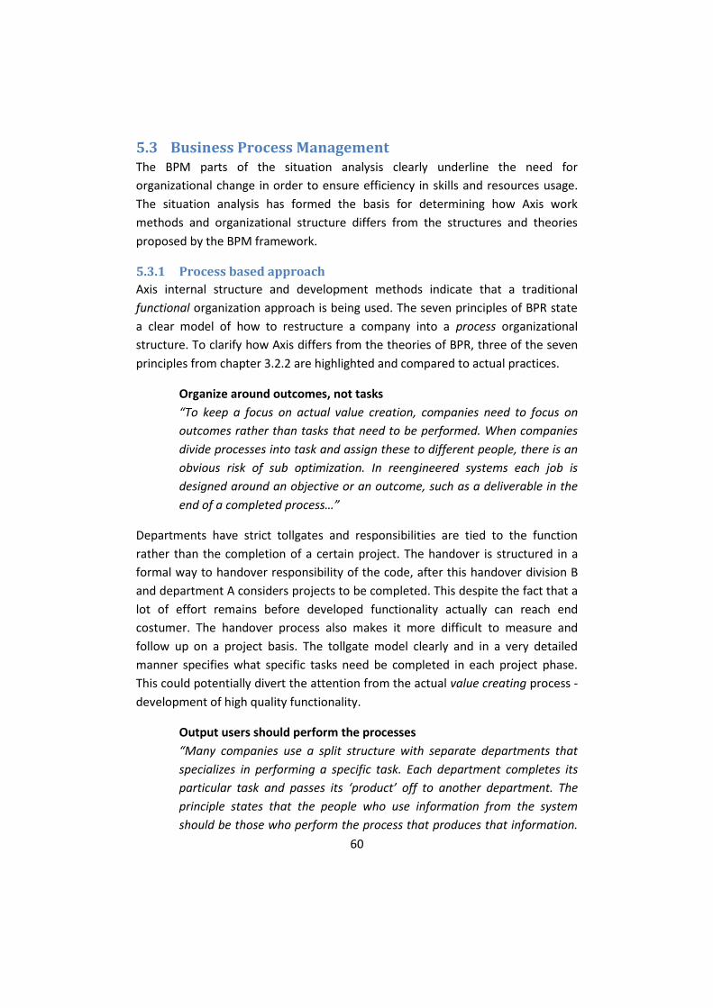
60
5.3 Business Process Management The BPM parts of the situation analysis clearly underline the need for
organizational change in order to ensure efficiency in skills and resources usage.
The situation analysis has formed the basis for determining how Axis work
methods and organizational structure differs from the structures and theories
proposed by the BPM framework.
5.3.1 Process based approach
Axis internal structure and development methods indicate that a traditional
functional organization approach is being used. The seven principles of BPR state
a clear model of how to restructure a company into a process organizational
structure. To clarify how Axis differs from the theories of BPR, three of the seven
principles from chapter 3.2.2 are highlighted and compared to actual practices.
Organize around outcomes, not tasks
“To keep a focus on actual value creation, companies need to focus on
outcomes rather than tasks that need to be performed. When companies
divide processes into task and assign these to different people, there is an
obvious risk of sub optimization. In reengineered systems each job is
designed around an objective or an outcome, such as a deliverable in the
end of a completed process…”
Departments have strict tollgates and responsibilities are tied to the function
rather than the completion of a certain project. The handover is structured in a
formal way to handover responsibility of the code, after this handover division B
and department A considers projects to be completed. This despite the fact that a
lot of effort remains before developed functionality actually can reach end
costumer. The handover process also makes it more difficult to measure and
follow up on a project basis. The tollgate model clearly and in a very detailed
manner specifies what specific tasks need be completed in each project phase.
This could potentially divert the attention from the actual value creating process -
development of high quality functionality.
Output users should perform the processes
“Many companies use a split structure with separate departments that
specializes in performing a specific task. Each department completes its
particular task and passes its ‘product’ off to another department. The
principle states that the people who use information from the system
should be those who perform the process that produces that information.

61
This eliminates “handovers” between different employees and
departments. Handover procedures can be the source of
misunderstandings and creates an unnecessary workload in the process.”
The development process is partially fragmented. Departments developing
functionality doesn’t fully implement and test their own code. In practice,
department A and division B1 develop functionality up to a point where the
project code is to be integrated into the LFP. The code is then integrated and
department C executes a full test-run on one product. The development team
then solves the most critical errors before the code is released into the latest LFP.
It remains then to run a full test-run towards all reference products. Once several
development projects are done and integrated into the LFP, the platform is
frozen 13 and Department C performs testing and creates tickets describing
identified errors. Division B2 and B3 then have to correct errors residing in code
that for them is unfamiliar. The fact that all divisions of the company; B1, B2 and
B3 use a common development platform creates an even clearer image that all
departments are involved in a common process with a common goal. The tollgate
model with strict handovers fortifies the invisible walls that separate the different
divisions of the company.
Link parallel activities in the workflow
“Many business processes are complex to an extent where they are
divided up and assigned to independent teams. These teams work in
parallel with each other and then integrate their tasks when they are
done. Since teams are managed independently many companies
experience process sub optimization.”
The tollgate model used in software development at Axis explicitly defines the
process of which all the projects must pass to reach completion. Some parts of
this process could be seen as overly complicated and formal. However, a far more
pressing issue is the fact that the development is split up in a number of
independently working teams. These teams have, in some instances, insufficient
cross-communication. Even though the teams work towards a common goal they
are managed as separate entities and herein lay the risk of sub optimization.
13
When projects enter the Freeze-tollgate no additional features are allowed to be implemented; only error correction is performed. For further descriptions of the tollgates and project phases, see section 4.3.

62
5.3.2 Measurement
Another benefit of switching to a process organization methodology is the
facilitation of measuring performance and project follow up. Measuring and
project follow up is something that is not currently implemented in the Axis
development organization. The reason for this is simple; the development is
simply too fragmented. According to the principles of BPM, measurement should
be proactive and reflect the demands of stakeholders of the process. After a
process based, team-structured organization has been established, project
performance can be easily measured on a team basis. Each project then has a
defined set of resources and personnel tied to it, which greatly simplifies the
implementation of measurement system and follow up routines.
5.3.3 Refocusing on value creation
BPM offers a method for breaking down walls and refocusing the development
organization on the actual value creating process. The team-based approach
suggested by [15] also addresses one of the core issues expressed by managers
and project leaders at Axis, namely the topic of code knowledge and responsibility.
Restructuring into a process based organization refocuses the emphasis on
teamwork and focus the process using a horizontal development approach.
In the current situation all departments and divisions work independently of each
other with formal handover processes. There is really no clearly stated reason
justifying why the process is divided in the manner that it currently is. Specifically,
division B1 develop functionality that division B2 integrates into the LFP which
division B3 correct errors in. This creates inefficiency in the development process
in the sense that division B3 need to work with code developed by another
division of the company. Division B1 and B3 operate as two independent entities
and the communication between these are also impaired by the fact that they are
separated in time by integration and testing phases. At the time when the
functionality reaches B3, B1 considers the project to be finished which leads to
difficulties in determining responsibilities of the actual code. This also relates to
the fact that there is no clear connection between product requirements and the
integrated code of the LFP.
5.4 Packet distribution analysis The LFP contains a lot of functionality divided into separate packages.
Functionality can be configured for inclusion or exclusion from a menu
configuration tool. At compile-time the selected functionality and their

63
dependencies are included into the generated platform variant which will later
become the product firmware made available for download by end consumer.
As the functionality of the platform and the number of products it supports is
increasing, so does the risk that old and outdated features remaining in the
platform as a result of nonexistent traceability between variation points and the
variants it supports.
As part of our investigation of how the platform and its usage should develop,
there was a need to find out how the package usage was distributed among the
products. Since developing functionality to be included in the platform is more
expensive than developing for individual products, ideally the packages included
in the platform should be used by several products. Since the packages contained
in the platform differ greatly in size and functionality, lines of code (LOC) for the
individual packages must be considered when analyzing the distribution.
There is currently no data available describing the size of the platform or the size
of the individual packages. In order to analyze the distribution we had to write a
script collecting and aggregating the data for each package. A schematic outline of
the data collection process is described in Figure 16. The result was imported into
Microsoft Excel and was compiled in a histogram.
The distribution analysis was limited to products that had a firmware version
based on the latest LFP. The reason for this was to eliminate errors in the data
caused by discrepancies in the set of available packages between the different LFP
versions.
The compiled data shows that a great part of the available packages are being
used by a majority of the products. This observation holds true both measured as
number of imports and according to distribution of LOC. This indicates that the
platform is being used according to the guidelines; only functions shared by
multiple products should be included in the platform. However, there is a risk that
the results are misleading because of the undocumented relationship between
the different setting in available configuration parameters and the code
controlled by the parameter settings. Obsolete parameter settings or even unused
parameters can hide an unknown amount of unused or “dead” code, being
difficult to measure.

64
One of the criteria to reach level 2 in the process dimension of the SPL-evaluation
is to implement monitoring of the platform usage in terms of packages and code
books. The work we did to gather and compile usage-data shows that there exists
more data than today is being used by Axis. To reach higher maturity in the FEF-
evaluation and improve monitoring and control of the platform, Axis would have
to start collecting and analyze that data.
Figure 16: Schematic flowchart describing data collection principles for creating package usage and code distribution chart

65
6 Solution proposal
This solution proposal is structured into two sections, Software Product Lines and
Business Process Management. These two proposals are complementary and
together form a comprehensive solution to issues addressed in chapter 5 (Analysis).
Leaving this chapter, the reader should have an understanding of proposed
solutions and implications of these.
6.1 Software Product Lines Based on the FEF-evaluation carried out in consultation with managers at Axis, we
have developed the following plan of action based on theories from SPL. The
evaluation resulted in the process dimension receiving lowest grade of the four
evaluated dimensions. The areas that require attention within the process
dimension are also perceived as being among the more central areas of concern
according to our case study analysis.
6.1.1 Manage versions and variants
As the platform grows and number of products increase, the need of monitor and
manage the different aspects of the platform increases as well. An important step
in managing the platform is to create a model describing variation points and
variants as well as introduce traceability between the two. By monitor which parts
of the platform that are no longer used by any products, the platform can be kept
as compact as possible.
When a clear connection between variants (specific product firmware releases)
and variation points is established, it will become possible to list all products
affected by a found software bug or security flaw. The extent of the problem will
be apparent and necessary actions can be initiated and prioritized for the affected
releases.
Monitoring variation points may also simplify troubleshooting abnormalities that
only occur in certain products. A cross-check of shared variation points between
the faulty products can help identify and isolate the source of the problem.
A prerequisite for managing traceability is the introduction of a role similar to the
one described in section 3.1.4.6 called Domain Asset Manager, responsible for
maintaining versions and variants of all domain assets.

66
Several tools exists (of which some are listed in section 5.2.3) that enable
modeling of variation points and variants as well as versioning of other domain
assets. Used in conjunction with the already implemented GIT-system for code
versioning, asset management and traceability would increase the possibilities to
monitor and control platform usage and propose changes and prioritization of
code and functions accordingly.
6.1.2 Improve requirement management
The use of requirements in software engineering is important in all phases of the
development, ensuring that intended functionality is delivered. Software
architects needs requirements when designing functionality, developers when
implementing the design and testers when writing and executing tests for the
implemented code.
Requirements have to be testable and verifiable in order to subsequently
determine if a requirement is met. To ensure this we propose that Axis seek to
include testers much earlier in the project phase. Ideally, testers should be
involved when the requirements are formulated to be able to give direct
testability feedback.
Today, Axis collect project specific requirements in a document called Product
Requirements Specification. One of the cornerstones in the SPL-methodology is
striving to achieve full traceability among all shared assets in the organization. We
propose collecting all requirements on functionality level in a database with web-
interface, much like the QACE database. This would enable for easy search and
review of all requirements from a common interface. But more importantly this
would enable for traceability between requirements and functions. Testers would
be able to track changing requirements between two versions of a function,
assisting them in writing new and updated tests for the function. The easy
requirements overview could also prove beneficial in the earlier stage of the
process when creating roadmaps and long term product plans. This would enable
managers to see which requirements that are already implemented in the
platform and what needs to be added.
6.2 Business Process Management The solution proposal of this thesis in regards to BPM is a four-step process. Every
step contributes to the transition from a fragmented development structure to a
team based organization. The four steps are:

67
1. Develop a process map to reprioritize and restructure processes
2. Restructure organization to align with processes
3. Establish competence centers
4. Determine appropriate quantifiable measurements
6.2.1 Develop a process map to reprioritize and restructure processes
The process map is the most viable starting point of a BPM restructuring process.
This is done to acquire a starting point of improvement and to create
understanding of the current situation. The creation of a process map includes
mapping all current processes and then organizing them according to importance.
The most critical processes then form the basis for the main process map. A
process owner then restructures the process and begins delegating resources. The
methodology to perform such a mapping is for instance to perform a series of
structured interviews and workshops with key individuals in the organization. It is
important to get input from the entire organization when constructing the
process map. Managers and team leaders as well as developers and testers should
have their say in how the day to day development is structured, without prejudice
and absent of company politics. To streamline this process, we recommend Axis
to take help from a business process consultant. The research and structuring of a
process map is outside the scope of the thesis. However in Figure 17 we suggest a
simple outline for the mapping of the development process.
Figure 17: Axis Process Map
In Figure 17, the left column represents the internal customer e.g. orderer of
functionality. The right column represents the external costumer of the delivered

68
functionality. Costumer focus is one of the cornerstones of BPM, this format
underlines that the ultimate goal of any business process is to deliver customer
satisfaction. We have chosen to focus on the purely work organizational aspects
of BPM, since these are more easily distinguishable and applicable for the current
situation at Axis.
6.2.2 Restructure organization to align with processes
The core of this solution proposal is to restructure the development organization
from its current tollgate structure to a process-oriented team based structure. To
clarify how this organizational structure differs from the current situation,
consider the simplified depiction of the organizational structure in Figure 18.
Figure 18: Current organizational structure
Divisions B1 to B3 work independently of each other with separate management
and routines. The LFP functions as the intermediary as functionality is integrated
and versions iterated in release cycles. Division B1 and B3 have little direct
communication and department C is not involved with the development process
until division B2 initialize the platform integration process.

69
Figure 19: Principle structure Business Process Organization
Figure 19: Principle structure Business Process Organization is a representation of
our restructuring proposal. Key changes are:
Divisions B1, B2 and B3 operate as one unit. Product owner is the
stakeholder of the desired functionality. The role and responsibility of the
product owner remains unchanged. The development team is composed
of personnel from the different competence teams on project basis.
Resources owners are appointed according to area of expertise as per to
the role described in section 3.2.4.1. The resource owners may be
responsible for more than one competence center team each. He or she
delegates available personnel to current projects in collaboration with the
team leader and the product owner. The role of the resource owner
would most closely coincide with the current role of manager or possibly
project manager at Axis.
The team leader takes the operational lead and responsibility; a role
similar to the current role of the project manager with addition of the
responsibilities described in 3.2.4.3 Team Leader.
A process owner is appointed with the overall responsibility for managing
and improving the development process. The role of the process owner is
not equivalent to any role in the current organization; preferably this role
will be filled by personnel on manager level within Axis. To undertake the
responsibilities of process owner there should be a high level of

70
understanding of processes and methodology within the company. This
role is further described in 3.2.4.2 Process Owner.
6.2.3 Establish competence centers
Another key entity of the solution proposal is the establishment of competence
centers. As the company moves from a functional organization to a team based
structure, competence centers could be considered the new “divisions” of the
company, but without the implications of splitting up the organizational structure.
According to the principles of BPM, it is up to the resource owner to follow up on
team performance and long term knowledge improvement. The competence
centers do not limit developers to work on projects only related to their center,
any developer should be able to undertake any type of project. The competence
teams merely ensure knowledge sharing and growth. It is recommended that each
individual developer and tester becomes part of at least one competence team.
At the time being, Axis does not document or secure competence in a consistent
way, which can lead to that irreplaceable expertise is lost when individuals shift
employment. One of the goals with competence centers is to spread important
knowledge and skills to other members of the team in order to decrease
dependency on specific individuals.
The single most important task to perform when implementing competence
teams at Axis is to decide how to split the collective competence into specific
areas. Based on how the platform is currently structured we suggest that the
competence centers should consist of: Pan Tilt Zoom, Streaming, Linux and Web
applications.
6.2.4 Determine appropriate quantifiable measurements
We chose the format suggested in section 3.5, based on a case study performed in
the firmware department of HP DeskJet printers. The motivation for this choice is
simple: the printer firmware department of the company is similar to Axis in size
and technology and therefore should face the same types of challenges. Four
simple measurements are combined in a plotted graph which is then interpreted.
These measurements are iteratively sampled during a specific project. The
measurements are:
Code Turmoil
Open Defects

71
Defect Find Rate
Test Passing Rate
As stated by [15], a cardinal factor to successfully establishing a process based
organization is to ensure a well functioning system of measurements. The reason
for implementing a system of measurements should be to enable a proactive tool
for project leaders and other stakeholders to gain insight in the development
process. There exists, however, not only a single correct answer how to measure
and evaluate the performance and progression of a given project.

72
7 Conclusions This chapter presents the most important experiences and findings and concludes
these. Fulfillment of goals and purposes of the thesis are described and evaluated.
Possible evaluation of the proposal is suggested.
Leaving this chapter, the reader should have an understanding of the results and
limitations of this thesis.
7.1 Implementation
7.1.1 SPL
For the implementation of the two-part SPL improvement suggestion we
recommend the following implementation strategies.
7.1.1.1 Manage versions and variants
This improvement suggestion is centered on a system for managing variation
points, variants and to enable traceability between the two. This is preferably
done by purchasing an already existing tool for this specific purpose, presented in
section 5.2.3. We have also provided managers at Axis with our subjective opinion
and recommendation of most suitable tool, but the actual selection of this lies
outside the scope of this thesis. For us to estimate how much time an
implementation of such a tool would take is impossible as it’s depending on what
tool ultimately is selected.
7.1.1.2 Improve requirement management
The core of this suggestion is to collect all requirements on functionality level in a
database with web-interface, similar to the already existing QACE database. This
would preferably be developed in-house, under the same premises as QACE. A
requirements database would impact the entire organization, from development
units to testers and even product managers. Managers from respective units need
to meet and discuss the implications and possibilities of the requirements
database. It’s hard to say how long it would take to develop such a system.
7.1.2 BPM
For the implementation of the four-step BPM improvement suggestion we
recommend the following implementation strategies.

73
7.1.2.1 Develop a process map to reprioritize and restructure processes
When developing a process map it is critical to involve all stakeholders in the
process. For the technical expertise needed when constructing the process map
we recommend an external consultant with expert knowledge in BPM and process
improvement. The procedure of creating a process map can be both time-
consuming and complicated. It’s important to be persistent though, the process
map is at the core of the BPM restructuring process.
7.1.2.2 Restructure organization to align with processes
Before any actual change takes place, the organization restructuring need to be
acknowledged and motivated throughout the organization. Top level
management need to be involved and give sufficient mandate to the restructuring
process. Only if the restructuring is understood and its potential benefits are
apparent all parties will truly embrace the change. This is closely related to
concepts such as change management.
Axis has previously implemented organizational restructurings and managers
continuously implement improvements related to development. Historically, the
actual change process has proven relatively painless. We therefore think that the
core changes in the implementation phase of a restructuring could be performed
relatively quickly.
7.1.2.3 Establish competence centers
The basic components of the competence centers are already in place. Axis have
appointed code block maintainers and code block administrators, these have
deep knowledge in their respective fields. To minimalize impingement on the daily
work the competence centers should be established along with the organizational
restructuring. It would be problematic to restructure the organization to align
with processes without establishing competence centers, given their central role
in process based organizations. The formation of competence centers is a
separate activity in the restructuring and could therefore be implemented
relatively early in the process.
7.1.2.4 Determine appropriate quantifiable measurements
Hereafter follows a short description of how to obtain the suggested
measurements.
Code Turmoil This measurement can be sampled by using scripting commands available

74
in the global information tracker, GIT. An example of such a script has been presented to Axis.
Open Defects This measurement is already available to extract from the Trouble
database.
Defect Find Rate This measurement is already available to extract from the Trouble
database.
Test Passing Rate This measurement is already available to extract from the QACE test suite
environment.
It’s important to underline that these measurements need to be documented and
historically examined to calibrate the scale for a fair and balanced picture of the
project status. Since most of the measurements already are available, the
implementation of a measurement system ought to be done relatively quickly. It
should preferably include someone at manager or project manager level at Axis.
7.2 Results The overall goal of the SPL section of the solution proposal is to better manage
versions and variants and to systematize the use of requirements. Potential
benefits are:
Gain deeper understanding of the platform components and how they
relate to products. Enabling identification of functionality not longer being
used.
Simplify troubleshooting and maintenance of code.
Make requirements visible and up to date, accessible for all stakeholders.
Establish traceability between requirements and functions throughout the
development and testing process.
The overall goal of the four step process improvement suggestion is to shift
paradigm from functional teams towards project teams that follow the process
from requirement to firmware release. Potential benefits are:
Significant reduction of documentation and bureaucracy needed to
control and ensure sufficient quality.

75
To greatly reduce the need for handover procedures and formal meetings,
giving way for more informal and cooperative communication and
collaboration.
Elimination of the knowledge gap; code producers review and take
responsibility for own code.
Better knowledge management in managed competence centers.
These two different proposals together represent a combined solution for
identified problems. Potential drawbacks of this solution could be:
Difficulties in predicting actual impact of suggested changes.
Organizational changes are sometimes complex and require full
dedication by all involved parties to be fully embraced and successful.
7.3 Limitations The solution proposal of this thesis underline how Axis differ from methodology
and practices described in the literature. We have chosen to select merely a few
but highly important suggestions for improvement. We find that a too extensive
solution proposal would not be feasible, neither in terms of cost or time needed
to implement such changes. The multitude of proposed changes threatens to
interfere somewhat with each other, but this risk can be minimized by introducing
changes in evolutionary steps rather than change everything at once.
We find the process of appointing roles at individual level is best handled by
managers at Axis given their deeper understanding of the detailed work processes
and organization. The restructure of the development organization also renders
the current tollgate model insufficient. The current format of handover
procedures simply does not apply in a team based project structure. When
performing the organizational restructuring, the current documentation should be
updated and in some cases rationalized.
7.4 Evaluation An initial evaluation of the proposed solutions was performed subsequently to the
thesis presentation for managers and staff at Axis. We received feedback on the
feasibility of certain suggestions as well as guidance to what areas that needed
clarification. These improvement suggestions were important in refining and
finalizing the thesis.

76
To fully understand the impact of our suggested changes, one would have to
establish a “baseline” status before any implementation takes place. One way of
establishing a baseline could be to implement the system of measurements
suggested in this thesis. These would then be used to compare project outcome
before and after implementing the proposed changes.
To fully grasp the impact of the changes and to capture opinions and suggestions,
we suggest that a small questionnaire will be sent to personnel at Axis. Since the
purpose of the questionnaire is to track how the changes are perceived over time
it should be sent to the employees on a regular basis. Examples of relevant
questions is for instance:
What benefits do you see with these changes?
What are the drawbacks working in the new process?
How has your daily work changed since the implementation of these changes?
Do you have any ideas or suggestions how to improve your daily work?
7.5 Fulfillment of purpose
7.5.1 Goals
In the introduction chapter of this thesis we identified certain goals to be reached.
These were:
G1: Compilation of current academic work in the area.
G2: Investigation of current firmware development processes at Axis
Communications.
G3: Suggest possible improvements based on academic studies.
G4: Evaluation of our suggested improvements and their validity.
G1 is completed and summarized in chapter 3. The basis of this chapter was an
extensive literature search.
G2 is completed in chapter 4. The basis of this chapter was internal process and
role documentations, meetings and other material at Axis.
G3 is completed in chapter 6. The solutions proposal was created by comparing
findings in the case study to theories and practices described in chapter 3 and
suggesting possible changes.

77
G4 is completed in this chapter.
7.5.2 Research questions
In the introduction chapter of this thesis we stated the two main research
questions to be addressed.
RQ1: How should Axis firmware development organization be
restructured to better utilize the benefits from using a software platform?
RQ2: How can firmware development at Axis be measured and managed
using a process based management approach?
RQ1 is addressed in chapter 6.1. The restructuring proposal is based on findings
from the FEF-evaluation in section 5.2.1. The suggestion is focused on managing
traceability in the development process. This can be done by introducing roles,
tools and methodologies from practices established in Software Product Lines.
RQ2 is addressed in chapter 6.2. The solution proposal is a four step model based
on theories and practices found in BPM. The aim of this restructuring is essentially
to align the organizational structure to the actual development, and to refocus on
value creating processes.
By using two fundamentally different approaches, BPM and SPL, to reach the
conclusion for these research questions we feel that we have addressed these
questions as extensively as possible. The two different practices does in many
ways cover different parts of the company spectrum, to create one uniform
solution proposal.

78
8 Discussion
This chapter concludes the thesis with a discussion of generalizability and
suggestions for future work.
8.1 Generalizability The methodology we have chosen to use in this thesis follows the action research
format. This format does not in itself generate any immediate generalizability to
other contexts than described in this thesis. The solutions proposed are applicable
to the current situation of Axis, but should reasonably be transferable to
companies similar in size and practices.
During our literature studies, we found that there are other companies similar in
size and technology that in one way or another use platform based development.
We have based the first part of our solution proposal on established theories in
SPL. These have in turn been tested and proven effective in environments similar
to one in which Axis operates.
The practices described in BPM are very general and applies to almost any type of
company, from the strictly service oriented to production and product based.
Because the practices are general to this degree the solution proposal of the four
step BPM restructuring should be reasonably transferable to other contexts, given
that such a solution is further tailored to fit given preconditions.
8.2 Reflections The conclusions reached in this thesis apply to the firmware development
divisions at Axis. We cannot claim to fully grasp the processes and practices of
product development at department A. However, we do feel that there is little
reason to have split the organization in two departments, one dedicated to
developing firmware, and the other one responsible for product development.
Department A develops products independent of the platform, but still integrate
most of the functionality eventually.
It is clear that Axis uses certain elements of SPL methodology, but the FEF clearly
showed that there is lack of awareness of how to utilize the benefits of using a
platform. There are clearly stated solutions of how to restructure the organization
to reach all benefits of SPL engineering, even further than described in our
solution proposal.

79
During the time of writing the thesis Axis took measures to implement a team
based organization with a structure similar to the competence center model
described in the BPM solution proposal. We find this to be an exciting change and
hope to have contributed to the decision.
The incentive for change is strong; many of the perceived difficulties we have
observed during our time writing the thesis has been of simple communicative or
collaborative nature. We believe these shortcomings to greatly decrease with a
team-based development structure.

80
8.3 Future work During the course of writing this thesis we encountered several areas substantial
enough for serving as the basis for new theses. Rework of the daily build system
and improving the stability tests could be a good candidate for future projects.
Our suggestion of measurement dimensions and their follow up is only an initial
approach. The implementation of the suggested dimensions along with further
improvement of how to utilize collected data could be an appropriate scope for
yet another thesis.
The suggested adoption of a tool for managing versions and variants constitute a
project life cycle in its own, with planning, implementation and follow up phases.
The suggestions in the BPM improvement proposal are partly implemented, with
the exception of creating and reprioritizing a process map. If Axis chooses to
realize a fully process based organization, we recommend the first step to be
creating a process map. This could be done in cooperation with experts or as part
of another thesis. When a process based organization is in place, it would also be
feasible to look into other closely related management techniques such as Lean
and Six Sigma.

81
9 References 1. AXIS, Annual Report 2010. 2011. 2. IMS, The World Market CCTV and Video Surveillance Equipment - 2010
Edition. 2010. 3. Bryman, A., E. Bell, and B. Nilsson, Företagsekonomiska
forskningsmetoder. 2005: Liber ekonomi. 4. Holme, Forskningsmetodik: Om kvalitativa och kvantitativa metoder. 3 ed.
1996. 5. Höst, M., B. Regnell, and P. Runeson, Att genomföra examensarbete. 2006:
Studentlitteratur. 6. Sarah, R., et al., Business Action Research in Practice-A Strategic
Conversation About Conducting Action Research in Business Organizations. Systemic Practice and Action Research, 2002. 15(6): p. 535-546.
7. Denscombe, The Good Research Guide - For small-scale social research projects. 1998: Open University Press, Buckingham.
8. Ardis, M., et al., Software product lines: a case study. Software: Practice and Experience, 2000. 30(7): p. 825-847.
9. Linden, F., K. Schmid, and E. Rommes, Software product lines in action: the best industrial practice in product line engineering. 2007: Springer.
10. van der Linden, F., et al., Software Product Family Evaluation, in Software Product Lines, R. Nord, Editor. 2004, Springer Berlin / Heidelberg. p. 107-109.
11. Chopra, A.K., et al., Requirements as Goals and Commitments Too, in Intentional Perspectives on Information Systems Engineering, S. Nurcan, et al., Editors. 2010, Springer Berlin Heidelberg. p. 137-153.
12. Soliman, K.S. and J.F. Affisco, Business process management journal: E-government. 2006: Emerald Group Publishing.
13. Romney, M., Business process reengineering. (cover story). Internal Auditor, 1995. 52(3): p. 24.
14. MacIntosh, R., BPR: alive and well in the public sector. International Journal of Operations & Production Management, 2003. 23(3): p. 327-345.
15. Ljungberg, A.L., Everth, Processbaserad verksamhetsutveckling. 2001. 16. Tao, Y., et al., A research on BPM system based on process knowledge.
2008 IEEE Conference on Cybernetics and Intelligent Systems, 2008: p. 69-75.
17. Kah-Hin, C. and Y. Chee-Meng, Effective knowledge transfer in virtual teams: linking contents and mechanisms. International Journal of Networking and Virtual Organisations, 2004. 2(4): p. 312-322.
18. Mahanti, R. and J. Antony, Confluence of six sigma, simulation and software development. Managerial Auditing Journal, 2005. 20(7): p. 739-762.

82
19. Pantano, V., et al., Cluster-based Six Sigma Deployment in Small and Medium Sized Enterprises. 2006 IEEE International Conference on Management of Innovation and Technology, 2006. 2: p. 788-792.
20. Staats, B.R., D.J. Brunner, and D.M. Upton, Lean principles, learning, and knowledge work: Evidence from a software services provider. Journal of Operations Management, 2011. 29(5): p. 376-390.
21. Middleton, P., et al., Lean principles and techniques for improving the quality and productivity of software development projects: a case study. International Journal of Productivity and Quality Management, 2007. 2(4): p. 387-403.
22. Scherrer-Rathje, M., T.A. Boyle, and P. Deflorin, Lean, take two! Reflections from the second attempt at lean implementation. Business Horizons, 2009. 52(1): p. 79-88.
23. Santos, R.d., K.d. Oliveira, and W.d. Silva, Evaluating the service quality of software providers appraised in CMM/CMMI. Software Quality Journal, 2009. 17(3): p. 283-301.
24. Behr, P., W.K. Giloi, and R. Gueth, Education in firmware engineering and microprogramming. Microprocessing and Microprogramming, 1981. 8(3-5): p. 153-166.
25. Edward, A.L., Embedded Software. 2009. 26. Greene, B., Agile methods applied to embedded firmware development.
Agile Development Conference, 2004, 2004: p. 71-77. 27. D.E. Perry, W.M.E., An Empirical Study of Software Interface Faults.
Proceedings of the Twentieth Annual Hawaii International Conference on Systems Sciences, January 1987, Volume II 1985.
28. Hecht, M., Products liability issues for embedded software in consumer applications. Product Safety Engineering, 2005 IEEE Symposium on, 2005: p. 42-48.
29. Pearse, T., T. Freeman, and P. Oman, Using metrics to manage the end-game of a software project. Software Metrics Symposium, 1999. Proceedings. Sixth International, 1999: p. 207-215.
30. McConnell, S., Code Complete. 2009: O'Reilly Media, Inc. 31. Mikael, S. and B. Jan, A Case Study on Product Line Architecture Evolution.
2009. 32. Louridas, P., Version control. IEEE Software, 2006. 23(1): p. 104-107.

83
10 List of abbreviations API – Application Programming Interface
CBA – Code Block Administrator
CBM – Code Block Manager
CCTV–Closed Circuit Television
GIT - Global Information Tracker
LFP – Linux Firmware Platform
PTZ – Pan Tilt Zoom
RAT - Resource Allocation Tool
SA – Software Architect
SWO – Software Overview
TL – Technical Lead