Clinical and ultrasonographic differences between cattle and ...
Upload
khangminh22Category
view
1download
0
Steel Cattle YardsInstallation Guidelines
Including assembly instructions for: • The Super C-Force forcing pen • 3 way drafting module and wire rope control• Patented stepped loading ramp• Sliding gate top handle
Te Pari is a global market leader in safe, efficient and seamless livestock handling solutions.
REV-0217-3

2 Yard Installation
Be safe - Your safety is important
Health and Safety during yard installation Under Health and Safety legislation you are responsible for the Health and Safety of both yourself and others on site when installing Te Pari Yards and Equipment.
Some components are heavy and awkward to handle and move. Please take all due care and follow correct Health and Safety procedures.
Unloading:
• Wear Personal Protective Equipment (PPE): Gloves, boots, hard hat and eye protection.
• Panels and gates can topple off the truck deck. Secure them with lifting machinery prior to removing the strops.
• Unload on a level site.
• Keep people well clear of bundles of components while unloading.
• Do not stack bundles of panels and gates - Lie them down.
• When opening bundles of components beware of items moving and the strapping springing outward.
Assembly:
• Panels and gates are a team lift or use appropriate machinery.
• Beware of pinch points when assembling.
• Be aware of the position of other people around you when using machinery.
• Beware of crushing hazards - Particularly with gates, keep them latched shut whenever possible.
• Ensure appropriately qualified people carry out the installation of amenities like air and power etc.
Cattle Handling Skills By Kevin J. Stafford
This is an excellent booklet on the subject of safe and effective cattle handling and is available from WorkSafe online and at no charge.
If you are unsure about the finer points of cattle handling or would just like a refresher - we strongly recommend that you read this publication.
Google - worksafe cattle handling skills.

3 Yard Installation
Te Pari steel cattle yard installation guidelines
ContentsHealth and Safety notice 2
Overview 3
Your plans
Concrete and key item positioning plan 4
Component identification and position plan 5
Recognising gate opening types shown on your plan 6
Bow types and their positions 7
Common components
Panel identification and sizes 8
Gates - Hinge types, gate styles, identification and sizes 9-12
General fixings 13
Braces - Overhead and yard wall 14
Assembly details
Stepped and flat top loading ramp assembly 15-19
Super C-Force force gate post and pen installation 20-21
Draft gate post, loading ramp and race gate junction 22-23
Crush - Entry and exit connections 24
Headbail and sliding gate - Entry and exit connections 25
3 way drafting module plan and connection details 26
Fitting wire rope controls to a 3 way drafting module 27-29
Catwalk brackets and timber decking installation 30-31
Fitting a top handle to a sliding gate 32-33
Assembly and notes
Brief general installation sequence 34
Installation sequence checklist 35
Notes and area for key measurements Back cover
OverviewIt is important to read these guidelines through prior to commencing your installation.
This is because sometimes installation sequence is important, for both the positioning of the yards key items and the ease and accuracy of the installation process.
Throughout this guide generic plan examples are given. Your plans are designed specifically for your site by us so should always be referred to in the first instance. This guide is by no means comprehensive and is designed to cover details on installation and sequence that are most likely to be problematic during your install.
Remember we are here to help and are available to provide advice. We know that once your Te Pari Steel Cattle Yard is installed it will provide you with many years of sturdy and efficient performance.
Remember too that our yards can be added to at a later date to meet the growing needs of your operation.
Thank you for purchasing from us.

4 Yard Installation
Your plans - Concrete and key item positioning plan
Your plan is made specifically for your site, however certain points are true of all plans and we shall cover them here with an example.
In almost every installation determining the position of the loading ramp is the first thing to do because the position of service roads and other amenities are normally fixed.
For the ground work, plans are supplied with a reference line that all key positions are measured from. Usually this key line is at right angles to the loading ramp. Once the loading ramp position is established you have to peg out the reference positions S and T (shown with yellow circles here) at each end of the key line. They are measured out from the centre of the loading ramp E as shown in the example plan below.
The pegs need to be firmly set so that they can be referred to, and measured from, during ground preparation and yard construction, we recommend using waratahs that are well hammered in.
The ground work plan is provided with a table listing the key boundary points and the distance in metres from the key line points S and T (like point 5 being 20.4 metres from S and 15.4 metres from T in the inset above) Using spray paint or pegs you can start to mark out the outside shape of the yard. This provides the boundary for concreting, metal distribution or other yard surface preparation. The point positions also show the race area, so you can concrete that area only. Boundary lines also help in panel positioning, panels being placed about 500 mm inside this line.
If you have a Super C-Force in your design the fixing its centre post is a priority. The post is needed in position so the Super C-Force forcing gate can be hung from it and used to determine panel positions. The post concrete needs at least 24 hours to set before continuing Super C-Force installation. The coordinates for the Super C-Force force gate post will be on your plan key and labelled as Hole. Details for Super C-Force installation are on pages 20-21.
Yard concrete should be 20MPA with added fibre, at least 100 mm thick and have a broom finish.
To allow for drainage the concrete surface should have a 1% fall. Where your yard includes a weigh crate or crush particular attention should be paid to ensure the concrete in this area is even.
S T1 11.0 4.02 11.9 6.13 15.3 8.64 19.1 13.05 20.4 15.46 20.9 17.5Hole 16.9 14.8

5 Yard Installation
Your plans - Component identification and position plan
This plan is used to show you what panels go where.
Follow the general installation brief and sequence checklist on pages 34 and 35. In this way you will quickly notice if anything is not positioned correctly and will be able to adjust its position with minimal reworking.
B
Each panel is labelled with a code describing it. A list of the descriptions is supplied with your plan. Some examples are:
P Panel
UG Ultimate Gate
216 2.1 metre wide with 6 rails
L or R Left or Right opening
MG Man gate
SCF Super C-Force
HT High Top
So an UG256SCFL would be an Ultimate Gate,2.5 metres wide with 6 rails, for a Super C-Force that is left opening.
A P185 would be a 1.8 metre panel with 5 rails.
A
The two brace types are not labelled but are shown on your plan as these examples here from the plan above:
A High Top BraceA high top to high top overhead brace
B Yard Wall BraceOn concrete yards this is a Dynabolted down “L” brace. On other surfaces this is a straight post that is concreted in.

6 Yard Installation
Your Plans - Recognising gate opening types shown on your plan
Super C-Force gates - The forcing gate pivots around its centre post. The Super C-Force entry and exit gates are Ultimate Gates that are unique in that they have a built in angle that forms the circular wall of the forcing pen.
Ultimate Gates - Any gate that is fixed to a concrete surface can be an Ultimate Gate, they can not be fitted on yards with a gravel or earth surface. They have overhead, not ground level, braces. With no ground level brace the yard is easier to clean as muck cannot accumulate against it. This also improves flow and removes a potential trip hazard.
Note: Because all gates have high tops the high top, HT, designation is not used in their code.
Race gate - The opening direction is not shown, they always open as shown, opening the race to the loading ramp.
Man gates - Always have in-line hinges so open to 90° in both directions of the panel line.Because of this they have no opening direction label and are designated MG on your plans.
Sliding gates - No opening is shown, they slide open on the side proud of the panel line.Double sliding gates have a gate sliding in either direction. A single sliding gate shown here.
Gates with offset hinges - Open 180° in the main opening direction and about 20° in the opposite direction.They are designated left or right with a L or R suffix. A left hand ultimate gate is shown here.

7 Yard Installation
Bows are designed to add rigidity and strength in yard panel run terminations. The crush bows provide a strong frame for the race to terminate without being attached to the crush. This allows the crush to move freely unhindered by the race, as is required for weighing.
The 4 bow types and their positions on the example plan are shown below.
Standard race bow Race “U” bow low post is inner side
Heavy base race bow Used at the crush entry
Your Plans - Bow types and their positions
Wherever the inner race has a catwalk a race “U” bow is used
Note: From late 2016 this bow is not used when the crush exits to a drafting module.
Wide race bow Used at the crush exit
8 Yard Installation
Common components - Panel identification and sizes
All panels are available in the following widths: 1.25, 1.4, 1.8, 2.1, 2.5 and 3.1 metres.
6 Rail Panel
This is the most common yard panel component.
A suffix designates the number of rails on any given panel.
So a panel labelled P256 is a Panel, 2.5 metreswide with 6 rails.
5 Rail Panel
5 Rail Panels are mostly used on the yard race inner wall where a catwalk is fixed to them, this allows easy access into the race.
They are designated with the 5 suffix after the width on your plan.
So a panel labelled P255 is a Panel, 2.5 metreswide with 5 rails.
High Top Panel
Are used in the yard to allow for the fitment of overhead braces from their top rail.
They are designated with HT included in their suffix, after their width, on your plan.
So a panel labelled P255 is a Panel, 2.5 metreswide with 5 rails.
They are used in the yard to allow for the fitment of overhead braces from their top rail.
Panel fixing
Panels are usually joined to each other with male clamps. When the yard is fully positioned and braced panels are fixed to the yard surface through the pre-drilled holes in their feet. On a concrete surface Dynabolts are used. On other surfaces pins, that resemble large tent pegs, are used.
Note: Super C-Force and Calf Reduction panels are shown on pages 11 and 12.

9 Yard Installation
Gates with offset hinges
How we determine a gate to be either left or right opening
Only gates with offset hinges are classified as either left or right with a L or R Suffix.
Facing the gate, with its main opening direction towards you, left or right is the side the hinge pin is on.
The main opening direction is always on the same side as the hinge pin is located. So the graphic here shows a left hand gate.
Gates with in-line hinges - Single socket fitting centred on the frame
These are classified with an S Suffix.
They open 90° in either direction.
Because of this they can be fitted in either way around, so the hinge is on the left or right hand side to suit.
All man gates have this type of hinge and are designated MG. Man gates have a U or S prefix in their code to define if they are Ultimate or Standard configuration.
There are 2 main hinge types, an offset hinge and an in-line hinge.
1 Offset hinges, have 2 hinge pin sockets, one on either side.Gates with an offset hinge are designated left or right and open to 180° in the main opening direction and 20° in the opposite direction.
2 In-line hinges have a single centred socket. They open in either direction to 90°. They have an S designation, not Left or right because they be can fitted either way.
How gates open depends on the hinge type used:
Up to180° on the main opening side
Up to 20° in the opposite direction
Common Components - Gates - The 2 main hinge types and how they open
Hinge pin
1 2
Centred Hinge pin
Open up to 90° in either direction

10 Yard Installation
Gates in general
Gate panels have high tops to accommodate braces. Their codes designate sequentially; their type; their width; the number of rails they have; special position (like CF for a Super C-Force etc.) and finally howthey open L for left, R for right, S for 90° in either direction or MG for a Man gate.
.
Above left SG216S and right a SG216MG
Some examples of gate codes used on yard plans:
UG316LUG = Ulitmate gate; 31 = 3.1 metres wide; 6 = 6 rails; L =Left hand opening (offset hinge)
UG316SUG = Ulitmate gate; 31 = 3.1 metres wide; 6 = 6 rails; S = 90° opening in either direction (in-line hinge)
SG256RSG = Standard gate; 25 = 2.5 metres wide; 6 = 6 rails; R = Right hand opening (offset hinge)
SG256SSG = Standard gate; 25 = 2.5 metres wide; 6 = 6 rails; S = 90° opening in either direction (in-line hinge)
SG256RSG = Standard gate; 25 = 2.5 metres wide; 6 = 6 rails; R = Right hand opening (offset hinge)
SG256SSG = Standard gate; 25 = 2.5 metres wide; 6 = 6 rails; S = 90° opening in either direction (in-line hinge)
UG256SCFRUG = Ulitmate gate; 25 = 2.5 metres wide; 6 = 6 rails; S = 90° opening in either direction (in-line hinge);CF = For a Super C-Force; R = Right hand opening
S186MGS = Standard configuration; 18 = 1.8 metres wide; 6 = 6 rails; MG = Includes a man gate, these always open90° in either direction having in-line hinges.
Note: On man gate panels the actual man gate portion of the panel does not vary in width. The full width is made up by the panels rails.
Common Components - Gate and panel identification and sizes

11 Yard Installation
Super C-Force Panels and Super C-Force Gates
Designated with CF. The Super C-Force Panel (below left) is used on all non-opening sections of the Super C-Force forcing pen, they are labelled P1256CF on your plan.
The Super C-Force entry and exit gates (below right) are labelled either UG256SCFL, left opening, or UG256SCFR, right opening. All Super C-Force Gates are Ultimate Gates. They are also unique in that they have a built in angle, seen in the plan view (lower right), that form the circular wall of the forcing pen.
Common components - Gate and panel identification and sizes
Standard Gates
Distinguished by their ground level brace.
Designated with SG
Standard gates are available in 5 or 6 rail configurations and widths of: 1.8, 2.1, 2.5 and 3.1 metres.
.

12 Yard Installation
Calf reduction panels.Calf reduction panels are designed so you can to reduce the race width to suit handling smaller sized and younger stock. They are available in the same size range as race panels. As with many components on Te Pari Yards you can upgrade existing race panels to calf reducing panels at any time. Calf reduction panels have CR in their code.
Ultimate Gates Distinguished by having no ground level braces. Ultimate gates always have high tops for fitting overhead braces to. They can only be used on a yard (or yard portion) that has a concrete surface.
Ultimate gates are provided in the following widths: 1.8, 2.1, 2.5 and 3.1 metres.
Designated with UG. Below left; Ultimate gate left hand UG216L and right a 2.1m Ultimate man gate U216MG
Common components - Gate and panel identification and sizes

13 Yard Installation
Common components - General fixings
Male Clamp - The Male Clamp is the most used component.
1 The male clamp bracket has a male pin on it, the clamp is through bolted to the panels end post
2 The male clamp pin fits into the pipe socket welded onto the panel it is joining.
When connecting one panel to another, two male clamps are used, one upper and one lower. Ideally the clamps pins should point, one up and one down, with the top male clamp pin pointing downward.
Panel feet - Each panel has a drilled foot for Dynabolting or pinning the panel in place when final positioning is complete.
Key areas that can not be moved, such as crush entry and exit points, should be bolted down first. These then providing an anchor for the rest of the yard layout.
When the yard is completely in position and braced the remaining Dynabolts or pins can be fitted.
Offset gate hinge system
This system lets gates open 180° in their main opening direction and 20° the opposite way.
The main opening direction, the “opening side”, is on the same side of the gate that the male hinge pin is located.
Gates with offset hinges have a main opening direction and are shown with a L for left or R for right suffix, they can be reversed on site if required.
In this image, with the gate opening toward you, the male hinge pin would be on your right, so this is a right hand gate.
Joiner posts - designated JP on you plan - yellow in the image.
These are used in areas where multiple gate openings meet.
The inclusion of the joiner post between the meeting panels provides additional clearance in the gate latch area and so prevents gate clashes.
In the image to the left you can see a 3 gate joint and how the joiner post carries male clamp joints going in three directions. Plan view below.
1
2

14 Yard Installation
Yard wall braces
The wall brace positions are provided on your plan. An “L” brace is used on concrete surfaced yards and a support post is used in other circumstances.
On a concrete surface a “L” brace is used.The brace is placed in position, with the foot on the outside of the yard.
The bracket on the top of the brace is bolted to the panels fifth rail up, as shown in the inset on the left. The foot of the brace is then Dynabolted to the yard surface.
A support post brace is used for surfaces other than concreteThe support post brace does not have a foot like the “L” brace, it is in the form of a straight 2.2 m post, it is fitted at the 5th rail in the same way as a “L” brace.
Support post braces are concreted in-situ. To fit a support post brace mark its position at ground level, move the panel and dig a hole to 600 mm below the yard surface. Replace the panel and fit the brace so that its lower end dangles into the hole. You can now pour concrete around the brace.
Do not disturb the brace or attached panels while the concrete sets, this will take about 24 hours.
High top (overhead) braces
High top braces attach between the top frame of a gate, gates and or high top panel. They are usually fitted in pairs in areas where gates join or large gates open. They help to reduce distortion of yard components.
They have a standard bracket and bolt fixing at each end.
They should be fitted in the positions shown on your plan.
High top braces should, where possible, be placed at equal distances from the joint along the members they are attached to. This provides the maximum strength.
In most situations ultimate gates have overhead braces.
Braces should be fitted when the yard is fully assembled, after the gate opening directions have been checked, prior to finally bolting or pinning the panels down. It is important not to use the gates until the braces are fitted and in the case of a yard wall support post brace, until the concrete has set. This prevents distorting the gates and panels by using them without the correct braced support. See page 5 for how they are shown on your plan.
Common components - Overhead and yard wall braces
Note: earlier style bracket shown here

15 Yard Installation
Stepped loading ramp assembly - Standard and flat top
Your safety is of primary importance! Some of the panels used in the construction of our stepped loading ramps are heavy! The use of a tractor with safety strops attached to the panels, to prevent them falling during assembly, is strongly recommended. Panels with polyethylene siding may catch the wind and you should be aware of this risk, and secure them as required.
The early stages of assembly in particular involve the greatest risk from tipping panels. Once the base frame is assembled it becomes self supporting. As with all yard components - Wear personal protection equipment: heavy gloves, hard hat and crush proof boots during assembly.
Assembly of your loading ramp - In some cases the ramp will be supplied pre-assembled for you.
When assembling either version (standard or flat top) the standard ramp without the decking is assembled first. The flat top section then being added onto the standard ramp frame.
The decking is added last on either type.

16 Yard Installation
Stepped loading ramp frame assembly - Standard and flat top
Standard Ramp section
1 and 2 - Assembly starts with the high end frame, hold this in position with a tractor or such like while you attach the next panel to it. Bolt the non-sheeted side panel (personnel access side) to the high end frame with the supplied M12 x 160 mm bolts, with a washer beneath the nut. If installing a standard stepped loading ramp adjust the position to your plan key line and bolt the high end frame only down using M12 x 135 mm Dynabolts.
Note All frames are pre-drilled. For the standard ramp section all high end frame to frame bolts are M12 x 160 mm long and all lower end frame to frame bolts are M12 x 110 mm long.
3 - Bolt on the sheeted side panel to the high end frame, this side has the decking bracket.
4 - Bolt the lower end frame with M12 110 mm bolts between the 2 sides.
5 - Fit the central panel to both the high and low end panels with the bolt sizes for each end described above.
6 - Insert and bolt down the pre-drilled decking timbers - All ramp step timbers are 150 x 25 mm - with the supplied M10 x 150 mm coach bolts.
If installing a flat top stepped loading ramp, go to 1 overleaf on page18
1
4
2
5
3
6

17 Yard Installation
7 9a
9b
Stepped loading ramp finishing - Standard model
7 - Fit the rubber bumper to the high end frame on the central end frame cross member (high floor level)with the M12 x 120 mm bolts supplied onto the animals section of the ramp.
8 - Complete bolting the ramp down - M12 x 135 mm Dynabolts through the ramp entrance (low end frame) and M12 x 175 mm on the high end frame - through the pre-drilled frame holes.
9 - Important - Decking to decking fixingEach decking riser must be fixed to the treads at the front and the back with 3x A17 100 mm galvanised purlin screws, as shown in detail 9a below. 1x screw centred on the ramp and a screw in 150 mm from each side of the ramp treads.
Screws through the front face of the riser are vertically centred on the tread when down 45 mm from the risers nosing line. Screws at the back are vertically centred when up 25 mm from risers back lower edge, as shown in 9b. These fixings are an important bracing element, without them the steps may be broken by stock.
Perform a final check through to ensure everything required is fitted and snug.
Your standard model stepped loading ramp installation is complete.
Ramp portion - All treads and risers are 150 mm x 50 mm
Bumper fits to the stock use side of the ramp
Riser top
Riser bottomFront tread
45 mm to Ø
25 mm to Ø
Nosing 20 mm20 mm gap
appx
150 mm in
Screws are:
150 mm in
Centred on step width

18 Yard Installation
Stepped loading ramp frame assembly - Addition of the flat top section
Adding the flat top section
1 and 2 - At the high end frame of the completed standard loading ramp frame bolt on the flat top side frame (personnel side, without the sheeting) The bolt holes for the decking are on the inside.
3 - Bolt the remaining high end frame to the side panel using M12 x 160 mm bolts.
4 - Bolt on the sheeted side panel to form the flat top frame. Adjust the position to your plan key line and bolt the high flat top end frame only down using M12 x 135 mm Dynabolts.
5 - Bolt in the sheeted central panel with the mangate latching at the outer high end.
6 - The flat top section has 5x planks, 4x 200 x 50 mm and 1x 150 x 50 mm. The 150 mm plank is nearest the outside high end. Each plank has a 25 x 50 mm metal cleat and these are bolted down along with the planks, planks and cleats are pre-drilled. M10 x 175 mm coach bolts are provided to fix the cleat and plank to the frame.
1
4
2
5
3
6

19 Yard Installation
Stepped loading ramp finishing - Flat top model
7
Ramp portion - All treads and risers are 150 mm x 50 mm
Note: Measurements are approximate as shrinkage may occur prior to installation. Do not over tighten the screws, a snug fit is all that is required, over tightening the risers may cause them to split.
Riser top
Riser bottomFront tread
45 mm to Ø
25 mm to Ø
Nosing 20 mm20 mm gap
appx
150 mm in
Screws are:
150 mm in
Centred on step width
7 - Fit the rubber bumper to the high end frame on the central end frame cross member (high floor level)with the M12 x 120 mm bolts supplied onto the animals section of the ramp.
8 - Complete bolting the ramp down - M12 x 135 mm Dynabolts through the ramp entrance (low end) frame and M12 x 175 mm on the ramp high end and the flat top frame - through the pre-drilled frame holes.
9 - Important - Decking to decking fixingEach decking riser must be fixed to the treads at the front and the back with 3x A17 100 mm galvanised purlin screws, as shown in detail 9a below. 1x screw centred on the ramp and a screw in 150 mm from each side of the ramp treads.
Screws through the front face of the riser are vertically centred on the tread when down 45 mm from the risers nosing line. Screws at the back are vertically centred when up 25 mm from risers back lower edge, as shown in 9b. These fixings are an important bracing element, without them the steps may be broken by stock.
Perform a final check through to ensure everything required is fitted and snug.
Your standard model stepped loading ramp with flat top installation is complete.
Bumper fits to the stock use side of the ramp
9a
9b

20 Yard Installation
Assembly details - Super C-Force Force - Forcing gate post
If your yard includes a Super C-Force forcing pen - The first thing to do, once your reference points are pegged, is to mark the position of the Super C-Force centre post. The post needs to be concreted in at right angles to the yard surface, where the yard surface is sloped for drainage the post will not be plumb. The posts gate pins should face the sliding gate. Concrete in to 1100 mm below the finished yard surface level, the “fins” on the post being level with the finished yard surface. Ensure the concrete has set for 24 hours prior to placing the post under load.
3000
1100
76
1176
330
1660
115
50
190
Quantity Part Name
1 150Nb pipe 5mm wall 165.1 OD at 3000mm
4 50x10 flat at 1100mm
1 C Force HS post ring
2 20d X 115mm Male Clamp Rod
2 50x12+50
Ian King 10/09/2014
c Force post for horse shoe 150 Nb pipe
Checked by
Edition
Revision note Signature
1 4
B
Drawn by
3
File name
B
Quantity
D
2
RevNo
Itemref
Sheet
C
3
Approved by - date
A
6
Article No./Reference
Scale
Date
D
6
A
C
Checked
2
Title/Name, designation, material, dimension etc
1
5
Date
Ensure the pins are facing in the correct direction to hang the short panel in the force race throat. Pointing towards the sliding gate
The “fins” on the post should be level with the finished yard surface
finished yard surface
The post is concreted in to at least 1100 mm deep below the finished yard surface
You can see in this image that when the yard surface is completed it will be the same finished level as the “fins” on the post. This ensures the post is set at the correct height.
Post is set perpendicular (at 90°) to the yard surface

21 Yard Installation
Once the post has set the Super C-Force gate can be hung. Although it does not form a full circle, as shown in the plan below, the gate arc and dimensions shown are used to assist in marking out its panel positions.
Procedure: Once the gate is hung the panels and gates can be put in approximate posistion. The clearance between the gate end and the panels/gates is between 5 and 30 mm. Joiner posts can be twisted slightly to adjust spacing as required. Once roughly in position start dynabolting the components down, working your way around the pen, using the gate as a guide to correct clearances before fixing down.
Where a gate or panel joins onto the Super C-Force a joiner post is required at the junction. There is a photo of a joiner post junction on page 13.
Assembly details - Super C-Force - Forcing pen
Super C-Force Force gate and latch
Fitting the Super C-Force gate As with many yard components the Super C-Force forcing gate is heavy and installation should be carried out by hoisting into position with appropriate machinery with the use of strops to prevent the gate toppling while fitting.
While the gate is held in position attach the top ring. Once the top ring is fitted the gate will be self supporting and the bottom half ring can be fitted.

22 Yard Installation
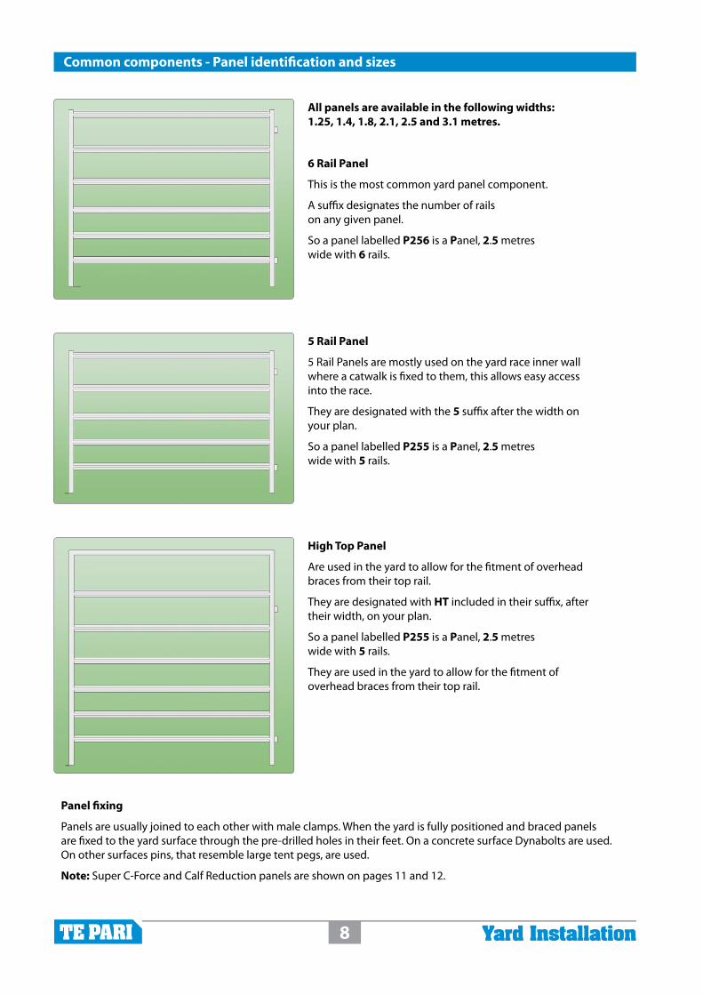
Assembly details - Draft gate post, loading ramp and race gate junction
1 - Working out from the round draft gate post:
Fit a race “U” bow on inner side and a standard race bow to the outer side
4 - Lastly hang the gate from the draft gate post centre pins to the race “U” bow
3 - Connect another “U” bow between the inner and outer panel ends
2 - Connect the 6 rail outer paneland 5 rail inner panel as shown
A draft gate post with a 3 way join is used where the loading ramp, lead-up race and race gate meet.
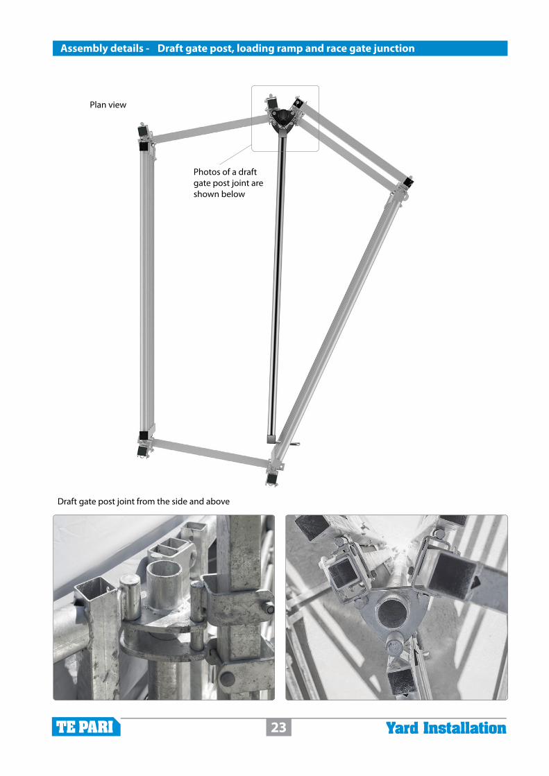
23 Yard Installation
Plan view
Photos of a draft gate post joint are shown below
Assembly details - Draft gate post, loading ramp and race gate junction
Draft gate post joint from the side and above

24 Yard Installation
Common components - BracesAssembly details - Crush - Entry and exit connections
Crush to gate connection
Where a crush exit joins to a gate the gate must be terminated in a fashion that allows for the free movement of the crush, for weighing.
This is achieved by terminating the gate with a wide race bow, coloured yellow in the graphic, that is near but completely free standing of the crush. The bow should be positioned half way between the rear of the cowling and nearest crush parts. The gate sections then attach to this bow using standard male clamps, coloured orange in the graphic.
Note: From late 2016 a wide race bow is not used where the crush exits to a drafting module. The drafting module is now designed to be completely free standing.
Race section to crush entry
Where a race joins the crush entry the race must be terminated in a fashion that allows for the free movement of the crush for weighing.
This is achieved by terminating the race with a heavy base race bow, coloured yellow in the graphic. The bow should be positioned 50 mm clear of the crush’s sliding gate.
The race sections attach to this bow using standard male clamps, coloured orange in the graphic.
The reason a heavy base race bow is used on the crush entry is to eliminate foot traps for animals entering the crush.

25 Yard Installation
Assembly details - Headbail and sliding gates - Entry and exit connections
Race section to headbail - entry and headbail to gate - exit
These connections are most often used where a race section makes up an animal working area, instead of a crush. These areas are formed with 5 and/or 6 rail panels connected between a sliding gate and headbail.
Where 5 and 6 rail panels join onto a headbail.
The end of the panels are bolted directly to the headbail frame, shown in yellow at the headbail entry on the left side of the graphic.
The headbail acts as a bow in this situation.
Where a headbail exit joins a gate.
The gates attach to the baulk gate subframe of the head-bail, shown in yellow at the headbail exit in the graphic.
They are attached with special 150 mm long male clamps that are provided specifically for this purpose, coloured orange in the graphic.
Race section to sliding gate and sliding gate to race section
Both the entry and exit connections of a sliding gate are the same. This connection is used wherever a sliding gate is used in the yard.
The race sections attach directly to the frame of the sliding gate using standard male clamps, coloured orange in the graphic.
Female connections are welded to the frame of the sliding gate on both the entry and exit sides for this purpose.
The sliding gate acts like a bow in this situation.

26 Yard Installation
Junction assembly details - Drafting module planAssembly details - Drafting module - Plan and connection details
Drafting module installation
To prevent loading on weigh platforms, loadbars and load cells the drafting module is not physically connected to the crush or headbail in anyway.
The gates either side nearest the headbail operate with vertically opposed heavy duty slam latches as shown in the photo and circled on graphic here.
Position
The distance from the Sign on the Headbail or Crush to the Drafter Latch Bow is not critical, but it needs to be at least 82mm.
The gap needs to provide enough room for uninterrupted gate operation but not allow room for an animal to squeeze through.
We recommend between 90 and 110mm.
90 to 110mm

27 Yard Installation
Overview of wire rope control installation for a 3 way drafting module - refer to plans over for positioning
Lay the wire channels out, with the pulley ends correctly orientated, and fit the brackets to them. Vertical brackets on the channel for the crush entry end, and outriggers for the channels on the side of the crush as shown below.
The channel and bracket assemblies can now be fixed in their correct positions on the crush.
Bolt the pulleys onto the drafting module frame. There are 2 of each type, 2 module entry pulleys (left below) and 2 module side pulleys (right below)
Bolt the shackle plates to the gates. there is 1 shackle plate for each gate.
The wire ropes can now be threaded through the channels and pulleys, ensure the wire ropes are not twisted around each other within the side channels.
Inside the crush end channel, the wire ropes do change orientation from horizontal to vertical.
Tidy up any extra wire at the gate end and fit handles to the operator end.
Note: Fitting the wire rope control involves working and fixing heavy items above head height.
Wear a hard hat. Have assistance when fitting the components especially the channel and bracket assemblies. Keep individuals not directly involved with the assembly away from the working area to prevent injury in the case an item being dropped from height.
Junction assembly details - Drafting module planAssembly details - Fitting wire rope control to a 3 way drafting module

28 Yard Installation
Chan
nel o
utrig
gers
for t
he c
rush
sid
e.
Thes
e ar
e br
acke
t bol
ted
to th
e cr
ush
top
side
fram
e an
d di
rect
ly b
olte
d to
the
chan
nel
Crus
h en
try
outr
igge
rs.
Vert
ical
bra
cket
bot
h en
ds
to c
rush
ent
ry “U
” Bow
top
21
3
66
7 8
45 7
8
Wire
rope
to g
ate
fittin
g.
Plat
e an
d sh
ackl
e fit
ted
to
mod
ule
gate
Dra
ft m
odul
e fr
ame
to g
ate.
Pl
ate
with
pul
ley
atta
ched
, bo
lted
to m
odul
e to
p fr
ame
Dra
ft m
odul
e en
tran
ce.
Pulle
ys b
olte
d to
mod
ule
entr
ance
fram
e
3x w
ire ro
pe c
hann
els.
Ther
e ar
e 3
iden
tical
RH
S ch
anne
ls a
nd e
ach
has
an a
ngle
d en
d w
ith 2
pul
leys
fitt
ed, t
he o
ther
end
is p
lain
.
6 an
d 7
are
fitte
d w
ith th
e pu
lleys
hor
izon
tal a
nd th
e po
inte
d en
d po
intin
g ou
twar
ds. N
ote
the
grap
hic
show
ing
the
dire
ctio
n.
Chan
nel 8
has
the
pulle
ys v
ertic
ally
with
the
poin
ted
end
up.
Not
e: E
nsur
e ch
anne
l 7 is
pos
ition
ed s
o th
e w
ire ro
pe e
nter
s cl
eanl
y in
to c
hann
el 8
with
out r
ubbi
ng, s
how
n at
righ
t. Th
e an
gled
end
of
chan
nel 6
sho
uld
posi
tione
d so
the
rope
s cl
ear t
he h
eadb
ail c
owlin
g.
67
8
44
44
5 5
3 322
1 1
Deno
tes p
ulley
s or p
ulley
end o
f guid
e cha
nnel
Adde
d gra
phics
are n
ot to
scale
for c
larity
Wire
rope
s
Assembly details - Fitting wire rope control to a 3 way drafting module

29 Yard Installation
A
CB
D
E
Assembly details - Fitting wire rope control - Directional views
BA
C
DE
Dire
ctio
n vi
ews;
A fr
om a
bove
; B fr
om th
e co
rner
sho
win
g al
l out
rigge
rs
and
chan
nels
; C lo
okin
g up
at s
ide
outr
igge
rs; D
The
ent
ry e
nd s
how
ing
the
chan
nel p
ositi
on. N
ote
the
chan
nel e
xten
ding
tow
ard
the
oper
ator
to k
eep
the
hand
les
wel
l cle
ar o
f the
cru
sh; E
The
cru
sh/m
odul
e ju
nctio
n.

30 Yard Installation
Assembly details - Catwalk brackets and 200 x 50 timber decking
1 - Attach the catwalk brackets to panels. Allow at least 250 mm where the brackets angle towards each other (point A) for an under deck support (see 8).
2 - Fix the first section of four planks to the brackets. 3 - Lay the next four planks in position without fixing
4 - Mark the angled cut line from the point where the planks meet (A-B) and cut the second set of planks
5 - lay the second set back in place
A

31 Yard Installation
Assembly details - Catwalk brackets and 200 x 50 timber decking
6 - Use the cut planks to mark the first set of planks.
7 - Butt the second set up to first and fix in place. 8 - Fix a plank beneath the unsupported ends to hold them in alignment and prevent trip hazard.
9 - Continue around the sections in this fashion until complete. When finished the brackets should be Dynabolted down.

32 Yard Installation
3
2
1
4 The top handle kit is supplied as 4 parts:
1 Top connector link
2 Link guide profile
3 Top handle
4 Latch profile
Step One
Remove the auto lock profile, if one is fitted, and replace with part 1, the latch profile.
Fit with 1x M12 mm x 90 mm hex bolt.
Step Two
Fit part 2 the link guide profile.
Fit with 1x 10 mm x 75 mm coach bolt, below the member it sits on.
Step Three
Remove the 2x M12 mm x 90 mm bolts first (if fitted) and fit part 3, the top handle, using 2x M12 mm x 100 mm hex bolts.
Assembly details - Fitting a top handle to a sliding gate

33 Yard Installation
Step Four
With the link bar passing through the slot in the link guide profile A; over the end of the latch profile B and above the shoulder block
- Fit the end of the link bar with the twist to the top handle c using 1x M10 mm x 40 mm hex bolt.
The top handle Installation is complete.
A
C
Assembly details - Fitting a top handle to a sliding gate
AB

34 Yard Installation
Assembly - Brief general installation sequence - After marking out
If your yard has a Super C-Force, first priority is to concrete in its centre gate post 1.
Complete the loading ramp lead up race and gate section then work around the race to the bail/crush area and in the opposite direction to the force pen area.
Follow with the headbail/crush area including drafting module section if applicable.
Next assemble the force pen area.
Work your way around the remainder of the yard. Loosely fit the panels together until the yard is closed in, in this way adjustments can be made easily prior to fitting the overhead braces and bolting or pinning everything down.
1

35 Yard Installation
Te Pari steel cattle yard installation sequence checklist
Mark the position of the loading ramp and its centre - the edge that aligns with the vehicle access.
Peg out your key line end reference points. These are normally measured from the centre of the loading race.
If your yard includes a Super C-Force race - The first thing to do is to mark the position of the Super C-Force forcing gate centre post. It needs to be concreted in with the pins facing in the correct direction. The concrete must set for 24 hours prior to placing it under load. See page 20.
Peg or mark out the yard boundary points from the key line reference points, Include pegs/marks for the race section if only it has a concrete surface.
Surface the yard. Concrete or concrete and metal. Where metal is used ensure to compact it.
Install your loading ramp - aligned to you key line and marked centre. Fix it in position.
Install the draft gate post, load ramp and race gate junction first then move toward the Super C-Force or force pen and in the opposite direction to the crush or headbail area. Boundary panels are about 500 mm from the concrete edge. See pages 22-23 for the draft gate post, load ramp and race gate junction details.
Position the: crush; headbail and sliding gate; drafting module and attach the appropiate lead in and lead out connections and bows as required. Bows and connections are shown on pages 7, 24-25. Fix in position.
When the Super C-Force post is set. Fit the forcing gate to it and use its arc, and your markings, to determine and position the remainder of the Super C-Force panels as on page 21.
Work your way around the perimeter of the yard, starting from the working area exit point and the force race. Ensure gate opening directions are correct.
Infill the central yard area panels.
Adjust all panels as required, your plans yard perimeter line is about 500 mm out from the panel line.
Install the yard wall braces - “L” braces - Dynabolted on a concrete surface, or yard wall support post braces concreted in when yard has a metal or earth surface, see page 14 for bracing details.
Install high top (overhead) braces as labelled your plan. Fit as shown on page 14.
Final check all positioning then tighten joint brackets and Dynabolt or pin all panels in position.
Fit catwalk brackets, and fix the catwalk timber decking, pages 30-31
Fit included options like top handles to sliding gate/s and wire rope draft module control.

36 Yard Installation
Super C-Force centre post mm from ref. point and mm from ref. point
Key measurements and Notes
Head Office9 Endeavour Crescent PO Box 25, Oamaru, 9444, New Zealand Freephone: NZ 0800 837 274 Freephone: AU1800 650 682
www.tepari.comFREEPHONE 0800 837 274
We welcome your feedback - Please let us know of any improvements you would like to see to the instructions in this manual.
Copyright © 2022 FDOKUMEN