
SSP437 Audi 3.0l V6 TFSI engine with Roots blower
56
with Roots blower Self-Study Programme 437 Service Training Audi 3.0l V6 TFSI engine ProCarManuals.com
-
Upload
khangminh22 -
Category
Documents
-
view
1 -
download
0
Transcript of SSP437 Audi 3.0l V6 TFSI engine with Roots blower

with Roots blower
Self-Study Programme 437
Service Training
Audi 3.0l V6 TFSI engine
Pro
Car
Man
uals
.com

437_003
For the first time, Audi has brought to market a mechanically supercharged powerplant: the 3.0l V6 TFSI. This Roots blower supercharged engine is based on the 3.2l V6 naturally aspirated engine from the current Audi V engine family.
By embracing new technology, in combination with the FSI combustion process, Audi has developed an engine concept that cuts an impressive figure in terms of its compact design, acoustics, responsiveness and fuel efficiency.
The engine has a broad range of characteristics from comfort-oriented to ultra-sporty. The sporty version of the engine specifically targets US clientele. The car's so-called take-off behaviour plays a key role here. The aim is to achieve the greatest possible acceleration between traffic lights in urban traffic.
With its enormous power, however, the 3.0l V6 TFSI engine is also well suited to comfort-oriented driving. A wide range of uses have been envisaged for it within the Audi product portfolio. In Europe, China and the USA, it will be available for the first time from the autumn of 2008 in the Audi A6.
Historically, mechanical supercharging using Roots blowers is nothing new to cars bearing the four-ring badge. In fact, Roots blowers were once used on the engines of the legendary AUTO UNION racing cars ("Silver Arrows"), which were powered by huge V engines with up to 16 cylinders supercharged by up to two Roots blowers. Between 1934 and 1939, the legendary AUTO UNION drivers spearheaded by Hans Stuck and Bernd Rosemeyer racked up numerous Grand Prix wins, not to mention setting a string of world speed records.
Pro
Car
Man
uals
.com

437_004
The objectives of this Self-Study Programme
In this Self-Study Programme you will learn about the design and operation of the 3.0l V6 TFSI engine. It provides you with all the information you need to describe the engine. Once you have worked your way through this Self-Study Programme, you will be able to answer the following questions:
– How is the engine designed mechanically?– How does the cooling system work, and to what should attention be paid during servicing?– How does the Roots blower based mechanical supercharging system work?– What are the special features of the improved fuel system?– How is the exhaust system configured?– What are the new features of the engine management system?– What do service employees need to know about the new engine?
Audi 3.0l V6 TFSI engine
Pro
Car
Man
uals
.com

Brief technical description . . . . . . . . . . . . . . . . . . . . . . . . . . . . . . . . . . . . . . . . . . . . . . 6
Introduction
Cylinder block . . . . . . . . . . . . . . . . . . . . . . . . . . . . . . . . . . . . . . . . . . . . . . . . . . . . . . . .10
Crank mechanism . . . . . . . . . . . . . . . . . . . . . . . . . . . . . . . . . . . . . . . . . . . . . . . . . . . .11
Crankcase ventilation . . . . . . . . . . . . . . . . . . . . . . . . . . . . . . . . . . . . . . . . . . . . . . . . .12
Cylinder head . . . . . . . . . . . . . . . . . . . . . . . . . . . . . . . . . . . . . . . . . . . . . . . . . . . . . . . .13
Driving the ancillary units/components. . . . . . . . . . . . . . . . . . . . . . . . . . . . . . . . . .14
Engine mechanicals
Oil circulation system . . . . . . . . . . . . . . . . . . . . . . . . . . . . . . . . . . . . . . . . . . . . . . . . .15
Oil supply
Cooling circuit. . . . . . . . . . . . . . . . . . . . . . . . . . . . . . . . . . . . . . . . . . . . . . . . . . . . . . . .36
Charge air cooling (intercooling) . . . . . . . . . . . . . . . . . . . . . . . . . . . . . . . . . . . . . . . .38
Cooling system
Air circulation system . . . . . . . . . . . . . . . . . . . . . . . . . . . . . . . . . . . . . . . . . . . . . . . . .16
Supercharger module . . . . . . . . . . . . . . . . . . . . . . . . . . . . . . . . . . . . . . . . . . . . . . . . .20
Load management. . . . . . . . . . . . . . . . . . . . . . . . . . . . . . . . . . . . . . . . . . . . . . . . . . . .31
Intake manifold flaps. . . . . . . . . . . . . . . . . . . . . . . . . . . . . . . . . . . . . . . . . . . . . . . . . .32
Soundproofing . . . . . . . . . . . . . . . . . . . . . . . . . . . . . . . . . . . . . . . . . . . . . . . . . . . . . . .34
Air supply
Contents
Secondary air system . . . . . . . . . . . . . . . . . . . . . . . . . . . . . . . . . . . . . . . . . . . . . . . . .42
Exhaust emissions treatment
Pro
Car
Man
uals
.com
Reference
Terms shown in italics and marked by an asterisk (*) are explained in the glossary at the end of this Self-Study Programme.
Overview . . . . . . . . . . . . . . . . . . . . . . . . . . . . . . . . . . . . . . . . . . . . . . . . . . . . . . . . . . . .46
Injectors . . . . . . . . . . . . . . . . . . . . . . . . . . . . . . . . . . . . . . . . . . . . . . . . . . . . . . . . . . . . .47
Fuel system
Maintenance work. . . . . . . . . . . . . . . . . . . . . . . . . . . . . . . . . . . . . . . . . . . . . . . . . . . .51
Special tools . . . . . . . . . . . . . . . . . . . . . . . . . . . . . . . . . . . . . . . . . . . . . . . . . . . . . . . . .52
Service
Glossary . . . . . . . . . . . . . . . . . . . . . . . . . . . . . . . . . . . . . . . . . . . . . . . . . . . . . . . . . . . . .53
Test yourself . . . . . . . . . . . . . . . . . . . . . . . . . . . . . . . . . . . . . . . . . . . . . . . . . . . . . . . . .54
Annex
The Self-Study Programme teaches the design and function of new vehicle models, new automotive components or new technologies.
The Self Study Programme is not a Repair Manual. All values given are intended for reference purposes only and refer to the software version valid at the time of preparation of the SSP.
For information about maintenance and repair work, always refer to the current technical literature.Terms written in italics or indicated by an asterisk (*) are explained in the glossary at the back of this Self-Study Programme.
Self-Study Programmes . . . . . . . . . . . . . . . . . . . . . . . . . . . . . . . . . . . . . . . . . . . . . . .55
Summary
System overview . . . . . . . . . . . . . . . . . . . . . . . . . . . . . . . . . . . . . . . . . . . . . . . . . . . . .48
Engine control unit . . . . . . . . . . . . . . . . . . . . . . . . . . . . . . . . . . . . . . . . . . . . . . . . . . .50
Engine management
NoteReference
Pro
Car
Man
uals
.com
6
437_005
Reference
For a detailed technical description of the basic engine (3.2l V6 FSI engine), please refer to Self-Study Programme 411 "Audi 2.8l and 3.2l FSI engine with Audi valvelift system".
Introduction
Brief technical description
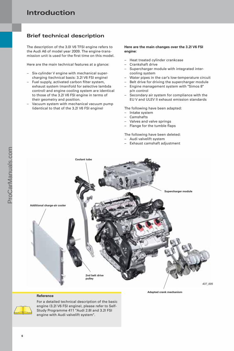
The description of the 3.0l V6 TFSI engine refers to the Audi A6 of model year 2009. The engine-trans-mission unit is used for the first time on this model.
Here are the main technical features at a glance:
– Six-cylinder V engine with mechanical super-charging (technical basis: 3.2l V6 FSI engine)
– Fuel supply, activated carbon filter system, exhaust system (manifold for selective lambda control) and engine cooling system are identical to those of the 3.2l V6 FSI engine in terms of their geometry and position.
– Vacuum system with mechanical vacuum pump (identical to that of the 3.2l V6 FSI engine)
Here are the main changes over the 3.2l V6 FSI engine:
– Heat treated cylinder crankcase– Crankshaft drive– Supercharger module with integrated inter-
cooling system– Water pipes in the car's low-temperature circuit– Belt drive for driving the supercharger module– Engine management system with "Simos 8"
p/n control– Secondary air system for compliance with the
EU V and ULEV II exhaust emission standards
The following have been adapted:– Intake system– Camshafts– Valves and valve springs– Flange for the tumble flaps
The following have been deleted:– Audi valvelift system– Exhaust camshaft adjustment
Coolant tube
Supercharger module
Adapted crank mechanism
2nd belt drivepulley
Additional charge-air cooler
Pro
Car
Man
uals
.com

7
5000 6000 7000 8000400030001000 2000
kW
90
50
170
210480
240
160
400
0
Nm
Specifications
Engine code CAJA
Engine type Six-cylinder V-engine
Displacement in cm3 2995
Max. power in kW (bhp) 213 (290) at 4850 – 7000 rpm
Max. torque in Nm 420 at 2500 – 4850 rpm
Valves per cylinder 4
Bore in mm 84.5
Stroke in mm 89
Compression ratio 10.5 : 1
Firing order 1–4–3–6–2–5
Engine weight in kg 190
Engine management Simos 8
Fuel grade 95 RON*
Mixture formation Direct injection FSI (homogeneous)High-pressure fuel pump HDP 3
Exhaust emission standard EU V, ULEV II
Exhaust aftertreatment Cylinder-selective lambda control with one broadband pre-cat sensor per cylinder bank, two ceramic catalytic converters
with post-cat oxygen sensor (nonlinear sensor)
CO2 emissions in g/km 228
Torque/power curve
Max. torque in Nm
Max. power in kW
Engine speed [rpm]
* 91 RON unleaded petrol can also be used with a slight reduction in performance
Pro
Car
Man
uals
.com
8
5000 6000 7000 8000400030001000 2000
130
90
50
170
210480
240
110280
160
70200
400
190440
150360
0
320
Introduction
Characterisation
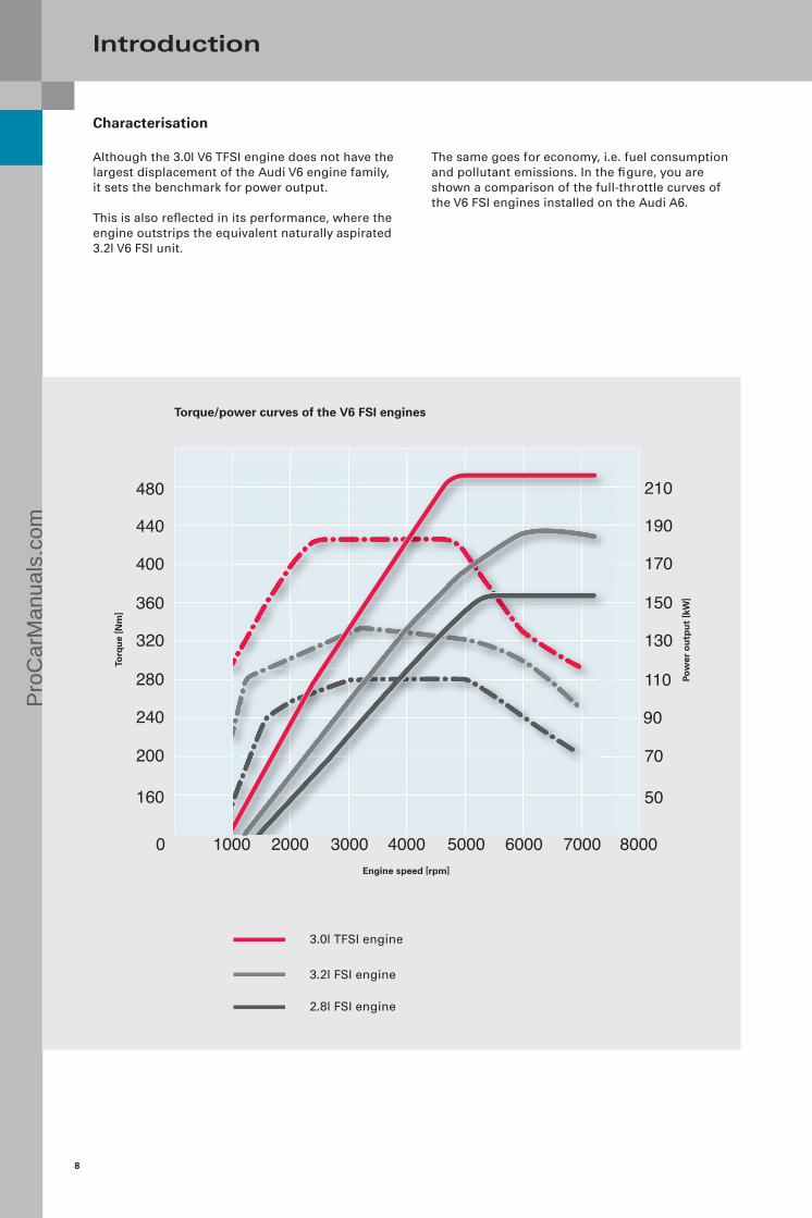
Although the 3.0l V6 TFSI engine does not have the largest displacement of the Audi V6 engine family, it sets the benchmark for power output.
This is also reflected in its performance, where the engine outstrips the equivalent naturally aspirated 3.2l V6 FSI unit.
The same goes for economy, i.e. fuel consumption and pollutant emissions. In the figure, you are shown a comparison of the full-throttle curves of the V6 FSI engines installed on the Audi A6.
Engine speed [rpm]
3.0l TFSI engine
3.2l FSI engine
2.8l FSI engine
Torque/power curves of the V6 FSI engines
Torq
ue
[Nm
]
Pow
er o
utp
ut
[kW
]
Pro
Car
Man
uals
.com

9
Specifications of the V6 engines on the Audi A6
Parameter 2.4l MPI 2.8l FSI 3.2l FSI 3.0l TFSI
Displacement in cm3 2393 2773 3123 2995
Stroke in mm 77,4 82.4 92.8 89
Bore in mm 81 84.5 84.5 84.5
Stroke/bore 0.96 0.98 1.10 1.05
Compression ratio 10.3 : 1 12.0 : 1 12.5 : 1 10.5 : 1
Cylinder spacing in mm 90 90 90 90
Cyl. bank offset in mm 18.5 18.5 18.5 18.5
Main bearing diameter in mm
58 58 65 65
Big-end bearing diameter in mm
50 54 56 56
Con-rod length in mm 159 159 154 153
Engine block height in mm 228 228 228 228
Max. power in kW at rpm
130 at 6000 154 at 5250 188 at 6500 213 at 4800 – 7000
Max. torque in kW at rpm 230 at 3000 280 at 3000 – 5000 330 at 3250 420 at 2500 – 4850
Fuel in RON 95/91 1) 95/91 1) 95/91 1) 95/91 1)
Comparison of performance data: 3.2l V6 FSI engine and 3.0l V6 TFSI engine on the Audi A6
Audi A63.2l FSI
188 kW/330 Nmtiptronic quattroModel year 2008
Audi A63.0l TFSI
213 kW/420 Nmtiptronic quattroModel year 2009
Parameter Units
0 – 100 kph S 7.1 6.3
Elasticity in speed D kph 80 – 120 80 – 120
S 6.0 5.3
Max. speed kph 250 2) 250 2)
rpm / gear 6350 / 5 4500 / 6
Average consumption (overall) l/100 km 10.9 9.6
CO2 emissions g/km 259 228
2) governed
1) with reduced power output
Pro
Car
Man
uals
.com
10
437_007
Engine mechanicals
Cylinder block
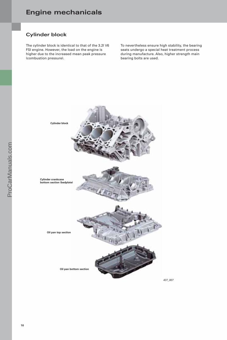
The cylinder block is identical to that of the 3.2l V6 FSI engine. However, the load on the engine is higher due to the increased mean peak pressure (combustion pressure).
To nevertheless ensure high stability, the bearing seats undergo a special heat treatment process during manufacture. Also, higher strength main bearing bolts are used.
Cylinder block
Cylinder crankcase bottom section (bedplate)
Oil pan top section
Oil pan bottom section
Pro
Car
Man
uals
.com

11
437_008
437_009
Crankshaft drive
Crankshaft
The crankshaft has been adapted for a stroke of 89 mm. Like the 3.2l V6 FSI engine, the crankshaft has a split-pin configuration* (see glossary).
The newly developed, cracked con-rods* are 153 mm long and optimised for strength. All bear-ing bushes are designed as lead-free 3-component composite bearing bushes.
Pistons
Unlike the 3.2l V6 FSI engine, the pistons, as ring carrier pistons, are rated for a compression ratio of 10.5:1.
The piston skirts therefore have a wear resistant Ferrostan plating. The special piston ring combina-tion provides high power output and low blow-by gas flow rates, as well as low oil consumption in conjunction with minimum friction and wear.
Cast piston
Ring carrier
1.2 mm asymmetric steel ring
1.5 mm taper-face ring
2.0 mm oil scraper ring (two piece)
Pro
Car
Man
uals
.com

12
Reference
For a description of the design and function of the PCV system, please refer to Self-Study Programme 411 "Audi 2.8l and 3.2l FSI engine with Audi valvelift system".
437_050
437_070
Engine mechanicals
Crankcase ventilation
The crankcase is ventilated in the same way as on the 3.2l V6 FSI engine.
Connection to supercharger module
The blow-by gases* are admitted into the super-charger module on the underside. An adaptor seals the feeder line off from the supercharger module. The opening in the supercharger module is tapered to aid inserting the adaptor.
The adaptor has a lug which can be used to position it exactly at the PCV outlet.
However, there is a difference with regard to the admission of treated crankcase ventilation gases. They are admitted along the shortest possible route directly from the V chamber preceding the rotors of the Roots blower.
Adaptor
Oil separator module
Connection to cylinder head cover, right (with integrated labyrinth oil separator)
PCV line with non-return valve
Connection to cylinder head cover, left (with integrated labyrinth oil separator)
Connection to supercharger module
Pro
Car
Man
uals
.com

13
437_071
437_072
Cylinder head
The four-valve cylinder heads will be adopted by and large unchanged from the 3.2l V6 FSI engine. The Audi valvelift system is not used in this engine-transmission unit.
Changes over 3.2l V6 FSI engine
It was also possible to dispense with the exhaust camshaft adjuster. However, an internal exhaust gas recirculation system has been implemented despite this.
Chain drive
The chain drive is identical design to that of the 3.2l FSI engine. Differences are the modified valve timing* and the absence of exhaust camshaft adjusters.
Valve springs(different alloy, different tensile strength)
Exhaust valves(chrome plated, sodium filled hollow-stem valve, steel plated at valve seat)
Cylinder head
Cylinder head cover
High-pressure fuel pump
Intake camshaft timing adjustment valve N205
Pro
Car
Man
uals
.com
14
437_055
437_010
Engine mechanicals
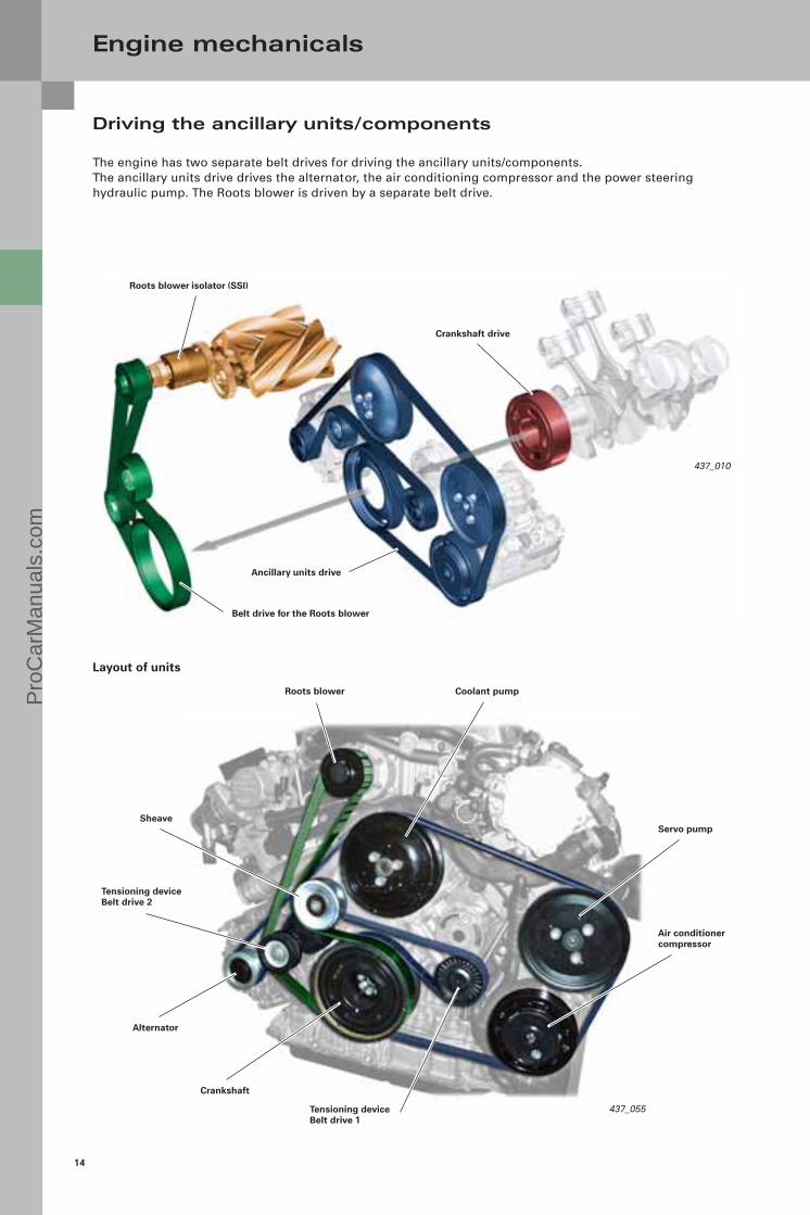
Driving the ancillary units/components
The engine has two separate belt drives for driving the ancillary units/components. The ancillary units drive drives the alternator, the air conditioning compressor and the power steering hydraulic pump. The Roots blower is driven by a separate belt drive.
Layout of units
Roots blower isolator (SSI)
Crankshaft drive
Ancillary units drive
Belt drive for the Roots blower
Roots blower
Servo pump
Air conditioner compressor
Tensioning device Belt drive 1
Crankshaft
Alternator
Tensioning device Belt drive 2
Sheave
Coolant pumpPro
Car
Man
uals
.com

15
Reference
For a description of the design and function of the lubrication oil circuit and the oil pump, please refer to Self-Study Programme 411, "Audi 2.8l and 3.2l FSI engine with Audi valvelift system".
437_073
Oil supply
However, there are the following differences:
– There are no spray nozzles for the cam followers in the valve gear (they are only needed in an engine with Audi valvelift system, since the narrower rollers require better lubrication).
Upright oil filter module
Oil pressure regulating valve N428
Oil cooler
Self-regulating oil pump
Unfiltered oil port
Clean oil port
– There is no drive module for the exhaust cam-shaft adjuster
Oil circulation system
The oil circulation system of the 3.0l V6 TFSI engine was adopted from the 3.2l V6 FSI engine.
Pro
Car
Man
uals
.com
16
437_025
Air supply
Given Audi's extensive experience with exhaust tur-bocharging, you may ask yourself why a mechanical supercharging system has been chosen for the 3.0l V6 TFSI engine.
After carefully weighing up the pros and cons on the basis of numerous tests conducted during the conceptual design and development phase, the decision fell in favour of the mechanical super-charging system.
The following criteria played a key role:
– High standard of comfort – Good starting performance, coupled with a
broad range of characteristics between comfort-oriented and ultra-sporty
– On account of this characteristic, the engine is suitable for use in multiple models (ranging from the Audi A4 to the A8).
– Compliance with all current and forthcoming exhaust emission standards (EU V and ULEV II)
Supercharger module
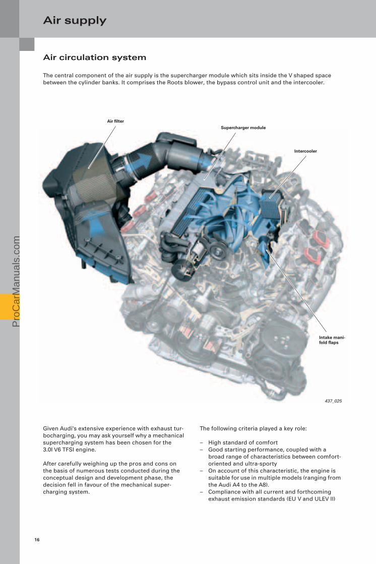
Air circulation system
The central component of the air supply is the supercharger module which sits inside the V shaped space between the cylinder banks. It comprises the Roots blower, the bypass control unit and the intercooler.
Air filter
Intercooler
Intake mani-fold flaps
Pro
Car
Man
uals
.com
17
437_053
437_044
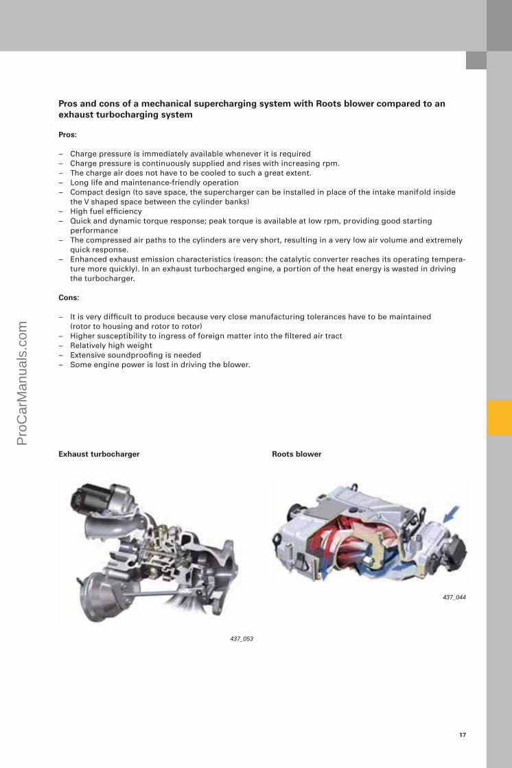
Pros and cons of a mechanical supercharging system with Roots blower compared to an exhaust turbocharging system
Pros:
– Charge pressure is immediately available whenever it is required – Charge pressure is continuously supplied and rises with increasing rpm. – The charge air does not have to be cooled to such a great extent. – Long life and maintenance-friendly operation – Compact design (to save space, the supercharger can be installed in place of the intake manifold inside
the V shaped space between the cylinder banks)– High fuel efficiency– Quick and dynamic torque response; peak torque is available at low rpm, providing good starting
performance– The compressed air paths to the cylinders are very short, resulting in a very low air volume and extremely
quick response. – Enhanced exhaust emission characteristics (reason: the catalytic converter reaches its operating tempera-
ture more quickly). In an exhaust turbocharged engine, a portion of the heat energy is wasted in driving the turbocharger.
Cons:
– It is very difficult to produce because very close manufacturing tolerances have to be maintained (rotor to housing and rotor to rotor)
– Higher susceptibility to ingress of foreign matter into the filtered air tract– Relatively high weight – Extensive soundproofing is needed – Some engine power is lost in driving the blower.
Exhaust turbocharger Roots blower
Pro
Car
Man
uals
.com

18
437_014
437_016437_015
Air supply
General information on Roots blowers
With their mechanical supercharging technology, Roots blowers are presently staging a comeback at Audi. In this section you will find general information about the design and development of this technology.
The historic blowers of yesteryear were equipped with twin-vane rotors.
From a design standpoint, it is very important that the rotors are sealed off against each another and against the housing. The difficulty here is that no friction must be allowed to develop.When the blower is operating (i.e. the rotors are rotating), air is conveyed between the vanes and the outer wall of the housing from the air inlet (on the intake side) to the air outlet (on the pressure side). The pressure of the conveyed air is produced by reverse flow.
Air outlet
Rotor 2
Today's modern versions usually have three vanes and are screw shaped to provide a higher and - above all - constant charge pressure (for better effi-ciency).
Air inlet
Rotor 1
Housing
Types
Basic principle
What are Roots blowers? In design terms, Roots blowers are rotary piston compressors. They work without inner compression according to the dis-placement principle. The fresh air blower consists of a housing in which two shafts (rotors) rotate.Both rotors are driven mechanically, e.g. by the crankshaft. Both rotors are coupled by a gearing outside the housing so that they counter-rotate synchronously. That is how they interact.
Pro
Car
Man
uals
.com

19
437_051
437_026
Historical evolution
The system is named after brothers Philander and Francis Roots, who had the principle patented as long ago as 1860.
At that time Roots blowers were principally used as wind generators for blast furnaces, but also found uses in other branches of industry. A Roots blower was used in an automobile for the first time by Gottlieb Daimler in 1900. In the 1920s and 1930s, Roots blowers were introduced into motorsport .
Special feature: these engines can be easily identi-fied by their typical "compressor squeal" sound. The illustration below shows a Roots blower from the 1936 AUTO UNION Type C grand prix racing car. With the development of highly temperature-resist-ant materials, the Roots blower was superseded by the exhaust turbocharger. Today, Roots blowers are mainly used on sporty vehicles.
16-cylinder engineCarburettor Roots blower
Fuel pump
The difference between the AUTO UNION racing car and the 3.0l V6 TFSI engine is that, on the former, the air-fuel mixture was formed upstream of the Roots blower.This configuration was chosen for conceptual rea-sons, because the partial vacuum needed to draw fuel out of the carburettor was only available upstream of the Roots blower. In the Roots blower, therefore, the air-fuel mixture was compressed. Archive: AUTO UNION
Rotors Housing
Upper bearing cover
Pro
Car
Man
uals
.com

20
Air supply
Supercharger module
Modern Roots blowers of the type used on Audi models are configured as twin-screw superchargers.Whereas the predecessor generation had three-vane rotors, the Audi Roots blower has four-vane rotors. Each vane of the two rotors is set at an angle of 160° relative to the longitudinal axis to provide a more continuous air flow with less pulsation. The Roots blower for the 3.0l V6 TFSI engine is manufactured by EATON. This company already has many years of experience in the manufacture of Roots blowers.
Belt pulley
Adaptor (main throttle valve)
Throttle valve control unit J338
Snap-in coupling for design cover
Charge pressure sender G31 Intake manifold temperature sender G72
Damping plate
Lifting lug
Housing
Rotors
Rear rotor bearing
Design
The entire supercharger module sits inside the V shaped space between the cylinder banks, so the engine is flat and meets pedestrian safety regula-tions. The total weight of the module is 18 kg (excluding coolant).
Pro
Car
Man
uals
.com

21
437_037
Bypass bend
Adaptor (bypass valve)
Control flap control unit J808
Intercooler
Intake air temperature sensor G42Intake manifold pressure sender G71
Side seal, intercooler
Bearing cover
Front rotor bearing
Synchroniser gears
Single Spring Isolator (SSI)
Drive housing
Input shaft with bearing
Charge pressure sender G447Intake manifold temperature sender G430
Pro
Car
Man
uals
.com

22
437_034
437_038
Air supply
Housing
The Roots blower, an electrically activated bypass valve and one intercooler per cylinder bank are integrated in a cast mono-block housing.
Snap-in coupling for design cover
Damping plate
Housing
Intercooler
Air outlets
Intake manifold pressure sender G42Intake air temperature sensor G72
Throttle valve control unit J338
PCV intake
Drive shaft
Direction of travel
The air outlets to the individual cylinders can be found on the underside of the housing. The lifting lugs bolted to the supercharger module are for suspending the engine during removal and installation.
Intercooler
Lifting lug
Pro
Car
Man
uals
.com

23
437_039
437_040
Drive
The Roots blower is driven by the crankshaft via the second pulley of the belt drive. Drive is permanent, and is not engaged or disen-gaged by a magnetic coupling. Each belt drive is insulated against crankshaft vibra-tion by a rubber buffer in a shared torsion vibration damper.
The result is better resonance damping at low engine speeds and full throttle. Spin-off: the load on the belt is significantly lower.
The crankshaft-to-supercharger drive ratio is 1:2.5. This means that a maximum engine speed of 18,000 rpm is possible.
The Roots blower is coupled by means of a Single Spring Isolator (SSI) integrated in the drive housing of the supercharger module. The SSI is designed to optimise force transmission under load reversal.
It ensures very smooth running (optimised acous-tics) and extends the life of the drive belt. The ribbed V-belt which drives the Roots blower has a replacement interval of 120,000 km.
Bearing cover
Front rotor bearing
Synchroniser gears
Single Spring Isolator (SSI)
Drive housing
Input shaft with bearing
Belt pulley
Supercharger module
2nd belt drive pulley
Pro
Car
Man
uals
.com

24
437_041
437_042
Air supply
Function
A spring element is built into the drive housing of the Roots blower. It consists of a torsion spring guided by an input bushing and an output bushing and transmits drive torque from the belt pulley to the gearing. The input and output bushings limit the excursion of the spring, both in and counter to the direction of rotation of the Roots blower.
The spring element is rated "soft" enough to effec-tively isolate the blower, yet also firm enough to prevent harshness during dynamic operation (under load reversal), which can cause unwanted noise.
Drive housing
Belt pulley
Input shaft with bearing
Input bushing
Output bushing
Rotors
Further along the drive-line, the second rotor is driven through a pair of gears, with the result that the two rotors counter-rotate absolutely synchro-nously. The large number of teeth serves to reduce vibration transmission. The gears are press fitted onto the rotor shafts by the manufacturer using special gauges. A perfect fit must be ensured, as the rotor vanes would otherwise come into contact with one another. For this reason, the gears must not be removed from the shafts during servicing. The drive head is filled with special-grade oil.
Rotors
The two four-vane rotors are set at an angle of 160° and run on maintenance-free roller bearings. To minimise wear during the run-in phase, the rotors have a special graphite-based coating.This coating also guards against air leakage (rotor to rotor, rotor to rotor bore), which means better performance.
RotorRear rotor bearing
Synchroniser gears
Torsion spring
Pro
Car
Man
uals
.com
25
437_044
437_043
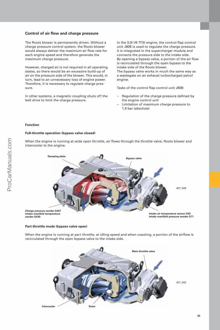
The Roots blower is permanently driven. Without a charge pressure control system, the Roots blower would always deliver the maximum air flow rate for each engine speed and therefore generate the maximum charge pressure.
However, charged air is not required in all operating states, so there would be an excessive build-up of air on the pressure side of the blower. This would, in turn, lead to an unnecessary loss of engine power. Therefore, it is necessary to regulate charge pres-sure.
In other systems, a magnetic coupling shuts off the belt drive to limit the charge pressure.
Damping plateBypass valve
In the 3.0l V6 TFSI engine, the control flap control unit J808 is used to regulate the charge pressure. It is integrated in the supercharger module and connects the pressure side to the intake side. By opening a bypass valve, a portion of the air flow is recirculated through the open bypass to the intake side of the Roots blower. The bypass valve works in much the same way as a wastegate on an exhaust turbocharged petrol engine.
Tasks of the control flap control unit J808:
– Regulation of the charge pressure defined by the engine control unit
– Limitation of maximum charge pressure to 1.9 bar (absolute)
Charge pressure sender G447Intake manifold temperature sender G430
Intake air temperature sensor G42Intake manifold pressure sender G71
Function
Full-throttle operation (bypass valve closed)
When the engine is running at wide open throttle, air flows through the throttle valve, Roots blower and intercooler to the engine.
Part-throttle mode (bypass valve open)
When the engine is running at part throttle, at idling speed and when coasting, a portion of the airflow is recirculated through the open bypass valve to the intake side.
Main throttle valve
Intercooler
Control of air flow and charge pressure
Rotor
Pro
Car
Man
uals
.com

26
20
40
60
80
100
1 2
437_036
Air supply
Control flap control unit J808
Use of the control flap control unit J808 eliminates the need for complex and expensive belt drive shut-off in the form a magnetic coupling. The power consumption of the supercharger module is between 1.5 and 38 kW, depending on engine speed.
Lower mechanical stop
Upper mechanical stop
1
2
Sensor travel
Bypass valve
Angle sender
Control flap adjustment servomotor V380
Signal characteristic of the control flap potentiometer G584
Sen
sor
outp
ut
[%]
Pro
Car
Man
uals
.com

27
437_052
Reference
For more information on magneto-resistive sensors, please refer to Self-Study Programme 411, "Audi 2.8l and 3.2l FSI engine with Audi valvelift system".
Legend:
G584 Control flap potentiometer
J808 Control flap control unit
V380 Control flap adjustment servomotor(type: DC motor)
Sensor voltage earth
Control signal
Positive sensor voltage
Motor supply voltage
1
2
3
4
5
Signal utilisation
The flap position feedback signal is utilised to deter-mine the control input variable. It is also used to determine the adaptation values.
Control flap potentiometer G584
This component senses the current position of the control flap and is integrated in the actuator hous-ing cover. Its output voltage range is between 0.5 and 4.5 V. The potentiometer operates on the magneto-resis-tive measurement principle and, therefore, is immune to electromagnetic radiation (EMC*).
Effects of signal failure
The flap is de-energised and moves into its wide open position under spring load. The fault is irre-versible for the duration of one driving cycle. In this case, no charge pressure is built up. Neither the full engine power output nor the full engine torque is available. This component is subject to OBD; i.e. if it fails, the exhaust gas warning lamp K83 (MIL) is activated.
Pro
Car
Man
uals
.com
28
437_028
437_029
437_018
Air supply
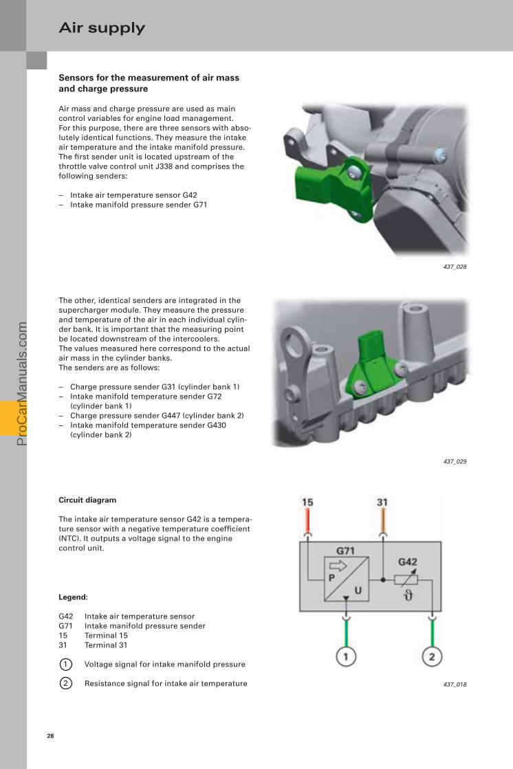
Sensors for the measurement of air mass and charge pressure
Air mass and charge pressure are used as main control variables for engine load management. For this purpose, there are three sensors with abso-lutely identical functions. They measure the intake air temperature and the intake manifold pressure. The first sender unit is located upstream of the throttle valve control unit J338 and comprises the following senders:
– Intake air temperature sensor G42 – Intake manifold pressure sender G71
The other, identical senders are integrated in the supercharger module. They measure the pressure and temperature of the air in each individual cylin-der bank. It is important that the measuring point be located downstream of the intercoolers. The values measured here correspond to the actual air mass in the cylinder banks. The senders are as follows:
– Charge pressure sender G31 (cylinder bank 1) – Intake manifold temperature sender G72
(cylinder bank 1)– Charge pressure sender G447 (cylinder bank 2) – Intake manifold temperature sender G430
(cylinder bank 2)
Circuit diagram
The intake air temperature sensor G42 is a tempera-ture sensor with a negative temperature coefficient (NTC). It outputs a voltage signal to the engine control unit.
Legend:
G42 Intake air temperature sensorG71 Intake manifold pressure sender15 Terminal 1531 Terminal 31
Voltage signal for intake manifold pressure
Resistance signal for intake air temperature
1
2
Pro
Car
Man
uals
.com

29
Sig
nal
ou
tpu
t vo
ltag
e U
A [V
]
Absolute pressure pabs [kPa]
Characteristic curve of supply voltage UV = 5.000 V
Signal characteristic of the intake manifold pressure sender
Signal utilisation
The signal generated by the intake manifold pres-sure sender G71 upstream of the throttle valve control unit is used to pre-determine the nominal position of the bypass valve. This information is required to set the requisite charge pressure. This nominal position of the bypass valve depends largely on the pressure level upstream of the supercharger module.
Charge pressure senders G31 and G447 serve firstly to adjust the charge pressure to the required nomi-nal value. Secondly, the air mass is calculated from their output signal during each working cycle. This air mass is a key input variable of the torque-based engine management system, which determines the injection rate, injection timing and ignition advance angle.
Effects of signal failure
In case of signal failure, the exhaust gas warning lamp K83 (MIL) is activated. Failure of the intake manifold pressure sender G71 will result in less precise adjustment of the charge pressure, which in turn can become apparent to the driver in the form of uneven acceleration. Failure of charge pressure senders G31 and G447 will result in an incorrect composition of the air-fuel mixture throughout the load/speed range because an erroneous air mass will be computed. This will in turn cause an incorrect quantity of fuel to be injected, resulting in higher exhaust emis-sions and loss of power (and even misfiring). In charging mode, a fault in this sender can result in wrong charge pressures, causing irreparable damage to the engine.
For this reason, all senders are validated after the ignition is turned on. If irregularities are detected, an entry will be made in the fault memory and the system switches over to an equivalent sensor or the backup sender. In this way, the system will operate as normal from the driver's viewpoint and conse-quential damage will be avoided.
Pro
Car
Man
uals
.com

30
437_020
Air supply
Circuit diagram
Legend:
G31 Charge pressure sender (cylinder bank 1)
G72 Intake manifold temperature sender (cylinder bank 1)
G430 Intake manifold temperature sender (cylinder bank 2)
G447 Charge pressure sender (cylinder bank 2)
J623 Engine control unit
Vs Supply voltage (5 volts)
PositiveGroundSensor signal
Pro
Car
Man
uals
.com

31
1000 2000 3000 4000 5000 60000
20
40
60
80
100
120
140
160
20040060080010001200140016001800
1 3
2
Load management
The control flap control unit J808 operates in con-junction with the throttle valve control unit J338.
The focus during the development of the control system was on maximising throttle-free operation and power delivery.
The following diagram shows the functions of both flaps. During part-throttle and naturally aspirated operation, the bypass valve is wide open and the engine throttle valve takes care of load manage-ment. In charge pressure mode, the bypass valve regulates the engine load and the engine throttle valve is wide open.
1
2
Op
enin
g a
ng
le [d
egre
es]
Inta
ke m
anifo
ld p
ress
ure
[mb
ar]
Naturally aspirated mode
Ambient pressure
Charging mode
Intake manifold pressure
Bypass valve
Throttle valve 3
Load section at 3000 rpm
Engine speed [rpm]
Pro
Car
Man
uals
.com

32
437_049
Note
To fit the adaptor element, the intake manifold flaps must be moved into the "power" position (intake port open).
437_027
Air supply
Intake manifold flaps
Intake manifold flaps are used on the 3.0l V6 TFSI engine to improve internal mixture formation. They are housed in an adaptor element between the supercharger module and the cylinder head.
Intake manifold flap valve N316
The intake manifold flaps are mounted on a common shaft and actuated by a vacuum cell. The partial vacuum required for this purpose is supplied by the intake manifold flap valve N316. The engine control unit activates the intake mani-fold flap valve N316 on the basis of a characteristic map.
Effects of failure
If N316 is not activated or faulty, no partial vacuum will be supplied. In this condition, the intake mani-fold flaps close the "power" port in the cylinder head under the spring pressure produced by the vacuum cell, thereby reducing engine output.
Actuation of the shaft for opening/closing the intake manifold flaps
Intake manifold flap potentiometer G336
Vacuum cell
Intake manifold flaps
Intake manifold flap module, left cylinder bank
Pro
Car
Man
uals
.com

33
437_030
-30 -20 -10
0,5
2,5
3,5
0
1,5
4,5
0 10 20 30 40
Intake manifold flap potentiometer
Two senders monitor the positions of the intake manifold flaps:
– Cylinder bank 1: Intake manifold flap potentio-meter G336
– Cylinder bank 2: Intake manifold flap potentio-meter 2 G512
The senders are integrated directly in the vacuum cell flange. They are contactless incremental encoders and work on the Hall sender* principle. The sensor electronics generate a voltage signal, which is evaluated by the engine control unit.
Signal utilisation
The signal is used to monitor the position of the intake manifold flap and for diagnostic purposes (e.g. to check for wear etc.).
Effects of signal failure
The position of the intake manifold flap will no longer be correctly sensed. No diagnosis will be possible.This component is subject to OBD; i.e. if it fails, the exhaust gas warning lamp K83 (MIL) is activated. Loss of power can occur.
Vol
tag
e si
gn
al [V
]
Angle of rotation [degrees]
Signal characteristic of the intake manifold flap potentiometer
Intake manifold flap potentiometer G336
Vacuum cell
Pro
Car
Man
uals
.com

34
437_047
Soundproofing
A further development goal was to keep the sound emission of the Roots blower to a minimum. This was achieved by modifying the design of the hous-ing. A multilayer damping plate reduces noise at the gas outlet on the Roots blower.
Noise is also reduced by modifications to the intake (see figure). Insulating mats positioned around and below the supercharger module provide additional soundproofing.
Air supply
Unfiltered air intakeFiltered air intake with broadband damper Helmholtz resonator*
Multilayer damping plate
Supercharger module
Air filter with foam mat
Air outlet
Pro
Car
Man
uals
.com
35
437_031
437_032
437_033
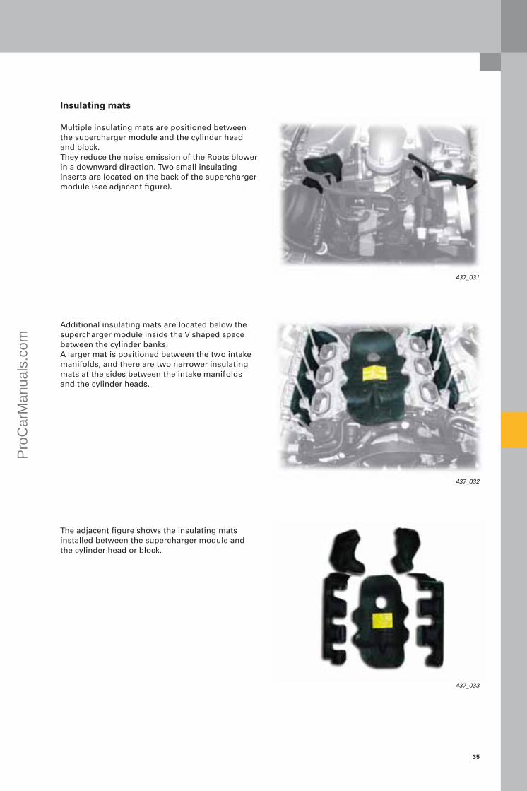
Insulating mats
Multiple insulating mats are positioned between the supercharger module and the cylinder head and block. They reduce the noise emission of the Roots blower in a downward direction. Two small insulating inserts are located on the back of the supercharger module (see adjacent figure).
Additional insulating mats are located below the supercharger module inside the V shaped space between the cylinder banks.A larger mat is positioned between the two intake manifolds, and there are two narrower insulating mats at the sides between the intake manifolds and the cylinder heads.
The adjacent figure shows the insulating mats installed between the supercharger module and the cylinder head or block.
Pro
Car
Man
uals
.com
36
Note
Please refer to the instructions for filling and venting the coolant system in the relevant service literature.
437_013
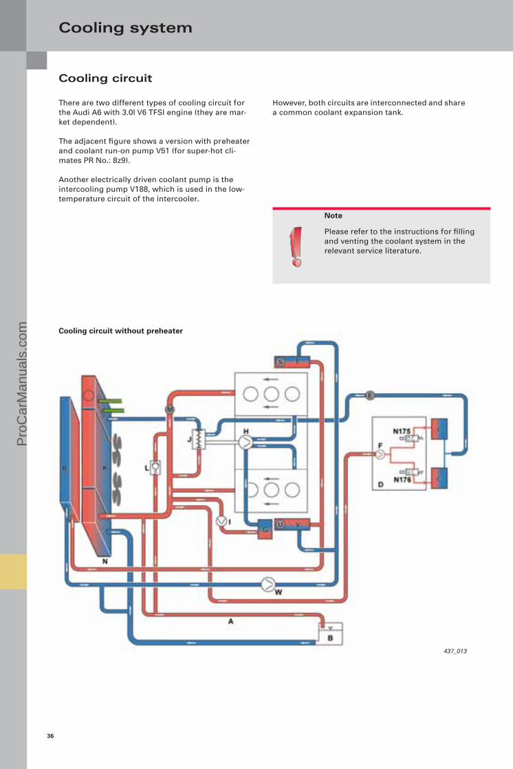
Cooling system
There are two different types of cooling circuit for the Audi A6 with 3.0l V6 TFSI engine (they are mar-ket dependent).
The adjacent figure shows a version with preheater and coolant run-on pump V51 (for super-hot cli-mates PR No.: 8z9).
Another electrically driven coolant pump is the intercooling pump V188, which is used in the low-temperature circuit of the intercooler.
However, both circuits are interconnected and share a common coolant expansion tank.
Cooling circuit without preheater
Cooling circuit
Pro
Car
Man
uals
.com

37
437_012
N ATF coolerN175 Heat regulation valve, leftN176 Heat regulation valve, rightO Recirculation pumpP Pre-heaterQ Heater coolant shut-off valve N279R Auxiliary cooler, frontS Vent screw T Intercooler, right U Vent screw V Intercooler, left W Intercooling pump V188
Cooling circuit with preheater
Legend:
A Vent lineB Expansion tankC Heat exchangerD Pump/valve unit (N175/N176 and V50)E Vent screwF Coolant circulation pump V50G Engine oil coolerH Coolant pumpI Coolant run-on pump (hot climates only)J Coolant thermostatK RadiatorL Non-return valveM Coolant temperature sender G62
Pro
Car
Man
uals
.com

38
437_045
Note
The intercooler must be installed and removed with the utmost care. Follow the instructions given in Workshop Manual.
Intercooler, right
Side seal of intercooler
Cooling system
Charge air cooling (intercooling)
The supercharger module comprises one intercooler per cylinder bank. Coolant flows through the inter-coolers, which are integrated in the intercooling circuit in a parallel configuration.
Intercooler, left
Supercharger module
Vent screws
Intercooler sealing kit
Pro
Car
Man
uals
.com
39
437_046
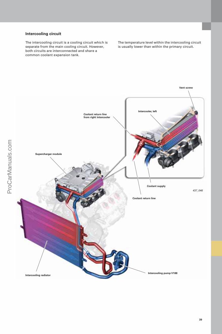
Intercooling circuit
The intercooling circuit is a cooling circuit which is separate from the main cooling circuit. However, both circuits are interconnected and share a common coolant expansion tank.
The temperature level within the intercooling circuit is usually lower than within the primary circuit.
Intercooler, left
Intercooling pump V188
Supercharger module
Intercooling radiator
Coolant supply
Coolant return line
Vent screw
Coolant return line from right intercooler
Pro
Car
Man
uals
.com

40
437_057
Cooling system
How the pump control unit works
The pump is activated in dependence on the tem-perature and pressure downstream of the inter-cooler, both of which are read from a map stored in the engine control unit. In any case, the pump begins to run at a pressure of 1300 mbar or a cool-ant temperature of 50 °C.
The pump is activated by a PWM signal generated by the engine control unit. The pump electronics calculate from this signal the required pump speed and activate the electric motor. If the pump is in order, the pump electronics feed the current pump speed back to the engine control unit. This process repeats itself cyclically through-out the duration of pump operation.
Effects of failure
If the pump electronics detect a fault, the PWM sig-nal will be altered. The modified signal is evaluated by the engine control unit, which initiates a response corresponding to the nature of the fault.
If a fault is found, the fault is stored in the fault memory of the engine control unit.The loss of power due to failure of the pump will only be noticeable when the throttle is wide open. Exhaust emissions are not affected, and no warning lamp is activated.
If the pump fails, no substitute response is initiated in the engine control unit. However, the charge air temperature is monitored. If an excessively high charge air temperature is diagnosed, engine output will be reduced.
If the signal line to the pump is broken or if a short circuit to positive occurs in the signal line, the pump will enter an emergency mode in which it delivers 100 % output. If a short circuit to ground occurs on the signal line, the pump will stop.
Pressure connection
Electrical connection
Intake port
Intercooling pump V188
The intercooling pump V188 is an electrically driven coolant pump. This is the first time it is being used in a cooling system on an Audi car.
It pumps the heated coolant from the intercooler inside the supercharger module to the low-tempera-ture cooler. The lower-temperature cooler is inte-grated in the cooling unit at the front end of the vehicle (in the direction of travel upstream of the radiator). The pump is close coupled to the oil cooler at the front left of the engine bay.
The pump is configured as a centrifugal pump. A centrifugal pump is not selfpriming, and, therefore, must not be allowed to run dry. The pump bearings could otherwise overheat.
The following subassemblies are integrated in the pump module:
– Centrifugal pump– Electric motor– Electronic control unit
The electrical connection of the pump has three pins:
– Battery voltage from the automatic gearbox control unit J271
– PWM signal*– Terminal 31
Pro
Car
Man
uals
.com
41
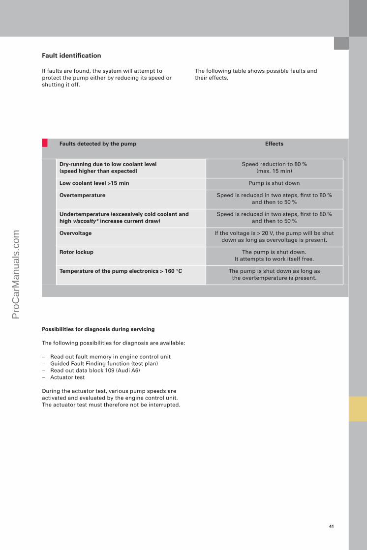
Faults detected by the pump Effects
Dry-running due to low coolant level (speed higher than expected)
Speed reduction to 80 % (max. 15 min)
Low coolant level >15 min Pump is shut down
Overtemperature Speed is reduced in two steps, first to 80 % and then to 50 %
Undertemperature (excessively cold coolant and high viscosity* increase current draw)
Speed is reduced in two steps, first to 80 % and then to 50 %
Overvoltage If the voltage is > 20 V, the pump will be shut down as long as overvoltage is present.
Rotor lockup The pump is shut down.It attempts to work itself free.
Temperature of the pump electronics > 160 °C The pump is shut down as long as the overtemperature is present.
Fault identification
If faults are found, the system will attempt to protect the pump either by reducing its speed or shutting it off.
Possibilities for diagnosis during servicing
The following possibilities for diagnosis are available:
– Read out fault memory in engine control unit– Guided Fault Finding function (test plan)– Read out data block 109 (Audi A6)– Actuator test
During the actuator test, various pump speeds are activated and evaluated by the engine control unit. The actuator test must therefore not be interrupted.
The following table shows possible faults and their effects.
Pro
Car
Man
uals
.com
42
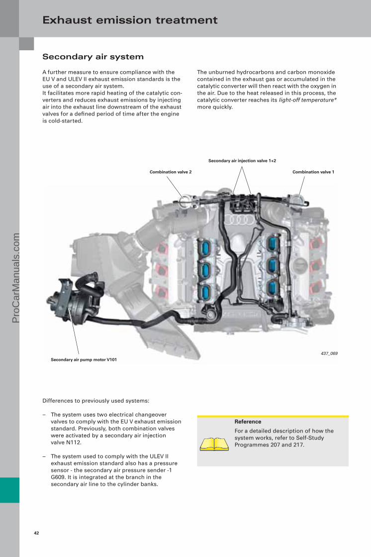
Reference
For a detailed description of how the system works, refer to Self-Study Programmes 207 and 217.
437_069
Exhaust emission treatment
Secondary air system
A further measure to ensure compliance with the EU V and ULEV II exhaust emission standards is the use of a secondary air system. It facilitates more rapid heating of the catalytic con-verters and reduces exhaust emissions by injecting air into the exhaust line downstream of the exhaust valves for a defined period of time after the engine is cold-started.
Differences to previously used systems:
– The system uses two electrical changeover valves to comply with the EU V exhaust emission standard. Previously, both combination valves were activated by a secondary air injection valve N112.
– The system used to comply with the ULEV II exhaust emission standard also has a pressure sensor - the secondary air pressure sender -1 G609. It is integrated at the branch in the secondary air line to the cylinder banks.
The unburned hydrocarbons and carbon monoxide contained in the exhaust gas or accumulated in the catalytic converter will then react with the oxygen in the air. Due to the heat released in this process, the catalytic converter reaches its light-off temperature* more quickly.
Secondary air injection valve 1+2
Combination valve 1
Secondary air pump motor V101
Combination valve 2
Pro
Car
Man
uals
.com

43
437_048
Note
The connectors and hoses of the second-ary air injection valves must not be inter-changed under any circumstances, as otherwise faults can occur in the system.
Testing the system on engines compliant with the EU V exhaust emission standard
The "oxygen sensor based secondary air diagnos-tics" function is used for testing systems on engines classified as compliant with the EU IV exhaust emission standard.
The secondary air mass is computed by the engine control unit on the basis of the changing oxygen content during the secondary air injection phase.However, this diagnosis is not made during normal secondary air operation as the oxygen sensors reach their operating temperature too late. The system is activated separately for diagnostic purposes and checked in several phases.
Measurement phase: The secondary air pump is activated and the sec-ondary air valves (combination valves) are opened. The engine control unit evaluates the signals gener-ated by the oxygen sensors and compares them with the threshold values. If the threshold values are not achieved, a fault is diagnosed.
Offset phase: After the secondary air pump is shut off, the quality of the pilot air-fuel mixture is evaluated. If the deter-mined value deviates too much from the nominal value, the result of the secondary air diagnosis will be rejected. A faulty carburetion cycle is assumed.
Secondary air injection valves
The two secondary air injection valves for activating the two combination valves are located on the back of the motor. They turn the vacuum on and off, and for this pur-pose are activated electrically by the engine control unit. A partial vacuum is supplied by the mechani-cally driven vacuum pump.
Data bus
If the system is faulty, the stipulated exhaust emis-sion limits can be exceeded very quickly. The limit value stipulated by the exhaust emission standard must not be exceeded by more than a factor of 1.5. For this reason, the system is subject to mandatory inspection.
Secondary air inlet valve N112
Combination valve 1 Combination valve 2
Secondary air injection valve 2 N320
Pro
Car
Man
uals
.com

44
Exhaust emission treatment
The pressure based secondary air diagnosis process (see figure)
Phase 0 The control unit is initialised at "ignition On". The signal from the secondary air pressure sender -1 G609 is saved and compared with the signals generated by the ambient pressure sensor and the intake manifold pressure sensor.
Phase 1 When the secondary air mass is injected, the pressure in the secondary air system also increases (to approx. 90 mbar). The rise in pressure is determined by secondary air pressure sender -1 G609. The analogue signal generated by G609 is evaluated by the engine control unit. If it exceeds the set limit value, for example due to a blockage in the system or a leak, a fault entry will be generated. If a fault repeats itself, the engine elec-tronics warning lamp will be activated. If no fault occurs during phase 1, the diagnostic process is continued.
Phases 2.1 and 2.2 During these two phases, a secondary air valve (combination valve) is opened and the other valve closed alternately for a short period of time. The determined values are compared with the value saved in phase 0. Blockages or leaks can thus be determined for each cylinder bank. Even leaks downstream of the combination valves can be identified from the pressure amplitudes.
Phase 2 During this phase, both combination valves are closed and checked for leaks. The value determined by the secondary air pressure sender -1 G609 is evaluated for this purpose.
Phase 3 The secondary air pump is shut off and both combination valves are closed. The difference between the actual measured pressure and the stored value determined in phase 0 is evaluated. A faulty secondary air pump (does not shut off) or faulty secondary air pressure sender -1- G609 can thus be detected.
Testing the system on engines compliant with the ULEV exhaust emission standard (North America and South Korea)
The California Air Resource Board (CARB) requires that the secondary air system be tested during the heat-up phase of the catalytic converter. However, the oxygen sensors do not reach their operating temperature quickly enough for this purpose. This is the reason why a pressure sensor (secondary air pressure sender -1 G609) is used for making the diagnosis. The "pressure based second-ary air diagnostics" function is used.
In this system the signal from G609 is evaluated in the engine control unit. The injected air quantity is determined from the pressure level. Restricted flow, e.g. ingress of dirt into the system downstream of the pressure sensor, causes the pressure level to increase. Restricted flow upstream of the pressure sensor or a leak in the system will cause the pres-sure level to decrease.
Pro
Car
Man
uals
.com

45
1
2
3
5
6
7
8
4
0 1 2.1 2.2 2 3
1
2
3
5
6
Blockage (restricted flow)
Reduced pumping capacity or a blockage upstream of secondary air pressure sender -1 G609
Secondary air pump running (does not shut off)
Combination valve 1 open
Faulty pressure sensor
Secondary air pump running
Combination valve 2 open
Pres
sure
dif
fere
nce
Time
Phases of the secondary air diagnosis process
Phase
Cyl
ind
er b
ank
1
Cyl
ind
er b
ank
2
4 Faulty pressure sensor
7
8
Pro
Car
Man
uals
.com

46
437_058
437_059
Reference
For information on the fuel system, please refer to Self-Study Programme 432, "Audi 1.4l TFSI engine".
Fuel system
Overview
Like the 3.2l V6 FSI engine with Audi valvelift system, the 3.0l V6 TFSI engine uses a supply-on-demand fuel system.
High-pressure fuel pump
A 3rd generation pump is used as the fuel pump. The high-pressure fuel pump is manufactured by Hitachi.
to engine control unit
Battery (positive)
Ground
Fuel metering valve N290
Fuel pump control unit J538
High pressure
Injectors 1, 3, 5N30, N32, N83
Fuel filter
Fuel pressure sender G247
Fuel pressure sender, low pressure G410
Injectors 2, 4, 6N31, N33, N84
Low pressure
Fuel pump G6
depressurised
Pro
Car
Man
uals
.com
47
437_024
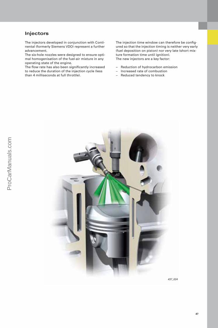
Injectors
The injectors developed in conjunction with Conti-nental (formerly Siemens VDO) represent a further advancement. The six-hole nozzles were designed to ensure opti-mal homogenisation of the fuel-air mixture in any operating state of the engine. The flow rate has also been significantly increased to reduce the duration of the injection cycle (less than 4 milliseconds at full throttle).
The injection time window can therefore be config-ured so that the injection timing is neither very early (fuel deposition on piston) nor very late (short mix-ture formation time until ignition). The new injectors are a key factor:
– Reduction of hydrocarbon emission– Increased rate of combustion– Reduced tendency to knock
Pro
Car
Man
uals
.com

48
Engine management
Sensors
Secondary air pressure sender -1 G609 (for ULEV vehicles only)
Engine speed sender G28
Hall sender G40 (intake, bank 1)Hall sender 2 G163 (intake, bank 2)Hall sender 3 G300 (exhaust, bank 1)Hall sender 4 G301 (exhaust, bank 2)
Accelerator pedal position sender G79Accelerator pedal position sender 2 G185Clutch position sender G476
Brake light switch F
Fuel pressure sender G247Fuel pressure sender, low pressure G410
Knock sensor G61 (bank 1)Knock sensor G66 (bank 2)
Coolant temperature sender G62
Oxygen sensor before catalytic converter G39 (bank 1), G108 (bank 2)Oxygen sensor after catalytic converter G130 (bank 1), G131 (bank 2)
Engine control unit J623
Auxiliary signals: J393 Door contact signalE45 Cruise control system (On/Off)J364 Preheater (87b)J695 Output start relay terminal 50 stage 2J53 Output start relay terminal 50 stage 1J518 Start commandJ518 Terminal 50 at starter
Fuel gauge sender GFuel gauge sender -2- G169
Throttle valve control unit J338Angle sender G188, G187
Oil pressure switch for reduced oil pressure F378
Powertrain CAN data bus
Intake manifold pressure sender G71intake air temperature sensor G42
Charge pressure sender G31, G447Intake manifold pressure sender G72, G430
Control flap control unit J808Control flap potentiometer G584
Intake manifold flap potentiometer G336 (bank 1)Intake manifold flap potentiometer 2 G512 (bank 2)
System overview (Audi A6 of model year 2009)
Oil pressure switch F22
Pro
Car
Man
uals
.com

49
437_035
Actuators
Engine component current supply relay J757
Activated charcoal filter solenoid valve 1 N80
Fuel metering valve N290
Intake camshaft timing adjustment valve 1+2 N205 (intake, bank 1), N208 (intake, bank 2)
Injectors for cylinders 1 – 6 N30 – 33 and N83, N84
Intercooling pump V188
Radiator fan control unit J293Radiator fan V7Radiator fan 2 V177
Electro/hydraulic engine mounting solenoid valves N144, N145
Fuel pump control unit J538Fuel pump (pre-supply pump) G6
Lambda probe heater Z19, Z28, Z29, Z30
Throttle valve control unit J338Throttle-valve drive G186
Ignition coils for cylinders 1 – 6N70, N127, N291, N292, N323, N324
Auxiliary coolant pump relay J496 Coolant run-on pump V51
Oil pressure regulating valve N428
Fuel system diagnostic pump V144(vehicles with fuel system diagnostic pump)
Diagnostic port
Motronic current supply relay J271
Control flap control unit J808Control flap adjustment servomotor V380
Intake manifold flap valve N316
Secondary air pump relay J299Secondary air pump motor V101Secondary air injection valve 1+2 N112, N320
Output signals:Engine speed to automatic gearbox control unit J217 (vehicles with automatic gearbox 01J only)
Pro
Car
Man
uals
.com

50
437_056
Engine management
Engine control unit
The latest generation of engine control unit is used in conjunction with this engine unit. The Simos 8 engine control unit is a joint develop-ment of Audi and Continental (formerly Siemens VDO).
2. Cold start/warm-up phase
During this phase, a dual injection or homogeneous split (HOSP) mode is used. The total quantity of fuel to be injected is divided into two partial quantities and injected into the combustion chamber at different times. The injec-tion time window is before and after the bottom dead centre position of the piston. By the second injection, the intake valves are already closed.
HOSP mode is used in two applications:
– The first application is the "cold start" and is always used. It serves to heat up the catalytic con-verters and takes place at coolant temperatures between -7 °C and 45 °C.
– The second application is the "warm-up", which is only used under heavy engine load when the driver requests a high engine output. It serves to optimise engine load and speed, but also to reduce soot emission. The temperature range for this application is between -20 °C and 45 °C. In this case, the second injection is later than during the cold start phase.
Operating modes
The FSI injection process is configured for homoge-neous mixture formation. The complete fuel charge is injected into the com-bustion chamber during the intake phase.This does not include the engine start and warm-up phases, during which the following operating modes are used.
1. Engine start
In the start phase of the engine, a high-pressure stratified start mode is implemented. For this purpose, the fuel pressure is increased to 45 – 100 bar. The fuel pressure level is dependent on the engine temperature. At low temperatures, the fuel pressure is higher.
High-pressure stratified starting takes place at cool-ant temperatures between -24 °C and at operating temperature (90 °C). At coolant temperatures below -24 °C, starting takes place at low pressure to protect the components. The pressure is identical to the pressure in the elec-trical fuel pump in the fuel tank.
During the development process, special emphasis was placed on throttle-free load regulation (refer to "Load regulation").
Pro
Car
Man
uals
.com
51
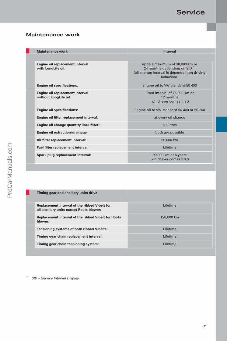
Timing gear and ancillary units drive
Replacement interval of the ribbed V-belt for all ancillary units except Roots blower:
Lifetime
Replacement interval of the ribbed V-belt for Roots blower:
120,000 km
Tensioning systems of both ribbed V-belts: Lifetime
Timing gear chain replacement interval: Lifetime
Timing gear chain tensioning system: Lifetime
Maintenance work Interval
Engine oil replacement interval with LongLife oil:
Engine oil specifications:
up to a maximum of 30,000 km or24 months depending on SID 1)
(oil change interval is dependent on driving behaviour)
Engine oil to VW standard 50 400
Engine oil replacement intervalwithout LongLife oil:
Engine oil specifications:
Fixed interval of 15,000 km or12 months
(whichever comes first)
Engine oil to VW standard 50 400 or 50 200
Engine oil filter replacement interval: at every oil change
Engine oil change quantity (incl. filter): 6.5 litres
Engine oil extraction/drainage: both are possible
Air filter replacement interval: 90,000 km
Fuel filter replacement interval: Lifetime
Spark plug replacement interval: 90,000 km or 6 years (whichever comes first)
1) SID = Service Interval Display
Maintenance work
ServiceP
roC
arM
anua
ls.c
om

52
437_075437_063
Service
Special tools
Here you can see the special tools for the 3.0l V6 TFSI engine with Roots blower.
T40206/1 Gearbox support plate T40206/2 Mount for supercharger module
Pro
Car
Man
uals
.com

53
Helmholtz resonatorA Helmholtz resonator is an acoustic resonator designed to reduce intake noise. It consists of an air space with a narrow opening to the exterior. The Helmholtz resonator was named after the German physicist Hermann von Helmholtz.
ViscosityAn important physical property of liquids is their viscosity. Viscosity is temperature dependent and is a measure of how "thick" a liquid is at different tem-peratures. The viscosity of oils is specified as a vis-cosity index. This index describes the flow behaviour of an oil at different temperatures.
Annex
Glossary
This glossary explains to you all terms written in italics or indicated by an asterisk (*) in this Self-Study Programme.
EMCThis abbreviation stands for Electromagnetic Com-patibility. It is defined as the ability of equipment electrical and electronic equipment to operate effectively in close proximity without causing mutual interference through unwanted electrical or electromagnetic effects.
Cracked con-rodThis name derives from the manufacturing process. In this process the con-rod shaft and the big end bearing cover are separated from one another by breaking (cracking) them at a pre-determined point. The advantage of this process is that the finished parts fit one another perfectly.
Valve timingThe term "valve timing" is used to describe the periods during which the valves of an engine are opened or closed. If the angular ranges of the valves are transferred to a pie chart, the result will be the timing diagram of an engine.
Blow-by gasesBlow-by gases are also known as leakage gases. When the engine running, blow-by gases flow from the combustion chamber and past the piston into the crankcase. This is due to the high pressure inside the combustion chamber and the absolutely normal leakage that occurs around the piston rings. Blow-by gases are extracted from the crankcase by the PCV system and admitted into the combustion chamber.
PWM signalThe abbreviation PWM stands for Pulse Width Mod-ulated signal. A PWM signal is a digital signal where one variable (e.g. electrical current) alternates between two values. The length of the interval between this change-over varies depending on activation level. In this way, it is possible to transmit digital signals.
Hall senderThe Hall sender (also known as Hall sensor or Hall probe) utilises the Hall effect to measure magnetic fields and currents, and for position sensing. If a Hall sensor is energised with electrical current and placed into a vertical magnetic field, it will supply an output voltage proportional to the product of the magnetic field strength and the electrical current.
Split-pin designDepending on engine type, the crank pin has an off-set (also referred to as split pin") due to the V angle or cylinder bank angle. This configuration is neces-sary to achieve a uniform firing interval.
Light-off temperatureThe temperature at which the conversion rate of the catalytic converter is 50 %. The light-off temperature is highly relevant to future and US exhaust emission standards, as they stipulate low emissions even when the engine is cold.
Pro
Car
Man
uals
.com

54
437_064
Annex
Test yourself
Which of the following answers is correct?Sometimes only one answer can be chosen.At other times, more than one answer may be correct – or all of them!
1. Why is a Roots blower based charging system used on the 3.0l V6 TFSI engine?
A The engine achieves good starting performance and has a wide range of characteristicsfrom comfort-oriented to ultra-sporty.
B Thanks to the characteristic resulting from supercharging, the engine is suitable for use in multiple models (ranging from the Audi A4 to the A8).
C Forthcoming exhaust emission standards cannot be met by using an exhaust turbocharger.
2. What are the advantages of a Roots blower over an exhaust turbocharger?
A Low cost of manufacture and low weight.B The compressed air paths to the cylinders are very short, resulting in extremely quick response.C Better exhaust emission characteristics because the catalytic converter reaches its operating
temperature more quickly.
3. Why is a bypass valve located in the supercharger module?
A To increase charge pressure when high output is requested.B It eliminates the need for complex shut-off of the Roots blower belt drive.C To regulate the charge pressure.
4. Please identify the component parts of the Roots blower!
1 ............................................
2 ............................................
3 ............................................
4 ............................................
5 ............................................
Solutions:
1.A, B; 2.B, C;3. B, C;4.1 = damping plate, 2 = main throttle valve,
3 = bypass valve, 4 = rotors, 5 = intercooler
Pro
Car
Man
uals
.com
55
437_060 437_061 437_062 437_065
From the glorious 1930s tradition of motor sport dominated by cars bearing the four-ring badge, the Roots blower is now staging a comeback. The new 3.0l TFSI engine is not only powerful, extremely quick and ultra-efficient. It is also the new top version in Audi's V6 engine range, and sets impressive benchmarks for fuel economy and clean emissions. The engine is notable for its sporty throttle response, exceptional agility and "bite". It revs up to its 6,500 rpm maximum with playful ease, achieving its rated output of 213 kW (290 bhp) at just under 5,000 rpm.
All this has been achieved thanks to an array of refined high-tech features. The crankcase has been adapted to the higher prevailing pressures, and all components have been systemat-ically optimised for minimal friction. Both intake camshafts can be adjusted through 42° crankshaft angle. In the intake ports, tumble flaps induce a tumbling movement in the incoming air to optimise mixture formation.
The improved fuel system with its new six-hole nozzles will allow up to three injections per working cycle in future. The engine's high compression ratio of 10.5:1 is also a major factor in enhancing efficiency. The direct injection principle is once again the key, because the intensively swirled fuel cools the combustion chamber, reducing the tendency to knock. Inside the Roots blower, two four-vane rotary pistons counter-rotate at a speed of up to 23,000 rpm, delivering 1,000 kg of air per hour and forcing it into the combustion chambers at a boost pressure of up to 0.8 bar. Two water-to-air intercoolers integrated in the supercharger module enhanced efficiency still further. An extensive package of measures reduces the level of noise generated by the Roots blower to a minimum.
The new 3.0l TFSI engine will achieve an average fuel consumption of well under 10 litres per 100 km in virtu-ally all longitudinally engined Audi models, for which it had been earmarked. As with all Audi innovations, the engine fully embraces the principle of "Vorsprung durch Technik".
Self-Study Programmes
In this Self-Study Programme you will find all you need to know about this engine presented in a summarised form. For more information on the subsystems mentioned in this document, please refer to the relevant Self-Study Programmes.
SSP 411 Audi 2.8l and 3.2l FSI Engines with Audi Valvelift SystemSSP 432 Audi 1.4l TFSI EngineSSP 325 Audi A6 ‘05 Engines and TransmissionsSSP 207 The Audi TT Coupé
SummaryP
roC
arM
anua
ls.c
om

43
7
All rights reserved. Technical specifications subject to change without notice.
CopyrightAUDI AGI/[email protected] +49-841/89-36367
AUDI AGD-85045 IngolstadtTechnical status: 10/08
Printed in GermanyA08.5S00.53.20
Vorsprung durch Technik
www.audi.co.uk
Pro
Car
Man
uals
.com