The 2019 Audi A8 Introduction - NHTSA
106
The 2019 Audi A8 Introduction eSelf-Study Program 990493
-
Upload
khangminh22 -
Category
Documents
-
view
9 -
download
0
Transcript of The 2019 Audi A8 Introduction - NHTSA
The 2019 Audi A8 IntroductioneSelf-Study Program 990493
ii
Audi of America, LLC Service Training Created in the U.S.A. Created 05/2018
Course Number 990493
©2018 Audi of America, LLC
All rights reserved. Information contained in this manual is based on the latest information available at the time of printing and is subject to the copyright and other intellectual property rights of Audi of America, LLC., its affiliated companies and its licensors. All rights are reserved to make changes at any time without notice. No part of this document may be reproduced, stored in a retrieval system, or transmitted in any form or by any means, electronic, mechanical, photocopying, recording or otherwise, nor may these materials be modified or reposted to other sites without the prior expressed written permission of the publisher.All requests for permission to copy and redistribute information should be referred to Audi of America, LLC.
Always check Technical Bulletins and the latest electronic service repair literature for information that may supersede any information included in this booklet.
Revision:1-June_2018
iii
Introduction 1Overview 2Dimensions 4
Body 6Introduction 6Attachments 10Interior equipment 12Roof 17
Engine 18Powertrain 19Fuel tank 20Exhaust system for the 3.0l TFSI engine 22
Power transmission 26Overview 26Automatic transmission selector mechanism 28Parking lock emergency release 298-speed automatic transmission 0D5 30Functions influencing the transmission and sport differential 37
Suspension 40Overview 40Axles and wheel alignment 41Adaptive air suspension 42Steering system 43Suspension 44Wheels and tires 45
Electrics and electronics 46Installation locations of the control modules 47
Climate control 48New features 49
Safety and driver assistance systems 50Passive safety 50Active safety 68Driver assistance systems 92
Infotainment and Audi connect 96Overview of versions 96
Inspection and maintenance 98Overview 98Special tools and workshop equipment 99
Appendix 100eSelf-Study Program 100
Knowledge assessment 101
iv
Note
Reference
The eSelf-Study Program (eSSP) teaches a basic understanding of the design and mode of operation of new models, new automotive components or new technologies. It is not a repair manual! Figures are given for explanatory purposes only and refer to the data valid at the time of preparation of the SSP.
For further information about maintenance and repair work, always refer to the current technical literature.
This eSSP contains video links which you
can use to access interactive media.
1
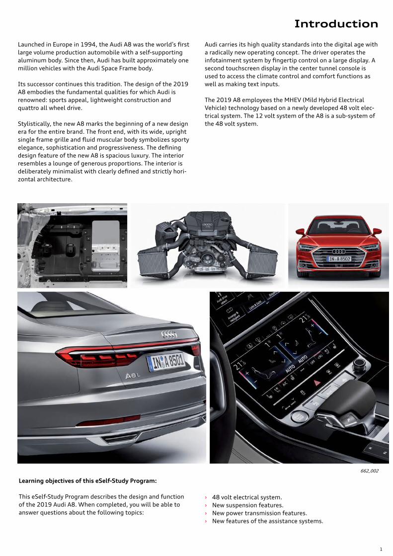
Learning objectives of this eSelf-Study Program:
This eSelf-Study Program describes the design and function of the 2019 Audi A8. When completed, you will be able to answer questions about the following topics:
› 48 volt electrical system. › New suspension features. › New power transmission features. › New features of the assistance systems.
662_002
Launched in Europe in 1994, the Audi A8 was the world’s first large volume production automobile with a self-supporting aluminum body. Since then, Audi has built approximately one million vehicles with the Audi Space Frame body.
Its successor continues this tradition. The design of the 2019 A8 embodies the fundamental qualities for which Audi is renowned: sports appeal, lightweight construction and quattro all wheel drive.
Stylistically, the new A8 marks the beginning of a new design era for the entire brand. The front end, with its wide, upright single frame grille and fluid muscular body symbolizes sporty elegance, sophistication and progressiveness. The defining design feature of the new A8 is spacious luxury. The interior resembles a lounge of generous proportions. The interior is deliberately minimalist with clearly defined and strictly hori-zontal architecture.
Audi carries its high quality standards into the digital age with a radically new operating concept. The driver operates the infotainment system by fingertip control on a large display. A second touchscreen display in the center tunnel console is used to access the climate control and comfort functions as well as making text inputs.
The 2019 A8 employees the MHEV (Mild Hybrid Electrical Vehicle) technology based on a newly developed 48 volt elec-trical system. The 12 volt system of the A8 is a sub-system of the 48 volt system.
Introduction
2
Overview
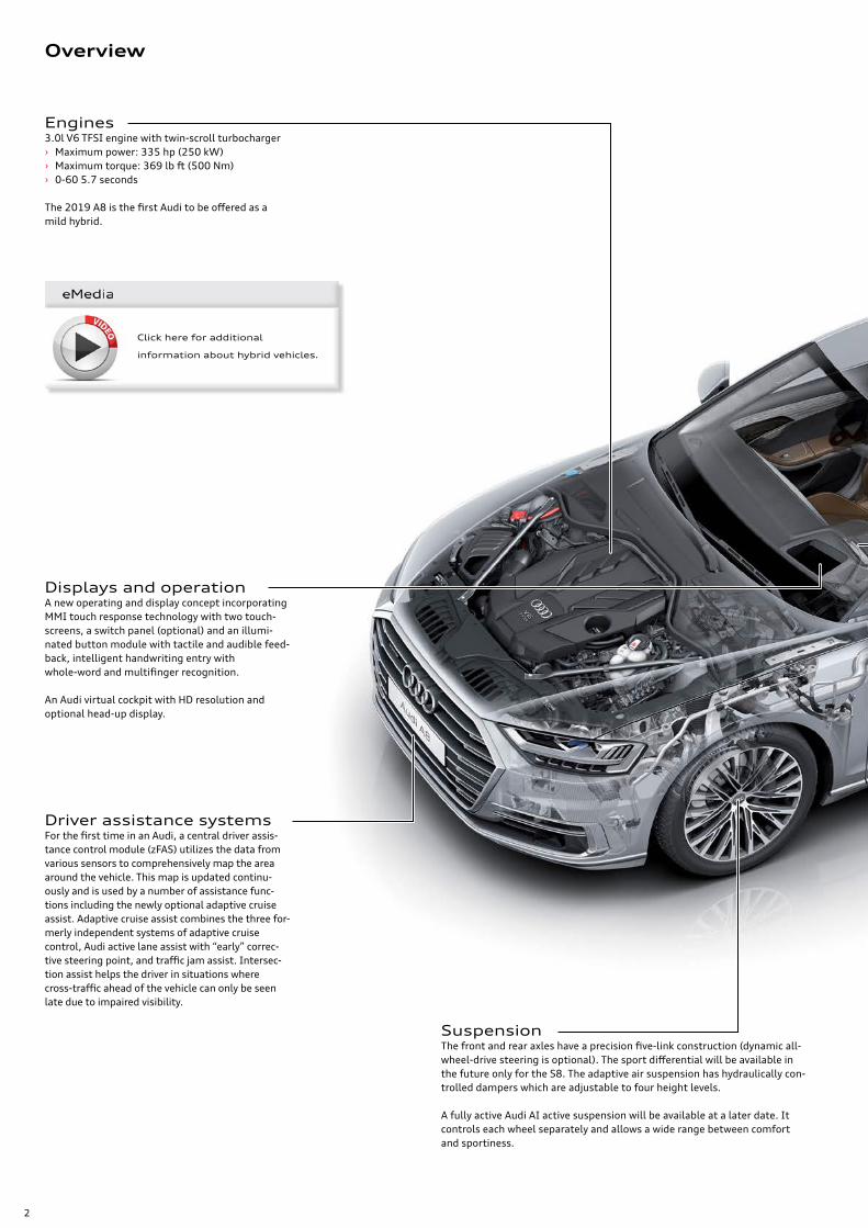
Engines3.0l V6 TFSI engine with twin-scroll turbocharger › Maximum power: 335 hp (250 kW) › Maximum torque: 369 lb ft (500 Nm) › 0-60 5.7 seconds
The 2019 A8 is the first Audi to be offered as a mild hybrid.
SuspensionThe front and rear axles have a precision five-link construction (dynamic all-wheel-drive steering is optional). The sport differential will be available in the future only for the S8. The adaptive air suspension has hydraulically con-trolled dampers which are adjustable to four height levels.
A fully active Audi AI active suspension will be available at a later date. It controls each wheel separately and allows a wide range between comfort and sportiness.
Displays and operationA new operating and display concept incorporating MMI touch response technology with two touch-screens, a switch panel (optional) and an illumi-nated button module with tactile and audible feed-back, intelligent handwriting entry with whole-word and multifinger recognition.
An Audi virtual cockpit with HD resolution and optional head-up display.
Driver assistance systemsFor the first time in an Audi, a central driver assis-tance control module (zFAS) utilizes the data from various sensors to comprehensively map the area around the vehicle. This map is updated continu-ously and is used by a number of assistance func-tions including the newly optional adaptive cruise assist. Adaptive cruise assist combines the three for-merly independent systems of adaptive cruise control, Audi active lane assist with “early” correc-tive steering point, and traffic jam assist. Intersec-tion assist helps the driver in situations where cross-traffic ahead of the vehicle can only be seen late due to impaired visibility.
Click here for additional
information about hybrid vehicles.
3
662_068
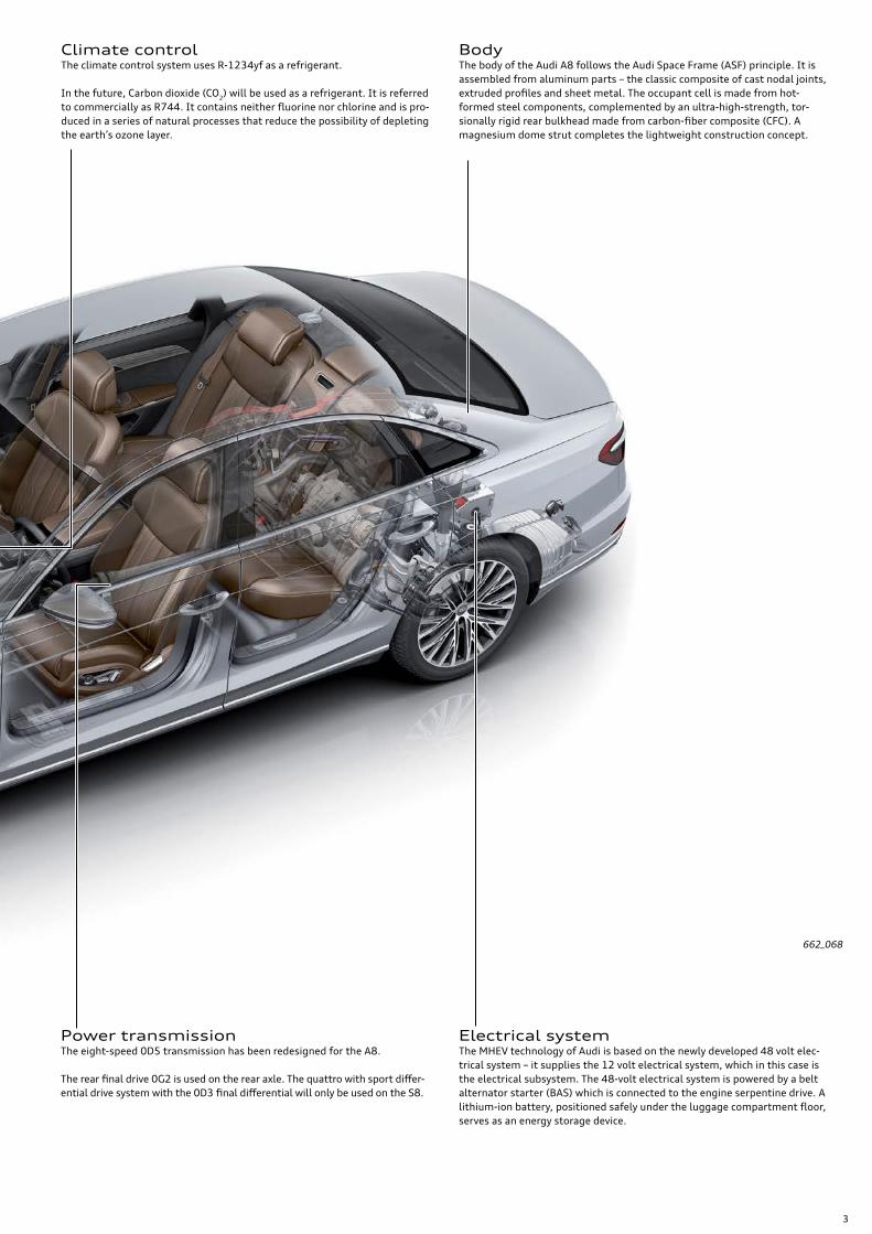
Electrical systemThe MHEV technology of Audi is based on the newly developed 48 volt elec-trical system – it supplies the 12 volt electrical system, which in this case is the electrical subsystem. The 48-volt electrical system is powered by a belt alternator starter (BAS) which is connected to the engine serpentine drive. A lithium-ion battery, positioned safely under the luggage compartment floor, serves as an energy storage device.
Power transmissionThe eight-speed 0D5 transmission has been redesigned for the A8.
The rear final drive 0G2 is used on the rear axle. The quattro with sport differ-ential drive system with the 0D3 final differential will only be used on the S8.
Climate controlThe climate control system uses R-1234yf as a refrigerant.
In the future, Carbon dioxide (CO2) will be used as a refrigerant. It is referred to commercially as R744. It contains neither fluorine nor chlorine and is pro-duced in a series of natural processes that reduce the possibility of depleting the earth’s ozone layer.
BodyThe body of the Audi A8 follows the Audi Space Frame (ASF) principle. It is assembled from aluminum parts – the classic composite of cast nodal joints, extruded profiles and sheet metal. The occupant cell is made from hot-formed steel components, complemented by an ultra-high-strength, tor-sionally rigid rear bulkhead made from carbon-fiber composite (CFC). A magnesium dome strut completes the lightweight construction concept.
4
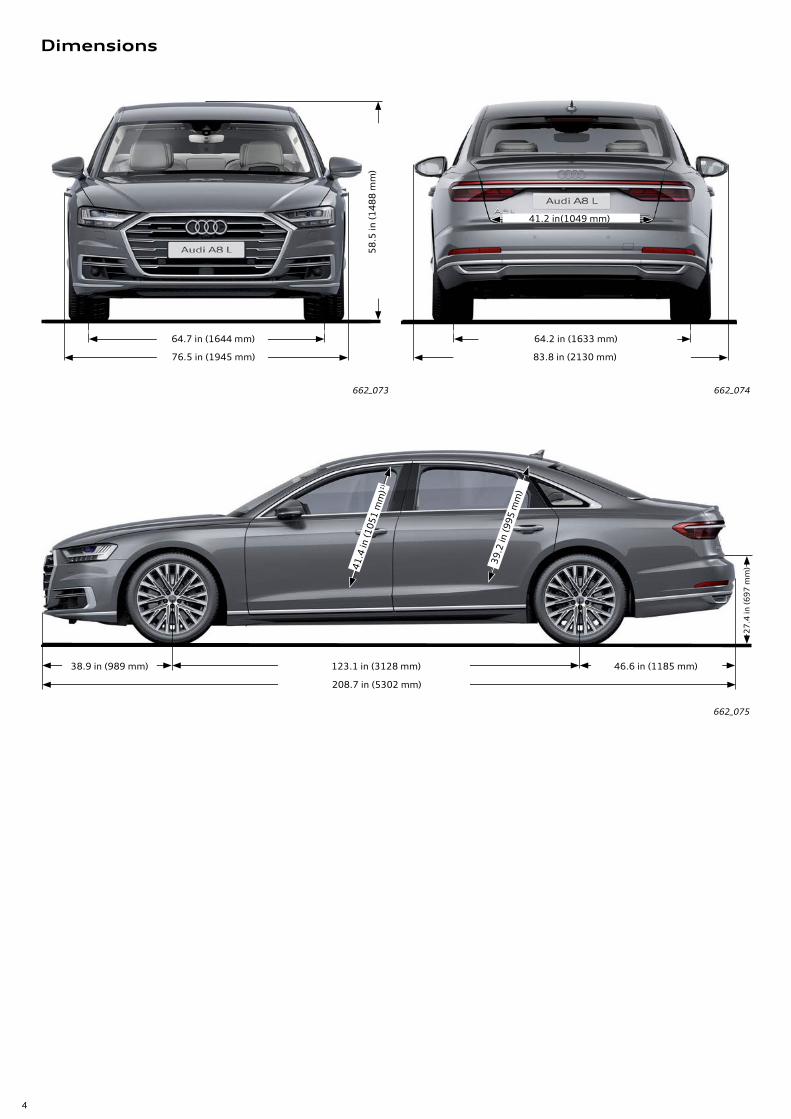
64.7 in (1644 mm)
76.5 in (1945 mm)5
8.5
in (
14
88
mm
)
64.2 in (1633 mm)
83.8 in (2130 mm)
41.2 in(1049 mm)
46.6 in (1185 mm)123.1 in (3128 mm)
208.7 in (5302 mm)
38.9 in (989 mm)
39.2
in (9
95 m
m)
27
.4 in
(6
97
mm
)41.4
in (1
051
mm
)1)
Dimensions
662_073 662_074
662_075
5
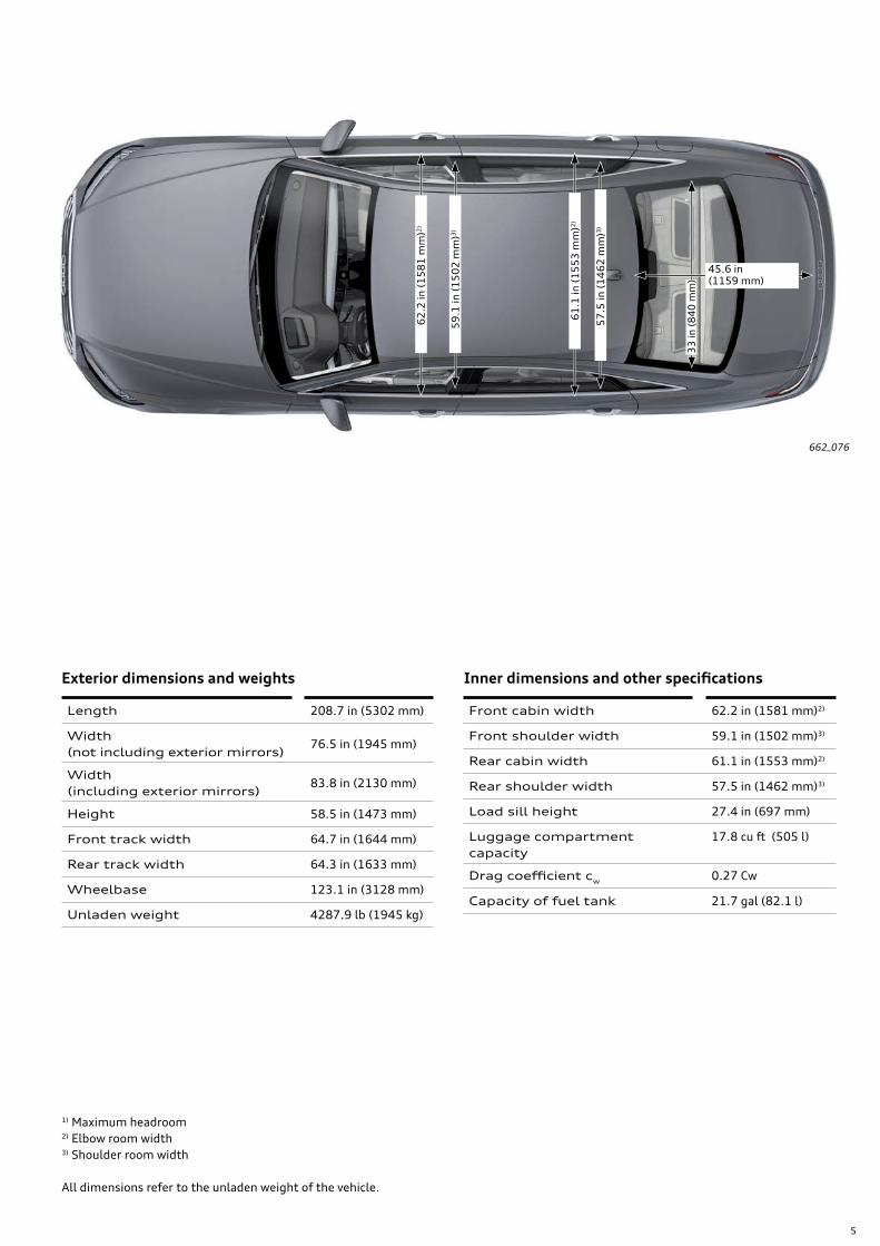
33
in (
84
0 m
m)
45.6 in (1159 mm)
59
.1 in
(1
50
2 m
m)3
)
57
.5 in
(1
46
2 m
m)3
)
62
.2 in
(1
58
1 m
m)2
)
61
.1 in
(1
55
3 m
m)2
)
662_076
1) Maximum headroom2) Elbow room width3) Shoulder room width
All dimensions refer to the unladen weight of the vehicle.
Exterior dimensions and weights
Length 208.7 in (5302 mm)
Width (not including exterior mirrors)
76.5 in (1945 mm)
Width (including exterior mirrors)
83.8 in (2130 mm)
Height 58.5 in (1473 mm)
Front track width 64.7 in (1644 mm)
Rear track width 64.3 in (1633 mm)
Wheelbase 123.1 in (3128 mm)
Unladen weight 4287.9 lb (1945 kg)
Inner dimensions and other specifications
Front cabin width 62.2 in (1581 mm)2)
Front shoulder width 59.1 in (1502 mm)3)
Rear cabin width 61.1 in (1553 mm)2)
Rear shoulder width 57.5 in (1462 mm)3)
Load sill height 27.4 in (697 mm)
Luggage compartment capacity
17.8 cu ft (505 l)
Drag coefficient cw 0.27 Cw
Capacity of fuel tank 21.7 gal (82.1 l)
6
Introduction
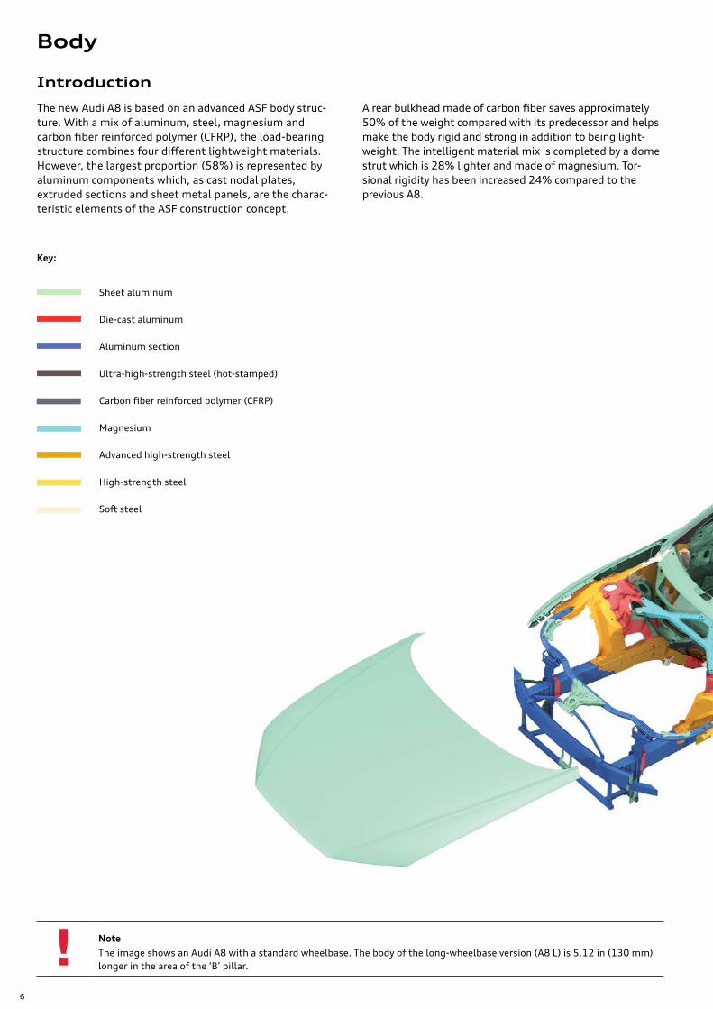
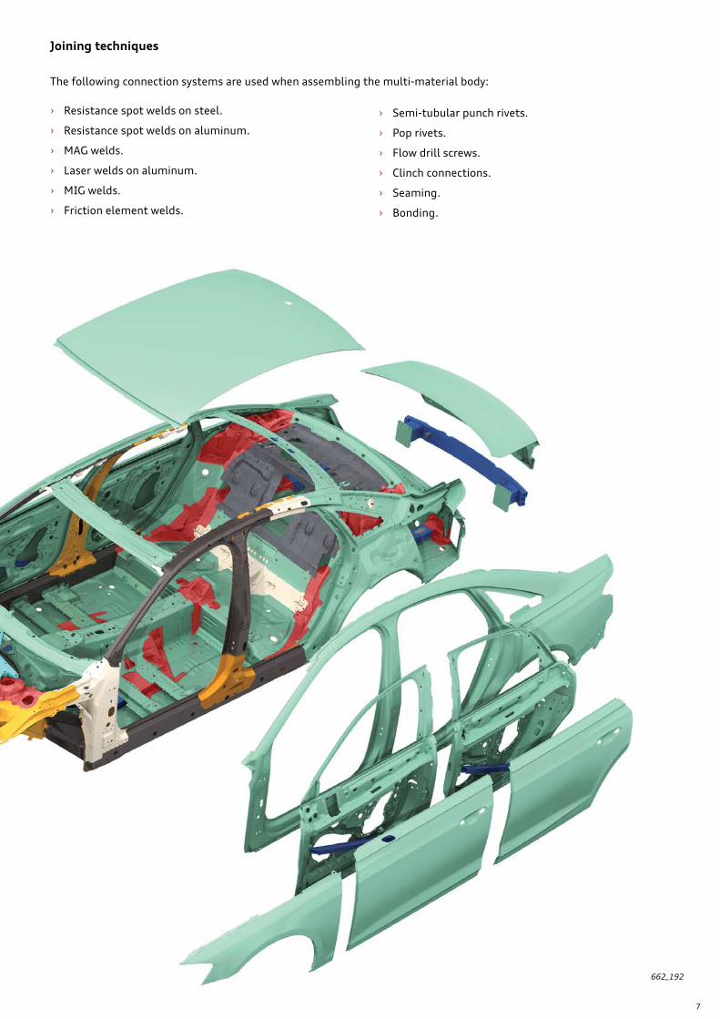
The new Audi A8 is based on an advanced ASF body struc-ture. With a mix of aluminum, steel, magnesium and carbon fiber reinforced polymer (CFRP), the load-bearing structure combines four different lightweight materials. However, the largest proportion (58%) is represented by aluminum components which, as cast nodal plates, extruded sections and sheet metal panels, are the charac-teristic elements of the ASF construction concept.
NoteThe image shows an Audi A8 with a standard wheelbase. The body of the long-wheelbase version (A8 L) is 5.12 in (130 mm) longer in the area of the ‘B’ pillar.
Key:
Sheet aluminum
Die-cast aluminum
Aluminum section
Ultra-high-strength steel (hot-stamped)
Carbon fiber reinforced polymer (CFRP)
Magnesium
Advanced high-strength steel
High-strength steel
Soft steel
A rear bulkhead made of carbon fiber saves approximately 50% of the weight compared with its predecessor and helps make the body rigid and strong in addition to being light-weight. The intelligent material mix is completed by a dome strut which is 28% lighter and made of magnesium. Tor-sional rigidity has been increased 24% compared to the previous A8.
Body
7
The following connection systems are used when assembling the multi-material body:
› Resistance spot welds on steel.
› Resistance spot welds on aluminum.
› MAG welds.
› Laser welds on aluminum.
› MIG welds.
› Friction element welds.
662_192
› Semi-tubular punch rivets.
› Pop rivets.
› Flow drill screws.
› Clinch connections.
› Seaming.
› Bonding.
Joining techniques
8
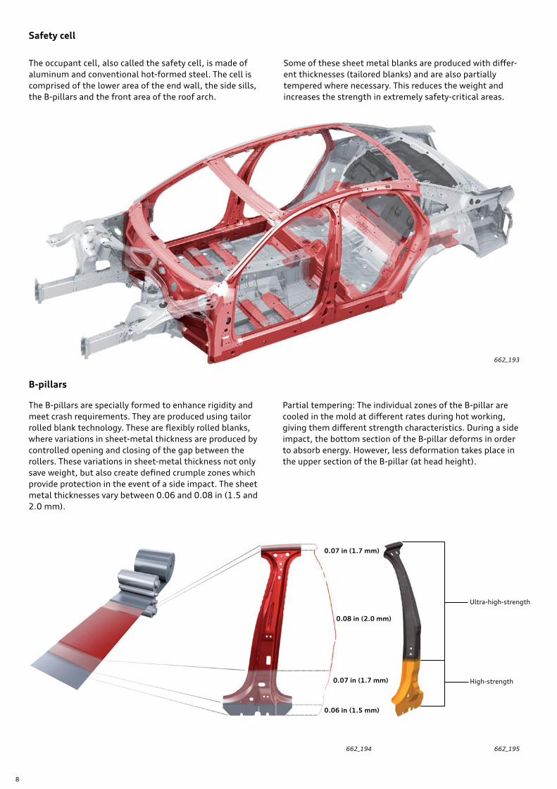
The occupant cell, also called the safety cell, is made of aluminum and conventional hot-formed steel. The cell is comprised of the lower area of the end wall, the side sills, the B-pillars and the front area of the roof arch.
Some of these sheet metal blanks are produced with differ-ent thicknesses (tailored blanks) and are also partially tempered where necessary. This reduces the weight and increases the strength in extremely safety-critical areas.
Safety cell
The B-pillars are specially formed to enhance rigidity and meet crash requirements. They are produced using tailor rolled blank technology. These are flexibly rolled blanks, where variations in sheet-metal thickness are produced by controlled opening and closing of the gap between the rollers. These variations in sheet-metal thickness not only save weight, but also create defined crumple zones which provide protection in the event of a side impact. The sheet metal thicknesses vary between 0.06 and 0.08 in (1.5 and 2.0 mm).
Partial tempering: The individual zones of the B-pillar are cooled in the mold at different rates during hot working, giving them different strength characteristics. During a side impact, the bottom section of the B-pillar deforms in order to absorb energy. However, less deformation takes place in the upper section of the B-pillar (at head height).
B-pillars
662_193
662_194 662_195
Ultra-high-strength
High-strength
0.07 in (1.7 mm)
0.08 in (2.0 mm)
0.07 in (1.7 mm)
0.06 in (1.5 mm)
9
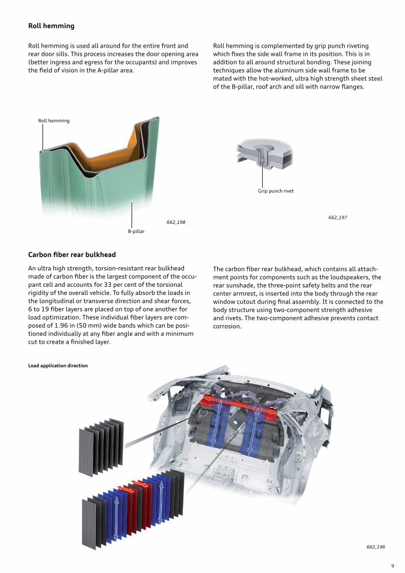
An ultra high strength, torsion-resistant rear bulkhead made of carbon fiber is the largest component of the occu-pant cell and accounts for 33 per cent of the torsional rigidity of the overall vehicle. To fully absorb the loads in the longitudinal or transverse direction and shear forces, 6 to 19 fiber layers are placed on top of one another for load optimization. These individual fiber layers are com-posed of 1.96 in (50 mm) wide bands which can be posi-tioned individually at any fiber angle and with a minimum cut to create a finished layer.
The carbon fiber rear bulkhead, which contains all attach-ment points for components such as the loudspeakers, the rear sunshade, the three-point safety belts and the rear center armrest, is inserted into the body through the rear window cutout during final assembly. It is connected to the body structure using two-component strength adhesive and rivets. The two-component adhesive prevents contact corrosion.
Roll hemming is used all around for the entire front and rear door sills. This process increases the door opening area (better ingress and egress for the occupants) and improves the field of vision in the A-pillar area.
Roll hemming is complemented by grip punch riveting which fixes the side wall frame in its position. This is in addition to all around structural bonding. These joining techniques allow the aluminum side wall frame to be mated with the hot-worked, ultra high strength sheet steel of the B-pillar, roof arch and sill with narrow flanges.
Carbon fiber rear bulkhead
Roll hemming
662_196
662_197
Grip punch rivet
662_198
Roll hemming
B-pillar
Load application direction
10
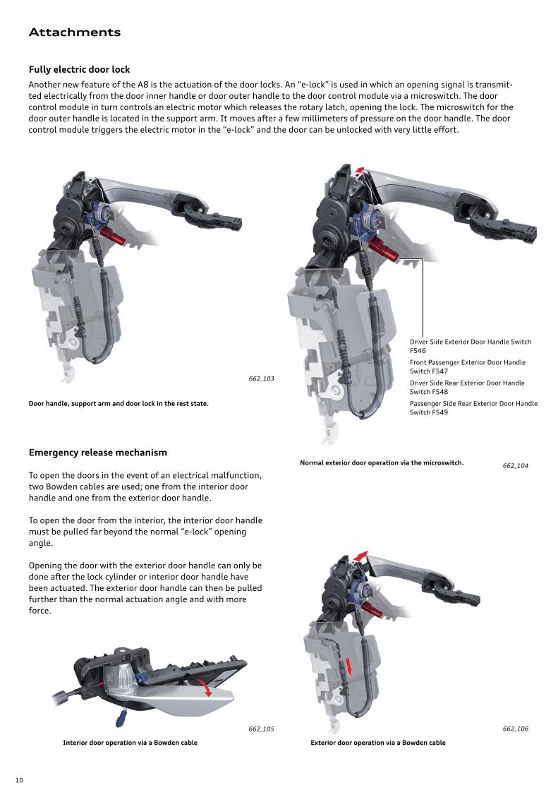
Fully electric door lock
662_106
Another new feature of the A8 is the actuation of the door locks. An “e-lock” is used in which an opening signal is transmit-ted electrically from the door inner handle or door outer handle to the door control module via a microswitch. The door control module in turn controls an electric motor which releases the rotary latch, opening the lock. The microswitch for the door outer handle is located in the support arm. It moves after a few millimeters of pressure on the door handle. The door control module triggers the electric motor in the “e-lock” and the door can be unlocked with very little effort.
662_103
662_105
662_104
Emergency release mechanism
To open the doors in the event of an electrical malfunction, two Bowden cables are used; one from the interior door handle and one from the exterior door handle.
To open the door from the interior, the interior door handle must be pulled far beyond the normal “e-lock” opening angle.
Opening the door with the exterior door handle can only be done after the lock cylinder or interior door handle have been actuated. The exterior door handle can then be pulled further than the normal actuation angle and with more force.
Door handle, support arm and door lock in the rest state.
Normal exterior door operation via the microswitch.
Interior door operation via a Bowden cable Exterior door operation via a Bowden cable
Driver Side Exterior Door Handle Switch F546
Front Passenger Exterior Door Handle Switch F547
Driver Side Rear Exterior Door Handle Switch F548
Passenger Side Rear Exterior Door Handle Switch F549
Attachments
11
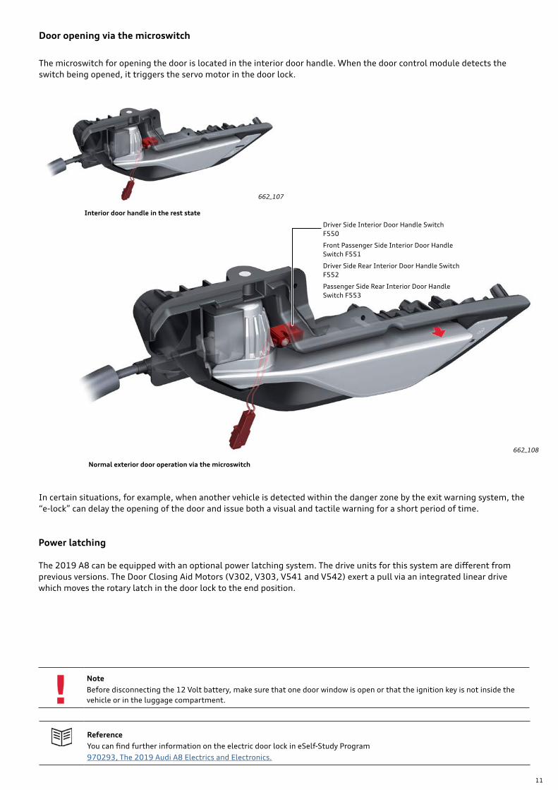
Door opening via the microswitch
In certain situations, for example, when another vehicle is detected within the danger zone by the exit warning system, the “e-lock” can delay the opening of the door and issue both a visual and tactile warning for a short period of time.
Power latching
The 2019 A8 can be equipped with an optional power latching system. The drive units for this system are different from previous versions. The Door Closing Aid Motors (V302, V303, V541 and V542) exert a pull via an integrated linear drive which moves the rotary latch in the door lock to the end position.
Normal exterior door operation via the microswitch
Interior door handle in the rest state
Driver Side Interior Door Handle Switch F550
Front Passenger Side Interior Door Handle Switch F551
Driver Side Rear Interior Door Handle Switch F552
Passenger Side Rear Interior Door Handle Switch F553
662_107
662_108
ReferenceYou can find further information on the electric door lock in eSelf-Study Program 970293, The 2019 Audi A8 Electrics and Electronics.
The microswitch for opening the door is located in the interior door handle. When the door control module detects the switch being opened, it triggers the servo motor in the door lock.
NoteBefore disconnecting the 12 Volt battery, make sure that one door window is open or that the ignition key is not inside the vehicle or in the luggage compartment.
12
Interior equipment
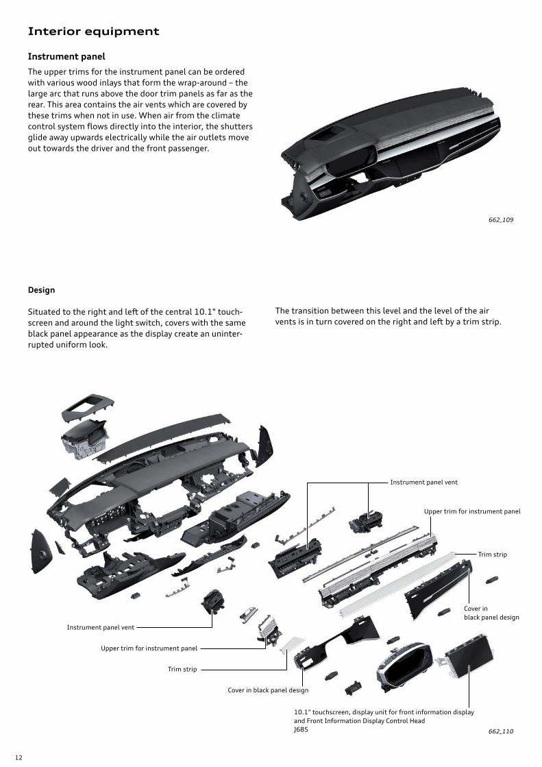
Instrument panel
The upper trims for the instrument panel can be ordered with various wood inlays that form the wrap-around – the large arc that runs above the door trim panels as far as the rear. This area contains the air vents which are covered by these trims when not in use. When air from the climate control system flows directly into the interior, the shutters glide away upwards electrically while the air outlets move out towards the driver and the front passenger.
Design
Situated to the right and left of the central 10.1" touch-screen and around the light switch, covers with the same black panel appearance as the display create an uninter-rupted uniform look.
The transition between this level and the level of the air vents is in turn covered on the right and left by a trim strip.
662_109
662_110
Instrument panel vent
Upper trim for instrument panel
10.1" touchscreen, display unit for front information display and Front Information Display Control Head J685
Trim strip
Cover in black panel design
Cover in black panel design
Trim strip
Upper trim for instrument panel
Instrument panel vent
13
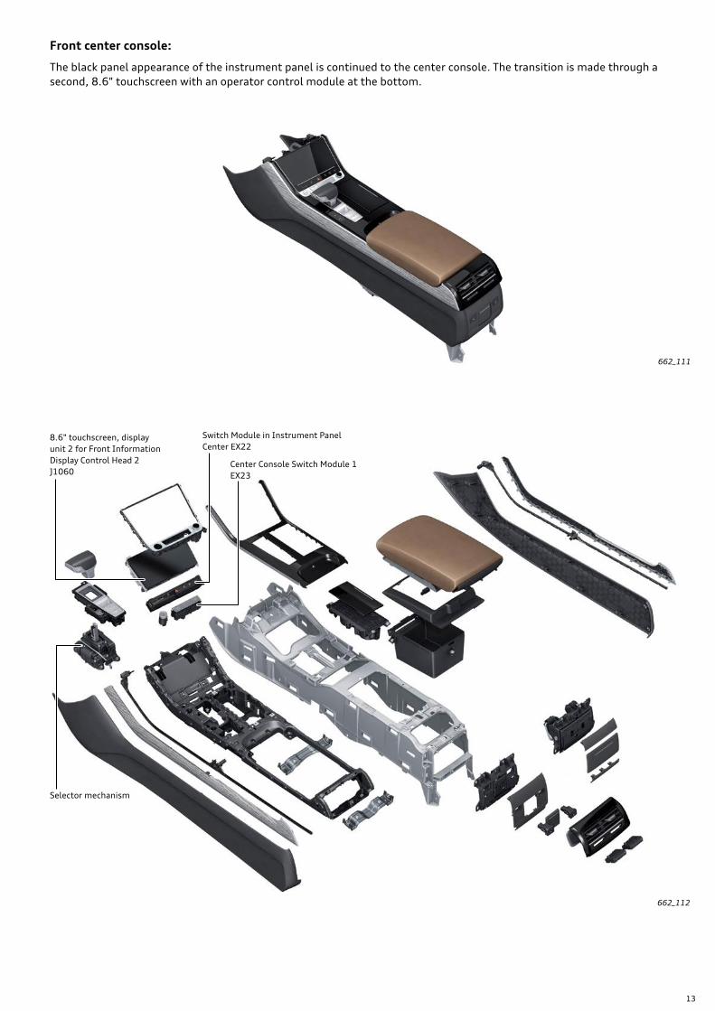
Front center console:
The black panel appearance of the instrument panel is continued to the center console. The transition is made through a second, 8.6" touchscreen with an operator control module at the bottom.
662_111
662_112
8.6" touchscreen, display unit 2 for Front Information Display Control Head 2 J1060
Selector mechanism
Switch Module in Instrument Panel Center EX22
Center Console Switch Module 1 EX23
14
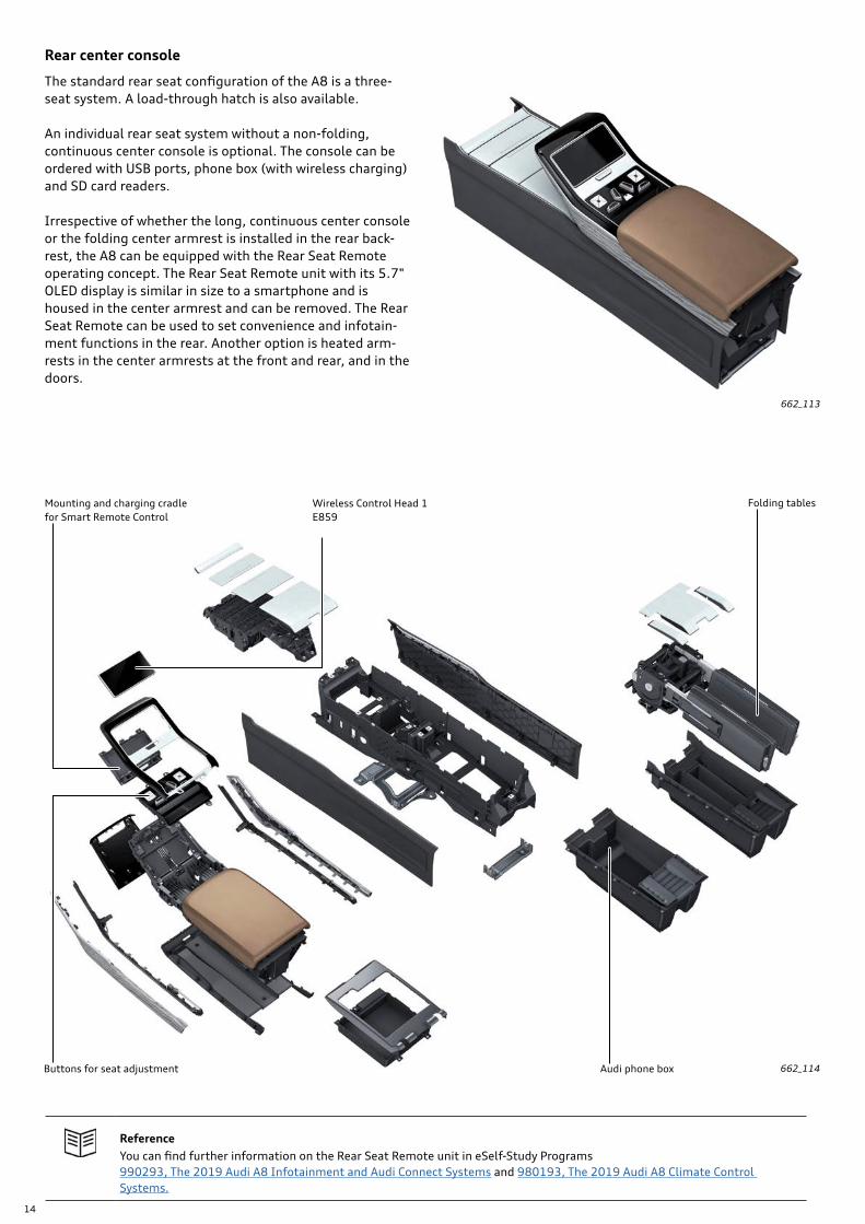
Rear center console
The standard rear seat configuration of the A8 is a three-seat system. A load-through hatch is also available.
An individual rear seat system without a non-folding, continuous center console is optional. The console can be ordered with USB ports, phone box (with wireless charging) and SD card readers.
Irrespective of whether the long, continuous center console or the folding center armrest is installed in the rear back-rest, the A8 can be equipped with the Rear Seat Remote operating concept. The Rear Seat Remote unit with its 5.7" OLED display is similar in size to a smartphone and is housed in the center armrest and can be removed. The Rear Seat Remote can be used to set convenience and infotain-ment functions in the rear. Another option is heated arm-rests in the center armrests at the front and rear, and in the doors.
662_114Buttons for seat adjustment
Folding tables
Audi phone box
662_113
ReferenceYou can find further information on the Rear Seat Remote unit in eSelf-Study Programs 990293, The 2019 Audi A8 Infotainment and Audi Connect Systems and 980193, The 2019 Audi A8 Climate Control Systems.
Wireless Control Head 1 E859
Mounting and charging cradle for Smart Remote Control
15
Seats
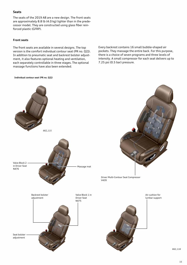
The seats of the 2019 A8 are a new design. The front seats are approximately 8.8 lb (4.0 kg) lighter than in the prede-cessor model. They are constructed using glass fiber rein-forced plastic (GFRP).
Front seats
The front seats are available in several designs. The top version is the comfort individual contour seat (PR no. Q2J). In addition to pneumatic seat and backrest bolster adjust-ment, it also features optional heating and ventilation, each separately controllable in three stages. The optional massage functions have also been extended.
Every backrest contains 16 small bubble-shaped air pockets. They massage the entire back. For this purpose, there is a choice of seven programs and three levels of intensity. A small compressor for each seat delivers up to 7.25 psi (0.5 bar) pressure.
662_115
662_116
Individual contour seat (PR no. Q2J)
Driver Multi-Contour Seat Compressor V439
Backrest bolster adjustment
Seat bolster adjustment
Valve Block 1 in Driver Seat N475
Air cushion for lumbar support
Massage mat
Valve Block 2 in Driver Seat N476
16
Reclining seat
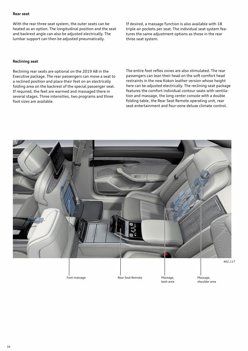
Reclining rear seats are optional on the 2019 A8 in the Executive package. The rear passengers can move a seat to a reclined position and place their feet on an electrically folding area on the backrest of the special passenger seat. If required, the feet are warmed and massaged there in several stages. Three intensities, two programs and three foot sizes are available.
662_117
Rear seat
With the rear three seat system, the outer seats can be heated as an option. The longitudinal position and the seat and backrest angle can also be adjusted electrically. The lumbar support can then be adjusted pneumatically.
If desired, a massage function is also available with 18 triple air pockets per seat. The individual seat system fea-tures the same adjustment options as those in the rear three seat system.
Foot massage Massage,shoulder area
Rear Seat Remote Massage,back area
The entire foot reflex zones are also stimulated. The rear passengers can lean their head on the soft comfort head restraints in the new Kokon leather version whose height here can be adjusted electrically. The reclining seat package features the comfort individual contour seats with ventila-tion and massage, the long center console with a double folding table, the Rear Seat Remote operating unit, rear seat entertainment and four-zone deluxe climate control.
17
Roof
662_119
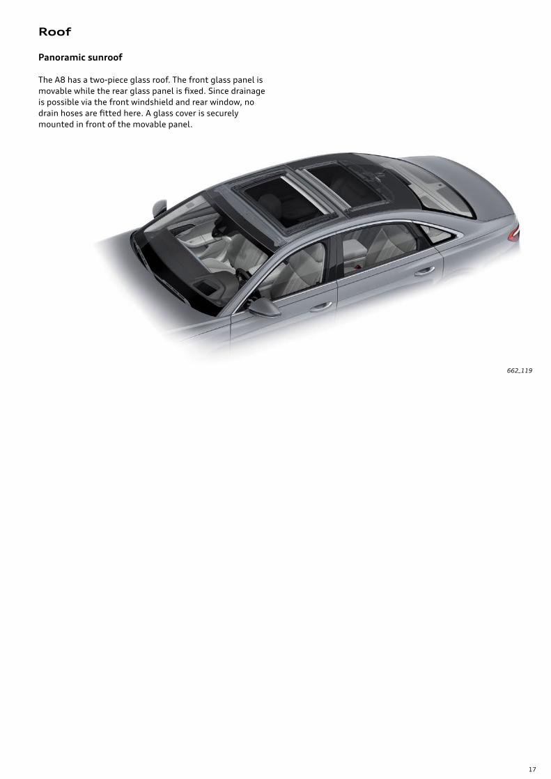
Panoramic sunroof
The A8 has a two-piece glass roof. The front glass panel is movable while the rear glass panel is fixed. Since drainage is possible via the front windshield and rear window, no drain hoses are fitted here. A glass cover is securely mounted in front of the movable panel.
18
Features Specifications
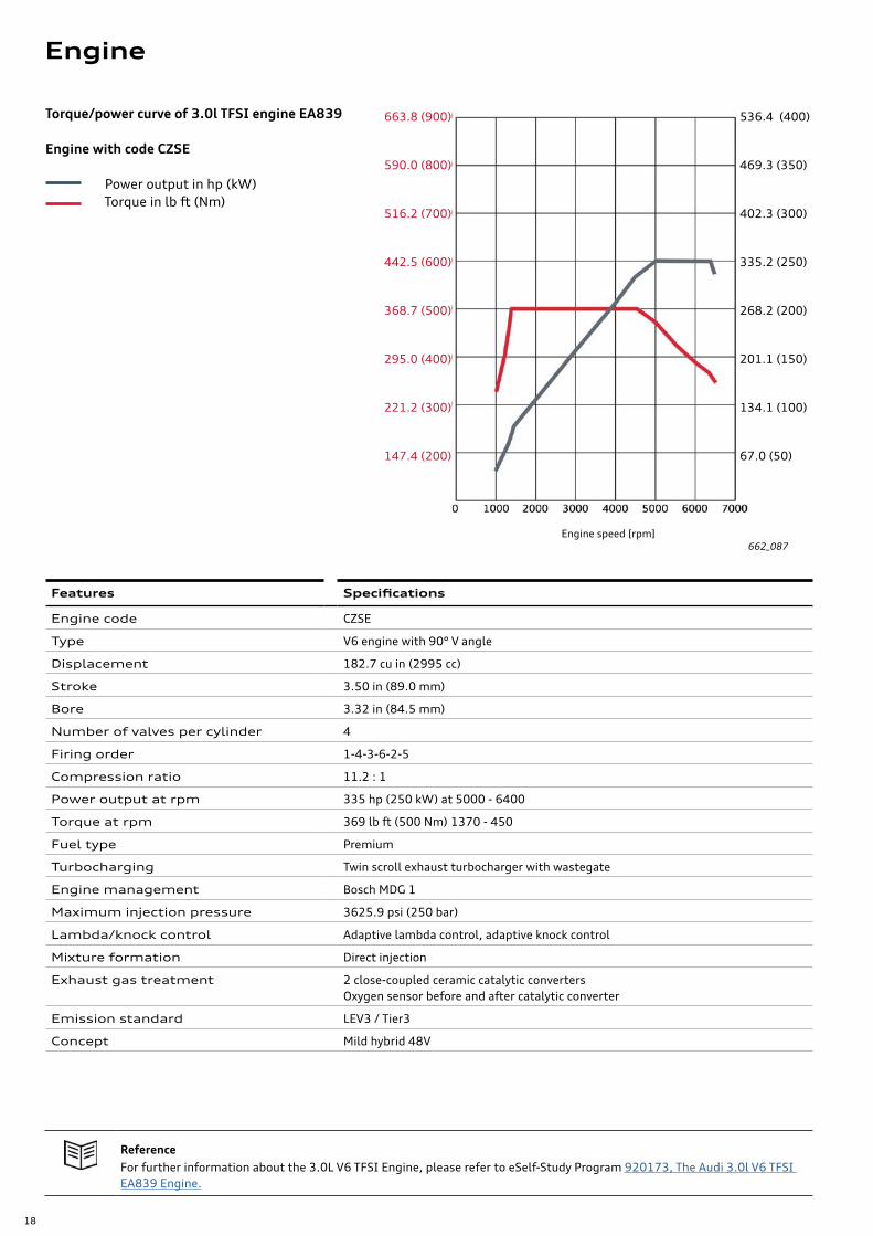
Engine code CZSE
Type V6 engine with 90° V angle
Displacement 182.7 cu in (2995 cc)
Stroke 3.50 in (89.0 mm)
Bore 3.32 in (84.5 mm)
Number of valves per cylinder 4
Firing order 1-4-3-6-2-5
Compression ratio 11.2 : 1
Power output at rpm 335 hp (250 kW) at 5000 - 6400
Torque at rpm 369 lb ft (500 Nm) 1370 - 450
Fuel type Premium
Turbocharging Twin scroll exhaust turbocharger with wastegate
Engine management Bosch MDG 1
Maximum injection pressure 3625.9 psi (250 bar)
Lambda/knock control Adaptive lambda control, adaptive knock control
Mixture formation Direct injection
Exhaust gas treatment 2 close-coupled ceramic catalytic convertersOxygen sensor before and after catalytic converter
Emission standard LEV3 / Tier3
Concept Mild hybrid 48V
Engine speed [rpm]662_087
ReferenceFor further information about the 3.0L V6 TFSI Engine, please refer to eSelf-Study Program 920173, The Audi 3.0l V6 TFSI EA839 Engine.
663.8 (900)
590.0 (800)
516.2 (700)
442.5 (600)
368.7 (500)
295.0 (400)
221.2 (300)
147.4 (200)
536.4 (400)
469.3 (350)
402.3 (300)
335.2 (250)
268.2 (200)
201.1 (150)
134.1 (100)
67.0 (50)
Torque/power curve of 3.0l TFSI engine EA839
Engine with code CZSE
Power output in hp (kW) Torque in lb ft (Nm)
Engine
19
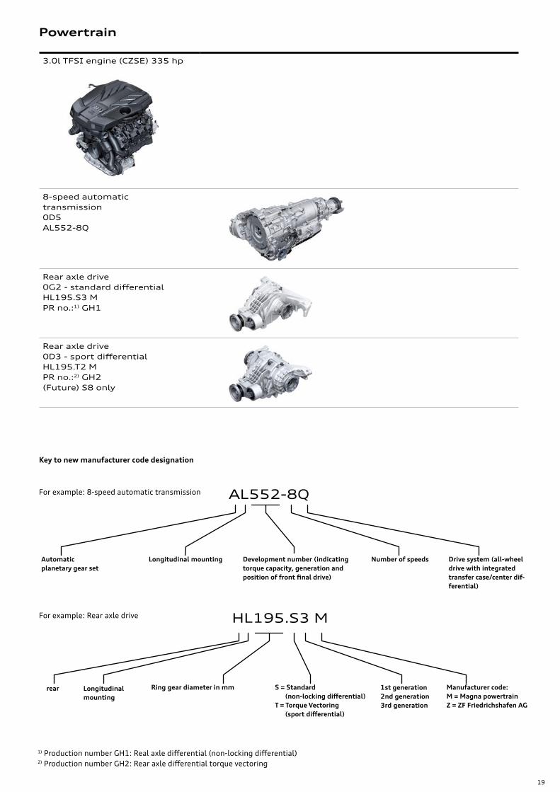
3.0l TFSI engine (CZSE) 335 hp
8-speed automatic transmission 0D5AL552-8Q
Rear axle drive0G2 - standard differential HL195.S3 M PR no.:1) GH1
Rear axle drive 0D3 - sport differentialHL195.T2 MPR no.:2) GH2(Future) S8 only
Powertrain
Automatic planetary gear set
Longitudinal mounting Number of speeds Drive system (all-wheel drive with integrated transfer case/center dif-ferential)
Development number (indicating torque capacity, generation and position of front final drive)
AL552-8Q
Key to new manufacturer code designation
For example: 8-speed automatic transmission
rear Ring gear diameter in mm 1st generation2nd generation3rd generation
Manufacturer code: M = Magna powertrainZ = ZF Friedrichshafen AG
S = Standard (non-locking differential)T = Torque Vectoring (sport differential)
HL195.S3 MFor example: Rear axle drive
1) Production number GH1: Real axle differential (non-locking differential)2) Production number GH2: Rear axle differential torque vectoring
Longitudinal mounting
20
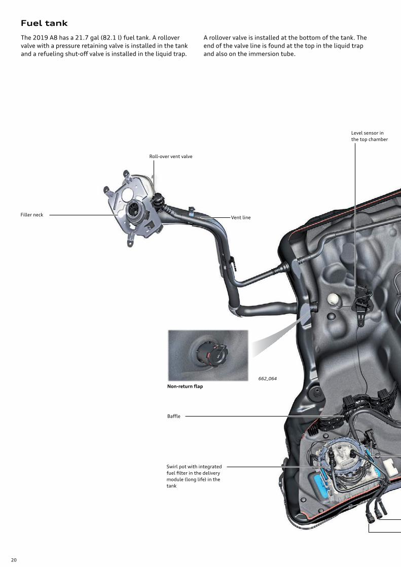
Fuel tank
662_064
Filler neck
Roll-over vent valve
Vent line
Baffle
The 2019 A8 has a 21.7 gal (82.1 l) fuel tank. A rollover valve with a pressure retaining valve is installed in the tank and a refueling shut-off valve is installed in the liquid trap.
Level sensor in the top chamber
Non-return flap
Swirl pot with integrated fuel filter in the delivery module (long life) in the tank
A rollover valve is installed at the bottom of the tank. The end of the valve line is found at the top in the liquid trap and also on the immersion tube.

21
Level sensor in the top chamber
662_059
662_057_alt
Immersion tube
Level sensor in the main chamber
Intake for suction jet pump
Baffle
Fuel supply line
Fuel return line
Liquid trap with short refuelling shut-off valve in 21.7 gal (82 l) fuel tank
Level sensor in the secondary chamber
Rollover valve with pressure retaining valve
Mixer tube on the transfer side
Line for suction jet pump
Refuelingshut-off valve
Vent line
22
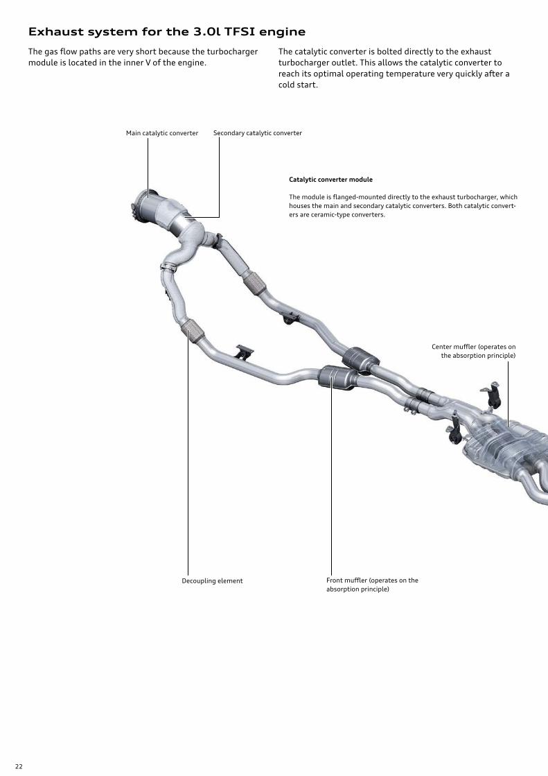
Exhaust system for the 3.0l TFSI engine
The gas flow paths are very short because the turbocharger module is located in the inner V of the engine.
Catalytic converter module
The module is flanged-mounted directly to the exhaust turbocharger, which houses the main and secondary catalytic converters. Both catalytic convert-ers are ceramic-type converters.
Center muffler (operates on the absorption principle)
Decoupling element Front muffler (operates on the absorption principle)
Main catalytic converter Secondary catalytic converter
The catalytic converter is bolted directly to the exhaust turbocharger outlet. This allows the catalytic converter to reach its optimal operating temperature very quickly after a cold start.

23
NoteThe exhaust flap is actuated by the exhaust flap control unit via a worm gear. Because this is a "self-locking" gear, it is essen-tial that the servomotor be removed before testing the movement of the flap.
Exhaust flaps
Two of the four exhaust outlets can be closed, reducing noise as the vehicle accelerates from a stop.
Exhaust Door Control Unit 2 J945
Rear muffler (operates on the reflec-tion and absorption prin-ciple)
Exhaust Door Control Unit J883
662_077
24
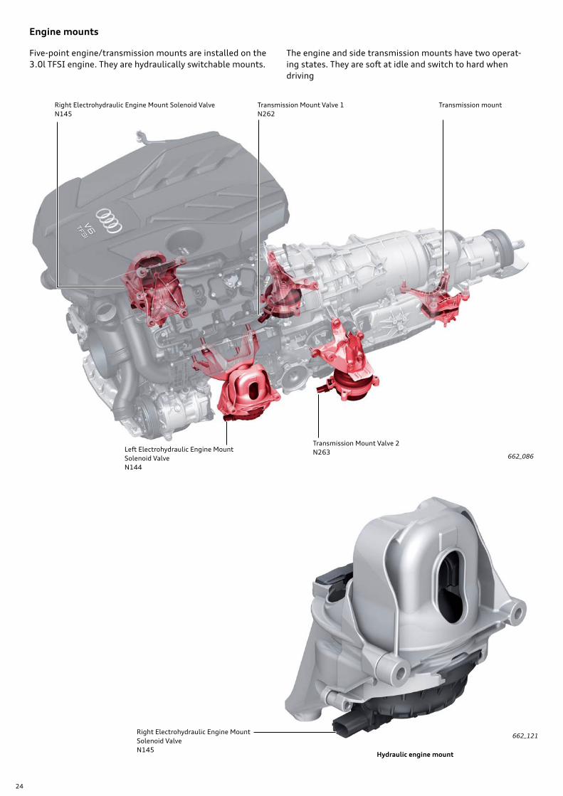
662_086Left Electrohydraulic Engine Mount Solenoid Valve N144
Transmission Mount Valve 2N263
Right Electrohydraulic Engine Mount Solenoid Valve N145
Transmission Mount Valve 1N262
Transmission mount
Right Electrohydraulic Engine Mount Solenoid Valve N145
Engine mounts
Five-point engine/transmission mounts are installed on the 3.0l TFSI engine. They are hydraulically switchable mounts.
The engine and side transmission mounts have two operat-ing states. They are soft at idle and switch to hard when driving
662_121
Hydraulic engine mount

25
Transmission mount
662_229
662_230
Transmission Mount Valve 2 N263
The hydraulically switchable transmission mounts, Trans-mission Mount Valve 1 and 2 (N262, N263) are laterally mounted to the transmission to counteract the torsional vibration of the engine and transmission unit.
The conventional transmission mount is installed in the rear section of the transmission and counteracts the load reversal and tilt functions.
Hydraulically switchable transmission mounting
Conventional transmission mounting
26
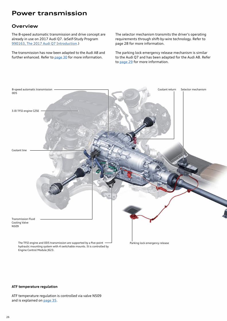
Overview
3.0l TFSI engine CZSE
Coolant return
Coolant line
8-speed automatic transmission 0D5
Selector mechanism
The TFSI engine and OD5 transmission are supported by a five-point hydraulic mounting system with 4 switchable mounts. It is controlled by Engine Control Module J623.
Parking lock emergency release
The 8-speed automatic transmission and drive concept are already in use on 2017 Audi Q7. (eSelf-Study Program 990163, The 2017 Audi Q7 Introduction.)
The transmission has now been adapted to the Audi A8 and further enhanced. Refer to page 30 for more information.
The selector mechanism transmits the driver's operating requirements through shift-by-wire technology. Refer to page 28 for more information.
The parking lock emergency release mechanism is similar to the Audi Q7 and has been adapted for the Audi A8. Refer to page 29 for more information.
ATF temperature regulation
ATF temperature regulation is controlled via valve N509 and is explained on page 35.
Transmission Fluid Cooling Valve N509
Power transmission
27
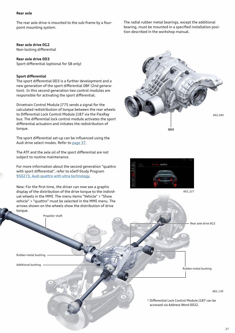
Rubber-metal bushing
Propeller shaft
Rear axle drive 0G2
Rubber-metal bushing
Additional bushing
662_130
1) Differential Lock Control Module J187 can be accessed via Address Word 0032.
Rear axle
The rear axle drive is mounted to the sub-frame by a four-point mounting system.
Rear axle drive 0G2Non-locking differential
Rear axle drive 0D3Sport differential (optional for S8 only)
The radial rubber metal bearings, except the additional bearing, must be mounted in a specified installation posi-tion described in the workshop manual.
662_045
Sport differentialThe sport differential 0D3 is a further development and a new generation of the sport differential 0BF (2nd genera-tion). In this second generation two control modules are responsible for activating the sport differential.
Drivetrain Control Module J775 sends a signal for the calculated redistribution of torque between the rear wheels to Differential Lock Control Module J187 via the FlexRay bus. The differential lock control module activates the sport differential actuators and initiates the redistribution of torque.
The sport differential set-up can be influenced using the Audi drive select modes. Refer to page 37.
The ATF and the axle oil of the sport differential are not subject to routine maintenance.
For more information about the second generation "quattro with sport differential", refer to eSelf-Study Program 950273, Audi quattro with ultra technology.
OD3
New: For the first time, the driver can now see a graphic display of the distribution of the drive torque to the individ-ual wheels in the MMI. The menu items "Vehicle" > "Show vehicle" > "quattro" must be selected in the MMI menu. The arrows shown on the wheels show the distribution of drive torque.
662_227
Vehicle · quattro
28
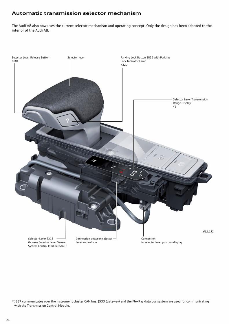
Automatic transmission selector mechanism
662_132
Selector leverSelector Lever Release Button E681
Selector Lever E313 (houses Selector Lever Sensor System Control Module J587)1)
Parking Lock Button E816 with Parking Lock Indicator Lamp K320
Connection to selector lever position display
Connection between selector lever and vehicle
Selector Lever Transmission Range Display Y5
The Audi A8 also now uses the current selector mechanism and operating concept. Only the design has been adapted to the interior of the Audi A8.
1) J587 communicates over the instrument cluster CAN bus. J533 (gateway) and the FlexRay data bus system are used for communicating with the Transmission Control Module.
29
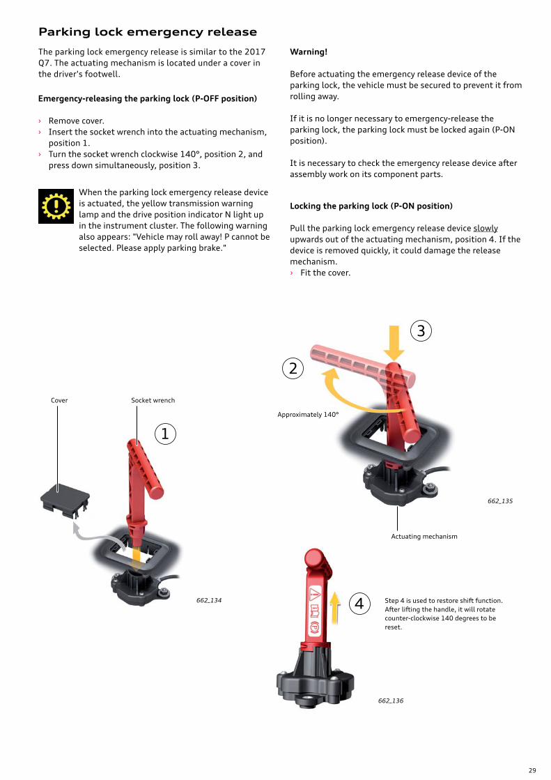
1
2
3
4 Step 4 is used to restore shift function. After lifting the handle, it will rotate counter-clockwise 140 degrees to be reset.
The parking lock emergency release is similar to the 2017 Q7. The actuating mechanism is located under a cover in the driver's footwell.
Parking lock emergency release
When the parking lock emergency release device is actuated, the yellow transmission warning lamp and the drive position indicator N light up in the instrument cluster. The following warning also appears: "Vehicle may roll away! P cannot be selected. Please apply parking brake."
662_134
662_135
662_136
Cover
Actuating mechanism
Socket wrench
Locking the parking lock (P-ON position)
Pull the parking lock emergency release device slowly upwards out of the actuating mechanism, position 4. If the device is removed quickly, it could damage the release mechanism. › Fit the cover.
Emergency-releasing the parking lock (P-OFF position)
› Remove cover. › Insert the socket wrench into the actuating mechanism,
position 1. › Turn the socket wrench clockwise 140°, position 2, and
press down simultaneously, position 3.
Approximately 140°
Warning!
Before actuating the emergency release device of the parking lock, the vehicle must be secured to prevent it from rolling away.
If it is no longer necessary to emergency-release the parking lock, the parking lock must be locked again (P-ON position).
It is necessary to check the emergency release device after assembly work on its component parts.
30
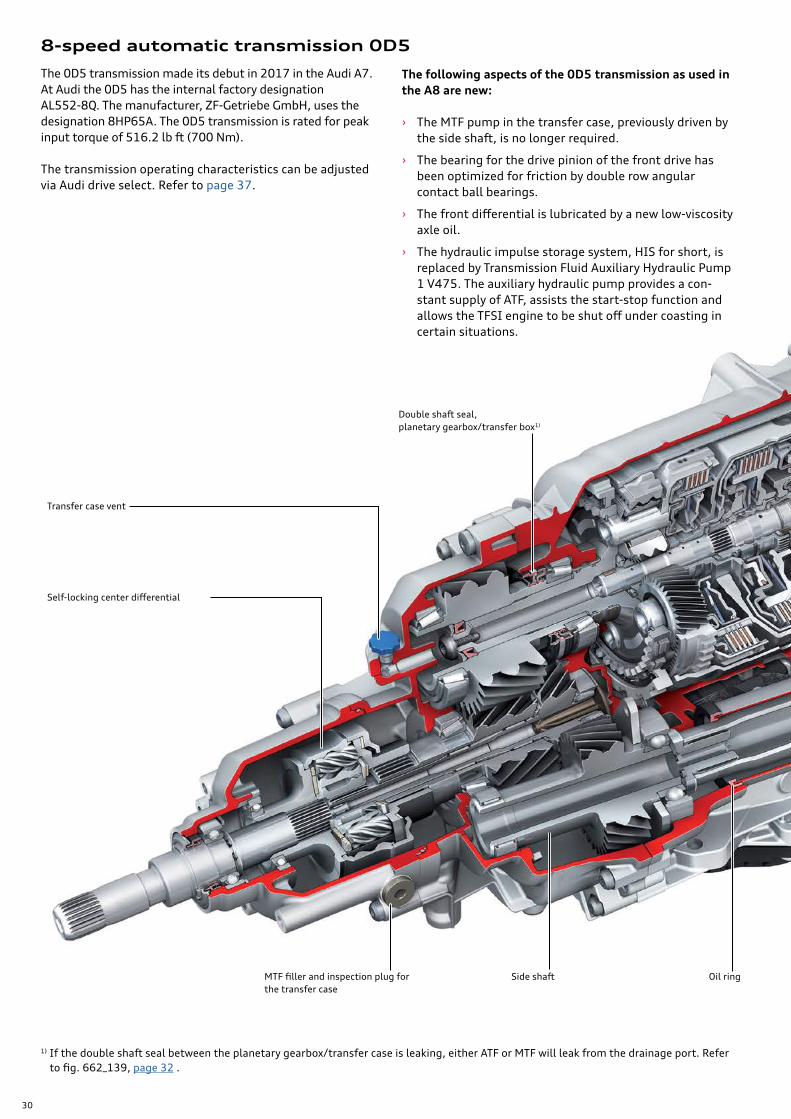
8-speed automatic transmission 0D5
The 0D5 transmission made its debut in 2017 in the Audi A7. At Audi the 0D5 has the internal factory designation AL552-8Q. The manufacturer, ZF-Getriebe GmbH, uses the designation 8HP65A. The 0D5 transmission is rated for peak input torque of 516.2 lb ft (700 Nm).
The transmission operating characteristics can be adjusted via Audi drive select. Refer to page 37.
Self-locking center differential
MTF filler and inspection plug for the transfer case
Oil ring
Transfer case vent
Double shaft seal,planetary gearbox/transfer box1)
The following aspects of the 0D5 transmission as used in the A8 are new:
› The MTF pump in the transfer case, previously driven by the side shaft, is no longer required.
› The bearing for the drive pinion of the front drive has been optimized for friction by double row angular contact ball bearings.
› The front differential is lubricated by a new low-viscosity axle oil.
› The hydraulic impulse storage system, HIS for short, is replaced by Transmission Fluid Auxiliary Hydraulic Pump 1 V475. The auxiliary hydraulic pump provides a con-stant supply of ATF, assists the start-stop function and allows the TFSI engine to be shut off under coasting in certain situations.
1) If the double shaft seal between the planetary gearbox/transfer case is leaking, either ATF or MTF will leak from the drainage port. Refer to fig. 662_139, page 32 .
Side shaft
31
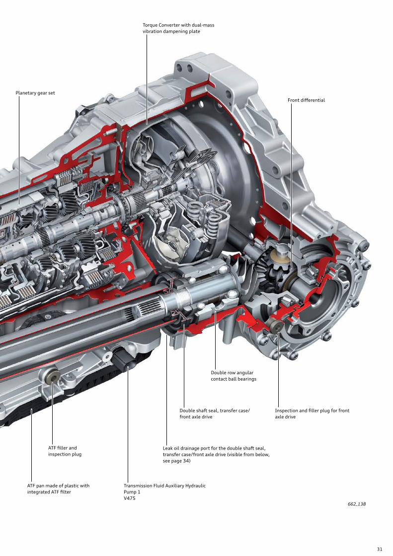
662_138
Oil ring Transmission Fluid Auxiliary Hydraulic Pump 1 V475
Leak oil drainage port for the double shaft seal, transfer case/front axle drive (visible from below, see page 34)
Double shaft seal, transfer case/front axle drive
Inspection and filler plug for front axle drive
Front differential
Double row angular contact ball bearings
ATF filler and inspection plug
ATF pan made of plastic with integrated ATF filter
Planetary gear set
Torque Converter with dual-mass vibration dampening plate
32
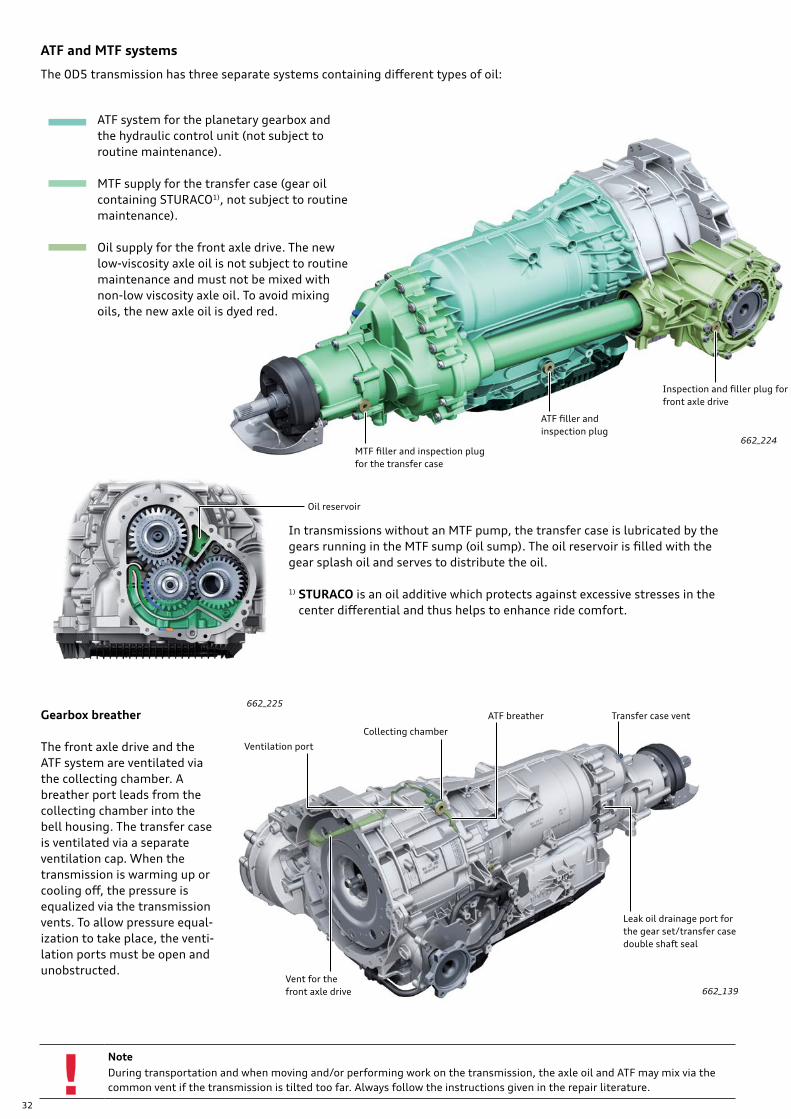
NoteDuring transportation and when moving and/or performing work on the transmission, the axle oil and ATF may mix via the common vent if the transmission is tilted too far. Always follow the instructions given in the repair literature.
Gearbox breather
The front axle drive and the ATF system are ventilated via the collecting chamber. A breather port leads from the collecting chamber into the bell housing. The transfer case is ventilated via a separate ventilation cap. When the transmission is warming up or cooling off, the pressure is equalized via the transmission vents. To allow pressure equal-ization to take place, the venti-lation ports must be open and unobstructed.
662_139
ATF system for the planetary gearbox and the hydraulic control unit (not subject to routine maintenance).
MTF supply for the transfer case (gear oil containing STURACO1), not subject to routine maintenance).
Oil supply for the front axle drive. The new low-viscosity axle oil is not subject to routine maintenance and must not be mixed with non-low viscosity axle oil. To avoid mixing oils, the new axle oil is dyed red.
ATF and MTF systems
The 0D5 transmission has three separate systems containing different types of oil:
Leak oil drainage port for the gear set/transfer case double shaft seal
Ventilation port
Vent for the front axle drive
Collecting chamber
ATF breather Transfer case vent
In transmissions without an MTF pump, the transfer case is lubricated by the gears running in the MTF sump (oil sump). The oil reservoir is filled with the gear splash oil and serves to distribute the oil.
1) STURACO is an oil additive which protects against excessive stresses in the center differential and thus helps to enhance ride comfort.
MTF filler and inspection plugfor the transfer case
ATF filler andinspection plug
Inspection and filler plug for front axle drive
Oil reservoir
662_224
662_225
33
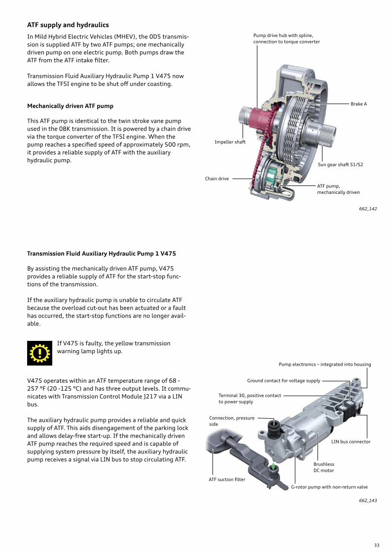
ATF supply and hydraulics
In Mild Hybrid Electric Vehicles (MHEV), the 0D5 transmis-sion is supplied ATF by two ATF pumps; one mechanically driven pump on one electric pump. Both pumps draw the ATF from the ATF intake filter.
Transmission Fluid Auxiliary Hydraulic Pump 1 V475 now allows the TFSI engine to be shut off under coasting.
Mechanically driven ATF pump
This ATF pump is identical to the twin stroke vane pump used in the 0BK transmission. It is powered by a chain drive via the torque converter of the TFSI engine. When the pump reaches a specified speed of approximately 500 rpm, it provides a reliable supply of ATF with the auxiliary hydraulic pump.
662_142
ATF pump, mechanically driven
Sun gear shaft S1/S2
Brake A
Pump drive hub with spline, connection to torque converter
Impeller shaft
Chain drive
Transmission Fluid Auxiliary Hydraulic Pump 1 V475
By assisting the mechanically driven ATF pump, V475 provides a reliable supply of ATF for the start-stop func-tions of the transmission.
If the auxiliary hydraulic pump is unable to circulate ATF because the overload cut-out has been actuated or a fault has occurred, the start-stop functions are no longer avail-able.
If V475 is faulty, the yellow transmission warning lamp lights up.
V475 operates within an ATF temperature range of 68 - 257 °F (20 -125 °C) and has three output levels. It commu-nicates with Transmission Control Module J217 via a LIN bus.
The auxiliary hydraulic pump provides a reliable and quick supply of ATF. This aids disengagement of the parking lock and allows delay-free start-up. If the mechanically driven ATF pump reaches the required speed and is capable of supplying system pressure by itself, the auxiliary hydraulic pump receives a signal via LIN bus to stop circulating ATF.
Ground contact for voltage supply
Terminal 30, positive contact to power supply
LIN bus connector
BrushlessDC motor
G-rotor pump with non-return valve
Connection, pressure side
ATF suction filter
662_143
Pump electronics – integrated into housing
34
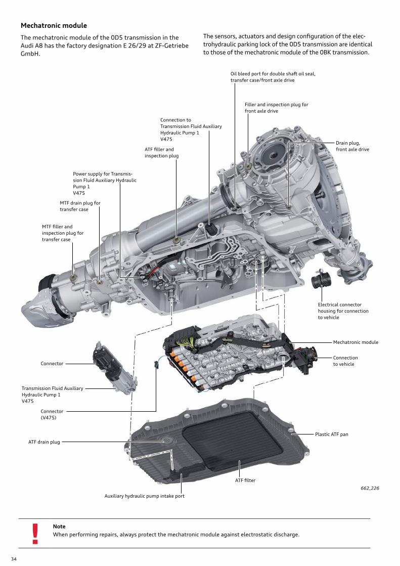
Mechatronic module
The mechatronic module of the 0D5 transmission in the Audi A8 has the factory designation E 26/29 at ZF-Getriebe GmbH.
NoteWhen performing repairs, always protect the mechatronic module against electrostatic discharge.
662_226
Auxiliary hydraulic pump intake port
Drain plug, front axle drive
ATF drain plug
ATF filter
Filler and inspection plug forfront axle drive
Connector (V475)
Plastic ATF pan
Oil bleed port for double shaft oil seal,transfer case/front axle drive
Transmission Fluid Auxiliary Hydraulic Pump 1 V475
Connection to vehicle
Connection toTransmission Fluid Auxiliary Hydraulic Pump 1 V475
Connector
Mechatronic module
ATF filler andinspection plug
MTF filler and inspection plug for transfer case
Electrical connector housing for connection to vehicle
Power supply for Transmis-sion Fluid Auxiliary Hydraulic Pump 1 V475
MTF drain plug fortransfer case
The sensors, actuators and design configuration of the elec-trohydraulic parking lock of the 0D5 transmission are identical to those of the mechatronic module of the 0BK transmission.
35
12
1
2
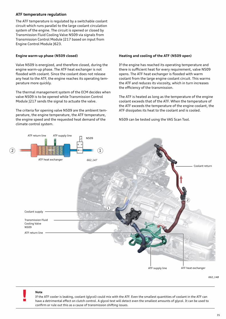
NoteIf the ATF cooler is leaking, coolant (glycol) could mix with the ATF. Even the smallest quantities of coolant in the ATF can have a detrimental effect on clutch control. A glycol test will detect even the smallest amounts of glycol. It can be used to confirm or rule out this as a cause of transmission shifting issues.
ATF temperature regulation
The ATF temperature is regulated by a switchable coolant circuit which runs parallel to the large coolant circulation system of the engine. The circuit is opened or closed by Transmission Fluid Cooling Valve N509 via signals from Transmission Control Module J217 based on input from Engine Control Module J623.
Engine warm-up phase (N509 closed)
Valve N509 is energized, and therefore closed, during the engine warm-up phase. The ATF heat exchanger is not flooded with coolant. Since the coolant does not release any heat to the ATF, the engine reaches its operating tem-perature more quickly.
The thermal management system of the ECM decides when valve N509 is to be opened while Transmission Control Module J217 sends the signal to actuate the valve.
The criteria for opening valve N509 are the ambient tem-perature, the engine temperature, the ATF temperature, the engine speed and the requested heat demand of the climate control system.
Heating and cooling of the ATF (N509 open)
If the engine has reached its operating temperature and there is sufficient heat for every requirement, valve N509 opens. The ATF heat exchanger is flooded with warm coolant from the large engine coolant circuit. This warms the ATF and reduces its viscosity, which in turn increases the efficiency of the transmission.
The ATF is heated as long as the temperature of the engine coolant exceeds that of the ATF. When the temperature of the ATF exceeds the temperature of the engine coolant, the ATF dissipates its heat to the coolant and is cooled.
N509 can be tested using the VAS Scan Tool.
Transmission Fluid Cooling Valve N509
Coolant supply
ATF return line
ATF heat exchangerATF supply line
ATF return line ATF supply line
ATF heat exchanger
N509
662_147
662_148
Coolant return
36
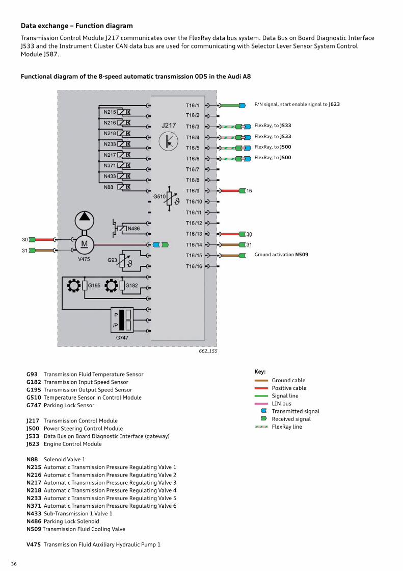
Data exchange – Function diagram
Transmission Control Module J217 communicates over the FlexRay data bus system. Data Bus on Board Diagnostic Interface J533 and the Instrument Cluster CAN data bus are used for communicating with Selector Lever Sensor System Control Module J587.
662_155
Functional diagram of the 8-speed automatic transmission 0D5 in the Audi A8
Key:
Ground cable Positive cable Signal line LIN bus Transmitted signal Received signal FlexRay line
G93 Transmission Fluid Temperature SensorG182 Transmission Input Speed SensorG195 Transmission Output Speed SensorG510 Temperature Sensor in Control ModuleG747 Parking Lock Sensor
J217 Transmission Control ModuleJ500 Power Steering Control ModuleJ533 Data Bus on Board Diagnostic Interface (gateway)J623 Engine Control Module
N88 Solenoid Valve 1N215 Automatic Transmission Pressure Regulating Valve 1N216 Automatic Transmission Pressure Regulating Valve 2N217 Automatic Transmission Pressure Regulating Valve 3N218 Automatic Transmission Pressure Regulating Valve 4N233 Automatic Transmission Pressure Regulating Valve 5N371 Automatic Transmission Pressure Regulating Valve 6N433 Sub-Transmission 1 Valve 1N486 Parking Lock SolenoidN509 Transmission Fluid Cooling Valve
V475 Transmission Fluid Auxiliary Hydraulic Pump 1
FlexRay, to J500
FlexRay, to J500
FlexRay, to J533
FlexRay, to J533
P/N signal, start enable signal to J623
Ground activation N509
37
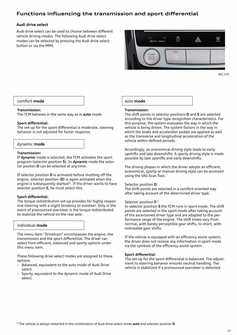
Audi drive select
Functions influencing the transmission and sport differential
Audi drive select can be used to choose between different vehicle driving modes. The following Audi drive select modes can be selected by pressing the Audi drive select button or via the MMI.
comfort mode
Transmission:The TCM behaves in the same way as in auto mode.
Sport differential:The set-up for the sport differential is moderate, steering behavior is not adjusted for faster response.
dynamic mode
Transmission:If dynamic mode is selected, the TCM activates the sport program (selector position S). In dynamic mode the selec-tor positon D can be selected at any time.
If selector position D is activated before shutting off the engine, selector position (D) is again activated when the engine is subsequently started1). If the driver wants to have selector position S, he must select this.
Sport differential:The torque redistribution set-up provides for highly respon-sive steering with a slight tendency to ovesteer. Only in the event of pronounced oversteer is the torque redistributed to stabilize the vehicle on the rear axle.
individual mode
The menu item “Drivetrain” encompasses the engine, the transmission and the sport differential. The driver can select from efficient, balanced and sporty options under this menu item.
These following drive select modes are assigned to these options: › Balanced, equivalent to the auto mode of Audi Drive
select. › Sporty, equivalent to the dynamic mode of Audi Drive
select.
auto mode
Transmission:The shift points in selector positions D and S are selected according to the driver type recognition characteristics. For this purpose, the system evaluates the way in which the vehicle is being driven. The system factors in the way in which the brake and accelerator pedals are applied as well as the transverse and longitudinal acceleration of the vehicle within defined periods.
Accordingly, an economical driving style leads to early upshifts and late downshifts. A sporty driving style is made possible by late upshifts and early downshifts.
The driving phases in which the driver adopts an efficient, economical, sporty or manual driving style can be accessed using the VAS Scan Tool.
Selector position D:The shift points are selected in a comfort-oriented way after taking account of the determined driver type.
Selector position S1):In selector position S the TCM runs in sport mode. The shift points are selected in the sport mode after taking account of the ascertained driver type and are adapted to the per-formance range of the engine. The shift times vary from normal, with barely perceptible gear shifts, to short, with noticeable gear shifts.
If the vehicle is equipped with an efficiency assist system, the driver does not receive any information in sport mode via the symbols of the efficiency assist system.
Sport differential:The set-up for the sport differential is balanced. The adjust-ment to steering behavior ensures neutral handling. The vehicle is stabilized if a pronounced oversteer is detected.
1) The vehicle is always restarted in the combination of Audi drive select mode auto and selector position D.
662_156

38
System inactive (switched off) conditions:
› Uphill or downhill gradient: > 10%1). › Max. speed:
› 105.6 mph (170 km/h)1). › ESC is deactivated. › Selector position S is selected. › tiptronic mode is activated via the tiptronic gate or by
selecting Tip- with the tiptronic paddle on the steering wheel.
› No ATF circulation by Transmission Fluid Auxiliary Hydraulic Pump 1 V475 due to overload protection function or fault.
The start-stop system is activated automatically whenever the ignition is switched on. It helps to save fuel and reduce C02 emissions. If the requirements for start-stop operation have been met, the engine is shut off automati-cally when the brake is applied as the vehicle rolls to a stop. One of these conditions is that the selector lever is not in position R. The engine is automatically restarted when required. The requirements for this are a very short start time and quick readíness for drive-away. In the Audi A8 with MHEV equipment, quick readiness for drive-away is ensured by Transmission Fluid Auxiliary Hydraulic Pump 1 V475. If the auxiliary hydraulic pump is unable to circu-late ATF because the overload cut-out has actuated or a fault has occurred, the start-stop function is deactivated and is no longer available.
Start-stop system
ReferenceThe shift schematic of the 0D5 transmission is identical to that of the 0BK and 0BL transmissions, refer to eSelf-Study Program 950103, The 2011 Audi A8 Driver Assistance.
39
Neutral idle control (NIC)
The neutral idle control system disengages the engine from the transmission when stopping or when the vehicle is stationary. Engine idle torque can be reduced to a minimum because the engine does not have to counteract the con-verter torque.
This helps save fuel and reduces C02 emissions. In addition, the engine runs more smoothly and quietly at low idle torque. For this reason, the neutral idle control system is activated as often as possible (see conditions for switching on and off).
› After a long pull of the Tip- shift paddle (long pull-), the transmission changes down into the lowest possible gear.
› After a long pull of the Tip+ shift paddle (long pull +), the transmission switches from temporary tiptronic mode to automatic mode.
› In the event of a malfunction of the selector mechanism, the positions P, R, N and D can be selected when the vehicle is stopped and the brake is activated by simulta-neously pressing both shift paddles(for longer than one second).
› The “Tip-shifting in D/S” function, which allows gear-shifts to be performed manually at any time, is available.
› The “Activation of coasting mode using Tip+” function has been deactivated in order to simplify the function assignments of the tiptronic steering wheel in the A8. However, it is still possible to exit coasting mode by pressing Tip-.
Downhill assist helps the driver to maintain a constant speed on downhill gradients. In this case the transmission selects the gear suitable for the gradient in order to main-tain the speed selected at the time of braking via the engine brake. Within the bounds of the system's physical limita-tions it may be necessary to also correct the speed, if neces-sary, using the brake pedal.
Downhill assist cuts out again as soon as the gradient lessens or the accelerator pedal is pressed.
Depending on the gradient, downhill assist is active in selector positions D and S while the brake is applied or while cruise control is active.
Note:Downhill assist cannot overcome the physical limitations of the vehicle and therefore cannot maintain a set speed in all conditions. The driver must always be ready to apply the brakes! Downhill assist could also be inactive if the brakes were too hot as calculated by the ABS control module.
Switch-on conditions:
› Full adaption of the shift elements (brakes, clutches).
› ATF temperature > approximately 68 °F (20 C°)1).
› Gradient < 4%1) (the gradient is determined by the longitudinal acceleration sensor of the ABS system).
› Selector position D or R .
› Accelerator not pressed.
› Foot brake pressed.
Shut-off conditions:
› Selector position S2) or tiptronic mode.
› Brake released. (unless the vehicle is secured by the electro-mechanical parking brake or hill start assist is active).
› Accelerator pressed.
› No ATF circulation by Transmission Fluid Auxiliary Hydraulic Pump 1 V475 due to overload protection function or fault.
› Towing mode detected.
ReferenceFor more detailed information about the neutral idle control function in the 0D5 transmission, refer eSelf-Study Program 990163 The 2017 Audi Q7 Introduction.
Downhill assist
Special features of the steering wheel tiptronic function
1) The values given are intended as a guideline. They may deviate depending on the model version. 2) Neutral idle control is not activated in selector position S in order to allow more direct acceleration. Without neutral control, clutch C or D is
immediately closed when drive positions S1 and R are selected. This is why traction is noticeable on selection of 1st gear or R gear and like-wise the traction reversal when shifting from 1st gear to R gear (or vice versa). This traction reversal is barely noticeable in selector position D, because when neutral control is active clutch C or D is open and traction cannot be established until the brake has been released.
40
Overview
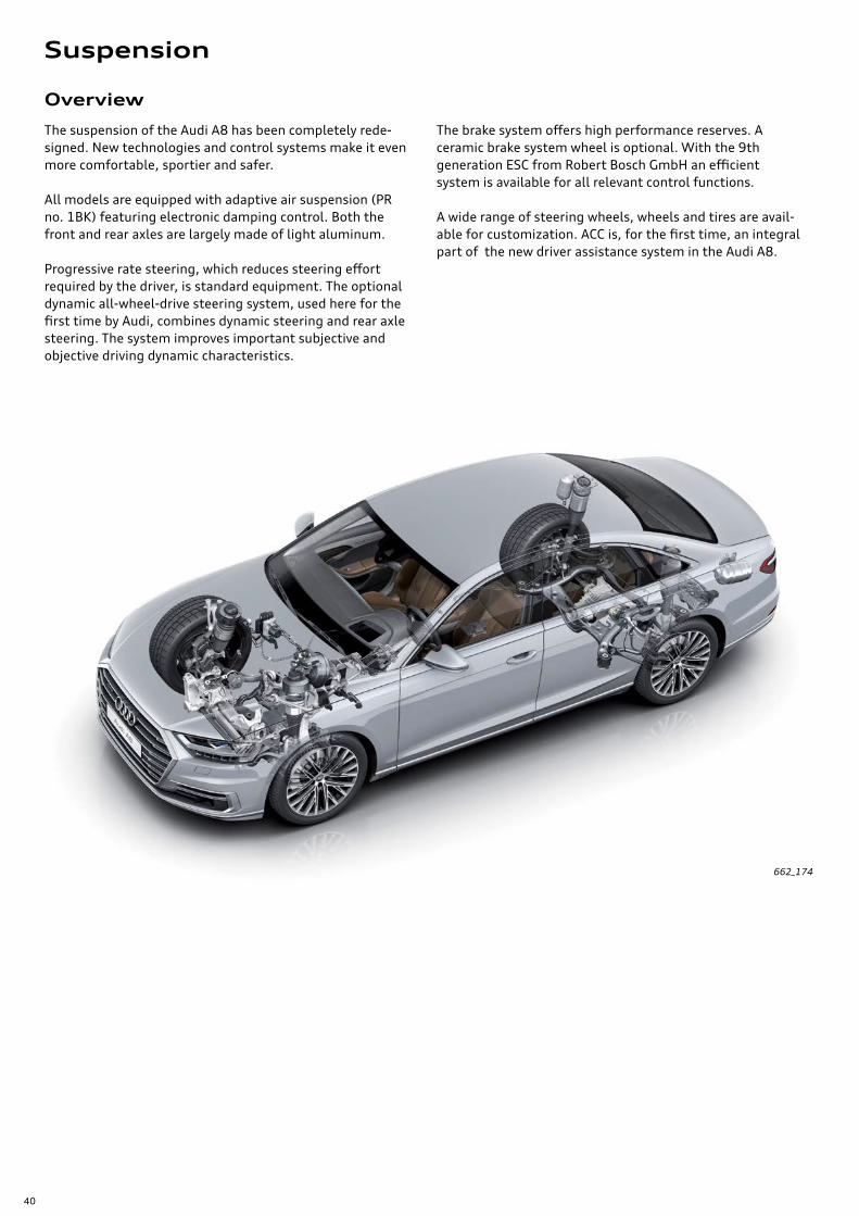
The suspension of the Audi A8 has been completely rede-signed. New technologies and control systems make it even more comfortable, sportier and safer.
All models are equipped with adaptive air suspension (PR no. 1BK) featuring electronic damping control. Both the front and rear axles are largely made of light aluminum.
Progressive rate steering, which reduces steering effort required by the driver, is standard equipment. The optional dynamic all-wheel-drive steering system, used here for the first time by Audi, combines dynamic steering and rear axle steering. The system improves important subjective and objective driving dynamic characteristics.
The brake system offers high performance reserves. A ceramic brake system wheel is optional. With the 9th generation ESC from Robert Bosch GmbH an efficient system is available for all relevant control functions.
A wide range of steering wheels, wheels and tires are avail-able for customization. ACC is, for the first time, an integral part of the new driver assistance system in the Audi A8.
662_174
Suspension
41
Axles and wheel alignment
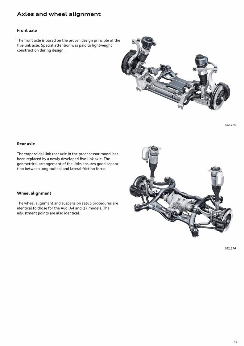
Front axle
The front axle is based on the proven design principle of the five-link axle. Special attention was paid to lightweight construction during design.
Rear axle
The trapezoidal link rear axle in the predecessor model has been replaced by a newly developed five-link axle. The geometrical arrangement of the links ensures good separa-tion between longitudinal and lateral friction force.
Wheel alignment
The wheel alignment and suspension setup procedures are identical to those for the Audi A4 and Q7 models. The adjustment points are also identical.
662_175
662_176
42
Adaptive air suspension
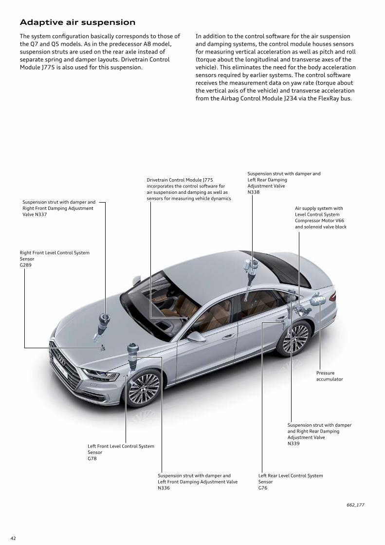
The system configuration basically corresponds to those of the Q7 and Q5 models. As in the predecessor A8 model, suspension struts are used on the rear axle instead of separate spring and damper layouts. Drivetrain Control Module J775 is also used for this suspension.
In addition to the control software for the air suspension and damping systems, the control module houses sensors for measuring vertical acceleration as well as pitch and roll (torque about the longitudinal and transverse axes of the vehicle). This eliminates the need for the body acceleration sensors required by earlier systems. The control software receives the measurement data on yaw rate (torque about the vertical axis of the vehicle) and transverse acceleration from the Airbag Control Module J234 via the FlexRay bus.
Suspension strut with damper and Right Front Damping Adjustment Valve N337
Right Front Level Control System Sensor G289
Suspension strut with damper and Left Front Damping Adjustment Valve N336
Left Front Level Control System Sensor G78
Left Rear Level Control System Sensor G76
Suspension strut with damper and Left Rear Damping Adjustment Valve N338
Pressure accumulator
Air supply system with Level Control System Compressor Motor V66 and solenoid valve block
Suspension strut with damper and Right Rear Damping Adjustment Valve N339
Drivetrain Control Module J775incorporates the control software forair suspension and damping as well as sensors for measuring vehicle dynamics
662_177

43
Steering system
Electromechanical progressive-rate steering
The Audi A8 uses the electromechanical steering system used previously in the 2017 Audi Q7. Progressive steering is standard. An electrically adjustable steering column is basic equipment. A heated steering wheel is available as an option.
662_178
Dynamic all-wheel-drive steering
As a logical development of the all-wheel-drive steering system, offered for the first time in the 2017 Audi Q7, a new system - dynamic all-wheel-drive steering - is optional in the Audi A8. A new feature is the combination of rear axle steering and dynamic steering. This allows the front and rear axles to implement defined steering angles inde-pendent of the driver.
This improves key subjective and objective dynamic steering characteristics, such as:
› Smaller turning radius. › Reduced steering effort. › Much better agility, particularly at low and medium
speeds. › Improved driving stability, specifically during lane-
changing and evasive maneuvers. › Improved response and faster vehicle reaction times.
662_179
44
Suspension
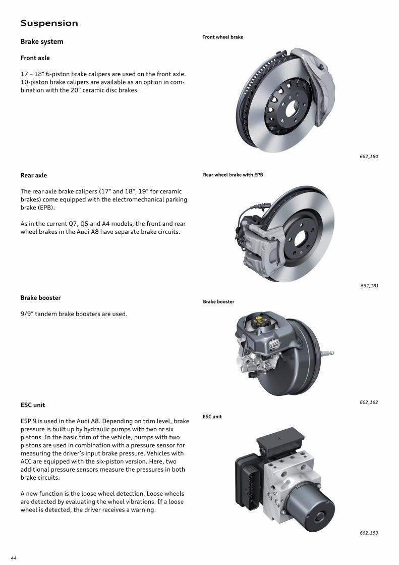
Brake system
Front axle
17 – 18" 6-piston brake calipers are used on the front axle. 10-piston brake calipers are available as an option in com-bination with the 20” ceramic disc brakes.
Rear axle
The rear axle brake calipers (17" and 18", 19" for ceramic brakes) come equipped with the electromechanical parking brake (EPB).
As in the current Q7, Q5 and A4 models, the front and rear wheel brakes in the Audi A8 have separate brake circuits.
Brake booster
9/9" tandem brake boosters are used.
ESC unit
ESP 9 is used in the Audi A8. Depending on trim level, brake pressure is built up by hydraulic pumps with two or six pistons. In the basic trim of the vehicle, pumps with two pistons are used in combination with a pressure sensor for measuring the driver’s input brake pressure. Vehicles with ACC are equipped with the six-piston version. Here, two additional pressure sensors measure the pressures in both brake circuits.
A new function is the loose wheel detection. Loose wheels are detected by evaluating the wheel vibrations. If a loose wheel is detected, the driver receives a warning.
662_180
662_181
662_182
662_183
Front wheel brake
Rear wheel brake with EPB
Brake booster
ESC unit
45
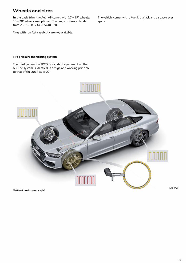
(2019 A7 used as an example)
Wheels and tires
In the basic trim, the Audi A8 comes with 17 – 19" wheels. 18 – 20" wheels are optional. The range of tires extends from 235/60 R17 to 265/40 R20.
Tires with run flat capability are not available.
The vehicle comes with a tool kit, a jack and a space saver spare.
Tire pressure monitoring system
The third generation TPMS is standard equipment on the A8. The system is identical in design and working principle to that of the 2017 Audi Q7.
669_158
46
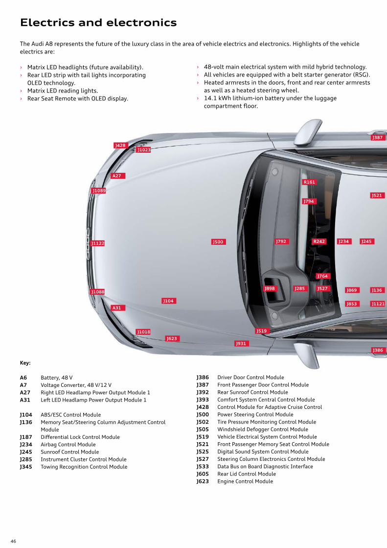
The Audi A8 represents the future of the luxury class in the area of vehicle electrics and electronics. Highlights of the vehicle electrics are:
› Matrix LED headlights (future availability). › Rear LED strip with tail lights incorporating
OLED technology. › Matrix LED reading lights. › Rear Seat Remote with OLED display.
› 48-volt main electrical system with mild hybrid technology. › All vehicles are equipped with a belt starter generator (RSG). › Heated armrests in the doors, front and rear center armrests
as well as a heated steering wheel. › 14.1 kWh lithium-ion battery under the luggage
compartment floor.
Key:
A6 Battery, 48 VA7 Voltage Converter, 48 V/12 VA27 Right LED Headlamp Power Output Module 1A31 Left LED Headlamp Power Output Module 1
J104 ABS/ESC Control ModuleJ136 Memory Seat/Steering Column Adjustment Control
ModuleJ187 Differential Lock Control ModuleJ234 Airbag Control ModuleJ245 Sunroof Control ModuleJ285 Instrument Cluster Control ModuleJ345 Towing Recognition Control Module
J386 Driver Door Control ModuleJ387 Front Passenger Door Control ModuleJ392 Rear Sunroof Control ModuleJ393 Comfort System Central Control ModuleJ428 Control Module for Adaptive Cruise ControlJ500 Power Steering Control ModuleJ502 Tire Pressure Monitoring Control ModuleJ505 Windshield Defogger Control ModuleJ519 Vehicle Electrical System Control ModuleJ521 Front Passenger Memory Seat Control ModuleJ525 Digital Sound System Control ModuleJ527 Steering Column Electronics Control ModuleJ533 Data Bus on Board Diagnostic InterfaceJ605 Rear Lid Control ModuleJ623 Engine Control Module
J500 R242
J898 J285 J527 J136
J853
J869
J1121
J764
J519
J931J623
J104
J1018
A31
J1088
J1122
J1089
A27
J1023J428
J792 J234 J245
R161
J794J521
J386
J387
Electrics and electronics
47
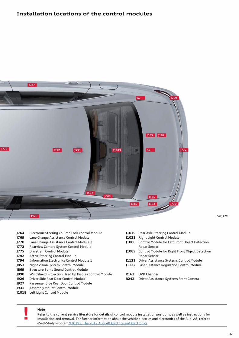
Installation locations of the control modules
NoteRefer to the current service literature for details of control module installation positions, as well as instructions for installation and removal. For further information about the vehicle electrics and electronics of the Audi A8, refer to eSelf-Study Program 970293, The 2019 Audi A8 Electrics and Electronics.
662_129
J764 Electronic Steering Column Lock Control ModuleJ769 Lane Change Assistance Control ModuleJ770 Lane Change Assistance Control Module 2J772 Rearview Camera System Control ModuleJ775 Drivetrain Control ModuleJ792 Active Steering Control ModuleJ794 Information Electronics Control Module 1J853 Night Vision System Control ModuleJ869 Structure Borne Sound Control ModuleJ898 Windshield Projection Head Up Display Control ModuleJ926 Driver Side Rear Door Control ModuleJ927 Passenger Side Rear Door Control ModuleJ931 Assembly Mount Control ModuleJ1018 Left Light Control Module
J1019 Rear Axle Steering Control ModuleJ1023 Right Light Control ModuleJ1088 Control Module for Left Front Object Detection
Radar SensorJ1089 Control Module for Right Front Object Detection
Radar SensorJ1121 Driver Assistance Systems Control ModuleJ1122 Laser Distance Regulation Control Module
R161 DVD ChangerR242 Driver Assistance Systems Front Camera
A6 J772J1019
J770
J525
J393J345
J605J502
J926
J505 J187
J769A7
J533J392
J927
J775
48
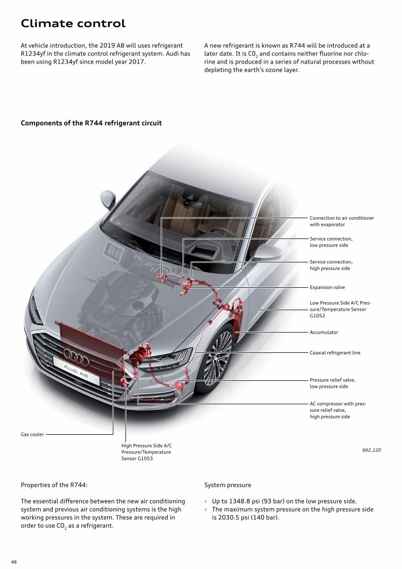
At vehicle introduction, the 2019 A8 will uses refrigerant R1234yf in the climate control refrigerant system. Audi has been using R1234yf since model year 2017.
Properties of the R744:
The essential difference between the new air conditioning system and previous air conditioning systems is the high working pressures in the system. These are required in order to use CO2 as a refrigerant.
Components of the R744 refrigerant circuit
System pressure
› Up to 1348.8 psi (93 bar) on the low pressure side. › The maximum system pressure on the high pressure side
is 2030.5 psi (140 bar).
662_120
AC compressor with pres-sure relief valve,high pressure side
Gas cooler
Pressure relief valve, low pressure side
Service connection,low pressure side
Expansion valve
Accumulator
Coaxial refrigerant line
Service connection,high pressure side
Low Pressure Side A/C Pres-sure/Temperature Sensor G1052
High Pressure Side A/C Pressure/Temperature Sensor G1053
Connection to air conditioner with evaporator
A new refrigerant is known as R744 will be introduced at a later date. It is C02 and contains neither fluorine nor chlo-rine and is produced in a series of natural processes without depleting the earth’s ozone layer.
Climate control

49
New features
Surface heating
Foot heater
Climate control panels in the front and rear
Back massage
The armrests in the door trims as well as the center arm-rests in the front and rear are heated surfaces. The heating function is activated and controlled through the seat heater.
All heated surfaces are deactivated and regulated through the seat heater.
The options here in the US are as follows: › Heated front seats standard. › Cold weather package: Rear seat heating, front heated
surfaces. › Rear heated surfaces optional.
The foot heater in the footrest of the comfort individual contour seat with reclining seat function can only be acti-vated in the unfolded position and in the rest position of the seats.
It can be operated through the Smart Remote Control and, like the seat heater and the seat ventilation system, is adjustable to three levels.
The A8 no longer requires the Climatronic Control Module J255. This means there is no need for separate control module.
The climate control is operated via two touchscreens. In terms of visual appearance and tactile feel, both displays are the key innovation in terms user operation. The MMI display and the touchscreen are installed at the center of the instrument panel and at the center of the center console respectively. Climate control functions in the upper MMI display can be accessed through the Car menu. Various control panels are available in the rear area, depending on trim level.
Cabin fragrance system
There is a choice of two different fragrances in the new Audi A8: a summer fragrance and a winter fragrance. The fragrances are stored in two cylindrical containers in Fra-grance System Functional Unit GX43, which is located to the left of the steering wheel below the instrument panel. A small fan blows the fragrance into the outer front air outlets. There is a choice of various aroma intensity levels.
Air improvement system
To improve air quality, ionisers are available in the new Audi A8. Ionizers improve air quality through the controlled negative charging of air particles before they are dis-charged into the cabin via the outer front air outlets.
An enhanced back massage feature is available in the new Audi A8. For this purpose, up to 16 bladders are integrated in the front seat and up to 18 in the rear seat. In standard trim, the seats are equipped with double lift bladders. The optional triple lift bladders are designed to provide a higher intensity back massage.
Foot massage
ReferenceFor further information about the climate control system, refer to eSelf-Study Program 980193, The 2019 Audi A8 Climate Control System.
The massage program offers two options allowing the soles of the feet to be massaged either by the linear application of pressure by massaging the reflex zones.
50
Passive safety
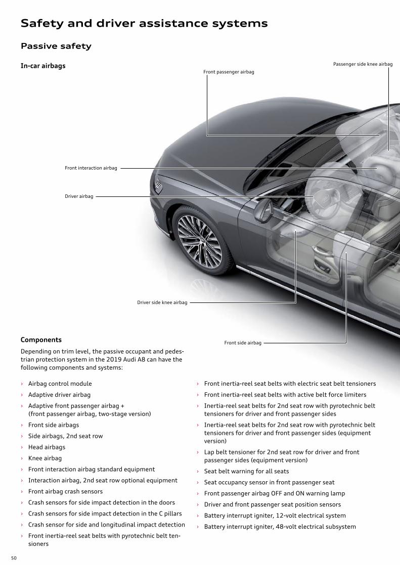
Depending on trim level, the passive occupant and pedes-trian protection system in the 2019 Audi A8 can have the following components and systems:
› Airbag control module
› Adaptive driver airbag
› Adaptive front passenger airbag + (front passenger airbag, two-stage version)
› Front side airbags
› Side airbags, 2nd seat row
› Head airbags
› Knee airbag
› Front interaction airbag standard equipment
› Interaction airbag, 2nd seat row optional equipment
› Front airbag crash sensors
› Crash sensors for side impact detection in the doors
› Crash sensors for side impact detection in the C pillars
› Crash sensor for side and longitudinal impact detection
› Front inertia-reel seat belts with pyrotechnic belt ten-sioners
In-car airbagsFront passenger airbag
Driver airbag
Front side airbag
› Front inertia-reel seat belts with electric seat belt tensioners
› Front inertia-reel seat belts with active belt force limiters
› Inertia-reel seat belts for 2nd seat row with pyrotechnic belt tensioners for driver and front passenger sides
› Inertia-reel seat belts for 2nd seat row with pyrotechnic belt tensioners for driver and front passenger sides (equipment version)
› Lap belt tensioner for 2nd seat row for driver and front passenger sides (equipment version)
› Seat belt warning for all seats
› Seat occupancy sensor in front passenger seat
› Front passenger airbag OFF and ON warning lamp
› Driver and front passenger seat position sensors
› Battery interrupt igniter, 12-volt electrical system
› Battery interrupt igniter, 48-volt electrical subsystem
Components
Front interaction airbag
Driver side knee airbag
Passenger side knee airbag
Safety and driver assistance systems

51
NoteThe diagrams in the chapter "Passive occupant safety" are schematic diagrams designed to aid understanding.
662_012
Front side airbag Head airbag,driver and front passenger sides
Side airbag, 2nd seat row
Side airbag, 2nd seat row
Interaction airbag, 2nd seat row (optional equipment)
52
G128
662_013
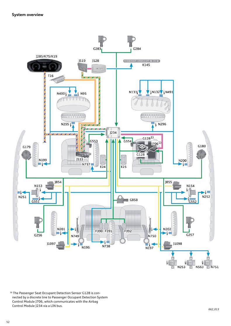
System overview
1) The Passenger Seat Occupant Detection Sensor G128 is con-nected by a discrete line to Passenger Occupant Detection System Control Module J706, which communicates with the Airbag Control Module J234 via a LIN bus.
53
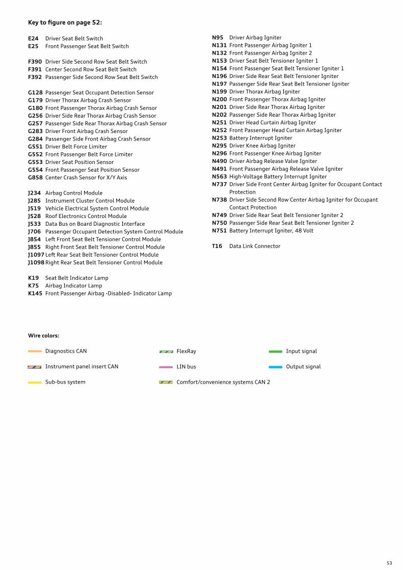
Key to figure on page 52:
E24 Driver Seat Belt SwitchE25 Front Passenger Seat Belt Switch
F390 Driver Side Second Row Seat Belt SwitchF391 Center Second Row Seat Belt SwitchF392 Passenger Side Second Row Seat Belt Switch
G128 Passenger Seat Occupant Detection SensorG179 Driver Thorax Airbag Crash SensorG180 Front Passenger Thorax Airbag Crash SensorG256 Driver Side Rear Thorax Airbag Crash SensorG257 Passenger Side Rear Thorax Airbag Crash SensorG283 Driver Front Airbag Crash SensorG284 Passenger Side Front Airbag Crash SensorG551 Driver Belt Force LimiterG552 Front Passenger Belt Force LimiterG553 Driver Seat Position SensorG554 Front Passenger Seat Position SensorG858 Center Crash Sensor for X/Y Axis
J234 Airbag Control ModuleJ285 Instrument Cluster Control ModuleJ519 Vehicle Electrical System Control ModuleJ528 Roof Electronics Control ModuleJ533 Data Bus on Board Diagnostic InterfaceJ706 Passenger Occupant Detection System Control ModuleJ854 Left Front Seat Belt Tensioner Control ModuleJ855 Right Front Seat Belt Tensioner Control ModuleJ1097 Left Rear Seat Belt Tensioner Control ModuleJ1098 Right Rear Seat Belt Tensioner Control Module
K19 Seat Belt Indicator LampK75 Airbag Indicator LampK145 Front Passenger Airbag -Disabled- Indicator Lamp
Wire colors:
Diagnostics CAN
Instrument panel insert CAN
Sub-bus system
Input signal
Output signal
FlexRay
LIN bus
Comfort/convenience systems CAN 2
N95 Driver Airbag IgniterN131 Front Passenger Airbag Igniter 1N132 Front Passenger Airbag Igniter 2N153 Driver Seat Belt Tensioner Igniter 1N154 Front Passenger Seat Belt Tensioner Igniter 1N196 Driver Side Rear Seat Belt Tensioner IgniterN197 Passenger Side Rear Seat Belt Tensioner IgniterN199 Driver Thorax Airbag IgniterN200 Front Passenger Thorax Airbag IgniterN201 Driver Side Rear Thorax Airbag IgniterN202 Passenger Side Rear Thorax Airbag IgniterN251 Driver Head Curtain Airbag IgniterN252 Front Passenger Head Curtain Airbag IgniterN253 Battery Interrupt IgniterN295 Driver Knee Airbag IgniterN296 Front Passenger Knee Airbag IgniterN490 Driver Airbag Release Valve IgniterN491 Front Passenger Airbag Release Valve IgniterN563 High-Voltage Battery Interrupt IgniterN737 Driver Side Front Center Airbag Igniter for Occupant Contact
ProtectionN738 Driver Side Second Row Center Airbag Igniter for Occupant
Contact ProtectionN749 Driver Side Rear Seat Belt Tensioner Igniter 2N750 Passenger Side Rear Seat Belt Tensioner Igniter 2N751 Battery Interrupt Igniter, 48 Volt
T16 Data Link Connector

54
Airbag Control Module J234
Data bus interface
J234 communicates via the FlexRay data bus. Due to the increased volume of data in comparison with the Audi Q7, J234 now communicates with the FlexRay data bus via two data lines (channels). These data lines are designated channel "A" and channel "B".
662_056
662_055
Installation location
Data Bus on Board Diagnostic Interface J533
Driver Assistance Systems Control Module J1121
J706
J854
J1097
J855
J1098
J187
J623
J1088
J1089
J769
J770
J104
J217
J775
J1019 J792
J500
J428
J1122
J234
J527
Channel A Channel B
Wire colors:
FlexRay
LIN bus
Sub-bus system
System overview
For the sake of clarity, additional system components are only shown on the Airbag Control Module J234.
55
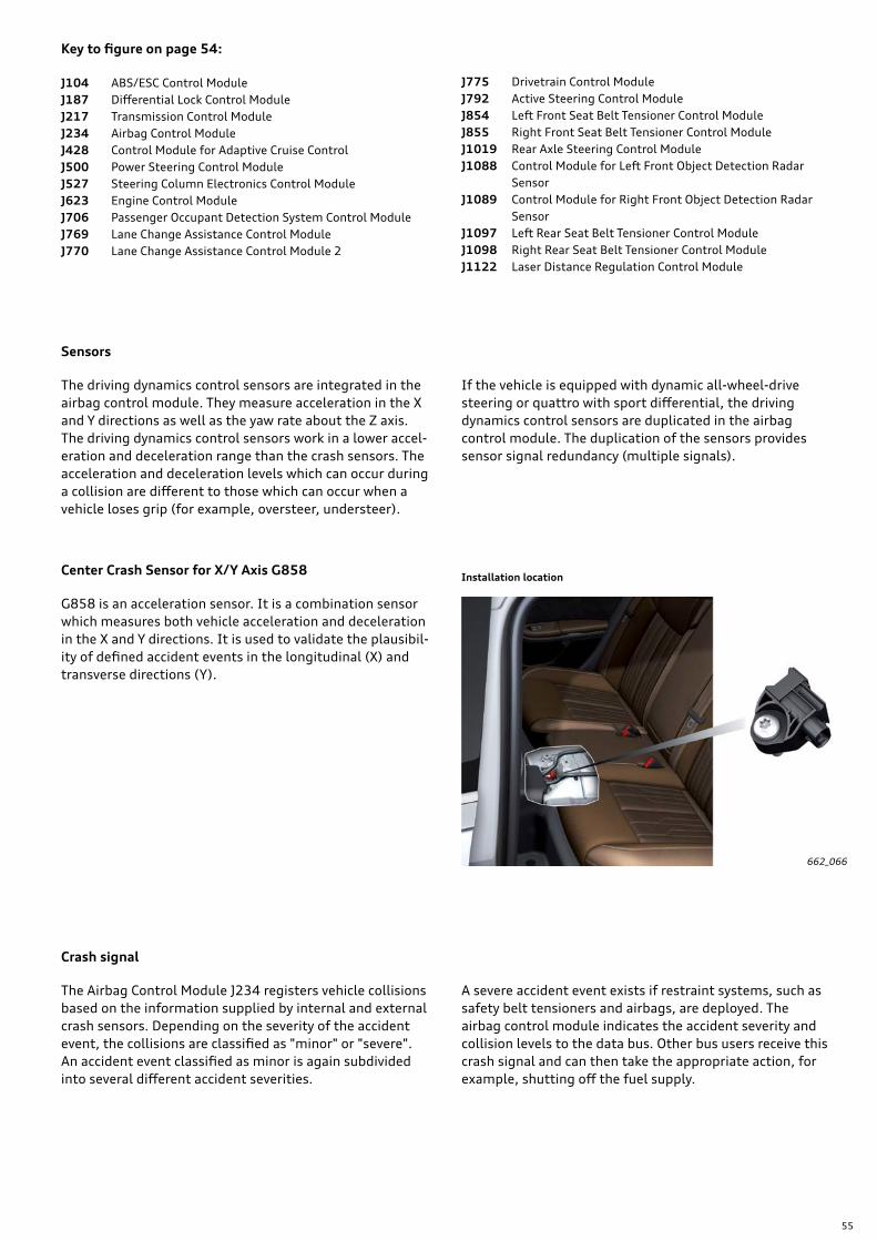
Sensors
The driving dynamics control sensors are integrated in the airbag control module. They measure acceleration in the X and Y directions as well as the yaw rate about the Z axis. The driving dynamics control sensors work in a lower accel-eration and deceleration range than the crash sensors. The acceleration and deceleration levels which can occur during a collision are different to those which can occur when a vehicle loses grip (for example, oversteer, understeer).
G858 is an acceleration sensor. It is a combination sensor which measures both vehicle acceleration and deceleration in the X and Y directions. It is used to validate the plausibil-ity of defined accident events in the longitudinal (X) and transverse directions (Y).
662_066
Crash signal
The Airbag Control Module J234 registers vehicle collisions based on the information supplied by internal and external crash sensors. Depending on the severity of the accident event, the collisions are classified as "minor" or "severe". An accident event classified as minor is again subdivided into several different accident severities.
Center Crash Sensor for X/Y Axis G858
A severe accident event exists if restraint systems, such as safety belt tensioners and airbags, are deployed. The airbag control module indicates the accident severity and collision levels to the data bus. Other bus users receive this crash signal and can then take the appropriate action, for example, shutting off the fuel supply.
If the vehicle is equipped with dynamic all-wheel-drive steering or quattro with sport differential, the driving dynamics control sensors are duplicated in the airbag control module. The duplication of the sensors provides sensor signal redundancy (multiple signals).
Installation location
Key to figure on page 54:
J104 ABS/ESC Control ModuleJ187 Differential Lock Control ModuleJ217 Transmission Control ModuleJ234 Airbag Control ModuleJ428 Control Module for Adaptive Cruise ControlJ500 Power Steering Control ModuleJ527 Steering Column Electronics Control ModuleJ623 Engine Control ModuleJ706 Passenger Occupant Detection System Control ModuleJ769 Lane Change Assistance Control ModuleJ770 Lane Change Assistance Control Module 2
J775 Drivetrain Control ModuleJ792 Active Steering Control ModuleJ854 Left Front Seat Belt Tensioner Control ModuleJ855 Right Front Seat Belt Tensioner Control ModuleJ1019 Rear Axle Steering Control ModuleJ1088 Control Module for Left Front Object Detection Radar
SensorJ1089 Control Module for Right Front Object Detection Radar
SensorJ1097 Left Rear Seat Belt Tensioner Control ModuleJ1098 Right Rear Seat Belt Tensioner Control ModuleJ1122 Laser Distance Regulation Control Module
56
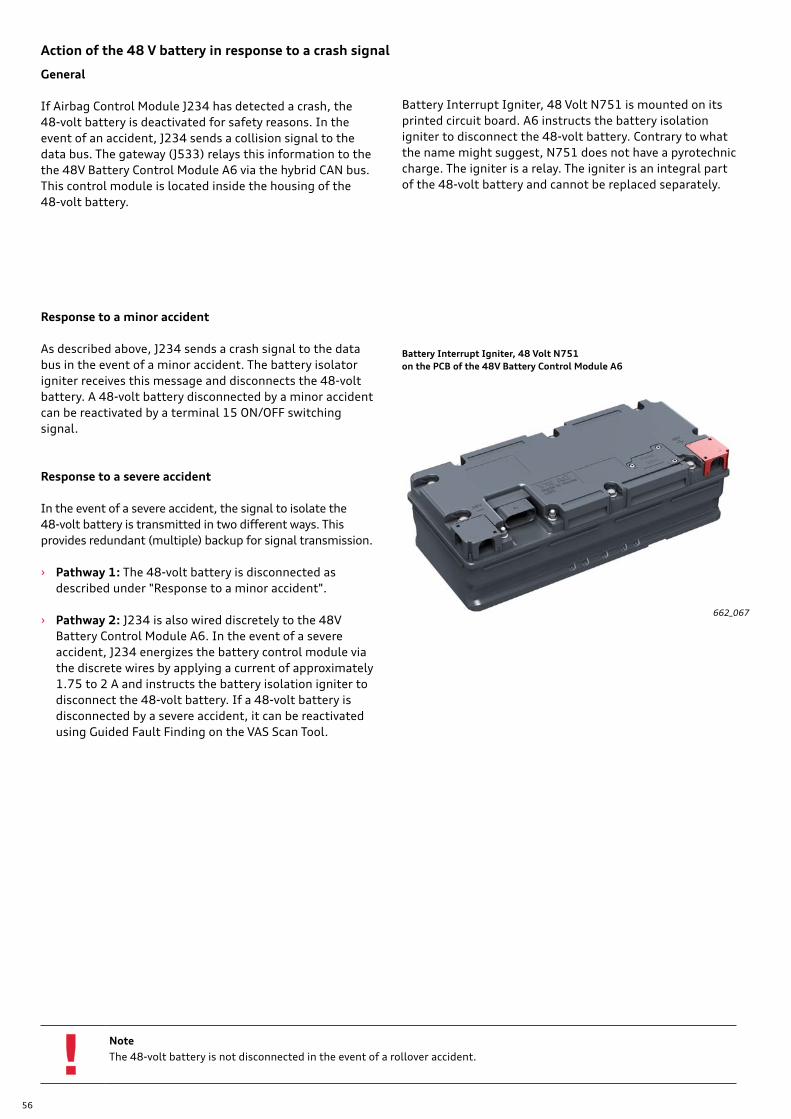
Battery Interrupt Igniter, 48 Volt N751on the PCB of the 48V Battery Control Module A6
662_067
Action of the 48 V battery in response to a crash signal
General
If Airbag Control Module J234 has detected a crash, the 48-volt battery is deactivated for safety reasons. In the event of an accident, J234 sends a collision signal to the data bus. The gateway (J533) relays this information to the the 48V Battery Control Module A6 via the hybrid CAN bus. This control module is located inside the housing of the 48-volt battery.
Response to a minor accident
As described above, J234 sends a crash signal to the data bus in the event of a minor accident. The battery isolator igniter receives this message and disconnects the 48-volt battery. A 48-volt battery disconnected by a minor accident can be reactivated by a terminal 15 ON/OFF switching signal.
Response to a severe accident
In the event of a severe accident, the signal to isolate the 48-volt battery is transmitted in two different ways. This provides redundant (multiple) backup for signal transmission.
› Pathway 1: The 48-volt battery is disconnected as described under "Response to a minor accident".
› Pathway 2: J234 is also wired discretely to the 48V Battery Control Module A6. In the event of a severe accident, J234 energizes the battery control module via the discrete wires by applying a current of approximately 1.75 to 2 A and instructs the battery isolation igniter to disconnect the 48-volt battery. If a 48-volt battery is disconnected by a severe accident, it can be reactivated using Guided Fault Finding on the VAS Scan Tool.
NoteThe 48-volt battery is not disconnected in the event of a rollover accident.
Battery Interrupt Igniter, 48 Volt N751 is mounted on its printed circuit board. A6 instructs the battery isolation igniter to disconnect the 48-volt battery. Contrary to what the name might suggest, N751 does not have a pyrotechnic charge. The igniter is a relay. The igniter is an integral part of the 48-volt battery and cannot be replaced separately.
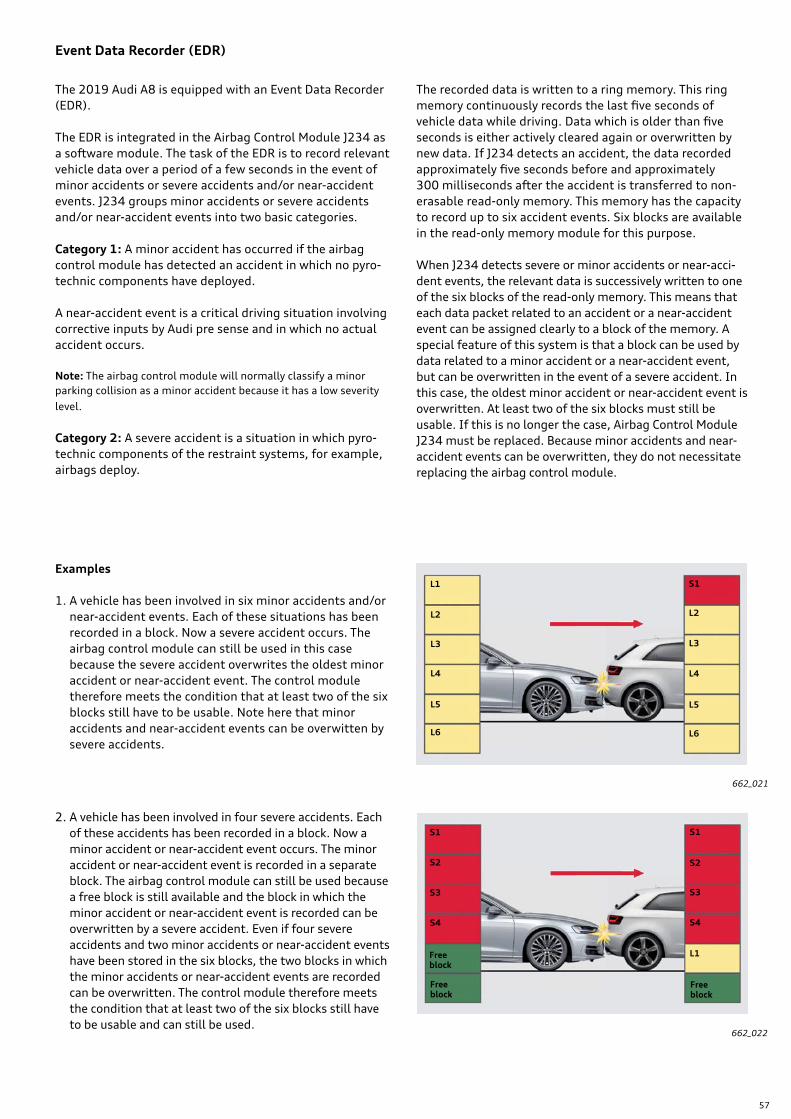
57
L1
L2
L3
L4
L5
L6
S1
L2
L3
L4
L5
L6
L1
S4
S3
S2
S1
S4
S3
S2
S1
Event Data Recorder (EDR)
The 2019 Audi A8 is equipped with an Event Data Recorder (EDR).
The EDR is integrated in the Airbag Control Module J234 as a software module. The task of the EDR is to record relevant vehicle data over a period of a few seconds in the event of minor accidents or severe accidents and/or near-accident events. J234 groups minor accidents or severe accidents and/or near-accident events into two basic categories.
Category 1: A minor accident has occurred if the airbag control module has detected an accident in which no pyro-technic components have deployed.
A near-accident event is a critical driving situation involving corrective inputs by Audi pre sense and in which no actual accident occurs.
Note: The airbag control module will normally classify a minor parking collision as a minor accident because it has a low severity level.
Category 2: A severe accident is a situation in which pyro-technic components of the restraint systems, for example, airbags deploy.
Examples
1. A vehicle has been involved in six minor accidents and/or near-accident events. Each of these situations has been recorded in a block. Now a severe accident occurs. The airbag control module can still be used in this case because the severe accident overwrites the oldest minor accident or near-accident event. The control module therefore meets the condition that at least two of the six blocks still have to be usable. Note here that minor accidents and near-accident events can be overwitten by severe accidents.
2. A vehicle has been involved in four severe accidents. Each of these accidents has been recorded in a block. Now a minor accident or near-accident event occurs. The minor accident or near-accident event is recorded in a separate block. The airbag control module can still be used because a free block is still available and the block in which the minor accident or near-accident event is recorded can be overwritten by a severe accident. Even if four severe accidents and two minor accidents or near-accident events have been stored in the six blocks, the two blocks in which the minor accidents or near-accident events are recorded can be overwritten. The control module therefore meets the condition that at least two of the six blocks still have to be usable and can still be used.
662_021
662_022
Free block
Free block
Free block
The recorded data is written to a ring memory. This ring memory continuously records the last five seconds of vehicle data while driving. Data which is older than five seconds is either actively cleared again or overwritten by new data. If J234 detects an accident, the data recorded approximately five seconds before and approximately 300 milliseconds after the accident is transferred to non-erasable read-only memory. This memory has the capacity to record up to six accident events. Six blocks are available in the read-only memory module for this purpose.
When J234 detects severe or minor accidents or near-acci-dent events, the relevant data is successively written to one of the six blocks of the read-only memory. This means that each data packet related to an accident or a near-accident event can be assigned clearly to a block of the memory. A special feature of this system is that a block can be used by data related to a minor accident or a near-accident event, but can be overwritten in the event of a severe accident. In this case, the oldest minor accident or near-accident event is overwritten. At least two of the six blocks must still be usable. If this is no longer the case, Airbag Control Module J234 must be replaced. Because minor accidents and near-accident events can be overwritten, they do not necessitate replacing the airbag control module.
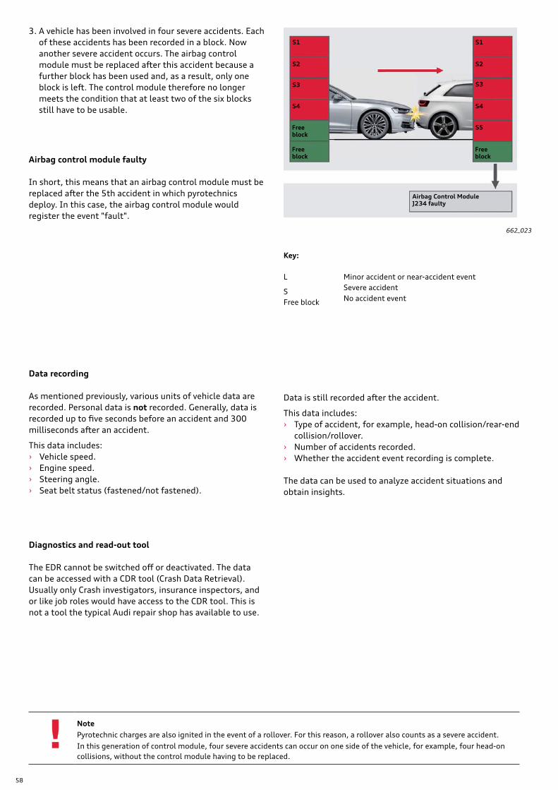
58
S5
S4
S3
S2
S1
S4
S3
S2
S1
L
S
3. A vehicle has been involved in four severe accidents. Each of these accidents has been recorded in a block. Now another severe accident occurs. The airbag control module must be replaced after this accident because a further block has been used and, as a result, only one block is left. The control module therefore no longer meets the condition that at least two of the six blocks still have to be usable.
662_023
Airbag control module faulty
In short, this means that an airbag control module must be replaced after the 5th accident in which pyrotechnics deploy. In this case, the airbag control module would register the event "fault".
NotePyrotechnic charges are also ignited in the event of a rollover. For this reason, a rollover also counts as a severe accident. In this generation of control module, four severe accidents can occur on one side of the vehicle, for example, four head-on collisions, without the control module having to be replaced.
Data recording
As mentioned previously, various units of vehicle data are recorded. Personal data is not recorded. Generally, data is recorded up to five seconds before an accident and 300 milliseconds after an accident.
This data includes: › Vehicle speed. › Engine speed. › Steering angle. › Seat belt status (fastened/not fastened).
Diagnostics and read-out tool
The EDR cannot be switched off or deactivated. The data can be accessed with a CDR tool (Crash Data Retrieval). Usually only Crash investigators, insurance inspectors, and or like job roles would have access to the CDR tool. This is not a tool the typical Audi repair shop has available to use.
Free block
Free block
Free block
Airbag Control Module J234 faulty
Minor accident or near-accident eventSevere accident
Key:
Free block No accident event
Data is still recorded after the accident.
This data includes: › Type of accident, for example, head-on collision/rear-end
collision/rollover. › Number of accidents recorded. › Whether the accident event recording is complete.
The data can be used to analyze accident situations and obtain insights.
59
Assistance system monitor (ASM)
The 2019 A8 is equipped worldwide with an assistance system monitor.
The ASM is integrated in Airbag Control Module J234 as a software module. The task of the ASM is to record the data from the driver assistance systems installed in the vehicle over a period of approximately ten seconds before an acci-dent or a near-accident event. The data is written to a ring memory. This ring memory continuously records the last ten seconds of vehicle data while driving. Data which is older than ten seconds is either actively cleared again or overwritten by new data. If the airbag control module detects an accident or a near-accident event, the last approximately ten seconds of vehicle data before the acci-dent is transferred to a read-only memory.
The ASM can be deactivated by service personnel using the "Guided Fault Finding" function. There is a special ASM deactivation form which must be filled out and signed by the customer.
ReferenceFor further information about the EDR and ASM, refer to the Owner's Manual.
Diagnostics
Introduction
As with the EDR, the ASM has a read-only memory consist-ing of six blocks. In this case, too, the relevant data is successively written to the blocks after an accident or a near-accident event. Generally, a distinction is made between static and dynamic data, both of which are recorded. Static data indicates whether a driver assistance system is on or off, while dynamic data indicates whether the ESC (Electronic Stability Control) has made corrective inputs or not. The ASM is able to record data from the driver assistance systems, for example, adaptive cruise assist, ESC (Electronic Stability Control), Audi pre sense and others.
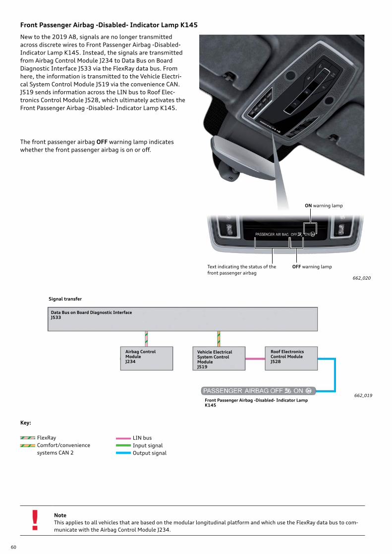
60
Front Passenger Airbag -Disabled- Indicator Lamp K145
662_019
662_020
New to the 2019 A8, signals are no longer transmitted across discrete wires to Front Passenger Airbag -Disabled- Indicator Lamp K145. Instead, the signals are transmitted from Airbag Control Module J234 to Data Bus on Board Diagnostic Interface J533 via the FlexRay data bus. From here, the information is transmitted to the Vehicle Electri-cal System Control Module J519 via the convenience CAN. J519 sends information across the LIN bus to Roof Elec-tronics Control Module J528, which ultimately activates the Front Passenger Airbag -Disabled- Indicator Lamp K145.
NoteThis applies to all vehicles that are based on the modular longitudinal platform and which use the FlexRay data bus to com-municate with the Airbag Control Module J234.
Key:
FlexRay Comfort/convenience
systems CAN 2
LIN bus Input signal Output signal
The front passenger airbag OFF warning lamp indicates whether the front passenger airbag is on or off.
Text indicating the status of the front passenger airbag
OFF warning lamp
ON warning lamp
Airbag Control Module J234
Data Bus on Board Diagnostic Interface J533
Vehicle Electrical System Control Module J519
Roof Electronics Control Module J528
Front Passenger Airbag -Disabled- Indicator LampK145
Signal transfer
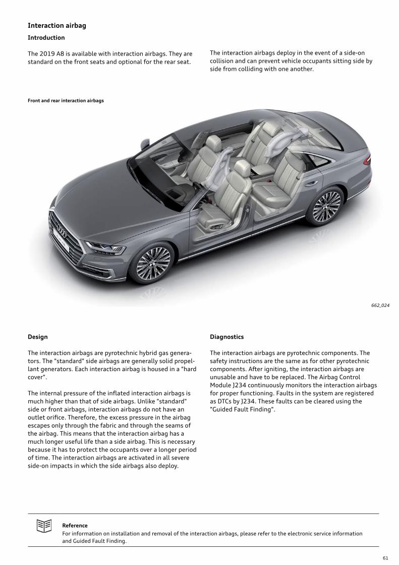
61
662_024
Interaction airbag
Introduction
The 2019 A8 is available with interaction airbags. They are standard on the front seats and optional for the rear seat.
The interaction airbags deploy in the event of a side-on collision and can prevent vehicle occupants sitting side by side from colliding with one another.
Design
The interaction airbags are pyrotechnic hybrid gas genera-tors. The "standard" side airbags are generally solid propel-lant generators. Each interaction airbag is housed in a "hard cover".
The internal pressure of the inflated interaction airbags is much higher than that of side airbags. Unlike "standard" side or front airbags, interaction airbags do not have an outlet orifice. Therefore, the excess pressure in the airbag escapes only through the fabric and through the seams of the airbag. This means that the interaction airbag has a much longer useful life than a side airbag. This is necessary because it has to protect the occupants over a longer period of time. The interaction airbags are activated in all severe side-on impacts in which the side airbags also deploy.
ReferenceFor information on installation and removal of the interaction airbags, please refer to the electronic service information and Guided Fault Finding.
Diagnostics
The interaction airbags are pyrotechnic components. The safety instructions are the same as for other pyrotechnic components. After igniting, the interaction airbags are unusable and have to be replaced. The Airbag Control Module J234 continuously monitors the interaction airbags for proper functioning. Faults in the system are registered as DTCs by J234. These faults can be cleared using the "Guided Fault Finding".
Front and rear interaction airbags
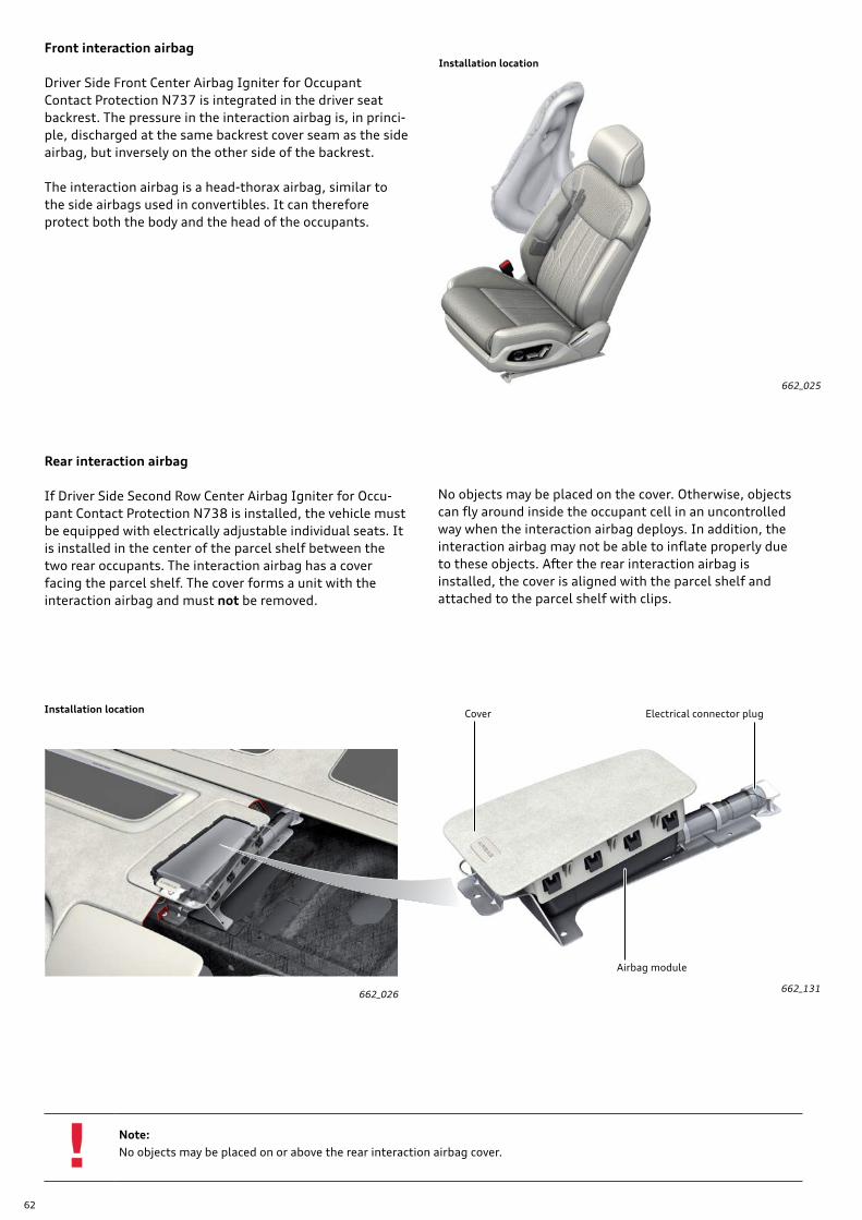
62
662_025
662_026
Front interaction airbag
Driver Side Front Center Airbag Igniter for Occupant Contact Protection N737 is integrated in the driver seat backrest. The pressure in the interaction airbag is, in princi-ple, discharged at the same backrest cover seam as the side airbag, but inversely on the other side of the backrest.
The interaction airbag is a head-thorax airbag, similar to the side airbags used in convertibles. It can therefore protect both the body and the head of the occupants.
Rear interaction airbag
If Driver Side Second Row Center Airbag Igniter for Occu-pant Contact Protection N738 is installed, the vehicle must be equipped with electrically adjustable individual seats. It is installed in the center of the parcel shelf between the two rear occupants. The interaction airbag has a cover facing the parcel shelf. The cover forms a unit with the interaction airbag and must not be removed.
Note:No objects may be placed on or above the rear interaction airbag cover.
Airbag module
Cover Electrical connector plug
No objects may be placed on the cover. Otherwise, objects can fly around inside the occupant cell in an uncontrolled way when the interaction airbag deploys. In addition, the interaction airbag may not be able to inflate properly due to these objects. After the rear interaction airbag is installed, the cover is aligned with the parcel shelf and attached to the parcel shelf with clips.
662_131
Installation location
Installation location
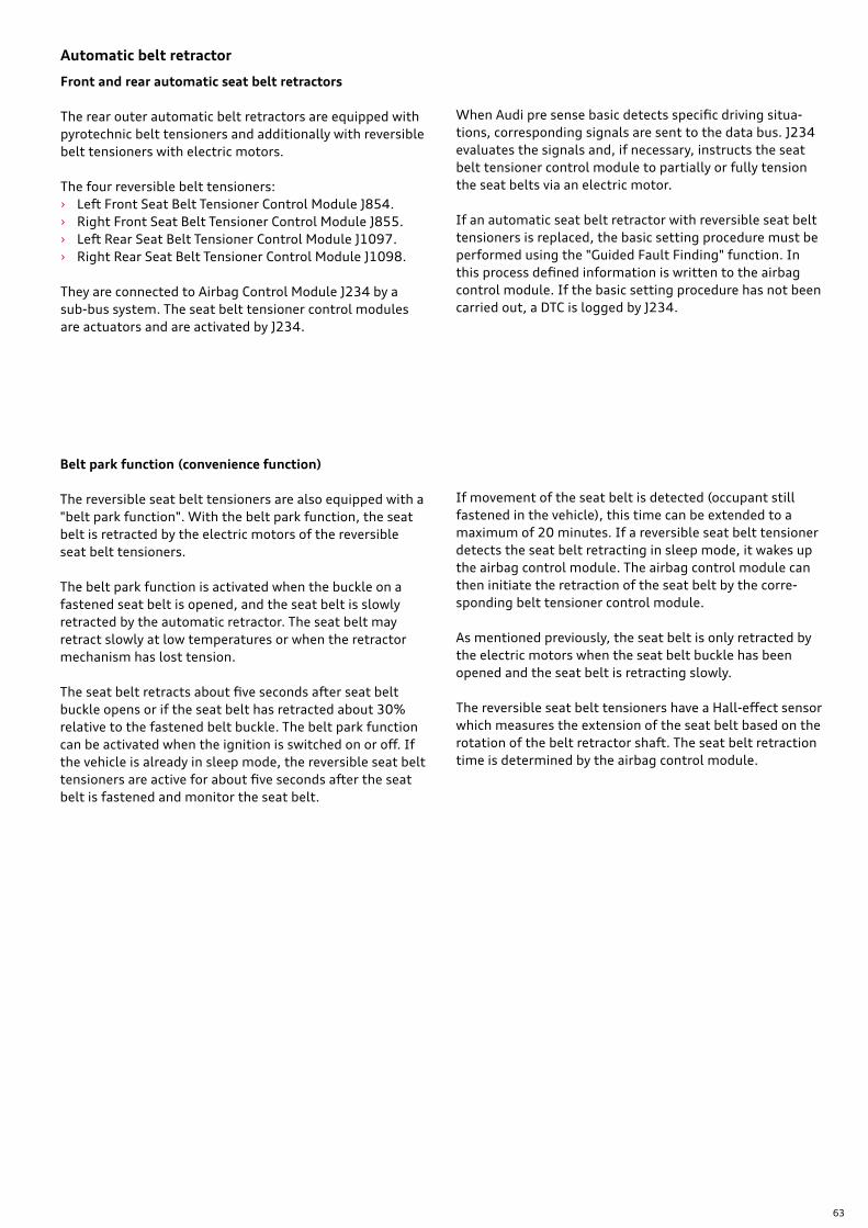
63
Front and rear automatic seat belt retractors
The rear outer automatic belt retractors are equipped with pyrotechnic belt tensioners and additionally with reversible belt tensioners with electric motors.
The four reversible belt tensioners: › Left Front Seat Belt Tensioner Control Module J854. › Right Front Seat Belt Tensioner Control Module J855. › Left Rear Seat Belt Tensioner Control Module J1097. › Right Rear Seat Belt Tensioner Control Module J1098.
They are connected to Airbag Control Module J234 by a sub-bus system. The seat belt tensioner control modules are actuators and are activated by J234.
Belt park function (convenience function)
The reversible seat belt tensioners are also equipped with a "belt park function". With the belt park function, the seat belt is retracted by the electric motors of the reversible seat belt tensioners.
The belt park function is activated when the buckle on a fastened seat belt is opened, and the seat belt is slowly retracted by the automatic retractor. The seat belt may retract slowly at low temperatures or when the retractor mechanism has lost tension.
The seat belt retracts about five seconds after seat belt buckle opens or if the seat belt has retracted about 30% relative to the fastened belt buckle. The belt park function can be activated when the ignition is switched on or off. If the vehicle is already in sleep mode, the reversible seat belt tensioners are active for about five seconds after the seat belt is fastened and monitor the seat belt.
Automatic belt retractor
When Audi pre sense basic detects specific driving situa-tions, corresponding signals are sent to the data bus. J234 evaluates the signals and, if necessary, instructs the seat belt tensioner control module to partially or fully tension the seat belts via an electric motor.
If an automatic seat belt retractor with reversible seat belt tensioners is replaced, the basic setting procedure must be performed using the "Guided Fault Finding" function. In this process defined information is written to the airbag control module. If the basic setting procedure has not been carried out, a DTC is logged by J234.
If movement of the seat belt is detected (occupant still fastened in the vehicle), this time can be extended to a maximum of 20 minutes. If a reversible seat belt tensioner detects the seat belt retracting in sleep mode, it wakes up the airbag control module. The airbag control module can then initiate the retraction of the seat belt by the corre-sponding belt tensioner control module.
As mentioned previously, the seat belt is only retracted by the electric motors when the seat belt buckle has been opened and the seat belt is retracting slowly.
The reversible seat belt tensioners have a Hall-effect sensor which measures the extension of the seat belt based on the rotation of the belt retractor shaft. The seat belt retraction time is determined by the airbag control module.
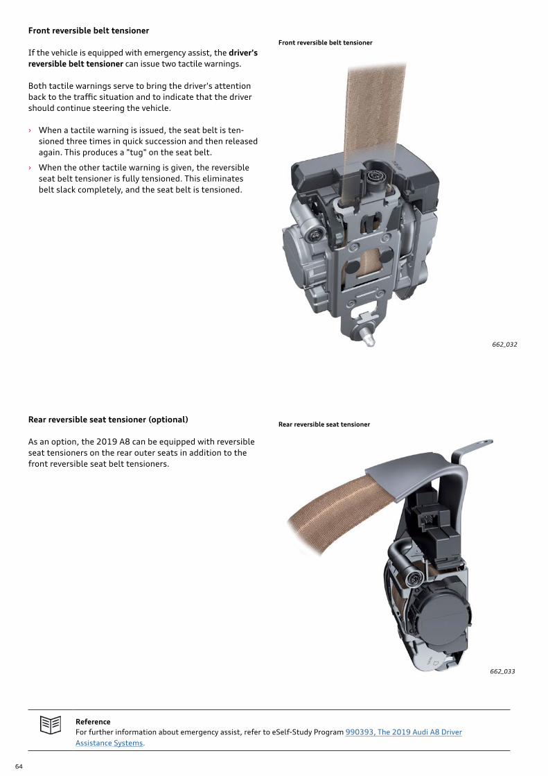
64
Front reversible belt tensioner
If the vehicle is equipped with emergency assist, the driver's reversible belt tensioner can issue two tactile warnings.
Both tactile warnings serve to bring the driver's attention back to the traffic situation and to indicate that the driver should continue steering the vehicle.
› When a tactile warning is issued, the seat belt is ten-sioned three times in quick succession and then released again. This produces a "tug" on the seat belt.
› When the other tactile warning is given, the reversible seat belt tensioner is fully tensioned. This eliminates belt slack completely, and the seat belt is tensioned.
662_032
Rear reversible seat tensioner (optional)
As an option, the 2019 A8 can be equipped with reversible seat tensioners on the rear outer seats in addition to the front reversible seat belt tensioners.
662_033
ReferenceFor further information about emergency assist, refer to eSelf-Study Program 990393, The 2019 Audi A8 Driver Assistance Systems.
Front reversible belt tensioner
Rear reversible seat tensioner
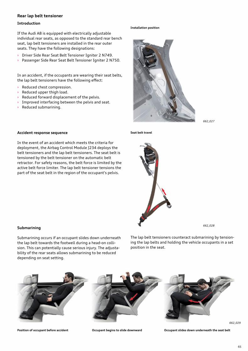
65
Rear lap belt tensioner
Introduction
If the Audi A8 is equipped with electrically adjustable individual rear seats, as opposed to the standard rear bench seat, lap belt tensioners are installed in the rear outer seats. They have the following designations:
› Driver Side Rear Seat Belt Tensioner Igniter 2 N749. › Passenger Side Rear Seat Belt Tensioner Igniter 2 N750.
In an accident, if the occupants are wearing their seat belts, the lap belt tensioners have the following effect:
› Reduced chest compression. › Reduced upper thigh load. › Reduced forward displacement of the pelvis. › Improved interfacing between the pelvis and seat. › Reduced submarining.
Accident response sequence
In the event of an accident which meets the criteria for deployment, the Airbag Control Module J234 deploys the belt tensioners and the lap belt tensioners. The seat belt is tensioned by the belt tensioner on the automatic belt retractor. For safety reasons, the belt force is limited by the active belt force limiter. The lap belt tensioner tensions the part of the seat belt in the region of the occupant's pelvis.
Submarining
Submarining occurs if an occupant slides down underneath the lap belt towards the footwell during a head-on colli-sion. This can potentially cause serious injury. The adjusta-bility of the rear seats allows submarining to be reduced depending on seat setting.
Position of occupant before accident Occupant begins to slide downward Occupant slides down underneath the seat belt
662_027
662_028
662_029
The lap belt tensioners counteract submarining by tension-ing the lap belts and holding the vehicle occupants in a set position in the seat.
Seat belt travel
Installation position
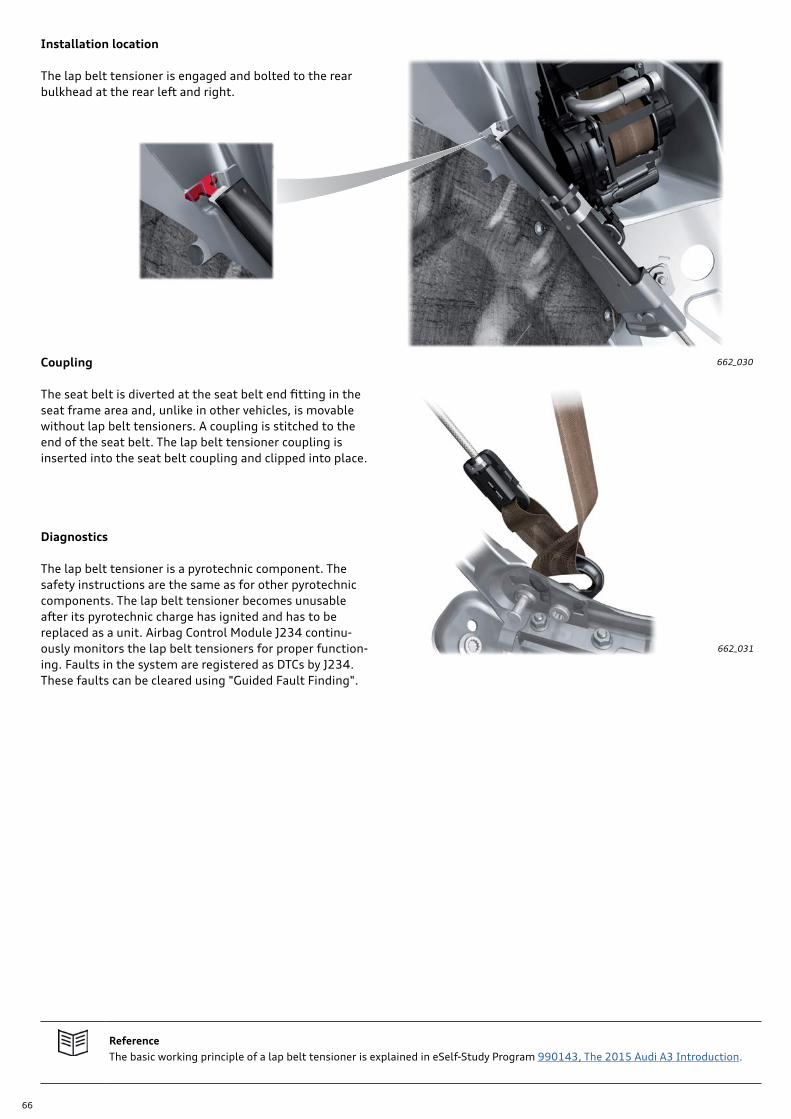
66
Installation location
The lap belt tensioner is engaged and bolted to the rear bulkhead at the rear left and right.
Coupling
The seat belt is diverted at the seat belt end fitting in the seat frame area and, unlike in other vehicles, is movable without lap belt tensioners. A coupling is stitched to the end of the seat belt. The lap belt tensioner coupling is inserted into the seat belt coupling and clipped into place.
Diagnostics
The lap belt tensioner is a pyrotechnic component. The safety instructions are the same as for other pyrotechnic components. The lap belt tensioner becomes unusable after its pyrotechnic charge has ignited and has to be replaced as a unit. Airbag Control Module J234 continu-ously monitors the lap belt tensioners for proper function-ing. Faults in the system are registered as DTCs by J234. These faults can be cleared using "Guided Fault Finding".
ReferenceThe basic working principle of a lap belt tensioner is explained in eSelf-Study Program 990143, The 2015 Audi A3 Introduction.
662_031
662_030

67
LED unit with housing
Optical fiber
Cap
Cable with 4-pin plug
Seat belt buckle
Illuminated seat belt buckles
Introduction
Illuminated seat belt buckles are standard on the A8 and help the vehicle occupants to locate their seat belt buckle in the dark.
The illuminated seat belt buckles are installed at the front and rear on the driver and front passenger sides. Vehicle Electrical System Control Module J519 is responsible for the illumination. For this reason, J519 is discretely wired to the seat belt buckle lighting units. For further information about the illumination function of the seat belt buckles (for example, switch-on point, run-on time etc.), please refer to eSelf-Study Program 970293, The 2019 Audi A8 Electrics and Electronics.
Design of the lighting unit
662_014
Luminous ring
The actual seat belt function is unchanged. This means that the seat belt buckles are still a component part of the occupant protection system and are wired to Airbag Control Module J234.
Illuminated seat belt buckles require four-pin electrical plugs instead of two.
68
Active safety
Audi pre sense
Working within its system limitations, Audi pre sense is able to initiate actions to protect the occupants and other road users in certain critical situations.
The vehicle and its occupants are prepared for in the event of a potentially imminent collision.
This is made possible by the connectivity of the various in-car systems. The systems send data continuously to the data bus. Other control modules are able to evaluate this information and take appropriate action.
Depending on the Audi pre sense package (rear, side, front, collision avoidance assist and turn assist), trucks, passen-ger cars, motorcycles, bicycles and pedestrians can be detected.
Please note that Audi pre sense cannot prevent collisions. It serves only to assist the driver and it can reduce the severity of the collision.
It should also be noted that not all objects or lane makings can be detected by the sensor or by the camera.
Pages 69 through 92 describe the Audi pre sense functions available (dependent on model and options selected) on the 2019 Audi A8 and how they interact with other systems on the vehicle.
Airbag Control Module J234 has been modified extensively with regard to Audi pre sense. These modifications mean that J234 can now initiate Audi pre sense actions which were previously initiated by other control modules.
For example, Driver Assistance Systems Front Camera R242 evaluates the "image data" which it has acquired. Depend-ing on the severity of the critical situation, the front camera then instructs other systems to initiate actions. Such actions can include an acute warning (brake warning) or automatic and/or assistive braking by ABS/ESC Control Module J104.
The ACC control module and the side assist control modules behave similarly. They also register and evaluate driving situations. If necessary, they can instruct other systems to initiate actions, depending on the driving situation.
Airbag control module
In consequence to the above-mentioned modifications, the various modules now send their driving situation data to Driver Assistance Systems Control Module J1121 where it is collated and evaluated.
This merging of information (data) from different sources is termed "data fusion". The advantage of data fusion is that it provides a comprehensive picture of the vehicle periphery. J1121 sends this data via the bus systems to recipients such as the airbag control module. The airbag control module evaluates this data and can instruct other systems to initiate actions appropriate to the situation.
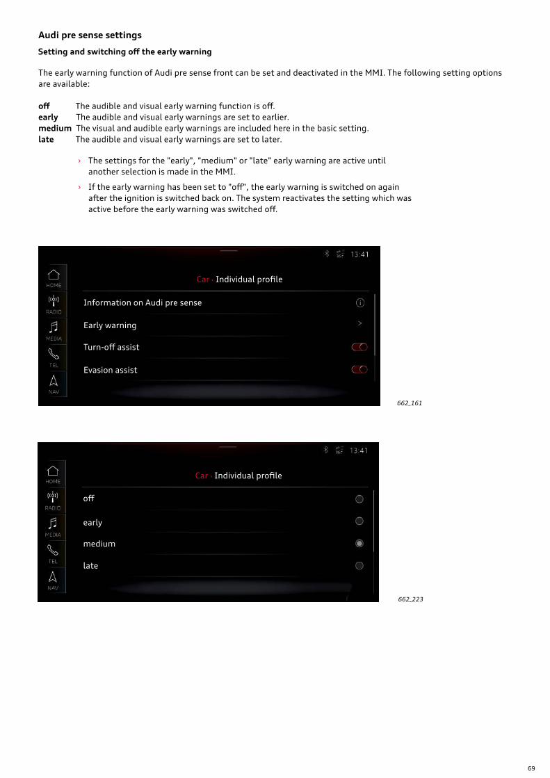
69
Audi pre sense settings
The early warning function of Audi pre sense front can be set and deactivated in the MMI. The following setting options are available:
off The audible and visual early warning function is off.early The audible and visual early warnings are set to earlier.medium The visual and audible early warnings are included here in the basic setting.late The audible and visual early warnings are set to later.
› The settings for the "early", "medium" or "late" early warning are active until another selection is made in the MMI.
› If the early warning has been set to "off", the early warning is switched on again after the ignition is switched back on. The system reactivates the setting which was active before the early warning was switched off.
Setting and switching off the early warning
662_161
662_223
Car Individual profile
Information on Audi pre sense
Early warning
Turn-off assist
Evasion assist
Car Individual profile
off
early
medium
late
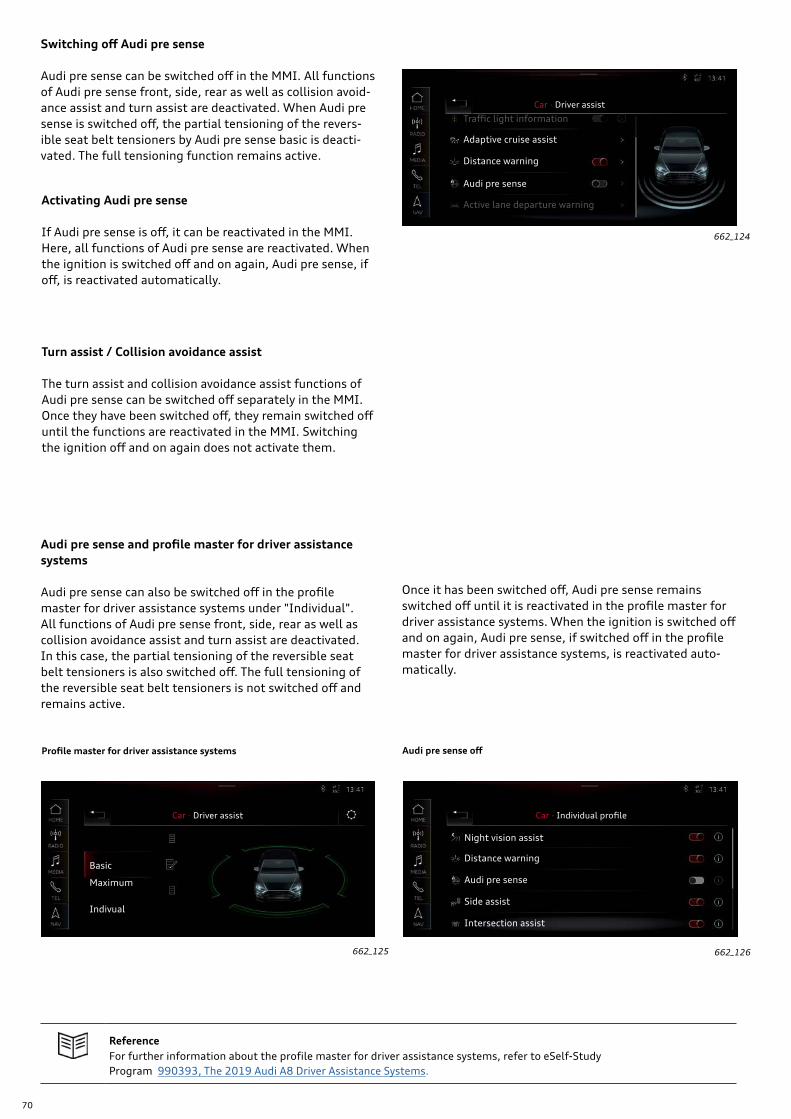
70
ReferenceFor further information about the profile master for driver assistance systems, refer to eSelf-Study Program 990393, The 2019 Audi A8 Driver Assistance Systems.
Profile master for driver assistance systems Audi pre sense off
662_126662_125
Maximum
Car · Driver assist
Basic
Indivual
Car · Individual profile
Night vision assist
Distance warning
Audi pre sense
Side assist
Intersection assist
Switching off Audi pre sense
Audi pre sense can be switched off in the MMI. All functions of Audi pre sense front, side, rear as well as collision avoid-ance assist and turn assist are deactivated. When Audi pre sense is switched off, the partial tensioning of the revers-ible seat belt tensioners by Audi pre sense basic is deacti-vated. The full tensioning function remains active.
Activating Audi pre sense
If Audi pre sense is off, it can be reactivated in the MMI. Here, all functions of Audi pre sense are reactivated. When the ignition is switched off and on again, Audi pre sense, if off, is reactivated automatically.
Turn assist / Collision avoidance assist
The turn assist and collision avoidance assist functions of Audi pre sense can be switched off separately in the MMI. Once they have been switched off, they remain switched off until the functions are reactivated in the MMI. Switching the ignition off and on again does not activate them.
Audi pre sense and profile master for driver assistance systems
Audi pre sense can also be switched off in the profile master for driver assistance systems under "Individual". All functions of Audi pre sense front, side, rear as well as collision avoidance assist and turn assist are deactivated. In this case, the partial tensioning of the reversible seat belt tensioners is also switched off. The full tensioning of the reversible seat belt tensioners is not switched off and remains active.
662_124
Car · Driver assist
Traffic light information
Adaptive cruise assist
Distance warning
Audi pre sense
Active lane departure warning
Once it has been switched off, Audi pre sense remains switched off until it is reactivated in the profile master for driver assistance systems. When the ignition is switched off and on again, Audi pre sense, if switched off in the profile master for driver assistance systems, is reactivated auto-matically.
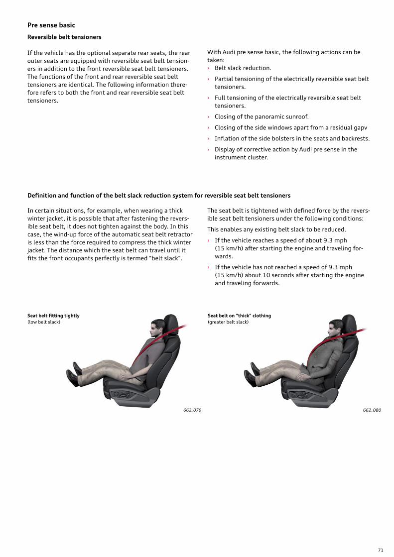
71
Pre sense basic
With Audi pre sense basic, the following actions can be taken: › Belt slack reduction.
› Partial tensioning of the electrically reversible seat belt tensioners.
› Full tensioning of the electrically reversible seat belt tensioners.
› Closing of the panoramic sunroof.
› Closing of the side windows apart from a residual gapv
› Inflation of the side bolsters in the seats and backrests.
› Display of corrective action by Audi pre sense in the instrument cluster.
Definition and function of the belt slack reduction system for reversible seat belt tensioners
In certain situations, for example, when wearing a thick winter jacket, it is possible that after fastening the revers-ible seat belt, it does not tighten against the body. In this case, the wind-up force of the automatic seat belt retractor is less than the force required to compress the thick winter jacket. The distance which the seat belt can travel until it fits the front occupants perfectly is termed "belt slack".
662_079 662_080
The seat belt is tightened with defined force by the revers-ible seat belt tensioners under the following conditions:
This enables any existing belt slack to be reduced.
› If the vehicle reaches a speed of about 9.3 mph (15 km/h) after starting the engine and traveling for-wards.
› If the vehicle has not reached a speed of 9.3 mph (15 km/h) about 10 seconds after starting the engine and traveling forwards.
Seat belt fitting tightly(low belt slack)
Seat belt on "thick" clothing (greater belt slack)
Reversible belt tensioners
If the vehicle has the optional separate rear seats, the rear outer seats are equipped with reversible seat belt tension-ers in addition to the front reversible seat belt tensioners. The functions of the front and rear reversible seat belt tensioners are identical. The following information there-fore refers to both the front and rear reversible seat belt tensioners.
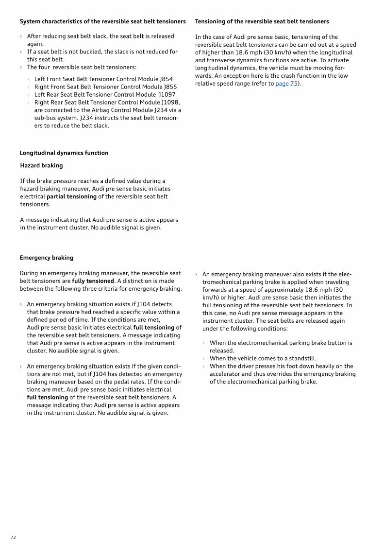
72
System characteristics of the reversible seat belt tensioners
› After reducing seat belt slack, the seat belt is released again.
› If a seat belt is not buckled, the slack is not reduced for this seat belt.
› The four reversible seat belt tensioners:
› Left Front Seat Belt Tensioner Control Module J854 › Right Front Seat Belt Tensioner Control Module J855 › Left Rear Seat Belt Tensioner Control Module J1097 › Right Rear Seat Belt Tensioner Control Module J1098,
are connected to the Airbag Control Module J234 via a sub-bus system. J234 instructs the seat belt tension-ers to reduce the belt slack.
Longitudinal dynamics function
Tensioning of the reversible seat belt tensioners
In the case of Audi pre sense basic, tensioning of the reversible seat belt tensioners can be carried out at a speed of higher than 18.6 mph (30 km/h) when the longitudinal and transverse dynamics functions are active. To activate longitudinal dynamics, the vehicle must be moving for-wards. An exception here is the crash function in the low relative speed range (refer to page 75).
Hazard braking
If the brake pressure reaches a defined value during a hazard braking maneuver, Audi pre sense basic initiates electrical partial tensioning of the reversible seat belt tensioners.
A message indicating that Audi pre sense is active appears in the instrument cluster. No audible signal is given.
Emergency braking
During an emergency braking maneuver, the reversible seat belt tensioners are fully tensioned. A distinction is made between the following three criteria for emergency braking.
› An emergency braking situation exists if J104 detects that brake pressure had reached a specific value within a defined period of time. If the conditions are met, Audi pre sense basic initiates electrical full tensioning of the reversible seat belt tensioners. A message indicating that Audi pre sense is active appears in the instrument cluster. No audible signal is given.
› An emergency braking situation exists if the given condi-tions are not met, but if J104 has detected an emergency braking maneuver based on the pedal rates. If the condi-tions are met, Audi pre sense basic initiates electrical full tensioning of the reversible seat belt tensioners. A message indicating that Audi pre sense is active appears in the instrument cluster. No audible signal is given.
› An emergency braking maneuver also exists if the elec-tromechanical parking brake is applied when traveling forwards at a speed of approximately 18.6 mph (30 km/h) or higher. Audi pre sense basic then initiates the full tensioning of the reversible seat belt tensioners. In this case, no Audi pre sense message appears in the instrument cluster. The seat belts are released again under the following conditions:
› When the electromechanical parking brake button is released.
› When the vehicle comes to a standstill. › When the driver presses his foot down heavily on the
accelerator and thus overrides the emergency braking of the electromechanical parking brake.
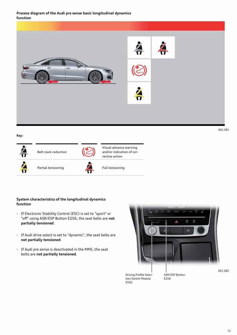
73
662_081
Process diagram of the Audi pre sense basic longitudinal dynamics function
System characteristics of the longitudinal dynamics function
› If Electronic Stability Control (ESC) is set to "sport" or "off" using ASR/ESP Button E256, the seat belts are not partially tensioned.
› If Audi drive select is set to "dynamic", the seat belts are not partially tensioned.
› If Audi pre sense is deactivated in the MMI, the seat belts are not partially tensioned.
662_082
Driving Profile Selec-tion Switch ModuleE592
ASR/ESP ButtonE256
Belt slack reductionVisual advance warning and/or indication of cor-rective action
Partial tensioning Full tensioning
Key:
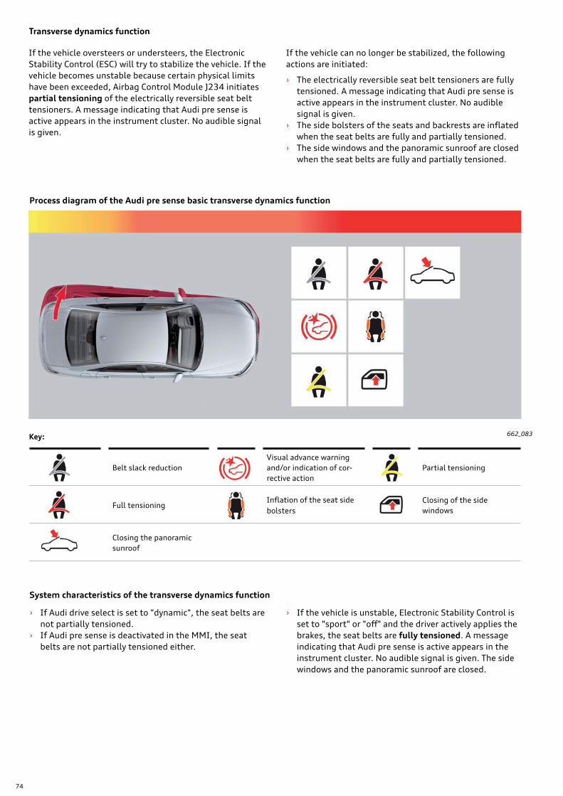
74
Transverse dynamics function
If the vehicle oversteers or understeers, the Electronic Stability Control (ESC) will try to stabilize the vehicle. If the vehicle becomes unstable because certain physical limits have been exceeded, Airbag Control Module J234 initiates partial tensioning of the electrically reversible seat belt tensioners. A message indicating that Audi pre sense is active appears in the instrument cluster. No audible signal is given.
› If Audi drive select is set to "dynamic", the seat belts are not partially tensioned.
› If Audi pre sense is deactivated in the MMI, the seat belts are not partially tensioned either.
› If the vehicle is unstable, Electronic Stability Control is set to "sport" or "off" and the driver actively applies the brakes, the seat belts are fully tensioned. A message indicating that Audi pre sense is active appears in the instrument cluster. No audible signal is given. The side windows and the panoramic sunroof are closed.
If the vehicle can no longer be stabilized, the following actions are initiated:
› The electrically reversible seat belt tensioners are fully tensioned. A message indicating that Audi pre sense is active appears in the instrument cluster. No audible signal is given.
› The side bolsters of the seats and backrests are inflated when the seat belts are fully and partially tensioned.
› The side windows and the panoramic sunroof are closed when the seat belts are fully and partially tensioned.
662_083
Process diagram of the Audi pre sense basic transverse dynamics function
Belt slack reductionVisual advance warning and/or indication of cor-rective action
Partial tensioning
Full tensioningInflation of the seat side bolsters
Closing of the side windows
Closing the panoramic sunroof
Key:
System characteristics of the transverse dynamics function
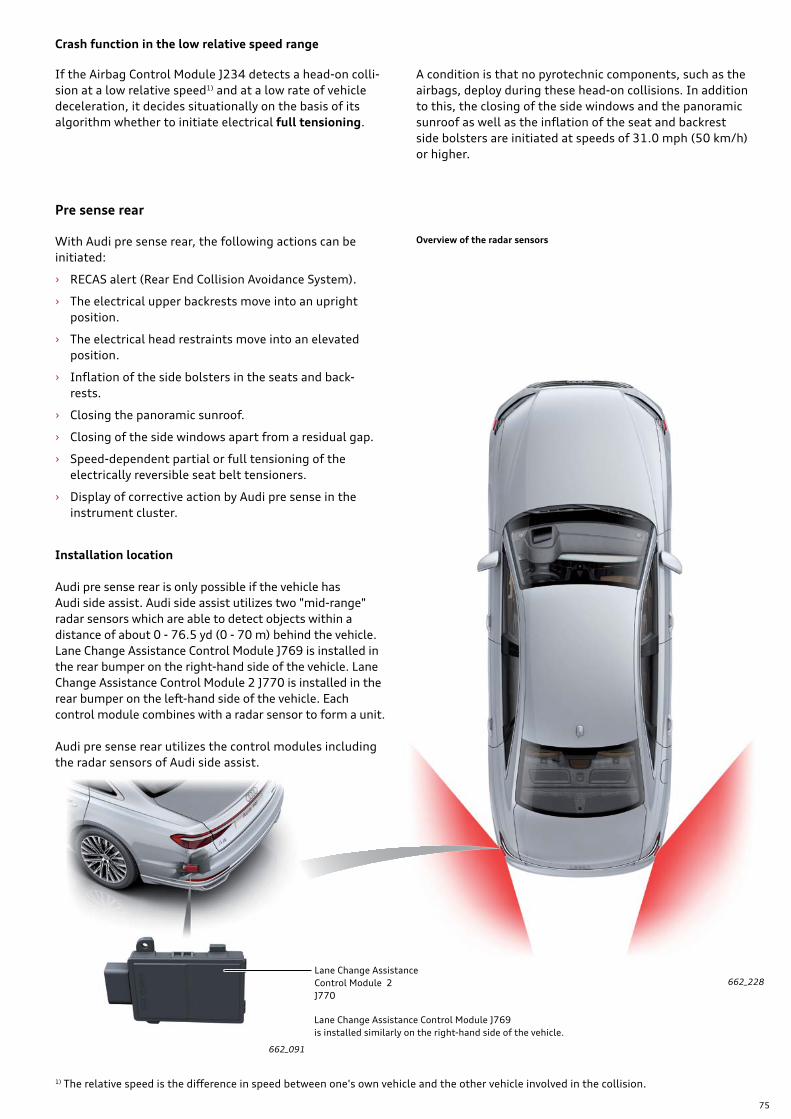
75
Installation location
Audi pre sense rear is only possible if the vehicle has Audi side assist. Audi side assist utilizes two "mid-range" radar sensors which are able to detect objects within a distance of about 0 - 76.5 yd (0 - 70 m) behind the vehicle. Lane Change Assistance Control Module J769 is installed in the rear bumper on the right-hand side of the vehicle. Lane Change Assistance Control Module 2 J770 is installed in the rear bumper on the left-hand side of the vehicle. Each control module combines with a radar sensor to form a unit.
Audi pre sense rear utilizes the control modules including the radar sensors of Audi side assist.
Crash function in the low relative speed range
If the Airbag Control Module J234 detects a head-on colli-sion at a low relative speed1) and at a low rate of vehicle deceleration, it decides situationally on the basis of its algorithm whether to initiate electrical full tensioning.
A condition is that no pyrotechnic components, such as the airbags, deploy during these head-on collisions. In addition to this, the closing of the side windows and the panoramic sunroof as well as the inflation of the seat and backrest side bolsters are initiated at speeds of 31.0 mph (50 km/h) or higher.
Pre sense rear
With Audi pre sense rear, the following actions can be initiated:
› RECAS alert (Rear End Collision Avoidance System).
› The electrical upper backrests move into an upright position.
› The electrical head restraints move into an elevated position.
› Inflation of the side bolsters in the seats and back-rests.
› Closing the panoramic sunroof.
› Closing of the side windows apart from a residual gap.
› Speed-dependent partial or full tensioning of the electrically reversible seat belt tensioners.
› Display of corrective action by Audi pre sense in the instrument cluster.
Lane Change Assistance Control Module 2 J770
Lane Change Assistance Control Module J769is installed similarly on the right-hand side of the vehicle.
662_228
1) The relative speed is the difference in speed between one's own vehicle and the other vehicle involved in the collision.
662_091
Overview of the radar sensors
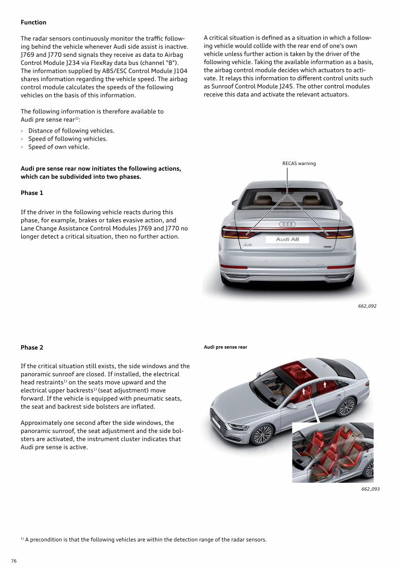
76
1) A precondition is that the following vehicles are within the detection range of the radar sensors.
Function
The radar sensors continuously monitor the traffic follow-ing behind the vehicle whenever Audi side assist is inactive. J769 and J770 send signals they receive as data to Airbag Control Module J234 via FlexRay data bus (channel "B"). The information supplied by ABS/ESC Control Module J104 shares information regarding the vehicle speed. The airbag control module calculates the speeds of the following vehicles on the basis of this information.
The following information is therefore available to Audi pre sense rear1):
› Distance of following vehicles. › Speed of following vehicles. › Speed of own vehicle.
A critical situation is defined as a situation in which a follow-ing vehicle would collide with the rear end of one's own vehicle unless further action is taken by the driver of the following vehicle. Taking the available information as a basis, the airbag control module decides which actuators to acti-vate. It relays this information to different control units such as Sunroof Control Module J245. The other control modules receive this data and activate the relevant actuators.
Audi pre sense rear now initiates the following actions, which can be subdivided into two phases.
Phase 1
If the driver in the following vehicle reacts during this phase, for example, brakes or takes evasive action, and Lane Change Assistance Control Modules J769 and J770 no longer detect a critical situation, then no further action.
662_093
Phase 2
If the critical situation still exists, the side windows and the panoramic sunroof are closed. If installed, the electrical head restraints1) on the seats move upward and the electrical upper backrests1) (seat adjustment) move forward. If the vehicle is equipped with pneumatic seats, the seat and backrest side bolsters are inflated.
Approximately one second after the side windows, the panoramic sunroof, the seat adjustment and the side bol-sters are activated, the instrument cluster indicates that Audi pre sense is active.
662_092
RECAS warning
Audi pre sense rear
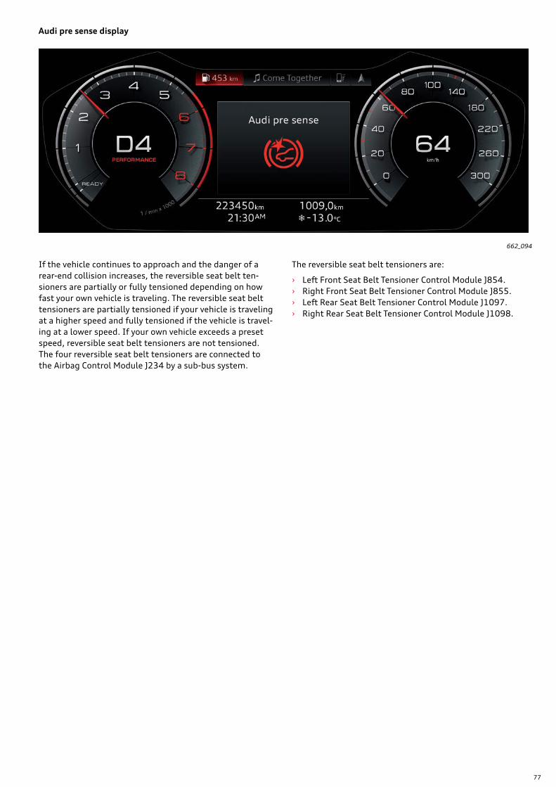
77
662_094
If the vehicle continues to approach and the danger of a rear-end collision increases, the reversible seat belt ten-sioners are partially or fully tensioned depending on how fast your own vehicle is traveling. The reversible seat belt tensioners are partially tensioned if your vehicle is traveling at a higher speed and fully tensioned if the vehicle is travel-ing at a lower speed. If your own vehicle exceeds a preset speed, reversible seat belt tensioners are not tensioned. The four reversible seat belt tensioners are connected to the Airbag Control Module J234 by a sub-bus system.
The reversible seat belt tensioners are:
› Left Front Seat Belt Tensioner Control Module J854. › Right Front Seat Belt Tensioner Control Module J855. › Left Rear Seat Belt Tensioner Control Module J1097. › Right Rear Seat Belt Tensioner Control Module J1098.
Audi pre sense display
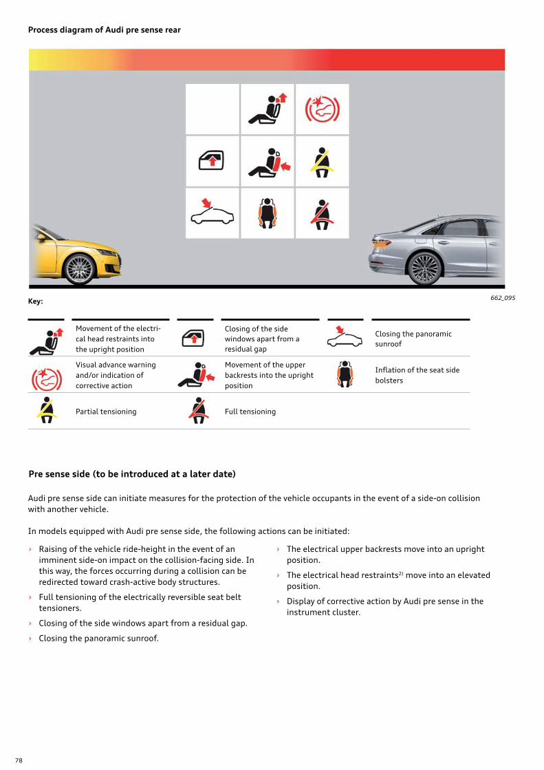
78
662_095
Process diagram of Audi pre sense rear
Pre sense side (to be introduced at a later date)
› Raising of the vehicle ride-height in the event of an imminent side-on impact on the collision-facing side. In this way, the forces occurring during a collision can be redirected toward crash-active body structures.
› Full tensioning of the electrically reversible seat belt tensioners.
› Closing of the side windows apart from a residual gap.
› Closing the panoramic sunroof.
› The electrical upper backrests move into an upright position.
› The electrical head restraints2) move into an elevated position.
› Display of corrective action by Audi pre sense in the instrument cluster.
Movement of the electri-cal head restraints into the upright position
Closing of the side windows apart from a residual gap
Closing the panoramic sunroof
Visual advance warning and/or indication of corrective action
Movement of the upper backrests into the upright position
Inflation of the seat side bolsters
Partial tensioning Full tensioning
Key:
Audi pre sense side can initiate measures for the protection of the vehicle occupants in the event of a side-on collision with another vehicle.
In models equipped with Audi pre sense side, the following actions can be initiated:
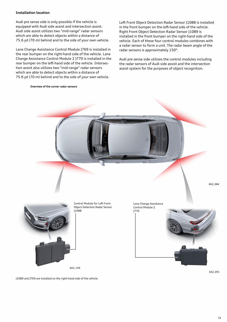
79
662_084
Control Module for Left Front Object Detection Radar Sensor J1088
Lane Change Assistance Control Module 2 J770
662_199
662_091
Installation location
Audi pre sense side is only possible if the vehicle is equipped with Audi side assist and intersection assist. Audi side assist utilizes two "mid-range" radar sensors which are able to detect objects within a distance of 75.6 yd (70 m) behind and to the side of your own vehicle.
Lane Change Assistance Control Module J769 is installed in the rear bumper on the right-hand side of the vehicle. Lane Change Assistance Control Module 2 J770 is installed in the rear bumper on the left-hand side of the vehicle. Intersec-tion assist also utilizes two "mid-range" radar sensors which are able to detect objects within a distance of 75.6 yd (70 m) behind and to the side of your own vehicle.
Left Front Object Detection Radar Sensor J1088 is installed in the front bumper on the left-hand side of the vehicle. Right Front Object Detection Radar Sensor J1089 is installed in the front bumper on the right-hand side of the vehicle. Each of these four control modules combines with a radar sensor to form a unit. The radar beam angle of the radar sensors is approximately 150°.
Audi pre sense side utilizes the control modules including the radar sensors of Audi side assist and the intersection assist system for the purposes of object recognition.
Overview of the corner radar sensors
J1089 and J769 are installed on the right-hand side of the vehicle.
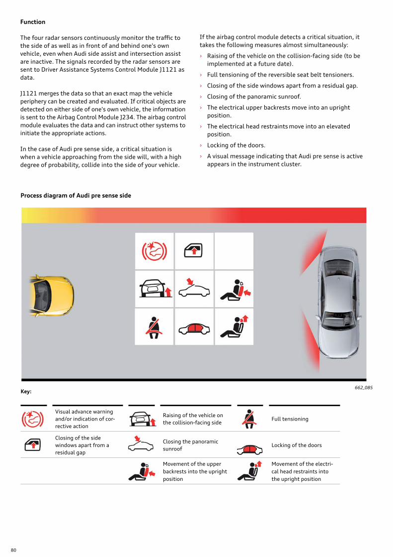
80
Function
The four radar sensors continuously monitor the traffic to the side of as well as in front of and behind one's own vehicle, even when Audi side assist and intersection assist are inactive. The signals recorded by the radar sensors are sent to Driver Assistance Systems Control Module J1121 as data.
J1121 merges the data so that an exact map the vehicle periphery can be created and evaluated. If critical objects are detected on either side of one's own vehicle, the information is sent to the Airbag Control Module J234. The airbag control module evaluates the data and can instruct other systems to initiate the appropriate actions.
In the case of Audi pre sense side, a critical situation is when a vehicle approaching from the side will, with a high degree of probability, collide into the side of your vehicle.
If the airbag control module detects a critical situation, it takes the following measures almost simultaneously:
› Raising of the vehicle on the collision-facing side (to be implemented at a future date).
› Full tensioning of the reversible seat belt tensioners.
› Closing of the side windows apart from a residual gap.
› Closing of the panoramic sunroof.
› The electrical upper backrests move into an upright position.
› The electrical head restraints move into an elevated position.
› Locking of the doors.
› A visual message indicating that Audi pre sense is active appears in the instrument cluster.
662_085
Process diagram of Audi pre sense side
Visual advance warning and/or indication of cor-rective action
Raising of the vehicle on the collision-facing side
Full tensioning
Closing of the side windows apart from a residual gap
Closing the panoramic sunroof
Locking of the doors
Movement of the upper backrests into the upright position
Movement of the electri-cal head restraints into the upright position
Key:
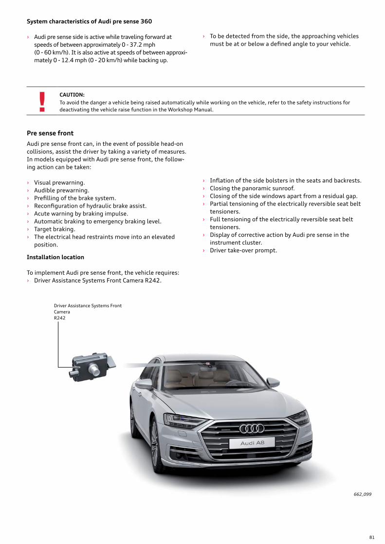
81
System characteristics of Audi pre sense 360
› Audi pre sense side is active while traveling forward at speeds of between approximately 0 - 37.2 mph (0 - 60 km/h). It is also active at speeds of between approxi-mately 0 - 12.4 mph (0 - 20 km/h) while backing up.
› To be detected from the side, the approaching vehicles must be at or below a defined angle to your vehicle.
Pre sense front
Audi pre sense front can, in the event of possible head-on collisions, assist the driver by taking a variety of measures. In models equipped with Audi pre sense front, the follow-ing action can be taken:
› Visual prewarning. › Audible prewarning. › Prefilling of the brake system. › Reconfiguration of hydraulic brake assist. › Acute warning by braking impulse. › Automatic braking to emergency braking level. › Target braking. › The electrical head restraints move into an elevated
position.
› Inflation of the side bolsters in the seats and backrests. › Closing the panoramic sunroof. › Closing of the side windows apart from a residual gap. › Partial tensioning of the electrically reversible seat belt
tensioners. › Full tensioning of the electrically reversible seat belt
tensioners. › Display of corrective action by Audi pre sense in the
instrument cluster. › Driver take-over prompt.
Installation location
To implement Audi pre sense front, the vehicle requires: › Driver Assistance Systems Front Camera R242.
662_099
Driver Assistance Systems Front CameraR242
CAUTION:To avoid the danger a vehicle being raised automatically while working on the vehicle, refer to the safety instructions for deactivating the vehicle raise function in the Workshop Manual.
82
Function
Driver Assistance Systems Front Camera R242 continuously monitors the traffic in front of the vehicle. The resulting signals are sent to Driver Assistance Systems Control Module J1121 as data. J1121 sends the data to the Airbag Control Module J234. J234 evaluates the data and can instruct other systems to initiate actions appropriate to the situation.
The system can, under certain conditions, detect the fol-lowing scenarios: › Vehicles in front of your vehicle (passenger cars, trucks,
motorcycles). › Cyclists in the same lane as the vehicle or moving into
the same lane as the vehicle. › Pedestrians in the same lane as the vehicle or moving
into same lane as the vehicle.
Response to vehicles
The following preconditions must be met in order to activate the system:
› Audi pre sense front is able to respond to vehicles which are traveling in the same direction and which have stopped or are stationary.
› Audi pre sense front does not respond to crossing or oncoming traffic.
› Audi pre sense front is active at a speed of approximately 6.2 mph (10 km/h) or higher.
› Audi pre sense front can warn against vehicles up to a speed of 155.3 mph (250 km/h).
› Audi pre sense front can initiate braking up to a speed of 155.3 mph (250 km/h).
Advance warning phase
If the vehicle approaches another vehicle which is traveling in the same direction at speeds of between approximately 18.6 mph and 155.3 mph (30 - 250 km/h). resulting in a critical driving situation, the instrument cluster gives the driver audible and visual early warnings when set limits are exceeded. These warnings are given within a certain time frame ahead of the last braking opportunity for braking or collision avoidance before the actual collision occurs. The timing of warnings depends on the driver's activity level. Depending on steering, pedal and turn signal inputs, the system classifies the driver as active or inactive and, conse-quently, as attentive or inattentive. If the driver is deemed to be "attentive", warnings are issued later than for a driver deemed to be "inattentive". At the same time, ABS/ESC Control Module J104 initiates prefilling of the brake system, and hydraulic brake assist is reconfigured. Hydrau-lic brake assist is more sensitive to the drivers pedal input.
Acute warning phase
If driver does not respond to the warnings, however, J104 generates an acute warning by initiating a brake warning. At the same time, a visual warning is issued in the instru-ment cluster display. The brake warning is a very brief but easily noticeable braking impulse which does not slow the vehicle down directly. It alerts the driver to the traffic situation and indicates to the driver that he must react immediately in order to prevent an impending collision. Depending on how attentive the driver is, the brake warning is produced within a certain time window ahead of the last opportunity to brake or take evasive action in order to avoid a collision.

83
Automatic brake intervention phase
If the driver fails to respond to the brake warning or only takes his foot off the accelerator, ABS/ESC Control Module J104 initiates automatic braking. Depending on the speed at which the vehicle is traveling, braking power may increase progressively to maximum level (emergency braking). Depending on the situation, the following addi-tional actions may be initiated:
› The electrical head restraints move into an elevated posi-tion.
› Inflation of the side bolsters in the seats and backrests. › Closing the panoramic sunroof. › Closing of the side windows apart from a residual gap. › Partial tensioning of the electrically reversible seat belt
tensioners › Full tensioning of the electrically reversible seat belt
tensioners. › Display of corrective action by Audi pre sense in the
instrument cluster.
662_162
Process diagram showing how Audi Pre sense front responds automatically to vehicles
Visual advance warning and/or indication of cor-rective action
Audible warning beepPrefilling of the brake system
Reconfiguration of hydraulic brake assist
Acute warning by braking impulse
Automatic braking up to emergency braking inten-sity
Closing of the side windows apart from a residual gap
Closing the panoramic sunroof
Partial tensioning
Full tensioningInflation of the seat side bolsters
Movement of the upper backrests into the upright position
Movement of the electri-cal head restraints into the upright position
Driver take-over prompt
Key:
If the vehicle automatically brakes itself to a standstill without driver intervention, a driver take-over prompt appears in the instrument cluster and further audible signals sound. These signals will alert the driver to the fact that he must actively take control of the vehicle (for example, by applying braking). If the driver fails to take control of the vehicle, the system will release the brake and the vehicle will start to move.
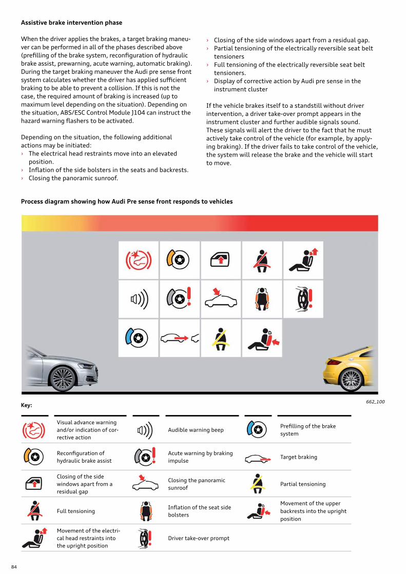
84
Assistive brake intervention phase
When the driver applies the brakes, a target braking maneu-ver can be performed in all of the phases described above (prefilling of the brake system, reconfiguration of hydraulic brake assist, prewarning, acute warning, automatic braking). During the target braking maneuver the Audi pre sense front system calculates whether the driver has applied sufficient braking to be able to prevent a collision. If this is not the case, the required amount of braking is increased (up to maximum level depending on the situation). Depending on the situation, ABS/ESC Control Module J104 can instruct the hazard warning flashers to be activated.
Depending on the situation, the following additional actions may be initiated: › The electrical head restraints move into an elevated
position. › Inflation of the side bolsters in the seats and backrests. › Closing the panoramic sunroof.
662_100
Process diagram showing how Audi Pre sense front responds to vehicles
Visual advance warning and/or indication of cor-rective action
Audible warning beepPrefilling of the brake system
Reconfiguration of hydraulic brake assist
Acute warning by braking impulse
Target braking
Closing of the side windows apart from a residual gap
Closing the panoramic sunroof
Partial tensioning
Full tensioningInflation of the seat side bolsters
Movement of the upper backrests into the upright position
Movement of the electri-cal head restraints into the upright position
Driver take-over prompt
Key:
› Closing of the side windows apart from a residual gap. › Partial tensioning of the electrically reversible seat belt
tensioners › Full tensioning of the electrically reversible seat belt
tensioners. › Display of corrective action by Audi pre sense in the
instrument cluster
If the vehicle brakes itself to a standstill without driver intervention, a driver take-over prompt appears in the instrument cluster and further audible signals sound. These signals will alert the driver to the fact that he must actively take control of the vehicle (for example, by apply-ing braking). If the driver fails to take control of the vehicle, the system will release the brake and the vehicle will start to move.

85
Response to pedestrian or cyclist
Audi pre sense city responds to pedestrians and cyclists in the same lane as the vehicle or moving into the same lane as the vehicle.
The following preconditions must be met in order to acti-vate the system:
› Audi pre sense front is active at a speed of approximately 6.2 mph (10 km/h) or higher.
› Audi pre sense front can warn against pedestrians and cyclists up to a speed of 52.8 mph (85 km/h).
› Audi pre sense front can initiate braking up to a speed of 52.8 mph (85 km/h).
Advance warning phase
If the vehicle is traveling at speeds of between approxi-mately 6.2 and 52.8 mph (10 - 85 km/h) and a pedestrian or cyclist is in the same lane as the vehicle or moving into the same lane as the vehicle resulting in a critical driving situation, the instrument cluster alerts the driver by issuing audible and visual warnings. These warnings are given within a certain time frame ahead of the last braking opportunity for braking or collision avoidance before the actual collision occurs. The timing of warnings depends on the driver's activity level.
Acute warning phase
If driver does not respond to the warnings, however, J104 generates an acute warning by initiating a brake warning. At the same time, a visual warning is issued via the instru-ment cluster display. The brake warning is a very brief but easily noticeable braking impulse which does not slow the vehicle down directly.
Automatic brake intervention phase
If the driver fails to respond to the brake warning or only takes his foot off the accelerator, ABS/ESP Control Module J104 initiates automatic braking. Depending on the speed at which the vehicle is traveling, braking power may increase progressively to maximum level (emergency braking).
Depending on the situation, the following additional actions may be initiated:
› Closing the panoramic sunroof.
› Closing of the side windows apart from a residual gap.
› Partial tensioning of the electrically reversible seat belt tensioners.
› Display of corrective action by Audi pre sense in the instrument cluster.
It alerts the driver to the traffic situation and indicates to the driver that he must react immediately in order to prevent an impending collision. Depending on how atten-tive the driver is deemed to be, the brake warning is pro-duced within a certain time window ahead of the last opportunity to brake or take evasive action in order to avoid a collision.
Depending on steering, pedal and turn signal inputs, the system classifies the driver as active or inactive and, conse-quently, as attentive or inattentive. If the driver is deemed to be "attentive", warnings are issued later than for a driver deemed to be "inattentive". At the same time, ABS/ESC Control Module J104 initiates prefilling of the brake system, and hydraulic brake assist is reconfigured. Hydrau-lic brake assist reacts more sensitively to pedal operations by the driver.
If the vehicle automatically brakes itself to a standstill without driver intervention, a driver take-over prompt appears in the instrument cluster and further audible signals sound. These signals will alert the driver to the fact that he must actively take control of the vehicle (for example, by applying braking). If the driver fails to take control of the vehicle, the system will release the brake and the vehicle will start to move.
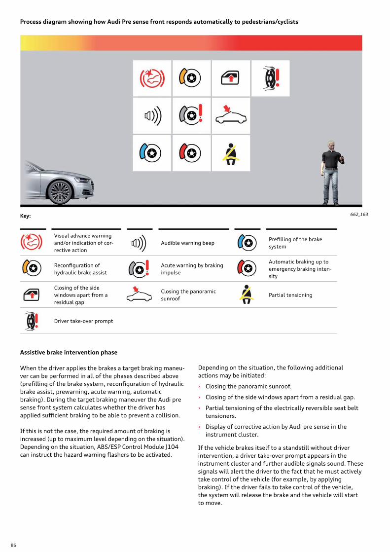
86
Assistive brake intervention phase
When the driver applies the brakes a target braking maneu-ver can be performed in all of the phases described above (prefilling of the brake system, reconfiguration of hydraulic brake assist, prewarning, acute warning, automatic braking). During the target braking maneuver the Audi pre sense front system calculates whether the driver has applied sufficient braking to be able to prevent a collision.
If this is not the case, the required amount of braking is increased (up to maximum level depending on the situation). Depending on the situation, ABS/ESP Control Module J104 can instruct the hazard warning flashers to be activated.
If the vehicle brakes itself to a standstill without driver intervention, a driver take-over prompt appears in the instrument cluster and further audible signals sound. These signals will alert the driver to the fact that he must actively take control of the vehicle (for example, by applying braking). If the driver fails to take control of the vehicle, the system will release the brake and the vehicle will start to move.
662_163
Process diagram showing how Audi Pre sense front responds automatically to pedestrians/cyclists
Visual advance warning and/or indication of cor-rective action
Audible warning beepPrefilling of the brake system
Reconfiguration of hydraulic brake assist
Acute warning by braking impulse
Automatic braking up to emergency braking inten-sity
Closing of the side windows apart from a residual gap
Closing the panoramic sunroof
Partial tensioning
Driver take-over prompt
Key:
Depending on the situation, the following additional actions may be initiated:
› Closing the panoramic sunroof.
› Closing of the side windows apart from a residual gap.
› Partial tensioning of the electrically reversible seat belt tensioners.
› Display of corrective action by Audi pre sense in the instrument cluster.
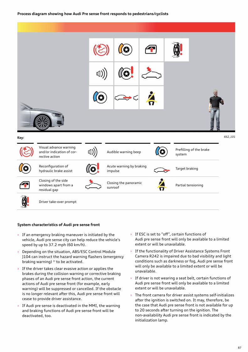
87
662_101
Process diagram showing how Audi Pre sense front responds to pedestrians/cyclists
Visual advance warning and/or indication of cor-rective action
Audible warning beepPrefilling of the brake system
Reconfiguration of hydraulic brake assist
Acute warning by braking impulse
Target braking
Closing of the side windows apart from a residual gap
Closing the panoramic sunroof
Partial tensioning
Driver take-over prompt
Key:
System characteristics of Audi pre sense front
› If an emergency braking maneuver is initiated by the vehicle, Audi pre sense city can help reduce the vehicle's speed by up to 37.2 mph (60 km/h).
› Depending on the situation, ABS/ESC Control Module J104 can instruct the hazard warning flashers (emergency braking warning) 1) to be activated.
› If the driver takes clear evasive action or applies the brakes during the collision warning or corrective braking phases of an Audi pre sense front action, the current actions of Audi pre sense front (for example, early warning) will be suppressed or cancelled. If the obstacle is no longer relevant after this, Audi pre sense front will cease to provide driver assistance.
› If Audi pre sense is deactivated in the MMI, the warning and braking functions of Audi pre sense front will be deactivated, too.
› If ESC is set to “off”, certain functions of Audi pre sense front will only be available to a limited extent or will be unavailable.
› If the functionality of Driver Assistance Systems Front Camera R242 is impaired due to bad visibility and light conditions such as darkness or fog, Audi pre sense front will only be available to a limited extent or will be unavailable.
› If driver is not wearing a seat belt, certain functions of Audi pre sense front will only be available to a limited extent or will be unavailable.
› The front camera for driver assist systems self-initializes after the ignition is switched on. It may, therefore, be the case that Audi pre sense front is not available for up to 20 seconds after turning on the ignition. The non-availability Audi pre sense front is indicated by the initialization lamp.
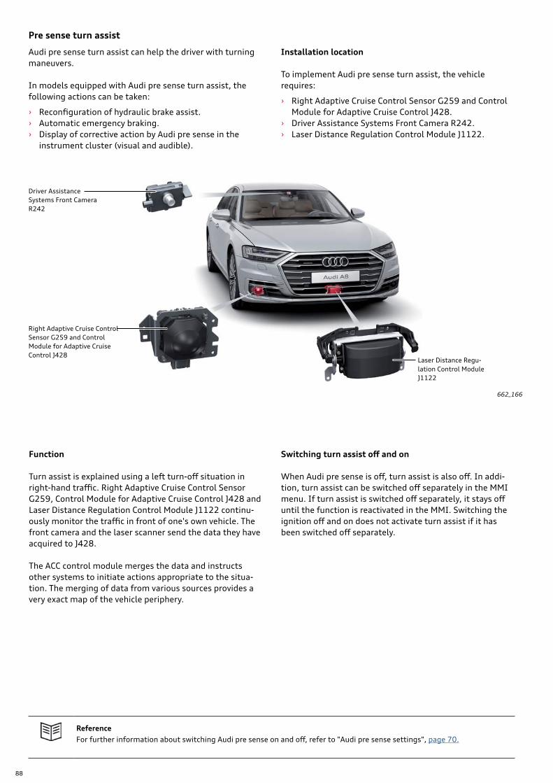
88
Switching turn assist off and on
When Audi pre sense is off, turn assist is also off. In addi-tion, turn assist can be switched off separately in the MMI menu. If turn assist is switched off separately, it stays off until the function is reactivated in the MMI. Switching the ignition off and on does not activate turn assist if it has been switched off separately.
Function
Turn assist is explained using a left turn-off situation in right-hand traffic. Right Adaptive Cruise Control Sensor G259, Control Module for Adaptive Cruise Control J428 and Laser Distance Regulation Control Module J1122 continu-ously monitor the traffic in front of one's own vehicle. The front camera and the laser scanner send the data they have acquired to J428.
The ACC control module merges the data and instructs other systems to initiate actions appropriate to the situa-tion. The merging of data from various sources provides a very exact map of the vehicle periphery.
662_166
Driver Assistance Systems Front CameraR242
Laser Distance Regu-lation Control Module J1122
Right Adaptive Cruise Control Sensor G259 and Control Module for Adaptive Cruise Control J428
Pre sense turn assist
Audi pre sense turn assist can help the driver with turning maneuvers.
In models equipped with Audi pre sense turn assist, the following actions can be taken:
› Reconfiguration of hydraulic brake assist. › Automatic emergency braking. › Display of corrective action by Audi pre sense in the
instrument cluster (visual and audible).
Installation location
To implement Audi pre sense turn assist, the vehicle requires:
› Right Adaptive Cruise Control Sensor G259 and Control Module for Adaptive Cruise Control J428.
› Driver Assistance Systems Front Camera R242. › Laser Distance Regulation Control Module J1122.
ReferenceFor further information about switching Audi pre sense on and off, refer to "Audi pre sense settings", page 70.
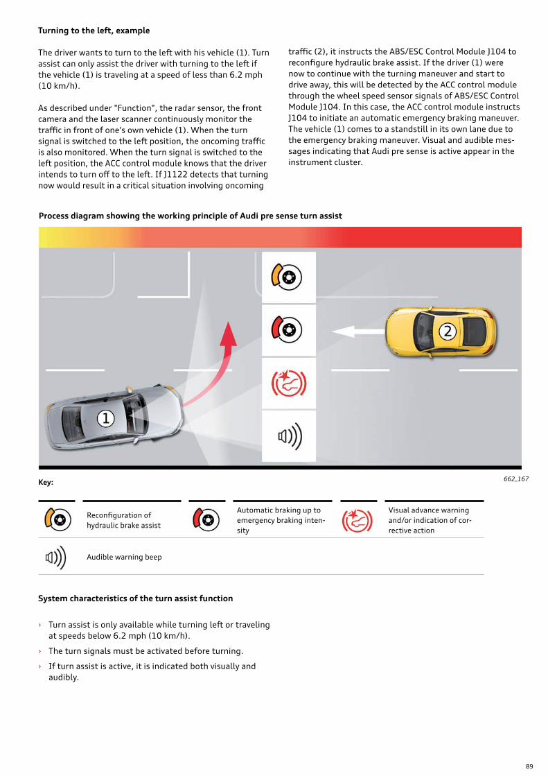
89
System characteristics of the turn assist function
› Turn assist is only available while turning left or traveling at speeds below 6.2 mph (10 km/h).
› The turn signals must be activated before turning.
› If turn assist is active, it is indicated both visually and audibly.
Turning to the left, example
The driver wants to turn to the left with his vehicle (1). Turn assist can only assist the driver with turning to the left if the vehicle (1) is traveling at a speed of less than 6.2 mph (10 km/h).
As described under "Function", the radar sensor, the front camera and the laser scanner continuously monitor the traffic in front of one's own vehicle (1). When the turn signal is switched to the left position, the oncoming traffic is also monitored. When the turn signal is switched to the left position, the ACC control module knows that the driver intends to turn off to the left. If J1122 detects that turning now would result in a critical situation involving oncoming
traffic (2), it instructs the ABS/ESC Control Module J104 to reconfigure hydraulic brake assist. If the driver (1) were now to continue with the turning maneuver and start to drive away, this will be detected by the ACC control module through the wheel speed sensor signals of ABS/ESC Control Module J104. In this case, the ACC control module instructs J104 to initiate an automatic emergency braking maneuver. The vehicle (1) comes to a standstill in its own lane due to the emergency braking maneuver. Visual and audible mes-sages indicating that Audi pre sense is active appear in the instrument cluster.
662_167
Process diagram showing the working principle of Audi pre sense turn assist
Reconfiguration of hydraulic brake assist
Automatic braking up to emergency braking inten-sity
Visual advance warning and/or indication of cor-rective action
Audible warning beep
Key:
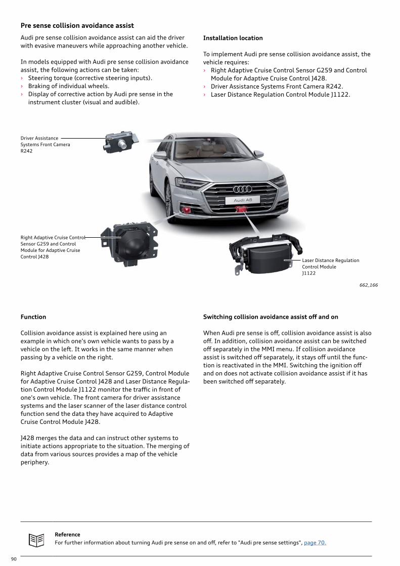
90
Switching collision avoidance assist off and on
When Audi pre sense is off, collision avoidance assist is also off. In addition, collision avoidance assist can be switched off separately in the MMI menu. If collision avoidance assist is switched off separately, it stays off until the func-tion is reactivated in the MMI. Switching the ignition off and on does not activate collision avoidance assist if it has been switched off separately.
Function
Collision avoidance assist is explained here using an example in which one's own vehicle wants to pass by a vehicle on the left. It works in the same manner when passing by a vehicle on the right.
Right Adaptive Cruise Control Sensor G259, Control Module for Adaptive Cruise Control J428 and Laser Distance Regula-tion Control Module J1122 monitor the traffic in front of one's own vehicle. The front camera for driver assistance systems and the laser scanner of the laser distance control function send the data they have acquired to Adaptive Cruise Control Module J428.
J428 merges the data and can instruct other systems to initiate actions appropriate to the situation. The merging of data from various sources provides a map of the vehicle periphery.
Audi pre sense collision avoidance assist can aid the driver with evasive maneuvers while approaching another vehicle.
In models equipped with Audi pre sense collision avoidance assist, the following actions can be taken: › Steering torque (corrective steering inputs). › Braking of individual wheels. › Display of corrective action by Audi pre sense in the
instrument cluster (visual and audible).
Installation location
To implement Audi pre sense collision avoidance assist, the vehicle requires: › Right Adaptive Cruise Control Sensor G259 and Control
Module for Adaptive Cruise Control J428. › Driver Assistance Systems Front Camera R242. › Laser Distance Regulation Control Module J1122.
Pre sense collision avoidance assist
662_166
Driver Assistance Systems Front CameraR242
Laser Distance Regulation Control Module J1122
Right Adaptive Cruise Control Sensor G259 and Control Module for Adaptive Cruise Control J428
ReferenceFor further information about turning Audi pre sense on and off, refer to "Audi pre sense settings", page 70.

91
Steering torque assistBraking of individual wheels
Visual advance warning and/or indication of cor-rective action
Audible warning beep
Collision avoidance assist, example
The vehicle (1) wants to evade the vehicle (2) traveling ahead.
As described under "Function", the radar sensor, the front camera and the laser scanner continuously monitor the traffic in front of one's own vehicle (1). Before collision avoidance assist can provide the driver with assistance, Audi pre sense front has already identified a critical situa-tion and initiated the following actions:
› Visual prewarning. › Audible prewarning. › Prefilling of the brake system. › Adaptation of hydraulic brake assist. › Acute warning by braking impulse.
Collision avoidance assist computes a suitable evasion line based on various items of information, such as one's own speed and the lane in which the vehicle ahead in driving. If vehicle (1) deviates too far from the evasion line within certain bounds, collision avoidance assist will, after the acute warning is issued, try to guide the vehicle (1) along the evasion line by providing steering assistance along the evasion line of the vehicle (2). The vehicle (1) is additionally stabilized by braking individual wheels. Collision avoidance assist can only help the driver (1) when the driver (1) carries out the evasion process actively by making correc-tive steering inputs himself. Visual and audible messages indicating that Audi pre sense is active appear in the instru-ment cluster. If the last possible evasion point has been surpassed, no assistance is provided by collision avoidance assist.
662_165
› Collision avoidance assist is active after the acute warning (brake warning) is issued.
› Collision avoidance assist is not active if the last possible evasion point has been surpassed.
› Collision avoidance assist does not provide assistance unless the driver is actively steering the vehicle.
System characteristics of the collision avoidance assist function
› Collision avoidance assist is available at speeds of between about 18.6 to 93.2 mph (30 to 150 km/h).
› Collision avoidance assist helps the driver to steer around an obstacle on the left or right.
Process diagram showing the working principle of Audi pre sense collision avoidance assist
Key:
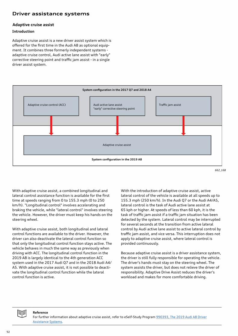
92
Driver assistance systems
Introduction
Adaptive cruise assist is a new driver assist system which is offered for the first time in the Audi A8 as optional equip-ment. It combines three formerly independent systems - adaptive cruise control, Audi active lane assist with "early" corrective steering point and traffic jam assist - in a single driver assist system.
662_168
With adaptive cruise assist, a combined longitudinal and lateral control assistance function is available for the first time at speeds ranging from 0 to 155.3 mph (0 to 250 km/h). "Longitudinal control" involves accelerating and braking the vehicle, while "lateral control" involves steering the vehicle. However, the driver must keep his hands on the steering wheel.
With adaptive cruise assist, both longitudinal and lateral control functions are available to the driver. However, the driver can also deactivate the lateral control function so that only the longitudinal control function stays active. The vehicle behaves in much the same way as previously when driving with ACC. The longitudinal control function in the 2019 A8 is largely identical to the 4th generation ACC system used in the 2017 Audi Q7 and in the 2018 Audi A4/A5. With adaptive cruise assist, it is not possible to deacti-vate the longitudinal control function while the lateral control function is active.
With the introduction of adaptive cruise assist, active lateral control of the vehicle is available at all speeds up to 155.3 mph (250 km/h). In the Audi Q7 or the Audi A4/A5, lateral control is the task of Audi active lane assist at 65 kph or higher. At speeds of less than 60 kph, it is the task of traffic jam assist if a traffic jam situation has been detected by the system. Lateral control may be interrupted for several seconds at the transition from active lateral control by Audi active lane assist to active lateral control by traffic jam assist, and vice versa. This interruption does not apply to adaptive cruise assist, where lateral control is provided continuously.
Because adaptive cruise assist is a driver assistance system, the driver is still fully responsible for operating the vehicle. The driver's hands must stay on the steering wheel. The system assists the driver, but does not relieve the driver of responsibility. Adaptive Drive Assist reduces the driver's workload and makes for more comfortable driving.
ReferenceFor further information about adaptive cruise assist, refer to eSelf-Study Program 990393, The 2019 Audi A8 Driver Assistance Systems.
Adaptive cruise assist
System configuration in the 2017 Q7 and 2018 A4
System configuration in the 2019 A8
Adaptive cruise control (ACC) Audi active lane assist "early" corrective steering point
Traffic jam assist
Adaptive cruise assist
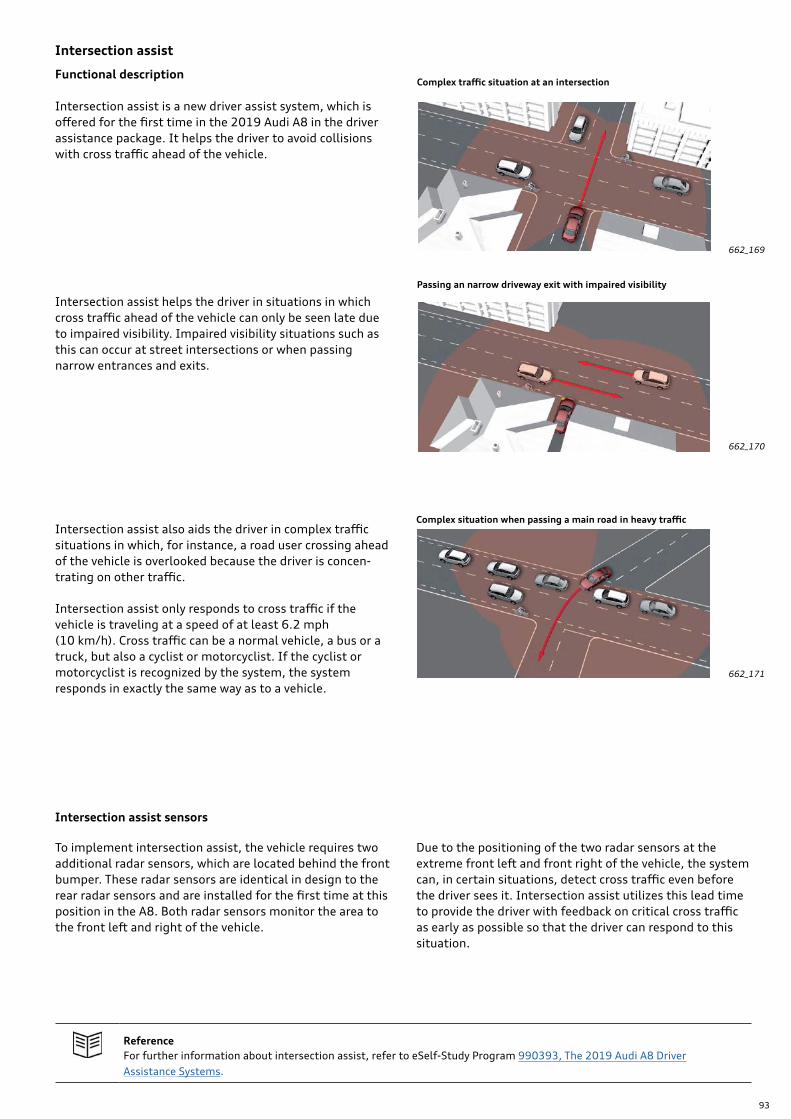
93
Intersection assist
Functional description
Intersection assist is a new driver assist system, which is offered for the first time in the 2019 Audi A8 in the driver assistance package. It helps the driver to avoid collisions with cross traffic ahead of the vehicle.
Intersection assist helps the driver in situations in which cross traffic ahead of the vehicle can only be seen late due to impaired visibility. Impaired visibility situations such as this can occur at street intersections or when passing narrow entrances and exits.
662_169
662_170
Complex traffic situation at an intersection
Passing an narrow driveway exit with impaired visibility
Complex situation when passing a main road in heavy traffic
662_171
Intersection assist also aids the driver in complex traffic situations in which, for instance, a road user crossing ahead of the vehicle is overlooked because the driver is concen-trating on other traffic.
Intersection assist only responds to cross traffic if the vehicle is traveling at a speed of at least 6.2 mph (10 km/h). Cross traffic can be a normal vehicle, a bus or a truck, but also a cyclist or motorcyclist. If the cyclist or motorcyclist is recognized by the system, the system responds in exactly the same way as to a vehicle.
Intersection assist sensors
To implement intersection assist, the vehicle requires two additional radar sensors, which are located behind the front bumper. These radar sensors are identical in design to the rear radar sensors and are installed for the first time at this position in the A8. Both radar sensors monitor the area to the front left and right of the vehicle.
Due to the positioning of the two radar sensors at the extreme front left and front right of the vehicle, the system can, in certain situations, detect cross traffic even before the driver sees it. Intersection assist utilizes this lead time to provide the driver with feedback on critical cross traffic as early as possible so that the driver can respond to this situation.
ReferenceFor further information about intersection assist, refer to eSelf-Study Program 990393, The 2019 Audi A8 Driver Assistance Systems.
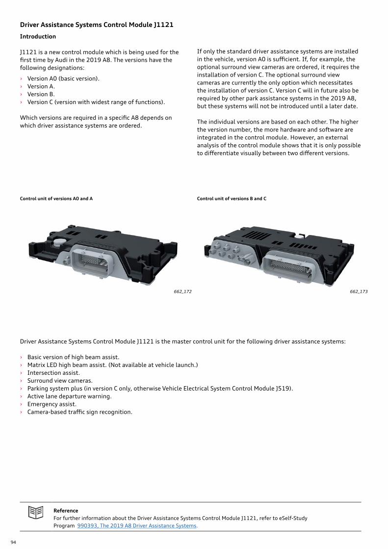
94
Driver Assistance Systems Control Module J1121
Introduction
J1121 is a new control module which is being used for the first time by Audi in the 2019 A8. The versions have the following designations:
› Version A0 (basic version). › Version A. › Version B. › Version C (version with widest range of functions).
Which versions are required in a specific A8 depends on which driver assistance systems are ordered.
If only the standard driver assistance systems are installed in the vehicle, version A0 is sufficient. If, for example, the optional surround view cameras are ordered, it requires the installation of version C. The optional surround view cameras are currently the only option which necessitates the installation of version C. Version C will in future also be required by other park assistance systems in the 2019 A8, but these systems will not be introduced until a later date.
The individual versions are based on each other. The higher the version number, the more hardware and software are integrated in the control module. However, an external analysis of the control module shows that it is only possible to differentiate visually between two different versions.
Control unit of versions A0 and A
662_172
Control unit of versions B and C
662_173
Driver Assistance Systems Control Module J1121 is the master control unit for the following driver assistance systems:
› Basic version of high beam assist. › Matrix LED high beam assist. (Not available at vehicle launch.) › Intersection assist. › Surround view cameras. › Parking system plus (in version C only, otherwise Vehicle Electrical System Control Module J519). › Active lane departure warning. › Emergency assist. › Camera-based traffic sign recognition.
ReferenceFor further information about the Driver Assistance Systems Control Module J1121, refer to eSelf-Study Program 990393, The 2019 A8 Driver Assistance Systems.
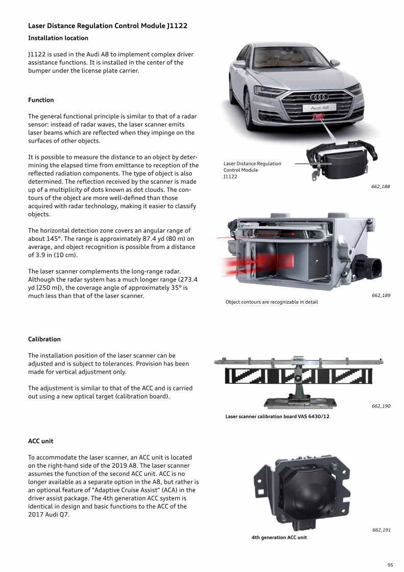
95
Laser Distance Regulation Control Module J1122
Installation location
J1122 is used in the Audi A8 to implement complex driver assistance functions. It is installed in the center of the bumper under the license plate carrier.
Laser Distance Regulation Control Module J1122
Function
The general functional principle is similar to that of a radar sensor: instead of radar waves, the laser scanner emits laser beams which are reflected when they impinge on the surfaces of other objects.
It is possible to measure the distance to an object by deter-mining the elapsed time from emittance to reception of the reflected radiation components. The type of object is also determined. The reflection received by the scanner is made up of a multiplicity of dots known as dot clouds. The con-tours of the object are more well-defined than those acquired with radar technology, making it easier to classify objects.
The horizontal detection zone covers an angular range of about 145°. The range is approximately 87.4 yd (80 m) on average, and object recognition is possible from a distance of 3.9 in (10 cm).
The laser scanner complements the long-range radar. Although the radar system has a much longer range (273.4 yd [250 m]), the coverage angle of approximately 35° is much less than that of the laser scanner.
Calibration
The installation position of the laser scanner can be adjusted and is subject to tolerances. Provision has been made for vertical adjustment only.
The adjustment is similar to that of the ACC and is carried out using a new optical target (calibration board).
ACC unit
To accommodate the laser scanner, an ACC unit is located on the right-hand side of the 2019 A8. The laser scanner assumes the function of the second ACC unit. ACC is no longer available as a separate option in the A8, but rather is an optional feature of "Adaptive Cruise Assist" (ACA) in the driver assist package. The 4th generation ACC system is identical in design and basic functions to the ACC of the 2017 Audi Q7.
Laser scanner calibration board VAS 6430/12
4th generation ACC unit
662_188
662_189
662_190
662_191
Object contours are recognizable in detail
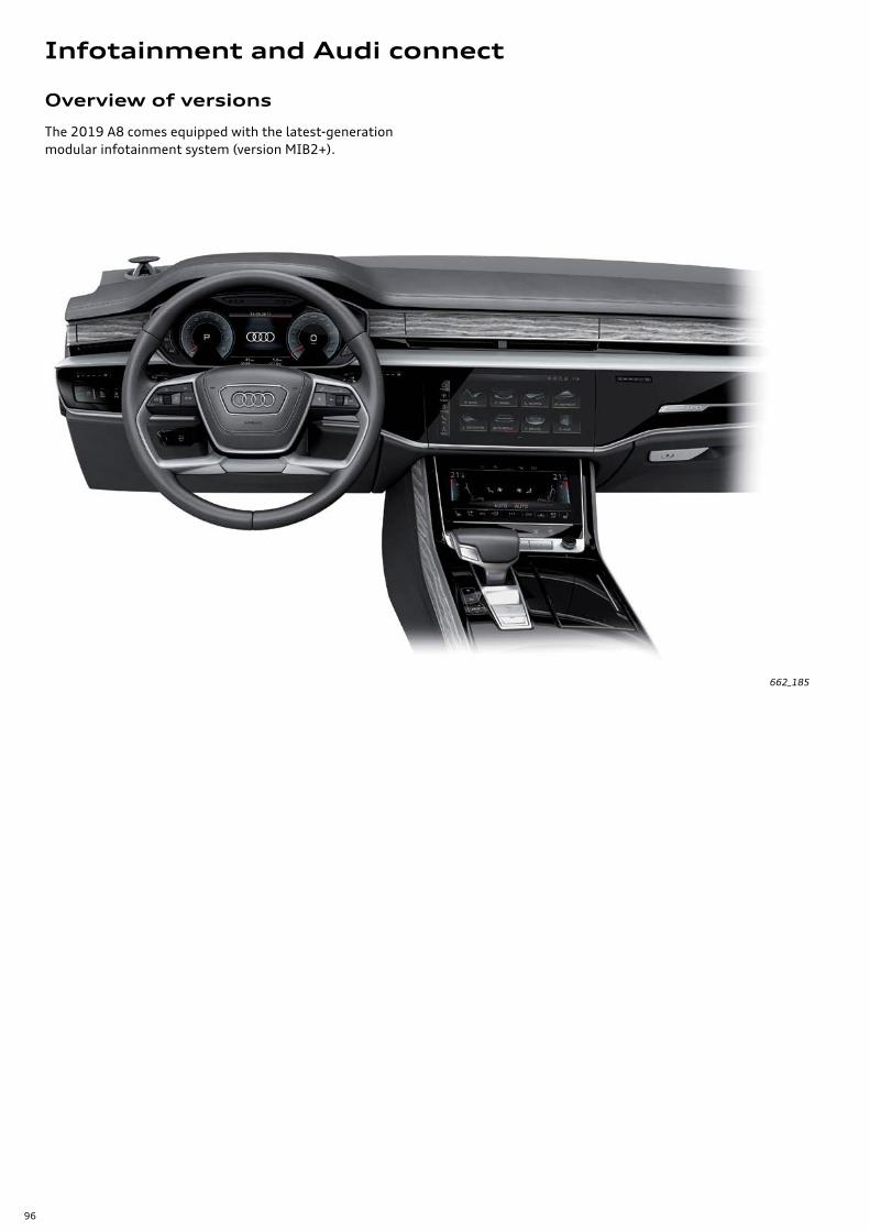
96
662_185
Overview of versions
The 2019 A8 comes equipped with the latest-generation modular infotainment system (version MIB2+).
Infotainment and Audi connect
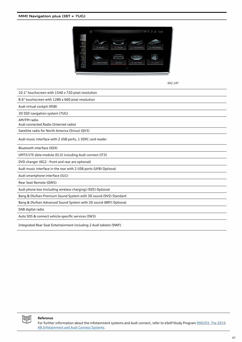
97
662_187
ReferenceFor further information about the infotainment systems and Audi connect, refer to eSelf-Study Program 990293, The 2019 A8 Infotainment and Audi Connect Systems.
MMI Navigation plus (I8T + 7UG)
10.1" touchscreen with 1540 x 720 pixel resolution
8.6" touchscreen with 1280 x 660 pixel resolution
Audi virtual cockpit (9S8)
3D SSD navigation system (7UG)
AM/FM radio Audi connected Radio (Internet radio)
Satellite radio for North America (Sirius) (QV3)
Audi music interface with 2 USB ports, 1 SDXC card reader
Bluetooth interface (9ZX)
UMTS/LTE data module (EL3) including Audi connect (IT3)
DVD changer (6G2 - front and rear are optional)
Audi music interface in the rear with 2 USB ports (UF8) Optional
Audi smartphone interface (IU1)
Rear Seat Remote (QW5)
Audi phone box (including wireless charging) (9ZE) Optional
Bang & Olufsen Premium Sound System with 3D sound (9VS) Standard
Bang & Olufsen Advanced Sound System with 3D sound (8RF) Optional
DAB digital radio
Auto SOS & connect vehicle-specific services (IW3)
Integrated Rear Seat Entertainment including 2 Audi tablets (9WF)
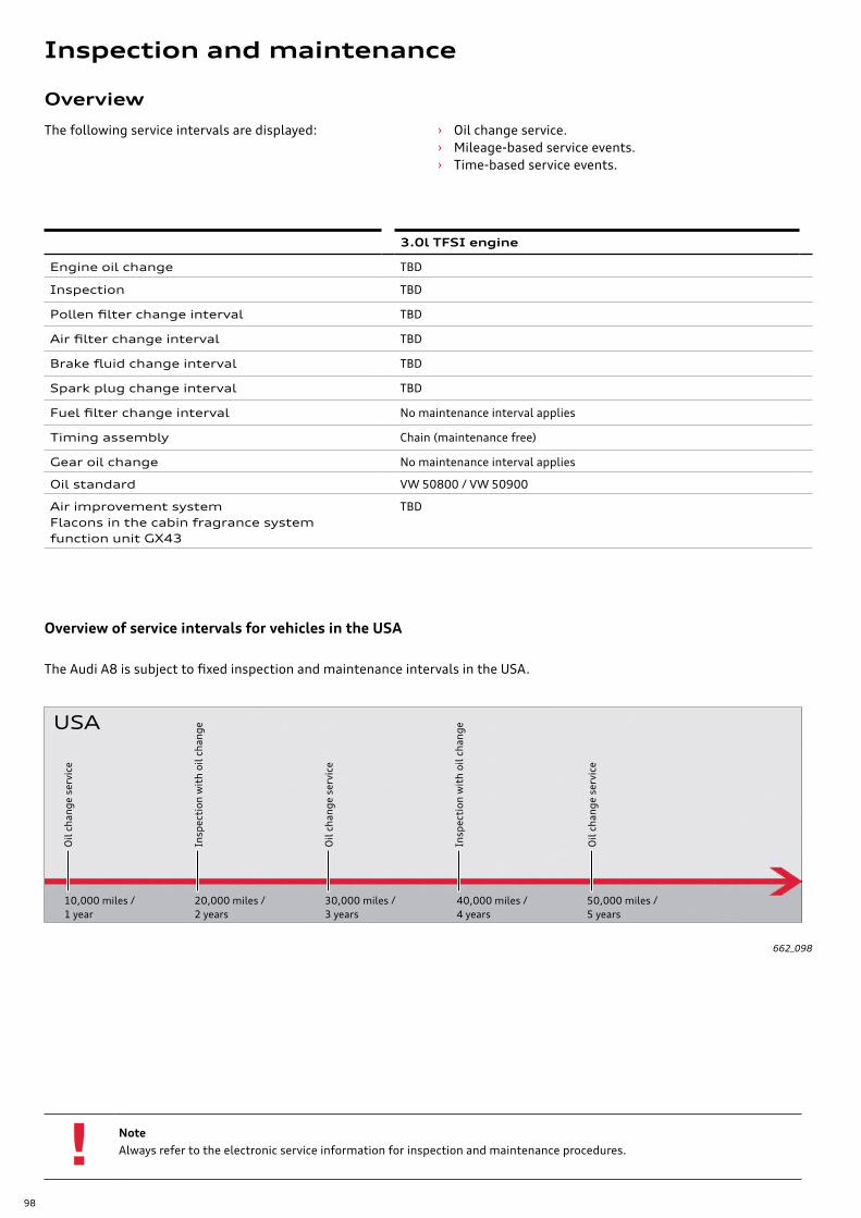
98
Overview
3.0l TFSI engine
Engine oil change TBD
Inspection TBD
Pollen filter change interval TBD
Air filter change interval TBD
Brake fluid change interval TBD
Spark plug change interval TBD
Fuel filter change interval No maintenance interval applies
Timing assembly Chain (maintenance free)
Gear oil change No maintenance interval applies
Oil standard VW 50800 / VW 50900
Air improvement systemFlacons in the cabin fragrance system function unit GX43
TBD
NoteAlways refer to the electronic service information for inspection and maintenance procedures.
The following service intervals are displayed: › Oil change service. › Mileage-based service events. › Time-based service events.
Overview of service intervals for vehicles in the USA
662_098
10,000 miles /1 year
20,000 miles /2 years
30,000 miles /3 years
40,000 miles /4 years
50,000 miles /5 years
Oil
chan
ge s
ervi
ce
Insp
ecti
on w
ith
oil c
hang
e
Oil
chan
ge s
ervi
ce
Insp
ecti
on w
ith
oil c
hang
e
Oil
chan
ge s
ervi
ce
The Audi A8 is subject to fixed inspection and maintenance intervals in the USA.
USA
Inspection and maintenance
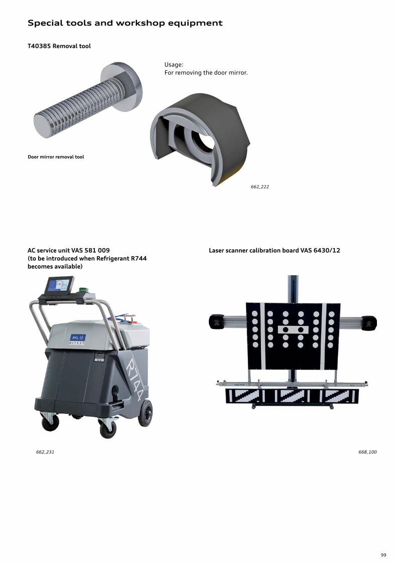
99
Special tools and workshop equipment
Door mirror removal tool
T40385 Removal tool
662_222
662_231
Usage:For removing the door mirror.
AC service unit VAS 581 009 (to be introduced when Refrigerant R744 becomes available)
Laser scanner calibration board VAS 6430/12
668_100
100
The Audi 3.0l V6 TFSI EA839 Engine
eSelf Study Program 920173
The 2019 Audi A8 Electrics and Electronics
eSelf-Study Program 970293
The 2019 A8 Climate Control System
eSelf-Study Program 980193
The 2019 A8 Running Gear and Suspension Systems
Self Study Program 960293
The 2019 A8 Infotainment and Audi Connect Systems
eSelf Study Program 990293
The 2019 A8 Driver Assistance Systems
Self Study Program 990393
SSP 990293 The 2019 Audi A8Infotainment and Audi Connect Systems
SSP 920173 The Audi 3.0l V6 TFSI EA839 engine
SSP 990393 The 2019 Audi A8 Driver Assistance Systems
SSP 960293The 2019 Audi A8 Running Gear and Suspension Systems
SSP 970293The 2019 Audi A8Electrical and Electronics
SSP 980193 The 2019 Audi A8Climate Control Systems
eSelf-Study Program
For more information about the technology of the Audi A8, please refer to the following eSelf-Study Program.
Appendix

101
From the accessaudi.com Homepage:
› Click on the “App Links”
› Click on the “Academy site CRC”
Click on the Course Catalog Search and select “990493 - The 2019 Audi A8 Introduction”
Please submit any questions or inquiries via the Academy CRC Online Support Form
which is located under the “Support” tab or the “Contact Us” tab of the Academy CRC.
Thank you for reading this eSelf-Study Program and taking the assessment.
The Knowledge Assessment is required for Certification credit.
You can find this Knowledge Assessment at: www.accessaudi.com
An On-Line Knowledge Assessment (exam) is Available for this eSelf-Study Program.
Knowledge assessment

99
04
93
All rights reserved.
Technical specifications subject to
change without notice.
Audi of America, LLC
2200 Ferdinand Porsche Drive
Herndon, VA 20171